Code-Making Panel 11 Public Input Report (A19) - NFPA
267
Code‐Making Panel 11 Public Input Report (A19)
-
Upload
khangminh22 -
Category
Documents
-
view
2 -
download
0
Transcript of Code-Making Panel 11 Public Input Report (A19) - NFPA

Code‐Making Panel 11 Public Input Report (A19)

Public Input No. 1781-NFPA 70-2017 [ Global Input ]
Type your content here ...Change "Physical Damage" to "Mechanical Damage"
Statement of Problem and Substantiation for Public Input
The term, "Physical damage" is not defined in Article 100, though it is used widely in the NEC. Therefore, in accordance with the Style Manual's Section 2.2.2.1 and Section 3.3.4, it should be interpreted in accordance with the standard dictionary definition rather than an "industry-specific term" or "trade terminology." The standard dictionary definition does not exclude temperature, chemicals, and other potential sources of harm. These are clearly not intended in many of the places where the term.appears, based on the requirements listed in those places for equipment subject to physical damage or severe physical damage. Mechanics is a dictionary term commonly understood to refer to the sort of forces our trade terminology has referred to by the term, "physical," to the extent that the Style Manual, in Section 3.2.55 recommends its use despite the apparent conflict with Section 3.3.4 "Mechanical damage" is used elsewhere in NP standards where the NEC uses "Physical damage."
Submitter Information Verification
Submitter Full Name: David Shapiro
Organization: Safety First Electrical
Street Address:
City:
State:
Zip:
Submittal Date: Fri Aug 04 15:48:20 EDT 2017
Copyright Assignment
I, David Shapiro, hereby irrevocably grant and assign to the National Fire Protection Association (NFPA) all and full rights incopyright in this Public Input (including both the Proposed Change and the Statement of Problem and Substantiation). Iunderstand and intend that I acquire no rights, including rights as a joint author, in any publication of the NFPA in which thisPublic Input in this or another similar or derivative form is used. I hereby warrant that I am the author of this Public Input and that Ihave full power and authority to enter into this copyright assignment.
By checking this box I affirm that I am David Shapiro, and I agree to be legally bound by the above Copyright Assignment andthe terms and conditions contained therein. I understand and intend that, by checking this box, I am creating an electronicsignature that will, upon my submission of this form, have the same legal force and effect as a handwritten signature
National Fire Protection Association Report http://submittals.nfpa.org/TerraViewWeb/FormLaunch?id=/TerraView/C...
1 of 1

Public Input No. 1342-NFPA 70-2017 [ Global Input ]
Type your content here ...Replace "listed and identified" with "listed" in all locations
Statement of Problem and Substantiation for Public Input
The use of the words "and identified" following the word "listed" is redundant and adds confusion to the NEC. If the equipment is listed, it is already "identified" based on the definition of "identified" and the informational note that follows that definition. The use of the term "listed and identified" would permit the use of a product that is not listed for the purpose to be used where the local inspection authority had "identified" that the product is suitable for the purpose. It appears to me that everywhere the code uses the term "listed" that the intent is that the product be listed for the purpose.
Submitter Information Verification
Submitter Full Name: Don Ganiere
Organization: none
Affilliation: none
Street Address:
City:
State:
Zip:
Submittal Date: Wed Jul 26 20:35:32 EDT 2017
Copyright Assignment
I, Don Ganiere, hereby irrevocably grant and assign to the National Fire Protection Association (NFPA) all and full rights incopyright in this Public Input (including both the Proposed Change and the Statement of Problem and Substantiation). Iunderstand and intend that I acquire no rights, including rights as a joint author, in any publication of the NFPA in which thisPublic Input in this or another similar or derivative form is used. I hereby warrant that I am the author of this Public Input and that Ihave full power and authority to enter into this copyright assignment.
By checking this box I affirm that I am Don Ganiere, and I agree to be legally bound by the above Copyright Assignment andthe terms and conditions contained therein. I understand and intend that, by checking this box, I am creating an electronicsignature that will, upon my submission of this form, have the same legal force and effect as a handwritten signature
National Fire Protection Association Report http://submittals.nfpa.org/TerraViewWeb/FormLaunch?id=/TerraView/C...
1 of 1

Public Input No. 1073-NFPA 70-2017 [ Global Input ]
Change all written percentages to numerical percentages.
Statement of Problem and Substantiation for Public Input
To standardize how percentages are represented in the NEC
Related Public Inputs for This Document
Related Input Relationship
Public Input No. 1071-NFPA 70-2017 [Section No. 690.8(B)(1)]
Public Input No. 1070-NFPA 70-2017 [Section No. 690.8(B)(1)]
Submitter Information Verification
Submitter Full Name: Kevin Nutley
Organization: Puget Sound Electrical Apprenticeship JATC
Street Address:
City:
State:
Zip:
Submittal Date: Sat Jun 24 16:11:26 EDT 2017
Copyright Assignment
I, Kevin Nutley, hereby irrevocably grant and assign to the National Fire Protection Association (NFPA) all and full rights incopyright in this Public Input (including both the Proposed Change and the Statement of Problem and Substantiation). Iunderstand and intend that I acquire no rights, including rights as a joint author, in any publication of the NFPA in which thisPublic Input in this or another similar or derivative form is used. I hereby warrant that I am the author of this Public Input and that Ihave full power and authority to enter into this copyright assignment.
By checking this box I affirm that I am Kevin Nutley, and I agree to be legally bound by the above Copyright Assignment andthe terms and conditions contained therein. I understand and intend that, by checking this box, I am creating an electronicsignature that will, upon my submission of this form, have the same legal force and effect as a handwritten signature
National Fire Protection Association Report http://submittals.nfpa.org/TerraViewWeb/FormLaunch?id=/TerraView/C...
1 of 1

Public Input No. 3453-NFPA 70-2017 [ Global Input ]
Remove the phrase “the provisions of” throughout the entire NEC and editorial revise each segment oftext as required.
Statement of Problem and Substantiation for Public Input
The phrase is unnecessary and redundant. This global public input seeks to request that each NEC Panel (technical committee) review the articles under their responsibility and remove this phrase and reword the text accordingly. The requirements are already provided in the NEC so it does not make sense to refer to provisions. In many cases the phrase should refer to a section, then state that section in accordance with the NEC Style Manual requirements.
Substantiation Examples:
90.6 Formal Interpretations. To promote uniformity of interpretation and application of the provisions of this Code, formal interpretation procedures have been established and are foundin the NFPA Regulations Governing Committee Projects.
110.3(A)Examination, Identification, Installation, Use, and Listing (Product Certification) of Equipment.(1) Suitability for installation and use in conformity with the provisions of this Code
110.30 General. Conductors and equipment used on circuits over 1000 volts, nominal, shall comply with Part I of this article and with 110.30 through 110.41 , which supplement or modifyPart I. In no case shall the provisions of this part apply to equipment on the supply side of the service point.
110.51 General.
(A)Covered. The provisions of this p Part IV shall apply to the installation and use of high-voltage power distribution and utilization equipment that is portable, mobile, or both, such as substations, trailers, cars, mobile shovels, draglines, hoists, drills, dredges, compressors, pumps, conveyors, underground excavators, and the like.
210.13 Ground-Fault Protection of Equipment. Each branch circuit disconnect rated 1000 A or more and installed on solidly grounded wye electrical systems of more than 150 volts to ground, but not exceeding 600 volts phase-to-phase, shall be provided with ground-fault protection of equipment in accordance with the provisions of 230.95.
Exception No. 1: The provisions of this This section shall not apply to a disconnecting means for a continuous industrial process where a nonorderly shutdown will introduce additional or increased hazards.Exception No. 2: The provisions of this This section shall not apply if ground-fault protection of equipment is provided on the supply side of the branch circuit and on the load side of any transformer supplying the branch circuit.
Section 210.60(B)
(B) Receptacle Placement. In applying the provisions of 210.52(A), the total number of receptacle outlets shall not be less than the minimum number that would comply with theprovisions of that section. These receptacle outlets shall be permitted to be located conveniently for permanent furniture layout. At least two receptacle outlets shall be readily accessible. Where receptacles are installed behind the bed, the receptacle shall be located to prevent the bed from contacting any attachment plug that may be installed or the receptacle shall be provided with a suitable guard.
Submitter Information Verification
Submitter Full Name: Agnieszka Golriz
Organization: NECA
Street Address:
National Fire Protection Association Report http://submittals.nfpa.org/TerraViewWeb/FormLaunch?id=/TerraView/C...
1 of 2

City:
State:
Zip:
Submittal Date: Wed Sep 06 10:12:45 EDT 2017
Copyright Assignment
I, Agnieszka Golriz, hereby irrevocably grant and assign to the National Fire Protection Association (NFPA) all and full rights in copyright in thisPublic Input (including both the Proposed Change and the Statement of Problem and Substantiation). I understand and intend that I acquire norights, including rights as a joint author, in any publication of the NFPA in which this Public Input in this or another similar or derivative form isused. I hereby warrant that I am the author of this Public Input and that I have full power and authority to enter into this copyright assignment.
By checking this box I affirm that I am Agnieszka Golriz, and I agree to be legally bound by the above Copyright Assignment and the termsand conditions contained therein. I understand and intend that, by checking this box, I am creating an electronic signature that will, upon mysubmission of this form, have the same legal force and effect as a handwritten signature
National Fire Protection Association Report http://submittals.nfpa.org/TerraViewWeb/FormLaunch?id=/TerraView/C...
2 of 2

Public Input No. 4317-NFPA 70-2017 [ Global Input ]
Each code making panel should set time aside to review the requirements under their purview toensure that new and existing requirements are in compliance with the NEC style manual.
Statement of Problem and Substantiation for Public Input
Code making panels are responsible for ensuring that the Code text which agreed upon at the technical panel meetings comply with all requirements of the NEC style manual. It would be prudent for each code making panel to set time aside to review the requirements under their purview to ensure that not only new but existing requirements are in compliance with the requirements of the NEC style manual.
Adherence to the NEC style manual promotes consistency throughout the NEC adding to clarity to the users of the NEC. Code making panels should spend available time reviewing for such important style manual requirements as the following: (These are just some examples and not a comprehensive list of style manual requirements.)
Unenforceable Terms. The NEC shall not contain references or requirements that are unenforceable or vague. The terms contained in Table 3.2.1 of the style manual shall be reviewed in context, and, addressed if the resulting requirement is unenforceable or vague. Examples of unenforceable and Vague Terms include the following:
designed for the purpose.goodadequatefrequent(ly)
Writing in present text. Requirements must be written in present text and not future text. A good example of this is as follows:
Correct: No conductor shall be used in such a manner that its operating temperature exceeds that designated for the type of insulated conductor involved.Incorrect: No conductor shall be used in such a manner that its operating temperature will exceed that designated for the type of insulated conductor involved.
Submitter Information Verification
Submitter Full Name: Thomas Domitrovich
Organization: Eaton Corporation
Street Address:
City:
State:
Zip:
Submittal Date: Thu Sep 07 20:19:11 EDT 2017
National Fire Protection Association Report http://submittals.nfpa.org/TerraViewWeb/FormLaunch?id=/TerraView/C...
1 of 2

Copyright Assignment
I, Thomas Domitrovich, hereby irrevocably grant and assign to the National Fire Protection Association (NFPA) all and full rights in copyright inthis Public Input (including both the Proposed Change and the Statement of Problem and Substantiation). I understand and intend that I acquireno rights, including rights as a joint author, in any publication of the NFPA in which this Public Input in this or another similar or derivative form isused. I hereby warrant that I am the author of this Public Input and that I have full power and authority to enter into this copyright assignment.
By checking this box I affirm that I am Thomas Domitrovich, and I agree to be legally bound by the above Copyright Assignment and the termsand conditions contained therein. I understand and intend that, by checking this box, I am creating an electronic signature that will, upon mysubmission of this form, have the same legal force and effect as a handwritten signature
National Fire Protection Association Report http://submittals.nfpa.org/TerraViewWeb/FormLaunch?id=/TerraView/C...
2 of 2

Public Input No. 777-NFPA 70-2017 [ Global Input ]
The terms “satisfactory” - "equal" - "equivalent", etc., are examples of numerous subjectiveterms found in the NEC where decisions of suitability fall under the purview of the AHJ.Changing or supplementing these terms to "approved" - "approved equivalent" will continuethe alignment of language used throughout the NEC.
I authored a couple of such changes for the 2014 NEC that were adopted in the 2017. It wassuggested to me by someone from NFPA that I submit a global input, so a committee wouldbe appointed to locate and revise all such subjective terms to include the word "approved".
This will reduce the number of terms used to determine suitability of equipment as it appliesto installation/inspection to one of the following: "Listed" - "Identified" - "Approved"
Statement of Problem and Substantiation for Public Input
I think the language in my global proposal not only states the problem, but offers a viable solution to facilitate uniformity of language throughout the NEC.
Submitter Information Verification
Submitter Full Name: Tom Pernal
Organization: Tom Pernal Electrical Seminars, LLC
Street Address:
City:
State:
Zip:
Submittal Date: Sat May 20 15:35:20 EDT 2017
Copyright Assignment
I, Tom Pernal, hereby irrevocably grant and assign to the National Fire Protection Association (NFPA) all and full rights incopyright in this Public Input (including both the Proposed Change and the Statement of Problem and Substantiation). Iunderstand and intend that I acquire no rights, including rights as a joint author, in any publication of the NFPA in which thisPublic Input in this or another similar or derivative form is used. I hereby warrant that I am the author of this Public Input and that Ihave full power and authority to enter into this copyright assignment.
By checking this box I affirm that I am Tom Pernal, and I agree to be legally bound by the above Copyright Assignment and theterms and conditions contained therein. I understand and intend that, by checking this box, I am creating an electronic signaturethat will, upon my submission of this form, have the same legal force and effect as a handwritten signature
National Fire Protection Association Report http://submittals.nfpa.org/TerraViewWeb/FormLaunch?id=/TerraView/C...
1 of 1

Public Input No. 948-NFPA 70-2017 [ Definition: Industrial Control Panel. ]
Industrial Control Panel.
An assembly of two or more components consisting of one of the following: (1) power circuit components only,such as motor controllers, overload relays, fused disconnect switches, and circuit breakers; (2) control circuitcomponents only, such as push buttons, pilot lights, selector switches, timers, switches, and control relays; (3) acombination of power and control circuit components. These components, with associated wiring and terminals,are mounted on, or contained within, an enclosure or mounted on a subpanel.
The industrial control panel does not include the controlled equipment. (CMP-11)
Statement of Problem and Substantiation for Public Input
The definition of industrial control panel in the NEC states "An assembly of two or more components consisting of one of the following: (2) control circuit components only, such as push buttons, pilot lights, selector switches, timers, switches, and control relays." The UL White Book, Industrial Control Panels (NITW), states industrial control panels "are factory-wired assemblies of industrial control equipment, such as motor controllers, switches, relays and auxiliary devices. The panels may include disconnect means and motor branch-circuit protective devices. An industrial control panel does not include the controlled loads, including motors, luminaires, heaters, or utilization equipment."
According to the definition of an industrial control panel, in both the NEC and UL White Book, a lighting relay panel used to control fixtures would classify as an industrial control panel. However, many engineers and designers do not apply the rules of an industrial control panel to lighting control panels due to the word industrial. This gives many people the impression that "industrial" is only for panels controlling industrial type equipment or panels located in an industrial facility. By removing the word industrial, it will become clear that any control panel, regardless of the equipment being controlled, will follow the regulations contained in section 409.
Submitter Information Verification
Submitter Full Name: Brian Johnson
Organization: AE Design
Street Address:
City:
State:
Zip:
Submittal Date: Fri Jun 09 00:14:15 EDT 2017
Copyright Assignment
I, Brian Johnson, hereby irrevocably grant and assign to the National Fire Protection Association (NFPA) all and full rights in copyright in thisPublic Input (including both the Proposed Change and the Statement of Problem and Substantiation). I understand and intend that I acquire norights, including rights as a joint author, in any publication of the NFPA in which this Public Input in this or another similar or derivative form isused. I hereby warrant that I am the author of this Public Input and that I have full power and authority to enter into this copyright assignment.
By checking this box I affirm that I am Brian Johnson, and I agree to be legally bound by the above Copyright Assignment and the terms andconditions contained therein. I understand and intend that, by checking this box, I am creating an electronic signature that will, upon mysubmission of this form, have the same legal force and effect as a handwritten signature
National Fire Protection Association Report http://submittals.nfpa.org/TerraViewWeb/FormLaunch?id=/TerraView/C...
1 of 1

Public Input No. 1719-NFPA 70-2017 [ Section No. 409.60 ]
409.60 Equipment Grounding Conductor .
Multisection industrial control panels shall be bonded together with an equipment groundingconductor or an equivalent equipment grounding bus sized in accordance with Table 250.122.Equipment grounding conductors shall be connected to this equipment grounding bus or to anequipment grounding termination point provided in a single-section industrial control panel.
Statement of Problem and Substantiation for Public Input
Edit for clarity.
Submitter Information Verification
Submitter Full Name: Mike Holt
Organization: Mike Holt Enterprises Inc
Street Address:
City:
State:
Zip:
Submittal Date: Thu Aug 03 15:55:39 EDT 2017
Copyright Assignment
I, Mike Holt, hereby irrevocably grant and assign to the National Fire Protection Association (NFPA) all and full rights in copyrightin this Public Input (including both the Proposed Change and the Statement of Problem and Substantiation). I understand andintend that I acquire no rights, including rights as a joint author, in any publication of the NFPA in which this Public Input in this oranother similar or derivative form is used. I hereby warrant that I am the author of this Public Input and that I have full power andauthority to enter into this copyright assignment.
By checking this box I affirm that I am Mike Holt, and I agree to be legally bound by the above Copyright Assignment and theterms and conditions contained therein. I understand and intend that, by checking this box, I am creating an electronic signaturethat will, upon my submission of this form, have the same legal force and effect as a handwritten signature
National Fire Protection Association Report http://submittals.nfpa.org/TerraViewWeb/FormLaunch?id=/TerraView/C...
1 of 1

Public Input No. 463-NFPA 70-2017 [ Section No. 409.22(B) Documentation... ]
(B) Documentation.
If an industrial control panel is required to be marked with a short-circuit current rating inaccordance with 409.110(4), the available short-circuit current at the industrial control panel and thedate the short-circuit current calculation was performed shall be posted at the control pnael, andshall be documented and made available to those authorized to inspect the , install, ormaintain the installation.
Statement of Problem and Substantiation for Public Input
Posting the fault current at the equipment ensures compliance with 110.10, and inspectors aren't the only people that need to know this information.
Submitter Information Verification
Submitter Full Name: Ryan Jackson
Organization: Ryan Jackson
Street Address:
City:
State:
Zip:
Submittal Date: Fri Mar 31 15:19:58 EDT 2017
Copyright Assignment
I, Ryan Jackson, hereby irrevocably grant and assign to the National Fire Protection Association (NFPA) all and full rights incopyright in this Public Input (including both the Proposed Change and the Statement of Problem and Substantiation). Iunderstand and intend that I acquire no rights, including rights as a joint author, in any publication of the NFPA in which thisPublic Input in this or another similar or derivative form is used. I hereby warrant that I am the author of this Public Input and that Ihave full power and authority to enter into this copyright assignment.
By checking this box I affirm that I am Ryan Jackson, and I agree to be legally bound by the above Copyright Assignment andthe terms and conditions contained therein. I understand and intend that, by checking this box, I am creating an electronicsignature that will, upon my submission of this form, have the same legal force and effect as a handwritten signature
National Fire Protection Association Report http://submittals.nfpa.org/TerraViewWeb/FormLaunch?id=/TerraView/C...
1 of 1

Public Input No. 3892-NFPA 70-2017 [ Article 430 ]
Article 430 Motors, Motor Circuits, and Controllers
Part I. General
430.1 Scope.
This article covers motors, motor branch-circuit and feeder conductors and their protection, motor overloadprotection, motor control circuits, motor controllers, and motor control centers.
Figure 430.1 Article 430 Contents.
Informational Note No. 1: Installation requirements for motor control centers are covered in 110.26(E).Air-conditioning and refrigerating equipment are covered in Article 440.
Informational Note No. 2: Figure 430.1 is for information only.
430.2 Definitions.
National Fire Protection Association Report http://submittals.nfpa.org/TerraViewWeb/FormLaunch?id=/TerraView/C...
1 of 65

Controller.
For the purpose of this article, a controller is any switch or device that is normally used to start and stop amotor by making and breaking the motor circuit current.
Part-Winding Motors.
A part-winding start induction or synchronous motor is one that is arranged for starting by first energizing partof its primary (armature) winding and, subsequently, energizing the remainder of this winding in one or moresteps. A standard part-winding start induction motor is arranged so that one-half of its primary winding can beenergized initially, and, subsequently, the remaining half can be energized, both halves then carrying equalcurrent. A hermetic refrigerant compressor motor shall not be considered a standard part-winding startinduction motor.
System Isolation Equipment.
A redundantly monitored, remotely operated contactor-isolating system, packaged to provide thedisconnection/isolation function, capable of verifiable operation from multiple remote locations by means oflockout switches, each having the capability of being padlocked in the “off” (open) position.
Valve Actuator Motor (VAM) Assemblies.
A manufactured assembly, used to operate a valve, consisting of an actuator motor and other componentssuch as controllers, torque switches, limit switches, and overload protection.
Informational Note: VAMs typically have short-time duty and high-torque characteristics.
430.4 Part-Winding Motors.
Where separate overload devices are used with a standard part-winding start induction motor, each half of themotor winding shall be individually protected in accordance with 430.32 and 430.37 with a trip current one-half that specified.
Each motor-winding connection shall have branch-circuit short-circuit and ground-fault protection rated at notmore than one-half that specified by 430.52 .
Exception: A short-circuit and ground-fault protective device shall be permitted for both windings if thedevice will allow the motor to start. Where time-delay (dual-element) fuses are used, they shall be permittedto have a rating not exceeding 150 percent of the motor full-load current.
430.5 Other Articles.
Motors and controllers shall also comply with the applicable provisions of Table 430.5 .
Table 430.5 Other Articles
Equipment/Occupancy Article Section
Air-conditioning and refrigerating equipment 440
Capacitors
460.8, 460.9
Commercial garages; aircraft hangars; motor fuel dispensing facilities; bulk storageplants; spray application, dipping, and coating processes; and inhalationanesthetizing locations
511, 513, 514, 515,516, and 517 Part IV
Cranes and hoists 610
Electrically driven or controlled irrigation machines 675
National Fire Protection Association Report http://submittals.nfpa.org/TerraViewWeb/FormLaunch?id=/TerraView/C...
2 of 65

Elevators, dumbwaiters, escalators, moving walks, wheelchair lifts, and stairway chair lifts 620
Fire pumps 695
Hazardous (classified) locations 500–503, 505, and 506
Industrial machinery 670
Motion picture projectors
540.11 and 540.20
Motion picture and television studios and similar locations 530
Resistors and reactors 470
Theaters, audience areas of motion picture and television studios, and similar locations
520.48
Transformers and transformer vaults 450
430.6 Ampacity and Motor Rating Determination.
The size of conductors supplying equipment covered by Article 430 shall be selected from the allowableampacity tables in accordance with 310.15(B) or shall be calculated in accordance with 310.15(C) . Whereflexible cord is used, the size of the conductor shall be selected in accordance with 400.5 . The requiredampacity and motor ratings shall be determined as specified in 430.6(A) , (B), (C), and (D).
(A) General Motor Applications.
For general motor applications, current ratings shall be determined based on (A)(1) and (A)(2).
National Fire Protection Association Report http://submittals.nfpa.org/TerraViewWeb/FormLaunch?id=/TerraView/C...
3 of 65

(1) Table Values.
Other than for motors built for low speeds (less than 1200 RPM) or high torques, and for multispeed motors,the values given in Table 430.247 , Table 430.248 , Table 430.249 , and Table 430.250 shall be used todetermine the ampacity of conductors or ampere ratings of switches, branch-circuit short-circuit and ground-fault protection, instead of the actual current rating marked on the motor nameplate. Where a motor is markedin amperes, but not horsepower, the horsepower rating shall be assumed to be that corresponding to thevalue given in Table 430.247 , Table 430.248 , Table 430.249 , and Table 430.250 , interpolated if necessary.Motors built for low speeds (less than 1200 RPM) or high torques may have higher full-load currents, andmultispeed motors will have full-load current varying with speed, in which case the nameplate current ratingsshall be used.
Exception No. 1: Multispeed motors shall be in accordance with 430.22(B) and 430.52 .
Exception No. 2: For equipment that employs a shaded-pole or permanent-split capacitor-type fan or blowermotor that is marked with the motor type, the full load current for such motor marked on the nameplate ofthe equipment in which the fan or blower motor is employed shall be used instead of the horsepower ratingto determine the ampacity or rating of the disconnecting means, the branch-circuit conductors, thecontroller, the branch-circuit short-circuit and ground-fault protection, and the separate overload protection.This marking on the equipment nameplate shall not be less than the current marked on the fan or blowermotor nameplate.
Exception No. 3: For a listed motor-operated appliance that is marked with both motor horsepower and full-load current, the motor full-load current marked on the nameplate of the appliance shall be used instead ofthe horsepower rating on the appliance nameplate to determine the ampacity or rating of the disconnectingmeans, the branch-circuit conductors, the controller, the branch-circuit short-circuit and ground-faultprotection, and any separate overload protection.
(2) Nameplate Values.
Separate motor overload protection shall be based on the motor nameplate current rating.
(B) Torque Motors.
For torque motors, the rated current shall be locked-rotor current, and this nameplate current shall be used todetermine the ampacity of the branch-circuit conductors covered in 430.22 and 430.24 , the ampere rating ofthe motor overload protection, and the ampere rating of motor branch-circuit short-circuit and ground-faultprotection in accordance with 430.52(B) .
Informational Note: For motor controllers and disconnecting means, see 430.83(D) and 430.110 .
(C) Alternating-Current Adjustable Voltage Motors.
For motors used in alternating-current, adjustable voltage, variable torque drive systems, the ampacity ofconductors, or ampere ratings of switches, branch-circuit short-circuit and ground-fault protection, and soforth, shall be based on the maximum operating current marked on the motor or control nameplate, or both. Ifthe maximum operating current does not appear on the nameplate, the ampacity determination shall bebased on 150 percent of the values given in Table 430.249 and Table 430.250 .
(D) Valve Actuator Motor Assemblies.
For valve actuator motor assemblies (VAMs), the rated current shall be the nameplate full-load current, andthis current shall be used to determine the maximum rating or setting of the motor branch-circuit short-circuitand ground-fault protective device and the ampacity of the conductors.
430.7 Marking on Motors and Multimotor Equipment.
National Fire Protection Association Report http://submittals.nfpa.org/TerraViewWeb/FormLaunch?id=/TerraView/C...
4 of 65

(A) Usual Motor Applications.
A motor shall be marked with the following information:
(1) Manufacturer’s name.
(2) Rated volts and full-load current. For a multispeed motor, full-load current for each speed, exceptshaded-pole and permanent-split capacitor motors where amperes are required only for maximumspeed.
(3) Rated frequency and number of phases if an ac motor.
(4) Rated full-load speed.
(5) Rated temperature rise or the insulation system class and rated ambient temperature.
(6) Time rating. The time rating shall be 5, 15, 30, or 60 minutes, or continuous.
(7) Rated horsepower if 1 ⁄ 8 hp or more. For a multispeed motor 1 ⁄ 8 hp or more, rated horsepower for
each speed, except shaded-pole and permanent-split capacitor motors 1 ⁄ 8 hp or more where ratedhorsepower is required only for maximum speed. Motors of arc welders are not required to be markedwith the horsepower rating.
(8) Code letter or locked-rotor amperes if an alternating-current motor rated 1 ⁄ 2 hp or more. On polyphasewound-rotor motors, the code letter shall be omitted.
Informational Note: See 430.7(B) .
(9) Design letter for design B, C, or D motors.
Informational Note: Motor design letter definitions are found in ANSI/NEMA MG 1-1993, Motorsand Generators, Part 1, Definitions, and in IEEE 100-1996, Standard Dictionary of Electrical andElectronic Terms .
(10) Secondary volts and full-load current if a wound-rotor induction motor.
(11) Field current and voltage for dc excited synchronous motors.
(12) Winding — straight shunt, stabilized shunt, compound, or series, if a dc motor. Fractional horsepower dcmotors 175 mm (7 in.) or less in diameter shall not be required to be marked.
(13) A motor provided with a thermal protector complying with 430.32(A)(2) or (B)(2) shall be marked“Thermally Protected.” Thermally protected motors rated 100 watts or less and complying with430.32(B)(2) shall be permitted to use the abbreviated marking “T.P.”
(14) A motor complying with 430.32(B)(4) shall be marked “Impedance Protected.” Impedance-protectedmotors rated 100 watts or less and complying with 430.32(B)(4) shall be permitted to use theabbreviated marking “Z.P.”
(15) Motors equipped with electrically powered condensation prevention heaters shall be marked with therated heater voltage, number of phases, and the rated power in watts.
(16) Motors complying with 430.32 (B) (5) shall be marked "Electronically Protected" or "E.P." ?
(B) Locked-Rotor Indicating Code Letters.
National Fire Protection Association Report http://submittals.nfpa.org/TerraViewWeb/FormLaunch?id=/TerraView/C...
5 of 65

Code letters marked on motor nameplates to show motor input with locked rotor shall be in accordance withTable 430.7(B) .
The code letter indicating motor input with locked rotor shall be in an individual block on the nameplate,properly designated.
Table 430.7(B) Locked-Rotor Indicating Code Letters
Code Letter Kilovolt-Amperes per Horsepower with Locked Rotor
A 0–3.14
B 3.15–3.54
C 3.55–3.99
D 4.0–4.49
E 4.5–4.99
F 5.0–5.59
G 5.6–6.29
H 6.3–7.09
J 7.1–7.99
K 8.0–8.99
L 9.0–9.99
M 10.0–11.19
N 11.2–12.49
P 12.5–13.99
R 14.0–15.99
S 16.0–17.99
T 18.0–19.99
U 20.0–22.39
V 22.4 and up
(1) Multispeed Motors.
Multispeed motors shall be marked with the code letter designating the locked-rotor kilovolt-ampere (kVA) perhorsepower (hp) for the highest speed at which the motor can be started.
Exception: Constant horsepower multispeed motors shall be marked with the code letter giving the highestlocked-rotor kilovolt-ampere (kVA) per horsepower (hp).
(2) Single-Speed Motors.
Single-speed motors starting on wye connection and running on delta connections shall be marked with acode letter corresponding to the locked-rotor kilovolt-ampere (kVA) per horsepower (hp) for the wyeconnection.
(3) Dual-Voltage Motors.
Dual-voltage motors that have a different locked-rotor kilovolt-ampere (kVA) per horsepower (hp) on the twovoltages shall be marked with the code letter for the voltage giving the highest locked-rotor kilovolt-ampere(kVA) per horsepower (hp).
(4) 50/60 Hz Motors.
Motors with 50- and 60-Hz ratings shall be marked with a code letter designating the locked-rotor kilovolt-ampere (kVA) per horsepower (hp) on 60 Hz.
(5) Part-Winding Motors.
Part-winding start motors shall be marked with a code letter designating the locked-rotor kilovolt-ampere(kVA) per horsepower (hp) that is based on the locked-rotor current for the full winding of the motor.
(C) Torque Motors.
Torque motors are rated for operation at standstill and shall be marked in accordance with 430.7(A) , exceptthat locked-rotor torque shall replace horsepower.
National Fire Protection Association Report http://submittals.nfpa.org/TerraViewWeb/FormLaunch?id=/TerraView/C...
6 of 65

(D) Multimotor and Combination-Load Equipment.
(1) Factory-Wired.
Multimotor and combination-load equipment shall be provided with a visible nameplate marked with themanufacturer’s name, the rating in volts, frequency, number of phases, minimum supply circuit conductorampacity, and the maximum ampere rating of the circuit short-circuit and ground-fault protective device. Theconductor ampacity shall be calculated in accordance with 430.24 and counting all of the motors and otherloads that will be operated at the same time. The short-circuit and ground-fault protective device rating shallnot exceed the value calculated in accordance with 430.53 . Multimotor equipment for use on two or morecircuits shall be marked with the preceding information for each circuit.
(2) Not Factory-Wired.
Where the equipment is not factory-wired and the individual nameplates of motors and other loads are visibleafter assembly of the equipment, the individual nameplates shall be permitted to serve as the requiredmarking.
430.8 Marking on Controllers.
A controller shall be marked with the manufacturer’s name or identification, the voltage, the current orhorsepower rating, the short-circuit current rating, and other necessary data to properly indicate theapplications for which it is suitable.
Exception No. 1: The short-circuit current rating is not required for controllers applied in accordance with430.81(A) or (B).
Exception No. 2: The short-circuit rating is not required to be marked on the controller when the short-circuitcurrent rating of the controller is marked elsewhere on the assembly.
Exception No. 3: The short-circuit rating is not required to be marked on the controller when the assemblyinto which it is installed has a marked short-circuit current rating.
Exception No. 4: Short-circuit ratings are not required for controllers rated less than 2 hp at 300 V or lessand listed exclusively for general-purpose branch circuits.
A controller that includes motor overload protection suitable for group motor application shall be marked withthe motor overload protection and the maximum branch-circuit short-circuit and ground-fault protection forsuch applications.
Combination controllers that employ adjustable instantaneous trip circuit breakers shall be clearly marked toindicate the ampere settings of the adjustable trip element.
Where a controller is built in as an integral part of a motor or of a motor-generator set, individual marking ofthe controller shall not be required if the necessary data are on the nameplate. For controllers that are anintegral part of equipment approved as a unit, the above marking shall be permitted on the equipmentnameplate.
Informational Note: See 110.10 for information on circuit impedance and other characteristics.
430.9 Terminals.
(A) Markings.
Terminals of motors and controllers shall be suitably marked or colored where necessary to indicate theproper connections.
(B) Conductors.
Motor controllers and terminals of control circuit devices shall be connected with copper conductors unlessidentified for use with a different conductor.
(C) Torque Requirements.
Control circuit devices with screw-type pressure terminals used with 14 AWG or smaller copper conductorsshall be torqued to a minimum of 0.8 N·m (7 lb-in.) unless identified for a different torque value.
430.10 Wiring Space in Enclosures.
National Fire Protection Association Report http://submittals.nfpa.org/TerraViewWeb/FormLaunch?id=/TerraView/C...
7 of 65

(A) General.
Enclosures for motor controllers and disconnecting means shall not be used as junction boxes, auxiliarygutters, or raceways for conductors feeding through or tapping off to the other apparatus unless designs areemployed that provide adequate space for this purpose.
Informational Note: See 312.8 for switch and overcurrent-device enclosures.
(B) Wire-Bending Space in Enclosures.
Minimum wire-bending space within the enclosures for motor controllers shall be in accordance with Table430.10(B) where measured in a straight line from the end of the lug or wire connector (in the direction thewire leaves the terminal) to the wall or barrier. Where alternate wire termination means are substituted for thatsupplied by the manufacturer of the controller, they shall be of a type identified by the manufacturer for usewith the controller and shall not reduce the minimum wire-bending space.
Table 430.10(B) Minimum Wire-Bending Space at the Terminals of Enclosed Motor Controllers
Size of Wire (AWG or kcmil)Wires per Terminal *
1
2
mm in.
mm in.
10 and smaller Not specified
— —
8–6 38 1 1 ⁄ 2
— —
4–3 50 2
— —
2 65 2 1 ⁄ 2
— —
1 75 3
— —
1/0 125 5
125 5
2/0 150 6
National Fire Protection Association Report http://submittals.nfpa.org/TerraViewWeb/FormLaunch?id=/TerraView/C...
8 of 65

150 6
3/0–4/0 175 7
175 7
250 200 8
200 8
300 250 10
250 10
350–500 300 12
300 12
600–700 350 14
400 16
750–900 450 18
475 19
* Where provision for three or more wires per terminal exists, the minimum wire-bending space shall be inaccordance with the requirements of Article 312.
430.11 Protection Against Liquids.
Suitable guards or enclosures shall be provided to protect exposed current-carrying parts of motors and theinsulation of motor leads where installed directly under equipment, or in other locations where dripping orspraying oil, water, or other liquid is capable of occurring, unless the motor is designed for the existingconditions.
430.12 Motor Terminal Housings.
(A) Material.
Where motors are provided with terminal housings, the housings shall be of metal and of substantialconstruction.
Exception: In other than hazardous (classified) locations, substantial, nonmetallic, noncombustiblehousings shall be permitted, provided an internal grounding means between the motor frame and theequipment grounding connection is incorporated within the housing.
(B) Dimensions and Space — Wire-to-Wire Connections.
Where these terminal housings enclose wire-to-wire connections, they shall have minimum dimensions andusable volumes in accordance with Table 430.12(B) .
Table 430.12(B) Terminal Housings — Wire-to-Wire Connections
Motors 275 mm (11 in.) in Diameter or Less
Horsepower Cover Opening Minimum Dimension
National Fire Protection Association Report http://submittals.nfpa.org/TerraViewWeb/FormLaunch?id=/TerraView/C...
9 of 65

Usable Volume Minimum
mm in.
cm 3 in. 3
1 and smaller a 41 1 5 ⁄ 8
170 10.5
1 1 ⁄ 2 , 2, and 3 b 45 1 3 ⁄ 4
275 16.8
5 and 7 1 ⁄ 2 50 2
365 22.4
10 and 15 65 2 1 ⁄ 2
595 36.4
Motors Over 275 mm (11 in.) in Diameter — Alternating-Current Motors
Maximum Full Load Current for 3-Phase Motors with Maximum of12 Leads (Amperes)
Terminal Box Cover OpeningMinimum
Dimension
Usable Volume Minimum
Typical Maximum Horsepower 3-Phase
mm in. cm 3 in. 3
230
Volt
460
Volt
45 65 2.5
595 36.4
15 30
70 84 3.3
1,265 77
National Fire Protection Association Report http://submittals.nfpa.org/TerraViewWeb/FormLaunch?id=/TerraView/C...
10 of 65

25 50
110 100 4.0
2,295 140
40 75
160 125 5.0
4,135 252
60 125
250 150 6.0
7,380 450
100 200
400 175 7.0
13,775 840
150 300
600 200 8.0
25,255 1540
250 500
Direct-Current Motors
Maximum Full-Load Current for Motors with Maximum of 6 Leads(Amperes)
Terminal Box MinimumDimensions
Usable Volume Minimum
mm in.
cm 3 in. 3
68 65 2.5
National Fire Protection Association Report http://submittals.nfpa.org/TerraViewWeb/FormLaunch?id=/TerraView/C...
11 of 65

425 26
105 84 3.3
900 55
165 100 4.0
1,640 100
240 125 5.0
2,950 180
375 150 6.0
5,410 330
600 175 7.0
9,840 600
900 200 8.0
18,040 1,100
Note: Auxiliary leads for such items as brakes, thermostats, space heaters, and exciting fields shall bepermitted to be neglected if their current-carrying area does not exceed 25 percent of the current-carryingarea of the machine power leads.
a For motors rated 1 hp and smaller, and with the terminal housing partially or wholly integral with the frame or
end shield, the volume of the terminal housing shall not be less than 18.0 cm 3 (1.1 in. 3 ) per wire-to-wireconnection. The minimum cover opening dimension is not specified.
b For motors rated 1 1 ⁄ 2 , 2, and 3 hp, and with the terminal housing partially or wholly integral with the frame
or end shield, the volume of the terminal housing shall not be less than 23.0 cm 3 (1.4 in. 3 ) per wire-to-wireconnection. The minimum cover opening dimension is not specified.
(C) Dimensions and Space — Fixed Terminal Connections.
Where these terminal housings enclose rigidly mounted motor terminals, the terminal housing shall be ofsufficient size to provide minimum terminal spacings and usable volumes in accordance with Table430.12(C)(1) and Table 430.12(C)(2) .
Table 430.12(C)(1) Terminal Spacings — Fixed Terminals
Nominal
Volts
Minimum Spacing
Between Line Terminals
Between Line Terminals and Other Uninsulated Metal Parts
mm in.
National Fire Protection Association Report http://submittals.nfpa.org/TerraViewWeb/FormLaunch?id=/TerraView/C...
12 of 65

mm in.
250 or less 6 1 ⁄ 4
6 1 ⁄ 4
Over 250 – 1000 10 3 ⁄ 8
10 3 ⁄ 8
Table 430.12(C)(2) Usable Volumes — Fixed Terminals
Power-Supply Conductor Size (AWG)Minimum Usable Volume per Power-Supply Conductor
cm 3 in. 3
14 16 1
12 and 10 20 1 1 ⁄ 4
8 and 6 37 2 1 ⁄ 4
(D) Large Wire or Factory Connections.
For motors with larger ratings, greater number of leads, or larger wire sizes, or where motors are installed asa part of factory-wired equipment, without additional connection being required at the motor terminal housingduring equipment installation, the terminal housing shall be of ample size to make connections, but theforegoing provisions for the volumes of terminal housings shall not be considered applicable.
(E) Equipment Grounding Connections.
A means for attachment of an equipment grounding conductor termination in accordance with 250.8 shall beprovided at motor terminal housings for wire-to-wire connections or fixed terminal connections. The means forsuch connections shall be permitted to be located either inside or outside the motor terminal housing.
Exception: Where a motor is installed as a part of factory-wired equipment that is required to be groundedand without additional connection being required at the motor terminal housing during equipmentinstallation, a separate means for motor grounding at the motor terminal housing shall not be required.
430.13 Bushing.
Where wires pass through an opening in an enclosure, conduit box, or barrier, a bushing shall be used toprotect the conductors from the edges of openings having sharp edges. The bushing shall have smooth, well-rounded surfaces where it may be in contact with the conductors. If used where oils, greases, or othercontaminants may be present, the bushing shall be made of material not deleteriously affected.
Informational Note: For conductors exposed to deteriorating agents, see 310.10(G) .
430.14 Location of Motors.
(A) Ventilation and Maintenance.
Motors shall be located so that adequate ventilation is provided and so that maintenance, such as lubricationof bearings and replacing of brushes, can be readily accomplished.
Exception: Ventilation shall not be required for submersible types of motors.
(B) Open Motors.
Open motors that have commutators or collector rings shall be located or protected so that sparks cannotreach adjacent combustible material.
Exception: Installation of these motors on wooden floors or supports shall be permitted.
National Fire Protection Association Report http://submittals.nfpa.org/TerraViewWeb/FormLaunch?id=/TerraView/C...
13 of 65

430.16 Exposure to Dust Accumulations.
In locations where dust or flying material collects on or in motors in such quantities as to seriously interferewith the ventilation or cooling of motors and thereby cause dangerous temperatures, suitable types ofenclosed motors that do not overheat under the prevailing conditions shall be used.
Informational Note: Especially severe conditions may require the use of enclosed pipe-ventilatedmotors, or enclosure in separate dusttight rooms, properly ventilated from a source of clean air.
430.17 Highest Rated or Smallest Rated Motor.
In determining compliance with 430.24 , 430.53(B) , and 430.53(C) , the highest rated or smallest ratedmotor shall be based on the rated full-load current as selected from Table 430.247 , Table 430.248 , Table430.249 , and Table 430.250 .
430.18 Nominal Voltage of Rectifier Systems.
The nominal value of the ac voltage being rectified shall be used to determine the voltage of a rectifier derivedsystem.
Exception: The nominal dc voltage of the rectifier shall be used if it exceeds the peak value of the acvoltage being rectified.
Part II. Motor Circuit Conductors
430.21 General.
Part II specifies ampacities of conductors that are capable of carrying the motor current without overheatingunder the conditions specified.
The provisions of Part II shall not apply to motor circuits rated over 1000 volts, nominal.
Informational Note: For over 1000 volts, nominal, see Part XI.
The provisions of Articles 250, 300, and 310 shall not apply to conductors that form an integral part ofequipment, such as motors, motor controllers, motor control centers, or other factory-assembled controlequipment.
Informational Note: See 110.14(C) and 430.9(B) for equipment device terminal requirements.
430.22 Single Motor.
Conductors that supply a single motor used in a continuous duty application shall have an ampacity of notless than 125 percent of the motor full-load current rating, as determined by 430.6(A)(1) , or not less thanspecified in 430.22(A) through (G).
(A) Direct-Current Motor-Rectifier Supplied.
For dc motors operating from a rectified power supply, the conductor ampacity on the input of the rectifiershall not be less than 125 percent of the rated input current to the rectifier. For dc motors operating from arectified single-phase power supply, the conductors between the field wiring output terminals of the rectifierand the motor shall have an ampacity of not less than the following percentages of the motor full-load currentrating:
(1) Where a rectifier bridge of the single-phase, half-wave type is used, 190 percent.
(2) Where a rectifier bridge of the single-phase, full-wave type is used, 150 percent.
(B) Multispeed Motor.
For a multispeed motor, the selection of branch-circuit conductors on the line side of the controller shall bebased on the highest of the full-load current ratings shown on the motor nameplate. The ampacity of thebranch-circuit conductors between the controller and the motor shall not be less than 125 percent of thecurrent rating of the winding(s) that the conductors energize.
National Fire Protection Association Report http://submittals.nfpa.org/TerraViewWeb/FormLaunch?id=/TerraView/C...
14 of 65

(C) Wye-Start, Delta-Run Motor.
For a wye-start, delta-run connected motor, the ampacity of the branch-circuit conductors on the line side ofthe controller shall not be less than 125 percent of the motor full-load current as determined by 430.6(A)(1) .The ampacity of the conductors between the controller and the motor shall not be less than 72 percent of themotor full-load current rating as determined by 430.6(A)(1) .
Informational Note: The individual motor circuit conductors of a wye-start, delta-run connected motorcarry 58 percent of the rated load current. The multiplier of 72 percent is obtained by multiplying58 percent by 1.25.
(D) Part-Winding Motor.
For a part-winding connected motor, the ampacity of the branch-circuit conductors on the line side of thecontroller shall not be less than 125 percent of the motor full-load current as determined by 430.6(A)(1) . Theampacity of the conductors between the controller and the motor shall not be less than 62.5 percent of themotor full-load current rating as determined by 430.6(A)(1) .
Informational Note: The multiplier of 62.5 percent is obtained by multiplying 50 percent by 1.25.
(E) Other Than Continuous Duty.
Conductors for a motor used in a short-time, intermittent, periodic, or varying duty application shall have anampacity of not less than the percentage of the motor nameplate current rating shown in Table 430.22(E) ,unless the authority having jurisdiction grants special permission for conductors of lower ampacity.
Table 430.22(E) Duty-Cycle Service
Classification of Service
Nameplate Current RatingPercentages
5-Minute
RatedMotor
15-Minute
Rated
Motor
30- &60-
Minute
Rated
Motor
Contin-
uous
Rated
Motor
Short-time duty operating valves, raising or lowering rolls, etc. 110 120 150 —
Intermittent duty freight and passenger elevators, tool heads,pumps, drawbridges, turntables, etc. (for arc welders, see 630.11)
85 85 90 140
Periodic duty rolls, ore- and coal-handling machines, etc. 85 90 95 140
Varying duty 110 120 150 200
Note: Any motor application shall be considered as continuous duty unless the nature of the apparatus itdrives is such that the motor will not operate continuously with load under any condition of use.
(F) Separate Terminal Enclosure.
The conductors between a stationary motor rated 1 hp or less and the separate terminal enclosure permittedin 430.245(B) shall be permitted to be smaller than 14 AWG but not smaller than 18 AWG, provided theyhave an ampacity as specified in 430.22 .
(G) Conductors for Small Motors.
Conductors for small motors shall not be smaller than 14 AWG unless otherwise permitted in 430.22(G)(1)or (G)(2).
National Fire Protection Association Report http://submittals.nfpa.org/TerraViewWeb/FormLaunch?id=/TerraView/C...
15 of 65

(1) 18 AWG Copper.
18 AWG individual copper conductors installed in a cabinet or enclosure, copper conductors that are part of ajacketed multiconductor cable assembly, or copper conductors in a flexible cord shall be permitted, undereither of the following sets of conditions:
(1) The circuit supplies a motor with a full-load current rating, as determined by 430.6(A)(1) , of greater than3.5 amperes, and less than or equal to 5 amperes, and all the following conditions are met:
(2) The circuit is protected in accordance with 430.52 .
(3) The circuit is provided with maximum Class 10 or Class 10A overload protection in accordance with430.32 .
(4) Overcurrent protection is provided in accordance with 240.4(D)(1)(2) .
(5) The circuit supplies a motor with a full-load current rating, as determined by 430.6(A)(1) , of 3.5 amperesor less, and all the following conditions are met:
(6) The circuit is protected in accordance with 430.52 .
(7) The circuit is provided with maximum Class 20 overload protection in accordance with 430.32 .
(8) Overcurrent protection is provided in accordance with 240.4(D)(1)(2) .
(2) 16 AWG Copper.
16 AWG individual copper conductors installed in a cabinet or enclosure, copper conductors that are part of ajacketed multiconductor cable assembly, or copper conductors in a flexible cord shall be permitted undereither of the following sets of conditions:
(1) The circuit supplies a motor with a full-load current rating, as determined by 430.6(A)(1) , of greater than5.5 amperes, and less than or equal to 8 amperes, and all the following conditions are met:
(2) The circuit is protected in accordance with 430.52 .
(3) The circuit is provided with maximum Class 10 or Class 10A overload protection in accordance with430.32 .
(4) Overcurrent protection is provided in accordance with 240.4(D)(2)(2) .
(5) The circuit supplies a motor with a full-load current rating, as determined by 430.6(A)(1) , of 5.5 amperesor less, and all the following conditions are met:
(6) The circuit is protected in accordance with 430.52 .
(7) The circuit is provided with maximum Class 20 overload protection in accordance with 430.32 .
(8) Overcurrent protection is provided in accordance with 240.4(D)(2)(2) .
430.23 Wound-Rotor Secondary.
(A) Continuous Duty.
For continuous duty, the conductors connecting the secondary of a wound-rotor ac motor to its controller shallhave an ampacity not less than 125 percent of the full-load secondary current of the motor.
(B) Other Than Continuous Duty.
For other than continuous duty, these conductors shall have an ampacity, in percent of full-load secondarycurrent, not less than that specified in Table 430.22(E) .
National Fire Protection Association Report http://submittals.nfpa.org/TerraViewWeb/FormLaunch?id=/TerraView/C...
16 of 65

(C) Resistor Separate from Controller.
Where the secondary resistor is separate from the controller, the ampacity of the conductors betweencontroller and resistor shall not be less than that shown in Table 430.23(C) .
Table 430.23(C) Secondary Conductor
Resistor Duty Classification Ampacity of Conductor in Percent of Full-Load Secondary Current
Light starting duty 35
Heavy starting duty 45
Extra-heavy starting duty 55
Light intermittent duty 65
Medium intermittent duty 75
Heavy intermittent duty 85
Continuous duty 110
430.24 Several Motors or a Motor(s) and Other Load(s).
Conductors supplying several motors, or a motor(s) and other load(s), shall have an ampacity not less thanthe sum of each of the following:
(1) 125 percent of the full-load current rating of the highest rated motor, as determined by 430.6(A)
(2) Sum of the full-load current ratings of all the other motors in the group, as determined by 430.6(A)
(3) 100 percent of the noncontinuous non-motor load
(4) 125 percent of the continuous non-motor load.
Informational Note: See Informative Annex D, Example No. D8.
Exception No. 1: Where one or more of the motors of the group are used for short-time, intermittent,periodic, or varying duty, the ampere rating of such motors to be used in the summation shall be determinedin accordance with 430.22(E) . For the highest rated motor, the greater of either the ampere rating from430.22(E) or the largest continuous duty motor full-load current multiplied by 1.25 shall be used in thesummation.
Exception No. 2: The ampacity of conductors supplying motor-operated fixed electric space-heatingequipment shall comply with 424.3(B) .
Exception No. 3: Where the circuitry is interlocked so as to prevent simultaneous operation of selectedmotors or other loads, the conductor ampacity shall be permitted to be based on the summation of thecurrents of the motors and other loads to be operated simultaneously that results in the highest total current.
430.25 Multimotor and Combination-Load Equipment.
The ampacity of the conductors supplying multimotor and combination-load equipment shall not be less thanthe minimum circuit ampacity marked on the equipment in accordance with 430.7(D) . Where the equipmentis not factory-wired and the individual nameplates are visible in accordance with 430.7(D)(2) , the conductorampacity shall be determined in accordance with 430.24 .
430.26 Feeder Demand Factor.
Where reduced heating of the conductors results from motors operating on duty-cycle, intermittently, or fromall motors not operating at one time, the authority having jurisdiction may grant permission for feederconductors to have an ampacity less than specified in 430.24 , provided the conductors have sufficientampacity for the maximum load determined in accordance with the sizes and number of motors supplied andthe character of their loads and duties.
Informational Note: Demand factors determined in the design of new facilities can often be validatedagainst actual historical experience from similar installations. Refer to ANSI/IEEE Std. 141, IEEERecommended Practice for Electric Power Distribution for Industrial Plants, and ANSI/IEEE Std. 241,Recommended Practice for Electric Power Systems in Commercial Buildings, for information on thecalculation of loads and demand factor.
National Fire Protection Association Report http://submittals.nfpa.org/TerraViewWeb/FormLaunch?id=/TerraView/C...
17 of 65

430.27 Capacitors with Motors.
Where capacitors are installed in motor circuits, conductors shall comply with 460.8 and 460.9 .
430.28 Feeder Taps.
Feeder tap conductors shall have an ampacity not less than that required by Part II, shall terminate in abranch-circuit protective device, and, in addition, shall meet one of the following requirements:
(1) Be enclosed either by an enclosed controller or by a raceway, be not more than 3.0 m (10 ft) in length,and, for field installation, be protected by an overcurrent device on the line side of the tap conductor, therating or setting of which shall not exceed 1000 percent of the tap conductor ampacity
(2) Have an ampacity of at least one-third that of the feeder conductors, be suitably protected from physicaldamage or enclosed in a raceway, and be not more than 7.5 m (25 ft) in length
(3) Have an ampacity not less than the feeder conductors
Exception: Feeder taps over 7.5 m (25 ft) long. In high-bay manufacturing buildings [over 11 m (35 ft) highat walls], where conditions of maintenance and supervision ensure that only qualified persons service thesystems, conductors tapped to a feeder shall be permitted to be not over 7.5 m (25 ft) long horizontally andnot over 30.0 m (100 ft) in total length where all of the following conditions are met:
(1) The ampacity of the tap conductors is not less than one-third that of the feeder conductors.
(2) The tap conductors terminate with a single circuit breaker or a single set of fuses complying with (1)Part IV, where the load-side conductors are a branch circuit, or (2) Part V, where the load-sideconductors are a feeder.
(3) The tap conductors are suitably protected from physical damage and are installed in raceways.
(4) The tap conductors are continuous from end-to-end and contain no splices.
(5) The tap conductors shall be 6 AWG copper or 4 AWG aluminum or larger.
(6) The tap conductors shall not penetrate walls, floors, or ceilings.
(7) The tap shall not be made less than 9.0 m (30 ft) from the floor.
430.29 Constant Voltage Direct-Current Motors — Power Resistors.
Conductors connecting the motor controller to separately mounted power accelerating and dynamic brakingresistors in the armature circuit shall have an ampacity not less than the value calculated from Table 430.29using motor full-load current. If an armature shunt resistor is used, the power accelerating resistor conductorampacity shall be calculated using the total of motor full-load current and armature shunt resistor current.
Armature shunt resistor conductors shall have an ampacity of not less than that calculated from Table 430.29using rated shunt resistor current as full-load current.
Table 430.29 Conductor Rating Factors for Power Resistors
Time in SecondsAmpacity of Conductor in Percent of Full-Load Current
On Off
5 75 35
10 70 45
15 75 55
15 45 65
15 30 75
15 15 85
Continuous Duty 110
Part III. Motor and Branch-Circuit Overload Protection
National Fire Protection Association Report http://submittals.nfpa.org/TerraViewWeb/FormLaunch?id=/TerraView/C...
18 of 65

430.31 General.
Part III specifies overload devices intended to protect motors, motor-control apparatus, and motor branch-circuit conductors against excessive heating due to motor overloads and failure to start.
Informational Note No. 1: See Informative Annex D, Example No. D8.
Informational Note No. 2: See the definition of Overload in Article 100.
These provisions shall not require overload protection where a power loss would cause a hazard, such as inthe case of fire pumps.
Informational Note: For protection of fire pump supply conductors, see 695.7 .
The provisions of Part III shall not apply to motor circuits rated over 1000 volts, nominal.
Informational Note: For over 1000 volts, nominal, see Part XI.
430.32 Continuous-Duty Motors.
(A) More Than 1 Horsepower.
Each motor used in a continuous duty application and rated more than 1 hp shall be protected againstoverload by one of the means in 430.32(A)(1) through (A) (
4
5 ).
(1) Separate Overload Device.
A separate overload device that is responsive to motor current. This device shall be selected to trip or shall berated at no more than the following percent of the motor nameplate full-load current rating:
Motors with a marked service factor 1.15 or greater 125%
Motors with a marked temperature rise 40°C or less 125%
All other motors 115%
Modification of this value shall be permitted as provided in 430.32(C) . For a multispeed motor, each windingconnection shall be considered separately.
Where a separate motor overload device is connected so that it does not carry the total current designated onthe motor nameplate, such as for wye-delta starting, the proper percentage of nameplate current applying tothe selection or setting of the overload device shall be clearly designated on the equipment, or themanufacturer’s selection table shall take this into account.
Informational Note: Where power factor correction capacitors are installed on the load side of themotor overload device, see 460.9 .
(2) Thermal Protector.
A thermal protector integral with the motor, approved for use with the motor it protects on the basis that it willprevent dangerous overheating of the motor due to overload and failure to start. The ultimate trip current of athermally protected motor shall not exceed the following percentage of motor full-load current given in Table430.248 , Table 430.249 , and Table 430.250 :
Motor full-load current 9 amperes or less 170%
Motor full-load current from 9.1 to, and including, 20 amperes 156%
Motor full-load current greater than 20 amperes 140%
If the motor current-interrupting device is separate from the motor and its control circuit is operated by aprotective device integral with the motor, it shall be arranged so that the opening of the control circuit willresult in interruption of current to the motor.
(3) Integral with Motor.
A protective device integral with a motor that will protect the motor against damage due to failure to start shallbe permitted if the motor is part of an approved assembly that does not normally subject the motor tooverloads.
National Fire Protection Association Report http://submittals.nfpa.org/TerraViewWeb/FormLaunch?id=/TerraView/C...
19 of 65

(4) Larger Than 1500 Horsepower.
For motors larger than 1500 hp, a protective device having embedded temperature detectors that causecurrent to the motor to be interrupted when the motor attains a temperature rise greater than marked on thenameplate in an ambient temperature of 40°C.
( 5) Electronically Protected Motors.
Electronically‐Protected. Motors employing electronic protec on listed for use on the basis the the protec on will
prevent dangerous overhea ng due to the failure of the electronic control, overload or failure to start of the motor.
( B) One Horsepower or Less, Automatically Started.
Any motor of 1 hp or less that is started automatically shall be protected against overload by one of the
following
means in 403 . 32(B)(1) through (B)(5) .
(1) Separate Overload Device.
By a separate overload device following the requirements of 430.32(A)(1) .
For a multispeed motor, each winding connection shall be considered separately. Modification of this valueshall be permitted as provided in 430.32(C) .
(2) Thermal Protector.
A thermal protector integral with the motor, approved for use with the motor that it protects on the basis that itwill prevent dangerous overheating of the motor due to overload and failure to start. Where the motor current-interrupting device is separate from the motor and its control circuit is operated by a protective device integralwith the motor, it shall be arranged so that the opening of the control circuit results in interruption of current tothe motor.
(3) Integral with Motor.
A protective device integral with a motor that protects the motor against damage due to failure to start shall bepermitted (1) if the motor is part of an approved assembly that does not subject the motor to overloads, or (2)if the assembly is also equipped with other safety controls (such as the safety combustion controls on adomestic oil burner) that protect the motor against damage due to failure to start. Where the assembly hassafety controls that protect the motor, it shall be so indicated on the nameplate of the assembly where it willbe visible after installation.
(4) Impedance-Protected.
If the impedance of the motor windings is sufficient to prevent overheating due to failure to start, the motorshall be permitted to be protected as specified in 430.32(D)(2)(a) for manually started motors if the motor ispart of an approved assembly in which the motor will limit itself so that it will not be dangerously overheated.
Informational Note: Many ac motors of less than 1 ⁄ 20 hp, such as clock motors, series motors, andso forth, and also some larger motors such as torque motors, come within this classification. It does notinclude split-phase motors having automatic switches that disconnect the starting windings.
( 5) Electronically Protected.
Electronically‐Protected. Motors employing electronic protec on listed for use on the basis the the
protec on will prevent dangerous overhea ng due to the failure of the electronic control, overload or failure
to start of the motor.
?
National Fire Protection Association Report http://submittals.nfpa.org/TerraViewWeb/FormLaunch?id=/TerraView/C...
20 of 65

( C) Selection of Overload Device.
Where the sensing element or setting or sizing of the overload device selected in accordance with430.32(A)(1) and 430.32(B)(1) is not sufficient to start the motor or to carry the load, higher size sensingelements or incremental settings or sizing shall be permitted to be used, provided the trip current of theoverload device does not exceed the following percentage of motor nameplate full-load current rating:
Motors with marked service factor 1.15 or greater 140%
Motors with a marked temperature rise 40°C or less 140%
All other motors 130%
If not shunted during the starting period of the motor as provided in 430.35 , the overload device shall havesufficient time delay to permit the motor to start and accelerate its load.
Informational Note: A Class 20 overload relay will provide a longer motor acceleration time than aClass 10 or Class 10A overload relay. A Class 30 overload relay will provide a longer motoracceleration time than a Class 20 overload relay. Use of a higher class overload relay may precludethe need for selection of a higher trip current.
(D) One Horsepower or Less, Nonautomatically Started.
(1) Permanently Installed.
Overload protection shall be in accordance with 430.32(B) .
(2) Not Permanently Installed.
(a) Within Sight from Controller. Overload protection shall be permitted to be furnished by the branch-circuit short-circuit and ground-fault protective device; such device, however, shall not be larger than thatspecified in Part IV of Article 430.
Exception: Any such motor shall be permitted on a nominal 120-volt branch circuit protected at not over20 amperes.
(b) Not Within Sight from Controller. Overload protection shall be in accordance with 430.32(B) .
(E) Wound-Rotor Secondaries.
The secondary circuits of wound-rotor ac motors, including conductors, controllers, resistors, and so forth,shall be permitted to be protected against overload by the motor-overload device.
430.33 Intermittent and Similar Duty.
A motor used for a condition of service that is inherently short-time, intermittent, periodic, or varying duty, asillustrated by Table 430.22(E) , shall be permitted to be protected against overload by the branch-circuit short-circuit and ground-fault protective device, provided the protective device rating or setting does not exceed thatspecified in Table 430.52 .
Any motor application shall be considered to be for continuous duty unless the nature of the apparatus itdrives is such that the motor cannot operate continuously with load under any condition of use.
430.35 Shunting During Starting Period.
(A) Nonautomatically Started.
For a nonautomatically started motor, the overload protection shall be permitted to be shunted or cut out ofthe circuit during the starting period of the motor if the device by which the overload protection is shunted orcut out cannot be left in the starting position and if fuses or inverse time circuit breakers rated or set at notover 400 percent of the full-load current of the motor are located in the circuit so as to be operative during thestarting period of the motor.
National Fire Protection Association Report http://submittals.nfpa.org/TerraViewWeb/FormLaunch?id=/TerraView/C...
21 of 65

(B) Automatically Started.
The motor overload protection shall not be shunted or cut out during the starting period if the motor isautomatically started.
Exception: The motor overload protection shall be permitted to be shunted or cut out during the startingperiod on an automatically started motor where the following apply:
(1) The motor starting period exceeds the time delay of available motor overload protective devices, and
(2) Listed means are provided to perform the following:
(3) Sense motor rotation and automatically prevent the shunting or cutout in the event that the motorfails to start, and
(4) Limit the time of overload protection shunting or cutout to less than the locked rotor time rating ofthe protected motor, and
(5) Provide for shutdown and manual restart if motor running condition is not reached.
430.36 Fuses — In Which Conductor.
Where fuses are used for motor overload protection, a fuse shall be inserted in each ungrounded conductorand also in the grounded conductor if the supply system is 3-wire, 3-phase ac with one conductor grounded.
430.37 Devices Other Than Fuses — In Which Conductor.
Where devices other than fuses are used for motor overload protection, Table 430.37 shall govern theminimum allowable number and location of overload units such as trip coils or relays.
Table 430.37 Overload Units
Kind ofMotor
Supply SystemNumber and Location of Overload Units, Such as
Trip Coils or Relays
1-phase acor dc
2-wire, 1-phase ac or dc ungrounded 1 in either conductor
1-phase acor dc
2-wire, 1-phase ac or dc, oneconductor grounded
1 in ungrounded conductor
1-phase acor dc
3-wire, 1-phase ac or dc, groundedneutral conductor
1 in either ungrounded conductor
1-phase ac Any 3-phase 1 in ungrounded conductor
2-phase ac 3-wire, 2-phase ac, ungrounded 2, one in each phase
2-phase ac3-wire, 2-phase ac, one conductorgrounded
2 in ungrounded conductors
2-phase ac4-wire, 2-phase ac, grounded orungrounded
2, one for each phase in ungrounded
conductors
2-phase acGrounded neutral or 5-wire, 2-phaseac, ungrounded
2, one for each phase in any ungrounded phase wire
3-phase ac Any 3-phase 3, one in each phase*
*Exception: An overload unit in each phase shall not be required where overload protection is provided byother approved means.
430.38 Number of Conductors Opened by Overload Device.
Motor overload devices, other than fuses or thermal protectors, shall simultaneously open a sufficient numberof ungrounded conductors to interrupt current flow to the motor.
National Fire Protection Association Report http://submittals.nfpa.org/TerraViewWeb/FormLaunch?id=/TerraView/C...
22 of 65

430.39 Motor Controller as Overload Protection.
A motor controller shall also be permitted to serve as an overload device if the number of overload unitscomplies with Table 430.37 and if these units are operative in both the starting and running position in thecase of a dc motor, and in the running position in the case of an ac motor.
430.40 Overload Relays.
Overload relays and other devices for motor overload protection that are not capable of opening short circuitsor ground faults shall be protected by fuses or circuit breakers with ratings or settings in accordance with430.52 or by a motor short-circuit protector in accordance with 430.52 .
Exception: Where approved for group installation and marked to indicate the maximum size of fuse orinverse time circuit breaker by which they must be protected, the overload devices shall be protected inaccordance with this marking.
430.42 Motors on General-Purpose Branch Circuits.
Overload protection for motors used on general-purpose branch circuits as permitted in Article 210 shall beprovided as specified in 430.42(A) , (B), (C), or (D).
(A) Not over 1 Horsepower.
One or more motors without individual overload protection shall be permitted to be connected to a general-purpose branch circuit only where the installation complies with the limiting conditions specified in 430.32(B)and 430.32(D) and 430.53(A)(1) and (A)(2).
(B) Over 1 Horsepower.
Motors of ratings larger than specified in 430.53(A) shall be permitted to be connected to general-purposebranch circuits only where each motor is protected by overload protection selected to protect the motor asspecified in 430.32 . Both the controller and the motor overload device shall be approved for groupinstallation with the short-circuit and ground-fault protective device selected in accordance with 430.53 .
(C) Cord-and Plug-Connected.
Where a motor is connected to a branch circuit by means of an attachment plug and a receptacle or a cordconnector, and individual overload protection is omitted as provided in 430.42(A) , the rating of theattachment plug and receptacle or cord connector shall not exceed 15 amperes at 125 volts or 250 volts.Where individual overload protection is required as provided in 430.42(B) for a motor or motor-operatedappliance that is attached to the branch circuit through an attachment plug and a receptacle or a cordconnector, the overload device shall be an integral part of the motor or of the appliance. The rating of theattachment plug and receptacle or the cord connector shall determine the rating of the circuit to which themotor may be connected, as provided in 210.21(B) .
(D) Time Delay.
The branch-circuit short-circuit and ground-fault protective device protecting a circuit to which a motor ormotor-operated appliance is connected shall have sufficient time delay to permit the motor to start andaccelerate its load.
430.43 Automatic Restarting.
A motor overload device that can restart a motor automatically after overload tripping shall not be installedunless approved for use with the motor it protects. A motor overload device that can restart a motorautomatically after overload tripping shall not be installed if automatic restarting of the motor can result ininjury to persons.
430.44 Orderly Shutdown.
If immediate automatic shutdown of a motor by a motor overload protective device(s) would introduceadditional or increased hazard(s) to a person(s) and continued motor operation is necessary for safeshutdown of equipment or process, a motor overload sensing device(s) complying with the provisions ofPart III of this article shall be permitted to be connected to a supervised alarm instead of causing immediateinterruption of the motor circuit, so that corrective action or an orderly shutdown can be initiated.
Part IV. Motor Branch-Circuit Short-Circuit and Ground-Fault Protection
National Fire Protection Association Report http://submittals.nfpa.org/TerraViewWeb/FormLaunch?id=/TerraView/C...
23 of 65

430.51 General.
Part IV specifies devices intended to protect the motor branch-circuit conductors, the motor control apparatus,and the motors against overcurrent due to short circuits or ground faults. These rules add to or amend theprovisions of Article 240. The devices specified in Part IV do not include the types of devices required by210.8 , 230.95 , and 590.6 .
Informational Note: See Informative Annex D, Example D8.
The provisions of Part IV shall not apply to motor circuits rated over 1000 volts, nominal.
Informational Note: For over 1000 volts, nominal, see Part XI.
430.52 Rating or Setting for Individual Motor Circuit.
(A) General.
The motor branch-circuit short-circuit and ground-fault protective device shall comply with 430.52(B) andeither 430.52(C) or (D), as applicable.
(B) All Motors.
The motor branch-circuit short-circuit and ground-fault protective device shall be capable of carrying thestarting current of the motor.
(C) Rating or Setting.
National Fire Protection Association Report http://submittals.nfpa.org/TerraViewWeb/FormLaunch?id=/TerraView/C...
24 of 65

(1) In Accordance with Table 430.52.
A protective device that has a rating or setting not exceeding the value calculated according to the valuesgiven in Table 430.52 shall be used.
Table 430.52 Maximum Rating or Setting of Motor Branch-Circuit Short-Circuit and Ground-Fault ProtectiveDevices
Type of Motor
Percentage of Full-Load Current
Nontime
Delay
Fuse 1
DualElement
(Time-Delay)
Fuse 1
Instantaneous
Trip
Breaker
Inverse
Time
Breaker 2
Single-phase motors 300 175 800 250
AC polyphase motors other than wound-rotor 300 175 800 250
Squirrel cage — other than Design B energy-efficient
300 175 800 250
Design B energy-efficient 300 175 1100 250
Synchronous 3 300 175 800 250
Wound-rotor 150 150 800 150
DC (constant voltage) 150 150 250 150
Note: For certain exceptions to the values specified, see 430.54.
1 The values in the Nontime Delay Fuse column apply to time-delay Class CC fuses.
2 The values given in the last column also cover the ratings of nonadjustable inverse time types of circuitbreakers that may be modified as in 430.52(C)(1), Exceptions No. 1 and No. 2.
3 Synchronous motors of the low-torque, low-speed type (usually 450 rpm or lower), such as are used to drivereciprocating compressors, pumps, and so forth, that start unloaded, do not require a fuse rating or circuit-breaker setting in excess of 200 percent of full-load current.
Exception No. 1: Where the values for branch-circuit short-circuit and ground-fault protective devicesdetermined by Table 430.52 do not correspond to the standard sizes or ratings of fuses, nonadjustablecircuit breakers, thermal protective devices, or possible settings of adjustable circuit breakers, a higher size,rating, or possible setting that does not exceed the next higher standard ampere rating shall be permitted.
Exception No. 2: Where the rating specified in Table 430.52 , or the rating modified by Exception No. 1, isnot sufficient for the starting current of the motor:
(1) The rating of a nontime-delay fuse not exceeding 600 amperes or a time-delay Class CC fuse shall bepermitted to be increased but shall in no case exceed 400 percent of the full-load current.
(2) The rating of a time-delay (dual-element) fuse shall be permitted to be increased but shall in no caseexceed 225 percent of the full-load current.
(3) The rating of an inverse time circuit breaker shall be permitted to be increased but shall in no caseexceed 400 percent for full-load currents of 100 amperes or less or 300 percent for full-load currentsgreater than 100 amperes.
(4) The rating of a fuse of 601–6000 ampere classification shall be permitted to be increased but shall inno case exceed 300 percent of the full-load current.
Informational Note: See Informative Annex D, Example D8, and Figure 430.1 .
National Fire Protection Association Report http://submittals.nfpa.org/TerraViewWeb/FormLaunch?id=/TerraView/C...
25 of 65

(2) Overload Relay Table.
Where maximum branch-circuit short-circuit and ground-fault protective device ratings are shown in themanufacturer’s overload relay table for use with a motor controller or are otherwise marked on the equipment,they shall not be exceeded even if higher values are allowed as shown above.
(3) Instantaneous Trip Circuit Breaker.
An instantaneous trip circuit breaker shall be used only if adjustable and if part of a listed combination motorcontroller having coordinated motor overload and short-circuit and ground-fault protection in each conductor,and the setting is adjusted to no more than the value specified in Table 430.52 .
Informational Note No. 1: Instantaneous trip circuit breakers are also known as motor-circuit protectors(MCPs).
Informational Note No. 2: For the purpose of this article, instantaneous trip circuit breakers mayinclude a damping means to accommodate a transient motor inrush current without nuisance trippingof the circuit breaker.
Exception No. 1: Where the setting specified in Table 430.52 is not sufficient for the starting current of themotor, the setting of an instantaneous trip circuit breaker shall be permitted to be increased but shall in nocase exceed 1300 percent of the motor full-load current for other than Design B energy-efficient motors andno more than 1700 percent of full-load motor current for Design B energy-efficient motors. Trip settingsabove 800 percent for other than Design B energy-efficient motors and above 1100 percent for Design Benergy-efficient motors shall be permitted where the need has been demonstrated by engineeringevaluation. In such cases, it shall not be necessary to first apply an instantaneous-trip circuit breaker at800 percent or 1100 percent.
Informational Note: For additional information on the requirements for a motor to be classified “energyefficient,” see NEMA Standards Publication No. MG1-1993, Revision, Motors and Generators,Part 12.59.
Exception No. 2: Where the motor full-load current is 8 amperes or less, the setting of the instantaneous-trip circuit breaker with a continuous current rating of 15 amperes or less in a listed combination motorcontroller that provides coordinated motor branch-circuit overload and short-circuit and ground-faultprotection shall be permitted to be increased to the value marked on the controller.
(4) Multispeed Motor.
For a multispeed motor, a single short-circuit and ground-fault protective device shall be permitted for two ormore windings of the motor, provided the rating of the protective device does not exceed the above applicablepercentage of the nameplate rating of the smallest winding protected.
Exception: For a multispeed motor, a single short-circuit and ground-fault protective device shall bepermitted to be used and sized according to the full-load current of the highest current winding, where all ofthe following conditions are met:
(1) Each winding is equipped with individual overload protection sized according to its full-load current.
(2) The branch-circuit conductors supplying each winding are sized according to the full-load current of thehighest full-load current winding.
(3) The controller for each winding has a horsepower rating not less than that required for the windinghaving the highest horsepower rating.
(5) Power Electronic Devices.
Semiconductor fuses intended for the protection of electronic devices shall be permitted in lieu of deviceslisted in Table 430.52 for power electronic devices, associated electromechanical devices (such as bypasscontactors and isolation contactors), and conductors in a solid-state motor controller system, provided that themarking for replacement fuses is provided adjacent to the fuses.
National Fire Protection Association Report http://submittals.nfpa.org/TerraViewWeb/FormLaunch?id=/TerraView/C...
26 of 65

(6) Self-Protected Combination Controller.
A listed self-protected combination controller shall be permitted in lieu of the devices specified in Table430.52 . Adjustable instantaneous-trip settings shall not exceed 1300 percent of full-load motor current forother than Design B energy-efficient motors and not more than 1700 percent of full-load motor current forDesign B energy-efficient motors.
Informational Note: Proper application of self-protected combination controllers on 3-phase systems,other than solidly grounded wye, particularly on corner grounded delta systems, considers the self-protected combination controllers' individual pole-interrupting capability.
(7) Motor Short-Circuit Protector.
A motor short-circuit protector shall be permitted in lieu of devices listed in Table 430.52 if the motor short-circuit protector is part of a listed combination motor controller having coordinated motor overload protectionand short-circuit and ground-fault protection in each conductor and it will open the circuit at currentsexceeding 1300 percent of motor full-load current for other than Design B energy-efficient motors and1700 percent of motor full-load motor current for Design B energy-efficient motors.
Informational Note: A motor short-circuit protector, as used in this section, is a fused device and is notan instantaneous trip circuit breaker.
(D) Torque Motors.
Torque motor branch circuits shall be protected at the motor nameplate current rating in accordance with240.4(B) .
430.53 Several Motors or Loads on One Branch Circuit.
Two or more motors or one or more motors and other loads shall be permitted to be connected to the samebranch circuit under conditions specified in 430.53(D) and in 430.53(A) , (B), or (C). The branch-circuitprotective device shall be fuses or inverse time circuit breakers.
(A) Not Over 1 Horsepower.
Several motors, each not exceeding 1 hp in rating, shall be permitted on a nominal 120-volt branch circuitprotected at not over 20 amperes or a branch circuit of 1000 volts, nominal, or less, protected at not over 15amperes, if all of the following conditions are met:
(1) The full-load rating of each motor does not exceed 6 amperes.
(2) The rating of the branch-circuit short-circuit and ground-fault protective device marked on any of thecontrollers is not exceeded.
(3) Individual overload protection conforms to 430.32 .
(B) If Smallest Rated Motor Protected.
If the branch-circuit short-circuit and ground-fault protective device is selected not to exceed that allowed by430.52 for the smallest rated motor, two or more motors or one or more motors and other load(s), with eachmotor having individual overload protection, shall be permitted to be connected to a branch circuit where itcan be determined that the branch-circuit short-circuit and ground-fault protective device will not open underthe most severe normal conditions of service that might be encountered.
National Fire Protection Association Report http://submittals.nfpa.org/TerraViewWeb/FormLaunch?id=/TerraView/C...
27 of 65

(C) Other Group Installations.
Two or more motors of any rating or one or more motors and other load(s), with each motor having individualoverload protection, shall be permitted to be connected to one branch circuit where the motor controller(s)and overload device(s) are (1) installed as a listed factory assembly and the motor branch-circuit short-circuitand ground-fault protective device either is provided as part of the assembly or is specified by a marking onthe assembly, or (2) the motor branch-circuit short-circuit and ground-fault protective device, the motorcontroller(s), and overload device(s) are field-installed as separate assemblies listed for such use andprovided with manufacturers’ instructions for use with each other, and (3) all of the following conditions arecomplied with:
(1) Each motor overload device is either (a) listed for group installation with a specified maximum rating offuse, inverse time circuit breaker, or both, or (b) selected such that the ampere rating of the motor-branchshort-circuit and ground-fault protective device does not exceed that permitted by 430.52 for thatindividual motor overload device and corresponding motor load.
(2) Each motor controller is either (a) listed for group installation with a specified maximum rating of fuse,circuit breaker, or both, or (b) selected such that the ampere rating of the motor-branch short-circuit andground-fault protective device does not exceed that permitted by 430.52 for that individual controller andcorresponding motor load.
(3) Each circuit breaker is listed and is of the inverse time type.
(4) The branch circuit shall be protected by fuses or inverse time circuit breakers having a rating notexceeding that specified in 430.52 for the highest rated motor connected to the branch circuit plus anamount equal to the sum of the full-load current ratings of all other motors and the ratings of other loadsconnected to the circuit. Where this calculation results in a rating less than the ampacity of the branch-circuit conductors, it shall be permitted to increase the maximum rating of the fuses or circuit breaker to avalue not exceeding that permitted by 240.4(B) .
(5) The branch-circuit fuses or inverse time circuit breakers are not larger than allowed by 430.40 for theoverload relay protecting the smallest rated motor of the group.
(6) Overcurrent protection for loads other than motor loads shall be in accordance with Parts I through VII ofArticle 240.
Informational Note: See 110.10 for circuit impedance and other characteristics.
National Fire Protection Association Report http://submittals.nfpa.org/TerraViewWeb/FormLaunch?id=/TerraView/C...
28 of 65

(D) Single Motor Taps.
For group installations described above, the conductors of any tap supplying a single motor shall not berequired to have an individual branch-circuit short-circuit and ground-fault protective device, provided theycomply with one of the following:
(1) No conductor to the motor shall have an ampacity less than that of the branch-circuit conductors.
(2) No conductor to the motor shall have an ampacity less than one-third that of the branch-circuitconductors, with a minimum in accordance with 430.22 . The conductors from the point of the tap to themotor overload device shall be not more than 7.5 m (25 ft) long and be protected from physical damageby being enclosed in an approved raceway or by use of other approved means.
(3) Conductors from the point of the tap from the branch circuit to a listed manual motor controlleradditionally marked “Suitable for Tap Conductor Protection in Group Installations,” or to a branch-circuitprotective device, shall be permitted to have an ampacity not less than one-tenth the rating or setting ofthe branch-circuit short-circuit and ground-fault protective device. The conductors from the controller tothe motor shall have an ampacity in accordance with 430.22 . The conductors from the point of the tap tothe controller(s) shall (1) be suitably protected from physical damage and enclosed either by an enclosedcontroller or by a raceway and be not more than 3 m (10 ft) long or (2) have an ampacity not less thanthat of the branch-circuit conductors.
(4) Conductors from the point of the tap from the branch circuit to a listed manual motor controlleradditionally marked “Suitable for Tap Conductor Protection in Group Installations,” or to a branch-circuitprotective device, shall be permitted to have an ampacity not less than one-third that of the branch-circuitconductors. The conductors from the controller to the motor shall have an ampacity in accordance with430.22 . The conductors from the point of the tap to the controller(s) shall (1) be suitably protected fromphysical damage and enclosed either by an enclosed controller or by a raceway and be not more than7.5 m (25 ft) long or (2) have an ampacity not less than that of the branch-circuit conductors.
430.54 Multimotor and Combination-Load Equipment.
The rating of the branch-circuit short-circuit and ground-fault protective device for multimotor andcombination-load equipment shall not exceed the rating marked on the equipment in accordance with430.7(D) .
430.55 Combined Overcurrent Protection.
Motor branch-circuit short-circuit and ground-fault protection and motor overload protection shall be permittedto be combined in a single protective device where the rating or setting of the device provides the overloadprotection specified in 430.32 .
430.56 Branch-Circuit Protective Devices — In Which Conductor.
Branch-circuit protective devices shall comply with the provisions of 240.15 .
430.57 Size of Fuseholder.
Where fuses are used for motor branch-circuit short-circuit and ground-fault protection, the fuseholders shallnot be of a smaller size than required to accommodate the fuses specified by Table 430.52 .
Exception: Where fuses having time delay appropriate for the starting characteristics of the motor are used,it shall be permitted to use fuseholders sized to fit the fuses that are used.
430.58 Rating of Circuit Breaker.
A circuit breaker for motor branch-circuit short-circuit and ground-fault protection shall have a current rating inaccordance with 430.52 and 430.110 .
Part V. Motor Feeder Short-Circuit and Ground-Fault Protection
430.61 General.
Part V specifies protective devices intended to protect feeder conductors supplying motors againstovercurrents due to short circuits or grounds.
Informational Note: See Informative Annex D, Example D8.
430.62 Rating or Setting — Motor Load.
National Fire Protection Association Report http://submittals.nfpa.org/TerraViewWeb/FormLaunch?id=/TerraView/C...
29 of 65

(A) Specific Load.
A feeder supplying a specific fixed motor load(s) and consisting of conductor sizes based on 430.24 shall beprovided with a protective device having a rating or setting not greater than the largest rating or setting of thebranch-circuit short-circuit and ground-fault protective device for any motor supplied by the feeder [based onthe maximum permitted value for the specific type of a protective device in accordance with 430.52 , or440.22(A) for hermetic refrigerant motor-compressors], plus the sum of the full-load currents of the othermotors of the group.
Where the same rating or setting of the branch-circuit short-circuit and ground-fault protective device is usedon two or more of the branch circuits supplied by the feeder, one of the protective devices shall be consideredthe largest for the above calculations.
Exception No. 1: Where one or more instantaneous trip circuit breakers or motor short-circuit protectors areused for motor branch-circuit short-circuit and ground-fault protection as permitted in 430.52(C) , theprocedure provided above for determining the maximum rating of the feeder protective device shall applywith the following provision: For the purpose of the calculation, each instantaneous trip circuit breaker ormotor short-circuit protector shall be assumed to have a rating not exceeding the maximum percentage ofmotor full-load current permitted by Table 430.52 for the type of feeder protective device employed.
Exception No. 2: Where the feeder overcurrent protective device also provides overcurrent protection for amotor control center, the provisions of 430.94 shall apply.
Informational Note: See Informative Annex D, Example D8.
(B) Other Installations.
Where feeder conductors have an ampacity greater than required by 430.24 , the rating or setting of thefeeder overcurrent protective device shall be permitted to be based on the ampacity of the feeder conductors.
430.63 Rating or Setting — Motor Load and Other Load(s).
Where a feeder supplies a motor load and other load(s), the feeder protective device shall have a rating notless than that required for the sum of the other load(s) plus the following:
(1) For a single motor, the rating permitted by 430.52
(2) For a single hermetic refrigerant motor-compressor, the rating permitted by 440.22
(3) For two or more motors, the rating permitted by 430.62
Exception: Where the feeder overcurrent device provides the overcurrent protection for a motor controlcenter, the provisions of 430.94 shall apply.
Part VI. Motor Control Circuits
430.71 General.
Part VI contains modifications of the general requirements and applies to the particular conditions of motorcontrol circuits.
430.72 Overcurrent Protection.
(A) General.
A motor control circuit tapped from the load side of a motor branch-circuit short-circuit and ground-faultprotective device(s) and functioning to control the motor(s) connected to that branch circuit shall be protectedagainst overcurrent in accordance with 430.72 . Such a tapped control circuit shall not be considered to be abranch circuit and shall be permitted to be protected by either a supplementary or branch-circuit overcurrentprotective device(s). A motor control circuit other than such a tapped control circuit shall be protected againstovercurrent in accordance with 725.43 or the notes to Table 11(A) and Table 11(B) in Chapter 9, asapplicable.
(B) Conductor Protection.
National Fire Protection Association Report http://submittals.nfpa.org/TerraViewWeb/FormLaunch?id=/TerraView/C...
30 of 65

The overcurrent protection for conductors shall be provided as specified in 430.72(B)(1) or (B)(2).
Exception No. 1: Where the opening of the control circuit would create a hazard as, for example, thecontrol circuit of a fire pump motor, and the like, conductors of control circuits shall require only short-circuitand ground-fault protection and shall be permitted to be protected by the motor branch-circuit short-circuitand ground-fault protective device(s).
Exception No. 2: Conductors supplied by the secondary side of a single-phase transformer having only atwo-wire (single-voltage) secondary shall be permitted to be protected by overcurrent protection providedon the primary (supply) side of the transformer, provided this protection does not exceed the valuedetermined by multiplying the appropriate maximum rating of the overcurrent device for the secondaryconductor from Table 430.72(B) by the secondary-to-primary voltage ratio. Transformer secondaryconductors (other than two-wire) shall not be considered to be protected by the primary overcurrentprotection.
(1) Separate Overcurrent Protection.
Where the motor branch-circuit short-circuit and ground-fault protective device does not provide protection inaccordance with 430.72(B)(2) , separate overcurrent protection shall be provided. The overcurrent protectionshall not exceed the values specified in Column A of Table 430.72(B) .
(2) Branch-Circuit Overcurrent Protective Device.
Conductors shall be permitted to be protected by the motor branch-circuit short-circuit and ground-faultprotective device and shall require only short-circuit and ground-fault protection. Where the conductors do notextend beyond the motor control equipment enclosure, the rating of the protective device(s) shall not exceedthe value specified in Column B of Table 430.72(B) . Where the conductors extend beyond the motor controlequipment enclosure, the rating of the protective device(s) shall not exceed the value specified in Column Cof Table 430.72(B) .
Table 430.72(B) Maximum Rating of Overcurrent Protective Device in Amperes
Column A
Separate Protection
Provided
Protection Provided by Motor Branch-Circuit Protective Device(s)
Column B
Conductors Within
Enclosure
Column C
Conductors Extend Beyond
Enclosure
National Fire Protection Association Report http://submittals.nfpa.org/TerraViewWeb/FormLaunch?id=/TerraView/C...
31 of 65
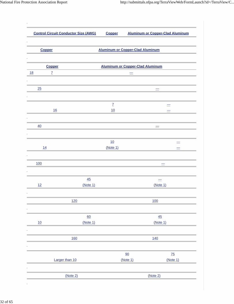
Control Circuit Conductor Size (AWG) Copper Aluminum or Copper-Clad Aluminum
Copper Aluminum or Copper-Clad Aluminum
Copper Aluminum or Copper-Clad Aluminum
18 7 —
25 —
7 —
16 10 —
40 —
10 —
14 (Note 1) —
100 —
45 —
12 (Note 1) (Note 1)
120 100
60 45
10 (Note 1) (Note 1)
160 140
90 75
Larger than 10 (Note 1) (Note 1)
(Note 2) (Note 2)
National Fire Protection Association Report http://submittals.nfpa.org/TerraViewWeb/FormLaunch?id=/TerraView/C...
32 of 65

(Note 3) (Note 3)
Notes:
1. Value specified in 310.15 as applicable.
2. 400 percent of value specified in Table 310.15(B)(17) for 60°C conductors.
3. 300 percent of value specified in Table 310.15(B)(16) for 60°C conductors.
(C) Control Circuit Transformer.
Where a motor control circuit transformer is provided, the transformer shall be protected in accordance with430.72(C)(1) , (C)(2), (C)(3), (C)(4), or (C)(5).
Exception: Overcurrent protection shall be omitted where the opening of the control circuit would create ahazard as, for example, the control circuit of a fire pump motor and the like.
(1) Compliance with Article 725.
Where the transformer supplies a Class 1 power-limited circuit, Class 2, or Class 3 remote-control circuitcomplying with the requirements of Article 725, protection shall comply with Article 725.
(2) Compliance with Article 450.
Protection shall be permitted to be provided in accordance with 450.3 .
(3) Less Than 50 Volt-Amperes.
Control circuit transformers rated less than 50 volt-amperes (VA) and that are an integral part of the motorcontroller and located within the motor controller enclosure shall be permitted to be protected by primaryovercurrent devices, impedance limiting means, or other inherent protective means.
(4) Primary Less Than 2 Amperes.
Where the control circuit transformer rated primary current is less than 2 amperes, an overcurrent devicerated or set at not more than 500 percent of the rated primary current shall be permitted in the primary circuit.
(5) Other Means.
Protection shall be permitted to be provided by other approved means.
430.73 Protection of Conductors from Physical Damage.
Where damage to a motor control circuit would constitute a hazard, all conductors of such a remote motorcontrol circuit that are outside the control device itself shall be installed in a raceway or be otherwiseprotected from physical damage.
430.74 Electrical Arrangement of Control Circuits.
Where one conductor of the motor control circuit is grounded, the motor control circuit shall be arranged sothat a ground fault in the control circuit remote from the motor controller will (1) not start the motor and (2) notbypass manually operated shutdown devices or automatic safety shutdown devices.
430.75 Disconnection.
National Fire Protection Association Report http://submittals.nfpa.org/TerraViewWeb/FormLaunch?id=/TerraView/C...
33 of 65

(A) General.
Motor control circuits shall be arranged so that they will be disconnected from all sources of supply when thedisconnecting means is in the open position. The disconnecting means shall be permitted to consist of two ormore separate devices, one of which disconnects the motor and the controller from the source(s) of powersupply for the motor, and the other(s), the motor control circuit(s) from its power supply. Where separatedevices are used, they shall be located immediately adjacent to each other.
Exception No. 1: Where more than 12 motor control circuit conductors are required to be disconnected, thedisconnecting means shall be permitted to be located other than immediately adjacent to each other whereall of the following conditions are complied with:
(1) Access to energized parts is limited to qualified persons in accordance with Part XII of this article.
(2) A warning sign is permanently located on the outside of each equipment enclosure door or coverpermitting access to the live parts in the motor control circuit(s), warning that motor control circuitdisconnecting means are remotely located and specifying the location and identification of eachdisconnect. Where energized parts are not in an equipment enclosure as permitted by 430.232 and430.233 , an additional warning sign(s) shall be located where visible to persons who may be workingin the area of the energized parts.
Exception No. 2: The motor control circuit disconnecting means shall be permitted to be remote from themotor controller power supply disconnecting means where the opening of one or more motor control circuitdisconnecting means is capable of resulting in potentially unsafe conditions for personnel or property andthe conditions of items (a) and (b) of Exception No. 1 are complied with.
(B) Control Transformer in Controller Enclosure.
Where a transformer or other device is used to obtain a reduced voltage for the motor control circuit and islocated in the controller enclosure, such transformer or other device shall be connected to the load side of thedisconnecting means for the motor control circuit.
Part VII. Motor Controllers
430.81 General.
Part VII is intended to require suitable controllers for all motors.
(A) Stationary Motor of 1 ⁄ 8 Horsepower or Less.
For a stationary motor rated at 1 ⁄ 8 hp or less that is normally left running and is constructed so that it cannotbe damaged by overload or failure to start, such as clock motors and the like, the branch-circuit disconnectingmeans shall be permitted to serve as the controller.
(B) Portable Motor of 1 ⁄ 3 Horsepower or Less.
For a portable motor rated at 1 ⁄ 3 hp or less, the controller shall be permitted to be an attachment plug andreceptacle or cord connector.
430.82 Controller Design.
(A) Starting and Stopping.
Each controller shall be capable of starting and stopping the motor it controls and shall be capable ofinterrupting the locked-rotor current of the motor.
(B) Autotransformer.
An autotransformer starter shall provide an “off” position, a running position, and at least one starting position.It shall be designed so that it cannot rest in the starting position or in any position that will render the overloaddevice in the circuit inoperative.
National Fire Protection Association Report http://submittals.nfpa.org/TerraViewWeb/FormLaunch?id=/TerraView/C...
34 of 65

(C) Rheostats.
Rheostats shall be in compliance with the following:
(1) Motor-starting rheostats shall be designed so that the contact arm cannot be left on intermediatesegments. The point or plate on which the arm rests when in the starting position shall have no electricalconnection with the resistor.
(2) Motor-starting rheostats for dc motors operated from a constant voltage supply shall be equipped withautomatic devices that will interrupt the supply before the speed of the motor has fallen to less than one-third its normal rate.
430.83 Ratings.
The controller shall have a rating as specified in 430.83(A) , unless otherwise permitted in 430.83(B) or (C),or as specified in (D), under the conditions specified.
(A) General.
(1) Horsepower Ratings.
Controllers, other than inverse time circuit breakers and molded case switches, shall have horsepower ratingsat the application voltage not lower than the horsepower rating of the motor.
(2) Circuit Breaker.
A branch-circuit inverse time circuit breaker rated in amperes shall be permitted as a controller for all motors.Where this circuit breaker is also used for overload protection, it shall conform to the appropriate provisions ofthis article governing overload protection.
(3) Molded Case Switch.
A molded case switch rated in amperes shall be permitted as a controller for all motors.
(B) Small Motors.
Devices as specified in 430.81(A) and (B) shall be permitted as a controller.
(C) Stationary Motors of 2 Horsepower or Less.
For stationary motors rated at 2 hp or less and 300 volts or less, the controller shall be permitted to be eitherof the following:
(1) A general-use switch having an ampere rating not less than twice the full-load current rating of the motor
(2) On ac circuits, a general-use snap switch suitable only for use on ac (not general-use ac–dc snapswitches) where the motor full-load current rating is not more than 80 percent of the ampere rating of theswitch
(D) Torque Motors.
For torque motors, the controller shall have a continuous-duty, full-load current rating not less than thenameplate current rating of the motor. For a motor controller rated in horsepower but not marked with theforegoing current rating, the equivalent current rating shall be determined from the horsepower rating by usingTable 430.247 , Table 430.248 , Table 430.249 , or Table 430.250 .
(E) Voltage Rating.
A controller with a straight voltage rating, for example, 240 volts or 480 volts, shall be permitted to be appliedin a circuit in which the nominal voltage between any two conductors does not exceed the controller’s voltagerating. A controller with a slash rating, for example, 120/240 volts or 480Y/277 volts, shall only be applied in asolidly grounded circuit in which the nominal voltage to ground from any conductor does not exceed the lowerof the two values of the controller’s voltage rating and the nominal voltage between any two conductors doesnot exceed the higher value of the controller’s voltage rating.
430.84 Need Not Open All Conductors.
The controller shall not be required to open all conductors to the motor.
Exception: Where the controller serves also as a disconnecting means, it shall open all ungroundedconductors to the motor as provided in 430.111 .
National Fire Protection Association Report http://submittals.nfpa.org/TerraViewWeb/FormLaunch?id=/TerraView/C...
35 of 65

430.85 In Grounded Conductors.
One pole of the controller shall be permitted to be placed in a permanently grounded conductor, provided thecontroller is designed so that the pole in the grounded conductor cannot be opened without simultaneouslyopening all conductors of the circuit.
430.87 Number of Motors Served by Each Controller.
Each motor shall be provided with an individual controller.
Exception No. 1: For motors rated 1000 volts or less, a single controller rated at not less than theequivalent horsepower, as determined in accordance with 430.110(C)(1) , of all the motors in the groupshall be permitted to serve the group under any of the following conditions:
(1) Where a number of motors drive several parts of a single machine or piece of apparatus, such asmetal and woodworking machines, cranes, hoists, and similar apparatus
(2) Where a group of motors is under the protection of one overcurrent device as permitted in 430.53(A)
(3) Where a group of motors is located in a single room within sight from the controller location
Exception No. 2: A branch-circuit disconnecting means serving as the controller as allowed in 430.81(A)shall be permitted to serve more than one motor.
430.88 Adjustable-Speed Motors.
Adjustable-speed motors that are controlled by means of field regulation shall be equipped and connected sothat they cannot be started under a weakened field.
Exception: Starting under a weakened field shall be permitted where the motor is designed for suchstarting.
430.89 Speed Limitation.
Machines of the following types shall be provided with speed-limiting devices or other speed-limiting means:
(1) Separately excited dc motors
(2) Series motors
(3) Motor-generators and converters that can be driven at excessive speed from the dc end, as by areversal of current or decrease in load
Exception: Separate speed-limiting devices or means shall not be required under either of the followingconditions:
(1) Where the inherent characteristics of the machines, the system, or the load and the mechanicalconnection thereto are such as to safely limit the speed
(2) Where the machine is always under the manual control of a qualified operator
430.90 Combination Fuseholder and Switch as Controller.
The rating of a combination fuseholder and switch used as a motor controller shall be such that the fuseholderwill accommodate the size of the fuse specified in Part III of this article for motor overload protection.
Exception: Where fuses having time delay appropriate for the starting characteristics of the motor are used,fuseholders of smaller size than specified in Part III of this article shall be permitted.
Part VIII. Motor Control Centers
430.92 General.
Part VIII covers motor control centers installed for the control of motors, lighting, and power circuits.
430.94 Overcurrent Protection.
Motor control centers shall be provided with overcurrent protection in accordance with Parts I, II, and VIII ofArticle 240. The ampere rating or setting of the overcurrent protective device shall not exceed the rating of thecommon power bus. This protection shall be provided by (1) an overcurrent protective device located aheadof the motor control center or (2) a main overcurrent protective device located within the motor control center.
National Fire Protection Association Report http://submittals.nfpa.org/TerraViewWeb/FormLaunch?id=/TerraView/C...
36 of 65

430.95 Service Equipment.
Where used as service equipment, each motor control center shall be provided with a single maindisconnecting means to disconnect all ungrounded service conductors.
Exception: A second service disconnect shall be permitted to supply additional equipment.
Where a grounded conductor is provided, the motor control center shall be provided with a main bondingjumper, sized in accordance with 250.28(D) , within one of the sections for connecting the groundedconductor, on its supply side, to the motor control center equipment ground bus.
Exception: High-impedance grounded neutral systems shall be permitted to be connected as provided in250.36 .
430.96 Grounding.
Multisection motor control centers shall be connected together with an equipment grounding conductor or anequivalent equipment grounding bus sized in accordance with Table 250.122 . Equipment groundingconductors shall be connected to this equipment grounding bus or to a grounding termination point providedin a single-section motor control center.
430.97 Busbars and Conductors.
(A) Support and Arrangement.
Busbars shall be protected from physical damage and be held firmly in place. Other than for requiredinterconnections and control wiring, only those conductors that are intended for termination in a verticalsection shall be located in that section.
Exception: Conductors shall be permitted to travel horizontally through vertical sections where suchconductors are isolated from the busbars by a barrier.
(B) Phase Arrangement.
The phase arrangement on 3-phase horizontal common power and vertical buses shall be A, B, C from frontto back, top to bottom, or left to right, as viewed from the front of the motor control center. The B phase shallbe that phase having the higher voltage to ground on 3-phase, 4-wire, delta-connected systems. Other busbararrangements shall be permitted for additions to existing installations and shall be marked.
Exception: Rear-mounted units connected to a vertical bus that is common to front-mounted units shall bepermitted to have a C, B, A phase arrangement where properly identified.
(C) Minimum Wire-Bending Space.
The minimum wire-bending space at the motor control center terminals and minimum gutter space shall be asrequired in Article 312(D).
(D) Spacings.
Spacings between motor control center bus terminals and other bare metal parts shall not be less thanspecified in Table 430.97(D) .
(E) Barriers.
Barriers shall be placed in all service-entrance motor control centers to isolate service busbars and terminalsfrom the remainder of the motor control center.
Table 430.97(D) Minimum Spacing Between Bare Metal Parts
Nominal Voltage Opposite Polarity Where Mounted on the Same Surface
Opposite Polarity Where Held Free in Air
Live Parts to Ground
mm in.
National Fire Protection Association Report http://submittals.nfpa.org/TerraViewWeb/FormLaunch?id=/TerraView/C...
37 of 65

mm in.
mm in.
Not over 125 volts, nominal 19.1 3 ⁄ 4
12.7 1 ⁄ 2
12.7 1 ⁄ 2
Not over 250 volts, nominal 31.8 1 1 ⁄ 4
19.1 3 ⁄ 4
12.7 1 ⁄ 2
Not over 600 volts, nominal 50.8 2
25.4 1
25.4 1
430.98 Marking.
(A) Motor Control Centers.
Motor control centers shall be marked according to 110.21 , and the marking shall be plainly visible afterinstallation. Marking shall also include common power bus current rating and motor control center short-circuitrating.
(B) Motor Control Units.
Motor control units in a motor control center shall comply with 430.8 .
430.99 Available Fault Current.
The available short circuit current at the motor control center and the date the short circuit current calculationwas performed shall be documented and made available to those authorized to inspect the installation.
Part IX. Disconnecting Means
430.101 General.
Part IX is intended to require disconnecting means capable of disconnecting motors and controllers from thecircuit.
430.102 Location.
National Fire Protection Association Report http://submittals.nfpa.org/TerraViewWeb/FormLaunch?id=/TerraView/C...
38 of 65

(A) Controller.
An individual disconnecting means shall be provided for each controller and shall disconnect the controller.The disconnecting means shall be located in sight from the controller location.
Exception No. 1: For motor circuits over 1000 volts, nominal, a controller disconnecting means lockable inaccordance with 110.25 shall be permitted to be out of sight of the controller, provided that the controller ismarked with a warning label giving the location of the disconnecting means.
Exception No. 2: A single disconnecting means shall be permitted for a group of coordinated controllersthat drive several parts of a single machine or piece of apparatus. The disconnecting means shall belocated in sight from the controllers, and both the disconnecting means and the controllers shall be locatedin sight from the machine or apparatus.
Exception No. 3: The disconnecting means shall not be required to be in sight from valve actuator motor(VAM) assemblies containing the controller where such a location introduces additional or increasedhazards to persons or property and conditions (a) and (b) are met.
(1) The valve actuator motor assembly is marked with a warning label giving the location of thedisconnecting means.
(2) The disconnecting means is lockable in accordance with 110.25 .
(B) Motor.
A disconnecting means shall be provided for a motor in accordance with (B)(1) or (B)(2).
(1) Separate Motor Disconnect.
A disconnecting means for the motor shall be located in sight from the motor location and the drivenmachinery location.
(2) Controller Disconnect.
The controller disconnecting means required in accordance with 430.102(A) shall be permitted to serve asthe disconnecting means for the motor if it is in sight from the motor location and the driven machinerylocation.
Exception to (1) and (2): The disconnecting means for the motor shall not be required under eithercondition (a) or condition (b), which follow, provided that the controller disconnecting means required in430.102(A) is lockable in accordance with 110.25 .
(1) Where such a location of the disconnecting means for the motor is impracticable or introducesadditional or increased hazards to persons or property
Informational Note: Some examples of increased or additional hazards include, but are notlimited to, motors rated in excess of 100 hp, multimotor equipment, submersible motors, motorsassociated with adjustable speed drives, and motors located in hazardous (classified) locations.
(2) In industrial installations, with written safety procedures, where conditions of maintenance andsupervision ensure that only qualified persons service the equipment
Informational Note: For information on lockout/tagout procedures, see NFPA 70E -2015, Standard forElectrical Safety in the Workplace .
430.103 Operation.
The disconnecting means shall open all ungrounded supply conductors and shall be designed so that no polecan be operated independently. The disconnecting means shall be permitted in the same enclosure with thecontroller. The disconnecting means shall be designed so that it cannot be closed automatically.
Informational Note: See 430.113 for equipment receiving energy from more than one source.
430.104 To Be Indicating.
The disconnecting means shall plainly indicate whether it is in the open (off) or closed (on) position.
National Fire Protection Association Report http://submittals.nfpa.org/TerraViewWeb/FormLaunch?id=/TerraView/C...
39 of 65

430.105 Grounded Conductors.
One pole of the disconnecting means shall be permitted to disconnect a permanently grounded conductor,provided the disconnecting means is designed so that the pole in the grounded conductor cannot be openedwithout simultaneously disconnecting all conductors of the circuit.
430.107 Readily Accessible.
At least one of the disconnecting means shall be readily accessible.
430.108 Every Disconnecting Means.
Every disconnecting means in the motor circuit between the point of attachment to the feeder or branch circuitand the point of connection to the motor shall comply with the requirements of 430.109 and 430.110 .
430.109 Type.
The disconnecting means shall be a type specified in 430.109(A) , unless otherwise permitted in 430.109(B)through (G), under the conditions specified.
(A) General.
(1) Motor Circuit Switch.
A listed motor-circuit switch rated in horsepower.
(2) Molded Case Circuit Breaker.
A listed molded case circuit breaker.
(3) Molded Case Switch.
A listed molded case switch.
(4) Instantaneous Trip Circuit Breaker.
An instantaneous trip circuit breaker that is part of a listed combination motor controller.
(5) Self-Protected Combination Controller.
Listed self-protected combination controller.
(6) Manual Motor Controller.
Listed manual motor controllers additionally marked “Suitable as Motor Disconnect” shall be permitted as adisconnecting means where installed between the final motor branch-circuit short-circuit protective device andthe motor. Listed manual motor controllers additionally marked“Suitable as Motor Disconnect” shall bepermitted as disconnecting means on the line side of the fuses permitted in 430.52(C)(5) . In this case, thefuses permitted in 430.52(C)(5) shall be considered supplementary fuses, and suitable branch-circuit short-circuit and ground-fault protective devices shall be installed on the line side of the manual motor controlleradditionally marked “Suitable as Motor Disconnect.”
(7) System Isolation Equipment.
System isolation equipment shall be listed for disconnection purposes. System isolation equipment shall beinstalled on the load side of the overcurrent protection and its disconnecting means. The disconnectingmeans shall be one of the types permitted by 430.109(A)(1) through (A)(3).
(B) Stationary Motors of 1 ⁄ 8 Horsepower or Less.
For stationary motors of 1 ⁄ 8 hp or less, the branch-circuit overcurrent device shall be permitted to serve asthe disconnecting means.
National Fire Protection Association Report http://submittals.nfpa.org/TerraViewWeb/FormLaunch?id=/TerraView/C...
40 of 65

(C) Stationary Motors of 2 Horsepower or Less.
For stationary motors rated at 2 hp or less and 300 volts or less, the disconnecting means shall be permittedto be one of the devices specified in (1), (2), or (3):
(1) A general-use switch having an ampere rating not less than twice the full-load current rating of the motor
(2) On ac circuits, a general-use snap switch suitable only for use on ac (not general-use ac–dc snapswitches) where the motor full-load current rating is not more than 80 percent of the ampere rating of theswitch
(3) A listed manual motor controller having a horsepower rating not less than the rating of the motor andmarked “Suitable as Motor Disconnect”
(D) Autotransformer-Type Controlled Motors.
For motors of over 2 hp to and including 100 hp, the separate disconnecting means required for a motor withan autotransformer-type controller shall be permitted to be a general-use switch where all of the followingprovisions are met:
(1) The motor drives a generator that is provided with overload protection.
(2) The controller is capable of interrupting the locked-rotor current of the motors, is provided with a novoltage release, and is provided with running overload protection not exceeding 125 percent of the motorfull-load current rating.
(3) Separate fuses or an inverse time circuit breaker rated or set at not more than 150 percent of the motorfull-load current is provided in the motor branch circuit.
(E) Isolating Switches.
For stationary motors rated at more than 40 hp dc or 100 hp ac, the disconnecting means shall be permittedto be a general-use or isolating switch where plainly marked “Do not operate under load.”
(F) Cord-and-Plug-Connected Motors.
For a cord-and-plug-connected motor, a horsepower-rated attachment plug and receptacle, flanged surfaceinlet and cord connector, or attachment plug and cord connector having ratings no less than the motor ratingsshall be permitted to serve as the disconnecting means. Horsepower-rated attachment plugs, flanged surfaceinlets, receptacles, or cord connectors shall not be required for cord-and-plug-connected appliances in
accordance with 422.33 , room air conditioners in accordance with 440.63 , or portable motors rated 1 ⁄ 3 hpor less.
(G) Torque Motors.
For torque motors, the disconnecting means shall be permitted to be a general-use switch.
430.110 Ampere Rating and Interrupting Capacity.
(A) General.
The disconnecting means for motor circuits rated 1000 volts, nominal, or less shall have an ampere rating notless than 115 percent of the full-load current rating of the motor.
Exception: A listed unfused motor-circuit switch having a horsepower rating not less than the motorhorsepower shall be permitted to have an ampere rating less than 115 percent of the full-load current ratingof the motor.
(B) For Torque Motors.
Disconnecting means for a torque motor shall have an ampere rating of at least 115 percent of the motornameplate current.
(C) For Combination Loads.
Where two or more motors are used together or where one or more motors are used in combination withother loads, such as resistance heaters, and where the combined load may be simultaneous on a singledisconnecting means, the ampere and horsepower ratings of the combined load shall be determined asfollows.
National Fire Protection Association Report http://submittals.nfpa.org/TerraViewWeb/FormLaunch?id=/TerraView/C...
41 of 65

(1) Horsepower Rating.
The rating of the disconnecting means shall be determined from the sum of all currents, including resistanceloads, at the full-load condition and also at the locked-rotor condition. The combined full-load current and thecombined locked-rotor current so obtained shall be considered as a single motor for the purpose of thisrequirement as follows.
The full-load current equivalent to the horsepower rating of each motor shall be selected from Table 430.247 ,Table 430.248 , Table 430.249 , or Table 430.250 . These full-load currents shall be added to the rating inamperes of other loads to obtain an equivalent full-load current for the combined load.
The locked-rotor current equivalent to the horsepower rating of each motor shall be selected from Table430.251(A) or Table 430.251(B) . The locked-rotor currents shall be added to the rating in amperes of otherloads to obtain an equivalent locked-rotor current for the combined load. Where two or more motors or otherloads cannot be started simultaneously, the largest sum of locked-rotor currents of a motor or group of motorsthat can be started simultaneously and the full-load currents of other concurrent loads shall be permitted to beused to determine the equivalent locked-rotor current for the simultaneous combined loads. In cases wheredifferent current ratings are obtained when applying these tables, the largest value obtained shall be used.
Exception: Where part of the concurrent load is resistance load, and where the disconnecting means is aswitch rated in horsepower and amperes, the switch used shall be permitted to have a horsepower ratingthat is not less than the combined load of the motor(s), if the ampere rating of the switch is not less than thelocked-rotor current of the motor(s) plus the resistance load.
(2) Ampere Rating.
The ampere rating of the disconnecting means shall not be less than 115 percent of the sum of all currents atthe full-load condition determined in accordance with 430.110(C)(1) .
Exception: A listed nonfused motor-circuit switch having a horsepower rating equal to or greater than theequivalent horsepower of the combined loads, determined in accordance with 430.110(C)(1) , shall bepermitted to have an ampere rating less than 115 percent of the sum of all currents at the full-load condition.
(3) Small Motors.
For small motors not covered by Table 430.247 , Table 430.248 , Table 430.249 , or Table 430.250 , thelocked-rotor current shall be assumed to be six times the full-load current.
430.111 Switch or Circuit Breaker as Both Controller and Disconnecting Means.
A switch or circuit breaker shall be permitted to be used as both the controller and disconnecting means if itcomplies with 430.111(A) and is one of the types specified in 430.111(B) .
(A) General.
The switch or circuit breaker complies with the requirements for controllers specified in 430.83 , opens allungrounded conductors to the motor, and is protected by an overcurrent device in each ungroundedconductor (which shall be permitted to be the branch-circuit fuses). The overcurrent device protecting thecontroller shall be permitted to be part of the controller assembly or shall be permitted to be separate. Anautotransformer-type controller shall be provided with a separate disconnecting means.
(B) Type.
The device shall be one of the types specified in 430.111(B)(1) , (B)(2), or (B)(3).
(1) Air-Break Switch.
An air-break switch, operable directly by applying the hand to a lever or handle.
(2) Inverse Time Circuit Breaker.
An inverse time circuit breaker operable directly by applying the hand to a lever or handle. The circuit breakershall be permitted to be both power and manually operable.
(3) Oil Switch.
An oil switch used on a circuit whose rating does not exceed 1000 volts or 100 amperes, or by specialpermission on a circuit exceeding this capacity where under expert supervision. The oil switch shall bepermitted to be both power and manually operable.
National Fire Protection Association Report http://submittals.nfpa.org/TerraViewWeb/FormLaunch?id=/TerraView/C...
42 of 65

430.112 Motors Served by Single Disconnecting Means.
Each motor shall be provided with an individual disconnecting means.
Exception: A single disconnecting means shall be permitted to serve a group of motors under any one ofthe conditions of (a), (b), and (c). The single disconnecting means shall be rated in accordance with430.110(C) .
(1) Where a number of motors drive several parts of a single machine or piece of apparatus, such asmetal- and woodworking machines, cranes, and hoists.
(2) Where a group of motors is under the protection of one set of branch-circuit protective devices aspermitted by 430.53(A) .
(3) Where a group of motors is in a single room within sight from the location of the disconnecting means.
430.113 Energy from More Than One Source.
Motor and motor-operated equipment receiving electric energy from more than one source shall be providedwith disconnecting means from each source of electric energy immediately adjacent to the equipment served.Each source shall be permitted to have a separate disconnecting means. Where multiple disconnectingmeans are provided, a permanent warning sign shall be provided on or adjacent to each disconnectingmeans.
Exception No. 1: Where a motor receives electric energy from more than one source, the disconnectingmeans for the main power supply to the motor shall not be required to be immediately adjacent to the motor,provided that the controller disconnecting means is lockable in accordance with 110.25 .
Exception No. 2: A separate disconnecting means shall not be required for a Class 2 remote-control circuitconforming with Article 725, rated not more than 30 volts, and isolated and ungrounded.
Part X. Adjustable-Speed Drive Systems
430.120 General.
The installation provisions of Part I through Part IX are applicable unless modified or supplemented by Part X.
430.122 Conductors — Minimum Size and Ampacity.
(A) Branch/Feeder Circuit Conductors.
Circuit conductors supplying power conversion equipment included as part of an adjustable-speed drivesystem shall have an ampacity not less than 125 percent of the rated input current to the power conversionequipment.
Informational Note: Power conversion equipment can have multiple power ratings and correspondinginput currents.
(B) Bypass Device.
For an adjustable-speed drive system that utilizes a bypass device, the conductor ampacity shall not be lessthan required by 430.6 . The ampacity of circuit conductors supplying power conversion equipment includedas part of an adjustable-speed drive system that utilizes a bypass device shall be the larger of either of thefollowing:
(1) 125 percent of the rated input current to the power conversion equipment
(2) 125 percent of the motor full-load current rating as determined by 430.6
430.124 Overload Protection.
Overload protection of the motor shall be provided.
(A) Included in Power Conversion Equipment.
Where the power conversion equipment is marked to indicate that motor overload protection is included,additional overload protection shall not be required.
National Fire Protection Association Report http://submittals.nfpa.org/TerraViewWeb/FormLaunch?id=/TerraView/C...
43 of 65

(B) Bypass Circuits.
For adjustable-speed drive systems that utilize a bypass device to allow motor operation at rated full-loadspeed, motor overload protection as described in Article 430, Part III, shall be provided in the bypass circuit.
(C) Multiple Motor Applications.
For multiple motor application, individual motor overload protection shall be provided in accordance withArticle 430, Part III.
430.126 Motor Overtemperature Protection.
(A) General.
Adjustable-speed drive systems shall protect against motor overtemperature conditions where the motor isnot rated to operate at the nameplate rated current over the speed range required by the application. Thisprotection shall be provided in addition to the conductor protection required in 430.32 . Protection shall beprovided by one of the following means.
(1) Motor thermal protector in accordance with 430.32
(2) Adjustable-speed drive system with load and speed-sensitive overload protection and thermal memoryretention upon shutdown or power loss
Exception to (2): Thermal memory retention upon shutdown or power loss is not required forcontinuous duty loads.
(3) Overtemperature protection relay utilizing thermal sensors embedded in the motor and meeting therequirements of 430.126(A)(2) or (B)(2)
(4) Thermal sensor embedded in the motor whose communications are received and acted upon by anadjustable-speed drive system
Informational Note: The relationship between motor current and motor temperature changes when themotor is operated by an adjustable-speed drive. In certain applications, overheating of motors canoccur when operated at reduced speed, even at current levels less than a motor’s rated full-loadcurrent. The overheating can be the result of reduced motor cooling when its shaft-mounted fan isoperating less than rated nameplate RPM. As part of the analysis to determine whether overheatingwill occur, it is necessary to consider the continuous torque capability curves for the motor given theapplication requirements. This will assist in determining whether the motor overload protection will beable, on its own, to provide protection against overheating. These overheating protection requirementsare only intended to apply to applications where an adjustable-speed drive, as defined in Article 100, isused.
For motors that utilize external forced air or liquid cooling systems, overtemperature can occur if thecooling system is not operating. Although this issue is not unique to adjustable speed applications,externally cooled motors are most often encountered with such applications. In these instances,overtemperature protection using direct temperature sensing is recommended [i.e., 430.126(A)(1) ,(A)(3), or (A)(4)], or additional means should be provided to ensure that the cooling system is operating(flow or pressure sensing, interlocking of adjustable-speed drive system and cooling system, etc.).
(B) Multiple Motor Applications.
For multiple motor applications, individual motor overtemperature protection shall be provided as required in430.126(A) .
(C) Automatic Restarting and Orderly Shutdown.
The provisions of 430.43 and 430.44 shall apply to the motor overtemperature protection means.
430.128 Disconnecting Means.
The disconnecting means shall be permitted to be in the incoming line to the conversion equipment and shallhave a rating not less than 115 percent of the rated input current of the conversion unit.
430.130 Branch-Circuit Short-Circuit and Ground-Fault Protection for Single Motor Circuits ContainingPower Conversion Equipment.
National Fire Protection Association Report http://submittals.nfpa.org/TerraViewWeb/FormLaunch?id=/TerraView/C...
44 of 65

(A) Circuits Containing Power Conversion Equipment.
Circuits containing power conversion equipment shall be protected by a branch-circuit short-circuit andground-fault protective device in accordance with the following:
(1) The rating and type of protection shall be determined by 430.52(C)(1) , (C)(3), (C)(5), or (C)(6), usingthe full-load current rating of the motor load as determined by 430.6 .
(2) Where maximum branch-circuit short-circuit and ground-fault protective ratings are stipulated forspecific device types in the manufacturer's instructions for the power conversion equipment or areotherwise marked on the equipment, they shall not be exceeded even if higher values are permitted by430.130(A)(1) .
(3) A self-protected combination controller shall only be permitted where specifically identified in themanufacturer’s instructions for the power conversion equipment or if otherwise marked on theequipment.
Informational Note: The type of protective device, its rating, and its setting are often marked onor provided with the power conversion equipment.
(4) Where an instantaneous trip circuit breaker or semiconductor fuses are permitted in accordance withthe drive manufacturer’s instructions for use as the branch-circuit short-circuit and ground-faultprotective device for listed power conversion equipment, they shall be provided as an integral part of asingle listed assembly incorporating both the protective device and power conversion equipment.
(B) Bypass Circuit/Device.
Branch-circuit short-circuit and ground-fault protection shall also be provided for a bypass circuit/device(s).Where a single branch-circuit short-circuit and ground-fault protective device is provided for circuitscontaining both power conversion equipment and a bypass circuit, the branch-circuit protective device typeand its rating or setting shall be in accordance with those determined for the power conversion equipmentand for the bypass circuit/device(s) equipment.
430.131 Several Motors or Loads on One Branch Circuit Including Power Conversion Equipment.
For installations meeting all the requirements of 430.53 that include one or more power converters, thebranch-circuit short-circuit and ground-fault protective fuses or inverse time circuit breakers shall be of atype and rating or setting permitted for use with the power conversion equipment using the full-load currentrating of the connected motor load in accordance with 430.53 . For the purposes of 430.53 and 430.131 ,power conversion equipment shall be considered to be a motor controller.
Part XI. Over 1000 Volts, Nominal
430.221 General.
Part XI recognizes the additional hazard due to the use of higher voltages. It adds to or amends the otherprovisions of this article.
430.222 Marking on Controllers.
In addition to the marking required by 430.8 , a controller shall be marked with the control voltage.
430.223 Raceway Connection to Motors.
Flexible metal conduit or liquidtight flexible metal conduit not exceeding 1.8 m (6 ft) in length shall bepermitted to be employed for raceway connection to a motor terminal enclosure.
430.224 Size of Conductors.
Conductors supplying motors shall have an ampacity not less than the current at which the motor overloadprotective device(s) is selected to trip.
430.225 Motor-Circuit Overcurrent Protection.
National Fire Protection Association Report http://submittals.nfpa.org/TerraViewWeb/FormLaunch?id=/TerraView/C...
45 of 65

(A) General.
Each motor circuit shall include coordinated protection to automatically interrupt overload and fault currentsin the motor, the motor-circuit conductors, and the motor control apparatus.
Exception: Where a motor is critical to an operation and the motor should operate to failure if necessary toprevent a greater hazard to persons, the sensing device(s) shall be permitted to be connected to asupervised annunciator or alarm instead of interrupting the motor circuit.
(B) Overload Protection.
(1) Type of Overload Device.
Each motor shall be protected against dangerous heating due to motor overloads and failure to start by athermal protector integral with the motor or external current-sensing devices, or both. Protective devicesettings for each motor circuit shall be determined under engineering supervision.
(2) Wound-Rotor Alternating-Current Motors.
The secondary circuits of wound-rotor ac motors, including conductors, controllers, and resistors rated forthe application, shall be considered as protected against overcurrent by the motor overload protectionmeans.
(3) Operation.
Operation of the overload interrupting device shall simultaneously disconnect all ungrounded conductors.
(4) Automatic Reset.
Overload sensing devices shall not automatically reset after trip unless resetting of the overload sensingdevice does not cause automatic restarting of the motor or there is no hazard to persons created byautomatic restarting of the motor and its connected machinery.
(C) Fault-Current Protection.
(1) Type of Protection.
Fault-current protection shall be provided in each motor circuit as specified by either (1)(a) or (1)(b).
(1) A circuit breaker of suitable type and rating arranged so that it can be serviced without hazard. Thecircuit breaker shall simultaneously disconnect all ungrounded conductors. The circuit breaker shall bepermitted to sense the fault current by means of integral or external sensing elements.
(2) Fuses of a suitable type and rating placed in each ungrounded conductor. Fuses shall be used withsuitable disconnecting means, or they shall be of a type that can also serve as the disconnectingmeans. They shall be arranged so that they cannot be serviced while they are energized.
(2) Reclosing.
Fault-current interrupting devices shall not automatically reclose the circuit.
Exception: Automatic reclosing of a circuit shall be permitted where the circuit is exposed to transientfaults and where such automatic reclosing does not create a hazard to persons.
(3) Combination Protection.
Overload protection and fault-current protection shall be permitted to be provided by the same device.
430.226 Rating of Motor Control Apparatus.
The ultimate trip current of overcurrent (overload) relays or other motor-protective devices used shall notexceed 115 percent of the controller’s continuous current rating. Where the motor branch-circuitdisconnecting means is separate from the controller, the disconnecting means current rating shall not beless than the ultimate trip setting of the overcurrent relays in the circuit.
430.227 Disconnecting Means.
The controller disconnecting means shall be lockable in accordance with 110.25 .
Part XII. Protection of Live Parts — All Voltages
430.231 General.
Part XII specifies that live parts shall be protected in an approved manner for the hazard involved.
National Fire Protection Association Report http://submittals.nfpa.org/TerraViewWeb/FormLaunch?id=/TerraView/C...
46 of 65

430.232 Where Required.
Exposed live parts of motors and controllers operating at 50 volts or more between terminals shall beguarded against accidental contact by enclosure or by location as follows:
(1) By installation in a room or enclosure that is accessible only to qualified persons
(2) By installation on a suitable balcony, gallery, or platform, elevated and arranged so as to excludeunqualified persons
(3) By elevation 2.5 m (8 ft) or more above the floor
Exception: Live parts of motors operating at more than 50 volts between terminals shall not requireadditional guarding for stationary motors that have commutators, collectors, and brush rigging locatedinside of motor-end brackets and not conductively connected to supply circuits operating at more than150 volts to ground.
430.233 Guards for Attendants.
Where live parts of motors or controllers operating at over 50 volts to ground are guarded against accidentalcontact only by location as specified in 430.232 , and where adjustment or other attendance may benecessary during the operation of the apparatus, suitable insulating mats or platforms shall be provided sothat the attendant cannot readily touch live parts unless standing on the mats or platforms.
Informational Note: For working space, see 110.26 and 110.34 .
Part XIII. Grounding — All Voltages
430.241 General.
Part XIII specifies the grounding of exposed non–current-carrying metal parts, likely to become energized, ofmotor and controller frames to prevent a voltage aboveground in the event of accidental contact betweenenergized parts and frames. Insulation, isolation, or guarding are suitable alternatives to grounding of motorsunder certain conditions.
430.242 Stationary Motors.
The frames of stationary motors shall be grounded under any of the following conditions:
(1) Where supplied by metal-enclosed wiring
(2) Where in a wet location and not isolated or guarded
(3) If in a hazardous (classified) location
(4) If the motor operates with any terminal at over 150 volts to ground
Where the frame of the motor is not grounded, it shall be permanently and effectively insulated from theground.
430.243 Portable Motors.
The frames of portable motors that operate over 150 volts to ground shall be guarded or grounded.
Informational Note No. 1: See 250.114(4) for grounding of portable appliances in other thanresidential occupancies.
Informational Note No. 2: See 250.119(C) for color of equipment grounding conductor.
Exception No. 1: Listed motor-operated tools, listed motor-operated appliances, and listed motor-operatedequipment shall not be required to be grounded where protected by a system of double insulation or itsequivalent. Double-insulated equipment shall be distinctively marked.
Exception No. 2: Listed motor-operated tools, listed motor-operated appliances, and listed motor-operatedequipment connected by a cord and attachment plug other than those required to be grounded inaccordance with 250.114 .
National Fire Protection Association Report http://submittals.nfpa.org/TerraViewWeb/FormLaunch?id=/TerraView/C...
47 of 65

430.244 Controllers.
Controller enclosures shall be connected to the equipment grounding conductor regardless of voltage.Controller enclosures shall have means for attachment of an equipment grounding conductor termination inaccordance with 250.8 .
Exception: Enclosures attached to ungrounded portable equipment shall not be required to be grounded.
430.245 Method of Grounding.
Connection to the equipment grounding conductor shall be done in the manner specified in Part VI of Article250.
(A) Grounding Through Terminal Housings.
Where the wiring to motors is metal-enclosed cable or in metal raceways, junction boxes to house motorterminals shall be provided, and the armor of the cable or the metal raceways shall be connected to them inthe manner specified in 250.96(A) and 250.97 .
(B) Separation of Junction Box from Motor.
The junction box required by 430.245(A) shall be permitted to be separated from the motor by not morethan 1.8 m (6 ft), provided the leads to the motor are stranded conductors within Type AC cable, interlockedmetal tape Type MC cable where listed and identified in accordance with 250.118(10) (a), or armored cordor are stranded leads enclosed in liquidtight flexible metal conduit, flexible metal conduit, intermediate metalconduit, rigid metal conduit, or electrical metallic tubing not smaller than metric designator 12 (trade size3 ⁄ 8 ), the armor or raceway being connected both to the motor and to the box.
Liquidtight flexible nonmetallic conduit and rigid nonmetallic conduit shall be permitted to enclose the leadsto the motor, provided the leads are stranded and the required equipment grounding conductor is connectedto both the motor and to the box.
Where stranded leads are used, protected as specified above, each strand within the conductor shall be notlarger than 10 AWG and shall comply with other requirements of this Code for conductors to be used inraceways.
(C) Grounding of Controller-Mounted Devices.
Instrument transformer secondaries and exposed non–current-carrying metal or other conductive parts orcases of instrument transformers, meters, instruments, and relays shall be grounded as specified in250.170 through 250.178 .
National Fire Protection Association Report http://submittals.nfpa.org/TerraViewWeb/FormLaunch?id=/TerraView/C...
48 of 65

Part XIV. Tables
National Fire Protection Association Report http://submittals.nfpa.org/TerraViewWeb/FormLaunch?id=/TerraView/C...
49 of 65

Table 430.247 Full-Load Current in Amperes, Direct-Current Motors
The following values of full-load currents * are for motors running at base speed.
HorsepowerArmature Voltage Rating *
90 Volts 120 Volts 180 Volts 240 Volts 500 Volts 550 Volts
1 ⁄ 4 4.0 3.1 2.0 1.6 — —
1 ⁄ 3 5.2 4.1 2.6 2.0 — —
1 ⁄ 2 6.8 5.4 3.4 2.7 — —
3 ⁄ 4 9.6 7.6 4.8 3.8 — —
1 12.2 9.5 6.1 4.7 — —
1 1 ⁄ 2 — 13.2 8.3 6.6 — —
2 — 17 10.8 8.5 — —
3 — 25 16 12.2 — —
5 — 40 27 20 — —
7 1 ⁄ 2 — 58 — 29 13.6 12.2
10 — 76 — 38 18 16
15 — — — 55 27 24
20 — — — 72 34 31
25 — — — 89 43 38
30 — — — 106 51 46
40 — — — 140 67 61
50 — — — 173 83 75
60 — — — 206 99 90
75 — — — 255 123 111
100 — — — 341 164 148
125 — — — 425 205 185
150 — — — 506 246 222
200 — — — 675 330 294
*These are average dc quantities.
Table 430.248 Full-Load Currents in Amperes, Single-Phase Alternating-Current Motors
The following values of full-load currents are for motors running at usual speeds and motors with normaltorque characteristics. The voltages listed are rated motor voltages. The currents listed shall be permittedfor system voltage ranges of 110 to 120 and 220 to 240 volts.
Horsepower
115
Volts
200
Volts
208
Volts
230
Volts
1 ⁄ 6 4.4 2.5 2.4 2.2
1 ⁄ 4 5.8 3.3 3.2 2.9
1 ⁄ 3 7.2 4.1 4.0 3.6
1 ⁄ 2 9.8 5.6 5.4 4.9
3 ⁄ 4 13.8 7.9 7.6 6.9
1 16 9.2 8.8 8.0
National Fire Protection Association Report http://submittals.nfpa.org/TerraViewWeb/FormLaunch?id=/TerraView/C...
50 of 65

Horsepower
115
Volts
200
Volts
208
Volts
230
Volts
1 1 ⁄ 2 20 11.5 11.0 10
2 24 13.8 13.2 12
3 34 19.6 18.7 17
5 56 32.2 30.8 28
7 1 ⁄ 2 80 46.0 44.0 40
10 100 57.5 55.0 50
Table 430.249 Full-Load Current, Two-Phase Alternating-Current Motors (4-Wire)
The following values of full-load current are for motors running at speeds usual for belted motors andmotors with normal torque characteristics. Current in the common conductor of a 2-phase, 3-wire systemwill be 1.41 times the value given. The voltages listed are rated motor voltages. The currents listed shall bepermitted for system voltage ranges of 110 to 120, 220 to 240, 440 to 480, and 550 to 600 volts.
Horsepower
Induction-Type Squirrel Cage and
Wound Rotor (Amperes)
115
Volts
230
Volts
460
Volts
575
Volts
2300
Volts
1 ⁄ 2 4.0 2.0 1.0 0.8 —
3 ⁄ 4 4.8 2.4 1.2 1.0 —
1 6.4 3.2 1.6 1.3 —
1 1 ⁄ 2 9.0 4.5 2.3 1.8 —
2 11.8 5.9 3.0 2.4 —
3 — 8.3 4.2 3.3 —
5 — 13.2 6.6 5.3 —
7 1 ⁄ 2 — 19 9.0 8.0 —
10 — 24 12 10 —
15 — 36 18 14 —
20 — 47 23 19 —
25 — 59 29 24 —
30 — 69 35 28 —
40 — 90 45 36 —
50 — 113 56 45 —
60 — 133 67 53 14
75 — 166 83 66 18
100 — 218 109 87 23
125 — 270 135 108 28
150 — 312 156 125 32
200 — 416 208 167 43
Table 430.250 Full-Load Current, Three-Phase Alternating-Current Motors
The following values of full-load currents are typical for motors running at speeds usual for belted motors
National Fire Protection Association Report http://submittals.nfpa.org/TerraViewWeb/FormLaunch?id=/TerraView/C...
51 of 65

and motors with normal torque characteristics. The voltages listed are rated motor voltages. The currentslisted shall be permitted for system voltage ranges of 110 to 120, 220 to 240, 440 to 480, and 550 to600 volts.
Horsepower Induction-Type Squirrel Cage and Wound Rotor (Amperes)
Synchronous-Type Unity Power
Factor* (Amperes)
115 Volts 200 Volts 208 Volts 230 Volts 460 Volts 575 Volts 2300 Volts
230 Volts 460 Volts 575 Volts 2300 Volts
1 ⁄ 2 4.4 2.5 2.4 2.2 1.1 0.9 —
— — — —
3 ⁄ 4 6.4 3.7 3.5 3.2 1.6 1.3 —
— — — —
1 8.4 4.8 4.6 4.2 2.1 1.7 —
— — — —
1 1 ⁄ 2 12.0 6.9 6.6 6.0 3.0 2.4 —
— — — —
2 13.6 7.8 7.5 6.8 3.4 2.7 —
— — — —
3 — 11.0 10.6 9.6 4.8 3.9 —
— — — —
5 — 17.5 16.7 15.2 7.6 6.1 —
— — — —
7 1 ⁄ 2 — 25.3 24.2 22 11 9 —
— — — —
10 — 32.2 30.8 28 14 11 —
National Fire Protection Association Report http://submittals.nfpa.org/TerraViewWeb/FormLaunch?id=/TerraView/C...
52 of 65

— — — —
15 — 48.3 46.2 42 21 17 —
— — — —
20 — 62.1 59.4 54 27 22 —
— — — —
25 — 78.2 74.8 68 34 27 —
53 26 21 —
30 — 92 88 80 40 32 —
63 32 26 —
40 — 120 114 104 52 41 —
83 41 33 —
50 — 150 143 130 65 52 —
104 52 42 —
60 — 177 169 154 77 62 16
123 61 49 12
75 — 221 211 192 96 77 20
155 78 62 15
100 — 285 273 248 124 99 26
202 101 81 20
125 — 359 343 312 156 125 31
253 126 101 25
150 — 414 396 360 180 144 37
302 151 121 30
200
552 528 480 240 192 49
National Fire Protection Association Report http://submittals.nfpa.org/TerraViewWeb/FormLaunch?id=/TerraView/C...
53 of 65

400 201 161 40
250 — — — — 302 242 60
— — — —
300 — — — — 361 289 72
— — — —
350 — — — — 414 336 83
— — — —
400 — — — — 477 382 95
— — — —
450 — — — — 515 412 103
— — — —
500 — — — — 590 472 118
National Fire Protection Association Report http://submittals.nfpa.org/TerraViewWeb/FormLaunch?id=/TerraView/C...
54 of 65

— — — —
*For 90 and 80 percent power factor, the figures shall be multiplied by 1.1 and 1.25, respectively.
Table 430.251(A) Conversion Table of Single-Phase Locked-Rotor Currents for Selection of DisconnectingMeans and Controllers as Determined from Horsepower and Voltage Rating
For use only with 430.110, 440.12, 440.41, and 455.8(C).
Rated
Horsepower
Maximum Locked-Rotor Current in
Amperes, Single Phase
115 Volts 208 Volts 230 Volts
½ 58.8 32.5 29.4
¾ 82.8 45.8 41.4
1 96 53 48
1½ 120 66 60
2 144 80 72
3 204 113 102
5 336 186 168
7½ 480 265 240
10 1000 332 300
Table 430.251(B) Conversion Table of Polyphase Design B, C, and D Maximum Locked-Rotor Currents forSelection of Disconnecting Means and Controllers as Determined from Horsepower and Voltage Rating andDesign Letter
For use only with 430.110, 440.12, 440.41, and 455.8(C).
Rated
Horsepower
Maximum Motor Locked-Rotor Current in Amperes, Two- and Three-Phase, Design B,C, and D*
115 Volts
200 Volts
208 Volts
230 Volts
460 Volts
575 Volts
B, C, D
B, C, D
National Fire Protection Association Report http://submittals.nfpa.org/TerraViewWeb/FormLaunch?id=/TerraView/C...
55 of 65

B, C, D
B, C, D
B, C, D
B, C, D
1 ⁄ 2 40
23
22.1
20
10
8
3 ⁄ 4 50
28.8
27.6
25
12.5
10
1 60
34.5
National Fire Protection Association Report http://submittals.nfpa.org/TerraViewWeb/FormLaunch?id=/TerraView/C...
56 of 65

33
30
15
12
1 1 ⁄ 2 80
46
44
40
20
16
2 100
57.5
55
50
25
20
3 —
73.6
71
National Fire Protection Association Report http://submittals.nfpa.org/TerraViewWeb/FormLaunch?id=/TerraView/C...
57 of 65

64
32
25.6
5 —
105.8
102
92
46
36.8
7 1 ⁄ 2 —
146
140
127
63.5
50.8
10 —
186.3
179
National Fire Protection Association Report http://submittals.nfpa.org/TerraViewWeb/FormLaunch?id=/TerraView/C...
58 of 65

162
81
64.8
15 —
267
257
232
116
93
20 —
334
321
290
145
116
25 —
420
404
365
National Fire Protection Association Report http://submittals.nfpa.org/TerraViewWeb/FormLaunch?id=/TerraView/C...
59 of 65

183
146
30 —
500
481
435
218
174
40 —
667
641
580
290
232
50 —
834
802
725
363
National Fire Protection Association Report http://submittals.nfpa.org/TerraViewWeb/FormLaunch?id=/TerraView/C...
60 of 65

290
60 —
1001
962
870
435
348
75 —
1248
1200
1085
543
434
100 —
1668
1603
1450
725
580
125 —
National Fire Protection Association Report http://submittals.nfpa.org/TerraViewWeb/FormLaunch?id=/TerraView/C...
61 of 65

2087
2007
1815
908
726
150 —
2496
2400
2170
1085
868
200 —
3335
3207
2900
1450
1160
250 —
—
National Fire Protection Association Report http://submittals.nfpa.org/TerraViewWeb/FormLaunch?id=/TerraView/C...
62 of 65

—
—
1825
1460
300 —
—
—
—
2200
1760
350 —
—
—
—
2550
2040
400 —
—
—
National Fire Protection Association Report http://submittals.nfpa.org/TerraViewWeb/FormLaunch?id=/TerraView/C...
63 of 65

—
2900
2320
450 —
—
—
—
3250
2600
500 —
—
—
—
3625
2900
*Design A motors are not limited to a maximum starting current or locked rotor current.
Additional Proposed Changes
File Name Description Approved
NEC_2020_proposal_to_add_electronic_protection_to_Article_430.docx Electronic protection ✓
Statement of Problem and Substantiation for Public Input
Approximately 10 years ago UL certified the first electronically protected motor. These motors can be found in like
National Fire Protection Association Report http://submittals.nfpa.org/TerraViewWeb/FormLaunch?id=/TerraView/C...
64 of 65

Heating, Ventilation and Air-conditioning (HVAC), pool pumps and refrigeration, among others.Evaluation of the reliability of the electronics (and, in some cases software) is not easily conducted through field testing. Additionally, the controls used with these motors often limit the inrush current, making selection of the correct fuse more challenging. Having qualified staff with access to complete laboratories fully evaluate the nature of the electronic protection is important to ensuring the product will reliably protect the motor.To distinguish these from traditionally protection schemes (thermally protected motors, typically employing a bi-metal or a thermal fuse and impedance protected motors, relying on the impedance of the windings), UL proposed identifying these motors as “electronically protected” or “E.P.” Electronically protected motors have been in commerce for more than 10 years and are widely available. The majority of these motors have been evaluated by third parties and therefore should post little impact to installers.
Submitter Information Verification
Submitter Full Name: Kirk Anderson
Organization: UL LLC
Street Address:
City:
State:
Zip:
Submittal Date: Thu Sep 07 08:11:26 EDT 2017
Copyright Assignment
I, Kirk Anderson, hereby irrevocably grant and assign to the National Fire Protection Association (NFPA) all and full rights in copyright in thisPublic Input (including both the Proposed Change and the Statement of Problem and Substantiation). I understand and intend that I acquire norights, including rights as a joint author, in any publication of the NFPA in which this Public Input in this or another similar or derivative form isused. I hereby warrant that I am the author of this Public Input and that I have full power and authority to enter into this copyright assignment.
By checking this box I affirm that I am Kirk Anderson, and I agree to be legally bound by the above Copyright Assignment and the terms andconditions contained therein. I understand and intend that, by checking this box, I am creating an electronic signature that will, upon mysubmission of this form, have the same legal force and effect as a handwritten signature
National Fire Protection Association Report http://submittals.nfpa.org/TerraViewWeb/FormLaunch?id=/TerraView/C...
65 of 65

Substantiation:
Approximately 10 years ago UL certified the first electronically protected motor. These motors can be
found in like Heating, Ventilation and Air‐conditioning (HVAC), pool pumps and refrigeration, among
others.
Evaluation of the reliability of the electronics (and, in some cases software) is not easily conducted
through field testing. Additionally, the controls used with these motors often limit the inrush current,
making selection of the correct fuse more challenging. Having qualified staff with access to complete
laboratories fully evaluate the nature of the electronic protection is important to ensuring the product
will reliably protect the motor.
To distinguish these from traditionally protection schemes (thermally protected motors, typically
employing a bi‐metal or a thermal fuse and impedance protected motors, relying on the impedance of
the windings), UL proposed identifying these motors as “electronically protected” or “E.P.”
Electronically protected motors have been in commerce for more than 10 years and are widely
available. The majority of these motors have been evaluated by third parties and therefore should post
little impact to installers.

Proposal:
Since these motors are becoming increasingly common, UL is proposing to update 430.7 (marking) and
inclusion of electronic protection for motors in 430.32A and 430.32B.
430.7 Marking on Motors and Multimotor Equipment. (A) Usual Motor Applications. A motor shall be
marked with the following information:
(1) Manufacturer’s name.
(2) Rated volts and full‐load current. For a multispeed motor, full‐load current for each speed,
except shadedpole and permanent‐split capacitor motors where amperes are required only for
maximum speed.
(3) Rated frequency and number of phases if an ac motor.
.
. (shortened)
.
(13) A motor provided with a thermal protector complying with 430.32(A)(2) or (B)(2) shall be
marked “Thermally Protected.” Thermally protected motors rated 100 watts or less and
complying with 430.32(B)(2) shall be permitted to use the abbreviated marking “T.P.”
(14) A motor complying with 430.32(B)(4) shall be marked “Impedance Protected.” Impedance‐
protected motors rated 100 watts or less and complying with 430.32(B)(4) shall be permitted to
use the abbreviated marking “Z.P.”
(15) Motors equipped with electrically powered condensation prevention heaters shall be
marked with the rated heater voltage, number of phases, and the rated power in watts.
(16) Motors complying with 430.32(B)(5) shall be marked “Electronically Protected” or “E.P.”
430.32 Continuous‐Duty Motors.
(A) More Than 1 Horsepower. Each motor used in a continuous duty application and rated more than 1
hp shall be protected against overload by one of the means in 430.32(A)(1) through (A)(4).(5).
(5) Electronically‐Protected. Motors employing electronic protection listed for use on the basis the
the protection will prevent dangerous overheating due to the failure of the electronic control,
overload or failure to start of the motor.
(B) One Horsepower or Less, Automatically Started. Any motor of 1 hp or less that is started
automatically shall be protected against overload by one of the following means in 430.32(B)(1) through
(B)(5).
(5) Electronically‐Protected. Motors employing electronic protection listed for use on the basis the
the protection will prevent dangerous overheating due to the failure of the electronic control,
overload or failure to start of the motor.

Public Input No. 462-NFPA 70-2017 [ Article 430 ]
Article 430 Motors, Motor Circuits, and Motor Controllers
Part I. General
430.1 Scope.
This article covers motors, motor branch-circuit and feeder conductors and their protection, motor overloadprotection, motor control circuits, motor controllers, and motor control centers.
Figure 430.1 Article 430 Contents.
Informational Note No. 1: Installation requirements for motor control centers are covered in 110.26(E).Air-conditioning and refrigerating equipment are covered in Article 440.
Informational Note No. 2: Figure 430.1 is for information only.
430.2 Definitions.
National Fire Protection Association Report http://submittals.nfpa.org/TerraViewWeb/FormLaunch?id=/TerraView/C...
1 of 64

Controller.
For the purpose of this article, a controller is any switch or device that is normally used to start and stop amotor by making and breaking the motor circuit current.
Part-Winding Motors.
A part-winding start induction or synchronous motor is one that is arranged for starting by first energizing partof its primary (armature) winding and, subsequently, energizing the remainder of this winding in one or moresteps. A standard part-winding start induction motor is arranged so that one-half of its primary winding can beenergized initially, and, subsequently, the remaining half can be energized, both halves then carrying equalcurrent. A hermetic refrigerant compressor motor shall not be considered a standard part-winding startinduction motor.
System Isolation Equipment.
A redundantly monitored, remotely operated contactor-isolating system, packaged to provide thedisconnection/isolation function, capable of verifiable operation from multiple remote locations by means oflockout switches, each having the capability of being padlocked in the “off” (open) position.
Valve Actuator Motor (VAM) Assemblies.
A manufactured assembly, used to operate a valve, consisting of an actuator motor and other componentssuch as controllers, torque switches, limit switches, and overload protection.
Informational Note: VAMs typically have short-time duty and high-torque characteristics.
430.4 Part-Winding Motors.
Where separate overload devices are used with a standard part-winding start induction motor, each half of themotor winding shall be individually protected in accordance with 430.32 and 430.37 with a trip current one-half that specified.
Each motor-winding connection shall have branch-circuit short-circuit and ground-fault protection rated at notmore than one-half that specified by 430.52 .
Exception: A short-circuit and ground-fault protective device shall be permitted for both windings if thedevice will allow the motor to start. Where time-delay (dual-element) fuses are used, they shall be permittedto have a rating not exceeding 150 percent of the motor full-load current.
430.5 Other Articles.
Motors and controllers shall also comply with the applicable provisions of Table 430.5 .
Table 430.5 Other Articles
Equipment/Occupancy Article Section
Air-conditioning and refrigerating equipment 440
Capacitors
460.8, 460.9
Commercial garages; aircraft hangars; motor fuel dispensing facilities; bulk storageplants; spray application, dipping, and coating processes; and inhalationanesthetizing locations
511, 513, 514, 515,516, and 517 Part IV
Cranes and hoists 610
Electrically driven or controlled irrigation machines 675
National Fire Protection Association Report http://submittals.nfpa.org/TerraViewWeb/FormLaunch?id=/TerraView/C...
2 of 64

Elevators, dumbwaiters, escalators, moving walks, wheelchair lifts, and stairway chair lifts 620
Fire pumps 695
Hazardous (classified) locations 500–503, 505, and 506
Industrial machinery 670
Motion picture projectors
540.11 and 540.20
Motion picture and television studios and similar locations 530
Resistors and reactors 470
Theaters, audience areas of motion picture and television studios, and similar locations
520.48
Transformers and transformer vaults 450
430.6 Ampacity and Motor Rating Determination.
The size of conductors supplying equipment covered by Article 430 shall be selected from the allowableampacity tables in accordance with 310.15(B) or shall be calculated in accordance with 310.15(C) . Whereflexible cord is used, the size of the conductor shall be selected in accordance with 400.5 . The requiredampacity and motor ratings shall be determined as specified in 430.6(A) , (B), (C), and (D).
(A) General Motor Applications.
For general motor applications, current ratings shall be determined based on (A)(1) and (A)(2).
National Fire Protection Association Report http://submittals.nfpa.org/TerraViewWeb/FormLaunch?id=/TerraView/C...
3 of 64

(1) Table Values.
Other than for motors built for low speeds (less than 1200 RPM) or high torques, and for multispeed motors,the values given in Table 430.247 , Table 430.248 , Table 430.249 , and Table 430.250 shall be used todetermine the ampacity of conductors or ampere ratings of switches, branch-circuit short-circuit and ground-fault protection, instead of the actual current rating marked on the motor nameplate. Where a motor is markedin amperes, but not horsepower, the horsepower rating shall be assumed to be that corresponding to thevalue given in Table 430.247 , Table 430.248 , Table 430.249 , and Table 430.250 , interpolated if necessary.Motors built for low speeds (less than 1200 RPM) or high torques may have higher full-load currents, andmultispeed motors will have full-load current varying with speed, in which case the nameplate current ratingsshall be used.
Exception No. 1: Multispeed motors shall be in accordance with 430.22(B) and 430.52 .
Exception No. 2: For equipment that employs a shaded-pole or permanent-split capacitor-type fan or blowermotor that is marked with the motor type, the full load current for such motor marked on the nameplate ofthe equipment in which the fan or blower motor is employed shall be used instead of the horsepower ratingto determine the ampacity or rating of the disconnecting means, the branch-circuit conductors, thecontroller, the branch-circuit short-circuit and ground-fault protection, and the separate overload protection.This marking on the equipment nameplate shall not be less than the current marked on the fan or blowermotor nameplate.
Exception No. 3: For a listed motor-operated appliance that is marked with both motor horsepower and full-load current, the motor full-load current marked on the nameplate of the appliance shall be used instead ofthe horsepower rating on the appliance nameplate to determine the ampacity or rating of the disconnectingmeans, the branch-circuit conductors, the controller, the branch-circuit short-circuit and ground-faultprotection, and any separate overload protection.
(2) Nameplate Values.
Separate motor overload protection shall be based on the motor nameplate current rating.
(B) Torque Motors.
For torque motors, the rated current shall be locked-rotor current, and this nameplate current shall be used todetermine the ampacity of the branch-circuit conductors covered in 430.22 and 430.24 , the ampere rating ofthe motor overload protection, and the ampere rating of motor branch-circuit short-circuit and ground-faultprotection in accordance with 430.52(B) .
Informational Note: For motor controllers and disconnecting means, see 430.83(D) and 430.110 .
(C) Alternating-Current Adjustable Voltage Motors.
For motors used in alternating-current, adjustable voltage, variable torque drive systems, the ampacity ofconductors, or ampere ratings of switches, branch-circuit short-circuit and ground-fault protection, and soforth, shall be based on the maximum operating current marked on the motor or control nameplate, or both. Ifthe maximum operating current does not appear on the nameplate, the ampacity determination shall bebased on 150 percent of the values given in Table 430.249 and Table 430.250 .
(D) Valve Actuator Motor Assemblies.
For valve actuator motor assemblies (VAMs), the rated current shall be the nameplate full-load current, andthis current shall be used to determine the maximum rating or setting of the motor branch-circuit short-circuitand ground-fault protective device and the ampacity of the conductors.
430.7 Marking on Motors and Multimotor Equipment.
National Fire Protection Association Report http://submittals.nfpa.org/TerraViewWeb/FormLaunch?id=/TerraView/C...
4 of 64

(A) Usual Motor Applications.
A motor shall be marked with the following information:
(1) Manufacturer’s name.
(2) Rated volts and full-load current. For a multispeed motor, full-load current for each speed, exceptshaded-pole and permanent-split capacitor motors where amperes are required only for maximumspeed.
(3) Rated frequency and number of phases if an ac motor.
(4) Rated full-load speed.
(5) Rated temperature rise or the insulation system class and rated ambient temperature.
(6) Time rating. The time rating shall be 5, 15, 30, or 60 minutes, or continuous.
(7) Rated horsepower if 1 ⁄ 8 hp or more. For a multispeed motor 1 ⁄ 8 hp or more, rated horsepower for
each speed, except shaded-pole and permanent-split capacitor motors 1 ⁄ 8 hp or more where ratedhorsepower is required only for maximum speed. Motors of arc welders are not required to be markedwith the horsepower rating.
(8) Code letter or locked-rotor amperes if an alternating-current motor rated 1 ⁄ 2 hp or more. On polyphasewound-rotor motors, the code letter shall be omitted.
Informational Note: See 430.7(B) .
(9) Design letter for design B, C, or D motors.
Informational Note: Motor design letter definitions are found in ANSI/NEMA MG 1-1993, Motorsand Generators, Part 1, Definitions, and in IEEE 100-1996, Standard Dictionary of Electrical andElectronic Terms .
(10) Secondary volts and full-load current if a wound-rotor induction motor.
(11) Field current and voltage for dc excited synchronous motors.
(12) Winding — straight shunt, stabilized shunt, compound, or series, if a dc motor. Fractional horsepower dcmotors 175 mm (7 in.) or less in diameter shall not be required to be marked.
(13) A motor provided with a thermal protector complying with 430.32(A)(2) or (B)(2) shall be marked“Thermally Protected.” Thermally protected motors rated 100 watts or less and complying with430.32(B)(2) shall be permitted to use the abbreviated marking “T.P.”
(14) A motor complying with 430.32(B)(4) shall be marked “Impedance Protected.” Impedance-protectedmotors rated 100 watts or less and complying with 430.32(B)(4) shall be permitted to use theabbreviated marking “Z.P.”
(15) Motors equipped with electrically powered condensation prevention heaters shall be marked with therated heater voltage, number of phases, and the rated power in watts.
(B) Locked-Rotor Indicating Code Letters.
National Fire Protection Association Report http://submittals.nfpa.org/TerraViewWeb/FormLaunch?id=/TerraView/C...
5 of 64

Code letters marked on motor nameplates to show motor input with locked rotor shall be in accordance withTable 430.7(B) .
The code letter indicating motor input with locked rotor shall be in an individual block on the nameplate,properly designated.
Table 430.7(B) Locked-Rotor Indicating Code Letters
Code Letter Kilovolt-Amperes per Horsepower with Locked Rotor
A 0–3.14
B 3.15–3.54
C 3.55–3.99
D 4.0–4.49
E 4.5–4.99
F 5.0–5.59
G 5.6–6.29
H 6.3–7.09
J 7.1–7.99
K 8.0–8.99
L 9.0–9.99
M 10.0–11.19
N 11.2–12.49
P 12.5–13.99
R 14.0–15.99
S 16.0–17.99
T 18.0–19.99
U 20.0–22.39
V 22.4 and up
(1) Multispeed Motors.
Multispeed motors shall be marked with the code letter designating the locked-rotor kilovolt-ampere (kVA) perhorsepower (hp) for the highest speed at which the motor can be started.
Exception: Constant horsepower multispeed motors shall be marked with the code letter giving the highestlocked-rotor kilovolt-ampere (kVA) per horsepower (hp).
(2) Single-Speed Motors.
Single-speed motors starting on wye connection and running on delta connections shall be marked with acode letter corresponding to the locked-rotor kilovolt-ampere (kVA) per horsepower (hp) for the wyeconnection.
(3) Dual-Voltage Motors.
Dual-voltage motors that have a different locked-rotor kilovolt-ampere (kVA) per horsepower (hp) on the twovoltages shall be marked with the code letter for the voltage giving the highest locked-rotor kilovolt-ampere(kVA) per horsepower (hp).
(4) 50/60 Hz Motors.
Motors with 50- and 60-Hz ratings shall be marked with a code letter designating the locked-rotor kilovolt-ampere (kVA) per horsepower (hp) on 60 Hz.
(5) Part-Winding Motors.
Part-winding start motors shall be marked with a code letter designating the locked-rotor kilovolt-ampere(kVA) per horsepower (hp) that is based on the locked-rotor current for the full winding of the motor.
(C) Torque Motors.
Torque motors are rated for operation at standstill and shall be marked in accordance with 430.7(A) , exceptthat locked-rotor torque shall replace horsepower.
National Fire Protection Association Report http://submittals.nfpa.org/TerraViewWeb/FormLaunch?id=/TerraView/C...
6 of 64

(D) Multimotor and Combination-Load Equipment.
(1) Factory-Wired.
Multimotor and combination-load equipment shall be provided with a visible nameplate marked with themanufacturer’s name, the rating in volts, frequency, number of phases, minimum supply circuit conductorampacity, and the maximum ampere rating of the circuit short-circuit and ground-fault protective device. Theconductor ampacity shall be calculated in accordance with 430.24 and counting all of the motors and otherloads that will be operated at the same time. The short-circuit and ground-fault protective device rating shallnot exceed the value calculated in accordance with 430.53 . Multimotor equipment for use on two or morecircuits shall be marked with the preceding information for each circuit.
(2) Not Factory-Wired.
Where the equipment is not factory-wired and the individual nameplates of motors and other loads are visibleafter assembly of the equipment, the individual nameplates shall be permitted to serve as the requiredmarking.
430.8 Marking on Controllers.
A controller shall be marked with the manufacturer’s name or identification, the voltage, the current orhorsepower rating, the short-circuit current rating, and other necessary data to properly indicate theapplications for which it is suitable.
Exception No. 1: The short-circuit current rating is not required for controllers applied in accordance with430.81(A) or (B).
Exception No. 2: The short-circuit rating is not required to be marked on the controller when the short-circuitcurrent rating of the controller is marked elsewhere on the assembly.
Exception No. 3: The short-circuit rating is not required to be marked on the controller when the assemblyinto which it is installed has a marked short-circuit current rating.
Exception No. 4: Short-circuit ratings are not required for controllers rated less than 2 hp at 300 V or lessand listed exclusively for general-purpose branch circuits.
A controller that includes motor overload protection suitable for group motor application shall be marked withthe motor overload protection and the maximum branch-circuit short-circuit and ground-fault protection forsuch applications.
Combination controllers that employ adjustable instantaneous trip circuit breakers shall be clearly marked toindicate the ampere settings of the adjustable trip element.
Where a controller is built in as an integral part of a motor or of a motor-generator set, individual marking ofthe controller shall not be required if the necessary data are on the nameplate. For controllers that are anintegral part of equipment approved as a unit, the above marking shall be permitted on the equipmentnameplate.
Informational Note: See 110.10 for information on circuit impedance and other characteristics.
430.9 Terminals.
(A) Markings.
Terminals of motors and controllers shall be suitably marked or colored where necessary to indicate theproper connections.
(B) Conductors.
Motor controllers and terminals of control circuit devices shall be connected with copper conductors unlessidentified for use with a different conductor.
(C) Torque Requirements.
Control circuit devices with screw-type pressure terminals used with 14 AWG or smaller copper conductorsshall be torqued to a minimum of 0.8 N·m (7 lb-?in.) unless identified for a different torque value.
430.10 Wiring Space in Enclosures.
National Fire Protection Association Report http://submittals.nfpa.org/TerraViewWeb/FormLaunch?id=/TerraView/C...
7 of 64

(A) General.
Enclosures for motor controllers and disconnecting means shall not be used as junction boxes, auxiliarygutters, or raceways for conductors feeding through or tapping off to the other apparatus unless designs areemployed that provide adequate space for this purpose.
Informational Note: See 312.8 for switch and overcurrent-device enclosures.
(B) Wire-Bending Space in Enclosures.
Minimum wire-bending space within the enclosures for motor controllers shall be in accordance with Table430.10(B) where measured in a straight line from the end of the lug or wire connector (in the direction thewire leaves the terminal) to the wall or barrier. Where alternate wire termination means are substituted for thatsupplied by the manufacturer of the controller, they shall be of a type identified by the manufacturer for usewith the controller and shall not reduce the minimum wire-bending space.
Table 430.10(B) Minimum Wire-Bending Space at the Terminals of Enclosed Motor Controllers
Size of Wire (AWG or kcmil)Wires per Terminal *
1
2
mm in.
mm in.
10 and smaller Not specified
— —
8–6 38 1 1 ⁄ 2
— —
4–3 50 2
— —
2 65 2 1 ⁄ 2
— —
1 75 3
— —
1/0 125 5
125 5
2/0 150 6
National Fire Protection Association Report http://submittals.nfpa.org/TerraViewWeb/FormLaunch?id=/TerraView/C...
8 of 64

150 6
3/0–4/0 175 7
175 7
250 200 8
200 8
300 250 10
250 10
350–500 300 12
300 12
600–700 350 14
400 16
750–900 450 18
475 19
* Where provision for three or more wires per terminal exists, the minimum wire-bending space shall be inaccordance with the requirements of Article 312.
430.11 Protection Against Liquids.
Suitable guards or enclosures shall be provided to protect exposed current-carrying parts of motors and theinsulation of motor leads where installed directly under equipment, or in other locations where dripping orspraying oil, water, or other liquid is capable of occurring, unless the motor is designed for the existingconditions.
430.12 Motor Terminal Housings.
(A) Material.
Where motors are provided with terminal housings, the housings shall be of metal and of substantialconstruction.
Exception: In other than hazardous (classified) locations, substantial, nonmetallic, noncombustiblehousings shall be permitted, provided an internal grounding means between the motor frame and theequipment grounding connection is incorporated within the housing.
(B) Dimensions and Space — Wire-to-Wire Connections.
Where these terminal housings enclose wire-to-wire connections, they shall have minimum dimensions andusable volumes in accordance with Table 430.12(B) .
Table 430.12(B) Terminal Housings — Wire-to-Wire Connections
Motors 275 mm (11 in.) in Diameter or Less
Horsepower Cover Opening Minimum Dimension
National Fire Protection Association Report http://submittals.nfpa.org/TerraViewWeb/FormLaunch?id=/TerraView/C...
9 of 64

Usable Volume Minimum
mm in.
cm 3 in. 3
1 and smaller a 41 1 5 ⁄ 8
170 10.5
1 1 ⁄ 2 , 2, and 3 b 45 1 3 ⁄ 4
275 16.8
5 and 7 1 ⁄ 2 50 2
365 22.4
10 and 15 65 2 1 ⁄ 2
595 36.4
Motors Over 275 mm (11 in.) in Diameter — Alternating-Current Motors
Maximum Full Load Current for 3-Phase Motors with Maximum of12 Leads (Amperes)
Terminal Box Cover OpeningMinimum
Dimension
Usable Volume Minimum
Typical Maximum Horsepower 3-Phase
mm in. cm 3 in. 3
230
Volt
460
Volt
45 65 2.5
595 36.4
15 30
70 84 3.3
1,265 77
National Fire Protection Association Report http://submittals.nfpa.org/TerraViewWeb/FormLaunch?id=/TerraView/C...
10 of 64

25 50
110 100 4.0
2,295 140
40 75
160 125 5.0
4,135 252
60 125
250 150 6.0
7,380 450
100 200
400 175 7.0
13,775 840
150 300
600 200 8.0
25,255 1540
250 500
Direct-Current Motors
Maximum Full-Load Current for Motors with Maximum of 6 Leads(Amperes)
Terminal Box MinimumDimensions
Usable Volume Minimum
mm in.
cm 3 in. 3
68 65 2.5
National Fire Protection Association Report http://submittals.nfpa.org/TerraViewWeb/FormLaunch?id=/TerraView/C...
11 of 64

425 26
105 84 3.3
900 55
165 100 4.0
1,640 100
240 125 5.0
2,950 180
375 150 6.0
5,410 330
600 175 7.0
9,840 600
900 200 8.0
18,040 1,100
Note: Auxiliary leads for such items as brakes, thermostats, space heaters, and exciting fields shall bepermitted to be neglected if their current-carrying area does not exceed 25 percent of the current-carryingarea of the machine power leads.
a For motors rated 1 hp and smaller, and with the terminal housing partially or wholly integral with the frame or
end shield, the volume of the terminal housing shall not be less than 18.0 cm 3 (1.1 in. 3 ) per wire-to-wireconnection. The minimum cover opening dimension is not specified.
b For motors rated 1 1 ⁄ 2 , 2, and 3 hp, and with the terminal housing partially or wholly integral with the frame
or end shield, the volume of the terminal housing shall not be less than 23.0 cm 3 (1.4 in. 3 ) per wire-to-wireconnection. The minimum cover opening dimension is not specified.
(C) Dimensions and Space — Fixed Terminal Connections.
Where these terminal housings enclose rigidly mounted motor terminals, the terminal housing shall be ofsufficient size to provide minimum terminal spacings and usable volumes in accordance with Table430.12(C)(1) and Table 430.12(C)(2) .
Table 430.12(C)(1) Terminal Spacings — Fixed Terminals
Nominal
Volts
Minimum Spacing
Between Line Terminals
Between Line Terminals and Other Uninsulated Metal Parts
mm in.
National Fire Protection Association Report http://submittals.nfpa.org/TerraViewWeb/FormLaunch?id=/TerraView/C...
12 of 64

mm in.
250 or less 6 1 ⁄ 4
6 1 ⁄ 4
Over 250 – 1000 10 3 ⁄ 8
10 3 ⁄ 8
Table 430.12(C)(2) Usable Volumes — Fixed Terminals
Power-Supply Conductor Size (AWG)Minimum Usable Volume per Power-Supply Conductor
cm 3 in. 3
14 16 1
12 and 10 20 1 1 ⁄ 4
8 and 6 37 2 1 ⁄ 4
(D) Large Wire or Factory Connections.
For motors with larger ratings, greater number of leads, or larger wire sizes, or where motors are installed asa part of factory-wired equipment, without additional connection being required at the motor terminal housingduring equipment installation, the terminal housing shall be of ample size to make connections, but theforegoing provisions for the volumes of terminal housings shall not be considered applicable.
(E) Equipment Grounding Connections.
A means for attachment of an equipment grounding conductor termination in accordance with 250.8 shall beprovided at motor terminal housings for wire-to-wire connections or fixed terminal connections. The means forsuch connections shall be permitted to be located either inside or outside the motor terminal housing.
Exception: Where a motor is installed as a part of factory-wired equipment that is required to be groundedand without additional connection being required at the motor terminal housing during equipmentinstallation, a separate means for motor grounding at the motor terminal housing shall not be required.
430.13 Bushing.
Where wires pass through an opening in an enclosure, conduit box, or barrier, a bushing shall be used toprotect the conductors from the edges of openings having sharp edges. The bushing shall have smooth, well-rounded surfaces where it may be in contact with the conductors. If used where oils, greases, or othercontaminants may be present, the bushing shall be made of material not deleteriously affected.
Informational Note: For conductors exposed to deteriorating agents, see 310.10(G) .
430.14 Location of Motors.
(A) Ventilation and Maintenance.
Motors shall be located so that adequate ventilation is provided and so that maintenance, such as lubricationof bearings and replacing of brushes, can be readily accomplished.
Exception: Ventilation shall not be required for submersible types of motors.
(B) Open Motors.
Open motors that have commutators or collector rings shall be located or protected so that sparks cannotreach adjacent combustible material.
Exception: Installation of these motors on wooden floors or supports shall be permitted.
National Fire Protection Association Report http://submittals.nfpa.org/TerraViewWeb/FormLaunch?id=/TerraView/C...
13 of 64

430.16 Exposure to Dust Accumulations.
In locations where dust or flying material collects on or in motors in such quantities as to seriously interferewith the ventilation or cooling of motors and thereby cause dangerous temperatures, suitable types ofenclosed motors that do not overheat under the prevailing conditions shall be used.
Informational Note: Especially severe conditions may require the use of enclosed pipe-ventilatedmotors, or enclosure in separate dusttight rooms, properly ventilated from a source of clean air.
430.17 Highest Rated or Smallest Rated Motor.
In determining compliance with 430.24 , 430.53(B) , and 430.53(C) , the highest rated or smallest ratedmotor shall be based on the rated full-load current as selected from Table 430.247 , Table 430.248 , Table430.249 , and Table 430.250 .
430.18 Nominal Voltage of Rectifier Systems.
The nominal value of the ac voltage being rectified shall be used to determine the voltage of a rectifier derivedsystem.
Exception: The nominal dc voltage of the rectifier shall be used if it exceeds the peak value of the acvoltage being rectified.
Part II. Motor Circuit Conductors
430.21 General.
Part II specifies ampacities of conductors that are capable of carrying the motor current without overheatingunder the conditions specified.
The provisions of Part II shall not apply to motor circuits rated over 1000 volts, nominal.
Informational Note: For over 1000 volts, nominal, see Part XI.
The provisions of Articles 250, 300, and 310 shall not apply to conductors that form an integral part ofequipment, such as motors, motor controllers, motor control centers, or other factory-assembled controlequipment.
Informational Note: See 110.14(C) and 430.9(B) for equipment device terminal requirements.
430.22 Single Motor.
Conductors that supply a single motor used in a continuous duty application shall have an ampacity of notless than 125 percent of the motor full-load current rating, as determined by 430.6(A)(1) , or not less thanspecified in 430.22(A) through (G).
(A) Direct-Current Motor-Rectifier Supplied.
For dc motors operating from a rectified power supply, the conductor ampacity on the input of the rectifiershall not be less than 125 percent of the rated input current to the rectifier. For dc motors operating from arectified single-phase power supply, the conductors between the field wiring output terminals of the rectifierand the motor shall have an ampacity of not less than the following percentages of the motor full-load currentrating:
(1) Where a rectifier bridge of the single-phase, half-wave type is used, 190 percent.
(2) Where a rectifier bridge of the single-phase, full-wave type is used, 150 percent.
(B) Multispeed Motor.
For a multispeed motor, the selection of branch-circuit conductors on the line side of the controller shall bebased on the highest of the full-load current ratings shown on the motor nameplate. The ampacity of thebranch-circuit conductors between the controller and the motor shall not be less than 125 percent of thecurrent rating of the winding(s) that the conductors energize.
National Fire Protection Association Report http://submittals.nfpa.org/TerraViewWeb/FormLaunch?id=/TerraView/C...
14 of 64

(C) Wye-Start, Delta-Run Motor.
For a wye-start, delta-run connected motor, the ampacity of the branch-circuit conductors on the line side ofthe controller shall not be less than 125 percent of the motor full-load current as determined by 430.6(A)(1) .The ampacity of the conductors between the controller and the motor shall not be less than 72 percent of themotor full-load current rating as determined by 430.6(A)?(1) .
Informational Note: The individual motor circuit conductors of a wye-start, delta-run connected motorcarry 58 percent of the rated load current. The multiplier of 72 percent is obtained by multiplying58 percent by 1.25.
(D) Part-Winding Motor.
For a part-winding connected motor, the ampacity of the branch-circuit conductors on the line side of thecontroller shall not be less than 125 percent of the motor full-load current as determined by 430.6(A)(1) . Theampacity of the conductors between the controller and the motor shall not be less than 62.5 percent of themotor full-load current rating as determined by 430.6(A)(1) .
Informational Note: The multiplier of 62.5 percent is obtained by multiplying 50 percent by 1.25.
(E) Other Than Continuous Duty.
Conductors for a motor used in a short-time, intermittent, periodic, or varying duty application shall have anampacity of not less than the percentage of the motor nameplate current rating shown in Table 430.22(E) ,unless the authority having jurisdiction grants special permission for conductors of lower ampacity.
Table 430.22(E) Duty-Cycle Service
Classification of Service
Nameplate Current RatingPercentages
5-Minute
RatedMotor
15-Minute
Rated
Motor
30- &60-
Minute
Rated
Motor
Contin-
uous
Rated
Motor
Short-time duty operating valves, raising or lowering rolls, etc. 110 120 150 —
Intermittent duty freight and passenger elevators, tool heads,pumps, drawbridges, turntables, etc. (for arc welders, see 630.11)
85 85 90 140
Periodic duty rolls, ore- and coal-handling machines, etc. 85 90 95 140
Varying duty 110 120 150 200
Note: Any motor application shall be considered as continuous duty unless the nature of the apparatus itdrives is such that the motor will not operate continuously with load under any condition of use.
(F) Separate Terminal Enclosure.
The conductors between a stationary motor rated 1 hp or less and the separate terminal enclosure permittedin 430.245(B) shall be permitted to be smaller than 14 AWG but not smaller than 18 AWG, provided theyhave an ampacity as specified in 430.22 .
(G) Conductors for Small Motors.
Conductors for small motors shall not be smaller than 14 AWG unless otherwise permitted in 430.22(G)(1)or (G)(2).
National Fire Protection Association Report http://submittals.nfpa.org/TerraViewWeb/FormLaunch?id=/TerraView/C...
15 of 64

(1) 18 AWG Copper.
18 AWG individual copper conductors installed in a cabinet or enclosure, copper conductors that are part of ajacketed multiconductor cable assembly, or copper conductors in a flexible cord shall be permitted, undereither of the following sets of conditions:
(1) The circuit supplies a motor with a full-load current rating, as determined by 430.6(A)(1) , of greater than3.5 amperes, and less than or equal to 5 amperes, and all the following conditions are met:
(2) The circuit is protected in accordance with 430.52 .
(3) The circuit is provided with maximum Class 10 or Class 10A overload protection in accordance with430.32 .
(4) Overcurrent protection is provided in accordance with 240.4(D)(1)(2) .
(5) The circuit supplies a motor with a full-load current rating, as determined by 430.6(A)(1) , of 3.5 amperesor less, and all the following conditions are met:
(6) The circuit is protected in accordance with 430.52 .
(7) The circuit is provided with maximum Class 20 overload protection in accordance with 430.32 .
(8) Overcurrent protection is provided in accordance with 240.4(D)(1)(2) .
(2) 16 AWG Copper.
16 AWG individual copper conductors installed in a cabinet or enclosure, copper conductors that are part of ajacketed multiconductor cable assembly, or copper conductors in a flexible cord shall be permitted undereither of the following sets of conditions:
(1) The circuit supplies a motor with a full-load current rating, as determined by 430.6(A)(1) , of greater than5.5 amperes, and less than or equal to 8 amperes, and all the following conditions are met:
(2) The circuit is protected in accordance with 430.52 .
(3) The circuit is provided with maximum Class 10 or Class 10A overload protection in accordance with430.32 .
(4) Overcurrent protection is provided in accordance with 240.4(D)(2)(2) .
(5) The circuit supplies a motor with a full-load current rating, as determined by 430.6(A)(1) , of 5.5 amperesor less, and all the following conditions are met:
(6) The circuit is protected in accordance with 430.52 .
(7) The circuit is provided with maximum Class 20 overload protection in accordance with 430.32 .
(8) Overcurrent protection is provided in accordance with 240.4(D)(2)(2) .
430.23 Wound-Rotor Secondary.
(A) Continuous Duty.
For continuous duty, the conductors connecting the secondary of a wound-rotor ac motor to its controller shallhave an ampacity not less than 125 percent of the full-load secondary current of the motor.
(B) Other Than Continuous Duty.
For other than continuous duty, these conductors shall have an ampacity, in percent of full-load secondarycurrent, not less than that specified in Table 430.22(E) .
National Fire Protection Association Report http://submittals.nfpa.org/TerraViewWeb/FormLaunch?id=/TerraView/C...
16 of 64

(C) Resistor Separate from Controller.
Where the secondary resistor is separate from the controller, the ampacity of the conductors betweencontroller and resistor shall not be less than that shown in Table 430.23(C) .
Table 430.23(C) Secondary Conductor
Resistor Duty Classification Ampacity of Conductor in Percent of Full-Load Secondary Current
Light starting duty 35
Heavy starting duty 45
Extra-heavy starting duty 55
Light intermittent duty 65
Medium intermittent duty 75
Heavy intermittent duty 85
Continuous duty 110
430.24 Several Motors or a Motor(s) and Other Load(s).
Conductors supplying several motors, or a motor(s) and other load(s), shall have an ampacity not less thanthe sum of each of the following:
(1) 125 percent of the full-load current rating of the highest rated motor, as determined by 430.6(A)
(2) Sum of the full-load current ratings of all the other motors in the group, as determined by 430.6(A)
(3) 100 percent of the noncontinuous non-motor load
(4) 125 percent of the continuous non-motor load.
Informational Note: See Informative Annex D, Example No. D8.
Exception No. 1: Where one or more of the motors of the group are used for short-time, intermittent,periodic, or varying duty, the ampere rating of such motors to be used in the summation shall be determinedin accordance with 430.22(E) . For the highest rated motor, the greater of either the ampere rating from430.22(E) or the largest continuous duty motor full-load current multiplied by 1.25 shall be used in thesummation.
Exception No. 2: The ampacity of conductors supplying motor-operated fixed electric space-heatingequipment shall comply with 424.3(B) .
Exception No. 3: Where the circuitry is interlocked so as to prevent simultaneous operation of selectedmotors or other loads, the conductor ampacity shall be permitted to be based on the summation of thecurrents of the motors and other loads to be operated simultaneously that results in the highest total current.
430.25 Multimotor and Combination-Load Equipment.
The ampacity of the conductors supplying multimotor and combination-load equipment shall not be less thanthe minimum circuit ampacity marked on the equipment in accordance with 430.7(D) . Where the equipmentis not factory-wired and the individual nameplates are visible in accordance with 430.7(D)(2) , the conductorampacity shall be determined in accordance with 430.24 .
430.26 Feeder Demand Factor.
Where reduced heating of the conductors results from motors operating on duty-cycle, intermittently, or fromall motors not operating at one time, the authority having jurisdiction may grant permission for feederconductors to have an ampacity less than specified in 430.24 , provided the conductors have sufficientampacity for the maximum load determined in accordance with the sizes and number of motors supplied andthe character of their loads and duties.
Informational Note: Demand factors determined in the design of new facilities can often be validatedagainst actual historical experience from similar installations. Refer to ANSI/IEEE Std. 141, IEEERecommended Practice for Electric Power Distribution for Industrial Plants, and ANSI/IEEE Std. 241,Recommended Practice for Electric Power Systems in Commercial Buildings, for information on thecalculation of loads and demand factor.
National Fire Protection Association Report http://submittals.nfpa.org/TerraViewWeb/FormLaunch?id=/TerraView/C...
17 of 64

430.27 Capacitors with Motors.
Where capacitors are installed in motor circuits, conductors shall comply with 460.8 and 460.9 .
430.28 Feeder Taps.
Feeder tap conductors shall have an ampacity not less than that required by Part II, shall terminate in abranch-circuit protective device, and, in addition, shall meet one of the following requirements:
(1) Be enclosed either by an enclosed controller or by a raceway, be not more than 3.0 m (10 ft) in length,and, for field installation, be protected by an overcurrent device on the line side of the tap conductor, therating or setting of which shall not exceed 1000 percent of the tap conductor ampacity
(2) Have an ampacity of at least one-third that of the feeder conductors, be suitably protected from physicaldamage or enclosed in a raceway, and be not more than 7.5 m (25 ft) in length
(3) Have an ampacity not less than the feeder conductors
Exception: Feeder taps over 7.5 m (25 ft) long. In high-bay manufacturing buildings [over 11 m (35 ft) highat walls], where conditions of maintenance and supervision ensure that only qualified persons service thesystems, conductors tapped to a feeder shall be permitted to be not over 7.5 m (25 ft) long horizontally andnot over 30.0 m (100 ft) in total length where all of the following conditions are met:
(1) The ampacity of the tap conductors is not less than one-third that of the feeder conductors.
(2) The tap conductors terminate with a single circuit breaker or a single set of fuses complying with (1)Part IV, where the load-side conductors are a branch circuit, or (2) Part V, where the load-sideconductors are a feeder.
(3) The tap conductors are suitably protected from physical damage and are installed in raceways.
(4) The tap conductors are continuous from end-to-end and contain no splices.
(5) The tap conductors shall be 6 AWG copper or 4 AWG aluminum or larger.
(6) The tap conductors shall not penetrate walls, floors, or ceilings.
(7) The tap shall not be made less than 9.0 m (30 ft) from the floor.
430.29 Constant Voltage Direct-Current Motors — Power Resistors.
Conductors connecting the motor controller to separately mounted power accelerating and dynamic brakingresistors in the armature circuit shall have an ampacity not less than the value calculated from Table 430.29using motor full-load current. If an armature shunt resistor is used, the power accelerating resistor conductorampacity shall be calculated using the total of motor full-load current and armature shunt resistor current.
Armature shunt resistor conductors shall have an ampacity of not less than that calculated from Table 430.29using rated shunt resistor current as full-load current.
Table 430.29 Conductor Rating Factors for Power Resistors
Time in SecondsAmpacity of Conductor in Percent of Full-Load Current
On Off
5 75 35
10 70 45
15 75 55
15 45 65
15 30 75
15 15 85
Continuous Duty 110
Part III. Motor and Branch-Circuit Overload Protection
National Fire Protection Association Report http://submittals.nfpa.org/TerraViewWeb/FormLaunch?id=/TerraView/C...
18 of 64

430.31 General.
Part III specifies overload devices intended to protect motors, motor-control apparatus, and motor branch-circuit conductors against excessive heating due to motor overloads and failure to start.
Informational Note No. 1: See Informative Annex D, Example No. D8.
Informational Note No. 2: See the definition of Overload in Article 100.
These provisions shall not require overload protection where a power loss would cause a hazard, such as inthe case of fire pumps.
Informational Note: For protection of fire pump supply conductors, see 695.7 .
The provisions of Part III shall not apply to motor circuits rated over 1000 volts, nominal.
Informational Note: For over 1000 volts, nominal, see Part XI.
430.32 Continuous-Duty Motors.
(A) More Than 1 Horsepower.
Each motor used in a continuous duty application and rated more than 1 hp shall be protected againstoverload by one of the means in 430.32(A)(1) through (A)(4).
(1) Separate Overload Device.
A separate overload device that is responsive to motor current. This device shall be selected to trip or shall berated at no more than the following percent of the motor nameplate full-load current rating:
Motors with a marked service factor 1.15 or greater 125%
Motors with a marked temperature rise 40°C or less 125%
All other motors 115%
Modification of this value shall be permitted as provided in 430.32(C) . For a multispeed motor, each windingconnection shall be considered separately.
Where a separate motor overload device is connected so that it does not carry the total current designated onthe motor nameplate, such as for wye-delta starting, the proper percentage of nameplate current applying tothe selection or setting of the overload device shall be clearly designated on the equipment, or themanufacturer’s selection table shall take this into account.
Informational Note: Where power factor correction capacitors are installed on the load side of themotor overload device, see 460.9 .
(2) Thermal Protector.
A thermal protector integral with the motor, approved for use with the motor it protects on the basis that it willprevent dangerous overheating of the motor due to overload and failure to start. The ultimate trip current of athermally protected motor shall not exceed the following percentage of motor full-load current given in Table430.248 , Table 430.249 , and Table 430.250 :
Motor full-load current 9 amperes or less 170%
Motor full-load current from 9.1 to, and including, 20 amperes 156%
Motor full-load current greater than 20 amperes 140%
If the motor current-interrupting device is separate from the motor and its control circuit is operated by aprotective device integral with the motor, it shall be arranged so that the opening of the control circuit willresult in interruption of current to the motor.
(3) Integral with Motor.
A protective device integral with a motor that will protect the motor against damage due to failure to start shallbe permitted if the motor is part of an approved assembly that does not normally subject the motor tooverloads.
(4) Larger Than 1500 Horsepower.
For motors larger than 1500 hp, a protective device having embedded temperature detectors that causecurrent to the motor to be interrupted when the motor attains a temperature rise greater than marked on thenameplate in an ambient temperature of 40°C.
(B) One Horsepower or Less, Automatically Started.
National Fire Protection Association Report http://submittals.nfpa.org/TerraViewWeb/FormLaunch?id=/TerraView/C...
19 of 64

Any motor of 1 hp or less that is started automatically shall be protected against overload by one of thefollowing means.
(1) Separate Overload Device.
By a separate overload device following the requirements of 430.32(A)(1) .
For a multispeed motor, each winding connection shall be considered separately. Modification of this valueshall be permitted as provided in 430.32(C) .
(2) Thermal Protector.
A thermal protector integral with the motor, approved for use with the motor that it protects on the basis that itwill prevent dangerous overheating of the motor due to overload and failure to start. Where the motor current-interrupting device is separate from the motor and its control circuit is operated by a protective device integralwith the motor, it shall be arranged so that the opening of the control circuit results in interruption of current tothe motor.
(3) Integral with Motor.
A protective device integral with a motor that protects the motor against damage due to failure to start shall bepermitted (1) if the motor is part of an approved assembly that does not subject the motor to overloads, or (2)if the assembly is also equipped with other safety controls (such as the safety combustion controls on adomestic oil burner) that protect the motor against damage due to failure to start. Where the assembly hassafety controls that protect the motor, it shall be so indicated on the nameplate of the assembly where it willbe visible after installation.
(4) Impedance-Protected.
If the impedance of the motor windings is sufficient to prevent overheating due to failure to start, the motorshall be permitted to be protected as specified in 430.32(D)(2)(a) for manually started motors if the motor ispart of an approved assembly in which the motor will limit itself so that it will not be dangerously overheated.
Informational Note: Many ac motors of less than 1 ⁄ 20 hp, such as clock motors, series motors, andso forth, and also some larger motors such as torque motors, come within this classification. It does notinclude split-phase motors having automatic switches that disconnect the starting windings.
(C) Selection of Overload Device.
Where the sensing element or setting or sizing of the overload device selected in accordance with430.32(A)(1) and 430.32(B)(1) is not sufficient to start the motor or to carry the load, higher size sensingelements or incremental settings or sizing shall be permitted to be used, provided the trip current of theoverload device does not exceed the following percentage of motor nameplate full-load current rating:
Motors with marked service factor 1.15 or greater 140%
Motors with a marked temperature rise 40°C or less 140%
All other motors 130%
If not shunted during the starting period of the motor as provided in 430.35 , the overload device shall havesufficient time delay to permit the motor to start and accelerate its load.
Informational Note: A Class 20 overload relay will provide a longer motor acceleration time than aClass 10 or Class 10A overload relay. A Class 30 overload relay will provide a longer motoracceleration time than a Class 20 overload relay. Use of a higher class overload relay may precludethe need for selection of a higher trip current.
(D) One Horsepower or Less, Nonautomatically Started.
(1) Permanently Installed.
Overload protection shall be in accordance with 430.32(B) .
National Fire Protection Association Report http://submittals.nfpa.org/TerraViewWeb/FormLaunch?id=/TerraView/C...
20 of 64

(2) Not Permanently Installed.
(a) Within Sight from Controller. Overload protection shall be permitted to be furnished by the branch-circuit short-circuit and ground-fault protective device; such device, however, shall not be larger than thatspecified in Part IV of Article 430.
Exception: Any such motor shall be permitted on a nominal 120-?volt branch circuit protected at notover 20 amperes.
(b) Not Within Sight from Controller. Overload protection shall be in accordance with 430.32(B) .
(E) Wound-Rotor Secondaries.
The secondary circuits of wound-rotor ac motors, including conductors, controllers, resistors, and so forth,shall be permitted to be protected against overload by the motor-overload device.
430.33 Intermittent and Similar Duty.
A motor used for a condition of service that is inherently short-time, intermittent, periodic, or varying duty, asillustrated by Table 430.22(E) , shall be permitted to be protected against overload by the branch-circuit short-circuit and ground-fault protective device, provided the protective device rating or setting does not exceed thatspecified in Table 430.52 .
Any motor application shall be considered to be for continuous duty unless the nature of the apparatus itdrives is such that the motor cannot operate continuously with load under any condition of use.
430.35 Shunting During Starting Period.
(A) Nonautomatically Started.
For a nonautomatically started motor, the overload protection shall be permitted to be shunted or cut out ofthe circuit during the starting period of the motor if the device by which the overload protection is shunted orcut out cannot be left in the starting position and if fuses or inverse time circuit breakers rated or set at notover 400 percent of the full-load current of the motor are located in the circuit so as to be operative during thestarting period of the motor.
(B) Automatically Started.
The motor overload protection shall not be shunted or cut out during the starting period if the motor isautomatically started.
Exception: The motor overload protection shall be permitted to be shunted or cut out during the startingperiod on an automatically started motor where the following apply:
(1) The motor starting period exceeds the time delay of available motor overload protective devices, and
(2) Listed means are provided to perform the following:
(3) Sense motor rotation and automatically prevent the shunting or cutout in the event that the motorfails to start, and
(4) Limit the time of overload protection shunting or cutout to less than the locked rotor time rating ofthe protected motor, and
(5) Provide for shutdown and manual restart if motor running condition is not reached.
430.36 Fuses — In Which Conductor.
Where fuses are used for motor overload protection, a fuse shall be inserted in each ungrounded conductorand also in the grounded conductor if the supply system is 3-wire, 3-phase ac with one conductor grounded.
National Fire Protection Association Report http://submittals.nfpa.org/TerraViewWeb/FormLaunch?id=/TerraView/C...
21 of 64

430.37 Devices Other Than Fuses — In Which Conductor.
Where devices other than fuses are used for motor overload protection, Table 430.37 shall govern theminimum allowable number and location of overload units such as trip coils or relays.
Table 430.37 Overload Units
Kind ofMotor
Supply SystemNumber and Location of Overload Units, Such as
Trip Coils or Relays
1-phase acor dc
2-wire, 1-phase ac or dc ungrounded 1 in either conductor
1-phase acor dc
2-wire, 1-phase ac or dc, oneconductor grounded
1 in ungrounded conductor
1-phase acor dc
3-wire, 1-phase ac or dc, groundedneutral conductor
1 in either ungrounded conductor
1-phase ac Any 3-phase 1 in ungrounded conductor
2-phase ac 3-wire, 2-phase ac, ungrounded 2, one in each phase
2-phase ac3-wire, 2-phase ac, one conductorgrounded
2 in ungrounded conductors
2-phase ac4-wire, 2-phase ac, grounded orungrounded
2, one for each phase in ungrounded
conductors
2-phase acGrounded neutral or 5-wire, 2-phaseac, ungrounded
2, one for each phase in any ungrounded phase wire
3-phase ac Any 3-phase 3, one in each phase*
*Exception: An overload unit in each phase shall not be required where overload protection is provided byother approved means.
430.38 Number of Conductors Opened by Overload Device.
Motor overload devices, other than fuses or thermal protectors, shall simultaneously open a sufficient numberof ungrounded conductors to interrupt current flow to the motor.
430.39 Motor Controller as Overload Protection.
A motor controller shall also be permitted to serve as an overload device if the number of overload unitscomplies with Table 430.37 and if these units are operative in both the starting and running position in thecase of a dc motor, and in the running position in the case of an ac motor.
430.40 Overload Relays.
Overload relays and other devices for motor overload protection that are not capable of opening short circuitsor ground faults shall be protected by fuses or circuit breakers with ratings or settings in accordance with430.52 or by a motor short-circuit protector in accordance with 430.52 .
Exception: Where approved for group installation and marked to indicate the maximum size of fuse orinverse time circuit breaker by which they must be protected, the overload devices shall be protected inaccordance with this marking.
430.42 Motors on General-Purpose Branch Circuits.
Overload protection for motors used on general-purpose branch circuits as permitted in Article 210 shall beprovided as specified in 430.42(A) , (B), (C), or (D).
(A) Not over 1 Horsepower.
One or more motors without individual overload protection shall be permitted to be connected to a general-purpose branch circuit only where the installation complies with the limiting conditions specified in 430.32(B)and 430.32(D) and 430.53(A)(1) and (A)(2).
National Fire Protection Association Report http://submittals.nfpa.org/TerraViewWeb/FormLaunch?id=/TerraView/C...
22 of 64

(B) Over 1 Horsepower.
Motors of ratings larger than specified in 430.53(A) shall be permitted to be connected to general-purposebranch circuits only where each motor is protected by overload protection selected to protect the motor asspecified in 430.32 . Both the controller and the motor overload device shall be approved for groupinstallation with the short-circuit and ground-fault protective device selected in accordance with 430.53 .
(C) Cord-and Plug-Connected.
Where a motor is connected to a branch circuit by means of an attachment plug and a receptacle or a cordconnector, and individual overload protection is omitted as provided in 430.42(A) , the rating of theattachment plug and receptacle or cord connector shall not exceed 15 amperes at 125 volts or 250 volts.Where individual overload protection is required as provided in 430.42(B) for a motor or motor-operatedappliance that is attached to the branch circuit through an attachment plug and a receptacle or a cordconnector, the overload device shall be an integral part of the motor or of the appliance. The rating of theattachment plug and receptacle or the cord connector shall determine the rating of the circuit to which themotor may be connected, as provided in 210.21(B) .
(D) Time Delay.
The branch-circuit short-circuit and ground-fault protective device protecting a circuit to which a motor ormotor-operated appliance is connected shall have sufficient time delay to permit the motor to start andaccelerate its load.
430.43 Automatic Restarting.
A motor overload device that can restart a motor automatically after overload tripping shall not be installedunless approved for use with the motor it protects. A motor overload device that can restart a motorautomatically after overload tripping shall not be installed if automatic restarting of the motor can result ininjury to persons.
430.44 Orderly Shutdown.
If immediate automatic shutdown of a motor by a motor overload protective device(s) would introduceadditional or increased hazard(s) to a person(s) and continued motor operation is necessary for safeshutdown of equipment or process, a motor overload sensing device(s) complying with the provisions ofPart III of this article shall be permitted to be connected to a supervised alarm instead of causing immediateinterruption of the motor circuit, so that corrective action or an orderly shutdown can be initiated.
Part IV. Motor Branch-Circuit Short-Circuit and Ground-Fault Protection
430.51 General.
Part IV specifies devices intended to protect the motor branch-circuit conductors, the motor control apparatus,and the motors against overcurrent due to short circuits or ground faults. These rules add to or amend theprovisions of Article 240. The devices specified in Part IV do not include the types of devices required by210.8 , 230.95 , and 590.6 .
Informational Note: See Informative Annex D, Example D8.
The provisions of Part IV shall not apply to motor circuits rated over 1000 volts, nominal.
Informational Note: For over 1000 volts, nominal, see Part XI.
430.52 Rating or Setting for Individual Motor Circuit.
(A) General.
The motor branch-circuit short-circuit and ground-fault protective device shall comply with 430.52(B) andeither 430.52(C) or (D), as applicable.
(B) All Motors.
The motor branch-circuit short-circuit and ground-fault protective device shall be capable of carrying thestarting current of the motor.
(C) Rating or Setting.
National Fire Protection Association Report http://submittals.nfpa.org/TerraViewWeb/FormLaunch?id=/TerraView/C...
23 of 64

(1) In Accordance with Table 430.52.
A protective device that has a rating or setting not exceeding the value calculated according to the valuesgiven in Table 430.52 shall be used.
Table 430.52 Maximum Rating or Setting of Motor Branch-Circuit Short-Circuit and Ground-Fault ProtectiveDevices
Type of Motor
Percentage of Full-Load Current
Nontime
Delay
Fuse 1
DualElement
(Time-Delay)
Fuse 1
Instantaneous
Trip
Breaker
Inverse
Time
Breaker 2
Single-phase motors 300 175 800 250
AC polyphase motors other than wound-rotor 300 175 800 250
Squirrel cage — other than Design B energy-efficient
300 175 800 250
Design B energy-efficient 300 175 1100 250
Synchronous 3 300 175 800 250
Wound-rotor 150 150 800 150
DC (constant voltage) 150 150 250 150
Note: For certain exceptions to the values specified, see 430.54.
1 The values in the Nontime Delay Fuse column apply to time-delay Class CC fuses.
2 The values given in the last column also cover the ratings of nonadjustable inverse time types of circuitbreakers that may be modified as in 430.52(C)(1), Exceptions No. 1 and No. 2.
3 Synchronous motors of the low-torque, low-speed type (usually 450 rpm or lower), such as are used to drivereciprocating compressors, pumps, and so forth, that start unloaded, do not require a fuse rating or circuit-breaker setting in excess of 200 percent of full-load current.
Exception No. 1: Where the values for branch-circuit short-circuit and ground-fault protective devicesdetermined by Table 430.52 do not correspond to the standard sizes or ratings of fuses, nonadjustablecircuit breakers, thermal protective devices, or possible settings of adjustable circuit breakers, a higher size,rating, or possible setting that does not exceed the next higher standard ampere rating shall be permitted.
Exception No. 2: Where the rating specified in Table 430.52 , or the rating modified by Exception No. 1, isnot sufficient for the starting current of the motor:
(1) The rating of a nontime-delay fuse not exceeding 600 amperes or a time-delay Class CC fuse shall bepermitted to be increased but shall in no case exceed 400 percent of the full-load current.
(2) The rating of a time-delay (dual-element) fuse shall be permitted to be increased but shall in no caseexceed 225 percent of the full-load current.
(3) The rating of an inverse time circuit breaker shall be permitted to be increased but shall in no caseexceed 400 percent for full-load currents of 100 amperes or less or 300 percent for full-load currentsgreater than 100 amperes.
(4) The rating of a fuse of 601–6000 ampere classification shall be permitted to be increased but shall inno case exceed 300 percent of the full-load current.
Informational Note: See Informative Annex D, Example D8, and Figure 430.1 .
National Fire Protection Association Report http://submittals.nfpa.org/TerraViewWeb/FormLaunch?id=/TerraView/C...
24 of 64

(2) Overload Relay Table.
Where maximum branch-circuit short-circuit and ground-fault protective device ratings are shown in themanufacturer’s overload relay table for use with a motor controller or are otherwise marked on the equipment,they shall not be exceeded even if higher values are allowed as shown above.
(3) Instantaneous Trip Circuit Breaker.
An instantaneous trip circuit breaker shall be used only if adjustable and if part of a listed combination motorcontroller having coordinated motor overload and short-circuit and ground-fault protection in each conductor,and the setting is adjusted to no more than the value specified in Table 430.52 .
Informational Note No. 1: Instantaneous trip circuit breakers are also known as motor-circuit protectors(MCPs).
Informational Note No. 2: For the purpose of this article, instantaneous trip circuit breakers mayinclude a damping means to accommodate a transient motor inrush current without nuisance trippingof the circuit breaker.
Exception No. 1: Where the setting specified in Table 430.52 is not sufficient for the starting current of themotor, the setting of an instantaneous trip circuit breaker shall be permitted to be increased but shall in nocase exceed 1300 percent of the motor full-load current for other than Design B energy-efficient motors andno more than 1700 percent of full-load motor current for Design B energy-efficient motors. Trip settingsabove 800 percent for other than Design B energy-efficient motors and above 1100 percent for Design Benergy-efficient motors shall be permitted where the need has been demonstrated by engineeringevaluation. In such cases, it shall not be necessary to first apply an instantaneous-trip circuit breaker at800 percent or 1100 percent.
Informational Note: For additional information on the requirements for a motor to be classified “energyefficient,” see NEMA Standards Publication No. MG1-1993, Revision, Motors and Generators,Part 12.59.
Exception No. 2: Where the motor full-load current is 8 amperes or less, the setting of the instantaneous-trip circuit breaker with a continuous current rating of 15 amperes or less in a listed combination motorcontroller that provides coordinated motor branch-circuit overload and short-circuit and ground-faultprotection shall be permitted to be increased to the value marked on the controller.
(4) Multispeed Motor.
For a multispeed motor, a single short-circuit and ground-fault protective device shall be permitted for two ormore windings of the motor, provided the rating of the protective device does not exceed the above applicablepercentage of the nameplate rating of the smallest winding protected.
Exception: For a multispeed motor, a single short-circuit and ground-fault protective device shall bepermitted to be used and sized according to the full-load current of the highest current winding, where all ofthe following conditions are met:
(1) Each winding is equipped with individual overload protection sized according to its full-load current.
(2) The branch-circuit conductors supplying each winding are sized according to the full-load current of thehighest full-load current winding.
(3) The controller for each winding has a horsepower rating not less than that required for the windinghaving the highest horsepower rating.
(5) Power Electronic Devices.
Semiconductor fuses intended for the protection of electronic devices shall be permitted in lieu of deviceslisted in Table 430.52 for power electronic devices, associated electromechanical devices (such as bypasscontactors and isolation contactors), and conductors in a solid-state motor controller system, provided that themarking for replacement fuses is provided adjacent to the fuses.
National Fire Protection Association Report http://submittals.nfpa.org/TerraViewWeb/FormLaunch?id=/TerraView/C...
25 of 64

(6) Self-Protected Combination Controller.
A listed self-protected combination controller shall be permitted in lieu of the devices specified in Table430.52 . Adjustable instantaneous-trip settings shall not exceed 1300 percent of full-load motor current forother than Design B energy-efficient motors and not more than 1700 percent of full-load motor current forDesign B energy-efficient motors.
Informational Note: Proper application of self-protected combination controllers on 3-phase systems,other than solidly grounded wye, particularly on corner grounded delta systems, considers the self-protected combination controllers' individual pole-interrupting capability.
(7) Motor Short-Circuit Protector.
A motor short-circuit protector shall be permitted in lieu of devices listed in Table 430.52 if the motor short-circuit protector is part of a listed combination motor controller having coordinated motor overload protectionand short-circuit and ground-fault protection in each conductor and it will open the circuit at currentsexceeding 1300 percent of motor full-load current for other than Design B energy-efficient motors and1700 percent of motor full-load motor current for Design B energy-efficient motors.
Informational Note: A motor short-circuit protector, as used in this section, is a fused device and is notan instantaneous trip circuit breaker.
(D) Torque Motors.
Torque motor branch circuits shall be protected at the motor nameplate current rating in accordance with240.4(B) .
430.53 Several Motors or Loads on One Branch Circuit.
Two or more motors or one or more motors and other loads shall be permitted to be connected to the samebranch circuit under conditions specified in 430.53(D) and in 430.53(A) , (B), or (C). The branch-circuitprotective device shall be fuses or inverse time circuit breakers.
(A) Not Over 1 Horsepower.
Several motors, each not exceeding 1 hp in rating, shall be permitted on a nominal 120-?volt branch circuitprotected at not over 20 amperes or a branch circuit of 1000 volts, nominal, or less, protected at not over 15amperes, if all of the following conditions are met:
(1) The full-load rating of each motor does not exceed 6 amperes.
(2) The rating of the branch-circuit short-circuit and ground-fault protective device marked on any of thecontrollers is not exceeded.
(3) Individual overload protection conforms to 430.32 .
(B) If Smallest Rated Motor Protected.
If the branch-circuit short-circuit and ground-fault protective device is selected not to exceed that allowed by430.52 for the smallest rated motor, two or more motors or one or more motors and other load(s), with eachmotor having individual overload protection, shall be permitted to be connected to a branch circuit where itcan be determined that the branch-circuit short-circuit and ground-fault protective device will not open underthe most severe normal conditions of service that might be encountered.
National Fire Protection Association Report http://submittals.nfpa.org/TerraViewWeb/FormLaunch?id=/TerraView/C...
26 of 64

(C) Other Group Installations.
Two or more motors of any rating or one or more motors and other load(s), with each motor having individualoverload protection, shall be permitted to be connected to one branch circuit where the motor controller(s)and overload device(s) are (1) installed as a listed factory assembly and the motor branch-circuit short-circuitand ground-fault protective device either is provided as part of the assembly or is specified by a marking onthe assembly, or (2) the motor branch-circuit short-circuit and ground-fault protective device, the motorcontroller(s), and overload device(s) are field-installed as separate assemblies listed for such use andprovided with manufacturers’ instructions for use with each other, and (3) all of the following conditions arecomplied with:
(1) Each motor overload device is either (a) listed for group installation with a specified maximum rating offuse, inverse time circuit breaker, or both, or (b) selected such that the ampere rating of the motor-branchshort-circuit and ground-fault protective device does not exceed that permitted by 430.52 for thatindividual motor overload device and corresponding motor load.
(2) Each motor controller is either (a) listed for group installation with a specified maximum rating of fuse,circuit breaker, or both, or (b) selected such that the ampere rating of the motor-branch short-circuit andground-fault protective device does not exceed that permitted by 430.52 for that individual controller andcorresponding motor load.
(3) Each circuit breaker is listed and is of the inverse time type.
(4) The branch circuit shall be protected by fuses or inverse time circuit breakers having a rating notexceeding that specified in 430.52 for the highest rated motor connected to the branch circuit plus anamount equal to the sum of the full-load current ratings of all other motors and the ratings of other loadsconnected to the circuit. Where this calculation results in a rating less than the ampacity of the branch-circuit conductors, it shall be permitted to increase the maximum rating of the fuses or circuit breaker to avalue not exceeding that permitted by 240.4(B) .
(5) The branch-circuit fuses or inverse time circuit breakers are not larger than allowed by 430.40 for theoverload relay protecting the smallest rated motor of the group.
(6) Overcurrent protection for loads other than motor loads shall be in accordance with Parts I through VII ofArticle 240.
Informational Note: See 110.10 for circuit impedance and other characteristics.
National Fire Protection Association Report http://submittals.nfpa.org/TerraViewWeb/FormLaunch?id=/TerraView/C...
27 of 64

(D) Single Motor Taps.
For group installations described above, the conductors of any tap supplying a single motor shall not berequired to have an individual branch-circuit short-circuit and ground-fault protective device, provided theycomply with one of the following:
(1) No conductor to the motor shall have an ampacity less than that of the branch-circuit conductors.
(2) No conductor to the motor shall have an ampacity less than one-third that of the branch-circuitconductors, with a minimum in accordance with 430.22 . The conductors from the point of the tap to themotor overload device shall be not more than 7.5 m (25 ft) long and be protected from physical damageby being enclosed in an approved raceway or by use of other approved means.
(3) Conductors from the point of the tap from the branch circuit to a listed manual motor controlleradditionally marked “Suitable for Tap Conductor Protection in Group Installations,” or to a branch-circuitprotective device, shall be permitted to have an ampacity not less than one-tenth the rating or setting ofthe branch-circuit short-circuit and ground-fault protective device. The conductors from the controller tothe motor shall have an ampacity in accordance with 430.22 . The conductors from the point of the tap tothe controller(s) shall (1) be suitably protected from physical damage and enclosed either by an enclosedcontroller or by a raceway and be not more than 3 m (10 ft) long or (2) have an ampacity not less thanthat of the branch-circuit conductors.
(4) Conductors from the point of the tap from the branch circuit to a listed manual motor controlleradditionally marked “Suitable for Tap Conductor Protection in Group Installations,” or to a branch-circuitprotective device, shall be permitted to have an ampacity not less than one-third that of the branch-circuitconductors. The conductors from the controller to the motor shall have an ampacity in accordance with430.22 . The conductors from the point of the tap to the controller(s) shall (1) be suitably protected fromphysical damage and enclosed either by an enclosed controller or by a raceway and be not more than7.5 m (25 ft) long or (2) have an ampacity not less than that of the branch-circuit conductors.
430.54 Multimotor and Combination-Load Equipment.
The rating of the branch-circuit short-circuit and ground-fault protective device for multimotor andcombination-load equipment shall not exceed the rating marked on the equipment in accordance with430.7(D) .
430.55 Combined Overcurrent Protection.
Motor branch-circuit short-circuit and ground-fault protection and motor overload protection shall be permittedto be combined in a single protective device where the rating or setting of the device provides the overloadprotection specified in 430.32 .
430.56 Branch-Circuit Protective Devices — In Which Conductor.
Branch-circuit protective devices shall comply with the provisions of 240.15 .
430.57 Size of Fuseholder.
Where fuses are used for motor branch-circuit short-circuit and ground-fault protection, the fuseholders shallnot be of a smaller size than required to accommodate the fuses specified by Table 430.52 .
Exception: Where fuses having time delay appropriate for the starting characteristics of the motor are used,it shall be permitted to use fuseholders sized to fit the fuses that are used.
430.58 Rating of Circuit Breaker.
A circuit breaker for motor branch-circuit short-circuit and ground-fault protection shall have a current rating inaccordance with 430.52 and 430.110 .
Part V. Motor Feeder Short-Circuit and Ground-Fault Protection
430.61 General.
Part V specifies protective devices intended to protect feeder conductors supplying motors againstovercurrents due to short circuits or grounds.
Informational Note: See Informative Annex D, Example D8.
430.62 Rating or Setting — Motor Load.
National Fire Protection Association Report http://submittals.nfpa.org/TerraViewWeb/FormLaunch?id=/TerraView/C...
28 of 64

(A) Specific Load.
A feeder supplying a specific fixed motor load(s) and consisting of conductor sizes based on 430.24 shall beprovided with a protective device having a rating or setting not greater than the largest rating or setting of thebranch-circuit short-circuit and ground-fault protective device for any motor supplied by the feeder [based onthe maximum permitted value for the specific type of a protective device in accordance with 430.52 , or440.22(A) for hermetic refrigerant motor-compressors], plus the sum of the full-load currents of the othermotors of the group.
Where the same rating or setting of the branch-circuit short-circuit and ground-fault protective device is usedon two or more of the branch circuits supplied by the feeder, one of the protective devices shall be consideredthe largest for the above calculations.
Exception No. 1: Where one or more instantaneous trip circuit breakers or motor short-circuit protectors areused for motor branch-circuit short-circuit and ground-fault protection as permitted in 430.52(C) , theprocedure provided above for determining the maximum rating of the feeder protective device shall applywith the following provision: For the purpose of the calculation, each instantaneous trip circuit breaker ormotor short-circuit protector shall be assumed to have a rating not exceeding the maximum percentage ofmotor full-load current permitted by Table 430.52 for the type of feeder protective device employed.
Exception No. 2: Where the feeder overcurrent protective device also provides overcurrent protection for amotor control center, the provisions of 430.94 shall apply.
Informational Note: See Informative Annex D, Example D8.
(B) Other Installations.
Where feeder conductors have an ampacity greater than required by 430.24 , the rating or setting of thefeeder overcurrent protective device shall be permitted to be based on the ampacity of the feeder conductors.
430.63 Rating or Setting — Motor Load and Other Load(s).
Where a feeder supplies a motor load and other load(s), the feeder protective device shall have a rating notless than that required for the sum of the other load(s) plus the following:
(1) For a single motor, the rating permitted by 430.52
(2) For a single hermetic refrigerant motor-compressor, the rating permitted by 440.22
(3) For two or more motors, the rating permitted by 430.62
Exception: Where the feeder overcurrent device provides the overcurrent protection for a motor controlcenter, the provisions of 430.94 shall apply.
Part VI. Motor Control Circuits
430.71 General.
Part VI contains modifications of the general requirements and applies to the particular conditions of motorcontrol circuits.
430.72 Overcurrent Protection.
(A) General.
A motor control circuit tapped from the load side of a motor branch-circuit short-circuit and ground-faultprotective device(s) and functioning to control the motor(s) connected to that branch circuit shall be protectedagainst overcurrent in accordance with 430.72 . Such a tapped control circuit shall not be considered to be abranch circuit and shall be permitted to be protected by either a supplementary or branch-circuit overcurrentprotective device(s). A motor control circuit other than such a tapped control circuit shall be protected againstovercurrent in accordance with 725.43 or the notes to Table 11(A) and Table 11(B) in Chapter 9, asapplicable.
(B) Conductor Protection.
National Fire Protection Association Report http://submittals.nfpa.org/TerraViewWeb/FormLaunch?id=/TerraView/C...
29 of 64

The overcurrent protection for conductors shall be provided as specified in 430.72(B)(1) or (B)(2).
Exception No. 1: Where the opening of the control circuit would create a hazard as, for example, thecontrol circuit of a fire pump motor, and the like, conductors of control circuits shall require only short-circuitand ground-fault protection and shall be permitted to be protected by the motor branch-circuit short-circuitand ground-fault protective device(s).
Exception No. 2: Conductors supplied by the secondary side of a single-phase transformer having only atwo-wire (single-voltage) secondary shall be permitted to be protected by overcurrent protection providedon the primary (supply) side of the transformer, provided this protection does not exceed the valuedetermined by multiplying the appropriate maximum rating of the overcurrent device for the secondaryconductor from Table 430.72(B) by the secondary-to-primary voltage ratio. Transformer secondaryconductors (other than two-wire) shall not be considered to be protected by the primary overcurrentprotection.
(1) Separate Overcurrent Protection.
Where the motor branch-circuit short-circuit and ground-fault protective device does not provide protection inaccordance with 430.72(B)(2) , separate overcurrent protection shall be provided. The overcurrent protectionshall not exceed the values specified in Column A of Table 430.72(B) .
(2) Branch-Circuit Overcurrent Protective Device.
Conductors shall be permitted to be protected by the motor branch-circuit short-circuit and ground-faultprotective device and shall require only short-circuit and ground-fault protection. Where the conductors do notextend beyond the motor control equipment enclosure, the rating of the protective device(s) shall not exceedthe value specified in Column B of Table 430.72(B) . Where the conductors extend beyond the motor controlequipment enclosure, the rating of the protective device(s) shall not exceed the value specified in Column Cof Table 430.72(B) .
Table 430.72(B) Maximum Rating of Overcurrent Protective Device in Amperes
Column A
Separate Protection
Provided
Protection Provided by Motor Branch-Circuit Protective Device(s)
Column B
Conductors Within
Enclosure
Column C
Conductors Extend Beyond
Enclosure
National Fire Protection Association Report http://submittals.nfpa.org/TerraViewWeb/FormLaunch?id=/TerraView/C...
30 of 64

Control Circuit Conductor Size (AWG) Copper Aluminum or Copper-Clad Aluminum
Copper Aluminum or Copper-Clad Aluminum
Copper Aluminum or Copper-Clad Aluminum
18 7 —
25 —
7 —
16 10 —
40 —
10 —
14 (Note 1) —
100 —
45 —
12 (Note 1) (Note 1)
120 100
60 45
10 (Note 1) (Note 1)
160 140
90 75
Larger than 10 (Note 1) (Note 1)
(Note 2) (Note 2)
National Fire Protection Association Report http://submittals.nfpa.org/TerraViewWeb/FormLaunch?id=/TerraView/C...
31 of 64

(Note 3) (Note 3)
Notes:
1. Value specified in 310.15 as applicable.
2. 400 percent of value specified in Table 310.15(B)(17) for 60°C conductors.
3. 300 percent of value specified in Table 310.15(B)(16) for 60°C conductors.
(C) Control Circuit Transformer.
Where a motor control circuit transformer is provided, the transformer shall be protected in accordance with430.72(C)(1) , (C)(2), (C)(3), (C)(4), or (C)(5).
Exception: Overcurrent protection shall be omitted where the opening of the control circuit would create ahazard as, for example, the control circuit of a fire pump motor and the like.
(1) Compliance with Article 725.
Where the transformer supplies a Class 1 power-limited circuit, Class 2, or Class 3 remote-control circuitcomplying with the requirements of Article 725, protection shall comply with Article 725.
(2) Compliance with Article 450.
Protection shall be permitted to be provided in accordance with 450.3 .
(3) Less Than 50 Volt-Amperes.
Control circuit transformers rated less than 50 volt-amperes (VA) and that are an integral part of the motorcontroller and located within the motor controller enclosure shall be permitted to be protected by primaryovercurrent devices, impedance limiting means, or other inherent protective means.
(4) Primary Less Than 2 Amperes.
Where the control circuit transformer rated primary current is less than 2 amperes, an overcurrent devicerated or set at not more than 500 percent of the rated primary current shall be permitted in the primary circuit.
(5) Other Means.
Protection shall be permitted to be provided by other approved means.
430.73 Protection of Conductors from Physical Damage.
Where damage to a motor control circuit would constitute a hazard, all conductors of such a remote motorcontrol circuit that are outside the control device itself shall be installed in a raceway or be otherwiseprotected from physical damage.
430.74 Electrical Arrangement of Control Circuits.
Where one conductor of the motor control circuit is grounded, the motor control circuit shall be arranged sothat a ground fault in the control circuit remote from the motor controller will (1) not start the motor and (2) notbypass manually operated shutdown devices or automatic safety shutdown devices.
430.75 Disconnection.
National Fire Protection Association Report http://submittals.nfpa.org/TerraViewWeb/FormLaunch?id=/TerraView/C...
32 of 64

(A) General.
Motor control circuits shall be arranged so that they will be disconnected from all sources of supply when thedisconnecting means is in the open position. The disconnecting means shall be permitted to consist of two ormore separate devices, one of which disconnects the motor and the controller from the source(s) of powersupply for the motor, and the other(s), the motor control circuit(s) from its power supply. Where separatedevices are used, they shall be located immediately adjacent to each other.
Exception No. 1: Where more than 12 motor control circuit conductors are required to be disconnected, thedisconnecting means shall be permitted to be located other than immediately adjacent to each other whereall of the following conditions are complied with:
(1) Access to energized parts is limited to qualified persons in accordance with Part XII of this article.
(2) A warning sign is permanently located on the outside of each equipment enclosure door or coverpermitting access to the live parts in the motor control circuit(s), warning that motor control circuitdisconnecting means are remotely located and specifying the location and identification of eachdisconnect. Where energized parts are not in an equipment enclosure as permitted by 430.232 and430.233 , an additional warning sign(s) shall be located where visible to persons who may be workingin the area of the energized parts.
Exception No. 2: The motor control circuit disconnecting means shall be permitted to be remote from themotor controller power supply disconnecting means where the opening of one or more motor control circuitdisconnecting means is capable of resulting in potentially unsafe conditions for personnel or property andthe conditions of items (a) and (b) of Exception No. 1 are complied with.
(B) Control Transformer in Controller Enclosure.
Where a transformer or other device is used to obtain a reduced voltage for the motor control circuit and islocated in the controller enclosure, such transformer or other device shall be connected to the load side of thedisconnecting means for the motor control circuit.
Part VII. Motor Controllers
430.81 General.
Part VII is intended to require suitable controllers for all motors.
(A) Stationary Motor of 1 ⁄ 8 Horsepower or Less.
For a stationary motor rated at 1 ⁄ 8 hp or less that is normally left running and is constructed so that it cannotbe damaged by overload or failure to start, such as clock motors and the like, the branch-circuit disconnectingmeans shall be permitted to serve as the controller.
(B) Portable Motor of 1 ⁄ 3 Horsepower or Less.
For a portable motor rated at 1 ⁄ 3 hp or less, the controller shall be permitted to be an attachment plug andreceptacle or cord connector.
430.82 Controller Design.
(A) Starting and Stopping.
Each controller shall be capable of starting and stopping the motor it controls and shall be capable ofinterrupting the locked-rotor current of the motor.
(B) Autotransformer.
An autotransformer starter shall provide an “off” position, a running position, and at least one starting position.It shall be designed so that it cannot rest in the starting position or in any position that will render the overloaddevice in the circuit inoperative.
National Fire Protection Association Report http://submittals.nfpa.org/TerraViewWeb/FormLaunch?id=/TerraView/C...
33 of 64

(C) Rheostats.
Rheostats shall be in compliance with the following:
(1) Motor-starting rheostats shall be designed so that the contact arm cannot be left on intermediatesegments. The point or plate on which the arm rests when in the starting position shall have no electricalconnection with the resistor.
(2) Motor-starting rheostats for dc motors operated from a constant voltage supply shall be equipped withautomatic devices that will interrupt the supply before the speed of the motor has fallen to less than one-third its normal rate.
430.83 Ratings.
The controller shall have a rating as specified in 430.83(A) , unless otherwise permitted in 430.83(B) or (C),or as specified in (D), under the conditions specified.
(A) General.
(1) Horsepower Ratings.
Controllers, other than inverse time circuit breakers and molded case switches, shall have horsepower ratingsat the application voltage not lower than the horsepower rating of the motor.
(2) Circuit Breaker.
A branch-circuit inverse time circuit breaker rated in amperes shall be permitted as a controller for all motors.Where this circuit breaker is also used for overload protection, it shall conform to the appropriate provisions ofthis article governing overload protection.
(3) Molded Case Switch.
A molded case switch rated in amperes shall be permitted as a controller for all motors.
(B) Small Motors.
Devices as specified in 430.81(A) and (B) shall be permitted as a controller.
(C) Stationary Motors of 2 Horsepower or Less.
For stationary motors rated at 2 hp or less and 300 volts or less, the controller shall be permitted to be eitherof the following:
(1) A general-use switch having an ampere rating not less than twice the full-load current rating of the motor
(2) On ac circuits, a general-use snap switch suitable only for use on ac (not general-use ac–dc snapswitches) where the motor full-load current rating is not more than 80 percent of the ampere rating of theswitch
(D) Torque Motors.
For torque motors, the controller shall have a continuous-duty, full-load current rating not less than thenameplate current rating of the motor. For a motor controller rated in horsepower but not marked with theforegoing current rating, the equivalent current rating shall be determined from the horsepower rating by usingTable 430.247 , Table 430.248 , Table 430.249 , or Table 430.250 .
(E) Voltage Rating.
A controller with a straight voltage rating, for example, 240 volts or 480 volts, shall be permitted to be appliedin a circuit in which the nominal voltage between any two conductors does not exceed the controller’s voltagerating. A controller with a slash rating, for example, 120/240 volts or 480Y/277 volts, shall only be applied in asolidly grounded circuit in which the nominal voltage to ground from any conductor does not exceed the lowerof the two values of the controller’s voltage rating and the nominal voltage between any two conductors doesnot exceed the higher value of the controller’s voltage rating.
430.84 Need Not Open All Conductors.
The controller shall not be required to open all conductors to the motor.
Exception: Where the controller serves also as a disconnecting means, it shall open all ungroundedconductors to the motor as provided in 430.111 .
National Fire Protection Association Report http://submittals.nfpa.org/TerraViewWeb/FormLaunch?id=/TerraView/C...
34 of 64

430.85 In Grounded Conductors.
One pole of the controller shall be permitted to be placed in a permanently grounded conductor, provided thecontroller is designed so that the pole in the grounded conductor cannot be opened without simultaneouslyopening all conductors of the circuit.
430.87 Number of Motors Served by Each Controller.
Each motor shall be provided with an individual controller.
Exception No. 1: For motors rated 1000 volts or less, a single controller rated at not less than theequivalent horsepower, as determined in accordance with 430.110(C)(1) , of all the motors in the groupshall be permitted to serve the group under any of the following conditions:
(1) Where a number of motors drive several parts of a single machine or piece of apparatus, such asmetal and woodworking machines, cranes, hoists, and similar apparatus
(2) Where a group of motors is under the protection of one overcurrent device as permitted in 430.53(A)
(3) Where a group of motors is located in a single room within sight from the controller location
Exception No. 2: A branch-circuit disconnecting means serving as the controller as allowed in 430.81(A)shall be permitted to serve more than one motor.
430.88 Adjustable-Speed Motors.
Adjustable-speed motors that are controlled by means of field regulation shall be equipped and connected sothat they cannot be started under a weakened field.
Exception: Starting under a weakened field shall be permitted where the motor is designed for suchstarting.
430.89 Speed Limitation.
Machines of the following types shall be provided with speed-limiting devices or other speed-limiting means:
(1) Separately excited dc motors
(2) Series motors
(3) Motor-generators and converters that can be driven at excessive speed from the dc end, as by areversal of current or decrease in load
Exception: Separate speed-limiting devices or means shall not be required under either of the followingconditions:
(1) Where the inherent characteristics of the machines, the system, or the load and the mechanicalconnection thereto are such as to safely limit the speed
(2) Where the machine is always under the manual control of a qualified operator
430.90 Combination Fuseholder and Switch as Controller.
The rating of a combination fuseholder and switch used as a motor controller shall be such that the fuseholderwill accommodate the size of the fuse specified in Part III of this article for motor overload protection.
Exception: Where fuses having time delay appropriate for the starting characteristics of the motor are used,fuseholders of smaller size than specified in Part III of this article shall be permitted.
Part VIII. Motor Control Centers
430.92 General.
Part VIII covers motor control centers installed for the control of motors, lighting, and power circuits.
430.94 Overcurrent Protection.
Motor control centers shall be provided with overcurrent protection in accordance with Parts I, II, and VIII ofArticle 240. The ampere rating or setting of the overcurrent protective device shall not exceed the rating of thecommon power bus. This protection shall be provided by (1) an overcurrent protective device located aheadof the motor control center or (2) a main overcurrent protective device located within the motor control center.
National Fire Protection Association Report http://submittals.nfpa.org/TerraViewWeb/FormLaunch?id=/TerraView/C...
35 of 64

430.95 Service Equipment.
Where used as service equipment, each motor control center shall be provided with a single maindisconnecting means to disconnect all ungrounded service conductors.
Exception: A second service disconnect shall be permitted to supply additional equipment.
Where a grounded conductor is provided, the motor control center shall be provided with a main bondingjumper, sized in accordance with 250.28(D) , within one of the sections for connecting the groundedconductor, on its supply side, to the motor control center equipment ground bus.
Exception: High-impedance grounded neutral systems shall be permitted to be connected as provided in250.36 .
430.96 Grounding.
Multisection motor control centers shall be connected together with an equipment grounding conductor or anequivalent equipment grounding bus sized in accordance with Table 250.122 . Equipment groundingconductors shall be connected to this equipment grounding bus or to a grounding termination point providedin a single-section motor control center.
430.97 Busbars and Conductors.
(A) Support and Arrangement.
Busbars shall be protected from physical damage and be held firmly in place. Other than for requiredinterconnections and control wiring, only those conductors that are intended for termination in a verticalsection shall be located in that section.
Exception: Conductors shall be permitted to travel horizontally through vertical sections where suchconductors are isolated from the busbars by a barrier.
(B) Phase Arrangement.
The phase arrangement on 3-phase horizontal common power and vertical buses shall be A, B, C from frontto back, top to bottom, or left to right, as viewed from the front of the motor control center. The B phase shallbe that phase having the higher voltage to ground on 3-phase, 4-wire, delta-connected systems. Other busbararrangements shall be permitted for additions to existing installations and shall be marked.
Exception: Rear-mounted units connected to a vertical bus that is common to front-mounted units shall bepermitted to have a C, B, A phase arrangement where properly identified.
(C) Minimum Wire-Bending Space.
The minimum wire-bending space at the motor control center terminals and minimum gutter space shall be asrequired in Article 312(D).
(D) Spacings.
Spacings between motor control center bus terminals and other bare metal parts shall not be less thanspecified in Table 430.97(D) .
(E) Barriers.
Barriers shall be placed in all service-entrance motor control centers to isolate service busbars and terminalsfrom the remainder of the motor control center.
Table 430.97(D) Minimum Spacing Between Bare Metal Parts
Nominal Voltage Opposite Polarity Where Mounted on the Same Surface
Opposite Polarity Where Held Free in Air
Live Parts to Ground
mm in.
National Fire Protection Association Report http://submittals.nfpa.org/TerraViewWeb/FormLaunch?id=/TerraView/C...
36 of 64

mm in.
mm in.
Not over 125 volts, nominal 19.1 3 ⁄ 4
12.7 1 ⁄ 2
12.7 1 ⁄ 2
Not over 250 volts, nominal 31.8 1 1 ⁄ 4
19.1 3 ⁄ 4
12.7 1 ⁄ 2
Not over 600 volts, nominal 50.8 2
25.4 1
25.4 1
430.98 Marking.
(A) Motor Control Centers.
Motor control centers shall be marked according to 110.21 , and the marking shall be plainly visible afterinstallation. Marking shall also include common power bus current rating and motor control center short-circuitrating.
(B) Motor Control Units.
Motor control units in a motor control center shall comply with 430.8 .
430.99 Available Fault Current.
The available short circuit current at the motor control center and the date the short circuit current calculationwas performed shall be documented and made available to those authorized to inspect the installation.
Part IX. Disconnecting Means
430.101 General.
Part IX is intended to require disconnecting means capable of disconnecting motors and controllers from thecircuit.
430.102 Location.
National Fire Protection Association Report http://submittals.nfpa.org/TerraViewWeb/FormLaunch?id=/TerraView/C...
37 of 64

(A) Controller.
An individual disconnecting means shall be provided for each controller and shall disconnect the controller.The disconnecting means shall be located in sight from the controller location.
Exception No. 1: For motor circuits over 1000 volts, nominal, a controller disconnecting means lockable inaccordance with 110.25 shall be permitted to be out of sight of the controller, provided that the controller ismarked with a warning label giving the location of the disconnecting means.
Exception No. 2: A single disconnecting means shall be permitted for a group of coordinated controllersthat drive several parts of a single machine or piece of apparatus. The disconnecting means shall belocated in sight from the controllers, and both the disconnecting means and the controllers shall be locatedin sight from the machine or apparatus.
Exception No. 3: The disconnecting means shall not be required to be in sight from valve actuator motor(VAM) assemblies containing the controller where such a location introduces additional or increasedhazards to persons or property and conditions (a) and (b) are met.
(1) The valve actuator motor assembly is marked with a warning label giving the location of thedisconnecting means.
(2) The disconnecting means is lockable in accordance with 110.25 .
(B) Motor.
A disconnecting means shall be provided for a motor in accordance with (B)(1) or (B)(2).
(1) Separate Motor Disconnect.
A disconnecting means for the motor shall be located in sight from the motor location and the drivenmachinery location.
(2) Controller Disconnect.
The controller disconnecting means required in accordance with 430.102(A) shall be permitted to serve asthe disconnecting means for the motor if it is in sight from the motor location and the driven machinerylocation.
Exception to (1) and (2): The disconnecting means for the motor shall not be required under eithercondition (a) or condition (b), which follow, provided that the controller disconnecting means required in430.102(A) is lockable in accordance with 110.25 .
(1) Where such a location of the disconnecting means for the motor is impracticable or introducesadditional or increased hazards to persons or property
Informational Note: Some examples of increased or additional hazards include, but are notlimited to, motors rated in excess of 100 hp, multimotor equipment, submersible motors, motorsassociated with adjustable speed drives, and motors located in hazardous (classified) locations.
(2) In industrial installations, with written safety procedures, where conditions of maintenance andsupervision ensure that only qualified persons service the equipment
Informational Note: For information on lockout/tagout procedures, see NFPA 70E? ?-2015, Standardfor Electrical Safety in the Workplace .
430.103 Operation.
The disconnecting means shall open all ungrounded supply conductors and shall be designed so that no polecan be operated independently. The disconnecting means shall be permitted in the same enclosure with thecontroller. The disconnecting means shall be designed so that it cannot be closed automatically.
Informational Note: See 430.113 for equipment receiving energy from more than one source.
430.104 To Be Indicating.
The disconnecting means shall plainly indicate whether it is in the open (off) or closed (on) position.
National Fire Protection Association Report http://submittals.nfpa.org/TerraViewWeb/FormLaunch?id=/TerraView/C...
38 of 64

430.105 Grounded Conductors.
One pole of the disconnecting means shall be permitted to disconnect a permanently grounded conductor,provided the disconnecting means is designed so that the pole in the grounded conductor cannot be openedwithout simultaneously disconnecting all conductors of the circuit.
430.107 Readily Accessible.
At least one of the disconnecting means shall be readily accessible.
430.108 Every Disconnecting Means.
Every disconnecting means in the motor circuit between the point of attachment to the feeder or branch circuitand the point of connection to the motor shall comply with the requirements of 430.109 and 430.110 .
430.109 Type.
The disconnecting means shall be a type specified in 430.109(A) , unless otherwise permitted in 430.109(B)through (G), under the conditions specified.
(A) General.
(1) Motor Circuit Switch.
A listed motor-circuit switch rated in horsepower.
(2) Molded Case Circuit Breaker.
A listed molded case circuit breaker.
(3) Molded Case Switch.
A listed molded case switch.
(4) Instantaneous Trip Circuit Breaker.
An instantaneous trip circuit breaker that is part of a listed combination motor controller.
(5) Self-Protected Combination Controller.
Listed self-protected combination controller.
(6) Manual Motor Controller.
Listed manual motor controllers additionally marked “Suitable as Motor Disconnect” shall be permitted as adisconnecting means where installed between the final motor branch-circuit short-circuit protective device andthe motor. Listed manual motor controllers additionally marked“Suitable as Motor Disconnect” shall bepermitted as disconnecting means on the line side of the fuses permitted in 430.52(C)(5) . In this case, thefuses permitted in 430.52(C)(5) shall be considered supplementary fuses, and suitable branch-circuit short-circuit and ground-fault protective devices shall be installed on the line side of the manual motor controlleradditionally marked “Suitable as Motor Disconnect.”
(7) System Isolation Equipment.
System isolation equipment shall be listed for disconnection purposes. System isolation equipment shall beinstalled on the load side of the overcurrent protection and its disconnecting means. The disconnectingmeans shall be one of the types permitted by 430.109(A)(1) through (A)(3).
(B) Stationary Motors of 1 ⁄ 8 Horsepower or Less.
For stationary motors of 1 ⁄ 8 hp or less, the branch-circuit overcurrent device shall be permitted to serve asthe disconnecting means.
National Fire Protection Association Report http://submittals.nfpa.org/TerraViewWeb/FormLaunch?id=/TerraView/C...
39 of 64

(C) Stationary Motors of 2 Horsepower or Less.
For stationary motors rated at 2 hp or less and 300 volts or less, the disconnecting means shall be permittedto be one of the devices specified in (1), (2), or (3):
(1) A general-use switch having an ampere rating not less than twice the full-load current rating of the motor
(2) On ac circuits, a general-use snap switch suitable only for use on ac (not general-use ac–dc snapswitches) where the motor full-load current rating is not more than 80 percent of the ampere rating of theswitch
(3) A listed manual motor controller having a horsepower rating not less than the rating of the motor andmarked “Suitable as Motor Disconnect”
(D) Autotransformer-Type Controlled Motors.
For motors of over 2 hp to and including 100 hp, the separate disconnecting means required for a motor withan autotransformer-type controller shall be permitted to be a general-use switch where all of the followingprovisions are met:
(1) The motor drives a generator that is provided with overload protection.
(2) The controller is capable of interrupting the locked-rotor current of the motors, is provided with a novoltage release, and is provided with running overload protection not exceeding 125 percent of the motorfull-load current rating.
(3) Separate fuses or an inverse time circuit breaker rated or set at not more than 150 percent of the motorfull-load current is provided in the motor branch circuit.
(E) Isolating Switches.
For stationary motors rated at more than 40 hp dc or 100 hp ac, the disconnecting means shall be permittedto be a general-use or isolating switch where plainly marked “Do not operate under load.”
(F) Cord-and-Plug-Connected Motors.
For a cord-and-plug-connected motor, a horsepower-rated attachment plug and receptacle, flanged surfaceinlet and cord connector, or attachment plug and cord connector having ratings no less than the motor ratingsshall be permitted to serve as the disconnecting means. Horsepower-rated attachment plugs, flanged surfaceinlets, receptacles, or cord connectors shall not be required for cord-and-plug-connected appliances in
accordance with 422.33 , room air conditioners in accordance with 440.63 , or portable motors rated 1 ⁄ 3 hpor less.
(G) Torque Motors.
For torque motors, the disconnecting means shall be permitted to be a general-use switch.
430.110 Ampere Rating and Interrupting Capacity.
(A) General.
The disconnecting means for motor circuits rated 1000 volts, nominal, or less shall have an ampere rating notless than 115 percent of the full-load current rating of the motor.
Exception: A listed unfused motor-circuit switch having a horsepower rating not less than the motorhorsepower shall be permitted to have an ampere rating less than 115 percent of the full-load current ratingof the motor.
(B) For Torque Motors.
Disconnecting means for a torque motor shall have an ampere rating of at least 115 percent of the motornameplate current.
(C) For Combination Loads.
Where two or more motors are used together or where one or more motors are used in combination withother loads, such as resistance heaters, and where the combined load may be simultaneous on a singledisconnecting means, the ampere and horsepower ratings of the combined load shall be determined asfollows.
National Fire Protection Association Report http://submittals.nfpa.org/TerraViewWeb/FormLaunch?id=/TerraView/C...
40 of 64

(1) Horsepower Rating.
The rating of the disconnecting means shall be determined from the sum of all currents, including resistanceloads, at the full-load condition and also at the locked-rotor condition. The combined full-load current and thecombined locked-rotor current so obtained shall be considered as a single motor for the purpose of thisrequirement as follows.
The full-load current equivalent to the horsepower rating of each motor shall be selected from Table 430.247 ,Table 430.248 , Table 430.249 , or Table 430.250 . These full-load currents shall be added to the rating inamperes of other loads to obtain an equivalent full-load current for the combined load.
The locked-rotor current equivalent to the horsepower rating of each motor shall be selected from Table430.251(A) or Table 430.251(B) . The locked-rotor currents shall be added to the rating in amperes of otherloads to obtain an equivalent locked-rotor current for the combined load. Where two or more motors or otherloads cannot be started simultaneously, the largest sum of locked-rotor currents of a motor or group of motorsthat can be started simultaneously and the full-load currents of other concurrent loads shall be permitted to beused to determine the equivalent locked-rotor current for the simultaneous combined loads. In cases wheredifferent current ratings are obtained when applying these tables, the largest value obtained shall be used.
Exception: Where part of the concurrent load is resistance load, and where the disconnecting means is aswitch rated in horsepower and amperes, the switch used shall be permitted to have a horsepower ratingthat is not less than the combined load of the motor(s), if the ampere rating of the switch is not less than thelocked-rotor current of the motor(s) plus the resistance load.
(2) Ampere Rating.
The ampere rating of the disconnecting means shall not be less than 115 percent of the sum of all currents atthe full-load condition determined in accordance with 430.110(C)(1) .
Exception: A listed nonfused motor-circuit switch having a horsepower rating equal to or greater than theequivalent horsepower of the combined loads, determined in accordance with 430.110(C)(1) , shall bepermitted to have an ampere rating less than 115 percent of the sum of all currents at the full-load condition.
(3) Small Motors.
For small motors not covered by Table 430.247 , Table 430.248 , Table 430.249 , or Table 430.250 , thelocked-rotor current shall be assumed to be six times the full-load current.
430.111 Switch or Circuit Breaker as Both Controller and Disconnecting Means.
A switch or circuit breaker shall be permitted to be used as both the controller and disconnecting means if itcomplies with 430.111(A) and is one of the types specified in 430.111(B) .
(A) General.
The switch or circuit breaker complies with the requirements for controllers specified in 430.83 , opens allungrounded conductors to the motor, and is protected by an overcurrent device in each ungroundedconductor (which shall be permitted to be the branch-circuit fuses). The overcurrent device protecting thecontroller shall be permitted to be part of the controller assembly or shall be permitted to be separate. Anautotransformer-type controller shall be provided with a separate disconnecting means.
(B) Type.
The device shall be one of the types specified in 430.111(B)(1) , (B)(2), or (B)(3).
(1) Air-Break Switch.
An air-break switch, operable directly by applying the hand to a lever or handle.
(2) Inverse Time Circuit Breaker.
An inverse time circuit breaker operable directly by applying the hand to a lever or handle. The circuit breakershall be permitted to be both power and manually operable.
(3) Oil Switch.
An oil switch used on a circuit whose rating does not exceed 1000 volts or 100 amperes, or by specialpermission on a circuit exceeding this capacity where under expert supervision. The oil switch shall bepermitted to be both power and manually operable.
National Fire Protection Association Report http://submittals.nfpa.org/TerraViewWeb/FormLaunch?id=/TerraView/C...
41 of 64

430.112 Motors Served by Single Disconnecting Means.
Each motor shall be provided with an individual disconnecting means.
Exception: A single disconnecting means shall be permitted to serve a group of motors under any one ofthe conditions of (a), (b), and (c). The single disconnecting means shall be rated in accordance with430.110(C) .
(1) Where a number of motors drive several parts of a single machine or piece of apparatus, such asmetal- and woodworking machines, cranes, and hoists.
(2) Where a group of motors is under the protection of one set of branch-circuit protective devices aspermitted by 430.53(A) .
(3) Where a group of motors is in a single room within sight from the location of the disconnecting means.
430.113 Energy from More Than One Source.
Motor and motor-operated equipment receiving electric energy from more than one source shall be providedwith disconnecting means from each source of electric energy immediately adjacent to the equipment served.Each source shall be permitted to have a separate disconnecting means. Where multiple disconnectingmeans are provided, a permanent warning sign shall be provided on or adjacent to each disconnectingmeans.
Exception No. 1: Where a motor receives electric energy from more than one source, the disconnectingmeans for the main power supply to the motor shall not be required to be immediately adjacent to the motor,provided that the controller disconnecting means is lockable in accordance with 110.25 .
Exception No. 2: A separate disconnecting means shall not be required for a Class 2 remote-control circuitconforming with Article 725, rated not more than 30 volts, and isolated and ungrounded.
Part X. Adjustable-Speed Drive Systems
430.120 General.
The installation provisions of Part I through Part IX are applicable unless modified or supplemented by Part X.
430.122 Conductors — Minimum Size and Ampacity.
(A) Branch/Feeder Circuit Conductors.
Circuit conductors supplying power conversion equipment included as part of an adjustable-speed drivesystem shall have an ampacity not less than 125 percent of the rated input current to the power conversionequipment.
Informational Note: Power conversion equipment can have multiple power ratings and correspondinginput currents.
(B) Bypass Device.
For an adjustable-speed drive system that utilizes a bypass device, the conductor ampacity shall not be lessthan required by 430.6 . The ampacity of circuit conductors supplying power conversion equipment includedas part of an adjustable-speed drive system that utilizes a bypass device shall be the larger of either of thefollowing:
(1) 125 percent of the rated input current to the power conversion equipment
(2) 125 percent of the motor full-load current rating as determined by 430.6
430.124 Overload Protection.
Overload protection of the motor shall be provided.
(A) Included in Power Conversion Equipment.
Where the power conversion equipment is marked to indicate that motor overload protection is included,additional overload protection shall not be required.
National Fire Protection Association Report http://submittals.nfpa.org/TerraViewWeb/FormLaunch?id=/TerraView/C...
42 of 64

(B) Bypass Circuits.
For adjustable-speed drive systems that utilize a bypass device to allow motor operation at rated full-loadspeed, motor overload protection as described in Article 430, Part III, shall be provided in the bypass circuit.
(C) Multiple Motor Applications.
For multiple motor application, individual motor overload protection shall be provided in accordance withArticle 430, Part III.
430.126 Motor Overtemperature Protection.
(A) General.
Adjustable-speed drive systems shall protect against motor overtemperature conditions where the motor isnot rated to operate at the nameplate rated current over the speed range required by the application. Thisprotection shall be provided in addition to the conductor protection required in 430.32 . Protection shall beprovided by one of the following means.
(1) Motor thermal protector in accordance with 430.32
(2) Adjustable-speed drive system with load and speed-sensitive overload protection and thermal memoryretention upon shutdown or power loss
Exception to (2): Thermal memory retention upon shutdown or power loss is not required forcontinuous duty loads.
(3) Overtemperature protection relay utilizing thermal sensors embedded in the motor and meeting therequirements of 430.126(A)(2) or (B)(2)
(4) Thermal sensor embedded in the motor whose communications are received and acted upon by anadjustable-speed drive system
Informational Note: The relationship between motor current and motor temperature changes when themotor is operated by an adjustable-speed drive. In certain applications, overheating of motors canoccur when operated at reduced speed, even at current levels less than a motor’s rated full-loadcurrent. The overheating can be the result of reduced motor cooling when its shaft-mounted fan isoperating less than rated nameplate RPM. As part of the analysis to determine whether overheatingwill occur, it is necessary to consider the continuous torque capability curves for the motor given theapplication requirements. This will assist in determining whether the motor overload protection will beable, on its own, to provide protection against overheating. These overheating protection requirementsare only intended to apply to applications where an adjustable-speed drive, as defined in Article 100, isused.
For motors that utilize external forced air or liquid cooling systems, overtemperature can occur if thecooling system is not operating. Although this issue is not unique to adjustable speed applications,externally cooled motors are most often encountered with such applications. In these instances,overtemperature protection using direct temperature sensing is recommended [i.e., 430.126(A)(1) ,(A)(3), or (A)(4)], or additional means should be provided to ensure that the cooling system is operating(flow or pressure sensing, interlocking of adjustable-speed drive system and cooling system, etc.).
(B) Multiple Motor Applications.
For multiple motor applications, individual motor overtemperature protection shall be provided as required in430.126(A) .
(C) Automatic Restarting and Orderly Shutdown.
The provisions of 430.43 and 430.44 shall apply to the motor overtemperature protection means.
430.128 Disconnecting Means.
The disconnecting means shall be permitted to be in the incoming line to the conversion equipment and shallhave a rating not less than 115 percent of the rated input current of the conversion unit.
430.130 Branch-Circuit Short-Circuit and Ground-Fault Protection for Single Motor Circuits ContainingPower Conversion Equipment.
National Fire Protection Association Report http://submittals.nfpa.org/TerraViewWeb/FormLaunch?id=/TerraView/C...
43 of 64

(A) Circuits Containing Power Conversion Equipment.
Circuits containing power conversion equipment shall be protected by a branch-circuit short-circuit andground-fault protective device in accordance with the following:
(1) The rating and type of protection shall be determined by 430.52(C)(1) , (C)(3), (C)(5), or (C)(6), usingthe full-load current rating of the motor load as determined by 430.6 .
(2) Where maximum branch-circuit short-circuit and ground-fault protective ratings are stipulated forspecific device types in the manufacturer's instructions for the power conversion equipment or areotherwise marked on the equipment, they shall not be exceeded even if higher values are permitted by430.130(A)(1) .
(3) A self-protected combination controller shall only be permitted where specifically identified in themanufacturer’s instructions for the power conversion equipment or if otherwise marked on theequipment.
Informational Note: The type of protective device, its rating, and its setting are often marked onor provided with the power conversion equipment.
(4) Where an instantaneous trip circuit breaker or semiconductor fuses are permitted in accordance withthe drive manufacturer’s instructions for use as the branch-circuit short-circuit and ground-faultprotective device for listed power conversion equipment, they shall be provided as an integral part of asingle listed assembly incorporating both the protective device and power conversion equipment.
(B) Bypass Circuit/Device.
Branch-circuit short-circuit and ground-fault protection shall also be provided for a bypass circuit/device(s).Where a single branch-circuit short-circuit and ground-fault protective device is provided for circuitscontaining both power conversion equipment and a bypass circuit, the branch-circuit protective device typeand its rating or setting shall be in accordance with those determined for the power conversion equipmentand for the bypass circuit/device(s) equipment.
430.131 Several Motors or Loads on One Branch Circuit Including Power Conversion Equipment.
For installations meeting all the requirements of 430.53 that include one or more power converters, thebranch-circuit short-circuit and ground-fault protective fuses or inverse time circuit breakers shall be of atype and rating or setting permitted for use with the power conversion equipment using the full-load currentrating of the connected motor load in accordance with 430.53 . For the purposes of 430.53 and 430.131 ,power conversion equipment shall be considered to be a motor controller.
Part XI. Over 1000 Volts, Nominal
430.221 General.
Part XI recognizes the additional hazard due to the use of higher voltages. It adds to or amends the otherprovisions of this article.
430.222 Marking on Controllers.
In addition to the marking required by 430.8 , a controller shall be marked with the control voltage.
430.223 Raceway Connection to Motors.
Flexible metal conduit or liquidtight flexible metal conduit not exceeding 1.8 m (6 ft) in length shall bepermitted to be employed for raceway connection to a motor terminal enclosure.
430.224 Size of Conductors.
Conductors supplying motors shall have an ampacity not less than the current at which the motor overloadprotective device(s) is selected to trip.
430.225 Motor-Circuit Overcurrent Protection.
National Fire Protection Association Report http://submittals.nfpa.org/TerraViewWeb/FormLaunch?id=/TerraView/C...
44 of 64

(A) General.
Each motor circuit shall include coordinated protection to automatically interrupt overload and fault currentsin the motor, the motor-circuit conductors, and the motor control apparatus.
Exception: Where a motor is critical to an operation and the motor should operate to failure if necessary toprevent a greater hazard to persons, the sensing device(s) shall be permitted to be connected to asupervised annunciator or alarm instead of interrupting the motor circuit.
(B) Overload Protection.
(1) Type of Overload Device.
Each motor shall be protected against dangerous heating due to motor overloads and failure to start by athermal protector integral with the motor or external current-sensing devices, or both. Protective devicesettings for each motor circuit shall be determined under engineering supervision.
(2) Wound-Rotor Alternating-Current Motors.
The secondary circuits of wound-rotor ac motors, including conductors, controllers, and resistors rated forthe application, shall be considered as protected against overcurrent by the motor overload protectionmeans.
(3) Operation.
Operation of the overload interrupting device shall simultaneously disconnect all ungrounded conductors.
(4) Automatic Reset.
Overload sensing devices shall not automatically reset after trip unless resetting of the overload sensingdevice does not cause automatic restarting of the motor or there is no hazard to persons created byautomatic restarting of the motor and its connected machinery.
(C) Fault-Current Protection.
(1) Type of Protection.
Fault-current protection shall be provided in each motor circuit as specified by either (1)(a) or (1)(b).
(1) A circuit breaker of suitable type and rating arranged so that it can be serviced without hazard. Thecircuit breaker shall simultaneously disconnect all ungrounded conductors. The circuit breaker shall bepermitted to sense the fault current by means of integral or external sensing elements.
(2) Fuses of a suitable type and rating placed in each ungrounded conductor. Fuses shall be used withsuitable disconnecting means, or they shall be of a type that can also serve as the disconnectingmeans. They shall be arranged so that they cannot be serviced while they are energized.
(2) Reclosing.
Fault-current interrupting devices shall not automatically reclose the circuit.
Exception: Automatic reclosing of a circuit shall be permitted where the circuit is exposed to transientfaults and where such automatic reclosing does not create a hazard to persons.
(3) Combination Protection.
Overload protection and fault-current protection shall be permitted to be provided by the same device.
430.226 Rating of Motor Control Apparatus.
The ultimate trip current of overcurrent (overload) relays or other motor-protective devices used shall notexceed 115 percent of the controller’s continuous current rating. Where the motor branch-circuitdisconnecting means is separate from the controller, the disconnecting means current rating shall not beless than the ultimate trip setting of the overcurrent relays in the circuit.
430.227 Disconnecting Means.
The controller disconnecting means shall be lockable in accordance with 110.25 .
Part XII. Protection of Live Parts — All Voltages
430.231 General.
Part XII specifies that live parts shall be protected in an approved manner for the hazard involved.
National Fire Protection Association Report http://submittals.nfpa.org/TerraViewWeb/FormLaunch?id=/TerraView/C...
45 of 64

430.232 Where Required.
Exposed live parts of motors and controllers operating at 50 volts or more between terminals shall beguarded against accidental contact by enclosure or by location as follows:
(1) By installation in a room or enclosure that is accessible only to qualified persons
(2) By installation on a suitable balcony, gallery, or platform, elevated and arranged so as to excludeunqualified persons
(3) By elevation 2.5 m (8 ft) or more above the floor
Exception: Live parts of motors operating at more than 50 volts between terminals shall not requireadditional guarding for stationary motors that have commutators, collectors, and brush rigging locatedinside of motor-end brackets and not conductively connected to supply circuits operating at more than150 volts to ground.
430.233 Guards for Attendants.
Where live parts of motors or controllers operating at over 50 volts to ground are guarded against accidentalcontact only by location as specified in 430.232 , and where adjustment or other attendance may benecessary during the operation of the apparatus, suitable insulating mats or platforms shall be provided sothat the attendant cannot readily touch live parts unless standing on the mats or platforms.
Informational Note: For working space, see 110.26 and 110.34 .
Part XIII. Grounding — All Voltages
430.241 General.
Part XIII specifies the grounding of exposed non–current-carrying metal parts, likely to become energized, ofmotor and controller frames to prevent a voltage aboveground in the event of accidental contact betweenenergized parts and frames. Insulation, isolation, or guarding are suitable alternatives to grounding of motorsunder certain conditions.
430.242 Stationary Motors.
The frames of stationary motors shall be grounded under any of the following conditions:
(1) Where supplied by metal-enclosed wiring
(2) Where in a wet location and not isolated or guarded
(3) If in a hazardous (classified) location
(4) If the motor operates with any terminal at over 150 volts to ground
Where the frame of the motor is not grounded, it shall be permanently and effectively insulated from theground.
430.243 Portable Motors.
The frames of portable motors that operate over 150 volts to ground shall be guarded or grounded.
Informational Note No. 1: See 250.114(4) for grounding of portable appliances in other thanresidential occupancies.
Informational Note No. 2: See 250.119(C) for color of equipment grounding conductor.
Exception No. 1: Listed motor-operated tools, listed motor-operated appliances, and listed motor-operatedequipment shall not be required to be grounded where protected by a system of double insulation or itsequivalent. Double-insulated equipment shall be distinctively marked.
Exception No. 2: Listed motor-operated tools, listed motor-operated appliances, and listed motor-operatedequipment connected by a cord and attachment plug other than those required to be grounded inaccordance with 250.114 .
National Fire Protection Association Report http://submittals.nfpa.org/TerraViewWeb/FormLaunch?id=/TerraView/C...
46 of 64

430.244 Controllers.
Controller enclosures shall be connected to the equipment grounding conductor regardless of voltage.Controller enclosures shall have means for attachment of an equipment grounding conductor termination inaccordance with 250.8 .
Exception: Enclosures attached to ungrounded portable equipment shall not be required to be grounded.
430.245 Method of Grounding.
Connection to the equipment grounding conductor shall be done in the manner specified in Part VI of Article250.
(A) Grounding Through Terminal Housings.
Where the wiring to motors is metal-enclosed cable or in metal raceways, junction boxes to house motorterminals shall be provided, and the armor of the cable or the metal raceways shall be connected to them inthe manner specified in 250.96(A) and 250.97 .
(B) Separation of Junction Box from Motor.
The junction box required by 430.245(A) shall be permitted to be separated from the motor by not morethan 1.8 m (6 ft), provided the leads to the motor are stranded conductors within Type AC cable, interlockedmetal tape Type MC cable where listed and identified in accordance with 250.118(10) (a), or armored cordor are stranded leads enclosed in liquidtight flexible metal conduit, flexible metal conduit, intermediate metalconduit, rigid metal conduit, or electrical metallic tubing not smaller than metric designator 12 (trade size3 ⁄ 8 ), the armor or raceway being connected both to the motor and to the box.
Liquidtight flexible nonmetallic conduit and rigid nonmetallic conduit shall be permitted to enclose the leadsto the motor, provided the leads are stranded and the required equipment grounding conductor is connectedto both the motor and to the box.
Where stranded leads are used, protected as specified above, each strand within the conductor shall be notlarger than 10 AWG and shall comply with other requirements of this Code for conductors to be used inraceways.
(C) Grounding of Controller-Mounted Devices.
Instrument transformer secondaries and exposed non–current-carrying metal or other conductive parts orcases of instrument transformers, meters, instruments, and relays shall be grounded as specified in250.170 through 250.178 .
National Fire Protection Association Report http://submittals.nfpa.org/TerraViewWeb/FormLaunch?id=/TerraView/C...
47 of 64

Part XIV. Tables
National Fire Protection Association Report http://submittals.nfpa.org/TerraViewWeb/FormLaunch?id=/TerraView/C...
48 of 64

Table 430.247 Full-Load Current in Amperes, Direct-Current Motors
The following values of full-load currents * are for motors running at base speed.
HorsepowerArmature Voltage Rating *
90 Volts 120 Volts 180 Volts 240 Volts 500 Volts 550 Volts
1 ⁄ 4 4.0 3.1 2.0 1.6 — —
1 ⁄ 3 5.2 4.1 2.6 2.0 — —
1 ⁄ 2 6.8 5.4 3.4 2.7 — —
3 ⁄ 4 9.6 7.6 4.8 3.8 — —
1 12.2 9.5 6.1 4.7 — —
1 1 ⁄ 2 — 13.2 8.3 6.6 — —
2 — 17 10.8 8.5 — —
3 — 25 16 12.2 — —
5 — 40 27 20 — —
7 1 ⁄ 2 — 58 — 29 13.6 12.2
10 — 76 — 38 18 16
15 — — — 55 27 24
20 — — — 72 34 31
25 — — — 89 43 38
30 — — — 106 51 46
40 — — — 140 67 61
50 — — — 173 83 75
60 — — — 206 99 90
75 — — — 255 123 111
100 — — — 341 164 148
125 — — — 425 205 185
150 — — — 506 246 222
200 — — — 675 330 294
*These are average dc quantities.
Table 430.248 Full-Load Currents in Amperes, Single-Phase Alternating-Current Motors
The following values of full-load currents are for motors running at usual speeds and motors with normaltorque characteristics. The voltages listed are rated motor voltages. The currents listed shall be permittedfor system voltage ranges of 110 to 120 and 220 to 240 volts.
Horsepower
115
Volts
200
Volts
208
Volts
230
Volts
1 ⁄ 6 4.4 2.5 2.4 2.2
1 ⁄ 4 5.8 3.3 3.2 2.9
1 ⁄ 3 7.2 4.1 4.0 3.6
1 ⁄ 2 9.8 5.6 5.4 4.9
3 ⁄ 4 13.8 7.9 7.6 6.9
1 16 9.2 8.8 8.0
National Fire Protection Association Report http://submittals.nfpa.org/TerraViewWeb/FormLaunch?id=/TerraView/C...
49 of 64

Horsepower
115
Volts
200
Volts
208
Volts
230
Volts
1 1 ⁄ 2 20 11.5 11.0 10
2 24 13.8 13.2 12
3 34 19.6 18.7 17
5 56 32.2 30.8 28
7 1 ⁄ 2 80 46.0 44.0 40
10 100 57.5 55.0 50
Table 430.249 Full-Load Current, Two-Phase Alternating-Current Motors (4-Wire)
The following values of full-load current are for motors running at speeds usual for belted motors andmotors with normal torque characteristics. Current in the common conductor of a 2-phase, 3-wire systemwill be 1.41 times the value given. The voltages listed are rated motor voltages. The currents listed shall bepermitted for system voltage ranges of 110 to 120, 220 to 240, 440 to 480, and 550 to 600 volts.
Horsepower
Induction-Type Squirrel Cage and
Wound Rotor (Amperes)
115
Volts
230
Volts
460
Volts
575
Volts
2300
Volts
1 ⁄ 2 4.0 2.0 1.0 0.8 —
3 ⁄ 4 4.8 2.4 1.2 1.0 —
1 6.4 3.2 1.6 1.3 —
1 1 ⁄ 2 9.0 4.5 2.3 1.8 —
2 11.8 5.9 3.0 2.4 —
3 — 8.3 4.2 3.3 —
5 — 13.2 6.6 5.3 —
7 1 ⁄ 2 — 19 9.0 8.0 —
10 — 24 12 10 —
15 — 36 18 14 —
20 — 47 23 19 —
25 — 59 29 24 —
30 — 69 35 28 —
40 — 90 45 36 —
50 — 113 56 45 —
60 — 133 67 53 14
75 — 166 83 66 18
100 — 218 109 87 23
125 — 270 135 108 28
150 — 312 156 125 32
200 — 416 208 167 43
Table 430.250 Full-Load Current, Three-Phase Alternating-Current Motors
The following values of full-load currents are typical for motors running at speeds usual for belted motors
National Fire Protection Association Report http://submittals.nfpa.org/TerraViewWeb/FormLaunch?id=/TerraView/C...
50 of 64

and motors with normal torque characteristics. The voltages listed are rated motor voltages. The currentslisted shall be permitted for system voltage ranges of 110 to 120, 220 to 240, 440 to 480, and 550 to600 volts.
Horsepower Induction-Type Squirrel Cage and Wound Rotor (Amperes)
Synchronous-Type Unity Power
Factor* (Amperes)
115 Volts 200 Volts 208 Volts 230 Volts 460 Volts 575 Volts 2300 Volts
230 Volts 460 Volts 575 Volts 2300 Volts
1 ⁄ 2 4.4 2.5 2.4 2.2 1.1 0.9 —
— — — —
3 ⁄ 4 6.4 3.7 3.5 3.2 1.6 1.3 —
— — — —
1 8.4 4.8 4.6 4.2 2.1 1.7 —
— — — —
1 1 ⁄ 2 12.0 6.9 6.6 6.0 3.0 2.4 —
— — — —
2 13.6 7.8 7.5 6.8 3.4 2.7 —
— — — —
3 — 11.0 10.6 9.6 4.8 3.9 —
— — — —
5 — 17.5 16.7 15.2 7.6 6.1 —
— — — —
7 1 ⁄ 2 — 25.3 24.2 22 11 9 —
— — — —
10 — 32.2 30.8 28 14 11 —
National Fire Protection Association Report http://submittals.nfpa.org/TerraViewWeb/FormLaunch?id=/TerraView/C...
51 of 64

— — — —
15 — 48.3 46.2 42 21 17 —
— — — —
20 — 62.1 59.4 54 27 22 —
— — — —
25 — 78.2 74.8 68 34 27 —
53 26 21 —
30 — 92 88 80 40 32 —
63 32 26 —
40 — 120 114 104 52 41 —
83 41 33 —
50 — 150 143 130 65 52 —
104 52 42 —
60 — 177 169 154 77 62 16
123 61 49 12
75 — 221 211 192 96 77 20
155 78 62 15
100 — 285 273 248 124 99 26
202 101 81 20
125 — 359 343 312 156 125 31
253 126 101 25
150 — 414 396 360 180 144 37
302 151 121 30
200
552 528 480 240 192 49
National Fire Protection Association Report http://submittals.nfpa.org/TerraViewWeb/FormLaunch?id=/TerraView/C...
52 of 64

400 201 161 40
250 — — — — 302 242 60
— — — —
300 — — — — 361 289 72
— — — —
350 — — — — 414 336 83
— — — —
400 — — — — 477 382 95
— — — —
450 — — — — 515 412 103
— — — —
500 — — — — 590 472 118
National Fire Protection Association Report http://submittals.nfpa.org/TerraViewWeb/FormLaunch?id=/TerraView/C...
53 of 64

— — — —
*For 90 and 80 percent power factor, the figures shall be multiplied by 1.1 and 1.25, respectively.
Table 430.251(A) Conversion Table of Single-Phase Locked-Rotor Currents for Selection of DisconnectingMeans and Controllers as Determined from Horsepower and Voltage Rating
For use only with 430.110, 440.12, 440.41, and 455.8(C).
Rated
Horsepower
Maximum Locked-Rotor Current in
Amperes, Single Phase
115 Volts 208 Volts 230 Volts
½ 58.8 32.5 29.4
¾ 82.8 45.8 41.4
1 96 53 48
1½ 120 66 60
2 144 80 72
3 204 113 102
5 336 186 168
7½ 480 265 240
10 1000 332 300
Table 430.251(B) Conversion Table of Polyphase Design B, C, and D Maximum Locked-Rotor Currents forSelection of Disconnecting Means and Controllers as Determined from Horsepower and Voltage Rating andDesign Letter
For use only with 430.110, 440.12, 440.41, and 455.8(C).
Rated
Horsepower
Maximum Motor Locked-Rotor Current in Amperes, Two- and Three-Phase, Design B,C, and D*
115 Volts
200 Volts
208 Volts
230 Volts
460 Volts
575 Volts
B, C, D
B, C, D
National Fire Protection Association Report http://submittals.nfpa.org/TerraViewWeb/FormLaunch?id=/TerraView/C...
54 of 64

B, C, D
B, C, D
B, C, D
B, C, D
1 ⁄ 2 40
23
22.1
20
10
8
3 ⁄ 4 50
28.8
27.6
25
12.5
10
1 60
34.5
National Fire Protection Association Report http://submittals.nfpa.org/TerraViewWeb/FormLaunch?id=/TerraView/C...
55 of 64

33
30
15
12
1 1 ⁄ 2 80
46
44
40
20
16
2 100
57.5
55
50
25
20
3 —
73.6
71
National Fire Protection Association Report http://submittals.nfpa.org/TerraViewWeb/FormLaunch?id=/TerraView/C...
56 of 64

64
32
25.6
5 —
105.8
102
92
46
36.8
7 1 ⁄ 2 —
146
140
127
63.5
50.8
10 —
186.3
179
National Fire Protection Association Report http://submittals.nfpa.org/TerraViewWeb/FormLaunch?id=/TerraView/C...
57 of 64

162
81
64.8
15 —
267
257
232
116
93
20 —
334
321
290
145
116
25 —
420
404
365
National Fire Protection Association Report http://submittals.nfpa.org/TerraViewWeb/FormLaunch?id=/TerraView/C...
58 of 64

183
146
30 —
500
481
435
218
174
40 —
667
641
580
290
232
50 —
834
802
725
363
National Fire Protection Association Report http://submittals.nfpa.org/TerraViewWeb/FormLaunch?id=/TerraView/C...
59 of 64

290
60 —
1001
962
870
435
348
75 —
1248
1200
1085
543
434
100 —
1668
1603
1450
725
580
125 —
National Fire Protection Association Report http://submittals.nfpa.org/TerraViewWeb/FormLaunch?id=/TerraView/C...
60 of 64

2087
2007
1815
908
726
150 —
2496
2400
2170
1085
868
200 —
3335
3207
2900
1450
1160
250 —
—
National Fire Protection Association Report http://submittals.nfpa.org/TerraViewWeb/FormLaunch?id=/TerraView/C...
61 of 64

—
—
1825
1460
300 —
—
—
—
2200
1760
350 —
—
—
—
2550
2040
400 —
—
—
National Fire Protection Association Report http://submittals.nfpa.org/TerraViewWeb/FormLaunch?id=/TerraView/C...
62 of 64

—
2900
2320
450 —
—
—
—
3250
2600
500 —
—
—
—
3625
2900
*Design A motors are not limited to a maximum starting current or locked rotor current.
Statement of Problem and Substantiation for Public Input
This proposal simply brings the title of the article into alignment with the scope. A controller (defined in 100) and a motor controller (defined in 430.2) are two different things.
Submitter Information Verification
Submitter Full Name: Ryan Jackson
National Fire Protection Association Report http://submittals.nfpa.org/TerraViewWeb/FormLaunch?id=/TerraView/C...
63 of 64

Organization: Ryan Jackson
Street Address:
City:
State:
Zip:
Submittal Date: Fri Mar 31 15:17:57 EDT 2017
Copyright Assignment
I, Ryan Jackson, hereby irrevocably grant and assign to the National Fire Protection Association (NFPA) all and full rights in copyright in thisPublic Input (including both the Proposed Change and the Statement of Problem and Substantiation). I understand and intend that I acquire norights, including rights as a joint author, in any publication of the NFPA in which this Public Input in this or another similar or derivative form isused. I hereby warrant that I am the author of this Public Input and that I have full power and authority to enter into this copyright assignment.
By checking this box I affirm that I am Ryan Jackson, and I agree to be legally bound by the above Copyright Assignment and the terms andconditions contained therein. I understand and intend that, by checking this box, I am creating an electronic signature that will, upon mysubmission of this form, have the same legal force and effect as a handwritten signature
National Fire Protection Association Report http://submittals.nfpa.org/TerraViewWeb/FormLaunch?id=/TerraView/C...
64 of 64

Public Input No. 1217-NFPA 70-2017 [ Section No. 430.2 ]
430.2 Definitions. The definitions in this section shall apply only within this article.
Controller.
For the purpose of this article, a controller is any switch or device that is normally used to start and stop amotor by making and breaking the motor circuit current.
Part-Winding Motors.
A part-winding start induction or synchronous motor is one that is arranged for starting by first energizing partof its primary (armature) winding and, subsequently, energizing the remainder of this winding in one or moresteps. A standard part-winding start induction motor is arranged so that one-half of its primary winding can beenergized initially, and, subsequently, the remaining half can be energized, both halves then carrying equalcurrent. A hermetic refrigerant compressor motor shall not be considered a standard part-winding startinduction motor.
System Isolation Equipment.
A redundantly monitored, remotely operated contactor-isolating system, packaged to provide thedisconnection/isolation function, capable of verifiable operation from multiple remote locations by means oflockout switches, each having the capability of being padlocked in the “off” (open) position.
Valve Actuator Motor (VAM) Assemblies.
A manufactured assembly, used to operate a valve, consisting of an actuator motor and other componentssuch as controllers, torque switches, limit switches, and overload protection.
Informational Note: VAMs typically have short-time duty and high-torque characteristics.
Statement of Problem and Substantiation for Public Input
Terraview underlined all text. The only proposed change is new parent text in 430.2.
This public input is submitted on behalf of task group appointed by the NEC Correlating Committee. This task group was appointed to identify potential issues in the NEC with respect to how definitions in both Article 100 and the XXX.2 sections of this Code apply. The member of the task group are: David Hittinger, Rich Holub, Chris Hunter, Dave Williams, Chris Porter, Alan Manche, Ken Boyce, John Kovacik, Donny Cook, Dave Kendall and Jim Dollard.
Section 2.2.2.1 of the NEC Style Manual requires that in general definitions that appear in two or more articles be located in Article 100. Section 2.2.2.2 requires that where an individual article contains definition(s), they be located in the second section (XXX.2) of the article. It is extremely important to note that the style manual does not prohibit a definition in the second section of an article from applying elsewhere in the NEC. The style manual clearly states that in general definitions that appear in two or more articles shall be located in Article 100. This has confused many code users in the past. This style manual requirement is accurate and these public inputs are simply an attempt to provide needed clarity. See the example below:
344.2 Definition.Rigid Metal Conduit (RMC). A threadable raceway of circular cross section designed for the physical protection and routing of conductors and cables and for use as an equipment grounding conductor when installed with its integral or associated coupling and appropriate fittings.
The definition of the term “rigid metal conduit” is appropriately located in the article that contains general, installation and construction specifications for this raceway. It is commonly understood that the term “rigid metal conduit” is used in more than one article. There are many articles that contain a single definition that is necessary for application of the contained requirements but will apply elsewhere in the NEC. This occurs in articles that address cable assemblies, raceways, systems and more.This public input seeks to delete the last sentence in the first paragraph, as it is unnecessary. A new sentence is proposed to simply inform the user of the code that definitions are also found in the second section (XXX.2) of other articles.
National Fire Protection Association Report http://submittals.nfpa.org/TerraViewWeb/FormLaunch?id=/TerraView/C...
1 of 2

This public input is supplemented with proposed revisions to the second section (XXX.2) of articles that contain definitions. New parent text is proposed for these sections to increase clarity and usability. There are two different scenarios that will be addressed. First, any second section (XXX.2) that contains definitions that apply only within that article will contain parent text as follows:
XXX.2 Definitions. The definitions in this section shall apply only within this article.
Second, any second section (XXX.2) that contains definitions that apply within the individual article and throughout the code will contain parent text as follows:
XXX.2 Definitions. The definitions in this section shall apply within this article and throughout the code.
In a few cases, in the second section (XXX.2) of an Article there are definitions that will apply only in that Article and some that will apply in that Article and throughout the code. New parent text and first level subdivisions are proposed to achieve clarity and usability The combination of these proposed revisions will provide necessary clarity and usability with respect to application of definitions. These actions will also achieve compliance with the NEC Style Manual
Related Public Inputs for This Document
Related Input Relationship
Public Input No. 1202-NFPA 70-2017 [Article 100 [Excluding any Sub-Sections]]
Submitter Information Verification
Submitter Full Name: James Dollard
Organization: IBEW Local Union 98
Street Address:
City:
State:
Zip:
Submittal Date: Fri Jul 21 12:30:10 EDT 2017
Copyright Assignment
I, James Dollard, hereby irrevocably grant and assign to the National Fire Protection Association (NFPA) all and full rights in copyright in thisPublic Input (including both the Proposed Change and the Statement of Problem and Substantiation). I understand and intend that I acquire norights, including rights as a joint author, in any publication of the NFPA in which this Public Input in this or another similar or derivative form isused. I hereby warrant that I am the author of this Public Input and that I have full power and authority to enter into this copyright assignment.
By checking this box I affirm that I am James Dollard, and I agree to be legally bound by the above Copyright Assignment and the terms andconditions contained therein. I understand and intend that, by checking this box, I am creating an electronic signature that will, upon mysubmission of this form, have the same legal force and effect as a handwritten signature
National Fire Protection Association Report http://submittals.nfpa.org/TerraViewWeb/FormLaunch?id=/TerraView/C...
2 of 2

Public Input No. 4336-NFPA 70-2017 [ Definition: Part-Winding Motors. ]
Part-Winding Motors.
A part-winding start induction or synchronous motor is one that is arranged for starting by firstenergizing part of its primary (armature) winding and, subsequently, energizing the remainder of thiswinding in one or more steps. A standard part-winding start induction motor is arranged so that one-half of its primary winding can be energized initially, and, subsequently, the remaining half can beenergized, both halves then carrying equal current. A hermetic refrigerant compressor motor shallnot be considered a standard part-winding start induction motor.
Statement of Problem and Substantiation for Public Input
Definitions should not contain requirements per the 2015 NEC Style Manual 2.2.2.
Submitter Information Verification
Submitter Full Name: Christel Hunter
Organization: Cerro Wire
Street Address:
City:
State:
Zip:
Submittal Date: Thu Sep 07 22:01:45 EDT 2017
Copyright Assignment
I, Christel Hunter, hereby irrevocably grant and assign to the National Fire Protection Association (NFPA) all and full rights incopyright in this Public Input (including both the Proposed Change and the Statement of Problem and Substantiation). Iunderstand and intend that I acquire no rights, including rights as a joint author, in any publication of the NFPA in which thisPublic Input in this or another similar or derivative form is used. I hereby warrant that I am the author of this Public Input and that Ihave full power and authority to enter into this copyright assignment.
By checking this box I affirm that I am Christel Hunter, and I agree to be legally bound by the above Copyright Assignment andthe terms and conditions contained therein. I understand and intend that, by checking this box, I am creating an electronicsignature that will, upon my submission of this form, have the same legal force and effect as a handwritten signature
National Fire Protection Association Report http://submittals.nfpa.org/TerraViewWeb/FormLaunch?id=/TerraView/C...
1 of 1

Public Input No. 3696-NFPA 70-2017 [ Section No. 430.6 ]
430.6 Ampacity and Motor Rating and Load Determination.
The size of conductors supplying equipment covered by Article 430 shall be selected from the allowableampacity tables in accordance with 310.15(B) or shall be calculated in accordance with 310.15(C) . Whereflexible cord is used, the size of the conductor shall be selected in accordance with 400.5 . The requiredampacity and motor ratings shall motor rating and load shall be determined as specified in 430.6(A), (B), (C),and (D).
(A) General Motor Applications.
For general motor applications, current ratings shall be determined based on (A)(1) and (A)(2).
National Fire Protection Association Report http://submittals.nfpa.org/TerraViewWeb/FormLaunch?id=/TerraView/C...
1 of 5

(1) Table Values.
National Fire Protection Association Report http://submittals.nfpa.org/TerraViewWeb/FormLaunch?id=/TerraView/C...
2 of 5

Other than for motors built for low speeds (less than 1200 RPM) or high torques, and for multispeed motors, thevalues given in Table 430.247, Table 430.248, Table 430.249, and Table 430.250 shall be used to determine theampacity of conductors or ampere ratings of switches, branch-circuit short-circuit and ground-fault protection,motor rating, instead of the actual current rating marked on the motor nameplate. Where a motor is marked inamperes, but not horsepower, the horsepower rating shall be assumed to be that corresponding to the valuegiven in Table 430.247, Table 430.248, Table 430.249, and Table 430.250, interpolated if necessary. Motorsbuilt for low speeds (less than 1200 RPM) or high torques may have higher full-load currents, and multispeedmotors will have full-load current varying with speed, in which case the highest nameplate current ratingsrating shall be used.
Exception No. 1:
Multispeed motors shall be in accordance with 430.22(B) and 430.52 . Exception No. 2:
For equipment that employs a shaded-pole or permanent-split capacitor-type fan or blower motor that ismarked with the motor type, the full load current for such motor marked on the nameplate of the equipmentin which the fan or blower motor is employed shall be used instead of the horsepower rating to determinethe
ampacity or rating of the disconnecting means, the branch-circuit conductors, the controller, the branch-circuit short-circuit and ground-fault protection, and the separate overload protection
motor rating . This marking on the equipment nameplate shall not be less than the current marked on thefan or blower motor nameplate.
Exception No. 3: For a listed motor-operated appliance that is marked with both motor horsepower and full-load current, the motor full-load current marked on the nameplate of the appliance shall be used instead ofthe horsepower rating on the appliance nameplate to determine the ampacity or rating of the disconnectingmeans, the branch-circuit conductors, the controller, the branch-circuit short-circuit and ground-faultprotection, and any separate overload protection.
(2) Nameplate Values.
Separate motor overload protection shall be based on the motor nameplate current rating.
(B) Torque Motors.
For torque motors, the rated current shall be locked-rotor current, and this nameplate current shall be used todetermine the
ampacity of the branch-circuit conductors covered in 430.22 and 430.24 , the ampere rating of the
motor
overload protection, and the ampere
rating
of motor branch-circuit short-circuit and ground-fault protection in accordance with 430
.
52(B).
Informational Note: For motor controllers and disconnecting means, see 430.83
(
D) and 430.110 .
(
C) Alternating-Current Adjustable Voltage Motors.
For motors used in alternating-current, adjustable voltage, variable torque drive systems, the
ampacity of conductors, or ampere ratings of switches, branch-circuit short-circuit and ground-fault protection,and so forth,
motor rating shall be based on the maximum operating current marked on the motor or control nameplate, orboth. If the maximum operating current does not appear on the nameplate, the ampacity determination shallbe based on 150 percent of the values given in Table 430.249 and Table 430.250 .
National Fire Protection Association Report http://submittals.nfpa.org/TerraViewWeb/FormLaunch?id=/TerraView/C...
3 of 5

(D) Valve Actuator Motor Assemblies.
For valve actuator motor assemblies (VAMs), the rated current shall be the nameplate full-load current
, and this current shall be used to determine the maximum rating or setting of the motor branch-circuit short-circuit and ground-fault protective device and the ampacity of the conductors
.
Statement of Problem and Substantiation for Public Input
This change is part of a series of changes to improve the organization and cross referencing within the NEC. In 2015 CMP 2 made clarifications to Articles 210, 215, and 220, with Articles 210 and 215 focusing on branch circuit and feeder sizing criteria and Article 220 focusing on load calculations.Separation of the load calculation from the ampere calculation of conductors and equipment is necessary as different elements of equipment have to be derated differently depending on their listing requirements. Article 430 needs language that specifically addresses motor loads without a concurrent reference to conductors, and the best location for this language is where the code refers to the motor tables, Section 430.6. Modifying 430.6 to address only the motor rating or load is also consistent with Figure 430.1 which shows the motor itself being in Part I, and Part II addressing the motor circuit conductor and feeder. Motor load requirements in Article 220 now refer to 430.22, 430.24, 430.25, and 430.26, all of which identify requirements for motor circuit conductors and not motor loads, Article 220 needs a means to reference motor loads independently of the conductor sizing criteria.Accordingly, this change modifies 430.6 to make it a motor rating only paragraph.Specific methods of the change include:The deleted text in the first paragraph discusses conductors and is appropriately located in Part II, 430.21. Text referring to conductors, disconnects, branch circuit, and ground fault protection is generally deleted from 430.6 as requirements for these elements are already covered elsewhere in Article 430, and the repetition and cross referencing is not necessary. In some instances it could be construed that the existing language was not necessarily clear, for example "..Table ### shall be used to determine the ampacity of conductors..." could be interpreted that the Table can be used directly instead of considering the requirement of 430.22.Exception 1 is deleted as the paragraph above it discusses multispeed motors and the concern expressed by the exception is addressed by inserting "highest" in front of "nameplate". Cross references in this paragraph to conductor sizing requirements in 430.22(B) are no longer necessary as 430.6 no longer discusses conductor sizing.Exception 2 is renamed as Exception 1 and modified to remove references to conductors, etc.Exception 3 is deleted as the ampere rating determination is met by 220.14(A) and Article 422. See related proposals for revision to additional Sections in Articles 220 and 430.
Related Public Inputs for This Document
Related Input Relationship
Public Input No. 2394-NFPA 70-2017 [Section No. 220.50]
Public Input No. 2389-NFPA 70-2017 [Section No. 220.14(C)]
Public Input No. 2388-NFPA 70-2017 [Section No. 430.21]
Submitter Information Verification
Submitter Full Name: James Degnan
Organization: Stantec
Street Address:
City:
State:
Zip:
Submittal Date: Wed Sep 06 17:30:28 EDT 2017
National Fire Protection Association Report http://submittals.nfpa.org/TerraViewWeb/FormLaunch?id=/TerraView/C...
4 of 5

Copyright Assignment
I, James Degnan, hereby irrevocably grant and assign to the National Fire Protection Association (NFPA) all and full rights in copyright in thisPublic Input (including both the Proposed Change and the Statement of Problem and Substantiation). I understand and intend that I acquire norights, including rights as a joint author, in any publication of the NFPA in which this Public Input in this or another similar or derivative form isused. I hereby warrant that I am the author of this Public Input and that I have full power and authority to enter into this copyright assignment.
By checking this box I affirm that I am James Degnan, and I agree to be legally bound by the above Copyright Assignment and the terms andconditions contained therein. I understand and intend that, by checking this box, I am creating an electronic signature that will, upon mysubmission of this form, have the same legal force and effect as a handwritten signature
National Fire Protection Association Report http://submittals.nfpa.org/TerraViewWeb/FormLaunch?id=/TerraView/C...
5 of 5

Public Input No. 941-NFPA 70-2017 [ Section No. 430.6 [Excluding any Sub-Sections] ]
The size of conductors supplying equipment covered by Article 430 shall be selected from the allowableampacity tables in accordance with 310.15(B) or shall be calculated in accordance with 310.15(C). Whereflexible cord is used, the size of the conductor shall be selected in accordance with 400.5. The requiredampacity and motor ratings shall be determined as specified in 430.6(A), (B), (C), and (D).
Statement of Problem and Substantiation for Public Input
This public input is the work of an Ampacity Task Group. The task group consisted of the following members: Thomas Domitrovich, Dave Mercier, Christine Porter, Derrick Atkins, and Christel Hunter.
This is a companion PI to other PIs that address the use of the term "allowable" with regard to the ampacity of a conductor. Ampacity is the maximum current, in amperes, that a conductor can carry continuously under the conditions of use without exceeding its temperature rating. The term used in this section should be "ampacity" and not "allowable ampacity" as it is the intent for this section to determine the ampacity of the conductor based upon its condition of use.
Related Public Inputs for This Document
Related Input Relationship
Public Input No. 883-NFPA 70-2017 [Section No. 210.19(A)(1)]Removal of the term "allowable" as itpertains to ampacity
Public Input No. 884-NFPA 70-2017 [Section No. 215.2(A)(1)]Removal of the term "allowable" as itpertains to ampacity
Public Input No. 928-NFPA 70-2017 [Section No. 230.42(A)]Removal of the term "allowable" as itpertains to ampacity
Public Input No. 929-NFPA 70-2017 [Section No. 230.90(A)]Removal of the term "allowable" as itpertains to ampacity
Public Input No. 930-NFPA 70-2017 [Section No. 310.15(A)(3)]Removal of the term "allowable" as itpertains to ampacity
Public Input No. 931-NFPA 70-2017 [Section No. 310.15(B)[Excluding any Sub-Sections]]
Removal of the term "allowable" as itpertains to ampacity
Public Input No. 934-NFPA 70-2017 [Section No. 370.23]Removal of the term "allowable" as itpertains to ampacity
Public Input No. 935-NFPA 70-2017 [Section No. 392.80(A)(1)]Removal of the term "allowable" as itpertains to ampacity
Public Input No. 936-NFPA 70-2017 [Section No. 392.80(A)(2)]Removal of the term "allowable" as itpertains to ampacity
Public Input No. 937-NFPA 70-2017 [Section No. 392.80(B)(1)]Removal of the term "allowable" as itpertains to ampacity
Public Input No. 938-NFPA 70-2017 [Section No. 400.5(A)]Removal of the term "allowable" as itpertains to ampacity
Public Input No. 939-NFPA 70-2017 [Section No. 400.17]Removal of the term "allowable" as itpertains to ampacity
Public Input No. 940-NFPA 70-2017 [Section No. 402.5]Removal of the term "allowable" as itpertains to ampacity
Public Input No. 942-NFPA 70-2017 [Section No. 727.8]Removal of the term "allowable" as itpertains to ampacity
Public Input No. 932-NFPA 70-2017 [Section No. 310.15(B)(3)]Removal of the term "allowable" as itpertains to ampacity
Public Input No. 933-NFPA 70-2017 [Section No. 334.80]Removal of the term "allowable" as itpertains to ampacity
National Fire Protection Association Report http://submittals.nfpa.org/TerraViewWeb/FormLaunch?id=/TerraView/C...
1 of 2

Submitter Information Verification
Submitter Full Name: Thomas Domitrovich
Organization: Eaton Corporation
Street Address:
City:
State:
Zip:
Submittal Date: Wed Jun 07 20:44:19 EDT 2017
Copyright Assignment
I, Thomas Domitrovich, hereby irrevocably grant and assign to the National Fire Protection Association (NFPA) all and full rights in copyright inthis Public Input (including both the Proposed Change and the Statement of Problem and Substantiation). I understand and intend that I acquireno rights, including rights as a joint author, in any publication of the NFPA in which this Public Input in this or another similar or derivative form isused. I hereby warrant that I am the author of this Public Input and that I have full power and authority to enter into this copyright assignment.
By checking this box I affirm that I am Thomas Domitrovich, and I agree to be legally bound by the above Copyright Assignment and the termsand conditions contained therein. I understand and intend that, by checking this box, I am creating an electronic signature that will, upon mysubmission of this form, have the same legal force and effect as a handwritten signature
National Fire Protection Association Report http://submittals.nfpa.org/TerraViewWeb/FormLaunch?id=/TerraView/C...
2 of 2

Public Input No. 3281-NFPA 70-2017 [ Section No. 430.6(D) ]
(D) Valve Actuator Motor Assemblies.
For valve actuator motor assemblies (VAMs), the rated current shall be the nameplate full-loadcurrent, and this current shall be used to determine the maximum rating or setting of the motorbranch-circuit short-circuit and ground-fault protective device and the ampacity of the conductors.
Infomational Note: For the purpose of applying 430.22(E), VAMs may be duty rated. Manufacturersinstructions contain information on applicable duty and time ratings.
Statement of Problem and Substantiation for Public Input
Questions have been raised over the past couple of Code cycles as to conductor sizing. Section 430.6(D) states that the nameplate FLC shall be used for conductor sizing, however the minimum conductor size can also depend on the duty cycles and time ratings.
I believe adding this Informational Note will clarify that the nameplate FLC doesn't need to be considered continuous if supported by the manufacturer's instructions.
Submitter Information Verification
Submitter Full Name: Paul Guidry
Organization: Fluor Enterprises, Inc.
Affilliation: Associated Builders and Contractors
Street Address:
City:
State:
Zip:
Submittal Date: Tue Sep 05 09:36:35 EDT 2017
Copyright Assignment
I, Paul Guidry, hereby irrevocably grant and assign to the National Fire Protection Association (NFPA) all and full rights incopyright in this Public Input (including both the Proposed Change and the Statement of Problem and Substantiation). Iunderstand and intend that I acquire no rights, including rights as a joint author, in any publication of the NFPA in which thisPublic Input in this or another similar or derivative form is used. I hereby warrant that I am the author of this Public Input and that Ihave full power and authority to enter into this copyright assignment.
By checking this box I affirm that I am Paul Guidry, and I agree to be legally bound by the above Copyright Assignment and theterms and conditions contained therein. I understand and intend that, by checking this box, I am creating an electronic signaturethat will, upon my submission of this form, have the same legal force and effect as a handwritten signature
National Fire Protection Association Report http://submittals.nfpa.org/TerraViewWeb/FormLaunch?id=/TerraView/C...
1 of 1

Public Input No. 1130-NFPA 70-2017 [ Section No. 430.120 ]
430.120 General.
The installation provisions of Part I through Part IX are applicable unless modified or supplemented by Part X.
Informational Note: Power conversion equipment has non-standard voltage, current and frequency outputcharacteristics . See equipment manufacturer's instructions when installing conductors and electricalequipment on the output of power conversion equipment.
Information to be considered can include:
(1) Voltage and operational frequency range
(2) Insulation voltage withstand capability
(3) Susceptibility to EMI/RFI emissions
(4) Conductor length
(5) Environmental conditions
Additional Proposed Changes
File Name Description Approved
Article_430.120_1is-sc7.pdf ✓
Statement of Problem and Substantiation for Public Input
Power conversion equipment output is typically characterized by voltage pulses, variable frequency, non-sinusoidal waveforms between 2 Hz and 15 kHz, etc. Experiences with insulation deterioration or equipment damage for devices connected to adjustable speed drive output have been reported and documented in industry publications for a number of years. A recent proposal for NFPA 79 in 4.3.2.8 provides similar text. See attached typical output waveform. Reference: NEMA Application Guide for Adjustable Speed Drives, ICS 7.2
Submitter Information Verification
Submitter Full Name: Vince Baclawski
Organization: Nema
Street Address:
City:
State:
Zip:
Submittal Date: Fri Jul 07 14:43:52 EDT 2017
Copyright Assignment
I, Vince Baclawski, hereby irrevocably grant and assign to the National Fire Protection Association (NFPA) all and full rights in copyright in thisPublic Input (including both the Proposed Change and the Statement of Problem and Substantiation). I understand and intend that I acquire norights, including rights as a joint author, in any publication of the NFPA in which this Public Input in this or another similar or derivative form isused. I hereby warrant that I am the author of this Public Input and that I have full power and authority to enter into this copyright assignment.
By checking this box I affirm that I am Vince Baclawski, and I agree to be legally bound by the above Copyright Assignment and the terms andconditions contained therein. I understand and intend that, by checking this box, I am creating an electronic signature that will, upon mysubmission of this form, have the same legal force and effect as a handwritten signature
National Fire Protection Association Report http://submittals.nfpa.org/TerraViewWeb/FormLaunch?id=/TerraView/C...
1 of 1

Public Input No. 2745-NFPA 70-2017 [ Section No. 430.130 ]
430.130 Branch-Circuit Short-Circuit and Ground-Fault Protection for Single Motor Circuits Containing PowerConversion Equipment.
(A) Circuits Containing Power Conversion Equipment.
Circuits containing power conversion equipment shall be protected by a branch-circuit short-circuit andground-fault protective device in accordance with the following:
(1) The rating and type of protection shall be determined by 430.52(C)(1) , (C)(3), (C)(5), or (C)(6), usingthe full-load current rating of the motor load as determined by 430.6 .
Exception to (1): Where the power conversion equipment is listed and additionally marked "Suitable forOutput Motor Conductor Protection", the maximum rating of the designated motor branch-circuit short-circuitand ground-fault protective device in Table 430.52 shall be permitted to be determined by replacing the motorfull-load current with the power conversion equipment's rated input current.
Informational Note: Motor conductor short-circuit and ground-fault protection is provided by the powerconversion equipment when the power conversion equipment is listed and additionally marked "Suitable foroutput Conductor Protection" per the product standard.
(1) Where maximum branch-circuit short-circuit and ground-fault protective ratings are stipulated forspecific device types in the manufacturer's instructions for the power conversion equipment or areotherwise marked on the equipment, they shall not be exceeded even if higher values are permitted by430.130(A)(1) .
(2) A self-protected combination controller shall only be permitted where specifically identified in themanufacturer’s instructions for the power conversion equipment or if otherwise marked on theequipment.
Informational Note: The type of protective device, its rating, and its setting are often marked on orprovided with the power conversion equipment.
(3) Where an instantaneous trip circuit breaker or semiconductor fuses are permitted in accordance with thedrive manufacturer’s instructions for use as the branch-circuit short-circuit and ground-fault protectivedevice for listed power conversion equipment, they shall be provided as an integral part of a single listedassembly incorporating both the protective device and power conversion equipment.
(B) Bypass Circuit/Device.
Branch-circuit short-circuit and ground-fault protection shall also be provided for a bypass circuit/device(s).Where a single branch-circuit short-circuit and ground-fault protective device is provided for circuits containingboth power conversion equipment and a bypass circuit, the branch-circuit protective device type and its ratingor setting shall be in accordance with those determined for the power conversion equipment and for thebypass circuit/device(s) equipment.
Additional Proposed Changes
File Name Description Approved
430.130_1IS_updated_08_04_17.docx 430.130(A)(1) new text added ✓
Statement of Problem and Substantiation for Public Input
Drive technology is capable of providing output conductor short-circuit and ground-fault protection. There is a UL 61800-5-1 task group developing requirements to investigate and mark a drive for protecting its output conductors in individual-motor installations. This change permits the use of such a drive to decouple the output conductor sizing from the branch circuit protective device sizing.
National Fire Protection Association Report http://submittals.nfpa.org/TerraViewWeb/FormLaunch?id=/TerraView/C...
1 of 2

This proposal is related to the proposed change to 430.122.
Submitter Information Verification
Submitter Full Name: Vince Baclawski
Organization: Nema
Street Address:
City:
State:
Zip:
Submittal Date: Fri Aug 25 15:15:27 EDT 2017
Copyright Assignment
I, Vince Baclawski, hereby irrevocably grant and assign to the National Fire Protection Association (NFPA) all and full rights in copyright in thisPublic Input (including both the Proposed Change and the Statement of Problem and Substantiation). I understand and intend that I acquire norights, including rights as a joint author, in any publication of the NFPA in which this Public Input in this or another similar or derivative form isused. I hereby warrant that I am the author of this Public Input and that I have full power and authority to enter into this copyright assignment.
By checking this box I affirm that I am Vince Baclawski, and I agree to be legally bound by the above Copyright Assignment and the terms andconditions contained therein. I understand and intend that, by checking this box, I am creating an electronic signature that will, upon mysubmission of this form, have the same legal force and effect as a handwritten signature
National Fire Protection Association Report http://submittals.nfpa.org/TerraViewWeb/FormLaunch?id=/TerraView/C...
2 of 2

Public Input No. 3712-NFPA 70-2017 [ Section No. 430.21 ]
430.21 General.
Part II specifies ampacities of conductors that are capable of carrying the motor current withoutoverheating under the conditions specified. The size of conductors supplying equipment coveredby Article 430 shall be selected from the allowable ampacity tables in accordance with 310.15(B) orshall be calcuated in accordance wh 30.15(C). Where flexible cord is used, the size of theconductor shall be selected in accordance with 400.5.
The provisions of Part II shall not apply to motor circuits rated over 1000 volts, nominal.
Informational Note: For over 1000 volts, nominal, see Part XI.
The provisions of Articles 250, 300, and 310 shall not apply to conductors that form an integral partof equipment, such as motors, motor controllers, motor control centers, or other factory-assembledcontrol equipment.
Informational Note: See 110.14(C) and 430.9(B) for equipment device terminal requirements.
Statement of Problem and Substantiation for Public Input
The added text is relocated from 430.6, as it is more appropriately located in Part II.
Related Public Inputs for This Document
Related Input Relationship
Public Input No. 3696-NFPA 70-2017 [Section No.430.6]
Text is removed from 430.6 and placed in430.21
Submitter Information Verification
Submitter Full Name: James Degnan
Organization: Stantec
Street Address:
City:
State:
Zip:
Submittal Date: Wed Sep 06 18:00:41 EDT 2017
Copyright Assignment
I, James Degnan, hereby irrevocably grant and assign to the National Fire Protection Association (NFPA) all and full rights incopyright in this Public Input (including both the Proposed Change and the Statement of Problem and Substantiation). Iunderstand and intend that I acquire no rights, including rights as a joint author, in any publication of the NFPA in which thisPublic Input in this or another similar or derivative form is used. I hereby warrant that I am the author of this Public Input and that Ihave full power and authority to enter into this copyright assignment.
By checking this box I affirm that I am James Degnan, and I agree to be legally bound by the above Copyright Assignment andthe terms and conditions contained therein. I understand and intend that, by checking this box, I am creating an electronicsignature that will, upon my submission of this form, have the same legal force and effect as a handwritten signature
National Fire Protection Association Report http://submittals.nfpa.org/TerraViewWeb/FormLaunch?id=/TerraView/C...
1 of 1

Public Input No. 1278-NFPA 70-2017 [ New Section after 430.22 ]
430.22 (H) Torque Motors
Conductors that supply a single torque motor shall have an ampacity of not less than 125% of themotor current rating as determined by 430.6(B).
Statement of Problem and Substantiation for Public Input
430.6(B) refers the user of the code to 430.22. There is no reference to Torque motors in 430.22 to go to. The only reference in 430.22 is 430.6(A)1, which cannot be used for Torque motors. By providing this language in 430.22(H) , The user has a clear cut path to find the information to properly size conductors for a torque motor.
Submitter Information Verification
Submitter Full Name: John McCamish
Organization: NECA IBEW Electrical Training
Affilliation: Self
Street Address:
City:
State:
Zip:
Submittal Date: Mon Jul 24 16:18:14 EDT 2017
Copyright Assignment
I, John McCamish, hereby irrevocably grant and assign to the National Fire Protection Association (NFPA) all and full rights incopyright in this Public Input (including both the Proposed Change and the Statement of Problem and Substantiation). Iunderstand and intend that I acquire no rights, including rights as a joint author, in any publication of the NFPA in which thisPublic Input in this or another similar or derivative form is used. I hereby warrant that I am the author of this Public Input and that Ihave full power and authority to enter into this copyright assignment.
By checking this box I affirm that I am John McCamish, and I agree to be legally bound by the above Copyright Assignmentand the terms and conditions contained therein. I understand and intend that, by checking this box, I am creating an electronicsignature that will, upon my submission of this form, have the same legal force and effect as a handwritten signature
National Fire Protection Association Report http://submittals.nfpa.org/TerraViewWeb/FormLaunch?id=/TerraView/C...
1 of 1

Public Input No. 1947-NFPA 70-2017 [ Section No. 430.22 ]
430.22 Single Motor.
Conductors that supply a single motor used in a continuous duty application shall have an ampacity of not lessthan 125 percent of the motor full-load current rating, as determined by 430.6(A)(1), or not less than specifiedin 430.22(A) through (G), in accordance with 210 . 19(A)(1) .
(A) Direct-Current Motor-Rectifier Supplied.
For dc motors operating from a rectified power supply, the conductor ampacity on the input of the rectifier shallnot be less than 125 percent of the rated input current to the rectifier. For dc motors operating from a rectifiedsingle-phase power supply, the conductors between the field wiring output terminals of the rectifier and themotor shall have an ampacity of not less than the following percentages of the motor full-load current rating:
(1) Where a rectifier bridge of the single-phase, half-wave type is used, 190 percent.
(2) Where a rectifier bridge of the single-phase, full-wave type is used, 150 percent.
(B) Multispeed Motor.
For a multispeed motor, the selection of branch-circuit conductors on the line side of the controller shall bebased on the highest of the full-load current ratings shown on the motor nameplate. The ampacity of thebranch-circuit conductors between the controller and the motor shall not be less than 125 percent of the currentrating of the winding(s) that the conductors energize.
(C) Wye-Start, Delta-Run Motor.
For a wye-start, delta-run connected motor, the ampacity of the branch-circuit conductors on the line side of thecontroller shall not be less than 125 percent of the motor full-load current as determined by 430.6(A)(1). Theampacity of the conductors between the controller and the motor shall not be less than 72 percent of the motorfull-load current rating as determined by 430.6(A)(1).
Informational Note: The individual motor circuit conductors of a wye-start, delta-run connected motorcarry 58 percent of the rated load current. The multiplier of 72 percent is obtained by multiplying58 percent by 1.25.
(D) Part-Winding Motor.
For a part-winding connected motor, the ampacity of the branch-circuit conductors on the line side of thecontroller shall not be less than 125 percent of the motor full-load current as determined by 430.6(A)(1). Theampacity of the conductors between the controller and the motor shall not be less than 62.5 percent of themotor full-load current rating as determined by 430.6(A)(1).
Informational Note: The multiplier of 62.5 percent is obtained by multiplying 50 percent by 1.25.
National Fire Protection Association Report http://submittals.nfpa.org/TerraViewWeb/FormLaunch?id=/TerraView/C...
1 of 3

(E) Other Than Continuous Duty.
Conductors for a motor used in a short-time, intermittent, periodic, or varying duty application shall have anampacity of not less than the percentage of the motor nameplate current rating shown in Table 430.22(E),unless the authority having jurisdiction grants special permission for conductors of lower ampacity.
Table 430.22(E) Duty-Cycle Service
Classification of Service
Nameplate Current RatingPercentages
5-Minute
RatedMotor
15-Minute
Rated
Motor
30- &60-
Minute
Rated
Motor
Contin-
uous
Rated
Motor
Short-time duty operating valves, raising or lowering rolls, etc. 110 120 150 —
Intermittent duty freight and passenger elevators, tool heads, pumps,drawbridges, turntables, etc. (for arc welders, see 630.11)
85 85 90 140
Periodic duty rolls, ore- and coal-handling machines, etc. 85 90 95 140
Varying duty 110 120 150 200
Note: Any motor application shall be considered as continuous duty unless the nature of the apparatus it drivesis such that the motor will not operate continuously with load under any condition of use.
(F) Separate Terminal Enclosure.
The conductors between a stationary motor rated 1 hp or less and the separate terminal enclosure permitted in430.245(B) shall be permitted to be smaller than 14 AWG but not smaller than 18 AWG, provided they have anampacity as specified in 430.22.
(G) Conductors for Small Motors.
Conductors for small motors shall not be smaller than 14 AWG unless otherwise permitted in 430.22(G)(1) or(G)(2).
(1) 18 AWG Copper.
18 AWG individual copper conductors installed in a cabinet or enclosure, copper conductors that are part of ajacketed multiconductor cable assembly, or copper conductors in a flexible cord shall be permitted, under eitherof the following sets of conditions:
(1) The circuit supplies a motor with a full-load current rating, as determined by 430.6(A)(1), of greater than3.5 amperes, and less than or equal to 5 amperes, and all the following conditions are met:
(2) The circuit is protected in accordance with 430.52 .
(3) The circuit is provided with maximum Class 10 or Class 10A overload protection in accordance with430.32 .
(4) Overcurrent protection is provided in accordance with 240.4(D)(1)(2) .
(5) The circuit supplies a motor with a full-load current rating, as determined by 430.6(A)(1), of 3.5 amperes orless, and all the following conditions are met:
(6) The circuit is protected in accordance with 430.52 .
(7) The circuit is provided with maximum Class 20 overload protection in accordance with 430.32 .
(8) Overcurrent protection is provided in accordance with 240.4(D)(1)(2) .
National Fire Protection Association Report http://submittals.nfpa.org/TerraViewWeb/FormLaunch?id=/TerraView/C...
2 of 3

(2) 16 AWG Copper.
16 AWG individual copper conductors installed in a cabinet or enclosure, copper conductors that are part of ajacketed multiconductor cable assembly, or copper conductors in a flexible cord shall be permitted under eitherof the following sets of conditions:
(1) The circuit supplies a motor with a full-load current rating, as determined by 430.6(A)(1), of greater than5.5 amperes, and less than or equal to 8 amperes, and all the following conditions are met:
(2) The circuit is protected in accordance with 430.52 .
(3) The circuit is provided with maximum Class 10 or Class 10A overload protection in accordance with430.32 .
(4) Overcurrent protection is provided in accordance with 240.4(D)(2)(2) .
(5) The circuit supplies a motor with a full-load current rating, as determined by 430.6(A)(1), of 5.5 amperes orless, and all the following conditions are met:
(6) The circuit is protected in accordance with 430.52 .
(7) The circuit is provided with maximum Class 20 overload protection in accordance with 430.32 .
(8) Overcurrent protection is provided in accordance with 240.4(D)(2)(2) .
Statement of Problem and Substantiation for Public Input
Add text "in accordance with 210.19(A)(1)" will have the Code user know what rules to apply when sizing conductors.
Submitter Information Verification
Submitter Full Name: Mike Holt
Organization: Mike Holt Enterprises Inc
Street Address:
City:
State:
Zip:
Submittal Date: Wed Aug 09 11:06:45 EDT 2017
Copyright Assignment
I, Mike Holt, hereby irrevocably grant and assign to the National Fire Protection Association (NFPA) all and full rights in copyright in this PublicInput (including both the Proposed Change and the Statement of Problem and Substantiation). I understand and intend that I acquire no rights,including rights as a joint author, in any publication of the NFPA in which this Public Input in this or another similar or derivative form is used. Ihereby warrant that I am the author of this Public Input and that I have full power and authority to enter into this copyright assignment.
By checking this box I affirm that I am Mike Holt, and I agree to be legally bound by the above Copyright Assignment and the terms andconditions contained therein. I understand and intend that, by checking this box, I am creating an electronic signature that will, upon mysubmission of this form, have the same legal force and effect as a handwritten signature
National Fire Protection Association Report http://submittals.nfpa.org/TerraViewWeb/FormLaunch?id=/TerraView/C...
3 of 3

Public Input No. 3716-NFPA 70-2017 [ Section No. 430.22 [Excluding any Sub-
Sections] ]
Conductors that supply a single motor used in a continuous duty application shall have an ampacityof not less than 125 percent of the motor full-load current rating, as determined by 430.6(A)(1) , ornot less than specified in 430.22(A) through (G).
Statement of Problem and Substantiation for Public Input
See my related proposal to modify 430.6. By deleting the reference to (A)(1) the motor types addressed in 430.6 (B), (C) and (D) are also covered by 430.22; and the text regarding motor circuit conductors in 430.6 (B), (C), and (D) can be deleted from 430.6.
Rather than tasking the CMP with a whole bunch of similar PIs the CMP is encouraged to review the balance of 430 to determine where it would be beneficial to change specific references to 430.6 (A) or 430.6 (A)(1) to 430.6, for example: 430.22(C) (D) (G) , 430.24, etc.
Related Public Inputs for This Document
Related Input Relationship
Public Input No. 3696-NFPA 70-2017 [Section No. 430.6]
Submitter Information Verification
Submitter Full Name: James Degnan
Organization: Stantec
Street Address:
City:
State:
Zip:
Submittal Date: Wed Sep 06 18:14:45 EDT 2017
Copyright Assignment
I, James Degnan, hereby irrevocably grant and assign to the National Fire Protection Association (NFPA) all and full rights incopyright in this Public Input (including both the Proposed Change and the Statement of Problem and Substantiation). Iunderstand and intend that I acquire no rights, including rights as a joint author, in any publication of the NFPA in which thisPublic Input in this or another similar or derivative form is used. I hereby warrant that I am the author of this Public Input and that Ihave full power and authority to enter into this copyright assignment.
By checking this box I affirm that I am James Degnan, and I agree to be legally bound by the above Copyright Assignment andthe terms and conditions contained therein. I understand and intend that, by checking this box, I am creating an electronicsignature that will, upon my submission of this form, have the same legal force and effect as a handwritten signature
National Fire Protection Association Report http://submittals.nfpa.org/TerraViewWeb/FormLaunch?id=/TerraView/C...
1 of 1

Public Input No. 2101-NFPA 70-2017 [ Section No. 430.24 ]
430.24 Several Motors or a Motor(s) and Other Load(s).
Conductors supplying several motors, or a motor(s) and other load(s), shall have an ampacity not less than thesum of each of the following:
(1) 125 percent of the full-load current rating of the highest rated motor, as determined by 430.6(A)
(2) Sum of the full-load current ratings of all the other motors in the group, as determined by 430.6(A)
(3) 100 percent of the noncontinuous non-motor load
(4) 125 percent of the continuous non-motor load.
Informational Note: See Informative Annex D, Example No. D8.
Exception No. 1: Where one or more of the motors of the group are used for short-time, intermittent, periodic,or varying duty, the ampere rating of such motors to be used in the summation shall be determined inaccordance with 430.22(E). For the highest rated motor, the greater of either the ampere rating from430.22(E) or the largest continuous duty motor full-load current multiplied by 1.25 shall be used in thesummation.
Exception No. 2: The ampacity of conductors supplying motor-operated fixed electric space-heatingequipment shall comply with 424.3(B).
Exception No. 3: Where the circuitry is interlocked so as to prevent simultaneous operation of selectedmotors or other loads, the conductor ampacity shall be permitted to be based on the summation of thecurrents of the motors and other loads to be operated simultaneously that results in the highest total current.
Statement of Problem and Substantiation for Public Input
Add reference to 210.19 and 215.2 provides the user with the information needed for conductor selection.
Submitter Information Verification
Submitter Full Name: Mike Holt
Organization: Mike Holt Enterprises Inc
Street Address:
City:
State:
Zip:
Submittal Date: Thu Aug 10 12:08:48 EDT 2017
Copyright Assignment
I, Mike Holt, hereby irrevocably grant and assign to the National Fire Protection Association (NFPA) all and full rights in copyright in this PublicInput (including both the Proposed Change and the Statement of Problem and Substantiation). I understand and intend that I acquire no rights,including rights as a joint author, in any publication of the NFPA in which this Public Input in this or another similar or derivative form is used. Ihereby warrant that I am the author of this Public Input and that I have full power and authority to enter into this copyright assignment.
By checking this box I affirm that I am Mike Holt, and I agree to be legally bound by the above Copyright Assignment and the terms andconditions contained therein. I understand and intend that, by checking this box, I am creating an electronic signature that will, upon mysubmission of this form, have the same legal force and effect as a handwritten signature
National Fire Protection Association Report http://submittals.nfpa.org/TerraViewWeb/FormLaunch?id=/TerraView/C...
1 of 1

Public Input No. 3219-NFPA 70-2017 [ Section No. 430.26 ]
430.26 Feeder Demand Factor.
Where reduced heating of the conductors results from motors operating on duty-cycle, intermittently, or from allmotors not operating at one time, the authority having jurisdiction may grant permission for feeder conductors tohave an ampacity less than specified in 430.24, provided the conductors have sufficient ampacity for themaximum load determined in accordance with the sizes and number of motors supplied and the character oftheir loads and duties.
Informational Note: Demand factors determined in the design of new facilities can often be validatedagainst actual historical experience from similar installations. Refer to ANSI/IEEE Std. 141, IEEERecommended Practice for Electric Power Distribution for Industrial Plants, and ANSI/IEEE Std. 241,Recommended Practice for Electric Power Systems in Commercial Buildings, for information on thecalculation of loads and demand factor. For more information, see IEEE 3004.8 Recommended Prac ce
for Motor Protec on in Industrial and Commercial Power Systems
Statement of Problem and Substantiation for Public Input
The stronger the linkage between the NFPA and IEEE on electrical power technology the better. This document replaces the previous reference to IEEE 142, which is now sunsetted and superceded by 3004.8.
IEEE 3000 Standards Collection™ is the trademarked name of the family of industrial and commercial power systems standards formerly known as IEEE Color Books. The IEEE 3000 Standards Collection overall includes the same content as the Color Books that have been referenced into previous editions of the NEC but is now organized into approximately 70 IEEE “dot” standards that cover specific technical topics.
This method of development, of capturing and quickly conveying leading practice from transactions among academic and practitioners into our industry, supports the NFPA International mission of eliminating death, injury, property and economic loss due to fire, electrical and related hazards. My own experience with other international electrical standard developers suggests that closer coupling of the fire and electrical safety "cultures" in the US would be welcomed.
Details about this document is available at the link below:
https://standards.ieee.org/findstds/standard/3004.8-2016.html
Submitter Information Verification
Submitter Full Name: Michael Anthony
Organization: Standards Michigan
Street Address:
City:
State:
Zip:
Submittal Date: Mon Sep 04 11:32:28 EDT 2017
National Fire Protection Association Report http://submittals.nfpa.org/TerraViewWeb/FormLaunch?id=/TerraView/C...
1 of 2

Copyright Assignment
I, Michael Anthony, hereby irrevocably grant and assign to the National Fire Protection Association (NFPA) all and full rights in copyright in thisPublic Input (including both the Proposed Change and the Statement of Problem and Substantiation). I understand and intend that I acquire norights, including rights as a joint author, in any publication of the NFPA in which this Public Input in this or another similar or derivative form isused. I hereby warrant that I am the author of this Public Input and that I have full power and authority to enter into this copyright assignment.
By checking this box I affirm that I am Michael Anthony, and I agree to be legally bound by the above Copyright Assignment and the terms andconditions contained therein. I understand and intend that, by checking this box, I am creating an electronic signature that will, upon mysubmission of this form, have the same legal force and effect as a handwritten signature
National Fire Protection Association Report http://submittals.nfpa.org/TerraViewWeb/FormLaunch?id=/TerraView/C...
2 of 2

Public Input No. 288-NFPA 70-2017 [ Part III. ]
Part III. Motor and Branch-Circuit Overload Protection Relocate this to Article 240.
Statement of Problem and Substantiation for Public Input
All overcurrent protection requirements should be consolidated in Article 240 for more convenient reading and to have all overcurrent protection under one code making panel.
Submitter Information Verification
Submitter Full Name: Billy Breitkreutz
Organization: Fluor Corporation
Street Address:
City:
State:
Zip:
Submittal Date: Fri Feb 24 12:44:54 EST 2017
Copyright Assignment
I, Billy Breitkreutz, hereby irrevocably grant and assign to the National Fire Protection Association (NFPA) all and full rights incopyright in this Public Input (including both the Proposed Change and the Statement of Problem and Substantiation). Iunderstand and intend that I acquire no rights, including rights as a joint author, in any publication of the NFPA in which thisPublic Input in this or another similar or derivative form is used. I hereby warrant that I am the author of this Public Input and that Ihave full power and authority to enter into this copyright assignment.
By checking this box I affirm that I am Billy Breitkreutz, and I agree to be legally bound by the above Copyright Assignment andthe terms and conditions contained therein. I understand and intend that, by checking this box, I am creating an electronicsignature that will, upon my submission of this form, have the same legal force and effect as a handwritten signature
National Fire Protection Association Report http://submittals.nfpa.org/TerraViewWeb/FormLaunch?id=/TerraView/C...
1 of 1

Public Input No. 3171-NFPA 70-2017 [ Section No. 430.52(C)(1) ]
National Fire Protection Association Report http://submittals.nfpa.org/TerraViewWeb/FormLaunch?id=/TerraView/C...
1 of 3

(1) In Accordance with Table 430.52.
A protective device that has a rating or setting not exceeding the value calculated according to the values givenin Table 430.52 shall be used.
Table 430.52 Maximum Rating or Setting of Motor Branch-Circuit Short-Circuit and Ground-Fault ProtectiveDevices
Type of Motor
Percentage of Full-Load Current
Nontime
Delay
Fuse 1
Dual Element
(Time-Delay)
Fuse 1
Instantaneous
Trip
Breaker 4
Inverse
Time
Breaker 2
Single-phase motors 300 175 800 250
AC polyphase motors other than wound-rotor 300 175 800 250
Squirrel cage — other than Design B energy-efficient 300 175 800 250
Design B energy-efficient 300 175 1100 250
Synchronous 3 300 175 800 250
Wound-rotor 150 150 800 150
DC (constant voltage) 150 150 250 150
Note: For certain exceptions to the values specified, see 430.54.
1The values in the Nontime Delay Fuse column apply to time-delay Class CC fuses.
2The values given in the last column also cover the ratings of nonadjustable inverse time types of circuitbreakers that may be modified as in 430.52(C)(1), Exceptions No. 1 and No. 2.
3Synchronous motors of the low-torque, low-speed type (usually 450 rpm or lower), such as are used to drivereciprocating compressors, pumps, and so forth, that start unloaded, do not require a fuse rating or circuit-breaker setting in excess of 200 percent of full-load current.
4 A motor circuit protector (MCP) is an instantaneous trip type circuit breaker
Exception No. 1: Where the values for branch-circuit short-circuit and ground-fault protective devicesdetermined by Table 430.52 do not correspond to the standard sizes or ratings of fuses, nonadjustable circuitbreakers, thermal protective devices, or possible settings of adjustable circuit breakers, a higher size, rating,or possible setting that does not exceed the next higher standard ampere rating shall be permitted.
Exception No. 2: Where the rating specified in Table 430.52, or the rating modified by Exception No. 1, is notsufficient for the starting current of the motor:
(a) The rating of a nontime-delay fuse not exceeding 600 amperes or a time-delay Class CC fuse shallbe permitted to be increased but shall in no case exceed 400 percent of the full-load current.
(b) The rating of a time-delay (dual-element) fuse shall be permitted to be increased but shall in no caseexceed 225 percent of the full-load current.
(c) The rating of an inverse time circuit breaker shall be permitted to be increased but shall in no caseexceed 400 percent for full-load currents of 100 amperes or less or 300 percent for full-load currents greaterthan 100 amperes.
(d) The rating of a fuse of 601–6000 ampere classification shall be permitted to be increased but shall inno case exceed 300 percent of the full-load current.
Informational Note: See Informative Annex D, Example D8, and Figure 430.1.
Statement of Problem and Substantiation for Public Input
National Fire Protection Association Report http://submittals.nfpa.org/TerraViewWeb/FormLaunch?id=/TerraView/C...
2 of 3

This simple subscript and Note below Table 430.52 provides clarity, and improves usability and proper application in the Code. Misapplication by replacement of an inverse time circuit breaker with an instantaneous circuit breaker MCP could be very hazardous to personnel in some applications, as Arc Flash incident energy is increased. I know of situations where this type of replacement has occurred. There is a know shortage of trained electrical workers in the USA. And, since the NEC is an International Code, this will be clarified wherever the Code is adopted. Mexico, Jamaica, Australia, and other countries as well. This minor clarification - not an additional requirement - could save human life.
Submitter Information Verification
Submitter Full Name: Michael Weitzel
Organization:
Street Address:
City:
State:
Zip:
Submittal Date: Sat Sep 02 10:10:28 EDT 2017
Copyright Assignment
I, Michael Weitzel, hereby irrevocably grant and assign to the National Fire Protection Association (NFPA) all and full rights in copyright in thisPublic Input (including both the Proposed Change and the Statement of Problem and Substantiation). I understand and intend that I acquire norights, including rights as a joint author, in any publication of the NFPA in which this Public Input in this or another similar or derivative form isused. I hereby warrant that I am the author of this Public Input and that I have full power and authority to enter into this copyright assignment.
By checking this box I affirm that I am Michael Weitzel, and I agree to be legally bound by the above Copyright Assignment and the terms andconditions contained therein. I understand and intend that, by checking this box, I am creating an electronic signature that will, upon mysubmission of this form, have the same legal force and effect as a handwritten signature
National Fire Protection Association Report http://submittals.nfpa.org/TerraViewWeb/FormLaunch?id=/TerraView/C...
3 of 3

Public Input No. 832-NFPA 70-2017 [ Section No. 430.52(C)(3) ]
(3) Instantaneous Trip Circuit Breaker.
An instantaneous trip circuit breaker shall be used only if adjustable and if part of a listed combination motorcontroller having coordinated motor overload and short-circuit and ground-fault protection in each conductor,and the setting is adjusted to no more than the value specified in Table 430.52.
Informational Note No. 1: Instantaneous trip circuit breakers are also known as motor-circuit protectors(MCPs).
Informational Note No. 2: For the purpose of this article, instantaneous trip circuit breakers may include adamping means to accommodate a transient motor inrush current without nuisance tripping of the circuitbreaker.
Exception No. 1: Where the setting specified in Table 430.52 is not sufficient for the starting current of themotor, the setting of an instantaneous trip circuit breaker shall be permitted to be increased but shall in nocase exceed 1300 percent of the motor full-load current for other than Design B energy-efficient motors andno more than 1700 percent of full-load motor current for Design B energy-efficient motors. Trip settings above800 percent for other than Design B energy-efficient motors and above 1100 percent for Design B energy-efficient motors shall be permitted where the need has been demonstrated by engineering evaluation. In suchcases, it shall not be necessary to first apply an instantaneous-trip circuit breaker at 800 percent or1100 percent.
Informational Note: For additional information on the requirements for a motor to be classified “energyefficient,” see NEMA Standards Publication No. MG1-1993, Revision, MG 1- 2016 , Motors andGenerators, Part 12.59.
Exception No. 2: Where the motor full-load current is 8 amperes or less, the setting of the instantaneous-tripcircuit breaker with a continuous current rating of 15 amperes or less in a listed combination motor controllerthat provides coordinated motor branch-circuit overload and short-circuit and ground-fault protection shall bepermitted to be increased to the value marked on the controller.
Statement of Problem and Substantiation for Public Input
Referenced current edition of referenced national consensus standard.
Submitter Information Verification
Submitter Full Name: Aaron Adamczyk
Organization: [ Not Specified ]
Street Address:
City:
State:
Zip:
Submittal Date: Sat May 27 01:33:45 EDT 2017
Copyright Assignment
I, Aaron Adamczyk, hereby irrevocably grant and assign to the National Fire Protection Association (NFPA) all and full rights in copyright in thisPublic Input (including both the Proposed Change and the Statement of Problem and Substantiation). I understand and intend that I acquire norights, including rights as a joint author, in any publication of the NFPA in which this Public Input in this or another similar or derivative form isused. I hereby warrant that I am the author of this Public Input and that I have full power and authority to enter into this copyright assignment.
By checking this box I affirm that I am Aaron Adamczyk, and I agree to be legally bound by the above Copyright Assignment and the termsand conditions contained therein. I understand and intend that, by checking this box, I am creating an electronic signature that will, upon mysubmission of this form, have the same legal force and effect as a handwritten signature
National Fire Protection Association Report http://submittals.nfpa.org/TerraViewWeb/FormLaunch?id=/TerraView/C...
1 of 1

Public Input No. 3173-NFPA 70-2017 [ Section No. 430.72(B)(2) ]
(2) Branch-Circuit Overcurrent Protective Device.
Conductors shall be permitted to be protected by the motor branch-circuit short-circuit and ground-faultprotective device and shall require only short-circuit and ground-fault protection. Where the conductors do notextend beyond the motor control equipment enclosure, the rating of the protective device(s) shall not exceedthe value specified in Column B of Table 430.72(B). Where the conductors extend beyond the motor controlequipment enclosure, the rating of the protective device(s) shall not exceed the value specified in Column C ofTable 430.72(B).
Table 430.72(B) Maximum Rating of Overcurrent Protective Device in Amperes
Column A
Separate Protection
Provided
Protection Provided by Motor Branch-CircuitProtective Device(s)
Column B
Conductors Within
Enclosure
Column C
Conductors ExtendBeyond
Enclosure
Control CircuitConductor Size
(AWG)Copper
Aluminum orCopper-Clad
Aluminum Copper
Aluminum orCopper-Clad
Aluminum Copper
Aluminum orCopper-Clad
Aluminum
18 7 — 25 — 7 —
16 10 — 40 — 10 —
14 (Note 1) — 100 — 45 —
12 (Note 1) (Note 1) 120 100 60 45
10 (Note 1) (Note 1) 160 140 90 75
Larger than 10 (Note 1) (Note 1) (Note 2) (Note 2) (Note 3) (Note 3)
Notes:
1. Value specified in 310.15 as applicable.
2. 400 percent of value specified in Table 310.15(B)(17) for 60°C conductors.
3. 300 percent of value specified in Table 310.15(B)(16) for 60°C conductors.
Additional Proposed Changes
File Name Description Approved
Prop_Table_430.pdf 430.72(B) ✓
Statement of Problem and Substantiation for Public Input
Laboratory testing has been completed for 14 AWG through 10 AWG copper-clad aluminum as detailed in separate Pubic Inputs to establish ampacities in Tables 310.l15(B)(16) and 310.15(B)(17). In addition, one manufacturer of copper-clad aluminum cables has a project underway with UL for expanding type NMB cable to include 14 AWG copper-clad aluminum. With the ampacity data and history or use, there is no technical reason modifications as proposed to this table should not allow a minimum conductors size of 14 AWG copper-clad aluminum and the expansion to include listings for 14 AWG copper-clad aluminum underground feeder and branch circuit cable.
While this allowance may enter the Code in this section, the requirements that circuit breakers, connectors, device and end use equipment would have to be identified for use with copper-clad aluminum conductors is still in place.
This Public Input is one of 19 being submitted for consideration in the 2020 NEC cycle to expand the potential use of copper-clad aluminum conductors.
National Fire Protection Association Report http://submittals.nfpa.org/TerraViewWeb/FormLaunch?id=/TerraView/C...
1 of 2

Related Public Inputs for This Document
Related Input Relationship
Public Input No. 3174-NFPA 70-2017 [Section No. 310.15(B)(7)] Heat Rise Testing from NRTL, NSF
Submitter Information Verification
Submitter Full Name: Peter Graser
Organization: Copperweld
Street Address:
City:
State:
Zip:
Submittal Date: Sat Sep 02 14:41:13 EDT 2017
Copyright Assignment
I, Peter Graser, hereby irrevocably grant and assign to the National Fire Protection Association (NFPA) all and full rights in copyright in thisPublic Input (including both the Proposed Change and the Statement of Problem and Substantiation). I understand and intend that I acquire norights, including rights as a joint author, in any publication of the NFPA in which this Public Input in this or another similar or derivative form isused. I hereby warrant that I am the author of this Public Input and that I have full power and authority to enter into this copyright assignment.
By checking this box I affirm that I am Peter Graser, and I agree to be legally bound by the above Copyright Assignment and the terms andconditions contained therein. I understand and intend that, by checking this box, I am creating an electronic signature that will, upon mysubmission of this form, have the same legal force and effect as a handwritten signature
National Fire Protection Association Report http://submittals.nfpa.org/TerraViewWeb/FormLaunch?id=/TerraView/C...
2 of 2


Public Input No. 2441-NFPA 70-2017 [ New Section after 430.72(B)(2) ]
TITLE OF NEW CONTENT
430.72(D) MTW Insulated Conductor Ampacity
Table 430.72(D) shall be used to determine the ampacity of MTW insulated conductors used forcontrol circuits.
Additional Proposed Changes
File Name Description Approved
430.72_D.jpg Table 430.72(D) ✓
Statement of Problem and Substantiation for Public Input
Since MTW is generally used as the control wiring for control panels the ampacity table from NFPA 79 should be shown in NFPA 70 to make it more accessible for electricians making modifications to control panels.
Submitter Information Verification
Submitter Full Name: Dennis Querry
Organization: Trinity River Authority
Street Address:
City:
State:
Zip:
Submittal Date: Fri Aug 18 11:07:01 EDT 2017
Copyright Assignment
I, Dennis Querry, hereby irrevocably grant and assign to the National Fire Protection Association (NFPA) all and full rights incopyright in this Public Input (including both the Proposed Change and the Statement of Problem and Substantiation). Iunderstand and intend that I acquire no rights, including rights as a joint author, in any publication of the NFPA in which thisPublic Input in this or another similar or derivative form is used. I hereby warrant that I am the author of this Public Input and that Ihave full power and authority to enter into this copyright assignment.
By checking this box I affirm that I am Dennis Querry, and I agree to be legally bound by the above Copyright Assignment andthe terms and conditions contained therein. I understand and intend that, by checking this box, I am creating an electronicsignature that will, upon my submission of this form, have the same legal force and effect as a handwritten signature
National Fire Protection Association Report http://submittals.nfpa.org/TerraViewWeb/FormLaunch?id=/TerraView/C...
1 of 1


Public Input No. 1147-NFPA 70-2017 [ Section No. 430.83 [Excluding any Sub-
Sections] ]
The controller shall have a rating as specified in 430.83(A), unless otherwise permitted in 430.83(B)or (C), or as specified in (D), under the conditions specified.
The controller shall be capable of carrying the starting current of the motor in which it serves.
Statement of Problem and Substantiation for Public Input
The proposed text would clarify that the controller would be required to carry the starting current for the motor in which it serves.
Submitter Information Verification
Submitter Full Name: Dennis Querry
Organization: Trinity River Authority
Street Address:
City:
State:
Zip:
Submittal Date: Thu Jul 13 22:26:05 EDT 2017
Copyright Assignment
I, Dennis Querry, hereby irrevocably grant and assign to the National Fire Protection Association (NFPA) all and full rights incopyright in this Public Input (including both the Proposed Change and the Statement of Problem and Substantiation). Iunderstand and intend that I acquire no rights, including rights as a joint author, in any publication of the NFPA in which thisPublic Input in this or another similar or derivative form is used. I hereby warrant that I am the author of this Public Input and that Ihave full power and authority to enter into this copyright assignment.
By checking this box I affirm that I am Dennis Querry, and I agree to be legally bound by the above Copyright Assignment andthe terms and conditions contained therein. I understand and intend that, by checking this box, I am creating an electronicsignature that will, upon my submission of this form, have the same legal force and effect as a handwritten signature
National Fire Protection Association Report http://submittals.nfpa.org/TerraViewWeb/FormLaunch?id=/TerraView/C...
1 of 1

Public Input No. 3523-NFPA 70-2017 [ New Section after 430.92 ]
TITLE OF NEW CONTENT
430.93 Locations. Motor control centers and controllers shall be capable of being reached foroperation, renewal, or inspections without damaging the building structure or finish or notpermanently closed in by the structure or finish of the building.
Statement of Problem and Substantiation for Public Input
Motor control centers and controllers shall be accessible for safe operation, inspection, and maintenance.
Submitter Information Verification
Submitter Full Name: David Kendall
Organization: Thomas Betts Corporation
Street Address:
City:
State:
Zip:
Submittal Date: Wed Sep 06 12:32:15 EDT 2017
Copyright Assignment
I, David Kendall, hereby irrevocably grant and assign to the National Fire Protection Association (NFPA) all and full rights incopyright in this Public Input (including both the Proposed Change and the Statement of Problem and Substantiation). Iunderstand and intend that I acquire no rights, including rights as a joint author, in any publication of the NFPA in which thisPublic Input in this or another similar or derivative form is used. I hereby warrant that I am the author of this Public Input and that Ihave full power and authority to enter into this copyright assignment.
By checking this box I affirm that I am David Kendall, and I agree to be legally bound by the above Copyright Assignment andthe terms and conditions contained therein. I understand and intend that, by checking this box, I am creating an electronicsignature that will, upon my submission of this form, have the same legal force and effect as a handwritten signature
National Fire Protection Association Report http://submittals.nfpa.org/TerraViewWeb/FormLaunch?id=/TerraView/C...
1 of 1

Public Input No. 1144-NFPA 70-2017 [ Section No. 430.95 ]
430.95 Service Equipment.
Where used as service equipment, each motor control center shall be provided with a single maindisconnecting means to disconnect all ungrounded service conductors.
Exception: A second service disconnect shall be permitted to supply additional equipment.
Where a grounded conductor is provided, the motor control center shall be provided with a mainbonding jumper, sized in accordance with 250.28(D), within one the main incoming line section ofthe sections for connecting the grounded conductor motor control center , on its supply side, to themotor control center equipment ground bus.
Exception: High-impedance grounded neutral systems shall be permitted to be connected asprovided in 250.36.
Statement of Problem and Substantiation for Public Input
The current wording allows the connection of the main bonding jumper to be installed in any section of the MCC making it hard to identify the location of the bonding jumper. The proposed wording would make it easier to identify and be less confusing to determine if the bonding is completed correctly
Submitter Information Verification
Submitter Full Name: Dennis Querry
Organization: Trinity River Authority
Street Address:
City:
State:
Zip:
Submittal Date: Thu Jul 13 21:58:00 EDT 2017
Copyright Assignment
I, Dennis Querry, hereby irrevocably grant and assign to the National Fire Protection Association (NFPA) all and full rights incopyright in this Public Input (including both the Proposed Change and the Statement of Problem and Substantiation). Iunderstand and intend that I acquire no rights, including rights as a joint author, in any publication of the NFPA in which thisPublic Input in this or another similar or derivative form is used. I hereby warrant that I am the author of this Public Input and that Ihave full power and authority to enter into this copyright assignment.
By checking this box I affirm that I am Dennis Querry, and I agree to be legally bound by the above Copyright Assignment andthe terms and conditions contained therein. I understand and intend that, by checking this box, I am creating an electronicsignature that will, upon my submission of this form, have the same legal force and effect as a handwritten signature
National Fire Protection Association Report http://submittals.nfpa.org/TerraViewWeb/FormLaunch?id=/TerraView/C...
1 of 1

Public Input No. 1145-NFPA 70-2017 [ Section No. 430.96 ]
430.96 Grounding.
Multisection motor control centers shall be connected together with an equipment groundingconductor or an equivalent equipment grounding bus sized in accordance with Table 250.122.Equipment grounding conductors shall be connected to this equipment grounding bus or to agrounding an equipment grounding termination point provided in a single-section motor controlcenter.
Statement of Problem and Substantiation for Public Input
The proposed text change would clarify that the connection is to be made to an equipment grounding termination point and not just any grounding point
Submitter Information Verification
Submitter Full Name: Dennis Querry
Organization: Trinity River Authority
Street Address:
City:
State:
Zip:
Submittal Date: Thu Jul 13 22:10:58 EDT 2017
Copyright Assignment
I, Dennis Querry, hereby irrevocably grant and assign to the National Fire Protection Association (NFPA) all and full rights incopyright in this Public Input (including both the Proposed Change and the Statement of Problem and Substantiation). Iunderstand and intend that I acquire no rights, including rights as a joint author, in any publication of the NFPA in which thisPublic Input in this or another similar or derivative form is used. I hereby warrant that I am the author of this Public Input and that Ihave full power and authority to enter into this copyright assignment.
By checking this box I affirm that I am Dennis Querry, and I agree to be legally bound by the above Copyright Assignment andthe terms and conditions contained therein. I understand and intend that, by checking this box, I am creating an electronicsignature that will, upon my submission of this form, have the same legal force and effect as a handwritten signature
National Fire Protection Association Report http://submittals.nfpa.org/TerraViewWeb/FormLaunch?id=/TerraView/C...
1 of 1

Public Input No. 1338-NFPA 70-2017 [ Section No. 430.96 ]
430.96 Grounding.
Multisection motor control centers shall be connected together with an equipment groundingconductor or an equivalent equipment grounding bus sized in accordance with Table 250.122.Equipment grounding conductors shall be connected to this equipment grounding bus or to a anequipment grounding termination point provided in a single-section motor control center.
Statement of Problem and Substantiation for Public Input
The proposed text change would clarify that the connection is to be made to an equipment grounding termination point and not just any grounding point. The term "grounding conductor" was deleted in the 2011 edition of the NEC.
Submitter Information Verification
Submitter Full Name: David Hittinger
Organization: Independent Electrical Contractors
Affilliation: Independent Electrical Contractors Codes and Standard
Street Address:
City:
State:
Zip:
Submittal Date: Wed Jul 26 17:26:44 EDT 2017
Copyright Assignment
I, David Hittinger, hereby irrevocably grant and assign to the National Fire Protection Association (NFPA) all and full rights incopyright in this Public Input (including both the Proposed Change and the Statement of Problem and Substantiation). Iunderstand and intend that I acquire no rights, including rights as a joint author, in any publication of the NFPA in which thisPublic Input in this or another similar or derivative form is used. I hereby warrant that I am the author of this Public Input and that Ihave full power and authority to enter into this copyright assignment.
By checking this box I affirm that I am David Hittinger, and I agree to be legally bound by the above Copyright Assignment andthe terms and conditions contained therein. I understand and intend that, by checking this box, I am creating an electronicsignature that will, upon my submission of this form, have the same legal force and effect as a handwritten signature
National Fire Protection Association Report http://submittals.nfpa.org/TerraViewWeb/FormLaunch?id=/TerraView/C...
1 of 1

Public Input No. 1729-NFPA 70-2017 [ Section No. 430.96 ]
430.96 Equipment Grounding Conductor .
Multisection motor control centers shall be connected together with an equipment groundingconductor or an equivalent equipment grounding bus sized in accordance with Table 250.122.Equipment grounding conductors shall be connected to this equipment grounding bus or to agrounding termination point provided in a single-section motor control center.
Statement of Problem and Substantiation for Public Input
Edit for clarity.
Submitter Information Verification
Submitter Full Name: Mike Holt
Organization: Mike Holt Enterprises Inc
Street Address:
City:
State:
Zip:
Submittal Date: Thu Aug 03 16:14:50 EDT 2017
Copyright Assignment
I, Mike Holt, hereby irrevocably grant and assign to the National Fire Protection Association (NFPA) all and full rights in copyrightin this Public Input (including both the Proposed Change and the Statement of Problem and Substantiation). I understand andintend that I acquire no rights, including rights as a joint author, in any publication of the NFPA in which this Public Input in this oranother similar or derivative form is used. I hereby warrant that I am the author of this Public Input and that I have full power andauthority to enter into this copyright assignment.
By checking this box I affirm that I am Mike Holt, and I agree to be legally bound by the above Copyright Assignment and theterms and conditions contained therein. I understand and intend that, by checking this box, I am creating an electronic signaturethat will, upon my submission of this form, have the same legal force and effect as a handwritten signature
National Fire Protection Association Report http://submittals.nfpa.org/TerraViewWeb/FormLaunch?id=/TerraView/C...
1 of 1

Public Input No. 1255-NFPA 70-2017 [ Section No. 430.99 ]
430.99 Available Fault Current.
The available short circuit fault current at the motor control center and the date the short circuit available faultcurrent calculation was performed shall be documented and made available to those authorized to inspect theinstallation.
Statement of Problem and Substantiation for Public Input
The Fault Current Working Group was formed to support the Correlating Committee’s Usability Task Group. Members of the Fault Current Working Group included Scott Blizard, Jim Dollard, Carl Fredericks, Jeff Hidaka, Chris Jensen, Alan Manche, and Vince Saporita. The goal of the Fault Current Working Group was to analyze the usage of the terms “short-circuit” and “fault” throughout the NEC, and submit Public Inputs, as appropriate, to improve clarity, consistency, and usability. While “short-circuit” and “fault” have been used interchangeably throughout the NEC (and the whole electrical industry), there are subtle differences between the two. This has resulted in confusion and a lack of consistency. Thus, numerous related Public Inputs have been submitted by the Working Group.The definition of “Fault Current, Available (Available Fault Current)” is taken from SR8 of NFPA70E-2018. The definition (“The largest amount of current capable of being delivered at a point on the system during a short-circuit condition”) clarifies that “available fault current” is the highest short-circuit current that can flow at a particular point in the electrical system. The Informational Note, also taken from SR8 of NFPA70E-2018, (“A short-circuit can occur during abnormal conditions such as a fault between circuit conductors or a ground fault. See Figure 100.0”) provides an example of the relationship between “short-circuit” and “fault”. Figure 100.0, also from SR8 of NFPA70E-2018, helps explain the difference between “available fault current”, “short-circuit current rating”, and “interrupting rating”.“Available short-circuit current” and “short-circuit current” are changed to “available fault current” for improved consistency. “Maximum” is deleted in front of “maximum available fault current” (and “maximum available short-circuit current”) because the new definition of “available fault current” clearly includes the maximum (largest). The only exceptions, which remain unchanged, are in 250.4(A)(5) and 250.4(B)(3), where the word “maximum” is still appropriate and is necessary for a complete understanding of the requirement.Equipment and component fault current ratings, short-circuit ratings, and short-circuit withstand ratings are changed to “short-circuit current ratings”, in agreement with equipment and component listing standards. The only exceptions, which remain unchanged, are for switch “fault closing ratings”, also to be in agreement with existing equipment and component listing standards. Finally, “Short-circuit current calculation” is replaced with “available fault current calculation”, improving consistency.
Related Public Inputs for This Document
Related Input Relationship
Public Input No. 1246-NFPA 70-2017 [Definition: Coordination, Selective(Selective Coordination...]
PI from Fault Current WorkingGroup
Public Input No. 1247-NFPA 70-2017 [New Definition after Definition:Externally Operable.]
PI from Fault Current WorkingGroup
Public Input No. 1248-NFPA 70-2017 [New Definition after Definition:Externally Operable.]
PI from Fault Current WorkingGroup
Public Input No. 1249-NFPA 70-2017 [Section No. 110.24(A)]PI from Fault Current WorkingGroup
Public Input No. 1250-NFPA 70-2017 [Section No. 110.24(B)]PI from Fault Current WorkingGroup
Public Input No. 1251-NFPA 70-2017 [Section No. 225.52(B)]PI from Fault Current WorkingGroup
Public Input No. 1252-NFPA 70-2017 [Section No. 230.82]PI from Fault Current WorkingGroup
National Fire Protection Association Report http://submittals.nfpa.org/TerraViewWeb/FormLaunch?id=/TerraView/C...
1 of 3

Public Input No. 1253-NFPA 70-2017 [Section No. 230.205(B)]PI from Fault Current WorkingGroup
Public Input No. 1254-NFPA 70-2017 [Section No. 368.258]PI from Fault Current WorkingGroup
Public Input No. 1256-NFPA 70-2017 [Section No. 445.11]PI from Fault Current WorkingGroup
Public Input No. 1257-NFPA 70-2017 [Section No. 480.7(D)]PI from Fault Current WorkingGroup
Public Input No. 1258-NFPA 70-2017 [Section No. 490.21(A)(4)]PI from Fault Current WorkingGroup
Public Input No. 1259-NFPA 70-2017 [Section No. 490.21(B)(2)]PI from Fault Current WorkingGroup
Public Input No. 1260-NFPA 70-2017 [Section No. 490.21(C)(3)]PI from Fault Current WorkingGroup
Public Input No. 1263-NFPA 70-2017 [Section No. 490.21(D)(2)]PI from Fault Current WorkingGroup
Public Input No. 1264-NFPA 70-2017 [Section No. 490.21(D)(4)]PI from Fault Current WorkingGroup
Public Input No. 1265-NFPA 70-2017 [Section No. 490.21(E) [Excluding anySub-Sections]]
PI from Fault Current WorkingGroup
Public Input No. 1266-NFPA 70-2017 [Section No. 440.10(B)]PI from Fault Current WorkingGroup
Public Input No. 1267-NFPA 70-2017 [Section No. 505.7(F)]PI from Fault Current WorkingGroup
Public Input No. 1271-NFPA 70-2017 [Section No. 545.13]PI from Fault Current WorkingGroup
Public Input No. 1272-NFPA 70-2017 [Section No. 550.15(K)]PI from Fault Current WorkingGroup
Public Input No. 1273-NFPA 70-2017 [Section No. 551.47(O)]PI from Fault Current WorkingGroup
Public Input No. 1274-NFPA 70-2017 [Section No. 552.48(N)]PI from Fault Current WorkingGroup
Public Input No. 1275-NFPA 70-2017 [Section No. 620.16(B)]PI from Fault Current WorkingGroup
Public Input No. 1276-NFPA 70-2017 [Section No. 620.51(D)(2)]PI from Fault Current WorkingGroup
Public Input No. 1277-NFPA 70-2017 [Sections 670.5(1), 670.5(2)]PI from Fault Current WorkingGroup
Public Input No. 1281-NFPA 70-2017 [Section No. 690.8(A)(1)]PI from Fault Current WorkingGroup
Public Input No. 1282-NFPA 70-2017 [Section No. 690.8(D)]PI from Fault Current WorkingGroup
Public Input No. 1283-NFPA 70-2017 [Section No. 690.9(A)]PI from Fault Current WorkingGroup
Public Input No. 1284-NFPA 70-2017 [Section No. 690.13(E)]PI from Fault Current WorkingGroup
Public Input No. 1285-NFPA 70-2017 [Section No. 690.15(B)]PI from Fault Current WorkingGroup
Public Input No. 1286-NFPA 70-2017 [Section No. 690.32]PI from Fault Current WorkingGroup
Public Input No. 1287-NFPA 70-2017 [Section No. 695.6(I)]PI from Fault Current WorkingGroup
National Fire Protection Association Report http://submittals.nfpa.org/TerraViewWeb/FormLaunch?id=/TerraView/C...
2 of 3

Public Input No. 1288-NFPA 70-2017 [Section No. 700.4(A)]PI from Fault Current WorkingGroup
Public Input No. 1289-NFPA 70-2017 [Section No. 701.4]PI from Fault Current WorkingGroup
Public Input No. 1290-NFPA 70-2017 [Section No. 702.4(A)]PI from Fault Current WorkingGroup
Public Input No. 1291-NFPA 70-2017 [Section No. 705.22]PI from Fault Current WorkingGroup
Public Input No. 1292-NFPA 70-2017 [Section No. 705.31]PI from Fault Current WorkingGroup
Public Input No. 1293-NFPA 70-2017 [Section No. 705.65(A)]PI from Fault Current WorkingGroup
Public Input No. 1294-NFPA 70-2017 [Section No. 706.7(D)]PI from Fault Current WorkingGroup
Public Input No. 1295-NFPA 70-2017 [Section No. 712.65]PI from Fault Current WorkingGroup
Public Input No. 1296-NFPA 70-2017 [Section No. 712.72]PI from Fault Current WorkingGroup
Public Input No. 1297-NFPA 70-2017 [Definition: Feeder Neutral Conductor]PI from Fault Current WorkingGroup
Submitter Information Verification
Submitter Full Name: Vincent Saporita
Organization: Eatons Bussmann Business
Affilliation: Eatons Bussmann Business
Street Address:
City:
State:
Zip:
Submittal Date: Mon Jul 24 11:38:23 EDT 2017
Copyright Assignment
I, Vincent Saporita, hereby irrevocably grant and assign to the National Fire Protection Association (NFPA) all and full rights in copyright in thisPublic Input (including both the Proposed Change and the Statement of Problem and Substantiation). I understand and intend that I acquire norights, including rights as a joint author, in any publication of the NFPA in which this Public Input in this or another similar or derivative form isused. I hereby warrant that I am the author of this Public Input and that I have full power and authority to enter into this copyright assignment.
By checking this box I affirm that I am Vincent Saporita, and I agree to be legally bound by the above Copyright Assignment and the terms andconditions contained therein. I understand and intend that, by checking this box, I am creating an electronic signature that will, upon mysubmission of this form, have the same legal force and effect as a handwritten signature
National Fire Protection Association Report http://submittals.nfpa.org/TerraViewWeb/FormLaunch?id=/TerraView/C...
3 of 3

Public Input No. 1849-NFPA 70-2017 [ Section No. 430.99 ]
430.99 Available Fault Current.
The available short circuit current at the motor control center and the date the short circuit current calculationwas performed shall be documented and made available to those authorized to inspect the installation.
Additional Proposed Changes
File Name Description Approved
P.I._Add_new_informational_note_following.docx Info.Note ✓P.I._430.99.pptx
Statement of Problem and Substantiation for Public Input
Add new informational note following “430.99 Available Fault Current.”
“Informational Note: The Available short circuit calculation addressed in 430.99 is related to required short-circuit current ratings of equipment. NFPA 70E -2015, Standard for Electrical Safety in the Workplace, provides assistance in determining the severity of potential exposure, planning safe work practices, and selecting personal protective equipment.”
The note to clarifies that a “Available short circuit calculation be performed, documented and made available to those authorized to inspect the installation” is relate to equipment fault current ratings and compliance with 110.9 and 110.10. This short circuit calculation value is not intended to be used for performing incident energy analysis.
See attached IAEI slide incorrectly indicating 430.99 be used for PPE! This slide and incorrect information is given to everyone taking the IAEI 2017 NEC up-date class.
Also see the Informational Note add (in the 2014 NEC) to Section 110.24;“Informational Note: The available fault-current marking(s)addressed in 110.24 is related to required short-circuit currentratings of equipment. NFPA 70E -2015, Standard for ElectricalSafety in the Workplace, provides assistance in determining theseverity of potential exposure, planning safe work practices, andselecting personal protective equipment.”
Submitter Information Verification
Submitter Full Name: Bruce McBride
Organization: PSEJATC
Affilliation: IBEW Local 46 Seattle,WA
Street Address:
City:
State:
Zip:
Submittal Date: Mon Aug 07 12:20:09 EDT 2017
National Fire Protection Association Report http://submittals.nfpa.org/TerraViewWeb/FormLaunch?id=/TerraView/C...
1 of 2

Copyright Assignment
I, Bruce McBride, hereby irrevocably grant and assign to the National Fire Protection Association (NFPA) all and full rights in copyright in thisPublic Input (including both the Proposed Change and the Statement of Problem and Substantiation). I understand and intend that I acquire norights, including rights as a joint author, in any publication of the NFPA in which this Public Input in this or another similar or derivative form isused. I hereby warrant that I am the author of this Public Input and that I have full power and authority to enter into this copyright assignment.
By checking this box I affirm that I am Bruce McBride, and I agree to be legally bound by the above Copyright Assignment and the terms andconditions contained therein. I understand and intend that, by checking this box, I am creating an electronic signature that will, upon mysubmission of this form, have the same legal force and effect as a handwritten signature
National Fire Protection Association Report http://submittals.nfpa.org/TerraViewWeb/FormLaunch?id=/TerraView/C...
2 of 2

Add new informational note following;
“430.99 Available Fault Current.”
The note to clarifies that a “Available short circuit calculation be performed, documented and made available to those authorized to inspect the installation” is relate to equipment fault current ratings and compliance with 110.9 and 110.10.
This short circuit calculation value is not intended to be used for performing incident energy analysis.
See the Informational Note add (in the 2014 NEC) to Section 110.24;
“Informational Note: The available fault-current marking(s) addressed in 110.24 is related to required short-circuit current ratings of equipment. NFPA 70E -2015, Standard for Electrical Safety in the Workplace, provides assistance in determining the severity of potential exposure, planning safe work practices, and selecting personal protective equipment.” “Informational Note: The Available short circuit calculation addressed in 430.99 is related to required short-circuit current ratings of equipment. NFPA 70E -2015, Standard for Electrical Safety in the Workplace, provides assistance in determining the severity of potential exposure, planning safe work practices, and selecting personal protective equipment.”

Public Input No. 436-NFPA 70-2017 [ Section No. 430.99 ]
430.99 Available Fault Current.
The available short circuit current at the motor control center and the date the short circuit currentcalculation was performed shall be posted the motor control center, and be documented and madeavailable to those authorized to inspect the , install, or maintain the installation.
Statement of Problem and Substantiation for Public Input
The inspector isn't the only person that needs to know this information. Also, it seems logical that this information would be located at the MCC. The current edition doesn't require any particular location.
Submitter Information Verification
Submitter Full Name: Ryan Jackson
Organization: Ryan Jackson
Street Address:
City:
State:
Zip:
Submittal Date: Fri Mar 31 13:26:51 EDT 2017
Copyright Assignment
I, Ryan Jackson, hereby irrevocably grant and assign to the National Fire Protection Association (NFPA) all and full rights incopyright in this Public Input (including both the Proposed Change and the Statement of Problem and Substantiation). Iunderstand and intend that I acquire no rights, including rights as a joint author, in any publication of the NFPA in which thisPublic Input in this or another similar or derivative form is used. I hereby warrant that I am the author of this Public Input and that Ihave full power and authority to enter into this copyright assignment.
By checking this box I affirm that I am Ryan Jackson, and I agree to be legally bound by the above Copyright Assignment andthe terms and conditions contained therein. I understand and intend that, by checking this box, I am creating an electronicsignature that will, upon my submission of this form, have the same legal force and effect as a handwritten signature
National Fire Protection Association Report http://submittals.nfpa.org/TerraViewWeb/FormLaunch?id=/TerraView/C...
1 of 1

Public Input No. 289-NFPA 70-2017 [ Part IV. ]
Part IV. Motor Branch-Circuit Short-Circuit and Ground-Fault Protection Relocate this to Article240.
Statement of Problem and Substantiation for Public Input
All overcurrent protection requirements should be consolidated in Article 240 for more convenient reading and to have all overcurrent protection under one code making panel.
Submitter Information Verification
Submitter Full Name: Billy Breitkreutz
Organization: Fluor Corporation
Street Address:
City:
State:
Zip:
Submittal Date: Fri Feb 24 12:49:50 EST 2017
Copyright Assignment
I, Billy Breitkreutz, hereby irrevocably grant and assign to the National Fire Protection Association (NFPA) all and full rights incopyright in this Public Input (including both the Proposed Change and the Statement of Problem and Substantiation). Iunderstand and intend that I acquire no rights, including rights as a joint author, in any publication of the NFPA in which thisPublic Input in this or another similar or derivative form is used. I hereby warrant that I am the author of this Public Input and that Ihave full power and authority to enter into this copyright assignment.
By checking this box I affirm that I am Billy Breitkreutz, and I agree to be legally bound by the above Copyright Assignment andthe terms and conditions contained therein. I understand and intend that, by checking this box, I am creating an electronicsignature that will, upon my submission of this form, have the same legal force and effect as a handwritten signature
National Fire Protection Association Report http://submittals.nfpa.org/TerraViewWeb/FormLaunch?id=/TerraView/C...
1 of 1

Public Input No. 3906-NFPA 70-2017 [ Part IX. ]
Part IX. Stopping and Disconnecting Means
Statement of Problem and Substantiation for Public Input
See the substantiation for the public input to add 430.103(C)
Related Public Inputs for This Document
Related Input Relationship
Public Input No. 3903-NFPA 70-2017 [Section No. 430.102(B)(2)]
Submitter Information Verification
Submitter Full Name: Jeff Goldsmith
Organization: Seven Seas Water
Street Address:
City:
State:
Zip:
Submittal Date: Thu Sep 07 08:53:17 EDT 2017
Copyright Assignment
I, Jeff Goldsmith, hereby irrevocably grant and assign to the National Fire Protection Association (NFPA) all and full rights incopyright in this Public Input (including both the Proposed Change and the Statement of Problem and Substantiation). Iunderstand and intend that I acquire no rights, including rights as a joint author, in any publication of the NFPA in which thisPublic Input in this or another similar or derivative form is used. I hereby warrant that I am the author of this Public Input and that Ihave full power and authority to enter into this copyright assignment.
By checking this box I affirm that I am Jeff Goldsmith, and I agree to be legally bound by the above Copyright Assignment andthe terms and conditions contained therein. I understand and intend that, by checking this box, I am creating an electronicsignature that will, upon my submission of this form, have the same legal force and effect as a handwritten signature
National Fire Protection Association Report http://submittals.nfpa.org/TerraViewWeb/FormLaunch?id=/TerraView/C...
1 of 1

Public Input No. 3908-NFPA 70-2017 [ Section No. 430.101 ]
430.101 General.
Part IX is intended to require disconnecting means capable of disconnecting motors and controllersfrom the circuit, and to require disconnecting means or other motor stopping means near the drivenmachinery .
Statement of Problem and Substantiation for Public Input
See the substantiation for the public input to add 430.103(C)
Related Public Inputs for This Document
Related Input Relationship
Public Input No. 3903-NFPA 70-2017 [Section No. 430.102(B)(2)]
Submitter Information Verification
Submitter Full Name: Jeff Goldsmith
Organization: Seven Seas Water
Street Address:
City:
State:
Zip:
Submittal Date: Thu Sep 07 08:56:55 EDT 2017
Copyright Assignment
I, Jeff Goldsmith, hereby irrevocably grant and assign to the National Fire Protection Association (NFPA) all and full rights incopyright in this Public Input (including both the Proposed Change and the Statement of Problem and Substantiation). Iunderstand and intend that I acquire no rights, including rights as a joint author, in any publication of the NFPA in which thisPublic Input in this or another similar or derivative form is used. I hereby warrant that I am the author of this Public Input and that Ihave full power and authority to enter into this copyright assignment.
By checking this box I affirm that I am Jeff Goldsmith, and I agree to be legally bound by the above Copyright Assignment andthe terms and conditions contained therein. I understand and intend that, by checking this box, I am creating an electronicsignature that will, upon my submission of this form, have the same legal force and effect as a handwritten signature
National Fire Protection Association Report http://submittals.nfpa.org/TerraViewWeb/FormLaunch?id=/TerraView/C...
1 of 1

Public Input No. 1571-NFPA 70-2017 [ Section No. 430.102(A) ]
(A) Controller.
An individual disconnecting means shall be provided for each controller and shall disconnect thecontroller. The disconnecting means shall be located in sight from the controller location.
Exception No. 1: For motor circuits over 1000 volts, nominal, a controller disconnecting meanslockable open in accordance with 110.25 shall be permitted to be out of sight of the controller,provided that the controller is marked with a warning label giving the location of the disconnectingmeans.
Exception No. 2: A single disconnecting means shall be permitted for a group of coordinatedcontrollers that drive several parts of a single machine or piece of apparatus. The disconnectingmeans shall be located in sight from the controllers, and both the disconnecting means and thecontrollers shall be located in sight from the machine or apparatus.
Exception No. 3: The disconnecting means shall not be required to be in sight from valve actuatormotor (VAM) assemblies containing the controller where such a location introduces additional orincreased hazards to persons or property and conditions (a) and (b) are met.
(a) The valve actuator motor assembly is marked with a warning label giving the location ofthe disconnecting means.
(b) The disconnecting means is lockable open in accordance with 110.25.
Statement of Problem and Substantiation for Public Input
Aligns the text with 110.25
Submitter Information Verification
Submitter Full Name: Dennis Querry
Organization: Trinity River Authority
Street Address:
City:
State:
Zip:
Submittal Date: Tue Aug 01 19:49:00 EDT 2017
Copyright Assignment
I, Dennis Querry, hereby irrevocably grant and assign to the National Fire Protection Association (NFPA) all and full rights incopyright in this Public Input (including both the Proposed Change and the Statement of Problem and Substantiation). Iunderstand and intend that I acquire no rights, including rights as a joint author, in any publication of the NFPA in which thisPublic Input in this or another similar or derivative form is used. I hereby warrant that I am the author of this Public Input and that Ihave full power and authority to enter into this copyright assignment.
By checking this box I affirm that I am Dennis Querry, and I agree to be legally bound by the above Copyright Assignment andthe terms and conditions contained therein. I understand and intend that, by checking this box, I am creating an electronicsignature that will, upon my submission of this form, have the same legal force and effect as a handwritten signature
National Fire Protection Association Report http://submittals.nfpa.org/TerraViewWeb/FormLaunch?id=/TerraView/C...
1 of 1

Public Input No. 1572-NFPA 70-2017 [ Section No. 430.102(B)(2) ]
(2) Controller Disconnect.
The controller disconnecting means required in accordance with 430.102(A) shall be permitted to serve as thedisconnecting means for the motor if it is in sight from the motor location and the driven machinery location.
Exception to (1) and (2): The disconnecting means for the motor shall not be required under either condition(a) or condition (b), which follow, provided that the controller disconnecting means required in 430.102(A) islockable open in accordance with 110.25.
(a) Where such a location of the disconnecting means for the motor is impracticable or introducesadditional or increased hazards to persons or property
Informational Note: Some examples of increased or additional hazards include, but are not limitedto, motors rated in excess of 100 hp, multimotor equipment, submersible motors, motors associatedwith adjustable speed drives, and motors located in hazardous (classified) locations.
(b) In industrial installations, with written safety procedures, where conditions of maintenance andsupervision ensure that only qualified persons service the equipment
Informational Note: For information on lockout/tagout procedures, see NFPA 70E-2015, Standard forElectrical Safety in the Workplace.
Statement of Problem and Substantiation for Public Input
Aligns the text with 110.25
Submitter Information Verification
Submitter Full Name: Dennis Querry
Organization: Trinity River Authority
Street Address:
City:
State:
Zip:
Submittal Date: Tue Aug 01 19:50:29 EDT 2017
Copyright Assignment
I, Dennis Querry, hereby irrevocably grant and assign to the National Fire Protection Association (NFPA) all and full rights in copyright in thisPublic Input (including both the Proposed Change and the Statement of Problem and Substantiation). I understand and intend that I acquire norights, including rights as a joint author, in any publication of the NFPA in which this Public Input in this or another similar or derivative form isused. I hereby warrant that I am the author of this Public Input and that I have full power and authority to enter into this copyright assignment.
By checking this box I affirm that I am Dennis Querry, and I agree to be legally bound by the above Copyright Assignment and the terms andconditions contained therein. I understand and intend that, by checking this box, I am creating an electronic signature that will, upon mysubmission of this form, have the same legal force and effect as a handwritten signature
National Fire Protection Association Report http://submittals.nfpa.org/TerraViewWeb/FormLaunch?id=/TerraView/C...
1 of 1

Public Input No. 3903-NFPA 70-2017 [ Section No. 430.102(B)(2) ]
(2) Controller Disconnect.
The controller disconnecting means required in accordance with 430.102(A) shall be permitted to serve as thedisconnecting means for the motor if it is in sight from the motor location and the driven machinery location.
Exception to (1) and (2): The disconnecting means for the motor shall not be required under either condition(a) or condition (b), which follow, provided that the controller disconnecting means required in 430.102(A) islockable in accordance with 110.25.
(a) Where such a location of the disconnecting means for the motor is impracticable or introducesadditional or increased hazards to persons or property
Informational Note: Some examples of increased or additional hazards include, but are not limitedto, motors rated in excess of 100 hp, multimotor equipment, submersible motors, motors associatedwith adjustable speed drives, and motors located in hazardous (classified) locations.
(b) In industrial installations, with written safety procedures, where conditions of maintenance andsupervision ensure that only qualified persons service the equipment
Informational Note: For information on lockout/tagout procedures, see NFPA 70E-2015, Standard forElectrical Safety in the Workplace.
(C) Driven Machinery. Where any exception to 430.102(B) is applied, and the result is that nodisconnecting means is in sight from the driven machinery, a motor stop control device shall be located insight from the driven machinery where practicable. This device and its control circuit shall be designed toreliably stop the motor at all times.
Informational Note: A typical stop control device is a red self-latching mushroom-head emergency stoppushbutton switch, which stops a single motor, a group of motors, or a machine. Requirements foremergency stop device selection and circuit design can be found in NFPA 79 Electrical Standard forIndustrial Machinery .
Statement of Problem and Substantiation for Public Input
There are three fundamental safety functions that are needed for the interaction of humans with electric motors and motor controllers:• Means for disconnecting electric power for maintenance• Means for preventing unexpected application of electric power• Means for stopping operation - putting the equipment into a safe state as soon as possibleThe first safety function is the obvious function of the disconnecting means required by Part IX of Article 430.The second safety function is the essence of lockout-tagout. Where a disconnecting means is lockable in accordance with 110.25, the disconnecting means facilitates the second safety function.The third safety function is especially important, because it protects all persons during emergency incidents. The motor disconnecting means generally provides this safety function. All three fundamental safety functions are implemented by most of the disconnecting means that currently satisfy Part IX of Article 430.Unlike the other functions, actuation of the third safety function is time-critical, so a stopping means needs to be at the motor and/or the driven machinery.Requirements for the third safety function already exist in NFPA 79, and in international standards such as IEC 60204-1 and EU Directives. A fundamental safety requirement in NFPA 79 and the other codes and standards is that there shall be a stop control function (Category 0 stop or emergency stop) “by immediately removing power to the machine actuators” (the typical machine actuator is a motor). “Hand-operated control devices shall be … accessible from the normal working position of the operator.” Then NFPA 79 says “Disconnecting (isolating) electrical devices …, where accessible to the operator, shall also be permitted to serve the function of emergency stop.” Essentially, NFPA 79 requires a stopping means near the driven machinery, and then allows the safety requirement to be satisfied by a disconnecting means near the driven machinery. Without its exceptions, 430.102(B) is a direct route to the same destination.
National Fire Protection Association Report http://submittals.nfpa.org/TerraViewWeb/FormLaunch?id=/TerraView/C...
1 of 2

I believe in the value of “Exception to (1) and (2)” of 430.102(B), which allows hardware for the non-time-critical first and second safety functions to be out of sight. It is reasonable to not require a motor disconnect for a 500 hp pump, or an explosionproof disconnect switch in a hazardous location, or an impedance discontinuity in a VFD output. However, the exception has the consequence of simply allowing the elimination of a disconnecting means within sight of the motor, without requiring any other local means for stopping operation. I think that this significantly diminishes “safeguarding of persons … from hazards arising from the use of electricity”. The intention of the public input is that the NEC will include a safe alternative practice that is somewhere between: unsafely requiring nothing per the exception; and requiring an onerous motor disconnecting means installation per the basic requirement.Part IX is the only part of Article 430 that is focused directly on the safety of persons. All other parts deal with protecting motors, conductors, controllers, and other things. Part IX already defines the person-protective measures that are needed for most installations. It would require fewer changes and less verbiage to tweak Part IX, instead of adding a new part in Article 430 to cover emergency stopping means for motors. I think that the logical place to cover stopping means is in 430.102, because the new requirement applies when using the exception in 430.102(B). The “where practicable” is intended to exempt submersible well pumps and other inaccessible equipment.Emergency stop control devices should be UL listed for category code number “NISD”.The informational note clarifies that the requirement is not intended to require a stopping means for each individual motor.
Submitter Information Verification
Submitter Full Name: Jeff Goldsmith
Organization: Seven Seas Water
Street Address:
City:
State:
Zip:
Submittal Date: Thu Sep 07 08:49:40 EDT 2017
Copyright Assignment
I, Jeff Goldsmith, hereby irrevocably grant and assign to the National Fire Protection Association (NFPA) all and full rights in copyright in thisPublic Input (including both the Proposed Change and the Statement of Problem and Substantiation). I understand and intend that I acquire norights, including rights as a joint author, in any publication of the NFPA in which this Public Input in this or another similar or derivative form isused. I hereby warrant that I am the author of this Public Input and that I have full power and authority to enter into this copyright assignment.
By checking this box I affirm that I am Jeff Goldsmith, and I agree to be legally bound by the above Copyright Assignment and the terms andconditions contained therein. I understand and intend that, by checking this box, I am creating an electronic signature that will, upon mysubmission of this form, have the same legal force and effect as a handwritten signature
National Fire Protection Association Report http://submittals.nfpa.org/TerraViewWeb/FormLaunch?id=/TerraView/C...
2 of 2

Public Input No. 3916-NFPA 70-2017 [ Section No. 430.102(B)(2) ]
(2) Controller Disconnect.
The controller disconnecting means required in accordance with 430.102(A) shall be permitted to serve as thedisconnecting means for the motor if it is in sight from the motor location and the driven machinery location.
Exception to (1) and (2): The disconnecting means for the motor shall not be required under either condition(a) or condition (b), which follow, provided that the controller disconnecting means required in 430.102(A)
, or it is lockable in accordance with 110.25 .
Where such a location of the disconnecting means for the motor is impracticable or introduces additional orincreased hazards to persons or property
Informational Note: Some examples of increased or additional hazards include, but are not limited to,motors rated in excess of 100 hp, multimotor equipment, submersible motors, motors associated withadjustable speed drives, and motors located in hazardous (classified) locations.
In industrial installations, with written safety procedures, where conditions of maintenance and supervisionensure that only qualified persons service the equipment
Informational Note: For information on lockout/tagout procedures, see NFPA 70E -2015, Standard forElectrical Safety in the Workplace .
Statement of Problem and Substantiation for Public Input
This is an alternative to the public input to add 430.103(C).Looking at that other public input from the opposite perspective: If the CMP agrees that stopping operation should be an NEC-required safety function of the disconnecting means, then this public input should be rejected, and the public input to add “stopping means” must be accepted. If the CMP thinks that stopping operation should not be an NEC-required safety function of the disconnecting means, then the “lockable” alternative must be added and all of the exceptions to 430.102(B)(2) must be entirely deleted.
Related Public Inputs for This Document
Related Input Relationship
Public Input No. 3903-NFPA 70-2017 [Section No. 430.102(B)(2)] Alternative
Submitter Information Verification
Submitter Full Name: Jeff Goldsmith
Organization: Seven Seas Water
Street Address:
City:
State:
Zip:
Submittal Date: Thu Sep 07 09:05:13 EDT 2017
National Fire Protection Association Report http://submittals.nfpa.org/TerraViewWeb/FormLaunch?id=/TerraView/C...
1 of 2

Copyright Assignment
I, Jeff Goldsmith, hereby irrevocably grant and assign to the National Fire Protection Association (NFPA) all and full rights in copyright in thisPublic Input (including both the Proposed Change and the Statement of Problem and Substantiation). I understand and intend that I acquire norights, including rights as a joint author, in any publication of the NFPA in which this Public Input in this or another similar or derivative form isused. I hereby warrant that I am the author of this Public Input and that I have full power and authority to enter into this copyright assignment.
By checking this box I affirm that I am Jeff Goldsmith, and I agree to be legally bound by the above Copyright Assignment and the terms andconditions contained therein. I understand and intend that, by checking this box, I am creating an electronic signature that will, upon mysubmission of this form, have the same legal force and effect as a handwritten signature
National Fire Protection Association Report http://submittals.nfpa.org/TerraViewWeb/FormLaunch?id=/TerraView/C...
2 of 2

Public Input No. 1146-NFPA 70-2017 [ Section No. 430.109 [Excluding any Sub-
Sections] ]
The disconnecting means shall be a type specified in 430.109(A), unless otherwise permitted in430.109(B) through (G), under the conditions specified.
The disconnecting means shall be capable of carrying the starting current of the motor in which itserves.
Statement of Problem and Substantiation for Public Input
The current wording of the article does not specifically state that the each of the disconnecting methods listed are required to be able carry the starting current of the motor.
Submitter Information Verification
Submitter Full Name: Dennis Querry
Organization: Trinity River Authority
Street Address:
City:
State:
Zip:
Submittal Date: Thu Jul 13 22:20:28 EDT 2017
Copyright Assignment
I, Dennis Querry, hereby irrevocably grant and assign to the National Fire Protection Association (NFPA) all and full rights incopyright in this Public Input (including both the Proposed Change and the Statement of Problem and Substantiation). Iunderstand and intend that I acquire no rights, including rights as a joint author, in any publication of the NFPA in which thisPublic Input in this or another similar or derivative form is used. I hereby warrant that I am the author of this Public Input and that Ihave full power and authority to enter into this copyright assignment.
By checking this box I affirm that I am Dennis Querry, and I agree to be legally bound by the above Copyright Assignment andthe terms and conditions contained therein. I understand and intend that, by checking this box, I am creating an electronicsignature that will, upon my submission of this form, have the same legal force and effect as a handwritten signature
National Fire Protection Association Report http://submittals.nfpa.org/TerraViewWeb/FormLaunch?id=/TerraView/C...
1 of 1

Public Input No. 310-NFPA 70-2017 [ Section No. 430.109(C) ]
(C) Stationary Motors of more than 1/8 Horsepower up to 2 Horsepower or Less .
For stationary motors rated at over 1/8 hp up to 2 hp or less and 300 volts or less, thedisconnecting means shall be permitted to be one of the devices specified in (1), (2), or (3):
(1) A general-use switch having an ampere rating not less than twice the full-load current rating ofthe motor
(2) On ac circuits, a general-use snap switch suitable only for use on ac (not general-use ac–dcsnap switches) where the motor full-load current rating is not more than 80 percent of theampere rating of the switch
(3) A listed manual motor controller having a horsepower rating not less than the rating of themotor and marked “Suitable as Motor Disconnect”
Statement of Problem and Substantiation for Public Input
the way it is written the range is 2 hp all the way down to the smallest hp motor available, however section 430.109 addresses motors 1/8 or less. this new language make it clear this section is for motors over 1/8 hp and not more than 2 hp
Submitter Information Verification
Submitter Full Name: Alfio Torrisi
Organization: Master Electrician
Street Address:
City:
State:
Zip:
Submittal Date: Mon Feb 27 15:52:43 EST 2017
Copyright Assignment
I, Alfio Torrisi, hereby irrevocably grant and assign to the National Fire Protection Association (NFPA) all and full rights incopyright in this Public Input (including both the Proposed Change and the Statement of Problem and Substantiation). Iunderstand and intend that I acquire no rights, including rights as a joint author, in any publication of the NFPA in which thisPublic Input in this or another similar or derivative form is used. I hereby warrant that I am the author of this Public Input and that Ihave full power and authority to enter into this copyright assignment.
By checking this box I affirm that I am Alfio Torrisi, and I agree to be legally bound by the above Copyright Assignment and theterms and conditions contained therein. I understand and intend that, by checking this box, I am creating an electronic signaturethat will, upon my submission of this form, have the same legal force and effect as a handwritten signature
National Fire Protection Association Report http://submittals.nfpa.org/TerraViewWeb/FormLaunch?id=/TerraView/C...
1 of 1

Public Input No. 2082-NFPA 70-2017 [ Section No. 430.109(F) ]
(F) Cord-and-Plug-Connected or Attachment Fitting-Connected Motors.
For a cord-and-plug-connected motor, an attachment fitting-connected motor, a horsepower-ratedattachment plug and receptacle, flanged surface inlet and cord connector, attachment fitting havingratings no less than the motor or attachment plug and cord connector having ratings no less thanthe motor ratings shall be permitted to serve as the disconnecting means. Horsepower-ratedattachment plugs or attachment fittings , flanged surface inlets, receptacles, or cord connectorsshall not be required for cord-and-plug-connected appliances in accordance with 422.33, room airconditioners in accordance with 440.63, ceiling-suspended (paddle) fans in accordance with314.27(E) or portable motors rated 1⁄3 hp or less.
Statement of Problem and Substantiation for Public Input
The text is intended to correlate with the new §314.27(E). The modifications assure that an attachment fitting and receptacle combination which is load-make/load-break rated, is recognized as a suitable disconnecting means.
Submitter Information Verification
Submitter FullName:
Amy Cronin
Organization: Strategic Code Solutions Llc
Affilliation:SQL Technologies (formerly Safety Quick Lighting and FansCorp.)
Street Address:
City:
State:
Zip:
Submittal Date: Wed Aug 09 18:07:01 EDT 2017
Copyright Assignment
I, Amy Cronin, hereby irrevocably grant and assign to the National Fire Protection Association (NFPA) all and full rights incopyright in this Public Input (including both the Proposed Change and the Statement of Problem and Substantiation). Iunderstand and intend that I acquire no rights, including rights as a joint author, in any publication of the NFPA in which thisPublic Input in this or another similar or derivative form is used. I hereby warrant that I am the author of this Public Input and that Ihave full power and authority to enter into this copyright assignment.
By checking this box I affirm that I am Amy Cronin, and I agree to be legally bound by the above Copyright Assignment and theterms and conditions contained therein. I understand and intend that, by checking this box, I am creating an electronic signaturethat will, upon my submission of this form, have the same legal force and effect as a handwritten signature
National Fire Protection Association Report http://submittals.nfpa.org/TerraViewWeb/FormLaunch?id=/TerraView/C...
1 of 1

Public Input No. 4057-NFPA 70-2017 [ Section No. 430.109(F) ]
(F) Cord-and-Plug-Connected Motors.
For a cord-and-plug-connected motor, an attachment fitting-connected motor, a horsepower-ratedattachment plug and receptacle, flanged surface inlet and cord connector, or attachment plug andcord connector having ratings no less than the motor ratings shall be permitted to serve as thedisconnecting means. Horsepower-rated attachment plugs or attachment fittings , flanged surfaceinlets, receptacles, or cord connectors shall not be required for cord-and-plug-connected appliancesin accordance with 422.33, room air conditioners in accordance with 440.63, ceiling-suspended(paddle) fans in accordance with 314.27(E) or portable motors rated 1⁄3 hp or less.
Statement of Problem and Substantiation for Public Input
These text revisions are intended to correlate with the new §314.27(E). The modifications assure that an attachment fitting and receptacle combination which is load-make/load-break rated, is recognized as a suitable disconnecting means.
Submitter Information Verification
Submitter Full Name: Michael Fontaine
Organization: National Electrical Safety Group, Inc.
Affilliation: SQL Technologies Corp.
Street Address:
City:
State:
Zip:
Submittal Date: Thu Sep 07 13:12:19 EDT 2017
Copyright Assignment
I, Michael Fontaine, hereby irrevocably grant and assign to the National Fire Protection Association (NFPA) all and full rights incopyright in this Public Input (including both the Proposed Change and the Statement of Problem and Substantiation). Iunderstand and intend that I acquire no rights, including rights as a joint author, in any publication of the NFPA in which thisPublic Input in this or another similar or derivative form is used. I hereby warrant that I am the author of this Public Input and that Ihave full power and authority to enter into this copyright assignment.
By checking this box I affirm that I am Michael Fontaine, and I agree to be legally bound by the above Copyright Assignmentand the terms and conditions contained therein. I understand and intend that, by checking this box, I am creating an electronicsignature that will, upon my submission of this form, have the same legal force and effect as a handwritten signature
National Fire Protection Association Report http://submittals.nfpa.org/TerraViewWeb/FormLaunch?id=/TerraView/C...
1 of 1

Public Input No. 1573-NFPA 70-2017 [ Section No. 430.113 ]
430.113 Energy from More Than One Source.
Motor and motor-operated equipment receiving electric energy from more than one source shall beprovided with disconnecting means from each source of electric energy immediately adjacent to theequipment served. Each source shall be permitted to have a separate disconnecting means. Wheremultiple disconnecting means are provided, a permanent warning sign shall be provided on oradjacent to each disconnecting means.
Exception No. 1: Where a motor receives electric energy from more than one source, thedisconnecting means for the main power supply to the motor shall not be required to beimmediately adjacent to the motor, provided that the controller disconnecting means is lockableopen in accordance with 110.25.
Exception No. 2: A separate disconnecting means shall not be required for a Class 2 remote-control circuit conforming with Article 725, rated not more than 30 volts, and isolated andungrounded.
Statement of Problem and Substantiation for Public Input
Aligns the text with 110.25
Submitter Information Verification
Submitter Full Name: Dennis Querry
Organization: Trinity River Authority
Street Address:
City:
State:
Zip:
Submittal Date: Tue Aug 01 19:51:41 EDT 2017
Copyright Assignment
I, Dennis Querry, hereby irrevocably grant and assign to the National Fire Protection Association (NFPA) all and full rights incopyright in this Public Input (including both the Proposed Change and the Statement of Problem and Substantiation). Iunderstand and intend that I acquire no rights, including rights as a joint author, in any publication of the NFPA in which thisPublic Input in this or another similar or derivative form is used. I hereby warrant that I am the author of this Public Input and that Ihave full power and authority to enter into this copyright assignment.
By checking this box I affirm that I am Dennis Querry, and I agree to be legally bound by the above Copyright Assignment andthe terms and conditions contained therein. I understand and intend that, by checking this box, I am creating an electronicsignature that will, upon my submission of this form, have the same legal force and effect as a handwritten signature
National Fire Protection Association Report http://submittals.nfpa.org/TerraViewWeb/FormLaunch?id=/TerraView/C...
1 of 1

Public Input No. 2744-NFPA 70-2017 [ Section No. 430.122 ]
430.122 Conductors — Minimum Size and Ampacity.
(A) Branch/Feeder Circuit Conductors.
Circuit conductors supplying power conversion equipment included as part of an adjustable-speed drive systemshall have an ampacity not less than 125 percent of the rated input current to the power conversion equipment.
Informational Note: Power conversion equipment can have multiple power ratings and correspondinginput currents.
(B) Output Conductors. The output conductors from the power conversion equipment to the motor shallhave an ampacity not less than 125 percent of the motor full-load current as determined by 430.6
Informational Note: The minimum ampacity required of output conductors can be different than that of theconductors supplying the power conversion equipment. See 430.130 and 430.131 for branch circuit protectionrequirements.
(C) Bypass Device.
For an adjustable-speed drive system that utilizes a bypass device, the conductor ampacity shall not be lessthan required by 430.6. The ampacity of circuit conductors supplying power conversion equipment included aspart of an adjustable-speed drive system that utilizes a bypass device shall be the larger of either of thefollowing:
(1) 125 percent of the rated input current to the power conversion equipment
(2) 125 percent of the motor full-load current rating as determined by 430.6
Statement of Problem and Substantiation for Public Input
Drive technology is capable of providing output conductor short-circuit and ground-fault protection. There is a UL 61800-5-1 task group developing requirements to investigate and mark a drive for protecting its output conductors in individual-motor installations. This change permits the use of such a drive to decouple the output conductor sizing from the branch circuit protective device sizing.
This proposal is related to the proposed change to 430.130(A)(1).
Submitter Information Verification
Submitter Full Name: Vince Baclawski
Organization: Nema
Street Address:
City:
State:
Zip:
Submittal Date: Fri Aug 25 15:09:26 EDT 2017
Copyright Assignment
I, Vince Baclawski, hereby irrevocably grant and assign to the National Fire Protection Association (NFPA) all and full rights in copyright in thisPublic Input (including both the Proposed Change and the Statement of Problem and Substantiation). I understand and intend that I acquire norights, including rights as a joint author, in any publication of the NFPA in which this Public Input in this or another similar or derivative form isused. I hereby warrant that I am the author of this Public Input and that I have full power and authority to enter into this copyright assignment.
By checking this box I affirm that I am Vince Baclawski, and I agree to be legally bound by the above Copyright Assignment and the terms andconditions contained therein. I understand and intend that, by checking this box, I am creating an electronic signature that will, upon mysubmission of this form, have the same legal force and effect as a handwritten signature
National Fire Protection Association Report http://submittals.nfpa.org/TerraViewWeb/FormLaunch?id=/TerraView/C...
1 of 2

National Fire Protection Association Report http://submittals.nfpa.org/TerraViewWeb/FormLaunch?id=/TerraView/C...
2 of 2

Public Input No. 3425-NFPA 70-2017 [ Section No. 430.122(A) ]
(A) Branch/Feeder Circuit Conductors.
Circuit conductors supplying power conversion equipment included as part of an adjustable-speeddrive system shall have an ampacity not less than 125 percent of the rated input current to thepower conversion equipment.
Informational Note No. 1 : Power conversion equipment can have multiple power ratings andcorresponding input currents.
Informational Note No. 2: Circuit conductors on the output of an adjustable-speed drivesystem are susceptible to breakdown under certain conditions due to the characteristics ofthe output waveform of the drive. Factors affecting the conductors include but are not limitedto the output voltage, frequency and current, the length of the conductors and the spacingbetween the conductors. Methods to mitigate breakdown include consideration of one ormore of these factors.
Additional Proposed Changes
File Name Description Approved
PI_Art_430_Part_X_VFD_output_conductors.docA copy of the proposed revision is provided in the accompanying file.
✓
Statement of Problem and Substantiation for Public Input
The added Informational Note draws attention to a potential hazard involving circuit conductors on the output of an adjustable-speed drive system.
Submitter Information Verification
Submitter Full Name: John Kovacik
Organization: UL LLC
Street Address:
City:
State:
Zip:
Submittal Date: Wed Sep 06 05:54:53 EDT 2017
Copyright Assignment
I, John Kovacik, hereby irrevocably grant and assign to the National Fire Protection Association (NFPA) all and full rights incopyright in this Public Input (including both the Proposed Change and the Statement of Problem and Substantiation). Iunderstand and intend that I acquire no rights, including rights as a joint author, in any publication of the NFPA in which thisPublic Input in this or another similar or derivative form is used. I hereby warrant that I am the author of this Public Input and that Ihave full power and authority to enter into this copyright assignment.
By checking this box I affirm that I am John Kovacik, and I agree to be legally bound by the above Copyright Assignment andthe terms and conditions contained therein. I understand and intend that, by checking this box, I am creating an electronicsignature that will, upon my submission of this form, have the same legal force and effect as a handwritten signature
National Fire Protection Association Report http://submittals.nfpa.org/TerraViewWeb/FormLaunch?id=/TerraView/C...
1 of 1

Part X. Adjustable‐Speed Drive Systems
430.120 General. The installation provisions of Part I through Part IX are applicable unless modified or
supplemented by Part X.
430.122 Conductors ⁻ Minimum Size and Ampacity.
(A) Branch/Feeder Circuit Conductors. Circuit conductors supplying power conversion equipment
included as part of an adjustable‐speed drive system shall have an ampacity not less than 125 percent of
the rated input current to the power conversion equipment.
Informational Note No. 1: Power conversion equipment can have multiple power ratings and
corresponding input currents.
Informational Note No. 2: Circuit conductors on the output of an adjustable‐speed drive system are
susceptible to breakdown under certain conditions due to the characteristics of the output waveform of
the drive. Factors affecting the conductors include but are not limited to the output voltage, frequency
and current, the length of the conductors and the spacing between the conductors. Methods to mitigate
breakdown include consideration of one or more of these factors.

Public Input No. 300-NFPA 70-2017 [ Section No. 430.131 ]
430.131 Several Motors or Loads on One Branch Circuit Including Power Conversion Equipment.
For installations meeting all the requirements of 430.53 that include one or more power converters,the branch-circuit short-circuit and ground-fault protective fuses or inverse time circuit breakers shallbe of a type and rating or setting permitted for use with the power conversion equipment using thefull-load current rating of the connected motor load in accordance with 430.53. For the purposes of430.53 and 430.131, power conversion equipment shall be considered to be a motor controller.
Conductor supplying serveral motors and other loads including power conversion equipment shall have
ampacity per 430.24. U sing the rated input current of the power conversion equipment as theconsidered full-load motor current for purposes of calculating ampacity.
Statement of Problem and Substantiation for Public Input
The section includes determination of short circuit protection only, but doesn't included clear method of feeder sizing for multi-motors, multi-power conversion equipment with other loads. This clarifies 430.24 requirements for loads with power conversion equipment. This logically follows the method used for multi-motor loads and conductor sizing for power conversion equipment in 430.122. Without this clear direction the system designer is left potentially to multiple unclear directions.
Submitter Information Verification
Submitter Full Name: Daniel Pohnert
Organization: RS and H
Affilliation: None
Street Address:
City:
State:
Zip:
Submittal Date: Sat Feb 25 13:26:17 EST 2017
Copyright Assignment
I, Daniel Pohnert, hereby irrevocably grant and assign to the National Fire Protection Association (NFPA) all and full rights incopyright in this Public Input (including both the Proposed Change and the Statement of Problem and Substantiation). Iunderstand and intend that I acquire no rights, including rights as a joint author, in any publication of the NFPA in which thisPublic Input in this or another similar or derivative form is used. I hereby warrant that I am the author of this Public Input and that Ihave full power and authority to enter into this copyright assignment.
By checking this box I affirm that I am Daniel Pohnert, and I agree to be legally bound by the above Copyright Assignment andthe terms and conditions contained therein. I understand and intend that, by checking this box, I am creating an electronicsignature that will, upon my submission of this form, have the same legal force and effect as a handwritten signature
National Fire Protection Association Report http://submittals.nfpa.org/TerraViewWeb/FormLaunch?id=/TerraView/C...
1 of 1

Public Input No. 1574-NFPA 70-2017 [ Section No. 430.227 ]
430.227 Disconnecting Means.
The controller disconnecting means shall be lockable open in accordance with 110.25.
Statement of Problem and Substantiation for Public Input
Aligns the text with 110.25
Submitter Information Verification
Submitter Full Name: Dennis Querry
Organization: Trinity River Authority
Street Address:
City:
State:
Zip:
Submittal Date: Tue Aug 01 19:52:46 EDT 2017
Copyright Assignment
I, Dennis Querry, hereby irrevocably grant and assign to the National Fire Protection Association (NFPA) all and full rights incopyright in this Public Input (including both the Proposed Change and the Statement of Problem and Substantiation). Iunderstand and intend that I acquire no rights, including rights as a joint author, in any publication of the NFPA in which thisPublic Input in this or another similar or derivative form is used. I hereby warrant that I am the author of this Public Input and that Ihave full power and authority to enter into this copyright assignment.
By checking this box I affirm that I am Dennis Querry, and I agree to be legally bound by the above Copyright Assignment andthe terms and conditions contained therein. I understand and intend that, by checking this box, I am creating an electronicsignature that will, upon my submission of this form, have the same legal force and effect as a handwritten signature
National Fire Protection Association Report http://submittals.nfpa.org/TerraViewWeb/FormLaunch?id=/TerraView/C...
1 of 1

Public Input No. 3175-NFPA 70-2017 [ Part XIV. ]
National Fire Protection Association Report http://submittals.nfpa.org/TerraViewWeb/FormLaunch?id=/TerraView/C...
1 of 9

Part XIV. Tables
National Fire Protection Association Report http://submittals.nfpa.org/TerraViewWeb/FormLaunch?id=/TerraView/C...
2 of 9

Table 430.247 Full-Load Current in Amperes, Direct-Current Motors
The following values of full-load currents* are for motors running at base speed.
HorsepowerArmature Voltage Rating *
90 Volts 120 Volts 180 Volts 240 Volts 500 Volts 550 Volts
1 ⁄ 4 4.0 3.1 2.0 1.6 — —
1 ⁄ 3 5.2 4.1 2.6 2.0 — —
1 ⁄ 2 6.8 5.4 3.4 2.7 — —
3 ⁄ 4 9.6 7.6 4.8 3.8 — —
1 12.2 9.5 6.1 4.7 — —
1 1 ⁄ 2 — 13.2 8.3 6.6 — —
2 — 17 10.8 8.5 — —
3 — 25 16 12.2 — —
5 — 40 27 20 — —
7 1 ⁄ 2 — 58 — 29 13.6 12.2
10 — 76 — 38 18 16
15 — — — 55 27 24
20 — — — 72 34 31
25 — — — 89 43 38
30 — — — 106 51 46
40 — — — 140 67 61
50 — — — 173 83 75
60 — — — 206 99 90
75 — — — 255 123 111
100 — — — 341 164 148
125 — — — 425 205 185
150 — — — 506 246 222
200 — — — 675 330 294
*These are average dc quantities.
Table 430.248 Full-Load Currents in Amperes, Single-Phase Alternating-Current Motors
The following values of full-load currents are for motors running at usual speeds and motors with normaltorque characteristics. The voltages listed are rated motor voltages. The currents listed shall be permitted forsystem voltage ranges of 110 to 120 and 220 to 240 volts.
Horsepower
115
Volts
200
Volts
208
Volts
230
Volts
1 ⁄ 6 4.4 2.5 2.4 2.2
1 ⁄ 4 5.8 3.3 3.2 2.9
1 ⁄ 3 7.2 4.1 4.0 3.6
1 ⁄ 2 9.8 5.6 5.4 4.9
3 ⁄ 4 13.8 7.9 7.6 6.9
National Fire Protection Association Report http://submittals.nfpa.org/TerraViewWeb/FormLaunch?id=/TerraView/C...
3 of 9

Horsepower
115
Volts
200
Volts
208
Volts
230
Volts
1 16 9.2 8.8 8.0
1 1 ⁄ 2 20 11.5 11.0 10
2 24 13.8 13.2 12
3 34 19.6 18.7 17
5 56 32.2 30.8 28
7 1 ⁄ 2 80 46.0 44.0 40
10 100 57.5 55.0 50
Table 430.249 Full-Load Current, Two-Phase Alternating-Current Motors (4-Wire)
The following values of full-load current are for motors running at speeds usual for belted motors and motorswith normal torque characteristics. Current in the common conductor of a 2-phase, 3-wire system will be 1.41times the value given. The voltages listed are rated motor voltages. The currents listed shall be permitted forsystem voltage ranges of 110 to 120, 220 to 240, 440 to 480, and 550 to 600 volts.
Horsepower
Induction-Type Squirrel Cage and
Wound Rotor (Amperes)
115
Volts
230
Volts
460
Volts
575
Volts
2300
Volts
1 ⁄ 2 4.0 2.0 1.0 0.8 —
3 ⁄ 4 4.8 2.4 1.2 1.0 —
1 6.4 3.2 1.6 1.3 —
1 1 ⁄ 2 9.0 4.5 2.3 1.8 —
2 11.8 5.9 3.0 2.4 —
3 — 8.3 4.2 3.3 —
5 — 13.2 6.6 5.3 —
7 1 ⁄ 2 — 19 9.0 8.0 —
10 — 24 12 10 —
15 — 36 18 14 —
20 — 47 23 19 —
25 — 59 29 24 —
30 — 69 35 28 —
40 — 90 45 36 —
50 — 113 56 45 —
60 — 133 67 53 14
75 — 166 83 66 18
100 — 218 109 87 23
125 — 270 135 108 28
150 — 312 156 125 32
200 — 416 208 167 43
Table 430.250 Full-Load Current, Three-Phase Alternating-Current Motors
National Fire Protection Association Report http://submittals.nfpa.org/TerraViewWeb/FormLaunch?id=/TerraView/C...
4 of 9

The following values of full-load currents are typical for motors running at speeds usual for belted motors andmotors with normal torque characteristics. The voltages listed are rated motor voltages. The currents listedshall be permitted for system voltage ranges of 110 to 120, 220 to 240, 440 to 480, and 550 to 600 volts.
Horsepower Induction-Type Squirrel Cage and Wound Rotor (Amperes)
Synchronous-Type Unity Power
Factor* (Amperes)
115 Volts 200 Volts 208 Volts 230 Volts 460 Volts 575 Volts 2300 Volts
230 Volts 460 Volts 575 Volts 2300 Volts
1 ⁄ 2 4.4 2.5 2.4 2.2 1.1 0.9 —
— — — —
3 ⁄ 4 6.4 3.7 3.5 3.2 1.6 1.3 —
— — — —
1 8.4 4.8 4.6 4.2 2.1 1.7 —
— — — —
1 1 ⁄ 2 12.0 6.9 6.6 6.0 3.0 2.4 —
— — — —
2 13.6 7.8 7.5 6.8 3.4 2.7 —
— — — —
3 — 11.0 10.6 9.6 4.8 3.9 —
— — — —
5 — 17.5 16.7 15.2 7.6 6.1 —
— — — —
7 1 ⁄ 2 — 25.3 24.2 22 11 9 —
— — — —
10 — 32.2 30.8 28 14 11 —
— — — —
15 — 48.3 46.2 42 21 17 —
— — — —
20 — 62.1 59.4 54 27 22 —
— — — —
National Fire Protection Association Report http://submittals.nfpa.org/TerraViewWeb/FormLaunch?id=/TerraView/C...
5 of 9

25 — 78.2 74.8 68 34 27 —
53 26 21 —
30 — 92 88 80 40 32 —
63 32 26 —
40 — 120 114 104 52 41 —
83 41 33 —
50 — 150 143 130 65 52 —
104 52 42 —
60 — 177 169 154 77 62 16
123 61 49 12
75 — 221 211 192 96 77 20
155 78 62 15
100 — 285 273 248 124 99 26
202 101 81 20
125 — 359 343 312 156 125 31
253 126 101 25
150 — 414 396 360 180 144 37
302 151 121 30
200
552 528 480 240 192 49
400 201 161 40
250 — — — — 302 242 60
— — — —
300 — — — — 361 289 72
— — — —
350 — — — — 414 336 83
— — — —
400 — — — — 477 382 95
— — — —
450 — — — — 515 412 103
National Fire Protection Association Report http://submittals.nfpa.org/TerraViewWeb/FormLaunch?id=/TerraView/C...
6 of 9

— — — —
500 — — — — 590 472 118
— — — —
*For 90 and 80 percent power factor, the figures shall be multiplied by 1.1 and 1.25, respectively.
Table 430.251(A) Conversion Table of Single-Phase Locked-Rotor Currents for Selection of DisconnectingMeans and Controllers as Determined from Horsepower and Voltage Rating
For use only with 430.110, 440.12, 440.41, and 455.8(C).
Rated
Horsepower
Maximum Locked-Rotor Current in
Amperes, Single Phase
115 Volts 208 Volts 230 Volts
½ 58.8 32.5 29.4
¾ 82.8 45.8 41.4
1 96 53 48
1½ 120 66 60
2 144 80 72
3 204 113 102
5 336 186 168
7½ 480 265 240
10 1000 332 300
Table 430.251(B) Conversion Table of Polyphase Design B, C, and D Maximum Locked-Rotor Currents forSelection of Disconnecting Means and Controllers as Determined from Horsepower and Voltage Rating andDesign Letter
For use only with 430.110, 440.12, 440.41, and 455.8(C).
Rated
Horsepower
Maximum Motor
Locked-Rotor Current
in Amperes, Two- and Three-Phase, Design B, C, andD* 115 Volts 200 Volts 208 Volts 230 Volts 460 Volts 575 Volts B, C, D B, C, D B, C, D B, C,
D 1 ⁄ 2 40 23 22.1 20 10 8 3 ⁄ 4 50 28.8 27.6 25 12.5 10 1 60 34.5 33 30
15 12 1 1 ⁄ 2 80 46 44 40 20 16 2 100 57.5 55 50
25 20 3 — 73.6 71 64 32 25.6 5 — 105.8 102 92 46 36.8 7 1 ⁄ 2 — 146 140 127 63.5 50.8 10 — 18
*Design A motors are not limited to a maximum starting current or locked rotor current.
,
Amperes*Design Letters Locked-rotor kVA Code
1 ⁄ 2 20 B,D R
3 ⁄ 4 26 B, D P
1 31 B, C, D
B, C, D
National Fire Protection Association Report http://submittals.nfpa.org/TerraViewWeb/FormLaunch?id=/TerraView/C...
7 of 9

N
1 1 ⁄ 2 40 B, C, D M
2 50 B, C, D L
3 64 B, C, D K
5 100 B, C, D J
7 1 ⁄ 2 131 B, C, D H
10 175 B, C, D H
15 236 B, C, D G
20 315 B, C, D G
25 394 B, C, D G
30 473 B, C, D G
40 631 B, C, D G
50 789 B, C, D G
60 947 B, C, D G
75 1184 B, C, D G
100 1578 B, C, D G
125 1973 B, C, D G
150 2368 B, C, D G
200 3157 B, C G
250 3947 B G
300 4736 B G
350 5526 B G
400 6315 B G
450 7105 B G
500 7894 B G
* The locked-rotor current of motors designed for voltages other than 230 volts shallbe inversely proportional to the voltages.
.
Additional Proposed Changes
File Name Description Approved
.1504385537597 Table 430.251(B) ✓
Statement of Problem and Substantiation for Public Input
Over the past 25 yrs, the US Department of Energy has continued to expand regulations related to energy efficiency for NEMA Design motors.To achieve these efficiency levels, manufacturers had to reduce losses in the motor. The most significant contributor to losses is from the stator/winding resistances (in the form of I2R heating). As required energy efficiency levels have increased, manufacturer have continued to optimize their design, but as a result, locked-rotor currents have gradually increased.A study was recently conducted across several manufacturers and found that the locked-rotor limits were now generally higher across most ratings. This resulted in NEMA MG-1 being updated with tolerances to reflect the industry practice.The most recent proposed revisions to NEMA MG-1 are to remove the tolerance and replace it with discrete maximum values shown in the proposed table.While the energy regulations started nearly 25 yrs ago, most of the affected product shifted to the highest efficiency level (corresponding to higher locked-rotor values) nearly 10 yrs ago. Based on this, no impact to industry or installers
National Fire Protection Association Report http://submittals.nfpa.org/TerraViewWeb/FormLaunch?id=/TerraView/C...
8 of 9

is anticipated.This PI proposes to update table 430.251(B) to align with the proposal to update NEMA MG-1 table 12-1B. This would harmonize the two documents and provide consistent, clear expectations for installers and designers. The proposed table adds clarity/updates on the NEMA designs that are possible at each horsepower rating and explicitly shows the corresponding applicable KVA code.This PI was discussed during a recent NEMA technical meeting and submittal of this PI was supported by NEMA MG-1 staff.
Submitter Information Verification
Submitter Full Name: Kirk Anderson
Organization: UL LLC
Street Address:
City:
State:
Zip:
Submittal Date: Sat Sep 02 16:36:35 EDT 2017
Copyright Assignment
I, Kirk Anderson, hereby irrevocably grant and assign to the National Fire Protection Association (NFPA) all and full rights in copyright in thisPublic Input (including both the Proposed Change and the Statement of Problem and Substantiation). I understand and intend that I acquire norights, including rights as a joint author, in any publication of the NFPA in which this Public Input in this or another similar or derivative form isused. I hereby warrant that I am the author of this Public Input and that I have full power and authority to enter into this copyright assignment.
By checking this box I affirm that I am Kirk Anderson, and I agree to be legally bound by the above Copyright Assignment and the terms andconditions contained therein. I understand and intend that, by checking this box, I am creating an electronic signature that will, upon mysubmission of this form, have the same legal force and effect as a handwritten signature
National Fire Protection Association Report http://submittals.nfpa.org/TerraViewWeb/FormLaunch?id=/TerraView/C...
9 of 9

Public Input No. 3220-NFPA 70-2017 [ Part XIV. ]
National Fire Protection Association Report http://submittals.nfpa.org/TerraViewWeb/FormLaunch?id=/TerraView/C...
1 of 7

Part XIV. Tables
National Fire Protection Association Report http://submittals.nfpa.org/TerraViewWeb/FormLaunch?id=/TerraView/C...
2 of 7

Table 430.247 Full-Load Current in Amperes, Direct-Current Motors
The following values of full-load currents* are for motors running at base speed.
HorsepowerArmature Voltage Rating*
90 Volts 120 Volts 180 Volts 240 Volts 500 Volts 550 Volts
1⁄4 4.0 3.1 2.0 1.6 — —1⁄3 5.2 4.1 2.6 2.0 — —1⁄2 6.8 5.4 3.4 2.7 — —3⁄4 9.6 7.6 4.8 3.8 — —
1 12.2 9.5 6.1 4.7 — —
11⁄2 — 13.2 8.3 6.6 — —
2 — 17 10.8 8.5 — —
3 — 25 16 12.2 — —
5 — 40 27 20 — —
71⁄2 — 58 — 29 13.6 12.2
10 — 76 — 38 18 16
15 — — — 55 27 24
20 — — — 72 34 31
25 — — — 89 43 38
30 — — — 106 51 46
40 — — — 140 67 61
50 — — — 173 83 75
60 — — — 206 99 90
75 — — — 255 123 111
100 — — — 341 164 148
125 — — — 425 205 185
150 — — — 506 246 222
200 — — — 675 330 294
*These are average dc quantities.
Table 430.248 Full-Load Currents in Amperes, Single-Phase Alternating-Current Motors
The following values of full-load currents are for motors running at usual speeds and motors with normaltorque characteristics. The voltages listed are rated motor voltages. The currents listed shall be permitted forsystem voltage ranges of 110 to 120 and 220 to 240 volts.
Horsepower
115
Volts
200
Volts
208
Volts
230
Volts
1⁄6 4.4 2.5 2.4 2.21⁄4 5.8 3.3 3.2 2.91⁄3 7.2 4.1 4.0 3.61⁄2 9.8 5.6 5.4 4.93⁄4 13.8 7.9 7.6 6.9
1 16 9.2 8.8 8.0
11⁄2 20 11.5 11.0 10
2 24 13.8 13.2 12
3 34 19.6 18.7 17
National Fire Protection Association Report http://submittals.nfpa.org/TerraViewWeb/FormLaunch?id=/TerraView/C...
3 of 7

Horsepower
115
Volts
200
Volts
208
Volts
230
Volts
5 56 32.2 30.8 28
71⁄2 80 46.0 44.0 40
10 100 57.5 55.0 50
Table 430.249 Full-Load Current, Two-Phase Alternating-Current Motors (4-Wire)
The following values of full-load current are for motors running at speeds usual for belted motors and motorswith normal torque characteristics. Current in the common conductor of a 2-phase, 3-wire system will be 1.41times the value given. The voltages listed are rated motor voltages. The currents listed shall be permitted forsystem voltage ranges of 110 to 120, 220 to 240, 440 to 480, and 550 to 600 volts.
Horsepower
Induction-Type Squirrel Cage and
Wound Rotor (Amperes)
115
Volts
230
Volts
460
Volts
575
Volts
2300
Volts
1⁄2 4.0 2.0 1.0 0.8 —3⁄4 4.8 2.4 1.2 1.0 —
1 6.4 3.2 1.6 1.3 —
11⁄2 9.0 4.5 2.3 1.8 —
2 11.8 5.9 3.0 2.4 —
3 — 8.3 4.2 3.3 —
5 — 13.2 6.6 5.3 —
71⁄2 — 19 9.0 8.0 —
10 — 24 12 10 —
15 — 36 18 14 —
20 — 47 23 19 —
25 — 59 29 24 —
30 — 69 35 28 —
40 — 90 45 36 —
50 — 113 56 45 —
60 — 133 67 53 14
75 — 166 83 66 18
100 — 218 109 87 23
125 — 270 135 108 28
150 — 312 156 125 32
200 — 416 208 167 43
Table 430.250 Full-Load Current, Three-Phase Alternating-Current Motors
The following values of full-load currents are typical for motors running at speeds usual for belted motors andmotors with normal torque characteristics. The voltages listed are rated motor voltages. The currents listedshall be permitted for system voltage ranges of 110 to 120, 220 to 240, 440 to 480, 380 to 415, and 550 to600 volts.
Horsepower Induction-Type Squirrel Cage and Wound Rotor (Amperes)
Synchrono
Fact
National Fire Protection Association Report http://submittals.nfpa.org/TerraViewWeb/FormLaunch?id=/TerraView/C...
4 of 7

115 Volts 200 Volts 208 Volts 230 Volts 460 Volts 575 Volts 2300 Volts 230 Volts 460 Vo
1⁄2 4.4 2.5 2.4 2.2 1.1 0.9 — — —3⁄4 6.4 3.7 3.5 3.2 1.6 1.3 — — —
1 8.4 4.8 4.6 4.2 2.1 1.7 — — —
11⁄2 12.0 6.9 6.6 6.0 3.0 2.4 — — —
2 13.6 7.8 7.5 6.8 3.4 2.7 — — —
3 — 11.0 10.6 9.6 4.8 3.9 — — —
5 — 17.5 16.7 15.2 7.6 6.1 — — —
71⁄2 — 25.3 24.2 22 11 9 — — —
10 — 32.2 30.8 28 14 11 — — —
15 — 48.3 46.2 42 21 17 — — —
20 — 62.1 59.4 54 27 22 — — —
25 — 78.2 74.8 68 34 27 — 53 26
30 — 92 88 80 40 32 — 63 32
40 — 120 114 104 52 41 — 83 41
50 — 150 143 130 65 52 — 104 52
60 — 177 169 154 77 62 16 123 61
75 — 221 211 192 96 77 20 155 78
100 — 285 273 248 124 99 26 202 101
125 — 359 343 312 156 125 31 253 126
150 — 414 396 360 180 144 37 302 151
200 552 528 480 240 192 49 400
250 — — — — 302 242 60 — —
300 — — — — 361 289 72 — —
350 — — — — 414 336 83 — —
400 — — — — 477 382 95 — —
450 — — — — 515 412 103 — —
500 — — — — 590 472 118 — —
*For 90 and 80 percent power factor, the figures shall be multiplied by 1.1 and 1.25, respectively.
Table 430.251(A) Conversion Table of Single-Phase Locked-Rotor Currents for Selection of DisconnectingMeans and Controllers as Determined from Horsepower and Voltage Rating
For use only with 430.110, 440.12, 440.41, and 455.8(C).
Rated
Horsepower
Maximum Locked-Rotor Current in
Amperes, Single Phase
115 Volts 208 Volts 230 Volts
½ 58.8 32.5 29.4
¾ 82.8 45.8 41.4
1 96 53 48
1½ 120 66 60
2 144 80 72
3 204 113 102
5 336 186 168
7½ 480 265 240
10 1000 332 300
National Fire Protection Association Report http://submittals.nfpa.org/TerraViewWeb/FormLaunch?id=/TerraView/C...
5 of 7

Table 430.251(B) Conversion Table of Polyphase Design B, C, and D Maximum Locked-Rotor Currents forSelection of Disconnecting Means and Controllers as Determined from Horsepower and Voltage Rating andDesign Letter
For use only with 430.110, 440.12, 440.41, and 455.8(C).
Rated
Horsepower
Maximum Motor Locked-Rotor Current in Amperes, Two- andThree-Phase, Design B, C, and D*
115 Volts 200 Volts 208 Volts 230 Volts 460 Volts 575 Volts
B, C, D B, C, D B, C, D B, C, D B, C, D B, C, D
1⁄2 40 23 22.1 20 10 83⁄4 50 28.8 27.6 25 12.5 10
1 60 34.5 33 30 15 12
11⁄2 80 46 44 40 20 16
2 100 57.5 55 50 25 20
3 — 73.6 71 64 32 25.6
5 — 105.8 102 92 46 36.8
71⁄2 — 146 140 127 63.5 50.8
10 — 186.3 179 162 81 64.8
15 — 267 257 232 116 93
20 — 334 321 290 145 116
25 — 420 404 365 183 146
30 — 500 481 435 218 174
40 — 667 641 580 290 232
50 — 834 802 725 363 290
60 — 1001 962 870 435 348
75 — 1248 1200 1085 543 434
100 — 1668 1603 1450 725 580
125 — 2087 2007 1815 908 726
150 — 2496 2400 2170 1085 868
200 — 3335 3207 2900 1450 1160
250 — — — — 1825 1460
300 — — — — 2200 1760
350 — — — — 2550 2040
400 — — — — 2900 2320
450 — — — — 3250 2600
500 — — — — 3625 2900
*Design A motors are not limited to a maximum starting current or locked rotor current.
Additional Proposed Changes
File Name Description Approved
Full_Load_Amps_for_380_volt_rated_induction_motors.xlsxAdding a 380 volt column to Table 430.250
✓
Statement of Problem and Substantiation for Public Input
Motors rated for 380 volt applications are widely used. The NEC does not specify full-load currents for these motors. These values are needed when sizing various components in a motor branch circuit. The proposed revision to Table 430.250 will provide users of 380 volt motors consistent values of full-load current to insure a Code compliant
National Fire Protection Association Report http://submittals.nfpa.org/TerraViewWeb/FormLaunch?id=/TerraView/C...
6 of 7

installation. The values of full-load current for 380 volt motors are provided courtesy of the NEMA Motor and Generator Section.
Submitter Information Verification
Submitter Full Name: John Kovacik
Organization: UL LLC
Street Address:
City:
State:
Zip:
Submittal Date: Mon Sep 04 12:09:51 EDT 2017
Copyright Assignment
I, John Kovacik, hereby irrevocably grant and assign to the National Fire Protection Association (NFPA) all and full rights in copyright in thisPublic Input (including both the Proposed Change and the Statement of Problem and Substantiation). I understand and intend that I acquire norights, including rights as a joint author, in any publication of the NFPA in which this Public Input in this or another similar or derivative form isused. I hereby warrant that I am the author of this Public Input and that I have full power and authority to enter into this copyright assignment.
By checking this box I affirm that I am John Kovacik, and I agree to be legally bound by the above Copyright Assignment and the terms andconditions contained therein. I understand and intend that, by checking this box, I am creating an electronic signature that will, upon mysubmission of this form, have the same legal force and effect as a handwritten signature
National Fire Protection Association Report http://submittals.nfpa.org/TerraViewWeb/FormLaunch?id=/TerraView/C...
7 of 7

Add the column below for 380 volt motors to Table 430.250 under the heading "Induction‐Type Squirrel Cage and
The new column is to be inserted between the 230 and 460 volt columns.
HP 380 Volts
1/2 1.3
3/4 1.9
1 2.5
1‐1/2 3.6
2 4.1
3 5.8
5 9.2
7‐1/2 13
10 17
15 25
20 33
25 41
30 48
40 63
50 79
60 93
75 116
100 150
125 189
150 218
200 291
250 366
300 437
350 501
400 577
450 623
500 714

Wound Rotor (Amperes)."

Public Input No. 3461-NFPA 70-2017 [ Part XIV. ]
National Fire Protection Association Report http://submittals.nfpa.org/TerraViewWeb/FormLaunch?id=/TerraView/C...
1 of 15

Part XIV. Tables
National Fire Protection Association Report http://submittals.nfpa.org/TerraViewWeb/FormLaunch?id=/TerraView/C...
2 of 15

Table 430.247 Full-Load Current in Amperes, Direct-Current Motors
The following values of full-load currents* are for motors running at base speed.
HorsepowerArmature Voltage Rating *
90 Volts 120 Volts 180 Volts 240 Volts 500 Volts 550 Volts
1 ⁄ 4 4.0 3.1 2.0 1.6 — —
1 ⁄ 3 5.2 4.1 2.6 2.0 — —
1 ⁄ 2 6.8 5.4 3.4 2.7 — —
3 ⁄ 4 9.6 7.6 4.8 3.8 — —
1 12.2 9.5 6.1 4.7 — —
1 1 ⁄ 2 — 13.2 8.3 6.6 — —
2 — 17 10.8 8.5 — —
3 — 25 16 12.2 — —
5 — 40 27 20 — —
7 1 ⁄ 2 — 58 — 29 13.6 12.2
10 — 76 — 38 18 16
15 — — — 55 27 24
20 — — — 72 34 31
25 — — — 89 43 38
30 — — — 106 51 46
40 — — — 140 67 61
50 — — — 173 83 75
60 — — — 206 99 90
75 — — — 255 123 111
100 — — — 341 164 148
125 — — — 425 205 185
150 — — — 506 246 222
200 — — — 675 330 294
*These are average dc quantities.
Table 430.248 Full-Load Currents in Amperes, Single-Phase Alternating-Current Motors
The following values of full-load currents are for motors running at usual speeds and motors with normaltorque characteristics. The voltages listed are rated motor voltages. The currents listed shall be permitted forsystem voltage ranges of 110 to 120 and 220 to 240 volts.
Horsepower
115
Volts
200
Volts
208
Volts
230
Volts
1 ⁄ 6 4.4 2.5 2.4 2.2
1 ⁄ 4 5.8 3.3 3.2 2.9
1 ⁄ 3 7.2 4.1 4.0 3.6
1 ⁄ 2 9.8 5.6 5.4 4.9
3 ⁄ 4 13.8 7.9 7.6 6.9
National Fire Protection Association Report http://submittals.nfpa.org/TerraViewWeb/FormLaunch?id=/TerraView/C...
3 of 15

Horsepower
115
Volts
200
Volts
208
Volts
230
Volts
1 16 9.2 8.8 8.0
1 1 ⁄ 2 20 11.5 11.0 10
2 24 13.8 13.2 12
3 34 19.6 18.7 17
5 56 32.2 30.8 28
7 1 ⁄ 2 80 46.0 44.0 40
10 100 57.5 55.0 50
Table 430.249 Full-Load Current, Two-Phase Alternating-Current Motors (4-Wire)
The following values of full-load current are for motors running at speeds usual for belted motors and motorswith normal torque characteristics. Current in the common conductor of a 2-phase, 3-wire system will be 1.41times the value given. The voltages listed are rated motor voltages. The currents listed shall be permitted forsystem voltage ranges of 110 to 120, 220 to 240, 440 to 480, and 550 to 600 volts.
Horsepower
Induction-Type Squirrel Cage and
Wound Rotor (Amperes)
115
Volts
230
Volts
460
Volts
575
Volts
2300
Volts
1 ⁄ 2 4.0 2.0 1.0 0.8 —
3 ⁄ 4 4.8 2.4 1.2 1.0 —
1 6.4 3.2 1.6 1.3 —
1 1 ⁄ 2 9.0 4.5 2.3 1.8 —
2 11.8 5.9 3.0 2.4 —
3 — 8.3 4.2 3.3 —
5 — 13.2 6.6 5.3 —
7 1 ⁄ 2 — 19 9.0 8.0 —
10 — 24 12 10 —
15 — 36 18 14 —
20 — 47 23 19 —
25 — 59 29 24 —
30 — 69 35 28 —
40 — 90 45 36 —
50 — 113 56 45 —
60 — 133 67 53 14
75 — 166 83 66 18
100 — 218 109 87 23
125 — 270 135 108 28
150 — 312 156 125 32
200 — 416 208 167 43
Table 430.250 Full-Load Current, Three-Phase Alternating-Current Motors
National Fire Protection Association Report http://submittals.nfpa.org/TerraViewWeb/FormLaunch?id=/TerraView/C...
4 of 15

The following values of full-load currents are typical for motors running at speeds usual for belted motors andmotors with normal torque characteristics. The voltages listed are rated motor voltages. The currents listedshall be permitted for system voltage ranges of 110 to 120, 220 to 240, 440 to 480, and 550 to 600 volts.
Horsepower Induction-Type Squirrel Cage and Wound Rotor (Amperes)
Synchronous-Type Unity Power
Factor* (Amperes)
115 Volts 200 Volts 208 Volts 230 Volts 460 Volts 575 Volts 2300 Volts
230 Volts 460 Volts 575 Volts 2300 Volts
1 ⁄ 2 4.4 2.5 2.4 2.2 1.1 0.9 —
— — — —
3 ⁄ 4 6.4 3.7 3.5 3.2 1.6 1.3 —
— — — —
1 8.4 4.8 4.6 4.2 2.1 1.7 —
— — — —
1 1 ⁄ 2 12.0 6.9 6.6 6.0 3.0 2.4 —
— — — —
2 13.6 7.8 7.5 6.8 3.4 2.7 —
— — — —
3 — 11.0 10.6 9.6 4.8 3.9 —
— — — —
5 — 17.5 16.7 15.2 7.6 6.1 —
— — — —
7 1 ⁄ 2 — 25.3 24.2 22 11 9 —
— — — —
10 — 32.2 30.8 28 14 11 —
— — — —
15 — 48.3 46.2 42 21 17 —
— — — —
20 — 62.1 59.4 54 27 22 —
— — — —
National Fire Protection Association Report http://submittals.nfpa.org/TerraViewWeb/FormLaunch?id=/TerraView/C...
5 of 15

25 — 78.2 74.8 68 34 27 —
53 26 21 —
30 — 92 88 80 40 32 —
63 32 26 —
40 — 120 114 104 52 41 —
83 41 33 —
50 — 150 143 130 65 52 —
104 52 42 —
60 — 177 169 154 77 62 16
123 61 49 12
75 — 221 211 192 96 77 20
155 78 62 15
100 — 285 273 248 124 99 26
202 101 81 20
125 — 359 343 312 156 125 31
253 126 101 25
150 — 414 396 360 180 144 37
302 151 121 30
200
552 528 480 240 192 49
400 201 161 40
250 — — — — 302 242 60
— — — —
300 — — — — 361 289 72
— — — —
350 — — — — 414 336 83
— — — —
400 — — — — 477 382 95
— — — —
450 — — — — 515 412 103
National Fire Protection Association Report http://submittals.nfpa.org/TerraViewWeb/FormLaunch?id=/TerraView/C...
6 of 15

— — — —
500 — — — — 590 472 118
— — — —
*For 90 and 80 percent power factor, the figures shall be multiplied by 1.1 and 1.25, respectively.
Table 430.251(A) Conversion Table of Single-Phase Locked-Rotor Currents for Selection of DisconnectingMeans and Controllers as Determined from Horsepower and Voltage Rating
For use only with 430.110, 440.12, 440.41, and 455.8(C).
Rated
Horsepower
Maximum Locked-Rotor Current in
Amperes, Single Phase
115 Volts 208 Volts 230 Volts
½ 58.8 32.5 29.4
¾ 82.8 45.8 41.4
1 96 53 48
1½ 120 66 60
2 144 80 72
3 204 113 102
5 336 186 168
7½ 480 265 240
10 1000 332 300
Table 430.251(B) Conversion Table of of Maximum Locked-Rotor Currents for Polyphase Design B, C C ,andD Maximum Locked-Rotor Currents for Motors Excluding Fire Pump Motors for the Selection of DisconnectingMeans and Controllers as Determined from Horsepower and Voltage Rating and Design Letter
For use only with 430.110, 440.12, 440.41, and 455.8(C).
Rated
Horsepower
Maximum Motor Locked-Rotor Current in Amperes, Two- and Three-Phase, Design B, C,and D*
115 Volts
200 Volts
208 Volts
230 Volts
460 Volts
575 Volts
B, C, D
B, C, D
B, C, D
National Fire Protection Association Report http://submittals.nfpa.org/TerraViewWeb/FormLaunch?id=/TerraView/C...
7 of 15

B, C, D
B, C, D
B, C, D
1 ⁄ 2 40 .1
23
22.1
20
10
1 60 34.5 33 30 15 12
8
3 ⁄ 4
50 28.8 27.6 25 12.5 10
52.6 30.2 29.1 26.3 13.1 10.5
1 62.7 36 34.6 31.315.6
12.5
1 1 ⁄ 2 80
46
44 .2
40
20
16
2 100
57.5
55 .2
50
25
20
3 —
National Fire Protection Association Report http://submittals.nfpa.org/TerraViewWeb/FormLaunch?id=/TerraView/C...
8 of 15

74
73
71 .
6 71 64 32 25.6
1 64.3 32.1 25.7
5 —
115
105.8
110
36.8
100
102 92 46
50.1 40.1
7 1 ⁄ 2 —
151
146
145
63
131
140 127
65.6 52 .5
50.8
10 —
201
186.3
193
175
179
87.5
162 81 64.8
70
15 —
272
267
261
236
257
118
National Fire Protection Association Report http://submittals.nfpa.org/TerraViewWeb/FormLaunch?id=/TerraView/C...
9 of 15

232 116 93
94.7
20 —
363
334
349
315
321
157
290 145 116
126
25 —
453
420
436
394
404
197
365 183 146
157
30 —
544
500
523
473
481
236
435 218 174
189
40 —
726
667
698
631
641
315
580 290 232
252
National Fire Protection Association Report http://submittals.nfpa.org/TerraViewWeb/FormLaunch?id=/TerraView/C...
10 of 15

50 —
907
834
872
789
802
394
725 363 290
315
60 —
1089
1001
1047
947
962
473
870 435 348
378
75 —
1361
1248
1309
1184
1200
592
1085 543 434
473
100 —
1815
1668
1745
1578
1603
789
1450 725 580
631
125 —
National Fire Protection Association Report http://submittals.nfpa.org/TerraViewWeb/FormLaunch?id=/TerraView/C...
11 of 15

2269
2087
2182
1973
2007
986
1815 908 726
789
150 —
2723
2496
2618
2368
2400
1184
2170 1085 868
947
200 —
3631
3335
3491
3157
3207
1578
2900 1450 1160
1263
250 —
—
—
—
1973
1825
1578
1460
300 —
National Fire Protection Association Report http://submittals.nfpa.org/TerraViewWeb/FormLaunch?id=/TerraView/C...
12 of 15

—
—
—
2368
2200
1894
1760
350 —
—
—
—
2763
2550
2210
2040
400 —
—
—
—
3157
2900
2526
2320
450 —
—
—
—
3552
3250
2842
2600
National Fire Protection Association Report http://submittals.nfpa.org/TerraViewWeb/FormLaunch?id=/TerraView/C...
13 of 15

500 —
—
—
—
3947
3625
3157
2900
*Design A motors are not limited to a maximum starting current or locked rotor current.
Additional Proposed Changes
File Name Description Approved
Table_430.251_B.xlsxThis file is a duplicate of the mark-up I created in TerraView for Table 430.251(B)
✓
Table_430.251_C.xlsxThis file is new Table 430.251(C) that is proposed to be created as part of this public input
✓
Statement of Problem and Substantiation for Public Input
Although the maximum locked-rotor current values for Design B, C, and D motors in Table 430.251(B) match the values in the table in Part 12.35.1 of NEMA MG1-2016, the following footnote below the NEMA MG1 table permits a higher value of locked-rotor current for each motor rating: "A tolerance may be applied to the values in the locked rotor current amperes column up to the maximum current allowed by the corresponding locked-rotor kVA code defined in this table". To address this discrepancy, it is proposed to revise the values in Table 430.251(B) so that they reflect the values allowed by the footnote in the NEMA MG1 table with the exception of the 1-1/2, 3, 7-1/2, and 10 horsepower ratings for which a slightly lower value has been proposed because, for these ratings, the value allowed by the footnote in the NEMA MG1 table exceeds the maximum value of locked-rotor current allowed by either Table 2-4-1 or 2-4-3 in NEMA ICS 2-2000 (R2005) for the appropriately sized three-phase, single-speed, full-voltage magnetic controller. The technical committee for the NEMA Motor and Generator Section is aware of this conflict between NEMA MG1-2016 and NEMA ICS 2-2000 (R2005) and is circulating a ballot to modify NEMA MG1 to agree with the values proposed here for Table 430.251(B). The proposed values for Table 430.251(B) exceed the allowable limit for locked-rotor current for a fire pump motor as specified by Table 8.1 in UL 1004-5 and by Table 9.5.1.1 in NFPA 20. Therefore, fire pump motors are proposed to be excluded from Table 430.251(B) and a new Table 430.251(C) is proposed to be created that is dedicated to fire pump motors and which has values in it that are equivalent to those in Table 8.1 in UL 1004-5, Table 9.5.1.1 in NFPA 20, and Table 430.251(B) in the 2017 Edition of NFPA 70. The technical committee for the NEMA Motor and Generator Section is aware of the conflict for fire pump motors between NEMA MG1-2016 and UL 1004-5 and NFPA 20 and is circulating a ballot to modify the locked-rotor current limits for fire pump motors to values that agree with what has been proposed for Table 430.251(C).
Submitter Information Verification
Submitter Full Name: Stephen Ruffing
Organization: Nidec Motor Corporation
Street Address:
City:
State:
Zip:
Submittal Date: Wed Sep 06 10:45:35 EDT 2017
National Fire Protection Association Report http://submittals.nfpa.org/TerraViewWeb/FormLaunch?id=/TerraView/C...
14 of 15

Copyright Assignment
I, Stephen Ruffing, hereby irrevocably grant and assign to the National Fire Protection Association (NFPA) all and full rights in copyright in thisPublic Input (including both the Proposed Change and the Statement of Problem and Substantiation). I understand and intend that I acquire norights, including rights as a joint author, in any publication of the NFPA in which this Public Input in this or another similar or derivative form isused. I hereby warrant that I am the author of this Public Input and that I have full power and authority to enter into this copyright assignment.
By checking this box I affirm that I am Stephen Ruffing, and I agree to be legally bound by the above Copyright Assignment and the terms andconditions contained therein. I understand and intend that, by checking this box, I am creating an electronic signature that will, upon mysubmission of this form, have the same legal force and effect as a handwritten signature
National Fire Protection Association Report http://submittals.nfpa.org/TerraViewWeb/FormLaunch?id=/TerraView/C...
15 of 15

Table 430.251(B ) Conversion Table of Maximum Locked‐Rotor Currents for Polyphase Design B, C, and D
Motors Excluding Fire Pump Motors for the Selection of Disconnecting Means and Controllers as
Determined from Horsepower and Voltage Rating and Design Letter
For use only with 430.110, 440.12, 440.41, and 455.8(C ).
115 Volts 200 Volts 208 Volts 230 Volts 460 Volts 575 Volts
Rated
Horsepower B, C, D B, C, D B, C, D B, C, D B, C, D B, C, D
1/2 40.1 23 22.1 20 10 8
3/4 52.6 30.2 29.1 26.3 13.1 10.5
1 62.7 36 34.6 31.3 15.6 12.5
1 1/2 80 46 44.2 40 20 16
2 100 57.5 55.2 50 25 20
3 ‐ 74 71.1 64.3 32.1 25.7
5 ‐ 115 110 100 50.1 40.1
7 1/2 ‐ 151 145 131 65.6 52.5
10 ‐ 201 193 175 87.5 70
15 ‐ 272 261 236 118 94.7
20 ‐ 363 349 315 157 126
25 ‐ 453 436 394 197 157
30 ‐ 544 523 473 236 189
40 ‐ 726 698 631 315 252
50 ‐ 907 872 789 394 315
60 ‐ 1089 1047 947 473 378
75 ‐ 1361 1309 1184 592 473
100 ‐ 1815 1745 1578 789 631
125 ‐ 2269 2182 1973 986 789
150 ‐ 2723 2618 2368 1184 947
200 ‐ 3631 3491 3157 1578 1263
250 ‐ ‐ ‐ ‐ 1973 1578
300 ‐ ‐ ‐ ‐ 2368 1894
350 ‐ ‐ ‐ ‐ 2763 2210
400 ‐ ‐ ‐ ‐ 3157 2526
450 ‐ ‐ ‐ ‐ 3552 2842
500 ‐ ‐ ‐ ‐ 3947 3157
Maximum Locked‐Rotor Current in Amperes, Two‐ and Three‐Phase, Design B, C, and D* Motors Excluding
Fire Pump Motors

Table 430.251(C ) Conversion Table of Maximum Locked‐Rotor Currents for Three‐Phase Design B Fire Pump
Motors for the Selection of Disconnecting Means and Controllers as Determined from Horsepower and Voltage
Rating and Design Letter
For use only with 430.110, 440.12, 440.41, and 455.8(C ).
115 Volts 200 Volts 208 Volts 230 Volts 460 Volts 575 Volts
Rated
Horsepower B B B B B B
1/2 40 23 22.1 20 10 8
3/4 50 28.8 27.6 25 12.5 10
1 60 34.5 33 30 15 12
1 1/2 80 46 44 40 20 16
2 100 57.5 55 50 25 20
3 ‐ 73.6 71 64 32 25.6
5 ‐ 105.8 102 92 46 36.8
7 1/2 ‐ 146 140 127 63.5 50.8
10 ‐ 186.3 179 162 81 64.8
15 ‐ 267 257 232 116 93
20 ‐ 334 321 290 145 116
25 ‐ 420 404 365 183 146
30 ‐ 500 481 435 218 174
40 ‐ 667 641 580 290 232
50 ‐ 834 802 725 363 290
60 ‐ 1001 962 870 435 348
75 ‐ 1248 1200 1085 543 434
100 ‐ 1668 1603 1450 725 580
125 ‐ 2087 2007 1815 908 726
150 ‐ 2496 2400 2170 1085 868
200 ‐ 3335 3207 2900 1450 1160
250 ‐ ‐ ‐ ‐ 1825 1460
300 ‐ ‐ ‐ ‐ 2200 1760
350 ‐ ‐ ‐ ‐ 2550 2040
400 ‐ ‐ ‐ ‐ 2900 2320
450 ‐ ‐ ‐ ‐ 3250 2600
500 ‐ ‐ ‐ ‐ 3625 2900
Maximum Locked‐Rotor Current in Amperes, Three‐Phase, Design B Fire Pump Motors

Public Input No. 2720-NFPA 70-2017 [ Section No. 440.1 ]
440.1 Scope.
The provisions of this article apply to This article covers electric motor-driven air-conditioning andrefrigerating equipment and to the branch circuits and controllers for such equipment. It provides forthe special considerations necessary for circuits supplying hermetic refrigerant motor-compressorsand for any air-conditioning or refrigerating equipment that is supplied from a branch circuit thatsupplies a hermetic refrigerant motor-compressor.
Statement of Problem and Substantiation for Public Input
The revised text complies with the NEC Style Manual and is consistent with other NEC Articles.
Submitter Information Verification
Submitter Full Name: Julian Burns
Organization: Quality Power Solutions Inc
Street Address:
City:
State:
Zip:
Submittal Date: Fri Aug 25 11:35:11 EDT 2017
Copyright Assignment
I, Julian Burns, hereby irrevocably grant and assign to the National Fire Protection Association (NFPA) all and full rights incopyright in this Public Input (including both the Proposed Change and the Statement of Problem and Substantiation). Iunderstand and intend that I acquire no rights, including rights as a joint author, in any publication of the NFPA in which thisPublic Input in this or another similar or derivative form is used. I hereby warrant that I am the author of this Public Input and that Ihave full power and authority to enter into this copyright assignment.
By checking this box I affirm that I am Julian Burns, and I agree to be legally bound by the above Copyright Assignment andthe terms and conditions contained therein. I understand and intend that, by checking this box, I am creating an electronicsignature that will, upon my submission of this form, have the same legal force and effect as a handwritten signature
National Fire Protection Association Report http://submittals.nfpa.org/TerraViewWeb/FormLaunch?id=/TerraView/C...
1 of 1

Public Input No. 1218-NFPA 70-2017 [ Section No. 440.2 ]
440.2 Definitions. The definitions in this section shall apply only within this article.
Branch-Circuit Selection Current.
The value in amperes to be used instead of the rated-load current in determining the ratings of motor branch-circuit conductors, disconnecting means, controllers, and branch-circuit short-circuit and ground-fault protectivedevices wherever the running overload protective device permits a sustained current greater than the specifiedpercentage of the rated-load current. The value of branch-circuit selection current will always be equal to orgreater than the marked rated-load current.
Leakage-Current Detector-Interrupter (LCDI).
A device provided in a power supply cord or cord set that senses leakage current flowing between or from thecord conductors and interrupts the circuit at a predetermined level of leakage current.
Rated-Load Current.
The current of a hermetic refrigerant motor-compressor resulting when it is operated at the rated load, ratedvoltage, and rated frequency of the equipment it serves.
Statement of Problem and Substantiation for Public Input
This public input is submitted on behalf of task group appointed by the NEC Correlating Committee. This task group was appointed to identify potential issues in the NEC with respect to how definitions in both Article 100 and the XXX.2 sections of this Code apply. The member of the task group are: David Hittinger, Rich Holub, Chris Hunter, Dave Williams, Chris Porter, Alan Manche, Ken Boyce, John Kovacik, Donny Cook, Dave Kendall and Jim Dollard.
Section 2.2.2.1 of the NEC Style Manual requires that in general definitions that appear in two or more articles be located in Article 100. Section 2.2.2.2 requires that where an individual article contains definition(s), they be located in the second section (XXX.2) of the article. It is extremely important to note that the style manual does not prohibit a definition in the second section of an article from applying elsewhere in the NEC. The style manual clearly states that in general definitions that appear in two or more articles shall be located in Article 100. This has confused many code users in the past. This style manual requirement is accurate and these public inputs are simply an attempt to provide needed clarity. See the example below:
344.2 Definition.Rigid Metal Conduit (RMC). A threadable raceway of circular cross section designed for the physical protection and routing of conductors and cables and for use as an equipment grounding conductor when installed with its integral or associated coupling and appropriate fittings.
The definition of the term “rigid metal conduit” is appropriately located in the article that contains general, installation and construction specifications for this raceway. It is commonly understood that the term “rigid metal conduit” is used in more than one article. There are many articles that contain a single definition that is necessary for application of the contained requirements but will apply elsewhere in the NEC. This occurs in articles that address cable assemblies, raceways, systems and more.This public input seeks to delete the last sentence in the first paragraph, as it is unnecessary. A new sentence is proposed to simply inform the user of the code that definitions are also found in the second section (XXX.2) of other articles.This public input is supplemented with proposed revisions to the second section (XXX.2) of articles that contain definitions. New parent text is proposed for these sections to increase clarity and usability. There are two different scenarios that will be addressed. First, any second section (XXX.2) that contains definitions that apply only within that article will contain parent text as follows:
XXX.2 Definitions. The definitions in this section shall apply only within this article.
Second, any second section (XXX.2) that contains definitions that apply within the individual article and throughout the code will contain parent text as follows:
National Fire Protection Association Report http://submittals.nfpa.org/TerraViewWeb/FormLaunch?id=/TerraView/C...
1 of 2

XXX.2 Definitions. The definitions in this section shall apply within this article and throughout the code.
In a few cases, in the second section (XXX.2) of an Article there are definitions that will apply only in that Article and some that will apply in that Article and throughout the code. New parent text and first level subdivisions are proposed to achieve clarity and usability The combination of these proposed revisions will provide necessary clarity and usability with respect to application of definitions. These actions will also achieve compliance with the NEC Style Manual
Related Public Inputs for This Document
Related Input Relationship
Public Input No. 1202-NFPA 70-2017 [Article 100 [Excluding any Sub-Sections]]
Submitter Information Verification
Submitter Full Name: James Dollard
Organization: IBEW Local Union 98
Street Address:
City:
State:
Zip:
Submittal Date: Fri Jul 21 12:33:34 EDT 2017
Copyright Assignment
I, James Dollard, hereby irrevocably grant and assign to the National Fire Protection Association (NFPA) all and full rights in copyright in thisPublic Input (including both the Proposed Change and the Statement of Problem and Substantiation). I understand and intend that I acquire norights, including rights as a joint author, in any publication of the NFPA in which this Public Input in this or another similar or derivative form isused. I hereby warrant that I am the author of this Public Input and that I have full power and authority to enter into this copyright assignment.
By checking this box I affirm that I am James Dollard, and I agree to be legally bound by the above Copyright Assignment and the terms andconditions contained therein. I understand and intend that, by checking this box, I am creating an electronic signature that will, upon mysubmission of this form, have the same legal force and effect as a handwritten signature
National Fire Protection Association Report http://submittals.nfpa.org/TerraViewWeb/FormLaunch?id=/TerraView/C...
2 of 2

Public Input No. 1685-NFPA 70-2017 [ Section No. 440.9 ]
440.9 Grounding and Bonding.
Where multimotor Multimotor and combination-load equipment that is installed outdoors on a roof,an equipment grounding conductor of the wire type shall be installed in outdoor portions of metallicraceway systems that use non-threaded fittings. shall be wired using a metallic raceway system(s)with threaded fittings only or by nonmetallic rigid conduit (PVC) that contains a wire-type equipmentgrounding conductor sized in accordance with 250.122.
Statement of Problem and Substantiation for Public Input
There are two problems with this section. The first problem is that rooftops often include multiple metal raceways that supply more than just the equipment covered in Article 440. The second is that based on the substantiation with the original PI in the 2017 development cycle, the problem is most related to severe physical damage to the metal raceways (EMT) installed in these locations. It stands to reason that if EMT is being installed on rooftops, and is getting damaged, then it stands to reason that the wrong wiring method is being used and approved in error. Section 358.12 restricts EMT from being installed in locations that are subject to severe physical damage. This change is an effort to address the root cause of the problem rather than provide a band aid solution. Using the correct wiring method with threaded fittings would resolve this problem while at the same time providing an allowance for metal raceways that qualify as equipment grounding conductors in accordance with Section 250.118.
Submitter Information Verification
Submitter Full Name: Agnieszka Golriz
Organization: NECA
Street Address:
City:
State:
Zip:
Submittal Date: Thu Aug 03 14:56:28 EDT 2017
Copyright Assignment
I, Agnieszka Golriz, hereby irrevocably grant and assign to the National Fire Protection Association (NFPA) all and full rights incopyright in this Public Input (including both the Proposed Change and the Statement of Problem and Substantiation). Iunderstand and intend that I acquire no rights, including rights as a joint author, in any publication of the NFPA in which thisPublic Input in this or another similar or derivative form is used. I hereby warrant that I am the author of this Public Input and that Ihave full power and authority to enter into this copyright assignment.
By checking this box I affirm that I am Agnieszka Golriz, and I agree to be legally bound by the above Copyright Assignmentand the terms and conditions contained therein. I understand and intend that, by checking this box, I am creating an electronicsignature that will, upon my submission of this form, have the same legal force and effect as a handwritten signature
National Fire Protection Association Report http://submittals.nfpa.org/TerraViewWeb/FormLaunch?id=/TerraView/C...
1 of 1

Public Input No. 1730-NFPA 70-2017 [ Section No. 440.9 ]
440.9 Equipment Grounding and Bonding Conductor .
Where multimotor and combination-load equipment is installed outdoors on a roof, an equipmentgrounding conductor of the wire type shall be installed in outdoor portions of metallic racewaysystems that use non-threaded fittings.
Statement of Problem and Substantiation for Public Input
Edit for clarity.
Submitter Information Verification
Submitter Full Name: Mike Holt
Organization: Mike Holt Enterprises Inc
Street Address:
City:
State:
Zip:
Submittal Date: Thu Aug 03 16:16:55 EDT 2017
Copyright Assignment
I, Mike Holt, hereby irrevocably grant and assign to the National Fire Protection Association (NFPA) all and full rights in copyrightin this Public Input (including both the Proposed Change and the Statement of Problem and Substantiation). I understand andintend that I acquire no rights, including rights as a joint author, in any publication of the NFPA in which this Public Input in this oranother similar or derivative form is used. I hereby warrant that I am the author of this Public Input and that I have full power andauthority to enter into this copyright assignment.
By checking this box I affirm that I am Mike Holt, and I agree to be legally bound by the above Copyright Assignment and theterms and conditions contained therein. I understand and intend that, by checking this box, I am creating an electronic signaturethat will, upon my submission of this form, have the same legal force and effect as a handwritten signature
National Fire Protection Association Report http://submittals.nfpa.org/TerraViewWeb/FormLaunch?id=/TerraView/C...
1 of 1

Public Input No. 2732-NFPA 70-2017 [ Section No. 440.9 ]
440.9 Grounding and Bonding.
Where multimotor and combination-load
9 Rooftop installations. Where equipment is installed outdoors on a roof,
an equipment grounding conductor
one of the
wire type shall be installed in outdoor portions of metallic raceway systems that use non-threaded fittings
following shall apply:
(1) Where a raceway is used it shall be rigid metal conduit or intermediate metal conduit using threadedcouplings and conductors. Set screw couplings and connectors shall not be permitted.
(2) Supply conductors shall be routed below the roof and shall enter the roof within 6 feet of termination.
(3) Supply conductors shall be installed a minimum of 5 feet high unless within 6 feet of termination .
Statement of Problem and Substantiation for Public Input
This new requirement in 2017 was well intended. However, in my opinion, requiring an EGC does not get the job done. If damage is occurring on rooftops we have problems where an EGC is installed in a metal raceway and we have a problem where na EGC is not installed in a metal raceway.The issue is physical protection and the lack of it.This proposed revision will push installers to enter the rooftop as close to the equipment supplied thereby significantly reducing the likelihood of physical damage.
Submitter Information Verification
Submitter Full Name: James Dollard
Organization: IBEW Local Union 98
Street Address:
City:
State:
Zip:
Submittal Date: Fri Aug 25 12:29:54 EDT 2017
Copyright Assignment
I, James Dollard, hereby irrevocably grant and assign to the National Fire Protection Association (NFPA) all and full rights in copyright in thisPublic Input (including both the Proposed Change and the Statement of Problem and Substantiation). I understand and intend that I acquire norights, including rights as a joint author, in any publication of the NFPA in which this Public Input in this or another similar or derivative form isused. I hereby warrant that I am the author of this Public Input and that I have full power and authority to enter into this copyright assignment.
By checking this box I affirm that I am James Dollard, and I agree to be legally bound by the above Copyright Assignment and the terms andconditions contained therein. I understand and intend that, by checking this box, I am creating an electronic signature that will, upon mysubmission of this form, have the same legal force and effect as a handwritten signature
National Fire Protection Association Report http://submittals.nfpa.org/TerraViewWeb/FormLaunch?id=/TerraView/C...
1 of 1

Public Input No. 2743-NFPA 70-2017 [ Section No. 440.9 ]
440.9 Grounding and Bonding.
Where multimotor and combination-load equipment is installed outdoors on a roof, an equipmentgrounding conductor of the wire type shall be installed in outdoor portions of metallic racewaysystems that use non-threaded fittings.
Statement of Problem and Substantiation for Public Input
Grounding is the purview of CMP 5, which has repeatedly rejected this concept. The result of this new provision is to require a different installation for HVAC equipment on a rooftop than any other electrical equipment on a rooftop. The result is confusion and inconsistency. Proper workmanship, maintenance, and selection of the right product for the right application are basic premise of the entire Code. Without those assumptions the value of the Code, and product certifications for that matter, are greatly diminished. Steel conduit/Tubing and its associated fittings are certified as an equipment grounding conductor, recognized as such in section 250.118 and have been used safely in this application for decades. The National Electrical Code is a minimum safety code; if an engineer, contractor, or inspector feels that an installation needs a separate grounding conductor they can require one but this should be a design consideration not a code requirement.
Submitter Information Verification
Submitter Full Name: Vince Baclawski
Organization: Nema
Street Address:
City:
State:
Zip:
Submittal Date: Fri Aug 25 15:06:44 EDT 2017
Copyright Assignment
I, Vince Baclawski, hereby irrevocably grant and assign to the National Fire Protection Association (NFPA) all and full rights incopyright in this Public Input (including both the Proposed Change and the Statement of Problem and Substantiation). Iunderstand and intend that I acquire no rights, including rights as a joint author, in any publication of the NFPA in which thisPublic Input in this or another similar or derivative form is used. I hereby warrant that I am the author of this Public Input and that Ihave full power and authority to enter into this copyright assignment.
By checking this box I affirm that I am Vince Baclawski, and I agree to be legally bound by the above Copyright Assignmentand the terms and conditions contained therein. I understand and intend that, by checking this box, I am creating an electronicsignature that will, upon my submission of this form, have the same legal force and effect as a handwritten signature
National Fire Protection Association Report http://submittals.nfpa.org/TerraViewWeb/FormLaunch?id=/TerraView/C...
1 of 1

Public Input No. 2991-NFPA 70-2017 [ Section No. 440.9 ]
440.9 Grounding and Bonding.
Where multimotor and combination-load equipment is installed outdoors on a roof, an equipmentgrounding conductor of the wire type shall be installed in outdoor portions of metallic racewaysystems that use non-threaded fittings.
Statement of Problem and Substantiation for Public Input
EMT compression and set-screw fittings are tested by UL 514b for resistance and continuity and have been used for decades for the purpose of serving as a equipment grounding conductor for EMT. Steel conduit was tested by Georgia Tech for it's grounding properties and is listed by UL as an equipment grounding conductor. The current requirement was put into the code without sufficient substantiation or evidence.
Submitter Information Verification
Submitter Full Name: Dale Crawford
Organization: Steel Tube Institute
Street Address:
City:
State:
Zip:
Submittal Date: Wed Aug 30 11:50:00 EDT 2017
Copyright Assignment
I, Dale Crawford, hereby irrevocably grant and assign to the National Fire Protection Association (NFPA) all and full rights incopyright in this Public Input (including both the Proposed Change and the Statement of Problem and Substantiation). Iunderstand and intend that I acquire no rights, including rights as a joint author, in any publication of the NFPA in which thisPublic Input in this or another similar or derivative form is used. I hereby warrant that I am the author of this Public Input and that Ihave full power and authority to enter into this copyright assignment.
By checking this box I affirm that I am Dale Crawford, and I agree to be legally bound by the above Copyright Assignment andthe terms and conditions contained therein. I understand and intend that, by checking this box, I am creating an electronicsignature that will, upon my submission of this form, have the same legal force and effect as a handwritten signature
National Fire Protection Association Report http://submittals.nfpa.org/TerraViewWeb/FormLaunch?id=/TerraView/C...
1 of 1

Public Input No. 3566-NFPA 70-2017 [ Section No. 440.9 ]
440.9 Grounding and Bonding.
Where multimotor and combination-load equipment is installed outdoors on a roof, an equipmentgrounding conductor of the wire type shall be installed in outdoor portions of metallic racewaysystems that use non-threaded do not use cut theads and threaded fittings.
Statement of Problem and Substantiation for Public Input
When this rule was inserted into the 2017 NEC, it was meant to apply to metallic raceways installed outdoors on rooftops, but not all metallic raceway systems. It was intended for metallic raceways that use compression-type fittings [such as electrical metallic tubing (EMT)] as these metallic raceways (that utilize compression-type fittings) are subject to come apart at the fittings when stepped on or moved around by snow removable, etc. This rule was NOT intended for metallic raceways such as rigid metal conduit (RMC) or intermediate metal conduit (IMC) that utilize "threaded fittings" that are not subject to come apart easily. The wording that was settled upon for the 2017 NEC described "metallic raceway systems that use non-threaded fittings" as metallic raceway systems that DO NOT have to comply with this wire-type equipment grounding conductor rule.
An EMT compression-type fitting has threads (not the type of threads that CMP-11 was referring to), but threads none the less. A literal reading of the 2017 language at 440.9 would exempt EMT from having to comply with this rule as EMT fittings (coupling and connectors) are NOT "non-threaded fittings" by the letter of the law.
Submitter Information Verification
Submitter Full Name: L Keith Lofland
Organization: IAEI
Affilliation: Self
Street Address:
City:
State:
Zip:
Submittal Date: Wed Sep 06 13:50:42 EDT 2017
Copyright Assignment
I, L Keith Lofland, hereby irrevocably grant and assign to the National Fire Protection Association (NFPA) all and full rights incopyright in this Public Input (including both the Proposed Change and the Statement of Problem and Substantiation). Iunderstand and intend that I acquire no rights, including rights as a joint author, in any publication of the NFPA in which thisPublic Input in this or another similar or derivative form is used. I hereby warrant that I am the author of this Public Input and that Ihave full power and authority to enter into this copyright assignment.
By checking this box I affirm that I am L Keith Lofland, and I agree to be legally bound by the above Copyright Assignment andthe terms and conditions contained therein. I understand and intend that, by checking this box, I am creating an electronicsignature that will, upon my submission of this form, have the same legal force and effect as a handwritten signature
National Fire Protection Association Report http://submittals.nfpa.org/TerraViewWeb/FormLaunch?id=/TerraView/C...
1 of 1

Public Input No. 3582-NFPA 70-2017 [ Section No. 440.9 ]
440.9 Grounding and Bonding.
Where multimotor and combination-load equipment is installed outdoors on a roof, an equipmentgrounding conductor of the wire type shall be installed in outdoor portions of metallic racewaysystems that use non use compression -threaded type fittings.
Statement of Problem and Substantiation for Public Input
When this rule was inserted into the 2017 NEC, it was meant to apply to metallic raceways installed outdoors on rooftops, but not all metallic raceway systems. It was intended for metallic raceways that use compression-type fittings [such as electrical metallic tubing (EMT)] as these metallic raceways (that utilize compression-type fittings) are subject to come apart at the fittings when stepped on or moved around by snow removable, etc. This rule was NOT intended for metallic raceways such as rigid metal conduit (RMC) or intermediate metal conduit (IMC) that utilize "threaded fittings" that are not subject to come apart easily. The wording that was settled upon for the 2017 NEC described "metallic raceway systems that use non-threaded fittings" as metallic raceway systems that DO NOT have to comply with this wire-type equipment grounding conductor rule.
An EMT compression-type fitting has threads (not the type of threads that CMP-11 was referring to), but threads none the less. A literal reading of the 2017 language at 440.9 would exempt EMT from having to comply with this rule as EMT fittings (coupling and connectors) are NOT "non-threaded fittings" by the letter of the law.
Submitter Information Verification
Submitter Full Name: L Keith Lofland
Organization: IAEI
Affilliation: Self
Street Address:
City:
State:
Zip:
Submittal Date: Wed Sep 06 14:13:30 EDT 2017
Copyright Assignment
I, L Keith Lofland, hereby irrevocably grant and assign to the National Fire Protection Association (NFPA) all and full rights incopyright in this Public Input (including both the Proposed Change and the Statement of Problem and Substantiation). Iunderstand and intend that I acquire no rights, including rights as a joint author, in any publication of the NFPA in which thisPublic Input in this or another similar or derivative form is used. I hereby warrant that I am the author of this Public Input and that Ihave full power and authority to enter into this copyright assignment.
By checking this box I affirm that I am L Keith Lofland, and I agree to be legally bound by the above Copyright Assignment andthe terms and conditions contained therein. I understand and intend that, by checking this box, I am creating an electronicsignature that will, upon my submission of this form, have the same legal force and effect as a handwritten signature
National Fire Protection Association Report http://submittals.nfpa.org/TerraViewWeb/FormLaunch?id=/TerraView/C...
1 of 1

Public Input No. 2309-NFPA 70-2017 [ Section No. 440.10(A) ]
(A) Installation.
Motor controllers or industrial control panels of multimotor and combination-load equipment shallnot be installed where the available short-circuit current exceeds its short-circuit current rating asmarked in accordance with 440.4(B).
Statement of Problem and Substantiation for Public Input
The addition of "or industrial control panels" correlates with the requirements in 440.4(B) and 440.10(B), which already contain the phrase "or industrial control panel(s)". Without the addition of this phrase, only motor controllers need to be installed where the available short-circuit current does not exceed their short-circuit current rating. With the addition of this phrase, both the motor controllers and the industrial control panel must be installed where the available short-circuit current does not exceed their short-circuit current rating.
Submitter Information Verification
Submitter Full Name: Vincent Saporita
Organization: Eatons Bussmann Business
Affilliation: Eatons Bussmann Business
Street Address:
City:
State:
Zip:
Submittal Date: Wed Aug 16 10:53:50 EDT 2017
Copyright Assignment
I, Vincent Saporita, hereby irrevocably grant and assign to the National Fire Protection Association (NFPA) all and full rights incopyright in this Public Input (including both the Proposed Change and the Statement of Problem and Substantiation). Iunderstand and intend that I acquire no rights, including rights as a joint author, in any publication of the NFPA in which thisPublic Input in this or another similar or derivative form is used. I hereby warrant that I am the author of this Public Input and that Ihave full power and authority to enter into this copyright assignment.
By checking this box I affirm that I am Vincent Saporita, and I agree to be legally bound by the above Copyright Assignmentand the terms and conditions contained therein. I understand and intend that, by checking this box, I am creating an electronicsignature that will, upon my submission of this form, have the same legal force and effect as a handwritten signature
National Fire Protection Association Report http://submittals.nfpa.org/TerraViewWeb/FormLaunch?id=/TerraView/C...
1 of 1

Public Input No. 1266-NFPA 70-2017 [ Section No. 440.10(B) ]
(B) Documentation.
When motor controllers or industrial control panels of multimotor and combination load equipment are requiredto be marked with a short circuit current rating, the available short circuit fault current and the date the shortcircuit available fault current calculation was performed shall be documented and made available to thoseauthorized to inspect the installation.
Statement of Problem and Substantiation for Public Input
The Fault Current Working Group was formed to support the Correlating Committee’s Usability Task Group. Members of the Fault Current Working Group included Scott Blizard, Jim Dollard, Carl Fredericks, Jeff Hidaka, Chris Jensen, Alan Manche, and Vince Saporita. The goal of the Fault Current Working Group was to analyze the usage of the terms “short-circuit” and “fault” throughout the NEC, and submit Public Inputs, as appropriate, to improve clarity, consistency, and usability. While “short-circuit” and “fault” have been used interchangeably throughout the NEC (and the whole electrical industry), there are subtle differences between the two. This has resulted in confusion and a lack of consistency. Thus, numerous related Public Inputs have been submitted by the Working Group.The definition of “Fault Current, Available (Available Fault Current)” is taken from SR8 of NFPA70E-2018. The definition (“The largest amount of current capable of being delivered at a point on the system during a short-circuit condition”) clarifies that “available fault current” is the highest short-circuit current that can flow at a particular point in the electrical system. The Informational Note, also taken from SR8 of NFPA70E-2018, (“A short-circuit can occur during abnormal conditions such as a fault between circuit conductors or a ground fault. See Figure 100.0”) provides an example of the relationship between “short-circuit” and “fault”. Figure 100.0, also from SR8 of NFPA70E-2018, helps explain the difference between “available fault current”, “short-circuit current rating”, and “interrupting rating”.“Available short-circuit current” and “short-circuit current” are changed to “available fault current” for improved consistency. “Maximum” is deleted in front of “maximum available fault current” (and “maximum available short-circuit current”) because the new definition of “available fault current” clearly includes the maximum (largest). The only exceptions, which remain unchanged, are in 250.4(A)(5) and 250.4(B)(3), where the word “maximum” is still appropriate and is necessary for a complete understanding of the requirement.Equipment and component fault current ratings, short-circuit ratings, and short-circuit withstand ratings are changed to “short-circuit current ratings”, in agreement with equipment and component listing standards. The only exceptions, which remain unchanged, are for switch “fault closing ratings”, also to be in agreement with existing equipment and component listing standards. Finally, “Short-circuit current calculation” is replaced with “available fault current calculation”, improving consistency.
Related Public Inputs for This Document
Related Input Relationship
Public Input No. 1246-NFPA 70-2017 [Definition: Coordination, Selective(Selective Coordination...]
PI from Fault Current WorkingGroup
Public Input No. 1247-NFPA 70-2017 [New Definition after Definition:Externally Operable.]
PI from Fault Current WorkingGroup
Public Input No. 1248-NFPA 70-2017 [New Definition after Definition:Externally Operable.]
PI from Fault Current WorkingGroup
Public Input No. 1249-NFPA 70-2017 [Section No. 110.24(A)]PI from Fault Current WorkingGroup
Public Input No. 1250-NFPA 70-2017 [Section No. 110.24(B)]PI from Fault Current WorkingGroup
Public Input No. 1251-NFPA 70-2017 [Section No. 225.52(B)]PI from Fault Current WorkingGroup
Public Input No. 1252-NFPA 70-2017 [Section No. 230.82]PI from Fault Current WorkingGroup
National Fire Protection Association Report http://submittals.nfpa.org/TerraViewWeb/FormLaunch?id=/TerraView/C...
1 of 3

Public Input No. 1253-NFPA 70-2017 [Section No. 230.205(B)]PI from Fault Current WorkingGroup
Public Input No. 1254-NFPA 70-2017 [Section No. 368.258]PI from Fault Current WorkingGroup
Public Input No. 1255-NFPA 70-2017 [Section No. 430.99]PI from Fault Current WorkingGroup
Public Input No. 1256-NFPA 70-2017 [Section No. 445.11]PI from Fault Current WorkingGroup
Public Input No. 1257-NFPA 70-2017 [Section No. 480.7(D)]PI from Fault Current WorkingGroup
Public Input No. 1258-NFPA 70-2017 [Section No. 490.21(A)(4)]PI from Fault Current WorkingGroup
Public Input No. 1259-NFPA 70-2017 [Section No. 490.21(B)(2)]PI from Fault Current WorkingGroup
Public Input No. 1260-NFPA 70-2017 [Section No. 490.21(C)(3)]PI from Fault Current WorkingGroup
Public Input No. 1263-NFPA 70-2017 [Section No. 490.21(D)(2)]PI from Fault Current WorkingGroup
Public Input No. 1264-NFPA 70-2017 [Section No. 490.21(D)(4)]PI from Fault Current WorkingGroup
Public Input No. 1265-NFPA 70-2017 [Section No. 490.21(E) [Excluding anySub-Sections]]
PI from Fault Current WorkingGroup
Public Input No. 1267-NFPA 70-2017 [Section No. 505.7(F)]PI from Fault Current WorkingGroup
Public Input No. 1271-NFPA 70-2017 [Section No. 545.13]PI from Fault Current WorkingGroup
Public Input No. 1272-NFPA 70-2017 [Section No. 550.15(K)]PI from Fault Current WorkingGroup
Public Input No. 1273-NFPA 70-2017 [Section No. 551.47(O)]PI from Fault Current WorkingGroup
Public Input No. 1274-NFPA 70-2017 [Section No. 552.48(N)]PI from Fault Current WorkingGroup
Public Input No. 1275-NFPA 70-2017 [Section No. 620.16(B)]PI from Fault Current WorkingGroup
Public Input No. 1276-NFPA 70-2017 [Section No. 620.51(D)(2)]PI from Fault Current WorkingGroup
Public Input No. 1277-NFPA 70-2017 [Sections 670.5(1), 670.5(2)]PI from Fault Current WorkingGroup
Public Input No. 1281-NFPA 70-2017 [Section No. 690.8(A)(1)]PI from Fault Current WorkingGroup
Public Input No. 1282-NFPA 70-2017 [Section No. 690.8(D)]PI from Fault Current WorkingGroup
Public Input No. 1283-NFPA 70-2017 [Section No. 690.9(A)]PI from Fault Current WorkingGroup
Public Input No. 1284-NFPA 70-2017 [Section No. 690.13(E)]PI from Fault Current WorkingGroup
Public Input No. 1285-NFPA 70-2017 [Section No. 690.15(B)]PI from Fault Current WorkingGroup
Public Input No. 1286-NFPA 70-2017 [Section No. 690.32]PI from Fault Current WorkingGroup
Public Input No. 1287-NFPA 70-2017 [Section No. 695.6(I)]PI from Fault Current WorkingGroup
National Fire Protection Association Report http://submittals.nfpa.org/TerraViewWeb/FormLaunch?id=/TerraView/C...
2 of 3

Public Input No. 1288-NFPA 70-2017 [Section No. 700.4(A)]PI from Fault Current WorkingGroup
Public Input No. 1289-NFPA 70-2017 [Section No. 701.4]PI from Fault Current WorkingGroup
Public Input No. 1290-NFPA 70-2017 [Section No. 702.4(A)]PI from Fault Current WorkingGroup
Public Input No. 1291-NFPA 70-2017 [Section No. 705.22]PI from Fault Current WorkingGroup
Public Input No. 1292-NFPA 70-2017 [Section No. 705.31]PI from Fault Current WorkingGroup
Public Input No. 1293-NFPA 70-2017 [Section No. 705.65(A)]PI from Fault Current WorkingGroup
Public Input No. 1294-NFPA 70-2017 [Section No. 706.7(D)]PI from Fault Current WorkingGroup
Public Input No. 1295-NFPA 70-2017 [Section No. 712.65]PI from Fault Current WorkingGroup
Public Input No. 1296-NFPA 70-2017 [Section No. 712.72]PI from Fault Current WorkingGroup
Public Input No. 1297-NFPA 70-2017 [Definition: Feeder Neutral Conductor]PI from Fault Current WorkingGroup
Submitter Information Verification
Submitter Full Name: Vincent Saporita
Organization: Eatons Bussmann Business
Affilliation: Eatons Bussmann Business
Street Address:
City:
State:
Zip:
Submittal Date: Mon Jul 24 12:54:20 EDT 2017
Copyright Assignment
I, Vincent Saporita, hereby irrevocably grant and assign to the National Fire Protection Association (NFPA) all and full rights in copyright in thisPublic Input (including both the Proposed Change and the Statement of Problem and Substantiation). I understand and intend that I acquire norights, including rights as a joint author, in any publication of the NFPA in which this Public Input in this or another similar or derivative form isused. I hereby warrant that I am the author of this Public Input and that I have full power and authority to enter into this copyright assignment.
By checking this box I affirm that I am Vincent Saporita, and I agree to be legally bound by the above Copyright Assignment and the terms andconditions contained therein. I understand and intend that, by checking this box, I am creating an electronic signature that will, upon mysubmission of this form, have the same legal force and effect as a handwritten signature
National Fire Protection Association Report http://submittals.nfpa.org/TerraViewWeb/FormLaunch?id=/TerraView/C...
3 of 3

Public Input No. 3941-NFPA 70-2017 [ Section No. 440.10(B) ]
(B) Documentation.
When motor controllers or industrial control panels of multimotor and combination load equipmentare required to be marked with a short circuit current rating , the the rating shall not be less than22K. The available short circuit current and the date the short circuit current calculation wasperformed shall be documented and made available to those authorized to inspect the installation.
Statement of Problem and Substantiation for Public Input
Requiring the OEM's to have their default at 22k instead of the 5k that we see on 90% of the hvac equipment would mitigate 90% of the problems that are encountered in the field. There is a huge disconnect between the mechanical engineers and electrical engineers on this issue. Also Ul 508a requires using peak let through values which makes it impossible to get the fault current below the 5k. Also, 99% of engineers, inspectors and contractors do not have a copy of the expensive standard (508a) therefore trying to convince them that peak let through is required makes it difficult for the AHJ to enforce. I have been informed that the components to upgrade to 100k is a insignificant amount. This change would allow compliant installations without installing isolation transformers.
Submitter Information Verification
Submitter Full Name: James Dorsey
Organization: Douglas County Electrical Insp
Street Address:
City:
State:
Zip:
Submittal Date: Thu Sep 07 10:04:46 EDT 2017
Copyright Assignment
I, James Dorsey, hereby irrevocably grant and assign to the National Fire Protection Association (NFPA) all and full rights incopyright in this Public Input (including both the Proposed Change and the Statement of Problem and Substantiation). Iunderstand and intend that I acquire no rights, including rights as a joint author, in any publication of the NFPA in which thisPublic Input in this or another similar or derivative form is used. I hereby warrant that I am the author of this Public Input and that Ihave full power and authority to enter into this copyright assignment.
By checking this box I affirm that I am James Dorsey, and I agree to be legally bound by the above Copyright Assignment andthe terms and conditions contained therein. I understand and intend that, by checking this box, I am creating an electronicsignature that will, upon my submission of this form, have the same legal force and effect as a handwritten signature
National Fire Protection Association Report http://submittals.nfpa.org/TerraViewWeb/FormLaunch?id=/TerraView/C...
1 of 1

Public Input No. 1575-NFPA 70-2017 [ Section No. 440.14 ]
440.14 Location.
Disconnecting means shall be located within sight from, and readily accessible from the air-conditioning or refrigerating equipment. The disconnecting means shall be permitted to be installedon or within the air-conditioning or refrigerating equipment.
The disconnecting means shall not be located on panels that are designed to allow access to theair-conditioning or refrigeration equipment or to obscure the equipment nameplate(s).
Exception No. 1: Where the disconnecting means provided in accordance with 430.102(A) islockable open in accordance with 110.25 and the refrigerating or air-conditioning equipment isessential to an industrial process in a facility with written safety procedures, and where theconditions of maintenance and supervision ensure that only qualified persons service theequipment, a disconnecting means within sight from the equipment shall not be required.
Exception No. 2: Where an attachment plug and receptacle serve as the disconnecting means inaccordance with 440.13, their location shall be accessible but shall not be required to be readilyaccessible.
Informational Note No. 1: See Parts VII and IX of Article 430 for additional requirements.
Informational Note No. 2: See 110.26.
Statement of Problem and Substantiation for Public Input
Aligns the text with 110.25
Submitter Information Verification
Submitter Full Name: Dennis Querry
Organization: Trinity River Authority
Street Address:
City:
State:
Zip:
Submittal Date: Tue Aug 01 19:53:56 EDT 2017
Copyright Assignment
I, Dennis Querry, hereby irrevocably grant and assign to the National Fire Protection Association (NFPA) all and full rights incopyright in this Public Input (including both the Proposed Change and the Statement of Problem and Substantiation). Iunderstand and intend that I acquire no rights, including rights as a joint author, in any publication of the NFPA in which thisPublic Input in this or another similar or derivative form is used. I hereby warrant that I am the author of this Public Input and that Ihave full power and authority to enter into this copyright assignment.
By checking this box I affirm that I am Dennis Querry, and I agree to be legally bound by the above Copyright Assignment andthe terms and conditions contained therein. I understand and intend that, by checking this box, I am creating an electronicsignature that will, upon my submission of this form, have the same legal force and effect as a handwritten signature
National Fire Protection Association Report http://submittals.nfpa.org/TerraViewWeb/FormLaunch?id=/TerraView/C...
1 of 1

Public Input No. 2842-NFPA 70-2017 [ Section No. 440.14 ]
440.14 Location.
Disconnecting means The disconnect shall be located within sight from, and readily accessible from the air-conditioning or refrigerating equipment. The disconnecting means shall be permitted to be installed on orunless the disconnect is installed within the air-conditioning or refrigerating equipment.
The If installed on the equipment, the disconnecting means shall not be located on panels that are designed toallow access to the air-conditioning or refrigeration equipment or to obscure the equipment nameplate(s).
Exception No. 1: Where the disconnecting means provided in accordance with 430.102(A) is lockable inaccordance with 110.25 and the refrigerating or air-conditioning equipment is essential to an industrialprocess in a facility with written safety procedures, and where the conditions of maintenance and supervisionensure that only qualified persons service the equipment, a disconnecting means within sight from theequipment shall not be required.
Exception No. 2: Where an attachment plug and receptacle serve as the disconnecting means in thedisconnect is installed accordance with 440.13, their location shall be accessible but shall not be required tobe readily accessible.
Informational Note No. 1: See Parts VII and IX of Article 430 for additional requirements.
Informational Note No. 2: See 110.26.
Statement of Problem and Substantiation for Public Input
any outdoor circuit breaker enclosure would not comply with the within sight of because the disconnecting means is behind a cover this new text allows the disconnect enclosure. the exception should be clear in allowing all cord connection in 440.13
Submitter Information Verification
Submitter Full Name: Alfio Torrisi
Organization: Master electrician
Street Address:
City:
State:
Zip:
Submittal Date: Mon Aug 28 08:28:33 EDT 2017
Copyright Assignment
I, Alfio Torrisi, hereby irrevocably grant and assign to the National Fire Protection Association (NFPA) all and full rights in copyright in this PublicInput (including both the Proposed Change and the Statement of Problem and Substantiation). I understand and intend that I acquire no rights,including rights as a joint author, in any publication of the NFPA in which this Public Input in this or another similar or derivative form is used. Ihereby warrant that I am the author of this Public Input and that I have full power and authority to enter into this copyright assignment.
By checking this box I affirm that I am Alfio Torrisi, and I agree to be legally bound by the above Copyright Assignment and the terms andconditions contained therein. I understand and intend that, by checking this box, I am creating an electronic signature that will, upon mysubmission of this form, have the same legal force and effect as a handwritten signature
National Fire Protection Association Report http://submittals.nfpa.org/TerraViewWeb/FormLaunch?id=/TerraView/C...
1 of 1

Public Input No. 2157-NFPA 70-2017 [ Section No. 440.32 ]
440.32 Single Motor-Compressor.
Branch-circuit conductors supplying a single motor-compressor shall have an ampacity not lessthan the branch-circuit selection current or 125 percent of either the motor-compressor rated-loadcurrent or the branch-circuit selection current , whichever is greater.
For a wye-start, delta-run connected motor-compressor, the selection of branch-circuit conductorsbetween the controller and the motor-compressor shall be permitted to be based on 72 percent ofeither the motor-compressor rated-load current or the branch-circuit selection current, whichever isgreater.
Informational Note: The individual motor circuit conductors of wye-start, delta-run connectedmotor-compressors carry 58 percent of the rated load current. The multiplier of 72 percent isobtained by multiplying 58 percent by 1.25.
Statement of Problem and Substantiation for Public Input
As written, the text can easily be read as "...125% of the motor-compressor rated load current or 125% of the branch circuit selection current, whichever is greater." Because the current text states "...not less than 125% of either...," it appears as though the 125% refers to both. By switching the order, it becomes completely unambiguous.
Submitter Information Verification
Submitter Full Name: Eric Stromberg
Organization: Los Alamos National Laboratory
Affilliation: Self
Street Address:
City:
State:
Zip:
Submittal Date: Sun Aug 13 12:57:49 EDT 2017
Copyright Assignment
I, Eric Stromberg, hereby irrevocably grant and assign to the National Fire Protection Association (NFPA) all and full rights incopyright in this Public Input (including both the Proposed Change and the Statement of Problem and Substantiation). Iunderstand and intend that I acquire no rights, including rights as a joint author, in any publication of the NFPA in which thisPublic Input in this or another similar or derivative form is used. I hereby warrant that I am the author of this Public Input and that Ihave full power and authority to enter into this copyright assignment.
By checking this box I affirm that I am Eric Stromberg, and I agree to be legally bound by the above Copyright Assignment andthe terms and conditions contained therein. I understand and intend that, by checking this box, I am creating an electronicsignature that will, upon my submission of this form, have the same legal force and effect as a handwritten signature
National Fire Protection Association Report http://submittals.nfpa.org/TerraViewWeb/FormLaunch?id=/TerraView/C...
1 of 1

Public Input No. 1731-NFPA 70-2017 [ Section No. 440.61 ]
440.61 Equipment Grounding Conductor .
The enclosures of room air conditioners shall be connected to the equipment grounding conductorin accordance with 250.110, 250.112, and 250.114.
Statement of Problem and Substantiation for Public Input
Edit for clarity.
Submitter Information Verification
Submitter Full Name: Mike Holt
Organization: Mike Holt Enterprises Inc
Street Address:
City:
State:
Zip:
Submittal Date: Thu Aug 03 16:18:10 EDT 2017
Copyright Assignment
I, Mike Holt, hereby irrevocably grant and assign to the National Fire Protection Association (NFPA) all and full rights in copyrightin this Public Input (including both the Proposed Change and the Statement of Problem and Substantiation). I understand andintend that I acquire no rights, including rights as a joint author, in any publication of the NFPA in which this Public Input in this oranother similar or derivative form is used. I hereby warrant that I am the author of this Public Input and that I have full power andauthority to enter into this copyright assignment.
By checking this box I affirm that I am Mike Holt, and I agree to be legally bound by the above Copyright Assignment and theterms and conditions contained therein. I understand and intend that, by checking this box, I am creating an electronic signaturethat will, upon my submission of this form, have the same legal force and effect as a handwritten signature
National Fire Protection Association Report http://submittals.nfpa.org/TerraViewWeb/FormLaunch?id=/TerraView/C...
1 of 1

Public Input No. 1733-NFPA 70-2017 [ Section No. 460.10 ]
460.10 Equipment Grounding Conductor .
Capacitor cases shall be connected to the equipment grounding conductor.
Exception: Capacitor cases shall not be connected to the equipment grounding conductor wherethe capacitor units are supported on a structure designed to operate at other than groundpotential.
Statement of Problem and Substantiation for Public Input
Edit for clarity.
Submitter Information Verification
Submitter Full Name: Mike Holt
Organization: Mike Holt Enterprises Inc
Street Address:
City:
State:
Zip:
Submittal Date: Thu Aug 03 16:25:18 EDT 2017
Copyright Assignment
I, Mike Holt, hereby irrevocably grant and assign to the National Fire Protection Association (NFPA) all and full rights in copyrightin this Public Input (including both the Proposed Change and the Statement of Problem and Substantiation). I understand andintend that I acquire no rights, including rights as a joint author, in any publication of the NFPA in which this Public Input in this oranother similar or derivative form is used. I hereby warrant that I am the author of this Public Input and that I have full power andauthority to enter into this copyright assignment.
By checking this box I affirm that I am Mike Holt, and I agree to be legally bound by the above Copyright Assignment and theterms and conditions contained therein. I understand and intend that, by checking this box, I am creating an electronic signaturethat will, upon my submission of this form, have the same legal force and effect as a handwritten signature
National Fire Protection Association Report http://submittals.nfpa.org/TerraViewWeb/FormLaunch?id=/TerraView/C...
1 of 1

Public Input No. 838-NFPA 70-2017 [ Section No. 460.25(D) ]
(D) Protective Devices Rated or Adjusted.
Protective devices for capacitors or capacitor equipment shall be rated or adjusted to operate withinthe limits of the safe zone for individual capacitors. If the protective devices are rated or adjusted tooperate within the limits for Zone 1 or Zone 2, the capacitors shall be enclosed or isolated.
In no event shall the rating or adjustment of the protective devices exceed the maximum limit ofZone 2.
Informational Note: For definitions of Safe Zone, Zone 1, and Zone 2, see ANSI/ IEEE18-1992 2012 , Shunt Power Capacitors.
Statement of Problem and Substantiation for Public Input
Referenced current edition of referenced national consensus standard.
Submitter Information Verification
Submitter Full Name: Aaron Adamczyk
Organization: [ Not Specified ]
Street Address:
City:
State:
Zip:
Submittal Date: Sat May 27 02:00:01 EDT 2017
Copyright Assignment
I, Aaron Adamczyk, hereby irrevocably grant and assign to the National Fire Protection Association (NFPA) all and full rights incopyright in this Public Input (including both the Proposed Change and the Statement of Problem and Substantiation). Iunderstand and intend that I acquire no rights, including rights as a joint author, in any publication of the NFPA in which thisPublic Input in this or another similar or derivative form is used. I hereby warrant that I am the author of this Public Input and that Ihave full power and authority to enter into this copyright assignment.
By checking this box I affirm that I am Aaron Adamczyk, and I agree to be legally bound by the above Copyright Assignmentand the terms and conditions contained therein. I understand and intend that, by checking this box, I am creating an electronicsignature that will, upon my submission of this form, have the same legal force and effect as a handwritten signature
National Fire Protection Association Report http://submittals.nfpa.org/TerraViewWeb/FormLaunch?id=/TerraView/C...
1 of 1

Public Input No. 1734-NFPA 70-2017 [ Section No. 460.27 ]
460.27 Equipment Grounding Conductor .
Capacitor cases shall be connected to the equipment grounding conductor. If the capacitor neutralpoint is connected to a grounding electrode conductor, the connection shall be made in accordancewith Part III of Article 250.
Exception: Capacitor cases shall not be connected to the equipment grounding conductor wherethe capacitor units are supported on a structure designed to operate at other than groundpotential.
Statement of Problem and Substantiation for Public Input
Edit for clarity.
Submitter Information Verification
Submitter Full Name: Mike Holt
Organization: Mike Holt Enterprises Inc
Street Address:
City:
State:
Zip:
Submittal Date: Thu Aug 03 16:26:04 EDT 2017
Copyright Assignment
I, Mike Holt, hereby irrevocably grant and assign to the National Fire Protection Association (NFPA) all and full rights in copyrightin this Public Input (including both the Proposed Change and the Statement of Problem and Substantiation). I understand andintend that I acquire no rights, including rights as a joint author, in any publication of the NFPA in which this Public Input in this oranother similar or derivative form is used. I hereby warrant that I am the author of this Public Input and that I have full power andauthority to enter into this copyright assignment.
By checking this box I affirm that I am Mike Holt, and I agree to be legally bound by the above Copyright Assignment and theterms and conditions contained therein. I understand and intend that, by checking this box, I am creating an electronic signaturethat will, upon my submission of this form, have the same legal force and effect as a handwritten signature
National Fire Protection Association Report http://submittals.nfpa.org/TerraViewWeb/FormLaunch?id=/TerraView/C...
1 of 1

Public Input No. 1735-NFPA 70-2017 [ Section No. 470.19 ]
470.19 Equipment Grounding Conductor .
Resistor and reactor cases or enclosures shall be connected to the equipment grounding conductor.
Exception: Resistor or reactor cases or enclosures supported on a structure designed to operateat other than ground potential shall not be connected to the equipment grounding conductor.
Statement of Problem and Substantiation for Public Input
Edit for clarity.
Submitter Information Verification
Submitter Full Name: Mike Holt
Organization: Mike Holt Enterprises Inc
Street Address:
City:
State:
Zip:
Submittal Date: Thu Aug 03 16:26:55 EDT 2017
Copyright Assignment
I, Mike Holt, hereby irrevocably grant and assign to the National Fire Protection Association (NFPA) all and full rights in copyrightin this Public Input (including both the Proposed Change and the Statement of Problem and Substantiation). I understand andintend that I acquire no rights, including rights as a joint author, in any publication of the NFPA in which this Public Input in this oranother similar or derivative form is used. I hereby warrant that I am the author of this Public Input and that I have full power andauthority to enter into this copyright assignment.
By checking this box I affirm that I am Mike Holt, and I agree to be legally bound by the above Copyright Assignment and theterms and conditions contained therein. I understand and intend that, by checking this box, I am creating an electronic signaturethat will, upon my submission of this form, have the same legal force and effect as a handwritten signature
National Fire Protection Association Report http://submittals.nfpa.org/TerraViewWeb/FormLaunch?id=/TerraView/C...
1 of 1