NFPA® 25 - VA Vendor Portal
144
NFPA ® 25 Standard for the Inspection, Testing, and Maintenance of Water-Based Fire Protection Systems 2014 Edition NFPA, 1 Batterymarch Park, Quincy, MA 02169-7471 An International Codes and Standards Organization Customer ID 4451761 Copyright 2015 National Fire Protection Association (NFPA). Licensed, by agreement, for individual use and download on October 23, 2015 to VETERANS AFFAIRS. No other reproduction or transmission in any form permitted without written permission of NFPA. For inquires or to report unauthorized use, contact [email protected]. {3e0bff22-698c-46e7-87db-eba3b3d7337a}
-
Upload
khangminh22 -
Category
Documents
-
view
0 -
download
0
Transcript of NFPA® 25 - VA Vendor Portal

NFPA® 25
Standard for the Inspection, Testing, and
Maintenance of Water-Based Fire Protection Systems
2014 Edition
NFPA, 1 Batterymarch Park, Quincy, MA 02169-7471 An International Codes and Standards Organization
Customer ID
4451761
Copyright 2015 National Fire Protection Association (NFPA). Licensed, by agreement, for individual use and download on October 23, 2015 to VETERANS AFFAIRS. No other reproduction or transmission in any form permittedwithout written permission of NFPA. For inquires or to report unauthorized use, contact [email protected].
{3e0bff22-698c-46e7-87db-eba3b3d7337a}

IMPORTANT NOTICES AND DISCLAIMERS CONCERNING NFPA® DOCUMENTSNOTICE AND DISCLAIMER OF LIABILITY CONCERNING THE USE OF NFPA DOCUMENTS
NFPA® codes, standards, recommended practices, and guides (“NFPA Documents”), of which the document contained herein is one, are developed through a consensus standards development process approved by the American National Standards Institute. This process brings together volunteers representing varied viewpoints and interests to achieve consensus on fire and other safety issues. While the NFPA administers the process and establishes rules to promote fairness in the development of consensus, it does not independently test, evaluate, or verify the accuracy of any information or the soundness of any judgments contained in NFPA Documents.
The NFPA disclaims liability for any personal injury, property or other damages of any nature whatsoever, whether special, indirect, consequential or compensatory, directly or indirectly resulting from the publication, use of, or reliance on NFPA Documents. The NFPA also makes no guaranty or warranty as to the accuracy or completeness of any information published herein.
In issuing and making NFPA Documents available, the NFPA is not undertaking to render professional or other services for or on behalf of any person or entity. Nor is the NFPA undertaking to perform any duty owed by any person or entity to someone else. Anyone using this document should rely on his or her own independent judgment or, as appropriate, seek the advice of a competent professional in determining the exercise of reasonable care in any given circumstances.
The NFPA has no power, nor does it undertake, to police or enforce compliance with the contents of NFPA Documents. Nor does the NFPA list, certify, test, or inspect products, designs, or installations for compliance with this document. Any certification or other statement of compliance with the requirements of this document shall not be attributable to the NFPA and is solely the responsibility of the certifier or maker of the statement.
12 /12ISBN: 978-145590708-3 (Print)ISBN: 978-145590733-5 (PDF)
REMINDER: UPDATING OF NFPA DOCUMENTS
Users of NFPA codes, standards, recommended practices, and guides (“NFPA Documents”) should be aware that NFPA Documents may be amended from time to time through the issuance of Tentative Interim Amendments or corrected by Errata. An official NFPA Document at any point in time consists of the current edition of the document together with any Tentative Interim Amendment and any Errata then in effect.
In order to determine whether an NFPA Document has been amended through the issuance of Tentative Interim Amendments or corrected by Errata, visit the Document Information Pages on NFPA’s website. The Document Information Pages provide up-to-date, document specific information including any issued Tentative Interim Amendments and Errata.
To access the Document Information Page for a specific NFPA Document go to http://www.nfpa.org/document for a list of NFPA Documents, and click on the appropriate Document number (e.g., NFPA 101). In addition to posting all existing Tentative Interim Amendments and Errata, the Document Information Page also includes the option to sign-up for an “Alert” feature to receive an email notification when new updates and other information are posted regarding the document.
Copyright 2015 National Fire Protection Association (NFPA). Licensed, by agreement, for individual use and download on October 23, 2015 to VETERANS AFFAIRS. No other reproduction or transmission in any form permittedwithout written permission of NFPA. For inquires or to report unauthorized use, contact [email protected].
{3e0bff22-698c-46e7-87db-eba3b3d7337a}

IMPORTANT NOTICES AND DISCLAIMERS CONCERNING NFPA® DOCUMENTS
ADDITIONAL NOTICES AND DISCLAIMERS
Updating of NFPA Documents Users of NFPA codes, standards, recommended practices, and guides (“NFPA Documents”) should be aware that
these documents may be superseded at any time by the issuance of new editions or may be amended from time to time through the issuance of Tentative Interim Amendments. An official NFPA Document at any point in time consists of the current edition of the document together with any Tentative Interim Amendments and any Errata then in effect. In order to determine whether a given document is the current edition and whether it has been amended through the issuance of Tentative Interim Amendments or corrected through the issuance of Errata, consult appropriate NFPA publications such as the National Fire Codes® Subscription Service, visit the NFPA website at www.nfpa.org, or contact the NFPA at the address listed below.
Interpretations of NFPA Documents A statement, written or oral, that is not processed in accordance with Section 6 of the Regulations Governing
Committee Projects shall not be considered the official position of NFPA or any of its Committees and shall not be considered to be, nor be relied upon as, a Formal Interpretation.
Patents The NFPA does not take any position with respect to the validity of any patent rights referenced in, related to,
or asserted in connection with an NFPA Document. The users of NFPA Documents bear the sole responsibility for determining the validity of any such patent rights, as well as the risk of infringement of such rights, and the NFPA disclaims liability for the infringement of any patent resulting from the use of or reliance on NFPA Documents.
NFPA adheres to the policy of the American National Standards Institute (ANSI) regarding the inclusion of patents in American National Standards (“the ANSI Patent Policy”), and hereby gives the following notice pursuant to that policy:
NOTICE: The user’s attention is called to the possibility that compliance with an NFPA Document may require use of an invention covered by patent rights. NFPA takes no position as to the validity of any such patent rights or as to whether such patent rights constitute or include essential patent claims under the ANSI Patent Policy. If, in connection with the ANSI Patent Policy, a patent holder has filed a statement of willingness to grant licenses under these rights on reasonable and nondiscriminatory terms and conditions to applicants desiring to obtain such a license, copies of such filed statements can be obtained, on request, from NFPA. For further information, contact the NFPA at the address listed below.
Law and Regulations Users of NFPA Documents should consult applicable federal, state, and local laws and regulations. NFPA does
not, by the publication of its codes, standards, recommended practices, and guides, intend to urge action that is not in compliance with applicable laws, and these documents may not be construed as doing so.
Copyrights NFPA Documents are copyrighted. They are made available for a wide variety of both public and private uses.
These include both use, by reference, in laws and regulations, and use in private self-regulation, standardization, and the promotion of safe practices and methods. By making these documents available for use and adoption by public authorities and private users, the NFPA does not waive any rights in copyright to these documents.
Use of NFPA Documents for regulatory purposes should be accomplished through adoption by reference. The term “adoption by reference” means the citing of title, edition, and publishing information only. Any deletions, additions, and changes desired by the adopting authority should be noted separately in the adopting instrument. In order to assist NFPA in following the uses made of its documents, adopting authorities are requested to notify the NFPA (Attention: Secretary, Standards Council) in writing of such use. For technical assistance and questions concerning adoption of NFPA Documents, contact NFPA at the address below.
For Further Information All questions or other communications relating to NFPA Documents and all requests for information on NFPA
procedures governing its codes and standards development process, including information on the procedures for requesting Formal Interpretations, for proposing Tentative Interim Amendments, and for proposing revisions to NFPA documents during regular revision cycles, should be sent to NFPA headquarters, addressed to the attention of the Secretary, Standards Council, NFPA, 1 Batterymarch Park, P.O. Box 9101, Quincy, MA 02269-9101; email: [email protected]
For more information about NFPA, visit the NFPA website at www.nfpa.org.
12/11
Copyright 2015 National Fire Protection Association (NFPA). Licensed, by agreement, for individual use and download on October 23, 2015 to VETERANS AFFAIRS. No other reproduction or transmission in any form permittedwithout written permission of NFPA. For inquires or to report unauthorized use, contact [email protected].
{3e0bff22-698c-46e7-87db-eba3b3d7337a}

FMMA
2
nsRNSwbep
nRrgs
wa
gc
ar
gceosct
ifd
25–1
NFPA and National Fire Pr
Copyright 2015 National Fire Protection Association (NFPA). Licensed, by agreement, for individual use and download on October 23, 2015 to VETERANS AFFAIRS. No other reproduction or transmission in any form permittedwithout written permission of NFPA. For inquires or to report unauthorized use, contact [email protected].
{3e0b 7a}
Copyright © 2013 National Fire Protection Association®. All Rights Reserved.
NFPA® 25
Standard for the
Inspection, Testing, and Maintenance of Water-Based Fire ProtectionSystems
2014 Edition
This edition of NFPA 25, Standard for the Inspection, Testing, and Maintenance of Water-Basedire Protection Systems, was prepared by the Technical Committee on Inspection, Testing, andaintenance of Water-Based Systems and acted on by NFPA at its June Association Technicaleeting held June 10–13, 2013, in Chicago, IL. It was issued by the Standards Council onugust 1, 2013, with an effective date of August 21, 2013, and supersedes all previous editions.
This edition of NFPA 25 was approved as an American National Standard on August 21,013.
Origin and Development of NFPA 25The first edition of NFPA 25, in 1992, was a collection of inspection, testing, and mainte-
ance provisions that helped ensure the successful operation of water-based fire protectionystems. NFPA 25 was developed as an extension of existing documents such as NFPA 13A,ecommended Practice for the Inspection, Testing, and Maintenance of Sprinkler Systems, andFPA 14A, Recommended Practice for the Inspection, Testing, and Maintenance of Standpipe and Hose
ystems, which have successfully assisted authorities having jurisdiction and property ownersith routine inspections of sprinkler systems and standpipes. These documents have sinceeen withdrawn from the NFPA standards system. NFPA 25 became the main document gov-rning sprinkler systems as well as related systems, including underground piping, fireumps, storage tanks, water spray systems, and foam-water sprinkler systems.
This document provides instruction on how to conduct inspection, testing, and mainte-ance activities. It also stipulates how often such activities are required to be completed.equirements are provided for impairment procedures, notification processes, and systemestoration. This type of information, where incorporated into a building maintenance pro-ram, enhances the demonstrated favorable experience of all water-based fire protectionystems.
The 1995 edition incorporated several improvements that reflected the initial experienceith the standard. A new chapter was added that addressed obstructions in pipe as well asppropriate corrective actions.
The 1998 edition refined testing requirements and frequencies and provided additionaluidance for preplanned impairment programs. The document scope was expanded to in-lude marine systems.
The 2002 edition continued to refine testing frequencies for waterflow devices and evalu-tion of the annual fire pump test data. This edition also included additional informationegarding evaluation and test methods for microbiologically influenced corrosion (MIC).
In the 2008 edition a section permitting performance-based testing was added, providinguidance on alternative means for determining testing frequencies based on system/omponent failure rates. Component replacement testing tables were introduced in thisdition to provide guidance for the appropriate tests to be performed following replacementf system components. Inspection, testing, and maintenance requirements for water mistystems were extracted from NFPA 750 and were inserted into a new chapter. This actiononsolidated inspection, testing, and maintenance requirements for all water-based fire pro-ection systems into one document.
The 2011 edition further updated testing frequencies based on a growing database ofnspection, testing, and maintenance records. In two new annexes information was providedor classification of needed repairs and hazard evaluation. The 2011 edition also added newefinitions differentiating the levels of deficiency for determining the priority of repair.
ff22-698c-46e7-87db-eba3b3d733
otection Association are registered trademarks of the National Fire Protection Association, Quincy, Massachusetts 02169.
25–2 INSPECTION, TESTING, AND MAINTENANCE OF WATER-BASED FIRE PROTECTION SYSTEMS
2
Copyright 2015 National Fire Protection Association (NFPA). Licensed, by agreement, for individual use and download on October 23, 2015 to VETERANS AFFAIRS. No other reproduction or transmission in any form permittedwithout written permission of NFPA. For inquires or to report unauthorized use, contact [email protected].
}
The 2014 edition of NFPA 25 has many significant changes with many specific to the chapter on fire pumps. Theoperating test requirements were rewritten to consider a baseline weekly test for all pumps with a series of exceptionsthat would allow for a modified testing frequency. New language was added to address confirmation of pressurerecordings and a new fuel quality test for diesel-driven pumps.
Definitions were added for the various frequencies of inspection, testing, and maintenance (ITM) tasks to create a“window” for completion of the task. The concept of internal inspection has been modified to an internal assessmentconcept, where a performance-based assessment frequency is explicitly addressed. The scope of the Technical Com-mittee on Inspection, Testing, and -Based Systems was updated to specifically address water mist systems. The watermist system was modified such that the extract tags from NFPA 750 have been removed, since the material in thischapter is now in the jurisdiction of NFPA 25.
A new chapter was added to address NFPA 13D systems that are installed outside of one- and two-family homes. Therequirements for inspecting antifreeze systems have been updated to include the latest information from the FireProtection Research Foundation testing on standard spray sprinklers. The table providing examples of classificationsfor deficiencies and impairments has been relocated from Annex E to Annex A and is attached to the definition ofDeficiency.
{3e0bff22-698c-46e7-87db-eba3b3d7337a
014 Edition
CCGKR
M
JM&
JCGC
RIDGRICL
E
DC
DI
GM
T
P
BN
JI
G
L
TC
25–3COMMITTEE PERSONNEL
Copyright 2015 National Fire Protection Association (NFPA). Licensed, by agreement, for individual use and download on October 23, 2015 to VETERANS AFFAIRS. No other reproduction or transmission in any form permittedwithout written permission of NFPA. For inquires or to report unauthorized use, contact [email protected].
{3
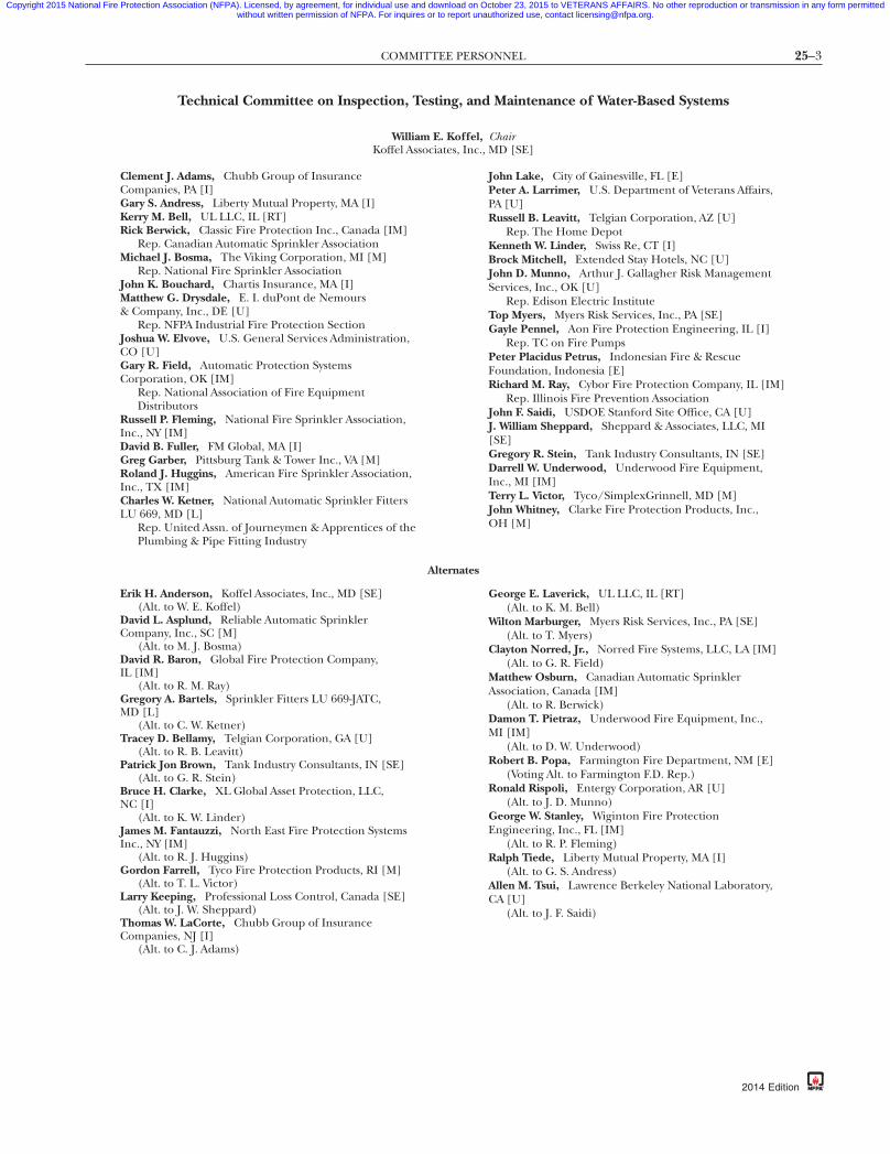
Technical Committee on Inspection, Testing, and Maintenance of Water-Based Systems
William E. Koffel, Chair
Koffel Associates, Inc., MD [SE]lement J. Adams, Chubb Group of Insuranceompanies, PA [I]ary S. Andress, Liberty Mutual Property, MA [I]erry M. Bell, UL LLC, IL [RT]ick Berwick, Classic Fire Protection Inc., Canada [IM]
Rep. Canadian Automatic Sprinkler Associationichael J. Bosma, The Viking Corporation, MI [M]
Rep. National Fire Sprinkler Associationohn K. Bouchard, Chartis Insurance, MA [I]atthew G. Drysdale, E. I. duPont de NemoursCompany, Inc., DE [U]Rep. NFPA Industrial Fire Protection Section
oshua W. Elvove, U.S. General Services Administration,O [U]ary R. Field, Automatic Protection Systemsorporation, OK [IM]
Rep. National Association of Fire EquipmentDistributors
ussell P. Fleming, National Fire Sprinkler Association,nc., NY [IM]avid B. Fuller, FM Global, MA [I]reg Garber, Pittsburg Tank & Tower Inc., VA [M]oland J. Huggins, American Fire Sprinkler Association,
nc., TX [IM]harles W. Ketner, National Automatic Sprinkler FittersU 669, MD [L]
Rep. United Assn. of Journeymen & Apprentices of the
Plumbing & Pipe Fitting IndustryAlternates
(Alt. to C. J. Adams)
-87d
John Lake, City of Gainesville, FL [E]Peter A. Larrimer, U.S. Department of Veterans Affairs,PA [U]Russell B. Leavitt, Telgian Corporation, AZ [U]
Rep. The Home DepotKenneth W. Linder, Swiss Re, CT [I]Brock Mitchell, Extended Stay Hotels, NC [U]John D. Munno, Arthur J. Gallagher Risk ManagementServices, Inc., OK [U]
Rep. Edison Electric InstituteTop Myers, Myers Risk Services, Inc., PA [SE]Gayle Pennel, Aon Fire Protection Engineering, IL [I]
Rep. TC on Fire PumpsPeter Placidus Petrus, Indonesian Fire & RescueFoundation, Indonesia [E]Richard M. Ray, Cybor Fire Protection Company, IL [IM]
Rep. Illinois Fire Prevention AssociationJohn F. Saidi, USDOE Stanford Site Office, CA [U]J. William Sheppard, Sheppard & Associates, LLC, MI[SE]Gregory R. Stein, Tank Industry Consultants, IN [SE]Darrell W. Underwood, Underwood Fire Equipment,Inc., MI [IM]Terry L. Victor, Tyco/SimplexGrinnell, MD [M]John Whitney, Clarke Fire Protection Products, Inc.,OH [M]
rik H. Anderson, Koffel Associates, Inc., MD [SE](Alt. to W. E. Koffel)
avid L. Asplund, Reliable Automatic Sprinklerompany, Inc., SC [M]
(Alt. to M. J. Bosma)avid R. Baron, Global Fire Protection Company,
L [IM](Alt. to R. M. Ray)
regory A. Bartels, Sprinkler Fitters LU 669-JATC,D [L]
(Alt. to C. W. Ketner)racey D. Bellamy, Telgian Corporation, GA [U]
(Alt. to R. B. Leavitt)atrick Jon Brown, Tank Industry Consultants, IN [SE]
(Alt. to G. R. Stein)ruce H. Clarke, XL Global Asset Protection, LLC,C [I]
(Alt. to K. W. Linder)ames M. Fantauzzi, North East Fire Protection Systemsnc., NY [IM]
(Alt. to R. J. Huggins)ordon Farrell, Tyco Fire Protection Products, RI [M]
(Alt. to T. L. Victor)arry Keeping, Professional Loss Control, Canada [SE]
(Alt. to J. W. Sheppard)homas W. LaCorte, Chubb Group of Insuranceompanies, NJ [I]
e0bff22-698c-46e7
George E. Laverick, UL LLC, IL [RT](Alt. to K. M. Bell)Wilton Marburger, Myers Risk Services, Inc., PA [SE](Alt. to T. Myers)
Clayton Norred, Jr., Norred Fire Systems, LLC, LA [IM](Alt. to G. R. Field)
Matthew Osburn, Canadian Automatic SprinklerAssociation, Canada [IM]
(Alt. to R. Berwick)Damon T. Pietraz, Underwood Fire Equipment, Inc.,MI [IM]
(Alt. to D. W. Underwood)Robert B. Popa, Farmington Fire Department, NM [E]
(Voting Alt. to Farmington F.D. Rep.)Ronald Rispoli, Entergy Corporation, AR [U]
(Alt. to J. D. Munno)George W. Stanley, Wiginton Fire ProtectionEngineering, Inc., FL [IM]
(Alt. to R. P. Fleming)Ralph Tiede, Liberty Mutual Property, MA [I]
(Alt. to G. S. Andress)Allen M. Tsui, Lawrence Berkeley National Laboratory,CA [U]
(Alt. to J. F. Saidi)
b-eba3b3d7337a}
2014 Edition

25–4 INSPECTION, TESTING, AND MAINTENANCE OF WATER-BASED FIRE PROTECTION SYSTEMS
2
Copyright 2015 National Fire Protection Association (NFPA). Licensed, by agreement, for individual use and download on October 23, 2015 to VETERANS AFFAIRS. No other reproduction or transmission in any form permittedwithout written permission of NFPA. For inquires or to report unauthorized use, contact [email protected].
Nonvoting
Cecil Bilbo, Jr., Academy of Fire Sprinkler Technology,Inc., IL [SE]Robert G. Caputo, Fire & Life Safety America, CA [IM]
Rep. TC on Sprinkler System Installation Criteria
Matthew J. Klaus, NFPA Staff Liaison
Tc
Na
Ca(asd
014 Edition
{3e0
Rohit Khanna, U.S. Consumer Product SafetyCommission, MD [C]Thomas F. Norton, Norel Service Company, Inc.,MA [IM]
37a}
his list represents the membership at the time the Committee was balloted on the final text of this edition. Since that time,hanges in the membership may have occurred. A key to classifications is found at the back of the document.
OTE: Membership on a committee shall not in and of itself constitute an endorsement of the Association orny document developed by the committee on which the member serves.
ommittee Scope: This Committee shall have primary responsibility for documents on inspection, testing,nd maintenance of systems utilizing water as a method of extinguishment. These include sprinkler systemsexcluding sprinkler systems installed in one- and two-family dwellings and manufactured homes), standpipend hose systems, fire service piping and appurtenances, fire pumps, water storage tanks, fixed water sprayystems, water mist systems, foam-water systems, valves, and allied equipment. This Committee shall alsoevelop procedures for the conduct and reporting of routine system impairments.
bff22-698c-46e7-87db-eba3b3d73

25–5CONTENTS
Copyright 2015 National Fire Protection Association (NFPA). Licensed, by agreement, for individual use and download on October 23, 2015 to VETERANS AFFAIRS. No other reproduction or transmission in any form permittedwithout written permission of NFPA. For inquires or to report unauthorized use, contact [email protected].
Contents
87
Chapter 1 Administration ............................... 25– 71.1 Scope ............................................... 25– 71.2 Purpose ............................................ 25– 71.3 Application ....................................... 25– 71.4 Units ................................................ 25– 7
Chapter 2 Referenced Publications ................... 25– 72.1 General ............................................ 25– 72.2 NFPA Publications ............................... 25– 82.3 Other Publications .............................. 25– 82.4 References for Extracts in Mandatory
Sections ............................................ 25– 8
Chapter 3 Definitions .................................... 25– 83.1 General ............................................ 25– 83.2 NFPA Official Definitions ...................... 25– 83.3 General Definitions ............................. 25– 93.4 Deluge Foam-Water Sprinkler and
Foam-Water Spray SystemsDefinitions ........................................ 25– 12
3.5 Valve Definitions ................................. 25– 123.6 Water-Based Fire Protection System
Definitions ........................................ 25– 123.7 ITM Task Frequencies .......................... 25– 13
Chapter 4 General Requirements ..................... 25– 134.1 Responsibility of Property Owner or
Designated Representative .................... 25– 134.2 Manufacturer’s Corrective Action ........... 25– 144.3 Records ............................................ 25– 144.4 Water Supply Status ............................. 25– 144.5 Inspection ......................................... 25– 144.6 Testing ............................................. 25– 144.7 Performance-Based Programs ................ 25– 144.8 Maintenance ..................................... 25– 144.9 Safety ............................................... 25– 15
Chapter 5 Sprinkler Systems ........................... 25– 155.1 General ............................................ 25– 155.2 Inspection ......................................... 25– 155.3 Testing ............................................. 25– 175.4 Maintenance ..................................... 25– 195.5 Component Action Requirements .......... 25– 19
Chapter 6 Standpipe and Hose Systems ............. 25– 216.1 General ............................................ 25– 216.2 Inspection ......................................... 25– 216.3 Testing ............................................. 25– 236.4 Maintenance ..................................... 25– 236.5 Component Action Requirements .......... 25– 23
Chapter 7 Private Fire Service Mains ................. 25– 247.1 General ............................................ 25– 247.2 Inspection and Corrective Action ........... 25– 25
{3e0bff22-698c-46e7-
7.3 Testing ............................................. 25– 257.4 Maintenance ..................................... 25– 267.5 Component Action Requirements .......... 25– 26
Chapter 8 Fire Pumps .................................... 25– 278.1 General ............................................ 25– 278.2 Inspection ......................................... 25– 308.3 Testing ............................................. 25– 308.4 Reports ............................................ 25– 338.5 Maintenance ..................................... 25– 338.6 Component Replacement Testing
Requirements .................................... 25– 33
Chapter 9 Water Storage Tanks ........................ 25– 369.1 General ............................................ 25– 369.2 Inspection ......................................... 25– 369.3 Testing ............................................. 25– 389.4 Maintenance ..................................... 25– 389.5 Automatic Tank Fill Valves .................... 25– 389.6 Component Action Requirements .......... 25– 38
Chapter 10 Water Spray Fixed Systems .............. 25– 3910.1 General ............................................ 25– 3910.2 Inspection and Maintenance
Procedures ........................................ 25– 3910.3 Operational Tests ................................ 25– 4210.4 Ultra-High-Speed Water Spray System
(UHSWSS) Operational Tests ................ 25– 4210.5 Component Action Requirements .......... 25– 43
Chapter 11 Foam-Water Sprinkler Systems .......... 25– 4311.1 General ............................................ 25– 4311.2 Inspection ......................................... 25– 4511.3 Operational Tests ................................ 25– 4611.4 Maintenance ..................................... 25– 4711.5 Component Action Requirements .......... 25– 48
Chapter 12 Water Mist Systems ........................ 25– 5012.1 Inspection and Testing. ........................ 25– 5012.2 Maintenance. ..................................... 25– 5312.3 Training ........................................... 25– 53
Chapter 13 Valves, Valve Components, andTrim ........................................... 25– 53
13.1 General ............................................ 25– 5313.2 General Provisions .............................. 25– 5513.3 Control Valves in Water-Based Fire
Protection Systems .............................. 25– 5513.4 System Valves ..................................... 25– 5613.5 Pressure-Reducing Valves and Relief
Valves ............................................... 25– 5913.6 Backflow Prevention Assemblies ............. 25– 6013.7 Fire Department Connections ............... 25– 6013.8 Component Testing Requirements ......... 25– 60
db-eba3b3d7337a}
2014 Edition

25–6 INSPECTION, TESTING, AND MAINTENANCE OF WATER-BASED FIRE PROTECTION SYSTEMS
Copyright 2015 National Fire Protection Association (NFPA). Licensed, by agreement, for individual use and download on October 23, 2015 to VETERANS AFFAIRS. No other reproduction or transmission in any form permittedwithout written permission of NFPA. For inquires or to report unauthorized use, contact [email protected].
Chapter 14 Internal Piping Condition andObstruction Investigation ................ 25– 63
14.1 General ............................................ 25– 6314.2 Assessment of Internal Condition of
Piping. ............................................. 25– 6314.3 Obstruction Investigation and
Prevention ........................................ 25– 6314.4 Ice Obstruction .................................. 25– 63
Chapter 15 Impairments ................................ 25– 6315.1 General ............................................ 25– 6315.2 Impairment Coordinator ...................... 25– 6415.3 Tag Impairment System ........................ 25– 6415.4 Impaired Equipment ........................... 25– 6415.5 Preplanned Impairment Programs .......... 25– 6415.6 Emergency Impairments ...................... 25– 64
15.7 Restoring Systems to Service .................. 25– 642014 Edition
{3e0bff22-698c-46e7-8
Chapter 16 Special Requirements from OtherNFPA Documents .......................... 25– 64
16.1 General ............................................ 25– 6416.2 Small Residential Board and Care
Occupancies ...................................... 25– 64
Annex A Explanatory Material ......................... 25– 65
Annex B Forms for Inspection, Testing, andMaintenance .................................... 25–112
Annex C Possible Causes of Pump Troubles ....... 25–112
Annex D Obstruction Investigation ................... 25–115
Annex E Hazard Evaluation Form ..................... 25–123
Annex F Informational References ................... 25–127
Index ........................................................... 25–129
7db-eba3b3d7337a}

25–7REFERENCED PUBLICATIONS
Copyright 2015 National Fire Protection Association (NFPA). Licensed, by agreement, for individual use and download on October 23, 2015 to VETERANS AFFAIRS. No other reproduction or transmission in any form permittedwithout written permission of NFPA. For inquires or to report unauthorized use, contact [email protected].
87
NFPA 25
Standard for the
Inspection, Testing, and Maintenance ofWater-Based Fire Protection Systems
2014 Edition
IMPORTANT NOTE: This NFPA document is made available foruse subject to important notices and legal disclaimers. These noticesand disclaimers appear in all publications containing this documentand may be found under the heading “Important Notices and Dis-claimers Concerning NFPA Documents.” They can also be obtainedon request from NFPA or viewed at www.nfpa.org/disclaimers.
NOTICE: An asterisk (*) following the number or letterdesignating a paragraph indicates that explanatory materialon the paragraph can be found in Annex A.
Changes other than editorial are indicated by a verticalrule beside the paragraph, table, or figure in which thechange occurred. These rules are included as an aid to theuser in identifying changes from the previous edition. Whereone or more complete paragraphs have been deleted, the de-letion is indicated by a bullet (•) between the paragraphs thatremain.
A reference in brackets [ ] following a section or paragraphindicates material that has been extracted from another NFPAdocument. As an aid to the user, the complete title and editionof the source documents for extracts in mandatory sections ofthe document are given in Chapter 2 and those for extracts ininformational sections are given in Annex F. Extracted textmay be edited for consistency and style and may include therevision of internal paragraph references and other refer-ences as appropriate. Requests for interpretations or revisionsof extracted text shall be sent to the technical committee re-sponsible for the source document.
Information on referenced publications can be found inChapter 2 and Annex F.
Chapter 1 Administration
1.1 Scope. This document establishes the minimum require-ments for the periodic inspection, testing, and maintenanceof water-based fire protection systems and the actions to un-dertake when changes in occupancy, use, process, materials,hazard, or water supply that potentially impact the perfor-mance of the water-based system are planned or identified.
1.1.1 Coordination with NFPA 72 Testing Requirements. Thisstandard does not address all of the inspection, testing, andmaintenance of the electrical components of the automaticfire detection equipment used to activate preaction and del-uge systems that are addressed by NFPA 72, National Fire Alarmand Signaling Code.
1.1.1.1 The inspection, testing, and maintenance required bythis standard and NFPA 72, National Fire Alarm and SignalingCode, shall be coordinated so that the system operates as in-tended.
1.1.1.2* All inspections, testing, and maintenance required byNFPA 72 shall conform to NFPA 72, and all inspections, testing,and maintenance required by this standard shall conform tothis standard.
{3e0bff22-698c-46e7-
1.1.2 Types of Systems.
1.1.2.1 The types of systems addressed by this standard in-clude, but are not limited to, sprinkler, standpipe and hose,fixed water spray, private fire hydrants, water mist, and foamwater.
1.1.2.2 Water supplies that are part of these systems, such asprivate fire service mains and appurtenances, fire pumps andwater storage tanks, and valves that control system flow, arealso included in this standard.
1.1.3* This standard addresses the operating condition of fireprotection systems as well as impairment handling and report-ing and applies to fire protection systems that have been prop-erly installed in accordance with generally accepted practice.
1.1.3.1* This standard does not require the inspector to verifythe adequacy of the design of the system.
1.1.4* Corrective action needed to ensure that a system oper-ates in a satisfactory manner shall be in accordance with thisstandard unless this standard specifically refers to an appropri-ate installation standard.
1.1.5 This standard shall not apply to sprinkler systems de-signed, installed, and maintained in accordance withNFPA 13D, Standard for the Installation of Sprinkler Systems in One-and Two-Family Dwellings and Manufactured Homes.
1.2* Purpose.
1.2.1 The purpose of this document is to provide requirementsthat ensure a reasonable degree of protection for life and prop-erty from fire through minimum inspection, testing, and mainte-nance methods for water-based fire protection systems.
1.2.2 In those cases where it is determined that an existingsituation involves a distinct hazard to life or property, the au-thority having jurisdiction shall be permitted to require in-spection, testing, and maintenance methods in excess of thoserequired by the standard.
1.3* Application.
1.3.1 It is not the intent of this document to limit or restrictthe use of other inspection, testing, or maintenance programsthat provide an equivalent level of system integrity and perfor-mance to that detailed in this document.
1.3.2 The authority having jurisdiction shall be consultedand approval obtained for such alternative programs.
1.4* Units. Metric units of measurement in this standard arein accordance with the modernized metric system known asthe International System of Units (SI).
1.4.1 If a value for measurement as given in this standard isfollowed by an equivalent value in other units, the first statedshall be regarded as the requirement. A given equivalent valueshall be considered to be approximate.
1.4.2 SI units have been converted by multiplying the quan-tity by the conversion factor and then rounding the result tothe appropriate number of significant digits. Where nominalor trade sizes exist, the nominal dimension has been recog-nized in each unit.
Chapter 2 Referenced Publications
2.1 General. The documents or portions thereof listed in thischapter are referenced within this standard and shall be con-sidered part of the requirements of this document.
db-eba3b3d7337a}
2014 Edition

25–8 INSPECTION, TESTING, AND MAINTENANCE OF WATER-BASED FIRE PROTECTION SYSTEMS
Copyright 2015 National Fire Protection Association (NFPA). Licensed, by agreement, for individual use and download on October 23, 2015 to VETERANS AFFAIRS. No other reproduction or transmission in any form permittedwithout written permission of NFPA. For inquires or to report unauthorized use, contact [email protected].
-8
2.2 NFPA Publications. National Fire Protection Association,1 Batterymarch Park, Quincy, MA 02169-7471.
NFPA 11, Standard for Low-, Medium-, and High-ExpansionFoam, 2010 edition.
NFPA 13, Standard for the Installation of Sprinkler Systems, 2013edition.
NFPA 13D, Standard for the Installation of Sprinkler Systems inOne- and Two-Family Dwellings and Manufactured Homes, 2013edition.
NFPA 14, Standard for the Installation of Standpipe and HoseSystems, 2013 edition.
NFPA 15, Standard for Water Spray Fixed Systems for Fire Protec-tion, 2012 edition.
NFPA 16, Standard for the Installation of Foam-Water Sprinklerand Foam-Water Spray Systems, 2011 edition.
NFPA 20, Standard for the Installation of Stationary Pumps forFire Protection, 2013 edition.
NFPA 22, Standard for Water Tanks for Private Fire Protection,2013 edition.
NFPA 24, Standard for the Installation of Private Fire ServiceMains and Their Appurtenances, 2013 edition.
NFPA72®, National FireAlarm and Signaling Code, 2013 edition.NFPA 101®, Life Safety Code®, 2012 edition.NFPA 110, Standard for Emergency and Standby Power Systems,
2013 edition.NFPA 307, Standard for the Construction and Fire Protection of
Marine Terminals, Piers, and Wharves, 2011 edition.NFPA 409, Standard on Aircraft Hangars, 2011 edition.NFPA 1962, Standard for the Care, Use, Inspection, Service Test-
ing, and Replacement of Fire Hose, Couplings, Nozzles, and Fire HoseAppliances, 2013 edition.
2.3 Other Publications.
2.3.1 ASTM Publications. ASTM International, 100 Barr Har-bor Drive, P.O. Box C700, West Conshohocken, PA 19428-2959.
ASTM D 975-11b, Standard Specification for Diesel Fuel Oils,2011.
ASTM D 3359, Standard Test Methods for Measuring Adhesionby Tape Test, 2008.
ASTM D 6751-11b, Standard Specification for Biodiesel FuelBlend Stock (B100) for Middle Distillate Fuels, 2011.
ASTM D 7462-11, Standard Test Method for Oxidation Stabilityof Biodiesel (B100) and Blends of Biodiesel with Middle DistillatePetroleum Fuel (accelerated Method), 2011.
2.3.2 HI Publications. Hydraulic Institute, 6 Campus Drive,First Floor North, Parsippany, NJ 07054-4406.
HI 3.6, Rotary Pump Tests, 2010..
2.3.3 Other Publications.
Merriam-Webster’s Collegiate Dictionary, 11th edition, Merriam-Webster, Inc., Springfield, MA, 2003.
2.4 References for Extracts in Mandatory Sections.NFPA 11, Standard for Low-, Medium-, and High-Expansion
Foam, 2010 edition.NFPA 13, Standard for the Installation of Sprinkler Systems, 2013
edition.NFPA 14, Standard for the Installation of Standpipe and Hose
Systems, 2013 edition.
{3e0bff22-698c-46e7
2014 Edition
NFPA 15, Standard for Water Spray Fixed Systems for Fire Protec-tion, 2012 edition.
NFPA 16, Standard for the Installation of Foam-Water Sprinklerand Foam-Water Spray Systems, 2011 edition.
NFPA 20, Standard for the Installation of Stationary Pumps forFire Protection, 2013 edition.
NFPA 24, Standard for the Installation of Private Fire ServiceMains and Their Appurtenances, 2013 edition.
NFPA 96, Standard for Ventilation Control and Fire Protection ofCommercial Cooking Operations, 2014 edition.
NFPA 101®, Life Safety Code®, 2012 edition.NFPA 110, Standard for Emergency and Standby Power Systems,
2013 edition.NFPA 750, Standard on Water Mist Fire Protection Systems, 2010
edition.NFPA 820, Standard for Fire Protection in Wastewater Treatment
and Collection Facilities, 2012 edition.NFPA 1141, Standard for Fire Protection Infrastructure for Land
Development in Wildland, Rural, and Suburban Areas, 2012 edition.NFPA 1911, Standard for the Inspection, Maintenance, Testing, and
Retirement of In-Service Automotive Fire Apparatus, 2012 edition.
Chapter 3 Definitions
3.1 General. The definitions contained in this chapter shallapply to the terms used in this standard. Where terms are notdefined in this chapter or within another chapter, they shallbe defined using their ordinarily accepted meanings withinthe context in which they are used. Merriam-Webster’s CollegiateDictionary, 11th edition, shall be the source for the ordinarilyaccepted meaning.
3.2 NFPA Official Definitions.
3.2.1* Approved. Acceptable to the authority having jurisdic-tion.
3.2.2* Authority Having Jurisdiction (AHJ). An organization,office, or individual responsible for enforcing the require-ments of a code or standard, or for approving equipment,materials, an installation, or a procedure.
3.2.3* Listed. Equipment, materials, or services included in alist published by an organization that is acceptable to the au-thority having jurisdiction and concerned with evaluation ofproducts or services, that maintains periodic inspection ofproduction of listed equipment or materials or periodic evalu-ation of services, and whose listing states that either the equip-ment, material, or service meets appropriate designated stan-dards or has been tested and found suitable for a specifiedpurpose.
3.2.4 Shall. Indicates a mandatory requirement.
3.2.5 Should. Indicates a recommendation or that which isadvised but not required.
3.2.6 Standard. A document, the main text of which containsonly mandatory provisions using the word “shall” to indicaterequirements and which is in a form generally suitable formandatory reference by another standard or code or for adop-tion into law. Nonmandatory provisions are not to be consid-ered a part of the requirements of a standard and shall belocated in an appendix, annex, footnote, informational note,or other means as permitted in the Manual of Style for NFPATechnical Committee Documents.
7db-eba3b3d7337a}

25–9DEFINITIONS
Copyright 2015 National Fire Protection Association (NFPA). Licensed, by agreement, for individual use and download on October 23, 2015 to VETERANS AFFAIRS. No other reproduction or transmission in any form permittedwithout written permission of NFPA. For inquires or to report unauthorized use, contact [email protected].
87
3.3 General Definitions.
3.3.1 Adjust. To maintain or regulate, within prescribed lim-its, by setting the operating characteristics to specified param-eters. [1911, 2012]
3.3.2* Alarm Receiving Facility. The place where alarm or su-pervisory signals are received.
3.3.3* Automatic Detection Equipment. Equipment that auto-matically detects heat, flame, products of combustion, flam-mable gases, or other conditions likely to produce fire or ex-plosion and cause other automatic actuation of alarm andprotection equipment.
3.3.4* Automatic Operation. Operation without human inter-vention.
3.3.5 Automatic Transfer Switch. Self-acting equipment fortransferring the connected load from one power source toanother power source. [110, 2013]
3.3.6 Clean. To remove dirt, scale, and debris.
3.3.7* Deficiency. For the purposes of inspection, testing, andmaintenance of water-based fire protection systems, a condi-tion that will or has the potential to adversely impact the per-formance of a system or portion thereof but does not rise tothe level of an impairment.
3.3.7.1 Critical Deficiency. A deficiency that, if not cor-rected, can have a material effect on the ability of the fireprotection system or unit to function as intended in afire event.
3.3.7.2 Noncritical Deficiency. A deficiency that does nothave a material effect on the ability of the fire protectionsystem or unit to function in a fire event, but correctionis needed to meet the requirements of this standard orfor the proper inspection, testing, and maintenance ofthe system or unit.
3.3.8 Discharge Device. A device designed to discharge wateror foam-water solution in a predetermined, fixed, or adjust-able pattern. Examples include, but are not limited to, sprin-klers, spray nozzles, and hose nozzles. [16, 2011]
3.3.9 Double Check Valve Assembly (DCVA). This assemblyconsists of two internally loaded check valves, either spring-loaded or internally weighted, installed as a unit between twotightly closing resilient-seated shutoff valves as an assembly,and fittings with properly located resilient-seated test cocks.
3.3.10 Drain.
3.3.10.1 Main Drain. The primary drain connection lo-cated on the system riser.
3.3.10.2* Sectional Drain. A drain located beyond a sec-tional control valve that drains only a portion of the system.
3.3.11 Fire Department Connection. A connection throughwhich the fire department can pump supplemental water intothe sprinkler system, standpipe, or other system furnishing waterfor fire extinguishment to supplement existing water supplies.
3.3.12* Fire Hydrant. A valved connection on a water supplysystem having one or more outlets and that is used to supplyhose and fire department pumpers with water. [1141, 2012]
3.3.12.1* Dry Barrel Hydrant (Frostproof Hydrant). A type ofhydrant with the main control valve below the frost linebetween the footpiece and the barrel.
{3e0bff22-698c-46e7-
3.3.12.2* Monitor Nozzle Hydrant. A hydrant equipped witha monitor nozzle capable of delivering more than 250 gpm(946 L/min).
3.3.12.3* Wall Hydrant. A hydrant mounted on the outsideof a wall of a building, fed from interior piping, and equippedwith control valves located inside the building that normallyare key-operated from the building’s exterior.
3.3.12.4* Wet Barrel Hydrant. A type of hydrant that some-times is used where there is no danger of freezing weather.Each outlet on a wet barrel hydrant is provided with avalved outlet threaded for fire hose. [24, 2013]
3.3.13* Foam Concentrate. A concentrated liquid foamingagent as received from the manufacturer. [11, 2010]
3.3.14 [Foam] Discharge Device. A device designed to dis-charge water or foam-water solution in a predetermined, fixed,or adjustable pattern. Examples include, but are not limited to,sprinklers, spray nozzles, and hose nozzles. [16, 2011]
3.3.15 Hose Connection. A combination of equipment pro-vided for connection of a hose to the standpipe system thatincludes a hose valve with a threaded outlet. [14, 2013]
3.3.16* Hose House. An enclosure located over or adjacentto a hydrant or other water supply designed to contain thenecessary hose nozzles, hose wrenches, gaskets, and spannersto be used in fire fighting in conjunction with and to provideaid to the local fire department.
3.3.17 Hose Nozzle. A device intended for discharging waterfor manual suppression or extinguishment of a fire.
3.3.18 Hose Station. A combination of a hose rack, hosenozzle, hose, and hose connection. [14, 2013]
3.3.19 Hose Storage Devices.
3.3.19.1* Conventional Pin Rack. A hose rack where thehose is folded vertically and attached over the pins.
3.3.19.2* Horizontal Rack. A hose rack where the hose isconnected to the valve, then stack-folded horizontally tothe top of the rack.
3.3.19.3* Hose Reel. A circular device used to store hose.
3.3.19.4* Semiautomatic Hose Rack Assembly. The same as a“conventional” pin rack or hose reel except that, after thevalve is opened, a retaining device holds the hose and wateruntil the last few feet are removed.
3.3.20 Hydrostatic Test. A test of a closed piping system andits attached appurtenances consisting of subjecting the pipingto an increased internal pressure for a specified period of du-ration to verify system integrity and leak rates. [24, 2013]
3.3.21* Impairment. A condition where a fire protection sys-tem or unit or portion thereof is out of order, and the condi-tion can result in the fire protection system or unit not func-tioning in a fire event.
3.3.21.1* Emergency Impairment. A condition where a water-based fire protection system or portion thereof is out oforder due to an unplanned occurrence, or the impairmentis found while performing inspection testing or mainte-nance activities.
3.3.21.2 Preplanned Impairment. Acondition where a water-based fire protection system or a portion thereof is out ofservice due to work planned in advance, such as revisions tothe water supply or sprinkler system piping.
db-eba3b3d7337a}
2014 Edition

25–10 INSPECTION, TESTING, AND MAINTENANCE OF WATER-BASED FIRE PROTECTION SYSTEMS
Copyright 2015 National Fire Protection Association (NFPA). Licensed, by agreement, for individual use and download on October 23, 2015 to VETERANS AFFAIRS. No other reproduction or transmission in any form permittedwithout written permission of NFPA. For inquires or to report unauthorized use, contact [email protected].
-8
3.3.22 Inspect. See 3.3.23, Inspection.
3.3.23 Inspection. A visual examination of a system or por-tion thereof to verify that it appears to be in operating condi-tion and is free of physical damage. [820, 2012]
3.3.24* Inspection, Testing, and Maintenance Service. A serviceprogram provided by a qualified contractor or qualified prop-erty owner’s representative in which all components unique tothe property’s systems are inspected and tested at the requiredtimes and necessary maintenance is provided.
3.3.25 Maintenance. In water-based fire protection systems,work performed to keep equipment operable or to make re-pairs.
3.3.26 Manual Operation. Operation of a system or its com-ponents through human action.
3.3.27 Nozzle.
3.3.27.1* Monitor Nozzle. A permanently mounted devicespecifically designed with a high flow rate to provide a far-reaching stream for locations where large amounts of waterneed to be available without the delay of laying hose lines.
3.3.27.2* Water Spray Nozzle. An open or automatic waterdischarge device that, when discharging water under pres-sure, will distribute the water in a specific, directional pat-tern.
3.3.28 Orifice Plate Proportioning. This system utilizes an ori-fice plate(s) through which passes a specific amount of foamconcentrate at a specific pressure drop across the orificeplate(s).
3.3.29 Performance-Based Program. Methods and frequenciesthat have been demonstrated to deliver equivalent or superiorlevels of performance through quantitative performance-basedanalysis.
3.3.30* Pressure-Regulating Device. A device designed for thepurpose of reducing, regulating, controlling, or restricting wa-ter pressure. [14, 2013]
3.3.31 Pressure-Restricting Device. A valve or device designedfor the purpose of reducing the downstream water pressureunder flowing (residual) conditions only. [14, 2013]
3.3.32* Pressure Vacuum Vent. A venting device mounted onatmospheric foam concentrate storage vessels to allow for con-centrate expansion and contraction and for tank breathingduring concentrate discharge or filling.
3.3.33* Proportioner.
3.3.33.1* Bladder Tank Proportioner. A system that is similarto a standard pressure proportioner, except the foam con-centrate is contained inside a diaphragm bag that is con-tained inside a pressure vessel.
3.3.33.2* In-Line Balanced Pressure Proportioner. A systemthat is similar to a standard balanced pressure system, ex-cept the pumped concentrate pressure is maintained at afixed preset value.
3.3.33.3* Line Proportioner. A system that uses a venturipickup-type device where water passing through the unitcreates a vacuum, thereby allowing foam concentrate to bepicked up from an atmospheric storage container.
3.3.33.4* Standard Balanced Pressure Proportioner. A systemthat utilizes a foam concentrate pump where foam concen-
{3e0bff22-698c-46e7
2014 Edition
trate is drawn from an atmospheric storage tank, is pressur-ized by the pump, and passes back through a diaphragmbalancing valve to the storage tank.
3.3.33.5* Standard Pressure Proportioner. A system that usesa pressure vessel containing foam concentrate where wateris supplied to the proportioner, which directs an amount ofthe supply downward onto the contained concentrate,thereby pressurizing the tank.
3.3.34 Qualified. A competent and capable person or com-pany that has met the requirements and training for a givenfield acceptable to the AHJ. [96, 2014]
3.3.35 Rebuild. To restore working condition by replace-ment or repair of worn or damaged parts.
3.3.36 Reduced-Pressure Principle Backflow Prevention Assem-bly (RPBA). Two independently acting check valves togetherwith a hydraulically operating, mechanically independentpressure differential relief valve located between the checkvalves, along with two resilient-seated shutoff valves, all as anassembly, and equipped with properly located test cocks.
3.3.37 Remove. To physically take away or eliminate.
3.3.38 Repair. Restore to sound working condition or to fixdamage.
3.3.39 Replace. To remove a component and install a new orequivalent component.
3.3.40 Sprinkler.
3.3.40.1 Installation Orientation. The following sprinklersare defined according to orientation.
3.3.40.1.1 Concealed Sprinkler. A recessed sprinkler withcover plate. [13, 2013]
3.3.40.1.2 Flush Sprinkler. A sprinkler in which all or partof the body, including the shank thread, is mounted abovethe lower plane of the ceiling. [13, 2013]
3.3.40.1.3 Pendent Sprinkler. A sprinkler designed to be in-stalled in such a way that the water stream is directed down-ward against the deflector. [13, 2013]
3.3.40.1.4 Recessed Sprinkler. A sprinkler in which all orpart of the body, other than the shank thread, is mountedwithin a recessed housing. [13, 2013]
3.3.40.1.5 Sidewall Sprinkler. A sprinkler having specialdeflectors that are designed to discharge most of the wateraway from the nearby wall in a pattern resembling one-quarter of a sphere, with a small portion of the dischargedirected at the wall behind the sprinkler. [13, 2013]
3.3.40.1.6 Upright Sprinkler. A sprinkler designed to be in-stalled in such a way that the water spray is directed up-wards against the deflector. [13, 2013]
3.3.40.2* Control Mode Specific Application (CMSA) Sprinkler.A type of spray sprinkler that is capable of producing char-acteristic large water droplets and that is listed for its capa-bility to provide fire control of specific high-challenge firehazards. [13, 2013]
3.3.40.3 Corrosion-Resistant Sprinkler. A sprinkler fabri-cated with corrosion-resistant material, or with special coat-ings or platings, to be used in an atmosphere that wouldnormally corrode sprinklers. [13, 2013]
7db-eba3b3d7337a}
25–11DEFINITIONS
Copyright 2015 National Fire Protection Association (NFPA). Licensed, by agreement, for individual use and download on October 23, 2015 to VETERANS AFFAIRS. No other reproduction or transmission in any form permittedwithout written permission of NFPA. For inquires or to report unauthorized use, contact [email protected].
87
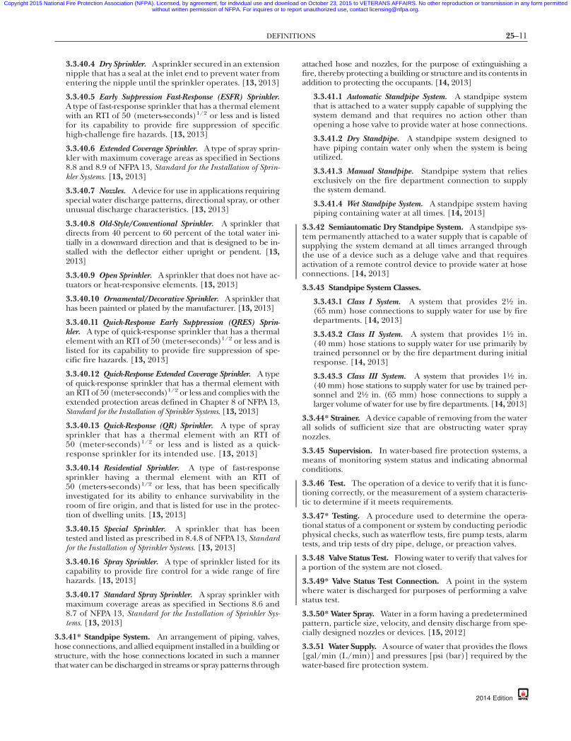
3.3.40.4 Dry Sprinkler. A sprinkler secured in an extensionnipple that has a seal at the inlet end to prevent water fromentering the nipple until the sprinkler operates. [13, 2013]
3.3.40.5 Early Suppression Fast-Response (ESFR) Sprinkler.A type of fast-response sprinkler that has a thermal elementwith an RTI of 50 (meters-seconds)1/2 or less and is listedfor its capability to provide fire suppression of specifichigh-challenge fire hazards. [13, 2013]
3.3.40.6 Extended Coverage Sprinkler. A type of spray sprin-kler with maximum coverage areas as specified in Sections8.8 and 8.9 of NFPA 13, Standard for the Installation of Sprin-kler Systems. [13, 2013]
3.3.40.7 Nozzles. A device for use in applications requiringspecial water discharge patterns, directional spray, or otherunusual discharge characteristics. [13, 2013]
3.3.40.8 Old-Style/Conventional Sprinkler. A sprinkler thatdirects from 40 percent to 60 percent of the total water ini-tially in a downward direction and that is designed to be in-stalled with the deflector either upright or pendent. [13,2013]
3.3.40.9 Open Sprinkler. A sprinkler that does not have ac-tuators or heat-responsive elements. [13, 2013]
3.3.40.10 Ornamental/Decorative Sprinkler. A sprinkler thathas been painted or plated by the manufacturer. [13, 2013]
3.3.40.11 Quick-Response Early Suppression (QRES) Sprin-kler. A type of quick-response sprinkler that has a thermalelement with an RTI of 50 (meter-seconds)1/2 or less and islisted for its capability to provide fire suppression of spe-cific fire hazards. [13, 2013]
3.3.40.12 Quick-Response Extended Coverage Sprinkler. A typeof quick-response sprinkler that has a thermal element withan RTI of 50 (meter-seconds)1/2 or less and complies with theextended protection areas defined in Chapter 8 of NFPA 13,Standard for the Installation of Sprinkler Systems. [13, 2013]
3.3.40.13 Quick-Response (QR) Sprinkler. A type of spraysprinkler that has a thermal element with an RTI of50 (meter-seconds)1/2 or less and is listed as a quick-response sprinkler for its intended use. [13, 2013]
3.3.40.14 Residential Sprinkler. A type of fast-responsesprinkler having a thermal element with an RTI of50 (meters-seconds)1/2 or less, that has been specificallyinvestigated for its ability to enhance survivability in theroom of fire origin, and that is listed for use in the protec-tion of dwelling units. [13, 2013]
3.3.40.15 Special Sprinkler. A sprinkler that has beentested and listed as prescribed in 8.4.8 of NFPA 13, Standardfor the Installation of Sprinkler Systems. [13, 2013]
3.3.40.16 Spray Sprinkler. A type of sprinkler listed for itscapability to provide fire control for a wide range of firehazards. [13, 2013]
3.3.40.17 Standard Spray Sprinkler. A spray sprinkler withmaximum coverage areas as specified in Sections 8.6 and8.7 of NFPA 13, Standard for the Installation of Sprinkler Sys-tems. [13, 2013]
3.3.41* Standpipe System. An arrangement of piping, valves,hose connections, and allied equipment installed in a building orstructure, with the hose connections located in such a mannerthat water can be discharged in streams or spray patterns through
{3e0bff22-698c-46e7-
attached hose and nozzles, for the purpose of extinguishing afire, thereby protecting a building or structure and its contents inaddition to protecting the occupants. [14, 2013]
3.3.41.1 Automatic Standpipe System. A standpipe systemthat is attached to a water supply capable of supplying thesystem demand and that requires no action other thanopening a hose valve to provide water at hose connections.
3.3.41.2 Dry Standpipe. A standpipe system designed tohave piping contain water only when the system is beingutilized.
3.3.41.3 Manual Standpipe. Standpipe system that reliesexclusively on the fire department connection to supplythe system demand.
3.3.41.4 Wet Standpipe System. A standpipe system havingpiping containing water at all times. [14, 2013]
3.3.42 Semiautomatic Dry Standpipe System. A standpipe sys-tem permanently attached to a water supply that is capable ofsupplying the system demand at all times arranged throughthe use of a device such as a deluge valve and that requiresactivation of a remote control device to provide water at hoseconnections. [14, 2013]
3.3.43 Standpipe System Classes.
3.3.43.1 Class I System. A system that provides 21⁄2 in.(65 mm) hose connections to supply water for use by firedepartments. [14, 2013]
3.3.43.2 Class II System. A system that provides 11⁄2 in.(40 mm) hose stations to supply water for use primarily bytrained personnel or by the fire department during initialresponse. [14, 2013]
3.3.43.3 Class III System. A system that provides 11⁄2 in.(40 mm) hose stations to supply water for use by trained per-sonnel and 21⁄2 in. (65 mm) hose connections to supply alarger volume of water for use by fire departments. [14, 2013]
3.3.44* Strainer. A device capable of removing from the waterall solids of sufficient size that are obstructing water spraynozzles.
3.3.45 Supervision. In water-based fire protection systems, ameans of monitoring system status and indicating abnormalconditions.
3.3.46 Test. The operation of a device to verify that it is func-tioning correctly, or the measurement of a system characteris-tic to determine if it meets requirements.
3.3.47* Testing. A procedure used to determine the opera-tional status of a component or system by conducting periodicphysical checks, such as waterflow tests, fire pump tests, alarmtests, and trip tests of dry pipe, deluge, or preaction valves.
3.3.48 Valve Status Test. Flowing water to verify that valves fora portion of the system are not closed.
3.3.49* Valve Status Test Connection. A point in the systemwhere water is discharged for purposes of performing a valvestatus test.
3.3.50* Water Spray. Water in a form having a predeterminedpattern, particle size, velocity, and density discharge from spe-cially designed nozzles or devices. [15, 2012]
3.3.51 Water Supply. A source of water that provides the flows[gal/min (L/min)] and pressures [psi (bar)] required by thewater-based fire protection system.
db-eba3b3d7337a}
2014 Edition

25–12 INSPECTION, TESTING, AND MAINTENANCE OF WATER-BASED FIRE PROTECTION SYSTEMS
Copyright 2015 National Fire Protection Association (NFPA). Licensed, by agreement, for individual use and download on October 23, 2015 to VETERANS AFFAIRS. No other reproduction or transmission in any form permittedwithout written permission of NFPA. For inquires or to report unauthorized use, contact [email protected].
-8
3.3.52 Waterflow Alarm Device. An attachment to a water-based fire protection system that detects and signals a prede-termined waterflow.
3.4 Deluge Foam-Water Sprinkler and Foam-Water Spray Sys-tems Definitions.
3.4.1 Foam-Water Spray System. A special system that is pipe-connected to a source of foam concentrate and to a watersupply. The system is equipped with foam-water spray nozzlesfor extinguishing agent discharge (foam followed by water orin reverse order) and for distribution over the area to be pro-tected. System operation arrangements parallel those forfoam-water sprinkler systems as described in the definition ofFoam-Water Sprinkler System. [16, 2011]
3.4.2 Foam-Water Sprinkler System. A special system that ispipe-connected to a source of foam concentrate and to a watersupply. The system is equipped with appropriate discharge de-vices for extinguishing agent discharge and for distributionover the area to be protected. The piping system is connectedto the water supply through a control valve that usually is actu-ated by operation of automatic detection equipment that isinstalled in the same areas as the sprinklers. When this valveopens, water flows into the piping system, foam concentrate isinjected into the water, and the resulting foam solution dis-charging through the discharge devices generates and distrib-utes foam. Upon exhaustion of the foam concentrate supply,water discharge follows and continues until shut off manually.Systems can be used for discharge of water first, followed bydischarge of foam for a specified period, and then followed bywater until manually shut off. Existing deluge sprinkler sys-tems that have been converted to the use of aqueous film-forming foam or film-forming fluoroprotein foam are classi-fied as foam-water sprinkler systems. [16, 2011]
3.5 Valve Definitions.
3.5.1* Control Valve. A valve controlling flow to water-basedfire protection systems.
3.5.2* Deluge Valve. A water supply control valve intended tobe operated by actuation of an automatic detection systemthat is installed in the same area as the discharge devices.
3.5.3 Hose Valve. The valve to an individual hose connec-tion. [14, 2013]
3.5.4 Pressure Control Valve. A pilot-operated pressure-reducing valve designed for the purpose of reducing thedownstream water pressure to a specific value under both flow-ing (residual) and nonflowing (static) conditions. [14, 2013]
3.5.5 Pressure-Reducing Valve. A valve designed for the pur-pose of reducing the downstream water pressure under bothflowing (residual) and nonflowing (static) conditions. [14, 2013]
3.5.5.1* Master Pressure-Reducing Valve. A pressure-reducingvalve installed to regulate pressures in an entire fire protec-tion system and/or standpipe system zone.
3.5.6 [Pressure] Relief Valve. A device that allows the diver-sion of liquid to limit excess pressure in a system. [20, 2013]
3.5.6.1 Circulation Relief Valve. A valve used to cool apump by discharging a small quantity of water. This valve isseparate from and independent of the main relief valve.[20, 2013]
{3e0bff22-698c-46e7
2014 Edition
3.6 Water-Based Fire Protection System Definitions.
3.6.1 Combined Standpipe and Sprinkler System. A systemwhere the water piping services both 21⁄2 in. (65 mm) outletsfor fire department use and outlets for automatic sprinklers.
3.6.2 Fire Pump. A pump that is a provider of liquid flow andpressure dedicated to fire protection. [20, 2013]
3.6.3* Private Fire Service Main. Private fire service main, asused in this standard, is that pipe and its appurtenances onprivate property (1) between a source of water and the base ofthe system riser for water-based fire protection systems, (2)between a source of water and inlets to foam-making systems,(3) between a source of water and the base elbow of privatehydrants or monitor nozzles, and (4) used as fire pump suc-tion and discharge piping, (5) beginning at the inlet side ofthe check valve on a gravity or pressure tank. [24, 2013]
3.6.4* Sprinkler System. A system that consists of an inte-grated network of piping designed in accordance with fireprotection engineering standards that includes a water supplysource, a water control valve, a waterflow alarm, and a drainand is commonly activated by heat from a fire, dischargingwater over the fire area. The portion of the sprinkler systemabove ground is a network of specifically sized or hydraulicallydesigned piping installed in a building, structure, or area, gen-erally overhead, and to which sprinklers are attached in a sys-tematic pattern. The system is commonly activated by heatfrom a fire and discharges water over the fire area. [13, 2013]
3.6.4.1 Antifreeze Sprinkler System. A wet pipe system usingautomatic sprinklers that contains a liquid solution to pre-vent freezing of the system, intended to discharge the solu-tion upon sprinkler operation, followed immediately by wa-ter from a water supply. [13, 2013]
3.6.4.1.1 Premixed Antifreeze Solution. A mixture of an anti-freeze material with water that is prepared and factory-mixed by the manufacturer with a quality control proce-dure in place that ensures that the antifreeze solutionremains homogeneous and that the concentration is asspecified. [13, 2013]
3.6.4.2 Deluge Sprinkler System. A sprinkler system employ-ing open sprinklers or nozzles that are attached to a pipingsystem that is connected to a water supply through a valvethat is opened by the operation of a detection system in-stalled in the same areas as the sprinklers or the nozzles.When this valve opens, water flows into the piping systemand discharges from all sprinklers or nozzles attachedthereto. [13, 2013]
3.6.4.3 Dry Pipe Sprinkler System. A sprinkler system em-ploying automatic sprinklers that are attached to a pipingsystem containing air or nitrogen under pressure, the re-lease of which (as from the opening of a sprinkler) permitsthe water pressure to open a valve known as a dry pipevalve, and the water then flows into the piping system andout the opened sprinklers. [13, 2013]
3.6.4.4 Marine System. A sprinkler system installed on aship, boat, or other floating structure that takes its supplyfrom the water on which the vessel floats.
3.6.4.5 Preaction Sprinkler System. A sprinkler system em-ploying automatic sprinklers that are attached to a pipingsystem that contains air that might or might not be underpressure, with a supplemental detection system installed inthe same areas as the sprinklers. [13, 2013]
7db-eba3b3d7337a}

25–13GENERAL REQUIREMENTS
•
Copyright 2015 National Fire Protection Association (NFPA). Licensed, by agreement, for individual use and download on October 23, 2015 to VETERANS AFFAIRS. No other reproduction or transmission in any form permittedwithout written permission of NFPA. For inquires or to report unauthorized use, contact [email protected].
87
3.6.4.6* Wet Pipe Sprinkler System. A sprinkler system em-ploying automatic sprinklers attached to a piping systemcontaining water and connected to a water supply so thatwater discharges immediately from sprinklers opened byheat from a fire. [13, 2013]
3.6.5 Water Mist System. A distribution system connected to awater supply or water and atomizing media supplies that isequipped with one or more nozzles capable of delivering wa-ter mist intended to control, suppress, or extinguish fires andthat has been demonstrated to meet the performance require-ments of its listing and [the applicable] standard. [750, 2010]
3.6.6* Water Spray System. An automatic or manually actu-ated fixed pipe system connected to a water supply andequipped with water spray nozzles designed to provide a spe-cific water discharge and distribution over the protected sur-faces or area. [15, 2012]
3.6.6.1 Ultra High-Speed Water Spray System. A type of auto-matic water spray system where water spray is rapidly ap-plied to protect specific hazards where deflagrations areanticipated. [15, 2012]
3.6.7 Water Tank. A tank supplying water for water-based fireprotection systems.
3.7 ITM Task Frequencies.
3.7.1* Frequency. Minimum and maximum time betweenevents.
3.7.1.1 Daily Frequency. Occurring every day.
3.7.1.2 Weekly Frequency. Occurring once per calendarweek.
3.7.1.3 Monthly Frequency. Occurring once per calendarmonth.
3.7.1.4 Quarterly Frequency. Occurring four times per yearwith a minimum of 2 months and a maximum of 4 months.
3.7.1.5 Semiannual Frequency. Occurring twice per yearwith a minimum of 4 months and a maximum of 8 months.
3.7.1.6 Annual Frequency. Occurring once per year with aminimum of 9 months and a maximum of 15 months.
3.7.1.7 Three Years Frequency. Occurring once every 36months with a minimum of 30 months and a maximum of40 months.
3.7.1.8 Five Years Frequency. Occurring once every 60months with a minimum of 54 months and a maximum of66 months.
Chapter 4 General Requirements
4.1 Responsibility of Property Owner or Designated Repre-sentative.
4.1.1* Responsibility for Inspection, Testing, Maintenance,and Impairment. The property owner or designated represen-tative shall be responsible for properly maintaining a water-based fire protection system.
4.1.1.1* Inspection, testing, maintenance, and impairmentprocedures shall be implemented in accordance with thoseestablished in this document and in accordance with themanufacturer’s instructions.
{3e0bff22-698c-46e7-
4.1.1.2 Inspection, testing, and maintenance shall be per-formed by qualified personnel.
4.1.1.3* Where the property owner or designated representativeis not the occupant, the property owner or designated represen-tative shall be permitted to delegate the authority for inspecting,testing, maintenance, and the managing of impairments of thefire protection system to a designated representative.
4.1.1.4 Where a designated representative has received theauthority for inspecting, testing, maintenance, and the man-aging of impairments, the designated representative shallcomply with the requirements identified for the propertyowner or designated representative throughout this standard.
4.1.2* Freeze Protection. The property owner or designatedrepresentative shall ensure that water-filled piping is main-tained at a minimum temperature of 40°F (4°C) unless anapproved antifreeze solution is utilized.
4.1.2.1 All areas of the building containing water-filled pip-ing that does not have another means of freeze protectionshall be maintained at a minimum temperature of 40°F (4°C).
4.1.2.2 Aboveground water-filled pipes that pass throughopen areas, cold rooms, passageways, or other areas exposedto temperatures below 40°F (4°C), protected against freezingby insulating coverings, frostproof casings, listed heat tracingsystems, or other reliable means, shall be maintained at tem-peratures between 40°F (4°C) and 120°F (48.9°C).
4.1.2.3 Where other approved means of freeze protection forwater-filled piping as described in 4.1.2.2 are utilized, theyshall be inspected, tested, and maintained in accordance withthis standard.
4.1.3* Accessibility. The property owner or designated repre-sentative shall provide ready accessibility to components ofwater-based fire protection systems that require inspection,testing, and maintenance.
4.1.4 Notification of System Shutdown or Testing. The prop-erty owner or designated representative shall notify the au-thority having jurisdiction, the fire department, if required,and the alarm-receiving facility before testing or shuttingdown a system or its supply.
4.1.4.1 The notification of system shutdown or test shall in-clude the purpose for the shutdown or test, the system or com-ponent involved, the estimated time of shutdown or test, andthe expected duration of the shutdown or test.
4.1.4.2 The authority having jurisdiction, the fire depart-ment, and the alarm-receiving facility shall be notified whenthe system, supply, or component is returned to service orwhen the test is complete.
4.1.5* Corrections and Repairs.
4.1.5.1* The property owner or designated representativeshall correct or repair deficiencies or impairments that arefound during the inspection, test, and maintenance requiredby this standard.
4.1.5.2 Corrections and repairs shall be performed by quali-fied maintenance personnel or a qualified contractor.
4.1.6* Changes in Occupancy, Use, Process, or Materials. Theproperty owner or designated representative shall not makechanges in the occupancy, the use or process, or the materialsused or stored in the building without evaluation of the fire
db-eba3b3d7337a}
2014 Edition

25–14 INSPECTION, TESTING, AND MAINTENANCE OF WATER-BASED FIRE PROTECTION SYSTEMS
•
Copyright 2015 National Fire Protection Association (NFPA). Licensed, by agreement, for individual use and download on October 23, 2015 to VETERANS AFFAIRS. No other reproduction or transmission in any form permittedwithout written permission of NFPA. For inquires or to report unauthorized use, contact [email protected].
-8
protection systems for their capability to protect the new occu-pancy, use, or materials.
4.1.6.1 The evaluation required by 4.1.6 shall not be consid-ered part of the normal inspection, testing, and maintenancerequired by this standard.
4.1.6.2 The evaluation shall consider factors that include, butare not limited to, the following:
(1) Occupancy changes such as converting office or produc-tion space into warehousing
(2) Process or material changes such as metal stamping tomolded plastics
(3) Building revisions such as relocated walls, added mezza-nines, and ceilings added below sprinklers
(4) Removal of heating systems in spaces with piping subjectto freezing
4.1.7* Addressing Changes in Hazard.
4.1.7.1 Where changes in the occupancy, hazard, water sup-ply, storage commodity, storage arrangement, building modi-fication, or other condition that affects the installation criteriaof the system are identified, the property owner or designatedrepresentative shall promptly take steps to evaluate the ad-equacy of the installed system in order to protect the buildingor hazard in question.
4.1.7.2 Where the evaluation reveals that the installed systemis inadequate to protect the building or hazard in question,the property owner or designated representative shall makethe required corrections.
4.1.7.3 Corrections shall be approved.
4.1.8 Valve Location. The location of shutoff valves shall beidentified at the system riser or other approved locations.
4.1.9 Information Sign.
4.1.9.1 A permanently marked metal or rigid plastic informa-tion sign shall be placed at the system control riser supplyingan antifreeze loop, dry system, preaction system, or auxiliarysystem control valve.
4.1.9.2 Each sign shall be secured with a corrosion-resistantwire, chain, or other approved means and shall indicate atleast the following information:
(1) Location of the area served by the system(2) Location of auxiliary drains and low-point drains for dry
pipe and preaction systems(3) The presence and location of antifreeze or other auxiliary
systems(4) The presence and location(s) of heat tape
4.1.10 Impairments.
4.1.10.1 Where an impairment to a water-based fire protec-tion system occurs or is identified during inspection, testing,or maintenance activities, the procedures outlined in Chapter15 shall be followed, including the attachment of a tag to theimpaired system.
4.1.10.2 Where a water-based fire protection system is re-turned to service following an impairment, the system shall beverified to be working properly by means of an appropriateinspection or test as described in the table “Summary of Com-ponent Replacement [Action] Requirements” in the appli-cable chapters of this document.
{3e0bff22-698c-46e7
2014 Edition
4.2 Manufacturer’s Corrective Action. Manufacturers shall bepermitted to make modifications to their own listed productin the field with listed devices that restore the original perfor-mance as intended by the listing, where acceptable to the au-thority having jurisdiction.
4.3 Records.
4.3.1* Records shall be made for all inspections, tests, and main-tenance of the system and its components and shall be madeavailable to the authority having jurisdiction upon request.
4.3.1.1* Records shall be permitted to be stored and accessedelectronically.
4.3.2 Records shall indicate the following:
(1) The procedure/activity performed (e.g., inspection, test,or maintenance)
(2) The organization that performed the activity(3) The required frequency of the activity(4) The results and date of the activity(5) The name and contact information of the qualified con-
tractor or owner, including lead person for activity
4.3.3* Records shall be maintained by the property owner.
4.3.4 As-built system installation drawings, hydraulic calcula-tions, original acceptance test records, and device manufac-turer’s data sheets shall be retained for the life of the system.
4.3.5 Subsequent records shall be retained for a period of1 year after the next inspection, test, or maintenance of thattype required by the standard.
4.4 Water Supply Status. During inspection, testing, and main-tenance, water supplies, including fire pumps, shall remain inservice unless under constant attendance by qualified personnelor unless impairment procedures in Chapter 15 are followed.
4.5* Inspection. System components shall be inspected at in-tervals specified in the appropriate chapters.
4.6 Testing.
4.6.1 All components and systems shall be tested to verify thatthey function as intended.
4.6.2 The frequency of tests shall be in accordance with thisstandard.
4.6.3 Fire protection system components shall be restored tofull operational condition following testing, including rein-stallation of plugs and caps for auxiliary drains and test valves.
4.6.4* Test results shall be compared with those of the originalacceptance test (if available) and with the most recent testresults.
4.6.5* When a component or subsystem is adjusted, repaired,reconditioned, or replaced, it shall be tested in accordancewith the original acceptance test required for that subsystemor the requirements where specified by the standard.
4.6.6* Automated Testing. (Reserved)
4.7* Performance-Based Programs. As an alternative means ofcompliance and where approved by the authority having juris-diction, components and systems shall be permitted to be in-spected, tested, and maintained under a performance-basedprogram.
4.8* Maintenance. Maintenance shall be performed to keepthe system equipment operable or to make repairs.
7db-eba3b3d7337a}

25–15SPRINKLER SYSTEMS
•
•
Copyright 2015 National Fire Protection Association (NFPA). Licensed, by agreement, for individual use and download on October 23, 2015 to VETERANS AFFAIRS. No other reproduction or transmission in any form permittedwithout written permission of NFPA. For inquires or to report unauthorized use, contact [email protected].
87
4.9 Safety.
4.9.1 General. Inspection, testing, and maintenance activitiesshall be conducted in accordance with applicable safety regu-lations.
4.9.2 Confined Spaces. Legally required precautions shall betaken prior to entering confined spaces such as tanks, valvepits, or trenches.
4.9.3 Fall Protection. Legally required equipment shall beworn or used to prevent injury from falls to personnel.
4.9.4 Hazards. Precautions shall be taken to address any haz-ards, such as protection against drowning where working onthe top of a filled embankment or a supported, rubberizedfabric tank, or over open water or other liquids.
4.9.5* Hazardous Materials.
4.9.5.1 Legally required equipment shall be used whereworking in an environment with hazardous materials present.
4.9.5.2 The property owner or designated representativeshall advise anyone performing inspection, testing, and main-tenance on any system under the scope of this document, withregard to hazardous materials stored on the premises.
4.9.6* Electrical Safety. Legally required precautions shall betaken when testing or maintaining electric controllers formotor-driven fire pumps.
Chapter 5 Sprinkler Systems
5.1 General.
5.1.1 Minimum Requirements.
5.1.1.1 This chapter shall provide the minimum require-ments for the routine inspection, testing, and maintenance ofsprinkler systems.
5.1.1.2 Table 5.1.1.2 shall be used to determine the mini-mum required frequencies for inspection, testing, and main-tenance.
5.1.2 Valves and Connections. Valves and fire departmentconnections shall be inspected, tested, and maintained in ac-cordance with Chapter 13.
5.1.3 Obstruction Investigations. The procedures outlined inChapter 14 shall be followed where there is a need to conductan obstruction investigation.
5.1.4 Impairments. The procedures outlined in Chapter 15shall be followed where an impairment to protection occurs.
5.1.5 Hose Connections. Hose connections shall be inspected,tested, and maintained in accordance with Chapters 6 and 13.
5.2* Inspection.
5.2.1 Sprinklers.
5.2.1.1* Sprinklers shall be inspected from the floor level an-nually.
5.2.1.1.1* Sprinklers shall not show signs of leakage; shall befree of corrosion, foreign materials, paint, and physical dam-age; and shall be installed in the correct orientation (e.g., up-right, pendent, or sidewall).
{3e0bff22-698c-46e7-
5.2.1.1.2 Any sprinkler that shows signs of any of the follow-ing shall be replaced:
(1) Leakage(2)*Corrosion(3) Physical damage(4) Loss of fluid in the glass bulb heat-responsive element(5)*Loading(6) Painting unless painted by the sprinkler manufacturer
5.2.1.1.3* Any sprinkler that has been installed in the incor-rect orientation shall be corrected by repositioning thebranchline, drop, or sprig, or shall be replaced.
5.2.1.1.4* Sprinklers installed in concealed spaces such asabove suspended ceilings shall not require inspection.
5.2.1.1.5 Sprinklers installed in areas that are inaccessible forsafety considerations due to process operations shall be in-spected during each scheduled shutdown.
5.2.1.1.6 Escutcheons and coverplates for recessed, flush,and concealed sprinklers shall be replaced if found missingduring the inspection.
5.2.1.1.7 Escutcheons for pendent sprinklers that are not re-cessed, flush, or concealed shall not be required to be re-placed if found missing during the inspection.
5.2.1.2* The minimum clearance to storage as described in5.2.1.2.1 through 5.2.1.2.6 shall be maintained below all sprin-kler deflectors.
5.2.1.2.1* Unless greater distances are required by 5.2.1.2.2,5.2.1.2.3, or 5.2.1.2.4, or lesser distances are permitted by5.2.1.2.6, clearance between the deflector and the top of stor-age shall be 18 in. (457 mm) or greater.
5.2.1.2.2 Where standards other than NFPA 13, Standard forthe Installation of Sprinkler Systems, specify greater clearance tostorage minimums, they shall be followed.
5.2.1.2.3* Clearance between the deflector and the top of stor-age shall be 36 in. (914 mm) or greater for special sprinklers.
5.2.1.2.4 Clearance from the top of storage to sprinkler de-flectors shall be 36 in. (914 mm) or greater where rubber tiresare stored.
5.2.1.2.5 In-rack sprinklers shall not be required to meet theobstruction criteria and clearance from storage requirements.
5.2.1.2.6* Clearance between the deflector and the top of stor-age shall be permitted to be less than 18 in. (457 mm) whereshown to be permitted by the installation standard.
5.2.1.3* Storage closer to the sprinkler deflector than permit-ted by the clearance rules of the installation standard de-scribed in 5.2.1.2.1 through 5.2.1.2.4 shall be corrected.
5.2.1.4 The supply of spare sprinklers shall be inspected an-nually for the following:
(1) The correct number and type of sprinklers as required by5.4.1.5
(2) A sprinkler wrench for each type of sprinkler as requiredby 5.4.1.5.5
(3) The list of spare sprinklers as required by 5.4.1.5.6
db-eba3b3d7337a}
2014 Edition

25–16 INSPECTION, TESTING, AND MAINTENANCE OF WATER-BASED FIRE PROTECTION SYSTEMS
Copyright 2015 National Fire Protection Association (NFPA). Licensed, by agreement, for individual use and download on October 23, 2015 to VETERANS AFFAIRS. No other reproduction or transmission in any form permittedwithout written permission of NFPA. For inquires or to report unauthorized use, contact [email protected].
b3d7337a}
Table 5.1.1.2 Summary of Sprinkler System Inspection, Testin
Item Frequenc
InspectionGauges (dry, preaction, and deluge
systems)Weekly/quarterly
Control valvesWaterflow alarm devices QuarterlyValve supervisory signal devices QuarterlySupervisory signal devices (except valve
supervisory switches)Quarterly
Gauges (wet pipe systems) QuarterlyHydraulic nameplate QuarterlyBuildings Annually (prior to fr
weather)Hanger/seismic bracing AnnuallyPipe and fittings AnnuallySprinklers AnnuallySpare sprinklers AnnuallyInformation sign AnnuallyFire department connectionsValves (all types)Obstruction, internal inspection of
piping5 years
Heat trace Per manufacturer’srequirements
TestWaterflow alarm devices
Mechanical devices QuarterlyVane and pressure switch–typedevices
Semiannually
Valve supervisory signal devicesSupervisory signal devices (except valve
supervisory switches)Main drainAntifreeze solution AnnuallyGauges 5 yearsSprinklers (extra-high or greater
temperature solder type)5 years
Sprinklers (fast-response) At 20 years and everythereafter
Sprinklers At 50 years and everythereafter
Sprinklers At 75 years and everythereafter
Sprinklers (dry) At 10 years and everythereafter
Sprinklers (in harsh environments) 5 yearsValves (all types)Valve status test
MaintenanceValves (all types)Low-point drains (dry pipe system)Sprinklers and automatic spray nozzles
protecting commercial cookingequipment and ventilation systems
Annually
InvestigationObstruction
{3e0bff22-698c-46e7
g, and Maintenance
y Reference
5.2.4.2, 5.2.4.3,5.2.4.4
Table 13.1.1.25.2.55.2.55.2.5
5.2.4.15.2.6
eezing 4.1.1.1
5.2.35.2.25.2.1
5.2.1.45.2.8
Table 13.1.1.2Table 13.1.1.2
14.2
5.2.7
5.3.3.15.3.3.2
Table 13.1.1.2Table 13.1.1.2
Table 13.1.1.25.3.45.3.2
5.3.1.1.1.4
10 years 5.3.1.1.1.3
10 years 5.3.1.1.1
5 years 5.3.1.1.1.5
10 years 5.3.1.1.1.6
5.3.1.1.2Table 13.1.1.2
13.3.1.2.1
Table 13.1.1.213.4.4.3.2
5.4.1.9
14.3
-87db-eba3
2014 Edition
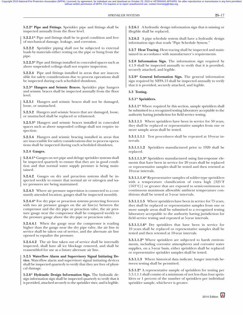
25–17SPRINKLER SYSTEMS
Copyright 2015 National Fire Protection Association (NFPA). Licensed, by agreement, for individual use and download on October 23, 2015 to VETERANS AFFAIRS. No other reproduction or transmission in any form permittedwithout written permission of NFPA. For inquires or to report unauthorized use, contact [email protected].
87
5.2.2* Pipe and Fittings. Sprinkler pipe and fittings shall beinspected annually from the floor level.
5.2.2.1* Pipe and fittings shall be in good condition and freeof mechanical damage, leakage, and corrosion.
5.2.2.2 Sprinkler piping shall not be subjected to externalloads by materials either resting on the pipe or hung from thepipe.
5.2.2.3* Pipe and fittings installed in concealed spaces such asabove suspended ceilings shall not require inspection.
5.2.2.4 Pipe and fittings installed in areas that are inacces-sible for safety considerations due to process operations shallbe inspected during each scheduled shutdown.
5.2.3* Hangers and Seismic Braces. Sprinkler pipe hangersand seismic braces shall be inspected annually from the floorlevel.
5.2.3.1 Hangers and seismic braces shall not be damaged,loose, or unattached.
5.2.3.2 Hangers and seismic braces that are damaged, loose,or unattached shall be replaced or refastened.
5.2.3.3* Hangers and seismic braces installed in concealedspaces such as above suspended ceilings shall not require in-spection.
5.2.3.4 Hangers and seismic bracing installed in areas thatare inaccessible for safety considerations due to process opera-tions shall be inspected during each scheduled shutdown.
5.2.4 Gauges.
5.2.4.1* Gauges on wet pipe and deluge sprinkler systems shallbe inspected quarterly to ensure that they are in good condi-tion and that normal water supply pressure is being main-tained.
5.2.4.2 Gauges on dry and preaction systems shall be in-spected weekly to ensure that normal air or nitrogen and wa-ter pressures are being maintained.
5.2.4.3 Where air pressure supervision is connected to a con-stantly attended location, gauges shall be inspected monthly.
5.2.4.4* For dry pipe or preaction systems protecting freezerswith two air pressure gauges on the air line(s) between thecompressor and the dry pipe or preaction valve, the air pres-sure gauge near the compressor shall be compared weekly tothe pressure gauge above the dry pipe or preaction valve.
5.2.4.4.1 When the gauge near the compressor is readinghigher than the gauge near the dry pipe valve, the air line inservice shall be taken out of service, and the alternate air lineopened to equalize the pressure.
5.2.4.4.2 The air line taken out of service shall be internallyinspected, shall have all ice blockage removed, and shall bereassembled for use as a future alternate air line.
5.2.5 Waterflow Alarm and Supervisory Signal Initiating De-vice. Waterflow alarm and supervisory signal initiating devicesshall be inspected quarterly to verify that they are free of physi-cal damage.
5.2.6* Hydraulic Design Information Sign. The hydraulic de-sign information sign shall be inspected quarterly to verify that itis provided, attached securely to the sprinkler riser, and is legible.
{3e0bff22-698c-46e7-
5.2.6.1 A hydraulic design information sign that is missing orillegible shall be replaced.
5.2.6.2 A pipe schedule system shall have a hydraulic designinformation sign that reads “Pipe Schedule System.”
5.2.7 Heat Tracing. Heat tracing shall be inspected and main-tained in accordance with manufacturer’s requirements.
5.2.8 Information Sign. The information sign required by4.1.9 shall be inspected annually to verify that it is provided,securely attached, and legible.
5.2.9* General Information Sign. The general informationsign required by NFPA 13 shall be inspected annually to verifythat it is provided, securely attached, and legible.
5.3 Testing.
5.3.1* Sprinklers.
5.3.1.1* Where required by this section, sample sprinklers shallbe submitted to a recognized testing laboratory acceptable to theauthority having jurisdiction for field service testing.
5.3.1.1.1 Where sprinklers have been in service for 50 years,they shall be replaced or representative samples from one ormore sample areas shall be tested.
5.3.1.1.1.1 Test procedures shall be repeated at 10-year in-tervals.
5.3.1.1.1.2 Sprinklers manufactured prior to 1920 shall bereplaced.
5.3.1.1.1.3* Sprinklers manufactured using fast-response ele-ments that have been in service for 20 years shall be replacedor representative samples shall be tested and then retested at10-year intervals.
5.3.1.1.1.4* Representative samples of solder-type sprinklerswith a temperature classification of extra high [325°F(163°C)] or greater that are exposed to semicontinuous tocontinuous maximum allowable ambient temperature con-ditions shall be tested at 5-year intervals.
5.3.1.1.1.5 Where sprinklers have been in service for 75 years,they shall be replaced or representative samples from one ormore sample areas shall be submitted to a recognized testinglaboratory acceptable to the authority having jurisdiction forfield service testing and repeated at 5-year intervals.
5.3.1.1.1.6* Dry sprinklers that have been in service for10 years shall be replaced or representative samples shall betested and then retested at 10-year intervals.
5.3.1.1.2* Where sprinklers are subjected to harsh environ-ments, including corrosive atmospheres and corrosive watersupplies, on a 5-year basis, either sprinklers shall be replacedor representative sprinkler samples shall be tested.
5.3.1.1.3 Where historical data indicate, longer intervals be-tween testing shall be permitted.
5.3.1.2* A representative sample of sprinklers for testing per5.3.1.1.1 shall consist of a minimum of not less than four sprin-klers or 1 percent of the number of sprinklers per individualsprinkler sample, whichever is greater.
db-eba3b3d7337a}
2014 Edition

25–18 INSPECTION, TESTING, AND MAINTENANCE OF WATER-BASED FIRE PROTECTION SYSTEMS
•
Copyright 2015 National Fire Protection Association (NFPA). Licensed, by agreement, for individual use and download on October 23, 2015 to VETERANS AFFAIRS. No other reproduction or transmission in any form permittedwithout written permission of NFPA. For inquires or to report unauthorized use, contact [email protected].
-8
5.3.1.3 Where one sprinkler within a representative samplefails to meet the test requirement, all sprinklers within thearea represented by that sample shall be replaced.
5.3.1.3.1 Manufacturers shall be permitted to make modifica-tions to their own sprinklers in the field with listed devices thatrestore the original performance as intended by the listing,where acceptable to the authority having jurisdiction.
5.3.2* Gauges.
5.3.2.1 Gauges shall be replaced every 5 years or tested every5 years by comparison with a calibrated gauge.
5.3.2.2 Gauges not accurate to within 3 percent of the fullscale shall be recalibrated or replaced.
5.3.2.3 Where multiple system risers are supplied by a com-mon water supply source with gauges located at the same el-evation, and the gauges for all systems read within 3 percent ofthe other(s), only one gauge shall be required to be tested todetermine if replacement is required.
5.3.3 Waterflow Alarm Devices.
5.3.3.1 Mechanical waterflow alarm devices including, butnot limited to, water motor gongs, shall be tested quarterly.
5.3.3.2* Vane-type and pressure switch–type waterflow alarmdevices shall be tested semiannually.
5.3.3.3 Testing waterflow alarm devices on wet pipe systemsshall be accomplished by opening the inspector’s test con-nection.
5.3.3.3.1 Where freezing weather conditions or other circum-stances prohibit use of the inspector’s test connection, the bypassconnection shall be permitted to be used.
5.3.3.4 Fire pumps shall not be taken out of service duringtesting unless constantly attended by qualified personnel or allimpairment procedures contained in Chapter 15 are followed.
5.3.3.5* Testing waterflow alarm devices on dry pipe, preac-tion, or deluge systems shall be accomplished by using thebypass connection.
5.3.4* Antifreeze Systems. Annually, before the onset of freez-ing weather, the antifreeze solution shall be tested using thefollowing procedure:
(1) Using installation records, maintenance records, infor-mation from the owner, chemical tests, or other reliablesources of information, the type of antifreeze in the sys-tem shall be determined.(a) If the type of antifreeze is found to be a type that is no
longer permitted, the system shall be drained com-pletely and replaced with an acceptable solution.
(b) If the type of antifreeze cannot be reliably deter-mined, the system shall be drained completely andreplaced with an acceptable solution.
(2) If the antifreeze is not replaced in accordance with step 1,test samples shall be taken at the top of each system and atthe bottom of each system.(a) If the most remote portion of the system is not near
the top or the bottom of the system, an additionalsample shall be taken at the most remote portion.
{3e0bff22-698c-46e7
2014 Edition
(b) If the connection to the water supply piping is notnear the top or the bottom of the system, an addi-tional sample shall be taken at the connection to thewater supply.
(3) The specific gravity of each solution shall be checked us-ing a hydrometer with a suitable scale or a refractometerhaving a scale calibrated for the antifreeze solution.
(4) If any of the samples exhibits a concentration in excess ofwhat is permitted by NFPA 25, the system shall be emptiedand refilled with a new acceptable solution. If a concen-tration greater than what is currently permitted byNFPA 25 was necessary to keep the fluid from freezing,alternate methods of preventing the pipe from freezingshall be employed.
(5) If any of the samples exhibits a concentration lower thanwhat is necessary to keep the fluid from freezing, the sys-tem shall be emptied and refilled with a new acceptablesolution.
5.3.4.1 The use of antifreeze solutions shall be in conformitywith state and local health regulations.
5.3.4.1.1* Listed CPVC sprinkler pipe and fittings shall be pro-tected from freezing with glycerine only.
5.3.4.1.1.1 The use of diethylene, ethylene, or propylene gly-cols shall be specifically prohibited.
5.3.4.2 Except as permitted by 5.3.4.2.1 and 5.3.4.2.2, all an-tifreeze systems shall utilize listed antifreeze solutions.
5.3.4.2.1* For systems installed prior to September 30, 2012,listed antifreeze solutions shall not be required until Septem-ber 30, 2022, where all of the following conditions are met:
(1)*The concentration of the antifreeze solution shall be lim-ited to 50 percent glycerine by volume or 40 percent pro-pylene glycol by volume.
(2) Newly introduced solutions shall be factory premixed an-tifreeze solutions (chemically pure or United States Phar-macopeia 96.5 percent).
(3)*Antifreeze systems with concentrations in excess of30 percent propylene glycol and 38 percent glycerineshall be permitted based upon an approved deterministicrisk assessment prepared by a qualified person approvedby the authority having jurisdiction.
5.3.4.2.2 Premixed antifreeze solutions of propylene glycolexceeding 30 percent concentration by volume shall be per-mitted for use with ESFR sprinklers where the ESFR sprinklersare listed for such use in a specific application.
5.3.4.3 The antifreeze solution shall be tested at its most re-mote portion and where it interfaces with the wet pipe system.
5.3.4.4 When antifreeze systems have a capacity larger than150 gal (568 L), tests at one additional point for every 100 gal(379 L) shall be made.
5.3.4.4.1 If the results indicate an incorrect freeze point atany point in the system, the system shall be drained and re-filled with new premixed antifreeze.
5.3.4.4.2 For premixed solutions, the manufacturer’s instruc-tions shall be permitted to be used with regard to the number
7db-eba3b3d7337a}
of test points and refill procedure.

25–19SPRINKLER SYSTEMS
•
•
•
Copyright 2015 National Fire Protection Association (NFPA). Licensed, by agreement, for individual use and download on October 23, 2015 to VETERANS AFFAIRS. No other reproduction or transmission in any form permittedwithout written permission of NFPA. For inquires or to report unauthorized use, contact [email protected].
87
5.4 Maintenance.
5.4.1 Sprinklers.
5.4.1.1 Where a sprinkler has been removed for any reason, itshall not be reinstalled.
5.4.1.2* Replacement sprinklers shall have the proper charac-teristics for the application intended, which include the fol-lowing:
(1) Style(2) Orifice size and K-factor(3) Temperature rating(4) Coating, if any(5) Deflector type (e.g., upright, pendent, sidewall)(6) Design requirements
5.4.1.2.1* Spray sprinklers shall be permitted to replace old-style sprinklers.
5.4.1.2.2 Replacement sprinklers for piers and wharves shallcomply with NFPA 307, Standard for the Construction and FireProtection of Marine Terminals, Piers, and Wharves.
5.4.1.3 Only new, listed sprinklers shall be used to replaceexisting sprinklers.
5.4.1.4* Special and quick-response sprinklers as defined byNFPA 13, Standard for the Installation of Sprinkler Systems, shall bereplaced with sprinklers of the same orifice, size, temperaturerange and thermal response characteristics, and K-factor.
5.4.1.5* A supply of at least six spare sprinklers shall be main-tained on the premises so that any sprinklers that have oper-ated or been damaged in any way can be promptly replaced.
5.4.1.5.1 The sprinklers shall correspond to the types andtemperature ratings of the sprinklers in the property.
5.4.1.5.2 The sprinklers shall be kept in a cabinet locatedwhere the temperature in which they are subjected will at notime exceed 100°F (38°C).
5.4.1.5.3 Where dry sprinklers of different lengths are in-stalled, spare dry sprinklers shall not be required, providedthat a means of returning the system to service is furnished.
5.4.1.5.4 The stock of spare sprinklers shall include all typesand ratings installed and shall be as follows:
(1) For protected facilities having under 300 sprinklers — nofewer than 6 sprinklers
(2) For protected facilities having 300 to 1000 sprinklers —no fewer than 12 sprinklers
(3) For protected facilities having over 1000 sprinklers — nofewer than 24 sprinklers
5.4.1.5.5* One sprinkler wrench as specified by the sprinklermanufacturer shall be provided in the cabinet for each type ofsprinkler installed to be used for the removal and installationof sprinklers in the system.
5.4.1.5.6 A list of the sprinklers installed in the property shallbe posted in the sprinkler cabinet.
5.4.1.5.6.1* The list shall include the following:
(1) Sprinkler identification number (SIN) if equipped; or themanufacturer, model, orifice, deflector type, thermal sen-sitivity, and pressure rating
{3e0bff22-698c-46e7-
(2) General description(3) Quantity of each type to be contained in the cabinet(4) Issue or revision date of the list
5.4.1.6* Sprinklers shall not be altered in any respect or haveany type of ornamentation, paint, or coatings applied aftershipment from the place of manufacture.
5.4.1.7 Sprinklers and automatic spray nozzles used for pro-tecting commercial-type cooking equipment and ventilatingsystems shall be replaced annually.
5.4.1.7.1 Where automatic bulb-type sprinklers or spraynozzles are used and annual examination shows no buildup ofgrease or other material on the sprinklers or spray nozzles,such sprinklers and spray nozzles shall not be required to bereplaced.
5.4.1.8 Protective Coverings.
5.4.1.8.1* Sprinklers protecting spray areas and mixing roomsin resin application areas installed with protective coveringsshall continue to be protected against overspray residue sothat they will operate in the event of fire.
5.4.1.8.2 Sprinklers installed as described in 5.4.1.8.1 shall beprotected using cellophane bags having a thickness of0.003 in. (0.076 mm) or less or thin paper bags.
5.4.1.8.3 Coverings shall be replaced periodically so thatheavy deposits of residue do not accumulate.
5.4.2* Dry Pipe Systems. Dry pipe systems shall be kept dry atall times.
5.4.2.1 During nonfreezing weather, a dry pipe system shallbe permitted to be left wet if the only other option is to removethe system from service while waiting for parts or during repairactivities.
5.4.2.2 Refrigerated spaces or other areas within the buildinginterior where temperatures are maintained at or below 40°F(4.0°C) shall not be permitted to be left wet.
5.4.2.3 Air driers shall be maintained in accordance with themanufacturer’s instructions.
5.4.2.4 Compressors used in conjunction with dry pipe sprin-kler systems shall be maintained in accordance with the manu-facturer’s instructions.
5.4.3* Marine Systems. Sprinkler systems that are normallymaintained using fresh water as a source shall be drained andrefilled, then drained and refilled again with fresh water fol-lowing the introduction of raw water into the system.
5.5 Component Action Requirements.
5.5.1 Whenever a component in a sprinkler system is ad-justed, repaired, reconditioned, or replaced, the actions re-quired in Table 5.5.1 shall be performed.
5.5.2 Where the original installation standard is differentfrom the cited standard, the use of the appropriate installingstandard shall be permitted.
5.5.3 These actions shall not require a design review, which isoutside the scope of this standard.
db-eba3b3d7337a}
2014 Edition
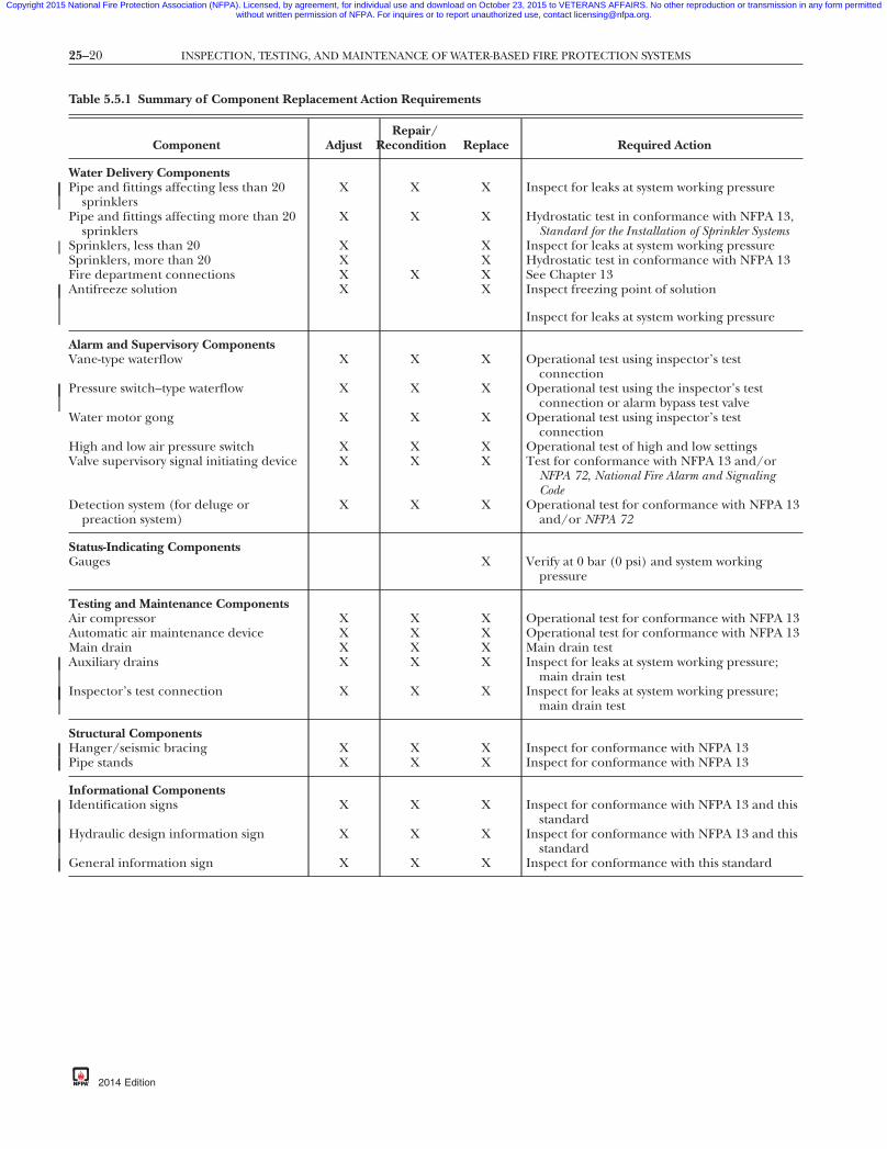
25–20 INSPECTION, TESTING, AND MAINTENANCE OF WATER-BASED FIRE PROTECTION SYSTEMS
Copyright 2015 National Fire Protection Association (NFPA). Licensed, by agreement, for individual use and download on October 23, 2015 to VETERANS AFFAIRS. No other reproduction or transmission in any form permittedwithout written permission of NFPA. For inquires or to report unauthorized use, contact [email protected].
Table 5.5.1 Summary of Component Replacement Action Req
Component AdjustRepa
Recond
Water Delivery ComponentsPipe and fittings affecting less than 20
sprinklersX X
Pipe and fittings affecting more than 20sprinklers
X X
Sprinklers, less than 20 XSprinklers, more than 20 XFire department connections X XAntifreeze solution X
Alarm and Supervisory ComponentsVane-type waterflow X X
Pressure switch–type waterflow X X
Water motor gong X X
High and low air pressure switch X XValve supervisory signal initiating device X X
Detection system (for deluge orpreaction system)
X X
Status-Indicating ComponentsGauges
Testing and Maintenance ComponentsAir compressor X XAutomatic air maintenance device X XMain drain X XAuxiliary drains X X
Inspector’s test connection X X
Structural ComponentsHanger/seismic bracing X XPipe stands X X
Informational ComponentsIdentification signs X X
Hydraulic design information sign X X
General information sign X X
{3e0bff22-698c-46e7
uirements
ir/ition Replace Required Action
X Inspect for leaks at system working pressure
X Hydrostatic test in conformance with NFPA 13,Standard for the Installation of Sprinkler Systems
X Inspect for leaks at system working pressureX Hydrostatic test in conformance with NFPA 13X See Chapter 13X Inspect freezing point of solution
Inspect for leaks at system working pressure
X Operational test using inspector’s testconnection
X Operational test using the inspector’s testconnection or alarm bypass test valve
X Operational test using inspector’s testconnection
X Operational test of high and low settingsX Test for conformance with NFPA 13 and/or
NFPA 72, National Fire Alarm and SignalingCode
X Operational test for conformance with NFPA 13and/or NFPA 72
X Verify at 0 bar (0 psi) and system workingpressure
X Operational test for conformance with NFPA 13X Operational test for conformance with NFPA 13X Main drain testX Inspect for leaks at system working pressure;
main drain testX Inspect for leaks at system working pressure;
main drain test
X Inspect for conformance with NFPA 13X Inspect for conformance with NFPA 13
X Inspect for conformance with NFPA 13 and thisstandard
X Inspect for conformance with NFPA 13 and thisstandard
X Inspect for conformance with this standard
-87db-eba3b3d7337a}
2014 Edition
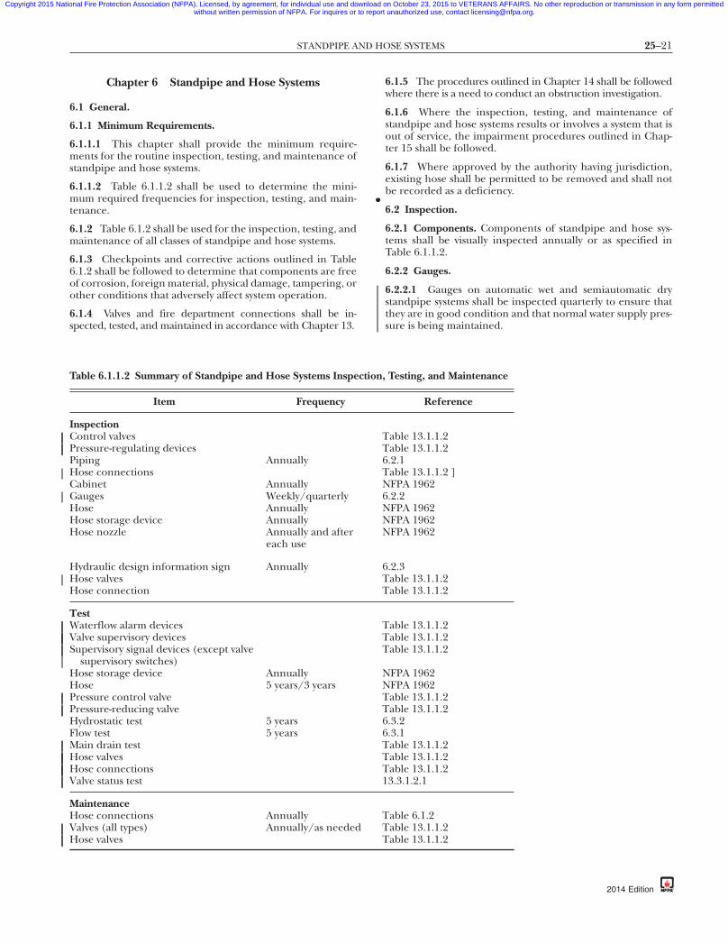
25–21STANDPIPE AND HOSE SYSTEMS
•
Copyright 2015 National Fire Protection Association (NFPA). Licensed, by agreement, for individual use and download on October 23, 2015 to VETERANS AFFAIRS. No other reproduction or transmission in any form permittedwithout written permission of NFPA. For inquires or to report unauthorized use, contact [email protected].
Chapter 6 Standpipe and Hose Systems
6.1 General.
6.1.1 Minimum Requirements.
6.1.1.1 This chapter shall provide the minimum require-ments for the routine inspection, testing, and maintenance ofstandpipe and hose systems.
6.1.1.2 Table 6.1.1.2 shall be used to determine the mini-mum required frequencies for inspection, testing, and main-tenance.
6.1.2 Table 6.1.2 shall be used for the inspection, testing, andmaintenance of all classes of standpipe and hose systems.
6.1.3 Checkpoints and corrective actions outlined in Table6.1.2 shall be followed to determine that components are freeof corrosion, foreign material, physical damage, tampering, orother conditions that adversely affect system operation.
6.1.4 Valves and fire department connections shall be in-spected, tested, and maintained in accordance with Chapter 13.
Table 6.1.1.2 Summary of Standpipe and Hose Systems Inspe
Item Frequency
InspectionControl valvesPressure-regulating devicesPiping AnnuallyHose connectionsCabinet AnnuallyGauges Weekly/quarterlyHose AnnuallyHose storage device AnnuallyHose nozzle Annually and after
each use
Hydraulic design information sign AnnuallyHose valvesHose connection
TestWaterflow alarm devicesValve supervisory devicesSupervisory signal devices (except valve
supervisory switches)Hose storage device AnnuallyHose 5 years/3 yearsPressure control valvePressure-reducing valveHydrostatic test 5 yearsFlow test 5 yearsMain drain testHose valvesHose connectionsValve status test
MaintenanceHose connections AnnuallyValves (all types) Annually/as neededHose valves
{3e0bff22-698c-46e7-
6.1.5 The procedures outlined in Chapter 14 shall be followedwhere there is a need to conduct an obstruction investigation.
6.1.6 Where the inspection, testing, and maintenance ofstandpipe and hose systems results or involves a system that isout of service, the impairment procedures outlined in Chap-ter 15 shall be followed.
6.1.7 Where approved by the authority having jurisdiction,existing hose shall be permitted to be removed and shall notbe recorded as a deficiency.
6.2 Inspection.
6.2.1 Components. Components of standpipe and hose sys-tems shall be visually inspected annually or as specified inTable 6.1.1.2.
6.2.2 Gauges.
6.2.2.1 Gauges on automatic wet and semiautomatic drystandpipe systems shall be inspected quarterly to ensure thatthey are in good condition and that normal water supply pres-sure is being maintained.
Testing, and Maintenance
Reference
able 13.1.1.2able 13.1.1.2.2.1able 13.1.1.2 ]FPA 1962.2.2FPA 1962FPA 1962FPA 1962
.2.3able 13.1.1.2able 13.1.1.2
able 13.1.1.2able 13.1.1.2able 13.1.1.2
FPA 1962FPA 1962able 13.1.1.2able 13.1.1.2.3.2.3.1able 13.1.1.2able 13.1.1.2able 13.1.1.23.3.1.2.1
able 6.1.2able 13.1.1.2able 13.1.1.2
db-eba3b3d7337a}
ction,
TT6TN6NNN
6TT
TTT
NNTT66TTT1
TTT
87
2014 Edition

25–22 INSPECTION, TESTING, AND MAINTENANCE OF WATER-BASED FIRE PROTECTION SYSTEMS
Copyright 2015 National Fire Protection Association (NFPA). Licensed, by agreement, for individual use and download on October 23, 2015 to VETERANS AFFAIRS. No other reproduction or transmission in any form permittedwithout written permission of NFPA. For inquires or to report unauthorized use, contact [email protected].
Table 6.1.2 Standpipe and Hose Systems
Component/Checkpoint
Hose ConnectionsCap missingFire hose connection damagedValve handles missingCap gaskets missing or deterioratedValve leakingVisible obstructionsRestricting device missingManual, semiautomatic, or dry standpipe — valve does not
operate smoothly
PipingDamaged pipingControl valves damagedMissing or damaged pipe support deviceDamaged supervisory signal initiating device
HoseInspect
Mildew, cuts, abrasions, and deterioration evidentCoupling damagedGaskets missing or deterioratedIncompatible threads on couplingHose not connected to hose rack nipple or valveHose test outdated
Hose NozzleHose nozzle missingGasket missing or deterioratedObstructionsNozzle does not operate smoothly
Hose Storage DeviceDifficult to operateDamagedObstructionHose improperly racked or rolledNozzle clip in place and nozzle correctly contained?If enclosed in cabinet, will hose rack swing out at least 90
degrees?
CabinetInspect overall condition for corroded or damaged partsDifficult to openCabinet door will not open fullyDoor glazing cracked or brokenIf cabinet is break-glass type, is lock functioning properly?Glass break device missing or not attachedNot properly identified as containing fire equipmentVisible obstructionsAll valves, hose, nozzles, fire extinguisher, etc., easily
accessible
{3e0bff22-698c-46e7
Corrective Action
ReplaceRepairReplaceReplaceClose or repairRemoveReplaceLubricate or repair
RepairRepair or replaceRepair or replaceRepair or replace
Remove and inspect the hose, including gaskets, and rerack orrereel at intervals in accordance with NFPA 1962, Standard forthe Care, Use, Inspection, Service Testing, and Replacement of FireHose, Couplings, Nozzles, and Fire Hose Appliances
Replace with listed lined, jacketed hoseReplace or repairReplaceReplace or provide thread adapterConnectRetest or replace in accordance with NFPA 1962
Replace with listed nozzleReplaceRemoveRepair or replace
Repair or replaceRepair or replaceRemoveRemoveReplace if necessaryRepair or remove any obstructions
Repair or replace parts; replace entire cabinet if necessaryRepairRepair or move obstructionsReplaceRepair or replaceReplace or attachProvide identificationRemoveRemove any material not related
-87db-eba3b3d7337a}
2014 Edition

25–23STANDPIPE AND HOSE SYSTEMS
•
•
Copyright 2015 National Fire Protection Association (NFPA). Licensed, by agreement, for individual use and download on October 23, 2015 to VETERANS AFFAIRS. No other reproduction or transmission in any form permittedwithout written permission of NFPA. For inquires or to report unauthorized use, contact [email protected].
87
6.2.2.2 Gauges on automatic dry standpipe systems shall beinspected weekly to ensure that normal air or nitrogen andwater pressure are being maintained.
6.2.2.3 Where air pressure supervision is connected to a con-stantly attended location, gauges shall be inspected monthly.
6.2.3* Hydraulic Design Information Sign. The hydraulic de-sign information sign for standpipe systems shall be inspectedannually to verify that it is provided, attached securely, andlegible.
6.2.3.1 A hydraulic design information sign that is missing orillegible shall be replaced.
6.2.3.2 A standpipe system that was not sized by hydraulicdesign shall have a hydraulic design information sign thatreads “Pipe Schedule System.”
6.3 Testing. Where water damage is a possibility, an air testshall be conducted on the system at 25 psi (1.7 bar) prior tointroducing water to the system.
6.3.1 Flow Tests.
6.3.1.1* A flow test shall be conducted every 5 years on all ClassI and Class III standpipe systems to verify that the requiredflow and pressure are available at the hydraulically most re-mote hose valve outlet(s) while flowing the standpipe systemdemand.
6.3.1.1.1 Where a flow test of the hydraulically most remoteoutlet(s) is not practical, the authority having jurisdictionshall be consulted for the appropriate location for the test.
6.3.1.2* The standpipe system demand shall include 500 gpm(1892 L/min) for the first standpipe and 250 gpm (946 L/min)for each additional standpipe until the total system demand issimultaneously flowing.
6.3.1.2.1* The 250 gpm (946 L/min) required from each ad-ditional standpipe shall be allowed to be flowed from the mostconvenient hose valve on that standpipe.
6.3.1.2.2* Where the 250 gpm (946 L/min) cannot be flowedfrom each additional standpipe, the authority having jurisdic-tion shall determine where the additional flow can be taken.
6.3.1.3 The standpipe system demand shall be based on thedesign criteria in effect at the time of the installation.
6.3.1.3.1 Where the standpipe system demand cannot be de-termined, the authority having jurisdiction shall determinethe standpipe system demand.
6.3.1.3.2 The actual test method(s) and performance criteriashall be discussed in advance with the authority having juris-diction.
6.3.1.4 Standpipes, sprinkler connections to standpipes, orhose stations equipped with pressure-reducing valves orpressure-regulating valves shall have these valves inspected,tested, and maintained in accordance with the requirementsof Chapter 13.
6.3.1.5 A main drain test shall be performed on all standpipesystems with automatic water supplies in accordance with therequirements of Chapter 13.
{3e0bff22-698c-46e7-
6.3.1.5.1 The test shall be performed at the low point drainfor each standpipe or the main drain test connection wherethe supply main enters the building (when provided).
6.3.1.5.2 Pressure gauges shall be provided for the test andshall be maintained in accordance with 5.3.2.
6.3.2 Hydrostatic Tests.
6.3.2.1* Hydrostatic tests of not less than 200 psi (13.8 bar)pressure for 2 hours, or at 50 psi (3.4 bar) in excess of themaximum pressure, where maximum pressure is in excess of150 psi (10.3 bar), shall be conducted every 5 years on manualstandpipe systems and semiautomatic dry standpipe systems,including piping in the fire department connection.
6.3.2.1.1 Manual wet standpipes that are part of a combinedsprinkler/standpipe system shall not be required to be testedin accordance with 6.3.2.1.
6.3.2.2 The hydrostatic test pressure shall be measured at thelow elevation point of the individual system or zone beingtested.
6.3.2.2.1 The inside standpipe piping shall show no leakage.
6.3.3 Waterflow Alarm and Supervisory Alarm Devices.
6.3.3.1 Where provided, waterflow alarm and supervisoryalarm devices shall be tested in accordance with 13.2.6 and13.3.3.5.
6.3.3.2 Where freezing conditions necessitate a delay in test-ing, tests shall be performed as soon as weather allows.
6.3.4* Gauges.
6.3.4.1 Gauges shall be replaced every 5 years or tested every5 years by comparison with a calibrated gauge.
6.3.4.2 Gauges not accurate to within 3 percent of the fullscale shall be recalibrated or replaced.
6.4 Maintenance.
6.4.1 Maintenance and repairs shall be in accordance with6.1.3 and Table 6.1.2.
6.4.2 Equipment that does not pass the inspection or testingrequirements shall be repaired and tested again or replaced.
6.5 Component Action Requirements.
6.5.1 Whenever components in standpipe and hose systemsare adjusted, repaired, reconditioned, or replaced, the actionsrequired in Table 6.5.1 shall be performed.
6.5.2 Where the original installation standard is differentfrom the cited standard, the use of the appropriate installingstandard shall be permitted.
6.5.3 These actions shall not require a design review, which isoutside the scope of this standard.
db-eba3b3d7337a}
2014 Edition
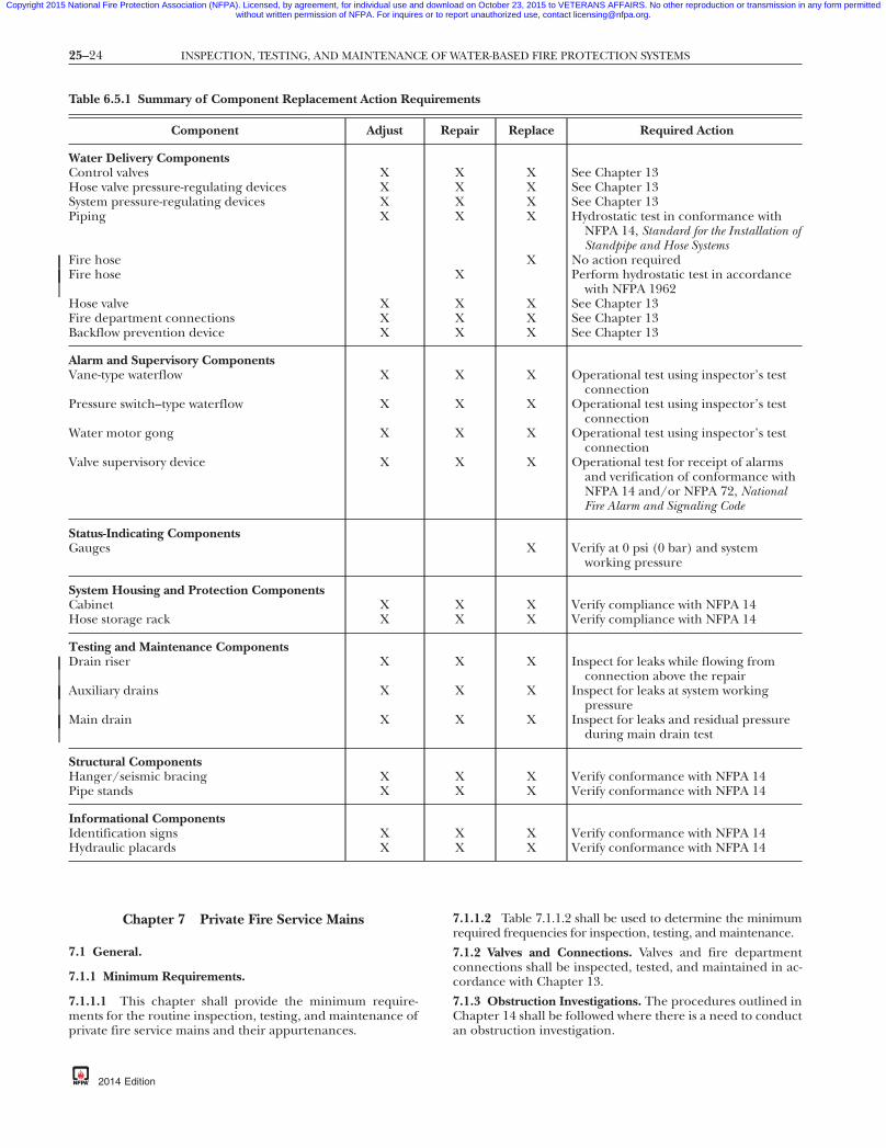
25–24 INSPECTION, TESTING, AND MAINTENANCE OF WATER-BASED FIRE PROTECTION SYSTEMS
Copyright 2015 National Fire Protection Association (NFPA). Licensed, by agreement, for individual use and download on October 23, 2015 to VETERANS AFFAIRS. No other reproduction or transmission in any form permittedwithout written permission of NFPA. For inquires or to report unauthorized use, contact [email protected].
Chapter 7 Private Fire Service Mains
7.1 General.
7.1.1 Minimum Requirements.
7.1.1.1 This chapter shall provide the minimum require-ments for the routine inspection, testing, and maintenance ofprivate fire service mains and their appurtenances.
Table 6.5.1 Summary of Component Replacement Action Req
Component Adjust
Water Delivery ComponentsControl valves XHose valve pressure-regulating devices XSystem pressure-regulating devices XPiping X
Fire hoseFire hose
Hose valve XFire department connections XBackflow prevention device X
Alarm and Supervisory ComponentsVane-type waterflow X
Pressure switch–type waterflow X
Water motor gong X
Valve supervisory device X
Status-Indicating ComponentsGauges
System Housing and Protection ComponentsCabinet XHose storage rack X
Testing and Maintenance ComponentsDrain riser X
Auxiliary drains X
Main drain X
Structural ComponentsHanger/seismic bracing XPipe stands X
Informational ComponentsIdentification signs XHydraulic placards X
{3e0bff22-698c-46e7
2014 Edition
7.1.1.2 Table 7.1.1.2 shall be used to determine the minimumrequired frequencies for inspection, testing, and maintenance.
7.1.2 Valves and Connections. Valves and fire departmentconnections shall be inspected, tested, and maintained in ac-cordance with Chapter 13.
7.1.3 Obstruction Investigations. The procedures outlined inChapter 14 shall be followed where there is a need to conductan obstruction investigation.
ents
pair Replace Required Action
X X See Chapter 13X X See Chapter 13X X See Chapter 13X X Hydrostatic test in conformance with
NFPA 14, Standard for the Installation ofStandpipe and Hose Systems
X No action requiredX Perform hydrostatic test in accordance
with NFPA 1962X X See Chapter 13X X See Chapter 13X X See Chapter 13
X X Operational test using inspector’s testconnection
X X Operational test using inspector’s testconnection
X X Operational test using inspector’s testconnection
X X Operational test for receipt of alarmsand verification of conformance withNFPA 14 and/or NFPA 72, NationalFire Alarm and Signaling Code
X Verify at 0 psi (0 bar) and systemworking pressure
X X Verify compliance with NFPA 14X X Verify compliance with NFPA 14
X X Inspect for leaks while flowing fromconnection above the repair
X X Inspect for leaks at system workingpressure
X X Inspect for leaks and residual pressureduring main drain test
X X Verify conformance with NFPA 14X X Verify conformance with NFPA 14
X X Verify conformance with NFPA 14X X Verify conformance with NFPA 14
7db-eba3b3d7337a}
uirem
Re
-8
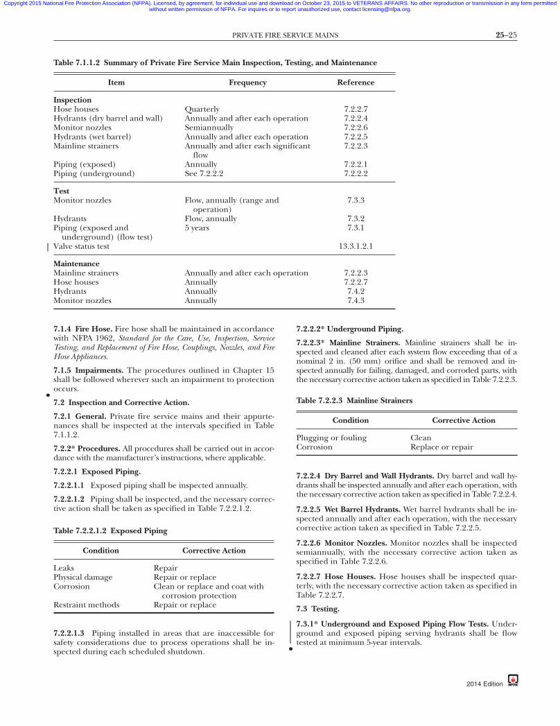
25–25PRIVATE FIRE SERVICE MAINS
•
•
Copyright 2015 National Fire Protection Association (NFPA). Licensed, by agreement, for individual use and download on October 23, 2015 to VETERANS AFFAIRS. No other reproduction or transmission in any form permittedwithout written permission of NFPA. For inquires or to report unauthorized use, contact [email protected].
87
7.1.4 Fire Hose. Fire hose shall be maintained in accordancewith NFPA 1962, Standard for the Care, Use, Inspection, ServiceTesting, and Replacement of Fire Hose, Couplings, Nozzles, and FireHose Appliances.
7.1.5 Impairments. The procedures outlined in Chapter 15shall be followed wherever such an impairment to protectionoccurs.
7.2 Inspection and Corrective Action.
7.2.1 General. Private fire service mains and their appurte-nances shall be inspected at the intervals specified in Table7.1.1.2.
7.2.2* Procedures. All procedures shall be carried out in accor-dance with the manufacturer’s instructions, where applicable.
7.2.2.1 Exposed Piping.
7.2.2.1.1 Exposed piping shall be inspected annually.
7.2.2.1.2 Piping shall be inspected, and the necessary correc-tive action shall be taken as specified in Table 7.2.2.1.2.
7.2.2.1.3 Piping installed in areas that are inaccessible forsafety considerations due to process operations shall be in-spected during each scheduled shutdown.
Table 7.1.1.2 Summary of Private Fire Service Main Inspectio
Item Frequency
InspectionHose houses QuarterlyHydrants (dry barrel and wall) Annually and after each oMonitor nozzles SemiannuallyHydrants (wet barrel) Annually and after each oMainline strainers Annually and after each s
flowPiping (exposed) AnnuallyPiping (underground) See 7.2.2.2
TestMonitor nozzles Flow, annually (range and
operation)Hydrants Flow, annuallyPiping (exposed and
underground) (flow test)5 years
Valve status test
MaintenanceMainline strainers Annually and after each oHose houses AnnuallyHydrants AnnuallyMonitor nozzles Annually
Table 7.2.2.1.2 Exposed Piping
Condition Corrective Action
Leaks RepairPhysical damage Repair or replaceCorrosion Clean or replace and coat with
corrosion protectionRestraint methods Repair or replace
{3e0bff22-698c-46e7-
7.2.2.2* Underground Piping.
7.2.2.3* Mainline Strainers. Mainline strainers shall be in-spected and cleaned after each system flow exceeding that of anominal 2 in. (50 mm) orifice and shall be removed and in-spected annually for failing, damaged, and corroded parts, withthe necessary corrective action taken as specified in Table 7.2.2.3.
7.2.2.4 Dry Barrel and Wall Hydrants. Dry barrel and wall hy-drants shall be inspected annually and after each operation, withthe necessary corrective action taken as specified in Table 7.2.2.4.
7.2.2.5 Wet Barrel Hydrants. Wet barrel hydrants shall be in-spected annually and after each operation, with the necessarycorrective action taken as specified in Table 7.2.2.5.
7.2.2.6 Monitor Nozzles. Monitor nozzles shall be inspectedsemiannually, with the necessary corrective action taken asspecified in Table 7.2.2.6.
7.2.2.7 Hose Houses. Hose houses shall be inspected quar-terly, with the necessary corrective action taken as specified inTable 7.2.2.7.
7.3 Testing.
7.3.1* Underground and Exposed Piping Flow Tests. Under-ground and exposed piping serving hydrants shall be flowtested at minimum 5-year intervals.
ting, and Maintenance
Reference
7.2.2.7ion 7.2.2.4
7.2.2.6ion 7.2.2.5ant 7.2.2.3
7.2.2.17.2.2.2
7.3.3
7.3.27.3.1
13.3.1.2.1
ion 7.2.2.37.2.2.77.4.27.4.3
Table 7.2.2.3 Mainline Strainers
Condition Corrective Action
Plugging or fouling CleanCorrosion Replace or repair
db-eba3b3d7337a}
n, Tes
perat
peratignific
perat
2014 Edition

25–26 INSPECTION, TESTING, AND MAINTENANCE OF WATER-BASED FIRE PROTECTION SYSTEMS
•
Copyright 2015 National Fire Protection Association (NFPA). Licensed, by agreement, for individual use and download on October 23, 2015 to VETERANS AFFAIRS. No other reproduction or transmission in any form permittedwithout written permission of NFPA. For inquires or to report unauthorized use, contact [email protected].
-8
Table 7.2.2.4 Dry Barrel and Wall Hydrants
Condition Corrective Action
Inaccessible Make accessibleBarrel contains water or ice
(presence of water or icecould indicate a faultydrain, a leaky hydrantvalve, or highgroundwater table)
Repair and drain; for highgroundwater it could benecessary to plug the drainand pump out the barrelafter each use
Improper drainage frombarrel
Repair drain
Leaks in outlets or at top ofhydrant
Repair or replace gaskets,packing, or parts as necessary
Cracks in hydrant barrel Repair or replaceTightness of outlet caps Lubricate if necessary; tighten if
necessaryWorn outlet threads Repair or replaceWorn hydrant operating
nutRepair or replace
Availability of operatingwrench
Make sure wrench is available
Table 7.2.2.5 Wet Barrel Hydrants
Condition Corrective Action
Inaccessible Make accessibleLeaks in outlets or at top of
hydrantRepair or replace gaskets,
packing, or parts asnecessary
Cracks in hydrant barrel Repair or replaceTightness of outlet caps Lubricate if necessary; tighten
if necessaryWorn outlet threads Repair or replaceWorn hydrant operating nut Repair or replaceAvailability of operating
wrenchMake sure wrench is available
Table 7.2.2.6 Monitor Nozzles
Condition Corrective Action
Leakage RepairPhysical damage Repair or replaceCorrosion Clean or replace, and lubricate
or protect as necessary
Table 7.2.2.7 Hose Houses
Condition Corrective Action
Inaccessible Make accessiblePhysical damage Repair or replaceMissing equipment Replace equipment
{3e0bff22-698c-46e7
2014 Edition
7.3.1.1 Any flow test results that indicate deterioration ofavailable waterflow and pressure shall be investigated to thecomplete satisfaction of the authority having jurisdiction toensure that the required flow and pressure are available forfire protection.
7.3.1.2 Where underground piping supplies individual firesprinkler, standpipe, water spray, or foam-water sprinkler sys-tems and there are no means to conduct full flow tests, testsgenerating the maximum available flows shall be permitted.
7.3.2 Hydrants. Hydrants shall be tested annually to ensureproper functioning.
7.3.2.1 Each hydrant shall be opened fully and water floweduntil all foreign material has cleared.
7.3.2.2 Flow shall be maintained for not less than 1 minute.
7.3.2.3 After operation, dry barrel and wall hydrants shall beobserved for proper drainage from the barrel.
7.3.2.4 Full drainage shall take no longer than 60 minutes.
7.3.2.5 Where soil conditions or other factors are such thatthe hydrant barrel does not drain within 60 minutes, or wherethe groundwater level is above that of the hydrant drain, thehydrant drain shall be plugged and the water in the barrelshall be pumped out.
7.3.2.6 Dry barrel hydrants that are located in areas subject tofreezing weather and that have plugged drains shall be identi-fied clearly as needing pumping after operation.
7.3.3 Monitor Nozzles.
7.3.3.1 Monitor nozzles that are mounted on hydrants shallbe tested as specified in 7.3.2.
7.3.3.2 All monitor nozzles shall be oscillated and movedthroughout their full range annually to ensure proper oper-ability.
7.4 Maintenance.
7.4.1 General. All equipment shall be maintained in properworking condition, consistent with the manufacturer’s recom-mendations.
7.4.2 Hydrants.
7.4.2.1 Hydrants shall be lubricated annually to ensure thatall stems, caps, plugs, and threads are in proper operatingcondition.
7.4.2.2* Hydrants shall be kept free of snow, ice, or other ma-terials and protected against mechanical damage so that freeaccess is ensured.
7.4.3 Monitor Nozzles. Monitor nozzles shall be lubricatedannually to ensure proper operating condition.
7.5 Component Action Requirements.
7.5.1 Whenever a component in a private fire service systemis adjusted, repaired, reconditioned, or replaced, the actionrequired in Table 7.5.1 shall be performed.
7.5.2 Where the original installation standard is differentfrom the cited standard, the use of the appropriate installingstandard shall be permitted.
7.5.3* Where a main drain is not provided, other equivalentmeans of flow testing shall be permitted.
7.5.4 The actions of 7.5.1 shall not require a design review,which is outside the scope of this standard.
7db-eba3b3d7337a}

25–27FIRE PUMPS
Copyright 2015 National Fire Protection Association (NFPA). Licensed, by agreement, for individual use and download on October 23, 2015 to VETERANS AFFAIRS. No other reproduction or transmission in any form permittedwithout written permission of NFPA. For inquires or to report unauthorized use, contact [email protected].
Chapter 8 Fire Pumps
8.1* General.
8.1.1 Minimum Requirements.
8.1.1.1 This chapter shall provide the minimum require-ments for the routine inspection, testing, and maintenance offire pump assemblies.
8.1.1.2 Table 8.1.1.2 shall be used to determine the minimumrequired frequencies for inspection, testing, and maintenance.
8.1.2 Alternative Inspection, Testing, and Maintenance Proce-dures. In the absence of manufacturer’s recommendations forpreventive maintenance, Table 8.1.2 shall be used for alterna-tive requirements.
Table 7.5.1 Summary of Component Replacement Action Req
Component Adjust
Water Delivery ComponentsPipe and fittings (exposed) X
Pipe and fittings (underground)
Hydrants X
Monitor nozzles X
Mainline strainers XFire department connection X
Alarm and Supervisory ComponentsValve supervisory device X
System-Indicating ComponentsGauges
System Housing and Protection ComponentsHose houses X
Hose
Hose
Structural ComponentsThrust blocks XTie rods XRetainer glands X
Informational ComponentsIdentification signs X
{3e0bff22-698c-46e7-
8.1.3 Valves and Connections. Valves and fire departmentconnections shall be inspected, tested, and maintained in ac-cordance with Chapter 13.
8.1.4 Obstruction Investigations. The procedures outlined inChapter 14 shall be followed where there is a need to conductan obstruction investigation.
8.1.5* Auxiliary Equipment. The pump assembly auxiliaryequipment shall include the following:
(1) Pump accessories as follows:(a) Pump shaft coupling(b) Automatic air release valve(c) Pressure gauges(d) Circulation relief valve (not used in conjunction with
diesel engine drive with heat exchanger)
ents
air/dition Replace Test Criteria
X Hydrostatic test in conformance withNFPA 24, Standard for the Installation ofPrivate Fire Service Mains and TheirAppurtenances
Flush in conformance with NFPA 24 orNFPA 20, as appropriate
X Hydrostatic test in conformance withNFPA 24
Waterflow in conformance withNFPA 24
Inspect for proper drainageX Hydrostatic test in conformance with
NFPA 24Flush in conformance with NFPA 24
X Flow test downstream of strainerX See Chapter 13
X Operational test for conformance withNFPA 24 and/or NFPA 72, NationalFire Alarm and Signaling Code
X Verify at 0 psi (0 bar) and systemworking pressure
X Verify integrity of hose house and hosehouse components
Repair and test hose in accordance withNFPA 1962
X No action required
X Test at system working pressureX Test at system working pressureX Test at system working pressure
X Verify conformance with NFPA 24
db-eba3b3d7337a}
uirem
RepRecon
X
X
X
XX
X
X
X
XXX
X
87
2014 Edition

25–28 INSPECTION, TESTING, AND MAINTENANCE OF WATER-BASED FIRE PROTECTION SYSTEMS
Copyright 2015 National Fire Protection Association (NFPA). Licensed, by agreement, for individual use and download on October 23, 2015 to VETERANS AFFAIRS. No other reproduction or transmission in any form permittedwithout written permission of NFPA. For inquires or to report unauthorized use, contact [email protected].
Table 8.1.2 Alternative Fire Pump Inspection, Testing, and Maintenance Procedures
Complete as ApplicableVisual
Inspection Inspect Change Clean Test Frequency
Pump SystemPump bearings X AnnuallyLubricate pump bearings X As neededInspect pump shaft end play X AnnuallyInspect accuracy of pressure gauges and sensors X X Annually (replace
or recalibrate when5% out ofcalibration)
Inspect pump coupling alignment X AnnuallyWet pit suction screens X X After each pump
operation
Mechanical TransmissionLubricate coupling X AnnuallyLubricate right-angle gear drive X Annually
Electrical SystemExercise isolating switch and circuit breaker X MonthlyTrip circuit breaker (if mechanism provided) X AnnuallyOperate manual starting means (electrical) X SemiannuallyInspect and operate emergency manual starting
means (without power)X X Annually
Tighten electrical connections as necessary X AnnuallyLubricate mechanical moving parts (excluding
starters and relays)X Annually
Calibrate pressure switch settings X AnnuallyGrease motor bearings X Annually
X Annually or asneeded
Voltmeter and ammeter for accuracy (5%) X AnnuallyAny corrosion on printed circuit boards (PCBs) X AnnuallyAny cracked cable/wire insulation X AnnuallyAny leaks in plumbing parts X AnnuallyAny signs of water on electrical parts X Annually
Diesel Engine SystemFuel
Tank level X X WeeklyTank float switch X X WeeklySolenoid valve operation X X WeeklyStrainer, filter, or dirt leg, or combination
thereofX Quarterly
Water and foreign material in tank X AnnuallyWater in system X X WeeklyFlexible hoses and connectors X WeeklyTank vents and overflow piping unobstructed X X AnnuallyPiping X Annually
Lubrication systemOil level X X WeeklyOil change X 50 hours or
annuallyOil filter(s) X 50 hours or
annuallyLube oil heater X WeeklyCrankcase breather X X X Quarterly
{3e0bff22-698c-46e7-87db-eba3b3d7337a}
2014 Edition

25–29FIRE PUMPS
Copyright 2015 National Fire Protection Association (NFPA). Licensed, by agreement, for individual use and download on October 23, 2015 to VETERANS AFFAIRS. No other reproduction or transmission in any form permittedwithout written permission of NFPA. For inquires or to report unauthorized use, contact [email protected].
Table 8.1.2 Continued
Complete as ApplicableVisual
Inspection Inspect Change Clean Test Frequency
Cooling systemLevel X X WeeklyAntifreeze protection level X SemiannuallyAntifreeze X AnnuallyAdequate cooling water to heat exchanger X WeeklyRod out heat exchanger X AnnuallyWater pump(s) X WeeklyCondition of flexible hoses and connections X X WeeklyJacket water heater X WeeklyInspect duct work, clean louvers (combustion
air)X X X Annually
Water strainer X Quarterly
Exhaust systemLeakage X X WeeklyDrain condensate trap X WeeklyInsulation and fire hazards X QuarterlyExcessive back pressure X AnnuallyExhaust system hangers and supports X AnnuallyFlexible exhaust section X Semiannually
Battery systemElectrolyte level X WeeklyTerminals clean and tight X X QuarterlyCase exterior clean and dry X X MonthlySpecific gravity or state of charge X MonthlyCharger and charge rate X MonthlyEqualize charge X MonthlyClean terminals X Annually
Cranking voltage exceeds 9 volts on a 12 volt systemor 18 volts on a 24 volt system
X Weekly
Electrical systemGeneral inspection X WeeklyTighten control and power wiring connections X AnnuallyWire chafing where subject to movement X X QuarterlyOperation of safeties and alarms X X SemiannuallyBoxes, panels, and cabinets X SemiannuallyCircuit breakers or fuses X X MonthlyCircuit breakers or fuses X Biennially
Voltmeter and ammeter for accuracy (5%) X AnnuallyAny corrosion on printed circuit boards (PCBs) X AnnuallyAny cracked cable/wire insulation X AnnuallyAny leaks in plumbing parts X AnnuallyAny signs of water on electrical parts X Annually
{3e0bff22-698c-46e7-87db-eba3b3d7337a}
(2) Pump test device(s)(3) Pump relief valve and piping (where maximum pump dis-
charge pressure exceeds the rating of the system compo-nents or the driver is of variable speed)
(4) Alarm sensors and indicators(5) Right-angle gear sets (for engine-driven vertical shaft tur-
bine pumps)(6) Pressure maintenance (jockey) pump and accessories
8.1.6 Water Supply to Pump Suction.
8.1.6.1 The suction supply for the fire pump shall provide therequired flow at a gauge pressure of 0 psi (0 bar) or higher atthe pump suction flange to meet the system demand.
8.1.6.2 Those installations for which NFPA 20, Standard for theInstallation of Stationary Pumps for Fire Protection, permittednegative suction gauge pressures at the time of pump installa-tion, where the system demand still can be met by the pumpand water supply, shall be considered to be in compliance with8.1.6.
8.1.7 Energy Source. The energy sources for the pump drivershall supply the necessary brake horsepower of the driver sothat the pump meets system demand.
8.1.8 Driver. The pump driver shall not overload beyond itsrating (including any service factor allowance) when deliver-ing the necessary brake horsepower.
2014 Edition

25–30 INSPECTION, TESTING, AND MAINTENANCE OF WATER-BASED FIRE PROTECTION SYSTEMS
•
Copyright 2015 National Fire Protection Association (NFPA). Licensed, by agreement, for individual use and download on October 23, 2015 to VETERANS AFFAIRS. No other reproduction or transmission in any form permittedwithout written permission of NFPA. For inquires or to report unauthorized use, contact [email protected].
-8
8.1.9* Controller. Automatic and manual controllers for ap-plying the energy source to the driver shall be capable of pro-viding this operation for the type of pump used.
8.1.10 Impairments. The procedures outlined in Chapter 15shall be followed where an impairment to protection occurs.
8.2 Inspection.
8.2.1 The purpose of inspection shall be to verify that thepump assembly appears to be in operating condition and isfree from physical damage.
8.2.2* The pertinent visual observations specified in the fol-lowing checklists shall be performed weekly:
(1) Pump house conditions as follows:(a) Heat is adequate, not less than 40°F (4°C) for pump
room with diesel engine–driven pumps with engineheaters.
(b) Heat is adequate, not less than 70°F (21°C) for pumproom with diesel engine–driven pumps without en-gine heaters.
(c) Ventilating louvers are free to operate.(2) Pump system conditions as follows:
(a) Pump suction and discharge and bypass valves arefully open.
(b) Piping is free of leaks.(c) Suction line pressure gauge reading is within accept-
able range.(d) System line pressure gauge reading is within accept-
able range.(e) Suction reservoir has the required water level.(f) Wet pit suction screens are unobstructed and in
place.(g) Waterflow test valves are in the closed position.
(3) Electrical system conditions as follows:(a) Controller pilot light (power on) is illuminated.(b) Transfer switch normal pilot light is illuminated.(c) Isolating switch is closed — standby (emergency)
source.
Table 8.1.1.2 Summary of Fire Pump Inspection, Testing, a
Item Freq
InspectionPump house, heating ventilating louvers WeeklyFire pump system Weekly
TestPump operationNo-flow conditionDiesel engine–driven fire pump WeeklyElectric motor–driven fire pump See 8.3.1.2
Flow condition AnnuallyFire pump alarm signals Annually
MaintenanceHydraulic AnnuallyMechanical transmission AnnuallyElectrical system VariesController, various components VariesMotor AnnuallyDiesel engine system, various components Varies
{3e0bff22-698c-46e7
2014 Edition
(d) Reverse phase alarm pilot light is off, or normal phaserotation pilot light is on.
(e) Oil level in vertical motor sight glass is within accept-able range.
(f) Power to pressure maintenance (jockey) pump isprovided.
(4) Diesel engine system conditions as follows:(a) Fuel tank is at least two-thirds full.(b) Controller selector switch is in auto position.(c) Batteries’ (2) voltage readings are within acceptable
range.(d) Batteries’ (2) charging current readings are within
acceptable range.(e) Batteries’ (2) pilot lights are on or battery failure (2)
pilot lights are off.(f) All alarm pilot lights are off.(g) Engine running time meter is reading.(h) Oil level in right angle gear drive is within acceptable
range.(i) Crankcase oil level is within acceptable range.(j) Cooling water level is within acceptable range.(k) Electrolyte level in batteries is within acceptable
range.(l) Battery terminals are free from corrosion.
(m) Water-jacket heater is operating.(5)*Steam system conditions: Steam pressure gauge reading is
within acceptable range.
8.3* Testing.
8.3.1 Frequency.
8.3.1.1* A non-flow test shall be conducted for diesel engine–driven fire pumps without recirculating water back to thepump suction on a test frequency in accordance with 8.3.1.1.1or 8.3.1.1.2.
8.3.1.1.1 Except as permitted in 8.3.1.1.2, a weekly test fre-quency shall be required.
8.3.1.1.2* The test frequency shall be permitted to be estab-lished by an approved risk analysis.
aintenance
Reference
8.2.2(1)8.2.2
8.3.1
8.3.38.3.3.5
8.58.58.58.58.58.5
7db-eba3b3d7337a}
nd M
uency
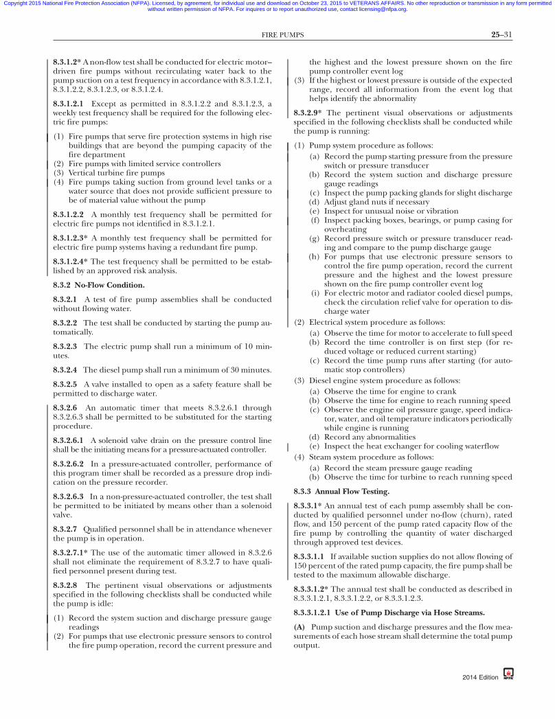
25–31FIRE PUMPS
Copyright 2015 National Fire Protection Association (NFPA). Licensed, by agreement, for individual use and download on October 23, 2015 to VETERANS AFFAIRS. No other reproduction or transmission in any form permittedwithout written permission of NFPA. For inquires or to report unauthorized use, contact [email protected].
87
8.3.1.2* A non-flow test shall be conducted for electric motor–driven fire pumps without recirculating water back to thepump suction on a test frequency in accordance with 8.3.1.2.1,8.3.1.2.2, 8.3.1.2.3, or 8.3.1.2.4.
8.3.1.2.1 Except as permitted in 8.3.1.2.2 and 8.3.1.2.3, aweekly test frequency shall be required for the following elec-tric fire pumps:
(1) Fire pumps that serve fire protection systems in high risebuildings that are beyond the pumping capacity of thefire department
(2) Fire pumps with limited service controllers(3) Vertical turbine fire pumps(4) Fire pumps taking suction from ground level tanks or a
water source that does not provide sufficient pressure tobe of material value without the pump
8.3.1.2.2 A monthly test frequency shall be permitted forelectric fire pumps not identified in 8.3.1.2.1.
8.3.1.2.3* A monthly test frequency shall be permitted forelectric fire pump systems having a redundant fire pump.
8.3.1.2.4* The test frequency shall be permitted to be estab-lished by an approved risk analysis.
8.3.2 No-Flow Condition.
8.3.2.1 A test of fire pump assemblies shall be conductedwithout flowing water.
8.3.2.2 The test shall be conducted by starting the pump au-tomatically.
8.3.2.3 The electric pump shall run a minimum of 10 min-utes.
8.3.2.4 The diesel pump shall run a minimum of 30 minutes.
8.3.2.5 A valve installed to open as a safety feature shall bepermitted to discharge water.
8.3.2.6 An automatic timer that meets 8.3.2.6.1 through8.3.2.6.3 shall be permitted to be substituted for the startingprocedure.
8.3.2.6.1 A solenoid valve drain on the pressure control lineshall be the initiating means for a pressure-actuated controller.
8.3.2.6.2 In a pressure-actuated controller, performance ofthis program timer shall be recorded as a pressure drop indi-cation on the pressure recorder.
8.3.2.6.3 In a non-pressure-actuated controller, the test shallbe permitted to be initiated by means other than a solenoidvalve.
8.3.2.7 Qualified personnel shall be in attendance wheneverthe pump is in operation.
8.3.2.7.1* The use of the automatic timer allowed in 8.3.2.6shall not eliminate the requirement of 8.3.2.7 to have quali-fied personnel present during test.
8.3.2.8 The pertinent visual observations or adjustmentsspecified in the following checklists shall be conducted whilethe pump is idle:
(1) Record the system suction and discharge pressure gaugereadings
(2) For pumps that use electronic pressure sensors to controlthe fire pump operation, record the current pressure and
{3e0bff22-698c-46e7-
the highest and the lowest pressure shown on the firepump controller event log
(3) If the highest or lowest pressure is outside of the expectedrange, record all information from the event log thathelps identify the abnormality
8.3.2.9* The pertinent visual observations or adjustmentsspecified in the following checklists shall be conducted whilethe pump is running:
(1) Pump system procedure as follows:(a) Record the pump starting pressure from the pressure
switch or pressure transducer(b) Record the system suction and discharge pressure
gauge readings(c) Inspect the pump packing glands for slight discharge(d) Adjust gland nuts if necessary(e) Inspect for unusual noise or vibration(f) Inspect packing boxes, bearings, or pump casing for
overheating(g) Record pressure switch or pressure transducer read-
ing and compare to the pump discharge gauge(h) For pumps that use electronic pressure sensors to
control the fire pump operation, record the currentpressure and the highest and the lowest pressureshown on the fire pump controller event log
(i) For electric motor and radiator cooled diesel pumps,check the circulation relief valve for operation to dis-charge water
(2) Electrical system procedure as follows:(a) Observe the time for motor to accelerate to full speed(b) Record the time controller is on first step (for re-
duced voltage or reduced current starting)(c) Record the time pump runs after starting (for auto-
matic stop controllers)(3) Diesel engine system procedure as follows:
(a) Observe the time for engine to crank(b) Observe the time for engine to reach running speed(c) Observe the engine oil pressure gauge, speed indica-
tor, water, and oil temperature indicators periodicallywhile engine is running
(d) Record any abnormalities(e) Inspect the heat exchanger for cooling waterflow
(4) Steam system procedure as follows:(a) Record the steam pressure gauge reading(b) Observe the time for turbine to reach running speed
8.3.3 Annual Flow Testing.
8.3.3.1* An annual test of each pump assembly shall be con-ducted by qualified personnel under no-flow (churn), ratedflow, and 150 percent of the pump rated capacity flow of thefire pump by controlling the quantity of water dischargedthrough approved test devices.
8.3.3.1.1 If available suction supplies do not allow flowing of150 percent of the rated pump capacity, the fire pump shall betested to the maximum allowable discharge.
8.3.3.1.2* The annual test shall be conducted as described in8.3.3.1.2.1, 8.3.3.1.2.2, or 8.3.3.1.2.3.
8.3.3.1.2.1 Use of Pump Discharge via Hose Streams.
(A) Pump suction and discharge pressures and the flow mea-surements of each hose stream shall determine the total pumpoutput.
db-eba3b3d7337a}
2014 Edition

25–32 INSPECTION, TESTING, AND MAINTENANCE OF WATER-BASED FIRE PROTECTION SYSTEMS
Copyright 2015 National Fire Protection Association (NFPA). Licensed, by agreement, for individual use and download on October 23, 2015 to VETERANS AFFAIRS. No other reproduction or transmission in any form permittedwithout written permission of NFPA. For inquires or to report unauthorized use, contact [email protected].
-8
(B) Care shall be taken to prevent water damage by verifyingthere is adequate drainage for the high pressure water dis-charge from hoses.
8.3.3.1.2.2 Use of Pump Discharge via Bypass Flowmeter toDrain or Suction Reservoir. Pump suction and discharge pres-sures and the flowmeter measurements shall determine thetotal pump output.
8.3.3.1.2.3 Use of Pump Discharge via Bypass Flowmeter toPump Suction (Closed-Loop Metering).
(A) Pump suction and discharge pressures and the flowmetermeasurements shall determine the total pump output.
(B) When testing includes recirculating water back to the firepump suction, the temperature of the recirculating water shallbe monitored to verify that it remains below temperatures thatcould result in equipment damage as defined by the pumpand engine manufacturers.
8.3.3.1.3 Where the annual test is conducted periodically inaccordance with 8.3.3.1.2.3, a test shall be conducted every3 years in accordance with 8.3.3.1.2.1 or 8.3.3.1.2.2 in lieu ofthe method described in 8.3.3.1.2.3.
8.3.3.1.4 Where 8.3.3.1.2.2 or 8.3.3.1.2.3 is used, the flowme-ter shall be adjusted immediately prior to conducting the testin accordance with the manufacturer’s instructions.
8.3.3.1.4.1 If the test results are not consistent with the previ-ous annual test, 8.3.3.1.2.1 shall be used.
8.3.3.1.4.2 If testing in accordance with 8.3.3.1.2.1 is not pos-sible, a flowmeter calibration shall be performed and the testshall be repeated.
8.3.3.2 The pertinent visual observations, measurements,and adjustments specified in the following checklists shall beconducted annually while the pump is running and flowingwater under the specified output condition:
(1) At no-flow condition (churn) as follows:(a) Inspect the circulation relief valve for operation to
discharge water(b) Inspect the pressure relief valve (if installed) for
proper operation(2) At each flow condition as follows:
(a) Record the electric motor voltage and current (alllines)
(b) Record the pump speed in rpm(c) Record the simultaneous (approximately) readings
of pump suction and discharge pressures and pumpdischarge flow
(3)*For electric motor–driven pumps, do not shut down thepump until it has run for 10 minutes
(4) For diesel motor–driven pumps, do not shut down thepump until it has run for 30 minutes
8.3.3.3* For installations having a pressure relief valve, theoperation of the relief valve shall be closely observed duringeach flow condition to determine whether the pump dis-charge pressure exceeds the normal operating pressure of thesystem components.
8.3.3.3.1* The pressure relief valve shall also be observed dur-ing each flow condition to determine whether the pressurerelief valve closes at the proper pressure.
{3e0bff22-698c-46e7
2014 Edition
8.3.3.3.2 The pressure relief valve shall be closed during flowconditions if necessary to achieve minimum rated characteris-tics for the pump and reset to normal position at the conclu-sion of the pump test.
8.3.3.3.2.1 When it is necessary to close the relief valve toachieve minimum rated characteristics for the pump, thepump discharge control valve shall be closed if the pumpchurn pressure exceeds the system rated pressure.
8.3.3.3.3 When pressure relief valves are piped back to thefire pump suction, the temperature of the recirculating watershall be monitored to verify that it remains below tempera-tures that could result in equipment damage as defined by thepump and engine manufacturers.
8.3.3.4 For installations having an automatic transfer switch,the following test shall be performed to ensure that the over-current protective devices (i.e., fuses or circuit breakers) donot open:
(1) Simulate a power failure condition while the pump is op-erating at peak load
(2) Verify that the transfer switch transfers power to the alter-nate power source
(3) Verify that the pump continues to perform at peak horse-power load on the alternate power source for 10 minutesfor an alternate utility or 30 minutes if the alternate powersource is a standby generator set
(4) Remove the power failure condition and verify that, aftera time delay, the pump is reconnected to the normalpower source
8.3.3.5* Alarm conditions shall be simulated by activatingalarm circuits at alarm sensor locations, and all such local orremote alarm indicating devices (visual and audible) shall beobserved for operation.
8.3.3.6* Safety. Section 4.9 shall be followed for safety require-ments while working near electric motor–driven fire pumps.
8.3.3.7* Suction Screens. After the waterflow portions of the an-nual test or fire protection system activations, the suction screensshall be inspected and cleared of any debris or obstructions.
8.3.3.8* Where engines utilize electronic fuel managementcontrol systems, the backup electronic control module (ECM)and the primary and redundant sensors for the ECM shall betested annually.
8.3.4 Diesel Fuel Testing and Maintenance.
8.3.4.1 Diesel fuel shall be tested for degradation no less thanannually.
8.3.4.1.1* Fuel degradation testing shall comply with ASTM D975-11b, Standard Specification for Diesel Fuel Oils, or ASTM D6751-11b, Standard Specification for Biodiesel Fuel Blend Stock(B100) for Middle Distillate Fuels, as approved by the enginemanufacturer, using ASTM D 7462-11, Standard Test Method forOxidation Stability of Biodiesel (B100) and Blends of Biodiesel withMiddle Distillate Petroleum Fuel (Accelerated Method).
8.3.4.2* If diesel fuel is found to be deficient in the testingrequired in 8.3.4.1.1, the fuel shall be reconditioned or re-placed, the supply tank shall be cleaned internally, and theengine fuel filter(s) shall be changed.
8.3.4.2.1 After the restoration of the fuel and tank in 8.3.4.2,the fuel shall be retested every 6 months until experience in-dicates the fuel can be stored for a minimum of 1 year withoutdegradation beyond that allowed in 8.3.4.1.1.
7db-eba3b3d7337a}

25–33FIRE PUMPS
•
Copyright 2015 National Fire Protection Association (NFPA). Licensed, by agreement, for individual use and download on October 23, 2015 to VETERANS AFFAIRS. No other reproduction or transmission in any form permittedwithout written permission of NFPA. For inquires or to report unauthorized use, contact [email protected].
87
8.3.4.3 When provided, active fuel maintenance systems shallbe listed for fire pump service.
8.3.4.3.1 Maintenance of active fuel maintenance systems shallbe in accordance with the manufacturer’s recommendations.
8.3.4.3.2 Maintenance of active fuel maintenance systemsshall be performed at a minimum annual frequency for anyportion of the system that the manufacturer does not providea recommended maintenance frequency.
8.3.4.3.3 Fuel additives shall be used and maintained in ac-cordance with the active fuel maintenance system manufactur-er’s recommendations.
8.3.5 Positive Displacement Pumps. [20:14.2.6.4.3]
8.3.5.1 Except as provided in 8.3.5.1 through 8.3.5.7, positivedisplacement pumps shall be tested in accordance with 8.3.1through 8.3.3.
8.3.5.2 The pump flow for positive displacement pumpsshall be tested and determined to meet the specified ratedperformance criteria where only one performance point isrequired to establish positive displacement pump accept-ability. [20:14.2.6.4.3.1]
8.3.5.3 The pump flow test for positive displacement pumpsshall be accomplished using a flowmeter or orifice plate installedin a test loop back to the supply tank, to the inlet side of a positivedisplacement water pump, or to drain. [20:14.2.6.4.3.2]
8.3.5.4 The flowmeter reading or discharge pressure shall berecorded and shall be in accordance with the pump manufac-turer’s flow performance data. [20:14.2.6.4.3.3]
8.3.5.5 If orifice plates are used, the orifice size and corre-sponding discharge pressure to be maintained on the up-stream side of the orifice plate shall be made available to theauthority having jurisdiction. [20:14.2.6.4.3.4]
8.3.5.6 Flow rates shall be as specified while operating at thesystem design pressure. Tests shall be performed in accor-dance with HI 3.6, Rotary Pump Tests. [20:14.2.6.4.3.5]
8.3.5.7 Positive displacement pumps intended to pump liquidsother than water shall be permitted to be tested with water; how-ever, the pump performance will be affected, and manufacturer’scalculations shall be provided showing the difference in viscositybetween water and the system liquid. [20:14.2.6.4.3.6]
8.3.6 Other Tests.
8.3.6.1 Engine generator sets supplying emergency or standbypower to fire pump assemblies shall be tested routinely in accor-dance with NFPA 110, Standard for Emergency and Standby PowerSystems.
8.3.6.2 Automatic transfer switches shall be tested routinelyand exercised in accordance with NFPA 110.
8.3.6.3 Tests of appropriate environmental pump room spaceconditions (e.g., heating, ventilation, illumination) shall bemade to ensure proper manual or automatic operation of theassociated equipment.
8.3.6.4* Parallel and angular alignment of the pump anddriver shall be inspected during the annual test, and any mis-alignment shall be corrected.
8.3.7 Test Results and Evaluation.
8.3.7.1* Interpretation.
8.3.7.1.1 The interpretation of the test results shall be thebasis for determining performance of the pump assembly.
{3e0bff22-698c-46e7-
8.3.7.1.2 Qualified individuals shall interpret the test results.
8.3.7.2 Engine Speed.
8.3.7.2.1 Theoretical factors for correction to the rated speedshall be applied where determining the compliance of thepump per the test.
8.3.7.2.2 Increasing the engine speed beyond the ratedspeed of the pump at rated condition shall not be permitted asa method for meeting the rated pump performance.
8.3.7.3 The fire pump assembly shall be considered acceptableif either of the following conditions is shown during the test:
(1)*The test is no less than 95 percent of the pressure at ratedflow and rated speed of the initial unadjusted field accep-tance test curve, provided that the original acceptancetest curve matches the original certified pump curve byusing theoretical factors.
(2) The fire pump is no less than 95 percent of the performancecharacteristics as indicated on the pump nameplate.
8.3.7.4* Degradation in excess of 5 percent of the pressure ofthe initial unadjusted acceptance test curve or nameplate shallrequire an investigation to reveal the cause of degraded per-formance.
8.3.7.5 Current and voltage readings whose product does notexceed the product of the rated voltage and rated full-loadcurrent multiplied by the permitted motor service factor shallbe considered acceptable.
8.3.7.6 Voltage readings at the motor within 5 percent belowor 10 percent above the rated (i.e., nameplate) voltage shallbe considered acceptable.
8.3.7.7 The pump performance shall be evaluated using theunadjusted flow rates and pressures to ensure the pump cansupply the system demand as supplied by the owner.
8.4 Reports.
8.4.1 Any abnormality observed during inspection or testingshall be reported promptly to the property owner or desig-nated representative.
8.4.2 Test results and any documented performance issuesshall be recorded and retained for comparison purposes inaccordance with Section 4.3.
8.4.3 All time delay intervals associated with the pump’s start-ing, stopping, and energy source transfer shall be recorded.
8.5 Maintenance.
8.5.1* A preventive maintenance program shall be establishedon all components of the pump assembly in accordance withthe manufacturer’s recommendations or Table 8.1.2.
8.5.2 Records shall be maintained on all work performed onthe pump, driver, controller, and auxiliary equipment.
8.5.3 The preventive maintenance program shall be initiatedimmediately after the pump assembly has passed acceptancetests.
8.6 Component Replacement Testing Requirements.
8.6.1 Whenever a component in a fire pump is adjusted,repaired, rebuilt, or replaced, the tests required to restorethe system to service shall be performed in accordance withTable 8.6.1.
db-eba3b3d7337a}
2014 Edition
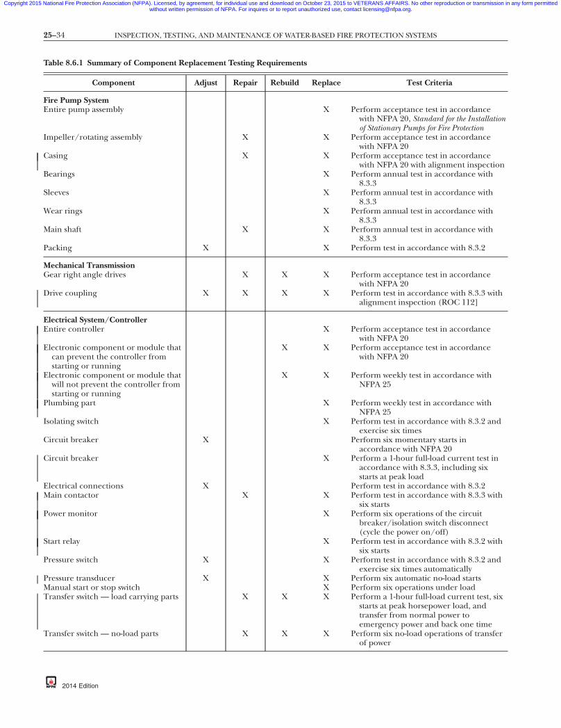
25–34 INSPECTION, TESTING, AND MAINTENANCE OF WATER-BASED FIRE PROTECTION SYSTEMS
Copyright 2015 National Fire Protection Association (NFPA). Licensed, by agreement, for individual use and download on October 23, 2015 to VETERANS AFFAIRS. No other reproduction or transmission in any form permittedwithout written permission of NFPA. For inquires or to report unauthorized use, contact [email protected].
Table 8.6.1 Summary of Component Replacement Testing Re
Component Adjust Repair
Fire Pump SystemEntire pump assembly
Impeller/rotating assembly X
Casing X
Bearings
Sleeves
Wear rings
Main shaft X
Packing X
Mechanical TransmissionGear right angle drives X
Drive coupling X X
Electrical System/ControllerEntire controller
Electronic component or module thatcan prevent the controller fromstarting or running
Electronic component or module thatwill not prevent the controller fromstarting or running
Plumbing part
Isolating switch
Circuit breaker X
Circuit breaker
Electrical connections XMain contactor X
Power monitor
Start relay
Pressure switch X
Pressure transducer XManual start or stop switchTransfer switch — load carrying parts X
Transfer switch — no-load parts X
{3e0bff22-698c-46e7
quirements
Rebuild Replace Test Criteria
X Perform acceptance test in accordancewith NFPA 20, Standard for the Installationof Stationary Pumps for Fire Protection
X Perform acceptance test in accordancewith NFPA 20
X Perform acceptance test in accordancewith NFPA 20 with alignment inspection
X Perform annual test in accordance with8.3.3
X Perform annual test in accordance with8.3.3
X Perform annual test in accordance with8.3.3
X Perform annual test in accordance with8.3.3
X Perform test in accordance with 8.3.2
X X Perform acceptance test in accordancewith NFPA 20
X X Perform test in accordance with 8.3.3 withalignment inspection (ROC 112]
X Perform acceptance test in accordancewith NFPA 20
X X Perform acceptance test in accordancewith NFPA 20
X X Perform weekly test in accordance withNFPA 25
X Perform weekly test in accordance withNFPA 25
X Perform test in accordance with 8.3.2 andexercise six times
Perform six momentary starts inaccordance with NFPA 20
X Perform a 1-hour full-load current test inaccordance with 8.3.3, including sixstarts at peak load
Perform test in accordance with 8.3.2X Perform test in accordance with 8.3.3 with
six startsX Perform six operations of the circuit
breaker/isolation switch disconnect(cycle the power on/off)
X Perform test in accordance with 8.3.2 withsix starts
X Perform test in accordance with 8.3.2 andexercise six times automatically
X Perform six automatic no-load startsX Perform six operations under load
X X Perform a 1-hour full-load current test, sixstarts at peak horsepower load, andtransfer from normal power toemergency power and back one time
X X Perform six no-load operations of transferof power
-87db-eba3b3d7337a}
2014 Edition

25–35FIRE PUMPS
Copyright 2015 National Fire Protection Association (NFPA). Licensed, by agreement, for individual use and download on October 23, 2015 to VETERANS AFFAIRS. No other reproduction or transmission in any form permittedwithout written permission of NFPA. For inquires or to report unauthorized use, contact [email protected].
Table 8.6.1 Continued
Component Adjust Repair Rebuild Replace Test Criteria
Electric Motor DriverElectric motor X X X Perform acceptance test in accordance
with 8.3.3, including alignment testsMotor bearings X Perform annual test in accordance with
8.3.3Incoming power conductors X Perform a 1-hour full-load current test
including six starts at peak load
Diesel Engine DriverEntire engine X X Perform acceptance test in accordance
with NFPA 20Fuel transfer pump X X X Perform test in accordance with 8.3.2Fuel injector pump or ECM X X Perform test in accordance with 8.3.3Fuel system filter X X Perform test in accordance with 8.3.2Combustion air intake system X X Perform test in accordance with 8.3.2Fuel tank X X Perform test in accordance with 8.3.2Cooling system X X X Perform test in accordance with 8.3.3Batteries X X Perform start/stop sequence in accordance
with NFPA 25Battery charger X X Perform test in accordance with 8.3.2Electric system X X Perform test in accordance with 8.3.2Lubrication filter/oil service X X Perform test in accordance with 8.3.2
Steam TurbinesSteam turbine X X Perform acceptance test in accordance
with NFPA 20Steam regulator or source upgrade X X Perform acceptance test in accordance
with NFPA 20
Positive Displacement PumpsEntire pump X Perform acceptance test in accordance
with NFPA 20Rotors X Perform annual test in accordance with
8.3.3Plungers X Perform annual test in accordance with
8.3.3Shaft X Perform annual test in accordance with
8.3.3Driver X X X Perform acceptance test in accordance
with NFPA 20Bearings X Perform annual test in accordance with
8.3.3Seals X Perform test in accordance with 8.3.2
Pump House and MiscellaneousComponents
Baseplate X Perform test in accordance with 8.3.2 withalignment inspection
Baseplate X Perform test in accordance with 8.3.3 withalignment inspection
Foundation X X X Perform test in accordance with 8.3.2 withalignment inspection
Suction/discharge pipe X X Perform visual inspection in accordancewith 8.2.2
Suction/discharge fittings X X Perform visual inspection in accordancewith 8.2.2
Suction/discharge valves X X X Perform operational test in accordancewith 13.3.3.1
{3e0bff22-698c-46e7-87db-eba3b3d7337a}
2014 Edition

25–36 INSPECTION, TESTING, AND MAINTENANCE OF WATER-BASED FIRE PROTECTION SYSTEMS
•
Copyright 2015 National Fire Protection Association (NFPA). Licensed, by agreement, for individual use and download on October 23, 2015 to VETERANS AFFAIRS. No other reproduction or transmission in any form permittedwithout written permission of NFPA. For inquires or to report unauthorized use, contact [email protected].
-8
8.6.2 NFPA 20 shall be consulted for the minimum require-ments for design, installation, and acceptance testing.
8.6.3 Replacement parts shall be provided that will maintainthe listing for the fire pump component assembly wheneverpossible.
8.6.3.1 If the part is no longer available from the originalequipment manufacturer, then an approved like part shall bepermitted to be used.
Chapter 9 Water Storage Tanks
9.1* General.
9.1.1 Minimum Requirements.
9.1.1.1 This chapter shall provide the minimum require-ments for the routine inspection, testing, and maintenance ofwater storage tanks dedicated to fire protection use.
9.1.1.2 Table 9.1.1.2 shall be used to determine the mini-mum required frequencies for inspection, testing, and main-tenance.
9.1.2 Valves and Connections. Valves and fire departmentconnections shall be inspected, tested, and maintained in ac-cordance with Chapter 13.
9.1.3 Obstruction Investigations. The procedures outlined inChapter 14 shall be followed where there is a need to conductan obstruction investigation.
9.1.4 Impairments. The procedures outlined in Chapter 15shall be followed where an impairment to protection occurs.
9.2 Inspection.
9.2.1 Water Level.
9.2.1.1* The water level in tanks equipped with supervisedwater level alarms that are connected to a constantly attendedlocation shall be inspected quarterly.
9.2.1.2 The water level in tanks not equipped with supervisedwater level alarms connected to a constantly attended locationshall be inspected monthly.
9.2.2 Air Pressure.
9.2.2.1 The air pressure in pressure tanks that have their airpressure source supervised in accordance with NFPA 72, NationalFire Alarm and Signaling Code, shall be inspected quarterly.
9.2.2.2 The air pressure in pressure tanks with a nonsuper-vised air pressure source shall be inspected monthly.
9.2.3 Heating System.
9.2.3.1 Tank heating systems installed on tanks equippedwith supervised low water temperature alarms that are con-nected to a constantly attended location shall be inspectedweekly.
9.2.3.2 Tank heating systems without a supervised low tem-perature alarm connected to a constantly attended locationshall be inspected daily during the heating season.
9.2.4 Water Temperature.
9.2.4.1 The temperature of water in tanks shall not be lessthan 40°F (4.0°C).
{3e0bff22-698c-46e7
2014 Edition
9.2.4.2 The temperature of water in tanks with low tempera-ture alarms connected to a constantly attended location shallbe inspected and recorded monthly during the heating seasonwhen the mean temperature is less than 40°F (4.0°C).
9.2.4.3 The temperature of water in tanks without low tem-perature alarms connected to a constantly attended locationshall be inspected and recorded weekly during the heatingseason when the mean temperature is less than 40°F (4.0°C).
9.2.5 Exterior Inspection.
9.2.5.1* The exterior of the tank, supporting structure, vents,foundation, and catwalks or ladders, where provided, shall beinspected quarterly for signs of obvious damage or weakening.
9.2.5.2 The area surrounding the tank and supporting struc-ture, where provided, shall be inspected quarterly to ensurethat the following conditions are met:
(1) The area is free of combustible storage, trash, debris, brush,or material that could present a fire exposure hazard.
(2) The area is free of the accumulation of material on or nearparts that could result in accelerated corrosion or rot.
(3) The tank and support are free of ice buildup.(4) The exterior sides and top of embankments supporting
coated fabric tanks are free of erosion.
9.2.5.3 Expansion joints, where provided, shall be inspectedannually for leaks and cracks.
9.2.5.4 The hoops and grillage of wooden tanks shall be in-spected annually.
9.2.5.5 Exterior painted, coated, or insulated surfaces of thetank and supporting structure, where provided, shall be in-spected annually for signs of degradation.
9.2.6 Interior Inspection.
9.2.6.1 Frequency.
9.2.6.1.1* The interior of steel tanks without corrosion protec-tion shall be inspected every 3 years.
9.2.6.1.2* The interior of all other types of tanks shall be in-spected every 5 years.
9.2.6.2 Where interior inspection is made by means of under-water evaluation, silt shall first be removed from the tank floor.
9.2.6.3 The tank interior shall be inspected for signs of pit-ting, corrosion, spalling, rot, other forms of deterioration,waste materials and debris, aquatic growth, and local or gen-eral failure of interior coating.
9.2.6.4 Steel tanks exhibiting signs of interior pitting, corro-sion, or failure of coating shall be tested in accordance with9.2.7.
9.2.6.5* Tanks on ring-type foundations with sand in themiddle shall be inspected for evidence of voids beneath thefloor.
9.2.6.6 The heating system and components including pip-ing shall be inspected.
9.2.6.7 The anti-vortex plate shall be inspected for deteriora-tion or blockage.
7db-eba3b3d7337a}

25–37WATER STORAGE TANKS
Copyright 2015 National Fire Protection Association (NFPA). Licensed, by agreement, for individual use and download on October 23, 2015 to VETERANS AFFAIRS. No other reproduction or transmission in any form permittedwithout written permission of NFPA. For inquires or to report unauthorized use, contact [email protected].
9.2.7 Tests During Interior Inspection. Where a drained inte-rior inspection of a steel tank is required by 9.2.6.4, the follow-ing tests shall be conducted:
(1) Evaluation of tank coatings shall be made in accordancewith the adhesion test of ASTM D 3359, Standard Test Meth-ods for Measuring Adhesion by Tape Test, generally referred toas the “cross-hatch test.”
Table 9.1.1.2 Summary of Water Storage Tank Inspection, Tes
Item
InspectionWater temperature — low temperature alarms connected
to constantly attended locationM
Water temperature — low temperature alarms notconnected to constantly attended location
W
Heating system — tanks with supervised low temperaturealarms connected to constantly attended location
W
Heating system — tanks without supervised lowtemperature alarms connected to constantly attendedlocation
D
Control valvesWater level — tanks equipped with supervised water level
alarms connected to constantly attended locationQ
Water level — tanks without supervised water level alarmsconnected to constantly attended location
M
Air pressure — tanks that have their air pressure sourcesupervised
Q
Air pressure — tanks without their air pressure sourcesupervised
M
Tank — exterior QSupport structure QCatwalks and ladders QSurrounding area QHoops and grillage APainted/coated surfaces AExpansion joints AInterior — tanks without corrosion protection 3Interior — all other tanks 5Temperature alarms — connected to constantly attended
locationM
Temperature alarms — not connected to constantlyattended location
W
Check valves
TestTank heating system P
sLow water temperature alarms MHigh temperature limit switches MWater level alarms SLevel indicators 5Pressure gauges 5Valve status test
MaintenanceWater level —Control valves —Embankment-supported coated fabric (ESCF) —Check valves —
*Cold weather/heating season only.
{3e0bff22-698c-46e7-
(2) Dry film thickness measurements shall be taken at ran-dom locations to determine the overall coating thickness.
(3) Nondestructive ultrasonic readings shall be taken toevaluate the wall thickness where there is evidence of pit-ting or corrosion.
(4) Interior surfaces shall be spot wet-sponge tested to detectpinholes, cracks, or other compromises in the coating.
nd Maintenance
quency Reference
ly 9.2.4.2
9.2.4.3
* 9.2.3.1
9.2.3.2
Table 13.1.1.2rly 9.2.1.1
ly 9.2.1.2
rly 9.2.2.1
ly 9.2.2.2
rly 9.2.5.1rly 9.2.5.1rly 9.2.5.1rly 9.2.5.2lly 9.2.5.4lly 9.2.5.5lly 9.2.5.3
9.2.6.1.19.2.6.1.2
ly* 9.2.4.2
* 9.2.4.3
Table 13.1.1.2
heating 9.3.2
ly* 9.3.3ly* 9.3.4nually 9.3.5
9.3.19.3.613.3.1.2.2.1
9.4.2Table 13.1.1.29.4.613.4.2.2
db-eba3b3d7337a}
ting, a
Fre
onth
eekly
eekly
aily*
uarte
onth
uarte
onth
uarteuarteuarteuartennuannuannuayearsyearsonth
eekly
rior toeasononthonth
emianyearsyears
87
2014 Edition
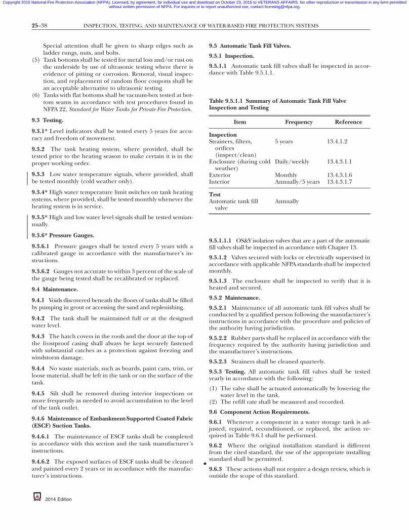
25–38 INSPECTION, TESTING, AND MAINTENANCE OF WATER-BASED FIRE PROTECTION SYSTEMS
•
Copyright 2015 National Fire Protection Association (NFPA). Licensed, by agreement, for individual use and download on October 23, 2015 to VETERANS AFFAIRS. No other reproduction or transmission in any form permittedwithout written permission of NFPA. For inquires or to report unauthorized use, contact [email protected].
-8
Special attention shall be given to sharp edges such asladder rungs, nuts, and bolts.
(5) Tank bottoms shall be tested for metal loss and/or rust onthe underside by use of ultrasonic testing where there isevidence of pitting or corrosion. Removal, visual inspec-tion, and replacement of random floor coupons shall bean acceptable alternative to ultrasonic testing.
(6) Tanks with flat bottoms shall be vacuum-box tested at bot-tom seams in accordance with test procedures found inNFPA 22, Standard for Water Tanks for Private Fire Protection.
9.3 Testing.
9.3.1* Level indicators shall be tested every 5 years for accu-racy and freedom of movement.
9.3.2 The tank heating system, where provided, shall betested prior to the heating season to make certain it is in theproper working order.
9.3.3 Low water temperature signals, where provided, shallbe tested monthly (cold weather only).
9.3.4* High water temperature limit switches on tank heatingsystems, where provided, shall be tested monthly whenever theheating system is in service.
9.3.5* High and low water level signals shall be tested semian-nually.
9.3.6* Pressure Gauges.
9.3.6.1 Pressure gauges shall be tested every 5 years with acalibrated gauge in accordance with the manufacturer’s in-structions.
9.3.6.2 Gauges not accurate to within 3 percent of the scale ofthe gauge being tested shall be recalibrated or replaced.
9.4 Maintenance.
9.4.1 Voids discovered beneath the floors of tanks shall be filledby pumping in grout or accessing the sand and replenishing.
9.4.2 The tank shall be maintained full or at the designedwater level.
9.4.3 The hatch covers in the roofs and the door at the top ofthe frostproof casing shall always be kept securely fastenedwith substantial catches as a protection against freezing andwindstorm damage.
9.4.4 No waste materials, such as boards, paint cans, trim, orloose material, shall be left in the tank or on the surface of thetank.
9.4.5 Silt shall be removed during interior inspections ormore frequently as needed to avoid accumulation to the levelof the tank outlet.
9.4.6 Maintenance of Embankment-Supported Coated Fabric(ESCF) Suction Tanks.
9.4.6.1 The maintenance of ESCF tanks shall be completedin accordance with this section and the tank manufacturer’sinstructions.
9.4.6.2 The exposed surfaces of ESCF tanks shall be cleanedand painted every 2 years or in accordance with the manufac-turer’s instructions.
{3e0bff22-698c-46e7
2014 Edition
9.5 Automatic Tank Fill Valves.
9.5.1 Inspection.
9.5.1.1 Automatic tank fill valves shall be inspected in accor-dance with Table 9.5.1.1.
9.5.1.1.1 OS&Y isolation valves that are a part of the automaticfill valves shall be inspected in accordance with Chapter 13.
9.5.1.2 Valves secured with locks or electrically supervised inaccordance with applicable NFPA standards shall be inspectedmonthly.
9.5.1.3 The enclosure shall be inspected to verify that it isheated and secured.
9.5.2 Maintenance.
9.5.2.1 Maintenance of all automatic tank fill valves shall beconducted by a qualified person following the manufacturer’sinstructions in accordance with the procedure and policies ofthe authority having jurisdiction.
9.5.2.2 Rubber parts shall be replaced in accordance with thefrequency required by the authority having jurisdiction andthe manufacturer’s instructions.
9.5.2.3 Strainers shall be cleaned quarterly.
9.5.3 Testing. All automatic tank fill valves shall be testedyearly in accordance with the following:
(1) The valve shall be actuated automatically by lowering thewater level in the tank.
(2) The refill rate shall be measured and recorded.
9.6 Component Action Requirements.
9.6.1 Whenever a component in a water storage tank is ad-justed, repaired, reconditioned, or replaced, the action re-quired in Table 9.6.1 shall be performed.
9.6.2 Where the original installation standard is differentfrom the cited standard, the use of the appropriate installingstandard shall be permitted.
9.6.3 These actions shall not require a design review, which isoutside the scope of this standard.
Table 9.5.1.1 Summary of Automatic Tank Fill ValveInspection and Testing
Item Frequency Reference
InspectionStrainers, filters,
orifices(inspect/clean)
5 years 13.4.1.2
Enclosure (during coldweather)
Daily/weekly 13.4.3.1.1
Exterior Monthly 13.4.3.1.6Interior Annually/5 years 13.4.3.1.7
TestAutomatic tank fill
valveAnnually
7db-eba3b3d7337a}

25–39WATER SPRAY FIXED SYSTEMS
Copyright 2015 National Fire Protection Association (NFPA). Licensed, by agreement, for individual use and download on October 23, 2015 to VETERANS AFFAIRS. No other reproduction or transmission in any form permittedwithout written permission of NFPA. For inquires or to report unauthorized use, contact [email protected].
Chapter 10 Water Spray Fixed Systems
10.1* General.
10.1.1 Minimum Requirements.
10.1.1.1 This chapter shall provide the minimum require-ments for the routine inspection, testing, and maintenance ofwater spray protection from fixed nozzle systems only.
10.1.1.2 Table 10.1.1.2 shall be used to determine the mini-mum required frequencies for inspection, testing, and main-tenance.
10.1.2 Water Spray Protection. This chapter shall not coverwater spray protection from portable nozzles, sprinkler sys-tems, monitor nozzles, or other means of application.
10.1.3* Design and Installation. NFPA 15, Standard for WaterSpray Fixed Systems for Fire Protection, shall be consulted to deter-mine the requirements for design and installation, includingacceptance testing.
10.1.4 Obstruction Investigations. The procedures outlinedin Chapter 14 shall be followed where there is a need to con-duct an obstruction investigation.
Table 9.6.1 Summary of Component Replacement Action Re
Component AdjustRepa
Recond
Tank ComponentsTank interior X
Tank exterior XSupport structure XHeating system X X
Catwalks and ladders X XHoops and grillage X XExpansion joints X XOverflow piping X XInsulation X
Alarm and Supervisory ComponentsHigh and low water level X X
Water temperature X X
Enclosure temperature X X
Valve supervision X X
Fill and Discharge ComponentsAutomatic fill valvesValves X X
Status IndicatorsLevel indicators X XPressure gauges
{3e0bff22-698c-46e7-
10.1.5 Valves and Connections. Valves and fire departmentconnections shall be inspected, tested, and maintained in ac-cordance with Chapter 13.
10.1.6* Impairments. The procedures outlined in Chapter 15shall be followed where an impairment to protection occurs.
10.1.6.1 When a water spray fixed system or any portion thereofis out of service for any reason, notice shall be given to facilitymanagement, the local fire department, the on-site fire brigade,and other authorities having jurisdiction, as applicable.
10.1.6.2 A sign shall be posted at each fire department con-nection or system control valve indicating which portion ofthe system is out of service.
10.2 Inspection and Maintenance Procedures.
10.2.1 Components. The components described in this sec-tion shall be inspected and maintained at the frequency speci-fied in Table 10.1.1.2 and in accordance with this standardand the manufacturer’s instructions.
10.2.1.1 Items in areas that are inaccessible for safety consid-erations due to factors such as continuous process operationsand energized electrical equipment shall be inspected duringeach scheduled shutdown but not more than every 18 months.
ents
Replace Test Criteria
X Remove debrisVerify integrity in conformance withNFPA 22, Standard for Water Tanks for PrivateFire Protection
X Verify integrity in conformance with NFPA 22X Verify integrity in conformance with NFPA 22X Verify heating system is in conformance with
NFPA 22X Verify integrity in conformance with NFPA 22X Verify integrity in conformance with NFPA 22X Verify integrity in conformance with NFPA 22X Verify integrity in conformance with NFPA 22X Verify integrity in conformance with NFPA 22
X Operational test for conformance withNFPA 22 and/or NFPA 72, National FireAlarm and Signaling Code, and the designwater levels
X Operational test for conformance withNFPA 22 and/or NFPA 72
X Operational test for conformance withNFPA 22 and/or NFPA 72
X Operational test for conformance withNFPA 22 and/or NFPA 72
See Chapter 13X See Chapter 13
X Verify conformance with NFPA 22X Verify at 0 psi (0 bar) and at system working
pressure
db-eba3b3d7337a}
quirem
ir/ition
87
2014 Edition

25–40 INSPECTION, TESTING, AND MAINTENANCE OF WATER-BASED FIRE PROTECTION SYSTEMS
Copyright 2015 National Fire Protection Association (NFPA). Licensed, by agreement, for individual use and download on October 23, 2015 to VETERANS AFFAIRS. No other reproduction or transmission in any form permittedwithout written permission of NFPA. For inquires or to report unauthorized use, contact [email protected].
Table 10.1.1.2 Summary of Water Spray Fixed System Inspection, Testing, and Maintenance
Item Frequency Reference
InspectionBackflow preventer Chapter 13Check valves Chapter 13Control valves Weekly (sealed) Chapter 13Control valves Monthly (locked, supervised) Chapter 13Deluge valve 10.2.2, Chapter 13Detection systems NFPA 72, National Fire Alarm and Signaling
CodeDetector check valves Chapter 13Drainage Quarterly 10.2.8Electric motor 10.2.9, Chapter 8Engine drive 10.2.9, Chapter 8Fire pump 10.2.9, Chapter 8Fittings Quarterly 10.2.4, 10.2.4.1Fittings (rubber-gasketed) Quarterly 10.2.4.1, A.10.2.4.1Gravity tanks 10.2.10, Chapter 9Hangers Annually and after each system activation 10.2.4.2Heat (deluge valve house) Daily/weekly 10.2.1.5, Chapter 13Nozzles Annually and after each system activation 10.2.1.1, 10.2.1.2, 10.2.1.6, 10.2.5.1,
10.2.5.2Pipe Annually and after each system activation 10.2.1.1, 10.2.1.2, 10.2.4, 10.2.4.1Pressure tank 10.2.10, Chapter 9Steam driver 10.2.9, Chapter 8Strainers Manufacturer’s instruction 10.2.7Suction tanks 10.2.10, Chapter 9Supports Quarterly 10.2.1.1, 10.2.1.2, 10.2.4.2Water supply piping 10.2.6.1, 10.2.6.2UHSWSS — detectors Monthly 10.4.2UHSWSS — controllers Each shift 10.4.3UHSWSS — valves Each shift 10.4.4
Operational TestBackflow preventer Chapter 13Check valves Chapter 13Control valves Annually 13.3.3.1Deluge valve 10.2.2, Chapter 13Detection systems NFPA 72Detector check valve Chapter 13Electric motor 10.2.9, Chapter 8Engine drive 10.2.9, Chapter 8Fire pump 10.2.9, Chapter 8Flushing Annually 10.2.1.3, Section 10.3 (flushing of
connection to riser, part of annual test)Gravity tanks 10.2.10, Chapter 9Main drain test Annually 13.3.3.4Manual release Annually 10.2.1.3, 10.3.6Nozzles Annually 10.2.1.3, 10.2.1.6, Section 10.3Pressure tank Section 10.2, Chapter 9Steam driver 10.2.9, Chapter 8Strainers Annually 10.2.1.3, 10.2.1.7, 10.2.7Suction tanks 10.2.10, Chapter 9Waterflow alarm Quarterly Chapter 5Water spray system test Annually Section 10.3, Chapter 13Water supply flow test 7.3.1UHSWSS Annually Section 10.4Valve status test 13.3.1.2.1
MaintenanceBackflow preventer Chapter 13Check valves Chapter 13
{3e0bff22-698c-46e7-87db-eba3b3d7337a}
2014 Edition

25–41WATER SPRAY FIXED SYSTEMS
Copyright 2015 National Fire Protection Association (NFPA). Licensed, by agreement, for individual use and download on October 23, 2015 to VETERANS AFFAIRS. No other reproduction or transmission in any form permittedwithout written permission of NFPA. For inquires or to report unauthorized use, contact [email protected].
Table 10.1.1.2 Continued
Item Frequency Reference
Control valves Annually 10.2.1.4, Chapter 13Deluge valve 10.2.2, Chapter 13Detection systems NFPA 72Detector check valve Chapter 13Electric motor 10.2.9, Chapter 8Engine drive 10.2.9, Chapter 8Fire pump 10.2.9, Chapter 8Gravity tanks 10.2.10, Chapter 9Pressure tank 10.2.6, Chapter 9Steam driver 10.2.9, Chapter 8Strainers Annually 10.2.1.4, 10.2.1.6, 10.2.7Strainers (baskets/screen) 5 years 10.2.1.4, 10.2.1.7, A.10.2.7Suction tanks 10.2.10, Chapter 9Water spray system Annually 10.2.1.4, Chapter 13
87
10.2.1.2 Inspections shall not be required for items in areaswith no provision for access and that are not subject to theconditions noted in 10.2.4.1, 10.2.4.2, and 10.2.5.1.
10.2.1.3 Items in areas that are inaccessible for safety consid-erations shall be tested at longer intervals in accordance with13.4.3.2.2.4.
10.2.1.4 Other maintenance intervals shall be permitted, de-pending on the results of the visual inspection and operatingtests.
10.2.1.5 Deluge valve enclosures shall be inspected in accor-dance with the provisions of Chapter 13.
10.2.1.6 Nozzle strainers shall be removed, inspected, andcleaned during the flushing procedure for the mainlinestrainer.
10.2.1.7 Mainline strainers shall be removed and inspectedevery 5 years for damaged and corroded parts.
10.2.2 Deluge Valves. Deluge valves shall be inspected, tested,and maintained in accordance with Chapter 13.
10.2.3 Automatic Detection Equipment.
10.2.3.1 Automatic detection equipment shall be inspected,tested, and maintained in accordance with NFPA 72, NationalFire Alarm and Signaling Code.
10.2.3.2 Automatic fire detection equipment not covered byNFPA 72 shall be inspected, tested, and maintained to ensurethat the detectors are in place, securely fastened, and pro-tected from corrosion, weather, and mechanical damage andthat the communication wiring, control panels, or tubing sys-tem is functional.
10.2.4* System Components. System piping, fittings, hangers,and supports shall be inspected and maintained to ensurecontinuity of water delivery to the spray nozzles at full water-flow and design pressure.
10.2.4.1* Piping and Fittings. System piping and fittings shallbe inspected for the following:
(1) Mechanical damage (e.g., broken piping or cracked fittings)
{3e0bff22-698c-46e7-
(2) External conditions (e.g., missing or damaged paint orcoatings, rust, and corrosion)
(3) Misalignment or trapped sections(4) Low-point drains (automatic or manual)(5) Location of rubber-gasketed fittings
10.2.4.2* Hangers and Supports. Hangers and supports shallbe inspected for the following and repaired or replaced asnecessary:
(1) Condition (e.g., missing or damaged paint or coating,rust, and corrosion)
(2) Secure attachment to structural supports and piping(3) Damaged or missing hangers
10.2.5* Water Spray Nozzles.
10.2.5.1 Water spray nozzles shall be inspected and main-tained to ensure that they are in place, continue to be aimedor pointed in the direction intended, and are free from exter-nal loading and corrosion.
10.2.5.2 Where caps or plugs are required, the inspection shallconfirm they are in place and free to operate as intended.
10.2.5.3 Misaligned water spray nozzles shall be adjusted(aimed) by visual means, and the discharge patterns shall beinspected at the next scheduled flow test.
10.2.6 Water Supply.
10.2.6.1 The dependability of the water supply shall be en-sured by regular inspection and maintenance, whether fur-nished by a municipal source, on-site storage tanks, a firepump, or private underground piping systems.
10.2.6.2* Water supply piping shall be maintained free of in-ternal obstructions.
10.2.7* Strainers.
10.2.7.1 Mainline strainers (basket or screen) shall beflushed until clear after each operation or flow test.
10.2.7.2 Individual water spray nozzle strainers shall be re-moved, cleaned, and inspected after each operation or flowtest.
db-eba3b3d7337a}
2014 Edition

25–42 INSPECTION, TESTING, AND MAINTENANCE OF WATER-BASED FIRE PROTECTION SYSTEMS
••
Copyright 2015 National Fire Protection Association (NFPA). Licensed, by agreement, for individual use and download on October 23, 2015 to VETERANS AFFAIRS. No other reproduction or transmission in any form permittedwithout written permission of NFPA. For inquires or to report unauthorized use, contact [email protected].
-8
10.2.7.3 All strainers shall be inspected and cleaned in accor-dance with the manufacturer’s instructions.
10.2.7.4 Damaged or corroded parts shall be replaced or re-paired.
10.2.8 Drainage. The area beneath and surrounding a waterspray fixed system shall be inspected visually on a quarterlybasis to ensure that drainage facilities, such as trap sumps anddrainage trenches, are not blocked and retention embank-ments or dikes are in good repair.
10.2.9 Fire Pumps. Chapter 8 shall be followed for inspectionand maintenance requirements.
10.2.10 Water Tanks (Gravity, Pressure, or Suction Tanks, orReservoirs). Chapter 9 shall be followed for inspection andmaintenance requirements.
10.3 Operational Tests.
10.3.1 Performance.
10.3.1.1 Frequency of system tests shall be in accordance withTable 10.1.1.2.
10.3.1.2 Water spray fixed systems shall be serviced in accor-dance with this standard and with the manufacturer’sinstructions.
10.3.2* Test Preparation. Precautions shall be taken to pre-vent damage to property during the test.
10.3.3 Operational Test Performance. Operational tests shallbe conducted to ensure that the water spray fixed systems re-spond as designed, both automatically and manually.
10.3.3.1* Response Time.
10.3.3.1.1 Under test conditions, the heat detection systems,where exposed to a heat test source, shall operate within40 seconds.
10.3.3.1.2 Under test conditions, the flammable gas detec-tion system, where exposed to a standard test gas concentra-tion, shall operate within the time frame specified in the sys-tem design.
10.3.3.1.3 These response times shall be recorded.
10.3.3.2 Discharge Time. The time lapse between operationof detection systems and water delivery time to the protectedarea shall be recorded.
10.3.3.3* Discharge Patterns.
10.3.3.3.1* The water discharge patterns from all of the openspray nozzles shall be observed to ensure that patterns are notimpeded by plugged nozzles, to ensure that nozzles are cor-rectly positioned, and to ensure that obstructions do not pre-vent discharge patterns from wetting surfaces to be protected.
10.3.3.3.1.1 Where the nature of the protected property issuch that water cannot be discharged, the nozzles shall be in-spected for proper orientation and the system tested with airto ensure that the nozzles are not obstructed.
10.3.3.3.2 Where obstructions occur, the piping and nozzlesshall be cleaned and the system retested.
10.3.3.4 Pressure Readings.
10.3.3.4.1 Pressure readings shall be recorded at the hydrau-lically most remote nozzle to ensure the waterflow has not
{3e0bff22-698c-46e7
2014 Edition
been impeded by partially closed valves or by plugged strain-ers or piping.
10.3.3.4.2 A second pressure reading shall be recorded at thedeluge valve to ensure the water supply is adequate.
10.3.3.4.3 Readings shall be compared to the hydraulic de-sign pressures to ensure the original system design require-ments are met and the water supply is adequate to meet thedesign requirements.
10.3.3.4.3.1 Where the hydraulically most remote nozzle isinaccessible, nozzles shall be permitted to be checked visuallywithout taking a pressure reading on the most remote nozzle.
10.3.3.4.3.2 Where the reading taken at the riser indicatesthat the water supply has deteriorated, a gauge shall be placedon the hydraulically most remote nozzle and the results com-pared with the required design pressure.
10.3.4 Multiple Systems. The maximum number of systemsexpected to operate in case of fire shall be tested simulta-neously to inspect the adequacy of the water supply.
10.3.5 Manual Operation. Manual actuation devices shall beoperated annually.
10.3.6 Return to Service. After the full flow test, the waterspray system shall be maintained and returned to service inaccordance with the manufacturer’s instructions.
10.3.6.1 Low Point Drains.
10.3.6.1.1 To prevent freezing and corrosion, all low pointdrains in aboveground piping shall be opened, the pipedrained, and the valves closed and plugs replaced.
10.3.6.1.2 Where weep holes are provided in lieu of low-pointdrains, they shall be inspected to ensure they are clear andunobstructed.
10.4 Ultra-High-Speed Water Spray System (UHSWSS) Op-erational Tests.
10.4.1 A full operational test, including measurements of re-sponse time, shall be conducted at intervals not exceeding1 year.
10.4.1.1 Systems out of service shall be tested before beingplaced back in service.
10.4.2 All detectors shall be tested and inspected monthly forphysical damage and accumulation of deposits on the lensesof optical detectors.
10.4.3 Controllers shall be inspected for faults at the start ofeach working shift.
10.4.4 Valves.
10.4.4.1 Valves on the water supply line shall be inspected atthe start of each working shift to verify they are open.
10.4.4.2 Valves secured in the open position with a lockingdevice or monitored by a signaling device that sounds atrouble signal at the deluge system control panel or other cen-tral location shall not require inspection.
10.4.5 Response Time.
10.4.5.1 The response time shall be verified during the op-erational test.
10.4.5.2 The response time shall be in accordance with the re-quirements of the system but not more than 100 milliseconds.
7db-eba3b3d7337a}

25–43FOAM-WATER SPRINKLER SYSTEMS
•
Copyright 2015 National Fire Protection Association (NFPA). Licensed, by agreement, for individual use and download on October 23, 2015 to VETERANS AFFAIRS. No other reproduction or transmission in any form permittedwithout written permission of NFPA. For inquires or to report unauthorized use, contact [email protected].
10.5 Component Action Requirements.
10.5.1 Whenever a component in a water spray fixed system isadjusted, repaired, reconditioned, or replaced, the action re-quired in Table 10.5.1 shall be performed.
10.5.2 Where the original installation standard is differentfrom the cited standard, the use of the appropriate installingstandard shall be permitted.
10.5.3 The actions of 10.5.1 shall not require a design review,which is outside the scope of this standard.
Table 10.5.1 Summary of Component Replacement Action Re
Component Adjust
Water Delivery ComponentsPipe and fittings XNozzles XManual release X
Fire department connections
Alarm and Supervisory ComponentsPressure switch–type waterflow X
Water motor gong X
Valve supervisory device X
Detection system X
Status-Indicating ComponentsGauges
Testing and Maintenance ComponentsMain drain XAuxiliary drains X
Structural ComponentsHanger/seismic bracing X
Pipe stands X
Informational ComponentsIdentification signs X
{3e0bff22-698c-46e7-
Chapter 11 Foam-Water Sprinkler Systems
11.1 General.
11.1.1 Minimum Requirements.
11.1.1.1 This chapter shall provide the minimum require-ments for the routine inspection, testing, and maintenance offoam-water systems.
11.1.1.2 Table 11.1.1.2 shall be used to determine the minimumrequired frequencies for inspection, testing, and maintenance.
ments
air/dition Replace Required Action
X Operational flow testX Operational flow testX (1) Operational test
(2) Check for leaks at systemworking pressure(3) Test all alarmsSee Chapter 13
X Operational test using inspector’stest connection
X Operational test using inspector’stest connection
X Test for conformance withNFPA 15, Standard for Water SprayFixed Systems for Fire Protection,and/or NFPA 72, National FireAlarm and Signaling Code
X Operational test for conformancewith NFPA 15 and/or NFPA 72
X Verify at 0 psi (0 bar) and systemworking pressure
X Full flow main drain testX (1) Inspect for leaks at system
working pressure(2) Main drain test
X Inspect for conformance withNFPA 15 and/or NFPA 13,Standard for the Installation ofSprinkler Systems
X Inspect for conformance withNFPA 15 and/or NFPA 13
X Inspect for conformance withNFPA 15
db-eba3b3d7337a}
quire
RepRecon
XXX
X
X
X
X
XX
X
X
X
87
2014 Edition

FP
B
L
25–44 INSPECTION, TESTING, AND MAINTENANCE OF WATER-BASED FIRE PROTECTION SYSTEMS
Copyright 2015 National Fire Protection Association (NFPA). Licensed, by agreement, for individual use and download on October 23, 2015 to VETERANS AFFAIRS. No other reproduction or transmission in any form permittedwithout written permission of NFPA. For inquires or to report unauthorized use, contact [email protected].
Table 11.1.1.2 Summary of Foam-Water Sprinkler System Inspection, Testing, and Maintenance
System/Component Frequency Reference
InspectionDischarge device location (sprinkler) Annually 11.2.5Discharge device location (spray nozzle) Monthly 11.2.5Discharge device position (sprinkler) Annually 11.2.5Discharge device position (spray nozzle) Monthly 11.2.5Foam concentrate strainer(s) Quarterly 11.2.7.2Drainage in system area Quarterly 11.2.8Proportioning system(s) — all Monthly 11.2.9Pipe corrosion Annually 11.2.3Pipe damage Annually 11.2.3Fittings corrosion Annually 11.2.3Fittings damage Annually 11.2.3Hangers/supports Annually 11.2.4Waterflow devices Quarterly 11.2.1Water supply tank(s) Chapter 9Fire pump(s) Chapter 8Water supply piping 11.2.6.1Control valve(s) Weekly/monthly —Deluge/preaction valve(s) 11.2.1, Chapter 13Detection system See NFPA 72, National Fire Alarm
and Signaling Code11.2.2
TestDischarge device location Annually 11.3.2.6Discharge device position Annually 11.3.2.6Discharge device obstruction Annually 11.3.2.6Foam concentrate strainer(s) Annually 11.2.7.2Proportioning system(s) — all Annually 11.2.9Complete foam-water system(s) Annually 11.3.3Foam-water solution Annually 11.3.5Manual actuation device(s) Annually 11.3.4Backflow preventer(s) Annually Chapter 13Fire pump(s) See Chapter 8 —Waterflow devices Quarterly/semiannually 11.3.1.3Water supply piping Annually Chapter 10Control valve(s) See Chapter 13 —Strainer(s) — mainline See Chapter 10 11.2.7.1Deluge/preaction valve(s) See Chapter 13 11.2.1Detection system See NFPA 72 11.2.2Backflow preventer(s) See Chapter 13 —Water supply tank(s) See Chapter 9 —Water supply flow test 5 years 7.3.1Valve status test 13.3.1.2.1
MaintenanceFoam concentrate pump operation Monthly 11.4.6.1, 11.4.7.1Foam concentrate strainer(s) Quarterly Section 11.4
oam concentrate samples Annually 11.2.10roportioning system(s) standard pressure typeBall drip (automatic type) drain valves 5 years 11.4.3.1Foam concentrate tank — drain and flush 10 years 11.4.3.2Corrosion and hydrostatic test 10 years 11.4.3.3
ladder tank typeSight glass 10 years 11.4.4.1Foam concentrate tank — hydrostatic test 10 years 11.4.4.2
ine typeFoam concentrate tank — corrosion and pickuppipes
10 years 11.4.5.1
Foam concentrate tank — drain and flush 10 years 11.4.5.2
{3e0bff22-698c-46e7-87db-eba3b3d7337a}
2014 Edition

25–45FOAM-WATER SPRINKLER SYSTEMS
Copyright 2015 National Fire Protection Association (NFPA). Licensed, by agreement, for individual use and download on October 23, 2015 to VETERANS AFFAIRS. No other reproduction or transmission in any form permittedwithout written permission of NFPA. For inquires or to report unauthorized use, contact [email protected].
Table 11.1.1.2 Continued
System/Component Frequency Reference
Standard balanced pressure typeFoam concentrate pump(s) 5 years (see Note) 11.4.6.2Balancing valve diaphragm 5 years 11.4.6.3Foam concentrate tank 10 years 11.4.6.4
In-line balanced pressure typeFoam concentrate pump(s) 5 years (see Note) 11.4.7.2Balancing valve diaphragm 5 years 11.4.7.3Foam concentrate tank 10 years 11.4.7.4
Pressure vacuum vents 5 years 11.4.8Water supply tank(s) See Chapter 9 —Fire pump(s) See Chapter 8 —Water supply Annually 11.2.6.1Backflow preventer(s) See Chapter 13 —Detector check valve(s) See Chapter 13 —Check valve(s) See Chapter 13 —Control valve(s) See Chapter 13 —Deluge/preaction valves See Chapter 13 11.2.1Strainer(s) — mainline See Chapter 10 —Detection system See NFPA 72 11.2.2
Note: Also refer to manufacturer’s instructions and frequency. Maintenance intervals other than preventivemaintenance are not provided, as they depend on the results of the visual inspections and operational tests.For foam-water systems in aircraft hangars, refer to the inspection, test, and maintenance requirements of
NFPA 409, Standard on Aircraft Hangars, Table 11.1.1.•
87
11.1.2 Other System Components. Fire pumps, water storagetanks, and valves common to other types of water-based fireprotection systems shall be inspected, tested, and maintainedin accordance with Chapters 8, 9, and 13, respectively, and asspecified in Table 11.1.1.2.
11.1.3 Foam-Water Systems.
11.1.3.1 This section shall apply to foam-water systems asspecified in NFPA 16, Standard for the Installation of Foam-WaterSprinkler and Foam-Water Spray Systems.
11.1.3.2 This section shall not include systems detailed inNFPA 11, Standard for Low-, Medium-, and High-Expansion Foam.
11.1.4 Foam-Water System.
11.1.4.1 If during routine inspection and testing the foam-water system is determined to have been altered or replaced(e.g., equipment replaced, relocated, or foam concentrate re-placed), it shall be determined whether the design intent hasbeen altered and whether the system operates properly.
11.1.4.1.1 Mechanical waterflow devices, including but notlimited to water motor gongs, shall be tested quarterly.
11.1.4.1.2 Valve-type and pressure switch–type waterflow de-vices shall be tested semiannually.
11.1.4.1.3 Waterflow devices shall be inspected quarterly toverify that they are free of physical damage.
11.1.4.2 The inspection shall verify that all components, in-cluding foam concentrate discharge devices and proportion-ing equipment, are installed in accordance with their listing.
11.1.5 Obstruction Investigations. The procedures outlinedin Chapter 14 shall be followed where there is a need to con-duct an obstruction investigation.
{3e0bff22-698c-46e7-
11.1.6 Impairments. The procedures outlined in Chapter 15shall be followed where an impairment to protection occurs.
11.2 Inspection. Systems shall be inspected in accordancewith the frequency specified in Table 11.1.1.2.
11.2.1 Deluge Valves. Deluge valves shall be inspected in ac-cordance with the provisions of Chapter 13.
11.2.2 Automatic Detection Equipment. Automatic detectionequipment shall be inspected, tested, and maintained in ac-cordance with NFPA 72, National Fire Alarm and Signaling Code,to ensure that the detectors are in place, securely fastened,and protected from corrosion, weather, and mechanical dam-age and that the communication wiring, control panels, orpneumatic tubing system is functional.
11.2.3 System Piping and Fittings. System piping and fittingsshall be inspected for the following:
(1) Mechanical damage (e.g., broken piping or cracked fittings)(2) External conditions (e.g., missing or damaged paint or
coatings, rust, and corrosion)(3) Misalignment or trapped sections(4) Low-point drains (automatic or manual)(5) Location and condition of rubber-gasketed fittings
11.2.4 Hangers and Supports. Hangers and supports shallbe inspected for the following and repaired or replaced asnecessary:
(1) Condition (e.g., missing or damaged paint or coating,rust, and corrosion)
(2) Secure attachment to structural supports and piping(3) Damaged or missing hangers
11.2.5* Foam-Water Discharge Devices.
11.2.5.1 Foam-water discharge devices shall be inspected visu-ally and maintained to ensure that they are in place, continue
db-eba3b3d7337a}
2014 Edition

25–46 INSPECTION, TESTING, AND MAINTENANCE OF WATER-BASED FIRE PROTECTION SYSTEMS
Copyright 2015 National Fire Protection Association (NFPA). Licensed, by agreement, for individual use and download on October 23, 2015 to VETERANS AFFAIRS. No other reproduction or transmission in any form permittedwithout written permission of NFPA. For inquires or to report unauthorized use, contact [email protected].
-8
to be aimed or pointed in the direction intended in the systemdesign, and are free from external loading and corrosion.
11.2.5.2 Where caps or plugs are required, the inspection shallconfirm they are in place and free to operate as intended.
11.2.5.3 Misaligned discharge devices shall be adjusted(aimed) by visual means, and the discharge patterns shall beinspected at the next scheduled flow test.
11.2.5.4* Inspection shall verify that unlisted combinationsof discharge devices and foam concentrate have not beensubstituted.
11.2.6 Water Supply.
11.2.6.1 The dependability of the water supply shall be en-sured by regular inspection and maintenance, whether fur-nished by a municipal source, on-site storage tanks, a firepump, or private underground piping systems.
11.2.6.2* Water supply piping shall be maintained free of in-ternal obstructions.
11.2.7 Strainers.
11.2.7.1 Mainline and individual discharge device strainers(basket or screen) shall be inspected in accordance with theprovisions of Chapter 10.
11.2.7.2 Foam concentrate strainers shall be inspected visu-ally to ensure the blow-down valve is closed and plugged.
11.2.7.3 Baskets or screens shall be removed and inspectedafter each operation or flow test.
11.2.8 Drainage. The area beneath and surrounding a foam-water spray system shall be inspected to ensure that drainage fa-cilities, such as trap sumps and drainage trenches, are notblocked and retention embankments or dikes are in good repair.
11.2.9* Proportioning Systems.
11.2.9.1 The components of the various proportioning sys-tems described in 11.2.9 shall be inspected in accordance withthe frequency specified in Table 11.1.1.2.
11.2.9.2 Valves specified to be inspected shall be permitted tobe open or closed, depending on specific functions withineach foam-water system.
11.2.9.3 The position (open or closed) of valves shall be veri-fied in accordance with specified operating conditions.
11.2.9.4* Inspection of the concentrate tank shall include veri-fication that the quantity of foam concentrate satisfies the re-quirements of the original design.
11.2.9.5 Additional inspection requirements shall be per-formed as detailed for the proportioning systems specified in11.2.9.
11.2.9.5.1 Standard Pressure Proportioner.
11.2.9.5.1.1* The pressure shall be removed before the inspec-tion to prevent injury.
11.2.9.5.1.2 The inspection shall verify the following:
(1) Ball drip valves (automatic drains) are free and opened.(2) External corrosion on foam concentrate storage tanks is
not present.
{3e0bff22-698c-46e7
2014 Edition
11.2.9.5.2 Bladder Tank Proportioner.
11.2.9.5.2.1* The pressure shall be removed before the inspec-tion to prevent injury.
11.2.9.5.2.2 The inspection shall include the following:
(1) Water control valves to foam concentrate tank(2) An inspection for external corrosion on foam concen-
trate storage tanks(3) An inspection for the presence of foam in the water sur-
rounding the bladder (annual)
11.2.9.5.3 Line Proportioner. The inspection shall include thefollowing:
(1)*Strainers(2)*Verification that pressure vacuum vent is operating freely(3) An inspection for external corrosion on foam concen-
trate storage tanks
11.2.9.5.4 Standard Balanced Pressure Proportioner. The in-spection shall include the following:
(1)*Strainers(2)*Verification that pressure vacuum vent is operating freely(3) Verification that gauges are in good operating condition(4) Verification that sensing line valves are open(5) Verification that power is available to foam liquid pump
11.2.9.5.5 In-Line Balanced Pressure Proportioner. The in-spection shall include the following:
(1)*Strainers(2)*Verification that pressure vacuum vent is operating freely(3) Verification that gauges are in good working condition(4) Verification that sensing line valves at pump unit and in-
dividual proportioner stations are open(5) Verification that power is available to foam liquid pump
11.2.9.5.6 Orifice Plate Proportioner. The inspection shall in-clude the following:
(1)*Strainers(2)*Verification that pressure vacuum vent is operating freely(3) Verification that gauges are in good working condition(4) Verification that power is available to foam liquid pump
11.2.10 Foam Concentrate Samples. Samples shall be submit-ted in accordance with the manufacturer’s recommendedsampling procedures.
11.3* Operational Tests. Frequency of system tests shall be inaccordance with Table 11.1.1.2.
11.3.1* Test Preparation. Precautions shall be taken to pre-vent damage to property during the test.
11.3.1.1 Mechanical waterflow devices, including but not lim-ited to water motor gongs, shall be tested quarterly.
11.3.1.2 Vane-type and pressure switch–type waterflow de-vices shall be tested semiannually.
11.3.1.3 Waterflow Devices. Waterflow devices shall be in-spected quarterly to verify that they are free of physical damage.
11.3.2* Operational Test Performance.
11.3.2.1 Operational tests shall be conducted to ensure thatthe foam-water system(s) responds as designed, both auto-matically and manually.
7db-eba3b3d7337a}

25–47FOAM-WATER SPRINKLER SYSTEMS
Copyright 2015 National Fire Protection Association (NFPA). Licensed, by agreement, for individual use and download on October 23, 2015 to VETERANS AFFAIRS. No other reproduction or transmission in any form permittedwithout written permission of NFPA. For inquires or to report unauthorized use, contact [email protected].
87
11.3.2.2 The test procedures shall simulate anticipated emer-gency events so the response of the foam-water system(s) canbe evaluated.
11.3.2.3 Where discharge from the system discharge deviceswould create a hazardous condition or conflict with local re-quirements, an approved alternate method to achieve full flowconditions shall be permitted.
11.3.2.4 Response Time. Under test conditions, the auto-matic fire detection systems, when exposed to a test source,shall operate within the requirements of NFPA 72, National FireAlarm and Signaling Code, for the type of detector provided,and the response time shall be recorded.
11.3.2.5 Discharge Time. The time lapse between operationof detection systems and water delivery time to the protectedarea shall be recorded for open discharge devices.
11.3.2.6 Discharge Patterns.
11.3.2.6.1 The discharge patterns from all of the open spraydevices shall be observed to ensure that patterns are not im-peded by plugged discharge devices and to ensure that dis-charge devices are correctly positioned and that obstructionsdo not prevent discharge patterns from covering surfaces tobe protected.
11.3.2.6.2 Where obstructions occur, the piping and dis-charge devices shall be cleaned and the system retested.
11.3.2.6.3 Discharge devices shall be permitted to be of dif-ferent orifice sizes and types.
11.3.2.7* Pressure Readings.
11.3.2.7.1 Pressure readings shall be recorded at the highest,most remote discharge device.
11.3.2.7.2 A second pressure reading shall be recorded at themain control valve.
11.3.2.7.3 Readings shall be compared to the hydraulic de-sign pressures to ensure the original system design require-ments are met.
11.3.3 Multiple Systems. The maximum number of systemsexpected to operate in case of fire shall be tested simulta-neously to inspect the adequacy of the water supply and con-centrate pump.
11.3.4 Manual Actuation Devices. Manual actuation devicesshall be tested annually.
11.3.5 Concentration Testing.
11.3.5.1 During the full flow foam test, a foam sample shall betaken.
11.3.5.2 The foam sample shall be inspected by refractomet-ric or other methods to verify concentration of the solution.
11.3.5.3 Concentration shall be within 10 percent of the ac-ceptance test results but in no case more than 10 percent be-low minimum design standards.
11.3.6 Return to Service. After the full flow test, the foam-water system shall be returned to service and the foam concen-trate tank shall be replenished to design level.
11.4* Maintenance.
11.4.1 Maintenance of foam-water systems shall be in accor-dance with the requirements of those chapters covering thespecific component parts.
{3e0bff22-698c-46e7-
11.4.2 Foam Components. Maintenance of specific foam com-ponents shall be in accordance with 11.4.3 through 11.4.7.
11.4.3 Standard Pressure Proportioner.
11.4.3.1 The ball drip (automatic-type) drain valves shall bedisassembled, cleaned, and reassembled.
11.4.3.2* The foam liquid storage tank shall be drained offoam liquid and flushed.
11.4.3.3 Foam liquid shall be permitted to be salvaged andreused.
11.4.3.4 The foam liquid tank shall be inspected for internaland external corrosion and hydrostatically tested to the speci-fied working pressure.
11.4.4 Bladder Tank Proportioner.
11.4.4.1 Sight glass, where provided, shall be removed andcleaned.
11.4.4.2* The foam concentrate tank shall be hydrostaticallytested to the specified working pressure.
11.4.5 Line Proportioner.
11.4.5.1 The foam concentrate tank shall be inspected forinternal corrosion.
11.4.5.2 Pickup pipes inside the tank shall be inspected forcorrosion, separation, or plugging.
11.4.5.3 The foam concentrate tank shall be drained andflushed.
11.4.5.4 Foam concentrate shall be permitted to be salvagedand reused.
11.4.6 Standard Balanced Pressure Proportioner.
11.4.6.1 Pump Operation.
11.4.6.1.1 The foam concentrate pump shall be operated.
11.4.6.1.2 Foam concentrate shall be circulated back to thetank.
11.4.6.2 Servicing. Foam pumps, drive train, and drivers shallbe serviced in accordance with the manufacturer’s instruc-tions and frequency but not at intervals of more than 5 years.
11.4.6.3 Flushing. The diaphragm balancing valve shall beflushed through the diaphragm section with water or foamconcentrate until fluid appears clear or new.
11.4.6.4 Corrosion and Sediment.
11.4.6.4.1 The foam concentrate tank shall be inspected in-ternally for corrosion and sediment.
11.4.6.4.2 Excessive sediment shall require draining andflushing of the tank.
11.4.7 In-Line Balanced Pressure Proportioner.
11.4.7.1 Pump Operation.
11.4.7.1.1 The foam concentrate pump shall be operated.
11.4.7.1.2 Foam concentrate shall be circulated back to thetank.
11.4.7.2 Servicing. Foam pumps, drive train, and drivers shallbe serviced in accordance with the manufacturer’s instruc-tions and frequency but not at intervals of more than 5 years.
db-eba3b3d7337a}
2014 Edition
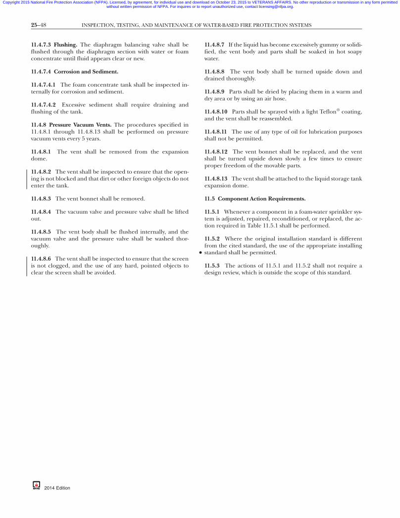
25–48 INSPECTION, TESTING, AND MAINTENANCE OF WATER-BASED FIRE PROTECTION SYSTEMS
•
Copyright 2015 National Fire Protection Association (NFPA). Licensed, by agreement, for individual use and download on October 23, 2015 to VETERANS AFFAIRS. No other reproduction or transmission in any form permittedwithout written permission of NFPA. For inquires or to report unauthorized use, contact [email protected].
-8
11.4.7.3 Flushing. The diaphragm balancing valve shall beflushed through the diaphragm section with water or foamconcentrate until fluid appears clear or new.
11.4.7.4 Corrosion and Sediment.
11.4.7.4.1 The foam concentrate tank shall be inspected in-ternally for corrosion and sediment.
11.4.7.4.2 Excessive sediment shall require draining andflushing of the tank.
11.4.8 Pressure Vacuum Vents. The procedures specified in11.4.8.1 through 11.4.8.13 shall be performed on pressurevacuum vents every 5 years.
11.4.8.1 The vent shall be removed from the expansiondome.
11.4.8.2 The vent shall be inspected to ensure that the open-ing is not blocked and that dirt or other foreign objects do notenter the tank.
11.4.8.3 The vent bonnet shall be removed.
11.4.8.4 The vacuum valve and pressure valve shall be liftedout.
11.4.8.5 The vent body shall be flushed internally, and thevacuum valve and the pressure valve shall be washed thor-oughly.
11.4.8.6 The vent shall be inspected to ensure that the screenis not clogged, and the use of any hard, pointed objects toclear the screen shall be avoided.{3e0bff22-698c-46e7
2014 Edition
11.4.8.7 If the liquid has become excessively gummy or solidi-fied, the vent body and parts shall be soaked in hot soapywater.
11.4.8.8 The vent body shall be turned upside down anddrained thoroughly.
11.4.8.9 Parts shall be dried by placing them in a warm anddry area or by using an air hose.
11.4.8.10 Parts shall be sprayed with a light Teflon® coating,and the vent shall be reassembled.
11.4.8.11 The use of any type of oil for lubrication purposesshall not be permitted.
11.4.8.12 The vent bonnet shall be replaced, and the ventshall be turned upside down slowly a few times to ensureproper freedom of the movable parts.
11.4.8.13 The vent shall be attached to the liquid storage tankexpansion dome.
11.5 Component Action Requirements.
11.5.1 Whenever a component in a foam-water sprinkler sys-tem is adjusted, repaired, reconditioned, or replaced, the ac-tion required in Table 11.5.1 shall be performed.
11.5.2 Where the original installation standard is differentfrom the cited standard, the use of the appropriate installingstandard shall be permitted.
11.5.3 The actions of 11.5.1 and 11.5.2 shall not require adesign review, which is outside the scope of this standard.7db-eba3b3d7337a}
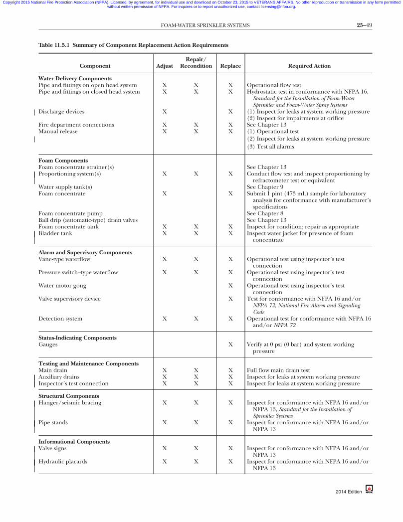
25–49FOAM-WATER SPRINKLER SYSTEMS
Copyright 2015 National Fire Protection Association (NFPA). Licensed, by agreement, for individual use and download on October 23, 2015 to VETERANS AFFAIRS. No other reproduction or transmission in any form permittedwithout written permission of NFPA. For inquires or to report unauthorized use, contact [email protected].
Table 11.5.1 Summary of Component Replacement Action Re
Component AdjustRepa
Recond
Water Delivery ComponentsPipe and fittings on open head system X XPipe and fittings on closed head system X X
Discharge devices X
Fire department connections X XManual release X X
Foam ComponentsFoam concentrate strainer(s)Proportioning system(s) X X
Water supply tank(s)Foam concentrate X
Foam concentrate pumpBall drip (automatic-type) drain valvesFoam concentrate tank X XBladder tank X X
Alarm and Supervisory ComponentsVane-type waterflow X X
Pressure switch–type waterflow X X
Water motor gong
Valve supervisory device
Detection system X X
Status-Indicating ComponentsGauges
Testing and Maintenance ComponentsMain drain X XAuxiliary drains X XInspector’s test connection X X
Structural ComponentsHanger/seismic bracing X X
Pipe stands X X
Informational ComponentsValve signs X X
Hydraulic placards X X
{3e0bff22-698c-46e7-
quirements
ir/ition Replace Required Action
X Operational flow testX Hydrostatic test in conformance with NFPA 16,
Standard for the Installation of Foam-WaterSprinkler and Foam-Water Spray Systems
X (1) Inspect for leaks at system working pressure(2) Inspect for impairments at orifice
X See Chapter 13X (1) Operational test
(2) Inspect for leaks at system working pressure(3) Test all alarms
See Chapter 13X Conduct flow test and inspect proportioning by
refractometer test or equivalentSee Chapter 9
X Submit 1 pint (473 mL) sample for laboratoryanalysis for conformance with manufacturer’sspecifications
See Chapter 8See Chapter 13
X Inspect for condition; repair as appropriateX Inspect water jacket for presence of foam
concentrate
X Operational test using inspector’s testconnection
X Operational test using inspector’s testconnection
X Operational test using inspector’s testconnection
X Test for conformance with NFPA 16 and/orNFPA 72, National Fire Alarm and SignalingCode
X Operational test for conformance with NFPA 16and/or NFPA 72
X Verify at 0 psi (0 bar) and system workingpressure
X Full flow main drain testX Inspect for leaks at system working pressureX Inspect for leaks at system working pressure
X Inspect for conformance with NFPA 16 and/orNFPA 13, Standard for the Installation ofSprinkler Systems
X Inspect for conformance with NFPA 16 and/orNFPA 13
X Inspect for conformance with NFPA 16 and/orNFPA 13
X Inspect for conformance with NFPA 16 and/orNFPA 13
87db-eba3b3d7337a}
2014 Edition

25–50 INSPECTION, TESTING, AND MAINTENANCE OF WATER-BASED FIRE PROTECTION SYSTEMS
Copyright 2015 National Fire Protection Association (NFPA). Licensed, by agreement, for individual use and download on October 23, 2015 to VETERANS AFFAIRS. No other reproduction or transmission in any form permittedwithout written permission of NFPA. For inquires or to report unauthorized use, contact [email protected].
Chapter 12 Water Mist Systems
12.1 Inspection and Testing.
12.1.1 Components and Systems.
12.1.1.1 All components and systems shall be inspected andtested to verify that they function as intended.
12.1.1.2 Water mist systems that are equipped with an addi-tive system shall be tested with the specific additive system en-gaged or used during the acceptance testing.
12.1.2 Requirements. The components of typical water mist sys-tems to be inspected and tested are provided in Table 12.1.2.
12.1.2.1 Water mist nozzles shall be inspected from the floorlevel annually.
12.1.2.1.1 Any water mist nozzle that shows signs of any of thefollowing shall be replaced:
(1) Leakage(2) Corrosion(3) Physical damage(4) Loss of fluid in the glass bulb heat responsive element(5)*Loading(6) Painting, unless painted by the water mist nozzle
manufacturer
12.1.2.1.2 Any water mist nozzle that has been installed in theincorrect orientation shall be corrected by repositioning thebranch line, drop, or sprig, or shall be replaced.
12.1.2.1.3 Water mist nozzles with glass bulbs shall be re-placed if the bulbs are empty of fluid.
2014 Edition
12.1.2.1.4 Water mist nozzles installed in concealed spacessuch as above suspended ceilings shall not require inspection.
12.1.2.1.5 Water mist nozzles installed in areas that are inac-cessible for safety considerations due to process operationsshall be inspected during each scheduled shutdown.
12.1.2.1.6 Stock, furnishings, or equipment closer to the wa-ter mist nozzle than permitted by the clearance specified inthe manufacturer’s installation instructions shall be corrected.
12.1.2.2 The supply of spare automatic water mist nozzlesshall be inspected annually for the correct number and type ofwater mist nozzles as required by NFPA 750.
12.1.2.3* Where required by this section, sample automaticwater mist nozzles shall be submitted to a recognized testinglaboratory acceptable to the authority having jurisdiction forfunctional testing.
12.1.2.3.1 Automatic water mist nozzles that have been inservice for 20 years shall be replaced, or representativesamples shall be tested and then retested at 10-year intervals.
12.1.2.3.2* Where water mist nozzles are subjected to harshenvironments, including corrosive atmospheres and corrosivewater supplies, they shall be either replaced or representativesamples tested on a 5-year basis.
12.1.2.4* A representative sample of water mist nozzles fortesting per 12.1.2.3 shall consist of a minimum of four watermist nozzles or 1 percent of the number of water mist nozzlesper individual water mist nozzle sample, whichever is greater.
12.1.2.4.1 Where one water mist nozzle within a representativesample fails to meet the test requirement, all water mist nozzleswithin the area represented by that sample shall be replaced.
Table 12.1.2 Mist Systems
Item Task Weekly Monthly QuarterlySemi-
annually Annually Other
Water supply (general) Inspect source pressure. XInspect source quality (*first year).
X* X
Test source pressure, flow,quantity, duration.
X
Water storage tanks Inspect water level (unsupervised). XInspect water level (supervised). XConfirm sight glass valves are
open.X
Inspect tank gauges, pressure. XInspect all valves, appurtenances. XDrain tank, inspect interior, and
refill.X
Inspect tank condition (corrosion). XInspect water quality. XInspect water temperature. Extreme
weather
Water storage cylinder Inspect water level (load cells). X(high pressure) Inspect water level (unsupervised). X
Inspect support frame/restraints. XInspect vent plugs at refilling. XInspect cylinder pressure on
discharge.X
Inspect filters on refill connection. X
{3e0bff22-698c-46e7-87db-eba3b3d7337a}
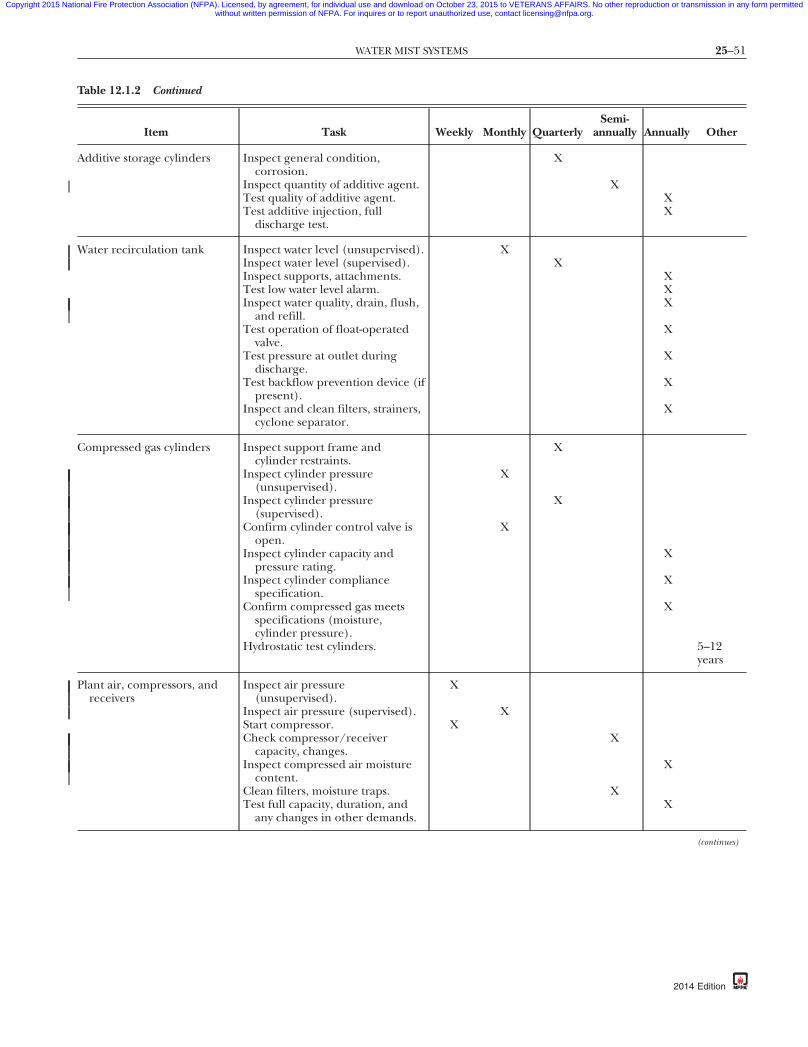
25–51WATER MIST SYSTEMS
Copyright 2015 National Fire Protection Association (NFPA). Licensed, by agreement, for individual use and download on October 23, 2015 to VETERANS AFFAIRS. No other reproduction or transmission in any form permittedwithout written permission of NFPA. For inquires or to report unauthorized use, contact [email protected].
Table 12.1.2 Continued
Item Task Weekly Monthly QuarterlySemi-
annually Annually Other
Additive storage cylinders Inspect general condition,corrosion.
X
Inspect quantity of additive agent. XTest quality of additive agent. XTest additive injection, full
discharge test.X
Water recirculation tank Inspect water level (unsupervised). XInspect water level (supervised). XInspect supports, attachments. XTest low water level alarm. XInspect water quality, drain, flush,
and refill.X
Test operation of float-operatedvalve.
X
Test pressure at outlet duringdischarge.
X
Test backflow prevention device (ifpresent).
X
Inspect and clean filters, strainers,cyclone separator.
X
Compressed gas cylinders Inspect support frame andcylinder restraints.
X
Inspect cylinder pressure(unsupervised).
X
Inspect cylinder pressure(supervised).
X
Confirm cylinder control valve isopen.
X
Inspect cylinder capacity andpressure rating.
X
Inspect cylinder compliancespecification.
X
Confirm compressed gas meetsspecifications (moisture,cylinder pressure).
X
Hydrostatic test cylinders. 5–12years
Plant air, compressors, andreceivers
Inspect air pressure(unsupervised).
X
Inspect air pressure (supervised). XStart compressor. XCheck compressor/receiver
capacity, changes.X
Inspect compressed air moisturecontent.
X
Clean filters, moisture traps. XTest full capacity, duration, and
any changes in other demands.X
(continues)
{3e0bff22-698c-46e7-87db-eba3b3d7337a}
2014 Edition
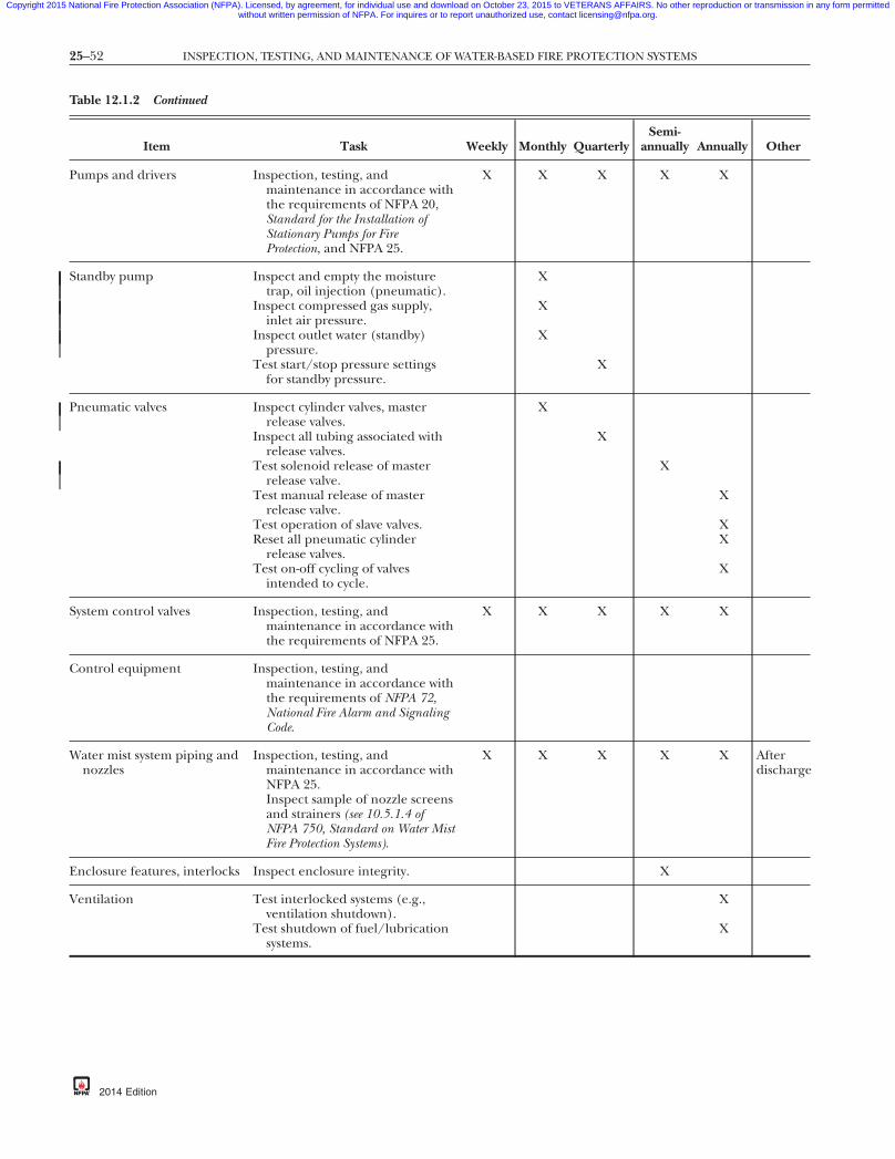
25–52 INSPECTION, TESTING, AND MAINTENANCE OF WATER-BASED FIRE PROTECTION SYSTEMS
Copyright 2015 National Fire Protection Association (NFPA). Licensed, by agreement, for individual use and download on October 23, 2015 to VETERANS AFFAIRS. No other reproduction or transmission in any form permittedwithout written permission of NFPA. For inquires or to report unauthorized use, contact [email protected].
Table 12.1.2 Continued
Item Task Weekly Monthly QuarterlySemi-
annually Annually Other
Pumps and drivers Inspection, testing, andmaintenance in accordance withthe requirements of NFPA 20,Standard for the Installation ofStationary Pumps for FireProtection, and NFPA 25.
X X X X X
Standby pump Inspect and empty the moisturetrap, oil injection (pneumatic).
X
Inspect compressed gas supply,inlet air pressure.
X
Inspect outlet water (standby)pressure.
X
Test start/stop pressure settingsfor standby pressure.
X
Pneumatic valves Inspect cylinder valves, masterrelease valves.
X
Inspect all tubing associated withrelease valves.
X
Test solenoid release of masterrelease valve.
X
Test manual release of masterrelease valve.
X
Test operation of slave valves. XReset all pneumatic cylinder
release valves.X
Test on-off cycling of valvesintended to cycle.
X
System control valves Inspection, testing, andmaintenance in accordance withthe requirements of NFPA 25.
X X X X X
Control equipment Inspection, testing, andmaintenance in accordance withthe requirements of NFPA 72,National Fire Alarm and SignalingCode.
Water mist system piping andnozzles
Inspection, testing, andmaintenance in accordance withNFPA 25.Inspect sample of nozzle screensand strainers (see 10.5.1.4 ofNFPA 750, Standard on Water MistFire Protection Systems).
X X X X X Afterdischarge
Enclosure features, interlocks Inspect enclosure integrity. X
Ventilation Test interlocked systems (e.g.,ventilation shutdown).
X
Test shutdown of fuel/lubricationsystems.
X
{3e0bff22-698c-46e7-87db-eba3b3d7337a}
2014 Edition
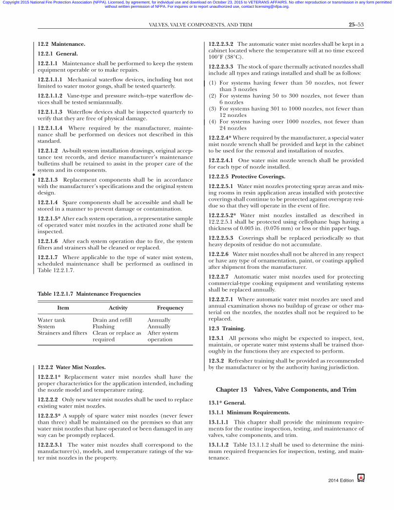
25–53VALVES, VALVE COMPONENTS, AND TRIM
•
Copyright 2015 National Fire Protection Association (NFPA). Licensed, by agreement, for individual use and download on October 23, 2015 to VETERANS AFFAIRS. No other reproduction or transmission in any form permittedwithout written permission of NFPA. For inquires or to report unauthorized use, contact [email protected].
87
12.2 Maintenance.
12.2.1 General.
12.2.1.1 Maintenance shall be performed to keep the systemequipment operable or to make repairs.
12.2.1.1.1 Mechanical waterflow devices, including but notlimited to water motor gongs, shall be tested quarterly.
12.2.1.1.2 Vane-type and pressure switch–type waterflow de-vices shall be tested semiannually.
12.2.1.1.3 Waterflow devices shall be inspected quarterly toverify that they are free of physical damage.
12.2.1.1.4 Where required by the manufacturer, mainte-nance shall be performed on devices not described in thisstandard.
12.2.1.2 As-built system installation drawings, original accep-tance test records, and device manufacturer’s maintenancebulletins shall be retained to assist in the proper care of thesystem and its components.
12.2.1.3 Replacement components shall be in accordancewith the manufacturer’s specifications and the original systemdesign.
12.2.1.4 Spare components shall be accessible and shall bestored in a manner to prevent damage or contamination.
12.2.1.5* After each system operation, a representative sampleof operated water mist nozzles in the activated zone shall beinspected.
12.2.1.6 After each system operation due to fire, the systemfilters and strainers shall be cleaned or replaced.
12.2.1.7 Where applicable to the type of water mist system,scheduled maintenance shall be performed as outlined inTable 12.2.1.7.
12.2.2 Water Mist Nozzles.
12.2.2.1* Replacement water mist nozzles shall have theproper characteristics for the application intended, includingthe nozzle model and temperature rating.
12.2.2.2 Only new water mist nozzles shall be used to replaceexisting water mist nozzles.
12.2.2.3* A supply of spare water mist nozzles (never fewerthan three) shall be maintained on the premises so that anywater mist nozzles that have operated or been damaged in anyway can be promptly replaced.
12.2.2.3.1 The water mist nozzles shall correspond to themanufacturer(s), models, and temperature ratings of the wa-ter mist nozzles in the property.
Table 12.2.1.7 Maintenance Frequencies
Item Activity Frequency
Water tank Drain and refill AnnuallySystem Flushing AnnuallyStrainers and filters Clean or replace as
requiredAfter systemoperation
{3e0bff22-698c-46e7-
12.2.2.3.2 The automatic water mist nozzles shall be kept in acabinet located where the temperature will at no time exceed100°F (38°C).
12.2.2.3.3 The stock of spare thermally activated nozzles shallinclude all types and ratings installed and shall be as follows:
(1) For systems having fewer than 50 nozzles, not fewerthan 3 nozzles
(2) For systems having 50 to 300 nozzles, not fewer than6 nozzles
(3) For systems having 301 to 1000 nozzles, not fewer than12 nozzles
(4) For systems having over 1000 nozzles, not fewer than24 nozzles
12.2.2.4* Where required by the manufacturer, a special watermist nozzle wrench shall be provided and kept in the cabinetto be used for the removal and installation of nozzles.
12.2.2.4.1 One water mist nozzle wrench shall be providedfor each type of nozzle installed.
12.2.2.5 Protective Coverings.
12.2.2.5.1 Water mist nozzles protecting spray areas and mix-ing rooms in resin application areas installed with protectivecoverings shall continue to be protected against overspray resi-due so that they will operate in the event of fire.
12.2.2.5.2* Water mist nozzles installed as described in12.2.2.5.1 shall be protected using cellophane bags having athickness of 0.003 in. (0.076 mm) or less or thin paper bags.
12.2.2.5.3 Coverings shall be replaced periodically so thatheavy deposits of residue do not accumulate.
12.2.2.6 Water mist nozzles shall not be altered in any respector have any type of ornamentation, paint, or coatings appliedafter shipment from the manufacturer.
12.2.2.7 Automatic water mist nozzles used for protectingcommercial-type cooking equipment and ventilating systemsshall be replaced annually.
12.2.2.7.1 Where automatic water mist nozzles are used andannual examination shows no buildup of grease or other ma-terial on the nozzles, the nozzles shall not be required to bereplaced.
12.3 Training.
12.3.1 All persons who might be expected to inspect, test,maintain, or operate water mist systems shall be trained thor-oughly in the functions they are expected to perform.
12.3.2 Refresher training shall be provided as recommendedby the manufacturer or by the authority having jurisdiction.
Chapter 13 Valves, Valve Components, and Trim
13.1* General.
13.1.1 Minimum Requirements.
13.1.1.1 This chapter shall provide the minimum require-ments for the routine inspection, testing, and maintenance ofvalves, valve components, and trim.
13.1.1.2 Table 13.1.1.2 shall be used to determine the mini-mum required frequencies for inspection, testing, and main-tenance.
db-eba3b3d7337a}
2014 Edition

25–54 INSPECTION, TESTING, AND MAINTENANCE OF WATER-BASED FIRE PROTECTION SYSTEMS
Copyright 2015 National Fire Protection Association (NFPA). Licensed, by agreement, for individual use and download on October 23, 2015 to VETERANS AFFAIRS. No other reproduction or transmission in any form permittedwithout written permission of NFPA. For inquires or to report unauthorized use, contact [email protected].
Table 13.1.1.2 Summary of Valves, Valve Components, and Trim Inspection, Testing, and Maintenance
Item Frequency Reference
InspectionControl ValvesSealed Weekly 13.3.2.1Locked or electrically supervised Monthly 13.3.2.1.1
Valve Supervisory Signal Initiating Device Quarterly 13.3.2.1.2
Alarm ValvesExterior Monthly 13.4.1.1Interior 5 years 13.4.1.2Strainers, filters, orifices 5 years 13.4.1.2
Check ValvesInterior 5 years 13.4.2.1
Preaction/Deluge ValvesEnclosure (during cold weather) Daily/weekly 13.4.3.1Exterior Monthly 13.4.3.1.6Interior Annually/5 years 13.4.3.1.7Strainers, filters, orifices 5 years 13.4.3.1.8
Dry Pipe Valves/ Quick-Opening DevicesGauges Weekly/monthly 13.4.4.1.2.4, 13.4.4.1.2.5Enclosure (during cold weather) Daily/weekly 13.4.4.1.1Exterior Monthly 13.4.4.1.4Interior Annually 13.4.4.1.5Strainers, filters, orifices 5 years 13.4.4.1.6
Pressure-Reducing and Relief ValvesSprinkler systems Quarterly 13.5.1.1Hose connections Annually 13.5.2.1Hose racks Annually 13.5.3.1Fire pumps
Casing relief valves Weekly 13.5.7.1, 13.5.7.1.1Pressure-relief valves Weekly 13.5.7.2, 13.5.7.2.1
Backflow Prevention AssembliesReduced pressure Weekly/monthly 13.6.1Reduced-pressure detectors Weekly/monthly 13.6.1
Fire Department Connections Quarterly 13.7.1
Testing
Main Drains Annually/quarterly 13.2.5, 13.2.5.1, 13.3.3.4
Gauges 5 years 13.2.7.2
Waterflow Alarms Quarterly/semiannually 13.2.6
Control ValvesPosition Annually 13.3.3.1Operation Annually 13.3.3.1Supervisory Semiannually 13.3.3.5
Preaction/Deluge ValvesPriming water Quarterly 13.4.3.2.1Low air pressure alarms Quarterly/annually 13.4.3.2.13, 13.4.3.2.14Full flow Annually 13.4.3.2.2Air leakage 3 years 13.4.3.2.6
{3e0bff22-698c-46e7-87db-eba3b3d7337a}
2014 Edition
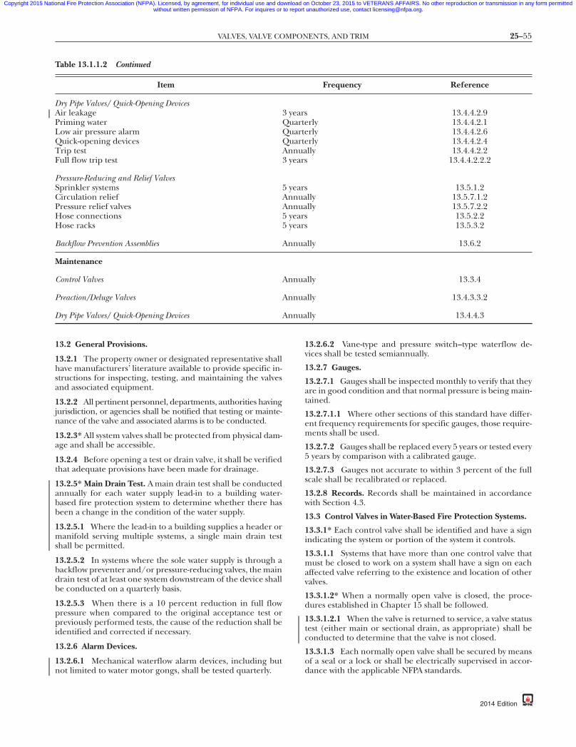
25–55VALVES, VALVE COMPONENTS, AND TRIM
Copyright 2015 National Fire Protection Association (NFPA). Licensed, by agreement, for individual use and download on October 23, 2015 to VETERANS AFFAIRS. No other reproduction or transmission in any form permittedwithout written permission of NFPA. For inquires or to report unauthorized use, contact [email protected].
Table 13.1.1.2 Continued
Item Frequency Reference
Dry Pipe Valves/ Quick-Opening DevicesAir leakage 3 years 13.4.4.2.9Priming water Quarterly 13.4.4.2.1Low air pressure alarm Quarterly 13.4.4.2.6Quick-opening devices Quarterly 13.4.4.2.4Trip test Annually 13.4.4.2.2Full flow trip test 3 years 13.4.4.2.2.2
Pressure-Reducing and Relief ValvesSprinkler systems 5 years 13.5.1.2Circulation relief Annually 13.5.7.1.2Pressure relief valves Annually 13.5.7.2.2Hose connections 5 years 13.5.2.2Hose racks 5 years 13.5.3.2
Backflow Prevention Assemblies Annually 13.6.2
Maintenance
Control Valves Annually 13.3.4
Preaction/Deluge Valves Annually 13.4.3.3.2
Dry Pipe Valves/ Quick-Opening Devices Annually 13.4.4.3
87
13.2 General Provisions.
13.2.1 The property owner or designated representative shallhave manufacturers’ literature available to provide specific in-structions for inspecting, testing, and maintaining the valvesand associated equipment.
13.2.2 All pertinent personnel, departments, authorities havingjurisdiction, or agencies shall be notified that testing or mainte-nance of the valve and associated alarms is to be conducted.
13.2.3* All system valves shall be protected from physical dam-age and shall be accessible.
13.2.4 Before opening a test or drain valve, it shall be verifiedthat adequate provisions have been made for drainage.
13.2.5* Main Drain Test. A main drain test shall be conductedannually for each water supply lead-in to a building water-based fire protection system to determine whether there hasbeen a change in the condition of the water supply.
13.2.5.1 Where the lead-in to a building supplies a header ormanifold serving multiple systems, a single main drain testshall be permitted.
13.2.5.2 In systems where the sole water supply is through abackflow preventer and/or pressure-reducing valves, the maindrain test of at least one system downstream of the device shallbe conducted on a quarterly basis.
13.2.5.3 When there is a 10 percent reduction in full flowpressure when compared to the original acceptance test orpreviously performed tests, the cause of the reduction shall beidentified and corrected if necessary.
13.2.6 Alarm Devices.
13.2.6.1 Mechanical waterflow alarm devices, including butnot limited to water motor gongs, shall be tested quarterly.
{3e0bff22-698c-46e7-
13.2.6.2 Vane-type and pressure switch–type waterflow de-vices shall be tested semiannually.
13.2.7 Gauges.
13.2.7.1 Gauges shall be inspected monthly to verify that theyare in good condition and that normal pressure is being main-tained.
13.2.7.1.1 Where other sections of this standard have differ-ent frequency requirements for specific gauges, those require-ments shall be used.
13.2.7.2 Gauges shall be replaced every 5 years or tested every5 years by comparison with a calibrated gauge.
13.2.7.3 Gauges not accurate to within 3 percent of the fullscale shall be recalibrated or replaced.
13.2.8 Records. Records shall be maintained in accordancewith Section 4.3.
13.3 Control Valves in Water-Based Fire Protection Systems.
13.3.1* Each control valve shall be identified and have a signindicating the system or portion of the system it controls.
13.3.1.1 Systems that have more than one control valve thatmust be closed to work on a system shall have a sign on eachaffected valve referring to the existence and location of othervalves.
13.3.1.2* When a normally open valve is closed, the proce-dures established in Chapter 15 shall be followed.
13.3.1.2.1 When the valve is returned to service, a valve statustest (either main or sectional drain, as appropriate) shall beconducted to determine that the valve is not closed.
13.3.1.3 Each normally open valve shall be secured by meansof a seal or a lock or shall be electrically supervised in accor-dance with the applicable NFPA standards.
db-eba3b3d7337a}
2014 Edition
25–56 INSPECTION, TESTING, AND MAINTENANCE OF WATER-BASED FIRE PROTECTION SYSTEMS
Copyright 2015 National Fire Protection Association (NFPA). Licensed, by agreement, for individual use and download on October 23, 2015 to VETERANS AFFAIRS. No other reproduction or transmission in any form permittedwithout written permission of NFPA. For inquires or to report unauthorized use, contact [email protected].
-8
13.3.1.4 Normally closed valves shall be secured by means ofa seal or shall be electrically supervised in accordance with theapplicable NFPA standard.
13.3.1.5 Sealing or electrical supervision shall not be re-quired for hose valves.
13.3.2 Inspection.
13.3.2.1 All valves shall be inspected weekly.
13.3.2.1.1 Valves secured with locks or supervised in accor-dance with applicable NFPA standards shall be permitted to beinspected monthly.
13.3.2.1.2 Control valve supervisory alarm devices shall be in-spected quarterly to verify that they are free of physical damage.
13.3.2.1.3 After any alterations or repairs, an inspection shallbe made by the property owner or designated representativeto ensure that the system is in service and all valves are in thenormal position and properly sealed, locked, or electricallysupervised.
13.3.2.2* The valve inspection shall verify that the valves are inthe following condition:
(1) In the normal open or closed position(2)*Sealed, locked, or supervised(3) Accessible(4) Post indicator valves (PIVs) are provided with correct
wrenches(5) Free from external leaks(6) Provided with applicable identification
13.3.3 Testing.
13.3.3.1 Each control valve shall be operated annuallythrough its full range and returned to its normal position.
13.3.3.2* Post indicator valves shall be opened until spring ortorsion is felt in the rod, indicating that the rod has not be-come detached from the valve.
13.3.3.2.1 This test shall be conducted every time the valve isclosed.
13.3.3.3 Post indicator and outside screw and yoke valvesshall be backed a one-quarter turn from the fully open posi-tion to prevent jamming.
13.3.3.4 A main drain test shall be conducted any time thecontrol valve is closed and reopened at system riser.
13.3.3.5* Supervisory Switches.
13.3.3.5.1 Valve supervisory switches shall be tested semian-nually.
13.3.3.5.2 A distinctive signal shall indicate movement fromthe valve’s normal position during either the first two revolu-tions of a hand wheel or when the stem of the valve has movedone-fifth of the distance from its normal position.
13.3.3.5.3 The signal shall not be restored at any valve posi-tion except the normal position.
13.3.4 Maintenance.
13.3.4.1 The operating stems of outside screw and yoke valvesshall be lubricated annually.
13.3.4.2 The valve then shall be completely closed and re-opened to test its operation and distribute the lubricant.
{3e0bff22-698c-46e7
2014 Edition
13.4 System Valves.
13.4.1 Inspection of Alarm Valves. Alarm valves shall be in-spected as described in 13.4.1.1 and 13.4.1.2.
13.4.1.1* Alarm valves and system riser check valves shall beexternally inspected monthly and shall verify the following:
(1) The gauges indicate normal supply water pressure is be-ing maintained.
(2) The valve is free of physical damage.(3) All valves are in the appropriate open or closed position.(4) The retarding chamber or alarm drains are not leaking.
13.4.1.2* Alarm valves and their associated strainers, filters,and restriction orifices shall be inspected internally every5 years unless tests indicate a greater frequency is necessary.
13.4.1.3 Maintenance.
13.4.1.3.1 Internal components shall be cleaned/repaired asnecessary in accordance with the manufacturer’s instructions.
13.4.1.3.2 The system shall be returned to service in accor-dance with the manufacturer’s instructions.
13.4.2 Check Valves.
13.4.2.1 Inspection. Valves shall be inspected internally every5 years to verify that all components operate correctly, movefreely, and are in good condition.
13.4.2.2 Maintenance. Internal components shall be cleaned,repaired, or replaced as necessary in accordance with themanufacturer’s instructions.
13.4.3 Preaction Valves and Deluge Valves.
13.4.3.1 Inspection.
13.4.3.1.1 Valve enclosures for preaction and deluge valvessubject to freezing shall be inspected daily during coldweather to verify a minimum temperature of 40°F (4.0°C).
13.4.3.1.1.1 Valve enclosures equipped with low temperaturealarms shall be inspected weekly.
13.4.3.1.2 Low temperature alarms, if installed in valve enclo-sures, shall be inspected annually at the beginning of the heat-ing season to verify that they are free of physical damage.
13.4.3.1.3 Gauges shall be inspected weekly.
13.4.3.1.3.1 The gauge on the supply side of the preaction ordeluge valve shall indicate that the normal supply water pres-sure is being maintained.
13.4.3.1.4 The gauge monitoring the preaction system supervi-sory air pressure, if provided, shall be inspected monthly to verifythat it indicates that normal pressure is being maintained.
13.4.3.1.5 The gauge monitoring the detection system pres-sure, if provided, shall be tested monthly to verify that it indi-cates that normal pressure is being maintained.
13.4.3.1.6 The preaction or deluge valve shall be externallyinspected monthly to verify the following:
(1) The valve is free from physical damage.(2) All trim valves are in the appropriate open or closed posi-
tion.(3) The valve seat is not leaking.(4) Electrical components are in service.
7db-eba3b3d7337a}
25–57VALVES, VALVE COMPONENTS, AND TRIM
Copyright 2015 National Fire Protection Association (NFPA). Licensed, by agreement, for individual use and download on October 23, 2015 to VETERANS AFFAIRS. No other reproduction or transmission in any form permittedwithout written permission of NFPA. For inquires or to report unauthorized use, contact [email protected].
87
13.4.3.1.7 The interior of the preaction or deluge valve andthe condition of detection devices shall be inspected annuallywhen the trip test is conducted.
13.4.3.1.7.1 Internal inspection of valves that can be resetwithout removal of a faceplate shall be permitted to be con-ducted every 5 years.
13.4.3.1.8 Strainers, filters, restricted orifices, and diaphragmchambers shall be inspected internally every 5 years unless testsindicate a greater frequency is necessary.
13.4.3.2 Testing.
13.4.3.2.1* The priming water level in supervised preactionsystems shall be tested quarterly for compliance with themanufacturer’s instructions.
13.4.3.2.2* Each deluge valve shall be trip tested annually atfull flow in warm weather and in accordance with the manu-facturer’s instructions.
13.4.3.2.2.1* Full flow tests shall incorporate full functionality ofthe system as a unit, including automatic and manual activation.
13.4.3.2.2.2 Protection shall be provided for any devices orequipment subject to damage by system discharge duringtests.
13.4.3.2.2.3 Where the nature of the protected property issuch that water cannot be discharged for test purposes, thetrip test shall be conducted in a manner that does not necessi-tate discharge in the protected area.
13.4.3.2.2.4 Where the nature of the protected property issuch that water cannot be discharged unless protected equip-ment is shut down (e.g., energized electrical equipment), afull flow system test shall be conducted at the next scheduledshutdown.
13.4.3.2.2.5 The full flow test frequency shall not exceed3 years.
13.4.3.2.2.6 The water discharge patterns from all of theopen spray nozzles or sprinklers shall be observed to ensurethat patterns are not impeded by plugged nozzles, that nozzlesare correctly positioned, and that obstructions do not preventdischarge patterns from wetting surfaces to be protected.
(A) Where the nature of the protected property is such thatwater cannot be discharged, the nozzles or open sprinklersshall be inspected for correct orientation and the systemtested with air to ensure that the nozzles are not obstructed.
(B) Where obstructions occur, the piping and sprinklers ornozzles shall be cleaned and the system retested.
13.4.3.2.3 Except for preaction systems covered by 13.4.3.2.5,every 3 years the preaction valve shall be trip tested with thecontrol valve fully open.
13.4.3.2.4 During those years when full flow testing in accor-dance with 13.4.3.2.3 is not required, the preaction valve shallbe trip tested with the control valve partially open.
13.4.3.2.5 Preaction or deluge valves protecting freezers shallbe trip tested in a manner that does not introduce moistureinto the piping in the freezer.
13.4.3.2.6 Preaction systems shall be tested once every 3 yearsfor air leakage, using one of the following test methods:
{3e0bff22-698c-46e7-
(1) A pressure test at 40 psi (3.2 bar) for 2 hours. The systemshall be permitted to lose up to 3 psi (0.2 bar) during theduration of the test. Air leaks shall be addressed if thesystem loses more than 3 psi (0.2 bar) during this test.
(2) With the system at normal system pressure, shut off the airsource (compressor or shop air) for 4 hours. If the low airpressure alarm goes off within this period, the air leaksshall be addressed.
13.4.3.2.7 Deluge System Pressure Readings.
13.4.3.2.7.1 Pressure readings shall be recorded at the hy-draulically most remote nozzle or sprinkler.
13.4.3.2.7.2 A second pressure reading shall be recorded atthe deluge valve.
13.4.3.2.7.3 These readings shall be compared to the hydrau-lic design pressures to ensure the original system design re-quirements are met by the water supply.
13.4.3.2.7.4 Where the hydraulically most remote nozzle orsprinkler is inaccessible, nozzles or sprinklers in other thanfoam-water systems shall be permitted to be inspected visuallywithout taking a pressure reading on the most remote nozzleor sprinkler.
13.4.3.2.7.5 Where the reading taken at the riser indicatesthat the water supply has deteriorated, a gauge shall be placedon the hydraulically most remote nozzle or sprinkler and theresults compared with the required design pressure.
13.4.3.2.8 Multiple Systems. The maximum number of sys-tems expected to operate in case of fire shall be tested simul-taneously to inspect the adequacy of the water supply.
13.4.3.2.9 Manual Operation. Manual actuation devices shallbe operated annually.
13.4.3.2.10 Return to Service. After the full flow test, the sys-tem shall be returned to service in accordance with the manu-facturer’s instructions.
13.4.3.2.11 Grease or other sealing materials shall not be ap-plied to the seating surfaces of preaction or deluge valves.
13.4.3.2.12* Records indicating the date the preaction or del-uge valve was last tripped and the tripping time, as well as theindividual and organization conducting the test, shall bemaintained at a location or in a manner readily available forreview by the authority having jurisdiction.
13.4.3.2.13 Low air pressure alarms, if provided, shall be testedquarterly in accordance with the manufacturer’s instructions.
13.4.3.2.14 Low temperature alarms, if installed in valve en-closures, shall be tested annually at the beginning of the heat-ing season.
13.4.3.2.15 Automatic air pressure maintenance devices, ifprovided, shall be tested yearly at the time of the annual pre-action or deluge valve trip test, in accordance with the manu-facturer’s instructions.
13.4.3.3 Maintenance.
13.4.3.3.1 Leaks causing drops in supervisory pressure suffi-cient to sound warning alarms, and electrical malfunctionscausing alarms to sound, shall be located and repaired.
db-eba3b3d7337a}
2014 Edition

25–58 INSPECTION, TESTING, AND MAINTENANCE OF WATER-BASED FIRE PROTECTION SYSTEMS
Copyright 2015 National Fire Protection Association (NFPA). Licensed, by agreement, for individual use and download on October 23, 2015 to VETERANS AFFAIRS. No other reproduction or transmission in any form permittedwithout written permission of NFPA. For inquires or to report unauthorized use, contact [email protected].
-8
13.4.3.3.2 During the annual trip test, the interior of the pre-action or deluge valve shall be cleaned thoroughly and theparts replaced or repaired as necessary.
13.4.3.3.2.1 Interior cleaning and parts replacement or re-pair shall be permitted every 5 years for valves that can be resetwithout removal of a faceplate.
13.4.3.3.3* Auxiliary drains in preaction or deluge systemsshall be operated after each system operation and before theonset of freezing conditions (and thereafter as needed).
13.4.3.3.4 Additional maintenance as required by the manu-facturer’s instructions shall be provided.
13.4.4 Dry Pipe Valves/Quick-Opening Devices.
13.4.4.1 Inspection.
13.4.4.1.1 Valve enclosures for preaction and deluge valvessubject to freezing shall be inspected daily during coldweather to verify a minimum temperature of 40°F (4°C).
13.4.4.1.1.1 Valve enclosures equipped with low temperaturealarms shall be inspected weekly.
13.4.4.1.1.2 Low temperature alarms, if installed in valve en-closures, shall be inspected annually at the beginning of theheating season to verify that they are free of physical damage.
13.4.4.1.2 Gauges.
13.4.4.1.2.1 The gauge on the supply side of the dry pipevalve shall indicate that the normal supply water pressure isbeing maintained.
13.4.4.1.2.2 The gauge on the system side of the dry pipevalve shall indicate that the proper ratio of air or nitrogenpressure to water supply pressure is being maintained in accor-dance with the manufacturer’s instructions.
13.4.4.1.2.3* The gauge on the quick-opening device, if pro-vided, shall indicate the same pressure as the gauge on thesystem side of the dry pipe valve.
13.4.4.1.2.4 Gauges on systems with low air or nitrogen pres-sure alarms shall be inspected monthly.
13.4.4.1.2.5 Gauges on systems other than those with low airor nitrogen pressure alarms shall be inspected weekly.
13.4.4.1.3 Systems with auxiliary drains shall require a sign atthe dry or preaction valve indicating the number of auxiliarydrains and location of each individual drain.
13.4.4.1.4 The dry pipe valve shall be externally inspectedmonthly to verify the following:
(1) The valve is free of physical damage.(2) All trim valves are in the appropriate open or closed
position.(3) The intermediate chamber is not leaking.
13.4.4.1.5 The interior of the dry pipe valve shall be in-spected annually when the trip test is conducted.
13.4.4.1.6 Strainers, filters, and restricted orifices shall be in-spected internally every 5 years unless tests indicate a greaterfrequency is necessary.
13.4.4.2 Testing.
13.4.4.2.1* The priming water level shall be tested quarterly.
13.4.4.2.2* Each dry pipe valve shall be trip tested annuallyduring warm weather.
{3e0bff22-698c-46e7
2014 Edition
13.4.4.2.2.1 Dry pipe valves protecting freezers shall be triptested in a manner that does not introduce moisture into thepiping in the freezers.
13.4.4.2.2.2* Every 3 years and whenever the system is altered,the dry pipe valve shall be trip tested with the control valve fullyopen and the quick-opening device, if provided, in service.
13.4.4.2.2.3* During those years when full flow testing in ac-cordance with 13.4.4.2.2.2 is not required, each dry pipe valveshall be trip tested with the control valve partially open.
13.4.4.2.2.4 When refilling a dry system, the air supply shallbe capable of restoring normal air pressure in the systemwithin 30 minutes.
13.4.4.2.2.5 The requirements of 13.4.4.2.2.4 shall not applyin refrigerated spaces maintained below 5°F (–15°C), wherenormal system air pressure shall be permitted to be restoredwithin 60 minutes.
13.4.4.2.3 Grease or other sealing materials shall not be ap-plied to the seating surfaces of dry pipe valves.
13.4.4.2.4* Quick-opening devices, if provided, shall be testedquarterly.
13.4.4.2.5 A tag or card that shows the date on which the drypipe valve was last tripped, and the name of the person andorganization conducting the test, shall be attached to thevalve.
13.4.4.2.5.1 Separate records of initial air and water pressure,tripping air pressure, and dry pipe valve operating conditionsshall be maintained on the premises for comparison with pre-vious test results.
13.4.4.2.5.2 Records of tripping time shall be maintained forfull flow trip tests.
13.4.4.2.6 Low air pressure alarms, if provided, shall be testedquarterly in accordance with the manufacturer’s instructions.
13.4.4.2.7 Low temperature alarms, if installed in valve enclo-sures, shall be tested annually at the beginning of the heatingseason.
13.4.4.2.8 Automatic air pressure maintenance devices, ifprovided, shall be tested annually during the dry pipe valvetrip test in accordance with the manufacturer’s instructions.
13.4.4.2.9 Dry pipe systems shall be tested once every 3 yearsfor gas leakage, using one of the following test methods:
(1) A gas (air or nitrogen) pressure test at 40 psi (3.2 bar)shall be performed for 2 hours.(a) The system shall be permitted to lose up to 3 psi
(0.2 bar) during the duration of the test.(b) Gas leaks shall be addressed if the system loses more
than 3 psi (0.2 bar) during this test.(2) With the system at normal system pressure, the gas source
(nitrogen supply, compressor, or shop air) shall be shutoff for 4 hours. If the low pressure alarm goes off withinthis period, the leaks shall be addressed.
13.4.4.3 Maintenance.
13.4.4.3.1 During the annual trip test, the interior of the drypipe valve shall be cleaned thoroughly, and parts replaced orrepaired as necessary.
7db-eba3b3d7337a}

25–59VALVES, VALVE COMPONENTS, AND TRIM
Copyright 2015 National Fire Protection Association (NFPA). Licensed, by agreement, for individual use and download on October 23, 2015 to VETERANS AFFAIRS. No other reproduction or transmission in any form permittedwithout written permission of NFPA. For inquires or to report unauthorized use, contact [email protected].
87
13.4.4.3.2* Auxiliary drains in dry pipe sprinkler systems shallbe drained after each operation of the system, before the on-set of freezing weather conditions, and thereafter as needed.
13.5 Pressure-Reducing Valves and Relief Valves.
13.5.1 Inspection and Testing of Sprinkler Pressure-ReducingValves. Sprinkler pressure-reducing valves shall be inspectedand tested as described in 13.5.1.1 and 13.5.1.2.
13.5.1.1 All valves shall be inspected quarterly to verify thatthe valves are in the following condition:
(1) In the open position(2) Not leaking(3) Maintaining downstream pressures in accordance with
the design criteria(4) In good condition, with handwheels installed and
unbroken
13.5.1.2* A full flow test shall be conducted on each valve at5-year intervals and shall be compared to previous test results.
13.5.1.2.1 Adjustments shall be made in accordance with themanufacturer’s instructions.
13.5.1.3 A partial flow test adequate to move the valve from itsseat shall be conducted annually.
13.5.2 Hose Connection Pressure-Regulating Devices.
13.5.2.1 All devices shall be inspected annually to verify thefollowing:
(1) The handwheel is not broken or missing.(2) The outlet hose threads are not damaged.(3) No leaks are present.(4) The hose adapter and the cap are not missing.
13.5.2.2* A full flow test shall be conducted on each device at5-year intervals and shall be compared to previous test results.
13.5.2.2.1 Adjustments shall be made in accordance with themanufacturer’s instructions.
13.5.2.3 A partial flow test adequate to move the device fromits seat shall be conducted annually.
13.5.3 Hose Rack Assembly Pressure-Regulating Devices.
13.5.3.1 All devices shall be inspected annually to verify thefollowing:
(1) The handwheel is not missing or broken.(2) No leaks are present.
13.5.3.2 A full flow test shall be conducted on each device at5-year intervals and compared to previous test results.
13.5.3.2.1 Adjustments shall be made in accordance with themanufacturer’s instructions.
13.5.3.3 A partial flow test adequate to move the device fromits seat shall be conducted annually.
13.5.4 Master Pressure-Regulating Devices.
13.5.4.1* Devices shall be inspected weekly to verify that thedevices are in the following condition:
(1)*The downstream pressures are maintained in accordancewith the design criteria.
(2) The supply pressure is in accordance with the design cri-teria.
(3) The devices are not leaking.(4) The devices and trim are in good condition.
{3e0bff22-698c-46e7-
13.5.4.2* A partial flow test adequate to move the valve from itsseat shall be conducted quarterly.
13.5.4.3* A full flow test shall be conducted on each valve an-nually and shall be compared to previous test results.
13.5.4.4 When valve adjustments are necessary, they shall bemade in accordance with the manufacturer’s instructions.
13.5.5 Pressure-Reducing Valves.
13.5.5.1 All pressure-reducing valves installed on fire protec-tion systems not covered by 13.5.1, 13.5.2, 13.5.3, or 13.5.4shall be inspected in accordance with 13.5.1.1.
13.5.5.2 All pressure-reducing valves installed on fire protec-tion systems not covered by 13.5.1, 13.5.2, 13.5.3, or 13.5.4shall be tested in accordance with 13.5.1.2.
13.5.6 Hose Valves.
13.5.6.1 Inspection.
13.5.6.1.1 Hose valves shall be inspected quarterly to verifythat the valves are in the following condition:
(1) Hose caps are in place and not damaged.(2) Hose threads are not damaged.(3) Valve handles are present and not damaged.(4) Gaskets are not damaged or showing signs of deterioration.(5) No leaks are present.(6) Valves are not obstructed or otherwise not capable of nor-
mal operation.
13.5.6.1.2 Hose valves shall be inspected to ensure that hosecaps are in place and not damaged.
13.5.6.1.3 Hose threads shall be inspected for damage.
13.5.6.1.4 Valve handles shall be present and not damaged.
13.5.6.1.5 Gaskets shall be inspected for damage or deterio-ration.
13.5.6.1.6 Hose valves shall be inspected for leaks.
13.5.6.1.7 Hose valves shall be inspected to ensure no ob-structions are present.
13.5.6.1.8 Hose valves shall be inspected to ensure that re-stricting devices are present.
13.5.6.2 Testing.
13.5.6.2.1* Class I and Class III standpipe system hose valvesshall be tested annually by fully opening and closing the valves.
13.5.6.2.1.1 Class I and Class III standpipe system hose valvesthat are difficult to operate or leak shall be repaired or replaced.
13.5.6.2.2* Hose valves on hose stations attached to sprinklersystems and Class II standpipe systems shall be tested every 3years by opening and closing the valves.
13.5.6.2.2.1 Hose valves on hose stations attached to sprin-kler systems and Class II standpipe systems that are difficult tooperate or leak shall be repaired or replaced.
13.5.6.3 Maintenance. Hose valves that do not operatesmoothly or open fully shall be lubricated, repaired, or replaced.
db-eba3b3d7337a}
2014 Edition
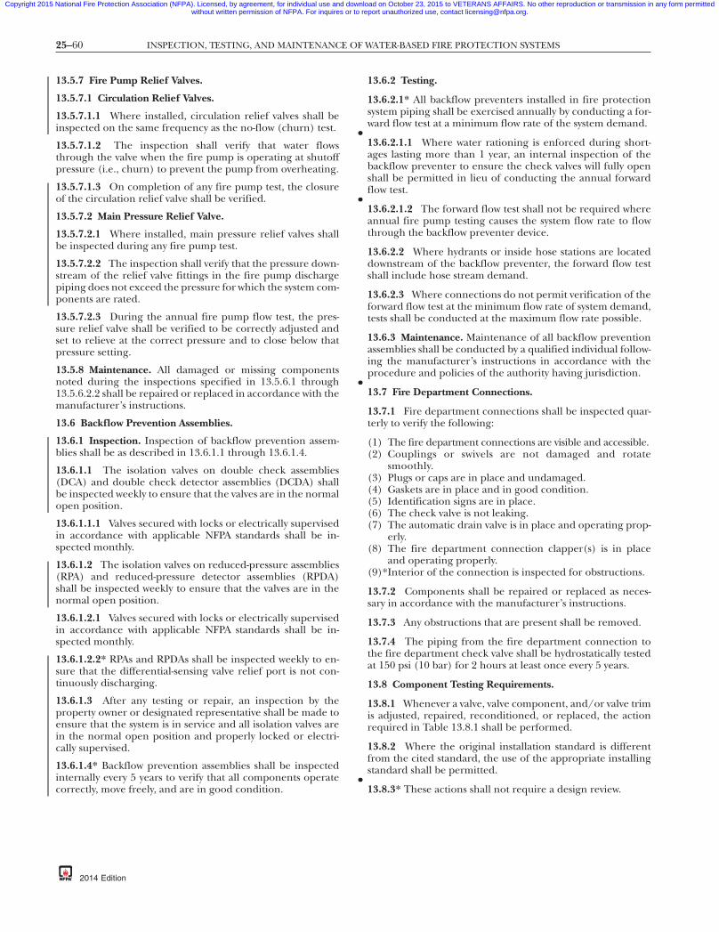
25–60 INSPECTION, TESTING, AND MAINTENANCE OF WATER-BASED FIRE PROTECTION SYSTEMS
•
•
•
•
Copyright 2015 National Fire Protection Association (NFPA). Licensed, by agreement, for individual use and download on October 23, 2015 to VETERANS AFFAIRS. No other reproduction or transmission in any form permittedwithout written permission of NFPA. For inquires or to report unauthorized use, contact [email protected].
-8
13.5.7 Fire Pump Relief Valves.
13.5.7.1 Circulation Relief Valves.
13.5.7.1.1 Where installed, circulation relief valves shall beinspected on the same frequency as the no-flow (churn) test.
13.5.7.1.2 The inspection shall verify that water flowsthrough the valve when the fire pump is operating at shutoffpressure (i.e., churn) to prevent the pump from overheating.
13.5.7.1.3 On completion of any fire pump test, the closureof the circulation relief valve shall be verified.
13.5.7.2 Main Pressure Relief Valve.
13.5.7.2.1 Where installed, main pressure relief valves shallbe inspected during any fire pump test.
13.5.7.2.2 The inspection shall verify that the pressure down-stream of the relief valve fittings in the fire pump dischargepiping does not exceed the pressure for which the system com-ponents are rated.
13.5.7.2.3 During the annual fire pump flow test, the pres-sure relief valve shall be verified to be correctly adjusted andset to relieve at the correct pressure and to close below thatpressure setting.
13.5.8 Maintenance. All damaged or missing componentsnoted during the inspections specified in 13.5.6.1 through13.5.6.2.2 shall be repaired or replaced in accordance with themanufacturer’s instructions.
13.6 Backflow Prevention Assemblies.
13.6.1 Inspection. Inspection of backflow prevention assem-blies shall be as described in 13.6.1.1 through 13.6.1.4.
13.6.1.1 The isolation valves on double check assemblies(DCA) and double check detector assemblies (DCDA) shallbe inspected weekly to ensure that the valves are in the normalopen position.
13.6.1.1.1 Valves secured with locks or electrically supervisedin accordance with applicable NFPA standards shall be in-spected monthly.
13.6.1.2 The isolation valves on reduced-pressure assemblies(RPA) and reduced-pressure detector assemblies (RPDA)shall be inspected weekly to ensure that the valves are in thenormal open position.
13.6.1.2.1 Valves secured with locks or electrically supervisedin accordance with applicable NFPA standards shall be in-spected monthly.
13.6.1.2.2* RPAs and RPDAs shall be inspected weekly to en-sure that the differential-sensing valve relief port is not con-tinuously discharging.
13.6.1.3 After any testing or repair, an inspection by theproperty owner or designated representative shall be made toensure that the system is in service and all isolation valves arein the normal open position and properly locked or electri-cally supervised.
13.6.1.4* Backflow prevention assemblies shall be inspectedinternally every 5 years to verify that all components operatecorrectly, move freely, and are in good condition.
{3e0bff22-698c-46e7
2014 Edition
13.6.2 Testing.
13.6.2.1* All backflow preventers installed in fire protectionsystem piping shall be exercised annually by conducting a for-ward flow test at a minimum flow rate of the system demand.
13.6.2.1.1 Where water rationing is enforced during short-ages lasting more than 1 year, an internal inspection of thebackflow preventer to ensure the check valves will fully openshall be permitted in lieu of conducting the annual forwardflow test.
13.6.2.1.2 The forward flow test shall not be required whereannual fire pump testing causes the system flow rate to flowthrough the backflow preventer device.
13.6.2.2 Where hydrants or inside hose stations are locateddownstream of the backflow preventer, the forward flow testshall include hose stream demand.
13.6.2.3 Where connections do not permit verification of theforward flow test at the minimum flow rate of system demand,tests shall be conducted at the maximum flow rate possible.
13.6.3 Maintenance. Maintenance of all backflow preventionassemblies shall be conducted by a qualified individual follow-ing the manufacturer’s instructions in accordance with theprocedure and policies of the authority having jurisdiction.
13.7 Fire Department Connections.
13.7.1 Fire department connections shall be inspected quar-terly to verify the following:
(1) The fire department connections are visible and accessible.(2) Couplings or swivels are not damaged and rotate
smoothly.(3) Plugs or caps are in place and undamaged.(4) Gaskets are in place and in good condition.(5) Identification signs are in place.(6) The check valve is not leaking.(7) The automatic drain valve is in place and operating prop-
erly.(8) The fire department connection clapper(s) is in place
and operating properly.(9)*Interior of the connection is inspected for obstructions.
13.7.2 Components shall be repaired or replaced as neces-sary in accordance with the manufacturer’s instructions.
13.7.3 Any obstructions that are present shall be removed.
13.7.4 The piping from the fire department connection tothe fire department check valve shall be hydrostatically testedat 150 psi (10 bar) for 2 hours at least once every 5 years.
13.8 Component Testing Requirements.
13.8.1 Whenever a valve, valve component, and/or valve trimis adjusted, repaired, reconditioned, or replaced, the actionrequired in Table 13.8.1 shall be performed.
13.8.2 Where the original installation standard is differentfrom the cited standard, the use of the appropriate installingstandard shall be permitted.
13.8.3* These actions shall not require a design review.
7db-eba3b3d7337a}

25–61VALVES, VALVE COMPONENTS, AND TRIM
Copyright 2015 National Fire Protection Association (NFPA). Licensed, by agreement, for individual use and download on October 23, 2015 to VETERANS AFFAIRS. No other reproduction or transmission in any form permittedwithout written permission of NFPA. For inquires or to report unauthorized use, contact [email protected].
Table 13.8.1 Summary of Component Replacement Action Requirements
Component AdjustRepair/
Recondition ReplaceInspection, Test, and Maintenance
Procedures
Water delivery components
Post indicator and wall indicator valves X X X (1) Inspect for leaks at system pressure(2) Perform full operational testconforming to 13.3.3.1(3) Perform spring torsion inspectionconforming to 13.3.3.1 and 13.3.3.2(4) Verify target visibility at shut andfull open position(5) Test supervisory device(6) Main drain test
Control valves other than postindicator and wall indicator valves
X X X (1) Inspect for leaks at system pressure(2) Perform full operational testconforming to 13.3.3.1(3) Perform spring torsion inspectionfor OS&Y valves conforming to13.3.3.2(4) Verify supervisory device(5) Main drain test
Alarm check valve X X X (1) Inspect for leaks at system pressureper 13.4.1(2) Test all alarms and supervisorysignals affected by the alarm valve(3) Main drain test
Dry pipe valve X X X (1) Inspect for leaks at system pressure(2) Trip test per 13.4.4.2(3) Inspect condition of valve seat(4) Test all dry pipe system alarms andsupervisory signals(5) Main drain test
Deluge/preaction valve X X X (1) Inspect for leaks at system pressureper 13.4.3(2) Trip test(3) Inspect condition of valve seat(4) Test all deluge/preaction systemalarms and supervisory signals(5) Main drain test
Quick-opening device X X X (1) Inspect for leaks at system pressureper 13.4.4.2.2(2) Trip test(3) Main drain test
Pressure-regulating device — hosevalves
X X X (1) Inspect for leaks at system pressureper 13.5.1(2) Full flow test(3) Main drain test (Only when acontrol valve has been closed)
Pressure-regulating devices — otherthan hose valves
X X X (1) Inspect for leaks at system pressureper Section 13.5(2) Test pressure setting with full flowand without flow(3) Test supervisory device and alarm(4) Main drain test
Hose valve X X X (1) Inspect for leaks at system pressureper 13.5.6(2) Main drain test
{3e0bff22-698c-46e7-87db-eba3b3d7337a}
(continues)
2014 Edition

25–62 INSPECTION, TESTING, AND MAINTENANCE OF WATER-BASED FIRE PROTECTION SYSTEMS
Copyright 2015 National Fire Protection Association (NFPA). Licensed, by agreement, for individual use and download on October 23, 2015 to VETERANS AFFAIRS. No other reproduction or transmission in any form permittedwithout written permission of NFPA. For inquires or to report unauthorized use, contact [email protected].
Table 13.8.1 Continued
Component AdjustRepair/
Recondition ReplaceInspection, Test, and Maintenance
Procedures
Backflow prevention device X X X (1) Inspect for leaks at system pressureper Section 13.6(2) Forward flow test per 13.6.2.1(3) Test supervisory device and alarm(4) Main drain test
Check valves X X X (1) Inspect for leaks at system pressureper 13.4.2(2) Inspect for leaking through checkvalve(3) Main drain test
Fire department connection X X (1) Inspect for leaks at system pressureper Section 13.7(2) Main drain test (Only when acontrol valve has been closed)
Fire department connection —sprinkler system(s)
X (1) Isolate and hydrostatic test for 2hours at 150 psi (10 bar)(2) Main drain test (Only when acontrol valve has been closed)
Fire department connection — otherthan sprinkler system(s)
X (1) Isolate and hydrostatic test for 2hours at 50 psi (3.5 bar) above thenormal working pressure [200 psi (14bar) minimum](2) Main drain test (Only when acontrol valve has been closed)
Strainers X X X Inspect and clean in accordance withmanufacturer’s instructions
Main drain valves X X X Main drain test per 13.2.5
Gauges X Calibrate per 13.2.7
Alarm and supervisory components
Alarm device X X X Test for conformance with NFPA 13and/or NFPA 72
Supervisory device X X X Test for conformance with NFPA 13and/or NFPA 72
System protection components
Pressure relief valve — fire pumpinstallation
X X X See 8.3.3.3 and 13.5.7
Pressure relief valve — other than firepump installation
X Verify relief valve is listed or approvedfor the application and set to thecorrect pressure
Informational components
Identification signs X X X Inspect for compliance with NFPA 13and 13.3.1
{3e0bff22-698c-46e7-87db-eba3b3d7337a}
2014 Edition

25–63IMPAIRMENTS
•
Copyright 2015 National Fire Protection Association (NFPA). Licensed, by agreement, for individual use and download on October 23, 2015 to VETERANS AFFAIRS. No other reproduction or transmission in any form permittedwithout written permission of NFPA. For inquires or to report unauthorized use, contact [email protected].
87
Chapter 14 Internal Piping Condition andObstruction Investigation
14.1* General. This chapter shall provide the minimum re-quirements for conducting investigations of fire protectionsystem piping for possible sources of materials that couldcause pipe blockage.
14.2 Assessment of Internal Condition of Piping.
14.2.1* An assessment of the internal condition of piping shallbe conducted on a frequency determined by 14.2.1.1 or14.2.1.2 for the purpose of inspecting for the presence of for-eign organic and inorganic material.
14.2.1.1 An assessment of the internal condition of pipingshall be conducted at a minimum of every 5 years or in accor-dance with 14.2.1.2 for the purpose of inspecting for the pres-ence of foreign organic and inorganic material.
14.2.1.2* Where an assessment frequency has been estab-lished by an approved risk analysis, the assessment shall beperformed at a frequency determined by the approved riskanalysis.
14.2.1.3 Tubercules or slime, if found, shall be tested for in-dications of microbiologically influenced corrosion (MIC).
14.2.1.4* If the presence of sufficient foreign organic or inor-ganic material is found to obstruct pipe or sprinklers, an ob-struction investigation shall be conducted as described in Sec-tion 14.3.
14.2.1.5 Nonmetallic pipe shall not be required to complywith Section 14.2.
14.2.2* In buildings having multiple wet pipe systems, everyother system shall have an assessment of the internal condi-tion of piping as described in 14.2.1.
14.2.2.1 During the next inspection frequency required by14.2.1.1 or 14.2.1.2, the alternate systems not assessed duringthe previous assessment shall be assessed as described in14.2.1.
14.2.2.2 If foreign organic and/or inorganic material is foundin any system in a building, all systems shall be assessed.
14.3 Obstruction Investigation and Prevention.
14.3.1* An obstruction investigation shall be conducted forsystem or yard main piping wherever any of the following con-ditions exist:
(1) Defective intake for fire pumps taking suction fromopen bodies of water
(2) The discharge of obstructive material during routine wa-ter tests
(3) Foreign materials in fire pumps, in dry pipe valves, or incheck valves
(4) Foreign material in water during drain tests or pluggingof inspector’s test connection(s)
(5) Unknown materials are heard in the system piping duringdraining, refilling, or otherwise flowing water through thesystem
(6) Plugged sprinklers(7) The presence of sufficient foreign organic or inorganic
material is found in the pipe(8) Failure to flush yard piping or surrounding public mains
following new installations or repairs(9) A record of broken public mains in the vicinity
{3e0bff22-698c-46e7-
(10) Abnormally frequent false tripping of a dry pipe valve(s)(11) A system that is returned to service after an extended
shutdown (greater than 1 year)(12) There is reason to believe that the sprinkler system con-
tains sodium silicate or highly corrosive fluxes in coppersystems
(13) A system has been supplied with raw water via the firedepartment connection
(14) Pinhole leaks(15) A 50 percent increase in the time it takes water to travel
to the inspector’s test connection from the time the valvetrips during a full flow trip test of a dry pipe sprinklersystem when compared to the original system accep-tance test
14.3.2* Systems shall be examined for internal obstructionswhere conditions exist that could cause obstructed piping.
14.3.2.1 If the condition has not been corrected or the con-dition is one that could result in obstruction of the pipingdespite any previous flushing procedures that have been per-formed, the system shall be examined for internal obstruc-tions every 5 years.
14.3.2.2* Internal examination shall be performed at the fol-lowing minimum four points:
(1) System valve(2) Riser(3) Cross main(4) Branch line
14.3.2.3* Alternative nondestructive examination methodsshall be permitted.
14.3.3* If an obstruction investigation indicates the presenceof sufficient material to obstruct pipe or sprinklers, a completeflushing program shall be conducted by qualified personnel.
14.3.4 Tubercules or slime, if found during an obstructioninvestigation, shall be tested for indications of microbiologi-cally influenced corrosion (MIC).
14.4 Ice Obstruction. Dry pipe or preaction sprinkler systempiping that protects or passes through freezers or cold storagerooms shall be inspected internally on an annual basis for iceobstructions at the point where the piping enters the refriger-ated area.
14.4.1 Alternative nondestructive examinations shall bepermitted.
14.4.2 All penetrations into the cold storage areas shall beinspected and, if an ice obstruction is found, additional pipeshall be examined to ensure no ice blockage exists.
Chapter 15 Impairments
15.1 General.
15.1.1 Minimum Requirements.
15.1.1.1 This chapter shall provide the minimum require-ments for a water-based fire protection system impairmentprogram.
15.1.1.2 Measures shall be taken during the impairment toensure that increased risks are minimized and the duration ofthe impairment is limited.
db-eba3b3d7337a}
2014 Edition
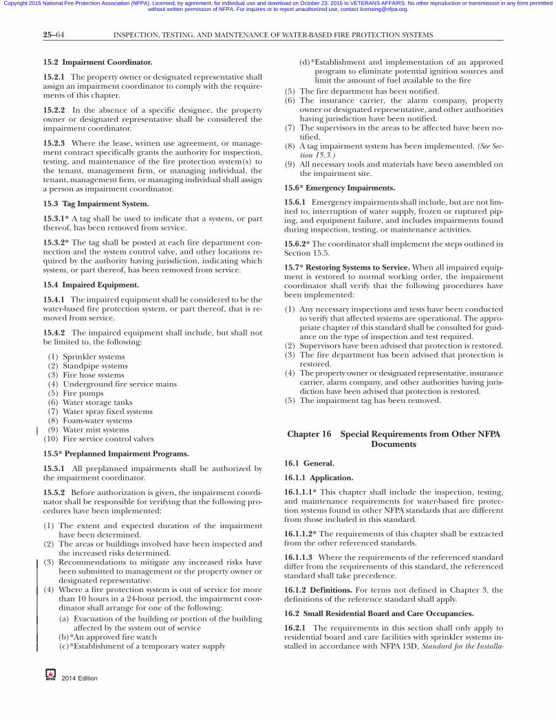
25–64 INSPECTION, TESTING, AND MAINTENANCE OF WATER-BASED FIRE PROTECTION SYSTEMS
Copyright 2015 National Fire Protection Association (NFPA). Licensed, by agreement, for individual use and download on October 23, 2015 to VETERANS AFFAIRS. No other reproduction or transmission in any form permittedwithout written permission of NFPA. For inquires or to report unauthorized use, contact [email protected].
-8
15.2 Impairment Coordinator.
15.2.1 The property owner or designated representative shallassign an impairment coordinator to comply with the require-ments of this chapter.
15.2.2 In the absence of a specific designee, the propertyowner or designated representative shall be considered theimpairment coordinator.
15.2.3 Where the lease, written use agreement, or manage-ment contract specifically grants the authority for inspection,testing, and maintenance of the fire protection system(s) tothe tenant, management firm, or managing individual, thetenant, management firm, or managing individual shall assigna person as impairment coordinator.
15.3 Tag Impairment System.
15.3.1* A tag shall be used to indicate that a system, or partthereof, has been removed from service.
15.3.2* The tag shall be posted at each fire department con-nection and the system control valve, and other locations re-quired by the authority having jurisdiction, indicating whichsystem, or part thereof, has been removed from service.
15.4 Impaired Equipment.
15.4.1 The impaired equipment shall be considered to be thewater-based fire protection system, or part thereof, that is re-moved from service.
15.4.2 The impaired equipment shall include, but shall notbe limited to, the following:
(1) Sprinkler systems(2) Standpipe systems(3) Fire hose systems(4) Underground fire service mains(5) Fire pumps(6) Water storage tanks(7) Water spray fixed systems(8) Foam-water systems(9) Water mist systems
(10) Fire service control valves
15.5* Preplanned Impairment Programs.
15.5.1 All preplanned impairments shall be authorized bythe impairment coordinator.
15.5.2 Before authorization is given, the impairment coordi-nator shall be responsible for verifying that the following pro-cedures have been implemented:
(1) The extent and expected duration of the impairmenthave been determined.
(2) The areas or buildings involved have been inspected andthe increased risks determined.
(3) Recommendations to mitigate any increased risks havebeen submitted to management or the property owner ordesignated representative.
(4) Where a fire protection system is out of service for morethan 10 hours in a 24-hour period, the impairment coor-dinator shall arrange for one of the following:(a) Evacuation of the building or portion of the building
affected by the system out of service(b)*An approved fire watch(c)*Establishment of a temporary water supply
{3e0bff22-698c-46e7
2014 Edition
(d)*Establishment and implementation of an approvedprogram to eliminate potential ignition sources andlimit the amount of fuel available to the fire
(5) The fire department has been notified.(6) The insurance carrier, the alarm company, property
owner or designated representative, and other authoritieshaving jurisdiction have been notified.
(7) The supervisors in the areas to be affected have been no-tified.
(8) A tag impairment system has been implemented. (See Sec-tion 15.3.)
(9) All necessary tools and materials have been assembled onthe impairment site.
15.6* Emergency Impairments.
15.6.1 Emergency impairments shall include, but are not lim-ited to, interruption of water supply, frozen or ruptured pip-ing, and equipment failure, and includes impairments foundduring inspection, testing, or maintenance activities.
15.6.2* The coordinator shall implement the steps outlined inSection 15.5.
15.7* Restoring Systems to Service. When all impaired equip-ment is restored to normal working order, the impairmentcoordinator shall verify that the following procedures havebeen implemented:
(1) Any necessary inspections and tests have been conductedto verify that affected systems are operational. The appro-priate chapter of this standard shall be consulted for guid-ance on the type of inspection and test required.
(2) Supervisors have been advised that protection is restored.(3) The fire department has been advised that protection is
restored.(4) The property owner or designated representative, insurance
carrier, alarm company, and other authorities having juris-diction have been advised that protection is restored.
(5) The impairment tag has been removed.
Chapter 16 Special Requirements from Other NFPADocuments
16.1 General.
16.1.1 Application.
16.1.1.1* This chapter shall include the inspection, testing,and maintenance requirements for water-based fire protec-tion systems found in other NFPA standards that are differentfrom those included in this standard.
16.1.1.2* The requirements of this chapter shall be extractedfrom the other referenced standards.
16.1.1.3 Where the requirements of the referenced standarddiffer from the requirements of this standard, the referencedstandard shall take precedence.
16.1.2 Definitions. For terms not defined in Chapter 3, thedefinitions of the reference standard shall apply.
16.2 Small Residential Board and Care Occupancies.
16.2.1 The requirements in this section shall only apply toresidential board and care facilities with sprinkler systems in-stalled in accordance with NFPA 13D, Standard for the Installa-
7db-eba3b3d7337a}

25–65ANNEX A
Copyright 2015 National Fire Protection Association (NFPA). Licensed, by agreement, for individual use and download on October 23, 2015 to VETERANS AFFAIRS. No other reproduction or transmission in any form permittedwithout written permission of NFPA. For inquires or to report unauthorized use, contact [email protected].
87
tion of Sprinkler Systems in One- and Two-Family Dwellings andManufactured Homes, as described in NFPA 101, Life Safety Code.
16.2.1.1 Systems installed in accordance with NFPA 13D, Stan-dard for the Installation of Sprinkler Systems in One- and Two-FamilyDwellings and Manufactured Homes, shall be inspected, tested, andmaintained in accordance with 33.2.3.5.8.1 through 33.2.3.5.8.15of NFPA 101, which reference specific sections of NFPA 25. Thefrequency of the inspection, test, or maintenance shall be in ac-cordance with [NFPA 101], whereas the purpose and procedureshall be from NFPA 25. [101:33.2.3.5.8]
16.2.1.1.1 Control valves shall be inspected monthly in accor-dance with 13.3.2 of NFPA 25. [101:33.2.3.5.8.1]
16.2.1.1.2 Gages shall be inspected monthly in accordancewith 13.2.7.1 of NFPA 25. [101:33.2.3.5.8.2]
16.2.1.1.3 Alarm devices shall be inspected quarterly in ac-cordance with 5.2.5 of NFPA 25. [101:33.2.3.5.8.3]
16.2.1.1.4 Alarm devices shall be tested semiannually in ac-cordance with 5.3.3 of NFPA 25. [101:33.2.3.5.8.4]
16.2.1.1.5 Valve supervisory switches shall be tested semiannu-ally in accordance with 13.3.3.5 of NFPA 25. [101:33.2.3.5.8.5]
16.2.1.1.6 Visible sprinklers shall be inspected annually inaccordance with 5.2.1 of NFPA 25. [101:33.2.3.5.8.6]
16.2.1.1.7 Visible pipe shall be inspected annually in accor-dance with 5.2.2 of NFPA 25. [101:33.2.3.5.8.7]
16.2.1.1.8 Visible pipe hangers shall be inspected annually inaccordance with 5.2.3 of NFPA 25. [101:33.2.3.5.8.8]
16.2.1.1.9 Buildings shall be inspected annually prior to theonset of freezing weather to ensure that there is adequate heatwherever water-filled piping is run in accordance with 5.2.5 ofNFPA 25. [101:33.2.3.5.8.9]
16.2.1.1.10 A representative sample of fast-response sprin-klers shall be tested once the sprinklers in the system are 20years old in accordance with 5.3.1.1.1.3 of NFPA 25. If thesample fails the test, all of the sprinklers represented by thatsample shall be replaced. If the sprinklers pass the test, the testshall be repeated every 10 years thereafter. [101:33.2.3.5.8.10]
16.2.1.1.11 A representative sample of dry-pendent sprinklersshall be tested once the sprinklers in the system are 10 yearsold in accordance with 5.3.1.1.1.6 of NFPA 25. If the samplefails the test, all of the sprinklers represented by that sampleshall be replaced. If the sprinklers pass the test, the test shallbe repeated every 10 years thereafter. [101:33.2.3.5.8.11]
16.2.1.1.12 Antifreeze solutions shall be tested annually inaccordance with 5.3.4 of NFPA 25. [101:33.2.3.5.8.12]
16.2.1.1.13 Control valves shall be operated through theirfull range and returned to normal annually in accordancewith 13.3.3.1 of NFPA 25. [101:33.2.3.5.8.13]
16.2.1.1.14 Operating stems of OS&Y valves shall be lubri-cated annually in accordance with 13.3.4 of NFPA 25.[101:33.2.3.5.8.14]
16.2.1.1.15 Dry-pipe systems that extend into the unheated por-tions of the building shall be inspected, tested, and maintained inaccordance with 13.4.4 of NFPA 25. [101:33.2.3.5.8.15]
{3e0bff22-698c-46e7-
Annex A Explanatory Material
Annex A is not a part of the requirements of this NFPA documentbut is included for informational purposes only. This annex containsexplanatory material, numbered to correspond with the applicable textparagraphs.
A.1.1.1.2 There are times when a single inspection or test canmeet the requirements of both NFPA 25 and NFPA 72 (e.g.,operation of a tamper switch). This standard does not neces-sarily require that two separate inspections or tests be con-ducted on the same component, provided the inspection ortest meets the requirements of both standards and the indi-vidual performing the inspection or test is qualified to per-form the inspection or test required by both standards.
A.1.1.3 Generally accepted NFPA installation practices forwater-based fire protection systems relevant to this standardare found in the following:
NFPA 13, Standard for the Installation of Sprinkler SystemsNFPA 13R, Standard for the Installation of Sprinkler Systems in
Low-Rise Residential OccupanciesNFPA 14, Standard for the Installation of Standpipe and Hose
SystemsNFPA 15, Standard for Water Spray Fixed Systems for Fire Protec-
tionNFPA 16, Standard for the Installation of Foam-Water Sprinkler
and Foam-Water Spray SystemsNFPA 20, Standard for the Installation of Stationary Pumps for
Fire ProtectionNFPA 22, Standard for Water Tanks for Private Fire ProtectionNFPA 24, Standard for the Installation of Private Fire Service
Mains and Their AppurtenancesNFPA 750, Standard on Water Mist Fire Protection Systems
A.1.1.3.1 The requirement to evaluate the adequacy of thedesign of the installed system is not a part of the periodicinspection, testing, and maintenance requirements of thisstandard. However, such evaluation is the responsibility of theproperty owner or designated representative as indicated in4.1.6 and 4.1.7.
A.1.1.4 For systems originally installed in accordance withone of these standards, the repair, replacement, alteration, orextension of such systems should also be performed in accor-dance with that same standard. When original installations arebased on other applicable codes or standards, repair, replace-ment, alteration, or extension practices should be conductedin accordance with those other applicable codes or standards.
A.1.2 History has shown that the performance reliability of awater-based fire protection system under fire-related condi-tions increases where comprehensive inspection, testing, andmaintenance procedures are enforced. Diligence during aninspection is important. The inspection, testing, and mainte-nance of some items in the standard might not be practical orpossible, depending on existing conditions. The inspectorshould use good judgment when making inspections.
A.1.3 An entire program of quality control includes, but isnot limited to, maintenance of equipment, inspection fre-quency, testing of equipment, on-site fire brigades, loss con-trol provisions, and personnel training. Personnel trainingcan be used as an alternative even if a specific frequency dif-fers from that specified in this standard.
db-eba3b3d7337a}
2014 Edition

25–66 INSPECTION, TESTING, AND MAINTENANCE OF WATER-BASED FIRE PROTECTION SYSTEMS
Copyright 2015 National Fire Protection Association (NFPA). Licensed, by agreement, for individual use and download on October 23, 2015 to VETERANS AFFAIRS. No other reproduction or transmission in any form permittedwithout written permission of NFPA. For inquires or to report unauthorized use, contact [email protected].
-8
A.1.4 The liter and bar units, which are not part of but arerecognized by SI, commonly are used in international fire pro-tection. These units are provided in Table A.1.4 with their con-version factors.
A.3.2.1 Approved. The National Fire Protection Associationdoes not approve, inspect, or certify any installations, proce-dures, equipment, or materials; nor does it approve or evalu-ate testing laboratories. In determining the acceptability ofinstallations, procedures, equipment, or materials, the author-ity having jurisdiction may base acceptance on compliancewith NFPA or other appropriate standards. In the absence ofsuch standards, said authority may require evidence of properinstallation, procedure, or use. The authority having jurisdic-tion may also refer to the listings or labeling practices of anorganization that is concerned with product evaluations and isthus in a position to determine compliance with appropriatestandards for the current production of listed items.
A.3.2.2 Authority Having Jurisdiction (AHJ). The phrase “au-thority having jurisdiction,” or its acronym AHJ, is used inNFPA documents in a broad manner, since jurisdictions andapproval agencies vary, as do their responsibilities. Where pub-lic safety is primary, the authority having jurisdiction may be afederal, state, local, or other regional department or indi-vidual such as a fire chief; fire marshal; chief of a fire preven-tion bureau, labor department, or health department; build-
Table A.1.4 Metric Conversions
Name of Unit Unit Symbol Conversion Factor
liter L 1 gal = 3.785 Lliter per minute
per squaremeter
L/min·m2 1 gpm/ft2 = 40.746L/min·m2
cubic decimeter dm3 1 gal = 3.785 dm3
pascal Pa 1 psi = 6894.757 Pabar bar 1 psi = 0.0689 barbar bar 1 bar = 105 Pa
Note: For additional conversions and information, see IEEE/ASTM-SI-10, American National Standard for Use of the International System ofUnits (SI): The Modern Metric System.
{3e0bff22-698c-46e7
ing official; electrical inspector; or others having statutory
2014 Edition
authority. For insurance purposes, an insurance inspection de-partment, rating bureau, or other insurance company repre-sentative may be the authority having jurisdiction. In manycircumstances, the property owner or his or her designatedagent assumes the role of the authority having jurisdiction; atgovernment installations, the commanding officer or depart-mental official may be the authority having jurisdiction.
A.3.2.3 Listed. The means for identifying listed equipmentmay vary for each organization concerned with product evalu-ation; some organizations do not recognize equipment aslisted unless it is also labeled. The authority having jurisdic-tion should utilize the system employed by the listing organi-zation to identify a listed product.
A.3.3.2 Alarm Receiving Facility. This can include proprietarysupervising stations, central supervising stations, remote supervis-ing stations, or public fire service communications centers.
A.3.3.3 Automatic Detection Equipment. Water spray systemscan use fixed temperature, rate-of-rise, rate-compensationfixed temperature, optical devices, flammable gas detectors,or products of combustion detectors.
A.3.3.4 Automatic Operation. This operation includes, but isnot limited to, heat, rate of heat rise, smoke, or pressurechange.
A.3.3.7 Deficiency. Depending on the nature and signifi-cance of the deficiency, it can result in a system impairment.Critical deficiencies will adversely impact performance butwithout the need for the implementing impairment proce-dures. Noncritical deficiencies have the potential to impactperformance.
Table A.3.3.7 provides examples for classifying conditionsneeding repair or correction that are identified during theinspection, testing, and maintenance of water-based suppres-sion systems. The conditions are classified as an impairment,critical deficiency, or noncritical deficiency. The table is notall-inclusive but is included to provide guidance in respondingto these conditions. For example, an impairment should beaddressed promptly by either immediately correcting the con-dition or implementing the impairment procedures found inChapter 15. Critical and noncritical deficiencies should becorrected as soon as practical after considering the nature andseverity of the risk. It should be noted that many jurisdictionshave requirements for the timely correction of impairments
7db-eba3b3d7337a}
and/or deficiencies.
Table A.3.3.7 Water-Based Fire Protection System Inspection and Testing Findings
Item Finding Reference ImpairmentCritical
DeficiencyNoncriticalDeficiency
Chapter 5: Sprinkler Systems — InspectionAll sprinklers Leaking — spraying or running
water5.2.1.1.1 X
All sprinklers Leaking — dripping water 5.2.1.1.1 XAll sprinklers Foreign material attached or
suspended from5.2.1.1.1 X
All sprinklers Spray pattern obstructed — lessthan 18 in. (457 mm) or 36 in.915 mm) below deflector (stock,furnishings, and equipment),temporary or nonpermanent(signs, banners, decorations, etc.)
5.2.1.1.1 X
All sprinklers Lightly loaded 5.2.1.1.1 X

25–67ANNEX A
Copyright 2015 National Fire Protection Association (NFPA). Licensed, by agreement, for individual use and download on October 23, 2015 to VETERANS AFFAIRS. No other reproduction or transmission in any form permittedwithout written permission of NFPA. For inquires or to report unauthorized use, contact [email protected].
Table A.3.3.7 Continued
Item Finding Reference ImpairmentCritical
DeficiencyNoncriticalDeficiency
Standard-response sprinklers innonresidential occupancies
One sprinkler and less than 50%of sprinklers in compartment isheavily loaded or corroded;painted operating element,bulb, deflector, or coverplate;improper orientation; glass bulbhas lost fluid
5.2.1.1.1 X
Standard-response sprinklers innonresidential occupancies
Two or more sprinklers incompartment are heavily loadedor corroded; painted operatingelement, bulb, deflector, orcoverplate; improperorientation; glass bulb has lostfluid
5.2.1.1.1 X
Fast-response element,quick-response, residentialsprinklers andstandard-response in residentialoccupancies
Any sprinklers, heavily loaded orcorroded; painted operatingelement, bulb, deflector, orcoverplate; improperorientation; glass bulb has lostfluid
5.2.1.1.1 X
Coverplates Concealed sprinkler coverplatescaulked or glued to ceiling
5.2.1.1.1 X
Escutcheons and coverplates Missing recessed or flushescutcheons, concealedcoverplate with deflector andoperating element in correctposition
5.2.1.1.6 X
Escutcheons and coverplates Missing recessed or flushescutcheons, concealedcoverplate with deflector andoperating element not incorrect position
5.2.1.1.6 X
Escutcheons Recessed or flush escutcheonscaulked or glued to ceiling
5.2.1.1.1 X
Spare sprinkler cabinet Cabinet missing, temperature over100°F, not proper number andtype, missing wrench for eachtype
new5.2.1.3(1), 5.2.1.3(2)
X
Pipe and fittings Leaking — slowly dripping and/ormoisture on surface
5.2.2.1 X
Pipe and fittings Leaking — spraying or runningwater
5.2.2.1 X
Pipe and fittings Critical mechanical damage XHangers and seismic braces Damaged or loose 5.2.3.2 XHangers and seismic braces Unattached 5.2.3.2 XGauges Poor condition 5.2.4.1 XGauges Not showing normal water/air
pressure5.2.4.1, 5.2.4.2 X
Gauges Freezer — system pressure lowerthan compressor
5.2.4.4 X
Alarm devices Physical damage apparent 5.2.5 XHydraulic design information sign Not attached properly, illegible or
missing5.2.6 X
Information sign Not attached, illegible or missing new XHeat tape Not in accordance with
manufacturer’s instructions5.2.7 X
Chapter 5: Sprinkler Systems — TestingGauges Not replaced or calibrated in 5
years, not accurate within 3% ofscale
5.3.2 X
Alarm devices Water motor and gong notfunctioning
5.3.3 X
Alarm devices Pressure switch– or vane-typeswitch not functioning or noalarm
5.3.3 X
(continues)
{3e0bff22-698c-46e7-87db-eba3b3d7337a}
2014 Edition

25–68 INSPECTION, TESTING, AND MAINTENANCE OF WATER-BASED FIRE PROTECTION SYSTEMS
Copyright 2015 National Fire Protection Association (NFPA). Licensed, by agreement, for individual use and download on October 23, 2015 to VETERANS AFFAIRS. No other reproduction or transmission in any form permittedwithout written permission of NFPA. For inquires or to report unauthorized use, contact [email protected].
Table A.3.3.7 Continued
Item Finding Reference ImpairmentCritical
DeficiencyNoncriticalDeficiency
Antifreeze systems Mixture and concentration doesnot meet requirements of5.3.4.2.1
5.3.4 X
Antifreeze systems Concentration is inadequate toprevent freezing
Table A.5.3.4.2.1(1) X
Main drain More than 10% drop in full flowpressure
13.2.5.2 X
Assessment of internal condition Inspection revealed presence ofMIC, zebra mussels, rust, andscale
14.2.1 X
Chapter 6: Standpipe and Hose Systems — InspectionPipe and fittings Leaking — slowly dripping and/or
moisture on surface6.2.1 X
Pipe and fittings Leaking — spraying or runningwater
6.2.1 X
Pipe and fittings Critical mechanical damage 6.2.1 XHose Cuts, couplings not of compatible
threads6.2.1, NFPA 1962 X
Hose Deterioration, no gasket ordamaged gaskets
6.2.1, NFPA 1962 X
Hose Mildew present, corrosion present,hose not connected
6.2.1, NFPA 1962 X
Hose nozzle Missing, broken parts or threadgasket damaged
6.2.1, NFPA 1962 X
Hose storage Hose not properly racked or rolled,nozzle clip missing, nozzle notcontained, damaged, obstructed
6.2.1, NFPA 1962 X
Cabinet Corroded or damaged parts, noteasy to open, not accessible, notidentified, door glazing in poorcondition, lock not functioning inbreak glass type, valve, hosenozzle, fire extinguisher, etc. notreadily accessible
6.2.1, NFPA 1962 X
Hydraulic design information sign Missing 6.2.3 X
Chapter 6: Standpipe and Hose Systems — TestingHose storage device Rack will not swing out of cabinet at
least 90 degrees6.2.1, NFPA 1962 X
Standpipe system Test results did not provide designpressure at required flow
6.3.1.1 X
Hydrostatic test of manual andsemiautomatic dry standpipesystems
Leakage in inside piping 6.3.2 X
Main drain More than 10% drop in full flowpressure
6.3.1.5 X
Assessment of internal condition Inspection revealed presence ofMIC, zebra mussels, rust, andscale
14.2.1 X
Chapter 7: Private Fire Service Mains — InspectionExposed piping Leaking — slowly dripping, and/or
moisture on surface7.2.2.1.2 X
Exposed piping Leaking — spraying or runningwater
7.2.2.1.2 X
Exposed piping Mechanical damage, corroded, notproperly restrained
7.2.2.1.2 X
Mainline strainers Plugged, fouled 7.2.2.3 XMainline strainers Corroded 7.2.2.3 XDry barrel, wet barrel, and wall
hydrantInaccessible, barrel contains ice,
cracks in barrel7.2.2.4 X
Dry barrel, wet barrel, and wallhydrant
Barrel contains water, improperdrainage from barrel, leaks atoutlets or top of hydrant
7.2.2.4 X
Dry barrel, wet barrel, and wallhydrant
Tightness of outlets, worn nozzlethreads, worn operating nut,missing wrench
7.2.2.4 X
Monitor nozzles Damaged, corroded, leaking 7.2.2.6 X
{3e0bff22-698c-46e7-87db-eba3b3d7337a}
2014 Edition

25–69ANNEX A
Copyright 2015 National Fire Protection Association (NFPA). Licensed, by agreement, for individual use and download on October 23, 2015 to VETERANS AFFAIRS. No other reproduction or transmission in any form permittedwithout written permission of NFPA. For inquires or to report unauthorized use, contact [email protected].
Table A.3.3.7 Continued
Item Finding Reference ImpairmentCritical
DeficiencyNoncriticalDeficiency
Hose/hydrant houses Inaccessible 7.2.2.7 XHose/hydrant houses Damaged 7.2.2.7 XHose/hydrant houses Not fully equipped 7.2.2.7 X
Chapter 7: Private Fire Service Mains — TestingUnderground and exposed piping Test results not comparable to
previous results7.3.1 X
Dry barrel and wall hydrant Hydrant did not flow clear or didnot drain within 60 minutes
7.3.2.1,7.3.2.4
X
Monitor nozzles Did not flow acceptable amount ofwater, did not operatethroughout their full range
7.3.3.17.3.3.2
X
Chapter 8: Fire Pumps — InspectionPump house/room Ventilating louvers not free to
operate8.2.2 X
Pump house/room Heat not adequate, temperatureless than 40°F
8.2.2(1) X
Pump house/room Heat not adequate, temperatureless than 70°F for diesel pumpswithout engine heaters
8.2.2(1) X
Pump house/room Heat not adequate, temperatureless than 40°F, not asrecommended by the enginemanufacturer, for diesel pumpswith engine heaters
8.2.2(1) X
Pump system Suction, discharge, or bypass valvesnot fully open, pipe leaking,suction line and system linepressure not normal, wet pitsuction screens obstructed
8.2.2 X
Pump system suction Reservoir empty 8.2.2 XPump system Suction reservoir does not have
required water level, wet pitsuction screens missing
8.2.2 X
Pump system Minor leaking or drips on floor 8.2.2(2) XPump system Suction, discharge, or bypass valves
not fully open, major leakingsuch as spraying or leaking toextent that pump performancemight be questioned
8.2.2(2) X
Electrical power to pump system No electrical power — controllerpilot light not illuminated,transfer switch pilot light notilluminated, isolating switch notclosed, reverse phase alarm pilotlight on or normal phase light isoff, oil level in vertical motorsight glass not normal
8.2.2(3) X
Electrical power to pump system Electrical power is provided —controller pilot light notilluminated, transfer switch pilotlight not illuminated, reversephase alarm pilot light on,normal phase light is notilluminated
8.2.2(3) X
Electrical power to pump system Circuit breakers and fusestripped/open
8.2.2(3) X
Diesel engine system Fuel tank empty 8.2.2 XDiesel engine system Alarm pilot lights are on 8.2.2(4) XDiesel engine system Battery charging current not
normal8.2.2(4) X
Diesel engine system Battery failure pilot lights on 8.2.2(4) XDiesel engine system Battery pilot lights off 8.2.2(4) XDiesel engine system Battery terminals corroded 8.2.2(4) XDiesel engine system Battery voltage readings not
normal8.2.2(4) X
Diesel engine system Controller selector switch not inauto position
8.2.2(4) X
{3e0bff22-698c-46e7-87db-eba3b3d7337a}
(continues)
2014 Edition
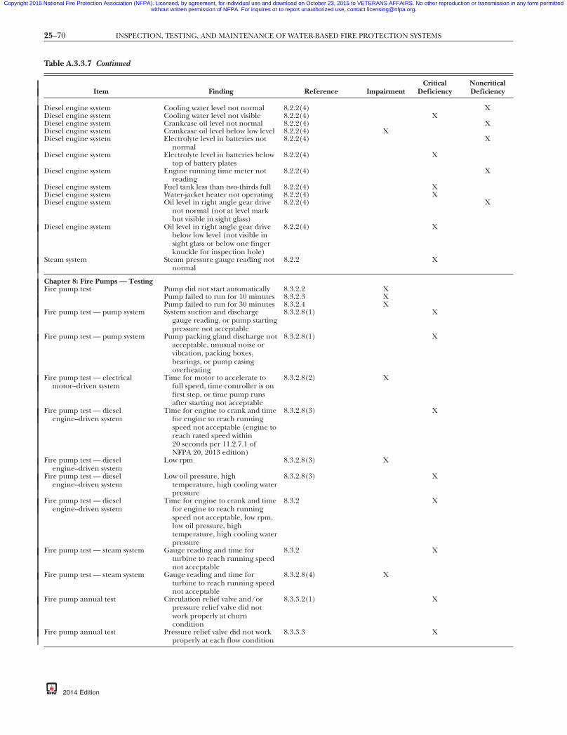
25–70 INSPECTION, TESTING, AND MAINTENANCE OF WATER-BASED FIRE PROTECTION SYSTEMS
Copyright 2015 National Fire Protection Association (NFPA). Licensed, by agreement, for individual use and download on October 23, 2015 to VETERANS AFFAIRS. No other reproduction or transmission in any form permittedwithout written permission of NFPA. For inquires or to report unauthorized use, contact [email protected].
Table A.3.3.7 Continued
Item Finding Reference ImpairmentCritical
DeficiencyNoncriticalDeficiency
Diesel engine system Cooling water level not normal 8.2.2(4) XDiesel engine system Cooling water level not visible 8.2.2(4) XDiesel engine system Crankcase oil level not normal 8.2.2(4) XDiesel engine system Crankcase oil level below low level 8.2.2(4) XDiesel engine system Electrolyte level in batteries not
normal8.2.2(4) X
Diesel engine system Electrolyte level in batteries belowtop of battery plates
8.2.2(4) X
Diesel engine system Engine running time meter notreading
8.2.2(4) X
Diesel engine system Fuel tank less than two-thirds full 8.2.2(4) XDiesel engine system Water-jacket heater not operating 8.2.2(4) XDiesel engine system Oil level in right angle gear drive
not normal (not at level markbut visible in sight glass)
8.2.2(4) X
Diesel engine system Oil level in right angle gear drivebelow low level (not visible insight glass or below one fingerknuckle for inspection hole)
8.2.2(4) X
Steam system Steam pressure gauge reading notnormal
8.2.2 X
Chapter 8: Fire Pumps — TestingFire pump test Pump did not start automatically 8.3.2.2 X
Pump failed to run for 10 minutes 8.3.2.3 XPump failed to run for 30 minutes 8.3.2.4 X
Fire pump test — pump system System suction and dischargegauge reading, or pump startingpressure not acceptable
8.3.2.8(1) X
Fire pump test — pump system Pump packing gland discharge notacceptable, unusual noise orvibration, packing boxes,bearings, or pump casingoverheating
8.3.2.8(1) X
Fire pump test — electricalmotor–driven system
Time for motor to accelerate tofull speed, time controller is onfirst step, or time pump runsafter starting not acceptable
8.3.2.8(2) X
Fire pump test — dieselengine–driven system
Time for engine to crank and timefor engine to reach runningspeed not acceptable (engine toreach rated speed within20 seconds per 11.2.7.1 ofNFPA 20, 2013 edition)
8.3.2.8(3) X
Fire pump test — dieselengine–driven system
Low rpm 8.3.2.8(3) X
Fire pump test — dieselengine–driven system
Low oil pressure, hightemperature, high cooling waterpressure
8.3.2.8(3) X
Fire pump test — dieselengine–driven system
Time for engine to crank and timefor engine to reach runningspeed not acceptable, low rpm,low oil pressure, hightemperature, high cooling waterpressure
8.3.2 X
Fire pump test — steam system Gauge reading and time forturbine to reach running speednot acceptable
8.3.2 X
Fire pump test — steam system Gauge reading and time forturbine to reach running speednot acceptable
8.3.2.8(4) X
Fire pump annual test Circulation relief valve and/orpressure relief valve did notwork properly at churncondition
8.3.3.2(1) X
Fire pump annual test Pressure relief valve did not workproperly at each flow condition
8.3.3.3 X
{3e0bff22-698c-46e7-87db-eba3b3d7337a}
2014 Edition

25–71ANNEX A
Copyright 2015 National Fire Protection Association (NFPA). Licensed, by agreement, for individual use and download on October 23, 2015 to VETERANS AFFAIRS. No other reproduction or transmission in any form permittedwithout written permission of NFPA. For inquires or to report unauthorized use, contact [email protected].
Table A.3.3.7 Continued
Item Finding Reference ImpairmentCritical
DeficiencyNoncriticalDeficiency
Fire pump annual test (withtransfer switch)
Overcurrent protective devicesopened when simulating apower failure condition at peakload, power not transferred toalternate source, pump did notcontinue to perform at peakload, pump did not reconnectto normal power after removingpower failure condition
8.3.3.4 X
Fire pump annual test Alarms did not properly operate 8.3.3.5 XPump house/room Heating, lighting, ventilating
systems did not pass test8.3.4.3 X
Fire pump annual test Parallel or angular alignment notcorrect
8.3.4.4 X
Fire pump annual test Flow test results not within 5% ofacceptance test or nameplate
8.3.5.4 X
Fire pump annual test Voltage readings at motor notwithin 5% below or 10% aboverated (nameplate)
8.3.5.6 X
Fire pump annual test Flow test results not within 5% ofinitial unadjusted acceptancetest or nameplate
8.3.5.4 X
Chapter 9: Water Storage Tanks — InspectionWater level Water level and/or condition not
correct9.2.1 X
Water level Tank is empty 9.2.1 XAir pressure Air pressure in pressure tanks not
correct9.2.2 X
Heating system Heating system not operational,water temperature below 40°F
9.2.3 X
Heating system Water temperature at or below32°F
9.2.3 X
Exterior Tank exterior, supportingstructure, vents, foundation,catwalks, or ladders whereprovided damaged
9.2.5.1 X
Exterior Area around tank has fireexposure hazard in form ofcombustible storage, trash,debris, brush, or material
9.2.5.2 X
Exterior Accumulation of material on ornear parts that could result inaccelerated corrosion or rot
9.2.5.2 X
Exterior Ice buildup on tank and support 9.2.5.2 XExterior Erosion exists on exterior sides or
top of embankments supportingcoated fabric tanks
9.2.5.2 X
Exterior Expansion joints leaking orcracking
9.2.5.3 X
Exterior Hoops and grilles of wooden tanksin poor condition
9.2.5.4 X
Exterior Exterior painted, coated, orinsulated surfaces of tanks orsupporting structure degraded
9.2.5.5 X
Interior (pressure tanks or steeltanks w/o corrosion protectionevery 3 years, all others every5 years)
Pitting, corrosion, spalling, rot,other forms of deterioration,waste materials exist, aquaticgrowth, local or general failureof interior coating
9.2.6.3 X
Interior (pressure tanks or steeltanks w/o corrosion protectionevery 3 years, all others every5 years)
Voids beneath floor, with sand inmiddle of tanks on ring-typefoundations
9.2.6.5 X
Interior (pressure tanks or steeltanks w/o corrosion protectionevery 3 years, all others every5 years)
Heating system components orpiping in poor condition butworking
9.2.6.6 X
{3e0bff22-698c-46e7-87db-eba3b3d7337a}
(continues)
2014 Edition

25–72 INSPECTION, TESTING, AND MAINTENANCE OF WATER-BASED FIRE PROTECTION SYSTEMS
Copyright 2015 National Fire Protection Association (NFPA). Licensed, by agreement, for individual use and download on October 23, 2015 to VETERANS AFFAIRS. No other reproduction or transmission in any form permittedwithout written permission of NFPA. For inquires or to report unauthorized use, contact [email protected].
Table A.3.3.7 Continued
Item Finding Reference ImpairmentCritical
DeficiencyNoncriticalDeficiency
Interior (pressure tanks or steeltanks w/o corrosion protectionevery 3 years, all others every5 years)
Heating system components orheating system piping in poorcondition and not working
9.2.6.6 X
Interior (pressure tanks or steeltanks w/o corrosion protectionevery 3 years, all others every5 years)
Blockage of antivortex plate 9.2.6.7 X
Interior (pressure tanks or steeltanks w/o corrosion protectionevery 3 years, all others every5 years)
Deterioration of antivortex plate 9.2.6.7 X
Chapter 9: Water Storage Tanks — TestingInterior testing Tank coating did not pass
adhesion, coating thickness, orwet sponge test
9.2.7 X
Interior testing Tank walls and bottoms did notpass ultrasonic test
9.2.7 X
Interior testing Tank bottom seams did not passvacuum-box test
9.2.7 X
Testing Level indicator not tested after5 years, lacked freedom ofmovement, or not accurate
9.3.1 X
Testing Low water temperature alarm didnot pass test
9.3.3 X
Testing High water temperature limitswitch did not pass test
9.3.4 X
Testing High and low water level alarmsdid not pass test
9.3.5 X
Gauges Not tested in 5 years, not accuratewithin 3% of scale
9.3.6 X
Chapter 10: Water Spray Fixed Systems — InspectionPipe and fittings Mechanical damage, missing or
damaged paint or coating,rusted or corroded, notproperly aligned or trappedsections, low point drains notfunctioning, improper locationof rubber-gasketed fittings
10.2.4.1 X
Hangers and seismic braces Damaged or missing, not securelyattached to structural or piping,missing or damaged paint orcoating, rusted or corroded
10.2.4.2 X
Water spray nozzles Discharge devices missing, notproperly positioned or pointedin design direction, loaded orcorroded
10.2.5.1 X
Water spray nozzles Missing caps or plugs if required,or not free to operate asintended
10.2.5.2 X
Strainers Strainer plugged or fouled 10.2.7 XStrainers Strainer damaged or corroded 10.2.7 XDrainage Trap sumps and drainage trenches
blocked, retentionembankments or dikes indisrepair
10.2.8 X
Ultra-high-speed Detectors have physical damage ordeposits on lenses of opticaldetectors
10.4.2 X
Ultra-high-speed Controllers found to have faults 10.4.3 X
Chapter 10: Water Spray Fixed Systems — TestingOperational test Heat detection system did not
operate within 40 seconds,flammable gas detection systemdid not operate within20 seconds
10.3.4.1.1 X
{3e0bff22-698c-46e7-87db-eba3b3d7337a}
2014 Edition
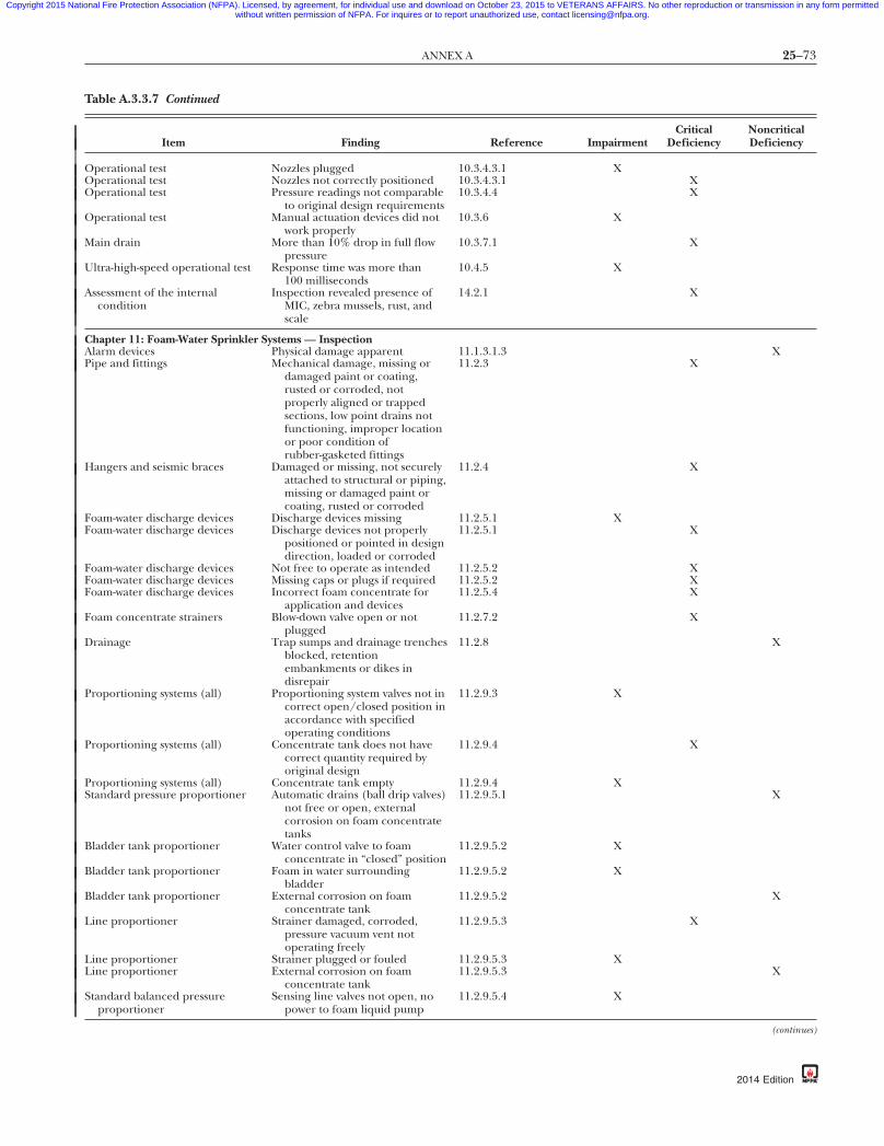
25–73ANNEX A
Copyright 2015 National Fire Protection Association (NFPA). Licensed, by agreement, for individual use and download on October 23, 2015 to VETERANS AFFAIRS. No other reproduction or transmission in any form permittedwithout written permission of NFPA. For inquires or to report unauthorized use, contact [email protected].
Table A.3.3.7 Continued
Item Finding Reference ImpairmentCritical
DeficiencyNoncriticalDeficiency
Operational test Nozzles plugged 10.3.4.3.1 XOperational test Nozzles not correctly positioned 10.3.4.3.1 XOperational test Pressure readings not comparable
to original design requirements10.3.4.4 X
Operational test Manual actuation devices did notwork properly
10.3.6 X
Main drain More than 10% drop in full flowpressure
10.3.7.1 X
Ultra-high-speed operational test Response time was more than100 milliseconds
10.4.5 X
Assessment of the internalcondition
Inspection revealed presence ofMIC, zebra mussels, rust, andscale
14.2.1 X
Chapter 11: Foam-Water Sprinkler Systems — InspectionAlarm devices Physical damage apparent 11.1.3.1.3 XPipe and fittings Mechanical damage, missing or
damaged paint or coating,rusted or corroded, notproperly aligned or trappedsections, low point drains notfunctioning, improper locationor poor condition ofrubber-gasketed fittings
11.2.3 X
Hangers and seismic braces Damaged or missing, not securelyattached to structural or piping,missing or damaged paint orcoating, rusted or corroded
11.2.4 X
Foam-water discharge devices Discharge devices missing 11.2.5.1 XFoam-water discharge devices Discharge devices not properly
positioned or pointed in designdirection, loaded or corroded
11.2.5.1 X
Foam-water discharge devices Not free to operate as intended 11.2.5.2 XFoam-water discharge devices Missing caps or plugs if required 11.2.5.2 XFoam-water discharge devices Incorrect foam concentrate for
application and devices11.2.5.4 X
Foam concentrate strainers Blow-down valve open or notplugged
11.2.7.2 X
Drainage Trap sumps and drainage trenchesblocked, retentionembankments or dikes indisrepair
11.2.8 X
Proportioning systems (all) Proportioning system valves not incorrect open/closed position inaccordance with specifiedoperating conditions
11.2.9.3 X
Proportioning systems (all) Concentrate tank does not havecorrect quantity required byoriginal design
11.2.9.4 X
Proportioning systems (all) Concentrate tank empty 11.2.9.4 XStandard pressure proportioner Automatic drains (ball drip valves)
not free or open, externalcorrosion on foam concentratetanks
11.2.9.5.1 X
Bladder tank proportioner Water control valve to foamconcentrate in “closed” position
11.2.9.5.2 X
Bladder tank proportioner Foam in water surroundingbladder
11.2.9.5.2 X
Bladder tank proportioner External corrosion on foamconcentrate tank
11.2.9.5.2 X
Line proportioner Strainer damaged, corroded,pressure vacuum vent notoperating freely
11.2.9.5.3 X
Line proportioner Strainer plugged or fouled 11.2.9.5.3 XLine proportioner External corrosion on foam
concentrate tank11.2.9.5.3 X
Standard balanced pressureproportioner
Sensing line valves not open, nopower to foam liquid pump
11.2.9.5.4 X
{3e0bff22-698c-46e7-87db-eba3b3d7337a}
(continues)
2014 Edition

25–74 INSPECTION, TESTING, AND MAINTENANCE OF WATER-BASED FIRE PROTECTION SYSTEMS
Copyright 2015 National Fire Protection Association (NFPA). Licensed, by agreement, for individual use and download on October 23, 2015 to VETERANS AFFAIRS. No other reproduction or transmission in any form permittedwithout written permission of NFPA. For inquires or to report unauthorized use, contact [email protected].
Table A.3.3.7 Continued
Item Finding Reference ImpairmentCritical
DeficiencyNoncriticalDeficiency
Standard balanced pressureproportioner
Strainer damaged, corroded,plugged, or fouled, pressurevacuum vent not operatingfreely, gauges damaged or notshowing proper pressures
11.2.9.5.4 X
In-line balanced pressureproportioner
Sensing line valves at pump unit orindividual proportioner stationsnot open, no power to foamliquid pump
11.2.9.5.5 X
In-line balanced pressureproportioner
Strainer damaged, corroded,pressure vacuum vent notoperating freely, gaugesdamaged or not showing properpressures
11.2.9.5.5 X
In-line balanced pressureproportioner
Strainer plugged or fouled 11.2.9.5.5 X
Orifice plate proportioner No power to foam liquid pump 11.2.9.5.6 XOrifice plate proportioner Strainer damaged, corroded,
pressure vacuum vent notoperating freely, gaugesdamaged or not showing properpressures
11.2.9.5.6 X
Orifice plate proportioner Strainer plugged or fouled 11.2.9.5.6 X
Chapter 11: Foam-Water Sprinkler Systems — TestingAlarm devices Water motor and gong not
functioning11.1.3.1.1,11.3.1.1
X
Alarm devices Pressure switch or vane-type switchnot functioning or no alarm
11.1.3.1.2,11.3.1.2
X
Operational test Fire detection system did notoperate within requirements ofNFPA 72
11.3.2.4 X
Operational test Nozzles plugged 11.3.2.6.1 XOperational test Nozzles not correctly positioned 11.3.2.6.1 XOperational test Pressure readings not comparable
to original design requirements11.3.2.7.3 X
Operational test Manual actuation devices notworking properly
11.3.4 X
Operational test Foam sample failed concentrationtest
11.3.5 X
Main drain More than 10% drop in full flowpressure
13.2.5.2 X
Assessment of internal condition Inspection revealed presence ofMIC, zebra mussels, rust, andscale
14.2.1 X
Chapter 13: Valves, Valve Components, and Trim — InspectionGauges Poor condition 13.2.7.1 XGauges Not showing normal water/air
pressure13.2.7.1 X
Control valve Improper closed position 13.3.2.2 XControl valve Improper open position, leaking 13.3.2.2 XControl valve Not accessible, no appropriate
wrench if required, noidentification
13.3.2.2 X
Control valve Not sealed, locked, or supervised 13.3.2.2 XAlarm valve External physical damage, trim
valves not in appropriate openor closed position, retardchamber or alarm drain leaking
13.4.1.1 X
Valve enclosure Upon visual observation, enclosurenot maintaining minimum 40°F(4°C) temperature
13.4.3.1.1,13.4.4.1.1
X
Valve enclosure Low temperature alarms (ifinstalled) are physicallydamaged
13.4.3.1.1,13.4.4.1.1
X
{3e0bff22-698c-46e7-87db-eba3b3d7337a}
2014 Edition

25–75ANNEX A
Copyright 2015 National Fire Protection Association (NFPA). Licensed, by agreement, for individual use and download on October 23, 2015 to VETERANS AFFAIRS. No other reproduction or transmission in any form permittedwithout written permission of NFPA. For inquires or to report unauthorized use, contact [email protected].
Table A.3.3.7 Continued
Item Finding Reference ImpairmentCritical
DeficiencyNoncriticalDeficiency
Preaction valve and deluge valve External physical damage, trimvalves not in appropriate openor closed position, valve seatleaking
13.4.3.1.6 X
Preaction valve and deluge valve Electrical components not inservice
13.4.3.1.6 X
Dry pipe valve/quick-openingdevice
External physical damage, trimvalves not in appropriate openor closed position, intermediatechamber leaking
13.4.4.1.4 X
Sprinkler pressure-reducingcontrol valves
Not in open position 13.5.1.1 X
Sprinkler pressure-reducingcontrol valves
Not maintaining downstreampressures in accordance withdesign criteria
13.5.1.1 X
Sprinkler pressure-reducingcontrol valves
Leaking, valve damaged, handwheel missing or broken
13.5.1.1 X
Hose connectionpressure-reducing valves
Hand wheel broken or missing,hose threads damaged, leaking,reducer missing
13.5.2.1 X
Hose connectionpressure-reducing valves
Cap missing 13.5.2.1 X
Hose rack assemblypressure-reducing valve
Hand wheel broken or missing,leaking
13.5.3.1 X
Hose valves Leaking, visible obstructions, caps,hose threads, valve handle, capgasket, no restricting device,damaged, or in poor condition
13.5.6.1 X
Hose valves Hose threads not compatible 13.5.6.1 XBackflow prevention assemblies Reduced-pressure assemblies,
differential-sensing valve reliefport continuously discharging
13.6.1.2 X
Fire department connection Not accessible, damagedcouplings, or clapper notoperating properly or missing
13.7.1 X
Fire department connection Couplings and swivels damaged,do not rotate smoothly, checkvalve leaking, automatic drainnot operating properly ormissing
13.7.1 X
Fire department connection Missing identification sign 13.7.1 X
Chapter 13: Valves, Valve Components, and Trim — TestingMain drain More than 10% drop in full flow
pressure13.2.5.2 X
Alarm devices Water motor and gong notfunctioning
13.2.6.1 X
Alarm devices Pressure switch or vane-type switchnot functioning, no alarm
13.2.6.2 X
Gauges Not replaced or calibrated in5 years, not accurate within 3%of scale
13.2.7.2,13.2.7.3
X
Control valve Valve not operating through its fullrange
13.3.3.1 X
Control valve No spring or torsion felt in rodwhen opening post indicatorvalve
13.3.3.2 X
Supervisory switches No signal from two revolutions ofhand wheel from normalposition or when stem hasmoved one-fifth of distancefrom normal position, signalrestored in position other thannormal
13.3.3.5.2 X
Preaction valve Priming water level not correct 13.4.3.2.1 X
(continues)
{3e0bff22-698c-46e7-87db-eba3b3d7337a}
2014 Edition

25–76 INSPECTION, TESTING, AND MAINTENANCE OF WATER-BASED FIRE PROTECTION SYSTEMS
Copyright 2015 National Fire Protection Association (NFPA). Licensed, by agreement, for individual use and download on October 23, 2015 to VETERANS AFFAIRS. No other reproduction or transmission in any form permittedwithout written permission of NFPA. For inquires or to report unauthorized use, contact [email protected].
Table A.3.3.7 Continued
Item Finding Reference ImpairmentCritical
DeficiencyNoncriticalDeficiency
Preaction valve Pressure reading at hydraulicallymost remote nozzle and/or atvalve not comparable to originaldesign values
13.4.4.2.2.2 X
Preaction valve Three-year leakage test failed 13.4.3.2.6 XDeluge valve Annual full flow trip test revealed
plugged nozzles, manualactuation devices did notoperate properly
13.4.3.2.2.3 X
Deluge valve Pressure reading at hydraulicallymost remote nozzle and/or atvalve not compatible withoriginal design values
13.4.3.2.2.3 X
Preaction valve Low air pressure switch did notsend signal, no alarm
13.4.3.2.12 X
Preaction and deluge valve Low temperature switch did notsend signal, no alarm
13.4.3.2.13 X
Preaction valve Automatic air maintenance devicedid not pass test
13.4.3.2.14 X
Dry pipe valve Priming water level not correct 13.4.4.2.1 XDry pipe valve Test results not comparable with
previous results13.4.4.2.2 X
Quick-opening device Quick-opening device did not passtest
13.4.4.2.4 X
Dry pipe valve Low air pressure switch did notsend signal, no alarm
13.4.4.2.6 X
Dry pipe valve Low temperature switch did notsend signal, no alarm
13.4.4.2.7 X
Dry pipe valve Automatic air maintenance devicedid not pass test
13.4.4.2.8 X
Dry pipe system Three-year leakage test failed 13.4.4.2.9 XSprinkler pressure-reducing
control valvesTest results not comparable to
previous results13.5.1.2 X
Hose connectionpressure-reducing valves
Test results not comparable toprevious results
13.5.2.2 X
Hose rack assemblypressure-reducing valve
Test results not comparable toprevious results
13.5.3.2 X
Hose valves (Class I and Class IIIstandpipe system)
Annual test revealed valve leakingor difficult to operate
13.5.6.2.1.1 X
Hose valves (Class II standpipesystem)
Test revealed valve leaking ordifficult to operate
13.5.6.2.2,13.5.6.2.2.1
X
Backflow prevention assemblies Did not pass forward flow test 13.6.2.1 X
{3e0bff22-698c-46e7-87db-eba3b3d7337a}
The table does not take into account every variation of theconditions needing repair or correction. For example, a singlelightly painted sprinkler in a large warehouse might be non-critical in its risk while a single painted sprinkler in a battery-charging station might be considered a critical deficiency orperhaps an impairment. In addition, the nature of the hazardor the life safety exposure of the occupancy should be consid-ered when assigning a classification. The table should be usedwith good judgment and could require input from the author-ity having jurisdiction.
A.3.3.10.2 Sectional Drain. An example of a sectional drain isa drain located beyond a floor control valve on a multistorybuilding.
A.3.3.12 Fire Hydrant. See Figure A.3.3.12(a) andFigure A.3.3.12(b).
A.3.3.12.1 Dry Barrel Hydrant (Frostproof Hydrant). A drainis located at the bottom of the barrel above the control valveseat for proper drainage after operation to prevent freezing.See Figure A.3.3.12.1.
2014 Edition
A.3.3.12.2 Monitor Nozzle Hydrant. See Figure A.3.3.12.2.
A.3.3.12.3 Wall Hydrant. See Figure A.3.3.12.3.
A.3.3.12.4 Wet Barrel Hydrant. See Figure A.3.3.12.4.
A.3.3.13 Foam Concentrate. For the purpose of this document,foam concentrate and concentrate are used interchangeably.
A.3.3.16 Hose House. See Figure A.3.3.16(a) throughFigure A.3.3.16(c).
A.3.3.19.1 Conventional Pin Rack. See Figure A.3.3.19.1.
A.3.3.19.2 Horizontal Rack. See Figure A.3.3.19.2.
A.3.3.19.3 Hose Reel. See Figure A.3.3.19.3.
A.3.3.19.4 Semiautomatic Hose Rack Assembly. SeeFigure A.3.3.19.4.

25–77ANNEX A
Copyright 2015 National Fire Protection Association (NFPA). Licensed, by agreement, for individual use and download on October 23, 2015 to VETERANS AFFAIRS. No other reproduction or transmission in any form permittedwithout written permission of NFPA. For inquires or to report unauthorized use, contact [email protected].
18 in. (457 mm)
Hydrantconnection valve
Thrustblock
Thrust blockagainstundisturbedsoil
Flat stone orconcrete slab
Smallstonesfordrainage
FIGURE A.3.3.12(a) Typical Fire Hydrant Connection.
87
Grade 27³⁄₈ in. (695 mm) × 24³⁄₈ in. (619 mm)
13¹⁄₁₆ in. (332 mm)
24 in.(607 mm)
trench(minimum)
FIGURE A.3.3.12(b) Flush-Type Hydrant.
{3e0bff22-698c-46e7-
Bonnet
Valve rod
Valve guide
Barrel
Valve leather
BootStrappinglugs
Drain
Gauge hole
Nozzle section
Valve seat ring
Oil hole
Weather hood
Stuffing box
Bonnet drainOperating stem(bronze)
FIGURE A.3.3.12.1 Dry Barrel Hydrant.
db-eba3b3d7337a}
FIGURE A.3.3.12.2 Hydrant with Monitor Nozzle.
2014 Edition

25–78 INSPECTION, TESTING, AND MAINTENANCE OF WATER-BASED FIRE PROTECTION SYSTEMS
Copyright 2015 National Fire Protection Association (NFPA). Licensed, by agreement, for individual use and download on October 23, 2015 to VETERANS AFFAIRS. No other reproduction or transmission in any form permittedwithout written permission of NFPA. For inquires or to report unauthorized use, contact [email protected].
4 in. (100 mm)minimum nonrisingstem gate valve
Specialcoupling
Square rod
Blank wall
Pipe sleeve
Capped wrench head valvecontrol or wall-type indicator post Capped outlets
Ball dripconnection below 4 in. (100 mm)
minimum pipe
Escutcheon plate
Wallopening
Plan
Minimum 6 in. (150 mm) valved water supply
FIGURE A.3.3.12.3 Wall Hydrant.
-8
Thrust block
Yokes and rods
Ductile iron
Thrustblock
Cross section showing operatingvalve arrangement (typical)
Operatingnut
Compressionvalve (one foreach outlet)
Operating nut
Valve carrier
Seat washer
Hydrant caps
Hydrant outlet
Seat washerretainer
Chain
FIGURE A.3.3.12.4 Wet Barrel Hydrant. (Courtesy of the Los
{3e0bff22-698c-46e7
Angeles Department of Water and Power.)
2014 Edition
FIGURE A.3.3.16(a) Hose House of Five-Sided Design forInstallation over Private Hydrant.
FIGURE A.3.3.16(b) Steel Hose House of Compact Dimen-sions for Installation over Private Hydrant. House is shownclosed; top lifts up, and doors on front side open for completeaccessibility.
7db-eba3b3d7337a}
FIGURE A.3.3.16(c) Hose House That Can Be Installed onLegs, As Pictured, or on Wall Near, but Not Directly over, Pri-vate Hydrant.

FIGURE A.3.3.19.1 Conventional Pin Rack.
FIGURE A.3.3.19.3 Constant Flow Hose Reel.
25–79ANNEX A
Copyright 2015 National Fire Protection Association (NFPA). Licensed, by agreement, for individual use and download on October 23, 2015 to VETERANS AFFAIRS. No other reproduction or transmission in any form permittedwithout written permission of NFPA. For inquires or to report unauthorized use, contact [email protected].
87
A.3.3.21 Impairment. The use of the phrase fire protection sys-tem or unit is a broad reference to those terms used in titles ofChapters 5 through 12. Some fire protection features are re-ferred to as systems in the installation standards (e.g., sprin-kler, standpipe, water spray, foam-water, and water mist), orare referred to as units (e.g., fire pumps), and others use nei-ther term (e.g., private service fire mains and water tanks). Forthe purpose of this standard, the term unit refers to a firepump and its connections required by NFPA 20, or a waterstorage tank and its connections required by NFPA 22, or aprivate service fire main and its connections required byNFPA 24. The use of the term unit in the definitions of impair-ment, deficiency, critical deficiency, and noncritical deficiencyis not referring to an individual component such as a sprin-kler, valve, fitting, switch, piece of pipe, and so forth.
Temporarily shutting down a system as part of performingthe routine inspection, testing, and maintenance on that sys-tem while under constant attendance by qualified personnel,and where the system can be restored to service quickly,should not be considered an impairment. Good judgmentshould be considered for the hazards presented.
A.3.3.21.1 Emergency Impairment. Examples of emergencyimpairments might include a ruptured pipe, an operatedsprinkler, or an interruption of the water supply to the system.
A.3.3.24 Inspection, Testing, and Maintenance Service. Thisprogram includes logging and retention of relevant records.
A.3.3.27.1 Monitor Nozzle. Monitor nozzles can be used toprotect large amounts of combustible materials, aircraft, tankfarms, and any other special hazard. See Figure A.3.3.27.1(a)and Figure A.3.3.27.1(b).
A.3.3.27.2 Water Spray Nozzle. The selection of the type andsize of spray nozzles should have been made with proper con-sideration given to factors such as physical character of thehazard involved, draft or wind conditions, material likely to beburning, and the general purpose of the system.
High velocity spray nozzles, generally used in piped instal-lations, discharge in the form of a spray-filled cone. Low veloc-ity spray nozzles usually deliver a much finer spray in the formof either a spray-filled spheroid or cone. Due to differences inthe size of orifices or waterways in the various nozzles and therange of water particle sizes produced by each type, nozzles ofone type cannot ordinarily be substituted for those of anothertype in an individual installation without seriously affectingfire extinguishment. In general, the higher the velocity and
FIGURE A.3.3.19.4 Semiautomatic Hose Rack Assembly.
db-eba3b3d7337a}
FIGURE A.3.3.19.2 Horizontal Rack.
{3e0bff22-698c-46e7-
2014 Edition
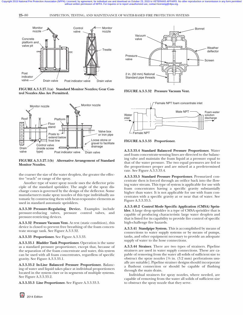
25–80 INSPECTION, TESTING, AND MAINTENANCE OF WATER-BASED FIRE PROTECTION SYSTEMS
Copyright 2015 National Fire Protection Association (NFPA). Licensed, by agreement, for individual use and download on October 23, 2015 to VETERANS AFFAIRS. No other reproduction or transmission in any form permittedwithout written permission of NFPA. For inquires or to report unauthorized use, contact [email protected].
-8
the coarser the size of the water droplets, the greater the effec-tive “reach” or range of the spray.Another type of water spray nozzle uses the deflector prin-ciple of the standard sprinkler. The angle of the spray dis-charge cones is governed by the design of the deflector. Somemanufacturers make spray nozzles of this type individually au-tomatic by constructing them with heat-responsive elements asused in standard automatic sprinklers.
A.3.3.30 Pressure-Regulating Device. Examples includepressure-reducing valves, pressure control valves, andpressure-restricting devices.
A.3.3.32 Pressure Vacuum Vent. At rest (static condition), thisdevice is closed to prevent free breathing of the foam concen-trate storage tank. See Figure A.3.3.32.
A.3.3.33 Proportioner. See Figure A.3.3.33.
A.3.3.33.1 Bladder Tank Proportioner. Operation is the sameas a standard pressure proportioner, except that, because ofthe separation of the foam concentrate and water, this systemcan be used with all foam concentrates, regardless of specificgravity. See Figure A.3.3.33.1.
A.3.3.33.2 In-Line Balanced Pressure Proportioner. Balanc-ing of water and liquid takes place at individual proportionerslocated in the system riser or in segments of multiple systems.See Figure A.3.3.33.2.
A.3.3.33.3 Line Proportioner. See Figure A.3.3.33.3.
Concreteplatform andvalve pit
Postindicatorvalve Post indicator valve Drain valve
Controlvalve
Monitornozzle
Monitornozzle
Drain valve
Trestle
FIGURE A.3.3.27.1(a) Standard Monitor Nozzles; Gear Con-trol Nozzles Also Are Permitted.
Loose stone orgravel to facilitatedrainage
Posts toextend belowfrost line
Post indicator valve Drain valve
Control valve(inside screwtype)
Monitor nozzle
Platform
Drainvalve
Valve boxor iron pipe
Monitor nozzle
Floorstand
Roof
FIGURE A.3.3.27.1(b) Alternative Arrangement of StandardMonitor Nozzles.{3e0bff22-698c-46e7
2014 Edition
A.3.3.33.4 Standard Balanced Pressure Proportioner. Waterand foam concentrate-sensing lines are directed to the balanc-ing valve and maintain the foam liquid at a pressure equal tothat of the water pressure. The two equal pressures are fed tothe proportioner proper and are mixed at a predeterminedrate. See Figure A.3.3.33.4.
A.3.3.33.5 Standard Pressure Proportioner. Pressurized con-centrate then is forced through an orifice back into the flow-ing water stream. This type of system is applicable for use withfoam concentrates having a specific gravity substantiallyhigher than water. It is not applicable for use with foam con-centrates with a specific gravity at or near that of water. SeeFigure A.3.3.33.5.
A.3.3.40.2 Control Mode Specific Application (CMSA) Sprin-kler. A large drop sprinkler is a type of CMSA sprinkler that iscapable of producing characteristic large water droplets andthat is listed for its capability to provide fire control of specifichigh-challenge fire hazards.
A.3.3.41 Standpipe System. This is accomplished by means ofconnections to water supply systems or by means of pumps,tanks, and other equipment necessary to provide an adequatesupply of water to the hose connections.
A.3.3.44 Strainer. There are two types of strainers. Pipelinestrainers are used in water supply connections. These are ca-pable of removing from the water all solids of sufficient size toobstruct the spray nozzles [1⁄8 in. (3.2 mm) perforations usu-ally are suitable]. Pipeline strainer designs should incorporatea flushout connection or should be capable of flushingthrough the main drain.
Individual strainers for spray nozzles, where needed, arecapable of removing from the water all solids of sufficient sizeto obstruct the spray nozzle that they serve.
Bonnet
Weatherdeflector
Screen
Vacuumvalve
Pressurevalve
2 in. (50 mm) NationalStandard pipe threads
FIGURE A.3.3.32 Pressure Vacuum Vent.
Foam-watersolutiondischarge
Waterinlet
Female NPT
Female NPT foam concentrate inlet
Male NPT
FIGURE A.3.3.33 Proportioner.
7db-eba3b3d7337a}

FIGURE A.3.3.33.3 Line Proportioner.
25–81ANNEX A
Copyright 2015 National Fire Protection Association (NFPA). Licensed, by agreement, for individual use and download on October 23, 2015 to VETERANS AFFAIRS. No other reproduction or transmission in any form permittedwithout written permission of NFPA. For inquires or to report unauthorized use, contact [email protected].
A.3.3.47 Testing. These tests follow up on the original accep-tance test at intervals specified in the appropriate chapter ofthis standard.
A.3.3.49 Valve Status Test Connection. These connectionscan include the main drain, fire pump test header, backflowpreventer forward flow test connection, fire hydrant, andother similar locations. In the absence of the aforementioneddevices, an inspector’s test connection might be used.
A.3.3.50 Water Spray. Water spray fixed systems are usuallyapplied to special fire protection problems, since the protec-tion can be specifically designed to provide for fire control,extinguishment, or exposure protection. Water spray fixed sys-tems are permitted to be independent of, or supplementaryto, other forms of protection.
A.3.5.1 Control Valve. Experience has shown that closedvalves are the primary cause of failure of water-based fire pro-tection systems in protected occupancies. Control valves donot include hose valves, inspector’s test valves, drain valves,trim valves for dry pipe, preaction and deluge valves, checkvalves, or relief valves.
A.3.5.2 Deluge Valve. Each deluge valve is intended to be ca-pable of automatic and manual operation.
Valve description
Valve no.1
1A23456789
Description Manual system Auto system
Normal position
Closed
Open
ClosedClosedClosedClosedClosedClosedClosed
Closed
Open
ClosedClosedClosedClosedClosedClosedClosed
Closed
Lwr. sight gauge (opt.)Upr. sight gauge (opt.)Concentrate drain/fillWater fillDiaph. conc. ventTank water ventFill cup shutoffWater pres. shutoffAuto. conc. shutoffConcentrate shutoff
N/A
balanced re proportioner
Foam solution
WaterFoam concentrateFoam solutionWater sensing
Flush-in connectionFlush-out connection
Strainer
Pressure gauge
Ratio controller
Pressure-regulating valve
Diaphragm balancing valvepressure-regulating servicewith manual override
Swing check valve
Pressure relief valve
Shutoff valve
db-eba3b3d7337a}
11A
9
8
6
Foamconcentratefeed line
Ratio controller
End View
Flow
Springcheckvalve
Supportbracket
4
2
3
1
75
Side View
Water feed line
FIGURE A.3.3.33.1 Bladder Tank Proportioner.
In-line pressu
Foam concentratepump and motorassembly
Pressure gauge
Foamconcentratesupply valve
Pressurevacuumvent
Expansion dome andcleanout opening Fill connection with fill funnel
Foam concentratestorage tank
Drain valve
Foam concentratereturn valve
Foamsolution
{3e0bff22-698c-46e7-87
FIGURE A.3.3.33.2 In-Line Balanced Pressure Proportioner.Note:Automation ofthis valve permitsthe activation ofthis system fromany remotesignaling source
Watersupply
Foamconcentratestorage tank
Expansion dome
Pressurevacuum vent
Pressure gauge
Side outlet strainer with valve
Pipe union
Check valve
Gate valve or ball valve
2014 Edition

r.
25–82 INSPECTION, TESTING, AND MAINTENANCE OF WATER-BASED FIRE PROTECTION SYSTEMS
Copyright 2015 National Fire Protection Association (NFPA). Licensed, by agreement, for individual use and download on October 23, 2015 to VETERANS AFFAIRS. No other reproduction or transmission in any form permittedwithout written permission of NFPA. For inquires or to report unauthorized use, contact [email protected].
A.3.5.5.1 Master Pressure-Reducing Valve. Master pressure-reducing valves are typically found downstream of a firepump’s discharge.
A.3.6.3 Private Fire Service Main. See Figure A.3.6.3.
A.3.6.4 Sprinkler System. A sprinkler system is considered tohave a single system riser control valve. The design and instal-lation of water supply facilities such as gravity tanks, firepumps, reservoirs, or pressure tanks are covered by NFPA 20,Standard for the Installation of Stationary Pumps for Fire Protection,and NFPA 22, Standard for Water Tanks for Private Fire Protection.
Legend: 1 Water supply valve (normally closed) 2 Ratio controller 3 or tubing recommended
4 pipe or tubing recommended
5 Sensing line valves (normally open) 6 Diaphragm control valve — automatic pressure balance — must be in vertical position
7 Block valves (normally open) 8 Manual bypass valve (normally open) 9 Water and concentrate pressure gauge (duplex) 10 Foam concentrate storage tank 11 Concentrate storage tank fill connection 12 Pressure vacuum vent 13 Concentrate storage tank drain valve (normally closed) 14 Foam concentrate pump and motor 15 Concentrate pump supply valve (normally open) 16 Pressure relief valve (setting as required by system) 17 Concentrate pump discharge valve (normally open) 18 Electric motor starter and switch
1211
10
6
7
9
54
S
16
14
A8
19
22
13
15
21
18
B
Water balance line — minimum ³⁄₁₆ in. (5 mm) I.D. pipe
Concentrate balance line — minimum ³⁄₁₆ in. (5 mm) I.D.
FIGURE A.3.3.33.4 Standard Balanced Pressure Proportione
{3e0bff22-698c-46e7
2014 Edition
A.3.6.4.6 Wet Pipe Sprinkler System. Hose connections [11⁄2 in.(40 mm) hose, valves, and nozzles] supplied by sprinkler systempiping are considered components of the sprinkler system.
A.3.6.6 Water Spray System. Automatic systems can be actu-ated by separate detection equipment installed in the samearea as the water spray nozzles or by the water spray nozzlesusing an operating element. In some cases, the automatic de-tector can also be located in another area. [15: A.3.3.21]
A.3.7.1 Frequency. The frequencies in NFPA 25 are intendedto establish an optimal time between tasks that are required by
Concentrate return line valve (normally open)
Strainer with valved side outlet Compound gauge
ration:rt concentrate pump (18). Open water supply valve (1).n concentrate pump discharge valve (17). Equal gaugeings then maintained at (9) by the automatic valve (6).
manual operation, valves (7) can be closed and equalge readings maintained by regulating valve (8) manually.
tem Automation:utomating certain valves, the balanced pressureortioning system can be activated from any remotealing source.
ater supply valve (1), normally closed, to be automaticallyerated;ncentrate pump discharge valve (17), normally closed, to automatically operated;
ectric motor starter switch (18) to be automatically operated.
17
D5 pipe
diameters
5 pipe
diameters
discharge
5
2 1
20
Water supply
Gate valve
Check valve
Manual bypass valve
Side outlet strainer with valve
Flush-out connection
Reducer
Ball drip valve — ³⁄₄ in. (20 mm) (install in horizontal position)
7db-eba3b3d7337a}
19 20 21 22
OpeStaOpereadForgau
SysBy apropsign
• W op• Co be• El
olution
C
3
-8

25–83ANNEX A
Copyright 2015 National Fire Protection Association (NFPA). Licensed, by agreement, for individual use and download on October 23, 2015 to VETERANS AFFAIRS. No other reproduction or transmission in any form permittedwithout written permission of NFPA. For inquires or to report unauthorized use, contact [email protected].
87
this document. When scheduling conflicts or other conditionsdo not allow the tasks to be performed on a strict calendarschedule, it is important that the required task frequencies beidentified and complied with according to the variances de-scribed in the frequency definitions. When the required taskfrequencies have not been followed, it should be noted on theinspection report, the task should be performed, and the taskfrequencies should be followed for all future tasks. The vari-ances should not be used to “skip” tasks or to perform fewertasks than called for in this document.
A.4.1.1 Any portion or all of the inspection, testing, andmaintenance can be permitted to be contracted with an in-spection, testing, and maintenance service.
A.4.1.1.1 In order to ensure compliance, the owner shouldverify that windows, skylights, doors, ventilators, other open-ings and closures, concealed spaces, unused attics, stair tow-ers, roof houses, and low spaces under buildings do not ex-pose water-filled piping to freezing. This should occur prior tothe onset of cold weather and periodically thereafter.
A.4.1.1.3 Examples of designated representatives can includethe occupant, management firm, or managing individualthrough specific provisions in the lease, written use agree-ment, or management contract.
A.4.1.2 Other means of freeze protection for water-filled pip-ing including heated valve enclosures, heat tracing, insula-tion, antifreeze solutions, or other methods are allowed by theapplicable installation standard. Installation standards requireheat tracing protecting fire protection piping against freezingto be supervised.
A.4.1.3 The components are not required to be open or ex-posed. Doors, removable panels, or valve pits can be permittedto satisfy the need for accessibility. Such equipment should notbe obstructed by features such as walls, ducts, columns, directburial, or stock storage.
A.4.1.5 Recalled products should be replaced or remedied.Remedies include entrance into a program for scheduled re-placement. Such replacement or remedial product should beinstalled in accordance with the manufacturer’s instructionsand the appropriate NFPA installation standards. A recalled
PPH operating he
Ball drip va
Inspectionand fill vent
Drainvalve
Normally closed
Water supply
Water inlet
Note:Automation of this valve permitsthe activation of this systemfrom any remote signaling source
Water bypass
Liquid fill connection
FIGURE A.3.3.33.5 Standard Pressure Proportioner.
{3e0bff22-698c-46e7-
product is a product subject to a statute or administrative regu-lation specifically requiring the manufacturer, importer, dis-tributor, wholesaler, or retailer of a product, or any combina-tion of such entities, to recall the product, or a productvoluntarily recalled by a combination of such entities.
Needed corrections and repairs should be classified as animpairment, critical deficiency, or noncritical deficiency ac-cording to the effect on the fire protection system and thenature of the hazard protected.
Impairments are the highest priority problem found dur-ing inspection, testing, and maintenance and should be cor-rected as soon as possible. The fire protection system cannotprovide an adequate response to a fire, and implementationof impairment procedures outlined in Chapter 15 is requireduntil the impairment is corrected.
Critical deficiencies need to be corrected in a timely fash-ion. The fire protection system is still capable of performing,but its performance can be impacted and the implementationof impairment procedures might not be needed. However,special consideration must be given to the hazard in the deter-mination of the classification. A deficiency that is critical forone hazard might be an impairment in another.
Noncritical deficiencies do not affect the performance ofthe fire protection system but should be corrected in a reason-able time period so that the system can be properly inspected,tested, and maintained.
Assembly occupancies, health care facilities, prisons, high-rise buildings, other occupancies where the life safety expo-sure is significant, or facilities that cannot be evacuated in atimely manner require special consideration. As an example, anonfunctioning waterflow alarm might be considered a criti-cal deficiency in a storage warehouse but an impairment in ahospital.
High hazard occupancies where early response to a fire iscritical also require special consideration. A small number ofpainted sprinklers could be considered an impairment for asystem protecting a high hazard occupancy but might be con-sidered a critical deficiency in a metal working shop.
Classifications of needed corrections and repairs are shownin Table A.3.3.7.
olution discharge valve(s)
Pressure proportioner
db-eba3b3d7337a}
Sad
lve
2014 Edition

25–84 INSPECTION, TESTING, AND MAINTENANCE OF WATER-BASED FIRE PROTECTION SYSTEMS
Copyright 2015 National Fire Protection Association (NFPA). Licensed, by agreement, for individual use and download on October 23, 2015 to VETERANS AFFAIRS. No other reproduction or transmission in any form permittedwithout written permission of NFPA. For inquires or to report unauthorized use, contact [email protected].
-8
A.4.1.5.1 System deficiencies not explained by normal wearand tear, such as hydraulic shock, can often be indicators ofsystem problems and should be investigated and evaluated bya qualified person or engineer. Failure to address these issuescould lead to catastrophic failure. Examples of deficienciesthat can be caused by issues beyond normal wear and tear areas follows:
(1) Pressure gauge deficiencies as follows:(a) Gauge not returning to zero(b) Gauge off scale(c) Gauge with bent needle
(2) Support devices deficiencies as follows:
See NFPA 221
Post indicator valve
Monitor nozzle
Building
Water tank
See NFPA 202
Fire pump
1
1
1
1
To water spray fixed system or open sprinkler system
Post indicatorvalve
Post indicator valve
1
1
Private property line
1
Note: The piping (aboveground or buried) shown is specific as to the end of the private fire service main, and this schematic is only for illustrative purposes beyond the end of the fire service main. Details of valves and their location requirements are covered in the specific standard involved.1. See NFPA 22, Standard for Water Tanks for Private Fire Protection, 2013.2. See NFPA 20, Standard for the Installation of Stationary Pumps for Fire Protection, 2013.
Check valve
Control valves
Check valve
Pump discharge valve
Hydrant
From jockey pumpFrom fire pump (if needed)To fire pump (if needed)To jockey pump
Check valve
Public main
End of private fire service main
FIGURE A.3.6.3 Typical Private Fire Service Main. [24:Fig-ure A.3.3.11]
{3e0bff22-698c-46e7
2014 Edition
(a) Bent hangers and/or rods(b) Hangers pulled out/off structure(c) Indication of pipe or hanger movement such as the
following:i. Hanger scrape marks on pipe, exposed pipe sur-
face where pipe and hangers are paintedii. Firestop material damaged at pipe penetration
of fire-rated assembly(3) Unexplained system damage as follows:
(a) Unexplained system damage beyond normal wearand tear
(b) Bent or broken shafts on valves(c) Bent or broken valve clappers(d) Unexplained leakage at branch lines, cross main, or
feed main piping(e) Unexplained leakage at closed nipples(f) Loose bolts on flanges and couplings
(4) Fire pump deficiencies as follows:(a) Fire pump driver out of alignment(b) Vibration of fire pump and/or driver(c) Unusual sprinkler system piping noises (sharp re-
port, loud bang)
A.4.1.6 The inspections and tests specified in this standarddo not address the adequacy of design criteria or the capabilityof the fire protection system to protect the building or its con-tents. It is assumed that the original system design and instal-lation were appropriate for the occupancy and use of thebuilding and were approved by all applicable authorities hav-ing jurisdiction. If no changes to the water supply or to thebuilding or its use have transpired since it was originally occu-pied, no evaluation is required. If changes are contemplated,it is the owner’s responsibility to arrange for the evaluation ofthe fire protection system(s). Where the inspections and testsspecified in the standard have been contracted to a qualifiedinspection provider or contractor, it is not the role of the in-spector or contractor to determine if any changes have beenmade or the subsequent evaluation of the fire protection sys-tem. The evaluation of any building changes should be con-ducted before any proposed change is incorporated andshould utilize the appropriate installation standard and inputfrom applicable authorities having jurisdiction.
Fire protection systems should not be removed from ser-vice when the building is not in use; however, where a systemthat has been out of service for a prolonged period (such as inthe case of idle or vacant properties) is returned to service, it isrecommended that a responsible and experienced contractorbe retained to perform all inspections and tests.
A.4.1.7 See Annex E for an example of a hazard evaluationform. A hazard evaluation is not part of a system inspection.
A.4.3.1 Inspection reports used for system inspections shouldcontain an “Owner’s Section” as shown in Figure A.4.3.1 thatthe property owner or designated representative should com-plete. Typical records include, but are not limited to, valveinspections; flow, drain, and pump tests; and trip tests of drypipe, deluge, and preaction valves.
Acceptance test records should be retained for the life of thesystem or its special components. Subsequent test records shouldbe retained for a period of 1 year after the next test. The compari-son determines deterioration of system performance or condi-tion and the need for further testing or maintenance.
7db-eba3b3d7337a}

25–85ANNEX A
Copyright 2015 National Fire Protection Association (NFPA). Licensed, by agreement, for individual use and download on October 23, 2015 to VETERANS AFFAIRS. No other reproduction or transmission in any form permittedwithout written permission of NFPA. For inquires or to report unauthorized use, contact [email protected].
87
A.4.3.1.1 Computer programs that file inspection and testresults should provide a means of comparing current and pastresults and should indicate the need for corrective mainte-nance or further testing.A.4.3.3 See Section B.2 for information regarding sampleforms.
A.4.5 Inspection and periodic testing determine what, if any,maintenance actions are required to maintain the operabilityof a water-based fire protection system. The standard estab-lishes minimum inspection/testing frequencies, responsibili-ties, test routines, and reporting procedures but does not de-fine precise limits of anomalies where maintenance actionsare required.
Substandard conditions, such as a closed valve, subnor-mal water pressure, loss of building heat or power, or ob-struction of sprinklers, nozzles, detectors, or hose stations,can delay or prevent system actuation and impede manualfire-fighting operations.
A.4.6.4 The types of tests required for each protection systemand its components, and the specialized equipment requiredfor testing, are detailed in the appropriate chapter.
As referred to in 4.3.4, original records should include, at aminimum, the contractor’s material and test certificate, “as-built” drawings and calculations, and any other required orpertinent test reports. These documents establish the condi-tions under which the systems were first installed and offersome insight to the design intent, installation standards used,and water supply present at the time of installation. Originalrecords are instrumental in determining any subsequentchanges or modifications to the buildings or system.
© 2013 National Fire Protection Association
Owner’s Section
A. Is the building occupied?
B. Has the occupancy and hazard of contents remained t
C. Are all fire protection systems in service?
D. Has the system remained in service without modifica
E. Was the system free of actuation of devices or alarms
Explain any “no” answers:
Owner or Designated Representative (print)
FIGURE A.4.3.1 Owner’s Section on Inspection Report.
{3e0bff22-698c-46e7-
A.4.6.5 Examples of subsystems or components include firepumps, drivers or controllers, pressure-regulating devices, de-tection systems and controls, alarm check, and dry pipe, del-uge, and preaction valves. The required tests for componentsare contained in the corresponding chapter in tables titledSummary of [Component] Inspection, Testing, and Maintenance.A.4.6.6 Some devices, such as waterflow alarms, can be testedautomatically. Some things to consider include the following:
(1) Automatic tests should be arranged to test the same func-tions as the required tests.
(2) Components and arrangements of automated testsshould be listed for the purpose and designed so that fail-ure of the testing equipment should not impair the opera-tion of the system unless indicated by a trouble or super-visory signal in accordance with NFPA 72.
(3) Failure of a component or system to pass an automatic testshould result in an audible trouble signal in accordancewith NFPA 72.
(4) Not all tests required by NFPA 25 can be suitable for auto-matic testing.
(5) Periodic visual inspection including the use of videoshould be performed.
A.4.7 Section 4.7 provides the option to adopt a performance-based test and inspection method as an alternative means of com-pliance with 4.6.2. The prescriptive test and requirements con-tained in this standard are essentially qualitative. Equivalent orsuperior levels of performance can be demonstrated throughquantitative performance-based analyses. This section provides abasis for implementing and monitoring a performance-basedprogram acceptable under this option (providing approval is ob-tained by the authority having jurisdiction).
NFPA 25
❏ Yes ❏ No
e since the last inspection? ❏ Yes ❏ No
❏ Yes ❏ No
nce the last inspection? ❏ Yes ❏ No
the last inspection? ❏ Yes ❏ No
ignature and Date
db-eba3b3d7337a}
he sam
tion si
since
S
2014 Edition

25–86 INSPECTION, TESTING, AND MAINTENANCE OF WATER-BASED FIRE PROTECTION SYSTEMS
Copyright 2015 National Fire Protection Association (NFPA). Licensed, by agreement, for individual use and download on October 23, 2015 to VETERANS AFFAIRS. No other reproduction or transmission in any form permittedwithout written permission of NFPA. For inquires or to report unauthorized use, contact [email protected].
-8
The concept of a performance-based testing and inspectionprogram is to establish the requirements and frequencies atwhich inspection must be performed to demonstrate an accept-able level of operational reliability. The goal is to balance theinspection/test frequency with proven reliability of the system orcomponent. The goal of a performance-based inspection pro-gram is also to adjust test/inspection frequencies commensuratewith historical documented equipment performance and de-sired reliability. Frequencies of test/inspection under aperformance-based program can be extended or reduced fromthe prescriptive test requirements contained in this standardwhen continued testing has been documented indicating ahigher or lower degree of reliability compared to the authorityhaving jurisdiction’s expectations of performance. Additionalprogram attributes that should be considered when adjustingtest/inspection frequencies include the following:
(1) System/component preventive maintenance programs(2) Consequences of system maloperation(3) System/component repair history(4) Building/service conditions
Fundamental to implementing a performance-based pro-gram is that adjusted test and inspection frequencies must betechnically defensible to the authority having jurisdiction andsupported by evidence of higher or lower reliability. Data collec-tion and retention must be established so that the data utilized toalter frequencies are representative, statistically valid, and evalu-ated against firm criteria. Frequencies should not arbitrarily beextended or reduced without a suitable basis and rationale. Itmust be noted that transitioning to a performance-based pro-gram might require additional expenditures of resources in or-der to collect and analyze failure data, coordinate review efforts,replace program documents, and seek approval from the author-ity having jurisdiction. The following factors should be consid-ered in determining whether a transition to a performance-basedtest program as permitted in Section 4.7 is appropriate:
(1) Past system/component reliability — have problems rou-tinely been identified during the performance of the pre-scriptive test requirements of 4.6.2, or have systems consis-tently performed with minimal discrepancies noted?
(2) Do the recurring resource expenditures necessary toimplement the prescriptive test requirements in 4.6.2 jus-tify conducting the detailed analysis needed to support aperformance-based testing program?
(3) Is the increased administrative burden of implementing,documenting, and monitoring a performance-based pro-gram worthwhile?
Failure Rate Calculation. A performance-based program re-quires that a maximum allowable failure rate be establishedand approved by the authority having jurisdiction in advanceof implementation. The use of historical system/componentfire system inspection records can be utilized to determinefailure rates. One method of calculating the failure rate of afire system is based on the following equation:
FSFR tNF
NC t( ) = ( )( )
where:FSFR(t) = fire system failure rate (failures per year)
t = time interval of review in yearsNF = number of failuresNC = total number of fire systems inspected or tested
{3e0bff22-698c-46e7
2014 Edition
Example. Data are collected for 50 fire pump weekly testsover a 5-year period. The testing is conducted, as described in8.3.1. A review of the data has identified five failures:
Total components: 280Data collection period: 5 yearsTotal failures: 5
FSFR =×
=5
280 50 003. /year
A fundamental requirement of a performance-based pro-gram is the continual monitoring of fire system/componentfailure rates and determining whether they exceed the maxi-mum allowable failure rates as agreed upon with the authorityhaving jurisdiction. The process used to complete this reviewshould be documented and repeatable.
Coupled with this ongoing review is a requirement for aformalized method of increasing or decreasing the frequencyof testing/inspection when systems exhibit either a higherthan expected failure rate or an increase in reliability as aresult of a decrease in failures, or both.
A formal process for reviewing the failure rates and increas-ing or decreasing the frequency of testing must be well docu-mented. Concurrence of the authority having jurisdiction onthe process used to determine test frequencies should be ob-tained in advance of any alterations to the test program. Thefrequency required for future tests might be reduced to thenext inspection frequency and maintained there for a periodequaling the initial data review or until the ongoing reviewindicates that the failure rate is no longer being exceeded —for example, going from annual to semiannual testing whenthe failure rate exceeds the authority having jurisdiction’s ex-pectations or from annual to every 18 months when the failuretrend indicates an increase in reliability.
References.Edward K. Budnick, P.E., “Automatic Sprinkler System Re-
liability,” Fire Protection Engineering, Society of Fire ProtectionEngineers, Winter 2001.
Fire Protection Equipment Surveillance Optimization and Mainte-nance Guide, Electric Power Research Institute, July 2003.
William E. Koffel, P.E., Reliability of Automatic Sprinkler Sys-tems, Alliance for Fire Safety.
NFPA’s Future in Performance Based Codes and Standards, July1995.
NFPA Performance Based Codes and Standards Primer, Decem-ber 1999.
A.4.8 Preventive maintenance includes, but is not limited to,lubricating control valve stems; adjusting packing glands onvalves and pumps; bleeding moisture and condensation fromair compressors, air lines, and dry pipe system auxiliary drains;and cleaning strainers. Frequency of maintenance is indicatedin the appropriate chapter.
Corrective maintenance includes, but is not limited to, replac-ing loaded, corroded, or painted sprinklers; replacing missing orloose pipe hangers; cleaning clogged fire pump impellers; re-placing valve seats and gaskets; restoring heat in areas subject tofreezing temperatures where water-filled piping is installed; andreplacing worn or missing fire hose or nozzles.
Emergency maintenance includes, but is not limited to, re-pairs due to piping failures caused by freezing or impact dam-age; repairs to broken underground fire mains; and replace-
7db-eba3b3d7337a}

25–87ANNEX A
Copyright 2015 National Fire Protection Association (NFPA). Licensed, by agreement, for individual use and download on October 23, 2015 to VETERANS AFFAIRS. No other reproduction or transmission in any form permittedwithout written permission of NFPA. For inquires or to report unauthorized use, contact [email protected].
87
ment of frozen or fused sprinklers, defective electric power, oralarm and detection system wiring.
A.4.9.5 Most places using or storing hazardous materials havestations set up for employees where material safety data sheets(MSDSs) are stored. The inspector should be familiar with thetypes of materials present and the appropriate actions to takein an emergency.
A.4.9.6 WARNING: NFPA 20, Standard for the Installation ofStationary Pumps for Fire Protection, includes electrical require-ments that discourage the installation of a disconnect meansin the power supply to electric motor-driven fire pumps. Thisis intended to ensure the availability of power to the firepumps. Where equipment connected to those circuits is ser-viced or maintained, the service person could be subject tounusual exposure to electrical and other hazards. It could benecessary to establish special safe work practices and to usesafeguards or personal protective clothing, or both. See alsoNFPA 70E for additional safety guidance.
A.5.2 The provisions of the standard are intended to apply toroutine inspections. In the event of a fire, a post-fire inspec-tion should be made of all sprinklers within the fire area. Insituations where the fire was quickly controlled or extin-guished by one or two sprinklers, it might be necessary only toreplace the activated sprinklers. Care should be taken that thereplacement sprinklers are of the same make and model orthat they have compatible performance characteristics (see5.4.1.2). Soot-covered sprinklers should be replaced becausedeposits can result in corrosion of operating parts. In theevent of a substantial fire, special consideration should begiven to replacing the first ring of sprinklers surrounding theoperated sprinklers because of the potential for excessive ther-mal exposure, which could weaken the response mechanisms.
A.5.2.1.1 The conditions described in this section can have adetrimental effect on the performance of sprinklers by affect-ing water distribution patterns, insulating thermal elements,delaying operation, or otherwise rendering the sprinkler inop-erable or ineffectual.
Severely loaded or corroded sprinklers should be rejectedas part of the visual inspection. Such sprinklers could be af-fected in their distribution or other performance characteris-tics not addressed by routine sample testing. Lightly loaded orcorroded sprinklers could be permitted for continued use ifsamples are selected for testing based on worst-case conditionsand the samples successfully pass the tests.
A.5.2.1.1.1 Sprinkler orientation includes the position of thedeflector in relation to the ceiling slope. The deflector is gen-erally required to be parallel to the slope of the ceiling. Theinspection should identify any corrections made where defi-ciencies are noted, for example, pipe with welded outlets andflexible grooved couplings that have “rolled” out of position.
A.5.2.1.1.2(2) Corrosion found on the seat, or built up on thedeflector that could affect the spray pattern, or a buildup onthe operating elements that could affect the operation canhave a detrimental effect on the performance of the sprinkler.Light surface corrosion on the boss, frame arms, and/or thedeflector, and/or surface discoloration, not impacting the op-eration of the sprinkler should not warrant replacement. Adegree of judgment should be exercised in the determinationof the extent, location, and character of corrosion that wouldnecessitate replacement.
A.5.2.1.1.2(5) In lieu of replacing sprinklers that are loadedwith a coating of dust, it is permitted to clean sprinklers with
{3e0bff22-698c-46e7-
compressed air or by a vacuum provided that the equipmentdoes not touch the sprinkler.
A.5.2.1.1.3 An example of a sprinkler needing replacementwould be a pendent sprinkler installed in the upright positionor vice versa.
A.5.2.1.1.4 Examples include spaces above ceilings, whetherthe ceilings are lay-in tile or gypsum board, areas under the-ater stages, pipe chases, and other inaccessible areas, even ifaccess panels or hatches are provided into the areas.
A.5.2.1.2 NFPA 13, Standard for the Installation of Sprinkler Sys-tems, in the storage definitions defines clearance as the dis-tance from the top of storage to the ceiling sprinkler deflec-tors. Other obstruction rules are impractical to enforce underthis standard. However, if obstructions that might cause a con-cern are present, the owner is advised to have an engineeringevaluation performed.
A.5.2.1.2.1 The 18 in. (457 mm) clearance rule generally ap-plies to standard pendent, upright and sidewall spray sprin-klers, extended coverage upright and pendent sprinklers, andresidential sprinklers.
A.5.2.1.2.3 The special sprinklers that the minimum 36 in.(915 mm) clearance rule generally applies to includes largedrop sprinklers, CMSA sprinklers, and early suppression fast-response (ESFR) sprinklers.
A.5.2.1.2.6 The purpose of maintaining a minimum clear-ance is to ensure water discharge is not obstructed. There arecertain installations where this can be achieved by othermeans. Examples include library stacks, record storage, andwhere sprinklers are installed in aisles in between storageshelving. Clearance is also not needed for shelving along pe-rimeter walls since this does not cause an obstruction. NFPA 13allows a clearance less than 18 in. (457 mm) where full-scalefire tests demonstrate an acceptable sprinkler discharge pat-tern. Also, where sufficient shielding of the sprinkler spraypattern has resulted in an increase in the hazard classificationto Extra Hazard Group 2, a clearance less than 18 in.(457 mm) might be acceptable.
A.5.2.1.3 Sprinkler spray patterns should not be obstructedby temporary or nonpermanent obstructions such as signs,banners, or decorations. While it is impractical for an inspec-tor to know all of the various obstruction rules for all the dif-ferent types of sprinklers, the inspector can observe when tem-porary or nonpermanent obstructions have been installedthat could block or obstruct a sprinkler’s spray pattern. Tem-porary or nonpermanent obstructions that appear to be ob-structions to sprinkler spray patterns should be removed orrepositioned so they are not an obstruction.
A.5.2.2 The conditions described in 5.2.2 can have a detri-mental effect on the performance and life of pipe by affectingcorrosion rates or pipe integrity or otherwise rendering thepipe ineffectual.
A.5.2.2.1 Surface corrosion not impacting the integrity of thepiping strength or raising concern of potential leakage shouldnot warrant the replacement of piping. A degree of judgmentshould be exercised in the determination of the extent of cor-rosion that would necessitate replacement.
A.5.2.2.3 Examples include some floor/ceiling or roof/ceiling assemblies, areas under theater stages, pipe chases,and other inaccessible areas.
db-eba3b3d7337a}
2014 Edition

6 ft
(1.9
m)
min
imum
25–88 INSPECTION, TESTING, AND MAINTENANCE OF WATER-BASED FIRE PROTECTION SYSTEMS
Copyright 2015 National Fire Protection Association (NFPA). Licensed, by agreement, for individual use and download on October 23, 2015 to VETERANS AFFAIRS. No other reproduction or transmission in any form permittedwithout written permission of NFPA. For inquires or to report unauthorized use, contact [email protected].
-8
A.5.2.3 The conditions described in this section can have adetrimental effect on the performance of hangers and bracesby allowing failures if the components become loose.
A.5.2.3.3 Examples of hangers and seismic braces installed inconcealed areas include some floor/ceiling or roof/ceilingassemblies, areas under theater stages, pipe chases, and otherinaccessible areas.
A.5.2.4.1 Due to the high probability of a buildup of excesspressure, gridded wet pipe systems should be provided with arelief valve not less than 1⁄4 in. (6.3 mm) in accordance withNFPA 13, Standard for the Installation of Sprinkler Systems.
It is normal, though, that the pressure above the alarm orsystem check valve is typically higher than that of the watersupply as a result of trapped pressure surges.
A.5.2.4.4 See Figure A.5.2.4.4.
A.5.2.6 The hydraulic design information sign should be se-cured to the riser with durable wire, chain, or equivalent. (SeeFigure A.5.2.6.)
A.5.2.9 The information sign should be secured with wire,chain, or equivalent to each system control valve, antifreezeloop, and auxiliary system control valve indicating the infor-mation required by 4.1.9.
A.5.3.1 The sprinkler field service testing described in thissection is considered routine testing. Nonroutine testing
Heated area Refrigerated space
Maincontrol valve
Water supply
Aircompressorand tank
Freezer air intake
Checkvalve
P1
P2
30 in.(762 mm)
P1 P2
Two easily removedsections of pipe
Air pressureWater supply source
Air pressureAir supply source
Check valve with ³⁄₃₂ in.
Normally opencontrol valve
Notes:
Dry/preaction valve
(2.4 mm) hole in clapper
1. Check valve with ³⁄₃₂ in. (2.4 mm) hole in clapper not required if prime water not used.2. Supply air to be connection to top or side of system pipe.3. Each removable air line should be a minimum of 1 in. (25 mm) diameter and minimum of 6 ft (1.9 m) long.
FIGURE A.5.2.4.4 Refrigerator Area Sprinkler System Usedto Minimize Chances of Developing Ice Plugs.
{3e0bff22-698c-46e7
2014 Edition
should be conducted to address unusual conditions not asso-ciated with the routine test cycles mandated within this stan-dard. Due to the nature of nonroutine testing, specific testscannot be identified in this standard. The type of tests to beconducted and the number and location of samples to be sub-mitted should be appropriate to the problem discovered orbeing investigated and based on consultation with the manu-facturer, listing agency, and the authority having jurisdiction.
Where documentation of the installation date is not avail-able, the start date for the in-service interval should be basedupon the sprinkler’s manufacture date.
A.5.3.1.1 Sprinklers should be first given a visual inspectionfor signs of mechanical damage, cleaning, painting, leakage inservice, or severe loading or corrosion, all of which are consid-ered causes for immediate replacement. Devices that havepassed the visual inspection should then be laboratory testedfor sensitivity and functionality. The waterway should clearwhen sensitivity/functionality tested at 5 psi (0.4 bar) or theminimum listed operating pressure for dry sprinklers.
Thermal sensitivity should be not less than that permittedin post-corrosion testing of new sprinklers of the same type.
Sprinklers that have been in service for a number of yearsshould not be expected to have all of the performance quali-ties of a new sprinkler. However, if there is any question abouttheir continued satisfactory performance, the sprinklersshould be replaced.
See Figure A.5.3.1.1.
A.5.3.1.1.1.3 Sprinklers defined as fast response have a ther-mal element with an RTI of 50 (meters-seconds)1/2 or less. Aquick-response sprinkler, residential sprinkler, and early sup-pression fast-response (ESFR) sprinklers are examples of fast-response sprinklers.
A.5.3.1.1.1.4 Due to solder migration caused by the high tem-peratures to which these devices are exposed, it is important totest them every 5 years. Because of this phenomenon, the op-erating temperature can vary over a wide range.
This system as shown on company
print no. dated
for
at contract no.
is designed to discharge at a rate of
gpm per ft2 (L/min per m2) of floor area over a maximum
area of ft2 (m2) when supplied
with water at a rate of gpm (L/min)
at psi (bar) at the base of the riser.
Hose stream allowance of
gpm (L/min) is included in the above.
FIGURE A.5.2.6 Sample Hydraulic Design Information Sign.
7db-eba3b3d7337a}

25–89ANNEX A
Copyright 2015 National Fire Protection Association (NFPA). Licensed, by agreement, for individual use and download on October 23, 2015 to VETERANS AFFAIRS. No other reproduction or transmission in any form permittedwithout written permission of NFPA. For inquires or to report unauthorized use, contact [email protected].
87
A.5.3.1.1.1.6 See 3.3.40.4.
A.5.3.1.1.2 Examples of these environments are paper mills,packing houses, tanneries, alkali plants, organic fertilizerplants, foundries, forge shops, fumigation areas, pickle andvinegar works, stables, storage battery rooms, electroplatingrooms, galvanizing rooms, steam rooms of all descriptions in-cluding moist vapor dry kilns, salt storage rooms, locomotivesheds or houses, driveways, areas exposed to outside weather,around bleaching equipment in flour mills, all portions ofcold storage areas, and portions of any area where corrosivevapors prevail. Harsh water environments include water sup-plies that are chemically reactive.
A.5.3.1.2 Within an environment, similar sidewall, upright,and pendent sprinklers produced by the same manufacturercould be considered part of the same sample, but additionalsprinklers would be included within the sample if produced bya different manufacturer.
A.5.3.2 The normal life expectancy of a gauge is between10 and 15 years. A gauge can be permitted to have a readingwith an error of ±3 percent of the maximum (full-scale) gaugereading. For example, a gauge having 200 psi (13.8 bar) maxi-mum radius installed on a system with 60 psi (4.1 bar) normalpressure can be permitted if the gauge reads from 54 psi to66 psi (3.7 bar to 4.5 bar).
A.5.3.3.2 Data concerning reliability of electrical waterflowswitches indicate no appreciable change in failure rates for thosetested quarterly and those tested semiannually. Mechanical mo-tor gongs, however, have additional mechanical and environ-mental failure modes and need to be tested more often.
A.5.3.3.5 Opening the inspector’s test connection can causethe system to trip accidentally.
Fast-response3 mm bulb
Standard-response5 mm bulb
Fast-responseelement
Fast-responselink
Standard-responsesolder link sprinkler
FIGURE A.5.3.1.1 Sprinkler Operating Element Identification.
{3e0bff22-698c-46e7-
A.5.3.4 Sampling from the top and bottom of the systemhelps to determine if the solution has settled. Antifreeze solu-tions are heavier than water. If the antifreeze compound isseparating from the water due to poor mixing, it will exhibit ahigher concentration in the lower portion of the system thanin the upper portion of the system. If the concentration isacceptable near the top, but too low near the water connec-tion, it might mean that the system is becoming diluted nearthe water supply. If the concentration is either too high or toolow in both the samples, it might mean that the wrong concen-tration was added to the system.
Two or three times during the freezing season, test samplescan be drawn from test valve B as shown in Figure 7.6.2.1(1) ofNFPA 13, especially if the water portion of the system has beendrained for maintenance or repairs. A small hydrometer can beused so that a small sample is sufficient. Where water appears atvalve B, or where the sample indicates that the solution has be-come weakened, the entire system should be emptied and re-filled with acceptable solution as previously described.
See Figure A.5.3.4 for expected minimum air temperaturesin 48 of the United States and parts of Canada where the low-est one-day mean temperature can be used as one method ofdetermining the minimum reasonable air temperature. Insituations where the piping containing the antifreeze solutionis protected in some way from exposure to the outside air,higher minimum temperatures can be anticipated.
Where systems are drained in order to be refilled, it is nottypically necessary to drain drops. Most systems with drops haveinsufficient volume to cause a problem, even if slightly higherconcentration solutions collect in the drops. For drops in excessof 36 in. (915 mm), consideration should be given to drainingdrops if there is evidence that unacceptably high concentrationsof antifreeze have collected in these long drops.
When emptying and refilling antifreeze solutions, every at-tempt should be made to recycle the old solution with theantifreeze manufacturer rather than discard it.
A.5.3.4.1.1 Where inspecting antifreeze systems employinglisted CPVC piping, the solution should be verified to be glyc-erine based.
A.5.3.4.2.1 All antifreeze systems installed after September 30,2012, are assumed to meet the minimum requirements ofNFPA 13, 2013 edition. For systems installed after September 30,2012, that do not meet the requirements of the 2013 edition ofNFPA 13, consideration should be given to applying 5.3.4.2.1.
A.5.3.4.2.1(1) The use of factory premixed solutions is requiredbecause solutions that are not mixed properly have a possibilityof separating from the water, allowing the pure concentrate(which is heavier than water) to drop out of solution and collectin drops or low points of the system. Such concentrations arecombustible and could present problems during fires. The prop-erties of glycerine are shown in Table A.5.3.4.2.1(1).
A.5.3.4.2.1(3) Antifreeze solutions with a maximum concen-tration of 38 percent glycerine or 30 percent propylene glycoldo not require a deterministic hazard analysis. The risk assess-ment should be prepared by individual(s) who can demon-strate an ability to prepare a risk assessment by education andexperience and who can demonstrate an understanding of theissues associated with antifreeze sprinkler systems, includingthe available related fire tests. For additional information re-garding the risk assessment process, documentation to be sub-mitted, and the AHJ’s role, refer to NFPA 551, Guide for the
db-eba3b3d7337a}
2014 Edition

Temp
25–90 INSPECTION, TESTING, AND MAINTENANCE OF WATER-BASED FIRE PROTECTION SYSTEMS
Copyright 2015 National Fire Protection Association (NFPA). Licensed, by agreement, for individual use and download on October 23, 2015 to VETERANS AFFAIRS. No other reproduction or transmission in any form permittedwithout written permission of NFPA. For inquires or to report unauthorized use, contact [email protected].
Evaluation of Fire Risk Assessments, and the SFPE EngineeringGuide: Fire Risk Assessment.
Propylene glycol and glycerine antifreeze solutions dis-charged from sprinklers have the potential to ignite undercertain conditions. Research testing has indicated that severalvariables may influence the potential for large-scale ignition ofthe antifreeze solution discharged from a sprinkler. Thesevariables include, but are not limited to, the concentration ofantifreeze solution, sprinkler discharge characteristics, inletpressure at the sprinkler, ceiling height, and size of fire at thetime of sprinkler discharge. All relevant data and informationshould be carefully reviewed and considered in the determin-istic risk assessment. As appropriate, the risk assessmentshould consider factors such as the following:
(1) Occupancy use group per NFPA 13(2) Ceiling height(3) Antifreeze solution concentration and type(4) Maximum system pressure (normal static pressures)(5) Sprinkler type, including K-factor(6) Potential and actual fuel load (Christmas trees)
Regina
PrinceAlbert
The Pas
Winnipeg
Williston
FargoBismarck
Aberdeen
Pierre
Sioux Falls
To
Wichita
North PlatteCheyenne
Pueblo
Denver
OklCity
D
-30∞-35∞
-15∞
-10∞
-5∞
0∞
5∞
15∞20∞
10∞
30∞
25∞
30∞35∞
40∞
-35∞
-35∞
-25∞-20∞
Amarillo
San AntonioHo
Santa FeGrand Canyon30∞
Phoenix
Tucson
San Diego
Fresno
Sheridan
Lander
PocatelloBoise
Reno
San Francisco
35∞
40∞
30∞
Los Angeles
Havre
Salt LakeCity
Helena
Billings
Portland
Baker
Spokane
30∞
Seattle
ClayoquotKamloops
Calgary
NelsonCranbrook Medicine Hat
VancouverVictoria
25∞
20∞
5∞ 0∞-15∞
-25∞-30∞ -40∞
-45∞
0∞-10∞-20∞-30∞
-45∞-40∞
-5∞-10∞-20∞
Edmonton
Saskatoon
PrinceGeorge
Prince Rupert
55∞
50∞
45∞
40∞
35∞
30∞
25∞
105∞
ISOTHERMAL LINES
Compiled from U.S. Department of CommerceEnvironmental Data Service and CanadianAtmospheric Environment Service.
KEY:Lowest One-Day Mean Temperatures
Normal Daily Minimum 30∞F Temperature
JANUARY
100∞
100∞105∞
PA
CI
FI
CO
CE
AN
D O M I N I O N O F
110∞115∞120∞125∞
InF
El Paso
Source: Compiled from United States Weather Bureau records.For SI units, ∞C = ⁵⁄₉ (∞F –32); 1 mi = 1.609 km.
FIGURE A.5.3.4 Isothermal Lines — Lowest One-Day Mean
{3e0bff22-698c-46e7
2014 Edition
(7) Type of structure (construction types)(8) Size of structure(9) Ability of the sprinkler system to control the fire
(10) Occupied spaces versus unoccupied spaces such as trashenclosures and dust collectors as follows:(a) Adjacent occupancies (spaces adjacent to the area
protected by antifreeze systems)(b) Separation between areas protected with an anti-
freeze system and other areas(c) Ventilation of areas protected with an antifreeze sys-
tem to prevent damage to adjacent areas(d) Duration of antifreeze discharge
Tests summarized in Table A.5.3.4.2.1(3) show that large-scale ignition of the sprinkler spray did not occur in tests with50 percent glycerine and 40 percent propylene glycol anti-freeze solutions discharging onto a fire having a nominal heatrelease rate (HRR) of 1.4 MW. A deterministic risk assessmentthat demonstrates that the heat release rate for reasonablycredible fire scenarios will be less than 1.4 MW at the time ofsprinkler activation should be acceptable. The risk assessment
x Lookout
Port Arthur
Kapuskasing
luth
Ludington
Green Bay
Des Moines
Milwaukee
Marquette
Detroit
FortWayne
Chicago
MolineCleveland
Indianapolis
Columbus
Springfield
Keokuk
St. Louis
nsas City
linSpringfield
MemphisChattanooga
Louisville Charleston
Wytheville
Nashville
ort Smith
ittle Rock
Shreveport
Jackson
Birmingham
Montgomery
Mobile
Atlanta
New Orleans
Knoxville
Savannah
Charleston
Norfolk
Columbia
Jacksonville
Richmond
Raleigh
Wilmington
Miami
Tampa
25∞
20∞
35∞
30∞
40∞
50∞
30∞ 15∞
10∞
5∞
0∞–5∞
-10∞
-20∞-25∞
-35∞-30∞
-40∞
-15∞-10∞
-30∞
Montreal
Huntsville
Haileybury
Arvida
Quebec
Lennoxville
Chatham Charlottetown
Amherst
St. JohnHalifax
Sydney
Saranac LakeOttawa Montpelier
Bangor
GULF OF
ST. LAWRENCE
A T L A N T I C
NEWFOUNDLANDGander
St. John’s
Buchans
Port-aux-Basques
-10∞ -5∞HUDSONBAY
-15∞-25∞ -20∞
Walkerton-10∞ Albany
Buffalo Hartford
Pittsburgh HarrisburgPhiladelphia
Baltimore
Toronto
London
New York
Washington
Asheville
GULF OF MEXICO AT
LA
NT
IC
OC
EA
N
90∞ 85∞ 80∞ 75∞Tr. No 69-2990
25∞
30∞
35∞
40∞
45∞
50∞
55∞65∞85∞90∞
A N A D A
Cincinnati
45∞
-20∞
Sault Ste.Marie
Concord
erature (°F). [24:Figure A.10.5.1]
7db-eba3b3d7337a}
Siou
Du
Minneapolis
Sioux City
Kapeka
Jop
Fahoma
L
allas
uston
95∞
95∞
C
ternationalalls
-8
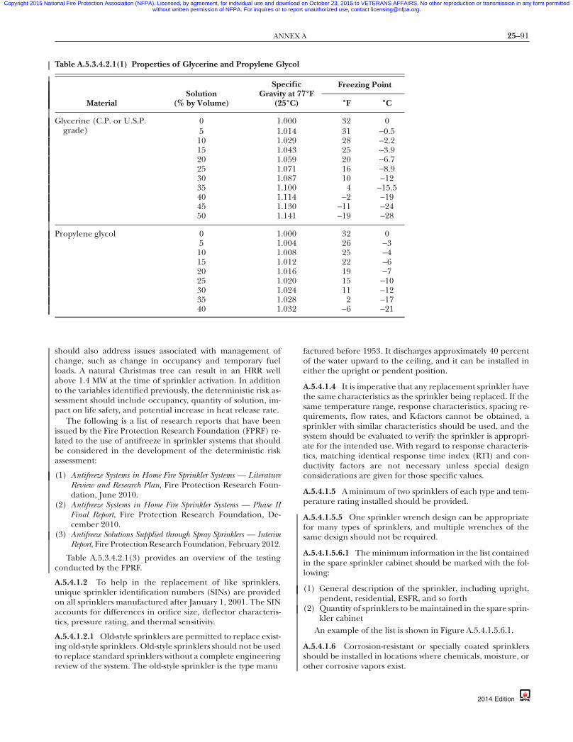
25–91ANNEX A
Copyright 2015 National Fire Protection Association (NFPA). Licensed, by agreement, for individual use and download on October 23, 2015 to VETERANS AFFAIRS. No other reproduction or transmission in any form permittedwithout written permission of NFPA. For inquires or to report unauthorized use, contact [email protected].
87
should also address issues associated with management ofchange, such as change in occupancy and temporary fuelloads. A natural Christmas tree can result in an HRR wellabove 1.4 MW at the time of sprinkler activation. In additionto the variables identified previously, the deterministic risk as-sessment should include occupancy, quantity of solution, im-pact on life safety, and potential increase in heat release rate.
The following is a list of research reports that have beenissued by the Fire Protection Research Foundation (FPRF) re-lated to the use of antifreeze in sprinkler systems that shouldbe considered in the development of the deterministic riskassessment:
(1) Antifreeze Systems in Home Fire Sprinkler Systems — LiteratureReview and Research Plan, Fire Protection Research Foun-dation, June 2010.
(2) Antifreeze Systems in Home Fire Sprinkler Systems — Phase IIFinal Report, Fire Protection Research Foundation, De-cember 2010.
(3) Antifreeze Solutions Supplied through Spray Sprinklers — InterimReport, Fire Protection Research Foundation, February 2012.
Table A.5.3.4.2.1(3) provides an overview of the testingconducted by the FPRF.
A.5.4.1.2 To help in the replacement of like sprinklers,unique sprinkler identification numbers (SINs) are providedon all sprinklers manufactured after January 1, 2001. The SINaccounts for differences in orifice size, deflector characteris-tics, pressure rating, and thermal sensitivity.
A.5.4.1.2.1 Old-style sprinklers are permitted to replace exist-ing old-style sprinklers. Old-style sprinklers should not be usedto replace standard sprinklers without a complete engineeringreview of the system. The old-style sprinkler is the type manu
Table A.5.3.4.2.1(1) Properties of Glycerine and Propylene G
MaterialSolution
(% by Volume)
SpGravit
(2
Glycerine (C.P. or U.S.P.grade)
0 1.5 1.
10 1.15 1.20 1.25 1.30 1.35 1.40 1.45 1.50 1.
Propylene glycol 0 1.5 1.
10 1.15 1.20 1.25 1.30 1.35 1.40 1.
{3e0bff22-698c-46e7-
factured before 1953. It discharges approximately 40 percentof the water upward to the ceiling, and it can be installed ineither the upright or pendent position.
A.5.4.1.4 It is imperative that any replacement sprinkler havethe same characteristics as the sprinkler being replaced. If thesame temperature range, response characteristics, spacing re-quirements, flow rates, and K-factors cannot be obtained, asprinkler with similar characteristics should be used, and thesystem should be evaluated to verify the sprinkler is appropri-ate for the intended use. With regard to response characteris-tics, matching identical response time index (RTI) and con-ductivity factors are not necessary unless special designconsiderations are given for those specific values.
A.5.4.1.5 A minimum of two sprinklers of each type and tem-perature rating installed should be provided.
A.5.4.1.5.5 One sprinkler wrench design can be appropriatefor many types of sprinklers, and multiple wrenches of thesame design should not be required.
A.5.4.1.5.6.1 The minimum information in the list containedin the spare sprinkler cabinet should be marked with the fol-lowing:
(1) General description of the sprinkler, including upright,pendent, residential, ESFR, and so forth
(2) Quantity of sprinklers to be maintained in the spare sprin-kler cabinet
An example of the list is shown in Figure A.5.4.1.5.6.1.
A.5.4.1.6 Corrosion-resistant or specially coated sprinklersshould be installed in locations where chemicals, moisture, orother corrosive vapors exist.
°FFreezing Point
°F °C
32 031 −0.528 −2.225 −3.920 −6.716 −8.910 −124 −15.5
−2 −19−11 −24−19 −28
32 026 −325 −422 −619 −715 −1011 −122 −17
−6 −21
db-eba3b3d7337a}
lycol
ecificy at 775°C)
000014029043059071087100114130141
000004008012016020024028032
2014 Edition

25–92 INSPECTION, TESTING, AND MAINTENANCE OF WATER-BASED FIRE PROTECTION SYSTEMS
Copyright 2015 National Fire Protection Association (NFPA). Licensed, by agreement, for individual use and download on October 23, 2015 to VETERANS AFFAIRS. No other reproduction or transmission in any form permittedwithout written permission of NFPA. For inquires or to report unauthorized use, contact [email protected].
Table A.5.3.4.2.1(3) FPRF Testing Summary
Topic Information
Scope of sprinklers tested The following sprinklers were used during the residential sprinkler researchprogram described in the report dated December 2010:
(1) Residential pendent style having nominal K-factors of 3.1, 4.9, and7.4 gpm/psi1/2
(2) Residential concealed pendent style having a nominal K-factor of 4.9 gpm/psi1/2
(3) Residential sidewall style having nominal K-factors of 4.2 and 5.5 gpm/psi1/2
The following sprinklers were used during the spray sprinkler research programdescribed in the report dated February 2012:
(1) Residential pendent style having a nominal K-factor of 3.1 gpm/psi1/2
(2) Standard spray pendent style having nominal K-factors of 2.8, 4.2, 5.6, and8.0 gpm/psi1/2
(3) Standard spray concealed pendent style having a nominal K-factor of 5.6gpm/psi1/2
(4) Standard spray upright style having a nominal K-factor of 5.6 gpm/psi1/2
(5) Standard spray extended coverage pendent style having a nominal K-factor of5.6 gpm/psi1/2
Antifreeze solution concentration <50% glycerine and <40% propylene glycol antifreeze solutions — solutions werenot tested.
50% glycerine and 40% propylene glycol antifreeze solutions — large-scale ignitionof the sprinkler spray did not occur in tests with sprinkler discharge onto a firehaving a nominal heat release rate (HRR) of 1.4 MW. Large-scale ignition of thesprinkler spray occurred in multiple tests with sprinkler discharge onto a firehaving a nominal HRR of 3.0 MW.
55% glycerine and 45% propylene glycol antifreeze solutions — large-scale ignitionof the sprinkler spray occurred in tests with sprinkler discharge onto a fire havinga nominal HRR of 1.4 MW.
>55% glycerine and >45% propylene glycol antifreeze solutions — large-scaleignition of the sprinkler spray occurred in tests with sprinkler discharge onto afire having an HRR of less than 500 kW.
70% glycerine and 60% propylene glycol antifreeze solutions — maximumantifreeze solution concentrations tested.
Sprinkler inlet pressure Large-scale ignition of the sprinkler discharge spray was not observed when thesprinkler inlet pressure was 50 psi or less for tests using 50% glycerine or 40%propylene glycol.
Ceiling height When discharging 50% glycerine and 40% propylene glycol antifreeze solutionsonto fires having an HRR of 1.4 MW, no large-scale ignition of the sprinkler spraywas observed with ceiling heights up to 20 ft.
When discharging 50% glycerine and 40% propylene glycol antifreeze solutionsonto fires having an HRR of 3.0 MW, large-scale ignition of the sprinkler spray wasobserved at a ceiling height of 20 ft.
Fire control The test results described in the test reports of December 2010 and February2012 indicated that discharging glycerine and propylene glycol antifreezesolutions onto a fire can temporarily increase the fire size until water isdischarged.
As a part of the residential sprinkler research described in report dated December 2010,tests were conducted to evaluate the effectiveness of residential sprinklers to controlfires involving furniture and simulated furniture. The results of these tests indicatedthat 50% glycerine and 40% propylene glycol antifreeze solutions demonstrated theability to control the furniture-type fires in a manner similar to water.
For standard spray–type sprinklers, no tests were conducted to investigate the ability ofthese sprinklers to control the types and sizes of fires that these sprinklers areintended to protect.
{3e0bff22-698c-46e7-87db-eba3b3d7337a}
2014 Edition
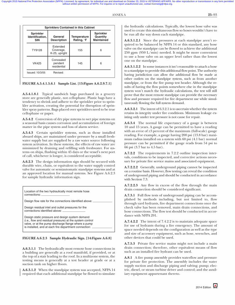
25–93ANNEX A
Copyright 2015 National Fire Protection Association (NFPA). Licensed, by agreement, for individual use and download on October 23, 2015 to VETERANS AFFAIRS. No other reproduction or transmission in any form permittedwithout written permission of NFPA. For inquires or to report unauthorized use, contact [email protected].
87
A.5.4.1.8.1 Typical sandwich bags purchased in a grocerystore are generally plastic, not cellophane. Plastic bags have atendency to shrink and adhere to the sprinkler prior to sprin-kler activation, creating the potential for disruption of sprin-kler spray patterns. Bags placed over sprinklers need to be truecellophane or paper.
A.5.4.2 Conversion of dry pipe systems to wet pipe systems ona seasonal basis causes corrosion and accumulation of foreignmatter in the pipe system and loss of alarm service.
A.5.4.3 Certain sprinkler systems, such as those installedaboard ships, are maintained under pressure by a small fresh-water supply but are supplied by a raw water source followingsystem activation. In these systems, the effects of raw water areminimized by draining and refilling with freshwater. For sys-tems on ships, flushing within 45 days or the vessel’s next portof call, whichever is longer, is considered acceptable.
A.6.2.3 The design information sign should be secured withdurable wire, chain, or equivalent to the water supply controlvalve for automatic or semiautomatic standpipe systems and atan approved location for manual systems. See Figure A.6.2.3for sample hydraulic information sign.
A.6.3.1.1 The hydraulically most remote hose connections ina building are generally at a roof manifold, if provided, or atthe top of a stair leading to the roof. In a multizone system, thetesting means is generally at a test header at grade or at asuction tank on higher floors.
A.6.3.1.2 When the standpipe system was accepted, NFPA 14required that each additional standpipe be flowed to simulate
SprinklerIdentification,
SINGeneral
DescriptionTemperature
Rating, ∞F
SprinklerQuantity
Maintained
TY9128Extended Coverage,
K-25, upright
Issued: 10/3/05 Revised:
155 6
VK425Concealed
pendent residential
145 6
Sprinklers Contained in this Cabinet
FIGURE A.5.4.1.5.6.1 Sample List. [13:Figure A.6.2.9.7.1]
Location of the two hydraulically most remote hoseconnections:
Design flow rate for the connections identified above:
Design residual inlet and outlet pressures for theconnections identified above:
Design static pressure and design system demand(i.e., flow and residual pressure) at the system controlvalve, or at the pump discharge flange where a pumpis installed, and at each fire department connection:
FIGURE A.6.2.3 Sample Hydraulic Sign. [14:Figure A.6.8]
{3e0bff22-698c-46e7-
the hydraulic calculations. Typically, the lowest hose valve wasused to create this simultaneous flow so hoses wouldn’t have tobe run all the way down each standpipe.
A.6.3.1.2.1 Since the pressures at each standpipe aren’t re-quired to be balanced by NFPA 14 or this standard, any hosevalve on the standpipe can be flowed to achieve the additional250 gpm (950 L/min) needed. It might be more convenientto use a hose valve on an upper level rather than the lowestone on the standpipe.
A.6.3.1.2.2 In some instances it isn’t reasonable to attach a hoseto a standpipe to provide this additional flow point. The authorityhaving jurisdiction can allow the additional flow be made atother outlets on the standpipe system, such as from anotherstandpipe, or from the fire pump test header. Although the re-sults of having the flow points somewhere else in the standpipesystem won’t match the hydraulic calculations, the test will stillprove that the most remote standpipe can provide the necessaryflow and pressure required for fire department use while simul-taneously flowing the full system demand.
A.6.3.2.1 The intent of 6.3.2.1 is to ascertain whether the systemretains its integrity under fire conditions. Minimum leakage ex-isting only under test pressure is not cause for repair.
A.6.3.4 The normal life expectancy of a gauge is between10 and 15 years. A gauge can be permitted to have a readingwith an error of ±3 percent of the maximum (full-scale) gaugereading. For example, a gauge having 200 psi (13.8 bar) maxi-mum radius installed on a system with 60 psi (4.1 bar) normalpressure can be permitted if the gauge reads from 54 psi to66 psi (3.7 bar to 4.5 bar).
A.7.2.2 The requirements in 7.2.2 outline inspection inter-vals, conditions to be inspected, and corrective actions neces-sary for private fire service mains and associated equipment.
A.7.2.2.2 Generally, underground piping cannot be inspectedon a routine basis. However, flow testing can reveal the conditionof underground piping and should be conducted in accordancewith Section 7.3.
A.7.2.2.3 Any flow in excess of the flow through the maindrain connection should be considered significant.
A.7.3.1 Full flow tests of underground piping can be accom-plished by methods including, but not limited to, flowthrough yard hydrants, fire department connections once thecheck valve has been removed, main drain connections, andhose connections. The flow test should be conducted in accor-dance with NFPA 291.
A.7.4.2.2 The intent of 7.4.2.2 is to maintain adequate spacefor use of hydrants during a fire emergency. The amount ofspace needed depends on the configuration as well as the typeand size of accessory equipment, such as hose, wrenches, andother devices that could be used.
A.7.5.3 Private fire service mains might not include a maindrain connection; therefore, other equivalent means of flowsuch as an installed fire hydrant can be used.
A.8.1 A fire pump assembly provides waterflow and pressurefor private fire protection. The assembly includes the watersupply suction and discharge piping and valving; pump; elec-tric, diesel, or steam turbine driver and control; and the auxil-iary equipment appurtenant thereto.
db-eba3b3d7337a}
2014 Edition
25–94 INSPECTION, TESTING, AND MAINTENANCE OF WATER-BASED FIRE PROTECTION SYSTEMS
Copyright 2015 National Fire Protection Association (NFPA). Licensed, by agreement, for individual use and download on October 23, 2015 to VETERANS AFFAIRS. No other reproduction or transmission in any form permittedwithout written permission of NFPA. For inquires or to report unauthorized use, contact [email protected].
-8
A.8.1.5 Types of centrifugal fire pumps include single and mul-tistage units of horizontal or vertical shaft design. Listed firepumps have rated capacities of 25 gpm to 5000 gpm (95 L/minto 18,925 L/min), with a net pressure range from approximately40 psi to 400 psi (2.75 bar to 27.6 bar).
(1) Horizontal Split Case. This pump has a double suction im-peller with an inboard and outboard bearing and is usedwith a positive suction supply. A variation of this designcan be mounted with the shaft in a vertical plane. [SeeFigure A.8.1.5(a).]
(2) End Suction and Vertical In-Line. This pump can have eithera horizontal or vertical shaft with a single suction impellerand a single bearing at the drive end. [See FigureA.8.1.5(b).]
(3) Vertical Shaft, Turbine Type. This pump has multiple impel-lers and is suspended from the pump head by a columnpipe that also serves as a support for the shaft and bear-ings. This pump is necessary where a suction lift isneeded, such as from an underground reservoir, well,river, or lake. [See Figure A.8.1.5(c).]
A.8.1.9 Controllers include air-, hydraulic-, or electric-operatedunits. These units can take power from the energy source fortheir operation, or the power can be obtained elsewhere. Con-trollers used with electric power sources can apply the source tothe driver in one (across-the-line) or two (reduced voltage orcurrent) steps. Controllers can be used with automatic andmanual transfer switches to select the available electric powersource where more than one is provided.
A.8.2.2 See Table A.8.2.2 and Figure A.8.2.2.
A.8.2.2(5) Visual indicators other than pilot lights can beused for the same purpose.
A.8.3 The purpose of testing the pump assembly is to ensureautomatic or manual operation upon demand and continu-ous delivery of the required system output. An additional pur-pose is to detect deficiencies of the pump assembly not evidentby inspection.
A.8.3.1.1 Fire pump systems should be designed so that thepressure relief valve has a minimum flow (to verify pressurerelief valve is properly set and operating) at churn, and onlyallows a larger flow under abnormal conditions (i.e., engineoverspeed or failure of a variable speed pressure limiting con-trol). The fire pump imparts more energy into the water whenrecirculating the water through the pump than when thepump is operating at churn (no flow). NFPA 20 requires acirculation relief valve downstream of the pressure relief valvewhenever the pressure relief valve is piped back to the pumpsuction. Improperly installed and/or operating circulation re-lief valves can result in unacceptably high water temperature,especially when recirculating the water to the pump suction.High water temperatures can affect the operation of a dieselengine drive. Modern engines, due to EPA requirements, aremore sensitive to cooling water temperatures.
A.8.3.1.1.2 The risk analysis should be prepared and re-viewed by qualified people. Increased test frequencies mightbe desirable when high impact losses could result from anuncontrolled fire. Examples where increased fire pump testfrequencies can be considered could include high piled stor-age facilities and buildings where the predominant occupancyis protected by an extra hazard density sprinkler system.
Test frequency has been a heavily discussed and researchedtopic for several years, and is still continuing to be researched.
{3e0bff22-698c-46e7
2014 Edition
A set of data was submitted in 2008 by a group of owners andmaintainers of large numbers of fire pumps. This data waspresented to the committee as indicating a decreased test fre-quency on electric fire pumps did not “significantly” impact“reliability”; however, “reliability” as used in the discussion ofthe data presentation was actually the failure rate, and did nottake into account the effect of test frequency on the fire pumpreliability (i.e., the time between failure and discovery of thefailure affects reliability). Subsequently, the NFPA ResearchCouncil commissioned research, and the resultant “Fire PumpField Data Collection and Analysis Report” in 2011 (availablefor download at www.nfpa.org\Foundation) reported thatelectric fire pumps tested weekly had a failure rate of approxi-mately 0.64 per year. Assuming a failure rate independent ofthe test frequency, and assuming that on the average the im-pairment occurs at the midpoint of the test interval, this fail-ure rate provides approximately 99.4 percent reliability withweekly testing and approximately 97.3 percent reliability withmonthly testing. Diesel engine fire pumps tested weekly had afailure rate of approximately 1.02 per year. Assuming a failurerate independent of the test frequency and assuming that onthe average the impairment occurs at the midpoint of the testinterval, this failure rate provides approximately 99.1 percentreliability with weekly testing and approximately 96.0 percentreliability with monthly testing.
Based on this data, the lower reliability has not been deter-mined to be acceptable for all facilities. Decisions to decreasetest frequency must be based on more than cost savings. Areliability/risk analysis to decrease test frequency should takeinto account the risk associated with life safety, property val-ues, hazards, and business interruption at the protected prop-erty. Fire pump redundancy can impact overall fire system re-liability and be used in a reliability/risk analysis.
A.8.3.1.2 For pressure relief valve operation, see 8.3.2.4.
A.8.3.1.2.3 For systems where multiple fire pumps are re-quired to meet the system demand, a one-for-one redundancyis not necessary (i.e., one backup pump for two or more pri-mary pumps meets the intent of this section).
A.8.3.1.2.4 The risk analysis should be prepared and re-viewed by qualified people. Increased test frequencies can bedesirable when high impact losses could result from an uncon-trolled fire. Examples where increased fire pump test frequen-cies can be considered could include high piled storage facili-ties and buildings where the predominant occupancy isprotected by an extra hazard density sprinkler system.
A.8.3.2.7.1 An automatic timer allows a person who has beeninstructed on what to watch for and record during this test tomonitor the test and request assistance should any issues arise.
A.8.3.2.9 See Table A.8.3.2.9.
A.8.3.3.1 Minimum flow for a pump is the churn pressure.
A.8.3.3.1.2 The method described in 8.3.3.1.2.3 is not consid-ered as complete as those in 8.3.3.1.2.1 and 8.3.3.1.2.2, because itdoes not test the adequacy of the water supply for compliancewith the requirements of 8.1.6 at the suction flange.
A.8.3.3.2(3) It is not the intent to discharge water for the full1-hour test duration, provided all flow tests can be conductedin less time and efforts are taken to prevent the pump fromoverheating.
7db-eba3b3d7337a}
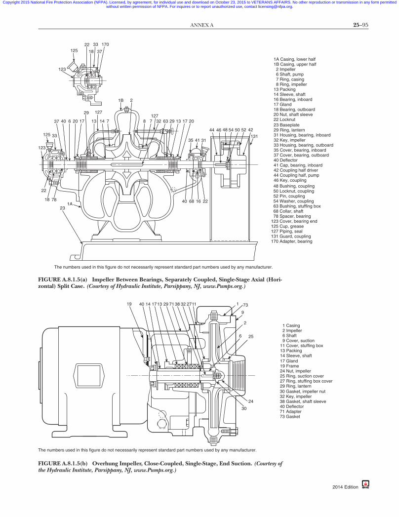
25–95ANNEX A
Copyright 2015 National Fire Protection Association (NFPA). Licensed, by agreement, for individual use and download on October 23, 2015 to VETERANS AFFAIRS. No other reproduction or transmission in any form permittedwithout written permission of NFPA. For inquires or to report unauthorized use, contact [email protected].
170
3712522 33
18
123
37
125 33
123
40 6 20 17
29 127
13 14 7
1B 2
8 7127
32 63 29 13 17 20
35 4
40 68
22
18 78
231A
The numbers used in this figure do not necessarily represent standard pa
FIGURE A.8.1.5(a) Impeller Between Bearings, Separately Czontal) Split Case. (Courtesy of Hydraulic Institute, Parsippany, N
19 40 14 1713 29 71 38 32 2711
The numbers used in this figure do not necessarily represent standard part numb
FIGURE A.8.1.5(b) Overhung Impeller, Close-Coupled, Sing
{3e0bff22-698c-46e7-
1 31
44 46 48 54 50 52
16 22
42
131
rt numbers used by any manufacturer.
1A Casing, lower half1B Casing, upper half 2 Impeller 6 Shaft, pump 7 Ring, casing 8 Ring, impeller13 Packing14 Sleeve, shaft16 Bearing, inboard17 Gland18 Bearing, outboard20 Nut, shaft sleeve22 Locknut23 Baseplate29 Ring, lantern31 Housing, bearing, inboard32 Key, impeller33 Housing, bearing, outboard35 Cover, bearing, inboard37 Cover, bearing, outboard40 Deflector41 Cap, bearing, inboard42 Coupling half driver44 Coupling half, pump46 Key, coupling48 Bushing, coupling50 Locknut, coupling52 Pin, coupling54 Washer, coupling63 Bushing, stuffing box68 Collar, shaft78 Spacer, bearing
123 Cover, bearing end125 Cup, grease127 Piping, seal131 Guard, coupling170 Adapter, bearing
oupled, Single-Stage Axial (Hori-J, www.Pumps.org.)
87db-eba3b3d7337a}
1 73
9
2
6 25
24
30
ers used by any manufacturer.
1 Casing 2 Impeller 6 Shaft 9 Cover, suction11 Cover, stuffing box13 Packing14 Sleeve, shaft17 Gland19 Frame24 Nut, impeller25 Ring, suction cover27 Ring, stuffing box cover29 Ring, lantern30 Gasket, impeller nut32 Key, impeller38 Gasket, shaft sleeve40 Deflector71 Adapter73 Gasket
le-Stage, End Suction. (Courtesy ofthe Hydraulic Institute, Parsippany, NJ, www.Pumps.org.)
2014 Edition

25–96 INSPECTION, TESTING, AND MAINTENANCE OF WATER-BASED FIRE PROTECTION SYSTEMS
Copyright 2015 National Fire Protection Association (NFPA). Licensed, by agreement, for individual use and download on October 23, 2015 to VETERANS AFFAIRS. No other reproduction or transmission in any form permittedwithout written permission of NFPA. For inquires or to report unauthorized use, contact [email protected].
2 Impeller 6 Shaft, pump 8 Ring, impeller 10 Shaft, head 12 Shaft, drive 13 Packing 17 Gland 29 Ring, lantern 39 Bushing, bearing 55 Bell, suction
66 Nut, shaft adjusting 70 Coupling, shaft 77 Lubricator 79 Bracket, lubricator
84 Collet, impeller lock
101 Pipe, column103 Bearing, lineshaft, enclosed183 Nut, tubing185 Plate, tension, tubing187 Head, surface discharge189 Flange, top column191 Coupling, column pipe193 Retainer bearing, open lineshaft
197 Case, discharge199 Bowl, intermediate203 Case, suction209 Strainer
The cross-sectional views illustrate the largest possible number of parts in their proper relationship and someconstruction modifications but do not necessarily represent recommended design.
66
10
77
17
83
79
18339
18513
291363
1871891017012
10385191193391951976391998428393964395539203211209
Enclosed lineshaft-typeenclosed impeller
Open lineshaft-typesemi-open impeller
63 Bushing, stuffing box 64 Collar, protecting
83 Stuffing box
85 Tube, shaft enclosing
195 Adapter, tubing
211 Pipe, suction
FIGURE A.8.1.5(c) Turbine-Type, Vertical, Multistage, Deep Well. (Courtesy of the Hydraulic
{3e0bff22-698c-46e7-87db-eba3b3d7337a}
Institute, Parsippany, NJ, www.Pumps.org.)
High water
Screens
Lowest standingwater level
Bottomof reservoir
Strainer
Yard system
Removable panel
Screen raised
Rack
FIGURE A.8.2.2 Wet Pit Suction Screen Installation.
2014 Edition
Table A.8.2.2 Observations — Before Pumping
Item Before Pump Is Operated
Horizontalpumps
1. Inspect drip pockets under packing glandsfor proper drainage. Standing water in drippockets is the most common cause ofbearing failure.
2. Inspect packing adjustment —approximately one drop per second isnecessary to keep packing lubricated.
3. Observe suction and discharge gauges.Readings higher than suction pressureindicate leakage back from system pressurethrough either the fire pump or jockeypump.

25–97ANNEX A
Copyright 2015 National Fire Protection Association (NFPA). Licensed, by agreement, for individual use and download on October 23, 2015 to VETERANS AFFAIRS. No other reproduction or transmission in any form permittedwithout written permission of NFPA. For inquires or to report unauthorized use, contact [email protected].
87
A.8.3.3.3 A pressure relief valve that opens during a flow con-dition is discharging water that is not measured by the record-ing device(s). It can be necessary to temporarily close the pres-sure relief valve to achieve favorable pump test results. At theconclusion of the pump test, the pressure relief valve must bereadjusted to relieve pressures in excess of the normal operat-ing pressure of the system components.
If the pressure relief valve is open during the flowing con-ditions due to the fact that the pressure is too high for thecomponents in the fire protection system, the discharge con-trol valve should be closed prior to closing the pressure reliefvalve to make sure that the fire protection system is not over-pressurized. After the test, the valve must be opened again.
A.8.3.3.3.1 A pressure relief valve that is open during a flowcondition will affect test results.
A.8.3.3.5 It is not the intent to verify that all the alarm condi-tions required by NFPA 20 (e.g., low oil pressure, high coolanttemperature, failure of engine to start, engine overspeed)transmit individually to a remote location, as long as thesealarms can be individually verified at the fire pump controller.
A.8.3.3.6 See also NFPA 70E for additional safety guidance.
A.8.3.3.7 During periods of unusual water supply conditionssuch as floods, inspection should be on a daily basis.
A.8.3.3.8 ECM and Sensor Testing. To verify the operation ofthe alternate ECM with the stop, the ECM selector switchshould be moved to the alternate ECM position. Reposition-ing of this should cause an alarm on the fire pump controller.Then the engine is started; it should operate normally with allfunctions. Next, the engine is shut down, switched back to theprimary ECM, and restarted briefly to verify that correctswitchback has been accomplished.
To verify the operation of the redundant sensor, with theengine running, the wires are disconnected from the primary
Table A.8.3.2.9 Observations — While Pumping
Item
Horizontal pumps 1. Read suction and dischargepressure, which should mat
2. Observe packing glands for3. Observe discharge from cas
overheating.
Vertical pumps 1. Read discharge gauge — adcompute psi (30.47 to comppump nameplate.
2. Observe packing glands for3. Observe discharge from cas
overheating.
Diesel engines 1. Observe discharge of coolinin cooling system for obstrucorrect flow.
2. Inspect engine instrumentammeter charging rate.
3. Inspect battery terminal con4. After pump has stopped ru
pressure recorder chart; an
{3e0bff22-698c-46e7-
sensor. There should be no change in the engine operation.The wires are then reconnected to the sensor, then discon-nected from the redundant sensor. There should be nochange in the engine operation. The wires should next bereconnected to the sensor. This process is repeated for all pri-mary and redundant sensors on the engines. It should benoted whether disconnecting and reconnecting of wires to thesensors can be done while the engine is not running, thenstarting the engine after each disconnecting and reconnect-ing of the wires to verify engine operation.
A.8.3.4.1.1 Commercial distillate fuel oils used in moderndiesel engines are subject to various detrimental effects fromstorage. The origin of the crude oil, refinement processingtechniques, time of year, and geographical consumption loca-tion all influence the determination of fuel blend formulas.Naturally occurring gums, waxes, soluble metallic soaps, wa-ter, dirt, blends, and temperature all contribute to the degra-dation of the fuel as it is handled and stored. These effectsbegin at the time of fuel refinement and continue until con-sumption. Proper maintenance of stored distillate fuel is criti-cal for engine operation, efficiency, and longevity.
Storage tanks should be kept water-free. Water contributesto steel tank corrosion and the development of microbiologi-cal growth where fuel and water interface. This and the metalsof the system provide elements that react with fuel to formcertain gels or organic acids, resulting in clogging of filtersand system corrosion. Scheduled fuel maintenance helps toreduce fuel degradation. Fuel maintenance filtration can re-move contaminants and water and maintain fuel conditions toprovide reliability and efficiency for standby fire pump en-gines. Fuel maintenance and testing should begin the day ofinstallation and first fill.
A.8.3.4.2 Where environmental or fuel quality conditions re-sult in degradation of the fuel while stored in the supply tank,
While Pump Is Operating
es — difference between these readings indicates churnurn pressure as shown on fire pump nameplate.
r leakage for cooling of packing.lief valve — adequate flow keeps pump case from
ance to water level in feet (or meters) and divide by 2.31 toar). This total must match churn pressure as shown on fire
r leakage for cooling of packing.lief valve — adequate flow keeps pump case from
er from heat exchanger — if not adequate, inspect strainer. If still not adequate, adjust pressure-reducing valve for
for correct speed, oil pressure, water temperature, and
ons for corrosion and clean if necessary., inspect intake screens, if provided; replace diesel systemnd if necessary.
db-eba3b3d7337a}
gaugch ch
propeing re
d distute b
propeing re
g watctions
panel
nectinningd rewi
2014 Edition
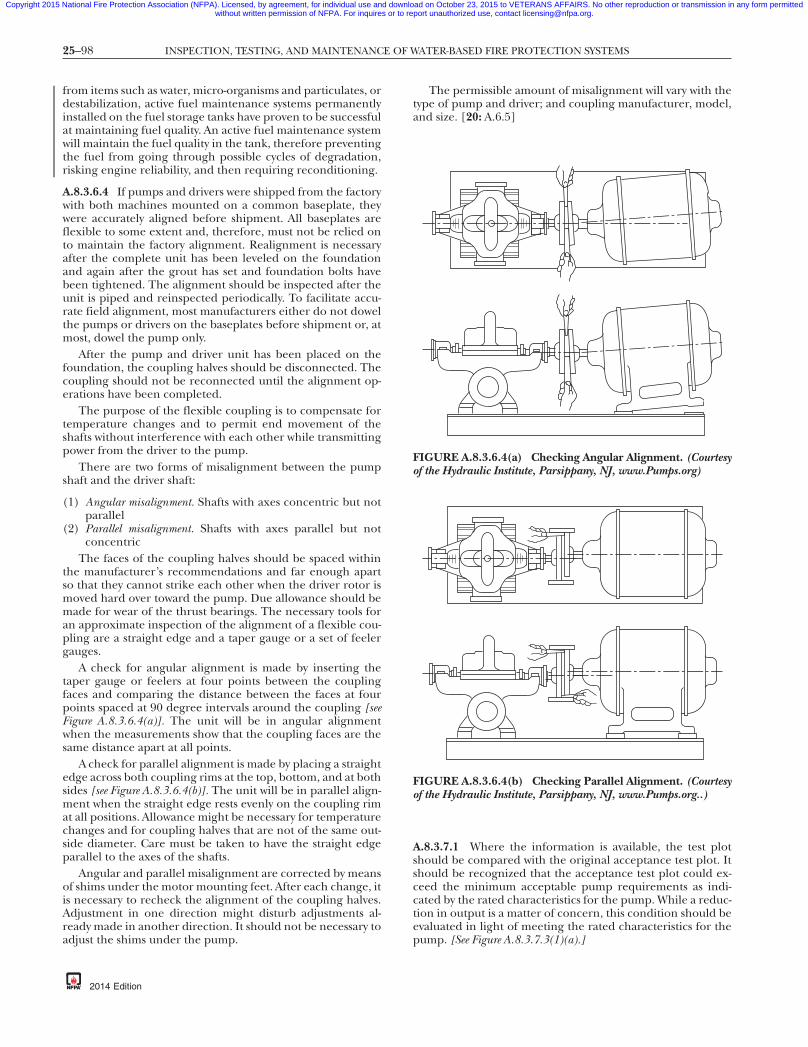
25–98 INSPECTION, TESTING, AND MAINTENANCE OF WATER-BASED FIRE PROTECTION SYSTEMS
Copyright 2015 National Fire Protection Association (NFPA). Licensed, by agreement, for individual use and download on October 23, 2015 to VETERANS AFFAIRS. No other reproduction or transmission in any form permittedwithout written permission of NFPA. For inquires or to report unauthorized use, contact [email protected].
-8
from items such as water, micro-organisms and particulates, ordestabilization, active fuel maintenance systems permanentlyinstalled on the fuel storage tanks have proven to be successfulat maintaining fuel quality. An active fuel maintenance systemwill maintain the fuel quality in the tank, therefore preventingthe fuel from going through possible cycles of degradation,risking engine reliability, and then requiring reconditioning.
A.8.3.6.4 If pumps and drivers were shipped from the factorywith both machines mounted on a common baseplate, theywere accurately aligned before shipment. All baseplates areflexible to some extent and, therefore, must not be relied onto maintain the factory alignment. Realignment is necessaryafter the complete unit has been leveled on the foundationand again after the grout has set and foundation bolts havebeen tightened. The alignment should be inspected after theunit is piped and reinspected periodically. To facilitate accu-rate field alignment, most manufacturers either do not dowelthe pumps or drivers on the baseplates before shipment or, atmost, dowel the pump only.
After the pump and driver unit has been placed on thefoundation, the coupling halves should be disconnected. Thecoupling should not be reconnected until the alignment op-erations have been completed.
The purpose of the flexible coupling is to compensate fortemperature changes and to permit end movement of theshafts without interference with each other while transmittingpower from the driver to the pump.
There are two forms of misalignment between the pumpshaft and the driver shaft:
(1) Angular misalignment. Shafts with axes concentric but notparallel
(2) Parallel misalignment. Shafts with axes parallel but notconcentric
The faces of the coupling halves should be spaced withinthe manufacturer’s recommendations and far enough apartso that they cannot strike each other when the driver rotor ismoved hard over toward the pump. Due allowance should bemade for wear of the thrust bearings. The necessary tools foran approximate inspection of the alignment of a flexible cou-pling are a straight edge and a taper gauge or a set of feelergauges.
A check for angular alignment is made by inserting thetaper gauge or feelers at four points between the couplingfaces and comparing the distance between the faces at fourpoints spaced at 90 degree intervals around the coupling [seeFigure A.8.3.6.4(a)]. The unit will be in angular alignmentwhen the measurements show that the coupling faces are thesame distance apart at all points.
A check for parallel alignment is made by placing a straightedge across both coupling rims at the top, bottom, and at bothsides [see Figure A.8.3.6.4(b)]. The unit will be in parallel align-ment when the straight edge rests evenly on the coupling rimat all positions. Allowance might be necessary for temperaturechanges and for coupling halves that are not of the same out-side diameter. Care must be taken to have the straight edgeparallel to the axes of the shafts.
Angular and parallel misalignment are corrected by meansof shims under the motor mounting feet. After each change, itis necessary to recheck the alignment of the coupling halves.Adjustment in one direction might disturb adjustments al-ready made in another direction. It should not be necessary toadjust the shims under the pump.
{3e0bff22-698c-46e7
2014 Edition
The permissible amount of misalignment will vary with thetype of pump and driver; and coupling manufacturer, model,and size. [20: A.6.5]
A.8.3.7.1 Where the information is available, the test plotshould be compared with the original acceptance test plot. Itshould be recognized that the acceptance test plot could ex-ceed the minimum acceptable pump requirements as indi-cated by the rated characteristics for the pump. While a reduc-tion in output is a matter of concern, this condition should beevaluated in light of meeting the rated characteristics for thepump. [See Figure A.8.3.7.3(1)(a).]
FIGURE A.8.3.6.4(a) Checking Angular Alignment. (Courtesyof the Hydraulic Institute, Parsippany, NJ, www.Pumps.org)
FIGURE A.8.3.6.4(b) Checking Parallel Alignment. (Courtesyof the Hydraulic Institute, Parsippany, NJ, www.Pumps.org..)
7db-eba3b3d7337a}

25–99ANNEX A
Copyright 2015 National Fire Protection Association (NFPA). Licensed, by agreement, for individual use and download on October 23, 2015 to VETERANS AFFAIRS. No other reproduction or transmission in any form permittedwithout written permission of NFPA. For inquires or to report unauthorized use, contact [email protected].
The test equipment should be of high quality and accuracy.All equipment should have been calibrated within the last12 months by an approved calibration facility. Where possible,the calibration facility should provide documentation indicat-ing the instrument reading against the calibrated reading. In-struments that pass the calibration test should be labeled bythe calibration facility with the name of the facility and thedate of the test.
Pressure gauges should have an accuracy not greater than1 percent of full scale. To prevent damage to a pressure gaugeutilizing a Bourdon tube mechanism, it should not be usedwhere the expected test pressure is greater than 75 percent ofthe test gauge scale. Some digital gauges can be subjected totwice the full scale pressure without damage. The manufactur-er’s recommendations should be consulted for the proper useof the gauge. To be able to easily read an analog gauge, thediameter of the face of the analog gauge should be greaterthan 3 in. (76 mm). Pressure snubbers should be used for allgauges to minimize needle fluctuation. All gauges used in thetest should be such that a gauge with the lowest full scale pres-sure is used. For example, a 300 psi (20.7 bar) gauge shouldnot be used to measure a 20 psi (1.4 bar) pitot pressure.
Equipment other than pressure gauges, such as volt/ammeters, tachometers, and flowmeters, should be calibratedto the manufacturer’s specifications. The readings fromequipment with this level of accuracy and calibration can beused without adjustment for accuracy.
Certified factory tesAlternate power sou
164.3
180
100
80
60
40
20
0
120
140
160
Pre
ssur
e (p
si)
126.0
125.0
124.3
8006004002000
40.0
Suction supplyCorrected performance +
FIGURE A.8.3.7.3(1)(a) Fire Pump Performance Curve — C
{3e0bff22-698c-46e7-
A.8.3.7.3(1) See Figure A.8.3.7.3(1)(a) andFigure A.8.3.7.3(1)(b).
A.8.3.7.4 See Annex C.
A.8.5.1 It is important to provide proper bearing lubricationand to keep bearings clean. Some bearings are the sealed typeand need no relubrication. Couplings with rubber drive partsdo not need lubrication; other types generally do. The follow-ing practices are recommended:
(1) Lubricant fittings should be cleaned before relubricatingwith grease.
(2) The proper amount of lubricant should be used. Toomuch lubricant results in churning, causing excessivepower loss and overheating.
(3) The correct lubricant should be used.
Engine Maintenance. Engines should be kept clean, dry,and well lubricated. The proper oil level in the crankcaseshould be maintained.
Battery Maintenance. Only distilled water should be used inbattery cells. Plates should be kept submerged at all times. Anautomatic battery charger is not a substitute for proper mainte-nance of the battery and charger. Periodic inspection ensuresthat the charger is operating correctly, the water level in the bat-tery is adequate, and the battery is holding its proper charge.
vailable)
+
18001600140012001000gpm)
30.0
20.0
132.7
103.0102.7
100.0 95.7
77.075.7
74.570.0
Most recent field test data (if available)Corrected system performance
ed Data.
db-eba3b3d7337a}
t curverce (if a
Flow (
orrect
87
2014 Edition

25–100 INSPECTION, TESTING, AND MAINTENANCE OF WATER-BASED FIRE PROTECTION SYSTEMS
Copyright 2015 National Fire Protection Association (NFPA). Licensed, by agreement, for individual use and download on October 23, 2015 to VETERANS AFFAIRS. No other reproduction or transmission in any form permittedwithout written permission of NFPA. For inquires or to report unauthorized use, contact [email protected].
-8
Fuel Supply Maintenance. The fuel storage tank should bekept at least two-thirds full. Fuel should be maintained free ofwater and foreign material by draining water and foreign ma-terial from the tank sump annually. This necessitates drainingapproximately 5 gal (19 L).
Temperature Maintenance. The temperature of the pumproom, pump house, or area where engines are installedshould never be less than the minimum recommended by theengine manufacturer. The manufacturer’s temperature rec-ommendations for water and oil heaters should be followed.
A.9.1 One source of information on the inspection and main-tenance of steel gravity and suction tanks is the AWWA Manualof Water Supply Practices — M42 Steel Water-Storage Tanks, Part IIIand Annex C.
A.9.2.1.1 More frequent inspections should be made whereextreme conditions, such as freezing temperatures or arid cli-mate, can increase the probability of adversely affecting thestored water.
Supervisory water level alarms installed on tanks providenotification that the tank water level is above or below an ac-ceptable level. The water level of the tank is the main concernas opposed to the condition of the water. For convenience,inspection of the condition of the water can take place concur-rently with the water level inspection.
A.9.2.5.1 Lightning protection systems, where provided, shouldbe inspected, tested, and maintained in accordance withNFPA780, Standard for the Installation of Lightning Protection Systems.
A.9.2.6.1.1 To aid in the inspection and evaluation of testresults, it is a good idea for the property owner or designatedrepresentative to stencil the last known date of an interiorpaint job on the exterior of the tank in a conspicuous place. Atypical place is near one of the manways at eye level.
180
100
80
60
40
20
0
120
140
160
10008006004002000
Pre
ssur
e (p
si)
Flow (gpm)
165.0
132.
40.0
30.0
112
102.0
125.0
Suction supplyUnadjusted net boost
Unadjusted system performanceSystem design #1 (if available)
FIGURE A.8.3.7.3(1)(b) Fire Pump Performance Curve — U
{3e0bff22-698c-46e7
2014 Edition
A.9.2.6.1.2 If written verification of interior corrosion protec-tion for a tank per NFPA 22, Standard for Water Tanks for PrivateFire Protection, cannot be provided by the building owner, theinterior of the tank should be inspected every 3 years.
A.9.2.6.5 This inspection can be performed by looking fordents on the tank floor. Additionally, walking on the tank floorand looking for buckling of the floor will identify problemareas.
A.9.3.1 The testing procedure for listed mercury gauges is asfollows.
To determine that the mercury gauge is accurate, thegauge should be tested every 5 years as follows [steps (1)through (7) coincide with Figure A.9.3.1]:
(1) Overflow the tank.(2) Close valve F. Open test cock D. The mercury will drop
quickly into the mercury pot. If it does not drop, there isan obstruction that needs to be removed from the pipe orpot between the test cock and the gauge glass.
(3) If the mercury does lower at once, close cock D and openvalve F. If the mercury responds immediately and comesto rest promptly opposite the “FULL” mark on the gaugeboard, the instrument is functioning properly.
(4) If the mercury column does not respond promptly andindicate the correct reading during the test, there prob-ably are air pockets or obstructions in the water connect-ing pipe. Open cock D. Water should flow out forcibly.Allow water to flow through cock D until all air is expelledand rusty water from the tank riser appears. Close cock D.The gauge now likely will read correctly. If air separatesfrom the water in the 1 in. (25 mm) pipe due to beingenclosed in a buried tile conduit with steam pipes, the aircan be removed automatically by installing a 3⁄4 in.(20 mm) air trap at the high point of the piping. The air
180016001400
94.0
20.0
74.0
10.1
System design #2 (if available)
sted Data.
7db-eba3b3d7337a}
1200
0
.51
nadju

25–101ANNEX A
Copyright 2015 National Fire Protection Association (NFPA). Licensed, by agreement, for individual use and download on October 23, 2015 to VETERANS AFFAIRS. No other reproduction or transmission in any form permittedwithout written permission of NFPA. For inquires or to report unauthorized use, contact [email protected].
87
trap usually can be installed most easily in a tee connectedby a short piece of pipe at E, with a plug in the top of thetee so that mercury can be added in the future, if neces-sary, without removing the trap. If there are inaccessiblepockets in the piping, as where located below grade orunder concrete floors, the air can be removed onlythrough petcock D.
(5) If, in step (4), the water does not flow forcibly throughcock D, there is an obstruction that needs to be removedfrom the outlet of the test cock or from the water pipebetween the test cock and the tank riser.
(6) If there is water on top of the mercury column in thegauge glass, it will provide inaccurate readings and shouldbe removed. First, lower the mercury into the pot as instep (2). Close cock D and remove plug G. Open valve Fvery slowly, causing the mercury to rise slowly and the wa-ter above it to drain through plug G. Close valve F quicklywhen mercury appears at plug G, but have a receptacleready to catch any mercury that drains out. Replace plugG. Replace any escaped mercury in the pot.
For marking oncover, see full-sizesketch abovebefore admittingwater. Fill with mercuryto graduation corres-ponding with full waterlevel in tank.
WA
TE
RLE
VE
L
FILL
Mercurycatcher
Not a standardpart of equipment.Install when nec-essary to preventblowing outof mercury.
A
Make pipe (C) asshort as possiblewithout air pockets.If another valve isplaced in this pipenear the tank riser,it should be a 1 in.OS&Y gatepadlocked open.
G
F
EOS&Yvalve
D
EG
All
part
s to
be
fast
ened
to w
all.
Do not use brass pipefor connections tomercury pot. 1 in. galv.
iron pipe
¹⁄₄ in. double plug
Mercury potMercury level whenpressure is on gauge
200100
15050B
Standard marking formercury pot cover.
C
Note: For SI units, 1 in. = 25.4 mm.
HEIGHT FOR FULL
ME
RC
UR
Y
YEARS OF MFR.
MFRS. INITIALS
FEET
200
100150
50
FIGURE A.9.3.1 Mercury Gauge.
{3e0bff22-698c-46e7-
(7) After testing, leave valve F open, except under the follow-ing conditions: If it is necessary to prevent forcing mer-cury and water into the mercury catcher, the controllingvalve F can be permitted to be closed when filling the tankbut should be left open after the tank is filled. In caseswhere the gauge is subjected to continual fluctuation ofpressure, it could be necessary to keep the gauge shut offexcept when it needs to be read. Otherwise, it could benecessary to remove water frequently from the top of themercury column as in step (5).
A.9.3.4 The manufacturer’s instructions should be consultedfor guidance on testing. In some situations, it might not bepossible to test the actual initiating device. In such cases, onlythe circuitry should be tested.
A.9.3.5 See A.9.3.4.
A.9.3.6 See A.5.3.2.
A.10.1 The effectiveness and reliability of water spray fixedsystems depends on maintenance of the integrity of hydrauliccharacteristics, water control valves, deluge valves and theirfire detection/actuation systems, pipe hangers, and preven-tion of obstructions to nozzle discharge patterns.
Water spray fixed systems are most commonly used to pro-tect processing equipment and structures, flammable liquidand gas vessels, piping, and equipment such as transformers,oil switches, and motors. They also have been shown to beeffective on many combustible solids.
Many of the components and subsystems found in a waterspray system require the same inspection, test, and mainte-nance procedures where they are used in automatic sprinklersystems and other fixed water-based fire protection systems.Other chapters of this standard should be consulted for par-ticulars on required inspection and maintenance.
A.10.1.3 Insulation acting in lieu of water spray protection isexpected to protect a vessel or structure for the duration ofthe exposure. The insulation is to prevent the temperaturefrom exceeding 850°F (454°C) for structural members and650°F (393°C) for vessels. If the insulation is missing, the struc-ture or vessel is not considered to be protected, regardless ofwater spray protection or insulation on other surfaces. To re-establish the proper protection, the insulation should be re-placed or the water spray protection should be extended, us-ing the appropriate density.
A.10.1.6 The inspection, testing, and maintenance of waterspray fixed systems can involve or result in a system that is outof service. Also see Chapter 15.
A.10.2.4 The operation of the water spray system is depen-dent on the integrity of the piping, which should be kept ingood condition and free of mechanical damage. The pipeshould not be used for support of ladders, stock, or other ma-terial. Where piping is subject to a corrosive atmosphere, aprotective corrosion-resistant coating should be provided andmaintained. Where the age or service conditions warrant, aninternal examination of the piping should be made. Where itis necessary to flush all or part of the piping system, this workshould be done by sprinkler contractors or other qualifiedworkers.
A.10.2.4.1 Rubber-gasketed fittings in the fire areas are in-spected to determine whether they are protected by the waterspray or other approved means. Unless properly protected,
db-eba3b3d7337a}
2014 Edition

25–102 INSPECTION, TESTING, AND MAINTENANCE OF WATER-BASED FIRE PROTECTION SYSTEMS
Copyright 2015 National Fire Protection Association (NFPA). Licensed, by agreement, for individual use and download on October 23, 2015 to VETERANS AFFAIRS. No other reproduction or transmission in any form permittedwithout written permission of NFPA. For inquires or to report unauthorized use, contact [email protected].
-8
fire could cause loss of the rubber gasket following excessiveleakage in a fire situation.
A.10.2.4.2 Hangers and supports are designed to support andrestrain the piping from severe movement when the water supplyoperates and to provide adequate pipe slope for drainage of wa-ter from the piping after the water spray system is shut down.Hangers should be kept in good repair. Broken or loose hangerscan put undue strain on piping and fittings, cause pipe breaks,and interfere with proper drainage of the pipe. Broken or loosehangers should be replaced or refastened.
A.10.2.5 Systems need inspection to ensure water spraynozzles effectively discharge water unobstructed onto surfacesto be protected from radiant heat (exposure protection) oronto flaming surfaces to extinguish or control combustion.Factors affecting the proper placement of water spray nozzlesinclude the following:
(1) Changes or additions to the protected area that obstructexisting nozzles or require additional coverage for com-pliance
(2) Removal of equipment from the protected area that re-sults in nozzle placement at excessive distances from thehazard
(3) Mechanical damage or previous flow tests that havecaused nozzles to be misdirected
(4) A change in the hazard being protected that requiresmore or different nozzles to provide adequate coveragefor compliance
Spray nozzles can be permitted to be placed in any positionnecessary to obtain proper coverage of the protected area.Positioning of nozzles with respect to surfaces to be protected,or to fires to be controlled or extinguished, should be guidedby the particular nozzle design and the character of waterspray produced. In positioning nozzles, care should be takenthat the water spray does not miss the targeted surface andreduce the efficiency or calculated discharge rate.
A.10.2.6.2 Water supply piping should be free of internal ob-structions that can be caused by debris (e.g., rocks, mud, tu-bercles) or by closed or partially closed control valves. SeeChapter 5 for inspection and maintenance requirements.
A.10.2.7 Mainline strainers should be removed and in-spected for damaged and corroded parts every 5 years.
A.10.3.2 The property owner or designated representativeshould take care to prevent damage to equipment or the struc-ture during the test. Damage could be caused by the systemdischarge or by runoff from the test site. It should be verifiedthat there is adequate and unobstructed drainage. Equipmentshould be removed or covered as necessary to prevent dam-age. Means such as curbing or sandbagging should be used toprevent entry of the water.
A.10.3.3.1 Test methods are as follows:
(1) Some detection circuits can be permitted to be deliber-ately desensitized in order to override unusual ambientconditions. In such cases, the response required in10.3.3.1 can be permitted to be exceeded.
(2) Testing of integrating tubing systems can be permitted tobe related to this test by means of a standard pressureimpulse test specified by the listing laboratory.
(3) One method of testing heat detection uses a radiant heatsurface at a temperature of 300°F (149°C) and a capacity
{3e0bff22-698c-46e7
2014 Edition
of 350 watts at a distance of 1 in. (25 mm) but not morethan 2 in. (50 mm) from the nearest part of the detector.This method of testing with an electric test set should notbe used in hazardous locations. Other test methods canbe permitted to be employed, but the results should beobtained under these conditions.
A.10.3.3.3 Spray nozzles can be of different sizes and types.Some are more subject to internal obstructions than others.
A.10.3.3.3.1 See 13.4.3.2.2.3.
A.11.2.5 Directional-type foam-water discharge devices arequite often located in heavy traffic areas and are more apt tobe dislocated compared to ordinary sprinkler locations. Ofparticular concern are low-level discharge devices in loadingracks in and around low-level tankage and monitor-mounteddevices that have been pushed out of the way for convenience.Inspection frequency might have to be increased accordingly.
A.11.2.5.4 Discharge devices are listed or approved for par-ticular foam concentrates.
A.11.2.6.2 Water supply piping should be free of internal ob-structions that can be caused by debris (e.g., rocks, mud, tu-bercles) or by closed or partially closed control valves. SeeChapter 5 for inspection and maintenance requirements.
A.11.2.9 Proportioning systems might or might not includefoam concentrate pumps. If pumps are part of the proportion-ing system, the driver, pump, and gear reducer should be in-spected in accordance with the manufacturer’s recommenda-tions, and the inspection can include items such aslubrication, fuel, filters, oil levels, and clutches.
A.11.2.9.4 In some cases, an adequate supply of foam liquid isavailable without a full tank. This is particularly true of foamliquid stored in nonmetallic tanks. If liquid is stored in metal-lic tanks, the proper liquid level should be one-half the dis-tance into the expansion dome.
A.11.2.9.5.1.1 The standard pressure proportioner is a pres-sure vessel. Although under normal standby conditions thistype of proportioning system should not be pressurized, someinstallations allow for inadvertent pressurization. Pressureshould be removed before inspection.
A.11.2.9.5.2.1 The bladder tank proportioner is a pressurevessel. Where inspecting for a full liquid tank, the manufactur-er’s instructions should be followed. If inspected incorrectly,the tank sight gauges could indicate a full tank when the tankactually is empty of foam liquid. Some foam liquids, due totheir viscosity, might not indicate true levels of foam liquid inthe tank where inspected via the sight glass.
CAUTION: Depending on system configuration, this type ofproportioner system might be pressurized or nonpressurizedunder normal conditions. Pressure should be removed beforeinspection.
A.11.2.9.5.3(1) See 11.2.7.1.
A.11.2.9.5.3(2) See Figure A.3.3.32.
A.11.2.9.5.4(1) See 11.2.7.1.
A.11.2.9.5.4(2) See Figure A.3.3.32.
A.11.2.9.5.5(1) See 11.2.7.1.
A.11.2.9.5.5(2) See Figure A.3.3.32.
A.11.2.9.5.6(1) See 11.2.7.1.
A.11.2.9.5.6(2) See Figure A.3.3.32.
7db-eba3b3d7337a}

25–103ANNEX A
Copyright 2015 National Fire Protection Association (NFPA). Licensed, by agreement, for individual use and download on October 23, 2015 to VETERANS AFFAIRS. No other reproduction or transmission in any form permittedwithout written permission of NFPA. For inquires or to report unauthorized use, contact [email protected].
A.11.3 Operational tests generally should be comprised ofthe following:
(1) A detection/actuation test with no flow to verify that allcomponents such as automated valves, foam and waterpumps, and alarms operate properly
(2) A water-only flow test to inspect piping continuity, dis-charge patterns, pressures, and line flushing
(3) A foam flow test to verify solution concentration(4) Resetting of system to its normal standby condition, in-
cluding draining of lines and filling of foam liquid tank
A.11.3.1 The property owner or designated representativeshould take care to prevent damage to equipment or the struc-ture during the test. Damage could be caused by the systemdischarge or by runoff from the test site. It should be verifiedthat there is adequate and unobstructed drainage. Equipmentshould be removed or covered as necessary to prevent dam-age. Means such as curbing or sandbagging should be used toprevent entry of the foam-water solution.
A.11.3.2 An alternative method for achieving flow can be per-mitted to be an installation as shown in Figure A.11.3.2. Thistype of testing does not verify system pipe conditions or dis-charge device performance but only the water supply, foamconcentrate supply, and proportioning accuracy.
A.11.3.2.7 Specific foam concentrates typically are listed orapproved with specific sprinklers. Part of the approval and
To sprinklers
Test connection
Proportioner controller
To isolation valve
Water supply
(Controller aftersprinkler valve)
OPTION A
To plant alarms
Flow alarm switch
OS&Y valve (supervised)
OS&Y valve (supervised)
Pro
Test
Note:Details typical of wet pipewith bladder-type propor
Sprinkler valve (alarm, dry or deluge)
To proportioner
Concentrate isolation valve
From pro
FIGURE A.11.3.2 Foam System/Test Header Combination.
{3e0bff22-698c-46e7-
listing is a minimum sprinkler operating pressure. Sprinkleroperating pressure affects foam quality, discharge patterns,and fire extinguishment (control) capabilities. Dischargepressures less than this specified minimum pressure should becorrected immediately; therefore, it is necessary to test underfull flow conditions.
A.11.4 The maintenance items specified in the body of this stan-dard are in addition to the typical inspection and test proceduresindicated. Foam-water systems are, as are all fire protection sys-tems, designed to be basically maintenance free. There are, how-ever, some areas that need special attention. Foam concentrateshelf life varies between liquids and is affected by factors such asheat, cold, dilution, contamination, and many others. As with allsystems, common sense dictates those maintenance-sensitive ar-eas that should be given attention. Routine testing and inspec-tion generally dictate the need for additional maintenance items.Those maintenance items specified are key procedures thatshould be performed routinely.
A.11.4.3.2 Foam concentrates tend to settle out over time. De-pending on the specific characteristics of the foam concentrate,sedimentation accumulates in the bottom of the storage vessel.This sediment can affect proportioning and foam concentrateintegrity. Some concentrates tend to settle out more rapidly thanothers. If the annual samples indicate excessive sediment, flush-ing the tank could be required more frequently.
To sprinklers
From proportioner
To proportioner
(Controller beforesprinkler valve)
OPTION B
isolation valveFlow alarm switch
Sprinkler valve (alarm, dry pipe,or deluge)
OS&Y valve (supervised)
Water supply
er controller
tion
ler system
Concentrate isolation valve
lant alarms
er
db-eba3b3d7337a}
To
portion
connec
sprinktioner
To p
pipe,
portion
87
2014 Edition
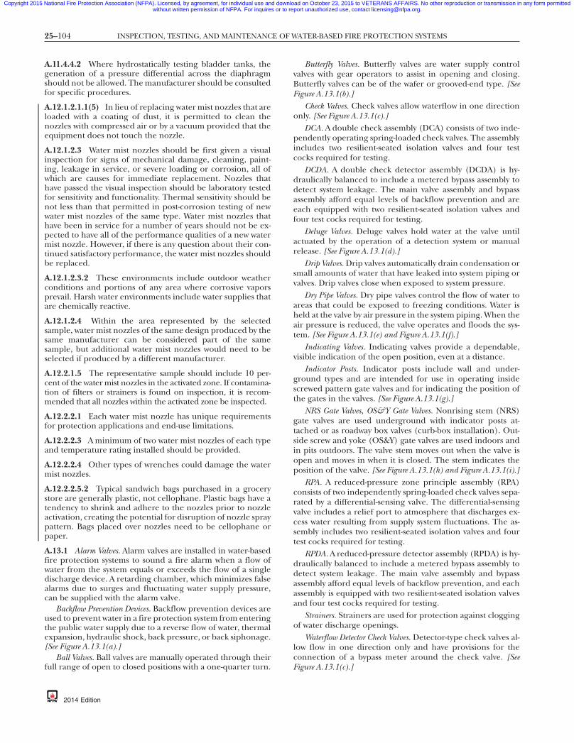
25–104 INSPECTION, TESTING, AND MAINTENANCE OF WATER-BASED FIRE PROTECTION SYSTEMS
Copyright 2015 National Fire Protection Association (NFPA). Licensed, by agreement, for individual use and download on October 23, 2015 to VETERANS AFFAIRS. No other reproduction or transmission in any form permittedwithout written permission of NFPA. For inquires or to report unauthorized use, contact [email protected].
-8
A.11.4.4.2 Where hydrostatically testing bladder tanks, thegeneration of a pressure differential across the diaphragmshould not be allowed. The manufacturer should be consultedfor specific procedures.
A.12.1.2.1.1(5) In lieu of replacing water mist nozzles that areloaded with a coating of dust, it is permitted to clean thenozzles with compressed air or by a vacuum provided that theequipment does not touch the nozzle.
A.12.1.2.3 Water mist nozzles should be first given a visualinspection for signs of mechanical damage, cleaning, paint-ing, leakage in service, or severe loading or corrosion, all ofwhich are causes for immediate replacement. Nozzles thathave passed the visual inspection should be laboratory testedfor sensitivity and functionality. Thermal sensitivity should benot less than that permitted in post-corrosion testing of newwater mist nozzles of the same type. Water mist nozzles thathave been in service for a number of years should not be ex-pected to have all of the performance qualities of a new watermist nozzle. However, if there is any question about their con-tinued satisfactory performance, the water mist nozzles shouldbe replaced.
A.12.1.2.3.2 These environments include outdoor weatherconditions and portions of any area where corrosive vaporsprevail. Harsh water environments include water supplies thatare chemically reactive.
A.12.1.2.4 Within the area represented by the selectedsample, water mist nozzles of the same design produced by thesame manufacturer can be considered part of the samesample, but additional water mist nozzles would need to beselected if produced by a different manufacturer.
A.12.2.1.5 The representative sample should include 10 per-cent of the water mist nozzles in the activated zone. If contamina-tion of filters or strainers is found on inspection, it is recom-mended that all nozzles within the activated zone be inspected.
A.12.2.2.1 Each water mist nozzle has unique requirementsfor protection applications and end-use limitations.
A.12.2.2.3 A minimum of two water mist nozzles of each typeand temperature rating installed should be provided.
A.12.2.2.4 Other types of wrenches could damage the watermist nozzles.
A.12.2.2.5.2 Typical sandwich bags purchased in a grocerystore are generally plastic, not cellophane. Plastic bags have atendency to shrink and adhere to the nozzles prior to nozzleactivation, creating the potential for disruption of nozzle spraypattern. Bags placed over nozzles need to be cellophane orpaper.
A.13.1 Alarm Valves. Alarm valves are installed in water-basedfire protection systems to sound a fire alarm when a flow ofwater from the system equals or exceeds the flow of a singledischarge device. A retarding chamber, which minimizes falsealarms due to surges and fluctuating water supply pressure,can be supplied with the alarm valve.
Backflow Prevention Devices. Backflow prevention devices areused to prevent water in a fire protection system from enteringthe public water supply due to a reverse flow of water, thermalexpansion, hydraulic shock, back pressure, or back siphonage.[See Figure A.13.1(a).]
Ball Valves. Ball valves are manually operated through theirfull range of open to closed positions with a one-quarter turn.
{3e0bff22-698c-46e7
2014 Edition
Butterfly Valves. Butterfly valves are water supply controlvalves with gear operators to assist in opening and closing.Butterfly valves can be of the wafer or grooved-end type. [SeeFigure A.13.1(b).]
Check Valves. Check valves allow waterflow in one directiononly. [See Figure A.13.1(c).]
DCA. A double check assembly (DCA) consists of two inde-pendently operating spring-loaded check valves. The assemblyincludes two resilient-seated isolation valves and four testcocks required for testing.
DCDA. A double check detector assembly (DCDA) is hy-draulically balanced to include a metered bypass assembly todetect system leakage. The main valve assembly and bypassassembly afford equal levels of backflow prevention and areeach equipped with two resilient-seated isolation valves andfour test cocks required for testing.
Deluge Valves. Deluge valves hold water at the valve untilactuated by the operation of a detection system or manualrelease. [See Figure A.13.1(d).]
Drip Valves. Drip valves automatically drain condensation orsmall amounts of water that have leaked into system piping orvalves. Drip valves close when exposed to system pressure.
Dry Pipe Valves. Dry pipe valves control the flow of water toareas that could be exposed to freezing conditions. Water isheld at the valve by air pressure in the system piping. When theair pressure is reduced, the valve operates and floods the sys-tem. [See Figure A.13.1(e) and Figure A.13.1(f).]
Indicating Valves. Indicating valves provide a dependable,visible indication of the open position, even at a distance.
Indicator Posts. Indicator posts include wall and under-ground types and are intended for use in operating insidescrewed pattern gate valves and for indicating the position ofthe gates in the valves. [See Figure A.13.1(g).]
NRS Gate Valves, OS&Y Gate Valves. Nonrising stem (NRS)gate valves are used underground with indicator posts at-tached or as roadway box valves (curb-box installation). Out-side screw and yoke (OS&Y) gate valves are used indoors andin pits outdoors. The valve stem moves out when the valve isopen and moves in when it is closed. The stem indicates theposition of the valve. [See Figure A.13.1(h) and Figure A.13.1(i).]
RPA. A reduced-pressure zone principle assembly (RPA)consists of two independently spring-loaded check valves sepa-rated by a differential-sensing valve. The differential-sensingvalve includes a relief port to atmosphere that discharges ex-cess water resulting from supply system fluctuations. The as-sembly includes two resilient-seated isolation valves and fourtest cocks required for testing.
RPDA. A reduced-pressure detector assembly (RPDA) is hy-draulically balanced to include a metered bypass assembly todetect system leakage. The main valve assembly and bypassassembly afford equal levels of backflow prevention, and eachassembly is equipped with two resilient-seated isolation valvesand four test cocks required for testing.
Strainers. Strainers are used for protection against cloggingof water discharge openings.
Waterflow Detector Check Valves. Detector-type check valves al-low flow in one direction only and have provisions for theconnection of a bypass meter around the check valve. [SeeFigure A.13.1(c).]
7db-eba3b3d7337a}
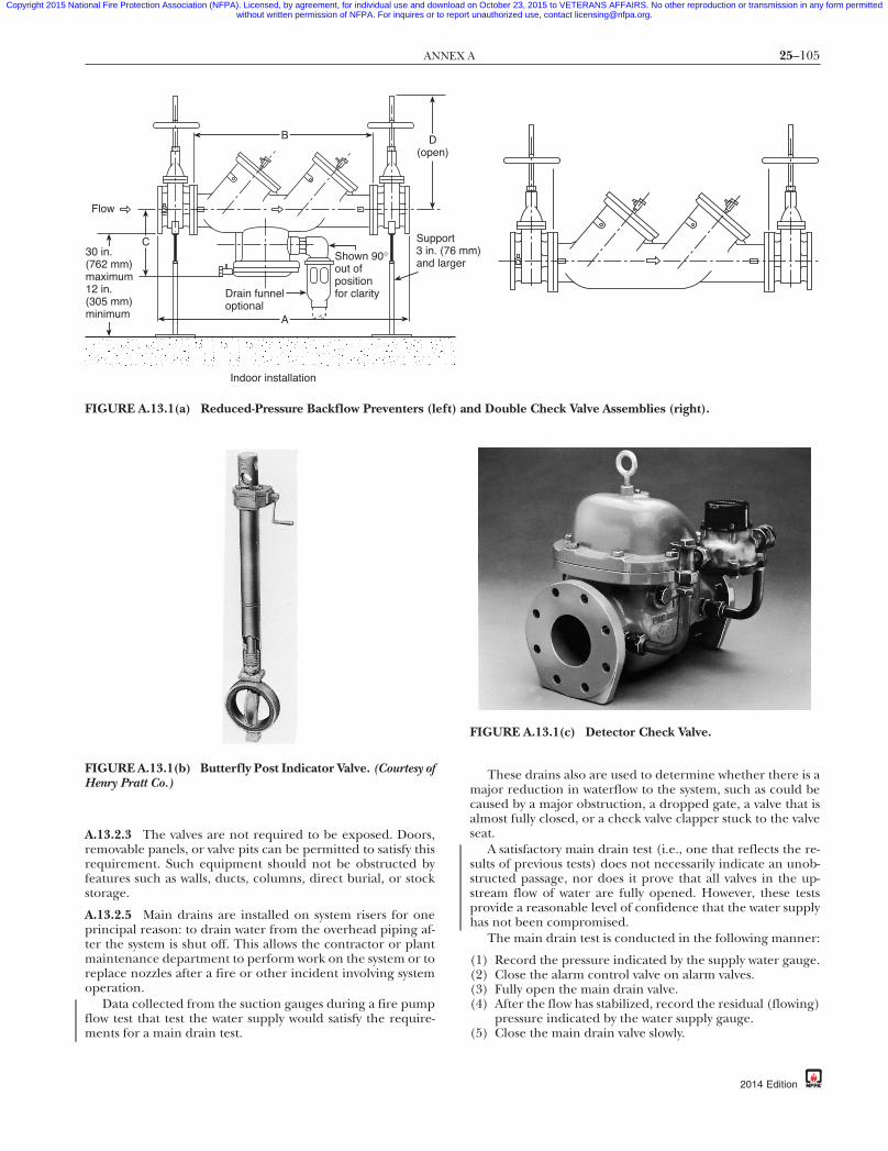
25–105ANNEX A
Copyright 2015 National Fire Protection Association (NFPA). Licensed, by agreement, for individual use and download on October 23, 2015 to VETERANS AFFAIRS. No other reproduction or transmission in any form permittedwithout written permission of NFPA. For inquires or to report unauthorized use, contact [email protected].
87
A.13.2.3 The valves are not required to be exposed. Doors,removable panels, or valve pits can be permitted to satisfy thisrequirement. Such equipment should not be obstructed byfeatures such as walls, ducts, columns, direct burial, or stockstorage.
A.13.2.5 Main drains are installed on system risers for oneprincipal reason: to drain water from the overhead piping af-ter the system is shut off. This allows the contractor or plantmaintenance department to perform work on the system or toreplace nozzles after a fire or other incident involving systemoperation.
Data collected from the suction gauges during a fire pumpflow test that test the water supply would satisfy the require-ments for a main drain test.
B
A
Drain funneloptional
Shown 90°out ofpositionfor clarity
D(ope
Sup3 in.and
Flow
30 in.(762 mm)maximum12 in.(305 mm)minimum
C
Indoor installation
FIGURE A.13.1(a) Reduced-Pressure Backflow Preventers (l
FIGURE A.13.1(b) Butterfly Post Indicator Valve. (Courtesy ofHenry Pratt Co.)
{3e0bff22-698c-46e7-
These drains also are used to determine whether there is amajor reduction in waterflow to the system, such as could becaused by a major obstruction, a dropped gate, a valve that isalmost fully closed, or a check valve clapper stuck to the valveseat.
A satisfactory main drain test (i.e., one that reflects the re-sults of previous tests) does not necessarily indicate an unob-structed passage, nor does it prove that all valves in the up-stream flow of water are fully opened. However, these testsprovide a reasonable level of confidence that the water supplyhas not been compromised.
The main drain test is conducted in the following manner:
(1) Record the pressure indicated by the supply water gauge.(2) Close the alarm control valve on alarm valves.(3) Fully open the main drain valve.(4) After the flow has stabilized, record the residual (flowing)
pressure indicated by the water supply gauge.(5) Close the main drain valve slowly.
)
d Double Check Valve Assemblies (right).
FIGURE A.13.1(c) Detector Check Valve.
db-eba3b3d7337a}
n)
port (76 mmlarger
eft) an
2014 Edition
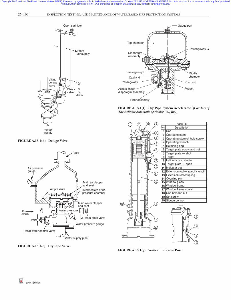
25–106 INSPECTION, TESTING, AND MAINTENANCE OF WATER-BASED FIRE PROTECTION SYSTEMS
Copyright 2015 National Fire Protection Association (NFPA). Licensed, by agreement, for individual use and download on October 23, 2015 to VETERANS AFFAIRS. No other reproduction or transmission in any form permittedwithout written permission of NFPA. For inquires or to report unauthorized use, contact [email protected].
Open sprinkler
Watersupply
Vikingdelugevalve
Checkvalve To
drain
Fromair supply
FIGURE A.13.1(d) Deluge Valve.
-8
Main air clapperand seat
Intermediate or nopressure chamber
Main water clapperand seat
Air pressure
Air pressuregauge
Toalarm
Main water control valve
Water supply pipe
Water pressure gauge
Main drain valve
Riser
Water pressure
FIGURE A.13.1(e) Dry Pipe Valve.
{3e0bff22-698c-46e7
2014 Edition
Passageway G
Accelo checkdiaphragm assembly
Gauge port
Top chamber
Diaphragmassembly
Passageway E
Cavity H
Passageway F
Filter assembly
Poppet
Push rod
Middlechamber
FIGURE A.13.1(f) Dry Pipe System Accelerator. (Courtesy ofThe Reliable Automatic Sprinkler Co., Inc.)
18
17
15
16
Parts listDescriptionNo
Cap
Operating stem oil hole screwOperating stem
Operating wrenchRetaining ringTarget plate screw and nutTarget plate — shutTargetIndicator post stapleTarget plate — openIndicator postExtension rod — specify lengthExtension rod couplingCoupling pinWindow glassWindow frameWindow frame screwCap bolt and nutSet screwSleeve bonnet20
19181716151413121110987
654321
SHUT
OPEN
1
20
14
1319
12
11
10
9
8
7
6
5
432
FIGURE A.13.1(g) Vertical Indicator Post.
7db-eba3b3d7337a}

25–107ANNEX A
Copyright 2015 National Fire Protection Association (NFPA). Licensed, by agreement, for individual use and download on October 23, 2015 to VETERANS AFFAIRS. No other reproduction or transmission in any form permittedwithout written permission of NFPA. For inquires or to report unauthorized use, contact [email protected].
87
A.13.3.1 Signs identifying underground fire service maincontrol valves in roadway boxes should indicate the directionof valve opening, the distance and direction of the valve fromthe sign location (if the valve is subject to being covered bysnow or ice), and the location of the wrench if not located withthe sign.
A.13.3.1.2 Valves that normally are closed during coldweather should be removed and replaced with devices thatprovide continuous fire protection service.
A.13.3.2.2 Valves should be kept free of snow, ice, storage, orother obstructions so that access is ensured.
A.13.3.2.2(2) The purpose of the valve sealing program is asfollows:
(1) The presence of a seal on a control valve is a deterrent toclosing a valve indiscriminately without obtaining theproper authority.
Handwheel
Stem
Yoke
Bonnet
Valve body
Disc
FIGURE A.13.1(h) OS&Y Gate Valve.
Street surface
FIGURE A.13.1(i) Nonindicating-Type Gate Valve.
{3e0bff22-698c-46e7-
(2) A broken or missing seal on a valve is cause for the plantinspector to verify that protection is not impaired and tonotify superiors of the fact that a valve could have beenclosed without following procedures.
A.13.3.3.2 A proper wrench needs to be used for this test.Using an improper wrench such as a pipe wrench has resultedin damage to the operating nut. The use of break over barsand extensions on the wrench can damage the valve and/orthe post. If the valve cannot be closed and reopened using theproper wrench with reasonable force, then some maintenanceand/or repairs are necessary so the valve can be operatedwhen needed in a fire event. These “spring tests” are made toverify that a post indicator valve is fully open. If an operatorfeels the valve is fully open, he or she should push in the“open” direction. The handle usually moves a short distance(approximately a one-quarter turn) and “springs” back towardthe operator in a subtle move when released. This spring oc-curs when the valve gate pulls up tight against the top of itscasting and the valve shaft (being fairly long) twists slightly.The spring indicates that the valve is fully opened and that thegate is attached to the handle. If the gate is jammed due to aforeign particle, the handle is not likely to spring back. If thegate is loose from the handle, the handle continues to turn inthe “open” direction with little resistance.
A.13.3.3.5 For further information, see NFPA 72, National FireAlarm and Signaling Code.
A.13.4.1.1 A higher pressure reading on the system gauge isnormal in variable pressure water supplies. Pressure over 175 psi(12.1 bar) can be caused by fire pump tests or thermal expansionand should be investigated and corrected.
A.13.4.1.2 The system should be drained for internal inspec-tion of valve components as follows:
(1) Close the control valve(2) Open the main drain valve(3) Open the inspector’s test valve(4) Wait for the sound of draining water to cease and for all
gauges to indicate 0 psi (0 bar) before removing the hand-hole cover or dismantling any component
A.13.4.3.2.1 High priming water levels can adversely affectthe operation of supervisory air. Test the water level as follows:
(1) Open the priming level test valve.(2) If water flows, drain it.(3) Close the valve when water stops flowing and air dis-
charges.(4) If air discharges when the valve is opened, the priming
water level could be too low. To add priming water, referto the manufacturer’s instructions.
A.13.4.3.2.2 Preaction and deluge valves in areas subject tofreezing should be trip tested in the spring to allow time be-fore the onset of cold weather for all water that has enteredthe system or condensation to drain to low points or back tothe valve.
A.13.4.3.2.2.1 It is necessary that the full flow test incorporatethe full functionality of the system, which would include anysolenoid valves or other actuation devices. It was a commonpractice in the past to test the detection system or manual pullstation up to the solenoid valve or actuator, and to separatelytest the deluge valve and system after the solenoid valve oractuator. The detectors on the system can be tested separately
db-eba3b3d7337a}
2014 Edition

25–108 INSPECTION, TESTING, AND MAINTENANCE OF WATER-BASED FIRE PROTECTION SYSTEMS
Copyright 2015 National Fire Protection Association (NFPA). Licensed, by agreement, for individual use and download on October 23, 2015 to VETERANS AFFAIRS. No other reproduction or transmission in any form permittedwithout written permission of NFPA. For inquires or to report unauthorized use, contact [email protected].
-8
as long as the functional test includes activation of the actua-tor or solenoid when it receives an actual or simulated signal.
A.13.4.3.2.12 Methods of recording maintenance includetags attached at each riser, records retained at each building,and records retained at one building in a complex.
A.13.4.3.3.3 Suitable facilities should be provided to disposeof drained water. Low points equipped with a single valveshould be drained as follows:
(1) Open the low-point drain valve slowly(2) Close the drain valve as soon as water ceases to discharge,
and allow time for additional accumulation above thevalve
(3) Repeat this procedure until water ceases to discharge(4) Replace plug or nipple and cap as necessary
Low points equipped with dual valves should be drained asfollows:
(1) Close the upper valve(2) Open the lower valve, and drain the accumulated water(3) Close the lower valve, open the upper valve, and allow
time for additional water accumulation(4) Repeat this procedure until water ceases to discharge(5) Replace plug or nipple and cap in lower valve
Removing water from a preaction or deluge system is anessential part of a good maintenance program. Failure to keepthese systems free of water can result in damage and expensiverepairs to both the system and building. A program for moni-toring the condition of the system and the operation of theauxiliary drains should be instituted. Auxiliary drains shouldbe operated on a daily basis after a system operation untilseveral days pass with no discharge of water from the drainvalve. Thereafter, it might be possible to decrease the fre-quency to weekly or longer intervals depending on the volumeof water discharged. Likewise, when preparing for coldweather, the auxiliary drains should be operated daily, withthe frequency of operation decreasing depending on the dis-charge of accumulated water. In many cases, the frequency ofthe operation can decrease significantly if a system is shown tobe dry.
A.13.4.4.1.2.3 A conflict in pressure readings could indicatean obstructed orifice or a leak in the isolated chamber of thequick-opening device, either of which could make the quick-opening device inoperative.
A.13.4.4.2.1 High priming water levels can affect the opera-tion of supervisory air or nitrogen pressure maintenance de-vices. Test the water level as follows:
(1) Open the priming level test valve.(2) If water flows, drain it.(3) Close the valve when water stops flowing and air dis-
charges.(4) If air discharges when the valve is opened, the priming
water level could be too low. To add priming water, referto the manufacturer’s instructions.
A.13.4.4.2.2 Dry pipe valves should be trip tested in thespring to allow time before the onset of cold weather for allwater that has entered the system or condensation to drain tolow points or back to the valve.
A.13.4.4.2.2.2 A full flow trip test generally requires at leasttwo individuals, one of whom is situated at the dry pipe valvewhile the other is at the inspector’s test. If possible, they
{3e0bff22-698c-46e7
2014 Edition
should be in communication with each other. A full flow triptest is conducted as follows:
(1) The main drain valve is fully opened to clean any accumu-lated scale or foreign material from the supply water pip-ing. The main drain valve then is closed.
(2) The system air or nitrogen pressure and the supply waterpressure are recorded.
(3) The system air or nitrogen pressure is relieved by openingthe inspector’s test valve completely. Concurrent withopening the valve, both testers start their stopwatches. Iftwo-way communication is not available, the tester at thedry valve is to react to the start of downward movement onthe air pressure gauge.
(4) Testers at the dry pipe valve note the air pressure at whichthe valve trips and note the tripping time.
(5) Testers at the inspector’s test note the time at which waterflows steadily from the test connection. This time is noted forcomparison purposes to previous tests and is not meant tobe a specific pass/fail criterion. Note that NFPA 13, Standardfor the Installation of Sprinkler Systems, does not require waterdelivery in 60 seconds for all systems.
(6) When clean water flows, the test is terminated by closingthe system control valve.
(7) The air or nitrogen pressure and the time elapsed are tobe recorded as follows:(a) From the complete opening of the test valve to the
tripping of the valve(b) From the complete opening of inspector’s valve to
the start of steady flow from the test connection(8) All low-point drains are opened and then closed when
water ceases to flow.(9) The dry pipe valve and quick-opening device are reset, if
installed, in accordance with the manufacturer’s instruc-tions, and the system is returned to service.
For dry pipe systems that were designed and installed usingeither a manual demonstration or a computer calculation tosimulate multiple openings to predict water delivery time, afull flow trip test from a single inspector’s test connectionshould have been conducted during the original system accep-tance and a full flow trip test from the single inspector’s testshould continue to be conducted every 3 years. The system isnot required to achieve water delivery to the inspector’s testconnection in 60 seconds, but comparison to the water deliv-ery time during the original acceptance will determine if thereis a problem with the system.
A.13.4.4.2.2.3 A partial flow trip test is conducted in the fol-lowing manner:
(1) Fully open the main drain valve to clean any accumulatedscale or foreign material from the supply water piping
(2) Close the control valve to the point where additionalclosure cannot provide flow through the entire area ofthe drain outlet
(3) Close the valve controlling flow to the device if a quick-opening device is installed
(4) Record the system air or nitrogen pressure and the sup-ply water pressure
(5) Relieve system air or nitrogen pressure by opening thepriming level test valve
(6) Note and record the air or nitrogen pressure and supplywater pressure when the dry pipe valve trips
7db-eba3b3d7337a}

25–109ANNEX A
Copyright 2015 National Fire Protection Association (NFPA). Licensed, by agreement, for individual use and download on October 23, 2015 to VETERANS AFFAIRS. No other reproduction or transmission in any form permittedwithout written permission of NFPA. For inquires or to report unauthorized use, contact [email protected].
87
(7) Immediately close the system control valve and open themain drain valve to minimize the amount of water enter-ing the system piping
(8) Trip test the quick-opening device, if installed, in accor-dance with the manufacturer’s instructions
(9) Open all low point drains and close when water ceases toflow
(10) Reset the dry pipe valve and quick-opening device, if in-stalled, in accordance with the manufacturer’s instruc-tions and return the system to service
CAUTION: A partial flow trip test does not provide a highenough rate of flow to latch the clappers of some model drypipe valves in the open position. When resetting such valves,check that the latching equipment is operative.
A.13.4.4.2.4 Except when a full flow trip test is conducted inaccordance with A.13.4.4.2.2.2, a quick-opening device shouldbe tested in the following manner:
(1) Close the system control valve(2) Open the main drain valve, and keep it in the open posi-
tion(3) Verify that the quick-opening device control valve is open(4) Open the inspector’s test valve. (Note that a burst of air
from the device indicates that it has tripped)(5) Close the device’s control valve(6) Return the device to service in accordance with the manu-
facturer’s instructions and return the system to service
A.13.4.4.3.2 Removing water from a dry system is an essentialpart of a good maintenance program. Failure to keep the drysystem free of water can result in damage and expensive re-pairs to both the system and building. A program for monitor-ing the condition of the system and the operation of the aux-iliary drains should be instituted. Auxiliary drains should beoperated on a daily basis after a dry sprinkler system operationuntil several days pass with no discharge of water from thedrain valve. Thereafter, it might be possible to decrease thefrequency to weekly or longer intervals depending on the vol-ume of water discharged. Likewise, when preparing for coldweather, the auxiliary drains should be operated daily with thefrequency of operation decreasing depending on the dis-charge of accumulated water. In many cases, the frequency ofthe operation can decrease significantly if a system is shown tobe dry. A quick-opening device, if installed, should be removedtemporarily from service prior to draining low points.
A.13.5.1.2 The sectional drain valve should be opened tocompare the results with the original installation or accep-tance tests.
A.13.5.2.2 PRV devices can be bench tested in accordancewith the manufacturer’s instructions or tested in place. To testin place, a gauge is connected on both the inlet side and theoutlet side of the device, and flow readings are taken using aPitot tube or a flowmeter. Water is discharged through a roofmanifold, if available, or through hose to the exterior of thebuilding. Another acceptable method for systems having atleast two risers is to take one standpipe out of service and use itas a drain by removing PRV devices and attaching hoses at theoutlets near the ground floor level. When testing in this man-ner, a flowmeter should be used and a hose line utilized toconnect the riser being tested and the drain riser.
Readings are to be compared to the system’s hydraulic de-mands at the test location. Field-adjustable valves are to bereset in accordance with manufacturer’s instructions. Nonad-justable valves should be replaced. Extreme caution should beexercised because of the high pressure involved when testing.
{3e0bff22-698c-46e7-
A.13.5.4.1 When the PRV is located in or immediately down-stream of the fire pump discharge, the weekly inspection ofthe master PRV can be performed during the weekly firepump operating test.
A.13.5.4.1(1) Pressures downstream of the master PRV shouldnot exceed the maximum pressure rating of the system compo-nents.
A.13.5.4.2 The partial flow test of the master PRV can beperformed during the quarterly main drain test. (See 13.2.5.2.)
A.13.5.4.3 When the PRV is located in the fire pump dis-charge, the full flow test of the master PRV can be performedduring the annual fire pump flow test.
A.13.5.6.2.1 Hose valves can be tested without a full flow ifthe cap is left on the hose threads. The purpose of this require-ment is to exercise the valve so it can be operated easily.
A.13.5.6.2.2 See A.13.5.6.2.1.
A.13.6.1.2.2 Intermittent discharge from a differential-sensingvalve relief port is normal. Continuous discharge is a sign of mal-function of either or both of the check valves, and maintenance isnecessary.
A.13.6.1.4 Where annual maintenance includes an internalinspection performed by a qualified person, this requirementis satisfied.
A.13.6.2.1 The full flow test of the backflow prevention valvecan be performed with a test header or other connectionsdownstream of the valve. A bypass around the check valve inthe fire department connection line with a control valve in thenormally closed position can be an acceptable arrangement.When flow to a visible drain cannot be accomplished, closedloop flow can be acceptable if a flowmeter or sight glass isincorporated into the system to ensure flow.
A.13.7.1(9) It is not the intent of this section for all fire de-partment connection piping to be inspected for obstructionsbut only the interior of the connection itself.
A.13.8.3 Design review is outside the scope of this standard.
A.14.1 For obstruction investigation and prevention, see An-nex D.
A.14.2.1 It is the intent of this requirement to provide a rea-sonable assurance that corrosion and obstruction issues withinfire protection systems are identified. It is not the intent torequire verification that every piece of pipe in the system isfree from corrosion and obstructions. An assessment of theinternal condition of piping can be accomplished by severalmethods that meet the intent of this section. These methodsinclude the following:
(1) Opening a flushing connection at the end of one main,and removing the end fitting or piece of branch line or asprinkler for the purpose of inspecting for the presenceof foreign organic and inorganic material.(a) In dry pipe systems and preaction systems, the branch
line inspected should be the most remote one fromthe source of water that is not equipped with the in-spector’s test valve.
(b) When performing normal maintenance that involvesdraining down a system to modify a system such as fortenant fit out or building renovations, or when re-moving or replacing piping, this inspection can beperformed as described and properly recorded at
db-eba3b3d7337a}
2014 Edition

25–110 INSPECTION, TESTING, AND MAINTENANCE OF WATER-BASED FIRE PROTECTION SYSTEMS
Copyright 2015 National Fire Protection Association (NFPA). Licensed, by agreement, for individual use and download on October 23, 2015 to VETERANS AFFAIRS. No other reproduction or transmission in any form permittedwithout written permission of NFPA. For inquires or to report unauthorized use, contact [email protected].
-8
that time. The time interval would then start for thenext assessment of that system at the frequency deter-mined by 14.2.1.1 or 14.2.1.2.
(c) If a sprinkler is removed to perform this inspection,5.4.1.1 requires a new sprinkler matching the charac-teristics of the replaced sprinkler.
(2) Utilizing alternative examination methods such as the fol-lowing:(a) Using video inspection equipment that is inserted
into the system at strategic points to observe the inter-nal condition of pipes. This equipment provides a vi-sual exam of the pipes using a camera and lightingsystem on the end of a push cable. Video inspectionequipment can be inserted in alarm, dry, and preac-tion valves for a look into risers, feed mains, somecross mains, and some branch lines, depending onthe system configuration. The push cable can also beinserted in a check valve when performing the five-year internal inspection required by 13.4.2.1 to viewadditional areas of a system, and in the fire depart-ment connection to perform the interior inspectionrequired by 13.7.2.
(b) Ultrasonic or similar technology that allows the pipewall to be tested to determine the extent of any dete-rioration due to microbiologically influenced corro-sion (MIC) or other forms of corrosion. This methodwould not typically be used for the internal inspec-tion of piping required by this section because itmight not detect the presence of solid material in thepiping, such as wood, plastic, or other foreign ob-structions, that are not a by-product of corrosion, be-cause only small representative sections of pipe areexamined.
(c) A laboratory analysis of water samples obtained fromthe fire protection system, combined with collectingand inspecting solid material from fire protection sys-tem water discharged from a main drain, and an in-spector’s test connection, can provide an indicationof the presence of corrosion, MIC, and/or foreignmaterials. If a high level of MIC is identified, or if asignificant amount of foreign materials is found, fur-ther investigation might be warranted to verify theextent of corrosion, MIC, or other obstructions in thesystem. The solid materials should be collected withan appropriately sized strainer. If inspection of thesolid materials identifies excessive rust, black watercolor, or sulfur (rotten egg) odors, an obstruction in-vestigation as described in Section 14.3 is warranted.
A.14.2.1.2 The purpose of the assessment of the internal con-dition of piping is to identify whether foreign organic andinorganic material is present, since the presence of such mate-rial can potentially be detrimental to the performance of thesprinkler system. Corrosion, which includes microbiologicallyinfluenced corrosion (MIC), can be prevalent in sprinkler pip-ing, but not necessarily in all systems, buildings, or geographiclocations. Therefore, the risk analysis should be based uponevidence noted and/or data obtained from proximate sprin-kler systems, known problems from the water supply, as well asother factors that could affect the integrity of the system pip-ing. The decision of when, how often, and which method touse to conduct an assessment should also consider the risk ofemptying and refilling the sprinkler system with water, whichcould adversely impact the sprinkler system by introducingforeign or inorganic material into the sprinkler system.
{3e0bff22-698c-46e7
2014 Edition
A.14.2.1.4 Most piping systems contain some foreign mate-rial or other evidence of corrosion but not sufficient to triggeran obstruction investigation. Furthermore, an internal inspec-tion is primarily an inspection for determining corrosion ofthe pipe, but it can result in finding the presence of materialthat would be an obstruction to piping or sprinklers. If such isfound, an obstruction investigation in Section 14.3 would berequired.
A.14.2.2 In large warehouses, high-rise buildings, and otherbuildings having multiple systems, it is reasonable to performthe assessment on half of the systems, and conclude that theseare representative of all systems in the building. The systems inthe building not assessed during one frequency cycle shouldbe assessed during the next one. As long as there is no evi-dence of any foreign organic and/or inorganic material foundin any of the systems being assessed, every other system wouldbe assessed once every frequency cycle. However, if foreignorganic and/or inorganic material is found in any system inthe building during the frequency cycle, all systems mustwould then be assessed during that frequency cycle.
A.14.3.1 Most piping systems contain some foreign materialor other evidence of corrosion but not sufficient to trigger anobstruction investigation. Furthermore, an internal inspec-tion is primarily an inspection for determining corrosion ofthe pipe, but it can result in finding the presence of materialthat would be an obstruction to piping or sprinklers. If such isfound, an obstruction investigation in Section 14.3 would berequired. For obstruction investigation procedures, see Sec-tion D.3. The type of obstruction investigation should be ap-propriately selected based on the observed condition. For in-stance, ordering an internal obstruction investigation wouldbe inappropriate where the observed condition was brokenpublic mains in the vicinity. On the other hand, such an inves-tigation would be appropriate where foreign materials are ob-served in the dry pipe valve.
A.14.3.2 For obstruction prevention program recommenda-tions, see Section D.4.
A.14.3.2.2 The indicated locations are presented as the mini-mum basis for determining the need for the initiation of amore extensive obstruction investigation effort. Additionalpoints of examination can be appropriately dictated to assessthe extent and severity of the obstructing material as deter-mined by the observed conditions at these locations. See Sec-tion D.3 for further discussion.
A.14.3.2.3 Alternative examination methods can include thefollowing:
(1) Using video inspection equipment that is inserted intothe system at strategic points to observe the internal con-dition of pipes. This equipment provides a visual exam ofthe pipes using a camera and lighting system on the endof a push cable. Video inspection equipment can be in-serted in alarm, dry, and preaction valves, in the risers,and into cross mains and branch lines, depending on thesystem configuration. This equipment can also be used todetermine the results of any flushing that was performed.
(2) Ultrasonic or similar technology that allows the pipe wallto be externally tested to determine the extent of any de-terioration due to MIC or other forms of corrosion. Thismethod has advantages including allowing the system tobe left in service while performing the examination, andpinpointing where pipes are about to fail before the ac-tual failure occurs, allowing preventive action to be taken.
7db-eba3b3d7337a}

25–111ANNEX A
Copyright 2015 National Fire Protection Association (NFPA). Licensed, by agreement, for individual use and download on October 23, 2015 to VETERANS AFFAIRS. No other reproduction or transmission in any form permittedwithout written permission of NFPA. For inquires or to report unauthorized use, contact [email protected].
87
This technology does have its limitations, and to be thor-ough all pipes would require access, even those in con-cealed spaces such as those above ceilings. This technol-ogy can detect the presence of a buildup of sludge, scale,or other by-products of corrosion, and can detect existingair pockets in wet systems as well as trapped sections ofpipe in dry systems that aren’t adequately drained. Thistechnology cannot detect the presence of MIC itself, butcan detect tubercules caused by MIC. In most cases thistechnology will not detect the presence of solid materialin the piping such as wood, plastic, or other foreign ob-structions that are not a by-product of corrosion, becauseonly small representative sections of pipe are examined.
A.14.3.3 For obstruction investigation flushing procedures,see Section D.5.
A.15.3.1 A clearly visible tag alerts building occupants andthe fire department that all or part of the water-based fireprotection system is out of service. The tag should be weatherresistant, plainly visible, and of sufficient size [typically 4 in.× 6 in. (100 mm × 150 mm)]. The tag should identify whichsystem is impaired, the date and time impairment began, andthe person responsible. Figure A.15.3.1 illustrates a typical im-pairment tag.
A.15.3.2 An impairment tag should be placed on the firedepartment connection to alert responding fire fighters of anabnormal condition. An impairment tag that is located on thesystem riser only could go unnoticed for an extended period iffire fighters encounter difficulty in gaining access to the build-ing or sprinkler control room.
ATTACH TO VALVE• READ INSTRUCTIONS ON OTHER SIDE •
SPRINKLER VALVE
SHUTTHIS VALVE CONTROLS SPRINKLERS IN BUILDING(S):
SHUT BY (SIGNATURE)
STATIC PRESSURE
DATE
DRAIN TEST MADE BY (SIGNATURE) DATE
psi (bar)FLOWING PRESSURE
➞ After valve is opened, make 2 in. (50 mm) drain test. Drop inpressure should be normal. If pressure drop is extreme and doesnot build up, the system is impaired and immediate investigation
is necessary.
DRAIN TEST RESULTS
psi (bar)
FIGURE A.15.3.1 Sample Impairment Tag.
{3e0bff22-698c-46e7-
A.15.5 The need for temporary fire protection, terminationof all hazardous operations, and frequency of inspections inthe areas involved should be determined. All work possibleshould be done in advance to minimize the length of the im-pairment. Where possible, temporary feedlines should beused to maintain portions of systems while work is completed.
Water-based fire protection systems should not be removedfrom service when the building is not in use. Where a systemthat has been out of service for a prolonged period, such as inthe case of idle or vacant properties, is returned to service,qualified personnel should be retained to inspect and test thesystems.
A.15.5.2(4)(b) A fire watch should consist of trained person-nel who continuously patrol the affected area. Ready access tofire extinguishers and the ability to promptly notify the firedepartment are important items to consider. During the pa-trol of the area, the person should not only be looking for fire,but making sure that the other fire protection features of thebuilding such as egress routes and alarm systems are availableand functioning properly.
A.15.5.2(4)(c) Temporary water supplies are possible from anumber of sources, including use of a large-diameter hosefrom a fire hydrant to a fire department connection, use of aportable tank and a portable pump, or use of a standby firedepartment pumper and/or tanker.
A.15.5.2(4)(d) Depending on the use and occupancy of thebuilding, it could be enough in some circumstances to stopcertain processes in the building or to cut off the flow of fuelto some machines. It is also helpful to implement “No Smok-ing” and “No Hot Work” (cutting, grinding, or welding) poli-cies while the system is out of service because these activitiesare responsible for many fire ignitions.
A.15.6 Emergency impairments include, but are not limitedto, system leakage, interruption of water supply, frozen or rup-tured piping, equipment failure, or other impairments foundduring inspection, testing, or maintenance activities.
A.15.6.2 When one or more impairments are discovered dur-ing inspection, testing, and maintenance activities, the owner orowner’s authorized representative should be notified in writing.See Figure A.15.6.2 for an example of written notification.
A.15.7 Occasionally, fire protection systems in idle or vacantbuildings are shut off and drained. When the equipment iseventually restored to service after a long period of not beingmaintained, it is recommended that qualified personnel or aqualified contractor perform the work. The following is anexample of a procedure:
(1) All piping should be traced from the extremities of thesystem to the main connections with a careful check forblank gaskets in flanges, closed valves, corroded or dam-aged sprinklers, nozzles, or piping, insecure or missinghangers, and insufficient support. Proper repairs or ad-justments should be made, and needed extensions or al-terations for the equipment should be completed.
(2) An air test at low pressure (40 psi) should be conductedprior to allowing water to fill the system. When the pipinghas been proven tight by passing the air test, water can beintroduced slowly into the system, with proper precau-tions against damage by escape of water from previouslyundiscovered defects. When the system has been filledunder normal service pressure, drain valve tests should be
db-eba3b3d7337a}
2014 Edition

25–112 INSPECTION, TESTING, AND MAINTENANCE OF WATER-BASED FIRE PROTECTION SYSTEMS
Copyright 2015 National Fire Protection Association (NFPA). Licensed, by agreement, for individual use and download on October 23, 2015 to VETERANS AFFAIRS. No other reproduction or transmission in any form permittedwithout written permission of NFPA. For inquires or to report unauthorized use, contact [email protected].
-8
made to detect any closed valve that possibly could havebeen overlooked. All available pipes should be flushed,and an obstruction investigation completed to make surethat the system is clear of debris.
(3) Where the system was known to have been damaged byfreezing or where other extensive damage might have oc-curred, a full hydrostatic test can be performed in accor-dance with NFPA 13 to determine whether the system in-tegrity has been maintained.
(4) Dry pipe valves, quick-opening devices, alarm valves, andall alarm connections should be examined, put in propercondition, and tested.
(5) Fire pumps, pressure and gravity tanks, reservoirs, andother water supply equipment should receive proper at-tention before being placed in service. Each supplyshould be tested separately and then together if they aredesigned to work together.
(6) All control valves should be operated from the closed tofully open position and should be left sealed, locked, orequipped with a tamper switch.
A.16.1.1.1 There are numerous NFPA documents that havespecial requirements for the inspection, testing, and mainte-nance of water-based fire protection systems that are differentfrom those in NFPA 25. In many cases those documents refer-ence NFPA 25 and could have either more stringent or evenless stringent requirements than those in NFPA 25.
DURING A RECENT INSPECTION OF YOUR FIRE PROTECTIONSYSTEM(S), AN EMERGENCY IMPAIRMENT WAS DISCOVEREDAND INDICATED ON THE INSPECTION REPORT. AS DEFINED BYNFPA 25, AN EMERGENCY IMPAIRMENT IS “A CONDITION WHEREA WATER-BASED FIRE PROTECTION SYSTEM OR PORTIONTHEREOF IS OUT OF ORDER DUE TO AN UNEXPECTEDOCCURRENCE, SUCH AS A RUPTURED PIPE, OPERATEDSPRINKLER, OR AN INTERRUPTION OF WATER SUPPLY TO THESYSTEM.” NFPA 25 FURTHER STATES, “EMERGENCYIMPAIRMENTS INCLUDE BUT ARE NOT LIMITED TO SYSTEMLEAKAGE, INTERRUPTION OF WATER SUPPLY, FROZEN ORRUPTURED PIPING, AND EQUIPMENT FAILURE.”
WE RECOMMEND THAT IMMEDIATE STEPS BE TAKEN, AS DESCRIBED IN THE ATTACHED COPY OF CHAPTER 15 OF NFPA 25, TO CORRECT THE FOLLOWING IMPAIRMENT(S) TO YOUR FIRE PROTECTION SYSTEM(S):
IMPAIRMENT NOTICE
❏ CONTROL VALVE SHUT. SYSTEM OUT OF SERVICE.
❏ LOW WATER PRESSURE DURING FLOW TEST. POSSIBLE OBSTRUCTION IN WATER SUPPLY OR PARTIALLY SHUT VALVE.
❏ PIPE(S) FROZEN.
❏ PIPE(S) LEAKING.
❏ PIPE(S) ARE OBSTRUCTED.
❏ SYSTEM PIPING OR PORTIONS OF SYSTEM PIPING ARE DISCONNECTED.
❏ FIRE DEPT. CONNECTION MISSING OR DAMAGED OR OBSTRUCTED.
❏ DRY PIPE VALVE CANNOT BE RESET.
❏ DRY PIPE SYSTEM QUICK-OPENING DEVICE IS OUT OF SERVICE.
❏ SPRINKLERS ARE PAINTED, CORRODED, DAMAGED, OR LOADED.
❏ FIRE PUMP IS OUT OF SERVICE.
❏ DETECTION/ACTUATION SYSTEM IS OUT OF SERVICE.
❏ OTHER:
FIGURE A.15.6.2 Sample Impairment Notice.{3e0bff22-698c-46e7
2014 Edition
A.16.1.1.2 These requirements are not written by or able tobe amended by the technical committee of this standard, andtherefore the text is an extract from the document that has therequirements.
Annex B Forms for Inspection, Testing, andMaintenance
This annex is not a part of the requirements of this NFPA documentbut is included for informational purposes only.
B.1 General. Forms need to be complete with respect to therequirements of NFPA 25 for the system being inspected,tested, or maintained, or any combination thereof. Becausewater-based fire protection systems are comprised of manycomponents, it could be necessary to complete more than oneform for each system.
Authorities having jurisdiction are legitimately concernedthat the forms used are comprehensive. Therefore, they coulddevelop their own forms or utilize those already developedand reviewed by their jurisdiction.
At least five formats can be used and are described as fol-lows:
(1) One form in which all requirements for NFPA 25 arespecified and large sections of information do not applyto most systems
(2) Individual forms that provide requirements correspond-ing to each chapter of NFPA 25 and address the following:(a) Sprinkler systems(b) Standpipe systems(c) Private fire service mains(d) Fire pumps(e) Storage tanks(f) Water spray systems(g) Foam-water sprinkler systems
(3) Forms that include information from the specific systemchapter: Chapter 1, Chapter 13, and Chapter 14
(4) A series of forms similar to option (2) but with a more de-tailed breakdown of system types. For example, fire sprinklersystems are divided into five separate forms such as:(a) Wet pipe fire sprinkler systems(b) Dry pipe fire sprinkler systems(c) Preaction fire sprinkler systems(d) Deluge fire sprinkler systems(e) Foam-water sprinkler systems
(5) Separate forms for each individual component of eachfire protection system
B.2 Sample Forms. Sample forms are available for download-ing at www.nfpa.org, www.nfsa.org, and www.sprinklernet.org.
Annex C Possible Causes of Pump Troubles
This annex is not a part of the requirements of this NFPA documentbut is included for informational purposes only.
This annex is extracted from NFPA 20, Standard for the In-stallation of Stationary Pumps for Fire Protection.
C.1 Causes of Pump Troubles. This annex contains a partialguide for locating pump troubles and their possible causes (seeFigure C.1). It also contains a partial list of suggested remedies.(For other information on this subject, see Hydraulic Institute Stan-
7db-eba3b3d7337a}

25–113ANNEX C
Copyright 2015 National Fire Protection Association (NFPA). Licensed, by agreement, for individual use and download on October 23, 2015 to VETERANS AFFAIRS. No other reproduction or transmission in any form permittedwithout written permission of NFPA. For inquires or to report unauthorized use, contact [email protected].
dard for Centrifugal, Rotary and Reciprocating Pumps.) The causeslisted here are in addition to possible mechanical breakagethat would be obvious on visual inspection. In case of trouble,it is suggested that those troubles that can be inspected easilyshould be corrected first or eliminated as possibilities.
C.1.1 Air Drawn into Suction Connection Through Leak(s).Air drawn into suction line through leaks causes a pump tolose suction or fail to maintain its discharge pressure. Uncoversuction pipe and locate and repair leak(s).
C.1.2 Suction Connection Obstructed. Examine suction in-take, screen, and suction pipe and remove obstruction. Repairor provide screens to prevent recurrence.
C.1.3 Air Pocket in Suction Pipe. Air pockets cause a reduc-tion in delivery and pressure similar to an obstructed pipe.Uncover suction pipe and rearrange to eliminate pocket.
Fire pumptroubles
Excessiveleakage atstuffing box
Pump or driveroverheats
Pump unitwill not start
No waterdischarge
Pump is noisyor vibrates
Too muchpower required
Dischargepressurenot constantfor same gpm
Pump losessuction afterstarting
Insufficientwater discharge
Dischargepressuretoo low for gpmdischarge
Suction Pump
Air
draw
n in
to s
uctio
n co
nnec
tion
thro
ugh
leak
(s)
Suc
tion
conn
ectio
n ob
stru
cted
Air
pock
et in
suc
tion
pipe
Wel
l col
laps
ed o
r se
rious
mis
alig
nmen
t
Wat
er s
eal o
r pi
pe to
sea
l obs
truc
ted
Air
leak
into
pum
p th
roug
h st
uffin
g bo
xes
Impe
ller
obst
ruct
ed
Wea
ring
rings
wor
n
Impe
ller
dam
aged
Wro
ng d
iam
eter
impe
ller
Act
ual n
et h
ead
low
er th
an r
ated
Cas
ing
gask
et d
efec
tive,
per
mitt
ing
inte
rnal
leak
age
(sin
gle-
stag
e an
d m
ultis
tage
pum
ps)
113121110987654321
Stu
ffing
box
too
tight
or
pack
ing
impr
oper
ly in
stal
led,
wor
n, d
efec
tive,
too
tight
, or
inco
rrec
t typ
e
FIGURE C.1 Possible Causes of Fire Pump Troubles.
{3e0bff22-698c-46e7-
C.1.4 Well Collapsed or Serious Misalignment. Consult a reli-able well drilling company and the pump manufacturer re-garding recommended repairs.
C.1.5 Stuffing Box Too Tight or Packing Improperly In-stalled, Worn, Defective, Too Tight, or of Incorrect Type.Loosen gland swing bolts and remove stuffing box glandhalves. Replace packing.
C.1.6 Water Seal or Pipe to Seal Obstructed. Loosen glandswing bolt and remove stuffing box gland halves along withthe water seal ring and packing. Clean the water passage toand in the water seal ring. Replace water seal ring, packinggland, and packing in accordance with manufacturer’s in-structions.
C.1.7 Air Leak into Pump Through Stuffing Boxes. Same aspossible cause in C.1.6.
Driver and/orPump Driver
Impe
llers
lock
ed
Pum
p is
froz
en
Pum
p sh
aft o
r sh
aft s
leev
e sc
ored
, ben
t, or
wor
n
Pum
p no
t prim
ed
Sea
l rin
g im
prop
erly
loca
ted
in s
tuffi
ng b
ox, p
reve
ntin
gw
ater
from
ent
erin
g sp
ace
to fo
rm s
eal
Exc
ess
bear
ing
fric
tion
due
to la
ck o
f lub
ricat
ion,
wea
r,di
rt, r
ustin
g, fa
ilure
, or
impr
oper
inst
alla
tion
Rot
atin
g el
emen
t bin
ds a
gain
st s
tatio
nary
ele
men
t
Pum
p an
d dr
iver
mis
alig
ned
Fou
ndat
ion
not r
igid
Eng
ine-
cool
ing
syst
em o
bstr
ucte
d
Fau
lty d
river
Lack
of l
ubric
atio
n
Spe
ed to
o lo
w
Wro
ng d
irect
ion
of r
otat
ion
Spe
ed to
o hi
gh
Rat
ed m
otor
vol
tage
diff
eren
t fro
m li
ne v
olta
ge
Fau
lty e
lect
rical
circ
uit,
obst
ruct
ed fu
el s
yste
m,ob
stru
cted
ste
am p
ipe,
or
dead
bat
tery
3231302928272625242322212019181716db-eba3b3d7337a}
Pressur
e ga
uge
is o
n to
p of
pum
p ca
sing
Inco
rrec
t im
pelle
r ad
just
men
t (ve
rtic
al s
haft
turb
ine-
type
pum
p on
ly)
15487
2014 Edition

25–114 INSPECTION, TESTING, AND MAINTENANCE OF WATER-BASED FIRE PROTECTION SYSTEMS
Copyright 2015 National Fire Protection Association (NFPA). Licensed, by agreement, for individual use and download on October 23, 2015 to VETERANS AFFAIRS. No other reproduction or transmission in any form permittedwithout written permission of NFPA. For inquires or to report unauthorized use, contact [email protected].
-8
C.1.8 Impeller Obstructed. Does not show on any one instru-ment, but pressures fall off rapidly when an attempt is made todraw a large amount of water.
For horizontal split-case pumps, remove upper case ofpump and remove obstruction from impeller. Repair or pro-vide screens on suction intake to prevent recurrence.
For vertical shaft turbine-type pumps, lift out column pipeand pump bowls from wet pit or well and disassemble pumpbowl to remove obstruction from impeller.
For close-coupled, vertical in-line pumps, lift motor on toppull-out design and remove obstruction from impeller.
C.1.9 Wearing Rings Worn. Remove upper case and insertfeeler gauge between case wearing ring and impeller wearingring. Clearance when new is 0.0075 in. (0.19 mm). Clearancesof more than 0.015 in. (0.38 mm) are excessive.
C.1.10 Impeller Damaged. Make minor repairs or return tomanufacturer for replacement. If defect is not too serious,order new impeller and use damaged one until replacementarrives.
C.1.11 Wrong Diameter Impeller. Replace with impeller ofproper diameter.
C.1.12 Actual Net Head Lower Than Rated. Check impellerdiameter and number and pump model number to make surecorrect head curve is being used.
C.1.13 Casing Gasket Defective, Permitting Internal Leakage(Single-Stage and Multistage Pumps). Replace defective gas-ket. Check manufacturer’s drawing to see whether gasket isrequired.
C.1.14 Pressure Gauge Is on Top of Pump Casing. Placegauges in correct location.
C.1.15 Incorrect Impeller Adjustment (Vertical ShaftTurbine-Type Pump Only). Adjust impellers according tomanufacturer’s instructions.
C.1.16 Impellers Locked. For vertical shaft turbine-typepumps, raise and lower impellers by the top shaft adjustingnut. If this adjustment is not successful, follow the manufactur-er’s instructions.
For horizontal split-case pumps, remove upper case andlocate and eliminate obstruction.
C.1.17 Pump Is Frozen. Provide heat in the pump room. Dis-assemble pump and remove ice as necessary. Examine partscarefully for damage.
C.1.18 Pump Shaft or Shaft Sleeve Scored, Bent, or Worn.Replace shaft or shaft sleeve.
C.1.19 Pump Not Primed. If a pump is operated without wa-ter in its casing, the wearing rings are likely to seize. The firstwarning is a change in pitch of the sound of the driver. Shutdown the pump.
For vertical shaft turbine-type pumps, check water level todetermine whether pump bowls have proper submergence.
C.1.20 Seal Ring Improperly Located in Stuffing Box, Pre-venting Water from Entering Space to Form Seal. Loosengland swing bolt and remove stuffing box gland halves alongwith the water-seal ring and packing. Replace, putting sealring in proper location.
C.1.21 Excess Bearing Friction Due to Lack of Lubrication,Wear, Dirt, Rusting, Failure, or Improper Installation. Removebearings and clean, lubricate, or replace as necessary.
{3e0bff22-698c-46e7
2014 Edition
C.1.22 Rotating Element Binds Against Stationary Element.Inspect clearances and lubrication and replace or repair thedefective part.
C.1.23 Pump and Driver Misaligned. Shaft running off centerbecause of worn bearings or misalignment. Align pump anddriver according to manufacturer’s instructions. Replace bear-ings according to manufacturer’s instructions.
C.1.24 Foundation Not Rigid. Tighten foundation bolts or re-place foundation if necessary.
C.1.25 Engine-Cooling System Obstructed. Heat exchangeror cooling water systems too small. Cooling pump faulty. Re-move thermostats. Open bypass around regulator valve andstrainer. Inspect regulator valve operation. Inspect strainer.Clean and repair if necessary. Disconnect sections of coolingsystem to locate and remove possible obstruction. Adjustengine-cooling water-circulating pump belt to obtain properspeed without binding. Lubricate bearings of this pump.
If overheating still occurs at loads up to 150 percent ofrated capacity, contact pump or engine manufacturer so thatnecessary steps can be taken to eliminate overheating.
C.1.26 Faulty Driver. Inspect electric motor, internal combus-tion engine, or steam turbine, in accordance with manufactur-er’s instructions, to locate reason for failure to start.
C.1.27 Lack of Lubrication. If parts have seized, replace dam-aged parts and provide proper lubrication. If not, stop pumpand provide proper lubrication.
C.1.28 Speed Too Low. For electric motor drive, confirm thatrated motor speed corresponds to rated speed of pump, volt-age is correct, and starting equipment is operating properly.
Low frequency and low voltage in the electric power supplyprevent a motor from running at rated speed. Low voltage canbe due to excessive loads and inadequate feeder capacity or(with private generating plants) low generator voltage. Thegenerator voltage of private generating plants can be cor-rected by changing the field excitation. When low voltage isfrom the other causes mentioned, it can be necessary to re-place transformer taps or increase feeder capacity.
Low frequency usually occurs with a private generatingplant and should be corrected at the source. Low speed canresult in older type squirrel-cage-type motors if fastenings ofcopper bars to end rings become loose. The remedy is to weldor braze these joints.
For steam turbine drive, confirm that valves in steam supplypipe are wide open; boiler steam pressure is adequate; steampressure is adequate at the turbine; strainer in the steam sup-ply pipe is not plugged; steam supply pipe is of adequate size;condensate is removed from steam supply pipe, trap, and tur-bine; turbine nozzles are not plugged; and setting of speedand emergency governor is correct.
For internal combustion engine drive, confirm that settingof speed governor is correct; hand throttle is opened wide;and there are no mechanical defects such as sticking valves,timing off, or spark plugs fouled, and so forth. The latter canrequire the services of a trained mechanic.
C.1.29 Wrong Direction of Rotation. Instances of an impellerturning backward are rare but are clearly recognizable by theextreme deficiency of pump delivery. Wrong direction of rota-tion can be determined by comparing the direction in whichthe flexible coupling is turning with the directional arrow onthe pump casing.
7db-eba3b3d7337a}

25–115ANNEX D
Copyright 2015 National Fire Protection Association (NFPA). Licensed, by agreement, for individual use and download on October 23, 2015 to VETERANS AFFAIRS. No other reproduction or transmission in any form permittedwithout written permission of NFPA. For inquires or to report unauthorized use, contact [email protected].
87
With polyphase electric motor drive, two wires must be re-versed; with dc driver, the armature connections must be re-versed with respect to the field connections. Where twosources of electrical current are available, the direction of ro-tation produced by each should be inspected.
C.1.30 Speed Too High. See that pump- and driver-rated speedcorrespond. Replace electric motor with one of correct ratedspeed. Set governors of variable-speed drivers for correct speed.Frequency at private generating stations can be too high.
C.1.31 Rated Motor Voltage Different from Line Voltage. Forexample, a 220 or 440 V motor on 208 or 416 V line. Obtainmotor of correct rated voltage or a larger size motor.
C.1.32 Faulty Electric Circuit, Obstructed Fuel System, Ob-structed Steam Pipe, or Dead Battery. Inspect for break inwiring open switch, open circuit breaker, or dead battery. Ifcircuit breaker in controller trips for no apparent reason,make sure oil is in dash pots in accordance with manufactur-er’s specifications. Make sure fuel pipe is clear, strainers areclean, and control valves open in fuel system to internal com-bustion engine. Make sure all valves are open and strainer isclean in steam line to turbine.
C.2 Warning. Chapters 6 and 7 of NFPA 20, Standard for theInstallation of Stationary Pumps for Fire Protection, include electri-cal requirements that discourage the installation of discon-nect means in the power supply to electric motor–driven firepumps. This requirement is intended to ensure the availabilityof power to the fire pumps. When equipment connected tothose circuits is serviced or maintained, the employee canhave unusual exposure to electrical and other hazards. It canbe necessary to require special safe work practices and specialsafeguards, personal protective clothing, or both.
C.3 Maintenance of Fire Pump Controllers After Fault Condi-tion.
C.3.1 Introduction. In a fire pump motor circuit that hasbeen properly installed, coordinated, and in service prior tothe fault, tripping of the circuit breaker or the isolating switchindicates a fault condition in excess of operating overload.
It is recommended that the following general proceduresbe observed by qualified personnel in the inspection and re-pair of the controller involved in the fault. These proceduresare not intended to cover other elements of the circuit, such aswiring and motor, which can also require attention.
C.3.2 Caution. All inspections and tests are to be made oncontrollers that are de-energized at the line terminal, discon-nected, locked out, and tagged so that accidental contact can-not be made with live parts and so that all plant safety proce-dures will be observed.
C.3.2.1 Enclosure. Where substantial damage to the enclo-sure, such as deformation, displacement of parts, or burninghas occurred, replace the entire controller.
C.3.2.2 Circuit Breaker and Isolating Switch. Examine the en-closure interior, circuit breaker, and isolating switch for evi-dence of possible damage. If evidence of damage is not appar-ent, the circuit breaker and isolating switch can continue to beused after the door is closed.
If there is any indication that the circuit breaker has openedseveral short-circuit faults, or if signs of possible deteriorationappear within either the enclosure, circuit breaker, or isolatingswitch (e.g., deposits on surface, surface discoloration, insulationcracking, or unusual toggle operation), replace the components.
{3e0bff22-698c-46e7-
Verify that the external operating handle is capable of openingand closing the circuit breaker and isolating switch. If the handlefails to operate the device, this would also indicate the need foradjustment or replacement.
C.3.2.3 Terminals and Internal Conductors. Where there areindications of arcing damage, overheating, or both, such asdiscoloration and melting of insulation, replace the damagedparts.
C.3.2.4 Contactor. Replace contacts showing heat damage,displacement of metal, or loss of adequate wear allowance ofthe contacts. Replace the contact springs where applicable. Ifdeterioration extends beyond the contacts, such as binding inthe guides or evidence of insulation damage, replace the dam-aged parts or the entire contactor.
C.3.2.5 Return to Service. Before returning the controller toservice, inspect for the tightness of electrical connections andfor the absence of short circuits, ground faults, and leakagecurrent.
Close and secure the enclosure before the controller circuitbreaker and isolating switch are energized. Follow operating pro-cedures on the controller to bring it into standby condition.
Annex D Obstruction Investigation
This annex is not a part of the requirements of this NFPA documentbut is included for informational purposes only.
D.1 For effective control and extinguishment of fire, auto-matic sprinklers should receive an unobstructed flow of water.Although the overall performance record of automatic sprin-klers has been very satisfactory, there have been numerousinstances of impaired efficiency because sprinkler piping orsprinklers were plugged with pipe scale, corrosion products,including those produced by microbiologically influencedcorrosion, mud, stones, or other foreign material. If the firstsprinklers to open in a fire are plugged, the fire in that areacannot be extinguished or controlled by prewetting of adja-cent combustibles. In such a situation, the fire can grow to anuncontrollable size, resulting in greater fire damage and ex-cessive sprinkler operation and even threatening the struc-tural integrity of the building, depending on the number ofplugged sprinklers and fire severity.
Keeping the inside of sprinkler system piping free of scale,silt, or other obstructing material is an integral part of an ef-fective loss prevention program.
D.1.1 While this chapter provides minimum requirementsfor the investigation and prevention of obstructions, authori-ties having jurisdiction must also consider regional, local, andproject-specific propensities and histories to determine rea-sonable testing and obstruction mitigation measures.
D.2 Obstruction Sources.
D.2.1 Pipe Scale. Loss studies have shown that dry pipe sprin-kler systems are involved in the majority of obstructed sprin-kler fire losses. Pipe scale was found to be the most frequentobstructing material (it is likely that some of the scale wascomposed of corrosion products, including those producedby microbiologically influenced corrosion). Dry pipe systemsthat have been maintained wet and then dry alternately over a
db-eba3b3d7337a}
2014 Edition

25–116 INSPECTION, TESTING, AND MAINTENANCE OF WATER-BASED FIRE PROTECTION SYSTEMS
Copyright 2015 National Fire Protection Association (NFPA). Licensed, by agreement, for individual use and download on October 23, 2015 to VETERANS AFFAIRS. No other reproduction or transmission in any form permittedwithout written permission of NFPA. For inquires or to report unauthorized use, contact [email protected].
-8
period of years are particularly susceptible to the accumulationof scale. Also, in systems that are continuously dry, condensationof moisture in the air supply can result in the formation of a hardscale, microbiological materials, and corrosion products alongthe bottom of the piping. When sprinklers open, the scale is bro-ken loose and carried along the pipe, plugging some of the sprin-klers or forming obstructions at the fittings.
D.2.2 Careless Installation or Repair. Many obstructions arecaused by careless workers during installation or repair of yard orpublic mains and sprinkler systems. Wood, paint brushes, buck-ets, gravel, sand, and gloves have been found as obstructions. Insome instances, with welded sprinkler systems and systems withholes for quick-connect fittings, the cutout discs or coupons havebeen left within the piping, obstructing flow to sprinklers.
D.2.3 Raw Water Sources. Materials can be sucked up from thebottoms of rivers, ponds, or open reservoirs by fire pumps withpoorly arranged or inadequately screened intakes and thenforced into the system. Sometimes floods damage intakes. Ob-structions include fine, compacted materials such as rust, mud,and sand. Coarse materials, such as stones, cinders, cast-iron tu-bercles, chips of wood, and sticks, also are common.
D.2.4 Biological Growth. Biological growth has been knownto cause obstructions in sprinkler piping. The Asiatic clam hasbeen found in fire protection systems supplied by raw river orlake water. With an available food supply and sunlight, theseclams grow to approximately 3⁄8 in. to 7⁄16 in. (9 mm to 11 mm)across the shell in 1 year and up to 21⁄8 in. (54 mm) and largerby the sixth year. However, once in fire mains and sprinklerpiping, the growth rate is much slower. The clams get into thefire protection systems in the larval stage or while still smallclams. They then attach themselves to the pipe and feed onbacteria or algae that pass through.
Originally brought to Washington state from Asia in the1930s, the clams have spread throughout at least 33 states andpossibly are present in every state. River areas reported to behighly infested include the Ohio River, Tennessee River Valley,Savannah River (South Carolina), Altamaha River (Georgia),Columbia River (Washington), and Delta-Mendota Canal(California).
D.2.5 Sprinkler Calcium Carbonate Deposits. Natural fresh-waters contain dissolved calcium and magnesium salts in vary-ing concentrations, depending on the sources and location ofthe water. If the concentration of these salts is high, the wateris considered hard. A thin film composed largely of calciumcarbonate, CaCO3, affords some protection against corrosionwhere hard water flows through the pipes. However, hardnessis not the only factor to determine whether a film forms. Theability of CaCO3 to precipitate on the metal pipe surface alsodepends on the water’s total acidity or alkalinity, the concen-tration of dissolved solids in the water, and its pH. In soft wa-ter, no such film can form.
In automatic sprinkler systems, the calcium carbonate scaleformation tends to occur on the more noble metal in the elec-trochemical series, which is copper, just as corrosion affectsthe less noble metal, iron. Consequently, scale formation natu-rally forms on sprinklers, often plugging the orifice. The pip-ing itself could be relatively clear. This type of sprinkler ob-struction cannot be detected or corrected by normal flushingprocedures. It can be found only by inspection of sprinklers insuspected areas and then removed.
Most public water utilities in very hard water areas softentheir water to reduce consumer complaints of scale buildup in
{3e0bff22-698c-46e7
2014 Edition
water heaters. Thus, the most likely locations for deposits insprinkler systems are where sprinklers are not connected topublic water but supplied without treatment directly fromwells or surface water in areas that have very hard water. Theseareas generally include the Mississippi basin west of the Missis-sippi River and north of the Ohio River, the rivers of Texas andthe Colorado basin, and other white areas in Figure D.2.5(a).(The water of the Great Lakes is only moderately hard.)
Within individual plants, the sprinklers most likely to havedeposits are located as follows:
(1) In wet systems only.(2) In high temperature areas, except where water has unusu-
ally high pH [see Figure D.2.5(b)]. High temperature areasinclude those near dryers, ovens, and skylights or at roofpeaks.
(3) In old sprinkler systems that are frequently drained andrefilled.
(4) In pendent sprinklers that are located away from air pock-ets and near convection currents.
D.2.6 Forms of Corrosion. Corrosion is defined as the dete-rioration of a material, usually a metal, resulting from a chemi-cal or electrochemical reaction. The eight main forms of cor-rosion include (1) uniform corrosion, (2) pitting, (3) galvaniccorrosion, (4) crevice corrosion, (5) selective leaching (part-ing), (6) erosion corrosion, (7) environmental cracking, and(8) intergranular corrosion. Microbiologically influenced cor-rosion (MIC) is included herein as a ninth form of corrosion,although it is usually a secondary factor that accelerates orexacerbates the rate of another form of corrosion. Definitionsof the different forms of corrosion are discussed next.
(1) Uniform (or general) corrosion: A regular loss of a small quan-tity of metal over the entire area or over a large section ofthe total area, which is evenly distributed within a pipe(s).
(2) Pitting: A localized form of corrosion that results in holesor cavities in the metal. Pitting is considered to be one ofthe more destructive forms of corrosion and is often diffi-cult to detect. Pits can be covered or open and normallygrow in the direction of gravity — for example, at thebottom of a horizontal surface.
Degree of tuberculation of water supplies
None to slight Slight to moderate Moderate to severe
FIGURE D.2.5(a) Map of Hard Water Areas. (Provided by CastIron Pipe Research Association. Used with permission.)
7db-eba3b3d7337a}
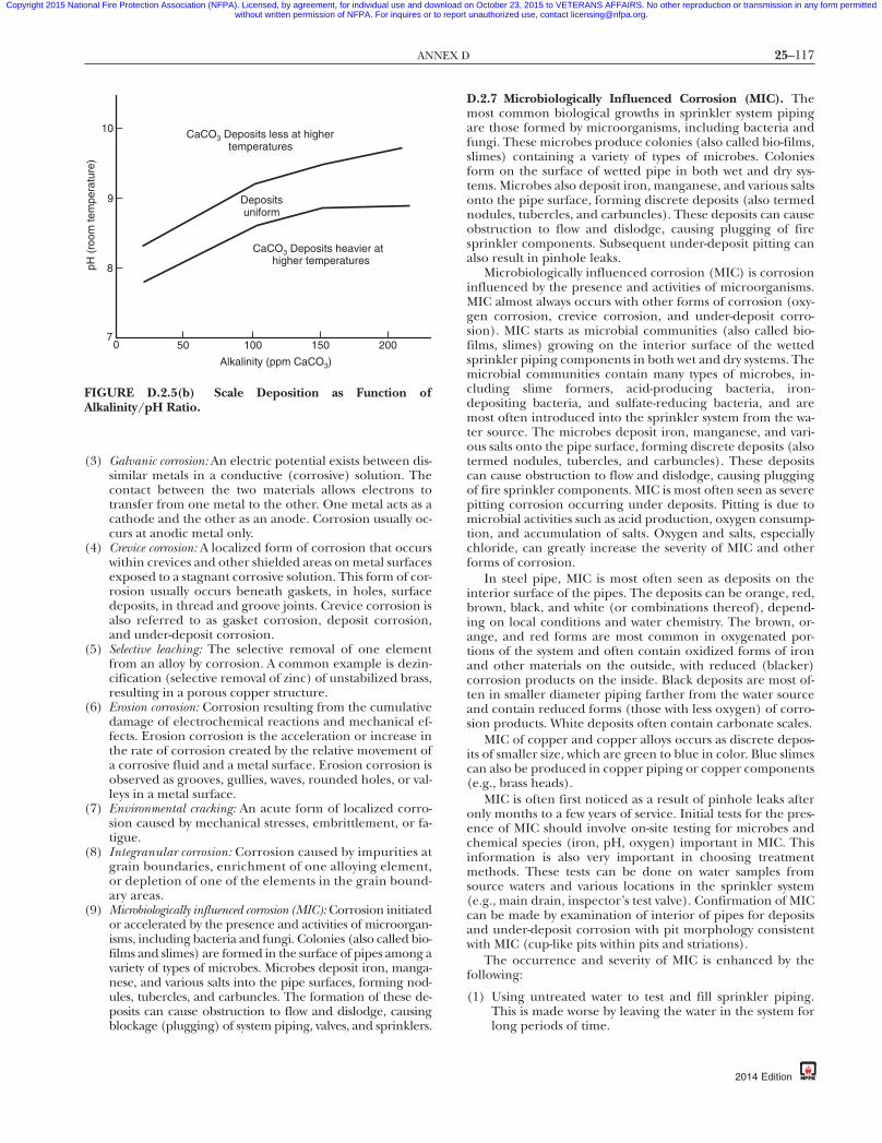
25–117ANNEX D
Copyright 2015 National Fire Protection Association (NFPA). Licensed, by agreement, for individual use and download on October 23, 2015 to VETERANS AFFAIRS. No other reproduction or transmission in any form permittedwithout written permission of NFPA. For inquires or to report unauthorized use, contact [email protected].
87
(3) Galvanic corrosion: An electric potential exists between dis-similar metals in a conductive (corrosive) solution. Thecontact between the two materials allows electrons totransfer from one metal to the other. One metal acts as acathode and the other as an anode. Corrosion usually oc-curs at anodic metal only.
(4) Crevice corrosion: A localized form of corrosion that occurswithin crevices and other shielded areas on metal surfacesexposed to a stagnant corrosive solution. This form of cor-rosion usually occurs beneath gaskets, in holes, surfacedeposits, in thread and groove joints. Crevice corrosion isalso referred to as gasket corrosion, deposit corrosion,and under-deposit corrosion.
(5) Selective leaching: The selective removal of one elementfrom an alloy by corrosion. A common example is dezin-cification (selective removal of zinc) of unstabilized brass,resulting in a porous copper structure.
(6) Erosion corrosion: Corrosion resulting from the cumulativedamage of electrochemical reactions and mechanical ef-fects. Erosion corrosion is the acceleration or increase inthe rate of corrosion created by the relative movement ofa corrosive fluid and a metal surface. Erosion corrosion isobserved as grooves, gullies, waves, rounded holes, or val-leys in a metal surface.
(7) Environmental cracking: An acute form of localized corro-sion caused by mechanical stresses, embrittlement, or fa-tigue.
(8) Integranular corrosion: Corrosion caused by impurities atgrain boundaries, enrichment of one alloying element,or depletion of one of the elements in the grain bound-ary areas.
(9) Microbiologically influenced corrosion (MIC): Corrosion initiatedor accelerated by the presence and activities of microorgan-isms, including bacteria and fungi. Colonies (also called bio-films and slimes) are formed in the surface of pipes among avariety of types of microbes. Microbes deposit iron, manga-nese, and various salts into the pipe surfaces, forming nod-ules, tubercles, and carbuncles. The formation of these de-posits can cause obstruction to flow and dislodge, causingblockage (plugging) of system piping, valves, and sprinklers.
2001501005007
8
9
higher temperatures
Depositsuniform
CaCO3 Deposits less at highertemperatures
10
pH (
room
tem
pera
ture
)
CaCO3 Deposits heavier at
Alkalinity (ppm CaCO3)
FIGURE D.2.5(b) Scale Deposition as Function ofAlkalinity/pH Ratio.
{3e0bff22-698c-46e7-
D.2.7 Microbiologically Influenced Corrosion (MIC). Themost common biological growths in sprinkler system pipingare those formed by microorganisms, including bacteria andfungi. These microbes produce colonies (also called bio-films,slimes) containing a variety of types of microbes. Coloniesform on the surface of wetted pipe in both wet and dry sys-tems. Microbes also deposit iron, manganese, and various saltsonto the pipe surface, forming discrete deposits (also termednodules, tubercles, and carbuncles). These deposits can causeobstruction to flow and dislodge, causing plugging of firesprinkler components. Subsequent under-deposit pitting canalso result in pinhole leaks.
Microbiologically influenced corrosion (MIC) is corrosioninfluenced by the presence and activities of microorganisms.MIC almost always occurs with other forms of corrosion (oxy-gen corrosion, crevice corrosion, and under-deposit corro-sion). MIC starts as microbial communities (also called bio-films, slimes) growing on the interior surface of the wettedsprinkler piping components in both wet and dry systems. Themicrobial communities contain many types of microbes, in-cluding slime formers, acid-producing bacteria, iron-depositing bacteria, and sulfate-reducing bacteria, and aremost often introduced into the sprinkler system from the wa-ter source. The microbes deposit iron, manganese, and vari-ous salts onto the pipe surface, forming discrete deposits (alsotermed nodules, tubercles, and carbuncles). These depositscan cause obstruction to flow and dislodge, causing pluggingof fire sprinkler components. MIC is most often seen as severepitting corrosion occurring under deposits. Pitting is due tomicrobial activities such as acid production, oxygen consump-tion, and accumulation of salts. Oxygen and salts, especiallychloride, can greatly increase the severity of MIC and otherforms of corrosion.
In steel pipe, MIC is most often seen as deposits on theinterior surface of the pipes. The deposits can be orange, red,brown, black, and white (or combinations thereof), depend-ing on local conditions and water chemistry. The brown, or-ange, and red forms are most common in oxygenated por-tions of the system and often contain oxidized forms of ironand other materials on the outside, with reduced (blacker)corrosion products on the inside. Black deposits are most of-ten in smaller diameter piping farther from the water sourceand contain reduced forms (those with less oxygen) of corro-sion products. White deposits often contain carbonate scales.
MIC of copper and copper alloys occurs as discrete depos-its of smaller size, which are green to blue in color. Blue slimescan also be produced in copper piping or copper components(e.g., brass heads).
MIC is often first noticed as a result of pinhole leaks afteronly months to a few years of service. Initial tests for the pres-ence of MIC should involve on-site testing for microbes andchemical species (iron, pH, oxygen) important in MIC. Thisinformation is also very important in choosing treatmentmethods. These tests can be done on water samples fromsource waters and various locations in the sprinkler system(e.g., main drain, inspector’s test valve). Confirmation of MICcan be made by examination of interior of pipes for depositsand under-deposit corrosion with pit morphology consistentwith MIC (cup-like pits within pits and striations).
The occurrence and severity of MIC is enhanced by thefollowing:
(1) Using untreated water to test and fill sprinkler piping.This is made worse by leaving the water in the system forlong periods of time.
db-eba3b3d7337a}
2014 Edition

25–118 INSPECTION, TESTING, AND MAINTENANCE OF WATER-BASED FIRE PROTECTION SYSTEMS
Copyright 2015 National Fire Protection Association (NFPA). Licensed, by agreement, for individual use and download on October 23, 2015 to VETERANS AFFAIRS. No other reproduction or transmission in any form permittedwithout written permission of NFPA. For inquires or to report unauthorized use, contact [email protected].
-8
(2) Introduction of new and untreated water containing oxy-gen, microbes, salts, and nutrients into the system on afrequent basis (during repair, renovation, and/or fre-quent flow tests).
(3) Leaving dirt, debris, and especially oils, pipe joint com-pound, and so forth in the piping. These provide nutri-ents and protection for the microbes, often preventingbiocides and corrosion inhibitors from reaching the mi-crobes and corrosion sites.
Once the presence of MIC has been confirmed, the systemshould be assessed to determine the extent and severity ofMIC. Severely affected portions should be replaced or cleanedto remove obstructions and pipe not meeting minimal me-chanical specifications.
D.3 Investigation Procedures. If unsatisfactory conditions areobserved as outlined in Section 14.3, investigations should bemade to determine the extent and severity of the obstructingmaterial. From the fire protection system plan, determine thewater supply sources, age of underground mains and sprinklersystems, types of systems, and general piping arrangement.Consider the possible sources of obstruction material.
Examine the fire pump suction supply and screening ar-rangements. If necessary, have the suction cleaned before us-ing the pump in tests and flushing operations. Gravity tanksshould be inspected internally, with the exception of steeltanks that have been recently cleaned and painted. If possible,have the tank drained and determine whether loose scale is onthe shell or if sludge or other obstructions are on the tankbottom. Cleaning and repainting could be in order, particu-larly if it has not been done within the previous 5 years.
Investigate yard mains first, then sprinkler systems.Where fire protection control valves are closed during in-
vestigation procedures, the fire protection impairment pre-cautions outlined in Chapter 15 should be followed.
Large quantities of water are needed for investigation andfor flushing. It is important to plan the safest means of dis-posal in advance. Cover stock and machinery susceptible towater damage, and keep equipment on hand for mopping upany accidental discharge of water.
D.3.1 Investigating Yard Mains. Flow water through yard hy-drants, preferably near the extremes of selected mains, to de-termine whether mains contain obstructive material. It is pref-erable to connect two lengths of 21⁄2 in. (65 mm) hose to thehydrant. Attach burlap bags to the free ends of the hose fromwhich the nozzles have been removed to collect any materialflushed out, and flow water long enough to determine thecondition of the main being investigated. If there are severalwater supply sources, investigate each independently, avoidingany unnecessary interruptions to sprinkler protection. In ex-tensive yard layouts, repeat the tests at several locations, if nec-essary, to determine general conditions.
If obstructive material is found, all mains should be flushedthoroughly before investigating the sprinkler systems. (See Sec-tion D.5.)
D.3.2 Investigating Sprinkler Systems. Investigate dry systemsfirst. Tests on several carefully selected, representative systemsusually are sufficient to indicate general conditions through-out the plant. If, however, preliminary investigations indicatethe presence of obstructing material, this justifies investigat-ing all systems (both wet and dry) before outlining neededflushing operations. Generally, the system can be considered
{3e0bff22-698c-46e7
2014 Edition
reasonably free of obstructing material, provided the follow-ing conditions apply:
(1) Less than 1⁄2 cup of scale is washed from the cross mains.(2) Scale fragments are not large enough to plug a sprinkler
orifice.(3) A full, unobstructed flow is obtained from each branch
line inspected.
Where other types of foreign material are found, judgmentshould be used before considering the system unobstructed.Obstruction potential is based on the physical characteristicsand source of the foreign material.
In selecting specific systems or branch lines for investiga-tion, the following should be considered:
(1) Lines found obstructed during a fire or during mainte-nance work
(2) Systems adjacent to points of recent repair to yard mains,particularly if hydrant flow shows material in the main
Tests should include flows through 21⁄2 in. (65 mm) firehose directly from cross mains [see Figure D.3.2(a) andFigure D.3.2(b)] and flows through 11⁄2 in. (40 mm) hosefrom representative branch lines. Two or three branch linesper system is a representative number of branch lines whereinvestigating for scale accumulation. If significant scale isfound, investigation of additional branch lines is war-ranted. Where investigating for foreign material (otherthan scale), the number of branch lines needed for repre-sentative sampling is dependent on the source and charac-teristic of the foreign material.
If provided, fire pumps should be operated for the largeline flows, since maximum flow is desirable. Burlap bagsshould be used to collect dislodged material as is done in theinvestigation of yard mains. Each flow should be continueduntil the water clears (i.e., a minimum of 2 to 3 minutes at fullflow for sprinkler mains). This is likely to be sufficient to indi-cate the condition of the piping interior.
D.3.3 Investigating Dry Pipe Systems. Flood dry pipe systemsone or two days before obstruction investigations to softenpipe scale and deposits. After selecting the test points of a drypipe system, close the main control valve and drain the system.Check the piping visually with a flashlight while it is beingdismantled. Attach hose valves and 11⁄2 in. (40 mm) hose to theends of the lines to be tested, shut the valves, have air pressurerestored on the system, and reopen the control valve. Openthe hose valve on the end branch line, allowing the system totrip in simulation of normal action. Any obstructions shouldbe cleared from the branch line before proceeding with fur-ther tests.
FIGURE D.3.2(a) Replacement of Elbow at End of CrossMain with Flushing Connection Consisting of 50 mm (2 in.)Nipple and Cap.
7db-eba3b3d7337a}

25–119ANNEX D
Copyright 2015 National Fire Protection Association (NFPA). Licensed, by agreement, for individual use and download on October 23, 2015 to VETERANS AFFAIRS. No other reproduction or transmission in any form permittedwithout written permission of NFPA. For inquires or to report unauthorized use, contact [email protected].
87
After flowing the small end line, shut its hose valve andtest the feed or cross main by discharging water through a21⁄2 in. (65 mm) fire hose, collecting any foreign material ina burlap bag.
After the test, the dry pipe valve should be cleaned inter-nally and reset. Its control valve should be locked open and adrain test performed.
D.3.4 Investigating Wet Pipe Systems. Testing of wet systemsis similar to that of dry systems, except that the system shouldbe drained after closing the control valve to permit installa-tion of hose valves for the test. Slowly reopen the control valveand make a small hose flow as specified for the branch line,followed by the 21⁄2 in. (65 mm) hose flow for the cross main.
In any case, if lines become plugged during the tests, pip-ing should be dismantled and cleaned, the extent of pluggingnoted, and a clear flow obtained from the branch line beforeproceeding further.
Perform similar tests on representative systems to indicatethe general condition of the wet systems throughout the plant,keeping a detailed record of the procedures performed.
D.3.5 Other Obstruction Investigation Methods. Other ob-struction investigation methods, such as technically proven ul-trasonic and X-ray examination, have been evaluated and ifapplied correctly, are successful at detecting obstructions.
The sources of the obstructing material should be deter-mined and steps taken to prevent further entrance of suchmaterial. This entails work such as inspection and cleaning ofpump suction screening facilities or cleaning of private reser-voirs. If recently laid public mains appear to be the source ofthe obstructing material, waterworks authorities should be re-quested to flush their system.
D.4 Obstruction Prevention Program.
D.4.1 Dry Pipe and Preaction Systems — Scale.
(1) Dry pipe and preaction systems using noncoated fer-rous piping should be thoroughly investigated for ob-struction from corrosion after they have been in servicefor 15 years, for 25 years, and every 5 years thereafter.
(2) Dry pipe systems with noncoated ferrous piping should bekept on air year-round, rather than on air and water alter-nately, to inhibit formation of rust and scale.
Flushingconnection
Cross main
hose gate valve
hose
Elbow and drop nippleattached for flushing
Nipple tobranch line
Bushing
2¹⁄₂ in. (65 mm)
2¹⁄₂ in. (65 mm)
FIGURE D.3.2(b) Connection of 65 mm (21⁄2 in.) Hose GateValve with 50 mm (2 in.) Bushing and Nipple and Elbow to50 mm (2 in.) Cross Main.
{3e0bff22-698c-46e7-
D.4.2 Flushing Connections. Sprinkler systems installed in ac-cordance with recent editions of NFPA 13, Standard for the Instal-lation of Sprinkler Systems, should have provisions for flushing eachcross main. Similarly, branch lines on gridded systems should becapable of being readily “broken” at a simple union or flexiblejoint. Property owners of systems installed without these provi-sions should be encouraged to provide them when replacementor repair work is being done.
D.4.3 Suction Supplies.
(1) Screen pump suction supplies and screens should bemaintained. Connections from penstocks should beequipped with strainers or grids, unless the penstock in-lets themselves are so equipped. Pump suction screens ofcopper or brass wire tend to promote less aquatic growth.
(2) Extreme care should be used to prevent material fromentering the suction piping when cleaning tanks andopen reservoirs. Materials removed from the interior ofgravity tanks during cleaning should not be allowed toenter the discharge pipe.
(3) Small mill ponds could need periodic dredging whereweeds and other aquatic growth are inherent.
D.4.4 Asian Clams. Effective screening of larvae and small-size, juvenile Asian clams from fire protection systems is verydifficult. To date, no effective method of total control hasbeen found. Such controls can be difficult to achieve in fireprotection systems.
D.4.5 Calcium Carbonate. For localities suspected of havinghard water, sample sprinklers should be removed and in-spected yearly. Paragraph D.2.5 outlines sprinkler locationsprone to the accumulation of deposits where hard water is aproblem. Sprinklers found with deposits should be replaced,and adjacent sprinklers should be inspected.
D.4.6 Zebra Mussels. Several means of controlling the zebramussel are being studied, including molluscicides, chlorines,ozone, shell strainers, manual removal, robotic cleaning, wa-ter jetting, line pigging, sonic pulses, high-voltage electricalfields, and thermal backwashing. It is believed that these con-trols might need to be applied only during spawning periodswhen water temperatures are 57°F to 61°F (14°C to 16°C) andveligers are present. Several silicon grease-based coatings alsoare being investigated for use within piping systems.
While it appears that the use of molluscicides could pro-vide the most effective means of controlling the mussel, thesechemicals are costly. It is believed that chlorination is the bestavailable short-term treatment, but there are problems associ-ated with the use of chlorine, including strict EnvironmentalProtection Agency regulations on the release of chlorine intolakes and streams. The use of nonselective poison, such aschlorine, in the amounts necessary to kill the mussels in largebodies of water could be devastating to entire ecosystems.
To provide an effective means of control against zebra mus-sels in fire protection systems, control measures should be ap-plied at the water source, instead of within the piping system.Effective controls for growth of the zebra mussel within fireprotection systems include the following:
(1) Selecting a water source that is not subject to infestation.This could include well water or potable or pretreated water.
(2) Implementing a water treatment program that includesbiocides or elevated pH, or both.
(3) Implementing a water treatment program to remove oxy-gen, to ensure control of biological growth within piping.
(4) Relying on a tight system approach to deny oxygen andnutrients that are necessary to support growth.
db-eba3b3d7337a}
2014 Edition
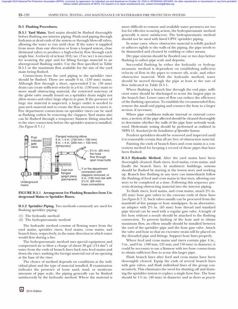
25–120 INSPECTION, TESTING, AND MAINTENANCE OF WATER-BASED FIRE PROTECTION SYSTEMS
Copyright 2015 National Fire Protection Association (NFPA). Licensed, by agreement, for individual use and download on October 23, 2015 to VETERANS AFFAIRS. No other reproduction or transmission in any form permittedwithout written permission of NFPA. For inquires or to report unauthorized use, contact [email protected].
-8
D.5 Flushing Procedures.
D.5.1 Yard Mains. Yard mains should be flushed thoroughlybefore flushing any interior piping. Flush yard piping throughhydrants at dead ends of the system or through blow-off valves,allowing the water to run until clear. If the water is suppliedfrom more than one direction or from a looped system, closedivisional valves to produce a high-velocity flow through eachsingle line. A velocity of at least 10 ft/sec (3 m/sec) is necessaryfor scouring the pipe and for lifting foreign material to anaboveground flushing outlet. Use the flow specified in TableD.5.1 or the maximum flow available for the size of the yardmain being flushed.
Connections from the yard piping to the sprinkler risershould be flushed. These are usually 6 in. (150 mm) mains.Although flow through a short, open-ended 2 in. (50 mm)drain can create sufficient velocity in a 6 in. (150 mm) main tomove small obstructing material, the restricted waterway ofthe globe valve usually found on a sprinkler drain might notallow stones and other large objects to pass. If the presence oflarge size material is suspected, a larger outlet is needed topass such material and to create the flow necessary to move it.Fire department connections on sprinkler risers can be usedas flushing outlets by removing the clappers. Yard mains alsocan be flushed through a temporary Siamese fitting attachedto the riser connection before the sprinkler system is installed.[See Figure D.5.1.]
D.5.2 Sprinkler Piping. Two methods commonly are used forflushing sprinkler piping:
(1) The hydraulic method(2) The hydropneumatic method
The hydraulic method consists of flowing water from theyard mains, sprinkler risers, feed mains, cross mains, andbranch lines, respectively, in the same direction in which waterwould flow during a fire.
The hydropneumatic method uses special equipment andcompressed air to blow a charge of about 30 gal (114 dm3) ofwater from the ends of branch lines back into feed mains anddown the riser, washing the foreign material out of an openingat the base of the riser.
The choice of method depends on conditions at the indi-vidual plant and the type of material installed. If examinationindicates the presence of loose sand, mud, or moderateamounts of pipe scale, the piping generally can be flushedsatisfactorily by the hydraulic method. Where the material is
Y or fire departmentconnection withclappers removed, or4 in. (100 mm) tee with
hose connections
Cast-ironflangedspigot piece(permanent)
Undergroundmains
fire hoseflow throughopen hose butts
Flanged reducing elbow6 in. ¥ 4 in. (150 mm ¥ 100 mm)8 in. ¥ 4 in. (200 mm ¥ 100 mm)(temporary)
2¹⁄₂ in. (65 mm)
2¹⁄₂ in. (65 mm)
Postindicatorgatevalve
FIGURE D.5.1 Arrangement for Flushing Branches from Un-derground Mains to Sprinkler Risers.
{3e0bff22-698c-46e7
2014 Edition
more difficult to remove and available water pressures are toolow for effective scouring action, the hydropneumatic methodgenerally is more satisfactory. The hydropneumatic methodshould not be used with listed CPVC sprinkler piping.
In some cases, where obstructive material is solidly packedor adheres tightly to the walls of the piping, the pipe needs tobe dismantled and cleaned by rodding or other means.
Dry pipe systems should be flooded one or two days beforeflushing to soften pipe scale and deposits.
Successful flushing by either the hydraulic or hydrop-neumatic method is dependent on establishing sufficientvelocity of flow in the pipes to remove silt, scale, and otherobstructive material. With the hydraulic method, watershould be moved through the pipe at least at the rate offlow indicated in Table D.5.1.
Where flushing a branch line through the end pipe, suffi-cient water should be discharged to scour the largest pipe inthe branch line. Lower rates of flow can reduce the efficiencyof the flushing operation. To establish the recommended flow,remove the small end piping and connect the hose to a largersection, if necessary.
Where pipe conditions indicate internal or external corro-sion, a section of the pipe affected should be cleaned thoroughlyto determine whether the walls of the pipe have seriously weak-ened. Hydrostatic testing should be performed as outlined inNFPA 13, Standard for the Installation of Sprinkler Systems.
Pendent sprinklers should be removed and inspected untilit is reasonably certain that all are free of obstruction material.
Painting the ends of branch lines and cross mains is a con-venient method for keeping a record of those pipes that havebeen flushed.
D.5.3 Hydraulic Method. After the yard mains have beenthoroughly cleaned, flush risers, feed mains, cross mains, andfinally the branch lines. In multistory buildings, systemsshould be flushed by starting at the lowest story and workingup. Branch line flushing in any story can immediately followthe flushing of feed and cross mains in that story, allowing onestory to be completed at a time. Following this sequence pre-vents drawing obstructing material into the interior piping.
To flush risers, feed mains, and cross mains, attach 21⁄2 in.(65 mm) hose gate valves to the extreme ends of these lines[see Figure D.5.3]. Such valves usually can be procured from themanifold of fire pumps or hose standpipes. As an alternative,an adapter with 21⁄2 in. (65 mm) hose thread and standardpipe thread can be used with a regular gate valve. A length offire hose without a nozzle should be attached to the flushingconnection. To prevent kinking of the hose and to obtainmaximum flow, an elbow usually should be installed betweenthe end of the sprinkler pipe and the hose gate valve. Attachthe valve and hose so that no excessive strain will be placed onthe threaded pipe and fittings. Support hose lines properly.
Where feed and cross mains and risers contain pipe 4 in.,5 in., and 6 in. (100 mm, 125 mm, and 150 mm) in diameter, itcould be necessary to use a Siamese with two hose connectionsto obtain sufficient flow to scour this larger pipe.
Flush branch lines after feed and cross mains have beenthoroughly cleared. Equip the ends of several branch lineswith gate valves, and flush individual lines of the group con-secutively. This eliminates the need for shutting off and drain-ing the sprinkler system to replace a single hose line. The hoseshould be 11⁄2 in. (40 mm) in diameter and as short as practi-
7db-eba3b3d7337a}
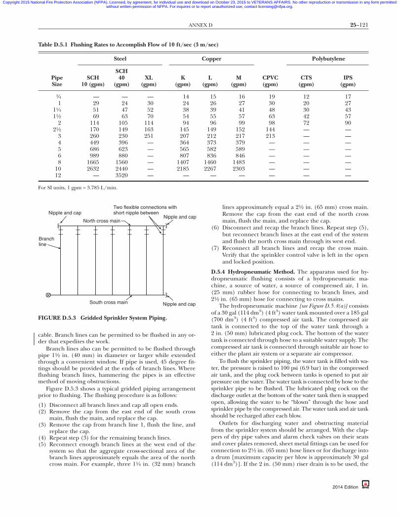
25–121ANNEX D
Copyright 2015 National Fire Protection Association (NFPA). Licensed, by agreement, for individual use and download on October 23, 2015 to VETERANS AFFAIRS. No other reproduction or transmission in any form permittedwithout written permission of NFPA. For inquires or to report unauthorized use, contact [email protected].
87
cable. Branch lines can be permitted to be flushed in any or-der that expedites the work.
Branch lines also can be permitted to be flushed throughpipe 11⁄2 in. (40 mm) in diameter or larger while extendedthrough a convenient window. If pipe is used, 45 degree fit-tings should be provided at the ends of branch lines. Whereflushing branch lines, hammering the pipes is an effectivemethod of moving obstructions.
Figure D.5.3 shows a typical gridded piping arrangementprior to flushing. The flushing procedure is as follows:
(1) Disconnect all branch lines and cap all open ends.(2) Remove the cap from the east end of the south cross
main, flush the main, and replace the cap.(3) Remove the cap from branch line 1, flush the line, and
replace the cap.(4) Repeat step (3) for the remaining branch lines.(5) Reconnect enough branch lines at the west end of the
system so that the aggregate cross-sectional area of thebranch lines approximately equals the area of the northcross main. For example, three 11⁄4 in. (32 mm) branch
Table D.5.1 Flushing Rates to Accomplish Flow of 10 ft/sec (3
Steel
PipeSize
SCH10 (gpm)
SCH40
(gpm)XL
(gpm)K
(gpm)
3⁄4 — — — 141 29 24 30 24
11⁄4 51 47 52 3811⁄2 69 63 70 54
2 114 105 114 9421⁄2 170 149 163 145
3 260 230 251 2074 449 396 — 3645 686 623 — 5656 989 880 — 8078 1665 1560 — 1407
10 2632 2440 — 218512 — 3520 — —
For SI units, 1 gpm = 3.785 L/min.
Two flexible connections withshort nipple between
Nipple and capNorth cross main
Nipple and cap
Branchline
South cross main Nipple and cap
FIGURE D.5.3 Gridded Sprinkler System Piping.
{3e0bff22-698c-46e7-
lines approximately equal a 21⁄2 in. (65 mm) cross main.Remove the cap from the east end of the north crossmain, flush the main, and replace the cap.
(6) Disconnect and recap the branch lines. Repeat step (5),but reconnect branch lines at the east end of the systemand flush the north cross main through its west end.
(7) Reconnect all branch lines and recap the cross main.Verify that the sprinkler control valve is left in the openand locked position.
D.5.4 Hydropneumatic Method. The apparatus used for hy-dropneumatic flushing consists of a hydropneumatic ma-chine, a source of water, a source of compressed air, 1 in.(25 mm) rubber hose for connecting to branch lines, and21⁄2 in. (65 mm) hose for connecting to cross mains.
The hydropneumatic machine [see Figure D.5.4(a)] consistsof a 30 gal (114 dm3) (4 ft3) water tank mounted over a 185 gal(700 dm3) (4 ft3) compressed air tank. The compressed airtank is connected to the top of the water tank through a2 in. (50 mm) lubricated plug cock. The bottom of the watertank is connected through hose to a suitable water supply. Thecompressed air tank is connected through suitable air hose toeither the plant air system or a separate air compressor.
To flush the sprinkler piping, the water tank is filled with wa-ter, the pressure is raised to 100 psi (6.9 bar) in the compressedair tank, and the plug cock between tanks is opened to put airpressure on the water. The water tank is connected by hose to thesprinkler pipe to be flushed. The lubricated plug cock on thedischarge outlet at the bottom of the water tank then is snappedopen, allowing the water to be “blown” through the hose andsprinkler pipe by the compressed air. The water tank and air tankshould be recharged after each blow.
Outlets for discharging water and obstructing materialfrom the sprinkler system should be arranged. With the clap-pers of dry pipe valves and alarm check valves on their seatsand cover plates removed, sheet metal fittings can be used forconnection to 21⁄2 in. (65 mm) hose lines or for discharge intoa drum [maximum capacity per blow is approximately 30 gal(114 dm3)]. If the 2 in. (50 mm) riser drain is to be used, the
c)
per Polybutylene
)M
(gpm)CPVC(gpm)
CTS(gpm)
IPS(gpm)
5 16 19 12 176 27 30 20 279 41 48 30 435 57 63 42 576 99 98 72 909 152 144 — —2 217 213 — —3 379 — — —2 589 — — —6 846 — — —0 1483 — — —7 2303 — — —
— — — —
db-eba3b3d7337a}
m/se
Cop
L(gpm
12359
1421375883
146226
—
2014 Edition

25–122 INSPECTION, TESTING, AND MAINTENANCE OF WATER-BASED FIRE PROTECTION SYSTEMS
Copyright 2015 National Fire Protection Association (NFPA). Licensed, by agreement, for individual use and download on October 23, 2015 to VETERANS AFFAIRS. No other reproduction or transmission in any form permittedwithout written permission of NFPA. For inquires or to report unauthorized use, contact [email protected].
-8
drain valve should be removed and a direct hose connectionmade. For wet pipe systems with no alarm check valves, theriser should be taken apart just below the drain opening and aplate inserted to prevent foreign material from dropping tothe base of the riser. Where dismantling of a section of theriser for this purpose is impractical, the hydropneumaticmethod should not be used.Before starting a flushing job, each sprinkler system to becleaned should be studied and a schematic plan preparedshowing the order of the blows.
To determine that the piping is clear after it has beenflushed, representative branch lines and cross mains shouldbe investigated, using both visual examination and sampleflushings.
(1) Branch Lines. With the yard mains already flushed or knownto be clear, the sprinkler branch lines should be flushednext. The order of cleaning individual branch lines shouldbe laid out carefully if an effective job is to be done. In gen-
2
1
4 56
7
31
18
9
1 Lubricated plug cocks2 Pipe connection between air and water tanks (This connection is open when flushing sprinkler system.)3 Air pressure gauge4 1 in. (25 mm) rubber hose (air type) (Used to flush sprinkler branch lines.)5 Hose connected to source of water (Used to fill water tank.)6 Hose connected to ample source of compressed air (Used to supply air tank.)7 Water tank overflow hose8 2¹⁄₂ in. (65 mm) pipe connection [Where flushing large interior piping, connect woven jacket fire hose here and close 1 in. (25 mm) plug cock hose connection (4) used for flushing sprinkler branch lines.]9 Air tank drain valve
Water tank
Air tank
FIGURE D.5.4(a) Hydropneumatic Machine.
{3e0bff22-698c-46e7
eral, the branch lines should be flushed, starting with the
2014 Edition
branch closest to the riser and working toward the dead endof the cross main. [See Figure D.5.4(b).] The order for flushingthe branch lines is shown by the circled numerals. In thisexample, the southeast quadrant is flushed first, then thesouthwest, followed by the northeast, and, finally, the north-west. Air hose 1 in. (25 mm) in diameter is used to connectthe machine with the end of the branch line being flushed.This hose air pressure should be allowed to drop to 85 psi(5.9 bar) before the valve is closed. The resulting short slugof water experiences less friction loss and a higher velocityand, therefore, cleans more effectively than if the full 30 gal(114 dm3) of water were to be used. One blow is made foreach branch line.
(2) Large Piping. Where flushing cross mains, fill the watertank completely and raise the pressure in the air receiverto 100 psi (6.9 bar) (690 kPa). Connect the machine tothe end of the cross main to be flushed with no more than50 ft (15.2 m) of 21⁄2 in. (65 mm) hose. After opening thevalve, allow air pressure in the machine to drop to zero(0). Two to six blows are necessary at each location,depending on the size and length of the main. InFigure D.5.4(b), the numerals in squares indicate the lo-cation and order of the cross main blows. Because the lastbranch line blows performed were located west of theriser, clean the cross main located east of the riser first.Where large cross mains are to be cleaned, it is best, ifpractical, to make one blow at 38, one at 39, the nextagain at 38, then again at 39, alternating in this manneruntil the required number of blows has been made ateach location.
(3) Where flushing cross mains and feed mains, arrange thework so that the water passes through a minimum of right-angle bends. In Figure D.5.4(b), blows at 38 should beadequate to flush the cross mains back to the riser. Do notattempt to clean the cross main from location A to theriser by backing out branch line 16 and connecting thehose to the open side of the tee. If this were to be done, aconsiderable portion of the blow would pass northwardup the 3 in. (76 mm) line supplying branches 34 to 37,and the portion passing eastward to the riser could beineffective. Where the size, length, and condition of crossmains necessitate blowing from a location correspondingto location A, the connection should be made directly tothe cross main corresponding to the 31⁄2 in. (90 mm) pipeso that the entire flow travels to the riser. Where flushingthrough a tee, always flush the run of the tee after flushingthe branch. Note the location of blows 35, 36, and 37 inFigure D.5.4(b). Gridded systems can be flushed in a simi-lar fashion. With branch lines disconnected and capped,begin flushing the branch line closest to the riser (branchline 1 in Figure D.5.3), working toward the most remoteline. Then flush the south cross main in Figure D.5.3 byconnecting the hose to the east end. Flushing the northcross main involves connecting the hose to one end whiledischarging to a safe location from the other end.
7db-eba3b3d7337a}

25–123ANNEX E
Copyright 2015 National Fire Protection Association (NFPA). Licensed, by agreement, for individual use and download on October 23, 2015 to VETERANS AFFAIRS. No other reproduction or transmission in any form permittedwithout written permission of NFPA. For inquires or to report unauthorized use, contact [email protected].
87db-eba3b3d7337a}
Annex E Hazard Evaluation Form
This annex is not a part of the requirements of this NFPA documentbut is included for informational purposes only.
E.1 This annex provides one example of a hazard evaluationform. A hazard evaluation is not part of a system inspection.(See Figure E.1.)
37
36
35
34
33
32
39
31 30 29 28 27 26 25 17 18 19 20 21 22 23 24
38
87654321910111213141516
2 in.(50 mm)3¹⁄₂ in. (90 mm)
5 in. (125 mm)
N
A
6 in.(150 mm)
Riser
4 in. (100 mm)
4 in. (100 mm)
3 in. (76 mm)
2¹⁄₂ in. (65 mm)
2¹⁄₂ in. (65 mm)
2¹⁄₂ in. (65 mm)
3 in. (76 mm)
3¹⁄₂ in. (90 mm)
FIGURE D.5.4(b) Schematic Diagram of Sprinkler System ShWhere Hydropneumatic Method Is To Be Utilized.
{3e0bff22-698c-46e7-
owing Sequence To Be Followed
2014 Edition

25–124 INSPECTION, TESTING, AND MAINTENANCE OF WATER-BASED FIRE PROTECTION SYSTEMS
Copyright 2015 National Fire Protection Association (NFPA). Licensed, by agreement, for individual use and download on October 23, 2015 to VETERANS AFFAIRS. No other reproduction or transmission in any form permittedwithout written permission of NFPA. For inquires or to report unauthorized use, contact [email protected].
NFPA 25 (p. 1 of 4)© 2013 National Fire Protection Association
FIRE SPRINKLER SYSTEM HAZARD EVALUATION
Changes in building occupancy, use, or process, or material used or stored, create the need for evaluation of the installed fire protection systems. This form is intended to identify and evaluate such changes and should be completed only by an individual properly qualified in the area of system design.
Owner: Owner’s address:
Property being evaluated:
Property address:
Date of work:
(All responses refer to the current hazard evaluation performed on this date.)
Section 1. Identification of Sprinklered Occupancy and Storage Hazards
(Use additional pages as needed.)
1.
2.
3.
4.
5.
Area of Property (List nonsprinklered areas separately in
Section 3.)
Type of System and Sprinklers
Design Capability of System
Hazard Protected (Uses or storage arrangements,
including commodity)
Improvements Needed to
Address Hazard
FIGURE E.1 Fire Sprinkler Hazard Evaluation.
{3e0bff22-698c-46e7-87db-eba3b3d7337a}
2014 Edition

25–125ANNEX F
Copyright 2015 National Fire Protection Association (NFPA). Licensed, by agreement, for individual use and download on October 23, 2015 to VETERANS AFFAIRS. No other reproduction or transmission in any form permittedwithout written permission of NFPA. For inquires or to report unauthorized use, contact [email protected].
NFPA 25 (p. 2 of 4)© 2013 National Fire Protection Association
FIRE SPRINKLER SYSTEM HAZARD EVALUATION (continued)
Section 2. Evaluation of Protection
For each area of the property evaluated in Section 1, please answer the following questions with a “yes,” “no,” “N/A,” or “?” and explain all “no” and “?” responses below by row and column identification:
Answer the following for each identified property area: 1 2 3 4 5
a. Are all sprinklers the correct type for their application?
b. Are the obstructions to sprinklers in all areas within acceptable limits for the specific types of sprinklers used?
c. Are hazards associated with all occupancy areas consistent with hazards typical for that occupancy hazard classification?
d. Are stockpiles of combustibles located within occupancy areas limited to appropriate heights?
e. Are miscellaneous and dedicated storage areas properly identified and managed?
f. Are all dedicated storage areas protected in accordance with the proper storage configuration and commodity classification?
g. Is the storage or use of flammable liquids, combustible liquids, or aerosol products in any area properly addressed?
h. Is all idle pallet storage properly protected?
i. Is there any presence of nitrate film, pyroxylin plastic, compressed or liquefied gas cylinders, liquid or solid oxidizers, or organic peroxide formulations except where specifically addressed by appropriate protection measures?
j. Are all sprinklers spaced appropriately for the hazard and the type of sprinkler?
k. Do the available sources of heat and cooling appear adequate for the type of system and temperature rating of sprinklers?
Explanation of “no” and “?” answers:
Examples: b2 – no – Obstructions to ESFR sprinklers exceed currently accepted standards e3 – ? – Owner must provide information on type of plastic involved in product before evaluation can be finalized.
FIGURE E.1 Continued
{3e0bff22-698c-46e7-87db-eba3b3d7337a}
2014 Edition

25–126 INSPECTION, TESTING, AND MAINTENANCE OF WATER-BASED FIRE PROTECTION SYSTEMS
Copyright 2015 National Fire Protection Association (NFPA). Licensed, by agreement, for individual use and download on October 23, 2015 to VETERANS AFFAIRS. No other reproduction or transmission in any form permittedwithout written permission of NFPA. For inquires or to report unauthorized use, contact [email protected].
NFPA 25 (p. 3 of 4)© 2013 National Fire Protection Association
FIRE SPRINKLER SYSTEM HAZARD EVALUATION (continued)
Section 3. Evaluation of Unsprinklered Areas
Section 4. Water Supply Evaluation
If this hazard evaluation is the result of a reduction in the residual pressure during routine inspections, explain the results of the investigation made to determine the reasons for this change:
Explain the basis of continued acceptability of the water supply or proposed improvements:
1.
2.
3.
4.
5.
Area of Property for Which Protection Is Not Provided
Basis of Lack of Protection (if known)
Basis for Omission Under Current Codes/Standards
FIGURE E.1 Continued
{3e0bff22-698c-46e7-87db-eba3b3d7337a}
2014 Edition

FIG
25–127ANNEX F
Copyright 2015 National Fire Protection Association (NFPA). Licensed, by agreement, for individual use and download on October 23, 2015 to VETERANS AFFAIRS. No other reproduction or transmission in any form permittedwithout written permission of NFPA. For inquires or to report unauthorized use, contact [email protected].
Annex F Informational References
F.1 Referenced Publications. The documents or portionsthereof listed in this annex are referenced within the informa-tional sections of this standard and are not part of the require-ments of this document unless also listed in Chapter 2 forother reasons.
F.1.1 NFPA Publications. National Fire Protection Associa-tion, 1 Batterymarch Park, Quincy, MA 02169-7471.
NFPA 13, Standard for the Installation of Sprinkler Systems, 2013edition.
NFPA 13R, Standard for the Installation of Sprinkler Systems inLow-Rise Residential Occupancies, 2013 edition.
NFPA 14, Standard for the Installation of Standpipe and HoseSystems, 2013 edition.
NFPA 15, Standard for Water Spray Fixed Systems for Fire Protec-tion, 2012 edition.
NFPA 16, Standard for the Installation of Foam-Water Sprinklerand Foam-Water Spray Systems, 2011 edition.
© 2013 National Fire Protection Association
FIRE SPRINKLER SYSTEM HAZ
Section 5. Hazard Evaluator’s Information and Certi
Evaluator:
Company:
Company address:
I state that the information on this form is correct at the tim
Is this hazard evaluation completed? (Note: All “?” must be
Explain if answer is not “yes”:
Have deficiencies in protection been identified that should b
Summarize improvements of corrections needed:
Signature of Evaluator:
License or Certification Number (if applicable):
URE E.1 Continued
{3e0bff22-698c-46e7-
NFPA 20, Standard for the Installation of Stationary Pumps forFire Protection, 2013 edition.
NFPA 22, Standard for Water Tanks for Private Fire Protection,2013 edition.
NFPA 24, Standard for the Installation of Private Fire ServiceMains and Their Appurtenances, 2013 edition.
NFPA 70E®, Standard for Electrical Safety in the Workplace®,2012 edition.
NFPA 72®, National Fire Alarm and Signaling Code, 2013 edi-tion.
NFPA 291, Recommended Practice for Fire Flow Testing andMarking of Hydrants, 2013 edition.
NFPA 551, Guide for the Evaluation of Fire Risk Assessments,2013 edition.
NFPA 750, Standard on Water Mist Fire Protection Systems, 2010edition.
NFPA 780, Standard for the Installation of Lightning ProtectionSystems, 2014 edition.
NFPA 25 (p. 4 of 4)
EVALUATION (continued)
on
place of my review of my evaluation.
ed.) ❏ Yes ❏ No
roved or corrected? ❏ Yes ❏ No
Date:
db-eba3b3d7337a}
ARD
ficati
e and
resolv
e imp
87
2014 Edition
25–128 INSPECTION, TESTING, AND MAINTENANCE OF WATER-BASED FIRE PROTECTION SYSTEMS
Copyright 2015 National Fire Protection Association (NFPA). Licensed, by agreement, for individual use and download on October 23, 2015 to VETERANS AFFAIRS. No other reproduction or transmission in any form permittedwithout written permission of NFPA. For inquires or to report unauthorized use, contact [email protected].
-8
NFPA 1962, Standard for the Care, Use, Inspection, Service Test-ing, and Replacement of Fire Hose, Couplings, Nozzles, and Fire HoseAppliances, 2013 edition.
NFPA’s Future in Performance Based Codes and Standards, July1995.
NFPA Performance Based Codes and Standards Primer, Decem-ber 1999.
F.1.2 Other Publications.
F.1.2.1 ASTM Publications. ASTM International, 100 BarrHarbor Drive, P.O. Box C700, West Conshohocken, PA 19428-2959.
IEEE/ASTM-SI-10, American National Standard for Use of theInternational System of Units (SI): The Modern Metric System, 2002.
F.1.2.2 AWWA Publications. American Water Works Associa-tion, 6666 West Quincy Avenue, Denver, CO 80235.
AWWA, Manual of Water Supply Practices — M42 Steel Water-Storage Tanks, 1998.
F.1.2.3 Hydraulic Institute Publications. Hydraulic Institute, 9Sylvan Way, Parsippany, NJ 07054.
Hydraulic Institute Standards for Centrifugal, Rotary and Recip-rocating Pumps, 14th edition, 1983.
F.1.2.4 SFPE Publications. Society of Fire Protection Engi-neers, 7315 Wisconsin Avenue, Suite 1225 W, Bethesda, MD,20814.
SFPE Engineering Guide: Fire Risk Assessment, 2006.
F.1.2.5 Other Publications.Edward K. Budnick, P.E., “Automatic Sprinkler System Re-
liability,” Fire Protection Engineering, Society of Fire ProtectionEngineers, Winter 2001.
Fire Protection Equipment Surveillance Optimization and Mainte-nance Guide, Electric Power Research Institute, July 2003.
William E. Koffel, P.E., Reliability of Automatic Sprinkler Sys-tems, Alliance for Fire Safety.
F.2 Informational References. The following documents orportions thereof are listed here as informational resources only.
{3e0bff22-698c-46e7
They are not a part of the requirements of this document.
2014 Edition
F.2.1 NFPA Publications. National Fire Protection Associa-tion, 1 Batterymarch Park, Quincy, MA 02169-7471.
NFPA 1, Fire Code, 2012 edition.
F.2.2 Other Publications.
F.2.2.1 AWWA Publications. American Water Works Associa-tion, 6666 West Quincy Avenue, Denver, CO 80235.
AWWA D101, Inspecting and Repairing Steel Water Tanks,Standpipes, Reservoirs, and Elevated Tanks, for Water Storage, 1986.
F.2.2.2 SSPC Publications. Society of Protective Coatings, 4024th Street, 6th Floor, Pittsburgh, PA 15222.
SSPC Chapter 3, “Special Pre-Paint Treatments,” 1993.SSPC-PA 1, Shop, Field, and Maintenance Painting, 1991.SSPC Paint 8, Aluminum Vinyl Paint, 1991.SSPC Paint 9, White (or Colored) Vinyl Paint, 1995.SSPC-SP 6, Commercial Blast Cleaning, 1994.SSPC-SP 8, Pickling, 1991.SSPC-SP 10, Near-White Blast Cleaning, 1994.
F.2.2.3 U.S. Government Publications. U.S. GovernmentPrinting Office, Washington, DC 20402.
Bureau of Reclamation Specification VR-3.Federal Specification TT- P-86, Specifications for Vinyl Resin
Paint, M-54, 1995.
F.3 References for Extracts in Informational Sections.NFPA 13, Standard for the Installation of Sprinkler Systems, 2013
edition.NFPA 14, Standard for the Installation of Standpipe and Hose
Systems, 2013 edition.NFPA 15, Standard for Water Spray Fixed Systems for Fire Protec-
tion, 2012 edition.NFPA 20, Standard for the Installation of Stationary Pumps for
Fire Protection, 2013 edition.NFPA 24, Standard for the Installation of Private Fire Service
7db-eba3b3d7337a}
Mains and Their Appurtenances, 2013 edition.

25–129INDEX
Copyright 2015 National Fire Protection Association (NFPA). Licensed, by agreement, for individual use and download on October 23, 2015 to VETERANS AFFAIRS. No other reproduction or transmission in any form permittedwithout written permission of NFPA. For inquires or to report unauthorized use, contact [email protected].
Index
Copyright © 2013 National Fire Protection Association. All Rights Reserved.
The copyright in this index is separate and distinct from the copyright in the document that it indexes. The licensing provisions set forth for thedocument are not applicable to this index. This index may not be reproduced in whole or in part by any means without the express written
permission of NFPA.87
-A-Accessibility . . . . . . . . . . 4.1.3, 5.2.1.1.5, 5.2.2.4, 13.2.3, A.4.1.3, A.13.2.3Adjust (definition) . . . . . . . . . . . . . . . . . . . . . . . . . . . . . . . . . . . . . . . . . . . . . . . . . . . 3.3.1Adjustments . . . . . . . . . . . . .see Repairs, reconditioning, replacements, or
adjustmentsAlarm devices . . . . . . . . . . . . . . . . . . . . . . . . . . .see also Waterflow alarm devices
False alarms . . . . . . . . . . . . . . . . . . .see Supervisory service, notification toFire pumps . . . . . . . . . . . . . . . . . . . . . . . . . . . . . . . . . . . . . . . . . . . . . . . 8.1.5, A.8.1.5Foam-water sprinkler systems . . . . . . . . . . . Table 11.5.1, Table A.3.3.7Inspection . . . . . . . . . . . . . . . . . . . . . . . . . . . . . . . . . . . . . . . . . . . . . . . . Table 5.1.1.2Private fire service mains . . . . . . . . . . . . . . . . . . . . . . . . . . . . . . . . . . Table 7.5.1Sprinkler systems . . . 5.2.5, 5.3.3, Table 5.5.1, 16.2.1.1.3, 16.2.1.1.4,
Table A.3.3.7, A.5.3.3.2, A.5.3.3.5, A.5.4.2Standpipe and hose systems . . . . . . . . . . . . . . . . . . . . . . . . 6.3.3, Table 6.5.1Valves . . . . . . 13.2.6, 13.4.3.2.13, 13.4.3.2.14, 13.4.3.3.1, 13.4.4.1.1.1,
13.4.4.1.1.2, 13.4.4.1.2.4, 13.4.4.2.6, 13.4.4.2.7,13.4.4.2.9(2), Table 13.8.1
Water spray systems . . . . . . . . . . . . . . . . . . . . . . . . . . . . . . . . . . . . . . . Table 10.5.1Water tanks . . . . . . . . . . . . . . . . . . . . . . . . . . . . . . . . . . . . . . . . . . . . . .see Water tanks
Alarm receiving facility (definition) . . . . . . . . . . . . . . . . . . . . . . . 3.3.2, A.3.3.2Alarm valves . . . . . . . . . . . . . . Table 13.1.1.2, 13.4.1, Table A.3.3.7, A.13.1,
A.13.4.1.1, A.13.4.1.2Antifreeze sprinkler systems . . . . . . . . . . . . . . . . . . . . . . . . . . . . . . . . . . . . . 4.1.9.1,
4.1.9.2(3), 5.3.4, Table A.3.3.7, A.5.3.4Antifreeze solution . . . . . . . . . . . . . . . . . . . . . . . . . . . . . . . Table 5.1.1.2, 5.3.4,
Table 5.5.1, 16.2.1.1.12, A.5.3.4Control valve information sign . . . . . . . . . . . . . . . . .see Information signsDefinition . . . . . . . . . . . . . . . . . . . . . . . . . . . . . . . . . . . . . . . . . . . . . . . . . . . . . . . . 3.6.4.1Premixed antifreeze solution . . . . . . . . . . . . . . . . . . . . . . . . . . . . . . . 5.3.4.2.2,
5.3.4.4.1, 5.3.4.4.2, A.5.3.4.2.1(1)Definition . . . . . . . . . . . . . . . . . . . . . . . . . . . . . . . . . . . . . . . . . . . . . . . . . . . 3.6.4.1.1
Application of standard . . . . . . . . . . . . . . . . . . . . . . . . . . . . . . . . . . . . . . . . 1.3, A.1.3Approved (definition) . . . . . . . . . . . . . . . . . . . . . . . . . . . . . . . . . . . . . . 3.2.1, A.3.2.1Asian clams, obstruction by . . . . . . . . . . . . . . . . . . . . . . . . . . . . . . . . . D.2.4, D.4.4Authority having jurisdiction (definition) . . . . . . . . . . . . . . . . 3.2.2, A.3.2.2Automatic detection equipment . . . . Table 10.1.1.2, 10.2.3, 10.3.3.1.1,
10.3.3.2, 10.4.2, Table 11.1.1.2, 11.2.2, 11.3.2.4Component action requirements . . . . . . . . . . . . . . . . . . . . . . . . Table 5.5.1,
Table 10.5.1, Table 11.5.1Definition . . . . . . . . . . . . . . . . . . . . . . . . . . . . . . . . . . . . . . . . . . . . . . . . . 3.3.3, A.3.3.3
Automatic operationDefinition . . . . . . . . . . . . . . . . . . . . . . . . . . . . . . . . . . . . . . . . . . . . . . . . . 3.3.4, A.3.3.4Standpipe system (definition) . . . . . . . . . . . . . . . . . . . . . . . . . . . . . . . . 3.3.41.1
Automatic transfer switch (definition) . . . . . . . . . . . . . . . . . . . . . . . . . . . . . 3.3.5
-B-Backflow prevention assemblies . . . . . . . . . . . . . . . . . . . . . . . . . Table 10.1.1.2,
Table 13.1.1.2, 13.2.5.2, 13.6, Table 13.8.1, TableA.3.3.7, A.13.1, A.13.6.1.2.2 to A.13.6.2.1; see alsoReduced-pressure principle backflowprevention assemblies (RPBA)
Ball valves . . . . . . . . . . . . . . . . . . . . . . . . . . . . . . . . . . . . . . . . . . . . Table 11.5.1, A.13.1Biological growth, obstruction caused by . . . . . . . . . . . . . . . . . D.2.4; see also
Microbiologically influenced corrosion (MIC)Bladder tank proportioners . . . . . . . . . . . . . . . . . Table 11.1.1.2, 11.2.9.5.2,
11.4.4, Table 11.5.1, Table A.3.3.7, A.11.2.9.5.2.1,A.11.4.4.2
Definition . . . . . . . . . . . . . . . . . . . . . . . . 3.3.33.1, A.3.3.33.1, Fig. A.3.3.33.1Buildings
Inspection of . . . . . . . . . . . . . . . . . . . . . . . . . . . . . . . . . . . . . . . . . . . . . Table 5.1.1.2Temperature of . . . . . . . . . . . . . . . . . . . . . . . . . . . . . . . . . . . . . . . . . . . . . . . . . . 4.1.2.1
{3e0bff22-698c-46e7-
-C-Calcium carbonate, obstruction by . . . . . . . . . . . . . . . . . . . . . . . . . D.2.5, D.4.5Changes
In hazard . . . . . . . . . . . . . . . . . . . . . . . . . . . . . . . . . . . . . . . . . . . . . . . . . 4.1.7, A.4.1.7In occupancy, use, process, or materials . . . . . . . . . . . . . . . 4.1.6, A.4.1.6
Check valves . . . . . Table 9.1.1.2, Table 10.1.1.2, Table 13.1.1.2, 13.4.2,Table 13.8.1, 14.3.1(3), A.13.1; see also Double checkvalve assembly (DCVA)
Clean (definition) . . . . . . . . . . . . . . . . . . . . . . . . . . . . . . . . . . . . . . . . . . . . . . . . . . . . 3.3.6Cold weather . . . . . . . . . . . . . . . . . .see Freezing conditions or cold weatherCombined standpipe and sprinkler systems (definition) . . . . . . . . . 3.6.1Commercial-type cooking equipment, sprinklers and
nozzles for . . . . . . . . . . . . . . . . . . . . . . . . . . . . . . . . . 5.4.1.7, 12.2.2.7Concealed spaces, sprinklers in . . . . . . . . . . . . . . . . . . . . . . . . . . . . . . . . 5.2.1.1.4,
5.2.2.3, A.5.2.1.1.4, A.5.2.2.3Concealed sprinklers . . . . . . . . . . . . . . . . . . . . . . . . . . . . . . . . . . . . . . . . . . . . 5.2.1.1.6
Definition . . . . . . . . . . . . . . . . . . . . . . . . . . . . . . . . . . . . . . . . . . . . . . . . . . . . 3.3.40.1.1Confined spaces, entry to . . . . . . . . . . . . . . . . . . . . . . . . . . . . . . . . . . . . . . . . . . . 4.9.2Connections
Fire department . . . . . . . . . . . . . . . . . . . .see Fire department connectionsFlushing . . . . . . . . . . . . . . . . . . . . . . . . . . . . . . . . . . . . . . . . . . . . . . . . . . . . . . . . . . . D.5.1Hose . . . . . . . . . . . . . . . . . . . . . . . . . . . . . . . . . . . . . . . . . . . . . .see Hose connectionsTest . . . . . . . . . . . . . . . . . . . . . . . . . . . . . . . . . . . . . . . . . . . . . . . . . . . . . . . . . . Table 5.5.1
Controllers, pump . . . . . . . . . . . . . . . . . . . . . . . . . . . . . . . . . . . . . 8.1.9, A.8.1.9, C.3Control mode specific application (CMSA) sprinklers
(definition) . . . . . . . . . . . . . . . . . . . . . . . . . . . . 3.3.40.2, A.3.3.40.2Control valves . . . . . . . . . . . . . . 4.1.9.1, 13.3, A.13.1, A.13.3.1 to A.13.3.3.5
Component action requirements . . . . . . . . . Table 6.5.1, Table 13.8.1Definition . . . . . . . . . . . . . . . . . . . . . . . . . . . . . . . . . . . . . . . . . . . . . . . . . 3.5.1, A.3.5.1Impairments, signs indicating . . . . . . . . . . . . . . . . . . . . . . . . . . . . . . . . 10.1.6.2Information signs . . . . . . . . . . . . . . . . . . . . . . . . . . . . . . . .see Information signsInspection . . . . . . . . . . . . . . . . Table 5.1.1.2, Table 6.1.1.2, Table 9.1.1.2,
Table 10.1.1.2, Table 12.1.2, Table 13.1.1.2, 13.3.2,16.2.1.1.1, A.13.3.2.2
Maintenance . . . . . . . . . . . . . . . . . . . . . . . . . . . . . . . . . .see Maintenance, valvesObstruction investigations, closure during . . . . . . . . . . . . . . . . . . . . . . . D.3Testing . . . . . . . . . . . . . . . . . . . . . . . . . . . . . . . . . . . . . . . . . . . . . . . .see Testing, valves
Conventional pin rack . . . . . . . . . . . . . . . . . . . . . . . . . .see Hose storage devicesCorrective action . . . . . . . . . . . . . . . . . . . . . . . . . . . . . . . . . . . . . . . 4.1.5, 4.2, A.4.1.5Corrosion . . . . . . . . . Table A.3.3.7; see also Microbiologically influenced
corrosion (MIC)Corrosion-resistant sprinklers . . . . . . . . . . . . . . . . . . . . . . . . . . . . . . . A.5.4.1.5
Definition . . . . . . . . . . . . . . . . . . . . . . . . . . . . . . . . . . . . . . . . . . . . . . . . . . . 3.3.40.3Corrosive atmospheres or water supplies . . . . . . 5.3.1.1.2, A.5.3.1.1.2Foam-water sprinkler systems . . . . . . . . . . . . . . . . . . . . . . . . . . Table 11.1.1.2Obstruction due to corrosion products . . . . . . . . . . . . . . . . . . 14.3.1(12),
D.1, D.2.1, D.2.6, D.5.2Piping . . . . . . . . . . . . . . . . . . . . . . . . . . Table 7.2.2.1.2, Table 7.2.2.3, A.5.4.2Sprinkler systems . . . . . . . . 5.2.1.1.1, 5.2.1.1.2(2), 5.2.2.1, A.5.2.1.1.1,
A.5.2.1.1.2(2), A.5.2.2.1, A.5.4.2Standpipe and hose systems . . . . . . . . . . . . . . . . . . . . . . . . . . . . . . . . . . . . . . 6.1.3Water mist nozzles . . . . . . . . . . . . . . . . . . . . . . . . . . . . . . 12.1.2.3.2, A.12.1.2.3Water spray systems . . . 10.2.3.2, 10.2.4.1(2), 10.2.4.2(1), 10.3.6.1.1Water tanks . . . . . . . . . . . . . . . . . . . . . . . . 9.2.6.3, 9.2.6.4, 9.2.7(3), 9.2.7(5)
Coverplates . . . . . . . . . . . . . . . . . . . . . . . . . . . . . . . . . . . . . . . 5.2.1.1.6, Table A.3.3.7
-D-Deficiency
Critical . . . . . . . . . . . . . . . . . . . . . . . . . . . . . . . . . . . . . . . . . . . . . . . . . . . . . . . . . . . A.3.3.7Definition . . . . . . . . . . . . . . . . . . . . . . . . . . . . . . . . . . . . . . . . . . . . . . . . . . . . . 3.3.7.1
Definition . . . . . . . . . . . . . . . . . . . . . . . . . . . . . . . . . . . . . . . . . . . . . . . . . 3.3.7, A.3.3.7Noncritical . . . . . . . . . . . . . . . . . . . . . . . . . . . . . . . . . . . . . . . . . . . . . . . . . . . . . . A.3.3.7
db-eba3b3d7337a}
2014 Edition
25–130 INSPECTION, TESTING, AND MAINTENANCE OF WATER-BASED FIRE PROTECTION SYSTEMS
Copyright 2015 National Fire Protection Association (NFPA). Licensed, by agreement, for individual use and download on October 23, 2015 to VETERANS AFFAIRS. No other reproduction or transmission in any form permittedwithout written permission of NFPA. For inquires or to report unauthorized use, contact [email protected].
-8
Definition . . . . . . . . . . . . . . . . . . . . . . . . . . . . . . . . . . . . . . . . . . . . . . . . . . . . . 3.3.7.2Definitions . . . . . . . . . . . . . . . . . . . . . . . . . . . . . . . . . . . . . . . . . . . . . . . . . . . . . . . . Chap. 3Deflectors, clearance to storage of . . . . . . . . . . . . . . . . . . . . . . . . . . . . . . 5.2.1.2,
5.2.1.3, A.5.2.1.2, A.5.2.1.3Deluge sprinkler systems . . . . . . Table 5.1.1.2, 5.2.4.1, A.5.2.4.1; see also
Deluge valvesDefinition . . . . . . . . . . . . . . . . . . . . . . . . . . . . . . . . . . . . . . . . . . . . . . . . . . . . . . . . 3.6.4.2Foam-water sprinkler and foam-water spray systems
(definitions) . . . . . . . . . . . 3.4; see also Foam-water sprinklersystems
Deluge valves . . . . . . . . . . . . . . . . . . . . . :Table 13.1.1.2, 13.4.3, Table 13.8.1,Table A.3.3.7, A.13.1, A.13.4.3.2.1 to A.13.4.3.3.3
Definition . . . . . . . . . . . . . . . . . . . . . . . . . . . . . . . . . . . . . . . . . . . . . . . . . 3.5.2, A.3.5.2Foam-water sprinkler systems . . . . . . . . . . . . . . . . . . . . . . . . . . . . . . . . . . . 11.2.1Water spray systems . . . . . . . . Table 10.1.1.2, Table 10.1.1.2, 10.2.1.5,
10.2.2Detection equipment, automatic . . . . . . . . . . . . . . .see Automatic detection
equipmentDischarge devices
Definition . . . . . . . . . . . . . . . . . . . . . . . . . . . . . . . . . . . . . . . . . . . . . . . . . . . . . . . . . . 3.3.8Foam-water . . . . . . . . . . . . . . . . . . . . . . . . . . . . . . . . . . . . . Table 11.1.1.2, 11.2.5,
Table 11.5.1, Table A.3.3.7, A.11.2.5Discharge patterns
Deluge and preaction systems . . . . . . . . . . . . . . . . . . . . . . . . . . . . 13.4.3.2.2.6Foam-water sprinkler systems . . . . . . . . . . . . . . . . . . . . . . . . . . . . . . . . . 11.3.2.6Water spray systems . . . . . . . . . . . . . . . . . . . . . . . . . . . . . . . 10.3.3.3, A.10.3.3.3
Discharge timeFoam-water sprinkler systems . . . . . . . . . . . . . . . . . . . . . . . . . . . . . . . . . 11.3.2.5Water spray systems . . . . . . . . . . . . . . . . . . . . . . . . . . . . . . . . . . . . . . . . . . . . 10.3.3.2
Double check detector assembly (DCDA) . . . . . . . . . . . . . . . . . . . . . . 13.6.1.1Double check valve assembly (DCVA) . . . . . . . . . . . . . . . . . . 13.6.1.1, A.13.1
Definition . . . . . . . . . . . . . . . . . . . . . . . . . . . . . . . . . . . . . . . . . . . . . . . . . . . . . . . . . . 3.3.9Drainage
Foam-water sprinkler systems . . . Table 11.1.1.2, 11.2.8, Table A.3.3.7Valves, open . . . . . . . . . . . . . . . . . . . . . . . . . . . . . . . . . . . . . . . . . . . . . . . . . . . . . . 13.2.4Water spray systems . . . . . . . . . . . . . . . . . . . 10.2.8, 10.3.6.1, Table A.3.3.7
DrainsAuxiliary . . . . . . . . . . . . . . . . . . . . . . . . . . . . . . . . . . 4.1.9.2(2), 4.6.3, 13.4.4.1.3Component action requirements . . . . . . . . . . . . . . . . . . . . . . . . Table 5.5.1,
Table 6.5.1, Table 10.5.1, Table 11.5.1Fire department connections . . . . . . . . . . . . . . . . . . . . . . . . . . . . . . . 13.7.1(7)Low point . . . . . . . . . . . . . . . . . . . . . . . . . . . . . . . . . . . . . . Table 5.1.1.2, 10.3.6.1Main . . . . . . . . . . . . . . . . . . . . . . . . . . . . . . . . . . . . . . . . . . . . . . . . . . . . .see Main drainsSectional . . . . . . . . . . . . . . . . . . . . . . . . . . . . . . . . . . . . . . . . . . . . . . . . . . . . . . 13.3.1.2.1
Definition . . . . . . . . . . . . . . . . . . . . . . . . . . . . . . . . . . . . . . . 3.3.10.2, A.3.3.10.2Tests . . . . . . . . . . . . . . . . . . . . . . . . . . . . . . . . . . . . . . . . . . . . . . . . . . . . . . . . . . . 14.3.1(4)
Drip valves . . . . . . . . . . . . . . . . . . . . . . . . . . . . . . . . . . . . . . . . . . . Table 11.5.1, A.13.1Driver, pump . . . . . . . . . . . . . . . . . . . . . . . . . . . . . . . . . . . . . . . . . . . . . . . . . . . . . . . . . 8.1.8Dry barrel hydrants . . . . . . . . . . . . . . . . . . . . . . . . . . . . . . . . . . . . . . . . . Table 7.1.1.2,
7.2.2.4, 7.3.2.3, 7.3.2.6, Table A.3.3.7Definition . . . . . . . . . . . . . . . . . . . . . . . . . . . . . . . . . . . . . . . . . . 3.3.12.1, A.3.3.12.1
Dry pipe sprinkler systems . . . . . 4.1.9.1, 4.1.9.2(2), 14.3.1(15); see alsoDry pipe valves
Control valve information sign . . . . . . . . . . . . . . . . .see Information signsConversion to wet pipe systems of . . . . . . . . . . . . . . . . . . . . . . . . . . . . A.5.4.2Definition . . . . . . . . . . . . . . . . . . . . . . . . . . . . . . . . . . . . . . . . . . . . . . . . . . . . . . . . 3.6.4.3Gauges . . . . . . . . . . . . . . . . . . . . . . . Table 5.1.1.2, 5.2.4.2, 5.2.4.4, A.5.2.4.4Inspection . . . . . . . . . . . . . . . . . . . . . . . . . . . . . . . . . . Table 5.1.1.2, 16.2.1.1.15Maintenance . . . . . . . . . . . . . . . . . . . . . . . . . . . . . . . . 5.4.2, 16.2.1.1.15, A.5.4.2Obstructions . . . . . . . . . . . . . . . . . D.2.1, D.3.2, D.3.3, D.4.1, D.5.2, D.5.4Testing . . . . . . . . . . . . . . . . . . . . . . . . . . . . . . . . . . . . . . . . . . . . . . . . . . . . . . 16.2.1.1.15
Dry pipe valves . . . . . . . . . . . . . . . . . . . . . . . . . . . 5.2.4.4, Table 13.1.1.2, 13.4.4,Table 13.8.1, 14.3.1(3), 14.3.1(10), Table A.3.3.7,A.5.2.4.4, A.13.1, A.13.4.4.1.2.3 to A.13.4.4.3.2
Dry sprinklers . . . . . . . . . . 5.3.1.1.1.6, 5.4.1.5.3, 16.2.1.1.11, A.5.3.1.1.1.6Definition . . . . . . . . . . . . . . . . . . . . . . . . . . . . . . . . . . . . . . . . . . . . . . . . . . . . . . 3.3.40.4
Dry standpipe system . . . . . . . . . . . . . . . . . . .see Standpipe and hose systems
-E-Early suppression fast-response (EFSR) sprinkler
(definition) . . . . . . . . . . . . . . . . . . . . . . . . . . . . . . . . . . . . . . . . . 3.3.40.5
{3e0bff22-698c-46e7
2014 Edition
Electrical safety . . . . . . . . . . . . . . . . . . . . . . . . . . . . . . . . . . . . . . . . . . . . . 4.9.6, A.4.9.6Emergency impairments . . . . . . . . . . . . . . . . . . . . . . . . . . . . . . . . . . . . . 15.6, A.15.6
Definition . . . . . . . . . . . . . . . . . . . . . . . . . . . . . . . . . . . . . . . . . . 3.3.21.1, A.3.3.21.1Escutcheons . . . . . . . . . . . . . . . . . . . . . . . . . . . 5.2.1.1.6, 5.2.1.1.7, Table A.3.3.7Exposed piping, private fire service mains
Inspection . . . . . . . . . . . . . . . . . . . . . . . Table 7.1.1.2, 7.2.2.1, Table A.3.3.7Testing . . . . . . . . . . . . . . . . . . . . Table 7.1.1.2, 7.3.1, Table A.3.3.7, A.7.3.1
Extended coverage sprinkler (definition) . . . . . . . . . . . . . . . . . . . . . . 3.3.40.6
-F-Fall protection . . . . . . . . . . . . . . . . . . . . . . . . . . . . . . . . . . . . . . . . . . . . . . . . . . . . . . . . 4.9.3False alarms . . . . . . . . . . . . . . . . . . . . . . . . . . . . . . . .see Supervisory signal devicesFire department connections . . . . . . . . . . . . . . Table 5.1.1.2, 5.1.2, 6.3.2.1,
Table 13.1.1.2, 13.7, 14.3.1(13), Table A.3.3.7, A.6.3.2.1,A.13.7.1(9)
Component action requirements . . . . . . . . . . . . . . . . . . . . . . . . Table 5.5.1,Table 10.5.1, Table 11.5.1, Table 13.8.1
Definition . . . . . . . . . . . . . . . . . . . . . . . . . . . . . . . . . . . . . . . . . . . . . . . . . . . . . . . . . 3.3.11Flushing outlets, used as . . . . . . . . . . . . . . . . . . . . . . . . . . . . . . . . . . . . . . . . . D.5.1Impairments, signs indicating . . . . . . . . . . . . . . . . . . . . . . . . . . . . . . . . 10.1.6.2Inspections . . . . . . . . . . . . . . . . . . . . . . . . . . . . . . . . . . . . . . . . . . . . . .see InspectionsMaintenance . . . . . . . . . . . . . . . . . . . . . . . . . . . . . . . . . . . . . . . . . .see MaintenanceTesting . . . . . . . . . . . . . . . . . . . . . . . . . . . . . . . . . . . . . . . . . . . . . . . . . . . . . . . .see TestingWater-spray fixed systems . . . . . . . . . . . . . . . . . . . . . . . . . . . . . . . . . . . . . . . 10.1.5
Fire hose, maintenance of . . . . . . . . . . 7.1.4; see also Standpipe and hosesystems
Fire hydrants . . . . . . . . . . . . . . . . . . . . . . . . . . . . . . . . . . . . . . . . . . . . . . . . . . . Table 7.5.1Definition . . . . . . . 3.3.12, A.3.3.12, Fig. A.3.3.12(a), Fig. A.3.3.12(b)Dry barrel . . . . . . . . . . . . . . . . . . . . . . . . . . . . . . . . . . . . . .see Dry barrel hydrantsInspection . . . . . . . . . . . . . . . . . . . . . . . . . . . . . . . . . . . . . . . . . . . . . . . . Table A.3.3.7Maintenance . . . . . . . . . . . . . . . . . . . . . . . . . . . Table 7.1.1.2, 7.4.2, A.7.4.2.2Monitor nozzle (definition) . . . . 3.3.12.2, A.3.3.12.2, Fig. A.3.3.12.2Testing . . . . . . . . . . . . . . . . . . . . . . . . . . . . . Table 7.1.1.2, 7.3.2, Table A.3.3.7Wall . . . . . . . . . . . . . . . . . . . . . . . . . . . . . . . . . . . . . . . . . . . . . . . . . . . .see Wall hydrantsWet barrel . . . . . . . . . . . . . . . . . . . . . . . . . . . . . . . . . . . . . .see Wet barrel hydrants
Fire pumps . . . . . . . . . . . . . . . . . . . . . . . . . . . . . . . . Chap. 8, 14.3.1(1), 14.3.1(3)Auxiliary equipment . . . . . . . . . . . . . . . . . . . . . . . . . . . . . . . . . . . . . 8.1.5, A.8.1.5Controllers . . . . . . . . . . . . . . . . . . . . . . . . . . . . 8.1.9, Table 8.6.1, A.8.1.9, C.3Definition . . . . . . . . . . . . . . . . . . . . . . . . . . . . . . . . . . . . . . . . . . . . . . . . . . . . . . . . . . 3.6.2Diesel engine systems . . . . . . . . . . Table 8.1.1.2, Table 8.1.2, 8.2.2(4),
8.3.1.1, 8.3.2.4, 8.3.2.9(3), 8.3.4, Table 8.6.1, TableA.3.3.7, A.8.3.1.1, Table A.8.3.2.9, A.8.3.4.1.1, A.8.3.4.2
Driver . . . . . . . . . . . . . . . . . . . . . . . . . . . . . . . 8.1.8, Table 8.6.1, Table 10.1.1.2Electrical system . . . . . . . . . . . . . . . . Table 8.1.1.2, Table 8.1.2, 8.2.2(3),
8.3.1.2, 8.3.2.3, 8.3.2.9(2), Table 8.6.1, Table 10.1.1.2,Table A.3.3.7, A.8.3.1.2
Emergency or standby power generators . . . . . . . . . . . . . . . . . . . . . 8.3.6.1Energy source . . . . . . . . . . . . . . . . . . . . . . . . . . . . . . . . . . . . . . . . . . . . 8.1.7, 8.3.6.1Engine speed . . . . . . . . . . . . . . . . . . . . . . . . . . . . . . . . . . . . . . . 8.3.7.2, A.8.3.7.2.1Foam-water sprinkler systems . . . . . . . . . . . . . . . . . . . . . . . . . . . . . . . . . . . 11.1.2Impairments . . . . . . . . . . . . . . . . . . . . . . . . . . . . . . . . . . . . . . . . . . . . . 5.3.3.4, 8.1.10Inspections . . . . . . . . . . . . . . . . . . . . . . . . . . . . . . . . . . . . . . . . . . . . . .see InspectionsMaintenance . . . . . . . . . . . . . . . . . . . . . . . . . . . . . . . . . . . . . . . . . .see MaintenanceObstruction investigation . . . . . . . . . . . . . . . . . . . . . . . . . . . . . . . . . . . . . . . . . . D.3Positive displacement pumps, testing of . . . . . . . . . . 8.3.5, Table 8.6.1Problems, possible causes of . . . . . . . . . . . . . . . . . . . . . . . . . . . . . . . . . Annex CRelief valves . . . . . . . . . . . . . . . . . . . . . . . . . . . . . .see Relief valves (fire pump)Reports . . . . . . . . . . . . . . . . . . . . . . . . . . . . . . . . . . . . . . . . . . . . . . . . . . . . . . . . . . . . . . . 8.4Steam systems . . . . . . . . . . . . . . . . . . . . . . . . . . . . . . . . . . . . 8.2.2(5), 8.3.2.9(4),
Table 8.6.1, Table 10.1.1.2, A.8.2.2(5)Testing . . . . . . . . . . . . . . . . . . . . . . . 8.1, Table 8.1.1.2, Table 8.1.2, 8.3, 8.4,
Table 10.1.1.2, Table 12.1.2, Table A.3.3.7, A.8.1, A.8.3Annual . . . . . . . . . . . . . . . . . 8.3.3, Table A.3.3.7, A.8.3.3.1 to A.8.3.3.8Component replacement testing requirements . . . . . . . . . . . . . . . 8.6At each flow condition . . . . . . . . . . . . . . . 8.3.3.1, 8.3.3.2(2), A.8.3.3.1At no-flow condition (churn) . . . . . . . . . . . . . . . . . . . . . . . 8.3.2, 8.3.3.1,
8.3.3.2(1), A.8.3.2.1 to A.8.3.2.9Results and evaluation . . . . . . . . . . . . . . . . 8.3.7, A.8.3.7.1 to A.8.3.7.4
Water spray systems . . . . . . . . . . . . . . . . . . . . . . . . . . . . . . . . . . . . . . . . . . . . . . 10.2.9Water supply
Pump suction . . . . . . . . . . . . . . . . . . . . . . . . . . . . . . . . . . . . . . . . . . . . . . . . . . . 8.1.6
7db-eba3b3d7337a}

25–131INDEX
Copyright 2015 National Fire Protection Association (NFPA). Licensed, by agreement, for individual use and download on October 23, 2015 to VETERANS AFFAIRS. No other reproduction or transmission in any form permittedwithout written permission of NFPA. For inquires or to report unauthorized use, contact [email protected].
87
Status during inspection, testing, and maintenance . . . . . . . . . . 4.4Fire watch . . . . . . . . . . . . . . . . . . . . . . . . . . . . . . . . . . 15.5.2(4)(b), A.15.5.2(4)(b)Fittings . . . . . . . . . . . . . . . . . . . . . . . . . . . . . . . . . . . . . . . . . . . . . . . . . . . . . . . . . . . .see PipingFixed nozzle systems . . . . . . . . . . . . . . . . . . . . . . . . . . . . .see Water spray systemsFlow tests
Obstruction investigation . . . . . . . . . . . . . . . . . . . . . . . . . . . . . . . . . . 14.3.1(15)Private fire service mains . . . . . . . . . Table 7.1.1.2, 7.3.1, 7.3.2, A.7.3.1Standpipe and hose systems . . . . . . . . . . . . . . . . . . . . . . . . . . . . Table 6.1.1.2,
6.3.1, A.6.3.1.1 to A.6.3.1.2.2Valves . . . . . . . . . . . . . . . . . . . . . 13.4.3.2.2, 13.4.4.2.2.3, 13.5.1.2, 13.5.2.2,
13.5.2.3, 13.5.3.2, 13.5.3.3, 13.5.4.2, 13.5.4.3,A.13.4.3.2.2, A.13.4.4.2.2.3, A.13.5.1.2,A.13.5.2.2, A.13.5.4.2, A.13.5.4.3
Fire pump . . . . . . . . . . . . . . . . . . . . . . . . . . . . . . . . . . . . . . . . . . . . . . . . . 13.5.7.2.3Flushing procedures . . . . . . . . . . . . . . Table 10.1.1.2, 14.3.1(8), D.4.2, D.5Flush sprinklers . . . . . . . . . . . . . . . . . . . . . . . . . . . . . . . . . . . . . . . . . . . . . . . . . . 5.2.1.1.6
Definition . . . . . . . . . . . . . . . . . . . . . . . . . . . . . . . . . . . . . . . . . . . . . . . . . . . . 3.3.40.1.2Foam concentrates . . . . . . . . . . . . . . . . . . . . . . . . . . . . . . . . . . . . . . . . . . Table A.3.3.7
Definition . . . . . . . . . . . . . . . . . . . . . . . . . . . . . . . . . . . . . . . . . . . . . . 3.3.13, A.3.3.13Samples . . . . . . . . . . . . . . . . . . . . . . . . . . . . . . . . . . . . . . . . . . . . . . . . . . . . . . . . . . 11.2.10Testing . . . . . . . . . . . . . . . . . . . . . . . . . . . . . . . . . . . . . . . . . . . . . . . . . . . . . . . . . . . . 11.3.5
Foam discharge devices . . . . . . . . . . . . . . . . . . . . . . . . . . . . . . . . . . 11.2.5, A.11.2.5Definition . . . . . . . . . . . . . . . . . . . . . . . . . . . . . . . . . . . . . . . . . . . . . . . . . . . . . . . . . 3.3.14
Foam-water spray system (definition) . . . . . . . 3.4.1; see also Foam-watersprinkler systems
Foam-water sprinkler systems . . . . . . . . . . . . . . . . . . . . . . . . . . . . . . . . . . Chap. 11Component action requirements . . . . . . . . . . . . . . . . . . . . . . . . . . . . . . . . 11.5Definition . . . . . . . . . . . . . . . . . . . . . . . . . . . . . . . . . . . . . . . . . . . . . . . . . . . . . . . . . . 3.4.2Impairments . . . . . . . . . . . . . . . . . . . . . . . . . . . . . . . . . . . . . . . . . . . . . . . . . . . . . . 11.1.6Inspections . . . . . . . . . . . . . . . . . . . . . . . . . . . . . . . . . . . . . . . . . . . . . .see InspectionsMaintenance . . . . . . . . . . . . . . . . . . . . . . . . . . . . . . . . . . . . . . . . . 11.1, 11.4, A.11.4Proportioners . . . . . . . . . . . . . . . . . . . . . . . . . . . . . . . . . . . . . . . .see ProportionersReturn to service after testing . . . . . . . . . . . . . . . . . . . . . . . . . . . . . . . . . . 11.3.6Testing . . . . . . . . . . . . . . . . . . . . . . . . . . . . . . . 11.1, 11.3, Table A.3.3.7, A.11.3
Freezers, systems protecting . . . . . . . . . . . . . . . . . . . . . . . . . 5.2.4.4, 13.4.3.2.5,13.4.4.2.2.1, 14.4, A.5.2.4.4
Freezing conditions or cold weather . . . . . . . . . . . . . . . . . . 4.1.2, 16.2.1.1.9,Table A.3.3.7, A.4.1.2; see also Antifreeze sprinklersystems
Ice obstruction prevention . . . . . . . . . . . . . . . . . . . . . . . . . . . . . . . . . . . . . . . . 14.4Standpipe and hose systems . . . . . . . . . . . . . . . . . . . . . . . . . . . . . . . . . . . . 6.3.3.2Valves . . . . . . . . . . . . . . . . . . . . . . . . . . . . . . . . . . . . . . . . . . . . 13.4.3.1.1, 13.4.3.3.3,
13.4.4.1.1, 13.4.4.3.2, A.13.4.3.3.3, A.13.4.4.3.2Water spray systems . . . . . . . . . . . . . . . . . . . . . . . . . . . . . . . . . . . . . . . . . . 10.3.6.1.1Water tanks . . . . . . . . . . . . . . . . . . . . . . . . . . . . . . . . . . . . . . . . . . . . . 9.2.4.2, 9.2.4.3,
9.2.5.2(3), 9.3.3, 9.4.3, A.9.2.1.1Frequency . . . . . . . . . . . . . . . . . . . . . . . . . . . . . . . . . . . . . . .see ITM task frequenciesFrostproof hydrants . . . . . . . . . . . . . . . . . . . . . . . . . . . . . .see Dry barrel hydrants
-G-Gauges . . . . . . . . . . . . . . . . . . . . . . . . . . . . . . . . . 13.4.3.1.3 to 13.4.3.1.5, A.4.1.5.1
Component action requirements . . . . . . . . . . Table 5.5.1, Table 6.5.1,Table 7.5.1, Table 10.5.1, Table 11.5.1, Table 13.8.1
Fire pumps . . . 8.1.5, 8.2.2(5), 8.3.2.8, 8.3.2.9(1), A.8.1.5, A.8.2.2(5)Sprinkler systems . . . . . . . . . . . . . . Table 5.1.1.2, 5.2.4, 5.3.2, 16.2.1.1.2,
Table A.3.3.7, A.5.2.4.1, A.5.2.4.4, A.5.3.2Standpipe and hose systems . . . . . . . . . . . . . . . . . . . . . Table 6.1.1.2, 6.2.2,
6.3.1.5.2, 6.3.4, A.6.3.4Valves . . . . . . . . . . . . . . . . . . 13.2.7, 13.4.1.1(1), 13.4.4.1.2, Table A.3.3.7,
A.13.4.4.1.2.3Water tanks . . . . . . . . . Table 9.1.1.2, 9.3.6, Table 9.6.1, Table A.3.3.7,
A.9.3.6
-H-Hangers . . . . . . . . . . . . . . . . . . . . . . . . . . . . . . . . . . . . . . . . . . . . . . . . . . . . . . . . . . . A.4.1.5.1
Component action requirements . . . . . . . . . . . . . . . . . . . . . . . Table 10.5.1Foam-water sprinkler systems . . . . . . . . . . . . . . . . . Table 11.1.1.2, 11.2.4,
Table 11.5.1, Table A.3.3.7Sprinkler systems . . . . . . . . . . . . . . . . . . . . . . . . . . . . . . . . . Table 5.1.1.2, 5.2.3,
16.2.1.1.8, Table A.3.3.7, A.5.2.3Standpipe and hose systems . . . . . . . . . . . . . . . . . . . . . . . . . . . . . . . Table 6.5.1
{3e0bff22-698c-46e7-
Water spray systems . . . . . . . . . . . . . . . 10.2.4.2, Table A.3.3.7, A.10.2.4.2Hazard evaluations . . . . . . . . . . . . . . . . . . . . . . . . . . . . 4.1.7.1, 4.1.7.2, Annex EHazardous materials . . . . . . . . . . . . . . . . . . . . . . . . . . . . . . . . . . . . . . . . 4.9.5, A.4.9.5Hazards . . . . . . . . . . . . . . . . . . . . . . . . . . . . . . . . . . . . . . . . . . . . . . . 4.1.7, 4.9.4, A.4.1.7Heat tape . . . . . . . . . . . . . . . . . . . . . . . . . . . . . . . . . . . . . . . . . . . . . . . . . . . . . . . . 4.1.9.2(4)Heat tracing . . . . . . . . . . . . . . . . . . . . . . . . . . . . . . . . . . . . . . . . . . . . . . . . . . . . . . . . . . . 5.2.7Horizontal rack . . . . . . . . . . . . . . . . . . . . . . . . . . . . . . . . . .see Hose storage devicesHose . . . . . . . . . . . . . . . . . . . . . . . . .see Fire hose; Standpipe and hose systemsHose connections . . . . . . . . . . . . . . . . . . . . . . . . . . . . . . . . . . . . . . . . . . . . . . . . . . . . 5.1.5
Definition . . . . . . . . . . . . . . . . . . . . . . . . . . . . . . . . . . . . . . . . . . . . . . . . . . . . . . . . . 3.3.15Pressure-reducing valves . . . . . . . . . . . . . . . Table 13.1.1.2, Table A.3.3.7Pressure-regulating valves . . . . . . . . . . . . . . . . . . . . . . . . . . 13.5.2, A.13.5.2.2Standpipe and hose systems . . . . . . . . . . . . . . Table 6.1.1.2, Table 6.1.2
Hose houses . . . . . . . . . . . . . . . . . . . . . . . . . . . . . . . . . . Table 6.5.1, Table 7.1.1.2,7.2.2.7, Table 7.5.1, Table A.3.3.7
Definition . . . . . . . . . . . . . . . . . . 3.3.16, A.3.3.16, Figs. A.3.3.16(a) to (c)Hose nozzles . . . . . . . . . . . . . . . . . . Table 6.1.1.2, Table 6.1.2, Table A.3.3.7
Definition . . . . . . . . . . . . . . . . . . . . . . . . . . . . . . . . . . . . . . . . . . . . . . . . . . . . . . . . . 3.3.17Hose reel . . . . . . . . . . . . . . . . . . . . . . . . . . . . . . . . . . . . . . . . .see Hose storage devicesHose station (definition) . . . . . . . . . . . . . . . . . . . . . . . . . . . . . . . . . . . . . . . . . . . 3.3.18Hose storage devices . . . . . . . . . . . . . . . . . . . . . . . . . Table 6.1.1.2, Table 6.1.2,
Table 6.5.1, Table A.3.3.7Conventional pin rack (definition) . . . . . . . . . . . . . . . . . . . . . . . . . 3.3.19.1,
A.3.3.19.1, Fig. A.3.3.19.1Horizontal rack (definition) . . . 3.3.19.2, A.3.3.19.2, Fig. A.3.3.19.2Hose reel (definition) . . . . . . . . . . 3.3.19.3, A.3.3.19.3, Fig. A.3.3.19.3Semiautomatic hose rack assembly (definition) . . . . . . . . . . . 3.3.19.4,
A.3.3.19.4, Fig. A.3.3.19.4Hose valves . . . . . . . . . 13.3.1.5, 13.5.6, 13.5.8, Table 13.8.1, A.13.5.6.2.2
Definition . . . . . . . . . . . . . . . . . . . . . . . . . . . . . . . . . . . . . . . . . . . . . . . . . . . . . . . . . . 3.5.3Hydrants, fire . . . . . . . . . . . . . . . . . . . . . . . . . . . . . . . . . . . . . . . . . . . .see Fire hydrantsHydraulic design information signs . . . . . . . . . . . . . .see Information signsHydraulic nameplate . . . . . . . . . . . . . . . . . . . . . . . . . . . . . . . . . . . . . . . Table 5.1.1.2Hydraulic placards . . . . . . . . . . . . . . . Table 5.5.1, Table 6.5.1, Table 11.5.1Hydrostatic tests . . . . . . . . . . . . . . . . . . Table 6.1.1.2, 6.3.2, 13.7.4, A.6.3.2.1
Definition . . . . . . . . . . . . . . . . . . . . . . . . . . . . . . . . . . . . . . . . . . . . . . . . . . . . . . . . . 3.3.20
-I-Ice obstruction prevention . . . . . . . . . . . . . . 14.4; see also Freezers, systems
protecting; Freezing conditions or cold weatherImpairment coordinator . . . . . . . . . . . . . . . . . . . . . . . . . . . . . . . . . . . . . 15.5, A.15.5Impairments . . . . . . . . . . . . . . . 4.1.10, Chap. 15; see also System shutdown
Coordinator . . . . . . . . . . . . . . . . . . . . . . . . . . . . . . . . . . . . . . . . . . . . . . . . . . . . . . . . 15.2Definition . . . . . . . . . . . . . . . . . . . . . . . . . . . . . . . . . 3.3.21, A.3.3.21, A.3.3.21.1Emergency . . . . . . . . . . . . . . . . . . . . . . . . . . . . . . . . . . . . . . . . . . . . . . . . . 15.6, A.15.6
Definition . . . . . . . . . . . . . . . . . . . . . . . . . . . . . . . . . . . . . . . . . . . . . . . . . . . 3.3.21.1Equipment involved . . . . . . . . . . . . . . . . . . . . . . . . . . . . . . . . . . . . . . . . . . . . . . . 15.4Fire pumps . . . . . . . . . . . . . . . . . . . . . . . . . . . . . . . . . . . . . . . . . . . . . . 5.3.3.4, 8.1.10Foam-water sprinkler systems . . . . . . . . . . . . . . . . . . . . . . . . . . . . . . . . . . . 11.1.6Preplanned
Definition . . . . . . . . . . . . . . . . . . . . . . . . . . . . . . . . . . . . . . . . . . . . . . . . . . . 3.3.21.2Preplanned programs . . . . . . . . . . . . . . . . . . . . . . . . . . . . . . . . . . . . . 15.5, A.15.5Private fire service mains . . . . . . . . . . . . . . . . . . . . . . . . . . . . . . . . . . . . . . . . . 7.1.5Restoring systems to service . . . . . . . . . . . . . . . . . . . . . . . . . . . . . . 15.7, A.15.7Sprinkler systems . . . . . . . . . . . . . . . . . . . . . . . . . . . . . . . . . . . . . . . . . 5.1.4, 5.3.3.4Standpipe and hose systems . . . . . . . . . . . . . . . . . . . . . . . . . . . . . . . . . . . . . . 6.1.6Tag system . . . . 4.1.10.1, 15.3, 15.5.2(8), 15.7(5), A.15.3.1, A.15.3.2Water spray systems . . . . . . . . . . . . . . . . . . . . . . . . . . . . . . . . . . . 10.1.6, A.10.1.6Water tanks . . . . . . . . . . . . . . . . . . . . . . . . . . . . . . . . . . . . . . . . . . . . . . . . . . . . . . . . 9.1.4
Information signs . . . . . . . . . . . . . . . . . . . . . . . . 4.1.9, 5.2.8, 5.2.9, Table 5.5.1,Table 6.5.1, Table 7.5.1, 10.1.6.2, Table 10.5.1, Table11.5.1, 13.3.1, 13.4.4.1.3, 13.4.4.2.5, Table 13.8.1,A.5.2.9, A.13.3.1
Hydraulic design . . . . . 5.2.6, 6.2.3, Table A.3.3.7, A.5.2.6, A.6.2.3 seealso Hydraulic placards
Tag impairment system . . . . . . . . . . . . . . . . . . . . . . . . . . . . . . . 15.3, 15.5.2(8),15.7(5), A.15.3.1, A.15.3.2
In-line balanced pressure proportioners . . . Table 11.1.1.2, 11.2.9.5.5,11.4.7, Table A.3.3.7, A.11.2.9.5.5(1), A.11.2.9.5.5(2)
Definition . . . . . . . . . . . . . . . . . . . . . . . . 3.3.33.2, A.3.3.33.2, Fig. A.3.3.33.2In-rack sprinklers . . . . . . . . . . . . . . . . . . . . . . . . . . . . . . . . . . . . . . . . . . . . . . . . 5.2.1.2.5
db-eba3b3d7337a}
2014 Edition

25–132 INSPECTION, TESTING, AND MAINTENANCE OF WATER-BASED FIRE PROTECTION SYSTEMS
Copyright 2015 National Fire Protection Association (NFPA). Licensed, by agreement, for individual use and download on October 23, 2015 to VETERANS AFFAIRS. No other reproduction or transmission in any form permittedwithout written permission of NFPA. For inquires or to report unauthorized use, contact [email protected].
-8
Inspection, testing, and maintenance service (definition) . . . . . 3.3.24,A.3.3.24
Inspections . . . . . . . . . . . . . . . . . . . . . . . . . . . . . . . . . . . . . . . . . . . . . . . . . . . . . . 4.5, TableA.3.3.7, A.4.5; see also Impairments; System shutdown,notification of
Backflow prevention assemblies . . . . 13.6.1, A.13.6.1.2.2, A.13.6.1.4Definition . . . . . . . . . . . . . . . . . . . . . . . . . . . . . . . . . . . . . . . . . . . . . . . . . . . . . . . . . 3.3.23Fire department connections . . . . . . . . . . . . . . . . . . . . . . . . . . . . 6.1.4, 7.1.2,
8.1.3, 9.1.2, 10.1.5, 13.7, A.13.7.1(9)Fire hydrants . . . . . . . . . . . . . . . . . . . . . . . . . . . . . . . . . . . . . . . . . . . . . Table A.3.3.7Fire pumps . . . . . . . . . . . . . . . . . . . . . . . 8.1, Table 8.1.1.2, Table 8.1.2, 8.2,
8.4.1, Table 10.1.1.2, 10.2.6.1, Table 12.1.2, Table13.1.1.2, Table A.3.3.7, A.8.1, A.8.2.2
Foam-water sprinkler systems . . . . . . . . . . . . . 11.1, Table 11.1.1.2, 11.2,Table A.3.3.7, A.11.2.5 to A.11.2.9.5.6(2)
Forms for . . . . . . . . . . . . . . . . . . . . . . . . . . . . . . . . . . . . . . . . . . . . . . . . . . . . . . Annex BObstructions . . . . . . . . . . . . . . . . . . . . . . . . . . . . . . . . . . 14.2, A.14.2.1, A.14.2.2Owner/occupant responsibilities . . . . . . . . . . . . . 4.1.1 to 4.1.5, 4.9.5.2Performance-based programs . . . . . . . . . . . . . . . . . . . . . . . . . . . . . . . 4.7, A.4.7Private fire service mains . . . . 7.1, 7.2, 10.2.6.1, Table A.3.3.7, A.7.2.2Records . . . . . . . . . . . . . . . . . . . . . . . . . . . . . . . . . . . . . . . . . . . . . . . . . . . . . .see RecordsReturn to service, . . . . . . . . . . . . . . . . . . . . . . . . . . . . . . . . . . . . . . . . . . . . . . 4.1.10.2Sprinklers . . . . . . . . . . . . . . . . . . . . . . . . . . . . . Table 5.1.1.2, 5.2.1, 16.2.1.1.6,
Table A.3.3.7, A.5.2.1.1 to A.5.2.1.3Sprinkler systems . . . . . . . . . . 5.1, 5.2, 16.1, 16.2, Table A.3.3.7, A.5.2,
A.16.1.1.1, A.16.1.1.2Standpipe and hose systems . . . . . . . . . . . . . . . . . . . . . . . 6.1, Table 6.1.1.2,
6.2, Table A.3.3.7, A.6.2.3Steam system conditions . . . . . . . . . . . . . . . . . . . . . . . . . 8.2.2(5), A.8.2.2(5)Valves . . . . . . . . . . . . . . . . . . . . . . . . . . . . . . . . . . . . . . . Table 5.1.1.2, 5.1.2, 6.1.4,
7.1.2, 8.1.3, 9.1.2, 10.1.5, Table 12.1.2, 13.1, TableA.3.3.7, A.13.1
Alarm . . . . . . . . . . . . . . . . . . . . . . . . . . . . . . . . . 13.4.1, A.13.4.1.1, A.13.4.1.2Automatic tank fill valves . . . . . . . . . . . . . . . . . . . . . . . . . . . . . . . . . . . . . . 9.5.1Check . . . . . . . . . . . . . . . . . . . . . . . . . . . . . . . . . . . . . . . . . . . . . . . . . . . . . . . . 13.4.2.1Control . . . . . . . . . . . . . . . . Table 5.1.1.2, Table 6.1.1.2, Table 9.1.1.2,
Table 10.1.1.2, Table 12.1.2, Table 13.1.1.2, 13.3.2,16.2.1.1.1, A.13.3.2.2
Deluge . . . . . . . . . . . . . . . . . . . . . . . . . . . . . . . . . . . . . . . . . . . . . . . . . . . . . . . 13.4.3.1Dry pipe/quick opening devices . . . . . . . . . 13.4.4.1, A.13.4.4.1.2.3Fire pump relief . . . . . . . . . . . . . . . . . . . . . . . . . . . . . . . . . . . . . . . . . . . . . . . 13.5.7Hose . . . . . . . . . . . . . . . . . . . . . . . . . . . . . . . . . . . . . . . . . . . . . . . . . . . . . . . . . 13.5.6.1Preaction . . . . . . . . . . . . . . . . . . . . . . . . . . . . . . . . . . . . . . . . . . . . . . . . . . . . 13.4.3.1Pressure-reducing . . . . . . . . . . . . . . . . . . . . . 13.5.1, 13.5.5.1, A.13.5.1.2Pressure-regulating . . . . . . . . . . . . . . . . . . . . . . . . . . . . . . . . . . . . . . . . . . 13.5.2,
13.5.3.1, 13.5.4.1, A.13.5.2.2, A.13.5.4.1Water mist systems . . . . . . . . . . . . . . . . 12.1, A.12.1.2.1.1(5) to A.12.1.2.4Water spray systems . . . . . . . . . . . . . . . . . . . . . . . . . . . .see Water spray systemsWater supply status during . . . . . . . . . . . . . . . . . . . . . . . . . . . . . . . . . . . . . . . . . 4.4Water tanks . . . . . . . . . . . . . . . . . . . . . . . . . . . . . 9.1, 9.2, 9.5.1, Table 10.1.1.2,
10.2.6.1, Table A.3.3.7, A.9.1, A.9.2.1.1 to A.9.2.6.5Inspector’s test connections . . . . . . . . . . . . . . . . . . . . . . . . . . . . . . . . . . . 14.3.1(4)ITM task frequencies
FrequenciesDefinitions . . . . . . . . . . . . . . . . . . . . . . . . . . . . . . . . . . . . . . . . . . . . . 3.7.1, A.3.7.1
-L-Line proportioners . . . . . . . . . . . . . . . . . . . Table 11.1.1.2, 11.2.9.5.3, 11.4.5,
Table A.3.3.7, A.11.2.9.5.3(1), A.11.2.9.5.3(2)Definition . . . . . . . . . . . . . . . . . . . . . . . . 3.3.33.3, A.3.3.33.3, Fig. A.3.3.33.3
Listed (definition) . . . . . . . . . . . . . . . . . . . . . . . . . . . . . . . . . . . . . . . . . . 3.2.3, A.3.2.3
-M-Main drains . . . . . . . . . . . . . . . . . . . . . . . . . . . . . . . . . . . . . . . . . . . . . . . . . . . Table 13.8.1
Component action requirements . . . . . . . . . . . . . . . . . . . . . . . . Table 5.5.1,Table 6.5.1, Table 10.5.1
Definition . . . . . . . . . . . . . . . . . . . . . . . . . . . . . . . . . . . . . . . . . . . . . . . . . . . . . . 3.3.10.1Test . . . . . . . . . . . . . . . Table 5.1.1.2, Table 6.1.1.2, 6.3.1.5, Table 11.5.1,
Table 13.1.1.2, 13.2.5, 13.3.1.2.1, 13.3.3.4, Table A.3.3.7,A.13.2.5
{3e0bff22-698c-46e7
2014 Edition
Mainline strainers . . . . . . . . . . . . . . . . . . . . . . . . . . . . . . . . . . . . . . . . . . . Table A.3.3.7Foam-water sprinkler systems . . . . . . . . . . . . . . . . . . . . . . . . . . . . . . . . . 11.2.7.1Private fire service mains . . . . . . . . . . . . . . . . . . . . . . . . . . . . . . . Table 7.1.1.2,
7.2.2.3, Table 7.5.1, A.7.2.2.3Water spray systems . . . . . . . . . . . . . . . . . . . . . . . 10.2.1.7, 10.2.7.1, A.10.2.7
MainsBroken . . . . . . . . . . . . . . . . . . . . . . . . . . . . . . . . . . . . . . . . . . . . . . . . . . . . . . . . 14.3.1(9)Flushing . . . . . . . . . . . . . . . . . . . . . . . . . . . . . . . . . . . . . . . . . . . . . . . . . . . . . . . 14.3.1(8)Private fire service . . . . . . . . . . . . . . . . . . . . . . .see Private fire service mainsYard . . . . . . . . . . . . . . . . . . . . . . . . . . . . . . . . . . . . . . . . 14.3.1, A.14.3.1, D.3, D.5.1
Maintenance . . . . . . . . . . . . . . . . . . . . . . . . . . . . 4.8, A.4.8; see also ImpairmentsBackflow prevention assemblies . . . . . . . . . . . . . . . . . . . . . . . . . . . . . . . . 13.6.3Definition . . . . . . . . . . . . . . . . . . . . . . . . . . . . . . . . . . . . . . . . . . . . . . . . . . . . . . . . . 3.3.25Fire department connections . . . . . . . 6.1.4, 7.1.2, 8.1.3, 9.1.2, 10.1.5Fire hydrants . . . . . . . . . . . . . . . . . . . . . . . . . . . Table 7.1.1.2, 7.4.2, A.7.4.2.2Fire pumps . . . . . . . . . . . . . . . . . . . . . . . . . . . . . 8.1, 8.3.4, 8.5, Table 10.1.1.2,
10.2.6.1, Table 12.1.2, A.8.1, A.8.3.4.1.1, A.8.3.4.2,A.8.5.1
Foam-water sprinkler systems . . . . . . . . . . . . . . . . . . . . . . 11.1, 11.4, A.11.4Forms for . . . . . . . . . . . . . . . . . . . . . . . . . . . . . . . . . . . . . . . . . . . . . . . . . . . . . . Annex BOwner/occupant responsibilities . . . . . . . . . . . . . 4.1.1 to 4.1.5, 4.9.5.2,
A.4.1.1 to A.4.1.5Performance-based programs . . . . . . . . . . . . . . . . . . . . . . . . . . . . . . . 4.7, A.4.7Private fire service mains . . . . . . . . . . . . . . . . . 7.1, 7.4, 10.2.6.1, A.7.4.2.2Records . . . . . . . . . . . . . . . . . . . . . . . . . . . . . . . . . . . . . . . . . . . . . . . . . . . . . .see RecordsSprinklers . . . . . . . . . . . . . . . . . . . . . . . . . . . . . . . 5.4.1, A.5.4.1.2 to A.5.4.1.8.1Sprinkler systems . . . . . . . . . . . . . . . . . . . . 5.1, 5.4, 16.1, 16.2, A.5.4.1.2 to
A.5.4.3, A.16.1.1.1, A.16.1.1.2Standpipe and hose systems . . . . . . . . . . . . . . . . . . . 6.1, Table 6.1.1.2, 6.4Valves . . . . . . . . . . . . . . . . . . . . . . . Table 5.1.1.2, 5.1.2, Table 6.1.1.2, 6.1.4,
7.1.2, 8.1.3, 9.1.2, 10.1.5, Table 12.1.2, 13.1, 16.2.1.1.14,A.13.1
Alarm . . . . . . . . . . . . . . . . . . . . . . . . . . . . . . . . . . . . . . . . . . . . . . . . . . . . . . . . 13.4.1.3Automatic tank fill valves . . . . . . . . . . . . . . . . . . . . . . . . . . . . . . . . . . . . . . 9.5.2Check . . . . . . . . . . . . . . . . . . . . . . . . . . . . . . . . . . . . . . . . . . . . . . . . . . . . . . . . 13.4.2.2Control . . . . . . . . . Table 6.1.1.2, Table 9.1.1.2, Table 12.1.2, 13.3.4Deluge . . . . . . . . . . . . . . . . . . . . . . . . . . . . . . . . . . . . . . . . 13.4.3.3, A.13.4.3.3.3Dry pipe/quick- opening devices . . . . . . . . . . . 13.4.4.3, A.13.4.4.3.2Hose . . . . . . . . . . . . . . . . . . . . . . . . . . . . . . . . . . . . . . . . . . . . . . . . . 13.5.6.3, 13.5.8Preaction . . . . . . . . . . . . . . . . . . . . . . . . . . . . . . . . . . . . . 13.4.3.3, A.13.4.3.3.3
Water mist systems . . . . Table 12.1.2, 12.2, A.12.2.1.5 to A.12.2.2.5.2Water spray systems . . . . . . . . .see Water spray systems, inspection and
maintenance proceduresWater supply status during . . . . . . . . . . . . . . . . . . . . . . . . . . . . . . . . . . . . . . . . . 4.4Water tanks . . . . . . . . . . . . . . . . . . . . . . . . . . . . . . 9.1, Table 9.1.1.2, 9.4, 9.5.2,
10.2.6.1, Table 12.1.2, Table 12.2.1.7, A.9.1Manual operation
Definition . . . . . . . . . . . . . . . . . . . . . . . . . . . . . . . . . . . . . . . . . . . . . . . . . . . . . . . . . 3.3.26Foam-water sprinkler systems . . . . Table 11.1.1.2, 11.3.4, Table 11.5.1Preaction and deluge valves . . . . . . . . . . . . . . . . . . . . . . . . . . . . . . . . 13.4.3.2.9Standpipe and hose systems . . . . . . . . 6.3.2.1, Table A.3.3.7, A.6.3.2.1
Definition . . . . . . . . . . . . . . . . . . . . . . . . . . . . . . . . . . . . . . . . . . . . . . . . . . . 3.3.41.3Water spray systems . . . . . . . . . . . . . . . . . . . . . . . . . . . . . . . . . . . . . . . . . . . . . . 10.3.5
Marine sprinkler systems . . . . . . . . . . . . . . . . . . . . . . . . . . . . . . . . . . . 5.4.3, A.5.4.3Definition . . . . . . . . . . . . . . . . . . . . . . . . . . . . . . . . . . . . . . . . . . . . . . . . . . . . . . . . 3.6.4.4
Master pressure-reducing valve . . . . . . . . . . . . . . . . . . . . . . . . . . . . . . . . . A.3.5.5.1Definition . . . . . . . . . . . . . . . . . . . . . . . . . . . . . . . . . . . . . . . . . . . . . . . . . . . . . . . . 3.5.5.1
Master pressure-regulating valve . . . . . . . 13.5.4, A.13.5.4.1 to A.13.5.4.3Materials, changes in . . . . . . . . . . . . . . . . . . . . . . . . . . . . . . . . . . . . . . . 4.1.6, A.4.1.6Measurement, units of . . . . . . . . . . . . . . . . . . . . . . . . . . . . . . . . . . . . . . . . . . 1.4, A.1.4Microbiologically influenced corrosion (MIC) . . . . . . . . . . Table A.3.3.7,
D.1, D.2.1, D.2.6, D.2.7Monitor nozzle hydrant (definition) . . . . . . . . . . . . . . . . . . . . . . . . . . . 3.3.12.2,
A.3.3.12.2, Fig. A.3.3.12.2Monitor nozzles
Component action requirements . . . . . . . . . . . . . . . . . . . . . . . . . Table 7.5.1Definition . . . . . . . . . . . . . . . . . . . . . . . . . . . . . . . . . . . . . . . . . . . . . . . . . . . . . . 3.3.27.1,
A.3.3.27.1, Fig. A.3.3.27.1(a), Fig. A.3.3.27.1(b)Inspection . . . . . . . . . . . . . . . . . . . . . . . Table 7.1.1.2, 7.2.2.6, Table A.3.3.7Maintenance . . . . . . . . . . . . . . . . . . . . . . . . . . . . . . . . . . . . . . . Table 7.1.1.2, 7.4.3Testing . . . . . . . . . . . . . . . . . . . . . . . . . . . . . . . . . . . . . . . . . . . . . Table 7.1.1.2, 7.3.3
Multiple systems, testing . . . . . . . . . . . . . . . . . . . . . . 10.3.4, 11.3.3, 13.4.3.2.8
7db-eba3b3d7337a}

25–133INDEX
Copyright 2015 National Fire Protection Association (NFPA). Licensed, by agreement, for individual use and download on October 23, 2015 to VETERANS AFFAIRS. No other reproduction or transmission in any form permittedwithout written permission of NFPA. For inquires or to report unauthorized use, contact [email protected].
87
-N-Notification, out of service . . . . . 15.5.2(5) to 15.5.2(7); see also System
shutdown, notification ofSprinkler system . . . . . . . . . . . . . . . . . . . . . . . . . . . . . . . . . . . . . . . . . . . . . . . . . . . 4.1.4Valves . . . . . . . . . . . . . . . . . . . . . . . . . . . . . . . . . . . . . . . . . . . . . . . . . . . . . . . . . . . . . . 13.2.2Water spray systems . . . . . . . . . . . . . . . . . . . . . . . . . . . . . . . . . . . . . . . . . . . . 10.1.6.1
NozzlesHose . . . . . . . . . . . . . . . . . . . . . . . . . . . . . . . . . . . . . . . . . . . . . . . . . . . .see Hose nozzlesMonitor . . . . . . . . . . . . . . . . . . . . . . . . . . . . . . . . . . . . . . . . . . . .see Monitor nozzlesSprinkler (definition) . . . . . . . . . . . . . . . . . . . . . . . . . . . . . . . . . . . . . . . . . 3.3.40.7Water mist . . . . . . . . . . . . . . . . . . . . . . . . . . . . . . . . . . . . . . . 12.1.2.1 to 12.1.2.4.1,
12.2.2, A.12.1.2.1.1(5) to A.12.1.2.4Water spray . . . . . . . . . . . . . . . . . . . . . . . . . . . . . . . . . . . . .see Water spray nozzles
-O-Obstructions
Ice . . . . . . . . . . . . . . . . . . . . . . . . . . . . . . . . . . . . . . . . . . . . . . . . . . . . . . . . . . . . . . . . . . . 14.4Inspection . . . . . . . . . . . . . . . . . . . . . . . . . . . . . . . . . . . . . 14.2, A.14.2.1, A.14.2.2
Fire department connections . . . . . . . . . . . . . . . . . . . . . . . . . . . . . . . . 13.7.3Investigation . . . . . . . . . . . . . . . . . . Table 5.1.1.2, 5.1.3, 6.1.5, 7.1.3, 14.3,
Table A.3.3.7, A.14.3.1 to A.14.3.2.3, Annex DFire pumps . . . . . . . . . . . . . . . . . . . . . . . . . . . . . . . . . . . . . . . . . . . . . . . . . . . . . . 8.1.4Foam-water sprinkler systems . . . . . . . . . . . . . . . . . . . . . . . . . . . . . . . . 11.1.5Procedure . . . . . . . . . . . . . . . . . . . . . . . . . . . . . . . . . . . . . . . . . . . . . . . . . . . . . . . . D.3Sources of obstruction . . . . . . . . . . . . . . . . . . . . . . . . . . . . . . . . . . . . . . . . . . D.2Water-spray fixed systems . . . . . . . . . . . . . . . . . . . . . . . . . . . . . . . . . . . . 10.1.4Water tanks . . . . . . . . . . . . . . . . . . . . . . . . . . . . . . . . . . . . . . . . . . . . . . . . . . . . . 9.1.3
Prevention . . . . . . . . . . . . . . . . . . . . . . . . . 10.2.6.2, 14.3, A.5.4.2, A.10.2.6.2,A.14.3.1 to A.14.3.2.3, D.4
Valve testing . . . . . . . . . . . . . . . . . . . . . . . . . . . . . . . . . . . . . . . . . . . . . . . . 13.4.3.2.2.6Occupancy, changes in . . . . . . . . . . . . . . . . . . . . . . . . . . . . . . . . . . . . . 4.1.6, A.4.1.6Old-style/conventional sprinklers . . . . . . . . . . . . . . . . 5.4.1.2.1, A.5.4.1.2.1
Definition . . . . . . . . . . . . . . . . . . . . . . . . . . . . . . . . . . . . . . . . . . . . . . . . . . . . . . 3.3.40.8Open sprinkler (definition) . . . . . . . . . . . . . . . . . . . . . . . . . . . . . . . . . . . . . 3.3.40.9Operation
Automatic (definition) . . . . . . . . . . . . . . . . . . . . . . . . . . . . . . . . . . 3.3.4, A.3.3.4Manual . . . . . . . . . . . . . . . . . . . . . . . . . . . . . . . . . . . . . . . . . . .see Manual operation
Orifice plate proportioning . . . . . . . . . . . . . . . . . . . 11.2.9.5.6, Table A.3.3.7,A.11.2.9.5.6(1), A.11.2.9.5.6(2)
Definition . . . . . . . . . . . . . . . . . . . . . . . . . . . . . . . . . . . . . . . . . . . . . . . . . . . . . . . . . 3.3.28Ornamental/decorative sprinkler (definition) . . . . . . . . . . . . . . . 3.3.40.10Owner/occupant responsibilities . . . . . . . . . . . . . . . . . . . 4.1, 4.9.5.2, 13.2.1,
15.2, 15.5.2(3), A.4.3.1
-P-Painted sprinklers . . . . . . . . . . . . . 5.2.1.1.1, 5.2.1.1.2(6), 5.4.1.6, 12.2.2.6,
Table A.3.3.7, A.5.2.1.1.1, A.5.4.1.6, A.12.1.2.3Pendent sprinklers . . . . . . . . . . . . . . . . . . . . . . . . . . . . . . . . 5.2.1.1.7, 16.2.1.1.11,
A.5.2.1.1.3, A.5.4.1.2.1, D.2.5, D.5.2Definition . . . . . . . . . . . . . . . . . . . . . . . . . . . . . . . . . . . . . . . . . . . . . . . . . . . . 3.3.40.1.3
Performance-based program (definition) . . . . . . . . . . . . . . . . . . . . . . . . 3.3.29Performance-based programs . . . . . . . . . . . . . . . . . . . . . . . . . . . . . . . . . . 4.7, A.4.7Piers, sprinklers for . . . . . . . . . . . . . . . . . . . . . . . . . . . . . . . . . . . . . . . . . . . . . . 5.4.1.2.2Piping
Assessment of internal condition . . . . . . . . . . . 14.2, A.14.2.1, A.14.2.2Flushing . . . . . . . . . . . . . . . . . . . . . . . . Table 10.1.1.2, 14.3.1(8), D.4.2, D.5Foam-water sprinkler systems . . . . . . . . . . . . . . . . . . . . . . . . . Table 11.1.1.2,
11.2.3, Table 11.5.1, Table A.3.3.7Obstructions . . . . . . . . . . . . . . . . . . . . . . . . . . . . . . . . . . . . . . . . . . .see ObstructionsPrivate fire service mains . . . . . . . . . . . . . . . . . . Table 7.5.1, Table A.3.3.7
Exposed . . . . . . . . . . . .see Exposed piping, private fire service mainsUnderground . . . . . Table 7.1.1.2, 7.2.2.2, 7.3.1, A.7.2.2.2, A.7.3.1
Sprinkler systems . . . . . . . . . . . . . . . . . . . Table 5.1.1.2, 5.2.2, Table 5.5.1,16.2.1.1.7, Table A.3.3.7, A.5.2.2, D.3 to D.5
Standpipe and hose systems . . . . . . . . . . . . . . . . . . . . . . . . . . . . Table 6.1.1.2,Table 6.1.2, Table 6.5.1, Table A.3.3.7
Water spray systems . . . . . . . . . . . . . . . . . . . Table 10.1.1.2, 10.2.4, 10.2.6,Table 10.5.1, Table A.3.3.7, A.10.2.4, A.10.2.6.2
Preaction sprinkler systems . . . . . . . . . . . . . . . . . . . . . . . . . . 4.1.9.1, 4.1.9.2(2)Control valve information sign . . . . . . . . . . . . . . . . .see Information signs
{3e0bff22-698c-46e7-
Definition . . . . . . . . . . . . . . . . . . . . . . . . . . . . . . . . . . . . . . . . . . . . . . . . . . . . . . . . 3.6.4.5Gauges . . . . . . . . . . . . . . . . . . . . . . . Table 5.1.1.2, 5.2.4.2, 5.2.4.4, A.5.2.4.4Inspection . . . . . . . . . . . . . . . . . . . . . . . . . . . . . . . . . . . . . . . . . . . . . . . . Table 5.1.1.2Obstructions . . . . . . . . . . . . . . . . . . . . . . . . . . . . . . . . . . . . . . . . . . . . . . . . . . . . . . D.4.1
Preaction valves . . . . . . . . . . . . . . . . . . . . . . . . . . 5.2.4.4, Table 13.1.1.2, 13.4.3,Table 13.8.1, Table A.3.3.7, A.5.2.4.4, A.13.4.3.2.1 toA.13.4.3.3.3
Premixed antifreeze solution . . . . . . . . . .see Antifreeze sprinkler systemsPreplanned impairments . . . . . . . . . . . . . . . . . . . . . . . . . . . . . . . . . . . . 15.5, A.15.5
Definition . . . . . . . . . . . . . . . . . . . . . . . . . . . . . . . . . . . . . . . . . . . . . . . . . . . . . . 3.3.21.2Pressure control valves
Definition . . . . . . . . . . . . . . . . . . . . . . . . . . . . . . . . . . . . . . . . . . . . . . . . . . . . . . . . . . 3.5.4Standpipe and hose systems . . . . . . . . . . . . . . . . . . . . . . . . . . . . Table 6.1.1.2
Pressure readingsDeluge and preaction systems . . . . . . . . . . . . . . . . . . . . . . . . . . . . . . 13.4.3.2.7Foam-water sprinkler systems . . . . . . . . . . . . . . . . . . . . 11.3.2.7, A.11.3.2.7Water spray systems . . . . . . . . . . . . . . . . . . . . . . . . . . . . . . . . . . . . . . . . . . . . 10.3.3.4
Pressure-reducing valves . . . . . . . Table 6.1.1.2, Table 13.1.1.2, 13.2.5.2,13.5, 13.5.5, A.13.5.1.2 to A.13.5.6.2.2; see also Reliefvalves (fire pump)
Definition . . . . . . . . . . . . . . . . . . . . . . . . . . . . . . . . . . . . . . . . . . . . . . . . . . . . . . . . . . 3.5.5Fire pumps . . . . . . . . . . . . . . . . . . . . . . . . . . . . . . . . . . . . . . . . . . . . . . Table 13.1.1.2Hose connection . . . . . . . . . . . . . . . . . . . . . . . Table 13.1.1.2, Table A.3.3.7Hose rack assembly . . . . . . . . . . . . . . . . . . . . Table 13.1.1.2, Table A.3.3.7Master pressure-reducing valve (definition) . . . . . . 3.5.5.1, A.3.5.5.1Sprinkler . . . . . . . . . . . Table 13.1.1.2, 13.5.1, Table A.3.3.7, A.13.5.1.2Standpipe and hose systems . . . . . . . . . . . . . . . . . . . . . . . . . . . . . . . . . . . . 6.3.1.4
Pressure-regulating devices . . . . Table 6.1.1.2, 6.3.1.4, Table 13.8.1; seealso Pressure control valves; Pressure-reducing valves;Relief valves (fire pump)
Definition . . . . . . . . . . . . . . . . . . . . . . . . . . . . . . . . . . . . . . . . . . . . . . 3.3.30, A.3.3.30Pressure-regulating valves
Hose connection . . . . . . . . . . . . . . . . . . . . . . . . . . . . . . . . . . . . 13.5.2, A.13.5.2.2Hose rack assembly . . . . . . . . . . . . . . . . . . . . . . . . . . . . . . . . . . . . . . . . . . . . . . 13.5.3Master pressure-regulating valve . . . . 13.5.4, A.13.5.4.1 to A.13.5.4.3
Pressure relief valves . . . . . . . . . . . . . . . . . . . . . . . . . . . . . . . . . . . . .see Relief valvesCirculation relief valve
Definition . . . . . . . . . . . . . . . . . . . . . . . . . . . . . . . . . . . . . . . . . . . . . . . . . . . . . 3.5.6.1Definition . . . . . . . . . . . . . . . . . . . . . . . . . . . . . . . . . . . . . . . . . . . . . . . . . . . . . . . . . . 3.5.6
Pressure-restricting devices (definition) . . . . . . . . . . . . . . . . . . . . . . . . . . 3.3.31Pressure vacuum vents . . . Table 11.1.1.2, 11.2.9.5.3(2), 11.2.9.5.4(2),
11.2.9.5.5(2), 11.2.9.5.6(2), 11.4.8, A.11.2.9.5.3(2),A.11.2.9.5.4(2), A.11.2.9.5.5(2), A.11.2.9.5.6(2)
Definition . . . . . . . . . . . . . . . . . . . . . . . . . . . . . . 3.3.32, A.3.3.32, Fig. A.3.3.32Private fire service mains . . . . . . . . . . . . . . . . . . . . . . . . . . . . . . . . . . . . . . . . Chap. 7
Component action requirements . . . . . . . . . . . . . . . . . . . . . . . . 7.5, A.7.5.3Definition . . . . . . . . . . . . . . . . . . . . . . . . . . . . . . . . . . . . . . . . . . . . . . . . . 3.6.3, A.3.6.3Impairments . . . . . . . . . . . . . . . . . . . . . . . . . . . . . . . . . . . . . . . . . . . . . . . . . . . . . . . 7.1.5Inspections . . . . . . . . . . . . . . . . . . . . . . . . . . . . . . . . . . . . . . . . . . . . . .see InspectionsMaintenance . . . . . . . . . . . . . . . . . . . . . . . . . . . . . . . . . . . . . . . . . .see MaintenanceTesting . . . . . . . . . . . . . . . . . . . . . . . . . . . . . . . . . 7.1, 7.3, Table A.3.3.7, A.7.3.1
Process, changes in . . . . . . . . . . . . . . . . . . . . . . . . . . . . . . . . . . . . . . . . . 4.1.6, A.4.1.6Proportioners . . . . . . . . . . . . . . . . . . . . . . . . . . . . . . . . . . . . . Table 11.1.1.2, 11.2.9,
Table 11.5.1, Table A.3.3.7, A.11.2.9Definitions . . . . . . . . . . . . . . . . . . . . . . . . . . . . . . . . . . . . . . . . 3.3.33.1 to 3.3.33.5,
A.3.3.33, Figs. A.3.3.33 to A.3.3.33.5Pumps . . . . . . . . . . . . . . . . . . . . . . . . . . . . . . . . . . . . . . . . . . . . . . . . . . . . . . .see Fire pumpsPurpose of standard . . . . . . . . . . . . . . . . . . . . . . . . . . . . . . . . . . . . . . . . . . . . 1.2, A.1.2
-Q-Qualified (definition) . . . . . . . . . . . . . . . . . . . . . . . . . . . . . . . . . . . . . . . . . . . . . . 3.3.34Quick-opening devices . . . . . . . . . . . . . . . . . . . . . . . . . . . Table 13.1.1.2, 13.4.4,
Table 13.8.1, Table A.3.3.7, A.13.4.4.1.2.3 to A.13.4.4.3.2Quick-response early suppression (QRES) sprinklers
(definition) . . . . . . . . . . . . . . . . . . . . . . . . . . . . . . . . . . . . . . . . 3.3.40.11Quick-response extended coverage sprinklers
(definition) . . . . . . . . . . . . . . . . . . . . . . . . . . . . . . . . . . . . . . . 3.3.40.12Quick-response (QR) sprinklers . . . . . . . . . . . . . . . . . . . . . . . . . . . . . . . . . 5.4.1.4,
16.2.1.1.10, Table A.3.3.7, A.5.4.1.4Definition . . . . . . . . . . . . . . . . . . . . . . . . . . . . . . . . . . . . . . . . . . . . . . . . . . . . . 3.3.40.13
db-eba3b3d7337a}
2014 Edition

25–134 INSPECTION, TESTING, AND MAINTENANCE OF WATER-BASED FIRE PROTECTION SYSTEMS
Copyright 2015 National Fire Protection Association (NFPA). Licensed, by agreement, for individual use and download on October 23, 2015 to VETERANS AFFAIRS. No other reproduction or transmission in any form permittedwithout written permission of NFPA. For inquires or to report unauthorized use, contact [email protected].
-8
-R-Rebuild (definition) . . . . . . . . . . . . . . . . . . . . . . . . . . . . . . . . . . . . . . . . . . . . . . . . 3.3.35Recessed sprinklers . . . . . . . . . . . . . . . . . . . . . . . . . . . . . . . . . . . . . . . . . . . . . . 5.2.1.1.6
Definition . . . . . . . . . . . . . . . . . . . . . . . . . . . . . . . . . . . . . . . . . . . . . . . . . . . . 3.3.40.1.4Records . . . . . . . . . . . . . . . . . . . . . . . . . . . . . . . . . . . . . . . . . . . . . . . 4.3, A.4.3.1, A.4.3.3
Owner/occupant responsibilities . . . . . . . . . . . . . 4.3.3, A.4.3.1, A.4.3.3Valves . . . . . . . . . . . . . . . . . . . . . . . . . . . . . . . . . . . . . . . . . . . . . . . . . . . . . . . . . . . . . . 13.2.8
Reduced-pressure detector assemblies (RPDA) . . . . . . . . . . . . . . . 13.6.1.2,A.13.1, A.13.6.1.2.2
Reduced-pressure principle backflow preventionassemblies (RPBA) . . . . . . . . . . . . . . . . . . . . . . . . . . . . . . . . 13.6.1.2,A.13.1, A.13.6.1.2.2
Definition . . . . . . . . . . . . . . . . . . . . . . . . . . . . . . . . . . . . . . . . . . . . . . . . . . . . . . . . . 3.3.36References . . . . . . . . . . . . . . . . . . . . . . . . . . . . . . . . . . . . . . . . . . . . . Chap. 2, Annex FRefrigerated spaces . . . . 5.4.2.2; see also Freezers; Freezing conditions
or cold weatherRelief valves . . . . . . . . . . . . . . . . . . . . . . . . . . . . . . . . . . . . .see Pressure relief valvesRelief valves (fire pump)
Circulation relief . . . . . . . . . . . . . . . . 8.3.3.2(1), Table 13.1.1.2, 13.5.7.1Pressure relief . . . . . . . . . . . . . . . . . . . . . . . . . . . . . . . . . . . . . . 8.3.3.2(1), 8.3.3.3,
Table 13.1.1.2, 13.5.7.2, Table 13.8.1, A.8.3.3.3Remove (definition) . . . . . . . . . . . . . . . . . . . . . . . . . . . . . . . . . . . . . . . . . . . . . . . . 3.3.37Repair (definition) . . . . . . . . . . . . . . . . . . . . . . . . . . . . . . . . . . . . . . . . . . . . . . . . . 3.3.38Repairs, reconditioning, replacements, or adjustments . . . . . . . . . 4.1.5,
4.1.7.2, 4.1.7.3, A.3.3.7, A.4.1.5; see also MaintenanceFire department connections . . . . . . . . . . . . . . . . . . . . . . . . . . . . . . . . . . . 13.7.2Fire pumps . . . . . . . . . . . . . . . . . . . . . . . . . . . . . . . . . . . . . . . . . . . . . . . . . . . . . . . . . 8.6.1Foam-water sprinkler systems . . . . . . . . . . . . . . . . . . . . . . . . . . . . . . . . . . . 11.5.1Private fire service mains . . . . . . . . . . . . . . . . . . . . . . . . . . . . . . . . . . . . . . . . . 7.5.1Sprinklers . . . . . . . . . . . . . . . 5.3.1.1.1, 5.4.1.2 to 5.4.1.5, A.5.3.1.1.1.3 to
A.5.3.1.1.1.6, A.5.4.1.4, A.5.4.1.5Sprinkler systems . . . . . . . . . . . . . . . . . . . . . . . . . . . . . . . . . . . . . . . . . . . . . . . . . . 5.5.1Standpipe and hose systems . . . . . . . . . . . . . . . . . . . . . . . . . . . . . . . . . . . . . . 6.5.1Valves . . . . . . . . . . . . . . . . . . . . . . . . . . . . . . . . . . . . . . . . . . . . . . . . . . . . . . . . . . . . . . 13.8.1Water spray systems . . . . . . . . . . . . . . . . . . . . . . . . . . . . . . . . . . . . . . . . . . . . . . 10.5.1Water storage tanks . . . . . . . . . . . . . . . . . . . . . . . . . . . . . . . . . . . . . . . . . . . . . . . 9.6.1
Replace (definition) . . . . . . . . . . . . . . . . . . . . . . . . . . . . . . . . . . . . . . . . . . . . . . . . 3.3.39Residential board and care occupancies, small . . . . . . . . . . . . . . . . . . . . 16.2Residential sprinklers . . . . . . . . . . . . . . . . . . . . . . . . . . . . . . . . . . . . . . Table A.3.3.7
Definition . . . . . . . . . . . . . . . . . . . . . . . . . . . . . . . . . . . . . . . . . . . . . . . . . . . . . 3.3.40.14Response time
Foam-water sprinkler systems . . . . . . . . . . . . . . . . . . . . . . . . . . . . . . . . . 11.3.2.4Water spray systems . . . . . . . . . . . . . . . . . . . . . . . 10.3.3.1, 10.4.5, A.10.3.3.1
Rubber tire storage . . . . . . . . . . . . . . . . . . . . . . . . . . . . . . . . . . . . . . . . . . . . . . 5.2.1.2.4
-S-Safety . . . . . . . . . . . . . . . . . . . . . . . . . . . . . . . . . . . . . . . . . . . . . . . . . . . . 4.9, 4.9.6, A.4.9.6Scope of standard . . . . . . . . . . . . . . . . . . . . . . . . . . . . . . . . . 1.1, A.1.1.1.2 to A.1.4Sectional drains . . . . . . . . . . . . . . . . . . . . . . . . . . . . . . . . . . . . . . . . . . . . . . . . . 13.3.1.2.1
Definition . . . . . . . . . . . . . . . . . . . . . . . . . . . . . . . . . . . . . . . . . . . . . . . . . . . . . . 3.3.10.2Seismic braces . . . . . . . . . . . . . . . . . . . . . . . . . Table 5.1.1.2, 5.2.3, Table 6.5.1,
Table 10.5.1, Table 11.5.1, Table A.3.3.7, A.5.2.3Semiautomatic dry standpipe system . . . . . . . . . . . . . . . . . . . . . . . . . . . . 6.3.2.1,
Table A.3.3.7, A.6.3.2.1Definition . . . . . . . . . . . . . . . . . . . . . . . . . . . . . . . . . . . . . . . . . . . . . . . . . . . . . . . . . 3.3.42
Semiautomatic hose rack assembly . . . . . . . . . . . .see Hose storage devicesShall (definition) . . . . . . . . . . . . . . . . . . . . . . . . . . . . . . . . . . . . . . . . . . . . . . . . . . . . . 3.2.4Should (definition) . . . . . . . . . . . . . . . . . . . . . . . . . . . . . . . . . . . . . . . . . . . . . . . . . . 3.2.5Shutdown, system . . . . . . . . . . . . . . . . . . .see Impairments; System shutdownShutoff valves . . . . . . . . . . . . . . . . . . . . . . . . . . . . . . . . . . . . . . . . . . . . . . . . . . . . . . . . 4.1.8Sidewall sprinklers (definition) . . . . . . . . . . . . . . . . . . . . . . . . . . . . . . . 3.3.40.1.5Signs, information . . . . . . . . . . . . . . . . . . . . . . . . . . . . . . . . . .see Information signsSmall residential board and care occupancies . . . . . . . . . . . . . . . . . . . . . . 16.2Special sprinklers . . . . . . . . . . . . . . 5.2.1.2.3, 5.4.1.4, A.5.2.1.2.3, A.5.4.1.4
Definition . . . . . . . . . . . . . . . . . . . . . . . . . . . . . . . . . . . . . . . . . . . . . . . . . . . . . 3.3.40.15Spray coating areas, sprinklers protecting . . . . . . . . . . . . . . . . . . . . . . 5.4.1.8,
12.2.2.5, A.5.4.1.8.1Spray sprinklers . . . . . . . . . . . . . . . . . . . . . . . . . . . . . . . . . . . . . . . . . . . . . . . . . . 5.4.1.2.1
Definition . . . . . . . . . . . . . . . . . . . . . . . . . . . . . . . . . . . . . . . . . . . . . . . . . . . . . 3.3.40.16Standard spray sprinkler (definition) . . . . . . . . . . . . . . . . . . . . . . 3.3.40.17
{3e0bff22-698c-46e7
2014 Edition
Sprinklers . . . . . . . . . . . . . . . . . . . . . . . . . . . . . . . . . . . . . . . . . . . . . . . . . . . . Table A.3.3.7Standard spray . . . . . . . . . .see also Dry sprinklers; Pendent sprinklers;
Quick-response (QR) sprinklers; Standard spraysprinkler
Component action requirements . . . . . . . . . . . . . . . . . . . . . . Table 5.5.1Concealed . . . . . . . . . . . . . . . . . . . . . . . . . . . . . . . . . . . . . . . . . . . . . . . . . . 5.2.1.1.6
Definition . . . . . . . . . . . . . . . . . . . . . . . . . . . . . . . . . . . . . . . . . . . . . . 3.3.40.1.1Concealed spaces, in . . . . . . . . . . . . . . . . . . . . . . . . . 5.2.1.1.4, A.5.2.1.1.4Control mode specific application (CMSA)
(definition) . . . . . . . . . . . . . . . . . . . . . . . . . . . . 3.3.40.2, A.3.3.40.2Corrosion-resistant . . . . . . . . . . . . . . . . . . . . . . . . . . . . . . . . . . . . . . . . A.5.4.1.6
Definition . . . . . . . . . . . . . . . . . . . . . . . . . . . . . . . . . . . . . . . . . . . . . . . . 3.3.40.3Definitions . . . . . . . . . . . . . . . . . . . . . . . . . . . . . . . . . . . . 3.3.40.1 to 3.3.40.17Deflector clearance to storage . . . . . . . . . . . . . . . . . . . . 5.2.1.2, 5.2.1.3,
A.5.2.1.2, A.5.2.1.3Early suppression fast-response (ESFR) . . . . . . . . . . . . . . . . . . . . . . . . . . . .
. . . . . . . . . . . . .see Early suppression fast response sprinklersExtended coverage . . . . . . . . . . . . . see Extended coverage sprinklersFlush . . . . . . . . . . . . . . . . . . . . . . . . . . . . . . . . . . . . . . . . . . . . . . . . . . . . . . . . 5.2.1.1.6
Definition . . . . . . . . . . . . . . . . . . . . . . . . . . . . . . . . . . . . . . . . . . . . . . 3.3.40.1.2Hazard evaluation form . . . . . . . . . . . . . . . . . . . . . . . . . . . . . . . . . . . Annex EIn-rack . . . . . . . . . . . . . . . . . . . . . . . . . . . . . . . . . . . . . . . . . . . . . . . . . . . . . . . 5.2.1.2.5Inspections . . . . . . . . . . . . . . . . . . . . . . . . . . . . . . . . . . . . . . . . . . .see InspectionsInstallation (definition) . . . . . . . . . . . . . . . . . . . . . . . . . . . . . . . . . . . . 3.3.40.1Maintenance . . . . . . . . . . . . . . . . . . . . . . . . . 5.4.1, A.5.4.1.2 to A.5.4.1.8.1Nozzles (definition) . . . . . . . . . . . . . . . . . . . . . . . . . . . . . . . . . . . . . . . . 3.3.40.7Old-style/conventional . . . . . . . . . . . . . . . . . . . . . . . 5.4.1.2.1, A.5.4.1.2.1
Definition . . . . . . . . . . . . . . . . . . . . . . . . . . . . . . . . . . . . . . . . . . . . . . . . 3.3.40.8Open . . . . . . . . . . . . . . . . . . . . . . . . . . . . . . . . . . . . . . . . . . . . . see Open sprinklerOrnamental/decorative . . . see Ornamental/decorative sprinklerRecessed . . . . . . . . . . . . . . . . . . . . . . . . . . . . . . . . . . . . . . . . . . . . . . . . . . . . 5.2.1.1.6
Definition . . . . . . . . . . . . . . . . . . . . . . . . . . . . . . . . . . . . . . . . . . . . . . 3.3.40.1.4Residential sprinklers . . . . . . . . . . . . . . . . . . . . . . . . . . . . . . . . Table A.3.3.7
Definition . . . . . . . . . . . . . . . . . . . . . . . . . . . . . . . . . . . . . . . . . . . . . . . 3.3.40.14Sidewall (definition) . . . . . . . . . . . . . . . . . . . . . . . . . . . . . . . . . . . . . 3.3.40.1.5Spare . . . . . . . . . . . Table 5.1.1.2, 5.2.1.4, 5.4.1.5, 5.4.1.5.4, A.5.4.1.5Special . . . . . . . . . . . . . . . . . . . . . . . . . . . . . . . . . . . . . . . . .see Special sprinklersSpray . . . . . . . . . . . . . . . . . . . . . . . . . . . . . . . . . . . . . . . . . . . . . . . . . . . . . . . . 5.4.1.2.1Standard spray . . . . . . . . . . . . . . . . . . . . . . . see Standard spray sprinkler
Definition . . . . . . . . . . . . . . . . . . . . . . . . . . . . . . . . . . . . . . . . . . . . . . . 3.3.40.16Testing . . . . . . . . . . . . . . . . . . . . . . . . . . . . . . . . . . . . . . . . . . . . . . . . . . . . .see TestingUpright . . . . . . . . . . . . . . . . . . . . . . . . . . . . . . . . . . . . . . . . . . . . . . . . . . . A.5.4.1.2.1
Definition . . . . . . . . . . . . . . . . . . . . . . . . . . . . . . . . . . . . . . . . . . . . . . 3.3.40.1.6Sprinkler systems . . . . . . Chap. 5; see also Foam-water sprinkler systems
Combined standpipe and sprinkler (definition) . . . . . . . . . . . . . . . 3.6.1Component action requirements . . . . . . . . . . . . . . . . . . . . . . . . . . . . . . . . . . 5.5Definition . . . . . . . . . . . . . . . . . . . . . . . . . . . . . . . . . . . . . . . . . . . . . . . . . 3.6.4, A.3.6.4Flushing . . . . . . . . . . . . . . . . . . . . . . . . . . . . . . . . . . . . . . .see Flushing proceduresImpairments . . . . . . . . . . . . . . . . . . . . . . . . . . . . . . . . . . . . . . . . . . . . . . . . . . . . . . . 5.1.4Inspection . . . . . . . . . . . . . . . . . . . . . . . . . . . . . . . . . . . . . . . . . . . . . . .see InspectionsInstallation . . . . . . . . . . . . . . . . . . . . . . . . . . . . . . . . . . . . . . . . . . . . . . . . . . . . . . . . . 5.5.2Maintenance . . . . . . . . . . . . . . . . . . . . . . . . . . . . . 5.1, 5.4, A.5.4.1.2 to A.5.4.3Marine systems . . . . . . . . . . . . . . . . . . . . . . . . . . . . . . . . . . . . . . . . . . . 5.4.3, A.5.4.3Obstructions . . . . . . . . . . . . . . . . . . . . . . . . . . . . . . . . . . . . . . . . . . . 14.3.1, A.14.3.1Piping . . . . . . . . . . . . . . . . . . . . . . . . . . . . . . . . . . . . . . . . . . . . . . . . . . . . . . . . . .see PipingTesting . . . . . . . . . . . . . . . . . . . . . . . . . . . . . . . . . . . . . . . . . . . . . . . . . . . . . . . .see Testing
Standard balanced pressure proportioners . . . . . . . . . . . . . Table 11.1.1.2,11.2.9.5.4, 11.4.6,Table A.3.3.7, A.11.2.9.5.4(1), A.11.2.9.5.4(2)
Definition . . . . . . . . . . . . . . . . . . . . . . . . 3.3.33.4, A.3.3.33.4, Fig. A.3.3.33.4Standard (definition) . . . . . . . . . . . . . . . . . . . . . . . . . . . . . . . . . . . . . . . . . . . . . . . . 3.2.6Standard pressure proportioners . . . . . . . . . . . . . . . . . . . . . 11.2.9.5.1, 11.4.3,
Table A.3.3.7, A.11.2.9.5.1.1, A.11.4.3.2Definition . . . . . . . . . . . . . . . . . . . . . . . . 3.3.33.5, A.3.3.33.5, Fig. A.3.3.33.5
Standard spray sprinkler (definition) . . . . . . . . . . . . . . . . . . . . . . . . . 3.3.40.17Standpipe and hose systems . . . . . . . . . . . . . . . . . . . . . . . . . . . . . . . . . . . . . Chap. 6
Alarm devices . . . . . . . . . . . . . . . . . . . . . . . . . . . . . . . . . . . . . . . . . . . . . . . . . . . . . . 6.3.3Automatic standpipe systems (definition) . . . . . . . . . . . . . . . . . . . 3.3.41.1Combined sprinkler and standpipe system (definition) . . . . . . 3.6.1Component action requirements . . . . . . . . . . . . . . . . . . . . . . . . . . . . . . . . . . 6.5Components . . . . . . . . . . . . . . . . . . . . . . . . . . . . . . . . . . . . . . . . . Table 6.1.2, 6.2.1Definition . . . . . . . . . . . . . . . . . . . . . . . . . . . . . . . . . . . . . . . . . . . . . . 3.3.41, A.3.3.41
7db-eba3b3d7337a}

25–135INDEX
Copyright 2015 National Fire Protection Association (NFPA). Licensed, by agreement, for individual use and download on October 23, 2015 to VETERANS AFFAIRS. No other reproduction or transmission in any form permittedwithout written permission of NFPA. For inquires or to report unauthorized use, contact [email protected].
87
Dry standpipe system . . . . . . . . . . . . . . . . 6.3.2.1, Table A.3.3.7, A.6.3.2.1Definition . . . . . . . . . . . . . . . . . . . . . . . . . . . . . . . . . . . . . . . . . . . . . . . . . . . 3.3.41.2Semiautomatic . . . . . . . . . . . . . . . . . . . . 6.3.2.1, Table A.3.3.7, A.6.3.2.1
Definition . . . . . . . . . . . . . . . . . . . . . . . . . . . . . . . . . . . . . . . . . . . . . . . . . . . 3.3.42Inspections . . . . . . . . . . . . . . . . . . . . . . . . . . . . . . . . . . . . . . . . . . . . . see InspectionsMaintenance . . . . . . . . . . . . . . . . . . . . . . . . . . . . . . . . . . . . 6.1, Table 6.1.1.2, 6.4Manual standpipe system . . . . . . . . . . . 6.3.2.1, Table A.3.3.7, A.6.3.2.1
Definition . . . . . . . . . . . . . . . . . . . . . . . . . . . . . . . . . . . . . . . . . . . . . . . . . . . 3.3.41.3Testing . . . . . . . . . . . . . . . . . . . . . . . . . . . . . . . . . . . . . . . . . . . . . . . . . . . . . . . .see TestingTypes of standpipe systems
Class I system (definition) . . . . . . . . . . . . . . . . . . . . . . . . . . . . . . . . . 3.3.43.1Class II system (definition) . . . . . . . . . . . . . . . . . . . . . . . . . . . . . . . . 3.3.43.2Class III system (definition) . . . . . . . . . . . . . . . . . . . . . . . . . . . . . . . 3.3.43.3
Wet standpipe system . . . . . . . . . . . . . . . . . . . . . . . . . 6.3.2.1.1, Table A.3.3.7Definition . . . . . . . . . . . . . . . . . . . . . . . . . . . . . . . . . . . . . . . . . . . . . . . . . . . 3.3.41.4
Storage, sprinkler deflector clearance to . . . . . . . . . . . . . . . . . . . . . . . 5.2.1.2,5.2.1.3, A.5.2.1.2, A.5.2.1.3
Storage tanks . . . . . . . . . . . . . . . . . . . . . . . . . . . . . . . . . . . . . . . . . . . . . . .see Water tanksStrainers . . . . . . . . . . . . . . . . . . . . . . . . . . . . . . . . . . 13.4.1.2, 13.4.3.1.8, A.13.4.1.2
Definition . . . . . . . . . . . . . . . . . . . . . . . . . . . . . . . . . . . . . . . . . . . . . . 3.3.44, A.3.3.44Dry or preaction valves . . . . . . . . . . . . . . . . . . . . . . . . . . . . . . . . . . . . . . 13.4.4.1.6Foam concentrate . . . . . . . . . . . . . . . . . . . . . . . . . . . . . 11.2.7.2, Table A.3.3.7Foam-water sprinkler systems . . . . . . . . . . . . . . . . . . 11.2.7, 11.2.9.5.3(1),
11.2.9.5.4(1), 11.2.9.5.5(1), 11.2.9.5.6(1),A.11.2.9.5.3(1), A.11.2.9.5.4(1), A.11.2.9.5.5(1),A.11.2.9.5.6(1)
Mainline . . . . . . . . . . . . . . . . . . . . . . . . . . . . . . . . . . . . . . . . .see Mainline strainersNozzle . . . . . . . . . . . . . . . . . . . . . . . . . . . . . . . . . . . . . . . . . . . . . . . . . . . . . . . . . . . 10.2.1.6Valves . . . . . . . . . . . . . . . . . . . . . . . . . . . . . Table 13.1.1.2, Table 13.8.1, A.13.1Water mist systems . . . . . . . . . . . . . . . . . . . . . . . . . . . Table 12.2.1.7, 12.2.2.6Water spray systems . . . . . . . . . . . Table 10.1.1.2, 10.2.7, Table A.3.3.7,
A.10.2.7Water tank automatic tank fill valves . . . . . . . . . . . . . . . . . . . . . . . . . . 9.5.2.3
Suction screens . . . . . . . . . . . . . . . . . . . . . . . . 8.2.2(2), 8.3.3.7, A.8.3.3.7, C.1.2Obstructions . . . . . . . . . . . . . . . . . . . . . . . . . . . . . . . . . . . . . . . . . . . . . . . . . D.3, D.4.3
Supervision (definition) . . . . . . . . . . . . . . . . . . . . . . . . . . . . . . . . . . . . . . . . . . . . 3.3.45Supervisory signal devices . . . . . . . . . . . . . . . . . . . . . . . . . . Table 5.1.1.2, 5.2.5,
Table 6.1.1.2, 6.3.3, Table 13.8.1Supports . . . . . . . . . 10.2.4.2, Table 11.1.1.2, 11.2.4, A.4.1.5.1, A.10.2.4.2;
see also HangersSwitches . . . . . . . . . . . . . . . . . . . . . . . . . . . . . . . . . . . .see Automatic transfer switchSystem shutdown; . . . . . . . . . . . . . . . . . . . . . . . . . . . . . . . . . . .see also Impairments
Notification of system shutdown . . . . . . 4.1.4, 15.5.2(5) to 15.5.2(7)Owner/occupant responsibilities . . . . . . . . . . . . . . . . . . . . . . . . . . . . . . . . 4.1.4Pipe and fittings inspection . . . . . . . . . . . . . . . . . . . . . . . . . . . . . . . . . . . . 5.2.2.4Restoring systems to service . . . . . . . . . . . . . . . . . . . . . . . 4.1.4.2, 14.3.1(11)Shutoff valves, location of . . . . . . . . . . . . . . . . . . . . . . . . . . . . . . . . . . . . . . . . 4.1.8Sprinkler inspection . . . . . . . . . . . . . . . . . . . . . . . . . . . . . . . . . . . . . . . . . . 5.2.1.1.5
System valves . . . . . . . . . . . . . . . . . . . . . . . . . . . . 13.4, A.13.4.1.1 to A.13.4.4.3.2
-T-Tanks, water . . . . . . . . . . . . . . . . . . . . . . . . . . . . . . . . . . . . . . . . . . . . . . . .see Water tanksTemporary fire protection . . . . . . . . . . . . . . . . 15.5.2(4)(c), A.15.5.2(4)(c)Test . . . . . . . . . . . . . . . . . . . . . . . . . . . . . . . . . . . . . . . . . . . . . . . .see also Valve status test
Definition . . . . . . . . . . . . . . . . . . . . . . . . . . . . . . . . . . . . . . . . . . . . . . . . . . . . . . . . . 3.3.46Testing . . . . . . . . 4.6, Table A.3.3.7, A.4.6.4 to A.4.6.6; see also Flow tests;
Hydrostatic tests; Impairments; Supervisory signaldevices
Backflow prevention assemblies . . . . . . . . . . . . . . . . . . . 13.6.2, A.13.6.2.1Definition . . . . . . . . . . . . . . . . . . . . . . . . . . . . . . . . . . . . . . . . . . . . . . 3.3.47, A.3.3.47Fire department connections . . . . . . . 6.1.4, 7.1.2, 8.1.3, 9.1.2, 10.1.5Fire hydrants . . . . . . . . . . . . . . . . . . . . . . Table 7.1.1.2, 7.3.2, Table A.3.3.7Fire pumps . . . . . . . . . . . . . . . . . . . . . . . . . . . . . . . . . . . . . . . . . . . . . .see Fire pumpsFoam-water sprinkler systems . . . . . . . . . . . . . . . . . . . Table 11.1.1.2, 11.3,
Table A.3.3.7, A.11.3Forms for . . . . . . . . . . . . . . . . . . . . . . . . . . . . . . . . . . . . . . . . . . . . . . . . . . . . . . Annex BMain drain test . . . . . . . . . . . . . . . . . . . . . . . . . . . . . . . . . . . . . . . . .see Main drainsOwner/occupant responsibilities . . . . . . . . . . . . . . . . . . . . . . 4.1.1 to 4.1.5,
4.9.5.2, A.4.1.1 to A.4.1.5Performance-based programs . . . . . . . . . . . . . . . . . . . . . . . . . . . . . . . 4.7, A.4.7
{3e0bff22-698c-46e7-
Private fire service mains . . . . . . . . . . . . . . . . . . . . . . . . . . Table 7.1.1.2, 7.3,Table A.3.3.7, A.7.3.1
Records . . . . . . . . . . . . . . . . . . . . . . . . . . . . . . . . . . . . . . . . . . . . . . . . . . . . . .see RecordsReturn to service . . . . . . . . . . . . . . . . . . . . . . . . . . . . . . . . . . . . . . . . . . . . . . . 4.1.10.2Sprinklers . . . . . . . . . . . . . . . . Table 5.1.1.2, 5.3.1, Table A.3.3.7, A.5.3.1Sprinkler systems . . . . . . . . . . . . . . . . . . 5.1, 5.3, 16.1, 16.2, Table A.3.3.7,
A.5.3.1 to A.5.3.4.2.1(3), A.16.1.1.1, A.16.1.1.2Standpipe and hose systems . . . . . . . . . . . . . . . . . . 6.1, Table 6.1.1.2, 6.3,
Table A.3.3.7, A.6.3.1.1 to A.6.3.4Valves . . . . . . . . . . . . . 7.1.2, 13.1, 13.2.5, Table A.3.3.7, A.13.1, A.13.2.5
Automatic tank fill valves . . . . . . . . . . . . . . . . . . . . . . . . . . . . . . . . . . . . . . 9.5.3Control . . . . . . . . . . . . . . . . . . . . . . . . . . Table 12.1.2, 13.3.3, 16.2.1.1.13,
Table A.3.3.7, A.13.3.3.2, A.13.3.3.5Deluge . . . . . . . . . . . . . . . . . . . . . . . . . 13.4.3.2, A.13.4.3.2.1 to A.4.3.2.12Dry pipe/quick- opening devices . . . . . . . . . . . . . . . . . . . . . . . . . 13.4.4.2,
A.13.4.4.2.1 to A.13.4.4.2.4Hose . . . . . . . . . . . . . . . . . . . . . . . . . . . . . . . . . . . . . . . . . . . 13.5.6.2, A.13.5.6.2.2Preaction . . . . . . . . . . . . . . . . . . . . . . 13.4.3.2, A.13.4.3.2.1 to A.4.3.2.12Pressure-reducing . . . . . . . . . . . . . . . . . . . . . 13.5.1, 13.5.5.2, A.13.5.1.2Pressure-regulating . . . . . . . . . . . . . . . . . . . . . . . . . . . . . . 13.5.2.2, 13.5.2.3,
13.5.3.2, 13.5.3.3, A.13.5.2.2Pressure relief . . . . . . . . . . . . . . . . . . . . . . . . . . . . . . . . . . . . . . . . . . . . . 13.5.7.2.3Water mist systems . . . . . . . . . . . . . . . . . . . . . . . . . . . . . . . . . . . . . Table 12.1.2Water spray systems . . . . . . . . . . . . . . . . . . . . . . . . . . . . . . . . . . . . . . . . . . . 10.4.4
Water mist systems . . . . . . . . . . . . . . . . 12.1, A.12.1.2.1.1(5) to A.12.1.2.4Water spray systems . . . . . . . . . . . . . . . . . . . . . . . . 10.1, 10.2.1.3, 10.3, 10.4,
Table A.3.3.7, A.10.1, A.10.3.2 to A.10.3.3.3.1Water supply status during . . . . . . . . . . . . . . . . . . . . . . . . . . . . . . . . . . . . . . . . . 4.4Water tanks . . . . . . . . . . . . . . . . . . . . . . . . . . . . . . 9.1, Table 9.1.1.2, 9.3, 9.5.3,
Table 10.1.1.2, Table A.3.3.7, A.9.1, A.9.3.1 to A.9.3.6Tire storage . . . . . . . . . . . . . . . . . . . . . . . . . . . . . . . . . . . . . . . . . . . . . . . . . . . . . . . 5.2.1.2.4
-U-Ultra-high-speed water spray systems . . . . . . . . . . . . . . . 10.4, Table A.3.3.7Underground piping, private fire service mains
Inspection . . . . . . . . . . . . . . . . . . . . . . . . . . . . . . . . . . . . . . . . . . . . 7.2.2.2, A.7.2.2.2Testing . . . . . . . . . . . . . . . . . . . . . . . . . . . . . . . . . . . . 7.3.1, Table A.3.3.7, A.7.3.1
Units of measurement . . . . . . . . . . . . . . . . . . . . . . . . . . . . . . . . . . . . . . . . . . 1.4, A.1.4Upright sprinklers . . . . . . . . . . . . . . . . . . . . . . . . . . . . . . . . . . . . . . . . . . . . . A.5.4.1.2.1
Definition . . . . . . . . . . . . . . . . . . . . . . . . . . . . . . . . . . . . . . . . . . . . . . . . . . . . 3.3.40.1.6Use, changes in . . . . . . . . . . . . . . . . . . . . . . . . . . . . . . . . . . . . . . . . . . . . . . 4.1.6, A.4.1.6
-V-Valves . . . Chap. 13; see also Alarm valves; Check valves; Control valves;
Deluge valves; Dry pipe valves; Hose valves; Pressurecontrol valves; Pressure-reducing valves; Relief valves(fire pump)
Automatic tank fill valves . . . . . . . . . . . . . . . . . . . . . . . . . . . . . 9.5, Table 9.6.1Ball . . . . . . . . . . . . . . . . . . . . . . . . . . . . . . . . . . . . . . . . . . . . . . . . Table 11.5.1, A.13.1Check . . . . . . . . . . . . . . . . . . . . . . . . . . . . . . . . . . . . . . . . . . . . . . . . . . . . . . . . . . . . . 13.4.2Component action requirements . . . . . . . . . . Table 6.5.1, Table 9.6.1,
Table 10.5.1, Table 11.5.1, 13.8, A.13.8.3Drip . . . . . . . . . . . . . . . . . . . . . . . . . . . . . . . . . . . . . . . . . . . . . . . . Table 11.5.1, A.13.1Flushing, used for . . . . . . . . . . . . . . . . . . . . . . . . . . . . . . . . . . . . . . . . . . . . . . . . D.5.3Gauges . . . . . . . . . . . . . . . . . . . . . . . . . . . . . . . . . . . . . . . . . . . . . . . . . . . . . . . . . . . . 13.2.7Inspections . . . . . . . . . . . . . . . . . . . . . . . . . . . . . . . . . . . . . . . . . . . . . .see InspectionsLocation . . . . . . . . . . . . . . . . . . . . . . . . . . . . . . . . . . . . . . . . . . . . . . . . . . . . . . . . . . . . 4.1.8Maintenance . . . . . . . . . . . . . . . . . . . . . . . . . . . . . . . . . . . . . . . . . .see MaintenanceOwner/occupant responsibilities . . . . . . . . . . . . . . . . . . . . . . . . . . . . . . 13.2.1Preaction . . . . . . . . . . . . . . . . . . . . . . . . . 13.4.3, A.13.4.3.2.1 to A.13.4.3.3.3Protection of . . . . . . . . . . . . . . . . . . . . . . . . . . . . . . . . . . . . . . . . . . . 13.2.3, A.13.2.3Records . . . . . . . . . . . . . . . . . . . . . . . . . . . . . . . . . . . . . . . . . . . . . . . . . . . . . . . . . . . 13.2.8Return to service after testing . . . . . . . . . . . . . . . . . . . . . . . . . . . . . 13.4.3.2.10Shutoff . . . . . . . . . . . . . . . . . . . . . . . . . . . . . . . . . . . . . . . . . . . . . . . . . . . . . . . . . . . . . 4.1.8System . . . . . . . . . . . . . . . . . . . . . . . . . . . . . . . . . 13.4, A.13.4.1.1 to A.13.4.4.3.2Testing . . . . . . . . . . . . . . . . . . . . . . . . . . . . . . . . . . . . . . . . . . . . . . . . . . . . . . . .see TestingTest valves . . . . . . . . . . . . . . . . . . . . . . . . . . . . . . . . . . . . . . . . . . . . . . . . . . . . . . . . . . 4.6.3Water mist systems . . . . . . . . . . . . . . . . . . . . . . . . . . . . . . . . . . . . . . . . Table 12.1.2Water-spray fixed systems . . . . . . . . . . . . . . . . . . . . . . . . . . . . . . . . . . . . . . . 10.1.5
Valve status test (definition) . . . . . . . . . . . . . . . . . . . . . . . . . . . . . . . . . . . . . . . 3.3.48
db-eba3b3d7337a}
2014 Edition

25–136 INSPECTION, TESTING, AND MAINTENANCE OF WATER-BASED FIRE PROTECTION SYSTEMS
Copyright 2015 National Fire Protection Association (NFPA). Licensed, by agreement, for individual use and download on October 23, 2015 to VETERANS AFFAIRS. No other reproduction or transmission in any form permittedwithout written permission of NFPA. For inquires or to report unauthorized use, contact [email protected].
-8
Valve status test connection (definition) . . . . . . . . . . . . . . . 3.3.49, A.3.3.49Valve supervisory devices . . . . . . . . . . . . . . . . . . Table 5.1.1.2, Table 6.1.1.2,
Table 11.5.1, 13.3.3.5, 16.2.1.1.5, A.13.3.3.5Component action requirements . . . . . . . . . . Table 5.5.1, Table 6.5.1,
Table 7.5.1Water tanks . . . . . . . . . . . . . . . . . . . . . . . . . . . . . . . . . . . . . . . . . . . . . . . . . Table 9.6.1
Ventilating systems, sprinklers for . . . . . . . . . . . . . . . . . . . . . 5.4.1.7, 12.2.2.7Vents, pressure vacuum . . . . . . . . . . . . . . . . . . . . . . . . . . . . . . . . . . . . . . . . . . . . . 11.4.8
-W-Wall hydrants . . . . . . . . . . . . . . Table 7.1.1.2, 7.2.2.4, 7.3.2.3, Table A.3.3.7
Definition . . . . . . . . . . . . . . . . . . . . . . . . 3.3.12.3, A.3.3.12.3, Fig. A.3.3.12.3Waterflow alarm devices . . . . . . . . . . . . . . . . . Table 13.1.1.2, 13.2.6, A.13.1
Definition . . . . . . . . . . . . . . . . . . . . . . . . . . . . . . . . . . . . . . . . . . . . . . . . . . . . . . . . . 3.3.52Foam-water sprinkler systems . . . . . . . . . . Table 11.1.1.2, 11.1.4.1.1 to
11.1.4.1.3, 11.3.1.1, Table 11.5.1Sprinkler systems . . . . . . . . . . . . . . . . . . . . . . . . . . Table 5.1.1.2, 5.2.5, 5.3.3,
Table 5.5.1, A.5.3.3.2, A.5.3.3.5Standpipe and hose systems . . . . . . . . Table 6.1.1.2, 6.3.3, Table 6.5.1Water mist systems . . . . . . . . . . . . . . . . . . . . . . . . . . . . . . . . . . . . . . . . . . . 12.2.1.1.3Water spray systems . . . . . . . . . . . . . . . . . . . . . . . . . . . . . . . . . . . . . . . Table 10.5.1
Water mist systems . . . . . . . . . . . . . . . . . . . . . . . . . . . . . . . . . . . . . . . . . . . . . . Chap. 12Definition . . . . . . . . . . . . . . . . . . . . . . . . . . . . . . . . . . . . . . . . . . . . . . . . . . . . . . . . . . 3.6.5Inspection, maintenance, and testing . . . . . . . . . . . . . . . . . . . . . 12.1, 12.2,
A.12.1.2.1.1(5) to A.12.1.2.4, A.12.2.1.5 to A.12.2.2.5.2Training . . . . . . . . . . . . . . . . . . . . . . . . . . . . . . . . . . . . . . . . . . . . . . . . . . . . . . . . . . . . 12.3
Water spray (definition) . . . . . . . . . . . . . . . . . . . . . . . . . . . . . . . . . 3.3.50, A.3.3.50Water spray nozzles . . . . . . . . . . . . . . . . . . . . . . 5.4.1.7, Table 10.1.1.2, 10.2.5,
10.3.3.3, Table A.3.3.7, A.10.2.5, A.10.3.3.3Component action requirements . . . . . . . . . . . . . . . . . . . . . . . Table 10.5.1Definition . . . . . . . . . . . . . . . . . . . . . . . . . . . . . . . . . . . . . . . . . . 3.3.27.2, A.3.3.27.2
Water spray systems . . . . . . . . Chap. 10; see also Fire pumps; Water tanksComponent action requirements . . . . . . . . . . . . . . . . . . . . . . . . . . . . . . . . 10.5Definition . . . . . . . . . . . . . . . . . . . . . . . . . . . . . . . . . . . . . . . . . . . . . . . . . 3.6.6, A.3.6.6Foam-water spray system (definition) . . . . 3.4.1; see also Foam-water
sprinkler systemsImpairments . . . . . . . . . . . . . . . . . . . . . . . . . . . . . . . . . . . . . . . . . . . 10.1.6, A.10.1.6Inspection and maintenance procedures . . . . . . . . . . . . . . . . . . . . . . . 10.1,
Table 10.1.1.2, 10.2, Table A.3.3.7, A.10.1, A.10.2.4 toA.10.2.7
Automatic detection equipment . . . . . . . . . . . . . . . . . . . . 10.2.3, 10.4.2Deluge valves . . . . . . . . . . . . . . . . . . . . . . . . . . . . . . . . . . . . . . . . 10.2.1.5, 10.2.2Drainage . . . . . . . . . . . . . . . . . . . . . . . . . . . . . . . . . . . . . . . . . . . . . . . . . . . . . . . 10.2.8
{3e0bff22-698c-46e7
2014 Edition
Strainers . . . . . . . . . . . . . . . . . . . . . . . . . . . . . . . . . . . . . . . . . . . . . 10.2.7, A.10.2.7Valves . . . . . . . . . . . . . . . . . . . . . . . . . . . . . . . . . . . . . . . . . . . . . . . 10.4.4, Chap. 13Water supply . . . . . . . . . . . . . . . . . . . . . . . . . . . . . . . . . . . . . . 10.2.6, A.10.2.6.2
Manual operations . . . . . . . . . . . . . . . . . . . . . . . . . . . . . . . . . . . . . . . . . . . . . . . 10.3.5Return to service after testing . . . . . . . . . . . . . . . . . . . . . . . . . . . . . . . . . . 10.3.6Testing . . . . . . . . . . . . . . . . . . . . . . . . . . . . . . . . . . . . . . . . . . . . . . . . . . . . . . . .see TestingUltra high-speed water spray system (definition) . . . . . . . . . . . . 3.6.6.1
Water supplyDefinition . . . . . . . . . . . . . . . . . . . . . . . . . . . . . . . . . . . . . . . . . . . . . . . . . . . . . . . . . 3.3.51Foam-water sprinkler systems . . . . . . . . . . . . . . . . . . . . . . 11.2.6, A.11.2.6.2Obstructions . . . . . . . . . . . . . . . . . . . . . . . . . . . . . . . . . . . . . . . . . . . . . . . . . . Annex DStatus during inspection, testing, and maintenance . . . . . . . . . . . . . 4.4Water spray systems . . . . . . . . . . . . . . . . . . . . . . . . . 10.2.6, 10.3.4, A.10.2.6.2
Water tanks . . . . . . . . . . . . . . . . . . . . . . . . . . . . . . . . . . . . . . . . . . . . . . . . . . . . . . . . Chap. 9Alarm devices . . . . . . . . . . . . . . . . . . . . . Table 9.1.1.2, 9.2.1, 9.2.3, 9.2.4.2,
9.3.3, 9.3.5, Table 9.6.1, A.9.2.1.1, A.9.3.5Component action requirements . . . . . . . . . . . . . . . . . . . . . . . . . . . . . . . . . . 9.6Definition . . . . . . . . . . . . . . . . . . . . . . . . . . . . . . . . . . . . . . . . . . . . . . . . . . . . . . . . . . 3.6.7Embankment-supported coated fabric tanks,
maintenance of . . . . . . . . . . . . . . . . . . . . . . . . Table 9.1.1.2, 9.4.6Foam-water sprinkler systems . . . . . . . . . . . . . . . . . . . . . . . . . . . . . . . . . . . 11.1.2Heating systems . . . . . . . . . . . . . . . . . . . . . Table 9.1.1.2, 9.2.3, Table 9.6.1Impairments . . . . . . . . . . . . . . . . . . . . . . . . . . . . . . . . . . . . . . . . . . . . . . . . . . . . . . . 9.1.4Inspections . . . . . . . . . . . . . . . . . . . . . . . . . . . . . . . . . . . . . . . . . . . . . see InspectionsMaintenance . . . . . . . . . . . . . . . . . . . . . . . . . . . . . . . . . . . . . . . . . .see MaintenanceObstruction investigations . . . . . . . . . . . . . . . . . . . . . . . . . . . . . . . . . . . . . . . . . D.3Pressure tanks . . . Table 9.1.1.2, 9.2.2, Table 10.1.1.2, Table A.3.3.7Testing . . . . . . . . . . . . . . . . . . . . . . . . . . . . . . . . . . . . . . . . . . . . . . . . . . . . . . . .see TestingWater spray systems . . . . . . . . . . . . . . . . . . . . . . . . . . . . . . . . . . . . . . . . . . . . . 10.2.10
Wet barrel hydrants . . . . . . . . . . . . . . . . Table 7.1.1.2, 7.2.2.5, Table A.3.3.7Definition . . . . . . . . . . . . . . . . . . . . . . . . 3.3.12.4, A.3.3.12.4, Fig. A.3.3.12.4
Wet pipe sprinkler systemsConversion of dry pipe systems to . . . . . . . . . . . . . . . . . . . . . . . . . . . . . A.5.4.2Definition . . . . . . . . . . . . . . . . . . . . . . . . . . . . . . . . . . . . . . . . . . . . . 3.6.4.6, A.3.6.4.6Gauges . . . . . . . . . . . . . . . . . . . . . . . . . . . . . . . . . . . . . . . . . . . . . . . . 5.2.4.1, A.5.2.4.1Inspection . . . . . . . . . . . . . . . . . . . . . . . . . . . . . . . . . . . . . . . . . . . . . . . . Table 5.1.1.2Obstructions . . . . . . . . . . . . . . . . . . . . . . . . . . . . . . . . D.2.5, D.3.2, D.3.4, D.5.4
Wharves, sprinklers for . . . . . . . . . . . . . . . . . . . . . . . . . . . . . . . . . . . . . . . . . . 5.4.1.2.2
-Y-Yard mains . . . . . . . . . . . . . . . . . . . . . . . . . . . . . . . . . . . 14.3.1, A.14.3.1, D.3, D.5.1
-Z-
7db-eba3b3d7337a}
Piping . . . . . . . . . . . . . . . . . . . . . . . . . . 10.2.4, 10.2.6, A.10.2.4, A.10.2.6.2 Zebra mussels, obstruction by . . . . . . . . . . . . . . . . . . . . . . . . . . . . . . . . . . . . . . D.4.6
Cou/W13 14 15 16 6 5 4 3 2 1

Sequence of Events Leading to Issuance of This NFPA Committee Document
Step 1: Call for Proposals
• Proposed new Document or new edition of an existing Document is entered into one of two yearly revision cy-cles, and a Call for Proposals is published.
Step 2: Report on Proposals (ROP)
• Committee meets to act on Proposals, to develop its own Proposals, and to prepare its Report.
• Committee votes by written ballot on Proposals. If two-thirds approve, Report goes forward. Lacking two-thirds approval, Report returns to Committee.
• Report on Proposals (ROP) is published for public re-view and comment.
Step 3: Report on Comments (ROC)
• Committee meets to act on Public Comments to develop its own Comments, and to prepare its report.
• Committee votes by written ballot on Comments. If two-thirds approve, Report goes forward. Lacking two-thirds approval, Report returns to Committee.
• Report on Comments (ROC) is published for public re-view.
Step 4: Technical Report Session
• “Notices of intent to make a motion” are filed, are reviewed, and valid motions are certified for presentation at the Technical Report Session. (“Consent Documents” that have no certified motions bypass the Technical Report Session and proceed to the Standards Council for issu-ance.)
• NFPA membership meets each June at the Annual Meet-ing Technical Report Session and acts on Technical Committee Reports (ROP and ROC) for Documents with “certified amending motions.”
• Committee(s) vote on any amendments to Report ap-proved at NFPA Annual Membership Meeting.
Step 5: Standards Council Issuance
• Notification of intent to file an appeal to the Standards Council on Association action must be filed within 20 days of the NFPA Annual Membership Meeting.
• Standards Council decides, based on all evidence, whether or not to issue Document or to take other ac-tion, including hearing any appeals.
Committee Membership ClassificationsThe following classifications apply to Technical Commit-tee members and represent their principal interest in the activity of the committee.
M Manufacturer: A representative of a maker or mar-keter of a product, assembly, or system, or portion thereof, that is affected by the standard.
U User: A representative of an entity that is subject to the provisions of the standard or that voluntarily uses the standard.
I/M Installer/Maintainer: A representative of an entity that is in the business of installing or maintaining a product, assembly, or system affected by the stan-dard.
L Labor: A labor representative or employee con-cerned with safety in the workplace.
R/T Applied Research/Testing Laboratory: A representative of an independent testing laboratory or indepen-dent applied research organization that promul-gates and/or enforces standards.
E Enforcing Authority: A representative of an agency or an organization that promulgates and/or en-forces standards.
I Insurance: A representative of an insurance com-pany, broker, agent, bureau, or inspection agency.
C Consumer: A person who is, or represents, the ul-timate purchaser of a product, system, or service affected by the standard, but who is not included in the User classification.
SE Special Expert: A person not representing any of the previous classifications, but who has a special expertise in the scope of the standard or portion thereof.
NOTES:1. “Standard” connotes code, standard, recommended practice, or guide.2. A representative includes an employee.3. While these classifications will be used by the Standards Council to achieve a balance for Technical Committees, the Standards Council may determine that new classifi-cations of members or unique interests need representa-tion in order to foster the best possible committee delib-erations on any project. In this connection, the Standards Council may make appointments as it deems appropriate in the public interest, such as the classification of “Utili-ties” in the National Electrical Code Committee.4. Representatives of subsidiaries of any group are gener-ally considered to have the same classification as the par-ent organization.
12/12-A
Copyright 2015 National Fire Protection Association (NFPA). Licensed, by agreement, for individual use and download on October 23, 2015 to VETERANS AFFAIRS. No other reproduction or transmission in any form permitted withoutwritten permission of NFPA. For inquires or to report unauthorized use, contact [email protected].
{3e0bff22-698c-46e7-87db-eba3b3d7337a}
Submitting Public Input / Public Comment through the Electronic Submission System (e-Submission):
As soon as the current edition is published, a Standard is open for Public Input.
Before accessing the e-Submission System, you must first sign-in at www.NFPA.org. Note: You will be asked to sign-in or create a free online account with NFPA before using this system:
a. Click in the gray Sign In box on the upper left side of the page. Once signed-in, you will see a red “Welcome” message in the top right corner.
b. Under the Codes and Standards heading, Click on the Document Information pages (List of Codes & Standards), and then select your document from the list or use one of the search features in the upper right gray box.
OR
a. Go directly to your specific document page by typing the convenient short link of www.nfpa.org/document#, (Example: NFPA 921 would be www.nfpa.org/921) Click in the gray Sign In box on the upper left side of the page. Once signed in, you will see a red “Welcome” message in the top right corner.
To begin your Public Input, select the link The next edition of this standard is now open for Public Input (formally “proposals”) located on the Document Information tab, the Next Edition tab, or the right-hand Navigation bar. Alternatively, the Next Edition tab includes a link to Submit Public Input online
At this point, the NFPA Standards Development Site will open showing details for the document you have selected. This “Document Home” page site includes an explanatory introduction, information on the current document phase and closing date, a left-hand navigation panel that includes useful links, a document Table of Contents, and icons at the top you can click for Help when using the site. The Help icons and navigation panel will be visible except when you are actually in the process of creating a Public Input.
Once the First Draft Report becomes available there is a Public comment period during which anyone may submit a Public Comment on the First Draft. Any objections or further related changes to the content of the First Draft must be submitted at the Comment stage.
To submit a Public Comment you may access the e-Submission System utilizing the same steps as previous explained for the submission of Public Input.
For further information on submitting public input and public comments, go to: http://www.nfpa.org/publicinput
Other Resources available on the Doc Info Pages
Document information tab: Research current and previous edition information on a Standard
Next edition tab: Follow the committee’s progress in the processing of a Standard in its next revision cycle.
Technical committee tab: View current committee member rosters or apply to a committee
Technical questions tab: For members and Public Sector Officials/AHJs to submit questions about codes and standards to NFPA staff. Our Technical Questions Service provides a convenient way to receive timely and consistent technical assistance when you need to know more about NFPA codes and standards relevant to your work. Responses are provided by NFPA staff on an informal basis.
Products/training tab: List of NFPA’s publications and training available for purchase.
Community tab: Information and discussions about a Standard
12/12-B
Copyright 2015 National Fire Protection Association (NFPA). Licensed, by agreement, for individual use and download on October 23, 2015 to VETERANS AFFAIRS. No other reproduction or transmission in any form permittedwithout written permission of NFPA. For inquires or to report unauthorized use, contact [email protected].
{3e0bff22-698c-46e7-87db-eba3b3d7337a}

Information on the NFPA Standards Development Process
I. Applicable Regulations. The primary rules governing the processing of NFPA standards (codes, standards, recommended practices, and guides) are the NFPA Regulations Governing the Development of NFPA Standards (Regs). Other applicable rules include NFPA Bylaws, NFPA Technical Meeting Convention Rules, NFPA Guide for the Conduct of Participants in the NFPA Standards Development Process, and the NFPA Regulations Governing Petitions to the Board of Directors from Decisions of the Standards Council. Most of these rules and regulations are contained in the NFPA Standards Directory. For copies of the Directory, contact Codes and Standards Administration at NFPA Headquarters; all these documents are also available on the NFPA website at “www.nfpa.org.”
The following is general information on the NFPA process. All participants, however, should refer to the actual rules and regulations for a full understanding of this process and for the criteria that govern participation.
II. Technical Committee Report. The Technical Committee Report is defined as “the Report of the responsible Committee(s), in accordance with the Regulations, in preparation of a new or revised NFPA Standard.” The Technical Committee Report is in two parts and consists of the First Draft Report and the Second Draft Report. (See Regs at 1.4)
III. Step 1: First Draft Report. The First Draft Report is defined as “Part one of the Technical Committee Report, which documents the Input Stage.” The First Draft Report consists of the First Draft, Public Input, Committee Input, Committee and Correlating Committee Statements, Correlating Input, Correlating Notes, and Ballot Statements. (See Regs at 4.2.5.2 and Section 4.3) Any objection to an action in the First Draft Report must be raised through the filing of an appropriate Comment for consideration in the Second Draft Report or the objection will be considered resolved. [See Regs at 4.3.1(b)]
IV. Step 2: Second Draft Report. The Second Draft Report is defined as “Part two of the Technical Committee Report, which documents the Comment Stage." The Second Draft Report consists of the Second Draft, Public Comments with corresponding Committee Actions and Committee Statements, Correlating Notes and their respective Committee Statements, Committee Comments, Correlating Revisions, and Ballot Statements. (See Regs at Section 4.2.5.2 and 4.4) The First Draft Report and the Second Draft Report together constitute the Technical Committee Report. Any outstanding objection following the Second Draft Report must be raised through an appropriate Amending Motion at the Association Technical Meeting or the objection will be considered resolved. [See Regs at 4.4.1(b)] V. Step 3a: Action at Association Technical Meeting. Following the publication of the Second Draft Report, there is a period during which those wishing to make proper Amending Motions on the Technical Committee Reports must signal their intention by submitting a Notice of Intent to Make a Motion. (See Regs at 4.5.2) Standards that receive notice of proper Amending Motions (Certified Amending Motions) will be presented for action at the annual June Association Technical Meeting. At the meeting, the NFPA membership can consider and act on these Certified Amending Motions as well as Follow-up Amending Motions, that is, motions that become necessary as a result of a previous successful Amending Motion. (See 4.5.3.2 through 4.5.3.6 and Table1, Columns 1-3 of Regs for a summary of the available Amending Motions and who may make them.) Any outstanding objection following action at an Association Technical Meeting (and any further Technical Committee consideration following successful Amending Motions, see Regs at 4.5.3.7 through 4.6.5.3) must be raised through an appeal to the Standards Council or it will be considered to be resolved. VI. Step 3b: Documents Forwarded Directly to the Council. Where no Notice of Intent to Make a Motion (NITMAM) is received and certified in accordance with the Technical Meeting Convention Rules, the standard is forwarded directly to the Standards Council for action on issuance. Objections are deemed to be resolved for these documents. (See Regs at 4.5.2.5)
VII. Step 4a: Council Appeals. Anyone can appeal to the Standards Council concerning procedural or substantive matters related to the development, content, or issuance of any document of the Association or on matters within the purview of the authority of the Council, as established by the Bylaws and as determined by the Board of Directors. Such appeals must be in written form and filed with the Secretary of the Standards Council (See Regs at 1.6). Time constraints for filing an appeal must be in accordance with 1.6.2 of the Regs. Objections are deemed to be resolved if not pursued at this level.
VIII. Step 4b: Document Issuance. The Standards Council is the issuer of all documents (see Article 8 of Bylaws). The Council acts on the issuance of a document presented for action at an Association Technical Meeting within 75 days from the date of the recommendation from the Association Technical Meeting, unless this period is extended by the Council (See Regs at 4.7.2). For documents forwarded directly to the Standards Council, the Council acts on the issuance of the document at its next scheduled meeting, or at such other meeting as the Council may determine (See Regs at 4.5.2.5 and 4.7.4).
IX. Petitions to the Board of Directors. The Standards Council has been delegated the responsibility for the administration of the codes and standards development process and the issuance of documents. However, where extraordinary circumstances requiring the intervention of the Board of Directors exist, the Board of Directors may take any action necessary to fulfill its obligations to preserve the integrity of the codes and standards development process and to protect the interests of the Association. The rules for petitioning the Board of Directors can be found in the Regulations Governing Petitions to the Board of Directors from Decisions of the Standards Council and in 1.7 of the Regs. X. For More Information. The program for the Association Technical Meeting (as well as the NFPA website as information becomes available) should be consulted for the date on which each report scheduled for consideration at the meeting will be presented. For copies of the First Draft Report and Second Draft Report as well as more information on NFPA rules and for up-to-date information on schedules and deadlines for processing NFPA documents, check the NFPA website (www.nfpa.org/aboutthecodes) or contact NFPA Codes & Standards Administration at (617) 984-7246.
12/12-C
Copyright 2015 National Fire Protection Association (NFPA). Licensed, by agreement, for individual use and download on October 23, 2015 to VETERANS AFFAIRS. No other reproduction or transmission in any form permittedwithout written permission of NFPA. For inquires or to report unauthorized use, contact [email protected].
{3e0bff22-698c-46e7-87db-eba3b3d7337a}
TERMS AND PAYMENT:❏ 1 year ($150)
❏ 2 years ($270)
❏ 3 years ($390) SAVE $60
Annual membership dues include a $45 subscription to NFPA Journal®. Regular membership in NFPA is individual and non-transferable. NFPA Journal is a registered trademark of the National Fire Protection Association, Quincy, MA 02169. Voting privileges begin after 180 days of individual membership. Prices subject to change.
PAYMENT METHOD:Check One:
❏ Payment Enclosed (Make check payable to NFPA.)
❏ Purchase Order (Please attach this form to your P.O.)
❏ Bill Me Later (Not available on International memberships.)
Charge My: ❏ VISA ❏ MasterCard ❏ AmEx ❏ Discover
Card # _ _ _ _ _ _ _ _ _ _ _ _ _ _ _ _ _ _ _ _ _ _ _ _ _ _ _ _ _ _ _ _ _ _ _ _ _ _ _ _ _ _ _ _ _ _ _ _ _ _ _ _ _ _ _ _ _ _ _ _ _ _ _ _ _ _ _ _ _ _ _ _ _ _ _ _ _ _ _ _ _ _ _ _ _ _ _ _ _ _ _ _ _ _ _ _ _ _ _ _
Expiration Date _ _ _ _ _ _ _ _ _ _ _ _ _ _ _ _ _ _ _ _ _ _ _ _ _ _ _ _ _ _ _ _ _ _ _ _ _ _ _ _ _ _ _ _ _ _ _ _ _ _ _ _ _ _ _ _ _ _ _ _ _ _ _ _ _ _ _ _ _ _ _ _ _ _ _ _ _ _ _ _ _ _ _ _
Name on Card _ _ _ _ _ _ _ _ _ _ _ _ _ _ _ _ _ _ _ _ _ _ _ _ _ _ _ _ _ _ _ _ _ _ _ _ _ _ _ _ _ _ _ _ _ _ _ _ _ _ _ _ _ _ _ _ _ _ _ _ _ _ _
Signature _ _ _ _ _ _ _ _ _ _ _ _ _ _ _ _ _ _ _ _ _ _ _ _ _ _ _ _ _ _ _ _ _ _ _ _ _ _ _ _ _ _ _ _ _ _ _ _ _ _ _ _ _ _ _ _ _ _ _ _ _ _ _ _ _ _ _ _ _ _ _ _ _ _ _ _ _ _ _ _ _ _ _ _ _ _ _ _ _ _ _ _ _ _International members: Please note prepayment is required on all International orders. Be sure to enclose a check or select your preferred credit card option.
❏ YES please enroll me as a member of NFPA for the term checked below. Activate all benefits, and ship my Member Kit including the Benefits Guide, NFPA Codes and Standards Directory, and other resources to help me make the most of my NFPA membership. Please allow three to four weeks for the kit to arrive.
Job Title (check one)
❏ Architect, Engineer, Consultant, Contractor (C17)❏ Facilities Safety Officer (F14)❏ Fire Chief, Other Fire Service (A11)❏ Loss Control, Risk Manager (L11)❏ Inspector, Building Official, Fire Marshal (F03)❏ Owner, President, Manager, Administrator (C10)❏ Other (please specify): (G11) _ _ _ _ _ _ _ _ _ _ _ _ _ _ _ _ _ _ _ _ _ _ _ _ _ _ _ _ _ _ _ _ _ _ _ _ _ _ _ _ _ _ _ _ _ _ _ _ _ _ _ _ _ _ _ _ _ _
Type of Organization (check one)
❏ Architecture, Engineering, Contracting (A14)❏ Commercial Firm (Office, Retail, Lodging, Restaurant) (G13)❏ Electrical Services, Installation (J11)❏ Fire Service, Public and Private (AA1)❏ Government (C12)❏ Industrial Firm (Factory, Warehouse) (C11)❏ Institutional (Health Care, Education, Detention, Museums) (B11)❏ Insurance, Risk Management (B12)❏ Utilities (G12)❏ Other (please specify): (G11) _ _ _ _ _ _ _ _ _ _ _ _ _ _ _ _ _ _ _ _ _ _ _ _ _ _ _ _ _ _ _ _ _ _ _ _ _ _ _ _ _ _ _ _ _ _ _ _ _ _ _ _ _ _ _ _ _ _
PLEASE ANSWER THE FOLLOWING QUESTIONS:
4 EASY WAYS TO JOIN
STAY UP-TO-DATE. JOIN NFPA® TODAY!
Fax: 1-800-593-6372, Outside the U.S. +1-508-895-8301Mail: NFPA Membership Services Center,
11 Tracy Drive, Avon, MA 02322-9908Online: nfpa.orgCall: 1-800-344-3555 Outside the U.S. call +1-617-770-3000
BILLING INFORMATION:
Name _ _ _ _ _ _ _ _ _ _ _ _ _ _ _ _ _ _ _ _ _ _ _ _ _ _ _ _ _ _ _ _ _ _ _ _ _ _ _ _ _ _ _ _ _ _ _ _ _ _ _ _ _ _ _ _ _ _ _ _ _ _ _ _ _ _ _ _ _ _ _ _ _ _ _ _ _ _ _ _ _ _ _ _ _ _ _ _ _ _ _ _ _ _ _ _ _ _ _ _ _ _ _ Title _ _ _ _ _ _ _ _ _ _ _ _ _ _ _ _ _ _ _ _ _ _ _ _ _ _ _ _ _ _ _ _ _ _ _ _ _ _ _ _ _ _ _ _ _ _ _ _ _ _ _ _ _ _ _ _ _ _ _ _ _ _ _ _ _ _ _ _ _ _ _ _ _ _ _ _ _ _ _ _ _ _ _ _ _ _ _ _ _ _ _ _ _ _ _ _ _ _ _ _ _ _ _ _ _ _
Organization _ _ _ _ _ _ _ _ _ _ _ _ _ _ _ _ _ _ _ _ _ _ _ _ _ _ _ _ _ _ _ _ _ _ _ _ _ _ _ _ _ _ _ _ _ _ _ _ _ _ _ _ _ _ _ _ _ _ _ _ _ _ _ _ _ _ _ _ _ _ _ _ _ _ _ _ _ _ _ _ _ _ _ _ _ _ _ _ _ _ _ _ _ _ _ _ _ _ _ _ _ _ _ _ _ _ _ _ _ _ _ _ _ _ _ _ _ _ _ _ _ _ _ _ _ _ _ _ _ _ _ _ _ _ _ _ _ _ _ _ _ _ _ _ _ _ _ _ _ _ _ _ _ _ _ _ _ _ _ _ _ _ _ _ _ _ _ _ _ _ _ _ _ _ _ _ _ _ _ _ _ _ _ _ _ _ _ _ _ _ _ _ _ _ _ _ _ _ _ _ _ _ _ _ _
Address _ _ _ _ _ _ _ _ _ _ _ _ _ _ _ _ _ _ _ _ _ _ _ _ _ _ _ _ _ _ _ _ _ _ _ _ _ _ _ _ _ _ _ _ _ _ _ _ _ _ _ _ _ _ _ _ _ _ _ _ _ _ _ _ _ _ _ _ _ _ _ _ _ _ _ _ _ _ _ _ _ _ _ _ _ _ _ _ _ _ _ _ _ _ _ _ _ _ _ _ _ _ _ _ _ _ _ _ _ _ _ _ _ _ _ _ _ _ _ _ _ _ _ _ _ _ _ _ _ _ _ _ _ _ _ _ _ _ _ _ _ _ _ _ _ _ _ _ _ _ _ _ _ _ _ _ _ _ _ _ _ _ _ _ _ _ _ _ _ _ _ _ _ _ _ _ _ _ _ _ _ _ _ _ _ _ _ _ _ _ _ _ _ _ _ _ _ _ _ _ _ _ _ _ _ _ _ _ _ _ _ _ _ _
City _ _ _ _ _ _ _ _ _ _ _ _ _ _ _ _ _ _ _ _ _ _ _ _ _ _ _ _ _ _ _ _ _ _ _ _ _ _ _ _ _ _ _ _ _ _ _ _ _ _ _ _ _ _ _ _ _ _ _ _ _ _ _ _ _ _ _ _ _ _ _ _ _ _ _ _ _ _ _ _ _ _ _ _ _ _ _ _ _ _ _ _ _ _ _ _ _ _ _ _ _ _ _ _ _ State _ _ _ _ _ _ _ _ _ _ _ _ _ _ _ _ Zip/Postal Code _ _ _ _ _ _ _ _ _ _ _ _ _ _ _ _ _ _ _ _ _ _ _ _ _ _ _ _ _ _ _ _ _ _ _ _ _ _ _ _ _ _ _ _ _ _ _ _ _ _ _ _ _ _ _ _ _ _ _ _ _ _
Country _ _ _ _ _ _ _ _ _ _ _ _ _ _ _ _ _ _ _ _ _ _ _ _ _ _ _ _ _ _ _ _ _ _ _ _ _ _ _ _ _ _ _ _ _ _ _ _ _ _ _ _ _ _ _ _ _ _ _ _ _ _ _ _ _ _ _ _ _ _ _ _ _ _ _ _ _ _ _ _ _ _ _ _ _ _ _ _ _ _ _ _ _ _ _ _ _ _ _ _ _ _ _ _ _ _ _ _ _ _ _ _ _ _ _ _ _ _ _ _ _ _ _ _ _ _ _ _ _ _ _ _ _ _ _ _ _ _ _ _ _ _ _ _ _ _ _ _ _ _ _ _ _ _ _ _ _ _ _ _ _ _ _ _ _ _ _ _ _ _ _ _ _ _ _ _ _ _ _ _ _ _ _ _ _ _ _ _ _ _ _ _ _ _ _ _ _ _ _ _ _ _ _ _ _ _ _ _ _ _ _ _ _ _
Phone _ _ _ _ _ _ _ _ _ _ _ _ _ _ _ _ _ _ _ _ _ _ _ _ _ _ _ _ _ _ _ _ _ _ _ _ _ _ _ _ _ _ _ _ _ _ _ _ _ _ _ _ _ _ _ _ _ _ _ _ _ _ _ _ _ _ _ _ _ _ _ _ _ _ _ _ _ _ _ _ _ _ _ _ _ _ _ _ _ _ _ _ _ _ _ _ _ E-mail _ _ _ _ _ _ _ _ _ _ _ _ _ _ _ _ _ _ _ _ _ _ _ _ _ _ _ _ _ _ _ _ _ _ _ _ _ _ _ _ _ _ _ _ _ _ _ _ _ _ _ _ _ _ _ _ _ _ _ _ _ _ _ _ _ _ _ _ _ _ _ _ _ _ _ _ _ _ _ _ _ _ _ _ _ _ _ _ _ _ _ _ _ _ _ _ _ _ _ _ _ _ _ _ _ _ Priority Code: 8J-MIS-1Z
100% MONEY-BACK GUARANTEEIf anytime during your first year you decide
membership is not for you, let us know and you’ll receive a 100% refund of your dues.
✓
10/08–D
SAVE $30
1 year ($165)
2 years ($300) SAVE $303 years ($430) SAVE $65
❒ YES Please enroll me as a member of NFPA for the term checked below. Activate all benefits, and ship my Member Kit including the Benefits Guide and other resources to help me make the most of my NFPA membership. Please allow three to four weeks for the kit to arrive.
✔
05/13-D
Copyright 2015 National Fire Protection Association (NFPA). Licensed, by agreement, for individual use and download on October 23, 2015 to VETERANS AFFAIRS. No other reproduction or transmission in any form permittedwithout written permission of NFPA. For inquires or to report unauthorized use, contact [email protected].
{3e0bff22-698c-46e7-87db-eba3b3d7337a}

“Member-Only” Benefits Keeps You Up-To-Date!
FREE! Technical Support — Technical Support by Phone/Email. Get fast, reliable answers to all code-related questions—from electrical safety for employee workplaces to carbon dioxide extinguishing systems—from NFPA’s team of fire protection specialists.
NFPA Journal® — THE journal of record for fire protection, this bi-monthly publication will keep you abreast of the latest fire prevention and safety practices, as well as new technologies and strategies for protecting life and property from fire.
NFPA Update — This easy-to-read monthly e-newsletter will keep you up-to-date on important association programs such as the annual meeting; bring you times of interest from NFPA’s regional offices; and alert you to nationwide events and opportunities you won’t want to miss.
NFPA News — From new standards for dry cleaning plants to warning equipment for household carbon monoxide, this monthly online update keeps you abreast of additions of changes that could impact how you do you work.
NFPA Standards Directory — The NFPA Standards Directory is your complete guide to NFPA’s code-making process. Simply access your online NFPA member profile for document revision guidelines, the revision cycle schedule, and forms for submitting Proposals and Comments. Your online NFPA member profile and access to the NFPA Standards Directory is automatically generated once you join NFPA.
FREE! Section Membership — Share YOUR expertise with others in any of 16 industry-specific sections covering your own field of interest.
Member Kit — Includes Membership Certificate, Pin, Decals, ID Card, and Camera-ready Logo Art. Display the NFPA member logo proudly on your business correspondence, literature, website, and vehicles.
10% Discounts — Save hundreds of dollars each year on the many products and services listed in the NFPA Catalog, including codes and standards publications, handbooks, training videos, and other education materials to increase your knowledge and skills.Voting Rights — Your chance to help shape the future direction of fire prevention codes and standards. Voting rights go into effect 180 days from the start of individual membership.
Conference Invitation— Invitation to the NFPA Conference and Expo. Attend this important meeting at discounted rates as a member of NFPA.
Join NFPA today!www.nfpa.org
NFPA® and NFPA Journal® are registered trademarks of the National Fire Protection Association, Quincy, MA 02169-7471
12/12-E
Copyright 2015 National Fire Protection Association (NFPA). Licensed, by agreement, for individual use and download on October 23, 2015 to VETERANS AFFAIRS. No other reproduction or transmission in any form permittedwithout written permission of NFPA. For inquires or to report unauthorized use, contact [email protected].
{3e0bff22-698c-46e7-87db-eba3b3d7337a}