92_F2014_SDreport.pdf - NFPA
188
NFPA 92, Standard for Smoke Control Systems, 2012 Edition NFPA STANDARDS DEVELOPMENT SITE SECOND DRAFT REPORT Released Version Closing Date: July 18, 2014 NOTE: All Public Comment must be received by 5:00 pm EST/EDST on the published Closing Date. Welcome Kimberly Shea! Quick Print Show PI/PC's Show Revisions/Notes Save As Word Chapter 1 Administration 1.1 * Scope. This standard shall apply to the design, installation, acceptance testing, operation, and ongoing periodic testing of smoke control systems. 1.2 Purpose. 1.2.1 The purpose of this standard shall be to establish requirements for smoke control systems to accomplish one or more of the following: (1) Inhibit smoke from entering stairwells, means of egress, smoke refuge areas, elevator shafts, or similar areas (2) Maintain a tenable environment in smoke refuge areas and means of egress during the time required for evacuation (3) Inhibit the migration of smoke from the smoke zone (4) Provide conditions outside the smoke zone that enable emergency response personnel to conduct search and rescue operations and to locate and control the fire (5) Contribute to the protection of life and to the reduction of property loss 1.2.2 The requirements specifying the conditions under which a smoke control system shall be provided are addressed by other codes and standards. 1.2.3 Specific design objectives are established in other codes and standards. 1.3 Retroactivity. 1.3.1 Unless otherwise noted, it is not intended that the provisions of this document be applied to facilities, equipment, structures, or installations that were existing or approved for construction or installation prior to the effective date of this document. 1.3.2 In those cases where the authority having jurisdiction determines that the existing situation involves a distinct hazard to life or property, retroactive application of the provisions of this document shall be permitted. 1.3.3 Where a smoke control system is being altered, extended, or renovated, the requirements of this standard shall apply only to the work being undertaken. 1.3.4 Verification is required to ensure that new or modified systems do not adversely affect the performance of existing smoke control systems. 1.4 Equivalency. Nothing in this standard is intended to prevent the use of systems, methods, or devices of equivalent or superior quality, strength, fire resistance, effectiveness, durability, and safety over those prescribed by this standard. 1.4.1 Technical documentation shall be submitted to the authority having jurisdiction to demonstrate equivalency. 1.4.2 The system, method, or device shall be approved for the intended purpose by the authority having jurisdiction. 1.5 Units and Formulas. (Reserved) http://submittals.nfpa.org/TerraViewWeb/ContentFetcher?contentId=92-... 1 of 1 3/25/2015 10:04 AM
-
Upload
khangminh22 -
Category
Documents
-
view
0 -
download
0
Transcript of 92_F2014_SDreport.pdf - NFPA

NFPA 92, Standard for Smoke Control Systems, 2012 Edition
NFPA STANDARDS DEVELOPMENT SITE
SECOND DRAFT REPORTReleased Version Closing Date: July 18, 2014 NOTE: All Public Comment must be received by 5:00 pm EST/EDST on the published Closing Date.
Welcome Kimberly Shea!
Quick PrintShow PI/PC'sShow Revisions/NotesSave As WordChapter 1 Administration
1.1* Scope.
This standard shall apply to the design, installation, acceptance testing, operation, and ongoing periodic testing of smoke controlsystems.
1.2 Purpose.
1.2.1
The purpose of this standard shall be to establish requirements for smoke control systems to accomplish one or more of thefollowing:
(1) Inhibit smoke from entering stairwells, means of egress, smoke refuge areas, elevator shafts, or similar areas
(2) Maintain a tenable environment in smoke refuge areas and means of egress during the time required for evacuation
(3) Inhibit the migration of smoke from the smoke zone
(4) Provide conditions outside the smoke zone that enable emergency response personnel to conduct search and rescueoperations and to locate and control the fire
(5) Contribute to the protection of life and to the reduction of property loss
1.2.2
The requirements specifying the conditions under which a smoke control system shall be provided are addressed by other codesand standards.
1.2.3
Specific design objectives are established in other codes and standards.
1.3 Retroactivity.
1.3.1
Unless otherwise noted, it is not intended that the provisions of this document be applied to facilities, equipment, structures, orinstallations that were existing or approved for construction or installation prior to the effective date of this document.
1.3.2
In those cases where the authority having jurisdiction determines that the existing situation involves a distinct hazard to life orproperty, retroactive application of the provisions of this document shall be permitted.
1.3.3
Where a smoke control system is being altered, extended, or renovated, the requirements of this standard shall apply only to thework being undertaken.
1.3.4
Verification is required to ensure that new or modified systems do not adversely affect the performance of existing smoke controlsystems.
1.4 Equivalency.
Nothing in this standard is intended to prevent the use of systems, methods, or devices of equivalent or superior quality, strength,fire resistance, effectiveness, durability, and safety over those prescribed by this standard.
1.4.1
Technical documentation shall be submitted to the authority having jurisdiction to demonstrate equivalency.
1.4.2
The system, method, or device shall be approved for the intended purpose by the authority having jurisdiction.
1.5 Units and Formulas. (Reserved)
http://submittals.nfpa.org/TerraViewWeb/ContentFetcher?contentId=92-...
1 of 1 3/25/2015 10:04 AM
kshea
Text Box

NFPA 92, Standard for Smoke Control Systems, 2012 Edition
NFPA STANDARDS DEVELOPMENT SITE
SECOND DRAFT REPORTReleased Version Closing Date: July 18, 2014 NOTE: All Public Comment must be received by 5:00 pm EST/EDST on the published Closing Date.
Welcome Kimberly Shea!
Quick PrintShow PI/PC'sShow Revisions/NotesSave As WordChapter 2 Referenced Publications
2.1 General.
The documents or portions thereof listed in this chapter are referenced within this standard and shall be considered part of therequirements of this document.
2.2 NFPA Publications.
National Fire Protection Association, 1 Batterymarch Park, Quincy, MA 02169-7471.
NFPA 70®, National Electrical Code®, 2014 edition.
NFPA 72®, National Fire Alarm and Signaling Code, 2013 edition.
NFPA 90A, Standard for the Installation of Air-Conditioning and Ventilating Systems, 2012 2015 edition.
NFPA 101® , Life Safety Code®, 2015 edition.
NFPA 110, Standard for Emergency and Standby Power Systems, 2013 edition.
NFPA 221, Standard for High Challenge Fire Walls, Fire Walls, and Fire Barrier Walls, 2012 2015 edition.
2.3 Other Publications.
2.3.1 UL Publications.
Underwriters Laboratories Inc., 333 Pfingsten Road, Northbrook, IL 60062-2096.
ANSI/UL 555, Standard for Fire Dampers, 2006, Revised revised 2012.
ANSI/UL 555S, Standard for Smoke Dampers, 2006, Revised revised 2010.
ANSI/UL 864, Standard for Control Units and Accessories for Fire Alarm Systems, 2003, Revised revised 2012.
2.3.2 Other Publications.
Merriam-Webster's Collegiate Dictionary, 11th edition, Merriam-Webster, Inc., Springfield, MA, 2003.
2.4 References for Extracts in Mandatory Sections.
NFPA 1, Fire Code, 2015 edition.
NFPA 3, Recommended Practice for Commissioning and Integrated Testing of Fire Protection and Life Safety Systems , 2015edition.
NFPA 101®, Life Safety Code®, 2015 edition.
NFPA 556, Guide on Methods for Evaluating Fire Hazard to Occupants of Passenger Road Vehicles , 2011 edition.
http://submittals.nfpa.org/TerraViewWeb/ContentFetcher?contentId=92-...
1 of 1 3/25/2015 10:05 AM
kshea
Text Box
kshea
Text Box

NFPA 92, Standard for Smoke Control Systems, 2012 Edition
NFPA STANDARDS DEVELOPMENT SITE
SECOND DRAFT REPORTReleased Version Closing Date: July 18, 2014 NOTE: All Public Comment must be received by 5:00 pm EST/EDST on the published Closing Date.
Welcome Kimberly Shea!
Quick PrintShow PI/PC'sShow Revisions/NotesSave As Word
PCs [1] SR-1 Hide Legislative
Chapter 3 Definitions
3.1 General.
The definitions contained in this chapter shall apply to the terms used in this standard. Where terms are not defined in this chapteror within another chapter, they shall be defined using their ordinarily accepted meanings within the context in which they are used.Merriam-Webster’s Collegiate Dictionary, 11th edition, shall be the source for the ordinarily accepted meaning.
3.2 NFPA Official Definitions.
3.2.1* Approved.
Acceptable to the authority having jurisdiction.
3.2.2* Authority Having Jurisdiction (AHJ).
An organization, office, or individual responsible for enforcing the requirements of a code or standard, or for approving equipment,materials, an installation, or a procedure.
3.2.3 Labeled.
Equipment or materials to which has been attached a label, symbol, or other identifying mark of an organization that is acceptableto the authority having jurisdiction and concerned with product evaluation, that maintains periodic inspection of production of labeledequipment or materials, and by whose labeling the manufacturer indicates compliance with appropriate standards or performance ina specified manner.
3.2.4* Listed.
Equipment, materials, or services included in a list published by an organization that is acceptable to the authority havingjurisdiction and concerned with evaluation of products or services, that maintains periodic inspection of production of listedequipment or materials or periodic evaluation of services, and whose listing states that either the equipment, material, or servicemeets appropriate designated standards or has been tested and found suitable for a specified purpose.
3.2.5 Shall.
Indicates a mandatory requirement.
3.2.6 Should.
Indicates a recommendation or that which is advised but not required.
3.2.7 Standard.
A document, the main text of which contains only mandatory provisions using the word “shall” to indicate requirements and which isin a form generally suitable for mandatory reference by another standard or code or for adoption into law. Nonmandatory provisionsshall be located in an appendix or annex, footnote, or fine-print note and are not to be considered a part of the requirements of astandard. An NFPA Standard, the main text of which contains only mandatory provisions using the word “shall” to indicaterequirements and that is in a form generally suitable for mandatory reference by another standard or code or for adoption into law.Nonmandatory provisions are not to be considered a part of the requirements of a standard and shall be located in an appendix,annex, footnote, informational note, or other means as permitted in the NFPA Manuals of Style. When used in a generic sense,such as in the phrase “standards development process” or “standards development activities,” the term “standards” includes allNFPA Standards, including Codes, Standards, Recommended Practices, and Guides.
3.3 General Definitions.
3.3.1 Atrium.
A large-volume space created by a floor opening or series of floor openings connecting two or more stories that is covered at thetop of the series of openings and is used for purposes other than an enclosed stairway; an elevator hoistway; an escalator opening;or as a utility shaft used for plumbing, electrical, air-conditioning, or communications facilities. [101, 2012]
3.3.2* Ceiling Jet.
A flow of smoke under the ceiling, extending radially from the point of fire plume impingement on the ceiling.
3.3.3* Design Pressure Difference.
The desired pressure difference between the protected space and an adjacent space measured at the boundary of the protectedspace under a specified set of conditions with the smoke control system operating.
3.3.4* Draft Curtain.
A fixed or automatically deployable barrier that protrudes downward from the ceiling to channel, contain, or prevent the migration ofsmoke.
3.3.5 Fire.
3.3.5.1 Fuel Limited Fire.
A fire that has a heat release rate that is controlled by the material burning.
3.3.5.2 Steady Fire.
A fire that has a constant heat release rate.
http://submittals.nfpa.org/TerraViewWeb/ContentFetcher?contentId=92-...
1 of 4 3/25/2015 10:05 AM
kshea
Text Box

PCs [1]
SR-7 Hide Legislative
PCs [1] SR-2 Hide Legislative
PCs [1]
3.3.5.3 t-squared (t2) Fire.
A fire that has a heat release rate that grows proportionally to the square of time from ignition. [See Annex B for further information
on t-squared (t2) profile fires.]
3.3.5.4 Unsteady Fire.
A fire that has a heat release rate that varies with respect to time.
3.3.5.5 Ventilation Limited Fire.
A fire where every object in the fire compartment is fully involved in fire and the heat release rate depends on the airflow through theopenings to the fire compartment.
3.3.6* Fire Fighters’ Smoke Control Station (FSCS).
A system that provides graphical monitoring and manual overriding capability over smoke control systems and equipment atdesignated location(s) within the building for use by the fire department.
3.3.7 Growth Time (tg).
The time interval from the time of effective ignition until the heat release rate of the fire is 1000 Btu/sec (1055 kW).
3.3.8 Plugholing.
The condition where air from below the smoke layer is pulled through the smoke layer into the smoke exhaust due to a high exhaustrate.
3.3.9* Plume.
A column of smoke that rises above a fire.
3.3.9.1* Axisymmetric Plume.
A plume that rises above a fire, does not come into contact with walls or other obstacles, and is not disrupted or deflected by airflow.
3.3.9.2* Balcony Spill Plume.
A smoke plume that originates from a compartment fire, flows out the doorway, flows under a balcony, and flows upward afterpassing the balcony edge.
3.3.9.3* Window Plume.
A plume that flows out of an opening to a room or other compartment that is involved in a ventilation limited fire.
3.3.10 Pressurized Stairwells.
A type of containment smoke control system in which stair shafts are mechanically pressurized, with respect to the fire area, withoutdoor air to keep smoke from contaminating them during a fire incident.
3.3.11 Registered Design Professional (RDP).
An individual who is registered or licensed to practice their respective design profession as defined by the statutory requirementsof the professional registration laws of the jurisdiction in which the project is to be constructed, or other professional withqualifications or credentials acceptable to the jurisdiction in which the project is to be constructed. [ 3, 2015]
3.3.12 Smoke.
The airborne solid and liquid particulates and gases involved evolved when a material undergoes pyrolysis or combustion, togetherwith the quantity of air that is entrained or otherwise mixed into the mass. [ 556, 2011]
3.3.12.1* First Indication of Smoke.
The boundary between the transition zone and the smoke free air.
3.3.13* Smoke Barrier.
For the purposes of this standard, a continuous membrane, either vertical or horizontal, such as a wall, floor, or ceiling assembly,that is designed and constructed to restrict the movement of smoke in conjunction with a smoke control system.
3.3.14* Smoke Containment.
A smoke control method that uses mechanical equipment to produce pressure differences across smoke barriers.
3.3.15 Smoke Control Mode.
A predefined operational configuration of a system or device for the purpose of smoke control.
3.3.16 Smoke Damper.
A device within the air distribution system to control the movement of smoke.
3.3.17* Smoke Layer.
The accumulated thickness of smoke below a physical or thermal barrier.
3.3.18* Smoke Layer Interface.
The theoretical boundary between a smoke layer and the smoke-free air.
http://submittals.nfpa.org/TerraViewWeb/ContentFetcher?contentId=92-...
2 of 4 3/25/2015 10:05 AM

3.3.19 Smoke Management.
A smoke control method that utilizes natural or mechanical systems to maintain a tenable environment in the means of egressfrom a large-volume space or to control and reduce the migration of smoke between the fire area and communicating spaces
3.3.20 Smoke Refuge Area.
An area of the building separated from other spaces by fire resistance–rated smoke barriers in which a tenable environment ismaintained for the period of time that such areas might need to be occupied at the time of fire.
3.3.21 Space.
3.3.21.1* Communicating Space.
A space within a building that has an open pathway to a large-volume space such that smoke from a fire either in thecommunicating space or in a large-volume space can move from one to another without restriction.
3.3.21.2 Large-Volume Space.
An uncompartmented space, generally two or more stories in height, within which smoke from a fire either in the space or in acommunicating space can move and accumulate without restriction.
3.3.21.3 Separated Spaces.
Spaces within a building that are isolated from large-volume spaces by smoke barriers.
3.3.21.4* Communicating Space.
A space within a building that has an open pathway to a large-volume space such that smoke from a fire either in thecommunicating space or in a large-volume space can move from one to another without restriction.
3.3.22 Stack Effect.
The vertical airflow within buildings caused by the temperature-created density differences between the building interior andexterior or between two interior spaces.
3.3.23 System.
3.3.23.1 Compensated System.
A system that adjusts for changing conditions either by modulating supply airflows or by relieving excess pressure.
3.3.23.2* Dedicated Smoke Control System.
Smoke control systems and components that are installed for the sole purpose of providing smoke control and that upon activationof the systems operate specifically to perform the smoke control function.
3.3.23.3* Nondedicated Smoke Control Systems.
A smoke-control system that shares components with some other system(s), such as the building HVAC system, which changes itsmode of operation to achieve the smoke-control objective. [1, 2013]
3.3.23.4 Pressurization System.
3.3.23.4.1 Multiple-Injection Pressurization System.
A type of smoke control system that has pressurization air supplied from multiple locations.
3.3.23.4.2 Single-Injection Pressurization System.
A type of containment smoke control system that has pressurization air supplied from only one location.
3.3.23.5 Smoke Control System.
An engineered system that includes all methods that can be used singly or in combination to modify smoke movement.
3.3.23.6* Smoke Exhaust System.
A mechanical or gravity system intended to move smoke from the smoke zone to the exterior of the building, including smokeremoval, purging, and venting systems, as well as the function of exhaust fans utilized to reduce the pressure in a smoke zone.
3.3.23.7 Zoned Smoke Control System.
A smoke control system that includes a combination of smoke containment and smoke management methods for smoke exhaustfor the smoke zone and pressurization for all contiguous smoke control zones.
3.3.17 Smoke Damper.
A device within the air distribution system to control the movement of smoke.
3.3.18* Smoke Layer.
The accumulated thickness of smoke below a physical or thermal barrier.
3.3.19* Smoke Layer Interface.
The theoretical boundary between a smoke layer and the smoke-free air.
3.3.20 Smoke Management.
A smoke control method that utilizes natural or mechanical systems to maintain a tenable environment in the means of egressfrom a large-volume space or to control and reduce the migration of smoke between the fire area and communicating spaces
3.3.21 Smoke Refuge Area.
An area of the building separated from other spaces by fire resistance–rated smoke barriers in which a tenable environment ismaintained for the period of time that such areas might need to be occupied at the time of fire.
3.3.22 Stack Effect.
The vertical airflow within buildings caused by the temperature-created density differences between the building interior andexterior or between two interior spaces.
http://submittals.nfpa.org/TerraViewWeb/ContentFetcher?contentId=92-...
3 of 4 3/25/2015 10:05 AM

3.3.24* Tenable Environment.
An environment in which smoke and heat are limited or otherwise restricted to maintain the impact on occupants to a level that isnot life threatening.
3.3.25 Zone.
3.3.25.1 Smoke Control Zone.
A space within a building enclosed by smoke barriers, including the top and bottom, that is part of a zoned smoke control system.
3.3.25.2 Smoke Zone.
The smoke control zone in which the fire is located.
3.3.25.3* Transition Zone.
The layer between the smoke layer interface and the first indication of smoke in which the smoke layer temperature decreases toambient.
http://submittals.nfpa.org/TerraViewWeb/ContentFetcher?contentId=92-...
4 of 4 3/25/2015 10:05 AM

NFPA 92, Standard for Smoke Control Systems, 2012 Edition
NFPA STANDARDS DEVELOPMENT SITE
SECOND DRAFT REPORTReleased Version Closing Date: July 18, 2014 NOTE: All Public Comment must be received by 5:00 pm EST/EDST on the published Closing Date.
Welcome Kimberly Shea!
Quick PrintShow PI/PC'sShow Revisions/NotesSave As Word
SR-21 Hide Legislative
Chapter 4 Design Fundamentals
4.1 Design Objectives.
4.1.1*
The methods for accomplishing smoke control shall include one or more of the following:
(1) The containment of smoke to the zone of origin by establishment and maintenance of pressure differences across smoke zoneboundaries
(2) The management of smoke within a large-volume space and any unseparated spaces that communicate with the large-volumespace
4.1.2*
The specific objectives to be achieved over the design interval time shall include one or more of the following:
(1) Containing the smoke to the zone of fire origin
(2) Maintaining a tenable environment within exit stairwells for the time necessary to allow occupants to exit the building
(3) Maintaining a tenable environment within all exit access and smoke refuge area access paths for the time necessary to allowoccupants to reach an exit or smoke refuge area
(4) Maintaining the smoke layer interface to a predetermined elevation in large volume spaces
4.2 Design Basis.
4.2.1* Smoke Containment Systems.
A smoke control system in a given building shall be designed to contain smoke to a given zone or keep smoke from enteringanother zone.
4.2.1.1
The design pressure difference shall be based on the following:
(1) Whether the smoke zone is sprinklered
(2) The height of the ceiling in the smoke zone
(3) Maximum and minimum pressure differentials
4.2.2 Smoke Management Systems.
The design basis for smoke management within a given large-volume space and any unseparated spaces shall include thedetermination of the following parameters:
(1) The design basis fires used to calculate smoke production (i.e., type, location, and quantity of fuel for each design basis fire,extent of coverage and reliability of automatic suppression, and extent and type of ventilation)
(2) Height, cross-sectional area, and plan area of the large-volume space to be protected
(3) Height, cross-sectional area, and plan area of each unseparated space that communicates with the large-volume space
(4) Type and location of occupancies within and communicating with the large-volume space
(5) Barriers, if any, that separate the communicating space from the large-volume space
(6) Egress routes from the large-volume space and any communicating space
(7) Any areas of refuge
4.2.3 Temperature Ratings.
4.2.3.1
The temperature ratings for the equipment used for smoke control systems shall be based on the expected temperatureexperienced by the equipment while the equipment is intended to be operational.
4.2.3.2
Temperature ratings shall be based on the following:
(1) Proximity to the fire
(2) Effects of dilution of the smoke and hot gases by entrained air
4.3 Design Approaches.
http://submittals.nfpa.org/TerraViewWeb/ContentFetcher?contentId=92-...
1 of 5 3/25/2015 10:06 AM
kshea
Text Box

PCs [1] SR-3 Hide Legislative
4.3.1 Smoke Containment Systems.
The design approach for smoke containment systems shall be one of or a combination of the following:
(1) Stairwell pressurization
(2) Zoned pressurization smoke control
(3) Elevator pressurization
(4) Vestibule pressurization
(5) Smoke refuge area pressurization
4.3.2* Smoke Management Systems.
The design approach for smoke management within large-volume spaces and communicating spaces shall be one of or acombination of the following:
(1) Natural smoke filling of an unoccupied volume or smoke reservoir and calculating or modeling of smoke layer descent todetermine whether the smoke layer interface will reach a height at which occupants will be exposed to smoke prior to theirability to egress from the space
(2)
(3) Mechanical smoke exhaust capacity to remove smoke from a space to slow the rate of smoke layer descent for a period thatallows occupants to safely egress from the space
(4) Gravity smoke venting to maintain the smoke layer interface at a predefined height in the space for the design interval time
(5) Gravity smoke venting to slow the rate of smoke layer descent for a period that allows occupants to egress from the space
(6)
4.4 Design Criteria.
4.4.1* Weather Data.
Designs shall incorporate the effect of outdoor temperature and wind on the performance of systems.
4.4.2 Pressure Differences.
The maximum and minimum allowable pressure differences across the boundaries of smoke control zones shall be established forcontainment systems.
4.4.2.1 Pressure Differences Across Spaces.
4.4.2.1.1*
Except as specified by 4.4.2.1.2, the pressure differences in Table 4.4.2.1.1 shall be used for designs that are based onmaintaining minimum pressure differences between specified spaces.
Table 4.4.2.1.1 Minimum Design Pressure Differences Across Smoke Barriers
Building Type Ceiling Height (ft)
Design Pressure Difference*
(in. w.g.)
AS Any 0.05
NS 9 0.10
NS 15 0.14
NS 21 0.18
For SI units, 1 ft = 0.305 m; 0.1 in. w.g. = 25 Pa.
AS: Sprinklered. NS: Nonsprinklered.
Notes:
(1) The table presents minimum design pressure differences developed for a gas temperature of 1700°F (927°C) next to the smokebarrier.
(2) For design purposes, a smoke control system must maintain these minimum pressure differences under specified designconditions of stack effect or wind.
*For zoned smoke control systems, the pressure difference is required to be measured between the smoke zone and adjacentspaces while the affected areas are in the smoke control mode.
4.4.2.1.2
Where the system designer has determined that a higher minimum pressure difference is necessary to achieve the smoke controlsystem objectives, the higher minimum pressure difference shall be used.
4.4.2.1.3
The minimum allowable pressure difference shall restrict smoke leakage during building evacuation to a level that maintains atenable environment in areas outside the smoke zone.
4.4.2.1.4
The minimum pressure difference for smoke control systems shall be established at a level that is high enough that it will not beovercome by the forces of wind, stack effect, or buoyancy of hot smoke.
4.4.2.1.5
The calculations shall take into account the design number of doors to be opened simultaneously.
* Mechanical smoke exhaust capacity to remove smoke from a space to maintain the smoke layer interface at a predefinedheight in the space for the design interval time
* Opposed airflow to prevent smoke movement between a large-volume space and a communicating space
http://submittals.nfpa.org/TerraViewWeb/ContentFetcher?contentId=92-...
2 of 5 3/25/2015 10:06 AM

PCs [1] SR-8 Hide Legislative
4.4.2.2* Pressure Differences Across Doors.
The pressure differences across doors shall not cause the maximum force permitted to begin opening the door to exceed the valuestipulated in NFPA 101, Life Safety Code , or state or local codes and regulations.
4.4.3 Fire Location.
The source of the smoke from the design basis fires shall consider fire locations within the large-volume space and withinunseparated communicating spaces.
4.4.4 Smoke Movement and Airflow.
4.4.4.1* Makeup Air.
Makeup air for smoke management systems shall be provided by fans or by openings to the outside.
4.4.4.1.1
The supply points for the makeup air shall be located beneath the smoke layer interface.
4.4.4.1.2
Mechanical makeup air shall be less than the mass flow rate of the mechanical smoke exhaust.
4.4.4.1.3
The makeup air shall not cause door-opening force to exceed allowable limits.
4.4.4.1.4*
The makeup air velocity shall not exceed 200 ft/min (1.02 m/sec) where the makeup air could come into contact with the plumeunless a higher makeup air velocity is supported by engineering analysis.
4.4.4.2 Communicating Spaces.
4.4.4.2.1 Managing Smoke Spread to Communicating Spaces.
4.4.4.2.1.1
Managing smoke spread to communicating spaces shall be accomplished by one of the following methods:
(1) Maintaining the smoke layer interface at a level higher than that of the highest opening to the communicating space
(2) Providing a smoke barrier to limit smoke spread into the communicating space
(3) Providing an opposed airflow through the opening to prohibit smoke spread into the communicating space
4.4.4.2.1.2
When smoke barriers are used to limit smoke spread into the communicating space, engineering calculations shall be provided toverify whether a pressure difference applied across the smoke barrier will be needed to prevent smoke migration.
4.4.4.2.1.3
When the airflow method is used to prevent smoke movement from the large-volume space into communicating spaces for largeopenings, the flow shall be nearly perpendicular to the plane of the opening.
4.4.4.2.2* Managing Smoke from Communicating Spaces.
4.4.4.2.2.1
When communicating spaces are designed to allow the smoke to spill into the large-volume space, the smoke spilling into the large-volume space shall be handled by the smoke management system to maintain the design smoke layer interface height.
4.4.4.2.2.2
When the smoke control systems are designed to use airflow to prevent the movement of smoke into the large-volume space,sufficient exhaust from the communicating space shall be provided to establish a minimum flow between the communicating spaceand the large-volume space. (See 5.10.1.)
4.4.4.3* Openings and Leakage Areas.
Designs shall incorporate the effect of openings and leakage areas in smoke barriers on the performance of smoke control systems.
4.4.4.4 Special Considerations Related to Natural Venting.
Smoke management system designs that use a mix of natural and mechanical ventilation shall have supporting engineeringanalysis or physical (scale) modeling to verify the design functions as intended.
4.4.5* Gaseous Fire Suppression Systems.
The operation of the smoke control system shall not compromise the performance of gaseous agent fire protection systems.
4.5* System Operation.
4.5.1 Limitations
4.5.1.1* Tenability.
Where the design of the smoke control system is based on the potential for occupants being exposed to smoke, the tenabilityconditions shall be assessed.
4.5.1.2* Egress Analysis.
Where the design of the smoke control system is based on occupants exiting a space before being exposed to smoke or beforetenability thresholds are reached, there shall be sufficient time for the movement of the occupant as determined by a timed egressanalysis.
http://submittals.nfpa.org/TerraViewWeb/ContentFetcher?contentId=92-...
3 of 5 3/25/2015 10:06 AM

4.5.1.3* Minimum Design Smoke Layer Depth.
The minimum design depth of the smoke layer for a smoke management system shall be either of the following:
(1) Twenty percent of the floor-to-ceiling height
(2) Based on an engineering analysis
4.5.2 Activation.
Activation of smoke control systems shall be accomplished by an approved automatic means.
4.5.3 System Startup.
4.5.3.1
The smoke control system shall achieve full operation prior to conditions in the space reaching the design smoke conditions.
4.5.3.2
The determination of the time it takes for the system to become operational shall consider the following events (as appropriate tothe specific design objectives):
(1) Time for detection of the fire incident
(2) HVAC system activation time, including shutdown and startup of air-handling equipment, opening and closing of dampers, andopening and closing of natural ventilation devices
4.5.4 Duration.
4.5.4.1
When the design of the smoke management system is based on occupants exiting a space before being exposed to smoke orbefore tenability thresholds are reached, the following shall be met:
(1) A timed egress analysis shall be conducted.
(2) The system shall remain operational for the duration required.
4.5.4.2
Smoke management systems designed to maintain tenable conditions shall not be required to prevent the descent of a smoke layerin spaces where tenable conditions are demonstrated.
4.6 Stairwell Pressurization Systems.
4.6.1* General.
When stairwell pressurization systems are provided, the pressure difference between the smoke zone and the stairwell, with zeroand the design number of doors open, shall be as follows:
(1) Not less than the minimum pressure difference specified in 4.4.2
(2) Not greater than the maximum pressure difference specified in 4.4.2.2
4.6.2 Location of Supply Air Source.
To limit smoke from entering the stairwell through the supply air intake, the supply air intake shall be separated from all buildingexhausts, outlets from smoke shafts and roof smoke and heat vents, open vents from elevator shafts, and other building openingsthat might expel smoke from the building in a fire.
4.6.3 Supply Air Fans.
4.6.3.1* Propeller Fans.
Roof or exterior wall-mounted propeller fans shall be permitted to be used in single-injection systems, provided that wind shields areprovided for the fan.
4.6.3.2 Other Types of Fans.
Centrifugal or in-line axial fans shall be permitted to be used in single- or multiple-injection systems.
4.6.4* Single- and Multiple-Injection Systems.
4.6.4.1 Single-Injection Systems.
4.6.4.1.1*
The air injection point for a single-injection system shall be permitted to be located at any location within the stairwell.
4.6.4.1.2*
Design analysis shall be performed for all single-bottom-injection systems and for all other single-injection systems for stairwells inexcess of 100 ft (30.5 m) in height.
4.6.4.2* Multiple-Injection Systems.
For system designs with injection points more than three stories apart, a design analysis shall be performed to ensure that loss ofpressurization air through open doors does not lead to stairwell pressurization below the minimum design pressure.
4.7* Elevator Pressurization Systems.
Where elevator pressurization is provided, elevator hoistways shall be pressurized to maintain a minimum positive pressure inaccordance with 4.4.2. The minimum pressure shall be maintained with the elevator car at the recall floor and elevator doors andthe hoistway vents open.
4.8* Zoned Smoke Control.
4.8.1 Smoke Control Zones.
4.8.1.1
http://submittals.nfpa.org/TerraViewWeb/ContentFetcher?contentId=92-...
4 of 5 3/25/2015 10:06 AM

When zoned smoke control is to be used to provide containment, the building shall be divided into smoke control zones, with eachzone separated from the others by smoke barriers.
4.8.1.1.1*
A smoke control zone shall be permitted to consist of one or more floors.
4.8.1.1.2
A floor shall be permitted to consist of one or more smoke control zones.
4.8.1.2
The zoned smoke control system shall be designed such that when zoned smoke control is active, the pressure differencesbetween the adjacent non–smoke zones and the smoke zone meet or exceed the minimum design pressure differences given in4.4.2, and at locations with doors, the pressure difference shall not exceed the values given in 4.4.2.2.
4.8.2 Smoke Zone Exhaust.
4.8.2.1
The smoke zone exhaust shall discharge to the outside of the building.
4.8.2.2
The smoke zone exhaust shall be permitted to be either mechanical or natural ventilation.
4.8.3* Smoke Refuge Areas.
4.8.3.1
A non–smoke zone of a zoned smoke control system shall be permitted to be used as an area intended to protect occupants for theperiod of time needed for evacuation or to provide a smoke refuge area.
4.8.3.2
For areas of refuge adjacent to stairwells or elevators, provisions shall be made to prevent the loss of pressure or excessivepressures due to the interaction between the smoke refuge area smoke control and the shaft smoke control.
4.9* Combination of Systems.
Smoke control systems shall be designed such that where multiple smoke control systems operate simultaneously, each system willmeet its individual design objectives.
4.10 Vestibules.
4.10.1*
Vestibules shall not be required but shall be permitted as part of the building smoke control system.
4.10.2*
Where vestibules are provided, either pressurized or nonpressurized vestibules shall be permitted.
4.11* Doors.
Doors located in smoke barriers shall be self-closing or shall be arranged to close automatically upon activation of the smokecontrol system.
http://submittals.nfpa.org/TerraViewWeb/ContentFetcher?contentId=92-...
5 of 5 3/25/2015 10:06 AM

NFPA 92, Standard for Smoke Control Systems, 2012 Edition
NFPA STANDARDS DEVELOPMENT SITE
SECOND DRAFT REPORTReleased Version Closing Date: July 18, 2014 NOTE: All Public Comment must be received by 5:00 pm EST/EDST on the published Closing Date.
Welcome Kimberly Shea!
Quick PrintShow PI/PC'sShow Revisions/NotesSave As WordChapter 5 Smoke Management Calculation Procedures
5.1* Introduction.
The method of analysis used for design of a smoke management system shall be one of the methods given in 5.1.1 through 5.1.3.
5.1.1* Algebraic Equations.
The algebraic equations in Chapter 5 shall be permitted to be used to provide a means of calculating individual factors thatcollectively can be used to establish the design requirements of a smoke management system.
5.1.2* Scale Modeling.
5.1.2.1
In a scale model, the model shall be proportional in all dimensions to the actual building.
5.1.2.2
The size of the fire and the interpretation of the results shall be governed by the scaling laws, as given in Section 5.11.
5.1.3* Compartment Fire Models.
Compartment fire models shall be zone fire models or computational fluid dynamics (CFD) models. (For information about zone firemodels and CFD models, see Annex C.)
5.2 Design Fire.
5.2.1* General.
This section presents the equations that shall be used to calculate the heat release rates for design fires. (For information about theheat release rates of fires, see Annex B.)
5.2.2 Design Fire Types.
Design fires shall be one of the following:
(1) Steady fire with a constant heat release rate
(2) Unsteady fire with a heat release rate that varies with time
5.2.3 Steady Design Fires.
5.2.3.1
The heat release rate of steady design fires shall be based on available or developed test data.
5.2.3.2
Where the available fuel mass is used to limit the duration of a steady design fire, the duration of the fire shall be calculated usingEquation 5.2.3.2 as follows:
( [ 5.2.3.2) ]
where:
∆t = duration of fire (sec)
m = total fuel mass consumed (lb or kg)
Hc = heat of combustion of fuel (Btu/lb or kJ/kg)
Q = heat release rate (Btu/sec or kW)
5.2.4 Unsteady Design Fires.
http://submittals.nfpa.org/TerraViewWeb/ContentFetcher?contentId=92-...
1 of 15 3/25/2015 10:06 AM
kshea
Text Box

Unsteady design fires shall include a growth phase and shall include a steady phase or a decay phase, as depicted in Figure5.2.4(a) and Figure 5.2.4(b), where steady or decay phases are justified based on test data, fuel configuration, or proposedprotection systems.
Figure 5.2.4(a) Unsteady Design Fire with Steady Phase.
Figure 5.2.4(b) Unsteady Design Fire with Decay Phase.
5.2.4.1 Growth Phase.
The growth phase of the fire shall be described using one of the following:
(1) Fire test data
(2) t-squared fire growth model
(3) Other fire growth models acceptable to the authority having jurisdiction
5.2.4.2 t-squared Fire Growth Model.
5.2.4.2.1
Where used, the heat release rate of a t-squared design fire shall be calculated according to Equation 5.2.4.2.1a or 5.2.4.2.1b asfollows:
( [ 5.2.4.2.1a) ]
where:
Q = heat release rate of design fire (Btu/sec)
t = time after effective ignition (sec)
tg = growth time (sec)
( [ 5.2.4.2.1b) ]
where:
Q = heat release rate of design fire (kW)
t = time after effective ignition (sec)
tg = growth time (sec)
http://submittals.nfpa.org/TerraViewWeb/ContentFetcher?contentId=92-...
2 of 15 3/25/2015 10:06 AM

5.2.4.2.2
Where the available fuel mass is used to limit the duration of a t-squared fire, the duration of the fire shall be calculated usingEquation 5.2.4.2.2 as follows:
( [ 5.2.4.2.2) ]
where:
∆t = duration of fire (sec)
m = total fuel mass consumed (lb or kg)
Hc = heat of combustion of fuel (Btu or kJ/kg)
tg = growth time (sec)
5.2.4.3 Steady Phase.
The growth of an unsteady design fire shall be permitted to reach a steady heat release rate based on one of the following:
(1) Fire test data
(2) Engineering analysis of fire growth and sprinkler response
5.2.4.4* Decay Phase.
The heat release rate of a design fire shall be permitted to decay based on one of the following:
(1) Fire test data
(2) Analysis of the effect of sprinkler protection on the fuel at the prevailing ceiling height
5.2.5* Separation Distance.
5.2.5.1
The design fire shall be determined by considering the type of fuel, fuel spacing, and configuration.
5.2.5.2
The selection of the design fire shall start with a determination of the base fuel package, which is the maximum probable size fuelpackage likely to be involved in fire.
5.2.5.3
The design fire shall be increased if other combustibles are within the separation distance, R, as determined from Equation 5.2.5.3as follows:
( [ 5.2.5.3) ]
where:
R = separation distance from target to center of fuel package (ft or m)
Qr = radiative portion of the heat release rate of the fire (Btu/ft or kW)
qr = incident radiant flux required for piloted ignition (Btu/ft2 · s or kW/m2)
5.2.5.4
The radiative portion of the heat release rate of the fire shall be determined from Equation 5.2.5.4 as follows:
( [ 5.2.5.4) ]
where:
Qr = radiative portion of the heat release rate of the fire (Btu/sec or kW)
ξ = radiative fraction (dimensionless)
Q = heat release rate of the fire (Btu/sec or kW)
5.2.5.5
A value of 0.3 shall be used for the radiative fraction unless another value is substantiated in accordance with test data.
5.2.5.6
If the base fuel package is not circular, an equivalent radius shall be calculated by equating the floor area covered by the fuelpackage with that subtended by a circle of the equivalent radius.
5.2.5.7
A value of 0.9 Btu/ft2 · sec (10 kW/m2) shall be used for the incident radiant heat flux required for piloted ignition unless anothervalue is substantiated in accordance with approved test data.
5.3 Mass Consumption.
http://submittals.nfpa.org/TerraViewWeb/ContentFetcher?contentId=92-...
3 of 15 3/25/2015 10:06 AM

5.3.1
For a steady fire, the total mass consumption required to sustain the steady heat release rate shall be determined in accordancewith Equation 5.3.1 as follows:
( [ 5.3.1) ]
where:
m = total fuel mass consumed (lb or kg)
Q = heat release rate (Btu/sec or kW)
∆t = duration of fire (sec)
Hc = heat of combustion of fuel (Btu/lb or kJ/kg)
5.3.2
For a t-squared fire, the total mass consumed shall be determined in accordance with Equation 5.3.2 as follows:
( [ 5.3.2) ]
where:
m = total fuel mass consumed (lb or kg)
∆t = duration of fire (sec)
Hc = heat of combustion of fuel (Btu/lb or kJ/kg)
tg = growth time (sec)
5.4 Smoke Layer Calculations.
5.4.1* General.
The position of the first indication of smoke at any time or the smoke layer interface height shall be determined from the relations in5.4.2 and 5.5.
5.4.2 Height of First Indication of Smoke with No Smoke Exhaust Operating.
5.4.2.1* Steady Fires.
Where all the following conditions occur, the height of the first indication of smoke above the fire surface, z, shall be calculatedusing either Equation 5.4.2.1a or 5.4.2.1b:
(1) Uniform cross-sectional areas with respect to height
(2) A/H2 ratios in the range from 0.9 to 14
(3) z/H > 0.2
(4) Steady fires
(5) No smoke exhaust operating
( [ 5.4.2.1a) ]
where:
z = distance above the base of the fire to the first indication of smoke (ft)
H = ceiling height above the fire surface (ft)
t = time (sec)
Q = heat release rate from steady fire (Btu/sec)
A = cross-sectional area of the space being filled with smoke (ft2)
( [ 5.4.2.1b) ]
where:
z = distance above the base of the fire to the first indication of smoke (m)
H = ceiling height above the fire surface (m)
t = time (sec)
Q = heat release rate from steady fire (kW)
A = cross-sectional area of the space being filled with smoke (m2)
http://submittals.nfpa.org/TerraViewWeb/ContentFetcher?contentId=92-...
4 of 15 3/25/2015 10:06 AM

5.4.2.2* Unsteady Fires.
Where all the following conditions occur, the descent of the height of the initial indication of smoke shall be calculated for t-squaredfires using Equation 5.4.2.2a or 5.4.2.2b:
(1) Uniform cross-sectional areas with respect to height
(2) A/H2 ratios in the range from 0.9 to 23
(3) z/H > 0.2
(4) Unsteady fires
(5) No smoke exhaust operating
( [ 5.4.2.2a) ]
where:
z = distance above the base of the fire to the first indication of smoke (ft)
H = ceiling height above the fire surface (ft)
t = time (sec)
tg = growth time (sec)
A = cross-sectional area of the space being filled with smoke (ft2)
( [ 5.4.2.2b) ]
where:
z = distance above the base of the fire to the first indication of smoke (m)
H = ceiling height above the fire surface (m)
t = time (sec)
tg = growth time (sec)
A = cross-sectional area of the space being filled with smoke (m2)
5.5 Rate of Smoke Mass Production.
5.5.1 Axisymmetric Plumes.
http://submittals.nfpa.org/TerraViewWeb/ContentFetcher?contentId=92-...
5 of 15 3/25/2015 10:06 AM

5.5.1.1*
Where the plume is axisymmetric, the mass rate of smoke production shall be calculated using Equation 5.5.1.1a, 5.5.1.1b, or5.5.1.1c or Equation 5.5.1.1d, 5.5.1.1e, or 5.5.1.1f as follows:
[ (5.5.1.1a) ]
( [ 5.5.1.1b] )
( [ 5.5.1.1c) ]
where:
zl = limiting elevation (ft)
Qc = convective portion of heat release rate (Btu/sec)
z = distance above the base of the fire to the smoke layer interface (ft)
m = mass flow rate in plume at height z (lb/sec)
( [ 5.5.1.1d) ]
( [ 5.5.1.1e) ]
[ (5.5.1.1f) ]
where:
zl = limiting elevation (m)
Qc = convective portion of heat release rate (kW)
z = distance above the base of the fire to the smoke layer interface (m)
m = mass flow rate in plume at height z (kg/sec)
5.5.1.2
Equations 5.5.1.1b, 5.5.1.1c, 5.5.1.1e, and 5.5.1.1f shall not be used when the temperature rise above ambient (Tp - To) is less
than 4°F (2.2°C). (See 5.5.5.)
5.5.1.3
The convective portion of the heat release rate of the fire shall be determined from Equation 5.5.1.3 as follows:
( [ 5.5.1.3) ]
where:
Qc = convective portion of the heat release rate of the fire (Btu/s or kW)
χ = convective fraction (dimensionless)
Q = heat release rate of the fire (Btu/s or kW)
5.5.1.4
A value of 0.7 shall be used for the convective fraction unless another value is substantiated in accordance with test data.
Global SR-20 Hide Deleted
5.5.2* Balcony Spill Plumes.
http://submittals.nfpa.org/TerraViewWeb/ContentFetcher?contentId=92-...
6 of 15 3/25/2015 10:06 AM

PCs [1]
SR-19 Hide Legislative
5.5.2.1*
Where the smoke plume is a balcony spill plume and the height, zb, of the smoke layer is <50 ft (15 m), the mass rate of smoke
production shall be calculated using either Equation 5.5.2.1a or 5.5.2.1b as follows:
( [ 5.5.2.1a) ]
where:
m = mass flow rate in plume (lb/sec)
Q = heat release rate of the fire (Btu/sec)
W = width of the plume as it spills under the balcony (ft)
zb = height above the underside of the balcony to the smoke layer interface (ft)
H = height of balcony above base of fire (ft)
( [ 5.5.2.1b) ]
where:
m = mass flow rate in plume (kg/sec)
Q = heat release rate of the fire (kW)
W = width of the plume as it spills under the balcony (m)
zb = height above the underside of the balcony to the smoke layer interface (m)
H = height of balcony above base of fire (m)
5.5.2.2
Equations 5.5.2.1a and 5.5.2.1b shall not be used when the temperature rise above ambient (Tp - To) is less than 4°F (2.2°C). (See
5.5.5.)
5.5.2.3
The width of the plume, W, shall be permitted to be determined by considering the presence of any physical barriers such as draftcurtains protruding below the balcony to restrict horizontal smoke migration under the balcony.
5.5.2.4*
Where draft curtains are used, they shall be perpendicular to the opening, in order to channel smoke, and extend below the balconyceiling a distance of at least 10 percent of the floor-to-ceiling height of the balcony.
5.5.2.5
Where draft curtains are used, they shall remain in place and shall confine smoke when exposed to the maximum predictedtemperature for the design interval time, assuming a design fire in close proximity to the draft curtain.
Global SR-19 Hide Deleted
5.5.2.6
In addition to the requirements in 5.5.2.5 , deployable draft curtains shall be activated automatically and shall remain in placeuntil manually reset.
5.5.2.7*
In the absence of any barriers, the equivalent width shall be calculated using Equation 5.5.2.6 5.5.2.7 as follows:
(5.5.2.6) [5.5.2.7]
where:
W = width of the plume (ft or m)
w = width of the opening from the area of origin (ft or m)
b = distance from the opening to the balcony edge (ft or m)
http://submittals.nfpa.org/TerraViewWeb/ContentFetcher?contentId=92-...
7 of 15 3/25/2015 10:06 AM

5.5.2.8*
Where the smoke plume is a balcony spill plume and the height, zb, of the smoke layer is ≥50 ft (15 m) and the width of the plume
determined using Equation 5.5.2.6 5.5.2.7 is <32.8 ft (10 m), the mass flow rate of smoke production shall be calculated usingeither Equation 5.5.2.7a 5.5.2.8a or 5.5.2.7b 5.5.2.8b .
(5.5.2.7a) [5.5.2.8a]
where:
= mass flow entering the smoke layer at height zb (lb/sec)
= convective heat output (Btu/sec)
W = length of the spill (ft)
zb = height of plume above the balcony edge (ft)
H = height of balcony above the base of the fire (ft)
(5.5.2.7b) [5.5.2.8b]
where:
= mass flow entering the smoke layer at height zb (kg/s)
= convective heat output (kW)
W = length of the spill (m)
zb = height of plume above the balcony edge (m)
H = height of balcony above the base of the fire (m)
5.5.2.9*
Where the smoke plume is a balcony spill plume and the height, zb, of the smoke layer is ≥50 ft (15 m) and the width of the plume
determined using Equation 5.5.2.6 5.5.2.7 is ≥32.8 ft (10 m) and ≤45.9 ft (14 m), the mass flow rate of smoke production shall becalculated using Equation 5.5.2.8a 5.5.2.9a or 5.5.2.8b 5.5.2.9b .
(5.5.2.8a) [5.5.2.9a]
where:
= mass flow entering the smoke layer at height zb (lb/sec)
= convective heat output (Btu/sec)
W = length of the spill (ft)
zb = height of plume above the balcony edge (ft)
H = height of balcony above the base of the fire (ft)
(5.5.2.8b) [5.5.2.9b]
where:
= mass flow entering the smoke layer at height zb (kg/sec)
= convective heat output (kW)
W = length of the spill (m)
zb = height of plume above the balcony edge (m)
H = height of balcony above the base of the fire (m)
5.5.2.10*
For high smoke layer interface heights (zb ≥ 50 ft [15 m]), both a balcony spill plume fire scenario and an atrium fire scenario
(axisymmetric plume using Equation 5.5.1.1b or 5.5.1.1e) with appropriate design fire sizes shall be evaluated and the higher massflow rate used for the design of the atrium smoke management system.
5.5.3* Window Plumes.
http://submittals.nfpa.org/TerraViewWeb/ContentFetcher?contentId=92-...
8 of 15 3/25/2015 10:06 AM

5.5.3.1*
Where the smoke plume is a window plume, the total heat release rate of a ventilation-limited fire shall be calculated using Equation5.5.3.1a or 5.5.3.1b as follows:
( [ 5.5.3.1a) ]
where:
Q = heat release rate (Btu/sec)
Aw = area of ventilation opening (ft2)
Hw = height of ventilation opening (ft)
( [ 5.5.3.1b) ]
where:
Q = heat release rate (kW)
Aw = area of ventilation opening (m2)
Hw = height of ventilation opening (m)
5.5.3.2*
Where the smoke plume is a window plume, the mass entrainment for window plumes shall be determined using Equation 5.5.3.2aor 5.5.3.2b as follows:
( [ 5.5.3.2a) ]
where:
m = mass flow rate plume at height zw (lb/sec)
Aw = area of ventilation opening (ft2)
Hw = height of ventilation opening (ft)
zw = height above the top of the window (ft)
a = [2.40Aw2/5Hw
1/5] - 2.1Hw (ft)
( [ 5.5.3.2b) ]
where:
m = mass flow rate plume at height zw (kg/sec)
Aw = area of ventilation opening (m2)
Hw = height of ventilation opening (m)
zw = height above the top of the window (m)
a = [2.40Aw2/5Hw
1/5] - 2.1Hw (m)
5.5.3.3
Equations 5.5.1.1b, 5.5.1.1c, 5.5.2.1, and 5.5.3.2 shall not be used when the temperature rise above ambient (Tp - To) is less than
4°F (2.2°C). (See 5.5.5.)
5.5.4* Axisymmetric Plume Diameter.
5.5.4.1 Calculation.
The diameter of an axisymmetric plume shall be calculated using Equation 5.5.4.1. The diameter constant can range from 0.25 to0.5, and the following values shall be used: Kd = 0.5 for plume contact with walls and Kd = 0.25 for beam detection of the smoke
plume
( [ 5.5.4.1) ]
where:
dp = axisymmetric plume diameter (ft or m)
Kd = diameter constant
z = distance above the base of the fire (ft or m)
5.5.4.2 Plume Contact with Walls.
When the calculated plume diameter indicates that the plume will come into contact with all the walls of the large-volume space orwith two parallel walls of the large-volume space, the point of contact shall be the smoke layer interface.
5.5.5* Smoke Layer Temperature.
http://submittals.nfpa.org/TerraViewWeb/ContentFetcher?contentId=92-...
9 of 15 3/25/2015 10:06 AM

The temperature of the smoke layer shall be determined in accordance with Equation 5.5.5 as follows:
( [ 5.5.5) ]
where:
Ts = smoke layer temperature (°F or °C)
To = ambient temperature (°F or °C)
Ks = fraction of convective heat release contained in smoke layer
Qc = convective portion of heat release (Btu/sec or kW)
m = mass flow rate of the plume at elevation z (lb/sec or kg/sec)
Cp = specific heat of plume gases (0.24 Btu/lb-°F or 1.0 kJ/kg-°C)
5.5.5.1
For calculating the volumetric flow rate of smoke exhaust, a value of 1.0 shall be used for the fraction of convective heat releasecontained in the smoke layer, Ks, unless another value is substantiated in accordance with test data.
5.5.5.2
For calculating the maximum volumetric flow rate, Vmax, that can be exhausted without plugholing, a value of 0.5 shall be used for
the fraction of convective heat release contained in the smoke layer, Ks, unless another value is substantiated in accordance with
approved test data.
5.6* Number of Exhaust Inlets.
5.6.1
The minimum number of exhaust inlets shall be determined so that the maximum flow rates for exhaust without plugholing are notexceeded.
5.6.2
More than the minimum number of exhaust inlets required shall be permitted.
5.6.3*
The maximum volumetric flow rate that can be exhausted by a single exhaust inlet without plugholing shall be calculated usingEquation 5.6.3a or 5.6.3b.
( [ 5.6.3a) ]
where:
V max = maximum volumetric flow rate without plugholing at Ts (ft3/min)
γ = exhaust location factor (dimensionless)
d = depth of smoke layer below the lowest point of the exhaust inlet (ft)
Ts = absolute temperature of the smoke layer (R)
To = absolute ambient temperature (R)
( [ 5.6.3b) ]
where:
V max = maximum volumetric flow rate without plugholing at Ts (m3/sec)
γ = exhaust location factor (dimensionless)
d = depth of smoke layer below the lowest point of the exhaust inlet (m)
Ts = absolute temperature of the smoke layer (K)
To = absolute ambient temperature (K)
5.6.4*
For exhaust inlets centered no closer than twice the diameter from the nearest wall, a value of 1.0 shall be used for γ.
5.6.5*
For exhaust inlets centered less than twice the diameter from the nearest wall, a value of 0.5 shall be used for γ.
5.6.6*
For exhaust inlets on a wall, a value of 0.5 shall be used for the value of γ.
5.6.7*
The ratio d/Di shall be greater than 2, where Di is the diameter of the inlet.
http://submittals.nfpa.org/TerraViewWeb/ContentFetcher?contentId=92-...
10 of 15 3/25/2015 10:06 AM

5.6.8
For rectangular exhaust inlets, Di shall be calculated using Equation 5.6.8
( [ 5.6.8) ]
where:
Di = diameter of the inlet
a = length of the inlet
b = width of the inlet
5.6.9
Where multiple exhaust inlets are required to prevent plugholing (see 5.6.1), the minimum separation distance shall be calculatedusing Equation 5.6.9a or 5.6.9b as follows:
( [ 5.6.9a) ]
where:
S min = minimum edge-to-edge separation between inlets (ft)
Ve = volumetric flow rate of one exhaust inlet (ft3/min)
( [ 5.6.9b) ]
where:
S min = minimum edge-to-edge separation between inlets (m)
Ve = volumetric flow rate of one exhaust inlet (m3/sec)
5.7* Volumetric Flow Rate.
The volumetric flow rate of smoke exhaust shall be determined using Equation 5.7a or 5.7b as follows:
( [ 5.7a) ]
where:
V = volumetric flow rate of smoke exhaust (ft3/min)
m = mass flow rate of smoke exhaust (lb/sec)
ρ = density of smoke (lb/ft3)
( [ 5.7b) ]
where:
V = volumetric flow rate of smoke exhaust (m3/sec)
m = mass flow rate of smoke exhaust (kg/sec)
ρ = density of smoke (kg/m3)
5.8* Density of Smoke.
The density of smoke shall be determined using Equation 5.8a or 5.8b as follows:
( [ 5.8a) ]
where:
ρ = density of smoke at temperature (lb/ft3)
Patm = atmospheric pressure (lb/in.2)
R = gas constant (53.34)
T = temperature of smoke (°F)
( [ 5.8b) ]
where:
ρ = density of smoke at temperature (kg/m3)
Patm = atmospheric pressure (Pa)
R = gas constant (287)
T = absolute temperature of smoke (K)
http://submittals.nfpa.org/TerraViewWeb/ContentFetcher?contentId=92-...
11 of 15 3/25/2015 10:06 AM

5.9* Varying Cross-Sectional Geometries and Complex Geometries.
When the large space has a nonuniform cross-sectional area, the design analysis shall take into account the variation of cross-sectional area with height.
5.10 Opposed Airflow.
5.10.1
Where opposed airflow is used to prevent smoke originating in a communicating space from propagating into the large-volumespace, as shown in Figure 5.10.1, the communicating space shall be exhausted at a sufficient rate to cause the average air velocityin the opening from the large-volume space to exceed the limiting average air velocity, ve, calculated using Equation 5.10.1a or
5.10.1b as follows:
( [ 5.10.1a) ]
where:
ve = limiting average air velocity (ft/min)
g = acceleration of gravity (32.2 ft/sec2)
H = height of the opening as measured from the bottom of the opening (ft)
Tf = temperature of heated smoke (R)
To = temperature of ambient air (R)
( [ 5.10.1b) ]
where:
ve = limiting average air velocity (m/sec)
g = acceleration of gravity (9.81 m/sec2)
H = height of the opening as measured from the bottom of the opening (m)
Tf = temperature of heated smoke (K)
To = temperature of ambient air (K)
Figure 5.10.1 Use of Airflow to Prevent Smoke Propagation from a Communicating Space to a Large-Volume Space.
5.10.2
http://submittals.nfpa.org/TerraViewWeb/ContentFetcher?contentId=92-...
12 of 15 3/25/2015 10:06 AM

Where opposed airflow is used to prevent smoke originating from the plume within the large-volume space from propagating into acommunicating space below the smoke layer interface, as illustrated in Figure 5.10.2, air shall be supplied from the communicatingspace at the limiting average velocity, ve, as calculated in accordance with Equation 5.10.2a or 5.10.2b as follows:
Figure 5.10.2 Use of Airflow to Prevent Smoke Propagation from the Plume Within the Large-Volume Space to aCommunicating Space Located Below the Smoke Layer Interface.
( [ 5.10.2a) ]
where:
ve = limiting average air velocity (ft/min)
Q = heat release rate of the fire (Btu/sec)
z = distance above the base of the fire to the bottom of the opening (ft)
( [ 5.10.2b) ]
where:
ve = limiting average air velocity (m/sec)
Q = heat release rate of the fire (kW)
z = distance above the base of the fire to the bottom of the opening (m)
5.10.2.1
Where the limiting average air velocity, ve, calculated from Equation 5.10.2a or 5.10.2b exceeds 200 ft/min (1.02 m/sec), the
opposed airflow method shall not be used for the purpose of this subsection.
5.10.2.2
Equations 5.10.2a and 5.10.2b shall not be used when z is less than 10 ft (3 m).
5.10.3
http://submittals.nfpa.org/TerraViewWeb/ContentFetcher?contentId=92-...
13 of 15 3/25/2015 10:06 AM

Where opposed airflow is used to prevent smoke originating in the large-volume space from propagating into a communicatingspace above the smoke layer interface, as shown in Figure 5.10.3, air shall be supplied from the communicating space at thelimiting average velocity, ve, as determined in accordance with Equation 5.10.3a or 5.10.3b as follows:
( [ 5.10.3a) ]
where:
ve = limiting average air velocity (ft/min)
g = acceleration of gravity (32.2 ft/sec2)
H = height of the opening as measured from the bottom of the opening (ft)
Tf = temperature of heated smoke (R)
To = temperature of ambient air (R)
( [ 5.10.3b) ]
where:
ve = limiting average air velocity (m/sec)
g = acceleration of gravity (9.81 m/sec2)
H = height of the opening as measured from the bottom of the opening (m)
Tf = temperature of heated smoke (K)
To = temperature of ambient air (K)
Figure 5.10.3 Use of Airflow to Prevent Smoke Propagation from a Large-Volume Space to a Communicating SpaceLocated Above the Smoke Layer Interface.
5.10.3.1
Where the limiting average air velocity, ve, calculated from Equation 5.10.3a or 5.10.3b exceeds 200 ft/min (1.02 m/sec), the
opposed airflow method shall not be used for the purpose of this subsection.
5.10.3.2
The mass flow rate of air supply from the communicating space shall be included in the design of the smoke exhaust for the large-volume space.
5.11* Scaling Laws.
http://submittals.nfpa.org/TerraViewWeb/ContentFetcher?contentId=92-...
14 of 15 3/25/2015 10:06 AM

5.11.1
The scale model shall be based on the relationships in Table 5.11.1.
Table 5.11.1 Scaling Expressions
Characteristic Relationship Expression
Geometric position xm = xF (lm/lF)
Temperature Tm = TF
Pressure difference ∆pm = ∆pF (lm/lF)
Velocity vm = vF (lm/lF)1/2
Total heat release rate Qm = QF (lm/lF)5/2
Convective heat release rate Qc,m = Qc,F (lm/lF)5/2
Volumetric exhaust rate Vfan,m = Vfan,F (lm/lF)5/2
Time tm = tF (lm/lF)1/2
where:
l = length
∆p = pressure difference
Q = heat release rate
t = time
T = temperature (ambient and smoke)
v = velocity
V = volumetric exhaust rate
x = position
Subscripts:
c = convective
F = full-scale
m = small-scale model
5.11.2
The model shall be made large enough that the height of one story in the scale model or the design height of the smoke interface isnot less than 1 ft (0.3 m).
http://submittals.nfpa.org/TerraViewWeb/ContentFetcher?contentId=92-...
15 of 15 3/25/2015 10:06 AM

NFPA 92, Standard for Smoke Control Systems, 2012 Edition
NFPA STANDARDS DEVELOPMENT SITE
SECOND DRAFT REPORTReleased Version Closing Date: July 18, 2014 NOTE: All Public Comment must be received by 5:00 pm EST/EDST on the published Closing Date.
Welcome Kimberly Shea!
Quick PrintShow PI/PC'sShow Revisions/NotesSave As WordChapter 6 Building Equipment and Controls
6.1 General.
Equipment and controls used for smoke control purposes shall be in accordance with this chapter.
6.2* Heating, Ventilating, and Air-Conditioning (HVAC) Equipment.
6.2.1 General.
HVAC equipment used for smoke control purposes shall be permitted to be located within the conditioned space, within adjacentspaces, or within remote mechanical equipment rooms.
6.2.2 Outside Air.
HVAC systems used for smoke control purposes shall be provided with outside air for pressurization.
6.2.3
Where supply and return air systems are interconnected as part of normal HVAC operation, smoke dampers shall be provided toseparate the supply and exhaust during smoke control operation.
6.2.4* Makeup Air System.
For smoke management systems with makeup air supplied by fans, supply fan actuation shall be sequenced with exhaust fanactivation.
6.3 Smoke Dampers.
6.3.1
Smoke dampers used to protect openings in smoke barriers or used as safety-related dampers in engineered smoke controlsystems shall be listed and labeled in accordance with ANSI/UL 555S, Standard for Smoke Dampers.
6.3.2
Combination fire and smoke dampers shall be listed and labeled in accordance with ANSI/UL 555, Standard for Fire Dampers, andANSI/UL 555S, Standard for Smoke Dampers.
6.4* Smoke Control Systems.
6.4.1
Control systems shall be listed in accordance with ANSI/UL 864, Standard for Control Units and Accessories for Fire AlarmSystems, category UUKL, for their intended purpose.
6.4.2 Coordination.
A single control system shall coordinate the functions provided by the fire alarm system, fire fighters' smoke control station (FSCS),and any other related systems with the operation of the building HVAC systems and dedicated smoke control equipment.
6.4.3* HVAC System Controls.
Operating controls of the HVAC system shall be designed or modified to provide the smoke control mode with the highest priorityover all other control modes.
6.4.4 Activation and Deactivation.
6.4.4.1 Automatic Activation.
6.4.4.1.1*
Smoke control systems shall be automatically activated in response to signals received from a specific fire detection device or acombination of fire detection devices.
6.4.4.1.2*
In the event that signals are received from more than one smoke zone, the system shall continue automatic operation in the modedetermined by the first signal received except as provided for in 6.4.4.1.3.
6.4.4.1.3*
For systems designed for operation of multiple zones using only heat-activated detection devices, it shall be permitted to expandthe control strategy to accommodate additional zones, up to the limits of the mechanical system design.
6.4.4.1.4* Schedule.
The equipment to be operated for each automatically activated smoke control configuration shall be fully defined in the projectdocuments.
6.4.4.1.5* Stratification of Smoke.
For large spaces where smoke stratification can occur, one of the following detection schemes shall be used:
(1)
(2)
(3)
6.4.4.2 Manual Activation.
* An upward beam to detect the smoke layer
* Detection of the smoke layer at various levels
* Horizontal beams to detect the smoke plume
http://submittals.nfpa.org/TerraViewWeb/ContentFetcher?contentId=92-...
1 of 5 3/25/2015 10:06 AM
kshea
Text Box

6.4.4.2.1*
Where approved by the authority having jurisdiction, manual activation by an authorized user shall be permitted.
6.4.4.2.2*
Manual fire alarm pull stations shall not be used to activate smoke control systems that require information on the location of thefire.
6.4.4.2.3*
Stairwell pressurization systems or other smoke management systems where the response of the system is identical for all zonealarms shall be permitted to be activated from a manual fire alarm pull station.
6.4.4.2.4
Fire alarm pull stations shall be permitted to cause doors in smoke barrier walls to close.
6.4.4.2.5*
Manual activation and deactivation shall be permitted to be at a controlled device, at a local control panel, at the building's maincontrol center, or at the fire command station.
6.4.4.2.6
Key-operated manual switches that are clearly marked to identify their function shall be permitted to manually activate the smokecontrol system.
6.4.5 FSCS Activation.
6.4.5.1
Smoke control systems shall be capable of being activated from the FSCS by switches clearly marked to identify the location andfunction.
6.4.5.2 Sequence of Control Priorities.
Smoke control systems shall be subject to the sequences of control priorities given in 6.4.5.2.1, 6.4.5.2.2, and 6.4.5.2.2.2.
6.4.5.2.1 Automatic Activation.
6.4.5.2.1.1
Automatic activation of systems and equipment for smoke control shall have the highest priority over all other sources of automaticcontrol within the building.
6.4.5.2.1.2*
Except as provided for in 6.4.5.2.1.3, where equipment used for smoke control is also used for normal building operation, control ofthis equipment shall be preempted or overridden as required for smoke control.
6.4.5.2.1.3
The following controls shall not be automatically overridden:
(1) Static pressure high limits
(2) Duct smoke detectors on supply air systems
6.4.5.2.2 Manual Activation and Deactivation.
6.4.5.2.2.1
Manual activation or deactivation of smoke control systems and equipment shall have priority over automatic activation of smokecontrol systems and equipment and all other sources of automatic control within the building and over prior manual smoke controlactivation or deactivation commands.
6.4.5.2.2.2
If equipment used for smoke control is subject to automatic activation in response to an alarm from an automatic fire detector of afire alarm system, or if such equipment is subject to automatic control according to building occupancy schedules, energymanagement strategies, or other nonemergency purposes, such automatic control shall be preempted or overridden by manualactivation or deactivation of the smoke control equipment.
6.4.5.2.2.3
Manual controls provided specifically for manual activation or deactivation for smoke control purposes shall be clearly marked toindicate the location and function served.
6.4.5.2.2.4
Operation of manual controls that are shared both for smoke control functions and for other building control purposes, as in abuilding's main control center, shall fully cover the smoke control functionality in operational documentation for the control center.
6.4.5.2.3 FSCS Activation.
The FSCS shall have the highest priority control over all smoke control systems and equipment.
6.4.5.3 Response Time.
6.4.5.3.1
The smoke control mode shall be initiated within 10 seconds after an automatic, manual, or FSCS activation command is receivedat the smoke control system.
6.4.5.3.2*
Smoke control systems shall activate individual components (e.g., dampers, fans) in the sequence necessary to prevent physicaldamage to the fans, dampers, ducts, and other equipment.
http://submittals.nfpa.org/TerraViewWeb/ContentFetcher?contentId=92-...
2 of 5 3/25/2015 10:06 AM

6.4.5.3.3* Smoke Containment Systems.
The time necessary for individual smoke containment components to achieve their desired state or operational mode from when thecomponent receives the signal shall not exceed the following time periods:
(1) Fan operation at the desired state: 60 seconds
(2) Completion of damper travel: 75 seconds
6.4.5.3.4* Smoke Management Systems.
The total response time, including that necessary for detection, shutdown of smoke management operating equipment, and smokecontrol system startup, shall allow for full operational mode to be achieved before the conditions in the space exceed the designsmoke conditions.
6.4.5.4* Fire Fighters' Smoke Control Station (FSCS).
6.4.5.4.1
An FSCS shall be provided for all smoke control systems.
6.4.5.4.2
The FSCS shall be installed at a location acceptable to the authority having jurisdiction.
6.4.5.4.3*
The FSCS shall provide status indication, fault condition indication, and manual control of all smoke control system components.
6.4.5.4.4
Status indicators and controls shall be arranged and labeled to convey the intended system objectives.
6.4.5.4.5
Operator controls, status indication, and fault indication shall be provided for each smoke control zone, each piece of equipmentcapable of activation for smoke control, or a combination of these approaches.
6.4.5.4.6
Positive status indication (ON and OFF) shall be provided individually or by zone in accordance with 6.4.5.4.5 for the following:
(1) Dedicated smoke control system fans
(2) Nondedicated fans used for smoke control having a capacity in excess of 2000 ft3/min (57 m3/min)
6.4.5.4.7*
ON status shall be sensed by a pressure difference, an airflow switch, or some other positive proof of airflow.
6.4.5.4.8
Positive status indication (fully open and fully closed) of damper position shall be provided if individual controls for the damper areprovided on the FSCS.
6.4.5.4.9
Provision shall be included for testing the pilot lamps on the FSCS control panel(s) by means of one or more “LAMP TEST”momentary push buttons or other self-restoring means.
6.4.5.4.10
Diagrams and graphic representations of the system shall be used.
6.4.5.4.11
The FSCS shall have the highest priority control over all smoke control systems and equipment.
6.4.5.4.12
Where manual controls for control of smoke control systems are also provided at other building locations, the control mode selectedfrom the FSCS shall prevail.
6.4.5.4.13
FSCS control shall override or bypass other building controls such as hand-off-auto and start/stop switches located on fan motorcontrollers, freeze detection devices, and duct smoke detectors except as provided by 6.4.5.4.13.1.
6.4.5.4.13.1
The FSCS fan control capability shall not be required to bypass hand-off-auto or start/stop switches located on motor controllers ofnondedicated smoke control system fans where both of the following conditions exist:
(1) Such fan motor controllers are located in mechanical or electrical equipment rooms or in other areas accessible only toauthorized personnel.
(2) The use of such a motor controller switch to turn a fan on or off will cause an off-normal indication at the building's main controlcenter during normal HVAC or building control operations of the nondedicated fan.
6.4.5.4.14
FSCS control shall not take precedence over fire suppression, electrical protection, or personnel protection devices.
6.4.6 Controls for Stairwell Pressurization Systems.
When stairwell pressurization systems are provided, they shall be activated as described in 6.4.6.1 through 6.4.6.4.2.
6.4.6.1 Automatic Activation.
6.4.6.1.1*
Operation of any zone of the building fire alarm system shall cause all stairwell pressurization fans to start except as indicated in6.4.6.1.2.
http://submittals.nfpa.org/TerraViewWeb/ContentFetcher?contentId=92-...
3 of 5 3/25/2015 10:06 AM

PCs [1] SR-5 Hide Legislative
6.4.6.1.2
Where an engineering analysis determines that operation of all stairwell pressurization fans is not required to achieve the designobjective, only the stairwell pressurization fans identified during the analysis shall be required to be activated.
6.4.6.2 Smoke Detection.
6.4.6.2.1
A smoke detector shall be provided in the air supply to the pressurized stairwell.
6.4.6.2.2
On detection of smoke in the air supply, the supply fan(s) shall be stopped.
6.4.6.3 Manual Pull Stations.
Stairwell pressurization systems where the response of the system is identical for all zone alarms shall be permitted to be activatedfrom a manual fire alarm pull station.
6.4.6.4 FSCS Activation.
6.4.6.4.1
Manual activation and deactivation control of the stairwell pressurization systems shall be provided at the FSCS.
6.4.6.4.2
An override switch shall be permitted to be provided at the FSCS to restart the stairwell pressurization fan(s) after shutdown fromthe smoke detector.
6.4.7 Controls for Zoned Smoke Control Systems.
6.4.7.1 General.
When zoned smoke control systems are provided, they shall be activated as described in 6.4.7.2.1 and 6.4.7.2.2.
6.4.7.2 Automatic Activation.
6.4.7.2.1*
When signals from fire alarm systems are used to activate the zoned smoke control system(s), the fire alarm zones shall bearranged to coincide with the smoke containment zones.
6.4.7.2.2
Where an automatic smoke detection system is used to automatically activate a zoned smoke control system, the smoke detection
system shall be permitted to be of limited coverage having spacing greater than 900 ft2 (84 m2) per detector.
6.4.7.2.3
Where an automatic smoke detection system is used to automatically activate a zoned smoke control system, the location of smokedetectors and the zoning of the detectors shall be arranged to detect smoke before it leaves the smoke zone.
6.4.7.2.4
Where a waterflow switch or heat detector is used to activate a zoned smoke control system, zoning of such systems shall coincidewith the smoke containment zone.
6.4.7.3*
Zoned smoke control systems shall not be activated from manual fire alarm pull stations.
6.4.8* Control System Verification.
6.4.8.1
Every dedicated smoke control system and each dedicated smoke control subsystem in a nondedicated smoke control system shallhave a means of verifying correct operation when activated.
6.4.8.2
Verification shall include positive confirmation of activation, testing, manual override, and the presence of operating powerdownstream of all circuit disconnects.
6.4.8.3
Failure to receive positive confirmation after activation or cessation of such positive confirmation while the system or subsystemremains activated shall result in an off-normal indication at the smoke control system within 200 seconds.
6.4.8.4
Fire alarm signaling paths to the smoke control system shall be monitored for integrity in accordance with 10.17.1 of NFPA 72,National Fire Alarm and Signaling Code , with trouble annunciation provided at the FSCS, unless both of the following conditionsare met:
(1) The interconnecting wiring between the fire alarm system and the smoke control system is located within 20 ft (6.1 m) of eachother.
(2) The conductors are installed in conduit or equivalently protected against mechanical injury.
6.4.8.5
Ground-fault annunciation shall not be required where receipt of the activation signal by the smoke control system is not affected bya single ground fault.
6.4.8.6
Operational capability of dedicated smoke control equipment shall be verified as specified by the registered design professional(RDP) and approved by the AHJ .
http://submittals.nfpa.org/TerraViewWeb/ContentFetcher?contentId=92-...
4 of 5 3/25/2015 10:06 AM

6.5 Energy Management.
Energy management systems, particularly those that cycle supply, return, and exhaust fans for energy conservation, shall beoverridden when their control or operation is in conflict with a smoke control mode.
6.6 Materials.
6.6.1
Materials used for systems providing smoke control shall conform to NFPA 90A, Standard for the Installation of Air-Conditioningand Ventilating Systems , and other applicable NFPA documents.
6.6.2
Duct materials shall be selected and ducts shall be designed to convey smoke, to withstand additional pressure (both positive andnegative) by the supply and exhaust fans when operating in a smoke control mode, and to maintain their structural integrity duringthe period for which the system is designed to operate.
6.6.3*
Equipment, including but not limited to fans, ducts, and balance dampers, shall be suitable for its intended use and the probabletemperatures to which it is likely to be exposed.
6.7 Electric Services Installation.
6.7.1
All electrical installations shall meet the requirements of NFPA 70, National Electrical Code .
6.7.2
The smoke control system shall be designed so that loss of normal power for a period of up to 15 minutes will result in thecomponents automatically performing their function upon restoration of power.
6.7.3
Where standby power is provided in accordance with NFPA 110, Standard for Emergency and Standby Power Systems , thestandby power source and related transfer switches shall be separated from transformers and switch gear for the primary powersupply and enclosed in a room with a 1-hour fire resistance–rated fire barrier wall installed in accordance with NFPA 221, Standardfor High Challenge Fire Walls, Fire Walls, and Fire Barrier Walls .
http://submittals.nfpa.org/TerraViewWeb/ContentFetcher?contentId=92-...
5 of 5 3/25/2015 10:06 AM

NFPA 92, Standard for Smoke Control Systems, 2012 Edition
NFPA STANDARDS DEVELOPMENT SITE
SECOND DRAFT REPORTReleased Version Closing Date: July 18, 2014 NOTE: All Public Comment must be received by 5:00 pm EST/EDST on the published Closing Date.
Welcome Kimberly Shea!
Quick PrintShow PI/PC'sShow Revisions/NotesSave As WordChapter 7 Smoke Control System Documentation
7.1 Documentation Required.
The following documents shall be generated by the designer during the design process:
(1) Detailed design report
(2) Operations and maintenance manual
7.2 Detailed Design Report.
7.2.1
The detailed design report shall provide documentation of the smoke control system as it is designed and intended to be installed.
7.2.2
The design report shall include the following elements, if applicable:
(1) System purpose
(2) System design objectives
(3) Design approach
(4) Design assumptions (building height, ambient conditions, reliance on other fire protection systems, leakage, etc.)
(5) Location of smoke zone(s)
(6) Design pressure differences
(7) Building use limitations that arise out of the system design
(8) Design calculations
(9) Fan and duct specifications
(10) Damper specifications
(11) Detailed inlet or exhaust inlets site information
(12) Detailed method of activation
(13) Smoke control system operation logic
(14) System commissioning procedures
7.3* Operations and Maintenance Manual.
The operations and maintenance manual shall provide the requirements to ensure the proper operation of the system over the lifeof the building.
7.3.1
The operations and maintenance manual shall include the following:
(1) The procedures used in the initial commissioning of the system as well as the measured performance of the system at the timeof commissioning
(2) The testing and inspection requirements for the system and system components and the required frequency of testing (seeChapter 8)
(3) The critical design assumptions used in the design and limitations on the building and its use that arise out of the designassumptions and limitations
(4) The purpose of the smoke control system
7.3.2
Copies of the operations and maintenance manual shall be provided to the owner and the authorities having jurisdiction.
7.3.3
The building owner shall be responsible for all system testing and shall maintain records of all periodic testing and maintenance inaccordance with the operations and maintenance manual.
7.3.4
The building owner shall be responsible for limiting the use of the space in a manner consistent with the limitations provided in theoperations and maintenance manual.
http://submittals.nfpa.org/TerraViewWeb/ContentFetcher?contentId=92-...
1 of 1 3/25/2015 10:07 AM
kshea
Text Box

NFPA 92, Standard for Smoke Control Systems, 2012 Edition
NFPA STANDARDS DEVELOPMENT SITE
SECOND DRAFT REPORTReleased Version Closing Date: July 18, 2014 NOTE: All Public Comment must be received by 5:00 pm EST/EDST on the published Closing Date.
Welcome Kimberly Shea!
Quick PrintShow PI/PC'sShow Revisions/NotesSave As WordChapter 8 Testing
8.1* General.
8.1.1
Each smoke control system shall be tested against its specific design criteria.
8.1.2
Testing shall confirm that the design objectives described in Section 4.1 are achieved.
8.1.3
Design documents shall include all acceptance testing procedures and pass/fail criteria.
8.1.4*
Responsibility for each phase of the testing shall be defined clearly prior to commencing inspection and testing.
8.2 Preliminary Building Inspections.
8.2.1
Prior to testing, the party responsible for testing shall verify completeness of building construction.
8.2.2
The following architectural features, where applicable, shall be inspected:
(1) Smoke barriers, including joints therein
(2) Shaft integrity
(3) Firestopping
(4) Doors/closers
(5) Glazing, including that enclosing a large-volume space
(6) Partitions and ceilings
8.3* Component System Testing.
8.3.1
An operational test of each smoke control system component and subsystem shall be performed prior to the acceptance test.
8.3.2
Operational tests shall be performed prior to interconnection of individual components and subsystems to the smoke controlsystem.
8.3.3*
Smoke control system operational testing shall include all subsystems to the extent that they affect the operation of the smokecontrol system.
8.3.4
Requirements and responsibilities for each component test shall be identified in the design documentation.
8.3.5
All documentation from component system testing relative to the smoke control system shall be included in the final testingdocumentation.
8.4 Acceptance Testing.
8.4.1* General.
Acceptance testing shall demonstrate that the final system installation complies with the specific design and is functioning properly.
8.4.2* Test Parameters.
Where appropriate to the design, all parameters shall be measured during acceptance testing
8.4.3* Measurement Locations.
The locations for measurement of the parameters identified in 8.4.2 shall be in accordance with nationally recognized methods.
8.4.4 Testing Procedures.
The acceptance testing shall include the procedures described in 8.4.4.1 through 8.4.4.4.
8.4.4.1*
Prior to beginning acceptance testing, all building equipment shall be placed in the normal operating mode, including equipment thatis not used to implement smoke control.
8.4.4.2*
If standby power has been provided for the operation of the smoke control system, the acceptance testing shall be conducted whileon both normal and standby power.
http://submittals.nfpa.org/TerraViewWeb/ContentFetcher?contentId=92-...
1 of 5 3/25/2015 10:07 AM
kshea
Text Box

8.4.4.3
The acceptance testing shall include demonstrating that the correct outputs are produced for a given input for each controlsequence specified.
8.4.4.4
The complete smoke control sequence shall be demonstrated for the following:
(1) Normal mode
(2)
(3) Transfer to standby power if provided.
(4) Return to normal
8.4.4.5
The force necessary to open each egress door shall be measured using a spring-type scale and recorded.
8.4.4.6
Door-opening forces shall not exceed those allowed by the building code.
8.4.4.7
Activation of each smoke control system response to all means of activation, both automatic and manual, as specified in the designreport and operations and maintenance manual in Chapter 7, shall be verified and recorded.
8.4.4.8
The proper operation of all fans, dampers, and related equipment, as outlined by the project documents referenced in 6.4.4.1.4,shall be verified and recorded.
8.4.5* Testing of Smoke Management Systems in Large-Volume Spaces.
Acceptance testing to verify systems performance shall include the following:
(1) Prior to performance testing:
(a) Verify the exact location of the perimeter of each large-volume space smoke management system, identify any dooropenings into that space, and identify all adjacent areas that are to remain open and that are to be protected by airflowalone.
(b) For larger openings, measure the velocity by making appropriate traverses of the opening.
(2) Activate the smoke management system, then do the following:
(a) Verify and record the operation of all fans, dampers, doors, and related equipment.
(b) Measure fan exhaust capacities and air velocities through inlet doors and grilles or at supply grilles if there is amechanical makeup air system.
(c) Measure the force to open exit doors.
(3) Where appropriate to the design, measure and record the pressure difference across all doors that separate the smokemanagement system area from adjacent spaces and the velocities at interfaces with open areas.
8.4.6 Testing of Smoke Containment Systems.
8.4.6.1 Pressure Testing.
8.4.6.1.1
With the containment system activated, the pressure difference across each smoke barrier shall be measured and recorded with allinterior doors closed.
8.4.6.1.2
If an exterior door would normally be open during evacuation, it shall be open during testing.
8.4.6.1.3
The HVAC system shall be off unless the normal mode is to leave the HVAC system on during smoke control operations.
8.4.6.1.4*
With the containment system activated and the number of egress doors used in the system design open, the pressure differenceacross the barrier shall be measured and recorded.
8.4.6.1.5
No pressure difference shall be less than the minimum design pressure differences in Table 4.4.2.1.1 or the pressures specified inthe design documents.
8.4.6.2* Force Testing.
8.4.6.2.1
With the containment system activated and the number of doors used in the system design open, the force necessary to open eachegress door shall be measured and recorded.
8.4.6.2.2
All other doors shall be closed when the measurements specified in 8.4.6.2.1 are made.
8.4.6.3 Stairwell Pressurization Systems.
8.4.6.3.1
The requirements in 8.4.6.3 shall apply where stairwell pressurization is the only smoke control system in the building.
* Automatic smoke control mode for first alarm
http://submittals.nfpa.org/TerraViewWeb/ContentFetcher?contentId=92-...
2 of 5 3/25/2015 10:07 AM

8.4.6.3.2
Where stairwell pressurization is used in combination with zoned smoke control, the requirements of 8.4.6.7.1 shall apply.
8.4.6.3.3
Pressurized stairwell vestibules shall be treated as a zone in a zoned smoke control system. (See 8.4.6.4.)
8.4.6.4* Zoned Smoke Control System.
8.4.6.4.1
The requirements in 8.4.6.4 shall apply where zoned smoke control is the only smoke control system in the building.
8.4.6.4.2 Normal HVAC Mode.
8.4.6.4.2.1
The pressure difference across all smoke control zones that divide a building floor shall be measured and recorded while the HVACsystems serving the floor's smoke zones are operating in their normal (non-smoke control) mode and while all smoke barrier doorsthat separate the floor zones are closed.
8.4.6.4.3 Smoke Control Mode for Each Smoke Control Zone.
8.4.6.4.3.1
Each separate smoke control zone shall be activated by a simulated fire alarm input.
8.4.6.4.3.2
The pressure difference across all smoke barriers that separate the smoke zone from adjacent zones shall be measured andrecorded.
8.4.6.4.3.3
The measurements shall be made while all smoke barrier doors that separate the smoke zone from the other zones are fully closed.
8.4.6.4.3.4
One measurement shall be made across each smoke barrier or set of doors, and the data shall clearly indicate the higher and lowerpressure sides of the doors or barriers.
8.4.6.4.3.5
Doors that have a tendency to open slightly due to the pressure difference shall have one pressure measurement made while heldclosed and another made while not held closed.
8.4.6.4.3.6*
Testing, as described in 8.4.6.4.3.1, shall continue until all fire alarm inputs have been activated.
8.4.6.5* Elevator Smoke Control Systems.
8.4.6.5.1 Elevator Hoistway Pressurization Systems.
8.4.6.5.1.1 General.
(A)
The requirements in 8.4.6.5.1 shall apply where elevator hoistway pressurization is the only smoke control system in the building.
(B)
Where elevator hoistway pressurization is used in combination with zoned smoke control, the requirements of 8.4.6.7.3 shall apply.
8.4.6.5.1.2 Pressure Testing.
(A)
With the elevator pressurization system activated, the pressure difference across each elevator door with all elevator doors closedshall be measured and recorded.
(B)
If the elevator door on the recall floor would normally be open during system pressurization, it shall be open during testing.
(C)
The HVAC system shall be off unless the normal mode is to leave the HVAC system on during smoke control operations.
(D)
If the elevator pressurization system has been designed to operate during elevator movement, the tests in 8.4.6.5.1.2(A) through8.4.6.5.1.2(C) shall be repeated under these conditions.
8.4.6.5.2 Lobby Pressurization Systems.
8.4.6.5.2.1 General.
(A)
The requirements in 8.4.6.5.2 shall apply where enclosed elevator lobby pressurization is the only smoke control system in thebuilding.
(B)
Where elevator lobby pressurization is used in combination with zoned smoke control, the requirements of 8.4.6.7.3 shall apply.
(C)*
Where enclosed elevator lobbies are pressurized by an elevator lobby pressurization system, or where enclosed elevator lobbiesreceive secondary pressurization from the elevator hoistway, the requirements of 8.4.6.7.3 shall apply.
8.4.6.6 Smoke Refuge Area.
http://submittals.nfpa.org/TerraViewWeb/ContentFetcher?contentId=92-...
3 of 5 3/25/2015 10:07 AM

SR-14 Hide Legislative
8.4.6.6.1
A smoke refuge area shall be treated as a zone in a zoned smoke control system.
8.4.6.6.2
The tests outlined in 8.4.6.4 shall be conducted.
8.4.6.7 Combination of Smoke Control Systems.
8.4.6.7.1* Stairwell and Zoned Smoke Control System.
8.4.6.7.1.1
The stairwell pressurization system shall be considered as one zone in a zoned smoke control system.
8.4.6.7.1.2
The tests outlined in 8.4.6.1, 8.4.6.2, and 8.4.6.4 shall be conducted.
8.4.6.7.1.3
All tests shall be conducted with both systems operating in response to a simulated fire alarm input.
8.4.6.7.2 Smoke Refuge Area and Zoned Smoke Control System.
8.4.6.7.2.1
A smoke refuge area shall be treated as a separate zone in a zoned smoke control system.
8.4.6.7.2.2
The tests outlined 8.4.6.4 shall be conducted.
8.4.6.7.3 Elevator Pressurization and Zoned Smoke Control System.
8.4.6.7.3.1
The elevator pressurization system shall be considered as one zone in a zoned smoke control system.
8.4.6.7.3.2
Each elevator lobby in an enclosed elevator lobby pressurization system shall be considered as one zone in a zoned smoke controlsystem.
8.4.6.7.3.3
The tests outlined in 8.4.6.4 shall be conducted.
8.4.6.7.3.4
The tests outlined in 8.4.6.5.1 shall be conducted if a hoistway pressurization system is present.
8.4.6.7.3.5
The tests outlined in 8.4.6.5.2 shall be conducted if a lobby pressurization system is present.
8.4.6.7.3.6
The tests outlined in both 8.4.6.5.1 and 8.4.6.5.2 shall be conducted if both systems are present.
8.4.7 Tests of Fire Fighter’s Smoke Control Station.
8.4.7.1
All inputs to and outputs from the FSCS shall be tested.
8.4.7.2
Tests shall include manual override of normal and automatic smoke control modes.
8.5 Testing Documentation.
8.5.1*
Upon completion of acceptance testing, a copy of all operational testing documentation shall be provided to the owner and to theauthority having jurisdiction.
8.5.2
Owner’s manuals containing complete data on the smoke control system and instructions for operating and maintaining the systemshall be provided to the owner.
8.6 Periodic Testing.
8.6.1*
Proper maintenance of the system shall, at a minimum, include the periodic testing of all equipment Periodic testing of smokecontrol equipment shall be performed in accordance with this section .
8.6.1.1
Dedicated systems shall be tested at least semiannually.
8.6.1.2
Non-dedicated systems shall be tested at least annually.
8.6.2
The equipment shall be maintained in accordance with the manufacturer's recommendations.
http://submittals.nfpa.org/TerraViewWeb/ContentFetcher?contentId=92-...
4 of 5 3/25/2015 10:07 AM

PCs [1]
8.6.3
The periodic tests shall determine the airflow quantities and the pressure differences at the following locations:
(1) Across smoke barrier openings
(2) At the air makeup supplies
(3) At smoke exhaust equipment
8.6.4
All data points shall coincide with the acceptance test location to facilitate comparison measurements.
8.6.5
The system shall be tested by persons who are thoroughly knowledgeable in the operation, testing, and maintenance of thesystems.
8.6.5.1
The results of the tests shall be documented in the operations and maintenance log and made available for inspection.
8.6.5.2
The smoke control system shall be operated for each sequence in the current design criteria.
8.6.5.3
The operation of the correct outputs for each given input shall be observed.
8.6.5.4
Tests shall also be conducted under standby power if applicable.
8.6.6
Special arrangements shall be considered for the introduction of large quantities of outside air into occupied areas or sensitiveequipment spaces when outside temperature and humidity conditions are extreme and when such unconditioned air could damagecontents.
8.7 Modifications.
8.7.1*
All operational and acceptance testing shall be performed on the applicable part of the system whenever the system is changed ormodified.
8.7.2
If the smoke control system or the zone boundaries have been modified since the last test, acceptance testing shall be conductedon the portion modified.
8.7.3
Documentation shall be updated to reflect these changes or modifications.
http://submittals.nfpa.org/TerraViewWeb/ContentFetcher?contentId=92-...
5 of 5 3/25/2015 10:07 AM

NFPA 92, Standard for Smoke Control Systems, 2012 Edition
NFPA STANDARDS DEVELOPMENT SITE
SECOND DRAFT REPORTReleased Version Closing Date: July 18, 2014 NOTE: All Public Comment must be received by 5:00 pm EST/EDST on the published Closing Date.
Welcome Kimberly Shea!
Quick PrintShow PI/PC'sShow Revisions/NotesSave As WordAnnex A Explanatory Material
Annex A is not a part of the requirements of this NFPA document but is included for informational purposes only. This annexcontains explanatory material, numbered to correspond with the applicable text paragraphs.
A.1.1
This standard incorporates methods for applying engineering calculations and reference models to provide a designer with the toolsto develop smoke control system designs. The designs are based on select design objectives presented in Section 4.1.
This standard addresses the following topics:
(1) Basic physics of smoke movement in indoor spaces
(2) Methods of smoke control
(3) Supporting data and technology
(4) Building equipment and controls applicable to smoke control systems
(5) Approaches to testing and maintenance methods
This standard does not address the interaction of sprinklers and smoke control systems. The cooling effect of sprinklers can resultin some of the smoke losing buoyancy and migrating downward below the design smoke layer interface. This standard also doesnot provide methodologies to assess the effects of smoke exposure on people, property, or mission continuity.
A.3.2.1 Approved.
The National Fire Protection Association does not approve, inspect, or certify any installations, procedures, equipment, or materials;nor does it approve or evaluate testing laboratories. In determining the acceptability of installations, procedures, equipment, ormaterials, the authority having jurisdiction may base acceptance on compliance with NFPA or other appropriate standards. In theabsence of such standards, said authority may require evidence of proper installation, procedure, or use. The authority havingjurisdiction may also refer to the listings or labeling practices of an organization that is concerned with product evaluations and isthus in a position to determine compliance with appropriate standards for the current production of listed items.
A.3.2.2 Authority Having Jurisdiction (AHJ).
The phrase “authority having jurisdiction,” or its acronym AHJ, is used in NFPA documents in a broad manner, since jurisdictionsand approval agencies vary, as do their responsibilities. Where public safety is primary, the authority having jurisdiction may be afederal, state, local, or other regional department or individual such as a fire chief; fire marshal; chief of a fire prevention bureau,labor department, or health department; building official; electrical inspector; or others having statutory authority. For insurancepurposes, an insurance inspection department, rating bureau, or other insurance company representative may be the authorityhaving jurisdiction. In many circumstances, the property owner or his or her designated agent assumes the role of the authorityhaving jurisdiction; at government installations, the commanding officer or departmental official may be the authority havingjurisdiction.
A.3.2.4 Listed.
Equipment, materials, or services included in a list published by an organization that is acceptable to the authority havingjurisdiction and concerned with evaluation of products or services, that maintains periodic inspection of production of listedequipment or materials or periodic evaluation of services, and whose listing states that either the equipment, material, or servicemeets appropriate designated standards or has been tested and found suitable for a specified purpose.
A.3.3.2 Ceiling Jet.
Normally, the temperature of the ceiling jet is greater than the adjacent smoke layer.
A.3.3.3 Design Pressure Difference.
Protected spaces include the nonsmoke zones in a zoned smoke control system, the stairwells in a stairwell pressurization system,a smoke refuge area, and the elevator shaft in an elevator hoistway system.
A.3.3.4 Draft Curtain.
A draft curtain can be a solid fixed obstruction such as a beam, girder, soffit, or similar material. Alternately, a deployable barrier canbe used that descends to a fixed depth during its operation.
A.3.3.6 Fire Fighters' Smoke Control Station (FSCS).
Other fire fighters’ systems (such as voice alarm, public address, fire department communication, and elevator status and controls)are not covered in this document.
A.3.3.9 Plume.
A plume entrains air as it rises so that the mass flow of the plume increases with height and the temperature and other smokeproperties of the plume decrease with height.
http://submittals.nfpa.org/TerraViewWeb/ContentFetcher?contentId=92-...
1 of 32 3/25/2015 10:08 AM
kshea
Text Box

A.3.3.9.1 Axisymmetric Plume.
Strictly speaking, an axisymmetric plume applies only to round fires, but it is a useful idealization for fires of many other shapes.When the largest dimension of a fire is much less than the height of the plume, the plume mass flow and temperature can beapproximated by those characteristics of an axisymmetric plume.
An axisymmetric plume (see Figure A.3.3.9.1) is expected for a fire originating on the atrium floor, removed from any walls. In thatcase, air is entrained from all sides along the entire height of the plume until the plume becomes submerged in the smoke layer.
Figure A.3.3.9.1 Approximation of an Axisymmetric Plume.
A.3.3.9.2 Balcony Spill Plume.
A balcony spill plume is one that flows under and around a balcony before rising, giving the impression of spilling from the balcony,from an inverted perspective, as illustrated in Figure A.3.3.9.2.
Figure A.3.3.9.2 Approximation of a Balcony Spill Plume.
A.3.3.9.3 Window Plume.
Plumes issuing from wall openings, such as doors and windows of an adjacent compartment, into a large-volume open space arereferred to as window plumes (see Figure A.3.3.9.3). Window plumes usually occur when the adjacent compartment is fullyinvolved in a fire typically after the compartment has reached flashover.
Figure A.3.3.9.3 Approximation of a Window Plume.
http://submittals.nfpa.org/TerraViewWeb/ContentFetcher?contentId=92-...
2 of 32 3/25/2015 10:08 AM

A.3.3.12.1 First Indication of Smoke.
See Figure A.3.3.12.1. For design evaluations using the algebraic approach outlined in Chapter 5, the first indication of smoke canbe determined using Equations 5.4.2.1(a) and (b) and Equations 5.4.2.2(a) and (b).
For design evaluations using physical or computational fluid dynamics (CFD) modeling, a method to define the smoke interfaceheight and the first indication of smoke using a limited number of point measurements over the height of the atrium is required. Oneapproach (Cooper et al. [4]; Madrzykowski and Vettori [29]) uses linear interpolation of the point measurements. Using temperaturedata, the interfaces are at the heights at which the temperature is as follows:
( [ A.3.3.13.1) ]
where:
Tn = temperature at the interface height
Cn = interpolation constant with values of 0.1–0.2 for the first indication of smoke and 0.8–0.9 for the smoke layer interface,respectively
Tmax
= temperature in the smoke layer
Tb = temperature in the cold lower layer
Figure A.3.3.12.1 First Indication of Smoke.
A.3.3.13 Smoke Barrier.
A smoke barrier might or might not have a fire resistance rating. Such barriers might have protected openings. Smoke barriers asused with smoke control or smoke management systems described in this standard could have openings protected either byphysical opening protectives or by pressure differences created by the smoke control or smoke management system. Smokebarriers described in some other codes and standards might require that the openings be protected by physical opening protectives.
A.3.3.14 Smoke Containment.
Smoke containment can be achieved by using smoke barriers alone. This standard deals with active mechanical systems. Passivesmoke containment achieved by construction features are outside the scope of this document. For further information on the use of
smoke barriers, see the requirements in NFPA 101, Life Safety Code ® , and NFPA 5000, Building Construction and Safety
Code ® .
A.3.3.17 Smoke Layer.
The smoke layer includes a transition zone that is nonhomogeneous and separates the hot upper layer from the smoke-free air. Thesmoke layer is not a homogeneous mixture, nor does it have a uniform temperature. The calculation methods presented in thisstandard can assume homogeneous conditions.
A.3.3.18 Smoke Layer Interface.
In practice, the smoke layer interface (see Figure A.3.3.12.1) is an effective boundary within a transition buffer zone, which can beseveral feet (meters) thick. Below this effective boundary, the smoke density in the transition zone decreases to zero. This height isused in the application of the equations in 5.5.3.1, 5.5.3.2, 5.5.4.1, and Section 5.7.
A.3.3.21.1 Communicating Space.
Communicating spaces can open directly into the large-volume space or connect through open passageways.
A.3.3.23.2 Dedicated Smoke Control System.
Dedicated smoke-control systems are separate systems of air-moving and distribution equipment that do not function under normalbuilding operating conditions.
Advantages of dedicated systems include the following:
(1) Modification of system controls after installation is less likely.
(2) Operation and control of the system is generally simpler.
(3) Reliance on or impact by other building systems is limited.
Disadvantages of dedicated systems include the following:
(1) System impairments might go undiscovered between periodic tests or maintenance activities.
(2) Systems can require more physical space.
http://submittals.nfpa.org/TerraViewWeb/ContentFetcher?contentId=92-...
3 of 32 3/25/2015 10:08 AM

SR-10 Hide Legislative
A.3.3.23.3 Nondedicated Smoke Control Systems.
Advantages of nondedicated systems include the following:
(1) Impairments to shared equipment required for normal building operation are likely to be corrected promptly.
(2) Limited additional space for smoke-control equipment is necessary.
Disadvantages of nondedicated systems include the following:
(1) System control might become elaborate.
(2) Modification of shared equipment or controls can impair smoke-control functionality.
A.3.3.23.6 Smoke Exhaust System.
Maintenance of a tenable environment in the smoke zone is not within the capability of these systems.
A.3.3.24 Tenable Environment.
It is not expected that a tenable environment will be completely free of smoke.
A.3.3.25.3 Transition Zone.
See Figure A.3.3.12.1 for further details.
A.4.1.1
For the purposes of this document, all systems used to address the impact of smoke from a fire are termed smoke control systems.Past editions of both NFPA 92A and NFPA 92B attempted to draw a distinction between types of systems, referring to thepressurization systems (covered by NFPA 92A) as smoke control systems and the systems used to mitigate smoke in large-volumespaces (covered by NFPA 92B) as smoke management systems. The distinction between smoke control and smoke managementhad the potential to cause confusion, particularly when building codes and standards labeled all systems smoke control systems.This document follows the convention of using smoke control as the general classification, with smoke containment systems beingadopted for the subclassification of pressurization systems and smoke management systems being adopted for thesubclassification of systems for large-volume spaces.
Passive smoke control is a smoke containment method used in areas of a building to prevent smoke from migrating outside thesmoke zone. It is a method recognized by model building codes; however, this standard covers only pressurization systems forcontainment. If a passive system is used, the following design parameters should be considered as a minimum: stack effect, windeffect, operation of the HVAC equipment, leakage of boundary elements, and whether the space is sprinklered.
A.4.1.2
In addition to the design objectives listed, smoke control systems can be used for the following objectives:
(1) Allowing fire department personnel sufficient visibility to approach, locate, and extinguish a fire
(2) Limiting the spread of toxic gases that can affect building occupants
(3) Limiting the spread of products of combustion to provide protection for building contents
(See Annex G for additional information about objectives for smoke management systems.)
A.4.2.1
The performance objective of automatic sprinklers installed in accordance with NFPA 13, Standard for the Installation of SprinklerSystems , is to provide fire control, which is defined as follows: limiting the size of a fire by distribution of water so as to decreasethe heat release rate and pre-wet adjacent combustibles while controlling ceiling gas temperatures to avoid structural damage. Alimited number of investigations have been undertaken involving full-scale fire tests in which the sprinkler system was challengedbut provided the expected level of performance (Madrzykowski and Vettori [29]; Lougheed, Mawhinney, and O'Neill [26]). Theseinvestigations indicate that, for a fire control situation, although the heat release rate is limited, smoke can continue to be produced.However, the temperature of the smoke is reduced, and the pressure differences provided in this document for smoke controlsystems in fully sprinklered buildings are conservative. In addition, with the reduced smoke temperatures, the temperaturerequirement for smoke control components in contact with exhaust gases can be limited.
A.4.3.2
The design approaches are intended either to prevent people from coming into contact with smoke or to maintain a tenableenvironment when people do come into contact with smoke. The smoke development analysis in each of the design approacheslisted should be justified using algebraic calculations, CFD models, compartment fire models, scale modeling, or zone models.
A.4.3.2(2)
An equilibrium position for the smoke layer interface can be achieved by exhausting smoke at the same rate it is supplied to thesmoke layer.
A.4.3.2(6)
Opposed airflow can have applications beyond large-volume spaces and communicating spaces, but this document does notprovide design guidance for those other applications.
A.4.4.1
The temperature differences between the exterior and the interior of the building cause stack effect and determine the stack effect'sdirection and magnitude. The stack effectshould effect should be considered when selecting exhaust fans. The effect oftemperature and wind velocity varies with building height, configuration, leakage, and openings in wall and floor construction. Onesource of weather data for outdoor temperatures and wind velocities is Chapter 2 of the ASHRAE/ICC/FNPA NFPA /SFPEHandbook of Smoke Control Engineering. If available, newer or more site-specific wind weather data should be consulted.
http://submittals.nfpa.org/TerraViewWeb/ContentFetcher?contentId=92-...
4 of 32 3/25/2015 10:08 AM

A.4.4.2.1.1
A smoke control system designed to provide smoke containment should be designed to maintain the minimum design pressuredifferences under likely conditions of stack effect or wind. Pressure differences produced by smoke control systems tend to fluctuatedue to the wind, fan pulsations, doors opening, doors closing, and other factors. Short-term deviations from the suggested minimumdesign pressure difference might not have a serious effect on the protection provided by a smoke control system. There is noclear-cut allowable value for this deviation. It depends on the tightness of doors, the tightness of construction, the toxicity of thesmoke, airflow rates, and the volumes of spaces. Intermittent deviations up to 50 percent of the suggested minimum designpressure difference are considered tolerable in most cases.
The minimum design pressure differences in Table 4.4.2.1.1 for nonsprinklered spaces are values that will not be overcome bybuoyancy forces of hot gases. The method used to obtain the values in Table 4.4.2.1.1 for nonsprinklered spaces follows. Thismethod can be used to calculate pressure differences for gas temperatures other than 1700°F (927°C).
The pressure difference due to buoyancy of hot gases is calculated by the following equations:
[ A.4.4.2.1.1a]
where:
∆P = pressure difference due to buoyancy of hot gases (in. w.g.)
To = absolute temperature of surroundings (R)
TF = absolute temperature of hot gases (R)
h = distance above neutral plane (ft)
[ A.4.4.2.1.1b]
where:
∆P = pressure difference due to buoyancy of hot gases (Pa)
To = absolute temperature of surroundings (K)
TF = absolute temperature of hot gases (K)
h = distance above neutral plane (m)
The neutral plane is a horizontal plane between the fire space and a surrounding space at which the pressure difference betweenthe fire space and the surrounding space is zero. For Table 4.4.2.1.1, h was conservatively selected at two-thirds of the floor-to-ceiling height, the temperature of the surroundings was selected at 70°F (20°C), the temperature of the hot gases was selectedat 1700°F (927°C), and a safety factor of 0.03 in. w.g. (7.5 Pa) was used.
For example, the minimum design pressure difference for a ceiling height of 12 ft should be calculated as follows:
[ A.4.4.2.1.1c]
From the first equation, ∆P = 0.087 in. w.g. Adding the safety factor and rounding off, the minimum design pressure difference is0.12 in. w.g.
http://submittals.nfpa.org/TerraViewWeb/ContentFetcher?contentId=92-...
5 of 32 3/25/2015 10:08 AM

A.4.4.2.2
The forces on a door in a smoke control system are illustrated in Figure A.4.4.2.2. The force required to open a door in a smokecontrol system is as follows:
( [ A.4.4.2.2) ]
where:
F = total door-opening force (lb)
Fr = force to overcome the door closer and other friction (lb)
W = door width (ft)
A = door area (ft2)
∆P = pressure difference across the door (in. w.g.)
d = distance from the doorknob to the knob side of the door (ft)
Figure A.4.4.2.2 Forces on a Door in a Smoke Control System.
When the maximum door-opening force is specified at 30 lbf, Table A.4.4.2.2 can be used to determine the maximum pressuredifference across the door.
Table A.4.4.2.2 Maximum Pressure Differences Across Doors
Door Width (in. w.g.)†
Door-Closer Force*
(lbf) 32 in. 36 in. 40 in. 44 in. 48 in.
6 0.45 0.40 0.37 0.34 0.31
8 0.41 0.37 0.34 0.31 0.28
10 0.37 0.34 0.30 0.28 0.26
12 0.34 0.30 0.27 0.25 0.23
14 0.30 0.27 0.24 0.22 0.21
For SI units, 1 lbf = 4.4 N; 1 in. = 25.4 mm; 0.1 in. w.g. = 25 Pa.
Notes:
(1) Total door-opening force is 30 lbf.
(2) Door height is 7 ft.
(3) The distance from the doorknob to the knob side of the door is 3 in.
(4) For other door-opening forces, other door sizes, or hardware other than a knob (e.g., panic hardware), the calculation procedureprovided in ASHRAE/ICC/NFPA/SFPE Handbook of Smoke Control Engineering should be used.
*Many door closers require less force in the initial portion of the opening cycle than that required to bring the door to the fully openposition. The combined impact of the door closer and the imposed pressure combine only until the door is opened enough to allowair to pass freely through the opening. The force imposed by a closing device to close the door is often different from that imposedon opening.
†Door widths apply only if the door is hinged at one end; otherwise, the calculation procedure provided in ASHRAE/ICC/NFPA/SFPE Handbook of Smoke Control Engineering should be used.
A.4.4.4.1
Makeup air has to be provided to ensure that the exhaust fans are able to move the design air quantities and to ensure thatdoor-opening force requirements are not exceeded. The large openings to the outside can consist of open doors, open windows,and open vents. The large openings to the outside do not include cracks in the construction, gaps around closed doors, gapsaround closed windows, and other small paths. It is recommended that makeup air be designed at 85 percent to 95 percent of theexhaust, not including the leakage through small paths. This is based on experience that the remaining air (5 percent to 15 percent)to be exhausted will enter the large-volume space as leakage through the small paths. The reason that less makeup air is suppliedthan is being exhausted is to avoid positively pressurizing the large-volume space.
A.4.4.4.1.4
The maximum value of 200 ft/min (1.02 m/sec) for makeup air is to prevent significant plume deflection and disruption of the smokeinterface. An engineering analysis of the effect of a higher makeup air velocity can be done by comparison with full-scaleexperimental data, scale modeling, or CFD modeling. The maximum makeup air velocity is based on flame deflection data (Mudanand Croce [36]). Where maintaining a smoke layer height is not a design goal, plume disruption due to supply velocity might not bedetrimental. When the exhaust is provided by natural venting, makeup air should also be supplied by natural venting to avoidpressurizing the space.
http://submittals.nfpa.org/TerraViewWeb/ContentFetcher?contentId=92-...
6 of 32 3/25/2015 10:08 AM

A.4.4.4.2.2
Fires in communicating spaces can produce buoyant gases that spill into the large space. The design for this case is analogous tothe design for a fire in the large space. However, the design has to consider the difference in entrainment behavior between anaxisysmmetric plume and a spill plume. If communicating open spaces are protected by automatic sprinklers, the calculations setforth in this standard might show that no additional venting is required. Alternatively, whether or not communicating spaces aresprinklered, smoke can be prevented from spilling into the large space if the communicating space is exhausted at a rate to cause asufficient inflow velocity across the interface to the large space.
A.4.4.4.3
In the design of smoke control systems, airflow paths must be identified and evaluated. Some leakage paths are obvious, such asgaps around closed doors, open doors, elevator doors, windows, and air transfer grilles. Construction cracks in building walls andfloors are less obvious but no less important. The flow area of most large openings can be calculated easily. The flow area ofconstruction cracks is dependent on workmanship, for example, how well a door is fitted or how well weather stripping is installed.Typical leakage areas of construction cracks in walls and floors of commercial buildings are listed in Table A.4.4.4.3. Doors open forshort periods of time result in a transition condition that is necessary to provide egress from or access to the smoke zone.
Table A.4.4.4.3 Typical Leakage Areas for Walls and Floors of Commercial Buildings
Construction Element Tightness Area Ratioa
Exterior building walls (includes construction cracks and cracks around windows and doors)
Tightb
Averageb
Looseb
Very looseb
0.50 × 10⁻⁴
0.17 × 10⁻³
0.35 × 10⁻³
0.12 × 10⁻²
Stairwell walls (includes construction cracks but not cracks around windows and doors)
Tightc
Averagec
Loosec
0.14 × 10⁻⁴
0.11 × 10⁻³
0.35 × 10⁻³
Elevator shaft walls (includes construction cracks but not cracks and gaps around doors)
Tightc
Averagec
Loosec
0.18 × 10⁻³
0.84 × 10⁻³
0.18 × 10⁻²
Floors (includes construction cracks and gaps around penetrations)
Tightd
Averagee
Loosed
0.66 × 10⁻⁵
0.52 × 10⁻⁴
0.17 × 10⁻³
aFor a wall, the area ratio is the area of the leakage through the wall divided by the total wall area. For a floor, the area ratio is thearea of the leakage through the floor divided by the total area of the floor.
bValues based on measurements of Tamura and Shaw [50] [48] ; Tamura and Wilson [53] [51] ; and Shaw, Reardon, and Cheung[45] [44] .
cValues based on measurements of Tamura and Wilson [53] [51] and Tamura and Shaw [51] [49] .
dValues extrapolated from average floor tightness based on range of tightness of other construction elements.
eValues based on measurements of Tamura and Shaw [52] [50] .
A.4.4.5
In the event that the smoke control and the suppression systems are activated concurrently, the smoke control system might dilutethe gaseous agent in the space. Because gaseous suppression systems commonly provide only one application of the agent, thepotential arises for renewed growth of the fire.
A.4.5
The following factors should be considered in determining the ability of the system to remain effective for the time period necessary:
(1) Reliability of power source(s)
(2) Arrangement of power distribution
(3) Method and protection of controls and system monitoring
(4) Equipment materials and construction
(5) Building occupancy
http://submittals.nfpa.org/TerraViewWeb/ContentFetcher?contentId=92-...
7 of 32 3/25/2015 10:08 AM

SR-13 Hide Legislative
A.4.5.1.1
Tenability analysis is outside the scope of this document. However, other references are available that present analytical methodsfor use in tenability analysis. The SFPE Engineering Guide to Performance-Based Fire Protection Analysis and Design of Buildingsdescribes a process of establishing tenability limits. Additional guidance is given in NFPA 130 and in the ASHRAE Handbook ofSmoke Control Engineering .
The SFPE guide references D. A. Purser, “Toxicity Assessment of Combustion Products,” Chapter 2/6, SFPE Handbook of FireProtection Engineering [42 41 ], which describes a fractional effective dose (FED) calculation approach, which is also contained inNFPA 269, Standard Test Method for Developing Toxic Potency Data for Use in Fire Hazard Modeling . The FED addresses theeffects of carbon monoxide, hydrogen cyanide, carbon dioxide, hydrogen chloride, hydrogen bromide, and anoxia. It is possible touse the test data, combined with laboratory experience, to estimate the FED value that leads to the survival of virtually all people.This value is about 0.8.
A.4.5.1.2
Timed egress analysis is outside the scope of this document. However, other references are available that present analyticalmethods for use in egress analysis, for example, ASHRAE/ICC/NFPA/SFPE Handbook of Smoke Control Engineering [21].
A.4.5.1.3
The depth of the smoke layer depends on many factors and generally ranges from 10 percent to 20 percent of the floor to ceilingheight. An engineering analysis of the depth of the smoke layer can be done by comparison with full scale experimental data, scalemodeling, or CFD modeling.
A.4.6.1
This number depends largely on the building occupancy and the type of smoke control system. In some systems, doors most likelyare open for only short periods of time and smoke leakage is negligible. In other systems, frequent egress from the smoke zonecould cause at least one door to be open most of the time.
Where the building egress strategy anticipates multiple floors to be evacuated simultaneously or the design for the stairwellpressurization system assumes the exit door is open, the stairwell pressurization system should be designed to accommodate morethan one door open, at least one of which should be the discharge door from the stairwell.
The effect of opening a door to the outside is usually much greater than that of opening interior doors. The importance of theexterior stairwell door can be explained by considering the conservation of mass of the pressurization air. This air comes from theoutside and must eventually flow back to the outside. For an open interior door, the rest of the building on that floor acts as flowresistance to the air flowing out the open doorway. When the exterior door is open, there is no other flow resistance, and the flowcan be 10 to 30 times more than through an open interior door. (See Annex F for information on types of stairwell pressurizationsystems.) This separation should be as great as is practicable. Because hot smoke rises, consideration should be given to locatingsupply air intakes below such critical openings. However, outdoor smoke movement that might result in smoke feedback dependson the location of the fire, the location of points of smoke leakage from the building, the wind speed and direction, and thetemperature difference between the smoke and the outside air.
http://submittals.nfpa.org/TerraViewWeb/ContentFetcher?contentId=92-...
8 of 32 3/25/2015 10:08 AM

A.4.6.3.1
Simple single-point injection systems such as that illustrated in Figure A.4.6.3.1 can use roof or exterior wall-mounted propellerfans. The use of propeller fans without windshields is not permitted because of the extreme effect wind can have on theperformance of such fans.
Figure A.4.6.3.1 Stairwell Pressurization by Roof-Mounted Propeller Fan.
One major advantage of using propeller fans for stairwell pressurization is that they have a relatively flat pressure response curvewith respect to varying flow. Therefore, as doors are opened and closed, propeller fans quickly respond to airflow changes in thestairwell without major pressure fluctuations. A second advantage of using propeller fans is that they are less costly than other typesof fans and can provide adequate smoke control with lower installed costs.
A disadvantage of using propeller fans is that they often require windshields at the intake because they operate at low pressuresand are readily affected by wind pressure on the building. This is less critical on roofs, where the fans are often protected byparapets and where the direction of the wind is at right angles to the axis of the fan.
Propeller fans mounted on walls pose the greatest susceptibility to the adverse effects of wind pressures. The adverse effect is at amaximum when wind direction is in direct opposition to the fan airflow, resulting in a lower intake pressure and thus significantlyreducing fan effectiveness. Winds that are variable in intensity and direction also pose a threat to the ability of the system tomaintain control over the stairwell static pressure.
http://submittals.nfpa.org/TerraViewWeb/ContentFetcher?contentId=92-...
9 of 32 3/25/2015 10:08 AM

A.4.6.4
Figure A.4.6.4(a) and Figure A.4.6.4(b) are two examples of the many possible multiple-injection systems that can be used toovercome the limitations of single-injection systems. The pressurization fans can be located at ground level, at roof level, or at anylocation in between.
Figure A.4.6.4(a) Stairwell Pressurization by Multiple Injection with the Fan Located at Ground Level.
Figure A.4.6.4(b) Stairwell Pressurization by Multiple Injection with Roof-Mounted Fan.
In Figure A.4.6.4(a)and Figure A.4.6.4(b), the supply duct is shown in a separate shaft. However, systems have been built thathave eliminated the expense of a separate duct shaft by locating the supply duct in the stair enclosure itself. Care should be takenso that the duct does not reduce the required exit width or become an obstruction to orderly building evacuation.
http://submittals.nfpa.org/TerraViewWeb/ContentFetcher?contentId=92-...
10 of 32 3/25/2015 10:08 AM

A.4.6.4.1.1
The most common injection point is at the top of the stairwell, as illustrated in Figure A.4.6.4.1.1.
Figure A.4.6.4.1.1 Stairwell Pressurization by Top Injection.
A.4.6.4.1.2
Single-injection systems can fail when a few doors are open near the air supply injection point. All the pressurization air can be lostthrough these open doors, at which time the system will fail to maintain positive pressures across doors farther from the injectionpoint.
Because a ground-level stairwell door is likely to be in the open position much of the time, a single-bottom-injection system isespecially prone to failure. Careful design analysis is needed for all single-bottom-injection systems and for all other single-injectionsystems for stairwells in excess of 100 ft (30.5 m) in height to ensure proper pressurization throughout the stairwell.
A.4.6.4.2
Many multiple-injection systems have been built with supply air injection points on each floor. These systems represent the ultimatein preventing loss of pressurization air through a few open doors; however, that many injection points might not be necessary. Forsystem designs with injection points more than three stories apart, the designer should use a computer analysis such as the one inASHRAE/ICC/NFPA/SFPE Handbook of Smoke Control Engineering [21]. The purpose of this analysis is to ensure that loss ofpressurization air through a few open doors does not lead to substantial loss of stairwell pressurization.
A.4.7
If elevators are intended to be used for evacuation during a fire, the elevator pressurization system should be protected againstheat, flame, smoke, loss of electrical power, loss of elevator machine room cooling, water intrusion, and inadvertent activation ofcontrols.
Historically, elevator hoistways have proved to be a readily available conduit for the movement of smoke throughout buildings. Thereason is that elevator doors have not been tight-fitting and elevator hoistways have been provided with openings in their tops. Thebuilding stack effect has provided the driving force that has readily moved smoke into and out of the loosely constructed elevatorhoistways. Several methods of correcting this problem have been proposed and investigated. These methods include the following:
(1) Exhaust of the fire floor
(2) Pressurization of enclosed elevator lobbies
(3) Construction of smoke-tight elevator lobbies
(4) Pressurization of the elevator hoistway
(5) Closing of elevator doors after automatic recall
(Note: Rule 211.3a, Phase I Emergency Recall Operations, of ASME/ANSI A17.1, Safety Code for Elevators and Escalators,requires that elevator doors open and remain open after the elevators are recalled. This results in large openings into the elevatorhoistways, which can greatly increase the airflow required for pressurization. NFPA 80, Standard for Fire Doors and Other OpeningProtectives , permits closing of elevator doors after a predetermined time when required by the authority having jurisdiction. Localrequirements on operation of elevator doors should be determined and incorporated into the system design.)
The methods listed in A.4.7(1) through A.4.7(5) have been employed either singly or in combination. However, their application to aparticular project, including the effect of any vents in the elevator hoistway, should be closely evaluated. The open vent at the top ofthe elevator hoistway could have an undesirable effect on elevator smoke control systems.
The following references discuss research concerning elevator use during fire situations: Klote and Braun [17]; Klote [15]; Klote,Levin, and Groner [20]; Klote, Levin, and Groner [19]; Klote [13]; Klote et al. [18]; and Klote et al. [16].
If it is intended to open the elevator doors during operation of the smoke control system, the maximum pressure difference acrossthe elevator doors that allows the elevator doors to operate should be established.
http://submittals.nfpa.org/TerraViewWeb/ContentFetcher?contentId=92-...
11 of 32 3/25/2015 10:08 AM

A.4.8
The pressurized stairwells discussed in Section 4.6 are intended to control smoke to the extent that they inhibit smoke infiltrationinto the stairwell. However, in a building with a pressurized stairwell as the sole means of smoke control, smoke can flow throughcracks in floors and partitions and through other shafts and threaten life and damage property at locations remote from the fire. Theconcept of zoned smoke control discussed in this section is intended to limit this type of smoke movement within a building.
Limiting fire size (mass burning rate) increases the reliability and viability of smoke control systems. Fire size can be limited by fuelcontrol, compartmentation, or automatic sprinklers. It is possible to provide smoke control in buildings not having fire-limitingfeatures, but in those instances careful consideration must be given to fire pressure, high temperatures, mass burning rates,accumulation of unburned fuels, and other outputs resulting from uncontrolled fires.
A.4.8.1.1.1
Arrangements of some smoke control zones are illustrated in Figure A.4.8.1.1.1.
Figure A.4.8.1.1.1 Arrangements of Smoke Control Zones.
In Figure A.4.8.1.1.1, the smoke zone is indicated by a minus sign and pressurized spaces are indicated by plus signs. Each floorcan be a smoke control zone, as in (a) and (b), or a smoke zone can consist of more than one floor, as in (c) and (d). A smoke zonecan also be limited to a part of a floor, as in (e).
When a fire occurs, all the non–smoke zones in the building can be pressurized as shown in Figure A.4.8.1.1.1, parts (a), (c), and(e). This system requires large quantities of outside air. The comments concerning location of supply air inlets of pressurizedstairwells also apply to the supply air inlets for non–smoke zones.
In cold climates, the introduction of large quantities of outside air can cause serious damage to building systems. Therefore, seriousconsideration should be given to emergency preheat systems that temper the incoming air and help to avoid or limit damage.Alternatively, pressurizing only those zones immediately adjacent to the smoke zones could limit the quantity of outside air required,as in Figure A.4.8.1.1.1, parts (b) and (d). However, the disadvantage of this limited approach is that it is possible to have smokeflow through shafts past the pressurized zone and into unpressurized spaces. When this alternative is considered, a carefulexamination of the potential smoke flows involved should be accomplished and a determination of acceptability made.
Smoke zones should be kept as small as practicable so that evacuation from these zones can be readily achieved and so that thequantity of air required to pressurize the surrounding spaces can be kept to a manageable level. However, these zones should belarge enough so that heat buildup from the fire will be sufficiently diluted with surrounding air so as to prevent failure of majorcomponents of the smoke control system. Design guidance on dilution temperature is provided in ASHRAE/ICC/NFPA/SFPEHandbook of Smoke Control Engineering .
A.4.8.3
Methods of design for smoke refuge areas are presented in Klote [14].
http://submittals.nfpa.org/TerraViewWeb/ContentFetcher?contentId=92-...
12 of 32 3/25/2015 10:08 AM

A.4.9
Examples of smoke control systems that can interact when operating simultaneously include the following:
(1) Pressurized stairwells that connect to floor areas that are part of a zoned smoke control system
(2) Elevator hoistways that are part of an elevator smoke control system that connects to floor areas that are part of a zonedsmoke control system
(3) Elevator smoke control systems that are connected to areas of refuge that are in turn connected with floor areas that are partof a zoned smoke control system
(4) Pressurized stairwells that are also connected to a smoke refuge area
Often smoke control systems are designed independently to operate under the dynamic forces they are expected to encounter(e.g., buoyancy, stack effect, wind). Once the design is completed, it is necessary to study the impact the smoke control systemswill have on one another. For example, an exhausted smoke zone operating in conjunction with a stairwell pressurization systemcan tend to improve the performance of the stairwell pressurization system. At the same time, it could increase the pressuredifference across the door, causing difficulty in opening the door into the stairwell. For complex systems, it is recommended that acomputer network model be used for the analysis.
Unless venting or exhaust is provided in the fire zones, the required pressure differences might not be developed. Eventuallypressure equalization between the fire zone and the unaffected zones will become established, and there will be nothing to inhibitsmoke spread into all other zones.
A.4.10.1
Stairwells that do not have vestibules can be pressurized using systems currently available. Some buildings are constructed withvestibules because of building code requirements.
A.4.10.2
Nonpressurized Vestibules. Stairwells that have nonpressurized vestibules can have applications in existing buildings. With bothvestibule doors open, the two doors in series provide an increased resistance to airflow compared to a single door. This increasedresistance will reduce the required airflow so as to produce a given pressure in the stairwell. This subject is discussed in detail inASHRAE/ICC/NFPA/SFPE Handbook of Smoke Control Engineering.
In buildings with low occupant loads, it is possible that one of the two vestibule doors might be closed or at least partially closedduring the evacuation period. This will further reduce the required airflow to produce a given pressure.
Pressurized Vestibules. Closing both doors to a vestibule can limit the smoke entering a vestibule and provide a tenableenvironment as a smoke refuge area. The adjacent stairwell is indirectly pressurized by airflow from the pressurized vestibule.However, this pressurization can be lost if the exterior door is open. Also, smoke can flow into the stairwell through any leakageopenings in the stairwell walls adjacent to the floor space. Such walls should be constructed to minimize leakages for a stairwellprotected by a pressurized vestibule system.
Pressurized Vestibules and Stairwells. To minimize the amount of smoke entering a vestibule and a stairwell, both the vestibule andthe stairwell can be pressurized. The combined system will enhance the effectiveness of the stairwell pressurization system. Also,the pressurized vestibule can provide a temporary smoke refuge area.
Purged or Vented Vestibules. Purged or vented vestibule systems fall outside the scope of this document. A hazard analysis wouldbe required using the procedures provided in the SFPE Handbook of Fire Protection Engineering. An engineering analysis shouldbe performed to determine the benefits, if any, of pressurizing, purging, or exhausting vestibules on the stairwell.
A.4.11
For a stairwell pressurization system that has not been designed to accommodate the opening of doors, pressurization will dropwhen any doors open, and smoke can then infiltrate the stairwell. For a building of low occupant density, the opening and closing ofa few doors during evacuation has little effect on the system. For a building with a high occupant density and total buildingevacuation, it can be expected that most of the doors will be open at some time during evacuation. The methods provided inASHRAE/ICC/NFPA/SFPE Handbook of Smoke Control Engineering can be used to design systems to accommodate anywherefrom a few open doors to almost all the doors being open.
During the time that occupants of the smoke zone are exiting the area, the conditions in the smoke zone are still tenable. Althoughopening the stairwell door on the fire floor during this time might release some smoke into the stairwell, it will not create untenableconditions there. Once conditions in the smoke zone become untenable, it is unlikely that the door to the fire floor would be openedby occupants of that floor. For this reason, designing for an open stairwell door on the fire floor is normally not required. Doorsblocked open in violation of applicable codes are beyond the capability of the system.
A.5.1
Scale modeling uses a reduced-scale physical model following established scaling laws, whereby small-scale tests are conductedto determine the requirements and capabilities of the modeled smoke management system.
Algebraic, closed-form equations are derived primarily from the correlation of large- and small-scale experimental results.
Compartment fire models use both theory and empirically derived values to estimate conditions in a space.
Each approach has advantages and disadvantages. Although the results obtained from the different approaches normally should besimilar, they usually are not identical. The state of the art, while advanced, is empirically based, and a final theory provable infundamental physics has not yet been developed. The core of each calculation method is based on the entrainment of air (or othersurrounding gases) into the rising fire-driven plume. A variation of approximately 20 percent in entrainment occurs between theempirically derived entrainment equations commonly used, such as those indicated in Chapter 5, or in zone fire models. Users canadd an appropriate safety factor to exhaust capacities to account for this uncertainty.
http://submittals.nfpa.org/TerraViewWeb/ContentFetcher?contentId=92-...
13 of 32 3/25/2015 10:08 AM

A.5.1.1
The equations presented in Chapter 5 are considered to be the most accurate, simplest algebraic expressions available for theproposed purposes. In general, they are limited to cases involving fires that burn at a constant rate of heat release (“steady fires”) orfires that increase in rate of heat release as a function of the square of time (“unsteady fires”). The equations are not appropriate forother fire conditions or for a condition that initially grows as a function of time but then, after reaching its maximum growth, burns ata steady state. In most cases, judicious use of the equations can reasonably overcome this limitation. Each of the equations hasbeen derived from experimental data. In some cases, the test data are limited or have been collected within a limited set of firesizes, space dimensions, or points of measurement. Where possible, comments are included on the range of data used in derivingthe equations presented. It is important to consider these limits.
Caution should be exercised in using the equations to solve the variables other than the ones presented in the list of variables,unless it is clear how sensitive the result is to minor changes in any of the variables involved. If these restrictions present a limit thatobstructs the users’ needs, consideration should be given to combining the use of equations with either scale or compartment firemodels. Users of the equations should appreciate the sensitivity of changes in the variables being solved.
A.5.1.2
Scale modeling is especially desirable where the space being evaluated has projections or other unusual arrangements that preventa free-rising plume. This approach is expensive, time-consuming, and valid only within the range of tests conducted. Because thisapproach is usually reserved for complex structures, it is important that the test series cover all the potential variations in factors,such as position and size of fire, location and capacity of exhaust and intake flows, variations in internal temperature (stratificationor floor-ceiling temperature gradients), and other variables. It is likely that detection will not be appraisable using scale models.
A.5.1.3
Computer capabilities sufficient to execute some of the family of compartment fire models are widely available. All compartment firemodels solve the conservation equations for distinct regions (control volumes). Compartment fire models can be classified as zonefire models or CFD models.
Verifying computer fire model results is important because it is sometimes easier to obtain results than to determine their accuracy.Computer fire model results have been verified over a limited range of experimental conditions (Emmons [5]; Klote [14]; Soderbom[46] [45] ); review of these results should provide the user with a level of confidence. However, because the very nature of a firemodel’s utility is to serve as a tool for investigating unknown conditions, there will be conditions for which any model has yet to beverified. It is for those conditions that the user should have some assistance in judging the model’s accuracy.
There are three areas of understanding that greatly aid accurate fire modeling of unverified conditions. The first area involvesunderstanding what items are being modeled. The second area involves appropriately translating the real-world items into firemodel input. The third area involves understanding the model conversion of input to output.
http://submittals.nfpa.org/TerraViewWeb/ContentFetcher?contentId=92-...
14 of 32 3/25/2015 10:08 AM

A.5.2.1
A design fire size of approximately 5000 Btu/sec (5275 kW) for mercantile occupancies is often referenced (Morgan [33]). This isprimarily based on a statistical distribution of fire sizes in shops (retail stores) in the United Kingdom that included sprinklerprotection. Less than 5 percent of fires in this category exceeded 5000 Btu/sec. Geometrically, a 5000 Btu/sec (5275 kW) fire in ashop has been described as a 10 ft × 10 ft (3.1 m × 3.1 m) area resulting in an approximate heat release rate per unit area of 50
Btu/ft2 · s (568 kW/m2).
Automatic suppression systems are designed to limit the mass burning rate of a fire and will, therefore, limit smoke generation.Fires in sprinklered spaces adjacent to atria and covered mall pedestrian areas can also be effectively limited to reduce the effecton atrium spaces or covered mall pedestrian areas and thus increase the viability of a smoke management system.
The likelihood of sprinkler activation is dependent on many factors, including heat release rate of the fire and the ceiling height.Thus, for modest fire sizes, sprinkler operation is most likely to occur in a reasonable time in spaces with lower ceiling heights, suchas 8 ft (2.4 m) to 25 ft (7.6 m). Activation of sprinklers near a fire causes smoke to cool, resulting in reduced buoyancy. This reducedbuoyancy can cause smoke to descend and visibility to be reduced. Equations 5.4.2.1 and 5.4.2.2 for smoke filling and Equations5.5.1.1a, 5.5.1.1b, 5.5.1.1c, and 5.5.3.2 for smoke production do not apply if a loss of buoyancy due to sprinkler operation hasoccurred.
Sprinkler activation in spaces adjacent to an atrium results in cooling of the smoke. For fires with a low heat release rate, thetemperature of the smoke leaving the compartment is near ambient, and the smoke will be dispersed over the height of the opening.For fires with a high heat release rate, the smoke temperature will be above ambient, and the smoke entering the atrium will bebuoyant.
The performance objective of automatic sprinklers installed in accordance with NFPA 13, Standard for the Installation of SprinklerSystems , is to provide fire control, which is defined as follows: Limiting the size of a fire by distribution of water so as to decreasethe heat release rate and pre-wet adjacent combustibles, while controlling ceiling gas temperatures to avoid structural damage. Alimited number of investigations have been undertaken in which full-scale fire tests were conducted in which the sprinkler systemwas challenged but provided the expected level of performance. These investigations indicate that, for a fire control situation, theheat release rate is limited but smoke can continue to be produced. However, the temperature of the smoke is reduced.
Full-scale sprinklered fire tests were conducted for open-plan office scenarios (Lougheed [23]; Madrzykowski [29]). These testsindicate that there is an exponential decay in the heat release rate for the sprinklered fires after the sprinklers are activated andachieve control. The results of these tests also indicate that a design fire with a steady-state heat release rate of 474 Btu/sec (500kW) provides a conservative estimate for a sprinklered open-plan office.
Limited full-scale test data are available for use in determining design fire size for other sprinklered occupancies. Hansell andMorgan [7] provide conservative estimates for the convective heat release rate based on UK fire statistics: 1 MW for a sprinkleredoffice, 0.5–1.0 MW for a sprinklered hotel bedroom, and 5 MW for a sprinklered retail occupancy. These steady-state design firesassume the area is fitted with standard response sprinklers.
Full-scale fire tests for retail occupancies were conducted in Australia (Bennetts et al. [1]). These tests indicated that for somecommon retail outlets (clothing and book stores) the fire is controlled and eventually extinguished with a single sprinkler. Thesetests also indicated that the sprinklers might have difficulty suppressing a fire in a shop with a high fuel load, such as a toy store.
Full-scale fire tests were conducted for a variety of occupancies (retail stores, cellular offices, and libraries) in the United Kingdom(Heskestad [11]). Full-scale fire tests were conducted for compact mobile storage systems used for document storage. Informationon tests conducted in 1979 on behalf of the Library of Congress is provided in Annex H of NFPA 909, Code for the Protection ofCultural Resource Properties — Museums, Libraries, and Places of Worship . Subsequent full-scale fire tests conducted for theLibrary of Congress Archives II and the National Library of Canada showed that fires in compact mobile storage systems are difficultto extinguish (Lougheed, Mawhinney, and O'Neill [26]).
During the initial active phase of the fire with the sprinklers operating, the smoke layer remains stratified under the ceiling(Heskestad [10]). Near the sprinklers, smoke is pulled into the cold lower layer by the water droplets and returns to the smoke layerdue to buoyancy. Once the sprinklers gain control and begin to suppress the fire, the gas temperature in the smoke layer fallsrapidly and the smoke is dispersed throughout the volume as buoyancy decays.
The temperature of smoke produced in a sprinklered fire depends on factors such as the heat release rate of the fire, the number ofsprinklers operating, and sprinkler application density. Full-scale fire tests with the water temperature at 50°F (10°C) indicate that,for four operating sprinklers, the smoke temperature is cooled to near or below ambient if the heat release rate is <190 Btu/sec
(<200 kW) at an application density of 0.1 gpm/ft2 (4.1 L/m2) and <474 Btu/sec (<500 kW) at an application density of 0.2 gpm/ft2
(8.15 L/m2). For higher heat release rates, the smoke temperature is above ambient and is buoyant as it leaves the sprinkleredarea.
For low heat release rate sprinklered fires, the smoke is mixed over the height of the compartment. The smoke flow through largeopenings into an atrium has a constant temperature with height.
With higher heat release rates, a hot upper layer is formed. The temperature of the upper layer will be between the ambienttemperature and the operating temperature of the sprinkler. If the smoke is hotter than the sprinkler operating temperature, furthersprinklers will be activated and the smoke will be cooled. For design purposes, a smoke temperature equivalent to the operatingtemperature of the sprinklers can be assumed.
http://submittals.nfpa.org/TerraViewWeb/ContentFetcher?contentId=92-...
15 of 32 3/25/2015 10:08 AM

A.5.2.4.4
Full-scale fire tests for open-plan offices (Lougheed [23]; Madrzykowski [29]) have shown that, once the sprinklers gain control ofthe fire but are not immediately able to extinguish it due to the fuel configuration, the heat release rate decreases exponentially asfollows:
( [ A.5.2.4.4) ]
where:
Q(t) = heat release rate at time t after sprinkler activation (Btu/sec or kW)
Qact = heat release rate at sprinkler activation (Btu/sec or kW)
k = decay constant (sec-1)
t = time after sprinkler activation (sec)
Estimates for the decay constant for office occupancies protected with a discharge density of 0.1 gpm/ft2 (4.1 L/m2) are 0.0023 for
situations with light fuel loads in shielded areas (Madrzykowski [29]) and 0.00155 sec-1 for situations with heavy loads (Lougheed[23]).
A.5.2.5
The entire floor area covered or included between commodities should be considered in the calculations. Figure A.5.2.5(a) andFigure A.5.2.5(b) illustrate the concepts of separation distance.
Figure A.5.2.5(a) Separation Distance, R.
Figure A.5.2.5(b) Fuel Items.
http://submittals.nfpa.org/TerraViewWeb/ContentFetcher?contentId=92-...
16 of 32 3/25/2015 10:08 AM

A.5.4.1
The relations address the following three situations:
(1) No smoke exhaust is operating (see 5.4.2.1 and 5.4.2.2).
(2) The mass rate of smoke exhaust equals the mass rate of smoke supplied from the plume to the smoke layer.
(3) The mass rate of smoke exhaust is less than the rate of smoke supplied from the plume to the smoke layer.
The height of the smoke layer interface can be maintained at a constant level by exhausting the same mass flow rate from the layeras is supplied by the plume. The rate of mass supplied by the plume depends on the configuration of the smoke plume. Threesmoke plume configurations are addressed in this standard.
The following provides a basic description of the position of smoke layer interface with smoke exhaust operating:
(1) Mass Rate of Smoke Exhaust Equal to Mass Rate of Smoke Supplied. After the smoke exhaust system has operated for asufficient period of time, an equilibrium position of the smoke layer interface is achieved if the mass rate of smoke exhaust isequal to the mass rate of smoke supplied by the plume to the base of the smoke layer. Once achieved, this position should bemaintained as long as the mass rates remain equal. See Section 5.5 for the mass rate of smoke supplied to the base of thesmoke layer for different plume configurations.
(2) Mass Rate of Smoke Exhaust Not Equal to Mass Rate of Smoke Supplied. With a greater rate of mass supply than exhaust,an equilibrium position of the smoke layer interface will not be achieved. The smoke layer interface can be expected todescend, but at a slower rate than if no exhaust were provided (see 5.4.2 ). Table A.5.4.1 includes information on the smokelayer position as a function of time for axisymmetric plumes of steady fires, given the inequality of the mass rates. For otherplume configurations, a computer analysis is required.
Table A.5.4.1 Increase in Time for Smoke Layer Interface to Reach Selected Position for Axisymmetric Plumes
t/t0
z/H m/me = 0.25 0.35 0.5 0.7 0.85 0.95
0.2 1.12 1.19 1.3 1.55 1.89 2.49
0.3 1.14 1.21 1.35 1.63 2.05 2.78
0.4 1.16 1.24 1.4 1.72 2.24 3.15
0.5 1.17 1.28 1.45 1.84 2.48 3.57
0.6 1.20 1.32 1.52 2.00 2.78 4.11
0.7 1.23 1.36 1.61 2.20 3.17 4.98
0.8 1.26 1.41 1.71 2.46 3.71 6.25
where:
t = time for smoke layer interface to descend to z
t0 = value of t in absence of smoke exhaust (see Equation 5.4.2.1)
z = design height of smoke layer interface above base of the fire
H = ceiling height above fire source
m = mass flow rate of smoke exhaust (minus any mass flow rate into smoke layer from sources other than the plume)
me = value of m required to maintain smoke layer interface indefinitely at z (see Equation 5.5.1.1b)
A.5.4.2.1
The equations in 5.4.2.1 are for use with the worst-case condition, a fire away from any walls. The equations provide aconservative estimate of hazard because z relates to the height where there is a first indication of smoke, rather than the smokelayer interface position. Calculation results yielding z/H > 1.0 indicate that the smoke layer has not yet begun to descend.
The equations are based on limited experimental data (Cooper et al. [4]; Hagglund, Jansson, and Nireus [6]; Heskestad andDelichatsios [12]; Mulholland et al. [38]; Nowler [40]) from investigations using the following:
(1) Uniform cross-sectional areas with respect to height
(2) A/H2 ratios ranging from 0.9 to 14
(3) z/H ≥ 0.2
A.5.4.2.2
See Annex I for additional information on unsteady fires.
http://submittals.nfpa.org/TerraViewWeb/ContentFetcher?contentId=92-...
17 of 32 3/25/2015 10:08 AM

SR-20 Hide Legislative
A.5.5.1.1
The mass rate of smoke production is calculated based on the rate of entrained air, because the mass rate of combustion productsgenerated from the fire is generally much less than the rate of air entrained in the plume.
Several entrainment relations for axisymmetric fire plumes have been proposed. Those recommended here were first derived inconjunction with the 1982 edition of NFPA 204, Standard for Smoke and Heat Venting . The relations were later slightly modified bythe incorporation of a virtual origin and were also compared against other entrainment relations. For more information about fireplumes, see Heskestad [9] and Beyler [2].
The entrainment relations for axisymmetric fire plumes in this standard are essentially those presented in the 1982 edition of NFPA204. Effects of virtual origin are ignored, because they generally would be small in the current application.
The base of the fire has to be the lowest point of the fuel array. The mass flow rate in the plume depends on whether locationsabove or below the mean flame height are considered (i.e., whether the flames are below the smoke layer interface or reach intothe smoke layer).
The rate of mass supplied by the plume to the smoke layer is obtained from Equation 5.5.1.1c for clear heights less than the flameheight (see Equation 5.5.1.1a and otherwise from Equation 5.5.1.1b). The clear height is selected as the design height of the smokelayer interface above the fire source.
It should be noted that Equations 5.5.1.1b and 5.5.1.1c do not explicitly address the types of materials involved in the fire, otherthan through the rate of heat release. This is due to the mass rate of air entrained being much greater than the mass rate ofcombustion products generated and to the amount of air entrained only being a function of the strength (i.e., rate of heat release ofthe fire).
Fires can be located near the edge or a corner of the open space. In this case, entrainment might not be from all sides of the plume,resulting in a lesser smoke production rate than where entrainment can occur from all sides. Thus, conservative design calculationsshould be conducted based on the assumption that entrainment occurs from all sides.
Physical model tests (Lougheed [24]; Lougheed [25]) with steady-state fires have shown that Equation 5.5.1.1b provides a goodestimate of the plume mass flow rate for an atrium smoke management system operating under equilibrium conditions (see5.5.1.1). The results also showed that the smoke layer was well mixed. The average temperature in the smoke layer can beapproximated using the adiabatic estimate for the plume temperature at the height of the smoke layer interface (see Equation5.5.5).
At equilibrium, the height z in Equation 5.5.1.1b is the location of the smoke layer interface above the base of fuel (see FigureA.3.3.12.1). For an efficient smoke management system, the depth of the transition zone is approximately 10 percent of the atriumheight. In the transition zone, the temperature and other smoke parameters decrease linearly with height between the smoke layerinterface height and the lower edge of the transition zone.
Plume contact with the walls can be of concern for cases where the plume diameter increases (see 5.5.4) to contact multiple wallsof the atrium below the intended design smoke layer interface. The effective smoke layer interface will occur at or below the heightwhere the plume is in contact with all the walls.
In situations where the flame height as calculated from Equation 5.5.1.1a is greater than 50 percent of the ceiling height or in acondition of dispersed fuel packages (see 5.2.5) that can be burning simultaneously, the application of the virtual origin concept canmake a difference in the mass flow calculation. Equations that include the virtual origin and revised flame height calculation can befound in NFPA 204, Standard for Smoke and Heat Venting , 9.2.3, Mass Flow Rate in Plume.
Global SR-20 Hide Deleted
A.5.5.2
An alternative method of spill plume calculation has been developed by Harrison and Spearpoint as part of a PhD thesis at theUniversity of Canterbury, New Zealand [86-90].
http://submittals.nfpa.org/TerraViewWeb/ContentFetcher?contentId=92-...
18 of 32 3/25/2015 10:08 AM

SR-11 Hide Legislative
A.5.5.2.1
Equation 5.5.2.1 is based on Law’s interpretation [22] of small-scale experiments by Morgan and Marshall [35]. Scenarios withbalcony spill plumes involve smoke rising above a fire, reaching a ceiling, balcony, or other significant horizontal projection, thentraveling horizontally toward the edge of the “balcony.” Characteristics of the resulting balcony spill plume depend on characteristicsof the fire, width of the spill plume, and height of the ceiling above the fire. In addition, the path of horizontal travel from the plumecenterline to the balcony edge is significant.
Agreement of the predictions from Equation 5.5.2.1 with those from small-scale experimental efforts is presented in FigureA.5.5.2.1. Whereas the agreement is quite good, the results are from only two small-scale experimental programs.
The results of full-scale tests conducted as part of a joint research project involving the American Society for Heating, Refrigeratingand Air-Conditioning Engineers and the National Research Council (Lougheed [27]; Lougheed [28]) indicate that the balcony spillplume equation developed by Law provides a reasonable but conservative estimate for smoke layer interface heights up to 50 ft (15m).
The full-scale tests as well as research conducted at Building Research Establishment (BRE) using scale physical models (Marshalland Harrison [30]) indicate that higher smoke production rates than predicted by spill plume equations can be produced in a smallatrium of 10 m × 10 m × 19 m in height. The additional smoke production has been attributed to the recirculation of the ceiling jetproduced by the spill plume in the atrium space resulting in additional air entrainment. This additional smoke production is morelikely to occur for scenarios with narrow openings (7.5 m) and with draft curtains. For a small atrium, it is recommended that the finaldesign be supported by a modeling study.
Figure A.5.5.2.1 Agreement Between Predictions and Experimental Values (Morgan and Marshall [35]; Mulholland [37]).
A.5.5.2.4
Materials suitable for use as draft curtains can include steel sheeting, cementitious panels, and gypsum board or any materials thatmeet the performance criteria in 7.2 Section 7.2, NFPA 204 .
There is an ISO standard for draft curtains ( ISO DIS 21927–1 21927-1 , Specification for smoke barriers) . The ISO standard istechnically equivalent to the European (EN) standard for these products, EN 12101-1, Specification for smoke barriers. Productsthat carry the CE mark, which is mandatory for sale of these products within the European Union, are subject to independent testingand ongoing factory production control by Notified Bodies appointed by national governments.
A.5.5.2.7
Visual observations of the width of the balcony spill plume at the balcony edge were made in a set of small-scale experiments byMorgan and Marshall [35] and analyzed by Law [22]. In those experiments, the fire was in a communicating space immediatelyadjacent to the atrium. An equivalent width can be defined by equating the entrainment from an unconfined balcony spill plume tothat from a confined balcony spill plume.
The results of full-scale tests conducted as part of a joint research project involving the American Society for Heating, Refrigeratingand Air-Conditioning Engineers and the National Research Council (Lougheed [27]; Lougheed [28]) indicate that the equation forthe width of the unconfined spill plume is valid for spill plumes from compartments with opening widths of 16 ft (5 m) to 46 ft (14 m).
A.5.5.2.8
Equations 5.5.2.7a 5.5.2.8a and 5.5.2.7b 5.5.2.8b are based on a parametric study using CFD model simulations (Lougheed [28];McCartney, Lougheed, and Weckman [31]) to determine the best fit for the parameters to determine smoke production rates in ahigh atrium. The virtual origin term for the equation was determined such that Equation 5.5.2.7a 5.5.2.8a or 5.5.2.7b 5.5.2.8bprovides the same estimate for the mass flow rate for a smoke layer interface height at 50 ft (15 m) as Equation 5.5.2.1a or5.5.2.1b. For narrow spill plumes, the initially rectangular plume will evolve to an axisymmetric plume as it rises, resulting in a highersmoke production rate than that predicted by Equation 5.5.2.8a 5.5.2.9a or 5.5.2.8b 5.5.2.9b . It is recommended that the finaldesign be supported by a CFD modeling study.
A.5.5.2.9
Equations 5.5.2.8a 5.5.2.9a and 5.5.2.8b 5.5.2.9b are similar to the algebraic equation used to determine smoke production by aline plume originating in the large-volume space (CIBSE [3]). The equations are also comparable to the algebraic equationsdetermined for a spill plume based on an infinite line plume approximation (Morgan et al. [34]). The virtual origin term for theequations was determined such that Equation 5.5.2.8a 5.5.2.9a or 5.5.2.8b 5.5.2.9b provides the same estimate for the mass flowrate for a smoke layer interface height at 50 ft (15 m) as Equation 5.5.2.1a or 5.5.2.1b. It is recommended that the final design besupported by a CFD modeling study.
http://submittals.nfpa.org/TerraViewWeb/ContentFetcher?contentId=92-...
19 of 32 3/25/2015 10:08 AM

A.5.5.2.10
For high smoke layer interface heights, a fire in an atrium can result in a higher smoke production rate than a balcony spill plume.
Figure A.5.5.2.10 compares the mass flow rates in the spill plume estimated using Figure Equation 61 (Equation 5.5.2.1a or5.5.2.1b), Figure Equation 63 (Equation 5.5.2.8a 5.5.2.9a or 5.5.2.8b 5.5.2.9b ), and Figure Equation 64 (Equation5.5.2.7a 5.5.2.8a or 5.5.2.7b 5.5.2.8b ) for a design fire with a convective heat release rate of 1000 kW and a balcony height of 16 ft(5 m) and spill widths of 16 ft (5 m) and 33 ft (10 m). The estimated mass flow rates are the same at the 50 ft (15 m) height abovethe balcony. Also, Figure Equations 63 and 64 provide comparable results for the case with the 33 ft (10 m) spill width.
Figure A.5.5.2.10 Estimated Mass Flow Rates.
A.5.5.3
Window plumes are not expected for sprinkler-controlled fires.
A.5.5.3.1
Equation 5.5.3.1a or 5.5.3.1b is appropriate when the heat release rate is limited by the air supply to the compartment, the fuelgeneration is limited by the air supply, and excess fuel burns outside the compartment using air entrained outside the compartment.The methods in 5.5.3.1 are also valid only for compartments having a single ventilation opening.
Equations 5.5.3.1a and 5.5.3.1b are for a ventilation-controlled fire where the heat release rate can be related to the characteristicsof the ventilation opening. These equations are based on experimental data for wood and polyurethane by Modak and Alpert [32]and Tewarson [54] [52] .
A.5.5.3.2
The air entrained into the window plume can be determined by analogy with the axisymmetric plume. This is accomplished bydetermining the entrainment rate at the tip of the flames issuing from the window and determining the height in an axisymmetricplume that would yield the same amount of entrainment. The mass entrainment for window plumes is given as follows:
( [ A.5.5.3.2) ]
Substituting Equation 5.5.3.1 into this mass flow rate and using Qc = 0.7j results in Equation 5.5.3.2.
The virtual source height is determined as the height of a fire source in the open that gives the same entrainments as the windowplume at the window plume flame tip. Further entrainment above the flame tip is assumed to be the same as for a fire in the open.Although this development is a reasonably formulated model for window plume entrainment, no data are available to validate itsuse. As such, the accuracy of the model is unknown.
A.5.5.4
As a plume rises, it entrains air and widens. The required values of Kd will result in conservative calculations.
http://submittals.nfpa.org/TerraViewWeb/ContentFetcher?contentId=92-...
20 of 32 3/25/2015 10:08 AM

A.5.5.5
The mass flow rate of the plume can be calculated from Equation 5.5.1.1b, 5.5.1.1c, 5.5.2.1, or 5.5.3.2, which were developed forstrongly buoyant plumes; for small temperature differences between the plume and ambient, errors due to low buoyancy could besignificant. This topic needs further study; in the absence of better data, it is recommended that the plume equations not be usedwhen this temperature difference is small [<4°F (<2.2°C)].
The temperature from Equation 5.5.5 is a mass flow average, but the temperature varies over the plume cross section. The plumetemperature is greatest at the centerline of the plume; the centerline temperature is of interest when atria are tested by real fires.
The plume's centerline temperature should not be confused with the average plume temperature. The centerline temperature of anaxisymmetric plume should be determined using Equation A.5.5.5a as follows:
For U.S. units,
( [ A.5.5.5a) ]
where:
Tcp = absolute centerline plume temperature of an axisymmetric plume at elevation z (R)
To = absolute ambient temperature (R)
g = acceleration of gravity (32.2 ft/sec2)
Cp = specific heat of air (0.24 Btu/lb-R)
ρo = density of ambient air (lb/ft3)
Q = convective heat release rate of the fire (Btu/sec)
z = height above base of fuel (ft)
For SI units,
Tcp = absolute centerline plume temperature of an axisymmetric plume at elevation z (K)
To = absolute ambient temperature (K)
g = acceleration of gravity (9.81 m/sec2)
Cp = specific heat of air (1.0 kJ/kg-K)
ρo = density of ambient air (kg/m3)
Q = convective heat release rate of the fire (kW)
z = height above base of fuel (m)
Based on the first law of thermodynamics, the average temperature of the plume above the flame should be determined usingEquation A.5.5.5b, as follows:
( [ A.5.5.5b) ]
where:
Tp = average plume temperature at elevation z (°F or °C)
To = ambient temperature (°F or °C)
Qc = convective portion of heat release (Btu/sec or kW)
m = mass flow rate of the plume at elevation z (lb/sec or kg/sec)
Cp = specific heat of plume gases (0.24 Btu/lb-°F or 1.0 kJ/kg-°C)
A.5.6
The sizing and spacing of exhaust fan intakes should balance the following concerns:
(1) The exhaust intakes need to be sufficiently close to one another to prevent the smoke from cooling to the point that it losesbuoyancy as it travels along the underside of the ceiling to an intake and descends from the ceiling. This is particularlyimportant for spaces where the length is greater than the height, such as shopping malls.
(2) The exhaust intakes need to be sized and distributed in the space to minimize the likelihood of air beneath the smoke layerfrom being drawn through the layer. This phenomenon is called plugholing.
The objective of distributing fan inlets is to establish a gentle and generally uniform rate over the entire smoke layer. To accomplishthis, the velocity of the exhaust inlet should not exceed the value determined from Equation 5.6.3a or 5.6.3b.
A.5.6.3
The plugholing equations in this paragraph are consistent with and derived from the scale model studies of Spratt and Heselden[47] [46] . These equations are also consistent with the recent study of Nii et al. [39].
A.5.6.4
The γ factor of 1.0 applies to ceiling vents remote from a wall. Remote is regarded as a separation greater than two times the depthof the smoke layer below the lower point of the exhaust opening.
http://submittals.nfpa.org/TerraViewWeb/ContentFetcher?contentId=92-...
21 of 32 3/25/2015 10:08 AM

A.5.6.5
The γ factor of 0.5 is based on potential flow considerations for a ceiling vent adjacent to a wall. While γ should vary smoothly from0.5 for a vent directly adjacent to a wall to 1.0 for a ceiling vent remote from a wall, the available data do not support this level ofdetail in the requirements of the standard.
A.5.6.6
The γ factor of 0.5 is used for all wall vents. Because no data exist for wall exhausts, a value of γ greater than 0.5 could not bejustified.
A.5.6.7
Noise due to exhaust fan operation or to velocity at the exhaust inlet should be limited to allow the fire alarm signal to be heard.
A.5.7
For smoke management purposes, the density of smoke can be considered the same as the density of air. Equations 5.8a and 5.8bapply to both smoke and air. Designers should use the atmospheric pressure for a specific location. Standard atmospheric pressureis 14.696 psi (101,325 Pa).
A.5.8
For smoke management purposes, the density of smoke can be considered the same as the density of air. Equations 5.8a and 5.8bapply to both smoke and air. Designers should use the atmospheric pressure for a specific location. Standard atmospheric pressureis 14.696 psi (101,325 Pa).
A.5.9
The algebraic equations in Chapter 5 and many of the compartment fire models are only for spaces of uniform cross-sectional area.In practice, it is recognized that spaces being evaluated will not always exhibit a simple uniform geometry. The descent of the firstindication of smoke in varying cross sections or complex geometric spaces can be affected by conditions such as sloped ceilings,variations in cross-sectional areas of the space, and projections into the rising plume. Methods of analysis that can be used to dealwith complex and nonuniform geometries are as follows:
(1) Scale models (See 5.1.2, Section 5.6, and A.5.6.)
(2) CFD models (See 5.1.3 and Annex F.)
(3) Zone model adaptation (See Annex C.)
(4) Bounding analysis (See Annex C.)
http://submittals.nfpa.org/TerraViewWeb/ContentFetcher?contentId=92-...
22 of 32 3/25/2015 10:08 AM

A.5.11
http://submittals.nfpa.org/TerraViewWeb/ContentFetcher?contentId=92-...
23 of 32 3/25/2015 10:08 AM

In this standard, scale modeling pertains to the movement of hot gas through building configurations due to fire. A fire needs to bespecified in terms of a steady or unsteady heat release rate.
For the zone modeling of this standard, combustion and flame radiation phenomena are ignored. Fire growth is not modeled.
A more complete review of scaling techniques and examples can be found in the referenced literature (Quintiere [43]). Smoke flowstudies have been made by Heskestad [8] and by Quintiere, McCaffrey, and Kashiwagi [44] [43] . Analog techniques using a waterand saltwater system are also available (Steckler, Baum, and Quintiere [48] [47] ). Smoke flow modeling for buildings is based onmaintaining a balance between the buoyancy and convective “forces” while ignoring viscous and heat conduction effects.Neglecting these terms is not valid near solid boundaries. Some compensation can be made in the scale model by selectingdifferent materials of construction.
Dimensionless groups can be formulated for a situation involving a heat source representing a fire along with exhaust and makeupair supply fans of a given volumetric flow rate. The solution of the gas temperature (T), velocity (v), pressure (p), and surfacetemperature (Ts) expressed in dimensionless terms and as a function of x, y, z, and time (t) are as follows:
( [ A.5.11a) ]
where:
To = ambient temperature
g = gravitational acceleration
l = characteristic length
ρo = ambient density
π1, π2, and π3 are dimensionless groups arising from the energy release of the fire, fan flows, and wall heat transfer as follows:
( [ A.5.11b) ]
where:
Q = energy release rate of the fire
co = specific heat of the ambient air
( [ A.5.11c) ]
where:
Vfan = volumetric flow rate of the exhaust fan
( [ A.5.11d) ]
where:
(kρc)w = thermal properties (conductivity, density, and specific heat) of the wall
μ = gas viscosity
k = gas thermal conductivity
The expression of π3 is applicable to a thermally thick construction material. Additionally, more than one dimensionless π will be
needed if wall thickness and radiation effects are significant. π3 attempts to correct for heat loss at the boundary by permitting a
different construction material in the scale model in order to maintain a balance for the heat losses.
The scaling expression for the fire heat release rate follows from preserving π1. Similarly, expressions for the volumetric exhaust
rate and wall thermal properties are obtained from preserving π2 and π3.
The wall properties condition is easily met by selecting a construction material that is noncombustible and approximately matches(kρc)w with a material of sufficient thickness to maintain the thermally thick condition. The thermal properties of enclosure can be
scaled as follows:
http://submittals.nfpa.org/TerraViewWeb/ContentFetcher?contentId=92-...
24 of 32 3/25/2015 10:08 AM

( [ A.5.11e) ]
where:
(kρc)w,m = thermal properties of the wall of the model
(kρc)w,F = thermal properties of the wall of the full-scale facility
c = specific heat of enclosure materials (wall, ceiling)
k = thermal conductivity of enclosure materials (wall, ceiling)
ρ = density of enclosure materials (wall, ceiling)
The following examples are included to provide insight into the way that the Froude modeling scaling relations are used.
Example 1. What scale model should be used for a mall where the smallest area of interest at 3 m is the floor-to-ceiling height onthe balconies?
Note that it is essential that the flow in the model is fully developed turbulent flow; to achieve this, it is suggested that areas ofinterest in the scale model be at least 0.3 m. The corresponding floor-to-ceiling height of the model should be at least 0.3 m. Set lm= 0.3 m, and lF = 3 m, then lm/lF = 0.1.
Example 2. The design fire for a specific facility is a constant fire of 5000 kW. What size fire will be needed for a one-tenth scalemodel?
( [ A.5.11f) ]
( [ A.5.11g) ]
Example 3. For a full-scale facility with a smoke exhaust rate of 250 m3/sec, what is the smoke exhaust rate for a one-tenth scalemodel?
( [ A.5.11h) ]
Example 4. The walls of a full-scale facility are made of concrete. What is the impact of constructing the walls of a one-tenth scale
model of gypsum board? The kρc of brick is 1.7 kW2/m-4 · K-2 · s. The ideal thermal properties of the model can be calculated asfollows:
( [ A.5.11i) ]
The value for gypsum board is 0.18 kW2/m-4 · K-2 · s, which is close to the ideal value above, so that the gypsum board is a goodmatch. It should be noted that using glass windows for video and photographs would be more important than scaling of thermalproperties.
Example 5. In a one-tenth scale model, the following clear heights were observed: 2.5 m at 26 seconds, 1.5 m at 85 seconds, and1.0 m at 152 seconds. What are the corresponding clear heights for the full-scale facility? For the first clear height and time pair ofzm = 2.5 m at tm = 26 seconds:
( [ A.5.11j) ]
and
( [ A.5.11k) ]
The other clear height and time pairs are calculated in the same manner and are listed in Table A.5.11(a) and Table A.5.11(b).
Table A.5.11(a) Scale Model Observation Clear Height
Clear Height
(m)
Time
(sec)
2.5 26
1.5 85
1.0 152
Table A.5.11(b) Full-Scale Facility Prediction
Clear Height
(m)
Time
(sec)
http://submittals.nfpa.org/TerraViewWeb/ContentFetcher?contentId=92-...
25 of 32 3/25/2015 10:08 AM

Clear Height
(m)
Time
(sec)
25 82
15 269
10 480
A.6.2
See Annex G for information on types of HVAC air-handling systems.
A.6.2.4
Exhaust fans should be operated prior to the operation of the makeup air supply. The simplest method of introducing makeup airinto the space is through direct openings to the outside, such as through doors and louvers, which can be opened upon systemactivation. Such openings can be coordinated with the architectural design and be located as required below the design smokelayer. For locations where such openings are impractical, a mechanical supply system can be considered. This system could be anadaptation of the building's HVAC system if capacities, outlet grille locations, and velocities are suitable. For those locations whereclimates are such that damage to the space or contents could be extensive during testing or frequent inadvertent operation of thesystem, consideration should be given to heating the makeup air.
A.6.4
Related systems can include fire protection signaling systems, sprinkler systems, and HVAC systems, among others. Simplicityshould be the goal of each control system. Complex systems should be avoided. Such systems tend to confuse, might not beinstalled correctly, might not be properly tested, might have a low level of reliability, and might not be maintained.
A.6.4.3
Various types of control systems are commonly used for HVAC systems. These control systems utilize pneumatic, electric,electronic, and programmable logic-based control units. All these control systems can be adapted to provide the necessary logicand control sequences to configure HVAC systems for smoke control functions. Programmable electronic logic-based (i.e.,microprocessor-based) control units, which control and monitor HVAC systems as well as provide other building control andmonitoring functions, are readily applicable for providing the necessary logic and control sequences for an HVAC system's smokecontrol mode of operation.
The control system should be designed as simply as possible to attain the required functionality. Complex controls, if not properlydesigned and tested, can have a low level of reliability and can be difficult to maintain.
A.6.4.4.1.1
For purposes of automatic activation, fire detection devices include automatic devices such as smoke detectors, waterflow switches,and heat detectors.
A.6.4.4.1.2
During a fire, it is likely that enough smoke to activate a smoke detector might travel to other zones and subsequently cause alarminputs for other zones. Systems activated by smoke detectors should continue to operate according to the first alarm input receivedrather than divert controls to respond to any subsequent alarm input(s).
A.6.4.4.1.3
Systems initiated by heat-activated devices and designed with sufficient capacity to exhaust multiple zones can expand the numberof zones being exhausted to include the original zone and subsequent additional zones, up to the limit of the mechanical system'sability to maintain the design pressure difference. Exceeding the design capacity likely will result in the system's failing toadequately exhaust the fire zone or to achieve the desired pressure differences. If the number of zones that can be exhausted whilestill maintaining the design pressure is not known, that number should be assumed to be one.
A.6.4.4.1.4
Documentation of the equipment to be operated for each automatically activated smoke control system configuration includes, but isnot limited to, the following parameters:
(1) Fire zone in which a smoke control system automatically activates.
(2) Type of signal that activates a smoke control system, such as sprinkler waterflow or smoke detector.
(3) Smoke zone(s) where maximum mechanical exhaust to the outside is implemented and no supply air is provided.
(4) Positive pressure smoke control zone(s) where maximum air supply is implemented and no exhaust to the outside is provided.
(5) Fan(s) ON as required to implement the smoke control system. Multiple-speed fans should be further noted as FAST or MAX.VOLUME to ensure that the intended control configuration is achieved.
(6) Fan(s) OFF as required to implement the smoke control system.
(7) Damper(s) OPEN where maximum airflow must be achieved.
(8) Damper(s) CLOSED where no airflow should take place.
(9) Auxiliary functions might be required to achieve the smoke control system configuration or might be desirable in addition tosmoke control. Changes or override of normal operation static pressure control set points should also be indicated ifapplicable.
(10) Damper position at fan failure.
Examples of auxiliary functions that can be useful, but that are not required, are the opening and closing of terminal boxes whilepressurizing or exhausting a smoke zone. These functions are considered auxiliary if the desired state is achieved without thefunctions, but the functions help to achieve the desired state more readily.
A.6.4.4.1.5
See Annex E for additional information on the stratification of smoke.
http://submittals.nfpa.org/TerraViewWeb/ContentFetcher?contentId=92-...
26 of 32 3/25/2015 10:08 AM
SR-22 Hide Legislative
A.6.4.4.1.5(1)
The purpose of using an upward beam to detect the smoke layer is to quickly detect the development of a smoke layer at whatevertemperature condition exists. One or more beams should be aimed at an upward angle to intersect the smoke layer regardless ofthe level of smoke stratification. More than one beam smoke detector should be used. The manufacturers' recommendations shouldbe reviewed when using these devices for this application. Devices installed in this manner can require additional maintenanceactivity.
A.6.4.4.1.5(2)
The purpose of using horizontal beams to detect the smoke layer at various levels is to quickly detect the development of a smokelayer at whatever temperature condition exists. One or more beam detectors are located at the ceiling. Additional detectors arelocated at other levels lower in the volume. The exact positioning of the beams is a function of the specific design but should includebeams at the bottom of any identified unconditioned (dead-air) spaces and at or near the design smoke level with intermediatebeam positions at other levels.
A.6.4.4.1.5(3)
The purpose of using horizontal beams to detect the smoke plume is to detect the rising plume rather than the smoke layer. For thisapproach, an arrangement of beams close enough to each other to ensure intersection of the plume is installed at a level below thelowest expected stratification level. The spacing between beams has to be based on the narrowest potential width of the plume atthe level of detection.
A.6.4.4.2.1
Authorized users possess keys, passwords, or other devices that limit unauthorized users from operating the smoke controlequipment.
A.6.4.4.2.2
Manual pull stations are not used to activate smoke control strategies systems that require information on the location of the firebecause of the likelihood of a person signaling an alarm from a station outside the zone of fire origin.
A.6.4.4.2.3
Generally, stairwell pressurization systems can be activated from a manual pull station, provided the response is common for allzones. Other systems that respond identically for all zone alarms can also be activated from a manual pull station. An active-tracking stairwell pressurization system that provides control based on the pressure measured at the fire floor should not beactivated from a manual pull station.
A.6.4.4.2.5
Manual controls exclusively for other building-control purposes, such as hand-off-auto switches located on a thermostat, are notconsidered to be manual controls in the context of smoke control. Manual activation and deactivation for smoke control purposesshould override manual controls for other purposes.
A.6.4.5.2.1.2
This equipment includes air supply/return fans and dampers subject to automatic control according to building occupancyschedules, energy management, or other purposes.
A.6.4.5.3.2
To prevent damage to equipment, it might be necessary to delay activation of certain equipment until other equipment has achieveda prerequisite state (i.e., delay starting a fan until its associated damper is partially or fully open).
A.6.4.5.3.3
The times given for components to achieve their desired state are measured from the time each component is activated.
A.6.4.5.3.4
Refer to 4.5.3 for additional information regarding calculation of time required for the system to become fully operational.
A.6.4.5.4
See Annex H for additional considerations for a fire fighters' smoke control station.
A.6.4.5.4.3
For complex control and containment system designs, status indication, fault indication, or manual control can be provided forgroups of components or by smoke control zone.
A.6.4.5.4.7
Indirect indication of fan status, such as motor current measurement or motor starter contact position, may might not be positiveproof of airflow.
A.6.4.6.1.1
In limited instances, it can be desirable to pressurize only some stairwells due to fastidious building configurations and conditions.
A.6.4.7.2.1
If fire alarm zones and smoke control zones do not coincide, there is a possibility that the wrong smoke control system(s) can beactivated.
A.6.4.7.3
Manual pull stations are not used to activate zoned smoke containment strategies because these types of system requireinformation on the location of the fire, and there is no assurance that the pull station that was activated is located in the smokezone.
http://submittals.nfpa.org/TerraViewWeb/ContentFetcher?contentId=92-...
27 of 32 3/25/2015 10:08 AM

SR-9 Hide Legislative
A.6.4.8
The means and frequency of verification methods will vary according to the complexity and importance of the system as follows:
(1) Positive confirmation of fan activation should be by means of duct pressure, airflow, or equivalent sensors that respond to lossof operating power, problems in the power or control circuit wiring, airflow restrictions, and failure of the belt, the shaft coupling,or the motor itself.
(2) Positive confirmation of damper operation should be by contact, proximity, or equivalent sensors that respond to loss ofoperating power or compressed air; problems in the power, control circuit, or pneumatic lines; and failure of the damperactuator, the linkage, or the damper itself.
(3) Other devices, methods, or combinations of methods as approved by the authority having jurisdiction might also be used.
Items A.6.4.8(1) through A.6.4.8(3) describe multiple methods that can be used, either singly or in combination, to verify that allportions of the controls and equipment are operational. For example, conventional (electrical) supervision might be used to verifythe integrity of portions of the circuit used to send an activation signal from a fire alarm system control unit to the relay contact within3 ft (1 m) of the smoke-control system input (see 6.4.8.4), and end-to-end verification might be used to verify operation from thesmoke-control system input to the desired end result. If different systems are used to verify different portions of the control circuit,controlled equipment, or both, then each system would be responsible for indicating off-normal conditions on its respectivesegment.
End-to-end verification monitors both the electrical and mechanical components of a smoke control system. End-to-end verificationis a self-testing method that provides positive confirmation that the desired result (e.g., airflow or damper position) has beenachieved during the time that a controlled device is activated, such as during smoke control testing, or manual override operations .The intent of end-to-end verification goes beyond determining whether a circuit fault exists, but instead ascertains whether thedesired end result (e.g., airflow or damper position) is achieved. True end-to-end verification, therefore, requires a comparison ofthe desired operation to the actual end result.
An open control circuit, failure of a fan belt, disconnection of a shaft coupling, blockage of an air filter, failure of a motor, or otherabnormal condition that could prevent proper operation is not expected to result in an off-normal indication when the controlleddevice is not activated, since the measured result at that time matches the expected result. If a condition that prevents properoperation persists during the next attempted activation of the device, an off-normal indication should be displayed.
A.6.6.3
Temperatures within the smoke layer and the fire plume can be determined using methods outlined in this standard. Whereflashover in the room of fire origin is a concern, the design temperature should be 1700°F (927°C).
A.7.3
The building owner can pass on the owner responsibilities identified in 7.3.3 and 7.3.4 to the occupant, management firm, ormanaging individual through specific provisions in the lease, written use agreement, or management contract. Where this is done,the building owner should provide a copy of the operations and maintenance manual, including testing results, to all responsibleparties.
A.8.1
Some smoke control systems are designed to limit smoke migration at the boundaries of a smoke control area using pressuredifferences. A stairwell pressurization system is used to limit smoke movement from the floor area into the stairwell and thus providea tenable environment during egress. For zoned smoke control, pressure differences are used to contain smoke within the smokezone and limit the migration of smoke and fire gases to other parts of the building. Testing appropriate to the objective of the systemconsists of measuring the pressure difference between the smoke zone and the adjacent zones. The testing procedures provided inSection 8.4 are based on the measurement of pressure differences and door-opening forces under the design conditions agreed onwith the authority having jurisdiction.
An understanding with the authority having jurisdiction on the expected performance of the system and the acceptance testprocedures should be established early in the design. (Detailed engineering design information is contained in ASHRAE/ICC/NFPA/SFPE Handbook of Smoke Control Engineering [21] and the NFPA publication Smoke Movement and Control in High-RiseBuildings [49] ).
Absence of a consensus agreement for a testing procedure and acceptance criteria historically has created numerous problems atthe time of system acceptance, including delays in obtaining a certificate of occupancy.
It is recommended that the building owner, the designer, and the authority having jurisdiction meet during the planning stage of theproject to share their thoughts and objectives concerning the smoke control system and agree on the design criteria and thepass/fail performance tests for the systems. Such an agreement helps to overcome the numerous problems that occur during finalacceptance testing and facilitates obtaining the certificate of occupancy.
A.8.1.4
The intent is that all parties — designers, installers, owners, and authorities having jurisdiction — have a clear understanding of thesystem objectives and the testing procedure.
A.8.3
The intent of component system testing is to establish that the final installation complies with the specified design, is functioningproperly, and is ready for acceptance testing. Operational testing of system components should be completed during construction.These operational tests normally are performed by various trades before interconnection is made to integrate the overall smokecontrol system. It should be documented in writing that each individual system component’s installation is complete and thecomponent is functional. Each component test, including items such as speed, volume, sensitivity calibration, voltage, andamperage, should be individually documented.
http://submittals.nfpa.org/TerraViewWeb/ContentFetcher?contentId=92-...
28 of 32 3/25/2015 10:08 AM

A.8.3.3
Systems that could affect or be affected by the operation of the smoke control system include the following:
(1) Fire alarm system (see NFPA 72, National Fire Alarm and Signaling Code )
(2) Energy management system
(3) Building management system
(4) Heating, ventilating, and air-conditioning (HVAC) equipment
(5) Electrical equipment
(6) Temperature control system
(7) Power sources
(8) Standby power
(9) Automatic suppression systems
(10) Automatic operating doors and closures
(11) Other smoke control systems
(12) Emergency elevator operation
(13) Dampers
(14) Fire fighters’ control station (FFCS)
A.8.4.1
Representatives of one or more of the following should be present during acceptance testing to grant acceptance:
(1) Authority having jurisdiction
(2) Owner
(3) Designer
(4) Subsystem contractors
http://submittals.nfpa.org/TerraViewWeb/ContentFetcher?contentId=92-...
29 of 32 3/25/2015 10:08 AM

A.8.4.2
Parameters that should be tested during the acceptance testing include the following:
(1) Total volumetric flow rate
(2) Airflow velocities
(3) Airflow direction
(4) Door-opening forces
(5) Pressure differences
(6) Ambient indoor and outdoor temperatures
(7) Wind speed and direction
The following equipment might be needed to perform acceptance testing:
(1) Differential pressure gauges, inclined water manometers, or electronic manometer [instrument ranges 0–0.25 in. w.g. (0–62.5Pa) and 0–0.50 in. w.g. (0–125 Pa) with a sufficient length of tubing], including traversing equipment
(2) Scale suitable for measuring door-opening force
(3) Anemometer
(4) Ammeter and voltmeter
(5) Door wedges
(6) Tissue paper roll or other convenient device for indicating direction of airflow
(7) Signs indicating that a test of the smoke control system is in progress and that doors should not be opened
(8) Several walkie-talkie radios (useful to help coordinate equipment operation and data recording)
(9) Psychrometer
(10) Flow measuring hood (optional)
Other Test Methods. Much can be accomplished to demonstrate smoke control system operation without resorting todemonstrations that use smoke or products that simulate smoke.
The test methods previously described should provide an adequate means to evaluate the smoke control system's performance.Other test methods have been used historically in instances where the authority having jurisdiction requires additional testing.These test methods have limited value in evaluating certain system performance, and their validity as a method of testing a smokecontrol system is questionable.
As covered in the preceding chapters, the dynamics of the fire plume, buoyancy forces, and stratification are all major criticalelements in the design of the smoke control system. Therefore, to test the system properly, a real fire condition would be the mostappropriate and meaningful test. However, there are many valid reasons why such a fire is not practical in a completed building.Open flame/actual fire testing might be dangerous and normally should not be attempted. Any other test is a compromise. If a testof the smoke control system for building acceptance is mandated by the authority having jurisdiction, such a test condition wouldbecome the basis of design and might not in any way simulate any real fire condition. More important, it could be a deception andprovide a false sense of security that the smoke control system would perform adequately in a real fire emergency.
Smoke bomb tests do not provide the heat, buoyancy, and entrainment of a real fire and are not useful in evaluating the realperformance of the system. A system designed in accordance with this document and capable of providing the intended smokecontrol might not pass smoke bomb tests. Conversely, it is possible for a system that is incapable of providing the intended smokecontrol to pass smoke bomb tests. Because of the impracticality of conducting real fire tests, the acceptance tests described in thisdocument are directed to those aspects of smoke control systems that can be verified.
It is an understatement to say that acceptance testing involving a real fire has obvious danger to life and property because of theheat generated and the toxicity of the smoke.
A.8.4.3
Guidance on test procedures can be found in the publications of organizations such as the Associated Air Balance Council (AABC);the National Environmental Balancing Bureau (NEBB); the American Society of Heating, Refrigerating and Air-ConditioningEngineers (ASHRAE); and the Sheet Metal and Air Conditioning Contractors National Association (SMACNA).
A.8.4.4.1
Building mechanical equipment that is not typically used to implement smoke control includes but is not limited to toilet exhaust,elevator shaft vents, elevator machine room fans, and elevator and kitchen hoods.
A.8.4.4.2
The normal building power should be disconnected at the main service disconnect to simulate true operating conditions in standbypower mode.
A.8.4.4.4(2)
One or more device circuits on the fire alarm system can initiate a single input signal to the smoke control system. Therefore,consideration should be given to establishing the appropriate number of initiating devices and initiating device circuits to beoperated to demonstrate the smoke control system operation.
A.8.4.5
Large-volume spaces come in many configurations, each with its own peculiarities. They can be tall and thin or short and wide,have balconies and interconnecting floors, be open or closed to adjacent floors, have corridors and stairs for use in evacuation,have only exposed walls and windows (sterile tube), or be a portion of a hotel, hospital, shopping center, or arena. Specific smokecontrol criteria have to be developed for each unique situation.
http://submittals.nfpa.org/TerraViewWeb/ContentFetcher?contentId=92-...
30 of 32 3/25/2015 10:08 AM

A.8.4.6.1.4
The local code and contract documents' requirements should be followed regarding the number and location of all doors that needto be opened for this test.
In lieu of specific direction in the local code or contract documents, choose the doors to be opened as follows in order to producethe most severe conditions:
(1) For the differential pressure test, the open doors should include those for which the highest pressure difference was measuredin the tests with all doors closed (see 8.4.6.1). When measured with the stairwell as the reference, these doors have thegreatest negative values.
(2) When systems are designed for open stairwell doors and total building evacuation, the number of open doors should includethe exterior stairwell door.
(3) Because the pressure in the stairwell must be greater than the pressure in the occupied areas, it is not necessary to repeat thedoor-opening force tests with open doors. Opening any door would decrease the pressure in the stairwell and therebydecrease the door-opening force on the remaining doors.
A.8.4.6.2
Door-opening forces include frictional forces, the forces produced by the door hardware, and the forces produced by the smokecontrol system. In cases where frictional forces are excessive, the door should be repaired. (See Annex I for information on testingfor leakage between smoke zones.)
A.8.4.6.4
The exact location of each smoke control zone and the door openings in the perimeter of each zone should be verified. If the plansdo not specifically identify these zones and doors, the fire alarm system in those zones might have to be activated so that any doorsmagnetically held open will close and identify the zone boundaries. (See Annex I for information on testing for leakage betweensmoke zones.)
A.8.4.6.4.3.6
After a smoke zone's smoke control systems have been tested, it should be ensured that the systems are properly deactivated andthe HVAC systems involved are returned to their normal operating modes prior to activation of another zone's smoke controlsystem. It should be also ensured that all controls necessary to prevent excessive pressure differences are functional so as toprevent damage to ducts and related building equipment.
A.8.4.6.5
A consistent procedure should be established for recording data throughout the entire test, such that the shaft side of the doors isalways considered as the reference point [0 in. w.g. (0 Pa)] and the floor side of the doors always has the pressure difference value(positive if higher than the shaft and negative if less than the shaft).
Because the hoistway pressurization system is intended to produce a positive pressure within the hoistway, all negative pressurevalues recorded on the floor side of the doors are indicative of a potential airflow from the shaft to the floor.
A.8.4.6.5.2.1(C)
Where enclosed elevator lobbies are pressurized by an elevator lobby pressurization system, or where enclosed elevator lobbiesreceive secondary pressurization from the elevator hoistway, they should be treated as a zone in a zoned smoke control system.
A.8.4.6.7.1
When testing the combination of zoned smoke control systems and stairwell pressurization systems, the tests applicable to eachstand-alone system should be conducted. Differential pressure tests are specified in both 8.4.6.3 and 8.4.6.4. When the twosystems are used in combination, the stairwell should be treated as a zone in a zoned smoke control system. The minimum designpressures specified in Table 4.4.2.1.1 apply only to the differential pressure tests specified in 8.4.6.4.
Differential pressure tests conducted as directed in 8.4.6.1 are used to determine the doors that should be opened during the testsspecified in 8.4.6.2. It is not expected that these values will comply with the minimum design pressures specified in Table 4.4.2.1.1,except at the fire floor.
In lieu of specific direction in the local code or contract documents, choose the doors to be opened as follows in order to producethe most severe conditions:
(1) For the differential pressure test, the open doors should include those for which the highest pressure difference was measuredin the tests with all doors closed (see 8.4.6.2), excluding the door on the fire floor. When measured with the stairwell as thereference, these doors have the greatest negative values.
(2) When systems are designed for open stairwell doors and total building evacuation, the number of open doors should includethe exterior stairwell door.
(3) For the door-opening force test, the open doors should include any doors (up to the specified number) found in the tests withall doors closed (see 8.4.6.2) to have pressure in the occupied area greater than the pressure in the stairwell. Opening thesedoors adds pressure to the stairwell, thereby increasing door-opening forces on the remaining doors. When measured with thestairwell as the reference, these doors have the greatest positive values. If no doors meet these criteria, it is not necessary torepeat the door-opening force tests with open doors, since opening any door would decrease the pressure in the stairwell andthereby decrease the door-opening force on the remaining doors.
A.8.5.1
This documentation should include results from the preliminary building inspection, component testing, and acceptance testing.
A.8.6.1
During the life of the building, maintenance is essential to ensure that the smoke control system will perform its intended functionunder fire conditions. Proper maintenance of the system should, as a minimum, include periodic testing of all equipment such asinitiating devices, fans, dampers, controls, doors, and windows. The equipment should be maintained in accordance with themanufacturer's recommendations. (See NFPA 90A, Standard for the Installation of Air-Conditioning and Ventilating Systems .)
Special arrangements might have to be made for the introduction of large quantities of outside air into occupied areas or computercenters when outside temperature and humidity conditions are extreme. Because smoke control systems override limit controls,such as freezestats, tests should be conducted when outside air conditions will not cause damage to equipment and systems.
http://submittals.nfpa.org/TerraViewWeb/ContentFetcher?contentId=92-...
31 of 32 3/25/2015 10:08 AM

A.8.7.1
Documentation should be updated to reflect changes or modifications.
http://submittals.nfpa.org/TerraViewWeb/ContentFetcher?contentId=92-...
32 of 32 3/25/2015 10:08 AM

NFPA 92, Standard for Smoke Control Systems, 2012 Edition
NFPA STANDARDS DEVELOPMENT SITE
SECOND DRAFT REPORTReleased Version Closing Date: July 18, 2014 NOTE: All Public Comment must be received by 5:00 pm EST/EDST on the published Closing Date.
Welcome Kimberly Shea!
Quick PrintShow PI/PC'sShow Revisions/NotesSave As WordAnnex B Predicting the Rate of Heat Release of Fires
This annex is not a part of the requirements of this NFPA document but is included for informational purposes only.
B.1 Introduction.
This annex presents techniques for estimating the heat release rate of various fuel arrays likely to be present in buildings wheresmoke venting is a potential fire safety provision. It primarily addresses the estimation of fuel concentrations found in retail shops,stadiums, offices, and similar locations that might involve large areas addressed by this standard. Conversely, NFPA 204, Standardfor Smoke and Heat Venting , addresses the types of fuel arrays more common to storage and manufacturing locations and othertypes of building situations covered by that standard. This standard is applicable to situations where the hot layer does not enhancethe burning rate. The methods provided in this annex for estimating the rate of heat release, therefore, are based on “free burning”conditions in which no ceiling or hot gas layer effects are involved. It is assumed that the burning rate is relatively unaffected by thehot layer.
Limited heat release rate data for some fuel commodities have been reported (Babrauskas and Krasny [56]; Babrauskas { [ 55];Klote and Milke [21]). However, furniture construction details and materials are known to substantially influence the peak heatrelease rate, such that heat release rate data are not available for all furniture items or for generic furniture items.
B.2 Sources of Data.
The following sources of data appear in their approximate order of priority, given equal quality of data acquisition:
(1) Actual tests of the array involved
(2) Actual tests of similar arrays
(3) Algorithms derived from tests of arrays having similar fuels and dimensional characteristics
(4) Calculations based on tested properties and materials and expected flame flux
(5) Mathematical models of fire spread and development
B.3 Actual Tests of the Array Involved.
Where an actual calorific test of the specific array under consideration has been conducted and the data are in a form that can beexpressed as rate of heat release, the data can then be used as input for the methods in this standard. Since actual test dataseldom produce the steady state assumed for a limited-growth fire or the square of time growth assumed for a continuous growth(t-squared) fire, engineering judgment is usually needed to derive the actual input necessary if either of these approaches is used.(See Section B.7 for further details relevant to t-squared fires.) If a computer model that is able to respond to a rate of heat releaseversus time curve is used, the data can be used directly. Currently there is no established catalog of tests of specific arrays. Sometest data can be found in technical reports. Alternatively, individual tests can be conducted.
Many fire tests do not include a direct measurement of rate of heat release. In some cases, it can be derived based onmeasurement of mass loss rate using the following equation:
( [ B.3a) ]
where:
Q = rate of heat release (kW)
m˙ = mass loss rate (kg/sec)
hc = heat of combustion (kJ/kg)
In other cases, the rate of heat release can be derived based on measurement of flame height as follows:
( [ B.3b) ]
where:
Q = rate of heat release (kW)
L = flame height (m)
D = fire diameter (m)
B.4 Actual Tests of Arrays Similar to That Involved.
Where an actual calorific test of the specific array under consideration cannot be found, it can be possible to find data on one ormore tests that are similar to the fuel of concern in important matters such as type of fuel, arrangement, or ignition scenario.
The more the actual tests are similar to the fuel of concern, the higher the confidence that can be placed in the derived rate of heatrelease. The addition of engineering judgment, however, might be needed to adjust the test data to those approximating the fuel ofconcern. If rate of heat release has not been directly measured, it can be estimated using the method described for estimatingburning rate from flame height in Section B.3.
B.5 Algorithms Derived from Tests of Arrays Having Similar Fuels and Dimensional Characteristics.
http://submittals.nfpa.org/TerraViewWeb/ContentFetcher?contentId=92-...
1 of 16 3/25/2015 10:08 AM
kshea
Text Box

B.5.1 Pool Fires.
In many cases, the rate of heat release of a tested array has been divided by a common dimension, such as occupied floor area, toderive a normalized rate of heat release per unit area. The rate of heat release of pool fires is the best documented and acceptedalgorithm in this class.
An equation for the mass release rate from a pool fire is as follows (Babrauskas [55]):
( [ B.5.1) ]
The variables for Equation B.5.1 are as shown in Table B.5.1.
The mass rates derived from Equation B.5.1 are converted to rates of heat release using Equation B.3a and the heat of combustionfrom Table B.5.1. The rate of heat release per unit area times the area of the pool yields heat release data for the anticipated fire.
Table B.5.1 Data for Large Pool Burning Rate Estimates
Density hc kb
Material lb/ft3 kg/m3 Btu/lb mJ/kg lb/ft2·s kg/m2·s ft-1 m-1
Cryogenicsa
Liquid H2 4.4 70 55,500 120 0.0035 0.017 1.9 6.1
LNG (mostly CH4) 26 415 21,500 50.0 0.016 0.078 0.33 1.1
LPG (mostly C3H8) 37 585 20,000 46.0 0.02 0.099 0.43 1.4
Alcohols
Methanol (CH3OH) 50 796 8,500 20.0 0.0035 — b —
Ethanol (C2H5OH) 50 794 11,500 26.8 0.0031 — b —
Simple organic fuels
Butane (C4H10) 36 573 20,000 45.7 0.016 0.078 0.82 2.7
Benzene (C5H6) 53 874 17,000 40.1 0.017 0.085 0.82 2.7
Hexane (C6H14) 41 650 19,000 44.7 0.015 0.074 0.58 1.9
Heptane (C7H16) 42 875 19,000 44.6 0.021 0.101 0.34 1.1
Xylene (C8H10) 54 870 17,500 40.8 0.018 0.090 0.42 1.4
Acetone (C3H6O) 49 791 11,000 25.8 0.0084 0.041 0.58 1.9
Dioxane (C4H8O2) 65 1035 11,000 26.2 0.0037c 0.018 1.6c 5.4
Diethyl ether (C4H10O) 45 714 14,500 34.2 0.017 0.085 0.21 0.7
Petroleum products
Benzene 46 740 19,000 44.7 0.0098 0.048 1.1 3.6
Gasoline 46 740 19,000 43.7 0.011 0.055 0.64 2.1
Kerosene 51 820 18,500 43.2 0.008 0.039 1.1 3.5
JP-4 47 760 18,500 43.5 0.01 0.051 1.1 3.6
JP-5 51 810 18,500 43.0 0.011 0.054 0.49 1.6
Transformer oil, hydrocarbon 47 760 20,000 46.4 0.008c 0.039 0.21c 0.7
Fuel oil, heavy 59–62 940–1000 17,000 39.7 0.0072 0.035 0.52 1.7
Crude oil 52–55 830–880 18,000 42.5–42.7 0.0045–0.0092 0.022–0.045 0.85 2.8
Solids
Polymethylmethacrylate (C5H8 O2)n 74 1184 10,000 24.9 0.0041 0.022 1.0 3.2
Polypropylene (C3H6)n 56 905 18,500 43.2 0.0037 — — —
Polystyrene (C8H8)n 66 1050 17,000 39.7 0.007 — — —
aFor pools on dry land, not over water.
bValue independent of diameter in turbulent regime.
cEstimate uncertain, since only two data points available.
http://submittals.nfpa.org/TerraViewWeb/ContentFetcher?contentId=92-...
2 of 16 3/25/2015 10:08 AM

B.5.2 Other Normalized Data.
http://submittals.nfpa.org/TerraViewWeb/ContentFetcher?contentId=92-...
3 of 16 3/25/2015 10:08 AM

Other data based on burning rate per unit area in tests have been developed. Table B.5.2(a) and Table B.5.2(b) list the mostavailable of these data.
Table B.5.2(a) Unit Heat Release Rate for Commodities
Commodity
Btu/sec · ft2 of
Floor Area
kW/m2 of
Floor Area
Wood pallets, stacked 11⁄2 ft high (6–12% moisture) 125 1,420
Wood pallets, stacked 5 ft high (6–12% moisture) 350 4,000
Wood pallets, stacked 10 ft high (6–12% moisture) 600 6,800
Wood pallets, stacked 16 ft high (6–12% moisture) 900 10,200
Mail bags, filled, stored 5 ft high 35 400
Cartons, compartmented, stacked 15 ft high 150 1,700
PE letter trays, filled, stacked 5 ft high on cart 750 8,500
PE trash barrels in cartons, stacked 15 ft high 175 2,000
PE fiberglass shower stalls in cartons, stacked 15 ft high 125 1,400
PE bottles packed in compartmented cartons 550 6,200
PE bottles in cartons, stacked 15 ft high 175 2,000
PU insulation board, rigid foam, stacked 15 ft high 170 1,900
PS jars packed in compartmented cartons 1,250 14,200
PS tubs nested in cartons, stacked 14 ft high 475 5,400
PS toy parts in cartons, stacked 15 ft high 180 2,000
PS insulation board, rigid foam, stacked 14 ft high 290 3,300
PVC bottles packed in compartmented cartons 300 3,400
PP tubs packed in compartmented cartons 390 4,400
PP & PE film in rolls, stacked 14 ft high 550 6,200
Methyl alcohol 65 740
Gasoline 200 2,300
Kerosene 200 2,300
Diesel oil 175 2,040
For SI units, 1 ft = 0.305 m.
PE: Polyethylene. PP: Polypropylene. PS: Polystyrene. PU: Polyurethane. PV: Polyvinyl chloride.
Note: Heat release rate per unit floor area of fully involved combustibles, based on negligible radiative feedback from thesurroundings and 100 percent combustion efficiency.
Table B.5.2(b) Maximum Heat Release Rates
Warehouse Materials
Growth Time
(sec)
Heat Release
Density
(q) Classification
Wood pallets, stacked 11⁄2 ft high (6–12% moisture) 150–310 110 M–F
Wood pallets, stacked 5 ft high (6–12% moisture) 90–190 330 F
Wood pallets, stacked 10 ft high (6–12% moisture) 80–110 600 F
Wood pallets, stacked 16 ft high (6–12% moisture) 75–105 900 F
Mail bags, filled, stored 5 ft high 190 35 F
Cartons, compartmented, stacked 15 ft high 60 200 *
Paper, vertical rolls, stacked 20 ft high 15–28 — *
Cotton (also PE, PE/Cot, Acrylic/Nylon/PE), garments in 12 ft high rack 20–42 — *
Cartons on pallets, rack storage, 15–30 ft high 40–280 — M–F
Paper products, densely packed in cartons, rack storage, 20 ft high 470 — M–S
PE letter trays, filled, stacked 5 ft high on cart 190 750 F
PE trash barrels in cartons stacked 15 ft high 55 250 *
FRP shower stalls in cartons, stacked 15 ft high 85 110 *
PE bottles packed in compartmented cartons 85 550 *
PE bottles in cartons, stacked 15 ft high 75 170 *
PE pallets, stacked 3 ft high 130 — F
PE pallets, stacked 6–8 ft high 30–55 — *
PU mattress, single, horizontal 110 — F
PF insulation, board, rigid foam, stacked 15 ft high 8 170 *
http://submittals.nfpa.org/TerraViewWeb/ContentFetcher?contentId=92-...
4 of 16 3/25/2015 10:08 AM

Warehouse Materials
Growth Time
(sec)
Heat Release
Density
(q) Classification
PS jars packed in compartmented cartons 55 1200 *
PS tubs nested in cartons, stacked 14 ft high 105 450 F
PS toy parts in cartons, stacked 15 ft high 110 180 F
PS insulation board, rigid, stacked 14 ft high 7 290 *
PVC bottles packed in compartmented cartons 9 300 *
PP tubs packed in compartmented cartons 10 390 *
PP and PE film in rolls, stacked 14 ft high 40 350 *
Distilled spirits in barrels, stacked 20 ft high 23–40 — *
Methyl alcohol — 65 —
Gasoline — 200 —
Kerosene — 200 —
Diesel oil — 180 —
For SI units, 1 ft = 0.305 m.
S: Slow. M: Medium. F: Fast.
FRP: Fiberglass-reinforced polyester. PE: Polyethylene. PP: Polypropylene. PS: Polystyrene. PU: Polyurethane. PVC: Polyvinylchloride.
Notes:
(1) Qm = qA, where Qm = maximum heat release rate (Btu/sec), q = heat release density (Btu/sec · ft2), and A = floor area (ft2).
(2) The heat release rates per unit floor area are for fully involved combustibles, assuming 100 percent efficiency. The growth timesshown are those required to exceed 1000 Btu/sec heat release rate for developing fires, assuming 100 percent combustionefficiency.
*Fire growth rate exceeds classification criteria.
http://submittals.nfpa.org/TerraViewWeb/ContentFetcher?contentId=92-...
5 of 16 3/25/2015 10:08 AM

B.5.3 Other Useful Data.
http://submittals.nfpa.org/TerraViewWeb/ContentFetcher?contentId=92-...
6 of 16 3/25/2015 10:08 AM

Other data that are not normalized might be useful in developing the rate of heat release curve. Examples are included in TableB.5.3(a) through Table B.5.3(h) .
Table B.5.3(a) Maximum Heat Release Rates from Fire Detection Institute Analysis
Commodity Approximate Values (Btu/sec)
Medium wastebasket with milk cartons 100
Large barrel with milk cartons 140
Upholstered chair with polyurethane foam 350
Latex foam mattress (heat at room door) 1200
Furnished living room (heat at open door) 4000–8000
For SI units, 1 Btu/sec = 1.055 W.
Table B.5.3(b) Characteristics of Ignition Sources (Babrauskas and Krasny [56])
Ignition Source
Typical
Heat Output
(W)
Burn
Timea
(sec)
Maximum FlameHeight
(mm)
FlameWidth
(mm)
Maximum HeatFlux
(kW/m2)
Cigarette 1.1 g (not puffed, laid on solidsurface), bone dry
Conditioned to 50% 5 1,200 — — 42
Relative humidity 5 1,200 — — 35
Methenamine pill, 0.15 g 45 90 — — 4
Match, wooden (laid on solid surface) 80 20–30 30 14 18–20
Wood cribs, BS 5852 Part 2
No. 4 crib, 8.5 g 1,000 190 — — 15d
No. 5 crib, 17 g 1,900 200 — — 17d
No. 6 crib, 60 g 2,600 190 — — 20d
No. 7 crib, 126 g 6,400 350 — — 25d
Crumpled brown lunch bag, 6 g 1,200 80 — — —
Crumpled wax paper, 4.5 g (tight) 1,800 25 — — —
Crumpled wax paper, 4.5 g (loose) 5,300 20 — — —
Folded double-sheet newspaper, 22 g (bottomignition)
4,000 100 — — —
Crumpled double-sheet newspaper, 22 g (topignition)
7,400 40 — — —
Crumpled double-sheet newspaper, 22 g(bottom ignition)
17,000 20 — — —
Polyethylene wastebasket, 285 g, filled with 12milk cartons (390 g)
50,000 200b 550 200 35c
Plastic trash bags, filled with cellulosic trash
(1.2–14 kg)e120,000–350,000 200b — — —
For U.S. units, 1 in. = 25.4 mm; 1 Btu/sec = 1.055 W; 1 oz = 0.02835 kg = 28.35 g; 1 Btu/ft2-sec = 11.35 kW/m2.
aTime duration of significant flaming.
bTotal burn time in excess of 1800 seconds.
cAs measured on simulation burner.
dMeasured from 25 mm away.
eResults vary greatly with packing density.
Table B.5.3(c) Characteristics of Typical Furnishings as Ignition Sources (Babrauskas and Krasny [56])
Furnishings
TotalMass
(kg)
Total HeatContent
(mJ)
Maximum Rate of HeatRelease
(kW)
Maximum Thermal Radiation to Center ofFloor*
(kW/m2)
Wastepaper baskets 0.73–1.04 0.7–7.3 4–18 0.1
Curtains, velvet,cotton
1.9 24 160–240 1.3–3.4
Curtains,acrylic/cotton
1.4 15–16 130–150 0.9–1.2
TV sets 27–33 145–150 120–290 0.3–2.6
http://submittals.nfpa.org/TerraViewWeb/ContentFetcher?contentId=92-...
7 of 16 3/25/2015 10:08 AM

Furnishings
TotalMass
(kg)
Total HeatContent
(mJ)
Maximum Rate of HeatRelease
(kW)
Maximum Thermal Radiation to Center ofFloor*
(kW/m2)
Chair mockup 1.36 21–22 63–66 0.4–0.5
Sofa mockup 2.8 42 130 0.9
Arm chair 26 18 160 1.2
Christmas trees, dry 6.5–7.4 11–41 500–650 3.4–14
For U.S. units, 1 lb = 0.4536 kg = 453.6 g; 1 Btu = 1.055 × 10⁻³ mJ; 1 Btu/sec = 1.055 kW; 1 Btu/ft2 · sec = 11.35 kW/m2.
*Measured at approximately 2 m away from the burning object.
Table B.5.3(d) Heat Release Rates of Chairs (Babrauskas and Krasny [56])
Specimen kgMass Combustible
(kg) Style Frame Padding Fabric Interliner
Peakm
(g/sec)
Peakq
(kW)
C12 17.9 17.0 Traditional easy chair Wood Cotton Nylon — 19.0 290a
F22 31.9 — Traditional easy chair Wood Cotton (FR) Cotton — 25.0 370
F23 31.2 — Traditional easy chair Wood Cotton (FR) Olefin — 42.0 700
F27 29.0 — Traditional easy chair Wood Mixed Cotton — 58.0 920
F28 29.2 — Traditional easy chair Wood Mixed Cotton — 42.0 730
CO2 13.1 12.2 Traditional easy chair Wood Cotton, PU Olefin — 13.2 800b
CO3 13.6 12.7 Traditional easy chair Wood Cotton, PU Cotton — 17.5 460a
CO1 12.6 11.7 Traditional easy chair Wood Cotton, PU Cotton — 17.5 260a
CO4 12.2 11.3 Traditional easy chair Wood PU Nylon — 75.7 1350b
C16 19.1 18.2 Traditional easy chair Wood PU Nylon Neoprene NA 180
F25 27.8 — Traditional easy chair Wood PU Olefin — 80.0 1990
T66 23.0 — Traditional easy chair WoodPU,
polyesterCotton — 27.7 640
F21 28.3 — Traditional easy chair Wood PU (FR) Olefin — 83.0 1970
F24 28.3 — Traditional easy chair Wood PU (FR) Cotton — 46.0 700
C13 19.1 18.2 Traditional easy chair Wood PU Nylon Neoprene 15.0 230a
C14 21.8 20.9 Traditional easy chair Wood PU Olefin Neoprene 13.7 220a
C15 21.8 20.9 Traditional easy chair Wood PU Olefin Neoprene 13.1 210b
T49 15.7 — Easy chair Wood PU Cotton — 14.3 210
F26 19.2 — Thinner easy chair Wood PU (FR) Olefin — 61.0 810
F33 39.2 — Traditional loveseat Wood Mixed Cotton — 75.0 940
F31 40.0 — Traditional loveseat Wood PU (FR) Olefin — 130.0 2890
F32 51.5 — Traditional sofa Wood PU (FR) Olefin — 145.0 3120
T57 54.6 — Loveseat Wood PU, cotton PVC — 61.9 1100
T56 11.2 — Office chair Wood Latex PVC — 3.1 80
CO9/T64 16.6 16.2 Foam block chair Wood (part)PU,
polyesterPU — 19.9 460
CO7/T48 11.4 11.2 Modern easy chair PS foam PU PU — 38.0 960
C10 12.1 8.6 Pedestal chairRigid PU
foamPU PU — 15.2 240a
C11 14.3 14.3 Foam block chair — PU Nylon — NA 810b
F29 14.0 — Traditional easy chair PP foam PU Olefin — 72.0 1950
F30 25.2 — Traditional easy chairRigid PU
foamPU Olefin — 41.0 1060
CO8 16.3 15.4 Pedestal swivel chair Molded PE PU PVC — 112.0 830b
CO5 7.3 7.3 Bean bag chair — Polystyrene PVC — 22.2 370a
CO6 20.4 20.4Frameless foam back
chair— PU Acrylic — 151.0 2480b
T50 16.5 — Waiting room chair Metal Cotton PVC — NA <10
T53 15.5 1.9 Waiting room chair Metal PU PVC — 13.1 270
http://submittals.nfpa.org/TerraViewWeb/ContentFetcher?contentId=92-...
8 of 16 3/25/2015 10:08 AM

Specimen kgMass Combustible
(kg) Style Frame Padding Fabric Interliner
Peakm
(g/sec)
Peakq
(kW)
T54 27.3 5.8 Metal frame loveseat Metal PU PVC — 19.9 370
T75/F20 7.5(×4) 2.6 Stacking chairs (4) Metal PU PVC — 7.2 160
For U.S. units, 1 lb/sec = 0.4536 kg/sec = 453.6 g/sec; 1 lb = 0.4536 kg; 1 Btu/sec = 1.055 kW.
aEstimated from mass loss records and assumed Whc.
bEstimated from doorway gas concentrations.
Table B.5.3(e) Effect of Fabric Type on Heat Release Rate in Table B.5.3(a) (Within Each Group All Other ConstructionFeatures Kept Constant) (Babrauskas and Krasny [56])
Specimen
Full-Scale Peak q
(kW) Padding Fabric
Group 1
F24 700 Cotton (750 g/m2) FR PU foam
F21 1970 Polyolefin (560 g/m2) FR PU foam
Group 2
F22 370 Cotton (750 g/m2) Cotton batting
F23 700 Polyolefin (560 g/m2) Cotton batting
Group 3
28 760 None FR PU foam
17 530 Cotton (650 g/m2) FR PU foam
21 900 Cotton (110 g/m2) FR PU foam
14 1020 Polyolefin (650 g/m2) FR PU foam
7, 19 1340 Polyolefin (360 g/m2) FR PU foam
For U.S. units, 1 lb/ft2 = 48.83 g/m2; 1 oz/ft2 = 305 g/m2; 1 Btu/sec = 1.055 kW.
Table B.5.3(f) Effect of Padding Type on Maximum Heat Release Rate in Table B.5.3(d) (Within Each Group All OtherConstruction Features Kept Constant) (Babrauskas and Krasny [56])
Specimen
Full-Scale Peak q
(kW) Padding Fabric
Group 1
F21 1970 FR PU foam Polyolefin (560 g/m2)
F23 1990 NFR PU foam Polyolefin (560 g/m2)
Group 2
F21 1970 FR PU foam Polyolefin (560 g/m2)
F23 700 Cotton batting Polyolefin (560 g/m2)
Group 3
F24 700 FR PU foam Cotton (750 g/m2)
F22 370 Cotton batting Cotton (750 g/m2)
Group 4
12, 27 1460 NFR PU foam Polyolefin (360 g/m2)
7, 19 1340 FR PU foam Polyolefin (360 g/m2)
15 120 Neoprene foam Polyolefin (360 g/m2)
Group 5
20 430 NFR PU foam Cotton (650 g/m2)
17 530 FR PU foam Cotton (650 g/m2)
22 0 Neoprene foam Cotton (650 g/m2)
For U.S. units, 1 lb/ft2 = 48.83 g/m2; 1 oz/ft2 = 305 g/m2; 1 Btu/sec = 1.055 kW.
http://submittals.nfpa.org/TerraViewWeb/ContentFetcher?contentId=92-...
9 of 16 3/25/2015 10:08 AM

Table B.5.3(g) Effect of Frame Material for Specimens with NFR PU Padding and Polyolefin Fabrics (Babrauskas andKrasny [56])
Specimen
Mass
(kg)
Peak q
(kW) Frame
F25 27.8 1990 Wood
F30 25.2 1060 Polyurethane
F29 14.0 1950 Polypropylene
For U.S. units, 1 lb = 0.4536 kg; 1 Btu/sec = 1.055 kW.
Table B.5.3(h) Considerations for Selecting Heat Release Rates for Design
Constant Heat Release Rate Fires Heat Release Rate
Theobald (industrial) 260 kW/m2 (approx. 26 Btu/sec-ft2)
Law [22] (offices) 290 kW/m2 (approx. 29 Btu/sec-ft2)
Hansell & Morgan [7] (hotel rooms) 249 kW/m2 (approx. 25 Btu/sec-ft2)
Variable Heat Release Rate Fires
NBSIR 88-3695 Fire Growth Rate
Fuel Configuration
Computer workstation
Free burn Slow to fast
Compartment Very slow
Shelf storage
Free burn Medium up to 200 sec, fast after 200 sec
Office module Very slow to medium
NISTIR 483 Peak Heat
Fuel commodity: Release Rate (kW)
Computer workstation 1000–1300
NBS Monograph 173
Fuel commodity:
Chairs 80–2480 (<10, metal frame)
Loveseats 940–2890 (370, metal frame)
Sofa 3120
For U.S. units, 1 Btu/sec = 1.055 kW.
B.6 Calculated Fire Description Based on Tested Properties.
B.6.1 Background.
It is possible to make general estimates of the rate of heat release of burning materials based on the fire properties of that material.The fire properties involved can be determined by small-scale tests. The most important of these tests are calorimeter testsinvolving both oxygen depletion calorimetry and the application of external heat flux to the sample while determining time to ignition,rate of mass release, and rate of heat release for the specific applied flux.
Most prominent of the current test apparatus are the cone calorimeter (see ASTM E 1354, Standard Test Method for Heat andVisible Smoke Release Rates for Materials and Products Using an Oxygen Consumption Calorimeter) and the Factory Mutualcalorimeter (Tewarson [54]). In addition to these directly measured properties, it is possible to derive ignition temperature, criticalignition flux, effective thermal inertia (kρc), heat of combustion, and heat of gasification based on results from these calorimeters.Properties not derivable from these calorimeters and essential to determining flame spread in directions not concurrent with the flowof the flame can be obtained from the lateral ignition and flame travel (LIFT) apparatus (see ASTM E 1321, Standard Test Methodfor Determining Material Ignition and Flame Spread Properties). This section presents a concept of the use of fire property test dataas the basis of an analytical evaluation of the rate of heat release involved in the use of a tested material.
The approach outlined in this section is based on that presented by Nelson and Forssell [57].
http://submittals.nfpa.org/TerraViewWeb/ContentFetcher?contentId=92-...
10 of 16 3/25/2015 10:08 AM

B.6.2 Discussion of Measured Properties.
http://submittals.nfpa.org/TerraViewWeb/ContentFetcher?contentId=92-...
11 of 16 3/25/2015 10:08 AM

Table B.6.2(a) lists the type of fire properties obtainable from the cone or Factory Mutual calorimeters and similar instruments.
In Table B.6.2(a) , the rate of heat release (RHR), mass loss, and time to ignition are functions of the externally applied incidentradiant heat flux imposed on the tested sample. The purpose of the externally applied flux is to simulate the fire environmentsurrounding a burning item. In general, it can be estimated that a free-burning fuel package (i.e., one that burns in the open and isnot affected by energy feedback from a hot gas layer of a heat source other than its own flame) is impacted by a flux in the range of
25 kW/m2 to 50 kW/m2. If the fire is in a space and conditions are approaching flashover, this can increase to the range of 50
kW/m2 to 75 kW/m2. In fully developed, post-flashover fires, a range of 75 kW/m2 to over 100 kW/m2 can be expected. Thefollowing is a discussion of the individual properties measured or derived and the usual form used to report the property.
Rate of Heat Release. Rate of heat release is determined by oxygen depletion calorimetry. Each test is run at a user-specificincident flux and either for a predetermined period of time or until the sample is consumed. The complete results are presented inthe form of a plot of rate of heat release against time, with the level of applied flux noted. In some cases, the rate of heat release forseveral tests of the same material at different levels of applied flux is plotted on a single curve for comparison. Figure B.6.2 is anexample of such a plotting.
Often only the peak rate of heat release at a specific flux is reported. Table B.6.2(b) is an example.
Mass Loss Rate (m). Mass loss rate is determined by a load cell. The method of reporting is identical to that for rate of heat release.In the typical situation where the material has a consistent heat of combustion, the curves for mass loss rate and rate of heatrelease are similar in shape.
Time to Ignition (qi). Time to ignition is reported for each individual test and applied flux level conducted.
Effective Thermal Inertia (kDc). Effective thermal inertia is a measurement of the heat rise response of the tested material to theheat flux imposed on the sample. It is derived at the time of ignition and is based on the ratio of the actual incident flux to the criticalignition flux and the time to ignition. A series of tests at different levels of applied flux is necessary to derive the effective thermalinertia. Effective thermal inertia derived in this manner can differ from and be preferable to that derived using handbook data for thevalues of k, D, and c derived without a fire.
Heat of Combustion (Hc). Heat of combustion is derived by dividing the measured rate of heat release by the measured mass loss
rate. It is normally reported as a single value, unless the sample is a composite material and the rates of heat release and massloss vary significantly with time and exposure.
Heat of Gasification (hg). Heat of gasification is the flux needed to pyrolyze a unit mass of fuel. It is derived as a heat balance and is
usually reported as a single value in terms of the amount of energy per unit mass of material released (e.g., kJ/g).
Critical Ignition Flux (qcr). Critical ignition flux is the minimum level of incident flux on the sample needed to ignite the sample, given
an unlimited time of application. At incident flux levels less than the critical ignition flux, ignition does not take place.
Ignition Temperature (Ti). Ignition temperature is the surface temperature of a sample at which flame occurs. This is a sample
material value that is independent of the incident flux. It is derivable from the calorimeter tests, the LIFT apparatus test, and othertests. It is derived from the time to ignite in a given test, the applied flux in that test, and the effective thermal inertia of the sample. Itis reported at a single temperature.
If the test includes a pilot flame or spark, the reported temperature is for piloted ignition; if there is no pilot present, the temperatureis for autoignition. Most available data are for piloted ignition.
Table B.6.2(a) Relation of Calorimeter-Measured Properties to Fire Analysis
Property Ignition Flame Spread Fire Size (Energy)
Rate of heat release* X X
Mass loss* X
Time to ignition* X X
Effective thermal properties† X X
Heat of combustion† X X
Heat of gasification† X
Critical ignition flux† X X
Ignition temp.† X X
*Property is a function of the externally applied incident flux.
†Derived properties from calorimeter measurements.
Table B.6.2(b) Average Maximum Heat Release Rates (kW/m2)
Material Orientation
2.2 Btu/sec/ft2
(25 kW/m2)
Exposing Flux
4.4 Btu/sec/ft2
(50 kW/m2)
Exposing Flux
6.6 Btu/sec/ft2
(75 kW/m2)
Exposing Flux
PMMA Horizontal 57 79 114
Vertical 49 63 114
Pine Horizontal 12 21 23
Vertical 11 15 56
Sample A Horizontal 11 18 22
Vertical 8 11 19
Sample B Horizontal 12 15 21
http://submittals.nfpa.org/TerraViewWeb/ContentFetcher?contentId=92-...
12 of 16 3/25/2015 10:08 AM

Material Orientation
2.2 Btu/sec/ft2
(25 kW/m2)
Exposing Flux
4.4 Btu/sec/ft2
(50 kW/m2)
Exposing Flux
6.6 Btu/sec/ft2
(75 kW/m2)
Exposing Flux
Vertical 5.3 18 29
Sample C Horizontal — 19 22
Vertical — 15 15
Sample D Horizontal 6.2 13 13
Vertical — 11 11
Figure B.6.2 Typical Graphic Output of Cone Calorimeter Test.
B.6.3 Ignition.
Equations for time to ignition, tig, are given for both thermally thin and thermally thick materials, as defined in B.6.3.1 and B.6.3.2.
For materials of intermediate depth, estimates for tig necessitate considerations beyond the scope of this presentation (Quintiere
[44]; Hirsch [58]).
B.6.3.1 Thermally Thin Materials.
Relative to ignition from a constant incident heat flux, qi, at the exposed surface and with relatively small heat transfer losses at the
unexposed surface, a thermally thin material is a material whose temperature is relatively uniform throughout its entire thickness, l,at t = tig. For example, at t = tigα :
( [ B.6.3.1a) ]
Equation B.6.3.1a can be used to show that a material is thermally thin (Hirsch [58]) if:
( [ B.6.3.1b) ]
For example, for sheets of maple or oak wood (where the thermal diffusivity = 1.28 × 10⁻⁷ m2/sec; Sako and Hasemi [59]), if tig =
35 seconds is measured in a piloted ignition test, then, according to Equation B.6.3.1b, if the sample thickness is less thanapproximately 0.0013 m, the unexposed surface of the sample can be expected to be relatively close to Tig at the time of ignition,
and the sample is considered to be thermally thin.
The time to ignition of a thermally thin material subjected to incident flux above a critical incident flux is as follows:
[ (B.6.3.1c) ]
http://submittals.nfpa.org/TerraViewWeb/ContentFetcher?contentId=92-...
13 of 16 3/25/2015 10:08 AM

B.6.3.2 Thermally Thick Materials.
Relative to the type of ignition test described in B.6.3.1, a sample of a material of a thickness, l, is considered to be thermally thick ifthe increase in temperature of the unexposed surface is relatively small compared to that of the exposed surface at t = tig . For
example, at t = tig:
( [ B.6.3.2a) ]
Equation B.6.3.2a can be used to show that a material is thermally thick (Carslaw and Jaeger [60]) if
( [ B.6.3.2b) ]
For example, according to Equation B.6.3.2b, in the case of an ignition test on a sheet of maple or oak wood, if tig = 35 seconds is
measured in a piloted ignition test, then, if the sample thickness is greater than approximately 0.0042 m, the unexposed surface ofthe sample can be expected to be relatively close to To at t = tig and the sample is considered to be thermally thick.
Time to ignition of a thermally thick material subjected to incident flux above a critical incident flux is as follows:
( [ B.6.3.2c) ]
It should be noted that a particular material is not intrinsically thermally thin or thick (i.e., the characteristic of being thermally thin orthick is not a material characteristic or property) but also depends on the thickness of the particular sample (i.e., a particularmaterial can be implemented in either a thermally thick or thermally thin configuration).
B.6.3.3 Propagation Between Separate Fuel Packages.
Where the concern is for propagation between individual separated fuel packages, incident flux can be calculated using traditionalradiation heat transfer procedures (Tien, Lee, and Stretton [61]).
The rate of radiation heat transfer from a flaming fuel package of total energy release rate, Q, to a facing surface element of anexposed fuel package can be estimated from the following:
( [ B.6.3.3) ]
where:
q″inc = incident flux on exposed fuel
Xr = radiant fraction of exposing fire
Q = rate of heat release of exposing fire
r = radial distance from center of exposing fire to exposed fuel
B.6.4 Estimating Rate of Heat Release.
As discussed in B.6.2, tests have demonstrated that the energy feedback from a burning fuel package ranges from approximately
25 kW/m2 to 50 kW/m2. For a reasonable conservative analysis, it is recommended that test data developed with an incident flux of
50 kW/m2 be used. For a first-order approximation, it should be assumed that all the surfaces that can be simultaneously involvedin burning are releasing energy at a rate equal to that determined by testing the material in a fire properties calorimeter with an
incident flux of 50 kW/m2 for a free-burning material and 75 kW/m2 to 100 kW/m2 for post-flashover conditions.
In making this estimate, it is necessary to assume that all surfaces that can “see” an exposing flame (or superheated gas, in thepost-flashover condition) are burning and releasing energy and mass at the tested rate. If sufficient air is present, the rate of heatrelease estimate is then calculated as the product of the exposed area and the rate of heat release per unit area as determined inthe test calorimeter. Where there are test data taken at the incident flux of the exposing flame, the tested rate of heat release shouldbe used. Where the test data are for a different incident flux, the burning rate should be estimated using the heat of gasification asexpressed in Equation B.6.4a to calculate the mass burning rate per unit area:
( [ B.6.4a) ]
The resulting mass loss rate is then multiplied by the derived effective heat of combustion and the burning area exposed to theincident flux to produce the estimated rate of heat release as follows:
( [ B.6.4b) ]
http://submittals.nfpa.org/TerraViewWeb/ContentFetcher?contentId=92-...
14 of 16 3/25/2015 10:08 AM

B.6.5 Flame Spread.
If it is desired to predict the growth of fire as it propagates over combustible surfaces, it is necessary to estimate flame spread. Thecomputation of flame spread rates is an emerging technology still in an embryonic stage. Predictions should be considered asorder-of-magnitude estimates.
Flame spread is the movement of the flame front across the surface of a material that is burning (or exposed to an ignition flame)where the exposed surface is not yet fully involved.
Physically, flame spread can be treated as a succession of ignitions resulting from the heat energy produced by the burning portionof a material, its flame, and any other incident heat energy imposed upon the unburned surface. Other sources of incident energyinclude another burning object, high temperature gases that can accumulate in the upper portion of an enclosed space, and theradiant heat sources used in a test apparatus such as the cone calorimeter or the LIFT mechanism. For analysis purposes, flamespread can be divided into two categories: that which moves in the same direction as the flame (concurrent or wind-aided flamespread) and that which moves in any other direction (lateral or opposed flame spread). Concurrent flame spread is assisted by theincident heat flux from the flame to unignited portions of the burning material. Lateral flame spread is not so assisted and tends tobe much slower in progression unless an external source of heat flux is present. Concurrent flame spread can be expressed asfollows:
( [ B.6.5) ]
The values for kρc and ignition temperature are calculated from the cone calorimeter as previously discussed. For this equation, theflame length (L) is measured from the leading edge of the burning region.
B.7 t-Squared Fires.
B.7.1
Over the past decade, persons interested in developing generic descriptions of the rate of heat release of accidental open flamingfires have used a “t-squared” approximation for this purpose. A t-squared fire is one in which the burning rate varies proportionallyto the square of time. Frequently, t-squared fires are classed by speed of growth, labeled fast, medium, and slow (and occasionallyultra-fast). Where these classes are used, they are defined on the basis of the time required for the fire to grow to a rate of heatrelease of 1000 Btu/sec. The times related to each of these classes are as shown in Table B.7.1.
Table B.7.1 Time for the Fire Growth Rate to Reach 1000 Btu/sec
Class
Time
(sec)
Ultra-fast 75
Fast 150
Medium 300
Slow 600
The general equation is as follows:
( [ B.7.1) ]
where:
q = rate of heat release (normally in Btu/sec or kW)
a = constant governing the speed of growth
t = time (normally in sec)
http://submittals.nfpa.org/TerraViewWeb/ContentFetcher?contentId=92-...
15 of 16 3/25/2015 10:08 AM

B.7.2 Relevance of t-Squared Approximation to Real Fires.
A t-squared fire can be viewed as one in which the rate of heat release per unit area is constant over the entire ignited surface andthe fire is spreading as a circle with a steadily increasing radius. In such cases, the burning area increases as the square of thesteadily increasing fire radius. Of course, other fires that do not have such a conveniently regular fuel array and consistent burningrate might or might not actually produce a t-squared curve. The tacit assumption is that the t-squared approximation is close enoughfor reasonable design decisions.
Figure B.7.2(a) is extracted from NFPA 204, Standard for Smoke and Heat Venting . It is presented to demonstrate that most fireshave an incubation period in which the fire does not conform to a t-squared approximation. In some cases this incubation period canbe a serious detriment to the use of the t-squared approximation. In most instances, this is not a serious concern in atria and otherlarge spaces covered by this standard. It is expected that the rate of heat release during the incubation period usually would not besufficient to cause activation of the smoke detection system. In any case, where such activation happens or human observationresults in earlier activation of the smoke management system, a fortuitous safeguard would result.
Figure B.7.2(b), extracted from Nelson [62], compares rate of heat release curves developed by the aforementioned classes oft-squared fires and two test fires commonly used for test purposes. The test fires are shown as dashed lines labeled “Furniture” and“6 ft storage.” The dashed curves farther from the origin show the actual rates of heat release of the test fires used in thedevelopment of the residential sprinkler and a standard 6 ft high array of test cartons containing foam plastic pails also frequentlyused as a standard test fire.
The other set of dashed lines in Figure B.7.2(b) shows these same fire curves relocated to the origin of the graph. This is a moreappropriate comparison with the generic curves. As can be seen, the rate of growth in these fires is actually faster than thatprescribed for an ultra-fast fire. Such is appropriate for a test fire designed to challenge the fire suppression system being tested.
Figure B.7.2(c) relates the classes of t-squared fire growth curves to a selection of actual fuel arrays from NFPA 204. The individualarrays are also described in Annex B.
Figure B.7.2(a) Conceptual Illustration of Continuous Fire Growth. [204:Figure 8.3.1]
Figure B.7.2(b) Rates of Energy Release in a t-Squared Fire. (Source: Nelson [62])
Figure B.7.2(c) Relation of t-Squared Fire to Some Fire Tests.
http://submittals.nfpa.org/TerraViewWeb/ContentFetcher?contentId=92-...
16 of 16 3/25/2015 10:08 AM

NFPA 92, Standard for Smoke Control Systems, 2012 Edition
NFPA STANDARDS DEVELOPMENT SITE
SECOND DRAFT REPORTReleased Version Closing Date: July 18, 2014 NOTE: All Public Comment must be received by 5:00 pm EST/EDST on the published Closing Date.
Welcome Kimberly Shea!
Quick PrintShow PI/PC'sShow Revisions/NotesSave As WordAnnex C Computer-Based Models for Atria and Malls
This annex is not a part of the requirements of this NFPA document but is included for informational purposes only.
C.1 Zone Fire Models
C.1.1 Overview.
Smoke produced from a fire in a large, open space is assumed to be buoyant, rising in a plume above the fire and striking theceiling or stratifying due to temperature inversion. After the smoke either strikes the ceiling or stratifies, the space can be expectedto begin to fill with smoke, with the smoke layer interface descending. The descent rate of the smoke layer interface depends on therate at which smoke is supplied to the smoke layer from the plume. Such smoke filling is represented by a two-zone model in whichthere is a the ambient air. For engineering purposes, the smoke supply rate from the plume can be estimated to be the airentrainment rate into the plume below the smoke layer interface.
Sprinklers can reduce the heat release rate and the air entrainment rate into the plume.
As a result of the zone model approach, the model assumes uniform properties (smoke concentration and temperature) from thepoint of interface through the ceiling and horizontally throughout the entire smoke layer.
For general information about fire plumes and ceiling jets, see Beyler [2].
C.1.2 Simplifications of Zone Fire Models.
Zone models are simple models and can usually be run on personal computers. Zone models divide the space into two zones, anupper zone, which contains the smoke and hot gases produced by the fire, and a lower zone, which is the source of entrainment air.The sizes of the two zones vary during the course of a fire, depending on the rate of flow from the lower to the upper zone, the rateof exhaust of the upper zone, and the temperature of the smoke and gases in the upper zone. Because of the small number ofzones, zone models use engineering equations for heat and mass transfer to evaluate the transfer of mass and energy from thelower zone to the upper zone, the heat and mass losses from the upper zone, and other features. Generally, the equations assumethat conditions are uniform in each zone.
In zone models, the source of the flow into the upper zone is the fire plume. All zone models have a plume equation. A few modelsallow the user to select among several plume equations.
Most current zone models are based on an axisymmetric plume.
Because zone models assume that there is no pre-existing temperature variation in the space, they cannot directly handlestratification. Zone models also assume that the ceiling smoke layer forms instantly and evenly from wall to wall, which fails toaccount for the initial lateral flow of smoke across the ceiling. The resulting error can be significant in spaces having large ceilingareas. Zone models can, however, calculate many important factors in the course of events (e.g., smoke level, temperature,composition, and rate of descent) from any fire that the user can describe. Most zone models will calculate the extent of heat loss tothe space boundaries. Several models calculate the impact of vents or mechanical exhaust, and some predict the response of heat-or smoke-actuated detection systems.
Common simplifications of zone models are listed as follows:
(1) Fuel
(a) Heat release rate is not accelerated by heat feedback from smoke layer.
(b) Post-flashover heat release rate is weakly understood, and its unique simulation is attempted by only a few models.
(c) CO production is simulated, but its mechanism is not fully understood through the flashover transition.
(d) Some models do not consider burning of excess pyrolyzate on exit from a vent.
(2) Plumes
(a) Plume mass entrainment is ±20 percent and not well verified in tall compartments.
(b) There is no transport time from the fire elevation to the position of interest in the plume and ceiling jet.
(c) Spill plume models are not well developed.
(d) Not all plume models consider the fuel area geometry.
(e) Entrainment along stairwells is not simulated.
(f) Entrainment from horizontal vents is not simulated by all models.
(3) Layers
(a) Hot stagnation layers at the ceiling are not simulated.
(b) There is uniformity in temperature.
(4) Heat transfer
(a) Some models do not distinguish between thermally thin and thermally thick walls.
(b) There is no heat transfer via barriers from room to room.
(c) Momentum effects are neglected.
(5) Ventilation: Mixing at vents is correlationally determined.
http://submittals.nfpa.org/TerraViewWeb/ContentFetcher?contentId=92-...
1 of 10 3/25/2015 10:09 AM
kshea
Text Box

C.1.3 Nonuniform Spaces.
http://submittals.nfpa.org/TerraViewWeb/ContentFetcher?contentId=92-...
2 of 10 3/25/2015 10:09 AM

C.1.3.1 Sensitivity Analysis.
http://submittals.nfpa.org/TerraViewWeb/ContentFetcher?contentId=92-...
3 of 10 3/25/2015 10:09 AM

In the absence of an analysis using scale models, field models, or zone model adaptation, a sensitivity analysis should beconsidered. A sensitivity analysis can provide important information to assist in engineering judgments regarding the use ofEquations 5.4.2.1 and 5.4.2.2 for complex and nonuniform geometries. An example of a sensitivity analysis for a large space havinga nonflat ceiling geometry follows.
The first step of the analysis would be to convert a nonuniform geometry to a similar or volume-equivalent uniform geometry.
In the case of the geometry shown in Figure C.1.3.1(a), this would be done as follows:
(1) Convert the actual nonrectangular vertical cross-sectional area to a rectangular vertical cross section of equal area.
(2) The height dimension corresponding to the equivalent rectangular cross section would then be used as a substitute heightfactor Hsub in Equation 5.4.2.2.
Results of Equation 5.4.2.2 should be compared with other minimum and maximum conditions as indicated by Figure C.1.3.1(b).
An appropriate method of comparison could be a graph of Equation 5.4.2.2 as shown in Figure C.1.3.1(c). Assume that the buildingin question can be evacuated in 3 minutes and that the design criteria require the smoke layer to remain available 10 ft above thefloor at this time. A review of the curves would indicate that the smoke layer heights as calculated for the substitute case areappropriate. This conclusion can be drawn by noting that neither the extreme minimum height case (H = 30 ft, W = 60 ft) nor themaximum height case (H = 60 ft) offers an expected answer, but the results for two cases (H = 41.6 ft, W = 60 ft; and H = 30 ft, W =83.3 ft) can be judged to reasonably approximate the behavior of the nonuniform space. It might otherwise be unreasonable toexpect the behavior indicated by the maximum or minimum cases.
Figure C.1.3.1(a) Large Space with Nonflat Ceiling.
Figure C.1.3.1(b) Other Nonuniform Geometry Considerations.
Figure C.1.3.1(c) Comparison Data for Guidance on Nonrectangular Geometries — Growing Fire.
http://submittals.nfpa.org/TerraViewWeb/ContentFetcher?contentId=92-...
4 of 10 3/25/2015 10:09 AM

C.1.3.2 Zone Model Adaptation.
A zone model predicated on smoke filling a uniform cross-sectional geometry is modified to recognize the changing cross-sectionalareas of a space. The entrainment source can be modified to account for expected increases or decreases in entrainment due togeometric considerations, such as projections.
C.1.3.3 Bounding Analysis.
An irregular space is evaluated using maximum height and minimum height identifiable from the geometry of the space usingequivalent height or volume considerations.
http://submittals.nfpa.org/TerraViewWeb/ContentFetcher?contentId=92-...
5 of 10 3/25/2015 10:09 AM

C.1.4 Zone Fire Model Using Algebraic Equations.
http://submittals.nfpa.org/TerraViewWeb/ContentFetcher?contentId=92-...
6 of 10 3/25/2015 10:09 AM

A computer model (written in a programming language or using a spreadsheet) can be constructed using the algebraic equationscontained in Chapter 5 to calculate the position of a smoke layer interface over time, with and without smoke exhaust. Thisapproach involves the calculation of the mass flow rate of smoke entering the smoke layer, the temperature of the smoke enteringthe layer, and the mass flow rate of smoke removed from the smoke layer by mechanical or gravity venting. The steps to calculatethe position of the smoke layer interface are as follows:
(1) Select the time interval for the calculation, ∆t. (See Table C.1.4.)
(2) Determine the design fire (e.g., steady fire, growing fire, growing fire with steady maximum, or other description of heat releaserate as a function of time). (See Section 5.2 for a discussion of design fires.)
(3) For an unsteady fire, calculate or specify the heat release rate, Q, of the design fire at the midpoint of the current time interval.Calculate the convective portion of the heat release rate, Qc , at the midpoint of the current time interval.
(4) Calculate the mass flow rate of smoke entering the smoke layer during the current time interval. For an axisymmetric plume,the plume mass flow rate should be calculated using either Equation 5.5.1.1b or 5.5.1.1c, depending on the position of thesmoke layer at the end of the previous time interval relative to the flame height of the design fire. For a balcony spill plume, theplume mass flow rate should be calculated using Equation 5.5.2.1. For a window plume, the plume mass flow rate should becalculated using Equation 5.5.3.2.
(5) Calculate the temperature of the smoke entering the smoke layer using Equation 5.5.5.
(6) Calculate the mass of smoke in the smoke layer at the end of this time interval as follows:
( [ C.1.4a) ]
where:
M 2 = mass of smoke in the smoke layer at the end of current time interval (kg)
M 1 = mass of smoke in the smoke layer at the start of current time interval (kg)
mp = mass flow rate of plume (kg/sec)
me = mass flow rate of exhaust (kg/sec)
∆t = time interval (sec)
When there is more than one exhaust point from the smoke layer, the mass flow rate of exhaust, me , is the total of the flows
from all the exhaust points.
(7) Calculate the energy of the smoke layer as follows:
( [ C.1.4b) ]
where:
E 2 = energy of the smoke layer at the end of the time interval (kJ)
E 1 = energy of the smoke layer at the beginning of the time interval (kJ)
Cp = specific heat of the smoke (kJ/kg-K)
Tp = absolute temperature of plume (K)
Ts,1 = absolute temperature of the smoke layer at the start of current time interval (K)
η = heat loss factor (dimensionless)
To = absolute ambient temperature (K)
The heat loss factor is the fraction of the convective heat release rate that is transferred from the smoke layer to the ceilingand walls, and it has a maximum value of 1.0. The maximum temperature rise occurs where the heat loss factor is zero.
(8) Calculate the new temperature of the smoke layer as follows:
( [ C.1.4c) ]
where:
Ts,2 = the absolute temperature of the smoke layer at the end of current time interval (K)
(9) Calculate the density of the smoke layer:
( [ C.1.4d) ]
where:
ρs = density of the smoke layer at the end of the time interval (kg/m3)
Po = ambient pressure (Pa)
R = gas constant of smoke layer (287 J/kg-K)
(10) Calculate the volume of the smoke layer as follows:
http://submittals.nfpa.org/TerraViewWeb/ContentFetcher?contentId=92-...
7 of 10 3/25/2015 10:09 AM

( [ C.1.4e) ]
where:
V 2 = the volume of the smoke layer at the end of the time interval (m3)
(11) Determine the new smoke layer interface position as a function of the upper layer volume and the geometry of the smokereservoir. For constant cross-sectional areas, the smoke layer position is calculated as follows:
( [ C.1.4f) ]
where:
z 2 = smoke layer interface height above floor at the end of the time interval (m)
Hceiling = ceiling height above floor (m)
Areservoir = area of reservoir (m2)
(12) Stop calculations if the maximum number of time intervals has been reached or if the smoke layer interface is at or below thetop of the fuel.
(13) Return to interval (3) and use the newly calculated values for the calculations of the next time interval.
The Fortran computer program AZONE, provided with the smoke management book by Klote and Milke [21], is an example of thepreceding routine. However, AZONE has a number of features not included in the routine. AZONE is capable of dealing with largespaces of variable cross-sectional area. It can also simulate the effect of plugholing on the exhaust flow rate.
Table C.1.4 The Effect of Time Interval on the Accuracy of Smoke Filling Simulations
Atrium Height,H
Cross-Sectional Area,A Time Interval,
∆t
(s)
Steady Firea Fast t-Squared Fireb
ft m ft2 m2Simulation Time
(sec) Errorc(%)Simulation Time
(sec) Errorc(%)
Small Atrium
30 9.14 1,000 93 0.005 30 0.0 90 0.0
0.01 30 0.0 90 0.0
0.05 30 0.2 90 0.1
0.20 30 1.2 90 0.2
0.50 30 3.7 90 0.6
1.00 30 7.7 90 1.2
5.00 30 65.0 90 6.1
Small Spread-Out Atrium
30 9.14 12,000 1,110 0.01 240 0.0 300 0.0
0.05 240 0.0 300 0.0
0.20 240 0.1 300 0.1
0.50 240 0.1 300 0.1
1.00 240 0.3 300 0.3
5.00 240 1.5 300 1.5
20.00 240 6.3 300 6.4
Large Atrium
150 45.7 25,000 2,320 0.01 480 0.0 300 0.0
0.05 480 0.0 300 0.0
0.20 480 0.0 300 0.1
0.50 480 0.1 300 0.1
1.00 480 0.3 300 0.3
5.00 480 1.4 300 1.4
20.00 480 6.0 300 5.8
Large Spread-Out Atrium
150 44.7 300,000 27,900 0.01 1200 0.0 600 0.0
0.05 1200 0.0 600 0.0
0.20 1200 0.0 600 0.0
0.50 1200 0.0 600 0.0
1.00 1200 0.0 600 0.0
5.00 1200 0.1 600 0.2
http://submittals.nfpa.org/TerraViewWeb/ContentFetcher?contentId=92-...
8 of 10 3/25/2015 10:09 AM

Atrium Height,H
Cross-Sectional Area,A Time Interval,
∆t
(s)
Steady Firea Fast t-Squared Fireb
ft m ft2 m2Simulation Time
(sec) Errorc(%)Simulation Time
(sec) Errorc(%)
20.00 1200 0.2 600 0.7
Note: Calculations were done with AZONE with the following conditions: (1) ambient temperature of 70°F (21°C); (2) constant cross-sectional area; (3) no smoke exhaust; (4) top of fuel at floor level; (5) wall heat transfer fraction of 0.3.
aThe steady fire was 5000 Btu/sec (5275 kW).
bFor the t-squared fire, the growth time was 150 sec.
cThe error, δ, is the error of the smoke layer height, z, using the equation δ = 100(zm - z)/z, where zm is the value of z at the
smallest time interval listed in the table for that atrium size.
C.2 Computational Fluid Dynamic (CFD) Models.
C.2.1 Overview.
CFD models, also referred to as field models, usually require large-capacity computer workstations or mainframe computers andadvanced expertise to operate and interpret.
CFD models, however, can potentially overcome the limitations of zone models and complement or supplant scale models. As withzone models, CFD models solve the fundamental conservation equations. In CFD models, the space is divided into many cells, andthe governing equations are used to solve the movement of heat and mass between the cells. The governing equations include theequations of conservation of mass, momentum, and energy. These partial differential equations can be solved numerically byalgorithms specifically developed for that purpose. For smoke management applications, the number of cells is generally in therange of tens of thousands to millions.
Because of the very large number of cells, CFD models avoid the more generalized engineering equations used in zone models.Through the use of small cells, CFD models can examine the situation in much greater detail and account for the impact of irregularshapes and unusual air movements that cannot be addressed by either zone models or algebraic equations. The level of refinementexceeds that which can usually be observed or derived from scale models.
The conservation equations are generally expressed in either vector notation or tensor notation. For information about thesemathematical forms of notation, see Borisenko and Tarapov [63] and Hay [64]. Information about the governing equations isprovided in many fluid dynamics texts (Welty, Wicks, and Wilson [65]; Schetz [66]; Schlichting [67]; Sherman [68]). For a detailedderivation of the governing equations, see Aris [69]. For a general overview of CFD modeling, see Klote [22]. For more detailedinformation about CFD modeling, see Anderson, Tannehill, and Pletcher [70]; Abbott and Basco [71]; Hoffmann [72]; Markatos [73];Hirsch [58, 74]; and Kumar [75].
C.2.2 General and Specific Application Models.
Many computer CFD programs have been developed that are capable of simulation of fire-induced flows. Friedman [78] discusses10 such codes. Several of these are general purpose codes that are commercially available. Some commercially available codesrequire that the user do computer programming in order to simulate fire-induced smoke transport.
The Fire Dynamics Simulator (FDS) model (McGrattan, et al. [76]; McGrattan and Forney [77]) was developed specifically for fireapplications. FDS can be considered the product of decades of basic research in CFD modeling of fire and smoke transportconducted at the National Institute of Standards and Technology (NIST) in Gaithersburg, Maryland. FDS is in the public domain, andit can be obtained from NIST at no cost.
http://submittals.nfpa.org/TerraViewWeb/ContentFetcher?contentId=92-...
9 of 10 3/25/2015 10:09 AM

C.2.3 Simplifications of CFD Models.
The items the modeler must accurately characterize are the fuel, the compartment, and the ambient conditions, as follows:
(1) Burning fuel description:
(a) Heat release rate as it changes with time
(b) Fire elevation
(c) Radiation fraction
(d) Species production rate
(e) Area of fire (line, pool, or gaseous)
(2) Compartment description:
(a) Height of ceiling
(b) Size, location, and dynamic status (open or closed) of the vent (including leakage area)
(c) Thermophysical properties of wall, ceiling, and floor material
(d) Location, capacity, and status of mechanical ventilation
(e) Presence of beams or trusses
(f) Smoke transport time in the plume or ceiling jet
(g) Structural failure
(h) Initial temperature
(3) Ambient conditions description:
(a) Elevation
(b) Ambient pressure
(c) Ambient temperature
(d) Wind speed and direction
(e) Relative humidity
(f) Outside temperature
The fuel heat release rate is an important feature to describe. Many other details of the fuel also affect fire growth, such as speciesproduction, radiative heat loss fraction, fuel-to-air combustion ratio, and heat of combustion. However, the desired accuracy of thesecalculation results dictate which should be included and which can be ignored.
Compartment vent descriptions also must be properly evaluated. Often, leakage areas can account for substantial, unanticipatedgas flows, especially in instances of extreme weather conditions with regard to temperature or wind.
Translating actual characteristics into a format recognizable as model input is the second major area of fire modeling. Some itemssimply do not merit attention because of their lower-order effects. Other items must be represented in ways that are alteredsomewhat. An example of the first case is excluding a mechanical ventilation duct when a large door to a room remains open. Anexample of the second case is a 5 ft vertical section of wall. The height of the fire is best described as the floor level, the lowestpoint where flames can entrain air.
The last area of understanding is perhaps the most difficult for the novice to master: understanding how the model converts input tooutput. It is not practical for the new user to grasp every detail of this transformation process, but it is possible for the novice toanticipate many results with a basic comprehension of fire dynamics (DiNenno [79]; Drysdale [80]) and working knowledge of theconservation equations. The conservation laws can be expressed with differential equations to reproduce the smooth, continuouschanges exhibited by properties behaving in real fires. To the degree that the mathematics deviates from the differentialrepresentation of the conservation laws, the more uncertain the model accuracy becomes outside the range of verification. Thepotential for model inaccuracy is affected by the relative influence of the particular term in the equation. Terms having the greatestinfluence contain variables that are raised to exponential powers greater than 1.
Algebraic correlations, other fire models, scale models, and common sense can be used to verify model accuracy. The algebraicequations are only verified given the experimental conditions from which they were correlated. Projections beyond theseexperimental domains can be based on trends at the experimental endpoints. Using one model to verify another model ensuresprecision but not necessarily accuracy, unless the second model has been independently verified.
http://submittals.nfpa.org/TerraViewWeb/ContentFetcher?contentId=92-...
10 of 10 3/25/2015 10:09 AM

NFPA 92, Standard for Smoke Control Systems, 2012 Edition
NFPA STANDARDS DEVELOPMENT SITE
SECOND DRAFT REPORTReleased Version Closing Date: July 18, 2014 NOTE: All Public Comment must be received by 5:00 pm EST/EDST on the published Closing Date.
Welcome Kimberly Shea!
Quick PrintShow PI/PC'sShow Revisions/NotesSave As WordAnnex D Additional Design Objectives
This annex is not a part of the requirements of this NFPA document but is included for informational purposes only.
D.1
In addition to the design objectives listed in Section 1.2, smoke management systems can be used for the following objectives:
(1) Allowing fire department personnel sufficient visibility to approach, locate, and extinguish a fire
(2) Limiting the rise of the smoke layer temperature and toxic gas concentration and limiting the reduction of visibility
D.1.1 Egress Analysis.
Timed egress analysis is outside the scope of this document. However, other references are available that present analyticalmethods for use in egress analysis (Klote and Milke [21]; Nelson and Mowrer [81]).
D.1.2 Tenability.
Factors that should be considered in a tenability analysis include the following:
(1) Heat exposure
(2) Smoke toxicity
(3) Visibility
Other references are available that present analytical methods for tenability analyses (Purser [42]).
http://submittals.nfpa.org/TerraViewWeb/ContentFetcher?contentId=92-...
1 of 5 3/25/2015 10:09 AM
kshea
Text Box

D.1.3
Equations to calculate the smoke layer depth, average temperature rise, optical density, and species concentrations during thesmoke-filling stage and the quasi-steady vented stage are provided in Table D.1.3. These equations apply to fires with constantheat release rates and t-squared fires. These equations can also be used to calculate the conditions within the smoke layer oncethe vented conditions exist.
For design purposes, the topic of algebraic equations for gas concentrations and obscuration of visibility can be addressed for twolimit cases:
(1) The smoke-filling scenario, where all products of combustion are assumed to accumulate in the descending smoke layer.
(2) The quasi-steady vented scenario, where a quasi-steady balance exists between the rates of inflow into and outflow from thesmoke layer. Normally, the quasi-steady vented scenario is of interest for design purposes because this scenario representsthe quasi-steady conditions that develop with a smoke extraction system operating. The smoke-filling scenario might be ofinterest to analyze the conditions that can develop before the smoke extraction system is actuated. A transient period existsbetween these two limit cases. During this transient intermediate period, the smoke layer is both filling and being exhausted.
Analysis of this transient period generally requires numerical computer-based approaches. From a design standpoint, this periodshould be of little consequence since it is not a limit case, so it is not addressed further.
Methods to analyze the gas composition and optical characteristics for the two limit cases can be addressed in terms of a number ofalgebraic equations. These algebraic equations are exact, but the data used in these equations are uncertain (Milke and Mowrer[82]). The user should be made aware of these uncertainties to the extent they are known.
Table D.1.3 Equations for Calculating Properties of Smoke Layer
Unvented Fires
Parameters Steady Fires t-Squared Fires Vented Fires
∆T To{[exp(Qn/Qo)] - 1} To{[exp(Qn/Qo)] - 1} [60(1 - χl)Qc]/(ρocpV)
D (DmQt)/[χa ∆HcA(H - z)] (Dmαt3)/ [3χa ∆HcA(H - z)] (60DmQ/(χa ∆HcV)
Yi (fiQt)/[ρoχa ∆HcA(H - z)] (fiαt3)/[3ρoχa ∆HcA(H - z)] (60 fiQ)/(ρoχa ∆HcV)
where:
A = horizontal cross-sectional area of space (ft2)
cp = specific heat of ambient air (Btu/lb · °F)
D = L-1 log(Io/I), optical density
Dm = mass optical density (ft2/lb) measured in a test stream containing all the smoke from a material test sample
fi = yield factor of species i (lb species i/lb fuel)
H = ceiling height (ft)
∆Hc = heat of complete combustion (Btu/lb)
Q = heat release rate of fire (Btu/sec)
Qc = convective portion of heat release rate (Btu/sec)
Qn = ζ (1 - χl) Qdt; for steady fires, Qn = (1 - χl) Qt (Btu); for t-squared fires, Qn = (1 - χl) αt3/3 (Btu)
Qo = ρocpToA (H - z) (Btu)
t = time from ignition (sec)
To = absolute ambient temperature (R)
∆T = temperature rise in smoke layer (°F)
V = volumetric venting rate (ft3/min)
Yi = mass fraction of species i (lb species i/lb of smoke)
z = height from top of fuel to smoke layer interface (ft)
α = t-squared fire growth coefficient (Btu/sec3)
ρo = density of ambient air (lb/ft3)
χa = combustion efficiency factor, maximum value of 1 (Hirsch [58])
χl = total heat loss factor from smoke layer to atrium boundaries, maximum value of 1; maximum temperature rise will occur if χl = 0
http://submittals.nfpa.org/TerraViewWeb/ContentFetcher?contentId=92-...
2 of 5 3/25/2015 10:09 AM

D.2 Smoke-Filling Stage — Optical Properties Analysis.
The average optical density (D) of the descending smoke layer can be estimated if the mass optical density of the fuel can bereasonably estimated. Equation D.2a is used to estimate the optical density as a function of the mass optical density, the mass offuel consumed, and the volume of the smoke layer.
( [ D.2a) ]
where:
Dm = mass optical density [ft2/lb (m2/kg)]
mf = total fuel mass consumed [lb (kg)]
m˙f = burning rate of fuel [lb/sec (kg/sec)]
t = time
Vu = volume of upper layer [ft3 (m3)]
A = horizontal cross-sectional area of atrium [ft2 (m2)]
zu = depth of upper layer [ft (m)]
For the case of a flat ceiling, negligible plume area, and a fire with constant mass and heat release rates, Equation D.2a evaluatesas follows:
( [ D.2b) ]
( [ D.2c) ]
where:
Q = heat release rate from fire [Btu/sec (kW)]
χa = combustion efficiency
∆Hc = heat of combustion [Btu/lb (kJ/kg)]
Au = cross-sectional area of the smoke layer
H = height of ceiling above floor [ft (m)]
V = volume of atrium [ft3 (m3)]
Vent = volumetric rate of air entrainment [ft3/sec (m3/sec)]
kv = volumetric entrainment constant [0.32 ft4/3/Btu1/2sec2/3 (0.064 m4/3/kW1/3sec)]
α = fire growth rate 1000/(tg)2 (sec)
For the case of a flat ceiling, negligible plume area, and a t-squared fire, Equation D.2a evaluates as follows:
( [ D.2d) ]
where:
α = fire growth rate = 1000/(tg)2 (sec)
For other scenarios, appropriate values must be substituted into Equation D.2a. For some scenarios, numerical integration might benecessary.
http://submittals.nfpa.org/TerraViewWeb/ContentFetcher?contentId=92-...
3 of 5 3/25/2015 10:09 AM

D.3 Smoke-Filling Stage — Layer Composition Analysis.
Analysis of the composition of the smoke layer is analogous in many respects to the analysis of the optical density of the layer. Toanalyze the smoke layer composition as a function of time, a yield factor, fi , must first be assigned for each species i of interest, as
follows:
( [ D.3a) ]
where:
fi = yield factor (lb)
The mass fraction, Yi, of each species in the smoke layer is as follows:
( [ D.3b) ]
where:
Yi = mass fraction (lb)
The term in the numerator of Equation D.3b is calculated, similar to Equation D.2a, as follows:
( [ D.3c) ]
For the case of a constant yield factor and a t-squared fire growth rate, Equation D.3c evaluates as follows:
( [ D.3d) \
For the case of a constant yield factor and a steady fire, Equation D.3c evaluates as follows:
( [ D.3e) ]
The term in the denominator of Equation D.3b represents the total mass of the smoke layer. Typically, the mass of fuel released isnegligible compared to the mass of air entrained into the smoke layer, so the total mass of the smoke layer can be approximated asfollows:
( [ D.3f) ]
For the case where the temperature rise of the smoke layer is small relative to the ambient absolute temperature
, Equation D.3f reduces to the following:
( [ D.3g) ]
Substituting Equations D.3d and D.3g into Equation D.3b yields, for the t-squared fire, as follows:
( [ D.3h) ]
Substituting Equations D.3e and D.3g into Equation D.3b yields, for the steady fire, as follows:
( [ D.3i) ]
For a fire that grows as a t-squared fire from Q = 0 at time t = 0 to Q = Qqs at time t = tqs , then continues to burn indefinitely at Q =
Qqs , Equations D.3h and D.3i can be combined to yield the following:
( [ D.3j) ]
The volume of the smoke layer, Vu , in these equations is evaluated by the methods presented in Section 5.5 with Vu = (H - z).
http://submittals.nfpa.org/TerraViewWeb/ContentFetcher?contentId=92-...
4 of 5 3/25/2015 10:09 AM

D.4 Quasi-Steady Ventilated Stage — Optical Properties Analysis.
Under quasi-steady ventilated conditions, a balance exists between the rate of mass inflow into the smoke layer and the rate ofmass outflow from the smoke layer. The average optical density of the smoke layer can be calculated on a rate basis as follows:
( [ D.4a) ]
Equation D.4a can be used to determine the average optical density of the smoke layer for a given exhaust rate. Alternatively, therequired exhaust rate needed to produce a particular optical density, D, can be determined by rearranging Equation D.4a as follows:
( [ D.4b) ]
Use of Equations D.4a and D.4b requires knowledge of the mass optical density, Dm, of the smoke. Mass optical densities for a
variety of fuels are reported by Tewarson [54] and Mulholland [37]. Values reported by those investigators are based on small-scalefire tests, generally conducted under well-ventilated conditions. It should be recognized that the optical properties of smoke can beaffected by ventilation, so it is not clear how well these small-scale data correlate with large-scale behavior, particularly forscenarios where the large-scale conditions include underventilated fires. This topic requires further research.
D.5 Quasi-Steady Ventilated Stage — Layer Composition Analysis.
The mass fraction of each species i in the smoke layer under quasi-steady flow conditions is given in general by the following:
( [ D.5a) ]
Under quasi-steady flow conditions, the mass flow rate of each species is given as follows:
( [ D.5b) ]
The total mass flow rate under quasi-steady conditions is given by the following:
( [ D.5c) ]
Substituting Equations D.5b and D.5c into Equation D.5a permits calculation of the mass fraction for each species i of interest interms of a known exhaust rate, as follows:
( [ D.5d) ]
To determine the required volumetric exhaust rate needed to limit the mass fraction of some species i to a limit value, Yi , Equation
D.5e is arranged to the following:
( [ D.5e) ]
The volumetric expansion rate, Vexp, is calculated as follows:
( [ D.5f) ]
http://submittals.nfpa.org/TerraViewWeb/ContentFetcher?contentId=92-...
5 of 5 3/25/2015 10:09 AM

NFPA 92, Standard for Smoke Control Systems, 2012 Edition
NFPA STANDARDS DEVELOPMENT SITE
SECOND DRAFT REPORTReleased Version Closing Date: July 18, 2014 NOTE: All Public Comment must be received by 5:00 pm EST/EDST on the published Closing Date.
Welcome Kimberly Shea!
Quick PrintShow PI/PC'sShow Revisions/NotesSave As WordAnnex E Stratification of Smoke
This annex is not a part of the requirements of this NFPA document but is included for informational purposes only.
E.1 Introduction.
When the temperature of the air in the upper portion of the large space is greater than that at lower levels, smoke can stratify underthe hot layer of air and not reach ceiling-mounted smoke detectors.
The potential for stratification relates to the difference in temperature between the smoke and the surrounding air at any elevation,as explained by Morton, Taylor, and Turner [83].
The maximum height to which plume fluid (smoke) rises, especially early after ignition, depends on the convective heat release rateand the ambient temperature variation in the open space.
Of particular interest are those situations in which the temperature of the air in the upper portion of the large open space is greaterthan at lower levels before the fire. This can occur as a result of a solar load where the ceiling contains glazing materials.Computational methods are available to assess the potential for intermediate stratification.
One case of interest is depicted in Figure E.1. In this case, the temperature of the ambient air is relatively constant up to a heightabove which there is a layer of warm air at uniform temperature. This situation can occur if the upper portion of a mall, atrium, orother large space is unoccupied so that the air in that portion is left unconditioned. If the interior air has a discrete temperaturechange at some elevation above floor level, the potential for stratification can be assessed by applying the plume centerlinetemperature correlation. If the plume centerline temperature is equal to the ambient temperature, the plume is no longer buoyant,loses its ability to rise, and stratifies at that height. Once a smoke evacuation system has started in an atrium or other large space,the stratification condition will be eliminated by removal of the hot layer. The problem facing the designer is how to ensure that thepresence of smoke is promptly detected through all potential pre-fire temperature profiles. Under some conditions, such as nightsand cold days, it is probable that a stratification condition will not be present and any smoke plume will promptly rise to the roof orceiling of the volume, in which case detection at or near the top of the volume would be responsive. In other cases, such as hotsummer days or days with a high solar load, the plume might not reach the top of the volume, and the smoke can spread at a levellower than intended. In that case, detection near the top of the volume would not respond, and the smoke management systemwould not be started. There is no sure way of identifying what condition will exist at the start of a fire; however, beam smokedetectors can be used to detect smoke with and without smoke stratification.
Figure E.1 Pre-Fire Temperature Profile.
http://submittals.nfpa.org/TerraViewWeb/ContentFetcher?contentId=92-...
1 of 2 3/25/2015 10:09 AM
kshea
Text Box

E.2 Temperature Gradient.
Another case for which a solution has been developed is depicted in Figure E.2.
Figure E.2 Unusual Case of Linear Temperature Profile.
In this case, the ambient interior air within the large space has a constant temperature gradient (temperature change per unitheight) from floor level to ceiling. This case is less likely than temperatures that approximate a step function. For the lineartemperature profile, the maximum height that smoke will rise can be derived from the pioneering work of Morton, Taylor, and Turner[83], as follows:
( [ E.2a) ]
where:
zm = maximum height of smoke rise above base of fuel (ft)
Qc = convective portion of the heat release rate (Btu/sec)
∆T/dz = rate of change of ambient temperature with respect to height (°F/ft)
The convective portion of the heat release rate, Qc, can be estimated as 70 percent of the total heat release rate.
The minimum Qc required to overcome the ambient temperature difference and drive the smoke to the ceiling (zm = H) follows
readily from the preceding equation, as follows:
( [ E.2b) ]
where:
Qc, min = minimum convective heat release rate to overcome stratification (Btu/sec)
H = ceiling height above fire surface (ft)
∆To = difference between ambient temperature at the ceiling and ambient temperature at the level of the fire surface
Alternatively, an expression is provided in terms of the ambient temperature increase from floor to ceiling, which is just sufficient toprevent a plume of heat release, Qc , from reaching a ceiling of height H, as follows:
( [ E.2c) ]
Finally, as a third alternative, the maximum ceiling clearance to which a plume of strength, Qc, can rise for a given ∆To follows from
rewriting Equation E.2c, as follows:
[ ( E.2d) ]
http://submittals.nfpa.org/TerraViewWeb/ContentFetcher?contentId=92-...
2 of 2 3/25/2015 10:09 AM

NFPA 92, Standard for Smoke Control Systems, 2012 Edition
NFPA STANDARDS DEVELOPMENT SITE
SECOND DRAFT REPORTReleased Version Closing Date: July 18, 2014 NOTE: All Public Comment must be received by 5:00 pm EST/EDST on the published Closing Date.
Welcome Kimberly Shea!
Quick PrintShow PI/PC'sShow Revisions/NotesSave As WordAnnex F Types of Stairwell Pressurization Systems
This annex is not a part of the requirements of this NFPA document but is included for informational purposes only.
F.1 Noncompensated Systems.
In a noncompensated system, supply air is injected into the stairwell by actuating a single-speed fan, thus providing one pressuredifference with all doors closed, another difference with one door open, and so on.
F.2 Compensated Systems.
Compensated systems adjust to various combinations of doors that are open and closed, while maintaining positive pressuredifferences across such openings.
Systems compensate for changing conditions either by modulating supply airflows or by relieving excess pressure from thestairwell. The response time of the control system should be closely evaluated to ensure that pressures do not fall below the valuesgiven in Table 4.4.2.1.1. The location of the exhaust inlet(s) from the stairwell relative to the supply outlet(s) into the stairwell shouldbe such that short circuits will not occur.
F.3 Compensated Systems — Modulating Supply Airflow.
In a modulating supply airflow system, the capacity of the supply fan should be sized to provide at least the minimum air velocitywhen the design number of doors are open. Figure F.3 illustrates such a system. The flow rate of air into the stairwell is varied bymodulating bypass dampers, which are controlled by one or more static pressure sensors that sense the pressure differencebetween the stairwell and the building. When all the stairwell doors are closed, the pressure difference increases and the bypassdamper opens to increase the bypass air and decrease the flow of supply air to the stairwell. In this manner, excessive pressuredifferences between the stairwell and the building are prevented. The same effect can be achieved by the use of relief dampers onthe supply duct when the fan is located outside the building. Supply airflow modulation can also be accomplished by varying fanspeed, inlet vanes, variable pitch fan blades, or the number of fans operating. Response times of the controls with any systemshould be considered.
Figure F.3 Stairwell Pressurization with Bypass Around Supply Fan.
http://submittals.nfpa.org/TerraViewWeb/ContentFetcher?contentId=92-...
1 of 2 3/25/2015 10:09 AM
kshea
Text Box

F.4 Compensated Systems — Overpressure Relief.
Compensated system operation can also be accomplished by overpressure relief. In this instance, pressure buildup in the stairwellas doors close is relieved directly from the stairwell to the outside.
The amount of air relieved varies with the number of doors open, thus attempting to achieve an essentially constant pressure in thestairwell. Where exterior relief openings are subject to adverse effects from the wind, windbreaks or windshields are recommended.
If overpressure relief is to be discharged into the building, the effects on the integrity of the stairwells and the interaction with otherbuilding HVAC systems should be closely studied.
Systems using this principle should have combination fire/smoke dampers in the stairwell wall penetrations.
Overpressure relief can be accomplished by one of the following four methods:
(1) Barometric dampers with adjustable counterweights can be used to allow the damper to open when the maximum interiorpressure is reached. This represents the simplest, least expensive method of overpressure relief because there is no physicalinterconnection between the dampers and the fan. The location of the dampers should be chosen carefully because damperslocated too close to the supply openings can operate too quickly and not allow the system to meet the pressure requirementsthroughout the stairwell. The dampers can be subject to chattering during operation. Figure F.4 illustrates overpressure reliefusing barometric dampers.
(2) Motor-operated dampers with pneumatic or electric motor operators are another option for overpressure relief. These dampersare to be controlled by differential pressure controls located in the stairwell. This method provides more positive control overthe stairwell pressures than barometric dampers. It requires more control than the barometric dampers and therefore is morecomplicated and costly.
(3) An alternative method of venting a stairwell is through an automatic-opening stairwell door or vent to the outside at groundlevel. Under normal conditions, this door would be closed and, in most cases, locked for security reasons. Provisions shouldbe made to ensure that this lock does not conflict with the automatic operation of the system. Possible adverse wind effectsare also a concern with a system that uses an opening to the exterior at ground level as a vent. Occasionally, high local windvelocities develop near the exterior stairwell door. Such local winds are difficult to estimate in the vicinity of new buildingswithout expensive modeling. Adjacent objects can act as windbreaks or windshields. Systems utilizing vents to the outside atground level are more effective under cold conditions, with the stack effect assisting the stair pressurization system forstairwells primarily above grade.
(4) An exhaust fan can be used to prevent excessive pressure when all stairwell doors are closed. The fan should be controlled bya differential pressure sensor configured so that the fan will not operate when the pressure difference between the stairwelland the building falls below a specified level. This should prevent the fan from pulling smoke into the stairwell when a numberof open doors have reduced stairwell pressurization. Such an exhaust fan should be specifically sized so that thepressurization system will perform within design limits. To achieve the desired performance, it is believed that the exhaust fancontrol should be of a modulating type as opposed to an on–off type. If the exhaust fan will be adversely affected by the wind,a windshield is recommended.
Figure F.4 Stairwell Pressurization with Vent to the Outside.
http://submittals.nfpa.org/TerraViewWeb/ContentFetcher?contentId=92-...
2 of 2 3/25/2015 10:09 AM

NFPA 92, Standard for Smoke Control Systems, 2012 Edition
NFPA STANDARDS DEVELOPMENT SITE
SECOND DRAFT REPORTReleased Version Closing Date: July 18, 2014 NOTE: All Public Comment must be received by 5:00 pm EST/EDST on the published Closing Date.
Welcome Kimberly Shea!
Quick PrintShow PI/PC'sShow Revisions/NotesSave As WordAnnex G HVAC Air-Handling System Types
This annex is not a part of the requirements of this NFPA document but is included for informational purposes only.
G.1 HVAC Air-Handling System Types.
Various types and arrangements of air-handling systems are commonly used in different types of buildings. Some types are morereadily adaptable for smoke-control applications than others. Examples of typical air-handling systems are described below.
G.2 Individual Floor Systems.
The use of individual air-handling units serving one floor or part of a floor is a common design approach. These HVAC units might ormight not have separate return/exhaust fans. Where these fans are not separate, a means for providing relief of the fire floorpressures, either through relief dampers on the duct system or by other means, should be investigated. Outdoor air can be suppliedto each air-handling unit by one of the following means:
(1) Exterior louvers and dampers
(2) A common duct system sized to handle the required quantities of air
(3) A common duct system having a variable-speed supply fan
(4) Individual variable-speed supply fans
Air-handling units can be used for smoke control if sufficient outside air and exhaust air capability are available.
G.3 Centralized Multifloor Systems.
Some buildings utilize centralized HVAC equipment in main mechanical areas that serve multiple floors within the building. HVACsystems of this type might require fire and smoke shaft dampering to provide exhaust of the fire floor and pressurization of theadjacent floors with outside air. Because these central fans can be of large capacity, care must be taken in designing a system toinclude a means of avoiding excessive pressures within the duct system to prevent rupture, collapse, or other damage. Meansshould be provided to control pressures within exits and corridors that could inhibit doors from being opened or closed.
G.4 Fan/Coil Units and Water Source Heat Pump Units.
Fan/coil and water source heat pump types of air-handling units are often located around the perimeter of a building floor tocondition the perimeter zones. They can also be located throughout the entire floor area to provide air conditioning for the entirespace. Because the fan/coil and water source heat pump units are comparatively small in outside air capacity and are typicallydifficult to reconfigure for smoke-control purposes, they generally are not suitable for performing smoke-control functions. If theseunits have outside air-intake provisions, such units within the smoke zone should be shut down when the zone is to be negativelypressurized. The fan/coil and water source heat pump units are typically used in combination with larger central HVAC equipment orindividual interior zone air-handling units. The zone smoke control functionality should be provided by the larger central or interiorzone air-handling units.
G.5 Induction Systems.
Induction-type air-handling units located around the perimeter of a building are primarily used to condition the perimeter zone ofolder multistory structures. A central HVAC system supplies high-pressure heated or cooled air to each perimeter induction unit.Room air is then induced into the induction unit, mixed with the primary air from the central HVAC system, and discharged into theroom. Induction units within the smoke zone should be shut down or should have the primary air closed off on initiation of smokecontrol in smoke zones.
G.6 Dual Duct and Multizone Systems.
HVAC units used in dual duct and multizone systems contain cooling and heating coils, each in a separate compartment or deckwithin the unit.
Dual-duct systems have separate hot and cold ducts connected between the decks and the mixing boxes that mix the air suppliedto the space served. For high-pressure systems, the mixing boxes also reduce the system pressure. Multizone systems mix heatedand cooled air at the unit and supply the mixture through low-pressure ducts to each space. Smoke control can be achieved bysupplying maximum air to areas adjacent to the smoke zone. This should be accomplished using the cold deck because it is usuallysized to handle larger air quantities. For the smoke zone, supply fans should be shut off.
G.7 Variable Air Volume (VAV) Systems.
Variable air volume (VAV) systems are either individual floor systems or centralized multifloor systems that are provided withterminal devices that typically supply cooling only. Individual areas served by the system usually have other sources of heating(e.g., baseboard or cabinet heaters). VAV systems vary the quantity of cold air supplied to the occupied space based on actualspace demands. Some VAV systems bypass supply air to the return air inlet of the fan, reducing supply air volumes and resultantpressure to avoid fan or ductwork damage. In the smoke control mode, such bypasses must be closed. For smoke control, thespeed of the VAV system supply fan(s) should be increased, and VAV terminal unit controls should be configured to open theterminals in the nonsmoke zone to supply maximum volume of outside air to pressurize spaces if sufficient air is available. Bypassdampers on systems using this method must be closed. It is possible to achieve smoke control with the VAV system supplyingminimal air, but care must be taken to ensure that adequate pressure is developed in the space.
http://submittals.nfpa.org/TerraViewWeb/ContentFetcher?contentId=92-...
1 of 2 3/25/2015 10:10 AM
kshea
Text Box

G.8 Fan-Powered Terminal Systems.
A fan-powered terminal unit receives variable air volumes of primary cooled air and return air that blend in the terminal unit toprovide a constant volume of variable temperature supply air to the occupied spaces. The terminal unit consists of a constant airvolume fan for supplying the blended air to the occupied space, a damper-controlled primary air connection, and a return airopening.
Terminal units serving perimeter zones can have a heating coil to provide additional heat for the perimeter zone. In the smoke-control mode, terminal unit fans located in the smoke zone should be shut off and the primary air damper closed. Terminal unitsserving zones adjacent to the smoke zone can continue to operate.
G.9 Mixed Systems.
When combinations of the examples described in this annex are used, care must be exercised in the application of different types ofvariable-volume terminal units to determine their effect on zoned smoke control. Designs must be based on the capability of systemconfigurations to achieve positive or negative pressures as needed for smoke control.
G.10 Ventilation Systems with No Outside Air.
In certain instances, specialized systems with no outside air are used for primary cooling and heating. These systems includeself-contained air conditioners, radiant panel systems, and computer room units. Because these systems provide no outside air,they are not suitable for smoke-control application. Because building codes require ventilation for all occupied locations, a separatesystem for providing outside air is needed. The system supplying outside air can be used for smoke control, although the quantity ofair provided might not be adequate for full pressurization.
G.11 Special-Use Systems.
Laboratories, animal facilities, hospital facilities, and other unusual occupancies sometimes use once-through outdoor air systemsto avoid contamination and could have special filtration and pressurization requirements. These special-use systems can besuitable for a smoke-control application. Care should be exercised to avoid contamination of bacteria-free areas, experiments,processes, and similar areas.
http://submittals.nfpa.org/TerraViewWeb/ContentFetcher?contentId=92-...
2 of 2 3/25/2015 10:10 AM

NFPA 92, Standard for Smoke Control Systems, 2012 Edition
NFPA STANDARDS DEVELOPMENT SITE
SECOND DRAFT REPORTReleased Version Closing Date: July 18, 2014 NOTE: All Public Comment must be received by 5:00 pm EST/EDST on the published Closing Date.
Welcome Kimberly Shea!
Quick PrintShow PI/PC'sShow Revisions/NotesSave As WordAnnex H Fire Fighters’ Smoke-Control Station (FSCS) Considerations
This annex is not a part of the requirements of this NFPA document but is included for informational purposes only.
http://submittals.nfpa.org/TerraViewWeb/ContentFetcher?contentId=92-...
1 of 2 3/25/2015 10:10 AM
kshea
Text Box

H.1
Considerations for a fire fighters’ smoke-control station (FSCS) should include the following:
(1) Location and Access. The FSCS should be located as close in proximity to other fire fighters’ systems as can be providedwithin the building. Means should be provided to ensure only authorized access to the FSCS. Where acceptable to theauthority having jurisdiction, the FSCS should be provided within a specific location or room, separated from public areas by asuitably marked and locked door. If the FSCS is located in a separate room, the room location, size, access means, and otherphysical design considerations should be acceptable to the authority having jurisdiction.
(2) Physical Arrangement. The FSCS should be designed to graphically depict the physical building arrangement, smoke-controlsystems and equipment, and the areas of the building served by the equipment. Following is a summary of the statusindicators and smoke-control capability applicable to the FSCS smoke-control graphic(s). Status indicators should be providedfor all smoke-control equipment by pilot lamp–type indicators. The positions of multiposition control switches should not beused to indicate the status of a controlled device in lieu of pilot lamp–type status indicators.
(a) Smoke-control fans and other critical operating equipment in the operating state: green.
(b) Smoke-control equipment and other critical equipment that can have two or more states or positions, such as dampers:green (i.e., open), yellow (i.e., closed). The position of each piece of equipment should be indicated by lamps andappropriate legends. Intermediate positions (e.g., modulating dampers that are not fully open or fully closed) can beindicated by not illuminating either of their pilot lamps.
(c) Smoke-control system or equipment faults: amber/orange.
(3) Smoke-Control Capability. The FSCS should provide control capability over all smoke-control system equipment or zoneswithin the building. Wherever practical, it is recommended that control be provided by zone, rather than by individualequipment. This approach will aid fire fighters in readily understanding the operation of the system and will help to avoidproblems caused by manually activating equipment in the wrong sequence or by neglecting to control a critical component.Control by zone should be accomplished as follows: PRESSURE-AUTO-EXHAUST control over each zone that can becontrolled as a single entity relies on system programming to properly sequence all devices in the zone to produce the desiredeffect. In systems utilizing common supply or return ducts, or both, inclusion of an ISOLATE mode is desirable. To enable useof the system to flush smoke out of a zone after the fire has been extinguished, a PURGE (equal supply and exhaust) modecan also be desirable. If control over individual pieces of equipment is deemed necessary, the following control options shouldbe provided:
(a) ON-AUTO-OFF control over each individual piece of operating smoke-control equipment that can also be controlled fromother sources within the building. Controlled components include all stairway pressurization fans; smoke exhaust fans;
HVAC supply, return, and exhaust fans in excess of 2000 ft3/min (57 m3/min); elevator shaft fans; atrium supply andexhaust fans; and any other operating equipment used or intended for smoke-control purposes.
(b) ON-OFF or OPEN-CLOSE control over all smoke control and other critical equipment associated with a fire or smokeemergency and that can be controlled only from the FSCS.
(c) OPEN-AUTO-CLOSE control over all individual dampers relating to smoke control that are also controlled from othersources within the building. HVAC terminal units, such as VAV mixing boxes that are all located within and serve onedesignated smoke-control zone, can be controlled collectively instead of individually. HVAC unit coil face bypass dampersthat are arranged so as not to restrict overall airflow within the system can be exempt. Additional controls might berequired by the authority having jurisdiction.
(4) Control Action and Priorities. The FSCS control action should be as follows:
(a) ON-OFF, OPEN-CLOSE. These control actions should have the highest priority of any control point within the building.Once issued from the FSCS, no automatic or manual control from any other control point within the building shouldcontradict the FSCS control action.
i. If automatic means are provided to interrupt normal nonemergency equipment operation or produce a specific resultto safeguard the building or equipment (e.g., duct freezestats, duct smoke detectors, high-temperature cutouts,temperature actuated linkage, and similar devices), such means should be capable of being overridden or reset tolevels not exceeding levels of imminent system failure, by the FSCS control action, and the last control action asindicated by each FSCS switch position should prevail.
ii. Control actions issued from the FSCS should not override or bypass devices and controls intended to protectagainst electrical overloads, provide for personnel safety, and prevent major system damage. These devices includeovercurrent protection devices and electrical disconnect switches, high limit static pressure switches, andcombination fire/smoke dampers beyond their degradation temperature classifications meeting ANSI/UL 555,Standard for Fire Dampers, or ANSI/UL 555S, Standard for Smoke Dampers.
(b) AUTO. Only the AUTO position of each three-position FSCS control should allow automatic or manual control action fromother control points within the building. The AUTO position should be the normal, nonemergency, building, controlposition. When an FSCS control is in the AUTO position, the actual status of the device (on, off, open, closed) shouldcontinue to be indicated by the status indicator(s).
(c) FSCS Response Time. For purposes of smoke control, the FSCS response time should be the same as for automatic ormanual smoke-control action initiated from any other building control point. FSCS pilot lamp indication of the actual statusof each piece of equipment should not exceed 15 seconds after operation of the respective feedback device.
(5) Graphic Depiction. The location of smoke-control systems and equipment within the building should be indicated by symbolswithin the overall FSCS graphic panel. Where zoned smoke control is used, a sufficient number of smoke-control componentsto convey the intended operation of the smoke-control systems and equipment should be shown. These components normallywould include major ducts, fans, and dampers that are part of the smoke control system. Where control is provided overindividual fans and dampers used for smoke control, these components should be shown on the FSCS graphic panel and,where appropriate, should be shown connected to their respective ducts, with a clear indication of the direction of airflow. Ineither case, the building areas served by the smoke-control systems should be shown on the FSCS graphic panel. Statusindications for damper positions should be shown where their inclusion would aid in understanding the operation of the systemand can be omitted where their inclusion would hinder understanding of the system, such as on an already densely populatedpanel. Damper position indication can also be omitted where no separate control over damper position is provided.
http://submittals.nfpa.org/TerraViewWeb/ContentFetcher?contentId=92-...
2 of 2 3/25/2015 10:10 AM

NFPA 92, Standard for Smoke Control Systems, 2012 Edition
NFPA STANDARDS DEVELOPMENT SITE
SECOND DRAFT REPORTReleased Version Closing Date: July 18, 2014 NOTE: All Public Comment must be received by 5:00 pm EST/EDST on the published Closing Date.
Welcome Kimberly Shea!
Quick PrintShow PI/PC'sShow Revisions/NotesSave As WordAnnex I Information on Testing for Leakage Between Smoke Zones
This annex is not a part of the requirements of this NFPA document but is included for informational purposes only.
I.1
Although not part of the formal testing procedure, the testing of buildings to determine the amount of leakage between smoke zonescan be of value in developing the initial system. Testing for this purpose can often use airflow-measuring equipment existing in thesystems. This section describes the normal arrangement of a variety of systems and testing methods that can be used to determinethe leakage of enclosures. Leakage in buildings comes from a variety of sources, such as the following:
(1) Curtain wall construction, where leakage paths can be formed between the outer surface and the floor slab
(2) Drywall partitions, where gaps in the drywall behind cover moldings can form leakage paths
(3) Electric switches and outlets in drywall partitions that form leakage paths through the partitions
(4) Installation of doors with undercuts, latching mechanisms, and other gaps forming leakage paths
(5) Interface of drywall partitions at fluted metal deck requiring seals in the flute
(6) Electric outlets in floor slabs within the space or above the space and providing leakage to other floors of the building
(7) Duct penetrations through walls, where there can be leakage around the duct behind angles that hold fire dampers in place
(8) Perimeter induction systems, which often have gaps around ducts through floor slabs that are hidden behind air distributionenclosures
(9) Pipe, conduit, and wire way penetrations through walls and floors requiring listed through-penetration seals
I.2 Building HVAC Systems Suitable for Enclosure Tightness Testing.
Many building HVAC systems can be used to measure the leakage through enclosures. These systems typically contain a centralfan that can draw large quantities of outside air into the building for pressurizing. Because all these systems contain openings,ductwork, and sometimes fans to return the air from the enclosure to the central air handler, it is important that these systems beshut off during the test. The use of smoke dampers at the points where the ducts leave the enclosure will give more assurance thatleakage from the space through this source will be minimized.
I.2.1 Single-Floor VAV Systems.
Many modern office buildings are provided with a separate air handler on each floor of the building to supply conditioned air to thespace. These systems are arranged as variable volume systems, whereby the thermostats vary the amount of air delivered to thespace rather than the temperature of that air. This arrangement requires a variable frequency controller on the fan that responds topressure in the duct system. As the variable volume control device is closed, the pressure builds up in the duct and the fan speed isslowed in response to that pressure. Normally these systems contain air-measuring devices in the supply and return ducts that areused to synchronize the return fan operation with the supply fan, so a constant quantity of outside air can be introduced into thespace to maintain indoor air quality. These airflow-measuring devices can be used to measure the airflow introduced into the space,and the speed of the fan can be adjusted to control the pressure across the enclosure barriers.
I.2.2 Central Fan VAV Systems.
Central fan VAV systems are a variation of the single-floor VAV system. A single fan will supply 10 or more floors, each of which hasa number of variable volume boxes. As in the case of the single-floor system, the fan responds to a pressure sensor in the duct. Aflow-measuring station at the fan is used to track the return fan with the supply fan in order to maintain constant outside air, as in thecase of the single-floor VAV system. Generally, these systems are provided with a motor-operated shut-off damper at each floor,since the system can be economically used to supply only a portion of the floors when other floors are vacant.
These systems can be used for testing of spaces by commanding that all the supply dampers to the floors be closed except on thefloor being tested. In this manner, the airflow onto the floor can be measured as the pressure across the barriers is adjusted. Theleakage characteristics of the main duct system as well as those of the dampers that are to be shut must be known so thecorrections for duct and damper leakage in the system of the floor under test can be determined ahead of time. This can beaccomplished by shutting all the dampers on the system, pressurizing the duct system to various pressures using the supply fans,and measuring the airflow at the air measuring station in the supply duct. One variation of a multifloor VAV system hasair-measuring stations on each floor of the building. The purpose of these stations is to verify that a particular tenant is not creatingso much load on the floor that more airflow is used than is designed into the system. When overload is encountered, the airflow canbe measured directly on the floor so that adjustments for main duct leakage are unnecessary.
I.2.3 Constant-Volume Multizone Systems.
Constant-volume multizone systems mix hot and cold air at a central air handling unit and have a separate duct system that goesout to various spaces. Typically, they are not provided with air-measuring stations that would have to be retrofitted to the ductsdelivering air to the spaces. The spaces need to coincide with the enclosures being tested. Typically, there is also no means ofvarying the flow to each space. Varying the flow requires the addition of either manual or motorized dampers in the duct system thatare adjusted to achieve the test pressure or pressures.
I.2.4 Constant-Volume Terminal Reheat System.
Constant-volume terminal reheat systems are the most difficult to use for testing for enclosure tightness. Typically, these systemscontain central fans that deliver air to a duct system at a set temperature. The duct system is distributed throughout the building,and reheated coils are placed at various locations to temper the air to maintain space conditions. There are typically no measuringstations or any automatic dampers in the system. To use this system for testing, it is first necessary to retrofit it with air-measuringstations and dampers to coincide with the enclosures being tested.
http://submittals.nfpa.org/TerraViewWeb/ContentFetcher?contentId=92-...
1 of 2 3/25/2015 10:10 AM
kshea
Text Box

I.3 Building HVAC Systems Not Suitable for Enclosure Tightness Testing.
A number of HVAC systems have little or no value in testing the tightness of an enclosure, because they introduce a limited amountof airflow into the space or are arranged so that there are multiple duct entrances into the space. Therefore, making airflowmeasurement in such systems is impractical.
I.3.1 Unitary Heat Pump/Fan Coil Systems.
Unitary heat pump/fan coil systems come in a number of configurations. These systems are similar, in that the space is providedwith a number of separate units, each with limited airflow capacity. Outside air to the space is introduced in one of three ways:
(1) Units are located on the perimeter with a separate outside air duct for each unit. This arrangement typically has a smallpenetration through the outside wall of the building with no ductwork attached. The amount of outside air introduced is so smalland the capacity of the systems to pressurize the space is so limited that the systems cannot be used for testing the integrity ofthe space. In these instances, the units will be detrimental to the operation of any system in the space designed to pressurize itunless each outside air duct is fitted with a tight-closing automatic damper.
(2) Units are located only on the perimeter, and outside air is introduced through a separate duct system. In this instance, the unitsare used in conjunction with an interior duct system. The outside air duct for the perimeter is of limited capacity and should befitted with tight-closing automatic dampers to maintain the integrity of the enclosure. Testing of the space should be donethrough the interior duct system.
(3) Units are distributed throughout both the perimeter and the interior. In this instance, outside air is introduced into the spacethrough a separate duct system that distributes throughout the entire floor area. This duct system is sized to handle theminimum outside air quantities needed in the space and might or might not have sufficient flow to provide pressure in thespace. Whether this system can be used for the pressure testing must be decided on a case-by-case basis. It will benecessary to provide the system with air-measuring stations and possibly shut-off dampers if the system serves multiple floors.
I.3.2 Perimeter Induction Systems.
Perimeter induction systems are typically arranged to handle only the perimeter of the building. These systems are arranged with aterminal unit along the perimeter under the windows, each provided with a duct to a central air distribution system. The ducts
typically are small [under 20 in.2 (129 cm2) per unit] and either penetrate the floor to a distribution system on the floor below orconnect to a vertical riser that extends up through the building and supplies four to six units per floor. These systems do not lendthemselves to testing of spaces because of the multiple duct connections on each floor. The duct connections should be providedwith tight-closing automatic dampers so that pressurization of the space will be possible. Generally an interior system, previouslydescribed, is provided, which is one of the types that can be used for the testing and pressurization.
http://submittals.nfpa.org/TerraViewWeb/ContentFetcher?contentId=92-...
2 of 2 3/25/2015 10:10 AM

NFPA 92, Standard for Smoke Control Systems, 2012 Edition
NFPA STANDARDS DEVELOPMENT SITE
SECOND DRAFT REPORTReleased Version Closing Date: July 18, 2014 NOTE: All Public Comment must be received by 5:00 pm EST/EDST on the published Closing Date.
Welcome Kimberly Shea!
Quick PrintShow PI/PC'sShow Revisions/NotesSave As WordAnnex J Advisory Information on Acceptance Testing
This annex is not a part of the requirements of this NFPA document but is included for informational purposes only.
J.1
One or more of the following persons should be present to grant acceptance:
(1) Authority having jurisdiction
(2) Owner
(3) Designer
All documentation from operational testing should be available for inspection.
J.2 Testing Documentation.
On completion of acceptance testing, a copy of all operational testing documentation should be provided to the owner. Thisdocumentation should be available for reference during periodic testing and maintenance.
J.3 Owner’s Manuals and Instruction.
Information should be provided to the owner that defines the operation and maintenance of the system. Basic instruction on theoperation of the system should be provided to the owner’s representatives. Because the owner can assume beneficial use of thesmoke control system on completion of acceptance testing, this basic instruction should be completed prior to acceptance testing.
J.4 Partial Occupancy.
Acceptance testing should be performed as a single step when a certificate of occupancy is being obtained. However, if the buildingis to be completed or occupied in stages, multiple acceptance tests can be conducted in order to obtain temporary certificates ofoccupancy.
J.5 Simulated Smoke.
Where the authority having jurisdiction requires demonstrations utilizing smoke or products that simulate smoke, they should bebased on the objective of inhibiting smoke from migrating across smoke zone boundaries to other areas. Test criteria based on thesystem’s ability to remove smoke from an area should not be used for zoned smoke-control systems designed for containment, notremoval, of smoke.
J.6
Much can be accomplished to demonstrate smoke control system operation without resorting to demonstrations that use smoke orproducts that simulate smoke. The test methods described in 8 should provide an adequate means to evaluate the smoke-controlsystem’s performance. Other test methods have been used historically in instances where the authority having jurisdiction requiresadditional testing. These test methods have limited value in evaluating certain system performance, and their validity as methods oftesting a smoke-control system is questionable. Examples of other test methods that have been used are as follows:
(1) Chemical smoke tests
(2) Tracer gas tests
(3) Real fire tests
Chemical smoke tests have achieved a degree of popularity out of proportion to the limited information they are capable ofproviding. The most common sources of chemical smoke are the commercially available “smoke candle” (sometimes called asmoke bomb) and the smoke generator apparatus. In this test, the smoke candle is usually placed in a metal container and ignited.The purpose of the metal container is protection from heat damage after ignition; it does not inhibit observation of the movement ofthe chemical smoke. Care needs to be exercised during observations, because inhalation of chemical smoke can cause nausea.This type of testing is less realistic than real fire testing because chemical smoke is cold and lacks the buoyancy of smoke from aflaming fire. Such buoyancy forces can be sufficiently large to overpower a smoke-control system that was not designed towithstand them. Smoke from a sprinklered fire has little buoyancy, and so it might be expected that such smoke movement is similarto the movement of unheated chemical smoke. This has not yet been confirmed by test data. Chemical smoke testing can identifyleakage paths, and such tests are simple and inexpensive to perform. The question arises as to what information can be obtainedfrom a cold chemical smoke test. If a smoke-control system does not achieve a high enough level of pressurization, the pressuresdue to hot, buoyant smoke could overcome that system. The ability to control cold chemical smoke provides no assurance of theability to control hot smoke in the event of a real fire.
Chemical smoke is also used to evaluate the effectiveness of so-called smoke “purging” systems. Even though such systems arenot smoke-control systems, they are closely related and thus are briefly addressed here. For example, consider a system that hassix air changes per hour when in the smoke purge mode. Some testing officials have mistaken this number of air changes to meanthat the air is completely changed every 10 minutes and that 10 minutes after the smoke candle is out, all the smoke should begone from the space. Of course, this is not what happens. In a purging system, the air entering the space mixes to some extent withthe air and smoke in the space. If the purging system is part of the HVAC system, it has been designed to promote a rathercomplete degree of mixing. If the concentration of smoke is close to uniform within the space, then the method of analysis forpurging presented in Section 4.1.2 of ASHRAE/ICC/NFPA/SFPE Handbook of Smoke Control Engineering is appropriate. Based onsuch perfect mixing, after 10 minutes, 37 percent of the original smoke remains in the space.
http://submittals.nfpa.org/TerraViewWeb/ContentFetcher?contentId=92-...
1 of 1 3/25/2015 10:10 AM
kshea
Text Box

NFPA 92, Standard for Smoke Control Systems, 2012 Edition
NFPA STANDARDS DEVELOPMENT SITE
SECOND DRAFT REPORTReleased Version Closing Date: July 18, 2014 NOTE: All Public Comment must be received by 5:00 pm EST/EDST on the published Closing Date.
Welcome Kimberly Shea!
Quick PrintShow PI/PC'sShow Revisions/NotesSave As WordAnnex K Example Problems Illustrating the Use of Equations
This annex is not a part of the requirements of this NFPA document but is included for informational purposes only.
K.1 Problem Data.
Given: Atrium with uniform rectangular cross-sectional area and the following:
(1) Height (H) = 120 ft
(2) Area (A) = 20,000 ft2
(3) Design fire (stead state) = 5000 Btu/sec
(4) Highest walking surface = 94 ft
http://submittals.nfpa.org/TerraViewWeb/ContentFetcher?contentId=92-...
1 of 6 3/25/2015 10:10 AM
kshea
Text Box
kshea
Text Box

K.1.1 Problem 1.
http://submittals.nfpa.org/TerraViewWeb/ContentFetcher?contentId=92-...
2 of 6 3/25/2015 10:10 AM

Determine the time when the first indication of smoke is 6 ft above the highest walking surface.
Solution:
(1) Use Equation 5.4.2.1:
( [ K.1.1a) ]
where:
z = 100 ft
H = 120 ft
Q = 5000 Btu/sec
Q 1/3 = 17.1
H 4/3 = 591.9
A/H 2 = 1.4
( [ K.1.1b) ]
where:
0.16 = -0.28 ln(0.02t)
-0.57 = ln(0.02t)
0.56 = 0.02t
t = 28 seconds
(2) Use the mass flow method, based on Equation 5.5.1.1b.
Two calculation methods will be used. The first calculation will assume a smoke density of 0.075 lb/ft3. This is equivalent to smokeat a temperature of 70°F. The second calculation assumes the layer temperature is equal to the average plume temperature at theheight of the smoke layer interface. In both cases, no heat loss from the smoke layer to the atrium boundaries is assumed. A timeinterval of 1 second is chosen for each case.
Step 1. Calculate mass flow (lb/sec) at z = H, using Equation 5.5.1.1b.
Step 2. Determine temperature of the smoke layer, estimated as average smoke plume temperature at the height of the smokelayer interface:
( [ K.1.1c) ]
where:
Tp = average plume temperature at elevation z (°F)
To = ambient temperature (°F)
Qc = convective portion of heat release rate (Btu/sec)
m = mass flow rate in plume at height z (lb/sec)
Cp = specific heat of plume gases (0.24 Btu/lb-°F)
Step 3. Convert mass flow to volume flow, assuming smoke temperature is 70°F, as follows:
( [ K.1.1d) ]
where:
V = volume flow (ft3/min)
m = mass flow (lb/sec)
ρ = density of smoke (lb/ft3)
Step 4. Assume that the smoke volume produced in the selected time interval is instantly and uniformly distributed over the atriumarea. Determine the depth of the smoke layer, dz (ft), deposited during the selected time period.
Step 5. Calculate the new smoke layer interface height (ft). Repeat steps (1) through (5) until the smoke layer interface reaches thedesign height. Table K.1.1, showing sample values, illustrates the calculation technique.
Table K.1.1 Sample Calculated Values
Time
Mass (lb/sec)
Temperature
Volume (ft3/sec)
Z
http://submittals.nfpa.org/TerraViewWeb/ContentFetcher?contentId=92-...
3 of 6 3/25/2015 10:10 AM

(sec) (°F) (ft)
0 70 120
1 990 84.7 13,565 119.3
2 981 84.9 13,443 118.6
3 972 85.0 13,322 118.0
4 963 85.1 13,203 117.3
5 954 85.3 13,085 116.7
6 945 85.4 12,969 116.0
7 937 85.6 12,855 115.4
8 928 85.7 12,741 114.7
9 920 85.9 12,629 114.1
10 911 86.0 12,519 113.5
11 903 86.1 12,410 112.9
12 895 86.3 12,302 112.2
13 887 86.4 12,196 111.6
14 879 86.6 12,090 111.0
15 871 86.7 11,987 110.4
16 864 86.9 11,884 109.8
17 856 87.0 11,783 109.3
18 849 87.2 11,683 108.7
19 841 87.3 11,584 108.1
20 834 87.5 11,486 107.5
21 827 87.6 11,389 106.9
22 820 87.8 11,294 106.4
23 812 87.9 11,200 105.8
24 805 88.1 11,107 105.3
25 799 88.3 11,014 104.7
26 792 88.4 10,923 104.2
27 785 88.6 10,834 103.6
28 778 88.7 10,745 103.1
29 772 88.9 10,657 102.6
30 765 89.1 10,570 102.0
31 759 89.2 10,484 101.5
32 752 89.4 10,399 101.0
33 746 89.5 10,316 100.5
34 740 89.7 10,233 100.0
http://submittals.nfpa.org/TerraViewWeb/ContentFetcher?contentId=92-...
4 of 6 3/25/2015 10:10 AM

K.1.2 Problem 2.
Determine the volumetric exhaust rate required to keep smoke 6 ft above the highest walking level in the atrium, that is, the ninthfloor balcony. Consider the fire to be located in the center of the floor of the atrium. With the fire located in the center of the atrium,an axisymmetric plume is expected. First, Equation 5.5.1.1a must be applied to determine the flame height.
Given:
Qc = 3500 Btu/sec
zl = 0.533Qc2/5
zl = 0.533(3500)2/5
zl = 13.9 ft
With the design interface of the smoke layer at 85 ft above floor level, the flame height is less than the design smoke layer height.Thus, using Equation 5.5.1.1b to determine the smoke production rate at the height of the smoke layer interface:
z = 100 ft
m = 0.022Qc1/3z5/3 + 0.0042Qc
m = 0.022(3500)1/3 (100)5/3 + 0.0042(3500)
m = 734 lb/sec
If the smoke exhaust rate is equal to the smoke production rate, the smoke layer depth will be stabilized at the design height. Thus,converting the mass flow rate to a volumetric flow rate is as follows:
( [ K.1.2) ]
where:
ρ = 0.075 lb/ft3
V = 734/0.075
V = 9790 ft3/sec, or 587,400 scfm
K.1.3 Problem 3.
Determine whether the plume will contact all of the walls prior to reaching the design height noted in Problem 2 (6 ft above thehighest walking level). The calculation in Problem 2 assumes that the smoke plume has not widened to contact the walls of theatrium prior to reaching the design interface height. This calculation serves as a check.
Using Equation 5.5.4.1 with an interface height of 100 ft (z = 100 ft):
d = 0.5z
d = 0.5(100)
d = 50 ft
Thus, the smoke does not contact the walls of the atrium prior to reaching the design interface height.
K.1.4 Problem 4.
Determine the temperature of the smoke layer after fan actuation.
The quality of the smoke contained in the smoke layer might be important in the context of tenability or damageability studies.Applying the ∆T equation for vented fires as indicated in Table D.1.3:
Given:
Qc = 3500 Btu/sec
ρ = 0.075 lb/ft3
c = 0.24 Btu/lb-°F
V = 9790 ft3/sec (the value calculated in K.1.3)
χ1 = 0 (adiabatic case to obtain upper limit estimate of temperature rise)
Solution:
∆T = Qc/(ρcV)
∆T = 3500/[(0.075)(0.24)(9790)]
∆T = 20°F
http://submittals.nfpa.org/TerraViewWeb/ContentFetcher?contentId=92-...
5 of 6 3/25/2015 10:10 AM
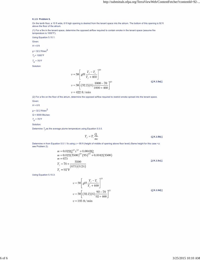
K.1.5 Problem 5.
On the tenth floor, a 10 ft wide, 6 ft high opening is desired from the tenant space into the atrium. The bottom of this opening is 92 ftabove the floor of the atrium.
(1) For a fire in the tenant space, determine the opposed airflow required to contain smoke in the tenant space (assume firetemperature is 1000°F).
Using Equation 5.10.1:
Given:
H = 6 ft
g = 32.2 ft/sec2
Tf = 1000°F
To = 70°F
Solution:
( [ K.1.5a) ]
(2) For a fire on the floor of the atrium, determine the opposed airflow required to restrict smoke spread into the tenant space.
Given:
H = 6 ft
g = 32.2 ft/sec2
Q = 5000 Btu/sec
To = 70°F
Solution:
Determine Tf as the average plume temperature using Equation 5.5.5.
( [ K.1.5b) ]
Determine m from Equation 5.5.1.1b using z = 95 ft (height of middle of opening above floor level) (flame height for this case <z;see Problem 2):
[ ( K.1.5c) ]
Using Equation 5.10.3:
( [ K.1.5d) ]
http://submittals.nfpa.org/TerraViewWeb/ContentFetcher?contentId=92-...
6 of 6 3/25/2015 10:10 AM

NFPA 92, Standard for Smoke Control Systems, 2012 Edition
NFPA STANDARDS DEVELOPMENT SITE
SECOND DRAFT REPORTReleased Version Closing Date: July 18, 2014 NOTE: All Public Comment must be received by 5:00 pm EST/EDST on the published Closing Date.
Welcome Kimberly Shea!
Quick PrintShow PI/PC'sShow Revisions/NotesSave As WordAnnex L Comparison of Equations
This annex is not a part of the requirements of this NFPA document but is included for informational purposes only.
L.1
Calculation results using Equation 5.4.2.2 or 5.4.2.2a that yield z/H>1.0 indicate that the smoke layer has not yet begun to descend.Equations 5.4.2.2 and 5.4.2.2a are based on limited experimental data.
Equations 5.4.2.1 and 5.4.2.2 are empirically based for estimating the smoke layer interface position during the smoke fillingprocess. This review of Equations 5.4.2.1 and 5.4.2.2 is divided into two parts as follows:
(1) Comparison of the results of both Equations 5.4.2.1 and 5.4.2.2 with those from theoretically based equations (with empiricallydetermined constants), hereafter referred to as ASET-based equations
(2) Evaluation of the predictive capability of Equation 5.4.2.1 and an ASET-based equation by comparing the output from theequations with experimental data
L.2 Comparisons with ASET-Based Equations.
Comparisons of the NFPA 92 equations for smoke filling with ASET-based equations provide an indication of the differencesbetween empirically based equations, for example, Equations 5.4.2.1 and 5.4.2.2, with those that are based principally on theory.
http://submittals.nfpa.org/TerraViewWeb/ContentFetcher?contentId=92-...
1 of 6 3/25/2015 10:11 AM
kshea
Text Box

L.3 Steady Fires.
http://submittals.nfpa.org/TerraViewWeb/ContentFetcher?contentId=92-...
2 of 6 3/25/2015 10:11 AM

A theoretically based equation for smoke filling can be derived using the laws of conservation of mass and energy to determine theadditional volume being supplied to the upper layer (Milke and Mowrer [82]). Using Zukoski’s plume entrainment correlation (Waltonand Notorianni [84]),
( [ L.3a) ]
where:
z = smoke layer interface position above base of fuel (m)
H = ceiling height (m)
kv = entrainment constant ≉0.064 m4/3/(sec-kW1/3)
t = time from ignition (sec)
Q = heat release rate (kW)
A = cross-sectional area of space (m2)
A comparison of z/H predicted by Equations 5.4.2.1 and L.3a is presented in Figure L.3(a) for a ceiling height of 30 m, a steady fire
size of 5 MW, and a wide range of A/H2 ratios. In general, the agreement between the two equations is reasonable.
Figure L.3(a) Comparison of Algebraic Equations, Equations 5.4.2.1 and L.3a: Steady Fire.
Equation 5.4.2.1 predicts a lower smoke layer interface position at most times, except in the case of the voluminous space
represented by A/H2 of 10. In this case, Equation 5.4.2.1 indicates a delay of approximately 100 seconds before a layer forms,while Equation L.3a indicates immediate formation of the layer. Such a delay is reasonable for such a large space. This delay canbe addressed by including an additional term in Equation L.3a to account for the transport lag (Mowrer and Williamson [85]). The
transport lag is estimated as 37 seconds for this case, with a height of 30 m and a cross-sectional area of 9000 m2. While thecomparison in Figure L.3(a) is useful, it applies only to selected values of A, H, and Q. This comparison can be generalized for allvalues of A, H, and Q by forming a ratio of the two equations expressed in terms of t, as follows:
( [ L.3b) ]
Figure L.3(b) indicates the relationship of the time ratio with the normalized smoke layer depth, (H - – z)/H. For perfect agreementbetween the two equations, the time ratio should have a value of 1.0. However, the time ratio varies appreciably and is within 20percent of 1.0 for only a very small range. For normalized smoke layer depths less than 0.13 (or a normalized clear height of 0.87),Equation L.3a always predicts a shorter time to reach a particular depth than Equation 5.4.2.1. Conversely, Equation 5.4.2.1predicts shorter times to attain any normalized smoke layer depth in excess of 0.13.
The time ratio is relatively insensitive for values of (H - – z)/H, ranging from 0.4 to 0.6. Within this range, the time ratio is nominally1.5, that is, the time predicted by Equation L.3a to obtain a smoke layer of a particular depth is 50 percent greater than thatpredicted by Equation 5.4.2.1. Alternatively, Equation 5.4.2.1 predicts a more rapid descent to this range of smoke layer depths thanEquation L.3a.
Figure L.3(b) Comparison of Algebraic Equations, Equations 5.4.2.1 and L.3a: Steady Fire — Normalized Smoke LayerDepth.
http://submittals.nfpa.org/TerraViewWeb/ContentFetcher?contentId=92-...
3 of 6 3/25/2015 10:11 AM

http://submittals.nfpa.org/TerraViewWeb/ContentFetcher?contentId=92-...
4 of 6 3/25/2015 10:11 AM

L.4 t-Squared Fires.
A similar comparison of the empirically based Equation 5.4.2.2 and a theoretically based equation for t-squared fires can beconducted. The ASET-based equation is as follows:
( [ L.4a) ]
where tg = fire growth rate (sec).
A comparison of the predicted z/H values are presented in Figure L.4(a) for a ceiling height of 30 m, a moderate fire growth rate (tg
= 300 seconds), and a wide range of A/H2 ratios. For values of A/H2 up to 1.0, the agreement appears very reasonable once the
smoke layer has formed. Again, the empirically derived equation implicitly includes the transport lag. For A/H2 of 10.0, the delay for
a smoke layer to form is greater than that for smaller A/H2 ratios such that reasonable agreement in smoke layer interface positionis not achieved until approximately 800 seconds. The estimated transport lag is 206 seconds (Mowrer and Williamson [85]).
The value of z/H of 0.59 for the point of intersection of the various curves for the two equations is a constant, independent of thevalues for A, H, and Q. Thus, for values of z/H > 0.59, Equation L.4a estimates a shorter time to attain a particular position of thesmoke layer interface, whereas Equation 5.4.2.2 estimates a faster time for lesser values of z/H. Given the different exponents onthe right side of the two equations, a general comparison is again possible only by solving for the times and expressing a ratio:
( [ L.4b) ]
Figure L.4(a) Comparison of Algebraic Equations, Equations 5.4.2.2 and L.4a: t-Squared Fire.
Figure L.4(b) Comparison of Algebraic Equations, Equations 5.4.2.2 and L.4a: t-Squared Fire — Normalized Smoke LayerDepths.
The relationship of the time ratio for various normalized smoke layer depths, (H – z)/H is provided in Figure L.4(b). In general, theagreement between the two predicted times for t-squared fires is much better than that for steady fires, with the predicted time usingEquation L.4a being within 20 percent of that from Equation 5.4.2.2 for (H – z)/H values from 0.26 to 0.80. As in the case of thesteady fire, the time ratio is less than 1.0 for small normalized smoke layer depths. However, in this case, the time ratio does notexceed 1.0 until the normalized smoke layer depth is at least 0.40.
http://submittals.nfpa.org/TerraViewWeb/ContentFetcher?contentId=92-...
5 of 6 3/25/2015 10:11 AM

L.5 Large-Scale Experimental Programs in Tall Ceiling Spaces.
The predictive capabilities of each equation can be examined by comparing the output to experimental data.
The predictive capability of Equation L.3a is examined by comparing the output to large-scale experimental data. Sources of theexperimental data involving a range of ceiling heights from 2.4 m to 12.5 m as well as room sizes and fire scenarios are identified inTable L.5. Included in the table are the data sources referenced in the initial development of Equation 5.4.2.1 (Heskestad [10]). Twoadditional sets of experimental data have become available since the committee’s initial analysis (Yamana and Tanaka [86]);Lougheed [87]). Comprehensive descriptions of the test programs are provided elsewhere (Hagglund, Jansson, and Nireus [6];Mulholland et al. [38]; Cooper et al. [4]; Milke and Mowrer [82]). Because the two additional sets of data were collected from fires inspaces with significantly greater ceiling heights than in the initial sets of data, the new sets of data are of particular interest. Themeasured and predicted smoke layer positions as a function of time from the previous data and two new sets of data are presentedin Figure L.5. The data identified as “the committee’s” include all the data on which the committee based initial development ofEquation 5.4.2.1. The new sets of data are identified separately. As indicated in Figure L.5, the smoke layer position from the dataanalyzed is between that measured by the National Research Council of Canada (NRCC) and the Building Research Institute (BRI).Thus, despite the differences in ceiling height, the new and initial sets of data appear to be reasonably similar. The graph labeled“NFPA 92” depicts the predictions of Equation 5.4.2.1. In general, agreement between the predictions from both Equations 5.4.2.1and L.3a and the experimental data is very reasonable. Equation 5.4.2.1 provides a lower limit of the experimental data, includingthe new NRCC data. Equation L.3a appears to predict a midrange value of data.
Table L.5 Summary of Full-Scale Experiments
ResearchGroup Fuel
Heat ReleaseRate Dimension of Test Room
Measurements of Smoke LayerPosition
New Data
Yamana &Tanaka [86] Methanol pool, 3.24 m2 1.3 MW (steady) 30 m × 24 m; height, 26.3 m
Visual observations, firsttemperature rise
NRCC [87]Ethanol pool, 3.6 mdiameter
8 MW (steady) 55 m × 33 m; height, 12.5 m First temperature rise
Committee Data
Sandia, Test 7[40]
Propylene burner, 0.91m diameter
516 kW 18.3 m × 12.2 m; height, 6.1 mFirst temperature rise, carbondioxide concentration
Mulholland [38] Acetylene burner 16.2 kW 3.7 m × 3.7 m; height, 2.4 m Temperature rise, light obscuration
Cooper [4] Methane burner25 kW, 100 kW,225 kW
89.6 m2 room; corridor andlobby height, 2.4 m
Temperature rise
Hagglund [6] Kerosene pool, 0.5 m2 280 kW5.62 m × 5.62 m; height, 6.15m
Visual observations, firsttemperature rise
Figure L.5 Comparison of Smoke Layer Position, Experimental Data vs. Predictions.
Equations comparable to Equations 5.4.2.1 and L.3a can be derived for variable cross-sectional areas and for fires that follow apower law (e.g., t-squared fires). In addition, algebraic equations pertaining to a variety of smoke layer characteristics are available,including temperature, light obscuration, and species concentration (Milke and Mowrer [82]). These equations are applicable toevaluating transient conditions prior to operation of the smoke management system or equilibrium conditions with an operationalsmoke management system. Thus, a variety of algebraic equations are available and can serve as useful tools for relativelyelementary designs or as checks of specific aspects of computer calculations for more complicated situations.
http://submittals.nfpa.org/TerraViewWeb/ContentFetcher?contentId=92-...
6 of 6 3/25/2015 10:11 AM

NFPA 92, Standard for Smoke Control Systems, 2012 Edition
NFPA STANDARDS DEVELOPMENT SITE
SECOND DRAFT REPORTReleased Version Closing Date: July 18, 2014 NOTE: All Public Comment must be received by 5:00 pm EST/EDST on the published Closing Date.
Welcome Kimberly Shea!
Quick PrintShow PI/PC'sShow Revisions/NotesSave As Word
SR-15 Hide Legislative
SR-12 Hide Legislative
Annex M Informational References
M.1 Referenced Publications.
The documents or portions thereof listed in this annex are referenced within the informational sections of this standard and are notpart of the requirements of this document unless also listed in Chapter 2 for other reasons.
M.1.1 NFPA Publications.
National Fire Protection Association, 1 Batterymarch Park, Quincy, MA 02169-7471.
NFPA 13, Standard for the Installation of Sprinkler Systems, 2013 edition.
NFPA 72®, National Fire Alarm and Signaling Code, 2013 edition.
NFPA 80, Standard for Fire Doors and Other Opening Protectives, 2013 edition.
NFPA 90A, Standard for the Installation of Air-Conditioning and Ventilating Systems, 2012 edition.
NFPA 101®, Life Safety Code®, 2015 edition.
NFPA 130, Standard for Fixed Guideway Transit and Passenger Rail Systems , 2014 edition.
NFPA 204, Standard for Smoke and Heat Venting, 2015 edition.
NFPA 269, Standard Test Method for Developing Toxic Potency Data for Use in Fire Hazard Modeling, 2012 edition.
NFPA 909, Code for the Protection of Cultural Resource Properties — Museums, Libraries, and Places of Worship, 2013 edition.
NFPA 5000®, Building Construction and Safety Code®, 2015 edition.
49. Tamura, G. T., Smoke Movement and Control in High-Rise Buildings, 1994 edition.
M.1.2 Other Publications.
M.1.2.1 ASHRAE Publications.
American Society of Heating, Refrigerating, and Air Conditioning Engineers, Inc., 1791 Tullie Circle, NE, Atlanta, GA 30329-2305.
Handbook of Smoke Control Engineering by J. H. Klote, J. A. Milke, P. G. Turnbull, A. Kashef, and M. J. Ferreira. ASHRAE/ICC/NFPA/SFPE.
M.1.2.2 ASME Publications.
American Society of Mechanical Engineers, Three Park Avenue, New York, NY 10016-5990.
ASME/ANSI A17.1, Safety Code for Elevators and Escalators, 2010.
M.1.2.3 ASTM Publications.
ASTM International, 100 Barr Harbor Drive, P.O. Box C700, West Conshohocken, PA 19428-2959.
ASTM E 1321, Standard Test Method for Determining Material Ignition and Flame Spread Properties, 2009.
ASTM E 1354, Standard Test Method for Heat and Visible Smoke Release Rates for Materials and Products Using an OxygenConsumption Calorimeter, 2011.
M.1.2.4 British Standards BSI Publications .
BSI British Standards, 389 Chiswick High Road, London W4 4AL UK.
BS EN 12101-8: Smoke and heat control systems- — Part 8: Smoke control dampers, 2011.
M.1.2.5 EN Publications.
European Committee for Electrotechnical Standardization (CENELEC), 35, Rue de Stassartstraat, B-1050 Brussels, Belgium.
EN 12101–1, Specification for smoke barriers, 2005.
M.1.2.6 ISO Publications .
International Organization for Standardization, 1, ch. de la Voie-Creuse CP 56 CH-1211 Geneva 20 Switzerland.
ISO 21927-1:2008 Smoke and heat control systems — Part 1 Specification for S s moke B b arriers, 2008 .
M.1.2.7 SFPE Publications.
Society of Fire Protection Engineers, 7315 Wisconsin Avenue, Suite 1225 W, Bethesda, MD 20814.
Handbook of Fire Protection Engineering, 2008, 4th edition.
SFPE Engineering Guide to Performance-Based Fire Protection , 2007, 2nd edition.
http://submittals.nfpa.org/TerraViewWeb/ContentFetcher?contentId=92-...
1 of 8 3/25/2015 10:11 AM
kshea
Text Box

M.1.2.8 UL Publications.
Underwriters Laboratories Inc., 333 Pfingsten Road, Northbrook, IL 60062-2096.
ANSI/UL 555, Standard for Fire Dampers, 2006, Revised 2012.
ANSI/UL 555S, Standard for Smoke Dampers, 1999, Revised 2012.
M.1.2.7 ISO Publication.
International Organization for Standardization, 1, ch. de la Voie-Creuse CP 56 CH-1211 Geneva 20 Switzerland.
ISO 21927-1: Smoke and heat control systems — Part 1 Specification for S moke B arriers , 2008 .
M.1.2.8 British Standards BSI Publication s .
BSI British Standards, 389 Chiswick High Road, London W4 4AL UK.
BS EN 12101-8: Smoke and heat control systems - — Part 8: Smoke control dampers , 2011.
http://submittals.nfpa.org/TerraViewWeb/ContentFetcher?contentId=92-...
2 of 8 3/25/2015 10:11 AM

SR-18 Hide Legislative
M.1.2.9 Other Publications.
http://submittals.nfpa.org/TerraViewWeb/ContentFetcher?contentId=92-...
3 of 8 3/25/2015 10:11 AM

1. Bennetts, I. D., Culton, M., Dickerson, M. L., Lewins, R., Poh, K. W., Poon, S. L., Ralph, R., Lee, A. C., Beever, P. F., Cooper, R.J., Haggar, P. I., Moore, I. P., Ramsay, G. C., and Timms, G. R., Simulated Shopping Centre Fire Tests, BHPR/SM/R.G/062, BrokenHill Proprietary Company Limited, Australia, 1997.
2. Beyler, C., “Fire Plumes and Ceiling Jets,” Fire Safety Journal, 11, pp. 63–65, 1986.
3. CIBSE. “Relationships for smoke control calculations,” Technical Memoranda TM19, Chartered Institution of Building ServicesEngineers. London, UK, 1995.
4. Cooper, L. Y., Harkleroad, M., Quintiere, J., and Rinkinen, W., “An Experimental Study of Upper Hot Layer Stratification inFull-Scale Multiroom Fire Scenarios,” Paper 81-HT-9, the American Society of Mechanical Engineers, 1981.
5. Emmons, H., “The Use of Fire Test Data in Fire Models,” The Home Fire Project Technical Report No. 78, Harvard University,Division of Applied Sciences, Februrary 1989.
6. Hagglund, B., Jansson, R., and Nireus, K., Smoke Filling Experiments in a 6×6×6 Meter Enclosure, FOA Rapport C20585-06,Forsavrets Forskningsanstalt, Sweden, September 1985.
7. Hansell, G. O., and Morgan, H. P., Design Approaches for Smoke Control in Atrium Buildings, BRE 258, Borehamwood, UK;Building Research Establishment, 1994.
8. Heskestad, G., “Determination of Gas Venting Geometry and Capacity of Air Pollution Control System at Factory MutualResearch Center,” FMRC Ser. No. 20581, Fire Mutual Research Corp., Norwood, MA, November 1972.
9. Heskestad, G., “Fire Plumes, Flame Height, and Air Entrainment,” Chapter 2-1, SFPE Handbook of Fire Protection Engineering,DiNenno et al. editors, National Fire Protection Association, Quincy, MA, 2002.
10. Heskestad, G., “Letter to the Editor,” Fire Technology, 27, 2, pp. 174–185, May 1991.
11. Heskestad, G., Sprinkler/Hot Layer Interaction, NISTGCR-91-590, National Institute of Standards, Gaithersburg, MD, 1991.
12. Heskestad, G. and Delichatsios, M. A., Environments of Fire Detectors—Phase 1 Effect of Fire Size, Ceiling Height andMaterials. Volume I — Measurements (NBS-GCR-77-86), Volume II - Analysis (NBS-GCR-77-95), National Bureau of Standards(now National Institute of Standards and Technology), Gaithersburg, MD, 1977.
13. Klote, J. H., “A Method for Calculation of Elevator Evacuation Time,” Journal of Fire Protection Engineering, Vol. 5, 1993, pp.83–96.
14. Klote, J. H., “Design of Smoke Control Systems for Areas of Refuge,” ASHRAE Transactions, American Society of Heating,Refrigerating, and Air Conditioning Engineers, Atlanta, GA, Vol. 99, Part 2, 1993b, pp. 793–807.
15. Klote, J. H., “Design of Smoke Control Systems for Elevator Fire Evacuation Including Wind Effects,” 2nd Symposium onElevators, Fire and Accessibility, Baltimore, ASME, New York, NY, 1995, pp. 59–77.
16. Klote, J. H., D. M. Alvord, B. M. Levin, and N. E. Groner, “Feasibility and Design Considerations of Emergency Evacuation byElevators,” NISTIR 4870, National Institute of Standards and Technology, Gaithersburg, MD, 1992.
17. Klote, J. H., and E. Braun, “Water Leakage of Elevator Doors with Application to Building Fire Suppression,” NISTIR 5925,National Institute of Standards and Technology, Gaithersburg, MD, 1996.
18. Klote, J. H., S. P. Deal, E. A. Donoghue, B. M. Levin, and N. E. Groner, “Fire Evacuation by Elevators,” ElevatorWorld, 1993, pp.66–75.
19. Klote, J. H., B. M. Levin, and N. E. Groner, “Feasibility of Fire Evacuation by Elevators at FAA Control Towers,” NISTIR 5445,National Institute of Standards and Technology, Gaithersburg, MD, 1994.
20. Klote, J. H., B. M. Levin, and N. E. Groner, “Emergency Elevator Evacuation Systems,” 2nd Symposium on Elevators, Fire andAccessibility, Baltimore, ASME, New York, NY, 1995, pp. 131–150.
21. Klote, J. , and Milke, J., “Principles of Smoke Management,” ASHRAE/SFPE, Atlanta, GA, 2002 H., Milke, J. A., Turnbull, P. G.,Kashef, A., and Ferreira, M. J., Handbook of Smoke Control Engineering , ASHRAE/ICC/NFPA/SFPE, 2012 .
22. Law, M., “A Note on Smoke Plumes from Fires in Multi-Level Shopping Malls,” Fire Safety Journal, 10, p. 197, 1986.
23. Lougheed, G. D., “Expected Size of Shielded Fires in Sprinklered Office Buildings,” ASHRAE Transactions, Volume 103, Part 1,1997, p. 395.
24. Lougheed, G. D., and Hadjisophocleous, G. V., “Investigation of Atrium Smoke Exhaust Effectiveness,” ASHRAE Transactions103, pp. 1–15, 1997.
25. Lougheed, G. D., Hadjisophocleous, G. V., McCartney, C., and Taber, B. C., “Large-Scale Physical Model Studies for an AtriumSmoke Exhaust System,” ASHRAE Transactions 104, 1999.
26. Lougheed, G. D., J. R. Mawhinney, and J. O’Neill, “Full-Scale Fire Tests and the Development of Design Criteria for SprinklerProtection of Mobile Shelving Units,” Fire Technology, Vol. 30, 1994, pp. 98–133.
27. Lougheed, G. D., and McCartney, C. J., “Balcony Spill Plumes: Full-Scale Experiments, Part 2 (RP-1247),” ASHRAETransactions, to be published.
28. Lougheed, G. D., McCartney, C. J., and Gibbs, E., “Balcony Spill Plumes Final Report RP-1247,” ASHRAE, Atlanta, Georgia,2007.
29. Madrzykowski, D., and Vettori, R., “A Sprinkler Fire Suppression Algorithm,” Journal of Fire Protection Engineering, 4, pp.151–164, 1992.
30. Marshall, N. R., and Harrison, R., “Experimental studies of thermal spill plumes, Occasional Paper, OP1,” Building ResearchEstablishment, Garston, UK, 1996.
31. McCartney, C. J., Lougheed, G. D. and Weckman, E.J., “CFD Investigation of Balcony Spill Plumes in Atria,” ASHRAETransactions, to be published.
32. Modak, A. T., and Alpert, R. L., Influence of Enclosures on Fire Growth — Volume I: Guide to Test Data, FMRC 0A0R2.BU-8,Factory Mutual Research, Norwood, MA, 1978.
33. Morgan, H. P., Smoke Control Methods in Enclosed Shopping Complexes of One or More Storeys: A Design Summary, BuildingResearch Establishment, 1979.
34. Morgan, H. P., Ghosh, B. K., Garrard, G., Pamlitschka, R., De Smedt, J. C., and Schoonbaert, L. R. “Design Methodologies for
http://submittals.nfpa.org/TerraViewWeb/ContentFetcher?contentId=92-...
4 of 8 3/25/2015 10:11 AM

Smoke and Heat Exhaust Ventilation,” Construction Research Communications Ltd, London, UK, 1999.
35. Morgan, H. P., and Marshall, N. R., Smoke Control Measures in Covered Two-Story Shopping Malls Having Balconies andPedestrian Walkways, BRE CP 11/79, Borehamwood, 1979.
36. Mudan, K. S., and Croce, P. A., “Fire Hazard Calculations for Large Open Hydrocarbon Fires,” SFPE Handbook of FireProtection Engineering, National Fire Protection Association, Quincy, MA, 1988.
37. Mulholland, G., Section 1/Chapter 25 “Smoke Production and Properties,” SFPE Handbook of Fire Protection Engineering,National Fire Protection Association, Quincy, MA, 1988.
38. Mulholland, G., Handa, T., Sugawa, O., and Yamamoto, H., “Smoke Filling in an Enclosure,” Paper 81-HT-8, the AmericanSociety of Mechanical Engineers, 1981.
39. Nii, Nitta, Harada, and Yamaguchi, “Air Entrainment into Mechanical Smoke Vent on Ceiling,” Fire Safety Science, Proceedingsof the Seventh International Symposium, pp.729–740, 2003.
40. Nowler, S. P., Enclosure Environment Characterization Testing for the Base Line Validation of Computer Fire Simulation Codes,NUREG/CR-4681, SAND 86-1296, Sandia National Laboratories, March 1987.
41. Purser, D. A., “Toxicity Assessment of Combustion Products,” SFPE Handbook of Fire Protection Engineering, National FireProtection Association, Quincy, MA, 2002.
42. Quintiere, J. G., Fire Safety Journal, 1, 15, 1989.
43. Quintiere, J. G., McCaffrey, B. J., and Kashiwagi, T., Combustion Science and Technology, 18, 1978.
44. Shaw, C. Y., J. T. Reardon, and M. S. Cheung, “Changes in Air Leakage Levels of Six Canadian Office Buildings,” ASHRAEJournal, American Society of Heating, Refrigerating and Air Conditioning Engineers, Atlanta, GA, 1993.
45. Soderbom, J., “Smoke Spread Experiments in Large Rooms. Experimental Results and Numerical Simulations,” StatensProvningsanstalt, SR Report 1992:52, Swedish National Testing and Research Institute, Boras, Sweden, 1992.
46. Spratt, D., and Heselden, A. J. M., “Efficient Extraction of Smoke from a Thin Layer Under a Ceiling,” Fire Research Note No.1001, February 1974.
47. Steckler, K. D., Baum, H. R., and Quintiere, J. G., 21st Symposium (Int.) on Combustion, pp. 143–149, 1986.
48. Tamura, G. T., and C. Y. Shaw, “Studies on ExteriorWall Air Tightness and Air Infiltration of Tall Buildings,” ASHRAETransactions, American Society of Heating, Refrigerating and Air Conditioning Engineers, Atlanta, GA, Vol. 82, Part 1, 1976, pp.122–134.
49. Tamura, G. T., and C. Y. Shaw, “Air Leakage Data for the Design of Elevator and Stair Shaft Pressurization Systems,” ASHRAETransactions, American Society of Heating, Refrigerating and Air Conditioning Engineers, Atlanta, GA, Vol. 82, Part 2, 1976b, pp.179–190.
50. Tamura, G. T., and C. Y. Shaw, “Experimental Studies of Mechanical Venting for Smoke Control in Tall Office Buildings,”ASHRAE Transactions, American Society of Heating, Refrigerating and Air Conditioning Engineers, Atlanta, GA, Vol. 86, Part 1,1978, pp. 54–71.
51. Tamura, G. T., and A. G.Wilson, “Pressure Differences for a Nine-Story Building as a Result of Chimney Effect and VentilationSystem Operation,” ASHRAE Transactions, American Society of Heating, Refrigerating and Air Conditioning Engineers, Atlanta,GA, Vol. 72, Part 1, 1966, pp. 180–189.
52. Tewarson, A., “Generation of Heat and Chemical Compounds in Fires,” SFPE Handbook of Fire Protection Engineering, 2nded., P. J. DiNenno (ed.), National Fire Protection Association, Quincy, MA, 2002.
53. Babrauskas, V., “Heat Release Rates,” SFPE Handbook of Fire Protection Engineering, 3rd ed., P. J. DiNenno (ed.), NationalFire Protection Association, Quincy, MA, 2002.
54. Babrauskas, V., and Krasny, J., Fire Behavior of Upholstered Furniture, NBS Monograph 173, National Bureau of Standards(now National Institute of Standards and Technology), November 1985.
55. Nelson, H. E., and Forssell, E. W., “Use of Small-Scale Test Data in Hazard Analysis,” Proceedings of the 4th InternationalSymposium of IAFSS, Ottawa, Canada, 1994.
56. Hirsch, C., Numerical Computation of Internal and External Flows, Vol. 1: Fundamentals of Numerical Discretization,Wiley, NewYork, 1988.
57. Sako, S., and Hasemi, Y., “Response Time of Automatic Sprinklers Below a Confined Ceiling,” Fire Safety Science-Proceedingsof the Second International Symposium, Hemisphere Publishing Corporation, New York, p. 613, 1989.
58. Carslaw, H. S., and Jaeger, J. C., Conduction of Heat in Solids, Oxford University, Oxford, 1959.
59. Tien, C. L., Lee, K. Y., and Stretton, A. J., “Radiation Heat Transfer,” SFPE Handbook of Fire Protection Engineering, 2nd ed., P.J. DiNenno (ed.), National Fire Protection Association, Quincy, MA, 2002.
60. Nelson, H. E., An Engineering Analysis of the Early Stages of Fire Development—The Fire at the Du Pont Plaza Hotel andCasino — December 31, 1986, Report NBSIR 87-3560, 1987.
61. Borisenko, A. I., and Tarapov, I. E., Vector and Tensor Analysis with Applications, Translated by R. A. Silverman, Dover, NewYork, 1968.
62. Hay, G. E., Vector and Tensor Analysis, Dover, New York, 1953.
63. Welty, J. R.,Wicks, C. E., and Wilson, R. E., Fundamentals of Momentum, Heat and Mass Transfer, John Wiley & Sons, NewYork, 1976.
64. Schetz, J. A., Boundary Layer Analysis, Prentice Hall, Englewood Cliffs, NJ, 1993.
65. Schlichting, H., Boundary Layer Theory, 4th ed., Kestin, J. translator, McGraw, New York, 1960.
66. Sherman, F. S., Viscous Flow, McGraw, New York, 1990.
67. Aris, R., Vectors, Tensors, and the Basic Equations of Fluid Mechanics, Dover, New York, 1962.
68. Anderson, D. A., Tannehill J. C., and Pletcher, R. H., Computational Fluid Mechanics and Heat Transfer, Hemisphere, New York,1984.
http://submittals.nfpa.org/TerraViewWeb/ContentFetcher?contentId=92-...
5 of 8 3/25/2015 10:11 AM

SR-16 Hide Legislative
69. Abbott, M. B., and Basco, D. R., Computational Fluid Dynamics: An Introduction for Engineers, Wiley, New York, 1989.
70. Hoffmann, K. A., Computational Fluid Dynamics for Engineers, Engineering Education System, Austin, TX, 1989.
71. Markatos, N. C., The Mathematical Modelling of Turbulent Flows, Applied Mathematical Modeling, Vol. 10, No. 3, pp. 190–220,1986.
72. Hirsch, C., Numerical Computation of Internal and External Flows, Vol. 2: Computational Methods for Inviscid and ViscousFlows, Wiley, New York, 1990.
73. Kumar, S., Mathematical Modelling of Natural Convection in Fire — A State of the Art Review of the Field Modelling of VariableDensity Turbulent Flow, Fire and Materials, Vol. 7, No. 1, pp. 1–24, 1983.
74. McGrattan, K. B., et al., Fire Dynamics Simulator – Technical Reference Guide, NISTIR 6467, National Institute of Standardsand Technology, Gaithersburg, MD, 2000.
75 McGrattan, K. B., and Forney, G. P., Fire Dynamics Simulator– User’s Manual, NISTIR 6469, National Institute of Standards andTechnology, Gaithersburg, MD, 2000.
76. Friedman, R., An International Survey of Computer Models for Fire and Smoke, Journal of Fire Protection Engineering, Vol. 4,No. 3, pp. 81–92, 1992.
77. DiNenno, P. J., ed., SFPE Handbook of Fire Protection Engineering, National Fire Protection Association, Quincy, MA, 2002.
78. Drysdale, D. D., An Introduction of Fire Dynamics, John Wiley & Sons, New York, 1985.
79. Nelson, H. E., and Mowrer, F., “Emergency Movement,” Chapter 3-14, SFPE Handbook of Fire Protection Engineering, DiNennoet al. editors, National Fire Protection Association, Quincy, MA, 2002.
80. Milke, J. A., and Mowrer, F. W., “An Algorithm for the Design Analysis of Atrium Smoke Management Systems,” FP93-04,Department of Fire Protection Engineering, University of Maryland at College Park, May 1993
81. Morton, B. R., Taylor, Sir Geoffrey, and Turner, J. S., “Turbulent Gravitational Convection from Maintained and InstantaneousSources,” Proc. Royal Society A 234, 1–23, 1956.
82. Walton, W. D., and Notorianni, “A Comparison of Ceiling Jet Temperatures Measured in an Aircraft Hangar Test Fire withTemperatures Predicted by the DETECT and LAVENT Computer Models,” NISTIR (Draft), Building and Fire Research Laboratory,National Institute of Standards and Technology, August 1992.
83. Mowrer, F.W., and Williamson, R. B., “Estimating Room Temperatures from Fires along Walls and in Corners,” Fire Technology23, 2, pp. 133–145, May 1987.
84. Yamana, T., and Tanaka, T. “Smoke Control in Large Scale Spaces—Part 2: Smoke Control in Large Scale Spaces,” FireScience and Technology, 5, 1, pp. 41–54, 1985.
85. Personal Communication, G. D. Lougheed, National Research Council of Canada, March 20, 1991.
86. Harrison, R., and Spearpoint, M., “A review of simple entrainment calculation methods for the thermal spill plume,” InternationalJournal on Engineering Performance-Based Fire Codes , volume 9, number 4, pp. 142–153.
87. Harrison, R., and Spearpoint, M., “A simple approximation to predict the transition from a balcony spill plume to anaxisymmetric plume,” Journal of Fire Protection Engineering , volume 20, November 2010.
88. Harrison, R., and Spearpoint, M.J., “Characterisation of balcony spill plume entrainment using physical scale modelling,” FireSafety Science — Proceedings of the 9th Symposium , London. International Association for Fire Safety Science, pp. 727–738,2008.
89. Harrison, R., and Spearpoint, M., “Entrainment of air into a balcony spill plume,” Journal of Fire Protection Engineering ,volume 16, number 3, pp. 211–245, 2006.
90. Harrison, R. and Spearpoint, M., “Physical scale modelling of adhered spill plume entrainment,” Fire Safety Journal, volume 45,pp. 149–158, 2010.
M.2 Informational References.
The following documents or portions thereof are listed here as informational resources only. They are not a part of the requirementsof this document.
Global SR-16 Hide Deleted
M.2.1 ISO Publications.
International Organization for Standardization, 1, ch. de la Voie-Creuse, Case postale 56, CH-1211, Geneva 20, Switzerland.
ISO 21927-1:2008 Smoke and heat control systems — Part 1 Specification for smoke barriers .
ISO 21927-2:2006 + A1 Smoke and heat control systems — Part 2 Specification for natural smoke and heat exhaust ventilators .
ISO 21927-3:2006 A1 +A1 Smoke and heat control systems — Part 3: Specification for powered smoke and heat exhaustventilators .
ISO 21927-7:2013 Smoke and heat control systems — Part 7: Smoke control ducts .
ISO 21927-8:2013 Smoke and heat control systems — Part 8: Specification for smoke control dampers .
ISO 21927-9:2012 Smoke and heat control systems — Part 9: Control panels and emergency control panels .
ISO 21927-10:2011 Smoke and heat control systems — Part 10: Power supplies .
http://submittals.nfpa.org/TerraViewWeb/ContentFetcher?contentId=92-...
6 of 8 3/25/2015 10:11 AM

M.2.2 Other Publications.
The following documents or portions thereof are listed here as informational resources only. They are not a part of the requirementsof this document.
Alpert, R. L., and Ward, E. J., Evaluating Unsprinklered Fire Hazards, FMRC No. 01836.20, Norwood, MA, Factory MutualResearch Corporation, pp. 46 and 48, August 1982.
Bullen, M. C., and Thomas, P. A, “Compartment Fires with Non-Cellulosic Fuels; 17th Symposium (International) on Combustion,”The Combustion Institute, pp. 1139–1148, 1979.
CIBSE, Relationships for Smoke Control Calculations, Technical Memoranda TM19, The Chartered Institution of Building ServicesEngineers, London, UK, 1995.
Cooper, L. Y., Harkleroad, M., Quintiere, J., and Rinkinen, W., “An Experimental Study of Upper Hot Layer Stratification in Full-ScaleMultiroom Fire Scenarios,” Journal of Heat Transfer, 104, pp. 741–749, 1982.
Emmons, H., “The Use of Fire Test Data in Fire Models,” The Home Fire Project Technical Report No. 78, Harvard University,Division of Applied Sciences, February 1989.
Fang, J. B., and Breese, J. N., Fire Development in Residential Basement Rooms, NBSIR 80-2120, National Bureau of Standards,October 1980.
Ghosh, B. K., “Fires in Real Scenarios,” International Symposium on Fire Science and Technology, ISFST 1997, Seoul, Korea, pp.439–447, 1997.
Gottuk, D., Roby, R., and Eglo, C., “A Study of Carbon Monoxide and Smoke Yields from Compartment Fires with External Burning;24th Symposium (International) on Combustion,” The Combustion Institute, pp. 1729–1735, 1992.
Hadjisophocleous, G. V., Lougheed, G. D., and Cao, S., “Numerical Study of the Effectiveness of Atrium Smoke Exhaust Systems,”ASHRAE Transactions 104, 1999.
Hansell, G. O., Morgan, H., and Marshall, N. R., “Smoke Flow Experiments in a Model Atrium,” BRE Occasional Paper, July 1993.
Heskestad, G., Engineering Relations for Fire Plumes, SFPE TR 82-8, Boston, Society of Fire Protection Engineers, 1982.
Heskestad, G., Inflow of Air Required at Wall and Ceiling Apertures to Prevent Escape of Fire Smoke, FMRC J.I. 0Q4E4.RU,Factory Mutual Research Corporation, July 1989.
Heskestad, G., and Bill, R. G., Jr., “Modeling of Thermal Responsiveness of Automatic Sprinklers,” Fire Safety Science —Proceedings of the Second International Symposium, Hemisphere Publishing Corporation, New York, p. 603, 1989.
Heskestad, G. and Delichatsios, M. A., “The Initial Convective Flow in Fire,” Seventeenth Symposium (International) onCombustion, the Combustion Institute, Pittsburgh, PA, p. 1113, 1979.
Heskestad, G. and Delichatsios, M. A., “Update: The Initial Convective Flow in Fire,” Fire Safety Journal, 15, p. 471, 1989.
Heskestad, G., and Hill, J. P., “Experimental Fire in Multiroom/Corridor Enclosures,” FMRC J.I. 0J2N8.RU, Factory Mutual ResearchCorporation, October 1985.
Hinkley, P. L., Hansell, G. O., Marshall, N. R., and Harrison, R., “Experiments at the Multifunctioneel Training Centrum, Ghent, onthe Interaction Between Sprinklers and Smoke Venting,” Building Research Establishment Report, 1992.
Kanury, A. M., “Ignition of Liquid Fuels,” SFPE Handbook of Fire Protection Engineering, 2nd ed., P. J. DiNenno (ed.), National FireProtection Association, Quincy, MA, 1995.
Klote, J. H., and X. Bodart, “Validation of Network Models for Smoke Control Analysis,” ASHRAE Transactions, American Society ofHeating, Refrigerating and Air Conditioning Engineers, Atlanta, GA, Vol. 91, Part 2B, 1985, pp. 1134–1145.
Law, M., “Air Supported Structures: Fire and Smoke Hazards,” Fire Prevention, 148, 1982.
Morgan, H. P., “Comments on a Note on Smoke Plumes from Fires in Multi-Level Shopping Malls,” Fire Safety Journal, 12, p. 83,1987.
Morgan, H. P., and Hansell, G. O., “Fire Sizes and Sprinkler Effectiveness in Offices-Implications for Smoke Control Design,” FireSafety Journal, volume 8, no. 3, pp. 187–198, 1985.
Mulholland, G., Handa, T., Sugawa, O., and Yamamoto, H., “Smoke Filling in an Enclosure,” Fire Science and Technology, 1, p. 1,1981.
Newman, J. S., and Hill, J. P., “Assessment of Exposure Fire Hazard to Cable Trays,” NP-1675 Research Project 1165-1-1,Prepared for Electric Power Research Institute by Factory Mutual Research Corporation, January 1981.
Peacock, R. D., and Babrauskas, V., “Analyses of Large-Scale Fire Test Data,” Fire Safety Journal, 17, pp. 387-414.
Spratt, D., and Heselden, A. J. M., “Efficient Extraction of Smoke from a Thin Layer Under a Ceiling,” UK Joint Fire ResearchOrganization, Fire Research Note No. 1001, 1994.
Thomas, P. H., “On the Upward Movement of Smoke and Related Shopping Mall Problems,” Fire Safety Journal, 12, p. 191, 1987.
Thomas, P. H., Heselden, J. M., and Law, M., “Fully-Developed Compartment Fires — Two Kinds of Behavior,” Fire ResearchTechnical Paper No. 18, 1967.
Thomas, P. H., Hinckley, P. L., Theobald, C. R., and Sims, D. L., “Investigations into the Flow of Hot Gases in Roof Venting,” FireResearch Technical Papers No. 7, HMSO, London, 1963.
Turner, J. S., Buoyancy Effects in Fluids, Cambridge University Press, Cambridge, 1973.
White, F. M. Viscous Fluid Flow, McGraw, New York, 1974.
Walton, G. N., “CONTAM96 User Manual,” NISTIR-6056, National Institute of Standards and Technology, Gaithersburg, MD, 1997.
Wray, C. P., and G. K. Yuill, “An Evaluation of Algorithms for Analyzing Smoke Control Systems,” ASHRAE Transactions, AmericanSociety of Heating, Refrigerating and Air Conditioning Engineers, Atlanta, GA, Vol. 99, Part 1, 1993, pp. 160–174.
Yamana, T., and Tanaka, T., “Smoke Control in Large Scale Spaces,” Fire Science and Technology, 5, p. 41, 1985.
Zukoski, E. E., Kubota, T., and Cetegen, B., “Entrainment in Fire Plumes,” Fire Safety Journal, 3, pp. 107–121, 1980/1981.
http://submittals.nfpa.org/TerraViewWeb/ContentFetcher?contentId=92-...
7 of 8 3/25/2015 10:11 AM

M.3 References for Extracts in Informational Sections.
NFPA 204, Standard for Smoke and Heat Venting , 2015 edition.
http://submittals.nfpa.org/TerraViewWeb/ContentFetcher?contentId=92-...
8 of 8 3/25/2015 10:11 AM

Public Comment No. 4-NFPA 92-2013 [ Section No. 3.3.4 ]
3.3.4 * Draft Curtain.A fixed or automatically deployable barrier that protrudes downward from the ceiling to channel, contain, or prevent the migration of smoke.
Statement of Problem and Substantiation for Public Comment
As written, a deployable draft curtain could mean a manually operated unit. In order to be effective, the deployable unit must automatically deploy when needed. To ensure deployment of the non-fixed draft curtain, the word “automatically” should be added just before the word “deployable”. This removes the allowance of manually deployed draft curtains.
Related ItemFirst Revision No. 2-NFPA 92-2013 [Section No. 3.3.5]
Submitter Information Verification
Submitter Full Name: Jim Muir
Organization: Building Safety Division, Clark County Washington
Affilliation: NFPA Building Code Development Committee (BCDC)
Street Address:
City:
State:
Zip:
Submittal Date: Wed Nov 13 15:36:22 EST 2013
Committee Statement
CommitteeAction:
Accepted
Resolution: SR-1-NFPA 92-2014
Statement: As previously written, a deployable draft curtain could mean a manually operated unit. In order to be effective, the deployable unit must automatically deploy when needed. To ensure deployment of the non-fixed draft curtain, the word “automatically” should be added just before the word “deployable”. This removes the allowance of manually deployed draftcurtains.
Page 1 of 10National Fire Protection Association Report
4/9/2014http://submittals.nfpa.org/TerraViewWeb/ContentFetcher?commentParams=%28Comment...

Public Comment No. 1-NFPA 92-2013 [ Section No. 3.3.9 [Excluding
any Sub-Sections] ]
A The column of smoke that rises hot gases, flames, and smoke rising above a fire; also called convection column, thermal updraft, or thermalcolumn .
Statement of Problem and Substantiation for Public Comment
I am a member of the Glossary of Terms Task Group (GOT). The proposed definition is used by many other standards. Having common definitions across NFPA standards, where appropriate, is the goal of the GOT.
Submitter Information Verification
Submitter Full Name: Jack McNamara
Organization: Bosch Security Systems
Affilliation: GOT
Street Address:
City:
State:
Zip:
Submittal Date: Sun Oct 27 12:45:48 EDT 2013
Committee Statement
Committee Action:
Rejected
Resolution: The committee understands the objectives of the GOT but does not think the proposed definition from NFPA 921 works for NFPA 92. The definition would need to be modified further, which defeats the purpose of the GOT.
Page 2 of 10National Fire Protection Association Report
4/9/2014http://submittals.nfpa.org/TerraViewWeb/ContentFetcher?commentParams=%28Comment...

Public Comment No. 3-NFPA 92-2013 [ Section No. 3.3.11 [Excluding
any Sub-Sections] ]
The airborne solid and liquid particulates and gases involved evolved when a material undergoes pyrolysis or combustion, together with the quantity of air that is entrained or otherwise mixed into the mass. [NFPA 556, 2011]
Statement of Problem and Substantiation for Public Comment
Many NFPA documents include the same definition of "smoke", including NFPA 90A, 204, 318, 556, 921 and 1404. It is essential that the definition not be changed. My suggestion that NFPA 556 be used for the extraction is because it is the most generic document, but any of the others could be chosen also.
Moreover, the concept of smoke addresses the products of combustion "evolved" and it does not address what products are "involved" in any issue.
This comment is made on behalf of the Glossary on Terminology committee set up to obtain uniformity of definitions.
Submitter Information Verification
Submitter Full Name: Marcelo Hirschler
Organization: GBH International
Affilliation: NFPA GOT
Street Address:
City:
State:
Zip:
Submittal Date: Tue Oct 29 12:46:48 EDT 2013
Committee Statement
Committee Action:
Accepted
Resolution: SR-2-NFPA 92-2014
Statement: The concept of smoke addresses the products of combustion "evolved" and it does not address what products are "involved" in any issue.
Page 3 of 10National Fire Protection Association Report
4/9/2014http://submittals.nfpa.org/TerraViewWeb/ContentFetcher?commentParams=%28Comment...

Public Comment No. 2-NFPA 92-2013 [ Section No. 3.3.12 ]
3.3.12* Smoke Barrier.For the purposes of this standard, a A continuous membrane, either vertical or horizontal, such as a wall, floor, or ceiling assembly, that or a membrane with discontinuities created by protected openings, where such membrane is designed and constructed to restrict the movement of smoke in conjunction with a smoke control system .
Statement of Problem and Substantiation for Public Comment
I am a member of the Glossary of Terms Task Group (GOT). The proposed definition is used by many other standards. Having common definitions across NFPA standards, where appropriate, is the goal of the GOT. A smoke barrier is not always used with smoke control systems
Submitter Information Verification
Submitter Full Name: Jack McNamara
Organization: Bosch Security Systems
Affilliation: GOT
Street Address:
City:
State:
Zip:
Submittal Date: Sun Oct 27 12:49:11 EDT 2013
Committee Statement
Committee Action:
Rejected
Resolution: The term Smoke Barrier is used differently in NFPA 92 than it is used in other standards such as NFPA 101 and NFPA 5000. The committee considered developing a new term "Smoke Control Barrier" but did not want to create unintended conflicts.
Page 4 of 10National Fire Protection Association Report
4/9/2014http://submittals.nfpa.org/TerraViewWeb/ContentFetcher?commentParams=%28Comment...

Public Comment No. 5-NFPA 92-2013 [ Section No. 4.3.1 ]
4.3.1 Smoke Containment Systems.The design approach for smoke containment systems shall be thepressurization of one of or a combination of the following:
(1) Stairwell pressurization Stairwells
(2) Zoned pressurization areas
(3) Elevator pressurization Elevators
(4) Vestibule pressurization Vestibules
(5) Smoke refuge area pressurization areas
Statement of Problem and Substantiation for Public Comment
The proposed revision in PI-5 is appropriate and easier to understand. It is not necessary from a technical perspective, but it makes NFPA 92 a better document because it reduces repetitive language and provides requirements more concisely. A better standard will be easier for designers, installers and enforcers.
Related Item
Public Input No. 5-NFPA 92-2012 [Section No. 4.3.1]
Submitter Information Verification
Submitter Full Name: Jim Muir
Organization: Building Safety Division, Clark County Washington
Affilliation: NFPA Building Code Development Committee (BCDC)
Street Address:
City:
State:
Zip:
Submittal Date: Wed Nov 13 15:49:18 EST 2013
Committee Statement
CommitteeAction:
Rejected but see related SR
Resolution: SR-3-NFPA 92-2014
Statement: Not all of these methods use positive pressurization, so the submitter's suggestion to move pressurization to the leading paragraph would not be accurate. The committee revised item (2) to remove the term pressurization and replace it with "Zoned Smoke Control". Zoned Smoke Control is the term used throughout the document.
Page 5 of 10National Fire Protection Association Report
4/9/2014http://submittals.nfpa.org/TerraViewWeb/ContentFetcher?commentParams=%28Comment...

Public Comment No. 6-NFPA 92-2013 [ Section No. 4.4.2.2 ]
4.4.2.2 * Pressure Differences Across Doors.The pressure differences across doors shall not cause the maximum force permitted to begin opening the door to exceed the value stipulated in NFPA 101, Life Safety Code, or state or local codes and regulations.
Statement of Problem and Substantiation for Public Comment
This was one of the changes suggested by PI-7. We do not agree with the change in the title suggested by PI-7, but we do agree with this change. Some states do not allow local codes or regulations to supersede that of the state codes or regulations, therefore “state” codes and regulations should be added.
Related ItemPublic Input No. 7-NFPA 92-2012 [Section No. 4.4.2.2]
Submitter Information Verification
Submitter Full Name: Jim Muir
Organization: Building Safety Division, Clark County Washington
Affilliation: NFPA Building Code Development Committee (BCDC)
Street Address:
City:
State:
Zip:
Submittal Date: Wed Nov 13 16:04:08 EST 2013
Committee Statement
CommitteeAction:
Rejected but see related SR
Resolution: SR-8-NFPA 92-2014
Statement: Some states do not allow local codes or regulations to supersede that of the state codes or regulations, therefore “state” codes and regulations should be added. This language is similar to language used in other codes and standards.
Page 6 of 10National Fire Protection Association Report
4/9/2014http://submittals.nfpa.org/TerraViewWeb/ContentFetcher?commentParams=%28Comment...

Public Comment No. 7-NFPA 92-2013 [ Section No. 5.5.2.5 ]
5.5.2.5Where draft curtains are used, they shall remain in place and shall confine smoke when exposed to the maximum predicted temperature for the design interval time, assuming a design fire in close proximity to the draft curtain.Where used, deployable draft curtains shall not reset automatically.
Statement of Problem and Substantiation for Public Comment
FR-2 now allows draft curtains to be deployable. PC-4 proposes to make those "automatically" deployable. This proposed revision to FR-16 adds the requirement that deployable draft curtains not reset automatically, but manually, so that the draft curtain stays in place while needed. Once the incident is over, manual reset can occur.
Related Public Comments for This Document
Related Comment RelationshipPublic Comment No. 4-NFPA 92-2013 [Section No. 3.3.4]
Related ItemFirst Revision No. 16-NFPA 92-2013 [New Section after 5.5.2.4]
Submitter Information Verification
Submitter Full Name: Jim Muir
Organization: Building Safety Division, Clark County Washington
Affilliation: NFPA Building Code Development Committee (BCDC)
Street Address:
City:
State:
Zip:
Submittal Date: Wed Nov 13 16:13:34 EST 2013
Committee Statement
CommitteeAction:
Rejected but see related SR
Resolution: SR-19-NFPA 92-2014
Statement: Section 5.5.2.5 allows draft curtains to be deployable. This proposed revision adds the requirement that deployable draft curtains not reset automatically, but manually, so that the draft curtain stays in place while needed. Once the incident is over, manual reset can occur.
Page 7 of 10National Fire Protection Association Report
4/9/2014http://submittals.nfpa.org/TerraViewWeb/ContentFetcher?commentParams=%28Comment...

Public Comment No. 8-NFPA 92-2013 [ Section No. 6.4.8.6 ]
6.4.8.6Operational capability of dedicated smoke control equipment shall be verified as specified by the engineer of record and approved by the AHJ .
Statement of Problem and Substantiation for Public Comment
FR-10 gives no indication of the frequency for operational capability. This should be specified by the engineer of record, and the AHJ should approve of the frequency (based on the risk of the occupancy).
Related ItemFirst Revision No. 10-NFPA 92-2013 [Section No. 6.4.8.6]
Submitter Information Verification
Submitter Full Name: Jim Muir
Organization: Building Safety Division, Clark County Washington
Affilliation: NFPA Building Code Development Committee (BCDC)
Street Address:
City:
State:
Zip:
Submittal Date: Wed Nov 13 16:23:54 EST 2013
Committee Statement
CommitteeAction:
Rejected but see related SR
Resolution: SR-5-NFPA 92-2014
Statement: The frequency for operational capability should be specified by the registered design professional and the AHJ should approve of the frequency (based on the risk of the occupancy).
Page 8 of 10National Fire Protection Association Report
4/9/2014http://submittals.nfpa.org/TerraViewWeb/ContentFetcher?commentParams=%28Comment...

Public Comment No. 9-NFPA 92-2013 [ New Section after 8.6.5.1 ]
A8.6.5.1.1 Testing shall be conducted and a final report submitted within 90 days after the completion of testing.
8.6.5.1.2 Testing and auditing of records shall be performed in order to issue a certificate of compliance.
8.6.5.1.2.1* Testing shall include the verification that devices are properly annunciated at the control panel, verification that system function by placing zones into alarm and checking the input and output signals and device functionality against the information contained within the approved smoke control report.
A.8.6.5.1.2.1 - Auditing of records should include verification of the location and integrity of smoke zone boundaries to approved documents, review of maintenance records of devices and equipment making up the smoke control system (initiating devices, fans, dampers, controls, doors and windows if self or automatic closing), verify that the appropriate maintenance requirements are being met by the facility, and previous testing done in conjunction with fire alarm system testing. Documentation should also be on forms submitted as a part of the preliminary smoke control report.
8.6.5.1.2.2*. The AHJ shall be notified immediately in writing, whenever it is discovered that any component or system is inoperable and is creating a life threatening situation.
A8.6.5.1.2.2 Upon discovery of any non-complying aspect of the smoke control system that cannot be corrected immediately, the owner must notify the AHJ prior to them concluding the testing and leaving for the day. All non-complying aspects must be corrected to ensure that the smoke control system is properly operating as designed.
Statement of Problem and Substantiation for Public Comment
This is similar to PI-2. We support the reason provided by the proponent of PI-2. It is important to notify the AHJ if there are deficiencies. The TC statement only addresses a small part of this proposal that is proposed for the annex in A8.6.5.1.2.2. To address the TC concern, this comment changes the annex to say the "owner" not the “testing individual” must notify the “AHJ”. As well, the first sentence presented in PI-2 of A.8.6.5.1.2.1 was deleted.
Related Item
Public Input No. 2-NFPA 92-2012 [Section No. 8.6.5.1]
Submitter Information Verification
Submitter Full Name: Jim Muir
Organization: Building Safety Division, Clark County Washington
Affilliation: NFPA Building Code Development Committee (BCDC)
Street Address:
City:
State:
Zip:
Submittal Date: Wed Nov 13 16:31:19 EST 2013
Page 9 of 10National Fire Protection Association Report
4/9/2014http://submittals.nfpa.org/TerraViewWeb/ContentFetcher?commentParams=%28Comment...

Committee Statement
CommitteeAction:
Rejected
Resolution: The topics suggested by the submitter are outside of the scope of NFPA 92. These details should be addressed by the local AHJs.
Page 10 of 10National Fire Protection Association Report
4/9/2014http://submittals.nfpa.org/TerraViewWeb/ContentFetcher?commentParams=%28Comment...

National Fire Protection Association 1 Batterymarch Park, Quincy, MA 02169-7471 Phone: 617-770-3000 • Fax: 617-770-0700 • www.nfpa.org
TO: Technical Committee on Smoke Management Systems
FROM: Tracy Vecchiarelli, Staff Liaison
DATE: May 7, 2014
SUBJECT: NFPA 92 Second Draft TC Final Ballot Results (F2014) ____________________________________________________________________________ According to the final ballot results, all ballot items received the necessary affirmative votes to pass
ballot.
30 Members Eligible to Vote 3 Ballots Not Returned (M. Dillon, A. Militello and R. Sampson) 19 Members Voted Affirmative (6 with comment – P. Compton, K. Derr, M. Ferreira, J.
Kampmeyer and P. Turnbull ) 8 Members Voted Negative on one or more Second Revisions (S. Aggarwal, E. Avidor,
D. Evans, M. Ferreira, J. Kampmeyer, J. Milke, L. Shudak and P. Turnbull) 0 Members Abstained The attached report shows the number of affirmative, negative, and abstaining votes as well as the explanation of the vote for each second revision.
There are two criteria necessary for each second revision to pass ballot: (1) simple majority and (2)
affirmative 2/3 vote. The mock examples below show how the calculations are determined.
(1) Example for Simple Majority: Assuming there are 20 vote eligible committee members, 11 affirmative votes are required to pass ballot. (Sample calculation: 20 members eligible to vote ÷ 2 = 10 + 1 = 11)
(2) Example for Affirmative 2/3: Assuming there are 20 vote eligible committee members and 1
member did not return their ballot and 2 members abstained, the number of affirmative votes required would be 12. (Sample calculation: 20 members eligble to vote – 1 not returned – 2 abstentions = 17 x 0.66 = 11.22 = 12 ) As always please feel free to contact me if you have any questions.

Second Revision No. 1-NFPA 92-2014 [ Section No. 3.3.4 ]
3.3.4* Draft Curtain.A fixed or automatically deployable barrier that protrudes downward from the ceiling to channel, contain, or prevent the migration of smoke.
Submitter Information Verification
Submitter Full Name: [ Not Specified ]
Organization: [ Not Specified ]
Street Address:
City:
State:
Zip:
Submittal Date: Wed Feb 26 08:17:47 EST 2014
Committee Statement
Committee Statement:
As previously written, a deployable draft curtain could mean a manually operated unit. In order to be effective, the deployable unit must automatically deploy when needed. To ensure deployment of the non-fixed draft curtain, the word “automatically” should be added just before the word “deployable”. This removes the allowance of manually deployed draft curtains.
ResponseMessage:
Public Comment No. 4-NFPA 92-2013 [Section No. 3.3.4]
Ballot Results
This item has passed ballot
30 Eligible Voters
3 Not Returned
26 Affirmative All
1 Affirmative with Comments
0 Negative with Comments
0 Abstention
Not ReturnedDillon, Michael EarlMilitello, Anthony J.Sampson, Robert C.
Affirmative AllAggarwal, SanjayAvidor, Elyahu
Page 1 of 46National Fire Protection Association Report
5/7/2014http://submittals.nfpa.org/TerraViewWeb/ContentFetcher?commentParams=%28Comment...

Chen, Flora F.Compton, Paul DavidDavis, Richard J.Derr, Kevin L.Eisenstein, KellyEvans, Douglas H.Green, BrianHarris, GeoffreyKampmeyer, Sr., John E.Killian, David A.Koffel, William E.McCartney, Cameron J.Milke, James A.Orris, Timothy J.Parrish, Thomas J.Shudak, Lawrence J.Supanavongs, Deo SuriyaTubbs, Jeffrey S.Tucker, Randolph W.Turnbull, Paul G.Vaughn, Allyn J.Welch, Stacy N.Willse, Peter J.Wolin, Steven D.
Affirmative with CommentFerreira, Michael J. Accepted.
Page 2 of 46National Fire Protection Association Report
5/7/2014http://submittals.nfpa.org/TerraViewWeb/ContentFetcher?commentParams=%28Comment...

Second Revision No. 7-NFPA 92-2014 [ New Section after 3.3.9.2 ]
3.3.11 Registered Design Professional (RDP).An individual who is registered or licensed to practice their respective design profession as defined by the statutory requirements of the professional registration laws of the jurisdiction in which the project is to be constructed, or other professional with qualifications or credentials acceptable to the jurisdiction in which the project is to be constructed. [ 3, 2015]
Submitter Information Verification
Submitter Full Name: [ Not Specified ]
Organization: [ Not Specified ]
Street Address:
City:
State:
Zip:
Submittal Date: Wed Feb 26 09:22:51 EST 2014
Committee Statement
Committee Statement:
Added a new definition of Registered Design Professional extracted from NFPA 3. This term is used in section 6.4.8.6.
ResponseMessage:
Ballot Results
This item has passed ballot
30 Eligible Voters
3 Not Returned
24 Affirmative All
1 Affirmative with Comments
2 Negative with Comments
0 Abstention
Not ReturnedDillon, Michael EarlMilitello, Anthony J.Sampson, Robert C.
Affirmative AllAggarwal, SanjayChen, Flora F.Compton, Paul David
Page 3 of 46National Fire Protection Association Report
5/7/2014http://submittals.nfpa.org/TerraViewWeb/ContentFetcher?commentParams=%28Comment...

Davis, Richard J.Derr, Kevin L.Eisenstein, KellyEvans, Douglas H.Green, BrianHarris, GeoffreyKillian, David A.Koffel, William E.McCartney, Cameron J.Milke, James A.Orris, Timothy J.Parrish, Thomas J.Shudak, Lawrence J.Supanavongs, Deo SuriyaTubbs, Jeffrey S.Tucker, Randolph W.Turnbull, Paul G.Vaughn, Allyn J.Welch, Stacy N.Willse, Peter J.Wolin, Steven D.
Affirmative with CommentFerreira, Michael J. Accepted.
Negative with CommentAvidor, Elyahu The definition is for a Registered Design Professional which is a specific requirement as opposed to the broader definition of being qualified or having credentials. Requiring aprofessional registration entails a state level accreditation. Allowing the local jurisdiction to decide on the acceptability of qualification and/or credentials might affect the uniformity and reduce the level of professionalism of design across the state.Kampmeyer, Sr., John E. This conflictts with registration laws and the IBC which defiones Registered Design Professional as follows: REGISTERED DESIGN PROFESSIONAL. An individual who is registered or licensed to practice their respective design profession as defined by the statutory requirements of the professional registration laws of the state or jurisdiction in which the project is to be constructed
Page 4 of 46National Fire Protection Association Report
5/7/2014http://submittals.nfpa.org/TerraViewWeb/ContentFetcher?commentParams=%28Comment...

Second Revision No. 2-NFPA 92-2014 [ Section No. 3.3.11 [Excluding
any Sub-Sections] ]
The airborne solid and liquid particulates and gases involved evolved when a material undergoes pyrolysis or combustion, together with the quantity of air that is entrained or otherwise mixed into the mass. [ 556, 2011]
Submitter Information Verification
Submitter Full Name: [ Not Specified ]
Organization: [ Not Specified ]
Street Address:
City:
State:
Zip:
Submittal Date: Wed Feb 26 08:23:57 EST 2014
Committee Statement
Committee Statement:
The concept of smoke addresses the products of combustion "evolved" and it does not address what products are "involved" in any issue.
Response Message:
Public Comment No. 3-NFPA 92-2013 [Section No. 3.3.11 [Excluding any Sub-Sections]]
Ballot Results
This item has passed ballot
30 Eligible Voters
3 Not Returned
26 Affirmative All
1 Affirmative with Comments
0 Negative with Comments
0 Abstention
Not ReturnedDillon, Michael EarlMilitello, Anthony J.Sampson, Robert C.
Affirmative AllAggarwal, SanjayAvidor, ElyahuChen, Flora F.Compton, Paul David
Page 5 of 46National Fire Protection Association Report
5/7/2014http://submittals.nfpa.org/TerraViewWeb/ContentFetcher?commentParams=%28Comment...

Davis, Richard J.Derr, Kevin L.Eisenstein, KellyEvans, Douglas H.Green, BrianHarris, GeoffreyKampmeyer, Sr., John E.Killian, David A.Koffel, William E.McCartney, Cameron J.Milke, James A.Orris, Timothy J.Parrish, Thomas J.Shudak, Lawrence J.Supanavongs, Deo SuriyaTubbs, Jeffrey S.Tucker, Randolph W.Turnbull, Paul G.Vaughn, Allyn J.Welch, Stacy N.Willse, Peter J.Wolin, Steven D.
Affirmative with CommentFerreira, Michael J. Accepted.
Page 6 of 46National Fire Protection Association Report
5/7/2014http://submittals.nfpa.org/TerraViewWeb/ContentFetcher?commentParams=%28Comment...

Second Revision No. 21-NFPA 92-2014 [ Section No. 4.2.1 [Excluding
any Sub-Sections] ]
A smoke control system in a given building shall be designed to contain smoke to a given zone or keep smoke from entering another zone.
Submitter Information Verification
Submitter Full Name: Tracy Vecchiarelli
Organization: National Fire Protection Assoc
Street Address:
City:
State:
Zip:
Submittal Date: Thu Mar 13 10:50:24 EDT 2014
Committee Statement
CommitteeStatement:
Editorial revision. This section did not contain mandatory language.
Response Message:
Ballot Results
This item has passed ballot
30 Eligible Voters
3 Not Returned
26 Affirmative All
1 Affirmative with Comments
0 Negative with Comments
0 Abstention
Not ReturnedDillon, Michael EarlMilitello, Anthony J.Sampson, Robert C.
Affirmative AllAggarwal, SanjayAvidor, ElyahuChen, Flora F.Compton, Paul DavidDavis, Richard J.Derr, Kevin L.Eisenstein, Kelly
Page 7 of 46National Fire Protection Association Report
5/7/2014http://submittals.nfpa.org/TerraViewWeb/ContentFetcher?commentParams=%28Comment...

Evans, Douglas H.Green, BrianHarris, GeoffreyKampmeyer, Sr., John E.Killian, David A.Koffel, William E.McCartney, Cameron J.Milke, James A.Orris, Timothy J.Parrish, Thomas J.Shudak, Lawrence J.Supanavongs, Deo SuriyaTubbs, Jeffrey S.Tucker, Randolph W.Turnbull, Paul G.Vaughn, Allyn J.Welch, Stacy N.Willse, Peter J.Wolin, Steven D.
Affirmative with CommentFerreira, Michael J. Accepted.
Page 8 of 46National Fire Protection Association Report
5/7/2014http://submittals.nfpa.org/TerraViewWeb/ContentFetcher?commentParams=%28Comment...

Second Revision No. 3-NFPA 92-2014 [ Section No. 4.3.1 ]
4.3.1 Smoke Containment Systems.The design approach for smoke containment systems shall be one of or a combination of the following:
(1) Stairwell pressurization
(2) Zoned pressurization smoke control
(3) Elevator pressurization
(4) Vestibule pressurization
(5) Smoke refuge area pressurization
Submitter Information Verification
Submitter Full Name: [ Not Specified ]
Organization: [ Not Specified ]
Street Address:
City:
State:
Zip:
Submittal Date: Wed Feb 26 08:51:05 EST 2014
Committee Statement
Committee Statement:
Not all of these methods use positive pressurization, so the submitter's suggestion to move pressurization to the leading paragraph would not be accurate. The committee revised item (2) to remove the term pressurization and replace it with "Zoned Smoke Control". Zoned Smoke Control is the term used throughout the document.
ResponseMessage:
Public Comment No. 5-NFPA 92-2013 [Section No. 4.3.1]
Ballot Results
This item has passed ballot
30 Eligible Voters
3 Not Returned
26 Affirmative All
1 Affirmative with Comments
0 Negative with Comments
0 Abstention
Not Returned
Page 9 of 46National Fire Protection Association Report
5/7/2014http://submittals.nfpa.org/TerraViewWeb/ContentFetcher?commentParams=%28Comment...

Dillon, Michael EarlMilitello, Anthony J.Sampson, Robert C.
Affirmative AllAggarwal, SanjayAvidor, ElyahuChen, Flora F.Compton, Paul DavidDavis, Richard J.Derr, Kevin L.Eisenstein, KellyEvans, Douglas H.Green, BrianHarris, GeoffreyKampmeyer, Sr., John E.Killian, David A.Koffel, William E.McCartney, Cameron J.Milke, James A.Orris, Timothy J.Parrish, Thomas J.Shudak, Lawrence J.Supanavongs, Deo SuriyaTubbs, Jeffrey S.Tucker, Randolph W.Turnbull, Paul G.Vaughn, Allyn J.Welch, Stacy N.Willse, Peter J.Wolin, Steven D.
Affirmative with CommentFerreira, Michael J. Accepted.
Page 10 of 46National Fire Protection Association Report
5/7/2014http://submittals.nfpa.org/TerraViewWeb/ContentFetcher?commentParams=%28Comment...

Second Revision No. 8-NFPA 92-2014 [ Section No. 4.4.2.2 ]
4.4.2.2* Pressure Differences Across Doors.The pressure differences across doors shall not cause the maximum force permitted to begin opening the door to exceed the value stipulated in NFPA 101, Life Safety Code , or state or local codes and regulations.
Submitter Information Verification
Submitter Full Name: [ Not Specified ]
Organization: [ Not Specified ]
Street Address:
City:
State:
Zip:
Submittal Date: Wed Feb 26 09:51:26 EST 2014
Committee Statement
Committee Statement:
Some states do not allow local codes or regulations to supersede that of the state codes or regulations, therefore “state” codes and regulations should be added. This language is similar to language used in other codes and standards.
ResponseMessage:
Public Comment No. 6-NFPA 92-2013 [Section No. 4.4.2.2]
Ballot Results
This item has passed ballot
30 Eligible Voters
3 Not Returned
26 Affirmative All
1 Affirmative with Comments
0 Negative with Comments
0 Abstention
Not ReturnedDillon, Michael EarlMilitello, Anthony J.Sampson, Robert C.
Affirmative AllAggarwal, SanjayAvidor, Elyahu
Page 11 of 46National Fire Protection Association Report
5/7/2014http://submittals.nfpa.org/TerraViewWeb/ContentFetcher?commentParams=%28Comment...

Chen, Flora F.Compton, Paul DavidDavis, Richard J.Derr, Kevin L.Eisenstein, KellyEvans, Douglas H.Green, BrianHarris, GeoffreyKampmeyer, Sr., John E.Killian, David A.Koffel, William E.McCartney, Cameron J.Milke, James A.Orris, Timothy J.Parrish, Thomas J.Shudak, Lawrence J.Supanavongs, Deo SuriyaTubbs, Jeffrey S.Tucker, Randolph W.Turnbull, Paul G.Vaughn, Allyn J.Welch, Stacy N.Willse, Peter J.Wolin, Steven D.
Affirmative with CommentFerreira, Michael J. Accepted.
Page 12 of 46National Fire Protection Association Report
5/7/2014http://submittals.nfpa.org/TerraViewWeb/ContentFetcher?commentParams=%28Comment...

Second Revision No. 19-NFPA 92-2014 [ New Section after 5.5.2.5 ]
5.5.2.6In addition to the requirements in 5.5.2.5 , deployable draft curtains shall be activated automatically and shall remain in place until manually reset.
Submitter Information Verification
Submitter Full Name: Tracy Vecchiarelli
Organization: National Fire Protection Assoc
Street Address:
City:
State:
Zip:
Submittal Date: Fri Feb 28 14:55:28 EST 2014
Committee Statement
CommitteeStatement:
Section 5.5.2.5 allows draft curtains to be deployable. This proposed revision adds the requirement that deployable draft curtains not reset automatically, but manually, so that the draft curtain stays in place while needed. Once the incident is over, manual reset can occur.
ResponseMessage:
Public Comment No. 7-NFPA 92-2013 [Section No. 5.5.2.5]
Ballot Results
This item has passed ballot
30 Eligible Voters
3 Not Returned
25 Affirmative All
2 Affirmative with Comments
0 Negative with Comments
0 Abstention
Not ReturnedDillon, Michael EarlMilitello, Anthony J.Sampson, Robert C.
Affirmative AllAggarwal, SanjayAvidor, ElyahuChen, Flora F.
Page 13 of 46National Fire Protection Association Report
5/7/2014http://submittals.nfpa.org/TerraViewWeb/ContentFetcher?commentParams=%28Comment...

Compton, Paul DavidDavis, Richard J.Eisenstein, KellyEvans, Douglas H.Green, BrianHarris, GeoffreyKampmeyer, Sr., John E.Killian, David A.Koffel, William E.McCartney, Cameron J.Milke, James A.Orris, Timothy J.Parrish, Thomas J.Shudak, Lawrence J.Supanavongs, Deo SuriyaTubbs, Jeffrey S.Tucker, Randolph W.Turnbull, Paul G.Vaughn, Allyn J.Welch, Stacy N.Willse, Peter J.Wolin, Steven D.
Affirmative with CommentDerr, Kevin L. It should be noted that manual reset can be accommplished via manual resetting of the smoke control panel. It is not the intent of the requirement to physically be at thedeployable barrier.Ferreira, Michael J. Accepted.
Page 14 of 46National Fire Protection Association Report
5/7/2014http://submittals.nfpa.org/TerraViewWeb/ContentFetcher?commentParams=%28Comment...

Second Revision No. 5-NFPA 92-2014 [ Section No. 6.4.8.6 ]
6.4.8.6Operational capability of dedicated smoke control equipment shall be verified as specified by the registered design professional (RDP) and approved by the AHJ .
Submitter Information Verification
Submitter Full Name: [ Not Specified ]
Organization: [ Not Specified ]
Street Address:
City:
State:
Zip:
Submittal Date: Wed Feb 26 09:13:45 EST 2014
Committee Statement
Committee Statement:
The frequency for operational capability should be specified by the registered design professional and the AHJ should approve of the frequency (based on the risk of the occupancy).
ResponseMessage:
Public Comment No. 8-NFPA 92-2013 [Section No. 6.4.8.6]
Ballot Results
This item has passed ballot
30 Eligible Voters
3 Not Returned
21 Affirmative All
0 Affirmative with Comments
6 Negative with Comments
0 Abstention
Not ReturnedDillon, Michael EarlMilitello, Anthony J.Sampson, Robert C.
Affirmative AllAvidor, ElyahuChen, Flora F.Compton, Paul DavidDavis, Richard J.
Page 15 of 46National Fire Protection Association Report
5/7/2014http://submittals.nfpa.org/TerraViewWeb/ContentFetcher?commentParams=%28Comment...
Derr, Kevin L.Eisenstein, KellyGreen, BrianHarris, GeoffreyKampmeyer, Sr., John E.Killian, David A.Koffel, William E.McCartney, Cameron J.Orris, Timothy J.Parrish, Thomas J.Supanavongs, Deo SuriyaTubbs, Jeffrey S.Tucker, Randolph W.Vaughn, Allyn J.Welch, Stacy N.Willse, Peter J.Wolin, Steven D.
Negative with CommentAggarwal, Sanjay The weekly self-test function is useful and important to maintain system reliability. Therefore, it should revert back to Section 6.4.8.6 of the 2012 Edition of NFPA 92.Evans, Douglas H. A reasonable periodic self diagnostic is needed, especially for dedicated systems.Ferreira, Michael J. The 2012 edition of NFPA 92 required verification of dedicated smoke control equipment through use of the weekly self-test function that is a mandatory capability of every UUKL-listed smoke control panel. FR-10-NFPA 92-2013 attempted to acknowledge that there may be situations where strict compliance with the UUKL weekly self test is not practical and other means of verification may be necessary. It did so by deleting all requirements regarding the frequency or capabilities to be verified. As such, it will result in widely disparate verification methods whose effectiveness depends on the experience level of the engineer and the AHJ, rather than relying on a consistent method that is tested as part of a 3rd-party product listing. NFPA 92 should define what must be done in lieu of the weekly self test to provide an acceptable level of verification. It would be much better for NFPA 92 to revert to the 2012 version of paragraph 6.4.8.6 and then develop a more complete description of acceptable alternatives for the next edition of NFPA 92, than to move forward with relaxed requirements in the 2015 edition that provide no guidance or enforcement criteria.Milke, James A. I agree with the concerns expressed in the negatives provided by Turnbull, Ferreira andShudak.Shudak, Lawrence J.
Page 16 of 46National Fire Protection Association Report
5/7/2014http://submittals.nfpa.org/TerraViewWeb/ContentFetcher?commentParams=%28Comment...

The 2012 edition of NFPA 92 required verification of dedicated smoke control equipment through use of the weekly self-test function that is a mandatory capability of every UUKL-listed smoke control panel. FR-10-NFPA 92-2013 attempted to acknowledge that there may be situations where strict compliance with the UUKL weekly self test is not practical and other means of verification may be necessary, but it did so by deleting all requirements regarding the frequency or capabilities to be verified. Public Comment 8-NFPA 92-2013 attempts to close this gap by placing responsibility for specifying the frequency and capabilities to be tested on the engineer of record and the AHJ. While this addition is better than no statement at all, it will result in widely disparate verification methods whose effectiveness depends on the experience level of the engineer and the AHJ, rather than relying on a consistent method that is tested as part of a 3rd-partyproduct listing. I realize there are times when an alternate method of verification may be a better fit for the space being protected than the automatic weekly self test, but as a standard responsible for life safety of the building occupants, NFPA 92 should define what must be done in lieu of the weekly self test to provide an acceptable level of verification. Committee members should note that the ICC recently voted to include specific additionalverification methods in the 2015 edition of the IFC and IBC as an alternate to the weekly self test requirement. I think it would be much better for NFPA 92 to revert to the 2012 version of paragraph 6.4.8.6 and then develop a more complete description of acceptable alternatives for the next edition of NFPA 92, than to move forward with relaxed requirements in the 2015 edition that provide no guidance or enforcement criteria.Turnbull, Paul G. The 2012 edition of NFPA 92 required verification of dedicated smoke control equipment through use of the weekly self-test function that is a mandatory capability of every UUKL-listed smoke control panel. FR-10-NFPA 92-2013 attempted to acknowledge that there may be situations where strict compliance with the UUKL weekly self test is not practical and other means of verification may be necessary, but it did so by deleting allrequirements regarding the frequency or capabilities to be verified. Public Comment 8-NFPA 92-2013 attempts to close this gap by placing responsibility for specifying the frequency and capabilities to be tested on the engineer of record and the AHJ. While this addition is better than no statement at all, it will result in widely disparate verification methods whose effectiveness depends on the experience level of the engineer and the AHJ, rather than relying on a consistent method that is tested by a 3rd-party as part of the product listing. I realize there are times when an alternate method of verification may be abetter fit for the space being protected than the automatic weekly self test, but as a standard responsible for life safety of the building occupants, NFPA 92 should define what must be done in lieu of the weekly self test to provide an acceptable level of verification. Committee members should note that the ICC recently voted to include specific additional verification methods in the 2015 edition of the IFC and IBC as an alternate to the weekly self test requirement. I think it would be much better for NFPA 92 to revert to the 2012 version of paragraph 6.4.8.6 and then develop a more complete description of acceptablealternatives for the next edition of NFPA 92, than to move forward with relaxedrequirements in the 2015 edition that provide no guidance or enforcement criteria.
Page 17 of 46National Fire Protection Association Report
5/7/2014http://submittals.nfpa.org/TerraViewWeb/ContentFetcher?commentParams=%28Comment...

Second Revision No. 14-NFPA 92-2014 [ Section No. 8.6.1 [Excluding
any Sub-Sections] ]
Proper maintenance of the system shall, at a minimum, include the periodic testing of all equipment Periodic testing of smoke control equipment shall be performed in accordance with this section .
Submitter Information Verification
Submitter Full Name: [ Not Specified ]
Organization: [ Not Specified ]
Street Address:
City:
State:
Zip:
Submittal Date: Wed Feb 26 11:25:45 EST 2014
Committee Statement
Committee Statement: Editorial rewording.
Response Message:
Ballot Results
This item has passed ballot
30 Eligible Voters
3 Not Returned
26 Affirmative All
1 Affirmative with Comments
0 Negative with Comments
0 Abstention
Not ReturnedDillon, Michael EarlMilitello, Anthony J.Sampson, Robert C.
Affirmative AllAggarwal, SanjayAvidor, ElyahuChen, Flora F.Compton, Paul DavidDavis, Richard J.Derr, Kevin L.Eisenstein, Kelly
Page 18 of 46National Fire Protection Association Report
5/7/2014http://submittals.nfpa.org/TerraViewWeb/ContentFetcher?commentParams=%28Comment...

Evans, Douglas H.Green, BrianHarris, GeoffreyKampmeyer, Sr., John E.Killian, David A.Koffel, William E.McCartney, Cameron J.Milke, James A.Orris, Timothy J.Parrish, Thomas J.Shudak, Lawrence J.Supanavongs, Deo SuriyaTubbs, Jeffrey S.Tucker, Randolph W.Turnbull, Paul G.Vaughn, Allyn J.Welch, Stacy N.Willse, Peter J.Wolin, Steven D.
Affirmative with CommentFerreira, Michael J. Accepted.
Page 19 of 46National Fire Protection Association Report
5/7/2014http://submittals.nfpa.org/TerraViewWeb/ContentFetcher?commentParams=%28Comment...

Second Revision No. 10-NFPA 92-2014 [ Section No. A.4.4.1 ]
A.4.4.1The temperature differences between the exterior and the interior of the building cause stack effect and determine the stack effect's direction and magnitude. The stack effectshould effect should be considered when selecting exhaust fans. The effect of temperature and wind velocity varies with building height, configuration, leakage, and openings in wall and floor construction. One source of weather data for outdoor temperatures and wind velocities is Chapter 2 of the ASHRAE/ICC/FNPA NFPA /SFPE Handbook of Smoke Control Engineering. If available, newer or more site-specific wind weather data should be consulted.
Submitter Information Verification
Submitter Full Name: [ Not Specified ]
Organization: [ Not Specified ]
Street Address:
City:
State:
Zip:
Submittal Date: Wed Feb 26 10:07:36 EST 2014
Committee Statement
Committee Statement:
The last sentence should not be limited to wind data. There may be additional weather data found in ASHRAE's publication, however it is not published yet.
Response Message:
Ballot Results
This item has passed ballot
30 Eligible Voters
3 Not Returned
25 Affirmative All
2 Affirmative with Comments
0 Negative with Comments
0 Abstention
Not ReturnedDillon, Michael EarlMilitello, Anthony J.Sampson, Robert C.
Affirmative All
Page 20 of 46National Fire Protection Association Report
5/7/2014http://submittals.nfpa.org/TerraViewWeb/ContentFetcher?commentParams=%28Comment...

Aggarwal, SanjayAvidor, ElyahuChen, Flora F.Compton, Paul DavidDavis, Richard J.Derr, Kevin L.Eisenstein, KellyEvans, Douglas H.Green, BrianHarris, GeoffreyKampmeyer, Sr., John E.Killian, David A.Koffel, William E.McCartney, Cameron J.Milke, James A.Orris, Timothy J.Parrish, Thomas J.Shudak, Lawrence J.Supanavongs, Deo SuriyaTubbs, Jeffrey S.Tucker, Randolph W.Vaughn, Allyn J.Welch, Stacy N.Willse, Peter J.Wolin, Steven D.
Affirmative with CommentFerreira, Michael J. Accepted.Turnbull, Paul G. Information about which weather data should be used was removed as part of the change from the ASHRAE Handbook to the Handbook of Smoke Control Engineering because the Handbook of Smoke Control Engineering only contains one set of weather data. Since A.4.4.1 says that newer or more site-specific sources for weather data should be used if it is available, I feel that the previous text suggesting use of 99.6% heating dry bulb and 0.4% cooling dry bulb temperatures, and 1% extreme wind velocity values, should be retained as guidance when these other sources of weather data are used.
Page 21 of 46National Fire Protection Association Report
5/7/2014http://submittals.nfpa.org/TerraViewWeb/ContentFetcher?commentParams=%28Comment...

Second Revision No. 13-NFPA 92-2014 [ Section No. A.4.5.1.1 ]
A.4.5.1.1Tenability analysis is outside the scope of this document. However, other references are available that present analytical methods for use in tenability analysis. The SFPE Engineering Guide to Performance-Based Fire Protection Analysis and Design of Buildings describes a process of establishing tenability limits. Additional guidance is given in NFPA 130 and in the ASHRAE Handbook of Smoke Control Engineering .
The SFPE guide references D. A. Purser, “Toxicity Assessment of Combustion Products,” Chapter 2/6, SFPE Handbook of Fire Protection Engineering [42 41 ], which describes a fractional effective dose (FED) calculation approach, which is also contained in NFPA 269, Standard Test Method for Developing Toxic Potency Data for Use in Fire Hazard Modeling . The FED addresses the effects of carbon monoxide, hydrogen cyanide, carbon dioxide, hydrogen chloride, hydrogen bromide, and anoxia. It is possible to use the test data, combined with laboratory experience, to estimate the FED value that leads to the survival of virtually all people. This value is about 0.8.
Submitter Information Verification
Submitter Full Name: [ Not Specified ]
Organization: [ Not Specified ]
Street Address:
City:
State:
Zip:
Submittal Date: Wed Feb 26 11:21:21 EST 2014
Committee Statement
Committee Statement:
NFPA 130 Annex B and the Handbook of Smoke Control Engineering has additional information on tenability. This change is related to CI #9.
Response Message:
Ballot Results
This item has passed ballot
30 Eligible Voters
3 Not Returned
25 Affirmative All
2 Affirmative with Comments
0 Negative with Comments
0 Abstention
Page 22 of 46National Fire Protection Association Report
5/7/2014http://submittals.nfpa.org/TerraViewWeb/ContentFetcher?commentParams=%28Comment...

Not ReturnedDillon, Michael EarlMilitello, Anthony J.Sampson, Robert C.
Affirmative AllAggarwal, SanjayAvidor, ElyahuChen, Flora F.Compton, Paul DavidDavis, Richard J.Derr, Kevin L.Eisenstein, KellyEvans, Douglas H.Green, BrianHarris, GeoffreyKillian, David A.Koffel, William E.McCartney, Cameron J.Milke, James A.Orris, Timothy J.Parrish, Thomas J.Shudak, Lawrence J.Supanavongs, Deo SuriyaTubbs, Jeffrey S.Tucker, Randolph W.Turnbull, Paul G.Vaughn, Allyn J.Welch, Stacy N.Willse, Peter J.Wolin, Steven D.
Affirmative with CommentFerreira, Michael J. Accepted.Kampmeyer, Sr., John E.
Page 23 of 46National Fire Protection Association Report
5/7/2014http://submittals.nfpa.org/TerraViewWeb/ContentFetcher?commentParams=%28Comment...

The use of tenanbilityt must be approached with extreme caution. The following are some quotes on the issue: Extracted from the Fire Protection Engineering Handbook - Fourth Edition The margin of safety designated as acceptable for a design, therefore, needs to be determined by the designer and regulatory authority in the context of any particular application. The different sections in this chapter describe the effects of exposure to different fire hazards and calculation methods that may assist with decisions onacceptable design limits. Information is also presented on lethal and post exposure health effects, which may also be relevant to these considerations, as well as to probabilistic fire safety engineering design and forensic fire incident investigation. Additionally, the following precautions are provided in the International Fire Code Commentary: Extracted from the IFC Commentary Also, Section 909.8.1 specifies a minimum distance for the smoke layer interface from any walking surface whereas Section 4.5.3 of NFPA 92B has provisions that simply allows the analysis to demonstrate tenability regardless of where the layer height is located above the floor. Defining tenability can be more difficult as there is not a standard definition as to what is considered tenable. Any design using that approach would need to be addressed through Section 104.9. 104.9 Alternative materials and methods. The provisions of this code are not intended to prevent the installation of any material or to prohibit any method of construction not specifically prescribed by this code, provided that any such alternative has been approved. The fire code official is authorized to approve an alternative material or method of construction where the fire code official finds that the proposed design is satisfactory and complies with the intent ofthe provisions of this code, and that the material, method or work offered is, for the purpose intended, at least the equivalent of that prescribed in this code in quality, strength, effectiveness, fire resistance, durability and safety. The Handbook of Fire Protection Engineering also contains the following admonitions: Asthmatics and sufferers of other lung conditions, such as chronic bronchitis and reactive airways dysfunction syndrome, are particularly susceptible to bronchoconstriction on even brief exposure to very low concentrations of irritants, with distress, severely reduced aerobic work capacity, collapse, and death resulting, depending on the sensitivity of the individual and the severity of the exposure. It is the objective of fire safety engineering to ensure that essentially all occupants, including sensitive subpopulations, should be able to escape safely without experiencing or developing serious health effects. Thus, safe levels for exposure of the human population to fire effluent toxicants must be significantly lower than those determined from experiments with uniformly healthy animal or even humansurrogates.
Page 24 of 46National Fire Protection Association Report
5/7/2014http://submittals.nfpa.org/TerraViewWeb/ContentFetcher?commentParams=%28Comment...

Second Revision No. 20-NFPA 92-2014 [ New Section after A.5.5.1.1 ]
A.5.5.2An alternative method of spill plume calculation has been developed by Harrison and Spearpoint as part of a PhD thesis at the University of Canterbury, New Zealand [86-90].
Submitter Information Verification
Submitter Full Name: Patrick Foley
Organization: NFPA
Street Address:
City:
State:
Zip:
Submittal Date: Mon Mar 03 16:00:37 EST 2014
Committee Statement
Committee Statement:
New annex note developed to reference an alternative method for calculating balcony spill plumes( corresponding section is 5.5.2 Balcony Spill Plumes). A list of references for the new method is referenced in Annex M.1.2.9.
Response Message:
Ballot Results
This item has passed ballot
30 Eligible Voters
3 Not Returned
26 Affirmative All
1 Affirmative with Comments
0 Negative with Comments
0 Abstention
Not ReturnedDillon, Michael EarlMilitello, Anthony J.Sampson, Robert C.
Affirmative AllAggarwal, SanjayAvidor, ElyahuChen, Flora F.
Page 25 of 46National Fire Protection Association Report
5/7/2014http://submittals.nfpa.org/TerraViewWeb/ContentFetcher?commentParams=%28Comment...

Compton, Paul DavidDavis, Richard J.Derr, Kevin L.Eisenstein, KellyEvans, Douglas H.Green, BrianHarris, GeoffreyKampmeyer, Sr., John E.Killian, David A.Koffel, William E.McCartney, Cameron J.Milke, James A.Orris, Timothy J.Parrish, Thomas J.Shudak, Lawrence J.Supanavongs, Deo SuriyaTubbs, Jeffrey S.Tucker, Randolph W.Turnbull, Paul G.Vaughn, Allyn J.Welch, Stacy N.Willse, Peter J.Wolin, Steven D.
Affirmative with CommentFerreira, Michael J. Accepted.
Page 26 of 46National Fire Protection Association Report
5/7/2014http://submittals.nfpa.org/TerraViewWeb/ContentFetcher?commentParams=%28Comment...

Second Revision No. 11-NFPA 92-2014 [ Section No. A.5.5.2.4 ]
A.5.5.2.4Materials suitable for use as draft curtains can include steel sheeting, cementitious panels, and gypsum board or any materials that meet the performance criteria in 7.2 Section 7.2, NFPA 204 .
There is an ISO standard for draft curtains ( ISO DIS 21927–1 21927-1 , Specification for smoke barriers) . The ISO standard is technically equivalent to the European (EN) standard for these products, EN 12101-1, Specification for smoke barriers. Products that carry the CE mark, which is mandatory for sale of these products within the European Union, are subject to independent testing and ongoing factory production control by Notified Bodies appointed by nationalgovernments.
Submitter Information Verification
Submitter Full Name: [ Not Specified ]
Organization: [ Not Specified ]
Street Address:
City:
State:
Zip:
Submittal Date: Wed Feb 26 10:21:32 EST 2014
Committee Statement
Committee Statement:
Revised incorrect reference. Annex note was taken from 204 during the First Draft and the reference was not updated. Performance criteria is in Section 7.2 of NFPA 204.
ResponseMessage:
Ballot Results
This item has passed ballot
30 Eligible Voters
3 Not Returned
25 Affirmative All
2 Affirmative with Comments
0 Negative with Comments
0 Abstention
Not ReturnedDillon, Michael EarlMilitello, Anthony J.Sampson, Robert C.
Page 27 of 46National Fire Protection Association Report
5/7/2014http://submittals.nfpa.org/TerraViewWeb/ContentFetcher?commentParams=%28Comment...

Affirmative AllAggarwal, SanjayAvidor, ElyahuChen, Flora F.Davis, Richard J.Derr, Kevin L.Eisenstein, KellyEvans, Douglas H.Green, BrianHarris, GeoffreyKampmeyer, Sr., John E.Killian, David A.Koffel, William E.McCartney, Cameron J.Milke, James A.Orris, Timothy J.Parrish, Thomas J.Shudak, Lawrence J.Supanavongs, Deo SuriyaTubbs, Jeffrey S.Tucker, Randolph W.Turnbull, Paul G.Vaughn, Allyn J.Welch, Stacy N.Willse, Peter J.Wolin, Steven D.
Affirmative with CommentCompton, Paul David The ISO standard is no longer a DIS. The reference should simply be ISO 21927-1.Ferreira, Michael J. Accepted.
Page 28 of 46National Fire Protection Association Report
5/7/2014http://submittals.nfpa.org/TerraViewWeb/ContentFetcher?commentParams=%28Comment...

Second Revision No. 22-NFPA 92-2014 [ Section No. A.6.4.4.2.2 ]
A.6.4.4.2.2Manual pull stations are not used to activate smoke control strategies systems that require information on the location of the fire because of the likelihood of a personsignaling an alarm from a station outside the zone of fire origin.
Submitter Information Verification
Submitter Full Name: Tracy Vecchiarelli
Organization: National Fire Protection Assoc
Street Address:
City:
State:
Zip:
Submittal Date: Thu Mar 13 11:10:19 EDT 2014
Committee Statement
Committee Statement: Editorial revision.
Response Message:
Ballot Results
This item has passed ballot
30 Eligible Voters
3 Not Returned
26 Affirmative All
1 Affirmative with Comments
0 Negative with Comments
0 Abstention
Not ReturnedDillon, Michael EarlMilitello, Anthony J.Sampson, Robert C.
Affirmative AllAggarwal, SanjayAvidor, ElyahuChen, Flora F.Compton, Paul DavidDavis, Richard J.Derr, Kevin L.Eisenstein, Kelly
Page 29 of 46National Fire Protection Association Report
5/7/2014http://submittals.nfpa.org/TerraViewWeb/ContentFetcher?commentParams=%28Comment...

Evans, Douglas H.Green, BrianHarris, GeoffreyKampmeyer, Sr., John E.Killian, David A.Koffel, William E.McCartney, Cameron J.Milke, James A.Orris, Timothy J.Parrish, Thomas J.Shudak, Lawrence J.Supanavongs, Deo SuriyaTubbs, Jeffrey S.Tucker, Randolph W.Turnbull, Paul G.Vaughn, Allyn J.Welch, Stacy N.Willse, Peter J.Wolin, Steven D.
Affirmative with CommentFerreira, Michael J. Accepted.
Page 30 of 46National Fire Protection Association Report
5/7/2014http://submittals.nfpa.org/TerraViewWeb/ContentFetcher?commentParams=%28Comment...

Second Revision No. 9-NFPA 92-2014 [ Section No. A.6.4.8 ]
A.6.4.8The means and frequency of verification methods will vary according to the complexity and importance of the system as follows:
(1) Positive confirmation of fan activation should be by means of duct pressure, airflow, or equivalent sensors that respond to loss of operating power, problems in the power or control circuit wiring, airflow restrictions, and failure of the belt, the shaft coupling, or the motor itself.
(2) Positive confirmation of damper operation should be by contact, proximity, or equivalent sensors that respond to loss of operating power or compressed air; problems in the power, control circuit, or pneumatic lines; and failure of the damper actuator, the linkage, or the damper itself.
(3) Other devices, methods, or combinations of methods as approved by the authority having jurisdiction might also be used.
Items A.6.4.8(1) through A.6.4.8(3) describe multiple methods that can be used, either singly or in combination, to verify that all portions of the controls and equipment are operational. For example, conventional (electrical) supervision might be used to verify the integrity of portions of the circuit used to send an activation signal from a fire alarm system control unit to the relay contact within 3 ft (1 m) of the smoke-control system input (see 6.4.8.4), and end-to-end verification might be used to verify operation from the smoke-control system input to the desired end result. If different systems are used to verify different portions of the control circuit, controlled equipment, or both, then each system would be responsible for indicatingoff-normal conditions on its respective segment.
End-to-end verification monitors both the electrical and mechanical components of a smoke control system. End-to-end verification is a self-testing method that provides positive confirmation that the desired result (e.g., airflow or damper position) has been achieved during the time that a controlled device is activated, such as during smoke control testing, or manual override operations . The intent of end-to-end verification goes beyond determining whether a circuit fault exists, but instead ascertains whether the desired end result (e.g., airflow or damper position) is achieved. True end-to-end verification, therefore, requires a comparison of thedesired operation to the actual end result.
An open control circuit, failure of a fan belt, disconnection of a shaft coupling, blockage of an air filter, failure of a motor, or other abnormal condition that could prevent proper operation is not expected to result in an off-normal indication when the controlled device is not activated, since the measured result at that time matches the expected result. If a condition that prevents proper operation persists during the next attempted activation of the device, an off-normal indication should be displayed.
Submitter Information Verification
Page 31 of 46National Fire Protection Association Report
5/7/2014http://submittals.nfpa.org/TerraViewWeb/ContentFetcher?commentParams=%28Comment...

Submitter Full Name: [ Not Specified ]
Organization: [ Not Specified ]
Street Address:
City:
State:
Zip:
Submittal Date: Wed Feb 26 09:55:07 EST 2014
Committee Statement
Committee Statement:
The term "end to end verification" is only used in the annex. The annex was revised to include the definition which was removed from Chapter 3 during the First Draft.
ResponseMessage:
Ballot Results
This item has passed ballot
30 Eligible Voters
3 Not Returned
26 Affirmative All
1 Affirmative with Comments
0 Negative with Comments
0 Abstention
Not ReturnedDillon, Michael EarlMilitello, Anthony J.Sampson, Robert C.
Affirmative AllAggarwal, SanjayAvidor, ElyahuChen, Flora F.Compton, Paul DavidDavis, Richard J.Derr, Kevin L.Eisenstein, KellyEvans, Douglas H.Green, BrianHarris, GeoffreyKampmeyer, Sr., John E.Killian, David A.Koffel, William E.McCartney, Cameron J.Milke, James A.Orris, Timothy J.
Page 32 of 46National Fire Protection Association Report
5/7/2014http://submittals.nfpa.org/TerraViewWeb/ContentFetcher?commentParams=%28Comment...

Parrish, Thomas J.Shudak, Lawrence J.Supanavongs, Deo SuriyaTubbs, Jeffrey S.Tucker, Randolph W.Turnbull, Paul G.Vaughn, Allyn J.Welch, Stacy N.Willse, Peter J.Wolin, Steven D.
Affirmative with CommentFerreira, Michael J. Accepted.
Page 33 of 46National Fire Protection Association Report
5/7/2014http://submittals.nfpa.org/TerraViewWeb/ContentFetcher?commentParams=%28Comment...

Second Revision No. 12-NFPA 92-2014 [ Section No. M.1.2.7 ]
M.1.2.6 ISO Publications .International Organization for Standardization, 1, ch. de la Voie-Creuse CP 56 CH-1211 Geneva 20 Switzerland.
ISO 21927-1:2008 Smoke and heat control systems — Part 1 Specification for S s moke B b arriers, 2008 .
Submitter Information Verification
Submitter Full Name: [ Not Specified ]
Organization: [ Not Specified ]
Street Address:
City:
State:
Zip:
Submittal Date: Wed Feb 26 10:28:44 EST 2014
Committee Statement
Committee Statement: Editorial revision to remove "Part".
Response Message:
Ballot Results
This item has passed ballot
30 Eligible Voters
3 Not Returned
26 Affirmative All
1 Affirmative with Comments
0 Negative with Comments
0 Abstention
Not ReturnedDillon, Michael EarlMilitello, Anthony J.Sampson, Robert C.
Affirmative AllAggarwal, SanjayAvidor, ElyahuChen, Flora F.Compton, Paul DavidDavis, Richard J.
Page 34 of 46National Fire Protection Association Report
5/7/2014http://submittals.nfpa.org/TerraViewWeb/ContentFetcher?commentParams=%28Comment...

Derr, Kevin L.Eisenstein, KellyEvans, Douglas H.Green, BrianHarris, GeoffreyKampmeyer, Sr., John E.Killian, David A.Koffel, William E.McCartney, Cameron J.Milke, James A.Orris, Timothy J.Parrish, Thomas J.Shudak, Lawrence J.Supanavongs, Deo SuriyaTubbs, Jeffrey S.Tucker, Randolph W.Turnbull, Paul G.Vaughn, Allyn J.Welch, Stacy N.Willse, Peter J.Wolin, Steven D.
Affirmative with CommentFerreira, Michael J. Accepted.
Page 35 of 46National Fire Protection Association Report
5/7/2014http://submittals.nfpa.org/TerraViewWeb/ContentFetcher?commentParams=%28Comment...

Second Revision No. 15-NFPA 92-2014 [ Section No. M.1.2.8 ]
M.1.2.4 British Standards BSI Publications .BSI British Standards, 389 Chiswick High Road, London W4 4AL UK.
BS EN 12101-8: Smoke and heat control systems- — Part 8: Smoke control dampers, 2011.
Submitter Information Verification
Submitter Full Name: Tracy Vecchiarelli
Organization: National Fire Protection Assoc
Street Address:
City:
State:
Zip:
Submittal Date: Wed Feb 26 15:07:32 EST 2014
Committee Statement
Committee Statement: Editorial revision to remove the word "Part".
Response Message:
Ballot Results
This item has passed ballot
30 Eligible Voters
3 Not Returned
26 Affirmative All
1 Affirmative with Comments
0 Negative with Comments
0 Abstention
Not ReturnedDillon, Michael EarlMilitello, Anthony J.Sampson, Robert C.
Affirmative AllAggarwal, SanjayAvidor, ElyahuChen, Flora F.Compton, Paul DavidDavis, Richard J.Derr, Kevin L.
Page 36 of 46National Fire Protection Association Report
5/7/2014http://submittals.nfpa.org/TerraViewWeb/ContentFetcher?commentParams=%28Comment...

Eisenstein, KellyEvans, Douglas H.Green, BrianHarris, GeoffreyKampmeyer, Sr., John E.Killian, David A.Koffel, William E.McCartney, Cameron J.Milke, James A.Orris, Timothy J.Parrish, Thomas J.Shudak, Lawrence J.Supanavongs, Deo SuriyaTubbs, Jeffrey S.Tucker, Randolph W.Turnbull, Paul G.Vaughn, Allyn J.Welch, Stacy N.Willse, Peter J.Wolin, Steven D.
Affirmative with CommentFerreira, Michael J. Accepted.
Page 37 of 46National Fire Protection Association Report
5/7/2014http://submittals.nfpa.org/TerraViewWeb/ContentFetcher?commentParams=%28Comment...

Second Revision No. 18-NFPA 92-2014 [ Section No. M.1.2.9 ]
M.1.2.9 Other Publications.1. Bennetts, I. D., Culton, M., Dickerson, M. L., Lewins, R., Poh, K. W., Poon, S. L., Ralph, R., Lee, A. C., Beever, P. F., Cooper, R. J., Haggar, P. I., Moore, I. P., Ramsay, G. C., and Timms, G. R., Simulated Shopping Centre Fire Tests, BHPR/SM/R.G/062, Broken Hill Proprietary Company Limited, Australia, 1997.
2. Beyler, C., “Fire Plumes and Ceiling Jets,” Fire Safety Journal, 11, pp. 63–65, 1986.
3. CIBSE. “Relationships for smoke control calculations,” Technical Memoranda TM19, Chartered Institution of Building Services Engineers. London, UK, 1995.
4. Cooper, L. Y., Harkleroad, M., Quintiere, J., and Rinkinen, W., “An Experimental Study of Upper Hot Layer Stratification in Full-Scale Multiroom Fire Scenarios,” Paper 81-HT-9, the American Society of Mechanical Engineers, 1981.
5. Emmons, H., “The Use of Fire Test Data in Fire Models,” The Home Fire Project Technical Report No. 78, Harvard University, Division of Applied Sciences, Februrary 1989.
6. Hagglund, B., Jansson, R., and Nireus, K., Smoke Filling Experiments in a 6×6×6 Meter Enclosure, FOA Rapport C20585-06, Forsavrets Forskningsanstalt, Sweden, September 1985.
7. Hansell, G. O., and Morgan, H. P., Design Approaches for Smoke Control in Atrium Buildings, BRE 258, Borehamwood, UK; Building Research Establishment,1994.
8. Heskestad, G., “Determination of Gas Venting Geometry and Capacity of Air Pollution Control System at Factory Mutual Research Center,” FMRC Ser. No. 20581, Fire Mutual Research Corp., Norwood, MA, November 1972.
9. Heskestad, G., “Fire Plumes, Flame Height, and Air Entrainment,” Chapter 2-1, SFPE Handbook of Fire Protection Engineering, DiNenno et al. editors, National Fire Protection Association, Quincy, MA, 2002.
10. Heskestad, G., “Letter to the Editor,” Fire Technology, 27, 2, pp. 174–185, May 1991.
11. Heskestad, G., Sprinkler/Hot Layer Interaction, NISTGCR-91-590, NationalInstitute of Standards, Gaithersburg, MD, 1991.
12. Heskestad, G. and Delichatsios, M. A., Environments of Fire Detectors—Phase 1 Effect of Fire Size, Ceiling Height and Materials. Volume I — Measurements(NBS-GCR-77-86), Volume II - Analysis (NBS-GCR-77-95), National Bureau ofStandards (now National Institute of Standards and Technology), Gaithersburg,MD, 1977.
13. Klote, J. H., “A Method for Calculation of Elevator Evacuation Time,” Journal of Fire Protection Engineering, Vol. 5, 1993, pp. 83–96.
14. Klote, J. H., “Design of Smoke Control Systems for Areas of Refuge,” ASHRAE Transactions, American Society of Heating, Refrigerating, and Air Conditioning Engineers, Atlanta, GA, Vol. 99, Part 2, 1993b, pp. 793–807.
15. Klote, J. H., “Design of Smoke Control Systems for Elevator Fire Evacuation Including Wind Effects,” 2nd Symposium on Elevators, Fire and Accessibility, Baltimore, ASME, New York, NY, 1995, pp. 59–77.
Page 38 of 46National Fire Protection Association Report
5/7/2014http://submittals.nfpa.org/TerraViewWeb/ContentFetcher?commentParams=%28Comment...

16. Klote, J. H., D. M. Alvord, B. M. Levin, and N. E. Groner, “Feasibility and Design Considerations of Emergency Evacuation by Elevators,” NISTIR 4870, National Institute of Standards and Technology, Gaithersburg, MD, 1992.
17. Klote, J. H., and E. Braun, “Water Leakage of Elevator Doors with Application to Building Fire Suppression,” NISTIR 5925, National Institute of Standards and Technology, Gaithersburg, MD, 1996.
18. Klote, J. H., S. P. Deal, E. A. Donoghue, B. M. Levin, and N. E. Groner, “Fire Evacuation by Elevators,” ElevatorWorld, 1993, pp. 66–75.
19. Klote, J. H., B. M. Levin, and N. E. Groner, “Feasibility of Fire Evacuation by Elevators at FAA Control Towers,” NISTIR 5445, National Institute of Standards and Technology, Gaithersburg, MD, 1994.
20. Klote, J. H., B. M. Levin, and N. E. Groner, “Emergency Elevator Evacuation Systems,” 2nd Symposium on Elevators, Fire and Accessibility, Baltimore, ASME, New York, NY, 1995, pp. 131–150.
21. Klote, J. , and Milke, J., “Principles of Smoke Management,” ASHRAE/SFPE, Atlanta, GA, 2002 H., Milke, J. A., Turnbull, P. G., Kashef, A., and Ferreira, M. J., Handbook of Smoke Control Engineering , ASHRAE/ICC/NFPA/SFPE, 2012 .
22. Law, M., “A Note on Smoke Plumes from Fires in Multi-Level Shopping Malls,” Fire Safety Journal, 10, p. 197, 1986.
23. Lougheed, G. D., “Expected Size of Shielded Fires in Sprinklered Office Buildings,” ASHRAE Transactions, Volume 103, Part 1, 1997, p. 395.
24. Lougheed, G. D., and Hadjisophocleous, G. V., “Investigation of Atrium Smoke Exhaust Effectiveness,” ASHRAE Transactions 103, pp. 1–15, 1997.
25. Lougheed, G. D., Hadjisophocleous, G. V., McCartney, C., and Taber, B. C., “Large-Scale Physical Model Studies for an Atrium Smoke Exhaust System,” ASHRAE Transactions 104, 1999.
26. Lougheed, G. D., J. R. Mawhinney, and J. O’Neill, “Full-Scale Fire Tests and the Development of Design Criteria for Sprinkler Protection of Mobile Shelving Units,” Fire Technology, Vol. 30, 1994, pp. 98–133.
27. Lougheed, G. D., and McCartney, C. J., “Balcony Spill Plumes: Full-Scale Experiments, Part 2 (RP-1247),” ASHRAE Transactions, to be published.
28. Lougheed, G. D., McCartney, C. J., and Gibbs, E., “Balcony Spill Plumes Final Report RP-1247,” ASHRAE, Atlanta, Georgia, 2007.
29. Madrzykowski, D., and Vettori, R., “A Sprinkler Fire Suppression Algorithm,”Journal of Fire Protection Engineering, 4, pp. 151–164, 1992.
30. Marshall, N. R., and Harrison, R., “Experimental studies of thermal spill plumes, Occasional Paper, OP1,” Building Research Establishment, Garston, UK, 1996.
31. McCartney, C. J., Lougheed, G. D. and Weckman, E.J., “CFD Investigation of Balcony Spill Plumes in Atria,” ASHRAE Transactions, to be published.
32. Modak, A. T., and Alpert, R. L., Influence of Enclosures on Fire Growth —Volume I: Guide to Test Data, FMRC 0A0R2.BU-8, Factory Mutual Research, Norwood, MA, 1978.
33. Morgan, H. P., Smoke Control Methods in Enclosed Shopping Complexes of One or More Storeys: A Design Summary, Building Research Establishment, 1979.
34. Morgan, H. P., Ghosh, B. K., Garrard, G., Pamlitschka, R., De Smedt, J. C., and Schoonbaert, L. R. “Design Methodologies for Smoke and Heat Exhaust Ventilation,” Construction Research Communications Ltd, London, UK, 1999.
35. Morgan, H. P., and Marshall, N. R., Smoke Control Measures in Covered Two-Story Shopping Malls Having Balconies and Pedestrian Walkways, BRE CP 11/79, Borehamwood, 1979.
Page 39 of 46National Fire Protection Association Report
5/7/2014http://submittals.nfpa.org/TerraViewWeb/ContentFetcher?commentParams=%28Comment...

36. Mudan, K. S., and Croce, P. A., “Fire Hazard Calculations for Large Open Hydrocarbon Fires,” SFPE Handbook of Fire Protection Engineering, National Fire Protection Association, Quincy, MA, 1988.
37. Mulholland, G., Section 1/Chapter 25 “Smoke Production and Properties,” SFPE Handbook of Fire Protection Engineering, National Fire ProtectionAssociation, Quincy, MA, 1988.
38. Mulholland, G., Handa, T., Sugawa, O., and Yamamoto, H., “Smoke Filling in an Enclosure,” Paper 81-HT-8, the American Society of Mechanical Engineers, 1981.
39. Nii, Nitta, Harada, and Yamaguchi, “Air Entrainment into Mechanical Smoke Vent on Ceiling,” Fire Safety Science, Proceedings of the Seventh International Symposium, pp.729–740, 2003.
40. Nowler, S. P., Enclosure Environment Characterization Testing for the Base Line Validation of Computer Fire Simulation Codes, NUREG/CR-4681, SAND 86-1296, Sandia National Laboratories, March 1987.
41. Purser, D. A., “Toxicity Assessment of Combustion Products,” SFPE Handbook of Fire Protection Engineering, National Fire Protection Association, Quincy, MA,2002.
42. Quintiere, J. G., Fire Safety Journal, 1, 15, 1989.
43. Quintiere, J. G., McCaffrey, B. J., and Kashiwagi, T., Combustion Science and Technology, 18, 1978.
44. Shaw, C. Y., J. T. Reardon, and M. S. Cheung, “Changes in Air Leakage Levels of Six Canadian Office Buildings,” ASHRAE Journal, American Society of Heating,Refrigerating and Air Conditioning Engineers, Atlanta, GA, 1993.
45. Soderbom, J., “Smoke Spread Experiments in Large Rooms. Experimental Results and Numerical Simulations,” Statens Provningsanstalt, SR Report 1992:52, Swedish National Testing and Research Institute, Boras, Sweden, 1992.
46. Spratt, D., and Heselden, A. J. M., “Efficient Extraction of Smoke from a Thin Layer Under a Ceiling,” Fire Research Note No. 1001, February 1974.
47. Steckler, K. D., Baum, H. R., and Quintiere, J. G., 21st Symposium (Int.) on Combustion, pp. 143–149, 1986.
48. Tamura, G. T., and C. Y. Shaw, “Studies on ExteriorWall Air Tightness and Air Infiltration of Tall Buildings,” ASHRAE Transactions, American Society of Heating, Refrigerating and Air Conditioning Engineers, Atlanta, GA, Vol. 82, Part 1, 1976, pp. 122–134.
49. Tamura, G. T., and C. Y. Shaw, “Air Leakage Data for the Design of Elevator and Stair Shaft Pressurization Systems,” ASHRAE Transactions, American Society of Heating, Refrigerating and Air Conditioning Engineers, Atlanta, GA, Vol. 82, Part 2, 1976b, pp. 179–190.
50. Tamura, G. T., and C. Y. Shaw, “Experimental Studies of Mechanical Venting for Smoke Control in Tall Office Buildings,” ASHRAE Transactions, American Society of Heating, Refrigerating and Air Conditioning Engineers, Atlanta, GA, Vol. 86, Part 1, 1978, pp. 54–71.
51. Tamura, G. T., and A. G.Wilson, “Pressure Differences for a Nine-Story Building as a Result of Chimney Effect and Ventilation System Operation,” ASHRAE Transactions, American Society of Heating, Refrigerating and Air Conditioning Engineers, Atlanta, GA, Vol. 72, Part 1, 1966, pp. 180–189.
52. Tewarson, A., “Generation of Heat and Chemical Compounds in Fires,” SFPE Handbook of Fire Protection Engineering, 2nd ed., P. J. DiNenno (ed.), National Fire Protection Association, Quincy, MA, 2002.
Page 40 of 46National Fire Protection Association Report
5/7/2014http://submittals.nfpa.org/TerraViewWeb/ContentFetcher?commentParams=%28Comment...

53. Babrauskas, V., “Heat Release Rates,” SFPE Handbook of Fire Protection Engineering, 3rd ed., P. J. DiNenno (ed.), National Fire Protection Association, Quincy, MA, 2002.
54. Babrauskas, V., and Krasny, J., Fire Behavior of Upholstered Furniture, NBS Monograph 173, National Bureau of Standards (now National Institute of Standards and Technology), November 1985.
55. Nelson, H. E., and Forssell, E. W., “Use of Small-Scale Test Data in Hazard Analysis,” Proceedings of the 4th International Symposium of IAFSS, Ottawa, Canada, 1994.
56. Hirsch, C., Numerical Computation of Internal and External Flows, Vol. 1: Fundamentals of Numerical Discretization,Wiley, New York, 1988.
57. Sako, S., and Hasemi, Y., “Response Time of Automatic Sprinklers Below a Confined Ceiling,” Fire Safety Science-Proceedings of the Second International Symposium, Hemisphere Publishing Corporation, New York, p. 613, 1989.
58. Carslaw, H. S., and Jaeger, J. C., Conduction of Heat in Solids, Oxford University, Oxford, 1959.
59. Tien, C. L., Lee, K. Y., and Stretton, A. J., “Radiation Heat Transfer,” SFPE Handbook of Fire Protection Engineering, 2nd ed., P. J. DiNenno (ed.), National Fire Protection Association, Quincy, MA, 2002.
60. Nelson, H. E., An Engineering Analysis of the Early Stages of Fire Development—The Fire at the Du Pont Plaza Hotel and Casino — December 31,1986, Report NBSIR 87-3560, 1987.
61. Borisenko, A. I., and Tarapov, I. E., Vector and Tensor Analysis with Applications, Translated by R. A. Silverman, Dover, New York, 1968.
62. Hay, G. E., Vector and Tensor Analysis, Dover, New York, 1953.
63. Welty, J. R.,Wicks, C. E., and Wilson, R. E., Fundamentals of Momentum, Heat and Mass Transfer, John Wiley & Sons, New York, 1976.
64. Schetz, J. A., Boundary Layer Analysis, Prentice Hall, Englewood Cliffs, NJ, 1993.
65. Schlichting, H., Boundary Layer Theory, 4th ed., Kestin, J. translator, McGraw, New York, 1960.
66. Sherman, F. S., Viscous Flow, McGraw, New York, 1990.
67. Aris, R., Vectors, Tensors, and the Basic Equations of Fluid Mechanics, Dover, New York, 1962.
68. Anderson, D. A., Tannehill J. C., and Pletcher, R. H., Computational Fluid Mechanics and Heat Transfer, Hemisphere, New York, 1984.
69. Abbott, M. B., and Basco, D. R., Computational Fluid Dynamics: An Introduction for Engineers, Wiley, New York, 1989.
70. Hoffmann, K. A., Computational Fluid Dynamics for Engineers, Engineering Education System, Austin, TX, 1989.
71. Markatos, N. C., The Mathematical Modelling of Turbulent Flows, Applied Mathematical Modeling, Vol. 10, No. 3, pp. 190–220, 1986.
72. Hirsch, C., Numerical Computation of Internal and External Flows, Vol. 2: Computational Methods for Inviscid and Viscous Flows, Wiley, New York, 1990.
73. Kumar, S., Mathematical Modelling of Natural Convection in Fire — A State of the Art Review of the Field Modelling of Variable Density Turbulent Flow, Fire and Materials, Vol. 7, No. 1, pp. 1–24, 1983.
Page 41 of 46National Fire Protection Association Report
5/7/2014http://submittals.nfpa.org/TerraViewWeb/ContentFetcher?commentParams=%28Comment...

74. McGrattan, K. B., et al., Fire Dynamics Simulator – Technical Reference Guide,NISTIR 6467, National Institute of Standards and Technology, Gaithersburg, MD,2000.
75 McGrattan, K. B., and Forney, G. P., Fire Dynamics Simulator– User’s Manual,NISTIR 6469, National Institute of Standards and Technology, Gaithersburg, MD, 2000.
76. Friedman, R., An International Survey of Computer Models for Fire and Smoke, Journal of Fire Protection Engineering, Vol. 4, No. 3, pp. 81–92, 1992.
77. DiNenno, P. J., ed., SFPE Handbook of Fire Protection Engineering, National Fire Protection Association, Quincy, MA, 2002.
78. Drysdale, D. D., An Introduction of Fire Dynamics, John Wiley & Sons, New York, 1985.
79. Nelson, H. E., and Mowrer, F., “Emergency Movement,” Chapter 3-14, SFPE Handbook of Fire Protection Engineering, DiNenno et al. editors, National Fire Protection Association, Quincy, MA, 2002.
80. Milke, J. A., and Mowrer, F. W., “An Algorithm for the Design Analysis of AtriumSmoke Management Systems,” FP93-04, Department of Fire Protection Engineering, University of Maryland at College Park, May 1993
81. Morton, B. R., Taylor, Sir Geoffrey, and Turner, J. S., “Turbulent Gravitational Convection from Maintained and Instantaneous Sources,” Proc. Royal Society A 234, 1–23, 1956.
82. Walton, W. D., and Notorianni, “A Comparison of Ceiling Jet Temperatures Measured in an Aircraft Hangar Test Fire with Temperatures Predicted by the DETECT and LAVENT Computer Models,” NISTIR (Draft), Building and Fire Research Laboratory, National Institute of Standards and Technology, August 1992.
83. Mowrer, F.W., and Williamson, R. B., “Estimating Room Temperatures from Fires along Walls and in Corners,” Fire Technology 23, 2, pp. 133–145, May 1987.
84. Yamana, T., and Tanaka, T. “Smoke Control in Large Scale Spaces—Part 2: Smoke Control in Large Scale Spaces,” Fire Science and Technology, 5, 1, pp. 41–54, 1985.
85. Personal Communication, G. D. Lougheed, National Research Council of Canada, March 20, 1991.
86. Harrison, R., and Spearpoint, M., “A review of simple entrainment calculation methods for the thermal spill plume,” International Journal on EngineeringPerformance-Based Fire Codes , volume 9, number 4, pp. 142–153.
87. Harrison, R., and Spearpoint, M., “A simple approximation to predict thetransition from a balcony spill plume to an axisymmetric plume,” Journal of Fire Protection Engineering , volume 20, November 2010.
88. Harrison, R., and Spearpoint, M.J., “Characterisation of balcony spill plumeentrainment using physical scale modelling,” Fire Safety Science — Proceedings of the 9th Symposium , London. International Association for Fire Safety Science, pp. 727–738, 2008.
89. Harrison, R., and Spearpoint, M., “Entrainment of air into a balcony spillplume,” Journal of Fire Protection Engineering , volume 16, number 3, pp. 211–245, 2006.
90. Harrison, R. and Spearpoint, M., “Physical scale modelling of adhered spillplume entrainment,” Fire Safety Journal, volume 45, pp. 149–158, 2010.
Submitter Information Verification
Page 42 of 46National Fire Protection Association Report
5/7/2014http://submittals.nfpa.org/TerraViewWeb/ContentFetcher?commentParams=%28Comment...

Submitter Full Name: Tracy Vecchiarelli
Organization: National Fire Protection Assoc
Street Address:
City:
State:
Zip:
Submittal Date: Fri Feb 28 14:33:46 EST 2014
Committee Statement
CommitteeStatement:
Additional resources are available for calculating balcony spill plumes.
Response Message:
Ballot Results
This item has passed ballot
30 Eligible Voters
3 Not Returned
26 Affirmative All
1 Affirmative with Comments
0 Negative with Comments
0 Abstention
Not ReturnedDillon, Michael EarlMilitello, Anthony J.Sampson, Robert C.
Affirmative AllAggarwal, SanjayAvidor, ElyahuChen, Flora F.Compton, Paul DavidDavis, Richard J.Derr, Kevin L.Eisenstein, KellyEvans, Douglas H.Green, BrianHarris, GeoffreyKampmeyer, Sr., John E.Killian, David A.Koffel, William E.McCartney, Cameron J.Milke, James A.Orris, Timothy J.Parrish, Thomas J.Shudak, Lawrence J.
Page 43 of 46National Fire Protection Association Report
5/7/2014http://submittals.nfpa.org/TerraViewWeb/ContentFetcher?commentParams=%28Comment...

Supanavongs, Deo SuriyaTubbs, Jeffrey S.Tucker, Randolph W.Turnbull, Paul G.Vaughn, Allyn J.Welch, Stacy N.Willse, Peter J.Wolin, Steven D.
Affirmative with CommentFerreira, Michael J. Accepted.
Page 44 of 46National Fire Protection Association Report
5/7/2014http://submittals.nfpa.org/TerraViewWeb/ContentFetcher?commentParams=%28Comment...

Second Revision No. 16-NFPA 92-2014 [ Section No. M.2.1 ]
M.2.1 ISO Publications.International Organization for Standardization, 1, ch. de la Voie-Creuse, Case postale 56, CH-1211, Geneva 20, Switzerland.
ISO 21927-1:2008 Smoke and heat control systems — Part 1 Specification for smoke barriers.
ISO 21927-2:2006+ A1 Smoke and heat control systems — Part 2 Specification for natural smoke and heat exhaust ventilators.
ISO 21927-3:2006 A1 +A1 Smoke and heat control systems — Part 3: Specification for powered smoke and heat exhaust ventilators.
ISO 21927-7:2013 Smoke and heat control systems — Part 7: Smoke control ducts.
ISO 21927-8:2013 Smoke and heat control systems — Part 8: Specification for smoke control dampers.
ISO 21927-9:2012 Smoke and heat control systems — Part 9: Control panels and emergency control panels.
ISO 21927-10:2011 Smoke and heat control systems — Part 10: Power supplies.
Submitter Information Verification
Submitter Full Name: Tracy Vecchiarelli
Organization: National Fire Protection Assoc
Street Address:
City:
State:
Zip:
Submittal Date: Wed Feb 26 15:08:30 EST 2014
Committee Statement
Committee Statement: Editorial revision to remove the term "Part" from each reference.
Response Message:
Ballot Results
This item has passed ballot
30 Eligible Voters
3 Not Returned
26 Affirmative All
1 Affirmative with Comments
0 Negative with Comments
0 Abstention
Page 45 of 46National Fire Protection Association Report
5/7/2014http://submittals.nfpa.org/TerraViewWeb/ContentFetcher?commentParams=%28Comment...

Not ReturnedDillon, Michael EarlMilitello, Anthony J.Sampson, Robert C.
Affirmative AllAggarwal, SanjayAvidor, ElyahuChen, Flora F.Compton, Paul DavidDavis, Richard J.Derr, Kevin L.Eisenstein, KellyEvans, Douglas H.Green, BrianHarris, GeoffreyKampmeyer, Sr., John E.Killian, David A.Koffel, William E.McCartney, Cameron J.Milke, James A.Orris, Timothy J.Parrish, Thomas J.Shudak, Lawrence J.Supanavongs, Deo SuriyaTubbs, Jeffrey S.Tucker, Randolph W.Turnbull, Paul G.Vaughn, Allyn J.Welch, Stacy N.Willse, Peter J.Wolin, Steven D.
Affirmative with CommentFerreira, Michael J. Accepted.
Page 46 of 46National Fire Protection Association Report
5/7/2014http://submittals.nfpa.org/TerraViewWeb/ContentFetcher?commentParams=%28Comment...


![Public Input No. 59-NFPA 101-2021 [ Section No. 18.2.2.2.4 ]](https://static.fdokumen.com/doc/165x107/6329153b2dd4b030ca0c6d57/public-input-no-59-nfpa-101-2021-section-no-182224-.jpg)
![Public Input No. 1-NFPA 1124-2017 [ New Section after 1.1.1 ]](https://static.fdokumen.com/doc/165x107/63229d09117b4414ec0bf9e7/public-input-no-1-nfpa-1124-2017-new-section-after-111-.jpg)