
M E M O R A N D U M - NFPA
371
M E M O R A N D U M TO: FROM: DATE: Technical Committee on Gaseous Fire Extinguishing Systems Barry Chase, Staff Liaison March 20, 2019 SUBJECT: NFPA 12/12A/2001 First Draft Meeting Agenda (F2020) April 24-26, 2019, Memphis, TN 1. Call to Order – April 24, 2019, 8:00am ET 2. Chair’s comments 3. Previous minutes [April 25, 2017, Linthicum Heights, MD] 4. NFPA Staff Liaison Presentation a. NFPA Standards Development Process b. NFPA Resources 5. NFPA 2001 First Draft a. Public input [see attached] b. Report of the Task Group on Total Flooding Design Concentration Requirements (5.4.2) [P. Rivers] c. Presentation on Halocarbon Blend 55 (related to PI 49, 50, 51, 52, 53, 54, 55, 56, 57, 58, 58, 60) [Robert Richard – Honeywell] d. April 25, 8:00AM - Presentation on Toxicity of Halocarbon Impurities (related to PI 74) [Kurt Werner, Government and Regulatory Affairs Manager, 3M Electronics Materials Solutions Division] e. April 25, 9:00AM - Presentation on Toxicity of Halocarbon Impurities [Steve Hodges, Alion Science and Technology] f. Committee revisions g. Staff notes and editorial issues 6. NFPA 12 First Draft a. Public input [see attached] b. Report of the Task Group on Low Pressure Containers (4.6.6.1.1) [K. Adrian] c. Committee revisions d. Staff notes and editorial issues 7. NFPA 12A First Draft a. Public input [see attached] b. Committee revisions c. Staff notes and editorial issues 8. Other business 9. Next meeting location and dates 1 of 371
-
Upload
khangminh22 -
Category
Documents
-
view
1 -
download
0
Transcript of M E M O R A N D U M - NFPA
M E M O R A N D U M
TO:
FROM:
DATE:
Technical Committee on Gaseous Fire Extinguishing Systems
Barry Chase, Staff Liaison
March 20, 2019
SUBJECT: NFPA 12/12A/2001 First Draft Meeting Agenda (F2020) April 24-26, 2019, Memphis, TN
1. Call to Order – April 24, 2019, 8:00am ET2. Chair’s comments3. Previous minutes [April 25, 2017, Linthicum Heights, MD]4. NFPA Staff Liaison Presentation
a. NFPA Standards Development Processb. NFPA Resources
5. NFPA 2001 First Drafta. Public input [see attached]b. Report of the Task Group on Total Flooding Design Concentration Requirements (5.4.2) [P.
Rivers]c. Presentation on Halocarbon Blend 55 (related to PI 49, 50, 51, 52, 53, 54, 55, 56, 57, 58, 58, 60)
[Robert Richard – Honeywell]d. April 25, 8:00AM - Presentation on Toxicity of Halocarbon Impurities (related to PI 74) [Kurt
Werner, Government and Regulatory Affairs Manager, 3M Electronics Materials SolutionsDivision]
e. April 25, 9:00AM - Presentation on Toxicity of Halocarbon Impurities [Steve Hodges, AlionScience and Technology]
f. Committee revisionsg. Staff notes and editorial issues
6. NFPA 12 First Drafta. Public input [see attached]b. Report of the Task Group on Low Pressure Containers (4.6.6.1.1) [K. Adrian]c. Committee revisionsd. Staff notes and editorial issues
7. NFPA 12A First Drafta. Public input [see attached]b. Committee revisionsc. Staff notes and editorial issues
8. Other business9. Next meeting location and dates
1 of 371
All NFPA Technical Committee meetings are open to the public. Please contact me for information on attending a meeting as a guest. If a guest wishes to address the committee regarding a specific agenda item, the request should be submitted at least seven days before the meeting. Read NFPA's Regulations Governing Committee Projects (Section 3.3.3.3) for further information.
Additional Meeting Information: See the Meeting Notice on the Document Information Page (nfpa.org/12, nfpa.org/12A, or nfpa.org/2001) for meeting location details. If you have any questions, please feel free to contact Yiu Lee, Project Administrator at 617-984-7683 or by email [email protected].
C. Standards Administration
2 of 371
Public Input No. 41-NFPA 2001-2018 [ Global Input ]
Type your content here ...Annex F Pure N2 Nitrogen Performance and Applications
How a cloud of cohesive, pure, inert, cryogenically cold to start, N2 Nitrogen endsfires
Evaporated from liquid Nitrogen which is a liquid clear as water but flows like Mercury, the Nitrogengas cloud has the same affinity for its own molecules as the liquid allowing it to form a transparentspace in a smoke-filled environment by displacing Oxygen, water, Carbon dioxide, toxins, andsmoke particles thus staying pure and transparent.
This cloud ends the flames because there is no Oxygen where the cloud exists.
And starting at cryogenic temperature, -195.8oC., it cools the fuels. The original size of the cloud is230 times the volume of the evaporated liquid. As it cools the fuel, it expands to 250 times theliquid volume at ambient temperatures and heating to inferno temperatures it becomes 600 to 700times the volume. The volume increase causes the cloud to be lighter weight so it rises in the air. As the winds in the fire exist, it is wind driven. The winds move it cross-wise and the coolingcauses it to rise upward.
As the cloud of evaporated Nitrogen moves, it stays together, not losing volume and not beingdissipated because of its inertness as N2, double Nitrogen molecules. Where the cloud has been,no flames exist unless or until the cooled fuels which, still within re-ignition temperature, start toflicker little flames. In outdoor fires including wildland fires and structure fires having escapingburning embers extinguished halts fire expansion.
With the flames out, smoke production ends. With re-ignition, there is but a trickle of smoke untilits expansion speeds up. Another Nitrogen application ends this fire.
The area where the fire occurred, if controlled with evaporated Nitrogen clouds, has no residualmaterial left by the fire suppressant since Nitrogen leaves the fire moving into the air where it mixeswith the atmosphere which has 78% (N2)Nitrogen content.
Recovery is limited to replacing what burned away, melted, warped or charred. One finds no waterdamage, no electrical arcing leaving electrical and electronics equipment functional unless it was inthe fire. Food, paper and fabrics not in the fire are in usable condition and can be eaten, worn,walked on, sat upon and used. The smell of smoke is removed using Febreze ™ (Proctor andGamble).
Stored liquid Nitrogen does dissipate in large cryogenic containers at 1% per day and in smallerunits as much as 10% per day. This going cost of replenishment assures less loss were a fire eventto occur, less recovery time, and possibly lower insurance rates. Nitrogen use also can handlecrises events as spills, overheating, and flooding.
This evaporated Nitrogen as a fire suppressant differs from all other means of fire control becauseit is the only cohesive cloud. Helium, Neon, Argon, and even compressed Nitrogen gas also areinert, but they form no cohesive clouds, but rather lower the Oxygen percentage in the air by mixingwith the air when released in the pure state. Other molecules as carbon dioxide dissipate byphotosynthesis or, in the case of water, condensing making clouds and wetting things down and
dissolving salts. In fire fighting as water puddles it is useless in fire control. Also, below 0oC.water is ice which must be melted to be useful. Water is a fire suppressant as a liquid or extremely
hot steam. Nitrogen (N2), a gas from -195.8oC through inferno temperatures, always displacesOxygen and other atoms and molecules which ends flames, and cools fuels that are hotter than theNitrogen gas encountered. As it cools, Nitrogen gas warms expanding its volume and making thecloud ride higher and higher in the air space. When it escapes the fire and cools to match the air, itmixes into the atmosphere sustaining the 78% Nitrogen level. The Nitrogen had been removed fromthe atmosphere in the liquefaction process. After fire use, it is returned.
Evaporated Nitrogen does not reduce air Oxygen ratio as other gas fire suppressants do. Itdisplaces Oxygen and stays pure pushing Oxygen aside, ending flames.
Finally, the term rain was defined in the patent process for the Liquid Nitrogen Enabled, patent USP7,631,506 as releasing liquid Nitrogen through perforated pan, cap or trough, as falling by gravity. My patent attorneys, the late, brilliant Christopher J. Kukowski and Jim Boyle of Boyle Fredrickson
National Fire Protection Association Report https://submittals.nfpa.org/TerraViewWeb/ContentFetcher?commentPar...
1 of 176 3/15/2019, 10:45 AM
3 of 371
SC of Milwaukee and examiner William C. Doerrler worked out the necessities for issuance. Fallingby gravity, water falls as rain, snow, sleet, hail, compared to dew and frost which condense fromwater vapor onto solid items in the air. Liquid Nitrogen, as the patent states, falls as drops througha matrix of small holes by gravity creating the evaporated Nitrogen gas cloud as here described. We call this cryorain since the original cloud starts at liquid Nitrogen temperature as these dropsfall and evaporate forming the evaporated pure Nitrogen N2 molecule, cohesive, inert, cryogenicallycold cloud which retains purity by displacing all other gases and airborne particles and ending theflames as it moves in the fire rising as it warms when cooling the fuel.
And use of Nitrogen here described saves the portion of fresh water normally expended in waterfire control for community and agricultural applications.
Patent USP7,631,506 covers all uses of evaporated Nitrogen and rights are in place until December15, 2029. It is assigned to AirWars Defense lp and will be licensed to CryoRain Inc. where the shortterm transport and dispersing tools will be made.
This evaporated Nitrogen adds both the thermal factor and its cohesive purity to handling crisesending fires instantly, stopping floods, solidifying spills to be skimmed up, preventing ordnancefrom exploding, and handling criminal situations saving all, restraining criminals and freeinginnocents, preserving their homes and communities. This changes fire control, law enforcementand defense department practices. It reduces the migration levels as they flee the ruins in theMiddle East. Ending coal mine fires in-situ does not disturb surface features and can halt sea levelrise by year 2021. The fires ended no longer perpetually heat the earth's crust which cradles nowcooled oceans so less snow mass melts, and tops the mountains allowing glaciers to grow. Freezefracking oil shale and hot Nitrogen extracting fuel stops man made earthquakes, ends ground watercontamination, and yields cleaner fuel and separating the fuel types at well locations. Our freshwater is preserved when Nitrogen is used in fighting fires.
Applications in Nuclear Reactor Coolant and Nuclear Facility ProtectionReference - communications regarding the Fukushima crisis; https://www.nrc.gov/docs/ML1132/ML11322A196.pdf
Pages: 57/374 - 62/374 with additional communications on Nitrogen uses on pages 63/374 -92/374.
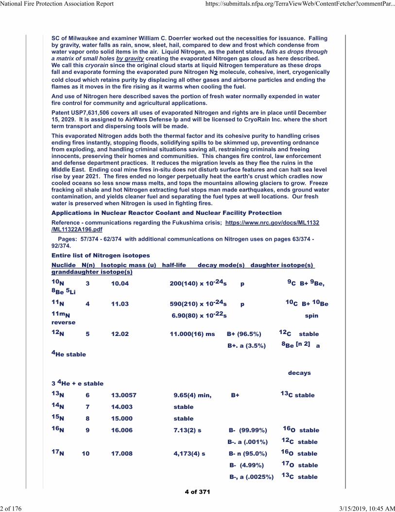
Entire list of Nitrogen isotopesNuclide N(n) Isotopic mass (u) half-life decay mode(s) daughter isotope(s) granddaughter isotope(s)10N 3 10.04 200(140) x 10-24s p 9C B+ 9Be,8Be 5Li11N 4 11.03 590(210) x 10-24s p 10C B+ 10Be11mN 6.90(80) x 10-22s spinreverse12N 5 12.02 11.000(16) ms B+ (96.5%) 12C stable
B+. a (3.5%) 8Be [n 2] a4He stable decays
3 4He + e stable13N 6 13.0057 9.65(4) min, B+ 13C stable14N 7 14.003 stable 15N 8 15.000 stable16N 9 16.006 7.13(2) s B- (99.99%) 16O stable
B-. a (.001%) 12C stable17N 10 17.008 4,173(4) s B- n (95.0%) 16O stable
B- (4.99%) 17O stable
B-, a (.0025%) 13C stable
National Fire Protection Association Report https://submittals.nfpa.org/TerraViewWeb/ContentFetcher?commentPar...
2 of 176 3/15/2019, 10:45 AM
4 of 371
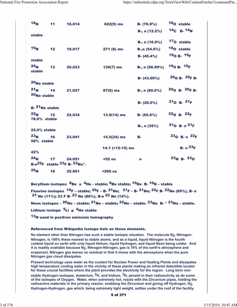
18N 11 18.014 622(9) ms B- (76.9%) 18O stable
B-, a (12.2%) 14C B- 14N stable
B-, n (10.9%) 17O stable19N 12 19.017 271 (8) ms B-,n (54.6%) 18O stable
B- (45.4%) 19O B- 19Fstable20N 13 20.023 130(7) ms B-, n (56.99%) 19O B- 19Fstable
B- (43.00%) 20O B- 20F B-20Ne stable21N 14 21.027 87(6) ms B-, n (80.0%) 20O B- 20F B-20Ne stable
B- (20.0%) 21O B- 21F B- 21Ne stable22N 15 22.034 13.9(14) ms B- (65.0%) 22O B- 22F 78.0% stable
B-, n (35%) 21O B- n 21F22.0% stable23N 16 23.041 14.5(24) ms B- 23O B- n 22F58% stable
14.1 (+12-15) ms B- n 23F 42% 24N 17 24.051 <52 ns n 23N B- 23OB-n22F stable 23F B- 23Na*.25N 18 25.061 <260 ns
Beryllium isotopes 8Be a 4He - stable; 9Be stable; 10Be B- 10B – stable
Fluorine isotopes 19F – stable; 20F – B- 21Ne; 21F – B- 21Ne; 22F B- 22Ne (89%), B- n 21 Ne (11%); 23 F B- 23 Ne (86%), B-n 22 Ne (14%).
Neon isotopes – 20Ne – stable; 21Ne – stable; 22Ne – stable. 23Ne B- * 23Na – stable.
Lithium isotope 5Li p 4He stable13N used in positron emission tomography Referenced from Wikipedia Isotope lists on these elements.No element other than Nitrogen has such a stable isotopic situation. The molecule N2, Nitrogen-Nitrogen, is 100% these nearest to stable atoms, and as a liquid, liquid Nitrogen is the fourthcoldest liquid on earth with only liquid Helium, liquid Hydrogen, and liquid Neon being colder. Andit is readily available because N2, Nitrogen-Nitrogen, gas is 78% of the earth's atmosphere andevaporant, Nitrogen gas leaves no residual in that it mixes with the atmosphere when the pureNitrogen gas cloud dissipates.
Present technology uses water as the coolant for Nuclear Power and Heating Plants and dissipateshigh temperature cooling water in the vicinity of these plants making an infrared detectible locatorfor these crucial facilities where the plant provides the electricity for the region. Long term non-
stable Hydrogen isotopes, dueterium, 2H, and tridium, 3H, persist in their radioactivity as do someof the isotopes of Oxygen. Water, when extremely hot, reacts with the Zirconium pipes, holding theradioactive materials in the primary reactor, oxidizing the Zirconium and giving off Hydrogen, H2,Hydrogen-Hydrogen, gas which, being extremely light weight, settles under the roof of the facility.
National Fire Protection Association Report https://submittals.nfpa.org/TerraViewWeb/ContentFetcher?commentPar...
3 of 176 3/15/2019, 10:45 AM
5 of 371
Hydrogen, being extremely reactive with Oxygen present, causes the explosion blowing the roof offhe facility, an event termed melt-down. This term masks the significance of the event which endedthe use of Hydrogen gas in dirigibles with the 1937 burning in the Hindenburg where the air shipexploded and burned low in the skies over New Jersey. It also is blamed for the serious damage inthe nuclear accidents in Chernobyl and Fukushima which spread radiation over large parts of theplanet Earth.
Changing the cooling material from water to Evaporated Nitrogen Gas from liquid Nitrogen hasmany advantages. A few include:
1. Nitrogen has fewer radioactive isotopes and those which are not stable have half-lives in nano-,micro- and whole
seconds, or at most 13N which has a half-life of 9.65 minutes and is used in positron emissiontomography, a human
medical procedure, where H2O is long term radioactive. Refer here to the above isotope profileof Nitrogen.
2. If you want to cool material, why not start below zero (0oC.)? Liquid Nitrogen evaporates
at -195.8oC. so the
Evaporated Nitrogen Gas cloud starts really cold. Liquid Nitrogen is the fourth coldest liquid onearth.
3. Where water cooling leaves a residual and can dissolve and carry particles, Evaporated Nitrogen Gas leaves no
residual and goes off into the air as a stable molecule of two like atoms of 14N or 15N or aNitrogen that rapidly
disappears as its halflife is so short, it becomes a stable Oxygen, Carbon or Fluorine atom mostoften in decay.
4. Making a still of the cooling wash over the zirconium pipes filled with radioactive material, therecan be a separation of
many useful compounds, some radioactive, and some not, that can be sold to chemicalsuppliers.
5. Residual Nitrogen molecules, Nitrogen-Nitrogen, can be liquefied into liquid Nitrogen andrecycled or allowed be be
released into the air. Water is a marker for nuclear plants and with an infrared camera, they canbe located very easily
were an air attack planned. The hot ring of cooling water around the power plants just givesthem away. Converting to
Nitrogen there would be no hot ring of water. The Nuclear Plant south of Holland Michigan onthe eastern shore of
Lake Michigan gas allowed a delightful early spring swim for me and my pups while travelingBoston to Milwaukee.
6. This conversion can be done by inserting a small part on the massive, aging plants ormake newer plants smaller to
serve localities rather than putting power on a nation-wide grid.
7. Power losses in transport through the grid are massive. One could coat the wiresenabling a ventilating coolant,
Evaporated Nitrogen Gas, and possibly get superfluidity in the wires greatly reducing powerlosses.
8. Replacing water sprinkler systems in the nuclear facilities with Fixed Nitrogen Fire Controlprevents the damage water
causes to the electrical and electronics needed in controlling the functions of the nuclear facilitysince the cold Nitrogen
gas does not conduct electricity nor react with any chemical nor dissolve materials nor leave aresidual to contaminate
and change the function of these tools nor destroy paper and other information containing orfunction driving
materials.
National Fire Protection Association Report https://submittals.nfpa.org/TerraViewWeb/ContentFetcher?commentPar...
4 of 176 3/15/2019, 10:45 AM
6 of 371
Gas excerpt from Nitrogen coverage in Wikipedia Nitrogen edited August 18, 2018 -proposed additionsThe applications of Nitrogen compounds are naturally extremely widely varied due to the huge sizeof this class: hence, only applications of pure Nitrogen itself will be considered here. Two-thirds ofNitrogen produced by industry is sold as the gas and the remaining one-third as the liquid. The gasis mostly used as an inert atmosphere whenever the Oxygen in the air would pose a fire, explosion,
or oxidizing hazard. Some examples include:[67]
ꞏ As a modified atmosphere, pure or mixed with Carbon dioxide, to nitrogenate and preservethe freshness of packaged or bulk foods (by delaying rancidity and other forms of oxidativedamage). Pure Nitrogen as food additive is labeled in the European Union with the E
number E941.[70]
ꞏ In incandescent light bulbs as an inexpensive alternative to Argon.[71]
ꞏ In fire suppression systems for Information technology (IT) equipment.[67]
ꞏ In the manufacture of stainless steel.[72]
ꞏ In the case-hardening of steel by nitriding.[73]
ꞏ In some aircraft fuel systems to reduce fire hazard (see inerting system).[74]
ꞏ To inflate race car and aircraft tires,[75] reducing the problems caused by moisture and
Oxygen in natural air.[67]
Nitrogen is commonly used during sample preparation in chemical analysis. It is used toconcentrate and reduce the volume of liquid samples. Directing a pressurized stream of Nitrogengas perpendicular to the surface of the liquid causes the solvent to evaporate while leaving the
solute(s) and un-evaporated solvent behind.[76]
Nitrogen can be used as a replacement, or in combination with, Carbon dioxide to pressurize kegsof some beers, particularly stouts and British ales, due to the smaller bubbles it produces, which
makes the dispensed beer smoother and headier.[77] A pressure-sensitive Nitrogen capsule knowncommonly as a "widget" allows Nitrogen-charged beers to be packaged in cans and bottles.[78][79] Nitrogen tanks are also replacing Carbon dioxide as the main power source for paintballguns. Nitrogen must be kept at higher pressure than CO2, making N2 tanks heavier and more
expensive.[80]Nitrogen gas has become the inert gas of choice for inert gas asphyxiation, and is
under consideration as a replacement for lethal injection in Oklahoma.[81][82] Nitrogen gas, formedfrom the decomposition of Sodium azide, is used for the inflation of airbags.
TEXT CHANGES I SUBMITTED LAST WEEK – 9/6/18 - to Wikipedia for addition to their just updatedNitrogen publication.
Introduction could include what control the inert N2 molecule has on atmospheric content:
I find, since it is 78% of the earth’s sea level atmosphere, it must police the Oxygen content. And, italso supports the water cycle distributing fresh water throughout the earth as rain, dew, snow,sleet, frost, and more depending on temperature and pressure. This gives the atmosphere power toallow lift if one does a molecular study as I have put together in Molecular Air Chemistry a bookletto be published.
In my years of thinking what liquid Nitrogen might do besides cool vacuum systems for tightervacuum and, when thrown on a lab floor, carry the dust, shavings, and scraps to the end of the flowof the balls of liquid Nitrogen putting the mess at the wall junction or under cabinets out of sight ofguests which I experienced in 1959, I offered:
In 1991 my offering flooding a moat around Kuwait oil fires and lining it with black plastic so liquidNitrogen could be poured in. The heat of the sun and the fire burning above would evaporate theliquid Nitrogen quickly and the resulting Nitrogen gas rise enveloping the fire would end the burnand cool the wellhead. The Romanain Canon was the choice for this oil well fire control, floodingthe well sites with sea water - salt water contaminating the ground around the wells.
Then, early 2003, I discovered that putting liquid Nitrogen through a container with a perforatedbottom so the liquid Nitrogen would fall like rain, powered by gravity, formed a cohesive, inert,cryogenically cold to start, pure N2 Nitrogen gas cloud. This is different from compressed Nitrogengas which when pressured is pushed into the atmosphere diluting the Oxygen content. Thiscohesive cloud (having the same molecule to molecule attraction as the liquid which flows likeMercury) displaces everything but N2 Nitrogen molecules. This displacement removes Oxygenfrom the transparent cloud of Nitrogen gas which ends flames as if one has switched off the light
National Fire Protection Association Report https://submittals.nfpa.org/TerraViewWeb/ContentFetcher?commentPar...
5 of 176 3/15/2019, 10:45 AM
7 of 371
switch. And it cools the fuel reducing re-ignition.
The US Federal Agencies refuse to test this instant fire control, among them the US Forest Service,National Institute of Standards and Technology, and ignored by the Department of Defense -perhaps because the discoverer is a woman. My first request for testing was to George Jackson,Director of the Missoula MT USFS test site in my letter of July, 2003. From 2004 through 2017 theUnited States spent $22trillion on wildfire suppression alone. Had they tested this cohesiveNitrogen cloud, I'll wager the cost to the government would have been under $11trillion since pureNitrogen gas should end these fires swiftly and cleanly with small clouds moving through the fireending the flames and cooling the fuel. Ag Secretary Sonny Perdue keeps having the US ForestService women administrators write me. They use the same stupid reasons stated in 2003 for nottesting this technology or providing me $15,000 to do the test on currently burning fires. What aloss to this nation and the world this has been! Other countries cannot use it because it is not inpractice in the United States according to the Commerce Nation's desks.
An August 18, 2003 letter went to Darryl Alverson, Iraq Purchasing Agent for the US Army Corps ofEngineers, telling him that my Nitrogen method would end the Iraq Oil Pipeline fires in one day. Ontelevision nightly, it showed the US contractor ending these fires in ten days each. Two women gotthe letter and in November 2003 demanded that these fires which were taking ten days each tocontrol be ended in one day starting January 1, 2004, since my Nitrogen means would do that. Thecontractor for the $7billion Iraq Oil Contract complied with the demand. Then, by June, 2004 theterrorists that were lighting the fires stopped doing so because only $75million per fire rather thanthe earlier 2003 $750million per fire loss of Iraq's oil resources was below their risk level. The firstmove reduced oil fire control costs by 90% and the terrorists' move, and the terrorists' decisionreduced it further to 100%.
In November 2004 the Federal Bureau of Investigation discovered who the contractor was and putout a press release including remarks from officers of the Halliburton Corporation stating sadly thatthey were only able to bill the US Government $2.6billion of the $7billion Iraq Oil Contract, whichthey thought they would be collecting had not the limit be put upon them January 1, 2004 to end thefires in one day.
The loss to their bottom line, the $4.4billion loss, was blamed on me and brought revenge. Theykept me from freezing levees around New Orleans in 2005 and after Katrina, Halliburton received the$2.4billion contract to rebuild the levees around New Orleans using the same drawings as wereused in building the levees that failed. I offered them my piping of the levees to freeze a 4' widecore in the levee from sea floor to levee top and shore to shore, freezing it when the threat of amajor hurricane was made, and I was turned down.
I offered to freeze the crude on the Gulf of Mexico from the BP Oil Spill, and collect it in a conveyorahead of catamaran fishing boats to store and melt in barrels and sell to area refineries to cover thecosts of the cleanup, but the word given to proposal evaluators for BP and later the US Coast Guardwas "Freezing is not feasible." And now we have 500 square miles of dead space in the Gulf ofMexico floor where after they were burning square miles of crude on the surface, they sunk the restwith detergent killing the life at the bottom of the sea.
This is all politics. What is wrong with their science must come through somehow. As a woman, Iam not believed.
I have a few videos. One, the Oil Fire video shows instant flame control - 17 second video with 7seconds applying N2 and ending flames. A second, the home simulation, uses a clear plasticcovered 8' cube on the grass with a barbecue grill pan with a long burning log fire inside. Theceiling cover has an "X" serving as a chimney. The fire is burning inside the space filling it withsmoke. An LN-4 dewar with liquid Nitrogen and a 12" diameter cake pan, with 1/4" holes 1" centerto center, are brought into the space and liquid Nitrogen poured into the perforated pan causing theliquid Nitrogen to fall as drops (cryorain) evaporating into a transparent cloud of Nitrogen gasresting on the grass floor of the space. The flames go out and cool cloud warms as it cools thefuel, but the internal heat of the logs starts the flames after some 30 - 45 seconds. A secondinfusion of cryorain at the opening again ends the flames and causes water vapor at the grasslevel. This water vapor is pushed out the top of the transparent cloud making it again transparent -you can see the grass on the other side of the enclosed space clearly. Two more infusions ofcryorain are done well spaced after the flames return to the log, with the fourth application gettingthe log cooled sufficiently that it does no longer flare up in a flame so the fire is out and the smallamount, probably ½ gallon, of Nitrogen filling 1/3 the space of the 8' cube remains transparent. Athird is ending the long burning log fire in the open air which takes several doses of EvaporatedNitrogen Gas to end re-ignition.
Were there a way to share these video segments, I will do it.
Compressed Nitrogen gas reduces the Oxygen level which will most likely cause more Carbonmonoxide production than using this pure Nitrogen gas from cryorain with liquid Nitrogen as thesource and the perforated dispersion tool producing this cohesive cloud that is transparent in a
National Fire Protection Association Report https://submittals.nfpa.org/TerraViewWeb/ContentFetcher?commentPar...
6 of 176 3/15/2019, 10:45 AM
8 of 371
smoke atmosphere. This uniqueness is covered in my US Patent USP 7,631,506 and my textbookand information marketing text, print ready, Nitrogen Pure and Powerful. It covers fire controluses and the 150 or so other uses of this unique Nitrogen form.
Most recently Mike Richmond of the Office of Surface Mines Reclamation and Enforcement(OSMRE) has recognized liquid Nitrogen as a means to end coal mine fire. He states this in the lastsentence in this web space on Coal Mine Fires. He said it is based on my proposed coal mine firecontrol where we pulse the liquid Nitrogen drop through a drilling size perforated pan so theEvaporated Nitrogen Cloud grows pushing its way through the crevices in the soil and rock endingthe burning and the coldness cools the coal taking away all but fuel in what is needed for a fire toburn.
Fire = Oxygen, Heat, and Fuel. Nitrogen gas here takes away Oxygen as it remains pure, and Heatas it is very cold. The remaining Fuel can be coal, oil, food cooking, your home and furnishings,many precious items, the art and artifacts in the Brazil Museum taking our history proofs from theworld.
If we end the US Coal Mine Fires and see the effect on the NOAA data on air, water and soiltemperatures, we can judge how many coal mine fires elsewhere in the world we need to end inorder to halt sea level rise by 2021. The perpetual burning coal mine fires heat the earth's crustwhich is thermally transmitting and covers mountain tops and the ocean floor cradling the heatingwaters. If the crust cools, so do the ocean waters and cooling the ocean waters will halt sea levelrise because the glaciers at the poles and throughout Greenland stop melting. The permafrostareas of Siberia, Norway, Greenland, Canada and Alaska, if they melt further will release diseaseorganisms preserved in the frozen state causing diseases long controlled to flare up throughout theworld. Ending these fires will prevent that event as well as destruction of ocean shore lines andislands as predicted.
Later in the Nitrogen presentation and included in the Molecular Air Chemistry booklet is the factthat Titan, the largest moon of Saturn also has a Nitrogen atmosphere and a proliferation ofMethane as does Triton, the Neptunian moon going the wrong way against the rotation direction ofNeptune. Like the earth's atmosphere of Nitrogen and Oxygen where the 21% level is maintained,there must be an optimum for Methane dilution which would prevent Natural Gas explosions. Inhandling pipe breakages and coal mine collections of Methane which cause powerful explosions, ifthis cohesive Nitrogen cloud would be piped into the digging, perhaps the explosiveness of theleaking Methane can be modified by the pure Nitrogen mixing with the pure Methane preventing thehuge damage these leakages have done in the past.
I have not been able to find a curious team of youngsters to do the experiment needed to know ifone can fly in the cohesive Evaporated Nitrogen gas cloud. I suggest a clear plastic cube withlaunch entrances for a bird, a butterfly and a bat. Releasing them in the 100% Nitrogen cloud, theywill attempt to fly. Will they be successful? If not, my flyable construction of atmospheric gas withthe wrapped Oxygen molecules and the interrupting water vapor since higher humidity makes formushier air when flying a light aircraft, is correct. If it is a flight supporting medium, I'll have tothink up a new model for its percentage of Oxygen preservation.
These points should be made available to the selected editor of the Nitrogen article. He or she hasedited in many new uses including the Oklahoma death penalty means of carrying out the deed. Itshould be noted that organs can be harvested for transplant from the bodies of those succumbedto Nitrogen coma because, though the breathing stops, the heart continues to beat carrying theremaining Oxygen in the blood to be passed to vital organs. The brain sleeps as the diaphragmstops so the maximum amount of oxygen is carried by the blood to preserve the function of theseorgans, heart and all. With other means of killing these individuals, the poison prevents the transferof vital, live organs to those needing them to preserve their lives.
This is all covered in the Nitrogen Pure and Powerful text which can be made available to you.
Respectfully submitted,
Denyse Claire DuBrucq EdD
Inventor: USP 7,631,506 with rights thru Dec. 14, 2029
Author: Nitrogen Pure and Powerful and Molecular Air Chemistry
Chief Trainer and Managing General Partner
AirWars Defense LP
2300 Eden Lane 937 253-2300
Dayton Ohio 45431-1909 USA [email protected]
Additional Proposed Changes
National Fire Protection Association Report https://submittals.nfpa.org/TerraViewWeb/ContentFetcher?commentPar...
7 of 176 3/15/2019, 10:45 AM
9 of 371
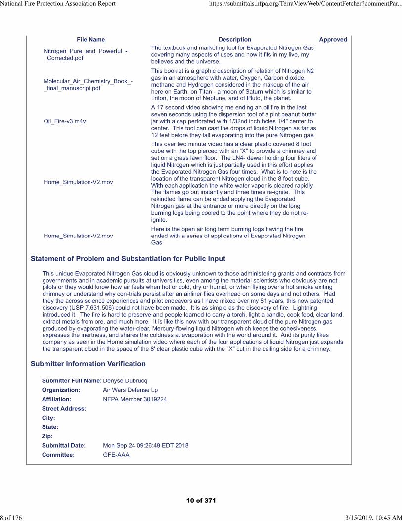
File Name Description Approved
Nitrogen_Pure_and_Powerful_-_Corrected.pdf
The textbook and marketing tool for Evaporated Nitrogen Gas covering many aspects of uses and how it fits in my live, my believes and the universe.
Molecular_Air_Chemistry_Book_-_final_manuscript.pdf
This booklet is a graphic description of relation of Nitrogen N2 gas in an atmosphere with water, Oxygen, Carbon dioxide, methane and Hydrogen considered in the makeup of the air here on Earth, on Titan - a moon of Saturn which is similar to Triton, the moon of Neptune, and of Pluto, the planet.
Oil_Fire-v3.m4v
A 17 second video showing me ending an oil fire in the last seven seconds using the dispersion tool of a pint peanut butter jar with a cap perforated with 1/32nd inch holes 1/4" center to center. This tool can cast the drops of liquid Nitrogen as far as 12 feet before they fall evaporating into the pure Nitrogen gas.
Home_Simulation-V2.mov
This over two minute video has a clear plastic covered 8 foot cube with the top pierced with an "X" to provide a chimney and set on a grass lawn floor. The LN4- dewar holding four liters of liquid Nitrogen which is just partially used in this effort applies the Evaporated Nitrogen Gas four times. What is to note is the location of the transparent Nitrogen cloud in the 8 foot cube. With each application the white water vapor is cleared rapidly. The flames go out instantly and three times re-ignite. This rekindled flame can be ended applying the Evaporated Nitrogen gas at the entrance or more directly on the long burning logs being cooled to the point where they do not re-ignite.
Home_Simulation-V2.movHere is the open air long term burning logs having the fire ended with a series of applications of Evaporated Nitrogen Gas.
Statement of Problem and Substantiation for Public Input
This unique Evaporated Nitrogen Gas cloud is obviously unknown to those administering grants and contracts from governments and in academic pursuits at universities, even among the material scientists who obviously are not pilots or they would know how air feels when hot or cold, dry or humid, or when flying over a hot smoke exiting chimney or understand why con-trials persist after an airliner flies overhead on some days and not others. Had they the across science experiences and pilot endeavors as I have mixed over my 81 years, this now patented discovery (USP 7,631,506) could not have been made. It is as simple as the discovery of fire. Lightning introduced it. The fire is hard to preserve and people learned to carry a torch, light a candle, cook food, clear land, extract metals from ore, and much more. It is like this now with our transparent cloud of the pure Nitrogen gas produced by evaporating the water-clear, Mercury-flowing liquid Nitrogen which keeps the cohesiveness, expresses the inertness, and shares the coldness at evaporation with the world around it. And its purity likes company as seen in the Home simulation video where each of the four applications of liquid Nitrogen just expands the transparent cloud in the space of the 8' clear plastic cube with the "X" cut in the ceiling side for a chimney.
Submitter Information Verification
Submitter Full Name: Denyse Dubrucq
Organization: Air Wars Defense Lp
Affiliation: NFPA Member 3019224
Street Address:
City:
State:
Zip:
Submittal Date: Mon Sep 24 09:26:49 EDT 2018
Committee: GFE-AAA
National Fire Protection Association Report https://submittals.nfpa.org/TerraViewWeb/ContentFetcher?commentPar...
8 of 176 3/15/2019, 10:45 AM
10 of 371
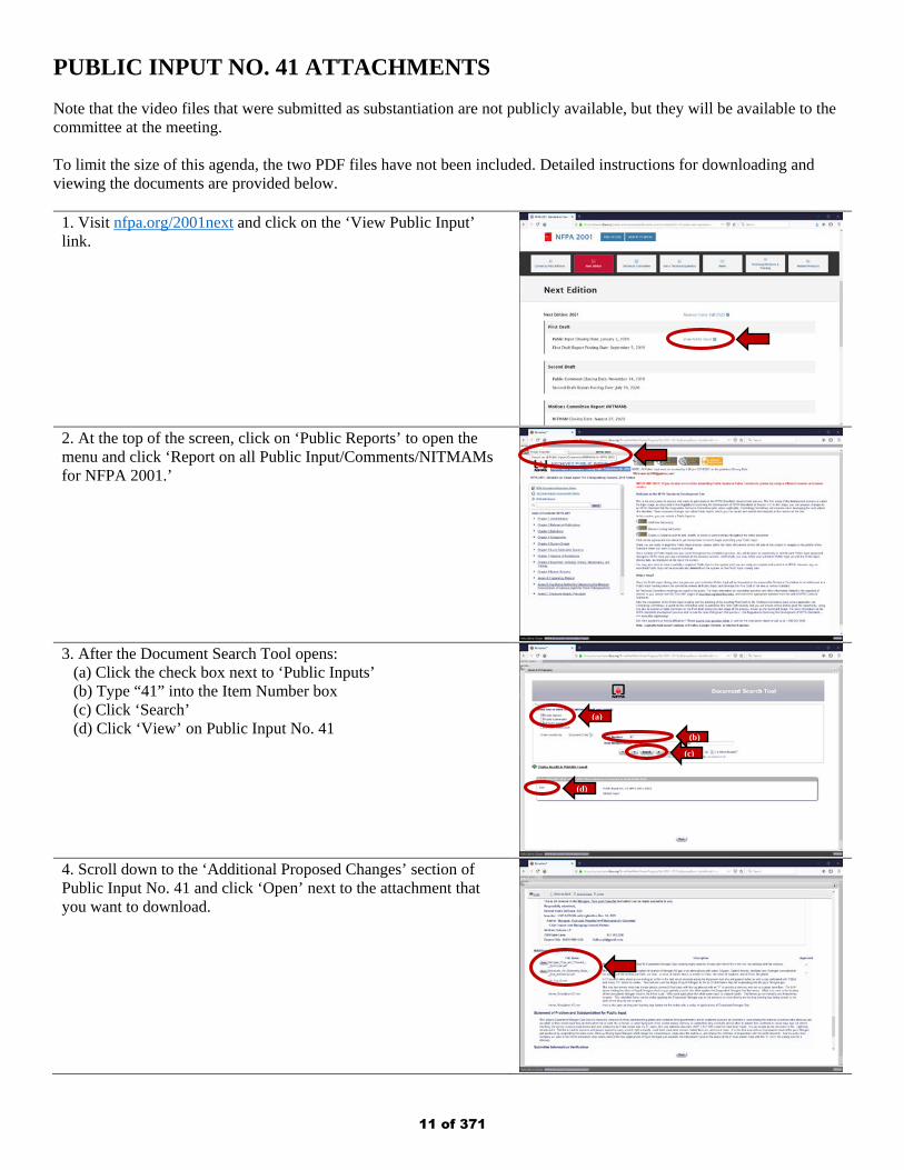
PUBLIC INPUT NO. 41 ATTACHMENTS Note that the video files that were submitted as substantiation are not publicly available, but they will be available to the committee at the meeting. To limit the size of this agenda, the two PDF files have not been included. Detailed instructions for downloading and viewing the documents are provided below.
1. Visit nfpa.org/2001next and click on the ‘View Public Input’ link.
2. At the top of the screen, click on ‘Public Reports’ to open the menu and click ‘Report on all Public Input/Comments/NITMAMs for NFPA 2001.’
3. After the Document Search Tool opens:
(a) Click the check box next to ‘Public Inputs’ (b) Type “41” into the Item Number box (c) Click ‘Search’ (d) Click ‘View’ on Public Input No. 41
4. Scroll down to the ‘Additional Proposed Changes’ section of Public Input No. 41 and click ‘Open’ next to the attachment that you want to download.
(a)
(b)
(c)
(d)
11 of 371
Public Input No. 64-NFPA 2001-2018 [ Global Input ]
Type your content here ...Remove “ANSI/” and “Standard for” from all UL publications referenced inthis code.
Statement of Problem and Substantiation for Public Input
Update of references and removal of repetitive wording and removal of ANSI because many years ago, UL preferred the ANSI/UL reference because there was a transition of traditional UL standards towards an ANSI standards development process.
Now, years later, a large majority of UL Standards are ANSI approved and follow the ANSI development and maintenance process. However, sometimes readers are confused because they don't understand the standards are UL standards, not developed by ANSI. There are many other references to standards promulgated by different standards development organizations where they are considered ANSI approved but do not include ANSI in the reference.
Submitter Information Verification
Submitter Full Name: Kelly Nicolello
Organization: UL LLC
Street Address:
City:
State:
Zip:
Submittal Date: Wed Dec 26 15:10:11 EST 2018
Committee: GFE-AAA
National Fire Protection Association Report https://submittals.nfpa.org/TerraViewWeb/ContentFetcher?commentPar...
9 of 176 3/15/2019, 10:45 AM
12 of 371
Public Input No. 69-NFPA 2001-2018 [ Section No. 1.4 ]
1.4 * General Information.
Add Annex Material:
The Fire Suppression Systems Association (FSSA) has published a "Guide to Clean FireExtingushing Agents and Their Use in Fixed Systems" which offers a user-friendly presentation ofthe essential properties of the agents.
1.4.1* Applicability of Agents.
1.4.1.1
The fire extinguishing agents addressed in this standard shall be electrically nonconducting and leave noresidue upon evaporation.
National Fire Protection Association Report https://submittals.nfpa.org/TerraViewWeb/ContentFetcher?commentPar...
10 of 176 3/15/2019, 10:45 AM
13 of 371
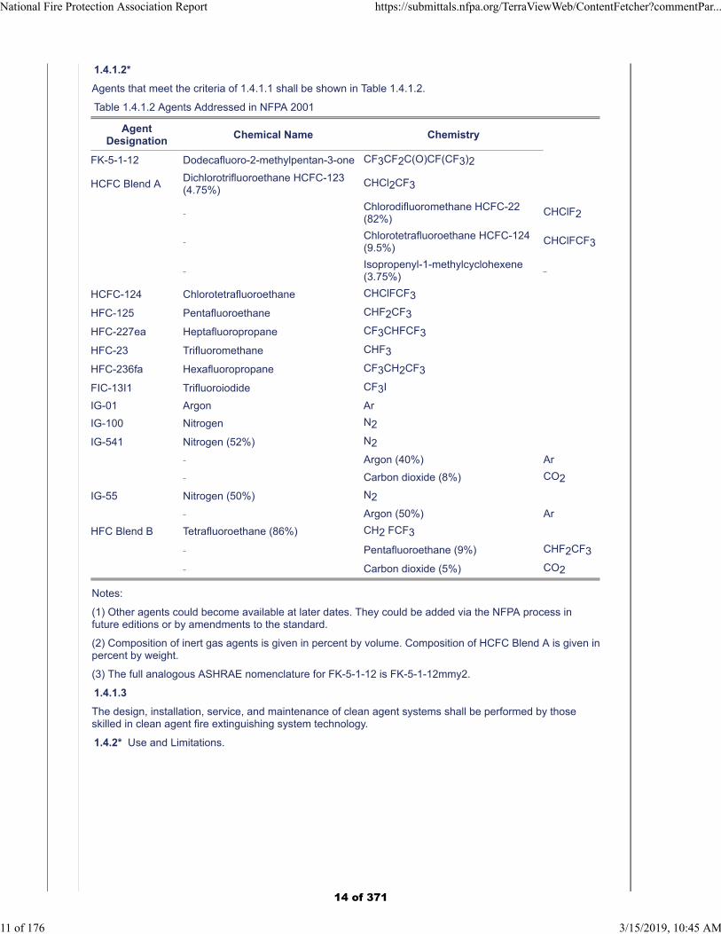
1.4.1.2*
Agents that meet the criteria of 1.4.1.1 shall be shown in Table 1.4.1.2.
Table 1.4.1.2 Agents Addressed in NFPA 2001
AgentDesignation
Chemical Name Chemistry
FK-5-1-12 Dodecafluoro-2-methylpentan-3-one CF3CF2C(O)CF(CF3)2
HCFC Blend ADichlorotrifluoroethane HCFC-123(4.75%)
CHCl2CF3
Chlorodifluoromethane HCFC-22(82%)
CHClF2
Chlorotetrafluoroethane HCFC-124(9.5%)
CHClFCF3
Isopropenyl-1-methylcyclohexene(3.75%)
HCFC-124 Chlorotetrafluoroethane CHClFCF3
HFC-125 Pentafluoroethane CHF2CF3
HFC-227ea Heptafluoropropane CF3CHFCF3
HFC-23 Trifluoromethane CHF3
HFC-236fa Hexafluoropropane CF3CH2CF3
FIC-13I1 Trifluoroiodide CF3I
IG-01 Argon Ar
IG-100 Nitrogen N2
IG-541 Nitrogen (52%) N2
Argon (40%) Ar
Carbon dioxide (8%) CO2
IG-55 Nitrogen (50%) N2
Argon (50%) Ar
HFC Blend B Tetrafluoroethane (86%) CH2 FCF3
Pentafluoroethane (9%) CHF2CF3
Carbon dioxide (5%) CO2
Notes:
(1) Other agents could become available at later dates. They could be added via the NFPA process infuture editions or by amendments to the standard.
(2) Composition of inert gas agents is given in percent by volume. Composition of HCFC Blend A is given inpercent by weight.
(3) The full analogous ASHRAE nomenclature for FK-5-1-12 is FK-5-1-12mmy2.
1.4.1.3
The design, installation, service, and maintenance of clean agent systems shall be performed by thoseskilled in clean agent fire extinguishing system technology.
1.4.2* Use and Limitations.
National Fire Protection Association Report https://submittals.nfpa.org/TerraViewWeb/ContentFetcher?commentPar...
11 of 176 3/15/2019, 10:45 AM
14 of 371
1.4.2.1
All pre-engineered systems shall be installed to protect hazards within the limitations that have beenestablished by the listing. Pre-engineered systems shall be listed to one of the following types:
(1) Those consisting of system components designed to be installed according to pre-tested limitations bya testing laboratory. These pre-engineered systems shall be permitted to incorporate special nozzles,flow rates, methods of application, nozzle placement, and pressurization levels that could differ fromthose detailed elsewhere in this standard. All other requirements of the standard shall apply.
(2) Automatic extinguishing units incorporating special nozzles, flow rates, methods of application, nozzleplacement, actuation techniques, piping materials, discharge times, mounting techniques, andpressurization levels that could differ from those detailed elsewhere in this standard.
1.4.2.2
Clean agents shall not be used on fires involving the following materials unless the agents have beentested to the satisfaction of the authority having jurisdiction:
(1) Certain chemicals or mixtures of chemicals, such as cellulose nitrate and gunpowder, which arecapable of rapid oxidation in the absence of air
(2) Reactive metals such as lithium, sodium, potassium, magnesium, titanium, zirconium, uranium, andplutonium
(3) Metal hydrides
(4) Chemicals capable of undergoing autothermal decomposition, such as certain organic peroxides,pyrophoric materials, and hydrazine
1.4.2.3*
Where a total flooding system is used, a fixed enclosure shall be provided about the hazard that allows aspecified agent concentration to be achieved and maintained for a specified period of time.
1.4.2.4*
The effects of agent decomposition on fire protection effectiveness and equipment shall be consideredwhere clean agents are used in hazards with high ambient temperatures (e.g., furnaces and ovens).
Additional Proposed Changes
File Name Description Approved
Clean_Fire_Extinguishing_Agents_in_Fixed_Systems_-_for_NFPA_TC_Jan_2019.pdf
FSSA "Guide to Clean Fire Extinguishing Agents & Their Use in Fixed Systems" for Annex material to Chapter 1.4 and to be added to the Annex E Informational References, E.1.2.8 FSSA Publications.
Statement of Problem and Substantiation for Public Input
The FSSA guide serves to compliment the the NFPA 2001 Standard and is intended to assist the designer and end user to better understand the concepts of the Clean Agents.
Submitter Information Verification
Submitter Full Name: John Spalding
Organization: Healey Fire Protection, Inc.
Affiliation: Fire Suppression Systems Association
Street Address:
City:
State:
Zip:
Submittal Date: Mon Dec 31 12:38:33 EST 2018
Committee: GFE-AAA
National Fire Protection Association Report https://submittals.nfpa.org/TerraViewWeb/ContentFetcher?commentPar...
12 of 176 3/15/2019, 10:45 AM
15 of 371
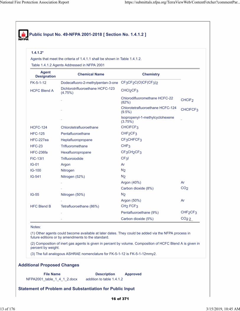
Public Input No. 49-NFPA 2001-2018 [ Section No. 1.4.1.2 ]
1.4.1.2*
Agents that meet the criteria of 1.4.1.1 shall be shown in Table 1.4.1.2.
Table 1.4.1.2 Agents Addressed in NFPA 2001
AgentDesignation
Chemical Name Chemistry
FK-5-1-12 Dodecafluoro-2-methylpentan-3-one CF3CF2C(O)CF(CF3)2
HCFC Blend ADichlorotrifluoroethane HCFC-123(4.75%)
CHCl2CF3
Chlorodifluoromethane HCFC-22(82%)
CHClF2
Chlorotetrafluoroethane HCFC-124(9.5%)
CHClFCF3
Isopropenyl-1-methylcyclohexene(3.75%)
HCFC-124 Chlorotetrafluoroethane CHClFCF3
HFC-125 Pentafluoroethane CHF2CF3
HFC-227ea Heptafluoropropane CF3CHFCF3
HFC-23 Trifluoromethane CHF3
HFC-236fa Hexafluoropropane CF3CH2CF3
FIC-13I1 Trifluoroiodide CF3I
IG-01 Argon Ar
IG-100 Nitrogen N2
IG-541 Nitrogen (52%) N2
Argon (40%) Ar
Carbon dioxide (8%) CO2
IG-55 Nitrogen (50%) N2
Argon (50%) Ar
HFC Blend B Tetrafluoroethane (86%) CH2 FCF3
Pentafluoroethane (9%) CHF2CF3
Carbon dioxide (5%) CO2 2
Notes:
(1) Other agents could become available at later dates. They could be added via the NFPA process infuture editions or by amendments to the standard.
(2) Composition of inert gas agents is given in percent by volume. Composition of HCFC Blend A is given inpercent by weight.
(3) The full analogous ASHRAE nomenclature for FK-5-1-12 is FK-5-1-12mmy2.
Additional Proposed Changes
File Name Description Approved
NFPA2001_table_1_4_1_2.docx addition to table 1.4.1.2
Statement of Problem and Substantiation for Public Input
National Fire Protection Association Report https://submittals.nfpa.org/TerraViewWeb/ContentFetcher?commentPar...
13 of 176 3/15/2019, 10:45 AM
16 of 371
Addition of new fire suppression agent.
Submitter Information Verification
Submitter Full Name: Robert Richard
Organization: Honeywell, Inc.
Street Address:
City:
State:
Zip:
Submittal Date: Tue Dec 18 11:56:27 EST 2018
Committee: GFE-AAA
National Fire Protection Association Report https://submittals.nfpa.org/TerraViewWeb/ContentFetcher?commentPar...
14 of 176 3/15/2019, 10:45 AM
17 of 371
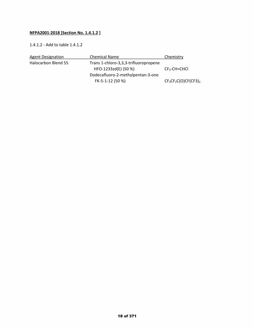
NFPA2001-2018 [Section No. 1.4.1.2 ] 1.4.1.2 - Add to table 1.4.1.2 Agent Designation Chemical Name Chemistry Halocarbon Blend 55 Trans 1-chloro-3,3,3-trifluoropropene
HFO-1233zd(E) (50 %) CF3-CH=CHCl Dodecafluoro-2-methylpentan-3-one
FK-5-1-12 (50 %) CF3CF2C(O)CF(CF3)2
18 of 371
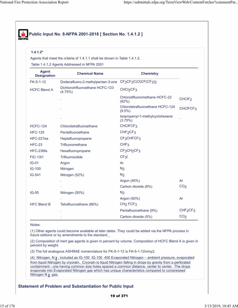
Public Input No. 8-NFPA 2001-2018 [ Section No. 1.4.1.2 ]
1.4.1.2*
Agents that meet the criteria of 1.4.1.1 shall be shown in Table 1.4.1.2.
Table 1.4.1.2 Agents Addressed in NFPA 2001
AgentDesignation
Chemical Name Chemistry
FK-5-1-12 Dodecafluoro-2-methylpentan-3-one CF3CF2C(O)CF(CF3)2
HCFC Blend ADichlorotrifluoroethane HCFC-123(4.75%)
CHCl2CF3
Chlorodifluoromethane HCFC-22(82%)
CHClF2
Chlorotetrafluoroethane HCFC-124(9.5%)
CHClFCF3
Isopropenyl-1-methylcyclohexene(3.75%)
HCFC-124 Chlorotetrafluoroethane CHClFCF3
HFC-125 Pentafluoroethane CHF2CF3
HFC-227ea Heptafluoropropane CF3CHFCF3
HFC-23 Trifluoromethane CHF3
HFC-236fa Hexafluoropropane CF3CH2CF3
FIC-13I1 Trifluoroiodide CF3I
IG-01 Argon Ar
IG-100 Nitrogen N2
IG-541 Nitrogen (52%) N2
Argon (40%) Ar
Carbon dioxide (8%) CO2
IG-55 Nitrogen (50%) N2
Argon (50%) Ar
HFC Blend B Tetrafluoroethane (86%) CH2 FCF3
Pentafluoroethane (9%) CHF2CF3
Carbon dioxide (5%) CO2
Notes:
(1) Other agents could become available at later dates. They could be added via the NFPA process infuture editions or by amendments to the standard.
(2) Composition of inert gas agents is given in percent by volume. Composition of HCFC Blend A is given inpercent by weight.
(3) The full analogous ASHRAE nomenclature for FK-5-1-12 is FK-5-1-12mmy2.
(4) Nitrogen, N 2 , included as IG-100 IG-100 400 Evaporated Nitrogen – ambient pressure, evaporatedfrom liquid Nitrogen by cryorain. Cryorain is liquid Nitrogen falling in drops by gravity from a perforatedcontainment - one having common size holes spaced a common distance, center to center. The dropsevaporate into Evaporated Nitrogen gas which has unique characteristics compared to compressedNitrogen N 2 gas.
Statement of Problem and Substantiation for Public Input
National Fire Protection Association Report https://submittals.nfpa.org/TerraViewWeb/ContentFetcher?commentPar...
15 of 176 3/15/2019, 10:45 AM
19 of 371
The IG 100 is the proper category for Nitrogen. The three listed are various pressures of compressed Nitrogen gas. That evaporated from liquid Nitrogen with the liquid Nitrogen as the carrier of the substance to the event or crises differs from the canisters for compressed gases and it will be expanded upon as the changes I have prepared are inserted. I am suggesting Evaporated Nitrogen Gas be IG 100-400.
Submitter Information Verification
Submitter Full Name: Denyse Dubrucq
Organization: Air Wars Defense Lp
Affiliation: NFPA Member 3019224
Street Address:
City:
State:
Zip:
Submittal Date: Fri Aug 31 15:10:09 EDT 2018
Committee: GFE-AAA
National Fire Protection Association Report https://submittals.nfpa.org/TerraViewWeb/ContentFetcher?commentPar...
16 of 176 3/15/2019, 10:45 AM
20 of 371
Public Input No. 42-NFPA 2001-2018 [ New Section after 1.4.2.4 ]
TITLE OF NEW CONTENT
1.4.2.5 Effects of acoustical noise in an occupancy containing noise-sensitive equipment shall beconsidered.
Statement of Problem and Substantiation for Public Input
To bring awareness and some guidance on protecting noise sensitive equipment with clean agent systems.
Related Public Inputs for This Document
Related Input Relationship
Public Input No. 43-NFPA 2001-2018 [New Section after A.1.4.2.4]
Submitter Information Verification
Submitter Full Name: Katherine Adrian
Organization: Johnson Controls
Street Address:
City:
State:
Zip:
Submittal Date: Thu Nov 08 12:01:49 EST 2018
Committee: GFE-AAA
National Fire Protection Association Report https://submittals.nfpa.org/TerraViewWeb/ContentFetcher?commentPar...
17 of 176 3/15/2019, 10:45 AM
21 of 371

Public Input No. 50-NFPA 2001-2018 [ Section No. 1.5.1.2.1 ]
National Fire Protection Association Report https://submittals.nfpa.org/TerraViewWeb/ContentFetcher?commentPar...
18 of 176 3/15/2019, 10:45 AM
22 of 371

1.5.1.2.1*
National Fire Protection Association Report https://submittals.nfpa.org/TerraViewWeb/ContentFetcher?commentPar...
19 of 176 3/15/2019, 10:45 AM
23 of 371
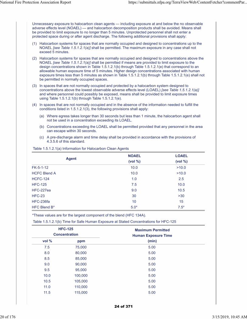
Unnecessary exposure to halocarbon clean agents — including exposure at and below the no observableadverse effects level (NOAEL) — and halocarbon decomposition products shall be avoided. Means shallbe provided to limit exposure to no longer than 5 minutes. Unprotected personnel shall not enter aprotected space during or after agent discharge. The following additional provisions shall apply:
(1) Halocarbon systems for spaces that are normally occupied and designed to concentrations up to theNOAEL [see Table 1.5.1.2.1(a)] shall be permitted. The maximum exposure in any case shall notexceed 5 minutes.
(2) Halocarbon systems for spaces that are normally occupied and designed to concentrations above theNOAEL [see Table 1.5.1.2.1(a)] shall be permitted if means are provided to limit exposure to thedesign concentrations shown in Table 1.5.1.2.1(b) through Table 1.5.1.2.1(e) that correspond to anallowable human exposure time of 5 minutes. Higher design concentrations associated with humanexposure times less than 5 minutes as shown in Table 1.5.1.2.1(b) through Table 1.5.1.2.1(e) shall notbe permitted in normally occupied spaces.
(3) In spaces that are not normally occupied and protected by a halocarbon system designed toconcentrations above the lowest observable adverse effects level (LOAEL) [see Table 1.5.1.2.1(a)]and where personnel could possibly be exposed, means shall be provided to limit exposure timesusing Table 1.5.1.2.1(b) through Table 1.5.1.2.1(e).
(4) In spaces that are not normally occupied and in the absence of the information needed to fulfill theconditions listed in 1.5.1.2.1(3), the following provisions shall apply:
(a) Where egress takes longer than 30 seconds but less than 1 minute, the halocarbon agent shallnot be used in a concentration exceeding its LOAEL.
(b) Concentrations exceeding the LOAEL shall be permitted provided that any personnel in the areacan escape within 30 seconds.
(c) A pre-discharge alarm and time delay shall be provided in accordance with the provisions of4.3.5.6 of this standard.
Table 1.5.1.2.1(a) Information for Halocarbon Clean Agents
AgentNOAEL
(vol %)
LOAEL
(vol %)
FK-5-1-12 10.0 >10.0
HCFC Blend A 10.0 >10.0
HCFC-124 1.0 2.5
HFC-125 7.5 10.0
HFC-227ea 9.0 10.5
HFC-23 30 >30
HFC-236fa 10 15
HFC Blend B* 5.0* 7.5*
*These values are for the largest component of the blend (HFC 134A).
Table 1.5.1.2.1(b) Time for Safe Human Exposure at Stated Concentrations for HFC-125
HFC-125
ConcentrationMaximum Permitted
Human Exposure Time
(min)vol % ppm
7.5 75,000 5.00
8.0 80,000 5.00
8.5 85,000 5.00
9.0 90,000 5.00
9.5 95,000 5.00
10.0 100,000 5.00
10.5 105,000 5.00
11.0 110,000 5.00
11.5 115,000 5.00
National Fire Protection Association Report https://submittals.nfpa.org/TerraViewWeb/ContentFetcher?commentPar...
20 of 176 3/15/2019, 10:45 AM
24 of 371
HFC-125
ConcentrationMaximum Permitted
Human Exposure Time
(min)vol % ppm
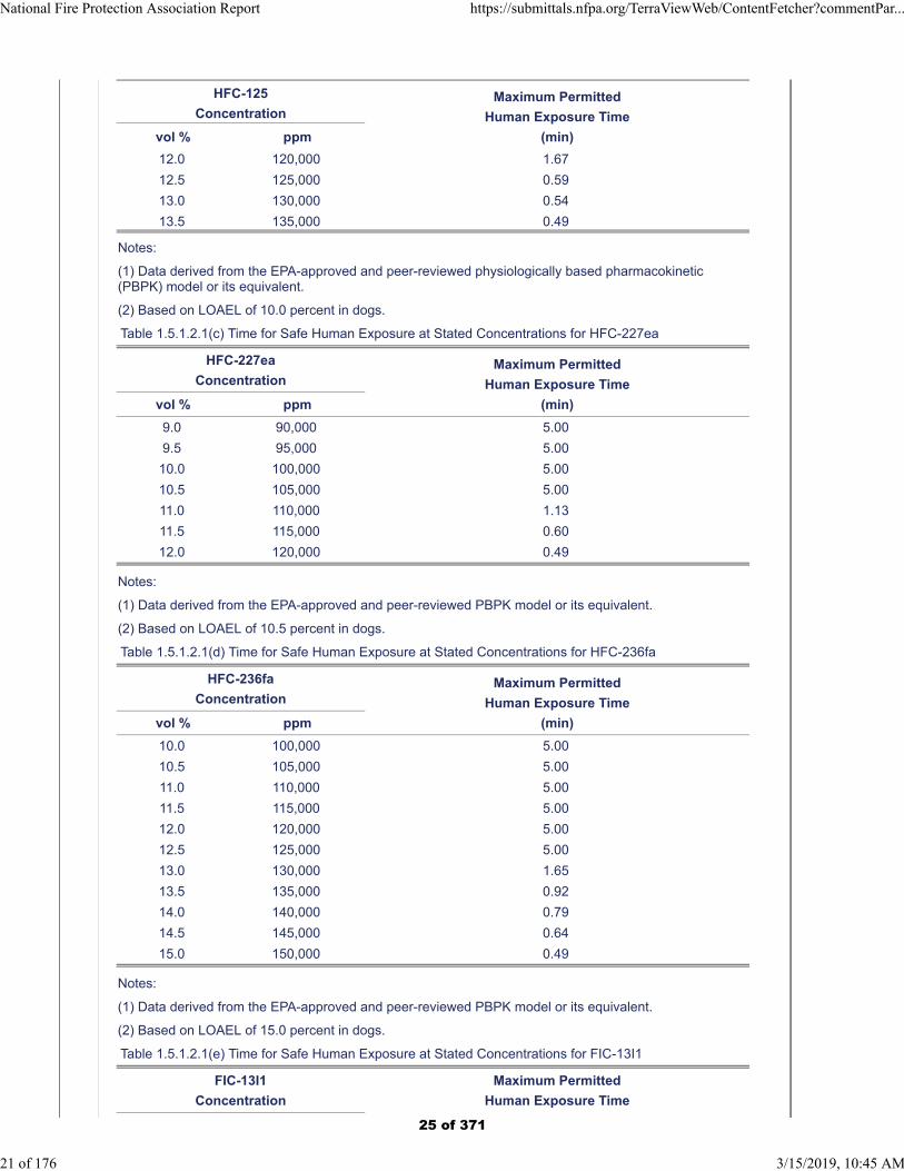
12.0 120,000 1.67
12.5 125,000 0.59
13.0 130,000 0.54
13.5 135,000 0.49
Notes:
(1) Data derived from the EPA-approved and peer-reviewed physiologically based pharmacokinetic(PBPK) model or its equivalent.
(2) Based on LOAEL of 10.0 percent in dogs.
Table 1.5.1.2.1(c) Time for Safe Human Exposure at Stated Concentrations for HFC-227ea
HFC-227ea
ConcentrationMaximum Permitted
Human Exposure Time
(min)vol % ppm
9.0 90,000 5.00
9.5 95,000 5.00
10.0 100,000 5.00
10.5 105,000 5.00
11.0 110,000 1.13
11.5 115,000 0.60
12.0 120,000 0.49
Notes:
(1) Data derived from the EPA-approved and peer-reviewed PBPK model or its equivalent.
(2) Based on LOAEL of 10.5 percent in dogs.
Table 1.5.1.2.1(d) Time for Safe Human Exposure at Stated Concentrations for HFC-236fa
HFC-236fa
ConcentrationMaximum Permitted
Human Exposure Time
(min)vol % ppm
10.0 100,000 5.00
10.5 105,000 5.00
11.0 110,000 5.00
11.5 115,000 5.00
12.0 120,000 5.00
12.5 125,000 5.00
13.0 130,000 1.65
13.5 135,000 0.92
14.0 140,000 0.79
14.5 145,000 0.64
15.0 150,000 0.49
Notes:
(1) Data derived from the EPA-approved and peer-reviewed PBPK model or its equivalent.
(2) Based on LOAEL of 15.0 percent in dogs.
Table 1.5.1.2.1(e) Time for Safe Human Exposure at Stated Concentrations for FIC-13I1
FIC-13I1
Concentration
Maximum Permitted
Human Exposure Time
National Fire Protection Association Report https://submittals.nfpa.org/TerraViewWeb/ContentFetcher?commentPar...
21 of 176 3/15/2019, 10:45 AM
25 of 371
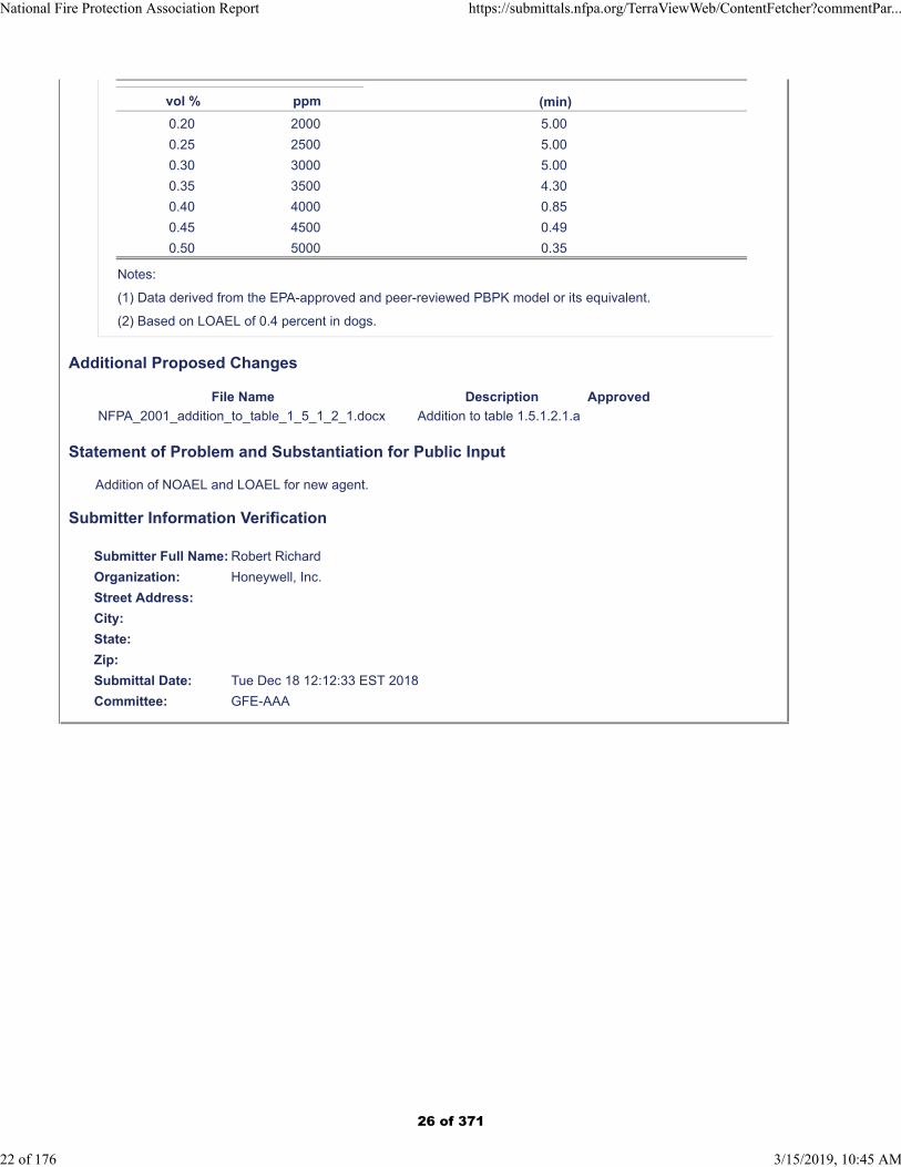
(min)vol % ppm
0.20 2000 5.00
0.25 2500 5.00
0.30 3000 5.00
0.35 3500 4.30
0.40 4000 0.85
0.45 4500 0.49
0.50 5000 0.35
Notes:
(1) Data derived from the EPA-approved and peer-reviewed PBPK model or its equivalent.
(2) Based on LOAEL of 0.4 percent in dogs.
Additional Proposed Changes
File Name Description Approved
NFPA_2001_addition_to_table_1_5_1_2_1.docx Addition to table 1.5.1.2.1.a
Statement of Problem and Substantiation for Public Input
Addition of NOAEL and LOAEL for new agent.
Submitter Information Verification
Submitter Full Name: Robert Richard
Organization: Honeywell, Inc.
Street Address:
City:
State:
Zip:
Submittal Date: Tue Dec 18 12:12:33 EST 2018
Committee: GFE-AAA
National Fire Protection Association Report https://submittals.nfpa.org/TerraViewWeb/ContentFetcher?commentPar...
22 of 176 3/15/2019, 10:45 AM
26 of 371

NFPA 2001-2018 [ Section No. 1.5.1.2.1 ]
1.5.1.2.1 - Add agent to table 1.5.1.2.1(a)
Agent NOAEL LOAEL
Halocarbon Blend 55 10.0 >10.0
27 of 371
Public Input No. 16-NFPA 2001-2018 [ Section No. 1.5.1.3 ]
1.5.1.3* Inert Gas Clean Agents.
Unnecessary exposure to inert gas agent systems resulting in low oxygen atmospheres shall be avoided.The maximum exposure time in any case shall not exceed 5 minutes. See Table 5.5.3.3 for atmosphericcorrection factors that shall be considered when determining the design concentrations. One objective ofpre-discharge alarms and time delays is to prevent human exposure to agents. A pre-discharge alarm andtime delay shall be provided in accordance with the provisions of 4.3.5.6 of this standard. Unprotectedpersonnel shall not enter the area during or after agent discharge. The following additional provisions shallapply:
(1) Inert gas systems designed to concentrations below 43 percent (corresponding to an oxygenconcentration of 12 percent, sea level equivalent of oxygen) shall be permitted where means areprovided to limit exposure to no longer than 5 minutes.
(2) Inert gas systems designed to concentrations between 43 and 52 percent (corresponding to between12 and 10 percent oxygen, sea level equivalent of oxygen) shall be permitted where means areprovided to limit exposure to no longer than 3 minutes.
(3) Inert gas systems designed to concentrations between 52 and 62 percent (corresponding to between10 and 8 percent oxygen, sea level equivalent of oxygen) shall be permitted given the following:
(4) The space is normally unoccupied.
(5) Where personnel could possibly be exposed, means are provided to limit the exposure to lessthan 30 seconds.
(6) Inert gas systems designed to concentrations above 62 percent (corresponding to 8 percent oxygen orbelow, sea level equivalent of oxygen) shall be used only in unoccupied areas where personnel are notexposed to such oxygen depletion.
(7) Inert gas clouds created by evaporating drops of liquid Nitrogen from a dispensing tool falling bygravity produces a transparent, pure, inert, cryogenically cold to start, cohesive cloud of N 2 Nitrogengas. It displaces all but N 2 including Oxygen ending flames and cools the fuel warming as it expandsand rises from the floor or ground level to midway and warming further to inferno temperatures leavesan outdoor fire through the canopy of the woods ending the burning embers so just charcoal chunks flyahead of the fire stopping the advance. Breathing by SCBA or in the smoke-filled section of the spaceallows what Oxygen the fire has not consumed to be inhaled. Cloud expansions at evaporation is 230times liquid volume, at ambient temperatures 250 times and at inferno temperatures 600 to 700 timesliquid volume.
Statement of Problem and Substantiation for Public Input
These edits to 2018 NFPA 2001 enables the inclusion of a fourth Nitrogen entry which both does not conduct electricity and leaves no residual, Evaporated Nitrogen Gas evaporated from liquid Nitrogen stored at ambient pressure in cryogenic tanks or dewars. Passing the liquid Nitrogen through the matrix of constant sized holes, most used, 1/4" (quarter inch) diameter holes, at constant center to center distances, most used 1" (one inch) in a pan or trough. Pouring liquid Nitrogen into there perforated containers allows cryorain, liquid Nitrogen falling in drops by gravity which evaporates into the Evaporated Nitrogen Gas Cloud which is cohesive, inert, cryogenically cold at the start, and pure N2 Nitrogen gas. This transparent cloud displaces Oxygen ending flames instantly and cools the fuel warming and expanding as it reduces re-ignition of the fire. Hundreds of uses are possible.
Submitter Information Verification
Submitter Full Name: Denyse Dubrucq
Organization: Air Wars Defense Lp
Affiliation: NFPA Member 3019224
Street Address:
City:
National Fire Protection Association Report https://submittals.nfpa.org/TerraViewWeb/ContentFetcher?commentPar...
23 of 176 3/15/2019, 10:45 AM
28 of 371

State:
Zip:
Submittal Date: Thu Sep 06 11:49:45 EDT 2018
Committee: GFE-AAA
National Fire Protection Association Report https://submittals.nfpa.org/TerraViewWeb/ContentFetcher?commentPar...
24 of 176 3/15/2019, 10:45 AM
29 of 371
Public Input No. 65-NFPA 2001-2018 [ Section No. 2.3.9 ]
2.3.9 UL Publications.
Underwriters Laboratories Inc., 333 Pfingsten Road, Northbrook, IL 60062-2096.
ANSI/ UL 2127,Standard for Inert Gas Clean Agent Extinguishing System Units, 2012 (revised2015) 2018 .ANSI/
UL 2166,Standard for Halocarbon Clean Agent Extinguishing System Units, 2012 (revised 2015) 2018 .
Statement of Problem and Substantiation for Public Input
Update of references and removal of repetitive wording and removal of ANSI because many years ago, UL preferred the ANSI/UL reference because there was a transition of traditional UL standards towards an ANSI standards development process.
Now, years later, a large majority of UL Standards are ANSI approved and follow the ANSI development and maintenance process. However, sometimes readers are confused because they don't understand the standards are UL standards, not developed by ANSI. There are many other references to standards promulgated by different standards development organizations where they are considered ANSI approved but do not include ANSI in the reference.
Related Public Inputs for This Document
Related Input Relationship
Public Input No. 66-NFPA 2001-2018 [Section No. 2.3.10]
Public Input No. 67-NFPA 2001-2018 [Section No. E.1.2.14]
Submitter Information Verification
Submitter Full Name: Kelly Nicolello
Organization: UL LLC
Street Address:
City:
State:
Zip:
Submittal Date: Wed Dec 26 15:11:23 EST 2018
Committee: GFE-AAA
National Fire Protection Association Report https://submittals.nfpa.org/TerraViewWeb/ContentFetcher?commentPar...
25 of 176 3/15/2019, 10:45 AM
30 of 371
Public Input No. 66-NFPA 2001-2018 [ Section No. 2.3.10 ]
2.3.10 ULC Publications.
Underwriters Laboratories of Canada, 7 Underwriters Road, Toronto, ON M1R 3B4, Canada. ULCStandards, 171 Nepean Street, Suite 400, Ottawa, ON K2P 0B4 Canada
CAN/ULC S524-14,Standard for the Installation of Fire Alarm Systems, 2014.
CAN/ULC S529-16, Smoke Detectors for Fire Alarm Systems, 2016.
Statement of Problem and Substantiation for Public Input
A new address for ULC was provided to reflect the company location change and "Standard for" was removed to come in line with ULC title changes that remove unnecessary or repetitive wording.
Related Public Inputs for This Document
Related Input Relationship
Public Input No. 65-NFPA 2001-2018 [Section No. 2.3.9]
Public Input No. 67-NFPA 2001-2018 [Section No. E.1.2.14]
Submitter Information Verification
Submitter Full Name: Kelly Nicolello
Organization: UL LLC
Street Address:
City:
State:
Zip:
Submittal Date: Wed Dec 26 15:13:04 EST 2018
Committee: GFE-AAA
National Fire Protection Association Report https://submittals.nfpa.org/TerraViewWeb/ContentFetcher?commentPar...
26 of 176 3/15/2019, 10:45 AM
31 of 371
Public Input No. 10-NFPA 2001-2018 [ Section No. 3.3.3 ]
3.3.3 Agent Concentration.
The portion of agent in an agent-air mixture expressed in volume percent.
AMEND: For IG-100 –400 Evaporated Nitrogen gas from liquid Nitrogen, Nitrogen gas is cohesivedisplacing all but N 2 molecules so what might start as a mixture quickly works contaminating moleculesfrom the pure N 2 gas. (See Home Video - return of Evaporated Nitrogen’s cloud to transparency.)
Additional Proposed Changes
File Name Description Approved
Home_Simulation-V2.mov
Statement of Problem and Substantiation for Public Input
See the video where the LN-4 dewar holding four liters of liquid Nitrogen is partially used to end a long burning log fire in the fire container in a 8' x 8' x 8' clear plastic enclosure with the top covered and pierced with an "X" to serve as a chimney. The clear plastic covers five sides of the cube leaving the sixth be the grass of a yard where we did 21 demonstrations using 14 liters of liquid NItrogen over a two hour period. This one shows the transparency of the Evaporated Nitrogen gas created by pouring some liquid Nitrogen into a 12" diameter cake pan with a matrix of holes 1/4" diameter placed 1" apart center to center making it a perforated pan, a dispersion tool for liquid Nitrogen to produce cryorain, the liquid Nitrogen falling in drops by the force of gravity, evaporating into a cohesive, inert, cryogenically cold to start, pure N2 Nitrogen cloud. This pure Nitrogen cloud is transparent and when disturbed, will recover its transparency. Here, with each of four doses of liquid Nitrogen, the coldness condenses water vapor from the grass which makes its way through the Nitrogen cloud and comes out on top of the cloud because water vapor is lighter weight than cryogencially cold Nitrogen gas. Note how fast the flames go out with each dose. Note, too, that the second dose was done at the entry and had the same affect on the fire and on the return to transparency. It tool four doses to cool the fuel enough that it no longer rekindled the fire. Note, too, how gentle and candle-like the returned flames appear. Can you imagine a cloud, a transparent cloud of Evaporated Nitrogen Gas drawn in from the fire draft and putting out the flames where the cloud exists. Then as it warms it enlarges and rises and as it is caught in the fire winds it moves horizontally, and the flames go out and the fuel is cooled. And when it heats to inferno temperatures it expands more, rises, and leaves the fire through the canopy taking the burning embers and converting them to charcoal chunks that fly ahead of the fire ending the movement of the fire to new territory stopping fire advance. Yes, as the trees and fallen logs rekindle the fire, the flames are tender and a fire fighter with a insulated vessel of liquid Nitrogen and a dispersion tool can again cool these fuels until the no longer burn. If undergrowth and ground material is burning, the fire fighter can apply the Evaporated Nitrogen directly on the once treated fire zone and the cryogenically cold Evaporated Nitrogen gas can penetrate down into the ground cover ending its smoldering and again bathe the logs and heavy tree growth until it no longer can re-ignite. How many homes would be saved. This was offered to put out the Nov. 2017 Thomas Fire in California in time for Christmas so those people whose homes were still standing could enjoy the holidays without the worry that they would lose their homes. The proposal was denied. It was offered again to end the fire by New Years and again the proposal was turned down. So God got mad and started the rain January 7, 2018 and didn't stop it until most of the homes still standing were destroyed in mudslides sending refrigerator sized boulders down the hills bowling down the homes, flooding the roadways, destroying the vehicles and costing unbelievable amounts of money in ending the mud slides and clearing the roadways and then the double recovery from both the wildfires and the mudslides. And it all could have ended by Christmas, 2017 with a much less cost on both fire control and recovery. Will the Forest Service ever read my rebuttals to the dangers they concoct for Nitrogen gas. We live in it.It regulates the Oxygen level in the atmosphere and controls the water cycle putting fresh water everywhere on earth. We breathe it from birth until we turn in our chips, so to speak.
Submitter Information Verification
Submitter Full Name: Denyse Dubrucq
Organization: Air Wars Defense Lp
Affiliation: NFPA Member 3019224
Street Address:
National Fire Protection Association Report https://submittals.nfpa.org/TerraViewWeb/ContentFetcher?commentPar...
27 of 176 3/15/2019, 10:45 AM
32 of 371

City:
State:
Zip:
Submittal Date: Fri Aug 31 16:14:56 EDT 2018
Committee: GFE-AAA
National Fire Protection Association Report https://submittals.nfpa.org/TerraViewWeb/ContentFetcher?commentPar...
28 of 176 3/15/2019, 10:45 AM
33 of 371
Public Input No. 19-NFPA 2001-2018 [ Section No. 3.3.18 ]
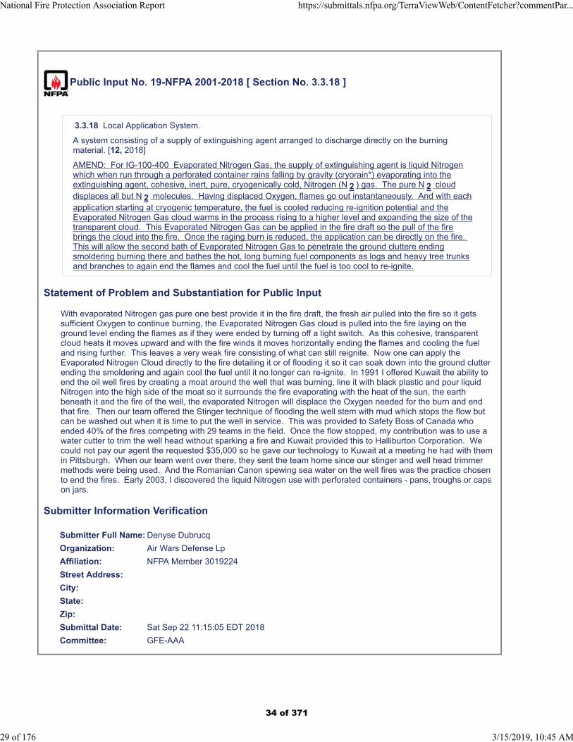
3.3.18 Local Application System.
A system consisting of a supply of extinguishing agent arranged to discharge directly on the burningmaterial. [12, 2018]
AMEND: For IG-100-400 Evaporated Nitrogen Gas, the supply of extinguishing agent is liquid Nitrogenwhich when run through a perforated container rains falling by gravity (cryorain*) evaporating into theextinguishing agent, cohesive, inert, pure, cryogenically cold, Nitrogen (N 2 ) gas. The pure N 2 clouddisplaces all but N 2 molecules. Having displaced Oxygen, flames go out instantaneously. And with eachapplication starting at cryogenic temperature, the fuel is cooled reducing re-ignition potential and theEvaporated Nitrogen Gas cloud warms in the process rising to a higher level and expanding the size of thetransparent cloud. This Evaporated Nitrogen Gas can be applied in the fire draft so the pull of the firebrings the cloud into the fire. Once the raging burn is reduced, the application can be directly on the fire. This will allow the second bath of Evaporated Nitrogen Gas to penetrate the ground cluttere endingsmoldering burning there and bathes the hot, long burning fuel components as logs and heavy tree trunksand branches to again end the flames and cool the fuel until the fuel is too cool to re-ignite.
Statement of Problem and Substantiation for Public Input
With evaporated Nitrogen gas pure one best provide it in the fire draft, the fresh air pulled into the fire so it gets sufficient Oxygen to continue burning, the Evaporated Nitrogen Gas cloud is pulled into the fire laying on the ground level ending the flames as if they were ended by turning off a light switch. As this cohesive, transparent cloud heats it moves upward and with the fire winds it moves horizontally ending the flames and cooling the fuel and rising further. This leaves a very weak fire consisting of what can still reignite. Now one can apply the Evaporated Nitrogen Cloud directly to the fire detailing it or of flooding it so it can soak down into the ground clutter ending the smoldering and again cool the fuel until it no longer can re-ignite. In 1991 I offered Kuwait the ability to end the oil well fires by creating a moat around the well that was burning, line it with black plastic and pour liquid Nitrogen into the high side of the moat so it surrounds the fire evaporating with the heat of the sun, the earth beneath it and the fire of the well, the evaporated Nitrogen will displace the Oxygen needed for the burn and end that fire. Then our team offered the Stinger technique of flooding the well stem with mud which stops the flow but can be washed out when it is time to put the well in service. This was provided to Safety Boss of Canada who ended 40% of the fires competing with 29 teams in the field. Once the flow stopped, my contribution was to use a water cutter to trim the well head without sparking a fire and Kuwait provided this to Halliburton Corporation. We could not pay our agent the requested $35,000 so he gave our technology to Kuwait at a meeting he had with them in Pittsburgh. When our team went over there, they sent the team home since our stinger and well head trimmer methods were being used. And the Romanian Canon spewing sea water on the well fires was the practice chosen to end the fires. Early 2003, I discovered the liquid Nitrogen use with perforated containers - pans, troughs or caps on jars.
Submitter Information Verification
Submitter Full Name: Denyse Dubrucq
Organization: Air Wars Defense Lp
Affiliation: NFPA Member 3019224
Street Address:
City:
State:
Zip:
Submittal Date: Sat Sep 22 11:15:05 EDT 2018
Committee: GFE-AAA
National Fire Protection Association Report https://submittals.nfpa.org/TerraViewWeb/ContentFetcher?commentPar...
29 of 176 3/15/2019, 10:45 AM
34 of 371
Public Input No. 51-NFPA 2001-2018 [ Section No. 4.1.2 ]
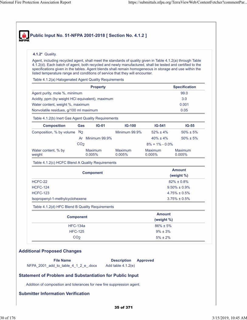
4.1.2* Quality.
Agent, including recycled agent, shall meet the standards of quality given in Table 4.1.2(a) through Table4.1.2(d). Each batch of agent, both recycled and newly manufactured, shall be tested and certified to thespecifications given in the tables. Agent blends shall remain homogeneous in storage and use within thelisted temperature range and conditions of service that they will encounter.
Table 4.1.2(a) Halogenated Agent Quality Requirements
Property Specification
Agent purity, mole %, minimum 99.0
Acidity, ppm (by weight HCl equivalent), maximum 3.0
Water content, weight %, maximum 0.001
Nonvolatile residues, g/100 ml maximum 0.05
Table 4.1.2(b) Inert Gas Agent Quality Requirements
Composition Gas IG-01 IG-100 IG-541 IG-55
Composition, % by volume N2 Minimum 99.9% 52% ± 4% 50% ± 5%
Ar Minimum 99.9% 40% ± 4% 50% ± 5%
CO2 8% + 1% - 0.0%
Water content, % byweight
Maximum0.005%
Maximum0.005%
Maximum0.005%
Maximum0.005%
Table 4.1.2(c) HCFC Blend A Quality Requirements
ComponentAmount
(weight %)
HCFC-22 82% ± 0.8%
HCFC-124 9.50% ± 0.9%
HCFC-123 4.75% ± 0.5%
Isopropenyl-1-methylcyclohexene 3.75% ± 0.5%
Table 4.1.2(d) HFC Blend B Quality Requirements
ComponentAmount
(weight %)
HFC-134a 86% ± 5%
HFC-125 9% ± 3%
CO2 5% ± 2%
Additional Proposed Changes
File Name Description Approved
NFPA_2001_add_to_table_4_1_2_e_.docx Add table 4.1.2(e)
Statement of Problem and Substantiation for Public Input
Addition of composition and tolerances for new fire suppression agent.
Submitter Information Verification
National Fire Protection Association Report https://submittals.nfpa.org/TerraViewWeb/ContentFetcher?commentPar...
30 of 176 3/15/2019, 10:45 AM
35 of 371
Submitter Full Name: Robert Richard
Organization: Honeywell, Inc.
Street Address:
City:
State:
Zip:
Submittal Date: Tue Dec 18 12:22:22 EST 2018
Committee: GFE-AAA
National Fire Protection Association Report https://submittals.nfpa.org/TerraViewWeb/ContentFetcher?commentPar...
31 of 176 3/15/2019, 10:45 AM
36 of 371
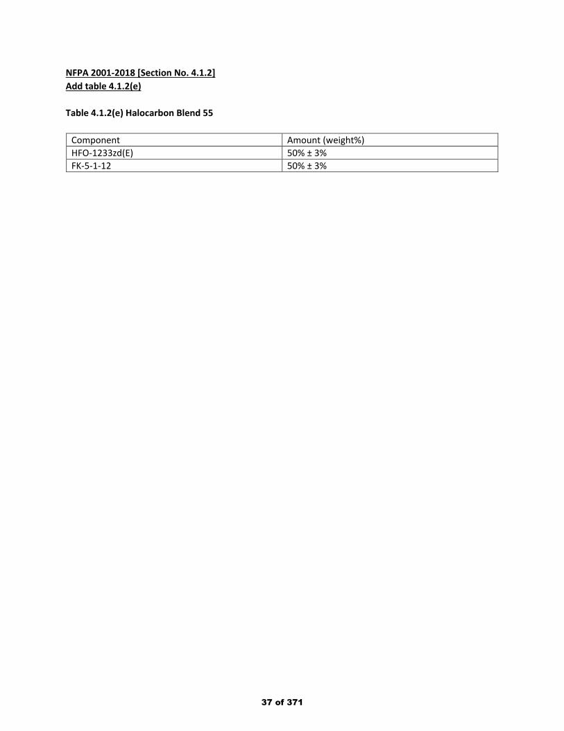
NFPA 2001-2018 [Section No. 4.1.2] Add table 4.1.2(e) Table 4.1.2(e) Halocarbon Blend 55
Component Amount (weight%) HFO-1233zd(E) 50% ± 3% FK-5-1-12 50% ± 3%
37 of 371
Public Input No. 74-NFPA 2001-2019 [ Section No. 4.1.2 ]
National Fire Protection Association Report https://submittals.nfpa.org/TerraViewWeb/ContentFetcher?commentPar...
32 of 176 3/15/2019, 10:45 AM
38 of 371

4.1.2* Quality.
National Fire Protection Association Report https://submittals.nfpa.org/TerraViewWeb/ContentFetcher?commentPar...
33 of 176 3/15/2019, 10:45 AM
39 of 371
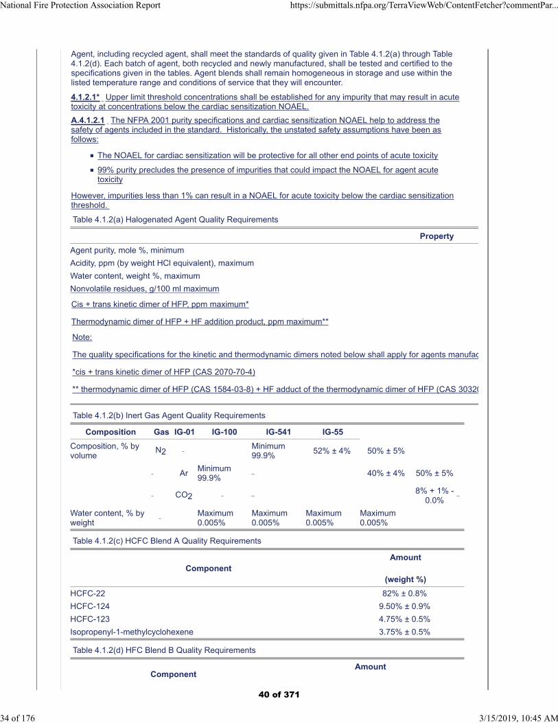
Agent, including recycled agent, shall meet the standards of quality given in Table 4.1.2(a) through Table4.1.2(d). Each batch of agent, both recycled and newly manufactured, shall be tested and certified to thespecifications given in the tables. Agent blends shall remain homogeneous in storage and use within thelisted temperature range and conditions of service that they will encounter.
4.1.2.1* Upper limit threshold concentrations shall be established for any impurity that may result in acutetoxicity at concentrations below the cardiac sensitization NOAEL.
A.4.1.2.1 The NFPA 2001 purity specifications and cardiac sensitization NOAEL help to address thesafety of agents included in the standard. Historically, the unstated safety assumptions have been asfollows:
The NOAEL for cardiac sensitization will be protective for all other end points of acute toxicity
99% purity precludes the presence of impurities that could impact the NOAEL for agent acutetoxicity
However, impurities less than 1% can result in a NOAEL for acute toxicity below the cardiac sensitizationthreshold.
Table 4.1.2(a) Halogenated Agent Quality Requirements
Property
Agent purity, mole %, minimum
Acidity, ppm (by weight HCl equivalent), maximum
Water content, weight %, maximum
Nonvolatile residues, g/100 ml maximum
Cis + trans kinetic dimer of HFP, ppm maximum*
Thermodynamic dimer of HFP + HF addition product, ppm maximum**
Note:
The quality specifications for the kinetic and thermodynamic dimers noted below shall apply for agents manufac
*cis + trans kinetic dimer of HFP (CAS 2070-70-4)
** thermodynamic dimer of HFP (CAS 1584-03-8) + HF adduct of the thermodynamic dimer of HFP (CAS 30320
Table 4.1.2(b) Inert Gas Agent Quality Requirements
Composition Gas IG-01 IG-100 IG-541 IG-55
Composition, % byvolume
N2 Minimum99.9%
52% ± 4% 50% ± 5%
ArMinimum99.9%
40% ± 4% 50% ± 5%
CO2 8% + 1% -
0.0%
Water content, % byweight
Maximum0.005%
Maximum0.005%
Maximum0.005%
Maximum0.005%
Table 4.1.2(c) HCFC Blend A Quality Requirements
ComponentAmount
(weight %)
HCFC-22 82% ± 0.8%
HCFC-124 9.50% ± 0.9%
HCFC-123 4.75% ± 0.5%
Isopropenyl-1-methylcyclohexene 3.75% ± 0.5%
Table 4.1.2(d) HFC Blend B Quality Requirements
ComponentAmount
National Fire Protection Association Report https://submittals.nfpa.org/TerraViewWeb/ContentFetcher?commentPar...
34 of 176 3/15/2019, 10:45 AM
40 of 371
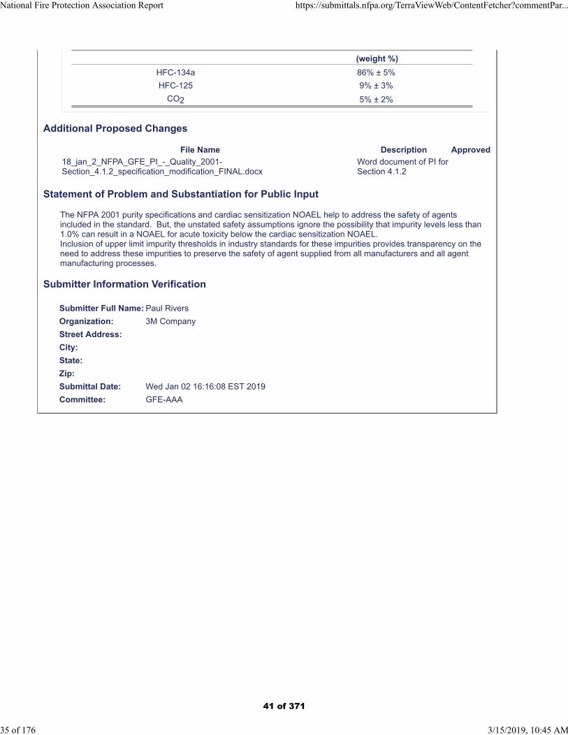
(weight %)
HFC-134a 86% ± 5%
HFC-125 9% ± 3%
CO2 5% ± 2%
Additional Proposed Changes
File Name Description Approved
18_jan_2_NFPA_GFE_PI_-_Quality_2001-Section_4.1.2_specification_modification_FINAL.docx
Word document of PI for Section 4.1.2
Statement of Problem and Substantiation for Public Input
The NFPA 2001 purity specifications and cardiac sensitization NOAEL help to address the safety of agents included in the standard. But, the unstated safety assumptions ignore the possibility that impurity levels less than 1.0% can result in a NOAEL for acute toxicity below the cardiac sensitization NOAEL.Inclusion of upper limit impurity thresholds in industry standards for these impurities provides transparency on the need to address these impurities to preserve the safety of agent supplied from all manufacturers and all agent manufacturing processes.
Submitter Information Verification
Submitter Full Name: Paul Rivers
Organization: 3M Company
Street Address:
City:
State:
Zip:
Submittal Date: Wed Jan 02 16:16:08 EST 2019
Committee: GFE-AAA
National Fire Protection Association Report https://submittals.nfpa.org/TerraViewWeb/ContentFetcher?commentPar...
35 of 176 3/15/2019, 10:45 AM
41 of 371
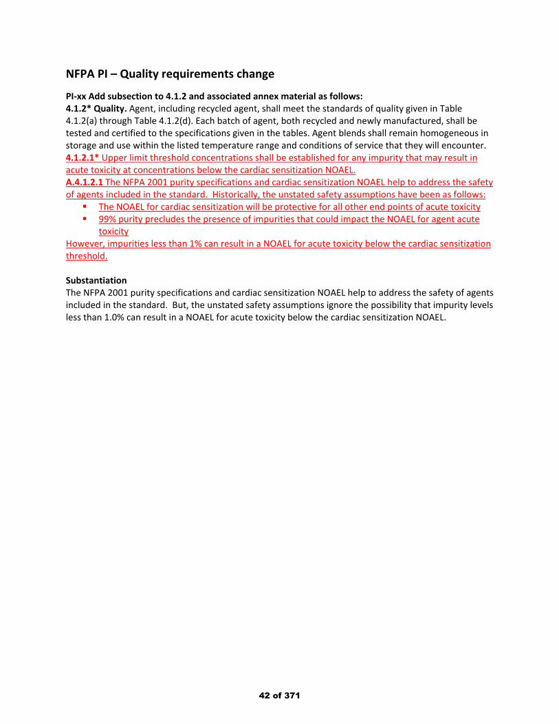
NFPA PI – Quality requirements change
PI-xx Add subsection to 4.1.2 and associated annex material as follows: 4.1.2* Quality. Agent, including recycled agent, shall meet the standards of quality given in Table 4.1.2(a) through Table 4.1.2(d). Each batch of agent, both recycled and newly manufactured, shall be tested and certified to the specifications given in the tables. Agent blends shall remain homogeneous in storage and use within the listed temperature range and conditions of service that they will encounter. 4.1.2.1* Upper limit threshold concentrations shall be established for any impurity that may result in acute toxicity at concentrations below the cardiac sensitization NOAEL. A.4.1.2.1 The NFPA 2001 purity specifications and cardiac sensitization NOAEL help to address the safety of agents included in the standard. Historically, the unstated safety assumptions have been as follows: The NOAEL for cardiac sensitization will be protective for all other end points of acute toxicity 99% purity precludes the presence of impurities that could impact the NOAEL for agent acute
toxicity However, impurities less than 1% can result in a NOAEL for acute toxicity below the cardiac sensitization threshold. Substantiation The NFPA 2001 purity specifications and cardiac sensitization NOAEL help to address the safety of agents included in the standard. But, the unstated safety assumptions ignore the possibility that impurity levels less than 1.0% can result in a NOAEL for acute toxicity below the cardiac sensitization NOAEL.
42 of 371
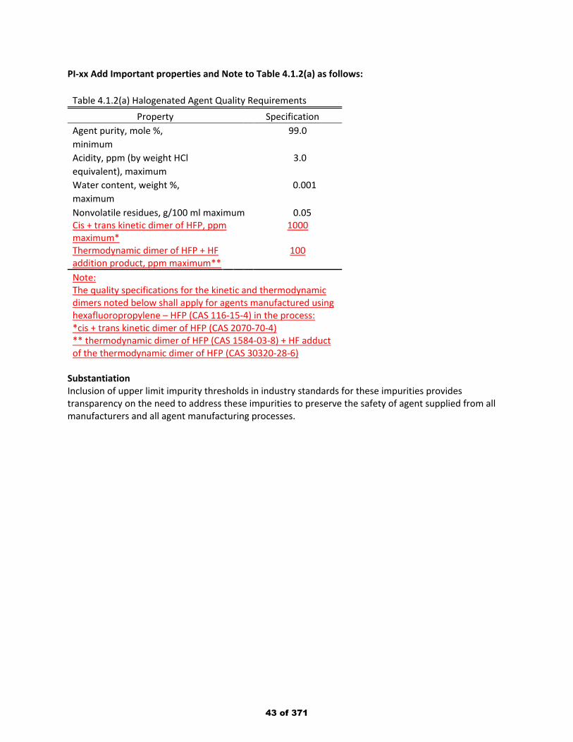
PI-xx Add Important properties and Note to Table 4.1.2(a) as follows:
Table 4.1.2(a) Halogenated Agent Quality Requirements Property Specification
Agent purity, mole %, 99.0 minimum Acidity, ppm (by weight HCl 3.0 equivalent), maximum Water content, weight %, 0.001 maximum Nonvolatile residues, g/100 ml maximum 0.05 Cis + trans kinetic dimer of HFP, ppm maximum*
1000
Thermodynamic dimer of HFP + HF addition product, ppm maximum**
100
Note: The quality specifications for the kinetic and thermodynamic dimers noted below shall apply for agents manufactured using hexafluoropropylene – HFP (CAS 116-15-4) in the process: *cis + trans kinetic dimer of HFP (CAS 2070-70-4) ** thermodynamic dimer of HFP (CAS 1584-03-8) + HF adduct of the thermodynamic dimer of HFP (CAS 30320-28-6)
Substantiation Inclusion of upper limit impurity thresholds in industry standards for these impurities provides transparency on the need to address these impurities to preserve the safety of agent supplied from all manufacturers and all agent manufacturing processes.
43 of 371
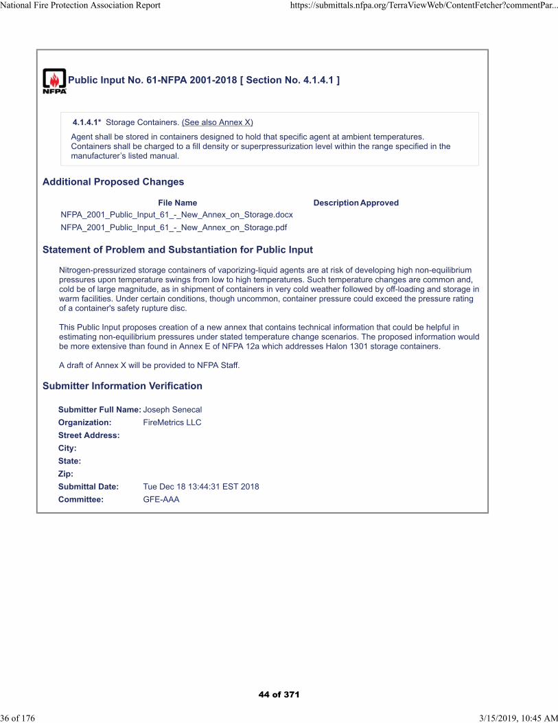
Public Input No. 61-NFPA 2001-2018 [ Section No. 4.1.4.1 ]
4.1.4.1* Storage Containers. (See also Annex X)
Agent shall be stored in containers designed to hold that specific agent at ambient temperatures.Containers shall be charged to a fill density or superpressurization level within the range specified in themanufacturer’s listed manual.
Additional Proposed Changes
File Name Description Approved
NFPA_2001_Public_Input_61_-_New_Annex_on_Storage.docx
NFPA_2001_Public_Input_61_-_New_Annex_on_Storage.pdf
Statement of Problem and Substantiation for Public Input
Nitrogen-pressurized storage containers of vaporizing-liquid agents are at risk of developing high non-equilibrium pressures upon temperature swings from low to high temperatures. Such temperature changes are common and, cold be of large magnitude, as in shipment of containers in very cold weather followed by off-loading and storage in warm facilities. Under certain conditions, though uncommon, container pressure could exceed the pressure rating of a container's safety rupture disc.
This Public Input proposes creation of a new annex that contains technical information that could be helpful in estimating non-equilibrium pressures under stated temperature change scenarios. The proposed information would be more extensive than found in Annex E of NFPA 12a which addresses Halon 1301 storage containers.
A draft of Annex X will be provided to NFPA Staff.
Submitter Information Verification
Submitter Full Name: Joseph Senecal
Organization: FireMetrics LLC
Street Address:
City:
State:
Zip:
Submittal Date: Tue Dec 18 13:44:31 EST 2018
Committee: GFE-AAA
National Fire Protection Association Report https://submittals.nfpa.org/TerraViewWeb/ContentFetcher?commentPar...
36 of 176 3/15/2019, 10:45 AM
44 of 371
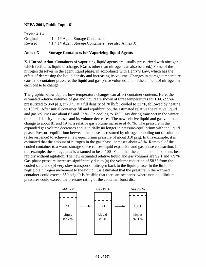
NFPA 2001, Public Input 61 Revise 4.1.4 Original 4.1.4.1* Agent Storage Containers. Revised 4.1.4.1* Agent Storage Containers. [see also Annex X] Annex X Storage Containers for Vaporizing-liquid Agents X.1 Introduction. Containers of vaporizing-liquid agents are usually pressurized with nitrogen, which facilitates liquid discharge. (Gases other than nitrogen can also be used.) Some of the nitrogen dissolves in the agent liquid phase, in accordance with Henry’s Law, which has the effect of decreasing the liquid density and increasing its volume. Changes in storage temperature cause the container pressure, the liquid and gas-phase volumes, and in the amount of nitrogen in each phase to change. The graphic below depicts how temperature changes can affect container contents. Here, the estimated relative volumes of gas and liquid are shown at three temperatures for HFC-227ea pressurized to 360 psig at 70 °F at a fill density of 70 lb/ft3, cooled to 32 °F, followed by heating to 100 °F. After initial container fill and equilibration, the estimated relative the relative liquid and gas volumes are about 87 and 13 %. On cooling to 32 °F, say during transport in the winter, the liquid density increases and its volume decreases. The new relative liquid and gas volumes change to about 81 and 19 %, a relative gas volume increase of 46 %. The pressure in the expanded gas volume decreases and is initially no longer in pressure-equilibrium with the liquid phase. Pressure equilibrium between the phases is restored by nitrogen bubbling out of solution (effervescence) to achieve a new equilibrium pressure of about 310 psig. In this example, it is estimated that the amount of nitrogen in the gas phase increases about 48 %. Removal of the cooled container to a warm storage space causes liquid expansion and gas phase contraction. In this example, the storage area is assumed to be at 100 °F and that the container and contents heat rapidly without agitation. The new estimated relative liquid and gas volumes are 92.1 and 7.9 %. Gas-phase pressure increases significantly due to (a) the volume reduction of 58 % from the cooled state and (b) very slow transport of nitrogen back to the liquid phase. In the limit of negligible nitrogen movement to the liquid, it is estimated that the pressure in the warmed container could exceed 850 psig. It is feasible that there are scenarios where non-equilibrium pressures could exceed the pressure rating of the container burst disc.
45 of 371
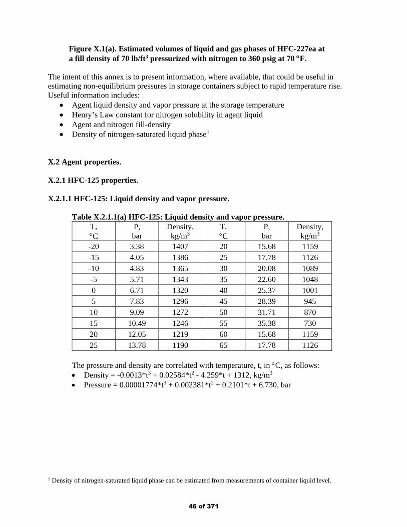
Figure X.1(a). Estimated volumes of liquid and gas phases of HFC-227ea at a fill density of 70 lb/ft3 pressurized with nitrogen to 360 psig at 70 °F.
The intent of this annex is to present information, where available, that could be useful in estimating non-equilibrium pressures in storage containers subject to rapid temperature rise. Useful information includes:
• Agent liquid density and vapor pressure at the storage temperature • Henry’s Law constant for nitrogen solubility in agent liquid • Agent and nitrogen fill-density • Density of nitrogen-saturated liquid phase1
X.2 Agent properties. X.2.1 HFC-125 properties. X.2.1.1 HFC-125: Liquid density and vapor pressure.
Table X.2.1.1(a) HFC-125: Liquid density and vapor pressure. T, °C
P, bar
Density, kg/m3
T, °C
P, bar
Density, kg/m3
-20 3.38 1407 20 15.68 1159 -15 4.05 1386 25 17.78 1126 -10 4.83 1365 30 20.08 1089 -5 5.71 1343 35 22.60 1048 0 6.71 1320 40 25.37 1001 5 7.83 1296 45 28.39 945 10 9.09 1272 50 31.71 870 15 10.49 1246 55 35.38 730 20 12.05 1219 60 15.68 1159 25 13.78 1190 65 17.78 1126
The pressure and density are correlated with temperature, t, in °C, as follows: • Density = -0.0013*t3 + 0.02584*t2 - 4.259*t + 1312, kg/m3 • Pressure = 0.00001774*t3 + 0.002381*t2 + 0.2101*t + 6.730, bar
1 Density of nitrogen-saturated liquid phase can be estimated from measurements of container liquid level.
46 of 371
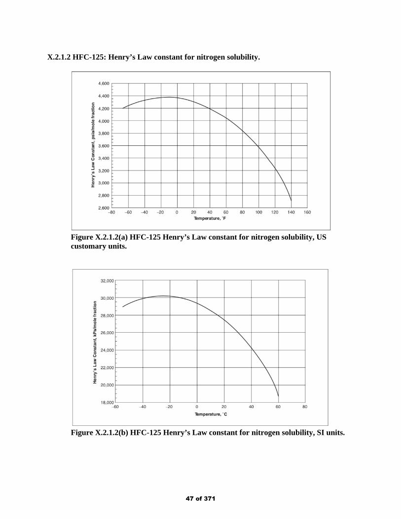
X.2.1.2 HFC-125: Henry’s Law constant for nitrogen solubility.
Figure X.2.1.2(a) HFC-125 Henry’s Law constant for nitrogen solubility, US customary units.
Figure X.2.1.2(b) HFC-125 Henry’s Law constant for nitrogen solubility, SI units.
47 of 371
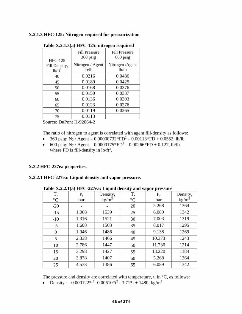
X.2.1.3 HFC-125: Nitrogen required for pressurization
Table X.2.1.3(a) HFC-125: nitrogen required
HFC-125 Fill Density,
lb/ft3
Fill Pressure 360 psig
Fill Pressure 600 psig
Nitrogen / Agent lb/lb
Nitrogen /Agent lb/lb
40 0.0216 0.0486 45 0.0189 0.0425 50 0.0168 0.0376 55 0.0150 0.0337 60 0.0136 0.0303 65 0.0123 0.0276 70 0.0119 0.0265 75 0.0113
Source: DuPont H-92064-2 The ratio of nitrogen to agent is correlated with agent fill-density as follows: • 360 psig: N2 / Agent = 0.00000732*FD2 – 0.00113*FD + 0.0552, lb/lb • 600 psig: N2 / Agent = 0.0000175*FD2 – 0.00266*FD + 0.127, lb/lb
where FD is fill-density in lb/ft3. X.2.2 HFC-227ea properties. X.2.2.1 HFC-227ea: Liquid density and vapor pressure.
Table X.2.2.1(a) HFC-227ea: Liquid density and vapor pressure
T, °C
P, bar
Density, kg/m3
T, °C
P, bar
Density, kg/m3
-20 - - 20 5.268 1364 -15 1.068 1539 25 6.089 1342 -10 1.316 1521 30 7.003 1319 -5 1.608 1503 35 8.017 1295 0 1.946 1486 40 9.138 1269 5 2.338 1466 45 10.373 1243 10 2.786 1447 50 11.730 1214 15 3.298 1427 55 13.220 1184 20 3.878 1407 60 5.268 1364 25 4.533 1386 65 6.089 1342
The pressure and density are correlated with temperature, t, in °C, as follows: • Density = -0.000122*t3 -0.00610*t2 - 3.71*t + 1480, kg/m3
48 of 371
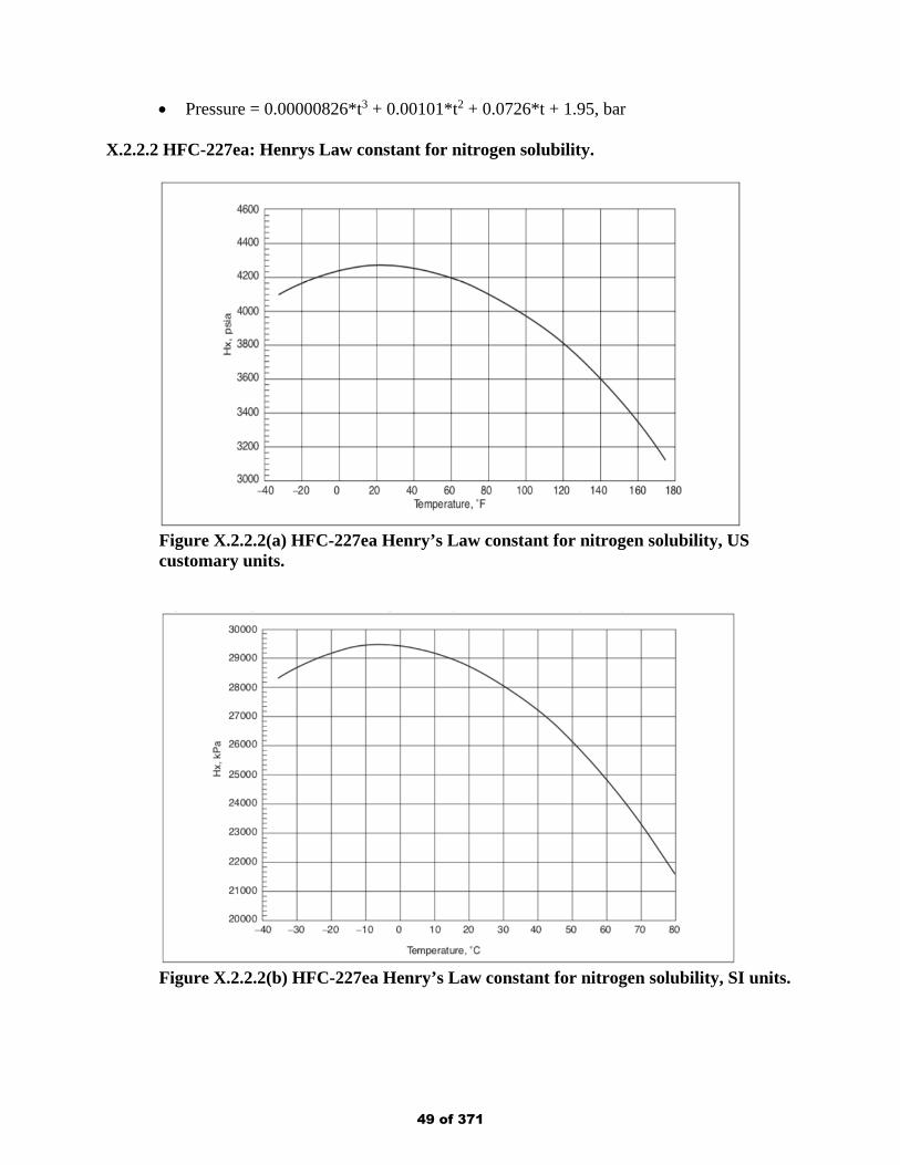
• Pressure = 0.00000826*t3 + 0.00101*t2 + 0.0726*t + 1.95, bar X.2.2.2 HFC-227ea: Henrys Law constant for nitrogen solubility.
Figure X.2.2.2(a) HFC-227ea Henry’s Law constant for nitrogen solubility, US customary units.
Figure X.2.2.2(b) HFC-227ea Henry’s Law constant for nitrogen solubility, SI units.
49 of 371
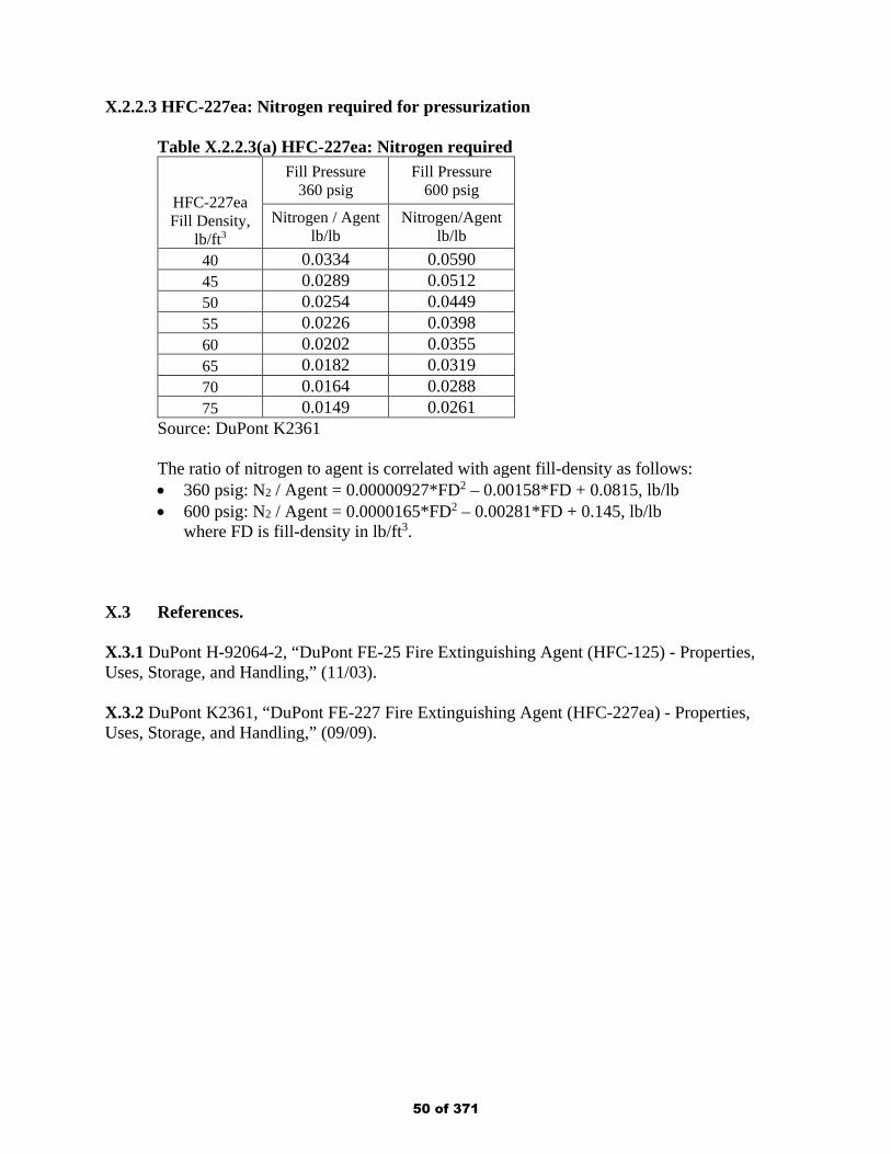
X.2.2.3 HFC-227ea: Nitrogen required for pressurization
Table X.2.2.3(a) HFC-227ea: Nitrogen required
HFC-227ea Fill Density,
lb/ft3
Fill Pressure 360 psig
Fill Pressure 600 psig
Nitrogen / Agent lb/lb
Nitrogen/Agent lb/lb
40 0.0334 0.0590 45 0.0289 0.0512 50 0.0254 0.0449 55 0.0226 0.0398 60 0.0202 0.0355 65 0.0182 0.0319 70 0.0164 0.0288 75 0.0149 0.0261
Source: DuPont K2361 The ratio of nitrogen to agent is correlated with agent fill-density as follows: • 360 psig: N2 / Agent = 0.00000927*FD2 – 0.00158*FD + 0.0815, lb/lb • 600 psig: N2 / Agent = 0.0000165*FD2 – 0.00281*FD + 0.145, lb/lb
where FD is fill-density in lb/ft3. X.3 References. X.3.1 DuPont H-92064-2, “DuPont FE-25 Fire Extinguishing Agent (HFC-125) - Properties, Uses, Storage, and Handling,” (11/03). X.3.2 DuPont K2361, “DuPont FE-227 Fire Extinguishing Agent (HFC-227ea) - Properties, Uses, Storage, and Handling,” (09/09).
50 of 371
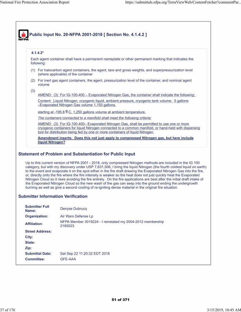
Public Input No. 20-NFPA 2001-2018 [ Section No. 4.1.4.2 ]
4.1.4.2*
Each agent container shall have a permanent nameplate or other permanent marking that indicates thefollowing:
(1) For halocarbon agent containers, the agent, tare and gross weights, and superpressurization level(where applicable) of the container
(2) For inert gas agent containers, the agent, pressurization level of the container, and nominal agentvolume
(3)AMEND: (3) For IG-100-400 – Evaporated Nitrogen Gas, the container shall indicate the following:
Content: Liquid Nitrogen, cryogenic liquid, ambient pressure, cryogenic tank volume: 5 gallons–Evaporated Nitrogen Gas volume 1,150 gallons.
starting at -195.8 o C, 1,250 gallons volume at ambient temperature.
The containers connected to a manifold shall meet the following criteria:
AMEND: (3) For IG-100-400– Evaporated Nitrogen Gas, shall be permitted to use one or morecryogenic containers for liquid Nitrogen connected to a common manifold, or hand-held with dispersingtool for distribution being fed by one or more containers of liquid Nitrogen.
Amendment inserts: Does this not just apply to compressed Nitrogen gas, but here includeliquid Nitrogen?
Statement of Problem and Substantiation for Public Input
Up to this current version of NFPA 2001 - 2018, only compressed Nitrogen methods are included in the IG 100 category, but with my discovery under USP 7,631,506, I bring the liquid Nitrogen (the fourth coldest liquid on earth) to the event and evaporate it on the spot either in the fire draft drawing the Evaporated Nitrogen Gas into the fire, or, directly onto the fire where the fire intensity is weaker so the heat does not just quickly heat the Evaporated Nitrogen Cloud so it rises avoiding the fire entirely. On the fire applications are best after the initial draft intake of the Evaporated Nitrogen Cloud so the new wash of the gas can seep into the ground ending the undergrowth burning as well as give a second cooling of re-igniting dense material in the original fire situation.
Submitter Information Verification
Submitter FullName:
Denyse Dubrucq
Organization: Air Wars Defense Lp
Affiliation:NFPA Member 3019224 - I reinstated my 2004-2012 membership2185023
Street Address:
City:
State:
Zip:
Submittal Date: Sat Sep 22 11:20:32 EDT 2018
Committee: GFE-AAA
National Fire Protection Association Report https://submittals.nfpa.org/TerraViewWeb/ContentFetcher?commentPar...
37 of 176 3/15/2019, 10:45 AM
51 of 371
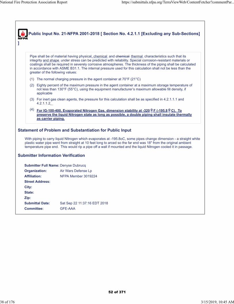
Public Input No. 21-NFPA 2001-2018 [ Section No. 4.2.1.1 [Excluding any Sub-Sections]
]
Pipe shall be of material having physical, chemical and chemical thermal characteristics such that itsintegrity and shape under stress can be predicted with reliability. Special corrosion-resistant materials orcoatings shall be required in severely corrosive atmospheres. The thickness of the piping shall be calculatedin accordance with ASME B31.1. The internal pressure used for this calculation shall not be less than thegreater of the following values:
(1) The normal charging pressure in the agent container at 70°F (21°C)
(2) Eighty percent of the maximum pressure in the agent container at a maximum storage temperature ofnot less than 130°F (55°C), using the equipment manufacturer’s maximum allowable fill density, ifapplicable
(3) For inert gas clean agents, the pressure for this calculation shall be as specified in 4.2.1.1.1 and4.2.1.1.2.
(4) For IG-100-400, Evaporated Nitrogen Gas, dimension stability at -320 o F (-195.8 o C). Topreserve the liquid Nitrogen state as long as possible, a double piping shall insulate thermallyas carrier piping.
Statement of Problem and Substantiation for Public Input
With piping to carry liquid NItrogen which evaporates at -195.8oC, some pipes change dimension - a straight white plastic water pipe went from straight at 10 feet long to arced so the far end was 18" from the original ambient temperature pipe end. This would rip a pipe off a wall if mounted and the liquid Nitrogen cooled it in passage.
Submitter Information Verification
Submitter Full Name: Denyse Dubrucq
Organization: Air Wars Defense Lp
Affiliation: NFPA Member 3019224
Street Address:
City:
State:
Zip:
Submittal Date: Sat Sep 22 11:37:16 EDT 2018
Committee: GFE-AAA
National Fire Protection Association Report https://submittals.nfpa.org/TerraViewWeb/ContentFetcher?commentPar...
38 of 176 3/15/2019, 10:45 AM
52 of 371

Public Input No. 18-NFPA 2001-2018 [ Section No. 4.2.1.1.1 ]
National Fire Protection Association Report https://submittals.nfpa.org/TerraViewWeb/ContentFetcher?commentPar...
39 of 176 3/15/2019, 10:45 AM
53 of 371

4.2.1.1.1
National Fire Protection Association Report https://submittals.nfpa.org/TerraViewWeb/ContentFetcher?commentPar...
40 of 176 3/15/2019, 10:45 AM
54 of 371
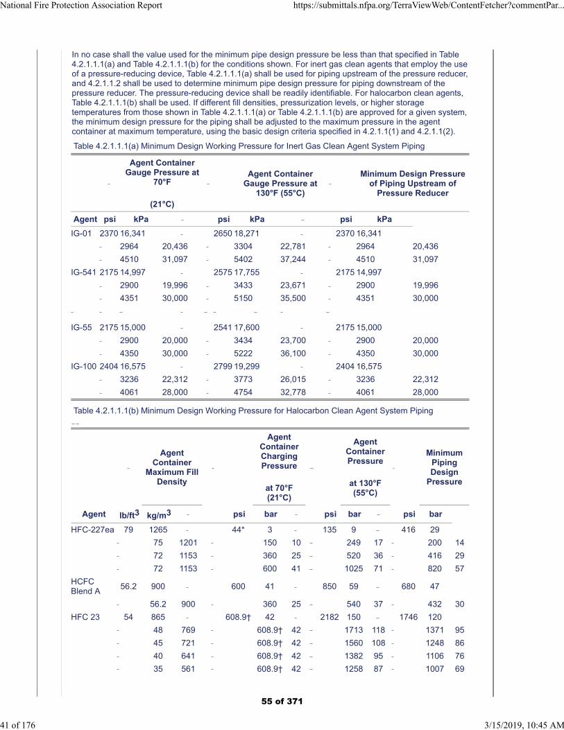
In no case shall the value used for the minimum pipe design pressure be less than that specified in Table4.2.1.1.1(a) and Table 4.2.1.1.1(b) for the conditions shown. For inert gas clean agents that employ the useof a pressure-reducing device, Table 4.2.1.1.1(a) shall be used for piping upstream of the pressure reducer,and 4.2.1.1.2 shall be used to determine minimum pipe design pressure for piping downstream of thepressure reducer. The pressure-reducing device shall be readily identifiable. For halocarbon clean agents,Table 4.2.1.1.1(b) shall be used. If different fill densities, pressurization levels, or higher storagetemperatures from those shown in Table 4.2.1.1.1(a) or Table 4.2.1.1.1(b) are approved for a given system,the minimum design pressure for the piping shall be adjusted to the maximum pressure in the agentcontainer at maximum temperature, using the basic design criteria specified in 4.2.1.1(1) and 4.2.1.1(2).
Table 4.2.1.1.1(a) Minimum Design Working Pressure for Inert Gas Clean Agent System Piping
Agent ContainerGauge Pressure at
70°F
(21°C)
Agent Container
Gauge Pressure at130°F (55°C)
Minimum Design Pressure
of Piping Upstream ofPressure Reducer
Agent psi kPa psi kPa psi kPa
IG-01 2370 16,341 2650 18,271 2370 16,341
2964 20,436 3304 22,781 2964 20,436
4510 31,097 5402 37,244 4510 31,097
IG-541 2175 14,997 2575 17,755 2175 14,997
2900 19,996 3433 23,671 2900 19,996
4351 30,000 5150 35,500 4351 30,000
IG-55 2175 15,000 2541 17,600 2175 15,000
2900 20,000 3434 23,700 2900 20,000
4350 30,000 5222 36,100 4350 30,000
IG-100 2404 16,575 2799 19,299 2404 16,575
3236 22,312 3773 26,015 3236 22,312
4061 28,000 4754 32,778 4061 28,000
Table 4.2.1.1.1(b) Minimum Design Working Pressure for Halocarbon Clean Agent System Piping
AgentContainer
Maximum FillDensity
AgentContainerChargingPressure
at 70°F(21°C)
AgentContainerPressure
at 130°F(55°C)
MinimumPipingDesign
Pressure
Agent lb/ft3 kg/m3 psi bar psi bar psi bar
HFC-227ea 79 1265 44* 3 135 9 416 29
75 1201 150 10 249 17 200 14
72 1153 360 25 520 36 416 29
72 1153 600 41 1025 71 820 57
HCFCBlend A
56.2 900 600 41 850 59 680 47
56.2 900 360 25 540 37 432 30
HFC 23 54 865 608.9† 42 2182 150 1746 120
48 769 608.9† 42 1713 118 1371 95
45 721 608.9† 42 1560 108 1248 86
40 641 608.9† 42 1382 95 1106 76
35 561 608.9† 42 1258 87 1007 69
National Fire Protection Association Report https://submittals.nfpa.org/TerraViewWeb/ContentFetcher?commentPar...
41 of 176 3/15/2019, 10:45 AM
55 of 371
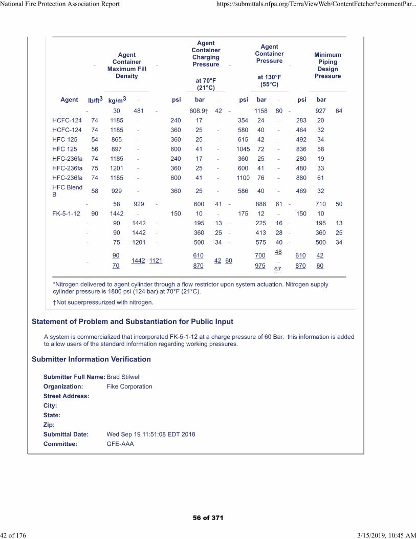
AgentContainer
Maximum FillDensity
AgentContainerChargingPressure
at 70°F(21°C)
AgentContainerPressure
at 130°F(55°C)
MinimumPipingDesign
Pressure
Agent lb/ft3 kg/m3 psi bar psi bar psi bar
30 481 608.9† 42 1158 80 927 64
HCFC-124 74 1185 240 17 354 24 283 20
HCFC-124 74 1185 360 25 580 40 464 32
HFC-125 54 865 360 25 615 42 492 34
HFC 125 56 897 600 41 1045 72 836 58
HFC-236fa 74 1185 240 17 360 25 280 19
HFC-236fa 75 1201 360 25 600 41 480 33
HFC-236fa 74 1185 600 41 1100 76 880 61
HFC BlendB
58 929 360 25 586 40 469 32
58 929 600 41 888 61 710 50
FK-5-1-12 90 1442 150 10 175 12 150 10
90 1442 195 13 225 16 195 13
90 1442 360 25 413 28 360 25
75 1201 500 34 575 40 500 34
90
701442 1121
610
87042 60
700
975
48
67
610
870
42
60
*Nitrogen delivered to agent cylinder through a flow restrictor upon system actuation. Nitrogen supplycylinder pressure is 1800 psi (124 bar) at 70°F (21°C).
†Not superpressurized with nitrogen.
Statement of Problem and Substantiation for Public Input
A system is commercialized that incorporated FK-5-1-12 at a charge pressure of 60 Bar. this information is added to allow users of the standard information regarding working pressures.
Submitter Information Verification
Submitter Full Name: Brad Stilwell
Organization: Fike Corporation
Street Address:
City:
State:
Zip:
Submittal Date: Wed Sep 19 11:51:08 EDT 2018
Committee: GFE-AAA
National Fire Protection Association Report https://submittals.nfpa.org/TerraViewWeb/ContentFetcher?commentPar...
42 of 176 3/15/2019, 10:45 AM
56 of 371
Public Input No. 22-NFPA 2001-2018 [ Section No. 4.2.1.1.1 ]
National Fire Protection Association Report https://submittals.nfpa.org/TerraViewWeb/ContentFetcher?commentPar...
43 of 176 3/15/2019, 10:45 AM
57 of 371

4.2.1.1.1
National Fire Protection Association Report https://submittals.nfpa.org/TerraViewWeb/ContentFetcher?commentPar...
44 of 176 3/15/2019, 10:45 AM
58 of 371
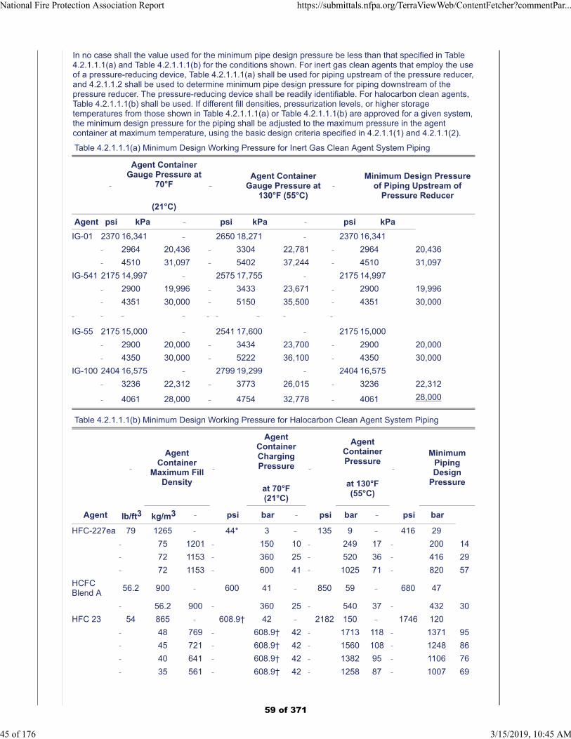
In no case shall the value used for the minimum pipe design pressure be less than that specified in Table4.2.1.1.1(a) and Table 4.2.1.1.1(b) for the conditions shown. For inert gas clean agents that employ the useof a pressure-reducing device, Table 4.2.1.1.1(a) shall be used for piping upstream of the pressure reducer,and 4.2.1.1.2 shall be used to determine minimum pipe design pressure for piping downstream of thepressure reducer. The pressure-reducing device shall be readily identifiable. For halocarbon clean agents,Table 4.2.1.1.1(b) shall be used. If different fill densities, pressurization levels, or higher storagetemperatures from those shown in Table 4.2.1.1.1(a) or Table 4.2.1.1.1(b) are approved for a given system,the minimum design pressure for the piping shall be adjusted to the maximum pressure in the agentcontainer at maximum temperature, using the basic design criteria specified in 4.2.1.1(1) and 4.2.1.1(2).
Table 4.2.1.1.1(a) Minimum Design Working Pressure for Inert Gas Clean Agent System Piping
Agent ContainerGauge Pressure at
70°F
(21°C)
Agent Container
Gauge Pressure at130°F (55°C)
Minimum Design Pressure
of Piping Upstream ofPressure Reducer
Agent psi kPa psi kPa psi kPa
IG-01 2370 16,341 2650 18,271 2370 16,341
2964 20,436 3304 22,781 2964 20,436
4510 31,097 5402 37,244 4510 31,097
IG-541 2175 14,997 2575 17,755 2175 14,997
2900 19,996 3433 23,671 2900 19,996
4351 30,000 5150 35,500 4351 30,000
IG-55 2175 15,000 2541 17,600 2175 15,000
2900 20,000 3434 23,700 2900 20,000
4350 30,000 5222 36,100 4350 30,000
IG-100 2404 16,575 2799 19,299 2404 16,575
3236 22,312 3773 26,015 3236 22,312
4061 28,000 4754 32,778 4061 28,000
Table 4.2.1.1.1(b) Minimum Design Working Pressure for Halocarbon Clean Agent System Piping
AgentContainer
Maximum FillDensity
AgentContainerChargingPressure
at 70°F(21°C)
AgentContainerPressure
at 130°F(55°C)
MinimumPipingDesign
Pressure
Agent lb/ft3 kg/m3 psi bar psi bar psi bar
HFC-227ea 79 1265 44* 3 135 9 416 29
75 1201 150 10 249 17 200 14
72 1153 360 25 520 36 416 29
72 1153 600 41 1025 71 820 57
HCFCBlend A
56.2 900 600 41 850 59 680 47
56.2 900 360 25 540 37 432 30
HFC 23 54 865 608.9† 42 2182 150 1746 120
48 769 608.9† 42 1713 118 1371 95
45 721 608.9† 42 1560 108 1248 86
40 641 608.9† 42 1382 95 1106 76
35 561 608.9† 42 1258 87 1007 69
National Fire Protection Association Report https://submittals.nfpa.org/TerraViewWeb/ContentFetcher?commentPar...
45 of 176 3/15/2019, 10:45 AM
59 of 371
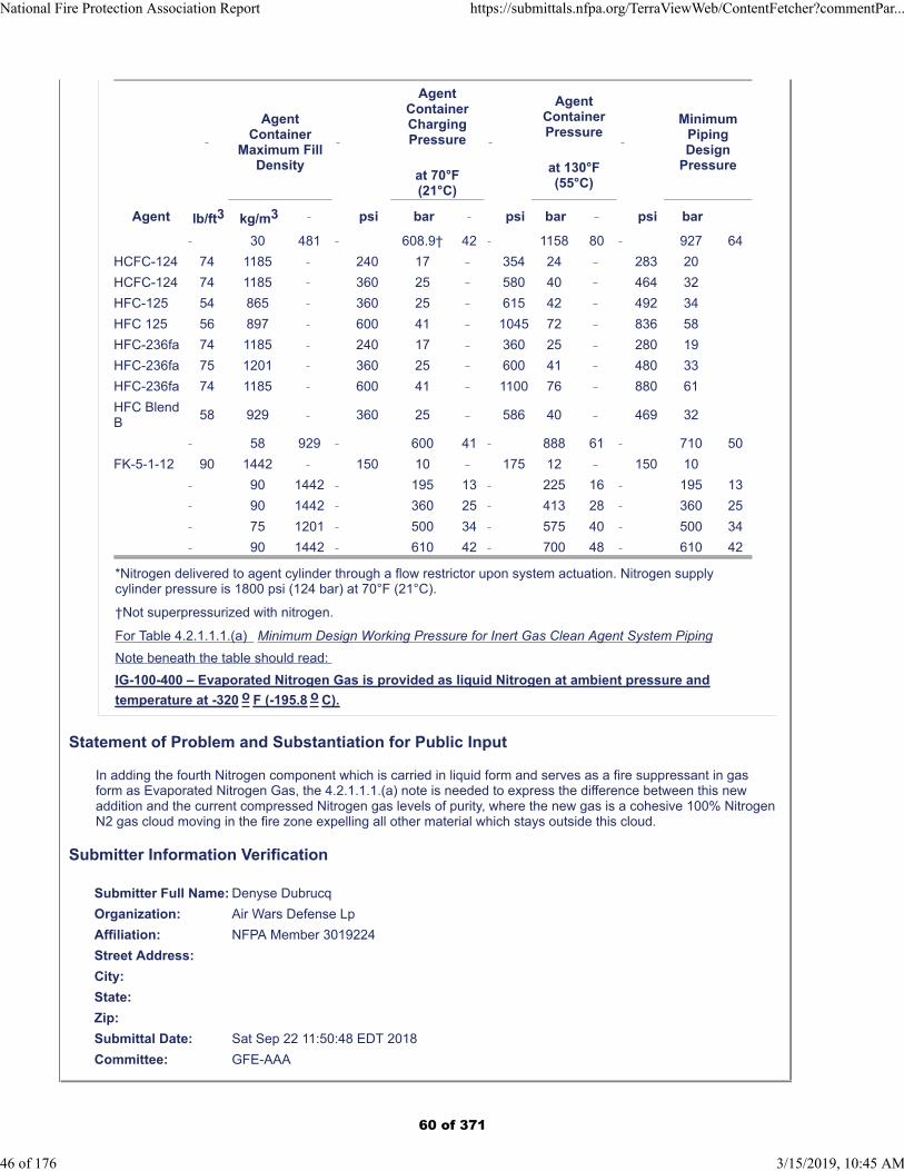
AgentContainer
Maximum FillDensity
AgentContainerChargingPressure
at 70°F(21°C)
AgentContainerPressure
at 130°F(55°C)
MinimumPipingDesign
Pressure
Agent lb/ft3 kg/m3 psi bar psi bar psi bar
30 481 608.9† 42 1158 80 927 64
HCFC-124 74 1185 240 17 354 24 283 20
HCFC-124 74 1185 360 25 580 40 464 32
HFC-125 54 865 360 25 615 42 492 34
HFC 125 56 897 600 41 1045 72 836 58
HFC-236fa 74 1185 240 17 360 25 280 19
HFC-236fa 75 1201 360 25 600 41 480 33
HFC-236fa 74 1185 600 41 1100 76 880 61
HFC BlendB
58 929 360 25 586 40 469 32
58 929 600 41 888 61 710 50
FK-5-1-12 90 1442 150 10 175 12 150 10
90 1442 195 13 225 16 195 13
90 1442 360 25 413 28 360 25
75 1201 500 34 575 40 500 34
90 1442 610 42 700 48 610 42
*Nitrogen delivered to agent cylinder through a flow restrictor upon system actuation. Nitrogen supplycylinder pressure is 1800 psi (124 bar) at 70°F (21°C).
†Not superpressurized with nitrogen.
For Table 4.2.1.1.1.(a) Minimum Design Working Pressure for Inert Gas Clean Agent System Piping
Note beneath the table should read:
IG-100-400 – Evaporated Nitrogen Gas is provided as liquid Nitrogen at ambient pressure and
temperature at -320 o F (-195.8 o C).
Statement of Problem and Substantiation for Public Input
In adding the fourth Nitrogen component which is carried in liquid form and serves as a fire suppressant in gas form as Evaporated Nitrogen Gas, the 4.2.1.1.1.(a) note is needed to express the difference between this new addition and the current compressed Nitrogen gas levels of purity, where the new gas is a cohesive 100% Nitrogen N2 gas cloud moving in the fire zone expelling all other material which stays outside this cloud.
Submitter Information Verification
Submitter Full Name: Denyse Dubrucq
Organization: Air Wars Defense Lp
Affiliation: NFPA Member 3019224
Street Address:
City:
State:
Zip:
Submittal Date: Sat Sep 22 11:50:48 EDT 2018
Committee: GFE-AAA
National Fire Protection Association Report https://submittals.nfpa.org/TerraViewWeb/ContentFetcher?commentPar...
46 of 176 3/15/2019, 10:45 AM
60 of 371

Public Input No. 23-NFPA 2001-2018 [ Section No. 4.2.1.1.1 ]
National Fire Protection Association Report https://submittals.nfpa.org/TerraViewWeb/ContentFetcher?commentPar...
47 of 176 3/15/2019, 10:45 AM
61 of 371

4.2.1.1.1
National Fire Protection Association Report https://submittals.nfpa.org/TerraViewWeb/ContentFetcher?commentPar...
48 of 176 3/15/2019, 10:45 AM
62 of 371
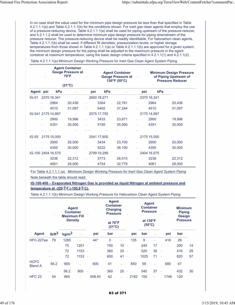
In no case shall the value used for the minimum pipe design pressure be less than that specified in Table4.2.1.1.1(a) and Table 4.2.1.1.1(b) for the conditions shown. For inert gas clean agents that employ the useof a pressure-reducing device, Table 4.2.1.1.1(a) shall be used for piping upstream of the pressure reducer,and 4.2.1.1.2 shall be used to determine minimum pipe design pressure for piping downstream of thepressure reducer. The pressure-reducing device shall be readily identifiable. For halocarbon clean agents,Table 4.2.1.1.1(b) shall be used. If different fill densities, pressurization levels, or higher storagetemperatures from those shown in Table 4.2.1.1.1(a) or Table 4.2.1.1.1(b) are approved for a given system,the minimum design pressure for the piping shall be adjusted to the maximum pressure in the agentcontainer at maximum temperature, using the basic design criteria specified in 4.2.1.1(1) and 4.2.1.1(2).
Table 4.2.1.1.1(a) Minimum Design Working Pressure for Inert Gas Clean Agent System Piping
Agent ContainerGauge Pressure at
70°F
(21°C)
Agent Container
Gauge Pressure at130°F (55°C)
Minimum Design Pressure
of Piping Upstream ofPressure Reducer
Agent psi kPa psi kPa psi kPa
IG-01 2370 16,341 2650 18,271 2370 16,341
2964 20,436 3304 22,781 2964 20,436
4510 31,097 5402 37,244 4510 31,097
IG-541 2175 14,997 2575 17,755 2175 14,997
2900 19,996 3433 23,671 2900 19,996
4351 30,000 5150 35,500 4351 30,000
IG-55 2175 15,000 2541 17,600 2175 15,000
2900 20,000 3434 23,700 2900 20,000
4350 30,000 5222 36,100 4350 30,000
IG-100 2404 16,575 2799 19,299 2404 16,575
3236 22,312 3773 26,015 3236 22,312
4061 28,000 4754 32,778 4061 28,000
For Table 4.2.1.1.1.(a) Minimum Design Working Pressure for Inert Gas Clean Agent System Piping
Note beneath the table should read:
IG-100-400 – Evaporated Nitrogen Gas is provided as liquid Nitrogen at ambient pressure and
temperature at -320 o F (-195.8 o C).
Table 4.2.1.1.1(b) Minimum Design Working Pressure for Halocarbon Clean Agent System Piping
AgentContainer
Maximum FillDensity
AgentContainerChargingPressure
at 70°F(21°C)
AgentContainerPressure
at 130°F(55°C)
MinimumPipingDesign
Pressure
Agent lb/ft3 kg/m3 psi bar psi bar psi bar
HFC-227ea 79 1265 44* 3 135 9 416 29
75 1201 150 10 249 17 200 14
72 1153 360 25 520 36 416 29
72 1153 600 41 1025 71 820 57
HCFCBlend A
56.2 900 600 41 850 59 680 47
56.2 900 360 25 540 37 432 30
HFC 23 54 865 608.9† 42 2182 150 1746 120
National Fire Protection Association Report https://submittals.nfpa.org/TerraViewWeb/ContentFetcher?commentPar...
49 of 176 3/15/2019, 10:45 AM
63 of 371
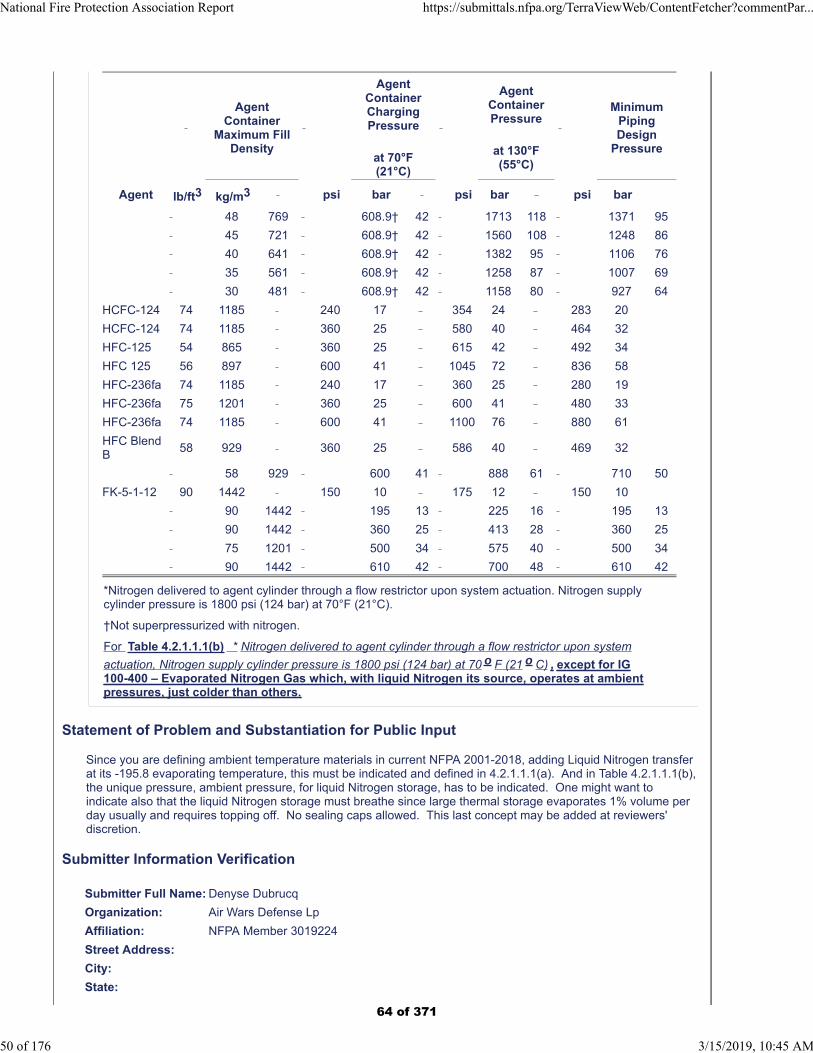
AgentContainer
Maximum FillDensity
AgentContainerChargingPressure
at 70°F(21°C)
AgentContainerPressure
at 130°F(55°C)
MinimumPipingDesign
Pressure
Agent lb/ft3 kg/m3 psi bar psi bar psi bar
48 769 608.9† 42 1713 118 1371 95
45 721 608.9† 42 1560 108 1248 86
40 641 608.9† 42 1382 95 1106 76
35 561 608.9† 42 1258 87 1007 69
30 481 608.9† 42 1158 80 927 64
HCFC-124 74 1185 240 17 354 24 283 20
HCFC-124 74 1185 360 25 580 40 464 32
HFC-125 54 865 360 25 615 42 492 34
HFC 125 56 897 600 41 1045 72 836 58
HFC-236fa 74 1185 240 17 360 25 280 19
HFC-236fa 75 1201 360 25 600 41 480 33
HFC-236fa 74 1185 600 41 1100 76 880 61
HFC BlendB
58 929 360 25 586 40 469 32
58 929 600 41 888 61 710 50
FK-5-1-12 90 1442 150 10 175 12 150 10
90 1442 195 13 225 16 195 13
90 1442 360 25 413 28 360 25
75 1201 500 34 575 40 500 34
90 1442 610 42 700 48 610 42
*Nitrogen delivered to agent cylinder through a flow restrictor upon system actuation. Nitrogen supplycylinder pressure is 1800 psi (124 bar) at 70°F (21°C).
†Not superpressurized with nitrogen.
For Table 4.2.1.1.1(b) * Nitrogen delivered to agent cylinder through a flow restrictor upon system
actuation, Nitrogen supply cylinder pressure is 1800 psi (124 bar) at 70 o F (21 o C) , except for IG100-400 – Evaporated Nitrogen Gas which, with liquid Nitrogen its source, operates at ambientpressures, just colder than others.
Statement of Problem and Substantiation for Public Input
Since you are defining ambient temperature materials in current NFPA 2001-2018, adding Liquid Nitrogen transfer at its -195.8 evaporating temperature, this must be indicated and defined in 4.2.1.1.1(a). And in Table 4.2.1.1.1(b), the unique pressure, ambient pressure, for liquid Nitrogen storage, has to be indicated. One might want toindicate also that the liquid Nitrogen storage must breathe since large thermal storage evaporates 1% volume per day usually and requires topping off. No sealing caps allowed. This last concept may be added at reviewers' discretion.
Submitter Information Verification
Submitter Full Name: Denyse Dubrucq
Organization: Air Wars Defense Lp
Affiliation: NFPA Member 3019224
Street Address:
City:
State:
National Fire Protection Association Report https://submittals.nfpa.org/TerraViewWeb/ContentFetcher?commentPar...
50 of 176 3/15/2019, 10:45 AM
64 of 371

Zip:
Submittal Date: Sat Sep 22 12:01:52 EDT 2018
Committee: GFE-AAA
National Fire Protection Association Report https://submittals.nfpa.org/TerraViewWeb/ContentFetcher?commentPar...
51 of 176 3/15/2019, 10:45 AM
65 of 371

Public Input No. 52-NFPA 2001-2018 [ Section No. 4.2.1.1.1 ]
National Fire Protection Association Report https://submittals.nfpa.org/TerraViewWeb/ContentFetcher?commentPar...
52 of 176 3/15/2019, 10:45 AM
66 of 371

4.2.1.1.1
National Fire Protection Association Report https://submittals.nfpa.org/TerraViewWeb/ContentFetcher?commentPar...
53 of 176 3/15/2019, 10:45 AM
67 of 371
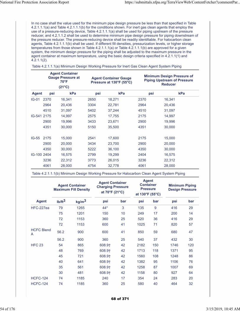
In no case shall the value used for the minimum pipe design pressure be less than that specified in Table4.2.1.1.1(a) and Table 4.2.1.1.1(b) for the conditions shown. For inert gas clean agents that employ theuse of a pressure-reducing device, Table 4.2.1.1.1(a) shall be used for piping upstream of the pressurereducer, and 4.2.1.1.2 shall be used to determine minimum pipe design pressure for piping downstream ofthe pressure reducer. The pressure-reducing device shall be readily identifiable. For halocarbon cleanagents, Table 4.2.1.1.1(b) shall be used. If different fill densities, pressurization levels, or higher storagetemperatures from those shown in Table 4.2.1.1.1(a) or Table 4.2.1.1.1(b) are approved for a givensystem, the minimum design pressure for the piping shall be adjusted to the maximum pressure in theagent container at maximum temperature, using the basic design criteria specified in 4.2.1.1(1) and4.2.1.1(2).
Table 4.2.1.1.1(a) Minimum Design Working Pressure for Inert Gas Clean Agent System Piping
Agent ContainerGauge Pressure at
70°F
(21°C)
Agent Container GaugePressure at 130°F (55°C)
Minimum Design Pressure ofPiping Upstream of Pressure
Reducer
Agent psi kPa psi kPa psi kPa
IG-01 2370 16,341 2650 18,271 2370 16,341
2964 20,436 3304 22,781 2964 20,436
4510 31,097 5402 37,244 4510 31,097
IG-541 2175 14,997 2575 17,755 2175 14,997
2900 19,996 3433 23,671 2900 19,996
4351 30,000 5150 35,500 4351 30,000
IG-55 2175 15,000 2541 17,600 2175 15,000
2900 20,000 3434 23,700 2900 20,000
4350 30,000 5222 36,100 4350 30,000
IG-100 2404 16,575 2799 19,299 2404 16,575
3236 22,312 3773 26,015 3236 22,312
4061 28,000 4754 32,778 4061 28,000
Table 4.2.1.1.1(b) Minimum Design Working Pressure for Halocarbon Clean Agent System Piping
Agent ContainerMaximum Fill Density
Agent ContainerCharging Pressure
at 70°F (21°C)
AgentContainerPressure
at 130°F (55°C)
Minimum PipingDesign Pressure
Agent lb/ft3 kg/m3 psi bar psi bar psi bar
HFC-227ea 79 1265 44* 3 135 9 416 29
75 1201 150 10 249 17 200 14
72 1153 360 25 520 36 416 29
72 1153 600 41 1025 71 820 57
HCFC BlendA
56.2 900 600 41 850 59 680 47
56.2 900 360 25 540 37 432 30
HFC 23 54 865 608.9† 42 2182 150 1746 120
48 769 608.9† 42 1713 118 1371 95
45 721 608.9† 42 1560 108 1248 86
40 641 608.9† 42 1382 95 1106 76
35 561 608.9† 42 1258 87 1007 69
30 481 608.9† 42 1158 80 927 64
HCFC-124 74 1185 240 17 354 24 283 20
HCFC-124 74 1185 360 25 580 40 464 32
National Fire Protection Association Report https://submittals.nfpa.org/TerraViewWeb/ContentFetcher?commentPar...
54 of 176 3/15/2019, 10:45 AM
68 of 371
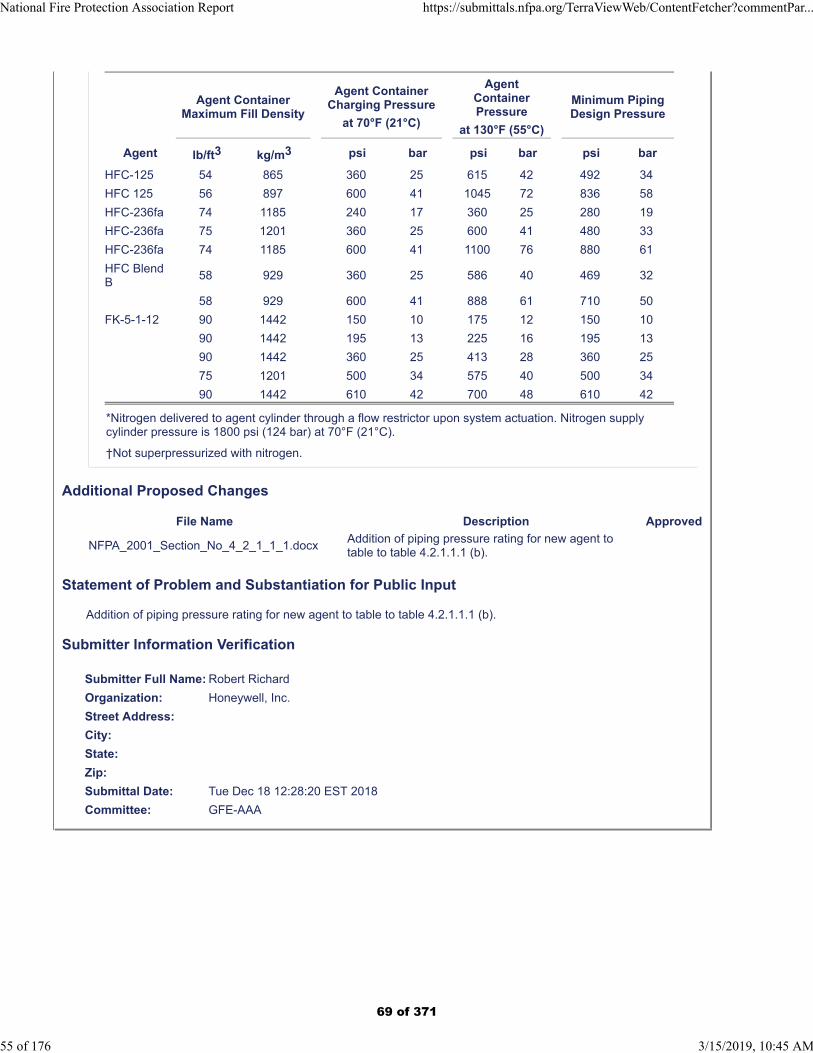
Agent ContainerMaximum Fill Density
Agent ContainerCharging Pressure
at 70°F (21°C)
AgentContainerPressure
at 130°F (55°C)
Minimum PipingDesign Pressure
Agent lb/ft3 kg/m3 psi bar psi bar psi bar
HFC-125 54 865 360 25 615 42 492 34
HFC 125 56 897 600 41 1045 72 836 58
HFC-236fa 74 1185 240 17 360 25 280 19
HFC-236fa 75 1201 360 25 600 41 480 33
HFC-236fa 74 1185 600 41 1100 76 880 61
HFC BlendB
58 929 360 25 586 40 469 32
58 929 600 41 888 61 710 50
FK-5-1-12 90 1442 150 10 175 12 150 10
90 1442 195 13 225 16 195 13
90 1442 360 25 413 28 360 25
75 1201 500 34 575 40 500 34
90 1442 610 42 700 48 610 42
*Nitrogen delivered to agent cylinder through a flow restrictor upon system actuation. Nitrogen supplycylinder pressure is 1800 psi (124 bar) at 70°F (21°C).
†Not superpressurized with nitrogen.
Additional Proposed Changes
File Name Description Approved
NFPA_2001_Section_No_4_2_1_1_1.docxAddition of piping pressure rating for new agent to table to table 4.2.1.1.1 (b).
Statement of Problem and Substantiation for Public Input
Addition of piping pressure rating for new agent to table to table 4.2.1.1.1 (b).
Submitter Information Verification
Submitter Full Name: Robert Richard
Organization: Honeywell, Inc.
Street Address:
City:
State:
Zip:
Submittal Date: Tue Dec 18 12:28:20 EST 2018
Committee: GFE-AAA
National Fire Protection Association Report https://submittals.nfpa.org/TerraViewWeb/ContentFetcher?commentPar...
55 of 176 3/15/2019, 10:45 AM
69 of 371
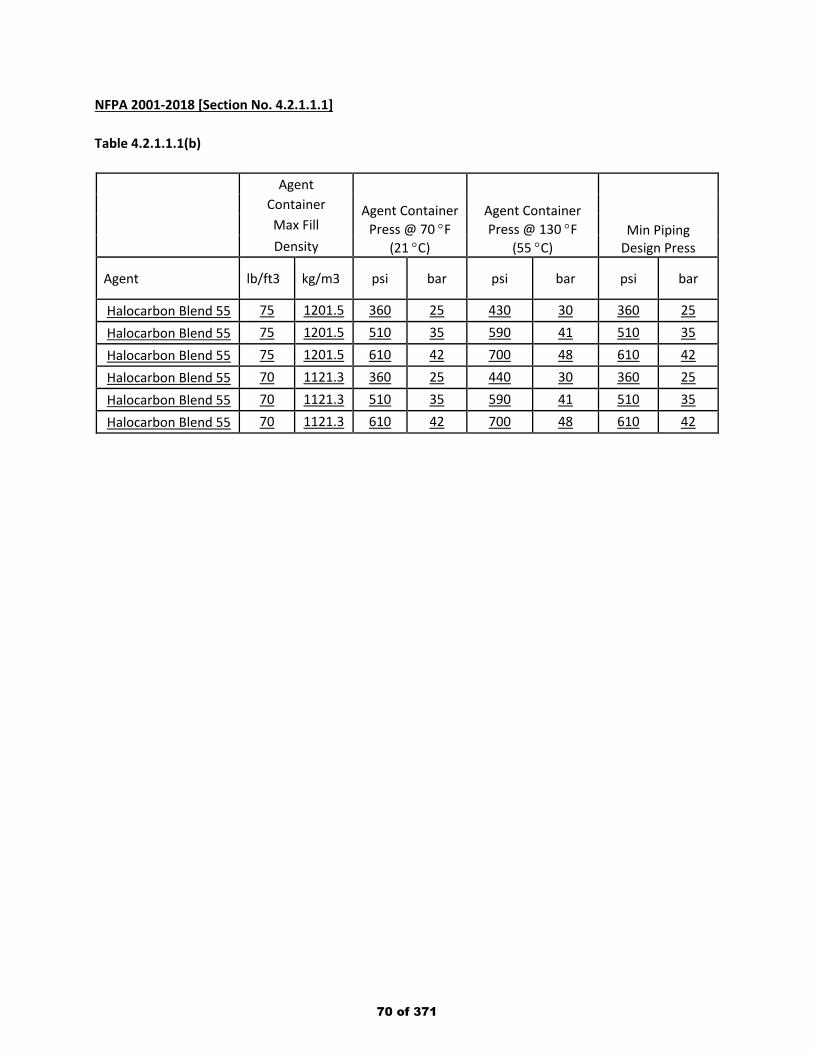
NFPA 2001-2018 [Section No. 4.2.1.1.1] Table 4.2.1.1.1(b)
Agent
Agent Container Press @ 70 °F
(21 °C)
Agent Container Press @ 130 °F
(55 °C) Min Piping
Design Press
Container Max Fill Density
Agent lb/ft3 kg/m3 psi bar psi bar psi bar
Halocarbon Blend 55 75 1201.5 360 25 430 30 360 25 Halocarbon Blend 55 75 1201.5 510 35 590 41 510 35 Halocarbon Blend 55 75 1201.5 610 42 700 48 610 42 Halocarbon Blend 55 70 1121.3 360 25 440 30 360 25 Halocarbon Blend 55 70 1121.3 510 35 590 41 510 35 Halocarbon Blend 55 70 1121.3 610 42 700 48 610 42
70 of 371
Public Input No. 6-NFPA 2001-2018 [ New Section after 4.2.1.6 ]
4.2.1.6.1 Single nozzle systems with a single pipe run from a clean agent container to the nozzleare not required to have a dirt trap.
Statement of Problem and Substantiation for Public Input
Main, secondary and branch lines (supplying multiple nozzles) have tees provided at each branch which can facilitate the installation of a dirt trap. Single nozzle systems typically have straight runs of pipe connected directly to the single nozzle with no branch tees. In addition, single nozzle systems are typically short pipe runs required to be free of particulate matter and oil residue (as are all systems; see section 4.2.1.5).
Submitter Information Verification
Submitter Full Name: Daniel Hubert
Organization: AmerexJanus Fire Systems
Street Address:
City:
State:
Zip:
Submittal Date: Thu Aug 09 17:35:28 EDT 2018
Committee: GFE-AAA
National Fire Protection Association Report https://submittals.nfpa.org/TerraViewWeb/ContentFetcher?commentPar...
56 of 176 3/15/2019, 10:45 AM
71 of 371
Public Input No. 5-NFPA 2001-2018 [ Section No. 4.2.1.6 ]
4.2.1.6 Dirt Trap.
A dirt trap consisting of a tee with a capped nipple, at least 2 in. (50 mm) long, shall be installed at the endinstalled beyond the last branch connection of each main supply pipe run, secondary (cross main) piperuns and branch lines supplying multiple nozzles .
Statement of Problem and Substantiation for Public Input
The additional language further details where dirt traps should be required to be installed.
Submitter Information Verification
Submitter Full Name: Daniel Hubert
Organization: AmerexJanus Fire Systems
Street Address:
City:
State:
Zip:
Submittal Date: Thu Aug 09 17:29:16 EDT 2018
Committee: GFE-AAA
National Fire Protection Association Report https://submittals.nfpa.org/TerraViewWeb/ContentFetcher?commentPar...
57 of 176 3/15/2019, 10:45 AM
72 of 371
Public Input No. 24-NFPA 2001-2018 [ New Section after 4.2.2.10 ]
TITLE OF NEW CONTENT
AMEND: 4.2.2.11 For IG-100-400 – Evaporated Nitrogen Gas systems, fittings shall corner with 45 o
turns taking two 45 o turns to comprise a 90 o turn to prevent further bounce-back of liquid Nitrogen. Alltransitions downhill will have the fitting and tubing on equal plane or the upper component from the sourcewill be higher than the one leading to dispersion tool so there is no splash back currents in the flow of liquidNitrogen.
Additional Proposed Changes
File Name Description Approved
.1537636427432
Patent drawing for fixed nitrogen fire control showing 45o angle turns combined for 90oturn and flat flow so not to have liquid Nitrogen splashback slowing the flow. See first 7 drawings.
Patent-Cryogenictransport_color_print_and_scan.ppt
Liquid Nitrogen flows like Mercury, rapid movement in mass, balls, keeping clear liquid with no inclusion of other than N2 Nitrogen. When it hits a "T" or turns a 90o corner "L" it will splash back disrupting smooth flow. Using 45o corners, two for a 90o turn, the flow will just move along as it did. If you have a smooth flow surface, it will move along undisturbed; however if there are ridges to climb as it flows, again the flow will be disrupted. These are to be avoided to get the whole amount of liquid Nitrogen to the location of the crisis.
Statement of Problem and Substantiation for Public Input
Liquid NItrogen is clear as water, but flows like Mercury having the same attraction: Mercury to Mercury atoms are self attracting as are Nitrogen N2 molecules. The flow is in masses of liquid Nitrogen. When they hit a wall as they would with either a "T" intersection of 90o turn "L" the mass of liquid Nitrogen hits the wall and splashes back disturbing the flow, slowing the delivery. Similarly, if a ridge happens in the joining of two sections of pipe, it too disturbs the flow slowing the delivery of liquid Nitrogen to its destination and use.
Submitter Information Verification
Submitter Full Name: Denyse Dubrucq
Organization: Air Wars Defense Lp
Affiliation: NFPA Member 3019224
Street Address:
City:
State:
Zip:
Submittal Date: Sat Sep 22 13:10:58 EDT 2018
Committee: GFE-AAA
National Fire Protection Association Report https://submittals.nfpa.org/TerraViewWeb/ContentFetcher?commentPar...
58 of 176 3/15/2019, 10:45 AM
73 of 371

Numbering Index1. Nitrogen gas
10. Liquid Nitrogen11. CryoRain - drops12. Stored N2 to fill pipes13. Liquefying N214. Cooling N215. Heating N2 to gather fuels16. Purifying N217. Perforated surfaces18. Evaporator19. Air - atmosphere
2. Insulating spaces20. Parallel pipe space21. Molded components22. Fitting other products23. Frame induced spacing24. Insulating material
3. Plastic30. Pipes31. Connectors32. Roller bearings33. Seamed materials34. High temperature35. Installed components
36. Ventilated cap37. Fused seams38. Slow flow pipe39. Oxygen supply & tube
4. Valves, motion40. Allow/stop flow41. One way42. Tippers – fill & spill43. Cycling - evaporator
5. Electronics50. Lighting51. Batteries – solar52. Situation switching53. Valve motion54. Wiring55. Indicators56. Regulators57. Remote control58. Chain puller
6. Thermal qualities60. Switch by cold61. No frost or icing62. Heat to kill bedbugs63. Heat to select fuel
64. Cool to separate65. Cool to liquefy66. Keep hot for Fuels67. Smoke
7. Signals70. Smoke detector71. Fuel/water separator72. Battery operating73. Fire74. Thermal indicator75. Thermal flow control76. Lift with scale77. CO2 filter78. Nitrogen release signal
8. Item 80. Motor81. Truck82. Cap83. Oil spill84. Water85. Oven86. Clothing87. Skimmer, net88. Ties holding equipment89. Cover to protect from rain
74 of 371
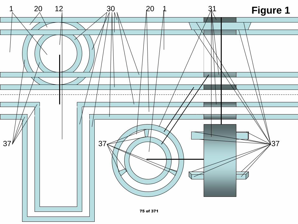
Figure 11 20 12 30 20 1 31
37 37 37
75 of 371
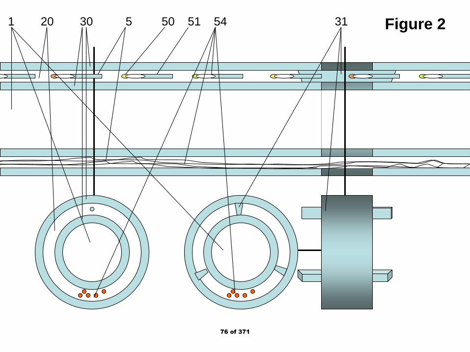
Figure 21 20 30 5 50 51 54 31
76 of 371

Figure 3
. .
30 20 1 50 51 4 53 40 10 1 54 53 31 40
77 of 371

Figure 4
54 30 20 1 31 54 5178 of 371
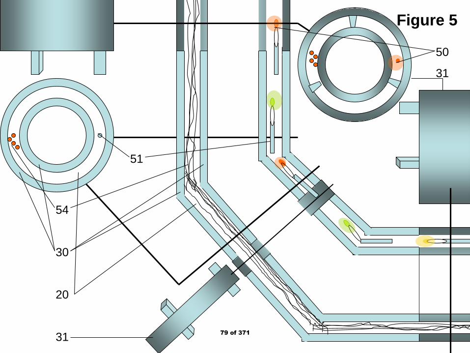
Figure 5
54
30
20
31
50
31
51
79 of 371
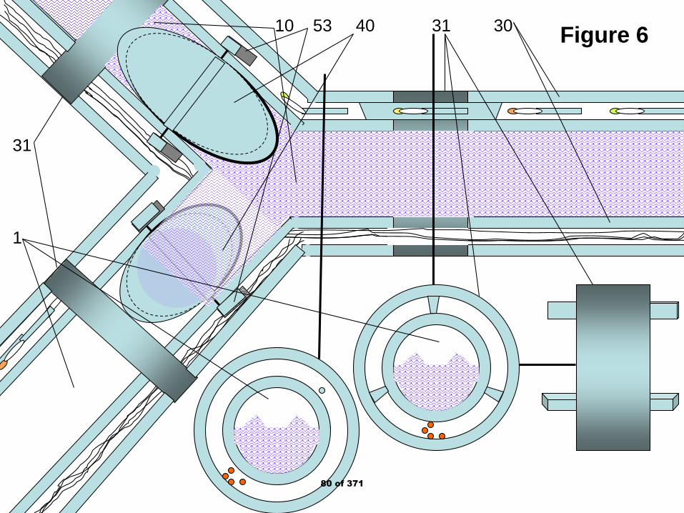
Figure 610 53 40 31 30
31
1
80 of 371
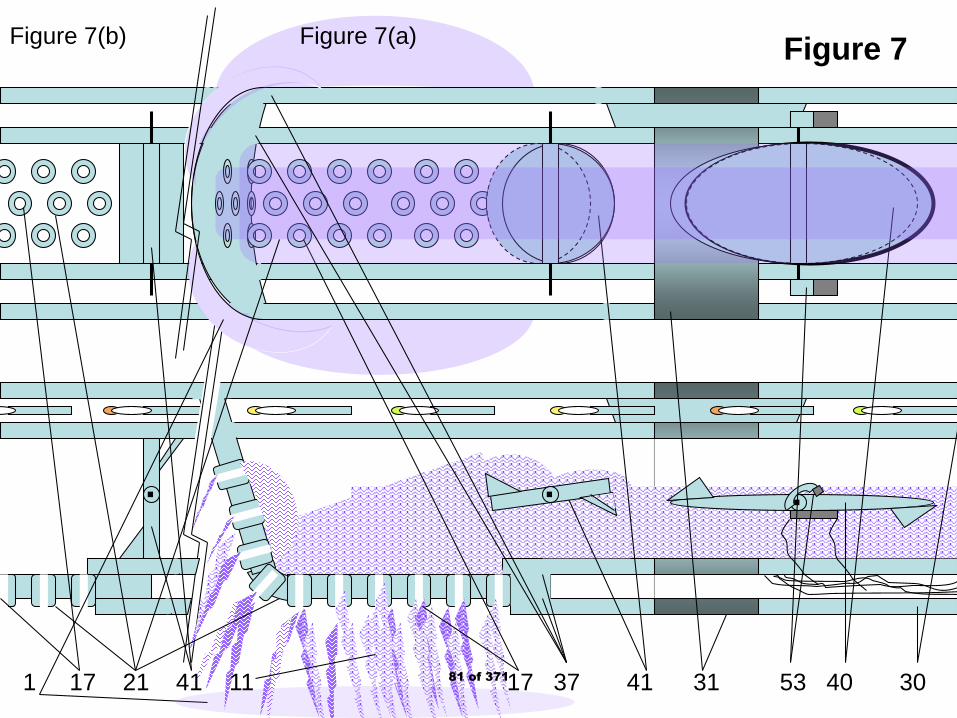
Figure 7
.. .
1 17 21 41 11 17 37 41 31 53 40 30
Figure 7(b) Figure 7(a)
81 of 371

Figure 8
40 11 1 73 10 17 81 30 17 37 30 11 20
1 83 87 64
Figure 8(a) Figure 8(b)
Figure8(c)
82 of 371

Figure 917
36
10
11
1
21
37
30
20
Figure 9(a)
Figure 9(b)37
38
83 of 371

Figure 1021
37
50
54
20
30
72
51
37
34
21
10
42 17
10
11
1
73
Figure 10a Figure 10(b)
Figure 10(c)84 of 371

Figure 11
17
82
30
20
21
37
22
36 21 37
Figure 11(a) Figure 11(c)
Figure 11(b)
85 of 371

Figure 12
10
11
22
1
82
17
20
61
21
Figure 12(a) Figure 12(b)
86 of 371

Figure 1373 86 1 11 10
73 85 1 11 10
Figure 13(a)
Figure 13(b)
Figure 13(c)
42
87 of 371
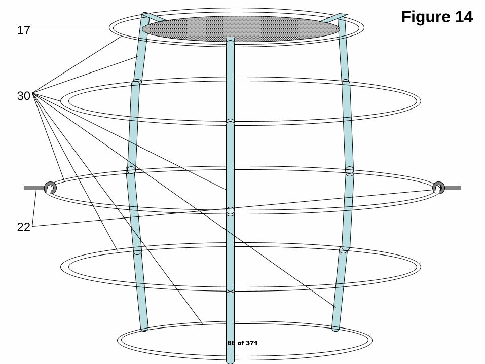
Figure 1417
30
22
88 of 371

Figure 1576
80
57
35
22
32
58
31
89 of 371

Figure 16
77
57
31
58
82
10
30
58
76
17
81
1
30
10
35
32
22
33
23
Figure 16(a) Figure 16(b)
Figure 16(c)
90 of 371

Figure 1776
1
33
22
32
81
76
10
23
30
1711
1
80
57
31
58
30
82
Figure 17(a) Figure 17(b) Figure 17(c)
91 of 371
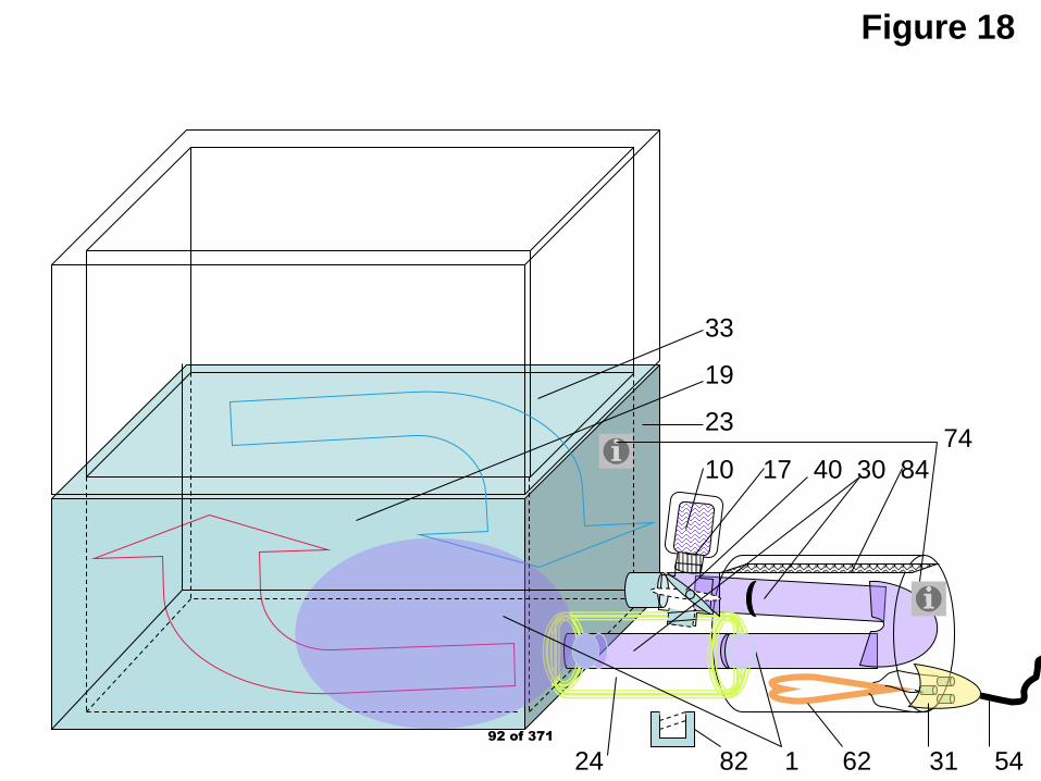
Figure 18
24 82 1 62 31 54
74 10 17 40 30 84
33
19
23
92 of 371
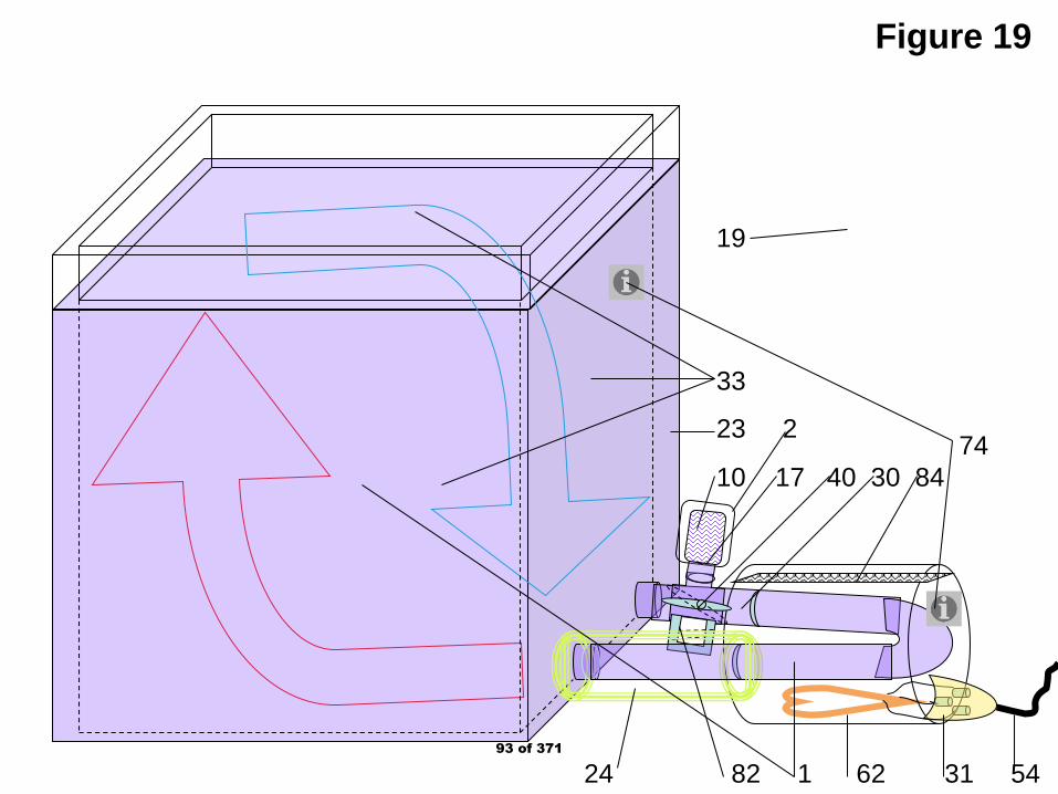
Figure 19
24 82 1 62 31 54
74 10 17 40 30 84
19
33
23 2
93 of 371

Figure 20
.
30
40
80
20
17
18
14 20 3794 of 371

Figure 21
.
30
40
80
17
18
10
1
11
20
30
195 of 371

CH4
Figure 22
Neon
H2/He
N2Ether
Water
LNGLPG
O2/Ar
43
18
1 10
13
74
17
1
15 63 73 74 30 37 20 40 15 73 63
Fig. 22(a) Fig. 22(b)
64 77 75 1
71
84
65 10
Heating oil Kerosene Gasoline
30
66
24
3066
Fig. 22(d)
Fig. 22(c)96 of 371
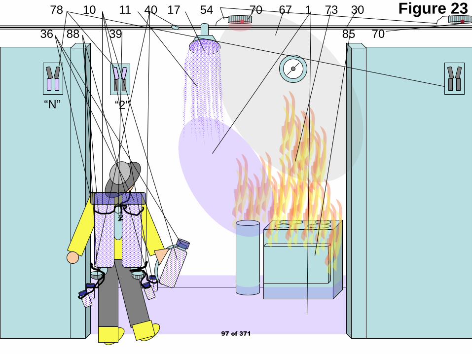
Figure 23
“N” “2”
22
78 10 11 40 17 54 70 67 1 73 30
36 88 39 85 70
97 of 371

Figure 24
“N”“2”
22
78 11 40 1 70 67 73 30
88 10 39 17 85
8920361
Figure 24(a)
Figure 24(b)98 of 371
Public Input No. 25-NFPA 2001-2018 [ New Section after 4.2.3.4.2 ]
TITLE OF NEW CONTENT
AMEND: 4.2.3.4.3 For IG-100-400 – Evaporated Nitrogen, pressure nozzles are not used, but dispersiontools with tubing entering a perforated outlet which enables cryorain (drops of liquid Nitrogen falling by forceof gravity and evaporating into Evaporated Nitrogen Gas.). Entry from tubing into dispensing tool will beflush or the tubing outlet from the source shall be above the dispensing tool entry for smooth flow of liquidNitrogen....
Additional Proposed Changes
File Name Description Approved
.1537637557007 Same reference as for 4.2.1.1.1(b)
Patent-Cryogenictransport_color_print_and_scan.ppt
Same as used for 4.2.1.1.1.(a) and (b). 90o turns causes liquid Nitrogen to splash back so use two 45o turns in sequence and the flow will be rapid and smooth. Similarly, ridges in the pathway as when pipe sections are joined will cause flow disruption as well slowing the arrival of the liquid Nitrogen to event.
Statement of Problem and Substantiation for Public Input
For most efficient use of liquid Nitrogen, the flow must not meet with abrupt ends as with a "T" or "L" configuration needing 90o turns. Using two 45o turns in sequence will get an undisturbed flow around a corner or in a choice of direction where using a "Y" configuration with additional 45o turn will get the same choice and direction change without the flow diturbance of the liquid Nitrogen. Also ridges in the pathway disturb flow as well so eliminate any abrupt uphill movement of the liquid Nitrogen.
Submitter Information Verification
Submitter Full Name: Denyse Dubrucq
Organization: Air Wars Defense Lp
Affiliation: NFPA Member 3019224
Street Address:
City:
State:
Zip:
Submittal Date: Sat Sep 22 13:30:02 EDT 2018
Committee: GFE-AAA
National Fire Protection Association Report https://submittals.nfpa.org/TerraViewWeb/ContentFetcher?commentPar...
59 of 176 3/15/2019, 10:45 AM
99 of 371
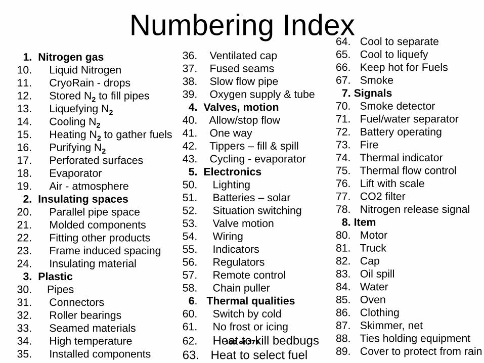
Numbering Index1. Nitrogen gas
10. Liquid Nitrogen11. CryoRain - drops12. Stored N2 to fill pipes13. Liquefying N214. Cooling N215. Heating N2 to gather fuels16. Purifying N217. Perforated surfaces18. Evaporator19. Air - atmosphere
2. Insulating spaces20. Parallel pipe space21. Molded components22. Fitting other products23. Frame induced spacing24. Insulating material
3. Plastic30. Pipes31. Connectors32. Roller bearings33. Seamed materials34. High temperature35. Installed components
36. Ventilated cap37. Fused seams38. Slow flow pipe39. Oxygen supply & tube
4. Valves, motion40. Allow/stop flow41. One way42. Tippers – fill & spill43. Cycling - evaporator
5. Electronics50. Lighting51. Batteries – solar52. Situation switching53. Valve motion54. Wiring55. Indicators56. Regulators57. Remote control58. Chain puller
6. Thermal qualities60. Switch by cold61. No frost or icing62. Heat to kill bedbugs63. Heat to select fuel
64. Cool to separate65. Cool to liquefy66. Keep hot for Fuels67. Smoke
7. Signals70. Smoke detector71. Fuel/water separator72. Battery operating73. Fire74. Thermal indicator75. Thermal flow control76. Lift with scale77. CO2 filter78. Nitrogen release signal
8. Item 80. Motor81. Truck82. Cap83. Oil spill84. Water85. Oven86. Clothing87. Skimmer, net88. Ties holding equipment89. Cover to protect from rain
100 of 371

Figure 11 20 12 30 20 1 31
37 37 37
101 of 371

Figure 21 20 30 5 50 51 54 31
102 of 371
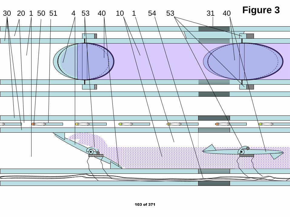
Figure 3
. .
30 20 1 50 51 4 53 40 10 1 54 53 31 40
103 of 371
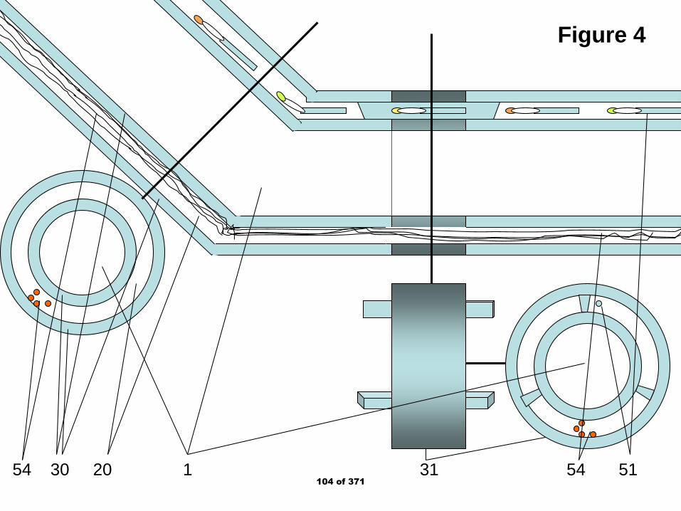
Figure 4
54 30 20 1 31 54 51104 of 371

Figure 5
54
30
20
31
50
31
51
105 of 371

Figure 610 53 40 31 30
31
1
106 of 371

Figure 7
.. .
1 17 21 41 11 17 37 41 31 53 40 30
Figure 7(b) Figure 7(a)
107 of 371

Figure 8
40 11 1 73 10 17 81 30 17 37 30 11 20
1 83 87 64
Figure 8(a) Figure 8(b)
Figure8(c)
108 of 371

Figure 917
36
10
11
1
21
37
30
20
Figure 9(a)
Figure 9(b)37
38
109 of 371
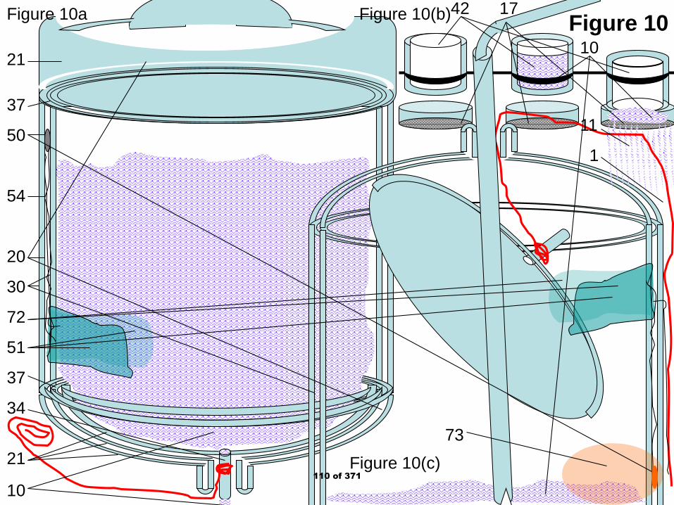
Figure 1021
37
50
54
20
30
72
51
37
34
21
10
42 17
10
11
1
73
Figure 10a Figure 10(b)
Figure 10(c)110 of 371

Figure 11
17
82
30
20
21
37
22
36 21 37
Figure 11(a) Figure 11(c)
Figure 11(b)
111 of 371
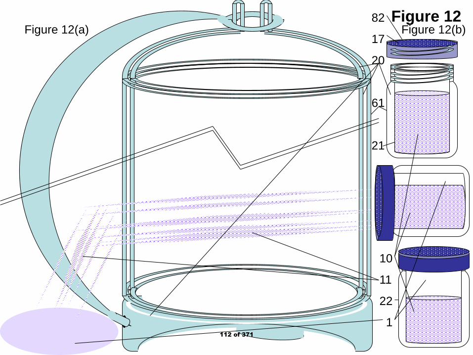
Figure 12
10
11
22
1
82
17
20
61
21
Figure 12(a) Figure 12(b)
112 of 371

Figure 1373 86 1 11 10
73 85 1 11 10
Figure 13(a)
Figure 13(b)
Figure 13(c)
42
113 of 371

Figure 1417
30
22
114 of 371
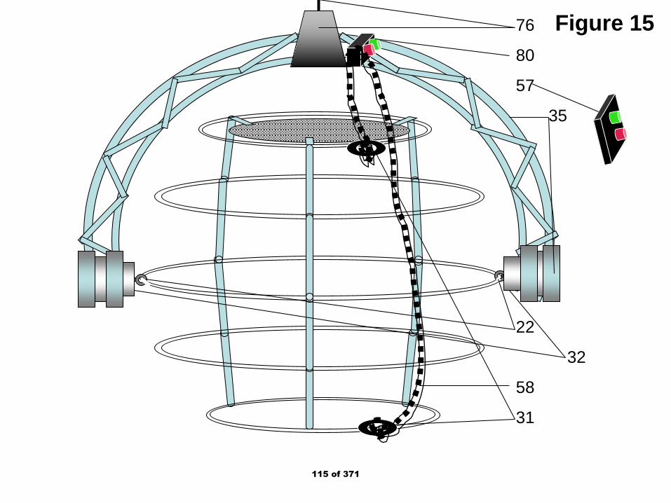
Figure 1576
80
57
35
22
32
58
31
115 of 371
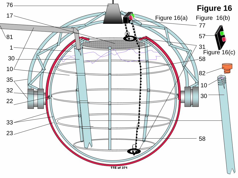
Figure 16
77
57
31
58
82
10
30
58
76
17
81
1
30
10
35
32
22
33
23
Figure 16(a) Figure 16(b)
Figure 16(c)
116 of 371
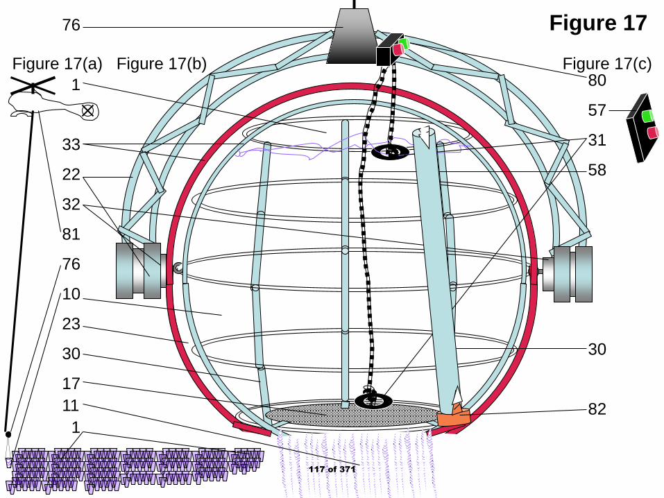
Figure 1776
1
33
22
32
81
76
10
23
30
1711
1
80
57
31
58
30
82
Figure 17(a) Figure 17(b) Figure 17(c)
117 of 371

Figure 18
24 82 1 62 31 54
74 10 17 40 30 84
33
19
23
118 of 371
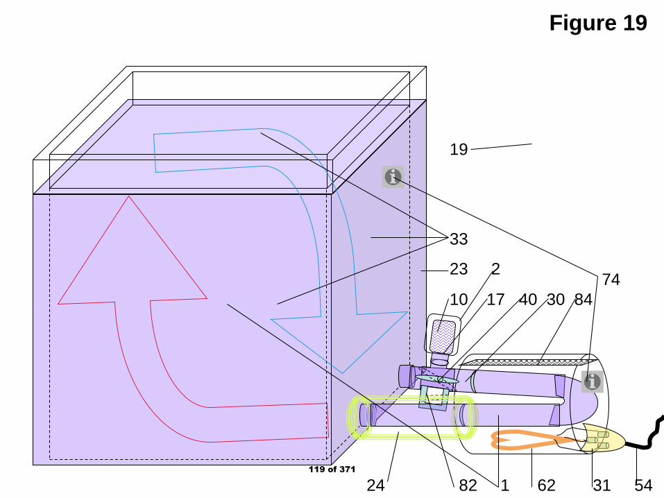
Figure 19
24 82 1 62 31 54
74 10 17 40 30 84
19
33
23 2
119 of 371

Figure 20
.
30
40
80
20
17
18
14 20 37120 of 371

Figure 21
.
30
40
80
17
18
10
1
11
20
30
1121 of 371

CH4
Figure 22
Neon
H2/He
N2Ether
Water
LNGLPG
O2/Ar
43
18
1 10
13
74
17
1
15 63 73 74 30 37 20 40 15 73 63
Fig. 22(a) Fig. 22(b)
64 77 75 1
71
84
65 10
Heating oil Kerosene Gasoline
30
66
24
3066
Fig. 22(d)
Fig. 22(c)122 of 371

Figure 23
“N” “2”
22
78 10 11 40 17 54 70 67 1 73 30
36 88 39 85 70
123 of 371
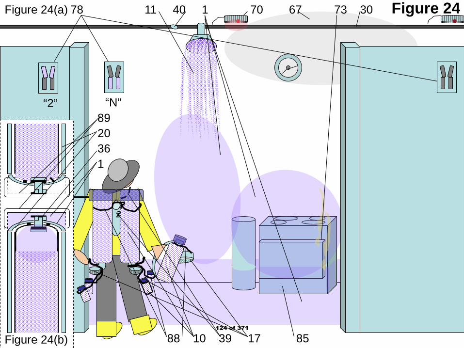
Figure 24
“N”“2”
22
78 11 40 1 70 67 73 30
88 10 39 17 85
8920361
Figure 24(a)
Figure 24(b)124 of 371
Public Input No. 70-NFPA 2001-2019 [ Section No. 5.1 ]
5.1 * Specifications, Plans, and Approvals.
5.1.1 Specifications.
Specifications for total flooding and local application clean agent fire extinguishing systems shall beprepared under the supervision of a person fully experienced and qualified in the design of such systemsand with the advice of the authority having jurisdiction. The specifications shall include all pertinent itemsnecessary for the proper design of the system, such as the designation of the authority having jurisdiction,variances from the standard to be permitted by the authority having jurisdiction, design criteria, systemsequence of operations, the type and extent of the approval testing to be performed after installation of thesystem, and owner training requirements.
5.1.2 Working Plans.
5.1.2.1
Working plans and calculations shall be submitted for approval to the authority having jurisdiction beforesystem installation or remodeling begins. These documents shall be prepared only by persons fullyexperienced and qualified in the design of total flooding and local application clean agent fire extinguishingsystems. Deviation from these documents shall require permission of the authority having jurisdiction.
National Fire Protection Association Report https://submittals.nfpa.org/TerraViewWeb/ContentFetcher?commentPar...
60 of 176 3/15/2019, 10:45 AM
125 of 371

5.1.2.2
National Fire Protection Association Report https://submittals.nfpa.org/TerraViewWeb/ContentFetcher?commentPar...
61 of 176 3/15/2019, 10:45 AM
126 of 371
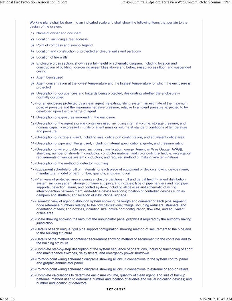
Working plans shall be drawn to an indicated scale and shall show the following items that pertain to thedesign of the system:
(1) Name of owner and occupant
(2) Location, including street address
(3) Point of compass and symbol legend
(4) Location and construction of protected enclosure walls and partitions
(5) Location of fire walls
(6) Enclosure cross section, shown as a full-height or schematic diagram, including location andconstruction of building floor-ceiling assemblies above and below, raised access floor, and suspendedceiling
(7) Agent being used
(8) Agent concentration at the lowest temperature and the highest temperature for which the enclosure isprotected
(9) Description of occupancies and hazards being protected, designating whether the enclosure isnormally occupied
(10) For an enclosure protected by a clean agent fire extinguishing system, an estimate of the maximumpositive pressure and the maximum negative pressure, relative to ambient pressure, expected to bedeveloped upon the discharge of agent
(11) Description of exposures surrounding the enclosure
(12) Description of the agent storage containers used, including internal volume, storage pressure, andnominal capacity expressed in units of agent mass or volume at standard conditions of temperatureand pressure
(13) Description of nozzle(s) used, including size, orifice port configuration, and equivalent orifice area
(14) Description of pipe and fittings used, including material specifications, grade, and pressure rating
(15) Description of wire or cable used, including classification, gauge [American Wire Gauge (AWG)],shielding, number of strands in conductor, conductor material, and color coding schedule; segregationrequirements of various system conductors; and required method of making wire terminations
(16) Description of the method of detector mounting
(17) Equipment schedule or bill of materials for each piece of equipment or device showing device name,manufacturer, model or part number, quantity, and description
(18) Plan view of protected area showing enclosure partitions (full and partial height); agent distributionsystem, including agent storage containers, piping, and nozzles; type of pipe hangers and rigid pipesupports; detection, alarm, and control system, including all devices and schematic of wiringinterconnection between them; end-of-line device locations; location of controlled devices such asdampers and shutters; and location of instructional signage
(19) Isometric view of agent distribution system showing the length and diameter of each pipe segment;node reference numbers relating to the flow calculations; fittings, including reducers, strainers, andorientation of tees; and nozzles, including size, orifice port configuration, flow rate, and equivalentorifice area
(20) Scale drawing showing the layout of the annunciator panel graphics if required by the authority havingjurisdiction
(21) Details of each unique rigid pipe support configuration showing method of securement to the pipe andto the building structure
(22) Details of the method of container securement showing method of securement to the container and tothe building structure
(23) Complete step-by-step description of the system sequence of operations, including functioning of abortand maintenance switches, delay timers, and emergency power shutdown
(24) Point-to-point wiring schematic diagrams showing all circuit connections to the system control paneland graphic annunciator panel
(25) Point-to-point wiring schematic diagrams showing all circuit connections to external or add-on relays
(26) Complete calculations to determine enclosure volume, quantity of clean agent, and size of backupbatteries; method used to determine number and location of audible and visual indicating devices; andnumber and location of detectors
National Fire Protection Association Report https://submittals.nfpa.org/TerraViewWeb/ContentFetcher?commentPar...
62 of 176 3/15/2019, 10:45 AM
127 of 371

Numbering Index1. Nitrogen gas
10. Liquid Nitrogen11. CryoRain - drops12. Stored N2 to fill pipes13. Liquefying N214. Cooling N215. Heating N2 to gather fuels16. Purifying N217. Perforated surfaces18. Evaporator19. Air - atmosphere
2. Insulating spaces20. Parallel pipe space21. Molded components22. Fitting other products23. Frame induced spacing24. Insulating material
3. Plastic30. Pipes31. Connectors32. Roller bearings33. Seamed materials34. High temperature35. Installed components
36. Ventilated cap37. Fused seams38. Slow flow pipe39. Oxygen supply & tube
4. Valves, motion40. Allow/stop flow41. One way42. Tippers – fill & spill43. Cycling - evaporator
5. Electronics50. Lighting51. Batteries – solar52. Situation switching53. Valve motion54. Wiring55. Indicators56. Regulators57. Remote control58. Chain puller
6. Thermal qualities60. Switch by cold61. No frost or icing62. Heat to kill bedbugs63. Heat to select fuel
64. Cool to separate65. Cool to liquefy66. Keep hot for Fuels67. Smoke
7. Signals70. Smoke detector71. Fuel/water separator72. Battery operating73. Fire74. Thermal indicator75. Thermal flow control76. Lift with scale77. CO2 filter78. Nitrogen release signal
8. Item 80. Motor81. Truck82. Cap83. Oil spill84. Water85. Oven86. Clothing87. Skimmer, net88. Ties holding equipment89. Cover to protect from rain
128 of 371
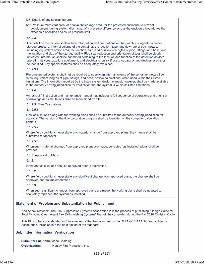
(27) Details of any special features
(28)
5.1.2.3
The detail on the system shall include information and calculations on the quantity of agent; containerstorage pressure; internal volume of the container; the location, type, and flow rate of each nozzle,including equivalent orifice area; the location, size, and equivalent lengths of pipe, fittings, and hose; andthe location and size of the storage facility. Pipe size reduction and orientation of tees shall be clearlyindicated. Information shall be submitted pertaining to the location and function of the detection devices,operating devices, auxiliary equipment, and electrical circuitry, if used. Apparatus and devices used shallbe identified. Any special features shall be adequately explained.
5.1.2.3.1
Pre-engineered systems shall not be required to specify an internal volume of the container, nozzle flowrates, equivalent lengths of pipe, fittings, and hose, or flow calculations, when used within their listedlimitations. The information required by the listed system design manual, however, shall be made availableto the authority having jurisdiction for verification that the system is within its listed limitations.
5.1.2.4
An “as-built” instruction and maintenance manual that includes a full sequence of operations and a full setof drawings and calculations shall be maintained on site.
5.1.2.5 Flow Calculations.
5.1.2.5.1
Flow calculations along with the working plans shall be submitted to the authority having jurisdiction forapproval. The version of the flow calculation program shall be identified on the computer calculationprintout.
5.1.2.5.2
Where field conditions necessitate any material change from approved plans, the change shall besubmitted for approval.
5.1.2.5.3
When such material changes from approved plans are made, corrected “as-installed” plans shall beprovided.
5.1.3 Approval of Plans.
5.1.3.1
Plans and calculations shall be approved prior to installation.
5.1.3.2
Where field conditions necessitate any significant change from approved plans, the change shall beapproved prior to implementation.
5.1.3.3
When such significant changes from approved plans are made, the working plans shall be updated toaccurately represent the system as installed.
Statement of Problem and Substantiation for Public Input
Add Annex Material: The Fire Suppression Systems Association is in the process of publishing "Design Guide for Total Flooding Clean Agent Fire Extinguishing Systems" that will be completed during the Fall 2020 Revision Cycle.
This PI is to be a placeholder for future review of the the document by the NFPA GFE-AAA TC and, subject to acceptance, inclusion into the next edition of the standard.
Submitter Information Verification
Submitter Full Name: John Spalding
Organization: Healey Fire Protection, Inc.
* Pressure relief vent area, or equivalent leakage area, for the protected enclosure to preventdevelopment, during system discharge, of a pressure difference across the enclosure boundaries thatexceeds a specified enclosure pressure limit
National Fire Protection Association Report https://submittals.nfpa.org/TerraViewWeb/ContentFetcher?commentPar...
63 of 176 3/15/2019, 10:45 AM
129 of 371
Affiliation: Fire Suppression Systems Association
Street Address:
City:
State:
Zip:
Submittal Date: Wed Jan 02 13:50:32 EST 2019
Committee: GFE-AAA
National Fire Protection Association Report https://submittals.nfpa.org/TerraViewWeb/ContentFetcher?commentPar...
64 of 176 3/15/2019, 10:45 AM
130 of 371
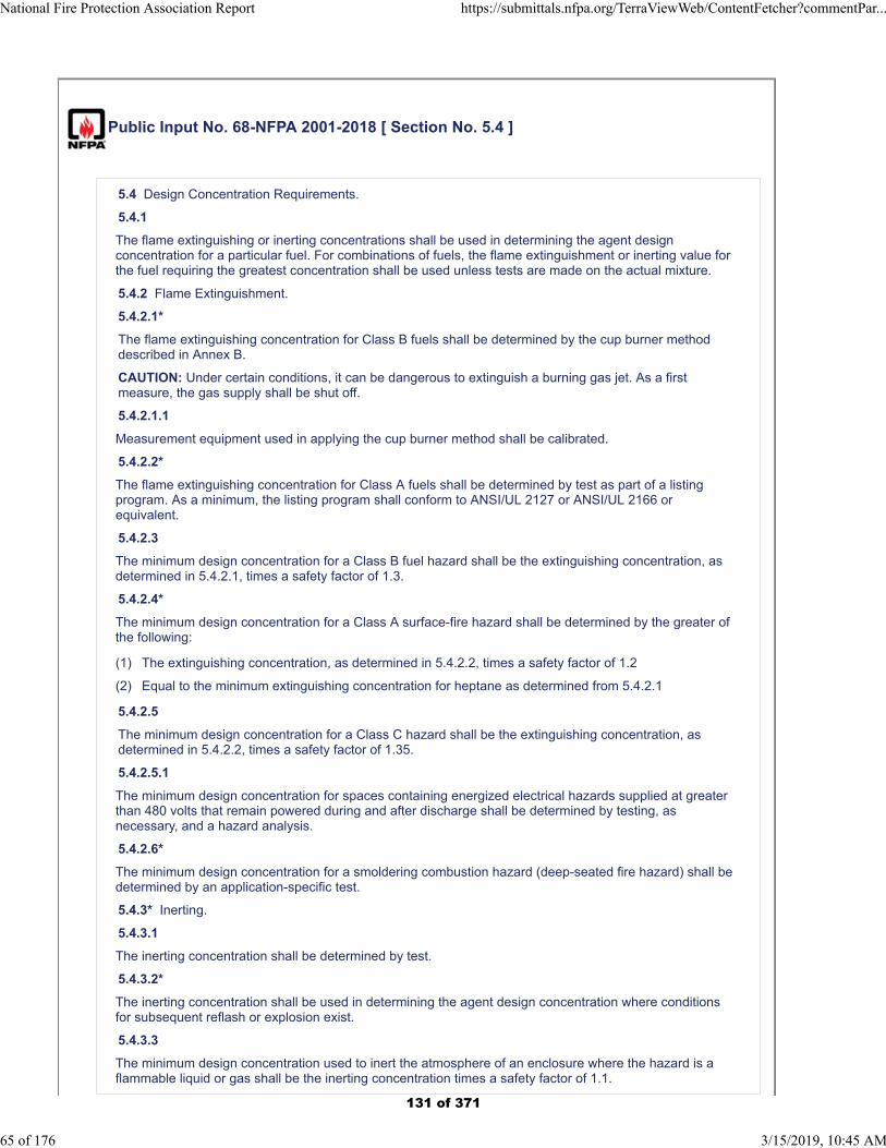
Public Input No. 68-NFPA 2001-2018 [ Section No. 5.4 ]
5.4 Design Concentration Requirements.
5.4.1
The flame extinguishing or inerting concentrations shall be used in determining the agent designconcentration for a particular fuel. For combinations of fuels, the flame extinguishment or inerting value forthe fuel requiring the greatest concentration shall be used unless tests are made on the actual mixture.
5.4.2 Flame Extinguishment.
5.4.2.1*
The flame extinguishing concentration for Class B fuels shall be determined by the cup burner methoddescribed in Annex B.
CAUTION: Under certain conditions, it can be dangerous to extinguish a burning gas jet. As a firstmeasure, the gas supply shall be shut off.
5.4.2.1.1
Measurement equipment used in applying the cup burner method shall be calibrated.
5.4.2.2*
The flame extinguishing concentration for Class A fuels shall be determined by test as part of a listingprogram. As a minimum, the listing program shall conform to ANSI/UL 2127 or ANSI/UL 2166 orequivalent.
5.4.2.3
The minimum design concentration for a Class B fuel hazard shall be the extinguishing concentration, asdetermined in 5.4.2.1, times a safety factor of 1.3.
5.4.2.4*
The minimum design concentration for a Class A surface-fire hazard shall be determined by the greater ofthe following:
(1) The extinguishing concentration, as determined in 5.4.2.2, times a safety factor of 1.2
(2) Equal to the minimum extinguishing concentration for heptane as determined from 5.4.2.1
5.4.2.5
The minimum design concentration for a Class C hazard shall be the extinguishing concentration, asdetermined in 5.4.2.2, times a safety factor of 1.35.
5.4.2.5.1
The minimum design concentration for spaces containing energized electrical hazards supplied at greaterthan 480 volts that remain powered during and after discharge shall be determined by testing, asnecessary, and a hazard analysis.
5.4.2.6*
The minimum design concentration for a smoldering combustion hazard (deep-seated fire hazard) shall bedetermined by an application-specific test.
5.4.3* Inerting.
5.4.3.1
The inerting concentration shall be determined by test.
5.4.3.2*
The inerting concentration shall be used in determining the agent design concentration where conditionsfor subsequent reflash or explosion exist.
5.4.3.3
The minimum design concentration used to inert the atmosphere of an enclosure where the hazard is aflammable liquid or gas shall be the inerting concentration times a safety factor of 1.1.
National Fire Protection Association Report https://submittals.nfpa.org/TerraViewWeb/ContentFetcher?commentPar...
65 of 176 3/15/2019, 10:45 AM
131 of 371
Additional Proposed Changes
File Name Description Approved
18_dec_21_2001-5.4.2_TaskGroupReport_2018-12-14_FINAL.docx
See the attached for proposed change to the existing Section 5.4.2 Flame Extinguishment. as directed at the final GFE committee meeting last cycle.
Statement of Problem and Substantiation for Public Input
Section 5.4.1 is revised to comply with the Manual of Style, including a new subsection title and separating the requirements into individual paragraphs.Section 5.4.2 is revised to more clearly establish the basis for minimum extinguishing concentrations and minimum design concentrations for each class of fire.Protection of smoldering (deep-seated) combustion hazards is deleted from 5.4.2, since minimum extinguishing concentrations have not been established by test for any clean agent. Addressing this type of hazard in 5.4.2 could lead to confusion over the applicability of clean agent systems to deep-seated hazards. Therefore, “Class A materials subject to smoldering (deep-seated) combustion” is added to the list in 1.4.2.2, which identifies materials that cannot be protected with a clean agent without testing. This is a more appropriate location for this requirement. A new definition of ‘smoldering (deep-seated) combustion’ is added as would be needed.
Submitter Information Verification
Submitter Full Name: Paul Rivers
Organization: 3M Company
Street Address:
City:
State:
Zip:
Submittal Date: Fri Dec 28 13:12:21 EST 2018
Committee: GFE-AAA
National Fire Protection Association Report https://submittals.nfpa.org/TerraViewWeb/ContentFetcher?commentPar...
66 of 176 3/15/2019, 10:45 AM
132 of 371
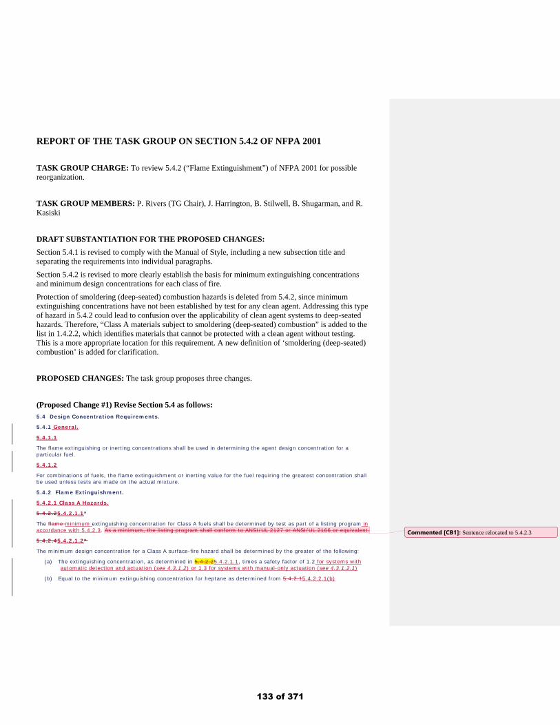
REPORT OF THE TASK GROUP ON SECTION 5.4.2 OF NFPA 2001 TASK GROUP CHARGE: To review 5.4.2 (“Flame Extinguishment”) of NFPA 2001 for possible reorganization.
TASK GROUP MEMBERS: P. Rivers (TG Chair), J. Harrington, B. Stilwell, B. Shugarman, and R. Kasiski
DRAFT SUBSTANTIATION FOR THE PROPOSED CHANGES: Section 5.4.1 is revised to comply with the Manual of Style, including a new subsection title and separating the requirements into individual paragraphs. Section 5.4.2 is revised to more clearly establish the basis for minimum extinguishing concentrations and minimum design concentrations for each class of fire. Protection of smoldering (deep-seated) combustion hazards is deleted from 5.4.2, since minimum extinguishing concentrations have not been established by test for any clean agent. Addressing this type of hazard in 5.4.2 could lead to confusion over the applicability of clean agent systems to deep-seated hazards. Therefore, “Class A materials subject to smoldering (deep-seated) combustion” is added to the list in 1.4.2.2, which identifies materials that cannot be protected with a clean agent without testing. This is a more appropriate location for this requirement. A new definition of ‘smoldering (deep-seated) combustion’ is added for clarification. PROPOSED CHANGES: The task group proposes three changes.
(Proposed Change #1) Revise Section 5.4 as follows: 5.4 Design Concentration Requirements.
5.4.1 General.
5.4.1.1
The flame extinguishing or inerting concentrations shall be used in determining the agent design concentration for a particular fuel.
5.4.1.2
For combinations of fuels, the flame extinguishment or inerting value for the fuel requiring the greatest concentration shall be used unless tests are made on the actual mixture.
5.4.2 Flame Extinguishment.
5.4.2.1 Class A Hazards.
5.4.2.25.4.2.1.1*
The flame minimum extinguishing concentration for Class A fuels shall be determined by test as part of a listing program in accordance with 5.4.2.3. As a minimum, the listing program shall conform to ANSI/UL 2127 or ANSI/UL 2166 or equivalent.
5.4.2.45.4.2.1.2*
The minimum design concentration for a Class A surface-fire hazard shall be determined by the greater of the following:
(a) The extinguishing concentration, as determined in 5.4.2.25.4.2.1.1, times a safety factor of 1.2 for systems with automatic detection and actuation (see 4.3.1.2) or 1.3 for systems with manual-only actuation (see 4.3.1.2.1)
(b) Equal to the minimum extinguishing concentration for heptane as determined from 5.4.2.15.4.2.2.1(b)
Commented [CB1]: Sentence relocated to 5.4.2.3
133 of 371
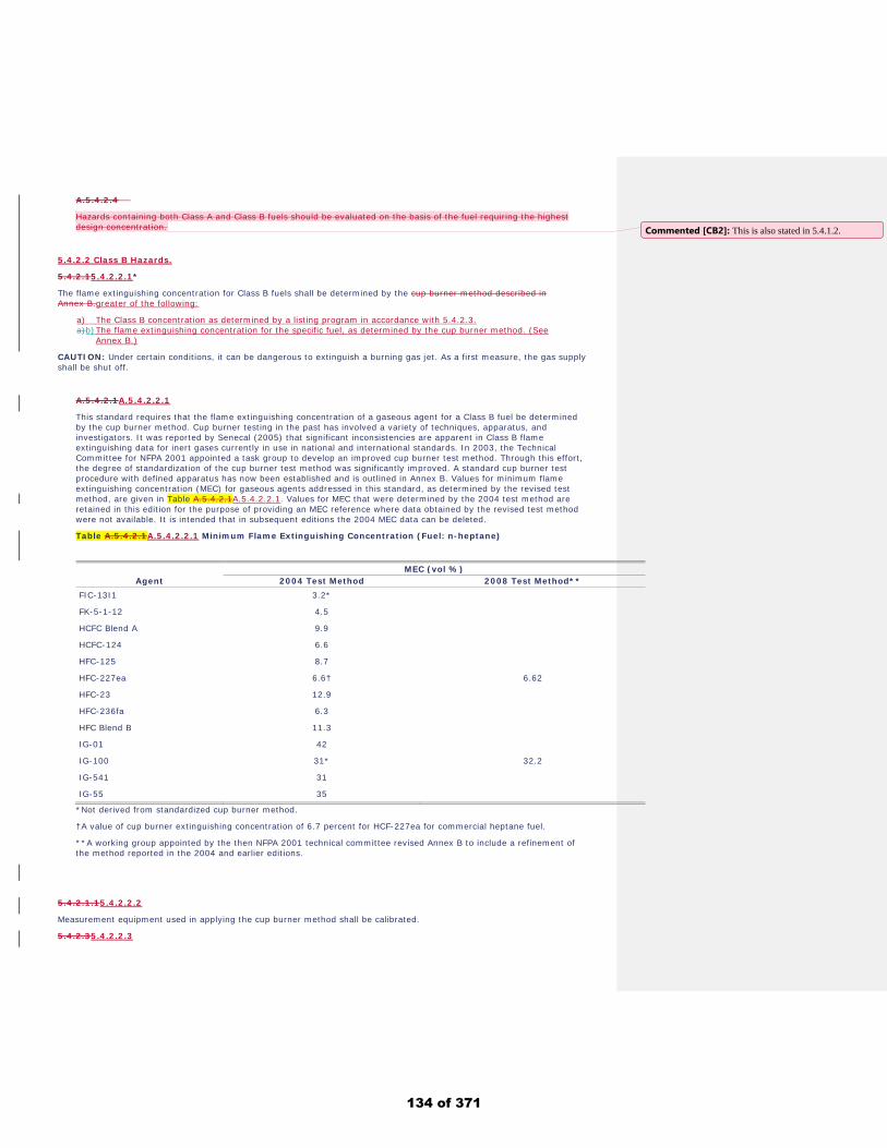
A.5.4.2.4
Hazards containing both Class A and Class B fuels should be evaluated on the basis of the fuel requiring the highest design concentration.
5.4.2.2 Class B Hazards.
5.4.2.15.4.2.2.1*
The flame extinguishing concentration for Class B fuels shall be determined by the cup burner method described in Annex B.greater of the following:
a) The Class B concentration as determined by a listing program in accordance with 5.4.2.3. a)b) The flame extinguishing concentration for the specific fuel, as determined by the cup burner method. (See
Annex B.)
CAUTION: Under certain conditions, it can be dangerous to extinguish a burning gas jet. As a first measure, the gas supply shall be shut off.
A.5.4.2.1A.5.4.2.2.1
This standard requires that the flame extinguishing concentration of a gaseous agent for a Class B fuel be determined by the cup burner method. Cup burner testing in the past has involved a variety of techniques, apparatus, and investigators. It was reported by Senecal (2005) that significant inconsistencies are apparent in Class B flame extinguishing data for inert gases currently in use in national and international standards. In 2003, the Technical Committee for NFPA 2001 appointed a task group to develop an improved cup burner test method. Through this effort, the degree of standardization of the cup burner test method was significantly improved. A standard cup burner test procedure with defined apparatus has now been established and is outlined in Annex B. Values for minimum flame extinguishing concentration (MEC) for gaseous agents addressed in this standard, as determined by the revised test method, are given in Table A.5.4.2.1A.5.4.2.2.1. Values for MEC that were determined by the 2004 test method are retained in this edition for the purpose of providing an MEC reference where data obtained by the revised test method were not available. It is intended that in subsequent editions the 2004 MEC data can be deleted.
Table A.5.4.2.1A.5.4.2.2.1 Minimum Flame Extinguishing Concentration (Fuel: n-heptane)
MEC (vol %) Agent 2004 Test Method 2008 Test Method**
FIC-13I1 3.2*
FK-5-1-12 4.5
HCFC Blend A 9.9
HCFC-124 6.6
HFC-125 8.7
HFC-227ea 6.6† 6.62
HFC-23 12.9
HFC-236fa 6.3
HFC Blend B 11.3
IG-01 42
IG-100 31* 32.2
IG-541 31
IG-55 35
*Not derived from standardized cup burner method.
†A value of cup burner extinguishing concentration of 6.7 percent for HCF-227ea for commercial heptane fuel.
**A working group appointed by the then NFPA 2001 technical committee revised Annex B to include a refinement of the method reported in the 2004 and earlier editions.
5.4.2.1.15.4.2.2.2
Measurement equipment used in applying the cup burner method shall be calibrated.
5.4.2.35.4.2.2.3
Commented [CB2]: This is also stated in 5.4.1.2.
134 of 371
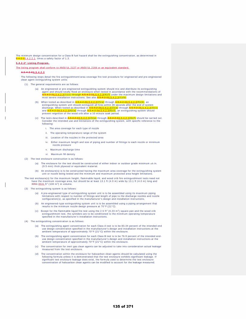
The minimum design concentration for a Class B fuel hazard shall be the extinguishing concentration, as determined in 5.4.2.15.4.2.2.1, times a safety factor of 1.3.
5.4.2.3* Listing Program.
The listing program shall conform to ANSI/UL 2127 or ANSI/UL 2166 or an equivalent standard.
A.5.4.2.2A.5.4.2.3
The following steps detail the fire extinguishment/area coverage fire test procedure for engineered and pre-engineered clean agent extinguishing system units:
(1) The general requirements are as follows: (a) An engineered or pre-engineered extinguishing system should mix and distribute its extinguishing
agent and should totally flood an enclosure when tested in accordance with the recommendations of A.5.4.2.2A.5.4.2.3(1)(c) through A.5.4.2.2A.5.4.2.3(6)(f) under the maximum design limitations and most severe installation instructions. See also A.5.4.2.2A.5.4.2.3(1)(b).
(b) When tested as described in A.5.4.2.2A.5.4.2.3(2)(a) through A.5.4.2.2A.5.4.2.3(5)(b), an extinguishing system unit should extinguish all fires within 30 seconds after the end of system discharge. When tested as described in A.5.4.2.2A.5.4.2.3(2)(a) through A.5.4.2.2A.5.4.2.3(3)(c) and A.5.4.2.2A.5.4.2.3(6)(a) through A.5.4.2.2A.5.4.2.3(6)(f), an extinguishing system should prevent reignition of the wood crib after a 10 minute soak period.
(c) The tests described in A.5.4.2.2A.5.4.2.3(2)(a) through A.5.4.2.2A.5.4.2.3(6)(f) should be carried out. Consider the intended use and limitations of the extinguishing system, with specific reference to the following:
i. The area coverage for each type of nozzle ii. The operating temperature range of the system
iii. Location of the nozzles in the protected area
iv. Either maximum length and size of piping and number of fittings to each nozzle or minimum nozzle pressure
v. Maximum discharge time
vi. Maximum fill density
(2) The test enclosure construction is as follows: (a) The enclosure for the test should be constructed of either indoor or outdoor grade minimum 3⁄8 in.
(9.5 mm) thick plywood or equivalent material. (b) An enclosure(s) is to be constructed having the maximum area coverage for the extinguishing system
unit or nozzle being tested and the minimum and maximum protected area height limitations.
The test enclosure(s) for the maximum height, flammable liquid, and wood crib fire extinguishment tests need not have the maximum coverage area, but should be at least 13.1 ft (4.0 m) wide by 13.1 ft (4.0 m) long and 3351 3531 ft3 (100 m3) in volume.
(3) The extinguishing system is as follows: (a) A pre-engineered type of extinguishing system unit is to be assembled using its maximum piping
limitations with respect to number of fittings and length of pipe to the discharge nozzles and nozzle configuration(s), as specified in the manufacturer’s design and installation instructions.
(b) An engineered-type extinguishing system unit is to be assembled using a piping arrangement that results in the minimum nozzle design pressure at 70°F (21°C).
(c) Except for the flammable liquid fire test using the 2.5 ft2 (0.23 m2) square pan and the wood crib extinguishment test, the cylinders are to be conditioned to the minimum operating temperature specified in the manufacturer’s installation instructions.
(4) The extinguishing concentration is as follows: (a) The extinguishing agent concentration for each Class A test is to be 83.34 percent of the intended end
use design concentration specified in the manufacturer’s design and installation instructions at the ambient temperature of approximately 70°F (21°C) within the enclosure.
(b) The extinguishing agent concentration for each Class B test is to be 76.9 percent of the intended end-use design concentration specified in the manufacturer’s design and installation instructions at the ambient temperature of approximately 70°F (21°C) within the enclosure.
(c) The concentration for inert gas clean agents can be adjusted to take into consideration actual leakage measured from the test enclosure.
(d) The concentration within the enclosure for halocarbon clean agents should be calculated using the following formula unless it is demonstrated that the test enclosure exhibits significant leakage. If significant test enclosure leakage does exist, the formula used to determine the test enclosure concentration of halocarbon clean agents can be modified to account for the leakage measured.
135 of 371
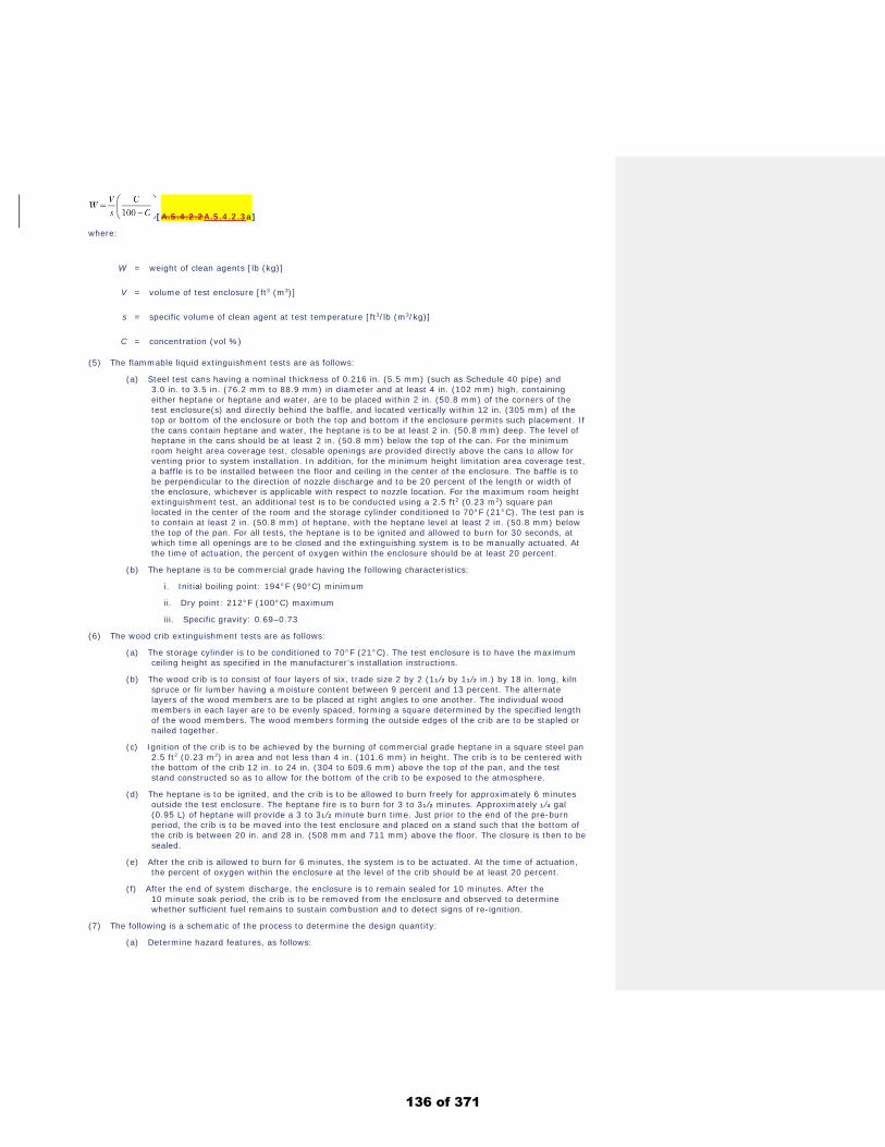
[A.5.4.2.2A.5.4.2.3a]
where:
W = weight of clean agents [lb (kg)]
V = volume of test enclosure [ft3 (m3)]
s = specific volume of clean agent at test temperature [ft3/lb (m3/kg)]
C = concentration (vol %)
(5) The flammable liquid extinguishment tests are as follows: (a) Steel test cans having a nominal thickness of 0.216 in. (5.5 mm) (such as Schedule 40 pipe) and
3.0 in. to 3.5 in. (76.2 mm to 88.9 mm) in diameter and at least 4 in. (102 mm) high, containing either heptane or heptane and water, are to be placed within 2 in. (50.8 mm) of the corners of the test enclosure(s) and directly behind the baffle, and located vertically within 12 in. (305 mm) of the top or bottom of the enclosure or both the top and bottom if the enclosure permits such placement. If the cans contain heptane and water, the heptane is to be at least 2 in. (50.8 mm) deep. The level of heptane in the cans should be at least 2 in. (50.8 mm) below the top of the can. For the minimum room height area coverage test, closable openings are provided directly above the cans to allow for venting prior to system installation. In addition, for the minimum height limitation area coverage test, a baffle is to be installed between the floor and ceiling in the center of the enclosure. The baffle is to be perpendicular to the direction of nozzle discharge and to be 20 percent of the length or width of the enclosure, whichever is applicable with respect to nozzle location. For the maximum room height extinguishment test, an additional test is to be conducted using a 2.5 ft2 (0.23 m2) square pan located in the center of the room and the storage cylinder conditioned to 70°F (21°C). The test pan is to contain at least 2 in. (50.8 mm) of heptane, with the heptane level at least 2 in. (50.8 mm) below the top of the pan. For all tests, the heptane is to be ignited and allowed to burn for 30 seconds, at which time all openings are to be closed and the extinguishing system is to be manually actuated. At the time of actuation, the percent of oxygen within the enclosure should be at least 20 percent.
(b) The heptane is to be commercial grade having the following characteristics: i. Initial boiling point: 194°F (90°C) minimum ii. Dry point: 212°F (100°C) maximum
iii. Specific gravity: 0.69–0.73
(6) The wood crib extinguishment tests are as follows: (a) The storage cylinder is to be conditioned to 70°F (21°C). The test enclosure is to have the maximum
ceiling height as specified in the manufacturer’s installation instructions. (b) The wood crib is to consist of four layers of six, trade size 2 by 2 (11⁄2 by 11⁄2 in.) by 18 in. long, kiln
spruce or fir lumber having a moisture content between 9 percent and 13 percent. The alternate layers of the wood members are to be placed at right angles to one another. The individual wood members in each layer are to be evenly spaced, forming a square determined by the specified length of the wood members. The wood members forming the outside edges of the crib are to be stapled or nailed together.
(c) Ignition of the crib is to be achieved by the burning of commercial grade heptane in a square steel pan 2.5 ft2 (0.23 m2) in area and not less than 4 in. (101.6 mm) in height. The crib is to be centered with the bottom of the crib 12 in. to 24 in. (304 to 609.6 mm) above the top of the pan, and the test stand constructed so as to allow for the bottom of the crib to be exposed to the atmosphere.
(d) The heptane is to be ignited, and the crib is to be allowed to burn freely for approximately 6 minutes outside the test enclosure. The heptane fire is to burn for 3 to 31⁄2 minutes. Approximately 1⁄4 gal (0.95 L) of heptane will provide a 3 to 31⁄2 minute burn time. Just prior to the end of the pre-burn period, the crib is to be moved into the test enclosure and placed on a stand such that the bottom of the crib is between 20 in. and 28 in. (508 mm and 711 mm) above the floor. The closure is then to be sealed.
(e) After the crib is allowed to burn for 6 minutes, the system is to be actuated. At the time of actuation, the percent of oxygen within the enclosure at the level of the crib should be at least 20 percent.
(f) After the end of system discharge, the enclosure is to remain sealed for 10 minutes. After the 10 minute soak period, the crib is to be removed from the enclosure and observed to determine whether sufficient fuel remains to sustain combustion and to detect signs of re-ignition.
(7) The following is a schematic of the process to determine the design quantity: (a) Determine hazard features, as follows:
136 of 371
i. Fuel type: Extinguishing concentration (EC) per 5.4.2 or inerting concentration (IC) per 5.4.3 ii. Enclosure volume
iii. Enclosure temperature
iv. Enclosure barometric pressure
(b) Determine the agent minimum design concentration (MDC) by multiplying EC or IC by the safety factor (SF):
[A.5.4.2.2A.5.4.2.3b] (c) Determine the agent minimum design quantity (MDQ) by referring to 5.5.1 for halocarbons or 5.5.2 for
inert gases
(d) Determine whether design factors (DF) apply. See 5.5.3 to determine individual DF [DF(i)] and then determine sum:
[A.5.4.2.2A.5.4.2.3c] (e) Determine the agent adjusted minimum design quantity (AMDQ):
[A.5.4.2.2A.5.4.2.3d] (f) Determine the pressure correction factor (PCF) per 5.5.3.3
(g) Determine the final design quantity (FDQ) as follows: [A.5.4.2.2A.5.4.2.3e]
Where any of the following conditions exist, higher extinguishing concentrations might be required:
(1) Cable bundles greater than 4 in. (100 mm) in diameter
(2) Cable trays with a fill density greater than 20 percent of the tray cross section
(3) Horizontal or vertical stacks of cable trays less than 10 in. (250 mm) apart
(4) Equipment energized during the extinguishment period where the collective power consumption exceeds 5 kW
Fire extinguishment tests for (noncellulosic) Class A Surface Fires. The purpose of the tests outlined in this procedure is to develop the minimum extinguishing concentration (MEC) for a gaseous fire suppression agent for a range of noncellulosic, solid polymeric combustibles. It is intended that the MEC will be increased by appropriate safety factors and flooding factors as provided for in the standard.
These Class A tests should be conducted in a draft-free room with a volume of at least 3530 ft3 (100 m3) and a minimum height of 11.5 ft (3.5 m) and each wall at least 13.1 ft (4 m) long. Provisions should be made for relief venting if required.
The test objects are as follows:
(1) The polymer fuel array consists of four sheets of polymer, 3⁄8 in. (9.53 mm) thick, 16 in. (406 mm) tall, and 8 in. (203 mm) wide. Sheets are spaced and located per Figure A.5.4.2.2A.5.4.2.3(a). The bottom of the fuel array is located 8 in. (203 mm) from the floor. The fuel sheets should be mechanically fixed at the required spacing.
(2) A fuel shield is provided around the fuel array as indicated in Figure A.5.4.2.2A.5.4.2.3(a). The fuel shield is 15 in. (381 mm) wide, 33.5 in. (851 mm) high, and 24 in. (610 mm) deep. The 24 in. (610 mm) wide × 33.5 in. (851 mm) high sides and the 24 in. (610 mm) × 15 in. (381 mm) top are sheet metal. The remaining two sides and the bottom are open. The fuel array is oriented in the fuel shield such that the 8 in. (203 mm) dimension of the fuel array is parallel to the 24 in. (610 mm) side of the fuel shield.
(3) Two external baffles measuring 40 in. × 40 in. (1 m × 1 m) and 12 in. (0.3 m) tall are located around the exterior of the fuel shield as shown in Figure A.5.4.2.2A.5.4.2.3(a) and Figure A.5.4.2.2A.5.4.2.3(b). The baffles are placed 3.5 in. (0.09 m) above the floor. The top baffle is rotated 45 degrees with respect to the bottom baffle.
(4) Tests are conducted for three plastic fuels — polymethyl methacrylate (PMMA), polypropylene (PP), and acrylonitrile-butadiene-styrene (ABS) polymer. Plastic properties are given in Table A.5.4.2.2A.5.4.2.3(a).
(5) The ignition source is a heptane pan 2 in. × 2 in. × 7⁄8 in. deep (51 mm × 51 mm × 22 mm deep) centered 1⁄2 in. (12 mm) below the bottom of the plastic sheets. The pan is filled with 3.0 ml of heptane to provide 90 seconds of burning.
(6) The agent delivery system should be distributed through an approved nozzle. The system should be operated at the minimum nozzle pressure (±10 percent) and the maximum discharge time (±1 second).
The test procedure is as follows:
(1) The procedures for ignition are as follows: (a) The heptane pan is ignited and allowed to burn for 90 seconds.
137 of 371
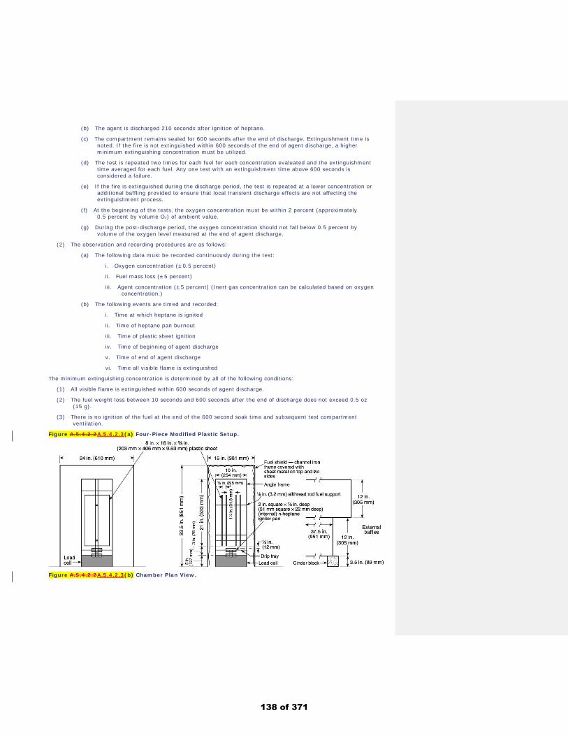
(b) The agent is discharged 210 seconds after ignition of heptane.
(c) The compartment remains sealed for 600 seconds after the end of discharge. Extinguishment time is noted. If the fire is not extinguished within 600 seconds of the end of agent discharge, a higher minimum extinguishing concentration must be utilized.
(d) The test is repeated two times for each fuel for each concentration evaluated and the extinguishment time averaged for each fuel. Any one test with an extinguishment time above 600 seconds is considered a failure.
(e) If the fire is extinguished during the discharge period, the test is repeated at a lower concentration or additional baffling provided to ensure that local transient discharge effects are not affecting the extinguishment process.
(f) At the beginning of the tests, the oxygen concentration must be within 2 percent (approximately 0.5 percent by volume O2) of ambient value.
(g) During the post-discharge period, the oxygen concentration should not fall below 0.5 percent by volume of the oxygen level measured at the end of agent discharge.
(2) The observation and recording procedures are as follows: (a) The following data must be recorded continuously during the test:
i. Oxygen concentration (±0.5 percent) ii. Fuel mass loss (±5 percent)
iii. Agent concentration (±5 percent) (Inert gas concentration can be calculated based on oxygen concentration.)
(b) The following events are timed and recorded: i. Time at which heptane is ignited ii. Time of heptane pan burnout
iii. Time of plastic sheet ignition
iv. Time of beginning of agent discharge
v. Time of end of agent discharge
vi. Time all visible flame is extinguished
The minimum extinguishing concentration is determined by all of the following conditions:
(1) All visible flame is extinguished within 600 seconds of agent discharge.
(2) The fuel weight loss between 10 seconds and 600 seconds after the end of discharge does not exceed 0.5 oz (15 g).
(3) There is no ignition of the fuel at the end of the 600 second soak time and subsequent test compartment ventilation.
Figure A.5.4.2.2A.5.4.2.3(a) Four-Piece Modified Plastic Setup.
Figure A.5.4.2.2A.5.4.2.3(b) Chamber Plan View.
138 of 371
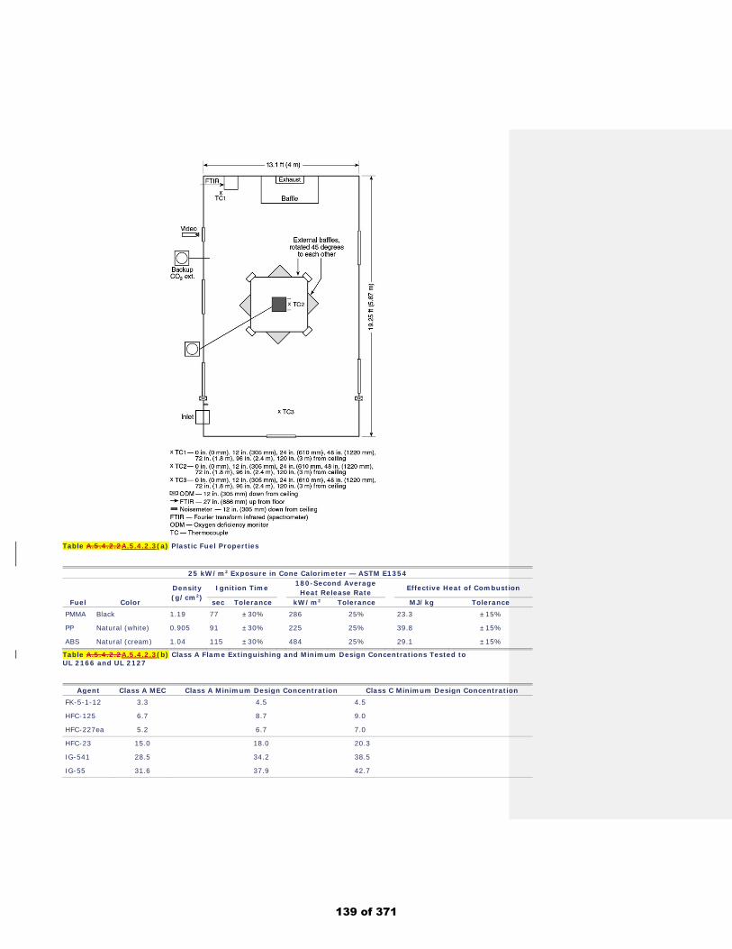
Table A.5.4.2.2A.5.4.2.3(a) Plastic Fuel Properties
25 kW/m2 Exposure in Cone Calorimeter — ASTM E1354
Density .
(g/cm2) Ignition Time 180-Second Average
.
Heat Release Rate Effective Heat of Combustion
Fuel Color sec Tolerance kW/m2 Tolerance MJ/kg Tolerance PMMA Black 1.19 77 ±30% 286 25% 23.3 ±15%
PP Natural (white) 0.905 91 ±30% 225 25% 39.8 ±15%
ABS Natural (cream) 1.04 115 ±30% 484 25% 29.1 ±15%
Table A.5.4.2.2A.5.4.2.3(b) Class A Flame Extinguishing and Minimum Design Concentrations Tested to UL 2166 and UL 2127
Agent Class A MEC Class A Minimum Design Concentration Class C Minimum Design Concentration FK-5-1-12 3.3 4.5 4.5
HFC-125 6.7 8.7 9.0
HFC-227ea 5.2 6.7 7.0
HFC-23 15.0 18.0 20.3
IG-541 28.5 34.2 38.5
IG-55 31.6 37.9 42.7
139 of 371
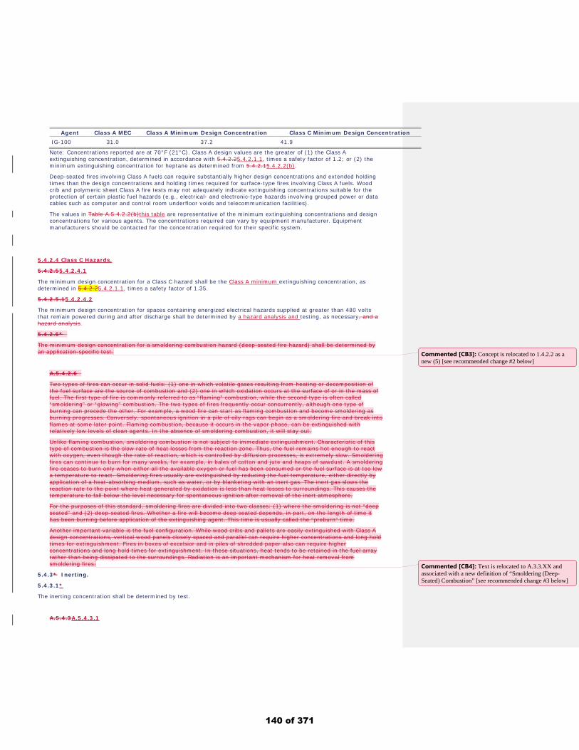
Agent Class A MEC Class A Minimum Design Concentration Class C Minimum Design Concentration IG-100 31.0 37.2 41.9
Note: Concentrations reported are at 70°F (21°C). Class A design values are the greater of (1) the Class A extinguishing concentration, determined in accordance with 5.4.2.25.4.2.1.1, times a safety factor of 1.2; or (2) the minimum extinguishing concentration for heptane as determined from 5.4.2.15.4.2.2(b).
Deep-seated fires involving Class A fuels can require substantially higher design concentrations and extended holding times than the design concentrations and holding times required for surface-type fires involving Class A fuels. Wood crib and polymeric sheet Class A fire tests may not adequately indicate extinguishing concentrations suitable for the protection of certain plastic fuel hazards (e.g., electrical- and electronic-type hazards involving grouped power or data cables such as computer and control room underfloor voids and telecommunication facilities).
The values in Table A.5.4.2.2(b)this table are representative of the minimum extinguishing concentrations and design concentrations for various agents. The concentrations required can vary by equipment manufacturer. Equipment manufacturers should be contacted for the concentration required for their specific system.
5.4.2.4 Class C Hazards.
5.4.2.55.4.2.4.1
The minimum design concentration for a Class C hazard shall be the Class A minimum extinguishing concentration, as determined in 5.4.2.25.4.2.1.1, times a safety factor of 1.35.
5.4.2.5.15.4.2.4.2
The minimum design concentration for spaces containing energized electrical hazards supplied at greater than 480 volts that remain powered during and after discharge shall be determined by a hazard analysis and testing, as necessary, and a hazard analysis.
5.4.2.6*
The minimum design concentration for a smoldering combustion hazard (deep-seated fire hazard) shall be determined by an application-specific test.
A.5.4.2.6
Two types of fires can occur in solid fuels: (1) one in which volatile gases resulting from heating or decomposition of the fuel surface are the source of combustion and (2) one in which oxidation occurs at the surface of or in the mass of fuel. The first type of fire is commonly referred to as “flaming” combustion, while the second type is often called “smoldering” or “glowing” combustion. The two types of fires frequently occur concurrently, although one type of burning can precede the other. For example, a wood fire can start as flaming combustion and become smoldering as burning progresses. Conversely, spontaneous ignition in a pile of oily rags can begin as a smoldering fire and break into flames at some later point. Flaming combustion, because it occurs in the vapor phase, can be extinguished with relatively low levels of clean agents. In the absence of smoldering combustion, it will stay out.
Unlike flaming combustion, smoldering combustion is not subject to immediate extinguishment. Characteristic of this type of combustion is the slow rate of heat losses from the reaction zone. Thus, the fuel remains hot enough to react with oxygen, even though the rate of reaction, which is controlled by diffusion processes, is extremely slow. Smoldering fires can continue to burn for many weeks, for example, in bales of cotton and jute and heaps of sawdust. A smoldering fire ceases to burn only when either all the available oxygen or fuel has been consumed or the fuel surface is at too low a temperature to react. Smoldering fires usually are extinguished by reducing the fuel temperature, either directly by application of a heat-absorbing medium, such as water, or by blanketing with an inert gas. The inert gas slows the reaction rate to the point where heat generated by oxidation is less than heat losses to surroundings. This causes the temperature to fall below the level necessary for spontaneous ignition after removal of the inert atmosphere.
For the purposes of this standard, smoldering fires are divided into two classes: (1) where the smoldering is not “deep seated” and (2) deep-seated fires. Whether a fire will become deep seated depends, in part, on the length of time it has been burning before application of the extinguishing agent. This time is usually called the “preburn” time.
Another important variable is the fuel configuration. While wood cribs and pallets are easily extinguished with Class A design concentrations, vertical wood panels closely spaced and parallel can require higher concentrations and long hold times for extinguishment. Fires in boxes of excelsior and in piles of shredded paper also can require higher concentrations and long hold times for extinguishment. In these situations, heat tends to be retained in the fuel array rather than being dissipated to the surroundings. Radiation is an important mechanism for heat removal from smoldering fires.
5.4.3* Inerting.
5.4.3.1*
The inerting concentration shall be determined by test.
A.5.4.3A.5.4.3.1
Commented [CB3]: Concept is relocated to 1.4.2.2 as a new (5) [see recommended change #2 below]
Commented [CB4]: Text is relocated to A.3.3.XX and associated with a new definition of “Smoldering (Deep-Seated) Combustion” [see recommended change #3 below]
140 of 371
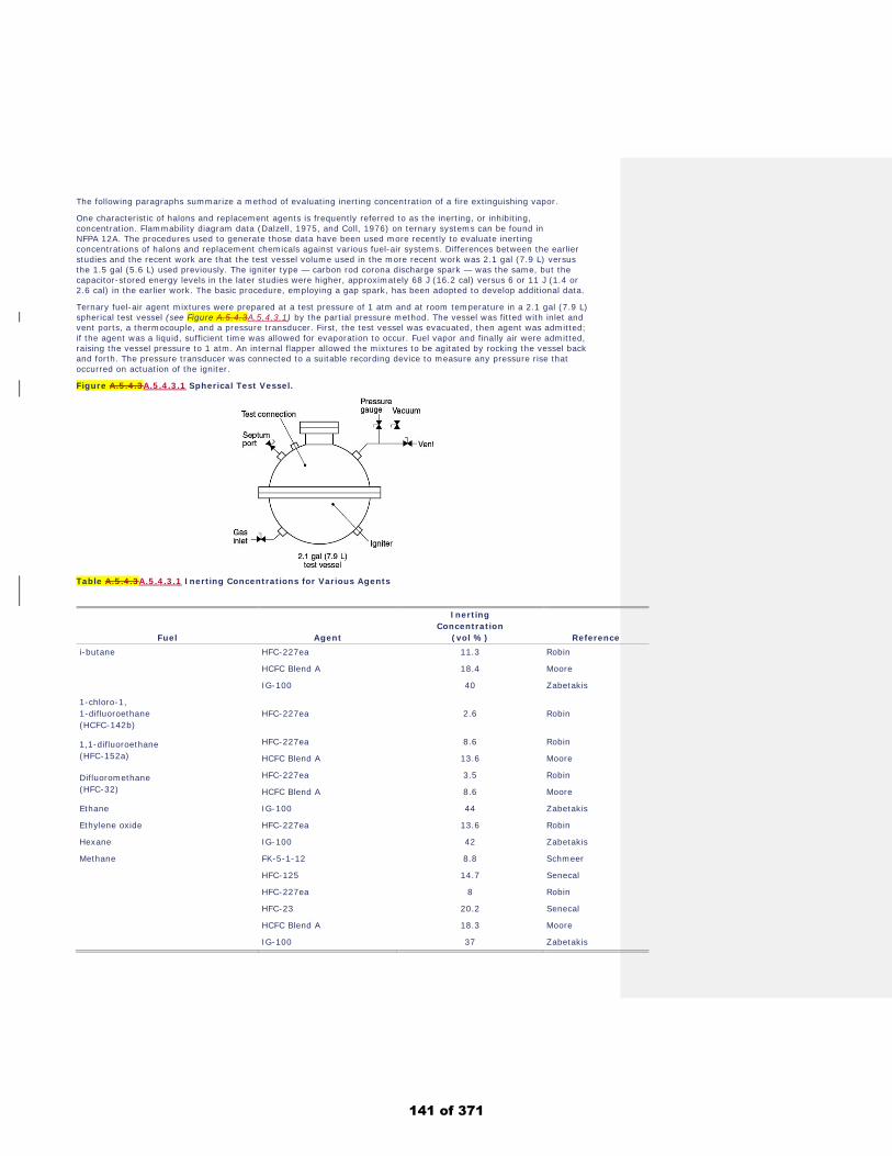
The following paragraphs summarize a method of evaluating inerting concentration of a fire extinguishing vapor.
One characteristic of halons and replacement agents is frequently referred to as the inerting, or inhibiting, concentration. Flammability diagram data (Dalzell, 1975, and Coll, 1976) on ternary systems can be found in NFPA 12A. The procedures used to generate those data have been used more recently to evaluate inerting concentrations of halons and replacement chemicals against various fuel-air systems. Differences between the earlier studies and the recent work are that the test vessel volume used in the more recent work was 2.1 gal (7.9 L) versus the 1.5 gal (5.6 L) used previously. The igniter type — carbon rod corona discharge spark — was the same, but the capacitor-stored energy levels in the later studies were higher, approximately 68 J (16.2 cal) versus 6 or 11 J (1.4 or 2.6 cal) in the earlier work. The basic procedure, employing a gap spark, has been adopted to develop additional data.
Ternary fuel-air agent mixtures were prepared at a test pressure of 1 atm and at room temperature in a 2.1 gal (7.9 L) spherical test vessel (see Figure A.5.4.3A.5.4.3.1) by the partial pressure method. The vessel was fitted with inlet and vent ports, a thermocouple, and a pressure transducer. First, the test vessel was evacuated, then agent was admitted; if the agent was a liquid, sufficient time was allowed for evaporation to occur. Fuel vapor and finally air were admitted, raising the vessel pressure to 1 atm. An internal flapper allowed the mixtures to be agitated by rocking the vessel back and forth. The pressure transducer was connected to a suitable recording device to measure any pressure rise that occurred on actuation of the igniter.
Figure A.5.4.3A.5.4.3.1 Spherical Test Vessel.
Table A.5.4.3A.5.4.3.1 Inerting Concentrations for Various Agents
Fuel Agent
Inerting .
Concentration .
(vol %) Reference i-butane HFC-227ea 11.3 Robin
HCFC Blend A 18.4 Moore
IG-100 40 Zabetakis
1-chloro-1, .
1-difluoroethane .
(HCFC-142b) HFC-227ea 2.6 Robin
1,1-difluoroethane .
(HFC-152a) HFC-227ea 8.6 Robin
HCFC Blend A 13.6 Moore
Difluoromethane .
(HFC-32) HFC-227ea 3.5 Robin
HCFC Blend A 8.6 Moore
Ethane IG-100 44 Zabetakis
Ethylene oxide HFC-227ea 13.6 Robin
Hexane IG-100 42 Zabetakis
Methane FK-5-1-12 8.8 Schmeer
HFC-125 14.7 Senecal
HFC-227ea 8 Robin
HFC-23 20.2 Senecal
HCFC Blend A 18.3 Moore
IG-100 37 Zabetakis
141 of 371
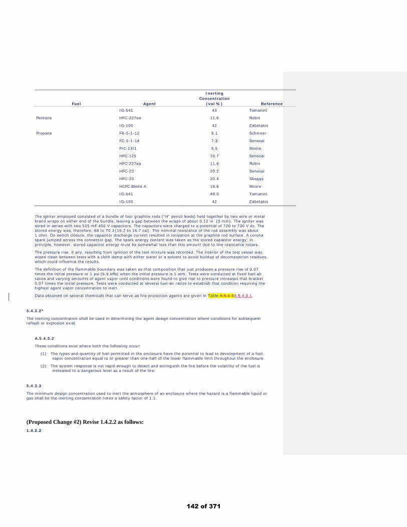
Fuel Agent
Inerting .
Concentration .
(vol %) Reference IG-541 43 Tamanini
Pentane HFC-227ea 11.6 Robin
IG-100 42 Zabetakis
Propane FK-5-1-12 8.1 Schmeer
FC-5-1-14 7.3 Senecal
FIC-13I1 6.5 Moore
HFC-125 15.7 Senecal
HFC-227ea 11.6 Robin
HFC-23 20.2 Senecal
HFC-23 20.4 Skaggs
HCFC Blend A 18.6 Moore
IG-541 49.0 Tamanini
IG-100 42 Zabetakis
The igniter employed consisted of a bundle of four graphite rods (“H” pencil leads) held together by two wire or metal brand wraps on either end of the bundle, leaving a gap between the wraps of about 0.12 in. (3 mm). The igniter was wired in series with two 525 mF 450 V capacitors. The capacitors were charged to a potential of 720 to 730 V dc. The stored energy was, therefore, 68 to 70 J (16.2 to 16.7 cal). The nominal resistance of the rod assembly was about 1 ohm. On switch closure, the capacitor discharge current resulted in ionization at the graphite rod surface. A corona spark jumped across the connector gap. The spark energy content was taken as the stored capacitor energy; in principle, however, stored capacitor energy must be somewhat less than this amount due to line resistance losses.
The pressure rise, if any, resulting from ignition of the test mixture was recorded. The interior of the test vessel was wiped clean between tests with a cloth damp with either water or a solvent to avoid buildup of decomposition residues, which could influence the results.
The definition of the flammable boundary was taken as that composition that just produces a pressure rise of 0.07 times the initial pressure or 1 psi (6.9 kPa) when the initial pressure is 1 atm. Tests were conducted at fixed fuel-air ratios and varying amounts of agent vapor until conditions were found to give rise to pressure increases that bracket 0.07 times the initial pressure. Tests were conducted at several fuel-air ratios to establish that condition requiring the highest agent vapor concentration to inert.
Data obtained on several chemicals that can serve as fire protection agents are given in Table A.5.4.3A.5.4.3.1.
5.4.3.2*
The inerting concentration shall be used in determining the agent design concentration where conditions for subsequent reflash or explosion exist.
A.5.4.3.2
These conditions exist where both the following occur:
(1) The types and quantity of fuel permitted in the enclosure have the potential to lead to development of a fuel vapor concentration equal to or greater than one-half of the lower flammable limit throughout the enclosure.
(2) The system response is not rapid enough to detect and extinguish the fire before the volatility of the fuel is increased to a dangerous level as a result of the fire.
5.4.3.3
The minimum design concentration used to inert the atmosphere of an enclosure where the hazard is a flammable liquid or gas shall be the inerting concentration times a safety factor of 1.1.
(Proposed Change #2) Revise 1.4.2.2 as follows: 1.4.2.2
142 of 371
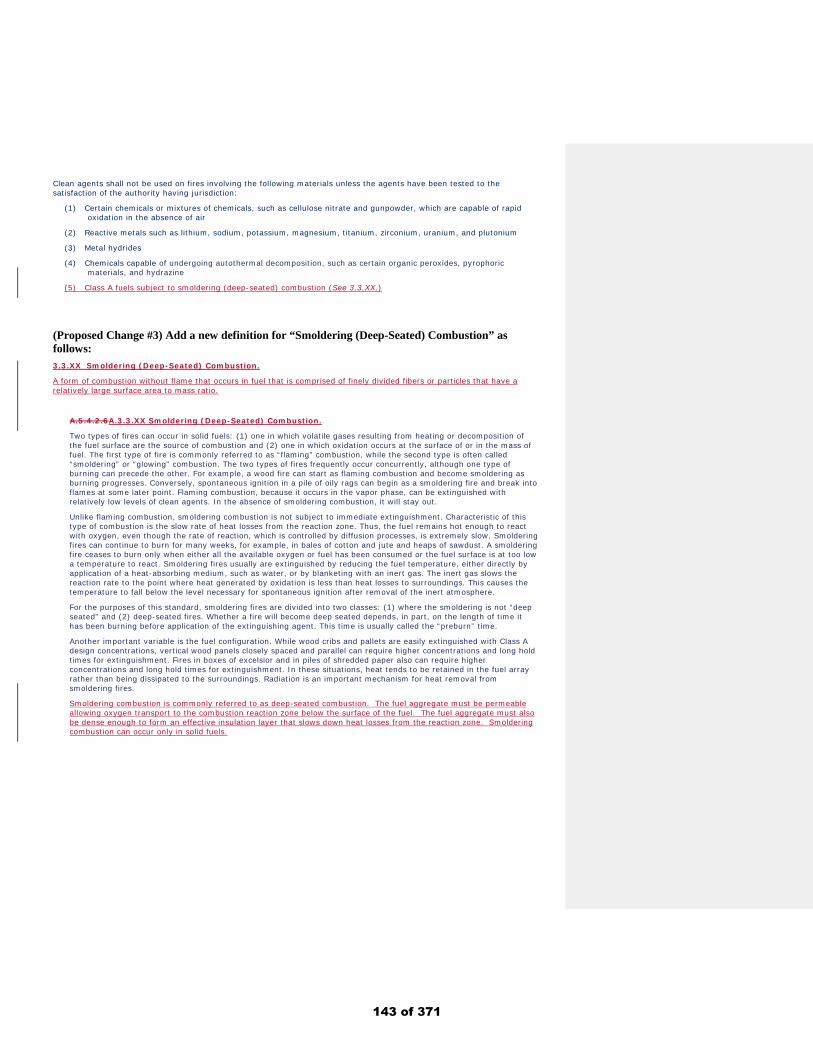
Clean agents shall not be used on fires involving the following materials unless the agents have been tested to the satisfaction of the authority having jurisdiction:
(1) Certain chemicals or mixtures of chemicals, such as cellulose nitrate and gunpowder, which are capable of rapid oxidation in the absence of air
(2) Reactive metals such as lithium, sodium, potassium, magnesium, titanium, zirconium, uranium, and plutonium
(3) Metal hydrides
(4) Chemicals capable of undergoing autothermal decomposition, such as certain organic peroxides, pyrophoric materials, and hydrazine
(5) Class A fuels subject to smoldering (deep-seated) combustion (See 3.3.XX.)
(Proposed Change #3) Add a new definition for “Smoldering (Deep-Seated) Combustion” as follows: 3.3.XX Smoldering (Deep-Seated) Combustion.
A form of combustion without flame that occurs in fuel that is comprised of finely divided fibers or particles that have a relatively large surface area to mass ratio.
A.5.4.2.6A.3.3.XX Smoldering (Deep-Seated) Combustion.
Two types of fires can occur in solid fuels: (1) one in which volatile gases resulting from heating or decomposition of the fuel surface are the source of combustion and (2) one in which oxidation occurs at the surface of or in the mass of fuel. The first type of fire is commonly referred to as “flaming” combustion, while the second type is often called “smoldering” or “glowing” combustion. The two types of fires frequently occur concurrently, although one type of burning can precede the other. For example, a wood fire can start as flaming combustion and become smoldering as burning progresses. Conversely, spontaneous ignition in a pile of oily rags can begin as a smoldering fire and break into flames at some later point. Flaming combustion, because it occurs in the vapor phase, can be extinguished with relatively low levels of clean agents. In the absence of smoldering combustion, it will stay out.
Unlike flaming combustion, smoldering combustion is not subject to immediate extinguishment. Characteristic of this type of combustion is the slow rate of heat losses from the reaction zone. Thus, the fuel remains hot enough to react with oxygen, even though the rate of reaction, which is controlled by diffusion processes, is extremely slow. Smoldering fires can continue to burn for many weeks, for example, in bales of cotton and jute and heaps of sawdust. A smoldering fire ceases to burn only when either all the available oxygen or fuel has been consumed or the fuel surface is at too low a temperature to react. Smoldering fires usually are extinguished by reducing the fuel temperature, either directly by application of a heat-absorbing medium, such as water, or by blanketing with an inert gas. The inert gas slows the reaction rate to the point where heat generated by oxidation is less than heat losses to surroundings. This causes the temperature to fall below the level necessary for spontaneous ignition after removal of the inert atmosphere.
For the purposes of this standard, smoldering fires are divided into two classes: (1) where the smoldering is not “deep seated” and (2) deep-seated fires. Whether a fire will become deep seated depends, in part, on the length of time it has been burning before application of the extinguishing agent. This time is usually called the “preburn” time.
Another important variable is the fuel configuration. While wood cribs and pallets are easily extinguished with Class A design concentrations, vertical wood panels closely spaced and parallel can require higher concentrations and long hold times for extinguishment. Fires in boxes of excelsior and in piles of shredded paper also can require higher concentrations and long hold times for extinguishment. In these situations, heat tends to be retained in the fuel array rather than being dissipated to the surroundings. Radiation is an important mechanism for heat removal from smoldering fires.
Smoldering combustion is commonly referred to as deep-seated combustion. The fuel aggregate must be permeable allowing oxygen transport to the combustion reaction zone below the surface of the fuel. The fuel aggregate must also be dense enough to form an effective insulation layer that slows down heat losses from the reaction zone. Smoldering combustion can occur only in solid fuels.
143 of 371
Public Input No. 26-NFPA 2001-2018 [ New Section after 5.5.2 ]
TITLE OF NEW CONTENT
5.5.2 The quantity of inert gas agent required to achieve the design concentration shall be calculated usingEquation 5.5.2, 5.5.2.1a or 5.5.2.b , or 5.5.2.1.c where 5.5.2.1.c applies to IG-100-400 – EvaporatedNitrogen Gas breaking loose of the water temperature restraints and starting at evaporating
temperature of liquid Nitrogen, -195.8 o C or -320.4 o F.
AMEND: 5.5.2.1c For IG-100-400 – Evaporated Nitrogen Gas, upon evaporation of liquid Nitrogen at
-195.8 o C, expands 230 times liquid volume, warming to ambient temperature it reaches 250 times liquidvolume and at inferno temperatures becomes 600-700 times liquid volume. (Make this into equations if youlike.)
The Inert Gas equations use 2.303 rather than the 100 of Halon gases which must divide the 230 cryogenicevaporation expansion of liquid Nitrogen indicating the tanks are filled with a weight of liquid Nitrogen tosecure a stated pressure in the tank. Using liquid Nitrogen at ambient pressure as the source has the 230expansion as 100% of released gas at -195.8oC.
Also, evaporation of liquid Nitrogen gives cohesive Nitrogen gas in forming cloud displacing Oxygen incloud volume, not an averaged mix as the other Nitrogen sources are stated to create which reduce Oxygenconcentration, not displace the Oxygen. The space around this tranparent Evaporated Nitrogen Gas cloudhas the same Oxygen content as it had before cloud invasion. In a fire where the fire consumes Oxygen,one cannot depend on full 21% Oxygen content, but that amount declining by the Oxygen reduction by thecurrent fire conditions over time.
Statement of Problem and Substantiation for Public Input
Compressed Nitrogen gas released mixes with the air as it squirts out of the nozzle into the atmosphere. Depending on volume one gets a portion of the Oxygen depending on balance of air:compressed Nitrogen. With the Evaporated Nitrogen Gas cloud being cohesive, inert, cryogenically cold to start and pure N2 Nitrogen gas, one gets a transparent cloud of 100% Nitrogen gas in the midst of the air and it clears itself to stay pure. Thus the air portion has its Oxygen level constant or reduce by the presence of fire. To breath the Oxygen and building toxin levels, one breaths the smokey air in a fire with the transparent Nitrogen cloud ending the flames and cooling the fuel, or wearing SCBA gear, operates within the Evaporated Nitrogen Gas Cloud with this supplemental Oxygen.
Submitter Information Verification
Submitter Full Name: Denyse Dubrucq
Organization: Air Wars Defense Lp
Affiliation: NFPA Member 3019224
Street Address:
City:
State:
Zip:
Submittal Date: Sat Sep 22 13:45:00 EDT 2018
Committee: GFE-AAA
National Fire Protection Association Report https://submittals.nfpa.org/TerraViewWeb/ContentFetcher?commentPar...
67 of 176 3/15/2019, 10:45 AM
144 of 371
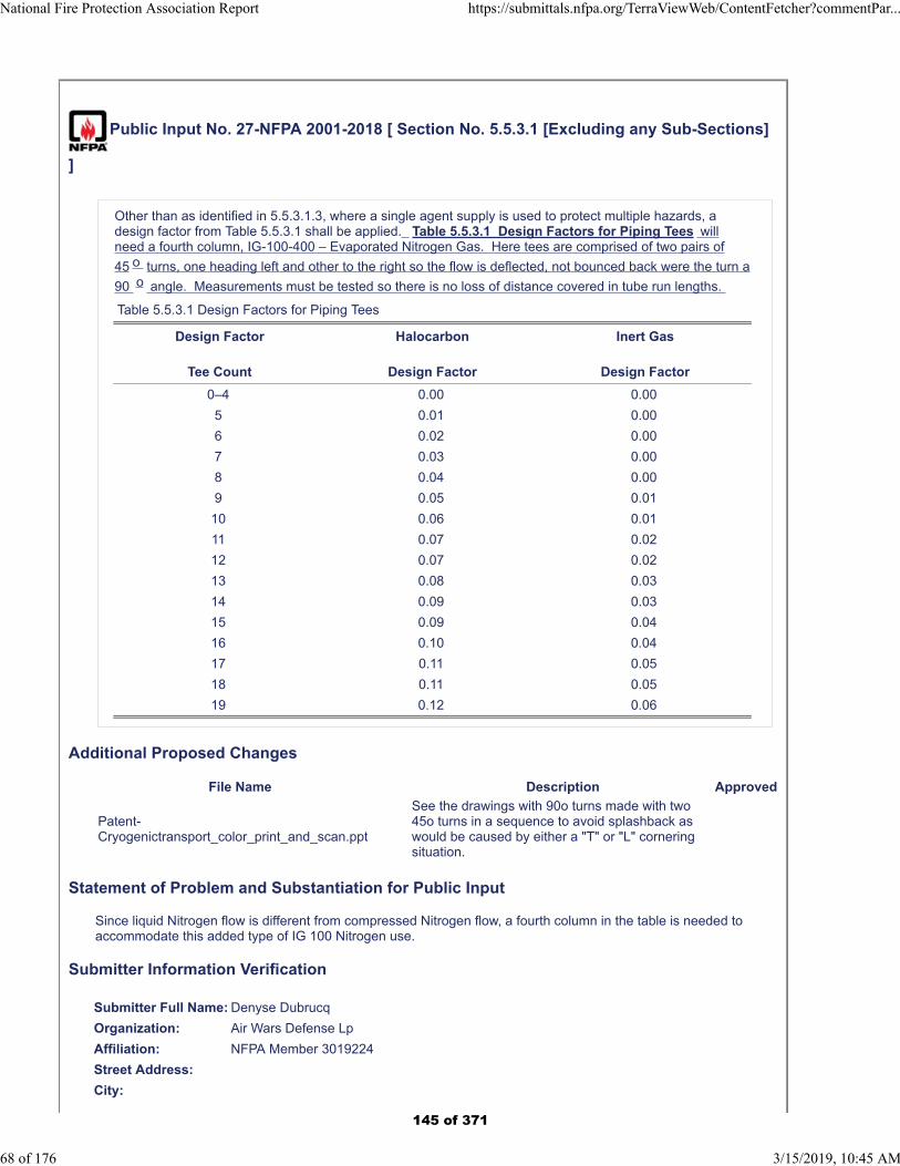
Public Input No. 27-NFPA 2001-2018 [ Section No. 5.5.3.1 [Excluding any Sub-Sections]
]
Other than as identified in 5.5.3.1.3, where a single agent supply is used to protect multiple hazards, adesign factor from Table 5.5.3.1 shall be applied. Table 5.5.3.1 Design Factors for Piping Tees willneed a fourth column, IG-100-400 – Evaporated Nitrogen Gas. Here tees are comprised of two pairs of
45 o turns, one heading left and other to the right so the flow is deflected, not bounced back were the turn a
90 o angle. Measurements must be tested so there is no loss of distance covered in tube run lengths.
Table 5.5.3.1 Design Factors for Piping Tees
Design Factor
Tee Count
Halocarbon
Design Factor
Inert Gas
Design Factor
0–4 0.00 0.00
5 0.01 0.00
6 0.02 0.00
7 0.03 0.00
8 0.04 0.00
9 0.05 0.01
10 0.06 0.01
11 0.07 0.02
12 0.07 0.02
13 0.08 0.03
14 0.09 0.03
15 0.09 0.04
16 0.10 0.04
17 0.11 0.05
18 0.11 0.05
19 0.12 0.06
Additional Proposed Changes
File Name Description Approved
Patent-Cryogenictransport_color_print_and_scan.ppt
See the drawings with 90o turns made with two 45o turns in a sequence to avoid splashback as would be caused by either a "T" or "L" cornering situation.
Statement of Problem and Substantiation for Public Input
Since liquid Nitrogen flow is different from compressed Nitrogen flow, a fourth column in the table is needed to accommodate this added type of IG 100 Nitrogen use.
Submitter Information Verification
Submitter Full Name: Denyse Dubrucq
Organization: Air Wars Defense Lp
Affiliation: NFPA Member 3019224
Street Address:
City:
National Fire Protection Association Report https://submittals.nfpa.org/TerraViewWeb/ContentFetcher?commentPar...
68 of 176 3/15/2019, 10:45 AM
145 of 371

State:
Zip:
Submittal Date: Sat Sep 22 14:00:17 EDT 2018
Committee: GFE-AAA
National Fire Protection Association Report https://submittals.nfpa.org/TerraViewWeb/ContentFetcher?commentPar...
69 of 176 3/15/2019, 10:45 AM
146 of 371

Numbering Index1. Nitrogen gas
10. Liquid Nitrogen11. CryoRain - drops12. Stored N2 to fill pipes13. Liquefying N214. Cooling N215. Heating N2 to gather fuels16. Purifying N217. Perforated surfaces18. Evaporator19. Air - atmosphere
2. Insulating spaces20. Parallel pipe space21. Molded components22. Fitting other products23. Frame induced spacing24. Insulating material
3. Plastic30. Pipes31. Connectors32. Roller bearings33. Seamed materials34. High temperature35. Installed components
36. Ventilated cap37. Fused seams38. Slow flow pipe39. Oxygen supply & tube
4. Valves, motion40. Allow/stop flow41. One way42. Tippers – fill & spill43. Cycling - evaporator
5. Electronics50. Lighting51. Batteries – solar52. Situation switching53. Valve motion54. Wiring55. Indicators56. Regulators57. Remote control58. Chain puller
6. Thermal qualities60. Switch by cold61. No frost or icing62. Heat to kill bedbugs63. Heat to select fuel
64. Cool to separate65. Cool to liquefy66. Keep hot for Fuels67. Smoke
7. Signals70. Smoke detector71. Fuel/water separator72. Battery operating73. Fire74. Thermal indicator75. Thermal flow control76. Lift with scale77. CO2 filter78. Nitrogen release signal
8. Item 80. Motor81. Truck82. Cap83. Oil spill84. Water85. Oven86. Clothing87. Skimmer, net88. Ties holding equipment89. Cover to protect from rain
147 of 371

Figure 11 20 12 30 20 1 31
37 37 37
148 of 371

Figure 21 20 30 5 50 51 54 31
149 of 371

Figure 3
. .
30 20 1 50 51 4 53 40 10 1 54 53 31 40
150 of 371

Figure 4
54 30 20 1 31 54 51151 of 371

Figure 5
54
30
20
31
50
31
51
152 of 371

Figure 610 53 40 31 30
31
1
153 of 371

Figure 7
.. .
1 17 21 41 11 17 37 41 31 53 40 30
Figure 7(b) Figure 7(a)
154 of 371
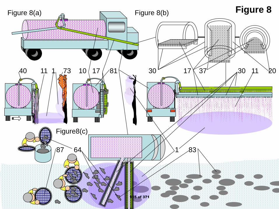
Figure 8
40 11 1 73 10 17 81 30 17 37 30 11 20
1 83 87 64
Figure 8(a) Figure 8(b)
Figure8(c)
155 of 371
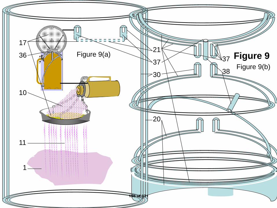
Figure 917
36
10
11
1
21
37
30
20
Figure 9(a)
Figure 9(b)37
38
156 of 371

Figure 1021
37
50
54
20
30
72
51
37
34
21
10
42 17
10
11
1
73
Figure 10a Figure 10(b)
Figure 10(c)157 of 371
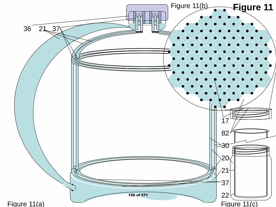
Figure 11
17
82
30
20
21
37
22
36 21 37
Figure 11(a) Figure 11(c)
Figure 11(b)
158 of 371

Figure 12
10
11
22
1
82
17
20
61
21
Figure 12(a) Figure 12(b)
159 of 371
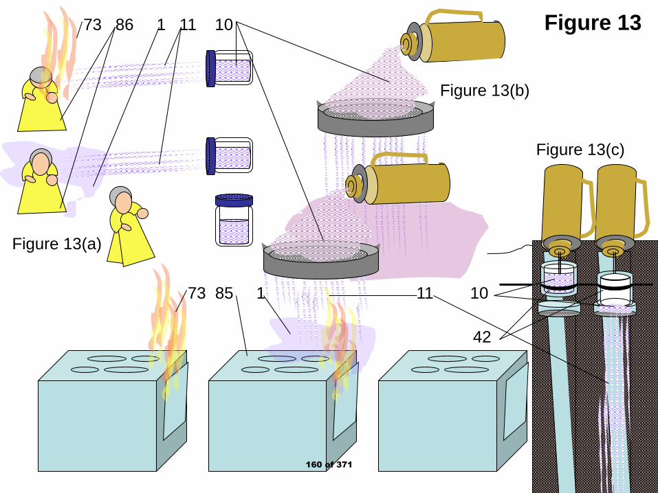
Figure 1373 86 1 11 10
73 85 1 11 10
Figure 13(a)
Figure 13(b)
Figure 13(c)
42
160 of 371

Figure 1417
30
22
161 of 371

Figure 1576
80
57
35
22
32
58
31
162 of 371

Figure 16
77
57
31
58
82
10
30
58
76
17
81
1
30
10
35
32
22
33
23
Figure 16(a) Figure 16(b)
Figure 16(c)
163 of 371

Figure 1776
1
33
22
32
81
76
10
23
30
1711
1
80
57
31
58
30
82
Figure 17(a) Figure 17(b) Figure 17(c)
164 of 371

Figure 18
24 82 1 62 31 54
74 10 17 40 30 84
33
19
23
165 of 371
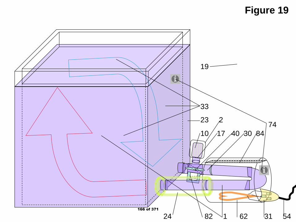
Figure 19
24 82 1 62 31 54
74 10 17 40 30 84
19
33
23 2
166 of 371
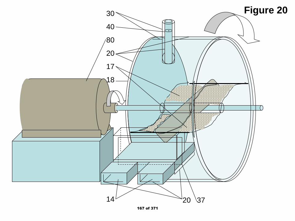
Figure 20
.
30
40
80
20
17
18
14 20 37167 of 371
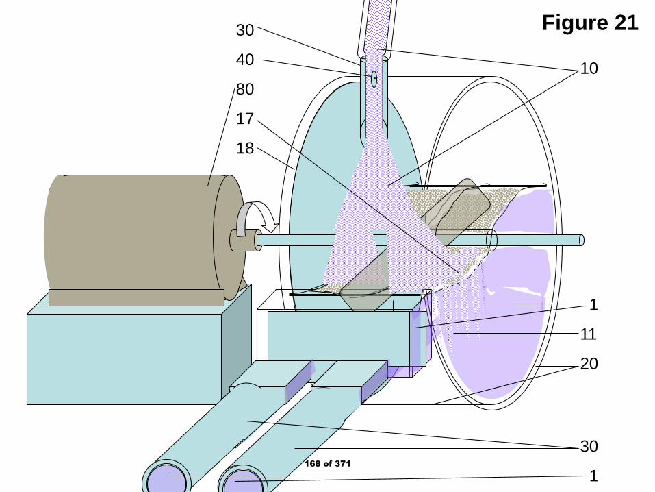
Figure 21
.
30
40
80
17
18
10
1
11
20
30
1168 of 371
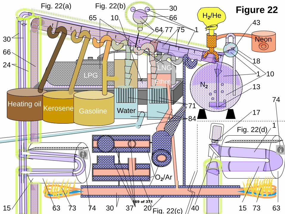
CH4
Figure 22
Neon
H2/He
N2Ether
Water
LNGLPG
O2/Ar
43
18
1 10
13
74
17
1
15 63 73 74 30 37 20 40 15 73 63
Fig. 22(a) Fig. 22(b)
64 77 75 1
71
84
65 10
Heating oil Kerosene Gasoline
30
66
24
3066
Fig. 22(d)
Fig. 22(c)169 of 371

Figure 23
“N” “2”
22
78 10 11 40 17 54 70 67 1 73 30
36 88 39 85 70
170 of 371

Figure 24
“N”“2”
22
78 11 40 1 70 67 73 30
88 10 39 17 85
8920361
Figure 24(a)
Figure 24(b)171 of 371
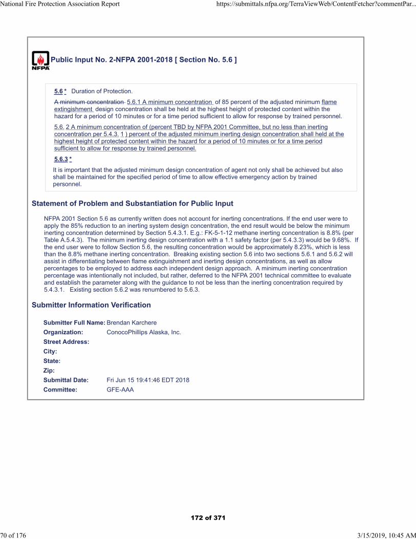
Public Input No. 2-NFPA 2001-2018 [ Section No. 5.6 ]
5.6 * Duration of Protection.
A minimum concentration 5.6.1 A minimum concentration of 85 percent of the adjusted minimum flameextingishment design concentration shall be held at the highest height of protected content within thehazard for a period of 10 minutes or for a time period sufficient to allow for response by trained personnel.
5.6. 2 A minimum concentration of (percent TBD by NFPA 2001 Committee, but no less than inertingconcentration per 5.4.3. 1 ) percent of the adjusted minimum inerting design concentration shall held at thehighest height of protected content within the hazard for a period of 10 minutes or for a time periodsufficient to allow for response by trained personnel.
5.6.3 *
It is important that the adjusted minimum design concentration of agent not only shall be achieved but alsoshall be maintained for the specified period of time to allow effective emergency action by trainedpersonnel.
Statement of Problem and Substantiation for Public Input
NFPA 2001 Section 5.6 as currently written does not account for inerting concentrations. If the end user were to apply the 85% reduction to an inerting system design concentration, the end result would be below the minimum inerting concentration determined by Section 5.4.3.1. E.g.: FK-5-1-12 methane inerting concentration is 8.8% (per Table A.5.4.3). The minimum inerting design concentration with a 1.1 safety factor (per 5.4.3.3) would be 9.68%. If the end user were to follow Section 5.6, the resulting concentration would be approximately 8.23%, which is less than the 8.8% methane inerting concentration. Breaking existing section 5.6 into two sections 5.6.1 and 5.6.2 will assist in differentiating between flame extinguishment and inerting design concentrations, as well as allow percentages to be employed to address each independent design approach. A minimum inerting concentration percentage was intentionally not included, but rather, deferred to the NFPA 2001 technical committee to evaluate and establish the parameter along with the guidance to not be less than the inerting concentration required by 5.4.3.1. Existing section 5.6.2 was renumbered to 5.6.3.
Submitter Information Verification
Submitter Full Name: Brendan Karchere
Organization: ConocoPhillips Alaska, Inc.
Street Address:
City:
State:
Zip:
Submittal Date: Fri Jun 15 19:41:46 EDT 2018
Committee: GFE-AAA
National Fire Protection Association Report https://submittals.nfpa.org/TerraViewWeb/ContentFetcher?commentPar...
70 of 176 3/15/2019, 10:45 AM
172 of 371
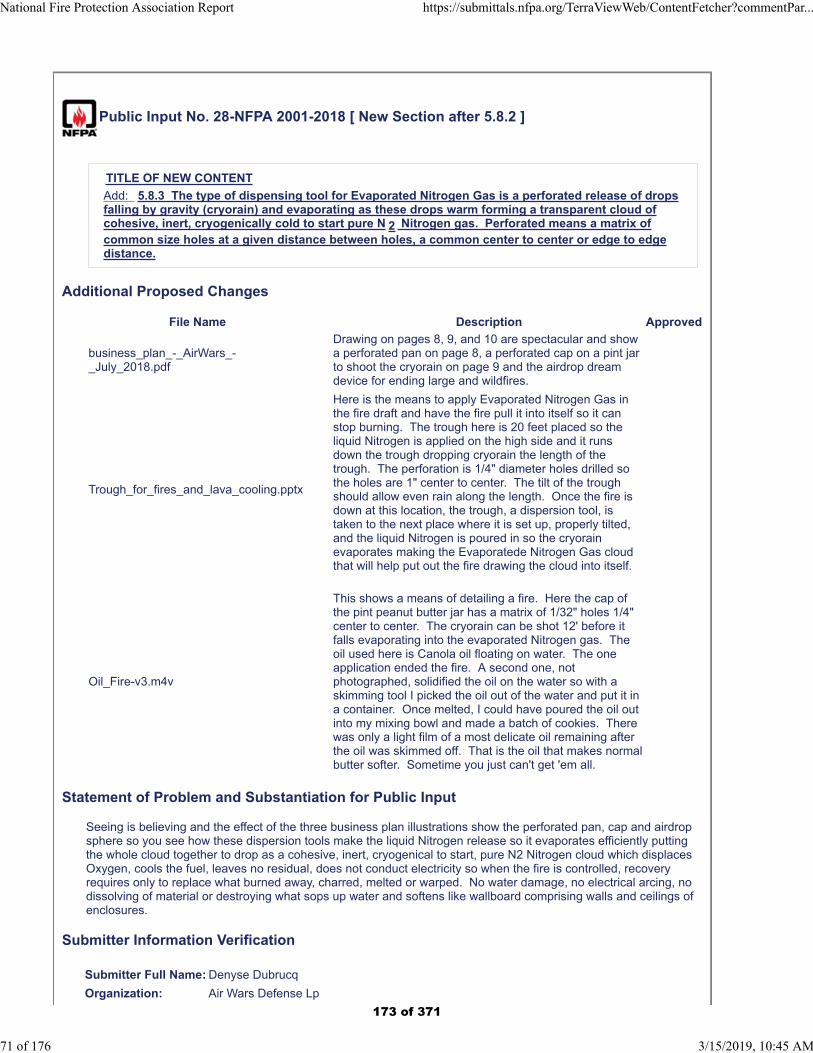
Public Input No. 28-NFPA 2001-2018 [ New Section after 5.8.2 ]
TITLE OF NEW CONTENT
Add: 5.8.3 The type of dispensing tool for Evaporated Nitrogen Gas is a perforated release of dropsfalling by gravity (cryorain) and evaporating as these drops warm forming a transparent cloud ofcohesive, inert, cryogenically cold to start pure N 2 Nitrogen gas. Perforated means a matrix ofcommon size holes at a given distance between holes, a common center to center or edge to edgedistance.
Additional Proposed Changes
File Name Description Approved
business_plan_-_AirWars_-_July_2018.pdf
Drawing on pages 8, 9, and 10 are spectacular and show a perforated pan on page 8, a perforated cap on a pint jar to shoot the cryorain on page 9 and the airdrop dream device for ending large and wildfires.
Trough_for_fires_and_lava_cooling.pptx
Here is the means to apply Evaporated Nitrogen Gas in the fire draft and have the fire pull it into itself so it can stop burning. The trough here is 20 feet placed so the liquid Nitrogen is applied on the high side and it runs down the trough dropping cryorain the length of the trough. The perforation is 1/4" diameter holes drilled so the holes are 1" center to center. The tilt of the trough should allow even rain along the length. Once the fire is down at this location, the trough, a dispersion tool, is taken to the next place where it is set up, properly tilted, and the liquid Nitrogen is poured in so the cryorain evaporates making the Evaporatede Nitrogen Gas cloud that will help put out the fire drawing the cloud into itself.
Oil_Fire-v3.m4v
This shows a means of detailing a fire. Here the cap of the pint peanut butter jar has a matrix of 1/32" holes 1/4" center to center. The cryorain can be shot 12' before it falls evaporating into the evaporated Nitrogen gas. The oil used here is Canola oil floating on water. The one application ended the fire. A second one, not photographed, solidified the oil on the water so with a skimming tool I picked the oil out of the water and put it in a container. Once melted, I could have poured the oil out into my mixing bowl and made a batch of cookies. There was only a light film of a most delicate oil remaining after the oil was skimmed off. That is the oil that makes normal butter softer. Sometime you just can't get 'em all.
Statement of Problem and Substantiation for Public Input
Seeing is believing and the effect of the three business plan illustrations show the perforated pan, cap and airdrop sphere so you see how these dispersion tools make the liquid Nitrogen release so it evaporates efficiently putting the whole cloud together to drop as a cohesive, inert, cryogenical to start, pure N2 Nitrogen cloud which displaces Oxygen, cools the fuel, leaves no residual, does not conduct electricity so when the fire is controlled, recovery requires only to replace what burned away, charred, melted or warped. No water damage, no electrical arcing, no dissolving of material or destroying what sops up water and softens like wallboard comprising walls and ceilings of enclosures.
Submitter Information Verification
Submitter Full Name: Denyse Dubrucq
Organization: Air Wars Defense Lp
National Fire Protection Association Report https://submittals.nfpa.org/TerraViewWeb/ContentFetcher?commentPar...
71 of 176 3/15/2019, 10:45 AM
173 of 371

Affiliation: NFPA Member 3019224
Street Address:
City:
State:
Zip:
Submittal Date: Sat Sep 22 14:07:22 EDT 2018
Committee: GFE-AAA
National Fire Protection Association Report https://submittals.nfpa.org/TerraViewWeb/ContentFetcher?commentPar...
72 of 176 3/15/2019, 10:45 AM
174 of 371
Business Plan
AirWars Defense lp Colorado registered July 26, 2002
Duns 117944343 – Cage Code 3B0P9 – SAM Registered
Executive Summary
AirWars Defense lp, a partnership owned 80% by Denyse Claire
DuBrucq EdD, with 11.2% held by David M. Berry of Toronto,
Canada and Richard Farrell of California, holds the assets of the
Evaporated Nitrogen discovery and is ready for market entry.
Market entry for three income streams include, for AirWars
Defense lp, training and certification, grants and contracting, and
for CryoRain Inc, production and marketing of dispersion tools.
This Evaporated Nitrogen discovery is a most basic discovery of
our time. Nowhere else does one have a cohesive, inert, starting
at cryogenic temperature, pure cloud which is only possible using
the Nitrogen molecule N2. Evaporated Nitrogen is the optimum
fire suppressant speeding fire control with no damage or mess.
Training first responders and people interested in doing specialty
projects as team members takes place in two parts: Home study
followed by the five day lab experience to qualify for certification.
Contracting, subcontracting and Grant recipient AirWars Defense
will apply for opportunities in emergency management, energy
and environment throughout Federal, state and local agencies.
Products, sourced from CryoRain Inc., include short term
transport containers for liquid Nitrogen and dispersion tools for
evaporating liquid Nitrogen at the right time, location and quantity
to optimize use of Evaporated Nitrogen.
175 of 371
2
Both AirWars Defense and CryoRain market items. AirWars
training and complete program contracting, CryoRain, the tools.
AirWars Defense lp was awarded SAM Registered qualification
for Federal government grants and contracts on July 3, 2018.
The projections for the first year are rough. We take on people over the year so by year end we have a staff of 30 salaried and 30 wage earning people. It will take a ten year, low interest loan, $1,180,000, and a line of credit covering expenses not covered by income over the first year. Profit? How’s $2.3million? We’ll try.
Company Description
AirWars Defense lp, a partnership owned 80% by Denyse Claire
DuBrucq EdD, with 11.2% held by David M. Berry of Toronto,
Canada and Richard Farrell of California, holds the assets of the
Evaporated Nitrogen discovery and is ready for market entry.
These assets include the assignment of US Patent 7,631,506,
Liquid Nitrogen Enabled, with rights through December 14, 2029;
and the copyrights for Nitrogen Pure and Powerful and Molecular
Air Chemistry, the textbook and chemistry lesson written by Dr.
Denyse Claire DuBrucq. Both are print ready e-books.
The discovery of Evaporated Nitrogen and its methods with
techniques in handling emergency management, energy and
environmental tasks happened in March, 2003. Over the fifteen
years, DuBrucq has worked to ready this technology for market
world-wide. She encountered difficulties with practices and
regulations set to protect current practices as water use because
it is “free” and, because it carries major financial gain, protective
measures. Of late, DuBrucq is working to include Evaporated
Nitrogen in National Fire Protection Association Code 2001 and
with Underwriters’ Laboratory LLC for certifications.
176 of 371
3
Market entry for three income streams include, for AirWars
Defense lp,
training and certification of emergency management and
specialty crew members to use these cryogenic methods
and to carry liquid Nitrogen in their vehicles along with
dispersion tools to handle crises they encounter. This will
limit much of crises fighting as well as recovery costs.
Having trained personnel for the major projects enables
wildland fire fighting, coal mine fire control, freeze fracking
oil shale and hot Nitrogen extracting the fuels, and
remediation, spill control and collection, and even converting
nuclear steam power generating plants from water cooling to
using Evaporated Nitrogen gas.
Government grant work and contracting for projects which
are exclusive to Evaporated Nitrogen use characteristics.
And for CryoRain Inc., a C-corporation registered in Delaware,
Production and marketing of dispersion tools and short term
transport for liquid Nitrogen to enable the trained personnel
to carry out the methods and techniques of Evaporated
Nitrogen uses for emergency management, energy and
environmental efforts.
Services and Products
This Evaporated Nitrogen discovery is one of the most basic
discoveries of our time.
Nowhere else does one have a cohesive, inert, and starting
at cryogenic temperature, pure cloud which is only possible
using the Nitrogen molecule N2.
177 of 371
4
At -195.8oC coldness, liquid Nitrogen looks like water, but
flows like Mercury. It evaporates into Nitrogen gas which
retains its self-affinity eliminating all other material from
within its space, thus this cloud displaces Oxygen.
N2 molecules are inert, don’t react with other elements
unless charged by lightning level energy, so its presence
does not burn or react with material in the environment.
Being pure, it forms a transparent cloud in a smoke-filled
space.
Yes, Evaporated Nitrogen is the optimum fire suppressant
speeding fire control without damaging anything in its space,
which does not dissipate, but keeps unchanged as it moves in the
winds of a fire and rises as the cloud heats until rising above the
fire where the N2 molecules mix with the 78% Nitrogen gas level
of the air leaving no residual substance, no water damage, no
electrical arcing.
As for ease of use, one carries liquid Nitrogen to the event in
thermos-like containers and using dispersion tools
evaporates the liquid Nitrogen volume which creates 230
times the liquid volume in Evaporated Nitrogen gas clouds
starting at -195.8oC.
As the cloud warms, at ambient (room) temperature, it
becomes 250 times the liquid volume, and
in fires as it cools the fuels, it reaches inferno temperatures
and expands to 600 to 700 times the volume.
And since Evaporated Nitrogen is the cloud filling space that is
the fire suppressant at all volumes based on temperature, it does
not take much to end even a huge fire. Four cubic feet of liquid
178 of 371
5
Nitrogen evaporates at room temperature to 1,000 cubic feet, a
space 10’ x 10’ x 10’ – the size of a small bedroom or kitchen.
Liquid Nitrogen is sourced from Industrial Gas entities where
today three entities carry much of the market. They include
AirGas which is held by Air Liquide of France, Air Products and
Chemicals, and Praxair who recently acquired Linde.
Training first responders and people interested in doing
specialty projects as team members takes place in two parts:
Home study with the textbook, Nitrogen Pure and Powerful
and the booklet Molecular Air Chemistry, and five lectures
and 35 demonstrations video-recorded, the interested
parties get to learn about the technology and how it can be
applied to situations. This will cost $50 for the materials and
some phone time discussion with AirWars instructors.
Lab experiences at the planned Riverside location where
there will be five days of using Evaporated Nitrogen for
groups of 30 people working together which will cost $100
and those successful will be certified to carry liquid Nitrogen
and dispersing tools in the vehicles and/or participate in
team effort crews for major tasks.
Contracting, subcontracting and Grant recipient AirWars
Defense will propose and apply for these opportunities, manage
these efforts, gather data and use it for optimizing the results of
the work, applying it to future efforts, and justifying its value to the
programs it applied to. Areas of these efforts include:
remediation to protect the ground water used in the Dayton,
algae control for lake and river water sources as in Toledo,
179 of 371
6
fire department conversions from water use to Nitrogen,
coal mine fire control in eastern US region followed by
selected location worldwide which can halt sea level rise,
wildland fire control in western states where 100 fires now
burn
lava flow control to see if Evaporated Nitrogen cooling and
fire control can limit the Hawaiian volcano which has now
destroyed some 700 homes and expanded to 12 square
miles and invaded the ocean expanding its landmass, and
Department of Defense and police work in handling
terrorists, hostage takers, provide safer removal of
unexploded ordnance and quiet warfare. These efforts can
protect embassies and consulate locations of the US State
Department and make warfare efforts free of collateral
damage so innocent families survive attacks, retain their
homes and communities ending the migration surge, and
terrorists targeted are interrogated and imprisoned taking the
“shine” off of terrorist participation.
Products, sourced from CryoRain Inc., include short term
transport containers for liquid Nitrogen and dispersion tools for
evaporating liquid Nitrogen at the right time, location and quantity
to optimize use of Evaporated Nitrogen.
For comparison, a gallon of water in fire suppression gives one
gallon of fire control. A gallon of liquid Nitrogen gives 230 gallons
of Evaporated Nitrogen gas at evaporating temperature and more
volume as it cools things warming to inferno temperature at 600
times volume. And a gallon of water weighs 8 pounds while a
gallon of liquid Nitrogen weighs 6.4 pounds. A lighter load, but
extremely cold – liquid Nitrogen is the fourth coldest liquid.
180 of 371
7
Because of the diversity of the transport containers and
dispersion tools, CryoRain Inc. will be contracting with current
manufacturers of metal, plastic and accommodating products.
Transport containers for liquid Nitrogen allow people and their
rigging of situations to take the liquid Nitrogen from large
containers – silo-like tanks or cryotanks in eighteen-wheeler truck
configurations which evaporate about 1% of their volume per day
to dewars and small tanks which lose 10% by evaporation a day.
None of these are hand portable so our efforts will provide
containers for up to five gallons of liquid Nitrogen, 32 pounds, for
the run to the dispersion tool or apply the liquid Nitrogen to the fire
or other situation either by spout or by perforated flow, “cryorain,”
raining of the cryogenic liquid Nitrogen which evaporated into the
Evaporated Nitrogen cloud.
These short term transport containers can be only for hand carry
or nest in a vehicle in groups of one to three gallon containers.
They will have adequate handles for carriage and pouring, and for
groupings design includes the vehicle installed nest and
removable units. Currently available commercially available
dewars to hold a gallon of liquid Nitrogen weigh several times the
weight of a gallon of liquid Nitrogen – 6.4 pounds – making use of
this technology difficult. We aim to have containers half the
weight, 3.2 pounds or less, implementing easier use of Nitrogen.
Dispersion tools vary in size and scope, but all are perforated,
have a matrix of holes through which the liquid Nitrogen flows
dispersing in drops (cryorain) which evaporate into the cohesive,
inert, cryogenically cold to start, pure Nitrogen gas which we label
Evaporated Nitrogen gas clouds. These tools range from the fun
device, the peanut butter jar with perforated cap, to fixed Nitrogen
181 of 371
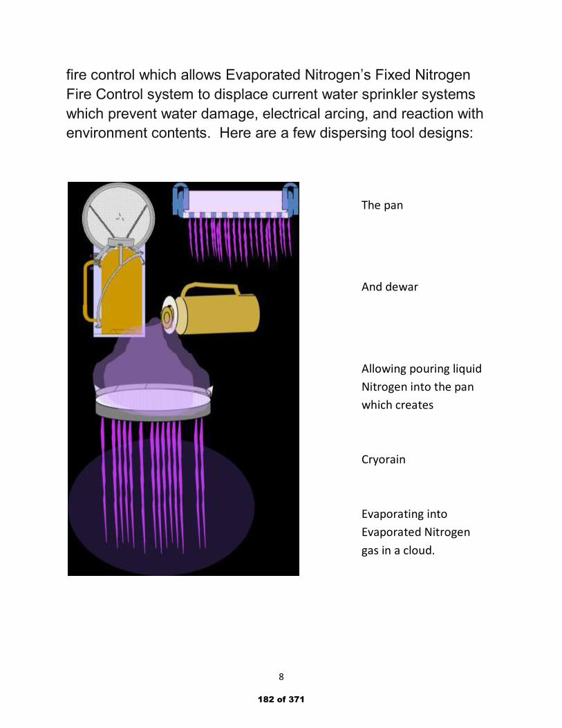
8
fire control which allows Evaporated Nitrogen’s Fixed Nitrogen
Fire Control system to displace current water sprinkler systems
which prevent water damage, electrical arcing, and reaction with
environment contents. Here are a few dispersing tool designs:
The pan
And dewar
Allowing pouring liquid
Nitrogen into the pan
which creates
Cryorain
Evaporating into
Evaporated Nitrogen
gas in a cloud.
182 of 371
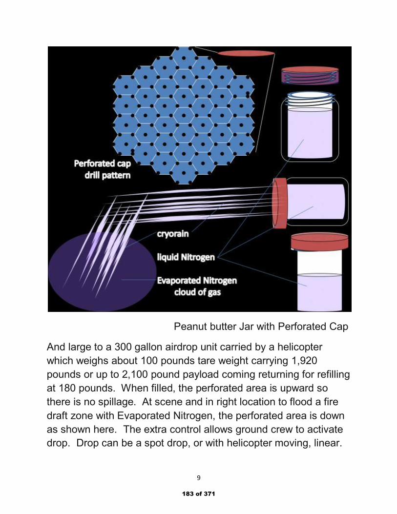
9
Peanut butter Jar with Perforated Cap
And large to a 300 gallon airdrop unit carried by a helicopter
which weighs about 100 pounds tare weight carrying 1,920
pounds or up to 2,100 pound payload coming returning for refilling
at 180 pounds. When filled, the perforated area is upward so
there is no spillage. At scene and in right location to flood a fire
draft zone with Evaporated Nitrogen, the perforated area is down
as shown here. The extra control allows ground crew to activate
drop. Drop can be a spot drop, or with helicopter moving, linear.
183 of 371
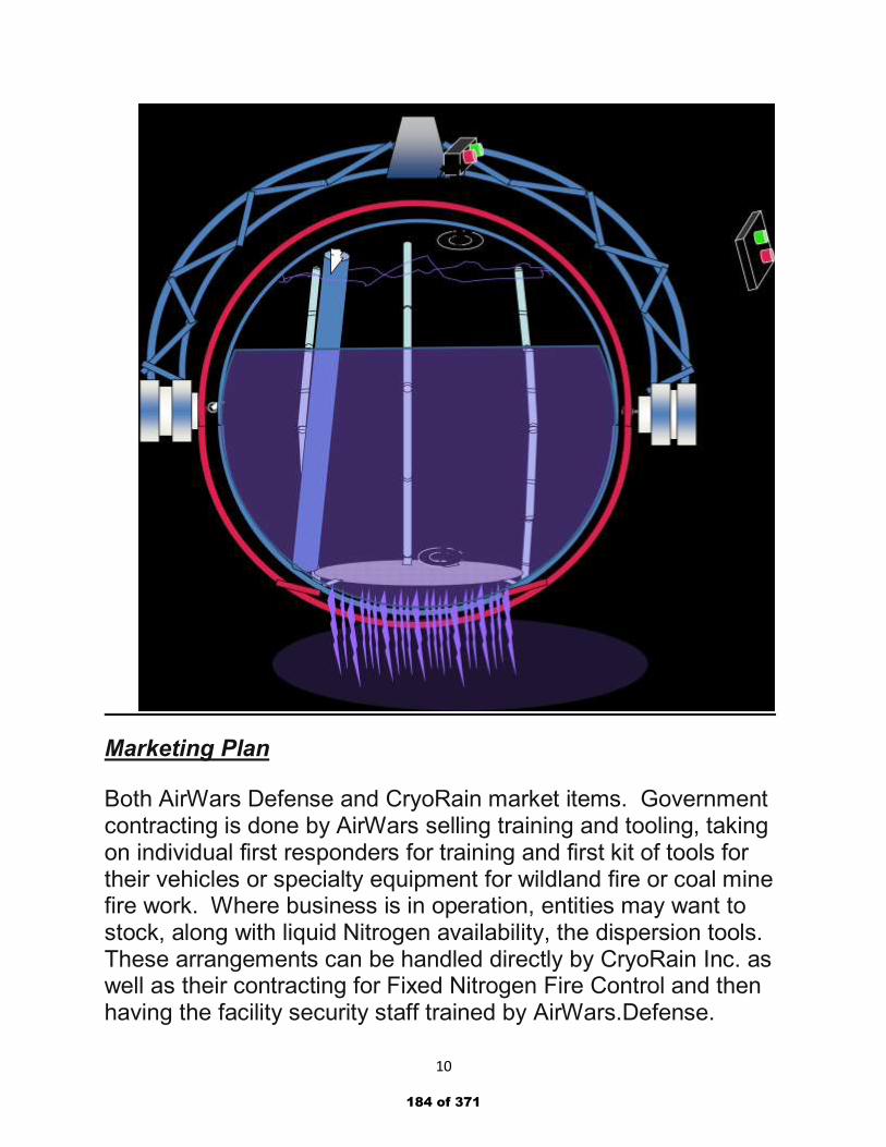
10
Marketing Plan
Both AirWars Defense and CryoRain market items. Government contracting is done by AirWars selling training and tooling, taking on individual first responders for training and first kit of tools for their vehicles or specialty equipment for wildland fire or coal mine fire work. Where business is in operation, entities may want to stock, along with liquid Nitrogen availability, the dispersion tools. These arrangements can be handled directly by CryoRain Inc. as well as their contracting for Fixed Nitrogen Fire Control and then having the facility security staff trained by AirWars.Defense.
184 of 371
11
Operational Plan
With discovery of this result of evaporating liquid Nitrogen and getting the stand alone Evaporated Nitrogen cloud which pushes out flames and cools the fuel to lower the chance of re-ignition while it allows fire fighters to find the people and pets in the burning environment happening in March, 2003, it has taken until now, July of 2018, to be ready to train users of the methods and get some final designs of the dispersion equipment for the huge range of uses of the methods.
AirWars Defense stands ready to train all employees we take on in uses of liquid Nitrogen – some to join in training people, some marketing, some accounting, but all able, if they would like, to take part in the vast, week long experience of preparing others to ably use the technology to protect their communities or carry out the special tasks from coal mine and wildland fire control, freeze fracking oil shale and hot Nitrogen extracting, spill cleanup on land or sea – remediation, handling spills and possible explosive situations, and more.
AirWars Defense lp was finally awarded the SAM Registered qualification for Federal government grants and contracts on July 3, 2018 and we are working to subcontract with AmWater, a General Contractor with Wright Patterson Air Force Base here, to clean up the spilled fire prevention foam which is currently polluting the fresh water supply here in the Dayton area. We can do remediation to pull the poisons from the soil which are washing into the ground water supplies.
We are also working to offer the City of Toledo, Ohio, a means to advance the temperature so the algae blocking their fresh water supply goes into autumn remission by cooling the waters near the water intake units.
Wildland and coal mine fire control tasks are being requested.
185 of 371
12
We have requests to do Evaporated Nitrogen testing at Dayton Fire Department joint area test site so some first responders can experience this new technology and we get a movement to work for use, use our methods, and interest their communities in the potential provided. Some fire departments might want to consider using Evaporated Nitrogen rather than water to reduce costs of crises management and recovery for their communities.
The operation in doing this might well get established fire control suppliers to make dispersion tools and convert the pumper trucks from water tanks to cryotanks to carry liquid Nitrogen with a 1% daily Nitrogen loss and to bracket the unit to carry the dispersion tools preparing the Fire Department for the conversion.
We are now ready to take this major step of involving others, organizing the group between the two businesses here, tapping those groups working with me over the years to fit into the plan and move forward surprising many at the advantage of change in emergency management, energy and environmental practices.
If we can interest those at World Bank into supporting our coal mine fire efforts, we can end those fires in the USA east of the Mississippi and from what we learn of earth crust temperature changes determine which ones and how many of the other coal mine fires to control to halt sea level rise by year 2021. And, with this saving of coal resources and combining it with the remaining oil and gas resources, we can then fit the power and heating plants burning Carbon fuels with Evaporated Nitrogen means to totally capture all the smoke which allow burning the remainder of Carbon fuel resources without polluting the air and fresh water.
When the US Forest Service will test our wildland fire control, or, with Underwriter Laboratory Certification and/or NFPA Code 2001 inclusion, CAL-Fire will test this technology, we can save lands, property, homes and communities from these fires.
186 of 371
13
Management & Organization
Currently AirWars Defense lp and CryoRain Inc. are operating at 2300 Eden Lane, Dayton Ohio 45431-1909 USA. As we are funded, we can bring in two workers while we design and build out the K-Mart abandoned building at 601 Woodman Drive in Dayton, Ohio.
We can expand the office to use some space at the Springfield exit off Woodman Drive – Harshman Road owned by the City of Riverside once those at Underwriters’ Laboratory LLC in Chicago We are working to certify or get a draft included in the NFPA 2001 as a fourth IG-100, Nitrogen, entry with the three other Nitrogen compressed gas listings. This takes our covering their costs of time and experimenting. Mr. Blake Shugarman, heading our team at UL is a committeeman on the roster for NFPA 2001.
We are seeking two business leaders to work harmoniously, to head AirWars Defense lp and the other CryoRain Inc. We will continue videotaping five lectures and the 34 demonstrations, listed on page 140 of Nitrogen Pure and Powerful, for the home study segment of training. We will also lead each lab exercise for the visiting section of Evaporated Nitrogen certification and see that the modification of the building at 601 Woodman allows each in a safe manner and eliminating smoke so the neighborhood is not adversely affected. For the certification, we will be training 30 candidates to participate in the lab exercises and certification needs, as well as serve either company in some capacity.
The companies can share duty officers as secretary, treasure, bookkeeper, billing officers and personnel director and team. Contract marketing will be exclusively an AirWars Defense function with possible assistance given to CryoRain Inc for fixed Nitrogen fire control installations in hospitals, senior homes, office buildings and high rises. CryoRain will house the engineers and
187 of 371

14
software developers, equipment design team and fire department conversion specialists.
Each entity will have its own accounts and once a project is assigned, that account will be assigned. For contracts and grants, AirWars will buy from CryoRain and for training in construction work CryoRain will assign training to AirWars covering those expenses for their account.
We will have to be sure to get these situations done correctly to not have parties falling through the cracks getting service from each but being no-accounts. AirWars will mostly be dealing with governments and CryoRain with corporations, other businesses and the private sector.
Startup Expenses & Capitalization
With a 15 year history of development, and disappointment that it has taken so long, we are assuming $100,000 in loans, contract work and wages earned.
The Dayton area is not a high-salary region so our plan is to hire personnel with salaries at $60K per year to start, and wages at $15/hour both with benefits of 20% to cover employee needs from loan coverage to insurance and retirement accounts.
As the team expands, there will be an assignment time late in the first year with salary or wage adjustments to merit the change.
Parties working with me to get this underway can do contracting with AirWars Defense lp and each situation is agreed upon in advance. I also can only give appreciation to SCORE Advisor, Dr. Al Torres and to retired Dayton Mayor Gary Leitzell for their contributions to the advancement of this technology.
Mayor Leitzell hosted a demonstration of the technology in his back yard in 2015.
188 of 371
15
Because this Evaporated Nitrogen technology is in the emergency management section of operations, we dare not step out and try each method.
Financial Plan
A Financial Plan will be available upon request.
Appendices
SAM Registration activation
DuBrucq references – one pager, landscape, Dahlawi letter
Capability Statement
Evaporated Nitrogen Fire Performance
Water Saver
Coal Mine fire – Halting Sea Level Rise w/ budget
Wildland Fire Work – Chap. 4, Nitrogen Pure and Powerful
Oil Fire Video – 17 seconds using Peanut Butter Jar tool.
Molecular Air Chemistry (upon request)
Nitrogen Pure and Powerful (upon request)
For further information and documentation support, please contact me at 937 253-2300.
Respectfully submitted:
Denyse Claire DuBrucq EdD 2300 Eden Lane Dayton, Ohio 45431-1909 USA [email protected]
189 of 371
Trough for fires and lava cooling
190 of 371
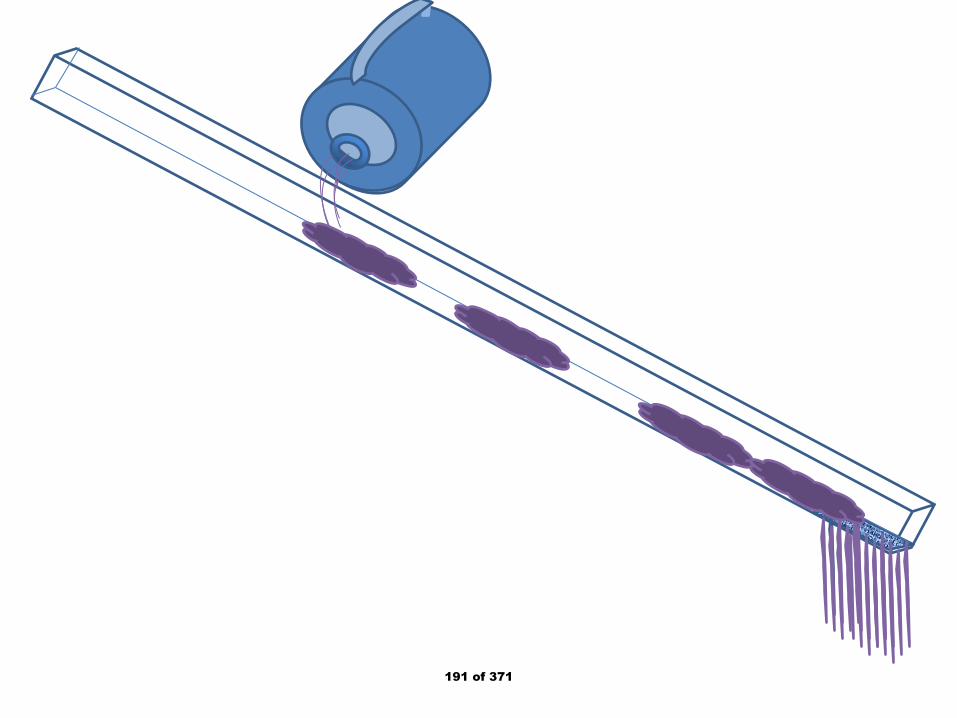
191 of 371
192 of 371
193 of 371
194 of 371
195 of 371
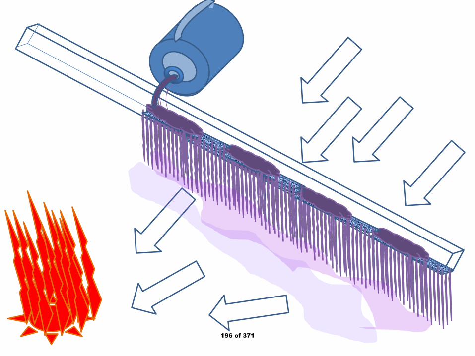
196 of 371
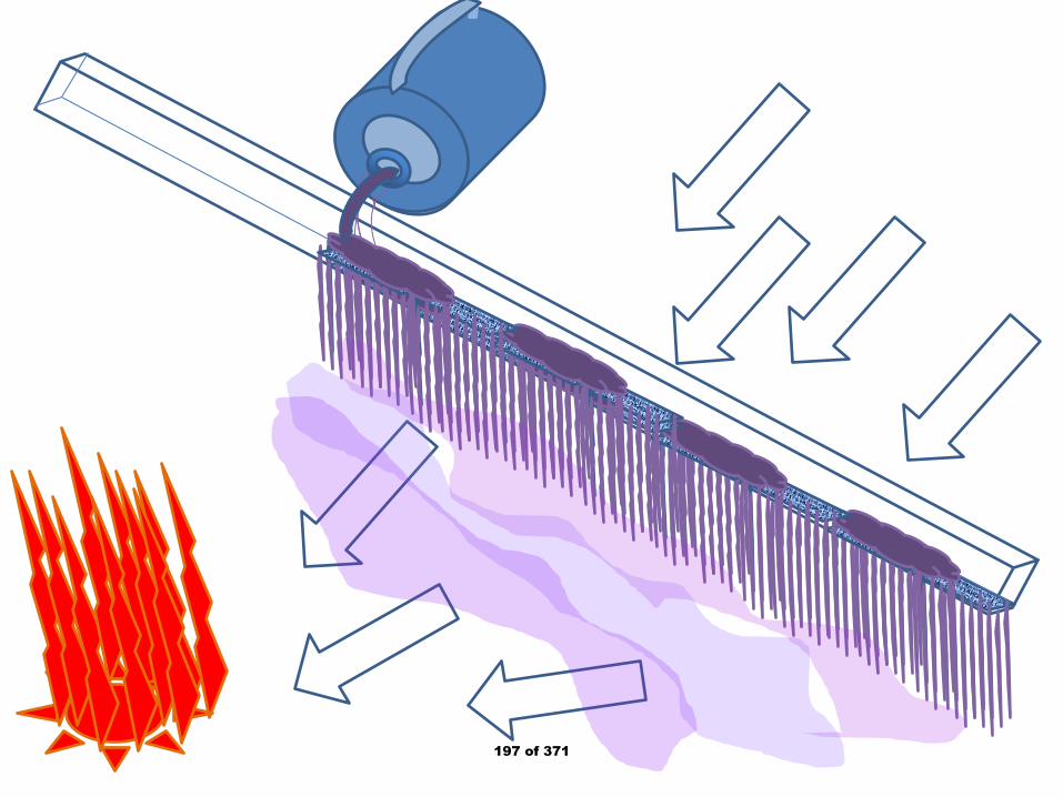
197 of 371
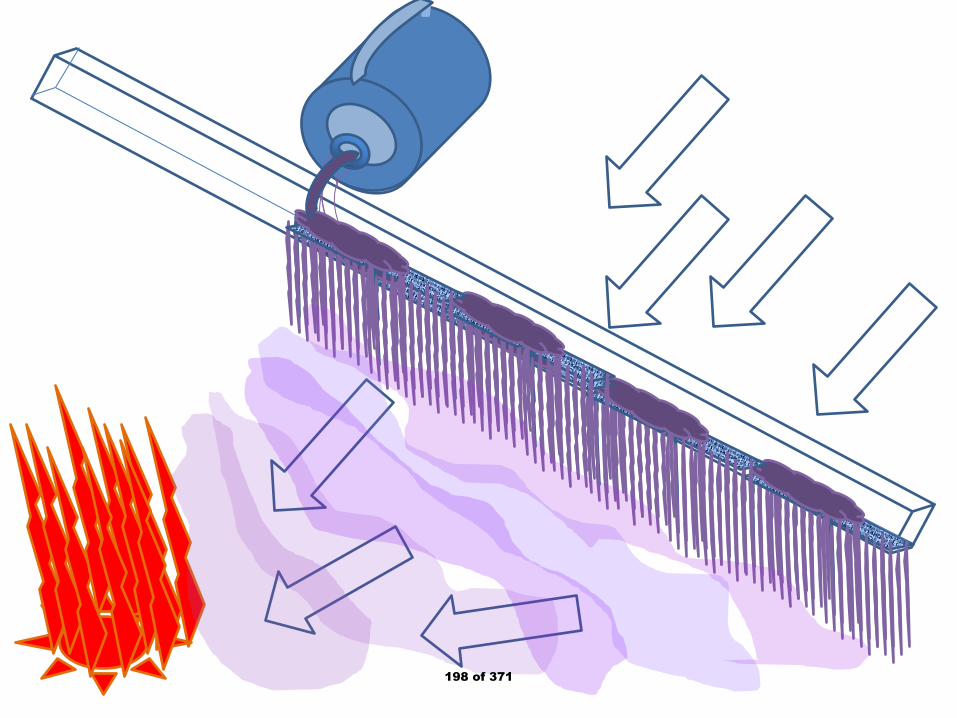
198 of 371
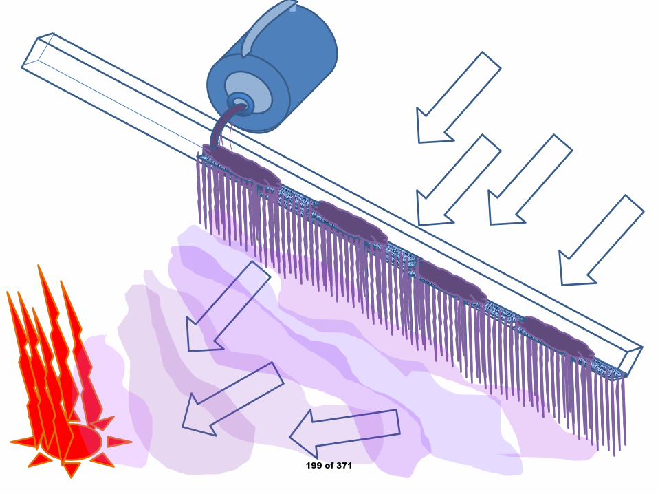
199 of 371
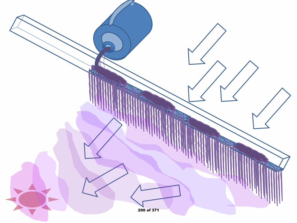
200 of 371
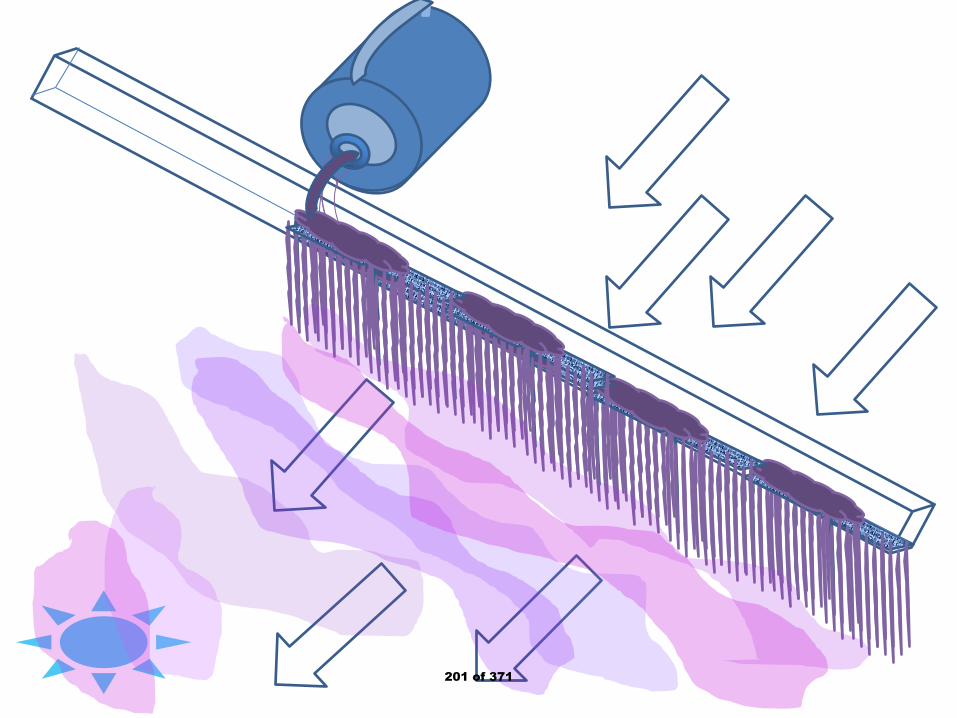
201 of 371
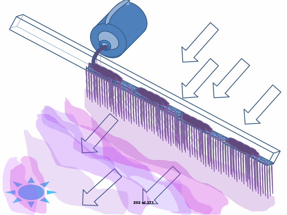
202 of 371
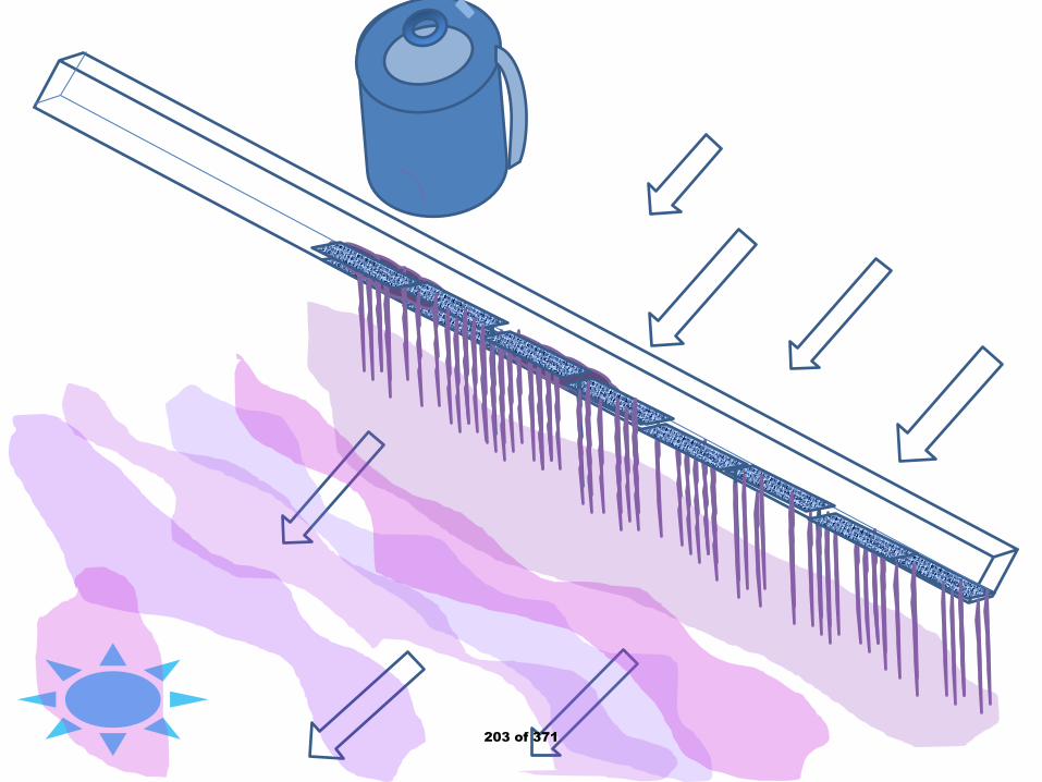
203 of 371
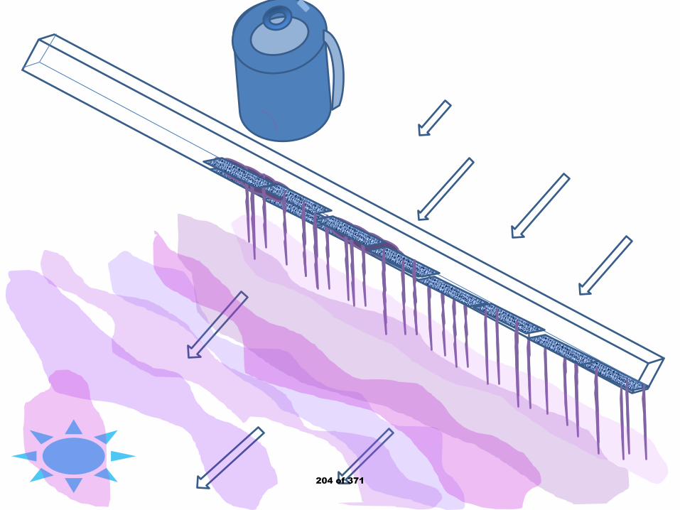
204 of 371
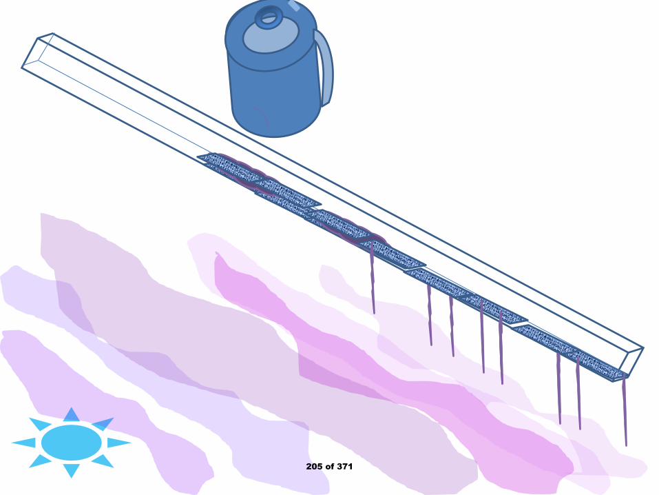
205 of 371
206 of 371

207 of 371

208 of 371
209 of 371
Public Input No. 29-NFPA 2001-2018 [ Section No. 6.6 ]
6.6* Operation.
The system shall be designed for automatic operation except where the authority having jurisdiction permitsmanual operation.
6.6 Operation . The system shall be designed for automatic operation except where the authority havingjurisdiction permits manual operation. Placing the cryorain into a fire draft uses the power of the fire todraw the Nitrogen cloud into the fire interrupting the fresh air intake. The fresh air provides Oxygen wherethe cohesive Nitrogen cloud displaces Oxygen. Lacking Oxygen the flames end immediately. The cloudtemperature allows cooling of the fuel to reduce re-ignition and this warms the cloud causing it to rise tonew space in the fire zone. Eventually, heated, it rises through the canopy if outside ending burningembers causing the fire to release just chunks of charcoal which will not move the fire to further andnew territory.
Statement of Problem and Substantiation for Public Input
This allows the definition of the evaporated Nitrogen gas in a fire situation which is in concert with the prior inclusions on this topic.
Submitter Information Verification
Submitter Full Name: Denyse Dubrucq
Organization: Air Wars Defense Lp
Affiliation: NFPA Member 3019224
Street Address:
City:
State:
Zip:
Submittal Date: Sat Sep 22 15:03:05 EDT 2018
Committee: GFE-AAA
National Fire Protection Association Report https://submittals.nfpa.org/TerraViewWeb/ContentFetcher?commentPar...
73 of 176 3/15/2019, 10:45 AM
210 of 371
Public Input No. 30-NFPA 2001-2018 [ New Section after 7.2.3.6 ]
TITLE OF NEW CONTENT
AMEND: 7.2.3.6.1 For IG-100-400 – Evaporated Nitrogen Gas, container weight shall be recorded beforeand after the discharge test since liquid Nitrogen is the delivery agent and its mass tells quantity remaining. Specific gravity of water is 1.0 where liquid Nitrogen has a 0.8 specific gravity thus one gallon of waterweighs 8 pounds where one gallon of liquid Nitrogen weighs 6.4 pounds.
Statement of Problem and Substantiation for Public Input
To tell how much fire suppressant one is using, it is easiest when considering Evaporated Nitrogen Gas to determine the amount of liquid Nitrogen released. This is done by recording the pre-task weight of the container with liquid Nitrogen and after the release, again weigh the container with liquid Nitrogen. Then subtract the pre-weight from the post-weight and that amount in pounds (grams) of liquid Nitrogen was used. The volume of fire suppressant is then determined with the temperature expansion factored in...as 6.4 pounds of liquid Nitrogen used gives the same gas weight, but the volume of the evaporated gas is 230 times the liquid volume of one gallon or 230 gallons. At ambient temperatures the volume is 250 times the liquid volume. And at inferno temperatures 600 to 700 times or 600 to 700 gallons. Hitting the gallon to cubic feet conversion one gets: Liquid volume is 0.133681 cubic feet, gas volume at cryogenic temperature is 30.74653 cubic feet; at ambient temperature is 33.4201 cubic feet and at inferno temperatures is 80.2083 to 93.5764 cubic feet. And what is most spectacular, you'll see the transparent cloud that size in the smoke-filled space of the fire. To start, if one fills a space with 10% volume of cryogenic temperature Evaporated Nitrogen Gas, this will hug the ground allowing a low to the ground camera to find people and pets while the rescuer roams the smokey space and gets the life out of the fire zone. Then fill the space with Evaporated Nitrogen gas and the flames are gone, the fuel is cooling and one can extinguish the rekindling fuel with a small squirt of Evaporated Nitrogen Gas from the pint jar with perforated cap holding one cup of liquid Nitrogen doing the final cooling to below re-ignition temperature. I hope you'll find this useful in fire control.
Submitter Information Verification
Submitter Full Name: Denyse Dubrucq
Organization: Air Wars Defense Lp
Affiliation: NFPA Member 3019224
Street Address:
City:
State:
Zip:
Submittal Date: Sat Sep 22 15:08:12 EDT 2018
Committee: GFE-AAA
National Fire Protection Association Report https://submittals.nfpa.org/TerraViewWeb/ContentFetcher?commentPar...
74 of 176 3/15/2019, 10:45 AM
211 of 371
Public Input No. 63-NFPA 2001-2018 [ New Section after 8.3 ]
Add annex 8.3 Determination of Agent Quantity
To determine the quantity of halocarbon agent in a cylinder, the cylinder may be weighed or a listed devicesuch as a liquid level indicator may be used. Cylinders can be heavy and bulky so proper precautions mustbe taken to avoid personnel injury if cylinders are to be weighed. To avoid the need for lifting cylinders,dedicated in place weighing systems may be used or a listed liquid level indicator may be used.
Statement of Problem and Substantiation for Public Input
Agent cylinders can be very heavy as well as bulky. Cylinders may weigh 1000 pounds or more. Moving or lifting such large heavy cylinders presents the potential for injury to service personnel. The suggested addition to the Annex highlights some options to moving and lifting cylinders for the purpose of determining the quantity of agent in the cylinder.
Submitter Information Verification
Submitter Full Name: Thomas Wysocki
Organization: Guardian Services, Inc.
Street Address:
City:
State:
Zip:
Submittal Date: Wed Dec 26 11:55:24 EST 2018
Committee: GFE-AAA
National Fire Protection Association Report https://submittals.nfpa.org/TerraViewWeb/ContentFetcher?commentPar...
75 of 176 3/15/2019, 10:45 AM
212 of 371
Public Input No. 7-NFPA 2001-2018 [ Section No. 8.3.2 ]
8.3.2
For halocarbon agent containers without a means of pressure indication, if a container shows a loss inagent quantity of more than 5 percent, it shall be refilled or replaced.
Statement of Problem and Substantiation for Public Input
Halocarbon systems which require inert gas superpressurization as the energy source to drive the the clean agent out of the container and through the piping system and nozzle/s should be required to be monitored for pressure.
Section 8.3.2 is in direct conflict with section 4.1.4.4: "A means shall be provided to determine the pressure in containers of inert gas agents, superpressurized liquid agents, and superpressurized liquefied compressed gas agents."
Submitter Information Verification
Submitter Full Name: Daniel Hubert
Organization: AmerexJanus Fire Systems
Street Address:
City:
State:
Zip:
Submittal Date: Thu Aug 09 17:42:43 EDT 2018
Committee: GFE-AAA
National Fire Protection Association Report https://submittals.nfpa.org/TerraViewWeb/ContentFetcher?commentPar...
76 of 176 3/15/2019, 10:45 AM
213 of 371
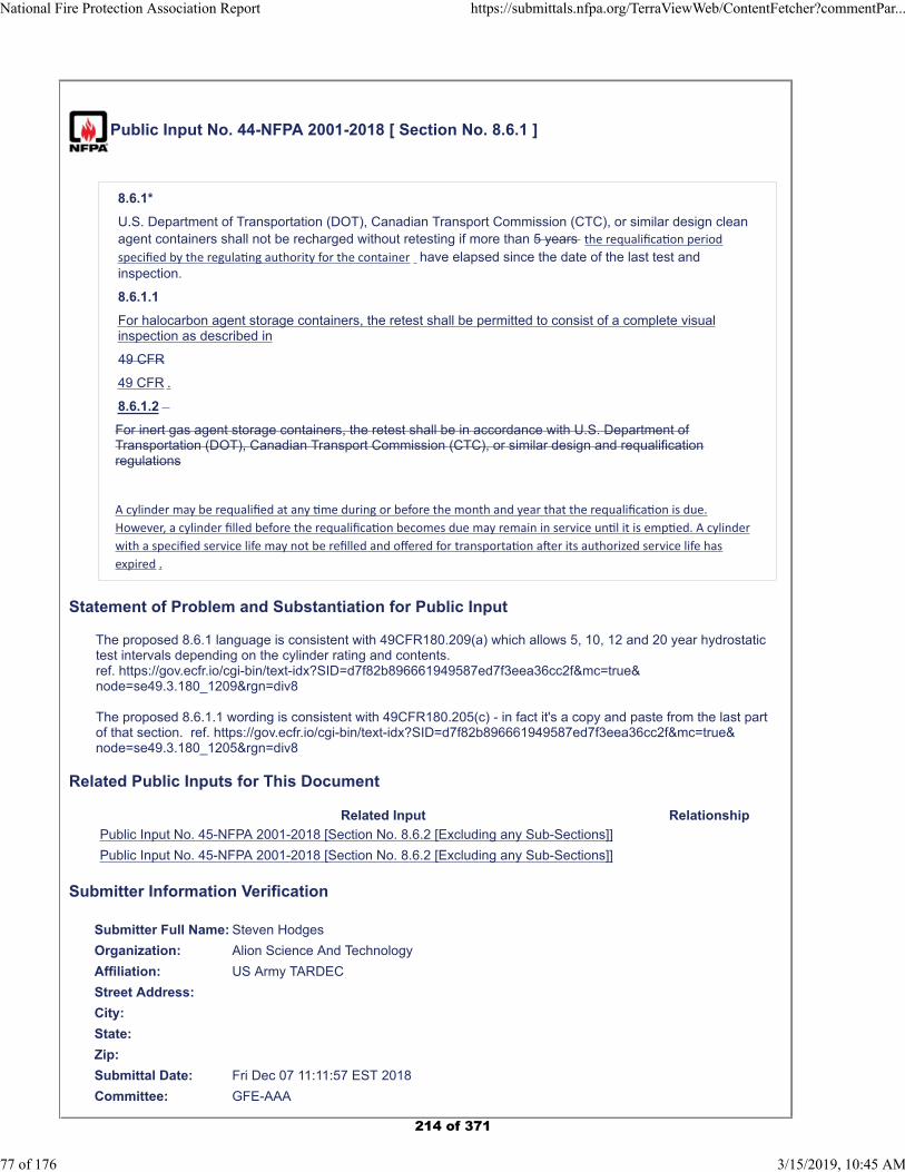
Public Input No. 44-NFPA 2001-2018 [ Section No. 8.6.1 ]
8.6.1*
U.S. Department of Transportation (DOT), Canadian Transport Commission (CTC), or similar design cleanagent containers shall not be recharged without retesting if more than 5 years the requalifica on period
specified by the regula ng authority for the container have elapsed since the date of the last test andinspection.
8.6.1.1
For halocarbon agent storage containers, the retest shall be permitted to consist of a complete visualinspection as described in
49 CFR
49 CFR .
8.6.1.2
For inert gas agent storage containers, the retest shall be in accordance with U.S. Department ofTransportation (DOT), Canadian Transport Commission (CTC), or similar design and requalificationregulations
A cylinder may be requalified at any me during or before the month and year that the requalifica on is due.
However, a cylinder filled before the requalifica on becomes due may remain in service un l it is emp ed. A cylinder
with a specified service life may not be refilled and offered for transporta on a er its authorized service life has
expired .
Statement of Problem and Substantiation for Public Input
The proposed 8.6.1 language is consistent with 49CFR180.209(a) which allows 5, 10, 12 and 20 year hydrostatic test intervals depending on the cylinder rating and contents. ref. https://gov.ecfr.io/cgi-bin/text-idx?SID=d7f82b896661949587ed7f3eea36cc2f&mc=true&node=se49.3.180_1209&rgn=div8
The proposed 8.6.1.1 wording is consistent with 49CFR180.205(c) - in fact it's a copy and paste from the last part of that section. ref. https://gov.ecfr.io/cgi-bin/text-idx?SID=d7f82b896661949587ed7f3eea36cc2f&mc=true&node=se49.3.180_1205&rgn=div8
Related Public Inputs for This Document
Related Input Relationship
Public Input No. 45-NFPA 2001-2018 [Section No. 8.6.2 [Excluding any Sub-Sections]]
Public Input No. 45-NFPA 2001-2018 [Section No. 8.6.2 [Excluding any Sub-Sections]]
Submitter Information Verification
Submitter Full Name: Steven Hodges
Organization: Alion Science And Technology
Affiliation: US Army TARDEC
Street Address:
City:
State:
Zip:
Submittal Date: Fri Dec 07 11:11:57 EST 2018
Committee: GFE-AAA
National Fire Protection Association Report https://submittals.nfpa.org/TerraViewWeb/ContentFetcher?commentPar...
77 of 176 3/15/2019, 10:45 AM
214 of 371

National Fire Protection Association Report https://submittals.nfpa.org/TerraViewWeb/ContentFetcher?commentPar...
78 of 176 3/15/2019, 10:45 AM
215 of 371
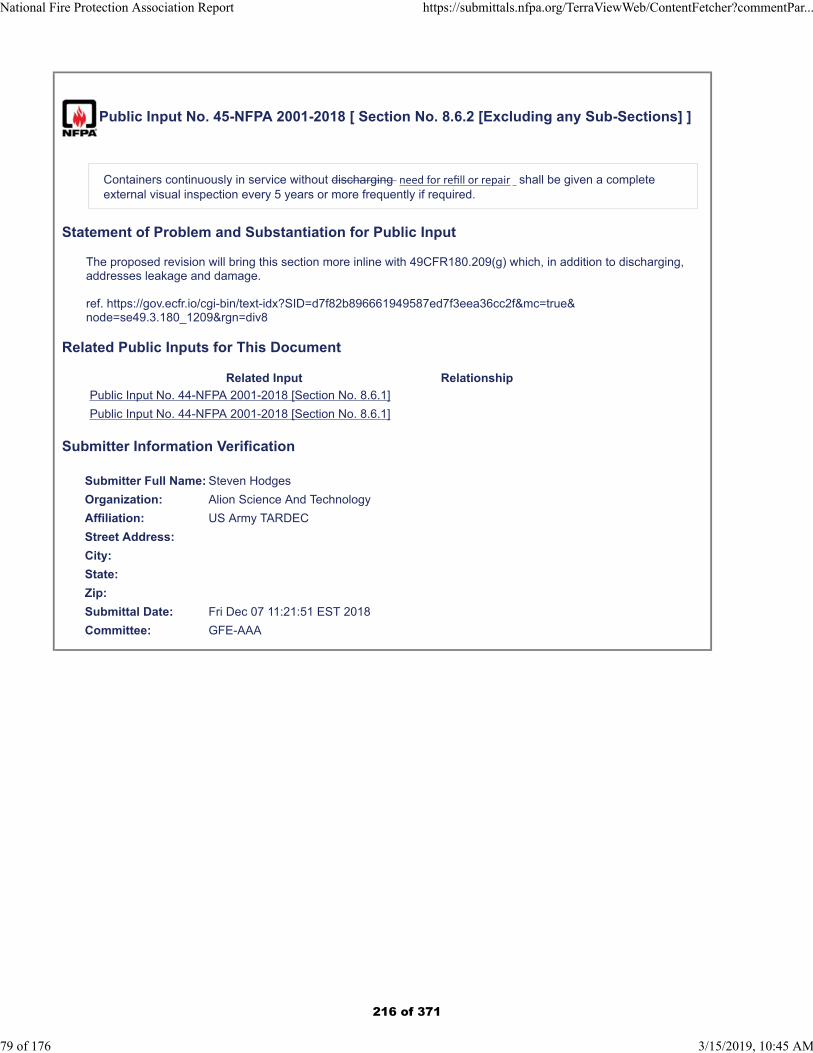
Public Input No. 45-NFPA 2001-2018 [ Section No. 8.6.2 [Excluding any Sub-Sections] ]
Containers continuously in service without discharging need for refill or repair shall be given a completeexternal visual inspection every 5 years or more frequently if required.
Statement of Problem and Substantiation for Public Input
The proposed revision will bring this section more inline with 49CFR180.209(g) which, in addition to discharging, addresses leakage and damage.
ref. https://gov.ecfr.io/cgi-bin/text-idx?SID=d7f82b896661949587ed7f3eea36cc2f&mc=true&node=se49.3.180_1209&rgn=div8
Related Public Inputs for This Document
Related Input Relationship
Public Input No. 44-NFPA 2001-2018 [Section No. 8.6.1]
Public Input No. 44-NFPA 2001-2018 [Section No. 8.6.1]
Submitter Information Verification
Submitter Full Name: Steven Hodges
Organization: Alion Science And Technology
Affiliation: US Army TARDEC
Street Address:
City:
State:
Zip:
Submittal Date: Fri Dec 07 11:21:51 EST 2018
Committee: GFE-AAA
National Fire Protection Association Report https://submittals.nfpa.org/TerraViewWeb/ContentFetcher?commentPar...
79 of 176 3/15/2019, 10:45 AM
216 of 371
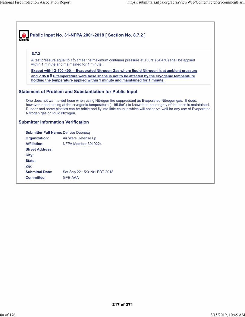
Public Input No. 31-NFPA 2001-2018 [ Section No. 8.7.2 ]
8.7.2
A test pressure equal to 11⁄2 times the maximum container pressure at 130°F (54.4°C) shall be appliedwithin 1 minute and maintained for 1 minute.
Except with IG-100-400 – Evaporated Nitrogen Gas where liquid Nitrogen is at ambient pressure
and -195.8 o C temperature were hose shape is not to be affected by the cryogenic temperatureholding the temperature applied within 1 minute and maintained for 1 minute.
Statement of Problem and Substantiation for Public Input
One does not want a wet hose when using Nitrogen fire suppressant as Evaporated Nitrogen gas. It does, however, need testing at the cryogenic temperature (-195.8oC) to know that the integrity of the hose is maintained. Rubber and some plastics can be brittle and fly into little chunks which will not serve well for any use of Evaporated Nitrogen gas or liquid Nitrogen.
Submitter Information Verification
Submitter Full Name: Denyse Dubrucq
Organization: Air Wars Defense Lp
Affiliation: NFPA Member 3019224
Street Address:
City:
State:
Zip:
Submittal Date: Sat Sep 22 15:31:01 EDT 2018
Committee: GFE-AAA
National Fire Protection Association Report https://submittals.nfpa.org/TerraViewWeb/ContentFetcher?commentPar...
80 of 176 3/15/2019, 10:45 AM
217 of 371
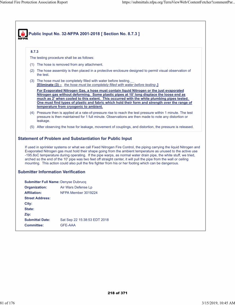
Public Input No. 32-NFPA 2001-2018 [ Section No. 8.7.3 ]
8.7.3
The testing procedure shall be as follows:
(1) The hose is removed from any attachment.
(2) The hose assembly is then placed in a protective enclosure designed to permit visual observation ofthe test.
(3) The hose must be completely filled with water before testing. [Eliminate (3) – the hose must be completely filled with water before testing .]
For Evaporated Nitrogen Gas, a hose must contain liquid Nitrogen or the just evaporatedNitrogen gas without deforming. Some plastic pipes at 10’ long displace the loose end asmuch as 2’ when cooled to this extent. This occurred with the white plumbing pipes tested. One must find types of plastic and fabric which hold their form and strength over the range oftemperature from cryogenic to ambient.
(4) Pressure then is applied at a rate-of-pressure rise to reach the test pressure within 1 minute. The testpressure is then maintained for 1 full minute. Observations are then made to note any distortion orleakage.
(5) After observing the hose for leakage, movement of couplings, and distortion, the pressure is released.
Statement of Problem and Substantiation for Public Input
If used in sprinkler systems or what we call Fixed Nitrogen Fire Control, the piping carrying the liquid Nitrogen and Evaporated Nitrogen gas must hold their shape going from the ambient temperature as unused to the active use -195.8oC temperature during operating. If the pipe warps, as normal water drain pipe, the white stuff, we tried, arched so the end of the 10' pipe was two feet off straight center, it will pull the pipe from the wall or ceiling mounting. This action could also pull the fire fighter from his or her footing which can be dangerous.
Submitter Information Verification
Submitter Full Name: Denyse Dubrucq
Organization: Air Wars Defense Lp
Affiliation: NFPA Member 3019224
Street Address:
City:
State:
Zip:
Submittal Date: Sat Sep 22 15:38:53 EDT 2018
Committee: GFE-AAA
National Fire Protection Association Report https://submittals.nfpa.org/TerraViewWeb/ContentFetcher?commentPar...
81 of 176 3/15/2019, 10:45 AM
218 of 371
Public Input No. 33-NFPA 2001-2018 [ Section No. 9.1.1 ]
9.1.1 Scope.
This chapter is limited to marine applications of clean agent fire extinguishing systems on commercial andgovernment vessels. Explosion inerting systems were not considered during development of this chapter.
9.1.1 ….. Explosion inerting systems were not considered during development of this chapter. IG-100-400 – Evaporated Nitrogen Gas can inert explosions by taking, first, the battery to below functiontemperature, and then, continuing cooling until the ingredients are below their window of reaction, thuspreventing explosion. Explosives most often contain sufficient Oxygen to react, but they becomepowerless below their temperature to function or react.
Statement of Problem and Substantiation for Public Input
No place but this to get Evaporated Nitrogen Gas' use for ending potential explosions into the minds of fire fighters who might encounter situations like this with IEDs, old battle grounds, and experimenting people that could bring danger to the community.
Submitter Information Verification
Submitter Full Name: Denyse Dubrucq
Organization: Air Wars Defense Lp
Affiliation: NFPA Member 3019224
Street Address:
City:
State:
Zip:
Submittal Date: Sat Sep 22 15:46:17 EDT 2018
Committee: GFE-AAA
National Fire Protection Association Report https://submittals.nfpa.org/TerraViewWeb/ContentFetcher?commentPar...
82 of 176 3/15/2019, 10:45 AM
219 of 371
Public Input No. 34-NFPA 2001-2018 [ Section No. 9.2.2 ]
9.2.2*
In addition to the limitations given in 1.4.2.2, clean agent fire extinguishing systems shall not be used toprotect the following:
(1) Dry cargo holds
(2) Bulk cargo9.2.2 . .with the exception of . IG-100-400 – Evaporated Nitrogen Gas, which can protect both (1) drycargo holds and (2) bulk cargo. Dry cargo holds when bathed periodically in evaporated Nitrogen gaswill displace Oxygen which can cause explosions and toxin formation, which can poison those thatbreathe the gases, and Carbon dioxide from rotting or burning. The Nitrogen gas leaves thecontained material in an anaerobic state. Replaced by filtered air, the dry cargo hold and bulk cargoare returned to an aerobic state with reduced losses from rodents and aerobic biologic entities that eator decompose the stored material.
For Bulk cargo, periodic bathing the cargo in Evaporated Nitrogen Gas can kill invaders that consumethe cargo, rats, insects, mold and bacteria. During starvation situations, cargo ships come with holdsof grain to feed the starving and, with overload of help, the ships cannot be unloaded quickly. By thetime a ship can be unloaded, it sometimes losses a great percentage of its cargo to invading lifemaking the shipment useless in fighting hunger. Nitrogen washes reduce this type of lossconsiderably.
Statement of Problem and Substantiation for Public Input
Today, in Yemen people are starving in their Northwestern sectors since there is little or no food or water and the harbor serving the folks is controlled by the enemy. Though the UN and other ships carrying food have arrived, unloading and transferring the food is slow and much must be lost to the invading rodents, bacteria, mold and the like making it useless to handle the starving masses. Why they are not using helicopters to take loads of food from the ships at sea, I could not tell you.
Submitter Information Verification
Submitter Full Name: Denyse Dubrucq
Organization: Air Wars Defense Lp
Affiliation: NFPA Member 3019224
Street Address:
City:
State:
Zip:
Submittal Date: Sat Sep 22 15:49:43 EDT 2018
Committee: GFE-AAA
National Fire Protection Association Report https://submittals.nfpa.org/TerraViewWeb/ContentFetcher?commentPar...
83 of 176 3/15/2019, 10:45 AM
220 of 371
Public Input No. 35-NFPA 2001-2018 [ Section No. 9.2.3 ]
9.2.3
The effects of agent decomposition products and combustion products on fire protection effectiveness andequipment shall be considered where using clean agents in hazards with high ambient temperatures (e.g.,incinerator rooms, hot machinery and piping).
9.2.3 …. It can also remain inert and effective in hazards with high ambient temperatures (e.g. incineratorrooms, hot machinery and piping.) since Nitrogen, N 2 , is a stable gas throughout a very wide temperaturerange, like -195.8oC through 10,000oC.
Statement of Problem and Substantiation for Public Input
Evaporated Nitrogen Gas is a very versatile crises handling material. Not only holding its own as an inert, pure gas through the temperature range - as good in the dead of winter as the heat of summer plus the flame environment through molten steel. We may as well flaunt it. It might be most useful in some very hot fires where water in gone up in steam and the Nitrogen just fights right on displacing the Oxygen ending flames and cooling the fuel reducing re-ignition.
Submitter Information Verification
Submitter Full Name: Denyse Dubrucq
Organization: Air Wars Defense Lp
Affiliation: NFPA Member 3019224
Street Address:
City:
State:
Zip:
Submittal Date: Sat Sep 22 15:56:18 EDT 2018
Committee: GFE-AAA
National Fire Protection Association Report https://submittals.nfpa.org/TerraViewWeb/ContentFetcher?commentPar...
84 of 176 3/15/2019, 10:45 AM
221 of 371
Public Input No. 36-NFPA 2001-2018 [ New Section after 9.3 ]
TITLE OF NEW CONTENT 9.3.3
With IG 100-400 – Evaporated Nitrogen Gas, flooding of any confined space with this self-purifyingtransparent Nitrogen cloud, only those with sufficient supplemental Oxygen (SCBA Equipment)should enter, and only for the length of time the Oxygen supply will maintain sufficient Oxygen tosustain consciousness and breathing.
Statement of Problem and Substantiation for Public Input
This answers the confined space fear of using Nitrogen gas. It narrows down the situation to specify when to avoid Nitrogen in the pure state and, if one must, how to safely enter the space with the requirement that the time in the space must be less than the amount of available supplemental Oxygen one has in hand. Be it known that the exhaled water vapor and Carbon dioxide will be pushed out of the Evaporated Nitrogen Cloud by its cohesion, causing only N2 Nitrogen in the pure cloud environment. Lots of toxins can be avoided using this strategy. Toxins are also kept from inside the cloud. There may be a way to use this for poisonous gas attacks. I'm not an expert on this, but others may be and should be asked how this can be used.
Submitter Information Verification
Submitter Full Name: Denyse Dubrucq
Organization: Air Wars Defense Lp
Affiliation: NFPA Member 3019224
Street Address:
City:
State:
Zip:
Submittal Date: Sat Sep 22 16:03:52 EDT 2018
Committee: GFE-AAA
National Fire Protection Association Report https://submittals.nfpa.org/TerraViewWeb/ContentFetcher?commentPar...
85 of 176 3/15/2019, 10:45 AM
222 of 371
Public Input No. 37-NFPA 2001-2018 [ New Section after 9.4 ]
9.4.9 for IG 100-400 –Evaporated Nitrogen Gas, agent is stored as cryogenic liquid Nitrogen at ambient pressure and
thermally insulated so contents can remain at below -320 o F or -195.8 o C. Losses over time fromlarge cryotanks is 1% per day and small, like LN-4, 10% per day. Routine topping off stored systemskeeps supply sufficient to handle a crisis when it happens. ...
Also, amendment to the 9.4 - Agent Supply: IG100-400 – Evaporated Nitrogen Gas is not stored instorage cylinders, pressured; but in cyrotanks at ambient pressure.
Statement of Problem and Substantiation for Public Input
The versatility of having Nitrogen available without having it in a weighty pressure tank can open its uses in crises fighting a great deal. This gives the differences in storage and duration time compared with the compressed air uses.
Submitter Information Verification
Submitter Full Name: Denyse Dubrucq
Organization: Air Wars Defense Lp
Affiliation: NFPAMember 3019224
Street Address:
City:
State:
Zip:
Submittal Date: Sat Sep 22 16:12:27 EDT 2018
Committee: GFE-AAA
National Fire Protection Association Report https://submittals.nfpa.org/TerraViewWeb/ContentFetcher?commentPar...
86 of 176 3/15/2019, 10:45 AM
223 of 371
Public Input No. 38-NFPA 2001-2018 [ New Section after 9.7.1.1 ]
9.7.1.2 for IG 100-400for IG 100-400, Evaporated Nitrogen Gas, application within a confined space, automatic releases
will be limited to 1/10 th volume of the space until first responders check for occupants, and, then, ifthe fire is not ended and people and pets are removed from the space, full flooding is allowed withcalculated quantity of liquid Nitrogen released to meet the space dimensions of the confined spacewhen manually initiated by first responders.
Statement of Problem and Substantiation for Public Input
This explains a safe use of Evaporated Nitrogen Gas as Fixed Nitrogen Fire Control systems are installed in facilities. Its transparent cloud allows camera viewing to find victims, people and pets, in a fire. Removing them, the location can be flooded. Were first responders with supplemental Oxygen located in the fire zone, with full flooding of the space, anybody missed can be provided with the shared Oxygen and guided out of the fire space. If overcome with NItrogen coma, they can be rapidly resuscitated with the normal amount of Oxygen needed. Compare this with the panting of being overcome with Carbon dioxide in a fire where a victim in a coma can deplete an Oxygen supply in a few breaths.
Submitter Information Verification
Submitter Full Name: Denyse Dubrucq
Organization: Air Wars Defense Lp
Affiliation: NFPA Member 3019224
Street Address:
City:
State:
Zip:
Submittal Date: Sat Sep 22 16:19:43 EDT 2018
Committee: GFE-AAA
National Fire Protection Association Report https://submittals.nfpa.org/TerraViewWeb/ContentFetcher?commentPar...
87 of 176 3/15/2019, 10:45 AM
224 of 371
Public Input No. 39-NFPA 2001-2018 [ Section No. 9.9.2.3 ]
9.9.2.3
The discharge time for inert gas agents shall not exceed 120 seconds for 85 percent of the designconcentration or as otherwise required by the authority having jurisdiction.
for IG 100-400 – Evaporated Nitrogen Gas, application within a confined space, automatic releases
will be limited to 1/10 th volume of the space until first responders check for occupants, and, then,if the fire is not ended and people and pets are removed from the space, full flooding is allowedwith calculated quantity of liquid Nitrogen released to meet the space dimensions of the confinedspace when manually initiated by first responders. First responders entering the fire zone with fullflooding of Nitrogen finding a victim overcome with Nitrogen coma can share the Oxygen supplywith this victim resuscitating them with the normal Oxygen levels needing for breathing. However,finding a victim in a fire zone overcome with Carbon dioxide, when being resuscitated, theirbreathing will consume all of the Oxygen in a few breaths since the victim is panting to get theCarbon dioxide level in the lungs down to normal. This will consume a supplemental Oxygensupply in a few breaths endangering both the one being rescued and the rescuer.
Statement of Problem and Substantiation for Public Input
One has to use research done in Canada and France where they allow respiratory research. Nitrogen coma leaves lungs flooded with Nitrogen when they normally are flooded with 78% Nitrogen N2 gas from the air. Having 100% Nitrogen lung content only requires getting the Oxygen percentage from zero percent to 21% for normal breathing. However, having the lungs flooded with Carbon dioxide, one must empty the lungs and replace the Carbon dioxide with Nitrogen at 78% and Oxygen at 21%. No amount of Oxygen can affect the Carbon dioxide coma until the triggering gas, Carbon dioxide is down to normal levels as the Nitrogen at 78% and Oxygen at 21% operates so the Oxygen exchange for Carbon dioxide in the blood in the capillaries in the lungs returns to operational. Thus the panting thrusts the Carbon dioxide out of the lungs. This could be compared to bathroom use. One can come and get a drink of water and leave satisfied with a half cup from a glass, or one can want to rid the toilet of excretions and flush the toilet so the toilet bowl is empty of wastes, clean and not smelly. This takes a toilet tank of water. It represents normal breathing with Nitrogen coma and panting to end a Carbon dioxide coma.
Submitter Information Verification
Submitter Full Name: Denyse Dubrucq
Organization: Air Wars Defense Lp
Affiliation: NFPA Member 3019224
Street Address:
City:
State:
Zip:
Submittal Date: Sat Sep 22 16:28:32 EDT 2018
Committee: GFE-AAA
National Fire Protection Association Report https://submittals.nfpa.org/TerraViewWeb/ContentFetcher?commentPar...
88 of 176 3/15/2019, 10:45 AM
225 of 371
Public Input No. 40-NFPA 2001-2018 [ New Section after 9.11.3.1 ]
9.11.3.2 For IG 100-400For IG 100-400 – Evaporated Nitrogen Gas, an inert gas stored as liquid Nitrogen, testing andcontinual weekly top off of liquid Nitrogen volume in large cryotank is mandatory as is refilling afteruse. Liquid Nitrogen bleeds off these large tanks at an anticipated rate of 1% of the volume per day. Smaller dewars and other short term transport vessels may bleed off 10% per day with goodinsulation and thus would best be topped off more frequently as twice weekly to keep a usefulsupply on hand and refilled after use.
Statement of Problem and Substantiation for Public Input
This storing the inert gas that is not electrically conductive nor leaves any residual material done for Evaporated Nitrogen Gas requires storage of liquid Nitrogen at ambient temperature accommodating its evaporation from large insulated tanks at 1% per day and smaller insulated tanks, often called dewars, at 10% per day requiring weekly or for the small ones bi-weekly topping off and refilling after any use. Attention is required to the fact that this bleeding off must be accommodated with safe carriage of the evaporated gas to release in the atmosphere where this Nitrogen N2 adds to the 78% Nitrogen N2 gas atmosphere we have here on earth.
Also, the containers are not dangerous as the highly compressed gas cylinders where they can be stored pressurized over a century and as the cylinder disintegrates could burst open, or where a bullet hitting it just right will pierce the armor of the cylinder and cause the pressured gas to move the cylinder at increasing speeds.
One does have to be mindful that large, well insulated tanks dissipate 1% per day and smaller vessels, often called dewars, dissipate evaporated Nitrogen at 10% per day so topping off weekly for the large vessels and bi-weekly for the small ones allows a good supply for use when needed. When an event requires use of Evaporated Nitrogen Gas these vessels must be filled immediately to keep a working supply available.
Liquid Nitrogen is purchased from Industrial Gas companies which are located throughout the world. Also there are independent compressors to supply massive users of liquid Nitrogen where the supply might not be readily available like aboard ship of in remote areas where large quantities might be needed. Reusable rockets might be the proper large supply conveyance for wildfire control or coal mine fire control in remote areas where roads are limited and time is of the essence.
Any Annex inclusions suggested by reviewers will be made to be submitted at this time for the next revision of NFPA 2001. Please let Member 3019224 know in advance of the final days for submission to enable preparation of this added material.
Submitter Information Verification
Submitter Full Name: Denyse Dubrucq
Organization: Air Wars Defense Lp
Affiliation: NFPA Member 3019224
Street Address:
City:
State:
Zip:
Submittal Date: Sat Sep 22 16:47:07 EDT 2018
Committee: GFE-AAA
National Fire Protection Association Report https://submittals.nfpa.org/TerraViewWeb/ContentFetcher?commentPar...
89 of 176 3/15/2019, 10:45 AM
226 of 371

Public Input No. 53-NFPA 2001-2018 [ Section No. A.1.4.1 ]
National Fire Protection Association Report https://submittals.nfpa.org/TerraViewWeb/ContentFetcher?commentPar...
90 of 176 3/15/2019, 10:45 AM
227 of 371

A.1.4.1
National Fire Protection Association Report https://submittals.nfpa.org/TerraViewWeb/ContentFetcher?commentPar...
91 of 176 3/15/2019, 10:45 AM
228 of 371
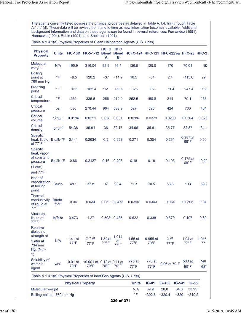
The agents currently listed possess the physical properties as detailed in Table A.1.4.1(a) through TableA.1.4.1(d). These data will be revised from time to time as new information becomes available. Additionalbackground information and data on these agents can be found in several references: Fernandez (1991),Hanauska (1991), Robin (1991), and Sheinson (1991).
Table A.1.4.1(a) Physical Properties of Clean Halocarbon Agents (U.S. Units)
PhysicalProperty
Units FIC-13I1 FK-5-1-12HCFCBlend
A
HFCBlend
BHCFC-124 HFC-125 HFC-227ea HFC-23 HFC-2
Molecularweight
N/A 195.9 316.04 92.9 99.4 136.5 120.0 170 70.01 152
Boilingpoint at760 mm Hg
°F −8.5 120.2 −37 −14.9 10.5 −54 2.4 −115.6 29.
Freezingpoint
°F −166 −162.4 161 −153.9 −326 −153 −204 −247.4 −153
Criticaltemperature
°F 252 335.6 256 219.9 252.5 150.8 214 79.1 256
Criticalpressure
psi 586 270.44 964 588.9 527 525 424 700 464
Criticalvolume ft3/lbm 0.0184 0.0251 0.028 0.031 0.0286 0.0279 0.0280 0.0304 0.029
Criticaldensity lbm/ft3 54.38 39.91 36 32.17 34.96 35.81 35.77 32.87 34.4
Specificheat, liquidat 77°F
Btu/lb-°F 0.141 0.2634 0.3 0.339 0.271 0.354 0.2810.987 at
68°F0.30
Specificheat, vaporat constantpressure
(1 atm)
and 77°F
Btu/lb-°F 0.86 0.2127 0.16 0.203 0.18 0.19 0.1930.175 at
68°F0.20
Heat ofvaporizationat boilingpoint
Btu/lb 48.1 37.8 97 93.4 71.3 70.5 56.6 103 68.9
Thermalconductivityof liquid at77°F
Btu/hr-ft-°F
0.04 0.034 0.052 0.0478 0.0395 0.0343 0.034 0.0305 0.04
Viscosity,liquid at77°F
lb/ft-hr 0.473 1.27 0.508 0.485 0.622 0.338 0.579 0.107 0.69
Relativedielectricstrength at
1 atm at734 mmHg, (N2 =1)
N/A1.41 at77°F
2.3 at
77°F1.32 at77°F
1.014at
77°F
1.55 at77°F
0.955 at70°F
2 at
77°F1.04 at77°F
1.01677°
Solubility ofwater inagent
wt%0.01 at70°F
<0.001 at70°F
0.12 at70°F
0.11 at70°F
770 at
77°F
770 at
77°F0.06 at 70°F
500 at
50°F
740
68°
Table A.1.4.1(b) Physical Properties of Inert Gas Agents (U.S. Units)
Physical Property Units IG-01 IG-100 IG-541 IG-55
Molecular weight N/A 39.9 28.0 34.0 33.95
Boiling point at 760 mm Hg °F −302.6 −320.4 −320 −310.2
National Fire Protection Association Report https://submittals.nfpa.org/TerraViewWeb/ContentFetcher?commentPar...
92 of 176 3/15/2019, 10:45 AM
229 of 371
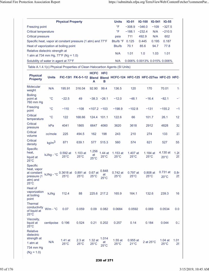
Physical Property Units IG-01 IG-100 IG-541 IG-55
Freezing point °F −308.9 −346.0 −109 −327.5
Critical temperature °F −188.1 −232.4 N/A −210.5
Critical pressure psia 711 492.9 N/A 602
Specific heat, vapor at constant pressure (1 atm) and 77°F Btu/lb °F 0.125 0.445 0.195 0.187
Heat of vaporization at boiling point Btu/lb 70.1 85.6 94.7 77.8
Relative dielectric strength at
1 atm at 734 mm Hg, 77°F (N2 = 1.0)N/A 1.01 1.0 1.03 1.01
Solubility of water in agent at 77°F N/A 0.006% 0.0013% 0.015% 0.006%
Table A.1.4.1(c) Physical Properties of Clean Halocarbon Agents (SI Units)
PhysicalProperty
Units FIC-13I1 FK-5-1-12HCFC
BlendA
HFC
BlendB
HCFC-124 HFC-125 HFC-227ea HFC-23 HFC-
Molecularweight
N/A 195.91 316.04 92.90 99.4 136.5 120 170 70.01 15
Boilingpoint at760 mm Hg
°C −22.5 49 −38.3 −26.1 −12.0 −48.1 −16.4 −82.1 −1
Freezingpoint
°C −110 −108 <107.2 −103 −198.9 −102.8 −131 −155.2 −1
Criticaltemperature
°C 122 168.66 124.4 101.1 122.6 66 101.7 26.1 12
Criticalpressure
kPa 4041 1865 6647 4060 3620 3618 2912 4828 32
Criticalvolume
cc/mole 225 494.5 162 198 243 210 274 133 27
Criticaldensity kg/m3 871 639.1 577 515.3 560 574 621 527 55
Specificheat,
liquid at25°C
kJ/kg - °C0.592 at
25°C1.103 at
25°C
1.256at
25°C
1.44 at25°C
1.153 at25°C
1.407 at25°C
1.184 at25°C
4.130 at
20°C1.26
25
Specificheat, vaporat constantpressure (1atm) and25°C
kJ/kg - °C0.3618 at
25°C0.891 at
25°C0.67 at25°C
0.848at
25°C
0.742 at25°C
0.797 at25°C
0.808 at25°C
0.731 at
20°C0.84
25
Heat ofvaporizationat boilingpoint
kJ/kg 112.4 88 225.6 217.2 165.9 164.1 132.6 239.3 16
Thermalconductivityof liquid at25°C
W/m - °C 0.07 0.059 0.09 0.082 0.0684 0.0592 0.069 0.0534 0.0
Viscosity,liquid at25°C
centipoise 0.196 0.524 0.21 0.202 0.257 0.14 0.184 0.044 0.2
Relativedielectricstrength at
1 atm at
734 mm Hg
(N2 = 1.0)
N/A1.41 at25°C
2.3 at25°C
1.32 at25°C
1.014at
25°C
1.55 at25°C
0.955 at21°C
2 at 25°C1.04 at25°C
1.0125
National Fire Protection Association Report https://submittals.nfpa.org/TerraViewWeb/ContentFetcher?commentPar...
93 of 176 3/15/2019, 10:45 AM
230 of 371
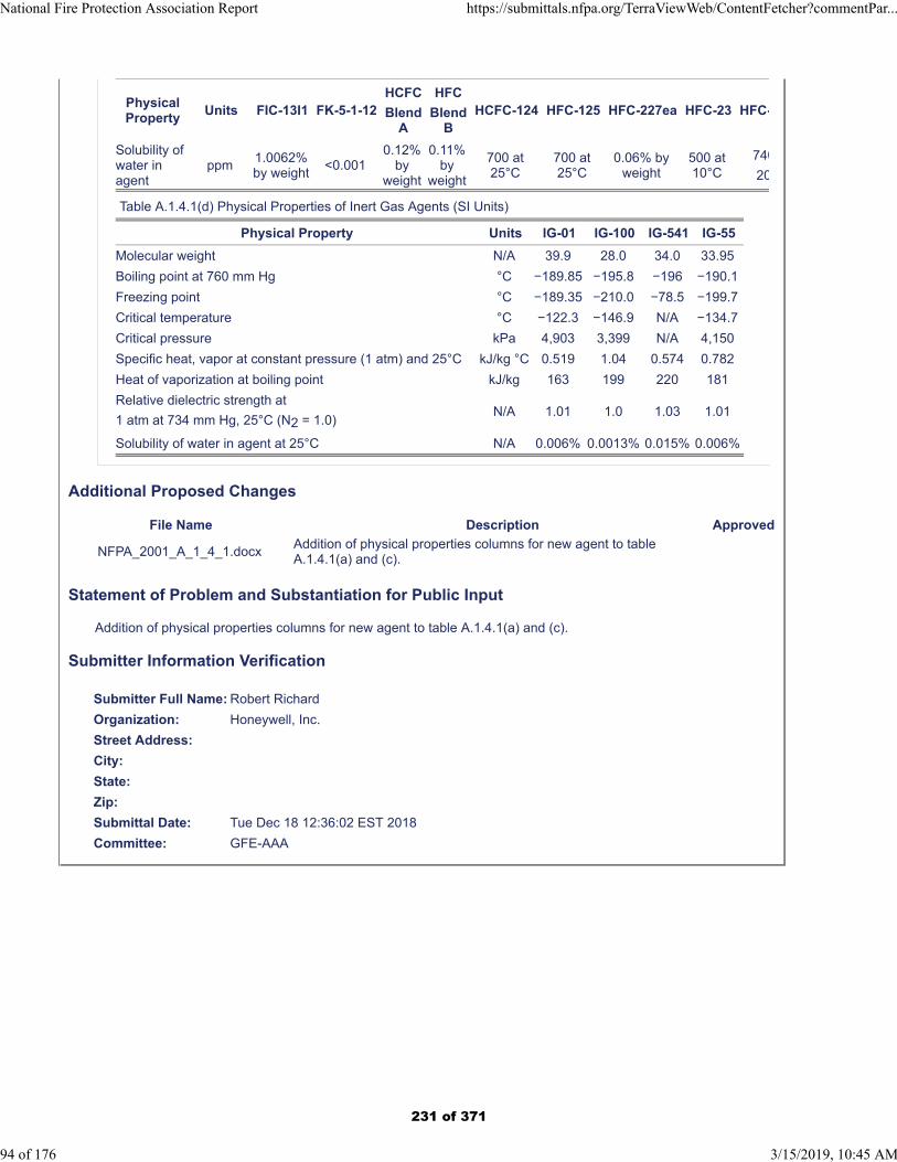
PhysicalProperty
Units FIC-13I1 FK-5-1-12HCFC
BlendA
HFC
BlendB
HCFC-124 HFC-125 HFC-227ea HFC-23 HFC-
Solubility ofwater inagent
ppm1.0062%by weight
<0.0010.12%
byweight
0.11%by
weight
700 at25°C
700 at25°C
0.06% byweight
500 at10°C
740
20
Table A.1.4.1(d) Physical Properties of Inert Gas Agents (SI Units)
Physical Property Units IG-01 IG-100 IG-541 IG-55
Molecular weight N/A 39.9 28.0 34.0 33.95
Boiling point at 760 mm Hg °C −189.85 −195.8 −196 −190.1
Freezing point °C −189.35 −210.0 −78.5 −199.7
Critical temperature °C −122.3 −146.9 N/A −134.7
Critical pressure kPa 4,903 3,399 N/A 4,150
Specific heat, vapor at constant pressure (1 atm) and 25°C kJ/kg °C 0.519 1.04 0.574 0.782
Heat of vaporization at boiling point kJ/kg 163 199 220 181
Relative dielectric strength at
1 atm at 734 mm Hg, 25°C (N2 = 1.0)N/A 1.01 1.0 1.03 1.01
Solubility of water in agent at 25°C N/A 0.006% 0.0013% 0.015% 0.006%
Additional Proposed Changes
File Name Description Approved
NFPA_2001_A_1_4_1.docxAddition of physical properties columns for new agent to table A.1.4.1(a) and (c).
Statement of Problem and Substantiation for Public Input
Addition of physical properties columns for new agent to table A.1.4.1(a) and (c).
Submitter Information Verification
Submitter Full Name: Robert Richard
Organization: Honeywell, Inc.
Street Address:
City:
State:
Zip:
Submittal Date: Tue Dec 18 12:36:02 EST 2018
Committee: GFE-AAA
National Fire Protection Association Report https://submittals.nfpa.org/TerraViewWeb/ContentFetcher?commentPar...
94 of 176 3/15/2019, 10:45 AM
231 of 371
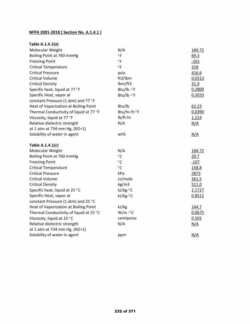
NFPA 2001-2018 [ Section No. A.1.4.1 ] Table A.1.4.1(a) Molecular Weight N/A 184.72 Boiling Point at 760 mmHg °F 69.3 Freezing Point °F -161 Critical Temperature °F 318 Critical Pressure psia 416.6 Critical Volume ft3/lbm 0.0313 Critical Density lbm/ft3 31.9 Specific heat, liquid at 77 °F Btu/lb -°F 0.2800 Specific Heat, vapor at constant Pressure (1 atm) and 77 °F
Btu/lb -°F 0.2033
Heat of Vaporization at Boiling Point Btu/lb 62.23 Thermal Conductivity of liquid at 77 °F Btu/hr-ft-°F 0.0390 Viscosity, liquid at 77 °F lb/ft-hr 1.214 Relative dielectric strength at 1 atm at 734 mm Hg, (N2=1)
N/A N/A
Solubility of water in agent Table A.1.4.1(c)
wt% N/A
Molecular Weight N/A 184.72 Boiling Point at 760 mmHg °C 20.7 Freezing Point °C -107 Critical Temperature °C 158.8 Critical Pressure kPa 2873 Critical Volume cc/mole 361.5 Critical Density kg/m3 511.0 Specific heat, liquid at 25 °C kJ/kg-°C 1.1717 Specific Heat, vapor at constant Pressure (1 atm) and 25 °C
kJ/kg-°C 0.8512
Heat of Vaporization at Boiling Point kJ/kg 144.7 Thermal Conductivity of liquid at 25 °C W/m -°C 0.0675 Viscosity, liquid at 25 °C centipoise 0.502 Relative dielectric strength at 1 atm at 734 mm Hg, (N2=1)
N/A N/A
Solubility of water in agent ppm N/A
232 of 371
Public Input No. 43-NFPA 2001-2018 [ New Section after A.1.4.2.4 ]
A.1.4.2.5
Acoustical noise from a range of sources, including those related to some types of clean agent systems andthose not related to clean agent systems (e.g., alarms), has been shown to have an impact on theperformance of hard disk drives under certain conditions. Generally, noise in excess of 110dB has beenshown to impact hard disk drive (HDD) performance. The HDD impact can range from temporarydegradation of disk performance up to permanent drive damage and data loss.
Mitigation strategies should begin with the creation of an acoustic study or calculation for the specific roombeing protected by a fire suppression system. The study should focus on determining the sound pressurelevel at a HDD. From this study, the design of the suppression system, room environment and HDDlocation can be modified to obtain the acoustic impact at the HDD below 110dB. Some of the modificationsto obtain sound pressure at a HDD below 110dB is to, locate suppression nozzles further away from theHDD , mount HDD using vibration isolation damping fixtures in data racks, shutdown the electronicequipment in accordance with NFPA 75 prior to discharge, increase room sound absorbing materials,modify the clean agent system design in accordance with manufacturer’s recommendations and giveconsideration to the use of discharge nozzles specifically designed to reduce the noise energy duringdischarge.
Statement of Problem and Substantiation for Public Input
Provide additional education and guidance on the use of clean agents with noise sensitive equipment.
Related Public Inputs for This Document
Related Input Relationship
Public Input No. 42-NFPA 2001-2018 [New Section after 1.4.2.4]
Submitter Information Verification
Submitter Full Name: Katherine Adrian
Organization: Johnson Controls
Street Address:
City:
State:
Zip:
Submittal Date: Thu Nov 08 12:06:29 EST 2018
Committee: GFE-AAA
National Fire Protection Association Report https://submittals.nfpa.org/TerraViewWeb/ContentFetcher?commentPar...
95 of 176 3/15/2019, 10:45 AM
233 of 371

Public Input No. 48-NFPA 2001-2018 [ Section No. A.1.5.1.2 ]
National Fire Protection Association Report https://submittals.nfpa.org/TerraViewWeb/ContentFetcher?commentPar...
96 of 176 3/15/2019, 10:45 AM
234 of 371

A.1.5.1.2
National Fire Protection Association Report https://submittals.nfpa.org/TerraViewWeb/ContentFetcher?commentPar...
97 of 176 3/15/2019, 10:45 AM
235 of 371
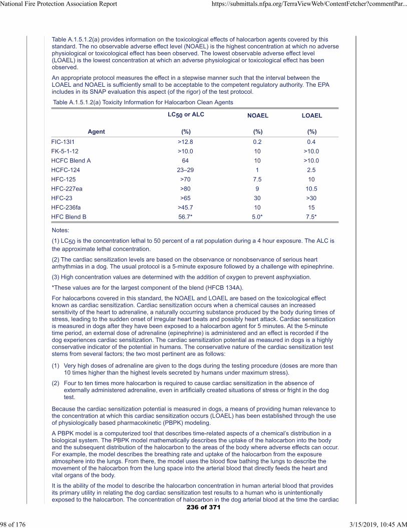
Table A.1.5.1.2(a) provides information on the toxicological effects of halocarbon agents covered by thisstandard. The no observable adverse effect level (NOAEL) is the highest concentration at which no adversephysiological or toxicological effect has been observed. The lowest observable adverse effect level(LOAEL) is the lowest concentration at which an adverse physiological or toxicological effect has beenobserved.
An appropriate protocol measures the effect in a stepwise manner such that the interval between theLOAEL and NOAEL is sufficiently small to be acceptable to the competent regulatory authority. The EPAincludes in its SNAP evaluation this aspect (of the rigor) of the test protocol.
Table A.1.5.1.2(a) Toxicity Information for Halocarbon Clean Agents
Agent
LC50 or ALC
(%)
NOAEL
(%)
LOAEL
(%)
FIC-13I1 >12.8 0.2 0.4
FK-5-1-12 >10.0 10 >10.0
HCFC Blend A 64 10 >10.0
HCFC-124 23–29 1 2.5
HFC-125 >70 7.5 10
HFC-227ea >80 9 10.5
HFC-23 >65 30 >30
HFC-236fa >45.7 10 15
HFC Blend B 56.7* 5.0* 7.5*
Notes:
(1) LC50 is the concentration lethal to 50 percent of a rat population during a 4 hour exposure. The ALC isthe approximate lethal concentration.
(2) The cardiac sensitization levels are based on the observance or nonobservance of serious heartarrhythmias in a dog. The usual protocol is a 5-minute exposure followed by a challenge with epinephrine.
(3) High concentration values are determined with the addition of oxygen to prevent asphyxiation.
*These values are for the largest component of the blend (HFCB 134A).
For halocarbons covered in this standard, the NOAEL and LOAEL are based on the toxicological effectknown as cardiac sensitization. Cardiac sensitization occurs when a chemical causes an increasedsensitivity of the heart to adrenaline, a naturally occurring substance produced by the body during times ofstress, leading to the sudden onset of irregular heart beats and possibly heart attack. Cardiac sensitizationis measured in dogs after they have been exposed to a halocarbon agent for 5 minutes. At the 5-minutetime period, an external dose of adrenaline (epinephrine) is administered and an effect is recorded if thedog experiences cardiac sensitization. The cardiac sensitization potential as measured in dogs is a highlyconservative indicator of the potential in humans. The conservative nature of the cardiac sensitization teststems from several factors; the two most pertinent are as follows:
(1) Very high doses of adrenaline are given to the dogs during the testing procedure (doses are more than10 times higher than the highest levels secreted by humans under maximum stress).
(2) Four to ten times more halocarbon is required to cause cardiac sensitization in the absence ofexternally administered adrenaline, even in artificially created situations of stress or fright in the dogtest.
Because the cardiac sensitization potential is measured in dogs, a means of providing human relevance tothe concentration at which this cardiac sensitization occurs (LOAEL) has been established through the useof physiologically based pharmacokinetic (PBPK) modeling.
A PBPK model is a computerized tool that describes time-related aspects of a chemical’s distribution in abiological system. The PBPK model mathematically describes the uptake of the halocarbon into the bodyand the subsequent distribution of the halocarbon to the areas of the body where adverse effects can occur.For example, the model describes the breathing rate and uptake of the halocarbon from the exposureatmosphere into the lungs. From there, the model uses the blood flow bathing the lungs to describe themovement of the halocarbon from the lung space into the arterial blood that directly feeds the heart andvital organs of the body.
It is the ability of the model to describe the halocarbon concentration in human arterial blood that providesits primary utility in relating the dog cardiac sensitization test results to a human who is unintentionallyexposed to the halocarbon. The concentration of halocarbon in the dog arterial blood at the time the cardiac
National Fire Protection Association Report https://submittals.nfpa.org/TerraViewWeb/ContentFetcher?commentPar...
98 of 176 3/15/2019, 10:45 AM
236 of 371
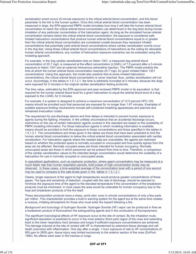
sensitization event occurs (5-minute exposure) is the critical arterial blood concentration, and this bloodparameter is the link to the human system. Once this critical arterial blood concentration has beenmeasured in dogs, the EPA-approved PBPK model simulates how long it will take the human arterial bloodconcentration to reach the critical arterial blood concentration (as determined in the dog test) during humaninhalation of any particular concentration of the halocarbon agent. As long as the simulated human arterialconcentration remains below the critical arterial blood concentration, the exposure is considered safe.Inhaled halocarbon concentrations that produce human arterial blood concentrations equal to or greaterthan the critical arterial blood concentration are considered unsafe because they represent inhaledconcentrations that potentially yield arterial blood concentrations where cardiac sensitization events occurin the dog test. Using these critical arterial blood concentrations of halocarbons as the ceiling for allowablehuman arterial concentrations, any number of halocarbon exposure scenarios can be evaluated using thismodeling approach.
For example, in the dog cardiac sensitization test on Halon 1301, a measured dog arterial bloodconcentration of 25.7 mg/L is measured at the effect concentration (LOAEL) of 7.5 percent after a 5-minuteexposure to Halon 1301 and an external intravenous adrenaline injection. The PBPK model predicts thetime at which the human arterial blood concentration reaches 25.7 mg/L for given inhaled Halon 1301concentrations. Using this approach, the model also predicts that at some inhaled halocarbonconcentrations, the critical arterial blood concentration is never reached; thus, cardiac sensitization will notoccur. Accordingly, in the tables in 1.5.1.2.1, the time is arbitrarily truncated at 5 minutes, because the dogswere exposed for 5 minutes in the original cardiac sensitization testing protocols.
The time value, estimated by the EPA-approved and peer-reviewed PBPK model or its equivalent, is thatrequired for the human arterial blood level for a given halocarbon to equal the arterial blood level of a dogexposed to the LOAEL for 5 minutes.
For example, if a system is designed to achieve a maximum concentration of 12.0 percent HFC-125,means should be provided such that personnel are exposed for no longer than 1.67 minutes. Examples ofsuitable exposure-limiting mechanisms include self-contained breathing apparatuses and planned andrehearsed evacuation routes.
The requirement for pre-discharge alarms and time delays is intended to prevent human exposure toagents during fire fighting. However, in the unlikely circumstance that an accidental discharge occurs,restrictions on the use of certain halocarbon agents covered in this standard are based on the availability ofPBPK modeling information. For those halocarbon agents in which modeling information is available,means should be provided to limit the exposure to those concentrations and times specified in the tables in1.5.1.2.1. The concentrations and times given in the tables are those that have been predicted to limit thehuman arterial blood concentration to below the critical arterial blood concentration associated with cardiacsensitization. For halocarbon agents where the needed data are unavailable, the agents are restrictedbased on whether the protected space is normally occupied or unoccupied and how quickly egress from thearea can be effected. Normally occupied areas are those intended for human occupancy. Normallyunoccupied areas are those in which personnel can be present from time to time. Therefore, a comparisonof the cardiac sensitization values to the intended design concentration would determine the suitability of ahalocarbon for use in normally occupied or unoccupied areas.
In specialized applications, such as explosion protection, where agent concentration may be measured at amuch faster rate than human respiration periods, brief pulses of high concentration levels may beobserved. In these cases, a time-weighted average of the concentration level with a period of one secondmay be used to compare to the safe levels given in the tables in 1.5.1.2.1.
Clearly, longer exposure of the agent to high temperatures would produce greater concentrations of thesegases. The type and sensitivity of detection, coupled with the rate of discharge, should be selected tominimize the exposure time of the agent to the elevated temperature if the concentration of the breakdownproducts must be minimized. In most cases the area would be untenable for human occupancy due to theheat and breakdown products of the fire itself.
These decomposition products have a sharp, acrid odor, even in minute concentrations of only a few partsper million. This characteristic provides a built-in warning system for the agent but at the same time createsa noxious, irritating atmosphere for those who must enter the hazard following a fire.
Background and toxicology of hydrogen fluoride. Hydrogen fluoride (HF) vapor can be produced in fires asa breakdown product of fluorocarbon fire extinguishing agents and in the combustion of fluoropolymers.
The significant toxicological effects of HF exposure occur at the site of contact. By the inhalation route,significant deposition is predicted to occur in the most anterior (front part) region of the nose and extendingback to the lower respiratory tract (airways and lungs) if sufficient exposure concentrations are achieved.The damage induced at the site of contact with HF is characterized by extensive tissue damage and celldeath (necrosis) with inflammation. One day after a single, 1-hour exposure of rats to HF concentrations of950 ppm to 2600 ppm, tissue injury was limited exclusively to the anterior section of the nose (DuPont,1990). No effects were seen in the trachea or lungs.
National Fire Protection Association Report https://submittals.nfpa.org/TerraViewWeb/ContentFetcher?commentPar...
99 of 176 3/15/2019, 10:45 AM
237 of 371
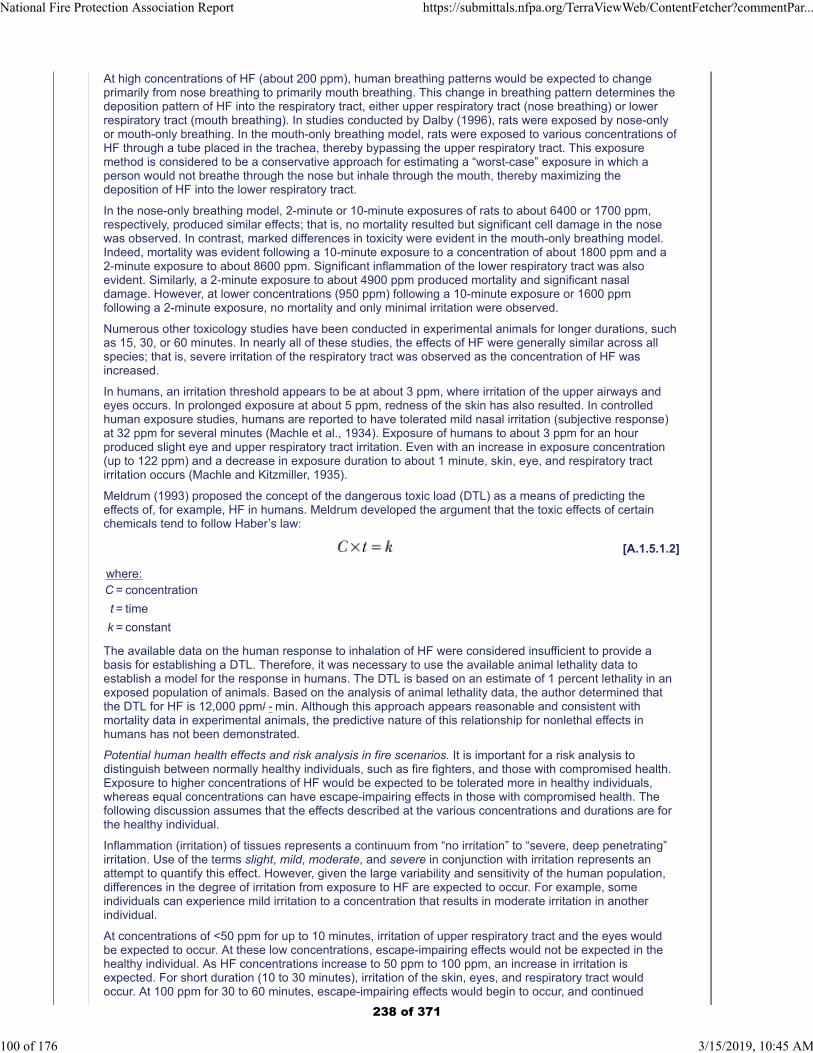
At high concentrations of HF (about 200 ppm), human breathing patterns would be expected to changeprimarily from nose breathing to primarily mouth breathing. This change in breathing pattern determines thedeposition pattern of HF into the respiratory tract, either upper respiratory tract (nose breathing) or lowerrespiratory tract (mouth breathing). In studies conducted by Dalby (1996), rats were exposed by nose-onlyor mouth-only breathing. In the mouth-only breathing model, rats were exposed to various concentrations ofHF through a tube placed in the trachea, thereby bypassing the upper respiratory tract. This exposuremethod is considered to be a conservative approach for estimating a “worst-case” exposure in which aperson would not breathe through the nose but inhale through the mouth, thereby maximizing thedeposition of HF into the lower respiratory tract.
In the nose-only breathing model, 2-minute or 10-minute exposures of rats to about 6400 or 1700 ppm,respectively, produced similar effects; that is, no mortality resulted but significant cell damage in the nosewas observed. In contrast, marked differences in toxicity were evident in the mouth-only breathing model.Indeed, mortality was evident following a 10-minute exposure to a concentration of about 1800 ppm and a2-minute exposure to about 8600 ppm. Significant inflammation of the lower respiratory tract was alsoevident. Similarly, a 2-minute exposure to about 4900 ppm produced mortality and significant nasaldamage. However, at lower concentrations (950 ppm) following a 10-minute exposure or 1600 ppmfollowing a 2-minute exposure, no mortality and only minimal irritation were observed.
Numerous other toxicology studies have been conducted in experimental animals for longer durations, suchas 15, 30, or 60 minutes. In nearly all of these studies, the effects of HF were generally similar across allspecies; that is, severe irritation of the respiratory tract was observed as the concentration of HF wasincreased.
In humans, an irritation threshold appears to be at about 3 ppm, where irritation of the upper airways andeyes occurs. In prolonged exposure at about 5 ppm, redness of the skin has also resulted. In controlledhuman exposure studies, humans are reported to have tolerated mild nasal irritation (subjective response)at 32 ppm for several minutes (Machle et al., 1934). Exposure of humans to about 3 ppm for an hourproduced slight eye and upper respiratory tract irritation. Even with an increase in exposure concentration(up to 122 ppm) and a decrease in exposure duration to about 1 minute, skin, eye, and respiratory tractirritation occurs (Machle and Kitzmiller, 1935).
Meldrum (1993) proposed the concept of the dangerous toxic load (DTL) as a means of predicting theeffects of, for example, HF in humans. Meldrum developed the argument that the toxic effects of certainchemicals tend to follow Haber’s law:
[A.1.5.1.2]
where:C = concentration
t = time
k = constant
The available data on the human response to inhalation of HF were considered insufficient to provide abasis for establishing a DTL. Therefore, it was necessary to use the available animal lethality data toestablish a model for the response in humans. The DTL is based on an estimate of 1 percent lethality in anexposed population of animals. Based on the analysis of animal lethality data, the author determined thatthe DTL for HF is 12,000 ppm/ - min. Although this approach appears reasonable and consistent withmortality data in experimental animals, the predictive nature of this relationship for nonlethal effects inhumans has not been demonstrated.
Potential human health effects and risk analysis in fire scenarios. It is important for a risk analysis todistinguish between normally healthy individuals, such as fire fighters, and those with compromised health.Exposure to higher concentrations of HF would be expected to be tolerated more in healthy individuals,whereas equal concentrations can have escape-impairing effects in those with compromised health. Thefollowing discussion assumes that the effects described at the various concentrations and durations are forthe healthy individual.
Inflammation (irritation) of tissues represents a continuum from “no irritation” to “severe, deep penetrating”irritation. Use of the terms slight, mild, moderate, and severe in conjunction with irritation represents anattempt to quantify this effect. However, given the large variability and sensitivity of the human population,differences in the degree of irritation from exposure to HF are expected to occur. For example, someindividuals can experience mild irritation to a concentration that results in moderate irritation in anotherindividual.
At concentrations of <50 ppm for up to 10 minutes, irritation of upper respiratory tract and the eyes wouldbe expected to occur. At these low concentrations, escape-impairing effects would not be expected in thehealthy individual. As HF concentrations increase to 50 ppm to 100 ppm, an increase in irritation isexpected. For short duration (10 to 30 minutes), irritation of the skin, eyes, and respiratory tract wouldoccur. At 100 ppm for 30 to 60 minutes, escape-impairing effects would begin to occur, and continued
National Fire Protection Association Report https://submittals.nfpa.org/TerraViewWeb/ContentFetcher?commentPar...
100 of 176 3/15/2019, 10:45 AM
238 of 371
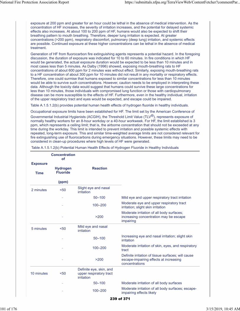
exposure at 200 ppm and greater for an hour could be lethal in the absence of medical intervention. As theconcentration of HF increases, the severity of irritation increases, and the potential for delayed systemiceffects also increases. At about 100 to 200 ppm of HF, humans would also be expected to shift theirbreathing pattern to mouth breathing. Therefore, deeper lung irritation is expected. At greaterconcentrations (>200 ppm), respiratory discomfort, pulmonary (deep lung) irritation, and systemic effectsare possible. Continued exposure at these higher concentrations can be lethal in the absence of medicaltreatment.
Generation of HF from fluorocarbon fire extinguishing agents represents a potential hazard. In the foregoingdiscussion, the duration of exposure was indicated for 10 to 60 minutes. In fire conditions in which HFwould be generated, the actual exposure duration would be expected to be less than 10 minutes and inmost cases less than 5 minutes. As Dalby (1996) showed, exposing mouth-breathing rats to HFconcentrations of about 600 ppm for 2 minutes was without effect. Similarly, exposing mouth-breathing ratsto a HF concentration of about 300 ppm for 10 minutes did not result in any mortality or respiratory effects.Therefore, one could surmise that humans exposed to similar concentrations for less than 10 minuteswould be able to survive such concentrations. However, caution needs to be employed in interpreting thesedata. Although the toxicity data would suggest that humans could survive these large concentrations forless than 10 minutes, those individuals with compromised lung function or those with cardiopulmonarydisease can be more susceptible to the effects of HF. Furthermore, even in the healthy individual, irritationof the upper respiratory tract and eyes would be expected, and escape could be impaired.
Table A.1.5.1.2(b) provides potential human health effects of hydrogen fluoride in healthy individuals.
Occupational exposure limits have been established for HF. The limit set by the American Conference of
Governmental Industrial Hygienists (ACGIH), the Threshold Limit Value (TLV®), represents exposure ofnormally healthy workers for an 8-hour workday or a 40-hour workweek. For HF, the limit established is 3ppm, which represents a ceiling limit; that is, the airborne concentration that should not be exceeded at anytime during the workday. This limit is intended to prevent irritation and possible systemic effects withrepeated, long-term exposure. This and similar time-weighted average limits are not considered relevant forfire extinguishing use of fluorocarbons during emergency situations. However, these limits may need to beconsidered in clean-up procedures where high levels of HF were generated.
Table A.1.5.1.2(b) Potential Human Health Effects of Hydrogen Fluoride in Healthy Individuals
Exposure
Time
Concentrationof
HydrogenFluoride
(ppm)
Reaction
2 minutes <50Slight eye and nasalirritation
50–100 Mild eye and upper respiratory tract irritation
100–200Moderate eye and upper respiratory tractirritation; slight skin irritation
>200Moderate irritation of all body surfaces;increasing concentration may be escapeimpairing
5 minutes <50Mild eye and nasalirritation
50–100Increasing eye and nasal irritation; slight skinirritation
100–200Moderate irritation of skin, eyes, and respiratorytract
>200Definite irritation of tissue surfaces; will causeescape-impairing effects at increasingconcentrations
10 minutes <50Definite eye, skin, andupper respiratory tractirritation
50–100 Moderate irritation of all body surfaces
100–200Moderate irritation of all body surfaces; escape-impairing effects likely
National Fire Protection Association Report https://submittals.nfpa.org/TerraViewWeb/ContentFetcher?commentPar...
101 of 176 3/15/2019, 10:45 AM
239 of 371
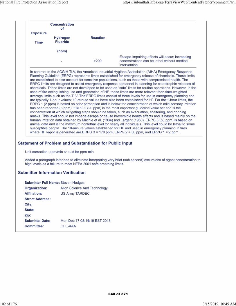
Exposure
Time
Concentrationof
HydrogenFluoride
(ppm)
Reaction
>200Escape-impairing effects will occur; increasingconcentrations can be lethal without medicalintervention
In contrast to the ACGIH TLV, the American Industrial Hygiene Association (AIHA) Emergency ResponsePlanning Guideline (ERPG) represents limits established for emergency release of chemicals. These limitsare established to also account for sensitive populations, such as those with compromised health. TheERPG limits are designed to assist emergency response personnel in planning for catastrophic releases ofchemicals. These limits are not developed to be used as “safe” limits for routine operations. However, in thecase of fire extinguishing use and generation of HF, these limits are more relevant than time-weightedaverage limits such as the TLV. The ERPG limits consist of three levels for use in emergency planning andare typically 1-hour values; 10-minute values have also been established for HF. For the 1-hour limits, theERPG 1 (2 ppm) is based on odor perception and is below the concentration at which mild sensory irritationhas been reported (3 ppm). ERPG 2 (20 ppm) is the most important guideline value set and is theconcentration at which mitigating steps should be taken, such as evacuation, sheltering, and donningmasks. This level should not impede escape or cause irreversible health effects and is based mainly on thehuman irritation data obtained by Machle et al. (1934) and Largent (1960). ERPG 3 (50 ppm) is based onanimal data and is the maximum nonlethal level for nearly all individuals. This level could be lethal to somesusceptible people. The 10-minute values established for HF and used in emergency planning in fireswhere HF vapor is generated are ERPG 3 = 170 ppm, ERPG 2 = 50 ppm, and ERPG 1 = 2 ppm.
Statement of Problem and Substantiation for Public Input
Unit correction: ppm/min should be ppm-min.
Added a paragraph intended to eliminate interpreting very brief (sub second) excursions of agent concentration to high levels as a failure to meet NFPA 2001 safe breathing limits.
Submitter Information Verification
Submitter Full Name: Steven Hodges
Organization: Alion Science And Technology
Affiliation: US Army TARDEC
Street Address:
City:
State:
Zip:
Submittal Date: Mon Dec 17 08:14:19 EST 2018
Committee: GFE-AAA
National Fire Protection Association Report https://submittals.nfpa.org/TerraViewWeb/ContentFetcher?commentPar...
102 of 176 3/15/2019, 10:45 AM
240 of 371
Public Input No. 54-NFPA 2001-2018 [ Section No. A.1.5.1.2 ]
National Fire Protection Association Report https://submittals.nfpa.org/TerraViewWeb/ContentFetcher?commentPar...
103 of 176 3/15/2019, 10:45 AM
241 of 371

A.1.5.1.2
National Fire Protection Association Report https://submittals.nfpa.org/TerraViewWeb/ContentFetcher?commentPar...
104 of 176 3/15/2019, 10:45 AM
242 of 371
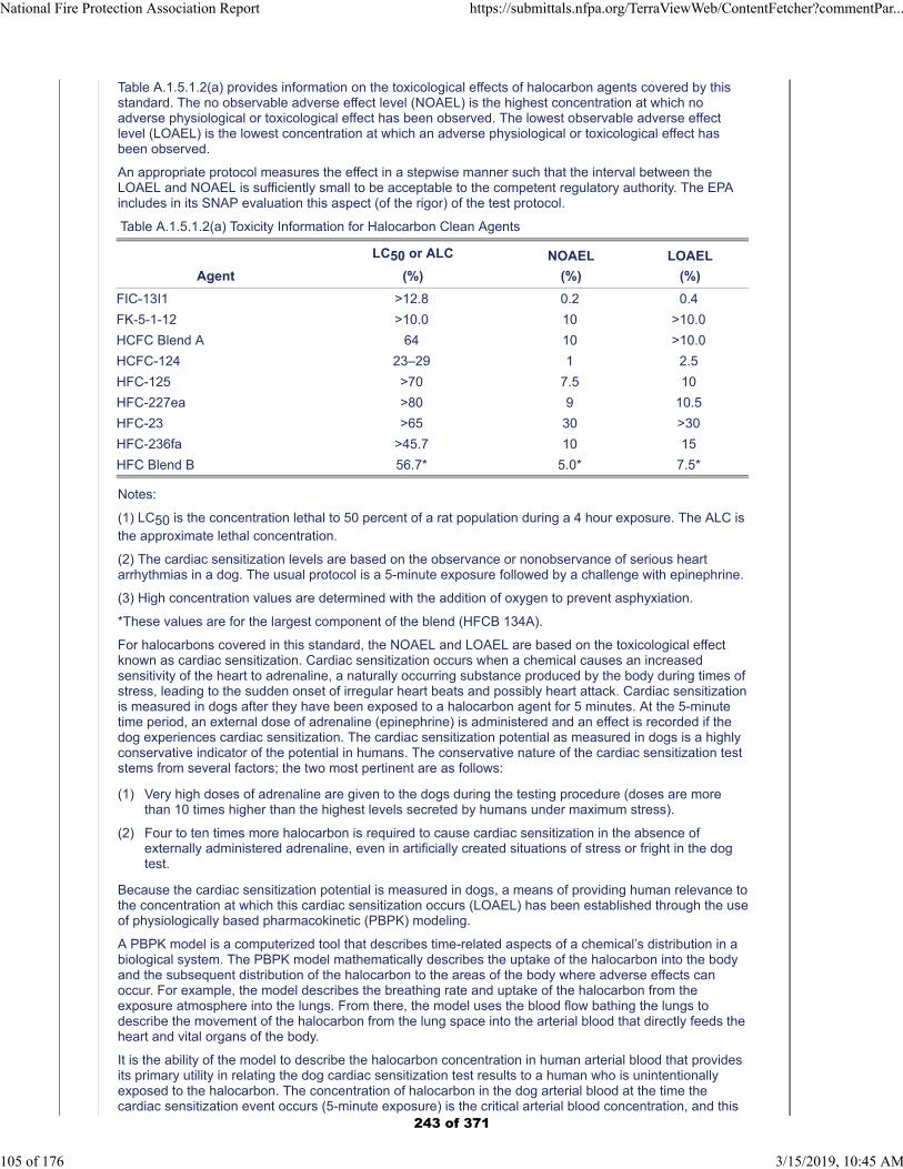
Table A.1.5.1.2(a) provides information on the toxicological effects of halocarbon agents covered by thisstandard. The no observable adverse effect level (NOAEL) is the highest concentration at which noadverse physiological or toxicological effect has been observed. The lowest observable adverse effectlevel (LOAEL) is the lowest concentration at which an adverse physiological or toxicological effect hasbeen observed.
An appropriate protocol measures the effect in a stepwise manner such that the interval between theLOAEL and NOAEL is sufficiently small to be acceptable to the competent regulatory authority. The EPAincludes in its SNAP evaluation this aspect (of the rigor) of the test protocol.
Table A.1.5.1.2(a) Toxicity Information for Halocarbon Clean Agents
Agent
LC50 or ALC
(%)
NOAEL
(%)
LOAEL
(%)
FIC-13I1 >12.8 0.2 0.4
FK-5-1-12 >10.0 10 >10.0
HCFC Blend A 64 10 >10.0
HCFC-124 23–29 1 2.5
HFC-125 >70 7.5 10
HFC-227ea >80 9 10.5
HFC-23 >65 30 >30
HFC-236fa >45.7 10 15
HFC Blend B 56.7* 5.0* 7.5*
Notes:
(1) LC50 is the concentration lethal to 50 percent of a rat population during a 4 hour exposure. The ALC isthe approximate lethal concentration.
(2) The cardiac sensitization levels are based on the observance or nonobservance of serious heartarrhythmias in a dog. The usual protocol is a 5-minute exposure followed by a challenge with epinephrine.
(3) High concentration values are determined with the addition of oxygen to prevent asphyxiation.
*These values are for the largest component of the blend (HFCB 134A).
For halocarbons covered in this standard, the NOAEL and LOAEL are based on the toxicological effectknown as cardiac sensitization. Cardiac sensitization occurs when a chemical causes an increasedsensitivity of the heart to adrenaline, a naturally occurring substance produced by the body during times ofstress, leading to the sudden onset of irregular heart beats and possibly heart attack. Cardiac sensitizationis measured in dogs after they have been exposed to a halocarbon agent for 5 minutes. At the 5-minutetime period, an external dose of adrenaline (epinephrine) is administered and an effect is recorded if thedog experiences cardiac sensitization. The cardiac sensitization potential as measured in dogs is a highlyconservative indicator of the potential in humans. The conservative nature of the cardiac sensitization teststems from several factors; the two most pertinent are as follows:
(1) Very high doses of adrenaline are given to the dogs during the testing procedure (doses are morethan 10 times higher than the highest levels secreted by humans under maximum stress).
(2) Four to ten times more halocarbon is required to cause cardiac sensitization in the absence ofexternally administered adrenaline, even in artificially created situations of stress or fright in the dogtest.
Because the cardiac sensitization potential is measured in dogs, a means of providing human relevance tothe concentration at which this cardiac sensitization occurs (LOAEL) has been established through the useof physiologically based pharmacokinetic (PBPK) modeling.
A PBPK model is a computerized tool that describes time-related aspects of a chemical’s distribution in abiological system. The PBPK model mathematically describes the uptake of the halocarbon into the bodyand the subsequent distribution of the halocarbon to the areas of the body where adverse effects canoccur. For example, the model describes the breathing rate and uptake of the halocarbon from theexposure atmosphere into the lungs. From there, the model uses the blood flow bathing the lungs todescribe the movement of the halocarbon from the lung space into the arterial blood that directly feeds theheart and vital organs of the body.
It is the ability of the model to describe the halocarbon concentration in human arterial blood that providesits primary utility in relating the dog cardiac sensitization test results to a human who is unintentionallyexposed to the halocarbon. The concentration of halocarbon in the dog arterial blood at the time thecardiac sensitization event occurs (5-minute exposure) is the critical arterial blood concentration, and this
National Fire Protection Association Report https://submittals.nfpa.org/TerraViewWeb/ContentFetcher?commentPar...
105 of 176 3/15/2019, 10:45 AM
243 of 371
blood parameter is the link to the human system. Once this critical arterial blood concentration has beenmeasured in dogs, the EPA-approved PBPK model simulates how long it will take the human arterial bloodconcentration to reach the critical arterial blood concentration (as determined in the dog test) duringhuman inhalation of any particular concentration of the halocarbon agent. As long as the simulated humanarterial concentration remains below the critical arterial blood concentration, the exposure is consideredsafe. Inhaled halocarbon concentrations that produce human arterial blood concentrations equal to orgreater than the critical arterial blood concentration are considered unsafe because they represent inhaledconcentrations that potentially yield arterial blood concentrations where cardiac sensitization events occurin the dog test. Using these critical arterial blood concentrations of halocarbons as the ceiling for allowablehuman arterial concentrations, any number of halocarbon exposure scenarios can be evaluated using thismodeling approach.
For example, in the dog cardiac sensitization test on Halon 1301, a measured dog arterial bloodconcentration of 25.7 mg/L is measured at the effect concentration (LOAEL) of 7.5 percent after a 5-minuteexposure to Halon 1301 and an external intravenous adrenaline injection. The PBPK model predicts thetime at which the human arterial blood concentration reaches 25.7 mg/L for given inhaled Halon 1301concentrations. Using this approach, the model also predicts that at some inhaled halocarbonconcentrations, the critical arterial blood concentration is never reached; thus, cardiac sensitization will notoccur. Accordingly, in the tables in 1.5.1.2.1, the time is arbitrarily truncated at 5 minutes, because thedogs were exposed for 5 minutes in the original cardiac sensitization testing protocols.
The time value, estimated by the EPA-approved and peer-reviewed PBPK model or its equivalent, is thatrequired for the human arterial blood level for a given halocarbon to equal the arterial blood level of a dogexposed to the LOAEL for 5 minutes.
For example, if a system is designed to achieve a maximum concentration of 12.0 percent HFC-125,means should be provided such that personnel are exposed for no longer than 1.67 minutes. Examples ofsuitable exposure-limiting mechanisms include self-contained breathing apparatuses and planned andrehearsed evacuation routes.
The requirement for pre-discharge alarms and time delays is intended to prevent human exposure toagents during fire fighting. However, in the unlikely circumstance that an accidental discharge occurs,restrictions on the use of certain halocarbon agents covered in this standard are based on the availabilityof PBPK modeling information. For those halocarbon agents in which modeling information is available,means should be provided to limit the exposure to those concentrations and times specified in the tables in1.5.1.2.1. The concentrations and times given in the tables are those that have been predicted to limit thehuman arterial blood concentration to below the critical arterial blood concentration associated with cardiacsensitization. For halocarbon agents where the needed data are unavailable, the agents are restrictedbased on whether the protected space is normally occupied or unoccupied and how quickly egress fromthe area can be effected. Normally occupied areas are those intended for human occupancy. Normallyunoccupied areas are those in which personnel can be present from time to time. Therefore, a comparisonof the cardiac sensitization values to the intended design concentration would determine the suitability of ahalocarbon for use in normally occupied or unoccupied areas.
Clearly, longer exposure of the agent to high temperatures would produce greater concentrations of thesegases. The type and sensitivity of detection, coupled with the rate of discharge, should be selected tominimize the exposure time of the agent to the elevated temperature if the concentration of the breakdownproducts must be minimized. In most cases the area would be untenable for human occupancy due to theheat and breakdown products of the fire itself.
These decomposition products have a sharp, acrid odor, even in minute concentrations of only a few partsper million. This characteristic provides a built-in warning system for the agent but at the same timecreates a noxious, irritating atmosphere for those who must enter the hazard following a fire.
Background and toxicology of hydrogen fluoride. Hydrogen fluoride (HF) vapor can be produced in fires asa breakdown product of fluorocarbon fire extinguishing agents and in the combustion of fluoropolymers.
The significant toxicological effects of HF exposure occur at the site of contact. By the inhalation route,significant deposition is predicted to occur in the most anterior (front part) region of the nose and extendingback to the lower respiratory tract (airways and lungs) if sufficient exposure concentrations are achieved.The damage induced at the site of contact with HF is characterized by extensive tissue damage and celldeath (necrosis) with inflammation. One day after a single, 1-hour exposure of rats to HF concentrations of950 ppm to 2600 ppm, tissue injury was limited exclusively to the anterior section of the nose (DuPont,1990). No effects were seen in the trachea or lungs.
At high concentrations of HF (about 200 ppm), human breathing patterns would be expected to changeprimarily from nose breathing to primarily mouth breathing. This change in breathing pattern determinesthe deposition pattern of HF into the respiratory tract, either upper respiratory tract (nose breathing) orlower respiratory tract (mouth breathing). In studies conducted by Dalby (1996), rats were exposed bynose-only or mouth-only breathing. In the mouth-only breathing model, rats were exposed to variousconcentrations of HF through a tube placed in the trachea, thereby bypassing the upper respiratory tract.
National Fire Protection Association Report https://submittals.nfpa.org/TerraViewWeb/ContentFetcher?commentPar...
106 of 176 3/15/2019, 10:45 AM
244 of 371
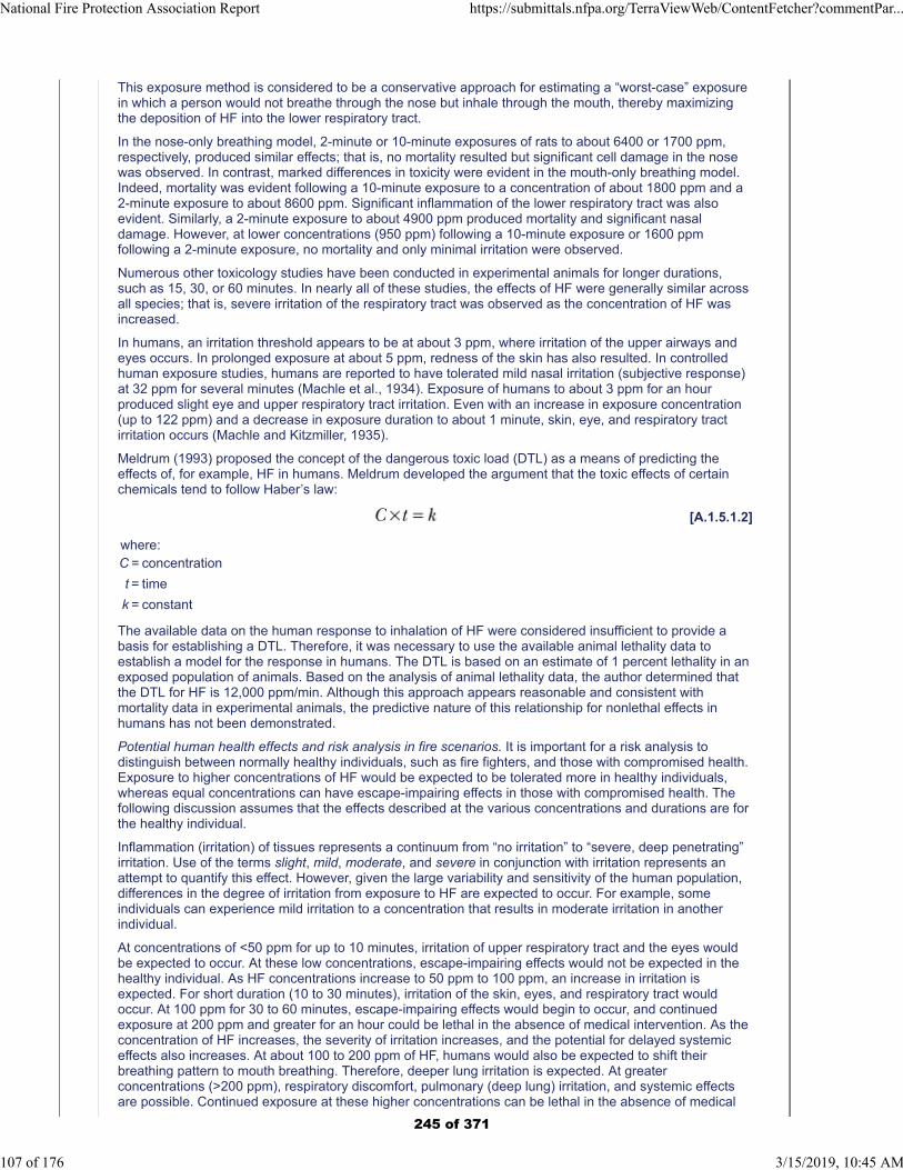
This exposure method is considered to be a conservative approach for estimating a “worst-case” exposurein which a person would not breathe through the nose but inhale through the mouth, thereby maximizingthe deposition of HF into the lower respiratory tract.
In the nose-only breathing model, 2-minute or 10-minute exposures of rats to about 6400 or 1700 ppm,respectively, produced similar effects; that is, no mortality resulted but significant cell damage in the nosewas observed. In contrast, marked differences in toxicity were evident in the mouth-only breathing model.Indeed, mortality was evident following a 10-minute exposure to a concentration of about 1800 ppm and a2-minute exposure to about 8600 ppm. Significant inflammation of the lower respiratory tract was alsoevident. Similarly, a 2-minute exposure to about 4900 ppm produced mortality and significant nasaldamage. However, at lower concentrations (950 ppm) following a 10-minute exposure or 1600 ppmfollowing a 2-minute exposure, no mortality and only minimal irritation were observed.
Numerous other toxicology studies have been conducted in experimental animals for longer durations,such as 15, 30, or 60 minutes. In nearly all of these studies, the effects of HF were generally similar acrossall species; that is, severe irritation of the respiratory tract was observed as the concentration of HF wasincreased.
In humans, an irritation threshold appears to be at about 3 ppm, where irritation of the upper airways andeyes occurs. In prolonged exposure at about 5 ppm, redness of the skin has also resulted. In controlledhuman exposure studies, humans are reported to have tolerated mild nasal irritation (subjective response)at 32 ppm for several minutes (Machle et al., 1934). Exposure of humans to about 3 ppm for an hourproduced slight eye and upper respiratory tract irritation. Even with an increase in exposure concentration(up to 122 ppm) and a decrease in exposure duration to about 1 minute, skin, eye, and respiratory tractirritation occurs (Machle and Kitzmiller, 1935).
Meldrum (1993) proposed the concept of the dangerous toxic load (DTL) as a means of predicting theeffects of, for example, HF in humans. Meldrum developed the argument that the toxic effects of certainchemicals tend to follow Haber’s law:
[A.1.5.1.2]
where:C = concentration
t = time
k = constant
The available data on the human response to inhalation of HF were considered insufficient to provide abasis for establishing a DTL. Therefore, it was necessary to use the available animal lethality data toestablish a model for the response in humans. The DTL is based on an estimate of 1 percent lethality in anexposed population of animals. Based on the analysis of animal lethality data, the author determined thatthe DTL for HF is 12,000 ppm/min. Although this approach appears reasonable and consistent withmortality data in experimental animals, the predictive nature of this relationship for nonlethal effects inhumans has not been demonstrated.
Potential human health effects and risk analysis in fire scenarios. It is important for a risk analysis todistinguish between normally healthy individuals, such as fire fighters, and those with compromised health.Exposure to higher concentrations of HF would be expected to be tolerated more in healthy individuals,whereas equal concentrations can have escape-impairing effects in those with compromised health. Thefollowing discussion assumes that the effects described at the various concentrations and durations are forthe healthy individual.
Inflammation (irritation) of tissues represents a continuum from “no irritation” to “severe, deep penetrating”irritation. Use of the terms slight, mild, moderate, and severe in conjunction with irritation represents anattempt to quantify this effect. However, given the large variability and sensitivity of the human population,differences in the degree of irritation from exposure to HF are expected to occur. For example, someindividuals can experience mild irritation to a concentration that results in moderate irritation in anotherindividual.
At concentrations of <50 ppm for up to 10 minutes, irritation of upper respiratory tract and the eyes wouldbe expected to occur. At these low concentrations, escape-impairing effects would not be expected in thehealthy individual. As HF concentrations increase to 50 ppm to 100 ppm, an increase in irritation isexpected. For short duration (10 to 30 minutes), irritation of the skin, eyes, and respiratory tract wouldoccur. At 100 ppm for 30 to 60 minutes, escape-impairing effects would begin to occur, and continuedexposure at 200 ppm and greater for an hour could be lethal in the absence of medical intervention. As theconcentration of HF increases, the severity of irritation increases, and the potential for delayed systemiceffects also increases. At about 100 to 200 ppm of HF, humans would also be expected to shift theirbreathing pattern to mouth breathing. Therefore, deeper lung irritation is expected. At greaterconcentrations (>200 ppm), respiratory discomfort, pulmonary (deep lung) irritation, and systemic effectsare possible. Continued exposure at these higher concentrations can be lethal in the absence of medical
National Fire Protection Association Report https://submittals.nfpa.org/TerraViewWeb/ContentFetcher?commentPar...
107 of 176 3/15/2019, 10:45 AM
245 of 371
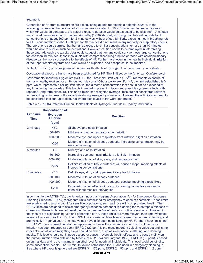
treatment.
Generation of HF from fluorocarbon fire extinguishing agents represents a potential hazard. In theforegoing discussion, the duration of exposure was indicated for 10 to 60 minutes. In fire conditions inwhich HF would be generated, the actual exposure duration would be expected to be less than 10 minutesand in most cases less than 5 minutes. As Dalby (1996) showed, exposing mouth-breathing rats to HFconcentrations of about 600 ppm for 2 minutes was without effect. Similarly, exposing mouth-breathing ratsto a HF concentration of about 300 ppm for 10 minutes did not result in any mortality or respiratory effects.Therefore, one could surmise that humans exposed to similar concentrations for less than 10 minuteswould be able to survive such concentrations. However, caution needs to be employed in interpretingthese data. Although the toxicity data would suggest that humans could survive these large concentrationsfor less than 10 minutes, those individuals with compromised lung function or those with cardiopulmonarydisease can be more susceptible to the effects of HF. Furthermore, even in the healthy individual, irritationof the upper respiratory tract and eyes would be expected, and escape could be impaired.
Table A.1.5.1.2(b) provides potential human health effects of hydrogen fluoride in healthy individuals.
Occupational exposure limits have been established for HF. The limit set by the American Conference of
Governmental Industrial Hygienists (ACGIH), the Threshold Limit Value (TLV®), represents exposure ofnormally healthy workers for an 8-hour workday or a 40-hour workweek. For HF, the limit established is 3ppm, which represents a ceiling limit; that is, the airborne concentration that should not be exceeded atany time during the workday. This limit is intended to prevent irritation and possible systemic effects withrepeated, long-term exposure. This and similar time-weighted average limits are not considered relevantfor fire extinguishing use of fluorocarbons during emergency situations. However, these limits may need tobe considered in clean-up procedures where high levels of HF were generated.
Table A.1.5.1.2(b) Potential Human Health Effects of Hydrogen Fluoride in Healthy Individuals
Exposure
Time
Concentration of
HydrogenFluoride
(ppm)
Reaction
2 minutes <50 Slight eye and nasal irritation
50–100 Mild eye and upper respiratory tract irritation
100–200 Moderate eye and upper respiratory tract irritation; slight skin irritation
>200Moderate irritation of all body surfaces; increasing concentration may beescape impairing
5 minutes <50 Mild eye and nasal irritation
50–100 Increasing eye and nasal irritation; slight skin irritation
100–200 Moderate irritation of skin, eyes, and respiratory tract
>200Definite irritation of tissue surfaces; will cause escape-impairing effects atincreasing concentrations
10 minutes <50 Definite eye, skin, and upper respiratory tract irritation
50–100 Moderate irritation of all body surfaces
100–200 Moderate irritation of all body surfaces; escape-impairing effects likely
>200Escape-impairing effects will occur; increasing concentrations can belethal without medical intervention
In contrast to the ACGIH TLV, the American Industrial Hygiene Association (AIHA) Emergency ResponsePlanning Guideline (ERPG) represents limits established for emergency release of chemicals. These limitsare established to also account for sensitive populations, such as those with compromised health. TheERPG limits are designed to assist emergency response personnel in planning for catastrophic releases ofchemicals. These limits are not developed to be used as “safe” limits for routine operations. However, inthe case of fire extinguishing use and generation of HF, these limits are more relevant than time-weightedaverage limits such as the TLV. The ERPG limits consist of three levels for use in emergency planning andare typically 1-hour values; 10-minute values have also been established for HF. For the 1-hour limits, theERPG 1 (2 ppm) is based on odor perception and is below the concentration at which mild sensoryirritation has been reported (3 ppm). ERPG 2 (20 ppm) is the most important guideline value set and is theconcentration at which mitigating steps should be taken, such as evacuation, sheltering, and donningmasks. This level should not impede escape or cause irreversible health effects and is based mainly onthe human irritation data obtained by Machle et al. (1934) and Largent (1960). ERPG 3 (50 ppm) is basedon animal data and is the maximum nonlethal level for nearly all individuals. This level could be lethal tosome susceptible people. The 10-minute values established for HF and used in emergency planning infires where HF vapor is generated are ERPG 3 = 170 ppm, ERPG 2 = 50 ppm, and ERPG 1 = 2 ppm.
National Fire Protection Association Report https://submittals.nfpa.org/TerraViewWeb/ContentFetcher?commentPar...
108 of 176 3/15/2019, 10:45 AM
246 of 371
Additional Proposed Changes
File Name Description Approved
NFPA_2001_Section_No_A_1_5_1_2.docx Addition of ACL or LC50 for new agent
Statement of Problem and Substantiation for Public Input
Addition of ACL or LC50 for new agent
Submitter Information Verification
Submitter Full Name: Robert Richard
Organization: Honeywell, Inc.
Street Address:
City:
State:
Zip:
Submittal Date: Tue Dec 18 12:40:51 EST 2018
Committee: GFE-AAA
National Fire Protection Association Report https://submittals.nfpa.org/TerraViewWeb/ContentFetcher?commentPar...
109 of 176 3/15/2019, 10:45 AM
247 of 371

NFPA 2001-2018 [ Section No. A.1.5.1.2 ] Add to Table A.1.5.1.2(a) Agent LC50 or ALC NOAEL LOAEL Halocarbon Blend 55 >11 10 >10
248 of 371
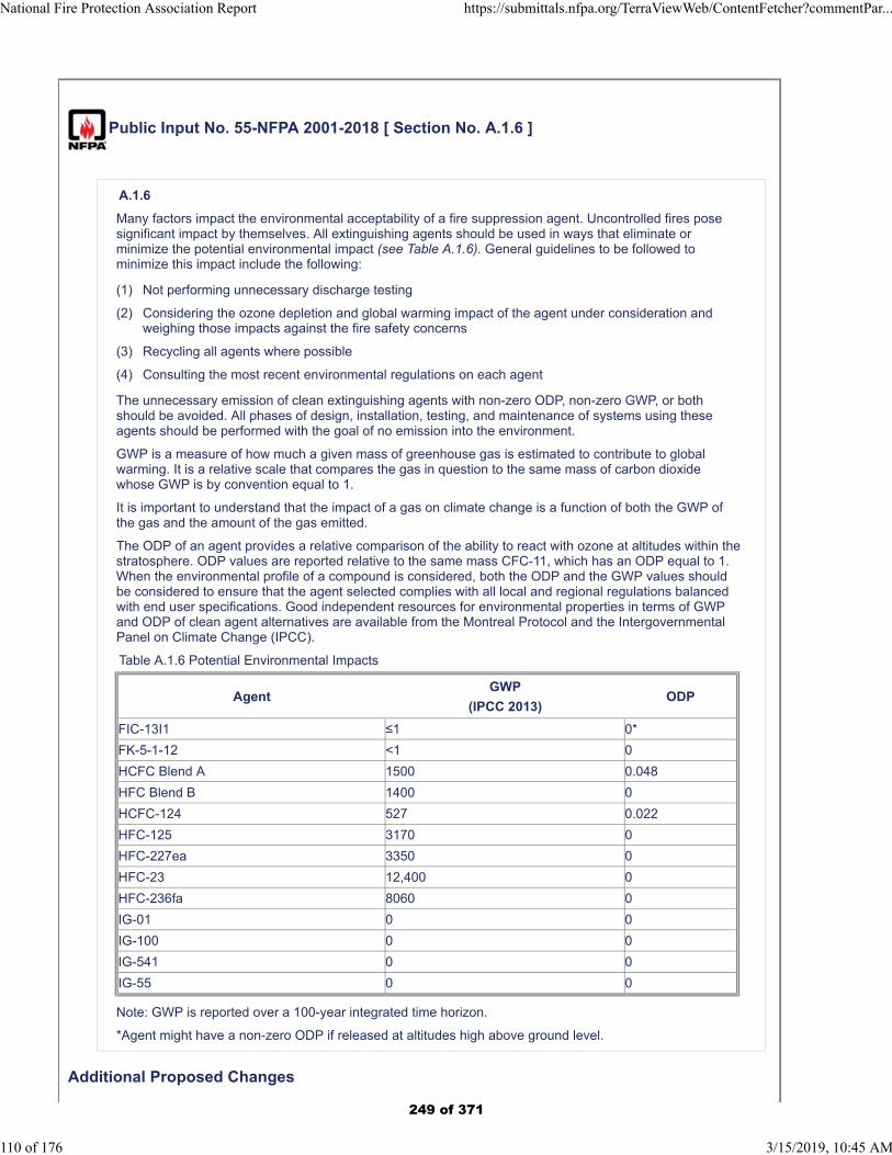
Public Input No. 55-NFPA 2001-2018 [ Section No. A.1.6 ]
A.1.6
Many factors impact the environmental acceptability of a fire suppression agent. Uncontrolled fires posesignificant impact by themselves. All extinguishing agents should be used in ways that eliminate orminimize the potential environmental impact (see Table A.1.6). General guidelines to be followed tominimize this impact include the following:
(1) Not performing unnecessary discharge testing
(2) Considering the ozone depletion and global warming impact of the agent under consideration andweighing those impacts against the fire safety concerns
(3) Recycling all agents where possible
(4) Consulting the most recent environmental regulations on each agent
The unnecessary emission of clean extinguishing agents with non-zero ODP, non-zero GWP, or bothshould be avoided. All phases of design, installation, testing, and maintenance of systems using theseagents should be performed with the goal of no emission into the environment.
GWP is a measure of how much a given mass of greenhouse gas is estimated to contribute to globalwarming. It is a relative scale that compares the gas in question to the same mass of carbon dioxidewhose GWP is by convention equal to 1.
It is important to understand that the impact of a gas on climate change is a function of both the GWP ofthe gas and the amount of the gas emitted.
The ODP of an agent provides a relative comparison of the ability to react with ozone at altitudes within thestratosphere. ODP values are reported relative to the same mass CFC-11, which has an ODP equal to 1.When the environmental profile of a compound is considered, both the ODP and the GWP values shouldbe considered to ensure that the agent selected complies with all local and regional regulations balancedwith end user specifications. Good independent resources for environmental properties in terms of GWPand ODP of clean agent alternatives are available from the Montreal Protocol and the IntergovernmentalPanel on Climate Change (IPCC).
Table A.1.6 Potential Environmental Impacts
AgentGWP
(IPCC 2013)ODP
FIC-13I1 ≤1 0*
FK-5-1-12 <1 0
HCFC Blend A 1500 0.048
HFC Blend B 1400 0
HCFC-124 527 0.022
HFC-125 3170 0
HFC-227ea 3350 0
HFC-23 12,400 0
HFC-236fa 8060 0
IG-01 0 0
IG-100 0 0
IG-541 0 0
IG-55 0 0
Note: GWP is reported over a 100-year integrated time horizon.
*Agent might have a non-zero ODP if released at altitudes high above ground level.
Additional Proposed Changes
National Fire Protection Association Report https://submittals.nfpa.org/TerraViewWeb/ContentFetcher?commentPar...
110 of 176 3/15/2019, 10:45 AM
249 of 371
File Name Description Approved
NFPA_2001_addition_to_table_A_1_6.docxAddition of environmental properties for new fire suppression agent.
Statement of Problem and Substantiation for Public Input
Addition of environmental properties for new fire suppression agent.
Submitter Information Verification
Submitter Full Name: Robert Richard
Organization: Honeywell, Inc.
Street Address:
City:
State:
Zip:
Submittal Date: Tue Dec 18 12:44:43 EST 2018
Committee: GFE-AAA
National Fire Protection Association Report https://submittals.nfpa.org/TerraViewWeb/ContentFetcher?commentPar...
111 of 176 3/15/2019, 10:45 AM
250 of 371

NFPA 2001-2018 [ Section No. A.1.6 Add to Table A.1.6 Agent GWP ODP Halocarbon Blend 55 1 0.00017
251 of 371
Public Input No. 17-NFPA 2001-2018 [ Section No. A.4.1.4.1 ]
National Fire Protection Association Report https://submittals.nfpa.org/TerraViewWeb/ContentFetcher?commentPar...
112 of 176 3/15/2019, 10:45 AM
252 of 371

A.4.1.4.1
National Fire Protection Association Report https://submittals.nfpa.org/TerraViewWeb/ContentFetcher?commentPar...
113 of 176 3/15/2019, 10:45 AM
253 of 371
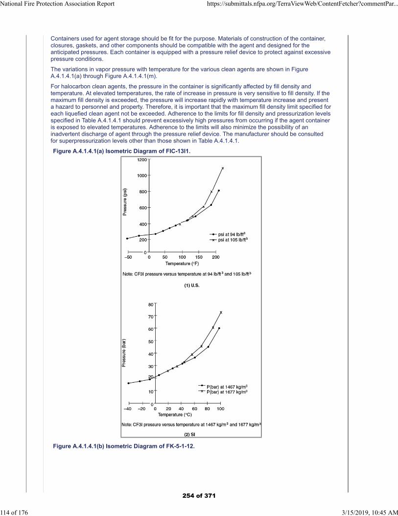
Containers used for agent storage should be fit for the purpose. Materials of construction of the container,closures, gaskets, and other components should be compatible with the agent and designed for theanticipated pressures. Each container is equipped with a pressure relief device to protect against excessivepressure conditions.
The variations in vapor pressure with temperature for the various clean agents are shown in FigureA.4.1.4.1(a) through Figure A.4.1.4.1(m).
For halocarbon clean agents, the pressure in the container is significantly affected by fill density andtemperature. At elevated temperatures, the rate of increase in pressure is very sensitive to fill density. If themaximum fill density is exceeded, the pressure will increase rapidly with temperature increase and presenta hazard to personnel and property. Therefore, it is important that the maximum fill density limit specified foreach liquefied clean agent not be exceeded. Adherence to the limits for fill density and pressurization levelsspecified in Table A.4.1.4.1 should prevent excessively high pressures from occurring if the agent containeris exposed to elevated temperatures. Adherence to the limits will also minimize the possibility of aninadvertent discharge of agent through the pressure relief device. The manufacturer should be consultedfor superpressurization levels other than those shown in Table A.4.1.4.1.
Figure A.4.1.4.1(a) Isometric Diagram of FIC-13I1.
Figure A.4.1.4.1(b) Isometric Diagram of FK-5-1-12.
National Fire Protection Association Report https://submittals.nfpa.org/TerraViewWeb/ContentFetcher?commentPar...
114 of 176 3/15/2019, 10:45 AM
254 of 371
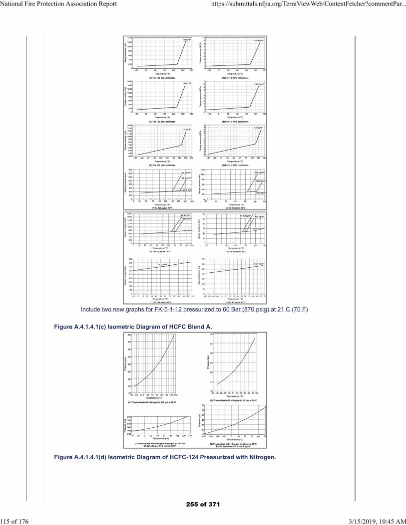
Include two new graphs for FK-5-1-12 pressurized to 60 Bar (870 psig) at 21 C (70 F)
Figure A.4.1.4.1(c) Isometric Diagram of HCFC Blend A.
Figure A.4.1.4.1(d) Isometric Diagram of HCFC-124 Pressurized with Nitrogen.
National Fire Protection Association Report https://submittals.nfpa.org/TerraViewWeb/ContentFetcher?commentPar...
115 of 176 3/15/2019, 10:45 AM
255 of 371
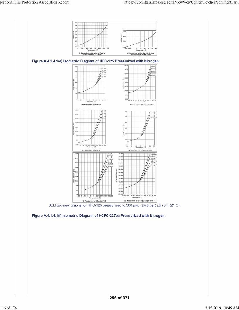
Figure A.4.1.4.1(e) Isometric Diagram of HFC-125 Pressurized with Nitrogen.
Add two new graphs for HFC-125 pressurized to 360 psig (24.8 bar) @ 70 F (21 C)
Figure A.4.1.4.1(f) Isometric Diagram of HCFC-227ea Pressurized with Nitrogen.
National Fire Protection Association Report https://submittals.nfpa.org/TerraViewWeb/ContentFetcher?commentPar...
116 of 176 3/15/2019, 10:45 AM
256 of 371
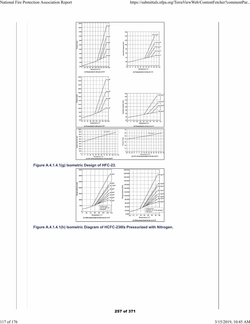
Figure A.4.1.4.1(g) Isometric Design of HFC-23.
Figure A.4.1.4.1(h) Isometric Diagram of HCFC-236fa Pressurized with Nitrogen.
National Fire Protection Association Report https://submittals.nfpa.org/TerraViewWeb/ContentFetcher?commentPar...
117 of 176 3/15/2019, 10:45 AM
257 of 371
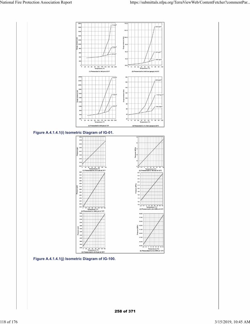
Figure A.4.1.4.1(i) Isometric Diagram of IG-01.
Figure A.4.1.4.1(j) Isometric Diagram of IG-100.
National Fire Protection Association Report https://submittals.nfpa.org/TerraViewWeb/ContentFetcher?commentPar...
118 of 176 3/15/2019, 10:45 AM
258 of 371
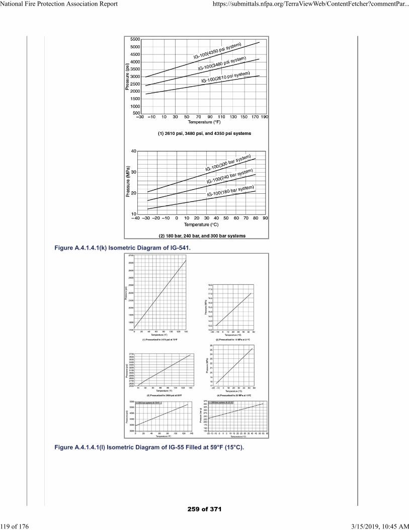
Figure A.4.1.4.1(k) Isometric Diagram of IG-541.
Figure A.4.1.4.1(l) Isometric Diagram of IG-55 Filled at 59°F (15°C).
National Fire Protection Association Report https://submittals.nfpa.org/TerraViewWeb/ContentFetcher?commentPar...
119 of 176 3/15/2019, 10:45 AM
259 of 371
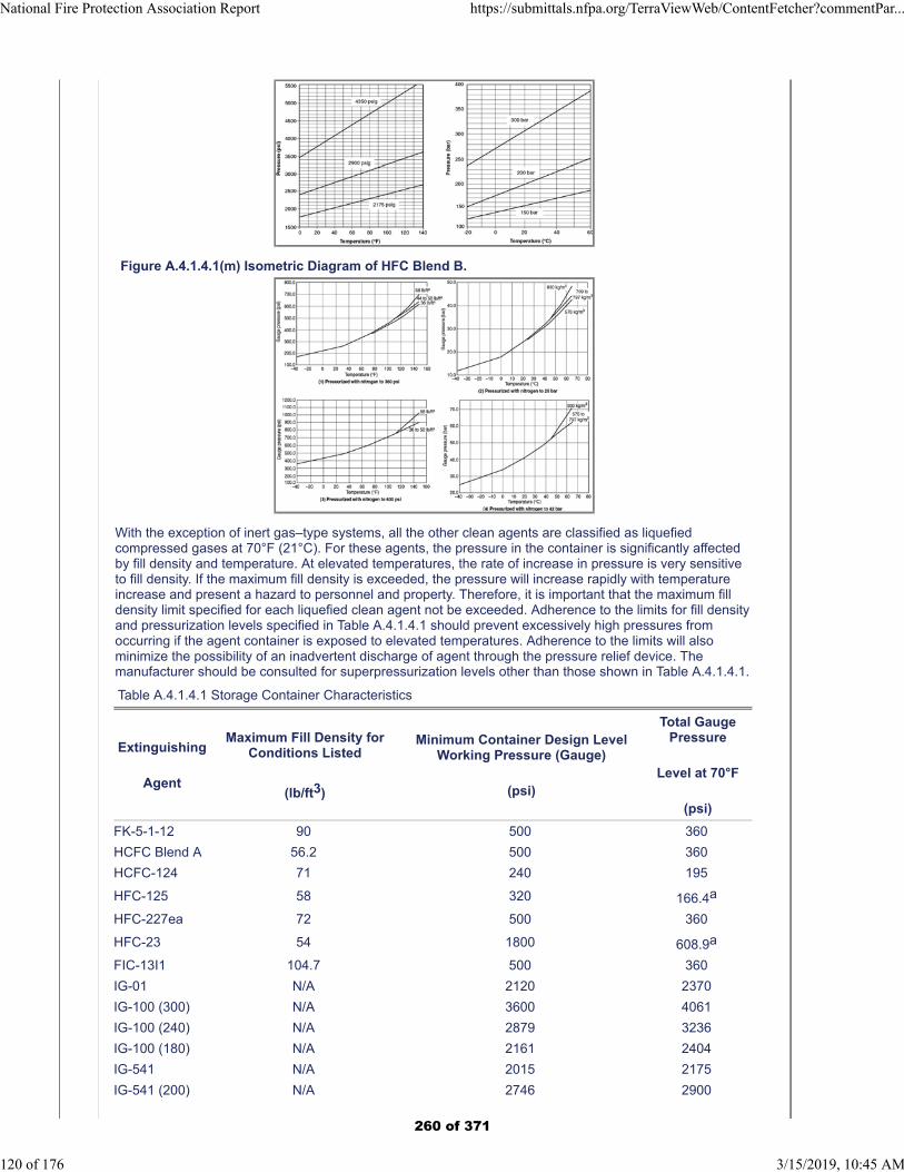
Figure A.4.1.4.1(m) Isometric Diagram of HFC Blend B.
With the exception of inert gas–type systems, all the other clean agents are classified as liquefiedcompressed gases at 70°F (21°C). For these agents, the pressure in the container is significantly affectedby fill density and temperature. At elevated temperatures, the rate of increase in pressure is very sensitiveto fill density. If the maximum fill density is exceeded, the pressure will increase rapidly with temperatureincrease and present a hazard to personnel and property. Therefore, it is important that the maximum filldensity limit specified for each liquefied clean agent not be exceeded. Adherence to the limits for fill densityand pressurization levels specified in Table A.4.1.4.1 should prevent excessively high pressures fromoccurring if the agent container is exposed to elevated temperatures. Adherence to the limits will alsominimize the possibility of an inadvertent discharge of agent through the pressure relief device. Themanufacturer should be consulted for superpressurization levels other than those shown in Table A.4.1.4.1.
Table A.4.1.4.1 Storage Container Characteristics
Extinguishing
Agent
Maximum Fill Density forConditions Listed
(lb/ft3)
Minimum Container Design LevelWorking Pressure (Gauge)
(psi)
Total GaugePressure
Level at 70°F
(psi)
FK-5-1-12 90 500 360
HCFC Blend A 56.2 500 360
HCFC-124 71 240 195
HFC-125 58 320 166.4a
HFC-227ea 72 500 360
HFC-23 54 1800 608.9a
FIC-13I1 104.7 500 360
IG-01 N/A 2120 2370
IG-100 (300) N/A 3600 4061
IG-100 (240) N/A 2879 3236
IG-100 (180) N/A 2161 2404
IG-541 N/A 2015 2175
IG-541 (200) N/A 2746 2900
National Fire Protection Association Report https://submittals.nfpa.org/TerraViewWeb/ContentFetcher?commentPar...
120 of 176 3/15/2019, 10:45 AM
260 of 371
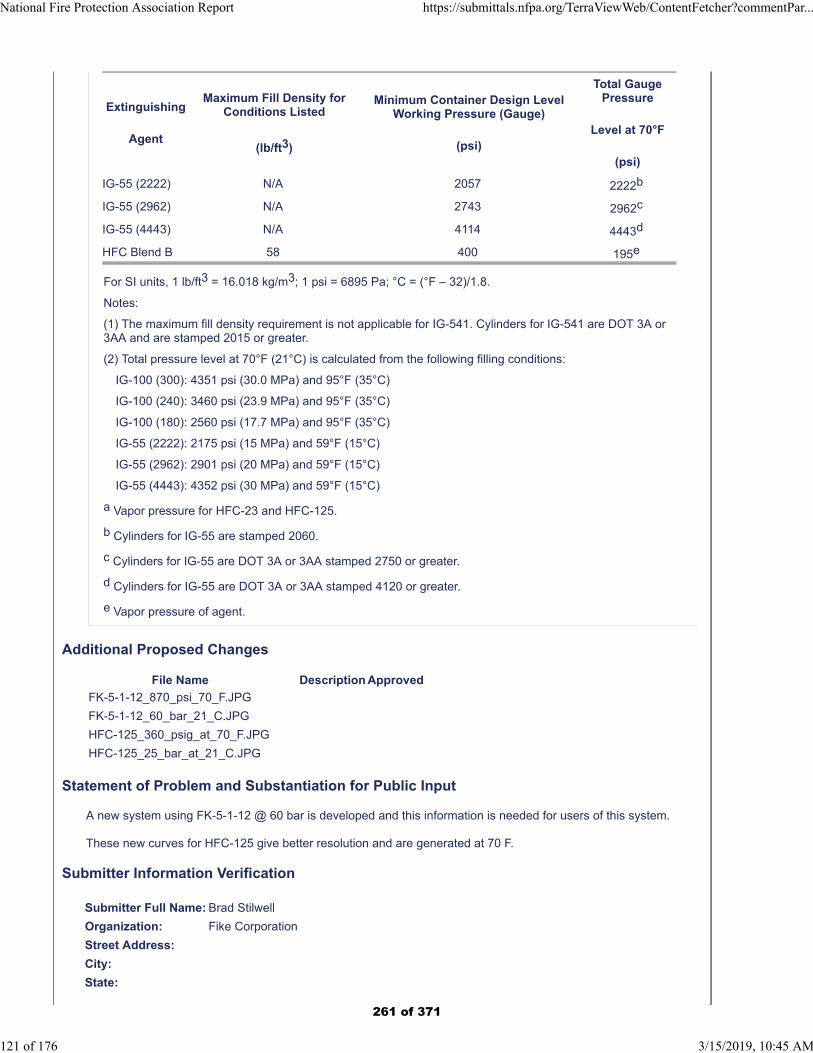
Extinguishing
Agent
Maximum Fill Density forConditions Listed
(lb/ft3)
Minimum Container Design LevelWorking Pressure (Gauge)
(psi)
Total GaugePressure
Level at 70°F
(psi)
IG-55 (2222) N/A 2057 2222b
IG-55 (2962) N/A 2743 2962c
IG-55 (4443) N/A 4114 4443d
HFC Blend B 58 400 195e
For SI units, 1 lb/ft3 = 16.018 kg/m3; 1 psi = 6895 Pa; °C = (°F – 32)/1.8.
Notes:
(1) The maximum fill density requirement is not applicable for IG-541. Cylinders for IG-541 are DOT 3A or3AA and are stamped 2015 or greater.
(2) Total pressure level at 70°F (21°C) is calculated from the following filling conditions:
IG-100 (300): 4351 psi (30.0 MPa) and 95°F (35°C)
IG-100 (240): 3460 psi (23.9 MPa) and 95°F (35°C)
IG-100 (180): 2560 psi (17.7 MPa) and 95°F (35°C)
IG-55 (2222): 2175 psi (15 MPa) and 59°F (15°C)
IG-55 (2962): 2901 psi (20 MPa) and 59°F (15°C)
IG-55 (4443): 4352 psi (30 MPa) and 59°F (15°C)
a Vapor pressure for HFC-23 and HFC-125.
b Cylinders for IG-55 are stamped 2060.
c Cylinders for IG-55 are DOT 3A or 3AA stamped 2750 or greater.
d Cylinders for IG-55 are DOT 3A or 3AA stamped 4120 or greater.
e Vapor pressure of agent.
Additional Proposed Changes
File Name Description Approved
FK-5-1-12_870_psi_70_F.JPG
FK-5-1-12_60_bar_21_C.JPG
HFC-125_360_psig_at_70_F.JPG
HFC-125_25_bar_at_21_C.JPG
Statement of Problem and Substantiation for Public Input
A new system using FK-5-1-12 @ 60 bar is developed and this information is needed for users of this system.
These new curves for HFC-125 give better resolution and are generated at 70 F.
Submitter Information Verification
Submitter Full Name: Brad Stilwell
Organization: Fike Corporation
Street Address:
City:
State:
National Fire Protection Association Report https://submittals.nfpa.org/TerraViewWeb/ContentFetcher?commentPar...
121 of 176 3/15/2019, 10:45 AM
261 of 371

Zip:
Submittal Date: Wed Sep 19 11:31:08 EDT 2018
Committee: GFE-AAA
National Fire Protection Association Report https://submittals.nfpa.org/TerraViewWeb/ContentFetcher?commentPar...
122 of 176 3/15/2019, 10:45 AM
262 of 371
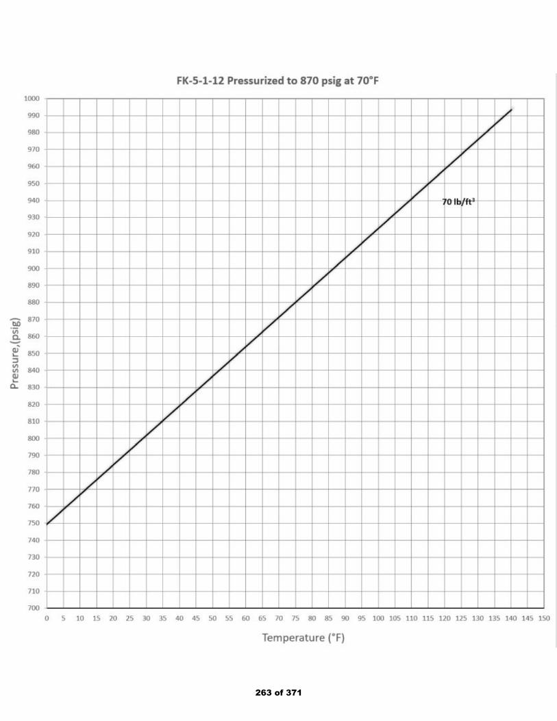
263 of 371
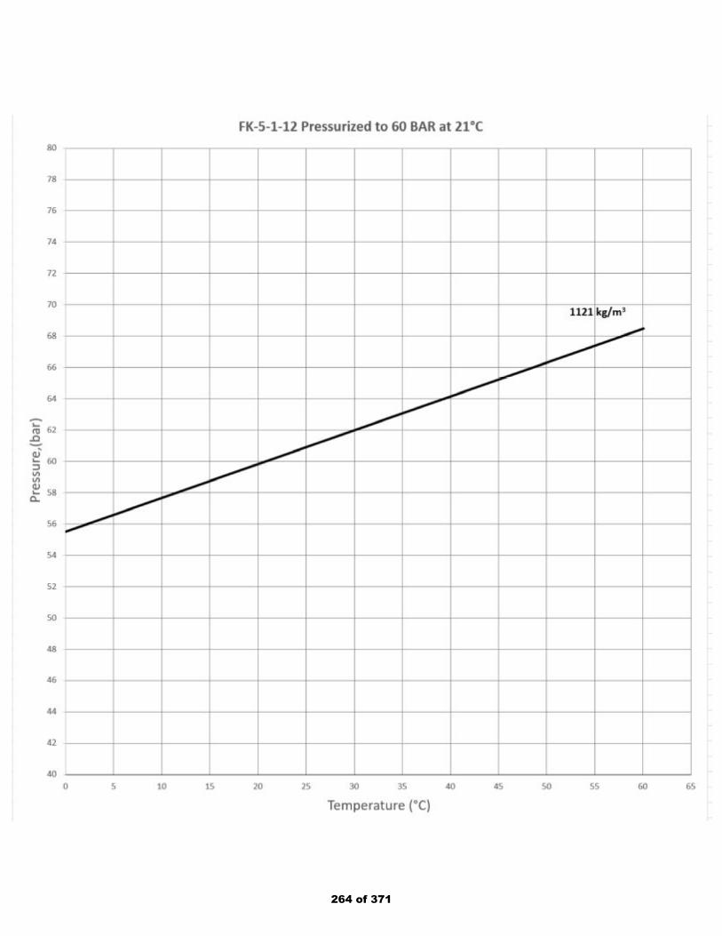
264 of 371
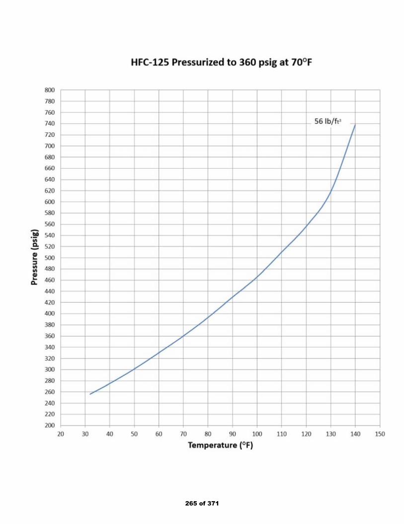
265 of 371
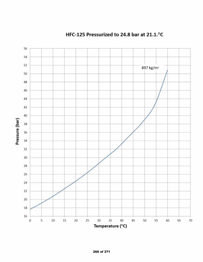
266 of 371

Public Input No. 56-NFPA 2001-2018 [ Section No. A.4.1.4.1 ]
National Fire Protection Association Report https://submittals.nfpa.org/TerraViewWeb/ContentFetcher?commentPar...
123 of 176 3/15/2019, 10:45 AM
267 of 371

A.4.1.4.1
National Fire Protection Association Report https://submittals.nfpa.org/TerraViewWeb/ContentFetcher?commentPar...
124 of 176 3/15/2019, 10:45 AM
268 of 371
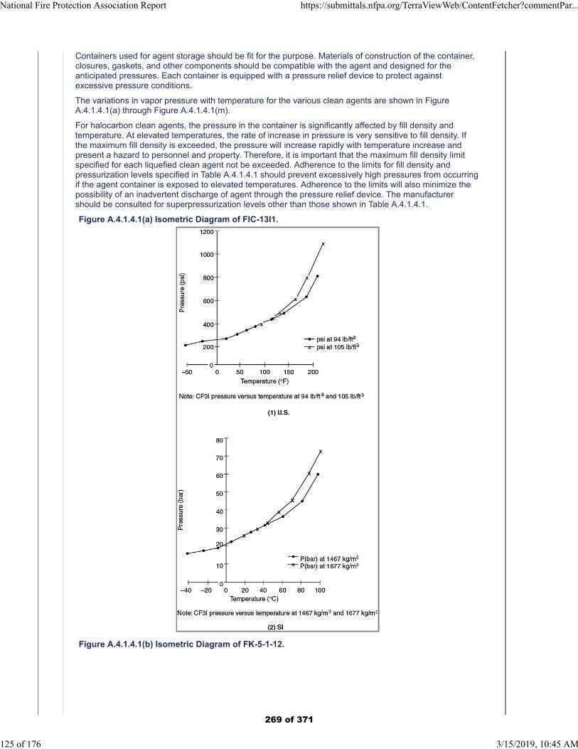
Containers used for agent storage should be fit for the purpose. Materials of construction of the container,closures, gaskets, and other components should be compatible with the agent and designed for theanticipated pressures. Each container is equipped with a pressure relief device to protect againstexcessive pressure conditions.
The variations in vapor pressure with temperature for the various clean agents are shown in FigureA.4.1.4.1(a) through Figure A.4.1.4.1(m).
For halocarbon clean agents, the pressure in the container is significantly affected by fill density andtemperature. At elevated temperatures, the rate of increase in pressure is very sensitive to fill density. Ifthe maximum fill density is exceeded, the pressure will increase rapidly with temperature increase andpresent a hazard to personnel and property. Therefore, it is important that the maximum fill density limitspecified for each liquefied clean agent not be exceeded. Adherence to the limits for fill density andpressurization levels specified in Table A.4.1.4.1 should prevent excessively high pressures from occurringif the agent container is exposed to elevated temperatures. Adherence to the limits will also minimize thepossibility of an inadvertent discharge of agent through the pressure relief device. The manufacturershould be consulted for superpressurization levels other than those shown in Table A.4.1.4.1.
Figure A.4.1.4.1(a) Isometric Diagram of FIC-13I1.
Figure A.4.1.4.1(b) Isometric Diagram of FK-5-1-12.
National Fire Protection Association Report https://submittals.nfpa.org/TerraViewWeb/ContentFetcher?commentPar...
125 of 176 3/15/2019, 10:45 AM
269 of 371
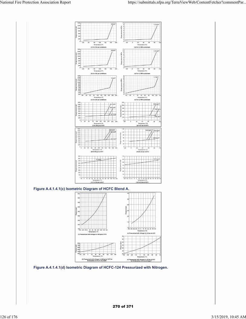
Figure A.4.1.4.1(c) Isometric Diagram of HCFC Blend A.
Figure A.4.1.4.1(d) Isometric Diagram of HCFC-124 Pressurized with Nitrogen.
National Fire Protection Association Report https://submittals.nfpa.org/TerraViewWeb/ContentFetcher?commentPar...
126 of 176 3/15/2019, 10:45 AM
270 of 371
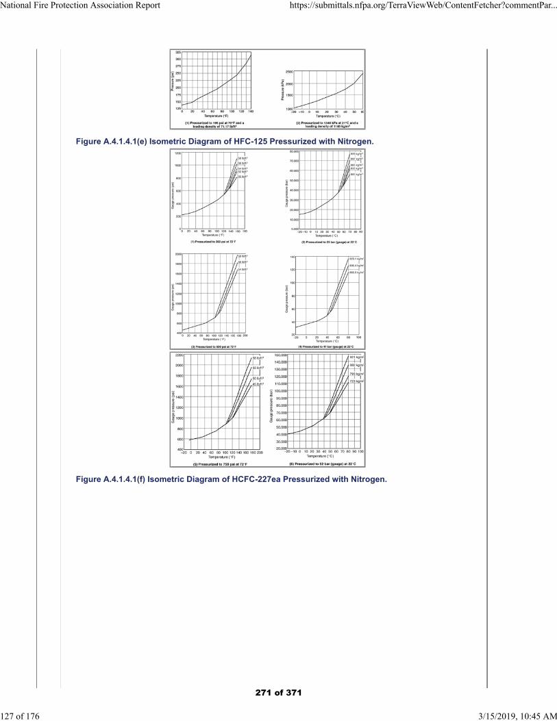
Figure A.4.1.4.1(e) Isometric Diagram of HFC-125 Pressurized with Nitrogen.
Figure A.4.1.4.1(f) Isometric Diagram of HCFC-227ea Pressurized with Nitrogen.
National Fire Protection Association Report https://submittals.nfpa.org/TerraViewWeb/ContentFetcher?commentPar...
127 of 176 3/15/2019, 10:45 AM
271 of 371
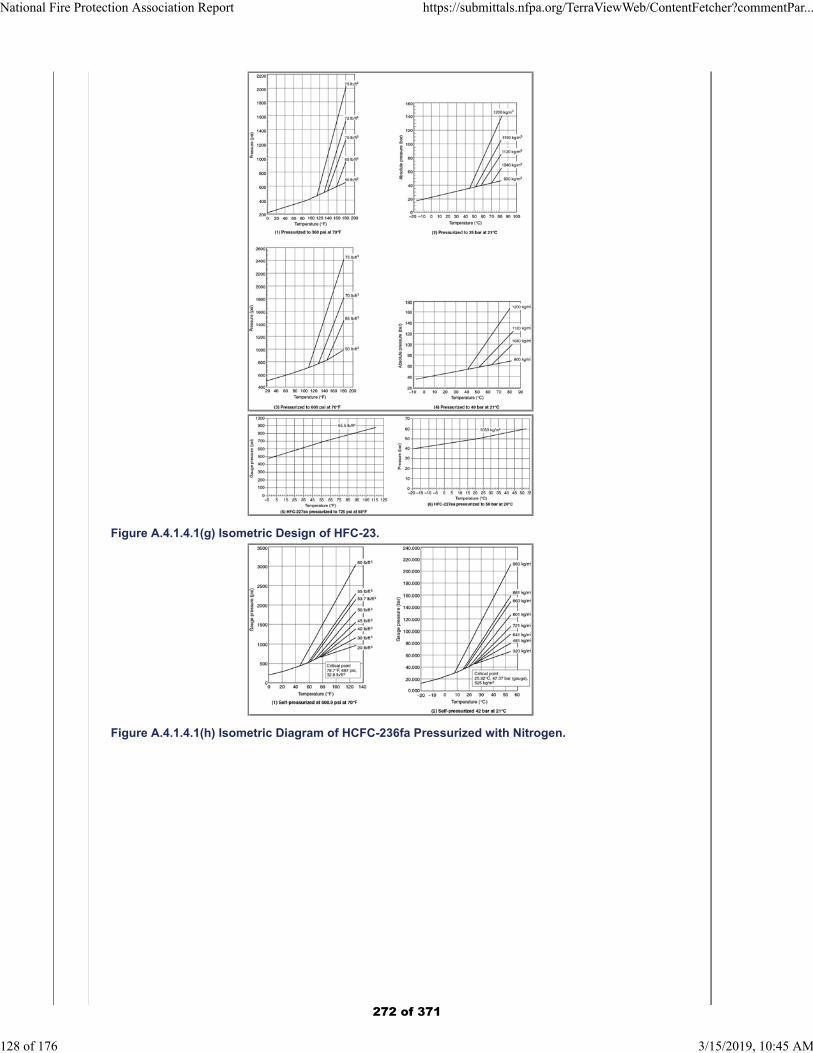
Figure A.4.1.4.1(g) Isometric Design of HFC-23.
Figure A.4.1.4.1(h) Isometric Diagram of HCFC-236fa Pressurized with Nitrogen.
National Fire Protection Association Report https://submittals.nfpa.org/TerraViewWeb/ContentFetcher?commentPar...
128 of 176 3/15/2019, 10:45 AM
272 of 371
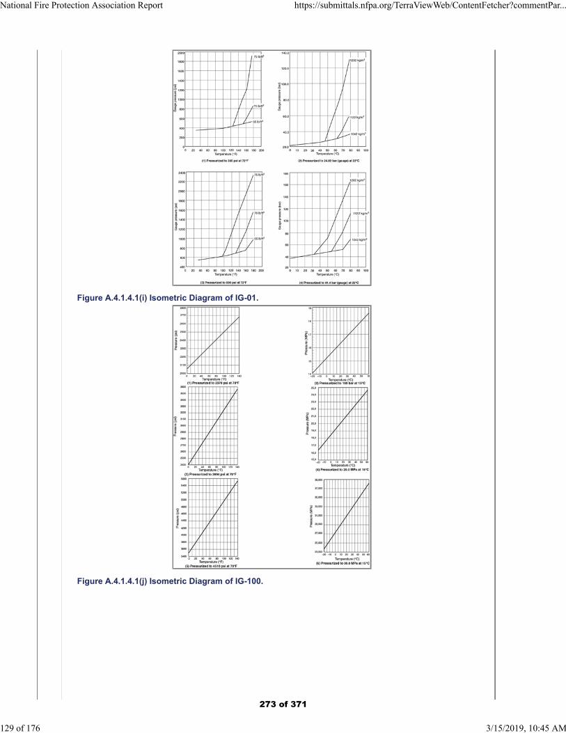
Figure A.4.1.4.1(i) Isometric Diagram of IG-01.
Figure A.4.1.4.1(j) Isometric Diagram of IG-100.
National Fire Protection Association Report https://submittals.nfpa.org/TerraViewWeb/ContentFetcher?commentPar...
129 of 176 3/15/2019, 10:45 AM
273 of 371
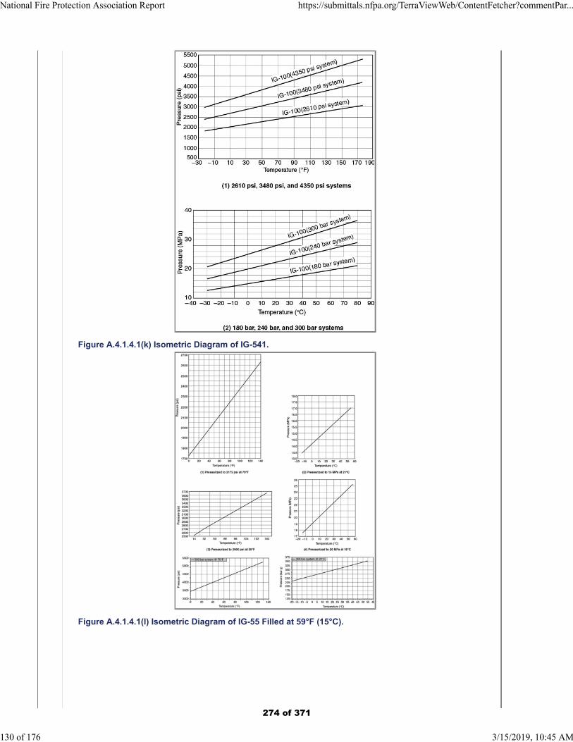
Figure A.4.1.4.1(k) Isometric Diagram of IG-541.
Figure A.4.1.4.1(l) Isometric Diagram of IG-55 Filled at 59°F (15°C).
National Fire Protection Association Report https://submittals.nfpa.org/TerraViewWeb/ContentFetcher?commentPar...
130 of 176 3/15/2019, 10:45 AM
274 of 371
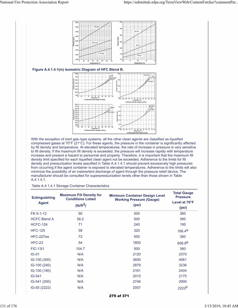
Figure A.4.1.4.1(m) Isometric Diagram of HFC Blend B.
With the exception of inert gas–type systems, all the other clean agents are classified as liquefiedcompressed gases at 70°F (21°C). For these agents, the pressure in the container is significantly affectedby fill density and temperature. At elevated temperatures, the rate of increase in pressure is very sensitiveto fill density. If the maximum fill density is exceeded, the pressure will increase rapidly with temperatureincrease and present a hazard to personnel and property. Therefore, it is important that the maximum filldensity limit specified for each liquefied clean agent not be exceeded. Adherence to the limits for filldensity and pressurization levels specified in Table A.4.1.4.1 should prevent excessively high pressuresfrom occurring if the agent container is exposed to elevated temperatures. Adherence to the limits will alsominimize the possibility of an inadvertent discharge of agent through the pressure relief device. Themanufacturer should be consulted for superpressurization levels other than those shown in TableA.4.1.4.1.
Table A.4.1.4.1 Storage Container Characteristics
Extinguishing
Agent
Maximum Fill Density forConditions Listed
(lb/ft3)
Minimum Container Design LevelWorking Pressure (Gauge)
(psi)
Total GaugePressure
Level at 70°F
(psi)
FK-5-1-12 90 500 360
HCFC Blend A 56.2 500 360
HCFC-124 71 240 195
HFC-125 58 320 166.4a
HFC-227ea 72 500 360
HFC-23 54 1800 608.9a
FIC-13I1 104.7 500 360
IG-01 N/A 2120 2370
IG-100 (300) N/A 3600 4061
IG-100 (240) N/A 2879 3236
IG-100 (180) N/A 2161 2404
IG-541 N/A 2015 2175
IG-541 (200) N/A 2746 2900
IG-55 (2222) N/A 2057 2222b
National Fire Protection Association Report https://submittals.nfpa.org/TerraViewWeb/ContentFetcher?commentPar...
131 of 176 3/15/2019, 10:45 AM
275 of 371
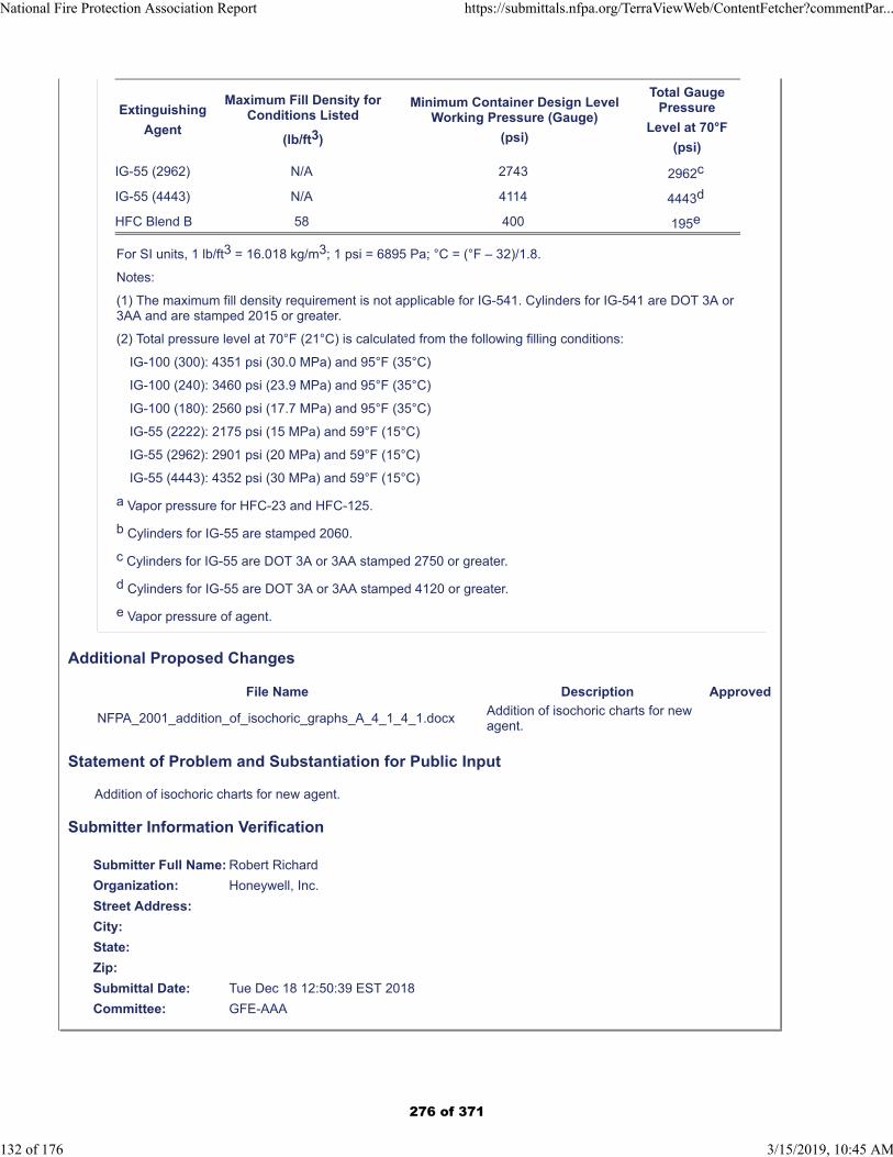
Extinguishing
Agent
Maximum Fill Density forConditions Listed
(lb/ft3)
Minimum Container Design LevelWorking Pressure (Gauge)
(psi)
Total GaugePressure
Level at 70°F
(psi)
IG-55 (2962) N/A 2743 2962c
IG-55 (4443) N/A 4114 4443d
HFC Blend B 58 400 195e
For SI units, 1 lb/ft3 = 16.018 kg/m3; 1 psi = 6895 Pa; °C = (°F – 32)/1.8.
Notes:
(1) The maximum fill density requirement is not applicable for IG-541. Cylinders for IG-541 are DOT 3A or3AA and are stamped 2015 or greater.
(2) Total pressure level at 70°F (21°C) is calculated from the following filling conditions:
IG-100 (300): 4351 psi (30.0 MPa) and 95°F (35°C)
IG-100 (240): 3460 psi (23.9 MPa) and 95°F (35°C)
IG-100 (180): 2560 psi (17.7 MPa) and 95°F (35°C)
IG-55 (2222): 2175 psi (15 MPa) and 59°F (15°C)
IG-55 (2962): 2901 psi (20 MPa) and 59°F (15°C)
IG-55 (4443): 4352 psi (30 MPa) and 59°F (15°C)
a Vapor pressure for HFC-23 and HFC-125.
b Cylinders for IG-55 are stamped 2060.
c Cylinders for IG-55 are DOT 3A or 3AA stamped 2750 or greater.
d Cylinders for IG-55 are DOT 3A or 3AA stamped 4120 or greater.
e Vapor pressure of agent.
Additional Proposed Changes
File Name Description Approved
NFPA_2001_addition_of_isochoric_graphs_A_4_1_4_1.docxAddition of isochoric charts for new agent.
Statement of Problem and Substantiation for Public Input
Addition of isochoric charts for new agent.
Submitter Information Verification
Submitter Full Name: Robert Richard
Organization: Honeywell, Inc.
Street Address:
City:
State:
Zip:
Submittal Date: Tue Dec 18 12:50:39 EST 2018
Committee: GFE-AAA
National Fire Protection Association Report https://submittals.nfpa.org/TerraViewWeb/ContentFetcher?commentPar...
132 of 176 3/15/2019, 10:45 AM
276 of 371
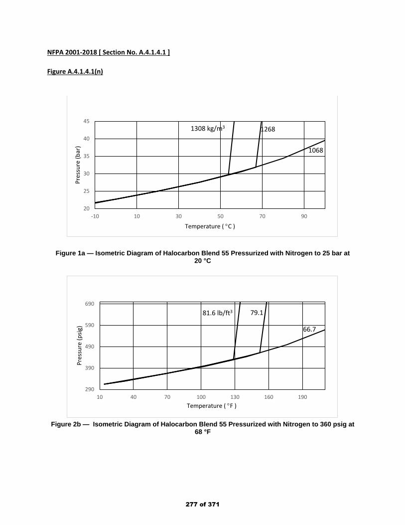
NFPA 2001-2018 [ Section No. A.4.1.4.1 ] Figure A.4.1.4.1(n)
Figure 1a — Isometric Diagram of Halocarbon Blend 55 Pressurized with Nitrogen to 25 bar at 20 °C
Figure 2b — Isometric Diagram of Halocarbon Blend 55 Pressurized with Nitrogen to 360 psig at
68 °F
20
25
30
35
40
45
-10 10 30 50 70 90
Pres
sure
(bar
)
Temperature ( °C )
1268
1068
1308 kg/m3
290
390
490
590
690
10 40 70 100 130 160 190
Pres
sure
(psig
)
Temperature ( °F )
79.1
66.7
81.6 lb/ft3
277 of 371
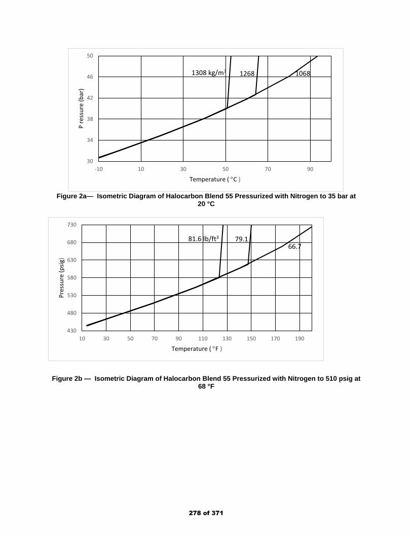
Figure 2a— Isometric Diagram of Halocarbon Blend 55 Pressurized with Nitrogen to 35 bar at
20 °C
Figure 2b — Isometric Diagram of Halocarbon Blend 55 Pressurized with Nitrogen to 510 psig at
68 °F
30
34
38
42
46
50
-10 10 30 50 70 90
P re
ssur
e (b
ar)
Temperature ( °C )
1068 12681308 kg/m3
430
480
530
580
630
680
730
10 30 50 70 90 110 130 150 170 190
Pres
sure
(psig
)
Temperature ( °F )
66.779.181.6 lb/ft3
278 of 371
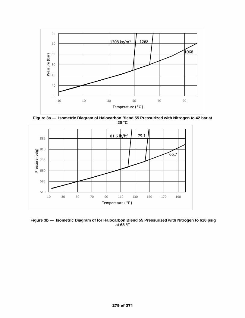
Figure 3a — Isometric Diagram of Halocarbon Blend 55 Pressurized with Nitrogen to 42 bar at
20 °C
Figure 3b — Isometric Diagram of for Halocarbon Blend 55 Pressurized with Nitrogen to 610 psig
at 68 °F
35
40
45
50
55
60
65
-10 10 30 50 70 90
Pres
sure
(bar
)
Temperature ( °C )
1308 kg/m3 1268
1068
510
585
660
735
810
885
10 30 50 70 90 110 130 150 170 190
Pres
sure
(psig
)
Temperature ( °F )
81.6 lb/ft3 79.1
66.7
279 of 371
Public Input No. 62-NFPA 2001-2018 [ New Section after A.4.1.4.2 ]
A.4.1.4.2 (1)*For refillable halocarbon agent containers, liquid level indicators (LLI) may be considered, whenavailable from the system manufacturer as a standard optional offering. The liquid level indicator(LLI) device provides the means to determine the quantity of halocarbon agent in accordance withthe requirements of 8.3.1. Further, the LLI device allows the fire protection service technician ameans to safely determine the halocarbon agent quantity without lifting or moving the container.
Statement of Problem and Substantiation for Public Input
Most manufacturers of refillable halocarbon agent containers offer an optional liquid level device (LLI), in at least part of the product line, to assist the servicing personnel to determine the quantity of halocarbon agent in the storage container, without the need to lift or move the container. This allows for “safe” handling practices to avoid injury to the service personnel. Where available, this liquid level indicator (LLI) option should be provided.
Submitter Information Verification
Submitter Full Name: Daniel Hubert
Organization: Amerex/Janus Fire Systems
Street Address:
City:
State:
Zip:
Submittal Date: Wed Dec 26 11:17:40 EST 2018
Committee: GFE-AAA
National Fire Protection Association Report https://submittals.nfpa.org/TerraViewWeb/ContentFetcher?commentPar...
133 of 176 3/15/2019, 10:45 AM
280 of 371

Public Input No. 47-NFPA 2001-2018 [ Section No. A.5.4.2.1 ]
National Fire Protection Association Report https://submittals.nfpa.org/TerraViewWeb/ContentFetcher?commentPar...
134 of 176 3/15/2019, 10:45 AM
281 of 371

A.5.4.2.1
National Fire Protection Association Report https://submittals.nfpa.org/TerraViewWeb/ContentFetcher?commentPar...
135 of 176 3/15/2019, 10:45 AM
282 of 371
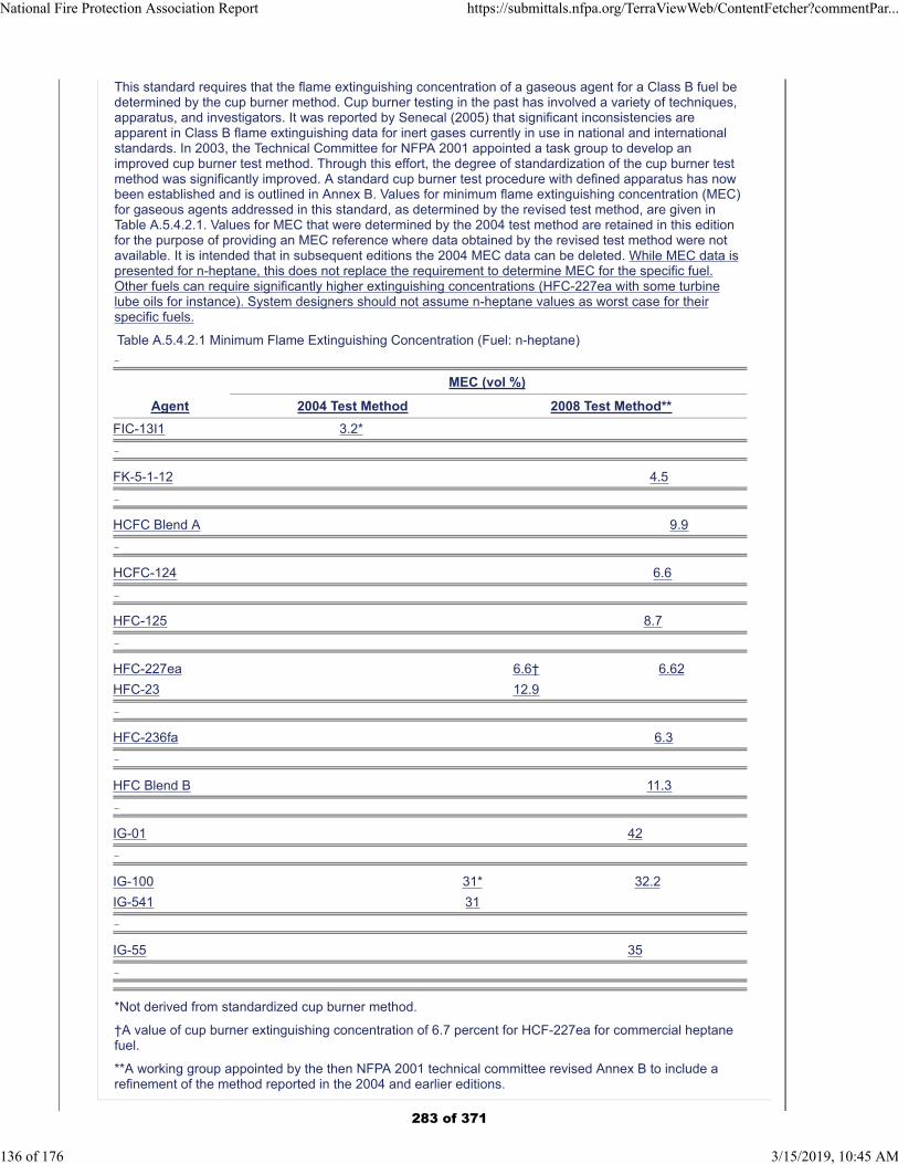
This standard requires that the flame extinguishing concentration of a gaseous agent for a Class B fuel bedetermined by the cup burner method. Cup burner testing in the past has involved a variety of techniques,apparatus, and investigators. It was reported by Senecal (2005) that significant inconsistencies areapparent in Class B flame extinguishing data for inert gases currently in use in national and internationalstandards. In 2003, the Technical Committee for NFPA 2001 appointed a task group to develop animproved cup burner test method. Through this effort, the degree of standardization of the cup burner testmethod was significantly improved. A standard cup burner test procedure with defined apparatus has nowbeen established and is outlined in Annex B. Values for minimum flame extinguishing concentration (MEC)for gaseous agents addressed in this standard, as determined by the revised test method, are given inTable A.5.4.2.1. Values for MEC that were determined by the 2004 test method are retained in this editionfor the purpose of providing an MEC reference where data obtained by the revised test method were notavailable. It is intended that in subsequent editions the 2004 MEC data can be deleted. While MEC data ispresented for n-heptane, this does not replace the requirement to determine MEC for the specific fuel.Other fuels can require significantly higher extinguishing concentrations (HFC-227ea with some turbinelube oils for instance). System designers should not assume n-heptane values as worst case for theirspecific fuels.
Table A.5.4.2.1 Minimum Flame Extinguishing Concentration (Fuel: n-heptane)
MEC (vol %)
Agent 2004 Test Method 2008 Test Method**
FIC-13I1 3.2*
FK-5-1-12 4.5
HCFC Blend A 9.9
HCFC-124 6.6
HFC-125 8.7
HFC-227ea 6.6† 6.62
HFC-23 12.9
HFC-236fa 6.3
HFC Blend B 11.3
IG-01 42
IG-100 31* 32.2
IG-541 31
IG-55 35
*Not derived from standardized cup burner method.
†A value of cup burner extinguishing concentration of 6.7 percent for HCF-227ea for commercial heptanefuel.
**A working group appointed by the then NFPA 2001 technical committee revised Annex B to include arefinement of the method reported in the 2004 and earlier editions.
National Fire Protection Association Report https://submittals.nfpa.org/TerraViewWeb/ContentFetcher?commentPar...
136 of 176 3/15/2019, 10:45 AM
283 of 371
Additional Proposed Changes
File Name Description Approved
HFC-227ea_design_challenges_for_large_frame_GTs_PI-47-NFPA_2001-2018.pdf
Graph showing the impact of higher MEC value for a specific fuel on the predicted agent concentration and corresponding system requirements for a large frame gas turbine hazard.
Statement of Problem and Substantiation for Public Input
We have had experienced suppliers assume that n-heptane MEC values are worst case for system design in lieu of specific cup burner testing for our fuel. Cup burner testing shows that certain mineral oil turbine lubrication fluids can actually require higher extinguishing concentrations, to the point that the system would require the safety features listed in 1.5.1.4.3. When we came across this issue we had trouble finding a listed system with those safety features available, and eventually abandoned the specific clean agent system design. A little bit of additional text here may help prevent someone else falling into that same hole. Attached graph shows the impact on the design for a hypothetical project.
Submitter Information Verification
Submitter Full Name: Matthew Taylor
Organization: Mitsubishi Hitachi Power Systems
Street Address:
City:
State:
Zip:
Submittal Date: Thu Dec 13 16:04:52 EST 2018
Committee: GFE-AAA
National Fire Protection Association Report https://submittals.nfpa.org/TerraViewWeb/ContentFetcher?commentPar...
137 of 176 3/15/2019, 10:45 AM
284 of 371
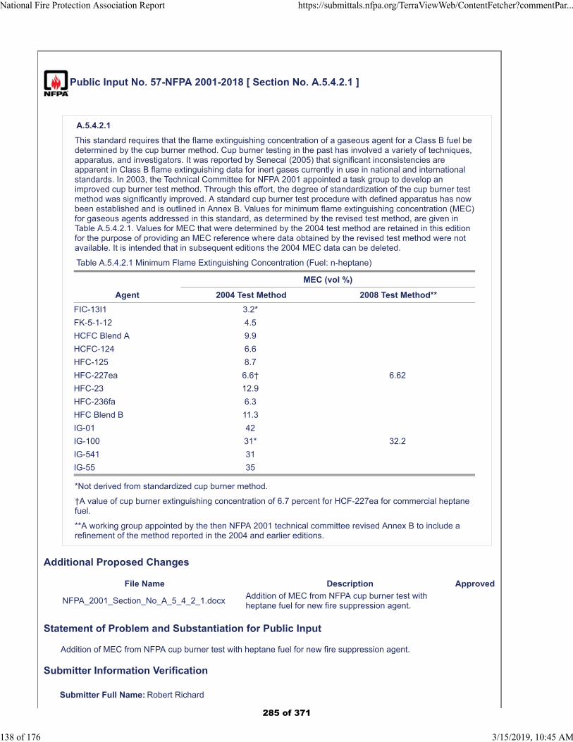
Public Input No. 57-NFPA 2001-2018 [ Section No. A.5.4.2.1 ]
A.5.4.2.1
This standard requires that the flame extinguishing concentration of a gaseous agent for a Class B fuel bedetermined by the cup burner method. Cup burner testing in the past has involved a variety of techniques,apparatus, and investigators. It was reported by Senecal (2005) that significant inconsistencies areapparent in Class B flame extinguishing data for inert gases currently in use in national and internationalstandards. In 2003, the Technical Committee for NFPA 2001 appointed a task group to develop animproved cup burner test method. Through this effort, the degree of standardization of the cup burner testmethod was significantly improved. A standard cup burner test procedure with defined apparatus has nowbeen established and is outlined in Annex B. Values for minimum flame extinguishing concentration (MEC)for gaseous agents addressed in this standard, as determined by the revised test method, are given inTable A.5.4.2.1. Values for MEC that were determined by the 2004 test method are retained in this editionfor the purpose of providing an MEC reference where data obtained by the revised test method were notavailable. It is intended that in subsequent editions the 2004 MEC data can be deleted.
Table A.5.4.2.1 Minimum Flame Extinguishing Concentration (Fuel: n-heptane)
MEC (vol %)
Agent 2004 Test Method 2008 Test Method**
FIC-13I1 3.2*
FK-5-1-12 4.5
HCFC Blend A 9.9
HCFC-124 6.6
HFC-125 8.7
HFC-227ea 6.6† 6.62
HFC-23 12.9
HFC-236fa 6.3
HFC Blend B 11.3
IG-01 42
IG-100 31* 32.2
IG-541 31
IG-55 35
*Not derived from standardized cup burner method.
†A value of cup burner extinguishing concentration of 6.7 percent for HCF-227ea for commercial heptanefuel.
**A working group appointed by the then NFPA 2001 technical committee revised Annex B to include arefinement of the method reported in the 2004 and earlier editions.
Additional Proposed Changes
File Name Description Approved
NFPA_2001_Section_No_A_5_4_2_1.docxAddition of MEC from NFPA cup burner test with heptane fuel for new fire suppression agent.
Statement of Problem and Substantiation for Public Input
Addition of MEC from NFPA cup burner test with heptane fuel for new fire suppression agent.
Submitter Information Verification
Submitter Full Name: Robert Richard
National Fire Protection Association Report https://submittals.nfpa.org/TerraViewWeb/ContentFetcher?commentPar...
138 of 176 3/15/2019, 10:45 AM
285 of 371

Organization: Honeywell, Inc.
Street Address:
City:
State:
Zip:
Submittal Date: Tue Dec 18 12:57:19 EST 2018
Committee: GFE-AAA
National Fire Protection Association Report https://submittals.nfpa.org/TerraViewWeb/ContentFetcher?commentPar...
139 of 176 3/15/2019, 10:45 AM
286 of 371

NFPA 2001-2018 [ Section No. A.5.4.2.1 ] Table A.5.4.2.1 Agent By 2004 Test Method by revised test method Halocarbon Blend 55 - 6.0
287 of 371
Public Input No. 58-NFPA 2001-2018 [ Section No. A.5.4.2.2 ]
National Fire Protection Association Report https://submittals.nfpa.org/TerraViewWeb/ContentFetcher?commentPar...
140 of 176 3/15/2019, 10:45 AM
288 of 371

A.5.4.2.2
National Fire Protection Association Report https://submittals.nfpa.org/TerraViewWeb/ContentFetcher?commentPar...
141 of 176 3/15/2019, 10:45 AM
289 of 371
The following steps detail the fire extinguishment/area coverage fire test procedure for engineered andpre-engineered clean agent extinguishing system units:
(1) The general requirements are as follows:
(a) An engineered or pre-engineered extinguishing system should mix and distribute its extinguishingagent and should totally flood an enclosure when tested in accordance with the recommendationsof A.5.4.2.2(1)(c) through A.5.4.2.2(6)(f) under the maximum design limitations and most severeinstallation instructions. See also A.5.4.2.2(1)(b).
(b) When tested as described in A.5.4.2.2(2)(a) through A.5.4.2.2(5)(b), an extinguishing system unitshould extinguish all fires within 30 seconds after the end of system discharge. When tested asdescribed in A.5.4.2.2(2)(a) through A.5.4.2.2(3)(c) and A.5.4.2.2(6)(a) through A.5.4.2.2(6)(f), anextinguishing system should prevent reignition of the wood crib after a 10 minute soak period.
(c) The tests described in A.5.4.2.2(2)(a) through A.5.4.2.2(6)(f) should be carried out. Consider theintended use and limitations of the extinguishing system, with specific reference to the following:
i. The area coverage for each type of nozzle
ii. The operating temperature range of the system
iii. Location of the nozzles in the protected area
iv. Either maximum length and size of piping and number of fittings to each nozzle or minimumnozzle pressure
v. Maximum discharge time
vi. Maximum fill density
(2) The test enclosure construction is as follows:
(a) The enclosure for the test should be constructed of either indoor or outdoor grade minimum 3⁄8 in.(9.5 mm) thick plywood or equivalent material.
(b) An enclosure(s) is to be constructed having the maximum area coverage for the extinguishingsystem unit or nozzle being tested and the minimum and maximum protected area heightlimitations.
The test enclosure(s) for the maximum height, flammable liquid, and wood crib fire extinguishmenttests need not have the maximum coverage area, but should be at least 13.1 ft (4.0 m) wide by 13.1 ft
(4.0 m) long and 3351 ft3 (100 m3) in volume.
(3) The extinguishing system is as follows:
(a) A pre-engineered type of extinguishing system unit is to be assembled using its maximum pipinglimitations with respect to number of fittings and length of pipe to the discharge nozzles andnozzle configuration(s), as specified in the manufacturer’s design and installation instructions.
(b) An engineered-type extinguishing system unit is to be assembled using a piping arrangement thatresults in the minimum nozzle design pressure at 70°F (21°C).
(c) Except for the flammable liquid fire test using the 2.5 ft2 (0.23 m2) square pan and the wood cribextinguishment test, the cylinders are to be conditioned to the minimum operating temperaturespecified in the manufacturer’s installation instructions.
(4) The extinguishing concentration is as follows:
(a) The extinguishing agent concentration for each Class A test is to be 83.34 percent of the intendedend use design concentration specified in the manufacturer’s design and installation instructionsat the ambient temperature of approximately 70°F (21°C) within the enclosure.
(b) The extinguishing agent concentration for each Class B test is to be 76.9 percent of the intendedend-use design concentration specified in the manufacturer’s design and installation instructionsat the ambient temperature of approximately 70°F (21°C) within the enclosure.
(c) The concentration for inert gas clean agents can be adjusted to take into consideration actualleakage measured from the test enclosure.
(d) The concentration within the enclosure for halocarbon clean agents should be calculated usingthe following formula unless it is demonstrated that the test enclosure exhibits significant leakage.If significant test enclosure leakage does exist, the formula used to determine the test enclosureconcentration of halocarbon clean agents can be modified to account for the leakage measured.
National Fire Protection Association Report https://submittals.nfpa.org/TerraViewWeb/ContentFetcher?commentPar...
142 of 176 3/15/2019, 10:45 AM
290 of 371
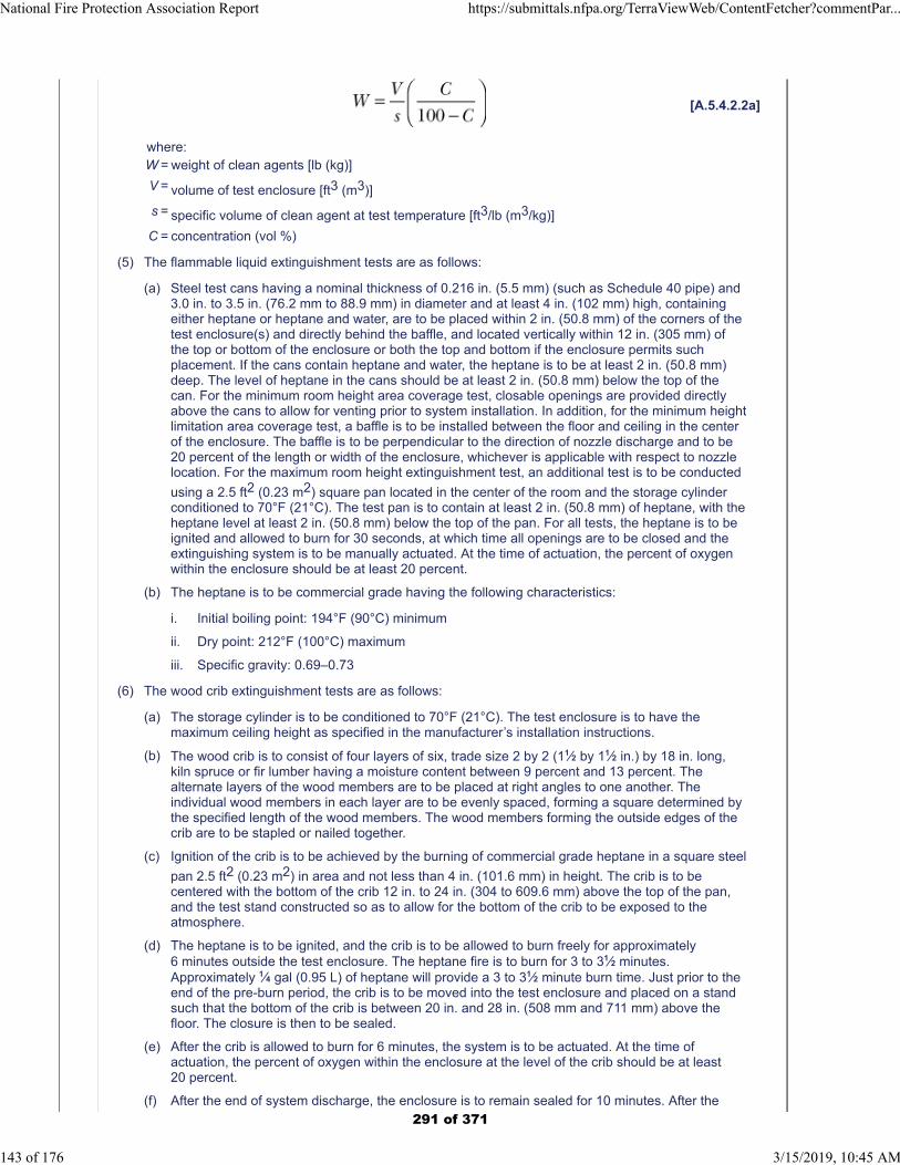
[A.5.4.2.2a]
where:W = weight of clean agents [lb (kg)]
V = volume of test enclosure [ft3 (m3)]
s = specific volume of clean agent at test temperature [ft3/lb (m3/kg)]
C = concentration (vol %)
(5) The flammable liquid extinguishment tests are as follows:
(a) Steel test cans having a nominal thickness of 0.216 in. (5.5 mm) (such as Schedule 40 pipe) and3.0 in. to 3.5 in. (76.2 mm to 88.9 mm) in diameter and at least 4 in. (102 mm) high, containingeither heptane or heptane and water, are to be placed within 2 in. (50.8 mm) of the corners of thetest enclosure(s) and directly behind the baffle, and located vertically within 12 in. (305 mm) ofthe top or bottom of the enclosure or both the top and bottom if the enclosure permits suchplacement. If the cans contain heptane and water, the heptane is to be at least 2 in. (50.8 mm)deep. The level of heptane in the cans should be at least 2 in. (50.8 mm) below the top of thecan. For the minimum room height area coverage test, closable openings are provided directlyabove the cans to allow for venting prior to system installation. In addition, for the minimum heightlimitation area coverage test, a baffle is to be installed between the floor and ceiling in the centerof the enclosure. The baffle is to be perpendicular to the direction of nozzle discharge and to be20 percent of the length or width of the enclosure, whichever is applicable with respect to nozzlelocation. For the maximum room height extinguishment test, an additional test is to be conducted
using a 2.5 ft2 (0.23 m2) square pan located in the center of the room and the storage cylinderconditioned to 70°F (21°C). The test pan is to contain at least 2 in. (50.8 mm) of heptane, with theheptane level at least 2 in. (50.8 mm) below the top of the pan. For all tests, the heptane is to beignited and allowed to burn for 30 seconds, at which time all openings are to be closed and theextinguishing system is to be manually actuated. At the time of actuation, the percent of oxygenwithin the enclosure should be at least 20 percent.
(b) The heptane is to be commercial grade having the following characteristics:
i. Initial boiling point: 194°F (90°C) minimum
ii. Dry point: 212°F (100°C) maximum
iii. Specific gravity: 0.69–0.73
(6) The wood crib extinguishment tests are as follows:
(a) The storage cylinder is to be conditioned to 70°F (21°C). The test enclosure is to have themaximum ceiling height as specified in the manufacturer’s installation instructions.
(b) The wood crib is to consist of four layers of six, trade size 2 by 2 (11⁄2 by 11⁄2 in.) by 18 in. long,kiln spruce or fir lumber having a moisture content between 9 percent and 13 percent. Thealternate layers of the wood members are to be placed at right angles to one another. Theindividual wood members in each layer are to be evenly spaced, forming a square determined bythe specified length of the wood members. The wood members forming the outside edges of thecrib are to be stapled or nailed together.
(c) Ignition of the crib is to be achieved by the burning of commercial grade heptane in a square steel
pan 2.5 ft2 (0.23 m2) in area and not less than 4 in. (101.6 mm) in height. The crib is to becentered with the bottom of the crib 12 in. to 24 in. (304 to 609.6 mm) above the top of the pan,and the test stand constructed so as to allow for the bottom of the crib to be exposed to theatmosphere.
(d) The heptane is to be ignited, and the crib is to be allowed to burn freely for approximately6 minutes outside the test enclosure. The heptane fire is to burn for 3 to 31⁄2 minutes.Approximately 1⁄4 gal (0.95 L) of heptane will provide a 3 to 31⁄2 minute burn time. Just prior to theend of the pre-burn period, the crib is to be moved into the test enclosure and placed on a standsuch that the bottom of the crib is between 20 in. and 28 in. (508 mm and 711 mm) above thefloor. The closure is then to be sealed.
(e) After the crib is allowed to burn for 6 minutes, the system is to be actuated. At the time ofactuation, the percent of oxygen within the enclosure at the level of the crib should be at least20 percent.
(f) After the end of system discharge, the enclosure is to remain sealed for 10 minutes. After the
National Fire Protection Association Report https://submittals.nfpa.org/TerraViewWeb/ContentFetcher?commentPar...
143 of 176 3/15/2019, 10:45 AM
291 of 371
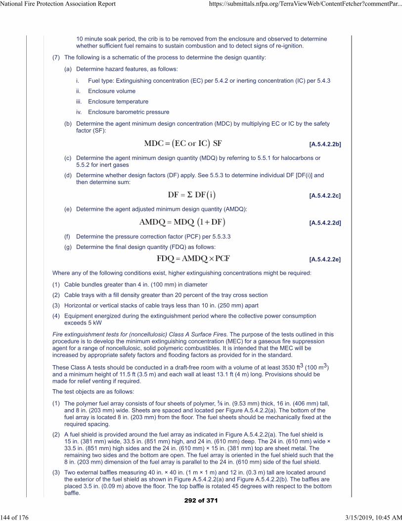
10 minute soak period, the crib is to be removed from the enclosure and observed to determinewhether sufficient fuel remains to sustain combustion and to detect signs of re-ignition.
(7) The following is a schematic of the process to determine the design quantity:
(a) Determine hazard features, as follows:
i. Fuel type: Extinguishing concentration (EC) per 5.4.2 or inerting concentration (IC) per 5.4.3
ii. Enclosure volume
iii. Enclosure temperature
iv. Enclosure barometric pressure
(b) Determine the agent minimum design concentration (MDC) by multiplying EC or IC by the safetyfactor (SF):
[A.5.4.2.2b]
(c) Determine the agent minimum design quantity (MDQ) by referring to 5.5.1 for halocarbons or5.5.2 for inert gases
(d) Determine whether design factors (DF) apply. See 5.5.3 to determine individual DF [DF(i)] andthen determine sum:
[A.5.4.2.2c]
(e) Determine the agent adjusted minimum design quantity (AMDQ):
[A.5.4.2.2d]
(f) Determine the pressure correction factor (PCF) per 5.5.3.3
(g) Determine the final design quantity (FDQ) as follows:
[A.5.4.2.2e]
Where any of the following conditions exist, higher extinguishing concentrations might be required:
(1) Cable bundles greater than 4 in. (100 mm) in diameter
(2) Cable trays with a fill density greater than 20 percent of the tray cross section
(3) Horizontal or vertical stacks of cable trays less than 10 in. (250 mm) apart
(4) Equipment energized during the extinguishment period where the collective power consumptionexceeds 5 kW
Fire extinguishment tests for (noncellulosic) Class A Surface Fires. The purpose of the tests outlined in thisprocedure is to develop the minimum extinguishing concentration (MEC) for a gaseous fire suppressionagent for a range of noncellulosic, solid polymeric combustibles. It is intended that the MEC will beincreased by appropriate safety factors and flooding factors as provided for in the standard.
These Class A tests should be conducted in a draft-free room with a volume of at least 3530 ft3 (100 m3)and a minimum height of 11.5 ft (3.5 m) and each wall at least 13.1 ft (4 m) long. Provisions should bemade for relief venting if required.
The test objects are as follows:
(1) The polymer fuel array consists of four sheets of polymer, 3⁄8 in. (9.53 mm) thick, 16 in. (406 mm) tall,and 8 in. (203 mm) wide. Sheets are spaced and located per Figure A.5.4.2.2(a). The bottom of thefuel array is located 8 in. (203 mm) from the floor. The fuel sheets should be mechanically fixed at therequired spacing.
(2) A fuel shield is provided around the fuel array as indicated in Figure A.5.4.2.2(a). The fuel shield is15 in. (381 mm) wide, 33.5 in. (851 mm) high, and 24 in. (610 mm) deep. The 24 in. (610 mm) wide ×33.5 in. (851 mm) high sides and the 24 in. (610 mm) × 15 in. (381 mm) top are sheet metal. Theremaining two sides and the bottom are open. The fuel array is oriented in the fuel shield such that the8 in. (203 mm) dimension of the fuel array is parallel to the 24 in. (610 mm) side of the fuel shield.
(3) Two external baffles measuring 40 in. × 40 in. (1 m × 1 m) and 12 in. (0.3 m) tall are located aroundthe exterior of the fuel shield as shown in Figure A.5.4.2.2(a) and Figure A.5.4.2.2(b). The baffles areplaced 3.5 in. (0.09 m) above the floor. The top baffle is rotated 45 degrees with respect to the bottombaffle.
National Fire Protection Association Report https://submittals.nfpa.org/TerraViewWeb/ContentFetcher?commentPar...
144 of 176 3/15/2019, 10:45 AM
292 of 371
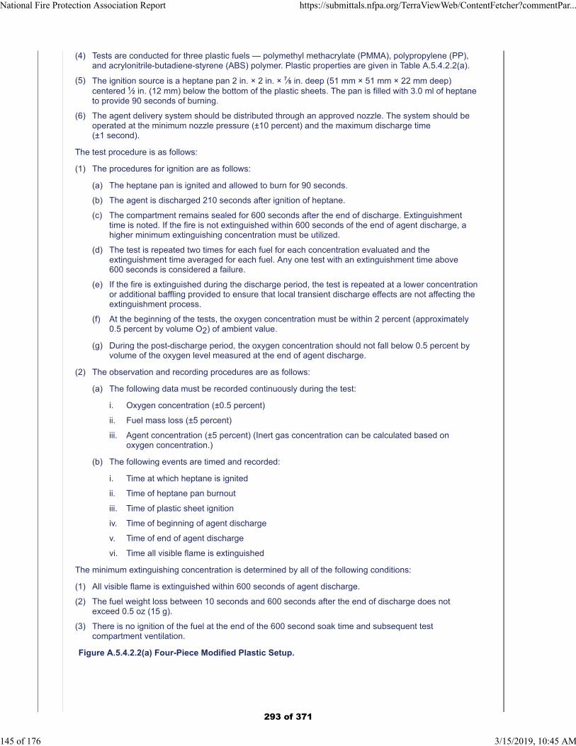
(4) Tests are conducted for three plastic fuels — polymethyl methacrylate (PMMA), polypropylene (PP),and acrylonitrile-butadiene-styrene (ABS) polymer. Plastic properties are given in Table A.5.4.2.2(a).
(5) The ignition source is a heptane pan 2 in. × 2 in. × 7⁄8 in. deep (51 mm × 51 mm × 22 mm deep)centered 1⁄2 in. (12 mm) below the bottom of the plastic sheets. The pan is filled with 3.0 ml of heptaneto provide 90 seconds of burning.
(6) The agent delivery system should be distributed through an approved nozzle. The system should beoperated at the minimum nozzle pressure (±10 percent) and the maximum discharge time(±1 second).
The test procedure is as follows:
(1) The procedures for ignition are as follows:
(a) The heptane pan is ignited and allowed to burn for 90 seconds.
(b) The agent is discharged 210 seconds after ignition of heptane.
(c) The compartment remains sealed for 600 seconds after the end of discharge. Extinguishmenttime is noted. If the fire is not extinguished within 600 seconds of the end of agent discharge, ahigher minimum extinguishing concentration must be utilized.
(d) The test is repeated two times for each fuel for each concentration evaluated and theextinguishment time averaged for each fuel. Any one test with an extinguishment time above600 seconds is considered a failure.
(e) If the fire is extinguished during the discharge period, the test is repeated at a lower concentrationor additional baffling provided to ensure that local transient discharge effects are not affecting theextinguishment process.
(f) At the beginning of the tests, the oxygen concentration must be within 2 percent (approximately0.5 percent by volume O2) of ambient value.
(g) During the post-discharge period, the oxygen concentration should not fall below 0.5 percent byvolume of the oxygen level measured at the end of agent discharge.
(2) The observation and recording procedures are as follows:
(a) The following data must be recorded continuously during the test:
i. Oxygen concentration (±0.5 percent)
ii. Fuel mass loss (±5 percent)
iii. Agent concentration (±5 percent) (Inert gas concentration can be calculated based onoxygen concentration.)
(b) The following events are timed and recorded:
i. Time at which heptane is ignited
ii. Time of heptane pan burnout
iii. Time of plastic sheet ignition
iv. Time of beginning of agent discharge
v. Time of end of agent discharge
vi. Time all visible flame is extinguished
The minimum extinguishing concentration is determined by all of the following conditions:
(1) All visible flame is extinguished within 600 seconds of agent discharge.
(2) The fuel weight loss between 10 seconds and 600 seconds after the end of discharge does notexceed 0.5 oz (15 g).
(3) There is no ignition of the fuel at the end of the 600 second soak time and subsequent testcompartment ventilation.
Figure A.5.4.2.2(a) Four-Piece Modified Plastic Setup.
National Fire Protection Association Report https://submittals.nfpa.org/TerraViewWeb/ContentFetcher?commentPar...
145 of 176 3/15/2019, 10:45 AM
293 of 371
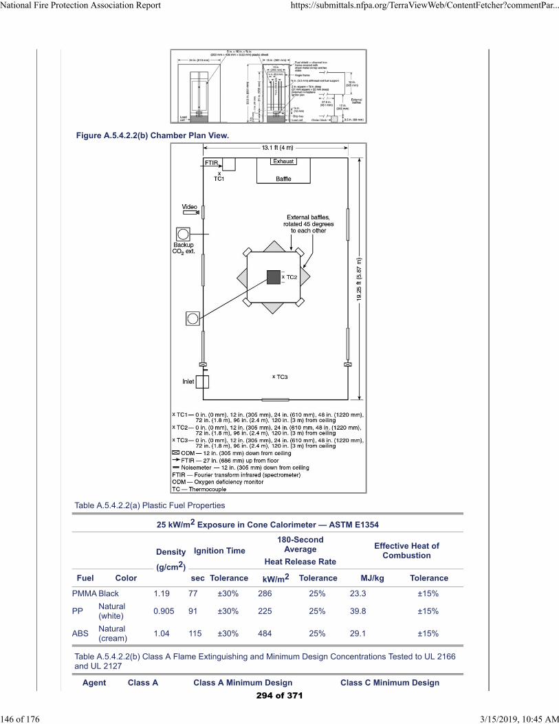
Figure A.5.4.2.2(b) Chamber Plan View.
Table A.5.4.2.2(a) Plastic Fuel Properties
25 kW/m2 Exposure in Cone Calorimeter — ASTM E1354
Density
(g/cm2)
Ignition Time180-Second
Average
Heat Release Rate
Effective Heat ofCombustion
Fuel Color sec Tolerance kW/m2 Tolerance MJ/kg Tolerance
PMMA Black 1.19 77 ±30% 286 25% 23.3 ±15%
PPNatural(white)
0.905 91 ±30% 225 25% 39.8 ±15%
ABSNatural(cream)
1.04 115 ±30% 484 25% 29.1 ±15%
Table A.5.4.2.2(b) Class A Flame Extinguishing and Minimum Design Concentrations Tested to UL 2166and UL 2127
Agent Class A Class A Minimum Design Class C Minimum Design
National Fire Protection Association Report https://submittals.nfpa.org/TerraViewWeb/ContentFetcher?commentPar...
146 of 176 3/15/2019, 10:45 AM
294 of 371
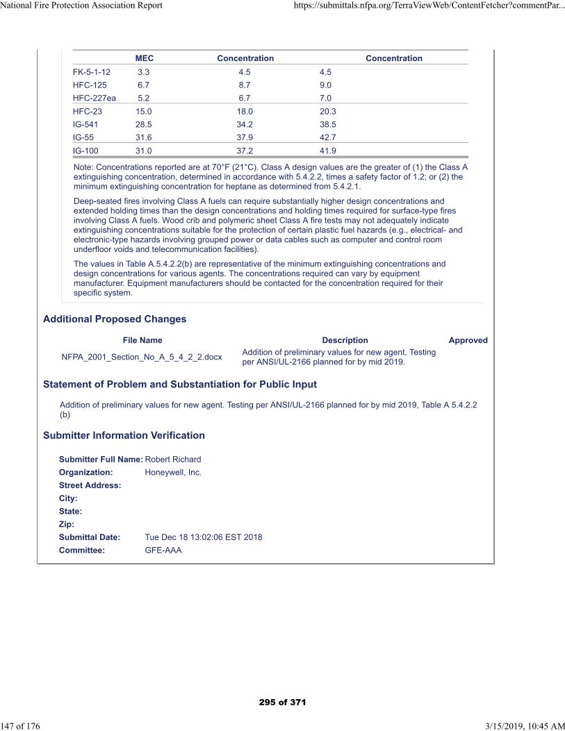
MEC Concentration Concentration
FK-5-1-12 3.3 4.5 4.5
HFC-125 6.7 8.7 9.0
HFC-227ea 5.2 6.7 7.0
HFC-23 15.0 18.0 20.3
IG-541 28.5 34.2 38.5
IG-55 31.6 37.9 42.7
IG-100 31.0 37.2 41.9
Note: Concentrations reported are at 70°F (21°C). Class A design values are the greater of (1) the Class Aextinguishing concentration, determined in accordance with 5.4.2.2, times a safety factor of 1.2; or (2) theminimum extinguishing concentration for heptane as determined from 5.4.2.1.
Deep-seated fires involving Class A fuels can require substantially higher design concentrations andextended holding times than the design concentrations and holding times required for surface-type firesinvolving Class A fuels. Wood crib and polymeric sheet Class A fire tests may not adequately indicateextinguishing concentrations suitable for the protection of certain plastic fuel hazards (e.g., electrical- andelectronic-type hazards involving grouped power or data cables such as computer and control roomunderfloor voids and telecommunication facilities).
The values in Table A.5.4.2.2(b) are representative of the minimum extinguishing concentrations anddesign concentrations for various agents. The concentrations required can vary by equipmentmanufacturer. Equipment manufacturers should be contacted for the concentration required for theirspecific system.
Additional Proposed Changes
File Name Description Approved
NFPA_2001_Section_No_A_5_4_2_2.docxAddition of preliminary values for new agent. Testing per ANSI/UL-2166 planned for by mid 2019.
Statement of Problem and Substantiation for Public Input
Addition of preliminary values for new agent. Testing per ANSI/UL-2166 planned for by mid 2019, Table A 5.4.2.2 (b)
Submitter Information Verification
Submitter Full Name: Robert Richard
Organization: Honeywell, Inc.
Street Address:
City:
State:
Zip:
Submittal Date: Tue Dec 18 13:02:06 EST 2018
Committee: GFE-AAA
National Fire Protection Association Report https://submittals.nfpa.org/TerraViewWeb/ContentFetcher?commentPar...
147 of 176 3/15/2019, 10:45 AM
295 of 371
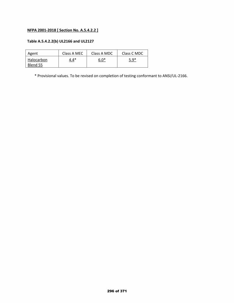
NFPA 2001-2018 [ Section No. A.5.4.2.2 ] Table A.5.4.2.2(b) UL2166 and UL2127 Agent Class A MEC Class A MDC Class C MDC Halocarbon Blend 55
4.4* 6.0* 5.9*
* Provisional values. To be revised on completion of testing conformant to ANSI/UL-2166.
296 of 371

Public Input No. 59-NFPA 2001-2018 [ Section No. A.5.5.1 ]
National Fire Protection Association Report https://submittals.nfpa.org/TerraViewWeb/ContentFetcher?commentPar...
148 of 176 3/15/2019, 10:45 AM
297 of 371

A.5.5.1
National Fire Protection Association Report https://submittals.nfpa.org/TerraViewWeb/ContentFetcher?commentPar...
149 of 176 3/15/2019, 10:45 AM
298 of 371
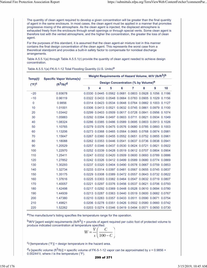
The quantity of clean agent required to develop a given concentration will be greater than the final quantityof agent in the same enclosure. In most cases, the clean agent must be applied in a manner that promotesprogressive mixing of the atmosphere. As the clean agent is injected, the displaced atmosphere isexhausted freely from the enclosure through small openings or through special vents. Some clean agent istherefore lost with the vented atmosphere, and the higher the concentration, the greater the loss of cleanagent.
For the purposes of this standard, it is assumed that the clean agent-air mixture lost in this mannercontains the final design concentration of the clean agent. This represents the worst case from atheoretical standpoint and provides a built-in safety factor to compensate for nonideal dischargearrangements.
Table A.5.5.1(a) through Table A.5.5.1(r) provide the quantity of clean agent needed to achieve designconcentration.
Table A.5.5.1(a) FK-5-1-12 Total Flooding Quantity (U.S. Units)a
Temp(t)
(°F)c
Specific Vapor Volume(s)
(ft3/lb)d
Weight Requirements of Hazard Volume, W/V (lb/ft3)b
Design Concentration (% by Volume)e
3 4 5 6 7 8 9 10
−20 0.93678 0.0330 0.0445 0.0562 0.0681 0.0803 0.0928 0.1056 0.1186
−10 0.96119 0.0322 0.0433 0.0548 0.0664 0.0783 0.0905 0.1029 0.1156
0 0.9856 0.0314 0.0423 0.0534 0.0648 0.0764 0.0882 0.1003 0.1127
10 1.01001 0.0306 0.0413 0.0521 0.0632 0.0745 0.0861 0.0979 0.1100
20 1.03442 0.0299 0.0403 0.0509 0.0617 0.0728 0.0841 0.0956 0.1074
30 1.05883 0.0292 0.0394 0.0497 0.0603 0.0711 0.0821 0.0934 0.1049
40 1.08324 0.0286 0.0385 0.0486 0.0589 0.0695 0.0803 0.0913 0.1026
50 1.10765 0.0279 0.0376 0.0475 0.0576 0.0680 0.0785 0.0893 0.1003
60 1.13206 0.0273 0.0368 0.0465 0.0564 0.0665 0.0768 0.0874 0.0981
70 1.15647 0.0267 0.0360 0.0455 0.0552 0.0651 0.0752 0.0855 0.0961
80 1.18088 0.0262 0.0353 0.0446 0.0541 0.0637 0.0736 0.0838 0.0941
90 1.20529 0.0257 0.0346 0.0437 0.0530 0.0624 0.0721 0.0821 0.0922
100 1.22970 0.0252 0.0339 0.0428 0.0519 0.0612 0.0707 0.0804 0.0904
110 1.25411 0.0247 0.0332 0.0420 0.0509 0.0600 0.0693 0.0789 0.0886
120 1.27852 0.0242 0.0326 0.0412 0.0499 0.0589 0.0680 0.0774 0.0869
130 1.30293 0.0237 0.0320 0.0404 0.0490 0.0578 0.0667 0.0759 0.0853
140 1.32734 0.0233 0.0314 0.0397 0.0481 0.0567 0.0655 0.0745 0.0837
150 1.35175 0.0229 0.0308 0.0389 0.0472 0.0557 0.0643 0.0732 0.0822
160 1.37616 0.0225 0.0303 0.0382 0.0464 0.0547 0.0632 0.0719 0.0807
170 1.40057 0.0221 0.0297 0.0376 0.0456 0.0537 0.0621 0.0706 0.0793
180 1.42498 0.0217 0.0292 0.0369 0.0448 0.0528 0.0610 0.0694 0.0780
190 1.44939 0.0213 0.0287 0.0363 0.0440 0.0519 0.0600 0.0682 0.0767
200 1.47380 0.0210 0.0283 0.0357 0.0433 0.0511 0.0590 0.0671 0.0754
210 1.49821 0.0206 0.0278 0.0351 0.0426 0.0502 0.0580 0.0660 0.0742
220 1.52262 0.0203 0.0274 0.0346 0.0419 0.0494 0.0571 0.0650 0.0730
aThe manufacturer's listing specifies the temperature range for the operation.
bW/V [agent weight requirements (lb/ft3)] = pounds of agent required per cubic foot of protected volume toproduce indicated concentration at temperature specified.
ct [temperature (°F)] = design temperature in the hazard area.
ds [specific volume (ft3/lb)] = specific volume of FK-5-1-12 vapor can be approximated by s = 0.9856 +0.002441t, where t is the temperature (°F).
National Fire Protection Association Report https://submittals.nfpa.org/TerraViewWeb/ContentFetcher?commentPar...
150 of 176 3/15/2019, 10:45 AM
299 of 371
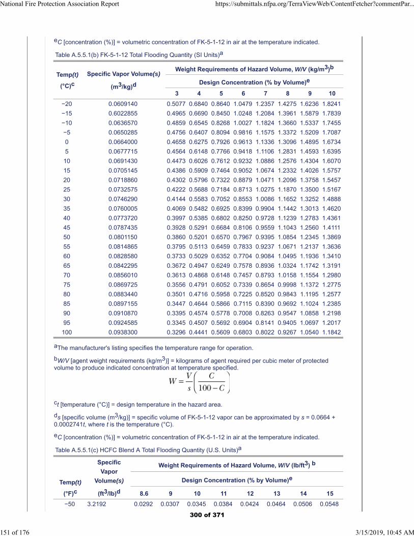
eC [concentration (%)] = volumetric concentration of FK-5-1-12 in air at the temperature indicated.
Table A.5.5.1(b) FK-5-1-12 Total Flooding Quantity (SI Units)a
Temp(t)
(°C)c
Specific Vapor Volume(s)
(m3/kg)d
Weight Requirements of Hazard Volume, W/V (kg/m3)b
Design Concentration (% by Volume)e
3 4 5 6 7 8 9 10
−20 0.0609140 0.5077 0.6840 0.8640 1.0479 1.2357 1.4275 1.6236 1.8241
−15 0.6022855 0.4965 0.6690 0.8450 1.0248 1.2084 1.3961 1.5879 1.7839
−10 0.0636570 0.4859 0.6545 0.8268 1.0027 1.1824 1.3660 1.5337 1.7455
−5 0.0650285 0.4756 0.6407 0.8094 0.9816 1.1575 1.3372 1.5209 1.7087
0 0.0664000 0.4658 0.6275 0.7926 0.9613 1.1336 1.3096 1.4895 1.6734
5 0.0677715 0.4564 0.6148 0.7766 0.9418 1.1106 1.2831 1.4593 1.6395
10 0.0691430 0.4473 0.6026 0.7612 0.9232 1.0886 1.2576 1.4304 1.6070
15 0.0705145 0.4386 0.5909 0.7464 0.9052 1.0674 1.2332 1.4026 1.5757
20 0.0718860 0.4302 0.5796 0.7322 0.8879 1.0471 1.2096 1.3758 1.5457
25 0.0732575 0.4222 0.5688 0.7184 0.8713 1.0275 1.1870 1.3500 1.5167
30 0.0746290 0.4144 0.5583 0.7052 0.8553 1.0086 1.1652 1.3252 1.4888
35 0.0760005 0.4069 0.5482 0.6925 0.8399 0.9904 1.1442 1.3013 1.4620
40 0.0773720 0.3997 0.5385 0.6802 0.8250 0.9728 1.1239 1.2783 1.4361
45 0.0787435 0.3928 0.5291 0.6684 0.8106 0.9559 1.1043 1.2560 1.4111
50 0.0801150 0.3860 0.5201 0.6570 0.7967 0.9395 1.0854 1.2345 1.3869
55 0.0814865 0.3795 0.5113 0.6459 0.7833 0.9237 1.0671 1.2137 1.3636
60 0.0828580 0.3733 0.5029 0.6352 0.7704 0.9084 1.0495 1.1936 1.3410
65 0.0842295 0.3672 0.4947 0.6249 0.7578 0.8936 1.0324 1.1742 1.3191
70 0.0856010 0.3613 0.4868 0.6148 0.7457 0.8793 1.0158 1.1554 1.2980
75 0.0869725 0.3556 0.4791 0.6052 0.7339 0.8654 0.9998 1.1372 1.2775
80 0.0883440 0.3501 0.4716 0.5958 0.7225 0.8520 0.9843 1.1195 1.2577
85 0.0897155 0.3447 0.4644 0.5866 0.7115 0.8390 0.9692 1.1024 1.2385
90 0.0910870 0.3395 0.4574 0.5778 0.7008 0.8263 0.9547 1.0858 1.2198
95 0.0924585 0.3345 0.4507 0.5692 0.6904 0.8141 0.9405 1.0697 1.2017
100 0.0938300 0.3296 0.4441 0.5609 0.6803 0.8022 0.9267 1.0540 1.1842
aThe manufacturer's listing specifies the temperature range for operation.
bW/V [agent weight requirements (kg/m3)] = kilograms of agent required per cubic meter of protectedvolume to produce indicated concentration at temperature specified.
ct [temperature (°C)] = design temperature in the hazard area.
ds [specific volume (m3/kg)] = specific volume of FK-5-1-12 vapor can be approximated by s = 0.0664 +0.0002741t, where t is the temperature (°C).
eC [concentration (%)] = volumetric concentration of FK-5-1-12 in air at the temperature indicated.
Table A.5.5.1(c) HCFC Blend A Total Flooding Quantity (U.S. Units)a
Temp(t)
(°F)c
Specific
Vapor
Volume(s)
(ft3/lb)d
Weight Requirements of Hazard Volume, W/V (lb/ft3) b
Design Concentration (% by Volume)e
8.6 9 10 11 12 13 14 15
−50 3.2192 0.0292 0.0307 0.0345 0.0384 0.0424 0.0464 0.0506 0.0548
National Fire Protection Association Report https://submittals.nfpa.org/TerraViewWeb/ContentFetcher?commentPar...
151 of 176 3/15/2019, 10:45 AM
300 of 371
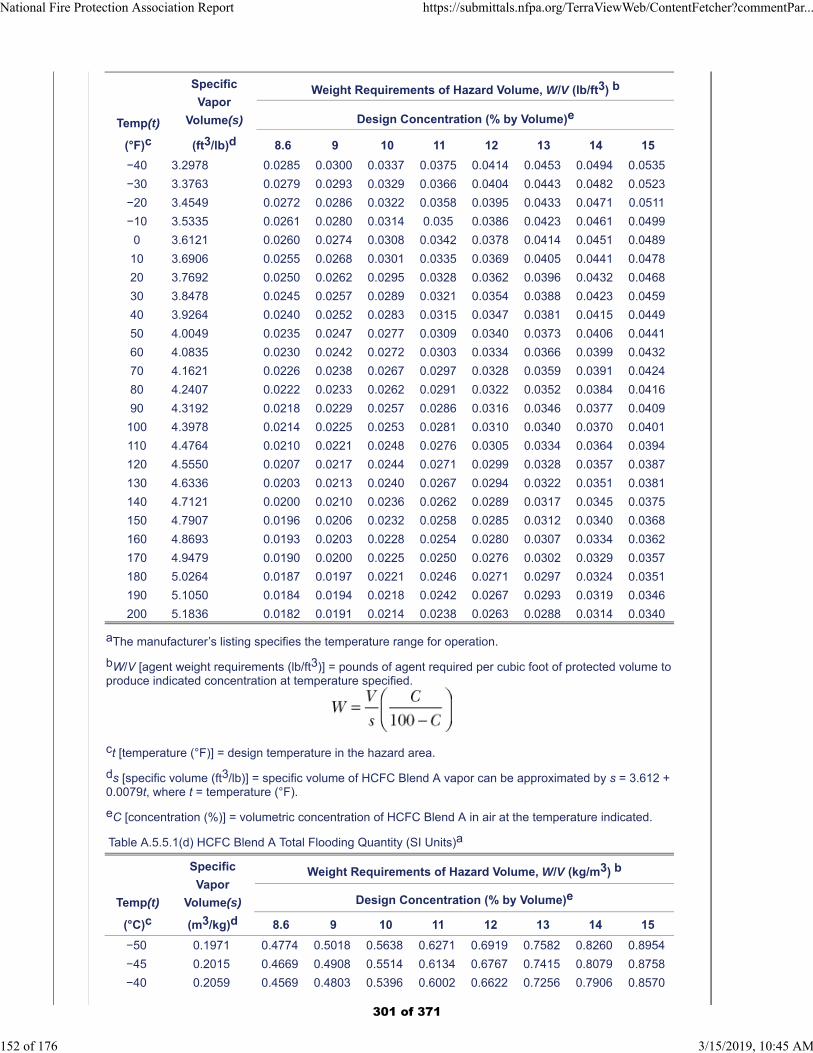
Temp(t)
(°F)c
Specific
Vapor
Volume(s)
(ft3/lb)d
Weight Requirements of Hazard Volume, W/V (lb/ft3) b
Design Concentration (% by Volume)e
8.6 9 10 11 12 13 14 15
−40 3.2978 0.0285 0.0300 0.0337 0.0375 0.0414 0.0453 0.0494 0.0535
−30 3.3763 0.0279 0.0293 0.0329 0.0366 0.0404 0.0443 0.0482 0.0523
−20 3.4549 0.0272 0.0286 0.0322 0.0358 0.0395 0.0433 0.0471 0.0511
−10 3.5335 0.0261 0.0280 0.0314 0.035 0.0386 0.0423 0.0461 0.0499
0 3.6121 0.0260 0.0274 0.0308 0.0342 0.0378 0.0414 0.0451 0.0489
10 3.6906 0.0255 0.0268 0.0301 0.0335 0.0369 0.0405 0.0441 0.0478
20 3.7692 0.0250 0.0262 0.0295 0.0328 0.0362 0.0396 0.0432 0.0468
30 3.8478 0.0245 0.0257 0.0289 0.0321 0.0354 0.0388 0.0423 0.0459
40 3.9264 0.0240 0.0252 0.0283 0.0315 0.0347 0.0381 0.0415 0.0449
50 4.0049 0.0235 0.0247 0.0277 0.0309 0.0340 0.0373 0.0406 0.0441
60 4.0835 0.0230 0.0242 0.0272 0.0303 0.0334 0.0366 0.0399 0.0432
70 4.1621 0.0226 0.0238 0.0267 0.0297 0.0328 0.0359 0.0391 0.0424
80 4.2407 0.0222 0.0233 0.0262 0.0291 0.0322 0.0352 0.0384 0.0416
90 4.3192 0.0218 0.0229 0.0257 0.0286 0.0316 0.0346 0.0377 0.0409
100 4.3978 0.0214 0.0225 0.0253 0.0281 0.0310 0.0340 0.0370 0.0401
110 4.4764 0.0210 0.0221 0.0248 0.0276 0.0305 0.0334 0.0364 0.0394
120 4.5550 0.0207 0.0217 0.0244 0.0271 0.0299 0.0328 0.0357 0.0387
130 4.6336 0.0203 0.0213 0.0240 0.0267 0.0294 0.0322 0.0351 0.0381
140 4.7121 0.0200 0.0210 0.0236 0.0262 0.0289 0.0317 0.0345 0.0375
150 4.7907 0.0196 0.0206 0.0232 0.0258 0.0285 0.0312 0.0340 0.0368
160 4.8693 0.0193 0.0203 0.0228 0.0254 0.0280 0.0307 0.0334 0.0362
170 4.9479 0.0190 0.0200 0.0225 0.0250 0.0276 0.0302 0.0329 0.0357
180 5.0264 0.0187 0.0197 0.0221 0.0246 0.0271 0.0297 0.0324 0.0351
190 5.1050 0.0184 0.0194 0.0218 0.0242 0.0267 0.0293 0.0319 0.0346
200 5.1836 0.0182 0.0191 0.0214 0.0238 0.0263 0.0288 0.0314 0.0340
aThe manufacturer’s listing specifies the temperature range for operation.
bW/V [agent weight requirements (lb/ft3)] = pounds of agent required per cubic foot of protected volume toproduce indicated concentration at temperature specified.
ct [temperature (°F)] = design temperature in the hazard area.
ds [specific volume (ft3/lb)] = specific volume of HCFC Blend A vapor can be approximated by s = 3.612 +0.0079t, where t = temperature (°F).
eC [concentration (%)] = volumetric concentration of HCFC Blend A in air at the temperature indicated.
Table A.5.5.1(d) HCFC Blend A Total Flooding Quantity (SI Units)a
Temp(t)
(°C)c
Specific
Vapor
Volume(s)
(m3/kg)d
Weight Requirements of Hazard Volume, W/V (kg/m3) b
Design Concentration (% by Volume)e
8.6 9 10 11 12 13 14 15
−50 0.1971 0.4774 0.5018 0.5638 0.6271 0.6919 0.7582 0.8260 0.8954
−45 0.2015 0.4669 0.4908 0.5514 0.6134 0.6767 0.7415 0.8079 0.8758
−40 0.2059 0.4569 0.4803 0.5396 0.6002 0.6622 0.7256 0.7906 0.8570
National Fire Protection Association Report https://submittals.nfpa.org/TerraViewWeb/ContentFetcher?commentPar...
152 of 176 3/15/2019, 10:45 AM
301 of 371
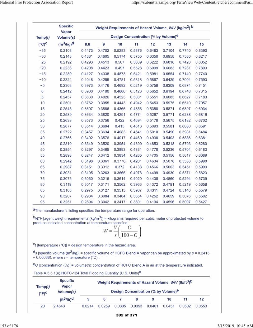
Temp(t)
(°C)c
Specific
Vapor
Volume(s)
(m3/kg)d
Weight Requirements of Hazard Volume, W/V (kg/m3) b
Design Concentration (% by Volume)e
8.6 9 10 11 12 13 14 15
−35 0.2103 0.4473 0.4702 0.5283 0.5876 0.6483 0.7104 0.7740 0.8390
−30 0.2148 0.4381 0.4605 0.5174 0.5755 0.6350 0.6958 0.7580 0.8217
−25 0.2192 0.4293 0.4513 0.507 0.5639 0.6222 0.6818 0.7428 0.8052
−20 0.2236 0.4208 0.4423 0.497 0.5528 0.6099 0.6683 0.7281 0.7893
−15 0.2280 0.4127 0.4338 0.4873 0.5421 0.5981 0.6554 0.7140 0.7740
−10 0.2324 0.4048 0.4255 0.4781 0.5318 0.5867 0.6429 0.7004 0.7593
−5 0.2368 0.3973 0.4176 0.4692 0.5219 0.5758 0.6309 0.6874 0.7451
0 0.2412 0.3900 0.4100 0.4606 0.5123 0.5652 0.6194 0.6748 0.7315
5 0.2457 0.3830 0.4026 0.4523 0.5031 0.5551 0.6083 0.6627 0.7183
10 0.2501 0.3762 0.3955 0.4443 0.4942 0.5453 0.5975 0.6510 0.7057
15 0.2545 0.3697 0.3886 0.4366 0.4856 0.5358 0.5871 0.6397 0.6934
20 0.2589 0.3634 0.3820 0.4291 0.4774 0.5267 0.5771 0.6288 0.6816
25 0.2633 0.3573 0.3756 0.422 0.4694 0.5178 0.5675 0.6182 0.6702
30 0.2677 0.3514 0.3694 0.415 0.4616 0.5093 0.5581 0.6080 0.6591
35 0.2722 0.3457 0.3634 0.4083 0.4541 0.5010 0.5490 0.5981 0.6484
40 0.2766 0.3402 0.3576 0.4017 0.4469 0.4930 0.5403 0.5886 0.6381
45 0.2810 0.3349 0.3520 0.3954 0.4399 0.4853 0.5318 0.5793 0.6280
50 0.2854 0.3297 0.3465 0.3893 0.4331 0.4778 0.5236 0.5704 0.6183
55 0.2898 0.3247 0.3412 0.3834 0.4265 0.4705 0.5156 0.5617 0.6089
60 0.2942 0.3198 0.3361 0.3776 0.4201 0.4634 0.5078 0.5533 0.5998
65 0.2987 0.3151 0.3312 0.372 0.4138 0.4566 0.5003 0.5451 0.5909
70 0.3031 0.3105 0.3263 0.3666 0.4078 0.4499 0.4930 0.5371 0.5823
75 0.3075 0.3060 0.3216 0.3614 0.4020 0.4435 0.4860 0.5294 0.5739
80 0.3119 0.3017 0.3171 0.3562 0.3963 0.4372 0.4791 0.5219 0.5658
85 0.3163 0.2975 0.3127 0.3513 0.3907 0.4311 0.4724 0.5146 0.5579
90 0.3207 0.2934 0.3084 0.3464 0.3854 0.4252 0.4659 0.5076 0.5502
95 0.3251 0.2894 0.3042 0.3417 0.3801 0.4194 0.4596 0.5007 0.5427
aThe manufacturer’s listing specifies the temperature range for operation.
bW/V [agent weight requirements (kg/m3)] = kilograms required per cubic meter of protected volume toproduce indicated concentration at temperature specified.
ct [temperature (°C)] = design temperature in the hazard area.
ds [specific volume (m3/kg)] = specific volume of HCFC Blend A vapor can be approximated by s = 0.2413+ 0.00088t, where t = temperature (°C).
eC [concentration (%)] = volumetric concentration of HCFC Blend A in air at the temperature indicated.
Table A.5.5.1(e) HCFC-124 Total Flooding Quantity (U.S. Units)a
Temp(t)
(°F)c
Specific
Vapor
Volume(s)
(ft3/lb)d
Weight Requirements of Hazard Volume, W/V (lb/ft3)b
Design Concentration (% by Volume)e
5 6 7 8 9 10 11 12
20 2.4643 0.0214 0.0259 0.0305 0.0353 0.0401 0.0451 0.0502 0.0553
National Fire Protection Association Report https://submittals.nfpa.org/TerraViewWeb/ContentFetcher?commentPar...
153 of 176 3/15/2019, 10:45 AM
302 of 371
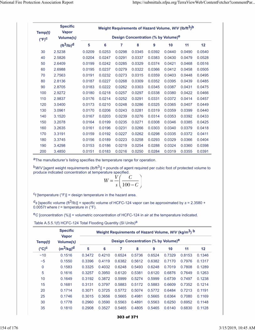
Temp(t)
(°F)c
Specific
Vapor
Volume(s)
(ft3/lb)d
Weight Requirements of Hazard Volume, W/V (lb/ft3)b
Design Concentration (% by Volume)e
5 6 7 8 9 10 11 12
30 2.5238 0.0209 0.0253 0.0298 0.0345 0.0392 0.0440 0.0490 0.0540
40 2.5826 0.0204 0.0247 0.0291 0.0337 0.0383 0.0430 0.0479 0.0528
50 2.6409 0.0199 0.0242 0.0285 0.0329 0.0374 0.0421 0.0468 0.0516
60 2.6988 0.0195 0.0237 0.0279 0.0322 0.0366 0.0412 0.0458 0.0505
70 2.7563 0.0191 0.0232 0.0273 0.0315 0.0359 0.0403 0.0448 0.0495
80 2.8136 0.0187 0.0227 0.0268 0.0309 0.0352 0.0395 0.0439 0.0485
90 2.8705 0.0183 0.0222 0.0262 0.0303 0.0345 0.0387 0.0431 0.0475
100 2.9272 0.0180 0.0218 0.0257 0.0297 0.0338 0.0380 0.0422 0.0466
110 2.9837 0.0176 0.0214 0.0252 0.0291 0.0331 0.0372 0.0414 0.0457
120 3.0400 0.0173 0.0210 0.0248 0.0286 0.0325 0.0365 0.0407 0.0449
130 3.0961 0.0170 0.0206 0.0243 0.0281 0.0319 0.0359 0.0399 0.0440
140 3.1520 0.0167 0.0203 0.0239 0.0276 0.0314 0.0353 0.0392 0.0433
150 3.2078 0.0164 0.0199 0.0235 0.0271 0.0308 0.0346 0.0385 0.0425
160 3.2635 0.0161 0.0196 0.0231 0.0266 0.0303 0.0340 0.0379 0.0418
170 3.3191 0.0159 0.0192 0.0227 0.0262 0.0298 0.0335 0.0372 0.0411
180 3.3745 0.0156 0.0189 0.0223 0.0258 0.0293 0.0329 0.0366 0.0404
190 3.4298 0.0153 0.0186 0.0219 0.0254 0.0288 0.0324 0.0360 0.0398
200 3.4850 0.0151 0.0183 0.0216 0.0250 0.0284 0.0319 0.0355 0.0391
aThe manufacturer’s listing specifies the temperature range for operation.
bW/V [agent weight requirements (lb/ft3)] = pounds of agent required per cubic foot of protected volume toproduce indicated concentration at temperature specified.
ct [temperature (°F)] = design temperature in the hazard area.
ds [specific volume (ft3/lb)] = specific volume of HCFC-124 vapor can be approximated by s = 2.3580 +0.0057t where t = temperature in (°F).
eC [concentration (%)] = volumetric concentration of HCFC-124 in air at the temperature indicated.
Table A.5.5.1(f) HCFC-124 Total Flooding Quantity (SI Units)a
Temp(t)
(°C)c
Specific
Vapor
Volume(s)
(m3/kg)d
Weight Requirements of Hazard Volume, W/V (kg/m3) b
Design Concentration (% by Volume)e
5 6 7 8 9 10 11 12
−10 0.1516 0.3472 0.4210 0.6524 0.5736 0.6524 0.7329 0.8153 0.1346
−5 0.1550 0.3396 0.4119 0.6382 0.5612 0.6382 0.7170 0.7976 0.1317
0 0.1583 0.3325 0.4032 0.6248 0.5493 0.6248 0.7019 0.7808 0.1289
5 0.1616 0.3257 0.3950 0.6120 0.5381 0.6120 0.6876 0.7649 0.1263
10 0.1649 0.3192 0.3872 0.5999 0.5274 0.5999 0.6739 0.7497 0.1238
15 0.1681 0.3131 0.3797 0.5883 0.5172 0.5883 0.6609 0.7352 0.1214
20 0.1714 0.3071 0.3725 0.5772 0.5074 0.5772 0.6484 0.7213 0.1191
25 0.1746 0.3015 0.3656 0.5665 0.4981 0.5665 0.6364 0.7080 0.1169
30 0.1778 0.2960 0.3590 0.5563 0.4891 0.5563 0.6250 0.6952 0.1148
35 0.1810 0.2908 0.3527 0.5465 0.4805 0.5465 0.6140 0.6830 0.1128
National Fire Protection Association Report https://submittals.nfpa.org/TerraViewWeb/ContentFetcher?commentPar...
154 of 176 3/15/2019, 10:45 AM
303 of 371
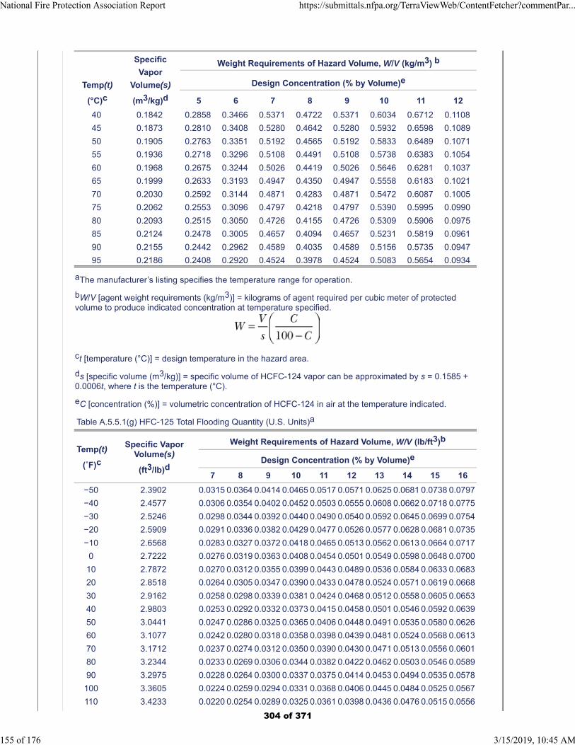
Temp(t)
(°C)c
Specific
Vapor
Volume(s)
(m3/kg)d
Weight Requirements of Hazard Volume, W/V (kg/m3) b
Design Concentration (% by Volume)e
5 6 7 8 9 10 11 12
40 0.1842 0.2858 0.3466 0.5371 0.4722 0.5371 0.6034 0.6712 0.1108
45 0.1873 0.2810 0.3408 0.5280 0.4642 0.5280 0.5932 0.6598 0.1089
50 0.1905 0.2763 0.3351 0.5192 0.4565 0.5192 0.5833 0.6489 0.1071
55 0.1936 0.2718 0.3296 0.5108 0.4491 0.5108 0.5738 0.6383 0.1054
60 0.1968 0.2675 0.3244 0.5026 0.4419 0.5026 0.5646 0.6281 0.1037
65 0.1999 0.2633 0.3193 0.4947 0.4350 0.4947 0.5558 0.6183 0.1021
70 0.2030 0.2592 0.3144 0.4871 0.4283 0.4871 0.5472 0.6087 0.1005
75 0.2062 0.2553 0.3096 0.4797 0.4218 0.4797 0.5390 0.5995 0.0990
80 0.2093 0.2515 0.3050 0.4726 0.4155 0.4726 0.5309 0.5906 0.0975
85 0.2124 0.2478 0.3005 0.4657 0.4094 0.4657 0.5231 0.5819 0.0961
90 0.2155 0.2442 0.2962 0.4589 0.4035 0.4589 0.5156 0.5735 0.0947
95 0.2186 0.2408 0.2920 0.4524 0.3978 0.4524 0.5083 0.5654 0.0934
aThe manufacturer’s listing specifies the temperature range for operation.
bW/V [agent weight requirements (kg/m3)] = kilograms of agent required per cubic meter of protectedvolume to produce indicated concentration at temperature specified.
ct [temperature (°C)] = design temperature in the hazard area.
ds [specific volume (m3/kg)] = specific volume of HCFC-124 vapor can be approximated by s = 0.1585 +0.0006t, where t is the temperature (°C).
eC [concentration (%)] = volumetric concentration of HCFC-124 in air at the temperature indicated.
Table A.5.5.1(g) HFC-125 Total Flooding Quantity (U.S. Units)a
Temp(t)
(˚F)c
Specific VaporVolume(s)
(ft3/lb)d
Weight Requirements of Hazard Volume, W/V (lb/ft3)b
Design Concentration (% by Volume)e
7 8 9 10 11 12 13 14 15 16
−50 2.3902 0.0315 0.0364 0.0414 0.0465 0.0517 0.0571 0.0625 0.0681 0.0738 0.0797
−40 2.4577 0.0306 0.0354 0.0402 0.0452 0.0503 0.0555 0.0608 0.0662 0.0718 0.0775
−30 2.5246 0.0298 0.0344 0.0392 0.0440 0.0490 0.0540 0.0592 0.0645 0.0699 0.0754
−20 2.5909 0.0291 0.0336 0.0382 0.0429 0.0477 0.0526 0.0577 0.0628 0.0681 0.0735
−10 2.6568 0.0283 0.0327 0.0372 0.0418 0.0465 0.0513 0.0562 0.0613 0.0664 0.0717
0 2.7222 0.0276 0.0319 0.0363 0.0408 0.0454 0.0501 0.0549 0.0598 0.0648 0.0700
10 2.7872 0.0270 0.0312 0.0355 0.0399 0.0443 0.0489 0.0536 0.0584 0.0633 0.0683
20 2.8518 0.0264 0.0305 0.0347 0.0390 0.0433 0.0478 0.0524 0.0571 0.0619 0.0668
30 2.9162 0.0258 0.0298 0.0339 0.0381 0.0424 0.0468 0.0512 0.0558 0.0605 0.0653
40 2.9803 0.0253 0.0292 0.0332 0.0373 0.0415 0.0458 0.0501 0.0546 0.0592 0.0639
50 3.0441 0.0247 0.0286 0.0325 0.0365 0.0406 0.0448 0.0491 0.0535 0.0580 0.0626
60 3.1077 0.0242 0.0280 0.0318 0.0358 0.0398 0.0439 0.0481 0.0524 0.0568 0.0613
70 3.1712 0.0237 0.0274 0.0312 0.0350 0.0390 0.0430 0.0471 0.0513 0.0556 0.0601
80 3.2344 0.0233 0.0269 0.0306 0.0344 0.0382 0.0422 0.0462 0.0503 0.0546 0.0589
90 3.2975 0.0228 0.0264 0.0300 0.0337 0.0375 0.0414 0.0453 0.0494 0.0535 0.0578
100 3.3605 0.0224 0.0259 0.0294 0.0331 0.0368 0.0406 0.0445 0.0484 0.0525 0.0567
110 3.4233 0.0220 0.0254 0.0289 0.0325 0.0361 0.0398 0.0436 0.0476 0.0515 0.0556
National Fire Protection Association Report https://submittals.nfpa.org/TerraViewWeb/ContentFetcher?commentPar...
155 of 176 3/15/2019, 10:45 AM
304 of 371
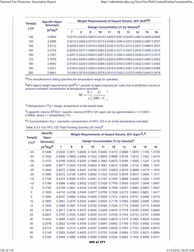
Temp(t)
(˚F)c
Specific VaporVolume(s)
(ft3/lb)d
Weight Requirements of Hazard Volume, W/V (lb/ft3)b
Design Concentration (% by Volume)e
7 8 9 10 11 12 13 14 15 16
120 3.4859 0.0216 0.0249 0.0284 0.0319 0.0355 0.0391 0.0429 0.0467 0.0506 0.0546
130 3.5485 0.0212 0.0245 0.0279 0.0313 0.0348 0.0384 0.0421 0.0459 0.0497 0.0537
140 3.6110 0.0208 0.0241 0.0274 0.0308 0.0342 0.0378 0.0414 0.0451 0.0489 0.0527
150 3.6734 0.0205 0.0237 0.0269 0.0302 0.0336 0.0371 0.0407 0.0443 0.0480 0.0519
160 3.7357 0.0201 0.0233 0.0265 0.0297 0.0331 0.0365 0.0400 0.0436 0.0472 0.0510
170 3.7979 0.0198 0.0229 0.0260 0.0293 0.0325 0.0359 0.0393 0.0429 0.0465 0.0502
180 3.8600 0.0195 0.0225 0.0256 0.0288 0.0320 0.0353 0.0387 0.0422 0.0457 0.0493
190 3.9221 0.0192 0.0222 0.0252 0.0283 0.0315 0.0348 0.0381 0.0415 0.0450 0.0486
200 3.9841 0.0189 0.0218 0.0248 0.0279 0.0310 0.0342 0.0375 0.0409 0.0443 0.0478
aThe manufacturer’s listing specifies the temperature range for operation.
bW/V [agent weight requirements (lb/ft3)] = pounds of agent required per cubic foot of protected volume toproduce indicated concentration at temperature specified.
ct [temperature (°F)] = design temperature in the hazard area.
ds [specific volume (ft3/lb)] = specific volume of HFC-125 vapor can be approximated s = 2.7208 +0.0064t, where t = temperature (°F).
eC [concentration (%)] = volumetric concentration of HFC-125 in air at the temperature indicated.
Table A.5.5.1(h) HFC-125 Total Flooding Quantity (SI Units)a
Temp(t)
(°C)c
Specific
Vapor
Volume(s)
(m3/kg)d
Weight Requirements of Hazard Volume, W/V (kg/m3) b
Design Concentration (% by Volume)e
7 8 9 10 11 12 13 14 15 16
−45 0.1496 0.5030 0.5811 0.6609 0.7425 0.8260 0.9113 0.9986 1.0879 1.1793 1.2729
−40 0.1534 0.4906 0.5668 0.6446 0.7242 0.8055 0.8888 0.9739 1.0610 1.1502 1.2415
−35 0.1572 0.4788 0.5532 0.6292 0.7069 0.7863 0.8675 0.9506 1.0356 1.1227 1.2118
−30 0.1609 0.4677 0.5404 0.6146 0.6905 0.7681 0.8474 0.9286 1.0116 1.0966 1.1837
−25 0.1646 0.4572 0.5282 0.6007 0.6749 0.7507 0.8283 0.9076 0.9888 1.0719 1.1570
−20 0.1683 0.4472 0.5166 0.5876 0.6602 0.7343 0.8102 0.8878 0.9672 1.0485 1.1317
−15 0.1720 0.4377 0.5056 0.5751 0.6461 0.7187 0.7930 0.8689 0.9466 1.0262 1.1076
−10 0.1756 0.4286 0.4952 0.5632 0.6327 0.7038 0.7765 0.8509 0.9270 1.0049 1.0847
−5 0.1792 0.4199 0.4851 0.5518 0.6199 0.6896 0.7608 0.8337 0.9082 0.9845 1.0627
0 0.1829 0.4116 0.4756 0.5409 0.6077 0.6759 0.7458 0.8172 0.8903 0.9651 1.0417
5 0.1865 0.4037 0.4664 0.5304 0.5959 0.6629 0.7314 0.8014 0.8731 0.9465 1.0216
10 0.1900 0.3961 0.4576 0.5204 0.5847 0.6504 0.7176 0.7863 0.8566 0.9286 1.0023
15 0.1936 0.3888 0.4491 0.5108 0.5739 0.6384 0.7043 0.7718 0.8408 0.9115 0.9838
20 0.1972 0.3817 0.4410 0.5016 0.5635 0.6268 0.6916 0.7578 0.8256 0.8950 0.9660
25 0.2007 0.3750 0.4332 0.4927 0.5535 0.6157 0.6793 0.7444 0.8110 0.8791 0.9489
30 0.2043 0.3685 0.4257 0.4841 0.5439 0.6050 0.6675 0.7315 0.7969 0.8639 0.9324
35 0.2078 0.3622 0.4184 0.4759 0.5347 0.5947 0.6562 0.7190 0.7833 0.8492 0.9165
40 0.2114 0.3561 0.4114 0.4679 0.5257 0.5848 0.6452 0.7070 0.7702 0.8349 0.9012
45 0.2149 0.3503 0.4047 0.4603 0.5171 0.5752 0.6346 0.6954 0.7576 0.8213 0.8864
50 0.2184 0.3446 0.3982 0.4528 0.5088 0.5659 0.6244 0.6842 0.7454 0.8080 0.8721
National Fire Protection Association Report https://submittals.nfpa.org/TerraViewWeb/ContentFetcher?commentPar...
156 of 176 3/15/2019, 10:45 AM
305 of 371
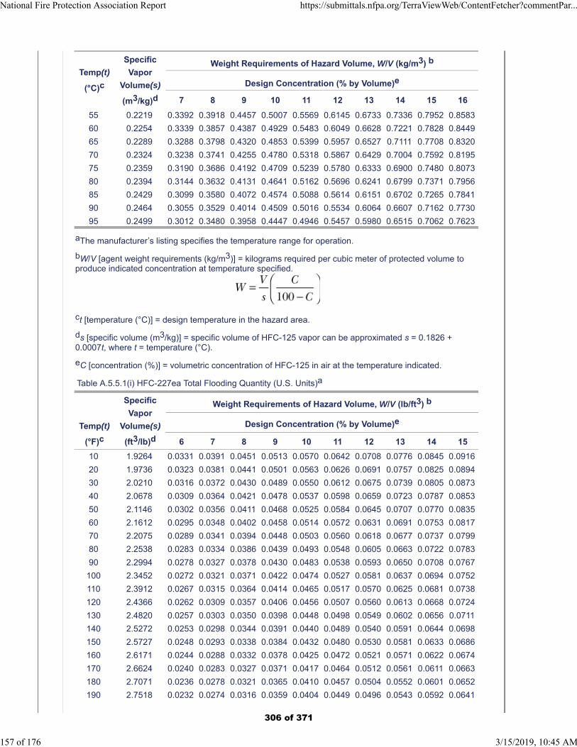
Temp(t)
(°C)c
Specific
Vapor
Volume(s)
(m3/kg)d
Weight Requirements of Hazard Volume, W/V (kg/m3) b
Design Concentration (% by Volume)e
7 8 9 10 11 12 13 14 15 16
55 0.2219 0.3392 0.3918 0.4457 0.5007 0.5569 0.6145 0.6733 0.7336 0.7952 0.8583
60 0.2254 0.3339 0.3857 0.4387 0.4929 0.5483 0.6049 0.6628 0.7221 0.7828 0.8449
65 0.2289 0.3288 0.3798 0.4320 0.4853 0.5399 0.5957 0.6527 0.7111 0.7708 0.8320
70 0.2324 0.3238 0.3741 0.4255 0.4780 0.5318 0.5867 0.6429 0.7004 0.7592 0.8195
75 0.2359 0.3190 0.3686 0.4192 0.4709 0.5239 0.5780 0.6333 0.6900 0.7480 0.8073
80 0.2394 0.3144 0.3632 0.4131 0.4641 0.5162 0.5696 0.6241 0.6799 0.7371 0.7956
85 0.2429 0.3099 0.3580 0.4072 0.4574 0.5088 0.5614 0.6151 0.6702 0.7265 0.7841
90 0.2464 0.3055 0.3529 0.4014 0.4509 0.5016 0.5534 0.6064 0.6607 0.7162 0.7730
95 0.2499 0.3012 0.3480 0.3958 0.4447 0.4946 0.5457 0.5980 0.6515 0.7062 0.7623
aThe manufacturer’s listing specifies the temperature range for operation.
bW/V [agent weight requirements (kg/m3)] = kilograms required per cubic meter of protected volume toproduce indicated concentration at temperature specified.
ct [temperature (°C)] = design temperature in the hazard area.
ds [specific volume (m3/kg)] = specific volume of HFC-125 vapor can be approximated s = 0.1826 +0.0007t, where t = temperature (°C).
eC [concentration (%)] = volumetric concentration of HFC-125 in air at the temperature indicated.
Table A.5.5.1(i) HFC-227ea Total Flooding Quantity (U.S. Units)a
Temp(t)
(°F)c
Specific
Vapor
Volume(s)
(ft3/lb)d
Weight Requirements of Hazard Volume, W/V (lb/ft3) b
Design Concentration (% by Volume)e
6 7 8 9 10 11 12 13 14 15
10 1.9264 0.0331 0.0391 0.0451 0.0513 0.0570 0.0642 0.0708 0.0776 0.0845 0.0916
20 1.9736 0.0323 0.0381 0.0441 0.0501 0.0563 0.0626 0.0691 0.0757 0.0825 0.0894
30 2.0210 0.0316 0.0372 0.0430 0.0489 0.0550 0.0612 0.0675 0.0739 0.0805 0.0873
40 2.0678 0.0309 0.0364 0.0421 0.0478 0.0537 0.0598 0.0659 0.0723 0.0787 0.0853
50 2.1146 0.0302 0.0356 0.0411 0.0468 0.0525 0.0584 0.0645 0.0707 0.0770 0.0835
60 2.1612 0.0295 0.0348 0.0402 0.0458 0.0514 0.0572 0.0631 0.0691 0.0753 0.0817
70 2.2075 0.0289 0.0341 0.0394 0.0448 0.0503 0.0560 0.0618 0.0677 0.0737 0.0799
80 2.2538 0.0283 0.0334 0.0386 0.0439 0.0493 0.0548 0.0605 0.0663 0.0722 0.0783
90 2.2994 0.0278 0.0327 0.0378 0.0430 0.0483 0.0538 0.0593 0.0650 0.0708 0.0767
100 2.3452 0.0272 0.0321 0.0371 0.0422 0.0474 0.0527 0.0581 0.0637 0.0694 0.0752
110 2.3912 0.0267 0.0315 0.0364 0.0414 0.0465 0.0517 0.0570 0.0625 0.0681 0.0738
120 2.4366 0.0262 0.0309 0.0357 0.0406 0.0456 0.0507 0.0560 0.0613 0.0668 0.0724
130 2.4820 0.0257 0.0303 0.0350 0.0398 0.0448 0.0498 0.0549 0.0602 0.0656 0.0711
140 2.5272 0.0253 0.0298 0.0344 0.0391 0.0440 0.0489 0.0540 0.0591 0.0644 0.0698
150 2.5727 0.0248 0.0293 0.0338 0.0384 0.0432 0.0480 0.0530 0.0581 0.0633 0.0686
160 2.6171 0.0244 0.0288 0.0332 0.0378 0.0425 0.0472 0.0521 0.0571 0.0622 0.0674
170 2.6624 0.0240 0.0283 0.0327 0.0371 0.0417 0.0464 0.0512 0.0561 0.0611 0.0663
180 2.7071 0.0236 0.0278 0.0321 0.0365 0.0410 0.0457 0.0504 0.0552 0.0601 0.0652
190 2.7518 0.0232 0.0274 0.0316 0.0359 0.0404 0.0449 0.0496 0.0543 0.0592 0.0641
National Fire Protection Association Report https://submittals.nfpa.org/TerraViewWeb/ContentFetcher?commentPar...
157 of 176 3/15/2019, 10:45 AM
306 of 371
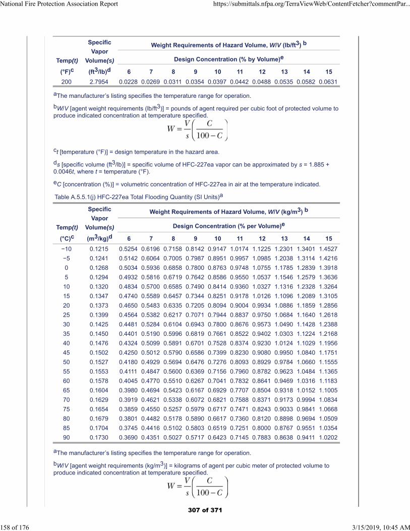
Temp(t)
(°F)c
Specific
Vapor
Volume(s)
(ft3/lb)d
Weight Requirements of Hazard Volume, W/V (lb/ft3) b
Design Concentration (% by Volume)e
6 7 8 9 10 11 12 13 14 15
200 2.7954 0.0228 0.0269 0.0311 0.0354 0.0397 0.0442 0.0488 0.0535 0.0582 0.0631
aThe manufacturer’s listing specifies the temperature range for operation.
bW/V [agent weight requirements (lb/ft3)] = pounds of agent required per cubic foot of protected volume toproduce indicated concentration at temperature specified.
ct [temperature (°F)] = design temperature in the hazard area.
ds [specific volume (ft3/lb)] = specific volume of HFC-227ea vapor can be approximated by s = 1.885 +0.0046t, where t = temperature (°F).
eC [concentration (%)] = volumetric concentration of HFC-227ea in air at the temperature indicated.
Table A.5.5.1(j) HFC-227ea Total Flooding Quantity (SI Units)a
Temp(t)
(°C)c
Specific
Vapor
Volume(s)
(m3/kg)d
Weight Requirements of Hazard Volume, W/V (kg/m3) b
Design Concentration (% per Volume)e
6 7 8 9 10 11 12 13 14 15
−10 0.1215 0.5254 0.6196 0.7158 0.8142 0.9147 1.0174 1.1225 1.2301 1.3401 1.4527
−5 0.1241 0.5142 0.6064 0.7005 0.7987 0.8951 0.9957 1.0985 1.2038 1.3114 1.4216
0 0.1268 0.5034 0.5936 0.6858 0.7800 0.8763 0.9748 1.0755 1.1785 1.2839 1.3918
5 0.1294 0.4932 0.5816 0.6719 0.7642 0.8586 0.9550 1.0537 1.1546 1.2579 1.3636
10 0.1320 0.4834 0.5700 0.6585 0.7490 0.8414 0.9360 1.0327 1.1316 1.2328 1.3264
15 0.1347 0.4740 0.5589 0.6457 0.7344 0.8251 0.9178 1.0126 1.1096 1.2089 1.3105
20 0.1373 0.4650 0.5483 0.6335 0.7205 0.8094 0.9004 0.9934 1.0886 1.1859 1.2856
25 0.1399 0.4564 0.5382 0.6217 0.7071 0.7944 0.8837 0.9750 1.0684 1.1640 1.2618
30 0.1425 0.4481 0.5284 0.6104 0.6943 0.7800 0.8676 0.9573 1.0490 1.1428 1.2388
35 0.1450 0.4401 0.5190 0.5996 0.6819 0.7661 0.8522 0.9402 1.0303 1.1224 1.2168
40 0.1476 0.4324 0.5099 0.5891 0.6701 0.7528 0.8374 0.9230 1.0124 1.1029 1.1956
45 0.1502 0.4250 0.5012 0.5790 0.6586 0.7399 0.8230 0.9080 0.9950 1.0840 1.1751
50 0.1527 0.4180 0.4929 0.5694 0.6476 0.7276 0.8093 0.8929 0.9784 1.0660 1.1555
55 0.1553 0.4111 0.4847 0.5600 0.6369 0.7156 0.7960 0.8782 0.9623 1.0484 1.1365
60 0.1578 0.4045 0.4770 0.5510 0.6267 0.7041 0.7832 0.8641 0.9469 1.0316 1.1183
65 0.1604 0.3980 0.4694 0.5423 0.6167 0.6929 0.7707 0.8504 0.9318 1.0152 1.1005
70 0.1629 0.3919 0.4621 0.5338 0.6072 0.6821 0.7588 0.8371 0.9173 0.9994 1.0834
75 0.1654 0.3859 0.4550 0.5257 0.5979 0.6717 0.7471 0.8243 0.9033 0.9841 1.0668
80 0.1679 0.3801 0.4482 0.5178 0.5890 0.6617 0.7360 0.8120 0.8898 0.9694 1.0509
85 0.1704 0.3745 0.4416 0.5102 0.5803 0.6519 0.7251 0.8000 0.8767 0.9551 1.0354
90 0.1730 0.3690 0.4351 0.5027 0.5717 0.6423 0.7145 0.7883 0.8638 0.9411 1.0202
aThe manufacturer’s listing specifies the temperature range for operation.
bW/V [agent weight requirements (kg/m3)] = kilograms of agent per cubic meter of protected volume toproduce indicated concentration at temperature specified.
National Fire Protection Association Report https://submittals.nfpa.org/TerraViewWeb/ContentFetcher?commentPar...
158 of 176 3/15/2019, 10:45 AM
307 of 371
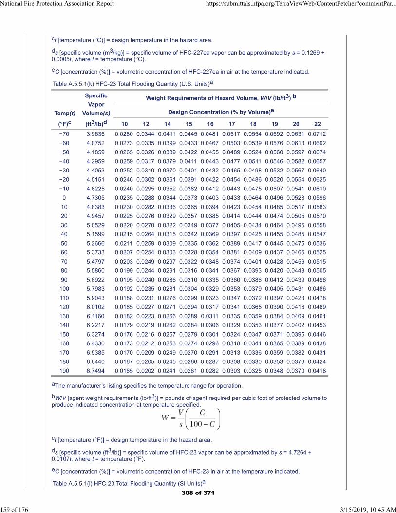
ct [temperature (°C)] = design temperature in the hazard area.
ds [specific volume (m3/kg)] = specific volume of HFC-227ea vapor can be approximated by s = 0.1269 +0.0005t, where t = temperature (°C).
eC [concentration (%)] = volumetric concentration of HFC-227ea in air at the temperature indicated.
Table A.5.5.1(k) HFC-23 Total Flooding Quantity (U.S. Units)a
Temp(t)
(°F)c
Specific
Vapor
Volume(s)
(ft3/lb)d
Weight Requirements of Hazard Volume, W/V (lb/ft3) b
Design Concentration (% by Volume)e
10 12 14 15 16 17 18 19 20 22
−70 3.9636 0.0280 0.0344 0.0411 0.0445 0.0481 0.0517 0.0554 0.0592 0.0631 0.0712
−60 4.0752 0.0273 0.0335 0.0399 0.0433 0.0467 0.0503 0.0539 0.0576 0.0613 0.0692
−50 4.1859 0.0265 0.0326 0.0389 0.0422 0.0455 0.0489 0.0524 0.0560 0.0597 0.0674
−40 4.2959 0.0259 0.0317 0.0379 0.0411 0.0443 0.0477 0.0511 0.0546 0.0582 0.0657
−30 4.4053 0.0252 0.0310 0.0370 0.0401 0.0432 0.0465 0.0498 0.0532 0.0567 0.0640
−20 4.5151 0.0246 0.0302 0.0361 0.0391 0.0422 0.0454 0.0486 0.0520 0.0554 0.0625
−10 4.6225 0.0240 0.0295 0.0352 0.0382 0.0412 0.0443 0.0475 0.0507 0.0541 0.0610
0 4.7305 0.0235 0.0288 0.0344 0.0373 0.0403 0.0433 0.0464 0.0496 0.0528 0.0596
10 4.8383 0.0230 0.0282 0.0336 0.0365 0.0394 0.0423 0.0454 0.0485 0.0517 0.0583
20 4.9457 0.0225 0.0276 0.0329 0.0357 0.0385 0.0414 0.0444 0.0474 0.0505 0.0570
30 5.0529 0.0220 0.0270 0.0322 0.0349 0.0377 0.0405 0.0434 0.0464 0.0495 0.0558
40 5.1599 0.0215 0.0264 0.0315 0.0342 0.0369 0.0397 0.0425 0.0455 0.0485 0.0547
50 5.2666 0.0211 0.0259 0.0309 0.0335 0.0362 0.0389 0.0417 0.0445 0.0475 0.0536
60 5.3733 0.0207 0.0254 0.0303 0.0328 0.0354 0.0381 0.0409 0.0437 0.0465 0.0525
70 5.4797 0.0203 0.0249 0.0297 0.0322 0.0348 0.0374 0.0401 0.0428 0.0456 0.0515
80 5.5860 0.0199 0.0244 0.0291 0.0316 0.0341 0.0367 0.0393 0.0420 0.0448 0.0505
90 5.6922 0.0195 0.0240 0.0286 0.0310 0.0335 0.0360 0.0386 0.0412 0.0439 0.0496
100 5.7983 0.0192 0.0235 0.0281 0.0304 0.0329 0.0353 0.0379 0.0405 0.0431 0.0486
110 5.9043 0.0188 0.0231 0.0276 0.0299 0.0323 0.0347 0.0372 0.0397 0.0423 0.0478
120 6.0102 0.0185 0.0227 0.0271 0.0294 0.0317 0.0341 0.0365 0.0390 0.0416 0.0469
130 6.1160 0.0182 0.0223 0.0266 0.0289 0.0311 0.0335 0.0359 0.0384 0.0409 0.0461
140 6.2217 0.0179 0.0219 0.0262 0.0284 0.0306 0.0329 0.0353 0.0377 0.0402 0.0453
150 6.3274 0.0176 0.0216 0.0257 0.0279 0.0301 0.0324 0.0347 0.0371 0.0395 0.0446
160 6.4330 0.0173 0.0212 0.0253 0.0274 0.0296 0.0318 0.0341 0.0365 0.0389 0.0438
170 6.5385 0.0170 0.0209 0.0249 0.0270 0.0291 0.0313 0.0336 0.0359 0.0382 0.0431
180 6.6440 0.0167 0.0205 0.0245 0.0266 0.0287 0.0308 0.0330 0.0353 0.0376 0.0424
190 6.7494 0.0165 0.0202 0.0241 0.0261 0.0282 0.0303 0.0325 0.0348 0.0370 0.0418
aThe manufacturer’s listing specifies the temperature range for operation.
bW/V [agent weight requirements (lb/ft3)] = pounds of agent required per cubic foot of protected volume toproduce indicated concentration at temperature specified.
ct [temperature (°F)] = design temperature in the hazard area.
ds [specific volume (ft3/lb)] = specific volume of HFC-23 vapor can be approximated by s = 4.7264 +0.0107t, where t = temperature (°F).
eC [concentration (%)] = volumetric concentration of HFC-23 in air at the temperature indicated.
Table A.5.5.1(l) HFC-23 Total Flooding Quantity (SI Units)a
National Fire Protection Association Report https://submittals.nfpa.org/TerraViewWeb/ContentFetcher?commentPar...
159 of 176 3/15/2019, 10:45 AM
308 of 371
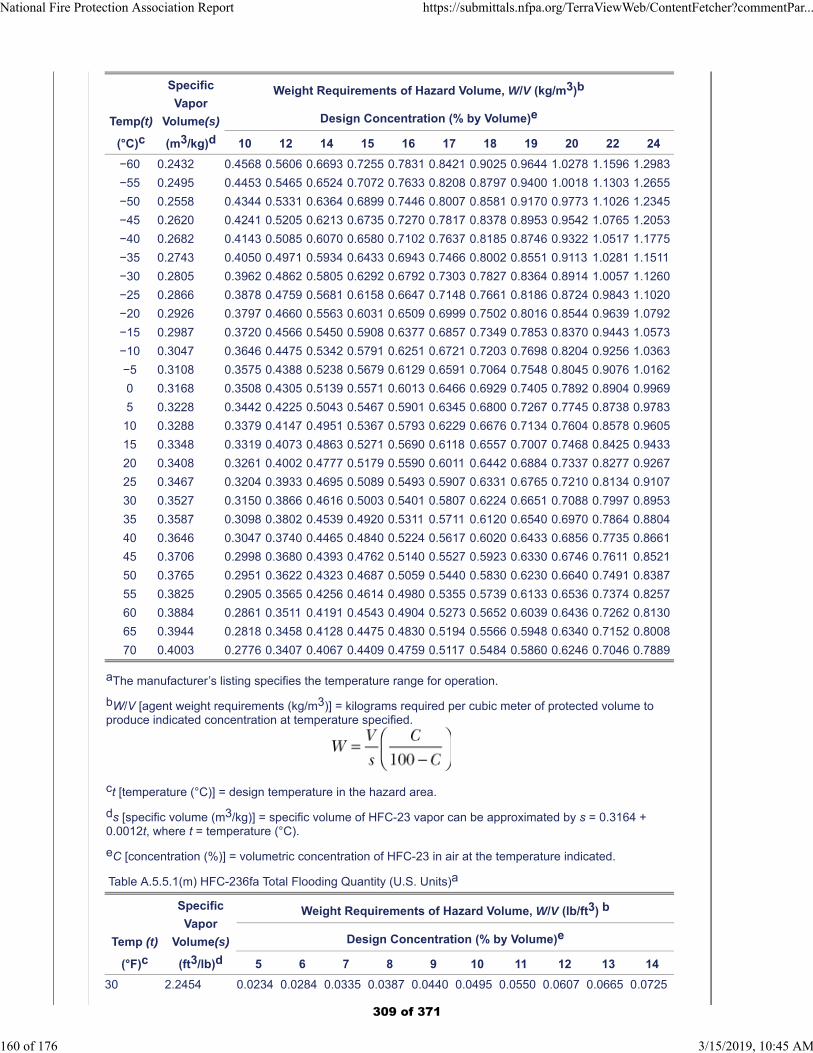
Temp(t)
(°C)c
Specific
Vapor
Volume(s)
(m3/kg)d
Weight Requirements of Hazard Volume, W/V (kg/m3)b
Design Concentration (% by Volume)e
10 12 14 15 16 17 18 19 20 22 24
−60 0.2432 0.4568 0.5606 0.6693 0.7255 0.7831 0.8421 0.9025 0.9644 1.0278 1.1596 1.2983
−55 0.2495 0.4453 0.5465 0.6524 0.7072 0.7633 0.8208 0.8797 0.9400 1.0018 1.1303 1.2655
−50 0.2558 0.4344 0.5331 0.6364 0.6899 0.7446 0.8007 0.8581 0.9170 0.9773 1.1026 1.2345
−45 0.2620 0.4241 0.5205 0.6213 0.6735 0.7270 0.7817 0.8378 0.8953 0.9542 1.0765 1.2053
−40 0.2682 0.4143 0.5085 0.6070 0.6580 0.7102 0.7637 0.8185 0.8746 0.9322 1.0517 1.1775
−35 0.2743 0.4050 0.4971 0.5934 0.6433 0.6943 0.7466 0.8002 0.8551 0.9113 1.0281 1.1511
−30 0.2805 0.3962 0.4862 0.5805 0.6292 0.6792 0.7303 0.7827 0.8364 0.8914 1.0057 1.1260
−25 0.2866 0.3878 0.4759 0.5681 0.6158 0.6647 0.7148 0.7661 0.8186 0.8724 0.9843 1.1020
−20 0.2926 0.3797 0.4660 0.5563 0.6031 0.6509 0.6999 0.7502 0.8016 0.8544 0.9639 1.0792
−15 0.2987 0.3720 0.4566 0.5450 0.5908 0.6377 0.6857 0.7349 0.7853 0.8370 0.9443 1.0573
−10 0.3047 0.3646 0.4475 0.5342 0.5791 0.6251 0.6721 0.7203 0.7698 0.8204 0.9256 1.0363
−5 0.3108 0.3575 0.4388 0.5238 0.5679 0.6129 0.6591 0.7064 0.7548 0.8045 0.9076 1.0162
0 0.3168 0.3508 0.4305 0.5139 0.5571 0.6013 0.6466 0.6929 0.7405 0.7892 0.8904 0.9969
5 0.3228 0.3442 0.4225 0.5043 0.5467 0.5901 0.6345 0.6800 0.7267 0.7745 0.8738 0.9783
10 0.3288 0.3379 0.4147 0.4951 0.5367 0.5793 0.6229 0.6676 0.7134 0.7604 0.8578 0.9605
15 0.3348 0.3319 0.4073 0.4863 0.5271 0.5690 0.6118 0.6557 0.7007 0.7468 0.8425 0.9433
20 0.3408 0.3261 0.4002 0.4777 0.5179 0.5590 0.6011 0.6442 0.6884 0.7337 0.8277 0.9267
25 0.3467 0.3204 0.3933 0.4695 0.5089 0.5493 0.5907 0.6331 0.6765 0.7210 0.8134 0.9107
30 0.3527 0.3150 0.3866 0.4616 0.5003 0.5401 0.5807 0.6224 0.6651 0.7088 0.7997 0.8953
35 0.3587 0.3098 0.3802 0.4539 0.4920 0.5311 0.5711 0.6120 0.6540 0.6970 0.7864 0.8804
40 0.3646 0.3047 0.3740 0.4465 0.4840 0.5224 0.5617 0.6020 0.6433 0.6856 0.7735 0.8661
45 0.3706 0.2998 0.3680 0.4393 0.4762 0.5140 0.5527 0.5923 0.6330 0.6746 0.7611 0.8521
50 0.3765 0.2951 0.3622 0.4323 0.4687 0.5059 0.5440 0.5830 0.6230 0.6640 0.7491 0.8387
55 0.3825 0.2905 0.3565 0.4256 0.4614 0.4980 0.5355 0.5739 0.6133 0.6536 0.7374 0.8257
60 0.3884 0.2861 0.3511 0.4191 0.4543 0.4904 0.5273 0.5652 0.6039 0.6436 0.7262 0.8130
65 0.3944 0.2818 0.3458 0.4128 0.4475 0.4830 0.5194 0.5566 0.5948 0.6340 0.7152 0.8008
70 0.4003 0.2776 0.3407 0.4067 0.4409 0.4759 0.5117 0.5484 0.5860 0.6246 0.7046 0.7889
aThe manufacturer’s listing specifies the temperature range for operation.
bW/V [agent weight requirements (kg/m3)] = kilograms required per cubic meter of protected volume toproduce indicated concentration at temperature specified.
ct [temperature (°C)] = design temperature in the hazard area.
ds [specific volume (m3/kg)] = specific volume of HFC-23 vapor can be approximated by s = 0.3164 +0.0012t, where t = temperature (°C).
eC [concentration (%)] = volumetric concentration of HFC-23 in air at the temperature indicated.
Table A.5.5.1(m) HFC-236fa Total Flooding Quantity (U.S. Units)a
Temp (t)
(°F)c
Specific
Vapor
Volume(s)
(ft3/lb)d
Weight Requirements of Hazard Volume, W/V (lb/ft3) b
Design Concentration (% by Volume)e
5 6 7 8 9 10 11 12 13 14
30 2.2454 0.0234 0.0284 0.0335 0.0387 0.0440 0.0495 0.0550 0.0607 0.0665 0.0725
National Fire Protection Association Report https://submittals.nfpa.org/TerraViewWeb/ContentFetcher?commentPar...
160 of 176 3/15/2019, 10:45 AM
309 of 371
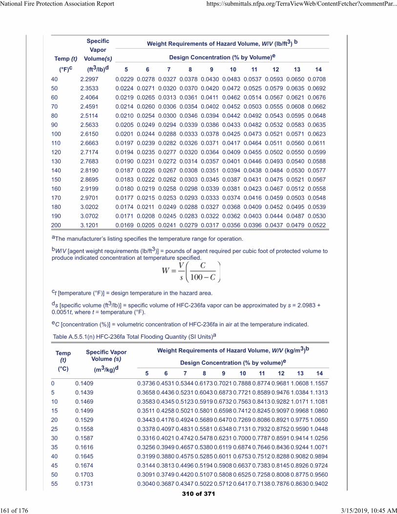
Temp (t)
(°F)c
Specific
Vapor
Volume(s)
(ft3/lb)d
Weight Requirements of Hazard Volume, W/V (lb/ft3) b
Design Concentration (% by Volume)e
5 6 7 8 9 10 11 12 13 14
40 2.2997 0.0229 0.0278 0.0327 0.0378 0.0430 0.0483 0.0537 0.0593 0.0650 0.0708
50 2.3533 0.0224 0.0271 0.0320 0.0370 0.0420 0.0472 0.0525 0.0579 0.0635 0.0692
60 2.4064 0.0219 0.0265 0.0313 0.0361 0.0411 0.0462 0.0514 0.0567 0.0621 0.0676
70 2.4591 0.0214 0.0260 0.0306 0.0354 0.0402 0.0452 0.0503 0.0555 0.0608 0.0662
80 2.5114 0.0210 0.0254 0.0300 0.0346 0.0394 0.0442 0.0492 0.0543 0.0595 0.0648
90 2.5633 0.0205 0.0249 0.0294 0.0339 0.0386 0.0433 0.0482 0.0532 0.0583 0.0635
100 2.6150 0.0201 0.0244 0.0288 0.0333 0.0378 0.0425 0.0473 0.0521 0.0571 0.0623
110 2.6663 0.0197 0.0239 0.0282 0.0326 0.0371 0.0417 0.0464 0.0511 0.0560 0.0611
120 2.7174 0.0194 0.0235 0.0277 0.0320 0.0364 0.0409 0.0455 0.0502 0.0550 0.0599
130 2.7683 0.0190 0.0231 0.0272 0.0314 0.0357 0.0401 0.0446 0.0493 0.0540 0.0588
140 2.8190 0.0187 0.0226 0.0267 0.0308 0.0351 0.0394 0.0438 0.0484 0.0530 0.0577
150 2.8695 0.0183 0.0222 0.0262 0.0303 0.0345 0.0387 0.0431 0.0475 0.0521 0.0567
160 2.9199 0.0180 0.0219 0.0258 0.0298 0.0339 0.0381 0.0423 0.0467 0.0512 0.0558
170 2.9701 0.0177 0.0215 0.0253 0.0293 0.0333 0.0374 0.0416 0.0459 0.0503 0.0548
180 3.0202 0.0174 0.0211 0.0249 0.0288 0.0327 0.0368 0.0409 0.0452 0.0495 0.0539
190 3.0702 0.0171 0.0208 0.0245 0.0283 0.0322 0.0362 0.0403 0.0444 0.0487 0.0530
200 3.1201 0.0169 0.0205 0.0241 0.0279 0.0317 0.0356 0.0396 0.0437 0.0479 0.0522
aThe manufacturer’s listing specifies the temperature range for operation.
bW/V [agent weight requirements (lb/ft3)] = pounds of agent required per cubic foot of protected volume toproduce indicated concentration at temperature specified.
ct [temperature (°F)] = design temperature in the hazard area.
ds [specific volume (ft3/lb)] = specific volume of HFC-236fa vapor can be approximated by s = 2.0983 +0.0051t, where t = temperature (°F).
eC [concentration (%)] = volumetric concentration of HFC-236fa in air at the temperature indicated.
Table A.5.5.1(n) HFC-236fa Total Flooding Quantity (SI Units)a
Temp(t)
(°C)
Specific VaporVolume (s)
(m3/kg)d
Weight Requirements of Hazard Volume, W/V (kg/m3)b
Design Concentration (% by volume)e
5 6 7 8 9 10 11 12 13 14
0 0.1409 0.3736 0.4531 0.5344 0.6173 0.7021 0.7888 0.8774 0.9681 1.0608 1.1557
5 0.1439 0.3658 0.4436 0.5231 0.6043 0.6873 0.7721 0.8589 0.9476 1.0384 1.1313
10 0.1469 0.3583 0.4345 0.5123 0.5919 0.6732 0.7563 0.8413 0.9282 1.0171 1.1081
15 0.1499 0.3511 0.4258 0.5021 0.5801 0.6598 0.7412 0.8245 0.9097 0.9968 1.0860
20 0.1529 0.3443 0.4176 0.4924 0.5689 0.6470 0.7269 0.8086 0.8921 0.9775 1.0650
25 0.1558 0.3378 0.4097 0.4831 0.5581 0.6348 0.7131 0.7932 0.8752 0.9590 1.0448
30 0.1587 0.3316 0.4021 0.4742 0.5478 0.6231 0.7000 0.7787 0.8591 0.9414 1.0256
35 0.1616 0.3256 0.3949 0.4657 0.5380 0.6119 0.6874 0.7646 0.8436 0.9244 1.0071
40 0.1645 0.3199 0.3880 0.4575 0.5285 0.6011 0.6753 0.7512 0.8288 0.9082 0.9894
45 0.1674 0.3144 0.3813 0.4496 0.5194 0.5908 0.6637 0.7383 0.8145 0.8926 0.9724
50 0.1703 0.3091 0.3749 0.4420 0.5107 0.5808 0.6525 0.7258 0.8008 0.8775 0.9560
55 0.1731 0.3040 0.3687 0.4347 0.5022 0.5712 0.6417 0.7138 0.7876 0.8630 0.9402
National Fire Protection Association Report https://submittals.nfpa.org/TerraViewWeb/ContentFetcher?commentPar...
161 of 176 3/15/2019, 10:45 AM
310 of 371
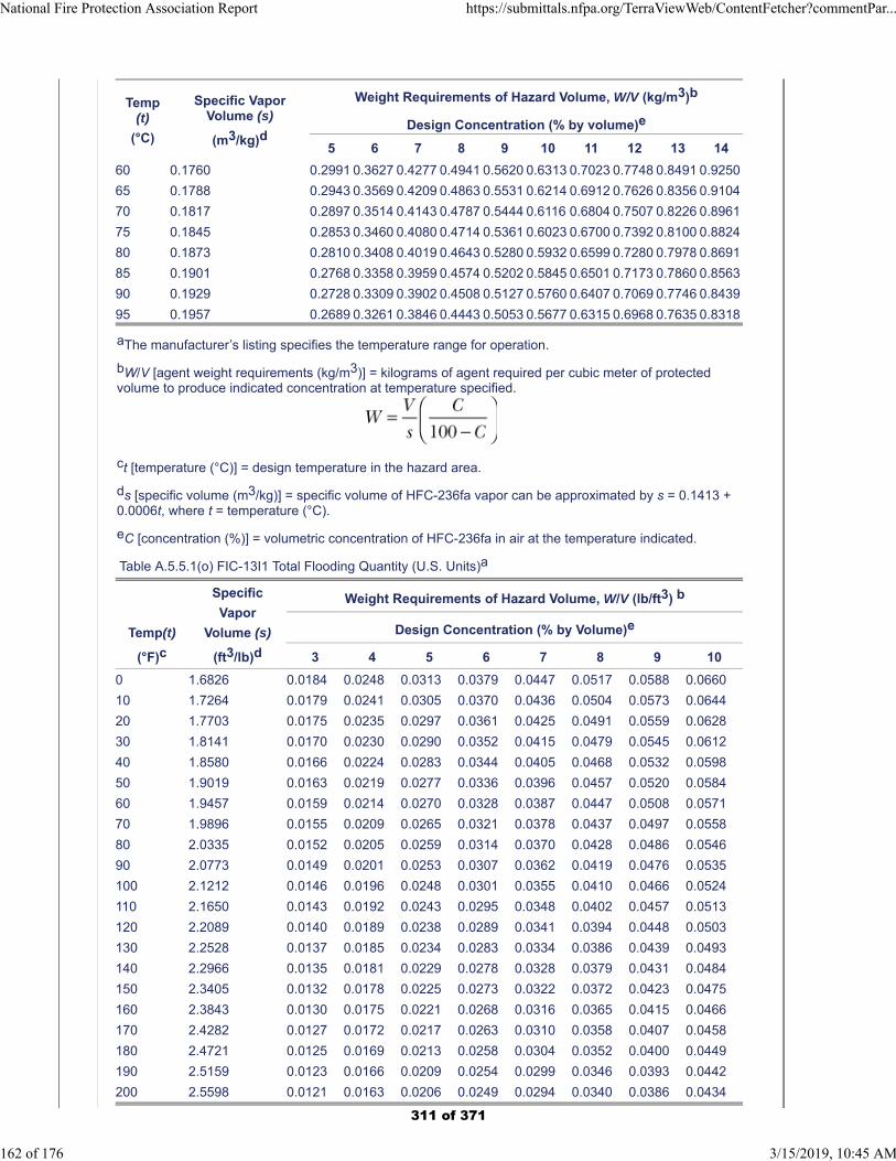
Temp(t)
(°C)
Specific VaporVolume (s)
(m3/kg)d
Weight Requirements of Hazard Volume, W/V (kg/m3)b
Design Concentration (% by volume)e
5 6 7 8 9 10 11 12 13 14
60 0.1760 0.2991 0.3627 0.4277 0.4941 0.5620 0.6313 0.7023 0.7748 0.8491 0.9250
65 0.1788 0.2943 0.3569 0.4209 0.4863 0.5531 0.6214 0.6912 0.7626 0.8356 0.9104
70 0.1817 0.2897 0.3514 0.4143 0.4787 0.5444 0.6116 0.6804 0.7507 0.8226 0.8961
75 0.1845 0.2853 0.3460 0.4080 0.4714 0.5361 0.6023 0.6700 0.7392 0.8100 0.8824
80 0.1873 0.2810 0.3408 0.4019 0.4643 0.5280 0.5932 0.6599 0.7280 0.7978 0.8691
85 0.1901 0.2768 0.3358 0.3959 0.4574 0.5202 0.5845 0.6501 0.7173 0.7860 0.8563
90 0.1929 0.2728 0.3309 0.3902 0.4508 0.5127 0.5760 0.6407 0.7069 0.7746 0.8439
95 0.1957 0.2689 0.3261 0.3846 0.4443 0.5053 0.5677 0.6315 0.6968 0.7635 0.8318
aThe manufacturer’s listing specifies the temperature range for operation.
bW/V [agent weight requirements (kg/m3)] = kilograms of agent required per cubic meter of protectedvolume to produce indicated concentration at temperature specified.
ct [temperature (°C)] = design temperature in the hazard area.
ds [specific volume (m3/kg)] = specific volume of HFC-236fa vapor can be approximated by s = 0.1413 +0.0006t, where t = temperature (°C).
eC [concentration (%)] = volumetric concentration of HFC-236fa in air at the temperature indicated.
Table A.5.5.1(o) FIC-13I1 Total Flooding Quantity (U.S. Units)a
Temp(t)
(°F)c
Specific
Vapor
Volume (s)
(ft3/lb)d
Weight Requirements of Hazard Volume, W/V (lb/ft3) b
Design Concentration (% by Volume)e
3 4 5 6 7 8 9 10
0 1.6826 0.0184 0.0248 0.0313 0.0379 0.0447 0.0517 0.0588 0.0660
10 1.7264 0.0179 0.0241 0.0305 0.0370 0.0436 0.0504 0.0573 0.0644
20 1.7703 0.0175 0.0235 0.0297 0.0361 0.0425 0.0491 0.0559 0.0628
30 1.8141 0.0170 0.0230 0.0290 0.0352 0.0415 0.0479 0.0545 0.0612
40 1.8580 0.0166 0.0224 0.0283 0.0344 0.0405 0.0468 0.0532 0.0598
50 1.9019 0.0163 0.0219 0.0277 0.0336 0.0396 0.0457 0.0520 0.0584
60 1.9457 0.0159 0.0214 0.0270 0.0328 0.0387 0.0447 0.0508 0.0571
70 1.9896 0.0155 0.0209 0.0265 0.0321 0.0378 0.0437 0.0497 0.0558
80 2.0335 0.0152 0.0205 0.0259 0.0314 0.0370 0.0428 0.0486 0.0546
90 2.0773 0.0149 0.0201 0.0253 0.0307 0.0362 0.0419 0.0476 0.0535
100 2.1212 0.0146 0.0196 0.0248 0.0301 0.0355 0.0410 0.0466 0.0524
110 2.1650 0.0143 0.0192 0.0243 0.0295 0.0348 0.0402 0.0457 0.0513
120 2.2089 0.0140 0.0189 0.0238 0.0289 0.0341 0.0394 0.0448 0.0503
130 2.2528 0.0137 0.0185 0.0234 0.0283 0.0334 0.0386 0.0439 0.0493
140 2.2966 0.0135 0.0181 0.0229 0.0278 0.0328 0.0379 0.0431 0.0484
150 2.3405 0.0132 0.0178 0.0225 0.0273 0.0322 0.0372 0.0423 0.0475
160 2.3843 0.0130 0.0175 0.0221 0.0268 0.0316 0.0365 0.0415 0.0466
170 2.4282 0.0127 0.0172 0.0217 0.0263 0.0310 0.0358 0.0407 0.0458
180 2.4721 0.0125 0.0169 0.0213 0.0258 0.0304 0.0352 0.0400 0.0449
190 2.5159 0.0123 0.0166 0.0209 0.0254 0.0299 0.0346 0.0393 0.0442
200 2.5598 0.0121 0.0163 0.0206 0.0249 0.0294 0.0340 0.0386 0.0434
National Fire Protection Association Report https://submittals.nfpa.org/TerraViewWeb/ContentFetcher?commentPar...
162 of 176 3/15/2019, 10:45 AM
311 of 371
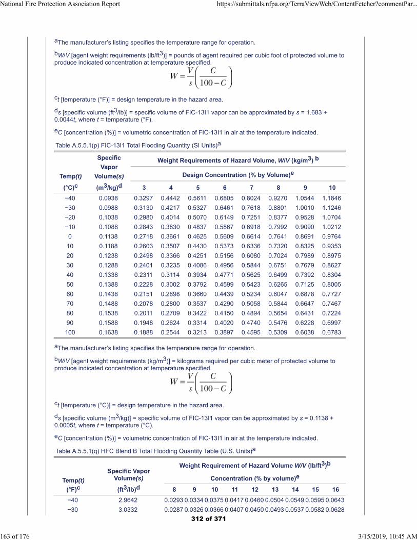
aThe manufacturer’s listing specifies the temperature range for operation.
bW/V [agent weight requirements (lb/ft3)] = pounds of agent required per cubic foot of protected volume toproduce indicated concentration at temperature specified.
ct [temperature (°F)] = design temperature in the hazard area.
ds [specific volume (ft3/lb)] = specific volume of FIC-13I1 vapor can be approximated by s = 1.683 +0.0044t, where t = temperature (°F).
eC [concentration (%)] = volumetric concentration of FIC-13I1 in air at the temperature indicated.
Table A.5.5.1(p) FIC-13I1 Total Flooding Quantity (SI Units)a
Temp(t)
(°C)c
Specific
Vapor
Volume(s)
(m3/kg)d
Weight Requirements of Hazard Volume, W/V (kg/m3) b
Design Concentration (% by Volume)e
3 4 5 6 7 8 9 10
−40 0.0938 0.3297 0.4442 0.5611 0.6805 0.8024 0.9270 1.0544 1.1846
−30 0.0988 0.3130 0.4217 0.5327 0.6461 0.7618 0.8801 1.0010 1.1246
−20 0.1038 0.2980 0.4014 0.5070 0.6149 0.7251 0.8377 0.9528 1.0704
−10 0.1088 0.2843 0.3830 0.4837 0.5867 0.6918 0.7992 0.9090 1.0212
0 0.1138 0.2718 0.3661 0.4625 0.5609 0.6614 0.7641 0.8691 0.9764
10 0.1188 0.2603 0.3507 0.4430 0.5373 0.6336 0.7320 0.8325 0.9353
20 0.1238 0.2498 0.3366 0.4251 0.5156 0.6080 0.7024 0.7989 0.8975
30 0.1288 0.2401 0.3235 0.4086 0.4956 0.5844 0.6751 0.7679 0.8627
40 0.1338 0.2311 0.3114 0.3934 0.4771 0.5625 0.6499 0.7392 0.8304
50 0.1388 0.2228 0.3002 0.3792 0.4599 0.5423 0.6265 0.7125 0.8005
60 0.1438 0.2151 0.2898 0.3660 0.4439 0.5234 0.6047 0.6878 0.7727
70 0.1488 0.2078 0.2800 0.3537 0.4290 0.5058 0.5844 0.6647 0.7467
80 0.1538 0.2011 0.2709 0.3422 0.4150 0.4894 0.5654 0.6431 0.7224
90 0.1588 0.1948 0.2624 0.3314 0.4020 0.4740 0.5476 0.6228 0.6997
100 0.1638 0.1888 0.2544 0.3213 0.3897 0.4595 0.5309 0.6038 0.6783
aThe manufacturer’s listing specifies the temperature range for operation.
bW/V [agent weight requirements (kg/m3)] = kilograms required per cubic meter of protected volume toproduce indicated concentration at temperature specified.
ct [temperature (°C)] = design temperature in the hazard area.
ds [specific volume (m3/kg)] = specific volume of FIC-13I1 vapor can be approximated by s = 0.1138 +0.0005t, where t = temperature (°C).
eC [concentration (%)] = volumetric concentration of FIC-13I1 in air at the temperature indicated.
Table A.5.5.1(q) HFC Blend B Total Flooding Quantity Table (U.S. Units)a
Temp(t)
(°F)c
Specific VaporVolume(s)
(ft3/lb)d
Weight Requirement of Hazard Volume W/V (lb/ft3)b
Concentration (% by volume)e
8 9 10 11 12 13 14 15 16
−40 2.9642 0.0293 0.0334 0.0375 0.0417 0.0460 0.0504 0.0549 0.0595 0.0643
−30 3.0332 0.0287 0.0326 0.0366 0.0407 0.0450 0.0493 0.0537 0.0582 0.0628
National Fire Protection Association Report https://submittals.nfpa.org/TerraViewWeb/ContentFetcher?commentPar...
163 of 176 3/15/2019, 10:45 AM
312 of 371
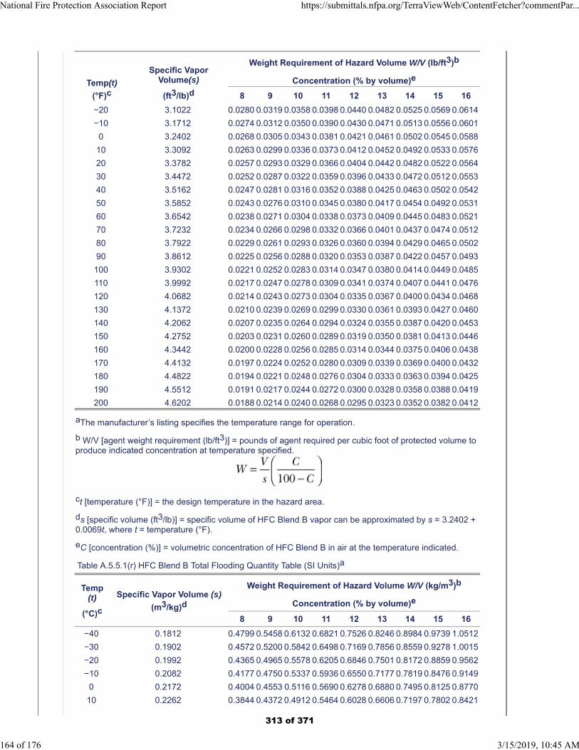
Temp(t)
(°F)c
Specific VaporVolume(s)
(ft3/lb)d
Weight Requirement of Hazard Volume W/V (lb/ft3)b
Concentration (% by volume)e
8 9 10 11 12 13 14 15 16
−20 3.1022 0.0280 0.0319 0.0358 0.0398 0.0440 0.0482 0.0525 0.0569 0.0614
−10 3.1712 0.0274 0.0312 0.0350 0.0390 0.0430 0.0471 0.0513 0.0556 0.0601
0 3.2402 0.0268 0.0305 0.0343 0.0381 0.0421 0.0461 0.0502 0.0545 0.0588
10 3.3092 0.0263 0.0299 0.0336 0.0373 0.0412 0.0452 0.0492 0.0533 0.0576
20 3.3782 0.0257 0.0293 0.0329 0.0366 0.0404 0.0442 0.0482 0.0522 0.0564
30 3.4472 0.0252 0.0287 0.0322 0.0359 0.0396 0.0433 0.0472 0.0512 0.0553
40 3.5162 0.0247 0.0281 0.0316 0.0352 0.0388 0.0425 0.0463 0.0502 0.0542
50 3.5852 0.0243 0.0276 0.0310 0.0345 0.0380 0.0417 0.0454 0.0492 0.0531
60 3.6542 0.0238 0.0271 0.0304 0.0338 0.0373 0.0409 0.0445 0.0483 0.0521
70 3.7232 0.0234 0.0266 0.0298 0.0332 0.0366 0.0401 0.0437 0.0474 0.0512
80 3.7922 0.0229 0.0261 0.0293 0.0326 0.0360 0.0394 0.0429 0.0465 0.0502
90 3.8612 0.0225 0.0256 0.0288 0.0320 0.0353 0.0387 0.0422 0.0457 0.0493
100 3.9302 0.0221 0.0252 0.0283 0.0314 0.0347 0.0380 0.0414 0.0449 0.0485
110 3.9992 0.0217 0.0247 0.0278 0.0309 0.0341 0.0374 0.0407 0.0441 0.0476
120 4.0682 0.0214 0.0243 0.0273 0.0304 0.0335 0.0367 0.0400 0.0434 0.0468
130 4.1372 0.0210 0.0239 0.0269 0.0299 0.0330 0.0361 0.0393 0.0427 0.0460
140 4.2062 0.0207 0.0235 0.0264 0.0294 0.0324 0.0355 0.0387 0.0420 0.0453
150 4.2752 0.0203 0.0231 0.0260 0.0289 0.0319 0.0350 0.0381 0.0413 0.0446
160 4.3442 0.0200 0.0228 0.0256 0.0285 0.0314 0.0344 0.0375 0.0406 0.0438
170 4.4132 0.0197 0.0224 0.0252 0.0280 0.0309 0.0339 0.0369 0.0400 0.0432
180 4.4822 0.0194 0.0221 0.0248 0.0276 0.0304 0.0333 0.0363 0.0394 0.0425
190 4.5512 0.0191 0.0217 0.0244 0.0272 0.0300 0.0328 0.0358 0.0388 0.0419
200 4.6202 0.0188 0.0214 0.0240 0.0268 0.0295 0.0323 0.0352 0.0382 0.0412
aThe manufacturer’s listing specifies the temperature range for operation.
b W/V [agent weight requirement (lb/ft3)] = pounds of agent required per cubic foot of protected volume toproduce indicated concentration at temperature specified.
ct [temperature (°F)] = the design temperature in the hazard area.
ds [specific volume (ft3/lb)] = specific volume of HFC Blend B vapor can be approximated by s = 3.2402 +0.0069t, where t = temperature (°F).
eC [concentration (%)] = volumetric concentration of HFC Blend B in air at the temperature indicated.
Table A.5.5.1(r) HFC Blend B Total Flooding Quantity Table (SI Units)a
Temp(t)
(°C)c
Specific Vapor Volume (s)
(m3/kg)d
Weight Requirement of Hazard Volume W/V (kg/m3)b
Concentration (% by volume)e
8 9 10 11 12 13 14 15 16
−40 0.1812 0.4799 0.5458 0.6132 0.6821 0.7526 0.8246 0.8984 0.9739 1.0512
−30 0.1902 0.4572 0.5200 0.5842 0.6498 0.7169 0.7856 0.8559 0.9278 1.0015
−20 0.1992 0.4365 0.4965 0.5578 0.6205 0.6846 0.7501 0.8172 0.8859 0.9562
−10 0.2082 0.4177 0.4750 0.5337 0.5936 0.6550 0.7177 0.7819 0.8476 0.9149
0 0.2172 0.4004 0.4553 0.5116 0.5690 0.6278 0.6880 0.7495 0.8125 0.8770
10 0.2262 0.3844 0.4372 0.4912 0.5464 0.6028 0.6606 0.7197 0.7802 0.8421
National Fire Protection Association Report https://submittals.nfpa.org/TerraViewWeb/ContentFetcher?commentPar...
164 of 176 3/15/2019, 10:45 AM
313 of 371
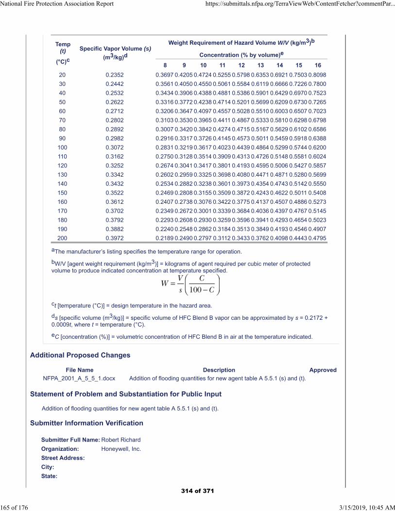
Temp(t)
(°C)c
Specific Vapor Volume (s)
(m3/kg)d
Weight Requirement of Hazard Volume W/V (kg/m3)b
Concentration (% by volume)e
8 9 10 11 12 13 14 15 16
20 0.2352 0.3697 0.4205 0.4724 0.5255 0.5798 0.6353 0.6921 0.7503 0.8098
30 0.2442 0.3561 0.4050 0.4550 0.5061 0.5584 0.6119 0.6666 0.7226 0.7800
40 0.2532 0.3434 0.3906 0.4388 0.4881 0.5386 0.5901 0.6429 0.6970 0.7523
50 0.2622 0.3316 0.3772 0.4238 0.4714 0.5201 0.5699 0.6209 0.6730 0.7265
60 0.2712 0.3206 0.3647 0.4097 0.4557 0.5028 0.5510 0.6003 0.6507 0.7023
70 0.2802 0.3103 0.3530 0.3965 0.4411 0.4867 0.5333 0.5810 0.6298 0.6798
80 0.2892 0.3007 0.3420 0.3842 0.4274 0.4715 0.5167 0.5629 0.6102 0.6586
90 0.2982 0.2916 0.3317 0.3726 0.4145 0.4573 0.5011 0.5459 0.5918 0.6388
100 0.3072 0.2831 0.3219 0.3617 0.4023 0.4439 0.4864 0.5299 0.5744 0.6200
110 0.3162 0.2750 0.3128 0.3514 0.3909 0.4313 0.4726 0.5148 0.5581 0.6024
120 0.3252 0.2674 0.3041 0.3417 0.3801 0.4193 0.4595 0.5006 0.5427 0.5857
130 0.3342 0.2602 0.2959 0.3325 0.3698 0.4080 0.4471 0.4871 0.5280 0.5699
140 0.3432 0.2534 0.2882 0.3238 0.3601 0.3973 0.4354 0.4743 0.5142 0.5550
150 0.3522 0.2469 0.2808 0.3155 0.3509 0.3872 0.4243 0.4622 0.5011 0.5408
160 0.3612 0.2407 0.2738 0.3076 0.3422 0.3775 0.4137 0.4507 0.4886 0.5273
170 0.3702 0.2349 0.2672 0.3001 0.3339 0.3684 0.4036 0.4397 0.4767 0.5145
180 0.3792 0.2293 0.2608 0.2930 0.3259 0.3596 0.3941 0.4293 0.4654 0.5023
190 0.3882 0.2240 0.2548 0.2862 0.3184 0.3513 0.3849 0.4193 0.4546 0.4907
200 0.3972 0.2189 0.2490 0.2797 0.3112 0.3433 0.3762 0.4098 0.4443 0.4795
aThe manufacturer’s listing specifies the temperature range for operation.
bW/V [agent weight requirement (kg/m3)] = kilograms of agent required per cubic meter of protectedvolume to produce indicated concentration at temperature specified.
ct [temperature (°C)] = design temperature in the hazard area.
ds [specific volume (m3/kg)] = specific volume of HFC Blend B vapor can be approximated by s = 0.2172 +0.0009t, where t = temperature (°C).
eC [concentration (%)] = volumetric concentration of HFC Blend B in air at the temperature indicated.
Additional Proposed Changes
File Name Description Approved
NFPA_2001_A_5_5_1.docx Addition of flooding quantities for new agent table A 5.5.1 (s) and (t).
Statement of Problem and Substantiation for Public Input
Addition of flooding quantities for new agent table A 5.5.1 (s) and (t).
Submitter Information Verification
Submitter Full Name: Robert Richard
Organization: Honeywell, Inc.
Street Address:
City:
State:
National Fire Protection Association Report https://submittals.nfpa.org/TerraViewWeb/ContentFetcher?commentPar...
165 of 176 3/15/2019, 10:45 AM
314 of 371

Zip:
Submittal Date: Tue Dec 18 13:07:41 EST 2018
Committee: GFE-AAA
National Fire Protection Association Report https://submittals.nfpa.org/TerraViewWeb/ContentFetcher?commentPar...
166 of 176 3/15/2019, 10:45 AM
315 of 371
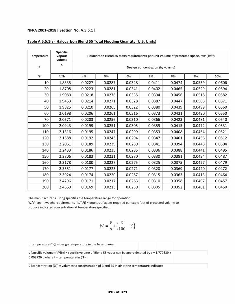
NFPA 2001-2018 [ Section No. A.5.5.1 ] Table A.5.5.1(s) Halocarbon Blend 55 Total Flooding Quantity (U.S. Units)
Temperature Specific vapour volume
Halocarbon Blend 55 mass requirements per unit volume of protected space, m/V (lb/ft3)
T s
Design concentration (by volume)
°F ft3/lb 4% 5% 6% 7% 8% 9% 10%
10 1.8335 0.0227 0.0287 0.0348 0.0411 0.0474 0.0539 0.0606 20 1.8708 0.0223 0.0281 0.0341 0.0402 0.0465 0.0529 0.0594 30 1.9080 0.0218 0.0276 0.0335 0.0394 0.0456 0.0518 0.0582 40 1.9453 0.0214 0.0271 0.0328 0.0387 0.0447 0.0508 0.0571 50 1.9825 0.0210 0.0265 0.0322 0.0380 0.0439 0.0499 0.0560 60 2.0198 0.0206 0.0261 0.0316 0.0373 0.0431 0.0490 0.0550 70 2.0571 0.0203 0.0256 0.0310 0.0366 0.0423 0.0481 0.0540
100 2.0943 0.0199 0.0251 0.0305 0.0359 0.0415 0.0472 0.0531 110 2.1316 0.0195 0.0247 0.0299 0.0353 0.0408 0.0464 0.0521 120 2.1688 0.0192 0.0243 0.0294 0.0347 0.0401 0.0456 0.0512 130 2.2061 0.0189 0.0239 0.0289 0.0341 0.0394 0.0448 0.0504 140 2.2433 0.0186 0.0235 0.0285 0.0336 0.0388 0.0441 0.0495 150 2.2806 0.0183 0.0231 0.0280 0.0330 0.0381 0.0434 0.0487 160 2.3178 0.0180 0.0227 0.0275 0.0325 0.0375 0.0427 0.0479 170 2.3551 0.0177 0.0223 0.0271 0.0320 0.0369 0.0420 0.0472 180 2.3924 0.0174 0.0220 0.0267 0.0315 0.0363 0.0413 0.0464 190 2.4296 0.0171 0.0217 0.0263 0.0310 0.0358 0.0407 0.0457 200 2.4669 0.0169 0.0213 0.0259 0.0305 0.0352 0.0401 0.0450
The manufacturer’s listing specifies the temperature range for operation. W/V [agent weight requirements (lb/ft3)] = pounds of agent required per cubic foot of protected volume to produce indicated concentration at temperature specified.
𝑊𝑊 =𝑉𝑉𝑠𝑠∗ �
𝐶𝐶100
− 𝐶𝐶�
t [temperature (°F)] = design temperature in the hazard area.
s [specific volume (ft3/lb)] = specific volume of Blend 55 vapor can be approximated by s = 1.777639 + 0.003726 t where t = temperature in (°F).
C [concentration (%)] = volumetric concentration of Blend 55 in air at the temperature indicated.
316 of 371
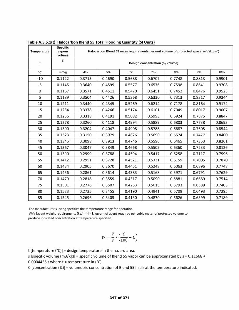
Table A.5.5.1(t) Halocarbon Blend 55 Total Flooding Quantity (SI Units)
Temperature Specific vapour volume
Halocarbon Blend 55 mass requirements per unit volume of protected space, m/V (kg/m3)
T s
Design concentration (by volume)
°C m3/kg 4% 5% 6% 7% 8% 9% 10%
-10 0.1122 0.3713 0.4690 0.5688 0.6707 0.7748 0.8813 0.9901 -5 0.1145 0.3640 0.4599 0.5577 0.6576 0.7598 0.8641 0.9708 0 0.1167 0.3571 0.4511 0.5470 0.6451 0.7452 0.8476 0.9523 5 0.1189 0.3504 0.4426 0.5368 0.6330 0.7313 0.8317 0.9344
10 0.1211 0.3440 0.4345 0.5269 0.6214 0.7178 0.8164 0.9172 15 0.1234 0.3378 0.4266 0.5174 0.6101 0.7049 0.8017 0.9007 20 0.1256 0.3318 0.4191 0.5082 0.5993 0.6924 0.7875 0.8847 25 0.1278 0.3260 0.4118 0.4994 0.5889 0.6803 0.7738 0.8693 30 0.1300 0.3204 0.4047 0.4908 0.5788 0.6687 0.7605 0.8544 35 0.1323 0.3150 0.3979 0.4826 0.5690 0.6574 0.7477 0.8400 40 0.1345 0.3098 0.3913 0.4746 0.5596 0.6465 0.7353 0.8261 45 0.1367 0.3047 0.3849 0.4668 0.5505 0.6360 0.7233 0.8126 50 0.1390 0.2999 0.3788 0.4594 0.5417 0.6258 0.7117 0.7996 55 0.1412 0.2951 0.3728 0.4521 0.5331 0.6159 0.7005 0.7870 60 0.1434 0.2905 0.3670 0.4451 0.5248 0.6063 0.6896 0.7748 65 0.1456 0.2861 0.3614 0.4383 0.5168 0.5971 0.6791 0.7629 70 0.1479 0.2818 0.3559 0.4317 0.5090 0.5881 0.6689 0.7514 75 0.1501 0.2776 0.3507 0.4253 0.5015 0.5793 0.6589 0.7403 80 0.1523 0.2735 0.3455 0.4190 0.4941 0.5709 0.6493 0.7295 85 0.1545 0.2696 0.3405 0.4130 0.4870 0.5626 0.6399 0.7189
The manufacturer’s listing specifies the temperature range for operation. W/V [agent weight requirements (kg/m3)] = kilogram of agent required per cubic meter of protected volume to produce indicated concentration at temperature specified.
𝑊𝑊 =𝑉𝑉𝑠𝑠∗ �
𝐶𝐶100
− 𝐶𝐶�
t [temperature (°C)] = design temperature in the hazard area. s [specific volume (m3/kg)] = specific volume of Blend 55 vapor can be approximated by s = 0.11668 + 0.0004455 t where t = temperature in (°C). C [concentration (%)] = volumetric concentration of Blend 55 in air at the temperature indicated.
317 of 371
Public Input No. 46-NFPA 2001-2018 [ Section No. B.19 ]
National Fire Protection Association Report https://submittals.nfpa.org/TerraViewWeb/ContentFetcher?commentPar...
167 of 176 3/15/2019, 10:45 AM
318 of 371

B.19 Figures.
National Fire Protection Association Report https://submittals.nfpa.org/TerraViewWeb/ContentFetcher?commentPar...
168 of 176 3/15/2019, 10:45 AM
319 of 371
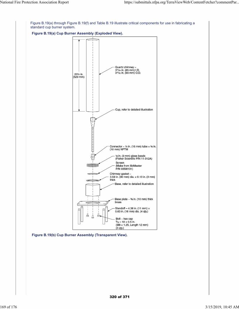
Figure B.19(a) through Figure B.19(f) and Table B.19 illustrate critical components for use in fabricating astandard cup burner system.
Figure B.19(a) Cup Burner Assembly (Exploded View).
Figure B.19(b) Cup Burner Assembly (Transparent View).
National Fire Protection Association Report https://submittals.nfpa.org/TerraViewWeb/ContentFetcher?commentPar...
169 of 176 3/15/2019, 10:45 AM
320 of 371
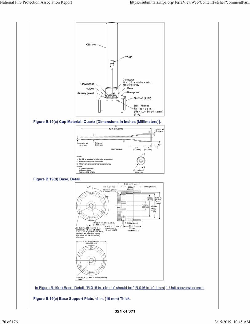
Figure B.19(c) Cup Material: Quartz [Dimensions in Inches (Millimeters)].
Figure B.19(d) Base, Detail.
In Figure B.19(d) Base, Detail, "R.016 in. (4mm)" should be " R.016 in. (0.4mm) ". Unit conversion error.
Figure B.19(e) Base Support Plate, 3⁄8 in. (10 mm) Thick.
National Fire Protection Association Report https://submittals.nfpa.org/TerraViewWeb/ContentFetcher?commentPar...
170 of 176 3/15/2019, 10:45 AM
321 of 371
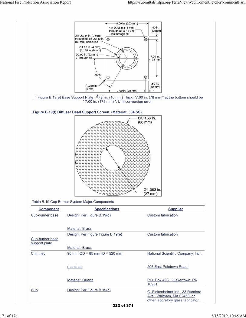
In Figure B.19(e) Base Support Plate, 3 ⁄ 8 in. (10 mm) Thick, "7.00 in. (78 mm)" at the bottom should be" 7.00 in. (178 mm) ". Unit conversion error.
Figure B.19(f) Diffuser Bead Support Screen. (Material: 304 SS).
Table B.19 Cup Burner System Major Components
Component Specifications Supplier
Cup-burner base Design: Per Figure B.19(d)
Material: Brass
Custom fabrication
Cup-burner basesupport plate
Design: Per Figure Figure B.19(e)
Material: Brass
Custom fabrication
Chimney 90 mm OD × 85 mm ID × 520 mm
(nominal)
Material: Quartz
National Scientific Company, Inc.,
205 East Paletown Road,
P.O. Box 498, Quakertown, PA18951
Cup Design: Per Figure B.19(c) G. Finkenbeiner Inc., 33 RumfordAve., Waltham, MA 02453, orother laboratory glass fabricator
National Fire Protection Association Report https://submittals.nfpa.org/TerraViewWeb/ContentFetcher?commentPar...
171 of 176 3/15/2019, 10:45 AM
322 of 371
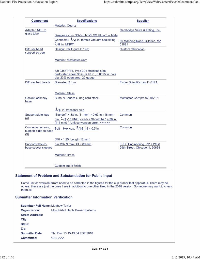
Component Specifications Supplier
Material: Quartz
Adapter, NPT toglass tube
Swagelock p/n SS-8-UT-1-6, SS Ultra-Torr Male
Connector, 1 ⁄ 2 in. female vacuum seal fitting –3 ⁄ 8 in. MNPT
Cambridge Valve & Fitting, Inc.,
50 Manning Road, Billerica, MA01821
Diffuser beadsupport screen
Design: Per Figure B.19(f)
Material: McMaster-Carr
p/n 9358T131. Type 304 stainless steelperforated sheet 36 in. × 40 in., 0.0625 in. holedia, 23% open area, 22 gauge
Custom fabrication
Diffuser bed beads Diameter: 3 mm
Material: Glass
Fisher Scientific p/n 11-312A
Gasket, chimney-base
Buna-N Square O-ring cord stock,
1 ⁄ 8 in. fractional size
McMaster-Carr p/n 9700K121
Support plate legs(4)
Standoff–4.38 in. (11 mm) × 0.63 in. (16 mm)
dia. 1 ⁄ 2 -13 UNC <<<<<< Should be " 4.38 in.(111 mm) ". Unit conversion error. >>>>>>
Common
Connector screws,support plate-to-base(3)
Bolt – Hex cap, 5 ⁄ 16 -18 × 0.5 in.
(M8 x 1.25, Length 12 mm)
Common
Support plate-to-base spacer sleeves
p/n M37 9 mm OD × 89 mm
Material: Brass
Custom cut to finish
K & S Engineering, 6917 West59th Street, Chicago, IL 60638
Statement of Problem and Substantiation for Public Input
Some unit conversion errors need to be corrected in the figures for the cup burner test apparatus. There may be others, these are just the ones I see in addition to one other fixed in the 2018 version. Someone may want to check them all.
Submitter Information Verification
Submitter Full Name: Matthew Taylor
Organization: Mitsubishi Hitachi Power Systems
Street Address:
City:
State:
Zip:
Submittal Date: Thu Dec 13 15:49:54 EST 2018
Committee: GFE-AAA
National Fire Protection Association Report https://submittals.nfpa.org/TerraViewWeb/ContentFetcher?commentPar...
172 of 176 3/15/2019, 10:45 AM
323 of 371
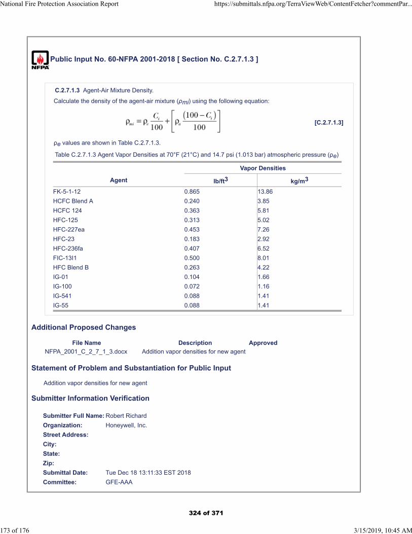
Public Input No. 60-NFPA 2001-2018 [ Section No. C.2.7.1.3 ]
C.2.7.1.3 Agent-Air Mixture Density.
Calculate the density of the agent-air mixture (ρmi) using the following equation:
[C.2.7.1.3]
ρe values are shown in Table C.2.7.1.3.
Table C.2.7.1.3 Agent Vapor Densities at 70°F (21°C) and 14.7 psi (1.013 bar) atmospheric pressure (ρe)
Vapor Densities
Agent lb/ft3 kg/m3
FK-5-1-12 0.865 13.86
HCFC Blend A 0.240 3.85
HCFC 124 0.363 5.81
HFC-125 0.313 5.02
HFC-227ea 0.453 7.26
HFC-23 0.183 2.92
HFC-236fa 0.407 6.52
FIC-13I1 0.500 8.01
HFC Blend B 0.263 4.22
IG-01 0.104 1.66
IG-100 0.072 1.16
IG-541 0.088 1.41
IG-55 0.088 1.41
Additional Proposed Changes
File Name Description Approved
NFPA_2001_C_2_7_1_3.docx Addition vapor densities for new agent
Statement of Problem and Substantiation for Public Input
Addition vapor densities for new agent
Submitter Information Verification
Submitter Full Name: Robert Richard
Organization: Honeywell, Inc.
Street Address:
City:
State:
Zip:
Submittal Date: Tue Dec 18 13:11:33 EST 2018
Committee: GFE-AAA
National Fire Protection Association Report https://submittals.nfpa.org/TerraViewWeb/ContentFetcher?commentPar...
173 of 176 3/15/2019, 10:45 AM
324 of 371

NFPA 2001-2018 [ Section No. C.2.7.1.3 ] Table C.2.7.1.3 Agent vapor density at 70 °F (21 °C) and 14.7 psi (1.013 bar) atmospheric pressure ( ρe) Agent lb/ft3 kg/m3 Halocarbon Blend 55 0.4966 7.9115
325 of 371
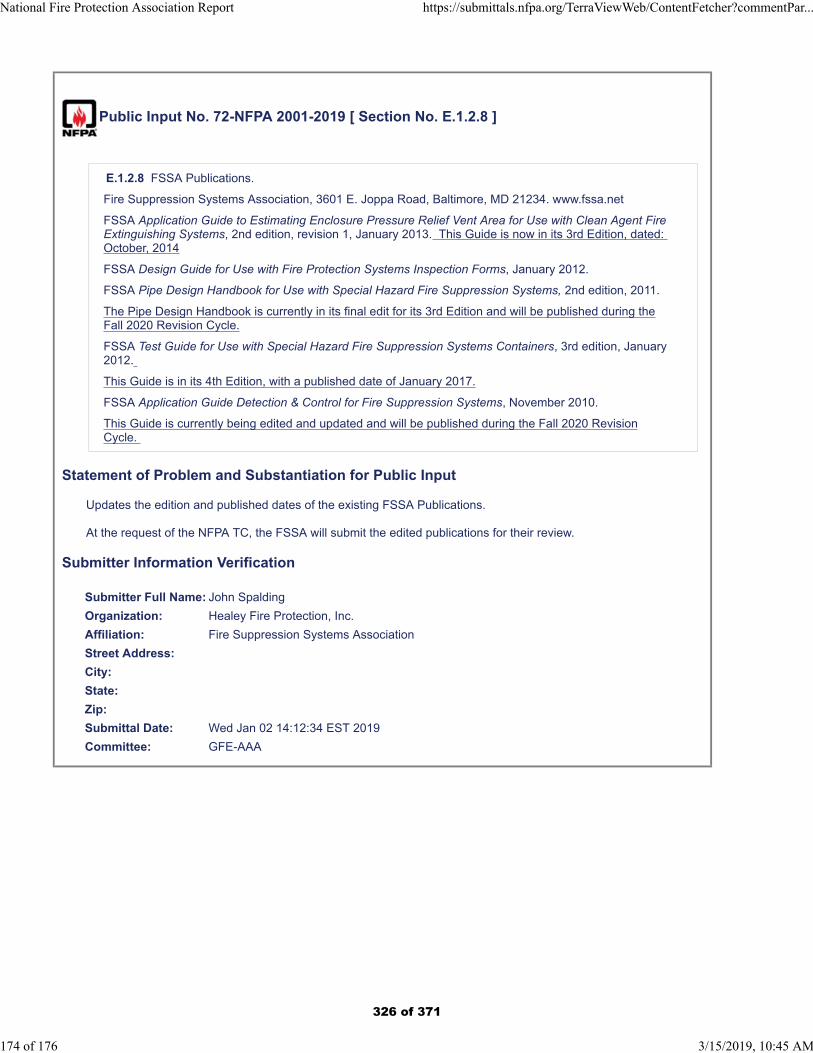
Public Input No. 72-NFPA 2001-2019 [ Section No. E.1.2.8 ]
E.1.2.8 FSSA Publications.
Fire Suppression Systems Association, 3601 E. Joppa Road, Baltimore, MD 21234. www.fssa.net
FSSA Application Guide to Estimating Enclosure Pressure Relief Vent Area for Use with Clean Agent FireExtinguishing Systems, 2nd edition, revision 1, January 2013. This Guide is now in its 3rd Edition, dated: October, 2014
FSSA Design Guide for Use with Fire Protection Systems Inspection Forms, January 2012.
FSSA Pipe Design Handbook for Use with Special Hazard Fire Suppression Systems, 2nd edition, 2011.
The Pipe Design Handbook is currently in its final edit for its 3rd Edition and will be published during theFall 2020 Revision Cycle.
FSSA Test Guide for Use with Special Hazard Fire Suppression Systems Containers, 3rd edition, January2012.
This Guide is in its 4th Edition, with a published date of January 2017.
FSSA Application Guide Detection & Control for Fire Suppression Systems, November 2010.
This Guide is currently being edited and updated and will be published during the Fall 2020 RevisionCycle.
Statement of Problem and Substantiation for Public Input
Updates the edition and published dates of the existing FSSA Publications.
At the request of the NFPA TC, the FSSA will submit the edited publications for their review.
Submitter Information Verification
Submitter Full Name: John Spalding
Organization: Healey Fire Protection, Inc.
Affiliation: Fire Suppression Systems Association
Street Address:
City:
State:
Zip:
Submittal Date: Wed Jan 02 14:12:34 EST 2019
Committee: GFE-AAA
National Fire Protection Association Report https://submittals.nfpa.org/TerraViewWeb/ContentFetcher?commentPar...
174 of 176 3/15/2019, 10:45 AM
326 of 371
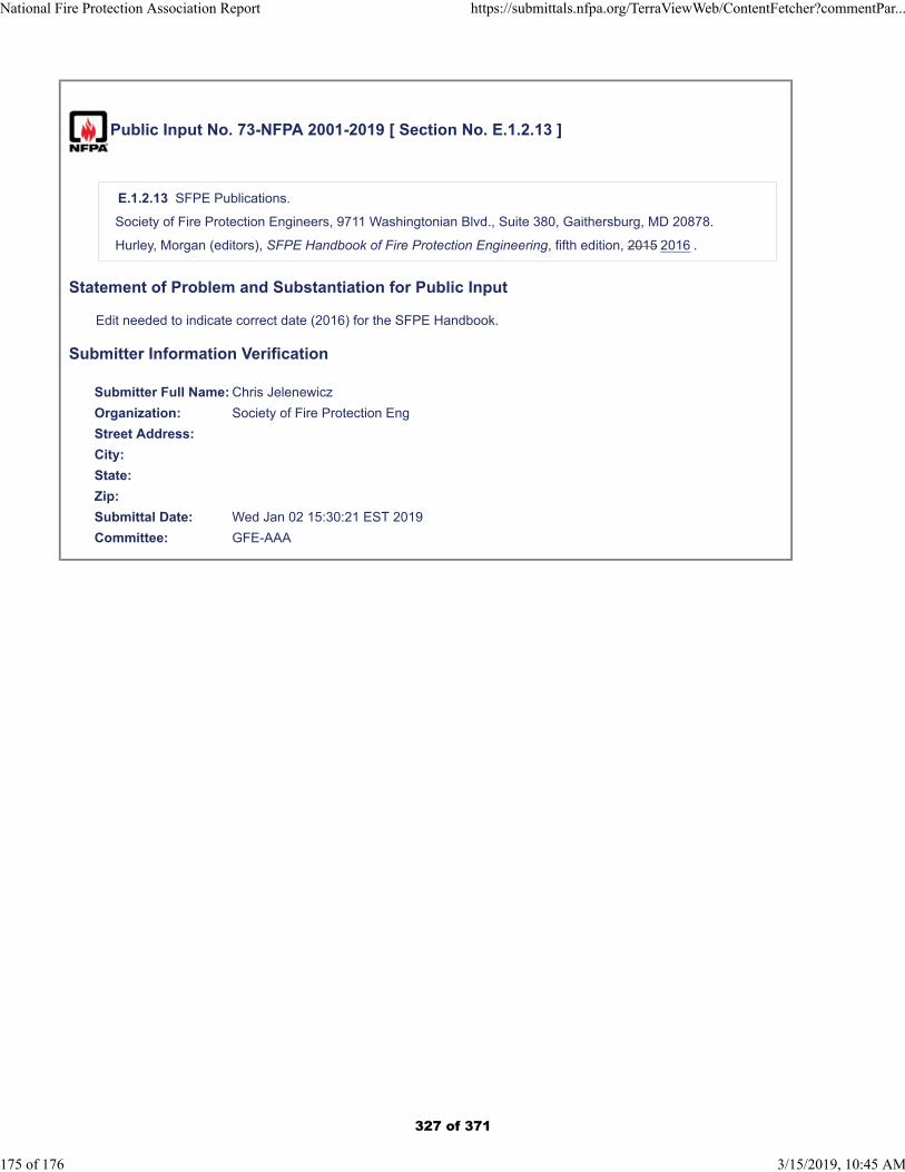
Public Input No. 73-NFPA 2001-2019 [ Section No. E.1.2.13 ]
E.1.2.13 SFPE Publications.
Society of Fire Protection Engineers, 9711 Washingtonian Blvd., Suite 380, Gaithersburg, MD 20878.
Hurley, Morgan (editors), SFPE Handbook of Fire Protection Engineering, fifth edition, 2015 2016 .
Statement of Problem and Substantiation for Public Input
Edit needed to indicate correct date (2016) for the SFPE Handbook.
Submitter Information Verification
Submitter Full Name: Chris Jelenewicz
Organization: Society of Fire Protection Eng
Street Address:
City:
State:
Zip:
Submittal Date: Wed Jan 02 15:30:21 EST 2019
Committee: GFE-AAA
National Fire Protection Association Report https://submittals.nfpa.org/TerraViewWeb/ContentFetcher?commentPar...
175 of 176 3/15/2019, 10:45 AM
327 of 371
Public Input No. 67-NFPA 2001-2018 [ Section No. E.1.2.14 ]
E.1.2.14 UL Publications.
Underwriters Laboratories Inc., 333 Pfingsten Road, Northbrook, IL 60062–2096.
ANSI/ UL 2127,Standard for Inert Gas Clean Agent Extinguishing System Units, 2012 (revised2015) 2018 .ANSI/
UL 2166,Standard for Halocarbon Clean Agent Extinguishing System Units, 2012 (revised 2015) 2018 .
Statement of Problem and Substantiation for Public Input
Update of references and removal of repetitive wording and removal of ANSI because many years ago, UL preferred the ANSI/UL reference because there was a transition of traditional UL standards towards an ANSI standards development process.
Now, years later, a large majority of UL Standards are ANSI approved and follow the ANSI development and maintenance process. However, sometimes readers are confused because they don't understand the standards are UL standards, not developed by ANSI. There are many other references to standards promulgated by different standards development organizations where they are considered ANSI approved but do not include ANSI in the reference.
Related Public Inputs for This Document
Related Input Relationship
Public Input No. 65-NFPA 2001-2018 [Section No. 2.3.9]
Public Input No. 66-NFPA 2001-2018 [Section No. 2.3.10]
Submitter Information Verification
Submitter Full Name: Kelly Nicolello
Organization: UL LLC
Street Address:
City:
State:
Zip:
Submittal Date: Wed Dec 26 15:15:26 EST 2018
Committee: GFE-AAA
National Fire Protection Association Report https://submittals.nfpa.org/TerraViewWeb/ContentFetcher?commentPar...
176 of 176 3/15/2019, 10:45 AM
328 of 371
Public Input No. 1-NFPA 12-2018 [ Global Input ]
Type your content here ...
Title: Improved clarity of the terms “fire” and “extinguishment”, highlighting electrostatic explosionhazard when fighting smoldering fires with CO2.
Concern:There is a problem with CO₂ batteries. When liquid CO₂ is released, static discharges are generated. It's a known source of ignition, e.g. in NFPA 77.This is not problem for fighting a fire with flames. But a smoldering fire will likely have filled theheadspace with flammable gases. If ignited due to CO₂ injection, a confined explosion will result. NFPA 12 does not mention this hazard clearly. On the contrary, section 5.2.3 states that CO₂ can beused for "deep-seated fires". This is a problem.I wrote an article on an explosion caused by this phenomenon:Hedlund FH (2018) Carbon dioxide not suitable for extinguishment of smouldering silo fires: staticelectricity may cause silo explosion. Biomass and Bioenergy. 108:113-119. https://doi.org/10.1016/j.biombioe.2017.11.009
Quoting from this article:NFPA 12 [21] on carbon dioxide extinguishing systems provides ambiguous advice on theelectrostatic hazard. Annex A states that the discharge of liquid carbon dioxide is known toproduce electrostaticcharges that, under certain conditions, could create a spark and duly refers to NFPA 77.The standard also specifies, that “carbon dioxide fire extinguishing systems protecting areas whereexplosive atmospheres could exist shall utilize metal nozzles, and the entire system shall begrounded” [[21], Sec. 4.2.1].The first issue of concern is if the reader realizes that an ignitable (and explosive) atmosphere canexist not only when flammable liquids give off vapours but also when pyrolysis gases haveaccumulated.The second issue of concern is if effective grounding is sufficient to prevent hazardouselectrostatic discharges – the Bitburg accident would appear to contraindicate this.The third and perhaps most important issue of concern is the standard's ill-conceived advice on theapplication of CO2 to “deep-seated fires involving solids subject to smoldering” [[21], Sec 5.2.3].
This is precisely the situation where pyrolysis gases may have accumulated in the headspace to anextent where they are in the ignitable range – but the reader may not have realized this, and thestandard does not identify the potential presence of flammable pyrolysis gases.
The nub of the issue may well be lack of clarity in the meaning of the terms “fire” and“extinguishment”, which are not defined in the standard's terminology section.The application of CO2 is excellent for extinguishing a fire with flames, but unsuitable forquenching a deep-seated smouldering fire without flame.
I'm not a US citizen and have no means to enter a lengthy comments procedure for a US standard. Unfortunately, I cannot pursue this issue further with NFPA.
Frank Huess [email protected]
Statement of Problem and Substantiation for Public Input
Currently, the standard gives ill-conceived advice on the application of CO2 to “deep-seated fires involving solids subject to smoldering”, not alerting readers to explosion hazard
Submitter Information Verification
Submitter Full Name: Frank Hedlund
Organization: COWI (a consultancy) & Technical University of Denmark
National Fire Protection Association Report https://submittals.nfpa.org/TerraViewWeb/ContentFetcher?commentPar...
1 of 38 3/15/2019, 10:29 AM
329 of 371

Street Address:
City:
State:
Zip:
Submittal Date: Mon Jun 04 04:25:09 EDT 2018
Committee: GFE-AAA
National Fire Protection Association Report https://submittals.nfpa.org/TerraViewWeb/ContentFetcher?commentPar...
2 of 38 3/15/2019, 10:29 AM
330 of 371
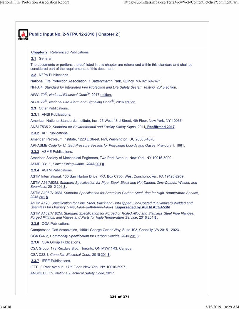
Public Input No. 2-NFPA 12-2018 [ Chapter 2 ]
Chapter 2 Referenced Publications
2.1 General.
The documents or portions thereof listed in this chapter are referenced within this standard and shall beconsidered part of the requirements of this document.
2.2 NFPA Publications.
National Fire Protection Association, 1 Batterymarch Park, Quincy, MA 02169-7471.
NFPA 4, Standard for Integrated Fire Protection and Life Safety System Testing, 2018 edition.
NFPA 70®, National Electrical Code®, 2017 edition.
NFPA 72®, National Fire Alarm and Signaling Code®, 2016 edition.
2.3 Other Publications.
2.3.1 ANSI Publications.
American National Standards Institute, Inc., 25 West 43rd Street, 4th Floor, New York, NY 10036.
ANSI Z535.2, Standard for Environmental and Facility Safety Signs, 2011, Reaffirmed 2017 .
2.3.2 API Publications.
American Petroleum Institute, 1220 L Street, NW, Washington, DC 20005-4070.
API-ASME Code for Unfired Pressure Vessels for Petroleum Liquids and Gases, Pre–July 1, 1961.
2.3.3 ASME Publications.
American Society of Mechanical Engineers, Two Park Avenue, New York, NY 10016-5990.
ASME B31.1, Power Piping Code , 2016 201 8 .
2.3.4 ASTM Publications.
ASTM International, 100 Barr Harbor Drive, P.O. Box C700, West Conshohocken, PA 19428-2959.
ASTM A53/A53M, Standard Specification for Pipe, Steel, Black and Hot-Dipped, Zinc-Coated, Welded andSeamless, 2012 201 8 .
ASTM A106/A106M, Standard Specification for Seamless Carbon Steel Pipe for High-Temperature Service,2015 201 8 .
ASTM A120, Specification for Pipe, Steel, Black and Hot-Dipped Zinc-Coated (Galvanized) Welded andSeamless for Ordinary Uses, 1984 (withdrawn 1987) Superseded by ASTM A53/A53M .
ASTM A182/A182M, Standard Specification for Forged or Rolled Alloy and Stainless Steel Pipe Flanges,Forged Fittings, and Valves and Parts for High-Temperature Service, 2016 201 8 .
2.3.5 CGA Publications.
Compressed Gas Association, 14501 George Carter Way, Suite 103, Chantilly, VA 20151-2923.
CGA G-6.2, Commodity Specification for Carbon Dioxide, 2011 201 3 .
2.3.6 CSA Group Publications.
CSA Group, 178 Rexdale Blvd., Toronto, ON M9W 1R3, Canada.
CSA C22.1, Canadian Electrical Code, 2015 201 8 .
2.3.7 IEEE Publications.
IEEE, 3 Park Avenue, 17th Floor, New York, NY 10016-5997.
ANSI/IEEE C2, National Electrical Safety Code, 2017.
National Fire Protection Association Report https://submittals.nfpa.org/TerraViewWeb/ContentFetcher?commentPar...
3 of 38 3/15/2019, 10:29 AM
331 of 371
2.3.8 U.S. Government Publications.
U.S. Government Publishing Office, 732 North Capitol Street, NW, Washington, DC 20401-0001.
Title 46, Code of Federal Regulations, Part 58.20.
Title 46, Code of Federal Regulations, Part 72.
Title 49, Code of Federal Regulations, Parts 171–190 (Department of Transportation).
Coward, H. F., and G. W. Jones, Limits of Flammability of Gases and Vapors, U.S. Bureau of Mines Bulletin503,1952.
Zabetakis, Michael G., Flammability Characteristics of Combustible Gases and Vapors, U.S. Bureau ofMines Bulletin 627, 1965.
2.3.9 Other Publications.
Merriam-Webster’s Collegiate Dictionary, 11th edition, Merriam-Webster, Inc., Springfield, MA, 2003.
2.4 References for Extracts in Mandatory Sections.
NFPA 1, Fire Code, 2018 edition.
NFPA 122, Standard for Fire Prevention and Control in Metal/Nonmetal Mining and Metal MineralProcessing Facilities, 2015 edition.
NFPA 820, Standard for Fire Protection in Wastewater Treatment and Collection Facilities, 2016 edition.
Statement of Problem and Substantiation for Public Input
Referenced updated editions.
Submitter Information Verification
Submitter Full Name: Aaron Adamczyk
Organization: [ Not Specified ]
Street Address:
City:
State:
Zip:
Submittal Date: Sun Sep 09 02:15:52 EDT 2018
Committee: GFE-AAA
National Fire Protection Association Report https://submittals.nfpa.org/TerraViewWeb/ContentFetcher?commentPar...
4 of 38 3/15/2019, 10:29 AM
332 of 371
Public Input No. 12-NFPA 12-2018 [ Section No. 4.6.1 [Excluding any Sub-Sections] ]
The amount of the main supply of carbon dioxide in the system shall be at least sufficient for the largestsingle hazard protected or group of hazards that are to be protected simultaneously. The supply pipe fromthe tank to the hazard can contain a significant amount of CO2 at the completion of a discharge and shallbe considered in sizing the supply.
Statement of Problem and Substantiation for Public Input
The supply pipe between the low pressure CO2 tank and the hazard can contain a large volume of CO2, especially for large hazards with 4 in pipe some distance away. It is our understanding that the flow calculations only figure the mass of CO2 that leaves the nozzles and enters the hazard during discharge. When the valve at the tank closes, the CO2 in the supply pipe is left abandoned in the pipe, not reliable for extinguishing and no longer available for another discharge from the tank. When sizing systems, this volume should be included as consumed CO2.
Submitter Information Verification
Submitter Full Name: Matthew Taylor
Organization: Mitsubishi Hitachi Power Systems
Street Address:
City:
State:
Zip:
Submittal Date: Thu Dec 27 11:49:23 EST 2018
Committee: GFE-AAA
National Fire Protection Association Report https://submittals.nfpa.org/TerraViewWeb/ContentFetcher?commentPar...
5 of 38 3/15/2019, 10:29 AM
333 of 371
Public Input No. 10-NFPA 12-2018 [ Section No. 5.4.4.2 ]
5.4.4.2
If leakage is appreciable, consideration shall be given to an extended discharge system as covered inA. 5.5. 2 or 5.5. 3. (See also 5.2.1.3.)
Systems other than those covered in 5.5.3 (enclosed rotating electrical equipement) may require extendeddischarge systems. Annex A.5.5.2 paragraphs 2 and forward talks in depth about determining extendeddischarge requirements for leaky hazards. To send a user to 5.5.3 may send the wrong message to use thetables in A.5.5.3 when they should actually be considering A.5.5.2 information.
Statement of Problem and Substantiation for Public Input
There is confusion with regard to extended discharge requirements for leaky systems that are not "enclosed rotation electrical equipment". This change would provide clearer direction in this aspect of system designs, for ga turbine enclosures for instance.
Related Public Inputs for This Document
Related Input Relationship
Public Input No. 8-NFPA 12-2018 [Section No.5.5.3]
Same issue
Public Input No. 9-NFPA 12-2018 [Section No.A.5.5.3]
Same issue
Public Input No. 6-NFPA 12-2018 [Section No.A.5.5.2]
Different correction in a related section of thestandard.
Submitter Information Verification
Submitter Full Name: Matthew Taylor
Organization: Mitsubishi Hitachi Power Systems
Street Address:
City:
State:
Zip:
Submittal Date: Thu Dec 27 11:15:53 EST 2018
Committee: GFE-AAA
National Fire Protection Association Report https://submittals.nfpa.org/TerraViewWeb/ContentFetcher?commentPar...
6 of 38 3/15/2019, 10:29 AM
334 of 371
Public Input No. 14-NFPA 12-2018 [ Section No. 5.5.2.1 ]
5.5.2.1 *
For surface fires, the design concentration shall be achieved within 1 minute from start of discharge.
Response time of the instrument shall be considered in determining pass/fail criteria for concentrationtesting.
(Response time of the available sensors can consume significant portion of the discharge timerequirement. They simply do not respond fast enough to accurately determine concentration with 1minute. State of the art infrared detectors can take as long as 20 seconds to read 63% of full signal, and 50seconds to read full signal from the time they are exposed to a full concentration calibrated CO2 gassample. The older Tripoint thermal conductivity based instruments claimed a T95 of 60 seconds, so theycould take 60 seconds to read 95% of the full concentration value, even longer to read the actual value.
These instrument dynamics can cause a technician to interpret a discharge test as a fail because theinstrument doesn't reach the design concentration with 60 seconds on the instrument used to measure onthe test. These values are independent of any additional time delays due to long lengths of tubing or delaysin the discharge flow, they are just inherent in the detectors. In practical terms, the concentration inside ahazard is gradually increasing during the discharge, so the driving gain in the system is even worse than inthe calibration setup.
Some guidance should be provided to accomodate the delays inherent in the instruments. The requirementis to achieve the design concentration within the hazard within 1 minute. If the available instrumenttakes 50 seconds to read full signal, a large portion of that additional time should be added to the pass/failrequirement for the test to fairly assess the actual concentration inside the enclosure.)
Additional Proposed Changes
File Name Description Approved
CO2_Analyzer_Response_Time_Characterization.pdfTypical CO2 analyzer response time graph during a bench test.
Statement of Problem and Substantiation for Public Input
The response time performance of CO2 concentration analyzers is not clearly considered in the standard requirement for application rate for short duration discharges. Without additional guidance, technicians can improperly assess test results resulting in system rework and delays. Describe typical performance of the devices and give guidance on how to use them to appropriately assess the concentration inside the hazard. Attached graph is provided for background for the technical committee, not to be considered to be included in the standard.
Submitter Information Verification
Submitter Full Name: Matthew Taylor
Organization: Mitsubishi Hitachi Power Systems
Street Address:
City:
State:
Zip:
Submittal Date: Thu Dec 27 13:11:11 EST 2018
Committee: GFE-AAA
National Fire Protection Association Report https://submittals.nfpa.org/TerraViewWeb/ContentFetcher?commentPar...
7 of 38 3/15/2019, 10:29 AM
335 of 371
Public Input No. 8-NFPA 12-2018 [ Section No. 5.5.3 ]
5.5.3 * Enclosed Rotating Electrical Equipment.
For enclosed rotating electrical equipment, a minimum concentration of 30 percent shall be maintained forthe deceleration period, but not less than 20 minutes. Enclosed rotating electrical equipment includeselectrical machinery like electric motors and generators. Please clarifiy what this section pertains to. Thissection and the supporting annex A.5.5.3 are routinely mis-applied to gas turbine engines bymanufacturers and integrators. Gas turbine engines are not electrical equipment in these terms Their holdtime requirements should be considered under the provisions of NFPA 37. Ref 10/22/2015 NFPA TechnicalQuestion Response [ ref:_00D5077Vx._50050hY3tt:ref ].
Statement of Problem and Substantiation for Public Input
Clarify the definition of "enclosed rotating electrical equipment" and the applicability of this section to completely mechanical equipment like gas turbine engines.
Related Public Inputs for This Document
Related Input Relationship
Public Input No. 9-NFPA 12-2018 [Section No. A.5.5.3]
Public Input No. 10-NFPA 12-2018 [Section No. 5.4.4.2]
Submitter Information Verification
Submitter Full Name: Matthew Taylor
Organization: Mitsubishi Hitachi Power Systems
Street Address:
City:
State:
Zip:
Submittal Date: Thu Dec 27 10:44:54 EST 2018
Committee: GFE-AAA
National Fire Protection Association Report https://submittals.nfpa.org/TerraViewWeb/ContentFetcher?commentPar...
8 of 38 3/15/2019, 10:29 AM
336 of 371
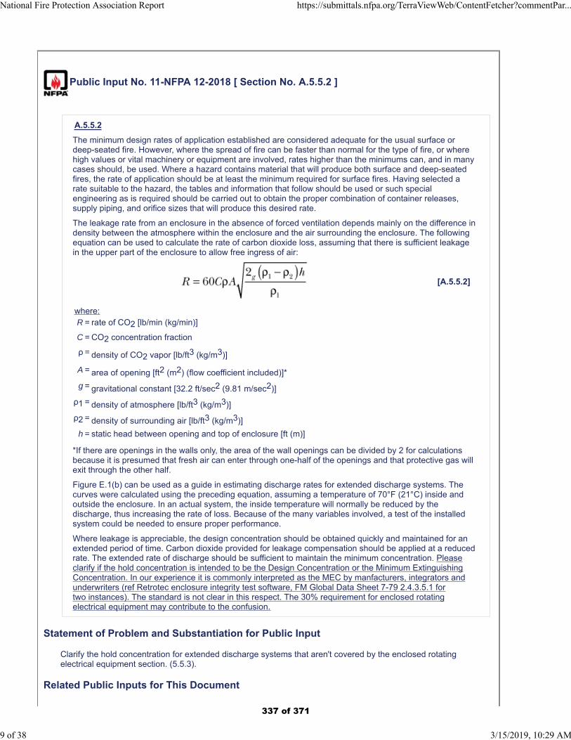
Public Input No. 11-NFPA 12-2018 [ Section No. A.5.5.2 ]
A.5.5.2
The minimum design rates of application established are considered adequate for the usual surface ordeep-seated fire. However, where the spread of fire can be faster than normal for the type of fire, or wherehigh values or vital machinery or equipment are involved, rates higher than the minimums can, and in manycases should, be used. Where a hazard contains material that will produce both surface and deep-seatedfires, the rate of application should be at least the minimum required for surface fires. Having selected arate suitable to the hazard, the tables and information that follow should be used or such specialengineering as is required should be carried out to obtain the proper combination of container releases,supply piping, and orifice sizes that will produce this desired rate.
The leakage rate from an enclosure in the absence of forced ventilation depends mainly on the difference indensity between the atmosphere within the enclosure and the air surrounding the enclosure. The followingequation can be used to calculate the rate of carbon dioxide loss, assuming that there is sufficient leakagein the upper part of the enclosure to allow free ingress of air:
[A.5.5.2]
where:R = rate of CO2 [lb/min (kg/min)]
C = CO2 concentration fraction
ρ = density of CO2 vapor [lb/ft3 (kg/m3)]
A = area of opening [ft2 (m2) (flow coefficient included)]*
g = gravitational constant [32.2 ft/sec2 (9.81 m/sec2)]
ρ1 = density of atmosphere [lb/ft3 (kg/m3)]
ρ2 = density of surrounding air [lb/ft3 (kg/m3)]
h = static head between opening and top of enclosure [ft (m)]
*If there are openings in the walls only, the area of the wall openings can be divided by 2 for calculationsbecause it is presumed that fresh air can enter through one-half of the openings and that protective gas willexit through the other half.
Figure E.1(b) can be used as a guide in estimating discharge rates for extended discharge systems. Thecurves were calculated using the preceding equation, assuming a temperature of 70°F (21°C) inside andoutside the enclosure. In an actual system, the inside temperature will normally be reduced by thedischarge, thus increasing the rate of loss. Because of the many variables involved, a test of the installedsystem could be needed to ensure proper performance.
Where leakage is appreciable, the design concentration should be obtained quickly and maintained for anextended period of time. Carbon dioxide provided for leakage compensation should be applied at a reducedrate. The extended rate of discharge should be sufficient to maintain the minimum concentration. Pleaseclarify if the hold concentration is intended to be the Design Concentration or the Minimum ExtinguishingConcentration. In our experience it is commonly interpreted as the MEC by manfacturers, integrators andunderwriters (ref Retrotec enclosure integrity test software, FM Global Data Sheet 7-79 2.4.3.5.1 fortwo instances). The standard is not clear in this respect. The 30% requirement for enclosed rotatingelectrical equipment may contribute to the confusion.
Statement of Problem and Substantiation for Public Input
Clarify the hold concentration for extended discharge systems that aren't covered by the enclosed rotating electrical equipment section. (5.5.3).
Related Public Inputs for This Document
National Fire Protection Association Report https://submittals.nfpa.org/TerraViewWeb/ContentFetcher?commentPar...
9 of 38 3/15/2019, 10:29 AM
337 of 371
Related Input Relationship
Public Input No. 6-NFPA 12-2018 [Section No.A.5.5.2]
Correction in the same section but unrelatedissue.
Submitter Information Verification
Submitter Full Name: Matthew Taylor
Organization: Mitsubishi Hitachi Power Systems
Street Address:
City:
State:
Zip:
Submittal Date: Thu Dec 27 11:33:41 EST 2018
Committee: GFE-AAA
National Fire Protection Association Report https://submittals.nfpa.org/TerraViewWeb/ContentFetcher?commentPar...
10 of 38 3/15/2019, 10:29 AM
338 of 371
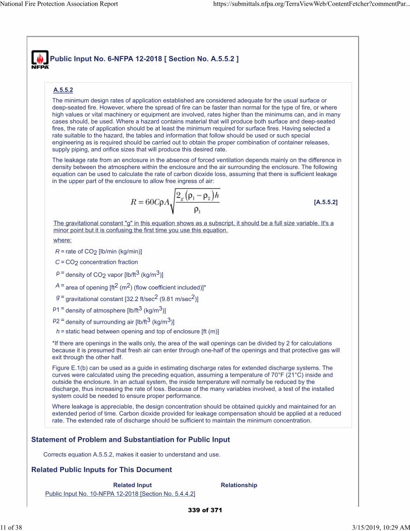
Public Input No. 6-NFPA 12-2018 [ Section No. A.5.5.2 ]
A.5.5.2
The minimum design rates of application established are considered adequate for the usual surface ordeep-seated fire. However, where the spread of fire can be faster than normal for the type of fire, or wherehigh values or vital machinery or equipment are involved, rates higher than the minimums can, and in manycases should, be used. Where a hazard contains material that will produce both surface and deep-seatedfires, the rate of application should be at least the minimum required for surface fires. Having selected arate suitable to the hazard, the tables and information that follow should be used or such specialengineering as is required should be carried out to obtain the proper combination of container releases,supply piping, and orifice sizes that will produce this desired rate.
The leakage rate from an enclosure in the absence of forced ventilation depends mainly on the difference indensity between the atmosphere within the enclosure and the air surrounding the enclosure. The followingequation can be used to calculate the rate of carbon dioxide loss, assuming that there is sufficient leakagein the upper part of the enclosure to allow free ingress of air:
[A.5.5.2]
The gravitational constant "g" in this equation shows as a subscript, it should be a full size variable. It's aminor point but it is confusing the first time you use this equation.
where:
R = rate of CO2 [lb/min (kg/min)]
C = CO2 concentration fraction
ρ = density of CO2 vapor [lb/ft3 (kg/m3)]
A = area of opening [ft2 (m2) (flow coefficient included)]*
g = gravitational constant [32.2 ft/sec2 (9.81 m/sec2)]
ρ1 = density of atmosphere [lb/ft3 (kg/m3)]
ρ2 = density of surrounding air [lb/ft3 (kg/m3)]
h = static head between opening and top of enclosure [ft (m)]
*If there are openings in the walls only, the area of the wall openings can be divided by 2 for calculationsbecause it is presumed that fresh air can enter through one-half of the openings and that protective gas willexit through the other half.
Figure E.1(b) can be used as a guide in estimating discharge rates for extended discharge systems. Thecurves were calculated using the preceding equation, assuming a temperature of 70°F (21°C) inside andoutside the enclosure. In an actual system, the inside temperature will normally be reduced by thedischarge, thus increasing the rate of loss. Because of the many variables involved, a test of the installedsystem could be needed to ensure proper performance.
Where leakage is appreciable, the design concentration should be obtained quickly and maintained for anextended period of time. Carbon dioxide provided for leakage compensation should be applied at a reducedrate. The extended rate of discharge should be sufficient to maintain the minimum concentration.
Statement of Problem and Substantiation for Public Input
Corrects equation A.5.5.2, makes it easier to understand and use.
Related Public Inputs for This Document
Related Input Relationship
Public Input No. 10-NFPA 12-2018 [Section No. 5.4.4.2]
National Fire Protection Association Report https://submittals.nfpa.org/TerraViewWeb/ContentFetcher?commentPar...
11 of 38 3/15/2019, 10:29 AM
339 of 371
Public Input No. 11-NFPA 12-2018 [Section No. A.5.5.2]
Submitter Information Verification
Submitter Full Name: Matthew Taylor
Organization: Mitsubishi Hitachi Power Systems
Street Address:
City:
State:
Zip:
Submittal Date: Thu Dec 27 10:40:30 EST 2018
Committee: GFE-AAA
National Fire Protection Association Report https://submittals.nfpa.org/TerraViewWeb/ContentFetcher?commentPar...
12 of 38 3/15/2019, 10:29 AM
340 of 371
Public Input No. 9-NFPA 12-2018 [ Section No. A.5.5.3 ]
National Fire Protection Association Report https://submittals.nfpa.org/TerraViewWeb/ContentFetcher?commentPar...
13 of 38 3/15/2019, 10:29 AM
341 of 371

A.5.5.3
National Fire Protection Association Report https://submittals.nfpa.org/TerraViewWeb/ContentFetcher?commentPar...
14 of 38 3/15/2019, 10:29 AM
342 of 371
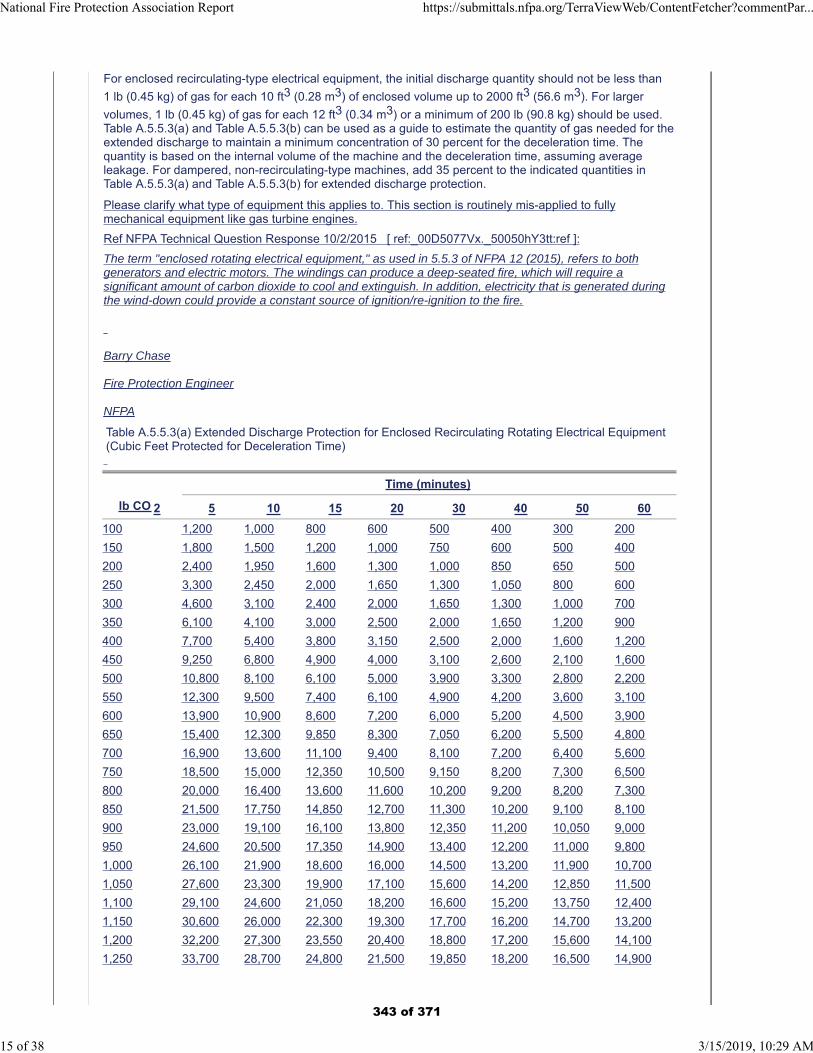
For enclosed recirculating-type electrical equipment, the initial discharge quantity should not be less than
1 lb (0.45 kg) of gas for each 10 ft3 (0.28 m3) of enclosed volume up to 2000 ft3 (56.6 m3). For larger
volumes, 1 lb (0.45 kg) of gas for each 12 ft3 (0.34 m3) or a minimum of 200 lb (90.8 kg) should be used.Table A.5.5.3(a) and Table A.5.5.3(b) can be used as a guide to estimate the quantity of gas needed for theextended discharge to maintain a minimum concentration of 30 percent for the deceleration time. Thequantity is based on the internal volume of the machine and the deceleration time, assuming averageleakage. For dampered, non-recirculating-type machines, add 35 percent to the indicated quantities inTable A.5.5.3(a) and Table A.5.5.3(b) for extended discharge protection.
Please clarify what type of equipment this applies to. This section is routinely mis-applied to fullymechanical equipment like gas turbine engines.
Ref NFPA Technical Question Response 10/2/2015 [ ref:_00D5077Vx._50050hY3tt:ref ]:
The term "enclosed rotating electrical equipment," as used in 5.5.3 of NFPA 12 (2015), refers to bothgenerators and electric motors. The windings can produce a deep-seated fire, which will require asignificant amount of carbon dioxide to cool and extinguish. In addition, electricity that is generated duringthe wind-down could provide a constant source of ignition/re-ignition to the fire.
Barry Chase
Fire Protection Engineer
NFPA
Table A.5.5.3(a) Extended Discharge Protection for Enclosed Recirculating Rotating Electrical Equipment(Cubic Feet Protected for Deceleration Time)
Time (minutes)
lb CO 2 5 10 15 20 30 40 50 60
100 1,200 1,000 800 600 500 400 300 200
150 1,800 1,500 1,200 1,000 750 600 500 400
200 2,400 1,950 1,600 1,300 1,000 850 650 500
250 3,300 2,450 2,000 1,650 1,300 1,050 800 600
300 4,600 3,100 2,400 2,000 1,650 1,300 1,000 700
350 6,100 4,100 3,000 2,500 2,000 1,650 1,200 900
400 7,700 5,400 3,800 3,150 2,500 2,000 1,600 1,200
450 9,250 6,800 4,900 4,000 3,100 2,600 2,100 1,600
500 10,800 8,100 6,100 5,000 3,900 3,300 2,800 2,200
550 12,300 9,500 7,400 6,100 4,900 4,200 3,600 3,100
600 13,900 10,900 8,600 7,200 6,000 5,200 4,500 3,900
650 15,400 12,300 9,850 8,300 7,050 6,200 5,500 4,800
700 16,900 13,600 11,100 9,400 8,100 7,200 6,400 5,600
750 18,500 15,000 12,350 10,500 9,150 8,200 7,300 6,500
800 20,000 16,400 13,600 11,600 10,200 9,200 8,200 7,300
850 21,500 17,750 14,850 12,700 11,300 10,200 9,100 8,100
900 23,000 19,100 16,100 13,800 12,350 11,200 10,050 9,000
950 24,600 20,500 17,350 14,900 13,400 12,200 11,000 9,800
1,000 26,100 21,900 18,600 16,000 14,500 13,200 11,900 10,700
1,050 27,600 23,300 19,900 17,100 15,600 14,200 12,850 11,500
1,100 29,100 24,600 21,050 18,200 16,600 15,200 13,750 12,400
1,150 30,600 26,000 22,300 19,300 17,700 16,200 14,700 13,200
1,200 32,200 27,300 23,550 20,400 18,800 17,200 15,600 14,100
1,250 33,700 28,700 24,800 21,500 19,850 18,200 16,500 14,900
National Fire Protection Association Report https://submittals.nfpa.org/TerraViewWeb/ContentFetcher?commentPar...
15 of 38 3/15/2019, 10:29 AM
343 of 371
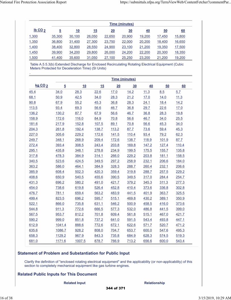
Time (minutes)
lb CO 2 5 10 15 20 30 40 50 60
1,300 35,300 30,100 26,050 22,650 20,900 19,200 17,450 15,800
1,350 36,800 31,400 27,300 23,750 22,000 20,200 18,400 16,650
1,400 38,400 32,800 28,550 24,900 23,100 21,200 19,350 17,500
1,450 39,900 34,200 29,800 26,000 24,200 22,200 20,300 18,350
1,500 41,400 35,600 31,050 27,100 25,250 23,200 21,200 19,200
Table A.5.5.3(b) Extended Discharge for Enclosed Recirculating Rotating Electrical Equipment (CubicMeters Protected for Deceleration Time) (SI Units)
Time (minutes)
kg CO 2 5 10 15 20 30 40 50 60
45.4 34.0 28.3 22.6 17.0 14.2 11.3 8.5 5.7
68.1 50.9 42.5 34.0 28.3 21.2 17.0 14.0 11.3
90.8 67.9 55.2 45.3 36.8 28.3 24.1 18.4 14.2
113.5 93.4 69.3 56.6 46.7 36.8 29.7 22.6 17.0
136.2 130.2 87.7 67.9 56.6 46.7 36.8 28.3 19.8
158.9 172.6 116.0 84.9 70.8 56.6 46.7 34.0 25.5
181.6 217.9 152.8 107.5 89.1 70.8 56.6 45.3 34.0
204.3 261.8 192.4 138.7 113.2 87.7 73.6 59.4 45.3
227.0 305.6 229.2 172.6 141.5 110.4 93.4 79.2 62.3
249.7 348.1 268.9 209.4 172.6 138.7 118.9 101.9 87.7
272.4 393.4 308.5 243.4 203.8 169.8 147.2 127.4 110.4
295.1 435.8 348.1 278.8 234.9 199.5 175.5 155.7 135.8
317.8 478.3 384.9 314.1 266.0 229.2 203.8 181.1 158.5
340.5 523.6 424.5 349.5 297.2 258.9 232.1 206.6 184.0
363.2 586.0 464.1 384.9 328.3 288.7 260.4 232.1 206.6
385.9 608.4 502.3 420.3 359.4 319.8 288.7 257.5 229.2
408.6 650.9 540.5 455.6 390.5 349.5 317.0 284.4 254.7
431.3 696.2 580.2 491.0 421.7 379.2 345.3 311.3 277.3
454.0 738.6 619.8 526.4 452.8 410.4 373.6 336.8 302.8
476.7 781.1 659.4 563.2 483.9 441.5 401.9 363.7 325.5
499.4 823.5 696.2 595.7 515.1 469.8 430.2 389.1 350.9
522.1 866.0 735.8 631.1 546.2 500.9 458.5 416.0 373.6
544.8 911.3 772.6 666.5 577.3 532.0 486.8 441.5 399.0
567.5 953.7 812.2 701.8 609.4 561.8 515.1 467.0 421.7
590.2 999.0 851.8 737.2 641.0 591.5 543.4 493.8 447.1
612.9 1041.4 888.6 772.6 672.1 622.6 571.7 520.7 471.2
635.6 1086.7 928.2 808.0 704.7 653.7 600.0 547.6 495.3
658.3 1129.2 967.9 843.3 735.8 684.9 628.3 574.5 519.3
681.0 1171.6 1007.5 878.7 766.9 713.2 656.6 600.0 543.4
Statement of Problem and Substantiation for Public Input
Clarify the definition of "enclosed rotating electrical equipment" and the applicability (or non-applicability) of this section to completely mechanical equipment like gas turbine engines.
Related Public Inputs for This Document
Related Input Relationship
National Fire Protection Association Report https://submittals.nfpa.org/TerraViewWeb/ContentFetcher?commentPar...
16 of 38 3/15/2019, 10:29 AM
344 of 371
Public Input No. 8-NFPA 12-2018 [Section No. 5.5.3] Same issue in the body of the standard.
Public Input No. 10-NFPA 12-2018 [Section No. 5.4.4.2]
Submitter Information Verification
Submitter Full Name: Matthew Taylor
Organization: Mitsubishi Hitachi Power Systems
Street Address:
City:
State:
Zip:
Submittal Date: Thu Dec 27 11:08:08 EST 2018
Committee: GFE-AAA
National Fire Protection Association Report https://submittals.nfpa.org/TerraViewWeb/ContentFetcher?commentPar...
17 of 38 3/15/2019, 10:29 AM
345 of 371
Public Input No. 13-NFPA 12-2018 [ Section No. C.1 ]
National Fire Protection Association Report https://submittals.nfpa.org/TerraViewWeb/ContentFetcher?commentPar...
18 of 38 3/15/2019, 10:29 AM
346 of 371

C.1
National Fire Protection Association Report https://submittals.nfpa.org/TerraViewWeb/ContentFetcher?commentPar...
19 of 38 3/15/2019, 10:29 AM
347 of 371
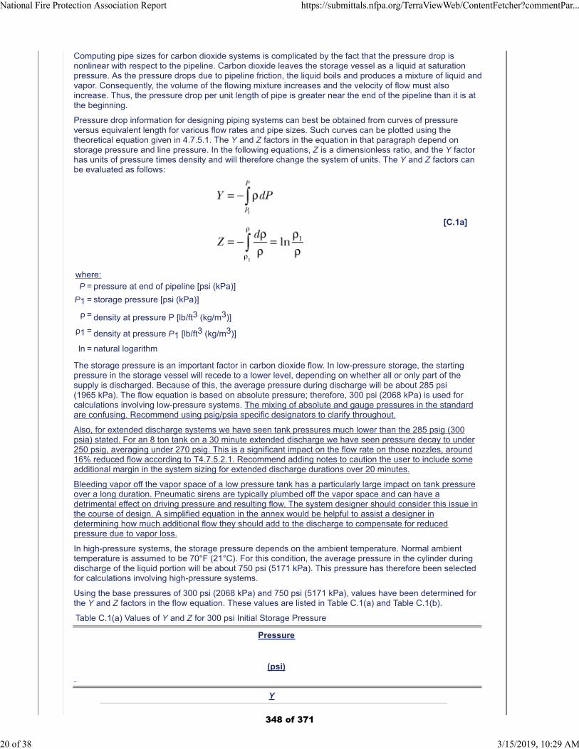
Computing pipe sizes for carbon dioxide systems is complicated by the fact that the pressure drop isnonlinear with respect to the pipeline. Carbon dioxide leaves the storage vessel as a liquid at saturationpressure. As the pressure drops due to pipeline friction, the liquid boils and produces a mixture of liquid andvapor. Consequently, the volume of the flowing mixture increases and the velocity of flow must alsoincrease. Thus, the pressure drop per unit length of pipe is greater near the end of the pipeline than it is atthe beginning.
Pressure drop information for designing piping systems can best be obtained from curves of pressureversus equivalent length for various flow rates and pipe sizes. Such curves can be plotted using thetheoretical equation given in 4.7.5.1. The Y and Z factors in the equation in that paragraph depend onstorage pressure and line pressure. In the following equations, Z is a dimensionless ratio, and the Y factorhas units of pressure times density and will therefore change the system of units. The Y and Z factors canbe evaluated as follows:
[C.1a]
where:P = pressure at end of pipeline [psi (kPa)]
P1 = storage pressure [psi (kPa)]
ρ = density at pressure P [lb/ft3 (kg/m3)]
ρ1 = density at pressure P1 [lb/ft3 (kg/m3)]
ln = natural logarithm
The storage pressure is an important factor in carbon dioxide flow. In low-pressure storage, the startingpressure in the storage vessel will recede to a lower level, depending on whether all or only part of thesupply is discharged. Because of this, the average pressure during discharge will be about 285 psi(1965 kPa). The flow equation is based on absolute pressure; therefore, 300 psi (2068 kPa) is used forcalculations involving low-pressure systems. The mixing of absolute and gauge pressures in the standardare confusing. Recommend using psig/psia specific designators to clarify throughout.
Also, for extended discharge systems we have seen tank pressures much lower than the 285 psig (300psia) stated. For an 8 ton tank on a 30 minute extended discharge we have seen pressure decay to under250 psig, averaging under 270 psig. This is a significant impact on the flow rate on those nozzles, around16% reduced flow according to T4.7.5.2.1. Recommend adding notes to caution the user to include someadditional margin in the system sizing for extended discharge durations over 20 minutes.
Bleeding vapor off the vapor space of a low pressure tank has a particularly large impact on tank pressureover a long duration. Pneumatic sirens are typically plumbed off the vapor space and can have adetrimental effect on driving pressure and resulting flow. The system designer should consider this issue inthe course of design. A simplified equation in the annex would be helpful to assist a designer indetermining how much additional flow they should add to the discharge to compensate for reducedpressure due to vapor loss.
In high-pressure systems, the storage pressure depends on the ambient temperature. Normal ambienttemperature is assumed to be 70°F (21°C). For this condition, the average pressure in the cylinder duringdischarge of the liquid portion will be about 750 psi (5171 kPa). This pressure has therefore been selectedfor calculations involving high-pressure systems.
Using the base pressures of 300 psi (2068 kPa) and 750 psi (5171 kPa), values have been determined forthe Y and Z factors in the flow equation. These values are listed in Table C.1(a) and Table C.1(b).
Table C.1(a) Values of Y and Z for 300 psi Initial Storage Pressure
Pressure
(psi)
Y
National Fire Protection Association Report https://submittals.nfpa.org/TerraViewWeb/ContentFetcher?commentPar...
20 of 38 3/15/2019, 10:29 AM
348 of 371
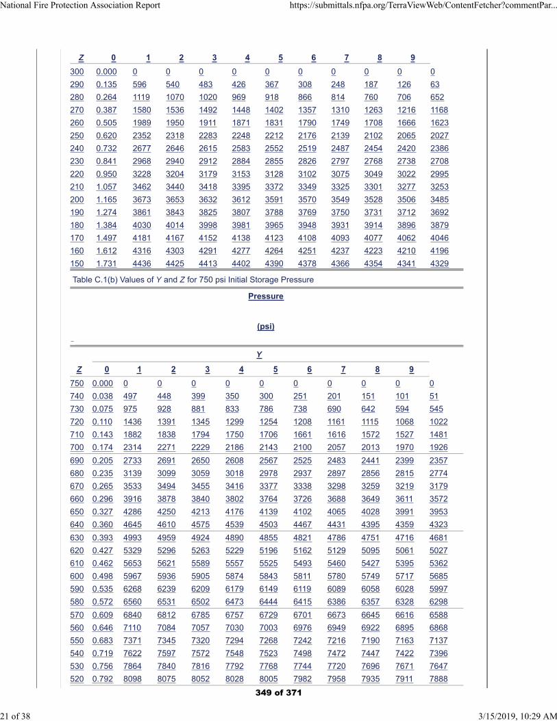
Z 0 1 2 3 4 5 6 7 8 9
300 0.000 0 0 0 0 0 0 0 0 0 0
290 0.135 596 540 483 426 367 308 248 187 126 63
280 0.264 1119 1070 1020 969 918 866 814 760 706 652
270 0.387 1580 1536 1492 1448 1402 1357 1310 1263 1216 1168
260 0.505 1989 1950 1911 1871 1831 1790 1749 1708 1666 1623
250 0.620 2352 2318 2283 2248 2212 2176 2139 2102 2065 2027
240 0.732 2677 2646 2615 2583 2552 2519 2487 2454 2420 2386
230 0.841 2968 2940 2912 2884 2855 2826 2797 2768 2738 2708
220 0.950 3228 3204 3179 3153 3128 3102 3075 3049 3022 2995
210 1.057 3462 3440 3418 3395 3372 3349 3325 3301 3277 3253
200 1.165 3673 3653 3632 3612 3591 3570 3549 3528 3506 3485
190 1.274 3861 3843 3825 3807 3788 3769 3750 3731 3712 3692
180 1.384 4030 4014 3998 3981 3965 3948 3931 3914 3896 3879
170 1.497 4181 4167 4152 4138 4123 4108 4093 4077 4062 4046
160 1.612 4316 4303 4291 4277 4264 4251 4237 4223 4210 4196
150 1.731 4436 4425 4413 4402 4390 4378 4366 4354 4341 4329
Table C.1(b) Values of Y and Z for 750 psi Initial Storage Pressure
Pressure
(psi)
Y
Z 0 1 2 3 4 5 6 7 8 9
750 0.000 0 0 0 0 0 0 0 0 0 0
740 0.038 497 448 399 350 300 251 201 151 101 51
730 0.075 975 928 881 833 786 738 690 642 594 545
720 0.110 1436 1391 1345 1299 1254 1208 1161 1115 1068 1022
710 0.143 1882 1838 1794 1750 1706 1661 1616 1572 1527 1481
700 0.174 2314 2271 2229 2186 2143 2100 2057 2013 1970 1926
690 0.205 2733 2691 2650 2608 2567 2525 2483 2441 2399 2357
680 0.235 3139 3099 3059 3018 2978 2937 2897 2856 2815 2774
670 0.265 3533 3494 3455 3416 3377 3338 3298 3259 3219 3179
660 0.296 3916 3878 3840 3802 3764 3726 3688 3649 3611 3572
650 0.327 4286 4250 4213 4176 4139 4102 4065 4028 3991 3953
640 0.360 4645 4610 4575 4539 4503 4467 4431 4395 4359 4323
630 0.393 4993 4959 4924 4890 4855 4821 4786 4751 4716 4681
620 0.427 5329 5296 5263 5229 5196 5162 5129 5095 5061 5027
610 0.462 5653 5621 5589 5557 5525 5493 5460 5427 5395 5362
600 0.498 5967 5936 5905 5874 5843 5811 5780 5749 5717 5685
590 0.535 6268 6239 6209 6179 6149 6119 6089 6058 6028 5997
580 0.572 6560 6531 6502 6473 6444 6415 6386 6357 6328 6298
570 0.609 6840 6812 6785 6757 6729 6701 6673 6645 6616 6588
560 0.646 7110 7084 7057 7030 7003 6976 6949 6922 6895 6868
550 0.683 7371 7345 7320 7294 7268 7242 7216 7190 7163 7137
540 0.719 7622 7597 7572 7548 7523 7498 7472 7447 7422 7396
530 0.756 7864 7840 7816 7792 7768 7744 7720 7696 7671 7647
520 0.792 8098 8075 8052 8028 8005 7982 7958 7935 7911 7888
National Fire Protection Association Report https://submittals.nfpa.org/TerraViewWeb/ContentFetcher?commentPar...
21 of 38 3/15/2019, 10:29 AM
349 of 371
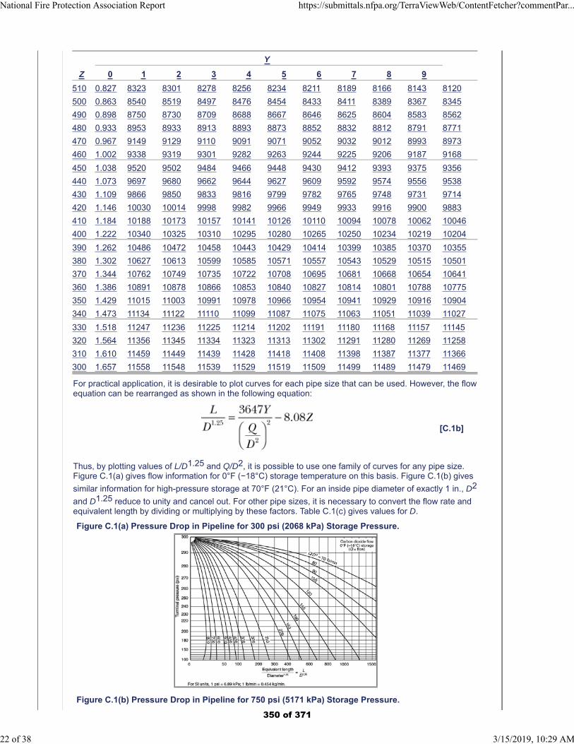
Y
Z 0 1 2 3 4 5 6 7 8 9
510 0.827 8323 8301 8278 8256 8234 8211 8189 8166 8143 8120
500 0.863 8540 8519 8497 8476 8454 8433 8411 8389 8367 8345
490 0.898 8750 8730 8709 8688 8667 8646 8625 8604 8583 8562
480 0.933 8953 8933 8913 8893 8873 8852 8832 8812 8791 8771
470 0.967 9149 9129 9110 9091 9071 9052 9032 9012 8993 8973
460 1.002 9338 9319 9301 9282 9263 9244 9225 9206 9187 9168
450 1.038 9520 9502 9484 9466 9448 9430 9412 9393 9375 9356
440 1.073 9697 9680 9662 9644 9627 9609 9592 9574 9556 9538
430 1.109 9866 9850 9833 9816 9799 9782 9765 9748 9731 9714
420 1.146 10030 10014 9998 9982 9966 9949 9933 9916 9900 9883
410 1.184 10188 10173 10157 10141 10126 10110 10094 10078 10062 10046
400 1.222 10340 10325 10310 10295 10280 10265 10250 10234 10219 10204
390 1.262 10486 10472 10458 10443 10429 10414 10399 10385 10370 10355
380 1.302 10627 10613 10599 10585 10571 10557 10543 10529 10515 10501
370 1.344 10762 10749 10735 10722 10708 10695 10681 10668 10654 10641
360 1.386 10891 10878 10866 10853 10840 10827 10814 10801 10788 10775
350 1.429 11015 11003 10991 10978 10966 10954 10941 10929 10916 10904
340 1.473 11134 11122 11110 11099 11087 11075 11063 11051 11039 11027
330 1.518 11247 11236 11225 11214 11202 11191 11180 11168 11157 11145
320 1.564 11356 11345 11334 11323 11313 11302 11291 11280 11269 11258
310 1.610 11459 11449 11439 11428 11418 11408 11398 11387 11377 11366
300 1.657 11558 11548 11539 11529 11519 11509 11499 11489 11479 11469
For practical application, it is desirable to plot curves for each pipe size that can be used. However, the flowequation can be rearranged as shown in the following equation:
[C.1b]
Thus, by plotting values of L/D1.25 and Q/D2, it is possible to use one family of curves for any pipe size.Figure C.1(a) gives flow information for 0°F (−18°C) storage temperature on this basis. Figure C.1(b) gives
similar information for high-pressure storage at 70°F (21°C). For an inside pipe diameter of exactly 1 in., D2
and D1.25 reduce to unity and cancel out. For other pipe sizes, it is necessary to convert the flow rate andequivalent length by dividing or multiplying by these factors. Table C.1(c) gives values for D.
Figure C.1(a) Pressure Drop in Pipeline for 300 psi (2068 kPa) Storage Pressure.
Figure C.1(b) Pressure Drop in Pipeline for 750 psi (5171 kPa) Storage Pressure.
National Fire Protection Association Report https://submittals.nfpa.org/TerraViewWeb/ContentFetcher?commentPar...
22 of 38 3/15/2019, 10:29 AM
350 of 371

Table C.1(c) Values of D1.25 and D2 for Various Pipe Sizes
Pipe Size
and Type
Inside Diameter
(in.) D 1.25 D 2
1 ⁄ 2 Std. 0.622 0.5521 0.3869
3 ⁄ 4 Std. 0.824 0.785 0.679
1 Std. 1.049 1.0615 1.100
1 XH 0.957 0.9465 0.9158
1 1 ⁄ 4 Std. 1.380 1.496 1.904
1 1 ⁄ 4 XH 1.278 1.359 1.633
1 1 ⁄ 2 Std. 1.610 1.813 2.592
1 1 ⁄ 2 XH 1.500 1.660 2.250
2 Std. 2.067 2.475 4.272
2 XH 1.939 2.288 3.760
2 1 ⁄ 2 Std. 2.469 3.09 6.096
2 1 ⁄ 2 XH 2.323 2.865 5.396
3 Std. 3.068 4.06 9.413
3 XH 2.900 3.79 8.410
4 Std. 4.026 5.71 16.21
4 XH 3.826 5.34 14.64
5 Std. 5.047 7.54 25.47
5 XH 4.813 7.14 23.16
6 Std. 6.065 9.50 36.78
6 XH 5.761 8.92 33.19
These curves can be used for designing systems or for checking possible flow rates. For example, assumethe problem is to determine the terminal pressure for a low-pressure system consisting of a single 2 in.Schedule 40 pipeline with an equivalent length of 500 ft and a flow rate of 1000 lb/min. The flow rate andthe equivalent length must be converted to terms of Figure C.1(a) as follows:
[C.1c]
From Figure C.1(a), the terminal pressure is found to be about 228 psi at the point where the interpolatedflow rate of 234 lb/min intersects the equivalent length scale at 201 ft.
National Fire Protection Association Report https://submittals.nfpa.org/TerraViewWeb/ContentFetcher?commentPar...
23 of 38 3/15/2019, 10:29 AM
351 of 371
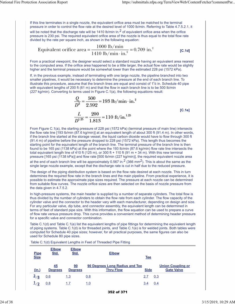
If this line terminates in a single nozzle, the equivalent orifice area must be matched to the terminalpressure in order to control the flow rate at the desired level of 1000 lb/min. Referring to Table 4.7.5.2.1, it
will be noted that the discharge rate will be 1410 lb/minꞏin.2 of equivalent orifice area when the orificepressure is 230 psi. The required equivalent orifice area of the nozzle is thus equal to the total flow ratedivided by the rate per square inch, as shown in the following equation:
[C.1d]
From a practical viewpoint, the designer would select a standard nozzle having an equivalent area nearestto the computed area. If the orifice area happened to be a little larger, the actual flow rate would be slightlyhigher and the terminal pressure would be somewhat lower than the estimated 228 psi (1572 kPa).
If, in the previous example, instead of terminating with one large nozzle, the pipeline branched into twosmaller pipelines, it would be necessary to determine the pressure at the end of each branch line. Toillustrate this procedure, assume that the branch lines are equal and consist of 11⁄2 in. Schedule 40 pipewith equivalent lengths of 200 ft (61 m) and that the flow in each branch line is to be 500 lb/min(227 kg/min). Converting to terms used in Figure C.1(a), the following equations result:
[C.1e]
From Figure C.1(a), the starting pressure of 228 psi (1572 kPa) (terminal pressure of main line) intersectsthe flow rate line [193 lb/min (87.6 kg/min)] at an equivalent length of about 300 ft (91.4 m). In other words,if the branch line started at the storage vessel, the liquid carbon dioxide would have to flow through 300 ft(91.4 m) of pipeline before the pressure dropped to 228 psi (1572 kPa). This length thus becomes thestarting point for the equivalent length of the branch line. The terminal pressure of the branch line is thenfound to be 165 psi (1138 kPa) at the point where the 193 lb/min (87.6 kg/min) flow rate line intersects thetotal equivalent length line of 410 ft (125 m), or 300 ft + 110 ft (91 m + 34 m). With this new terminalpressure [165 psi (1138 kPa)] and flow rate [500 lb/min (227 kg/min)], the required equivalent nozzle area
at the end of each branch line will be approximately 0.567 in.2 (366 mm2). This is about the same as thesingle large nozzle example, except that the discharge rate is cut in half due to the reduced pressure.
The design of the piping distribution system is based on the flow rate desired at each nozzle. This in turndetermines the required flow rate in the branch lines and the main pipeline. From practical experience, it ispossible to estimate the approximate pipe sizes required. The pressure at each nozzle can be determinedfrom suitable flow curves. The nozzle orifice sizes are then selected on the basis of nozzle pressure fromthe data given in 4.7.5.2.
In high-pressure systems, the main header is supplied by a number of separate cylinders. The total flow isthus divided by the number of cylinders to obtain the flow rate from each cylinder. The flow capacity of thecylinder valve and the connector to the header vary with each manufacturer, depending on design and size.For any particular valve, dip tube, and connector assembly, the equivalent length can be determined interms of feet of standard pipe size. With this information, the flow equation can be used to prepare a curveof flow rate versus pressure drop. This curve provides a convenient method of determining header pressurefor a specific valve and connector combination.
Table C.1(d) and Table C.1(e) list the equivalent lengths of pipe fittings for determining the equivalent lengthof piping systems. Table C.1(d) is for threaded joints, and Table C.1(e) is for welded joints. Both tables werecomputed for Schedule 40 pipe sizes; however, for all practical purposes, the same figures can also beused for Schedule 80 pipe sizes.
Table C.1(d) Equivalent Lengths in Feet of Threaded Pipe Fitting
PipeSize
(in.)
ElbowStd.
45Degrees
ElbowStd.
90Degrees
Elbow
90 Degrees Long Radius and TeeThru Flow
Tee
SideUnion Coupling or
Gate Valve
3 ⁄ 8 0.6 1.3 0.8 2.7 0.3
1 ⁄ 2 0.8 1.7 1.0 3.4 0.4
National Fire Protection Association Report https://submittals.nfpa.org/TerraViewWeb/ContentFetcher?commentPar...
24 of 38 3/15/2019, 10:29 AM
352 of 371

PipeSize
(in.)
ElbowStd.
45Degrees
ElbowStd.
90Degrees
Elbow
90 Degrees Long Radius and TeeThru Flow
Tee
SideUnion Coupling or
Gate Valve
3 ⁄ 4 1.0 2.2 1.4 4.5 0.5
1 1.3 2.8 1.8 5.7 0.6
1 1 ⁄ 4 1.7 3.7 2.3 7.5 0.8
1 1 ⁄ 2 2.0 4.3 2.7 8.7 0.9
2 2.6 5.5 3.5 11.2 1.2
2 1 ⁄ 2 3.1 6.6 4.1 13.4 1.4
3 3.8 8.2 5.1 16.6 1.8
4 5.0 10.7 6.7 21.8 2.4
5 6.3 13.4 8.4 27.4 3.0
6 7.6 16.2 10.1 32.8 3.5
For SI units, 1 ft = 0.3048 m.
Table C.1(e) Equivalent Lengths in Feet of Welded Pipe Fitting
PipeSize
(in.)Elbow Std. 45
DegreesElbow Std. 90
Degrees
Elbow
90 Degrees Long Radius andTee Thru Flow
Tee
SideGate
Valve
3 ⁄ 8 0.2 0.7 0.5 1.6 0.3
1 ⁄ 2 0.3 0.8 0.7 2.1 0.4
3 ⁄ 4 0.4 1.1 0.9 2.8 0.5
1 0.5 1.4 1.1 3.5 0.6
1 1 ⁄ 4 0.7 1.8 1.5 4.6 0.8
1 1 ⁄ 2 0.8 2.1 1.7 5.4 0.9
2 1.0 2.8 2.2 6.9 1.2
2 1 ⁄ 2 1.2 3.3 2.7 8.2 1.4
3 1.8 4.1 3.3 10.2 1.8
4 2.0 5.4 4.4 13.4 2.4
5 2.5 6.7 5.5 16.8 3.0
6 3.0 8.1 6.6 20.2 3.5
For SI units, 1 ft = 0.3048 m.
For nominal changes in elevation of piping, the change in head pressure is negligible. However, if there is asubstantial change in elevation, this factor should be taken into account. The head pressure correction perfoot of elevation depends on the average line pressure where the elevation takes place because the densitychanges with pressure. Correction factors are given in Table C.1(f) and Table C.1(g) for low-pressure andhigh-pressure systems, respectively. The correction is subtracted from the terminal pressure when the flowis upward and is added to the terminal pressure when the flow is downward.
Table C.1(f) Elevation Correction Factors for Low-Pressure System
Average Line Pressure
Elevation Correction
psi kPa
National Fire Protection Association Report https://submittals.nfpa.org/TerraViewWeb/ContentFetcher?commentPar...
25 of 38 3/15/2019, 10:29 AM
353 of 371
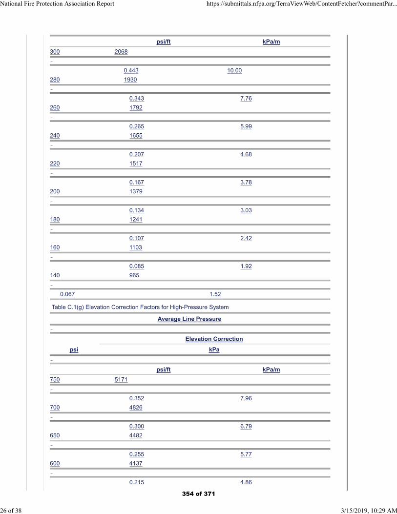
psi/ft kPa/m
300 2068
0.443 10.00
280 1930
0.343 7.76
260 1792
0.265 5.99
240 1655
0.207 4.68
220 1517
0.167 3.78
200 1379
0.134 3.03
180 1241
0.107 2.42
160 1103
0.085 1.92
140 965
0.067 1.52
Table C.1(g) Elevation Correction Factors for High-Pressure System
Average Line Pressure
Elevation Correction
psi kPa
psi/ft kPa/m
750 5171
0.352 7.96
700 4826
0.300 6.79
650 4482
0.255 5.77
600 4137
0.215 4.86
National Fire Protection Association Report https://submittals.nfpa.org/TerraViewWeb/ContentFetcher?commentPar...
26 of 38 3/15/2019, 10:29 AM
354 of 371
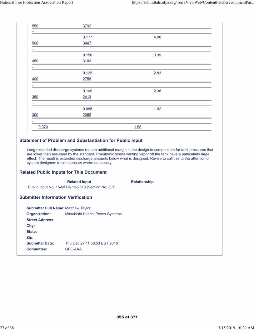
550 3792
0.177 4.00
500 3447
0.150 3.39
450 3103
0.125 2.83
400 2758
0.105 2.38
350 2413
0.085 1.92
300 2068
0.070 1.58
Statement of Problem and Substantiation for Public Input
Long extended discharge systems require additional margin in the design to compensate for tank pressures that are lower than assumed by the standard. Pneumatic sirens venting vapor off the tank have a particularly large effect. The result is extended discharge amounts below what is designed. Revise to call this to the attention of system designers to compensate where necessary.
Related Public Inputs for This Document
Related Input Relationship
Public Input No. 15-NFPA 12-2018 [Section No. C.1]
Submitter Information Verification
Submitter Full Name: Matthew Taylor
Organization: Mitsubishi Hitachi Power Systems
Street Address:
City:
State:
Zip:
Submittal Date: Thu Dec 27 11:58:53 EST 2018
Committee: GFE-AAA
National Fire Protection Association Report https://submittals.nfpa.org/TerraViewWeb/ContentFetcher?commentPar...
27 of 38 3/15/2019, 10:29 AM
355 of 371
Public Input No. 15-NFPA 12-2018 [ Section No. C.1 ]
National Fire Protection Association Report https://submittals.nfpa.org/TerraViewWeb/ContentFetcher?commentPar...
28 of 38 3/15/2019, 10:29 AM
356 of 371

C.1
National Fire Protection Association Report https://submittals.nfpa.org/TerraViewWeb/ContentFetcher?commentPar...
29 of 38 3/15/2019, 10:29 AM
357 of 371
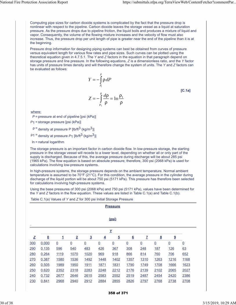
Computing pipe sizes for carbon dioxide systems is complicated by the fact that the pressure drop isnonlinear with respect to the pipeline. Carbon dioxide leaves the storage vessel as a liquid at saturationpressure. As the pressure drops due to pipeline friction, the liquid boils and produces a mixture of liquid andvapor. Consequently, the volume of the flowing mixture increases and the velocity of flow must alsoincrease. Thus, the pressure drop per unit length of pipe is greater near the end of the pipeline than it is atthe beginning.
Pressure drop information for designing piping systems can best be obtained from curves of pressureversus equivalent length for various flow rates and pipe sizes. Such curves can be plotted using thetheoretical equation given in 4.7.5.1. The Y and Z factors in the equation in that paragraph depend onstorage pressure and line pressure. In the following equations, Z is a dimensionless ratio, and the Y factorhas units of pressure times density and will therefore change the system of units. The Y and Z factors canbe evaluated as follows:
[C.1a]
where:P = pressure at end of pipeline [psi (kPa)]
P1 = storage pressure [psi (kPa)]
ρ = density at pressure P [lb/ft3 (kg/m3)]
ρ1 = density at pressure P1 [lb/ft3 (kg/m3)]
ln = natural logarithm
The storage pressure is an important factor in carbon dioxide flow. In low-pressure storage, the startingpressure in the storage vessel will recede to a lower level, depending on whether all or only part of thesupply is discharged. Because of this, the average pressure during discharge will be about 285 psi(1965 kPa). The flow equation is based on absolute pressure; therefore, 300 psi (2068 kPa) is used forcalculations involving low-pressure systems.
In high-pressure systems, the storage pressure depends on the ambient temperature. Normal ambienttemperature is assumed to be 70°F (21°C). For this condition, the average pressure in the cylinder duringdischarge of the liquid portion will be about 750 psi (5171 kPa). This pressure has therefore been selectedfor calculations involving high-pressure systems.
Using the base pressures of 300 psi (2068 kPa) and 750 psi (5171 kPa), values have been determined forthe Y and Z factors in the flow equation. These values are listed in Table C.1(a) and Table C.1(b).
Table C.1(a) Values of Y and Z for 300 psi Initial Storage Pressure
Pressure
(psi)
Y
Z 0 1 2 3 4 5 6 7 8 9
300 0.000 0 0 0 0 0 0 0 0 0 0
290 0.135 596 540 483 426 367 308 248 187 126 63
280 0.264 1119 1070 1020 969 918 866 814 760 706 652
270 0.387 1580 1536 1492 1448 1402 1357 1310 1263 1216 1168
260 0.505 1989 1950 1911 1871 1831 1790 1749 1708 1666 1623
250 0.620 2352 2318 2283 2248 2212 2176 2139 2102 2065 2027
240 0.732 2677 2646 2615 2583 2552 2519 2487 2454 2420 2386
230 0.841 2968 2940 2912 2884 2855 2826 2797 2768 2738 2708
National Fire Protection Association Report https://submittals.nfpa.org/TerraViewWeb/ContentFetcher?commentPar...
30 of 38 3/15/2019, 10:29 AM
358 of 371
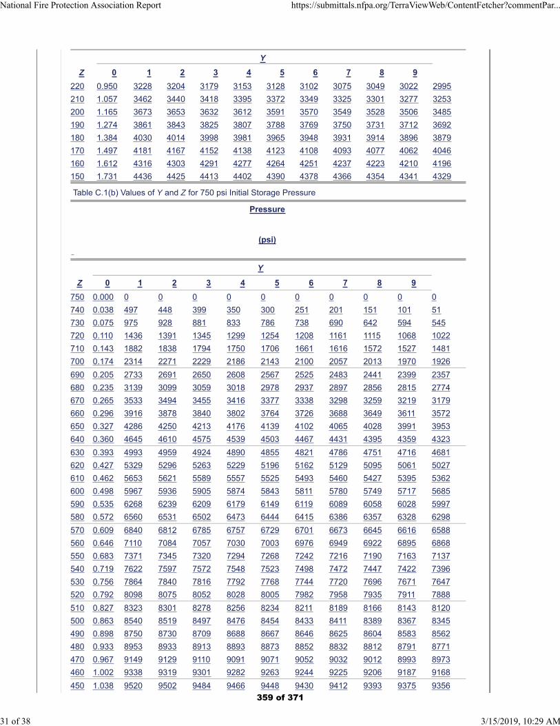
Y
Z 0 1 2 3 4 5 6 7 8 9
220 0.950 3228 3204 3179 3153 3128 3102 3075 3049 3022 2995
210 1.057 3462 3440 3418 3395 3372 3349 3325 3301 3277 3253
200 1.165 3673 3653 3632 3612 3591 3570 3549 3528 3506 3485
190 1.274 3861 3843 3825 3807 3788 3769 3750 3731 3712 3692
180 1.384 4030 4014 3998 3981 3965 3948 3931 3914 3896 3879
170 1.497 4181 4167 4152 4138 4123 4108 4093 4077 4062 4046
160 1.612 4316 4303 4291 4277 4264 4251 4237 4223 4210 4196
150 1.731 4436 4425 4413 4402 4390 4378 4366 4354 4341 4329
Table C.1(b) Values of Y and Z for 750 psi Initial Storage Pressure
Pressure
(psi)
Y
Z 0 1 2 3 4 5 6 7 8 9
750 0.000 0 0 0 0 0 0 0 0 0 0
740 0.038 497 448 399 350 300 251 201 151 101 51
730 0.075 975 928 881 833 786 738 690 642 594 545
720 0.110 1436 1391 1345 1299 1254 1208 1161 1115 1068 1022
710 0.143 1882 1838 1794 1750 1706 1661 1616 1572 1527 1481
700 0.174 2314 2271 2229 2186 2143 2100 2057 2013 1970 1926
690 0.205 2733 2691 2650 2608 2567 2525 2483 2441 2399 2357
680 0.235 3139 3099 3059 3018 2978 2937 2897 2856 2815 2774
670 0.265 3533 3494 3455 3416 3377 3338 3298 3259 3219 3179
660 0.296 3916 3878 3840 3802 3764 3726 3688 3649 3611 3572
650 0.327 4286 4250 4213 4176 4139 4102 4065 4028 3991 3953
640 0.360 4645 4610 4575 4539 4503 4467 4431 4395 4359 4323
630 0.393 4993 4959 4924 4890 4855 4821 4786 4751 4716 4681
620 0.427 5329 5296 5263 5229 5196 5162 5129 5095 5061 5027
610 0.462 5653 5621 5589 5557 5525 5493 5460 5427 5395 5362
600 0.498 5967 5936 5905 5874 5843 5811 5780 5749 5717 5685
590 0.535 6268 6239 6209 6179 6149 6119 6089 6058 6028 5997
580 0.572 6560 6531 6502 6473 6444 6415 6386 6357 6328 6298
570 0.609 6840 6812 6785 6757 6729 6701 6673 6645 6616 6588
560 0.646 7110 7084 7057 7030 7003 6976 6949 6922 6895 6868
550 0.683 7371 7345 7320 7294 7268 7242 7216 7190 7163 7137
540 0.719 7622 7597 7572 7548 7523 7498 7472 7447 7422 7396
530 0.756 7864 7840 7816 7792 7768 7744 7720 7696 7671 7647
520 0.792 8098 8075 8052 8028 8005 7982 7958 7935 7911 7888
510 0.827 8323 8301 8278 8256 8234 8211 8189 8166 8143 8120
500 0.863 8540 8519 8497 8476 8454 8433 8411 8389 8367 8345
490 0.898 8750 8730 8709 8688 8667 8646 8625 8604 8583 8562
480 0.933 8953 8933 8913 8893 8873 8852 8832 8812 8791 8771
470 0.967 9149 9129 9110 9091 9071 9052 9032 9012 8993 8973
460 1.002 9338 9319 9301 9282 9263 9244 9225 9206 9187 9168
450 1.038 9520 9502 9484 9466 9448 9430 9412 9393 9375 9356
National Fire Protection Association Report https://submittals.nfpa.org/TerraViewWeb/ContentFetcher?commentPar...
31 of 38 3/15/2019, 10:29 AM
359 of 371
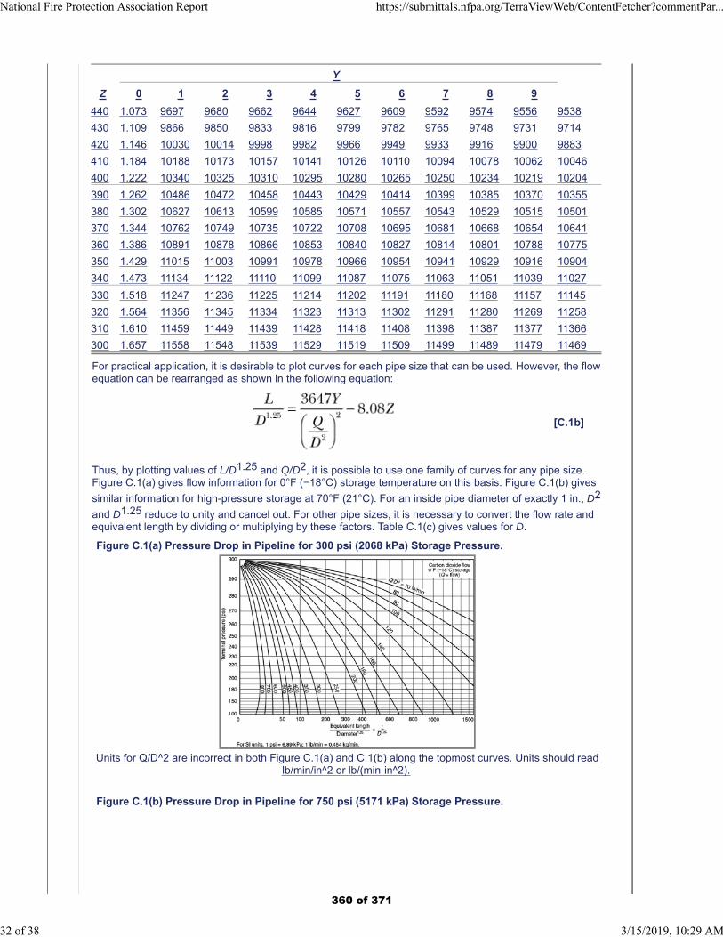
Y
Z 0 1 2 3 4 5 6 7 8 9
440 1.073 9697 9680 9662 9644 9627 9609 9592 9574 9556 9538
430 1.109 9866 9850 9833 9816 9799 9782 9765 9748 9731 9714
420 1.146 10030 10014 9998 9982 9966 9949 9933 9916 9900 9883
410 1.184 10188 10173 10157 10141 10126 10110 10094 10078 10062 10046
400 1.222 10340 10325 10310 10295 10280 10265 10250 10234 10219 10204
390 1.262 10486 10472 10458 10443 10429 10414 10399 10385 10370 10355
380 1.302 10627 10613 10599 10585 10571 10557 10543 10529 10515 10501
370 1.344 10762 10749 10735 10722 10708 10695 10681 10668 10654 10641
360 1.386 10891 10878 10866 10853 10840 10827 10814 10801 10788 10775
350 1.429 11015 11003 10991 10978 10966 10954 10941 10929 10916 10904
340 1.473 11134 11122 11110 11099 11087 11075 11063 11051 11039 11027
330 1.518 11247 11236 11225 11214 11202 11191 11180 11168 11157 11145
320 1.564 11356 11345 11334 11323 11313 11302 11291 11280 11269 11258
310 1.610 11459 11449 11439 11428 11418 11408 11398 11387 11377 11366
300 1.657 11558 11548 11539 11529 11519 11509 11499 11489 11479 11469
For practical application, it is desirable to plot curves for each pipe size that can be used. However, the flowequation can be rearranged as shown in the following equation:
[C.1b]
Thus, by plotting values of L/D1.25 and Q/D2, it is possible to use one family of curves for any pipe size.Figure C.1(a) gives flow information for 0°F (−18°C) storage temperature on this basis. Figure C.1(b) gives
similar information for high-pressure storage at 70°F (21°C). For an inside pipe diameter of exactly 1 in., D2
and D1.25 reduce to unity and cancel out. For other pipe sizes, it is necessary to convert the flow rate andequivalent length by dividing or multiplying by these factors. Table C.1(c) gives values for D.
Figure C.1(a) Pressure Drop in Pipeline for 300 psi (2068 kPa) Storage Pressure.
Units for Q/D^2 are incorrect in both Figure C.1(a) and C.1(b) along the topmost curves. Units should readlb/min/in^2 or lb/(min-in^2).
Figure C.1(b) Pressure Drop in Pipeline for 750 psi (5171 kPa) Storage Pressure.
National Fire Protection Association Report https://submittals.nfpa.org/TerraViewWeb/ContentFetcher?commentPar...
32 of 38 3/15/2019, 10:29 AM
360 of 371
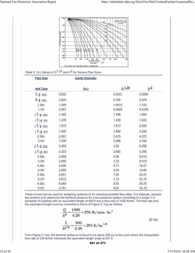
Table C.1(c) Values of D1.25 and D2 for Various Pipe Sizes
Pipe Size
and Type
Inside Diameter
(in.) D 1.25 D 2
1 ⁄ 2 Std. 0.622 0.5521 0.3869
3 ⁄ 4 Std. 0.824 0.785 0.679
1 Std. 1.049 1.0615 1.100
1 XH 0.957 0.9465 0.9158
1 1 ⁄ 4 Std. 1.380 1.496 1.904
1 1 ⁄ 4 XH 1.278 1.359 1.633
1 1 ⁄ 2 Std. 1.610 1.813 2.592
1 1 ⁄ 2 XH 1.500 1.660 2.250
2 Std. 2.067 2.475 4.272
2 XH 1.939 2.288 3.760
2 1 ⁄ 2 Std. 2.469 3.09 6.096
2 1 ⁄ 2 XH 2.323 2.865 5.396
3 Std. 3.068 4.06 9.413
3 XH 2.900 3.79 8.410
4 Std. 4.026 5.71 16.21
4 XH 3.826 5.34 14.64
5 Std. 5.047 7.54 25.47
5 XH 4.813 7.14 23.16
6 Std. 6.065 9.50 36.78
6 XH 5.761 8.92 33.19
These curves can be used for designing systems or for checking possible flow rates. For example, assumethe problem is to determine the terminal pressure for a low-pressure system consisting of a single 2 in.Schedule 40 pipeline with an equivalent length of 500 ft and a flow rate of 1000 lb/min. The flow rate andthe equivalent length must be converted to terms of Figure C.1(a) as follows:
[C.1c]
From Figure C.1(a), the terminal pressure is found to be about 228 psi at the point where the interpolatedflow rate of 234 lb/min intersects the equivalent length scale at 201 ft.
National Fire Protection Association Report https://submittals.nfpa.org/TerraViewWeb/ContentFetcher?commentPar...
33 of 38 3/15/2019, 10:29 AM
361 of 371
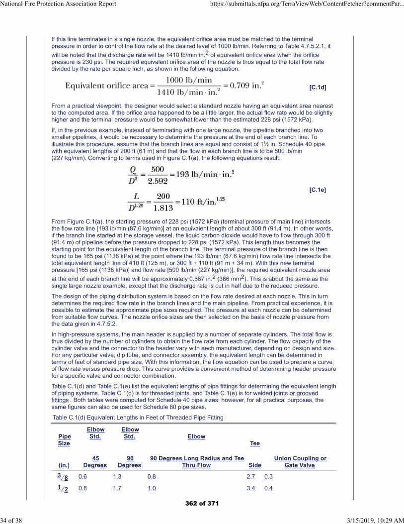
If this line terminates in a single nozzle, the equivalent orifice area must be matched to the terminalpressure in order to control the flow rate at the desired level of 1000 lb/min. Referring to Table 4.7.5.2.1, it
will be noted that the discharge rate will be 1410 lb/minꞏin.2 of equivalent orifice area when the orificepressure is 230 psi. The required equivalent orifice area of the nozzle is thus equal to the total flow ratedivided by the rate per square inch, as shown in the following equation:
[C.1d]
From a practical viewpoint, the designer would select a standard nozzle having an equivalent area nearestto the computed area. If the orifice area happened to be a little larger, the actual flow rate would be slightlyhigher and the terminal pressure would be somewhat lower than the estimated 228 psi (1572 kPa).
If, in the previous example, instead of terminating with one large nozzle, the pipeline branched into twosmaller pipelines, it would be necessary to determine the pressure at the end of each branch line. Toillustrate this procedure, assume that the branch lines are equal and consist of 11⁄2 in. Schedule 40 pipewith equivalent lengths of 200 ft (61 m) and that the flow in each branch line is to be 500 lb/min(227 kg/min). Converting to terms used in Figure C.1(a), the following equations result:
[C.1e]
From Figure C.1(a), the starting pressure of 228 psi (1572 kPa) (terminal pressure of main line) intersectsthe flow rate line [193 lb/min (87.6 kg/min)] at an equivalent length of about 300 ft (91.4 m). In other words,if the branch line started at the storage vessel, the liquid carbon dioxide would have to flow through 300 ft(91.4 m) of pipeline before the pressure dropped to 228 psi (1572 kPa). This length thus becomes thestarting point for the equivalent length of the branch line. The terminal pressure of the branch line is thenfound to be 165 psi (1138 kPa) at the point where the 193 lb/min (87.6 kg/min) flow rate line intersects thetotal equivalent length line of 410 ft (125 m), or 300 ft + 110 ft (91 m + 34 m). With this new terminalpressure [165 psi (1138 kPa)] and flow rate [500 lb/min (227 kg/min)], the required equivalent nozzle area
at the end of each branch line will be approximately 0.567 in.2 (366 mm2). This is about the same as thesingle large nozzle example, except that the discharge rate is cut in half due to the reduced pressure.
The design of the piping distribution system is based on the flow rate desired at each nozzle. This in turndetermines the required flow rate in the branch lines and the main pipeline. From practical experience, it ispossible to estimate the approximate pipe sizes required. The pressure at each nozzle can be determinedfrom suitable flow curves. The nozzle orifice sizes are then selected on the basis of nozzle pressure fromthe data given in 4.7.5.2.
In high-pressure systems, the main header is supplied by a number of separate cylinders. The total flow isthus divided by the number of cylinders to obtain the flow rate from each cylinder. The flow capacity of thecylinder valve and the connector to the header vary with each manufacturer, depending on design and size.For any particular valve, dip tube, and connector assembly, the equivalent length can be determined interms of feet of standard pipe size. With this information, the flow equation can be used to prepare a curveof flow rate versus pressure drop. This curve provides a convenient method of determining header pressurefor a specific valve and connector combination.
Table C.1(d) and Table C.1(e) list the equivalent lengths of pipe fittings for determining the equivalent lengthof piping systems. Table C.1(d) is for threaded joints, and Table C.1(e) is for welded joints or groovedfittings . Both tables were computed for Schedule 40 pipe sizes; however, for all practical purposes, thesame figures can also be used for Schedule 80 pipe sizes.
Table C.1(d) Equivalent Lengths in Feet of Threaded Pipe Fitting
PipeSize
(in.)
ElbowStd.
45Degrees
ElbowStd.
90Degrees
Elbow
90 Degrees Long Radius and TeeThru Flow
Tee
SideUnion Coupling or
Gate Valve
3 ⁄ 8 0.6 1.3 0.8 2.7 0.3
1 ⁄ 2 0.8 1.7 1.0 3.4 0.4
National Fire Protection Association Report https://submittals.nfpa.org/TerraViewWeb/ContentFetcher?commentPar...
34 of 38 3/15/2019, 10:29 AM
362 of 371
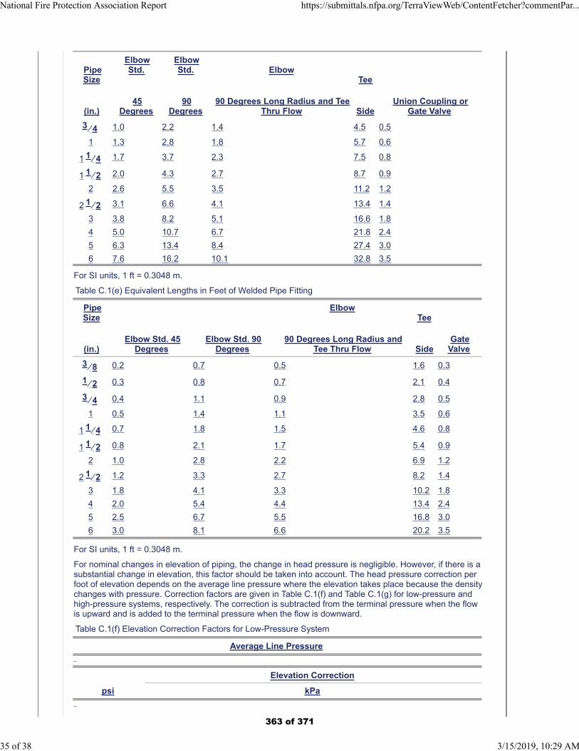
PipeSize
(in.)
ElbowStd.
45Degrees
ElbowStd.
90Degrees
Elbow
90 Degrees Long Radius and TeeThru Flow
Tee
SideUnion Coupling or
Gate Valve
3 ⁄ 4 1.0 2.2 1.4 4.5 0.5
1 1.3 2.8 1.8 5.7 0.6
1 1 ⁄ 4 1.7 3.7 2.3 7.5 0.8
1 1 ⁄ 2 2.0 4.3 2.7 8.7 0.9
2 2.6 5.5 3.5 11.2 1.2
2 1 ⁄ 2 3.1 6.6 4.1 13.4 1.4
3 3.8 8.2 5.1 16.6 1.8
4 5.0 10.7 6.7 21.8 2.4
5 6.3 13.4 8.4 27.4 3.0
6 7.6 16.2 10.1 32.8 3.5
For SI units, 1 ft = 0.3048 m.
Table C.1(e) Equivalent Lengths in Feet of Welded Pipe Fitting
PipeSize
(in.)Elbow Std. 45
DegreesElbow Std. 90
Degrees
Elbow
90 Degrees Long Radius andTee Thru Flow
Tee
SideGate
Valve
3 ⁄ 8 0.2 0.7 0.5 1.6 0.3
1 ⁄ 2 0.3 0.8 0.7 2.1 0.4
3 ⁄ 4 0.4 1.1 0.9 2.8 0.5
1 0.5 1.4 1.1 3.5 0.6
1 1 ⁄ 4 0.7 1.8 1.5 4.6 0.8
1 1 ⁄ 2 0.8 2.1 1.7 5.4 0.9
2 1.0 2.8 2.2 6.9 1.2
2 1 ⁄ 2 1.2 3.3 2.7 8.2 1.4
3 1.8 4.1 3.3 10.2 1.8
4 2.0 5.4 4.4 13.4 2.4
5 2.5 6.7 5.5 16.8 3.0
6 3.0 8.1 6.6 20.2 3.5
For SI units, 1 ft = 0.3048 m.
For nominal changes in elevation of piping, the change in head pressure is negligible. However, if there is asubstantial change in elevation, this factor should be taken into account. The head pressure correction perfoot of elevation depends on the average line pressure where the elevation takes place because the densitychanges with pressure. Correction factors are given in Table C.1(f) and Table C.1(g) for low-pressure andhigh-pressure systems, respectively. The correction is subtracted from the terminal pressure when the flowis upward and is added to the terminal pressure when the flow is downward.
Table C.1(f) Elevation Correction Factors for Low-Pressure System
Average Line Pressure
Elevation Correction
psi kPa
National Fire Protection Association Report https://submittals.nfpa.org/TerraViewWeb/ContentFetcher?commentPar...
35 of 38 3/15/2019, 10:29 AM
363 of 371

psi/ft kPa/m
300 2068
0.443 10.00
280 1930
0.343 7.76
260 1792
0.265 5.99
240 1655
0.207 4.68
220 1517
0.167 3.78
200 1379
0.134 3.03
180 1241
0.107 2.42
160 1103
0.085 1.92
140 965
0.067 1.52
Table C.1(g) Elevation Correction Factors for High-Pressure System
Average Line Pressure
Elevation Correction
psi kPa
psi/ft kPa/m
750 5171
0.352 7.96
700 4826
0.300 6.79
650 4482
0.255 5.77
600 4137
0.215 4.86
National Fire Protection Association Report https://submittals.nfpa.org/TerraViewWeb/ContentFetcher?commentPar...
36 of 38 3/15/2019, 10:29 AM
364 of 371
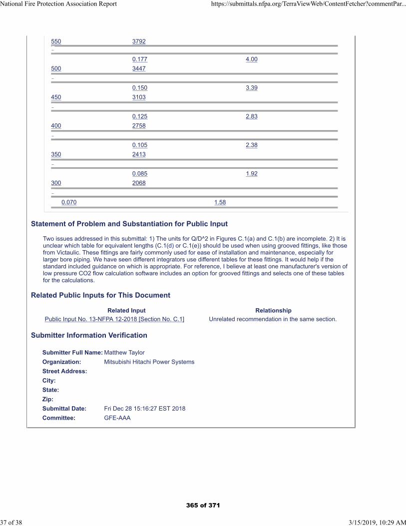
550 3792
0.177 4.00
500 3447
0.150 3.39
450 3103
0.125 2.83
400 2758
0.105 2.38
350 2413
0.085 1.92
300 2068
0.070 1.58
Statement of Problem and Substantiation for Public Input
Two issues addressed in this submittal: 1) The units for Q/D^2 in Figures C.1(a) and C.1(b) are incomplete. 2) It is unclear which table for equivalent lengths (C.1(d) or C.1(e)) should be used when using grooved fittings, like those from Victaulic. These fittings are fairly commonly used for ease of installation and maintenance, especially for larger bore piping. We have seen different integrators use different tables for these fittings. It would help if the standard included guidance on which is appropriate. For reference, I believe at least one manufacturer's version of low pressure CO2 flow calculation software includes an option for grooved fittings and selects one of these tables for the calculations.
Related Public Inputs for This Document
Related Input Relationship
Public Input No. 13-NFPA 12-2018 [Section No. C.1] Unrelated recommendation in the same section.
Submitter Information Verification
Submitter Full Name: Matthew Taylor
Organization: Mitsubishi Hitachi Power Systems
Street Address:
City:
State:
Zip:
Submittal Date: Fri Dec 28 15:16:27 EST 2018
Committee: GFE-AAA
National Fire Protection Association Report https://submittals.nfpa.org/TerraViewWeb/ContentFetcher?commentPar...
37 of 38 3/15/2019, 10:29 AM
365 of 371
Public Input No. 5-NFPA 12-2018 [ New Section after G.1 ]
Physical Properties of CO2
Type your content here ...Add tables and graphs excerpted from ch 45 in the SFPE Handbook
Additional Proposed Changes
File Name Description Approved
image001.png Properties of CO2
image002.png Saturation Properties of CO2
image004.png Properties of superheated CO2
image005.png Solubility of CO2 in water
image006.png Material compatibility of CO2
Statement of Problem and Substantiation for Public Input
NFPA 12-18 currently does not include basic physical property information for CO2. This is at odds with NFPA 12A,12B and 2001 which do include that information for the subject agent(s). The proposed change seeks to add physical property information for CO2 in line with what is done for related NFPA Standards. The proposed added information are extracts from ch 45 in teh SFPE Handbook.
Submitter Information Verification
Submitter Full Name: Steven Hodges
Organization: Alion Science And Technology
Affiliation: US Army TARDEC
Street Address:
City:
State:
Zip:
Submittal Date: Fri Dec 07 08:47:48 EST 2018
Committee: GFE-AAA
National Fire Protection Association Report https://submittals.nfpa.org/TerraViewWeb/ContentFetcher?commentPar...
38 of 38 3/15/2019, 10:29 AM
366 of 371
Public Input No. 2-NFPA 12A-2018 [ Section No. 2.3.5 ]
2.3.5 ULC Publications.
Underwriters Laboratories of Canada, 7 Underwriters Road, Toronto, ON M1R 3A9, Canada ULCPublications. ULC Standards, 17 Nepean Street, Suite 400, Ottawa, Ontario K2P0B4, Canada .
CAN/ULC S524-14,Standard for the Installation of Fire Alarm Systems, 2014, R 2016 .
CAN/ULC S529-16,Standard for Smoke S moke Detectors for Fire Alarm Systems, 2016.
Statement of Problem and Substantiation for Public Input
Update of standard publication date and removal of repetitive wording and publication address.
Submitter Information Verification
Submitter Full Name: Kelly Nicolello
Organization: UL LLC
Street Address:
City:
State:
Zip:
Submittal Date: Wed Dec 26 10:14:01 EST 2018
Committee: GFE-AAA
National Fire Protection Association Report https://submittals.nfpa.org/TerraViewWeb/ContentFetcher?commentPar...
1 of 5 3/15/2019, 10:34 AM
367 of 371
Public Input No. 1-NFPA 12A-2018 [ Section No. 6.2.1 ]
6.2.1
U.S. Department of Transportation ( DOT) , Canadian Transport Commission ( CTC) , or similar designHalon 1301 cylinders shall not be recharged without a retest retesting if more than 5 years therequalification period specified by the regulating authority for the container have elapsed since the date ofthe last test and inspection.
6.2.1.1
The retest shall be permitted to consist of a complete visual inspection as described in 49 CFR.
6.2.1.2
A cylinder may be requalified at any time during or before the month and year that the requalification isdue. However, a cylinder filled before the requalification becomes due may remain in service until it isemptied. A cylinder with a specified service life may not be refilled and offered for transportation after itsauthorized service life has expired.
6.2.1.3
In Canada, the corresponding information shall be as set forth by the Canadian Transportation Agency.
Statement of Problem and Substantiation for Public Input
Harmonize the language with the relevant section in 2001, and for better agreement with 49CFR.
Submitter Information Verification
Submitter Full Name: Steven Hodges
Organization: Alion Science And Technology
Affiliation: US Army TARDEC
Street Address:
City:
State:
Zip:
Submittal Date: Mon Dec 17 16:50:00 EST 2018
Committee: GFE-AAA
National Fire Protection Association Report https://submittals.nfpa.org/TerraViewWeb/ContentFetcher?commentPar...
2 of 5 3/15/2019, 10:34 AM
368 of 371
Public Input No. 3-NFPA 12A-2019 [ Section No. A.4.1.2 ]
A.4.1.2
Transfer of full Halon 1301 containers that do not change ownership does not require recycling or qualitytesting. All Where agent recycling is performed, i t is recommended that the guidance of the HRC Code ofPractice for Halon Reclaiming Companies be followed . All other design features should comply with thisstandard.
Statement of Problem and Substantiation for Public Input
The HRC Code of Practice for Halon Reclaiming Companies was developed by the members of the Halon Recycling Corporation. The member companies have agreed the voluntary measures that these companies have agreed to observe. The measures address matters relation to operations, safety, equipment, and customer service.
Submitter Information Verification
Submitter Full Name: Joseph Senecal
Organization: Firemetrics
Street Address:
City:
State:
Zip:
Submittal Date: Thu Jan 03 17:58:26 EST 2019
Committee: GFE-AAA
National Fire Protection Association Report https://submittals.nfpa.org/TerraViewWeb/ContentFetcher?commentPar...
3 of 5 3/15/2019, 10:34 AM
369 of 371
Public Input No. 4-NFPA 12A-2019 [ Section No. M.1.2 ]
Add a new reference to NFPA 12a Annex M titled: HRC Code of Practice for Halon ReclaimingCompanies , by the Halon Recycling Corporation, 1001 19th Street North, Suite 1200, Arlington, VA22209 . www.halon.org .
M. 1.2 Other Publications.
M.1.2.1 ASME Publications.
American Society of Mechanical Engineers, Two Park Avenue, New York, NY 10016-5590.
ASME B31.1, Power Piping Code, 2016.
ASME B31.9, Building Services Piping, 2014.
M.1.2.2 ASTM Publications.
ASTM International, 100 Barr Harbor Drive, P.O. Box C700, West Conshohocken, PA 19428-2959.
ASTM A53/A53M, Standard Specification for Pipe, Steel, Black and Hot-Dipped, Zinc-Coated, Welded andSeamless, 2012.
ASTM A106/A106M, Standard Specification for Seamless Carbon Steel Pipe for High Temperature Service,2015.
ASTM A120, Specification for Pipe, Steel, Black and Hot-Dipped Zinc-Coated (Galvanized) Welded andSeemless for Ordinary Uses, 1984 (withdrawn 1987).
ASTM B88, Standard Specification for Seamless Copper Water Tube, 2016.
ASTM E779, Standard Test Method for Determining Air Leakage Rate by Fan Pressurization, 2010.
ASTM SI10, American National Standard for Metric Practice, 2016.
M.1.2.3 CGA Publications.
Compressed Gas Association, 14501 George Carter Way, Suite 103, Chantilly, VA 20151-2923.
CGA P-1, Safe Handling of Compressed Gas in Containers, 2015.
M.1.2.4 CSA Group Publications.
CSA Group, 178 Rexdale Blvd., Toronto, ON M9W 1R3, Canada.
CAN/CGSB-149.10-M86, Determination of the Airtightness of Building Envelopes by the FanDepressurization Method, 1986.
M.1.2.5 EPA Publications.
Environmental Protection Agency, William Jefferson Clinton East Bldg., 1200 Pennsylvania Avenue, NW,Washington, DC 20460.
Safety Guide for Decommissioning Halon Systems, Volume 2 of the U.S. Environmental Protection AgencyOutreach Report, "Moving Towards a World Without Halon," 1999.
M.1.2.6 Flame Extinguishment and Inerting References.
Bajpai, S. N., July 1976, “Extinction of Diffusion Flames by Halons,” FMRC Serial No. 22545, ReportNo. 76-T-59.
Booth, K., B. J. Melia, and R. Hirst, June 24, 1976, “A Method for Critical Concentration Measurements forthe Flame Extinguishment of Liquid Surface and Gaseous Diffusion Flames Using a Laboratory ‘CupBurner’ Apparatus and Halons 1211 and 1301 as Extinguishants.”
Dalzell, W. G., October 7, 1975, “A Determination of the Flammability Envelope of Four Ternary Fuel-Air-Halon 1301 Systems,” Fenwal Inc., Report DSR-624.
Riley, J. F., and K. R. Olson, July 1, 1976, “Determination of Halon 1301/1211 Threshold ExtinguishmentConcentrations Using the Cup Burner Method,” Ansul Report AL-530A.
National Fire Protection Association Report https://submittals.nfpa.org/TerraViewWeb/ContentFetcher?commentPar...
4 of 5 3/15/2019, 10:34 AM
370 of 371
M.1.2.7 Toxicology References.
Clark, D. G., 1970, “The toxicity of bromotrifluoromethane (FE 1301) in animals and man,” Ind. Hyg. Res.Lab. Imperial Chemical Industries, Alderley Park, Cheshire, England.
The Hine Laboratories, Inc., 1968, “Clinical toxicologic studies on Freon FE 1301,” Report No. 1, SanFrancisco, CA (unpublished).
Paulet, G., 1962, “Etude toxicologique et physiopathologique du mono-bromo-trifluoromethane (CF3Br),”Arch. Mal. Prof. Med. Trav. Secur. Soc. 23:341-348. (Chem. Abstr. 60:738e).
Stewart, Richard D., Paul E. Newton, Anthony Wu, Carl L. Hake, and Neil D. Krivanek, 1978, “HumanExposure to Halon 1301,” Medical College of Wisconsin, Milwaukee (unpublished).
Trochimowicz, H. J., A. Azar, J. B. Terrill, and L.S. Mullin, 1974, “Blood Levels of Fluorocarbon Related toCardiac Sensitization,” Part II, Am. Ind. Hyg. Assoc. J. 35:632-639.
Trochimowicz, H. J., et al., 1978, “The effect of myocardial infarction on the cardiac sensitization potential ofcertain halocarbons.” J. Occup. Med. 18(1):26-30.
Van Stee, E. W., and K. C. Back, 1969, “Short-term inhalation exposure to bromotrifluoromethane,” Tox. &Appl. Pharm. 15:164-174.
M.1.2.8 UL Publications.
Underwriters Laboratories Inc, 333 Pfingsten Road, Northbrook, IL 60062-2096.
UL 711, Rating and Fire Testing of Fire Extinguishers, 2002. [Historical reference. See I.2.]
M.1.2.9 Additional References.
United Nations Environment Programme, Montreal Protocol on Substances that Deplete the Ozone Layer— Final Act 1987, UNEP/RONA, Room DC2-0803, United Nations, New York, NY 10017.
Statement of Problem and Substantiation for Public Input
The United States Environmental Protection Agency (EPA) has determined that emissions of the halons used in fire suppression equipment contribute to the depletion of stratospheric ozone and has published regulations concerning halon use and disposal (40 CFR § 82.270). It is therefore a public responsibility of companies engaged in reclaiming halon from such equipment to ensure that it is reclaimed in a manner which minimizes halon emissions to the atmosphere. Additionally, section 4.1.2 requires that, as a quality matter, Halon 1301 shall comply with the requirements of either Table 4.1.2 or ASTM D5632 / D5631M. Thus, the COP directly supports 4.1.2. The Code of Practice for Halon Reclaiming Companies was developed by the members of the Halon Recycling Corporation. The member companies have agreed the voluntary measures that these companies have agreed to observe. The measures address matters relation to operations, safety, equipment, and customer service.
Submitter Information Verification
Submitter Full Name: Joseph Senecal
Organization: Firemetrics
Street Address:
City:
State:
Zip:
Submittal Date: Thu Jan 03 18:02:47 EST 2019
Committee: GFE-AAA
National Fire Protection Association Report https://submittals.nfpa.org/TerraViewWeb/ContentFetcher?commentPar...
5 of 5 3/15/2019, 10:34 AM
371 of 371


![Đi u 1 [Thành l p m t Liên hi p] Đi u 2](https://static.fdokumen.com/doc/165x107/631aa776bb40f9952b021ace/di-u-1-thanh-l-p-m-t-lien-hi-p-di-u-2.jpg)