S U B M I T S U B M I T T A L T R A N S M ...
162
3679 S Huron Street, Suite 404 Englewood, Colorado 80110 Phone: (303) 789-4111 FAX: (303) 789-4310 S U B M I T S U B M I T S U B M I T S U B M I T T A L A L A L A L T R A N S M I T A L T R A N S M I T A L T R A N S M I T A L T R A N S M I T A L February 2, 2012 February 2, 2012 February 2, 2012 February 2, 2012 Submittal ubmittal ubmittal ubmittal No: 14555 4555 4555 4555-00 00 00 002 (OM) 2 (OM) 2 (OM) 2 (OM) PROJECT: Harold Thompson Harold Thompson Harold Thompson Harold Thompson Regional Regional Regional Regional WRF WRF WRF WRF Birdsall Rd. Fountain, CO 80817 Job No. 2908 ENGINEER: GMS, Inc. GMS, Inc. GMS, Inc. GMS, Inc. 611 No. Weber St., #300 Colorado Springs, CO 80903 719-475-2935 Roger Sams OWNER: Lower Fountain Metropolitan Lower Fountain Metropolitan Lower Fountain Metropolitan Lower Fountain Metropolitan Sewage Disposal District Sewage Disposal District Sewage Disposal District Sewage Disposal District 901 S. Santa Fe Ave. Fountain, CO 80817 719-382-5303 James Heckman CONTRACTOR: WesTech Engineering, Inc. esTech Engineering, Inc. esTech Engineering, Inc. esTech Engineering, Inc. 3665 S West Temple Salt Lake, UT 84115 801-265-1000 SUBJECT: Preliminary O&M for the Horizontal Spiral Conveyor - Model CVH260 & Control Panel Tag: CV-1 SPEC SECTION: 14555 – Shaftless Screw Conveyors PREVIOUS SUBMISSION DATES: DEVIATIONS FROM SPEC: YES X NO CONTRACTOR’S STAMP: This submittal has been reviewed by WCM and approved with respect to the means, methods, techniques, & safety precautions & programs incidental thereto. Weaver General Construction also warrants that this submittal complies with contracted documents and comprises on deviations thereto: Contractor’s Stamp: Engineer’s Stamp: Date: 2/02/12 Reviewed by: Chuck Berry ( ) Reviewed Without Comments (X) Reviewed With Comments ENGINEER’S COMMENTS:___________________________________________________________ ______________________________________________________________________
-
Upload
khangminh22 -
Category
Documents
-
view
0 -
download
0
Transcript of S U B M I T S U B M I T T A L T R A N S M ...

3679 S Huron Street, Suite 404 Englewood, Colorado 80110
Phone: (303) 789-4111 FAX: (303) 789-4310
S U B M I TS U B M I TS U B M I TS U B M I T TTTT A L A L A L A L T R A N S M I T A LT R A N S M I T A LT R A N S M I T A LT R A N S M I T A L
February 2, 2012February 2, 2012February 2, 2012February 2, 2012
SSSSubmittal ubmittal ubmittal ubmittal NNNNoooo:::: 11114555455545554555----000000002 (OM)2 (OM)2 (OM)2 (OM)
PROJECT: Harold ThompsonHarold ThompsonHarold ThompsonHarold Thompson Regional Regional Regional Regional WRFWRFWRFWRF Birdsall Rd. Fountain, CO 80817 Job No. 2908
ENGINEER: GMS, Inc.GMS, Inc.GMS, Inc.GMS, Inc. 611 No. Weber St., #300 Colorado Springs, CO 80903 719-475-2935 Roger Sams
OWNER: Lower Fountain Metropolitan Lower Fountain Metropolitan Lower Fountain Metropolitan Lower Fountain Metropolitan Sewage Disposal DistrictSewage Disposal DistrictSewage Disposal DistrictSewage Disposal District 901 S. Santa Fe Ave. Fountain, CO 80817 719-382-5303 James Heckman
CONTRACTOR: WWWWesTech Engineering, Inc. esTech Engineering, Inc. esTech Engineering, Inc. esTech Engineering, Inc. 3665 S West Temple Salt Lake, UT 84115 801-265-1000
SUBJECT: Preliminary O&M for the Horizontal Spiral Conveyor - Model CVH260 & Control Panel Tag: CV-1
SPEC SECTION: 14555 – Shaftless Screw Conveyors PREVIOUS SUBMISSION DATES: DEVIATIONS FROM SPEC: YES X NO
CONTRACTOR’S STAMP: This submittal has been reviewed by WCM and approved with respect to the means, methods, techniques, & safety precautions & programs incidental thereto. Weaver General Construction also
warrants that this submittal complies with contracted documents and comprises on deviations thereto:
Contractor’s Stamp: Engineer’s Stamp: Date: 2/02/12 Reviewed by: Chuck Berry ( ) Reviewed Without Comments (X) Reviewed With Comments ENGINEER’S COMMENTS:_________________________________________________________________________________________________________________________________

Project: HDTWRF
Location: Fountain, CO
Supplier: WesTech Engineering Inc. / Goble Sampson Assoc.
Date: 2/2/12
Submittal No: 14555-002 OM
WCM O&M Submittal Review Comments:
1. On the title page of the O&M, per spec section 01730, indicate: Headworks Building.
2. On the title page of the O&M, indicate the equipment number as shown on the contract
drawings. For this equipment the number is CV-1.
3. The contract requires that the warranty is for two years from the date of substantial
completion regardless of the date of delivery.

AN EMPLOYEE OWNED COMPANY
OPERATION & MAINTENANCE
MANUAL COVER PAGE
EQUIPMENT:
ONE ( 1 ) CVH260 HORIZONTAL SPIRAL CONVEYOR
FOR:
HAROLD D THOMPSON RWRF FOUNTAIN, CO
USA
FURNISHED BY:
WESTECH ENGINEERING, INC. SALT LAKE CITY, UTAH
WESTECH JOB NUMBER 21393B JANUARY, 2012

ii
This page left intentionally blank.
TITLE PAGE
AN EMPLOYEE OWNED COMPANY
OPERATION AND MAINTENANCE MANUAL
iii
ONE ( 1 ) CVH260 HORIZONTAL SPIRAL CONVEYOR
TITLE PAGE
FOR:
HAROLD D THOMPSON WATER RECLAMATION FACILITY FOUNTAIN, CO USA
ENGINEER:
GMS, Inc. Consulting Engineers 611 North Weber, Suite 300
Colorado Springs, Colorado 80903-1074
WESTECH AGENT:
GOBLE SAMPSON ASSOCIATES 6805 N. BROADWAY DENVER, CO 80221
CONTACT: JOSH QUEEN PHONE: (303) 770-6418 FAX: (303) 770-7549
MANUFACTURER:
WESTECH ENGINEERING, INC. 3625 SOUTH WEST TEMPLE SALT LAKE CITY, UTAH 84115
PHONE: (801) 265-1000 FAX: (801) 265-1080
24 Hour Emergency Assistance (801) 267-4220 www.westech-inc.com
WESTECH JOB NUMBER 21393B JANUARY, 2012

iv
This page left intentionally blank.

TABLE OF CONTENTS
AN EMPLOYEE OWNED COMPANY
OPERATION AND MAINTENANCE MANUAL
v
TABLE OF CONTENTS
TABLE OF CONTENTS
COVER PAGE ........................................................................................................................ I TITLE PAGE ......................................................................................................................... III TABLE OF CONTENTS ......................................................................................................... V
SUMMARY OF WARNINGS ................................................................................................ VII
1 EQUIPMENT INFORMATION ......................................................................................... 1-1
WARRANTY ....................................................................................................................... 1-3
EQUIPMENT RECORD FORM ....................................................................................... 1-5
PRODUCT LINE CARD ...................................................................................................... 1-7
GENERAL DESCRIPTION ............................................................................................... 1-11
GENERAL PRECAUTIONS .............................................................................................. 1-12
SHORTAGES, DISCREPANCIES, AND FIELD CHARGES ............................................. 1-15
2 INSTALLATION INSTRUCTIONS .................................................................................. 2-1
BASIC INSTALLATION ....................................................................................................... 2-3
TROUGH AND SPIRAL ASSEMBLY (IF REQUIRED) .................................................... 2-5
MOTOR INSTALLATION ................................................................................................. 2-6
FINAL CHECK OF POSITION ............................................................................................ 2-7
ELECTRICAL ...................................................................................................................... 2-8
3 START-UP AND OPERATION ....................................................................................... 3-1
GENERAL SAFETY INSTRUCTIONS ................................................................................ 3-3
HORIZONTAL CONVEYOR PRE-STARTUP CHECKLIST ................................................ 3-4
START-UP AND OPERATION ........................................................................................... 3-5
4 MAINTENANCE AND PARTS ........................................................................................ 4-1
EQUIPMENT MAINTENANCE ............................................................................................ 4-3
REPLACEMENT OF UHMW TROUGH LINER ............................................................... 4-4
REPLACEMENT OF SPIRAL .......................................................................................... 4-6
REPLACEMENT OF PACKING GLAND (IF PROVIDED) ............................................... 4-7
HELICAL REDUCER REMOVAL ........................................................................................ 4-9
HELICAL REDUCER REPLACEMENT ......................................................................... 4-10
RECOMMENDED EQUIPMENT MAINTENANCE SCHEDULE ....................................... 4-11
LUBRICATION SCHEDULE ............................................................................................. 4-12
STORAGE AND SHUTDOWN PRECAUTIONS ............................................................... 4-13
SHUTDOWN OF HORIZONTAL CONVEYOR .............................................................. 4-13
MOTOR TROUBLESHOOTING GUIDE ........................................................................... 4-14
TYPICAL MOTOR BURNOUT PATTERNS ...................................................................... 4-16
EQUIPMENT TROUBLESHOOTING GUIDE ................................................................... 4-17
EXPLANATION OF PARTS LIST ..................................................................................... 4-18
REPLACEMENT OR SPARE PARTS ........................................................................... 4-19
5 ACCESSORY EQUIPMENT ........................................................................................... 5-1

TABLE OF CONTENTS
AN EMPLOYEE OWNED COMPANY
OPERATION AND MAINTENANCE MANUAL
vi
GEAR REDUCER
MOTOR
ZERO SPEED SWITCH
6 ENCLOSURES ............................................................................................................... 6-2
21393B-D101 PARTS LIST
21393AB-D011 GENERAL ARRANGEMENT DRAWING
21393AB-E10D CONTROL PANEL PARTS LIST
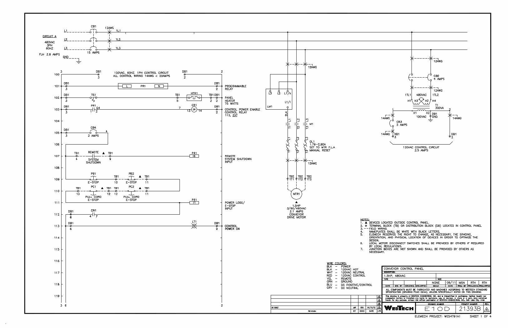
21393AB-E10D CONTROL PANEL DRAWING
JWATRY
Text Box
JWATRY
Text Box

SUMMARY OF WARNINGS
AN EMPLOYEE OWNED COMPANY
OPERATION AND MAINTENANCE MANUAL
vii
SUMMARY OF WARNINGS
This page lists all warnings contained in this manual and the page numbers on which they are found.
WesTech will not accept responsibility for damage to equipment which has not been handled in accordance with the manufacturer's instructions. Please read the General Precautions, General Safety Instructions, and Storage and Shutdown Precautions sections of this manual before storing, installing, or operating this equipment.
• Insure that all lifting equipment is properly sized to handle the load. (See p. 2-3)
• Anti-seize compound MUST be used on all stainless steel fasteners to prevent galling or seizing. (See p. 2-3)
• If grouting is necessary (see general arrangement drawing(s)), do not grout under support stands until final leveling is completed and verified. (See p. 2-4)
• In order to avoid corrosion, touch-up any paint or galvanizing damaged during installation. (See p. 2-4)
• To prevent personal injury, the Horizontal Conveyor must be shut down before any maintenance or adjustments requiring personal contact are made. If the unit is opened for inspection, cleaning, or observation, the motor must be locked out electrically in such a manner that it cannot be restarted by anyone during the inspection, cleaning, or observation. (See p. 3-3)
• The helical auger will act as a torsional spring and store a tremendous amount of energy if it becomes caught or
jammed in the basket. This could cause serious injury or death if released suddenly. Ensure that no energy is stored in the auger before performing any maintenance on the equipment. (See p. 3-3)
• Running the conveyor empty should be avoided to prevent premature wear to the trough liner and spiral. (See p. 3-5)
• All fasteners should be checked regularly and tightened as required. (See p. 4-3)
• Regularly examine the trough liner for excessive wear or misalignment. The. See Recommended Equipment Maintenance Schedule for suggested intervals. Failure to maintain wear liner will void warranty.
• (See p. 4-3)
• The equipment must be routinely lubricated according to the Lubrication Schedule and the accessory item instructions enclosed. Failure to do so will shorten the lifetime of the equipment and void the equipment warranty. (See p. 4-3)
• If reducer unit is removed, keep driveshaft clean of all debris and dirt. Any contamination will make replacing the reducer more difficult and perhaps impossible. (See p. 4-11)

viii
This page left intentionally blank.

AN EMPLOYEE OWNED COMPANY
1-1
1 EQUIPMENT
INFORMATION

1-2
This page left intentionally blank.

QF-00-032E 1-3 Rev. 08/18/05
WARRANTY
WesTech equipment is backed by WesTech's reputation as a quality manufacturer, and by many years of experience in the design of reliable equipment.
Equipment manufactured or sold by WesTech Engineering, Inc., once paid for in full, is backed by the following warranty:
For the benefit of the original user, WesTech warrants all new equipment manufactured by WesTech Engineering, Inc. to be free from defects in material and workmanship, and will replace or repair, F.O.B. its factories or other location designated by it, any part or parts returned to it which WesTech's examination shall show to have failed under normal use and service by the original user within one (1) year following initial start-up, or eighteen (18) months from shipment to the purchaser, whichever occurs first. Such repair or replacement shall be free of charge for all items except for those items such as resin, filter media and the like that are consumable and normally replaced during maintenance, with respect to which, repair or replacement shall be subject to a pro-rata charge based upon WesTech's estimate of the percentage of normal service life realized from the part. WesTech's obligation under this warranty is conditioned upon its receiving prompt notice of claimed defects, which shall in no event be later than thirty (30) days following expiration of the warranty period, and is limited to repair or replacement as aforesaid. THIS WARRANTY IS EXPRESSLY MADE BY WESTECH AND ACCEPTED BY PURCHASER IN LIEU OF ALL OTHER WARRANTIES, INCLUDING WARRANTIES OF MERCHANTABILITY AND FITNESS FOR PARTICULAR PURPOSE, WHETHER WRITTEN, ORAL, EXPRESS, IMPLIED, OR STATUTORY. WESTECH NEITHER ASSUMES NOR AUTHORIZES ANY OTHER PERSON TO ASSUME FOR IT ANY OTHER LIABILITY WITH RESPECT TO ITS EQUIPMENT. WESTECH SHALL NOT BE LIABLE FOR NORMAL WEAR AND TEAR, CORROSION, OR ANY CONTINGENT, INCIDENTAL, OR CONSEQUENTIAL DAMAGE OR EXPENSE DUE TO PARTIAL OR COMPLETE INOPERABILITY OF ITS EQUIPMENT FOR ANY REASON WHATSOEVER. This warranty shall not apply to equipment or parts thereof which have been altered or repaired outside of a WesTech factory, or damaged by improper installation, application, or maintenance, or subjected to misuse, abuse, neglect, accident, or incomplete adherence to all manufacturer’s requirements, including, but not limited to, Operations & Maintenance Manual guidelines & procedures. This warranty applies only to equipment made or sold by WesTech Engineering, Inc. WesTech Engineering, Inc. makes no warranty with respect to parts, accessories, or components purchased by the customer from others. The warranties which apply to such items are those offered by their respective manufacturers.

1-4
This page left intentionally blank.

EQUIPMENT RECORD FORM
AN EMPLOYEE OWNED COMPANY
OPERATION AND MAINTENANCE MANUAL
1-5
EQUIPMENT RECORD FORM
NOTE: To keep your warranty in force, this form must be completed and returned to WesTech regularly as indicated on the schedule at the bottom.
WESTECH PROJECT NUMBER:__ __ EQUIPMENT I.D. NO.:__ ___ DATE:_______________ MOTOR LOADS: DATE READ:____________ AMPS #1_______ #2_______ #3_______ LINE VOLTAGE: DATE LUBRICATED:____________TYPE OF GREASE USED:___________________ REDUCER: DATE LUBRICATED:__________________ BRAND OF OIL:______________________ WEIGHT OF OIL:_____________________ TROUGH LINER: FASTENERS: DATE CHECKED:____________________ DATE CHECKED:_____________
GENERAL FASTENERS: DATE CHECKED:____________________ Any other observations or comments:________________________________________ ______________________________________________________________________
SIGNED:____________________________ TITLE:_____________________________ REPORTS DUE: At regular three (3) month intervals after start-up.

1-6
This page left intentionally blank.

GROUNDWATER TREATMENTAeration Cascading Aerator Forced Draft Aerator Induced Draft Aerator
Sedimentation /Clarification Ballasted Flocculation ClariCell™ Package Treatment Plant Conventional Clarifier Flocculating Clarifier High Rate Clarifier solids CONTACT CLARIFIER™
SuperSettler™ Inclined Plate Settler
Filtration AeraFilter™ Iron and Manganese Removal Plant AltaFilter™ Ultrafiltration Membrane System AltaPac™ Ultrafiltration Membrane System Circular and Rectangular Open Top Gravity Filter ClariCell-B™ Package Treatment Plant Horizontal and Vertical Pressure Filter ModTech™ Cluster Filter
Residuals Handling Backwash Water Clarifier Decant Mechanism Gravity Sludge Thickener SuperSettler™ Inclined Plate Settler Vacuum Drum Filter
Softening Cation Exchange Softener Solids CONTACT CLARIFIER™
SURFACE WATER TREATMENTFlocculation Ducted Impeller Flocculator Horizontal Paddle Wheel Flocculator Vertical Paddle Wheel Flocculator
Sedimentation /Clarification ClariCell™ Package Treatment Plant Conventional Clarifier Flocculating Clarifier High Rate Clarifier Solids CONTACT CLARIFIER™
SuperSettler™ Inclined Plate Settler
Filtration AltaFilter™ Ultrafiltration Membrane System AltaPac™ Ultrafiltration Membrane System Circular and Rectangular Open Top Gravity Filter ClariCell-B™ Package Treatment Plant Horizontal and Vertical Pressure Filter ModTech™ Cluster Filter PolyBloc™ Roughing Filter
Package Treatment Plants AltaFilter™ Ultrafiltration Membrane System AltaPac™ Ultrafiltration Membrane System ClariCell-B™ Package Treatment Plant
Ion Exchange Cation Exchange Softener GAC Contactor
Residuals Handling Backwash Water Clarifier Decant Mechanism Gravity Sludge Thickener SuperSettler™ Inclined Plate Settler Vacuum Drum Filter
Tel: 801.265.1000Fax: 801.265.1080www.westech-inc.com
WesTech Municipal Water Products
Services Bench Scale Feasibility Testing Field Pilot Studies Full Scale Rental Equipment Installation and Erection Services Mechanical Evaluations Plant Process Audits
Tankage Supply and Erection

WesTech Municipal Wastewater Products
Anaerobic Digestion Equipment Digester Cover - Radial Beam Style Digester Cover - Truss Style DuoSphere™ Dual-Membrane Gas Holder Slab and Tank Mount Extreme Duty™ Mechanical Sludge Mixer Sludge Heating System Biological Treatment Landox™ Oxidation Ditch OxyStream™ Advanced Oxidation Ditch Process Slow Speed Surface Aerators STM-Aerotor™ IFAS Systems ClearLogic™ MBR System HydroDoc™ Rotary Distributor BioDoc® Rotary Distributor Clarifiers C.O.P.™ Clarifier Optimization Package Spiral Blades Sludge Ring Dual Gate EDI Suction Header solids CONTACT CLARIFIER™
Conventional Scraper Blade Suction Pipe Combined Sewer Overflow CleanFlo™ ROMAG CSO Screens Dissolved Air Flotation Pretreatment Clarifiers Sludge Thickeners Rectangular & Circular Electrical Controls PLC Based Control Systems UL Listed Panels (UL508A/CSA) Filters AltaFilter™ Ultrafiltration Membrane System SuperSand™ Continuous Backwash Filter Granular Media Gravity Filter Multi-Media Pressure Filter SuperDisc™ Cloth Media Disc Filter
Headworks CleanFlo™ Rotoscreen® CleanFlo™ Monoscreen® CleanFlo™ ALL-IN-ONE (Complete Plant) CleanFlo™ Element Continuous Belt Screen
CleanFlo™ Perf Perforated Plate Belt Screen CleanFlo™ Shear (Internally Fed Drum Screen) CleanFlo™ SludgeScreen®
CleanFlo™ Spiral Screen CleanWash™ Screenings Washer / Compactor Counter Pressure Screw CleanGrit™ Grit Washers Gritt Mitt™ Grit Classifiers Vortex Grit Separators
Laboratory & Pilot Plant Test Equipment Bench Scale Testing Pilot Plant Testing
Parts and Service Support 24 Hour Hot-Line Regional Service Technicians Full Service Parts Department
Rectangular Basin Skimming Helical Scum Skimmers Rotating Scum Pipes
Replacement Drives Adaptable to All Other Manufacturers Precision Bearing Grease Lubricated Option Clarifiers Thickeners Septage Receiving Station Screening and Grit Removal Options Hauler Access Stations Customer Management / Billing Software Tankage Material Supply Field Erection Thickeners Center Feed Rake Lifting Devices Side Feed Tel: 801.265.1000 Fax: 801.2651080 www.westech-inc.com

WesTech Mining and Metallurgical Products
Tel: 801.265.1000Fax: 801.265.1080
www.westech-inc.com
Clarifiers Buoyant Media Clarifier Flocculating Clarifier Metallurgical Contact Clarifier Solids CONTACT Clarifier™ SuperSettler™ Inclined Plate Settler
Clarifier / Thickener Drives Adaptable to All Other Manufacturers Bridge Supported Shaft Drive Column Supported Cage Drive Traction Drive
Granular Media Filtration Horizontal Pressure Filter Open Top Gravity Filter Circular Rectangular SuperSand™ Continuous Backwash Filter Vertical Pressure Filter
Magnetic Separators Permanent Magnet Belt Separator
Man Camp Potable Water Treatment AltaFilter™ Ultrafiltration Membrane System AltaPac™ Ultrafiltration Package System ClariCell-B™ Package Treatment Plant
Man Camp Wastewater Treatment ClearLogic™ MBR System STM-Aerotor™ IFAS Package System
Parts / Field Service / Training 24 Hour Hot-Line Full Service Parts Department Installation and Erection Services Mechanical Evaluations Operator Training Process Training Regional Service Technicians
Screens CIP / CIL Carbon Retention Screen Linear Screen
Services Bench Scale Feasibility Testing Field Pilot Studies Installation and Erection Services Mechanical Evaluations Plant Process Audits Pilot Rental Equipment AltaFloTM High Rate Thickener AltaPac™ Ultrafiltration Package System Buoyant Media Clarifier High Rate Thickener Horizontal Belt Filter Linear Screen Paste Thickener Precoat Filter Rotary Drum Filter Solids Contact Clarifier
Tankage Anchor Channel Tank Elevated Tank Steel Bottom Tank Supply and / or Field Erection
Thickeners AltaFloTM High Rate Thickener Conventional Thickener Deep Bed™ Paste Thickener HiDensity™ Paste Thickener HiFlo™ High Rate Thickener Swing Lift Thickener
Vacuum Filters Disc Filter Horizontal Belt Filter Precoat Drum Filter Rotary Drum Filter Belt Discharge Roll Discharge Scraper Discharge

WesTech Industrial Water and Wastewater Products
AerationCascading AeratorForced / Induced Draft AeratorPressure Aerator
Barrier/Media FiltrationAeraFilterTM Iron / Manganese RemovalAltaFilerTM Ultrafiltration Membrane SystemsAltaPacTM Ultrafiltration Package SystemsAltaPakTM Ultrafiltration SystemsClariCell-BTM Package TreatmentModTechTM Cluster FilterOpen Top Gravity Filter (Circular or Rectangular)PolyBlocTM Roughing FilterPressure Filter (Vertical or Horizontal) Reverse Osmosis SystemsSuperSandTM Continuous Backwash Filter
Biological TreatmentBioDoc® Rotary Distributor BiotreaterClearLogic MBR SystemsDuoSphereTM Dual Membrane Gasholder (Slab or Tank Mount) HydroDocTM Rotary DistributorOxidation DitchesSlow Speed Surface AeratorsSlow Speed Surface AeratorsSTM AeratorTM IFAS Systems
Clarification/SedimentationConventional ClarifierCOPTM ClarifierDraft TubeTM ClarifierFlocculating ClarifierMetallurgical Contact ClarifierSolids CONTACT ClarifierTM Suction HeaderSuperSettlerTM Incline Plate Settler
Clarifier / Thickener DrivesAdaptable to All Other ManufacturersPrecision Bearing
Dewatering Belt PressHorizontal Vacuum Belt FilterPrecoat Drum FilterRecessed Plate Filter PressRotary Drum Vacuum Filter
Dissolved Gas FlotationCircularRectangularSludge Thickener
Electrical ControlsPLC Based Control SystemsUL Listed Panels (UL508A / CSA)
Parts / Field Service /Training24 Hour Hot-LineFull Service Parts DepartmentInstallation and Erection ServicesMechanical EvaluationsOperator TrainingProcess TrainingRegional Service Technicians
Pilot Rental EquipmentAltaFilter™ Ultrafiltration Membrane SystemsAltaFlo™ High Rate ThickenerAltaPak™ Ultrafiltration UnitsBuoyant Media ClarifierHigh Rate ThickenerHorizontal Belt FilterLinear ScreenPaste ThickenerPilot Rental EquipmentPrecoat FilterReverse OsmosisSolids CONTACT Clarifier™ Vacuum Drum Filter
Oil / Water Separation DAF Units (Circular or Rectangular)DNF Units (Circular or Rectangular)Oil / Water Separator (Circular or Rectangular)
ScreensCleanFlo™ Element Continuous Belt ScreenCleanFlo™ Monoscreen®CleanFlo™ Rotoscreen®CleanFlo™ Shear (Internally Fed Drum Screen)CleanFlo™ Spiral ScreenCleanWash™ Screenings Washer / CompactorCounter Pressure ScrewGritt Mitt™ Grit ClassifiersLinear Screen

SofteningCation Exchange SoftenerCold Lime SofteningWarm Lime Softening
TankageAnchor Channel TankElevated TankSteel Bottom at GradeSupply and / or Field Erection
Thickeners AltaFlo™ High Rate Thickener Conventional Thickener Deep Bed™ Paste Thickener HiDensity™ Paste Thickener HiFlo™ High Rate Thickener
Tel: 801.265.1000Fax: 801.265.1080
www.westech-inc.com

1-12
This page left intentionally blank.

AN EMPLOYEE OWNED COMPANY
OPERATION AND MAINTENANCE MANUAL
1-11
GENERAL DESCRIPTION
The WesTech Horizontal Conveyor uses a shaftless spiral to transport screenings, sludge, and other solid wastes. The shaftless spiral eliminates the center shaft to allow stringy solids to convey freely to the discharge point without wrapping around a center shaft.
To perform as described, the Horizontal Conveyor will consist of the following:
CONVEYOR SECTION
An inlet hopper (if provided) will direct screenings into the conveyor trough. The
trough consists of a U-trough with a liner constructed of Ultra High Molecular Weight Polyethylene (UHMW PE). The shaftless helical screw rests on the wear liner and when the spiral rotates, solids are positively conveyed to the discharge point and into a solids receptacle. If provided, a drain will be provided to allow liquid to drain from the trough.
DRIVE UNIT
The conveyor drive unit consists of an electric motor directly driving a flange-mounted, hollow shaft, helical gear reducer. This unit attaches to the end of the trough housing and is bolted to the drive shaft.

GENERAL PRECAUTIONS
AN EMPLOYEE OWNED COMPANY
OPERATION AND MAINTENANCE MANUAL
1-12
GENERAL PRECAUTIONS
The erection instructions enclosed are provided to assist in the assembly and adjustment of this mechanism. These procedures are not intended to be substituted for the experience of the persons assigned to the task of erecting and assembling this equipment. WesTech strongly suggests that these instructions be studied prior to erecting, assembling, and adjusting.
During assembly of this equipment, it will be necessary to install, adjust, and maintain certain accessory items which are not manufactured by WesTech. This accessory equipment must be stored, handled, adjusted, and maintained in accordance with instructions provided by the manufacturer of that equipment. This is absolutely necessary in order to be assured of prompt and full participation in the warranty protection on the equipment. WesTech will not accept responsibility for damage to equipment which has not been handled in accordance with the manufacturer's instructions.
PACKING LIST
The Contractor's packing list consists of a sheet containing an itemized listing of parts.
The packing list contains:
1. A description of the item.
2. Sizes and lengths of nuts and bolts. These fasteners will be tagged with an item number.
3. The quantity of parts per assembled unit.
4. Total quantity of parts shipped.
5. An indication of direct shipment from the supplier or the fabricator.
6. The date and job number of the shipment.
The packing list will be found in one of the cartons which are shipped directly from Salt Lake City, Utah. The list should be kept in a readily accessible and safe place. Many contractors prefer to keep this list in some type of binder for protection and quick reference.
This list is particularly useful during erection for locating small parts and fasteners. When coordinated with the erection drawings, equipment tagging, and piece marking, the contractor's packing list can become an invaluable erection tool.
EQUIPMENT TAGS:
Each shipping piece has been tagged or piece-marked for convenience. Typically the part number or item number will be marked on all items. Piece-marked items received will have a mark such as "Part No. D120A", or “Item 203", which may be cross referenced with the packing list and general assembly drawing.
RECEIVING MATERIAL:
The equipment pieces and components received may have been shipped from:
1. WesTech Engineering, Inc. in Salt Lake City, Utah.
2. A fabricator acting under WesTech Engineering's instructions.
3. A "buy-out" distributor such as a motor or pump manufacturer.

GENERAL PRECAUTIONS
AN EMPLOYEE OWNED COMPANY
OPERATION AND MAINTENANCE MANUAL
1-13
Since there will often be more than one shipment to the job site, it is important to coordinate the receiving and storage of all items accordingly. All material has been thoroughly checked and inspected before shipment. However, there may be times when equipment is missing, damaged in transit or received with broken packaging. When receiving equipment, it is necessary to properly acknowledge receipt and any shortage or damage on the shipping documents. This must be done in a manner that helps assign responsibility to the proper party for the various parts of shipping and receiving equipment.
When receiving a shipment, the following procedures must be followed. These procedures are also listed on the Bill of Lading the shipping company provides and must be signed to prove delivery of the goods. If the following procedures are not followed, WesTech will not be liable for any shortages or damage on your shipments.
RECEIVING PROCEDURE
1. BEFORE signing the Bill of Lading (BOL) in receipt of the goods shown thereon, and BEFORE the driver leaves, do the following:
A. After inspecting the shipment, NOTE any damage or shortages (according to what is listed on the BOL). Be as detailed as necessary.
B. Have the driver sign the notation in acknowledgment.
C. Retain a copy (of the notated BOL) for use in filing a freight claim.
D. If there is damage, NOTIFY WesTech (801) 265-1000 IMMEDIATELY so that
arrangements can be made with the carrier, if necessary, to have the damaged goods inspected by their agent.
2. AFTER signing the BOL and receiving the shipment, do the following:
A. Use the attached/enclosed packing list to further inspect the entire shipment for shortages and/or damage and retain this list for future reference.
B. NOTIFY WesTech within THREE (3) working days from date of receipt, of any further shortages or concealed damage. If certain items are missing or damaged, make notes of this on the shipping papers to protect all interests and notify WesTech (801) 265-1000 IMMEDIATELY.
HANDLING & STORAGE
Please handle the equipment properly when unloading and erecting. All cartons, electrical equipment, and gear drives should be stored under cover and protected from moisture, grit, and mud. All rolled steel sections must be stored on edge or blocked up to prevent distortion. If allowed to lie flat, these items may lose their shape which could hinder erection and proper alignment of the equipment.
Long structural shapes should be checked for the proper camber. This would include beams, trusses, walkways, etc. The equipment has been designed with a positive camber so items do not appear to be sagging after erection.

GENERAL PRECAUTIONS
AN EMPLOYEE OWNED COMPANY
OPERATION AND MAINTENANCE MANUAL
1-14
PAINTING:
The material supplied for this job may have received surface preparation and paint in accordance with the specific contract plans and specifications.
Any indentations, mars, and/or scratches caused by loading and unloading the equipment must be IMMEDIATELY touched up in the field prior to storage.
NOTE: SHOP PRIMER PAINT DURABILITY
In the event the equipment supplied has been painted with only a primer coat, this notification should be adhered to. Shop primer paints are intended to serve only as a bonding coat between the metallic surface and the protective finish and serve only as a minimal protective finish. Unless otherwise noted in the contract documents, WesTech will not be responsible for condition of primed or finish painted surfaces after the equipment leaves our shops. Customers are invited to inspect coatings in our shops for proper surface preparation and application prior to shipment. WesTech assumes no responsibility for field surface preparation or touch up of shipping damage to paint. Painting of surfaces requiring touch up or painting of fasteners will be by the customer’s painting contractor after the mechanism is erected.
Shop primed surfaces should be finish coated within the time specified by the paint manufacturer. WesTech cannot be held responsible for shop primed surfaces that have deteriorated due to time and exposure.
FASTENERS:
All stainless steel erection fasteners shall incorporate anti-seize during assembly. Failure to utilize this will cause significant extra time by the erection and maintenance crews.
ANCHOR BOLTS:
If Provided, anchor bolts must be placed accurately to avoid future erection difficulties. Where applicable and upon request, WesTech can furnish a template for positioning the anchor bolts. If a template has not been furnished, remember that the location and projection of all anchorage is critical. The specified amount of projection and location are shown on the general arrangement drawings. Prior to equipment installation, clean the threads of all anchor bolts.
OPERATION & MAINTENANCE MANUAL:
Keep an O&M Manual in the area where the operators can familiarize themselves with it and have it for reference. The manual is useless if the operator and foreman do not have access to it.
FURTHER ASSISTANCE:
If a problem is encountered in installing or operating the equipment which cannot be solved by referring to this manual, feel free to contact WesTech Engineering, Inc., 3625 South West Temple, Salt Lake City, Utah 84115 (801) 265-1000 or fax (801) 265-1080. See also our website at www.westech-inc.com.

SHORTAGES, DISCREPANCIES, AND FIELD CHARGES
AN EMPLOYEE OWNED COMPANY
OPERATION AND MAINTENANCE MANUAL
1-15
SHORTAGES, DISCREPANCIES,
AND FIELD CHARGES
Please notify WesTech Engineering, Inc. immediately if any apparent manufacturing discrepancies or shortages are encountered with machinery, since no field charges for alterations or shortages will be accepted unless authorized in writing by our authorized representative.
Fabricated steel parts and assemblies furnished by WesTech Engineering, Inc. are manufactured following best shop practices and standards. However, some misfits and imperfect work may arise. In such cases, the American Institute of Steel Construction ASD, Ninth Edition, or LRFD, First Edition, "Code of Standard Practice", will apply to erection of this equipment. It reads as follows:
"7.12. Corrections and Errors
Normal erection operations include the correction of minor errors by moderate amounts of reaming, chipping, welding or cutting, and the drawing of elements into line through the use of drift pins. Errors which cannot be corrected by the foregoing means or which require major changes in member configuration are reported immediately to the owner and fabricator by the erector, to enable whoever is responsible either to correct the error or to approve the most efficient and economic method of correction is to be used by others."
Company policy dictates that no field charges will be allowed without prior approval. Written authority must be given in the form of a WesTech Inspection and Change Work form with an attached warranty tracking number. The Warranty tracking number will be issued when the extent of such modifications and the price for performing these modifications have been agreed upon.
In general, when parts require replacement, and WesTech agrees that replacement is necessary, WesTech will furnish the parts. The contractor will remove the defective parts and install the replacement parts at a cost agreed upon by both parties.

1-16
This page left intentionally blank.

AN EMPLOYEE OWNED COMPANY
2-1
2 INSTALLATION
INSTRUCTIONS

2-2
This page left intentionally blank.

BASIC INSTALLATION
AN EMPLOYEE OWNED COMPANY
OPERATION AND MAINTENANCE MANUAL
2-3
BASIC INSTALLATION
The sequence and procedures listed below are suggested and should not take precedence over the experience of the erector if, due to special circumstances or available equipment, he should decide to vary the given steps.
NOTE: Figures depicted in this section and throughout the manual are graphical examples only. Actual configuration of supplied unit may vary.
If installation is not immediately started upon delivery of the equipment, the appropriate short- or long-term storage procedure, as prescribed in the Storage and Shutdown Precautions section of this manual, must be followed.
The Horizontal Conveyor is preassembled in the shop. If the conveyor length exceeds 40 feet, it will be shipped in multiple sections and will require field assembly and welding of the spiral.
Only minor field assembly is required.
Insure that all lifting equipment is properly sized to handle the load.
IMPORTANT: Anti-seize compound MUST be used on all stainless steel fasteners to prevent galling or seizing.
The concrete and concrete dimensions shown on the general arrangement and assembly drawing(s) are nominal. Place the assembled equipment in correct position prior to fixing anchor bolt positions to verify proper fit and discharge location. Refer to the general assembly drawing(s) and parts list enclosed in this manual during all installation steps.
1. Mark anchor bolt positions for Horizontal Conveyor support frame. Check anchors for correct spacing and orientation with respect to the support legs and the entire Horizontal Conveyor.
2. Install Horizontal Conveyor anchors per the anchor manufacturer’s instructions and the general arrangement drawing(s).
Figure 2-1: Proper Lifting instructions
3. If Horizontal Conveyor unit support legs are to be placed on a bed of grout (see general arrangement drawing(s)), follow the next steps. If unit is to be placed directly on floor without grout, proceed to step 4 and make certain the floor is flat and the legs are flush with the floor before securing the unit. Level or shim under the feet as required to prevent any distortion to the equipment when it is secured to the floor.
a. Install support legs to the trough, if required. Adjust leveling nuts until level in all directions. Finger-tighten locking nuts to secure bases in position. Refer to the Final Check for Level procedures in this manual before permanently tightening nuts

BASIC INSTALLATION
AN EMPLOYEE OWNED COMPANY
OPERATION AND MAINTENANCE MANUAL
2-4
b. Adjust each anchor leveling nut face to the same elevation (approximately 1 inch from concrete surface).
IMPORTANT: If grouting is necessary (see general arrangement drawing(s)), do not grout under support stands until final positioning is completed and verified.
4. If the motor is shipped separately, install the motor to the reducer. Be sure to engage the motor and reducer shaft couplings with the flexible motor spider. See Trough Assembly (if required) instructions below.
5. Install the Horizontal Conveyor unit in position and tighten all the fasteners for the support frame.
6. If a trough drain is provided, connect the drain hose and place the other end of the hose to direct the drain liquid to a floor drain or channel.
7. A qualified electrician should wire the Horizontal Conveyor drive motor and emergency stop pushbutton. Jog the
drive motor. Ensure that the drive shaft rotates in the proper direction so as to cause the screw to convey material towards the discharge point.
8. Ensure proper screenings receptacle is in place.
NOTE: In order to avoid corrosion, touch-up any paint or galvanizing damaged during installation.

BASIC INSTALLATION
AN EMPLOYEE OWNED COMPANY
OPERATION AND MAINTENANCE MANUAL
2-5
TROUGH AND SPIRAL ASSEMBLY (IF REQUIRED)
If the trough length is over 40’, the trough will be provided in multiple sections and require field assembly. To facilitate the assembly, all the trough pieces have end flanges which are bolted together. Each part of trough is marked at each end with a number/letter: ALWAYS JOIN THE PARTS HAVING THE SAME NUMBER/LETTER.
• Check the number/letter signed on the trough, close to the fixing flange and match the two parts having the same number/letter.
• Seal the two flanges with a generous amount of silicone sealant.
• Fix the two connecting flanges by means of the supplied nuts and bolts.
Confirm the trough is perfectly aligned and tighten the bolts
All the spiral terminals have been machined in order to facilitate the welding. The spiral sections are not painted close to the ends where they have to be welded. They must be painted after the welding.
The spiral can be welded inside or outside the trough. If the spiral is welded inside the trough, it is necessary to protect the liner with suitable protection (for example. sheet metal). In case of welding outside the trough it is necessary to put the spiral sections on a flat surface in order to guarantee the perfect alignment of the spiral and to have suitable lifting equipment to position the welded spiral inside the trough. The spiral must be lifted using lifting hooks in order to avoid any dangerous deflection.
Necessary Tools.
• Welding machine, arc or wire type, 200/300 A.
• Portable Grinder. Working Procedure.
• The spiral ends must be cleaned and any corrosion shall be removed from the spiral. If there are multiple sections, the welding shall start at the drive end of the spiral. The end of the spiral will have a rounded end and all intermediate sections are interchangeable.
• Position all the sections in order to obtain the required length of spiral. Before welding, check the total length of the spiral: it must be as per the technical data sheet attached to the machine. THE TOTAL LENGTH OF

BASIC INSTALLATION
AN EMPLOYEE OWNED COMPANY
OPERATION AND MAINTENANCE MANUAL
2-6
THE SCREW MUST BE APPROX. 2 INCHES LESS THAN THE TROUGH.
• Weld the connections.
• Grind the welding in order to obtain a “continuous structure” of the spiral.

MOTOR INSTALLATION
AN EMPLOYEE OWNED COMPANY
OPERATION AND MAINTENANCE MANUAL
2-6
MOTOR INSTALLATION
Figure 2-2: Helical Reducer Assembly
If motor is not already installed to reducer:
1. Place motor coupling and key in location on motor shaft as per Figure 2-3 and Table 2-1 below for all SEW Eurodrive brand reducers. Also, check the manufacturer’s instructions in the Accessory Equipment section of this manual.
Figure 2-3: SEW Reducer/Motor Coupling Location
Table 2-1: SEW Reducer/Motor Coupling Location
SEW Reducer Adapter Size
NEMA Motor Frame
Coupling Location
Dimension (in.)
AM56 56C 1.23
AM143/145 143/145TC 1.68
AM182/184 182/184TC 2.10
AM213/215 213/215TC 2.76
2. Tighten set screw.
3. Place the flexible motor spider between the teeth of the motor coupling.
4. Align the motor coupling so that the teeth on the reducer coupling (installed in AM adapter) mesh with the motor coupling.
5. Install motor to reducer using bolts.
Coupling
NEMA
Motor Shaft
Coupling Location
Dimension

FINAL CHECK FOR LEVEL
AN EMPLOYEE OWNED COMPANY
OPERATION AND MAINTENANCE MANUAL
2-7
FINAL CHECK OF POSITION
If Horizontal Conveyor unit is not to be placed on a bed of grout (see general arrangement drawing(s)), disregard this section.
To ensure that the Horizontal Conveyor is positioned properly, it is necessary to make a final check.
1. The leveling nuts were used earlier to adjust the support frame.
2. Use a carpenter’s level to level each support frame base or use an inclinometer to confirm the proper inclination. Make sure that the inlet and discharge connections properly fit up to adjacent equipment.
3. If adjustment is necessary, lower or raise the corresponding leveling nuts, as required.
4. When the Horizontal Conveyor is properly located, secure the support frame base with top locking nut and grout with a non-shrink grout (not by WesTech).

PIPING AND ELECTRICAL
AN EMPLOYEE OWNED COMPANY
OPERATION AND MAINTENANCE MANUAL
2-8
ELECTRICAL
All wiring external to motors and controls is by others.
CONTROL PANEL
1. Install the electrical control panel in desired location.
2. Complete external wiring to motor, emergency stop pushbutton and any other electrical components indicated on the control panel drawings (if provided).

2-9
This page left intentionally blank.

AN EMPLOYEE OWNED COMPANY
3-1
3 START-UP AND
OPERATION

3-2
This page left intentionally blank.

GENERAL SAFETY INSTRUCTIONS
AN EMPLOYEE OWNED COMPANY
OPERATION AND MAINTENANCE MANUAL
3-3
GENERAL SAFETY
INSTRUCTIONS
1. Only trained operators who have been schooled in safety procedures should be allowed to work on or around this equipment. Exercise caution at all times. Allow access to authorized personnel only.
2. Anyone entering the area should be wearing adequate safety equipment, such as safety glasses, safety shoes, hard hats, etc. Long hair and loose clothing must be tied back, and jewelry must be removed.
3. To prevent personal injury, the Horizontal Conveyor must be shut down before any maintenance or adjustments requiring personal contact are made. If the unit is opened for inspection, cleaning or observation, the motor must be locked out electrically in such a manner that it cannot be restarted by anyone during the inspection, cleaning, or observation.
4. Locate “WARNING” signs to alert people of moving parts. Keep hands, clothing, etc. away from all moving parts.
5. Keep all flammable or explosive materials away from the equipment area at all times.
6. Keep people whose abilities may be impaired due to drinking alcohol, using drugs, taking medication, etc. away from the equipment.
7. Inspect equipment frequently for loose bolts, leaks, or other malfunctions. Problems should be fixed immediately.
8. Do not walk on conveyor covers or guards.
9. Do not poke or prod material in the conveyor unless the drive is off and power has been locked-out.
10. Do not place hands, feet, or any other object in any conveyor opening.
11. The helical auger will act as a torsional spring and store a tremendous amount of energy if it becomes caught or jammed in the basket. This could cause serious injury or death if released suddenly. Ensure that no energy is stored in the auger before performing any maintenance on the equipment.

HORIZONTAL CONVEYOR PRE-STARTUP CHECKLIST
AN EMPLOYEE OWNED COMPANY
OPERATION AND MAINTENANCE MANUAL
3-4
HORIZONTAL CONVEYOR PRE-
STARTUP CHECKLIST
The following is a checklist of items that should be in place and verified as correct prior to the arrival of a WesTech representative, if field service and start-up services have been arranged.
□ Confirm the position of the conveyor relative to the adjacent equipment (see assembly drawing(s) for correct angle).
□ Verify motor is wired correctly and screw rotates in the proper direction (see assembly drawing(s)).
□ If supplied, ensure electrical controls including emergency stop pushbutton are fully operational. THE CURRENT MONITOR MUST BE ADJUSTED TO IMMEDIATELY SHUT THE UNIT DOWN WHEN THE CURRENT DRAW IS SLIGHTLY ABOVE THE OPERATING LOAD. FAILURE TO DO THIS CAN RESULT IN DAMAGE TO THE SPIRAL.
□ Have solids available to witness successful operation of the screen.

START-UP AND OPERATION
AN EMPLOYEE OWNED COMPANY
OPERATION AND MAINTENANCE MANUAL
3-5
START-UP AND OPERATION
1. Be sure the mechanisms are lubricated in accordance with the lubrication instructions found in the Maintenance and Parts section of this manual.
2. Before the equipment is operated, a final mechanical checkout should be performed. All fasteners must be verified as tight. All moving parts must be properly aligned. To ensure that there is no binding or misalignment in the systems, rotate the conveyor slowly by hand, apply power only momentarily, and check for any problems.
3. In start-up of the Horizontal Conveyor, operate several minutes empty as a break-in period. Observe any abnormal heat build-up, unusual noises, or drive misalignment. Should any of these occur, refer to the Recommended Equipment Maintenance Schedule in the Maintenance and Parts section of this manual and take necessary corrective steps.
4. Begin normal operation. Do not overload the conveyor. Do not exceed conveyor speed, capacity, material density, or solids feed rate for which the conveyor and drive were designed.
5. Normal operation: The unit will accept screenings or sludge. After a short period of time, solids will accumulate in the trough. After the trough fills to at least half full, the conveyor will start and the transport the solids to clear the inlet area, and then stop. The conveyor will be controlled by the use of timers and will require field adjustment to operate as required by the site conditions. After the conveyor has run, it will stop and wait for more solids to accumulate.
IMPORTANT: Running the conveyor empty should be avoided to prevent premature wear to the trough liner and spiral.
Refer to control panel drawings in the Enclosures section to review all control functions for the provided equipment.

3-6
This page left intentionally blank.

AN EMPLOYEE OWNED COMPANY
4-1
4 MAINTENANCE
AND PARTS

4-2
This page left intentionally blank.

EQUIPMENT MAINTENANCE
AN EMPLOYEE OWNED COMPANY
OPERATION AND MAINTENANCE MANUAL
4-3
EQUIPMENT MAINTENANCE
1. All fasteners should be checked regularly and tightened as required.
2. Regularly examine the trough liner for excessive wear or misalignment. The UHMW is two-toned in inlet area, to allow easy visual indication when the liner needs replacing. See Recommended Equipment Maintenance Schedule for suggested intervals. Failure to maintain wear liner will void warranty.
3. Keep the equipment and surroundings clean.
4. Inspect all painted and galvanized surfaces frequently to check for corrosion. Remove any rust found and apply touch-up paint. All painted steel should be inspected once every year and repainted if required.
5. Corrosion may start to appear even on high-grade stainless steels due to external rust or rust films, dirt, chemical or similar residues that settle on the surface and corrode. Dirty stainless steel surfaces should be cleaned regularly as part of regular maintenance. Stainless steel surfaces should be treated with Stainless Shine™ surface cleaner/protector or an equivalent agent that DOES NOT contain hydrochloric acid and/or chlorides.
6. If the mechanism is to be shut down for an extended period of time, the appropriate Storage and Shutdown Precautions must be followed.
7. The equipment must be routinely lubricated according to the Lubrication Schedule and the accessory item instructions enclosed. Failure to do so
will shorten the lifetime of the equipment and void the equipment warranty.
8. The equipment should be checked regularly for unusual sounds, irregular motion, or other signs of improper operation. If any of these symptoms are discovered, it must be investigated immediately to determine the source of the problem. The mechanism must not be allowed to operate if such problems exist.
9. The following maintenance procedures may require that the screen be removed from its operating position:
A. Replacement of UHMW Trough Liner
B. Replacement of Spiral
C. Replacement of the Packing Gland
D. Helical Reducer Removal
E. Helical Reducer Replacement.

EQUIPMENT MAINTENANCE
AN EMPLOYEE OWNED COMPANY
OPERATION AND MAINTENANCE MANUAL
4-4
REPLACEMENT OF UHMW TROUGH LINER
Prior to working on equipment, the power supply to the motor is to be disconnected in a manner which will disallow anyone from reconnecting power without the knowledge of the person who is performing the maintenance.
1. Prevent any solids from entering the equipment.
2. Unbolt the screws holding the covers (12) in place and remove.
3. Remove the screws connecting the spiral drive flange to the flange of the conveyor.
4. Remove the spiral from the trough, by means of suitable lifting system.
5. Remove one of the liner retaining profiles (25).
6. Remove the old liner (24). 7. Clean the trough. 8. Install the new liner. To facilitate the
installation rotate it inside the trough. 9. Repeat the operation above written in
reverse sequence, steps 6 through 2. 10. Before installing the trough covers, test
the running of the spiral. To avoid the seizure of the spiral add some water on the liner.

EQUIPMENT MAINTENANCE
AN EMPLOYEE OWNED COMPANY
OPERATION AND MAINTENANCE MANUAL
4-5

EQUIPMENT MAINTENANCE
AN EMPLOYEE OWNED COMPANY
OPERATION AND MAINTENANCE MANUAL
4-6
REPLACEMENT OF SPIRAL
Prior to working on equipment, the power supply to the motor is to be disconnected in a manner which will disallow anyone from reconnecting power without the knowledge of the person who is performing the maintenance.
1. Prevent any solids from entering the conveyor. 2. Unbolt the screws holding the covers in place and remove. 3. Remove the screws fixing the spiral driven flange to the flange of the gearmotor. 4. Remove the spiral from the trough, by means of suitable lifting system. 5. Repeat the operation above written in reverse sequence, replacing the spiral. 6. Before installing the trough covers, test the perfect running of the spiral. To avoid seizure of
the spiral add some water, in case of HMDW Polyethylene, or grease/oil in case of S.S. strip.

EQUIPMENT MAINTENANCE
AN EMPLOYEE OWNED COMPANY
OPERATION AND MAINTENANCE MANUAL
4-7
REPLACEMENT OF PACKING GLAND (IF PROVIDED)
Prior to working on equipment, the power supply to the motor is to be disconnected in a manner which will disallow anyone from reconnecting power without the knowledge of the person who is performing the maintenance.
1. Divert flow away from screen channel.
2. Unscrew the bolts (H) fixing the gland (I) of the stuffing box.
3. Pull back the gland (I) in order to reach the packing.
4. Remove the old packing and replace it with the new one (L).
5. Tighten the bolts (H) in order to give the right preloading to the packing.

EQUIPMENT MAINTENANCE
AN EMPLOYEE OWNED COMPANY
OPERATION AND MAINTENANCE MANUAL
4-8

HELICAL REDUCER REMOVAL
AN EMPLOYEE OWNED COMPANY
OPERATION AND MAINTENANCE MANUAL
4-9
HELICAL REDUCER REMOVAL
1. Disconnect motor from power supply.
2. Measure and record the gap between the driveshaft flange and the discharge endplate. This measurement will be used when replacing the reducer to ensure proper spiral position.
3. Remove bolts attaching the spiral flange to the driveshaft flange.
4. Remove bolts attaching the reducer flange to the discharge endplate. Be sure that the reducer is adequately supported before doing this.
5. Remove reducer, exercising care when extracting driveshaft through discharge endplate hole. Place detached reducer in a safe and convenient working location.
6. Remove dust cap and existing retaining bolt and washer as per Figure 4-1.
Figure 4-1: Helical Reducer Dust Cap and Retaining Bolt
7. Insert a jack between the driveshaft flange and the reducer flange. If necessary, cover the flanges with a cloth to prevent damage from the jack. Steadily jack the driveshaft away from the reducer.
IMPORTANT: Keep driveshaft clean of all debris and dirt. Any contamination will make replacing the reducer more difficult and perhaps impossible.

HELICAL REDUCER REPLACEMENT
AN EMPLOYEE OWNED COMPANY
OPERATION AND MAINTENANCE MANUAL
4-10
HELICAL REDUCER
REPLACEMENT
NOTE: Apply anti-seize to driveshaft before inserting into reducer hollowshaft. Be sure driveshaft is free of dirt and contaminants before applying anti-seize.
1. Insert driveshaft into reducer hollow shaft with shaft key inserted into its proper groove. Be sure that the gap between the driveshaft flange and the discharge endplate is the same as recorded before the reducer was removed. This ensures that the spiral will be in proper position.
2. Replace retaining bolt and dust cap on reducer.
3. Attach reducer flange to the discharge endplate with bolts. See assembly drawings for proper reducer mounting orientation.
4. Pull up spiral flange into place to meet flush with the driveshaft flange. Attach and secure both flanges with original bolts.

MAINTENANCE SCHEDULE
AN EMPLOYEE OWNED COMPANY
OPERATION AND MAINTENANCE MANUAL
4-11
RECOMMENDED EQUIPMENT MAINTENANCE SCHEDULE
DESCRIPTION CHECK FOR INTERVAL ACTION TOOLS General Fasteners Loose Weekly Tighten Solids Inlet Clogging Daily Clear Solids Discharge Clogging Daily Clear Packing Gland leakage Weekly Clear drain, (if provided) tighten gland if necessary Liner Wear Monthly Screw, Reducer Vibration & Noise Monthly Repair or Replace Wrench & Motor Reducer Lubrication Yearly Lubricate (if required) Wrench (See Accessory Equipment Section)

LUBRICATION SCHEDULE
AN EMPLOYEE OWNED COMPANY
OPERATION AND MAINTENANCE MANUAL
4-12
LUBRICATION SCHEDULE
Description Lube Type Fill Amount Check / Change
Drive Reducer Exxon Mobil - Mobilgear 600XP 220
See Accessory Equipment Section
See Accessory Equipment Section
Motor Exxon Mobil – Polyrex EM
See Accessory Equipment Section
See Accessory Equipment Section

STORAGE AND SHUTDOWN PRECAUTIONS
AN EMPLOYEE OWNED COMPANY
OPERATION AND MAINTENANCE MANUAL
4-13
STORAGE AND SHUTDOWN
PRECAUTIONS
SHUTDOWN OF HORIZONTAL
CONVEYOR
To shut down the Horizontal Conveyor, stop flow to the unit and lock out power to drive. If the conveyor is to be inoperative for a prolonged period of time, operate conveyor until cleared of all material and open drain valve to drain unit of all liquid. This is particularly important when the material conveyed tends to harden or become more viscous or sticky, if allowed to stand for a period of time.
Check that all valves and drains are tightly closed and that the drive is operating normally.
STORING BEFORE INSTALLATION
It is preferable to store mechanical and electrical items indoors in a dry, well-ventilated enclosure with a temperature as constant as possible. The equipment should also be adequately supported to prevent distortion and undue stresses. It should be at least six inches off the floor.
The following instructions also apply if there is to be a period of time between installation and start-up or between start-up and the equipment going on stream. These steps are required to protect against corrosion and assure operating condition.
Whether stored indoors or outdoors, the following steps should be taken:
SHORT TERM STORAGE OR SHUTDOWN (From 30 to 120 days)
Cover with a tarpaulin that allows adequate ventilation, drainage, and inspection access
in an area protected against wind, direct sunlight, rain, and snow.
At least once a month, re-lubricate all items that are grease lubricated and grease exterior surfaces of all seals. Inspect all of the equipment for signs of corrosion and take corrective steps as required.
LONG TERM STORAGE OR SHUTDOWN (Over 120 days)
In addition to those steps shown under "Short Term", the following steps should be taken whether storage is indoors or outdoors:
Periodic checks, frequency dependent upon ambient conditions, must be made of painted surfaces for deterioration of paint. Wide variations in ambient temperatures are conducive to condensation with its resultant oxidation. Steps should be taken to protect the affected surfaces. Increasing ventilation and reducing humidity are frequently required. Where equipment is well covered and protected, inspection doors, covers, etc. should be blocked open slightly to increase ventilation. Relatively small areas and shafts can be coated with a waterproof grease or rust inhibitor.

MOTOR TROUBLESHOOTING GUIDE
AN EMPLOYEE OWNED COMPANY
OPERATION AND MAINTENANCE MANUAL
4-14
MOTOR TROUBLESHOOTING GUIDE
SYMPTOMS CAUSE RESULT REMEDY
1. MOTOR DOES NOT START
A. INCORRECTLY CONNECTED
A. BURNOUT A. CONNECT CORRECTLY PER DIAGRAM ON MOTOR
B. INCORRECT POWER SUPPLY
B. BURNOUT B. USE ONLY WITH CORRECT RATED POWER SUPPLY
C. FUSE OUT, LOOSE OR OPEN CONNECTION
C. BURNOUT C. CORRECT OPEN CIRCUIT CONDITION
D. OPEN CONTROL CIRCUIT
D. NONE D. CORRECT OPEN CIRCUIT CONDITION
E. ROTATING PARTS OF MOTOR MAY BE JAMMED MECHANICALLY
E. BURNOUT E. CHECK AND CORRECT:
1. BENT SHAFT 2. BROKEN
HOUSING 3. DAMAGED
BEARING 4. FOREIGN
MATERIAL IN MOTOR
F. DRIVEN MACHINE MAY BE JAMMED
F. BURNOUT F. CORRECT JAMMED CONDITION
G. NO POWER SUPPLY G. NONE G. CHECK FOR VOLTAGE AT MOTOR AND WORK BACK TO POWER SUPPLY
2. MOTOR STARTS BUT DOES NOT COME UP TO SPEED
A. SAME AS 1- A,B,C ABOVE
A. SAME AS 1- A,B,C ABOVE
A. SAME AS 1- A,B,C ABOVE
B. OVERLOAD B. BURNOUT B. REDUCE LOAD TO BRING CURRENT TO RATED LIMIT. USE PROPER FUSES AND OVERLOAD PROTECTION
3. MOTOR NOISY ELECTRICALLY
A. SAME AS 1- A,B,C ABOVE
A. SAME AS 1- A,B,C ABOVE
A. SAME AS 1- A,B,C ABOVE
4. MOTOR RUNS HOT (EXCEEDS RATING)
A. SAME AS 1- A,B,C ABOVE
A. SAME AS 1- A,B,C ABOVE
A. SAME AS 1- A,B,C ABOVE
B. OVERLOAD B. BURNOUT B. REDUCE LOAD
C. IMPAIRED VENTILATION
C. BURNOUT C. REMOVE OBSTRUCTION

MOTOR TROUBLESHOOTING GUIDE
AN EMPLOYEE OWNED COMPANY
OPERATION AND MAINTENANCE MANUAL
4-15
D. FREQUENT START OR STOP
D. BURNOUT D. 1. REDUCE NUMBERS OF STARTS OR REVERSALS
2. SECURE PROPER MOTOR FOR THIS DUTY
E. MISALIGNMENT BETWEEN ROTOR AND STATOR LIMITATIONS
E. BURNOUT E. REALIGN
5. NOISY MECHANICALLY
A. MISALIGNMENT OF COUPLING OR SPROCKET
A. BEARING FAILURE, BROKEN SHAFT, STATOR BURNOUT DUE TO MOTOR DRAG
A. CORRECT MISALIGNMENT
B. MECHANICAL IMBALANCE OF ROTATING PARTS
B. SAME AS 5-A B. FIND UNBALANCED PART, THEN BALANCE
C. LACK OF OR IMPROPER LUBRICANT
C. BEARING FAILURE C. USE CORRECT LUBRICANT, REPLACE PARTS AS NECESSARY
D. FOREIGN MATERIAL IN LUBRICANT
D. SAME AS 5-C D. CLEAN OUT AND REPLACE BEARINGS
E. OVERLOAD E. SAME AS 5-C E. REMOVE OVERLOAD CONDITION, REPLACE DAMAGED PARTS
F. SHOCK LOADING F. SAME AS 5-C F. CORRECT CAUSES AND REPLACE DAMAGED PARTS
G. MOUNTING ACTS AS AMPLIFIER OF NORMAL NOISE
G. ANNOYING NOISE G. ISOLATE MOTOR FROM BASE
H. ROTOR DRAGGING DUE TO WORN BEARINGS, SHAFT, OR BRACKET
H. BURNOUT H. REPLACE BEARINGS, SHAFT, OR BRACKET AS NEEDED
6. BEARING FAILURE A. SAME AS 5-A,B,C,D,E
A. BURNOUT, DAMAGED SHAFT, DAMAGED HOUSING
A. REPLACE BEARINGS AND FOLLOW 5-A,B,C,D,E
B. ENTRY OF WATER OR FOREIGN MATERIAL INTO BEARING HOUSING
B. SAME AS 6-A B. REPLACE BEARINGS AND SHIELD AGAINST ENTRY OF FOREIGN MATERIAL (WATER, DUST, ETC.) USE PROPER MOTOR

TYPICAL MOTOR BURNOUT PATTERNS
AN EMPLOYEE OWNED COMPANY
OPERATION AND MAINTENANCE MANUAL
4-16
TYPICAL MOTOR BURNOUT PATTERNS
SYMPTOM CAUSED BY APPEARANCE
SHORTED COIL MOISTURE, CHEMICALS,
FOREIGN MATERIAL IN
MOTOR, DAMAGED
WINDINGS
BLACK OR BURNED COIL WITH
REMAINDER OF WINDING
GOOD
100% FAILURE OVERLOAD
STALLED
IMPAIRED VENTILATION
FREQUENT REVERSAL OR
STARTING
INCORRECT POWER
EQUALLY BURNED ALL AROUND
WINDING
SINGLE PHASE CONDITION OPEN CIRCUIT IN ONE LINE.
THE MOST COMMON
CAUSES ARE LOOSE
CONNECTIONS, ONE FUSE
OUT, LOOSE CONTACT IN
SWITCH
IF 1800 RPM - FOUR EQUALLY
BURNED GROUPS AT 90
DEGREE INTERVALS
IF 1200 RPM - SIX EQUALLY
BURNED GROUPS AT 60
DEGREE INTERVALS
IF 3600 RPM - TWO EQUALLY
BURNED GROUPS AT 180
DEGREES
NOTE: IF Y CONNECTED, EACH
BURNED GROUP WILL
CONSIST OF TWO
ADJACENT PHASE
GROUPS. IF DELTA
CONNECTED, EACH
BURNED GROUP WILL
CONSIST OF ONE PHASE
GROUP
OTHER IMPROPER CONNECTION
GROUND
IRREGULAR BURNED GROUPS
OR SPOT BURNS
EQUIPMENT TROUBLESHOOTING GUIDE
AN EMPLOYEE OWNED COMPANY
OPERATION AND MAINTENANCE MANUAL
4-17
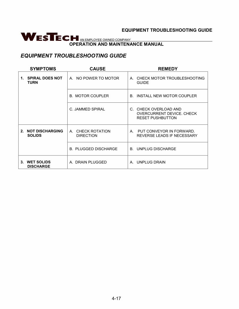
EQUIPMENT TROUBLESHOOTING GUIDE
SYMPTOMS CAUSE REMEDY
1. SPIRAL DOES NOT
TURN
A. NO POWER TO MOTOR
A. CHECK MOTOR TROUBLESHOOTING
GUIDE
B. MOTOR COUPLER
B. INSTALL NEW MOTOR COUPLER
C. JAMMED SPIRAL
C. CHECK OVERLOAD AND
OVERCURRENT DEVICE. CHECK
RESET PUSHBUTTON
2. NOT DISCHARGING
SOLIDS
A. CHECK ROTATION
DIRECTION
A. PUT CONVEYOR IN FORWARD.
REVERSE LEADS IF NECESSARY
B. PLUGGED DISCHARGE
B. UNPLUG DISCHARGE
3. WET SOLIDS
DISCHARGE
A. DRAIN PLUGGED
A. UNPLUG DRAIN

EXPLANATION OF PARTS LIST
AN EMPLOYEE OWNED COMPANY
OPERATION AND MAINTENANCE MANUAL
4-18
EXPLANATION OF PARTS LIST
ITEM NUMBERS Item numbers identify a part shown on an erection or assembly drawing. Item numbers are in circles on the drawing with an arrow pointing to the part. On the parts list, item numbers are found in the left most column of the list. Item numbers are three digit numbers.
PART NUMBERS Part numbers identify drawing numbers for shop drawings. Shop drawings are not included in operation and maintenance manuals.
ASSEMBLY: 20039A REV: B DWG #: 20039A-D101.DWG
PART DESCRIPTION: FALMOUTH, ME WWTF DWG REV: A
WRITTEN BY: MWB CHKD BY: PCH APP:
DATE: 1/25/2007 DATE: 1/25/2007 DATE:
DWG MATL B/M
ITEM SP PART NUMBER DRAWING NUMBER REV CODE PART DESCRIPTION QTY B/M REV
101 F 20039A-D102/A4 20039A-D102.DWG 0 SS MAIN ASSEMBLY, CFKS75, 3X8, 6MM, LH 1 Y A
102 F WFL-037 - - 304SS WASHER, FLAT, 3/8" 17 N -
103 F 20039A-D108/4 20039-D108.DWG 0 304SS CHUTE, CFK 1 N -
104 F BHH-037C0125 - - 304SS CAPSCREW, HH, 3/8"-16 X 1 1/4" LG 15 N -
105 F WLO-037 - - 304SS WASHER, LOCK, 3/8" 15 N -
MJG
1/25/2007
Figure 4-2: Parts List Identification

REPLACEMENT OR SPARE PARTS
AN EMPLOYEE OWNED COMPANY
OPERATION AND MAINTENANCE MANUAL
4-19
REPLACEMENT OR SPARE PARTS
Should you require assistance in determining which spare parts are appropriate for your particular situation, please don’t hesitate to contact WesTech PARTS SERVICES DEPARTMENT.
PROCEDURE FOR ORDERING REPLACEMENT OR SPARE PARTS:
Spare or replacement parts may be ordered from the Parts Services Department at:
WESTECH ENGINEERING, INC. 3625 SOUTH WEST TEMPLE SALT LAKE CITY, UT 84115 PHONE: (801) 265-1000 FAX: (801) 265-1080
24-HOUR SERVICE/EMERGENCY:
(801) 265-1000 8:00 am to 5:00 pm (801) 263-4093 5:00 pm to 8:00 am
E-MAIL ADDRESS:
WEB ADDRESS: www.westech-inc.com
If you would like to talk directly to a parts representative during normal business hours (8:00 am to 5:00 pm MST), dial (801) 265-1000 and ask for the Spare Parts Dept. You may Fax your order to (801) 265-1080 To use the 24-hour service/emergency line after hours (5:00 pm to 8:00 am), dial (801) 263-4093. Please indicate to the Answering Service Operator whether your facility is Water, Waste Water, or industrial. She will inform you that a WesTech representative will call and assist you with your problem. If you would like to e-mail a parts order, simply e-mail your request to us at [email protected] and a WesTech representative will process our order and follow up with an Order Acknowledgement. Parts may also be ordered directly from our web page (www.westech-inc.com). Simply go to the web page, click on Parts and Service, click on Contact the WesTech Spare Parts Department and fill out the online form. A WesTech representative will process your order and follow up with an Order Acknowledgement, or a return phone call to confirm that your order has been received.

REPLACEMENT OR SPARE PARTS
AN EMPLOYEE OWNED COMPANY
OPERATION AND MAINTENANCE MANUAL
4-20
To avoid unnecessary delays in obtaining the correct spare or replacement parts for your equipment, be sure to give the following information with each order.
Identify equipment using the WesTech job number as indicated on the cover sheet.
1. Identify the part by name and give the number of the drawing on which this part or assembly appears. If it is a part of a motor, pump, electrical control, or any part not manufactured by WesTech Engineering, the information will be found in the manufacturer's reference data included in this manual, or on the manufacturer's nameplate.
1. Identify the part number and / or item number.
2. Identify the size, and include all pertinent dimensions (such as diameter, length, thickness, bore, pitch, etc.) whenever possible.
3. If parts being ordered are electrical in nature, give all pertinent data; voltage, amperage, wattage, cycles, speed, power factor, or other information given on the part’s nameplate or included in the part’s brochure.
4. Submit your written purchase order or request for quotation. Be sure to sign and print your full name so that we will know whom to contact should further clarification of the inquiry be necessary. ALL VERBAL ORDERS MUST BE VERIFIED IN WRITING ON COMPANY LETTERHEAD.
5. Give a return address and a shipping address.
6. Give the preferred method of shipping (parcel post, truck freight, rail freight, air express, etc.).
7. Show the quantity desired.
8. Provide instructions for proper invoicing.
9. All parts orders are subject to a $100.00 minimum order charge.

REPLACEMENT OR SPARE PARTS
AN EMPLOYEE OWNED COMPANY
OPERATION AND MAINTENANCE MANUAL
4-21
10.

REPLACEMENT OR SPARE PARTS
AN EMPLOYEE OWNED COMPANY
OPERATION AND MAINTENANCE MANUAL
4-22
REPLACEMENT OR SPARE PARTS
AN EMPLOYEE OWNED COMPANY
OPERATION AND MAINTENANCE MANUAL
4-23
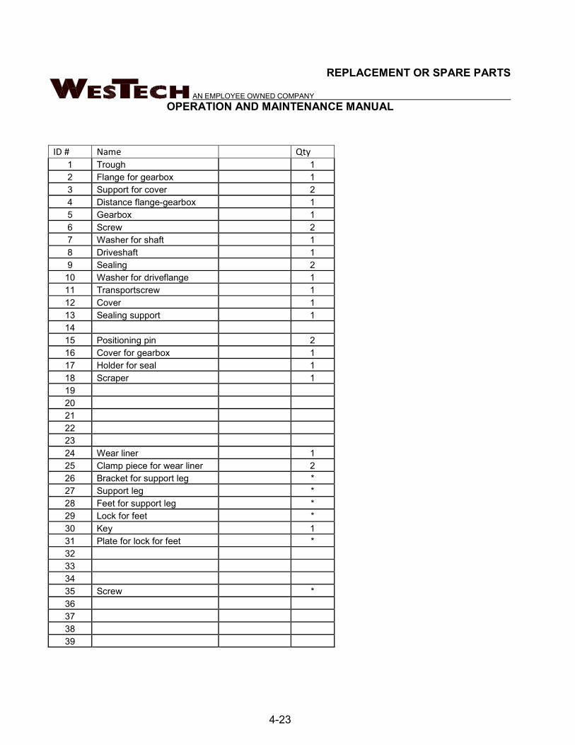
ID # Name Qty
1 Trough 1
2 Flange for gearbox 1
3 Support for cover 2
4 Distance flange-gearbox 1
5 Gearbox 1
6 Screw 2
7 Washer for shaft 1
8 Driveshaft 1
9 Sealing 2
10 Washer for driveflange 1
11 Transportscrew 1
12 Cover 1
13 Sealing support 1
14
15 Positioning pin 2
16 Cover for gearbox 1
17 Holder for seal 1
18 Scraper 1
19
20
21
22
23
24 Wear liner 1
25 Clamp piece for wear liner 2
26 Bracket for support leg *
27 Support leg *
28 Feet for support leg *
29 Lock for feet *
30 Key 1
31 Plate for lock for feet *
32
33
34
35 Screw *
36
37
38
39


AN EMPLOYEE OWNED COMPANY
5-1
5 ACCESSORY
EQUIPMENT

5-2
GEAR REDUCER
MOTOR
ZERO SPEED SWITCH
This page left intentionally blank.

AN EMPLOYEE OWNED COMPANY
GEAR REDUCER

This page left intentionally blank.

lb
G1000 – Subject to Change Without Notice C289
Clincher™ Shaft Mount Reducers Selection & Combinations
• SK 0182NB• SK 0282NB• SK 1382NB• SK 1282/02• SK 1282• SK 2282• SK 2382• SK 2282/02• SK 3282• SK 3382• SK 3282/12• SK 4282• SK 4382• SK 4282/12• SK 5282• SK 5382• SK 5282/12• SK 6282• SK 6382• SK 6282/22• SK 7282• SK 7382• SK 7382/22• SK 7382/32• SK 8282• SK 8382• SK 8382/32• SK 8382/42• SK 9282• SK 9382• SK 9382/42• SK 9382/52• SK 10282• SK 10382• SK 10382/52• SK 11282• SK 11382• SK 11382/52• SK 12382
Selection
www.nord.com
SK 2282 4.51 388 1646 5.00 3.30 2.50 1.65 5.72 306 1876 5.00 3.30 2.50 1.65 6.43 272 2000 5.00 3.30 2.50 1.65 7.48 234 2151 5.00 3.30 2.50 1.65 8.37 209 2266 5.00 3.30 2.50 1.65 9.03 194 2965 5.00 3.30 2.50 1.65 10.15 172 3151 5.00 3.30 2.50 1.65 11.81 148 3398 5.00 3.30 2.50 1.65 13.23 132 3584 5.00 3.30 2.50 1.65 16.53 106 4168 5.00 3.30 2.50 1.65 18.51 95 4301 5.00 3.30 2.50 1.65 21.90 80 4248 5.00 3.30 2.50 1.65 23.96 73 3850 4.46 2.94 2.23 1.47 24.97 70 4337 4.82 3.18 2.41 1.59 26.83 65 3885 4.01 2.64 2.00 1.32 29.65 59 4425 4.14 2.73 2.07 1.37 31.23 56 3938 3.50 2.31 1.75 1.15 36.54 48 4434 3.38 2.23 1.69 1.11 37.18 47 4071 3.04 2.00 1.52 1.00 43.71 40 4983 3.16 2.09 1.58 1.04 45.11 39 3983 2.46 1.63 1.23 0.81
Model Type Gear Ratio
Output Speed
Output Torque*
Maximum input power�Solid input shafts type “W“
itot n2 T2 max Input Speed
1750 rpm 1750 rpm 1150 rpm 875 rpm 580 rpm[rpm] [Ib-in] [hp] [hp] [hp] [hp]
RDANITZ
• SK 2282/02 • SK 3282 • SK 3382

www.nord.com A11G1000 – Subject to Change Without Notice
INTR
ODU
CTIO
N
SelectionInformation
Gearbox SelectionA number of factors are considered when selecting a gear unit, including gearbox rating, service factor, speed and speed variation, horsepower, thermal capacity, ratio, physical size, ambient conditions and cost. Below are some guideline steps to help aid in the gear unit selection.
1. Determine the speed and/or gear ratio2. Determine the required power or torque3. Determine Service Factor 4. Select the basic gearbox type and input5. Determine the required mounting position6. Select options7. Checks – overhung load, thrust load, NEMA motor weight, thermal considerations, and other application considerations
1. Speed and Gear Ratio
The fi rst step in selecting a gear unit is determining the fi nal output speed or speeds you need. This speed is nor-mally described in revolutions per minute (rpm). This out-put speed or speeds is determined by the input speed to the gear unit divided by its gear ratio. Their relationship is described by the following formulas.
i (gear ratio) = Input speed [rpm]
Output speed [rpm] = Input speed [rpm]
To specify a gear unit, you can identify either gear ratio needed or the output speed (rpm) if the input speed is known.
2. Power and Torque
The second step for selecting a gear unit is the required power or torque needed to power the load. Torque in this catalog is normally expressed in pound-inches [lb-in].
Power [hp] = Torque [lb-in] x speed [rpm]
Torque [lb-in] = Power [hp] x 63025
For a proper selection you must ensure that the motor or other prime mover can produce enough torque or powerand that the gear unit has adequate torque or power capacity. You must also consider if the power or torque is specifi ed at the input or output of the gear unit. The Helical-worm gear units have lower effi ciency than in-line or bevel gear units, therefore helical-worm products effi ciency may need to be considered in the selection.
To specify a gear unit you can identify either torque or power.
3. Service Factor or Service Class
In addition to power or torque, service factor must also be considered. A service factor is essentially the ratio of extra capacity in a gear unit compared to the power or torque that is needed to run that application. The goal of selecting a gear unit with extra capacity (service factor) is to provide adequate service life in operation.
One reason to apply a larger service factor is if a unit operates more hours per day. If a unit runs 24 hours per day it should normally have a higher service factor than a unit that runs 8 hours per day if you expect the same calendar life.
A second reason for applying a larger service factor is to cope with a more diffi cult application. Even if it takes the same power and speed to operate a rock crusher as a fan, the rock crusher needs a stronger gearbox (higher service factor) to give the same calendar operating life as the gear unit powering the fan.
The real question is how to determine the proper service factor for a gear unit in an application. Following are four possible methods.
Customer or User Speci� cationMany customers will have their own service factor guide-lines or specifi cations.
AGMA Service FactoringAmerican Gear Manufacturers Association (AGMA) pub-lishes lists of recommended service factors for different applications. These service factor recommendations have been determined form the experience of many gear manu-factures and are in AGMA standard 6010. See page 68 for additional detail.
AGMA Service ClassesAmerican Gear Manufactures Association (AGMA) has another method for selecting gear units service factors. AGMA standard 6009 lists many applications by a service class (I, II, III) with class I being the simplest applications and class III being the hardest. These applica-tion service classes are associated with a range of service factors by the following table.
AGMA Service Class Service FactorI 1.00 to 1.39II 1.40 to 1.99III 2.00 and above
In the gearmotors selection table each unit is also clas-sifi ed by an AGMA service class. See page 64 for additional detail.
Output speed [rpm]
i (gear ratio)
63025
speed [rpm]

www.nord.com A12
INTRO
DUCTIO
N
G1000 – Subject to Change Without Notice
SelectionInformation
NORD Mass Acceleration Service Factoring
NORD often uses a calculation based system to properly assign a service factor. This system considers hours of operation per day, the severity of the application and the number of times the equipment is cycled. See page 62 for additional detail.
4. Gearbox Type & Input
NORD gear drives are available in a number of mechanical confi gurations including:
• Helical in-line• Clincher™ shaft mount• Right-angle helical-bevel• Right-angle helical-worm
NORD’s modular design allows for a number of different inputs to be added to NORD reducers including:
• Integral motor• NEMA-C and IEC motor adapter• Solid input shaft• Servo motor adapter• Sugar scoop mount• Top motor mount platform• NORDISCTM variable speed friction drives• TitanTM variable speed belt boxes
5. Mounting Position
The gearbox mounting position is an important and often overlooked specifi cation. The mounting position deter-mines how much oil the gear reducer requires, in addition to determining the position of the oil drain, oil fi ll and vent on the gear drive. NORD offers six basic mounting posi-tions. If your application requires a variation from the six basic mounting positions, please contact NORD.
Many gearbox and motor options require a location des-ignation. For example a right-angle helical-bevel unit with a single solid shaft extension requires a shaft extension side location. Please see page 18 for additional options that require location designation.
6. Options
NORD offers a number of mechanical, protective, paint and lubrication options for gear reducers and motors. Please see pages 19 for gear unit options and refer to the motor section (Section G) for motor options.
7. Checks
Overhung Load
An overhung or radial load exists when a force is ap-plied at right-angles to a shaft beyond the shaft’s outer-most bearing. Pulleys, sheaves and sprockets will cause an overhung load when used as a power take-off. The amount of overhung load will vary, depending on the type of power take-off used and where it is located on the shaft.
Overhung load [FQ] can be found in the gearmotor rating tables and input shaft overhung load ratings [FQ1] can be found on pages 52 - 59. Overhung load capacities should not exceed the values in the table to ensure long bearing life. Overhung load capacities are to be applied at the midpoint of the shaft extension and without thrust loads.
To calculate overhung load see page 52.
Thrust Loads (Axial)
Loads that are directed towards or away from the gearbox along the axis of the shaft are called thrust or axial loads. Output shaft thrust capacity [FA] can be found in the gear-motor rating tables. Input shaft capacity [FA1] can be found on pages 52. Thrust load capacities should not ex-ceed the values listed in the tables to ensure long bearing life. Thrust load capacities are listed for pure axial loads with no overhung load. Contact NORD for combination loads or a more exact examination of the application.
NEMA C-face Motor Weight Limits
When mounting a motor to a NORD NEMA C-face motor adapter it is important to consider the motor’s weight. Fol-lowing is a table that includes the maximum motor weight the NEMA adapter can support. If the motor exceeds the listed weight is must be externally supported. When a C-face mounted motor is externally supported care must be taken to ensure that the support system does not impose additional pre-loads on the NEMA motor adapter.
NEMA WeightsMotor FRAME 56C 143TC 145TC 182TC 184TC
Max Weight [lb] 66 88 110 130 175
Motor FRAME 210TC 250TC 280TC 324TC 326TC
Max Weight [lb] 220 450 550 770 1100
Motor FRAME 365TC
Max Weight [lb] 1550
M1
M2
M6
M4
M3
M5

www.nord.com A13G1000 – Subject to Change Without Notice
INTR
ODU
CTIO
N
SelectionInformation
General Warnings & Cautions
Applications with risk of personal injury should be reviewed together with NORD. Examples of these are hoist, lifts or other applications where people may be at risk.
Helical-wormEf� ciency
NORD worm gear units can reach effi ciencies up to 92%.
Worm gears require a run-in period to reach their peak ef� ciency. Due to this the unit ef� ciency will be lower when the gear unit is new. The effect is greater at lower worm incline angles meaning with worms that have a low number of worm starts (or leads). Based on experience the following reduction in ef� ciency should be considered before the run-in is completed
Worm Starts (leads) Reduction in ef� ciency1 12%2 6%3 3%6 2%
The number of worm starts is listed in the gear ratio tables in the helical-worm reducer ratings tables.
The run-in period is approximately 25 hours operating time at maximum load.
Following conditions must be met in order to reach the catalog ef� ciency values.
- Gear unit is fully run-in - Gear unit has reached a constant temperature - The required type of lubricant is used - The required lubrication quantity is used - The unit is operating at full rated torque
Vertical Mounting Position for Gear Units & Gear Motors
Observe thermal limit rating – see page 14. For motors which are mounted vertically upwards (Mounting position M4) and ratios < 24, we highly recommend oil expansion chambers in order to avoid leakage through the vent plug.
NEMA and IEC adapters use in hoist, lifts and other appli-cations with danger of personal injury should be reviewed together with NORD.
NEMA/IEC adapter have additional shaft coupling and additional bearing seats compared to integral motors so there are higher no-load losses with NEMA or IEC adapt-ers. We recommend mounting the motor directly, since it offers both technical and cost advantages.
External Installation, Tropical Use
Gearboxes installed outside, in damp rooms, or used in the tropics may require special seals and anti-corrosion options. Please contact NORD for application assistance.
Special conditions
If special environmental or other conditions exist in transit, storage or operation these need to be considered in the unit selection. Special conditions may include (but are not limited to) the following:
- Exposure to aggressive corrosive materials (contaminated air, gasses, acids, bases, salts, etc.)- Very high relative humidity- Direct contact between t he motor and liquid- Material build- up on the gear unit or motor (dirt, dust, sand, etc.)- High atmospheric pressure- Radiation- Extreme temperatures, high, low or large temp. changes- High vibration, accelerations, shock or impacts- Other abnormal conditions
Storage Before Installation
The gear units and motors should be stored in a dry area before they are to be installed. Special measures are required for longer storage. Please request long term storage instructions from NORD Gear or from the NORD web site.
Multi-stage Gear Units
With 4-, 5-, 6-stage multi-stage gear units, there are ad-ditional no-load loss due to the added rotating parts and the relatively small drive input power. Thus, a no-load loss of approximately 40 watts for 4-pole motors up to 1 HP (0.75 kW) is accounted for in the performance tables.
NEMA C-Face Adapter Capacity
The NEMA adapters are designed to handle the torques produced by the standard NEMA power assignment at 4 pole (1800 rpm) motor speeds. If a larger motor power is used than the power below NORD should be consulted. Also if a NEMA adapter is being used for other than an AC induction motor NORD should be consulted.
Adapter Max Power[hp]
Adapter Max Power[hp]
56C 1 250TC 20140TC 2 280TC 30180TC 5 320TC 50210TC 10 360TC 75

www.nord.com A14
INTRO
DUCTIO
N
G1000 – Subject to Change Without Notice
Gear Reducer RatingsThe permissible continuous power limit of gear reducers is limited by both the mechanical rating and the thermal rating. The mechanical rating depends upon the materialstrength of the gear reducer’s gears, bearings, housing,shafts, etc. The mechanical input power limit to the reducer is also a function of the mechanical power rating divided by the relevant reducer service factor.
The thermal rating or thermal limit depends upon the amount heat generated within the reducer and is infl u-enced by a variety of factors including:
• Churning or splashing losses in the lubricant which depend upon reducer type, ratio, input style, mounting position or oil fi ll-level, and the circumferential travel velocities of the gear wheels.• The actual speed and load conditions. These factors determine load-dependent losses in the gears and frictional losses in the gears, bearings and seal areas. • Ambient Conditions: - Ambient Temperature. - Amount of free air circulation around the drive. - Possible near-by heat sources. - Heat dissipation or the ability of the reducer to transfer heat through the housing, shafts, and the mating sub- structure or mounting surface.
Observing the Reducer’s Thermal LimitWhen to Contact NORD
Through computer program analysis NORD can evaluate application conditions and the impact they have on a re-ducer’s thermal capacity.
When applying helical in-line, Clincher™ shaft mount, and helical-bevel gear units of case sizes 6 and larger (SK62, SK6282 and SK9072.1 and larger), consult NORD if any two or more of the following conditions apply:
• Gear ratio, itotal ≤ 24:1or ≤ 48:1 for helical-bevel units• Input power, P1 ≥ 60 hp (45 kw)• Input speed, n1 > 1800• Vertical positioning (mounting position M2 or M4)• Input confi guration: NEMA C-face, IEC, servo adapter or solid-shaft input (Type-W)• Elevated ambient temperature ≥ 86° F (30 °C)
When applying helical-worm or worm gear units, please consult NORD if any one of the following conditions applies:
• Input speed, n1 > 1800• Vertical positioning (mounting position M2 or M4)• Input confi guration: NEMA C-face, IEC, servo adapter or solid-shaft input (Type-W)• Elevated ambient temperature ≥ 86° F (30 °C)
Advise NORD of any special application considerations:
• Confi ned space or limited air circulation• Exposure to other near-by radiant heat sources• Dirty or dusty environments• High altitude operation > 3,280 ft (1000 m) a.s.l.
Dangers of Reducer OverheatingThe following problems may result when the reducer’s thermal capacity or maximum oil sump temperatures are exceeded:• Lubrication oxidation, breakdown and deterioration.• A decrease in lubrication viscosity and fi lm thickness.• Loss of critical bearing and gear clearances required for proper lubrication.• Increased contact pressures and increased operating temperatures in the critical load zones of the gearing and bearings.• An increased possibility for metal-to-metal contact and premature component wear.• A signifi cant reduction in the lubricant’s ability to prevent scuffi ng, pitting, and in extreme cases galling or welding.
Maximum Oil Sump Temperature LimitTo prevent reducer overheating, the reducer’s maximum oil sump temperature limit must not be exceeded for pro-longed periods of operation (up to 3 hours continuous operation, depending upon reducer size).
Oil Type Maximum Oil Temperature LimitNORD AGMA 9005-D94
Mineral 80-85 °C (176-185 °F) 95 °C (203 °F)Synthetic 105 °C (220 ° F) 107 ° C (225 ° F)
Measures to Expand the Application RangeThere are a variety of measures that may be taken in orderto protect against thermal overload and expand the application range of the gear reducer. Common examplesinclude the following:
• Recommending a change in lubrication viscosity and/or a specifi c synthetic lubricant type.• Applying high-temperature seals.• Increasing air fl ow around the gear unit.• Shielding or protecting the reducer from high heat sources.• Considering an integral motor instead of the bolt-on input assembly covers. In many cases the motor fan will substantially increase air-fl ow around the gear unit.• Add an Oil Expansion/Overfl ow Chamber (Option “OA”) or an Oil Reservoir (Option “OT”).• Oil Cooler (Option “OC”).• Water Cooling Cover (Option “WC”)
SelectionInformation

www.nord.com C295
W +
NEM
A
Model Type Gear Ratio
Output Speed
Output Torque*
Maximum input power�Solid input shafts type “W“
NEMA C-Face*Available Combinations
itot n2 T2 max Input Speed
1750 rpm 1750 rpm 1150 rpm 875 rpm 580 rpm
[rpm] [Ib-in] [hp] [hp] [hp] [hp] 56C 140TC 180TC 210TC 250TC 280TC 320TC 360TC
G1000 – Subject to Change Without Notice
SK 3282 4.48 391 4080 10.00 6.60 5.00 3.30 X X X X 5.74 305 4964 10.00 6.60 5.00 3.30 X X X X 6.70 261 5372 10.00 6.60 5.00 3.30 X X X X 8.31 211 5983 10.00 6.60 5.00 3.30 X X X X 9.80 179 7425 10.00 6.60 5.00 3.30 X X X X 11.38 154 7266 10.00 6.60 5.00 3.30 X X X X 14.11 124 7584 10.00 6.60 5.00 3.30 X X X X 16.67 105 7443 10.00 6.60 5.00 3.30 X X X X 20.18 87 7275 10.00 6.60 5.00 3.30 X X X X 21.38 82 6390 8.31 5.49 4.16 2.74 X X X X* 22.45 78 7080 8.76 5.78 4.38 2.89 X X X X* 23.71 74 7124 8.36 5.52 4.18 2.76 X X X X* 25.88 68 7487 8.08 5.33 4.04 2.67 X X X X* 28.70 61 7700 7.45 4.92 3.73 2.46 X X X X* 31.93 55 7761 6.77 4.47 3.39 2.24 X X X X* 37.77 46 7390 5.39 3.56 2.70 1.78 X X X 38.62 45 5611 4.01 2.64 2.00 1.32 X X X* 42.02 42 8222 5.48 3.62 2.74 1.81 X X X* 44.85 39 6522 4.04 2.66 2.02 1.33 X X X* 48.04 36 4885 2.79 1.84 1.40 0.92 X X 52.97 33 7478 3.92 2.58 1.96 1.29 X X X* 55.79 31 5682 2.79 1.84 1.40 0.92 X X 64.12 27 8983 3.85 2.54 1.92 1.27 X X X* 65.89 27 6708 2.87 1.90 1.44 0.95 X X 70.56 25 4991 1.98 1.31 0.99 0.65 X X* 79.76 22 7523 2.63 1.73 1.31 0.87 X X 88.74 20 8363 2.65 1.75 1.33 0.88 X X 100.88 17 7142 1.93 1.27 0.96 0.64 X X* 112.23 16 6815 1.73 1.14 0.86 0.57 X X*
SK 3282NEMA-C + W
Ratings & Combinations
W 56C 140TC 180TC 210TCSK 3282 110 106 115 123 143
lb
* Caution - The motor power may exceed the gear unit’s mechanical torque capacity� The mechanical power limit of the solid input shaft type “W” may limit the reducer rating.All ratings are mechanical. See page 14 for thermal considerations.
RDANITZ
100.88 17 7142 1.93 112.23 16 6815 1.73
RDANITZ
X* X*

www.nord.com C337
DIM
ENSI
ON
S
Dim
ensio
ns in
Inch
es
G1000 – Subject to Change Without Notice
ALT
ERN
ATE
SHA
FTS
SEE
PAG
ES 3
88 -
393
SK 3282A
SK 3282VF
SK 3282ASSK 3282AB
SK 3282V
SK 3282V
SK 3282A
SK 3282AF SK 3282ASH
NEMA Input
0.24 2.99
Ø5.3
3
9.61
Ø1.6
250
Ø2.1
7
1.61 2.17
8.86
Ø1.6
250
Ø1.6
250
Ø1.6
250
+0.0
009
-0.0
000
+0.0
009
-0.0
000
+0.0
000
-0.0
006
+0.0
000
-0.0
0065.71
6.85
Ø1.6
25Ø2
.17
6.14
0.93
I
II
I
II
6.85
Ø2.1
7Ø1
.625
2.28 2.28
0.37
5
1.732x (3/8 x 1/4 x 2-1/4)
-0.000
0+0.
0010
0.50
0
2.09
1/2 x 1/2 x 2-3/4
-0.00
00+0.
0010
Ø1.8
75
9.451.54
Ø0.55
0.243.50
Ø1.
875
9.84
7.01
6.388.90
3.15
0.71
15.2
04.
16
5/8-11
1/2-0.
0010
+0.000
0
V1
CC
BB1
U1
AK
1B
D1
C
BB
GA
2.09
1.933.50 0.24
Ø1.8
75AKBD
BF
90°
45°
AJ
9.45 5.95
BB
GA
Ø1.6
25AKBD
1.58
0.24
5.951.54
Ø0.55
Ø2.
179.
84
7.01
0.24 6.38 0.24
6.85
Ø2.
17Ø2
.17
Ø1.6
25
+0.00
01+0.
0000
V1
CC
BB1
U1
AK
1B
D1
C1
Y1
BF1AJ1
UY1
NEMA Dimensions
Type AJ1 AK1 BB1 BD1 BF1 U1 V1 UY1 Y1 C C1 CC
56C 5.88 4.500 0.18 6.54 0.43 0.625 2.06 0.71 0.188 14.04 10.54 4.60
140TC 5.88 4.500 0.18 6.54 0.43 0.875 2.12 0.96 0.188 14.04 10.54 4.60
180TC 7.25 8.500 0.23 9.17 0.59 1.125 2.62 1.24 0.250 16.04 12.54 6.60
210TC 7.25 8.500 0.39 9.17 0.59 1.375 3.12 1.52 0.312 16.04 12.54 6.60
SK 3282 + NEMA
Mounting Flange
BD (mm) AJ AK BB BF GA
9.84 (250) 8.46 7.09 + 0.0006- 0.0005 0.16 0.55 0.63
11.81 (300) 10.43 9.06 + 0.0000- 0.0013 0.16 0.55 0.79
���72���394

www.nord.com C378 G1000 – Subject to Change Without Notice
V1CC
BB1
U1AK
1BD
1
Y1
BF1AJ1
UY1
Y1
AJ1
UY1BF1
Figure 14 Bolt Flange
Figure 28 Bolt Flange
(For IEC 225-315)
IEC Inputs
CC DimensionsUnit IEC63 IEC 71 IEC 80 IEC 90 IEC 100 IEC 112 IEC 132 IEC 160 IEC 180 IEC 200 IEC 225 IEC 250 IEC 280 IEC 315SK 0182NB 3.35 3.35 4.06 4.06 4.96 4.96 – – – – – – – –SK 0282NB 3.35 3.35 4.06 4.06 4.96 4.96 – – – – – – – –SK 1382NB 3.35 3.35 4.06 4.06 4.96 4.96 – – – – – – – –SK 1282 3.35 3.50 4.13 4.13 5.12 5.12 – – – – – – – –SK 1282/02 3.35 3.50 4.13 4.13 5.12 5.12 – – – – – – – –SK 2282 – 3.46 4.25 4.25 4.92 4.92 6.14 – – – – – – –SK 2282/02 3.35 3.50 4.13 4.13 5.12 5.12 – – – – – – – –SK 2382 3.35 3.50 4.13 4.13 5.12 5.12 – – – – – – – –SK 3282 – 3.46 4.25 4.25 4.92 4.92 6.14 – – – – – – –SK 3282/12 3.35 3.50 4.13 4.13 5.12 5.12 – – – – – – – –SK 3382 3.35 3.50 4.13 4.13 5.12 5.12 – – – – – – – –SK 4282 – – – 4.29 5.24 5.24 7.48 7.64 7.64 – – – – –SK 4282/12 3.35 3.50 4.13 4.13 5.12 5.12 – – – – – – – –SK 4382 – 3.46 4.25 4.25 4.92 4.92 6.14 – – – – – – –SK 5282 – – – 4.29 5.24 5.24 7.48 7.64 7.64 – – – – –SK 5282/12 3.35 3.50 4.13 4.13 5.12 5.12 – – – – – – – –SK 5382 – 3.46 4.25 4.25 4.92 4.92 6.14 – – – – – – –SK 6282 – – – – 5.00 5.00 6.97 10.47 10.47 9.02 11.93 11.93 11.93 –SK 6382 – – – 4.29 5.24 5.24 7.48 7.64 7.64 – – – – –SK 6382/22 – 3.46 4.25 4.25 4.92 4.92 6.14 – – – – – – –SK 6382/32 – 3.46 4.25 4.25 4.92 4.92 6.14 – – – – – – –
IEC Dimensions (mm)Input AJ1 AK1 BB1 BD1 BF1 U1 V1 UY1 Y1 FlangeIEC 63 115 95 3.5 140 M8 11 23 12.8 4 Fig. 1IEC 71 130 110 4.0 160 M8 14 30 16.3 5 Fig. 1IEC 80 165 130 4.0 200 M10 19 40 21.8 6 Fig. 1IEC 90 165 130 4.0 200 M10 24 50 27.3 8 Fig. 1IEC 100 215 180 5.0 250 M12 28 60 31.3 8 Fig. 1IEC 112 215 180 5.0 250 M12 28 60 31.3 8 Fig. 1IEC 132 265 230 5.0 300 M12 38 80 41.3 10 Fig. 1IEC 160 300 250 6.0 350 M16 42 110 45.3 12 Fig. 1IEC 180 300 250 6.0 350 M16 48 110 51.8 14 Fig. 1IEC 200 350 300 6.0 400 M16 55 110 59.3 16 Fig. 1IEC 225 400 350 6.0 450 M16 60 140 64.4 18 Fig. 2IEC 250 500 450 6.0 550 M16 65 140 69.4 18 Fig. 2IEC 280 500 450 6.0 550 M16 75 140 79.9 20 Fig. 2IEC 315 600 550 7.0 660 M20 80 170 85.4 22 Fig. 2
DIMEN
SION
S

www.nord.com C388
DIMEN
SION
S
G1000 – Subject to Change Without Notice
Solid ShaftDimensions
UY
U
M
KEY
V
UM
KEY
V
VZ VFUNIT U DIAMETER TOLERANCE V UY KEY SIZE
w x h x lKEY QTY DRILL & TAP
M
SK 0182NB VZ/VF 0.750 +0.0000 / -0.0005 1.50 0.83 3/16 x 3/16 x 1-1/4 1 1/4-2025mm +0.015 / +0.002mm 50mm 28.0mm 8 x 7 x 40mm 1 M10
SK 0282NB VZ/VF 1.000 +0.0000 / -0.0005 2.13 1.11 1/4 x 1/4 x 1-5/8 1 3/8-1625mm +0.015 / +0.002mm 50mm 28.0mm 8 x 7 x 40mm 1 M10
SK 1382NB VZ/VF 1.250 +0.0000 / -0.0005 2.75 1.36 1/4 x 1/4 x 2-1/4 1 1/2-1330mm +0.015 / +0.002mm 60mm 33.0mm 8 x 7 x 50mm 1 M10
SK 1282 VZ/VF 1.250 +0.0000 / -0.0005 2.75 1.36 1/4 x 1/4 x 2-1/4 1 1/2-13SK 1382 VZ/VF 30mm +0.015 / +0.002mm 60mm 33.0mm 8 x 7 x 50mm 1 M10SK 2282 VZ/VF 1.375 +0.0000 / -0.0005 2.75 1.51 5/16 x 5/16 x 2-1/8 1 5/8-11SK 2382 VZ/VF 35mm +0.018 / +0.002mm 70mm 38.0mm 10 x 8 x 60mm 1 M12SK 3282 VZ/VF 1.875 +0.0000 / -0.0010 3.50 2.09 1/2 x 1/2 x 2-3/4 1 5/8-11SK 3382 VZ/VF 45mm +0.018 / +0.002mm 90mm 48.5mm 14 x 9 x 80mm 1 M16SK 4282 VZ/VF 2.250 +0.0000 / -0.0010 4.00 2.47 1/2 x 1/2 x 3-1/4 1 3/4-10SK 4382 VZ/VF 55mm +0.030 / +0.011mm 110mm 59.0mm 16 x 10 x 90mm 1 M20SK 5282 VZ/VF 2.500 +0.0000 / -0.0010 5.00 2.77 5/8 x 5/8 x 4 1 3/4-10SK 5382 VZ/VF 65mm +0.030 / +0.011mm 130mm 69.0mm 18 x 11 x 100mm 1 M20SK 6282 VZ/VF 3.000 +0.0000 / -0.0010 5.50 3.33 3/4 x 3/4 x 4-1/2 1 3/4-10SK 6382 VZ/VF 75mm +0.030 / +0.011mm 140mm 79.5mm 20 x 12 x 125mm 1 M20SK 7282 VZ/VF 3.500 +0.0000 / -0.0010 6.75 3.88 7/8 x 7/8 x 5-1/2 1 3/4-10SK 7382 VZ/VF 90mm +0.035 / +0.013mm 170mm 95.0mm 25 x 14 x 140mm 1 M24SK 8282 VZ/VF 4.250 +0.0000 / -0.0010 8.50 4.69 1 x 1 x 7-1/4 1 1-8SK 8382 VZ/VF 110mm +0.035 / +0.013mm 210mm 116mm 28 x 16 x 180mm 1 M24SK 9282 VZ/VF 5.250 +0.0000 / -0.0010 9.84 5.80 1-1/4 x 1-1/4 x 8-3/8 1 1-8SK 9382 VZ/VF 140mm +0.040 / +0.015mm 250mm 148mm 36 x 20 x 200mm 1 M24SK 10282 VZ/VF 6.250 +0.0000 / -0.0010 11.81 6.91 1-1/2 x 1-1/2 x 10 1 1-8SK 10382 VZ/VF 160mm +0.040 / +0.015mm 300mm 169mm 40 x 22 x 250mm 1 M24SK 11282 VZ/VF 7.000 +0.0000 / -0.0010 11.81 7.77 1-3/4 x 1-3/4 x 10 1 1-8SK 11382 VZ/VF 180mm +0.040 / +0.015mm 300mm 190mm 45 x 25 x 250mm 1 M24SK 12382 VZ/VF 7.000 +0.0000 / -0.0010 11.81 7.77 1-3/4 x 1-3/4 x 10 1 1-8
180mm +0.040 / +0.015mm 300mm 190mm 45 x 25 x 250mm 1 M24• Dimensions are in inches unless otherwise noted.• Metric Keys are captured in keyways.• For shaft sizes not shown, consult NORD.
Solid Shaft Dimensions(VZ/VF)
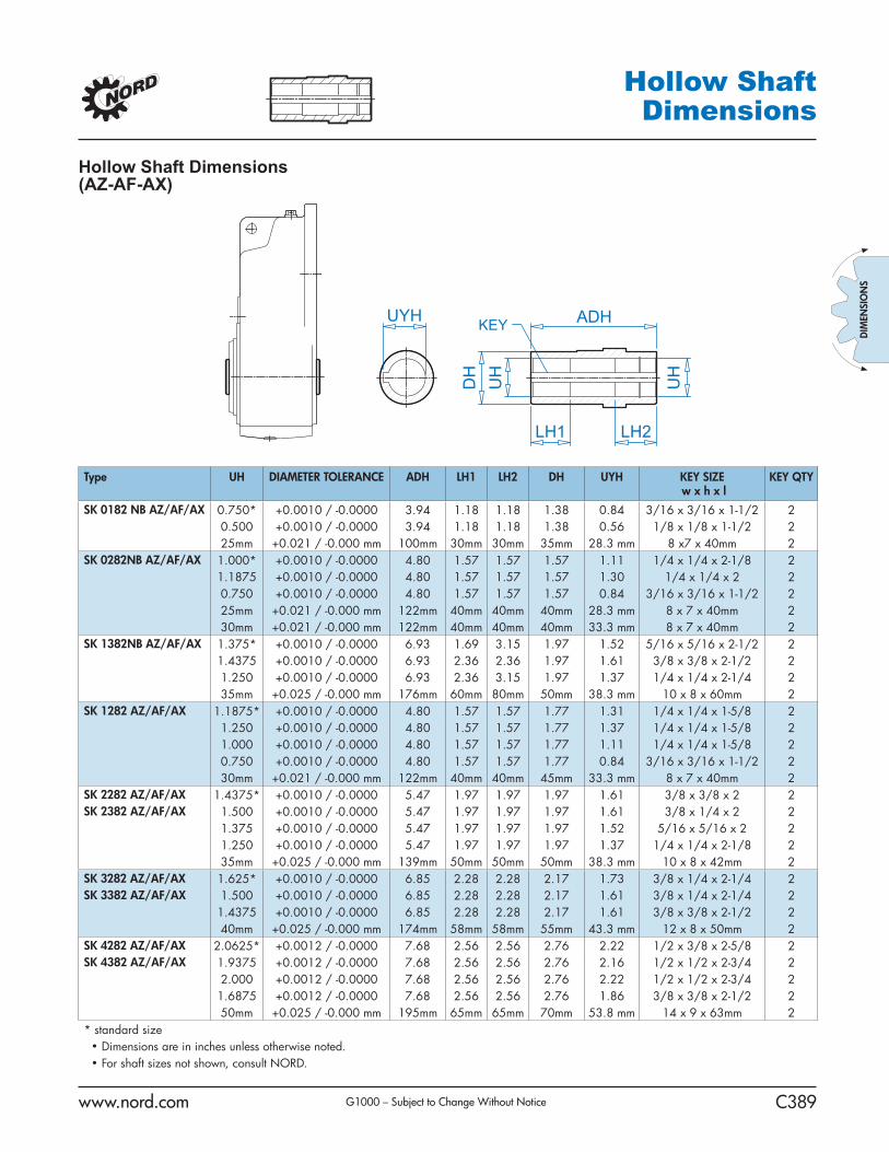
www.nord.com C389
DIM
ENSI
ON
S
G1000 – Subject to Change Without Notice
Hollow Shaft Dimensions
KEY ADHUYH
UH
UH
DH
LH1 LH2
Type UH DIAMETER TOLERANCE ADH LH1 LH2 DH UYH KEY SIZE w x h x l
KEY QTY
SK 0182 NB AZ/AF/AX 0.750* +0.0010 / -0.0000 3.94 1.18 1.18 1.38 0.84 3/16 x 3/16 x 1-1/2 20.500 +0.0010 / -0.0000 3.94 1.18 1.18 1.38 0.56 1/8 x 1/8 x 1-1/2 225mm +0.021 / -0.000 mm 100mm 30mm 30mm 35mm 28.3 mm 8 x7 x 40mm 2
SK 0282NB AZ/AF/AX 1.000* +0.0010 / -0.0000 4.80 1.57 1.57 1.57 1.11 1/4 x 1/4 x 2-1/8 21.1875 +0.0010 / -0.0000 4.80 1.57 1.57 1.57 1.30 1/4 x 1/4 x 2 20.750 +0.0010 / -0.0000 4.80 1.57 1.57 1.57 0.84 3/16 x 3/16 x 1-1/2 225mm +0.021 / -0.000 mm 122mm 40mm 40mm 40mm 28.3 mm 8 x 7 x 40mm 230mm +0.021 / -0.000 mm 122mm 40mm 40mm 40mm 33.3 mm 8 x 7 x 40mm 2
SK 1382NB AZ/AF/AX 1.375* +0.0010 / -0.0000 6.93 1.69 3.15 1.97 1.52 5/16 x 5/16 x 2-1/2 21.4375 +0.0010 / -0.0000 6.93 2.36 2.36 1.97 1.61 3/8 x 3/8 x 2-1/2 21.250 +0.0010 / -0.0000 6.93 2.36 3.15 1.97 1.37 1/4 x 1/4 x 2-1/4 235mm +0.025 / -0.000 mm 176mm 60mm 80mm 50mm 38.3 mm 10 x 8 x 60mm 2
SK 1282 AZ/AF/AX 1.1875* +0.0010 / -0.0000 4.80 1.57 1.57 1.77 1.31 1/4 x 1/4 x 1-5/8 21.250 +0.0010 / -0.0000 4.80 1.57 1.57 1.77 1.37 1/4 x 1/4 x 1-5/8 21.000 +0.0010 / -0.0000 4.80 1.57 1.57 1.77 1.11 1/4 x 1/4 x 1-5/8 20.750 +0.0010 / -0.0000 4.80 1.57 1.57 1.77 0.84 3/16 x 3/16 x 1-1/2 230mm +0.021 / -0.000 mm 122mm 40mm 40mm 45mm 33.3 mm 8 x 7 x 40mm 2
SK 2282 AZ/AF/AX 1.4375* +0.0010 / -0.0000 5.47 1.97 1.97 1.97 1.61 3/8 x 3/8 x 2 2SK 2382 AZ/AF/AX 1.500 +0.0010 / -0.0000 5.47 1.97 1.97 1.97 1.61 3/8 x 1/4 x 2 2
1.375 +0.0010 / -0.0000 5.47 1.97 1.97 1.97 1.52 5/16 x 5/16 x 2 21.250 +0.0010 / -0.0000 5.47 1.97 1.97 1.97 1.37 1/4 x 1/4 x 2-1/8 235mm +0.025 / -0.000 mm 139mm 50mm 50mm 50mm 38.3 mm 10 x 8 x 42mm 2
SK 3282 AZ/AF/AX 1.625* +0.0010 / -0.0000 6.85 2.28 2.28 2.17 1.73 3/8 x 1/4 x 2-1/4 2SK 3382 AZ/AF/AX 1.500 +0.0010 / -0.0000 6.85 2.28 2.28 2.17 1.61 3/8 x 1/4 x 2-1/4 2
1.4375 +0.0010 / -0.0000 6.85 2.28 2.28 2.17 1.61 3/8 x 3/8 x 2-1/2 240mm +0.025 / -0.000 mm 174mm 58mm 58mm 55mm 43.3 mm 12 x 8 x 50mm 2
SK 4282 AZ/AF/AX 2.0625* +0.0012 / -0.0000 7.68 2.56 2.56 2.76 2.22 1/2 x 3/8 x 2-5/8 2SK 4382 AZ/AF/AX 1.9375 +0.0012 / -0.0000 7.68 2.56 2.56 2.76 2.16 1/2 x 1/2 x 2-3/4 2
2.000 +0.0012 / -0.0000 7.68 2.56 2.56 2.76 2.22 1/2 x 1/2 x 2-3/4 21.6875 +0.0012 / -0.0000 7.68 2.56 2.56 2.76 1.86 3/8 x 3/8 x 2-1/2 250mm +0.025 / -0.000 mm 195mm 65mm 65mm 70mm 53.8 mm 14 x 9 x 63mm 2
* standard size • Dimensions are in inches unless otherwise noted. • For shaft sizes not shown, consult NORD.
Hollow Shaft Dimensions (AZ-AF-AX)

www.nord.com A16
INTRO
DUCTIO
N
G1000 – Subject to Change Without Notice
MountingPositions
In-line
Clincher™
Right-Angle
M6
M1
M2
M4M5
M3
M6
M1
M2
M4 M5
M3
M6
M1
M2
M4M5
M3
M6M2
M3
M5
M4
M1
M6M2
M3
M5M4
M1
M6
M1
M2
M4M5
M3
Mounting PositionsThe reducer mounting position determines the approximate oil fi ll level and the appropriate vent location. In some cases mounting position may dictate possible variation in fi nal reducer assembly. If considering any mounting positions that are not shown as catalog-standard options, it is critical that the customer consult with NORD prior to ordering.

www.nord.com A42
INTRO
DUCTIO
N
G1000 – Subject to Change Without Notice
Lubrication
Lubrication TypesProper gearbox lubrication is essential in order to reduce friction, heat, and component wear. Lubricants reduce heat and wear by inserting a protective “fl uid boundary” between mating parts and preventing direct metal to metal con-tact. Lubricants also help prevent corrosion and oxidation, minimize foam, improve heat transfer, optimize reducer effi ciency, absorb shock loads and reduce noise.
Mounting position not only determines the proper fi ll-level but may also have some effect on fi nal reducer assembly. If considering any mounting positions that are not shown as catalog-standard options, it is critical that the customer consult with NORD prior to ordering. Unless otherwise specifi ed, NORD supplies most all gear units (*) factory-fi lled with the standard lubrication type and the appropriate amount of lubricating oil.
* Gear units SK10282, SK10382, SK11282, SK11382, SK12382, and SK9096.1 are supplied without oil.
Standard Oil Lubricants
Gear Unit Type Ambient Temperature Oil Type ISO Viscosity Manufacturer Brand / Type
Helical-Inline, Parallel-Shaft, & Helical-Bevel
-4 to 104 °F (-20 to 40 °C) MIN-EP VG 220 Shell / Omala 220 �-40 to 140 °F (-40 to 60 °C) PAO VG 220 Mobil SHC 630 �23 to 104 °F (-5 to 40 °C) FG VG 220 Shell / FM 220 �
Helical-Worm -22 to 122 °F (-30 to 50 °C) PAO VG 680 Mobil SHC 636 �
Optional Oil LubricantsGear Unit Type Ambient Temperature Oil Type ISO Viscosity Manufacturer Brand / Type
Helical-Inline, Parallel-Shaft, & Helical-Bevel
-31 to 176 °F (-35 to 80 °C) PAO VG 460 Mobil SHC 634-40 to 77 °F (-40 to 25 °C) PAO VG 150 Mobil SHC 629-40 to 140 °F (-40 to 60 °C) FG-PAO VG 220 Shell / Cassida GL 220
Helical-Worm -40 to 122 °F (-40 to 50 °C) FG-PAO VG 460 Shell / Cassida GL 460
Standard Bearing Grease LubricantsGrease Type / Thickener Ambient Temperature NLGI Grade Manufacturer Brand / TypeStandard (Li-Complex) -22 to 140 °F (-30 to 60 °C) NLGI 2 Shell Albida EP LC2 �High Temp (Polyurea) -13 to 176 °F (-25 to 80 °C) NLGI 2 Mobil Polyrex EP 2 �Food-Grade (Al-Complex) -13 to 104 °F (-25 to 40 °C) NLGI 2 Mobil Grease FM 222 �
� Stocked Lubricant
Oil Formulation Codes
MIN-EP Mineral Oil with EP Additive
PAO Synthetic Polyalphaolefi n Oil
PG Synthetic Polyglycol Oil
FG Food-Grade Oil
FG-PAO Food-Grade, Synthetic Polyalphaolefi n Oil
Important Notes
• In worm gears avoid using (EP) gear oils that contain sulfur-phosphorous chemistries, as these additives can react adversely with bronze worm gears and accelerate wear.• Food grade lubricants must be in compliance with FDA 212 CFR 178.3570 and qualify as a NSF-H1 lubricant. Please consult with lubrication manufacture for more information. • When making a lubrication change, check with the lubrication supplier to assure compatibility and to obtain recommended cleaning or fl ushing procedures. • Do not mix different oils with different additive packages or different base oil formulation types. Polyglycol (PG) oils are not miscible with other oil types and should never be mixed with mineral oil, or Polyalphaolefi n (PAO) oil. • Please Consult NORD if considering cold-temperature oils below an ISO Viscosity VG100 or lower.

www.nord.com A46
INTRO
DU
CTION
G1000 – Subject to Change Without Notice
MountingPosition M1 M2 M3 M4 M5 M6
Quarts Liters Quarts Liters Quarts Liters Quarts Liters Quarts Liters Quarts LitersSK0182NB 0.42 0.40 0.58 0.55 0.63 0.60 0.58 0.55 0.37 0.35 0.37 0.35SK0282NB 0.74 0.70 1.06 1.00 0.85 0.80 1.16 1.10 0.95 0.90 0.95 0.90SK1382NB 1.37 1.30 2.43 2.30 1.48 1.40 2.22 2.10 2.11 2.00 2.01 1.90SK1282 0.95 0.90 1.37 1.30 0.95 0.90 1.27 1.20 1.00 0.95 1.00 0.95SK2282 1.74 1.65 2.54 2.40 2.01 1.90 2.11 2.00 1.90 1.80 1.90 1.80SK2382 1.80 1.70 2.75 2.60 2.01 1.90 3.28 3.10 1.59 1.50 1.59 1.50SK3282 3.33 3.15 4.33 4.10 3.44 3.25 4.33 4.10 3.33 3.15 3.33 3.15SK3382 4.33 4.10 5.18 4.90 3.49 3.30 5.92 5.60 3.49 3.30 3.49 3.30SK4282 4.97 4.70 6.45 6.10 5.02 4.75 5.71 5.40 4.97 4.70 4.97 4.70SK4382 6.24 5.90 7.19 6.80 5.18 4.90 8.77 8.30 5.18 4.90 5.18 4.90SK5282 7.93 7.50 9.30 8.80 7.93 7.50 9.30 8.80 7.61 7.20 7.61 7.20SK5382 13.2 12.5 12.7 12.0 7.08 6.70 14.8 14.0 8.77 8.30 8.77 8.30SK6282 18.0 17.0 14.8 14.0 12.7 12.0 18.5 17.5 10.6 10.0 14.8 14.0SK6382 17.4 16.5 13.7 13.0 10.1 9.60 19.0 18.0 14.8 14.0 13.2 12.5SK7282 26.4 25.0 22.2 21.0 21.1 20.0 28.5 27.0 16.9 16.0 22.2 21.0SK7382 23.3 22.0 21.1 20.0 16.9 16.0 26.4 25.0 24.3 23.0 20.1 19.0SK8282 39.1 37.0 34.9 33.0 31.7 30.0 43.3 41.0 32.8 31.0 32.8 31.0SK8382 35.9 34.0 33.8 32.0 26.4 25.0 40.2 38.0 37.0 35.0 31.7 30.0SK9282 78.2 74.0 74.0 70.0 58.1 55.0 76.1 72.0 63.4 60.0 62.4 59.0SK9382 77.2 73.0 74.0 70.0 47.6 45.0 78.2 74.0 68.7 65.0 63.4 60.0SK10282* 95.1 90.0 95.1 90.0 42.3 40.0 95.1 90.0 63.4 60.0 86.7 82.0SK10382* 89.8 85.0 106 100 77.2 73.0 106 100 84.6 80.0 84.6 80.0SK11282* 174 165 169 160 153 145 206 195 106 100 148 140SK11382* 169 160 164 155 148 140 222 210 164 155 143 135SK12382* 169 160 164 155 148 140 222 210 164 155 143 135* These units shipped without oil
Clincher™ Shaft Mount Positions & Oil Fill Quantities
M6
M1
M2
M4M5
M3
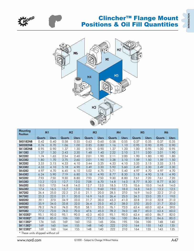
www.nord.com A47G1000 – Subject to Change Without Notice
INTR
OD
UCT
ION
M6
M1
M2
M4 M5
M3
MountingPosition M1 M2 M3 M4 M5 M6
Quarts Liters Quarts Liters Quarts Liters Quarts Liters Quarts Liters Quarts LitersSK0182NB 0.42 0.40 0.58 0.55 0.63 0.60 0.58 0.55 0.37 0.35 0.37 0.35SK0282NB 0.74 0.70 1.06 1.00 0.85 0.80 1.16 1.10 0.95 0.90 0.95 0.90SK1382NB 0.95 0.90 1.37 1.30 0.95 0.90 1.27 1.20 1.00 0.95 1.00 0.95SK1282 1.37 1.30 2.43 2.30 1.48 1.40 2.22 2.10 2.11 2.00 2.01 1.90SK2282 1.74 1.65 2.54 2.40 2.01 1.90 2.11 2.00 1.90 1.80 1.90 1.80SK2382 1.80 1.70 2.75 2.60 2.01 1.90 3.28 3.10 1.59 1.50 1.59 1.50SK3282 3.33 3.15 4.33 4.10 3.44 3.25 4.33 4.10 3.33 3.15 3.33 3.15SK3382 4.33 4.10 5.18 4.90 3.49 3.30 5.92 5.60 3.49 3.30 3.49 3.30SK4282 4.97 4.70 6.45 6.10 5.02 4.75 5.71 5.40 4.97 4.70 4.97 4.70SK4382 6.24 5.90 7.19 6.80 5.18 4.90 8.77 8.30 5.18 4.90 5.18 4.90SK5282 7.93 7.50 9.30 8.80 7.93 7.50 9.30 8.80 7.61 7.20 7.61 7.20SK5382 13.2 12.5 12.7 12.0 7.08 6.70 14.8 14.0 8.77 8.30 8.77 8.30SK6282 18.0 17.0 14.8 14.0 12.7 12.0 18.5 17.5 10.6 10.0 14.8 14.0SK6382 17.4 16.5 13.7 13.0 10.1 9.60 19.0 18.0 14.8 14.0 13.2 12.5SK7282 26.4 25.0 22.2 21.0 21.1 20.0 28.5 27.0 16.9 16.0 22.2 21.0SK7382 23.3 22.0 21.1 20.0 16.9 16.0 26.4 25.0 24.3 23.0 20.1 19.0SK8282 39.1 37.0 34.9 33.0 31.7 30.0 43.3 41.0 32.8 31.0 32.8 31.0SK8382 35.9 34.0 33.8 32.0 26.4 25.0 40.2 38.0 37.0 35.0 31.7 30.0SK9282 78.2 74.0 74.0 70.0 58.1 55.0 76.1 72.0 63.4 60.0 62.4 59.0SK9382 77.2 73.0 74.0 70.0 47.6 45.0 78.2 74.0 68.7 65.0 63.4 60.0SK10282* 95.1 90.0 95.1 90.0 42.3 40.0 95.1 90.0 63.4 60.0 86.7 82.0SK10382* 89.8 85.0 106 100 77.2 73.0 106 100 84.6 80.0 84.6 80.0SK11282* 174 165 169 160 153 145 206 195 106 100 148 140SK11382* 169 160 164 155 148 140 222 210 164 155 143 135SK12382* 169 160 164 155 148 140 222 210 164 155 143 135* These units shipped without oil
Clincher™ Flange MountPositions & Oil Fill Quantities
RDANITZ
M1
RDANITZ
SK2382 1.80 1.70 SK3282 3.33 3.15 SK3382 4.33 4.10

AN EMPLOYEE OWNED COMPANY
MOTOR

This page left intentionally blank.

Pro
du
ct In
form
atio
n P
acke
t
VC
P35
84T
1.5H
P,1
740R
PM
,3P
H,6
0HZ
,145
TC
,052
4M,T
EF
C
Cop
yrig
ht ©
All
prod
uct i
nfor
mat
ion
with
in th
is d
ocum
ent i
s su
bjec
t to
Bal
dor
Ele
ctric
Com
pany
cop
yrig
ht ©
pro
tect
ion,
unl
ess
othe
rwis
e no
ted.

Pag
e 2
of 1
0
Pro
duct
Info
rmat
ion
Pac
ket:
VC
P35
84T
- 1
.5H
P,1
740R
PM
,3P
H,6
0HZ
,145
TC
,052
4M,T
EF
C
Pro
du
ct D
etai
l
Rev
isio
n:
ES
tatu
s:P
RD
/AC
han
ge
#:P
rop
riet
ary:
No
Typ
e:A
CP
rod
Typ
e:05
24M
Ele
c. S
pec
:05
WG
W49
8C
D D
iag
ram
:C
D00
05
En
clo
sure
TE
FC
Mfg
Pla
nt:
Mec
h S
pec
:05
E24
8L
ayo
ut:
05LY
E24
8
Fra
me:
145T
CM
ou
nti
ng
:F
1P
ole
s:04
Cre
ated
Dat
e:
Bas
e:N
Ro
tati
on
:R
Insu
lati
on
:F
Eff
. Dat
e:05
-28-
2008
Lea
ds:
9#18
Rep
lace
d B
y:
Nam
epla
te N
P12
58E
CA
T.N
O.
SP
EC
.05
E24
8W49
8H2
HP
1.5
VO
LT
S20
8-23
0/46
0
AM
P4.
5-4.
2/2.
1
RP
M17
40
FR
AM
E14
5TC
HZ
60P
H3
SE
R.F
.1.
15C
OD
EK
DE
SB
CL
F
NE
MA
-NO
M-E
FF
84P
F79
RA
TIN
G40
C A
MB
-CO
NT
CC
US
AB
LE
AT
208
V4.
5
DE
6205
OD
E62
03
EN
CL
TE
FC
SN
Nam
epla
te N
P00
90E
FR
ON
T62
03
PU
LL
EY
6205
LU
BR
ICA
TE
WIT
H

Pag
e 3
of 1
0
Pro
duct
Info
rmat
ion
Pac
ket:
VC
P35
84T
- 1
.5H
P,1
740R
PM
,3P
H,6
0HZ
,145
TC
,052
4M,T
EF
C
GR
EA
SE
PO
LYR
EX
EM

Pag
e 4
of 1
0
Pro
duct
Info
rmat
ion
Pac
ket:
VC
P35
84T
- 1
.5H
P,1
740R
PM
,3P
H,6
0HZ
,145
TC
,052
4M,T
EF
C
Par
ts L
ist
Pro
du
ct ID
Des
crip
tio
nQ
uan
tity
Lis
t P
rice
SA
0935
41S
A 0
5E24
8W49
8H2
1.00
030
7.00
RA
0861
18R
A 0
5E24
8W49
8H2
1.00
025
6.00
S/P
101-
000-
000
EP
AC
T P
RO
CE
DU
RE
S-F
S P
LAN
T-P
OLY
RE
X E
M, N
O1.
000
HW
3201
A05
3/8-
16 E
YE
BO
LT1.
000
17.0
0
06C
B10
00A
02G
CO
ND
UIT
BO
X, M
AC
H G
RA
Y1.
000
31.0
0
RM
1016
LEA
D S
EP
AR
AT
OR
GA
SK
ET
- 3
05/3
06 C
.P.M
OT
O1.
000
16.0
0
51X
W25
20A
12.2
5-20
X .7
5, T
AP
TIT
E II
, HE
X W
SH
R S
LTD
2.00
02.
00
11X
W10
32G
0610
-32
X .3
8, T
AP
TIT
E II
, HE
X W
SH
R S
LTD
U1.
000
2.00
HW
3001
A01
D30
19 B
RA
SS
WA
SH
ER
(ST
IMP
)1.
000
2.00
10X
N25
20S
061/
4 20
X3/
8 H
X H
D C
AP
S.S
.1.
000
2.00
WD
1000
B16
KP
A-4
C B
UR
ND
Y T
ER
MIN
AL
1.00
04.
00
35E
P11
00A
55G
SP
L F
R E
ND
PLA
TE
, MA
CH
05M
143
-5T
D, C
P &
1.00
067
.00
HW
4500
A19
1/4-
28X
1/4
SLO
TT
ED
PLU
G F
/S1.
000
2.00
HA
4001
A01
SP
DR
AIN
PLU
G, P
LAS
TIC
(MIC
RO
PLA
S)
1.00
02.
00
HW
5100
A03
SP
WA
VY
WA
SH
ER
(W
1543
-017
)1.
000
2.00
35E
P13
00A
53G
PU
EN
DP
LAT
E, G
RA
Y.
1.00
013
7.00
HW
4500
A19
1/4-
28X
1/4
SLO
TT
ED
PLU
G F
/S1.
000
2.00
HA
4001
A01
SP
DR
AIN
PLU
G, P
LAS
TIC
(MIC
RO
PLA
S)
1.00
02.
00
51X
N10
32A
2010
-32
X 1
1/4
HX
WS
SL
SR
2.00
02.
00
HA
3100
A47
TH
RU
BO
LT 1
0-32
X 7
.625
4.00
02.
00
51X
B12
14A
1612
-14X
1.00
HX
WS
SLD
SE
RT
YB
1.00
02.
00
35F
H10
00A
04G
35F
H10
00A
04 W
/GR
AY
EP
OX
Y1.
000
57.0
0
10X
N25
20A
161/
4-20
X 1
HE
X H
EA
D C
AP
SC
R, Z
INC
PLA
TE
D3.
000
2.00
HW
1001
A25
LOC
KW
AS
HE
R 1
/4, Z
INC
PLT
.493
OD
, .25
5 I
3.00
02.
00

Pag
e 5
of 1
0
Pro
duct
Info
rmat
ion
Pac
ket:
VC
P35
84T
- 1
.5H
P,1
740R
PM
,3P
H,6
0HZ
,145
TC
,052
4M,T
EF
C
Par
ts L
ist
(co
nti
nu
ed)
Pro
du
ct ID
Des
crip
tio
nQ
uan
tity
Lis
t P
rice
WD
4100
A03
DE
-750
HE
YC
O P
LUG
62M
P07
50 M
ICR
O P
LAS
TIC
1.00
02.
00
35F
H45
00A
11D
RIP
CO
VE
R(W
/ AU
TO
PH
ER
ET
IC P
RIM
ER
)1.
000
10.0
0
HA
2001
A13
35-1
0103
SP
AC
ER
WE
LKE
R3.
000
5.00
51X
N10
32A
2010
-32
X 1
1/4
HX
WS
SL
SR
3.00
02.
00
06C
B15
00A
01G
CO
ND
UIT
BO
X L
ID, M
AC
H G
RA
Y1.
000
23.0
0
06G
S10
03G
AS
KE
T, K
OB
X L
ID, 1
/8"
TH
ICK
BLA
CK
NE
OP
R1.
000
2.00
10X
N25
20A
121/
4-20
X 3
/4 H
EX
HE
AD
CA
P2.
000
2.00
HW
1001
A25
LOC
KW
AS
HE
R 1
/4, Z
INC
PLT
.493
OD
, .25
5 I
2.00
02.
00
HW
4600
B32
SP
V-R
ING
SLI
NG
ER
1.0
00 X
1.5
40 X
0.2
401.
000
6.00
HA
1005
A05
SP
35-3
09 S
LIN
GE
R1.
000
2.00
HW
2501
D13
SP
KE
Y, 3
/16
SQ
X 1
.375
1.00
02.
00
HA
7000
A01
KE
Y R
ET
AIN
ER
7/8
" D
IA S
HA
FT
1.00
02.
00
MJ5
001A
0146
-665
RE
D S
EA
LER
0.00
157
.00
85X
U04
07S
044X
1/4
U D
RIV
E P
IN S
TA
INLE
SS
4.00
02.
00
LB10
02LA
BE
L,M
AR
INE
DU
TY
(O
N R
OLL
S)
1.00
02.
00
MJ1
000A
02G
RE
AS
E, P
OLY
RE
X E
M E
XX
ON
0.05
010
.00
MG
1025
Z02
AC
TIV
AT
OR
WIL
KO
FA
ST
060
-02
0.01
019
4.00
MG
1025
G05
PA
INT
DR
K M
ET
.GR
AY
,W/A
CT
IVA
TO
R0.
022
182.
00
35F
N30
02A
05S
PE
XT
ER
NA
L F
AN
, PLA
ST
IC, F
OR
.637
DIA
JO
UR
1.00
022
.00
LB11
25C
04S
TD
-E (
ST
OC
K C
TN
LA
BE
L S
TD
-E W
ITH
FLA
G)
1.00
02.
00
LC00
05E
01C
ON
N.D
IA./W
AR
NIN
G L
AB
EL
(LC
0005
/LB
1119
)1.
000
2.00
LB11
15LA
BE
L,LI
FT
ING
DE
VIC
E (
ON
RO
LLS
01.
000
2.00
LB11
15LA
BE
L,LI
FT
ING
DE
VIC
E (
ON
RO
LLS
01.
000
2.00
NP
1258
ES
TD
NA
ME
PLA
TE
CP
UL
CS
A, C
C, N
P S
TA
MP
ED
1.00
0

Pag
e 6
of 1
0
Pro
duct
Info
rmat
ion
Pac
ket:
VC
P35
84T
- 1
.5H
P,1
740R
PM
,3P
H,6
0HZ
,145
TC
,052
4M,T
EF
C
Par
ts L
ist
(co
nti
nu
ed)
Pro
du
ct ID
Des
crip
tio
nQ
uan
tity
Lis
t P
rice
NP
0090
EN
P B
RG
INF
O E
MB
OS
SE
D1.
000
36P
A10
00P
AC
K G
RO
UP
W/L
B50
011.
000
17.0
0

Pag
e 7
of 1
0
Pro
duct
Info
rmat
ion
Pac
ket:
VC
P35
84T
- 1
.5H
P,1
740R
PM
,3P
H,6
0HZ
,145
TC
,052
4M,T
EF
C
Per
form
ance
Dat
a at
460
V, 6
0Hz,
1.5
HP
(T
ypic
al p
erfo
rman
ce -
No
t g
uar
ante
ed v
alu
es)
Gen
eral
Ch
arac
teri
stic
s
Fu
ll L
oad
To
rqu
e:4.
5 LB
-FT
Sta
rt C
on
fig
ura
tio
n:
DO
L
No
-Lo
ad C
urr
ent:
1.16
Am
psB
reak
-Do
wn
To
rqu
e:22
.0 L
B-F
T
Lin
e-lin
e R
es. @
25°
C.:
10.5
Ohm
s A
Ph
/ 0.0
Ohm
s B
Ph
Pu
ll-U
p T
orq
ue:
13.0
LB
-FT
Tem
p. R
ise
@ R
ated
Lo
ad:
26ºC
Lo
cked
-Ro
tor
To
rqu
e:14
.0 L
B-F
T
Tem
p. R
ise
@ S
.F. L
oad
:30
ºCS
tart
ing
Cu
rren
t:20
.0 A
mps
Lo
ad C
har
acte
rist
ics
% o
f R
ated
Lo
ad:
2550
7510
012
515
0S
.F.
Po
wer
Fac
tor:
36.0
57.0
71.0
78.0
83.0
86.0
0.0
Eff
icie
ncy
:79
.786
.487
.787
.486
.785
.50.
0
Sp
eed
:17
86.0
1774
.017
62.0
1749
.017
36.0
1722
.00.
0
Lin
e A
mp
eres
:1.
261.
451.
732.
012.
432.
812.
28

Pag
e 8
of 1
0
Pro
duct
Info
rmat
ion
Pac
ket:
VC
P35
84T
- 1
.5H
P,1
740R
PM
,3P
H,6
0HZ
,145
TC
,052
4M,T
EF
C
Per
form
ance
Gra
ph a
t 460
V, 6
0Hz,
1.5
HP
(T
ypic
al p
erfo
rman
ce -
Not
gua
rant
eed
valu
es)
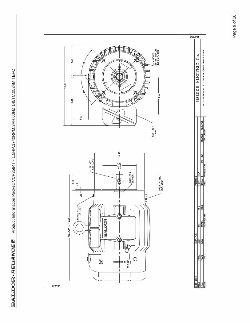
Pag
e 9
of 1
0
Pro
duct
Info
rmat
ion
Pac
ket:
VC
P35
84T
- 1
.5H
P,1
740R
PM
,3P
H,6
0HZ
,145
TC
,052
4M,T
EF
C

Pag
e 10
of 1
0
Pro
duct
Info
rmat
ion
Pac
ket:
VC
P35
84T
- 1
.5H
P,1
740R
PM
,3P
H,6
0HZ
,145
TC
,052
4M,T
EF
C

348
Mod ExpressSoft Start & D
ynamic B
rakesG
earmotors and
Gear P
roductsM
otorA
ccessoriesG
rindersG
eneratorsM
od ExpressB
aldor Education W
orkshopsC
atalog IndexB
aldor District
Offices
Modification Number
Motor Mod Express™Description and List Price
Working DaysRequired
TWODAYS
M21A Add Space Heaters to TEFC or Open Motors Standard space heater voltage is 110VAC. Heaters for 230 or 460 volts are available. Specify circuit voltage.
M21 Space Heaters
NOTE: Strip type space heaters are standard. 5000 frame perform in Charlotte. Contact Baldor for time.
CONTACTYOUR
BALDORREPRESENTATIVE
M21B Add Conduit Box for Thermostat or Heater Leads (See M4E) Not for explosion proof motors.
NOTE: Perform in Charlotte. Contact Baldor for time and freight charges to ship motor to Charlotte plant.
M22A Lint Proof Fan Cover for Textile Applications Remove standard fan cover and replace with textile fan shroud and cover.
TWODAYS
M22 Textile Service
NEMAFrame
List PricePer Motor
145T and Smaller 210182 - 215T 265254 - 365T 396404 - 447T 450
449T - 5011L 817
NEMAFrame
List Price
Up to 5011L Frame 356
NEMAFrame
List PricePer Motor
48 - 145T 192182 - 184T 251213 - 215T 284254 - 256T 405284 - 286T 477324 - 326T 528364 - 365T 626404 - 405T 681444 - 447T 735
Does Not Apply to Explosion-Proof Motors
KDEMAEGD
KDEMAEGD
KDEMAEGD
KDEMAEGD
KDEMAEGD

Section 1General Information
General Information 1-1MN400
Overview This manual contains general procedures that apply to Baldor Motor products. Be sure to read andunderstand the Safety Notice statements in this manual. For your protection, do not install, operate orattempt to perform maintenance procedures until you understand the Warning and Caution statements. AWarning statement indicates a possible unsafe condition that can cause harm to personnel. A Cautionstatement indicates a condition that can cause damage to equipment.
Important: This instruction manual is not intended to include a comprehensive listing of all details for allprocedures required for installation, operation and maintenance. This manual describes generalguidelines that apply to most of the motor products shipped by Baldor. If you have a questionabout a procedure or are uncertain about any detail, Do Not Proceed. Please contact your Baldordistributor for more information or clarification.
Before you install, operate or perform maintenance, become familiar with the following:� NEMA Publication MG-2, Safety Standard for Construction and guide
for Selection, Installation and Use of Electric Motors and Generators.� The National Electrical Code� Local codes and Practices
Limited Warranty
1. Baldor Electric motors are warranted for a period of one (1) year, from date of shipment from the factory or factorywarehouse against defects in material and workmanship. To allow for stocking and/or fabrication period and toprovide one year of actual service, the warranty period is extended for an additional period of six (6) months for atotal of eighteen (18) months from the original date of shipment from the factory or factory warehouse stock. In nocase will the warranty period be extended for a longer period. Baldor extends this limited warranty to each buyerof the electric motor for the purpose of resale and to the original purchaser for use.
2. Baldor will, at its option repair or replace a motor which fails due to defects in material or workmanship during thewarranty period if:
a. the purchaser presents the defective motor at or ships it prepaid to, the Baldor plant in Fort Smith, Arkansasor one of the Baldor Authorized Service Centers and
b. the purchaser gives written notification concerning the motor and the claimed defect including the datepurchased, the task performed by the Baldor motor and the problem encountered.
3. Baldor will not pay the cost of removal of any electric motor from any equipment, the cost of delivery to Fort Smith,Arkansas or a Baldor Authorized Service Center, or the cost of any incidental or consequential damages resultingfrom the claimed defects. (Some states do not allow the exclusion or limitation of incidental or consequentialdamages, so the above exclusion may not apply to you.) Any implied warranty given by laws shall be limited tothe duration of the warranty period hereunder. (Some states do not allow limitations on how long an impliedwarranty lasts, so the above limitation may not apply to you.)
4. Baldor Authorized Service Centers, when convinced to their satisfaction that a Baldor motor developed defects inmaterial or workmanship within the warranty period, are authorized to proceed with the required repairs to fulfillBaldor’s warranty when the cost of such repairs to be paid by Baldor does not exceed Baldor’s warranty repairallowance. Baldor will not pay overtime premium repair charges without prior written authorization.
5. The cost of warranty repairs made by centers other than Baldor Authorized Service Centers WILL NOT be paidunless first authorized in writing by Baldor.
6. Claims by a purchaser that a motor is defective even when a failure results within one hour after being placed intoservice are not always justified. Therefore, Baldor Authorized Service Centers must determine from the conditionof the motor as delivered to the center whether or not the motor is defective. If in the opinion of a BaldorAuthorized Service Center, a motor did not fail as a result of defects in material or workmanship, the center is toproceed with repairs only if the purchaser agrees to pay for such repairs. If the decision is in dispute, thepurchaser should still pay for the repairs and submit the paid invoice and the Authorized Service Center’s signedservice report to Baldor for further consideration.
7. This warranty gives you specific legal rights, and you may also have other rights which vary from state to state.
Note that Baldor Super–E� Premium Efficiency electric motors are warranted for a period of three (3) years.All other terms and conditions of the Limited Warranty statement apply.

1-2 General Information MN400
Safety Notice: This equipment contains high voltage! Electrical shock can cause serious or fatal injury.Only qualified personnel should attempt installation, operation and maintenance ofelectrical equipment.
Be sure that you are completely familiar with NEMA publication MG-2, safety standardsfor construction and guide for selection, installation and use of electric motors andgenerators, the National Electrical Code and local codes and practices. Unsafeinstallation or use can cause conditions that lead to serious or fatal injury. Only qualifiedpersonnel should attempt the installation, operation and maintenance of this equipment.
WARNING: Do not touch electrical connections before you first ensure thatpower has been disconnected. Electrical shock can cause seriousor fatal injury. Only qualified personnel should attempt theinstallation, operation and maintenance of this equipment.
WARNING: Be sure the system is properly grounded before applying power.Do not apply AC power before you ensure that all groundinginstructions have been followed. Electrical shock can causeserious or fatal injury. National Electrical Code and Local codesmust be carefully followed.
WARNING: Avoid extended exposure to machinery with high noise levels. Besure to wear ear protective devices to reduce harmful effects toyour hearing.
WARNING: This equipment may be connected to other machinery that hasrotating parts or parts that are driven by this equipment. Improperuse can cause serious or fatal injury. Only qualified personnelshould attempt to install operate or maintain this equipment.
WARNING: Do not by-pass or disable protective devices or safety guards.Safety features are designed to prevent damage to personnel orequipment. These devices can only provide protection if theyremain operative.
WARNING: Avoid the use of automatic reset devices if the automatic restartingof equipment can be hazardous to personnel or equipment.
WARNING: Be sure the load is properly coupled to the motor shaft beforeapplying power. The shaft key must be fully captive by the loaddevice. Improper coupling can cause harm to personnel orequipment if the load decouples from the shaft during operation.
WARNING: Use proper care and procedures that are safe during handling,lifting, installing, operating and maintaining operations. Improper methods may cause muscle strain or other harm.
WARNING: Before performing any motor maintenance procedure, be sure thatthe equipment connected to the motor shaft cannot cause shaftrotation. If the load can cause shaft rotation, disconnect the loadfrom the motor shaft before maintenance is performed. Unexpectedmechanical rotation of the motor parts can cause injury or motordamage.
WARNING: Disconnect all electrical power from the motor windings andaccessory devices before disassembly of the motor. Electricalshock can cause serious or fatal injury.
WARNING: Do not use these motors in the presence of flammable orcombustible vapors or dust. These motors are not designed foratmospheric conditions that require explosion proof operation.

Section 1General Information
1-4 General Information MN400
Receiving Each Baldor Electric Motor is thoroughly tested at the factory and carefully packaged forshipment. When you receive your motor, there are several things you should doimmediately.
1. Observe the condition of the shipping container and report any damageimmediately to the commercial carrier that delivered your motor.
2. Verify that the part number of the motor you received is the same as the partnumber listed on your purchase order.
Storage If the motor is not put into service immediately, the motor must be stored in a clean, dryand warm location. Several precautionary steps must be performed to avoid motordamage during storage.
1. Use a “Megger” periodically to ensure that the integrity of the winding insulationhas been maintained. Record the Megger readings. Immediately investigateany significant drop in insulation resistance.
2. Do not lubricate bearings during storage. Motor bearings are packed withgrease at the factory. Excessive grease can damage insulation quality.
3. Rotate motor shaft at least 10 turns every two months during storage (morefrequently if possible). This will prevent bearing damage due to storage.
4. If the storage location is damp or humid, the motor windings must be protectedfrom moisture. This can be done by applying power to the motors’ spaceheater (if available) while the motor is in storage.
Unpacking Each Baldor motor is packaged for ease of handling and to prevent entry ofcontaminants.
1. To avoid condensation inside the motor, do not unpack until the motor hasreached room temperature. (Room temperature is the temperature of the roomin which it will be installed). The packing provides insulation from temperaturechanges during transportation.
2. When the motor has reached room temperature, remove all protective wrappingmaterial from the motor.
Handling The motor should be lifted using the lifting lugs or eye bolts provided.
1. Use the lugs or eye bolts provided to lift the motor. Never attempt to lift themotor and additional equipment connected to the motor by this method. Thelugs or eye bolts provided are designed to lift only the motor. Never lift themotor by the motor shaft.
2. If the motor must be mounted to a plate with the driven equipment such aspump, compressor etc., it may not be possible to lift the motor alone. For thiscase, the assembly should be lifted by a sling around the mounting base. Theentire assembly can be lifted as an assembly for installation. Do not lift usingthe motor lugs or eye bolts provided.
If the load is unbalanced (as with couplings or additional attachments)additional slings or other means must be used to prevent tipping. In any event,the load must be secure before lifting.

Section 2Installation & Operation
Installation & Operation 2-1MN400
Overview Installation should conform to the National Electrical Code as well as local codes andpractices. When other devices are coupled to the motor shaft, be sure to installprotective devices to prevent future accidents. Some protective devices include,coupling, belt guard, chain guard, shaft covers etc. These protect against accidentalcontact with moving parts. Machinery that is accessible to personnel should providefurther protection in the form of guard rails, screening, warning signs etc.
Location The motor should be installed in an area that is protected from direct sunlight, corrosives,harmful gases or liquids, dust, metallic particles, and vibration. Exposure to these canreduce the operating life and degrade performance. Be sure to allow clearance forventilation and access for cleaning, repair, service and inspections. Ventilation isextremely important. Be sure the area for ventilation is not obstructed. Obstructions willlimit the free passage of air. Motors get warm and the heat must be dissipated to preventdamage.
These motors are not designed for atmospheric conditions that require explosion proofoperation. They must NOT be used in the presence of flammable or combustible vaporsor dust.
1. ODP motors are suitable only for indoor applications.
2. TEFC motors are suitable for indoor or outdoor standard service applications.
Mounting The motor must be securely installed to a rigid foundation or mounting surface tominimize vibration and maintain alignment between the motor and shaft load. Failure toprovide a proper mounting surface may cause vibration, misalignment and bearingdamage.
Foundation caps and sole plates are designed to act as spacers for the equipment theysupport. If these devices are used, be sure that they are evenly supported by thefoundation or mounting surface.
After installation is complete and accurate alignment of the motor and load isaccomplished, the base should be grouted to the foundation to maintain this alignment.
The standard motor base is designed for horizontal or vertical mounting. Adjustable orsliding rails are designed for horizontal mounting only. Consult your Baldor distributor orauthorized Baldor Service Center for further information.
Alignment Accurate alignment of the motor with the driven equipment is extremely important.
1. Direct CouplingFor direct drive, use flexible couplings if possible. Consult the drive orequipment manufacturer for more information. Mechanical vibration androughness during operation may indicate poor alignment. Use dial indicators tocheck alignment. The space between coupling hubs should be maintained asrecommended by the coupling manufacturer.
2. End-Play AdjustmentThe axial position of the motor frame with respect to its load is also extremelyimportant. The motor bearings are not designed for excessive external axialthrust loads. Improper adjustment will cause failure.
3. Pulley RatioThe pulley ratio should not exceed 8:1.
4. Belt DriveAlign sheaves carefully to minimize belt wear and axial bearing loads (seeEnd-Play Adjustment). Belt tension should be sufficient to prevent belt slippageat rated speed and load. However, belt slippage may occur during starting.
Caution: Do not over tension belts.

Section 1General Information
2-4 Installation & Operation MN400
First Time Start Up Be sure that all power to motor and accessories is off. Be sure the motor shaft isdisconnected from the load and will not cause mechanical rotation of the motor shaft.
1. Make sure that the mechanical installation is secure. All bolts and nuts aretightened etc.
2. If motor has been in storage or idle for some time, check winding insulationintegrity with a Megger.
3. Inspect all electrical connections for proper termination, clearance, mechanicalstrength and electrical continuity.
4. Be sure all shipping materials and braces (if used) are removed from motorshaft.
5. Manually rotate the motor shaft to ensure that it rotates freely.
6. Replace all panels and covers that were removed during installation.
7. Momentarily apply power and check the direction of rotation of the motor shaft.
8. If motor rotation is wrong, be sure power is off and change the motor leadconnections. Verify rotation direction before you continue.
9. Start the motor and ensure operation is smooth without excessive vibration ornoise. If so, run the motor for 1 hour with no load connected.
10. After 1 hour of operation, disconnect power and connect the load to the motorshaft. Verify all coupling guards and protective devices are installed. Ensuremotor is properly ventilated.
Coupled Start Up This procedure assumes a coupled start up. Also, that the first time start up procedurewas successful.
1. Check the coupling and ensure that all guards and protective devices areinstalled.
2. Check that the coupling is properly aligned and not binding.
3. The first coupled start up should be with no load. Apply power and verify thatthe load is not transmitting excessive vibration back to the motor though thecoupling or the foundation. Vibration should be at an acceptable level.
4. Run for approximately 1 hour with the driven equipment in an unloadedcondition.
The equipment can now be loaded and operated within specified limits. Do not exceedthe name plate ratings for amperes for steady continuous loads.
Jogging and Repeated Starts Repeated starts and/or jogs of induction motors generally reduce the life of the motorwinding insulation. A much greater amount of heat is produced by each acceleration orjog than than by the same motor under full load. If it is necessary to to repeatedly start orjog the motor, it is advisable to check the application with your local Baldor distributor orBaldor Service Center.
Heating - Duty rating and maximum ambient temperature are stated on the motor nameplate. Do not exceed these values. If there is any question regarding safe operation,contact your local Baldor distributor or Baldor Service Center.

Section 3Maintenance & Troubleshooting
Maintenance & Troubleshooting 3-1MN400
WARNING: UL rated motors must only be serviced by authorized BaldorService Centers if these motors are to be returned to a flammableand/or explosive atmosphere.
General Inspection Inspect the motor at regular intervals, approximately every 500 hours of operation orevery 3 months, whichever occurs first. Keep the motor clean and the ventilationopenings clear. The following steps should be performed at each inspection:
WARNING: Do not touch electrical connections before you first ensure thatpower has been disconnected. Electrical shock can cause seriousor fatal injury. Only qualified personnel should attempt theinstallation, operation and maintenance of this equipment.
1. Check that the motor is clean. Check that the interior and exterior of the motoris free of dirt, oil, grease, water, etc. Oily vapor, paper pulp, textile lint, etc. canaccumulate and block motor ventilation. If the motor is not properly ventilated,overheating can occur and cause early motor failure.
2. Use a “Megger” periodically to ensure that the integrity of the winding insulationhas been maintained. Record the Megger readings. Immediately investigateany significant drop in insulation resistance.
3. Check all electrical connectors to be sure that they are tight.
Lubrication & Bearings Bearing grease will lose its lubricating ability over time, not suddenly. The lubricatingability of a grease (over time) depends primarily on the type of grease, the size of thebearing, the speed at which the bearing operates and the severity of the operatingconditions. Good results can be obtained if the following recommendations are used inyour maintenance program.
Type of Grease A high grade ball or roller bearing grease should be used. Recommended grease forstandard service conditions is Polyrex EM (Exxon Mobil).
Equivalent and compatible greases include:Texaco Polystar, Rykon Premium #2, Pennzoil Pen 2 Lube and Chevron SRI.
– Maximum operating temperature for standard motors = 110° C. – Shut–down temperature in case of a malfunction = 115° C.
Lubrication Intervals Recommended lubrication intervals are shown in Table 3-1. It is important to realize thatthe recommended intervals of Table 3-1 are based on average use.
Refer to additional information contained in Tables 3-2 and 3-3.
Table 3-1 Lubrication Intervals *
Rated Speed - RPMNEMA / (IEC) Frame Size 10000 6000 3600 1800 1200 900
Up to 210 incl. (132) ** 2700 Hrs. 5500 Hrs. 12000 Hrs. 18000 Hrs. 22000 Hrs.Over 210 to 280 incl. (180) 3600 Hrs. 9500 Hrs. 15000 Hrs. 18000 Hrs.Over 280 to 360 incl. (225) * 2200 Hrs. 7400 Hrs. 12000 Hrs. 15000 Hrs.Over 360 to 5800 incl. (300) *2200 Hrs. 3500 Hrs. 7400 Hrs. 10500 Hrs.
* Lubrication intervals are for ball bearings. For roller bearings, divide the listed lubrication interval by 2.
** For 6205 and 6806 bearings. For 6807 bearings, consult oil mist lubrication (MN401). Relubrication interval for 6205 bearing bearing is 1550Hrs. (using grease lubrication).Relubrication interval for 6806 bearing bearing is 720Hrs. (using grease lubrication).

Maintenance & Troubleshooting 3-3MN400
Lubrication Procedure Be sure that the grease you are adding to the motor is compatible with the grease alreadyin the motor. Consult your Baldor distributor or an authorized service center if a greaseother than the recommended type is to be used.
Caution: To avoid damage to motor bearings, grease must be kept free of dirt.For an extremely dirty environment, contact your Baldor distributor oran authorized Baldor Service Center for additional information.
With Grease Outlet Plug
1. Clean all grease fittings.
2. Remove grease outlet plug.
3. If motor is stopped, add the recommended amount of grease.
If motor is to be greased while running, a slightly greater quantity of grease willhave to be added. Add grease slowly until new grease appears at shaft hole inthe endplate or purge outlet plug.
4. Re-install grease outlet plug.
Without Grease Outlet Plug
1. Disassemble motor.
2. Add recommended amount of grease to bearing and bearing cavity. (Bearingshould be about 1/3 full of grease and outboard bearing cavity should be about1/2 full of grease.)
Note: Bearing is 1/3 full when only one side of bearing is completely full of grease.
3. Assemble motor.
Sample Lubrication Determination
Assume - NEMA 286T (IEC 180), 1750 RPM motor driving an exhaust fan in an ambienttemperature of 43° C and the atmosphere is moderately corrosive.
1. Table 3-1 list 9500 hours for standard conditions.
2. Table 3-2 classifies severity of service as “Severe”.
3. Table 3-3 lists a multiplier value of 0.5 for Severe conditions.
4. Table 3-4 shows that 1.2 in3 or 3.9 teaspoon of grease is to be added.
Note: Smaller bearings in size category may require reduced amounts of grease.

Section 1General Information
Maintenance & Troubleshooting 3-5MN400
Table 3-5 Troubleshooting Chart
Symptom Possible Causes Possible SolutionsMotor will not start Usually caused by line trouble, such
as, single phasing at the starter.Check source of power. Check overloads, fuses,controls, etc.
Excessive humming High Voltage. Check input line connections.Eccentric air gap. Have motor serviced at local Baldor service center.
Motor Over Heating Overload. Compare actual amps(measured) with nameplate rating.
Locate and remove source of excessive friction inmotor or load.Reduce load or replace with motor of greater capacity.
Single Phasing. Check current at all phases (should be approximatelyequal) to isolate and correct the problem.
Improper ventilation. Check external cooling fan to be sure air is movingproperly across cooling fins.Excessive dirt build-up on motor. Clean motor.
Unbalanced voltage. Check voltage at all phases (should be approximatelyequal) to isolate and correct the problem.
Rotor rubbing on stator. Check air gap clearance and bearings.Tighten “Thru Bolts”.
Over voltage or under voltage. Check input voltage at each phase to motor.Open stator winding. Check stator resistance at all three phases for balance.Grounded winding. Perform dielectric test and repair as required.Improper connections. Inspect all electrical connections for proper
termination, clearance, mechanical strength andelectrical continuity. Refer to motor lead connectiondiagram.
Bearing Over Heating Misalignment. Check and align motor and driven equipment.Excessive belt tension. Reduce belt tension to proper point for load.Excessive end thrust. Reduce the end thrust from driven machine.Excessive grease in bearing. Remove grease until cavity is approximately 3/4 filled.Insufficient grease in bearing. Add grease until cavity is approximately 3/4 filled.Dirt in bearing. Clean bearing cavity and bearing. Repack with correct
grease until cavity is approximately 3/4 filled.Vibration Misalignment. Check and align motor and driven equipment.
Rubbing between rotating parts andstationary parts.
Isolate and eliminate cause of rubbing.
Rotor out of balance. Have rotor balance checked are repaired at yourBaldor Service Center.
Resonance. Tune system or contact your Baldor Service Center forassistance.
Noise Foreign material in air gap orventilation openings.
Remove rotor and foreign material. Reinstall rotor.Check insulation integrity. Clean ventilation openings.
Growling or whining Bad bearing. Replace bearing. Clean all grease from cavity and newbearing. Repack with correct grease until cavity isapproximately 3/4 filled.

This page left intentionally blank.

AN EMPLOYEE OWNED COMPANY
MOTION SENSOR

This page left intentionally blank.

Instruction Manual May 2008
MFA 4Pmilltronics
© Siemens Milltronics Process Instruments Inc. 2008
Safety Guidelines: Warning notices must be observed to ensure personal safety as well as that of others, and to protect the product and the connected equipment. These warning notices are accompanied by a clarification of the level of caution to be observed.
Qualified Personnel: This device/system may only be set up and operated in conjunction with this manual. Qualified personnel are only authorized to install and operate this equipment in accordance with established safety practices and standards.
Unit Repair and Excluded Liability:
• The user is responsible for all changes and repairs made to the device by the user or the user’s agent.
• All new components are to be provided by Siemens Milltronics Process Instruments Inc. • Restrict repair to faulty components only. • Do not reuse faulty components.
Warning: This product can only function properly and safely if it is correctly transported, stored, installed, set up, operated, and maintained.
This product is intended for use in industrial areas. Operation of this equipment in a residential area may cause interference to several frequency based communications.
Note: Always use product in accordance with specifications.
Copyright Siemens Milltronics Process Instruments Inc. 2008. All Rights Reserved
Disclaimer of Liability
This document is available in bound version and in electronic version. We encourage users to purchase authorized bound manuals, or to view electronic versions as designed and authored by Siemens Milltronics Process Instruments Inc. Siemens Milltronics Process Instruments Inc. will not be responsible for the contents of partial or whole reproductions of either bound or electronic versions.
While we have verified the contents of this manual for agreement with the instrumentation described, variations remain possible. Thus we cannot guarantee full agreement. The contents of this manual are regularly reviewed and corrections are included in subsequent editions. We welcome all suggestions for improvement. Technical data subject to change.
MILLTRONICS®is a registered trademark of Siemens Milltronics Process Instruments Inc. Contact SMPI Technical Publications European Authorized Representative at the following address: Technical Publications Siemens AG Siemens Milltronics Process Instruments Inc. Industry Sector 1954 Technology Drive, P.O. Box 4225 76181 Karlsruhe Peterborough, Ontario, Canada, K9J 7B1 Deutschland Email: [email protected] • For a selection of Siemens Milltronics level measurement manuals, go to:
www. siemens.com/processautomation. Under Process Instrumentation, select Level Measurement and then go to the manual archive listed under the product family.
• For a selection of Siemens Milltronics weighing manuals, go to: www. siemens.com/processautomation. Under Weighing Technology, select Continuous Weighing Systems and then go to the manual archive listed under the product family.

mm
mm
m
Table of Contents
7ML19985FM01.book Page i Wednesday, May 21, 2008 2:17 PM
Table of Contents
Milltronics MFA 4p ............................................................................................................. 1
Safety Notes .............................................................................................................................................1The Manual ...............................................................................................................................................1
Specifications ...................................................................................................................... 2
Installation ........................................................................................................................... 4
Milltronics MFA 4p ........................................................................................................................4Probe ................................................................................................................................................4Wiring ...............................................................................................................................................4
Dimensions ...............................................................................................................................................5MFA 4p .............................................................................................................................................5
Layout .........................................................................................................................................................7
Interconnection ...................................................................................................................8
MSP-1, 3, or 9 Probe with RMA (remote mounted pre-amplifier) ...............................................8MSP-12 Probe with IMA (internally mounted pre-amplifier) ........................................................8XPP-5 with IMA (internally mounted pre-amplifier) .......................................................................9Connection to power: ...........................................................................................................................10
Wiring .................................................................................................................................. 11
MFA 4p Wiring for Automatic Start Delay ......................................................................................11
Operating Principles ........................................................................................................ 12
MFA 4p .....................................................................................................................................................12Probe ........................................................................................................................................................12Pre-Amplifier (IMA and RMA) ............................................................................................................13MFA 4p Operation .................................................................................................................................13Calibration ..............................................................................................................................................14
Underspeed ..................................................................................................................................14Overspeed ....................................................................................................................................15
Signal Generator Interface .................................................................................................................16
Probes ................................................................................................................................. 17
Mini Sensing Probe MSP-1 .................................................................................................................17High Temperature Probe MSP-3 ........................................................................................................17Stainless Steel Probe MSP-9 ..............................................................................................................18
Mounting Details .........................................................................................................................18Standard Probe MSP-12 .....................................................................................................................19Hazardous Locations XPP-5 ................................................................................................................20
Interconnection Diagram for the XPP-5 .................................................................................21Mounting Details ...................................................................................................................................22
Applications .......................................................................................................................23
Bucket Elevators ...................................................................................................................................23Shafts .......................................................................................................................................................24
i

mm
mm
m
Tabl
e of
Con
tent
s
7ML19985FM01.book Page ii Wednesday, May 21, 2008 2:17 PM
Belt Conveyors .......................................................................................................................................24Screw Conveyors ...................................................................................................................................24Non-Ferrous Window .........................................................................................................................25Bucket Elevator ......................................................................................................................................25Rotating Shaft of Rotary Feeder ........................................................................................................26Drive Sprocket on Rotary Feeder ......................................................................................................26Screw Conveyor Flights .......................................................................................................................27End Bearing on Screw Conveyor ......................................................................................................27
Troubleshooting ................................................................................................................28
Maintenance ......................................................................................................................29
ii

mm
mm
m
Introduction
7ML19985FM01.book Page 1 Wednesday, May 21, 2008 2:17 PM
Milltronics MFA 4p
Milltronics MFA 4p is a highly sensitive, single setpoint motion sensor alarm unit, used with MSP and XPP probes. The probe detects an increase or decrease in the speed of rotating, reciprocating, or conveying equipment and sends the information to the MFA 4p. The MFA 4p works with a pre-amplifier which can be internal to the motion sensing probe, or remote from the motion sensing probe.
Pulses generated from the probe are continually compared to the adjustable setpoint. If the pulse rate is lower than the setpoint, the alarm relays operating in a faiI-safe mode will de-energize, indicating failure. The relays will not energize until the pulse rate increases above the setpoint.
Safety NotesSpecial attention must be paid to warnings and notes highlighted from the rest of the text by grey boxes.
The ManualThis instruction manual covers the installation, operation and maintenance of the Milltronics MFA 4p. It is essential that this manual be referred to for proper installation and operation of your unit. Adhering to the installation and operating procedures will insure a quick, trouble free installation and allow for the maximum accuracy and reliability of your motion sensing alarm unit and probes.
If you have any questions, comments, or suggestions about the manual contents, please email us at [email protected].
For the complete library of Siemens Milltronics manuals, go to www.siemens.com/processautomation.
Note: This product is intended for use in industrial areas. Operation of this equipment in a residential area may cause interference to several frequency based communications.
WARNING means that failure to observe the necessary precautions can result in death, serious injury, and/or considerable material damage.
Note: means important information about the product or that part of the operating manual.
7ML19985FM01 MFA 4p - INSTRUCTION MANUAL Page 1

mm
mm
m
Spec
ifica
tions
7ML19985FM01.book Page 2 Wednesday, May 21, 2008 2:17 PM
Specifications
Safety
Power � 100/115/200/ 230 V AC ±15%, 50/60 Hz, 15 VA
Output� 2 relays with Form C (S.P.D.T.) fail-safe contacts (relays operate in unison)
Resistive Rating:� 8 A @ 250 V AC
Repeatability� ± 1%
Temperature coefficient (setpoint variance)� 0.018%/ °C (0.01% / °F)
Setpoint adjustment range� 2 to 3,000 ppm (pulses per minute): standard model
� 0.15 to 15 ppm: slow speed version
Dynamic range� 0 to 7,200 ppm
Note: The Milltronics MFA 4p (Motion Failure Alarm) is to be used only in the manner outlined in this manual, otherwise protection provided by the equipment may be impaired.
Page 2 MFA 4p - INSTRUCTION MANUAL 7ML19985FM01

mm
mm
m
Installation
7ML19985FM01.book Page 3 Wednesday, May 21, 2008 2:17 PM
Weight� polycarbonate enclosure: 1.5 kg (3.3 lb.)
� mild steel or stainless steel enclosure: 4.3 kg (9.5 lbs.)
Approvals1
� CE, CSA(C/US), FM� EMC performance available on request
Environmental� location: Indoor/outdoor� altitude: 2000 m max.
� ambient temperature: �20 oC to 50 oC (�4 oF to 122 oF)� relative humidity: suitable for outdoor (Type 4X / NEMA 4X / IP65)*� installation category: II� pollution degree: 4
*Type 4/ NEMA 4 /IP65 with mild steel enclosure
1. EMC performance available upon request.
Related Equipment Ambient Temperature Range Approx wt.
RMA �40 °C to 60 °C (�40 °F to 140 °F ) 2.3 kg (5 lb)
MSP-12 �40 °C to 60 °C (�40 °F to 140 °F ) 1.4 kg (3 lb)
XPP-5 �40 °C to 60 °C (�40 °F to 140 °F ) 1.8 kg (4 lb)
MSP-1 �40 °C to 80 °C (�40 °F to 180 °F ) 0.5 kg (1 lb)
MSP-3 �40 °C to 260 °C (�40 °F to 500 °F ) 1.4 kg (3 lb)
MSP-9 �40 °C to 260 °C (�40 °F to 500 °F ) 1.8 kg (4 lb)
7ML19985FM01 MFA 4p - INSTRUCTION MANUAL Page 3

mm
mm
m
Inst
alla
tion
7ML19985FM01.book Page 4 Wednesday, May 21, 2008 2:17 PM
Installation
Milltronics MFA 4pThe MFA 4p (and RMA if applicable) must be mounted in a non-hazardous area that is clean, dry, vibration-free, within the ambient temperature range, and non-corrosive to the electronics or its enclosure. The door should be accessible for viewing and to allow calibration of the MFA 4p.
ProbeThe probe should be mounted onto a vibration free structure using the mounting flange. The gap between probe and target should be large enough to prevent the target from damaging the probe. The probe environment must be within the probe's ambient temperature range and non-corrosive to the probe's body. Refer to Applications drawings on page 23.
The probe design detects a changing magnetic field, typically caused by a ferromagnetic target disturbing the probe's magnetic field. Extremely strong magnetic fields (like those produced by the 30A/m requirements of 1EC 60004-8, Power Frequency Magnetic Field Immunity test) will be detected and will result in loss of functionality.
Functionality loss indicators:
� alarm conditions by relay trip� false pulse readings in LED1
Consider the probe location carefully before installation. Avoid strong magnetic fields (50/60 Hz) from nearby power transformers, heater elements, or large industrial motors, because these can affect the probe�s performance.
WiringWhere possible, the probe components should be interconnected via flexible conduit. This allows for easier removal or adjustment of the probe and mounting flange assembly.
Note: Do not mount MFA 4p in direct sunlight.
Note: Installation shall only be performed by qualified personnel and in accordance with local governing regulations.
Page 4 MFA 4p - INSTRUCTION MANUAL 7ML19985FM01

mm
mm
m
Installation
7ML19985FM01.book Page 5 Wednesday, May 21, 2008 2:17 PM
Dimensions
MFA 4p
Type 4X / NEMA 4X / IP65 Polycarbonate Enclosure
Notes: � Non-metallic enclosure does not provide grounding between conduit
connections: use grounding type bushings and jumpers.� Use only approved, suitable size hubs for watertight application.
160 mm (6.325")
131 mm (5.138")
15mm (0.59")
6 mm (0.25") 82 mm
(3.225")
240 mm (9.455")
228 mm (8.975")
lid screwsmounting holes 4.3 mm (0.170") dia. 4 places Suitable location for conduit entrance
7ML19985FM01 MFA 4p - INSTRUCTION MANUAL Page 5

mm
mm
m
Inst
alla
tion
7ML19985FM01.book Page 6 Wednesday, May 21, 2008 2:17 PM
Type 4 / NEMA 4 / IP65 Painted Steel Enclosure & Type 4X / NEMA 4X / IP65 Stainless Steel Enclosure
Notes: � Painted steel enclosure does not provide grounding between conduit
connections: use grounding type bushings and jumpers.� Use only approved, suitable size hubs for watertight application.
203 mm(8.0�)
152 mm(6.0�)
19 mm(0.75�)
273 mm (10.75�) 254 mm
(10.0�)
178 mm(7.0�)
∅ 8 mm(0.31�)
19 mm(0.75�)
227 mm(8.94�)
102 mm(4.0�)
21 mm(0.83�)
suitable location for Conduit Entrance
(customer specified)
Page 6 MFA 4p - INSTRUCTION MANUAL 7ML19985FM01

mm
mm
m
Interconnection
7ML19985FM01.book Page 7 Wednesday, May 21, 2008 2:17 PM
Layout
MFA 4p Circuit Board
R42R11R10
R9
SW2
Q4
Q1
P4
RL1 RL2
C13
C5
C6
X1X10X100
C2
C4 C3
C16
CW
CW
C15
IC5
IC2
IC3
IC4
R14
R2IC1C1
R15
R3R13
R1R12
R17
R28R43
D7
P2P1PULSES PER MINUTE START DELAY
STARTDELAYCALPPM
UNDERSPEED
OVERSPEED
P3C41
C18
C17C52
C40C38
D6
D27
D26
D28
D25 D23
D22
D21 D24
R16
9
15
21
00
10
20 40
50
6030
30
PPM
T2
SECONDS
R4
R5R7
R45
SW3
R19
OFF
S1
115V100V
230V 200V
SW1
R32
R22
SN
R33
R37R36R35R34
R41R30R31
R39
R40
R38
R26 R27
C12 C11
C7
C10
D4
D5
C9
Q10Q9
Q7 Q8
Q3 Q2
D2
Q6
Q11 Q5
C8R24
R18
R8LED1
LED2
NO NONC
1
1
2
2
3
3
4
4
5
5
6
6
7
7
8
8
PROBEINPUT
9
9
SW1
10
10
11
11
12
12
L2/N
RL1 RL2
L1
RELAYS SHOWN INDE-ENERGIZED POSITION250 V 8 AMP
NC
R29
R23
R21
R25
R20
R6
D1
7ML19985FM01 MFA 4p - INSTRUCTION MANUAL Page 7

mm
mm
m
Inte
rcon
nect
ion
7ML19985FM01.book Page 8 Wednesday, May 21, 2008 2:17 PM
Interconnection
MSP-1, 3, or 9 Probe with RMA (remote mounted pre-amplifier)
Maximum cable length from probe to RMA is 30 m / 100 ft of shielded cable, 18 ga. wire. See table on page 9 for cable lengths from RMA to main group.
MSP-12 Probe with IMA (internally mounted pre-amplifier)
Wire can be run in conduit common to motor supply or control wiring. Connection to probe leads can be made under probe cap. See table on page 9 for lengths from probe at MFA 4p.
GND
SHIELD
BLK
RMA
WHT
321
NO
NO
NC
1 1
2 2
3 3
4 4
5 5
6 6
77 7
88 8
PR
OB
EIN
PU
T
99 9
10 10
11 11
12 12
L2/N
RL1
RL2
L1
RE
LAY
SS
HO
WN
IND
E-E
NE
RG
IZE
DP
OS
ITIO
N250
V8
AM
P
NC
321
TB1 TB2
MFA 4p
BLKRED
NO
NO
NC
1 1
2 2
3 3
4 4
5 5
6 6
77 7
88 8
PR
OB
EIN
PU
T
99 9
10
10
11 11
12
12
L2/N
L1
NC
RL1
RL2
RE
LA
YS
SH
OW
NIN
DE
-EN
ER
GIZ
ED
PO
SIT
ION
25
0V
8A
MP
MFA 4p
Page 8 MFA 4p - INSTRUCTION MANUAL 7ML19985FM01
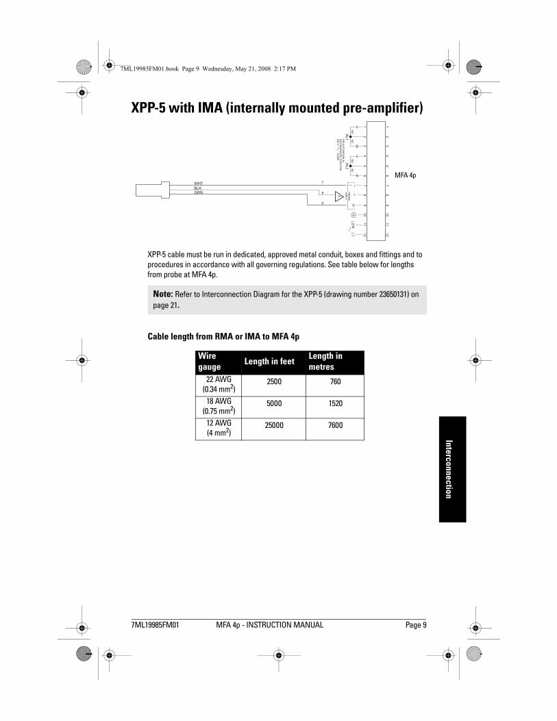
mm
mm
m
Interconnection
7ML19985FM01.book Page 9 Wednesday, May 21, 2008 2:17 PM
XPP-5 with IMA (internally mounted pre-amplifier)
XPP-5 cable must be run in dedicated, approved metal conduit, boxes and fittings and to procedures in accordance with all governing regulations. See table below for lengths from probe at MFA 4p.
Cable length from RMA or IMA to MFA 4p
Note: Refer to Interconnection Diagram for the XPP-5 (drawing number 23650131) on page 21.
Wire gauge Length in feet Length in
metres22 AWG
(0.34 mm2)2500 760
18 AWG(0.75 mm2)
5000 1520
12 AWG(4 mm2)
25000 7600
WHTBLKGRN
NO
NO
NC
1 1
2 2
3 3
4 4
5 5
6 6
77 7
88 8
PR
OB
EIN
PU
T
99 9
10 10
11 11
12 12
L2/N
RL1
RL2
L1
RE
LAY
SS
HO
WN
IND
E-E
NE
RG
IZE
DP
OS
ITIO
N250
V8
AM
P
NC
MFA 4p
7ML19985FM01 MFA 4p - INSTRUCTION MANUAL Page 9

mm
mm
m
Wiri
ng
7ML19985FM01.book Page 10 Wednesday, May 21, 2008 2:17 PM
Connection to power:
� Terminal 10 must be connected to reliable ground.
� The equipment must be protected by a 15A fuse or circuit breaker in the building installation.
� A circuit breaker or switch in the building installation, marked as the disconnect switch, shall be in close proximity to the equipment and within easy reach of the operator.
� AC input circuit, relay circuits, min. 14 AWG copper wire
� Recommended torque on terminal clamping screws, 7 in.lbs. max.
WARNING: All field wiring must have insulation suitable for at least 250 V.
NO NONC
1
1
2
2
3
3
4
4
5
5
6
6
7
7
8
8
PROBEINPUT
9
9
10
10
11
11
12
12
L2/N
RL1 RL2
L1
RELAYS SHOWN INDE-ENERGIZED POSITION250 V 8 AMP
NC
Page 10 MFA 4p � INSTRUCTION MANUAL 7ML19985FM01

mm
mm
m
Wiring
7ML19985FM01.book Page 11 Wednesday, May 21, 2008 2:17 PM
Wiring
MFA 4p Wiring for Automatic Start Delay
Should the Time Delay feature on start-up not be required, power should be applied continuously from a separate source and the potentiometer turned to zero. This is usually necessary for automatic up-stream start up of conveying devices after the down-stream drive has reached its operation speed.
Notes:1. Interlocks and Safety Pull Switches are not shown. 2. If START is initiated by programmable logic controller, closure time may be too
brief to allow MFA 4p contact to latch. In this case, program a timer contact into the circuit.
3. CSA requires an 8A or less fuse to protect contacts. For 240 V AC, protect the contacts with a 1500 VA transformer as well.
M
M
N
N
L
L
TB-1
TB-1
CONTACTOR
CONTACTOR
MFA 4p
MFA 4p
121
1
L L/N
START
115/230V AC 50/60 HZ
START
OR
STOP
STOP
SEE NOTE 3
SEE NOTE 3
SEE NOTE 2
MFA 4p
MFA 4p
TB-1
TB-1HOLD UNTIL UP TO SPEED
1/4
1/4
2/5
2/5
M
M
12
11
11
10
10
G
G
7ML19985FM01 MFA 4p - INSTRUCTION MANUAL Page 11

mm
mm
m
Wiri
ng
7ML19985FM01.book Page 12 Wednesday, May 21, 2008 2:17 PM
Operating Principles
MFA 4p Milltronics MFA 4p is a highly sensitive, single setpoint motion sensor alarm unit, used with MSP and XPP probes. The probe detects an increase or decrease in the speed of rotating, reciprocating, or conveying equipment and sends the information to the MFA 4p. The MFA 4p works with a pre-amplifier which can be internal to the motion sensing probe, or remote from the motion sensing probe.
Pulses generated from the probe are continually compared to the adjustable setpoint. If the pulse rate is lower than the setpoint, the alarm relays operating in a faiI-safe mode will de-energize, indicating failure. The relays will not energize until the pulse rate increases above the setpoint.
Probe The Milltronics probes work on the principle of Faraday�s Laws of Electromagnetic Induction. When a ferromagnetic object enters the probe�s permanent magnetic field, it distorts the flux causing it to cut the coil windings and generate a voltage. This voltage is proportional to the strength of the magnet and the number of wire turns in the coil (constant in the Milltronics probes) and the speed at which the ferrous target passes through the flux. The generated voltage is also inversely proportional to the square of the distance between the target and the probe.
The relationship between speed and gap of a standard probe:
FIG. A. 50 x 25 x 50 mm (2�x 1�x 2�)ferrous block
FIG C 50 x 25 x 25 mm (2�x 1�x 1�)ferrous block
FIG. B 50 x 50 x 25 mm (2�x 2�x 1�)ferrous block
(25.4 mm = 1 inch and 305 mm = 1 foot)
Page 12 MFA 4p � INSTRUCTION MANUAL 7ML19985FM01

mm
mm
m
Wiring
7ML19985FM01.book Page 13 Wednesday, May 21, 2008 2:17 PM
The resultant line indicates the threshold tolerance of the accompanying MFA 4p electronics. For example, in FIG. A, a 100 mm (4") gap requires a minimum velocity of about 10 m / minute (35 ft / minute): with a velocity of 0.61 m / minute (2 ft / minute), a maximum gap of 31 mm (1.25") is possible.
The graph was plotted from tests using four ferrous blocks set equidistantly on a 406 mm (16") diameter circle on a non-ferrous disc.
The physical shape of the ferrous target generally becomes important at low velocities or large gaps. At these points, tests indicate that a cubic shape gives the best results due to the sudden change it causes in the magnetic field.
An increase in block size beyond 50 x 50 x 25 mm (2" X 2" X 1") is generally not as effective as minimizing the gap, except at very low velocities.
The Milltronics Mini Sensing Probe, MSP-1
� The MSP-1 is approximately one-quarter the size of the standard probe with about one-eighth the sensitivity.
� Divide all operating values by 0.125 to obtain the specifications of the MSP-1. For example, with a gap of 12 mm (0.5"), the minimum velocity is approximately 60 m / min. (200 ft / min.), and with a velocity of 0.6 m / min. (2 ft / min. ) a maximum gap of 0.125" (3 mm) is possible.
Milltronics manufactures probes to suit a wide variety of environments: low temperature, high temperature, corrosive, and Class I, II and III applications.
Pre-Amplifier (IMA and RMA)The pre-amplifier accepts the voltage pulses generated by the probe and converts them into noise-immune current pulses. Current levels are 12 mA low and 45 mA high. The pre-amplifier comes internally mounted in the probe, or in an enclosure for remote mounting.
Internally mounted pre-amplifiers are called IMAs. Remote mounted pre-amplifiers are called RMAs.
MFA 4p OperationThe MFA 4p provides a short circuit protected, +24 V DC unregulated supply to the pre-amp. In the event that the interconnecting wiring is shorted, output current from the MFA 4p is automatically limited and the on-board alarm relays are de-energized to indicate failure.
The output current pulses from the pre-amp are super-imposed onto the dc current supply. These are monitored by Probe LED 1, which is illuminated at the rate of the incoming pulses and is useful for positioning the probe.
The rate at which the pulses are received by the MFA 4p is compared to a setpoint reference signal from the time base generator.
Note: 25.4 mm = 1 inch and 0.305 m = 1 foot
7ML19985FM01 MFA 4p - INSTRUCTION MANUAL Page 13

mm
mm
m
Wiri
ng
7ML19985FM01.book Page 14 Wednesday, May 21, 2008 2:17 PM
Although two pulses within range are required to energize the relays, as long as the frequency of the incoming pulses exceeds the setpoint frequency (or is less than that of the setpoint in the case of overspeed detection), the MFA 4p keeps the alarm relays energized. The reference generator is frequency adjustable by the pulses per minute (ppm) switch and potentiometer.
The alarm relays will de-energize after two time constants of the setpoint when the frequency of the incoming pulses falls below that of the setpoint (or exceeds that of the setpoint in the case of overspeed detection). The relay status is indicated by Relay LED 2, which is illuminated when the relays are energized (normal).
The MFA 4p has a 0 to 60 second time delay feature, allowing the monitored device to accelerate to normal running speed before monitoring begins.
This feature is activated when power is applied to the MFA 4p in parallel with the motor starter contact coil. The time delay circuit simulates normal operating conditions for the amount of time as set by the Start Delay potentiometer, keeping the alarm relays energized. If the monitored device does not reach normal speed before the set time period, the relays will de-energize giving an alarm condition. This feature is not applicable in the overspeed detection mode.
Calibration The probe and pre-amplifier require no calibration.
Connect the probe, pre-amp, and MFA 4p as shown in the Interconnection diagrams on pages 8 and 9. Connect the MFA 4p to power as shown in the Power Connection diagram on page 10, and if applicable, as shown for Automatic Start Delay on page 11.
MFA 4p (Refer to MFA 4p Circuit Board layout on page 7.)1. Operate monitored equipment at its normal operating speed.
2. Confirm that Probe LED 1 is pulsing at a regular frequency.
3. Set Start Delay fully counter-clockwise (CCW) to 0 seconds.
Underspeed 1. Set switch SW3 to Underspeed.
2. Set pulses per minute (ppm) switch SW2 to X 100 position.
3. Turn ppm potentiometer fully clockwise (CW) to 30.
4. Determine incoming pulse rate by slowly turning ppm potentiometer CCW until relay LED 2 goes on. As the MFA 4p requires 2 pulses within range before energizing relays, low ppm applications (e.g. 2 ppm) may require stepping of potentiometer at appropriate time intervals.
Note: To help the calibration procedure, short N.O. contacts of relays to prevent motor shut-down (terminals 1 to 2 and/or 4 to 5). This allows the system to run uninterrupted until an operating setpoint is established.
Page 14 MFA 4p � INSTRUCTION MANUAL 7ML19985FM01

mm
mm
m
Wiring
7ML19985FM01.book Page 15 Wednesday, May 21, 2008 2:17 PM
5. If no response is obtained when you set the ppm potentiometer to 3 (below this stability suffers), reset potentiometer fully CW, set switch SW2 to X 10 and then X 1 if required, and repeat step 4.
6. When Relay LED 2 goes on, indicating the incoming pulse rate, turn potentiometer CCW slightly past this point to obtain an operating setpoint that allows for normal fluctuations due to load and voltage variations. For 50% of full speed, set potentiometer (and SW2 if required) to halfway between incoming pulse rate of normal speed and 0 ppm.
7. Set Start Delay by adjusting potentiometer so that equipment being monitored can attain normal operating speed before LED 2 can turn off.
Overspeed 1. Set switch SW3 to Overspeed.
2. Set ppm switch SW2 to X 1 position.
3. Set ppm potentiometer fully CCW to 0.
4. Determine incoming pulse rate by slowly turning ppm potentiometer CW until Relay LED 2 goes on. Because the MFA 4p requires 2 pulses within range before energizing relays, low ppm applications (e.g. 2 ppm) may require stepping of potentiometer at appropriate time intervals.
5. If no response is obtained when you set the ppm potentiometer to 3, (below this stability suffers), re-set potentiometer fully CCW and set switch SW2 to X 10, and then X 1 if required, and repeat step 4.
6. When Relay LED 2 goes on, indicating the incoming pulse rate, turn potentiometer CW slightly past this point to obtain an operating setpoint that allows for normal fluctuations due to load and voltage variations.
Remember: If N.O. contacts were shorted as described in final note of calibration preamble, remove them now as calibration is complete.
7ML19985FM01 MFA 4p - INSTRUCTION MANUAL Page 15

mm
mm
m
Prob
es
7ML19985FM01.book Page 16 Wednesday, May 21, 2008 2:17 PM
Signal Generator Interface
The following circuit may be used for calibrating or for troubleshooting the MFA 4p.
470 to 620 ohm 2W
to MFA 4p
TB1 10K ohm1/4 W
2N4401
signal generator
3V p square
6 V p-p sine
6V p-p square
0 V
O V
O V
Circuit substitutes operating probe and pre-amp.
Set signal generator for:
8
7
Page 16 MFA 4p � INSTRUCTION MANUAL 7ML19985FM01

mm
mm
m
Probes
7ML19985FM01.book Page 17 Wednesday, May 21, 2008 2:17 PM
Probes
Mini Sensing Probe MSP-1
� CPVC body comes with 2 CPVC locknuts� 180 cm (6 ft.) of Belden 8760 supplied potted in probe� Remote mounted pre-amp in NEMA 4 cast aluminum enclosure.
High Temperature Probe MSP-3
� Cast aluminum body comes with cast aluminum cap and zinc flange, zinc plated locknut, and silicone rubber gasket
� See page 22 for Flange and Mounting Details� Pre-amp is mounted in a NEMA 4 cast aluminum enclosure
1" UNF1/2" NPT orPG16, TAPPEDBOTH SIDES
102 mm(4”)
8 mm ø (0.312”)4 HOLES
3/4" NPT
25 mm
51 mm
89 mm
165 mm (6.50”)111 mm (4.375”)
140 mm
(5.50”)
89 mm
(1”)
(2”)
(3.50”)
MOUNTING CENTERSMOUNTING CENTERS
(5.50”)
2" NPSL
1/2" NPTor PG16,TAPPEDBOTH SIDES
102 mm(4”)
8 mm ø (0.312”)4 HOLES
MOUNTING FLANGE
LOCKNUT
PROBE BODY
CAP c/w 1/2" NPTCONDUIT ENTRANCE
GASKET
60 mm
86 mm
127 mm
187 mm
165 mm (6.50”)111 mm (4.375”)
140 mm
(5.50”)
89 mm
(2.375”)
(3.375”)
(5”)
(7.375”)
MOUNTING CENTERSMOUNTING CENTERS
(5.50”)
7ML19985FM01 MFA 4p - INSTRUCTION MANUAL Page 17

mm
mm
m
Prob
es
7ML19985FM01.book Page 18 Wednesday, May 21, 2008 2:17 PM
Stainless Steel Probe MSP-9
Mounting Details
� For high temperature and corrosion resistance applications� 304 stainless steel body comes with stainless steel clamp and silicone gasket� 1.5 m (5 ft.) Belden 83321 Teflon®1 cable potted in probe� Pre-amp is mounted in an enamel painted steel Hammond 1414N4E enclosure
1. Teflon is a registered trademark of E.I. du Pont de Nemours and Company
111 mm(4.375”)
8 mm ø (0.312”)4 PLACES
CAP c/w22 mm ø HOLE(0.875”)
GASKET
86 mm ø(3.375”)
22 mm ø (0.875”)2 PLACES
CLAMPS4 PLACES
51 mm(2”)
178 mm
171 mm (6.75”)
152 mm(6”)191 mm(7.50”)
102 mm (4”)
152 mm
(6”)MOUNTING CENTERS
(7”)
MOUNTING CENTERS
102mm (4�)
102 mm (4")
probe flange
95 mm (3.75") diameter Probe clearance hole
panel
6 mm (0.25") diameter four holes equally spaced on a 114 mm (4.5") BCD
Page 18 MFA 4p � INSTRUCTION MANUAL 7ML19985FM01

mm
mm
m
Probes
7ML19985FM01.book Page 19 Wednesday, May 21, 2008 2:17 PM
Standard Probe MSP-12
� Phenolic body comes with die-cast aluminum cap and zinc flange, zinc plated locknut, and neoprene gasket
� See page 22 for Flange and Mounting Details� Pre-amp is potted in the probe body and comes with two 127 mm (5") long hook-up
wires
CAP c/w½" NPT or PG16CONDUIT ENTRANCE
LOCKNUT
MOUNTINGFLANGE
2" NPSL
PROBE BODY
GASKET
60 mm
86 mm
(2.375”)
(3.375”)187 mm
127 mm(5”)
(7.375”)
7ML19985FM01 MFA 4p - INSTRUCTION MANUAL Page 19
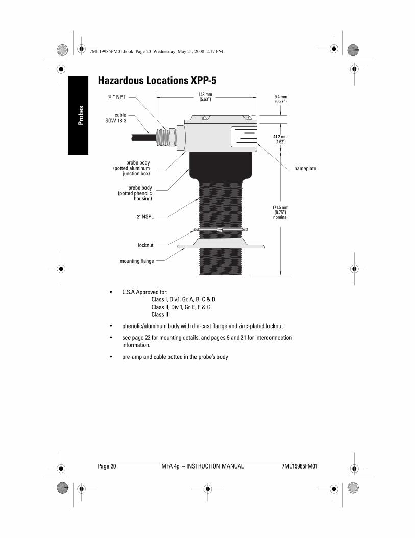
mm
mm
m
Prob
es
7ML19985FM01.book Page 20 Wednesday, May 21, 2008 2:17 PM
Hazardous Locations XPP-5
� C.S.A Approved for:Class I, Div.1, Gr. A, B, C & DClass II, Div 1, Gr. E, F & GClass III
� phenolic/aluminum body with die-cast flange and zinc-plated locknut
� see page 22 for mounting details, and pages 9 and 21 for interconnection information.
� pre-amp and cable potted in the probe�s body
cableSOW-18-3
probe body(potted phenolic
housing)
probe body(potted aluminum
junction box)
mounting flange
locknut
nameplate
¾ � NPT
171.5 mm (6.75�)
nominal
9.4 mm (0.37�)
41.2 mm(1.62")
143 mm (5.63�)
2" NSPL
Page 20 MFA 4p � INSTRUCTION MANUAL 7ML19985FM01
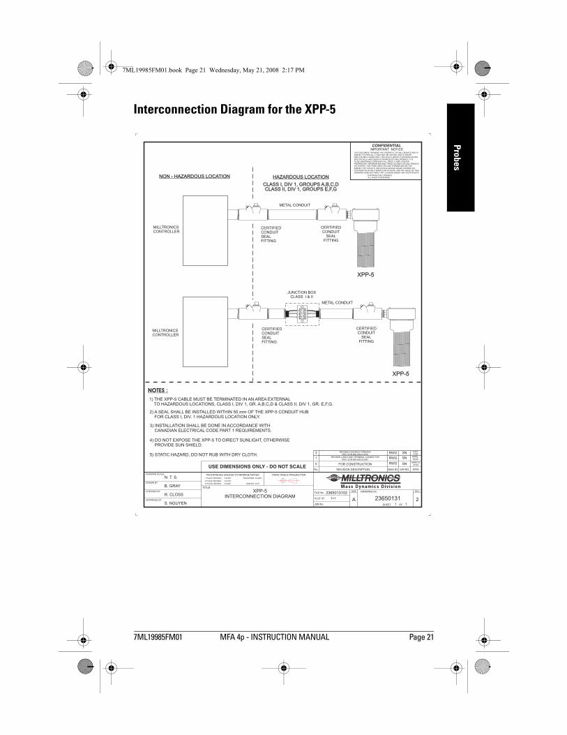
mm
mm
m
Probes
7ML19985FM01.book Page 21 Wednesday, May 21, 2008 2:17 PM
Interconnection Diagram for the XPP-5
1=1
11
R. CLOSS
B. GRAY
N. T. S.
S. NGUYEN
XPP-5INTERCONNECTION DIAGRAM
2365013102
23650131 2
RWG
RWG
RWG
SN
SN
SN
27/00MARCH
APRIL18/00
JULY11/00
0
1
2
FOR CONSTRUCTION
REVISED CABLE AND TERMINAL CONNECTORPER ECN #00-000-0-0037
REVISED HOUSING THREADSPER ECN #00-000-0-0070
NOTES :
2) A SEAL SHALL BE INSTALLED WITHIN 50 mm OF THE XPP-5 CONDUIT HUBFOR CLASS I, DIV. 1 HAZARDOUS LOCATION ONLY.
3) INSTALLATION SHALL BE DONE IN ACCORDANCE WITHCANADIAN ELECTRICAL CODE PART 1 REQUIREMENTS.
4) DO NOT EXPOSE THE XPP-5 TO DIRECT SUNLIGHT, OTHERWISEPROVIDE SUN SHIELD.
5) STATIC HAZARD, DO NOT RUB WITH DRY CLOTH.
1) THE XPP-5 CABLE MUST BE TERMINATED IN AN AREA EXTERNALTO HAZARDOUS LOCATIONS, CLASS I, DIV 1, GR. & CLASS II, DIV 1, GR. E,F,G.A,B,C,D
NON - HAZARDOUS LOCATIONNON - HAZARDOUS LOCATION HAZARDOUS LOCATIONHAZARDOUS LOCATION
MILLTRONICSCONTROLLER
MILLTRONICSCONTROLLER
JUNCTION BOXCLASS I & II
XPP-5
XPP-5
METAL CONDUIT
METAL CONDUIT
CERTIFIEDCONDUITSEALFITTING
CERTIFIEDCONDUITSEALFITTING
CERTIFIEDCONDUIT
SEALFITTING
CERTIFIEDCONDUIT
SEALFITTING
CLASS I, DIV 1, GROUPS A,B,C,DCLASS II, DIV 1, GROUPS E,F,G
CLASS I, DIV 1, GROUPS A,B,C,DCLASS II, DIV 1, GROUPS E,F,G
7ML19985FM01 MFA 4p - INSTRUCTION MANUAL Page 21

mm
mm
m
App
licat
ions
7ML19985FM01.book Page 22 Wednesday, May 21, 2008 2:17 PM
Mounting Details 6 mm (0.25�) dia.hole for ¼ -20 nut
and boltor drill and tap,
four holes on114 mm (4.5�) BCD 6 mm (0.25�) dia. hole for
¼ -20 bolt on 114 mm (4.5�)BCD, four places
95 mm (3.75�) dia.probe clearance
hole133 mm
(5.25�) O.D.
2� NSPL25mm
(1�)
Mounting FlangeAPPLICABLE TO ALL PROBES
EXCEPT MSP-1 AND MSP-9
Page 22 MFA 4p � INSTRUCTION MANUAL 7ML19985FM01

mm
mm
m
Applications
7ML19985FM01.book Page 23 Wednesday, May 21, 2008 2:17 PM
Applications
Bucket Elevators
For chain and sprocket drive elevators, place the probe so that the gap between the bucket and the probe does not exceed 102 mm (4"). To prevent damage to the probe from eccentric bucket motion, ensure that the gap is not less than 12.5 mm (0.5") in the worst condition.
Preferred location for belt-driven elevators with ferrous bucket spacing greater than 76 mm (3"), and non-ferrous buckets with ferrous bolts.
For ferrous buckets with spacings less than 76 mm (3") locate probe on the front of the leg.
probe (see Figure A)
preferred location for chain and sprocket drive elevators.
down leg
probe (see Figure A)
knee and housing
work floor
102 mm (4")
For elevators with ferrous walls, cut 88 mm to 95 mm (3.5" to 3.75") hole in the elevator wall. Any position from A to C may be used to maintain the gap.
Figure A
mounting flange and locknut
elevator wall
95 mm (3.75")
probe
A B C
7ML19985FM01 MFA 4p � INSTRUCTION MANUAL Page 23

mm
mm
m
App
licat
ions
7ML19985FM01.book Page 24 Wednesday, May 21, 2008 2:17 PM
Shafts
These methods are viable if the speed is such that the blades or key will provide the number of pulses required at a minimum velocity of 1.5 m / minute (5 ft. / minute). In applications where exposed moving parts are required, safety shields and precautions should be applied.
Where conditions prevent the sensing of buckets, a belt pulley or paddle mounted on an exposed shaft end, preferably the tail pulley, may be used.
Belt Conveyors
Potential for damage in each application governs the minimum gap allowable. Maximum gap for operation is 102 mm (4"), optimum 25 mm to 50 mm (1" to 2").
Screw Conveyors
A ferrous mass added behind the flight of a screw conveyor, where it passes the probe aids Borderline Operation. This mass must be added for all non-ferrous screws.
probe
shaft
added paddle
safety shield not shown
probe
shaft
key in keyway102 mm (4�) dia. min.
50 x 50 x 25 mm (2� X 2� X 1") ferrous blocks or spoked wheel
probe probe
The probe should be located at the idler end (usually feed end)
Arrows indicate permissible place-ment range of the probe
Page 24 MFA 4p � INSTRUCTION MANUAL 7ML19985FM01

mm
mm
m
Applications
7ML19985FM01.book Page 25 Wednesday, May 21, 2008 2:17 PM
Non-Ferrous Window
For screw conveyor with trough over 3.1 mm (0.125") thick or for high temperature applications. The dimensions shown for the base, window, and bracket are the minimum recommended with tolerances of ± 0.8 mm (0.031"). Use 305, 310, or 316 stainless steel, brass, or aluminum.
The probe may not touch the window if temperatures are in excess of 60 °C (140 °F) when using the low temperature probes or 260 °C (500 °F) when using the high temperature probes.
Bucket Elevator
MINIMUM RECOMMENDED DIMENSIONS SHOWN
PROBE ANDMOUNTING FLANGE
BRACKET
WELD
BASE PLATE
153 mm SQ.(6”)
12.7 mm MAX.(0.5”)
115 mm
115 mm
70 mm
140 mm SQ.
179 mm SQ.
(4.52”)
(4.52”)
(2.75”)(5.5”)
(7”)
WINDOW
CONVEYORHOUSING
6 mm ø (0.25”)CLEARANCE4 HOLES
64 mm ø (3.5”)CLEARANCEHOLE
C
C
7ML19985FM01 MFA 4p � INSTRUCTION MANUAL Page 25

mm
mm
m
App
licat
ions
7ML19985FM01.book Page 26 Wednesday, May 21, 2008 2:17 PM
Rotating Shaft of Rotary Feeder
Drive Sprocket on Rotary Feeder
Page 26 MFA 4p � INSTRUCTION MANUAL 7ML19985FM01

mm
mm
m
Troubleshooting
7ML19985FM01.book Page 27 Wednesday, May 21, 2008 2:17 PM
Screw Conveyor Flights
End Bearing on Screw Conveyor
7ML19985FM01 MFA 4p - INSTRUCTION MANUAL Page 27

mm
mm
m
Trou
bles
hoot
iing
7ML19985FM01.book Page 28 Wednesday, May 21, 2008 2:17 PM
Troubleshooting
Notes:
� Voltage levels are dc, nominal values, and may appear to be pulsing, coincidental with LED 1.
� If diagnosis does not solve the malfunction, the probe, pre-amp or MFA 4p may be defective.
� If no spare circuit boards or probes are available for interchanging, the MFA 4p may be tested as follows in order to determine which section is defective:
a. To find out if the MFA 4p is defective:i. Disconnect the pre-amp.
ii. Set ppm switch SW2 to X 1 position and turn potentiometer to 15.
iii. Connect one Iead of a 530 ohm, 1 watt resistor to terminal 7 and then momentarily contact terminal 8 at a rate of once per second. If the MFA 4p is functional, the relays will energize after two puIses and de-energize approximately 8 seconds after last pulse.
b.To find out if the RMA is defective: i. Disconnect pre-amp from the MFA 4p. Attach probe across terminals
TB1 1/2 and a 24V DC(floating) power supply across terminals TB2 3/2, according to the RMA Interconnectiondiagram on page 8.
ii. Run equipment to be monitored at normal operating speed or pass a ferrous object in front of and as close to probe as possible at a continuous rate.
iii. With an oscilloscope, look for approximately 6V peak to peak pulses or alternating hi/lo levels across ground and link 3. Or with an amp meter connected in series between the RMA and the 24V DC power supply, Iook for hi/lo levels of approximately 12mA/40mA alternating at the rate of the passing ferrous objects.
LED 1
LED 2
term 7/8 (note 1) C8 term 1/2
relay 1 outterm 4/5 relay 2 out
normal pulsing on 24 V 27 V closed closed
alarm pulsing off 24 V 27 V open open
probe reversed polarity
on off 20 V 27 V open open
probe wiring open circuit
off off 27 V 27 V open open
probe wiring short circuit
off off 0 V 27 V open open
relay defective pulsing on 24 V 27 V open open
Page 28 MFA 4p � INSTRUCTION MANUAL 7ML19985FM01

7ML19985FM01.book Page 29 Wednesday, May 21, 2008 2:17 PM
c.To find out if the probe is defective (non-IMA type only; i.e. MSP-1 , MSP-3, and MSP-9 ):i. Disconnect probe from pre-amp.
ii. Connect an ohmmeter across the black and white leads.
iii. Nominal probe impedances are as follows
If impedance deviates substantially from these values, an open or short circuit condition is indicated.
Maintenance
The Motion Failure Alarm MFA 4p requires no maintenance: however, we recommend a program of periodic checks.
If it is necessary to clean the enclosure and circuit boards:
1. First, make sure the power is disconnected at the main breaker.
2. Use a vacuum cleaner and a clean, dry paint brush.
3. Check all electrical contacts for corrosion and arcing.
It is a good idea to periodically check the face of the probe: it should be free of material build-up, corrosion or deformation.
MSP-1 115 ohms
MSP- 3 and MSP- 9 750 ohms
7ML19985FM01 MFA 4p - INSTRUCTION MANUAL Page 29

7ML19985FM01.book Page 30 Wednesday, May 21, 2008 2:17 PM
Page 30 MFA 4p - INSTRUCTION MANUAL 7ML19985FM01

7ML19985FM01 MFA 4p � INSTRUCTION MANUAL Page 31
mm
mm
m
IndexIndexAAmbient Temperature Range 3Applications 23Automatic Start Delay 11BBelt Conveyors 24Bucket Elevator 25Bucket Elevators 23CCable length 9Calibration 14DDimensions
MFA 4p 5Drive Sprocket on Rotary Feeder 26Dynamic range 2EEnd Bearing on Screw Conveyor 27IInstallation 4Interconnection 8Interconnection Diagram for the XPP-5 21LLayout
MFA 4p circuit board 7MMFA 4p
circuit board layout 7operating principles 12Operation 13
MSP-1 Mini Sensing Probedimensions 17specifications 13
MSP-1, 3, or 9 Probeinterconnection 8
MSP-12 Probe with IMAdimensions 19interconnection 8
MSP-3 High Temperature Probedimensions 17specifications 3
MSP-9 stainless steel probedimensions 18specifications 3
NNon-Ferrous Window 25
OOperating Principles 12Operation 13Output 2Overspeed 15PPower 2Pre-Amplifier (IMA and RMA) 13Probe
operating principle 12Probes
diagrams and details 17Mounting Details 22
RRepeatability 2Resistive Rating 2Rotating Shaft of Rotary Feeder 26SScrew Conveyor Flights 27Screw Conveyors 24Setpoint adjustment range 2Shafts 24Signal Generator Interface 16Specifications 2TTemperature coefficient 2Troubleshooting 28UUnderspeed 14WWiring 11XXPP-5
dimensions 20interconnection 9interconnection diagram 21specifications 3
7ML19985FM01.book Page 31 Wednesday, May 21, 2008 2:17 PM

*7ml19985fm01*Rev. 1.2
www.siemens.com/processautomation
Siemens Milltronics Process Instruments Inc.1954Technology Drive, P.O. Box 4225Peterborough, ON, Canada K9J 7B1Tel: (705) 745-2431 Fax: (705) 741-0466Email: [email protected]
Siemens Milltronics Process Instruments Inc. 2008Subject to change without prior notice
Printed in Canada

AN EMPLOYEE OWNED COMPANY
6-1
6 ENCLOSURES

6-2
21393B-D101 PARTS LIST
21393AB-D011 GENERAL ARRANGEMENT DRAWING
21393AB-E10D CONTROL PANEL PARTS LIST
21393AB-E10D CONTROL PANEL DRAWING
This page left intentionally blank

ASSEMBLY: 21393B-D101 REV: DWG #: 21393AB-D101
PART DESCRIPTION: GENERAL ARRANGEMENT DWG REV:
WRITTEN BY: MWB CHKD BY: PCH APP:
DATE: 9/8/2011 DATE: 9/8/2011 DATE:
DWG MATL B/M
ITEM SP PART NUMBER DRAWING NUMBER REV CODE PART DESCRIPTION QTY B/M REV
101 W 21393B-D102 21393AB-D101 0 304SS MAIN ASSY, CVH260 1 Y 0
- - - - - - BUILD PER APPROVED DRAWING - - -
- - - - - - LICENSOR MODEL: XC260 - - -
- - - - - - UNIT MATERIAL: 304 SS - - -
- - - - - - SPIRAL MATERIAL: CARBON STEEL - - -
- - - - - - UNIT LENGTH: 5610 mm - - -
- - - - - - INSTALLATION ANGLE: 0 DEGREES - - -
- - - - - - REDUCER:NORD, SK3282-AZ-BH-N140TC,
RATIO 112.23
- - -
102 W 21393B-D103 21393B-D103 304SS SUPPORT, CONVEYOR 2 N
103 W BHH-050C0200 - - 304SS CAPSCREW HH 1/2"-13 X 2" LG 16 N -
104 W WFL-050 - - 304SS WASHER, FLAT, 1/2" 16 N -
105 W WLO-050 - - 304SS WASHER, LOCK, 1/2" 16 N -
106 W NFI-050 - - 304SS NUT, HEX, 1/2"-13 16 N -
Revision:
JPW
9/8/2011

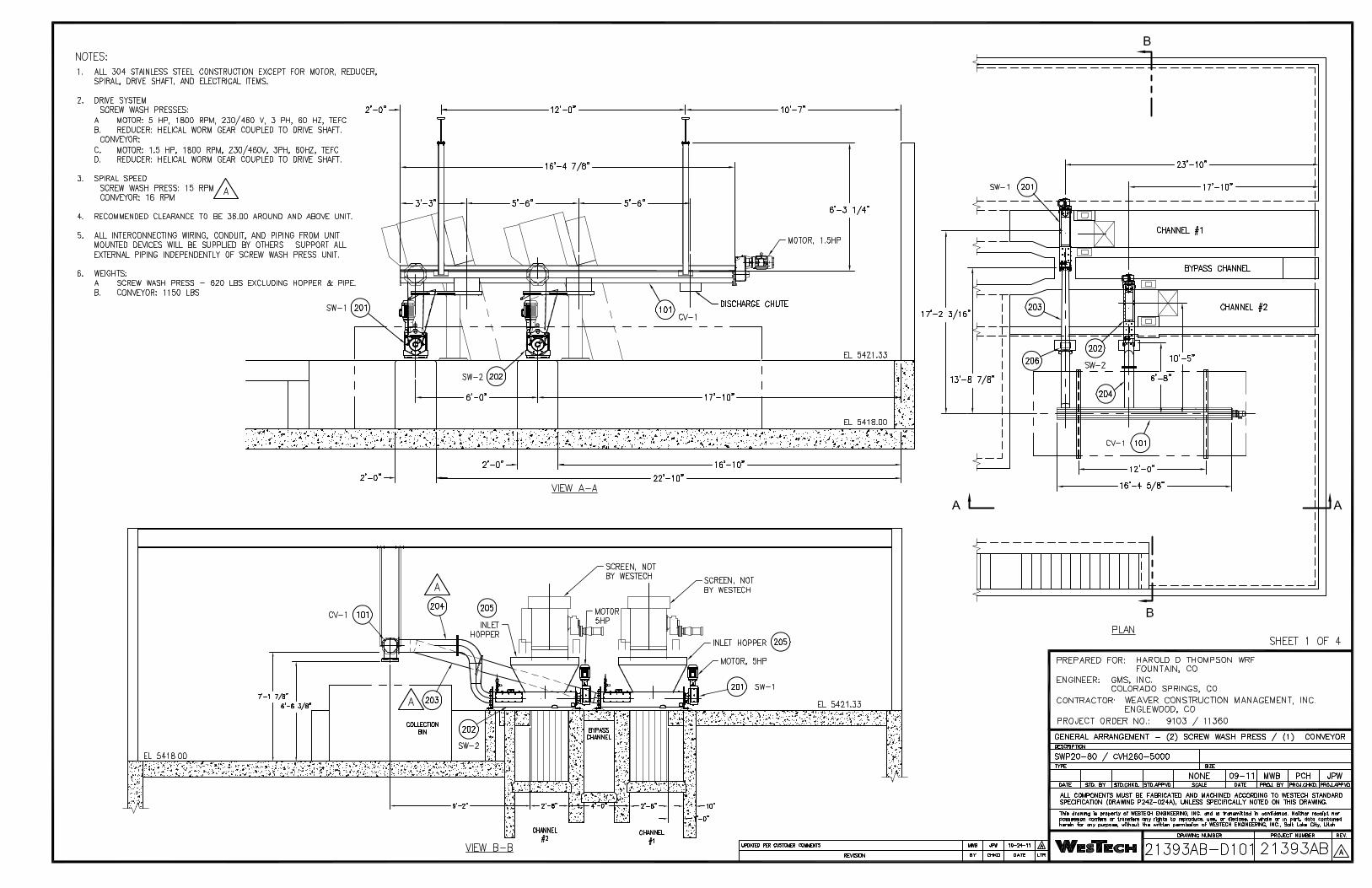


21393 Rev.A
Bill of Material
EleMech S.O. WES4791
Westech Engineering Inc.
Conveyor Control Panel
Harold D. Thompson, CO
Page 1 of 3
1/17/2012
Item No Component Description Manufacturer Part Number QTY Device
Conveyor Control Panel (Quantity: 1)
1 00-000-000 Wire, Hardware, Wire labels, etc. EleMech: Miscellaneous 1
2 10-069-000 Wireway Duct Cover, 1.5"W, 6 Ft. Section, w/Panduit F Series Panduit: C1.5WH6 3
3 10-069-001 Wireway Duct Cover, 1"W, 6 Ft. Section, w/Panduit F Series Panduit: C1WH6 3
4 10-069-005 Wireway Duct, 1.5"Wx3"H, 6 Foot Section Panduit: F1.5X3WH6 3
5 10-069-007 Wireway Duct, 1"Wx3"H, 6 Foot Section Panduit: F1X3WH6 3
6 25-000-A001 Legendplate Assembly, Yellow E-Stop, Standard Encl. EleMech: 25-000-A001 Assembly 1
7 25-000-A002 Legendplate Assembly, White, Black Text, Standard Encl. EleMech: 25-000-A002 Assembly 7
8 25-000-A019 Nameplate Assembly, White: Power Supply - 3/60/480VAC EleMech: 25-000-A019 Assembly 1
9 42-063-007 Terminal Block, Din Rail, 35MM Wide, 15 High, 2 Meters Long Wieland: 98.370.1000 1
10 52-000-000 Label, Underwriters Laboratories 508A, w/Decal Set EleMech: 508A 1
11 03-001-A008 Circuit Breaker Assembly, 3 Pole, 480VAC, 15A, T1, 8" Depth ABB: T1N015TL Assembly 1 CB1
12 03-056-024 Circuit Breaker, 1 Pole, 240VAC, 2A, 14kA, UL489, Type C Siemens: 5SJ4102-7HG40 1 CB4
13 06-058-011 Control Relay, 3PDT,120VAC, 11Pin Spade, Indicator, Operator Square D: RXM3AB2F7 3 CR1-3
14 06-058-012 Control Relay, Bus Jumper, 2-Pole, w/Telemec. RXM Relay Square D: RXZ S2 2 CR1-3
15 38-058-003 Socket, 11 Pin Spade, Din, Screw Term., 3Tier, 250V w/3-Pole Square D: RXZE2S111M 3 CR1-3
16 07-063-000 Distribution Block, End Cover, 4 Pole, 300V,10A, w/WK4E\V\VB Wieland: 07.311.4053.1 1 DB1
17 07-063-001 Distribution Block, Jumper, 4 Pole, 300V,10A, w/WK4E\V\VB Wieland: Z7.210.3427 3 DB1
18 07-063-002 Distribution Block, Single Pole, 10A, 300V, WK4E\V\VB Wieland: 57.404.6955.1 7 DB1
19 42-063-004 Terminal Block, Ground, 30A, 600V, 6MM Wide, w/WK4/U Wieland: 57.504.9055.0 1 DB1
20 11-035-027 Enclosure, NEMA 4, Painted Steel, 24"Hx24"Wx8"D, C. Hinge Hoffman: A-24H24BLP 1 EN1
21 11-035-133 Sub-Panel, Painted Steel, w/24"Hx24"W C. Hinge Encl Hoffman: A-24P24 1 EN1
22 15-011-000 Ground Lug Blackburn: L70 2 GND
23 16-052-005 Elapsed Time Meter, 6 Digit, Round, 3-Hole, NEMA 4X Redington: 722-0004 1 HM1
24 16-052-006 Elapsed Time Meter, Gasket, NEMA 4X (Use w/722-0004) Redington: 5003-011 1 HM1
25 17-062-001 Heater, Silicone Rubber, Flat, 120VAC, 75 Watts, w/12" Leads Watlow: 030050C1-A001B 1 HTR1
26 52-137-003 Label, Caution: Heater Element, 1.5"Wx0.75"H, White/Red Nameplate Tech: 52-137-003 1 HTR1
27 52-137-002 Label, Multiple Supply Sources, Warning, 2.5"Wx1.5"H, Yellow Nameplate Tech: 52-137-002 1 LBL1
28 52-137-000 Label, High Voltage, Danger, 2.25"Wx4.0"H, White/Black/Red Nameplate Tech: 52-137-000 1 LBL2
29 34-001-002 PM, 1/3PH, 110-500VAC, 0.5-5A, 2)SPDT, 120VAC ABB: 1SVR 450 330 R0000 1 LM1
30 32-005-046 Lens, Pilot Light, White, NEMA 4X, Standard, w/A-B 800H Allen-Bradley: 800T-N26W 1 LT1
31 32-005-048 Pilot light, NEMA 4X, 120VAC, Transformer, No Lens Allen-Bradley: 800H-PR16 5 LT1-5
32 32-005-044 Lens, Pilot Light, Green, NEMA 4X, Standard, w/A-B 800H Allen-Bradley: 800T-N26G 1 LT2
33 32-005-045 Lens, Pilot Light, Red, NEMA 4X, Standard, w/A-B 800H Allen-Bradley: 800T-N26R 3 LT3-5
34 22-018-000 Motor Starter, Non-Rev., NEMA 0, 1 NO Aux, 120VAC Coil, w/OL Cutler-Hammer: AN16BNOAC 1 M1

21393 Rev.A
Bill of Material
EleMech S.O. WES4791
Westech Engineering Inc.
Conveyor Control Panel
Harold D. Thompson, CO
Page 2 of 3
1/17/2012
35 22-018-006 Aux. Contact, Top mounted, 4NO, w/C-H Freedom Cutler-Hammer: C320KGT13 1 M1
36 25-000-A010 Nameplate Assembly, White, Black Text, 1"Hx3"W EleMech: 25-000-A010 Assembly 2 NP1,2
37 28-018-005 Overload Relay Heater Pack, 3PH, 1.79-2.90A, w/Freedom, C20 Cutler-Hammer: H2006B-3 1 OL1
38 29-005-010 Pushbutton E-Stop, NEMA 4X, Oper+1NCLB, Twist Rel. Red Head Allen-Bradley: 800H-FRXT6D4 1 PB1
39 02-005-000 Contact Block, 1NO/1NC, w/A-B 800 Series Allen-Bradley: 800T-XA 1 PB3
40 29-005-037 Pushbutton, NEMA 4X, Oper+1NC, Flush Head, Black Allen-Bradley: 800H-AR2D2 1 PB3
41 33-183-010 PR, Zelio, 120VAC, 8)120VAC In, 4)Relay Out Telemecanique: SR2B121FU 1 PR1
42 WES-52-P004 Program, PR, Zelio SR2B121FU, Standard EleMech: WES-52-P004 1 PR1
43 13-000-A000 Spare Parts Box Assembly, Din Rail Mount EleMech: 13-000-A000 Assembly 1 SP1
44 39-005-009 Selector Switch, NEMA 4X, 3 Pos. Maintained, 1NO-1NC Allen-Bradley: 800H-JR2A 1 SS1
45 41-018-A026 Control Transformer Assembly, 480-120VAC, 300VA, w/C-Breaker Cutler-Hammer: C0300E2A Assembly 1 T1,CB2,3
46 42-063-009 Terminal Block, End Clamp, w/WKN10/U Wieland: Z5.522.8553 5 TB,DB
47 42-063-008 Terminal Block, Labels, Blank, w/WK4/U Wieland: Z4.242.6353 22 TB1
48 42-063-015 Terminal Block, Jumper, w/WK4/U, 02 pole, Insulated Wieland: Z7.281.1227 2 TB1
49 42-063-035 Terminal Block, Ground, 30A, 600V, 6MM Wide, w/WKFN 4/U Wieland: 56.704.9055 1 TB1
50 42-063-033 Terminal Block, Single Pole, 30A, 600V, WKF4/U, Spring Clamp Wieland: 56.704.0055 33 TB1,2
51 42-063-034 Terminal Block, End Plate, Beige, w/WKFN 4/U Wieland: 07.312.9255 2 TB1,2
52 42-063-000 Terminal Block, Labels, Custom Printed, w/WK4/U Wieland: 04.242.6353-CUSTOM 62 TB1,2,DB1
53 46-034-000 Thermostat, for heater control, N.C.contact, 6 amp,30-140 F. Stego: 01140.9-00 1 TS1
Zero Motion Assembly, Milltronics MFA-4P, Nema 4X FRP (Quantity: 1)
54 11-035-126 Sub-Panel, Painted Steel, w/12"Hx10"W Junction Box Hoffman: A-12P10 1 EN
55 11-035-176 Enclosure Mounting Feet, Fiberglass, J box Hoffman: A-50MFKR 1 EN
56 11-035-273 Enclosure, Nema 4X, Fiberglass, 13.53"Hx10"Wx7"D, w/Window Hoffman: A-14107JFGQRPWR 1 EN
57 25-000-A010 Nameplate Assembly, White, Black Text, 1"Hx3"W EleMech: 25-000-A010 Assembly 1 NP
58 65-043-001 Zero Motion Sensor, 120VAC, 2-SPDT Relays, 4X, Probe Req'd Milltronics: MFA-4P 1 ZSC
LCS, 1 Hole, Nema 4/7/9, E-Stop (Quantity: 1)
59 25-000-A005 Legendplate Assembly, Yellow E-Stop, LCS Encl. EleMech: 25-000-A005 Assembly 1
60 53-053-003 Conduit, Lockwasher, 3/4", Use w/3/4" Nipple Steel City: LN102 1
61 11-004-004 Local Control Station, NEMA 4/7/9, 1 Hole, 3/4"NPT Holes Akron Electric: CXI-333-X1-N4-N5-2RP2 1 LCS1
62 29-005-009 Pushbutton E-Stop, NEMA 7/9, Oper+1NCLB, Push-Pull Red Head Allen-Bradley: 800H-FPX6D4 1 PB2
63 29-005-063 Pushbutton, Padlocking Cover, w/ 800T/H 30.5mm only Allen-Bradley: 800H-N140 1 PB2
Safety Switch, Left/Right, NEMA 7/9, w/fitting, cable, plug (Quantity: 2)
64 92-295-000 Safety Switch, Left/Right, NEMA7/9, 3/4"NPT, Flag Arm Control Components Company: RS-1X 1 PC1
65 92-295-001 Safety Cable, Vinyl Coated, 3/16" O.D., Orange, per ft. Control Components Company: RS-25 60 PC1
66 92-295-002 Safety Cable, End Fitting Control Components Company: RS-28 2 PC1
67 92-295-003 Safety Switch, Conduit Plug, 3/4" Control Components Company: RS-29 1 PC1

21393 Rev.A
Bill of Material
EleMech S.O. WES4791
Westech Engineering Inc.
Conveyor Control Panel
Harold D. Thompson, CO
Page 3 of 3
1/17/2012
68 65-043-002 Zero Motion Sensor, Probe, Class 1, Div 1, 10M CBL w/ MFA-4P Milltronics: XPP-5 1 ZSC