m/t diamond-t odme manual
146
M/T DIAMOND-T ODME MANUAL SHIP NAME : M/T DIAMOND-T IMO NUMBERS : 9499371 SHIPYARD : TURKER SHIPYARD / TURKEY HULL NR : 17 DATE : 25.01.2011 REVISION : 0 DOCUMENT NO : NB17 - ODME_rev0 GL NO : 113853 1
-
Upload
khangminh22 -
Category
Documents
-
view
8 -
download
0
Transcript of m/t diamond-t odme manual

M/T DIAMOND-T
ODME
MANUAL
SHIP NAME : M/T DIAMOND-T
IMO NUMBERS : 9499371
SHIPYARD : TURKER SHIPYARD / TURKEY
HULL NR : 17
DATE : 25.01.2011
REVISION : 0
DOCUMENT NO : NB17 - ODME_rev0
GL NO : 113853
1

- 1 -
PREFACE
This documentation contained herein are prepared in accordance with applicable parts of the requirements of IMO MEPC 108(49), ‘Revised Guidelines and Specifications for Oil Discharge Monitoring and Control System for Oil Tankers’.
The purpose of this documentation is to provide safe operational and technical
guidance in performing oily water discharge operations in compliance with the requirements of Regulation 9 of Annex I of MARPOL Consolidated Edition 2006.
This documentation shall also provide guidelines for governments and
certifying authorities when approving and surveying onboard the installation of oil discharge monitoring and control systems under Regulation 15(3) of Annex I of MARPOL Consolidated Edition 2006and IMO MEPC 108(49).
This documentation has been approved by Germanischer Lloyd’s on behalf
the National Administration and no alternation or revision shall be made to any part of without the prior approval of Germanischer Llyod.
This manual must be kept for ready use on board. As this manual is approved by administration /Classification society , any part of the manual must not be changed or revised without advance notice to Administration for authorization.Morever , if the oil discharge monitoring and control system is changed , any change of the manual in connection with such change of the system must also be reported to Administration for approval.
2

- 2 -
INDEX
Section Page
Ship Particulars 3
MARPOL Cons.2006 Annex I Regulations 15, 31.2, 31.3, 34, 36.6 4-7
Description of Ballast System 8
Description of Cargo and ODME System 9-11
Sample Response time calculation 12
Addendum A Special Areas Under MARPOL 13-14
Operation in case of Malfunction of the Oil discharge 15
Monitoring and Control system
VAF Oil Discharge Monitoring and Control System Technical Manual 16
Related Drawings
3

- 3 -
SHIP PARTICULARS
Ship Name DIAMOND-T Type of Ship IMO II CHEMICAL / OIL TANKER Owner GALATA DENİZCİLİK A.Ş.
Shipyard TURKER SHIPYARD
Hull No NB17
Date of Build 2011
Particulars of
Classification
GL, 100 A5 , OIL TANKER, CHEMICAL TANKER TYPE
II, ESP, UNRESTRICTED NAVIGATION ,E3 ,
MACHINERY MC,E1,AUT, VCS, IW IG,
ENVIROMENTAL PASSPORT, MON-SHAFT, CARGO
CONTROL,RP,INERT
Flag MALTA
Port Of Registry VALLETTA
IMO Number 9499371 MMSI Number -
Call Sign -
Length (OA) (abt) 169,90 m
Length (PP) (abt) 159.08 m
Length (WL) (abt) 150,60m
Breadth (MLD) (abt) 25.40 m
Depth (MLD) (abt) 14.90 m
Draught (Design) (abt) 10.90 m
Draught (Scantling) (abt) 10.05 m
Deadweight (Design) (abt) 26.000 t
Speed at Design Draught
(abt)
15.0 knot
Cargo Tank Capacity
(100%) (abt)
30.740 m3
On Main Deck Total Cargo
Capacity (100%) (abt) 31.371 m3
Ballast Water Tank Capacity
(abt)
12.227,52 m3
Main Engine 7860 kW
Personnel Number 25 persons
Freefall lifeboat capacity 25 persons
4

- 4 -
Applicable Regulations
Regulation 15 Control of discharge of oil
1 Subject to the provisions of regulation 4 of this annex and paragraphs 2, 3, and 6 of this
regulation, any discharge into the sea of oil or oily mixtures from ships shall be prohibited.
A. Discharges outside special areas
2 Any discharge into the sea of oil or oily mixtures from ships of 400 gross tonnage and
above shall be prohibited except when all the following conditions are satisfied:
.1 the ship is proceeding en route;
.2 the oily mixture is processed through an oil filtering equipment meeting the requirements
of regulation 14 of this Annex;
.3 the oil content of the effluent without dilution does not exceed 15 parts per million;
.4 the oily mixture does not originate from cargo pump room bilges on oil tankers; and
.5 the oily mixture, in case of oil tankers, is not mixed with oil cargo residues.
B. Discharges in special areas
3 Any discharge into the sea of oil or oily mixtures from ships of 400 gross tonnage and
above shall be prohibited except when all of the following conditions are satisfied:
.1 the ship is proceeding en route;
.2 the oily mixture is processed through an oil filtering equipment meeting the requirements of
regulation 14.7 of this Annex;
.3 the oil content of the effluent without dilution does not exceed 15 parts per million;
.4 the oily mixture does not originate from cargo pump room bilges on oil tankers; and
.5 the oily mixture, in case of oil tankers, is not mixed with oil cargo residues.
4 In respect of the Antarctic area, any discharge into the sea of oil or oily mixtures from any
ship shall be prohibited.
5 Nothing in this regulation shall prohibit a ship on a voyage only part of which is in a
special area from discharging outside a special area in accordance with paragraphs 2 of this
regulation.
5

- 5 -
C. Requirements for ships of less than 400 gross tonnage in all areas except the
Antarctic area
6 In the case of a ship of less than 400 gross tonnage, oil and all oily mixtures shall either
be retained on board for subsequent discharge to reception facilities or discharged into the sea in
accordance with the following provisions :
.1 the ship is proceeding en route;
.2 the ship has in operation equipment of a design approved by the Administration that
ensures that the oil content of the effluent without dilution does not exceed 15 parts per million;
.3 the oily mixture does not originate from cargo pump room bilges on oil tankers; and
.4 the oily mixture, in case of oil tankers, is not mixed with oil cargo residues.
D. General requirements
7 Whenever visible traces of oil are observed on or below the surface of the water in the
immediate vicinity of a ship or its wake, Governments of Parties to the present Convention should,
to the extent they are reasonably able to do so, promptly investigate the facts bearing on the issue
of whether there has been a violation of the provisions of this regulation. The investigation should
include, in particular, the wind and sea conditions, the track and speed of the ship, other possible
sources of the visible traces in the vicinity, and any relevant oil discharge records.
8 No discharge into the sea shall contain chemicals or other substances in quantities or
concentrations which are hazardous to the marine environment or chemicals or other substances
introduced for the purpose of circumventing the conditions of discharge specified in this regulation.
9 The oil residues which cannot be discharged into the sea in compliance with this
regulation shall be retained on board for subsequent discharge to reception facilities.
Regulation 31 Oil discharge monitoring and control system
1 Subject to the provisions of paragraphs 4 and 5 of regulation 3 of this Annex, oil tankers
of 150 gross tonnage and above shall be equipped with an oil discharge monitoring and control
system approved by the Administration.
2 In considering the design of the oil content meter to be incorporated in the system, the
Administration shall have regard to the specification recommended by the Organization.† The
system shall be fitted with a recording device to provide a continuous record of the discharge in
litres per nautical mile and total quantity discharged, or the oil content and rate of discharge. This
record shall be identifiable as to time and date and shall be kept for at least three years.
The oil discharge monitoring and control system shall come into operation when there is any
discharge of effluent into the sea and shall be such as will ensure that any discharge of oily mixture
is automatically stopped when the instantaneous rate of discharge of oil exceeds that permitted by
regulation 34 of this Annex. Any failure of this monitoring and control system shall stop the discharge.
In the event of failure of the oil discharge monitoring and control system a manually operated
alternative method may be used, but the defective unit shall be made operable as soon as possible.
Subject to allowance by the port State authority a tanker with a defective oil discharge monitoring
and control system may undertake one ballast voyage before proceeding to a repair port.
6

- 6 -
3 The oil discharge monitoring and control system shall be designed and installed in
compliance with the guidelines and specifications for oil discharge monitoring and control system for
oil tankers developed by the organization.Administrations may accept such specific arrangements
as detailed in the Guideline and specifications.
See appendix 4 to Unified Interpretations.
For oil content meters installed on oil tankers built prior to 2 October 1986, refer to the Recommendation on international performance and test specifications for oily-water separating equipment and oil content meters adopted by the Organization by resolution A.393(X). For oil content meters as part of discharge monitoring and control systems installed on oil tankers built on or after 2 October 1986, refer to the Guidelines and specifications for oil discharge monitoring and control systems for oil tankers adopted by the Organization by resolution A.586(14). For oil content meters as part of discharge monitoring and control systems installed on oil tankers the keel of which are laid or which are in a similar stage of construction on or after 1 January 2005, refer to the revised Guidelines and specifications for oil discharge monitoring and control systems for oil tankers adopted by the Organization by resolution MEPC.108(49).
4 Instructions as to the operation of the system shall be in accordance with an operational
manual approved by the Administration. They shall cover manual as well as automatic operations
and shall be intended to ensure that at no time shall oil be discharged except in compliance with the
conditions specified in regulation 34 of this Annex.
Regulation 34 Control of discharge of oil
A. Discharges outside special areas
1 Subject to the provisions of regulation 4 of this Annex and paragraph 2 of this regulation,
any discharge into the sea of oil or oily mixtures from the cargo area of an oil tanker, shall be
prohibited except when all the following conditions are satisfied:
.1 the tanker is not within a special area;
.2 the tanker is more than 50 nautical miles from the nearest land;
.3 the tanker is proceeding en route;
.4 the instantaneous rate of discharge of oil content does not exceed 30 litres per nautical mile;
.5 the total quantity of oil discharged into the sea does not exceed for tankers delivered on or
before 31 December 1979, as defined in regulation 1.28.1, 1/15,000 of the total quantity of the
particular cargo of which the residue formed a part, and for tankers delivered after 31 December
1979, as defined in regulation 1.28.2, 1/30,000 of the total quantity of the particular cargo of which
the residue formed a part; and
.6 the tanker has in operation an oil discharge monitoring and control system and a slop tank
arrangement as required by regulations 29 and 31 of this Annex.
2 The provisions of paragraph 1 of this regulation shall not apply to the discharge of clean
or segregated ballast.
B. Discharges in special areas
3 Subject to the provisions of paragraph 4 of this regulation, any discharge into the sea of
oil or oily mixture from the cargo area of an oil tanker shall be prohibited while in a special area∗.
7

- 7 -
4 The provisions of paragraph 3 of this regulation shall not apply to the discharge of clean
or segregated ballast.
5 Nothing in this regulation shall prohibit a ship on a voyage only part of which is in a
special area from discharging outside the special area in accordance with paragraph 1 of this
regulation.
C. Requirements for oil tankers of less than 150 gross tonnage
6 The requirements of regulations 29, 31 and 32 of this Annex shall not apply to oil tankers
of less than 150 gross tonnage, for which the control of discharge of oil under this regulation shall be
effected by the retention of oil on board with subsequent discharge of all contaminated washings to
reception facilities. The total quantity of oil and water used for washing and returned to a storage
tank shall be discharged to reception facilities unless adequate arrangements are made to ensure
that any effluent which is allowed to be discharged into the sea is effectively monitored to ensure
that the provisions of this regulation are complied with.
D. General requirements
7 Whenever visible traces of oil are observed on or below the surface of the water in the
immediate vicinity of a ship or its wake, the Governments of Parties to the present Convention
should, to the extent they are reasonably able to do so, promptly investigate the facts bearing on the
issue of whether there has been a violation of the provisions of this regulation. The investigation
should include, in particular, the wind and sea conditions, the track and speed of the ship, other
possible sources of the visible traces in the vicinity, and any relevant oil discharge records.
8 No discharge into the sea shall contain chemicals or other substances in quantities or
concentrations which are hazardous to the marine environment or chemicals or other substances
introduced for the purpose of circumventing the conditions of discharge specified in this regulation.
9 The oil residues which cannot be discharged into the sea in compliance with paragraphs
1 and 3 of this regulation shall be retained on board for subsequent discharge to reception facilities.
Regulation 36 Oil Record Book, Part II - Cargo/ballast operations
6 Any failure of the oil discharge monitoring and control system shall be noted in the Oil
Record Book Part II.
8

- 8 -
Description of ballast tanks and ballast pumping and piping arrangements
The segregated ballast system is such that the ship complies with IMO stability and
trim criteria without ballasting any cargo tank.
The ship is equipped with a segregated ballast system comprising a double hull and
bottom tank underneath the cargo tanks.
The capacities of the ballast tanks are also indicated in table 1.
Piping and pumping system shown in drawing Ballast System no. CT84-P-02 Rev_2
serves all the segregated ballast tanks. The drawing indicates the diameter and
thickness of the pipes and specification of other material employed in the system as
well.
The ballast tanks nos1 to 8 (P&S) are served by two pieces vertical single stage
deepwell ballast pumps made by FRAMO SB 300 type ,each 700 m3/h capacities at
20 mcl. These pumps are driven by hydraulically and located on main deck aft side
connected with gas-tight bulkhead penetration to pump.
The fore peak and trim tanks are served by the emergency fire pump in bow
thruster room.
The capacities and location of the side tanks are shown on the Tank Capacity Plan,
No. CT84-R-07 Rev_1, which is also attached
Table 1 – Water ballast tank information
9

- 9 -
Description of Cargo tanks, Cargo pumping and piping arrangements and ODME System
The vessel has been divided to 14 cargo tanks, separated with transverse and
longitudinal corrugated bulkheads. There are also 2 slop tanks placed on main
deck, which are suitable to be used as a cargo tanks. 1 slop tank and 7 cargo tanks
are at port, 1 slop tank and 7 cargo tanks are at starboard side and arranged
symmetrically. For more details, Please see Tank Capacity Plan, no. CT84-R-07
Rev-1
Line or schematic drawings showing the general arrangement of the ship and
indicating the position and numbering of the cargo tanks and heating arrangements
shall be included. Please see General Arrangement no. CT84-R-01 Rev-10
Compartments Volume (m3) Frame
Water Ballast Fore Peak 822,26 FR.217_FR.237
Water Ballast No 1 (P) 958,12 FR.178_FR.210
Water Ballast No 1 (S) 991,62 FR.178_FR.210
Water Ballast No 2 (P) 790,43 FR.154_FR.178
Water Ballast No 2 (S) 765,21 FR.154_FR.178
Water Ballast No 3 (P) 737,54 FR.130_FR.154
Water Ballast No 3 (S) 762,67 FR.130_FR.154
Water Ballast No 4 (P) 766,66 FR.106_FR.130
Water Ballast No 4 (S) 741,47 FR.106_FR.130
Water Ballast No 5 (P) 740,72 FR.82_FR.106
Water Ballast No 5 (S) 765,89 FR.82_FR.106
Water Ballast No 6 (P) 384,49 FR.70_FR.82
Water Ballast No 6 (S) 371,85 FR.70_FR.82
Water Ballast No 7 (P) 371,86 FR.58_FR.70
Water Ballast No 7 (S) 371,86 FR.58_FR.70
Water Ballast No 8 (P) 724,10 FR.42_FR.58
Water Ballast No 8 (S) 765,81 FR.42_FR.58
Aft Peak tank C 203,75 FR.3_FR.12
Trim Tank (P) 85,27 FR.212_FR.217
Trim Tank (S) 85,27 FR.212_FR.217
TOTAL 12.219,43
10

- 10 -
This ship is provided with double bottom and double sides in way of whole cargo
area, used as water ballast tank also for protection of cargo tanks. The cargo tank
area is also separated form the rest of the ship’s construction by a forward
cofferdam. The after cofferdam is designed as a ballast tank connected No:8
(P&STB) ballast tanks. The ballast piping system has been passing to in the ballast
tanks and all valves has been arranged remote controlled which is operated in the
cargo control room. Please see Ballast system CT84-P-02 Rev_2.
Tank top is sloping to centre to facilitate easy drainage of the cargo to the well
placed close to centre line without listing the vessel.
The cargo area is divided to 7 pairs of cargo tanks with corrugated centre and
transverse bulkheads. The side bulkheads are flash, fames outside cargo tanks. There
are also 2 slop tanks placed on main deck, which are suitable to be used as cargo
tanks. Capacities of tanks are also given in table 2.
The cargo and slop tanks are built of mild steel and coated with MARINE LINE
ADVANCED POLYMER COATINGS.
Table 2 - Cargo tank information
Compartments Vol.(m3) Frame
Cargo Tank No 1 (S) 2000,91 FR.178_FR.210
Cargo Tank No 1 (P) 2000,91 FR.178_FR.210
Cargo Tank No 2 (S) 2298,03 FR.154_FR.180
Cargo Tank No 2 (P) 2302,31 FR.154_FR.180
Cargo Tank No 3 (S) 2453,60 FR.130_FR.155
Cargo Tank No 3 (P) 2457,89 FR.130_FR.155
Cargo Tank No 4 (S) 2454,71 FR.106_FR.132
Cargo Tank No 4 (P) 2459,00 FR.106_FR.132
Cargo Tank No 5 (S) 2453,52 FR.82_FR.108
Cargo Tank No 5 (P) 2457,81 FR.82_FR.108
Cargo Tank No 6 (S) 1215,07 FR.70_FR.84
Cargo Tank No 6 (P) 1219,36 FR.70_FR.84
Cargo Tank No 7 (S) 2485,24 FR.45_FR.71
Cargo Tank No 7 (P) 2485,25 FR.45_FR.71
Slop Tank (S) 316,57 FR.152_FR.181
Slop Tank (P) 314,34 FR.152_FR.180
Total 31.371,62
Each cargo tank is provided with the following devices;
• Level gauge, closed type (Kongsberg parabolic tank radar). Indication in the
cargo control room with light and siren at top of accommodation.
11

- 11 -
• Temperature measuring system with two PT-100 sensors located at mid-level
and bottom of cargo tanks (Omicron sensors). Indication in the cargo control
room with light and siren at top of accommodation.
• Pressure monitoring system from Kongsberg with the pressure sensors mounted
on the base plate of the tank radars. Indication in the cargo control room with
light and siren at top of accommodation.
• High level (95%) / high level (98%) alarm (Saab system). Indication in the cargo
control room with light and siren at top of accommodation.
• Independent cargo tank venting system with a high velocity valve for each cargo
and slop tanks. There are two connections on each air pipe giving the possibility
to connect the air pipe to one of the two common vapor return lines. Both vapor
return lines are equipped with a cross over pipe at manifold area.
All cargo tanks are fitted with stainless steel heating coils for pump well, to ensure a
cargo temperature of at least 90°C. Each tanks is fitted with water glycol deck heater
. The coils are placed just inside pump well and connected by means of flat bar
support in the tank. See also attached drawing of Cargo Tank Heating System, no.
07/1-333/2b . The heating media is water glycol.
The cargo system is consisting of ;
a.) Cargo pumps
FRAMO Hydraulic driven Deepwell Pump, type SD-150 , hydraulic driven
Location : Cargo tanks
No: off : 12
Capacity / head : 380 m³ / h,115 m.I.c.
Viscosity / specific gravity : 1.0 cst – s.g.0.8
Motor : Hydraulic high pressure motor
Pump length : Apprx 13 meter
Hydraulic data : 341 ltr/min and 245 bar
FRAMO Hydraulic driven Deepwell Pump, type SD-125 , hydraulic driven
Location : Cargo tanks
No: off : 2
Capacity / head : 200 m³ / h,115 m.I.c.
Viscosity / specific gravity : 1.0 cst – s.g.0.8
Motor : Hydraulic high pressure motor
Pump length : Apprx 13 meter
Hydraulic data : 184 ltr/min and 245 bar
b.) Slop pump
Location : Slop tanks
No: off : 2
Framo Deepwell Pump : Type SD-125
Capacity /head : 200 m³/h 115 m.1.c
Viscosity / specific gravity : 1.0 cst at 20 C – s.g.0.8
Hydraulic data : 184 ltr/min and 245 bar
12

- 12 -
c.) Portable cargo pump
No: off : 1
Type : Framo TK80
Capacity / Head : 70 m³/h-70 m.I.c
Viscosity specific gravity : 1.0 cst at 20 c-s.g.0.8
Hydraulic motor type : Ax Plunger
Hydraulic system pressure : 188 bar
Hydraulic system oil consumption : 72 1tr/min
d.) Ballast pumps
FRAMO Hydraulic driven Deepwell Pump, type SB-300 , hydraulic driven
Location : Ballast deepwell on cargo deck area
No: off : 2
Capacity / head : 700 m³ / h,20 m.I.c.
Viscosity / specific gravity : 1.0 cst – s.g.0.8
Motor : Hydraulic high pressure motor
Pump length : Apprx 13 meter
Hydraulic data : 184 ltr/min and 188 bar
All cargo pipes and equipment connected with the cargo to be made of stainless
steel, each cargo tank has its own discharge and loading line with a diameter of 6”
and also each slop tank has it own discharge and loading line with a diameter of 4’’.
Manifold to be fitted with possibility for common line discharge with a diameter of
14”. Details can be seen at Addendum, CT84-P-01 Cargo System drawing.
All the material of the cargo piping system is AISI 316L stainless steel. PTFE is
used as gasket material. The system valves are hydraulically remote controlled
locally and remote controlled from cargo control room.
The oil discharge monitoring and control system is to be used for monitoring and
control of ballast discharge of oil tankers specified by the regulation, comprising the
following major components :
1. Oil content meter (Oilcon)
2. Flow rate indicating system
3. Control section
4. Overboard discharge control
5. Starting interlock
6. Ship’s LOG
The sample obtained at a sampling probe installed on overboard discharge line is
drawn to the measurement cell of the Mark Oilcon and its oil content is measured.
The signal of oil content is converted to the electric signal and used for indication at
the control box located in the cargo control room. This signal is also inputted to the
CCU.
13

- 13 -
The data is to be displayed on a LCD display and it is also printed on paper at 10
min. intervals.Control of the MCU is through a keyboard.The MCU also displays a
number of pages with information according to the operator's instructions.The
various pages are designed to help the operator to control the Oil Discharge
Monitoring & Control System and to give a wide range of information.
Principal operation ;
The measurement technique used in the Oilcon Oil Discharge Monitoring & Control
System is based on scattered light. The sample of discharge water passes through a
detector cell while light enters and leaves the measurement area of the cell. The
sample flow is at right angles to the optical path. When no particles or oil droplets
are present in the water, light can pass straight through the cell (Direct beam). When
oil is present in the form of a homogeneous mixture, light is scattered at different
angles (Scatter beam). The intensity of scattered light at a specific angle depends on
the density of oil droplets and upon their particle size relative to the wavelength of
radiation. The intensity of light of the direct beam decreases logarithmically with
increasing oil concentration, while the scatter beam increases linearly but passes
through a maximum before decreasing logarithmically. The maximum occurs
because of the increase in attenuation blocking out the scattered light at high
concentrations. The variation of light refraction by oil droplets only is quite different
to that refracted when solid contaminants are also present and this fact can be used
to obtain an accurate indication of oil content whilst disregarding solid particles up
to a point. The light source used in the Oilcon® Oil Discharge Monitoring &
Control System is a near infra red diode which is operated in the pulsed mode so that
the average power dissipation is very low, although the intensity is high. The light
signal is processed and transmitted along a communication cable from the detector
cell to the EPU where the three detection signals are used to compute the oil
concentration levels present in the sample passing through the detector cell. The
response in the optical detection is instantaneous and most of the delays when
reading oil levels lie in the sampling pipework. High velocity, short sampling length
and minimum pipework bends give fast response times. During periods of inactivity
the pipework may become fouled and when the system is started up, erroneous
readings could occur as oil is stripped from the pipework. Automatic sequential
control of forward and backward flushing at start up and shut down of the monitor
prevents erroneous readings and keeps the sampling lines clean. This also ensures
reliable start up, minimises system deterioration and ensures that the pipework is left
in clean condition prior to the next use of the monitor. At the end of the start up
flushing cycle a system zero check is performed, this automatic zero setting
compensates for any small deposits on the cell windows. The window wash pump
cleans the cell windows at regular intervals.
All operating controls and system alarms are situated on the MCU. Manual system
flush and window wash controls are available to make these two operations possible
at any time. With the exception of selecting the sample point and the oil type, the
system works automatically once sampling has been initiated. The oil level together
with the discharge flow rate and ships speed are input to the MCU to give a
permanent record of oil discharged overboard. Both calibration alarms and
operational alarms are provided and the alarm philosophy employed follows normal
14

- 14 -
marine practice. When a fault occurs, both audible and visual alarms are activated.
The audible alarm can be silenced by fault acceptance but the visual alarm cannot be
extinguished. It is only after the fault has been rectified that the visual alarm is
extinguished. Should a second alarm occur during this sequence, both audible and
the visual alarms would be reactivated.
Sample pump unit ;
The sample pump unit comprises a pump, bulkhead mounting flange with integral
gas-tight shaft seal and a flange mounted motor. For this purpose a hole of diameter
290 mm is to be made in the bulkhead wall. The pump unit shall be fitted to the
bulkhead utilising the welding ring as supplied with the pump. This ring shall be
welded to the bulkhead wall. For the location of this hole verify with the pump
dimensional drawing that there will be no obstacles, and that the pump unit can be
accessed for maintenance. Maintain sufficient free space around the motor for free
air circulation to cool the motor.If possible, the unit should be located below all
proposed sampling points and as central to these locations as possible. Care should
be taken to ensure that under all operational circumstances a zero or positive
pressure is present at the suction side of the pump.The joints of the suction line must
be air-tight, otherwise air leakage will occur causing reduced pumping and
monitoring performance. If air leakage is considerable, the pump may fail to prime
or pump at all.
It will be observed that a length restriction has been placed on the sample pipes .
This is for two reasons:
a) To ensure that the total response time of the system is less than 40 sec., as
required by the legislation. In fact, since the instrument response time is less than 5
seconds and the sample velocity in the specified pipework is 0.9 m/s, there is some
margin here.
b) To ensure that the sample pump is not faced with excessive negative suction
pressure due to high pipe losses.
Detailed drawings of ODME system is shown at CT84-P-33, including discharge
details. ODME discharge is on portside fr.172-173 and 9900 mm above from Base
line. Oil containment that required to be discharged is taken to the ODME unit
(VAF OILCON MARK6M) with the related valve is opened.
Allowable containment is discharged from the ODME discharge with the related
valve (could be seen in drawing number CT84-P-33 is opened. In the situation of
malfunction of the ODME equipment or in the situation of exceeding permissible
limits discharging to sea, oil water is taken to slop tanks including starboard and
portsides.
ODME System Installation started at 10 January 2011.
15

- 15 -
SAMPLE RESPONSE TIME CALCULATION
TOTAL RESPONSE TIME T1=40 Seconds (max)
Monitor Response Time T2=4 Seconds
Sample Response Time T3=T1-T2=36 seconds
Sample Pipe O.D. (Outside diameter ) : 15 mm
Sample Pipe WT (Wall thickness) : 1 mm
Sample Pipe Internal area ( A ) : 0,0001327 m2
Lmax = ( T3 x Q) / ( A x 60 x60 )
Where
T3 = Sample Response Time ( sec)
Q = Sample Flowrate ( m3/h)
A = Internal Area of Sample Pipe ( m2 )
Lmax = ( 36 x 0,5 ) / ( 0,0001327 x 60 x 60 ) = 37,7 meter
L = 20 meter (according to ship application measurement of sample pipe length)
V = 0,9 m/s (according to max rate of sample pump)
T = L / V = 23 / 0,9 = 25,5 seconds
MONITOR RESPONSE TIME :
Tm = 4,0 seconds
TOTAL RESPONSE TIME :
Tt = 4 + 25,5 = 29,5 seconds < 40 seconds
16

- 16 -
ODME CALCULATION
Acc. To Resolutation MEPC. 108 (49) maximum possible oil discharge rate per mile
PPM X FLOWRATE
< 30 liter / nm NOT MUCH MORE THAN !! ANNEX 1
SPEED X 1000
EXAMPLE CALCULATION
A= Qty of in ppm x flow rate in m3/h : Liters / nautical mile
Speed of vessel x 1000
INPUTS
Speed 11.5
A= : Oil quantity per nautical mile 15.6521 Liter/nm Flow rate 300
ppm 600
B= Qty of in ppm x flow rate in m3/h Liters/ Hour
1000
B= Oil quantity per hour 180 Liter / hr
C= Liters per hour x time in hours : Total quantitiy in liters (Total oil)
INPUT
Operation Time 1 hour C=
Total Slop Discharge Quantites: 300 Liters
Total Slop Discharge Quantites: Total cargo Q'tity(ton) Liters
30 000*
For New Building Tankers (1/30000 , For old Tankers 1 / 15000
17

- 17 -
MARPOL Consolidated Edition 2006 Annex I
Regulation For the Prevention of Oil Pollution by Oil
11. Special area means a sea area where for recognized technical reasons in relation to its
oceanographical and ecological condition and to the particular character of its traffic the
adoption of special mandatory methods for the prevention of sea pollution by oil is required.
For the purpose of this annex , the special areas are defined as follows :
.1 the Mediterranean Sea area means the Mediterranean Sea proper including the
gulfs and seas therein with the boundary between the Mediterranean and the Black sea
constituted by the 41° N parellel and bounded to the west by the Straits of Gibraltar at the
meridian 005° 36' W ;
.2 the Baltic sea area means the Baltic Sea proper with the Gulf of Bothnia , the Gulf
of Finland and the entrance to the Baltic Sea bounded by the parellel of the skaw in the
Skagerrak at 57° 44' .8 N ;
.3 the Black Sea area means the Black sea proper with the boundary between the
Mediterranean Sea and the Black sea constituted by the the parellel 41° N ;
.4 the Red Sea area means the Red sea proper including the Gulfs of Suez and
Aqaba bounded at the at the South by the rhumb line between Ras si Ane (12° 28' .5 N,
043° 19' .6 E) and Husn Murad (12° 40' .4 N, 043° 30' .2 E) ;
.5 the Gulf area means the sea area located North-west of the rhumb line between
Ras al Hadd (22° 30' N, 059° 48' E) and Ras al Fasteh (25° 04' N, 061° 25' E) ;
.6 the Gulf of Aden area means that part of the Gulf of Aden between the Red Sea
and the Arabian sea bounded to the west by the rhumb line between Ras si Ane (12° 28' .5
N, 043°19' .6 E) and Husn Murad (12° 40' .4 N, 043° 30' .2 E) and to the east by the rhumb
line between Ras Asir (11° 50' N, 051° 16' .9 E) and the Ras Fartak (15° 35' N, 052° 13' .8
E) ;
.7 the Antractic area means the sea area South of Latitude 60° S ; and
.8 the North West European waters include the North sea and its approaches ,the
Irish Sea and its approaches , the Celtic Sea and its approaches ,the Englisg Channel and its
approaches and part of the North East Atlantic immediately to the west of Ireland.The area
is bounded by lines joining the following points :
18

- 18 -
19

- 19 -
OPERATION IN CASE OF MALFUNCTION OF THE OIL
DISCHARGE MONITORING AND CONTROL SYSTEM
The basic requirements of MARPOL Consolidated edition 2006 Annex I - Ch.4-
Reg.31.2 are that the monitoring and control system must be in operation during all
discharges of oil-contaminated water. If the equipment fails during a ballast voyage
the operation may continue b use of alternative means but the equipment should be
repaired before the next ballast voyage unless the vessel is sailing to a repair yard.
In the event of failure of the oil discharge monitoring and control sytem a manually
operated alternative method may be used, but the defective unit shall be made
operable as soon as possible. Subject to allowance by the port state authority, a
tanker with a defective oil discharge monitoring and control system may undertake
one ballast voyage before proceeding to a repair port.
In case discharging of oil contaminated water has to be performed without the use
of the Oil Discharge Monitoring and Control System this fact must be recorded in
the Oil Record Book and the following instructions should be followed for
monitoring of the discharge.
.1 In case of failure of the complete system, the overboard valve is controlled
open by placing the lockable override switch on the computer in “manual override”
position.During the discharge under this condition it is necessary to keep a manual
record of the flow rate, speed and ppm values, estimated repeatedly at 20 minutes
intervals. Estimate the oil content by collection glass samples from the overboard
effluent. Compare, after setting, the appearance of the oil layer with samples,
which have been prepared with 100, 200, 500 ppm of oil in water glasses. For
approximate comparison, the volume of one drop of low viscosity oil leaving from
the tip of a 6 mm glass rod and being dispersed in 300 mm of water will equivalent
100ppm. Calculate the instantaneous rate of discharge and the total quantity of oil
discharged, using the formulas shown in page 15-16 of this manual. Sample water
may be collected from the sample point in the overboard line by removal of the cap
on the coarse filter unit.
.2 Pump flow rate is estimated from the pump speed setting, using the pump
diagrams. For ship’s speed information, use the value available on the bridge for navigational purposes.
.3 Observe visually the overboard effluent. This observation should be continuous
during the final, critical phase of discharge operation. Leave a safe water bottom in the slop tank during final decanting.
20

- 20 -
M/T DIAMOND-T
ODME
MANUAL
DRAWINGS
21

22

23
GL
Approved

24

25

26

27

28

29

30

31

32

33

34

35

36

37

38

39
GL
Callout
The valve at the collision bulkhead is classified in pipe class II.
GL
Approved

40

41

42

43

44

45
GL
Approved

M/T DIAMOND-T
ODME
TECHNICAL
MANUAL
46

47

1
CONTENTS
1. PREFACE .................................................................................................. 5
1.1 General ................................................................................................................. 5
1.2 Symbols................................................................................................................ 5
1.3 Copyright .............................................................................................................. 5
2. INSTALLATION ........................................................................................ 6
2.1 Introduction .......................................................................................................... 6
2.2 Utilities .................................................................................................................. 6
2.2.1 Fresh water supply....................................................................................... 6
2.2.2 Air supply ....................................................................................................... 7
2.2.3 Electrical supply............................................................................................ 7
2.3 Pipework general ................................................................................................ 8
2.3.1 Sample pump units ...................................................................................... 8
2.3.2 Installation of pump...................................................................................... 9
2.3.3 Electrical installation pump ......................................................................... 9
2.3.4 First start...................................................................................................... 10
2.3.5 Skid............................................................................................................... 10
2.3.6 Sampling probess ...................................................................................... 11
2.3.7 Orifice plate ................................................................................................. 12
2.3.8 d.P. transmitter ........................................................................................... 13
2.4 Bulkhead penetrations general ....................................................................... 14
2.4.1 Sample pump.............................................................................................. 14
2.4.2 Air pipelines................................................................................................. 14
2.4.3 I/S communication cable ........................................................................... 15
2.5 Electrical installation general .......................................................................... 16
2.5.1 Electro pneumatic unit (EPU) ................................................................... 16
2.5.2 Starter box ................................................................................................... 17
2.6 Control room equipment – main conrol unit (MCU)..................................... 17
2.7 Installation checklist.......................................................................................... 18
2.7.1 General installation checks....................................................................... 18
2.7.2 Check of Flowmeter and automatic control............................................ 19
2.7.3 Starting interlock and/or overboard valve control.................................. 20
2.7.4 Pipework response time............................................................................ 21
2.7.5 Final check .................................................................................................. 22
2.8 Overview installation check ............................................................................. 23
3. SYSTEM CONFIGURATION................................................................ 32
4. DETAILS OF MAJOR COMPONENTS OF THE SYSTEM ............. 36
4.1 Introduction general.......................................................................................... 36
4.2 Safety aspects ................................................................................................... 36
4.3 General information .......................................................................................... 37
4.3.1 Technical specification .............................................................................. 37
4.3.1.1 General ..................................................................................................................................................................37
4.3.1.2 Main control unit (MCU).......................................................................................................................................37
4.3.1.3 Electro pneumatic unit .........................................................................................................................................38
4.3.1.4 Skid.........................................................................................................................................................................39
4.3.1.5 Sample pumps ......................................................................................................................................................39
4.3.2 Reference table pf products which may be measured ......................... 40
48

2
4.4 System description ........................................................................................... 41
4.4.1 Oilcon® Oil Discharge Monitoring and Control System ........................ 41
4.4.1.1 Main Control Unit (MCU) .....................................................................................................................................41
4.4.1.2 Electro Pneumatic Unit (EPU) ............................................................................................................................42
4.4.1.3 I/S communication cable .....................................................................................................................................42
4.4.1.4 Starter box .............................................................................................................................................................42
4.4.1.5 Pump/motor assembly .........................................................................................................................................42
4.4.1.6 Skid aseembly.......................................................................................................................................................43
4.4.1.7 Flowmeter system ................................................................................................................................................43
4.4.1.8 Sample probe valve assembly............................................................................................................................43
4.4.2 Principle of operation ................................................................................. 44
4.4.3 Sampling system arrangements .............................................................. 44
4.4.4 System operations ..................................................................................... 46
4.4.4.1 System over-rides ................................................................................................................................................51
4.4.4.2 Transducer over-ride............................................................................................................................................51
4.4.4.3 Discharge control..................................................................................................................................................51
4.4.4.4 Discharge control answer-back ..........................................................................................................................52
4.5 Operation............................................................................................................ 53
4.5.1 Operation instructions................................................................................ 53
4.5.1.1 Modes of operation ..............................................................................................................................................53
4.5.1.2 Standby modes .....................................................................................................................................................53
4.5.1.3 Set up mode ..........................................................................................................................................................53
4.5.1.4 Flush mode............................................................................................................................................................54
4.5.1.5 Idle mode ...............................................................................................................................................................54
4.5.1.6 Sample mode ........................................................................................................................................................54
4.5.1.7 Shutdown modes ..................................................................................................................................................54
4.5.1.8 Extra set up mode ................................................................................................................................................55
4.5.1.9 Clean ballast discharge .......................................................................................................................................55
4.5.1.10 Help mode.........................................................................................................................................................55
4.5.1.11 Configuration mode .........................................................................................................................................55
4.5.2 Operation instruction.................................................................................. 56
4.5.2.1 Start-up – Dirty ballast discharge .......................................................................................................................56
4.5.2.2 Shutdown...............................................................................................................................................................59
4.5.3 Miscellaneous ............................................................................................. 60
4.5.3.1 Oil content reading higher than expected .........................................................................................................60
4.5.3.2 Oil level alarm .......................................................................................................................................................60
4.5.4 Alarms .......................................................................................................... 61
4.5.4.1 No air......................................................................................................................................................................61
4.5.4.2 No flow ...................................................................................................................................................................62
4.5.4.3 Zero error...............................................................................................................................................................62
4.5.4.4 Path dirty................................................................................................................................................................62
4.5.4.5 Power/communication failure..............................................................................................................................62
4.5.4.6 Watchdog ..............................................................................................................................................................62
4.5.4.7 Led monitor error ..................................................................................................................................................62
4.5.4.8 Flow overrange .....................................................................................................................................................63
4.5.4.9 Flow underrange...................................................................................................................................................63
4.5.4.10 Overboard arrangement failure ......................................................................................................................63
4.5.4.11 Printer failure ....................................................................................................................................................63
4.5.4.12 Dischange ratio ................................................................................................................................................63
4.5.4.13 Total dischanged oil limit.................................................................................................................................63
4.5.4.14 Bad shut-down..................................................................................................................................................64
4.5.5 System failures ........................................................................................... 64
4.5.5.1 Auto/manual operation.........................................................................................................................................64
4.5.5.2 Flowmeter ..............................................................................................................................................................64
4.5.5.3 Ship’s speed indicator..........................................................................................................................................65
4.5.5.4 Oil Discharge Monitoring & Control System .....................................................................................................65
4.5.5.5 Main Control Unit (MCU) .....................................................................................................................................65
4.6 Fault finding ....................................................................................................... 66
49

3
4.6.1 Introduction fault finding guide ................................................................. 66
4.6.2 Safety ........................................................................................................... 66
4.6.3 Fault finding guide...................................................................................... 67
4.6.4 Calibration alarms ...................................................................................... 69
4.6.4.1 Zero error alarm....................................................................................................................................................69
4.6.4.2 Path dirty alarm.....................................................................................................................................................70
4.6.5 System alarms ............................................................................................ 70
4.6.5.1 No air......................................................................................................................................................................70
4.6.5.2 No flow ...................................................................................................................................................................70
4.6.5.3 Power failures .......................................................................................................................................................70
4.6.5.4 Communication failure .........................................................................................................................................70
4.6.5.5 Led feedback error ...............................................................................................................................................71
4.6.5.6 Flow overrange failure .........................................................................................................................................71
4.6.5.7 Flow underrange failure .......................................................................................................................................71
4.6.5.8 Overboard arrangement failure ..........................................................................................................................71
4.6.5.9 Printer failure.........................................................................................................................................................71
4.6.5.10 Discharge rate failure ......................................................................................................................................72
4.6.5.11 Total discharge oil limit alarm.........................................................................................................................72
4.6.6 Power supply problems ............................................................................. 72
4.6.6.1 MCU .......................................................................................................................................................................72
4.6.6.2 Electro Pneumatic Unit ........................................................................................................................................72
4.6.7 Air supply problems ................................................................................... 73
4.6.8 Solenoid valve problems ........................................................................... 73
4.6.9 Pneumatic valve problems........................................................................ 74
4.6.10 Window wash pump problems ................................................................. 75
4.6.11 Sample pump problems ............................................................................ 76
4.6.11.1 Electrical problems...........................................................................................................................................76
4.6.11.2 Pump related problems ...................................................................................................................................76
4.6.12 Differential pressure transmitter problems ............................................. 77
4.6.13 Fault finding form........................................................................................ 78
4.7 Maintenance ...................................................................................................... 82
4.7.1 Maintenance general ................................................................................. 82
4.7.2 Routine maintence ..................................................................................... 83
4.7.2.1 Air regulators.........................................................................................................................................................83
4.7.2.2 Pump/motor lubricator .........................................................................................................................................83
4.7.3 Printer........................................................................................................... 84
4.7.3.1 Loading paper .......................................................................................................................................................84
4.7.4 Detector cell ................................................................................................ 84
4.7.4.1 Cleaning the detector cell windows....................................................................................................................85
4.7.4.2 Removing the detector cell..................................................................................................................................85
4.7.4.3 Re-mounting the detector cell.............................................................................................................................85
4.7.5 Window wash pump................................................................................... 85
4.7.5.1 Disassembling the window wash pump .............................................................................................................86
4.7.5.2 Air side problems..................................................................................................................................................86
4.7.5.3 Water side problems ............................................................................................................................................86
4.7.5.4 Re-assembling the window wash pump ............................................................................................................86
4.7.6 Skid shuttle valve ....................................................................................... 86
4.7.7 2-Way pneumatic valve(s) ........................................................................ 87
4.7.8 Sample pump.............................................................................................. 87
4.7.8.1 Mechanical shaft seal ..........................................................................................................................................87
4.7.8.2 Disassembling the pump/motor ..........................................................................................................................87
4.7.8.3 Re-assembling the pump/motor .........................................................................................................................88
4.7.9 Differential pressure transmitter............................................................... 89
4.7.9.1 Zero output check of DPT ...................................................................................................................................89
4.7.9.2 Zero adjustment of DPT ......................................................................................................................................89
4.7.9.3 Span adjustment of DPT .....................................................................................................................................90
50

4
4.7.9.4 Disassembling the DPT .......................................................................................................................................90
4.7.9.5 Electronic circuit....................................................................................................................................................91
4.7.9.6 Re-assembling the DPT ......................................................................................................................................91
4.7.10 Spare parts.................................................................................................. 93
4.7.10.1 Standard spares ...............................................................................................................................................93
4.7.10.2 Servicing spares...............................................................................................................................................93
5. TEST AND CHECK-OUT PROCEDURE ........................................... 95
6. CERTIFICATES OF APPROVAL AND CERTIFICATES OF CONFORMITY 100
7. MAINTENANCE RECORD SHEETS ................................................ 102
8. DRAWINGS........................................................................................... 105
9. COMMISSIONING CHECKLIST........................................................ 106
10. WARRANTY CONDITIONS ........................................................... 110
51

1. PREFACE
1.1 GENERAL
This manual contains instructions for installation, operation and maintenance (IOM) of the Oil
Discharge Monitoring and Control system.
For IOM information of associated equipment supplied by VAF Instruments, refer to the
separate manual supplied with those products.
This manual contains important information for the installer, the operator and for your
maintenance department.
To ensure safe and correct installation and operation, read this manual completely
before installing the equipment and starting operations.
For any additional information contact:
VAF Instruments B.V. Tel. +31 78 618 3100
Amstelwijckweg 21, NL-3316 BB Dordrecht (Sales/Office) Fax +31 78 617 7068
Pieter Zeemanweg 131, NL-3316 GZ Dordrecht (Warehouse/Factory) E-mail: [email protected]
P.O. Box 40, NL-3300 AA Dordrecht Internet: www.vaf.nl
The Netherlands
Or your local authorized VAF dealer.
Their addresses can be found on www.vaf.nl
1.2 SYMBOLS
The following symbols are used to call attention to specific types of information.
A warning to use caution! In some instances, personal injury or damage to the Oil Discharge Monitoring and Control system may result if these instructions are not followed properly.
An explanation or information of interest.
1.3 COPYRIGHT
This Technical Manual is copyrighted with all rights reserved.
While every precaution has been taken in the preparation of this manual, no responsibility for
errors or omissions is assumed. Neither is any liability assumed for damages resulting from
the use of the information contained herein. Specifications can be changed without notice.
Oilcon® is a registered trademark of VAF Instruments B.V.
52

6
2. INSTALLATION
2.1 INTRODUCTION
This specification sets out the requirements for the installation, operation and maintenance of an
Oilcon® Oil Discharge Monitoring & Control System on board a typical tanker.
It should be studied carefully before actually commencing any operation or work.
For the purpose of installation the system can be divided into four categories;
1. Pump room equipment and related deck ancillaries (hazardous area)
2. Bulkhead penetrations.
3. Engine room equipment * (non-hazardous area)
4. Control room equipment ** (non-hazardous area)
The exact location of the separate elements within these categories will vary from ship to ship but the
specific location of some units relative to others is important.
In addition to safety precautions which must always be strictly observed for work in hazardous spaces,
installation undertaken at sea, with the ship underway, require additional precautions.
* It is recognised that for some vessels the pump room and engine room are not adjacent.
If this is the case, it will be necessary to mount the electrical equipment in some other
suitable non-hazardous space adjacent to the pump room.
** Again, some vessels may not have a cargo control room. If this is the case, some other
convenient area must be identified, such as the navigation bridge, the engine room or
the accommodation area.
ANY COMPONENTS MOUNTED ON OPEN DECK OR IN AREAS LIKELY TO
ENCOUNTER TEMPERATURE AT OR BELOW FREEZING SHOULD BE
PROTECTED ACCORDINGLY AGAINST FREEZING.
2.2 UTILITIES
For operation of the Oil Discharge Monitoring & Control System the following utilities are required:
2.2.1 Fresh water supply
An un-interrupted supply of fresh water free of any contamination is important for a correct operation of
the Oil Discharge Monitoring & Control System, as the freshwater is used to keep the pipework and the
windows of the detection cell clean and to perform a Zero check prior to operation of the system.
Fresh water supply conditions:
53

7
nominal inlet pressure : 1.5 bar (150kPa.)
maximum inlet pressure : 6 bar (600kPa)
average consumption : 0.13 l/min
maximum consumption : 8 l/min, during FLUSH
temperature : 10 °C - 65 °C
2.2.2 Air supply
For a trouble free and satisfactory operation of the pneumatic components in the Oil Discharge
Monitoring & Control System a supply of clean, dry air at a constant pressure is essential.
Air supply conditions:
- valve control 4.0 bar nom. 7 bar max. (400kPa nom, 700kPa max)
- window wash pump 5.0 bar nom. 7 bar max. (500kPa nom, 700kPa max)
- average consumption 6 l/min
- maximum consumption 50 l/min
2.2.3 Electrical supply
Main Control Unit 115/230 VAC 50/60 Hz, 0,5 Amp
Emergency supply 24 VDC, 1 Amp
Electro Pneumatic Unit 115/230 VAC, 50/60 Hz, 0,5 Amp
Sample pump motor 440 VAC, 60 Hz, 1.3 kW, 2.5 Amp
or 380 VAC, 50 Hz, 1.1 kW, 2.6 Amp
54

8
2.3 PIPEWORK GENERAL
All pipework for water services should be of a suitable material and capable of withstanding working
pressures of up to 16 bar. The pipework has been standardised at 15mm O/D with a minimum wall
thickness of 1 mm. For example:
(ASTM B111-69 alloy 706 - or BS 378/2871 type CN 102-0).
Air signal pipework should be copper, and generally be 6 mm O/D x 4 mm I/D.
The exception in this sizing is the air supply for the window wash pump mounted on the skid, and
shown as V12. These lines are 8 mm O/D x 6 mm I/D. (ASTM B75-68 alloy 122 - or BS 2871/1971 type
C106-0).
Pipework must be clean and oil-free prior to fitting and care must be taken to ensure all joints are leak
tight. Failure to ensure this will adversely affect system function, particularly if air leakage is evident on
pump suction lines. Ideally all joints should be made using brazed couplings. If piping is being installed
during a sea passage then compression fittings may be used. These couplings should be of a salt
water resistant material, and the use of stainless steel compression rings may be necessary if a non-
flared tube end technique is used to make the joints. Mild steel couplings must not be used. Pipework
must be adequately clipped and supported, and shall not impose any strain or force on equipment, e.g.
pump or skid assembly. Pipework must also be protected in exposed situations. In those cases where
the water discharge from the ballast skid is taken to a slop tank, if the ship has an inert gas system, a
loop-seal arrangement must be fitted in the discharge line to prevent contamination being forced back
down the line. Also measurements must be taken to prevent the discharge from free-falling into the
tank. This is usually achieved by diverting the flow against the bulkhead of the tank.
CAUTION:
Before the system is put into operation or tested all pipework shall be flushed and
cleared from dirt or foreign matter.
Reference drawings;
Schematic installation diagram Oilcon® Monitor System Mk6 0806-8035-3
Bulkhead penetrations and piping diagram Oilcon® Monitor System Mk6 0806-8038-3
Dimensional drawing & parts list Skid Oilcon® Monitor System Mk6 0806-1280-3
2.3.1 Sample pump units
The sample pump unit comprises a pump, bulkhead mounting flange with integral gas-tight shaft seal
and a flange mounted motor. For this purpose a hole of diameter 290 mm is to be made in the
bulkhead wall. The pump unit shall be fitted to the bulkhead utilising the welding ring as supplied with
the pump. This ring shall be welded to the bulkhead wall. For the location of this hole verify with the
pump dimensional drawing that there will be no obstacles, and that the pump unit can be accessed for
maintenance. Maintain sufficient free space around the motor for free air circulation to cool the motor.
If possible, the unit should be located below all proposed sampling points and as central to these
locations as possible. Care should be taken to ensure that under all operational circumstances a zero
or positive pressure is present at the suction side of the pump.
The joints of the suction line must be air-tight, otherwise air leakage will occur causing reduced
pumping and monitoring performance. If air leakage is considerable, the pump may fail to prime or
pump at all.
55

9
It will be observed that a length restriction has been placed on the sample pipes (refer to section 2.7.4
pipe work response time calculation). This is for two reasons:
a) To ensure that the total response time of the system is less than 40 sec., as required by the
legislation. In fact, since the instrument response time is less than 5 seconds and the sample
velocity in the specified pipework is 0.9 m/s, there is some margin here.
b) To ensure that the sample pump is not faced with excessive negative suction pressure due to high
pipe losses.
2.3.2 Installation of pump
WARNING:
In the case of an installation at sea, where the pump room constitutes a hazardous
area, precautions for hot work as laid down by the owner must be strictly observed.
At the selected location a hole of diameter 290mm is to be made in the bulkhead wall. The installer
should note that in some circumstance it may be necessary to construct a 'top-hat' device, to artificially
extend the pump room/engine room bulkhead around the pump/motor assembly while the hole is being
cut and the mounting flange fitted.
Weld-on the welding ring; make sure that the bolt holes are in X-position. These holes are not to be in
+-position!
The gasket shall be placed in between the pump main plate and the welded ring.
For easy installation do not fit the oil reservoir yet.
Before connecting the system piping to the pump, the unit is to be securely fastened to the bulkhead.
Long or heavy piping sections shall not be supported from the pump but by separate supports.
ALIGNMENT: No inspection or corrections to pump/motor alignment are necessary.
Install the oil reservoir and top up the reservoir with the supplied oil.
WARNING:
The oil reservoir shall always be sufficiently filled with oil, as the proper functioning of
the gas seal located in the centre of the pump main plate relies on the presence of oil,
for lubricating, sealing and cooling purposes.
2.3.3 Electrical installation pump
Verify the power supply, this is to match the data as shown on the electric motor nameplate. Earthen is
to be carried out utilizing the earthen bolt located inside the terminal box, this before the motor is
connected to the mains.
56

10
2.3.4 First start
CAUTION:
UNDER NO CIRCUMSTANCES MUST THE PUMP BE RUN WITHOUT LIQUID. THE
PUMP CASING MUST BE FILLED WITH LIQUID FIRST OTHERWIZE THE PUMP
WILL SEIZE AND DAMAGE WILL OCCUR.
a) SELF-PRIMING
The pump will not function or prime until the casing is filled with liquid. Make sure any discharge
valve is opened before starting, enabling air to be released. Running the pump with zero capacity
will cause excessive system pressure; heat generated in the pump and may overload the electric
motor. Make sure any system valve should be fully opened when the pump is being started or
stopped.
b) DIRECTION OF ROTATION
This can be seen or checked from the motor side only. Make sure that all piping is installed, and
the pump is filled with water. Switch-on the pump unit for a short moment only! Look at the motor
fan and notice the direction in which the fan spins. This must be clockwise, when looking from the
back cover of the motor. An arrow also indicates correct direction of rotation. If direction of rotation
is wrong, interchange any of two line wires of the power cable in the terminal box.
Reference drawings:
Schematic inst. diagram Oilcon® Monitor System Mark 6 0806-8035-3
Sample pump/motor dimensions 0806-1076-3
B'hd penetrations & piping diagram Oilcon® Monitor System Mark6 0806-8038-3
Electrical interconnection diagram Oilcon® Monitor System Mark6M 0806-2036-3
2.3.5 Skid
The skid is normally located in the pump room and is mounted on the pump room/engine room
bulkhead. The unit should be positioned above the sample pump, but should be kept below the level of
the sampling probe points wherever possible. This is to ensure full pipework and provision of adequate
suction pressure for the pump.
The skid is provided with four mounting points, drilled to accept 12 mm bolts.
A sample should be fitted between the pump discharge and the skid to facilitate the taking of grab
samples for analysis.
Reference drawings:
Schematic installation diagram Oilcon® Monitor System Mark 6 0806-8035-3
Assembly drawing Oilcon® Monitor System Mark6M 0806-1280-3
Bulkhead penetration and piping diagram Oilcon® Monitor System Mark6 0806-8038-3
57

11
2.3.6 Sampling probess
WARNING:
In the case of an installation at sea safety precautions must be observed while drilling operations take
place. In the case where welding is not permitted a saddle clamp arrangement can be utilised. This
type of probe arrangement should only be viewed as temporary and arrangements should be made to
weld the probe in place at the next opportunity.
Two sample points are supplied with the monitor, for location at the selected points on the relevant
overboard discharge lines and contains the following:
- a pneumatic operated valve for selection of the sample point;
- a sample probe to take the sample from the discharge line.
Each probe is supplied with a compression fitting which can be welded to the pipeline. Each probe is
supplied with a hand valve.
Positioning of the sample probe within the pipeline is most important. To prevent excessive quantities
of air being drawn into the sample pump, the probe should ideally be mounted in a rising vertical pipe
section. This will ensure that -provide water is being pumped - the main pipe is always filled. Where it
is not possible to mount into a vertical pipe then a horizontal section may be used and the probe
located as shown in drawing 0806-1265-4. VAF Instruments recommend that whenever possible the
sample probe be installed on the upstream side of the orifice plate.
In any case the probe should be located upstream of any diverting line to the slop tank.
The important points to note are as follows:
a) The probe enters from the underside of the pipe.
b) The probe is mounted a small distance into the pipe. This ensures a representative sample
and reduces the possibility of picking up 'sludge' deposited in the pipe.
c) The probe end is located in the lower section of the pipe, partly to increase the possibility of
obtaining an air-free sample and partly to reduce the obstruction in the pipe.
d) The sample valve is mounted in the correct orientation. (Air inlet port uppermost)
e) The sample valve inlet and outlet ports are correctly mounted.
Reference drawings:
Schematic installation diagram Oilcon® Monitor System Mark6 0806-8035-3
Sampling probe installation 0806-1265-4
Dimensional drawing. Sample V/V Oilcon® Monitor System Mark6 0806-1077-4
58

12
2.3.7 Orifice plate
GENERAL INFORMATION
The orifice plate is a square-edged, concentric bore type, manufactured in stainless steel. It is
designed to be clamped between two flanges, within the PCD of the flange bolts. Working pressure is
up to 24 bar and working temperature is up to 290 degrees Celsius. Width is 3 mm on this vessels line
size. In such cases where a bevel is machined on the bore of the plate, the side with the bevel on
should be facing downstream when installed.
INSTALLATION OF FLOW SENSOR
The single most important consideration, when installing an orifice plate type flowmeter is the amount
of straight pipe available on each side of the orifice plate. It is appreciated that long lengths of straight
pipe are not common in the average pump room, but it is essential that the flow through the orifice
plate is not turbulent. The only way to achieve this is, have a long smooth approach to the orifice plate.
The minimum recommended length of straight pipe upstream of the plate is 10 pipe diameters and
downstream of the plate, is 5 diameters. Within these distances there should be no bends or
obstructions such as valves. The effect of reducing these distances is to considerably reduce the
accuracy of the flow metering system.
The accuracy of the flowmeter is limited to +/- 10 % and this is easily achieved at high flow rates.
However, at low flow rates, an orifice plate type flowmeter rapidly becomes inaccurate such that the
accuracy limit of +/- 10 % is reached at about 1/10th of the maximum flow. If the orifice plate is not
installed with adequate lengths of straight pipe, the effect is to reduce the effective measuring range of
the flowmeter and to produce a widely fluctuating signal.
The orifice plate should be mounted in such a position so as to ensure a full pipe at all times, which is
usually best achieved in a vertical pipe. The pipeline downstream of the sensor must be arranged to
ensure that no siphoning effect is possible. To prevent siphoning in horizontal installations, the
discharge line must rise by at least 1`xpipe diameter above horizontal centre line. The rise should be
so arranged that it is located at least 5x pipe diameters after orifice plate.
It must be stressed that if above installation requirements cannot be met, VAF Instruments should be
consulted for advice. VAF Instruments cannot held be responsible for any flow metering system
installed incorrectly or without due consultation.
The orifice plate is installed between the flanges using jointing material of 1.5mm thickness. Two
pressure tapping holes are required, one each side of the orifice plate. For pipelines larger than 25mm
diameter, it is advisable to weld a threaded boss to the pipeline. For lines less than 25 mm diameter
the pipe itself can be drilled and tapped. In both cases, the hole must be threaded for ¼” BSP. The
boss upstream of the orifice plate must be sited 1 pipe diameter from the centre-line of the plate. The
boss downstream of the orifice plate must be sited ½ pipe diameter from the centre-line of the plate. In
the case of a vertically rising line, the bosses can be sited at any position on the circumference of the
pipe. In a horizontal line, the bosses must be sited on the horizontal centre-line of the pipe.
Reference drawings:
Schematic installation diagram Oilcon® Monitor system Mark 6 0806-8035-3
Installation flowmeter Oilcon® Monitor System Mark6 0806-8016-3
Dim. drawing ball valve flowmeter kit Oilcon® Monitor System Mark6 0806-1041-4
59

13
2.3.8 d.P. transmitter
The electronic differential pressure transmitter is a two- wire transmitter which converts the differential
pressure developed by the flow sensor into a 4-20mA signal.
Select a location for the transmitter that is close to the flow sensor, not exceeding 16 metres and where
the ambient temperature will not exceed 90 degrees Celsius nor be less then -40 degrees Celsius. The
location should be as free from vibration as possible.
The transmitter must be mounted so that the measuring element is vertical. A mounting bracket and U-
bolt is supplied to mount the instrument on and is suitable for either pipe or surface mounting. For pipe
mounting, the bracket accepts from 30mm up to 60 mm diameter pipe and can be positioned on a
horizontal or vertical pipe.
The differential pressure sensing lines from the flow sensor are coupled to the transmitter's 3-way
manifold using 1/4" NPT/10 mm couplings which are supplied.
The 3-way manifold contains isolating valves and a equalizing valve.
The pressure sensing lines must be routed with a minimum gradient of 1 in 10 fall after an initial fall
from the pressure tapping points of 300 mm. The lines should be adequately clipped. Two isolating
valves are supplied; one end threaded 1/4" BSP for connection to the pipe.
DP/i transmitters these items of equipment are certified as II 1 G EEx ia IIC T4 or T5.
Reminder :
"EEx" equipment in compliance with European standards for potentially explosive atmospheres,
"ia" equipment in compliance with specific building rules for intrinsically safe equipment,
"C" equipment for use with gas of the subdivision C.
"T4 Temp ambient -40°C to +80°C equipment whose surface temperature does not exceed 135°C
when used in an ambient temperature less than 80°C.
The equipment is suitable for areas classified as Zone 0 (area in which an explosive atmosphere is
present continuously or during long periods) AND Zone1 (area in which an explosive atmosphere is
likely to occur in normal operating conditions).
Note:
In hazardous zones with explosion proof requirements the covers must be tightened with at least 7
turns. In hazardous zones with intrinsically safe or non-incendive requirements, the circuit entity
parameters and applicable installation procedures must be observed. Cable access to wiring
connections is obtained by one of the two cable conduit outlets. Conduit threads should be sealed by
means of code approved sealing methods. The unused outlet connection should be plugged
accordingly. Refer to section 2.4.3 of this section for further information.
Reference drawings:
Schematic installation diagram Oilcon® Monitor System Mark6 0806-8035-3
Bulkhead penetration and piping diagram Oilcon® Monitor System Mark6 0806-8038-3
Electrical interconnection diagram Oilcon® Monitor System Mark6M 0806-2036-3
Dimensional drawing dP Transmitter 0899-1092-3
Connection diagram dP Transmitter type FUJI 0810-2007-4
Control drawing Oilcon® Monitor System Mark6M 0806-0005-
3/0806-0005-4
60

14
2.4 BULKHEAD PENETRATIONS GENERAL
Great attention has been paid, during the design of the Oilcon® monitor, to minimise the number of
bulkhead penetrations which must be made and to make the total installation as simple and as
straightforward as possible.
Nevertheless, there remain two sets of penetrations which must be made.
2.4.1 Sample pump
The requirements for mounting this pump have been detailed in Section 2.3.1 of this manual.
2.4.2 Air pipelines
The recommended method for making these penetrations is, using a proprietary transit system, for
which approvals have been obtained such as the Multi Cable Transit system.
It is anticipated that the penetrations will usually be made with standard 6 mm and 10 mm pipe
provided with a pipe connector at each side.
When the Oilcon® installation is required to be proven with oil injection, a commissioning engineer must
make connections to the air supply line V11, on both sides of the bulkhead. The installers are therefore
requested: To make at least the V11 bulkhead penetration using a 6 mm pipe connector, one on each
side of the bulkhead penetration. Note that these components are outside VAF Instrument's normal
scope of supply.
Reference drawings:
Schematic installation diagram Oilcon® Monitor system Mark6 0806-8035-3
Multi cable transit Oilcon® Monitor System Mark6 0806-8037-4
Bulkhead penetration and piping diagram Oilcon® Monitor System Mark6 0806-8038-3
Parts list Air supply unit Oilcon® Monitor System Mark6 0899-1258-3
61

15
2.4.3 I/S communication cable
For general information, the communication cable between the Electro Pneumatic Unit and the skid
has a nominal 0.5mm2 diameter, 7 cores of 2 twisted pairs with an overall screen. (EG Helkama RFE-
HF60V).
The communication cable makes use of the same cable transit system as is used for the air pipelines
to ease installation of the system.
BEFORE OPERATION
It is vital to ensure that the equipment supplied exactly meets your needs and that it is certified for a
safe use in your expected operating conditions. For the components such as the measurement cell and
EPU items of equipment are certified.
See section 6 for certification standards.
All circuits are connected to the energy limiting circuits within the EPU. These circuits limit the voltage
by means redundant zener diodes, all connected to the same earth connection. The current is limited
by means of resistors. Each circuit is thermally protected by means of a fuse.
The ratings of the circuits to the measurement cell is such that even in case of an total short circuit of
all the circuits together, the energy within that short is still within non-ignitive intrinsically save energy
levels (including a safety factor of 1,5) The additional position detection circuits are separated from the
circuits to the measurement cell. The EPU contains two other energy limited circuits for connection to
the approved dP/I sensors. These circuits are separated from the aforementioned circuits.
WIRING PROCEDURE Before making wiring work, be sure to turn OFF the main power, cables, cable glands and plugs certified in accordance with the considered zone must be used.
More, whatever the protection mode, only use plugs or cable glands with a protection degree of at least
IP 65
- be sure that the cable diameter complies with the selected cable gland,
- tight the cable gland in accordance with supplier's instructions,
- never forget to mount the covers and tighten then correctly.
REPLACEMENT PARTS
The replacement of components can only be done by a person trained to act on equipment intended
for use in potentially explosive atmospheres.
Spare parts must only be genuine parts supplied by VAF Instruments.
During installation there is no need to operate the system and thus to switch the Electro Pneumatic
Unit on.
Reference drawings:
Schematic installation diagram Oilcon® Monitor system Mark6 0806-8035-3
Multi cable transit Oilcon® Monitor System Mark6 0806-8037-4
Bulkhead penetration and piping diagram Oilcon® Monitor System Mark6 0806-8038-3
Control drawing Oilcon® Monitor System Mark6M 0806-0005-3/
0806-0005-4
62

16
2.5 ELECTRICAL INSTALLATION GENERAL
ALL CABLES MUST BE OF SUITABLE TYPE FOR THE PURPOSE INTENDED.
All cables should be run on cable trays and should be secured to the tray by clips which will not
damage the cable sheathing. Metal clips are not recommended, unless coated with a suitable buffer
material such as nylon or PVC.
All screened cables should be run on a separate cable tray, if possible.
Under all circumstances screened cables must be kept segregated from AC power cables, at a
minimum distance of 0.5 metres.
All cables passing through bulkheads should be led through an approved gas-tight bulkhead
penetration/gland.
To avoid signal fouling due to electro magnetic induction, all braided copper screens on the screened
cables should be connected at one end only, in the engine room. All exposed braids should be suitably
trimmed and finished so that all braids end inside the cable gland, and no braids should enter into the
cabinet.
! Make sure the temperature rating of the cables connected to the EPU should at
least be 70 ºC.
! The supply cables connected to the EPU should be secured in such a way that
no connection can be made with the signal cables.
! For correct installation a suitable isolation switch shall be installed in the supply
line as near as possible to the equipment. Maximum fuse current 16A.
Cable terminations for individual conductors should be finished with a pin terminal crimped on the
conductor.
Cables are not supplied by VAF Instruments, unless specifically ordered.
2.5.1 Electro pneumatic unit (EPU)
ALL WIRING CONNECTED TO EPU FROM THE HAZARDOUS ZONE MUST BE
CONNECTED IN ACCORDANCE WITH DRAWING 0806-0005 IN ORDER TO ENSURE
INTRINSICALLY SAFE CIRCUITS REMAIN SAFE.
The Electro Pneumatic Unit is of sheet steel construction, it is mounted onto a steel frame which
carries the pneumatic section of the assembly. It is normally situated in the engine room on the engine
room/pump room bulkhead, opposite the skid mounted in the pump room.
This unit has both electrical and pneumatic connections, the electrical cables being run through the
base of the cabinet to internal connectors. Suitable cable glands are provided for in the base of the
cabinet.
The pneumatic connections are located in the right hand side of the cabinet mounting plate and are
suitable for 6 mm o.d. and 10 mm o.d. pipe.
Mounting is by means of six holes drilled to accept 8 mm bolts.
Should the mounting side selected be subject to excessive vibration, anti-vibration pads or stiffeners
should be installed to reduce this to an acceptable level.
63

17
2.5.2 Starter box
The starter box is used to switch and control the electrical supply to the sample pump motor and
contains a relay and thermal relay to protect the pump for overheating. It may be mounted to any
suitable location adjacent to the Electro Pneumatic Unit or pump motor. The unit is mounted by four
holes which accept 4 mm bolts.
Reference drawings:
Schematic installation diagram Oilcon® Monitor System Mark6 0806-8035-3
Dimensional drawing motor starter box 0806-1075-4
Assembly drawing Electro-pneumatic unit 0806-1282-3
Electrical interconnection diagram Oilcon® Monitor System Mark6M 0806-2036-3
Bulkhead penetration and piping diagram Oilcon® Monitor System Mark6 0806-8038-3
Connection diagram motor starter box 0806-2032-4
Control drawing Oilcon® Monitor System Mark6M 0806-0005-3
2.6 CONTROL ROOM EQUIPMENT – MAIN CONROL UNIT (MCU)
This unit is normally mounted in the cargo control room and may be fitted into an appropriate space in
one of the cargo control consoles, or wall mounted via a suitable wall mount box.
The Main Control Unit is suitable for mounting into a 19" rack system.
SPEED INPUT
1. The Main Control Unit is designed to accept a GPS NMEA 0183 input,
baud rate: 4800, data bits: 8, parity: none, stop bits: 1.
Important:
The latitude/longitude position command to be set with four (4) digits behind
comma.
The following NMEA0183 position messages can be accepted by the Main Control Unit:
! RMC (Recommended Minimum Specific GNSS Data)
! GLL (Geographic Position- Latitude/Longitude)
! GGA (Global Position System Fix Data)
The following NMEA0183 speed message can be accepted by the Main Control Unit:
! VTG (Course over ground and ground speed)
2. The Main Control Unit is designed to accept a voltage free pulse signal from the ships log or a
similar device.
Input pulses can be either 100, 200 or 400 pulses/N.mile.
OVERBOARD VALVE CONTROL
The overboard valve is controlled by the MCU. To achieve this, the MCU is provided with a double pole
switchover relay contact (discharge control relay) to control the discharge valve operation.
The valve feedback signal must be connected to the appropriate input terminal at the back of the MCU.
In case of system failure the Auto/Man relay contact can be used to override the MCU command, to
switchover to manual operation. The relay contact is controlled by the key switch on front of the MCU.
64

18
Reference drawings:
Dimensional drawing Main Control Unit 0806-1278-3
Electrical interconnection diagram Oilcon® Monitor System Mark6M 0806-2036-3
2.7 INSTALLATION CHECKLIST
2.7.1 General installation checks
1. Is pipework of correct materials and dimensions?
2. Is pipework adequately supported?
3. Does the max distance from furthest sample probe to skid give a system response time of less than
40 seconds?
4. Is pipework free from leaks?
5. Is sample discharge line to slop tank so arranged as to prevent free-fall into the tank?
6. Is loop-seal (or non-return valve) of adequate height installed in sample discharge line to slop tank?
7. Is sample pump installed in such a position as to have a positive pressure on the suction side of the
pump at all times?
8. Is relative position of sample pump to skid satisfactory?
9. Is relative position of skid to Electro Pneumatic Unit satisfactory?
10.Are sample probes adequately supported and fitted with a manual stop valve as well as the
pneumatic select valve?
11.Are sample probes located in a vertical section of pipe with the flow upwards or in a horizontal
section of pipe with the probe entering from the underside?
12.Are all discharges fitted with a sample probe?
13.Is the positioning of each sample probe at a location upstream of any recirculation line to the slop
tank?
14.Is sample probe inserted a distance of 1/4 of the pipe diameter and is probe correctly angled in the
direction of the flow?
15.Is capacity of fresh water supply adequate?
16.Is fresh water tank (if installed) made from non-corrosive material of adequate strength?
17.Is fresh water tank (if installed) located a minimum of 6 metres above skid?
18.Is fresh water tank (if installed) fitted with an automatic filling valve of adequate size?
19.Are Electro Pneumatic Unit and starter box mounted correctly?
20.Are all electrical cables supported adequately?
21.Are all signal cables segregated from AC power cables by at least 0.5 metres?
22.Are all cables terminated correctly?
23.Is Main Control Unit mounted correctly?
24.Are all bulkhead penetrations gastight and of a type approved by the Administration?
25.If starting interlock is required, has method been approved by the classification society?
65

19
2.7.2 Check of Flowmeter and automatic control
1. Does the flowmeter orifice plate have required minimum 10x pipe diameter upstream and 5x pipe
diameter downstream and has it been installed upstream of any re-circulating line to the slop tank?
2. Is the orifice plate located in a vertical section of the pipe with an upwards flow?
3. If the orifice plate is located in a horizontal section of pipe, have measures been taken to ensure
that the pipe will always be full of water, will not be subjected to syphoning and will ensure sufficient
back-pressure across the orifice?
4. Is positioning of orifice plate pressure tapping correct at 1x pipe diameter upstream and 1/2x pipe
diameter downstream of orifice plate?
5. Do the pressure sensing lines from the orifice plate pressure tapping fall continuously to the
differential pressure transmitter?
6. Is automatic control of overboard discharge valve(s) and recirculation valve(s) installed correctly?
7. Are manual stop valves fitted as required?
66

20
2.7.3 Starting interlock and/or overboard valve control
IMO Resolution MEPC 108 (49) entitled:
"Guidelines and specifications for Oil Discharge Monitoring & Control Systems for tankers"
Oil tankers of 150 gross tonnage and above shall be fitted with an oil discharge monitoring control
system approved by the Administration and designed and installed in compliance with the Gues and
Specifications for Oil discharge Monitoring and Control Systems for Oil Tankers adopted by the
Organization.
System should record and display the necessary information:
Input information: Ships position (GPS)
Ship speed
Overboard discharge valve position
Oil content ppm
Flowrate discharge
Time and date
Starting interlock
Output information: Time and date (UTC)
Ships position (GPS)
Auto/manual mode
Status of operational mode
Instantaneous oil content (ppm)
Flowrate of discharge (T/h)
Ships speed (kts)
Instantaneous rate of discharge of oil (l/Nm)
Total quantity of oil discharged (l)
Status of discharge
Sample point selected
Type of oil
The data is displayed on a LCD display and also printed on paper at selectable intervals (max. 10min).
Due to the wide variety of starting interlock and overboard discharge control circuits VAF Instruments
can only give a general concept of how they can be achieved. Firstly: the IMO description of each
version and then an interpretation of the system layout using the Oilcon® Oil Discharge Monitoring &
Control System.
i) Discharge valve control
The definition of an overboard discharge control is given in paragraph 3.3 of the Annex to IMO
Resolution MEPC 108 (49) and is as follows:
"An overboard discharge control is a device which automatically initiates the sequence to stop the
overboard discharge of the effluent in alarm conditions and prevents the discharge throughout the
period the alarm condition prevails. The device may be arranged to close the overboard valves or to
stop the relevant pumps, as appropriate."
67

21
ii) Starting interlock
The definition of a starting interlock is given in paragraph 3.4 of the Annex to IMO Resolution MEPC
108 (49) and is as follows:
"A starting interlock is a facility which prevents the initiation of the opening of the discharge valve or the
operation of other equivalent arrangements before the monitoring system is fully operational when use
of the monitoring system is required by the Convention."
By its very nature Overboard Discharge Control can be considered a starting interlock, if the overboard
valves are controlled from the Main Control Unit. They will only receive a signal to open for discharge
when all the input parameters are correct.
If so connected as to stop the discharge by use of stopping the relevant pumps, this is not deemed a
starting interlock. In this instance a starting interlock could be typically a valve spindle brake.
For an example of an overboard control circuit by use of interlocking overboard and slop tank return
valves see drawing 0806-5019-4. This also incorporates a starting interlock.
VAF Instruments advise that prior consultation is made with the classification society surveyor in each
case to ensure that the arrangement will be acceptable both as to the operation and with regard to
safety.
2.7.4 Pipework response time
MARPOL regulations require that taking into consideration the length of sampling piping, the overall
response time is as short as possible, and in any case not more than 40 seconds.
It is therefore necessary to place a restriction on the length of sample pipe from the probe to the
detector cell.
The maximum length of sample pipe permissible can be calculated as follows:
Total response time T1 = 40 sec (max)
Monitor response time T2 = 4 seconds
Sample response time T3 = T1 – T2 = 36 sec
68

22
Maximum length of sample pipe (in this example sample pipe O.D. 15 mm, thickness of pipe
1mm):
LMax = T3 x Q where : T3 = Sample response time (sec)
A x 60 x 60 Q = Sample flowrate (m³/h)
A = Internal area of sample pipe (m²)
Since internal area of pipe = 1.33 x 10 -4 m²
And the sample flowrate = 0.5 m³/h
Therefore: LMax = 36 x 0.5
1.33 x 10 -4 x 60 x 60
LMax = 37.5 m
2.7.5 Final check
Has completed system been inspected as a whole with regard to safety?
69

23
2.8 OVERVIEW INSTALLATION CHECK
70

Cable Connection Main Control Unit
A
C
B
A. Main Power Supply Connection. Cable supplied by VAF Instruments.
B. Screen and Tension Clamp (see Picture no. 2)
C. Communication cable. (see Picture no. 3)
Picture no. 1
Screen and Tension clamp
- Cable must be stripped to point D
- Stripped Cable must be inserted in clamp
- Cable must by tightened by using screw E
D
E
Ref. VAF Instruments Drawings
- 0806-2037-4
- 0806-2036-3
Picture no. 2
71

Picture no. 3
F
Picture no. 4
G H I J K L
F. Communication Cable Connection
MCU and EPU
Cable specifications.
2x2x0,5 mm2 (2x2 Individual screened)
G. Power supply cable IC-07
H. Communication cable IC-03
I. Starter Box Sample Pump cable IC-06
J. Connection cable EPU->Skid IC-02
K. Overboard Flowmeter #1 IC-04 (if applicable)
L. Overboard Flowmeter # 2 IC-05 (if applicable)
Cable Connection Electric Pneumatic Unit
Ref.: VAF Drawing
- 0806-2036-3
- 0806-0005-3
- 0806-0005-4
72

Picture no. 5 Picture no. 6
Picture no. 7
All cable connections to EPU and
Connection Box Skid
- Strip Cable
- Guide striped cable through synthetic insert M.
- Fold screen back over synthetic insert M
- Insert synthetic insert M in cable gland N.
- Tighten gland nut O.
M
N
O
73

Picture no. 8
Picture no. 9
GND
GND
GND
Picture no. 8 and 9: Intrinsically safe Ground points, measurement cell and EPU
Refer to drawing 0806-0005-3 and 0806-0005-4.
Picture no 10
Picture no. 10: Single phase Power supply ground EPU
74

Picture no.11 Picture no. 12
Picture no. 13
P
Q
R S
T
P. Power Supply Sample Pump to Starter Box IC-08
Q. Power Supply Sample Pump from Starter Box IC-09
R. Power Supply Sample Pump IC-09
S. 24VDc Start signal IC-06 (see picture no. 4 Item I)
T. Connection Cable EPU->Skid IC-02 (see picture no. 4 Item J)
(Cable Item T must be installed according instructions page 3)
75

Multi Cable Transit (Bulkhead Penetration)
Ref.: VAF Drawing
- 0806-8037-4
U VWX
YInstallation MCT
- Place insert blocs U
- Place cables and air pipes in accordance with size of insert blocs
- Place metal plates V
- Place next line of insert blocs
- When all blocs and cables are installed
place item W
- Tighten Nut X
- Insert item Y and tighten nuts.
Picture no. 14 Picture no. 15
Picture no. 16
76

Picture no. 18Picture no. 17
Picture no. 19
AA
BB CC DD
EE FF
GG
HH
AA Fresh water Inlet
BB Sample Pump Inlet
CC Sample Inlet from Sample Valve
DD Sample Pump Outlet
EE Airline from solenoid V12
FF Sample Outlet to Slop Tank
GG Airline from solenoid V11
HH Airline from solenoid V10
Water and Airline connections Skid
Ref.: VAF Instruments drawings
- 0806-1280-3
- 0806-1282-3
- 0806-8038-3
Picture no. 20
77

System settings.
Picture no. 21Picture no. 22
II
KK
LL
MM
Picture no. 21 Fresh water regulator
II Water pressure set knob set
pressure to 1,5 bar
KK Fresh water filter
Picture no. 22 Air supply regulator
LL Set pressure to 4 bar minimum
Picture no. 23
Starter Box
MM.
Trip level setting
78

32
3. SYSTEM CONFIGURATION
In order to configure the Oilcon® Mark 6 MCU to the ships specific requirements it is necessary to enter
the configuration mode of the unit.
Prior to entering this mode the operator must familiarise themselves with the system and also the
following information the majority of which can be located on the vessels IOPP certificate:
1. Ships Deadweight
2. Status of ship
3. How many sampling points are fitted on the vessel and the denomination of each
4. Max range of flowmeters (if fitted)
5. Pulses per nautical mile, Ships speed log input (if fitted), Ships GPS
To enter the configuration mode follow the steps below:
! Switch on power to the MCU (AC and DC) and EPU
! The system will be in the stand bye mode
! Press change to enter the extended set up mode, Enter password: 729
1
Max. flow Flowmeter 1 at 20mA: 0 T/h
Range 1..32000 T/hr
Press ‘CHANGE’ or ‘ENTER’
Value to be entered in ‘0’ area is the maximum
flow of the overboard discharge flow connected
to the Oil discharge monitoring and control
system, if fitted.
Action : “CHANGE”
2
Max. flow Flowmeter 1 at 20mA: _ T/h
Range 1..32000 T/hr
Type ‘NUMBER’ and press ‘ENTER’
Having pressed ‘CHANGE’ the value in the t/h
field is cleared. Now the numeric value must be
entered. If a value of 40000 is entered
Action : Type in 40000 and “ENTER”
3
Max. flow Flowmeter 1 at 20mA: 40000 T/h
Range 1..32000 T/h
Press ‘CHANGE’ or ‘ENTER’
This value is over max permissible value. A lower
value must be entered.
Action : “ENTER”
4
Max. flow Flowmeter 1 at 20mA: 40000 T/h
WARNING: Input out of range !
Press ‘CLEAR’
This action empties the data field
Action : “CLEAR”
79

33
5
Max. flow Flowmeter 1 at 20mA: _ T/h
Range 1..32000 T/hr
Type ‘NUMBER and press ‘ENTER’
Incorrect value is now cleared. Value entered is
max flow of overboard discharge flow through the
flow metering unit No1 connected to the Oil
discharge monitoring and control system. If a
value of 3500 is entered for example. Now
correct value has been entered you can proceed
to next input parameter field.
Action: Type in value 3500 and “ENTER”
6
Max. flow Flowmeter 1 at 20mA: 3500 T/h
Range 1..32000 T/hr
Type ‘CHANGE’ or ‘ENTER’
Value is now entered; proceed to next input
parameter field.
Action : “ENTER”
7
Max. flow Flowmeter 1 at 20mA: 3500 T/h
Range 1..32000 T/hr
Type ‘CHANGE’ or ‘ENTER’
Confirmation of data, if correct proceeds to next
input parameter field.
Action : “ENTER”
8
Max. flow Flowmeter 2 at 20mA: 3500 T/h
Range 1..32000 T/hr
Type ‘CHANGE’ or ‘ENTER’
This is set up of second flow metering unit in the
system (if installed). Set up is steps 2 through 5.
With a max flow of overboard discharge flow
through the second flow metering unit connected
to the Oil discharge monitoring and control
system. If correct proceed to next input parameter
field.
Action : “ENTER”
9
K-factor skid Flowmeter
THIS FACTOR MAY NOT BE CHANGED
Type ‘ENTER’
This is the k-factor of the flow meter (flow sensor)
installed in the skid. This factor is normally
factory set and is mentioned on tag plate of flow
meter (flow sensor).
Action : “ENTER”
10
Separated or combined flow measurement for
overboard / slop discharge
Separated =”0” / Combined = “1”
Type ‘CHANGE’ or ‘ENTER’
This function makes it able to combine two flow
meters, if fitted. The system will choose correct
flow metering system based on current flow rate.
See drawing 0806-8038 for configurating of
combined or separated system.
Action : “ENTER”
80

34
11
K-factor measurement cell
THIS FACTOR MAY NOT BE CHANGED
Type ‘CHANGE’ or ‘ENTER’
This is the k-factor of the measurement cell
installed in the skid. This factor is factory set.
Action : “ENTER”
12
K-factor of Ships log: 200 p/nm
Range 1..400 pulses/nm
Type ‘CHANGE’ or ‘ENTER’
Value entered is the input in pulses/nautical mile
from vessels speed log (if installed). Normal
values are either100, 200 or 400. Actions
“CLEAR”,”CHANGE” and “ENTER” function the
same as above steps. Here a value of 200 is
entered. If correct value has been entered you
can proceed to next input parameter field.
Action : “ENTER”
13
Total Ships volume: XXXX kTon
Range 1..6000 kTon
Press ‘CHANGE’ or ‘ENTER’
Value to be entered in ‘xxxx’ area is the ships
deadweight in kilo tons. In other words if
deadweight is 45,000 tons then a value of 45
must be entered in this area.
Action: ‘ENTER’
14
New or Old ship: X
New ship = 0
Old ship = 1
Press ‘CHANGE’ or ‘ENTER’
Value to be entered in ‘x’ area is either 1 or 0
based upon IOPP certificate Item 1.7
Action: ‘ENTER’
15
Number of Sample Points: X
Range 1 ..6
Press ‘CHANGE’ or ‘ENTER’
Value to be entered in ‘x’ area is based upon
number of sampling points installed on this
particular vessel
Action: ‘ENTER’
16
Name of Sample Points #1: X
1..port high 3..port low 5..stripping
2..stbd high 4..stbd low 6..clean ballast
Press ‘CHANGE’ or ‘ENTER’
Value to be entered in ‘x’ area is based upon
name or nomination of each particular sample
point number. Eg if ”Sample point No1” is
monitoring stbd high discharge then value 2 must
be entered.
Action: ‘ENTER’
NOTE:
For Clean/Segregated ballast operation, the system must be configured such that the highest numeric
sample point available on the system (2 or 6 depending upon type of system delivered) must have the
name clean ballast entered in the next step.
81

35
17
Name of Sample Points #2: X
1..port high 3..port low 5..stripping
2..stbd high 4..stbd low 6..clean ballast
Press ‘CHANGE’ or ‘ENTER’
Value to be entered in ‘x’ area is based upon
name or nomination of each particular sample
point number. E.g. if ”Sample point No2” is
monitoring stripping line discharge then value 5
must be entered.
(See note above for clean/segregated ballast)
Action: ‘ENTER’
18
Name of Sample Points #3: X
1..port high 3..port low 5..stripping
2..stbd high 4..stbd low 6..clean ballast
Press ‘CHANGE’ or ‘ENTER’
Value to be entered in ‘x’ area is based upon
name or nomination of each particular sample
point number. E.g. if ”Sample point No3” is
monitoring port high discharge then value 1 must
be entered…and so on
Press clear to exit setup or wait to enter set up again (refer to extended set-up mode).
Repeat step 15 for all 6 sample point options. The Software of the unit is capable of driving up to six
sample points, but the hardware may not be configured for six valves. No value needs to be entered in
this case
Note:
The highest available sample point installed must be called “CLEAN BALLAST” for the unit to
enable the 15ppm alarm monitoring capability.
Normal “STAND-BY MODE” screen (GPS generates date and time automatically):
15/7/02 18:12 MODE STANDBY
“Oilcon®” Oil discharge monitor VAF INSTRUMENTS
Setup: “>” V/V com: C pos: C
SETTING FLOW THROUGH THE SKID
During forward flush or sample, by pressing the scroll button, the MCU will display the flow rate of flush
or sample water passing through the skid. By adjusting the needle valve on the outlet side of the
measurement cell, the flow rate can be adjusted. Nominal flow should be between 450 and 550 litres
per hour. The “No-Flow” alarm is activated at flows less than 100 litres per hour.
82

36
4. DETAILS OF MAJOR COMPONENTS OF THE SYSTEM
4.1 INTRODUCTION GENERAL
The Oil Discharge Monitoring & Control System is used for monitoring and controlling the
discharge of dirty ballast water overboard. The system comprises the following main
components:
- Oilcon® Oil Discharge Monitor;
- Flow meter system.
The purpose of the Oil Discharge Monitor is to calculate and record:
- the instantaneous rate of discharge of oil, in litres per nautical mile;
- the total quantity of oil discharge into the sea on each voyage;
- and also to control the ship's overboard discharge system as necessary to reduce the possibility of
discharging excessively oily water.
This section of the manual contains important and essential instructions for handling,
operation and maintenance of the Oilcon® Oil Discharge Monitor & Control System. It
should be studied carefully before actually commencing any operation or work.
For installation details or ships particulars please refer to other relevant sections within this manual.
4.2 SAFETY ASPECTS
We have ensured in so far as reasonable practical that the equipment has been designed and
constructed to be safe and without risk to health when properly used. Provided that the
recommendations contained in this manual are carefully adhered to, we can not foresee
circumstances where the equipment will present a health or safety hazard.
- Make sure that all safety requirements are met before starting any maintenance work.
- Use adequate personal protection where necessary.
- Use adequate tools to perform the work.
- Do not assemble or disassemble electrical equipment or remove or install printed circuit boards
with power switched ON.
- Handle printed circuit boards with CMOS components according the correct procedures for such
components to prevent any damage due to electrostatic discharges.
- Use cleaning solvents in a well ventilated place. Avoid breathing fumes. Keep away from open
fire. Do not use solvents on plastic components/parts.
83

37
4.3 GENERAL INFORMATION
4.3.1 Technical specification
4.3.1.1 General
Range: 0 - 1000 ppm
Type of oils: in accordance with type approval certificate
Accuracy: in accordance with IMO Resolution MEPC 108 (49), the
system response is within the accuracy specified.
Response time: less than 20 seconds, in accordance with IMO Resolution
MEPC 108 (49)
Zero noise: less than 2 ppm
Response to oils: in accordance with IMO Resolution MEPC 108 (49), the
system response is within the accuracy specified.
Sensitivity to solids: in accordance with IMO Resolution MEPC 108 (49), the
system response is within the accuracy specified.
Fouling: in accordance with IMO Resolution MEPC 108 (49)
Alarm adjustment: 0 - 1000 ppm.
Sample points: 2 standard, (option 6 maximum)
4.3.1.2 Main control unit (MCU)
Electrical supply: 115/230 VAC 50/60 Hz
Emergency supply: 24VDC, 1A
Power consumption: 20 Watt
Input signals
GPS: GPS NMEA 0183,
Baud rate: 4800, Data bits: 8, Parity: none, Stop bits: 1
Ships log: 100, 200, or 400 p/nm, rating 5 mA
Discharge feedback: nc contact, rating 2.2 mA
Output signals
Discharge control: no/nc contact, rating 250 VAC - 5 A or 30 VDC - 5 A
Auto/Man control: no/nc contact, rating 250 VAC - 5 A or 30 VDC - 5 A
External alarm: no/nc contact, rating 250 VAC - 5 A or 30 VDC - 5 A
Segregated ballast alarm: no/nc contact, rating 250 VAC - 5 A or 30 VDC - 5 A
Ambient temperature: -20…+55ºC
Hunidity range: 0-95% RH
Mounting: Panel mounting, see drawing 0806-1278 for dimensions
Wiring supply: IEC Socket with 3 core (0.75mm2) PVC cable
Wiring output 0.2 – 2.5 mm2
Wiring input: 0.2 – 2.5 mm2
Installation category: II
Pollution degree : I acc. to IEC 664
Ventilation requirements: no special requirements
84

38
4.3.1.3 Electro pneumatic unit
Electrical supply: 115/230 VAC 50/60 Hz
Power consumption: 60 Watt
Air supply: 4 .. 7 bar, dry clean air {400kPa… 700kPa}
max. consumption 50 l/min
average consumption 6 l/min
Output signals
Communication: RS422/485 to MCU
Pump start/stop signal: 24 Vdc, ..mA to Sample pump Starter relay
Pneumatic supply: 4 bar to SKID and Sample valve
Ambient temperature: -20…+55ºC
Humidity range: 0-95% RH
Protection class: IP 65
Mounting: Wall mounting, see drawing 0806-1282 for dimensions
Cable connections
See drawing 0806-2037-4 for options
Power supply: M20 x 1,5 cable dia. 6-12 mm standard
Communication to MCU: M20 x 1,5 cable dia. 6-12 mm standard
Pump start/stop: M20 x 1,5 cable dia. 6-12 mm standard & M20 x 1,5
cable dia. 10-14 mm
Flow meters 1,2 M20 x 1,5 cable dia. 6-12 mm standard
Skid: M20 x 1,5 cable dia. 10-14 mm standard
Wiring supply: 0.2 – 2.5 mm2
Wiring output: 0.2 – 2.5 mm2
Wiring input: 0.5 – 4 mm2
Installation category: II
Pollution degree II acc. To IEC 664
Ventilation requirements: no special requirements
85

39
4.3.1.4 Skid
Sample flow rate: between 450 and 550 l/h
Sample inlet pressure: 3 bar (nom), 6 bar (max) {300kPa nom, 600kPa max}
Water temperature range: 10 °C - 65°C, in accordance with IMO Resolution MEPC
108 (49)
Fresh water supply: 6 bar (max), 3 bar (nom) {300kPa nom, 600kPa max}
max. consumption 8 l/min
average consumption 0.13 l/min
Ambient temperature: -20…+55ºC
Humidity range: 0-95% RH
Protection class: IP 65
Mounting: Wall mounting, see drawing 0806-1280 for dimensions
Connections
Fresh water and sample water: 15mm tube coupling
Air to valves: 6 mm tube coupling
Air to pneumatic pump: 8 mm tube coupling
Cable to EPU: M20 x 1,5 cable dia. 10-14 mm
Wiring: 0.2 – 2.5 mm2
4.3.1.5 Sample pumps
Electrical supply: 3 phase 380-420 VAC, 50Hz, 3 phase 440-480 VAC, 60
Hz
Power consumption: 1300 Watt
Isolation class: F, IEC 34-1
Protection class: IP 55
Mounting: Wall mounting, see drawing 0806-1076 for dimensions
Connections
Sample water: 15mm tube coupling
Cable: M20 x 1,5 cable dia. 10-14 mm
Wiring: 0.2 – 2.5 mm2
86

40
4.3.2 Reference table pf products which may be measured
CRUDE OILS, “BLACK AND WHITE” PRODUCTS, OIL-LIKE-NOXIOUS LIQUID SUBSTANCES
DESCRIBED IN MARPOL ANNEX II
Range
number
Chemical Range
number
Chemical
0 Marine Destilate Fuel oil
20 Hexene
1 Category 1 crude oil
21 iso-Octane (all isomers)
2 Category 2 crude oil
22 Methylcyclohexane
3 Category 3 crude oil
23 Nonane
4 Category 4 crude oil
24 Parafinne
5 Category 5 crude oil
25 Pentane
6 Category 6 crude oil
26 Pentene
7 Automotive Gasoline
27 Toluene
8 Kerosine
28 TetraHydroNaphtalene
9 Cyclohexane
29 Xylene (all isomers)
10 Cyclohexene
11 Cyclopentane
12 Cyclopentene
13 p-Cymene
14 Diethylbenzene
15 Dipentene
16 Dodecane
17 Ethylbenzene
18 Ethylcyclohexane
19 Hexane
87

41
4.4 SYSTEM DESCRIPTION
4.4.1 Oilcon® Oil Discharge Monitoring and Control System
The Oilcon® Oil Discharge Monitoring & Control System continuously samples the ballast water being
discharged overboard and measures the oil content and controls the discharge of the ballast water and
plays therefore, a central role in the Oil Discharge Monitor & Control System.
A schematic arrangement of the entire Oil Discharge Monitoring & Control System is shown in drawing
0806-8035-3.
The Oilcon® Oil Discharge Monitor comprises the elements labelled as: Skid, Electro Pneumatic Unit
(EPU), Starter box, Sample pump and Main Control Unit (MCU).
4.4.1.1 Main Control Unit (MCU)
See drawing. 0806-1278-3
The Main Control Unit is the central part of the Oil Discharge Monitoring & Control System and is
designed for mounting in the cargo control console (19' rack). Its function is to compute and record:
- the instantaneous rate of discharged oil, in litres per nautical mile;
- the total quantity of oil discharged into the sea on each voyage;
- to control the ships overboard discharge system.
It receives the following input signals:
- ships GPS input
- ships speed in knots;
- overboard valve position;
- oil content of ballast water in ppm; *
- rate of discharge of ballast water in tonnes per hour. *
Inputs marked * are received from the Electro Pneumatic Unit via a serial data link.
The MCU processes these inputs and records and displays all the necessary information:
- time and date (UTC) ( 29/10/95 12:15);
- position GPS ( N 53 deg 21.209 min.) (E 007 deg 10.485 min.)
- auto/manual mode ( CONC ppm A/M);
- status of operational mode ( MODE SAMPLE);
- instantaneous oil content ( CONC ppm);
- rate of discharge ( FLOW T/h);
- ships speed ( SPEED kts);
- instantaneous rate of discharge of oil ( DISCH l/Nm);
- total quantity of oil discharged ( TOT.OIL l);
- status of discharge ( V/V COM:C POS:C);
- sampling point selected ( SAMP.PNT 1);
- type of oil ( OIL: 12).
88
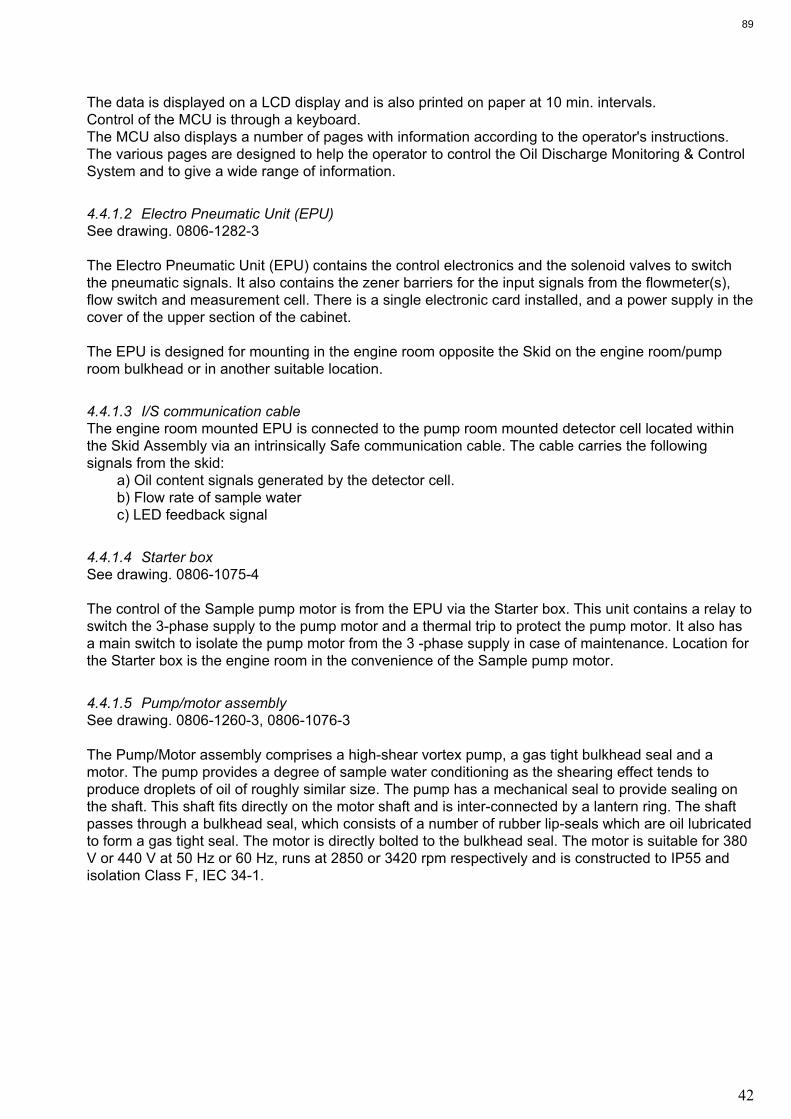
42
The data is displayed on a LCD display and is also printed on paper at 10 min. intervals.
Control of the MCU is through a keyboard.
The MCU also displays a number of pages with information according to the operator's instructions.
The various pages are designed to help the operator to control the Oil Discharge Monitoring & Control
System and to give a wide range of information.
4.4.1.2 Electro Pneumatic Unit (EPU)
See drawing. 0806-1282-3
The Electro Pneumatic Unit (EPU) contains the control electronics and the solenoid valves to switch
the pneumatic signals. It also contains the zener barriers for the input signals from the flowmeter(s),
flow switch and measurement cell. There is a single electronic card installed, and a power supply in the
cover of the upper section of the cabinet.
The EPU is designed for mounting in the engine room opposite the Skid on the engine room/pump
room bulkhead or in another suitable location.
4.4.1.3 I/S communication cable
The engine room mounted EPU is connected to the pump room mounted detector cell located within
the Skid Assembly via an intrinsically Safe communication cable. The cable carries the following
signals from the skid:
a) Oil content signals generated by the detector cell.
b) Flow rate of sample water
c) LED feedback signal
4.4.1.4 Starter box
See drawing. 0806-1075-4
The control of the Sample pump motor is from the EPU via the Starter box. This unit contains a relay to
switch the 3-phase supply to the pump motor and a thermal trip to protect the pump motor. It also has
a main switch to isolate the pump motor from the 3 -phase supply in case of maintenance. Location for
the Starter box is the engine room in the convenience of the Sample pump motor.
4.4.1.5 Pump/motor assembly
See drawing. 0806-1260-3, 0806-1076-3
The Pump/Motor assembly comprises a high-shear vortex pump, a gas tight bulkhead seal and a
motor. The pump provides a degree of sample water conditioning as the shearing effect tends to
produce droplets of oil of roughly similar size. The pump has a mechanical seal to provide sealing on
the shaft. This shaft fits directly on the motor shaft and is inter-connected by a lantern ring. The shaft
passes through a bulkhead seal, which consists of a number of rubber lip-seals which are oil lubricated
to form a gas tight seal. The motor is directly bolted to the bulkhead seal. The motor is suitable for 380
V or 440 V at 50 Hz or 60 Hz, runs at 2850 or 3420 rpm respectively and is constructed to IP55 and
isolation Class F, IEC 34-1.
89

43
4.4.1.6 Skid aseembly
See drawing. 0806-1280-3
The Skid Assembly contains the necessary items to handle the sampled ballast water and to measure
the oil content. In the Skid Assembly there is a pneumatically operated shuttle valve, (4) and a window
wash pump (1).
The shuttle valve selects between fresh water, forward or backward flush and sample water.
Also contained within the Skid Assembly is the detector cell which contains the electronic sensing
system to determine oil content. On the left hand side of the Skid Assembly is the Window Wash pump
(1). This is a pneumatically operated pump which provides a 10 to 1 pressure boost to the window
flushing water. Also included in the Skid Assembly is a flow setting valve (3), which sets a back
pressure on the Sample pump and a magnetic flow sensor (2) to determine flow through the Skid
assembly.
The Skid Assembly is normally mounted in the pump room opposite the EPU on the engine room side
of the bulkhead.
4.4.1.7 Flowmeter system
The flow metering system is shown in drawing. 0806-8016-3
The flow of water through the orifice plate causes a pressure difference across the plate. This
differential pressure is converted into a mA signal and transmitted to the EPU by the dP/I transmitter.
The manifold valve block fitted to the differential pressure transmitter, has three shut-off valves. The
two outer valves are for blocking off the pressure sensing lines from the sensor. The centre valve
serves as equalizing valve to balance the pressure at both sides of the transmitter.
See drawing 0806-8038 for configurating of combined or separated system.
4.4.1.8 Sample probe valve assembly
See drawings 0806-1265-4, 0806-1077-4 and 0806-1268-4
For taking a representative sample of the ballast water to measure the oil level content a sample probe
valve assembly is provided for. It comprises:
- a probe, for penetration in the selected discharge line;
- a gate valve, for manual closure upon completion of monitoring;
- a pneumatic valve, for remote selection of the discharge line, so the line can be changed whilst the
monitor is in operation.
90

44
4.4.2 Principle of operation
The measurement technique used in the Oilcon® Oil Discharge Monitoring & Control System is based
on scattered light. The sample of discharge water passes through a detector cell while light enters and
leaves the measurement area of the cell. The sample flow is at right angles to the optical path. When
no particles or oil droplets are present in the water, light can pass straight through the cell (Direct
beam). When oil is present in the form of a homogeneous mixture, light is scattered at different angles
(Scatter beam). The intensity of scattered light at a specific angle depends on the density of oil
droplets and upon their particle size relative to the wavelength of radiation. The intensity of light of the
direct beam decreases logarithmically with increasing oil concentration, while the scatter beam
increases linearly but passes through a maximum before decreasing logarithmically, see drawing.
0806-1622. The maximum occurs because of the increase in attenuation blocking out the scattered
light at high concentrations. The variation of light refraction by oil droplets only is quite different to that
refracted when solid contaminants are also present and this fact can be used to obtain an accurate
indication of oil content whilst disregarding solid particles up to a point.
The light source used in the Oilcon® Oil Discharge Monitoring & Control System is a near infra red
diode which is operated in the pulsed mode so that the average power dissipation is very low, although
the intensity is high. The light signal is processed and transmitted along a communication cable from
the detector cell to the EPU where the three detection signals are used to compute the oil
concentration levels present in the sample passing through the detector cell.
The response in the optical detection is instantaneous and most of the delays when reading oil levels
lie in the sampling pipework. High velocity, short sampling length and minimum pipework bends give
fast response times. During periods of inactivity the pipework may become fouled and when the
system is started up, erroneous readings could occur as oil is stripped from the pipework. Automatic
sequential control of forward and backward flushing at start up and shut down of the monitor prevents
erroneous readings and keeps the sampling lines clean. This also ensures reliable start up, minimises
system deterioration and ensures that the pipework is left in clean condition prior to the next use of the
monitor. At the end of the start up flushing cycle a system zero check is performed, this automatic zero
setting compensates for any small deposits on the cell windows. The window wash pump cleans the
cell windows at regular intervals.
All operating controls and system alarms are situated on the MCU. Manual system flush and window
wash controls are available to make these two operations possible at any time. With the exception of
selecting the sample point and the oil type, the system works automatically once sampling has been
initiated. The oil level together with the discharge flow rate and ships speed are input to the MCU to
give a permanent record of oil discharged overboard. Both calibration alarms and operational alarms
are provided and the alarm philosophy employed follows normal marine practice. When a fault occurs,
both audible and visual alarms are activated. The audible alarm can be silenced by fault acceptance
but the visual alarm cannot be extinguished. It is only after the fault has been rectified that the visual
alarm is extinguished. Should a second alarm occur during this sequence, both audible and the visual
alarms would be reactivated.
4.4.3 Sampling system arrangements
A suggested installation configuration of the Oil Discharge Monitoring & Control System is given in
drawing. 0806-8035-3. Up to 6 sampling points can be catered for, although most ships will have much
less than this. The total number of valves that are contained in the system is depending on the
particular configuration on the ship.
91

45
The sample point is selected from the MCU in the Ships Cargo Control Room; this causes the selected
valve to open. When the system is in Sample mode, water is drawn from the sample point by the
sample pump, passed through the detector cell and then discharged to the slop tank or discharged
overboard, depending on the installation.
The accuracy of the monitor is improved by the use of a flushing sequence before sampling
commences, at intervals during sampling and when the system is shut down after use. All the flushing
sequences are carried out automatically by the system. The flushing sequences serve three purposes:
- to clean the pipework; - to keep the detector cell windows clean, which keeps the optical path un-
obscured and to perform a zero check every time a flush sequence is activated. The flushing
sequences can be operated manually from the MCU, if required.
The Skid Assembly, see drawing. 0806-1280-3, contains a pneumatically operated shuttle valve, which
facilitates the forward flush and backward flush. During the automatic flushing sequences on start up,
and on shut down, the valve activates to flush all the pipework using the fresh water supply and
sequentially selects between backward and forward flush. When the manual flush is operated, valve
activates to allow fresh water into the system and an additional zero check is performed.
Every three minutes during sampling, an automatic cleaning of the windows in the detector cell is
carried out. A pneumatic pump mounted in the Skid Assembly supplies high pressure fresh water
which is sprayed across each window. It will be noticed that the window wash sequence is indicated on
the MCU by "MODE SAMPLE WW".
The use of fresh water for these sequences means that it is important, for correct operation of the Oil
Discharge Monitoring & Control System, that an un-interrupted supply of fresh water is available. The
fresh water used must be free of any contaminants.
The typical installation in drawing 0806-8035-3 shows a number of manual valves. These are used for
isolation of the system for maintenance purposes. The valves are:
a) fresh water pressure reducing / isolator valve;
b) sample discharge valve skid;
d) isolation valve to slop tank
* YARD SUPPLY* (usually a non-return valve as the slop tank will have pressure due to Inert Gas
system);
e) sample grab cock mounted on the sample pump discharge.
f) injection point ( for onboard calibration by Approved Service Engineer)
Note:
There is an unmarked valve inside the Skid Assembly on the outlet side of the measurement cell.. This
valve is used to provide back pressure for the sample pump. If the valve is open fully, there will be little
or no back pressure on the pump, so the pump could cavitate and this would cause erroneous reading
of oil content. The correct setting for the valve is almost closed; in this position the pump discharge will
be in the region of 450 -550 litres per hour. The flow can be checked by pressing “SCROLL” on the
MCU during either forward flush or sample modes which will then temporarily display the flow rate. A
precise setting of the valve is not necessary.
92

46
4.4.4 System operations
Operation of the Oil Discharge Monitoring & Control System is controlled from, and recorded by the
MCU.
A diagrammatic representation of the control panel of the MCU, as fitted in the Cargo Control Room, is
given in drawing. 0806-1278-3. The MCU control panel contains the following:
(i) LCD Display
- acts as the major interface between machine and operator, and displays all relevant information;
dd/mm/yy hh:mm SAMP.PNT 1 MODE SAMPLE
CONC ppm M DISCH l/nm
FLOW T/h M TOT.OIL l
SPEED kts M V/V COM:C POS:C OIL:1
(ii) Control switch
- "Off" - the display is blanked and the MCU goes to a quiescent state where the only active electronic
circuit is the battery backed clock/calendar;
Note: do not attempt to service the equipment in this mode, see Maintenance section 4.7;
- "Control Unit" – (CTRL) in this position the MCU is in the normal operational mode, automatically
controlling the ballast discharge system if automatic control is fitted;
- "Console" – (CNSL) in this position the MCU is in normal operational mode but manual control of the
ballast discharge system is provided from the cargo console;
(iii) Keyboard
- the operator can communicate with the equipment by using the keyboard. All inputs from the
keyboard are displayed on the LCD display. The keys are as follows;
- [WINDOW WASH] initiate a manual Window Wash;
- [FLUSH] initiate a manual Flush and calibration check;
- [STOP MONITOR] stop operation;
- [ALARM RESET] silences the audible alarm and displays the cause of the
alarm situation;
- [SCROLL] display the next page;
- [CHANGE] change a system setting;
- [CLEAR] clear the value of a display setting;
- [ENTER] enter a system setting;
- [ > ] select Set Up when in Standby mode, or select Sample
when in Idle mode;
- [ ? ] enter the Help mode;
- [ DARK] reduces the brightness of display back-lighting
- [ BRIGHT] increases the brightness of display back-lighting
- the numeric key's are used to enter the numeric values for the system settings.
(iv) Printer
93

47
Note:
According to the Regulations a printed record of the entire ballast water discharge operation must be
kept on board the vessel for at least 3 years.
The printer in the MCU provides a printout at the following intervals;
- at the start and at the end of the de-ballasting operation;
- at ten minutes intervals (or less, if set by the operator);
- at the occurrence of any alarm;
- if automatic or manual mode is selected;
- any fault of out of range inputs from the transducers;
- if any of the system settings is changed;
- if the front panel key-switch is operated;
- if the discharge rate changes by more than 10 l/nm.
- if an alarm situation is cleared
During normal operation, the data printed will be shown on the display. Each time a printout takes
place an appropriate message is printed at the top of the printout to explain why the printout has
occurred. The message takes the form;
During normal operation, the data printed will be shown on the display. Each time a printout takes
place an appropriate message is printed at the top of the printout to explain why the printout occurred.
The messages can take any of the following forms;
- ALARM PRINTOUT: - DISCHARGE RATE INCREASING:
- TIME INTERVAL REPORT : - CONTROL MODE REPORT :
- CONSOLE MODE REPORT : - MANUAL TO AUTO CHANGE :
- MANUAL DATA ENTERED : - OIL TYPE CHANGE :
- DISCHARGE VALVE OPEN : - DISCHARGE VALVE CLOSED :
- DISCHARGE PROHIBITED:
Examples of printouts:
Printout generated at the end of SET UP mode;
CONTROL MODE REPORT
04/05/02 12;50 UTC
N053 DEG 21.090 MIN
E007 DEG 10.485 MIN
A OIL CONTENT: 0 PPM
A SHIP SPEED: 11 KNOTS
A FLOW RATE: 123 T/HR
DISCHARGE RATE: 0 L/NM
OIL DISCHARGED: 22 L
SAMPLE VALVE NO.:
OIL TYPE: 1
COMMAND: CLOSED
STATUS : CLOSED
94

48
DATA ENTRY PARAMETERS
PRINT INTERVAL: 10 MINS
DISCHARGE LIMIT: 30 L/NM
TOTAL OIL LIMIT: 850 L
SAMPLE VALVE NO.: 1
RESET DISCHARGE: NO
DISCHARGE PROHIBITED
Printout generated during normal operation;
TIME INTERVAL REPORT
04/05/02 13:15 UTC
N053 DEG 21.090 MIN
E007 DEG 10.485 MIN
A OIL CONTENT: 188 PPM
A SHIP SPEED: 11 KNOTS
A FLOW RATE: 375 T/HR
DISCHARGE RATE: 6 L/NM
OIL DISCHARGED: 22 L
SAMPLE VALVE NO.: 1
OIL TYPE: 1
COMMAND: OPEN
STATUS: OPEN
Printout generated in case of an alarm for example an oil level alarm.
ALARM PRINTOUT
04/05/02 13:45 UTC
N053 DEG 21.090 MIN
E007 DEG 10.485 MIN
A OIL CONTENT: 940 PPM
A SHIP SPEED: 11 KNOTS
A FLOW RATE: 375 T/HR
DISCHARGE RATE: 32 L/NM
OIL DISCHARGED: 39 L
SAMPLE VALVE NO.: 1
OIL TYPE: 1
COMMAND: CLOSED
STATUS: CLOSED
THE FOLLOWING ALARMS
HAVE OCCURRED: DISCHARGE RATE OVER SET LEVEL.
95

49
Printout generated in case of an alarm situation being cleared.
ALARM PRINTOUT
04/05/02 13:02 UTC
N053 DEG 21.090 MIN
E007 DEG 10.485 MIN
A OIL CONTENT: 902 PPM
A SHIP SPEED: 11 KNOTS
A FLOW RATE: 175 T/HR
DISCHARGE RATE: 14 L/NM
OIL DISCHARGED: 40 L
SAMPLE VALVE NO.: 1
OIL TYPE: 1
COMMAND: OPEN
STATUS: OPEN
THE FOLLOWING ALARMS HAVE
BEEN CLEARED: OIL CONTENT OVER SET LEVEL.
Printout generated at end of SET UP mode for a clean ballast discharge.
CONTROL MODE REPORT
05/05/02 12;50 UTC
N053 DEG 21.090 MIN
E007 DEG 10.485 MIN
A OIL CONTENT: 0 PPM
A SHIP SPEED: -- KNOTS
A FLOW RATE: --- T/HR
CLEAN BALLAST DISCHARGE
SAMPLE VALVE NO.: 2 # (or 6 see Section 3, items 15, 16)
OIL TYPE: 1
COMMAND: CLOSED
STATUS: CLOSED
DATA ENTRY PARAMETERS
PRINT INTERVAL: 10 MINS
DISCHARGE LIMIT: 30 L/NM
TOTAL OIL LIMIT: 850 L
SAMPLE VALVE NO: 2 #
RESET DISCHARGE: NO
DISCHARGE PROHIBITED
96

50
Printout generated during normal clean ballast discharge operation;
TIME INTERVAL REPORT
04/05/02 13:15 UTC
N053 DEG 21.090 MIN
E007 DEG 10.485 MIN
A OIL CONTENT: 10 PPM
A SHIP SPEED: -- KNOTS
A FLOW RATE: --- T/HR
CLEAN BALLAST DISCHARGE
SAMPLE VALVE NO.: 2 #
OIL TYPE: 1
COMMAND: OPEN
STATUS: OPEN
Printout generated during alarm of clean ballast discharge operation;
TIME INTERVAL REPORT
04/05/02 13:15 UTC
N053 DEG 21.090 MIN
E007 DEG 10.485 MIN
A OIL CONTENT: 20 PPM
A SHIP SPEED: -- KNOTS
A FLOW RATE: --- T/HR
CLEAN BALLAST DISCHARGE
SAMPLE VALVE NO.: 2 #
OIL TYPE: 1
COMMAND: CLOSED
STATUS: CLOSED
THE FOLLOWING ALARMS
HAVE OCCURED: OIL CONTENT OVER SET LEVEL.
# : Valve number will either be 2 or 6 depending upon system configuration, 2 or max. 6 sample valve
version.
97

51
4.4.4.1 System over-rides
The MCU provides a number of output signals to allow flexible means of controlling the ballast water
discharge system. Two outputs are under the direct control of the MCU and these are used to
automatically control the discharge system -to stop the discharge when the alarm points are reached
and to permit discharge when the discharge rate of oil is within limits. Over-riding of the MCU should
only be considered if the MCU itself has failed or if special circumstances prevail.
There may be occasions when it is imperative to over-ride the control signal from the MCU to the
ballast discharge system, if automatic control is fitted. The control switch on the MCU front panel has a
position marked 'Console' with the switch in this position the automatic control is over-ridden, which
means that the control of the valves, pumps ect. in the ballast discharge system has reverted to the
cargo control room console. In the position marked 'Control Unit', control of the ballast discharge
system is entirely from the MCU. The fact that the switch has been operated will be printed on the
printer.
4.4.4.2 Transducer over-ride
On occasions, one of the three transducers in the system (Oil discharge Monitoring & Control System,
ship's log or discharge flow meter) may be defective. For this situation, the input of these transducers
can be changed from Auto to Manual. This can be done by entering the Set Up mode or the Extra Set
Up mode and selecting the required input signal. The input mode is indicated alongside the input by 'A'
for automatic and by 'M' for manual. The mode can be changed by pressing [CHANGE]. In manual
mode the value for that input must be entered with the numeric key's. Any of the 3 inputs and any
combination of these inputs can be set to manual. Any change of mode from automatic to manual or
vice-versa will be recorded on the printer.
4.4.4.3 Discharge control
The main purpose of the MCU is to control the discharge of ballast water overboard. The MCU controls
an internal relay which, when suitably connected, can be used to open or close an overboard valve, or
start and stop a cargo pump. The specific installation on any ship may vary.
The position of this internal relay is shown on the display on 'V/V COM:' and is either 'O' (open) or 'C'
(closed). The relay will be closed when;
- the Oil Discharge Monitor is switched off, or is self-flushing;
- when the discharge rate exceeds 30 l/nm;
- when the Total Oil discharged exceeds 1/30,000 of the last cargo carried;
- should there be any other alarm displayed on the MCU.
When the monitor has completed the Flush cycle and has switched to sample, there will be a 10
second delay before 'V/V COM:' changes to open. If the discharge is being restarted after an alarm
condition, then there will be a 2 minute delay after the alarm has been cleared before the 'V/V COM:'
changes to 'O'(open).
98

52
4.4.4.4 Discharge control answer-back
It is necessary for the MCU to know if the command output has been obeyed correctly. Hence, an input
is provided to signal the 'status' of the discharge control system. The input could be, for example, from
a micro switch on the overboard valve. The answer-back is shown on the display as 'POS:' and status
is shown as 'O' (open) or 'C' (closed).
If the MCU is in 'Control' mode and the command and status indications do not agree, after 2 minutes,
the 'status' indication will flash "ERROR" to indicate a fault. The overboard valve command will then be
'CLOSE'.
The Discharge Rate and Total Oil Discharged calculations are performed once the status is open. This
means that if the overboard valve is opened even when the command signal is to close the valve, then
the normal calculation will be carried out and the amount of oil discharged will be recorded.
99

53
4.5 OPERATION
4.5.1 Operation instructions
CAUTION:
No adjustments should be made to the electronic units prior to operation. Use of
controls or adjustments or performance of procedures other than those specified
herein may result in hazardous radiation exposure.
NOTE CAREFULLY:
On this system the screen will not acknowledge any change of input data until the
printer has printed the last input information.
4.5.1.1 Modes of operation
The MCU has several modes of operation which are; Standby, Set up, Flush, Idle, Sample, Automatic
Window Wash, Manual Window Wash, Manual Flush, Shutdown, Extra Set up, Clean Ballast
Discharge, Help and Configuration. These modes are either selected automatically or by the operator
via the keyboard.
4.5.1.2 Standby modes
The Standby mode is automatically selected after switching 'ON' (Key switch to “Control” [CTRL]
position) the system and is also automatically entered after performing the Shutdown flush sequence
or when in Set Up mode [STOP MONITOR] is pressed. In Standby mode the system is waiting for
manual input from the operator which can be:
a) press [>], to enter the Set Up mode and start operation;
b) press [SCROLL], to select the Self-test mode;
c) switching 'OFF' to stop operation.
4.5.1.3 Set up mode
The Set Up mode is used to set up the system before a discharge run can take place. The settings
which can be selected are:
a) Time and date;
b) Discharge rate;
c) Total Oil limit;
d) Reset Total Oil;
e) Sample point selection;
f) Oil type selection;
g) Oil concentration alarm;
h) Printer interval time;
i) Ships speed input mode (auto/man);
j) Discharge flow rate input mode (auto/man);
k) Oil content input mode (auto/man).
l) Selection of ships speed (using GPS/Speed log)
100

54
These settings are displayed sequentially and can be selected by pressing [ENTER]. In the display is
indicated which keyboard actions can be executed to change or input the correct value for that setting.
Once the Set Up is completed, which is indicated in the display, there are three possible actions:
a) press [ > ], to check the Set Up settings;
b) press [ENTER], to initiate the Flush mode and continue operation;
c) press [STOP MONITOR], to stop operation and return to Standby mode.
4.5.1.4 Flush mode
The Flush mode is used to clean the system prior to sampling and to check the condition of the
detector cell and the system. This mode consists of a 2 minute Backward flush, a 2 minute Forward
flush and calibration. If no failures are detected the system will select the Idle mode after completion of
the flush.
4.5.1.5 Idle mode
From this point there are four possible keyboard actions:
a) press [ > ], to select the Sample mode and continue operation;
b) press [STOP MONITOR], to initiate the Shutdown flush and return the system to Standby mode;
c) press [CHANGE], to enter the Extra Set Up mode to change the system settings;
d) press [SCROLL], to select the Self test mode.
4.5.1.6 Sample mode
In this operational mode the overboard discharge of ballast water is continuously monitored for oil
content and the discharge rate is controlled. If an alarm situation occurs the ballast water will
automatically be diverted from overboard to the slop tank to prevent any oil contamination. During the
sample mode an automatic Window Wash takes place every 3 minutes to keep the detector cell in an
optimal condition. There are four possible keyboard actions during the Sample mode.
a) press [WINDOW WASH], to initiate a Manual Window Wash;
b) press [FLUSH], to initiate a Manual Flush and calibration check. However during Manual Flush the
ballast water is diverted to the slop tank instead of discharged overboard;
c) press [STOP MONITOR], to return to Idle mode;
d) press [SCROLL], to select the Self test mode.
4.5.1.7 Shutdown modes
The shutdown mode is used to clean the piping of the Oil Discharge Monitoring & Control System prior
to a final stop of operation, thus leaving the system in a clean condition for the next discharge run. The
Shut down mode is entered when in Idle mode [STOP MONITOR] is pressed. In this mode a 2 minute
Backward and 2 minute forward flush are performed.
101

55
4.5.1.8 Extra set up mode
This mode can only be entered when in Idle mode [CHANGE] is pressed. In this mode the following
system settings can be changed;
a) Sample point selection;
b) Oil type selection;
c) Discharge rate;
d) Oil concentration alarm;
e) Ships speed input mode (auto/manual);
f) Discharge flow rate input mode (auto/manual);
g) Oil content input mode (auto/manual);
These settings can be selected by pressing [ENTER] and will be displayed sequentially.
The system will automatically return to Idle mode when [ENTER] is pressed after the last setting
selection or 15 seconds after the last keyboard action.
4.5.1.9 Clean ballast discharge
This mode can be entered by selecting during set-up the highest numerical sample point available on
the system. The operator enters the sample point as the highest numerical one available on the
system. The system then switches automatically over to CLEAN BALLAST DISCHARGE mode.
In this mode the ships speed and overboard discharge flow input parameters are not computed, and
only the oil content is registered. The maximum oil content permissible in this mode is 15ppm.
4.5.1.10 Help mode
The Help mode can be entered by pressing [ ? ] and give additional information about system
operation and operational actions which can be taken if an alarm situation occurs.
To return to the normal operational mode press [CLEAR].
4.5.1.11 Configuration mode
The Configuration mode is used to set up the system during installation and this should only be done
by a trained service engineer.
102

56
4.5.2 Operation instruction
4.5.2.1 Start-up – Dirty ballast discharge
Note:
The Oil Discharge Monitoring & Control System must be operated as directed under the regulations
given in Marpol 73/78, to prevent discharge of oil-contaminated water overboard. Where instructions in
this manual may apparently conflict with the Marpol requirements, then at all times the Marpol
regulations must be favoured.
CAUTION:
UNDER NO CIRCUMSTANCES MUST THE PUMP BE RUN WITHOUT LIQUID. THE
PUMP CASING MUST BE FILLED WITH LIQUID FIRST OTHERWIZE THE PUMP
WILL SEIZE AND DAMAGE WILL OCCUR.
Before operating the system ensure that the following conditions are met:
a) control air supply is on;
b) fresh water supply is on;
c) electrical supplies are on;
d) MCU is switched on;
e) EPU is switched on;
f) starter box is switched on;
g) all manual valves in the system are open;
h) cargo pump is on stand by;
i) check if sufficient paper is available in printer.
* Switch on Main Control Unit (MCU) to 'Control Unit'.
Display of MCU indicates 'MODE STANDBY'.
* Press [ >].
Time and date is displayed.
If correct, proceed with the next step.
If not correct, press [CHANGE] and follow the actions as indicated in the display.
* Press [ENTER].
Discharge rate is displayed.
If correct, proceed with the next step.
If not correct, press [CHANGE] and follow the actions as indicated in the display.
* Press [ENTER]
Total oil limit is displayed.
If correct, proceed with the next step.
If not correct, press [CHANGE] and follow actions as indicated in the display.
* Press [ENTER]
"Reset Oil Total?" is displayed.
If not, proceed with the next step.
If yes, press [CHANGE] and follow the actions as indicated in the display.
WARNING: It is only permissible to reset the Total Oil discharged at the start of a new ballast
voyage.
103

57
* Press [ENTER]
Sample point selection is displayed.
If correct sample point, proceed with next step.
If not correct, press [CHANGE] and follow the actions as indicated in the display.
* Press [ENTER]
Oil type selection is displayed.
If correct oil type, proceed with the next step.
If not correct, press [CHANGE] and follow the actions as indicated in the display.
* Press [ENTER]
Oil concentration alarm setting is displayed.
If alarm setting is correct, proceed with the next step.
If not correct, press [CHANGE] and follow the actions as indicated in the display.
* Press [ENTER]
Printer interval time is displayed.
If correct interval time, proceed with the next step.
If not correct, press [CHANGE] and follow the actions as indicated in the display.
WARNING: according to regulations the maximum printing interval is 10 minutes.
* Press [ENTER]
Ships speed input mode (Auto/Manual) is displayed.
If correct input mode, proceed with the next step.
If not correct, press [CHANGE] and follow the actions as indicated in the display.
* Press [ENTER]
Discharge flow rate input mode (Auto/Manual) is displayed.
If correct input mode, proceed with the next step.
If not correct, press [CHANGE] and follow the actions as indicated in the display.
* Press [ENTER]
Oil content input mode (Auto/Manual) is displayed.
If correct input mode, proceed with the next step.
If not correct, press [CHANGE] and follow the actions as indicated in the display.
* Press [ENTER]
Input mode for source of ship speed is displayed.
(Using ships log speed / Using GPS speed)
If correct, proceed with next step.
If not correct, press [CHANGE] and follow the actions as indicated in the display.
Note:
The use of GPS for ships speed requires an approved type of GPS.
* Press [ENTER]
The SET-UP sequence is now completed.
To continue monitoring, proceed with the next step.
To check SET-UP of the system, press [ >].
To stop monitoring and go into STANDBY, press [STOP MONITOR].
104
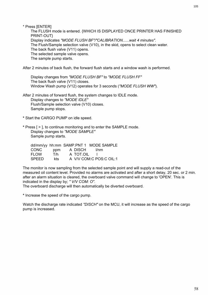
58
* Press [ENTER]
The FLUSH mode is entered. {WHICH IS DISPLAYED ONCE PRINTER HAS FINISHED
PRINT-OUT}
Display indicates "MODE FLUSH BF"/"CALIBRATION......wait 4 minutes".
The Flush/Sample selection valve (V10), in the skid, opens to select clean water.
The back flush valve (V11) opens.
The selected sample valve opens.
The sample pump starts.
After 2 minutes of back flush, the forward flush starts and a window wash is performed.
Display changes from "MODE FLUSH BF" to "MODE FLUSH FF"
The back flush valve (V11) closes.
Window Wash pump (V12) operates for 3 seconds ("MODE FLUSH WW").
After 2 minutes of forward flush, the system changes to IDLE mode.
Display changes to "MODE IDLE"
Flush/Sample selection valve (V10) closes.
Sample pump stops.
* Start the CARGO PUMP on idle speed.
* Press [ > ], to continue monitoring and to enter the SAMPLE mode.
Display changes to "MODE SAMPLE"
Sample pump starts.
dd/mm/yy hh:mm SAMP.PNT 1 MODE SAMPLE
CONC ppm A DISCH l/nm
FLOW T/h A TOT.OIL l
SPEED kts A V/V COM:C POS:C OIL:1
The monitor is now sampling from the selected sample point and will supply a read-out of the
measured oil content level. Provided no alarms are activated and after a short delay, 20 sec. or 2 min.
after an alarm situation is cleared, the overboard valve command will change to 'OPEN'. This is
indicated in the display by; " V/V COM: O".
The overboard discharge will then automatically be diverted overboard.
* Increase the speed of the cargo pump.
Watch the discharge rate indicated "DISCH" on the MCU, it will increase as the speed of the cargo
pump is increased.
105

59
Note:
If the discharge rate approaches the maximum permissible (i.e. 30 l/nm), it can be reduced by slowing
down the cargo pump.
The system is now operating fully automatically. If any of the permitted limits are exceeded or if any
other alarms are activated, an alarm will be given, the ballast will be diverted to the slop tank and the
printer will record.
When the Oil Discharge Monitoring & Control System is running normally, the oil content will be
displayed. At regular intervals a record of the monitor status is printed, which will build up to give a
complete printed record of the ballast discharge. Whenever there is a discharge overboard the Total
Oil Discharged will be incremented.
Every 3 minutes the window wash will operate automatically. This is indicated in the display by "MODE
SAMPLE WW". During the operation extra manual window flushing can be carried out, if required by
pressing [WINDOW WASH].
If it is suspected that the detector cell is particularly dirty, extra cleaning can be carried out by pressing
[FLUSH]. It should be noted however, that this will cause the discharge overboard to be stopped
automatically. The monitor will not be measuring the discharge overboard whilst flushing.
4.5.2.2 Shutdown
To stop operation the following steps should be performed;
* Stop cargo pumps.
* Press [STOP MONITOR]
Display changes from "MODE SAMPLE" to "MODE IDLE"
The overboard valve command changes from "V/V COM: O" to "V/V COM: C".
The sample pump stops.
* Press [STOP MONITOR]
The SHUTDOWN mode is started. This is an automatic flush sequence to clear the pipework of oil
contaminated water, leaving the monitor clean for the next time it is used.
Display indicates "MODE SHUTD BF"
The Flush/Sample selection valve (V10) opens to select clean water.
The back flush valve (V11) opens.
The selected sample valve opens.
The Sample pump starts.
After 2 minutes of back flush the system changes to the forward flush mode
Display indicates "MODE SHUTD FF"
The back flush valve (V11) closes.
The Window Wash pump (V12) operates for 3 seconds. ("MODE SHUTD WW").
106

60
After 2 minutes of forward flush the system changes to STANDBY mode
Display indicates "MODE STANDBY".
All valves are closed.
The sample pump is stopped.
* Switch the MCU to "OFF".
The system is now shut off. All manual valves in the system may be closed and all auxiliaries may be
shut off. The only active electronics will be the clock/calendar and the overboard valve position control.
If for any reasons there is a change in the overboard valve position from CLOSE to OPEN or vice
versa, a printout is made to record the event.
4.5.3 Miscellaneous
This section is to describe the problems that may be encountered during operation, and the suggested
reasons.
4.5.3.1 Oil content reading higher than expected
During a normal discharge run of ballast water the ppm reading should be around 50 to 150 ppm
assuming that sufficient time has been left to allow the oil to settle out in the tank.
The reading should be steady for most of the duration of discharge. If the reading is varying rapidly
with large excursions, it is likely that air is being entrained into the ballast water. This could be due to a
partly filled overboard line, a cavitating cargo pump or a low suction pressure on the monitor sample
pump casing causing air to enter the pump.
If the ppm reading is consistently high press [FLUSH]. This will cause the monitor to run on fresh water
for a short time. The ppm reading should therefore go down to zero.
Note:
Operation of the [FLUSH] key will signal the MCU to stop the discharge overboard, since the monitor is
no longer sampling the ballast water.
Once the calibration check is completed the monitor will return to sampling the ballast water. If reading
returns to it's previous level, then it is sure that the reading is accurate.
If there is any further doubt, the only solution is to stop the monitor and restart it again thereby forcing it
to complete a full flushing cycle.
4.5.3.2 Oil level alarm
During a normal ballast discharge, the ppm reading should be quite low probably in the region of
between 50 and 150 ppm, as the main bulk of the ballast tank is decanted. During this time, the rate of
discharge in litres per nautical mile as calculated by the MCU, will also be steady and remain within the
permitted limits. Obviously, as the level in the tank falls, there comes a time when the reading on the
monitor will start to rise, as oil is stripped from the layer on the surface. It is difficult to predict at what
depth of water this will occur due to a number of reasons:
107

61
- how long the tank had been left to settle;
- whether or not heating has been applied;
- whether conditions during discharge;
- type of oil being carried.
However, it is true to say that the entraining of oil into the tank suction occurs when an appreciable
level of separated water remains in the tank. The oil is pulled down from the oil-water interface due to
swirling in tanks, powerful cross currents between the frames and wier-ing over frames. This is all
caused by a high rate of pumping. To reduce this effect and to allow a greater quantity of water to be
pumped out, the rate of pumping must be reduced. This will have the effect of reducing the amount of
oil entrained, and the ppm reading should therefore fall.
In this way, the monitor can be used as an accurate means of sensing the oil-water interface and
ensuring that the maximum amount of water is discharged. If the 'oil level' alarm should sound, reduce
the pumping rate until the ppm reading falls and becomes steady. After a time the reading will rise
again. Reduce the pumping rate further to let the ppm reading fall again. Repeat this cycle until the
pumping reaches the oil-water interface at which time the ppm reading will rise rapidly and go over
scale. The discharge will now be complete. Considerably more water will have been discharged using
this technique, although it will have increased the time taken to discharge the ballast water.
4.5.4 Alarms
Note:
At all times the Oil Discharge Monitoring & Control System must be operated as directed by MARPOL
73/78 to prevent discharge of oil contaminated water overboard.
There are necessarily a number of alarm conditions in the MCU. Irrespective of what caused the alarm,
the result is the same. The letters 'ERR' or 'FLT' will appear on the display alongside whatever caused
the alarm. Also an internal buzzer will sound. A control signal will be sent to stop the ballast water
discharge.
Should any alarm occur during normal operation, press [ALARM RESET]. This will silence the audible
alarm. The display will give a message about the cause of the alarm. Pressing [ ? ] will give a help text
about the cause of the alarm and actions that can be taken to correct the situation. To return to normal
display press [CLEAR].
However the fault must be cleared before any discharge of ballast can take place.
4.5.4.1 No air
If for any reason there is no air supply to the Oil Discharge Monitoring & Control System the NO AIR
alarm is activated.
The alarm is indicated alongside the oil concentration indication; 'CONC ERR ppm'
The system will then return to Standby mode. Consult the Help mode of the MCU or Fault Finding
Section 4.6. of this manual, for corrective actions.
108

62
4.5.4.2 No flow
If for any reason there is no flow through the Oil Discharge Monitoring & Control System the NO FLOW
alarm is activated. The alarm is indicated alongside the oil concentration indication; 'CONC ERR ppm'.
The Sample pump will be stopped automatically to prevent any damage to the pump or motor.
If in Flush or Shutdown mode the system will return to Standby mode. When in Sample mode the
system will go to the Idle mode. Consult the Help mode of the MCU or Fault Finding Section 4.6, of this
manual, for corrective actions.
4.5.4.3 Zero error
During the calibration check of the Oil Discharge Monitoring & Control System, during Flush or Manual
Flush mode, the ZERO ERROR alarm can be activated if the flushing water is dirty, oily or if it contains
air. The alarm is indicated alongside the oil concentration indication; 'CONC ERR ppm'.
The system will go to Idle mode and from there only the Shutdown mode can be selected, to resume
operation after the fault is cleared. Thus a restart is made from Standby. Consult the Help mode of the
MCU or Fault Finding Section 4.6. of this manual, for corrective actions.
4.5.4.4 Path dirty
During the calibration check of the Oil Discharge Monitoring & Control System the PATH DIRTY alarm
can be activated if the optical path between the laser transmitter and the direct receiver is obscured.
The alarm is indicated alongside the oil concentration indication; 'CONC ERR ppm'.
The system will go to Idle mode and from there only the Shutdown mode can be selected, to resume
operation after the fault is cleared. Thus a restart is made from Standby. Consult the Help mode of the
MCU or Fault Finding Section 4.6, of this manual, for corrective actions.
4.5.4.5 Power/communication failure
If during operation of the Oil Discharge Monitoring & Control System a fault develops in the
communication link between the MCU and the EPU or a power failure condition occurs, then the
POWER/COMMUNICATION FAILURE alarm is activated. The alarm is indicated alongside the oil
concentration indication; 'CONC ERR ppm'.
The system will go to the Shutdown mode followed by Standby. However during such a situation the
emergency power supply will take over, thus no data will be lost. Consult the Help mode of the MCU or
Fault Finding Section 4.6. of this manual, for corrective actions.
4.5.4.6 Watchdog
If during operation a fault condition occurs in the program of the Oil Discharge Monitoring & Control
System the WATCHDOG is activated. The alarm is indicated alongside the oil concentration indication;
'CONC ERR ppm'. The system will go to Set-up page in Standby mode. Consult the Help mode of the
MCU or Fault Finding Section 4.6. of this manual, for corrective actions.
4.5.4.7 Led monitor error
If an optical LED failure is detected during operation of the Oil Discharge Monitoring & Control System
the LED MONITOR ERROR alarm is activated. The alarm is indicated alongside the oil concentration
indication; 'CONC ERR ppm'. Consult the Help mode of the MCU or Fault Finding Section 4.6 of this
manual, for corrective actions.
109

63
4.5.4.8 Flow overrange
If during operation of the Oil Discharge Monitoring & Control System an over-range fault is detected in
the flowmeter signal the FLOW OVERRANGE alarm is activated. The alarm is indicated alongside the
discharge flow rate; 'FLOW FLT T/H'. Consult the Help mode of the MCU or Fault Finding Section 4.6
of this manual for corrective actions.
4.5.4.9 Flow underrange
If during operation of the Oil Discharge Monitoring & Control System an under-range fault is detected in
the flowmeter signal the FLOW UNDERRANGE alarm is activated. The alarm is indicated alongside
the discharge flow rate; 'FLOW ERR T/H'. Consult the Help mode of the MCU or Fault Finding Section
4.6 of this manual, for corrective actions.
4.5.4.10 Overboard arrangement failure
The OVERBOARD ARRANGEMENT FAILURE is activated if during operation of the Oil Discharge
Monitoring & Control System, in 'Control' mode, a mismatch is detected between the overboard valve
command and the overboard valve position indication. The alarm is indicated by a flashing 'ERROR'
alongside the overboard valve command; 'V/V COM:C ERROR'. Consult the Help mode of the MCU or
Fault Finding Section 4.6 of this manual, for corrective actions.
4.5.4.11 Printer failure
The PRINTER FAILURE alarm is activated if during operation of the Oil Discharge Monitoring &
Control System a fault is detected in the printer. The alarm is indicated on the top line of the display by
a flashing message 'PRINTER FAILURE'. Consult the Help mode of the MCU or Fault Finding Section
4.6 of this manual, for corrective actions.
4.5.4.12 Dischange ratio
If during operation of the Oil Discharge Monitoring & Control System the rate of discharge exceeds 30
l/nm the DISCHARGE RATIO alarm is activated. The alarm is indicated alongside the discharge ratio;
'DISCH. FLT l/nm'. The system will continue operation in the Sample mode, although the ballast water
discharge will be stopped.
According to the Regulations the maximum discharge rate is 30 litres/nautical mile and the discharge
rate alarm level is set to this limit, but may be set to a lower figure, if required. This can be done on
SET Up page 2. If this limit is exceeded, the discharge of ballast water will be stopped automatically
and will only be permitted if the oil discharge rate i
4.5.4.13 Total dischanged oil limit
If the total discharge oil limit exceeds 1/30,000 of the last cargo carried, the
TOTAL DISCHARGED OIL LIMIT alarm is activated. The alarm is indicated alongside the total oil
indication; 'TOT.OIL FLT l'.
The limit is normally set by the operator and is calculated as:
- 1/30,000 of the last cargo carried (for new ships); or
- 1/15,000 of the last cargo (for existing ships).
110

64
The result, in litres, is entered on SET UP page 3. If this limit is exceeded, no further discharge of
ballast water can take place on that particular voyage.
The TOTAL OIL DISCHARGED can only be reset at the start of a new ballast voyage. (i.e. after a
cargo has been carried and the vessel is again ballasted). A printed record is made when the total oil
limit is reset.
4.5.4.14 Bad shut-down
If during the previous usage of the system the unit was shut-down in an incorrect manner, (i.e. without
going through shut-down flush procedure) then this message will appear briefly on the display at the
next start up. No print-out will be made, but this will be logged within the systems own internal data-
logger.
4.5.5 System failures
IMPORTANT
On any failure of the system the discharge should be stopped and the failure should be noted in the Oil
Records Book. A manually operated alternative system shall be provided and may be used in the event
of such a failure, but the defective unit must be made operable before the tanker commences its next
ballast voyage, unless it is proceeding to a repair yard.
4.5.5.1 Auto/manual operation
In the occasion of a failure of one of the three transducers in the system (Oil Discharge Monitoring &
Control System, ships log or discharge flowmeter) the input of these transducers can be changed from
Auto to Manual. This can be done by following the next instructions:
1. operate the MCU till the system is in SET Up mode or the EXTRA SET UP mode;
2. press [ENTER];
3. select the appropriate input (Ships speed, Discharge flowrate, Oil content), by pressing [ENTER];
4. press [CHANGE] to change from automatic to manual or vice versa;
Automatic input is indicated by 'A', manual input by 'M'.
5. enter the value for that input with the numeric key's;
6. press [ENTER];
7. operate the system till back in IDLE mode.
4.5.5.2 Flowmeter
In the event of failure of the discharge flow metering system, the flow rate should be estimated by the
best means available and entered into the MCU manually as described above.
The flowrate can be estimated by:
1. cargo pump characteristic curves, a copy of which should be included in this manual;
2. in the case of reciprocating pumps, the flow rate can be calculated by multiplying the number of
strokes per minute x the number of cylinders x the volume per cylinder;
3. alternatively, the flow rate can be calculated by taking ullage readings from the tank being
discharged at various intervals and using the ullage tables to calculate the flow rate.
111

65
4.5.5.3 Ship’s speed indicator
In the event of failure of the ship's speed indicating device the speed should be estimated by the best
means available and entered into the MCU manually as described in Section 4.5.5.1.
The speed can be estimated by:
1. the ship's speed log;
2. the main engine r.p.m;
3. from the charted ship's positions.
4.5.5.4 Oil Discharge Monitoring & Control System
In the event of failure of the Oil Discharge Monitoring & Control System the oil content should be
estimated by the best means available and entered into the MCU manually as described in Section
4.5.5.1.
The oil content in ppm cannot be estimated accurately other than with sophisticated test equipment.
However, the following, if all used together, would give a rough indication of oil content.
1. visual observation of the surface of the water around the ship;
2. the use of an interface detector in the tank being discharged;
3. the use of a part flow system where fitted.
4.5.5.5 Main Control Unit (MCU)
In the event of failure of the MCU, the following should be carried out;
1. discharge rate calculated by the following formula:
R = C x Q
V x 1000
Where R= Discharge rate in litres per nautical mile
C= Oil content in ppm
Q= Flow rate in cubic metres per hour
V= Ship's speed in knots
2. discharge total can be calculated by the following formula:
OD = R x V x T
Where OD= Oil discharged in litres
R= Discharge rate in litres per nautical mile
V= Ship's speed in knots
T= Discharge time in hours
3. discharge control can be carried out by manual operation of valves and pumps. This can also be
done in the event of failure of the discharge valve actuating circuits or cargo pump trips.
4. manual recording of all data, calculations, times and operations in the Oil Records Book.
112

66
4.6 FAULT FINDING
4.6.1 Introduction fault finding guide
The first requirement when attempting to find a fault in the system, is to ensure that the monitor is
correctly set up to run. A large number of service problems can be directly related to a simple
mechanical fault, that appears to cause a large number of seemingly un-related problems. It is
essential to check before delving too deeply, that all hand-valves in the system are open; that the fresh
water supply is available and clean and free of any contaminants; that the air supply to the EPU is on;
that electrical supply to the pump is on; and that the electrical supply to the MCU and EPU is on.
It is also important to note that most service problems are mechanical faults and not electronic faults.
On the whole, electronic systems are much more reliable than the mechanical components attached to
them. However, when a fault occurs, the tendency is to distrust the electronic systems and hunt for
faults in the electronic part, discounting the mechanical parts. This tendency should be reversed.
The emphasis in this fault-finding guide and the following 'Repair' section is on mechanical repair and
overhaul. Indications are given to assist in electronic repairs, but it is expected that most fault will be
rectified by complete board replacement, rather than component replacement. Therefore, it is indicated
which board is likely to be the source of the particular problem.
4.6.2 Safety
If any work is carried out on the monitor, the following precautions should be taken before any work is
commenced:
1. make sure that all safety requirements are met before starting any work;
2. use adequate personnel protection where necessary;
3. use adequate tools to perform the work;
4. Before starting the system, check that fresh water, air and electrical supplies are all on and that
manual valves are open.
5. CAUTION: The printed circuit boards have CMOS components which may be damaged by
electrostatic discharges. Observe correct procedures for handling CMOS components. It is also
recommended to store the circuit boards in electrostatic proof cases.
113

67
4.6.3 Fault finding guide
The structure of the following fault-finding guide is that the correct functioning path is on the left of the
page; the section of the manual for the fault-finding is indicated on the right of the page. To use the
guide, start at the beginning and take the monitor through the outlined operating procedure, checking
that the monitor operates correctly at each point. Should the monitor not operate as specified, refer to
the right side of the page and turn to that section of the manual or refer directly to the fault as indicated
on the MCU.
If the fault can not be rectified from this guide, then contact VAF Instruments to request specialist
assistance. Quote the serial number of the monitor and explain up to which section in this guide the
monitor worked correctly.
CORRECT PATH
IF FAULTY
1 Switch on MCU to 'Control Unit'.
Display of MCU indicates 'MODE STANDBY'
Refer to Section 4.6.6
2 Press [ >]
The SET-UP mode is entered.
Operate MCU till the SET-Up mode is completed,
By pressing [ENTER]. Select the appropriate
sample point and oil type.
Refer to Section 4.6.5
3 Press [ENTER]
The FLUSH mode is entered. The display indicates:
"MODE FLUSH/BF"/"CALIBRATION
...wait 4 minutes."
Refer to Section 4.6.5
4 Air is supplied to the solenoid valves in the EPU
Solenoid V10, and the selected sample valve are
energised
Refer to Section 4.6.8
5 The pneumatic shuttle valve on the Skid Assembly
activates V10 together with the selected sample valve in
the pump room are opened.
Refer to Section 4.6.9
6 The lamp 'Running' on the Starter Box lights up. The sample pump starts.
Refer to Section 4.6.11.1
The monitor is now in the BACKFLUSH MODE.
Fresh water is being pumped from the fresh water inlet,
through the sample pump, through the detector cell and
via V11 discharged through the sample inlet port of the
skid back to the sample probe selected.
Refer to Section 4.6.11.2
114

68
7 After approximately 2 minutes the FORWARD FLUSH
mode is entered and a window wash is performed for 3
sec.
The display of the MCU indicates:
"MODE FLUSH FF"/"MODE FLUSH WW"
Refer to Section 4.6.5
8 In the EPU solenoids V11 is energized
V12 is energised for 3 sec.
Refer to Section 4.6.8
9 The window wash pump on the Skid Assembly operates
for a few strokes.
Refer to Section 4.6.10
10 The pneumatic valve V11 on the Skid Assembly is now
open.
The monitor is now in the FORWARD FLUSH MODE.
Clean water is pumped from the fresh water inlet through
the sample pump, detector cell and then discharge
through the sample outlet port into the sloptank/disch
line.
Refer to Section 4.6.9
11 The No Flow alarm is now enabled. Any problem with the
fresh water supply will be highlighted at this point.
Refer to Section 4.6.11.2
12 At this point the calibration is checked.
Since the monitor is operating on fresh water, the ZERO
ERROR alarm will be activated, if there is any
contamination.
Refer to Section 4.6.4.1
13 If the windows in the detector cell on the Skid Assembly
are dirty the 'PATH DIRTY' alarm will be activated.
Refer to Section 4.6.4.2
14 At the end of the flush cycle the sample pump will stop
and V10 is released. The display of the MCU indicates
"MODE IDLE".
Refer to Section 4.6.5
15 In the EPU all the solenoids including the selected
sample point are de-activated.
The green lamp 'Running' on the Starter Box will go out.
The sample pump will stop.
Refer to Section 4.6.8
16 All the pneumatic valves in the system are now in their
de-energised position
Refer to Section 4.6.9
The system is now in IDLE mode. If required a self test
can be performed at this point. This can be done by
pressing [SCROLL] and following the actions as
indicated on the display of the MCU.
During the selftest the display should indicate 500 ppm,
the audio alarm should sound and a printer test is
performed.
115

69
17 To select SAMPLE mode press [ > ]
The display of the MCU indicates "MODE SAMPLE"
The green lamp 'Running' on the Starter Box will light.
V11 and the selected sample valve are energised.
The Sample pump starts running again.
Refer to Section 4.6.11
18 The monitor is now in sample mode and no alarms are
activated.
Refer to Section 4.6.5
19 After 3 minutes the window wash pump will operate for 3
seconds.
The window wash solenoid V12 in the EPU is activated.
This action is repeated every 3 minutes.
Refer to Section 4.6.10
4.6.4 Calibration alarms
4.6.4.1 Zero error alarm
Probable causes:
1. Sample pump cavitating.
- Check pressure gauge settings on the Skid Assembly, for correct settings see Section 4.6.11.2
If necessary consult Section 4.6.11.2
2. Flushing water contaminated.
- Check flushing water for oil, dirt or of it contains air.
- Check fresh water tank, if installed.
Drain the tank and refill, if necessary.
3. Excessive oil left in monitor.
- Check sample outlet of monitor.
Flush the monitor again till the 'Zero Error' alarms clears.
It is advisable to let the monitor complete the flush cycle each time.
This will give the maximum amount of flushing.
4. Transmitter error.
- Check cables from measurement cell to junction box – on skid.
- Check cables from junction box on skid to EPU terminal strip.
If the alarm persists, then it is likely that the cell is faulty and will require replacement.
Note:
See Section 4.7.4 for the replacement of the measurement cell assembly.
116

70
4.6.4.2 Path dirty alarm
Probable causes:
1. Windows of detector cell dirty.
Operate the window wash pump a few times by pressing [WINDOW WASH] during the flush cycle.
This should clean the windows sufficiently to cancel the alarm.
If the alarm persists it is necessary to clean the windows in the measurement cell manually.
Remove the top cover clean the windows as described in Section 4.7.4.
2. Excessive oil in detector cell, 'Zero Error' alarm also activated.
- Check sample outlet of monitor.
Flush the monitor again till the 'Zero Error' alarms clears.
It is advisable to let the monitor complete the flush cycle each time.
This will give the maximum amount of flushing.
3. Transmitter error.
- Check cables from measurement cell to junction box – on skid.
- Check cables from junction box on skid to EPU terminal strip.
If the alarm persists, then it is likely that the cell is faulty and will require replacement.
- Consult Section 4.6.5.5.
Note:
See Section 4.7.4 for the replacement of the measurement cell assembly.
4.6.5 System alarms
4.6.5.1 No air
Consult Section 4.6.7 & 4.6.8.
4.6.5.2 No flow
Consult Section 4.6.11.2.
4.6.5.3 Power failures
Consult Section 4.6.6
4.6.5.4 Communication failure
Probable cause:
1. Communication link not correct.
- Check power to EPU.
- Check communication link between the MCU and EPU.
Check with voltmeter on connector X9, terminal 1, 2, 3 and 4 in MCU or connector X1, terminal 5,
6, 8 and 9 in EPU for data transmission.
Term.1/2 or 5/6 for data transmission from MCU
Term.3/4 or 8/9 for data transmission from EPU
If alarm is persistent contact VAF Instruments
117

71
4.6.5.5 Led feedback error
Probable cause:
1. Transmitter error.
- Check cables from measurement cell to junction box – on skid.
- Check cables from junction box on skid to EPU terminal strip.
If the alarm persists, then it is likely that the cell is faulty and will require replacement.
Note: See Section 4.7.4 for the replacement of the measurement cell assembly.
4.6.5.6 Flow overrange failure
Probable causes:
1. Overboard discharge flow rate to high.
- Check overboard discharge flow rate and reduce if necessary.
2. Flowmeter not functioning correct.
- Check the connections of the related flowmeter.
- Check calibration of the related flowmeter.
Also consult Section 4.6.12.
4.6.5.7 Flow underrange failure
Probable causes:
1. Flowmeter not functioning correct.
- Check the connections of the related flowmeter.
- Check calibration of the related flowmeter.
Also consult Section 4.6.12.
4.6.5.8 Overboard arrangement failure
Probable causes:
1. No power supply.
- Check power supply to overboard valve actuator.
- Check signal connections between MCU and valve actuator.
2. No air supply.
- Check air supply to overboard valve actuator.
- Check signal connections between MCU and valve actuator.
3. Feedback switch failure.
- Check functioning of feedback switch.
- Check connections between MCU and feedback switch.
4. Overboard valve failure.
- Check functioning of overboard valve.
4.6.5.9 Printer failure
Probable causes:
1. No paper.
- Check paper and paper feed of printer.
To replace the paper roll consult Section 4.7.3.1
118

72
Note:
Make sure that the insert in the paper roll is of plastic material and not of cardboard, as this will pick-
up moisture and therefore might expand, which can cause a printer failure.
2. Electric connections.
- Check connections to printer.
4.6.5.10 Discharge rate failure
Probable cause:
1. Discharge rate to high.
- Check overboard discharge rate and reduce to clear the alarm.
See also Section 4.5.4.12.
4.6.5.11 Total discharge oil limit alarm
Probable cause:
1. Maximum oil limit is reached.
- STOP the discharge operation immediately.
See also Section 4.5.4.13.
Note:
The maximum amount of oil for this voyage is discharged. the Total Oil may only be reset at the start of
a new ballast voyage.
4.6.6 Power supply problems
4.6.6.1 MCU
(i) SYMPTOM: POWER FAILURE
Probable causes:
1. Single phase power failure.
- Check that the isolator for the single phase supply is ON.
- Check the switch at the back of the MCU is ON.
- Check the fuse in the power socket on the rear of the MCU, fuse 1 AF (fast).
2. Emergency power failure.
- Check that the emergency power is switched on.
- Check the fuse on the back panel of the MCU, fuse 1 AF (fast).
4.6.6.2 Electro Pneumatic Unit
(i) SYMPTOM: POWER FAILURE
Probable causes:
1. Single phase power failure.
- Check that the isolator for the single phase supply is ON.
- Check the fuse inside the cover of the EPU, fuse 1 AF (fast).
119

73
2. Power supply unit failure.
- Check power supply unit in EPU.
- Check fuse of power supply unit in EPU.
Note:
To check fuse, remove front panel from EPU. The fuse is located on the back face of the front panel. If
still causing problems the power supply should be replaced with a spare one and shipped back for
repair.
4.6.7 Air supply problems
(i) SYMPTOM: AIR SUPPLY FAILURE
Probable causes:
1. No air supply.
- Check air supply to EPU, normally set to 4.0 bar. (400kPa)
- Check ship's control air supply.
- Check connections for leakage.
2. Pressure sensor failure.
- Check connections to pressure sensor on solenoid valve block on EPU Assembly.
- Check functioning of pressure sensor with Digital Voltmeter for open/closed circuit function
(ii) SYMPTOM: WATER FOUND IN MONITORS AIR SYSTEM
Probable causes:
1. Water in air supply unit housing.
- Check air supply unit regulator and drain if necessary.
If a great deal of water is found then the filters in the regulators need to be replaced.
2. Malfunction in ship's control air system.
- Check compressors.
- Check air dryers.
4.6.8 Solenoid valve problems
(i) SYMPTOM: VALVE NOT WORKING
Probable causes:
1. No air supply.
- Check air supply unit regulator, normally set to 4.0 bar. (400kPa)
- Check ship's control air system.
- Check connections for leakage.
120

74
2. 24 V power supply failure.
- Check 24 V power supply.
- Check fuse of power supply.
- Check connections to solenoid valve.
3. Solenoid valve actuator not functioning.
- Check solenoid valve connections.
- Change plug on faulty solenoid, for the plug from a solenoid that is known to be working.
- Replace if necessary
WARNING:
ALWAYS turn the power off FIRST before removing any solenoid plug.
4. Solenoid air valve not working.
- Check the air valve for dirt, water or other contamination.
- Replace if necessary.
4.6.9 Pneumatic valve problems
For repair procedures of the pneumatic valves see Section 4.7.6.
(i) SYMPTOM: VALVE NOT FUNCTIONING
Probable cause:
1. No air supply
- Check air supply unit regulator in air supply line to valve, normally set to 4.0 bar (400kPa)
- Check air connections for leakage.
- Check ship's control air system.
- Check functioning of solenoid valve. See Section 4.6.8.
2. Pneumatic valve failure
- Check actuator housing for leakage.
(ii) SYMPTOM: VALVE GLAND LEAKAGE
Probable cause:
1. Worn packings
Damaged or worn packings or damage of valve gland.
Replacement packings are required. Unit should be returned to a qualified service centre for
repair.
ii) SYMPTOM: VALVE LEAKAGE
Probable cause:
1. Leakage between valve plug and seat
Damaged or worn valve seat and plug.
Replacement valve seat and plug are required.
Unit should be returned to a qualified service centre for repair
121
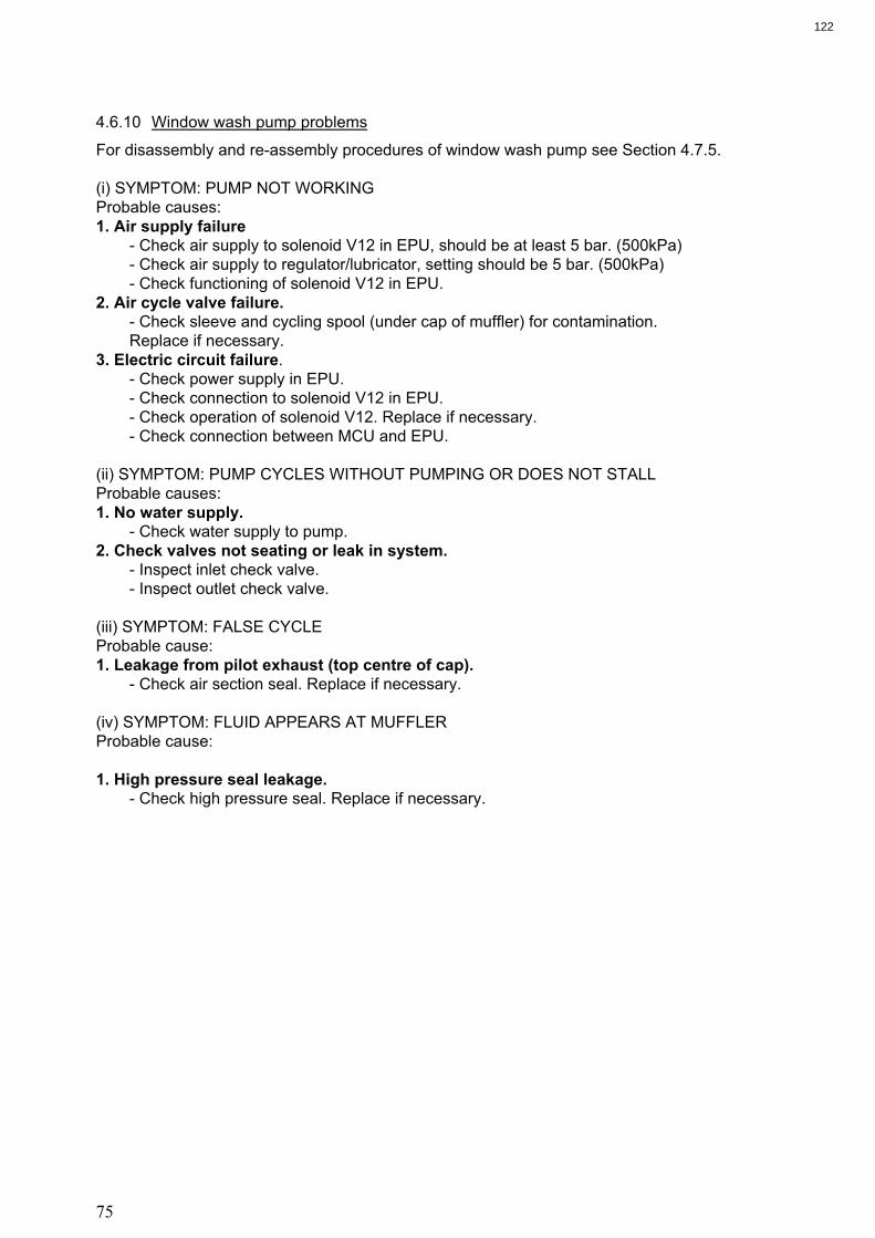
75
4.6.10 Window wash pump problems
For disassembly and re-assembly procedures of window wash pump see Section 4.7.5.
(i) SYMPTOM: PUMP NOT WORKING
Probable causes:
1. Air supply failure
- Check air supply to solenoid V12 in EPU, should be at least 5 bar. (500kPa)
- Check air supply to regulator/lubricator, setting should be 5 bar. (500kPa)
- Check functioning of solenoid V12 in EPU.
2. Air cycle valve failure.
- Check sleeve and cycling spool (under cap of muffler) for contamination.
Replace if necessary.
3. Electric circuit failure.
- Check power supply in EPU.
- Check connection to solenoid V12 in EPU.
- Check operation of solenoid V12. Replace if necessary.
- Check connection between MCU and EPU.
(ii) SYMPTOM: PUMP CYCLES WITHOUT PUMPING OR DOES NOT STALL
Probable causes:
1. No water supply.
- Check water supply to pump.
2. Check valves not seating or leak in system.
- Inspect inlet check valve.
- Inspect outlet check valve.
(iii) SYMPTOM: FALSE CYCLE
Probable cause:
1. Leakage from pilot exhaust (top centre of cap).
- Check air section seal. Replace if necessary.
(iv) SYMPTOM: FLUID APPEARS AT MUFFLER
Probable cause:
1. High pressure seal leakage.
- Check high pressure seal. Replace if necessary.
122

76
4.6.11 Sample pump problems
4.6.11.1 Electrical problems
(i) SYMPTOM: PUMP RUNNING BUT GREEN INDICATOR ON STARTER BOX OFF
Probable cause:
1. Indicator failure.
- Check power supply to indicator lamp.
- Check indicator lamp.
(ii) SYMPTOM: PUMP SHOULD BE RUNNING BUT IS OFF
Probable causes:
1. 3-phase supply failure.
- Check if 3-phase supply is switched on.
- Check fuses of 3 phase supply.
2. Thermal trip of pump.
- Check terminal trip on pump contactor in Starter Box. Red light is ON.
Reset if necessary.
Note:
If the motor repeatedly trips out on thermal trip, check the motor and pump for binding or blockages
etc. Do not force the motor to run.
3. Pump contactor failure
- Check the power on the contactor terminals (1,2), should be 24 VDC. Check also for correct
polarity.
- Check 24 VDC power supply in EPU.
- Check connections between Starter box and EPU.
4.6.11.2 Pump related problems
Nnote:
Normal operating conditions during forward flush and in sample are:
- pump discharge 5 to 8 bar. (500 to 800kPa)
- pump suction 0 to 1 bar. (0 to 100kPa)
(Pressures may vary from one installation to another).
(i) SYMPTOM: NO FLOW
Probable causes:
1. No fresh water supply. (low discharge pressure < 2 bar during flushing) (< 200kPa during flushing)
- Check fresh water supply to monitor. Pressure should be at least 1,5 bar. (220kPa)
- Check manual valves in fresh water inlet line.
123

77
2. No sample water supply.
(low discharge pressure < 2 bar during sampling) ) (< 200kPa during flushing)
- Check if cargo/stripping pump is on.
- Check if discharge line is filled with water.
- Check if manual valve of sample probe is open.
- Check if pneumatic valve in sample line is open.
- Check if manual valve in sample inlet of the Skid Assembly is open.
3. Blockage in outlet line. (high discharge pressure > 10 bar) ) (>1000kP)
- Check that manual valve in sample outlet of the Skid Assembly is open.
- Check that the manual valve on the discharge to the slop tank is open.
4. Flowrate through monitor too low.
- Check flowrate through monitor.
- Press “SCROLL” during either forward flush or sample and ensure flow is between 450 -550
l/hour
- Flow rate can be adjusted by needle valve on outlet of measurement cell.
Note:
During commissioning the flowrate through the monitor is set to between 450 and 550 l/hour.
5. Malfunction of flowsensor.
- Check electrical connections on flowsensor
- Check connections between flowsensor and EPU.
- Check function of flowsensor.
Nnote:
That during BACKFLUSH, the 'NO FLOW' alarm is inhibited. The flow alarm comes into operation at
the start of the FORWARD FLUSH cycle.
4.6.12 Differential pressure transmitter problems
Note:
For disassemble and re-assemble instructions consult Section 4.7.9
(i) SYMPTOM: NO LINE CURRENT
Probable causes:
1. Transmitter connections.
- Check wiring polarity and continuity.
- Check for shorts or ground loops.
- Check if power supply connector is connected to main board.
2. Power supply.
- Check power supply output. The voltage must be between 12 and 45 VDC at transmitter
terminals.
3. Electronic circuit failure.
- Check the main board for defect by replacing it with a spare one.
124

78
(ii) SYMPTOM: Current of 21.0 mA or 3.9 mA
Probable causes:
1. Pressure tap (piping).
- Verify if blocking valves are fully open.
- Check for gas in liquid lines.
- Check the specific gravity of process fluid.
- Check process flanges for sediments.
- Check the pressure connection.
- Check if bypass valve is closed.
- Check if pressure applied is not over upper limit of DPT range.
2. Sensor to main circuit connection.
- Check connection (male and female connectors).
3. Electronic circuit failure.
- Check the sensor circuit for damage by replacing it with a spare one.
- Replace sensor.
(iii) SYMPTOM: INCORRECT OUTPUT
Probable causes:
1. Transmitter connections.
- Check power supply voltage
- Check for intermittent short circuits, open circuits and grounding problems.
2. Noise measurement fluid.
- Adjust damping.
3. Pressure tap.
- Check for gas in liquid lines.
- Check the integrity of the circuit by replacing it with a spare one.
4. Calibration.
- Check calibration of DPT
4.6.13 Fault finding form
The fault finding form is made in case the fault finding guide does not result in a proper working of the
system. This form should be filled in and returned to VAF Instruments Service department. The form is
included in this technical manual 640M and also available on enclosed CD-rom.
125
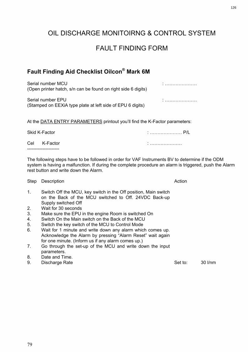
79
OIL DISCHARGE MONITOIRNG & CONTROL SYSTEM
FAULT FINDING FORM
Fault Finding Aid Checklist Oilcon® Mark 6M Serial number MCU : …………………
(Open printer hatch, s/n can be found on right side 6 digits)
Serial number EPU : …………………
(Stamped on EEXiA type plate at left side of EPU 6 digits)
At the DATA ENTRY PARAMETERS printout you’ll find the K-Factor parameters:
Skid K-Factor : ………………… P/L
Cel K-Factor : …………………
---------------------
The following steps have to be followed in order for VAF Instruments BV to determine if the ODM
system is having a malfunction. If during the complete procedure an alarm is triggered, push the Alarm
rest button and write down the Alarm.
Step Description Action
1. Switch Off the MCU, key switch in the Off position, Main switch
on the Back of the MCU switched to Off. 24VDC Back-up
Supply switched Off
2. Wait for 30 seconds
3. Make sure the EPU in the engine Room is switched On
4. Switch On the Main switch on the Back of the MCU
5. Switch the key switch of the MCU to Control Mode
6. Wait for 1 minute and write down any alarm which comes up.
Acknowledge the Alarm by pressing “Alarm Reset” wait again
for one minute. (Inform us if any alarm comes up.)
7. Go through the set-up of the MCU and write down the input
parameters.
8. Date and Time.
9. Discharge Rate Set to: 30 l/nm
126

80
10. Total Oil Limit Write down
11. Reset Total Oil Set to: Yes
12. Sample Point Write down
13. Oil Type Write down
14. Pre. Al. Oil Conc. Set to: 1000 PPM
15. Printing Interval Set to: 10 min
16. Ship Speed Input (set to auto)
17. Flow Rate Input (set to auto)
18. Oil Content (set to auto)
19. Source for ships speed (GPS/Speed log) Set to: Using
ships log
speed
20. Press Enter to go in Flush
21. Check if the pump is running now.
22. Wait until system comes in Idle Mode
23. Push Scroll Button
Active alarms will be shown
Write down
24. Push Scroll Button
Active errors will be shown
Write down
25. Push Scroll Button
Internal Flowmeter will be shown
Ignore
26. Push Scroll Button
System test will appear on screen
27. Push Change Button
System test will be activated on the print out the character test
will be printed and a log file of the 40 last alarms and errors will
be printed. Write down or copy these last alarms.
28. After print out the MCU will go back to Idle Mode
29. Push Stop Monitor
30. System will go to Stand-by
31. Switch Key switch to Off
127

81
List of alarms which were triggered during the above procedure:
: ………………………………………………………………
: ………………………………………………………………
: ………………………………………………………………
: ………………………………………………………………
: ………………………………………………………………
: ………………………………………………………………
: ………………………………………………………………
: ………………………………………………………………
VAF Instruments B.V.
Vierlingstraat 24,3316 EL Dordrecht
P.O. Box 40, 3300 AA Dordrecht
The Netherlands
Tel.: +31 (0)78 6183100
Fax: +31 (0)78 6177068
Website: www.vaf.nl
e-mail: [email protected]
128

82
4.7 MAINTENANCE
4.7.1 Maintenance general
The Oil Discharge Monitor & Control System is an assembly of components forming a complete
system. It comprises a mix of pneumatic, electronic and mechanical components. Once a control
system is functioning correctly there is no test, or tests, which can be applied to guarantee successful
operation for a stated period of time; random failure of components can occur and such random
failures can never be forecast. In consequence, satisfactory operation, in the way the system was
designed to operate, is the only test to apply. This involves frequent operation of the monitor,
especially if the monitor is shut down for long periods. A test run, once a month, will ensure that the
monitor will work correctly when it is required.
Dirt, corrosion, and, to a lesser extent, wear are the enemies of control. This means that clean
conditions must be maintained in the area of the monitoring equipment.
Pneumatic and hydraulic components require little maintenance. The various moving parts in the
system should be free from friction and in good working order. Oil should not be applied to pneumatic
components. Connections should be tight; loose connections not only waste air but produce
unsatisfactory operation and performance.
One of the greatest problems with pneumatic systems is the maintaining of a supply of clean , dry air at
a constant pressure. Moisture, oil or foreign particles carried into the system from the air supply will
cause problems. Pneumatic valves and controllers operating with clean dry air require virtually no
maintenance.
SAFETY
If any work is carried out on the monitor, the following precautions should be taken before any work is
commenced:
1. Make sure that all safety requirements are met before starting any maintenance work;
2. Make sure that all equipment is isolated from the electrical supplies;
3. Make sure that the equipment is isolated from the water supply;
4. Make sure that the equipment is isolated from the air supply;
5. Use adequate personnel protection where necessary;
6. Use adequate tools to perform the work;
7. Thoroughly clean the outside of all fittings, pipes and components, and surrounding structure before
any work commences;
8. Then pipe lines are disconnected fit dust caps to pipes and unions, mask any exposed surfaces and
make certain that foreign matter cannot enter the system;
9. If flushing pipes, use a clean inert solvent, such as inhibited methyl chloroform, from a clean
container;
10.Use cleaning solvent in a well ventilated place. Avoid breathing fumes. Keep away from open fire.
129

83
4.7.2 Routine maintence
There is little routine maintenance that can be carried out on the Oil Discharge Monitoring & Control
System. The major requirement is to ensure that the lubricator in the system is kept topped up and a
regular check of the air regulator housings for excess water.
4.7.2.1 Air regulators
For correct and fault free functioning of pneumatic components it is advised to regularly check and
drain the regulator housing of excess water. If a great deal of water is found the filter in the regulator
house should be replaced. Also a check should then be performed on the ship's control air system,
compressors, air-dryers etc.
4.7.2.2 Pump/motor lubricator
Proper functioning of the gas seal located in the centre of the pump main plate relies on the presence
of oil, for lubricating, sealing and cooling purposes.
The oil reservoir shall always be sufficiently filled with oil. It can easily be filled by opening the spring-
loaded cap on top, and pouring the oil in.
There is no need to disassemble any part of the support assembly.
For lubricating oil we recommend to use a light-duty type of machine oil, or Automatic Transmission
Fluid.
The viscosity of the oil can be within the range of:
- 20....100 cSt
- 20....100 cPs
- 100...500 SSU
- 3.....14° Engler
Suggested products are:
- AGIP OSO 22 or 32 AGIP ATF 2D
- Castrol MLV30
- Castrol Highspin AWH-M68
- Elf Olma DS 46 Elf Transomatic
- Elf Hydrelf DS 46
- Esso Teresso 32 or 46 Esso ATF-D
- Esso Nuto-H 32 or 46
- Kroon Carsinus U68 Kroon Almurol
- Kroon Abacod MEP 68
- Kroon Perlus AF
- Pennzoil AW Hydraulic 22 or 32 Pennzoil ATF
- Pennzoil Pennzgear 150 or 220
- Shell Tellus 22 or 37 Shell Donax TA
- Total Azolla ZS 32 Total Fluïde ATX
- Total Preslia 32
- Texaco ISO VG 32 or 68 Texaco Texamatic 4261
WARNING:
ATF-types of oil are not to be mixed with general machine oil.
130

84
4.7.3 Printer
The only routine maintenance required to the MCU is to ensure that there is an adequate supply of
paper in the printer before starting a ballast discharge operation.
Note:
Ensure printer head mechanism is clean.
CAUTION:
Never let the printer work without printing paper as this will damage the printing
mechanism.
4.7.3.1 Loading paper
1. Unscrew the two knurled thumb-screws on the front panel and allow the front panel to drop down on
its hinges.
2. Slide the take-up spindle from rear of the front panel by sliding off the free end. Slide the roll of
paper off the spindle and retain it on board.
3. Remove the rear paper feed spindle from the holder by pushing it out of the retaining clips and
discharge the empty spool. Slide the new roll of paper on the spindle.
4. Replace the feed spindle in the front retaining clips and ensure it locates securely. Feed the paper
through the printer using the red paper feed button located on the left hand side of the printer
module. Then feed the paper through the lower aperture in the front panel. (See Drawing. 0806-
8041).
5. Feed the paper back through the upper aperture in the front panel and onto the take up spindle.
Replace the paper retaining spindle, and ensure that the pins on the take-up spindle mesh correctly
with the cutouts on the spindle. The paper can now be tightened by turning the take-up spindle.
6. Lift the front panel back into position and tighten up the thumb-screws.
Note:
One roll of paper will provide approximately 50 hours of normal use.
4.7.4 Detector cell
Drawing 0806-1279-4 shows the detector cell and will help to visualize the following.
Make sure that the Electro Pneumatic Unit is switched off.
Note:
The internal parts of the detector cell have been chemically treated. It is important to ensure that the
coating remains intact and that no bare metal has been exposed.
131

85
4.7.4.1 Cleaning the detector cell windows
1. This is not normally required but in cases where repeated failure of the system to qualify occurs, the
following cleaning procedure can be undertaken.
2. Relieve any pressure from the cell body. Remove the upper pipe clamp above the cell.
3. Remove the flow regulator mounting bolts.
4. Unscrew the upper coupling on flow sensor.
5. Unscrew the four upper hex drive bolts.
6. Remove the upper connection piece of the measurement cell and slide out to the front of the skid
assembly.
7. The inner parts of the cell can now be cleaned by using the cleansing brush (Part number 0609-
0290) provided.
8. Re-assembly of the cell is the reverse procedure, taking care that the O-ring is properly seated.
4.7.4.2 Removing the detector cell
1. The detector cell only requires removal for complete unit replacement.
2. Proceed as for cleaning the window bolts, until step 6.
3. The centre section of the detector cell can now be removed.
4. The detector cell centre section must be removed and replaced with the attached cable. As such the
Connection box must be opened and the cable gland loosened and terminals undone. The detector
cell and cable can now be removed and replaced.
4.7.4.3 Re-mounting the detector cell
1. Ensure the lower O-ring is properly seated.
2. Slide the new centre section of the detector cell into place.
3. Slide the upper section of the cell into place. Line up the holes.
4. Insert the four hex drive bolts and tighten.
5. Re-connect the upper pipework connection.
6. Tighten pipe clamp and mounting bolts for flow sensor.
4.7.5 Window wash pump
Note:
When the pump is disassembled for repairs, all matched parts should be handled carefully to avoid
damage to lapped or honed surfaces.
WARNING:
Use cleaning solvent in a well ventilated place. Avoid breathing of fumes. Keep away
from open fire.
Drawing 0871-1212 shows the window wash pump and will help to visualize the following:
132

86
4.7.5.1 Disassembling the window wash pump
1. Isolate the pump and relieve any pressure from the pump.
2. Remove the pump from the Skid assembly to a clean and well lit work place, after first disconnecting
the two water pipe lines and the air supply line.
4.7.5.2 Air side problems
1. In the eventuality of an air drive malfunction the spool guide (8) and pilot valves (17) should be
replaced. Inspect this first and replace if necessary prior to retesting before further disassembly of
air drive. Spool guide (8) is most easily removed by removing the four star drive screws and
carefully removing, behind the spool guide is a small sliding port valve. Care should be taken to
ensure the sliding port valve is replace with the hollow side toward the body of the unit. The spool
guide is included in spare parts kit 0390-1202.
2. Secondly on the air drive side are the replacements of pilot valves (17). These two units should be
replaced as a pair, and form part of the Window wash pump maintenance kit (part number 0390-
1202)
4.7.5.3 Water side problems
1. The inlet and outlet couplings are provided with non-return valves. Should a leakage occur on the
water side replacement of the O-rings (45) should be carried out. Remove inlet or outlet gland
completely and remove O-ring from inner part. Replace with new. The O-rings are part of the
window wash maintenance kit 0390-1202.
2. If water is leaking from the wet side to the air side then the back up ring (33) should be replaced. To
perform this, first undo for star screws (29). Remove upper body (1). Remove Air piston (23). Place
lower assembly into a bench vice. With a 36mm box spanner remove cap nut (40). The O-ring(32
and back-up ring (33) are now visible and can be replaced with reserve from window wash pump
spare parts kit 0390-1202.
4.7.5.4 Re-assembling the window wash pump
1. Before starting re-assembly operations, wash all metallic parts thoroughly in solvent.
2. The air piston, air barrel, cycling valve and sleeve should be lubricated on assembly with lubricant
provided in the spare parts kit.
3. Re-insert air piston.
4. Replace body onto lower pump body, taking care to ensure O-ring (28) sits well and is not
“pinched”.
5. Replace the pump into the Skid Assembly and connect the water and air service pipes.
4.7.6 Skid shuttle valve
No maintenance on this unit is envisioned. Should the unit fail to operate, a replacement unit should be
installed. If any water leakage through the end cap bleed holes is detected, the assembly should be
delivered to a qualified VAF Instruments service point for overhaul.
133

87
4.7.7 2-Way pneumatic valve(s)
No maintenance on this unit is envisioned. Should the unit fail to operate, a replacement unit should be
installed. If any water leakage through the end cap bleed holes is detected, the assembly should be
delivered to a qualified VAF Instruments service point for overhaul.
4.7.8 Sample pump
WARNING:
The following point must be considered before commencing work to the unit.
- stop the pump;
- isolated the electric motor from the mains supply;
- isolated the pump from the water supply and relieve any pressure on the pump.
Drawing. 0806-1260-3 shows the pump/motor and will help to visualize the following:
4.7.8.1 Mechanical shaft seal
This sealing device requires no maintenance or adjustment. When a new seal is being run in, small
leakage may occur momentarily.
If any water leakage occurs, this will drip out of the 2mm. keyway at the bottom side of the pump
casing, visible from the pump room side.
4.7.8.2 Disassembling the pump/motor
1. Drain the pump and piping. On the pump casing a drain plug is provided. If repair to the impeller or
rotating part of the mechanical seal is required, the piping can remain in place. Otherwise, remove
the suction and discharge piping from the pump.
2. Remove the eight nuts (7) and washers (38) from the pump cover.
3. Remove the cover (5) from the pump casing, preferably utilising the two off jacking screws size M6.
Be careful not to damage the set of packing rings (4).
4. If only the impeller (10) is to be changed out, pull it out of the casing. If it sticks, gently use two snap
grips and apply little force evenly. Be careful not to be injured by the sharp impeller vanes, and also
not to damage the impeller. The keyway for the impeller is glued in place in the factory and should
not be disturbed.
5. For access to the mechanical seal (9), the coupling (14) is to be removed. For this purpose, the
impeller can be left in place and be blocked with a tool having a soft end. Be careful not to be
injured by the sharp impeller vanes, and also not to damage the impeller. Loosen the hexagon
socket head cap screw (12) of the coupling (14). Then remove the impeller, and the bolt (12) with
the o-ring (13).
6. Pull the coupling from the motor shaft. For this purpose a M16 thread is provided, enabling use of a
bolt as pull handle. Be careful as the rotating part of the mechanical seal (9) will come off with the
shaft sleeve. Prevent the seal part from striking the pump casing when it comes off. Do not damage
the sealing ring and store it in a clean cloth at a safe place.
134

88
7. For further disassembly remove the three hexagon socket head bolts (16) from the flange (22). Pull
the pump casing (2) with fitting ring (22) from the main plate. Care should be taken for the stationary
ring of the mechanical seal, this will come off together with the pump casing. This ring should not
strike the shaft, otherwise it may be damaged. Be aware that the key (31) should be kept in place.
Note:
The gas tight seal will be compromised if the following steps are taken. Ensure replacement
parts are to hand.
WARNING:
Gas tight integrity of the bulkhead will be shortly compromised. Ensure all safety
regulations are followed and blanking plates are available if the repair of the unit is
expected to take any length of time.
8. If deemed necessary the rings forming the gas seal can be removed. Remove the oil reservoir on
engine room side of bulkhead. Pull out the first oil seal (25), the lantern ring (26) and the second oil
ring. The oil seals will certainly be damaged and need to be replaced.
9. Clean the oil that will come out of the oil seal chamber.
10.Clean all components and store these at a safe place.
11.Now the electric motor (32) can be removed from the flange (22). Remove the bolts and washers
(23, 24) from the motor flange. Pull the motor from its fitting.
12.Seal the hole of the motor shaft using f.i. tape or a plug diameter 30 mm. Protect the sleeve on the
motor shaft from damage. If a new motor is being installed the bushing (27) is supplied fitted to the
original VAF Instruments spare part.
4.7.8.3 Re-assembling the pump/motor
Have all parts cleaned and be free of burrs. Have new gaskets, oil and if required oil seals available.
1. If the electric motor was removed or replaced, inspect the surface of the bushing (27) for scratches.
If the surface is damaged, then complete original VAF Instruments motor and bushing will need to
be replaced, as this item is critical for the gas tight seal.
2. If the oil seals (26) were removed, install these now, together with lantern ring (25). Take care not to
damage the oil seals. If the oil seals (26) are still in place, make sure that these are not damaged
during re-installation. Ensure the lubricating oil channel is clean. Smear a small amount of oil over
the seals. Install the electric motor (32). The terminal box should preferably be located at the top.
3. Smear some oil on the pump house (2) face. Mount the pump house (2) on the pump face (22) with
the three Hex Socket head drive screws (16). Use water and soap on the mechanical seal (9) and
press this into the pump house over the slightly prominent motor drive shaft.
4. Insert the woodruff key (11) into the coupling (14) with Loctite Retainer 542. Mount the coupling (14)
with attention to the mechanical seal onto the motor shaft. ( The sleeve should slip easily onto the
shaft). Care is to be taken to ensure the keyway in the coupling mates with the drive pin (31) in the
motor shaft.
135

89
5. Install the impeller (10) onto the shaft, taking care to line the keyway up with the woodruff key (11).
The impeller should fit readily onto the shaft. There is no difference between frontside or backside.
However, when re-fitting the same impeller it is preferable to adhere to the original position.
6. Place the casing cover (5) on the pump casing (2), with a new O-ring gasket (8). Re-use all of the
shims (4). If a shim gets damaged it must be replaced with a new one of exact the same thickness,
otherwise pump performance will be affected or the pump may even jam. Gently tighten all cover
nuts (7).
7. Check that the pump rotates freely by hand. This can be done at the cooling fan of the electric
motor.
8. Check the oil level in the reservoir (38), if required refill.
CAUTION:
UNDER NO CIRCUMSTANCES MUST THE PUMP BE RUN WITHOUT LIQUID. THE
PUMP CASING MUST BE FILLED WITH LIQUID FIRST. OTHERWIZE THE PUMP WILL SEIZE AND DAMAGE WILL OCCUR.
9. Re-connect the suction and discharge piping to the pump casing. Re-install the drain and vent plugs
after filling the pump casing and suction line with water.
10.Re-connect the pumpmotor to the mains supply. Make sure that all piping is installed, and the pump
is filled with water. Make sure any discharge valve is opened before starting, enabling air to be
released.
Check the direction of rotation by switching on the pumpmotor for a short moment only ! Look at the
motor fan and notice the direction in which the fan spins. This must be CLOCKWISE when looking
from the back cover of the motor. An arrow also indicates correct direction of rotation. If direction of
rotation is wrong, interchange any of two line wires of the power cable in the terminal box. Switch off
the electrical supply first !
4.7.9 Differential pressure transmitter
4.7.9.1 Zero output check of DPT
1. Open equalising valve of DPT.
2. The FLOW indication on the MCU should now read zero. If reading is not zero, adjust zero point at
DPT, in accordance with section 4.7.9.2, until reading is zero.
3. Close equalising valve of DPT.
4.7.9.2 Zero adjustment of DPT
1. Keep the transmitter energised for at least 10 minutes.
2. Remove cover from electronics housing of DPT.
3. Check that ‘MODE’ switch is at ‘O’ (refer to the illustrations in drawing 0899-1249-3).
4. Apply the lower value pressure.
5. Wait for the pressure to stabilise.
136

90
6. Slide away ‘ZERO’ cover on electronics housing and adjust zero point by turning adjustment screw
as shown in drawing 0899-1249-3.
7. Set ‘MODE’ switch to ‘2’.
Note:
When a digital voltmeter is used you will find an example of wiring (connected to CK- and CK+ on the
terminal block) with the illustrations. Lower pressure value should then correspond with an output of 4
mA.
Caution:
After adjustment of the transmitter, it should be kept energised for about 10 seconds.
4.7.9.3 Span adjustment of DPT
1. Unscrew cover from electronics section of DPT and read calibration data plate affixed to inside of
cover.
2. Connect a suitable pressure gauge and air supply to “+” side of DPT. Make sure that “-” side vents
to atmosphere.
3. Connect suitable digital voltmeter (refer to the illustrations in drawing 0899-1249-3).
4. Set ‘MODE’ switch to ‘1’ (see illustrations).
5. Apply pressure shown as “upper calibration value” on calibration data plate of the DPT.
6. Wait for the pressure to stabilise.
7. Observe mA signal output. If reading is not in accordance with the upper limit of the DPT the output
current can be adjusted using the zero/span screw.
8. Repeat steps 1, 2 and 3 of paragraph 4.7.9.1 to check that the zero point has not drifted.
9. Set ‘MODE’ switch to ‘2’.
10.Remove air tools and voltmeter. Close covers. Ensure that the sealing ring is installed otherwise the
transmitter is not in accordance with IP67.
Caution:
After adjustment of the transmitter, it should be kept energised for about 10 seconds.
Warning:
In hazardous zones with explosion proof requirements the cover must be tightened at
least 7 turns.
4.7.9.4 Disassembling the DPT
Warning: Use cleaning solvent in a well ventilated place. Avoid breathing of fumes. Keep away from open fire.
Warning: DO NOT DISASSEMBLE WITH POWER ON
137

91
In drawing 0899-1249-3 you will find illustrations with an exploded view of the DPT which will help to visualize the following:
1. In order to have access to the sensor (B1!5) for cleaning purposes, the transmitter should be
removed from its process connections. The transmitter should be isolated from the process by
means of manifolds or valves and must be vented from any remaining pressure prior to removing.
2. Remove the DPT to a clean and well lit work place.
3. The flange nuts (B-14) may now be loosened crosswise, one at a time. After removing bolts and
flanges (B-9), the isolating diaphragms will be easily accessible for cleaning.
4. Cleaning should be done carefully in order to avoid damaging of the delicate isolating diaphragms.
Use of a soft cloth and a non-acid solution is recommended.
5. The oscillating circuit is a part of the sensor and replacement of one implies replacing the other.
6. To remove the sensor from the electronics housing, the electrical connections (in the field terminal
side) and the main board connector must be disconnected.
7. Loosen the hex screw (A-31A) and carefully unscrew the electronics housing from the sensor,
observing that the flat cable is not excessively twisted.
Caution:
Do not rotate the electronics housing more than 180o without disconnecting the
electronic circuit from the sensor and from the power supply.
4.7.9.5 Electronic circuit
1. To remove the circuit board (A-6) loosen the two screws that anchor the board.
Caution:
The board has CMOS components which may be damaged by electrostatic discharges.
Observe correct procedures for handling CMOS components. It is also recommended to
store the circuit boards in electrostatic-proof cases.
2. Pull the main board out of the housing and disconnect the power supply and the sensor connectors.
4.7.9.6 Re-assembling the DPT
Warning:
Do not assemble with power on. (i) Sensor
1. When mounting the sensor (B1!5), it is recommended to make use of a new set of gaskets (B-8)
compatible with the process fluid. The bolts, nuts, flanges and other parts should be inspected for
corrosion or other eventual damage. Damaged parts should be replaced.
2. Gaskets should be lightly lubricated with silicone oil before they are fitted into their recesses. The
flanges should then be positioned in order to press them in place. With the flanges holding the O-
rings in place, insert the four bolts and tighten the nuts (B-14) finger-tight, making sure the flanges
remain parallel all the time.
138

92
! Tighten one nut till the flange seats. ! Tighten the nut diagonally across with a torque of approximately 25 Nm (20 ft.lbs). ! Tighten the first nut with the same torque. ! Verify the flange alignment. ! Check torque on the four bolts.
3. The fitting of the sensor must be done with the main board out of the electronic housing. Mount the
sensor to the housing turning clockwise until it stops. Then turn it counter-clockwise until it faces the
protective cover (A-1) parallel to the process flange. Tighten the hex screw (A-31A) to lock the
housing to the sensor. (ii) Electronic Circuit
1. Plug sensor connector and power supply connector to main board.
2. Anchor the main board with its screws.
3. After tightening the protective cover (A-1), mounting procedure is complete. The DPT is ready to be
energized and tested. It is recommended to open the DPT pressure valves to atmosphere and
adjust the TRIM.
Warning:
In hazardous zones with explosion proof requirements the cover must be tightened with
at least 7 turns.
139

93
4.7.10 Spare parts
4.7.10.1 Standard spares Standard spare parts supplied with every Oil Discharge Monitoring & Control System delivery: Description Stock number Quantity
Standard spare parts OIL DISCHARGE MONITOR system 0390-1194 comprising: Printer paper 10 Bulkhead seal lubricant 500ml O-ring I/D 26.70 x 1.78 mm 1 O-ring I/D 28.30 x 1.78 mm 1 Fuse 500mA (slow) 2 Fuse 1 A (slow) 2 Cleansing brush 1 Printer ribbon 5
4.7.10.2 Servicing spares When ordering spares, always refer to the Oil Discharge Monitoring & Control System's serial number and list required spares indicating: 1. stock number; 2. quantity required; 3. description of kit. We recommend to stock the following spares: Description Stock number Quantity
Sample pump maintenance kit 0390-1182 (See drawing 0806-1260) comprising: Mechanical seal (9) 1 O-ring (8) 1 O-ring (13) 1 Oil sealing (25) 2 Shim (set) (4) 1 Sample pump – Impeller replacement kit 0390-1210 (See drawing 0806-1260) comprising: Sample pump maintenance kit 0390-1182 1 Impeller((10) 1
140

94
Description Stock number Quantity
Sample pump electric motor kit 0390-1209 (See drawing 0806-1260) comprising: Electric motor (32) 1 Key (31) 1 Bushing (27) 1 Window wash maintenance kit 0390-1202 (See drawing 0871-1212) comprising: Pilot valve complete (17) 2 Back up ring (33) 1 O-ring (45) 2 Printer Kit 0390-1212 comprising: Printer paper 10 Printer ribbon 5 Electrical items spares kit 0390-1211 comprising: LED Green (starter box) 2 LED Red (starter box) 2 Fuses 500mA Slow (EPU & MCU) 4
141

95
5. TEST AND CHECK-OUT PROCEDURE
RECOMMENDED TEST PROCEDURE
Before test is carried out the person in charge should familiarise himself/herself with the operation of
the system and ensure the following conditions are met:
CAUTION:
UNDER NO CIRCUMSTANCES MUST THE PUMP BE RUN WITHOUT LIQUID. THE
PUMP CASING MUST BE FILLED WITH LIQUID FIRST OTHERWIZE THE PUMP
WILL SEIZE AND DAMAGE WILL OCCUR.
a) control air supply is on;
b) fresh water supply is on;
c) electrical supplies are on;
d) Main Control Unit is switched on;
e) Electro Pneumatic Unit is switched on;
f) starter box is switched on;
g) all manual valves in the system are open;
h) cargo pump is on stand by;
i) check if sufficient paper is available in printer.
Proceed as follows:
1. Switch MCU to "Control Unit" position.
2. Press [ > ], to enter SET UP mode.
3. Press [ENTER] till 'Total Oil Limit' is displayed.
4. Press [CHANGE] and enter Total Oil limit of 40 L.
5. Press [ENTER] to display 'Reset Oil Total ?'
6. Press [CHANGE] and [CLEAR ] to reset Oil Total to zero.
7. Press [ENTER] till 'Ships speed input' is selected. Change to manual mode and enter Ship's speed
of 15 knots.
8. Press [ENTER] till 'Flow rate input' is selected. Change to manual and enter flow rate of 1000 T/h.
9. Press [ENTER] till 'Oil content input' is selected. Change to manual and enter oil content of 400
ppm.
142

96
10.Press [ENTER] till end of SET UP mode is reached.
11.Press [ENTER] the system will go to IDLE mode.
12.Press [ > ] to start the SAMPLE mode.
13.Check the display of the MCU for correct information.
dd/mm/yy hh:mm SAMP.PNT 1 MODE SAMPLE
CONC 400 ppm M DISCH 0 l/nm
FLOW 1000 T/h M TOT.OIL l
SPEED 15 kts M V/V COM:C POS:C OIL:1
14.After approximately 2 minutes, the signal to open the overboard valve and to shut the slop tank
valve will be given. Which is indicated on the display as follows:
dd/mm/yy hh:mm SAMP.PNT 1 MODE SAMPLE
CONC 400 ppm M DISCH 26 l/nm
FLOW 1000 T/h M TOT.OIL xx l
SPEED 15 kts M V/V COM:O POS:O OIL:1
15.In the case of this vessel check that the valves have in fact operated. On the display of the MCU
this is indicated by the change of POS: from 'C' to 'O'.
16.Press [STOP MONITOR]. the system will return to IDLE mode and the signal to close the overboard
valve and open the slop tank valve will be given.
dd/mm/yy hh:mm SAMP.PNT 1 MODE IDLE
CONC 400 ppm M DISCH 26 l/nm
FLOW 1000 T/h M TOT.OIL l
SPEED 15 kts M V/V COM:C POS:C OIL:1
17.In the case of this vessel check that the valves have in fact operated.
18.Select EXTRA SET UP mode by pressing [CHANGE].
19.Press [ENTER] till 'Flow rate input' is selected. Change flow rate to 2000 T/h.
20.Wait till system is back in IDLE mode. (15 seconds after last keyboard action).
21.Select Sample mode by pressing [ > ].
22.Check the display of the MCU for correct information.
dd/mm/yy hh:mm SAMP.PNT 1 MODE SAMPLE
CONC 400 ppm M DISCH Flt l/nm
FLOW 2000 T/h M TOT.OIL l
SPEED 15 kts M V/V COM:C POS:C OIL:1
143

97
23.After approximately 2 minutes the overboard discharge valve signal will not change from close to
open.
24.Press [STOP MONITOR] to select IDLE mode again.
25.Select EXTRA SET UP mode by pressing [CHANGE].
26.Press [ENTER] till 'Flow rate input' is selected. Change flow rate to 1000 T/h.
27.Wait till system is back in IDLE mode. (15 seconds after last keyboard action).
28.Select Sample mode by pressing [ > ].
29.Check the display of the MCU for correct information.
dd/mm/yy hh:mm SAMP.PNT 1 MODE SAMPLE
CONC 400 ppm M DISCH 0 l/nm
FLOW 1000 T/h M TOT.OIL l
SPEED 15 kts M V/V COM:C POS:C OIL:1
30.After approximately 2 minutes, the signal to open the overboard valve and to shut the slop tank
valve will be given. Which is indicated on the display as follows:
dd/mm/yy hh:mm SAMP.PNT 1 MODE SAMPLE
CONC 400 ppm M DISCH 0 l/nm
FLOW 1000 T/h M TOT.OIL l
SPEED 15 kts M V/V COM:O POS: O OIL:1
31.In the case of this vessel check that the valves have in fact operated. On the display of the MCU
this is indicated by the change of POS: from 'C' to 'O'.
32.The discharged oil indicated on the display by 'TOT.OIL' will increase. Allow the oil discharge to
increase till it reaches 40 l, at which time the signal will be given to close the overboard valve and to
open the slop tank valve.
33.Check that the valves have in fact operated.
34.Press [STOP MONITOR] to select IDLE mode.
35.Press [STOP MONITOR] to select SHUTDOWN mode.
The system is now STANDBY mode.
36.Press [ > ] to select SET UP mode.
37.Press [ENTER] till 'Reset Oil Total ?' is displayed.
38.Press [ENTER].
39.Press [ENTER] till 'Ship's speed input' is selected. Change to auto mode.
40.Press [ENTER] till 'Flow rate input' is selected. Change to auto mode.
41.Press [ENTER] till 'Oil content input' is selected. Change to auto mode.
42.Press [ENTER] till ‘Using GPS speed / Using ship’s log speed’ is reached and select ‘Using ship’s
log speed’.
43.Press [ENTER] till end of SET UP mode is reached.
144

98
44.Press [ENTER] to start FLUSH mode.
45.Wait till the system has completed the flushing cycle and is back in IDLE mode.
46.Check the display of the MCU for correct information.
47.Start the cargo pump. NOTE: the MCU will divert the flow into the slop tank.
48.Press [ > ] to start sampling. Check that the ppm indication on the MCU is changing.
49.Press [STOP MONITOR] to select IDLE mode.
50.Press [CHANGE] to select EXTRA SET UP mode.
51.Press [CHANGE] and select the next sample point.
52.Wait 15 seconds till the system is back in IDLE mode again.
53.Press [ > ] to start sampling.
- Check that the correct sample point is indicated on the MCU.
- Check that the correct sample probe is selected.
54.Repeat step 48 to 52 for each sample point.
55.Press [STOP MONITOR] to select IDLE mode.
56.Press [CHANGE] to select EXTRA SET UP mode.
57.Press [ENTER] till 'Oil Type' selection is displayed and select the next oil type.
58.Wait 15 seconds till the system is back in IDLE mode again.
59.Check if correct Oil type is indicated on MCU.
60.Repeat step 56 to 58 for each oil type.
61.Press [ > ] to select the SAMPLE mode.
62.Press [WINDOW WASH].
The display will indicate "MW" alongside "SAMPLE MODE". The window wash pump should operate
for a few seconds.
63.Press [FLUSH].
The display will indicate "MF" alongside "SAMPLE MODE".
- Check that fresh water valve (V10) opens for approximately 2 minutes.
- Check that Oil content indication on MCU reads zero.
64.Test the NO FLOW alarm by manually shutting the sample inlet valve on the Skid Assembly.
- Check that sample pump is stopped after approximately 2 minutes
- Re-open sample inlet valve after test.
65.Check that the ship's speed, flow rate and oil content are all displayed on the MCU and wait for the
overboard discharge valve to open. Regulate cargo pump speed and back pressure to obtain a flow
rate equivalent to approx. 50 % of the rated capacity of the flowmeter. Check the accuracy of the
flowmeter against ullage readings or cargo pump characteristic curves.
145

99
66.Test underrange alarm by reduce of flow. Overboard valve shut and recirculating valve will go open.
Increase discharge flow and press “alarm reset”. Press “stop reset”.
67.Press [SCROLL] to select TEST mode.
Follow instructions as indicated on the display of MCU to perform a self test of the system
.- Display should indicate 500 ppm
- The audio alarm should sound.
- The printer should perform a print test.
68.Press [CLEAR] or wait for 15 seconds to return to SAMPLE mode.
69.Press [STOP MONITOR] to select IDLE mode.
70.Turn the keyswitch on the MCU to 'CONSOLE' position and check the manual control of the
overboard discharge valve and sloptank valve from the cargo control console.
71.Turn the keyswitch on the MCU to 'CONTROL UNIT' and check that the manual control of both
overboard discharge valve and slop tank valve from the cargo control console is not possible.
72.Press [STOP MONITOR] to select SHUTDOWN mode.
Check operation of SHUTDOWN flushing cycle as follows:
- Fresh water valve (V10) and back flush valve (V11) opens.
- Sample pump runs.- After 2 minutes (V11) should close.
- The window wash pump will operate for a few seconds
.- After a further 2 minutes valve (V10) will close and the pump stops.
The system is now in a STANDBY mode.
73.Inspect the system for evidence of any leaks.
146