051200 Structural Steel Framing - VA Vendor Portal
111
100342.00 SLVHCS REPLACEMENT MEDICAL CENTER PROJECT WP-9B 7/16/2012 s t u d i o NOVA 7/11/2012 050513 - 1 SHOP-APPLIED COATINGS FOR METAL SECTION 05 05 13 SHOP-APPLIED COATINGS FOR METAL PART 1 - GENERAL 1.1 SUMMARY A. Section Includes: 1. Anodic coatings. 2. Chemical finishes (Black oxide). 3. Painted coatings. a. Fluoropolymer (PVDF) 1) Louvers and Vents: 2-Coat Pearlescent System containing mica pearlescent flake pigments. 2) Curtain Wall Systems: a) Exterior: 2-Coat Pearlescent System containing mica pearlescent flake pigments. b) Interior: Thermal-Set Acrylic Spray Painted Coatings containing mica pearlescent flake pigments. 3) Aluminum-Framed Storefronts: Same as Curtain Wall Systems. 4) Insulated-Core Metal Panels: 2-Coat Pearlescent System containing mica pearlescent flake pigments. 5) Manufactured Metal Siding: 2-Coat Pearlescent System containing mica pearlescent flake pigments. 6) Composite Wall Panels: 2-Coat Pearlescent System containing mica pearlescent flake pigments. 7) Sliding Automatic Entrances: 2-Coat Pearlescent System containing mica pearlescent flake pigments. 8) Interior Automatic Sliding Entrance Doors: 2-Coat Pearlescent System containing mica pearlescent flake pigments. 9) Soffit Vents: Standard 2-Coat System. 10) Other items specified to receive PVDF: Base bid on 2-Coat Pearlescent System containing mica pearlescent flake pigments, unless indicated otherwise. 4. Maintenance Disclosure submitted with Bid. 1.2 RELATED WORK (Items not included in this Project Manual are available from the Construction Manager upon request) A. Hot Dip Galvanizing: Section 05 05 15. B. Metal fabrications: Section 05 50 00. C. Manufactured Metal Siding: 07 46 15. D. Flashing and Sheet Metal: Section 07 60 00. E. Roof Accessories: Section 07 72 00. F. Expansion Joint Cover Assemblies: Section 07 95 13.
-
Upload
khangminh22 -
Category
Documents
-
view
0 -
download
0
Transcript of 051200 Structural Steel Framing - VA Vendor Portal
100342.00 SLVHCS REPLACEMENT MEDICAL CENTER PROJECT WP-9B
7/16/2012
s t u d i o NOVA 7/11/2012
050513 - 1 SHOP-APPLIED COATINGS FOR METAL
SECTION 05 05 13 SHOP-APPLIED COATINGS FOR METAL
PART 1 - GENERAL
1.1 SUMMARY
A. Section Includes: 1. Anodic coatings. 2. Chemical finishes (Black oxide). 3. Painted coatings.
a. Fluoropolymer (PVDF) 1) Louvers and Vents: 2-Coat Pearlescent System containing mica
pearlescent flake pigments. 2) Curtain Wall Systems:
a) Exterior: 2-Coat Pearlescent System containing mica pearlescent flake pigments.
b) Interior: Thermal-Set Acrylic Spray Painted Coatings containing mica pearlescent flake pigments.
3) Aluminum-Framed Storefronts: Same as Curtain Wall Systems. 4) Insulated-Core Metal Panels: 2-Coat Pearlescent System containing mica
pearlescent flake pigments. 5) Manufactured Metal Siding: 2-Coat Pearlescent System containing mica
pearlescent flake pigments. 6) Composite Wall Panels: 2-Coat Pearlescent System containing mica
pearlescent flake pigments. 7) Sliding Automatic Entrances: 2-Coat Pearlescent System containing mica
pearlescent flake pigments. 8) Interior Automatic Sliding Entrance Doors: 2-Coat Pearlescent System
containing mica pearlescent flake pigments. 9) Soffit Vents: Standard 2-Coat System. 10) Other items specified to receive PVDF: Base bid on 2-Coat Pearlescent
System containing mica pearlescent flake pigments, unless indicated otherwise.
4. Maintenance Disclosure submitted with Bid.
1.2 RELATED WORK (Items not included in this Project Manual are available from the Construction Manager upon request)
A. Hot Dip Galvanizing: Section 05 05 15.
B. Metal fabrications: Section 05 50 00.
C. Manufactured Metal Siding: 07 46 15.
D. Flashing and Sheet Metal: Section 07 60 00.
E. Roof Accessories: Section 07 72 00.
F. Expansion Joint Cover Assemblies: Section 07 95 13.
100342.00 SLVHCS REPLACEMENT MEDICAL CENTER PROJECT WP-9B
7/16/2012
s t u d i o NOVA 7/11/2012
050513 - 2 SHOP-APPLIED COATINGS FOR METAL
G. Overhead Coiling Doors: Section 08 33 23.
H. Sealants: Section 07 92 00.
I. Interior Aluminum-Framed Storefronts: Section 08 41 13.
J. Glazed Aluminum Curtain Walls: Section 08 44 13.
K. Glazed Aluminum Curtain Walls for Dixie: Section 08 44 13.3.
L. Louvers and Vents: Section 08 90 00.
M. Color and coating type: Section 09 06 00, Schedule for Finishes.
1.3 APPLICABLE PUBLICATIONS
A. The publications listed below form a part of this specification to the extent referenced. The publications are referenced in the text by the basic designation only.
B. Architectural Aluminum Manufacturers Assoc. (AAMA):
611-98 Voluntary Specification for Anodized Architectural Aluminum
2603-02 Pigmented Organic Coatings on Aluminum Extrusions and Panels; Voluntary Specification, Performance Requirements and Test Procedures for
2604-05 High Performance Organic Coatings on Aluminum Extrusions and Panels; Voluntary Specification, Performance Requirements and Test Procedures for
2605-05 Superior Performing Organic Coatings on Aluminum Extrusions and Panels; Voluntary Specification, Performance Requirements and Test Procedures for
C. American Spray Coaters Association (ASCA):
96-96 Voluntary Specification for Superior Performance of Organic Coatings on Architectural Aluminum Curtainwall, Extrusions and Miscellaneous Aluminum.
D. The National Association of Architectural Metal Manufacturers (NAAMM).
NAAMM MFM, Metal Finishes Manual, January 2006 Edition
E. The National Coil Coaters Association (NCCA):
1.4 SYSTEMS BY SUBSTRATE
A. See coating descriptions in Part 2 below.
B. Exterior Aluminum: Spray PVDF. 1. See Summary in Part 1 above.
C. Interior Extruded Aluminum Framing (Include framing inside glazing): Thermal-set acrylic.
D. Siding: Coil-Coated PVDF.

100342.00 SLVHCS REPLACEMENT MEDICAL CENTER PROJECT WP-9B
7/16/2012
s t u d i o NOVA 7/11/2012
050513 - 3 SHOP-APPLIED COATINGS FOR METAL
1.5 PERFORMANCE REQUIREMENTS
A. High Performance Organic Coatings: Factory-applied liquid coatings to meet or exceed the following requirements: 1. Spray Coatings: ASCA 96 including the following:
a. Color uniformity. b. Specular gloss. c. Dry film hardness. d. Film adhesion. e. Impact resistance. f. Abrasion resistance. g. Chemical resistance. h. Corrosion resistance. i. Weathering: Florida exposure.
1) Color retention. 2) Gloss retention. 3) Chalk resistance. 4) Resistant to erosion.
2. Coil Coatings; Coating manufacturer’s published literature for coil coatings.
1.6 SUBMITTALS
A. Submit in accordance with Section 01 33 23.
B. Product Data: 1. Mfg's. Specifications and Installation Instructions: Submit manufacturer's specifications
for coating system including description of materials. Include cautions and limitations, if any, for proper use of proposed finishes plus recommendations for handling.
2. Certified Test Reports: Include certified reports from independent testing laboratory showing compliance with requirements where a test method is indicated.
C. Certification: Submit coater’s certification that organic spray coatings will meet or exceed requirements of the following: 1. Specified AAMA systems. 2. ASCA 96 for “bright whites”.
D. Letters: Coating material manufacturers shall certify that the coater is approved or licensed by coating material they manufacturer.
E. Samples: Submit samples of each type and color of finish required by this Section, on 12" sections of extrusions or formed shapes and on 6" squares of sheet/plate. Include two (2) or more samples in each set, showing near-limits of variations (if any) in color and texture of finish.
F. Finish and Maintenance Data: Provide written instructions for the following as required under Section 01 00 00 - General Requirements: 1. Finishes. List each type of coating and the names of products receiving that type of
coating. 2. Maintenance: Recommended materials and methods for proper maintenance of work for
each type of coating provided under this Section.

100342.00 SLVHCS REPLACEMENT MEDICAL CENTER PROJECT WP-9B
7/16/2012
s t u d i o NOVA 7/11/2012
050513 - 4 SHOP-APPLIED COATINGS FOR METAL
1.7 QUALITY ASSURANCE
A. Standards: Comply with applicable provisions of AAMA, NAAMM, NCCA, and ASCA. In case of conflict, the more stringent requirements shall apply.
B. Coater: A firm with not less than five (5) years of successful experience in application of coating systems similar to systems required for this project must be. 1. Approved or licensed by coating materials manufacturer.
C. Manufacturer: Coating products to be manufactured by one firm with minimum five (5) years experience in manufacturing of coating systems.
D. Bright Whites: Comply with ASCA advisory on “Bright Whites” which includes bright, clean colors. Provide additional film thickness and/or coats as needed to achieve the desired color and minimize color variation at no additional cost to Owner.
1.8 WARRANTY
A. Coating systems shall be guaranteed by manufacturer, applicator, and Contractor to Owner against failures, and defects of materials or workmanship. Guarantee to provide full labor and materials as required to restore defective coating system without cost to Owner. 1. Applicator/Manufacturer's warranty shall provide primary coverage and will be looked to
for initial relief from claims made by Owner. 2. Contractor's warranty shall provide secondary coverage to extent that manufacturer's
warranty does not apply. Contractor will be looked to for relief from claims made by Owner and not provided by manufacturer.
B. Warranty Period: 1. Painted finishes:
a. Coil Coated Systems: 20 years. b. Spray Systems: 10 years; 5 years for “exotic” colors. c. Anodized: 5 years.
C. "Defective" is defined to include abnormal deterioration/aging/weathering, deterioration, discoloration, peeling of finishes, or failure of coating system to meet performance requirements.
D. Repairs or replacements required because of acts of God exceeding performance requirements, vandalism, inadequate maintenance alterations, or other causes beyond manufacturer's/fabricator's/installer's /Contractor's control, as judged by Architect, shall be completed by Contractor/installer and paid for by Owner at reasonable prevailing rates mutually agreed upon at time of such repair/ replacement work.
E. Warranty and enforcement shall not deprive Owner of other available actions, rights or remedies.
F. Maintenance Disclosure: Disclose requirements for coating maintenance with Bid, type and intervals, which are conditions of Warranty. .

100342.00 SLVHCS REPLACEMENT MEDICAL CENTER PROJECT WP-9B
7/16/2012
s t u d i o NOVA 7/11/2012
050513 - 5 SHOP-APPLIED COATINGS FOR METAL
PART 2 - PRODUCTS
2.1 ANODIC COATINGS
A. See SYSTEMS BY SUBSTRATE in Part 1 above.
B. General: Comply with NAAMM MFM for recommendations relative to application and designation of finishes. Finish designations prefixed by "AA" conform to the system established by the Aluminum Association for designating aluminum finishes.
C. Exposed surfaces: Architectural Class I anodic coating AAMA 611. 1. Clear Anodic Finish: Eco-Friendly Anodize, AA-M10-C21-A41, 0.018 mm or thicker.
D. Interior: Any portion of system with exterior exposure must receive “Exterior” coating for entire system. Architectural Class II anodic coating or Class I at Contractor’s option. 1. Clear finish: AAMA 611, Eco-Friendly Anodize, AA-M10-C21-A31, 0.10mm or thicker.
E. Concealed surfaces: Manufacturer's standard.
2.2 CHEMICAL FINISH
A. Black Oxide Finish: Conform to MIL-DTL 13924D, Oxide, Black, for Ferrous Metals, Class 1 process. 1. Color: Actual color to be a medium bronze as approved by Architect; however, finish is
referred to as “black oxide”. 2. Restrictions: All fabrication must be complete before applying blackened finish. Finish
and protective coatings must be applied and cured in accordance with Finishers’ written instructions.
3. Comply with Finishers’ recommendations for fabrication to achieve best finish results. 4. Process involves chemical cleaning, rinses, hot oxide treatment, and protective coating
under controlled environment. 5. Hot oxide treatment requires parts immersed in an alkaline aqueous salt solution
operated at approximately 285 degrees F to produce a magnetite (Fe3O4) on the surface of the part.
6. Cold oxide process not acceptable.
2.3 SPRAY PAINTED COATINGS
A. See SYSTEMS BY SUBSTRATE in Part 1 above.
B. System: 1. Exterior (and doors): PVDF baked finish as specified below. 2. Interior: See THERMAL-SET ACRYLIC SPRAY PAINTED COATINGS Provide for all
exposed interior surfaces except doors.
C. Color(s) and Finish: As specified in Section 09 06 00 - Schedule for Finishes.
D. Chrome Pre-Treatment and Primer: Comply with AAMA 2605-98 for the following: 1. Pre-Treatment: Chemical conversion of the surface to amorphous chromium phosphate
in accordance with ASTM D 1730, Type B, Method 5 or 7. 2. Primer: Chromate based primer with coating weights at not less than 40 mg/sq.ft.

100342.00 SLVHCS REPLACEMENT MEDICAL CENTER PROJECT WP-9B
7/16/2012
s t u d i o NOVA 7/11/2012
050513 - 6 SHOP-APPLIED COATINGS FOR METAL
E. Standard 2-Coat System: PVDF (polyvinylidene fluoride) baked finish, factory applied, containing minimum 70% resins. A 2-coat system meeting requirements of AAMA 2605 Provide for all exposed surfaces 1. Metal Preparation: AAMA 2605, Section 6. 2. Minimum Dry Film Thickness: As required by manufacturer’s printed literature for paint
system and as required to achieve uniform color and complete coverage. 3. Coats: Minimum of 1 prime coat and 1 color coat.
F. 2-Coat Pearlescent System: PVDF (polyvinylidene fluoride) baked finish, factory applied, containing minimum 70% resins. A 2-coat system containing mica pearlescent flake pigments and meeting requirements of AAMA 2605. Provide for all exposed surfaces. 1. Metal Preparation: AAMA 2605, Section 6. 2. Minimum Dry Film Thickness: As required to achieve uniform color and complete
coverage but not less than the following: a. Primer: 0.4 mils + 0.1 mils. b. Topcoat:
1) Nonwhites: 1.2 mils + 0.1 mils. 2) Whites: 1.4 mils + 0.1 mils.
c. Total: 1.4 mils for non-whites; 1.6 mils for whites.
G. 3-Coat System: PVDF (polyvinylidene fluoride) baked finish, factory applied; containing minimum 70% resins. A 3-coat system meeting requirements of AAMA 2605. Provide for all exposed surfaces. 1. Metal Preparation: AAMA 2605, Section 6. 2. Minimum dry film thickness: As required by manufacturer’s printed literature for paint
system and as required to achieve uniform color and complete coverage. 3. Coats: Minimum of 1 prime coat, 1 colorcoat, and 1 clearcoat
H. Color(s) and Finish: As specified in Section 09 06 00 - Schedule for Finishes.
2.4 THERMAL-SET ACRYLIC SPRAY PAINTED COATINGS
A. See SYSTEMS BY SUBSTRATE in Part 1 above.
B. Spray applied coating meeting requirements of AAMA 2603. 1. Typical: Match color specified under PVDF SPRAY PAINTED COATINGS above. 2. Other Colors: As specified under applicable sections.
2.5 COIL PAINTED COATINGS
A. See SYSTEMS BY SUBSTRATE in Part 1 above.
B. Applicators: Approved by licensee by written documentation and under quality control program directed or approved by licensee.
C. 2-Coat System: PVDF (polyvinylidene fluoride) baked finish, factory applied, containing minimum 70% resins. A 2-coat system meeting requirements of AAMA 2605. Provide for all exposed surfaces. 1. Metal Preparation: As recommended by coating manufacturer and applicator. 2. Minimum Dry Film Thickness: As required to achieve uniform color and complete
coverage but not less than recommended by coating manufacturer. Normal range is 0.95 to 1.2 total mils. Whites may require increased thickness.

100342.00 SLVHCS REPLACEMENT MEDICAL CENTER PROJECT WP-9B
7/16/2012
s t u d i o NOVA 7/11/2012
050513 - 7 SHOP-APPLIED COATINGS FOR METAL
3. Coats: Minimum of 1 prime coat and 1 colorcoat.
D. 2-Coat Pearlescent System: PVDF (polyvinylidene fluoride) baked finish, factory applied, containing minimum 70% resins. A 2-coat system containing mica pearlescent flake pigments and meeting requirements of AAMA 2605. Provide for all exposed surfaces. 1. Metal Preparation: As recommended by coating manufacturer and applicator. 2. Minimum Dry Film Thickness: As required to achieve uniform color and complete
coverage but not less than recommended by coating manufacturer. Normal range is 0.95 to 1.2 total mils. Whites may require increased thickness.
3. Coats: Minimum of 1 prime coat and 1 colorcoat.
E. 3-Coat System: PVDF (polyvinylidene fluoride) baked finish, factory applied, containing minimum 70% resins. A 3-coat system with clear coat meeting requirements of coating manufacturer; and meeting requirements of AAMA 2605. Provide for all exposed surfaces. Provide for all exposed surfaces. 1. Metal Preparation: As recommended by coating manufacturer and applicator. 2. Minimum Dry Film Thickness: As required to achieve uniform color and complete
coverage but not less than recommended by coating manufacturer. 3. Coats: Minimum of 1 prime coat, 1 colorcoat, and 1 clearcoat
a. Primer and Colorcoat: Normal range is 0.95 to 1.2 total mils. Whites may require increased thickness.
b. Clearcoat: 0.5 mils + 0.1 mils.
F. Concealed Surface: Provide protective coating at reverse surface of items with exposed finish on only one side. 1. Primer: 0.3 mils thick epoxy primer. 2. Barrier Coat: 2.7 mil thick epoxy; equivalent to “Versacor® Epoxy Barrier Coat” by
Centria. 3. Total Thickness: Minimum 3 mils.
G. Color(s) and Finish: As specified in Section 09 06 00 - Schedule for Finishes.
2.6 GALVANIZED COATINGS
A. See Section 05 05 13 - Hot Dip Galvanizing
PART 3 - EXECUTION
3.1 EXAMINATION & PREPARATION
A. Examination: Inspect substrates to which coating work of this section is applied for conditions which may impair or be detrimental to the performance of the system. No coating work shall be installed until corrections to substrates have been performed.
B. Metal Preparation: Prepare substrates as required and recommended to provide optimum conditions to receive specified coating system. Include cleaning, pretreatment, conversion coating suitable for each type of coating and substrate.
C. Spray Painted Panels: Installed spray painted panel products may appear a different color/shade when oriented or rotated differently from the position in which they were coated.

100342.00 SLVHCS REPLACEMENT MEDICAL CENTER PROJECT WP-9B
7/16/2012
s t u d i o NOVA 7/11/2012
050513 - 8 SHOP-APPLIED COATINGS FOR METAL
Implement practices as needed to assure proper orientation of panels relative to their position in the completed work including, but not limited to, the following: 1. Hang panel products in same orientation in which they will occur in the completed work. 2. Mark panel products on unexposed surface to indicate the vertical position.
D. Dissimilar Materials: In addition to finish specified, aluminum surfaces that will contact masonry, concrete, wood, or steel shall be protected from contact by use of neoprene gaskets, where indicated, or a coat of bituminous paint to prevent galvanic or corrosive action.
3.2 CLEANING AND PROTECTION
A. After coating, members shall be protected and packaged following procedure recommended by coating manufacturer to prevent damage to finish during transit, handling, and storage until unpackaging for installation at jobsite.
B. Provide strippable coverings for painted finished. Remove strippable coverings on jobsite immediately before installation.
C. Contractor not to use any solvents detrimental to finish. Consult with manufacturer of finish to determine solvents and/or cleaning agents which may be used on the finish including recommended methods and limitations of procedures.
D. Protection shall be as recommended by manufacturer and approved by Resident Engineer. Contractor shall protect system from damage during subsequent construction activities. Remove and replace scratched or otherwise damaged coatings at no expenses to Owner.
3.3 FINISH REPAIR
A. Repairs of finishes due to damage not attributable work of this Section to be by installing trade in accordance with recommendations of this Section. Cost of repair work performed by this Section, if any; borne by installing trade.
B. Provide written repair recommendations to installing trades upon request.
END OF SECTION

100342.00 SLVHCS REPLACEMENT MEDICAL CENTER PROJECT WP-9B
7/16/2012
s t u d i o NOVA 7/11/2012
050515 - 1 HOT DIP GALVANIZING
SECTION 05 05 15 HOT DIP GALVANIZING
PART 1 - GENERAL
1.1 SUMMARY
A. Section Includes:
1. Hot dip galvanizing. 2. Paint finish over galvanized coating.
B. Related Sections: (Items not included in this Project Manual are available through Construction Manager upon request) 1. Structural Steel Framing: Section 05 12 00. 2. Metal fabrications: Section 05 50 00. 3. Decorative Metal Gate: Section 05 73 00. 4. Finish: Section 09 06 00 - Schedule for Finishes.
1.2 REFERENCES (Latest Editions Unless Otherwise Noted)
A. American Galvanizers Association (AGA): 1. Quality Assurance Manual. (1994) 2. MA-2 1986 Inspection of Products Hot Dip Galvanized After Fabrication. (2001) 3. MA-3 1986 The Design of Products to be Hot Dip Galvanized After Fabrication.
(2002) 4. MA-3A 1983 Recommended Details of Galvanized Structures. (2002)
B. American Society for Testing and Materials (ASTM): 1. A36 Carbon Structural Steel. 2. A123 Zinc (Hot-Dip Galvanized) Coatings on Iron and Steel Products. 3. A153 Zinc Coating (Hot-Dip) on Iron and Steel Hardware. 4. A143 Safeguarding Against Embrittlement of Hot-Dip Galvanized Structural Steel
Products and Procedure for Detecting Embrittlement. 5. A153 Zinc Coating (Hot-Dip) on Iron and Steel Hardware. 6. A242 High-Strength Low-Alloy Structural Steel. 7. A283 Low and Intermediate Tensile Strength Carbon Steel Plates. 8. A307 Carbon Steel Bolts and Studs, 60 000 PSI Tensile Strength. 9. A325 Structural Bolts, Steel, Heat Treated, 120/105 ksi Minimum Tensile Strength. 10. A354 Quenched and Tempered Alloy Steel Bolts, Studs, and Other Externally
Threaded Fasteners. 11. A384 Practice for Safeguarding Against Warpage and Distortion During Hot-Dip
Galvanizing of Steel Assemblies. 12. A385 Practice for Providing High-Quality Zinc Coatings (Hot-Dip). 13. A394 Steel Transmission Tower Bolts, Zinc-Coated and Bare. 14. A490 Structural Bolts, Alloy Steel, Heat Treated, 150 ksi Minimum Tensile Strength 15. A500 Cold-Formed Welded and Seamless Carbon Steel Structural Tubing in Rounds
and Shapes. 16. A501 Hot-Formed Welded and Seamless Carbon Steel Structural Tubing. 17. A529 High-Strength Carbon-Manganese Steel of Structural Quality. 18. A563 Carbon and Alloy Steel Nuts.

100342.00 SLVHCS REPLACEMENT MEDICAL CENTER PROJECT WP-9B
7/16/2012
s t u d i o NOVA 7/11/2012
050515 - 2 HOT DIP GALVANIZING
19. A572 High-Strength Low-Alloy Columbium-Vanadium Structural Steel. 20. A588 High-Strength Low-Alloy Structural Steel with 50 ksi 345 MPa) Minimum Yield
Point to 4-in. (100-mm) Thick. 21. A767 Zinc-Coated (Galvanized) Steel Bars for Concrete Reinforcement. 22. A780 Practice for Repair of Damaged and Uncoated Areas of Hot-Dip Galvanized
Coatings. 23. A1011 Steel, Sheet and Strip, Hot-Rolled, Carbon, Structural, High-Strength Low-Alloy
and High-Strength Low-Alloy with Improved Formability. 24. B6 Specification for Zinc. 25. B117 Operating Salt Spray (Fog) Apparatus 26. D522 Mandrel Bend Test of Attached Organic Coatings 27. D2485 Evaluating Coatings for High Temperature Service 28. D2794 Organic Coatings to the Effects of Rapid Deformation (Impact) 29. D3363 Testing Water Resistance of Coatings Using Controlled Condensation 30. D4060 Abrasion Resistance of Organic Coatings by the Taber Abraser 31. D4541 Fluorescent UV-Condensation Exposures of Paint and Related Coatings 32. D4585 Testing Water Resistance of Coatings Using Controlled Condensation 33. D4587 Fluorescent UV-Condensation Exposures of Paint and Related Coatings 34. D5894 Cyclic Salt Fog/UV Exposure of Painted Metal, (Alternating Exposures in a
Fog/Dry Cabinet and a UV/Condensation Cabinet) 35. D6386 Practice for Preparation of Zinc (Hot-Dip Galvanized) Coated Iron and Steel
Product and hardware surfaces for Painting. 36. E376 Practice for Measuring Coating Thickness by Magnetic-Field or Eddy-Current
(Electromagnetic) Test Methods.
C. The National Association of Architectural Metal Manufacturers (NAAMM): 1. Metal Finishes Manual, January 1988 Edition
1.3 SUBMITTALS
A. Submit in accordance with Section 01 33 23.
B. Product Data:
1. Manufacturer’s Specifications and Application Instructions: Submit manufacturer's specifications for coating system including description of materials. Include cautions and limitations, if any, for proper use of proposed finishes plus recommendations for handling.
2. Certified Test Reports: Include certified reports from independent testing laboratory showing compliance with requirements where a test method is indicated.
C. Samples: Submit samples of each type of finish required by this Section, on 12" long sections of shapes and on 6” x 12" pieces of sheet/plate. Include two (2) or more samples in each set, showing near-limits of variations (if any) in texture of finish.
1. Paint Finish: Same as required above; submit for each color required.
a. Stepped Sample: Mask small portions of sample to show each coating step from bare steel, galvanized, primer, and where specified, topcoat. Provide steps in approximately 1-inch increments with majority of sample showing final coating.
2. Architect reserves right to require fabrication samples showing prime members, joinery, anchorage, expansion provisions, glazing and similar details, profiles and intersections.

100342.00 SLVHCS REPLACEMENT MEDICAL CENTER PROJECT WP-9B
7/16/2012
s t u d i o NOVA 7/11/2012
050515 - 3 HOT DIP GALVANIZING
3. Welds: Submit a sampling for approval of a finished galvanized weld intended for use on project to assure proposed welding rod will allow a satisfactory zinc finish. Minimum one each for hollow sections and solid sections as applicable for project.
D. Certificate of Compliance: 1. Submit coating applicator's Certificate of Compliance that the hot dip galvanized coating
meets or exceeds the specified requirements of ASTM A 123, A 153, or A 767 (as applicable).
2. Submit coating applicator's Certificate of Compliance that the painting system meets or exceeds the requirements specified.
3. Upon request, submit Certificate of Compliance that steel material meets or exceeds the requirements specified for successful galvanizing. Material may be subjected to random testing to assure compliance.
1.4 QUALITY ASSURANCE
A. Standards: Comply with applicable provisions of the Quality Assurance Manual of the AGA.
B. Coater:
1. A firm specializing in hot dip galvanizing after fabrication and with not less than five (5) years of successful experience in hot dip galvanizing. and post-galvanized finish painting
2. Member of AGA.
C. Pre-construction Conference for Metal Fabrications: Contractor shall schedule a meeting to be attended by contractor, architect, fabricator and galvanizer. Topics to be addressed include project schedule, scope of metal fabrications, coordination between fabricator and galvanizer, finish of surfaces, application of coatings, submittals and approvals.
D. Coordination between Fabricator and Galvanizer: Prior to fabrication, fabricators shall submit approved fabrication shop drawings to the galvanizer. The Galvanizer shall review fabricator's shop drawings for suitability of materials for galvanizing, vent locations, and coordinate any required fabrication modifications.
E. Materials: For steel to be hot-dip galvanized, provide steel chemically suitable for metal coatings complying with the following requirements: carbon below 0.25%, phosphorous below 0.04%, manganese below 1.3%, and silicon below 0.04%. Notify the galvanizer if steel does not meet these requirements so that suitability for galvanizing may be determined and whether special processing techniques are required.
F. Paint Manufacturer's Representative: Where post-galvanized paint finish is required, representative of paint manufacturer to be present to witness and verify surface preparation and application of paint system complies with recommendations of paint manufacturer.
1.5 DELIVERY, STORAGE AND HANDLING
A. Store and protect products under the provisions of Section 01 60 00.
B. Load and store galvanized articles in accordance with accepted industry standards.
C. Painted products to be suitably separated, packaged, and handled to prevent damage to paint finish.

100342.00 SLVHCS REPLACEMENT MEDICAL CENTER PROJECT WP-9B
7/16/2012
s t u d i o NOVA 7/11/2012
050515 - 4 HOT DIP GALVANIZING
D. To minimize handling damage, trucking to and from the galvanizer must be the responsibility of the galvanizer utilizing galvanizer’s company-owned truck or by prior written agreement between steel fabricator and galvanizer.
1.6 PAINT SHOP CONDITIONS
A. Conditions under which shop painting of galvanized materials is performed to comply with the most stringent requirements of either the paint manufacturer or the following:
1. Temperatures:
a. Air: 50 degrees F minimum and 90 degrees F maximum. b. Steel Surface:
1) Minimum: 50 degrees F minimum and 2) Maximum: 100 degrees F not less than 5 degrees above dew point.
2. Humidity: 80%maximum
PART 2 - PRODUCTS
2.1 STEEL MATERIALS
A. Material for galvanizing to be geometrically suitable for galvanizing as described in ASTM A 384 and A 385. Steel materials suitable for galvanizing include structural shapes, pipe, sheet, fabrications and assemblies.
B. Material to be chemically suitable for galvanizing. 1. Steels containing carbon below 0.25 percent, phosphorus below 0.04 percent and
manganese below 1.35 percent, either individually or in combination, and providing the silicon content is .04 percent or less or a range of 0.15-0.23%, will normally develop a typical coating when conventional galvanizing techniques are applied. In cases where a steel is selected for considerations other than galvanizing and the chemistry of the elements (C, Mn, P, and Si) exceeds the limits indicated above, the steel may be galvanizable. The galvanizer must be advised of the variation in advance so that he can determine if the material is galvanizable and whether or not special processing techniques will be required or different appearance and bonding is acceptable. Experience has shown that silicon in the ranges of 0.02 to 0.04% and 0.15 to 0.23% produce coatings of normal integrity and performance. Steels with silicon contents significantly below 0.04% may not achieve the desired minimum coating thicknesses. Steel with silicon above 0.23% can have less bonding and adhesion, as well as, a higher milage and dull appearance.
C. Recommended steel materials for hot dip galvanizing include, but are not limited to:
1. Structural Shapes and Plates: ASTM A 36, A 242 type 2, A 283, A 529, A 572, and A 588.
2. Steel For Sheet Metal Articles: ASTM A 569 or A 570. 3. Steel For Pipe Or Tubing: ASTM A 500 and A 501 Gr A or B. 4. Steel For Fasteners:

100342.00 SLVHCS REPLACEMENT MEDICAL CENTER PROJECT WP-9B
7/16/2012
s t u d i o NOVA 7/11/2012
050515 - 5 HOT DIP GALVANIZING
General Category Bolt Material Carbon Steel A 307 GR A or B A 563 Gr A High Strength A 325 Type 1 A 563 Gr DH
Tower Bolts A 394 A 563 Gr A Quenched & Tempered (Carbon Steel Bolts)
A 449 A 563 Gr C
Quenched & Tempered (Alloy Steel Bolts)
A 354 Gr BC A 563 Gr DH
Caution: Avoid use of steel with an ultimate tensile strength greater than 150 ksi because these steels have been shown to have a potential for hydrogen embrittlement due to pickling prior to galvanizing.
2.2 FABRICATION REQUIREMENTS
A. Fabricate structural steel in accordance with Class 1 guidelines as described in Recommended Details of Galvanized Structures by AGA. Plug vent holes after galvanizing.
B. Fabrication practices for products to be in accordance with the applicable portions of ASTM A 143, A 384, and A 385, except as specified herein. Avoid fabrication techniques which could cause distortion or embrittlement of the steel.
C. The Fabricator shall consult with Architect/Engineer and hot dip galvanizer regarding potential problems or potential handling problems during the galvanizing process which may require modification of design before fabrication proceeds.
D. Remove all welding slag, splatter, anti-splatter compounds and burrs prior to delivery for galvanizing. When welding material to be galvanized, avoid the use of a high silicon welding rod. Consult with galvanizer for welding rods best suited for architectural exposed material. 1. Controlled silicon rods such as NR211 by Lincoln normally produces satisfactory results. 2. See “Welds” under “Samples” in SUBMITTALS in Part 1 above.
E. Provide holes and/or lifting lugs to facilitate handling during the galvanizing. Close holes after galvanizing where holes allow entry of water in completed work.
F. Avoid unsuitable marking paints. Use only water-soluble markers. Consult with the galvanizer about removal of grease, oil paint and other deleterious material prior to fabrication.
G. Remove by blast cleaning or other methods surface contaminants and coatings which would not be removable by the normal chemical cleaning process in the galvanizing operation.
H. Whenever possible, slip joints should be used to minimize field welding of materials.
2.3 PAINTED COATINGS
A. Coating Schedule: Provide products meeting requirements below by one manufacturer. Provide paint coatings on galvanized steel to view, unless noted otherwise.
1. Color and Gloss: Provide custom color as selected by Architect.

100342.00 SLVHCS REPLACEMENT MEDICAL CENTER PROJECT WP-9B
7/16/2012
s t u d i o NOVA 7/11/2012
050515 - 6 HOT DIP GALVANIZING
a. Refer to Section 09 06 00, SCHEDULE FOR FINISHES.
b. Gloss Level: Semi-Gloss unless indicated otherwise.
B. Shop Coats:
1. Surface Conditioner: Product recommended by coating manufacturer to lightly etch and form bonding zinc phosphate coating.
2. Primer Coat: Epoxy polyamide primer; 3 mils DFT, minimum. Basis of Design: Tnemec Series 161, "Tneme-Fascure".
3. Topcoat: Aliphatic acrylic polyurethane, semi-gloss; 3 mils DFT unless otherwise recommended by paint manufacturer. Basis of Design: Tnemec Series 73, "Endurashield".
C. Properties of Shop Primer Coat are as follows:
1. Minimum Solids by Volume: 67 +/- 2.0% (mixed).
D. Performance Requirements of Shop Primer Coat are as follows:
Abrasion Resistance ASTM D4060, CS17 wheel,
1000 cycles,1 kg load 210 mg loss
Accelerated Weathering - QUV1
ASTM D4587, QUV-A, 5,000 hours
Passes
Adhesion ASTM D4541 1000 psi Corrosion Weathering ASTM D5894, 13
cycles, 4,368 hours Rating 10 per ASTM D714 for Blistering; Rating 7 per ASTM D610 for Rusting
Direct Impact Resistance ASTM D2794 160 in. lbs. Dry Heat Resistance ASTM D2485 250°F (121°C) (discolors)
Flexibility ASTM D522, 180° bend, 1" mandrel
Passes
Moisture Condensation Resistance
ASTM D4585, 100°F (38°C), 2000 hours
Passes, no cracking or delamination
Pencil Hardness ASTM D3363 3H Salt Fog Resistance ASTM B117, 5,600 hours Passes, no cracking or
delamination Slip Coefficient, Red Oxide AISC Specification for
Structural Joints Using ASTM A325 or A490 Bolts
Class A, 0.50
E. Field Coats:
1. Primer for Damaged Galvanized Coating: See COATING REPAIR in Part 3 below. 2. Primer Touch-up: Touch-up with same primer and thickness of primer as used in shop. 3. 1 Coat Tnemec Series 161, "Tneme-Fascure" as specified above under Shop Coats. 4. 1 Coat Tnemec Series 73, "Endurashield", as specified above under Shop Coats.
F. Properties of Field Applied Finish Coats:
1. Minimum Solids by Volume: Gloss Finish Coat: 65 +/- 2.0% (mixed)
100342.00 SLVHCS REPLACEMENT MEDICAL CENTER PROJECT WP-9B
7/16/2012
s t u d i o NOVA 7/11/2012
050515 - 7 HOT DIP GALVANIZING
2. Semi-Gloss Finish Coat: 65 +/- 2.0% (mixed)
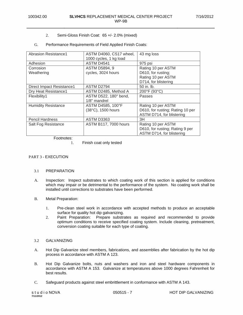
G. Performance Requirements of Field Applied Finish Coats:
Abrasion Resistance1 ASTM D4060, CS17 wheel, 1000 cycles, 1 kg load
43 mg loss
Adhesion ASTM D4541 975 psi Corrosion Weathering
ASTM D5894, 9 cycles, 3024 hours
Rating 10 per ASTM D610, for rusting; Rating 10 per ASTM D714, for blistering
Direct Impact Resistance1 ASTM D2794 50 in. lb. Dry Heat Resistance1 ASTM D2485, Method A 200°F (93°C) Flexibility1 ASTM D522, 180° bend,
1/8" mandrel Passes
Humidity Resistance ASTM D4585, 100°F (38°C), 1500 hours
Rating 10 per ASTM D610, for rusting; Rating 10 per ASTM D714, for blistering
Pencil Hardness ASTM D3363 3H Salt Fog Resistance ASTM B117, 7000 hours Rating 10 per ASTM
D610, for rusting; Rating 9 per ASTM D714, for blistering
Footnotes: 1. Finish coat only tested
PART 3 - EXECUTION
3.1 PREPARATION
A. Inspection: Inspect substrates to which coating work of this section is applied for conditions which may impair or be detrimental to the performance of the system. No coating work shall be installed until corrections to substrates have been performed.
B. Metal Preparation:
1. Pre-clean steel work in accordance with accepted methods to produce an acceptable surface for quality hot dip galvanizing.
2. Paint Preparation: Prepare substrates as required and recommended to provide optimum conditions to receive specified coating system. Include cleaning, pretreatment, conversion coating suitable for each type of coating.
3.2 GALVANIZING
A. Hot Dip Galvanize steel members, fabrications, and assemblies after fabrication by the hot dip process in accordance with ASTM A 123.
B. Hot Dip Galvanize bolts, nuts and washers and iron and steel hardware components in accordance with ASTM A 153. Galvanize at temperatures above 1000 degrees Fahrenheit for best results.
C. Safeguard products against steel embrittlement in conformance with ASTM A 143.

100342.00 SLVHCS REPLACEMENT MEDICAL CENTER PROJECT WP-9B
7/16/2012
s t u d i o NOVA 7/11/2012
050515 - 8 HOT DIP GALVANIZING
D. Galvanize reinforcing steel in accordance with ASTM A 767.
E. Handle all articles to be galvanized in such a manner as to avoid any mechanical damage and to minimize distortion.
F. To minimize surface imperfections use of the galvanizing process involving a flux blanket on the kettle (wet method) is prohibited.
G. Coat any steel item less than 44 feet in length and 8 feet in depth in a single dip to minimize potential distortion or contact the Galvanizer for Design help on progressive dip (double dip) of material.
H. Coating Requirements:
1. Coating Weight: Conform to the minimum shown in paragraph 6.1 of ASTM A 123, Table 1 of A 767, or Table 1 of ASTM A 153, as appropriate.
2. Surface Finish: Continuous, adherent, as smooth and evenly distributed as possible and free from any defect detrimental to the stated end use of the coated article.
3. Adhesion: Withstand normal handling consistent with the nature and thickness of the coating and normal use of the article.
4. Galvanizer must be made aware of architecturally exposed material or any other special appearance considerations prior to acceptance of quote or start of fabrication.
I. Cooling Material to be Painted:
1. Air cool galvanized material receiving paint finish. 2. Quenching: Quenching after galvanizing to reduce material temperature not permitted for
material requiring paint coating either under this Section or other section
3.3 TESTS
A. Inspection and testing of hot dip galvanized coatings shall be done under the guidelines of Inspection of Products Hot Dip Galvanized After Fabrication by AGA.
B. Include visual examination and tests in accordance with ASTM A 123, A 767 or A 153 as applicable to determine the thickness of the zinc coating on the metal surface.
C. Furnish Certificate of Compliance with ASTM Standards and Specifications herein listed. The Certificate must be signed by the galvanizer and contain a detailed description of the material processed. The Certificate shall include information as to the ASTM standard used for the coating.
D. Furnish a detail description as outlined in the Galvanizer ISO 9002 Quality Compliance certification.
3.4 PAINTING/DUPLEX SYSTEM
A. No “QUENCHING” of galvanized material that is to be painted.
B. Factory apply paint finish within 24 hours of galvanizing to prevent detrimental levels of oxidation from developing.

100342.00 SLVHCS REPLACEMENT MEDICAL CENTER PROJECT WP-9B
7/16/2012
s t u d i o NOVA 7/11/2012
050515 - 9 HOT DIP GALVANIZING
C. Preparation:
1. Sweep blast using non-abrasive media. 2. For items with configurations that preclude reasonable blasting such as bar grating, use
phosphate rinse in lieu of blasting and paint immediately. 3. Clean all surfaces with mineral spirits, naphtha, or approved solvent.
a. Remove all oil, grease, and other film. b. Roughen surface with steel wool as necessary to remove gloss.
D. Powder Coating: Use low temperature (350 to 360 degree F) system.
E. Environmental Conditions: See PAINT SHOP CONDITIONS in Part 1 above.
F. Steel Temperature Conditions:
1. Surface Temperature: 50 degrees F minimum and 100 degrees F maximum. 2. Steel Temperature: At least 5 degrees F above the dew point.
G. Comply with Section 09 91 00 for shop priming/painting.
H. Items to Receive Paint Finish: See SUMMARY in Part 1 above.
I. Prepare galvanized metal surfaces to be field painted in accordance with the recommendations of the paint manufacturer except sweep blast required; see below.
1. Sweep blast using nonabrasive media followed by a surface conditioner 2. Nonabrasive media includes walnut shells or synthetic sponges with low pressure. Metal,
sand, or mineral media not acceptable.
J. Shop coat galvanized metal surfaces with an approved primer for galvanizing or other approved coating.
K. Factory Quality Control:
1. Records: Maintain records for not less than 4 years of conditions specified for the following:
a. PAINT SHOP CONDITIONS in Part 1 above. b. “Steel Temperature Conditions” above. c. Tests, below.
3.5 COATING REPAIR
A. Galvanized Coatings:
1. Shop Repair: The maximum area to be repaired is defined in accordance with ASTM A 123 Section 6.2 “Finish”.
2. Field Repair: The maximum area to be repaired in the field shall be determined in advance by mutual agreement between parties.
3. Repair areas damaged by welding, flame cutting or during handling, transport or erection by whenever damage exceeds 3/16" in width.

100342.00 SLVHCS REPLACEMENT MEDICAL CENTER PROJECT WP-9B
7/16/2012
s t u d i o NOVA 7/11/2012
050515 - 10 HOT DIP GALVANIZING
a. Methods: Repair by one of the approved methods in accordance with ASTM A 780, except. Minimum thickness requirements for the repair are those described in ASTM A 123 Section 6.2 “Finish”.
B. Painted Coatings: Repair damaged paint coating in accordance with manufacturer's recommendations. Include surface preparation, prime coat, and finish coat.
1. Shop Repair: Repair all damage to paint coatings before shipment to jobsite. 2. Field Repair:
a. Repair all damage to paint coatings as result of shipping. b. Repair of damage to paint coatings resulting from unloading, site handling,
erection, or other on-site conditions to be performed by original applicator at General Contractor's cost.
C. All repair work to be performed at no additional cost to Owner.
3.6 PROTECTION
A. Protection shall be as recommended by manufacturer and approved by Resident Engineer. General Contractor shall protect system from damage during subsequent construction activities.
B. Repair damaged work as specified under COATING REPAIR above. Severely damaged work to be removed and shop recoated at no expenses to Owner.
END OF SECTION

100342.00 SLVHCS REPLACEMENT MEDICAL CENTER PROJECT WP-9B
7/16/2012
s t u d i o NOVA 7/11/2012
050523 - 1 METAL FASTENING
SECTION 05 05 23 METAL FASTENING
PART 1 - GENERAL
1.1 SUMMARY
A. Section Includes: 1. Self-drilling metal fasteners.
B. Related Sections (Items not included in this Project Manual are available through Construction Manager upon request): 1. Steel deck: Section 05 31 00 2. Structural Steel: Section 05 12 00. 3. Carpentry: Division 6. 4. Division 7 Sections for metal siding, and panels. 5. Division 8 Sections for metal storefronts, entrance doors, windows, and glazed framing
systems.
1.2 REFERENCES (Latest edition unless otherwise noted)
A. Society of Automotive Engineers (SAE):
J 78 Self-Drilling Tapping Screws.
J 429 Mechanical and Material Requirements for Externally Threaded Fasteners.
B. American Society for Testing and Materials (ASTM):
B 117 Practice for Operating Salt Spray (Fog) Apparatus.
F 593 Stainless Steel Bolts, Hex Cap Screws, and Studs.
1.3 DEFINITIONS
A. HASCC: Hydrogen-assisted stress corrosion cracking.
1.4 SUBMITTALS
A. Submit in accordance with Section 01 33 23.
B. Product Literature: Submit for approval, manufacturer’s product literature for each type fastener. Product data to fully describe fastener construction, finish, and resistance to HASCC.
C. Samples: Submit for each type fastener.

100342.00 SLVHCS REPLACEMENT MEDICAL CENTER PROJECT WP-9B
7/16/2012
s t u d i o NOVA 7/11/2012
050523 - 2 METAL FASTENING
PART 2 - PRODUCTS
2.1 MANUFACTURERS
A. Self-Drilling and Self-Tapping Screws: 1. Manufacturers: Subject to compliance with requirements, available manufacturers
offering products that may be incorporated into the Work include, but are not limited to, the following: a. Elco Construction Products, an Acument Global Technologies Co., 800 435-7213,
www.elcoconstruction.com. b. Others: As approved.
2.2 Self-Drilling and Self-Tapping Screws
A. Self-Drilling and Self-Tapping Screws: Comply with SAE J 78 except shanks and heads to comply with SAE J 429, Grade 5 with 120 ksi tensile strength and Rockwell C34 maximum hardness.
B. Where additional corrosion resistance is required, such as where fastener heads are exposed to aggressive environments, shanks and heads of fasteners shall be made of Series 300 (18-8) stainless steel per ASTM F 593, Condition CW (cold-worked), 100 to 150 ksi tensile strength, Rockwell B95 to C32 Hardness
C. Fastener Heads: Embossed with manufacturer’s mark for inspection purposes and indicating fasteners comply with specifications:
D. Carbon Steel Fasteners: Provide corrosion-resistant, hexavalent chrome-free coating with a zinc-rich basecoat and an aluminum-pigmented organic topcoat. Fastener shall withstand 800 hours without forming red rust when tested according to ASTM B 117. 1. Dril-Flex® by Elco or approved equal.
E. 300 Series Stainless Steel Fasteners: Provide galvanically compatible finish and coating, hexavalent chrome-free, zinc plate base coat and an aluminum-pigmented organic topcoat. 1. Bi-Flex® by Elco or approved equal.
PART 3 - EXECUTION
3.1 INSTALLATION
A. Install in accordance with manufacturer's recommendations using screw gun not exceeding 2500 RPM.
END OF SECTION

100342.00 SLVHCS REPLACEMENT MEDICAL CENTER PROJECT 7/16/12 WP_09B ADDENDUM 01 9/21/12
studio NOVA / Korda 051200 - 1 STRUCTURAL STEEL FRAMING 9/19/2012
SECTION 05 12 00 STRUCTURAL STEEL FRAMING PART 1 - GENERAL 1.1 DESCRIPTION:
A. This section specifies structural steel shown and classified by Section 2, Code of Standard
Practice for Steel Buildings and Bridges. B. The Engineer has designed a project which will be safe after full completion. The Engineer has
no expertise in, and takes no responsibility for, construction means and methods or job site safety during construction, which are exclusively the Contractor's responsibility. Processing and/or approving submittals made by the Contractor which may contain information related to construction methods or safety issues, or participation in meetings where such issues might be discussed, shall not be construed as voluntary assumption by the Engineer of any responsibility for safety procedures.
C. Products Installed but not Furnished Under this Section:
1. Primer for Intumescent Fireproofing: Section 07 81 23 - Intumescent Fireproofing. 1.2 RELATED WORK:
A. Materials testing and inspection during construction: Section 01 45 29, TESTING
LABORATORY SERVICES. B. Hot Dip Galvanizing: Section 05 05 15, HOT DIP GALVANIZING. C. Steel Roof Decking: Section 05 31 00, STEEL ROOF DECKING D. Composite Steel Deck: Section 05 36 00, COMPOSITE METAL DECKING. E. Fireproofing: Section 07 81 00, APPLIED FIREPROOFING and Section 07 81 23,
INTUMESCENT FIREPROOFING. F. Work Furnished but Installed Under Other Sections: Anchor bolts, loose bearing and base plates,
and loose lintels. G. Work Affected by Others: Framing, loads, openings, and structure in any way related to
plumbing, HVAC, or electrical requirements is shown for bidding purposes only. Responsibility for coordinating the work of this Section with these requirements is solely that of the Contractor. Contractor's review of shop drawings will be taken to indicate that this coordination has been accomplished.

100342.00 SLVHCS REPLACEMENT MEDICAL CENTER PROJECT 7/16/12 WP_09B ADDENDUM 01 9/21/12
studio NOVA / Korda 051200 - 2 STRUCTURAL STEEL FRAMING 9/19/2012
1.3 QUALITY ASSURANCE: A. Fabricator and erector shall maintain a program of quality assurance in conformance with
Section 8, Code of Standard Practice for Steel Buildings and Bridges. Work shall be fabricated in an AISC Standard for Steel Building Structures (STD) certified fabrication plant. Erector shall be an AISC Advanced Certified Steel Erector (ACSE).
B. Before authorizing the commencement of steel erection, the controlling contractor shall ensure
that the steel erector is provided with the written notification required by 29 CFR 1926.752. Provide copy of this notification to the Resident Engineer.
C. Erector's Qualifications: Minimum five (5) years continuous experience in similar steel erection. D. Welders' Qualifications: Personnel and procedures are to be qualified in accordance with AWS
D1.1/D1.1M:2008. 1.4 TOLERANCES:
A. Fabrication tolerances for structural steel shall be held within limits established by ASTM A6, by
Section 7, Code of Standard Practice for Buildings and Bridges, and by Standard Mill Practice - General Information (AISC Steel Construction Manual, Thirteenth Edition, Page 1-125, except as follows:
B. Elevation tolerance for column splice points at time member is erected is 3/8 inch. C. Elevation tolerance for top surface of steel beams and girders at connections to columns at time
floor is erected is 1/2 inch. D. Elevation tolerance for closure plates at the building perimeter and at slab openings prior to
concrete placement is 1/4 inch. E. Members indicated on the Drawings as Architecturally Exposed Structural Steel shall meet the
requirements of Section 10 of AISC Code of Standard Practice. 1.5 DESIGN:
A. Structural Framing Connections:
1. Design and detail all connections for each member size, steel grade and connection type to resist the loads and reactions indicated on the drawings or specified herein. Use details consistent with the details shown on the Drawings, supplementing where necessary. The details shown on the Drawings are conceptual and do not indicate the required weld sizes or number of bolts unless specifically noted. Use rational engineering design and standard practice in detailing, accounting for all loads and eccentricities in both the connection and the members. Promptly notify the Resident Engineer of any location where the connection design criteria is not clearly indicated. The design of all connections is subject to the review and acceptance of the Resident Engineer. Submit structural calculations prepared and sealed by a qualified engineer registered in Louisiana. Submit calculations for review before preparation of detail drawings.

100342.00 SLVHCS REPLACEMENT MEDICAL CENTER PROJECT 7/16/12 WP_09B ADDENDUM 01 9/21/12
studio NOVA / Korda 051200 - 3 STRUCTURAL STEEL FRAMING 9/19/2012
2. Select connections per AISC standards for forces and moments given on the Drawings. (In particular, note Schedule on Drawings for composite beams.) Where none are given, select connection for the full uniform load capacity of the member and for composite beams select connection for 1.5 x full uniform load capacity of the steel member.
3. Connections of beams framing into a girder from one side only, such as at spandrel girders, shall be made with double angle connections. Unless indicated otherwise, all other connections may be double angle connections or single plate shear connections.
4. Shop connections may be welded or bolted, unless shown otherwise. 5. Field connections shall be bolted, unless shown otherwise.
B. Exterior Wall Framing Connections
1. Design and detail all shear connections of vertical and horizontal girts for the lesser of the full uniformly loaded plastic moment capacity of the member or for 576 psf on the tributary area of the member. This is a requirement for blast loading.
1.6 REGULATORY REQUIREMENTS:
A. AISC: Specification for Structural Steel Buildings, March 9, 2005. B. AISC: Code of Standard Practice for Steel Buildings and Bridges. C. AISC: Specification for Structural Joints using ASTM A325 or A490 bolts (June 30, 2004). D. By the American Welding Society (AWS):
1. Structural Welding Code - Steel AWS D1.1/D1.1M:2008, Paragraph 6.6.5 specifically excluded.
2. Symbols for Welding and Non-Destructive Testing AWS A2.4:2007. 1.7 SUBMITTALS:
A. Submit in accordance with Section 01 33 23, SHOP DRAWINGS, PRODUCT DATA, AND
SAMPLES. B. Shop and Erection Drawings:
1. Indicate all shop and erection details, including cuts, copes, connections, holes, threaded fasteners, and welds. Include layout plan of all items to be embedded into concrete.
2. Indicate material specifications and finishes. 3. Indicate shop and field welds with symbols per AWS A2.4:2007.
C. Certificates:
1. Structural steel. 2. Steel for all connections. 3. Welding materials. 4. Shop coat primer paint.

100342.00 SLVHCS REPLACEMENT MEDICAL CENTER PROJECT 7/16/12 WP_09B ADDENDUM 01 9/21/12
studio NOVA / Korda 051200 - 4 STRUCTURAL STEEL FRAMING 9/19/2012
5. High Strength Threaded Fasteners. 6. Contractor shall certify that primer for Intumescent fireproofing specified in Section
07 81 23 - Intumescent Fireproofing has been applied to structural steel members, requiring intumescent fireproofing, in conformance with Intumescent Fireproofing manufacturer’s written instructions.
D. Test Reports:
1. Welders' qualifying tests.
E. Design Calculations and Drawings:
1. Connection calculations.
1.8 APPLICABLE PUBLICATIONS:
A. Publications listed below form a part of this specification to extent referenced. Publications are
referenced in text by basic designation only. B. American Institute of Steel Construction (AISC):
1. Specification for Structural Steel Buildings (March 9, 2005). 2. Code of Standard Practice for Steel Buildings and Bridges (March 18, 2005).
C. American National Standards Institute (ANSI):
B18.22.1-98 ...............................Plain Washers B18.22M-00...............................Metric Plain Washers
D. American Society for Testing and Materials (ASTM):
A6/A6M-02................................Standard Specification for General Requirements for Rolled
Structural Steel Bars, Plates, Shapes, and Sheet Piling A36/A36M-01............................Standard Specification for Carbon Structural Steel A53/A53M-01............................Standard Specification for Pipe, Steel, Black and Hot-Dipped,
Zinc-Coated Welded and Seamless A123/A123M-02........................Standard Specification for Zinc (Hot-Dip Galvanized) Coatings
on Iron and Steel Products A307-00 .....................................Standard Specification for Carbon Steel Bolts and Studs, 60,000
psi Tensile Strength A325-02 .....................................Standard Specification for Structural Bolts, Steel, Heat Treated,
120/105 ksi Minimum Tensile Strength A490-02 .....................................Standard Specification for Heat-Treated Steel Structural Bolts
150 ksi Minimum Tensile Strength A500-01 .....................................Standard Specification for Cold Formed Welded and Seamless
Carbon Steel Structural Tubing in Rounds and Shapes A501-01 .....................................Standard Specification for Hot-Formed Welded and Seamless
Carbon Steel Structural Tubing

100342.00 SLVHCS REPLACEMENT MEDICAL CENTER PROJECT 7/16/12 WP_09B ADDENDUM 01 9/21/12
studio NOVA / Korda 051200 - 5 STRUCTURAL STEEL FRAMING 9/19/2012
A572/A572M-01........................Standard Specification for High-Strength Low-Alloy Columbium-Vanadium Structural Steel
A992/A992M-02........................Standard Specification for Structural Steel Shapes E. American Welding Society (AWS):
D1.1-02 ......................................Structural Welding Code-Steel
F. Research Council on Structural Connections (RCSC) of The Engineering Foundation: Specification for Structural Joints Using ASTM A325 or A490 Bolts G. Military Specifications (Mil. Spec.):
MIL-P-21035 .............................Paint, High Zinc Dust Content, Galvanizing, Repair
H. Occupational Safety and Health Administration (OSHA):
29 CFR Part 1926-2001 .............Safety Standards for Steel Erection
I. Steel Structures Painting Council (SSPC):
1. SSPC SP 100 (R2004) Solvent Cleaning 2. SSPC SP 2-00 (R2004) Hand Tool Cleaning 3. SSPC SP 3-00 (R2004) Power Tool Cleaning 4. SSPC-SP 6-07 Commercial Blast Cleaning
1.9 LEED SUBMITTALS
A Product Data for Credit MR 4: For products having recycled content, documentation indicating
percentages by weight of postconsumer and preconsumer recycled content. Include statement indicating cost for each product having recycled content.
PART 2 - PRODUCTS 2.1 MATERIALS:
A. Structural Steel Channels, Angles, Plates, Bars, etc.: ASTM A36, unless indicated otherwise. B. Structural Steel Wide Flange Shapes: ASTM A572, Grade 50, or ASTM A992. C. Square and Rectangular Structural Tubing: ASTM A500, Grade B. D. Round Structural Tubing and Pipe: ASTM A501 or ASTM A53, Grade B.

100342.00 SLVHCS REPLACEMENT MEDICAL CENTER PROJECT 7/16/12 WP_09B ADDENDUM 01 9/21/12
studio NOVA / Korda 051200 - 6 STRUCTURAL STEEL FRAMING 9/19/2012
E. Bolts, Nuts and Washers: 1. High-strength bolts, including nuts and washers: ASTM A325 or A490. 2. Bolts and nuts, other than high-strength: ASTM A307, Grade A. 3. Plain washers, other than those in contact with high-strength bolt heads and nuts: ANSI
Standard B18.22.1. F. Zinc Coating: ASTM A123. G. Galvanizing Repair Paint: Mil. Spec. MIL-P-21035. H. Anchor Bolts: ASTM A572, Grade 50 or ASTM F1554, Grade 55 threaded rods. I. Welding Electrodes: Conform to requirements of AWS D1.1/D1.1M:2008, using Series E70
electrodes, appropriate for the materials being welded. J. Shop Paint Primer:
1. For bare steel, use modified alkyd or alkyd-oil primers, equal in quality to 10-99 Tnemec Primer, 10-99W Tnemec Primer, or 4-55 Versare Primer by Tnemec Company, Inc. and in the existing Dixie Building for all steel in contact with the existing exterior brick walls, use Tnemec Series 90-97 Tnemec-Zinc.
2. For galvanized steel to be painted, see Section 05 05 15, HOT DIP GALVANIZING. 3. Primer to be compatible with finish paint. 4. Primer for Intumescent Fireproofing: Furnished elsewhere.
K. Grating: All steel, 1 1/2 inches deep, with 3/16 inch bearing bars may be welded, pressure-
locked or riveted. The following are acceptable:
1. Types GW or GAA by McNichols. 2. Type W/B or B by Borden Metal Products Company. 3. Type WB or Type BS by IKG Industries. Attachment may be by tack welding or saddle clips.
L. Headed Studs: ASTM A108-07, Grades 1010 through 1020, inclusive, either semi-killed or killed deoxidization.
M. Masonry Anchors: 11 gauge channel slots or 3/16 inch diameter wires, shop welded to structural
steel. N. Deformed Bar Anchors: Flux-filled deformed bar anchors to be welded to structural steel.
Material shall conform to ASTM A496/A496M-07; acceptable products include Nelson D2L by Nelson Stud Welding.

100342.00 SLVHCS REPLACEMENT MEDICAL CENTER PROJECT 7/16/12 WP_09B ADDENDUM 01 9/21/12
studio NOVA / Korda 051200 - 7 STRUCTURAL STEEL FRAMING 9/19/2012
PART 3 - EXECUTION 3.1 CONNECTIONS (SHOP AND FIELD):
A. Welding: Welding in accordance with AWS D1.1. Welds shall be made only by welders and
welding operators who have been previously qualified by tests as prescribed in AWS D1.1 to perform type of work required.
B. High-Strength Bolts: High-strength bolts tightened to a bolt tension not less than proof load
given in Specification for Structural Joints Using ASTM A325 or A490 Bolts. Tightening done with properly calibrated wrenches, by turn-of-nut method or by use of direct tension indicators (bolts or washers). Tighten bolts in connections identified as slip-critical using Direct Tension Indicators or the turn-of-the-nut method. Twist-off torque bolts are not an acceptable alternate fastener for slip critical connections.
3.2 SURFACE CONDITIONS
A. Prior to beginning work of this Section, verify that the installed work of other trades is complete
and correct to the extent necessary for the proper execution of the work of this Section. This includes locations of anchor bolts, and lines and grades of bearing areas.
B. In the event of discrepancies, immediately notify the Architect. Do not proceed with work
affected by the discrepancies until they have been resolved.
3.3 FABRICATION: Fabrication in accordance with Chapter M, Specification for Steel Buildings, except where more
stringent requirements are indicated on the Drawings. 3.4 SHOP PAINTING:
A. General: Shop paint steel with primer in accordance with Section 6, Code of Standard Practice
for Steel Buildings and Bridges. B. Do not apply paint to following:
1. Surfaces within 2 inches of joints to be welded in field. 2. Surfaces which will be encased in concrete. 3. Surfaces receiving Cementitious Fireproofing.
C. Zinc Coated (Hot Dip Galvanized): Provide in compliance with Section 05 05 15, HOT DIP
GALVANIZING. D. Structural steel in the interstitial space that is not enclosed in concrete and does not receive
sprayed on fireproofing shall be painted with primer in accordance with general requirement of shop painting.

100342.00 SLVHCS REPLACEMENT MEDICAL CENTER PROJECT 7/16/12 WP_09B ADDENDUM 01 9/21/12
studio NOVA / Korda 051200 - 8 STRUCTURAL STEEL FRAMING 9/19/2012
E. Zinc Coated (Hot Dip Galvanized) per ASTM A123 (after fabrication): Touch-up after erection: Conform to requirements of Section 05 05 15, HOT DIP GALVANIZING.
F. Camber: Spans longer than 42 feet are to have minimum camber as follows: 42 - 52 feet, 1 inch;
52 - 65 feet, 2 inches; 65 - 85 feet, 3 inches; unless noted otherwise. G. Sweep: Fabricate exterior spandrel beams with natural sweep toward the interior of the building. H. Finishing: Ends of members in direct contact bearing, such as columns at their bases and splices,
are to be "finished," as defined in the Code of Standard Practice. I. Bearing and Base Plates: Column base plates are to be shop attached. Beam bearing plates may
be attached or loose. J. Holes: Drill or punch holes in members as required for passage of conduit and piping, and
attachment of joists, nailers, etc. Burning such holes is not permitted. If opening is not shown on structural drawings, obtain prior approval.
K. Cleaning:
1. Remove oil, dirt, loose mill scale, or other material which would impair welding, performance of slip critical connections, or adherence of concrete or sprayed fireproofing.
2. For steel that is to be painted, cleaning techniques are to be as required by the appropriate SSPC paint Specification listed below.
L. Shop Painting:
1. Shop-paint steel, except that to be galvanized or receive Intumescent Fireproofing, with primer as follows: a. Prepare surface by commercial blast cleaning (SSPC - SP6) and apply one (1) coat of
primer. b. Minimum dry film thickness shall be 2.0 mils, except zinc rich primer dry film
thickness shall be 2.5 to 3.5 mils. The primer shall be applied in a manner to assure no runs or sags in the coating and an overall uniform application.
c. Do not paint surfaces to be encased in concrete or to receive sprayed fireproofing, or contact surface in slip-critical connections, or surfaces to be field welded, or top surfaces of crane rails.
2. Paint all lintels in interior walls with one (1) coat of primer per the requirements in #1 above. 3. Shop-paint steel to receive Intumescent Fireproofing, with primer furnished by Section
07 81 23 as follows: a. Install in accordance with manufacturer’s written instructions and recommendations
provided by Section 07 81 23 – Intumescent Fireproofing. b. Prepare surface by commercial blast cleaning (SSPC - SP6) or to a higher level if
required by Section 07 81 23. Base bid on the following: 1) Base bid on commercial blast cleaning (SSPC - SP6), and advise Resident Engineer
in writing if a higher level is required by information received from Section 07 81 23 – Intumescent Fireproofing.

100342.00 SLVHCS REPLACEMENT MEDICAL CENTER PROJECT 7/16/12 WP_09B ADDENDUM 01 9/21/12
studio NOVA / Korda 051200 - 9 STRUCTURAL STEEL FRAMING 9/19/2012
c. Primer: Apply to steel following manufacture’s recommendations. Minimum dry film thickness (DFT).shall be 4.0 mils
d. Protect in accordance with PROJECT CONDITIONS in Section 07 81 00, and manufacturer’s recommendations.
3.5 ERECTION:
A. General: Erection in accordance with Section 7, Code of Standard Practice for Steel Buildings
and Bridges. B. Temporary Supports: Temporary support of structural steel frames during erection in accordance
with Section 7, Code of Standard Practice for Steel Buildings and Bridges. C. This structure is designed to be self-supporting and stable after the building is fully completed. It
is solely the Contractor's responsibility to determine erection procedures and sequence, and to ensure the stability of the building and its component parts, and the adequacy of temporary or incomplete connections, during erection. This includes the addition of any shoring, sheeting, temporary guys, bracing or tie-downs that might be necessary. Such material is not shown on the Drawings. If applied, they shall be removed as conditions permit, and shall remain the Contractor's property.
D. Safety: It is solely the Contractor's responsibility to follow all applicable safety codes and
regulations governing this work. E. Clean bearing surfaces and other surfaces in permanent contact, prior to assembly. F. Splices are permitted only where indicated. G. Field corrections of fabrication errors by gas cutting is not permitted in structural members
without prior approval of the Architect. H. The use of leveling plates or leveling nuts at column bases is prohibited. Grout below column
base plates is to be installed only after the steel is plumbed. I. Welds which are subject to foot traffic or are exposed to view in the finished structure are to be
ground smooth and flush with adjacent surfaces. J. Touch-up Painting: After erection, touch-up field connections and abrasions in the shop coat
with same paint used for shop coat. Do not paint welds until they have been cleaned in accordance with AWS D1.1/D1.1M:2008.
1. Intumescent Fireproofing Primer: Clean steel and repair any damaged primer on steel in
conformance with SSPC-SP2 Hand Cleaning, shortly before application of fireproofing by Section 07 81 23 – Intumescent Fireproofing. Apply touchup primer matching shop applied primer, 4.0 mils (DFT) minimum.
K. Remove galvanizing prior to welding. Touch-up per Section 05 05 15, HOT DIP
GALVANIZING.
See RFI 03792 For acceptableuse of leveling nuts.

100342.00 SLVHCS REPLACEMENT MEDICAL CENTER PROJECT 7/16/12 WP_09B ADDENDUM 01 9/21/12
studio NOVA / Korda 051200 - 10 STRUCTURAL STEEL FRAMING 9/19/2012
3.6 FIELD PAINTING: A. After erection, touch-up steel surfaces specified to be shop painted. After welding is completed,
clean and prime areas not painted due to field welding.
3.7 SURVEY A. Upon completion of finish bolting or welding on any part of the work, and prior to start of work
by other trades that may be supported, attached, or applied to the structural steel work, submit a certified report of survey to Resident Engineer for approval. Reports shall be prepared by Registered Land Surveyor or Registered Civil Engineer as specified in Section 01 00 00, GENERAL REQUIREMENTS. Report shall specify that location of structural steel is acceptable for plumbness, level and alignment within specified tolerance specified in the AISC Manual.
END OF SECTION
100342.00 SLVHCS REPLACEMENT MEDICAL CENTER PROJECT 7/16/12 WP_09B
studio NOVA / Korda 053100 - 1 STEEL ROOF DECKING 7/10/2012
SECTION 05 31 00 STEEL ROOF DECKING PART 1 - GENERAL 1.1 DESCRIPTION:
This section specifies material and services required for installation of steel roof decking as
shown and specified. 1.2 RELATED WORK:
A. Materials testing and inspection during construction: Section 01 45 29, TESTING
LABORATORY SERVICES. 1.3 DESIGN REQUIREMENTS:
A. Design steel decking in accordance with AISI publication, "Specification for the Design of Cold-
formed Steel Structural Members" except as otherwise shown or specified. B. Design all elements with the latest published version of applicable codes.
1.4 SUBMITTALS:
A. Submit in accordance with Section 01 33 23, SHOP DRAWINGS, PRODUCT DATA, AND
SAMPLES. B. Shop Drawings: Shop and erection drawings showing decking unit layout, connections to
supporting members, and similar information necessary for completing installation as shown and specified, including supplementary framing, sump pans, ridge and valley plates, cant strips, cut openings, special jointing or other accessories. Show welding, side lap, closure, deck reinforcing and closure reinforcing details. Show openings required for work of other trades, including openings not shown on structural drawings.
C. Manufacturer's Literature and Data: Showing steel decking section properties and specifying
structural characteristics.
1.5 APPLICABLE PUBLICATIONS: A. Publications listed below form a part of this specification to extent referenced. Publications are
referenced in text by basic designation only.

100342.00 SLVHCS REPLACEMENT MEDICAL CENTER PROJECT 7/16/12 WP_09B
studio NOVA / Korda 053100 - 2 STEEL ROOF DECKING 7/10/2012
B. American Society for Testing and Materials (ASTM): A36/A36M-08............................Standard Specification for Carbon Structural Steel A611-97 .....................................Standard Specification for Structural Steel (SS), Sheet, Carbon,
Cold-Rolled A653/A653M-08........................Standard Specification for Steel Sheet, Zinc-Coated
(Galvanized) or Zinc-Iron Alloy-Coated (Galvanized) by the Hot-Dip Process
C. American Institute of Steel Construction (AISC):
1. Specification for Structural Steel Buildings – Allowable Stress Design and Plastic Design
(Thirteenth Edition, 2005) D. American Iron and Steel Institute (AISI):
1. Specification and Commentary for the Design of Cold-Formed Steel Structural Members
E. American Welding Society (AWS):
D1.3-08 ......................................Structural Welding Code - Sheet Steel
F. Military Specifications (Mil. Spec.)
MIL-P-21035B...........................Paint, High Zinc Dust Content, Galvanizing Repair
1.6 LEED SUBMITTALS:
A. Product Data for Credit MR4: For products having recycled content, documentation including
percentages by weight of postconsumer and preconsumer recycled content. Include statement indicating cost for each product having recycled content.
PART 2 - PRODUCTS 2.1 MATERIALS:
A. Steel Decking: ASTM A653, Structural Quality. B. Galvanizing: ASTM A653, G90. C. Galvanizing Repair Paint: Mil. Spec. MIL-P-21035B. D. Miscellaneous Steel Shapes:
1. Channels, angles, and plates: ASTM A36. 2. Wide Flange Members: ASTM A572 or ASTM A992, Fy = 50 KSI.

100342.00 SLVHCS REPLACEMENT MEDICAL CENTER PROJECT 7/16/12 WP_09B
studio NOVA / Korda 053100 - 3 STEEL ROOF DECKING 7/10/2012
E. Welding Electrode: E70XX minimum. F. Sheet Metal Accessories: ASTM A653, galvanized, unless noted otherwise. Provide accessories
of every kind required to complete the installation of metal decking in the system shown. Finish sheet metal items to match deck including, but not limited to, the following items: 1. Metal Cover Plates: For end-abutting deck units, to close gaps at changes in deck direction,
columns, walls and openings. Same quality as deck units but not less than 18 gauge sheet steel.
2. Continuous Sheet Metal Edging: At openings and roof deck edges. Same quality as deck units but not less than 18 gauge steel.
3. Metal Closure Strips: For openings between decking and other construction, of not less than 18 gauge sheet steel of the same quality as the deck units. Form to the configuration required to provide tight-fitting closures at open ends of flutes and sides of decking.
4. Ridge and Valley Plates: Provide 18 gauge, minimum 4 inch wide ridge and valley plates where roof slope exceeds 1/2 inch per foot.
5. Cant Strips: Provide bent metal 45 degree leg cant strips where indicated on the Drawings. Fabricate cant strips from 20 gauge metal with a minimum 5 inch face width.
6. Seat Angles for Deck: Provide where a beam does not frame into a column. 7. Sump Pans for Roof Drains: Fabricated from single piece of minimum 14 gauge galvanized
sheet steel with level bottoms and sloping sides to direct water flow to drain, unless otherwise shown. Provide sump pans of adequate size to receive roof drains and with bearing flanges not less than 3 inches wide. Recess pans not less than 1 1/2 inches below roof deck surface, unless otherwise shown or required by deck configuration. Holes for drains will be cut in the field.
2.2 REQUIREMENTS:
A. Provide steel decking of the type, depth, gauge, and section properties as shown. B. Metal Roof Deck: Single pan fluted units with flat horizontal top surfaces utilized to act as a
permanent support for all superimposed loads. Comply with the depth and minimum gage requirements as shown on the Contract Documents. 1. Wide Rib (Type B) deck. 2. Deep Rib (Type N) deck. 3. Finish: Galvanized G-90.
C. Do not use steel deck for hanging supports for any type or kind of building components including
suspended ceilings, electrical light fixtures, plumbing, heating, or air conditioning pipes or ducts or electrical conduits.

100342.00 SLVHCS REPLACEMENT MEDICAL CENTER PROJECT 7/16/12 WP_09B
studio NOVA / Korda 053100 - 4 STEEL ROOF DECKING 7/10/2012
PART 3 - EXECUTION 3.1 ERECTION:
A. Do not start installation of metal decking until corresponding steel framework has been plumbed,
aligned and completed. Remove any oil, dirt, paint, ice, water and rust from steel surfaces to which metal decking will be welded.
B. Coordinate and cooperate with structural steel erector in locating decking bundles to prevent
overloading of structural members. C. Do not use floor deck units for storage or working platforms until permanently secured. Do not
overload deck units once placed. Replace any deck units that become damaged after erection and prior to casting concrete at no cost to the Government.
D. Provide steel decking in sufficient lengths to extend over 3 or more spans. E. Place steel decking units at right angles to supporting members. End laps of sheets of roof deck
shall be a minimum of 2 inches and shall occur over supports. F. Fastening Deck Units:
1. Fasten roof deck units to steel supporting members by not less than 5/8 inch diameter puddle
welds or elongated welds of equal strength, spaced not more than 12 inches o.c. at every support, and at closer spacing where required for lateral force resistance by diaphragm action. Attach split or partial panels to the structure in every valley. In addition, secure deck to each supporting member in ribs where side laps occur. Power driven fasteners may be used in lieu of welding for roof deck if strength equivalent to the welding specified above is provided. Submit test data and design calculations verifying equivalent design strength.
2. Mechanically fasten side laps of adjacent roof deck units with spans greater than 5 feet between supports, at intervals not exceeding 3 feet o.c., or midspan, whichever is closer, using self-tapping No. 8 or larger machine screws.
3. Provide any additional fastening necessary to comply with the requirements of Underwriters Laboratories and/or Factory Mutual to achieve the required ratings.
4. Uplift Loading: Install and anchor roof deck units to resist gross uplift service loading of 145 psf at eave overhang and 100 psf for other roof areas.
G. Cutting and Fitting:
1. Cut all metal deck units to proper length in the shop prior to shipping. 2. Field cutting by the metal deck erector is restricted to bevel cuts, notching to fit around
columns and similar items, and cutting openings that are located and dimensioned on the Structural Drawings.
3. Other penetrations shown on the approved metal deck shop drawings but not shown on the Structural Drawings are to be located, cut and reinforced by the trade requiring the opening.
4. Make all cuts neat and trim using a metal saw, drill or punchout device; cutting with torches is expressly prohibited.

100342.00 SLVHCS REPLACEMENT MEDICAL CENTER PROJECT 7/16/12 WP_09B
studio NOVA / Korda 053100 - 5 STEEL ROOF DECKING 7/10/2012
5. Do not make any cuts in the metal deck that are not shown on the approved metal deck drawings. If an additional opening not shown on the approved shop drawings is required, submit a sketch, to scale, locating the required new opening and any other openings and supports in the immediate area. Do not cut the opening until the sketch has been reviewed and accepted by the Resident Engineer. Provide any additional reinforcing or framing required for the opening at no cost to the Government. Failure to comply with these requirements is cause for rejection of the work and removal and replacement of the affected metal deck.
6. Reinforcement at Openings: Provide additional metal reinforcement and closure pieces as required for strength, continuity of decking, and support of other work shown.
3.2 WELDING:
Welds shall be made only by welders and welding operators who have been previously qualified
by tests as prescribed in AWS D1.3. 3.3 FIELD REPAIR:
1. Areas scarred during erection. 2. Welds to be thoroughly cleaned and touched-up. Touch-up paint for zinc-coated units shall
be zinc rich galvanizing repair paint.
END OF SECTION

100342.00 SLVHCS REPLACEMENT MEDICAL CENTER PROJECT 7/16/12 WP_09B
studio NOVA / Korda 053600 - 1 COMPOSITE METAL DECKING 7/10/2012
SECTION 05 36 00 COMPOSITE METAL DECKING PART 1 – GENERAL 1.1 DESCRIPTION:
This section specifies material and services required for installation of composite steel decking
and miscellaneous closures required to prepare deck for concrete placement as shown and specified.
1.2 RELATED WORK:
Materials testing and inspection during construction: Section 01 45 29, TESTING
LABORATORY SERVICES. 1.3 DESIGN REQUIREMENTS:
A. Design steel decking in accordance with American Iron And Steel Institute publication
"Specifications for the Design of Cold Formed Steel Structural Members", except as otherwise shown or specified.
B. Design all elements with the latest published version of applicable codes.
1.4 SUBMITTALS:
A. Submit in accordance with Section 01 33 23, SHOP DRAWINGS, PRODUCT DATA, AND
SAMPLES. B. Shop Drawings: Shop and erection drawings showing decking unit layout, connections to
supporting members, and information necessary to complete the installation as shown and specified, including supplementary framing, cant strips, cut openings, special jointing or other accessories. Show welding, side lap, closure, deck reinforcing and closure reinforcing details. Show openings required for work of other trades, including openings not shown on structural drawings. Indicate where temporary shoring is required to satisfy design criteria.
C. Manufacturer's Literature and Data: Showing steel decking section properties and specifying
structural characteristics as specified herein. D. Manufacturer's written recommendations for:
1. Shape of decking section to be used. 2. Cleaning of steel decking prior to concrete placement.
E. Test Report - Establishing structural characteristics of composite concrete and steel decking
system.

100342.00 SLVHCS REPLACEMENT MEDICAL CENTER PROJECT 7/16/12 WP_09B
studio NOVA / Korda 053600 - 2 COMPOSITE METAL DECKING 7/10/2012
F. Certification: For each type and gauge of metal deck supporting concrete slab or fill, furnish certification of the specified fire ratings. Certify that the units supplied are U.L. listed as a "Steel Floor and Form Unit".
1.5 QUALITY ASSURANCE:
Underwriters' Label: Provide metal floor deck units listed in Underwriters' Laboratories "Fire
Resistance Directory", with each deck unit bearing the UL label and marking for specific system detailed.
1.6 APPLICABLE PUBLICATIONS:
A. Publications listed below form a part of this specification to extent referenced. Publications are
referenced in text by basic designation only. Refer to the latest edition of all referenced Standards and codes.
B. American Iron and Steel Institute (AISI): Specification and Commentary for the Design of Cold-Formed Steel Structural Members (Latest
Edition). C. American Society of Testing and Materials (ASTM):
A36/A36M.................................Standard Specification for Carbon Structural Steel A108...........................................Standard Specification for Steel Bars, Carbon, Cold Finished,
Standard Quality A653/A653M.............................Standard Specification for Steel Sheet, Zinc-Coated
(Galvanized) or Zinc-Iron Alloy-Coated (Galvanized) by the Hot-Dip Process
D. American Institute of Steel Construction (AISC):
1. Specification for Structural Steel Buildings, March 9, 2005.
E. American Welding Society (AWS):
D1.1............................................Structural Welding Code - Steel D1.3............................................Structural Welding Code - Sheet Steel
F. Military Specifications (Mil. Spec.):
MIL-P-21035B...........................Paint, High Zinc Dust Content, Galvanizing Repair
G. Steel Structures Painting Council (SSPC): SSPC SP 1..................................Solvent Cleaning

100342.00 SLVHCS REPLACEMENT MEDICAL CENTER PROJECT 7/16/12 WP_09B
studio NOVA / Korda 053600 - 3 COMPOSITE METAL DECKING 7/10/2012
H. Master Painters Institute (MPI): 101 .............................................Epoxy Anti-Corrosive Metal Primer 163 .............................................Light Industrial Coating, Exterior, Water Based, Semi-Gloss
1.7 LEED SUBMITTALS
A. Product Data for Credit MR4: For products having recycled content, documentation indicating percentages by weight of postconsumer and preconsumer recycled content. Include statement indicating cost for each product having recycled content.
PART 2 - PRODUCTS 2.1 MATERIALS:
A. Steel Decking and all Flashings: ASTM A653, Structural Quality. B. Galvanizing: ASTM A653, G60. C. Galvanizing Repair Paint: Mil. Spec. MIL-P-21035B. D. Epoxy Primer: MPI 101. E. Waterborne Light Industrial Code: MPI 163. F. Miscellaneous Steel Shapes: ASTM A36. G. Welding Electrode: E60XX minimum. H. Sheet Metal Accessories: ASTM A653, galvanized, unless noted otherwise. Provide accessories
of every kind required to complete the installation of metal decking in the system shown. Finish sheet metal items to match deck including, but not limited to, the following items: 1. Metal Cover Plates: For end-abutting deck units, to close gaps at changes in deck direction,
columns, walls and openings. Same quality as deck units but not less than 18 gauge sheet steel.
2. Continuous sheet metal edging: at openings and concrete slab edges. Same quality as deck units but not less than 18 gauge steel. Side and end closures supporting concrete and their attachment to supporting steel shall be designed by the manufacturer to safely support the wet weight of concrete and construction loads. The deflection of cantilever closures shall be limited to 1/4 inch maximum.
3. Metal Closure Strips: For openings between decking and other construction, of not less than 18 gauge sheet steel of the same quality as the deck units. Form to the configuration required to provide tight-fitting closures at open ends of flutes and sides of decking.
4. Seat angles for deck: Where a beam does not frame into a column.

100342.00 SLVHCS REPLACEMENT MEDICAL CENTER PROJECT 7/16/12 WP_09B
studio NOVA / Korda 053600 - 4 COMPOSITE METAL DECKING 7/10/2012
2.2 REQUIREMENTS: A. Steel decking depth, gage, and section properties to be as shown. Provide edges of deck with
vertical interlocking male and female lip providing for a positive mechanical connection. B. Fabricate deck units with integral embossments to provide mechanical bond with concrete slab.
In combination with concrete slab, capable of supporting total design loads on spans shown. C. Steel decking capable of safely supporting total, normal construction service loads without
damage to decking unit. D. Steel decking units shall include an integral system which provides a simple point of attachment
for light duty hanger devices for flexibility for attaching hangers for support of acoustical, lathing, plumbing, heating, air conditioning and electrical items. System shall provide for minimum spacing pattern of 12 inches on centers longitudinally and 24 inches on centers transversely. Suspension system shall be capable of safely supporting a maximum allowable load of 100 pounds concentrated at any one hanger attachment point. System may consist of fold-down type hanger tabs or a lip hanger.
E. Galvanized Metal Deck to be Shop Painted (Metal Deck Above Pool Area of Building 6
Bounded by Column Lines 06 G, 06 K, 06 3, and 06 6). 1. Clean surfaces to remove grease, oil and other deterrents to paint adhesion in accordance
with SSPC-SP1 (Solvent Cleaning). 2. Paint bottom surface of metal deck with Epoxy Primer and Waterborne Industrial Coating as
follows:
MPI EXT 5.3K-G5 (Semigloss) Primer Intermediate Topcoat
MPI 101 MPE 163 MPI 163 System DFT: 5 mils 125 microns
PART 3 - EXECUTION 3.1 ERECTION:
A. Do not start installation of metal decking until corresponding steel framework has been plumbed,
aligned and completed and until temporary shoring, where required, has been installed. Remove any oil, dirt, paint, water and rust from steel surfaces to which metal decking will be welded.
B. Coordinate and cooperate with structural steel erector in locating decking bundles to prevent
overloading of structural members. C. Do not use floor deck units for storage or working platforms until permanently secured. Do not
overload deck units once placed. Replace any deck units that become damaged after erection and prior to casting concrete at no cost to the Government.

100342.00 SLVHCS REPLACEMENT MEDICAL CENTER PROJECT 7/16/12 WP_09B
studio NOVA / Korda 053600 - 5 COMPOSITE METAL DECKING 7/10/2012
D. Erect steel deck in accordance with manufacturer's printed instructions. E. Ship steel deck units to project in standard widths and cut to proper length. F. Provide steel decking in sufficient lengths to extend over 3 or more spans, except where
structural steel layout does not permit. G. Place steel decking units on supporting steel framework and adjust to final position before being
permanently fastening. Bring each unit to proper bearing on supporting beams. Place deck units in straight alignment for entire length of run of flutes and with close registration of flutes of one unit with those of abutting unit. Maximum space between ends of abutting units is 1/2 inch. If space exceeds 1/2 inch, install closure plates at no additional cost to Government.
H. Ceiling hanger loops, if used, must be flattened or removed to obtain bearing of units on
structural steel. I. Fastening Deck Units:
1. Fasten floor deck units to steel supporting members by not less than 5/8 inch diameter puddle
welds or elongated welds of equal strength, spaced not more than 12 inches o.c. with a minimum of two welds per unit at each support. Where two units abut, fasten each unit individually to the supporting steel framework.
2. Tack weld or use self-tapping No. 8 or larger machine screws at 3 feet o.c. for fastening end closures. Only use welds to attach longitudinal end closures.
3. Screw or button punch side laps of adjacent floor deck units that span more than 5 feet. Fasten at midspan or 3 feet o.c., whichever is smaller.
J. Welding to conform to AWS D1.3 and done by competent experienced welding mechanics. K. Areas scarred during erection and welds shall be thoroughly cleaned and touched-up with zinc
rich galvanizing repair paint. Paint touch-up is not required for welds or scars that are to be in direct contact with concrete.
L. Provide metal concrete stops at edges of deck as required. M. Cutting and Fitting:
1. Cut all metal deck units to proper length in the shop prior to shipping. 2. Field cutting by the metal deck erector is restricted to bevel cuts, notching to fit around
columns and similar items, and cutting openings that are located and dimensioned on the structural drawings.
3. Other penetrations shown on the approved metal deck shop drawings but not shown on the structural drawings are to be located, cut and reinforced by the trade requiring the opening.
4. Make all cuts neat and trim using a metal saw, drill or punchout device; cutting with torches is expressly prohibited.
RFI 08763: IT IS ACCEPTABLETO USE HILTI SHOT IN LIEUOF PUDDLE WELDS. SIZETHE POWER ACTUATEDFASTENERS TO MATCH THEREQUIRED WELD CAPACITY.

100342.00 SLVHCS REPLACEMENT MEDICAL CENTER PROJECT 7/16/12 WP_09B
studio NOVA / Korda 053600 - 6 COMPOSITE METAL DECKING 7/10/2012
5. Do not make any cuts in the metal deck that are not shown on the approved metal deck drawings. If an additional opening not shown on the approved shop drawings is required, submit a sketch, to scale, locating the required new opening and any other openings and supports in the immediate area. Do not cut the opening until the sketch has been reviewed and accepted by the Resident Engineer. Provide any additional reinforcing or framing required for the opening at no cost to the Government. Failure to comply with these requirements is cause for rejection of the work and removal and replacement of the affected metal deck.
6. Reinforcement at Openings: Provide additional metal reinforcement and closure pieces as required for strength, continuity of decking and support of other work shown.
3.2 CLEANING:
Clean deck in accordance with manufacturer's recommendation before concrete placement.
END OF SECTION

100342.00
SLVHCS REPLACEMENT MEDICAL CENTER PROJECT WP-9B
Addendum 03-Post Bid
7/16/2012
7/3/2013
s t u d i o NOVA 6/27/2013
054000 - 1 COLD-FORMED METAL FRAMING
SECTION 05 40 00 COLD-FORMED METAL FRAMING
PART 1 - GENERAL
1.1 SUMMARY
A. This section specifies materials and services required for installation of cold-formed steel, including tracks and required accessories as shown and specified. This Section includes the following: 1. Exterior Soffit framing at Dixie Carriageway. 2. Delegated design of cold formed metal framing at soffits, except blast resistant soffits.
B. Products Provided but not Specified Under this Section: 1. Exterior wall Sheathing: Section 06 16 63 - Cementitious Sheathing.
1.2 RELATED WORK
A. Exterior Wind Enclosure Requirements: Section 01 83 16.13.
B. Exterior Sheathing: Section 06 16 63.
C. Structural steel framing: Section 05 12 00, Structural Steel Framing.
D. Building Structure: See structural drawings.
E. DEFS: Section 07 24 00, Exterior Insulation and Finish System.
1.3 DEFINITIONS
A. Minimum Uncoated Steel Thickness: Minimum uncoated thickness of cold-formed framing delivered to the Project site shall be not less than 95 percent of the thickness used in the cold-formed framing design. Lesser thicknesses shall be permitted at bends due to cold forming.
B. Producer: Entity that produces steel sheet coil fabricated into cold-formed members.
C. “Cold-Formed Metal Framing”, “cold-formed steel stud”, “metal stud”, and “light gage metal framing” are interchangeable terms for purposes of the WP-9B contract.
D. Building Structure: Structure shown on structural drawings.
1.4 DESIGN REQUIREMENTS FOR NON-BLAST RESISTANT FRAMING
A. Delegated Design: Engage a fabricator who assumes undivided responsibility for engineering cold-formed metal framing by employing a qualified Professional Engineer to prepare design calculations, shop drawings, and other structural data, using performance requirements and design criteria indicated.

100342.00
SLVHCS REPLACEMENT MEDICAL CENTER PROJECT WP-9B
Addendum 03-Post Bid
7/16/2012
7/3/2013
s t u d i o NOVA 6/27/2013
054000 - 2 COLD-FORMED METAL FRAMING
B. Design steel in accordance with American Iron and Steel Institute Publication "Specification for the Design of Cold-Formed Steel Structural Members", except as otherwise shown or specified.
C. Structural Performance: Engineer, fabricate, and erect cold-formed metal framing to withstand design loads within limits and under conditions required.
D. Building Code: Comply with IBC, 2006 Edition.
E. Parameters: 1. Framing Spacing:
a. Supporting Exterior Sheathing: Not to exceed 12 inch centers. b. Others: Not to exceed 16 inch centers.
2. Minimum Framing Gage: 0.0566 inches, 16 gage. 3. Brace and support soffits from building structure. Adjacent blast resistant wall
constructions are not designed for soffit loads.
F. Design Loads: 1. General: Engineer cold-formed metal framing to withstand Project wind loads (including
soffit uplift), other live loads and dead loads without exceeding the allowable design work stress of the material involved, including anchors and connections. Wind Loads:
a. Exterior: As specified in Section 01 83 16.13 - Exterior Wind Enclosure Requirements.
2. Dead Loads: Weight of attached materials, and per Building Code. 3. Live Loads: As specified in Section 01 83 16.13 - Exterior Wind Enclosure Requirements. 4. Design framing systems to withstand design loads without deflections greater than the
following: At exterior applications with non-rigid facing (DEFS): Not to exceed L/240. 5. Design framing systems to provide for movement of framing members without damage or
overstressing, sheathing failure, connection failure, undue strain on fasteners and anchors, or other detrimental effects when subject to a maximum ambient temperature change (range) of 67 degrees C (120 degrees F).
6. Design framing system to accommodate deflection of primary building structure and construction tolerances, and to maintain clearances at openings.
7. Cementitious exterior sheathing shall be provided over the cold-formed metal framing and secured to the cold-formed metal framing to meet the wind loads specified in Section 01 83 16.13 - Exterior Wind Enclosure Requirements.
a. Fastening Method of Sheathing to Framing: As specified in Section 06 16 63, 1) Design with a safety factor of 3. 2) Fasteners shall not be spaced closer together than recommended by
exterior sheathing manufacturer, and fasteners shall be installed at recommended distance from edge of sheathing.
3) Provide additional framing, if required to meet this Performance requirement at no additional cost to Owner
G. Cold formed metal framing shall not be less than the sizes indicated on drawings.
H. If requirements conflict, comply with the more stringent requirement.
1.5 SUBMITTALS
A. Submit in accordance with Section 01 33 23, SHOP DRAWINGS, PRODUCT DATA, AND SAMPLES.

100342.00
SLVHCS REPLACEMENT MEDICAL CENTER PROJECT WP-9B
Addendum 03-Post Bid
7/16/2012
7/3/2013
s t u d i o NOVA 6/27/2013
054000 - 3 COLD-FORMED METAL FRAMING
B. Shop Drawings: Shop and erection drawings showing steel unit layout, connections to supporting members, and information necessary to complete installation as shown and specified. Show all welds, whether shop or field, and indicate all connections to steel frame, concrete, and masonry portions of the work. 1. Show schematic framing elevations indicating framing spacing, locations of different gage
members, if any, double or multiple studs, slip joints, deflection joints, control joints, bracing and bridging.
a. Indicate the method for securing exterior sheathing to framing, including type, size, placement, and spacing of fasteners to meet PERFORMANCE REQUIREMENTS. Indicate minimum distance from edge of exterior sheathing to fastener location.
b. Indicate type of exterior sheathing and include product data indicating manufacturer’s load tables and associated fastener criteria. .
1) Submit product data on fastener. 2. Locate expansion/control joints which reflect coordination with exterior finishes/cladding,
exterior sheathing, and cement plaster systems. 3. Indicate number of fasteners and size and length of weld.
C. Manufacturer's Literature and Data: Showing steel component sections and specifying structural characteristics. Product data for Cold Formed Metal Framing shall include plastic section modulus, Z.
D. Metal Thickness Identification: Provide chart indicating the distinct color used to identify each thickness of metal. See QUALITY ASSURANCE below.
E. For cold-formed metal framing indicated to comply with certain design loadings, include structural analysis data sealed and signed by the qualified professional engineer who was responsible for its preparation.
F. Certification for Galvanized Framing: See QUALITY ASSURANCE below.
G. Mill Certificates: Submit certificates signed by steel sheet producer or test reports from a qualified independent testing agency indicating steel sheet complies with requirements.
H. Calculations: Submit calculations for review by Architect; see "Cover Letter for Calculations" below. 1. Show plastic section moduli of primary members, and calculations of stresses and
deflections for performance under design loading. 2. Furnish calculations for studs, window heads and sills, jamb studs, runner track, bracing,
all related connections of members, attachment to cold-formed metal framing, and attachment to concrete and structural steel members.
3. Submittals may or may not be returned, and will not bear stamp of approval. 4. Include structural analysis data and calculations generated by a qualified Specialty
Engineer. See "Specialty Engineer" under QUALITY ASSURANCE below.
I. Cover Letter for Calculations: Furnish cover letter, signed and sealed by the Specialty Engineer, with Calculations submittal which states that the: 1. Specialty Engineer has reviewed the shop drawings, and: 2. Shop drawings accurately reflect the design intent of the calculations.
100342.00
SLVHCS REPLACEMENT MEDICAL CENTER PROJECT WP-9B
Addendum 03-Post Bid
7/16/2012
7/3/2013
s t u d i o NOVA 6/27/2013
054000 - 4 COLD-FORMED METAL FRAMING
1.6 QUALITY ASSURANCE
A. Professional Engineer: A professional engineer who is legally qualified to practice in Louisiana and who is experienced in providing engineering services of the kind indicated. Engineering services are defined as those performed for installations of cold-formed metal framing that are similar to those indicated for this Project in material, design, and extent. Shop Drawings and Calculations required for structural design shall bear seal and signature of professional engineer registered and be under his direct supervision. Maintain calculations on file and submit to Architect; see "Calculations" and "Cover Letter for Calculations" under SUBMITTALS above.
B. Welding: Qualify procedures and personnel according to AWS D1.1/D1.1M, "Structural Welding Code--Steel," and AWS D1.3, "Structural Welding Code--Sheet Steel."
C. Fire-Test-Response Characteristics: Where indicated, provide cold-formed metal framing identical to that of assemblies tested for fire resistance per ASTM E 119 by a testing and inspecting agency acceptable to authorities having jurisdiction.
D. Certification for Galvanized Framing: Submit the following with each shipment to Project: 1. Mill Certificates: Coating designation, grades, and minimum yield strengths for studs and
tracks per ASTM A 653. 2. Shipping Documents: Bills of lading or similar list of which identifies materials, quantities,
date, and shipping address that identifies the Project as the destination. 3. Letter of Certification: Statement on manufacturer’s letterhead that the material shipped
Project complies with requirements of this Specification and concurs with data indicated on “Mill Certificates” and “Shipping Documents” above is furnished to this Project.
E. AISI Specifications: Comply with AISI SG-971 for calculating structural characteristics of cold-formed metal framing.
F. Framing Identification: Provide all studs and track with a legible label, stencil, or embossment in accordance with ASTM C 955 showing the following. 1. Rollformer’s identification. 2. Minimum steel thickness exclusive of protective coating.
a. Indicate steel thickness by distinctly different paint colors. Provide color identification stripe (nominal 1 inch wide) at approximately 1/3 points on both flanges. All identification marking to be done at mill.
3. Minimum yield strength in ksi if other than 33 ksi. 4. Protective coating weight.
1.7 DELIVERY, STORAGE, AND HANDLING
A. Protect cold-formed metal framing from corrosion, deformation, and other damage during delivery, storage, and handling.
B. Store cold-formed metal framing, protect with a waterproof covering, and ventilate to avoid condensation.
1.8 APPLICABLE PUBLICATIONS (Latest edition unless otherwise noted)
A. Publications listed below form a part of this specification to extent referenced. Publications are referenced in text by basic designation only.

100342.00
SLVHCS REPLACEMENT MEDICAL CENTER PROJECT WP-9B
Addendum 03-Post Bid
7/16/2012
7/3/2013
s t u d i o NOVA 6/27/2013
054000 - 5 COLD-FORMED METAL FRAMING
B. American Iron and Steel Institute (AISI):
1. Specification and Commentary for the Design of Cold-Formed Steel Structural Members
C. American Society of Civil Engineers (ASCE):
1. ASCE 7 Minimum Design Loads for Buildings and Other Structures.
D. American Society of Testing and Materials (ASTM):
1. A36/A36M(REV. A) Standard Specifications for Carbon Structural Steel
2. A123/A123M-2002 Standard Specifications for Zinc (Hot-Dip Galvanized) Coatings on Iron and Steel Products
3. A153/A153M Standard Specifications for Zinc Coating (Hot-Dip) on Iron and Steel Hardware
4. A307-2002 Standard Specifications for Carbon Steel Bolts and Studs
5. A653/A653M Standard Specifications for Steel Sheet, Zinc-Coated (Galvanized) or Zinc-Iron Alloy-Coated (Galvannealed) by the Hot-Dip Process
6. C955 Standard Specifications for Load-Bearing (Transverse and Axial) Steel Studs, Runners (Tracks), and Bracing or Bridging for Screw Application of Gypsum Panel Products and Metal Plaster Bases
7. C1063-08 Installation of Lathing and Furring to Receive Interior and Exterior Portland Cement-Based Plaster
8. C1107 Standard Specifications for Packaged Dry, Hydraulic-Cement Grout (Non-shrink)
9. E488 Standard Test Methods for Strength of Anchors in Concrete and Masonry Elements
10. E1190 Standard Test Methods for Strength of Power-Actuated Fasteners Installed in Structural Members
E. American Welding Society (AWS):
1. D1.3 Structural Welding Code-Sheet Steel
F. International Building Code (IBC)
1. 2006 International Building Code
G. Military Specifications (Mil. Spec.):
1. MIL-P-21035B (Reinst. Notice 2) Paint, High Zinc Dust Content, Galvanizing Repair
100342.00
SLVHCS REPLACEMENT MEDICAL CENTER PROJECT WP-9B
Addendum 03-Post Bid
7/16/2012
7/3/2013
s t u d i o NOVA 6/27/2013
054000 - 6 COLD-FORMED METAL FRAMING
PART 2 - PRODUCTS
2.1 MATERIALS:
A. Sheet Steel for joists, studs and accessories 1. Minimum Thickness for Cold Metal Framing:
a. Typical: 0.0566 inch.. b. Interior Framing: 0.0346 inch.
2. Sheet Steel 0.0566 inches and Heavier: ASTM A653, structural steel, zinc coated G90, with a yield of 50 ksi minimum.
3. Sheet Steel 0.045 inches and Lighter: ASTM A653, structural steel, zinc coated G90, with a yield of 33 ksi minimum.
B. Galvanizing Repair Paint: MIL-P-21035B.
2.2 SOFFIT FRAMING
A. Steel Joists: Manufacturer’s standard C-shaped steel studs of web depth indicated, with lipped flanges, and complying with the following: 1. Design Uncoated-Steel Thickness:
a. 20 gage: 0.0346 inch. b. 18 gage: 0.0451 inch. c. 16 gage: 0.0566 inch. d. 14 gage: 0.0713 inch. e. 12 gage: 0.1017 inch. f. 10 gage: 0.1240 inch.
2. Minimum Flange Width (Unless indicated otherwise): a. 1-5/8 inches, with 1/2 inch return.
3. Web: Punched.
B. Steel Track: Manufacturer’s standard U-shaped steel track, unpunched, of web depths indicated, with straight flanges, and complying with the following: 1. Design Uncoated-Steel Thickness: Matching steel joists.
2.3 FRAMING ACCESSORIES
A. Fabricate steel framing accessories of the same material and finish used for framing members, with a minimum yield strength of 33 psi.
B. Provide accessories of manufacturer’s standard thickness and configuration, unless otherwise indicated, as follows: 1. Supplementary framing. 2. Bracing, bridging, and solid blocking.
a. Material Thickness: Match thickness of stud, but not less than 16 gage. 3. Web stiffeners. 4. Gusset plates. 5. Stud kickers and girts. 6. Joist hangers and end closures. 7. Reinforcement plates.

100342.00
SLVHCS REPLACEMENT MEDICAL CENTER PROJECT WP-9B
Addendum 03-Post Bid
7/16/2012
7/3/2013
s t u d i o NOVA 6/27/2013
054000 - 7 COLD-FORMED METAL FRAMING
8. Furring for Sheathing: Hat shape.
C. Accessories: As required for a complete installation.
2.4 ANCHORS, CLIPS, AND FASTENERS
A. Steel Shapes and Clips: ASTM A36, zinc coated by the hot-dip process according to ASTM A123.
B. Cast-in-Place Anchor Bolts and Studs: ASTM A307, Grade A, zinc coated by the hot-dip process according to ASTM A153.
C. Expansion Anchors: Fabricated from corrosion-resistant materials, with capability to sustain, without failure, a load equal to 5 times the design load, as determined by testing per ASTM E488 conducted by a qualified independent testing agency.
D. Power-Actuated Anchors: Fastener system of type suitable for application indicated, fabricated from corrosion-resistant materials, with capability to sustain, without failure, a load equal to 10 times the design load, as determined by testing per ASTM E1190 conducted by a qualified independent testing agency. Cost of testing to be borne by Contractor or manufacturer.
E. Mechanical Fasteners: Corrosion-resistant coated, self-drilling, self-threading steel drill screws. Low-profile head beneath sheathing, manufacturer’s standard elsewhere.
2.5 REQUIREMENTS
A. Welding in accordance with AWS D1.3
B. Furnish members and accessories by one manufacturer only.
PART 3 - EXECUTION
3.1 FABRICATION
A. Framing components may be preassembled into panels. Panels shall be square with components attached.
B. Cut framing components squarely or as required for attachment. Cut framing members by sawing or shearing; do not torch cut.
C. Hold members in place until fastened.
D. Fasten cold-formed metal framing members by welding or screw fastening, as standard with fabricator. Wire tying of framing members is not permitted. 1. Comply with AWS requirements and procedures for welding, appearance and quality of
welds, and methods used in correcting welding work. 2. Locate mechanical fasteners and install according to cold-formed metal framing
manufacturer’s instructions with screw penetrating joined members by not less than 3 exposed screw threads.

100342.00
SLVHCS REPLACEMENT MEDICAL CENTER PROJECT WP-9B
Addendum 03-Post Bid
7/16/2012
7/3/2013
s t u d i o NOVA 6/27/2013
054000 - 8 COLD-FORMED METAL FRAMING
3. Concrete or Masonry Substrate: Attach with expansion anchors not less than 1/2 inch diameter or approved equal.
3.2 ERECTION, EXTERIOR SOFFITS
A. General: 1. Erect all components in accurate locations as indicated, true to line, level and plumb in
accordance with applicable standard specifications and manufacturer's published details. 2. Meet or exceed PERFORMNACCE REQUIREMENTS. 3. Provide "Main Runners" suspended from rigid hangers in horizontal plane. 4. Provide "cross furring" in compliance with ASTM C1063.
B. Main Runners (Joists): 1. Install at 48 inch centers, max, with long web vertical. 2. Attach runners to hangers. Connection to hangar to support load indicated under
"Hanger" below. 3. Runners to run continuous over minimum three hanger supports.
C. Hangers: 1. Install hangers at 48 inch centers (maximum), both directions and within 12 inches of
perimeter walls. 2. Attach hangers to structure above using methods approved by Structural Engineer. 3. Brace hangers together at intervals of not more than 12 feet by attaching additional
framing member on top of and perpendicular to the main runners.
D. Level system and leave ready to receive cross furring and lath specified elsewhere.
E. Touch-Up: All field abrasions and welds to be coated/touched-up with cold applied zinc primer specified in accordance with manufacturer's printed instructions. Surface preparation in accordance with ASTM A 780, Annex A2.
F. Connections: 1. All connections (runners to hanger, and hanger to structure) must support load of 500 lbs.
or more in tension and compression. 2. All metal-to-metal connections screwed, bolted, or welded as required by conditions; note
requirements under "Hangers" above. 3. Powder actuated fasteners not permitted. 4. Welded connections, where required, to be as specified under "FABRICATION" in Part 2
above. 5. Detail all connections on shop drawings.
3.3 TOLERANCES
A. Vertical alignment (plumbness) of studs shall be within 1/960th of the span.
B. Horizontal alignment (levelness) of walls shall be within 1/960th of their respective lengths.
C. Spacing of studs shall not be more than 3 mm (1/8 inch) +/- from the designed spacing providing that the cumulative error does not exceed the requirements of the finishing materials.
D. Prefabricated panels shall be not more than 3 mm (1/8 inch) +/- out of square within the length of that panel.

100342.00
SLVHCS REPLACEMENT MEDICAL CENTER PROJECT WP-9B
Addendum 03-Post Bid
7/16/2012
7/3/2013
s t u d i o NOVA 6/27/2013
054000 - 9 COLD-FORMED METAL FRAMING
3.4 FIELD REPAIR
A. Touch-up damaged galvanizing with galvanizing repair paint.
- - - E N D - - -

100342.00 SLVHCS REPLACEMENT MEDICAL CENTER PROJECT WP-9B
7/16/2012
s t u d i o NOVA 7/16/2012
055000 - 1 METAL FABRICATIONS
SECTION 05 50 00 METAL FABRICATIONS
PART 1 - GENERAL
1.1 DESCRIPTION
A. This section specifies items and assemblies fabricated from structural steel shapes and other materials as shown and as specified.
B. Section Includes: All miscellaneous metal items specified, including all materials, fabrication, fastenings and accessories required for finished installations, where indicated on drawings or otherwise necessary for completion of the project. Work includes, but is not limited to, the following:
1. Overhead supports for: a. Surgery lights and booms. b. Glass markerboards. c. Glass partitions above ceiling.
2. Railing and Handrails: a. Interior railings, if any, not associated with metal stairs. b. Exterior railings except for the following:
1) Railing not associated with Section 05 73 16, Wire Rope Decorative Metal Railing.
3. Ladders. 4. Lintels, masonry relief (shelf) angles not shown on Structural Drawings. 5. Plate Door Sill at doors onto roofs. 6. Provide one ladder at every elevator. Ladders to provide access to elevator pit from
elevator door opening at lowest level elevator serves. 7. Bicycle racks. 8. Bar Grating:
a. Stainless steel bar gratings, with cast-in-place edge frames, where indicated including wash-down and drip pits in Clean Cage Wash 4P314.
1.2 RELATED WORK
A. Unit Masonry: Section 04 20 00.
B. Clear anodized finish on aluminum: Section 05 05 13 - Shop Applied Coatings for Metal.
C. Galvanizing and painting of hot dipped galvanized ferrous metal: Section 05 05 15 - Hot Dip Galvanizing.
D. Structural steel framing and catwalks: Section 05 12 00.
E. Railings attached to steel stairs: Section 05 51 00, Metal Stairs.
F. Stranded wire rope railing: Section 05 73 16, WIRE ROPE DECORATIVE METAL RAILING.
G. Overhead Coiling Doors: Section 08 33 23.
H. Colors, finishes, and textures: Section 09 06 00, SCHEDULE FOR FINISHES.
I. Painting and finishing not specified herein: Section 09 91 00, PAINTING.

100342.00 SLVHCS REPLACEMENT MEDICAL CENTER PROJECT WP-9B
7/16/2012
s t u d i o NOVA 7/16/2012
055000 - 2 METAL FABRICATIONS
J. Glass markerboards: Section 10 11 16, Custom Rail-Mounted Markerboards
1.3 DESIGN/PERFORMANCE REQUIREMENTS
A. Connections: Design and detail all connections for each member size, steel grade and connection type to resist the loads and reactions indicated on the drawings or specified herein. Use details consistent with the details shown on the Drawings, supplementing where necessary. The details shown on the Drawings are conceptual and do not indicate the required weld sizes or number of bolts unless specifically noted. Use rational engineering design and standard practice in detailing, accounting for all loads and eccentricities in both the connection and the members. Promptly notify the Resident Engineer of any location where the connection design criteria is not clearly indicated. The design of all connections is subject to the review and acceptance of the Resident Engineer. Submit structural calculations prepared and sealed by a qualified engineer registered in the state where the project is located. Submit calculations for review before preparation of detail drawings.
B. The Drawings show aesthetic design intent. Products provided must conform to design intent shown and performance levels specified.
C. In addition to the dead loads, design fabrications to support the following live loads unless otherwise specified.
D. Wind Load on Exterior Stairs: Comply with requirements of Section 01 83 16.13 - Exterior Wind Enclosure Requirements.
E. Ladders and Rungs: 120 kg (250 pounds) at any point. Ladders shall meet OSHA requirements.
F. Railings and Handrails: 1. Handrails and Top Rails of Guards:
a. Uniform load of 50 lbf/ft. (0.73 kN/m) applied in any direction. b. Concentrated load of 200 lbf (0.89 kN) applied in any direction. c. Uniform and concentrated loads need not be assumed to act concurrently.
2. Infill of Guards: a. Concentrated load of 50 lbf (0.22 kN) applied horizontally on an area of 1 sq. ft.
(0.093 sq. m). b. Infill load and other loads need not be assumed to act concurrently.
3. Openings: Guards must not allow passage of a sphere 4 inches in diameter.
G. Railing: Out side Diameter between 1-1/4 inch and 1-1/2 inch. Provide weights as required to comply with Design Requirements above.
1. Maintain uniform curvature and cross-section at each bend. 2. Terminations:
a. Closed ends, typical; no open ends permitted. b. Wall-Mounted Handrails: Horizontal extensions at top and bottom of length
required by code. c. Stringer-Mounted Wall Railing: Horizontal extensions at top and bottom of
length required by code. Continue top rail to bottom rail with smooth transitions and without interruption.
H. Pickets for Railing Infill: Solid bar stock. Provide sizes to comply with Design Requirements above and size limitations below. Minimum size as listed below.
1. Solid Bar Stock: a. Square: 1/2 inch.

100342.00 SLVHCS REPLACEMENT MEDICAL CENTER PROJECT WP-9B
7/16/2012
s t u d i o NOVA 7/16/2012
055000 - 3 METAL FABRICATIONS
b. Round: 5/8 inch diameter. 2. Tubing:
a. Square: 5/8 inch. b. Round: 3/4 inch diameter.
I. Railings and Handrails: 900 N (200 pounds) in any direction at any point.
J. Floor Gratings: 1. General: As required for dead load plus live load meeting requirements of applicable
Building Code. Maximum deflection under design load not to exceed L/240. 2. At wash-down and drip pits in Clean Cage Wash 4P314:
a. Vivarium Floor Traffic: Whichever of the following produces the greater stress: 1) 250 psf uniform load. 2) 8,000 pound concentrated load placed over 2.5 sq. ft. area located to
produce maximum stress. 3. Other Conditions: As required by Code except minimum 100 psf uniform live load.
1.4 SUBMITTALS
A. Submit in accordance with Section 01 33 23, SHOP DRAWINGS, PRODUCT DATA, AND SAMPLES.
B. Shop Drawings: 1. Each item specified, showing complete detail, location in the project, material and size of
components, method of joining various components and assemblies, finish, and location, size and type of anchors.
2. Mark items requiring field assembly for erection identification and furnish erection drawings and instructions.
3. Provide templates and rough-in measurements as required.
C. Manufacturer's Certificates: 1. Anodized finish as specified. 2. Live load designs as specified.
D. Calculations: Upon request, submit calculations for review by Resident Engineer. Show section moduli of primary load bearing members, and calculations of stresses and deflections for performance under design loading. Submittals, if requested, may or may not be returned, and will not bear stamp of approval.
E. Design Calculations for specified live loads including dead loads.
F. Furnish setting drawings and instructions for installation of anchors to be preset into concrete and masonry work, and for the positioning of items having anchors to be built into concrete or masonry construction.
G. LEED Submittals: 1. Product Data for Credit MR 4: For products having recycled content, documentation
indicating percentages by weight of postconsumer and preconsumer recycled content. Include statement indicating cost for each product having recycled content.

100342.00 SLVHCS REPLACEMENT MEDICAL CENTER PROJECT WP-9B
7/16/2012
s t u d i o NOVA 7/16/2012
055000 - 4 METAL FABRICATIONS
1.5 QUALITY ASSURANCE
A. Each manufactured product shall meet, as a minimum, the requirements specified, and shall be a standard commercial product of a manufacturer regularly presently manufacturing items of type specified.
B. Each product type shall be the same and be made by the same manufacturer.
C. Assembled product to the greatest extent possible before delivery to the site.
D. Include additional features, which are not specifically prohibited by this specification, but which are a part of the manufacturer's standard commercial product.
E. Welding Qualifications: Qualify procedures and personnel according to AWS D1.1/D1.1M, "Structural Welding Code - Steel."
F. Welding Qualifications: Qualify procedures and personnel according to the following:
1.6 PROJECT CONDITIONS
A. Field Measurements: Obtain field measurements for critical work under this Section.
1.7 APPLICABLE PUBLICATIONS (latest edition unless otherwise indicated)
A. The publications listed below form a part of this specification to the extent referenced. The publications are referenced in the text by the basic designation only.
B. American Society of Mechanical Engineers (ASME): 1. B18.6.1 Wood Screws 2. B18.2.2 Square and Hex Nuts
C. American Society for Testing and Materials (ASTM): 1. A36/A36M Structural Steel 2. A47 Malleable Iron Castings 3. A48 Gray Iron Castings 4. A53 Pipe, Steel, Black and Hot-Dipped, Zinc-Coated Welded and
Seamless 5. A123/A123M Zinc (Hot-Dip Galvanized) Coatings on Iron and Steel Products 6. A167 Stainless and Heat-Resisting Chromium-Nickel Steel Plate, Sheet and
Strip 7. A269 Seamless and Welded Austenitic Stainless Steel Tubing for General
Service 8. A307 Carbon Steel Bolts and Studs, 60,000 PSI Tensile Strength 9. A312/A312M Seamless, Welded, and Heavily Cold Worked Austenitic Stainless
Steel Pipes 10. A391/A391M Grade 80 Alloy Steel Chain 11. A500 Cold-Formed Welded and Seamless Carbon Steel Structural Tubing
in Rounds and Shapes. 12. A 501 Hot-Formed Welded and Seamless Carbon Steel Structural Tubing 13. A615/A615M Deformed and Plain Billet-Steel Bars for Concrete Reinforcement 14. A653/A653M Steel Sheet, Zinc Coated (Galvanized) or Zinc-Iron Alloy Coated
(Galvannealed) by the Hot-Dip Process 15. A786/A786M Hot-Rolled Carbon, Low-Alloy, High-Strength Low-Alloy, and Alloy
Steel Floor Plates

100342.00 SLVHCS REPLACEMENT MEDICAL CENTER PROJECT WP-9B
7/16/2012
s t u d i o NOVA 7/16/2012
055000 - 5 METAL FABRICATIONS
16. B221 Aluminum and Aluminum-Alloy Extruded Bars, Rods, Wire, Shapes, and Tubes
17. B456 Electrodeposited Coatings of Copper Plus Nickel Plus Chromium and Nickel Plus Chromium
18. B632 Aluminum-Alloy Rolled Tread Plate 19. C1107 Packaged Dry, Hydraulic-Cement Grout (Nonshrink) 20. D3656 Insect Screening and Louver Cloth Woven from Vinyl-Coated Glass
Yarns 21. F436 Hardened Steel Washers 22. F468 Nonferrous Bolts, Hex Cap Screws, and Studs for General Use 23. F593 Stainless Steel Bolts, Hex Cap Screws, and Studs 24. F1667 Driven Fasteners: Nails, Spikes and Staples
D. American Welding Society (AWS): 1. D1.1/D1.1M Structural Welding Code Steel 2. D1.2/D1.2M Structural Welding Code Aluminum 3. D1.3/D1.3M Structural Welding Code Sheet Steel
E. National Association of Architectural Metal Manufacturers (NAAMM) 1. AMP521 Pipe Railing Manual 2. AMP 500 Metal Finishes Manual 3. MBG 531 Metal Bar Grating Manual 4. MBG 532 Heavy Duty Metal Bar Grating Manual
F. Steel Structures Painting Council (SSPC): 1. SSPC SP 1 Solvent Cleaning 2. SSPC SP 2 Hand Tool Cleaning 3. SSPC SP 3 Power Tool Cleaning
G. Federal Specifications (Fed. Spec): 1. RR-T-650E Treads, Metallic and Nonmetallic, Nonskid
PART 2 - PRODUCTS
2.1 MATERIALS
A. Structural Steel: ASTM A36.
B. Stainless Steel: ASTM A167, Type 304.
C. Aluminum, Extruded: ASTM B221, Alloy 6063-T5 unless otherwise specified. For structural shapes use alloy 6061-T6 and alloy 6061-T4511.
D. Floor Plate: 1. Steel: ASTM A786. 2. Aluminum: ASTM B632.
E. Steel Pipe: ASTM A53. 1. Not suitable for galvanized finish; See “Steel Tube” below. 2. Type S, Grade A unless specified otherwise. 3. NPS (inside diameter) as shown.
F. Steel Tube: ASTM A 500, or A 501, with minimum yield strength not less than 33,000 psi.

100342.00 SLVHCS REPLACEMENT MEDICAL CENTER PROJECT WP-9B
7/16/2012
s t u d i o NOVA 7/16/2012
055000 - 6 METAL FABRICATIONS
1. OD (Outside diameter) as shown. 2. Shapes: As shown or noted. 3. When substituting for A53 pipe, provide tube in OD size closest to outside diameter of
pipe with combination of wall thickness and yield strength as required for strength to be not less than strength of specified pipe.
G. Cast-Iron: ASTM A48, Class 30, commercial pattern.
H. Malleable Iron Castings: A47.
I. Opaque Panels: Provide Ultra High Performance Concrete Panels as specified in Section 06 12 14.
J. Primer Paint: As specified in Section 09 91 00, PAINTING.
K. Stainless Steel Tubing: ASTM A269, type 302 or 304.
L. Modular Channel Units: 1. Factory fabricated, channel shaped, cold formed sheet steel shapes, complete with fittings
bolts and nuts required for assembly. 2. Form channel with in turned pyramid shaped clamping ridges on each side. 3. Provide case hardened steel nuts with serrated grooves in the top edges designed to be
inserted in the channel at any point and be given a quarter turn so as to engage the channel clamping ridges. Provide each nut with a spring designed to hold the nut in place.
4. Factory finish channels and parts with oven baked primer when exposed to view. Channels fabricated of ASTM A525, G90 galvanized steel may have primer omitted in concealed locations. Finish screws and nuts with zinc coating.
5. Fabricate snap-in closure plates to fit and close exposed channel openings of not more than 0.3 mm (0.0125 inch) thick stainless steel.
M. Grout: ASTM C1107, pourable type.
N. Embedded items: 1. Carbon steel: ASTM A 27, GR 60-30. 2. Structural Steel and Weld Plates: ASTM A 36. 3. Bolts: ASTM A 307, Grade A or ASTM A 36 (minimum requirement). 4. Welded Headed Studs: AWS D1.1, Article 7.3. 5. Gauges and types as approved on shop drawings. 6. Reinforcing Steel: ASTM A615/A615M, Grade 60 (Grade 420), deformed.
2.2 HARDWARE
A. Rough Hardware:
1. Furnish rough hardware with a standard plating, applied after punching, forming and assembly of parts; galvanized, cadmium plated, or zinc-coated by electro-galvanizing process. Galvanized G-90 where specified.
2. Use G90 galvanized coating on ferrous metal for exterior work unless non-ferrous metal or stainless is used.
B. Fasteners: 1. Bolts with Nuts:
a. ASME B18.2.2. b. ASTM A307 for 415 MPa (60,000 psi) tensile strength bolts.

100342.00 SLVHCS REPLACEMENT MEDICAL CENTER PROJECT WP-9B
7/16/2012
s t u d i o NOVA 7/16/2012
055000 - 7 METAL FABRICATIONS
c. ASTM F468 for nonferrous bolts. d. ASTM F593 for stainless steel.
2. Screws: ASME B18.6.1. 3. Washers: ASTM F436, type to suit material and anchorage. 4. Nails: ASTM F1667, Type I, style 6 or 14 for finish work.
2.3 MANUFACTURED EXTERIOR LADDERS
A. Exterior Fixed Vertical Steel Ladders: Engineered products by manufacturer. Mill finish. Types as required for application and conforming to applicable codes, authorities having jurisdiction, and requirements of ANSI A14.3.
B. Loads: Ladder, including platforms, rungs, rails, and support brackets, to support the following loads without failure or permanent deformation.
1. Live: The greater of the following: a. Not less than 300 lbs. at any two points separated by a distance of not less than
24 inches. b. Required by code.
2. Dead: Complete ladder including accessories and cage where indicated.
C. Description: 1. Width: Not less than 18 inches. 2. Components:
a. Rails: Manufacturer’s standard channel, not less than 1/8 inches thick. b. Rungs: Not less than 1-1/8 inch round or square bar with slip-resistant
serrations. Provide at 12-inch centers. Bottom rung not closer to grade or roof than 8 inches.
3. Types: Based on heights and parapet conditions: a. Type 1: High parapet with platform and return on inside of parapet. No cage. b. Type 2: Low parapet with platform. No return on inside of parapet. No cage. c. Type 3: Caged. Low parapet with platform. No return on inside of parapet. d. Type 4: Caged. High parapet with platform and return on inside of parapet.
4. Support Brackets: Manufacturer’s standard wall-mounted devices as needed to support dead and live loads. Ladder support from grade or roof not permitted.
5. Cage: a. Hoops and vertical bars: Not less than 3/16 inch x 2 inches. b. Fabricate ladder safety cages to comply with authority having jurisdiction.
Assemble by welding or riveting. Spacing of primary hoops, secondary hoops and vertical bars shall not exceed that required by code.
D. Accessories: 1. Cage: Provide for Types 3 & 4 and ladders exceeding 20’-0” in height. 2. Fall Arrest Device: Provide in accordance with OSHA regulation 1910.27; permanently
mounted to ladder rungs or rails and complete with necessary components. 3. Standoff Landing Platform: Provide at approximate mid-height when ladders exceed 30-
foot in height. 4. Walk-Thru:
a. Terminations at Top of ladder. Provide width and railing not less than required by code or governing regulations.
b. Platform: Channel shaped planks with slip-resistant finish. 5. Miscellaneous: As needed for complete installation.
E. Finish: Powder coat in bronze color as selected by Architect to match siding. Finish to comply with AAMA 2605, See Section 05 05 13, Shop-Applied Coatings for Metal for AAMA reference.

100342.00 SLVHCS REPLACEMENT MEDICAL CENTER PROJECT WP-9B
7/16/2012
s t u d i o NOVA 7/16/2012
055000 - 8 METAL FABRICATIONS
F. Subject to compliance with the requirements, manufacturers offering ladder products include, but are not necessarily limited to, the following:
1. O’Keeffe’s, Inc. 2. Precision. 3. Try-lock Roofing Company. 4. Royalite Manufacturing, Inc. 5. Alaco Ladder Co.
2.4 INTERIOR LADDERS
A. General: 1. Ladders are fixed rail type. 2. Comply with requirements of ANSI A14.3 and OSHA requirements.
B. Interior Vertical Steel Ladders for Roof Access: 1. Metal: Carbon steel, painted. 2. Width 16 inches clear. Install plumb. Comply with requirements of ANSI A14.3 and
OSHA requirements. 3. Ladder Rungs:
a. Fabricate from 25 mm (one inch) diameter steel bars. b. Provide with anti-slip finish specified in FABRICATION GENERAL under
“Finish” below. 4. Top Rung: One rung of any section of ladder shall be located at the level of the landing
laterally served by the ladder. Where access to the landing is through the ladder, the same rung spacing as used on the ladder shall be used from the landing platform to the first rung below the landing.
5. At ladders where access to the landing is through the ladder the rail extensions shall be equally spread apart above the top rung to maintain 23-1/2” between the rails; at 24 inches and above the top rail/landing height.
6. Safety Cage: Provide in conformance with OSHA 1910.27; where shown. a. Hoops: Not less than the following:
1) Large: 1/4 inch x 3 inch flat bar; provide at top and bottom. 2) Small: 3/16 inch x 2 inch flat bar; provide at 48 inches on center.
b. Verticals: Not less than 3/16 inch x 2 inch flat bar; provide at 9 inches plus or minus on center, weld to hoops.
7. Rail Extensions and Terminations: a. Shape rail tops to 1-1/4 inch radius. b. At Roof Hatches and Other Coverings: Terminate rails approximately 3 inches
below lid. c. Deflection: Do not exceed L/360.
C. Ships Ladders: Unless otherwise detailed on drawings, provide the following: 1. Metal: Carbon steel, painted. 2. Stringers: C 8 x 11.5. 3. Railing: Nominal 1-1/4 inch diameter, standard weight. 4. Treads: 3/16 inch bent checker plate. 5. Width: 24 inch tread width. 6. Angle: 60 to 75 degrees, verify through shop drawings.
D. Exterior Ladders: See MANUFACTURED LADDERS above.
2.5 FABRICATION GENERAL
A. Material

100342.00 SLVHCS REPLACEMENT MEDICAL CENTER PROJECT WP-9B
7/16/2012
s t u d i o NOVA 7/16/2012
055000 - 9 METAL FABRICATIONS
1. Use material as specified. Use material of commercial quality and suitable for intended purpose for material that is not named or its standard of quality not specified.
2. Use material free of defects which could affect the appearance or service ability of the finished product.
B. Fabrications Receiving Galvanized Finish: 1. Comply with FABRICATION REQUIREMENTS in Part 2 of Section 05 05 15 – Hot Dip
Galvanizing. 2. Fabricate so materials are geometrically suitable for galvanizing in as described in ASTM
A 384 and A 385. Obtain Architect's approval where modifications are visible in completed work or where such modifications may alter or be detrimental to the function or design of the fabrication.
3. Verify materials are chemically suitable for galvanizing.
C. Size: 1. Size and thickness of members as shown and as required to meet
DESIGN/PERFORMANCE REQUIREMENTS. 2. When size and thickness is not specified or shown for an individual part, use size and
thickness not less than that used for the same component on similar standard commercial items or in accordance with established shop methods.
D. Connections
1. Except as otherwise specified, connections may be made by welding, riveting or bolting. 2. Field riveting will not be approved. 3. Design size, number and placement of fasteners, to develop a joint strength of not less
than the design value. 4. Holes, for rivets and bolts: Accurately punched or drilled and burrs removed. 5. Size and shape welds to develop the full design strength of the parts connected by welds
and to transmit imposed stresses without permanent deformation or failure when subject to service loadings.
6. Use Rivets and bolts of material selected to prevent corrosion (electrolysis) at bimetallic contacts. Plated or coated material will not be approved.
7. Use stainless steel connectors for removable members machine screws or bolts.
E. Fasteners and Anchors
1. Use methods for fastening or anchoring metal fabrications to building construction as shown or specified.
2. Where fasteners and anchors are not shown, design the type, size, location and spacing to resist the loads imposed without deformation of the members or causing failure of the anchor or fastener, and suit the sequence of installation.
3. Use material and finish of the fasteners compatible with the kinds of materials which are fastened together and their location in the finished work.
4. Fasteners for securing metal fabrications to new construction only, may be by use of threaded or wedge type inserts or by anchors for welding to the metal fabrication for installation before the concrete is placed or as masonry is laid.
5. Fasteners for securing metal fabrication to existing construction or new construction may be expansion bolts, toggle bolts, power actuated drive pins, welding, self drilling and tapping screws or bolts.
F. Anchoring Cement: Factory-packaged, non-shrink, nonstaining, hydraulic-controlled expansion cement formulation for mixing with water at Project site to create pourable anchoring, patching, and grouting compound.
100342.00 SLVHCS REPLACEMENT MEDICAL CENTER PROJECT WP-9B
7/16/2012
s t u d i o NOVA 7/16/2012
055000 - 10 METAL FABRICATIONS
1. Water-Resistant Product: At exterior locations and unconditioned spaces provide formulation that is resistant to erosion from water exposure without needing protection by a sealer or waterproof coating and that is recommended by manufacturer for exterior use.
G. Workmanship 1. General:
a. Fabricate items to design shown. b. Furnish members in longest lengths commercially available within the limits
shown and specified. 1) Exception: See requirements for SHELF ANGLES in PART 3, below.
c. Fabricate straight, true, free from warp and twist, and where applicable square and in same plane.
d. Provide holes, sinkages and reinforcement shown and required for fasteners and anchorage items.
e. Provide openings, cut-outs, and tapped holes for attachment and clearances required for work of other trades.
f. Prepare members for the installation and fitting of hardware. g. Cut openings in gratings and floor plates for the passage of ducts, sumps,
pipes, conduits and similar items. Provide reinforcement to support cut edges. h. Fabricate surfaces and edges free from sharp edges, burrs and projections
which may cause injury. 2. Welding:
a. Weld in accordance with AWS. b. Welds shall show good fusion, be free from cracks and porosity and accomplish
secure and rigid joints in proper alignment. c. Where exposed in the finished work, continuous weld for the full length of the
members joined and have depressed areas filled and protruding welds finished smooth and flush with adjacent surfaces.
d. Finish welded joints to match finish of adjacent surface. 3. Joining:
a. Miter or butt members at corners. b. Where frames members are butted at corners, cut leg of frame member
perpendicular to surface, as required for clearance. 4. Anchors:
a. Where metal fabrications are shown to be preset in concrete, weld 32 x 3 mm (1-1/4 by 1/8 inch) steel strap anchors, 150 mm (6 inches) long with 25 mm (1 inch) hooked end, to back of member at 600 mm (2 feet) on center, unless otherwise shown.
b. Where metal fabrications are shown to be built into masonry use 32 x 3 mm (1-1/4 by 1/8 inch) steel strap anchors, 250 mm (10 inches) long with 50 mm (2 inch) hooked end, welded to back of member at 600 mm (2 feet) on center, unless otherwise shown.
5. Cutting and Fitting: a. Accurately cut, machine and fit joints, corners, copes, and miters. b. Fit removable members to be easily removed. c. Design and construct field connections in the most practical place for
appearance and ease of installation. d. Fit pieces together as required. e. Fabricate connections for ease of assembly and disassembly without use of
special tools. f. Joints firm when assembled. g. Conceal joining, fitting and welding on exposed work as far as practical. h. Do not show rivets and screws prominently on the exposed face.

100342.00 SLVHCS REPLACEMENT MEDICAL CENTER PROJECT WP-9B
7/16/2012
s t u d i o NOVA 7/16/2012
055000 - 11 METAL FABRICATIONS
i. The fit of components and the alignment of holes shall eliminate the need to modify component or to use exceptional force in the assembly of item and eliminate the need to use other than common tools.
H. Finish: 1. Finish exposed surfaces in accordance with NAAMM Metal Finishes Manual. 2. Aluminum: NAAMM AMP 501.
a. Concealed from View: Mill finish, AA-M10, as fabricated, use unless specified otherwise.
b. Typical: Unless indicated otherwise provide clear anodic coating In compliance with Section 05 05 13 - Shop Applied Coatings for Metal.
c. Painted: AA-C22R10. 3. Ferrous Metal:
a. Preparation: After fabrication, but before erection, clean all surfaces by mechanical or chemical methods, as approved, to remove all rust, scale, oil, corrosion, or other substances detrimental to bonding of subsequently applied protective coatings. Minimum SSPC SP-3.
b. Galvanized: For concealed metal items exposed to weather or moisture, items located in exterior walls, items supporting exterior masonry including backup, or where so noted on drawings, provide hot dipped galvanized finish in compliance with Section 05 05 15 - Hot Dip Galvanizing.
1) Hardware: ASTM A 153. 2) Remaining Items: ASTM A 123.
c. Galvanized & Painted: For exposed metal items exposed to weather or moisture, items located in exterior walls only (exterior lintels, shelf angles, and other ferrous metal in exterior walls exposed to view in completed work), galvanize member and shop paint exposed surfaces; in conformance with Section 05 05 15 - Hot Dip Galvanizing.
1) Color: Custom color, to match adjacent material, as selected by Architect. d. Surfaces exposed in the finished work:
1) Finish smooth rough surfaces and remove projections. 2) Fill holes, dents and similar voids and depressions with epoxy type patching
compound. e. Shop Prime Painting:
1) Surfaces of Ferrous metal: a) Items not specified to have other coatings. b) Galvanized surfaces specified to have prime paint. c) Remove all loose mill scale, rust, and paint, by hand or power tool
cleaning as defined in SSPC-SP2 and SP3. d) Clean of oil, grease, soil and other detrimental matter by use of
solvents or cleaning compounds as defined in SSPC-SP1. e) After cleaning and finishing apply one coat of primer as specified in
Section 09 91 00, PAINTING. 2) Non ferrous metals: Comply with MAAMM-500 series.
4. Stainless Steel: NAAMM AMP-504 Finish No. 4. 5. Chromium Plating: ASTM B456, satin or bright as specified, Service Condition No. SC2. 6. Anti-Slip Finish:
a. Provide for: 1) All ladders. 2) Exterior bar grating stairs and landings. 3) Bar grating subject to pedestrian traffic.
b. Performance requirements on steel substrate: 1) Coefficient of Friction Per ASTM F1679:
a) Wet: 1.0 b) Dry: 1.0

100342.00 SLVHCS REPLACEMENT MEDICAL CENTER PROJECT WP-9B
7/16/2012
s t u d i o NOVA 7/16/2012
055000 - 12 METAL FABRICATIONS
2) Coefficient of Friction Per ASTM C1028: a) Wet: 0.99. b) Dry: 1.09.
3) Surface Hardness, Rockwell C Scale, ASTM E140 and E 384: Minimum of 55.
4) Bond Strength, Surface to Substrate, ASTM C 633: Minimum of 4,000 psi. 5) Coefficient of Friction, Anti-Slip Surface: Minimum of 0.6. 6) UL Listed: Slip-resistant. 7) For exterior exposure, provide galvanized finish as referenced above.
Coordinate galvanizing sequence and process with anti-slip manufacturer. a) Pickled in Heated Sulfuric Acid Solution: Maximum of 3 minutes
immersion of slip-resistant metal fabrications when pickled in a heated sulfuric acid solution.
b) Pickled in Hydrochloric Acid Solution: Maximum of 10 minutes immersion, with ambient temperature, of slip-resistant metal fabrications when pickled in a hydrochloric acid solution.
c. Performance requirements on aluminum substrate: 1) Surface: Anti-slip aluminum surface consisting of aluminum oxide particles
8 to 10 matrix. 2) Bond Strength, Surface to Substrate, ASTM C 633: Minimum of 2,000 psi. 3) Coefficient of Friction, Anti-Slip Surface: Minimum of 0.6. 4) UL Listed: Slip-resistant.
I. Protection: 1. Insulate aluminum surfaces that will come in contact with concrete, masonry, plaster, or
metals other than stainless steel, zinc or white bronze by giving a coat of heavy-bodied alkali resisting bituminous paint or other approved paint in shop.
2. Spot prime all abraded and damaged areas of zinc coating which expose the bare metal, using zinc rich paint on hot-dip zinc coat items and zinc dust primer on all other zinc coated items.
2.6 SUPPORTS
A. General:
1. Fabricate ASTM A36 structural steel shapes as shown or steel tubes where noted. 2. Use clip angles or make provisions for welding hangers and braces to overhead
construction. 3. Field connections may be welded or bolted.
2.7 FRAMES
A. Channel Door Frames: 1. Fabricate of structural steel channels of size shown. 2. Miter and weld frames at corners. 3. Where anchored to masonry or embedded in concrete, weld to back of frame at each
jamb, 5 mm (3/16 inch) thick by 44 mm (1-3/4 inch) wide steel strap anchors with ends turned 50 mm (2 inches), and of sufficient length to extend at least 300 mm (12 inches) into wall. Space anchors 600 mm (24 inches) above bottom of frame and 600 mm (24 inches) o.c. to top of jamb. Weld clip angles to bottom of jambs and provide holes for expansion bolts.
4. Where anchored to concrete or masonry in prepared openings, drill holes at jambs for anchoring with expansion bolts. Weld clip angles to bottom of frame and provide holes for expansion bolt anchors as shown. Drill holes starting 600 mm (24 inches) above bottom

100342.00 SLVHCS REPLACEMENT MEDICAL CENTER PROJECT WP-9B
7/16/2012
s t u d i o NOVA 7/16/2012
055000 - 13 METAL FABRICATIONS
of frame and 600 mm (24 inches) o.c. to top of jamb and at top of jamb. Provide pipe spacers at holes welded to channel.
5. Where closure plates are shown, continuously weld them to the channel flanges. 6. Weld continuous 19 x 19 x 3 mm (3/4 x 3/4 x 1/8 inch) thick steel angles to the interior
side of each channel leg at the head and jambs to form a caulking groove. 7. Prepare frame for installation of hardware specified in Section 08 71 00, Door Hardware.
a. Cut slots in the lock jamb to receive the lock bolt and latch bolt. b. Where shown use continuous solid steel bar stops at perimeter of frame, weld
or secure with countersunk machine screws at not more than 450 mm (18 inches) on center.
c. Finish: Hot dipped galvanized in conformance with Section 05 05 15 - Hot Dip Galvanizing.
2.8 LOOSE LINTELS AND RELIEF ANGLES
A. Furnish lintels and relief angles of sizes shown. Where size of lintels is not shown, provide the sizes specified.
B. Fabricate lintels with not less than 150 mm (6 inch) bearing at each end for nonbearing masonry walls, and 200 mm (8 inch) bearing at each end for bearing walls.
C. Provide steel lintels for masonry openings and relief conditions in compliance with Structural General Notes but not less than the following:
1. Provide one angle lintel for each 100 mm (4 inches) of masonry thickness as follows except as otherwise specified or shown.
a. Openings 750 mm to 1800 mm (2-1/2 feet to 6 feet) - 100 x 90 x 8 mm (4 x 3-1/2 x 5/16 inch).
b. Openings 1800 mm to 3000 mm (6 feet to 10 feet) - 150 x 90 x 9 mm (6 x 3-1/2 x 3/8 inch).
2. For 150 mm (6 inch) thick masonry openings 750 mm to 3000 mm (2-1/2 feet to 10 feet) use one angle 150 x 90 x 9 mm (6 x 3-1/2 x 3/8 inch).
D. Relief Angles: Provide slotted attachment holes at 2-foot centers and not less than 8 inches from ends. Size holes for ¾-inch diameter bolts with not less than 1-1/2-inch vertical adjustment.
E. Welded Threaded Studs: Provide threaded studs on exterior lintels and relief angles where required to provide anchorage for wood nailer. Provide minimum ¼-inch diameter studs x 1-1/2 inches long. Space at not less than 3 inches from ends and 16-inch centers; weld to angle.
1. Coordinate with Section 05 05 15, Hot Dip Galvanizing for method required to assure threaded stud will receive nut after galvanizing.
F. Provide bearing plates for lintels where shown.
G. Weld or bolt upstanding legs of double angle lintels together with 19 mm (3/4 inch bolts) spaced at 300 mm (12 inches) on centers.
H. Insert spreaders at bolt points to separate the angles for insertion of metal windows, louver, and other anchorage.
I. Where shown or specified, punch upstanding legs of single lintels to suit size and spacing of anchor bolts.
100342.00 SLVHCS REPLACEMENT MEDICAL CENTER PROJECT WP-9B
7/16/2012
s t u d i o NOVA 7/16/2012
055000 - 14 METAL FABRICATIONS
2.9 PLATE DOOR SILL
A. Fabricate of checkered plate as detailed. 1. Aluminum Plate: ASTM B632, 3 mm (0.125 inch) thick.
a. Finish: Clear anodized. Provide in compliance with Section 05 05 13 - Shop Applied Coatings for Metal.
2. Steel Plate: ASTM A786, 3 mm (0.125 inch thick), hot dipped galvanized, without a paint finish, unless indicated otherwise.
B. Fabricate for anchorage with flat head countersunk bolts at each end and not over 300 mm (12 inches), o.c.
2.10 RAILINGS
A. In addition to the dead load design railing assembly to support live load specified.
B. Fabrication General: 1. Provide continuous welded joints, dressed smooth and flush. 2. Standard flush fittings, designed to be welded, may be used. 3. Exposed threads will not be approved. 4. Form handrail brackets to size and design shown. 5. Exterior Post Anchors.
a. Unless indicated otherwise, railing posts shall be set in concrete, provide stainless-steel sleeves not less than 6 inches (150 mm) long with inside dimensions not less than 1/2 inch (13 mm) greater than outside dimensions of post, with metal plate forming bottom closure.
b. Fabricate tube or pipe sleeves with closed ends or plates as shown. c. Where inserts interfere with reinforcing bars, provide flanged fittings welded or
threaded to posts for securing to concrete with expansion bolts. d. Provide heavy pattern sliding flange base plate with set screws at base of pipe
or tube posts.
C. Steel Pipe/Tube Railings: 1. Fabricate of steel pipe or tube with welded joints.
a. Interior Railing: Steel pipe or tube. b. Exterior Railing: Steel tube only.
2. Number and space of rails as shown. 3. Space posts for railings not over 1800 mm (6 feet) on centers between end posts. 4. Form handrail brackets from malleable iron. 5. Fabricate removable sections with posts at end of section.
D. Exterior Railing with Solid Posts: Same as “Steel Pipe/Tube Railings” above except posts fabricated from bar stock as indicated and where noted on L-series drawings.
1. Hot dip galvanized finish. 2. Concrete mounting typical.
E. Opening Guard Rails: 1. Fabricate rails with flanged fitting at each end to fit between wall opening jambs. 2. Design flange fittings for fastening with machine screws to steel plate anchored to jambs. 3. Fabricate rails for floor openings for anchorage in sleeves.
F. Finishes: 1. Interior: Prime painted. 2. Exterior: Galvanized after fabrication.

100342.00 SLVHCS REPLACEMENT MEDICAL CENTER PROJECT WP-9B
7/16/2012
s t u d i o NOVA 7/16/2012
055000 - 15 METAL FABRICATIONS
2.11 BICYCLE RACKS
A. Fabricate from round tube, diameter as shown, wall thickness not less than 0.140 inch.
B. Fabricate to configuration as shown and embedment in concrete.
C. Finish: Galvanized after fabrication.
2.12 MANUFACTURED BAR GRATINGS
A. Standard Bar Grating, Standard twisted or straight cross bars. 1. Metal:
a. Stainless Steel at Vivarium. 2. Types suitable for application. Provide as required to conform to load requirements below.
a. Standard Bar Grating: NAAMM MBG 531, Type W. b. Heavy Duty Grating: NAAMM MBG 532, Type W or R.
3. Load Requirements: See DESIGN/PERFORMANCE REQUIREMENTS in PART 1 above. 4. Bearing Bar Spacing: Not greater than 1/4 inch clear. 5. Hold-Downs for Removable Grating Units: Tamper resistant clips, fasteners, and other
devices recommended by grating manufacturer and approved by the Architect. a. Screws/Bolts: "Torx" head or approved equal.
2.13 MISCELLANEOUS ITEMS
A. Provide miscellaneous items including, but not limited to, the following: 1. Miscellaneous Framing: Provide all miscellaneous steel framing shown on Architectural
series drawings which is not otherwise specified herein.
PART 3 - EXECUTION
3.1 PREPARATION
A. Coordinate and furnish anchorages, setting drawings, diagrams, templates, instructions, and directions for installation of anchorages, including concrete inserts, sleeves, anchor bolts, and miscellaneous items having integral anchors that are to be embedded in concrete or masonry construction. Coordinate delivery of such items to project site.
3.2 INSTALLATION, GENERAL
A. Install fabrications in accordance with this Section and approved shop drawings.
B. Set work accurately, in alignment and where shown, plumb, level, free of rack and twist, and set parallel or perpendicular as required to line and plane of surface.
C. Fastening to In-Place Construction: Provide anchorage devices and fasteners where necessary for securing miscellaneous metal fabrications to in-place construction; include threaded fasteners for concrete and masonry inserts, toggle bolts, through-bolts, lag bolts, wood screws, and other connectors as required.
D. Provide temporary bracing or anchors in formwork for items that are to be built into concrete, masonry, or similar construction.

100342.00 SLVHCS REPLACEMENT MEDICAL CENTER PROJECT WP-9B
7/16/2012
s t u d i o NOVA 7/16/2012
055000 - 16 METAL FABRICATIONS
E. Fit exposed connections accurately together to form hairline joints. Weld connections that are not to be left as exposed joints, but cannot be shop welded because of shipping size limitations. Do not weld, cut, or abrade the surfaces of exterior units which have been hot-dip galvanized after fabrication, and are intended for bolted or screwed field connections.
F. Except as otherwise indicated, set frames of gratings flush with finish floor, paving, or wall surface and, where applicable, flush with side of opening.
G. Field weld in accordance with AWS. 1. Design and finish as specified for shop welding. 2. Use continuous weld unless specified otherwise. 3. Use materials and methods that minimize distortion and develop strength and corrosion
resistance of base metals. 4. Obtain fusion without undercut or overlap. 5. Remove welding flux immediately. 6. At exposed connections, finish exposed welds and surfaces smooth and blended so that
no roughness shows after finishing and contour of welded surface matches those adjacent.
7. Corrosion Protection: Coat concealed surfaces of aluminum that will come into contact with anchoring cement, grout, concrete, masonry, wood, or dissimilar metals with a heavy coat of bituminous paint or zinc chromate primer.
H. Install anchoring devices and fasteners as shown and as necessary for securing metal fabrications to building construction as specified. Power actuated drive pins may be used except for removable items and where members would be deformed or substrate damaged by their use.
I. Hot Dipped Galvanized Surfaces: Repair all abraded and damaged areas in conformance with Section 05 05 15 - Hot Dip Galvanizing
J. Spot prime all abraded and damaged areas of shop prime coat with same kind of paint used for shop priming.
K. Isolate aluminum from dissimilar metals and from contact with concrete and masonry materials as required to prevent electrolysis and corrosion.
L. Secure escutcheon plate with set screw.
3.3 INSTALLATION OF SUPPORTS
A. Anchorage to structure. 1. Secure angles or channels and clips to overhead structural steel by continuous welding
unless bolting is shown. 2. Secure supports to concrete inserts by bolting or continuous welding as shown. 3. Secure supports to mid height of concrete beams when inserts do not exist with
expansion bolts and to slabs, with expansion bolts, unless shown otherwise. 4. Secure steel plate or hat channels to studs as detailed.
3.4 DOOR FRAMES
A. Secure clip angles at bottom of frames to concrete slab with expansion bolts as shown.
B. Level and plumb frame; brace in position required.

100342.00 SLVHCS REPLACEMENT MEDICAL CENTER PROJECT WP-9B
7/16/2012
s t u d i o NOVA 7/16/2012
055000 - 17 METAL FABRICATIONS
C. At masonry, set frames in walls so anchors are built-in as the work progresses unless shown otherwise.
D. Set frames in formwork for frames cast into concrete.
E. Where frames are set in prepared openings, bolt to wall with spacers and expansion bolts.
3.5 OTHER FRAMES
A. Set frame flush with surface unless shown otherwise.
B. Anchor frames at ends and not over 450 mm (18 inches) on centers unless shown otherwise.
C. Set in formwork before concrete is placed.
3.6 STEEL LINTELS AND RELIEF ANGLES
A. Use lintel sizes and combinations shown or specified.
B. Install lintels with longest leg upstanding; except for openings in 150 mm (6 inch) masonry walls install lintels with longest leg horizontal.
C. Install lintels to have not less than 150 mm (6 inch) bearing at each end for nonbearing walls, and 200 mm (8 inch) bearing at each end for bearing walls.
D. Secure relief angles to reinforced CMU backup with ¾-inch diameter expansion bolts with heavy washers at each slotted hole.
3.7 PLATE DOOR SILL
A. Install after roofing base flashing and counter flashing work is completed.
B. Set in sealant and bolt to curb.
C. Align ladders with hatch openings
3.8 RAILINGS
A. Steel Railings and Handrails 1. Adjust railings prior to anchoring to ensure matching alignment at abutting joints. Space
posts at spacing indicated, or if not indicated, as required by design loadings. Plumb posts in each direction. Secure posts and railing ends to building construction as follows:
a. Anchor exterior posts in concrete by means of pipe sleeves preset and anchored into concrete. After posts have been inserted into sleeves, fill annular space between post and sleeve solid with anchoring cement and placed to comply with anchoring material manufacturer's directions.
1) Cover anchorage joint with a round sliding steel flange secured to post, after placement of anchoring material, with a set screw. Hinged sliding steel flange not acceptable.
b. Anchor rail ends into concrete and masonry with steel round flanges welded to rail ends and anchored into wall construction with expansion shields and bolts.
c. Secure sliding flanged fittings (escutcheon) to posts at base with set screws.

100342.00 SLVHCS REPLACEMENT MEDICAL CENTER PROJECT WP-9B
7/16/2012
s t u d i o NOVA 7/16/2012
055000 - 18 METAL FABRICATIONS
2. Expansion Joints: Provide expansion joints at locations indicated, or if not indicated, at intervals not to exceed 40 feet. Provide slip joint with internal sleeve extending 2 inches beyond joint on either side; fasten internal sleeve securely to one side; locate joint within 6 inches of posts.
B. Attachment of Handrails to Walls: 1. Attach handrails to wall with wall brackets and end fittings. Provide bracket with not less
than 1-1/2-inch clearance from inside face of handrail and finished wall surface. 2. Locate brackets as indicated or, if not indicated, at even spacing required to support
structural loads, spacing not to exceed 4 feet on center. 3. Secure wall brackets and wall return fittings to building construction as follows:
a. Use type of bracket with predrilled hole for exposed bolt anchorage. b. For concrete and solid masonry anchorage, use drilled-in expansion anchor. c. For hollow masonry anchorage, use toggle bolts with square heads. d. For steel framed gypsum board assemblies, fasten brackets directly to steel
framing or concealed anchors using self-tapping screws.
C. Steel Posts: 1. Secure fixed posts to concrete with expansion bolts through flanged fittings except where
sleeves are shown with pourable grout. 2. Install sleeves in concrete formwork. 3. Set post in sleeve and pour grout to surface. Apply beveled bead of urethane sealant at
perimeter of post or under flange fitting as specified in Section 07 92 00, JOINT SEALANTS on exterior posts.
4. Secure removable posts to concrete with either machine screws through flanged fittings which are secured to inverted flanges embedded in and set flush with finished floor, or set posts in close fitting pipe sleeves without grout.
5. Secure fixed flanged fittings to concrete with expansion bolts. 6. Secure sliding flanged fittings to posts at base with set screws.
3.9 OTHER ITEMS
A. Install in accordance with "General" above and as directed by Resident Engineer.
3.10 CLEAN AND ADJUSTING
A. Adjust movable parts including hardware to operate as designed without binding or deformation of the members centered in the opening or frame and, where applicable, contact surfaces fit tight and even without forcing or warping the components.
B. Clean after installation exposed prefinished and plated items and items fabricated from stainless steel, aluminum and copper alloys, as recommended by the metal manufacture and protected from damage until completion of the project.
C. Galvanized Steel: Provide coating repair in conformance with Section 05 05 15 - Hot Dip Galvanizing. Zinc dust paint not acceptable.
- - - E N D - - -

100342.00
SLVHCS REPLACEMENT MEDICAL CENTER PROJECT WP-9B
7/16/2012
s t u d i o NOVA 7/11/2012
055100 - 1 METAL STAIRS
SECTION 05 51 00 METAL STAIRS
PART 1 - GENERAL
1.1 DESCRIPTION
A. Section Includes:
1. Steel stairs with railings. 2. Handrails attached to walls adjacent to metal stairs. 3. Alternating Tread Devices. 4. Stair Types: B, C, D and F as indicated on drawings. See LETTERED STAIR TYPES in
Part 2 below. 5. Delegated Design.
B. Provide all supplemental framing required for support of stairs not shown on Structural Drawings in EWP-5.
1.2 RELATED WORK (Items not included in this Project Manual are available through Construction Manager upon request)
A. Concrete fill for treads and platforms: Section 03 30 09, Cast-In-Place Concrete.
B. Poured in place concrete for building structure: Section 03 30 09, Cast-In-Place Concrete.
C. Structural steel framing for building structure: Section 05 12 00, Structural Steel Framing.
D. Section 05 50 00:
1. Ladders. 2. Railings not associated with work of Metal Stairs.
E. Wall handrails and railings for other than steel stairs: Section 05 50 00, Metal Fabrications.
F. Hot dip galvanizing and painting of hot dipped galvanized steel: Section 05 05 15 - Hot dip galvanizing.
G. Self-drilling metal fasteners: Section 05 05 23 - Metal Fastening.
H. Requirements for shop painting and finishing of non-galvanized materials not specified herein: Section 09 91 00, Painting.
1.3 DESIGN/PERFORMANCE REQUIREMENTS FOR STAIRS
A. Delegated Design: Design metal stairs with railings including comprehensive engineering analysis by a qualified professional engineer, using performance requirements and design criteria indicated.

100342.00
SLVHCS REPLACEMENT MEDICAL CENTER PROJECT WP-9B
7/16/2012
s t u d i o NOVA 7/11/2012
055100 - 2 METAL STAIRS
B. Structural Performance of Stairs: Metal stairs shall withstand the effects of gravity loads and the following loads and stresses within limits and under conditions indicated.
1. Uniform Load: 100 lbf/sq. ft. 2. Concentrated Load: 300 lbf applied on an area of 4 sq. in. 3. Uniform and concentrated loads need not be assumed to act concurrently. 4. Stair Framing: Capable of withstanding stresses resulting from railing loads in addition to
loads specified above. 5. Equipment Loads: Design stair systems to support all equipment within stair areas
unless specifically detailed as supported directly by the building structure. Include, but not limited to, ladders, alternating tread stairs, partitions, standpipes, exhaust ductwork, and other mechanical and electrical equipment. Refer to applicable architectural, fire-protection, plumbing, HVAC, and electrical series drawings.
6. Limit deflection of treads, platforms, and framing members to L/360 or 1/4 inch, whichever is less.
7. Design Grating treads in accordance with NAAMM Metal Bar Grating Manual, except where more stringent requirements are specified or shown.
C. Structural Performance of Alternating Tread Devices: Alternating tread devices shall withstand the effects of loads and stresses within limits and under conditions specified in ICC's International Building Code.
D. Wind Load on Exterior Stairs: Comply with requirements of Section 01 83 16.13 - Exterior Wind Enclosure Requirements.
E. Structural Performance of Railings: Railings shall withstand the effects of gravity loads and the following loads and stresses within limits and under conditions indicated.
1. Handrails, Top Rails of Guards, and Concrete Panel Screens: a. Uniform load of 50 lbf/ ft. applied in any direction. b. Concentrated load of 250 lbf applied in any direction. c. Uniform and concentrated loads need not be assumed to act concurrently.
2. Infill of Guards: a. Concentrated load of 50 lbf applied horizontally on an area of 1 sq. ft. b. Infill load and other loads need not be assumed to act concurrently.
F. Railing system must not reduce required exit width.
G. Layout: Additional ½ tread plus minimum ¾ inch at each landing so railing crossover condition between flights is horizontal, not sloped. Increase landing width as required by Code to accommodate rail extension.
H. Design Grating treads in accordance with NAAMM Metal Bar Grating Manual.
I. Vertical Adjustment: Design stair system for vertical adjustment of not less than 1/2 inch for each floor to floor height to accommodate minor field variations.
J. Stair Supports at Roof: Coordinate locations of supports through roof membrane to be in compliance with roofing manufacturer’s recommendations. Provide galvanized structural steel tube, water tight tube, to support exterior stairs on roofs. Tube shall extend 10 to 12 inches above roof membrane to allow proper roof flashing, and support stair. Do not support stair from exterior wall, unless approved by Architect. Do not penetrate roof flashing. Supports shall not interfere with path of egress from building.

100342.00
SLVHCS REPLACEMENT MEDICAL CENTER PROJECT WP-9B
7/16/2012
s t u d i o NOVA 7/11/2012
055100 - 3 METAL STAIRS
K. Weight Limitation: Design stair sections for preassembled sections not to exceed 500 pounds to permit on-site movement and erection without use of cranes. Verify exact limitations with Construction Manager.
1.4 DESIGN/PERFORMANCE REQUIREMENTS FOR ALTERNATING TREAD DEVICES
A. Delegated Design: Design alternating tread devices with railings including comprehensive engineering analysis by a qualified professional engineer, using performance requirements and design criteria indicated.
B. Structural Performance of Alternating Tread Devices: Alternating tread devices shall withstand the effects of loads and stresses within limits and under conditions specified in ICC's International Building Code and the following:
1. Alternating Tread Stair Treads: shall be capable of withstanding a single concentrated 1000 pound load without permanent deformation; or 100 pounds per square foot or 300 pounds on an area of 4 square inches without exceeding the allowable working stress of the material.
2. Alternating Tread Stair Guard/Handrail: shall be capable of withstanding a single concentrated load of 200 pounds or a uniform load of 50 pounds per linear foot applied in any direction at any point on the rail without exceeding the allowable working stress of the material.
3. Alternating Tread Stair Stringers: shall be capable of withstanding a single concentrated load of 1000 pounds at any point on the stair without permanent deformation; or a uniform live loading of 100 pounds per square foot applied in a downward direction to all tread surfaces or a 300 pound load on an area of 4 square inches without exceeding the allowable working stress of the material.
C. Design:
1. Pedestrian Surfaces: shall be punched through with upset non-skid openings. 2. Riser Spacing: shall be equally spaced to within 3/16" for adjacent risers and to within
3/8" for any two non-adjacent risers on a stair. 3. Guards and Handrails: shall be contoured for body guidance and underarm support and
shall be attached to the outside stringers and landings by bolting. 4. Landing Reinforcement: shall be with 1/4" steel angle notched and punched and factory
welded to the landing at the points of a guard or handrail attachment. 5. Rubber Foot Divider: shall be affixed to the central portion of the landing. A rubber
bumper strip shall be attached or will be provided for field attaching to the central stringer.
1.5 SUBMITTALS
A. Submit in accordance with Section 01 33 23, SHOP DRAWINGS, PRODUCT DATA, AND SAMPLES.
B. Shop Drawings: Show design, fabrication details, installation, connections, material, and size of members.
1. Anchorage Drawings for Structural Steel Support Provided by this Section: a. Show embed types and layouts, anchorage locations, types and sizes of
anchors, and proposed methods of attachment to structure.
100342.00
SLVHCS REPLACEMENT MEDICAL CENTER PROJECT WP-9B
7/16/2012
s t u d i o NOVA 7/11/2012
055100 - 4 METAL STAIRS
b. Show details of anchors. Include range of adjustment for each anchor type and bolt size.
c. Describe all materials. d. Indicate all reactions or loads-imposed-on structure imposed on structure under
maximum design load conditions for Engineer to review. e. Shimming Depths: For each type of anchorage to structure, show maximum
allowable depths of shims permitted for normal conditions. Show details for shim depths exceeding normal conditions.
C. Calculations: Submit calculations for review by Architect. Show section moduli of primary load bearing members, and calculations of stresses and deflections for performance under design loading. Submittals may or may not be returned, and will not bear stamp of approval. See "Engineer" under QUALITY ASSURANCE below
1.6 QUALITY ASSURANCE
A. Qualifications: Fabricator must be experienced and regularly engaged in type of work specified, must employ only skilled personnel using proper equipment to produce the work.
B. Welding:
1. Welders: Qualified in accordance with AWS Welding Procedure and Performance Qualification requirements.
2. Procedures and Welding Operations: In accordance with AWS D1.1 and D1.3 as applicable.
C. Engineer: Shop drawings and associated calculations required for structural design shall bear seal and signature of professional engineer registered in state in which Project is located and be under his direct supervision. Maintain calculations on file and submit to Architect; see "Calculations" under SUBMITTALS above.
D. Roof Access: Coordinate placement of alternating tread stairs that provide access to roof with Section 07 71 00 - Roof Specialties and roofing work in Division7. 1. Top tread of alternating tread stair shall meet OSHA requirements and be at same
elevation as top of roofing.
1.7 PROJECT CONDITIONS
A. Field Measurements: Obtain field measurements for critical work under this Section.
1.8 SEQUENCING AND SCHEDULING
A. Wall Handrails:
1. Mount handrails only on completed walls. Do not support handrails temporarily by any means not satisfying structural design requirements.
2. Gypsum Board Assemblies: Where handrails occur on gypsum board assemblies, mount only on assemblies reinforced to receive anchors, and where the location of concealed anchor plates has been clearly marked for benefit of Installer. Where reinforcing is not indicated, General Contractor to provide concealed reinforcing adequate to satisfy structural design requirements.

100342.00
SLVHCS REPLACEMENT MEDICAL CENTER PROJECT WP-9B
7/16/2012
s t u d i o NOVA 7/11/2012
055100 - 5 METAL STAIRS
1.9 APPLICABLE PUBLICATIONS (LATEST EDITION UNLESS OTHERWISE NOTED)
A. The publications listed below form a part of this specification to the extent referenced. The publications are referenced in the text by basic designation.
B. American Society for Testing and Materials (ASTM):
1. A36/A36M Structural Steel 2. A47-99) Ferritic Malleable Iron Castings 3. A48 Gray Iron Castings 4. A53 Pipe, Steel, Black and Hot-Dipped Zinc-Coated Welded and
Seamless 5. A307 Carbon Steel Bolts and Studs, 60000 psi Tensile Strength 6. A 500 Cold-Formed Welded and Seamless Carbon Steel Structural
Tubing in Rounds and Shapes. 7. A 501 Hot-Formed Welded and Seamless Carbon Steel Structural
Tubing 8. A653/653M Steel Sheet, Zinc Coated (Galvanized) or Zinc Alloy Coated
(Galvannealed) by the Hot-Dip Process 9. A563 Carbon and Alloy Steel Nuts 10. A1008 Steel, Sheet, Cold-Rolled, Carbon, Structural, High-Strength, Low-Alloy 11. A786/A786M Rolled Steel Floor Plates 12. A 1011/A 1011M Steel, Sheet and Strip, Strip, Hot-Rolled Carbon,
Structural, High-Strength, Low-Alloy
C. American Welding Society (AWS):
1. D1.1 Structural Welding Code-Steel 2. D1.3 Structural Welding Code-Sheet Steel
D. The National Association of Architectural Metal Manufactures (NAAMM) Manuals:
1. Metal Bar Gratings (ANSI/NAAMM MBG 531-00) 2. AMP521 Pipe Railing Manual, Including Round Tube
E. American Iron and Steel Institute (AISI):
1. 2001 Design of Cold-Formed Steel Structural Members
F. National Ornamental & Miscellaneous Metals Association (NOMMA):
Guideline 1 Joint Finishes
PART 2 - PRODUCTS
2.1 MATERIALS
A. Metal Surfaces, General: Provide materials with smooth, flat surfaces unless otherwise indicated. For components exposed to view in the completed Work, provide materials without seam marks, roller marks, rolled trade names, or blemishes.

100342.00
SLVHCS REPLACEMENT MEDICAL CENTER PROJECT WP-9B
7/16/2012
s t u d i o NOVA 7/11/2012
055100 - 6 METAL STAIRS
B. Materials scheduled for zinc coating shall be acceptable for hot dipped galvanizing as specified in Section 05 05 15 - Hot Dip Galvanizing.
C. Recycled Content of Steel Products: Postconsumer recycled content plus one-half of preconsumer recycled content not less than 25 percent.
D. Steel Pipe: ASTM A53, Standard Weight, zinc coated.
E. Steel Tubing: ASTM A 500 Grade B (cold formed) or ASTM A 501, Grade A or B.
F. Steel Grating: Metal bar type grating NAAMM BG.
G. Structural Steel: ASTM A 36/A 36M.
H. Steel Floor Plate: ASTM A 786/A 786M.
I. Steel Bars for Grating Treads: ASTM A 36/A 36M
J. Wire Rod for Grating Crossbars: ASTM A 510.
K. Steel Plate: ASTM A 36 or A1011.
L. Abrasive-Surface Floor Plate: Steel plate with abrasive granules with abrasive material metallically bonded to steel.
2.2 LETTERED STAIR TYPES
A. Stair type as designated on drawings by letters as indicated below.
B. Type B Stairs: Interior, closed riser, concrete filled pan treads, conventional round handrails, with the following features: 1. Guard Rail Framing: Round tube or pipe. 2. Guard/Infill: Picket.
C. Type C Stairs: Interior, closed riser, checker plate treads and risers, conventional round handrails, with the following features: 1. Guard Rail Framing: Round tube or pipe. 2. Guard/Infill: Picket.
D. Type D Stairs: Exterior, open riser, manufactured grating banded treads with plate nosing, conventional round handrails, with the following features: 1. Guard Rail Framing and Handrails: Round tube. 2. Guard/Infill: Picket. 3. Pipe not permitted for galvanized railing due to potential high manganese content.
E. Type F Stairs: Interior, closed riser, checker plate treads and risers, round handrails, with the following features: 1. Handrail/Guard/Infill: As specified under Section 05 73 17, Interior Wire Rope Decorative
Railing.

100342.00
SLVHCS REPLACEMENT MEDICAL CENTER PROJECT WP-9B
7/16/2012
s t u d i o NOVA 7/11/2012
055100 - 7 METAL STAIRS
2.3 FABRICATION GENERAL
A. Verify dimensions before fabrication. Form metal items to accurate sizes and configurations as indicated on drawings and otherwise required for proper installation; make with all lines straight and angles sharp, clean and true; drill countersink, tap, and otherwise prepare items for connections with work of other trades, as required. Construct items with joints formed for strength with rigidity, accurately machining for proper fit; where exposed to weather, form to exclude water.
B. Fabrications Receiving Galvanized Finish:
1. Comply with FABRICATION REQUIREMENTS in Part 2 of Section 05 05 15 - Hot Dip Galvanizing.
2. Fabricate so materials are geometrically suitable for galvanizing in as described in ASTM A 384 and A 385. Obtain Architect's approval where modifications are visible in completed work or where such modifications may alter or be detrimental to the function or design of the fabrication.
3. Verify materials are chemically suitable for galvanizing.
C. Provide fasteners of types as required for assembly and installation of fabricated items.
1. Bolts: Externally and internally threaded fasteners; include necessary nuts and plain hardened washers. Low carbon steel. Corrosion resistant zinc coated.
a. ASTM A 307: Typical. b. ASTM A 325: For members for support of structural members or connection
thereto.
2. Expansion Anchors: All steel devices by Wej-it, Hilti, Liebig, ITW Ramset/Red Head, or equal. Corrosion resistant zinc coated. Length as required to provide minimum 2-1/2 inch embedment into sound masonry or concrete.
a. Sleeve type for masonry. b. Wedge type for concrete.
3. Conceal bolts and screws wherever possible. 4. Use countersunk heads on exposed bolts and screws with ends of bolts and screws
dressed flush after nuts are set. 5. Self-drilling Metal Fasteners: Provide self-drilling metal fasteners in conformance with
Section 05 05 23 - Metal Fastening.
D. Welding:
1. Structural steel, AWS D1.1 and sheet steel, AWS D1.3. 2. Where possible, locate welds on unexposed side. 3. See “Joint Appearance” below.
E. Joint Appearance: Finish joints in accordance with NOMMA Guideline 1 as follows: 1. Type A Stairs: Finish #2; completely sanded joint. 2. Type B & C Stairs: Finish #3; partially dressed with spatter removed. 3. Type D & E Stairs: Finish #4, Good quality, undressed with minimal spatter.
F. Remove sharp edges and burrs.
G. Fit stringers to head channel and close ends with steel plates welded in place where shown.

100342.00
SLVHCS REPLACEMENT MEDICAL CENTER PROJECT WP-9B
7/16/2012
s t u d i o NOVA 7/11/2012
055100 - 8 METAL STAIRS
H. Painting:
1. Typical: Shop Prime Painting: Prepare surface and apply primer as specified for ferrous metals in Section 09 91 00, PAINTING.
2. Hot Dip Galvanized: Galvanize in conformance with Section 05 05 15.
2.4 RAILINGS
A. Fabricate railings, including handrails, from steel pipe to comply with requirements indicated for design, dimensions, details, finish, and member sizes, including wall thickness of tube, post spacings, and anchorage, but not less than that needed to withstand indicated loads..
1. Rails may be bent at corners, rail returns, and wall returns, instead of using prefabricated fittings.
2. Connect posts to stair framing by direct welding unless otherwise indicated.
B. Return ends of handrail to wall and close free end.
C. Space intermediate posts not over six feet on center between end post.
D. Fabricate wall mounted handrail brackets from cast malleable iron.
E. Provide standard terminal fittings at ends of post and rails.
F. Design:
1. Rail Configurations: See drawings for location of each type a. Round rails with vertical pickets. b. Rectangular tubes with opaque panels.
2. Rail Configuration at landings: a. Handrail: Continuous.
3. Posts: Square, vertical, welded to stringer, closed top, and offset from railing system. a. Exception: Posts with opaque panels are as shown on drawings, and may not
be vertical.
G. Railing: Nominal 1-1/2 inch size; profile as specified under “Rail Configuration” above. Provide weights as required to comply with Design Requirements above.
1. Maintain uniform curvature and cross-section at each bend. 2. Terminations:
a. Closed ends, typical; no open ends permitted. b. Wall-Mounted Handrails: Horizontal extensions at top and bottom of length
required by code. c. Stringer-Mounted Wall Railing: Horizontal extensions at top and bottom of
length required by code. Continue top rail to bottom rail with smooth transitions and without interruption.
H. Pickets for Railing Infill: Solid bar stock. Provide sizes to comply with Design Requirements above and size limitations below. Minimum size as listed below.
1. Solid Bar Stock: a. Square: 1/2 inch. b. Round: 5/8 inch diameter.

100342.00
SLVHCS REPLACEMENT MEDICAL CENTER PROJECT WP-9B
7/16/2012
s t u d i o NOVA 7/11/2012
055100 - 9 METAL STAIRS
2. Tubing: a. Square: 5/8 inch. b. Round: 3/4 inch diameter.
2.5 CLOSED RISER STAIRS
A. Provide treads, risers, platforms, railings, stringers, headers and other supporting members.
B. Fabricate pans for treads and platforms, and risers from sheet steel.
C. Form risers with sanitary cove.
D. Fabricate stringers, headers, and other supporting members from structural steel.
2.6 INDUSTRIAL STAIRS
A. Provide treads, platforms, railings, stringers and other supporting members as shown.
B. Treads and Platforms of Steel Grating:
1. Fabricate steel grating treads and platforms in accordance with requirements of NAAMM Metal Bar Grating Manuals.
2. Provide end banding bars, except where carrier angle are used at tread ends. 3. Support treads by use of carrier plates or carrier angle. Use carrier plate end banding
bars on exterior stairs. 4. Provide abrasive nosing on treads and edge of platforms at head of stairs. 5. Provide toe plates on platforms at stairs on roofs and where shown.
C. Pan Filled Concrete Treads: For Type E stairs. 1. Galvanized steel pans with bolted connections to galvanized stringers.
2.7 MISCELLANEOUS MATERIALS:
A. Welding Rods and Bare Electrodes: Select according to AWS specifications for metal alloy welded.
B. Bituminous Paint: Cold-applied asphalt emulsion complying with ASTM D 1187.
C. Other: As required for complete installation.
2.8 ALTERNATING TREAD DEVICES
A. Alternating Tread Devices: Fabricate alternating tread devices to comply with ICC's International Building Code. Fabricate of open-type construction with channel or plate stringers and pipe and tube railings unless otherwise indicated. Provide brackets and fittings for installation.
B. Alternating tread devices by Lapeyre Stair Inc., and conforming to these specifications are acceptable.

100342.00
SLVHCS REPLACEMENT MEDICAL CENTER PROJECT WP-9B
7/16/2012
s t u d i o NOVA 7/11/2012
055100 - 10 METAL STAIRS
C. Fabricate from steel and assemble by welding or with stainless-steel fasteners.
D. Comply with applicable railing requirements in this Section.
E. Angle (from horizontal): 68 degrees
F. Width: 23" overall.
G. Walking Surfaces: Formed metal with permanent non-skid surface.
1. Treads: Minimum 13 gage. 2. Landings: Minimum 11 gage,
H. Stringers: Minimum 2" x 1-3/4" x 11 gage with rubber cushion strip on center stringer.
I. Railing: 1-1/2" O.D. tubing or pipe. Manufacturer's standard configurations.
2.9 FINISHES
A. Comply with NAAMM's "Metal Finishes Manual for Architectural and Metal Products" for recommendations for applying and designating finishes.
B. Factory finish metal stairs and alternating tread devices after factory fabrication.
C. Exterior Stairs:
1. Galvanizing: Hot-dip galvanize items as indicated to comply with Section 05 05 15 - Hot Dip Galvanizing.
a. Fill vent and drain holes that will be exposed in finished Work, unless indicated to remain as weep holes, by plugging with zinc solder and filing off smooth.
D. Interior Stairs and Alternating Tread Devices: 1. Prime paint steel in conformance with Section 09 91 00 – Painting: 2. Alkyd (Water based)
PART 3 - EXECUTION
3.1 STAIR INSTALLATION
A. Install stairs on roofs prior to installation of roofing materials.
B. Provide hangers and struts required to support the loads imposed.
C. Perform job site welding and bolting as specified for shop fabrication.
D. Set stairs and other members in position and secure to structure as shown.
E. Apply bituminous paint to metal surfaces in contact with concrete.
F. Install stairs plumb, level and true to line.

100342.00
SLVHCS REPLACEMENT MEDICAL CENTER PROJECT WP-9B
7/16/2012
s t u d i o NOVA 7/11/2012
055100 - 11 METAL STAIRS
G. Provide steel closure plate to fill any gap between the stringer and surrounding shaft wall. Weld and finish with prime and paint finish of adjoining steel.
3.2 RAILING INSTALLATION
A. Install standard terminal fittings at ends of posts and rails.
B. Secure brackets, posts and rails to steel by welds, and to masonry or concrete with expansion sleeves and bolts, except secure posts at concrete by setting in sleeves filled with commercial non-shrink grout.
C. Set rails horizontal or parallel to rake of stairs to within 3 mm in 3650 mm (1/8 inch in12 feet).
D. Set posts plumb and aligned to within 3 mm in 3650 mm (1/8 inch in 12 feet).
3.3 ALTERNATING TREAD DEVICE
A. Verification: Verify that dimensions and angle are correct and that substrate is in proper condition for alternating tread stair installation. Do not proceed with installation until all necessary corrections have been made.
B. If bumper has not been installed at the factory, install the bumper in accordance with the manufacturer's instructions (peel and stick).
C. Prepare mounting holes.
D. Position alternating tread stair with top tread at same elevation as upper finished floor or roof surface.
E. Secure alternating tread stair with not less than 2 bolts or studs at top and with not less than 2 at bottom of stair.
F. Touch up with matching paint any chipped or abraded damage to factory finish or
G. Touch up any damage to galvanized surfaces using galvanized repair paint in accordance with ASTM A780.
3.4 FIELD PRIME PAINTING AND ZINC REPAIR
A. Interior Locations: When installation is complete, clean field welds and surrounding areas to bright metal, and coat with same primer paint used for shop priming.
B. Exterior Locations: Provide coating repair in conformance with Section 05 05 15 - Hot Dip Galvanizing. Zinc dust paint not permitted.
C. Touch-up abraded areas with same primer paint used for shop priming.
- - - E N D - - -
100342.00 SLVHCS REPLACEMENT MEDICAL CENTER PROJECT WP-9B
7/16/2012
s t u d i o NOVA 7/11/2012
057050 - 1 ARCHITECTURAL METAL FABRICATIONS
SECTION 05 70 50 ARCHITECTURAL METAL FABRICATIONS
PART 1 - GENERAL
1.1 SUMMARY
A. Section Includes: Custom stainless steel fabrications as indicated including, but not limited to, the following:
1. Wall base, including work designated on Finish Legend as “SSB”, Stainless Steel Base. 2. “S ST ANGLES” on Drawings Sheet 8AI500. 3. Column covers. 4. Trim. 5. Shop finish.
B. Products Supplied, But Not Installed Under This Section: 1. “Reveals” at exterior brick walls. Supply to Section 04 20 00, Unit Masonry for
installation under that Section.
C. Related Sections (Items not included in this Project Manual are available through Construction Manager upon request):
1. Shop-Applied Coatings for Metal: Section 05 05 13. 2. Hot Dip Galvanizing: Section 05 05 15. 3. Structural steel: Sections 05 12 00. 4. Shop Applied Coatings for Metal: Section 05 05 13. 5. Standard metal fabrications: Section 05 50 00. 6. Steel with Black Oxide Finish: Section 05 71 00, Architectural Stairs and Railings. 7. Architectural Woodwork: Section 06 40 00. 8. Plastic Wall Cladding: Section 08 84 00, Plastic Glazing. 9. Colors, finishes, and textures: Section 09 06 00, Schedule for Finishes. 10. Non-Structural Metal Framing: Section 09 22 16. 11. Gypsum Board: Section 09 29 00. 12. Painting and finishing not specified herein: Section 09 91 00. 13. Thermostats and other HVAC items exposed on walls: Division 23. 14. Electrical devices exposed at walls: Division 26. 15. Communication devices exposed at walls: Division 27. 16. Electric safety and security devices exposed at walls: Division 28.
1.2 APPLICATION PUBLICATIONS (Latest edition unless otherwise noted)
A. American Society for Testing and Materials (ASTM): 1. A 480 General Requirements for Flat-Rolled Stainless and Heat-Resisting Steel Plate,
Sheet, and Strip. 2. B 209 Aluminum and Aluminum-Alloy Sheet and Plate
B. American Welding Society (AWS): 1. D1.2 Structural Welding Code - Aluminum. 2. D9.1M/D9.1 Sheet Metal Welding Code
C. National Association of Architectural Metal Manufacturers (NAAMM): 1. Metal Finishes Manual (1988)

100342.00 SLVHCS REPLACEMENT MEDICAL CENTER PROJECT WP-9B
7/16/2012
s t u d i o NOVA 7/11/2012
057050 - 2 ARCHITECTURAL METAL FABRICATIONS
D. International Building Code (IBC): 1. 2006 International Building Code
1.3 DESIGN REQUIREMENTS
A. Comply with applicable portions of Section 05 50 00, Metal Fabrications.
1.4 SUBMITTALS
A. Submit in accordance with Section 01 33 23, SHOP DRAWINGS, PRODUCT DATA, AND SAMPLES.
B. Shop Drawings: Furnish plans, elevations, sections and details. Show details of fabrication and installation; indicate materials, alloys and tempers, thicknesses of materials, gages, sizes, dimensions, methods of joining and fastening, welds, finishes, details of reinforcement and embedment, attachments, anchorages, miscellaneous metal items incidental to basic fabrication shown, provisions for work of other trades and other pertinent information as requested by the Architect.
C. Samples: Submit for each type of finish and metal required for the work. Show proposed finish. Samples to be minimum 4 inches x 6 inches for sheet metal and minimum 12 inches long for bars, tubes, pipe, or extrusions.
D. LEED Submittals: 1. Product Data for Credit IEQ 4.3: For sealers, documentation including printed statement
of VOC content. 2. Product Data for Credit MR 4: For products having recycled content, documentation
indicating percentages by weight of postconsumer and preconsumer recycled content. Include statement indicating cost for each product having recycled content.
1.5 QUALITY ASSURANCE
A. Qualifications: Fabricator must be experienced and regularly engaged in type of work specified, must employ only skilled personnel using proper equipment to produce the work.
B. Source Limitations: Obtain each type of Architectural Metal Fabrication from single source and from single manufacturer.
C. Product Options: Information on Drawings and in Specifications establishes requirements for system's aesthetic effects and performance characteristics. Aesthetic effects are indicated by dimensions, arrangements, alignment, and profiles of components and assemblies as they relate to sightlines, to one another, and to adjoining construction. Performance characteristics are indicated by criteria subject to verification by one or more methods including structural analysis, preconstruction testing, field testing, and in-service performance.
1. Do not modify intended aesthetic effects, as judged solely by Architect, except with Architect's approval. If modifications are proposed, submit comprehensive explanatory data to Architect for review.
D. Shop drawings and associated calculations for stair and railing design shall bear seal of professional engineer registered in state in which Project is located. Maintain calculations on file and submit to Architect upon request.

100342.00 SLVHCS REPLACEMENT MEDICAL CENTER PROJECT WP-9B
7/16/2012
s t u d i o NOVA 7/11/2012
057050 - 3 ARCHITECTURAL METAL FABRICATIONS
E. Welding Qualifications: Qualify procedures and personnel according to the following: 1. AWS D1.1/D1.1M, "Structural Welding Code - Steel." 2. AWS D1.2/D1.2M, "Structural Welding Code - Aluminum." 3. AWS D1.6, "Structural Welding Code - Stainless Steel." 4. AWS D9.1M/D9.1, “Sheet Metal Welding Code.”
1.6 DELIVERY, STORAGE, AND HANDLING
A. Deliver sheet metal fabrications as factory assembled units with protective crating and covering.
B. Store products on elevated platforms in a dry location.
PART 2 - PRODUCTS
2.1 MATERIALS
A. General: Provide sheet metals selected for their surface flatness, smoothness and freedom from surface blemishes where exposed to view in the finished unit. Do not use materials whose exposed surfaces exhibit pitting, seam marks, roller marks, variations in flatness exceeding those permitted by referenced standards for stretcher-leveled metal sheet, stains, discoloration or other imperfections.
B. Stainless Steel: 1. Type: Austenitic grades, AISI Types 304 as follows: 2. Interior: 304. 3. Sheet, Plate, and Flat Bars: ASTM A480.
C. Aluminum: 1. Sheet: ASTM B 209.
D. Hardware: Stainless steel. 1. Exposed Fasteners: Oval head, Robertson.
E. Structural Shapes, Pipe, Tubing and Plate: As specified under Section 05 50 00 - Metal Fabrications.
F. Miscellaneous Materials: Provide all incidental accessory materials, tools, methods and equipment required for fabrication and installation of miscellaneous metal items as indicated on drawings, and not furnished by other sections.
1. Welding Electrodes and Filler Metal: Type and alloy of filler metal and electrodes as recommended by producer of metal to be welded, complying with applicable AWS specifications, and as required for strength and compatibility in the fabricated items.
2. Fasteners: Of same basic metal and alloy as fastened metal, unless otherwise indicated. Do not use metals which are corrosive or incompatible with metals joined.
a. Provide Roberson oval-headmachine screws for exposed fasteners, unless otherwise indicated.
3. Anchors and Inserts: Of type, size, and material required for type of loading and installation indicated, as recommended by manufacturer, unless otherwise indicated. Use nonferrous metal or hot-dip galvanized anchors and inserts for exterior installations and elsewhere as required for corrosion resistance. Galvanizing shall be done in compliance with Section 05 05 15 - Hot Dip Galvanizing.

100342.00 SLVHCS REPLACEMENT MEDICAL CENTER PROJECT WP-9B
7/16/2012
s t u d i o NOVA 7/11/2012
057050 - 4 ARCHITECTURAL METAL FABRICATIONS
4. Expansion Anchors: As specified under Section 05 50 00. 5. Joint Sealers for Concealed Joints: Butyl-polyisobutylene sealant.
2.2 FABRICATION, GENERALLY
A. Verify dimensions before fabrication. Form metal items to accurate sizes and configurations as indicated on drawings and otherwise required for proper installation; make with all lines straight and angles sharp, clean and true; drill countersink, tap, and otherwise prepare items for connections with work of other trades, as required. Make permanent connections by welding and grind all exposed welds smooth to match adjacent surfaces; rough joint surfaces not permitted. Avoid using exposed fasteners unless specifically indicated or approved. Construct items with joints formed for strength with rigidity, accurately machining for proper fit; where exposed to weather, form to exclude water.
B. Increase metal thickness or reinforce metal with concealed stiffeners or backing materials or
both as required to produce surfaces whose variations in flatness exceed those permitted by referenced standards for stretcher-leveled metal sheet and to impart sufficient strength for use indicated.
C. Preassemble sheet metal fabrications in the shop to the greatest extent possible to minimize
field splicing and assembly.
D. Form sheet metal fabrications to profiles indicated in maximum lengths to minimize joints and without exposed cut edges. Fold back exposed ends of unsupported sheet metal to form a 1/2 inch wide hem on the concealed side, or ease exposed edges with backing to a radius of approximately 1/32 inch. Produce flat, flush surfaces without cracking and grain separation at bends. Top and bottom of panel shall in opaque glass panel system be bent to match profile need to set the metal panels into custom metal supports for “Opaque Glass Panels”.
E. Continuously weld all joints and seams except where other methods of joining are indicated;
grind, fill, and dress welds to produce smooth flush exposed surfaces in which welds are invisible after final finishing is completed.
F. Conceal fasteners where possible; otherwise locate where they will be as inconspicuous as
possible. Size fasteners to support closures and trim, with fasteners spaced to prevent buckling or waviness in finished surfaces.
G. Build-in straps, plates and brackets as required for support and anchorage of fabricated items to
adjoining construction; reinforce sheet metal units as required for attachment and support of other construction.
H. Drill and tap holes required for securing units and trim to other surfaces.
I. Support joints with concealed stiffeners as required to hold exposed faces of adjoining sheets in
flush alignment.
J. Miter or cope trim members at corners to form tight joint.
K. Work exposed edges smooth with slight radius to eliminate cutting potential.
L. Exposed Metal: All exposed metal shall be stainless steel with finish as indicated below; unless shown otherwise on drawings.

100342.00 SLVHCS REPLACEMENT MEDICAL CENTER PROJECT WP-9B
7/16/2012
s t u d i o NOVA 7/11/2012
057050 - 5 ARCHITECTURAL METAL FABRICATIONS
2.3 SHOP FINISHES
A. General: 1. Comply with NAAMM "Metal Finishes Manual" for finish designations and application
recommendations, except as otherwise indicated. 2. Protect mechanical finishes on exposed surfaces from damage by application of strippable
temporary protective covering before shipment. 3. Corrosion Protection: Metal to contact concrete, masonry and other dissimilar materials;
Where metal items are to be erected in contact with dissimilar materials, provide contact surfaces with coating of an approved zinc chromate primer in manner to obtain not less than 1.0 mil dry film thickness.
B. Stainless Steel Finish:
1. Exposed Surfaces: Provide No. 4 satin finish, unless indicated otherwise. 2. Concealed Surfaces: No requirements.
C. Aluminum Finish: Provide finish in conformance with Section 09 06 00, Schedule for Finishes
and Section 05 05 13 – SHOP-APPLIED COATINGS FOR METAL. 1. Default Finish: If finish is not indicated in Section 09 06 00, Schedule for Finishes base bid
on clear anodized finish, and verify required finish with Architect before starting work for specified material.
D. Touch-Up: Repair damaged areas in galvanizing or primer coatings before installation. Apply
zinc coatings and paint primers uniformly and smoothly; leave ready for finish painting as specified elsewhere. 1. Painted Surfaces: Repair with same materials used for coating. 2. Galvanized Surfaces: Repair in accordance with ASTM A780 including Annexes.
E. Metal to contact concrete, masonry and other dissimilar materials. Where metal items are to be
erected in contact with dissimilar materials, provide contact surfaces with coating of an approved zinc-chromate primer in manner to obtain not less than 1.0 mil dry film thickness, in addition to other coatings specified previously.
F. Protection:
1. Protect aluminum surfaces that will come in contact with concrete, masonry, plaster, or metals other than stainless steel, zinc or white bronze by giving a coat of heavy-bodied alkali resisting bituminous paint or other approved paint in shop.
2. Spot prime all abraded and damaged areas of zinc coating which expose the bare metal, using zinc rich paint on hot-dip zinc coat items and zinc dust primer on all other zinc coated items.
2.4 STAINLESS STEEL ASSEMBLIES
A. Trim: Custom shapes and profiles as shown. Gages as appropriate. Finish as specified under SHOP FINISHES above.
B. Metal Wall Base: Stainless steel, minimum 0.050” thick, height and configuration as indicated on drawings.
1. Provide in maximum practical lengths; minimum 8 feet. 2. Provide shop-formed outside corners with nominal 12” legs. 3. Finish: #4, satin stainless steel for exposed surfaces.

100342.00 SLVHCS REPLACEMENT MEDICAL CENTER PROJECT WP-9B
7/16/2012
s t u d i o NOVA 7/11/2012
057050 - 6 ARCHITECTURAL METAL FABRICATIONS
C. “Reveals” At Exterior Brick Walls: Stainless steel, minimum 0.025” thick, height and configuration as indicated on drawings. See “Products Supplied, But Not Installed Under This Section” under Summary in Part 1 above.
1. Provide in maximum practical lengths; minimum 8 feet. 2. Provide shop-formed outside corners with nominal 12” legs. Bend face; weld mitered
flanges. 3. Provide with inside backer plates at joints; minimum 0.015 inch thick x not less than 4
inches wide. Finish outer surface matching Reveal. 4. Drill or punch where indicated on drawings for #8 screw at 16 inch centers and within 2
inches of ends. 5. Finish: #4, satin stainless steel for exposed surfaces.
2.5 COLUMN COVERS
A. Metal: Aluminum, 0.090 inch thick.
B. Vertical Joints: Soft "V" which divides unit into halves.
C. Forming: Form metal items to accurate sizes and configurations as indicated on drawings and otherwise required for proper installation; make with all lines straight and angles sharp, clean and true.
D. Provide suitable backup framing as needed for proper support.
E. Finish: Architectural Class I anodic coating NAAMM 10-C22-A41, 0.7 mils, clear finish
PART 3 - EXECUTION
3.1 PREPARATION
A. Coordinate setting drawings, diagrams, templates, instructions, and directions for the installation of anchorages, such as concrete inserts, anchor bolts and miscellaneous items having integral anchors, which are to be embedded in concrete or masonry construction. Coordinate delivery of such items to the project site.
3.2 INSTALLATION
A. Locate and place architectural metal fabrications plumb, level and in alignment with adjacent construction.
B. Anchor securely in place, using concealed anchorage wherever possible.
C. Form tight joints with exposed connections accurately fitted together. Provide reveals and openings for sealants and joint fillers, as indicated.
D. Fit mechanical joints together accurately to form tight joints or, where detailed, uniform reveals. Where needed for weathertightness, provide spaces for joint fillers and sealants.
E. Do not cut or abrade finishes which cannot be completely restored in the field, including special finishes.
EXTC-3 per RFI 4925.
Aluminum break metal 0.032"RFI 07457.1 RFI 07457.1

100342.00 SLVHCS REPLACEMENT MEDICAL CENTER PROJECT WP-9B
7/16/2012
s t u d i o NOVA 7/11/2012
057050 - 7 ARCHITECTURAL METAL FABRICATIONS
F. Wall Base: 1. Lay out for minimum number of joints in each straight run. 2. Lengths less than 4 feet not permitted in a straight run; re-cut full length pieces equally as
needed for conditions less than 4 feet. 3. Install top edge level. Provide hairline butt joints in flush plane. 4. Adhere to wall substrate with construction adhesive. Remove squeeze-out adhesive, if
any, without damage to base or adjacent substrates. 5. Provide field cuts under this Section as needed for accurate tight butt joints and limits on
minimum length. Use methods to avoid color and finish change in appearance.
G. Column Covers: As specified above. Provide concealed fasteners where exposed to view after project is complete.
3.3 PROTECTION AND ADJUSTING
A. Protect finishes of sheet metal fabrications from damage during construction period. Remove temporary protective coverings at time of Project Completion.
B. Repair finishes damaged during installation and construction period so that no evidence remains of correction work. Return items which cannot be refinished in the field to the factory; make required alterations and refinish entire unit, or provide new units as required.
END OF SECTION

100342.00 SLVHCS REPLACEMENT MEDICAL CENTER PROJECT WP-9B
7/16/2012
s t u d i o NOVA 7/16/2012
057300 - 1 DECORATIVE METAL GATE
SECTION 05 73 00 DECORATIVE METAL GATE
PART 1 - GENERAL
1.1 DESCRIPTION
A. This work consists of all labor, materials, and equipment necessary for furnishing and installing decorative metal gate and accessories in conformance with the lines, grades, and details as shown. Gate is to be a replica of original gate which is now missing. 1. Field measure for the following:
a. Opening width. 2. New gate is not intended to be operational (swing), but is required to be removable to
make way for items too large to fit through normal doors in future. 3. Shop prime paint.
B. Delegated design for structure and attachment.
1.2 RELATED WORK
A. Colors, finishes, and textures: Section 09 06 00, SCHEDULE FOR FINISHES.
B. Section 09 91 00, PAINTING.
1.3 DESIGN/PERFORMANCE REQUIREMENTS
A. The Drawings and photographs show aesthetic design intent. Products provided must conform to design intent shown and performance levels specified.
B. Delegated Design: Submit shop drawings sealed by a qualified engineer registered in the state where the project is located indicating conformance with design requirements below including attachment to building substrate.
C. Gate shall withstand 130 mph wind speed.
D. Attachment Design: Design non-operational devices for attachment to building including sizing bolts. Provide minimum ¼-inch thick steel jamb plates, full height of gate, for holding devices and securing to building. Devices to accommodate the following without damaging gate components or building: 1. Allow future removal without cutting. 2. Allow expansion and contraction movement. 3. Support weight of gate with a factor of safety not less than 2.0. 4. Gate to remain in place with specified wind load. 5.
1.4 MANUFACTURER'S QUALIFICATIONS
A. Gate and accessories shall be products of firms regularly engaged in fabricating items of type specified including, but not limited to:

100342.00 SLVHCS REPLACEMENT MEDICAL CENTER PROJECT WP-9B
7/16/2012
s t u d i o NOVA 7/16/2012
057300 - 2 DECORATIVE METAL GATE
1. Iron Works Services. New Orleans, LA; (504)-949-8412. Contact Alan Tudury.
1.5 SUBMITTALS
A. Submit in accordance with Section 01 33 23, SHOP DRAWINGS, PRODUCT DATA AND SAMPLES:
B. Shop Drawings for gate . Show elevation, describe materials, sizes, and finish. Show proposed method of attachment including attachment devices and types and sizes of anchors to building masonry.
C. Sample: Provide sample of gate showing primary components including rail(s), pickets, and hinge. Minimum 18 inches wide x 24 inches high. 1. Finish: Furnish sample with zinc coating and paint finish of proposed color.
1.6 APPLICABLE PUBLICATIONS
A. The publications listed below form a part of this specification to the extent referenced. The publications are referenced in the text by the basic designation only. Latest edition unless otherwise noted.
B. American Architectural Manufacturers Association (AAMA): 1. 2604High Performance Organic Coatings on Aluminum Extrusions and Panels; Voluntary
Specification, Performance Requirements and Test Procedures for.
C. American Society for Testing and Materials (ASTM): 1. A 36 Carbon Structural Steel. 2. A 500 Cold-Formed Welded and Seamless Carbon Steel Structural Tubing in Rounds
and Shapes.
PART 2 - PRODUCTS
2.1 ORNAMENTAL GATE
A. The decorative gate shall be a metal palisade style gate with ornament. The gate shall include all components such as pickets, rails, frame and hardware required. Configuration as shown on drawings or photographs.
B. Material
1. Mild Steel: a. Shapes and Plates: ASTM A 36; Sizes and types as approved.
1) Pickets: minimum 5/8” square
2. Mouldings or Castings: If shown or required; Available steel alloy.
C. Size: As shown.
D. Finishes: See GENERAL above.

100342.00 SLVHCS REPLACEMENT MEDICAL CENTER PROJECT WP-9B
7/16/2012
s t u d i o NOVA 7/16/2012
057300 - 3 DECORATIVE METAL GATE
2.2 FABRICATION
A. Shop fabricate in two separate gates without field joints.
B. Provide welded connections to the greatest extent possible.
C. Plate: Cut with appropriate method for accurate profile.
D. Edges: Machine smooth and free of sharp arrises.
E. No field welding permitted.
2.3 ACCESSORIES
A. Mechanical Connections: Threaded fasteners; stainless steel.
B. Attachment: See “Attachment Design” under DESIGN/PERFORMANCE REQUIREMENTS in Part 1 above. 1. Center: Provide devices at meeting rails of gate to maintain position, align vertical rails,
and secure to concrete embedded steel bar in pavement with padlock. 2. Padlock: Shrouded design of hardened steel body with chrome rustproofing, 5/16-inch
diameter hardened boron alloy shackle, 5-pin cylinder lock. Basis of Design: #7045 by Master Lock
C. Miscellaneous: As required for complete installation.
2.4 SHOP FINISH
A. Preparation: Clean completed gate as recommended by primer manufacturer, but not less than SSPC-SP 6/NACE No. 3, Commercial Blast Cleaning.
B. Primer: Apply zinc-rich product as specified under Section 09 91 00, Painting.
C. Finish Coats: Specified under Section 09 91 00, Painting.
PART 3 - EXECUTION
3.1 INSTALLATION
A. Install gate by properly trained crew. Install gate in accordance with the approved shop drawings.
B. Install gate plumb, level, and secure for full opening without interference. Secure jamb plates of attachment devices to building masonry with approved expansion bolts.
3.2 ACCESSORIES
A. Supply accessories as required to ensure complete installation.
100342.00 SLVHCS REPLACEMENT MEDICAL CENTER PROJECT WP-9B
7/16/2012
s t u d i o NOVA 7/16/2012
057300 - 4 DECORATIVE METAL GATE
3.3 REPAIR OF PAINTED SURFACES
A. Repair prime painted surfaces in accordance with the manufacturer's printed directions.
- - - E N D - - -

100342.00 SLVHCS REPLACEMENT MEDICAL CENTER PROJECT WP-9B
7/16/2012
s t u d i o NOVA 7/11/2012
057316 -1 WIRE ROPE DECORATIVE RAILING
SECTION 05 73 16 WIRE ROPE DECORATIVE RAILING
PART 1 - GENERAL
1.1 SUMMARY
A. Section Includes:
1. Galvanized decorative guardrail with galvanized, wire-rope guard infill as shown on drawings. a. Vertical post and top rail shall be galvanized.
1.2 RELATED WORK
A. Division 5 Section “Hot Dip Galvanizing” for finish and repair of steel components.
B. Colors, finishes, and textures: Section 09 06 00, SCHEDULE FOR FINISHES and NOTES and LEGENDS on Landscape Drawings (referred to hereinafter as LEGENDS)
C. Division 32 Section, Architectural Site Concrete.
1.3 DEFINITIONS
A. Railings: Guards, handrails, and similar devices used for protection of occupants at open-sided floor areas, pedestrian guidance and support, visual separation, or wall protection.
1.4 PRECONSTRUCTION TESTING
A. Preconstruction Testing Service: Engage a qualified testing agency to perform preconstruction testing on laboratory mockups. Payment for these services will be made by Contractor. Retesting of products that fail to meet specified requirements shall be done at Contractor's expense.
1. Build laboratory mockups at testing agency facility; use personnel, materials, and methods of construction that will be used at Project site.
2. Test railings according to ASTM E 894 and ASTM E 935. 3. Notify Resident Engineer fourteen days in advance of the dates and times when
laboratory mockups will be tested.
1.5 PERFORMANCE REQUIREMENTS
A. Delegated Design: Design railings, including comprehensive engineering analysis by a qualified professional engineer, using performance requirements and design criteria indicated.
B. General: In engineering railings to withstand structural loads indicated, determine allowable design working stresses of railing materials based on the following:
100342.00 SLVHCS REPLACEMENT MEDICAL CENTER PROJECT WP-9B
7/16/2012
s t u d i o NOVA 7/11/2012
057316 -2 WIRE ROPE DECORATIVE RAILING
1. Aluminum: The lesser of minimum yield strength divided by 1.65 or minimum ultimate tensile strength divided by 1.95.
2. Steel: 72 percent of minimum yield strength.
C. Structural Performance: Railings shall withstand the effects of gravity loads and the following loads and stresses within limits and under conditions indicated:
D. Structural Performance of Railings: Railings shall withstand the effects of gravity loads and the following loads and stresses within limits and under conditions indicated.
1. Handrails and Top Rails of Guards: a. Uniform load of 50 lbf/ ft. applied in any direction. b. Concentrated load of 250 lbf applied in any direction. c. Uniform and concentrated loads need not be assumed to act concurrently.
2. Infill of Guards: a. Concentrated load of 50 lbf applied horizontally on an area of 1 sq. ft. b. Infill load and other loads need not be assumed to act concurrently.
3. Openings: Guardrail assemblies must not allow passage of a sphere 4 inches in diameter.
E. Thermal Movements: Allow for thermal movements from ambient and surface temperature changes acting on exterior metal fabrications by preventing buckling, opening of joints, overstressing of components, failure of connections, and other detrimental effects.
1. Temperature Change: 120 deg F (67 deg C), ambient; 180 deg F (100 deg C), material surfaces.
F. Control of Corrosion: Prevent galvanic action and other forms of corrosion by insulating metals and other materials from direct contact with incompatible materials.
G. Meet Americans with Disability Act Accessibility Guidelines and 2006 IBC requirements.
1.6 SUBMITTALS
A. Submit in accordance with Section 01 33 23, SHOP DRAWINGS, PRODUCT DATA, AND SAMPLES.
B. Product Data: For the following:
1. Manufacturer's product lines of railings assembled from standard components. 2. Grout, anchoring cement, and paint products.
C. Calculations: Submit calculations for review by Resident Engineer. Show conformance with Performance Requirements under SYSTEM DESCRIPTION above. Show section moduli of primary load bearing members, and calculations of stresses and deflections for performance under design loading. Submittals may or may not be returned, and will not bear stamp of approval. See "Engineer" under QUALITY ASSURANCE below.
D. LEED Submittals:
1. Product Data for Credit MR 4: For products having recycled content, documentation indicating percentages by weight of postconsumer and preconsumer recycled content. Include statement indicating cost for each product having recycled content.

100342.00 SLVHCS REPLACEMENT MEDICAL CENTER PROJECT WP-9B
7/16/2012
s t u d i o NOVA 7/11/2012
057316 -3 WIRE ROPE DECORATIVE RAILING
E. Shop Drawings: Include plans, elevations, sections, details, and attachments to other work.
F. Samples for Initial Selection: For products involving selection of color, texture, or design, including mechanical finishes.
G. Samples for Verification: For each type of exposed finish required.
1. Fittings and brackets. 2. Welded connections. 3. Assembled Samples of railing systems, made from full-size components, including top
rail, post, handrail, and infill. Show method of finishing members at intersections. Samples need not be full height.
H. Calculations: Upon request, submit calculations for review by Architect. Show section moduli of primary load bearing members, and calculations of stresses and deflections for performance under design loading. Submittals, if requested, may or may not be returned, and will not bear stamp of approval.
I. LEED Submittals: 1. Product Data for Credit MR 4: For products having recycled content, documentation
indicating percentages by weight of postconsumer and preconsumer recycled content. Include statement indicating cost for each product having recycled content.
J. Qualification Data: For qualified testing agency.
K. Mill Certificates: Signed by manufacturers of products certifying that products furnished comply with requirements.
L. Welding certificates.
M. Product Test Reports: Based on evaluation of comprehensive tests performed by a qualified testing agency, according to ASTM E 894 and ASTM E 935.
N. Preconstruction test reports.
1.7 QUALITY ASSURANCE
A. Source Limitations: Obtain each type of railing from single source from single manufacturer.
B. Product Options: Drawings indicate size, profiles, and dimensional requirements of railings and are based on the specific system indicated. Refer to Division 01 Section "Product Requirements."
1. Do not modify intended aesthetic effects, as judged solely by Architect, except with Architect's approval. If modifications are proposed, submit comprehensive explanatory data to Architect for review.
C. Engineer: Shop drawings and associated calculations required for structural design shall bear seal and signature of professional engineer registered in state in which Project is located and be under his direct supervision. Maintain calculations on file and submit to Resident Engineer; see "Calculations" under SUBMITTALS above.
D. Welding Qualifications: Qualify procedures and personnel according to the following:

100342.00 SLVHCS REPLACEMENT MEDICAL CENTER PROJECT WP-9B
7/16/2012
s t u d i o NOVA 7/11/2012
057316 -4 WIRE ROPE DECORATIVE RAILING
1. AWS D1.1/D1.1M, "Structural Welding Code - Steel." 2. AWS D1.2/D1.2M, "Structural Welding Code - Aluminum."
E. Electrical Components, Devices, and Accessories: Listed and labeled as defined in NFPA 70, by a qualified testing agency, and marked for intended location and application.
F. Preinstallation Conference: Conduct conference at Project site.
1.8 PROJECT CONDITIONS
A. Field Measurements: Verify actual locations of walls and other construction contiguous with railings by field measurements before fabrication and indicate measurements on Shop Drawings.
1.9 COORDINATION AND SCHEDULING
A. Schedule installation so wall attachments are made only to completed walls. Do not support railings temporarily by any means that do not suit structural performance requirements.
1.10 APPLICABLE PUBLICATIONS (LATEST EDITION UNLESS OTHERWISE NOTED)
A. American Society for Testing and Materials (ASTM):
1. A475 Zinc-Coated Steel Wire Strand. 2. Others: Refer to Section 05 5000 - Metal Fabrications.
B. American Welding Society (AWS):
1. D1.1 Structural Welding Code - Steel.
C. National Ornamental & Miscellaneous Metals Association (NOMMA):
1. Guideline 1: Joint Finishes
PART 2 - PRODUCTS
2.1 MANUFACTURERS
A. Galvanized Decorative Railings: Subject to compliance with requirements, fabricators capable of providing Work of this Section include, but are not limited to, the following
1. Steve Corts, Arch Glass and Metal, Baton Rouge, LA 70809 (225-751-8889). 2. Architectural Iron Designs, Inc. 3. Artezzi. 4. Bavarian Iron Works Co.; TT Triebenbacher. 5. Blum, Julius & Co., Inc. 6. Braun, J. G., Company; a division of the Wagner Companies. 7. Indital USA; a division of Ind.i.a. SPA. 8. Lawler Foundry Corporation.

100342.00 SLVHCS REPLACEMENT MEDICAL CENTER PROJECT WP-9B
7/16/2012
s t u d i o NOVA 7/11/2012
057316 -5 WIRE ROPE DECORATIVE RAILING
9. Livers Bronze Co. 10. Olin Wrought Iron. 11. Regency Railings. 12. Wagner, R & B, Inc.; a division of the Wagner Companies. 13. Wiemann Ironworks.
2.2 METALS, GENERAL
A. Metal Surfaces, General: Provide materials with smooth surfaces, without seam marks, roller marks, rolled trade names, stains, discolorations, or blemishes.
B. Brackets, Flanges, and Anchors: Same metal and finish as supported rails unless otherwise indicated.
1. Provide cast-metal brackets with flange tapped for concealed anchorage to threaded hanger bolt.
2. Provide either formed- or cast-metal brackets with predrilled hole for exposed bolt anchorage.
3. Provide formed-steel brackets with predrilled hole for bolted anchorage and with snap-on cover that matches rail finish and conceals bracket base and bolt head.
4. Provide extruded-aluminum brackets with interlocking pieces that conceal anchorage. Locate set screws on bottom of bracket.
2.3 STEEL AND IRON
A. Recycled Content of Steel Products: Postconsumer recycled content plus one-half of preconsumer recycled content not less than 25 percent.
B. Tubing: ASTM A 500 (cold formed) or ASTM A 501 (hot formed).
C. Bars: Hot-rolled, carbon steel complying with ASTM A 29/A 29M, Grade 1010.
D. Plates, Shapes, and Bars: ASTM A 36/A 36M.
E. Wire Rope: Galvanized, 1 x 19 or 1 x 7 wire rope made from wire complying with ASTM A 475, High Strength Grade, minimum 2,000 lb. break strength; Class “C” coating with 1.20 oz. of zinc per ft2 of uncoated wire surface.
1. Diameter: 1/8 inch, minimum.
F. Wire-Rope Fittings: Socket type connectors and turnbuckles, fabricated from galvanized steel, and with capability to sustain, without failure, a load equal to minimum breaking strength of wire rope with which they are used.
2.4 FASTENERS
A. Fastener Materials: Unless otherwise indicated, provide the following:
1. Galvanized-Steel Components: Plated-steel fasteners complying with ASTM B 633, Class Fe/Zn 25 for electrodeposited zinc coating.

100342.00 SLVHCS REPLACEMENT MEDICAL CENTER PROJECT WP-9B
7/16/2012
s t u d i o NOVA 7/11/2012
057316 -6 WIRE ROPE DECORATIVE RAILING
B. Fasteners for Anchoring to Other Construction: Select fasteners of type, grade, and class required to produce connections suitable for anchoring railings to other types of construction indicated and capable of withstanding design loads.
C. Provide concealed fasteners for interconnecting railing components and for attaching railings to other work unless otherwise indicated.
1. Provide Robertson flat-head machine screws for exposed fasteners unless otherwise indicated.
D. Anchors, General: Anchors capable of sustaining, without failure, a load equal to six times the load imposed when installed in unit masonry and four times the load imposed when installed in concrete, as determined by testing according to ASTM E 488, conducted by a qualified independent testing agency.
E. Post-Installed Anchors: Torque-controlled expansion anchors or chemical anchors.
1. Material for Interior Locations: Carbon-steel components zinc plated to comply with ASTM B 633 or ASTM F 1941 (ASTM F 1941M), Class Fe/Zn 5, unless otherwise indicated.
2. Material for Exterior Locations : ASTM 307, hot dip galvanized per Section 05 05 15, Hot Dip Galvanizing.
2.5 DECORATIVE GUARDRAIL WITH STAINLESS-STEEL WIRE-ROPE GUARD
A. Railing Components:
1. Posts and Top Rail: 2-inch O.D. tube. 2. Handrail: 1-1/2-inch O.D. tube.
a. Material: Seamless steel tube. 3. Bars: As detailed. 4. Finish: See IRON AND STEEL FINISHES below. 5. Wire Rope: As specified above. 6. Condensation Insert: Provide rigid plastic post insert to evacuate entrapped water in
hollow sections of railing members.
2.6 MISCELLANEOUS MATERIALS
A. Welding Rods and Bare Electrodes: Select according to AWS specifications for metal alloy welded.
B. Bituminous Paint: Cold-applied asphalt emulsion complying with ASTM D 1187.
C. Nonshrink, Nonmetallic Grout: Factory-packaged, nonstaining, noncorrosive, nongaseous grout complying with ASTM C 1107. Provide grout specifically recommended by manufacturer for interior and exterior applications.
D. Anchoring Cement: Factory-packaged, nonshrink, nonstaining, hydraulic-controlled expansion cement formulation for mixing with water at Project site to create pourable anchoring, patching, and grouting compound.

100342.00 SLVHCS REPLACEMENT MEDICAL CENTER PROJECT WP-9B
7/16/2012
s t u d i o NOVA 7/11/2012
057316 -7 WIRE ROPE DECORATIVE RAILING
1. Water-Resistant Product: At exterior locations and unconditioned spaces provide formulation that is resistant to erosion from water exposure without needing protection by a sealer or waterproof coating and that is recommended by manufacturer for exterior use.
E. Other: As required for a complete installation.
2.7 FABRICATION
A. General: Fabricate railings to comply with requirements indicated for design, dimensions, member sizes and spacing, details, finish, and anchorage, but not less than that required to support structural loads.
B. Assemble railings in the shop to greatest extent possible to minimize field splicing and assembly.
1. Disassemble units only as necessary for shipping and handling limitations. Clearly mark units for reassembly and coordinated installation.
2. Use connections that maintain structural value of joined pieces. 3. Provide temporary marking on units for reassembly and coordination with shop
drawings.
C. Make up wire-rope assemblies in the shop to field-measured dimensions with fittings machine swaged. Minimize amount of turnbuckle take-up used for dimensional adjustment so maximum amount is available for tensioning wire ropes. Tag wire-rope assemblies and fittings to identify installation locations and orientations for coordinated installation.
D. Cut, drill, and punch metals cleanly and accurately. Remove burrs and ease edges to a radius of approximately 1/32 inch (1 mm) unless otherwise indicated. Remove sharp or rough areas on exposed surfaces.
E. Form work true to line and level with accurate angles and surfaces.
F. Fabricate connections that will be exposed to weather in a manner to exclude water. Provide weep holes where water may accumulate. Locate weep holes in inconspicuous locations.
G. Cut, reinforce, drill, and tap as indicated to receive finish hardware, screws, and similar items.
H. Connections: Fabricate railings with welded connections unless otherwise indicated.
I. Welded Connections: Cope components at connections to provide close fit, or use fittings designed for this purpose. Weld all around at connections, including at fittings.
1. Use materials and methods that minimize distortion and develop strength and corrosion resistance of base metals.
2. Continuously weld all joints and seams except where other methods of joining are indicated.
3. Obtain fusion without undercut or overlap. 4. Remove flux immediately. 5. At exposed connections, finish exposed welds to comply with NOMMA's "Voluntary
Joint Finish Standards" for Type 1 welds: no evidence of a welded joint.

100342.00 SLVHCS REPLACEMENT MEDICAL CENTER PROJECT WP-9B
7/16/2012
s t u d i o NOVA 7/11/2012
057316 -8 WIRE ROPE DECORATIVE RAILING
J. Mechanical Connections: Connect members with concealed mechanical fasteners and fittings. Fabricate members and fittings to produce flush, smooth, rigid, hairline joints.
1. Fabricate splice joints for field connection using an epoxy structural adhesive if this is manufacturer's standard splicing method.
K. Form changes in direction as follows:
1. By radius bends of radius indicated. 2. By bending to smallest radius that will not result in distortion of railing member if not
shown.
L. Bend members in jigs to produce uniform curvature for each configuration required; maintain cross section of member throughout entire bend without buckling, twisting, cracking, or otherwise deforming exposed surfaces of components.
M. Close exposed ends of hollow railing members with prefabricated end fittings.
N. Provide wall returns at ends of wall-mounted handrails unless otherwise indicated. Close ends of returns, unless clearance between end of rail and wall is 1/4 inch (6 mm) or less.
O. Brackets, Flanges, Fittings, and Anchors: Provide wall brackets, flanges, miscellaneous fittings, and anchors to interconnect railing members to other work unless otherwise indicated.
P. Provide inserts and other anchorage devices for connecting railings to concrete or masonry work. Fabricate anchorage devices capable of withstanding loads imposed by railings. Coordinate anchorage devices with supporting structure.
Q. For railing posts set in concrete, either core drill or provide stainless-steel sleeves not less than 8 inches long with inside dimensions not less than 1/2 inch (13 mm) greater than outside dimensions of post, with metal plate forming bottom closure.
2.8 GENERAL FINISH REQUIREMENTS
A. Appearance of Finished Work: Noticeable variations in same piece are not acceptable. Variations in appearance of abutting or adjacent pieces are acceptable if they are within one-half of the range of approved Samples. Variations in appearance of other components are acceptable if they are within the range of approved Samples and are assembled or installed to minimize contrast.
B. Provide exposed fasteners with finish matching appearance, including color and texture, of railings.
2.9 STEEL AND IRON FINISHES
A. Galvanized Railings:
1. Hot-dip galvanize exterior steel and iron railings, including hardware, after fabrication. Zinc coating is the final finish for railing.
2. Comply with Section 05 05 15, Hot Dip Galvanizing.

100342.00 SLVHCS REPLACEMENT MEDICAL CENTER PROJECT WP-9B
7/16/2012
s t u d i o NOVA 7/11/2012
057316 -9 WIRE ROPE DECORATIVE RAILING
3. Fill vent and drain holes that are exposed in the finished Work, unless indicated to remain as weep holes, by plugging with zinc solder and filing off smooth.
B. For galvanized railings, provide hot-dip galvanized fittings, brackets, fasteners, sleeves, and other ferrous components.
PART 3 - EXECUTION
3.1 INSTALLATION, GENERAL
A. Fit exposed connections together to form tight, hairline joints.
B. Perform cutting, drilling, and fitting required for installing railings. Set railings accurately in location, alignment, and elevation; measured from established lines and levels and free of rack.
1. Do not weld, cut, or abrade surfaces of railing components that have been coated or finished after fabrication and that are intended for field connection by mechanical or other means without further cutting or fitting.
2. Set posts plumb within a tolerance of 1/16 inch in 3 feet (2 mm in 1 m). 3. Align rails so variations from level for horizontal members and variations from parallel
with rake of steps and ramps for sloping members do not exceed 1/4 inch in 12 feet (5 mm in 3 m).
C. Adjust railings before anchoring to ensure matching alignment at abutting joints.
D. Fastening to In-Place Construction: Use anchorage devices and fasteners where necessary for securing railings and for properly transferring loads to in-place construction.
3.2 RAILING CONNECTIONS
A. Nonwelded Connections: Where approved, use mechanical joints for permanently connecting railing components.
B. Welded Connections: Typical. Use fully welded joints for permanently connecting railing components. Comply with requirements for welded connections in "Fabrication" Article whether welding is performed in the shop or in the field.
C. Expansion Joints: Install expansion joints at locations indicated but not farther apart than required to accommodate thermal movement. Provide slip-joint internal sleeve extending 2 inches (50 mm) beyond joint on either side, fasten internal sleeve securely to one side, and locate joint within 6 inches (150 mm) of post.
3.3 ANCHORING POSTS
A. Provide one or both of the following methods:
1. Use stainless steel pipe sleeves preset and anchored to structure for installing posts. After posts have been inserted into sleeves, fill annular space between post and sleeve

100342.00 SLVHCS REPLACEMENT MEDICAL CENTER PROJECT WP-9B
7/16/2012
s t u d i o NOVA 7/11/2012
057316 -10 WIRE ROPE DECORATIVE RAILING
with nonshrink, nonmetallic grout or anchoring cement, mixed and placed to comply with anchoring material manufacturer's written instructions and as detailed.
2. Core-drill holes not less than 6 inches (125 mm) deep and 3/4 inch (20 mm) larger than OD of post for installing posts in concrete. Clean holes of loose material, insert posts, and fill annular space between post and concrete with nonshrink, nonmetallic grout or anchoring cement, mixed and placed to comply with anchoring material manufacturer's written instructions and as detailed. Core drilling must not cut reinforcing bars; provide non-destructive testing to locate reinforcing.
B. Cover anchorage joint with flange of same metal as post, attached to post with set screws.
3.4 ATTACHING RAILINGS
A. Anchor railing to existing concrete structure to meet PERFORMANCE REQUIREMENTS and meet intent of drawings. Anchoring method to be concealed from view.
3.5 INSTALLING WIRE ROPE
A. Lace wire rope through field posts. Attach to end posts with specified fittings.
B. Adjust tension with turnbuckles to bring rope to taut condition, with no visible sag. Take care not to over tension rope which may overstress post, stanchion, or attachment to structure.
3.6 FIELD QUALITY CONTROL
A. Testing Agency: Owner will engage a qualified testing and inspecting agency to perform field tests and inspections and prepare test reports. Payment for these services will be made by Owner.
B. Extent and Testing Methodology: Testing agency will randomly select completed railing assemblies for testing that are representative of different railing designs and conditions in the completed Work. Railings will be tested according to ASTM E 894 and ASTM E 935 for compliance with performance requirements.
C. Remove and replace railings where test results indicate that they do not comply with specified requirements unless they can be repaired in a manner satisfactory to Architect and will comply with specified requirements.
D. Additional testing and inspecting, at Contractor's expense, will be performed to determine compliance of replaced or additional work with specified requirements.
3.7 PROTECTION
A. Protect finishes of railings from damage during construction period with temporary protective coverings approved by railing manufacturer. Remove protective coverings at time of Substantial Completion.
B. Restore finishes damaged during installation and construction period so no evidence remains of correction work. Return items that cannot be refinished in the field to the shop; make required alterations and refinish entire unit, or provide new units.

100342.00 SLVHCS REPLACEMENT MEDICAL CENTER PROJECT WP-9B
7/16/2012
s t u d i o NOVA 7/11/2012
057316 -11 WIRE ROPE DECORATIVE RAILING
C. Restore zinc coatings in accordance with Section 05 05 15, Hot Dip Galvanizing.
END OF SECTION

100342.00 SLVHCS REPLACEMENT MEDICAL CENTER PROJECT WP-9B
7/16/2012
s t u d i o NOVA 7/16/2012
057317 -1 INTERIOR WIRE ROPE DECORATIVE RAILING
SECTION 05 73 17 INTERIOR WIRE ROPE DECORATIVE RAILING
PART 1 - GENERAL
1.1 SUMMARY
A. Section Includes:
1. Manufactured aluminum decorative guardrail with stainless-steel, wire-rope guard infill as shown on drawings.
2. At stairways with wire rope decorative railing provide wall mounted handrails matching design of handrails at wire rope decorative railing.
1.2 RELATED WORK
A. Division 5 Section “Metal Stairs”.
B. Colors, finishes, and textures: Section 09 06 00, SCHEDULE FOR FINISHES and NOTES and LEGENDS on Landscape Drawings (referred to hereinafter as LEGENDS)
C. Division 3 Section, Cast-In-Place Concrete.
D. Division 8 Section, Plastic Glazing for partitions adjacent to stair.
1.3 DEFINITIONS
A. Railings: Guards, handrails, and similar devices used for protection of occupants at open-sided floor areas, pedestrian guidance and support.
1.4 PERFORMANCE REQUIREMENTS
A. Delegated Design: Design railings, including comprehensive engineering analysis by a qualified professional engineer, using performance requirements and design criteria indicated.
B. General: In engineering railings to withstand structural loads indicated, determine allowable design working stresses of railing materials based on the following:
1. Aluminum: The lesser of minimum yield strength divided by 1.65 or minimum ultimate tensile strength divided by 1.95.
2. Steel: 72 percent of minimum yield strength.
C. Structural Performance: Railings shall withstand the effects of gravity loads and the following loads and stresses within limits and under conditions indicated:
D. Structural Performance of Railings: Railings shall withstand the effects of gravity loads and the following loads and stresses within limits and under conditions indicated.

100342.00 SLVHCS REPLACEMENT MEDICAL CENTER PROJECT WP-9B
7/16/2012
s t u d i o NOVA 7/16/2012
057317 -2 INTERIOR WIRE ROPE DECORATIVE RAILING
1. Handrails and Top Rails of Guards: a. Uniform load of 50 lbf/ ft. applied in any direction. b. Concentrated load of 250 lbf applied in any direction. c. Uniform and concentrated loads need not be assumed to act concurrently.
2. Infill of Guards: a. Concentrated load of 50 lbf applied horizontally on an area of 1 sq. ft. b. Infill load and other loads need not be assumed to act concurrently.
3. Openings: Guardrail assemblies must not allow passage of a sphere 4 inches in diameter.
E. Control of Corrosion: Prevent galvanic action and other forms of corrosion by insulating metals and other materials from direct contact with incompatible materials.
F. Meet Americans with Disability Act Accessibility Guidelines and 2006 IBC requirements.
1.5 SUBMITTALS
A. Submit in accordance with Section 01 33 23, SHOP DRAWINGS, PRODUCT DATA, AND SAMPLES.
B. Product Data: For the following:
1. Manufacturer's product lines of railings assembled from standard components. 2. Grout, anchoring cement, and paint products.
C. Calculations: Submit calculations for review by Resident Engineer. Show conformance with Performance Requirements under SYSTEM DESCRIPTION above. Show section moduli of primary load bearing members, and calculations of stresses and deflections for performance under design loading. Submittals may or may not be returned, and will not bear stamp of approval. See "Engineer" under QUALITY ASSURANCE below.
D. LEED Submittals:
1. Product Data for Credit MR 4: For products having recycled content, documentation indicating percentages by weight of postconsumer and preconsumer recycled content. Include statement indicating cost for each product having recycled content.
E. Shop Drawings: Include plans, elevations, sections, details, and attachments to other work.
F. Samples for Initial Selection: For products involving selection of color, texture, or design, including mechanical finishes.
G. Samples for Verification: For each type of exposed finish required. 1. Fittings and brackets. 2. Welded connections. 3. Assembled Samples of railing systems, made from full-size components, including top
rail, post, handrail, and infill. Show method of finishing members at intersections. Samples need not be full height.
H. Calculations: Upon request, submit calculations for review by Architect. Show section moduli of primary load bearing members, and calculations of stresses and deflections for

100342.00 SLVHCS REPLACEMENT MEDICAL CENTER PROJECT WP-9B
7/16/2012
s t u d i o NOVA 7/16/2012
057317 -3 INTERIOR WIRE ROPE DECORATIVE RAILING
performance under design loading. Submittals, if requested, may or may not be returned, and will not bear stamp of approval.
I. LEED Submittals: 1. Product Data for Credit MR 4: For products having recycled content, documentation
indicating percentages by weight of postconsumer and preconsumer recycled content. Include statement indicating cost for each product having recycled content.
J. Qualification Data: For qualified testing agency.
K. Mill Certificates: Signed by manufacturers of products certifying that products furnished comply with requirements.
L. Welding certificates.
M. Product Test Reports: Based on evaluation of comprehensive tests performed by a qualified testing agency, according to ASTM E 894 and ASTM E 935.
1.6 QUALITY ASSURANCE
A. Source Limitations: Obtain each type of railing from single source from single manufacturer.
B. Product Options: Drawings indicate size, profiles, and dimensional requirements of railings and are based on the specific system indicated. Refer to Division 01 Section "Product Requirements."
1. Do not modify intended aesthetic effects, as judged solely by Architect, except with Architect's approval. If modifications are proposed, submit comprehensive explanatory data to Architect for review.
C. Engineer: Shop drawings and associated calculations required for structural design shall bear seal and signature of professional engineer registered in state in which Project is located and be under his direct supervision. Maintain calculations on file and submit to Resident Engineer; see "Calculations" under SUBMITTALS above.
D. Welding Qualifications: Qualify procedures and personnel according to the following:
1. AWS D1.1/D1.1M, "Structural Welding Code - Steel." 2. AWS D1.2/D1.2M, "Structural Welding Code - Aluminum."
E. Preinstallation Conference: Conduct conference at Project site.
1.7 PROJECT CONDITIONS
A. Field Measurements: Verify actual locations of walls and other construction contiguous with railings by field measurements before fabrication and indicate measurements on Shop Drawings.

100342.00 SLVHCS REPLACEMENT MEDICAL CENTER PROJECT WP-9B
7/16/2012
s t u d i o NOVA 7/16/2012
057317 -4 INTERIOR WIRE ROPE DECORATIVE RAILING
1.8 COORDINATION AND SCHEDULING
A. Schedule installation so wall attachments are made only to completed walls. Do not support railings temporarily by any means that do not suit structural performance requirements.
1.9 APPLICABLE PUBLICATIONS (LATEST EDITION UNLESS OTHERWISE NOTED)
A. American Society for Testing and Materials (ASTM): 1. A492 Specification for Stainless Steel Rope Wire.” 2. Others: Refer to Section 05 5000 - Metal Fabrications.
B. American Welding Society (AWS):
1. D1.1 Structural Welding Code - Steel.
C. National Ornamental & Miscellaneous Metals Association (NOMMA):
1. Guideline 1: Joint Finishes
PART 2 - PRODUCTS
2.1 MANUFACTURERS
A. Aluminum Decorative Railings: Subject to compliance with requirements, fabricators capable of providing Work of this Section include, but are not limited to, the following
1. Basis of Design: “Dri Post System,” by Hansen Architectural Systems, Inc. 2. Steve Corts, Arch Glass and Metal, Baton Rouge, LA 70809 (225-751-8889). 3. Architectural Iron Designs, Inc. 4. Artezzi. 5. Bavarian Iron Works Co.; TT Triebenbacher. 6. Blum, Julius & Co., Inc. 7. Braun, J. G., Company; a division of the Wagner Companies. 8. Indital USA; a division of Ind.i.a. SPA. 9. Lawler Foundry Corporation. 10. Livers Bronze Co. 11. Olin Wrought Iron. 12. Regency Railings. 13. Wagner, R & B, Inc.; a division of the Wagner Companies. 14. Wiemann Ironworks.
2.2 METALS, GENERAL
A. Metal Surfaces, General: Provide materials with smooth surfaces, without seam marks, roller marks, rolled trade names, stains, discolorations, or blemishes.
B. Brackets, Flanges, and Anchors: Same metal and finish as supported rails unless otherwise indicated.
1. Provide cast-metal brackets with flange tapped for concealed anchorage to threaded hanger bolt.

100342.00 SLVHCS REPLACEMENT MEDICAL CENTER PROJECT WP-9B
7/16/2012
s t u d i o NOVA 7/16/2012
057317 -5 INTERIOR WIRE ROPE DECORATIVE RAILING
2. Provide either formed- or cast-metal brackets with predrilled hole for exposed bolt anchorage.
3. Provide formed-steel brackets with predrilled hole for bolted anchorage and with snap-on cover that matches rail finish and conceals bracket base and bolt head.
4. Provide extruded-aluminum brackets with interlocking pieces that conceal anchorage. Locate set screws on bottom of bracket.
2.3 ALUMINUM
A. Provide alloy and temper recommended by aluminum producer and finisher for type of use and finish indicated, and with not less than strength and durability properties of alloy and temper designated below for each aluminum form required:
1. Extruded Bar and Tube: ASTM B221/B221M, Alloy 6063-T5/T52.
2. Extruded Structural Pipe and Tube: ASTM B429/B429M, Alloy 6063-T832.
3. Drawn Seamless Tube: ASTM B210/B210M, Alloy 6063-T832.
4. Plate and Sheet: ASTM B209/B209M, Alloy 6061-T6.
5. Die and Hand Forgings: ASTM B247/B247M, Alloy 6061-T6.
6. Castings: ASTM B26/B26M, Alloy A356-T6.
2.4 STAINLESS STEEL
A. Wire Rope and Fittings: Provide connectors of types indicated, fabricated from stainless steel, and with capability to sustain, without failure, a load equal to the minimum breaking strength of the wire rope with which they are used.
1. Wire Rope: 1-by-19 wire rope made from wire complying with ASTM A 492, Type 304, pickled finish. a. Diameter: 1/8 inch, minimum.
2. Wire-Rope Fittings: Socket type connectors and turnbuckles, fabricated from stainless steel, and with capability to sustain, without failure, a load equal to minimum breaking strength of wire rope with which they are used.
2.5 FASTENERS
A. Fastener Materials: Unless otherwise indicated, provide the following: 1. Aluminum and Stainless-Steel Components: 300 series stainless-steel fasteners. 2. Dissimilar Metals: 300 series stainless-steel fasteners.
B. Fasteners for Anchoring to Other Construction: Select fasteners of type, grade, and class required to produce connections suitable for anchoring railings to other types of construction indicated and capable of withstanding design loads.
C. Provide concealed fasteners for interconnecting railing components and for attaching railings to other work unless otherwise indicated.

100342.00 SLVHCS REPLACEMENT MEDICAL CENTER PROJECT WP-9B
7/16/2012
s t u d i o NOVA 7/16/2012
057317 -6 INTERIOR WIRE ROPE DECORATIVE RAILING
1. Provide Robertson flat-head machine screws for exposed fasteners unless otherwise indicated.
D. Anchors, General: Anchors capable of sustaining, without failure, a load equal to six times the load imposed when installed in unit masonry and four times the load imposed when installed in concrete, as determined by testing according to ASTM E 488, conducted by a qualified independent testing agency.
E. Post-Installed Anchors: Torque-controlled expansion anchors or chemical anchors.
1. Material for Interior Locations: Carbon-steel components zinc plated to comply with ASTM B 633 or ASTM F 1941 (ASTM F 1941M), Class Fe/Zn 5, unless otherwise indicated.
2.6 DECORATIVE GUARDRAIL WITH STAINLESS-STEEL WIRE-ROPE GUARD
A. Railing Components: 1. Posts: 2.376 inches (60.35 mm) by 2.376 inches (60.35 mm) with radiused corner, 0.100
inch (2.54 mm) wall thickness. 2. Top Rail: Circular cross section, radius as indicated on the Drawings or, if not indicated, as
selected by the Architect from the manufacturer’s standards with an open bottom, 0.0866 inch (2.20 mm) wall thickness..
3. Bottom Rail: 1.6926 inches (42.99 mm) high by 1.676 inches (43.57 mm) high with a 0.765 inch (19.43 mm) wide pocket on the top and an open bottom.
4. Handrail: 1-1/2-inch O.D. tube. a. Material: Seamless steel tube.
5. Bars: As detailed. 6. Finish: See ALUMINUM FINISHES below. 7. Wire Rope: As specified above.
2.7 MISCELLANEOUS MATERIALS
A. Welding Rods and Bare Electrodes: Select according to AWS specifications for metal alloy welded.
B. Bituminous Paint: Cold-applied asphalt emulsion complying with ASTM D 1187.
C. Nonshrink, Nonmetallic Grout: Factory-packaged, nonstaining, noncorrosive, nongaseous grout complying with ASTM C 1107. Provide grout specifically recommended by manufacturer for interior and exterior applications.
D. Anchoring Cement: Factory-packaged, nonshrink, nonstaining, hydraulic-controlled expansion cement formulation for mixing with water at Project site to create pourable anchoring, patching, and grouting compound.
1. Water-Resistant Product: At exterior locations and unconditioned spaces provide formulation that is resistant to erosion from water exposure without needing protection by a sealer or waterproof coating and that is recommended by manufacturer for exterior use.
E. Other: As required for a complete installation.

100342.00 SLVHCS REPLACEMENT MEDICAL CENTER PROJECT WP-9B
7/16/2012
s t u d i o NOVA 7/16/2012
057317 -7 INTERIOR WIRE ROPE DECORATIVE RAILING
2.8 FABRICATION
A. General: Fabricate railings to comply with requirements indicated for design, dimensions, member sizes and spacing, details, finish, and anchorage, but not less than that required to support structural loads.
B. Assemble railings in the shop to greatest extent possible to minimize field splicing and assembly.
1. Disassemble units only as necessary for shipping and handling limitations. Clearly mark units for reassembly and coordinated installation.
2. Use connections that maintain structural value of joined pieces. 3. Provide temporary marking on units for reassembly and coordination with shop drawings.
C. Make up wire-rope assemblies in the shop to field-measured dimensions with fittings machine swaged. Minimize amount of turnbuckle take-up used for dimensional adjustment so maximum amount is available for tensioning wire ropes. Tag wire-rope assemblies and fittings to identify installation locations and orientations for coordinated installation.
D. Cut, drill, and punch metals cleanly and accurately. Remove burrs and ease edges to a radius of approximately 1/32 inch (1 mm) unless otherwise indicated. Remove sharp or rough areas on exposed surfaces.
E. Form work true to line and level with accurate angles and surfaces.
F. Fabricate connections that will be exposed to weather in a manner to exclude water. Provide weep holes where water may accumulate. Locate weep holes in inconspicuous locations.
G. Cut, reinforce, drill, and tap as indicated to receive finish hardware, screws, and similar items.
H. Connections: Fabricate railings with welded connections unless otherwise indicated.
I. Welded Connections: Cope components at connections to provide close fit, or use fittings designed for this purpose. Weld all around at connections, including at fittings.
1. Use materials and methods that minimize distortion and develop strength and corrosion resistance of base metals.
2. Continuously weld all joints and seams except where other methods of joining are indicated. 3. Obtain fusion without undercut or overlap. 4. Remove flux immediately. 5. At exposed connections, finish exposed welds to comply with NOMMA's "Voluntary Joint
Finish Standards" for Type 1 welds: no evidence of a welded joint.
J. Mechanical Connections: Connect members with concealed mechanical fasteners and fittings. Fabricate members and fittings to produce flush, smooth, rigid, hairline joints.
1. Fabricate splice joints for field connection using an epoxy structural adhesive if this is manufacturer's standard splicing method.
K. Form changes in direction as follows: 1. By radius bends of radius indicated. 2. By bending to smallest radius that will not result in distortion of railing member if not
shown.

100342.00 SLVHCS REPLACEMENT MEDICAL CENTER PROJECT WP-9B
7/16/2012
s t u d i o NOVA 7/16/2012
057317 -8 INTERIOR WIRE ROPE DECORATIVE RAILING
L. Bend members in jigs to produce uniform curvature for each configuration required; maintain cross section of member throughout entire bend without buckling, twisting, cracking, or otherwise deforming exposed surfaces of components.
M. Close exposed ends of hollow railing members with prefabricated end fittings.
N. Provide wall returns at ends of wall-mounted handrails unless otherwise indicated. Close ends of returns, unless clearance between end of rail and wall is 1/4 inch (6 mm) or less.
O. Brackets, Flanges, Fittings, and Anchors: Provide wall brackets, flanges, miscellaneous fittings, and anchors to interconnect railing members to other work unless otherwise indicated.
P. Provide inserts and other anchorage devices for connecting railings to concrete or masonry work. Fabricate anchorage devices capable of withstanding loads imposed by railings. Coordinate anchorage devices with supporting structure.
Q. For railing posts set in concrete, either core drill or provide stainless-steel sleeves not less than 8 inches long with inside dimensions not less than 1/2 inch (13 mm) greater than outside dimensions of post, with metal plate forming bottom closure.
2.9 GENERAL FINISH REQUIREMENTS
A. Appearance of Finished Work: Noticeable variations in same piece are not acceptable. Variations in appearance of abutting or adjacent pieces are acceptable if they are within one-half of the range of approved Samples. Variations in appearance of other components are acceptable if they are within the range of approved Samples and are assembled or installed to minimize contrast.
B. Provide exposed fasteners with finish matching appearance, including color and texture, of railings.
2.10 ALUMINUM FINISHES
A. Powder Coat Finish: AA-C12-C42-R1x (Chemical Finish: cleaned with inhibited chemicals; Chemical Finish: acid chromate-fluoride-phosphate conversion coating; Organic Coating: as specified below). Prepare, pretreat, and apply manufacturer's standard baked powder coat finish. Comply with coating manufacturer's written instructions for cleaning, surface preparation, pretreatment, and application.
B. Material: Polyester powder coating, 3.0 mil (0.076 mm). Comply with AAMA 2604, including, but not limited to, average film thickness.:
PART 3 - EXECUTION
3.1 INSTALLATION, GENERAL
A. Fit exposed connections together to form tight, hairline joints.

100342.00 SLVHCS REPLACEMENT MEDICAL CENTER PROJECT WP-9B
7/16/2012
s t u d i o NOVA 7/16/2012
057317 -9 INTERIOR WIRE ROPE DECORATIVE RAILING
B. Perform cutting, drilling, and fitting required for installing railings. Set railings accurately in location, alignment, and elevation; measured from established lines and levels and free of rack.
1. Do not weld, cut, or abrade surfaces of railing components that have been coated or finished after fabrication and that are intended for field connection by mechanical or other means without further cutting or fitting.
2. Set posts plumb within a tolerance of 1/16 inch in 3 feet (2 mm in 1 m). 3. Align rails so variations from level for horizontal members and variations from parallel with
rake of steps and ramps for sloping members do not exceed 1/4 inch in 12 feet (5 mm in 3 m).
C. Adjust railings before anchoring to ensure matching alignment at abutting joints.
D. Fastening to In-Place Construction: Use anchorage devices and fasteners where necessary for securing railings and for properly transferring loads to in-place construction.
3.2 RAILING CONNECTIONS
A. Nonwelded Connections: Where approved, use mechanical joints for permanently connecting railing components.
B. Welded Connections: Typical. Use fully welded joints for permanently connecting railing components. Comply with requirements for welded connections in "Fabrication" Article whether welding is performed in the shop or in the field.
C. Expansion Joints: Install expansion joints at locations indicated but not farther apart than required to accommodate thermal movement. Provide slip-joint internal sleeve extending 2 inches (50 mm) beyond joint on either side, fasten internal sleeve securely to one side, and locate joint within 6 inches (150 mm) of post.
3.3 ANCHORING POSTS
A. Attach posts to stair treads and landing using concealed methods as needed to meet PERFORMANCE REQUIREMENTS and meet intent of drawings. Anchoring method to be concealed from view.
B. Cover anchorage joint with flange, if needed, of same metal as post, attached to post with set screws.
3.4 ATTACHING HANDRAILS
A. Anchor separate handrails to posts and to adjacent partition to meet PERFORMANCE REQUIREMENTS and meet intent of drawings.
3.5 INSTALLING WIRE ROPE
A. Lace wire rope through field posts. Attach to end posts with specified fittings.

100342.00 SLVHCS REPLACEMENT MEDICAL CENTER PROJECT WP-9B
7/16/2012
s t u d i o NOVA 7/16/2012
057317 -10 INTERIOR WIRE ROPE DECORATIVE RAILING
B. Adjust tension with turnbuckles to bring rope to taut condition, with no visible sag. Take care not to over tension rope which may overstress post, stanchion, or attachment to structure.
3.6 FIELD QUALITY CONTROL
A. Testing Agency: Owner will engage a qualified testing and inspecting agency to perform field tests and inspections and prepare test reports. Payment for these services will be made by Owner.
B. Extent and Testing Methodology: Testing agency will randomly select completed railing assemblies for testing that are representative of different railing designs and conditions in the completed Work. Railings will be tested according to ASTM E 894 and ASTM E 935 for compliance with performance requirements.
C. Remove and replace railings where test results indicate that they do not comply with specified requirements unless they can be repaired in a manner satisfactory to Architect and will comply with specified requirements.
D. Additional testing and inspecting, at Contractor's expense, will be performed to determine compliance of replaced or additional work with specified requirements.
3.7 PROTECTION
A. Protect finishes of railings from damage during construction period with temporary protective coverings approved by railing manufacturer. Remove protective coverings at time of Substantial Completion.
B. Restore finishes damaged during installation and construction period so no evidence remains of correction work. Return items that cannot be refinished in the field to the shop; make required alterations and refinish entire unit, or provide new units.
END OF SECTION