SUBMITTAL 117 X Kevin R. Mitchell 02-11-16 - VA Vendor ...
91
A Service-Disabled Veteran-Owned Small Business SUBMITTAL 15800 SE 135 th Avenue, Clackamas, OR 97015 Phone: 503-650-1720 Fax: 503-650-1902 Project: VAPAHCS Sunnyvale – Building 1002 Seismic Retrofit and Lobby addition Contract/Project Number: VA261-15-C-0018 / 640-379 Submittal Title: Fire Detections and Alarm Spec Section No: 28 31 00 Submittal No.: 28 31 00-A Revision No: 0 Sent Date: 02-11-16 Contractor Stamp: Architect / Owner Stamp: Glen/Mar Construction Submittal # This drawing or submittal has been review for compliance with plans and specifications and coordination with the work of others. Approval does not relieve supplier or subcontractor of responsibility for errors, omissions, or noncompliance with the correct documents. Approved Approved as noted Revise and resubmit By:________ _ Date:_____ REMARKS: This submittal includes Fire Detections and Alarm product data. Copy to: File/ Field Glen/Mar Construction, Inc. Signed Project Engineer Dennis Becker, CO- VA Cc: Albert Bylund, COR- VA Cc: Tim Mo’unga, Inspector- APSI
-
Upload
khangminh22 -
Category
Documents
-
view
0 -
download
0
Transcript of SUBMITTAL 117 X Kevin R. Mitchell 02-11-16 - VA Vendor ...

A Service-Disabled Veteran-Owned Small Business
SUBMITTAL
15800 SE 135th Avenue, Clackamas, OR 97015 Phone: 503-650-1720
Fax: 503-650-1902
Project: VAPAHCS Sunnyvale –
Building 1002 Seismic Retrofit and
Lobby addition
Contract/Project Number:
VA261-15-C-0018 / 640-379
Submittal Title: Fire Detections and Alarm
Spec Section No: 28 31 00
Submittal No.: 28 31 00-A
Revision No: 0
Sent Date: 02-11-16
Contractor Stamp:
Architect / Owner Stamp:
Glen/Mar Construction
Submittal #
This drawing or submittal has been review for
compliance with plans and specifications and
coordination with the work of others. Approval does
not relieve supplier or subcontractor of responsibility
for errors, omissions, or noncompliance with the
correct documents.
_ Approved Approved as noted
Revise and resubmit
By:________ _ Date:_____
REMARKS:
This submittal includes Fire Detections and Alarm product data.
Copy to: File/ Field Glen/Mar Construction, Inc. Signed Project Engineer
Dennis Becker, CO- VA Cc: Albert Bylund, COR- VA Cc: Tim Mo’unga, Inspector- APSI
kevinm
Typewritten Text
117
kevinm
Typewritten Text
X
kevinm
Typewritten Text
Kevin R. Mitchell
kevinm
Typewritten Text
kevinm
Typewritten Text
02-11-16

A Service-Disabled Veteran-Owned Small Business
SUBMITTAL
15800 SE 135th Avenue, Clackamas, OR 97015 Phone: 503-650-1720
Fax: 503-650-1902
Part 2.3 & 2.4;
- Notifier NFS2-640 Intelligent Addressable Fire Alarm Panel
Part 2.3I;
- Notifier UDACT-2 Universal Digital Alarm Communicator
Part 2.5A;
- Notifier LCD-160 Remote Annunciator
Part 2.6A, B, C, D;
- Notifier DVC-EM Digital Voice Command Center
Part 2.6E;
- Notifier DAA2-5070 Digital Audio Amplifier
Part 2.7B, C;
- System Sensor SPSCW Ceiling Speaker/Strobe
Part 2.7C;
- System Sensor SCW Multi-Candela Strobe Light
- System Sensor SWK WP Strobe
Part 2.8A;
- Notifier NBG-12S Addressable Single Manual Pull Station
Part 2.8B;

A Service-Disabled Veteran-Owned Small Business
SUBMITTAL
15800 SE 135th Avenue, Clackamas, OR 97015 Phone: 503-650-1720
Fax: 503-650-1902
- Notifier FSP-851 Addressable Smoke Detector
Part 2.8C;
- Notifier FST-851 Addressable Heat Detector
Part 2.9A1, 2;
- Notifier DNRW WP Detector Housing
Installed with FSP-851 and FRM-1
Part 2.10;
- Notifier FMM-1 Addressable Monitor Module
Not Specified;
- Notifier FRM-1 Addressable Relay Module

A Service-Disabled Veteran-Owned Small Business
SUBMITTAL
15800 SE 135th Avenue, Clackamas, OR 97015 Phone: 503-650-1720
Fax: 503-650-1902
Part 2.3 & 2.4
Notifier NFS2-640 Intelligent Addressable Fire Alarm Panel

DN-7111:K • 4/28/2015 — Page 1 of 8
NFS2-640(E)Intelligent AddressableFire Alarm System
Intelligent Fire Alarm Control Panels
DN-7111:K • A-13
NFS2-640
NF
S2-
640-
DV
C_r
ight
.jpg
GeneralThe NFS2-640 intelligent Fire Alarm Control Panel is part ofthe ONYX® Series of Fire Alarm Controls from NOTIFIER.
In stand-alone or network configurations, ONYX Series prod-ucts meet virtually every application requirement.
The NFS2-640’s modular design makes system planning eas-ier. The panel can be configured with just a few devices forsmall building applications, or networked with many devices toprotect a large campus or a high-rise office block. Simply addadditional peripheral equipment to suit the application.
A host of other options are available, including single- or multi-channel voice; firefighter’s telephone; LED, LCD, or PC-basedgraphic annunciators; networking; advanced detection prod-ucts for challenging environments; wireless fire protection; andmany additional options.
NOTE: Unless called out with a version-specific “E” at the end ofthe part number, “NFS2-640” refers to models NFS2-640 andNFS2-640E; similarly, “CPU2-640” refers to models CPU2-640and CPU2-640E.
Features• Certified for seismic applications when used with the appro-
priate seismic mounting kit. • Approved for Marine applications when used with listed
compatible equipment. See DN-60688. • One, expandable to two, isolated intelligent Signaling Line
Circuit (SLC) Style 4, 6 or 7.• Wireless fire protection using SWIFT Smart Wireless Inte-
grated Fire Technology. See DN-60820.• Up to 159 detectors and 159 modules per SLC; 318 devices
per loop/636 per FACP or network node. – Detectors can be any mix of ion, photo, thermal, or multi-
sensor; wireless detectors are available for use with theFWSG.
– Modules include addressable pull stations, normally opencontact devices, two-wire smoke detectors, notification, orrelay; wireless modules are available for use with theFWSG.
• Standard 80-character display, 640-character large display(NCA-2), or display-less (a node on a network).
• Network options:– High-speed network for up to 200 nodes (NFS2-3030,
NFS2-640, NFS-320(C), NFS-320SYS, NCA-2, DVC-EM,ONYXWorks, NFS-3030, NFS-640, and NCA).
– Standard network for up to 103 nodes (NFS2-3030,NFS2-640, NFS-320(C), NFS-320SYS, NCA-2, DVC-EM,ONYXWorks, NCS, NFS-3030, NFS-640, NCA, AFP-200,AFP-300/400, AFP-1010, and AM2020). Up to 54 nodeswhen DVC-EM is used in network paging.
• 6.0 A switch mode power supply with four Class A/B built-inNotification Appliance Circuits (NAC). Selectable SystemSensor, Wheelock, or Gentex strobe synchronization.
• Built-in Alarm, Trouble, Security, and Supervisory relays.• VeriFire® Tools online or offline programming utility. Upload/
Download, save, store, check, compare, and simulate paneldatabases. Upgrade panel firmware.
• Autoprogramming and Walk Test reports.
• Multiple central station communication options:– Standard UDACT– Internet
– Internet/GSM• 80-character remote annunciators (up to 32).• EIA-485 annunciators, including custom graphics.• Printer interface (80-column and 40-column printers).• History file with 800-event capacity in nonvolatile memory,
plus separate 200-event alarm-only file.• Alarm Verification selection per point, with automatic
counter.• Presignal/Positive Alarm Sequence (PAS).• Silence inhibit and Auto Silence timer options.• March time/temporal/California two-stage coding/strobe
synchronization.• Field-programmable on panel or on PC, with VeriFire Tools
program check, compare, simulate.• Full QWERTY keypad.• Battery charger supports 18 – 200 AH batteries. • Non-alarm points for lower priority functions.• Remote ACK/Signal Silence/System Reset/Drill via monitor
modules.• Automatic time control functions, with holiday exceptions.• Surface Mount Technology (SMT) electronics.• Extensive, built-in transient protection.• Powerful Boolean logic equations.• Support for SCS Series smoke control system in HVAC
mode.

Page 2 of 8 — DN-7111:K • 4/28/2015
NCA-2 AS PRIMARY DISPLAY • Backlit, 640-character display.• Supports SCS Series smoke control system in FSCS mode
when SCS is connected to the NCA-2 used as primarydisplay.
• Supports DVC digital audio loop.• Printer and CRT EIA-232 ports.• EIA-485 annunciator and terminal mode ports.• Alarm, Trouble, Supervisory, and Security relays.
FLASHSCAN® INTELLIGENT FEATURES
• Polls up to 318 devices in less than two seconds.• Activates up to 159 outputs in less than five seconds.• Multicolor LEDs blink device address during Walk Test.• Fully digital, high-precision protocol (U.S. Patent
5,539,389).• Manual sensitivity adjustment — up to nine levels.• Pre-alarm ONYX intelligent sensing — up to nine levels.• Day/Night automatic sensitivity adjustment.• Sensitivity windows:
– Ion – 0.5 to 2.5%/foot obscuration.– Photo – 0.5 to 2.35%/foot obscuration. – Laser (VIEW®) – 0.02 to 2.0%/foot obscuration.– Acclimate Plus™ – 0.5 to 4.0%/foot obscuration.– IntelliQuad™ – 1.0 to 4.0%/foot obscuration.– IntelliQuad™ PLUS – 1.0 to 4.0%/foot obscuration
• Drift compensation (U.S. Patent 5,764,142).• Degraded mode — in the unlikely event that the CPU2-640
microprocessor fails, FlashScan detectors revert todegraded operation and can activate the CPU2-640 NAC
circuits and alarm relay. Each of the four built-in panelcircuits includes a Disable/Enable switch for this feature.
• Multi-detector algorithm involves nearby detectors in alarmdecision (U.S. Patent 5,627,515).
• Automatic detector sensitivity testing (NFPA-72 compliant).• Maintenance alert (two levels).• Self-optimizing pre-alarm.
FSL-751 (VERY INTELLIGENT EARLY WARNING)SMOKE DETECTION TECHNOLOGY • Advanced ONYX intelligent sensing algorithms differentiate
between smoke and non-smoke signals (U.S. Patent5,831,524).
• Addressable operation pinpoints the fire location.• Early warning performance comparable to the best aspira-
tion systems at a fraction of the lifetime cost.
FAPT-851 ACCLIMATE PLUS LOW-PROFILE INTELLIGENT MULTI-SENSOR
• Detector automatically adjusts sensitivity levels withoutoperator intervention or programming. Sensitivity increaseswith heat.
• Microprocessor-based technology; combination photo andthermal technology.
• Low-temperature warning signal at 40°F ± 5°F (4.44°C ±2.77°C).
FSC-851 INTELLIQUAD ADVANCED MULTI-CRITERIA DETECTOR
• Detects all four major elements of a fire (smoke, heat, CO,and flame).
• Automatic drift compensation of smoke sensor and CO cell.• High nuisance-alarm immunity.
SampleSystemOptions
7111blok-2014.wmf
SLC Intelligent Loop 1
DEVICES
FSC-851 IntelliQuad FAPT-851 Acclimate PLUS FSL-751 FlashScan VIEW
FSP-851 PhotoFSI-851 Ion
FST-851 ThermalFSA-8000
...etc.
NBG-12LX
FMM-1IDC
FDU-80LCD2-80
Up to 32 remote displays
EIA-485
EIA-485
EIA-232
2048 annunciator/control points
Optional 636-point UDACT
Dual phone lines to Central Station
ACM/AEM-24AT LED Annunciator
LDM-32 Custom Graphics
ACM-8R Relay Control
FCM-1 NAC
FRM-1 Relay Contact
SLC Intelligent Loop 2
KDM-R2 display OR
NCA-2OR
with no display
PRN Series Printer
NFS2-640“C” cabinet size shown
FWSG
XP6/10 I/O Modules

DN-7111:K • 4/28/2015 — Page 3 of 8
INTELLIGENT FAAST® DETECTORS FSA-5000, FSA-8000,AND FSA-20000• Connects directly to the SLC loop of compatible ONYX
series panels.• Provides five event thresholds that can be individually pro-
grammed with descriptive labels for control-by-event pro-gramming; uses five detector addresses.
• Uses patented particle separator and field-replaceable filterto remove contaminants.
• Advanced algorithms reject common nuisance conditions• FSA-5000 covers 5,000 square feet through one pipe.• FSA-8000 covers 8,000 square feet through one pipe.• FSA-20000 covers 28,800 square feet through one to four
pipes.
FCO-851 INTELLIQUAD™ PLUS ADVANCED MULTI-CRITERIA FIRE/CO DETECTOR
• Detects all four major elements of a fire.• Separate signal for life-safety CO detection.• Optional addressable sounder base for Temp-3 (fire) or
Temp-4 (CO) tone.• Automatic drift compensation of smoke sensor and CO cell.• High nuisance-alarm immunity.
SWIFT WIRELESS
• Self-healing mesh wireless protocol.• Each SWIFT Gateway supports up to 50 devices: 1 wireless
gateway and up to 49 SWIFT devices. • Up to 4 wireless gateways can be installed with overlapping
network coverage.
RELEASING FEATURES
• Ten independent hazards.• Sophisticated cross-zone (three options).• Delay timer and Discharge timers (adjustable).• Abort (four options).• Low-pressure CO2 listed.
DIGITAL VOICE AND TELEPHONE FEATURES
• Up to eight channels of digital audio.• 35, 50, 75, and 100/125 watt digital amplifiers (DAA2/DAX
series and DS series; NCA-2 required as primary display).• Solid-state digital message generation.• Firefighter telephone option.• 30- to 120-watt high-efficiency amplifiers (AA Series).• Backup tone generator and amplifier option.• NFS2-640 can also integrate with the FirstCommand Emer-
gency Communications System. See DN-60772.
HIGH-EFFICIENCY OFFLINE SWITCHING 3.0 A POWER SUPPLY (6.0 A IN ALARM)• 120 VAC (NFS2-640); 240 VAC (NFS2-640E).• Displays battery current/voltage on panel (with display).
FlashScan, Exclusive World-Leading Detector ProtocolAt the heart of the NFS2-640 is a set of detection devices anddevice protocol — FlashScan (U.S. Patent 5,539,389). FlashS-can is an all-digital protocol that gives superior precision andhigh noise immunity.
In addition to providing quick identification of an active inputdevice, this protocol can also activate many output devices in afraction of the time required by competitive protocols. This highspeed also allows the NFS2-640 to have the largest device perloop capacity in the industry — 318 points — yet every inputand output device is sampled in less than two seconds. The
microprocessor-based FlashScan detectors have bicolor LEDsthat can be coded to provide diagnostic information, such asdevice address during Walk Test.
ONYX Intelligent SensingIntelligent sensing is a set of software algorithms that providesthe NFS2-640 with industry-leading smoke detection capabil-ity. These complex algorithms require many calculations oneach reading of each detector, and are made possible by thehigh-speed microcomputer used by the NFS2-640.
Drift Compensation and Smoothing: Drift compensationallows the detector to retain its original ability to detect actualsmoke, and resist false alarms, even as dirt accumulates. Itreduces maintenance requirements by allowing the system toautomatically perform the periodic sensitivity measurementsrequired by NFPA 72. Smoothing filters are also provided bysoftware to remove transient noise signals, such as thosecaused by electrical interference.
Maintenance Warnings: When the drift compensation per-formed for a detector reaches a certain level, the performanceof the detector may be compromised, and special warningsare given. There are three warning levels: (1) Low Chambervalue; (2) Maintenance Alert, indicative of dust accumulationthat is near but below the allowed limit; (3) MaintenanceUrgent, indicative of dust accumulation above the allowed limit.
Sensitivity Adjust: Nine sensitivity levels are provided foralarm detection. These levels can be set manually, or canchange automatically between day and night. Nine levels ofpre-alarm sensitivity can also be selected, based on predeter-mined levels of alarm. Pre-alarm operation can be latching orself-restoring, and can be used to activate special control func-tions.
Self-Optimizing Pre-Alarm: Each detector may be set for“Self-Optimizing” pre-alarm. In this special mode, the detector“learns” its normal environment, measuring the peak analogreadings over a long period of time, and setting the pre-alarmlevel just above these normal peaks.
Cooperating Multi-Detector Sensing: A patented feature ofONYX intelligent sensing is the ability of a smoke sensor toconsider readings from nearby sensors in making alarm orpre-alarm decisions. Without statistical sacrifice in the ability toresist false alarms, it allows a sensor to increase its sensitivityto actual smoke by a factor of almost two to one.
Field Programming OptionsAutoprogram is a timesaving feature. The FACP “learns” whatdevices are physically connected and automatically loadsthem in the program with default values for all parameters.Requiring less than one minute to run, this routine allows theuser to have almost immediate fire protection in a new installa-tion, even if only a portion of the detectors are installed.
Keypad Program Edit (with KDM-R2) The NFS2-640, like allNOTIFIER intelligent panels, has the exclusive feature of pro-gram creation and editing capability from the front panel key-pad, while continuing to provide fire protection. Thearchitecture of the NFS2-640 software is such that each pointentry carries its own program, including control-by-event linksto other points. This allows the program to be entered withindependent per-point segments, while the NFS2-640 simulta-neously monitors other (already installed) points for alarm con-ditions.
VeriFire® Tools is an offline programming and test utility thatcan greatly reduce installation programming time, andincrease confidence in the site-specific software. It is Win-dows®-based and provides technologically advanced capabili-ties to aid the installer. The installer may create the entire

Page 4 of 8 — DN-7111:K • 4/28/2015
program for the NFS2-640 in the comfort of the office, test it,store a backup file, then bring it to the site and download froma laptop into the panel.
Placement of Equipment in Chassis and CabinetThe following guidelines outline the NFS2-640’s flexible sys-tem design.
Rows: The first row of equipment in the cabinet mounts in thechassis shipped with the FACP. Mount the second, third, orfourth rows of equipment in a CHS-4 series chassis or, for Dig-ital Voice Command products, in CA-1 or CA-2. (For DVC-EMand DAA2/DAX components see DVC Manual; for DS seriescomponents see DS-AMP Manual; for DVC-AO applications,see AA Series Installation Manual). Other options are avail-able; see your panel’s installation manual.
Wiring: When designing the cabinet layout, consider separa-tion of power-limited and non-power-limited wiring as dis-cussed in the NFS2-640 Installation Manual.
Positions: A chassis offers four basic side-by-side positionsfor components; the number of modules that can be mountedin each position depends on the chassis model and the size ofthe individual module. There are a variety of standoffs andhardware items available for different combinations and config-urations of components.
It is critical that all mounting holes of the NFS2-640 aresecured with a screw or standoff to ensure continuity of EarthGround.
Layers: The control panel’s chassis accepts four layers ofequipment, including the control panel. The CPU2-640 fillsthree positions (left to right) in the first-installed layer (the backof the chassis); its integral power supply occupies the centertwo positions in the next two layers; the optional display occu-pies (the left) two positions at the front, flush with the door.Some equipment, such as the NCA-2, may be mounted in thedress panel directly in front of the control panel. The NCA-2can be used as a primary display for the NFS2-640 (use NCA/640-2-KIT) by directly connecting their network ports (requiredin Canadian stand-alone applications); see NCA-2 data sheetfor mounting options (DN-7047).
Expansion: Installing an LEM-320 Loop Expander Moduleadds a second SLC loop to the control panel. The LEM-320 ismounted onto the CPU2-640, occupying the middle-right, sec-ond (back) slot on the chassis.
Networking: If networking two or more control panels, eachunit requires a Network Communication Module or High-Speed Network Communication Module. (HS-NCM can sup-port two nodes; see “Networking Options” on page 5). Thesemodules can be installed in any option board position (seemanual), and additional option boards can be mounted in frontof the network communication modules.
KDM-R2 Controls and IndicatorsProgram Keypad: QWERTY type (keyboard layout, seefigure).
12 LED indicators: Power; Fire Alarm; Pre-Alarm; Security;Supervisory; System Trouble; Signals Silenced; Points Dis-abled; Control Active; Abort; Pre-Discharge; Discharge.
Keypad Switch Controls: Acknowledge/Scroll Display; SignalSilence; Drill; System Reset; Lamp Test.
LCD Display: 80 characters (2 x 40) with long-life LEDbacklight.
Product Line Information• “Configuration Guidelines” on page 4• “Networking Options” on page 5• “Auxiliary Power Supplies and Batteries” on page 5• “Audio Options” on page 5• “Compatible Devices, EIA-232 Ports” on page 5• “Compatible Devices, EIA-485 Ports” on page 5• “Compatible Intelligent Devices” on page 6• “Enclosures, Chassis, and Dress Plates” on page 7• “Other Options” on page 7
CONFIGURATION GUIDELINES
Stand-alone and network systems require a main display. Onsystems with one FACP (one CPU2-640/-640E), displayoptions are the KDM-R2 or the NCA-2. On network systems(two or more networked fire panel nodes), at least one NCA-2,NCS, or ONYXWorks annunciation device is required. Otheroptions listed as follows;
KDM-R2: 80-character backlit LCD display with QWERTY pro-gramming and control keypad. Order two BMP-1 blank mod-ules and DP-DISP2 mounting plate separately. Requires toprow of a cabinet. Required for each stand-alone 80-characterdisplay system. The KDM-R2 may mount in network nodes todisplay “local” node information as long as at least one NCA-2or NCS/ONYXWorks network display is on the system to dis-play network information. (Non-English versions also available:KDM-R2-FR, KDM-R2-PO, KDM-R2-SP.)
NCA-2: Network Control Annunciator, 640 characters. On sin-gle CPU2-640/-640E systems, the optional NCA-2 can beused as the Primary Display for the panel and connectsdirectly to the CPU2-640/-640E. On network systems (two ormore networked fire panel nodes), one network display (eitherNCA-2 or NCS/ONYXWorks) is required for every system. Onnetwork systems, the NCA-2 connects to (and requires) astandard Network Communication Module or High-Speed Net-work Communication Module. Mounts in a row of FACP nodeor in two annunciator positions. Mounting options include theDP-DISP2, ADP-4B, or in an annunciator box, such as theABS-2D. In CAB-4 top-row applications, a DP-DISP2 and twoBMP-1 blank modules are required for mounting. Required forNFS2-640 applications employing the DVC-EM with DALdevices. Non-English versions are available. For marine appli-cations, order NCA-2-M; for non-English Marine applications,order NCA-2-M and the appropriate KP-KIT-XX. See DN-7047.
CPU2-640: Central processing unit (CPU) with integral 3.0 A(6.0 A in alarm) power supply for an NFS2-640 system.Includes control panel factory-mounted on a chassis; one Sig-naling Line Circuit expandable to two; documentation kit.Order one per system or as necessary (up to 103 networknodes) on a network system. (Non-English versions also avail-able: CPU2-640-FR, CPU2-640-PO, CPU2-640-SP.)
CPU2-640E: Same as CPU2-640 but requires 240 VAC, 1.5 A,(3.0 A in alarm). (Non-English versions also available: CPU2-640E-PO, CPU2-640E-SP.)
NCA/640-2-KIT: Bracket installation kit required to mountNCA-2 to the CPU2-640/-640E’s standard chassis.
DP-DISP2: Dress panel for top row in cabinet with CPU2-640/640E installed.
ADP2-640: Dress panel for middle rows with CPU2-640/640E.
BMP-1: Blank module for unused module positions.
BP2-4: Battery plate, required.
LEM-320: Loop Expander Module. Expands each NFS2-640to two Signaling Line Circuits. See DN-6881.

DN-7111:K • 4/28/2015 — Page 5 of 8
NETWORKING OPTIONS
NCM-W, NCM-F: Standard Network Communications Mod-ules. Wire and multi-mode fiber versions available. See DN-6861.
HS-NCM-W/MF/SF/WMF/WSF/MFSF: High-speed NetworkCommunications Modules that can connect to two nodes.Wire, single-mode fiber, multi-mode fiber, and media conver-sion models are available. See DN-60454.
RPT-W, RPT-F, RPT-WF: Standard-network repeater boardwith wire connection (RPT-W), multi-mode fiber connection(RPT-F), or allowing a change in media type between wire andfiber (RPT-WF). Not used with high-speed networks. See DN-6971.
ONYXWorks: UL-listed graphics PC workstation, software,and computer hardware. See DN-7048 for specific part num-bers.
NFN-GW-EM-3: NFN Gateway, embedded. (Replaces NFN-GW-EM.) See DN-60499.
NWS-3: NOTI•FIRE•NET™ Web Server. See DN-6928.
CAP-GW: Common Alerting Protocol Gateway. See DN-60576.
VESDA-HLI-GW: VESDAnet high-level interface gateway. SeeDN-60753.
LEDSIGN-GW: UL-listed sign gateway. Interfaces with classicand high-speed NOTI•FIRE•NET networks through the NFNGateway. See DN-60679.
OAX2-24V: UL-listed LED sign, used with LEDSIGN-GW. SeeDN-60679.
AUXILIARY POWER SUPPLIES AND BATTERIES
ACPS-610: 6.0 A or 10.0 A addressable charging power sup-ply. See DN-60244.
APS2-6R: Auxiliary Power Supply. Provides up to 6.0 amperesof power for peripheral devices. Includes battery input andtransfer relay, and overcurrent protection. Mounts on two offour positions on a CHS-4L or CHS-4 chassis. See DN-5952.
FCPS-24S6/S8: Remote 6 A and 8 A power supplies with bat-tery charger. See DN-6927.
BAT Series: Batteries. NFS2-640 uses two 12 volt, 18 to 200AH batteries. See DN-6933.
AUDIO OPTIONS NOTE: For mounting hardware, see “Enclosures, Chassis, andDress Plates” on page 7 and peripheral data sheets.
DVC-EM: Digital Voice Command, digital audio processor withmessage storage for up to 32 minutes of standard quality (4minutes at high quality) digital audio. Capable of playing up toeight simultaneous messages when used with Digital AudioLoop (DAL) devices. See DN-7045.
DVC-RPU: Digital Voice Command Remote Paging Unit foruse with DVC-EM. Includes the keypad/display. See DN-60726.
DS-DB: Digital Series Distribution Board, provides bulk ampli-fication capabilities to the DVC-EM while retaining digital audiodistribuition capabilities. Can be configured with up to four DS-AMPs, supplying high-level risers spread throughout an instal-lation. See DN-60565.
DVC-KD: DVC-EM keypad for local annunciation and controls;status LEDs and 24 user-programmable buttons. See DN-7045.
DS-AMP/E: 125W, 25 VRMS, or 100W, 70VRMS. 70VRMSrequires DS-XF70V step-up transformer. Digital Series Ampli-fier, part of the DS-DB system. See DN-60663.
DS-RFM, DS-FM, DS-SFM: Fiber conversion modules forDVC-EM, DS-DB distribution board, and DAX and DAA2Series amplifiers. See DN-60633.
DVC-AO: DVC Analog Output board provides four analog out-put circuits for use with AA Series amplifiers. Four-channeloperation supported. See DN-7045.
DAA2-5025(E): 50W, 25 Vrms Digital Audio Amplifier assem-bly with power supply; includes chassis. See DN-60556.
DAA2-5070(E): 50W, 70.7 Vrms Digital Audio Amplifierassembly with power supply; includes chassis. See DN-60556.
DAA2-7525(E): 75W, 25 Vrms digital audio amplifier assemblywith power supply; includes chassis. See DN-60556.
DAX-3525(E): 35W, 25 Vrms Digital Audio Amplifier assemblywith power supply, includes chassis. See DN-60561.
DAX-3570(E): 35W, 70.7 Vrms Digital Audio Amplifier assem-bly with power supply, includes chassis. See DN-60561.
DAX-5025(E): 50W, 25 Vrms Digital Audio Amplifier assemblywith power supply, includes chassis. See DN-60561.
DAX-5070(E): 50W, 70.7 Vrms Digital Audio Amplifier assem-bly with power supply, includes chassis. See DN-60561.
TELH-1: Firefighter’s Telephone Handset for use with theDVC-EM when mounted in the CA-2 chassis. See DN-7045.
CMIC-1: Optional microphone and microphone well assemblyused with the CA-1 chassis.
RM-1/RM-1SA: Remote microphone assemblies, mount onADP-4 (RM-1) dress panel or CAB-RM/-RMR (RM-1SA)stand-alone cabinets. See DN-6728.
AA-30: Audio Amplifier, 30 watts, 25 Vrms. Includes amplifierand audio input supervision, backup input, and automatic swi-tchover, power supply, cables. See DN-3224.
AA-120/AA-100: Audio Amplifier provides up to 120 watts of25 VRMS audio power for the NFS-640. The amplifier containsan integral chassis for mounting to a CAB-B4, -C4, or -D4backbox (consumes one row). Switch-mode power. Includesaudio input and amplified output supervision, backup input,and automatic switchover to backup tone. Order the AA-100for 70.7 VRMS systems and 100 watts of power. See DN-3224.
DAA Series Digital Audio Amplifiers: Legacy DAA Seriesamplifiers are compatible with DVC-EM systems runningSR4.0. For specific information on DAA-50 series amplifiers,refer to DN-7046. For information on DAA-7525 Series, refer toDN-60257.
NFC-25/50: 25 watt, 25 VRMS, emergency Voice EvacuationControl Panel (VECP) with integral commercial microphone,digital message generator, and single-/dual-channel Class Aor Class B speaker circuits. See DN-60772.
COMPATIBLE DEVICES, EIA-232 PORTS PRN-6: 80-column printer. See DN-6956.
PRN-7: 80-column printer. See DN-60897.
VS4095/5: Printer, 40-column, 24V. Mounted in external back-box. See DN-3260.
DPI-232: Direct Panel Interface, specialized modem forextending serial data links to remotely located FACPs and/orperipherals. See DN-6870.
COMPATIBLE DEVICES, EIA-485 PORTS
ACM-24AT: ONYX Series ACS annunciator – up to 96 pointsof annunciation with Alarm or Active LED, Trouble LED, andswitch per circuit. Active/Alarm LEDs can be programmed (bypowered-up switch selection) by point to be red, green, or yel-low; the Trouble LED is always yellow. See DN-6862.
Page 6 of 8 — DN-7111:K • 4/28/2015
AEM-24AT: Same LED and switch capabilities as ACM-24AT,expands the ACM-24AT to 48, 72, or 96 points. See DN-6862.
ACM-48A: ONYX Series ACS annunciator – up to 96 points ofannunciation with Alarm or Active LED per circuit. Active/Alarm LEDs can be programmed (by powered-up switch selec-tion) in groups of 24 to be red, green, or yellow. Expandable to96 points with one AEM-48A. See DN-6862.
AEM-48A: Same LED capabilities as ACM-48A, expands theACM-48A to 96 points. See DN-6862.
ACM-8R: Remote Relay Module with eight Form-C contacts.Can be located up to 6,000 ft. (1828.8 m) from panel on fourwires. See DN-3558.
FDU-80: Terminal mode. 80-character, backlit LCD display.Mounts up to 6,000 ft. (1828.8 m) from panel. Up to 32 perFACP. See DN-6820.
LCD2-80: Terminal and ACS mode. 80-character, backlit LCDdisplay. Mounts up to 6,000 ft. (1828.8 m) from panel. Up to 32per FACP. See DN-60548.
LDM: Lamp Driver Modules LDM-32, LDM-E32, and LDM-R32; remote custom graphic driver modules. See DN-0551.
SCS: Smoke control stations SCS-8, SCE-8, with lamp driversSCS-8L, SCE-8L; eight (expandable to 16) circuits (HVAConly). See DN-4818.
TM-4: Transmitter Module. Includes three reverse-polarity cir-cuits and one municipal box circuit. Mounts in panel moduleposition (single-address-style) or in CHS2-M2 position. SeeDN-6860.
UDACT-2: Universal Digital Alarm Communicator Transmitter,636 channel. See DN-60686.
UZC-256: Programmable Universal Zone Coder provides pos-itive non-interfering successive zone coding. Microprocessor-controlled, field-programmable from IBM®-compatible PCs(requires optional programming kit). Up to 256 programmablecodes. Mounts in BB-UZC or other compatible chassis (pur-chased separately). See DN-3404.
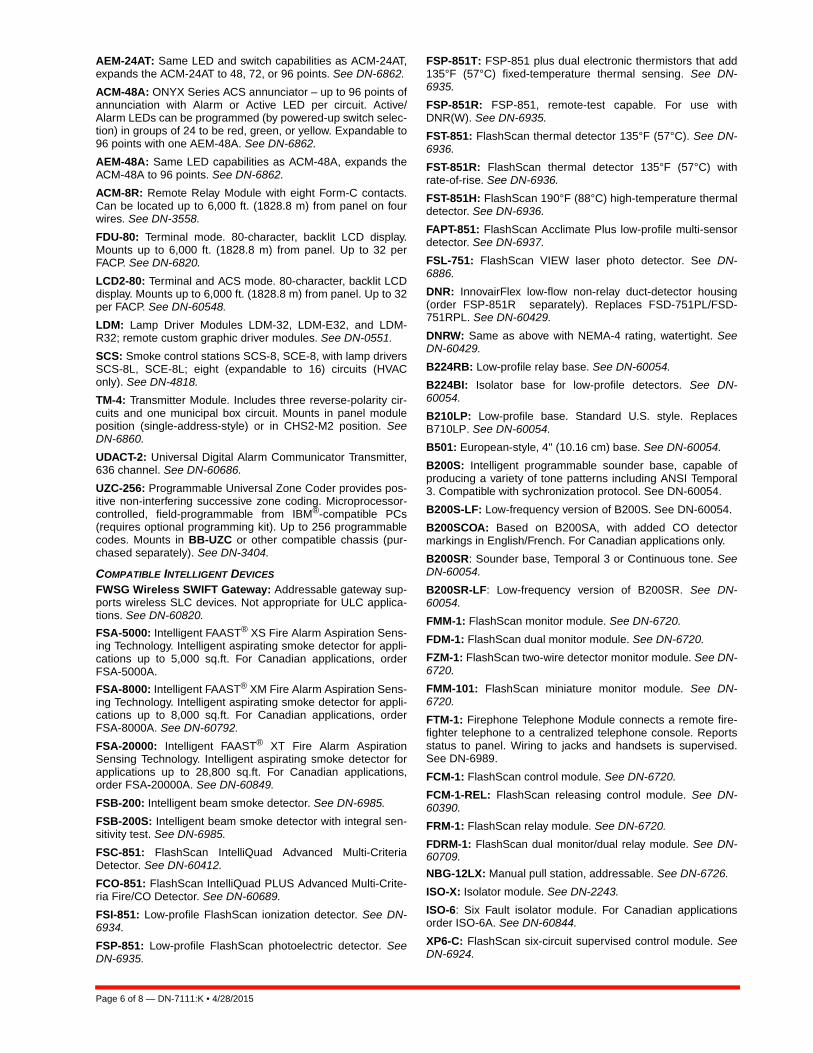
COMPATIBLE INTELLIGENT DEVICES
FWSG Wireless SWIFT Gateway: Addressable gateway sup-ports wireless SLC devices. Not appropriate for ULC applica-tions. See DN-60820.
FSA-5000: Intelligent FAAST® XS Fire Alarm Aspiration Sens-ing Technology. Intelligent aspirating smoke detector for appli-cations up to 5,000 sq.ft. For Canadian applications, orderFSA-5000A.
FSA-8000: Intelligent FAAST® XM Fire Alarm Aspiration Sens-ing Technology. Intelligent aspirating smoke detector for appli-cations up to 8,000 sq.ft. For Canadian applications, orderFSA-8000A. See DN-60792.
FSA-20000: Intelligent FAAST® XT Fire Alarm AspirationSensing Technology. Intelligent aspirating smoke detector forapplications up to 28,800 sq.ft. For Canadian applications,order FSA-20000A. See DN-60849.
FSB-200: Intelligent beam smoke detector. See DN-6985.
FSB-200S: Intelligent beam smoke detector with integral sen-sitivity test. See DN-6985.
FSC-851: FlashScan IntelliQuad Advanced Multi-CriteriaDetector. See DN-60412.
FCO-851: FlashScan IntelliQuad PLUS Advanced Multi-Crite-ria Fire/CO Detector. See DN-60689.
FSI-851: Low-profile FlashScan ionization detector. See DN-6934.
FSP-851: Low-profile FlashScan photoelectric detector. SeeDN-6935.
FSP-851T: FSP-851 plus dual electronic thermistors that add135°F (57°C) fixed-temperature thermal sensing. See DN-6935.
FSP-851R: FSP-851, remote-test capable. For use withDNR(W). See DN-6935.
FST-851: FlashScan thermal detector 135°F (57°C). See DN-6936.
FST-851R: FlashScan thermal detector 135°F (57°C) withrate-of-rise. See DN-6936.
FST-851H: FlashScan 190°F (88°C) high-temperature thermaldetector. See DN-6936.
FAPT-851: FlashScan Acclimate Plus low-profile multi-sensordetector. See DN-6937.
FSL-751: FlashScan VIEW laser photo detector. See DN-6886.
DNR: InnovairFlex low-flow non-relay duct-detector housing(order FSP-851R separately). Replaces FSD-751PL/FSD-751RPL. See DN-60429.
DNRW: Same as above with NEMA-4 rating, watertight. SeeDN-60429.
B224RB: Low-profile relay base. See DN-60054.
B224BI: Isolator base for low-profile detectors. See DN-60054.
B210LP: Low-profile base. Standard U.S. style. ReplacesB710LP. See DN-60054.
B501: European-style, 4" (10.16 cm) base. See DN-60054.
B200S: Intelligent programmable sounder base, capable ofproducing a variety of tone patterns including ANSI Temporal3. Compatible with sychronization protocol. See DN-60054.
B200S-LF: Low-frequency version of B200S. See DN-60054.
B200SCOA: Based on B200SA, with added CO detectormarkings in English/French. For Canadian applications only.
B200SR: Sounder base, Temporal 3 or Continuous tone. SeeDN-60054.
B200SR-LF: Low-frequency version of B200SR. See DN-60054.
FMM-1: FlashScan monitor module. See DN-6720.
FDM-1: FlashScan dual monitor module. See DN-6720.
FZM-1: FlashScan two-wire detector monitor module. See DN-6720.
FMM-101: FlashScan miniature monitor module. See DN-6720.
FTM-1: Firephone Telephone Module connects a remote fire-fighter telephone to a centralized telephone console. Reportsstatus to panel. Wiring to jacks and handsets is supervised.See DN-6989.
FCM-1: FlashScan control module. See DN-6720.
FCM-1-REL: FlashScan releasing control module. See DN-60390.
FRM-1: FlashScan relay module. See DN-6720.
FDRM-1: FlashScan dual monitor/dual relay module. See DN-60709.
NBG-12LX: Manual pull station, addressable. See DN-6726.
ISO-X: Isolator module. See DN-2243.
ISO-6: Six Fault isolator module. For Canadian applicationsorder ISO-6A. See DN-60844.
XP6-C: FlashScan six-circuit supervised control module. SeeDN-6924.

DN-7111:K • 4/28/2015 — Page 7 of 8
XP6-MA: FlashScan six-zone interface module; connectsintelligent alarm system to two-wire conventional detectionzone. See DN-6925.
XP6-R: FlashScan six-relay (Form-C) control module. SeeDN-6926.
XP10-M: FlashScan ten-input monitor module. See DN-6923.
SLC-IM: SLC integration module, for VESDAnet detectors.See DN-60755.
ENCLOSURES, CHASSIS, AND DRESS PLATES CAB-4 Series Enclosure: NFS2-640 mounts in a standardCAB-4 Series enclosure (available in four sizes, “A” through“D”). Backbox and door ordered seperately; requires BP2-4battery plate. A trim ring option is available for semi-flushmounting. See DN-6857.
EQ Series Cabinets: EQ series cabinets will house amplifiers,power supplies, battery chargers and control modules. EQcabinets are available in three sizes, “B” through “D”. See DN-60229. .
CAB-BM Marine System: Protects equipment in shipboardand waterfront applications. Also order BB-MB for systemsusing 100 AH batteries. For a full list of required and optionalequipment, see DN-60688.
CHS-4: Chassis for mounting up to four APS-6Rs.
CHS-4L: Low-profile four-position Chassis. Mounts two AA-30amplifiers or one AMG-E and one AA-30.
DP-1B: Blank dress panel. Provides dead-front panel forunused tiers; covers DAA2/DAX series or AA-series amplifier.
NFS-LBB: Battery Box (required for batteries larger than 26AH).
NFS-LBBR: Same as above but red.
CHS-BH1: Battery chassis; holds two 12.0 AH batteries.Mounts one the left side of DAA2 chassis. See DN-7046.
CA-1: Chassis, occupies one tier of a CAB-4 Series enclosure.The left side accommodates one DVC-EM and a DVC-KD(optional); and the right side houses a CMIC-1 microphoneand its well (optional). See DN-7045.
CA-2: Chassis assembly, occupies two tiers of a CAB-4 Seriesenclosure. The left side accommodates one DVC-EM mountedon a half-chassis and one NCA-2 mounted on a half-chassis.The right side houses a microphone/handset well. The CA-2assembly includes CMIC-1 microphone. ADDR Series doorswith two-tier visibility are available for use with the CA-2 config-uration: ADDR-B4, ADDR-C4, ADDR-D4 (below).
CFFT-1: Chassis to mount firefighter’s telephone and one ACSannunciator in a CAB-4 row. Includes TELH-1 firefighter’shandset for the DVC-EM, chassis, phone well and mountinghardware. Order DP-CFFT dress panel separately.
DP-CFFT: CFFT-1 dress panel. Requires BMP-1 if no ACSannunciator is installed.
ADDR-B4*: Two-tier-sized door designed for use with the CA-2 chassis configuration. ADDR Series doors are similar toCAB-4 Series “DR” doors, but a clear window space exposesthe top two tiers of the CAB-4 enclosure. Use an SBB-B4backbox with the ADDR-B4. See DN-7045, DN-6857.
ADDR-C4*: Three-tier-sized door, designed for use with theCA-2 chassis configuration. ADDR Series doors are similar toCAB-4 Series “DR” doors, but a clear window space exposesthe top two tiers of the CAB-4 enclosure. Use an SBB-C4backbox with the ADDR-C4. See DN-7045, DN-6857.
ADDR-D4*: Four-tier-sized door designed for use with the CA-2 chassis configuration. ADDR Series doors are similar toCAB-4 Series “DR” doors, but a clear window space exposes
the top two tiers of the CAB-4 enclosure. Use an SBB-D4backbox with the ADDR-D4. See DN-7045, DN-6857.
*Use ADDR-B4/C4/D4 when CA-2 chassis is installed in toptwo rows with NCA-2 or BP-CA2. Use standard door when CA-2 is not installed in top two rows. For additional configurationinformation, see the DVC application guide on http://esd.noti-fier.com.
DPA-1: Dress panel, used with the CA-1 chassis when config-ured with a DVC-EM, DVC-KD, and CMIC-1. See DN-7045.
DPA-2B: Dress panel used with CA-2 chassis assembly.
VP-2B: Dress panel, required when CA-2 chassis is installedin the top two cabinet rows.
DPA-1A4: Dress panel, used with the CA-1 chassis when theCMIC-1 is not used. Provides mounting options on right twobays for two ACS annunciators, or for blank plates. See DN-7045.
BP-CA2: Blank plate for CA-2 chassis.
BB-UZC: Backbox for housing the UZC-256 in applicationswhere the UZC-256 will not fit in panel enclosure. Black; forred, order BB-UZC-R.
SEISKIT-CAB: Seismic mounting kit. Required for seismic-certified applications with NFS2-640 and other equipmentmounted in CAB-4 Series Enclosures. Includes battery bracketfor two 26 AH batteries.
SEISKIT-LBB: Seismic kit for the NFS-LBB. Includes batterybracket for two 55 AH batteries.
OTHER OPTIONS
411: Slave digital alarm communicator. See DN-6619.
411UDAC: Digital alarm communicator. See DN-6746.
IPDACT-2/2UD, IPDACT Internet Monitoring Module: Con-nects to primary and secondary DACT telephone output portsfor internet communications over customer-provided Ethernetconnection. Requires compatible Teldat VisorALARM CentralStation Receiver. Can use DHCP or static IP. See DN-60408.
IPCHSKIT: IP Communicator Chassis Mounting Kit. Formounting an IPDACT-2/2UD onto the panel chassis or CHS-4series chassis. Use IPENC for external mounting applications.
IPSPLT: Y-adapter option allow connection of both panel dialeroutputs to one IPDACT-2/2UD cable input.
IPENC: External enclosure for IPDACT, includes IPBRKTmounting bracket; Red. For Black order IPENC-B.
IPGSM-4G: Internet and Digital Cellular Fire Alarm Communica-tor. Provides selectable configurable paths: cellular only, IP only,or IP primary with cellular backup. Connects to the primary andsecondary ports of a DACT. For Canadian applications orderIPGSM-4GC. See DH-60769.
NOTE: For other options including compatibility with retrofit equip-ment, refer to the panel's installation manual, the SLC manual, andthe Device Compatibility Document.
System SpecificationsSYSTEM CAPACITY
• Intelligent Signaling Line Circuits ............1 expandable to 2• Intelligent detectors ......................................... 159 per loop• Addressable monitor/control modules .............. 159 per loop• Programmable software zones......................................... 99• Special programming zones............................................. 14• LCD annunciators per CPU2-640/-640E
and NCA-2 (observe power)............................................. 32• ACS annunciators per
CPU2-640/-640E.......................... 32 addresses x 64 points
Page 8 of 8 — DN-7111:K • 4/28/2015
IntelliQuad™, NOTI•FIRE•NET™, ONYXWorks™, and SWIFT™ aretrademarks; and Acclimate® Plus™, FirstCommand®, FlashScan®,Intelligent FAAST®, NOTIFIER®, ONYX®, VeriFire® Tools, andVIEW® are registered trademarks of Honeywell International Inc.Microsoft® and Windows® are registered trademarks of MicrosoftCorporation. IBM® is a registered trademark of IBM Corporation. ©2015 by Honeywell International Inc. All rights reserved. Unauthorized useof this document is strictly prohibited.
This document is not intended to be used for installation purposes. We try to keep our product information up-to-date and accurate.
We cannot cover all specific applications or anticipate all requirements. All specifications are subject to change without notice.
For more information, contact Notifier. Phone: (203) 484-7161, FAX: (203) 484-7118.www.notifier.com
Made in the U.S. A.
• ACS annunciators per NCA-2..................................32 addresses x 64 or 96 points
NOTE: The NCA-2 supports up to 96 annunciator address pointsper ACM-24AT/-48A.
ELECTRICAL SPECIFICATIONS
• Primary input power: – CPU2-640 board: 120 VAC, 50/60 Hz, 5.0 A.
– CPU2-640E board: 220/240 VAC, 50/60 Hz, 2.5 A.• Current draw (standby/alarm):
– CPU2-640(E) board: 0.250 A. Add 0.035 A for each NACin use.
– KDM-R2: 0.100 A.– LEM-320: 0.100 A.
• Total output 24 V power: 6.0 A in alarm.NOTE: The power supply has a total of 6.0 A. of available power.This is shared by all internal circuits. See Installation Manual for acomplete current draw calculation sheet.
• Standard notification circuits (4): 1.5 A each.• Resettable regulated 24V power: 1.25 A.• Two non-resettable regulated 24V power outputs:
– 1.25 A. – 0.50 A.
• Non-resettable 5V power: 0.15 A.• Battery charger range: 18 AH – 200 AH. Use separate cab-
inet for batteries over 26 AH.• Float rate: 27.6 V.
CABINET SPECIFICATIONS
• Systems can be installed in CAB-4 Series cabinets (foursizes with various door options, see DN-6857). RequiresBP2-4 Battery Plate.
SHIPPING WEIGHT
• CPU2-640/-640: 14.3 lb (6.49 kg).• CPU2-640/-640E: 14.55 lb (6.60 kg).
TEMPERATURE AND HUMIDITY RANGES
This system meets NFPA requirements for operation at 0 –49°C/32 – 120°F and at a relative humidity 93% ± 2% RH(noncondensing) at 32°C ± 2°C (90°F ± 3°F). However, theuseful life of the system's standby batteries and the electroniccomponents may be adversely affected by extreme tempera-ture ranges and humidity. Therefore, it is recommended thatthis system and its peripherals be installed in an environmentwith a normal room temperature of 15 – 27°C/60 – 80°F.
AGENCY LISTINGS AND APPROVALS
The listings and approvals below apply to the basic NFS2-640control panel. In some cases, certain modules may not belisted by certain approval agencies, or listing may be in pro-cess. Consult factory for latest listing status.
• UL Listed: S635. • ULC Listed: S635. • FM Approved. • MEA: 128-07-E.• Fire Dept. of New York: #6121. • CSFM: 7165-0028:0243.• City of Chicago.
• City and County of Denver.• CCCF listed. Marine Applications: Marine approved systems must be con-figured using components itemized in this document. (SeeMain System Components, in “Product Line Information.) Spe-cific connections and requirements for those components aredescribed in the installation document, PN 54756. When theserequirements are followed, systems are approved by the fol-lowing agencies:
• US Coast Guard 161.002/50/0, 161.002/55/0 (Standard 46CFR and 161.002).
• Lloyd's Register 11/600013 (ENV 3 category).• American Bureau of Shipping (ABS) Type Approval. NOTE: For information on marine applications, see DN-60688.
STANDARDS
The NFS2-640 complies with the following UL Standards andNFPA 72, International Building Code (IBC), and CaliforniaBuilding Code (CBC) Fire Alarm Systems requirements:
• UL 864, 9th Edition (Fire).• UL 1076 (Burglary).• UL 2572 (Mass Notification Systems). (NFS2-640 version
20 or higher.)• LOCAL (Automatic, Manual, Waterflow and Sprinkler
Supervisory).• AUXILIARY (Automatic, Manual and Waterflow) (requires
TM-4).• REMOTE STATION (Automatic, Manual, Waterflow and
Sprinkler Supervisory) (requires TM-4).• PROPRIETARY (Automatic, Manual and Waterflow).
Not applicable for FM.• EMERGENCY VOICE/ALARM.• OT, PSDN (Other Technologies, Packet-switched Data Net-
work). • IBC 2012, IBC 2009, IBC 2006, IBC 2003, IBC 2000 (Seis-
mic).• CBC 2007 (Seismic).

CALIFORNIA DEPARTMENT OF FORESTRY & FIRE PROTECTION
OFFICE OF THE STATE FIRE MARSHAL
FIRE ENGINEERING - BUILDING MATERIALS LISTING PROGRAM
LISTING SERVICE
LISTING No. 7165-0028:0243 Page 1 of 4
CATEGORY: 7165 -- FIRE ALARM CONTROL UNIT (COMMERCIAL)
LISTEE: NotifierOne Fire-Lite Place, Northford, CT 06472-1653
Contact: Vladimir Kireyev (203) 484-6277 Fax (203) 484-7309
Email: [email protected]
DESIGN: Models NFS2-640, NFS-320/C (R), and NFS-320SYS fire alarm control units. Local,
auxiliary, remote station (PPU), proprietary (PPU), central station (PPU), manual, automatic,
waterfowl and sprinkler supervisory services. Also suitable for releasing service, Process
Management and Emergency Voice/Alarm communication System *. Model numbers may
be followed by an “R” suffix representing the enclosure color being red. Refer to listee's data
sheet for additional detailed product description and operational considerations. System
components:
ACM-8R, -16AT, -32A, -24AT, -48A; Annunciator Control Modules
ACPS-610, AMPS-24; Addressable power supply/charger
ADP-4B, -A4, -1, -2, DP-DISP2; Dress Panel
AEM-16AT, -32A, -24AT, -48A; Annunciator Expander Modules
AFM-16A, -16AT, -32A; Annunciator Fixed Modules
AKS-1B; Annunciator Key Switch
APS2-6R; Power supply
BB-100, -200, NFS-LBB/-LBBR; Battery Boxes
BGRA-SCS, BGRB-SCS; Smoke Control Station
BMP-1; Blank Module
BP-4, BP2-4; Battery Dress Plates
CAB-3/-4 Series; Enclosure
CAB-RP, CAB-RPR; Cabinets
CEF-SCS; Smoke Control Station
CHS-4, CHS-4N, CHS-4L; Chassis
CPU2-640, CPU-320SYS; CPU Board
CRT-2; Display Terminal
DP-1B; Blank Panel
DPA-1A4/1/2, DP-DISP2; Dress Panel
DPI-232; Panel Interface
DR-A4, DR-A4B, DR-A4BR, DR-A4R; Door Assembly
DR-AA4, DR-AA4B, DR-AA4BR, DR-AA4R; Door Assembly
DR-B3F; Door Assembly
DR-B4, DR-B4B, DR-B4BR, DR-B4R; Door Assembly
DR-C4, DR-C4B, DR-C4BR, DR-C4R; Door Assembly
DR-D4, DR-D4B, DR-D4BR, DR-D4R; Door Assembly
*Rev. 10-29-13 gt
July 01, 2015Date Issued: Listing Expires June 30, 2016
Authorized By:
Fire Engineering Division
This listing is based upon technical data submitted by the applicant. CSFM Fire Engineering staff has reviewed
the test results and/or other data but does not make an independent verification of any claims. This listing is not
an endorsement or recommendation of the item listed. This listing should not be used to verify correct
operational requirements or installation criteria. Refer to listee’s data sheet, installation instructions and/or other
JAMES PARSEGIAN, Program Coordinator
Jeremy
Arrow
Reza
Highlight
Listing No.
Page 2 of 4
7165-0028:0243
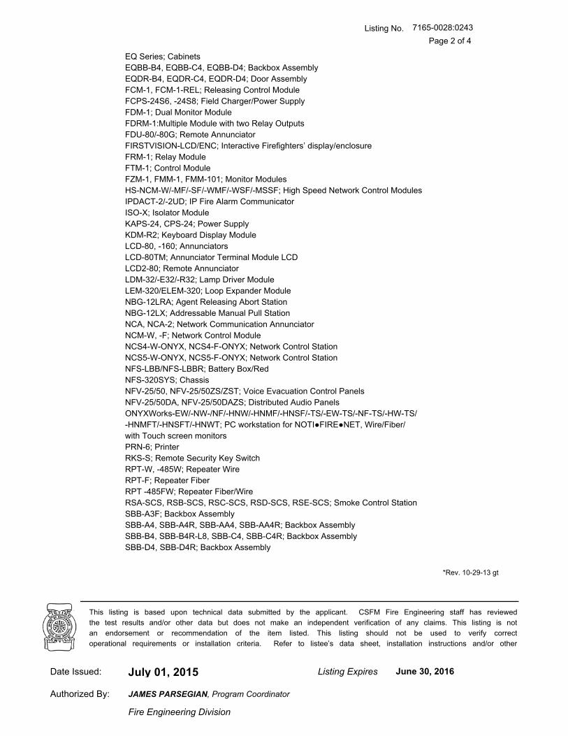
EQ Series; Cabinets
EQBB-B4, EQBB-C4, EQBB-D4; Backbox Assembly
EQDR-B4, EQDR-C4, EQDR-D4; Door Assembly
FCM-1, FCM-1-REL; Releasing Control Module
FCPS-24S6, -24S8; Field Charger/Power Supply
FDM-1; Dual Monitor Module
FDRM-1:Multiple Module with two Relay Outputs
FDU-80/-80G; Remote Annunciator
FIRSTVISION-LCD/ENC; Interactive Firefighters’ display/enclosure
FRM-1; Relay Module
FTM-1; Control Module
FZM-1, FMM-1, FMM-101; Monitor Modules
HS-NCM-W/-MF/-SF/-WMF/-WSF/-MSSF; High Speed Network Control Modules
IPDACT-2/-2UD; IP Fire Alarm Communicator
ISO-X; Isolator Module
KAPS-24, CPS-24; Power Supply
KDM-R2; Keyboard Display Module
LCD-80, -160; Annunciators
LCD-80TM; Annunciator Terminal Module LCD
LCD2-80; Remote Annunciator
LDM-32/-E32/-R32; Lamp Driver Module
LEM-320/ELEM-320; Loop Expander Module
NBG-12LRA; Agent Releasing Abort Station
NBG-12LX; Addressable Manual Pull Station
NCA, NCA-2; Network Communication Annunciator
NCM-W, -F; Network Control Module
NCS4-W-ONYX, NCS4-F-ONYX; Network Control Station
NCS5-W-ONYX, NCS5-F-ONYX; Network Control Station
NFS-LBB/NFS-LBBR; Battery Box/Red
NFS-320SYS; Chassis
NFV-25/50, NFV-25/50ZS/ZST; Voice Evacuation Control Panels
NFV-25/50DA, NFV-25/50DAZS; Distributed Audio Panels
ONYXWorks-EW/-NW-/NF/-HNW/-HNMF/-HNSF/-TS/-EW-TS/-NF-TS/-HW-TS/
-HNMFT/-HNSFT/-HNWT; PC workstation for NOTI●FIRE●NET, Wire/Fiber/
with Touch screen monitors
PRN-6; Printer
RKS-S; Remote Security Key Switch
RPT-W, -485W; Repeater Wire
RPT-F; Repeater Fiber
RPT -485FW; Repeater Fiber/Wire
RSA-SCS, RSB-SCS, RSC-SCS, RSD-SCS, RSE-SCS; Smoke Control Station
SBB-A3F; Backbox Assembly
SBB-A4, SBB-A4R, SBB-AA4, SBB-AA4R; Backbox Assembly
SBB-B4, SBB-B4R-L8, SBB-C4, SBB-C4R; Backbox Assembly
SBB-D4, SBB-D4R; Backbox Assembly
*Rev. 10-29-13 gt
July 01, 2015Date Issued: Listing Expires June 30, 2016
Authorized By:
Fire Engineering Division
This listing is based upon technical data submitted by the applicant. CSFM Fire Engineering staff has reviewed
the test results and/or other data but does not make an independent verification of any claims. This listing is not
an endorsement or recommendation of the item listed. This listing should not be used to verify correct
operational requirements or installation criteria. Refer to listee’s data sheet, installation instructions and/or other
JAMES PARSEGIAN, Program Coordinator
Listing No.
Page 3 of 4
7165-0028:0243
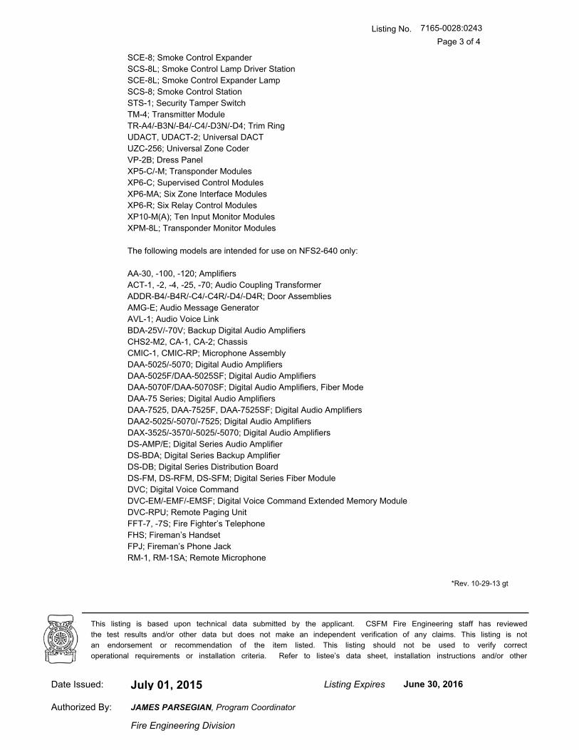
SCE-8; Smoke Control Expander
SCS-8L; Smoke Control Lamp Driver Station
SCE-8L; Smoke Control Expander Lamp
SCS-8; Smoke Control Station
STS-1; Security Tamper Switch
TM-4; Transmitter Module
TR-A4/-B3N/-B4/-C4/-D3N/-D4; Trim Ring
UDACT, UDACT-2; Universal DACT
UZC-256; Universal Zone Coder
VP-2B; Dress Panel
XP5-C/-M; Transponder Modules
XP6-C; Supervised Control Modules
XP6-MA; Six Zone Interface Modules
XP6-R; Six Relay Control Modules
XP10-M(A); Ten Input Monitor Modules
XPM-8L; Transponder Monitor Modules
The following models are intended for use on NFS2-640 only:
AA-30, -100, -120; Amplifiers
ACT-1, -2, -4, -25, -70; Audio Coupling Transformer
ADDR-B4/-B4R/-C4/-C4R/-D4/-D4R; Door Assemblies
AMG-E; Audio Message Generator
AVL-1; Audio Voice Link
BDA-25V/-70V; Backup Digital Audio Amplifiers
CHS2-M2, CA-1, CA-2; Chassis
CMIC-1, CMIC-RP; Microphone Assembly
DAA-5025/-5070; Digital Audio Amplifiers
DAA-5025F/DAA-5025SF; Digital Audio Amplifiers
DAA-5070F/DAA-5070SF; Digital Audio Amplifiers, Fiber Mode
DAA-75 Series; Digital Audio Amplifiers
DAA-7525, DAA-7525F, DAA-7525SF; Digital Audio Amplifiers
DAA2-5025/-5070/-7525; Digital Audio Amplifiers
DAX-3525/-3570/-5025/-5070; Digital Audio Amplifiers
DS-AMP/E; Digital Series Audio Amplifier
DS-BDA; Digital Series Backup Amplifier
DS-DB; Digital Series Distribution Board
DS-FM, DS-RFM, DS-SFM; Digital Series Fiber Module
DVC; Digital Voice Command
DVC-EM/-EMF/-EMSF; Digital Voice Command Extended Memory Module
DVC-RPU; Remote Paging Unit
FFT-7, -7S; Fire Fighter’s Telephone
FHS; Fireman’s Handset
FPJ; Fireman’s Phone Jack
RM-1, RM-1SA; Remote Microphone
*Rev. 10-29-13 gt
July 01, 2015Date Issued: Listing Expires June 30, 2016
Authorized By:
Fire Engineering Division
This listing is based upon technical data submitted by the applicant. CSFM Fire Engineering staff has reviewed
the test results and/or other data but does not make an independent verification of any claims. This listing is not
an endorsement or recommendation of the item listed. This listing should not be used to verify correct
operational requirements or installation criteria. Refer to listee’s data sheet, installation instructions and/or other
JAMES PARSEGIAN, Program Coordinator
Listing No.
Page 4 of 4
7165-0028:0243
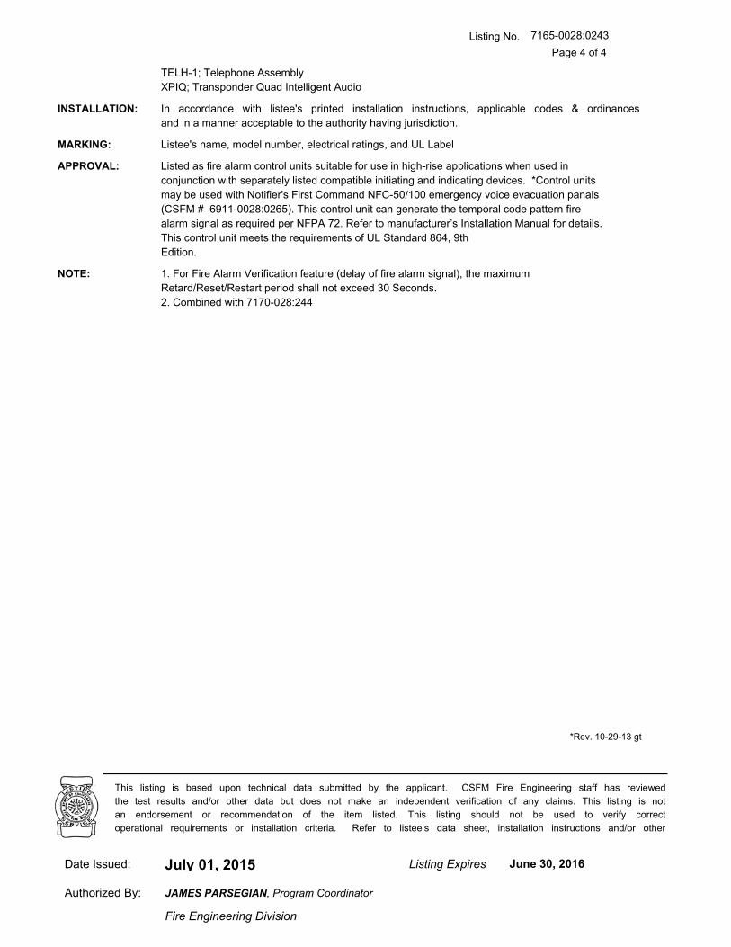
TELH-1; Telephone Assembly
XPIQ; Transponder Quad Intelligent Audio
INSTALLATION: In accordance with listee's printed installation instructions, applicable codes & ordinances
and in a manner acceptable to the authority having jurisdiction.
MARKING: Listee's name, model number, electrical ratings, and UL Label
APPROVAL: Listed as fire alarm control units suitable for use in high-rise applications when used in
conjunction with separately listed compatible initiating and indicating devices. *Control units
may be used with Notifier's First Command NFC-50/100 emergency voice evacuation panals
(CSFM # 6911-0028:0265). This control unit can generate the temporal code pattern fire
alarm signal as required per NFPA 72. Refer to manufacturer’s Installation Manual for details.
This control unit meets the requirements of UL Standard 864, 9th
Edition.
NOTE: 1. For Fire Alarm Verification feature (delay of fire alarm signal), the maximum
Retard/Reset/Restart period shall not exceed 30 Seconds.
2. Combined with 7170-028:244
*Rev. 10-29-13 gt
July 01, 2015Date Issued: Listing Expires June 30, 2016
Authorized By:
Fire Engineering Division
This listing is based upon technical data submitted by the applicant. CSFM Fire Engineering staff has reviewed
the test results and/or other data but does not make an independent verification of any claims. This listing is not
an endorsement or recommendation of the item listed. This listing should not be used to verify correct
operational requirements or installation criteria. Refer to listee’s data sheet, installation instructions and/or other
JAMES PARSEGIAN, Program Coordinator

A Service-Disabled Veteran-Owned Small Business
SUBMITTAL
15800 SE 135th Avenue, Clackamas, OR 97015 Phone: 503-650-1720
Fax: 503-650-1902
Part 2.3I
Notifier UDACT-2 Universal Digital Alarm Communicator

DN-60686:A1 • 4/2/12 — Page 1 of 2
UDACT-2Universal Digital Alarm Communicator Transmitter
Annunciator Control System
DN-60686:A1
GeneralThe Universal Digital Alarm Communicator Transmitter (UDACT-2) is designed for use on Notifier Fire Alarm Control Panels andon the NCA-2 Network Control Annunciator. When used in con-junction with the NCA-2 network control annunciator, theUDACT-2 can report the status of all control panels onNOTI•FIRE•NET™. The UDACT-2 transmits system status to ULlisted Central Station Receivers via the public switched tele-phone network. The UDACT-2 can be installed in the panel cab-inet or remotely in a separate enclosure.
NOTE: The UDACT-2 can also be used with legacy panels.Please refer to the UDACT-2 manual for more information.
The UDACT-2 upload/download programming and firmwareupdates are accomplished with VeriFire Tools. Refer to the Pro-gramming Section for further details.
The UDACT-2 is capable of transmitting the status of softwarezones (Alarm and Trouble), System Trouble, Panel Off-Normal,Supervisory, Bell Trouble, Low Battery, and AC Fail. TheUDACT-2 is capable of transmitting all of the zone and point sta-tus associated with each panel.
When the UDACT-2 is used with the NFS-3030, NFS2-3030,and NCA-2 it is capable of reporting up to 2,040 points. Report-ing may be in the form of points or zones (refer to the UDACT-2manual for specific reporting parameters). Points transmittedmay be programmed for a variety of types, including fire, water-flow, supervisory, etc.
NOTE: Descriptions regarding point capacity, listed above, are forreceivers which receive in Ademco Contact ID format. See charton page 2 for compatible receivers.
Features• Programmable with VeriFire Tools version 6.60 or higher,
allowing the UDACT-2 programming to be uploaded/down-loaded and saved.
• Maximum of 14 point trouble messages transmitted per hour.• Dual phone lines with line voltage detect.• Compact in size: 6.75" x 4.25" (17.145 x 10.795 cm).• USB port for upload/download programming.• Manual Test Report function.• Manual Transmission Clear function.• Mounts in a separate enclosure (ABS-8RB or UBS-1B/R).• Communicates vital system status including:
– Independent zone fire alarm.– Independent zone non-fire alarm.– Independent zone trouble.– Independent zone supervisory.– AC (mains) Power Loss (programmable).– Low Battery and Earth Fault.– System Off-Normal.– 12 or 24 hour test signal.– Abnormal Test Signal per new UL requirements.– EIA-485 Communication Bus Failure.
• Annunciation of UDACT-2 Troubles including: loss of phonelines, communication failure with either Central Station, totalcommunications failure.
• Individual LEDs for: Power, EIA-485 Loss, Manual Test, Kis-soff, Comm Fail, Primary Line Seize, Secondary Line Seizeand Modem Communications.
• Open Collector relay driver for Total Communications Failureor UDACT-2 trouble.
• Real-time clock.• Extensive transient protection.• EIA-485 interface to host panel.
ProgrammingThe UDACT-2 programming is created and downloaded usingVeriFire Tools. This enables the unit to be programmed prior toinstallation, be easily modified, and saved either online oroffline. A printed report with point or zone information can begenerated from VeriFire Tools for an ONYX Series panel or net-work annunciator. The point report consists of the central stationpoint address, ACS point, ACS point function, panel label, panelpoint, type code, custom and extended label, alarm verification,walktest participation, presignal, and PAS information. The zonereport consists of a grid with the central station point address,ACS point address, source, ACS point function, custom labeland panel label. This report may be sent to the Central Stationfor their records. VeriFire Tools also supports upgrading theUDACT-2 operating firmware.
UDACT-2

Page 2 of 2 — DN-60686:A1 • 4/2/12
NOTI•FIRE•NET™ is a trademark and Notifier® is a registered trademark ofHoneywell International Inc.©2012 by Honeywell International Inc. All rights reserved. Unauthorized useof this document is strictly prohibited.
This document is not intended to be used for installation purposes. We try to keep our product information up-to-date and accurate.
We cannot cover all specific applications or anticipate all requirements. All specifications are subject to change without notice.
For more information, contact Notifier. Phone: (203) 484-7161, FAX: (203) 484-7118.www.notifier.com
Made in the U.S. A.
Communication Formats• Ademco Contact ID• 4+2 Standard• SIANOTE: Ademco Contact ID must be used for independent zonereporting.
Type Mode FeatureAdemco Contact ID format - only Use Type Mode to identifyreports to Central Station as:
• Fire Alarm • Burglary• Supervisory • 24 hour Non-Burglary• Pull Station • High Temperature
• Heat Detector • Low Temperature• Waterflow • Low Water Pressure• Duct Detector • Low Water Level
• Flame Sensor • Pump Failure• Smoke Zone
Electrical SpecificationsStandby current: 40 mA.
Current while communicating: 75 mA.
Maximum current while communicating and with open collectoroutput activated: 100 mA.
Voltage: Regulated 24 volts. Range: 21.2 to 28.2 volts.
Agency Listings and ApprovalsIn some cases, certain modules may not be listed by certainapproval agencies, or listing may be in process. Consult factoryfor latest listing status.
• UL/ULC Listed: S635• FM Approved• CSFM: 7165-0028:0243 (NFS2-640/320), 7165-0028:0224
(NFS2-3030) • FDNY: COA#6085, COA#6098
Ordering InformationUDACT-2: Universal Digital Alarm Communicator Transmitter.Includes operating and programming instructions, and mountinghardware.
MCBL-7: DACT phone cord, 7 ft (2.13 m) long (two required).
ABS-8RB: Metal enclosure for externally mounting UDACT-2 upto 6,000 ft./1828.8 m from host FACP. 9.94" H x 4.63" W x 2.50"D (cm: 25.248 H x 11.760 W x 6.350 D).
UBS-1B: Metal enclosure with solid door, Black.
UBS-1BR: Metal enclosure with solid door, Red.
R-10E: SPDT Form-C relay. Contacts rated for 10 A @ 115 VAC.Connects to open collector relay driver.
R-20E: DPDT Two Form-C relays. Contacts rated for 10A @ 115VAC. Connects to open collector relay driver.
FBD-1: Ferrite bead kit. Use for remote mounting only.
UL Listed ReceiversThe chart below shows UL listed receivers compatible with theUDACT-2. A check in the protocol column indicates the receiversupports that protocol.
(1) With 685-8 Line Card with Rev 4.4d software
(2) With 124060V206B and 124063 Line Card Rev B
(3) With version V2.4 Receiver & 126047 Line Card Rev G
(4) With 124077V2.00 Receiver &126047 Line Card Rev M
(5) With software V3.9
(6) With V.7301 Receiver S/W
(7) With 01.01.03 Receiver S/W & Line Card 01.01.03
(8) With software V1.86
(9) With sotware V1.72
(10) With DSP4016 and V1.6 Line Card
Receiver
4+2 Standard 1800/2300
Ademco Contact
ID SIA
Ademco 685 (1)
Ademco MX8000 (2)
Silent Knight 9500 (3)
Silent Knight 9800 (4)
FBI CP220FB (5)
Osborne Hoffman 2000E (6)
Radionics 6600 (7)
SurGard MLR2 (8)
SurGard System III (9)
SurGard MLR-2000 (10)

CALIFORNIA DEPARTMENT OF FORESTRY & FIRE PROTECTION
OFFICE OF THE STATE FIRE MARSHAL
FIRE ENGINEERING - BUILDING MATERIALS LISTING PROGRAM
LISTING SERVICE
LISTING No. 7165-0028:0243 Page 1 of 4
CATEGORY: 7165 -- FIRE ALARM CONTROL UNIT (COMMERCIAL)
LISTEE: NotifierOne Fire-Lite Place, Northford, CT 06472-1653
Contact: Vladimir Kireyev (203) 484-6277 Fax (203) 484-7309
Email: [email protected]
DESIGN: Models NFS2-640, NFS-320/C (R), and NFS-320SYS fire alarm control units. Local,
auxiliary, remote station (PPU), proprietary (PPU), central station (PPU), manual, automatic,
waterfowl and sprinkler supervisory services. Also suitable for releasing service, Process
Management and Emergency Voice/Alarm communication System *. Model numbers may
be followed by an “R” suffix representing the enclosure color being red. Refer to listee's data
sheet for additional detailed product description and operational considerations. System
components:
ACM-8R, -16AT, -32A, -24AT, -48A; Annunciator Control Modules
ACPS-610, AMPS-24; Addressable power supply/charger
ADP-4B, -A4, -1, -2, DP-DISP2; Dress Panel
AEM-16AT, -32A, -24AT, -48A; Annunciator Expander Modules
AFM-16A, -16AT, -32A; Annunciator Fixed Modules
AKS-1B; Annunciator Key Switch
APS2-6R; Power supply
BB-100, -200, NFS-LBB/-LBBR; Battery Boxes
BGRA-SCS, BGRB-SCS; Smoke Control Station
BMP-1; Blank Module
BP-4, BP2-4; Battery Dress Plates
CAB-3/-4 Series; Enclosure
CAB-RP, CAB-RPR; Cabinets
CEF-SCS; Smoke Control Station
CHS-4, CHS-4N, CHS-4L; Chassis
CPU2-640, CPU-320SYS; CPU Board
CRT-2; Display Terminal
DP-1B; Blank Panel
DPA-1A4/1/2, DP-DISP2; Dress Panel
DPI-232; Panel Interface
DR-A4, DR-A4B, DR-A4BR, DR-A4R; Door Assembly
DR-AA4, DR-AA4B, DR-AA4BR, DR-AA4R; Door Assembly
DR-B3F; Door Assembly
DR-B4, DR-B4B, DR-B4BR, DR-B4R; Door Assembly
DR-C4, DR-C4B, DR-C4BR, DR-C4R; Door Assembly
DR-D4, DR-D4B, DR-D4BR, DR-D4R; Door Assembly
*Rev. 10-29-13 gt
July 01, 2015Date Issued: Listing Expires June 30, 2016
Authorized By:
Fire Engineering Division
This listing is based upon technical data submitted by the applicant. CSFM Fire Engineering staff has reviewed
the test results and/or other data but does not make an independent verification of any claims. This listing is not
an endorsement or recommendation of the item listed. This listing should not be used to verify correct
operational requirements or installation criteria. Refer to listee’s data sheet, installation instructions and/or other
JAMES PARSEGIAN, Program Coordinator

Listing No.
Page 2 of 4
7165-0028:0243
EQ Series; Cabinets
EQBB-B4, EQBB-C4, EQBB-D4; Backbox Assembly
EQDR-B4, EQDR-C4, EQDR-D4; Door Assembly
FCM-1, FCM-1-REL; Releasing Control Module
FCPS-24S6, -24S8; Field Charger/Power Supply
FDM-1; Dual Monitor Module
FDRM-1:Multiple Module with two Relay Outputs
FDU-80/-80G; Remote Annunciator
FIRSTVISION-LCD/ENC; Interactive Firefighters’ display/enclosure
FRM-1; Relay Module
FTM-1; Control Module
FZM-1, FMM-1, FMM-101; Monitor Modules
HS-NCM-W/-MF/-SF/-WMF/-WSF/-MSSF; High Speed Network Control Modules
IPDACT-2/-2UD; IP Fire Alarm Communicator
ISO-X; Isolator Module
KAPS-24, CPS-24; Power Supply
KDM-R2; Keyboard Display Module
LCD-80, -160; Annunciators
LCD-80TM; Annunciator Terminal Module LCD
LCD2-80; Remote Annunciator
LDM-32/-E32/-R32; Lamp Driver Module
LEM-320/ELEM-320; Loop Expander Module
NBG-12LRA; Agent Releasing Abort Station
NBG-12LX; Addressable Manual Pull Station
NCA, NCA-2; Network Communication Annunciator
NCM-W, -F; Network Control Module
NCS4-W-ONYX, NCS4-F-ONYX; Network Control Station
NCS5-W-ONYX, NCS5-F-ONYX; Network Control Station
NFS-LBB/NFS-LBBR; Battery Box/Red
NFS-320SYS; Chassis
NFV-25/50, NFV-25/50ZS/ZST; Voice Evacuation Control Panels
NFV-25/50DA, NFV-25/50DAZS; Distributed Audio Panels
ONYXWorks-EW/-NW-/NF/-HNW/-HNMF/-HNSF/-TS/-EW-TS/-NF-TS/-HW-TS/
-HNMFT/-HNSFT/-HNWT; PC workstation for NOTI●FIRE●NET, Wire/Fiber/
with Touch screen monitors
PRN-6; Printer
RKS-S; Remote Security Key Switch
RPT-W, -485W; Repeater Wire
RPT-F; Repeater Fiber
RPT -485FW; Repeater Fiber/Wire
RSA-SCS, RSB-SCS, RSC-SCS, RSD-SCS, RSE-SCS; Smoke Control Station
SBB-A3F; Backbox Assembly
SBB-A4, SBB-A4R, SBB-AA4, SBB-AA4R; Backbox Assembly
SBB-B4, SBB-B4R-L8, SBB-C4, SBB-C4R; Backbox Assembly
SBB-D4, SBB-D4R; Backbox Assembly
*Rev. 10-29-13 gt
July 01, 2015Date Issued: Listing Expires June 30, 2016
Authorized By:
Fire Engineering Division
This listing is based upon technical data submitted by the applicant. CSFM Fire Engineering staff has reviewed
the test results and/or other data but does not make an independent verification of any claims. This listing is not
an endorsement or recommendation of the item listed. This listing should not be used to verify correct
operational requirements or installation criteria. Refer to listee’s data sheet, installation instructions and/or other
JAMES PARSEGIAN, Program Coordinator

Listing No.
Page 3 of 4
7165-0028:0243
SCE-8; Smoke Control Expander
SCS-8L; Smoke Control Lamp Driver Station
SCE-8L; Smoke Control Expander Lamp
SCS-8; Smoke Control Station
STS-1; Security Tamper Switch
TM-4; Transmitter Module
TR-A4/-B3N/-B4/-C4/-D3N/-D4; Trim Ring
UDACT, UDACT-2; Universal DACT
UZC-256; Universal Zone Coder
VP-2B; Dress Panel
XP5-C/-M; Transponder Modules
XP6-C; Supervised Control Modules
XP6-MA; Six Zone Interface Modules
XP6-R; Six Relay Control Modules
XP10-M(A); Ten Input Monitor Modules
XPM-8L; Transponder Monitor Modules
The following models are intended for use on NFS2-640 only:
AA-30, -100, -120; Amplifiers
ACT-1, -2, -4, -25, -70; Audio Coupling Transformer
ADDR-B4/-B4R/-C4/-C4R/-D4/-D4R; Door Assemblies
AMG-E; Audio Message Generator
AVL-1; Audio Voice Link
BDA-25V/-70V; Backup Digital Audio Amplifiers
CHS2-M2, CA-1, CA-2; Chassis
CMIC-1, CMIC-RP; Microphone Assembly
DAA-5025/-5070; Digital Audio Amplifiers
DAA-5025F/DAA-5025SF; Digital Audio Amplifiers
DAA-5070F/DAA-5070SF; Digital Audio Amplifiers, Fiber Mode
DAA-75 Series; Digital Audio Amplifiers
DAA-7525, DAA-7525F, DAA-7525SF; Digital Audio Amplifiers
DAA2-5025/-5070/-7525; Digital Audio Amplifiers
DAX-3525/-3570/-5025/-5070; Digital Audio Amplifiers
DS-AMP/E; Digital Series Audio Amplifier
DS-BDA; Digital Series Backup Amplifier
DS-DB; Digital Series Distribution Board
DS-FM, DS-RFM, DS-SFM; Digital Series Fiber Module
DVC; Digital Voice Command
DVC-EM/-EMF/-EMSF; Digital Voice Command Extended Memory Module
DVC-RPU; Remote Paging Unit
FFT-7, -7S; Fire Fighter’s Telephone
FHS; Fireman’s Handset
FPJ; Fireman’s Phone Jack
RM-1, RM-1SA; Remote Microphone
*Rev. 10-29-13 gt
July 01, 2015Date Issued: Listing Expires June 30, 2016
Authorized By:
Fire Engineering Division
This listing is based upon technical data submitted by the applicant. CSFM Fire Engineering staff has reviewed
the test results and/or other data but does not make an independent verification of any claims. This listing is not
an endorsement or recommendation of the item listed. This listing should not be used to verify correct
operational requirements or installation criteria. Refer to listee’s data sheet, installation instructions and/or other
JAMES PARSEGIAN, Program Coordinator
Jeremy
Arrow
Reza
Highlight

Listing No.
Page 4 of 4
7165-0028:0243
TELH-1; Telephone Assembly
XPIQ; Transponder Quad Intelligent Audio
INSTALLATION: In accordance with listee's printed installation instructions, applicable codes & ordinances
and in a manner acceptable to the authority having jurisdiction.
MARKING: Listee's name, model number, electrical ratings, and UL Label
APPROVAL: Listed as fire alarm control units suitable for use in high-rise applications when used in
conjunction with separately listed compatible initiating and indicating devices. *Control units
may be used with Notifier's First Command NFC-50/100 emergency voice evacuation panals
(CSFM # 6911-0028:0265). This control unit can generate the temporal code pattern fire
alarm signal as required per NFPA 72. Refer to manufacturer’s Installation Manual for details.
This control unit meets the requirements of UL Standard 864, 9th
Edition.
NOTE: 1. For Fire Alarm Verification feature (delay of fire alarm signal), the maximum
Retard/Reset/Restart period shall not exceed 30 Seconds.
2. Combined with 7170-028:244
*Rev. 10-29-13 gt
July 01, 2015Date Issued: Listing Expires June 30, 2016
Authorized By:
Fire Engineering Division
This listing is based upon technical data submitted by the applicant. CSFM Fire Engineering staff has reviewed
the test results and/or other data but does not make an independent verification of any claims. This listing is not
an endorsement or recommendation of the item listed. This listing should not be used to verify correct
operational requirements or installation criteria. Refer to listee’s data sheet, installation instructions and/or other
JAMES PARSEGIAN, Program Coordinator

A Service-Disabled Veteran-Owned Small Business
SUBMITTAL
15800 SE 135th Avenue, Clackamas, OR 97015 Phone: 503-650-1720
Fax: 503-650-1902
Part 2.5A;
Notifier LCD-160 Remote Annunciator

DN-6940:B1 • 8/31/2011 — Page 1 of 4
LCD-160Liquid Crystal Display
Annunciator Control Systems
DN-6940:B1 • D-115
GeneralThe LCD-160 is a 640-character Liquid Crystal Display (LCD)annunciator and remote control for the NOTIFIER NFS-3030/NFS2-3030 Fire Alarm Control Panel (FACP). The LCD-160will mimic the top portion (160 characters) of the NFS-3030/NFS2-3030’s 640-character display. This provides the eventand preprogrammed custom messages as displayed on themain panel. The full screen contains soft key functions, andcan display other panel information.
LCD-160 Features• 640-character Liquid Crystal Display with backlit control.
• On-board input, output, and status indicators to supportdiagnostics.
• Software upgrades and foreign-languages character setsvia serial port from a panel or other device using theRemote Data Port (RDP) interface. Upgrades do not requirethe replacement of any programmable devices.
• Rubberized keypad.• Input for AKS-1B key switch.
• Fits in two ACS annunciator module locations.• Display and Control Center (DCC) participation/indication.
RDP InterfaceAny communication between the control panel and any RDPdevice, such as the LCD-160, occurs over an RDP interface.
• RDP interface communication is supervised by the FACPand the LCD-160.
• RDP bus can drive up to 32 RDP devices. The FACP mustbe at one end of the bus; the last RDP device on the circuitmust have an enabled end-of-line resistor.
• Each LCD-160 on the bus requires a non-resettable 24VDC power connection. The power circuit is inherentlysupervised and a loss of power registers as a communica-tion failure at the control panel.
• The LCD-160 can be powered by a regulated remote powersupply listed for fire-protective signaling use. If the 24 VDCpower comes from a non-power-limited source, it mustremain separate from the power-limited RDP bus.
SpecificationsInput supply voltage (TB2): Regulated, filtered 24 VDC vianon-resettable power supply interface listed for fire-protectivesignaling use. Sources can be: panels with integrated powersupplies, main power supplies (AMPS-24, etc.), auxiliarypower supplies (APS2-6R, etc.); or a compatible accessoriesoutput. If RDP devices are to be powered by separate powersupplies, a common reference connection must be estab-lished.
Data communications port (TB1): Power-limited RDP inter-face.
Current draw: Standby current: 0.300 A with backlight on,0.075 A with backlight off. Alarm current: 0.325 A with back-light on, all LEDs active.
RDP BUS WIRING SPECIFICATIONSWiring distance: 4000 feet (1219.2 m) at 18 AWG (0.78 mm²)between the panel and the last device on the RDP bus (sub-ject to system’s power restrictions).
Wiring size: 18 to 12 AWG (0.78 to 3.1 mm²) twisted-paircable, with characteristic impedance of 120 ohms ± 20%.
Wire resistance: Limit total wire resistance to 100 ohms onthe RDP bus, and 10 ohms on the RDP device power circuit.Unloaded resistance between RDP connectors must begreater than 1K ohm. A remote power supply is required if totalpower wiring resistance exceeds 10 ohms.
NOTE: 1) DO NOT RUN CABLE adjacent to, or in the same con-duit as: 120 VAC service; “noisy” electrical circuits that are power-ing mechanical bells or horns; audio circuits above 25 Vrms; motorcontrol circuits; SCR power circuits; or non-power-limited circuits.2) Refer to LCD-160 Manual, document no. 51850, if RDP devicesare to be mounted in SEPARATE CABINETS or powered byREMOTE POWER SUPPLIES.
PHYSICAL SPECIFICATIONSTemperature/humidity range: This system meets NFPArequirements for operation at 0 – 49°C/32 – 120°F and at arelative humidity 93% ± 2% RH (noncondensing) at 32°C ±2°C (90°F ± 3°F). However, the useful life of the system'sstandby batteries and the electronic components may beadversely affected by extreme temperature ranges and humid-ity. Therefore, it is recommended that this system and itsperipherals be installed in an environment with a normal roomtemperature of 15 – 27°C/60 – 80°F.
Shipping weight: 2.50 lb. (1.134 kg)

Page 2 of 4 — DN-6940:B1 • 8/31/2011
LCD-160 Interface and Indicators The liquid crystal display is 40 characters wide and 16 linesdeep, and displays all programming screens and other infor-mation. The keypad is functional only when an entry isrequested by the system. Enter or change fields and issuecommands on the display by using the two types of keys onthe keypad: fixed function and soft keys.
Fixed function keys are the ten keys labeled on the front ofthe LCD-160, operating at all times on all screens unless oth-erwise noted. With both an active command center and DCCenabled at the panel, Acknowledge, Signal Silence, SystemReset, and Drill require permission before they can be pro-cessed.
Acknowledge: Press to respond to any event or trouble sig-nal. If enabled, silences the LCD-160 piezo sounder. Sends anacknowledge message to the panel.
Signal Silence: Press to send a system silence command tothe panel, with the particular silencing action informationstored at the FACP. Verification screen appears on networkeddisplays.
System Reset: Press to send a system reset command to thepanel, with the particular reset action information stored at theFACP. Verification screen appears on networked displays.
Drill: Press (hold for two seconds) to activate all silenceablefire output circuits.
Lamp Test: Press to test the LED indicators and the piezo, ordisplay firmware version numbers.
Fire Alarm: Scroll/display a list of associated events.
Security: Scroll/display a list of associated events.
Supervisory: Scroll/display a list of associated events.
Trouble: Scroll/display a list of associated events.
Other Event: Scroll between prealarm and disabled events.
For complete information on key functions and effects on dif-ferent panels, refer to the LCD-160 Manual and panel manu-als.
Soft keys are the six keys to the right and left of the display.Use them to select commands that appear on the display foreach different screen. Refer to the screens in the LCD-160Manual for descriptions of the applicable soft keys.
STATUS LED INDICATORSPower (green) illuminates when AC power is within normaloperating limits.
Fire Alarm (red) illuminates when at least one fire alarm eventexists. It will flash if any of these events are unacknowledged.
Pre-Alarm (red) illuminates when at least one pre-alarm eventexists. It will flash if any of these events are unacknowledged.
Security (blue) illuminates when at least one security eventexists. It will flash if any of these events are unacknowledged.
Supervisory (yellow) illuminates when at least one supervi-sory event exists. It will flash if any of these events are unac-knowledged.
System Trouble (yellow) illuminates when at least one trou-ble event exists. It will flash if any of these events are unac-knowledged.
Other Event (yellow) (future release).
694
0bord
.wm
fLCD-160

DN-6940:B1 • 8/31/2011 — Page 3 of 4
Signals Silenced (yellow) illuminates if notification appli-ances have been silenced. It flashes if some, but not all, of theNACs have been silenced.
Point Disabled (yellow) illuminates when at least one devicehas been disabled. It will flash until all disabled points havebeen acknowledged.
Controls Active (green) illuminates when the LCD-160assumes control of the node as a primary display.
DIAGNOSTIC LED INDICATORSStatus, LED11 (green), blinks when the LCD-160 is on. Visi-ble to the installer/troubleshooter only.
Receive, LED12 (green), blinks when data is received fromthe panel. Visible to the installer/troubleshooter only.
Transmit, LED13 (green), blinks when data is transmitted tothe panel. Visible to the installer/troubleshooter only.
Microfail, LED14 (yellow), illuminates if the microcontrollerfails. Visible to the installer/troubleshooter only.
Event Handling and the Display and Control CenterUL and ULC require that when multiple command and controlcenters are installed, only one operator at any location can bein control at any given time for functions such as acknowledge,silence, and reset. This is called the Display and Control Cen-ter (DCC). DCC operation provides a mechanism to pass net-
work control to alternate network control centers. This protocolallows for a “request for control” from another networkedpanel, which will be accepted or rejected from the currentDCC. A 15-second time-out allowance provides for an auto-matic passing of control in the event there is no response fromthe original DCC. If the NFS-3030/NFS2-3030 panel associ-ated with an LCD-160 has been programmed to participate inDCC, all remote displays with Local Control ON will automati-cally participate.
Agency Listings and ApprovalsThese listings and approvals apply to the LCD-160. In somecases, certain modules or applications may not be listed bycertain approval agencies, or listing may be in process. Con-sult factory for latest listing status.
• UL: S635 • ULC: S635 • MEA: 8-04-E (annunciator only)
• FDNY: COA#6065 (with NFS2-3030) • CSFM: 7120-0028:0227, 7165-0028:0224 • FM Approved
RDP Bus Wire Runs
Sample Screen:
Point Event Display

Page 4 of 4 — DN-6940:B1 • 8/31/2011
NOTIFIER® is a registered trademark of Honeywell International Inc. ©2011 by Honeywell International Inc. All rights reserved. Unauthorized useof this document is strictly prohibited.
This document is not intended to be used for installation purposes. We try to keep our product information up-to-date and accurate.
We cannot cover all specific applications or anticipate all requirements. All specifications are subject to change without notice.
For more information, contact Notifier. Phone: (203) 484-7161, FAX: (203) 484-7118.www.notifier.com
Made in the U.S. A.
Product Line InformationLCD-160: 640-character Liquid Crystal Display annunciator.
BackboxesThe following backboxes can be surface- or semi-flush-mounted to provide an enclosure for remote mounting. Usewith 1/2" (1.27 cm) conduit in the provided knockouts.
ABS-2D (black) and ABS-2DR (red): Surface- or semi-flushenclosure for remote mounting. Mounts an LCD-160 directly tothe enclosure’s hinged dress plate. The ABS-2D and ABS-2DR do NOT support the installation of the AKS-1B key-switch. Not for use in Canadian applications. Optional trim ringTR-ABS2D for semi-flush mounting. Dimensions, box: 12.0"(30.480 cm) H x 12.0" (30.480 cm) W x 3.797" (9.644 cm) D(NOTE: The black ABS-2D is slightly deeper). Dimensions,door: 12.0" (30.480 cm) H x 12.0" (30.480 cm) W x 1.250"(3.175 cm) D.
ABS-4D (black) and ABS-4DR (red): Surface- or semi-flush-enclosure for remote mounting. Mounts an LCD-160 and twoannunciators directly to the enclosure’s hinged dress plate.The ABS-4D and ABS-4DR do NOT support the installation ofthe AKS-1B key-switch. Dimensions, box: 11.97" (30.40 cm)H x 19.87" (50.47 cm) W x 3.5" (8.89 cm) D. Dimensions,door: 11.97" (30.40 cm) H x 19.87" (50.47 cm) W x 1.250"(3.175 cm) D.
ABF-2B: Black flush enclosure for remote mounting. Mountsan LCD-160 directly to the enclosure’s dress plate. Not for usein Canadian applications. Includes a painted black metal trimplate [11" (27.94 cm) high x 10.625" (26.99 cm) wide] andadhesive-backed annunciator label. 9.938" (25.24 cm) high x9.188" (23.34 cm) wide x 3.75" (9.525 cm) deep.
ABF-2DB: Black flush enclosure for remote mounting. Mountsan LCD-160 directly to the enclosure’s dress plate. Does notsupport the installation of AKS-1B. Box dimensions: 9.938"(25.24 cm) high x 9.188" (23.24 cm) wide x 3.75" (9.525 cm)deep.Door dimensions: 11" (29.94 cm) high x 10.375" (26.35cm) wide x 0.75" (1.9 cm) deep.
ABF-4B: Black flush enclosure for remote mounting of oneLCD-160 and two annunciator modules directly to the enclo-sure’s dress plate. Knockouts are provided for use with 1/2"(1.27 cm) conduit. Includes a painted black metal trim plate[11" (27.94 cm) high x 19.375" (49.21 cm) wide] and an annun-ciator label. 9.938" (25.24 cm) high x 17.75" (45.09 cm) wide x2.5" (6.35 cm) deep.
CAB-4 Series cabinets: Surface- or semi-flush-mounted, insizes to accommodate one to four rows of equipment plus bat-teries (up to two 26 AH batteries). Four sizes are available.Doors are ordered separately, and feature reversible hinges tomount doors on the left or right side. Doors also open a full180°. Keylocks are included. For dimensions and further infor-mation, see datasheet DN-6857.
ACCESSORIESDP-DISP: Dress Panel Display for cabinet mounting of anLCD-160. LCD-160 mounts directly to the dress panel, whichhinge-mounts to the top tier of a CAB-4 Series backbox.
ADP-4B: Annunciator Dress Panel-4B (black) for cabinetmounting of an LCD-160. LCD-160 mounts directly to thedress panel, which hinge-mounts to the tier of a CAB-4 Seriesbackbox.
TR-ABS2D: Optional trim ring for semi-flush mounting ABS-2D(R).
VP-2B: Vented Dress Panel for use with the ADP-4B dresspanel installed in the top tier of a NOTIFIER cabinet. It coversthe gap between the dress panel and top of the cabinet.
AKS-1B: Annunciator Key Switch provides access security forthe control switches on the LCD-160. Key-switch kit includeskey, hardware, and an annunciator label.

CALIFORNIA DEPARTMENT OF FORESTRY & FIRE PROTECTION
OFFICE OF THE STATE FIRE MARSHAL
FIRE ENGINEERING - BUILDING MATERIALS LISTING PROGRAM
LISTING SERVICE
LISTING No. 7120-0028:0227 Page 1 of 1
CATEGORY: 7120 -- ANNUNCIATORS
LISTEE: NotifierOne Fire-Lite Place, Northford, CT 06472-1653
Contact: Vladimir Kireyev (203) 484-6277 Fax (203) 484-7309
Email: [email protected]
DESIGN: Model *LCD-160 annunciator control system. Unit has the ability to display custom
messages, graphics and mirror the compatible FACP display annunciation. Refer to listee's
data sheet for additional detailed product description and operational considerations. Unit
consists of the following modules:
ABF-2B, -4B Enclosures
ABS-2D/-2DR/-4D/-4DREnclosures
CAB 4 Series Enclosures
ADP-4B Annunciator Dress Panel
DP-DISP Dress Panel
VP-2/-2B Vented Dress Panel
AKS-1, -1B Annunciator Key Switches
RATING: 17.6-30Vdc
INSTALLATION: In accordance with listee's printed installation instructions, applicable codes & ordinances
and in manner acceptable to the authority having jurisdiction.
MARKING: Listee's name, model number, electrical rating, and UL label.
APPROVAL: Listed as an annunciator for use with separately listed compatible Model NFS-3030 fire alarm
control unit (CSFM Listing No. 7165-0028:224 & 7170-0028:223). Refer to listee’s Installation
Instruction Manual for details.
*Recert 04-13-2006
July 01, 2015Date Issued: Listing Expires June 30, 2016
Authorized By:
Fire Engineering Division
This listing is based upon technical data submitted by the applicant. CSFM Fire Engineering staff has reviewed
the test results and/or other data but does not make an independent verification of any claims. This listing is not
an endorsement or recommendation of the item listed. This listing should not be used to verify correct
operational requirements or installation criteria. Refer to listee’s data sheet, installation instructions and/or other
JAMES PARSEGIAN, Program Coordinator
Jeremy
Arrow
Reza
Highlight

A Service-Disabled Veteran-Owned Small Business
SUBMITTAL
15800 SE 135th Avenue, Clackamas, OR 97015 Phone: 503-650-1720
Fax: 503-650-1902
Part 2.6A, B, C, D
Notifier DVC-EM Digital Voice Command Center

DN-7045:I • 12/20/2013 — Page 1 of 4
DVC SeriesDigital Voice Command DVC-EM
Voice Control Systems
DN-7045:I • C-7
GeneralThe DVC is the heart of an integrated, full-featured Audio Command Center. The DVC Digital Voice Command combines the capabilities of a powerful digital audio processor, an event-driven audio message generator, and a router. Designed for use with Digital Audio Loop (DAL) devices such as DAA2, DAX and DAA series digital amplifiers as well as the DS-DB, each DVC supports a dedicated audio network with up to eight channels of audio, five channels of firefighter telephone com-munications, and control and supervision for up to 32 DAL devices. The DVC has two wire digital audio ports to connect to wire DAL segments. Either or both ports may be converted to multi-mode fiber or single-mode fiber using fiber option modules. Larger audio systems incorporating hundreds of amplifiers can be created by networking additional DVC units via NOTI•FIRE•NET™.
The DVC may be networked with ONYX® Series panels via NOTI•FIRE•NET with an NCA-2, or with an NFS2-3030(running in network monitor mode). A DVC can be connected directly with a single NFS2-640 or NFS2-3030 Fire Alarm Con-trol Panel (FACP) to create a standalone integrated audio solu-tion as well. Refer to the DVC manual for details.
When used as an Audio Command Center with Emergency Paging capability, the optional DVC-KD Keypad Display is required.
NOTE: Unless otherwise noted, the term “DVC” refers to the DVC-EM.
Features• Programmable from NUP port using VeriFire® Tools.• Up to 32 minutes of standard quality or 4 minutes of high
quality digital audio storage of user-selected/created mes-sages and tones. Supports twisted-pair wire media. Sup-ports single- and multi-mode fiber-optic media when used with fiber option modules.
• 4-channel analog audio supported with optional DVC-AO• Up to 1000 audio sequences.• Message prioritization.
• Equations support flexible programming for distribution of messages.
• Electrically isolated digital audio ports for direct connection with up to 32 Digital Audio Loop (DAL) devices. Style 4 or 7 configurations supported.
• Optional DS-RFM, DS-FM, and DS-SFM fiber modules may be used to convert one or both Digital Audio Ports for oper-ation with single-mode or multi-mode fiber.
• DCC (Display and Control Center) capabilities when used with optional DVC-KD.
• Firefighters’ Telephone Communications to local FFT riser on DVC, 32 local DAL device FFT risers, and FFT communication to additional command stations via NOTI•FIRE•NET.
• Local paging microphone option.
• Remote microphone options.• Optional Digital Voice Command Remote Paging Unit
(DVC-RPU), or DVC-RPU mode.
• Broad All-Call functionality when used with DVC-KD (DVC-Keyboard Display): All Call, Page Active Evac Areas, Page Active Alert Areas, Page Inactive Areas.
• Auxiliary input for 12 Vp-p analog low-level audio sources. Includes user audio level adjustment feature.
• Auxiliary input accepts external audio sources such as tele-phone paging or background music. High impedance input accepts 600 ohm, line level, 1.0 VRMS, or 1.41 Vp-p low level audio. Selectable AGC, user control of audio level, and audio supervision are supported.
• Associated NCA-2, or NFS2-3030 (programmed for net-work monitor mode) supports NOTI•FIRE•NET applica-tions.
• Multiple audio command centers supported via NOTI•FIRE•NET.
• Distribution of one channel of standard-level paging audio on NOTI•FIRE•NET.
• Three standalone, non-network mode options:– NFS2-3030 (NUP to NUP) digital and analog.– NFS2-640 (NUP to NUP) analog audio only.
– NFS2-640 with NCA-2 (NUP to NUP to NUP) digital and analog.
• Push-to-talk relay, or logic argument. • Isolated alarm bus input, to be used for backup activation of
alarm messages in the event network communication is lost.
Installation OptionsThe DVC provides flexible configurations based on one-row or two-row chassis options that mount into size “B”, “C”, or “D” CAB-4 Series cabinets.
DVC Shown using CA-2 mounting option,
SBB-C4, and ADDR-C4 door.
7045
cov.
jpg

Page 2 of 4 — DN-7045:I • 12/20/2013
The CA-2 supports a DVC, paging microphone, optional FFT telephone, and mounting location for an NCA-2 or NFS2-3030D CPU. The ADDR audio door series can be used when a CA-2 is mounted in the top two rows. The CA-1 supports aDVC and an optional microphone in a single row. For firefight-ers’ telephone applications with a CA-1, the CFFT-1 can be mounted in the row below the CA-1.
NOTE: For NFS2-640/DVC applications using DAL devices, anNCA-2 is required to annunciate DAL device events.Refer to the DVC System Audio Product Application Guide(part number M-AG-DVC) for more details on DVC applica-tions).
Specifications• 24 VDC power (TB1): 24 VDC, 1.0 A, non-resettable,
power-limited by the source. Recommended wiring: 14 to 18 AWG (2.08 to 0.821 mm²) twisted-pair.
• Digital audio ports, wire media, A and B (TB2, TB3): Maximum distance per segment is 1900 feet (579.12 m) on Belden 5320UJ (18 AWG, TP) FPL cable: 18 AWG (0.821 mm²) twisted-pair, foil-shielded, power-limited. Consult wir-ing documentation provided in document P/N 52916ADD:C Addendum to DVC and DAA Manuals.
• Digital audio ports, single- and multi-mode fiber-optic media: (See notes below)– DS-FM and DS-SFM fiber option module (no direct
DAA connection): • 6.5dB maximum attenuation for multi-mode with 50/125
micrometer cable @ 1310 nm.• 10dB maximum attenuation for multi-mode with 62.5/
125 micrometer cable @ 1310 nm.• 30dB maximum attenuation for single-mode with 9/125
micrometer cable @ 1310 nm.– DS-SFM (single-mode fiber DAA connection):
• 17dB maximum attenuation for single-mode with 9/125 micrometer cable at 1310 nm going from the DS-SFM to the fiber DAA.
• 4dB maximum attenuation for single-mode with 9/125 micrometer cable going from the fiber DAA to the DS-SFM.
• 12dB minimum attenuation going from the DS-SFM tothe fiber DAA.
– DS-RFM (multi-mode fiber DAA connection): • Attenuation going from the fiber DAA to the DS-RFM:
• 2dB maximum attenuation for multi-mode with 50/125 micrometer cable @ 850 nm for the DS-RFM.
• 4dB maximum attenuation for multi-mode with 62/5/125 micrometer cable @ 850 nm for the DS-RFM.
• Attenuation going from the fiber DS-RFM to the fiber DAA:
• 12dB minimum* attenuation, 16dB for both cable types.Notes: 1. If the length of the fiber run results in an attenuation of less than 12dB, a suitable attenuator must be used.2. ST® Style connection required at DAA end of any fiber connection. LC style connectors are required for the DS-FM, DS-RFM, and DS-SFM.
• Auxiliary input A (AUX A, TB4): Signal strength from low-level analog audio input: maximum 1.0 VRMS, or 1.41 Vp-p. Optional supervision is selectable through programming. Recommended wiring: 18 AWG (0.821 mm²) twisted-pair; max. 14 AWG (2.08 mm²). Auxiliary input must be in the same room as the DVC.
• Auxiliary input B (AUX B, TB14): Signal strength from low-level analog audio input: 12 Vp-p nominal, 15 Vp-p maxi-
mum. Optional supervision is selected through program-ming. Recommended wiring: 14 to 18 AWG (2.08 to 0.821 mm²) twisted-pair.
• Remote microphone interface (TB9): Recommended wir-ing: 14 to 18 AWG (2.08 to 0.821 mm²) twisted-pair. Power-limited. Maximum distance between remote microphone and DVC: 1000 feet (300 m).
• Push-to-talk interface (TB10): Dry contact. Recom-mended wiring: 14 to 18 AWG (2.08 to 0.821 mm²) twisted-pair.
• Alarm bus (TB12): Power-limited by source. Recom-mended wiring: 14 to 18 AWG (2.08 to 0.821 mm²) twisted-pair.
• FFT riser (TB13): Power-limited output. Class A (Style Z) or Class B (Style Y) operation. Style Y two-wire connections require a 3.9K ohm, 1/2 watt resistor (P/N K-3.9K). Maxi-mum wiring resistance (including individual telephone zone to last handset) permitted is 50 ohms, 10,000 feet (3048 m) maximum wiring distance at 12 AWG (3.31 mm²) to last handset.
• Optional DVC-AO analog audio output circuits (TB5, TB6, TB7, and TB8): Supervised, power-limited outputs. Signal strength: +12 Vp-p nominal, +15 Vp-p maximum. Rec-ommended wiring: 18 AWG (0.821 mm²) twisted-pair; max. 14 AWG (2.08 mm²). Maximum impedance: 66 ohms.
Standards and CodesThe Digital Voice Command DVC and DVC-EM comply with the following standards:
• NFPA 72 2002 National Fire Alarm Code.
• Underwriters Laboratories Standards UL 864, 9th edition, and UL 2572.
• Underwriters Laboratories of Canada (ULC) ULC-S527-99 Standard of Control Units for Fire Alarm Systems.
Listings and ApprovalsThe listings and approvals below apply to the DVC and DVC-EM Digital Voice Command. In some cases, certain modules may not be listed by certain approval agencies, or listing may be in process. Consult factory for latest listing status.
• UL Listed: S635.
• ULC Listed: S635.• FM Approved.• CSFM: 7165-0028:0224 (NFS2-3030); 7165-0028:0243
(NFS2-640).
• FDNY: COA#6114 (NFS2-3030): COA#6085, COA#6121 (NFS2-640).
• City of Chicago approved: High Rise, Class 1, Class 2 (NFS2-3030, NFS2-640, NCA-2).
• City of Denver approved (NFS2-3030).• PSB Corporation approved (Singapore) (NFS2-3030).
Product Line InformationDVC-EM: Digital Voice Command, digital audio processor with message storage for up to 32 minutes of standard quality (4 minutes at high quality) digital audio. Supports twisted-pair wire media. Options: DS Fiber modules, DVC-RPU.
DVC-RPU: Digital Voice Command Remote Paging Unit. Includes the keypad/display. Supports twisted-pair wire media; use DS fiber modules for fiber media. See DN-60726.
DVC-KD: Keypad for local annunciation and controls; status LEDs and 24 user-programmable buttons.

DN-7045:I • 12/20/2013 — Page 3 of 4
DVC-AO: Optional DVC Analog Output board provides four analog output circuits for use with AA or XPIQ Series amplifi-ers. Four-channel operation supported.
CA-1: Chassis, occupies one tier of a CAB-4 Series enclosure. The left side accommodates one DVC and a DVC-KD (optional); and the right side houses a CMIC-1 microphone and its well (optional).
CMIC-1: Optional microphone and microphone well assembly used with the CA-1 chassis.
CFFT-1: The CFFT-1 Chassis for Firefighters’ Telephone mounts in the row directly under a DVC that is mounted in a CA-1 single row chassis. The CFFT-1 includes one FFT hand-set. The DP-CFFT Dress Plate (separately ordered, required) has one open position for mounting an ACS annunciator or a BMP-1 Blank Module Plate.
CA-2: Chassis assembly, occupies two tiers of a CAB-4 Series enclosure. The left side accommodates one DVC mounted on a half-chassis and one NFS2-3030 or NCA-2 mounted on a half-chassis. The right side houses a microphone/handset well. The CA-2 assembly includes a microphone. DPA-2B dress plate is required (below); the VP-2B Vent Plate is also required for top row configurations. ADDR Series doors with two-tier visibility are available for use with the CA-2 configura-tion: ADDR-B4, ADDR-C4, ADDR-D4 (below).
DPA-2B: Dress plate required for CA-2 chassis assembly.
VP-2B: Vent plate required for cabinet configurations where the DPA-2B is used for the top two row position.
TELH-1: Firefighters’ Telephone Handset for use with the DVC when mounted in the CA-2 chassis. Order separately.
ADDR-B4: Two-tier-sized door designed for use with a CA-2 chassis mounted in the top rows. ADDR Series doors are sim-ilar to CAB-4 Series “DR” doors, but a clear window space exposes the top two tiers of the CAB-4 enclosure. Use an SBB-B4 backbox with the ADDR-B4. See DN-6857.
ADDR-C4: Three-tier-sized door designed for use with a CA-2 chassis mounted in the top rows. ADDR Series doors are sim-ilar to CAB-4 Series “DR” doors, but a clear window space exposes the top two tiers of the CAB-4 enclosure. Use an SBB-C4 backbox with the ADDR-C4. See DN-6857.
ADDR-D4: Four-tier-sized door designed for use with a CA-2 chassis mounted in the top rows. ADDR Series doors are sim-ilar to CAB-4 Series “DR” doors, but a clear window space exposes the top two tiers of the CAB-4 enclosure. Use an SBB-D4 backbox with the ADDR-D4. See DN-6857.
DPA-1: Dress panel, can be used with the CA-1 chassis when configured with a DVC, DVC-KD, and CMIC-1.
DPA-1A4: Dress panel, used with the CA-1 chassis when the CMIC-1 is not used. Provides mounting options on right two bays for two ACS annunciators, or for blank plates.
ACT-4: Audio-coupling transformer. Used to electronically iso-late DVC-AO analog risers.
ACT-25, ACT-70: Audio-coupling transformers for 25V and 70V high-level audio. Used to isolate and convert high-level audio to low-level, supporting applications with large numbers of analog amplifiers.
DAX-3525(E)/DAX-3570(E): 35W, 25 or 70.7VRMS. Digital audio amplifiers with charging power supply and 2 Class B or 1 Class A output, shipped mounted on chassis. Options: BDA-25/70 backup amplifier, DS Fiber modules.
DAX-5025(E)/DAX-5070(E): 50W, 25 or 70.7VRMS. Digital audio amplifiers with power supply and 2 Class B or 1 Class A output, shipped mounted on chassis. Options: BDA-25/70 backup amplifier, DS Fiber modules.
DAA2-5025(E)/DAA2-5070(E): 50W, 25 or 70.7VRMS. Digital audio amplifiers with charging power supply and 4 Class B or 2 Class A outputs, shipped mounted on chassis. RM-1 port, FFT port, Aux audio port. Supports optional BDA for backup ampli-fier or 2-channel operation, and DS Fiber modules.
DAA2-7525(E): 75W, 25VRMS. Digital audio amplifiers with power supply and 4 Class B or 2 Class A outputs, shipped mounted on chassis. RM-1 port, FFT port, Aux audio port. Supports optional BDA for backup amplifier or 2-channel oper-ation, and DS Fiber modules.
DS-DB: Digital Series Distribution Board, provides bulk ampli-fication capabilities to the DVC while retaining digital audio dis-tribuition capabilities. Can be configured with up to four DS-AMPs, supplying high-level risers spread throughout an instal-lation. See DN-60565.
DS-AMP/E: 125W, 25 VRMS, or 100W, 70VRMS. 70VRMS requires DS-XF70V step-up transformer. Digital Series Ampli-fier, part of the DS-DB system. See DN-60663.
DS-BDA: Digital Series Backup Digital Amplifier, 25 or 70VRMS, can be configured to act as a one-to-one backup for DS-AMP/E amplifiers. Can also be programmed to provide a second audio channel for a DS-AMP. See DN-60663.
BDA-25, BDA-70: Backup Digital Amplifier, 25 or 70.7VRMS, can be configured to act as a one-to-one backup for DAX and DAA2 series amplifiers. For DAA2 Series only, supports alter-native second channel operation.
DS-RFM, DS-FM, DS-SFM: Fiber conversion modules for DVC, DS-DB distribution board, and DAX and DAA2 Series amplifiers. See DN-60633.
DAA Series Digital Audio Amplifiers: Legacy DAA Series amplifiers are compatible with DVC systems running SR4.0. For DAA-50 series amplifiers, see DN-7046. For DAA-7525 Series, see DN-60257.
– DAA-5025: 50W, 25Vrms Digital Audio Amplifier assem-bly with DAA-PS power supply board, shipped mounted to its chassis. Supports twisted-pair wire media. (For multi-mode fiber-optic media order DAA-5025F. For single-mode fiber-optic media order DAA-5025SF.)
– DAA-5070: 50W, 70.7Vrms Digital Audio Amplifier assembly with DAA-PS power supply board, shipped mounted to its chassis. Supports twisted-pair wire media. (For multi-mode fiber-optic media order DAA-5070F. For single-mode fiber-optic media order DAA-5070SF.)
– DAA-7525: 75W, 25Vrms Digital Audio Amplifier assem-bly with DAA-PS power supply board. Shipped mounted to its chassis (no battery charger on DAA-7525 power supply board). Supports twisted-pair wire media. (For multi-mode fiber-optic media order DAA-7525F. For sin-gle-mode fiber-optic media order DAA-7525SF.)
SEISKIT-CAB: Seismic kit for CAB-4 series cabinets. Includes battery bracket for two 26AH Power Sonic batteries and TELH-1 telephone handset strap. See document 53829.
SEISKIT-DAA: Seismic kit for DAA, DAA2 and DAX series amplifiers, required when using CHS-BH1 chassis. Includes battery bracket for two 12AH Power Sonic batteries. See docu-ment 53851.

Page 4 of 4 — DN-7045:I • 12/20/2013
ONYX®, NOTIFIER®, and VeriFire® are registered trademarks of and NOTI•FIRE•NET™ is a trademark of Honeywell International Inc. ST® is a registered trademark of AT&T. ©2013 by Honeywell International Inc. All rights reserved. Unauthorized use of this document is strictly prohibited.
This document is not intended to be used for installation purposes. We try to keep our product information up-to-date and accurate.
We cannot cover all specific applications or anticipate all requirements. All specifications are subject to change without notice.
For more information, contact Notifier. Phone: (203) 484-7161, FAX: (203) 484-7118.www.notifier.com
Made in the U.S. A.

CALIFORNIA DEPARTMENT OF FORESTRY & FIRE PROTECTION
OFFICE OF THE STATE FIRE MARSHAL
FIRE ENGINEERING - BUILDING MATERIALS LISTING PROGRAM
LISTING SERVICE
LISTING No. 7165-0028:0243 Page 1 of 4
CATEGORY: 7165 -- FIRE ALARM CONTROL UNIT (COMMERCIAL)
LISTEE: NotifierOne Fire-Lite Place, Northford, CT 06472-1653
Contact: Vladimir Kireyev (203) 484-6277 Fax (203) 484-7309
Email: [email protected]
DESIGN: Models NFS2-640, NFS-320/C (R), and NFS-320SYS fire alarm control units. Local,
auxiliary, remote station (PPU), proprietary (PPU), central station (PPU), manual, automatic,
waterfowl and sprinkler supervisory services. Also suitable for releasing service, Process
Management and Emergency Voice/Alarm communication System *. Model numbers may
be followed by an “R” suffix representing the enclosure color being red. Refer to listee's data
sheet for additional detailed product description and operational considerations. System
components:
ACM-8R, -16AT, -32A, -24AT, -48A; Annunciator Control Modules
ACPS-610, AMPS-24; Addressable power supply/charger
ADP-4B, -A4, -1, -2, DP-DISP2; Dress Panel
AEM-16AT, -32A, -24AT, -48A; Annunciator Expander Modules
AFM-16A, -16AT, -32A; Annunciator Fixed Modules
AKS-1B; Annunciator Key Switch
APS2-6R; Power supply
BB-100, -200, NFS-LBB/-LBBR; Battery Boxes
BGRA-SCS, BGRB-SCS; Smoke Control Station
BMP-1; Blank Module
BP-4, BP2-4; Battery Dress Plates
CAB-3/-4 Series; Enclosure
CAB-RP, CAB-RPR; Cabinets
CEF-SCS; Smoke Control Station
CHS-4, CHS-4N, CHS-4L; Chassis
CPU2-640, CPU-320SYS; CPU Board
CRT-2; Display Terminal
DP-1B; Blank Panel
DPA-1A4/1/2, DP-DISP2; Dress Panel
DPI-232; Panel Interface
DR-A4, DR-A4B, DR-A4BR, DR-A4R; Door Assembly
DR-AA4, DR-AA4B, DR-AA4BR, DR-AA4R; Door Assembly
DR-B3F; Door Assembly
DR-B4, DR-B4B, DR-B4BR, DR-B4R; Door Assembly
DR-C4, DR-C4B, DR-C4BR, DR-C4R; Door Assembly
DR-D4, DR-D4B, DR-D4BR, DR-D4R; Door Assembly
*Rev. 10-29-13 gt
July 01, 2015Date Issued: Listing Expires June 30, 2016
Authorized By:
Fire Engineering Division
This listing is based upon technical data submitted by the applicant. CSFM Fire Engineering staff has reviewed
the test results and/or other data but does not make an independent verification of any claims. This listing is not
an endorsement or recommendation of the item listed. This listing should not be used to verify correct
operational requirements or installation criteria. Refer to listee’s data sheet, installation instructions and/or other
JAMES PARSEGIAN, Program Coordinator

Listing No.
Page 2 of 4
7165-0028:0243
EQ Series; Cabinets
EQBB-B4, EQBB-C4, EQBB-D4; Backbox Assembly
EQDR-B4, EQDR-C4, EQDR-D4; Door Assembly
FCM-1, FCM-1-REL; Releasing Control Module
FCPS-24S6, -24S8; Field Charger/Power Supply
FDM-1; Dual Monitor Module
FDRM-1:Multiple Module with two Relay Outputs
FDU-80/-80G; Remote Annunciator
FIRSTVISION-LCD/ENC; Interactive Firefighters’ display/enclosure
FRM-1; Relay Module
FTM-1; Control Module
FZM-1, FMM-1, FMM-101; Monitor Modules
HS-NCM-W/-MF/-SF/-WMF/-WSF/-MSSF; High Speed Network Control Modules
IPDACT-2/-2UD; IP Fire Alarm Communicator
ISO-X; Isolator Module
KAPS-24, CPS-24; Power Supply
KDM-R2; Keyboard Display Module
LCD-80, -160; Annunciators
LCD-80TM; Annunciator Terminal Module LCD
LCD2-80; Remote Annunciator
LDM-32/-E32/-R32; Lamp Driver Module
LEM-320/ELEM-320; Loop Expander Module
NBG-12LRA; Agent Releasing Abort Station
NBG-12LX; Addressable Manual Pull Station
NCA, NCA-2; Network Communication Annunciator
NCM-W, -F; Network Control Module
NCS4-W-ONYX, NCS4-F-ONYX; Network Control Station
NCS5-W-ONYX, NCS5-F-ONYX; Network Control Station
NFS-LBB/NFS-LBBR; Battery Box/Red
NFS-320SYS; Chassis
NFV-25/50, NFV-25/50ZS/ZST; Voice Evacuation Control Panels
NFV-25/50DA, NFV-25/50DAZS; Distributed Audio Panels
ONYXWorks-EW/-NW-/NF/-HNW/-HNMF/-HNSF/-TS/-EW-TS/-NF-TS/-HW-TS/
-HNMFT/-HNSFT/-HNWT; PC workstation for NOTI●FIRE●NET, Wire/Fiber/
with Touch screen monitors
PRN-6; Printer
RKS-S; Remote Security Key Switch
RPT-W, -485W; Repeater Wire
RPT-F; Repeater Fiber
RPT -485FW; Repeater Fiber/Wire
RSA-SCS, RSB-SCS, RSC-SCS, RSD-SCS, RSE-SCS; Smoke Control Station
SBB-A3F; Backbox Assembly
SBB-A4, SBB-A4R, SBB-AA4, SBB-AA4R; Backbox Assembly
SBB-B4, SBB-B4R-L8, SBB-C4, SBB-C4R; Backbox Assembly
SBB-D4, SBB-D4R; Backbox Assembly
*Rev. 10-29-13 gt
July 01, 2015Date Issued: Listing Expires June 30, 2016
Authorized By:
Fire Engineering Division
This listing is based upon technical data submitted by the applicant. CSFM Fire Engineering staff has reviewed
the test results and/or other data but does not make an independent verification of any claims. This listing is not
an endorsement or recommendation of the item listed. This listing should not be used to verify correct
operational requirements or installation criteria. Refer to listee’s data sheet, installation instructions and/or other
JAMES PARSEGIAN, Program Coordinator

Listing No.
Page 3 of 4
7165-0028:0243
SCE-8; Smoke Control Expander
SCS-8L; Smoke Control Lamp Driver Station
SCE-8L; Smoke Control Expander Lamp
SCS-8; Smoke Control Station
STS-1; Security Tamper Switch
TM-4; Transmitter Module
TR-A4/-B3N/-B4/-C4/-D3N/-D4; Trim Ring
UDACT, UDACT-2; Universal DACT
UZC-256; Universal Zone Coder
VP-2B; Dress Panel
XP5-C/-M; Transponder Modules
XP6-C; Supervised Control Modules
XP6-MA; Six Zone Interface Modules
XP6-R; Six Relay Control Modules
XP10-M(A); Ten Input Monitor Modules
XPM-8L; Transponder Monitor Modules
The following models are intended for use on NFS2-640 only:
AA-30, -100, -120; Amplifiers
ACT-1, -2, -4, -25, -70; Audio Coupling Transformer
ADDR-B4/-B4R/-C4/-C4R/-D4/-D4R; Door Assemblies
AMG-E; Audio Message Generator
AVL-1; Audio Voice Link
BDA-25V/-70V; Backup Digital Audio Amplifiers
CHS2-M2, CA-1, CA-2; Chassis
CMIC-1, CMIC-RP; Microphone Assembly
DAA-5025/-5070; Digital Audio Amplifiers
DAA-5025F/DAA-5025SF; Digital Audio Amplifiers
DAA-5070F/DAA-5070SF; Digital Audio Amplifiers, Fiber Mode
DAA-75 Series; Digital Audio Amplifiers
DAA-7525, DAA-7525F, DAA-7525SF; Digital Audio Amplifiers
DAA2-5025/-5070/-7525; Digital Audio Amplifiers
DAX-3525/-3570/-5025/-5070; Digital Audio Amplifiers
DS-AMP/E; Digital Series Audio Amplifier
DS-BDA; Digital Series Backup Amplifier
DS-DB; Digital Series Distribution Board
DS-FM, DS-RFM, DS-SFM; Digital Series Fiber Module
DVC; Digital Voice Command
DVC-EM/-EMF/-EMSF; Digital Voice Command Extended Memory Module
DVC-RPU; Remote Paging Unit
FFT-7, -7S; Fire Fighter’s Telephone
FHS; Fireman’s Handset
FPJ; Fireman’s Phone Jack
RM-1, RM-1SA; Remote Microphone
*Rev. 10-29-13 gt
July 01, 2015Date Issued: Listing Expires June 30, 2016
Authorized By:
Fire Engineering Division
This listing is based upon technical data submitted by the applicant. CSFM Fire Engineering staff has reviewed
the test results and/or other data but does not make an independent verification of any claims. This listing is not
an endorsement or recommendation of the item listed. This listing should not be used to verify correct
operational requirements or installation criteria. Refer to listee’s data sheet, installation instructions and/or other
JAMES PARSEGIAN, Program Coordinator

Listing No.
Page 4 of 4
7165-0028:0243
TELH-1; Telephone Assembly
XPIQ; Transponder Quad Intelligent Audio
INSTALLATION: In accordance with listee's printed installation instructions, applicable codes & ordinances
and in a manner acceptable to the authority having jurisdiction.
MARKING: Listee's name, model number, electrical ratings, and UL Label
APPROVAL: Listed as fire alarm control units suitable for use in high-rise applications when used in
conjunction with separately listed compatible initiating and indicating devices. *Control units
may be used with Notifier's First Command NFC-50/100 emergency voice evacuation panals
(CSFM # 6911-0028:0265). This control unit can generate the temporal code pattern fire
alarm signal as required per NFPA 72. Refer to manufacturer’s Installation Manual for details.
This control unit meets the requirements of UL Standard 864, 9th
Edition.
NOTE: 1. For Fire Alarm Verification feature (delay of fire alarm signal), the maximum
Retard/Reset/Restart period shall not exceed 30 Seconds.
2. Combined with 7170-028:244
*Rev. 10-29-13 gt
July 01, 2015Date Issued: Listing Expires June 30, 2016
Authorized By:
Fire Engineering Division
This listing is based upon technical data submitted by the applicant. CSFM Fire Engineering staff has reviewed
the test results and/or other data but does not make an independent verification of any claims. This listing is not
an endorsement or recommendation of the item listed. This listing should not be used to verify correct
operational requirements or installation criteria. Refer to listee’s data sheet, installation instructions and/or other
JAMES PARSEGIAN, Program Coordinator

A Service-Disabled Veteran-Owned Small Business
SUBMITTAL
15800 SE 135th Avenue, Clackamas, OR 97015 Phone: 503-650-1720
Fax: 503-650-1902
Part 2.6E
Notifier DAA2-5070 Digital Audio Amplifier

DN-60556:B • 11/17/2014 — Page 1 of 4
DAA2 SeriesDigital Audio Amplifiers
Voice Control Systems
DN-60556:B
GeneralThe DAA2 Series amplifiers are multi-featured amplifiers withdigital audio functionality. Each DAA2 is capable of accessingand processing one of up to eight audio channels on the DVCaudio loop, amplifying the signal, and distributing it via fourClass B or two Class A outputs. A DAA2-50 or DAA2-75series amplifier is capable of mounting an optional BDA Digi-tal amplifier, which can be used to provide one-to-one ampli-fier backup, or to support two-channel operation, orincreased output wattage to 100W (100W option applies toDAA2-50 series only, other rules apply).
The DAA2 has two wire digital audio ports to connect to wireDAL (digital audio loop) segments. Either or both ports maybe converted to fiber using fiber option modules.
Up to 32 devices, such as DAA2 amplifiers, can be con-nected to the DAL on one DVC Digital Voice Command unit.DAA2 amplifiers may be mixed with DAX and DAA seriesamplifiers on the same DAL.
An optional Firefighter telephone riser on the DAA2 supportslocal and network FFT communications. A DAA2 also sup-ports use of an RM-1 remote microphone.
DAA2 amplifiers can store backup alarm and trouble mes-sages, and provide an adjustable background music input.
Features• Listed to UL Standard 864, 9th edition.
• 50 W total output power at 25 VRMS (all DAA2-5025 mod-els) or 70 VRMS (all DAA2-5070 models).
• 75 W total output power at 25 VRMS (all DAA2-7525 mod-els).
• Supports two Class A high-level audio outputs; or fourClass B outputs.
• Optional BDA amplifiers support alternative configura-tions.
• Backup amplifier - supports one-to-one backup (allDAA2 models).
• Primary amplifier - supports two-channel operation (allDAA2 models).
• Primary amplifier - increase power up to 100W, one- ortwo-channel operation. (DAA2-50 series only, configura-tion rules apply.)
• Supports one-to-many amplifier backup applications usingthe same model DAA2.
• Firefighter telephone riser supports 7 active firefightertelephones. System Release 3.0 and higher supportsoptional configurations: direct connection for up to 7 fire-fighter telephones, or connection to multiple FTM-1 mod-ules.
• Remote microphone paging option with RM-1.
• Audio output activation via network control-by-event equa-tions resident within the DVC.
• Two wire digital audio ports that can be converted to fiberusing fiber option modules. Support Style 4 or 7 configura-tions.
• Auxiliary input for 1 VRMS, to be used for backgroundmusic input, an interface with a telephone paging source,or other compatible audio sources. Audio levels can beadjusted by end user. Optional supervision through pro-gramming.
• Isolated alarm bus input, to be used for backup activationof alarm messages when normal digital communication islost.
• Programmable through VeriFire® Tools.
• Up to 106 seconds of backup digital message storage foruse in the event of communication loss (from the Veri-Fire® Tools message library, or created by the installer).
• Battery charger disable provides battery sharing option forup to four DAA2s.
• Disconnect of deeply-discharged battery (low battery dis-connect).
InstallationThe DAA2 arrives from the factory already installed on itschassis. The DAA2 mounts in one row of any EQ or CAB-4Series cabinet: The CAB-4 row can be covered using a DP-1B dress panel, ordered separately.
One or two fiber option modules will plug directly onto aDAA2 for simple installation. A BDA backup amplifier mountsdirectly onto a DAA2.
Batteries for the DAA2 may be installed in any of the followingconfigurations:
• In a CHS-BH1 optional battery chassis. The CHS-BH1battery chassis will hold two 12.0 AH batteries, andmounts on the left side of the DAA2 chassis, so that theDAA2 and batteries are contained in a single cabinet tier.
• In the battery row (bottom) of the CAB-4 Series cabinet, orin the bottom row of an EQ Series cabinet.
• In a cabinet adjacent to the cabinet that holds the DAA2,with connections in conduit. External battery charging issupported.

Page 2 of 4 — DN-60556:B • 11/17/2014
Specifications
CPS-24 POWER SUPPLY BOARD
AC power (TB1)
• Models using 120 VAC, 60 Hz input:
– DAA2-5025 - 4.68A max.
– DAA2-5070 - 4.69A max.
– DAA2-7525 - 4.68A max.
• “E” version models using 220-240 VAC 60 Hz input:
– DAA2-5025E - 2.68A max.
– DAA2-5070E - 2.68A max.
– DAA2-7525E - 2.68A max.
Recommended wiring: 12 to 14 AWG (1.6 mm O.D.) with600 VAC insulation.
Shipping Weight: 13 lb (5.9 kg).
Secondary Power 5V and 24V AUX Outputs (TB2):24 V AUX: Power-limited, 24V @ 0.5A, utilizes wire sizes 12-18 AWG (3.31 mm2 - 2.08 mm2.5 V: Future Use.
Battery Connections: Supplied cable connections to batter-ies.
Battery Charger: Current-limited sealed lead acid batterycharger which charges two 12 volt batteries in series, up to200 AH.
Table 1: Battery Charging Capabilities
DAA2 BOARDS
Digital Audio Ports, wire media, A and B (TB2, TB3): Max-imum distance per segment is 1900 feet (579.12 m) onBelden 5320UJ (18AWG, TP) FPL cable: 18 AWG (0.821mm2) twisted-pair, unshielded, power-limited. For approvedcable types, see wiring documentation, P/N 52916ADD: CApproved Wire Cables for Digital Audio Loops.
Digital Audio Ports, fiber media, fiber option modules:Digital audio loop connectors support single- and multi-modefiber with the use of fiber option modules. Refer to the FiberOption Module datasheet for fiber specifications.
Alarm Bus: Power-limited, supervised by source. Recom-mended wiring: 14-18 AWG twisted-pair. Requires 16VDCminimum @ 20mA across the terminals to activate. Nominal24VDC.
Remote Microphone Interface: RMI power: +24VDC,power-limited @ 100mA. Supervised. Recommended wiring:14-18 AWG twisted-pair, Max. 14 AWG. Nominal AC signalstrength 2.5VRMS, 3VRMS Max. Maximum distance betweenremote microphone and DAA2: 100 ft (304.8 m).
FFT Riser: Power-limited output, supervised. Class A orClass B operation. Class B 2-wire connections require a 3.9k
ohm 1/2 watt resistor (P/N R-3.9K). Max. wiring resistance(including individual telephone zone to last handset) permit-ted is 50 ohms, 10,000 ft (3048 m) max. wiring distance at 14AWG to last handset.
Auxiliary Input: Signal strength from low-level analog audioinput (such as background music or telephone paging): 1Vp-pmax. Optional supervision through programming. Recom-mended wiring: 14-18 AWG, twisted-pair. Auxiliary inputsource must be within 25 ft. (7.6 m) of the DAA2, and withinthe same room.
Speaker circuits: Power-limited outputs (exception: a DAA2-5070 speaker circuit used with any Canadian Room Isolatormodule is non-power limited. Speaker circuit 1 (TB10) cannot be used.). Supervision determined by programming.DAA2-5025/70, Each circuit rated up to 50 watts*. DAA2-7525, each circuit rated up to 75 watts*. Recommended wir-ing: 12-18 AWG twisted-pair (shielded recommended). ClassB or Class A: Class B requires 20k end-of-line resistors(included, P/N ELR-20K). Class A requires 10k end-of-lineresistors (included, P/N R-10K) on the return. *total wattage may vary per configuration.
Backup: High-level audio input: 25VRMS (DAA2-5025 andDAA2-7525). 70 VRMS (DAA2-5070). Recommended wiring:14-18 AWG. Not supervised when inactive. Supervised bybackup source when active. Must be in same room or enclo-sure.
Standards and CodesThe DAA2 Series Digital Audio Amplifiers comply with the fol-lowing standards:
• NFPA 72 2007 National Fire Alarm Code
• Underwriter Laboratories Standard UL 864
• Underwriter Laboratories of Canada (ULC) ULC-S527-99Standard of Control Units for Fire Alarm Systems.
• Part 15 Class A conducted and radiated emissions asrequired by the FCC.
• IBC 2012, IBC 2009, IBC 2006, IBC 2003, IBC 2000(Seismic).
• CBC 2007 (Seismic)
Listings and ApprovalsThese listings and approvals apply to the basic DAA2 SeriesDigital Audio Amplifiers. In some cases, certain modules maynot be listed by certain agencies, or listing may be in process.Consult factory for latest listing status.
• UL Listed: S635.
• ULC LIsted: S635.
• CSFM: 7165-0028:0234 (NFS2-640/NFS-320), 7165-0028:0224 (NFS2-3030).
• Fire Dept. of New York: COA#6121 (NFS2-640/NFS-320),COA#6114 (NFS2-3030).
Product Line Information
50 WATT DAA2 AMPLIFIERS
Shipped mounted to the chassis.
DAA2-5025: 120 VAC Digital Audio Amplifier (50 W, 25VRMS).
DAA2-5070: 120 VAC Digital Audio Amplifier (50 W, 70VRMS).
Charge 7 AH to 26 AH
Batteries
Charge 26 AH to < 50 AH
Batteries
Charge 50 AH to 200 AH
Batteries
DAA2-5025DAA2-5070
Yes Yes Yes
DAA2-7525 Yes Yes No
DAA2-5025 or DAA-5070 w/BDA in Group 2 of VeriFire® Tools
No No No
Jeremy
Arrow
Reza
Highlight

DN-60556:B • 11/17/2014 — Page 3 of 4
DAA2-5025E: 220-240 VAC Digital Audio Amplifier (50 W,25 VRMS).
DAA2-5070E: 220-240 VAC Digital Audio Amplifier (50 W,70 VRMS).
75 WATT DAA2 AMPLIFIERS
Shipped mounted to the chassis.
DAA2-7525: 120 VAC Digital Audio Amplifier (75 W, 25VRMS).
DAA2-7525E: 220-240 VAC Digital Audio Amplifier (75 W,25 VRMS).
BDA BACKUP DIGITAL AMPLIFIERS
BDA-25V: Backup Digital Amplifier (25 VRMS), switch set-tings for 75, 50, and 35 W operation. Provides a secondaudio channel when programmed as a primary amplifier.
BDA-70V: Backup Digital Amplifier (70 VRMS), switch set-tings for 50 and 35 W operation. Provides a second audiochannel when programmed as a primary amplifier.
FIBER OPTION MODULES
DS-FM: Fiber option module for multi-mode fiber. Converts awire DAP (digital audio port) to a multi-mode fiber port.
DS-SFM: Fiber option module for single-mode fiber. Con-verts a wire DAP (digital audio port) to a single-mode fiberport.
DS-RFM: Fiber option module for multi-mode fiber. Usedexclusively for compatibility with multi-mode fiber DVC orDAA.
ACCESSORIES
CHS-BH1: Battery chassis. Holds two 12.0 AH batteries.Mounts on the left side of the DAA2 chassis.
DP-1B: Dress panel: covers one tier of CAB-4 Series cabi-net.
ACT-25, ACT-70: Audio-coupling transformers. Used withAA-30 or DAA2-series amplifiers to drive thousands of ampli-fiers in large system applications.
SEISKIT-DAA: Seismic kit for DAA, DAA2, and DAX seriesamplifiers. Required when using CHS-BH1 chassis. Includesbattery bracket for two 12AH Power Sonic batteries. See doc-ument 53851.

Page 4 of 4 — DN-60556:B • 11/17/2014
NOTIFIER® and VeriFire® Tools are registered trademarks of HoneywellInternational Inc.©2014 by Honeywell International Inc. All rights reserved. Unauthorized useof this document is strictly prohibited.
This document is not intended to be used for installation purposes. We try to keep our product information up-to-date and accurate.
We cannot cover all specific applications or anticipate all requirements. All specifications are subject to change without notice.
For more information, contact Notifier. Phone: (203) 484-7161, FAX: (203) 484-7118.www.notifier.com
Made in the U.S. A.
CALIFORNIA DEPARTMENT OF FORESTRY & FIRE PROTECTION
OFFICE OF THE STATE FIRE MARSHAL
FIRE ENGINEERING - BUILDING MATERIALS LISTING PROGRAM
LISTING SERVICE
LISTING No. 7165-0028:0243 Page 1 of 4
CATEGORY: 7165 -- FIRE ALARM CONTROL UNIT (COMMERCIAL)
LISTEE: NotifierOne Fire-Lite Place, Northford, CT 06472-1653
Contact: Vladimir Kireyev (203) 484-6277 Fax (203) 484-7309
Email: [email protected]
DESIGN: Models NFS2-640, NFS-320/C (R), and NFS-320SYS fire alarm control units. Local,
auxiliary, remote station (PPU), proprietary (PPU), central station (PPU), manual, automatic,
waterfowl and sprinkler supervisory services. Also suitable for releasing service, Process
Management and Emergency Voice/Alarm communication System *. Model numbers may
be followed by an “R” suffix representing the enclosure color being red. Refer to listee's data
sheet for additional detailed product description and operational considerations. System
components:
ACM-8R, -16AT, -32A, -24AT, -48A; Annunciator Control Modules
ACPS-610, AMPS-24; Addressable power supply/charger
ADP-4B, -A4, -1, -2, DP-DISP2; Dress Panel
AEM-16AT, -32A, -24AT, -48A; Annunciator Expander Modules
AFM-16A, -16AT, -32A; Annunciator Fixed Modules
AKS-1B; Annunciator Key Switch
APS2-6R; Power supply
BB-100, -200, NFS-LBB/-LBBR; Battery Boxes
BGRA-SCS, BGRB-SCS; Smoke Control Station
BMP-1; Blank Module
BP-4, BP2-4; Battery Dress Plates
CAB-3/-4 Series; Enclosure
CAB-RP, CAB-RPR; Cabinets
CEF-SCS; Smoke Control Station
CHS-4, CHS-4N, CHS-4L; Chassis
CPU2-640, CPU-320SYS; CPU Board
CRT-2; Display Terminal
DP-1B; Blank Panel
DPA-1A4/1/2, DP-DISP2; Dress Panel
DPI-232; Panel Interface
DR-A4, DR-A4B, DR-A4BR, DR-A4R; Door Assembly
DR-AA4, DR-AA4B, DR-AA4BR, DR-AA4R; Door Assembly
DR-B3F; Door Assembly
DR-B4, DR-B4B, DR-B4BR, DR-B4R; Door Assembly
DR-C4, DR-C4B, DR-C4BR, DR-C4R; Door Assembly
DR-D4, DR-D4B, DR-D4BR, DR-D4R; Door Assembly
*Rev. 10-29-13 gt
July 01, 2015Date Issued: Listing Expires June 30, 2016
Authorized By:
Fire Engineering Division
This listing is based upon technical data submitted by the applicant. CSFM Fire Engineering staff has reviewed
the test results and/or other data but does not make an independent verification of any claims. This listing is not
an endorsement or recommendation of the item listed. This listing should not be used to verify correct
operational requirements or installation criteria. Refer to listee’s data sheet, installation instructions and/or other
JAMES PARSEGIAN, Program Coordinator

Listing No.
Page 2 of 4
7165-0028:0243
EQ Series; Cabinets
EQBB-B4, EQBB-C4, EQBB-D4; Backbox Assembly
EQDR-B4, EQDR-C4, EQDR-D4; Door Assembly
FCM-1, FCM-1-REL; Releasing Control Module
FCPS-24S6, -24S8; Field Charger/Power Supply
FDM-1; Dual Monitor Module
FDRM-1:Multiple Module with two Relay Outputs
FDU-80/-80G; Remote Annunciator
FIRSTVISION-LCD/ENC; Interactive Firefighters’ display/enclosure
FRM-1; Relay Module
FTM-1; Control Module
FZM-1, FMM-1, FMM-101; Monitor Modules
HS-NCM-W/-MF/-SF/-WMF/-WSF/-MSSF; High Speed Network Control Modules
IPDACT-2/-2UD; IP Fire Alarm Communicator
ISO-X; Isolator Module
KAPS-24, CPS-24; Power Supply
KDM-R2; Keyboard Display Module
LCD-80, -160; Annunciators
LCD-80TM; Annunciator Terminal Module LCD
LCD2-80; Remote Annunciator
LDM-32/-E32/-R32; Lamp Driver Module
LEM-320/ELEM-320; Loop Expander Module
NBG-12LRA; Agent Releasing Abort Station
NBG-12LX; Addressable Manual Pull Station
NCA, NCA-2; Network Communication Annunciator
NCM-W, -F; Network Control Module
NCS4-W-ONYX, NCS4-F-ONYX; Network Control Station
NCS5-W-ONYX, NCS5-F-ONYX; Network Control Station
NFS-LBB/NFS-LBBR; Battery Box/Red
NFS-320SYS; Chassis
NFV-25/50, NFV-25/50ZS/ZST; Voice Evacuation Control Panels
NFV-25/50DA, NFV-25/50DAZS; Distributed Audio Panels
ONYXWorks-EW/-NW-/NF/-HNW/-HNMF/-HNSF/-TS/-EW-TS/-NF-TS/-HW-TS/
-HNMFT/-HNSFT/-HNWT; PC workstation for NOTI●FIRE●NET, Wire/Fiber/
with Touch screen monitors
PRN-6; Printer
RKS-S; Remote Security Key Switch
RPT-W, -485W; Repeater Wire
RPT-F; Repeater Fiber
RPT -485FW; Repeater Fiber/Wire
RSA-SCS, RSB-SCS, RSC-SCS, RSD-SCS, RSE-SCS; Smoke Control Station
SBB-A3F; Backbox Assembly
SBB-A4, SBB-A4R, SBB-AA4, SBB-AA4R; Backbox Assembly
SBB-B4, SBB-B4R-L8, SBB-C4, SBB-C4R; Backbox Assembly
SBB-D4, SBB-D4R; Backbox Assembly
*Rev. 10-29-13 gt
July 01, 2015Date Issued: Listing Expires June 30, 2016
Authorized By:
Fire Engineering Division
This listing is based upon technical data submitted by the applicant. CSFM Fire Engineering staff has reviewed
the test results and/or other data but does not make an independent verification of any claims. This listing is not
an endorsement or recommendation of the item listed. This listing should not be used to verify correct
operational requirements or installation criteria. Refer to listee’s data sheet, installation instructions and/or other
JAMES PARSEGIAN, Program Coordinator

Listing No.
Page 3 of 4
7165-0028:0243
SCE-8; Smoke Control Expander
SCS-8L; Smoke Control Lamp Driver Station
SCE-8L; Smoke Control Expander Lamp
SCS-8; Smoke Control Station
STS-1; Security Tamper Switch
TM-4; Transmitter Module
TR-A4/-B3N/-B4/-C4/-D3N/-D4; Trim Ring
UDACT, UDACT-2; Universal DACT
UZC-256; Universal Zone Coder
VP-2B; Dress Panel
XP5-C/-M; Transponder Modules
XP6-C; Supervised Control Modules
XP6-MA; Six Zone Interface Modules
XP6-R; Six Relay Control Modules
XP10-M(A); Ten Input Monitor Modules
XPM-8L; Transponder Monitor Modules
The following models are intended for use on NFS2-640 only:
AA-30, -100, -120; Amplifiers
ACT-1, -2, -4, -25, -70; Audio Coupling Transformer
ADDR-B4/-B4R/-C4/-C4R/-D4/-D4R; Door Assemblies
AMG-E; Audio Message Generator
AVL-1; Audio Voice Link
BDA-25V/-70V; Backup Digital Audio Amplifiers
CHS2-M2, CA-1, CA-2; Chassis
CMIC-1, CMIC-RP; Microphone Assembly
DAA-5025/-5070; Digital Audio Amplifiers
DAA-5025F/DAA-5025SF; Digital Audio Amplifiers
DAA-5070F/DAA-5070SF; Digital Audio Amplifiers, Fiber Mode
DAA-75 Series; Digital Audio Amplifiers
DAA-7525, DAA-7525F, DAA-7525SF; Digital Audio Amplifiers
DAA2-5025/-5070/-7525; Digital Audio Amplifiers
DAX-3525/-3570/-5025/-5070; Digital Audio Amplifiers
DS-AMP/E; Digital Series Audio Amplifier
DS-BDA; Digital Series Backup Amplifier
DS-DB; Digital Series Distribution Board
DS-FM, DS-RFM, DS-SFM; Digital Series Fiber Module
DVC; Digital Voice Command
DVC-EM/-EMF/-EMSF; Digital Voice Command Extended Memory Module
DVC-RPU; Remote Paging Unit
FFT-7, -7S; Fire Fighter’s Telephone
FHS; Fireman’s Handset
FPJ; Fireman’s Phone Jack
RM-1, RM-1SA; Remote Microphone
*Rev. 10-29-13 gt
July 01, 2015Date Issued: Listing Expires June 30, 2016
Authorized By:
Fire Engineering Division
This listing is based upon technical data submitted by the applicant. CSFM Fire Engineering staff has reviewed
the test results and/or other data but does not make an independent verification of any claims. This listing is not
an endorsement or recommendation of the item listed. This listing should not be used to verify correct
operational requirements or installation criteria. Refer to listee’s data sheet, installation instructions and/or other
JAMES PARSEGIAN, Program Coordinator

Listing No.
Page 4 of 4
7165-0028:0243
TELH-1; Telephone Assembly
XPIQ; Transponder Quad Intelligent Audio
INSTALLATION: In accordance with listee's printed installation instructions, applicable codes & ordinances
and in a manner acceptable to the authority having jurisdiction.
MARKING: Listee's name, model number, electrical ratings, and UL Label
APPROVAL: Listed as fire alarm control units suitable for use in high-rise applications when used in
conjunction with separately listed compatible initiating and indicating devices. *Control units
may be used with Notifier's First Command NFC-50/100 emergency voice evacuation panals
(CSFM # 6911-0028:0265). This control unit can generate the temporal code pattern fire
alarm signal as required per NFPA 72. Refer to manufacturer’s Installation Manual for details.
This control unit meets the requirements of UL Standard 864, 9th
Edition.
NOTE: 1. For Fire Alarm Verification feature (delay of fire alarm signal), the maximum
Retard/Reset/Restart period shall not exceed 30 Seconds.
2. Combined with 7170-028:244
*Rev. 10-29-13 gt
July 01, 2015Date Issued: Listing Expires June 30, 2016
Authorized By:
Fire Engineering Division
This listing is based upon technical data submitted by the applicant. CSFM Fire Engineering staff has reviewed
the test results and/or other data but does not make an independent verification of any claims. This listing is not
an endorsement or recommendation of the item listed. This listing should not be used to verify correct
operational requirements or installation criteria. Refer to listee’s data sheet, installation instructions and/or other
JAMES PARSEGIAN, Program Coordinator

A Service-Disabled Veteran-Owned Small Business
SUBMITTAL
15800 SE 135th Avenue, Clackamas, OR 97015 Phone: 503-650-1720
Fax: 503-650-1902
Part 2.7B, C
System Sensor SPSCW Ceiling Speaker/Strobe

Agency Listings
Indoor Selectable-Output Speaker Strobes and Dual Voltage Evacuation Speakers for Ceiling ApplicationsSpectrAlert® Advance selectable-output speaker strobes
and dual-voltage evacuation speakers can reduce ground
faults and enable faster installation.
Features
• Plug-in design and protective cover reduce ground faults
• Universal mounting plate with an onboard shorting spring tests wiring continuity before installation
• No extension ring required
• Field selectable candela settings: Standard: 15, 15/75, 30, 75, 95, 110, 115 High: 135, 150, 177, 185
• Automatic selection of 12- or 24-volt operation at 15 and 15/75 candela
• Rotary switch simplifies field selection of speaker voltage (25 and 70.7 Vrms) and power settings (¼, ½, 1 and 2 watts)
• SP speakers offer high fidelity sound output
• SPV speakers offer high volume sound output
• Compatible with System Sensor synchronization protocol
• Electrical compatibility with existing SpectrAlert products
• Tamper-resistant construction
• Listed for ceiling or wall mounting
The SpectrAlert Advance Series of speakers and speaker strobes reduce costly ground faults using a plug-in design and universal mounting plate that allow the installer to pre-wire mounting plates, dress the wires, and confirm wiring continuity before plugging in the speakers. In addition, a protective plastic cover prevents nicked wires by covering exposed speaker components.
These devices also enable faster installations by providing instant feedback to ensure that wiring is properly connected, rotary switches to select voltage and power settings, and 11 field-selectable candela settings for both wall and ceiling speaker strobes.
The low total harmonic distortion of the SP speaker offers high fidelity sound output while the SPV speaker offers high volume sound output for use in high ambient noise applications.
SpectrAlert Advance makes installation easy• Attach a universal mounting plate to a 4 × 4 × 21⁄8 inch back box .
Flush-mount applications do not require an extension ring.• Connect the notification appliance circuit or speaker wiring to the
terminals on the mounting plate.• Attach the speaker or speaker strobe to the mounting plate by
inserting the product tabs into the mounting plate grooves. Hinge the device into position to lock the product pins into the mounting plate terminals. The device will temporarily hold in place with a catch until it is secured with a captured mounting screw.
10-08-E7320-1653:201S4048

SpectrAlert Advance Speaker and Speaker Strobe SpecificationsArchitectural/Engineering Specifications
GeneralSpectrAlert Advance speaker and speaker strobes shall mount to a 4 × 4 × 21⁄8-inch back box. A universal mounting plate shall be used for mounting ceiling and wall products. The notification appliance circuit and amplifier wiring shall terminate at the universal mounting plate. Also, SpectrAlert Advance speaker strobes, when used with the Sync•Circuit™ Module accessory, shall be powered from a non-coded notification appliance circuit output and shall operate on a nominal 12 or 24 volts. When used with the Sync•Circuit Module, 12-volt rated notification appliance circuit outputs shall operate between 8.5 and 17.5 volts; 24-volt rated notification appliance circuit outputs shall operate between 16.5 and 33 volts. Indoor SpectrAlert Advance products shall operate between 32°F and 120°F from a regulated DC, or full-wave rectified, unfiltered power supply. Speaker strobes shall have field-selectable candela settings including 15, 15/75, 30, 75, 95, 110, 115, 135, 150,177, 185.
SpeakerThe speaker shall be a System Sensor SpectrAlert Advance model _______ dual-voltage transformer speaker capable of operating at 25.0 or 70.7 nominal Vrms. It should be listed to UL 1480 and shall be approved for fire protective service. The speaker shall have a frequency range of 400 to 4,000 Hz and shall have an operating temperature between 32°F and 120°F. The speaker shall have power taps and voltage that are selected by rotary switches.
Speaker Strobe combinationThe speaker strobe shall be a System Sensor SpectrAlert Advance model __________ listed to UL1480 and UL 1971 and be approved for fire protective signaling systems. The speaker shall be capable of operating at 25.0 or 70.7 nominal Vrms selected via rotary switch, and shall have a frequency range of 400 to 4,000 Hz. The speaker shall have power taps that are selected by rotary switch. The strobe shall comply with the NFPA 72 requirements for visible signaling appliances, flashing at 1 Hz over the strobe’s entire operating voltage range. The strobe light shall consist of a xenon flash tube and associated lens/reflector system.
Synchronization ModuleThe module shall be a System Sensor Sync•Circuit model MDL3 listed to UL 464 and shall be approved for fire protective service. The module shall synchronize SpectrAlert strobes at 1 Hz. The module shall mount to a 411⁄16 × 411⁄16 × 21⁄8-inch back box. The module shall also control two Style Y (class B) circuits or one Style Z (class A) circuit. The module shall synchronize multiple zones. Daisy chaining two or more synchronization modules together will synchronize all the zones they control. The module shall not operate on a coded power supply.
Physical Specifications
Operating Temperature 32°F to 120°F (0°C to 49°C)Humidity Range 10 to 93% non-condensingDimensions, Ceiling-Mount
Diameter Depth
SPC Speaker 6.8 in, 173 mm 2.8 in, 71 mmSPCV Speaker 6.8 in, 173 mm 2.9 in, 74 mmWith Surface Mount Back Box 6.9 in, 175 mm 3.4 in, 86 mmSPSC Speaker Strobe 6.8 in, 173 mm 2.8 in, 71 mmSPSCV Speaker Strobe 6.8 in, 173 mm 2.9 in, 74 mmWith Surface Mount Back Box 6.9 in, 175 mm 5.325 in, 135 mmElectrical/Operating Specifications
Nominal Voltage (speakers) 25 Volts or 70.7 Volts (nominal)
Maximum Supervisory Voltage (speakers) 50 VDCStrobe Flash Rate 1 flash per secondNominal Voltage (strobes) Regulated 12 V DC/FWR or regulated 24 DC/FWROperating Voltage Range (includes fire alarm panels with built in sync)
8 to 17.5 V (12 V nominal) or 16 to 33 V (24 V nominal)
Operating Voltage with MDL3 Sync Module 8.5 to 17.5 V (12 V nominal) or 16.5 to 33 V (24 V nominal)Frequency Range 400 to 4,000 HzPower ¼, ½, 1, 2 watts

UL Current Draw DataUL Max. Strobe Current Draw (mA RMS)
Candela
8 to 17.5 Volts 16 to 33 Volts
DC FWR DC FWR
StandardCandela Range
15 123 128 66 7115/75 142 148 77 8130 NA NA 94 9675 NA NA 158 15395 NA NA 181 176110 NA NA 202 195115 NA NA 210 205
HighCandela Range
135 NA NA 228 207150 NA NA 246 220177 NA NA 281 251185 NA NA 286 258
Sound OutputUL Reverberant (dBA @ 10 ft.) 2W 1W ½ W ¼ WCeiling-Mount SPC Series 86 83 80 77Ceiling-Mount SPCV Series 90 87 84 81Ceiling-Mount SPSC Series 85 82 79 76Ceiling-Mount SPSCV Series 89 86 83 80
Dimensions
6.81˝ .97˝ 1.96˝ 6.81˝ .97˝ 1.84˝
6.81˝ 1.60˝ 1.84˝2.83˝
Ceiling-Mount SPV Speaker Ceiling-Mount SP Speaker
Ceiling-Mount SPS Speaker Strobe

3825 Ohio Avenue • St. Charles, IL 60174 Phone: 800-SENSOR2 • Fax: 630-377-6495
www.systemsensor.com
©2015 System Sensor.Product specifications subject to change without notice. Visit systemsensor.com
for current product information, including the latest version of this data sheet.AVDS11102 • 2/15
Ordering Information for SpectrAlert® Advance Speakers and Speaker StrobesCeiling MountWhite Red DescriptionSPCW SPCR Speaker onlySPCWV SPCRV Speaker only, High dBSPSCW SPSCR Speaker Strobe, Standard cdSPSCW-P — Plain Speaker Strobe, Standard cdSPSCWH SPSCRH Speaker Strobe, High cdSPSCWH-P — Plain Speaker Strobe, High cdSPSCWV SPSCRV Speaker Strobe, Standard cd, High dBSPSCWV-P — Plain Speaker Strobe, High Volume, Clear Lens, WhiteSPSCWVH SPSCRVH Speaker Strobe, High cd, High dBSPSCW-CLR-ALERT — Speaker Strobe, Standard cd, Clear Lens AccessoriesWhite Red DescriptionRFPW RFP 7 in × 9.5 in Retrofit PlateSBBCW SBBCR Surface Mount Back BoxTRCW TRC Ceiling Mount Trim Ring
Notes:All -P models have a plain housing (no “FIRE” marking on cover)“Standard cd” refers to strobes that include 15, 15/75, 30, 75, 95, 110, and 115 candela settings. “High cd” refers to strobes that include 135, 150, 177, and 185 candela settings.
Surface Mounting
Ceiling-Mount Speaker with SBBCR/SBBCW Surface Mount Back Box Skirt
Jeremy
Arrow
Reza
Highlight
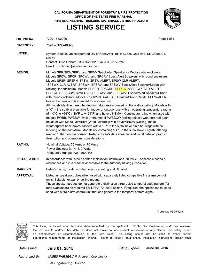
CALIFORNIA DEPARTMENT OF FORESTRY & FIRE PROTECTION
OFFICE OF THE STATE FIRE MARSHAL
FIRE ENGINEERING - BUILDING MATERIALS LISTING PROGRAM
LISTING SERVICE
LISTING No. 7320-1653:0201 Page 1 of 1
CATEGORY: 7320 -- SPEAKERS
LISTEE: System Sensor, Unincorporated Div of Honeywell Int'l Inc.3825 Ohio Ave, St. Charles, IL
60174
Contact: Trish Linhart (630) 762-5025 Fax (630) 377-7245
Email: [email protected]
DESIGN: Models SPR,SPW,SPRV, and SPWV SpectrAlert Speakers - Rectangular enclosure.
Models SPCW, SPCR, SPCWV, and SPCRV SpectrAlert Speakers with round enclosure.
Models SPSR, SPSRH, SPSW, SPSW-ALERT, SPSW-CLR-ALERT,
*SPSWK-CLR-ALERT, SPSWH, SPSRV, and SPSWV SpectrAlert Speaker/Strobe with
rectangular enclosure. Models SPSCR, SPSCRH, SPSCW, *SPSCWK-CLR-ALERT,
SPSCWH, SPSCRV, SPSCRVH, SPSCWV, and SPSCWVH SpectrAlert Speaker/Strobe
with round enclosure. Model SPSCW-CLR-ALERT Speaker/Strobe. Model SPSW-ALERT
has amber lens and is intended for non-fire use.
All models identified are intended for indoor use mounted on the wall or ceiling. Models with
a “K” in the suffix are suitable for indoor or outdoor use with an operating temperature rating
of -40°C to +66°C (-40°F to +151°F) and have a NEMA 4X enclosure rating when used with
models PWBB, PWBBW (wall) or the model PWBBCW (ceiling) plastic weatherproof back
boxes or with Model MWBBW (Wall), MWBB (Wall) or MWBBCW (Ceiling) metal
weatherproof back boxes. Models with a “- P” in the suffix have plain housings with no
lettering on the enclosure. Models not containing “- P”, in the suffix have English lettering
reading “FIRE” on the housing. Refer to listee's data sheet for additional detailed product
description and operational considerations.
RATING: Nominal Voltage: 25 Vrms or 70 Vrms
Power Settings: ¼, ½, 1, 2 Watts
Frequency Range: 400 - 4000 Hz
INSTALLATION: In accordance with listee's printed installation instructions, NFPA 72, applicable codes &
ordinances and in a manner acceptable to the authority having jurisdiction.
MARKING: Listee's name, model number, electrical rating and UL label.
APPROVAL: Listed as speaker/strobes when used with separately listed compatible fire alarm control
units. Suitable for wall or ceiling mount.
These speaker/strobes do not generate a distinctive three-pulse temporal code pattern (for
total evacuation) as required per NFPA 72, 2010 edition. If required, the appliances must be
used with a fire alarm control unit that can generate the temporal pattern signal.
*Corrected 02-06-12 bh
July 01, 2015Date Issued: Listing Expires June 30, 2016
Authorized By:
Fire Engineering Division
This listing is based upon technical data submitted by the applicant. CSFM Fire Engineering staff has reviewed
the test results and/or other data but does not make an independent verification of any claims. This listing is not
an endorsement or recommendation of the item listed. This listing should not be used to verify correct
operational requirements or installation criteria. Refer to listee’s data sheet, installation instructions and/or other
JAMES PARSEGIAN, Program Coordinator
Jeremy
Arrow
Reza
Highlight

A Service-Disabled Veteran-Owned Small Business
SUBMITTAL
15800 SE 135th Avenue, Clackamas, OR 97015 Phone: 503-650-1720
Fax: 503-650-1902
Part 2.7C
System Sensor SCW Multi-Candela Strobe Light

Agency Listings
Features
• Plug-in design with minimal intrusion into the back box
• Tamper-resistant construction
• Automatic selection of 12- or 24-volt operation at 15 and 15/75 candela
• Field-selectable candela settings on ceiling units: 15, 15/75, 30, 75, 95, 110, 115, 135, 150, 177, and 185
• Horn rated at 88+ dBA at 16 volts
• Rotary switch for horn tone and three volume selections
• Universal mounting plate for ceiling units
• Mounting plate shorting spring feature checks wiring continuity before device installation
• Electrically Compatible with legacy SpectrAlert devices
• Compatible with MDL3 sync module
• Listed for ceiling or wall mounting
The SpectrAlert Advance series offers the most versatile and easy-to-use line of horns, strobes, and horn strobes in the industry. With white and red plastic housings, wall and ceiling mounting options, and plain and FIRE-printed devices, SpectrAlert Advance can meet virtually any application requirement.
Like the entire SpectrAlert Advance product line, ceiling-mount strobes and horn strobes include a variety of features that increase their application versatility while simplifying installation. All devices feature a plug-in design with minimal intrusion into the back box, making installations fast and foolproof while virtually eliminating costly and time-consuming ground faults.
To further simplify installation, SpectrAlert Advance utilizes a universal mounting plate so you can mount them to a wide array of back boxes. With an onboard shorting spring, installers can test wiring continuity before the device is installed.
Installers can also easily adapt devices to a suit a wide range of application requirements using field-selectable candela settings, automatic selection of 12- or 24-volt operation, and a rotary switch for horn tones with three volume selections.
Indoor Selectable-Output Strobes and Horn Strobes for Ceiling Applications
SpectrAlert® Advance audible visible notification products
are rich with features guaranteed to cut installation times
and maximize profits.
MEA452-05-E3023572
7125-1653:0186 (indoor strobes)7125-1653:0188 (horn strobes,
chime strobes)7135-1653:0189 (horns, chimes)
S4011 (chimes, horn strobes, horns)S5512 (strobes)

AVDS10101
SpectrAlert Advance SpecificationsArchitect/Engineer SpecificationsGeneralSpectrAlert Advance strobes and horn strobes shall mount to a standard 4 × 4 × 1½-inch back box, 4-inch octagon back box, or double-gang back box. Two-wire products shall also mount to a single-gang 2 × 4 × 17⁄8-inch back box. A universal mounting plate shall be used for mounting ceiling and wall products. The notification appliance circuit wiring shall terminate at the universal mounting plate. Also, SpectrAlert Advance products, when used with the Sync•Circuit™ Module accessory, shall be powered from a non-coded notification appliance circuit output and shall operate on a nominal 12 or 24 volts. When used with the Sync•Circuit Module, 12-volt-rated notification appliance circuit outputs shall operate between 8.5 and 17.5 volts; 24-volt-rated notification appliance circuit outputs shall operate between 16.5 and 33 volts. Indoor SpectrAlert Advance products shall operate between 32 and 120 degrees Fahrenheit from a regulated DC or full-wave rectified unfiltered power supply. Strobes and horn strobes shall have field-selectable candela settings including 15, 15/75, 30, 75, 95, 110, 115, 135, 150, 177, and 185.
StrobeThe strobe shall be a System Sensor SpectrAlert Advance Model _______ listed to UL 1971 and shall be approved for fire protective service. The strobe shall be wired as a primary-signaling notification appliance and comply with the Americans with Disabilities Act requirements for visible signaling appliances, flashing at 1 Hz over the strobe’s entire operating voltage range. The strobe light shall consist of a xenon flash tube and associated lens/reflector system.
Horn Strobe CombinationThe horn strobe shall be a System Sensor SpectrAlert Advance Model _______ listed to UL 1971 and UL 464 and shall be approved for fire protective service. The horn strobe shall be wired as a primary-signaling notification appliance and comply with the Americans with Disabilities Act requirements for visible signaling appliances, flashing at 1 Hz over the strobe’s entire operating voltage range. The strobe light shall consist of a xenon flash tube and associated lens/reflector system. The horn shall have three audibility options and an option to switch between a temporal three pattern and a non-temporal (continuous) pattern. These options are set by a multiple position switch. On four-wire products, the strobe shall be powered independently of the sounder. The horn on horn strobe models shall operate on a coded or non-coded power supply.
Synchronization ModuleThe module shall be a System Sensor Sync•Circuit model MDL3 listed to UL 464 and shall be approved for fire protective service. The module shall synchronize SpectrAlert strobes at 1 Hz and horns at temporal three. Also, while operating the strobes, the module shall silence the horns on horn strobe models over a single pair of wires. The module shall mount to a 4 11⁄16 × 4 11⁄16 × 2 1⁄8-inch back box. The module shall also control two Style Y (class B) circuits or one Style Z (class A) circuit. The module shall synchronize multiple zones. Daisy chaining two or more synchronization modules together will synchronize all the zones they control. The module shall not operate on a coded power supply.
Physical/Electrical SpecificationsStandard Operating Temperature 32°F to 120°F (0°C to 49°C)Humidity Range 10 to 93% non-condensingStrobe Flash Rate 1 flash per secondNominal Voltage Regulated 12 DC/FWR or regulated 24 DC/FWR1
Operating Voltage Range2 8 to 17.5 V (12 V nominal) or 16 to 33 V (24 V nominal)Operating Voltage Range (MDL3) 8.5 to 17.5V (12 V nominal) or 16.5 to 33 V (24V nominal)Input Terminal Wire Gauge 12 to 18 AWGCeiling-Mount Dimensions (including lens) 6.8" diameter × 2.5" high (173 mm diameter × 64 mm high)Ceiling-Mount Surface Mount Back Box Skirt Dimensions (SBBCR, SBBCW)
6.9" diameter x 3.4" high (175 mm diameter x 86 mm high)
Notes:1. Full Wave Rectified (FWR) voltage is a non-regulated, time-varying power source that is used on some power supply and panel outputs.2. P, S, PC, and SC products will operate at 12 V nominal only for 15 and 15/75 cd.

AVDS10101
Horn Strobe Output (dBA)
Switch Position Sound Pattern dB
8–17.5 Volts
16–33Volts
24-Volt NominalReverberant Anechoic
DC FWR DC FWR DC FWR DC FWR1 Temporal High 78 78 84 84 88 88 99 982 Temporal Medium 74 74 80 80 86 86 96 963 Temporal Low 71 73 76 76 83 80 94 894 Non-Temporal High 82 82 88 88 93 92 100 1005 Non-Temporal Medium 78 78 85 85 90 90 98 986 Non-Temporal Low 75 75 81 81 88 84 96 927† Coded High 82 82 88 88 93 92 101 1018† Coded Medium 78 78 85 85 90 90 97 989† Coded Low 75 75 81 81 88 85 96 92
†Settings 7, 8, and 9 are not available on 2-wire horn strobes.
UL Max. Strobe Current Draw (mA RMS)
Candela8–17.5 Volts 16–33 VoltsDC FWR DC FWR
Standard Candela Range 15 123 128 66 7115/75 142 148 77 8130 NA NA 94 9675 NA NA 158 15395 NA NA 181 176110 NA NA 202 195115 NA NA 210 205
HighCandela Range
135 NA NA 228 207150 NA NA 246 220177 NA NA 281 251185 NA NA 286 258
UL Max. Current Draw (mA RMS), 2-Wire Horn Strobe, Standard Candela Range (15–115 cd)
DC Input8–17.5 Volts 16–33 Volts15 15/75 15 15/75 30 75 95 110 115
Temporal High 137 147 79 90 107 176 194 212 218Temporal Medium 132 144 69 80 97 157 182 201 210Temporal Low 132 143 66 77 93 154 179 198 207Non-Temporal High 141 152 91 100 116 176 201 221 229Non-Temporal Medium 133 145 75 85 102 163 187 207 216Non-Temporal Low 131 144 68 79 96 156 182 201 210FWR InputTemporal High 136 155 88 97 112 168 190 210 218Temporal Medium 129 152 78 88 103 160 184 202 206Temporal Low 129 151 76 86 101 160 184 194 201Non-Temporal High 142 161 103 112 126 181 203 221 229Non-Temporal Medium 134 155 85 95 110 166 189 208 216Non-Temporal Low 132 154 80 90 105 161 184 202 211
UL Max. Current Draw (mA RMS), 2-Wire Horn Strobe, High Candela Range (135–185 cd)
DC Input16–33 Volts
FWR Input16–33 Volts
135 150 177 185 135 150 177 185Temporal High 245 259 290 297 Temporal High 215 231 258 265Temporal Medium 235 253 288 297 Temporal Medium 209 224 250 258Temporal Low 232 251 282 292 Temporal Low 207 221 248 256Non-Temporal High 255 270 303 309 Non-Temporal High 233 248 275 281Non-Temporal Medium 242 259 293 299 Non-Temporal Medium 219 232 262 267Non-Temporal Low 238 254 291 295 Non-Temporal Low 214 229 256 262
UL Current Draw Data
Horn Strobe Tones and Sound Output Data

3825 Ohio Avenue • St. Charles, IL 60174 Phone: 800-SENSOR2 • Fax: 630-377-6495
©2015 System Sensor.Product specifications subject to change without notice. Visit systemsensor.com
for current product information, including the latest version of this data sheet.AVDS10102 • 03/15
SpectrAlert Advance Dimensions
Model DescriptionCeiling Horn StrobesPC2R 2-Wire Horn Strobe, Standard cd, RedPC2R-P 2-Wire Horn Strobe, Standard cd, Red, Plain
(no “FIRE”) markingPC2RH 2-Wire Horn Strobe, High cd, RedPC2W 2-Wire Horn Strobe, Standard cd, WhitePC2W-P 2-Wire Horn Strobe, Standard cd, White, Plain
(no “FIRE”) markingPC2W-SP 2-Wire Horn Strobe, Standard cd, White, “Fuego”
markingPC2WH 2-Wire Horn Strobe, High cd, WhitePC2WH-P 2-Wire Horn Strobe, High cd, White, Plain
(no “FIRE”) markingPC2WH-SP 2-Wire Horn Strobe, High cd, White, “Fuego”PC4R 4-Wire Horn Strobe, Standard cd, RedPC4RH 4-Wire Horn Strobe, High cd, RedPC4W 4-Wire Horn Strobe, Standard cd, White
SpectrAlert Advance Ordering Information
Notes:All -P models have a plain housing (no “FIRE” marking on cover)All -SP models have “FUEGO” marking on cover “Standard cd” refers to strobes that include 15, 15/75, 30, 75, 95, 110, and 115 candela settings. “High cd” refers to strobes that include 135, 150, 177, and 185 candela settings.
4.7"
5.6"
6.8"Dia.
2.5"
2.5"
5.703"
1.85"4.8"
6.922"dia.
2.5"
Ceiling-mount horn strobes Ceiling back box surface mount back box
Model DescriptionCeiling StrobesSCR Strobe, Standard cd, RedSCRH Strobe, High cd, RedSCW Strobe, Standard cd, WhiteSCW-P Strobe, Standard cd, White, Plain (no “Fire”) markingSCWH Strobe, High cd, WhiteAccessoriesSBBCR Surface Mount Back Box, Ceiling, Red SBBCW Surface Mount Back Box, Ceiling, White
Jeremy
Arrow
Reza
Highlight

CALIFORNIA DEPARTMENT OF FORESTRY & FIRE PROTECTION
OFFICE OF THE STATE FIRE MARSHAL
FIRE ENGINEERING - BUILDING MATERIALS LISTING PROGRAM
LISTING SERVICE
LISTING No. 7125-1653:0186 Page 1 of 1
CATEGORY: 7125 -- FIRE ALARM DEVICES FOR THE HEARING IMPAIRED
LISTEE: System Sensor, Unincorporated Div of Honeywell Int'l Inc.3825 Ohio Ave, St. Charles, IL
60174
Contact: Trish Linhart (630) 762-5025 Fax (630) 377-7245
Email: [email protected]
DESIGN: Synchronous type strobe lights, Models SR, SRH, SW, SW-CLR-ALERT, SWH, SCR,
SCRH, SCW, SCW-CLR-ALERT and SCWH followed by the suffix -P, -SP, -PG, or none.
Intended for indoor use mounted on the wall or the ceiling. Refer to listee's data sheet for
additional detailed product description and operational considerations.
RATING: 8-17.5 or 16-33 VDC/FWR
Candela: 15, 15/75, 30, 75, 95, 110, 115, *135, *150, *177, *185cd
INSTALLATION: In accordance with listee's printed installation instructions, applicable codes and ordinances,
and in a manner acceptable to the authority having jurisdiction.
MARKING: Listee's name, model number, electrical rating and UL label.
APPROVAL: Listed as strobe lights suitable for hearing impaired application when used with separately
listed compatible fire alarm control units. Suitable for indoor use, wall or ceiling mounted.
Refer to listee’s Installation Instruction Manual for details.
*Rev. 03-11-10 fm
July 01, 2015Date Issued: Listing Expires June 30, 2016
Authorized By:
Fire Engineering Division
This listing is based upon technical data submitted by the applicant. CSFM Fire Engineering staff has reviewed
the test results and/or other data but does not make an independent verification of any claims. This listing is not
an endorsement or recommendation of the item listed. This listing should not be used to verify correct
operational requirements or installation criteria. Refer to listee’s data sheet, installation instructions and/or other
JAMES PARSEGIAN, Program Coordinator
Jeremy
Arrow
Reza
Highlight
A Service-Disabled Veteran-Owned Small Business
SUBMITTAL
15800 SE 135th Avenue, Clackamas, OR 97015 Phone: 503-650-1720
Fax: 503-650-1902
Part 2.7C
System Sensor SWK WP Strobe

Agency Listings
Features
• Weatherproof per NEMA 4X, IP56
• Listed to UL 1638 (strobe) and UL 464 (horn)
• Compatible with System Sensor synchronization protocol and legacy SpectrAlert products
• Field-selectable candela settings: 15, 15/75, 30, 75, 95, 110, 115, 135, 150, 177, and 185
• Automatic selection of 12- or 24-volt operation at 15 and 15/75 candela
• Rotary switch for horn tone and three volume selections
• Horn rated at 88+ dBA at 16 volts
• Rated from –40°F to 151°F
• Universal mounting plate with an onboard shorting spring that tests wiring continuity before devices are installed
• Plug-in design with minimal intrusion into the back box
• Tamper-resistant construction
• Listed for ceiling or wall mounting
SpectrAlert Advance offers the broadest line of outdoor horns, strobes, and horn strobes in the industry. With white or red plastic housings, wall or ceiling mounting options, and plain or FIRE-printed devices, SpectrAlert Advance can meet virtually any application requirement, including indoor, outdoor, wet, and dry applications in temperatures from −40°F to 151°F.
Like the entire SpectrAlert Advance line, outdoor horns, strobes, and horn strobes for wall applications include a variety of features that increase application flexibility and simplify installation. First, field-selectable settings, including candela, automatic selection of 12- or 24-volt operation, horn tones, and three volume options enable installers to easily adapt devices to meet requirements.
Next, SpectrAlert Advance devices use a universal mounting plate for both wall and ceiling applications. This mounting plate includes an onboard shorting spring that ensures wiring continuity before devices are installed, so installers can verify proper wiring without mounting the devices and exposing them to potential construction damage. Once the plates are mounted, all SpectrAlert Advance devices utilize a plug-in design with a single captured screw to speed installation and virtually eliminate costly ground faults.
Outdoor devices ship with weatherproof plastic back boxes (metal back boxes are available separately) that accommodate in-and-out wiring for daisy chaining devices. Plastic back boxes feature removable side flanges and improved resistance to saltwater corrosion. Knock-outs located on the back eliminate the need to drill holes for screw-in mounting. Plastic and metal weatherproof back boxes come with ¾-inch top and bottom conduit entries and ¾-inch knock-outs at the back. A screw-in NPT plug with an O-ring gasket for a watertight seal is included with each back box.
Outdoor Selectable-Output Horns, Strobes, andHorn Strobes for Wall Applications
SpectrAlert® Advance outdoor audible visible products
are rich with features that cut installation times and
maximize profits.
MEA452-05-E3023572
7300-1653:187 (outdoor strobes)7125-1653:188 (horn strobes,
chime strobes)7135-1653:189 (horns, chimes)
S4011 (chimes, horn strobes, horns)S3593 (outdoor and alert strobes)
Jeremy
Arrow

AVDS01201
SpectrAlert Advance Outdoor Horn, Strobe, and Horn Strobe SpecificationsArchitect/Engineer SpecificationsGeneralSpectrAlert Advance outdoor horns, strobes, and horn strobes shall mount to a weatherproof back box. A universal mounting plate shall be used for mounting ceiling and wall products. The notification appliance circuit wiring shall terminate at the universal mounting plate. Also, SpectrAlert Advance products, when used with the Sync•Circuit™ Module accessory, shall be powered from a non-coded notification appliance circuit output and shall operate on a nominal 12 or 24 volts. When used with the Sync•Circuit Module, 12-volt-rated notification appliance circuit outputs shall operate between 9 and 17.5 volts; 24-volt-rated notification appliance circuit outputs shall operate between 17 and 33 volts. Outdoor SpectrAlert Advance products shall operate between −40 and 151 degrees Fahrenheit from a regulated DC or full-wave rectified unfiltered power supply. Strobes and horn strobes shall have field-selectable candela settings including 15, 15/75, 30, 75, 95, 110, 115, 135, 150, 177, and 185.
StrobeThe strobe shall be a System Sensor SpectrAlert Advance Model _______ listed to UL 1971 and shall be approved for fire protective service. The strobe shall be wired as a primary-signaling notification appliance and comply with the Americans with Disabilities Act requirements for visible signaling appliances, flashing at 1 Hz over the strobe’s entire operating voltage range. The strobe light shall consist of a xenon flash tube and associated lens/reflector system. The strobe must be installed with its weatherproof back box in order to remain outdoor approved per UL. The strobe shall be suitable for use in wet environments.
Horn Strobe CombinationThe horn strobe shall be a System Sensor SpectrAlert Advance Model _______ listed to UL 1971 and UL 464 and shall be approved for fire protective service. The horn strobe shall be wired as a primary-signaling notification appliance and comply with the Americans with Disabilities Act requirements for visible signaling appliances, flashing at 1 Hz over the strobe’s entire operating voltage range. The strobe light shall consist of a xenon flash tube and associated lens/reflector system. The horn shall have three audibility options and an option to switch between a temporal three pattern and a non-temporal (continuous) pattern. These options shall be set by a multiple position switch. On four-wire products, the strobe shall be powered independently of the sounder. The horn or horn strobe models shall operate on a coded or non-coded power supply. The horn strobe must be installed with its weatherproof back box in order to remain outdoor approved per UL. The horn strobe shall be suitable for use in wet environments.
Physical/Electrical SpecificationsOperating Temperature –40°F to 151°F (–40°C to 66°C)Strobe Flash Rate 1 flash per secondNominal Voltage Regulated 12 DC/FWR or regulated 24 DC/FWR1
Operating Voltage Range2 8 to 17.5 V (12 V nominal) or 16 to 33 V (24 V nominal)Input Terminal Wire Gauge 12 to 18 AWGWall-Mount Dimensions (including lens) 5.6˝ L × 4.7˝ W × 2.5˝ D (142 mm L × 119 mm W × 64 mm D)Horn Dimensions 5.6˝ L × 4.7˝ W × 1.3˝ D (142 mm L × 119 mm W × 33 mm D)Wall-Mount Weatherproof Back Box Dimensions (SA-WBB) 5.7˝ L × 5.1˝ W × 2.0˝ D (145 mm L × 130 mm W × 51 mm D)Notes:1. Full Wave Rectified (FWR) voltage is a non-regulated, time-varying power source that is used on some power supply and panel outputs.2. P, S, PC, and SC products will operate at 12 V nominal only for 15 and 15/75 cd.

AVDS01201
Horn and Horn Strobe Output (dBA)
Switch Position
Sound Pattern dB
8–17.5 Volts
16–33Volts
24-Volt NominalReverberant Anechoic
DC FWR DC FWR DC FWR DC FWR1 Temporal High 78 78 84 84 88 88 99 982 Temporal Medium 74 74 80 80 86 86 96 963 Temporal Low 71 73 76 76 83 80 94 894 Non-
TemporalHigh
82 82 88 88 93 92 100 100
5 Non-Temporal
Medium78 78 85 85 90 90 98 98
6 Non-Temporal
Low75 75 81 81 88 84 96 92
7† Coded High 82 82 88 88 93 92 101 1018† Coded Medium 78 78 85 85 90 90 97 989† Coded Low 75 75 81 81 88 85 96 92
†Settings 7, 8, and 9 are not available on 2-wire horn strobe.
UL Max. Strobe Current Draw (mA RMS)
Candela8–17.5 Volts 16–33 VoltsDC FWR DC FWR
Standard Candela Range
15 123 128 66 7115/75 142 148 77 8130 NA NA 94 9675 NA NA 158 15395 NA NA 181 176110 NA NA 202 195115 NA NA 210 205
HighCandela Range
135 NA NA 228 207150 NA NA 246 220177 NA NA 281 251185 NA NA 286 258
UL Max. Current Draw (mA RMS), 2-Wire Horn Strobe, Standard Candela Range (15–115 cd)
DC Input8–17.5 Volts 16–33 Volts15 15/75 15 15/75 30 75 95 110 115
Temporal High 137 147 79 90 107 176 194 212 218Temporal Medium 132 144 69 80 97 157 182 201 210Temporal Low 132 143 66 77 93 154 179 198 207Non-Temporal High 141 152 91 100 116 176 201 221 229Non-Temporal Medium 133 145 75 85 102 163 187 207 216Non-Temporal Low 131 144 68 79 96 156 182 201 210FWR InputTemporal High 136 155 88 97 112 168 190 210 218Temporal Medium 129 152 78 88 103 160 184 202 206Temporal Low 129 151 76 86 101 160 184 194 201Non-Temporal High 142 161 103 112 126 181 203 221 229Non-Temporal Medium 134 155 85 95 110 166 189 208 216Non-Temporal Low 132 154 80 90 105 161 184 202 211
UL Max. Current Draw (mA RMS), 2-Wire Horn Strobe, High Candela Range (135–185 cd)
DC Input16–33 Volts
FWR Input16–33 Volts
135 150 177 185 135 150 177 185Temporal High 245 259 290 297 Temporal High 215 231 258 265Temporal Medium 235 253 288 297 Temporal Medium 209 224 250 258Temporal Low 232 251 282 292 Temporal Low 207 221 248 256Non-Temporal High 255 270 303 309 Non-Temporal High 233 248 275 281Non-Temporal Medium 242 259 293 299 Non-Temporal Medium 219 232 262 267Non-Temporal Low 238 254 291 295 Non-Temporal Low 214 229 256 262
UL Max. Horn Current Draw (mA RMS)
Sound Pattern dB8–17.5 Volts 16–33 VoltsDC FWR DC FWR
Temporal High 57 55 69 75Temporal Medium 44 49 58 69Temporal Low 38 44 44 48Non-Temporal High 57 56 69 75Non-Temporal Medium 42 50 60 69Non-Temporal Low 41 44 50 50Coded High 57 55 69 75Coded Medium 44 51 56 69Coded Low 40 46 52 50
UL Current Draw Data
Horn Tones and Sound Output DataCandela DeratingFor K series products used at low temperatures, listed candela ratings must be reduced in accordance with this table.
Strobe Output (cd)Listed Candela Candela rating at –40°F15
Do not use below 32°F15/753075 4495 70110 110115 115135 135150 150177 177185 185

3825 Ohio Avenue • St. Charles, IL 60174 Phone: 800-SENSOR2 • Fax: 630-377-6495
©2012 System Sensor.Product specifications subject to change without notice. Visit systemsensor.com
for current product information, including the latest version of this data sheet.AVDS01201 • 3/12
SpectrAlert Advance Diagrams
Model DescriptionWall Horn StrobesP2RK*† 2-Wire Horn Strobe, Standard cd, Red, Outdoor (includes plastic weatherproof back box)P2RHK*† 2-Wire Horn Strobe, High cd, Red, Outdoor (includes plastic weatherproof back box)P2WK*† 2-Wire Horn Strobe, Standard cd, White, Outdoor (includes plastic weatherproof back box)P2WHK*† 2-Wire Horn Strobe, High cd, White, Outdoor (includes plastic weatherproof back box)P4RK† 4-Wire Horn Strobe, Standard cd, Red, Outdoor (includes plastic weatherproof back box)P4WK 4-Wire Horn Strobe, Standard cd, White, Outdoor (includes plastic weatherproof back box)P2RHK-120 2-Wire Horn Strobe, High cd, Red, Outdoor, 120 V (includes plastic weatherproof back box)Wall StrobesSRK*† Strobe, Standard cd, Red, Outdoor (includes plastic weatherproof back box)SRHK*† Strobe, High cd, Red, Outdoor (includes plastic weatherproof back box)SWK*† Strobe, Standard cd, White, Outdoor (includes plastic weatherproof back box)SWHK*† Strobe, High cd, White, Outdoor (includes plastic weatherproof back box)HornsHRK† Horn, Red, Outdoor (includes plastic weatherproof back box)AccessoriesSA-WBB Red, Metal Weatherproof Back Box SA-WBBW White, Metal Weatherproof Back Box
SpectrAlert Advance Ordering Information
Notes:* Add “-P” to model number for plain housing (no “FIRE” marking on cover), e.g., P2RK-P.† Add “-R” to model number for weatherproof replacement device (no back box included), only for use with weatherproof outdoor flush mounting plate, WTP and WTPW.“Standard cd” refers to strobes that include 15, 15/75, 30, 75, 95, 110, and 115 candela settings. “High cd” refers to strobes that include 135, 150, 177, and 185 candela settings. When replacing standard outdoor units both the device and back box must be replaced.
4.7˝
5.6˝
6.8˝Dia.
2.5˝
2.5˝
Wall-Mount Horn Strobes Wall Plastic Weatherproof Back Box
Wall-Mount Horn Strobe with Plastic Weatherproof Back Box
Jeremy
Arrow
Reza
Highlight

CALIFORNIA DEPARTMENT OF FORESTRY & FIRE PROTECTION
OFFICE OF THE STATE FIRE MARSHAL
FIRE ENGINEERING - BUILDING MATERIALS LISTING PROGRAM
LISTING SERVICE
LISTING No. 7300-1653:0187 Page 1 of 1
CATEGORY: 7300 -- FIRE ALARM CONTROL UNIT ACCESSORIES/MISC. DEVICES
LISTEE: System Sensor, Unincorporated Div of Honeywell Int'l Inc.3825 Ohio Ave, St. Charles, IL
60174
Contact: Trish Linhart (630) 762-5025 Fax (630) 377-7245
Email: [email protected]
DESIGN: Models SWK, SWHK, SCWK, SCWHK, SRK, SRHK, SCRK and SCRHK strobe lights
intended for indoor or outdoor use and may be mounted on the wall or the ceiling. These
strobe lights are suitable for outdoor use at an operating temperature range of -40°F to 150°F
(-40°C to 66°C)* rating and are NEMA 4X rated when used with the Listed models SA-WBB
(wall), SA-WBBW (Wall) or the model SA-WBBC (ceiling), SA-WBBCW (Ceiling)
weatherproof back boxes. May be followed by suffix -P for plain housing with no lettering.
Refer to listee's data sheet for additional detailed product description and operational
considerations.
RATING: 8-17.5 or 16-33 VDC/FWR
INSTALLATION: In accordance with listee's printed installation instruction, applicable codes and ordinances
and in a manner acceptable to the authority having jurisdiction.
MARKING: Listee's name, model number, electrical rating and UL label.
APPROVAL: Listed as strobe lights for general signaling. For indoor or outdoor use. Refer to listee’s
Installation Instruction Manual for details.
NOTE: Not approved for public mode and not to be used as an evacuation signal for the hearing
impaired.
*Corrected 07-22-10 fm
July 01, 2015Date Issued: Listing Expires June 30, 2016
Authorized By:
Fire Engineering Division
This listing is based upon technical data submitted by the applicant. CSFM Fire Engineering staff has reviewed
the test results and/or other data but does not make an independent verification of any claims. This listing is not
an endorsement or recommendation of the item listed. This listing should not be used to verify correct
operational requirements or installation criteria. Refer to listee’s data sheet, installation instructions and/or other
JAMES PARSEGIAN, Program Coordinator
Jeremy
Arrow
Reza
Highlight

A Service-Disabled Veteran-Owned Small Business
SUBMITTAL
15800 SE 135th Avenue, Clackamas, OR 97015 Phone: 503-650-1720
Fax: 503-650-1902
Part 2.8A
Notifier NBG-12S Addressable Single Manual Pull Station

DN-6643:A1 • 04/22/08 — Page 1 of 2
NBG-12 SeriesNon-Coded Conventional Manual Fire Alarm Pull Stations
Conventional Initiating Devices
DN-6643:A1 • I-410
GeneralThe NOTIFIER NBG-12 Series is a cost-effective, feature-packed series of non-coded manual fire alarm pull stations. Itwas designed to meet multiple applications with the installer andend-user in mind. The NBG-12 Series features a variety of mod-els including single- and dual-action versions.
The NBG-12 Series provides an alarm initiating input signal toconventional fire alarm control panels (FACPs) such as theSFP Series, and to XP Transponders. Its innovative design,durable construction, and multiple mounting options make theNBG-12 Series simple to install, maintain, and operate.
Features• Aesthetically pleasing, highly visible design and color.• Attractive contoured shape and light textured finish.• Meets ADA 5 lb. maximum pull-force.• Meets UL 38, Standard for Manually Actuated Signaling Boxes.• Easily operated (single- or dual-action, model dependent),
yet designed to prevent false alarms when bumped, shaken,or jarred.
• PUSH IN/PULL DOWN handle latches in the down position toclearly indicate the station has been operated.
• The word “ACTIVATED” appears on top of the handle inbright yellow, further indicating operation of the station.
• Operation handle features white arrows showing basic opera-tion direction for non-English-speaking persons.
• Braille text included on finger-hold area of operation handleand across top of handle.
• Multiple hex- and key-lock models available.• U.S. patented hex-lock needs only a quarter-turn to lock/
unlock.• Station can be opened for inspection and maintenance with-
out initiating an alarm.• Product ID label viewable by simply opening the cover; label
is made of a durable long-life material.• The words “NORMAL” and “ACTIVATED” are molded into the
plastic adjacent to the alarm switch (located inside).• Four-position terminal strip molded into backplate.• Terminal strip includes Phillips combination-head captive 8/32
screws for easy connection to Initiating Device Circuit (IDC).• Terminal screws backed-out at factory and shipped ready to
accept field wiring (up to 12 AWG/3.1 mm²).• Terminal numbers are molded into the backplate, eliminating
the need for labels.• Switch contacts are normally open.• Can be surface-mounted (with SB-10 or SB-I/O) or semi-
flush mounted. Semi-flush mount to a standard single-gang,double-gang, or 4" (10.16 cm) square electrical box.
• Backplate is large enough to overlap a single-gang backboxcutout by 1/2" (1.27 cm).
• Optional trim ring (BG12TR).• Spanish versions (FUEGO) available (NBG-12LSP, NBG-12LPSP).• Designed to replace the legacy NBG-10 Series.• Models packaged in attractive, clear plastic (PVC), clam-
shell-style, Point-of-Purchase packages. Packaging includesa cutaway dust/paint cover in shape of pull station.
Construction• Cover, backplate and operation handle are all molded of
durable polycarbonate material.• Cover features white lettering and trim.• Red color matches System Sensor’s popular SpectrAlert®
Advance horn/strobe series.
Operation
The NBG-12 manual pull stations provide a textured finger-holdarea that includes Braille text. In addition to PUSH IN and PULLDOWN text, there are arrows indicating how to operate the sta-tion, provided for non-English-speaking people.
Pushing in and then pulling down on the handle activates thenormally-open alarm switch. Once latched in the down position,the word “ACTIVATED” appears at the top in bright yellow, with aportion of the handle protruding at the bottom as a visible flag.Resetting the station is simple: insert the key or hex (modeldependent), twist one quarter-turn, then open the station’s frontcover, causing the spring-loaded operation handle to return toits original position. The alarm switch can then be reset to itsnormal (non-alarm) position manually (by hand) or by closingthe station’s front cover, which automatically resets the switch.
Specifications
PHYSICAL SPECIFICATIONS:
ELECTRICAL SPECIFICATIONS:Switch contact ratings: gold-plated; rating 0.25 A @ 30 VAC orVDC. Auxiliary contact circuit (Terminals 3 & 4, NBG-12LA):rated to 3.0 A @ 30 VAC or VDC.
6643cov.jpg
pull station SB-10 SB-I/O WBB WP-10
H5.500 in.
(13.97 cm)5.500 in.
(13.97 cm)5.601 in.
(14.23 cm)4.25 in.
(10.79 cm)6.000 in.
(15.24 cm)
W4.121 in.
(10.467 cm)4.125 in.
(10.478 cm)4.222 in.
(10.72 cm)4.25 in.
(10.79 cm)4.690 in.
(11.913 cm)
D1.390 in.
(3.531 cm)1.375 in.
(3.493 cm)1.439 in.(3.66 cm)
1.75 in.(4.445 cm)
2.000 in.(5.08 cm)
6643dim2.tbl

Page 2 of 2 — DN-6643:A1 • 04/22/08
NOTIFIER®, SpectrAlert® Advance, and System Sensor® are registeredtrademarks of Honeywell International Inc. ©2008 by Honeywell International Inc. All rights reserved. Unauthorized useof this document is strictly prohibited.
This document is not intended to be used for installation purposes. We try to keep our product information up-to-date and accurate.
We cannot cover all specific applications or anticipate all requirements. All specifications are subject to change without notice.
For more information, contact Notifier. Phone: (203) 484-7161, FAX: (203) 484-7118.www.notifier.com
Made in the U.S. A.
ENGINEERING/ARCHITECTURAL SPECIFICATIONSManual Fire Alarm Stations shall be non-code, with a key- orhex-operated reset lock in order that they may be tested, and sodesigned that after actual Emergency Operation, they cannot berestored to normal except by use of a key or hex. An operatedstation shall automatically condition itself so as to be visuallydetected as activated. Manual stations shall be constructed ofred colored LEXAN (or polycarbonate equivalent) with clearlyvisible operating instructions provided on the cover. The wordFIRE shall appear on the front of the stations in white letters,1.00 inches (2.54 cm) or larger.* Stations shall be suitable forsurface mounting on matching backbox SB-10 or SB-I/O; orsemi-flush mounting on a standard single-gang, double-gang, or4" (10.16 cm) square electrical box, and shall be installed withinthe limits defined by the Americans with Disabilities Act (ADA) orper national/local requirements. Manual Stations shall be Under-writers Laboratories listed.
NOTE: *The words “FIRE/FUEGO” on the NBG-12LSP and NBG-12LPSP shall appear on the front of the station in white letters,approximately 3/4" (1.905 cm) high.
Pre-Signal ModelsThe NBG-12LPS and NBG-12LPSP pull stations are non-codedmanual pull stations which provide a FACP with two normallyopen alarm initiating input signals. “Pre-signal” input is activatedby pushing in, then pulling down, the dual-action handle. A “gen-eral” alarm input signal can be manually activated via a momen-tary rocker switch mounted inside the unit. This general alarmswitch can only be accessed by opening the cover with the sup-plied key/lock. See diagram at right.
Agency Listings and ApprovalsThe listings and approvals below apply to the NBG-12 Seriespull stations. In some cases, certain modules may not be listedby certain approval agencies, or listing may be in process. Con-sult factory for latest listing status.
• C(UL)US Listed: file S692.• CSFM approved: file 7150-0028:199.• FM approved (except NBG-12LPS, NBG-12LPSP).• MEA approved: file 67-02-E (NBG-12, NBG-12L, NBG-12LOB,
NBG-12LA).• Lloyd’s Register type approved: file 93/60141 (E3) (NBG-12,
NBG-12L, NBG-12LA, NBG-12LOB, NBG-12S).• U.S. Coast Guard approved: files 161.002/23/3 (AFP-200 with
NBG-12, NBG-12L, NBG-12S); 161.002/42/1 (NFS-640 withNBG-12, NBG-12L, NBG-12S); 161.002/27/3 (AFP1010/AM2020 with NBG-12, NBG-12L, NBG-12S).
• Patented: U.S. Patent No. D428,351; 6,380,846; 6,314,772;6,632,108.
Product Line InformationNBG-12S: Single-action pull station with pigtail connections,hex lock.NBG-12: Dual-action pull station with SPST N/O switch, screwterminal connections, hex lock.NBG-12L: Dual-action pull station with SPST N/O switch,screw terminal connections, key lock.NBG-12LSP: Same as NBG-12L with English/Spanish (FIRE/FUEGO) labeling. NBG-12LPS: Dual-action pull station with pre-signal option.
NBG-12LPSP: Same as NBG-12LPS with English/Spanish(FIRE/FUEGO) labeling.NBG-12LOB: Dual-action pull station with key lock, outdoorapplications listings (NBG-12LO), and backbox. Includes SB-I/Oindoor/outdoor backbox, and sealing gasket. Model will alsomount to WP-10 weatherproof backbox in retrofit applications.NOTE: NBG-12LO not available separately; NBG-12LO + approved backbox = NBG-12LOB. Outdoor applications listings apply to NBG-12LOB combination.NBG-12LA: Dual-action pull station with key lock and annuncia-tor contacts.SB-10: Surface-mount backbox, metal. SB-I/O: Surface-mount backbox, plastic. (Included with NBG-12LOB.)
BG12TR: Optional trim ring for semi-flush mounting.WP-10: Outdoor use backbox.17021: Keys, set of two. (Included with key-lock pull stations.) 17007: Hex key, 9/64". (Included with hex-lock pull stations.) NOTE: For addressable NBG-12LX models, see data sheetDN-6726.
Dimensions
NBG-12LPS
6643
dim
2.w
mf
6643
lps.
wm
f
Jeremy
Arrow
Reza
Highlight
Reza
Highlight
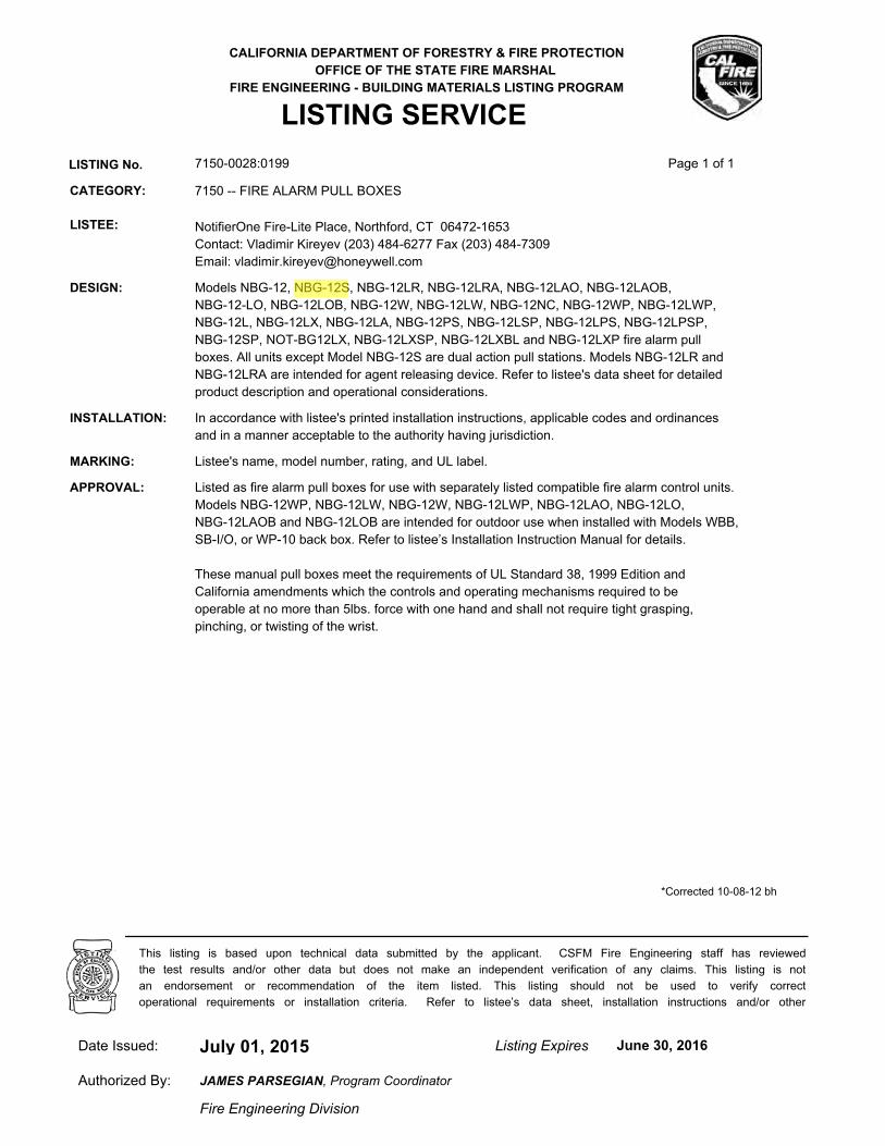
CALIFORNIA DEPARTMENT OF FORESTRY & FIRE PROTECTION
OFFICE OF THE STATE FIRE MARSHAL
FIRE ENGINEERING - BUILDING MATERIALS LISTING PROGRAM
LISTING SERVICE
LISTING No. 7150-0028:0199 Page 1 of 1
CATEGORY: 7150 -- FIRE ALARM PULL BOXES
LISTEE: NotifierOne Fire-Lite Place, Northford, CT 06472-1653
Contact: Vladimir Kireyev (203) 484-6277 Fax (203) 484-7309
Email: [email protected]
DESIGN: Models NBG-12, NBG-12S, NBG-12LR, NBG-12LRA, NBG-12LAO, NBG-12LAOB,
NBG-12-LO, NBG-12LOB, NBG-12W, NBG-12LW, NBG-12NC, NBG-12WP, NBG-12LWP,
NBG-12L, NBG-12LX, NBG-12LA, NBG-12PS, NBG-12LSP, NBG-12LPS, NBG-12LPSP,
NBG-12SP, NOT-BG12LX, NBG-12LXSP, NBG-12LXBL and NBG-12LXP fire alarm pull
boxes. All units except Model NBG-12S are dual action pull stations. Models NBG-12LR and
NBG-12LRA are intended for agent releasing device. Refer to listee's data sheet for detailed
product description and operational considerations.
INSTALLATION: In accordance with listee's printed installation instructions, applicable codes and ordinances
and in a manner acceptable to the authority having jurisdiction.
MARKING: Listee's name, model number, rating, and UL label.
APPROVAL: Listed as fire alarm pull boxes for use with separately listed compatible fire alarm control units.
Models NBG-12WP, NBG-12LW, NBG-12W, NBG-12LWP, NBG-12LAO, NBG-12LO,
NBG-12LAOB and NBG-12LOB are intended for outdoor use when installed with Models WBB,
SB-I/O, or WP-10 back box. Refer to listee’s Installation Instruction Manual for details.
These manual pull boxes meet the requirements of UL Standard 38, 1999 Edition and
California amendments which the controls and operating mechanisms required to be
operable at no more than 5lbs. force with one hand and shall not require tight grasping,
pinching, or twisting of the wrist.
*Corrected 10-08-12 bh
July 01, 2015Date Issued: Listing Expires June 30, 2016
Authorized By:
Fire Engineering Division
This listing is based upon technical data submitted by the applicant. CSFM Fire Engineering staff has reviewed
the test results and/or other data but does not make an independent verification of any claims. This listing is not
an endorsement or recommendation of the item listed. This listing should not be used to verify correct
operational requirements or installation criteria. Refer to listee’s data sheet, installation instructions and/or other
JAMES PARSEGIAN, Program Coordinator
Jeremy
Arrow
Reza
Highlight
Reza
Highlight

A Service-Disabled Veteran-Owned Small Business
SUBMITTAL
15800 SE 135th Avenue, Clackamas, OR 97015 Phone: 503-650-1720
Fax: 503-650-1902
Part 2.8B
Notifier FSP-851 Addressable Smoke Detector

DN-6935:E • 2/11/2015 — Page 1 of 2
FSP-851(A) SeriesIntelligent Plug-In PhotoelectricSmoke Detectors with FlashScan®
Intelligent/Addressable Devices
DN-6935:E • H-202
GeneralNotifier FSP-851(A) Series intelligent plug-in smoke detec-tors with integral communication provide features that sur-pass conventional detectors. Detector sensitivity can beprogrammed in the control panel software. Sensitivity is con-tinuously monitored and reported to the panel. Point ID capa-bility allows each detector’s address to be set with rotary,decimal address switches, providing exact detector locationfor selective maintenance when chamber contaminationreaches an unacceptable level. The FSP-851(A) photoelec-tric detector’s unique optical sensing chamber is engineeredto sense smoke produced by a wide range of combustionsources. Dual electronic thermistors add 135°F (57°C) fixed-temperature thermal sensing on the FSP-851T(A). The FSP-851R(A) is a remote test capable detector for use withDNR(A)/DNRW duct detector housings. FSP-851(A) seriesdetectors are compatible with Notifier Onyx and CLIP seriesFire Alarm Control Panels (FACPs).
FlashScan® (U.S. Patent 5,539,389) is a communicationprotocol developed by Notifier that greatly increases thespeed of communication between analog intelligent devices.Intelligent devices communicate in a grouped fashion. If oneof the devices in the group has new information, the panel’sCPU stops the group poll and concentrates on single points.The net effect is response speed greater than five times thatof earlier designs.
Features• Sleek, low-profile design.
• Addressable-analog communication.
• Stable communication technique with noise immunity.
• Low standby current.
• Two-wire SLC connection.
• Compatible with FlashScan® and CLIP protocol systems.
• Rotary, decimal addressing (1-99 on CLIP systems, 1-159on FlashScan systems).
• Optional remote, single-gang LED accessory.
• Dual LED design provides 360° viewing angle.
• Visible bi-color LEDs blink green every time the detector isaddressed, and illuminate steady red on alarm (FlashS-can systems only).
• Remote test feature from the panel.
• Walk test with address display (an address on 121 willblink the detector LED: 12-[pause]-1(FlashScan systemsonly).
• Built-in functional test switch activated by external magnet.
• Built-in tamper-resistant feature.
• Sealed against back pressure.
• Constructed of off-white fire-resistant plastic, designed tocommercial standards, and offers an attractive appear-ance.
• 94-5V plastic flammability rating.
• SEMS screws for wiring of the separate base.
• Optional relay, isolator, and sounder bases.
SpecificationsSensitivity: 0.5% to 2.35% per foot obscuration
Size: 2.1" (5.3 cm) high; base determines diameter.
– B210LP(A): 6.1" (15.5 cm) diameter.
– B501(A): 4.1" (10.4 cm) diameter.
– B200S(A): 6.875" (17.46 cm) diameter.
– B200SR(A): 6.875" (17.46 cm) diameter.
– B224RB(A): 6.2" (15.748 cm) diameter.
– B224BI(A): 6.2" (15.748 cm) diameter.
Shipping Weight: 5.2oz. (147g).
Operating Temperature range: FSP-851(A), 0°C to 49°C(32°F to 120°F). FSP-851T(A), 0°C to 38°C (32°F to 100°F).Low temperature signal for FSP-851T(A) at 45°F +/- 10°F(7.22°C +/- 5.54°C). FSP-851R(A) installed in a DNR(A)/DNRW, -20°C to 70°C (-4°F to 158°F).
UL/ULC Listed Velocity Range: 0-4000 ft/min. (1219.2 m/min.), suitable for installation in ducts.
Relative Humidity: 10%-93% noncondensing.
Thermal Ratings: Fixed-temperature setpoint 135°F (57°C).
DETECTOR SPACING AND APPLICATIONS
Notifier recommends spacing detectors in compliance withNFPA 72. In low airflow applications with smooth ceiling,space detectors 30 feet (9.144m) for ceiling heights 10 feet(3.148m) and higher. For specific information regardingdetector spacing, placement, and special applications refer toNFPA 72. System Smoke Detector Application Guide, docu-ment A05-1003, is available at systemsensor.com
ELECTRICAL SPECIFICATIONS
Voltage Range: 15-32 volts DC peak.
Standby Current (max. avg.): 300µA @ 24VDC (one com-munication every five seconds with LED enabled).
LED Current (max.): 6.5mA @ 24 VDC (“ON”).
FSP-851(A) in B210LP(A) Base
B210
-2951.jpg
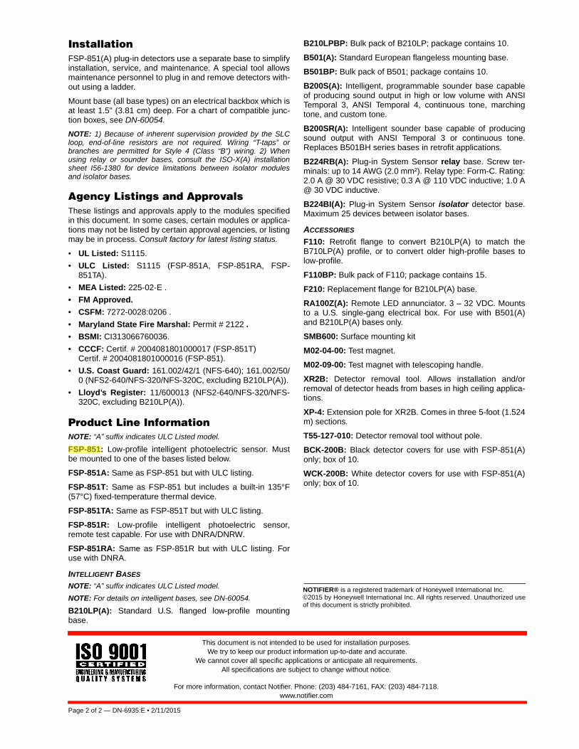
Page 2 of 2 — DN-6935:E • 2/11/2015
NOTIFIER® is a registered trademark of Honeywell International Inc.©2015 by Honeywell International Inc. All rights reserved. Unauthorized useof this document is strictly prohibited.
This document is not intended to be used for installation purposes. We try to keep our product information up-to-date and accurate.
We cannot cover all specific applications or anticipate all requirements. All specifications are subject to change without notice.
For more information, contact Notifier. Phone: (203) 484-7161, FAX: (203) 484-7118.www.notifier.com
InstallationFSP-851(A) plug-in detectors use a separate base to simplifyinstallation, service, and maintenance. A special tool allowsmaintenance personnel to plug in and remove detectors with-out using a ladder.
Mount base (all base types) on an electrical backbox which isat least 1.5" (3.81 cm) deep. For a chart of compatible junc-tion boxes, see DN-60054.
NOTE: 1) Because of inherent supervision provided by the SLCloop, end-of-line resistors are not required. Wiring “T-taps” orbranches are permitted for Style 4 (Class “B”) wiring. 2) Whenusing relay or sounder bases, consult the ISO-X(A) installationsheet I56-1380 for device limitations between isolator modulesand isolator bases.
Agency Listings and ApprovalsThese listings and approvals apply to the modules specifiedin this document. In some cases, certain modules or applica-tions may not be listed by certain approval agencies, or listingmay be in process. Consult factory for latest listing status.
• UL Listed: S1115.
• ULC Listed: S1115 (FSP-851A, FSP-851RA, FSP-851TA).
• MEA Listed: 225-02-E .
• FM Approved.
• CSFM: 7272-0028:0206 .
• Maryland State Fire Marshal: Permit # 2122 .
• BSMI: CI313066760036.
• CCCF: Certif. # 2004081801000017 (FSP-851T)Certif. # 2004081801000016 (FSP-851).
• U.S. Coast Guard: 161.002/42/1 (NFS-640); 161.002/50/0 (NFS2-640/NFS-320/NFS-320C, excluding B210LP(A)).
• Lloyd’s Register: 11/600013 (NFS2-640/NFS-320/NFS-320C, excluding B210LP(A)).
Product Line InformationNOTE: “A” suffix indicates ULC Listed model.
FSP-851: Low-profile intelligent photoelectric sensor. Mustbe mounted to one of the bases listed below.
FSP-851A: Same as FSP-851 but with ULC listing.
FSP-851T: Same as FSP-851 but includes a built-in 135°F(57°C) fixed-temperature thermal device.
FSP-851TA: Same as FSP-851T but with ULC listing.
FSP-851R: Low-profile intelligent photoelectric sensor,remote test capable. For use with DNRA/DNRW.
FSP-851RA: Same as FSP-851R but with ULC listing. Foruse with DNRA.
INTELLIGENT BASES
NOTE: “A” suffix indicates ULC Listed model.
NOTE: For details on intelligent bases, see DN-60054.
B210LP(A): Standard U.S. flanged low-profile mountingbase.
B210LPBP: Bulk pack of B210LP; package contains 10.
B501(A): Standard European flangeless mounting base.
B501BP: Bulk pack of B501; package contains 10.
B200S(A): Intelligent, programmable sounder base capableof producing sound output in high or low volume with ANSITemporal 3, ANSI Temporal 4, continuous tone, marchingtone, and custom tone.
B200SR(A): Intelligent sounder base capable of producingsound output with ANSI Temporal 3 or continuous tone.Replaces B501BH series bases in retrofit applications.
B224RB(A): Plug-in System Sensor relay base. Screw ter-minals: up to 14 AWG (2.0 mm²). Relay type: Form-C. Rating:2.0 A @ 30 VDC resistive; 0.3 A @ 110 VDC inductive; 1.0 A@ 30 VDC inductive.
B224BI(A): Plug-in System Sensor isolator detector base.Maximum 25 devices between isolator bases.
ACCESSORIES
F110: Retrofit flange to convert B210LP(A) to match theB710LP(A) profile, or to convert older high-profile bases tolow-profile.
F110BP: Bulk pack of F110; package contains 15.
F210: Replacement flange for B210LP(A) base.
RA100Z(A): Remote LED annunciator. 3 – 32 VDC. Mountsto a U.S. single-gang electrical box. For use with B501(A)and B210LP(A) bases only.
SMB600: Surface mounting kit
M02-04-00: Test magnet.
M02-09-00: Test magnet with telescoping handle.
XR2B: Detector removal tool. Allows installation and/orremoval of detector heads from bases in high ceiling applica-tions.
XP-4: Extension pole for XR2B. Comes in three 5-foot (1.524m) sections.
T55-127-010: Detector removal tool without pole.
BCK-200B: Black detector covers for use with FSP-851(A)only; box of 10.
WCK-200B: White detector covers for use with FSP-851(A)only; box of 10.
Jeremy
Arrow
Reza
Highlight

CALIFORNIA DEPARTMENT OF FORESTRY & FIRE PROTECTION
OFFICE OF THE STATE FIRE MARSHAL
FIRE ENGINEERING - BUILDING MATERIALS LISTING PROGRAM
LISTING SERVICE
LISTING No. 7272-0028:0206 Page 1 of 1
CATEGORY: 7272 -- SMOKE DETECTOR-SYSTEM TYPE-PHOTOELECTRIC
LISTEE: NotifierOne Fire-Lite Place, Northford, CT 06472-1653
Contact: Vladimir Kireyev (203) 484-6277 Fax (203) 484-7309
Email: [email protected]
DESIGN: Models FSP-751, HPX-751, FSP-751T, FSH-751, FAPT-751, FAPT-851, FSP-851,
FSP-851R* and FSP-851T photoelectric type smoke detectors. Models FSP-751T and
FSP-851T employ a 135°F supplement integral heat sensor which only assists in a fire
situation. This thermal circuitry is NOT approved for use in lieu of a required heat detector.
Refer to listee's data sheet for additional detailed product description and operational
considerations.
RATING: 24 VDC
INSTALLATION: In accordance with listee's printed installation instructions, applicable codes & ordinances
and in manner acceptable to the authority having jurisdiction.
MARKING: Listee's name, product number, electrical rating and UL label.
APPROVAL: Listed as photoelectric type smoke detector for use with listee's separately listed compatible
base and fire alarm control units. Models FSP-751, FSP-751T, FAPT-751, FAPT-851,
FSP-851, FSP-851R*, FSP-851T are suitable for open areas and inside duct installation with
air velocities between 0-4000 fpm. Model HPX-751 is suitable for open areas with air
velocities between 0-300 fpm. Model FSH-751 is suitable for open areas with air velocity
between 0-4000 fpm.
NOTE: Combined with 7272-0028:208
The photoelectric type detectors are generally more effective at detecting slow, smoldering
fires that smolder for hours before bursting into flame. Sources of these fires may include
cigarettes burning in couches or bedding. The ionization type detectors are generally more
effective at detecting fast, flaming fires that consume combustible materials rapidly and
spread quickly. Sources of these fires may include paper burning in a waste container or a
grease fire in the kitchen.
*Rev. 01-07-2009 fm
July 01, 2015Date Issued: Listing Expires June 30, 2016
Authorized By:
Fire Engineering Division
This listing is based upon technical data submitted by the applicant. CSFM Fire Engineering staff has reviewed
the test results and/or other data but does not make an independent verification of any claims. This listing is not
an endorsement or recommendation of the item listed. This listing should not be used to verify correct
operational requirements or installation criteria. Refer to listee’s data sheet, installation instructions and/or other
JAMES PARSEGIAN, Program Coordinator
Jeremy
Arrow
Reza
Highlight

A Service-Disabled Veteran-Owned Small Business
SUBMITTAL
15800 SE 135th Avenue, Clackamas, OR 97015 Phone: 503-650-1720
Fax: 503-650-1902
Part 2.8C
Notifier FST-851 Addressable Heat Detector

DN-6936:B • 12/07/2011 — Page 1 of 2
FST-851(A) SeriesIntelligent Thermal (Heat) Detectors with FlashScan®
Intelligent / Addressable Devices
DN-6936:B • H-211
GeneralNotifier FST-851(A) Series intelligent plug-in thermal detectorswith integral communication has features that surpass conven-tional detectors. Point ID capability allows each detector’saddress to be set with rotary, decimal address switches, pro-viding exact detector locations. FST-851(A) Series thermaldetectors use an innovative thermistor sensing circuit to pro-duce 135°F/57°C fixed-temperature (FST-851/A) and rate-of-rise thermal detection (FST-851R/A) in a low-profile package.FST-851H(A) provides fixed high-temperature detection at190°F/88°C. These thermal detectors provide effective, intelli-gent property protection in a variety of applications. FST-851(A) Series detectors are compatible with Notifier Onyx andCLIP series Fire Alarm Control Panels (FACPs).
FlashScan® (U.S. Patent 5,539,389) is a communication pro-tocol developed by Notifier Engineering that greatly enhancesthe speed of communication between analog intelligentdevices and certain NOTIFIER systems. Intelligent devicescommunicate in a grouped fashion. If one of the devices withinthe group has new information, the panel’s CPU stops thegroup poll and concentrates on single points. The net effect isresponse speed greater than five times that of earlier designs.
Features• Sleek, low-profile, stylish design.• State-of-the-art thermistor technology for fast response.• Rate-of-rise model (FST-851R/A), 15°F (8.3°C) per minute.
• Factory preset fixed temperature at 135°F (57°C); high-tem-perature model fixed at 190°F (88°C).
• Addressable by device.• Compatible with FlashScan® and CLIP protocol systems.• Rotary, decimal addressing (1-99 on CLIP systems, 1-159
on FlashScan systems).• Two-wire SLC connection.
• Visible LEDs “blink” every time the unit is addressed.• 360°-field viewing angle of the visual alarm indicators (two
bi-color LEDs). LEDs blink green in Normal condition andturn on steady red in Alarm.
• Integral communications and built-in device-type identifica-tion.
• Remote test feature from the panel.• Built-in functional test switch activated by external magnet.
• Walk test with address display (an address of 121 will blinkthe detector LED 12-(pause)-1).
• Low standby current.• Backward-compatible.• Built-in tamper-resistant feature.
• Designed for direct-surface or electrical-box mounting.• Sealed against back pressure.• Plugs into separate base for ease of installation and main-
tenance. Separate base allows interchange of photoelec-tric, ionization and thermal sensors.
• SEMS screws for wiring of the separate base.• Constructed of off-white fire-resistant plastic, designed to
commercial standards, and offers an attractive appearance.
• 94-5V plastic flammability rating.• Remote LED output connection to optional RA100Z(A)
remote LED annunciator.
• Optional sounder, relay, and isolator bases.• Optional flanced surface mounting kit.
SpecificationsSize: 2.1" (5.3 cm) high; base determines diameter.
– B210LP(A): 6.1" (15.5 cm) diameter.– B501(A): 4.1" (10.4 cm) diameter.
– B200S(A): 6.875" (17.46 cm) diameter.– B200SR(A): 6.875" (17.46 cm) diameter. – B224RB(A): 6.2" (15.748 cm) diameter.
– B224BI(A): 6.2" (15.748 cm) diameter. Shipping weight: 4.8 oz. (137 g).
Operating temperature range: FST-851(A) Series, FST-851R(A): –20°C to 38°C (–4°F to 100°F); FST-851H(A): –20°Cto 66°C (–4°F to 150°F).
Detector spacing: UL approved for 50 ft. (15.24 m) center tocenter. FM approved for 25 x 25 ft. (7.62 x 7.62 m) spacing.
Relative humidity: 10% – 93% noncondensing.
Thermal ratings: fixed-temperature setpoint 135°F (57°C),rate-of-rise detection 15°F (8.3°C) per minute, high tempera-ture heat 190°F (88°C).
ELECTRICAL SPECIFICATIONSVoltage range: 15 - 32 volts DC peak.
Standby current (max. avg.): 300 μA @ 24 VDC (one com-munication every 5 seconds with LED enabled).
LED current (max.): 6.5 mA @ 24 VDC (“ON”).
ApplicationsUse thermal detectors for protection of property. For furtherinformation, go to systemsensor.com for manual I56-407-00,Applications Manual for System Smoke Detectors, which pro-vides detailed information on detector spacing, placement,zoning, wiring, and special applications.
FST-851(A) in B210LP(A) Base
B2
10-2
251
.jpg
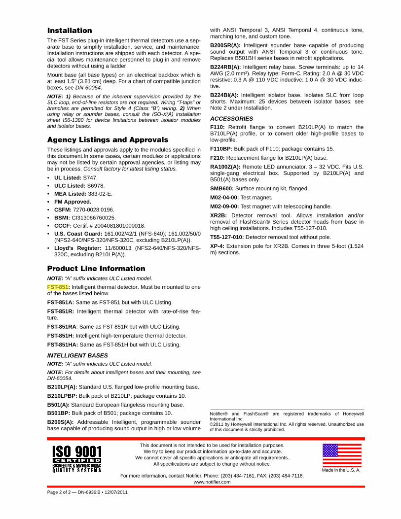
Page 2 of 2 — DN-6936:B • 12/07/2011
Notifier® and FlashScan® are registered trademarks of HoneywellInternational Inc.©2011 by Honeywell International Inc. All rights reserved. Unauthorized useof this document is strictly prohibited.
This document is not intended to be used for installation purposes. We try to keep our product information up-to-date and accurate.
We cannot cover all specific applications or anticipate all requirements. All specifications are subject to change without notice.
For more information, contact Notifier. Phone: (203) 484-7161, FAX: (203) 484-7118.www.notifier.com
Made in the U.S. A.
InstallationThe FST Series plug-in intelligent thermal detectors use a sep-arate base to simplify installation, service, and maintenance.Installation instructions are shipped with each detector. A spe-cial tool allows maintenance personnel to plug in and removedetectors without using a ladder
Mount base (all base types) on an electrical backbox which isat least 1.5" (3.81 cm) deep. For a chart of compatible junctionboxes, see DN-60054.
NOTE: 1) Because of the inherent supervision provided by theSLC loop, end-of-line resistors are not required. Wiring “T-taps” orbranches are permitted for Style 4 (Class “B”) wiring. 2) Whenusing relay or sounder bases, consult the ISO-X(A) installationsheet I56-1380 for device limitations between isolator modulesand isolator bases.
Agency Listings and ApprovalsThese listings and approvals apply to the modules specified inthis document.In some cases, certain modules or applicationsmay not be listed by certain approval agencies, or listing maybe in process. Consult factory for latest listing status.
• UL Listed: S747.• ULC Listed: S6978.
• MEA Listed: 383-02-E.• FM Approved.• CSFM: 7270-0028:0196.
• BSMI: CI313066760025.• CCCF: Certif. # 2004081801000018.• U.S. Coast Guard: 161.002/42/1 (NFS-640); 161.002/50/0
(NFS2-640/NFS-320/NFS-320C, excluding B210LP(A)).• Lloyd’s Register: 11/600013 (NFS2-640/NFS-320/NFS-
320C, excluding B210LP(A)).
Product Line InformationNOTE: “A” suffix indicates ULC Listed model.
FST-851: Intelligent thermal detector. Must be mounted to oneof the bases listed below.
FST-851A: Same as FST-851 but with ULC Listing.
FST-851R: Intelligent thermal detector with rate-of-rise fea-ture.
FST-851RA: Same as FST-851R but with ULC Listing.
FST-851H: Intelligent high-temperature thermal detector.
FST-851HA: Same as FST-851H but with ULC Listing.
INTELLIGENT BASESNOTE: “A” suffix indicates ULC Listed model.
NOTE: For details about intelligent bases and their mounting, seeDN-60054.
B210LP(A): Standard U.S. flanged low-profile mounting base.
B210LPBP: Bulk pack of B210LP; package contains 10.
B501(A): Standard European flangeless mounting base.
B501BP: Bulk pack of B501; package contains 10.
B200S(A): Addressable Intelligent, programmable sounderbase capable of producing sound output in high or low volume
with ANSI Temporal 3, ANSI Temporal 4, continuous tone,marching tone, and custom tone.
B200SR(A): Intelligent sounder base capable of producingsound output with ANSI Temporal 3 or continuous tone.Replaces B501BH series bases in retrofit applications.
B224RB(A): Intelligent relay base. Screw terminals: up to 14AWG (2.0 mm²). Relay type: Form-C. Rating: 2.0 A @ 30 VDCresistive; 0.3 A @ 110 VDC inductive; 1.0 A @ 30 VDC induc-tive.
B224BI(A): Intelligent isolator base. Isolates SLC from loopshorts. Maximum: 25 devices between isolator bases; seeNote 2 under Installation.
ACCESSORIESF110: Retrofit flange to convert B210LP(A) to match theB710LP(A) profile, or to convert older high-profile bases tolow-profile.
F110BP: Bulk pack of F110; package contains 15.
F210: Replacement flange for B210LP(A) base.
RA100Z(A): Remote LED annunciator. 3 – 32 VDC. Fits U.S.single-gang electrical box. Supported by B210LP(A) andB501(A) bases only.
SMB600: Surface mounting kit, flanged.
M02-04-00: Test magnet.
M02-09-00: Test magnet with telescoping handle.
XR2B: Detector removal tool. Allows installation and/orremoval of FlashScan® Series detector heads from base inhigh ceiling installations. Includes T55-127-010.
T55-127-010: Detector removal tool without pole.
XP-4: Extension pole for XR2B. Comes in three 5-foot (1.524m) sections.
Jeremy
Arrow
Reza
Highlight
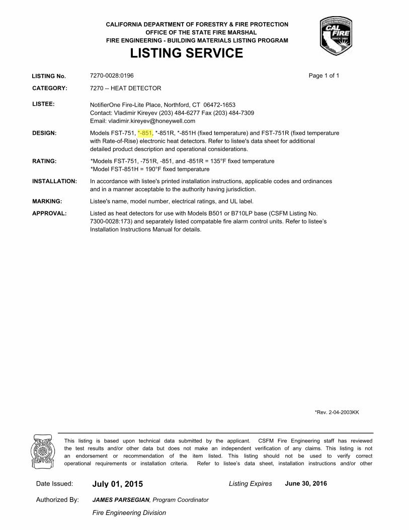
CALIFORNIA DEPARTMENT OF FORESTRY & FIRE PROTECTION
OFFICE OF THE STATE FIRE MARSHAL
FIRE ENGINEERING - BUILDING MATERIALS LISTING PROGRAM
LISTING SERVICE
LISTING No. 7270-0028:0196 Page 1 of 1
CATEGORY: 7270 -- HEAT DETECTOR
LISTEE: NotifierOne Fire-Lite Place, Northford, CT 06472-1653
Contact: Vladimir Kireyev (203) 484-6277 Fax (203) 484-7309
Email: [email protected]
DESIGN: Models FST-751, *-851, *-851R, *-851H (fixed temperature) and FST-751R (fixed temperature
with Rate-of-Rise) electronic heat detectors. Refer to listee's data sheet for additional
detailed product description and operational considerations.
RATING: *Models FST-751, -751R, -851, and -851R = 135°F fixed temperature
*Model FST-851H = 190°F fixed temperature
INSTALLATION: In accordance with listee's printed installation instructions, applicable codes and ordinances
and in a manner acceptable to the authority having jurisdiction.
MARKING: Listee's name, model number, electrical ratings, and UL label.
APPROVAL: Listed as heat detectors for use with Models B501 or B710LP base (CSFM Listing No.
7300-0028:173) and separately listed compatable fire alarm control units. Refer to listee’s
Installation Instructions Manual for details.
*Rev. 2-04-2003KK
July 01, 2015Date Issued: Listing Expires June 30, 2016
Authorized By:
Fire Engineering Division
This listing is based upon technical data submitted by the applicant. CSFM Fire Engineering staff has reviewed
the test results and/or other data but does not make an independent verification of any claims. This listing is not
an endorsement or recommendation of the item listed. This listing should not be used to verify correct
operational requirements or installation criteria. Refer to listee’s data sheet, installation instructions and/or other
JAMES PARSEGIAN, Program Coordinator
Jeremy
Arrow
Reza
Highlight

A Service-Disabled Veteran-Owned Small Business
SUBMITTAL
15800 SE 135th Avenue, Clackamas, OR 97015 Phone: 503-650-1720
Fax: 503-650-1902
Part 2.9A1, 2
Notifier DNRW WP Detector Housing Installed with FSP-851 and FRM-1

DN-60429:C1 • 4/19/2012 — Page 1 of 2
DNR(A)/DNRW InnovairFlexIntelligent Non-Relay Photoelectric Duct Smoke Detector
Intelligent Devices
DN-60429:C1
GeneralThe Notifier InnovairFlex® DNR(A) intelligent non-relay photo-electric duct smoke detector and DNRW watertight non-relayphotoelectric duct smoke detector feature a pivoting housingthat fits both square and rectangular footprints capable ofmounting to a round or rectangular duct.
DNRW duct smoke detector, with its NEMA-4 rating, is listedas a watertight, UV resistant enclosure providing protectionagainst falling dirt, rain, and windblown dust, splashing andhose directed water, allowing operators to use the detector inthe most extreme environments.
These units sense smoke in the most challenging conditions,operating in airflow speeds of 100 to 4,000 feet per minute (0.5to 20.32 m/s), temperatures of -4°F to 158°F (-20°C to 70°C),and a humidity range of 0 to 95 percent (non-condensing.)
An improved cover design isolates the sensor head, whichallows for ease of maintenance. A cover tamper feature indi-cates a trouble signal for a removed or improperly installedsensor cover. The Notifier InnovairFlex housing provides a 3/4-inch conduit knockout and ample space to facilitate easy wir-ing and mounting of a relay module.
The Notifier InnovairFlex duct smoke detector can be custom-ized to meet local codes and specifications without additionalwiring. The new InnovairFlex product line is compatible with allprevious Innovair models, including remote test accessories.
Features• Photoelectric, integrated low-flow technology.• Air velocity rating from 100 ft/min to 4,000 ft/min (0.5 m/s to
20.32 m/s).• Versatile mounting options: square or rectangular configu-
ration.• Broad ranges for operating temperature (-4°F to 158°F, -
20°C to 70°C) and humidity (0% to 95% non-condensing).• Patented sampling tube installs from front or back of the
detector with no tools required.• Cover tamper signal.
• Increased wiring space with a newly added 3/4” conduitknockout.
• Available space within housing to accommodate mountingof a relay module.
• Easily accessible code wheels on sensor head (sold sepa-rately).
• Clear cover for convenient visual inspection.• Remote testing capability.• Requires com line power only.
• Accommodates the installation of an addressable relaymodule, sold separately, (FRM-1 or NC-100R) for applica-tions requiring a Form-C relay.
SpecificationsSize: (Rectangle) 14.38 in (37 cm) Length; 5 in (12.7 cm)Width, 2.5 in (6.6 cm) Depth.
Size: (Square) 7.75 in (19.7 cm) Length; 9 in (22.9 cm) Width;2.5 in (6.35 cm) Depth.
Weight: 1.6 lb (0.73 kg).
Operating Temperature Range: -4°F to 158°F (-20°C to70°C).
Storage Temperature Range: -22°F to 158°F (-30°C to70°C).
Operating Humidity Range: 0% to 95% relative humidity(non-condensing).
Air Duct Velocity: 100 to 4,000 ft/min (0.5 to 20.32 m/s).
AccessoriesNotifier provides system flexibility with a variety of accessories,including two remote test stations and different means of visi-ble and audible system annunciation. As with our duct smokedetectors, all duct smoke detectors accessories are UL listed.
DNR(W)s with a date code of 0013 or higher do not requireexternal 24VDC for remote test applications when used with aremote-test-capable detector.
ACCESSORY CURRENT LOADS AT 24 VDC
Agency Listings and Approvals Consult product manual for lists of compatible UL-Listeddevices. In some cases, certain modules may not be listed bycertain approval agencies, or listing may be in process. Con-sult factory for latest listing status.
• UL: S911, S3705.• ULC: S635.
Device Standby Alarm
RA100Z 0mA 12 mA Max
RTS151/RTS151KEY
0mA 12mA Max
intelligent innovair-
Jeremy
Arrow
Reza
Highlight
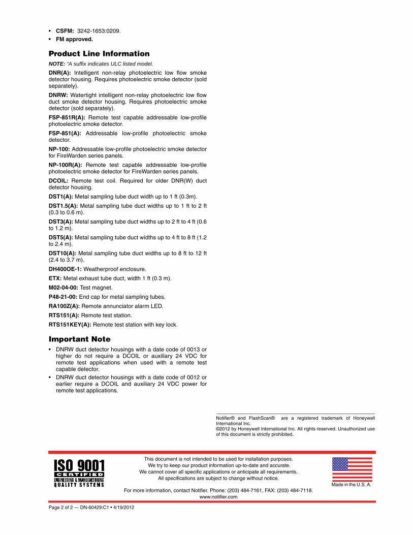
Page 2 of 2 — DN-60429:C1 • 4/19/2012
Notifier® and FlashScan® are a registered trademark of HoneywellInternational Inc. ©2012 by Honeywell International Inc. All rights reserved. Unauthorized useof this document is strictly prohibited.
This document is not intended to be used for installation purposes. We try to keep our product information up-to-date and accurate.
We cannot cover all specific applications or anticipate all requirements. All specifications are subject to change without notice.
For more information, contact Notifier. Phone: (203) 484-7161, FAX: (203) 484-7118.www.notifier.com
Made in the U.S. A.
• CSFM: 3242-1653:0209.
• FM approved.
Product Line InformationNOTE: “A suffix indicates ULC listed model.
DNR(A): Intelligent non-relay photoelectric low flow smokedetector housing. Requires photoelectric smoke detector (soldseparately).
DNRW: Watertight intelligent non-relay photoelectric low flowduct smoke detector housing. Requires photoelectric smokedetector (sold separately).
FSP-851R(A): Remote test capable addressable low-profilephotoelectric smoke detector.
FSP-851(A): Addressable low-profile photoelectric smokedetector.
NP-100: Addressable low-profile photoelectric smoke detectorfor FireWarden series panels.
NP-100R(A): Remote test capable addressable low-profilephotoelectric smoke detector for FireWarden series panels.
DCOIL: Remote test coil. Required for older DNR(W) ductdetector housing.
DST1(A): Metal sampling tube duct width up to 1 ft (0.3m).
DST1.5(A): Metal sampling tube duct widths up to 1 ft to 2 ft(0.3 to 0.6 m).
DST3(A): Metal sampling tube duct widths up to 2 ft to 4 ft (0.6to 1.2 m).
DST5(A): Metal sampling tube duct widths up to 4 ft to 8 ft (1.2to 2.4 m).
DST10(A): Metal sampling tube duct widths up to 8 ft to 12 ft(2.4 to 3.7 m).
DH400OE-1: Weatherproof enclosure.
ETX: Metal exhaust tube duct, width 1 ft (0.3 m).
M02-04-00: Test magnet.
P48-21-00: End cap for metal sampling tubes.
RA100Z(A): Remote annunciator alarm LED.
RTS151(A): Remote test station.
RTS151KEY(A): Remote test station with key lock.
Important Note• DNRW duct detector housings with a date code of 0013 or
higher do not require a DCOIL or auxiliary 24 VDC forremote test applications when used with a remote testcapable detector.
• DNRW duct detector housings with a date code of 0012 orearlier require a DCOIL and auxiliary 24 VDC power forremote test applications.

CALIFORNIA DEPARTMENT OF FORESTRY & FIRE PROTECTION
OFFICE OF THE STATE FIRE MARSHAL
FIRE ENGINEERING - BUILDING MATERIALS LISTING PROGRAM
LISTING SERVICE
LISTING No. 3242-1653:0209 Page 1 of 1
CATEGORY: 3242 -- DUCT SMOKE DETECTOR, PHOTO. (W/ OR W/O BASE)
LISTEE: System Sensor, Unincorporated Div of Honeywell Int'l Inc.3825 Ohio Ave, St. Charles, IL
60174
Contact: Trish Linhart (630) 762-5025 Fax (630) 377-7245
Email: [email protected]
DESIGN: Models DNR, DNRW, DNRHS and DNRECL* analog photoelectric duct smoke detector
housings. The units consist of a duct detector housing, exhaust tubes, and separately listed
compatible detector head. Model DNRW is a Type 4(NEMA4) watertight enclosure. Refer to
listee's data sheet for additional detailed product description and operational considerations.
RATING: 24 VDC
INSTALLATION: In accordance with listee's printed installation instruction, applicable codes and ordinances
and in a manner acceptable to the authority having jurisdiction.
MARKING: Listee's name, model number, rating, air velocity and UL label.
APPROVAL: Listed as conventional photoelectric duct smoke detector housing for use with separately
listed fire alarm control units. Refer to listee’s Installation Instruction Manual for details.
*Rev. 03-23-10 fm
July 01, 2015Date Issued: Listing Expires June 30, 2016
Authorized By:
Fire Engineering Division
This listing is based upon technical data submitted by the applicant. CSFM Fire Engineering staff has reviewed
the test results and/or other data but does not make an independent verification of any claims. This listing is not
an endorsement or recommendation of the item listed. This listing should not be used to verify correct
operational requirements or installation criteria. Refer to listee’s data sheet, installation instructions and/or other
JAMES PARSEGIAN, Program Coordinator
Jeremy
Arrow
Reza
Highlight

A Service-Disabled Veteran-Owned Small Business
SUBMITTAL
15800 SE 135th Avenue, Clackamas, OR 97015 Phone: 503-650-1720
Fax: 503-650-1902
Part 2.10
Notifier FMM-1 Addressable Monitor Module

DN-6720:C • 10/06/2010 — Page 1 of 4
FMM-1(A), FMM-101(A),FZM-1(A) & FDM-1(A)Monitor Modules with FlashScan®
Intelligent/Addressable Devices
DN-6720:C • H-220
GeneralFour different monitor modules are available for Notifier’s intel-ligent control panels for a variety of applications. Monitor mod-ules supervise a circuit of dry-contact input devices, such asconventional heat detectors and pull stations, or monitor andpower a circuit of two-wire smoke detectors (FZM-1(A)).
FMM-1(A) is a standard-sized module (typically mounts to a 4"[10.16 cm] square box) that supervises either a Style D (ClassA) or Style B (Class B) circuit of dry-contact input devices.
FMM-101(A) is a miniature monitor module a mere 1.3" (3.302cm) H x 2.75" (6.985 cm) W x 0.5" (1.270 cm) D that super-vises a Style B (Class B) circuit of dry-contact input devices.Its compact design allows the FMM-101(A) to be mounted in asingle-gang box behind the device it monitors.
FZM-1(A) is a standard-sized module that monitors and super-vises compatible two-wire, 24 volt, smoke detectors on a StyleD (Class A) or Style B (Class B) circuit.
FDM-1(A) is a standard-sized dual monitor module that moni-tors and supervises two independent two-wire Style B (ClassB) dry-contact initiating device circuits (IDCs) at two separate,consecutive addresses in intelligent, two-wire systems.
FlashScan® (U.S. Patent 5,539,389) is a communication pro-tocol developed by NOTIFIER that greatly increases the speedof communication between analog intelligent devices. Intelli-gent devices communicate in a grouped fashion. If one of thedevices within the group has new information, the panel CPUstops the group poll and concentrates on single points. Thenet effect is response speed greater than five times that ofother designs.
FMM-1(A) Monitor Module• Built-in type identification automatically identifies this device
as a monitor module to the control panel.• Powered directly by two-wire SLC loop. No additional power
required.• High noise (EMF/RFI) immunity.
• SEMS screws with clamping plates for ease of wiring.• Direct-dial entry of address: 01 – 159 on FlashScan loops;
01 – 99 on CLIP loops. • LED flashes green during normal operation (this is a pro-
grammable option) and latches on steady red to indicatealarm.
The FMM-1(A) Monitor Module is intended for use in intelli-gent, two-wire systems, where the individual address of eachmodule is selected using the built-in rotary switches. It pro-vides either a two-wire or four-wire fault-tolerant InitiatingDevice Circuit (IDC) for normally-open-contact fire alarm andsupervisory devices. The module has a panel-controlled LEDindicator. The FMM-1(A) can be used to replace MMX-1(A)modules in existing systems.
FMM-1(A) APPLICATIONSUse to monitor a zone of four-wire smoke detectors, manualfire alarm pull stations, waterflow devices, or other normally-open dry-contact alarm activation devices. May also be usedto monitor normally-open supervisory devices with specialsupervisory indication at the control panel. Monitored circuitmay be wired as an NFPA Style B (Class B) or Style D (Class
A) Initiating Device Circuit. A 47K ohm End-of-Line Resistor(provided) terminates the Style B circuit. No resistor isrequired for supervision of the Style D circuit.
FMM-1(A) OPERATIONEach FMM-1(A) uses one of the available module addresseson an SLC loop. It responds to regular polls from the controlpanel and reports its type and the status (open/normal/short)of its Initiating Device Circuit (IDC). A flashing LED indicatesthat the module is in communication with the control panel.The LED latches steady on alarm (subject to current limita-tions on the loop).
FMM-1(A) SPECIFICATIONSNominal operating voltage: 15 to 32 VDC.
Maximum current draw: 5.0 mA (LED on).
Average operating current: 350 μA (LED flashing), 1 com-munication every 5 seconds, 47k EOL.
Maximum IDC wiring resistance: 40 ohms.
EOL resistance: 47K ohms.
Temperature range: 32°F to 120°F (0°C to 49°C).
Humidity range: 10% to 93% noncondensing.
Dimensions: 4.5" (11.43 cm) high x 4" (10.16 cm) wide x1.25" (3.175 cm) deep. Mounts to a 4" (10.16 cm) square x2.125" (5.398 cm) deep box.
FMM-1(A) (Type H)
69
99cov.jpg
Jeremy
Arrow
Reza
Highlight

Page 2 of 4 — DN-6720:C • 10/06/2010
FMM-101(A) Mini Monitor Module• Built-in type identification automatically identifies this device
as a monitor module to the panel.• Powered directly by two-wire SLC loop. No additional power
required.• High noise (EMF/RFI) immunity.• Tinned, stripped leads for ease of wiring.
• Direct-dial entry of address: 01 – 159 on FlashScan loops;01 – 99 on CLIP loops.
The FMM-101(A) Mini Monitor Module can be installed in asingle-gang junction directly behind the monitored unit. Itssmall size and light weight allow it to be installed without rigidmounting. The FMM-101(A) is intended for use in intelligent,two-wire systems where the individual address of each moduleis selected using rotary switches. It provides a two-wire initiat-ing device circuit for normally-open-contact fire alarm andsecurity devices. The FMM-101(A) can be used to replaceMMX-101(A) modules in existing systems.
FMM-101(A) APPLICATIONSUse to monitor a single device or a zone of four-wire smokedetectors, manual fire alarm pull stations, waterflow devices, orother normally-open dry-contact devices. May also be used tomonitor normally-open supervisory devices with special super-visory indication at the control panel. Monitored circuit/deviceis wired as an NFPA Style B (Class B) Initiating Device Circuit.A 47K ohm End-of-Line Resistor (provided) terminates the cir-cuit.
FMM-101(A) OPERATIONEach FMM-101(A) uses one of the available moduleaddresses on an SLC loop. It responds to regular polls fromthe control panel and reports its type and the status (open/nor-mal/short) of its Initiating Device Circuit (IDC).
FMM-101(A) SPECIFICATIONSNominal operating voltage: 15 to 32 VDC.
Average operating current: 350 μA, 1 communication every5 seconds, 47k EOL; 600 μA Max. (Communicating, IDCShorted).
Maximum IDC wiring resistance: 40 ohms.
Maximum IDC Voltage: 11 Volts.
Maximum IDC Current: 400 μA.
EOL resistance: 47K ohms.
Temperature range: 32°F to 120°F (0°C to 49°C).
Humidity range: 10% to 93% noncondensing.
Dimensions: 1.3" (3.302 cm) high x 2.75" (6.985 cm) wide x0.65" (1.651 cm) deep.
Wire length: 6" (15.24 cm) minimum.
FZM-1(A) Interface Module• Supports compatible two-wire smoke detectors.• Supervises IDC wiring and connection of external power
source.• High noise (EMF/RFI) immunity.
• SEMS screws with clamping plates for ease of wiring.• Direct-dial entry of address: 01 – 159 on FlashScan loops,
01 – 99 on CLIP loops.• LED flashes during normal operation; this is a programma-
ble option.• LED latches steady to indicate alarm on command from
control panel.The FZM-1(A) Interface Module is intended for use in intelli-gent, addressable systems, where the individual address ofeach module is selected using built-in rotary switches. Thismodule allows intelligent panels to interface and monitor two-wire conventional smoke detectors. It transmits the status (nor-mal, open, or alarm) of one full zone of conventional detectorsback to the control panel. All two-wire detectors being moni-tored must be UL compatible with the module. The FZM-1(A)can be used to replace MMX-2(A) modules in existing sys-tems.
FZM-1(A) APPLICATIONSUse the FZM-1(A) to monitor a zone of two-wire smoke detec-tors. The monitored circuit may be wired as an NFPA Style B(Class B) or Style D (Class A) Initiating Device Circuit. A 3.9 Kohm End-of-Line Resistor (provided) terminates the end of theStyle B or D (class B or A) circuit (maximum IDC loop resis-tance is 25 ohms). Install ELR across terminals 8 and 9 forStyle D application.
FZM-1(A) OPERATIONEach FZM-1(A) uses one of the available module addresseson an SLC loop. It responds to regular polls from the controlpanel and reports its type and the status (open/normal/short)of its Initiating Device Circuit (IDC). A flashing LED indicatesthat the module is in communication with the control panel.The LED latches steady on alarm (subject to current limita-tions on the loop).
FZM-1(A) SPECIFICATIONSNominal operating voltage: 15 to 32 VDC.
Maximum current draw: 5.1 mA (LED on).
Maximum IDC wiring resistance: 25 ohms.
Average operating current: 300 μA, 1 communication and 1LED flash every 5 seconds, 3.9k eol.
EOL resistance: 3.9K ohms.
External supply voltage (between Terminals T3 and T4):DC voltage: 24 volts power limited. Ripple voltage: 0.1 Vrmsmaximum. Current: 90 mA per module maximum.
Temperature range: 32°F to 120°F (0°C to 49°C).
Humidity range: 10% to 93% noncondensing.
Dimensions: 4.5" (11.43 cm) high x 4" (10.16 cm) wide x1.25" (3.175 cm) deep. Mounts to a 4" (10.16 cm) square x2.125" (5.398 cm) deep box.
6720m101.w
mf

DN-6720:C • 10/06/2010 — Page 3 of 4
FDM1(A) Dual Monitor ModuleThe FDM-1(A) Dual Monitor Module is intended for use in intelli-gent, two-wire systems. It provides two independent two-wireinitiating device circuits (IDCs) at two separate, consecutiveaddresses. It is capable of monitoring normally open contact firealarm and supervisory devices; or either normally open or nor-mally closed security devices. The module has a single panel-controlled LED.
NOTE: The FDM-1(A) provides two Style B (Class B) IDC circuitsONLY. Style D (Class A) IDC circuits are NOT supported in anyapplication.
FDM-1(A) SPECIFICATIONSNormal operating voltage range: 15 to 32 VDC.
Maximum current draw: 6.4 mA (LED on).
Average operating current: 750 μA (LED flashing).
Maximum IDC wiring resistance: 1,500 ohms.
Maximum IDC Voltage: 11 Volts.
Maximum IDC Current: 240 μA
EOL resistance: 47K ohms.
Maximum SLC Wiring resistance: 40 Ohms.
Temperature range: 32° to 120°F (0° to 49°C).
Humidity range: 10% to 93% (non-condensing).
Dimensions: 4.5" (11.43 cm) high x 4" (10.16 cm) wide x2.125" (5.398 cm) deep.
FDM-1(A) AUTOMATIC ADDRESSINGThe FDM-1(A) automatically assigns itself to two addressablepoints, starting with the original address. For example, if theFDM-1(A) is set to address “26”, then it will automaticallyassign itself to addresses “26” and “27”.
NOTE: “Ones” addresses on the FDM-1(A) are 0, 2, 4, 6, or 8 only.Terminals 6 and 7 use the first address, and terminals 8 and 9 usethe second address.
InstallationFMM-1(A), FZM-1(A), and FDM-1(A) modules mount directlyto a standard 4" (10.16 cm) square, 2.125" (5.398 cm) deep,electrical box. They may also be mounted to the SMB500 sur-face-mount box. Mounting hardware and installation instruc-tions are provided with each module. All wiring must conformto applicable local codes, ordinances, and regulations. Thesemodules are intended for power-limited wiring only.
The FMM-101(A) module is intended to be wired and mountedwithout rigid connections inside a standard electrical box. Allwiring must conform to applicable local codes, ordinances, andregulations.
Agency Listings and ApprovalsIn some cases, certain modules may not be listed by certainapproval agencies, or listing may be in process. Consult fac-tory for latest listing status.
• UL: S635• ULC: S635 • FM Approved • CSFM: 7300-0028:0219• MEA: 457-99-E• U.S. Coast Guard:
– 161.002/23/3 (AFP-200: FMM-1/-101, FZM-1)
– 161.002/42/1 (NFS-640: FMM-1/-101)• Lloyd’s Register:
– 03/60011/E1 (FMM-1/-101, FZM-1)
– 94/60004/E2 (AFP-200: except FDM-1) – 02/60007 (NFS-640: FDM-1)
• FDNY: COA #6038 (NFS2-640, NFS-320), COA# 6058(NFS2-3030)
Product Line InformationNOTE: “A” suffix indicates ULC-listed model.
FMM-1(A): Monitor module.
FMM-101(A): Monitor module, miniature.
FZM-1(A): Monitor module, two-wire detectors.
FDM-1(A): Monitor module, dual, two independent Class B cir-cuits.
SMB500: Optional surface-mount backbox.
NOTE: See installation instructions and refer to the SLC WiringManual, PN 51253.
!CAUTION:
Avoid duplicating addresses on the system.

Page 4 of 4 — DN-6720:C • 10/06/2010
FlashScan® and NOTIFIER® are registered trademarks and FireWatch™ isa trademark of Honeywell International Inc.©2010 by Honeywell International Inc. All rights reserved. Unauthorized useof this document is strictly prohibited.
This document is not intended to be used for installation purposes. We try to keep our product information up-to-date and accurate.
We cannot cover all specific applications or anticipate all requirements. All specifications are subject to change without notice.
For more information, contact Notifier. Phone: (203) 484-7161, FAX: (203) 484-7118.www.notifier.com
Made in the U.S. A.

CALIFORNIA DEPARTMENT OF FORESTRY & FIRE PROTECTION
OFFICE OF THE STATE FIRE MARSHAL
FIRE ENGINEERING - BUILDING MATERIALS LISTING PROGRAM
LISTING SERVICE
LISTING No. 7300-0028:0219 Page 1 of 1
CATEGORY: 7300 -- FIRE ALARM CONTROL UNIT ACCESSORIES/MISC. DEVICES
LISTEE: NotifierOne Fire-Lite Place, Northford, CT 06472-1653
Contact: Vladimir Kireyev (203) 484-6277 Fax (203) 484-7309
Email: [email protected]
DESIGN: Models XP6-R relay module, XP6-C, supervising control module, XP10-M input monitor
module, XP6-MA six zone interface module, FMM-1, FMM-101, FZM-1, FSM-101, FDM-1,
FTM-1 monitor modules, FCM-1, FRM-1 control modules, and *FDRM-1 with 2 input/2 output
relay module. All devices are intended to be connected between the signaling line circuit of a
compatible fire alarm control panel. Refer to listee's data sheet for additional detailed product
description and operational considerations.
RATING: 16-33 VDC Primary
INSTALLATION: In accordance with listee's printed installation instructions, applicable codes & ordinances
and in manner acceptable to the authority having jurisdiction.
MARKING: Listee's name, product number and UL label.
APPROVAL: Listed as control unit accessories for use with listee's separately listed compatible fire alarm
control units. Model FTM-1 is intended to be used with Notifier Models NFS-640, NFS2-640
(CSFM Listing No. 7165-0028:214), NFS-3030, NFS2-3030 (CSFM Listing No.
7165-0028:224) Fire Alarm Control Units.
NOTE: If an external power supply is used for Model XP6-MA, the negative of the external power
supply is referenced to the negative of the auxiliary supply of the compatible control panel.
This is done in order to detect ground faults on the initiating circuit.
*Rev. 10-24-11 mt
July 01, 2015Date Issued: Listing Expires June 30, 2016
Authorized By:
Fire Engineering Division
This listing is based upon technical data submitted by the applicant. CSFM Fire Engineering staff has reviewed
the test results and/or other data but does not make an independent verification of any claims. This listing is not
an endorsement or recommendation of the item listed. This listing should not be used to verify correct
operational requirements or installation criteria. Refer to listee’s data sheet, installation instructions and/or other
JAMES PARSEGIAN, Program Coordinator
Jeremy
Arrow
Reza
Highlight

A Service-Disabled Veteran-Owned Small Business
SUBMITTAL
15800 SE 135th Avenue, Clackamas, OR 97015 Phone: 503-650-1720
Fax: 503-650-1902
Not Specified
Notifier FRM-1 Addressable Relay Module

DN-6724:B3 • 2/17/2011 — Page 1 of 2
FCM-1(A) & FRM-1(A) SeriesControl and Relay Modules
Intelligent / Addressable Devices
DN-6724:B3
GeneralFCM-1(A) Control Module: The FCM-1(A) Addressable Con-trol Module provides Notifier intelligent fire alarm control pan-els a circuit for Notification Appliances (horns, strobes,speakers, etc.). Addressability allows the FCM-1(A) to be acti-vated, either manually or through panel programming, on aselect (zone or area of coverage) basis.
FRM-1(A) Relay Module: The FRM-1(A) Addressable RelayModule provides the system with a dry-contact output for acti-vating a variety of auxiliary devices, such as fans, dampers,control equipment, etc. Addressability allows the dry contact tobe activated, either manually or through panel programming,on a select basis.
FlashScan® (U.S. Patent 5,539,389) is a communication pro-tocol developed by NOTIFIER Engineering that greatlyenhances the speed of communication between analog intelli-gent devices. Intelligent devices communicate in a groupedfashion. If one of the devices within the group has new infor-mation, the panel CPU stops the group poll and concentrateson single points. The net effect is response speed greater thanfive times that of other designs.
Features• Built-in type identification automatically identifies these
devices to the control panel.
• Internal circuitry and relay powered directly by two-wireSLC loop. The FCM-1(A) module requires power (for horns,strobes, etc.), or audio (for speakers).
• Integral LED “blinks” green each time a communication isreceived from the control panel and turns on in steady redwhen activated.
• LED blink may be deselected globally (affects all devices).• High noise immunity (EMF/RFI).
• The FCM-1(A) may be used to switch 24-volt NAC power,audio (up to 70.7 Vrms).
• Wide viewing angle of LED.• SEMS screws with clamping plates for wiring ease.
• Direct-dial entry of address 01– 159 for FlashScan loops,01 – 99 for CLIP mode loops.
• Speaker, and audible/visual applications may be wired forClass B or A (Style Y or Z).
ApplicationsThe FCM-1(A) is used to switch 24 VDC audible/visual power,high-level audio (speakers). The FRM-1(A) may be pro-grammed to operate dry contacts for applications such as doorholders or Air Handling Unit shutdown, and to reset four-wiresmoke detector power.
NOTE: Refer to the SLC Manual (PN 51253) for details regardingreleasing applications with the FCM-1(A). Refer to the FCM-1-RELdatasheet (DN-60390) for new FlashScan® releasing applications.
Construction• The face plate is made of off-white heat-resistant plastic.• Controls include two rotary switches for direct-dial entry of
address (01-159).
• The FCM-1(A) is configured for a single Class B (Style Y) orClass A (Style Z) Notification Appliance Circuit.
• The FRM-1(A) provides two Form-C dry contacts thatswitch together.
OperationEach FCM-1(A) or FRM-1(A) uses one of 159 possible moduleaddresses on a SLC loop (99 on CLIP loops). It responds toregular polls from the control panel and reports its type andstatus, including the open/normal/short status of its Notifica-tion Appliance Circuit (NAC). The LED blinks with each pollreceived. On command, it activates its internal relay. TheFCM-1(A) supervises Class B (Style Y) or Class A (Style Z)notification or control circuits.
Upon code command from the panel, the FCM-1(A) will dis-connect the supervision and connect the external power sup-ply in the proper polarity across the load device. Thedisconnection of the supervision provides a positive indicationto the panel that the control relay actually turned ON. Theexternal power supply is always relay isolated from the com-munication loop so that a trouble condition on the externalpower supply will never interfere with the rest of the system.
Rotary switches set a unique address for each module. Theaddress may be set before or after mounting. The built-inTYPE CODE (not settable) will identify the module to the con-trol panel, so as to differentiate between a module and a sen-sor address.
Specifications for FCM-1(A)Normal operating voltage: 15 to 32 VDC.
Maximum current draw: 6.5 mA (LED on).
Average operating current: 350 μA direct poll, 375 μA grouppoll with LED flashing, 485 μA Max. (LED flashing, NACshorted.)
FCM-1(A)
7000
cov.
JPG
Jeremy
Arrow
Reza
Highlight
Reza
Highlight
Reza
Highlight
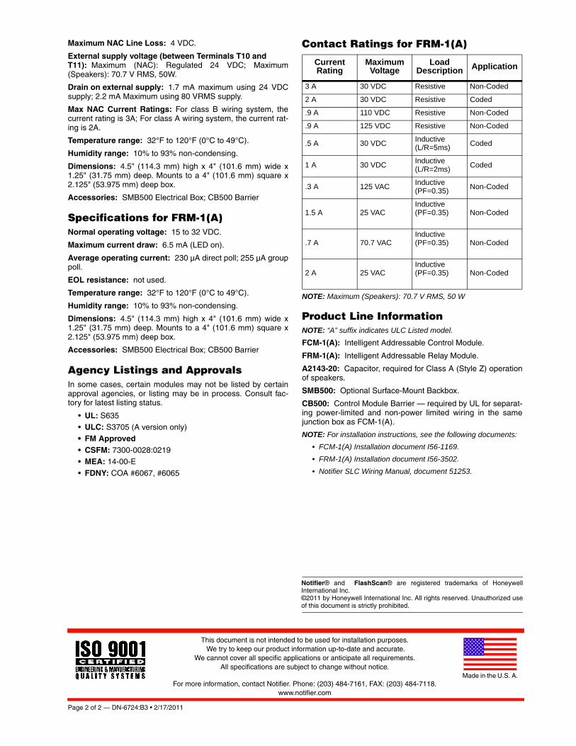
Page 2 of 2 — DN-6724:B3 • 2/17/2011
Notifier® and FlashScan® are registered trademarks of HoneywellInternational Inc. ©2011 by Honeywell International Inc. All rights reserved. Unauthorized useof this document is strictly prohibited.
This document is not intended to be used for installation purposes. We try to keep our product information up-to-date and accurate.
We cannot cover all specific applications or anticipate all requirements. All specifications are subject to change without notice.
For more information, contact Notifier. Phone: (203) 484-7161, FAX: (203) 484-7118.www.notifier.com
Made in the U.S. A.
Maximum NAC Line Loss: 4 VDC.
External supply voltage (between Terminals T10 and T11): Maximum (NAC): Regulated 24 VDC; Maximum(Speakers): 70.7 V RMS, 50W.
Drain on external supply: 1.7 mA maximum using 24 VDCsupply; 2.2 mA Maximum using 80 VRMS supply.
Max NAC Current Ratings: For class B wiring system, thecurrent rating is 3A; For class A wiring system, the current rat-ing is 2A.
Temperature range: 32°F to 120°F (0°C to 49°C).
Humidity range: 10% to 93% non-condensing.
Dimensions: 4.5" (114.3 mm) high x 4" (101.6 mm) wide x1.25" (31.75 mm) deep. Mounts to a 4" (101.6 mm) square x2.125" (53.975 mm) deep box.
Accessories: SMB500 Electrical Box; CB500 Barrier
Specifications for FRM-1(A)Normal operating voltage: 15 to 32 VDC.
Maximum current draw: 6.5 mA (LED on).
Average operating current: 230 μA direct poll; 255 μA grouppoll.
EOL resistance: not used.
Temperature range: 32°F to 120°F (0°C to 49°C).
Humidity range: 10% to 93% non-condensing.
Dimensions: 4.5" (114.3 mm) high x 4" (101.6 mm) wide x1.25" (31.75 mm) deep. Mounts to a 4" (101.6 mm) square x2.125" (53.975 mm) deep box.
Accessories: SMB500 Electrical Box; CB500 Barrier
Agency Listings and ApprovalsIn some cases, certain modules may not be listed by certainapproval agencies, or listing may be in process. Consult fac-tory for latest listing status.
• UL: S635• ULC: S3705 (A version only) • FM Approved• CSFM: 7300-0028:0219 • MEA: 14-00-E
• FDNY: COA #6067, #6065
Contact Ratings for FRM-1(A)
NOTE: Maximum (Speakers): 70.7 V RMS, 50 W
Product Line InformationNOTE: “A” suffix indicates ULC Listed model.
FCM-1(A): Intelligent Addressable Control Module.
FRM-1(A): Intelligent Addressable Relay Module.
A2143-20: Capacitor, required for Class A (Style Z) operationof speakers.
SMB500: Optional Surface-Mount Backbox.
CB500: Control Module Barrier — required by UL for separat-ing power-limited and non-power limited wiring in the samejunction box as FCM-1(A).
NOTE: For installation instructions, see the following documents:
• FCM-1(A) Installation document I56-1169.
• FRM-1(A) Installation document I56-3502.
• Notifier SLC Wiring Manual, document 51253.
Current Rating
Maximum Voltage
Load Description Application
3 A 30 VDC Resistive Non-Coded
2 A 30 VDC Resistive Coded
.9 A 110 VDC Resistive Non-Coded
.9 A 125 VDC Resistive Non-Coded
.5 A 30 VDCInductive(L/R=5ms)
Coded
1 A 30 VDCInductive(L/R=2ms)
Coded
.3 A 125 VACInductive(PF=0.35)
Non-Coded
1.5 A 25 VACInductive(PF=0.35) Non-Coded
.7 A 70.7 VACInductive(PF=0.35) Non-Coded
2 A 25 VACInductive(PF=0.35) Non-Coded
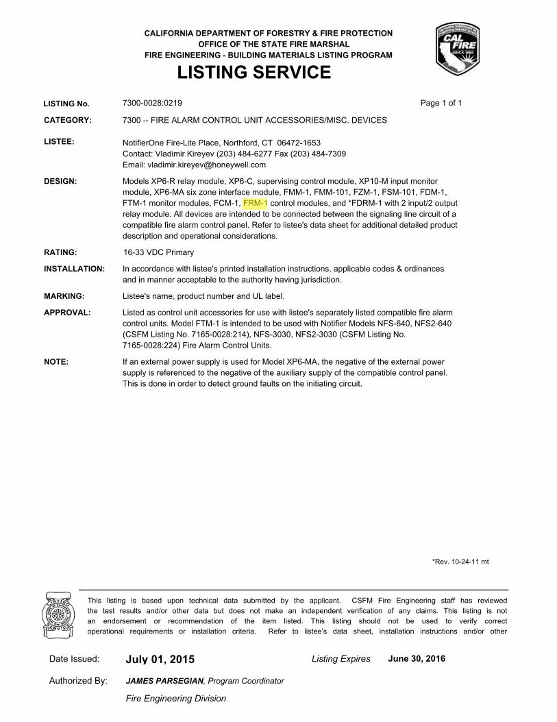
CALIFORNIA DEPARTMENT OF FORESTRY & FIRE PROTECTION
OFFICE OF THE STATE FIRE MARSHAL
FIRE ENGINEERING - BUILDING MATERIALS LISTING PROGRAM
LISTING SERVICE
LISTING No. 7300-0028:0219 Page 1 of 1
CATEGORY: 7300 -- FIRE ALARM CONTROL UNIT ACCESSORIES/MISC. DEVICES
LISTEE: NotifierOne Fire-Lite Place, Northford, CT 06472-1653
Contact: Vladimir Kireyev (203) 484-6277 Fax (203) 484-7309
Email: [email protected]
DESIGN: Models XP6-R relay module, XP6-C, supervising control module, XP10-M input monitor
module, XP6-MA six zone interface module, FMM-1, FMM-101, FZM-1, FSM-101, FDM-1,
FTM-1 monitor modules, FCM-1, FRM-1 control modules, and *FDRM-1 with 2 input/2 output
relay module. All devices are intended to be connected between the signaling line circuit of a
compatible fire alarm control panel. Refer to listee's data sheet for additional detailed product
description and operational considerations.
RATING: 16-33 VDC Primary
INSTALLATION: In accordance with listee's printed installation instructions, applicable codes & ordinances
and in manner acceptable to the authority having jurisdiction.
MARKING: Listee's name, product number and UL label.
APPROVAL: Listed as control unit accessories for use with listee's separately listed compatible fire alarm
control units. Model FTM-1 is intended to be used with Notifier Models NFS-640, NFS2-640
(CSFM Listing No. 7165-0028:214), NFS-3030, NFS2-3030 (CSFM Listing No.
7165-0028:224) Fire Alarm Control Units.
NOTE: If an external power supply is used for Model XP6-MA, the negative of the external power
supply is referenced to the negative of the auxiliary supply of the compatible control panel.
This is done in order to detect ground faults on the initiating circuit.
*Rev. 10-24-11 mt
July 01, 2015Date Issued: Listing Expires June 30, 2016
Authorized By:
Fire Engineering Division
This listing is based upon technical data submitted by the applicant. CSFM Fire Engineering staff has reviewed
the test results and/or other data but does not make an independent verification of any claims. This listing is not
an endorsement or recommendation of the item listed. This listing should not be used to verify correct
operational requirements or installation criteria. Refer to listee’s data sheet, installation instructions and/or other
JAMES PARSEGIAN, Program Coordinator
Jeremy
Arrow
Reza
Highlight