Re: Submittal of Notice of Intent, Remediation General Permit ...
Upload
khangminh22Category
view
1download
0
Submittal Package
Job Name Contractor
Job Location Wholesaler
Engineer NIBCO Sales Rep
Potable Water Hydronic Heating Chilled Water Cooling Water
Compressed Air (dry system) Oxygen (non-medical) Nitrogen Carbon Dioxide
Argon Hydrogen Vacuum Systems
PRODUCT DESCRIPTIONNIBCO® mechanical press copper fittings for use in plumbing or mechanical applications. Available sizes range from ½” through 4” in diameter. Product is designed to join ASTM B88 (Types K, L, M) hard drawn copper tube (1/2” through 4”) as well as soft cop-per tube (1/2”, 3/4” and 1”). Fittings are approved for installations in both above and below ground applications. Per code, local inspector approval must be obtained prior to installation below ground.
STANDARDS AND CODES• Uniform Plumbing Code*: UPC• Uniform Mechanical Code*: UMC• ASME B16.51 Performance• State of Massachusetts (Plumbing)
• International Residential Code®
• International Mechanical Code®
• International Plumbing Code®
*Uniform Plumbing Code and Uniform Mechanical Code are copyrighted publications of the International Association of Plumbing and Mechanical Officials
THIRD PARTY LISTINGS AND CERTIFICATIONS• NSF/ANSI 61• NSF/ANSI 372• ASME B16.51 (1/2” through 2”)• IAPMO PS-117
• ICC-ES LC 1002• International Code Council-Evaluation Service PMG 1098• American Bureau of Shipping
OPERATING PARAMETERS• Operating Pressure: 200 PSI maximum• Water Test Pressure: 50 PSI maximum
• Air Test Pressure: 15 PSI maximum• Operating Temperature: -20°F through 250°F
NIBCO INC. WORLD HEADQUARTERS • 1516 MIDDLEBURY ST. • ELKHART, IN 46516-4740 • USA • PH: 1.800.234.0227 TECH SERVICES PH: 1.888.446.4226 • FAX: 1.888.336.4226 • INTERNATIONAL OFFICE PH: +1.574.295.3327 • FAX: +1.574.295.3455
www.nibco.com
Visit our website for the most current information.
PFSP-0619-R061721 © 2021 NIBCO INC., Al l R ights Reser ved.
2NIBCO INC. WORLD HEADQUARTERS • 1516 MIDDLEBURY ST. • ELKHART, IN 46516-4740 • USA • PH: 1.800.234.0227
TECH SERVICES PH: 1.888.446.4226 • FAX: 1.888.336.4226 • INTERNATIONAL OFFICE PH: +1.574.295.3327 • FAX: +1.574.295.3455www.nibco.com
Visit our website for the most current information.
A H E A D O F T H E F L O W®
Submittal Package
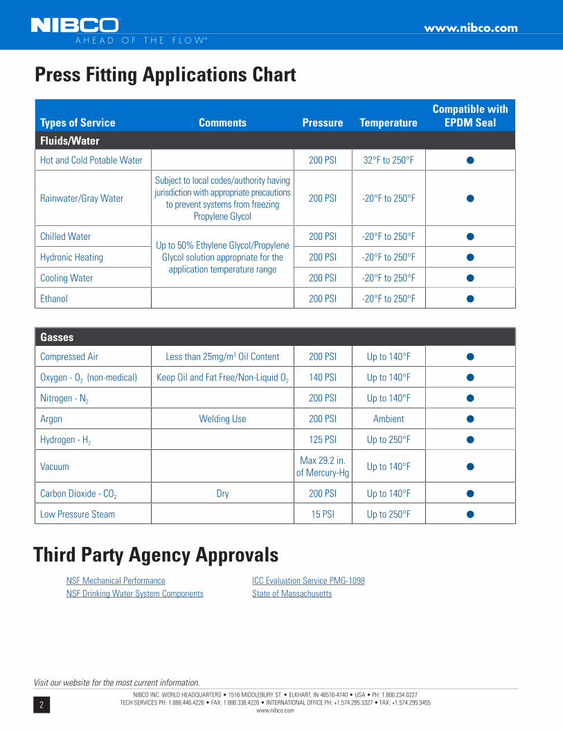
Press Fitting Applications Chart
A H E A D O F T H E F L O W®
www.nibco.com
Third Party Agency Approvals NSF Mechanical Performance NSF Drinking Water System Components
ICC Evaluation Service PMG-1098 State of Massachusetts
Types of Service Comments Pressure TemperatureCompatible with
EPDM Seal
Fluids/Water
Hot and Cold Potable Water 200 PSI 32°F to 250°F •
Rainwater/Gray Water
Subject to local codes/authority having jurisdiction with appropriate precautions
to prevent systems from freezing Propylene Glycol
200 PSI -20°F to 250°F •
Chilled WaterUp to 50% Ethylene Glycol/Propylene
Glycol solution appropriate for the application temperature range
200 PSI -20°F to 250°F •Hydronic Heating 200 PSI -20°F to 250°F •Cooling Water 200 PSI -20°F to 250°F •Ethanol 200 PSI -20°F to 250°F •
Gasses
Compressed Air Less than 25mg/m3 Oil Content 200 PSI Up to 140°F •Oxygen - O2 (non-medical) Keep Oil and Fat Free/Non-Liquid O2 140 PSI Up to 140°F •Nitrogen - N2 200 PSI Up to 140°F •Argon Welding Use 200 PSI Ambient •Hydrogen - H2 125 PSI Up to 250°F •Vacuum Max 29.2 in.
of Mercury-Hg Up to 140°F •Carbon Dioxide - CO2 Dry 200 PSI Up to 140°F •Low Pressure Steam 15 PSI Up to 250°F •
3NIBCO INC. WORLD HEADQUARTERS • 1516 MIDDLEBURY ST. • ELKHART, IN 46516-4740 • USA • PH: 1.800.234.0227
TECH SERVICES PH: 1.888.446.4226 • FAX: 1.888.336.4226 • INTERNATIONAL OFFICE PH: +1.574.295.3327 • FAX: +1.574.295.3455www.nibco.com
Visit our website for the most current information.
A H E A D O F T H E F L O W®
Submittal Package
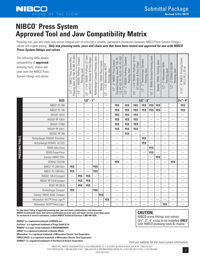
NIBCO® Press System Approved Tool and Jaw Compatibility MatrixPressing tool, jaw and chain sets are an integral part of ensuring a reliable, permanent connection between NIBCO Press System fittings, valves and copper piping. Only use pressing tools, jaws and chain sets that have been tested and approved for use with NIBCO Press System fittings and valves.
For the latest listing of approved pressing tool, jaw and chain combinations, visit nibco.com.NIBCO recommends minor tool service performed once per year and major service every three years. For technical or service assistance, contact NIBCO Technical Services 1-888-446-4226.
RIDGID® is a registered trademark of RIDGID, Inc.ProPress® is a registered trademark of Viega GmbH & CoROMAX® is a regis–tered trademark of ROTHENBERGERVIRAX® is a registered trademark of Stanley WorksMilwaukee® is a registered trademark of Milwaukee Electric Tool CorporationFORCE LOGICTM is a registered trademark of Milwaukee Electric Tool Corporation DEWALT® is a registered trademark of The Black & Decker Corporation
CAUTION:NIBCO press fittings and valves (2½”, 3”, 4” ends) to be installed ONLY with NIBCO pressing tools & chains.
The following table details compatibility of approved pressing tools, chains and jaws with the NIBCO Press System fittings and valves:
1/2”
- 1”
NIB
CO® P
ress
Sys
tem
Min
i Pr
essi
ng J
aws
(PC-
1M, P
C-2M
, PC-
3M)
1/2”
- 1”
RID
GID®
Pro
Pres
s® C
ompa
ct
Pres
sing
Jaw
s
1/2”
- 1-
1/4”
RID
GID®
Pro
Pres
s® C
1 Co
m-
pact
Kit
(C1
Actu
ator
& P
ress
Rin
gs)
Roth
enbe
rger
Com
pact
Pre
ssin
g Ja
ws
Stan
ley®
VIR
AX® P
ress
Inse
rts
1/2"
- 1
1/4"
Milw
auke
e® M
12™
Pr
essi
ng J
aws
1/2”
- 2”
NIB
CO® P
ress
Sys
tem
St
anda
rd P
ress
ing
Jaw
s (P
C-10
S, P
C-11
S, P
C-12
S, P
C-13
S,PC
-14S
, PC-
15S)
1/2”
- 2”
RID
GID®
Pro
Pres
s® S
tand
ard
Pres
sing
Jaw
s
1/2”
- 1-
1/4”
RID
GID®
Pro
Pres
s® V
1 Ki
t (V
1 Ac
tuat
or &
Pre
ss R
ings
)
1/2”
- 2”
Rot
henb
erge
r Sta
ndar
d
Pr
essi
ng J
aws
1/2”
2”
REM
S St
anda
rd P
ress
ing
Jaw
s
Stan
ley®
VIR
AX® P
ress
ing
Jaw
s
1/2"
- 2"
Milw
auke
e® M
18™
Pres
sing
Jaw
s
1/2"
- 2"
DEW
ALT
DCE2
00Pr
essi
ng J
aws
2 1/
2” -
4” N
IBCO
® P
ress
ing
Chai
ns
(P
C-2,
PC-
3, P
C-4)
PRES
SIN
G T
OO
LS
SIZE 1/2” - 1” 1/2” - 2” 21/2” - 4”NIBCO® PC-280 — — — — — — YES YES YES YES YES YES — — YES
NIBCO® PC-100 — — — — — — YES YES YES YES YES YES — — YES
RIDGID® 320-E — — — — — — YES YES YES — — — — — —
RIDGID® RP 330-B — — — — — — YES YES YES — — — — — —
RIDGID® CT400 — — — — — — YES YES YES — — — — — —
RIDGID® RP 330-C — — — — — — YES YES YES — — — — — —
RIDGID® RP 340 — — — — — — — YES — — — — — — —
Rothenberger ROMAX® Pressliner — — — — — — — — — YES — — — — —
Rothenberger ROMAX® AC ECO — — — — — — — — — YES — — — — —
REMS Akku-Press — — — — — — — — — — YES — — — —
REMS Power-Press — — — — — — — — — — YES — — — —
Stanley® VIRAX® P20+ — — — — — — — — — — — YES — — —
DEWALT DCE200 — — — — — — YES — — — — — — YES —
NIBCO® PC-20M Mini YES — — YES — — — — — — — — — — —
NIBCO® PC-10M Mini YES — — YES — — — — — — — — — — —
RIDGID® 100-B Compact — YES YES — — — — — — — — — — — —
RIDGID® RP 210-B Compact — YES YES — — — — — — — — — — — —
RIGID® RP 200-B — YES YES — — — — — — — — — — — —
Rothenberger Compact YES — — YES — — — — — — — — — — —
Stanley® VIRAX® M20+ Compact — — — — YES — — — — — — — — — —
Milwaukee® M12™ Force Logic™ — — — — — YES — — — — — — — — —
Milwaukee® M18™ Force Logic™ — — — — — — — — — — — — YES — —
Revised 5/31/2019
4NIBCO INC. WORLD HEADQUARTERS • 1516 MIDDLEBURY ST. • ELKHART, IN 46516-4740 • USA • PH: 1.800.234.0227
TECH SERVICES PH: 1.888.446.4226 • FAX: 1.888.336.4226 • INTERNATIONAL OFFICE PH: +1.574.295.3327 • FAX: +1.574.295.3455www.nibco.com
Visit our website for the most current information.
A H E A D O F T H E F L O W®
Submittal Package
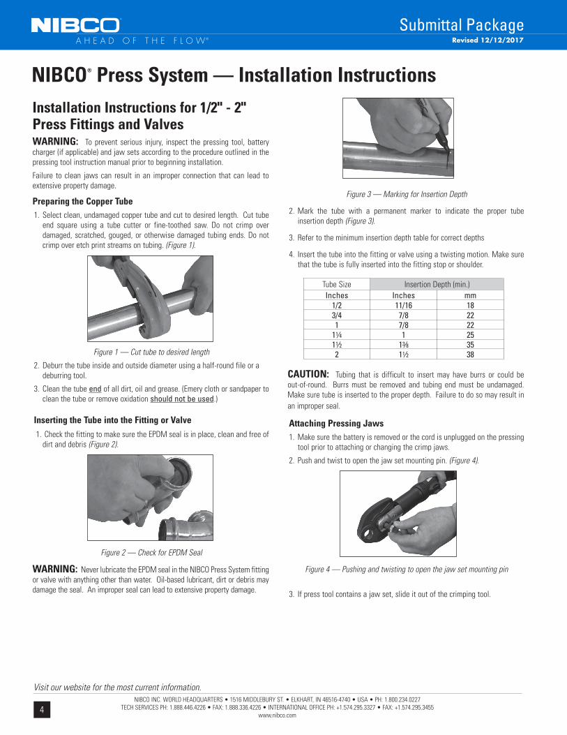
Installation Instructions for 1/2" - 2" Press Fittings and ValvesWARNING: To prevent serious injury, inspect the pressing tool, battery charger (if applicable) and jaw sets according to the procedure outlined in the pressing tool instruction manual prior to beginning installation.
Failure to clean jaws can result in an improper connection that can lead to extensive property damage.
Preparing the Copper Tube1. Select clean, undamaged copper tube and cut to desired length. Cut tube
end square using a tube cutter or fine-toothed saw. Do not crimp over damaged, scratched, gouged, or otherwise damaged tubing ends. Do not crimp over etch print streams on tubing. (Figure 1).
Figure 1 — Cut tube to desired length
2. Deburr the tube inside and outside diameter using a half-round file or a deburring tool.
3. Clean the tube end of all dirt, oil and grease. (Emery cloth or sandpaper to clean the tube or remove oxidation should not be used.)
Inserting the Tube into the Fitting or Valve 1. Check the fitting to make sure the EPDM seal is in place, clean and free of
dirt and debris (Figure 2).
Figure 2 — Check for EPDM Seal
WARNING: Never lubricate the EPDM seal in the NIBCO Press System fitting or valve with anything other than water. Oil-based lubricant, dirt or debris may damage the seal. An improper seal can lead to extensive property damage.
Figure 3 — Marking for Insertion Depth
2. Mark the tube with a permanent marker to indicate the proper tube insertion depth (Figure 3).
3. Refer to the minimum insertion depth table for correct depths
4. Insert the tube into the fitting or valve using a twisting motion. Make sure that the tube is fully inserted into the fitting stop or shoulder.
CAUTION: Tubing that is difficult to insert may have burrs or could be out-of-round. Burrs must be removed and tubing end must be undamaged. Make sure tube is inserted to the proper depth. Failure to do so may result in an improper seal.
Attaching Pressing Jaws1. Make sure the battery is removed or the cord is unplugged on the pressing
tool prior to attaching or changing the crimp jaws.
2. Push and twist to open the jaw set mounting pin. (Figure 4).
Figure 4 — Pushing and twisting to open the jaw set mounting pin
3. If press tool contains a jaw set, slide it out of the crimping tool.
NIBCO® Press System — Installation Instructions
Tube SizeInches Inches mm
1/2 11/16 183/4 7/8 221 7/8 22
11⁄4 1 2511⁄2 13⁄8 352 11⁄2 38
Insertion Depth (min.)
Revised 12/12/2017

5NIBCO INC. WORLD HEADQUARTERS • 1516 MIDDLEBURY ST. • ELKHART, IN 46516-4740 • USA • PH: 1.800.234.0227
TECH SERVICES PH: 1.888.446.4226 • FAX: 1.888.336.4226 • INTERNATIONAL OFFICE PH: +1.574.295.3327 • FAX: +1.574.295.3455www.nibco.com
Visit our website for the most current information.
A H E A D O F T H E F L O W®
Submittal Package
4. Select the jaw set that corresponds to the size of the joint to be crimped and insert the jaw set into the pressing tool (Figure 5).
Figure 5 — Inserting the NIBCO® Press System jaw
5. Push the jaw set mounting pin until it clicks into position.
NOTE: The tool will not properly press unless the pin is fully engaged.
Crimping a NIBCO Press System Fitting or Valve
1. Make sure the tubing is inserted to the proper depth in the fitting. (Figure 6).
Figure 6 — Inserting the tube to proper depth
2. Squeeze jaw arms to open the jaw set.
3. Place the open jaws around the fitting and ensure that the contour of the jaw is properly aligned with the contour of the fitting (Figure 7).
Figure 7 — Open the jaw set and place around the fitting
4. Make sure the tool is perpendicular to the tubing and depress the switch (Figure 8). Keep the trigger depressed from the time the cycle begins and the rollers contact the jaw arms until the end of the entire crimp cycle.
Figure 8 — Jaw set should be square to tubing
5. Once the crimp is complete, press the jaw arms to open the jaw and remove from the fitting.
If the tool displays an LED flash or emits an audible alarm, please refer to the tool instruction manual for troubleshooting suggestions.
CAUTION Avoid handling sharp edges that may have formed on the fitting during the crimping operation.
Inspecting the Crimp
1. Inspect the crimped fitting to ensure proper crimp.
NOTE: The use of the NIBCO Press System jaw will produce a unique witness mark “N” on the crimped fitting.
2. Inspect the crimped fitting checking the connection for the following problems:
• Not fully inserted tube, double check depth marks
• Incorrect jaw alignment with the fitting contour
If any problems are found, a new section of tubing and a new fitting will need to be prepared, installed and crimped.
3. Test the NIBCO Press System in accordance with crimp intergrity testing instructions for fittings and valves in this catalog.
NIBCO® Press System — Installation Instructions
Revised 12/12/2017
6NIBCO INC. WORLD HEADQUARTERS • 1516 MIDDLEBURY ST. • ELKHART, IN 46516-4740 • USA • PH: 1.800.234.0227
TECH SERVICES PH: 1.888.446.4226 • FAX: 1.888.336.4226 • INTERNATIONAL OFFICE PH: +1.574.295.3327 • FAX: +1.574.295.3455www.nibco.com
Visit our website for the most current information.
A H E A D O F T H E F L O W®
Submittal Package
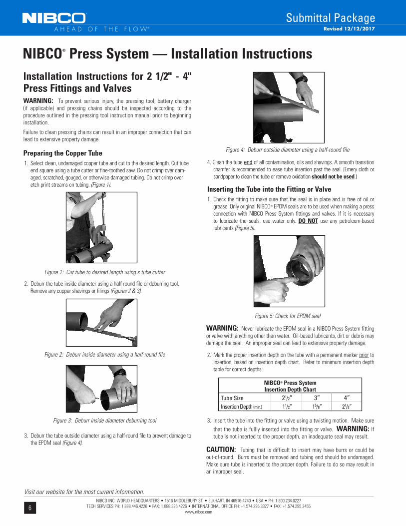
NIBCO® Press System — Installation Instructions Installation Instructions for 2 1/2" - 4" Press Fittings and ValvesWARNING: To prevent serious injury, the pressing tool, battery charger (if applicable) and pressing chains should be inspected according to the procedure outlined in the pressing tool instruction manual prior to beginning installation.
Failure to clean pressing chains can result in an improper connection that can lead to extensive property damage.
Preparing the Copper Tube1. Select clean, undamaged copper tube and cut to the desired length. Cut tube
end square using a tube cutter or fine-toothed saw. Do not crimp over dam-aged, scratched, gouged, or otherwise damaged tubing. Do not crimp over etch print streams on tubing. (Figure 1).
2. Deburr the tube inside diameter using a half-round file or deburring tool. Remove any copper shavings or filings (Figures 2 & 3).
Figure 1: Cut tube to desired length using s tube cutter
3. Deburr the tube outside diameter using a half-round file to prevent damage to the EPDM seal (Figure 4).
Figure 4: Deburr outside diameter using a half-round file
4. Clean the tube end of all contamination, oils and shavings. A smooth transition chamfer is recommended to ease tube insertion past the seal. (Emery cloth or sandpaper to clean the tube or remove oxidation should not be used.)
Inserting the Tube into the Fitting or Valve1. Check the fitting to make sure that the seal is in place and is free of oil or
grease. Only original NIBCO® EPDM seals are to be used when making a press connection with NIBCO Press System fittings and valves. If it is necessary to lubricate the seals, use water only. DO NOT use any petroleum-based lubricants (Figure 5).
Figure 5: Check for EPDM seal
WARNING: Never lubricate the EPDM seal in a NIBCO Press System fitting or valve with anything other than water. Oil-based lubricants, dirt or debris may damage the seal. An improper seal can lead to extensive property damage.
2. Mark the proper insertion depth on the tube with a permanent marker prior to insertion, based on insertion depth chart. Refer to minimum insertion depth table for correct depths.
3. Insert the tube into the fitting or valve using a twisting motion. Make sure that the tube is fullly inserted into the fitting or valve. WARNING: If tube is not inserted to the proper depth, an inadequate seal may result.
CAUTION: Tubing that is difficult to insert may have burrs or could be out-of-round. Burrs must be removed and tubing end should be undamaged. Make sure tube is inserted to the proper depth. Failure to do so may result in an improper seal.
NIBCO® Press SystemInsertion Depth Chart
Tube Size 21/2” 3” 4” Insertion Depth (min.) 11/2” 15/8” 21/8”
Figure 2: Deburr inside diameter using a half-round file
Figure 3: Deburr inside diameter deburring tool
Revised 12/12/2017
7NIBCO INC. WORLD HEADQUARTERS • 1516 MIDDLEBURY ST. • ELKHART, IN 46516-4740 • USA • PH: 1.800.234.0227
TECH SERVICES PH: 1.888.446.4226 • FAX: 1.888.336.4226 • INTERNATIONAL OFFICE PH: +1.574.295.3327 • FAX: +1.574.295.3455www.nibco.com
Visit our website for the most current information.
A H E A D O F T H E F L O W®
Submittal Package
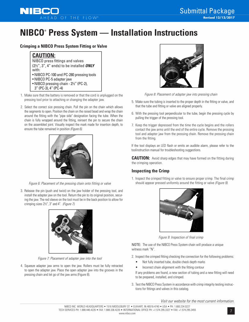
Crimping a NIBCO Press System Fitting or Valve
1. Make sure that the battery is removed or that the cord is unplugged on the pressing tool prior to attaching or changing the adapter jaw.
2. Select the correct size pressing chain. Pull the pin on the chain which allows the segments to open. Position the chain on the raised bead and wrap the chain around the fitting with the "pipe side" designation facing the tube. When the chain is fully wrapped around the fitting, reinsert the pin to secure the chain on the assembled joint. Visually inspect the mark made for insertion depth, to ensure the tube remained in position (Figure 6).
Figure 6: Placement of the pressing chain onto fitting or valve
3. Release the pin (push and twist) on the jaw holder of the pressing tool, and install the adapter jaw on the tool. Return the pin to its original position, secur-ing the jaw. The red sleeve on the tool must be in the back position to allow for crimping sizes 2½”, 3” and 4”. (Figure 7).
Figure 7: Placement of adapter jaw into the tool
4. Squeeze adapter jaw arms to open the jaw. Rollers must be fully retracted to open the adapter jaw. Place the open adapter jaw into the grooves in the pressing chain and let go of the jaw arms (Figure 8).
Figure 8: Placement of adapter jaw into pressing chain
5. Make sure the tubing is inserted to the proper depth in the fitting or valve, and that the tube and fitting or valve are aligned properly.
6. With the pressing tool perpendicular to the tube, begin the pressing cycle by pulling the trigger of the pressing tool.
7. Keep the trigger depressed from the time the cycle begins and the rollers contact the jaw arms until the end of the entire cycle. Remove the pressing tool and adapter jaw from the pressing chain. Remove the pressing chain from the fitting.
If the tool displays an LED flash or emits an audible alarm, please refer to the toolinstruction manual for troubleshooting suggestions.
CAUTION: Avoid sharp edges that may have formed on the fitting duringthe crimping operation.
Inspecting the Crimp
1. Inspect the crimped fitting or valve to ensure proper crimp. The final crimp should appear pressed uniformly around the fitting or valve (Figure 9).
Figure 9: Inspection of final crimp
NOTE: The use of the NIBCO Press System chain will produce a unique witness mark “N”.
2. Inspect the crimped fitting checking the connection for the following problems: • Not fully inserted tube, double check depth marks • Incorrect chain alignment with the fitting contour If any problems are found, a new section of tubing and a new fitting will need
to be prepared, installed, and crimped.
3. Test the NIBCO Press System in accordance with crimp integrity testing instruc-tions for fittings and valves in this catalog.
NIBCO® Press System — Installation Instructions
CAUTION:NIBCO press fittings and valves (2½”, 3”, 4” ends) to be installed ONLY with:• NIBCO PC-100 and PC-280 pressing tools• NIBCO PC-5 adapter jaw• NIBCO pressing chain - 2½” (PC-2), 3” (PC-3), 4” (PC-4)
Revised 12/12/2017

8NIBCO INC. WORLD HEADQUARTERS • 1516 MIDDLEBURY ST. • ELKHART, IN 46516-4740 • USA • PH: 1.800.234.0227
TECH SERVICES PH: 1.888.446.4226 • FAX: 1.888.336.4226 • INTERNATIONAL OFFICE PH: +1.574.295.3327 • FAX: +1.574.295.3455www.nibco.com
Visit our website for the most current information.
A H E A D O F T H E F L O W®
Submittal Package
Minimum Distance Between Joints
To prevent distortion of the tubing, certain fitting sizes require a minimum distance between crimp joints (refer to Chart 1 below). Failure to provide this minimum distance may result in an improper seal.
Spacing
1. Sufficient clearance must be left around each joint to allow room for the pressing tool and jaw to be attached without interference.
Clearance Requirements — Standard Jaw Sets
NIBCO® Press System — Installation Instructions
Tube Dia. Inches mm Inches mm 1/2 15/16 24 15/8 41 3/4 7/8 22 21/8 54 1 11/4 31 21/2 64 11/4 11/8 29 27/8 73 11/2 2 51 43/8 111 2 2 51 43/8 111
A (min.) B (min.)
Tube Dia. Inches mm Inches mm Inches mm 1/2 11/8 28 13/8 35 21/2 64 3/4 1 26 11/2 38 21/2 64 1 15/16 34 13/4 45 3 76 11/4 11/4 32 21/4 57 31/8 80 11/2 21/8 54 31/8 80 5 127 2 21/8 54 31/8 80 5 127 21/2 35/8 92 6 152 31/2 89 3 37/8 98 61/2 165 4 102 4 47/8 124 75/8 194 41/4 108
A (min.) B (min.) C (min.)
System Support
CAUTION — In any installation, the system should be suported to ensure the minimum stress is imposed on the tube and joints. The NIBCO® Press System should be supported in accordance with normal practice and to local jurisdiction piping code.
Annealing of Copper Tube
A NIBCO Press System installation should not be conducted within 12" of a brazed joint. The high temperature required for capillary joinery may cause the copper tube to become annealed and render it too soft for proper crimp-ing. However, a NIBCO Press System product may be crimped adjacent to a soldered joint, as normal temperatures created by silver soldering are not hot enough to cause the copper tube to become annealed.
CAUTION — Brazing or soldering should not be conducted within 12" of an existing NIBCO Press System connection as this may damage the EPDM seal. If there is any concern about heat damage to the o-ring, a cold, wet cloth should be wrapped around the crimped connection prior to soldering or brazing.
Tool perpendicular to wall
Tool angled to wall
NOTE: Clearance dimensions for 21/2", 3" & 4" are for wrapping pressing chains around fittings.
A (min.) Tube Dia. Inches mm 1⁄2"* 0 0 3⁄4"* 0 0 1"* 0 0 11⁄4"* 0 0 11⁄2"* 0 0 2"* 0 0 21⁄2" 3⁄8" 10 3" 3⁄8" 10 4" 3⁄8" 10
*No minimum distance required.
Revised 12/12/2017
9NIBCO INC. WORLD HEADQUARTERS • 1516 MIDDLEBURY ST. • ELKHART, IN 46516-4740 • USA • PH: 1.800.234.0227
TECH SERVICES PH: 1.888.446.4226 • FAX: 1.888.336.4226 • INTERNATIONAL OFFICE PH: +1.574.295.3327 • FAX: +1.574.295.3455www.nibco.com
Visit our website for the most current information.
A H E A D O F T H E F L O W®
Submittal PackageRevised 1/10/2019
NIBCO INC. warrants:
• NIBCO Press System fittings and flanges to be free from defects in materials and workmanship under normal use and service for a period of 50 years from the Warranty Commencement Date. The Warranty Commencement Date for NIBCO Press system fittings and flanges shall be the date upon which the fitting or flange is installed.
• NIBCO Press System pressure rated metal valve to be free from defects in materials and workmanship under normal use and service for a period of five (5) years from date put into service with the exception of models PC-FP-600A-LF for which a two (2) year warranty period from date put into service applies.
This limited warranty applies to all NIBCO Press System products installed in accordance with NIBCO’s approved and published installation, testing and application recommendations and instructions. This includes product installed in accordance with the Press Tool & Jaw Compatibility Matrix in effect at the time of installation as published in the most current online version of the NIBCO Press System Catalog.
NIBCO does NOT warrant against failure of NIBCO Press System fittings, flanges and valves (referred to hereafter as “product”) for:
1. any product, parts or systems which are not manufactured or sold by NIBCO, INC.;2. any product which is used for purposes other than a purpose authorized by NIBCO INC.;3. any product not installed in accordance with either the recommended installation guidelines provided by NIBCO INC.
and/or applicable plumbing codes;4. damage to the product caused by, contributed in whole or in part by, or resulting from, any of the following:
a. abuse, misuse, mishandling, tampering, neglect or accidental damage such as, without limitation, vandalismb. natural disasters, such as, without limitation, flooding, windstorm and lightningc. attachments or modifications to the product that are not authorized by NIBCO INC.d. external causes, where external, physical or chemical qualities produce damage to the product, such as, without
limitation, variation in water quality, aggressive water or an unsuitable or hostile environment, ore. any other cause beyond the control of NIBCO INC.
NIBCO shall NOT be liable under any circumstances for any other direct or indirect, incidental or consequential damages of any kind, including but not limited to loss of business, lost profits, mold intrusion, water damage, etc. The liability of NIBCO under this warranty is solely limited to the replacement of any product that has been determined by NIBCO INC., or an authorized representative or agent thereof, to contain a defect in material or workmanship.
NIBCO Press System tools are covered by a limited warranty against defects in material or manufacturing for a period of two (2) years from date of purchase by the contractor. This limited warranty covers the repair or replacement of the tool, at NIBCO’s discretion, if NIBCO has received the tool, inspected it, and the tool is found to be defective.
This warranty is the only warranty for the product provided by NIBCO INC., and is and shall be in lieu of any and all other warranties, expressed or implied, including but not limited to an implied warranty of merchantability, and for all other obligations or liabilities on the part of the Manufacturer. No employee of NIBCO INC., or any other distributor, agent or other person or business, is authorized to make any other warranty on behalf of NIBCO, INC.
In the event any defect occurs which is believed to be covered by this warranty, NIBCO Technical Services should be immediately contacted either in writing or by telephone at 888.446.4226. NIBCO Technical Services will make further arrangements for the product’s return to NIBCO INC. for review and evaluation. In the event that a returned product is determined by NIBCO INC. to be defective, NIBCO INC. will remediate the failure by repairing or replacing the product within a reasonable time, without charge to the owner of the product.
This warranty gives you specific legal rights, and you may also have other rights which vary from state to state.
To the best of our knowledge, the information contained in this publication is accurate. However, NIBCO does not assume any liability, whatsoever for the accuracy or completeness of such information. Final determination of the suitability of any information or product for the use to be contemplated is the sole responsibility of the user. The manner of that use, and whether there is any infringement of patents, is also the sole responsibility of the user.
NIBCO® Press System Limited Warranty

10NIBCO INC. WORLD HEADQUARTERS • 1516 MIDDLEBURY ST. • ELKHART, IN 46516-4740 • USA • PH: 1.800.234.0227
TECH SERVICES PH: 1.888.446.4226 • FAX: 1.888.336.4226 • INTERNATIONAL OFFICE PH: +1.574.295.3327 • FAX: +1.574.295.3455www.nibco.com
Visit our website for the most current information.
A H E A D O F T H E F L O W®
Submittal Package
ADAPTERS
PC603Adapter P x F – Wrot APPROX. DIM. A NOM. SIZE NET WT./LBS. INCHES
1/2 .103 13/16
1/2 x 3/8 .081 21/32
1/2 x 3/4 .151 31/32
3/4 .158 27/32
3/4 x 1/2 .153 25/32
1 .237 15/16
1 x 1/2 .172 3/4
1 x 3/4 .217 13/16
1 x 1 1/4 .436 13/16
1 1/4 .372 11/16
1 1/4 x 1 .359 11/16
1 1/4 x 1 1/2 .425 17/32
1 1/2 .518 11/16
1 1/4 x 2 .276 1 1 1/2 x 1 1/4 .515 1 2 .672 1 2 1/2 1.222 113/32
3 1.756 123/32
4 3.238 17/8
PC617Cap P – Wrot APPROX. DIM. N NOM. SIZE NET WT./LBS. INCHES
1/2 .046 5/32
3/4 .087 5/32
1 .125 1/8
1 1/4 .171 3/32
1 1/2 .314 3/32
2 .493 3/32
2 1/2 .476 7/32
3 .713 7/32
4 1.491 1/4
PC604Adapter P x M – Wrot APPROX. DIM. B NOM. SIZE NET WT./LBS. INCHES
1/2 .103 7/8
1/2 x 3/8 .105 27/32
1/2 x 3/4 .191 11/4
3/4 .180 11/16
3/4 x 1/2 .189 31/32
3/4 x 1 .268 1 3/16
1 .255 13/32
1 x 3/4 .253 11/32
1 x 1 1/4 .457 117/32
1 1/4 .467 113/32
1 1/4 x 1 .335 13/16
1 1/4 x 1 1/2 .537 11/2
1 1/2 .696 11/2
1 1/2 x 1 1/4 .603 13/8
1 1/2 x 2 .784 17/16
2 .856 17/16
2 x 1 1/2 1.087 119/32
2 1/2 1.322 127/32
3 2.104 21/8
4 3.298 29/32
PC604-PAdapter PEX x P – Wrot APPROX. DIM. B NOM. SIZE NET WT./LBS. INCHES
1/2 x 1/2 .055 1/8
1/2 x 3/4 .108 7/32
3/4 x 1/2 .057 3/32
3/4 x 3/4 .108 5/32
1 x 1 .148 5/32
CAPS
PC603-2Extended Adapter FTG x F – Wrot APPROX. DIM. B NOM. SIZE NET WT./LBS. INCHES
1/2 x 3/8 0.064 1 17/32
1/2 0.096 1 3/4
1/2 x 3/4 0.132 1 27/32
3/4 x 1/2 0.107 1 25/32
3/4 0.145 1 7/8
1 x 1/2 0.146 2 1 0.220 2 1/16
1 1/4 x 1/2 0.193 2 3/16
1 1/4 0.322 2 3/8
1 1/2 0.431 2 21/32
2 0.683 2 15/16
ADAPTERS (Cont.)
PC604-2Extended Adapter FTG x M – Wrot APPROX. DIM. B NOM. SIZE NET WT./LBS. INCHES
1/2 x 3/8 0.056 13/4
1/2 0.101 129/32
1/2 x 3/4 0.145 21/16
3/4 x 1/2 0.100 1 15/16
3/4 0.136 21/16
1 x 3/4 0.175 21/16
1 0.243 25/16
1 1/4 0.408 217/32
1 1/2 0.530 27/8
2 0.782 311/32
Revised 12/22/2020

11NIBCO INC. WORLD HEADQUARTERS • 1516 MIDDLEBURY ST. • ELKHART, IN 46516-4740 • USA • PH: 1.800.234.0227
TECH SERVICES PH: 1.888.446.4226 • FAX: 1.888.336.4226 • INTERNATIONAL OFFICE PH: +1.574.295.3327 • FAX: +1.574.295.3455www.nibco.com
Visit our website for the most current information.
A H E A D O F T H E F L O W®
Submittal PackageRevised 10/7/2019
PC60645° Elbow P x P – Wrot APPROX. DIM. C DIM. D NOM. SIZE NET WT./LBS. INCHES INCHES
1/2 .092 3/8 3/8
3/4 .181 1/2 1/2
1 .251 5/8 5/8
1 1/4 .403 25/32 25/32
1 1/2 .666 15/16 15/16
2 1.063 13/16 13/16
2 1/2 1.041 29/32 29/32
3 1.536 11/8 11/8
4 3.375 111/16 111/16
COUPLINGS (Cont.)
PC600-RReducing Coupling P x P – Wrot APPROX. DIM. A NOM. SIZE NET WT./LBS. INCHES
3/4 x 1/2 .121 1/4
1 x 1/2 .139 7/16
1 x 3/4 .184 13/32
1 1/4 x 3/4 .245 1/2
1 1/4 x 1 .231 7/16
1 1/2 x 3/4 .382 15/32
1 1/2 x 1 .370 13/32
1 1/2 x 1 1/4 .399 9/32
2 x 3/4 .516 29/32
2 x 1 .552 11/16
2 x 1 1/4 .570 11/16
2 x 1 1/2 .662 7/16
2 1/2 x 1 .620 31/32
2 1/2 x 1 1/4 .644 1 2 1/2 x 1 1/2 .678 23/32
2 1/2 x 2 .699 11/32
3 x 1 1/2 .956 11/16
3 x 2 1.032 23/32
3 x 2 1/2 .951 1/2
4 x 2 1.949 15/32
4 x 2 1/2 1.807 1 4 x 3 1.960 27/32
PC600-RSCoupling P x P – Wrot APPROX. DIM. A NOM. SIZE NET WT./LBS. INCHES
2 1/2 .688 1/8
3 .979 1/8
4 2.134 7/32
PC636Crossover Coupling P x P – Wrot APPROX. DIM. A NOM. SIZE NET WT./LBS. INCHES
1/2 .222 25/32
PC601 (No Stop)Repair Coupling P x P – Wrot APPROX. DIM. B NOM. SIZE NET WT./LBS. INCHES
1/2 .082 13/4
3/4 .157 21/4
1 .190 21/4
1 1/4 .271 215/32
1 1/2 .511 3 11/32
2 .691 3 5/8
2 1/2 .669 2 15/16
3 .979 3 5/16
4 1.878 4 5/16
COUPLINGS
PC600-DSCoupling P x P – Wrot APPROX. DIM. A NOM. SIZE NET WT./LBS. INCHES
1/2 .083 3/16
3/4 .157 5/32
1 .198 5/32
1 1/4 .271 5/32
1 1/2 .530 3/16
2 .691 5/32
2 1/2 .669 1/8
3 .979 1/8
4 2.134 7/32
ELBOWS
COUPLINGS (Cont.)
PC601L Extended Repair Coupling P x P APPROX. DIM. B NOM. SIZE NET WT./LBS. INCHES
1/2 0.1250 2 29/32
3/4 0.2200 3 9/32
1 0.3050 3 21/32
1 1/4 0.4090 4 1/16
1 1/2 0.7150 4 21/32
2 1.0230 5 1/4

12NIBCO INC. WORLD HEADQUARTERS • 1516 MIDDLEBURY ST. • ELKHART, IN 46516-4740 • USA • PH: 1.800.234.0227
TECH SERVICES PH: 1.888.446.4226 • FAX: 1.888.336.4226 • INTERNATIONAL OFFICE PH: +1.574.295.3327 • FAX: +1.574.295.3455www.nibco.com
Visit our website for the most current information.
A H E A D O F T H E F L O W®
Submittal Package
B
C
Revised 3/12/2020
PC607-290° Elbow Ftg x P – Wrot APPROX. DIM. B DIM. C NOM. SIZE NET WT/LBS. INCHES INCHES
1/2 .110 121/32 27/32
3/4 .219 27/32 11/16
1 .319 21/2 113/32
1 1/4 .490 33/32 129/32
1 1/2 .871 315/16 27/32
2 1.474 417/32 229/32
2 1/2 1.356 37/32 119/32
3 2.065 313/16 2 4 3.920 43/4 215/32
PC60790° Elbow P x P – Wrot APPROX. DIM. C DIM. D NOM. SIZE NET WT./LBS. INCHES INCHES
1/2 .110 23/32 23/32
3/4 .223 13/32 13/32
3/4 x 1/2 .201 11/32 15/32
1 .331 17/16 17/16
1 x 3/4 .321 15/16 17/16
1 1/4 .528 127/32 127/32
1 1/2 .895 27/32 27/32
2 1.480 215/16 215/16
2 1/2 1.224 15/8 15/8
3 1.900 2 2 4 3.935 215/32 215/32
ELBOWS (Cont.)
PC607-2-LT90° Long Radius Elbow Ftg x P - Wrot APPROX. DIM. B DIM. C NOM. SIZE NET WT/LBS. INCHES INCHES
2 1/2 2.114 57/32 311/16
3 3.037 53/4 41/32
PC607-390° Elbow P x F - Wrot APPROX. DIM. A DIM. C NOM. SIZE NET WT/LBS. INCHES INCHES
1/2 .191 21/2 25/32
1/2 x 3/8 .148 27/32 25/32
1/2 x 3/4 .243 211/16 25/32
3/4 .361 33/32 11⁄16
3/4 x 1/2 .321 213⁄16 11⁄16
1 .513 315⁄32 113⁄32
1 1/4 .892 43⁄16 127⁄32
1 1/2 1.314 51⁄16 27⁄32
2 2.109 55⁄8 229⁄32
PC607-490° Elbow P x M - Wrot APPROX. DIM. B DIM. C NOM. SIZE NET WT/LBS. INCHES INCHES
1/2 .183 29⁄32 25⁄32
1/2 x 3/4 .245 221/32 25⁄32
3/4 .373 3 11/16
3/4 x 1/2 .340 31/16 11/16
1 .521 33⁄8 17⁄16
1 1/4 .926 41⁄32 127⁄32
1 1/2 1.433 429/32 27/32
2 2.205 55/8 229/32
PC607E-2Extended Elbow P x FTG – Wrot APPROX. DIM. B DIM. CNOM. SIZE NET WT/LBS. INCHES INCHES
3/4 .407 61/8 29/32
PC607-LT90° Long Radius Elbow P x P – Wrot APPROX. DIM. C DIM. D NOM. SIZE NET WT/LBS. INCHES INCHES
2 1/2 2.066 311/16 311/16
3 2.810 41/32 41/32
4 5.696 51/4 51/4
PC606-245° Elbow Ftg x P – Wrot APPROX. DIM. B DIM. C NOM. SIZE NET WT/LBS. INCHES INCHES
1/2 .094 15/16 7/16
3/4 .171 113/32 17/32
1 .248 117/32 9/16
1 1/4 .368 13/4 11/16
1 1/2 .673 25/16 13/16
2 1.057 25/8 1 2 1/2 1.050 23/16 29/32
3 1.526 219/32 15/32
4 3.284 33/32 117/32
13NIBCO INC. WORLD HEADQUARTERS • 1516 MIDDLEBURY ST. • ELKHART, IN 46516-4740 • USA • PH: 1.800.234.0227
TECH SERVICES PH: 1.888.446.4226 • FAX: 1.888.336.4226 • INTERNATIONAL OFFICE PH: +1.574.295.3327 • FAX: +1.574.295.3455www.nibco.com
Visit our website for the most current information.
A H E A D O F T H E F L O W®
Submittal PackageRevised 5/11/2021
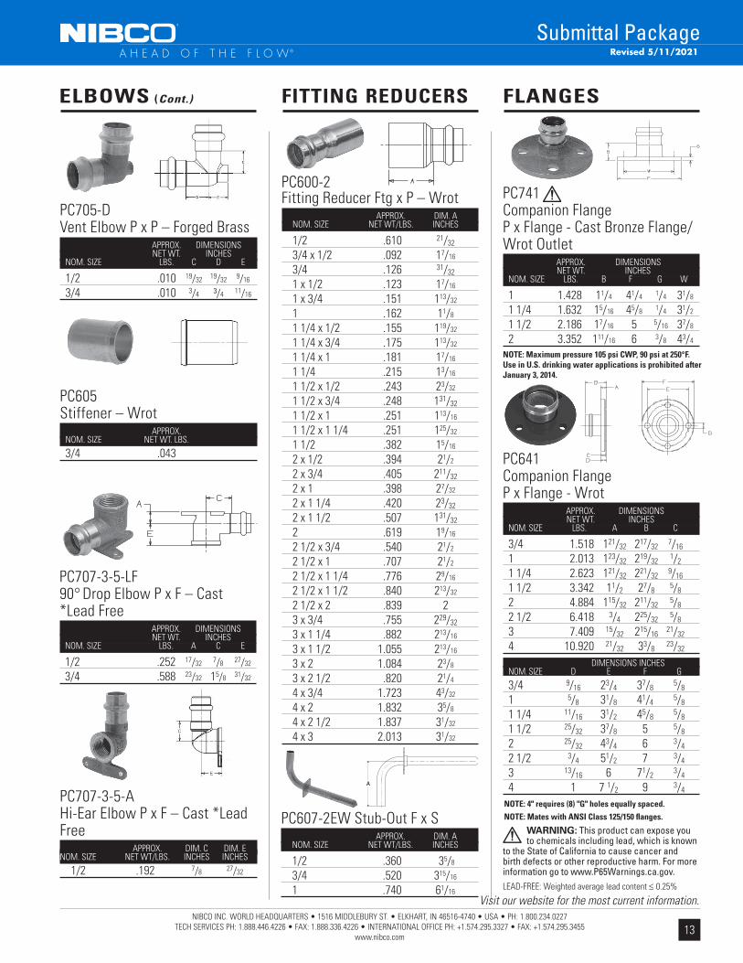
PC641Companion FlangeP x Flange - Wrot APPROX. DIMENSIONS NET WT. INCHES NOM. SIZE LBS. A B C
3/4 1.518 121/32 217/32 7/16
1 2.013 123/32 219/32 1/2
1 1/4 2.623 121/32 221/32 9/16
1 1/2 3.342 11/2 27/8 5/8
2 4.884 115/32 211/32 5/8
2 1/2 6.418 3/4 225/32 5/8
3 7.409 15/32 215/16 21/32
4 10.920 21/32 33/8 23/32
FLANGES
PC741Companion Flange P x Flange - Cast Bronze Flange/Wrot Outlet APPROX. DIMENSIONS NET WT. INCHES NOM. SIZE LBS. B F G W
1 1.428 11/4 41/4 1/4 31/8
1 1/4 1.632 15/16 45/8 1/4 31/2
1 1/2 2.186 17/16 5 5/16 37/8
2 3.352 111/16 6 3/8 43/4
NOTE: 4" requires (8) "G" holes equally spaced.NOTE: Mates with ANSI Class 125/150 fl anges.
DIMENSIONS INCHES NOM. SIZE D E F G
3/4 9/16 23/4 37/8 5/8
1 5/8 31/8 41/4 5/8
1 1/4 11/16 31/2 45/8 5/8
1 1/2 25/32 37/8 5 5/8
2 25/32 43/4 6 3/4
2 1/2 3/4 51/2 7 3/4
3 13/16 6 71/2 3/4
4 1 7 1/2 9 3/4
PC600-2Fitting Reducer Ftg x P – Wrot APPROX. DIM. A NOM. SIZE NET WT/LBS. INCHES
1/2 .610 21/32
3/4 x 1/2 .092 17/16
3/4 .126 31/32
1 x 1/2 .123 17/16
1 x 3/4 .151 113/32
1 .162 11/8
1 1/4 x 1/2 .155 119/32
1 1/4 x 3/4 .175 113/32
1 1/4 x 1 .181 17/16
1 1/4 .215 13/16
1 1/2 x 1/2 .243 23/32
1 1/2 x 3/4 .248 131/32
1 1/2 x 1 .251 113/16
1 1/2 x 1 1/4 .251 125/32
1 1/2 .382 15/16
2 x 1/2 .394 21/2
2 x 3/4 .405 211/32
2 x 1 .398 27/32
2 x 1 1/4 .420 23/32
2 x 1 1/2 .507 131/32
2 .619 19/16
2 1/2 x 3/4 .540 21/2
2 1/2 x 1 .707 21/2
2 1/2 x 1 1/4 .776 29/16
2 1/2 x 1 1/2 .840 213/32
2 1/2 x 2 .839 2 3 x 3/4 .755 229/32
3 x 1 1/4 .882 213/16
3 x 1 1/2 1.055 213/16
3 x 2 1.084 23/8
3 x 2 1/2 .820 21/4
4 x 3/4 1.723 43/32
4 x 2 1.832 35/8
4 x 2 1/2 1.837 31/32
4 x 3 2.013 31/32
FITTING REDUCERS
NOTE: Maximum pressure 105 psi CWP, 90 psi at 250°F. Use in U.S. drinking water applications is prohibited after January 3, 2014.
ELBOWS (Cont.)
PC707-3-5-LF90° Drop Elbow P x F – Cast *Lead Free APPROX. DIMENSIONS NET WT. INCHES NOM. SIZE LBS. A C E
1/2 .252 17/32 7/8 27/32
3/4 .588 23/32 15/8 31/32
PC705-DVent Elbow P x P – Forged Brass APPROX. DIMENSIONS NET WT. INCHES NOM. SIZE LBS. C D E
1/2 .010 19/32 19/32 9/16
3/4 .010 3/4 3/4 11/16
PC605Stiffener – Wrot APPROX. NOM. SIZE NET WT. LBS.
3/4 .043
PC707-3-5-AHi-Ear Elbow P x F – Cast *Lead Free APPROX. DIM. C DIM. ENOM. SIZE NET WT/LBS. INCHES INCHES
1/2 .192 7/8 27/32
LEAD-FREE: Weighted average lead content ≤ 0.25%
WARNING: This product can expose you to chemicals including lead, which is known
to the State of California to cause cancer and birth defects or other reproductive harm. For more information go to www.P65Warnings.ca.gov.
PC607-2EW Stub-Out F x S APPROX. DIM. A NOM. SIZE NET WT/LBS. INCHES
1/2 .360 35/8
3/4 .520 315/16
1 .740 61/16
A

14NIBCO INC. WORLD HEADQUARTERS • 1516 MIDDLEBURY ST. • ELKHART, IN 46516-4740 • USA • PH: 1.800.234.0227
TECH SERVICES PH: 1.888.446.4226 • FAX: 1.888.336.4226 • INTERNATIONAL OFFICE PH: +1.574.295.3327 • FAX: +1.574.295.3455www.nibco.com
A H E A D O F T H E F L O W®
Submittal Package
1 x 3/4 x 1 .578 13/16 11/16 7/8
1 x 1 x 1/2 .324 21/32 21/32 7/8
1 x 1 x 3/4 .388 3/4 3/4 27/32
1 x 1 x 1 1/4 .723 11/8 11/8 7/8
1 1/4 .759 1 1 15/16
1 1/4 x 1/2 x 11/4 .690 31/32 117/32 31/32
1 1/4 x 1 x 1/2 .674 31/32 15/32 15/8
1 1/4 x 3/4 x 1/2 .682 15/16 19/32 15/8
1 1/4 x 3/4 x 3/4 .565 3/4 17/32 11/32
1 1/4 x 3/4 x 1 .709 31/32 11/4 15/16
1 1/4 x 3/4 x 1 1/4 .698 31/32 19/32 15/16
1 1/4 x 1 x 3/4 .753 27/32 13/16 113/32
1 1/4 x 1 x 1 .725 31/32 17/32 19/32
1 1/4 x 1 1/4 x 1/2 .408 1 1 117/32
1 1/4 x 1 1/4 x 3/4 .589 23/32 23/32 15/16
1 1/4 x 1 1/4 x 1 .508 7/8 7/8 31/32
1 1/2 1.179 15/16 15/16 13/32
1 1/2 x 1/2 x 1 1/2 1.263 29/32 129/32 1 1 1/2 x 3/4 x 3/4 1.101 29/32 113/16 13/4
1 1/2 x 1 x 3/4 1.217 15/16 13/4 113/16
1 1/2 x 1 x 1 1.105 13/16 111/16 119/32
1 1/2 x 1 x 1 1/2 1.146 27/32 121/32 11/8
1 1/2 x 1 1/4 x 3/4 1.164 31/32 15/8 17/8
1 1/2 x 1 1/4 x 1 1.105 7/8 119/32 15/8
1 1/2 x 1 1/4 x 1 1/4 1.160 15/16 19/16 119/32
1 1/2 x 1 1/2 x 1/2 .639 3/8 3/8 11/8
1 1/2 x 1 1/2 x 3/4 .740 19/32 19/32 13/32
1 1/2 x 1 1/2 x 1 .785 11/16 11/16 13/16
1 1/2 x 1 1/2 x 1 1/4 1.262 7/8 7/8 119/32
2 1.771 113/32 113/32 113/32
2 x 1/2 x 2 1.663 113/32 21/2 17/16
2 x 1 x 1 1.764 113/32 21/4 27/32
2 x 1 x 2 1.564 113/32 25/32 113/32
2 x 1 1/4 x 1 1/4 1.471 111/32 21/16 21/8
2 x 1 1/2 x 3/4 1.542 111/32 129/32 21/4
2 x 1 1/2 x 1 1.546 13/8 129/32 21/4
2 x 1 1/2 x 1 1/4 1.543 13/8 129/32 25/32
2 x 1 1/2 x 1 1/2 1.670 11/8 19/16 113/32
2 x 1 1/2 x 2 1.787 15/32 111/16 11/2
2 x 2 x 1/2 1.576 13/8 13/8 27/16
2 x 2 x 3/4 1.256 3/4 3/4 11/2
2 x 2 x 1 1.530 29/32 29/32 111/16
2 x 2 x 1 1/4 1.576 13/8 13/8 21/8
2 x 2 x 1 1/2 1.770 11/8 11/8 11/2
2 1/2 2.082 19/16 19/16 17/8
2 1/2 x 3/4 x 2 1/2 2.294 121/32 27/8 113/16
2 1/2 x 1 x 2 1/2 2.004 11/2 21/2 125/32
2 1/2 x 1 1/4 x 2 1/2 2.081 121/32 217/32 113/16
2 1/2 x 1 1/2 x 2 1/2 2.973 125/32 27/16 17/8
2 1/2 x 1 1/2 x 2 3.052 115/16 27/16 23/8
TEES (Cont.) APPROX. DIMENSIONS NET WT. INCHES NOM. SIZE LBS. C F G
APPROX. DIMENSIONS NET WT. INCHES NOM. SIZE LBS. C F G
2 1/2 x 2 x 3/4 2.934 113/16 131/32 215/16
2 1/2 x 2 x 1 2.907 127/32 21/32 23/4
2 1/2 x 2 x 1 1/4 2.954 111/16 2 219/32
2 1/2 x 2 x 1 1/2 2.976 123/32 2 215/32
2 1/2 2 x 2 3.046 113/16 131/32 21/4
2 1/2 x 2 x 3 3.580 217/32 23/4 23/8
2 1/2 x 2 x 2 1/2 2.150 113/16 131/32 17/8
2 1/2 x 2 1/2 x 1/2 2.117 121/32 121/32 31/4
2 1/2 x 2 1/2 x 3/4 2.011 19/16 19/16 215/16
2 1/2 x 2 1/2 x 1 2.010 111/16 111/16 23/4
2 1/2 x 2 1/2 x 1 1/4 2.075 121/32 121/32 221/32
2 1/2 x 2 1/2 x 1 1/2 2.966 127/32 127/32 21/2
2 1/2 x 2 1/2 x 2 2.957 125/32 125/32 21/4
3 3.122 115/16 115/16 21/32
3 x 3/4 x 3 3.049 17/8 31/2 23/16
3 x 1 x 3 3.043 17/8 33/16 23/16
3 x 1 1/4 x 3 2.986 17/8 215/16 21/8
3 x 1 1/2 x 3 3.811 21/32 225/32 213/32
3 x 2 x 2 3.829 131/32 221/32 23/4
3 x 2 x 2 1/2 3.761 21/32 221/32 21/2
3 x 2 x 3 3.866 2 221/32 23/8
3 x 2 1/2 x 2 3.081 17/8 27/16 213/16
3 x 2 1/2 x 2 1/2 3.010 113/16 215/32 21/2
3 x 2 1/2 x 3 3.194 113/16 215/32 23/16
3 x 3 x 1/2 2.945 17/8 17/8 317/32
3 x 3 x 3/4 2.941 17/8 17/8 31/2
3 x 3 x 1 2.987 17/8 17/8 35/16
3 x 3 x 1 1/4 2.957 17/8 17/8 215/16
3 x 3 x 1 1/2 3.056 17/8 17/8 213/16
3 x 3 x 2 3.145 17/8 17/8 211/16
3 x 3 x 2 1/2 3.034 115/16 115/16 21/2
4 7.169 213/32 213/32 217/32
4 x 2 x 4 7.069 23/8 319/32 219/32
4 x 2 1/2 x 4 6.984 23/8 325/32 223/32
4 x 3 x 2 6.965 23/8 39/16 325/32
4 x 3 x 2 1/2 6.990 23/8 39/16 329/32
4 x 3 x 3 7.085 23/8 39/16 31/2
4 x 3 x 4 6.993 23/8 323/32 223/32
4 x 4 x 1/2 4.328 111/32 111/32 311/32
4 x 4 x 3/4 4.415 111/32 111/32 35/16
4 x 4 x 1 4.414 111/32 111/32 31/8
4 x 4 x 1 1/4 4.730 17/16 17/16 33/32
4 x 4 x 1 1/2 7.144 211/32 211/32 331/32
4 x 4 x 2 7.094 211/32 211/32 313/16
4 x 4 x 2 1/2 6.925 23/8 23/8 329/32
4 x 4 x 3 7.083 23/8 23/8 31/2
PC611Tee P x P x P – Wrot APPROX. DIMENSIONS NET WT. INCHES NOM. SIZE LBS. C F G
1/2 .176 23/32 23/32 15/32
1/2 x 1/2 x 3/4 .314 21/16 21/16 15/16
1/2 x 1/2 x 1 .491 17/32 17/32 7/8
3/4 .320 25/32 25/32 21/32
3/4 x 1/2 x 1/2 .281 5/8 29/32 21/32
3/4 x 1/2 x 3/4 .320 21/32 11/16 11/16
3/4 x 3/4 x 1/2 .276 21/32 21/32 21/32
3/4 x 3/4 x 1 .461 11/32 11/32 29/32
1 .501 7/8 7/8 29/32
1 x 1/2 x 3/4 .400 23/32 11/4 27/32
1 x 1/2 x 1 .513 13/16 15/32 27/32
1 x 3/4 x 1/2 .440 13/16 11/16 15/32
1 x 3/4 x 3/4 .459 25/32 31/32 13/16
Revised 5/11/2021
TEES
FLANGES (Cont.)
PC672-2 Companion FlangeFTG x Flange – Wrot APPROX. DIMENSIONS NET WT. INCHES NOM. SIZE LBS. A C D
2 5.46 6 5/8 25/32
2 1/2 7.44 6 5/8 25/32
3 8.63 6 5/8 25/32
4 12.03 6 23/32 7/8
DIMENSIONS INCHES NOM. SIZE E F G
2 4 3/4 6 3/4
2 1/2 5 1/2 7 3/4
3 6 7 1/2 3/4
4 7 1/2 9 3/4
15NIBCO INC. WORLD HEADQUARTERS • 1516 MIDDLEBURY ST. • ELKHART, IN 46516-4740 • USA • PH: 1.800.234.0227
TECH SERVICES PH: 1.888.446.4226 • FAX: 1.888.336.4226 • INTERNATIONAL OFFICE PH: +1.574.295.3327 • FAX: +1.574.295.3455www.nibco.com
Visit our website for the most current information.
A H E A D O F T H E F L O W®
Submittal PackageRevised 3/17/2021
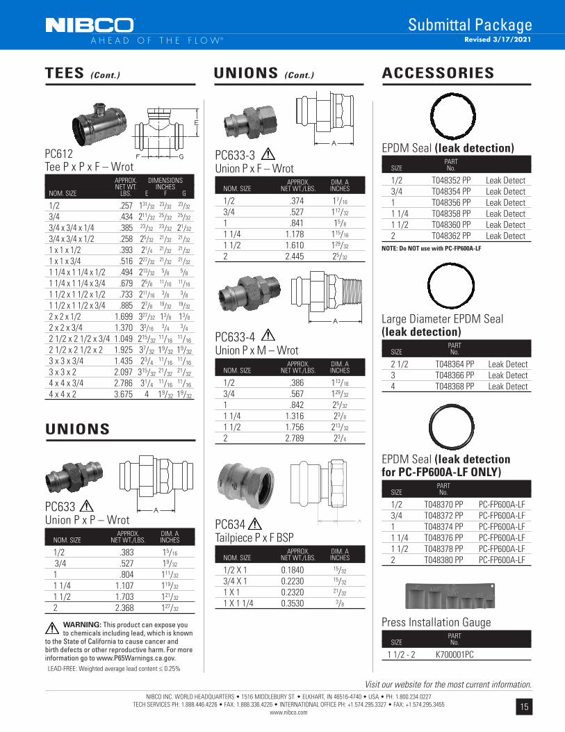
UNIONS (Cont.) ACCESSORIES
UNIONS
PC633-3Union P x F – Wrot APPROX. DIM. A NOM. SIZE NET WT./LBS. INCHES
1/2 .374 17/16
3/4 .527 117/32
1 .841 15/8
1 1/4 1.178 115/16
1 1/2 1.610 129/32
2 2.445 25/32
PC633Union P x P – Wrot APPROX. DIM. A NOM. SIZE NET WT./LBS. INCHES
1/2 .383 15/16 3/4 .527 19/32
1 .804 111/32
1 1/4 1.107 119/32
1 1/2 1.703 121/32
2 2.368 127/32
PC633-4Union P x M – Wrot APPROX. DIM. A NOM. SIZE NET WT./LBS. INCHES
1/2 .386 113/16
3/4 .567 129/32
1 .842 25/32
1 1/4 1.316 23/8
1 1/2 1.756 213/32
2 2.789 23/4
EPDM Seal (leak detection) PART SIZE No.
1/2 T048352 PP Leak Detect 3/4 T048354 PP Leak Detect 1 T048356 PP Leak Detect 1 1/4 T048358 PP Leak Detect 1 1/2 T048360 PP Leak Detect 2 T048362 PP Leak Detect
Large Diameter EPDM Seal (leak detection) PART SIZE No.
2 1/2 T048364 PP Leak Detect 3 T048366 PP Leak Detect 4 T048368 PP Leak Detect
NOTE: Do NOT use with PC-FP600A-LF
EPDM Seal (leak detectionfor PC-FP600A-LF ONLY) PART SIZE No.
1/2 T048370 PP PC-FP600A-LF 3/4 T048372 PP PC-FP600A-LF 1 T048374 PP PC-FP600A-LF 1 1/4 T048376 PP PC-FP600A-LF 1 1/2 T048378 PP PC-FP600A-LF 2 T048380 PP PC-FP600A-LF
Press Installation Gauge PART SIZE No.
1 1/2 - 2 K700001PC
PC634Tailpiece P x F BSP APPROX. DIM. A NOM. SIZE NET WT./LBS. INCHES
1/2 X 1 0.1840 15/32
3/4 X 1 0.2230 15/32
1 X 1 0.2320 21/32
1 X 1 1/4 0.3530 3/8
LEAD-FREE: Weighted average lead content ≤ 0.25%
WARNING: This product can expose you to chemicals including lead, which is known
to the State of California to cause cancer and birth defects or other reproductive harm. For more information go to www.P65Warnings.ca.gov.
PC612Tee P x P x F – Wrot APPROX. DIMENSIONS NET WT. INCHES NOM. SIZE LBS. E F G
1/2 .257 131/32 23/32 23/32
3/4 .434 211/32 25/32 25/32
3/4 x 3/4 x 1/4 .385 23/32 23/32 21/32
3/4 x 3/4 x 1/2 .258 25/32 21/32 21/32
1 x 1 x 1/2 .393 21/4 21/32 21/32
1 x 1 x 3/4 .516 227/32 21/32 21/32
1 1/4 x 1 1/4 x 1/2 .494 213/32 5/8 5/8
1 1/4 x 1 1/4 x 3/4 .679 25/8 11/16 11/16
1 1/2 x 1 1/2 x 1/2 .733 211/16 3/8 3/8
1 1/2 x 1 1/2 x 3/4 .885 27/8 19/32 19/32
2 x 2 x 1/2 1.699 327/32 13/8 13/8
2 x 2 x 3/4 1.370 33/16 3/4 3/4
2 1/2 x 2 1/2 x 3/4 1.049 215/32 11/16 11/16
2 1/2 x 2 1/2 x 2 1.925 37/32 19/32 19/32
3 x 3 x 3/4 1.435 23/4 11/16 11/16
3 x 3 x 2 2.097 315/32 21/32 21/32
4 x 4 x 3/4 2.786 31/4 11/16 11/16
4 x 4 x 2 3.675 4 19/32 19/32
TEES (Cont.)
Copyright © 2022 FDOKUMEN