SYSTEM PRODUCT SUBMITTAL - WM LYLES
90
Product ID Description Manufacture C.S.F.M. 4100-9311 4100ES FIRE ALARM CONTROL PANEL - 3BAY CABINET SIMPLEX 7165-0026:0251 2081-9296 50 aH BATTERIES SIMPLEX N/A 4603-9101 LCD ANNUNCIATOR SIMPLEX 7120-0026:0179 4090-9001 IDNET SUPERVISED IAM SIMPLEX 7300-0026:0223 4090-9002 IDNET RELAY IAM SIMPLEX 7300-0026:0223 2088-9008 TRACK MOUNTED SINGLE RELAY SPDT W/ ENCLOSURE SIMPLEX 7300-1004:0101 4098-9714 TRUEALARM PHOTO SMOKE SENSOR SIMPLEX 7272-0026:0218 4098-9733 TRUEALARM HEAT SENSOR SIMPLEX 7270-0026:0216 4098-9792 TRUE ALARM SENSOR BASE SIMPLEX 7300-0026:0217 4098-9019 IDNET ADDRESSABLE REFLECTIVE AUTO ALIGN BEAN SMOKE DETECTOR SYSTEM SIMPLEX 7260-0026:377 4098-9756 DUCT SENSOR HOUSING WITH RELAY OUTPUT SIMPLEX 3240-0026:0241 2098-9806 REMOTE TEST STATION W/ LED AND KEY SWITCH SIMPLEX 7300-0026:0150 4099-9020 IDNET NO GRIP MANUAL PULL STATION SIMPLEX 7150-0026:0224 4099-9012 ADDR DOUBLE ACTION PUSH/PULL STATION W/O LOGO SIMPLEX 7150-0026:0224 2080-9056 ABORT SWITCH, FLUSH SIMPLEX 7300-0026:0313 2080-9059 MAINT SWITCH W/LAMP,FLUSH SIMPLEX 7300-0026:0313 49VO-WWS TRUEALERT ADDRESSABLE MULTI-CANDELA STROBE WALL MOUNT WHITE SIMPLEX 7125-0026:0373 49AV-WWS-BA TRUEALERT ADDRESSABLE MULTI-CANDELA HORN/STROBE WALL MOUNT WHITE SIMPLEX 7125-0026:0373 4906-9204 STROBE, MULTI-CANDELA, ADDRESSABLE, CEILING MOUNT, WHITE SIMPLEX 7125-0026:0235 4906-9230 COMBINATION HORN/STROBE, MULTI-CANDELA, ADDRESSABLE, CEILING MOUNT, WHITE SIMPLEX 7125-0026:0239 49VO-WWFO TRUEALERT ADDRESSABLE MULTI-CANDELA WEATHERPROOF STROBE WALL MOUNT WHITE SIMPLEX 7125-0026:0373 FIRE ALARM CONTROL PANELS, ANNUNCIATORS AND BATTERIES SYSTEM PRODUCT SUBMITTAL Fountain Valley, CA 92708 10844 Ellis Ave. OCSD Orange County Sanitation District Sludge & Dewater Facility - Electric 428646 INERGEN 575 CYLINDER, 200 BAR ANSUL N/A 426144 2" DISCHARGE NOZZLE 180⁰ ANSUL N/A 426145 2.5" DISCHARGE NOZZLE 180⁰ ANSUL N/A 417363 .75" DISCHARGE NOZZLE 360⁰ ANSUL N/A 426336 1.5" DISCHARGE NOZZLE 360⁰ ANSUL N/A 427082 DISCHARGE HOSE ANSUL N/A 417720 DEFLECTOR SHIELD 1½" ANSUL N/A 79642 CYLINDER BACKGRAME - 6 CYLINDER ANSUL N/A 73092 CYLINDER CLAMP - 3 CYLINDER ANSUL N/A 79638 CYLINDER BACK FRAME - 2 CYLINDER ANSUL N/A 73091 CYLINDER CLAMP - 2 CYLINDER ANSUL N/A 418503 27" CARRIAGE BOLT W/ NUT ANSUL N/A 71682 WEIGH RAIL SUPPORT - DOUBLE ROW ANSUL N/A 73257 UPRIGHT SUPPORT ANSUL N/A 873553 DOUBLE ROW BRACKET FOOT, LEFT ANSUL N/A 873554 DOUBLE ROW BRACKET FOOT, RIGHT ANSUL N/A 418508 CENTER UPRIGHT FOOT ANSUL N/A 79413 BACK FRAME CONNECTOR ANSUL N/A 416682 2" PRESSURE REDUCER/UNION ANSUL N/A 427882 4" PRESSURE REDUCER/UNION ANSUL N/A 40665 3" MANIFOLD CHECK VALVE ANSUL N/A 437900 MANUAL DISCHARGE PRESSURE SWITCH ANSUL N/A 570537 VALVE ELECTRIC ACTUATOR ANSUL N/A 428949 BOOSTER ACTUATOR ANSUL N/A 57445 4" SELECTOR VALVE ANSUL N/A Job Number: 434-977666802 Prepared By: Torres Date: 1/9/2015 MISCELLANEOUS DEVICES
-
Upload
khangminh22 -
Category
Documents
-
view
0 -
download
0
Transcript of SYSTEM PRODUCT SUBMITTAL - WM LYLES

Product ID Description Manufacture C.S.F.M.
4100-9311 4100ES FIRE ALARM CONTROL PANEL - 3BAY CABINET SIMPLEX 7165-0026:02512081-9296 50 aH BATTERIES SIMPLEX N/A4603-9101 LCD ANNUNCIATOR SIMPLEX 7120-0026:01794090-9001 IDNET SUPERVISED IAM SIMPLEX 7300-0026:02234090-9002 IDNET RELAY IAM SIMPLEX 7300-0026:02232088-9008 TRACK MOUNTED SINGLE RELAY SPDT W/ ENCLOSURE SIMPLEX 7300-1004:01014098-9714 TRUEALARM PHOTO SMOKE SENSOR SIMPLEX 7272-0026:02184098-9733 TRUEALARM HEAT SENSOR SIMPLEX 7270-0026:02164098-9792 TRUE ALARM SENSOR BASE SIMPLEX 7300-0026:02174098-9019 IDNET ADDRESSABLE REFLECTIVE AUTO ALIGN BEAN SMOKE DETECTOR SYSTEM SIMPLEX 7260-0026:3774098-9756 DUCT SENSOR HOUSING WITH RELAY OUTPUT SIMPLEX 3240-0026:02412098-9806 REMOTE TEST STATION W/ LED AND KEY SWITCH SIMPLEX 7300-0026:01504099-9020 IDNET NO GRIP MANUAL PULL STATION SIMPLEX 7150-0026:02244099-9012 ADDR DOUBLE ACTION PUSH/PULL STATION W/O LOGO SIMPLEX 7150-0026:02242080-9056 ABORT SWITCH, FLUSH SIMPLEX 7300-0026:03132080-9059 MAINT SWITCH W/LAMP,FLUSH SIMPLEX 7300-0026:0313
49VO-WWS TRUEALERT ADDRESSABLE MULTI-CANDELA STROBE WALL MOUNT WHITE SIMPLEX 7125-0026:037349AV-WWS-BA TRUEALERT ADDRESSABLE MULTI-CANDELA HORN/STROBE WALL MOUNT WHITE SIMPLEX 7125-0026:0373
4906-9204 STROBE, MULTI-CANDELA, ADDRESSABLE, CEILING MOUNT, WHITE SIMPLEX 7125-0026:02354906-9230 COMBINATION HORN/STROBE, MULTI-CANDELA, ADDRESSABLE, CEILING MOUNT, WHITE SIMPLEX 7125-0026:0239
49VO-WWFO TRUEALERT ADDRESSABLE MULTI-CANDELA WEATHERPROOF STROBE WALL MOUNT WHITE SIMPLEX 7125-0026:0373
FIRE ALARM CONTROL PANELS, ANNUNCIATORS AND BATTERIES
SYSTEM PRODUCT SUBMITTAL
Fountain Valley, CA 9270810844 Ellis Ave.
OCSD Orange County Sanitation District Sludge & Dewater Facility - Electric
428646 INERGEN 575 CYLINDER, 200 BAR ANSUL N/A426144 2" DISCHARGE NOZZLE 180⁰ ANSUL N/A426145 2.5" DISCHARGE NOZZLE 180⁰ ANSUL N/A417363 .75" DISCHARGE NOZZLE 360⁰ ANSUL N/A426336 1.5" DISCHARGE NOZZLE 360⁰ ANSUL N/A427082 DISCHARGE HOSE ANSUL N/A417720 DEFLECTOR SHIELD 1½" ANSUL N/A79642 CYLINDER BACKGRAME - 6 CYLINDER ANSUL N/A73092 CYLINDER CLAMP - 3 CYLINDER ANSUL N/A79638 CYLINDER BACK FRAME - 2 CYLINDER ANSUL N/A73091 CYLINDER CLAMP - 2 CYLINDER ANSUL N/A418503 27" CARRIAGE BOLT W/ NUT ANSUL N/A71682 WEIGH RAIL SUPPORT - DOUBLE ROW ANSUL N/A73257 UPRIGHT SUPPORT ANSUL N/A873553 DOUBLE ROW BRACKET FOOT, LEFT ANSUL N/A873554 DOUBLE ROW BRACKET FOOT, RIGHT ANSUL N/A418508 CENTER UPRIGHT FOOT ANSUL N/A79413 BACK FRAME CONNECTOR ANSUL N/A416682 2" PRESSURE REDUCER/UNION ANSUL N/A427882 4" PRESSURE REDUCER/UNION ANSUL N/A40665 3" MANIFOLD CHECK VALVE ANSUL N/A437900 MANUAL DISCHARGE PRESSURE SWITCH ANSUL N/A570537 VALVE ELECTRIC ACTUATOR ANSUL N/A428949 BOOSTER ACTUATOR ANSUL N/A57445 4" SELECTOR VALVE ANSUL N/A
Job Number: 434-977666802Prepared By: Torres
Date: 1/9/2015
MISCELLANEOUS DEVICES

Features
Master Controller (top) bay standard equipment: 32-Bit Master Controller with color-coded operator
interface and raised switches for high confidence feedback Dual configuration program CPU, convenient service port
access, and capacity for up to 2500 addressable points CPU assembly includes 2 GB dedicated compact flash
memory for on-site system programming and information storage
An Enhanced Power Supply (EPS+) and battery charger (9 A total) with on-board IDNAC SLCs (signaling line circuit) for addressable appliance control, IDNet 1+ isolated addressable device control channel, and programmable function auxiliary output
Also available with InfoAlarm Command Center expanded content user interface (see data sheet S4100-0045)
Standard addressable device interfaces include: IDNet 1+ 250 point addressable device SLC supports
TrueAlarm analog sensors and IDNet communications monitoring and control devices, and operates with isolated output for use with either shielded or unshielded, twisted or untwisted single pair wiring
MINIPLEX Transponder and remote LCD and LED annunciator support via RUI+ (remote unit interface) communications port with isolated output for use with either shielded or unshielded, twisted or untwisted single pair wiring
Standard EPS+ power supplies provide enhanced power delivery IDNAC SLCs to addressable notification appliances: With IDNAC SLCs, a constant 29 VRMS source voltage is
maintained, even during battery standby, allowing strobes to operate at higher voltage with lower current and ensuring a consistent current draw and voltage drop margin under both primary power and secondary battery standby
Efficiencies include lower strobe currents, wiring distances up to 2 to 3 times farther than with conventional notification, support for more appliances per IDNAC SLC, ability to use smaller gauge wiring, all providing installation and maintenance savings with high assurance appliances that operate during normal system testing will operate during worst case alarm conditions
IDNAC SLCs are compatible with both TrueAlert ES and TrueAlert addressable notification appliances, and remote 4009 IDNAC Repeaters to extend power and wiring distance even farther
Optional modules and connections include: Fire Alarm Network Interfaces, city connections, and up
to five (5) RS-232 ports for printers and terminals Building Network Interface Module (BNIC) for Ethernet
connectivity options (see data sheet S4100-0061) Side mounted DACT assembly requiring minimal panel
space; DACT is compatible with IP Communicators Emergency communications systems (ECS) equipment;
8 channel digital audio or 2 channel analog audio
Press ACK l ocated under fl ashin g indicator.Repeat operation unti l al l events are acknowledged.Local tone wil l silence.
A B C
AC Power
D E F G H I
J K L M N O P Q R
'SP ' ( ) , 0 :
S T U V W X Y Z /
ALARMSFire Alarm Priority 2 Alarm
SYSTEM WARNINGSSupervisory Trouble Ala rm Silenced
Emergency Operating Instructions
Alarm or Warning Condition
How to Acknowledge / View Events
How to Silence Building SignalsSystem ind icator flashing. Tone On. Press Alarm Silence.
How to Reset SystemPress System Reset.Press Ack to si lence tone device.
ZONE
1SI G
2A UX
3
FB
4IO
5I DNet
6
P
7A
8L
9
N ET ADDR
0 DE L
Enter C/Exit
Fire AlarmAck
Priority 2Ack
SupvAck
TroubleAck
AlarmSilence
SystemReset
EventTime
Enable On Arm
Disable OffDisarm Auto Lamp
Test
MoreInfo
Menu
Previous
Next
On
Off
Auto
On
Off
Auto
On
Off
Auto
On
Off
Auto
On
Off
Auto
On
Off
Auto
On
Off
Auto
On
Off
Auto
Press ACK located under flashing indicator.Repeat operation until all events are acknowledged.Lo cal to ne will silence.
A B C
AC Power
D E F G H I
J K L M N O P Q R
'SP' ( ) , 0 :
S T U V W X Y Z /
ALARMSFire Alarm Priority 2 Ala rm
SYSTEM WARNINGSSupervisory Trouble Alarm Silenced
Emergency Operating Instructions
Alarm or Warning Condition
How to Acknowledge / View Events
How to Silence Building SignalsSystem indicator flashing. Tone On. Press Alarm Silence.
How to Reset SystemPress System Reset.Press Ack to si lence tone device.
ZONE
1SI G
2A UX
3
FB
4IO
5I DNet
6
P
7A
8L
9
NET ADDR
0 DEL
Enter C/Exit
Fire AlarmAck
Priority 2Ack
SupvAck
TroubleAck
AlarmSilence
SystemReset
EventTime
Enable On Arm
Disable OffDisarm Auto Lamp
Test
MoreInfo
Menu
Previous
Next
4100ES Cabinets are Available with One, Two or Three Bays
Option Modules (Continued) Additional IDNet 1+ addressable device communications
modules and IDNet+ quad output isolator modules; additional power supplies, alarm relays, and auxiliary relays
LED/switch modules and panel mount printers; VESDA Air Aspiration Systems interface, ASHRAE BACnet Interface, TCP/IP Bridges
Battery brackets for seismic area protection (see page 2) 4100ES compatible legacy interface modules,
including control of conventional (non-addressable) NACS (see data sheet reference list on page 8)
4100ES Listings reference: UL Std. 864, Fire Detection and Control (UOJZ), and
Smoke Control Service (UUKL) UL Std. 2017, Process Management Equipment (QVAX) UL Std. 1076, Proprietary Alarm Units-Burglar (APOU) UL Std. 1730, Smoke Detector Monitor (UULH) ULC Std. S527 Control Units for Fire Alarm Systems
Software Feature Summary
CPU provides dual configuration programs: Two programs allow for optimal system protection and
commissioning efficiency with one active program and one reserve; downtime is reduced because the system stays running during download
PC based programmer features: Convenient front panel accessed Ethernet port for quick
and easy download of site-specific programming Modifications can be uploaded as well as downloaded for
greater service flexibility; AND, firmware enhancements are made via software downloads to the on-board flash memory
* See pages 7 and 8 for product that is UL or ULC listed and additional listing information. This product has been listed by the California State Fire Marshal (CSFM) pursuant to Section 13144.1 of the California Health and Safety Code. See CSFM Listing 7165-0026:0251 for allowable values and/or conditions concerning material presented in this document. Additional listings may be applicable; contact your local Simplex product supplier for the latest status. Listings and approvals under Simplex Time Recorder Co. are the property of Tyco Fire Protection Products.
4100ES Fire Control Panels UL, ULC, CSFM Listed; Addressable Fire Detection and Control FM Approved* Basic Panel Modules and Accessories
S4100-0100-1 5/2013

Introduction
4100ES Series Fire Detection and Control Panels provide extensive installation, operator, and service features with point and module capacities suitable for a wide range of system applications. An on-board Ethernet port provides fast external system communications to expedite installation and service activity. Dedicated compact flash memory archiving provides secure on-site system information storage of electronic job configuration files to meet NFPA 72 (National Fire Alarm and Signaling Code) requirements.
Modular design. A wide variety of functional modules are available to meet specific system requirements. Selections allow panels to be configured for either Stand-Alone or Networked fire control operation.
Module Bay Description
The Master Controller Bay (top) includes a standard multi-featured enhanced power supply (EPS+), the master controller board, two vertical expansion blocks, and operator interface equipment.
The Expansion Bays include a Power Distribution Interface (PDI) for connection of single or multiple block modules, and/or slot style (motherboard/daughter card) modules.
The Battery Compartment (bottom) accepts two batteries, up to 50 Ah, to be mounted within the cabinet without interfering with module space.
PDI
4x5 Module
Expansion PowerSupply
(XPS)
4x5 Module
I/O Wiring
I/O Wiring
I/O Wiring
41
00 O
ptio
n
41
00 O
ptio
n
41
00 O
ptio
n
Slot 1 Slot 2 Slot 3 Slot 4 Slot 5 Slot 6 Slot 7 Slot 8
(Block E)
(Block F)
(Blocks G & H)
PDI
Ma
ster
Con
trol
ler
Bo
ard
Slot 1 Slot 2 Slot 3 Slot 4
PDI
4x5 Module
Expansion PowerSupply
(XPS)
4x5 Module
I/O Wiring
I/O Wiring
I/O Wiring
41
00 O
ptio
n
41
00 O
ptio
n
41
00 O
ptio
n
Slot 1 Slot 2 Slot 3 Slot 4 Slot 5 Slot 6 Slot 7 Slot 8
(Block E)
(Block F)
(Blocks G & H)
Master Controller Bay
Expansion Bay 1
Battery Compartment
EPS+ Power Supply with IDNet 1+ Module
Master controller with dual slot motherboard
Expansion Bay 2
Typical bays with mixed module sizes
PDI board with two connectors available
4100-6080 DACT mounting location
Optional 4190-6104 TrueInsight Module mounting location
4100ES Module Placement Reference in 3-Bay Cabinet
Mechanical Description
Boxes can be close-nippled; each box provides convenient stud markers for drywall thickness and nail-hole knockouts for quicker mounting
Smooth box surfaces are provided for locally cutting conduit entrance holes exactly where required
Cabinet assembly design has been seismic tested and is certified to IBC and CBC standards as well as to ASCE 7-05 category D, requires battery brackets as detailed on data sheet S2081-0019
The latching front panel assembly easily lifts off for internal access
Modules are power-limited (except as noted, such as relay modules)
The NEMA 1 box is ordered separately and available for early installation
Doors are available with tempered glass inserts or solid; boxes and doors are available in platinum or red
Boxes and door/retainer assemblies are ordered separately per system requirements; refer to data sheet S4100-0037
Operator Interface Detail Reference
The following illustration identifies the primary functions of the operator interface.
Press ACK located under flashing indicator.Repeat operation until all events are acknowledged.Local tone will silence.
A B C
AC Power
D E F G H I
J K L M N O P Q R
'SP' ( ) , 0 :
S T U V W X Y Z /
ALARMSFire Alarm Priority 2 Alarm
SYSTEM WARNINGSSupervisory Trouble Alarm Silenced
Emergency Operating Instructions
Alarm or Warning Condition
How to Acknowledge / View Events
How to Silence Building SignalsSystem indicator flashing. Tone On. Press Alarm Silence.
How to Reset SystemPress System Reset.Press Ack to silence tone device.
ZONE
1SIG
2AUX
3
FB
4IO
5IDNet
6
P
7A
8L
9
NET ADDR
0 DEL
Enter C/Exit
Fire AlarmAck
Priority 2Ack
SupvAck
TroubleAck
AlarmSilence
SystemReset
EventTime
EnableOnArm
DisableOff
DisarmAuto
LampTest
MoreInfo
Menu
Previous
Next
Upload/Download Ethernet port access (under sliding cover)
Basic operator instructions are printed on the interface
mounting plate
Panel sounder
Operator interface panel is directly viewable and accessible (no access door)
Software Feature Summary
“Install Mode” allows grouping of multiple troubles for uninstalled modules and devices into a single trouble condition (typical with future phased expansion); with future equipment and devices grouped into a single trouble, operators can more clearly identify events from the commissioned and occupied areas
Module level ground fault searching assists installation and service by locating and isolating modules with grounded wiring
“Recurring Trouble Filtering” allows the panel to recognize, process, and log recurring intermittent troubles (such as external wiring ground faults), but only sends a single outbound system trouble to avoid nuisance communications
WALKTEST silent or audible system test performs an automatic self-resetting test cycle
Support for TrueAlarm individual analog sensing and IDNAC addressable notification with front panel information and selection access
2 S4100-0100-1 5/2013

Operator Interface
Convenient Status Information. With the locking door closed, the glass window allows viewing of the display, status LEDs, and available operator switches. Features include a two-line by 40-character, wide viewing angle (super-twist) LCD with status LEDs and switches as shown in the illustration below.
LED indicators describe the general category of activity being displayed with the LCD providing more detail. For the authorized user, unlocking the door provides access to the control switches and allows further inquiry by scrolling the display for additional detail.
Operator Interface Features
Convenient and extensive operator information is provided using a logical, menu-driven display
Multiple automatic and manual diagnostics for maintenance reduction
Alarm and Trouble History Logs (up to 1250 entries for each, 2500 total events) are available for viewing from the LCD, or capable of being printed to a connected printer, or downloaded to a service computer
Convenient PC programmer label editing Password access control
A B C
AC Power
D E F G H I
J K L M N O P Q R
'SP' ( ) , 0 :
S T U V W X Y Z /
ALARMSFire Alarm Priority 2 Alarm
SYSTEM WARNINGSSupervisory Trouble Alarm Silenced
ZONE
1SIG
2AUX
3
FB
4IO
5IDNet
6
P
7A
8L
9
NET ADDR
0 DEL
Enter C/Exit
Fire AlarmAck
Priority 2Ack
SupvAck
TroubleAck
AlarmSilence
SystemReset
EventTime
EnableOn
Arm
DisableOff
DisarmAuto
LampTest
MoreInfo
Menu
Previous
Next
SIX SYSTEM STATUS INDICATOR LEDs provide system status indications in addition to LCD information, LEDs flash to indicate the condition and then when acknowledged, remain on until reset :Fire Alarm & Priority 2 Alarm, red LEDSupervisory & Trouble, yellow LEDAlarm Silenced, yellow LEDAC Power, green LED (on for normal)
FIVE PROGRAMMABLE FUNCTION SWITCHES, each with a yellow LED indicator
POINT STATUS CONTROL KEYS:Point Enable and DisableForce On or ArmForce Off or DisarmReturn On/Off or Arm/Disarm to Auto Mode
NUMERIC KEYPAD for point category and point selection (alphabet characters are not used at this time)
ADDITIONAL FUNCTION KEYS:Event Time RequestMore Information RequestLamp Test
Elevator Recall
City Disconnect
Manual Evac
Ground Fault
Waterflow-West
Waterflow-East
Custom label insert
LCD NAVIGATION CONTROL:Menu selectionVertical and Horizontal position selection buttons
FIRE ALARM ACK acknowledges a Fire Alarm condition, logs the acknowledge, and silences the operator panel and all annunciator tone-alerts
PRIORITY 2 ACK acknowledges a Priority 2 Alarm condition, logs the acknowledge, and silences the operator panel and all annunciator tone-alerts
SUPV ACK acknowledges system supervisory conditions, logs the acknowledge, and silences the operator panel and all annunciator tone-alerts
TROUBLE ACK acknowledges system troubles, logs the acknowledge, and silences the operator panel and all annunciator tone-alerts
ALARM SILENCE causes audible notification appliances to be silenced (depending on panel programming) typically after evacuation is complete and while alarm source is being investigated; may allow visible notification to continue (strobes still flashing)
SYSTEM RESET restores control panel to normal when all alarmed inputs are returned to normal
2 X 40 LCD READOUT, LED backlighted during normal conditions and abnormal operating conditions, provides up to 40 characters for custom label information
FIRST ALARM DISPLAY: Operation can be selected for maintained display of first alarm until acknowledged
THREE PROGRAMMABLE LEDs provide custom labeling, the top two LEDs are selectable as red or yellow, the bottom LED is selectable as green or yellow
ULC SYSTEMS require designating a Ground Fault indicator
Almost Dirty
Ground Fault Latch
3 S4100-0100-1 5/2013
Overview. The 4100ES with EPS+ power supplies provides IDNet 1+ addressable initiating device and IDNAC addressable notification appliance Signaling Line Circuits (SLCs) that supervise wiring connections and the individual device/appliance communications status on their SLC. With these 2-wire SLCs, initiation, monitoring, and control devices such as manual fire alarm stations, TrueAlarm sensors, control relays, and sprinkler waterflow switches; and notification appliances such as strobes and horns can communicate their identity and status and receive fire alarm system control. Additional interface modules include circuit isolators, conventional IDC zone adapters, and interface to other system circuits such as fans, dampers, and elevator controls.
IDNet Addressable Device Operation
Each addressable device on the IDNet 1+ communication channel is continuously interrogated for status condition such as: normal, off-normal, alarm, supervisory, or trouble. Both Class B and Class A operation is available. Sophisticated poll and response communication techniques ensure supervision integrity and allow for "T-tapping" of the circuits for Class B operation. Devices with LEDs pulse the LED to indicate receipt of a communications poll and can be turned on steady from the panel. With addressable devices, the location and status of the connected device is monitored and logged, and displayed on the operator interface LCD and on remote system annunciators with each device having its own 40 character custom label for precise identification.
TrueAlarm Addressable Sensor Operation
Addressable initiating device communications include operation of TrueAlarm smoke and temperature sensors. Smoke sensors transmit an output value based on their smoke chamber condition and the CPU maintains a current value, peak value, and an average value for each sensor. Status is determined by comparing the current sensor value to its average value. Tracking this average value as a continuously shifting reference point filters out environmental factors that cause shifts in sensitivity.
TrueAlarm Addressable Sensor Reference
TrueAlarm Photo Sensor with Base
TrueAlarm Photo/Heat
Sensor in CO Base
Programmable sensitivity of each sensor can be selected at the control panel for different levels of smoke obscuration (shown directly in percent) or for specific heat detection levels. To evaluate whether the sensitivity should be revised, the peak value is stored in memory and can be easily read (or downloaded as a report) and compared to the alarm threshold directly in percent.
CO sensor bases combine an electrolytic CO sensing module with a TrueAlarm analog sensor to provide a single multiple sensing assembly using one system address. The CO sensor can be enabled/disabled, used in LED/Switch modes and custom control, and can be made public for communication across a fire alarm Network. (refer to data sheet S4098-0041 for details)
TrueAlarm heat sensors can be selected for fixed temperature detection, with or without rate-of-rise detection. Utility temperature sensing is also available, typically to provide freeze warnings or alert to HVAC system problems. Readings can selected as either Fahrenheit or Celsius. TrueSense Early Fire Detection. Multi-sensor 4098-9754 provides photoelectric and heat sensor data using a single 4100ES IDNet address. The panel evaluates smoke activity, heat activity, and their combination, to provide TrueSense early detection. For more details on this operation, refer to data sheet S4098-0024.
Diagnostics and Default Device Type
Sensor Status. TrueAlarm operation allows the control panel to automatically indicate when a sensor is almost dirty, dirty, and excessively dirty. The NFPA 72 requirement for a test of the sensitivity range of the sensors is fulfilled by the ability of TrueAlarm operation to maintain the sensitivity level of each sensor. CO Sensors track their 5 year active life status providing indicators to assist with service planning. Indicators occur at: 1 year, 6 months, and end of life.
Modular TrueAlarm sensors use the same base and different sensor types (smoke or heat sensor) and can be easily interchanged to meet specific location requirements. This allows intentional sensor substitution during building construction when conditions are temporarily dusty. Instead of covering smoke sensors (causing them to be disabled), heat sensors may be installed without reprogramming the control panel. The control panel will indicate an incorrect sensor type, but the heat sensor will operate at a default sensitivity to provide heat detection for building protection at that location.
IDNet Addressable Device Wiring Reference
IDNet 1+ Addressable Channel Capacity. The CPU bay system power supply (EPS+) provides an IDNet 1+ signaling line circuit (SLC) that supports up to 250 addressable monitor and control points intermixed on the same pair of wires. Additional 250 address IDNet 1+ circuit modules are available.
IDNet 1+ SLC Wiring Specifications
Maximum Distance from Control Panel per Device Load
0 to 125 4000 ft (1219 m); 50 ohms
126-250 2500 feet (762 m); 35 ohms
Total Wire Length Allowed With “T” Taps for Class B Wiring
Up to 12,500 ft (3.8 km); 0.60 µF
Maximum Capacitance Between IDNet+ Channels
1 µF
Wire Type and Connections Shielded or unshielded, twisted or untwisted wire*
Connections Terminal blocks for 18 to 12 AWG
Installation Instructions (see for more information) 579-1014
* Some applications may require shielded wiring. Review your system with your local Simplex product supplier.
4 S4100-0100-1 5/2013
IDNet Addressable Device and IDNAC Addressable Notification Appliance Control

Addressable notification appliance communications include operation of TrueAlert and TrueAlert ES Visible only (V/O, strobe), Audible only (A/O, horn), Audible/Visible (A/V, horn/strobe), and strobes of Speaker/Visible (S/V) notification appliances. (S/V appliances require separate speaker wiring.) IDNAC SLC addressable communications allow each horn and strobe to be individually controlled using a single two-wire circuit, confirms the wiring connections to the individual notification appliance’s electronic circuit, and confirms communications between each appliance and the fire alarm control panel. Addressable communications increases supervision integrity versus conventional notification systems by providing supervision beyond the circuit wiring to each individual appliance and by constantly verifying the ability of each appliance to communicate with the control panel.
Individual Appliance Status and Settings. Each addressable notification appliance is polled by the control panel to verify its ability to communicate. The fire alarm control panel monitors each addressable notification appliances for its status, condition, type of appliance, and configured appliance settings. A fault in any individual appliance automatically reports a trouble condition to the control panel.
TrueAlert ES Addressable Appliance Reference
A/O (horn) V/O (strobe) A/V (horn/strobe)
Location Information, Diagnostics, and Troubleshooting. Each addressable notification appliance has its own 40 character custom label to identify the location of the appliance and to aid in troubleshooting fault conditions. In conventional notification systems, conventional appliances are not capable of communicating with the control panel. Fault reporting on a conventional system is limited to the circuit wiring and the entire area (zone) covered by appliances on the notification appliance circuit (NAC) making it much more difficult and costly to locate and correct the source of a problem.
Tracking Appliance Details. The 4100ES with IDNAC SLCs provides intelligent addressable communications that allow detailed information associated with each addressable notification appliance to be reported to the fire alarm control panel for diagnostics and troubleshooting. Detailed information available includes; the appliance location, status, condition, type of appliance, and configured appliance settings.
New Installation, Retrofit, and Life-Cycle Cost Benefits. With each addressable appliance capable of being controlled separately on the same two-wire SLC, installation time and expense for both retrofit and new construction can be significantly reduced. When Class B wiring is used, wiring can be “T-tapped”, allowing more savings in distance, wire, conduit (size and utilization), and overall installation efficiency.
Panel Control Convenience. Applicable operation settings for each appliance can be programmed without having to replace appliances or remove them from the wall or ceiling. An appliance’s notification zone can be easily changed through programming without having to add additional circuits, conduit, and wiring. Audible and visible appliances for non-Fire Emergency Communications notification can be programmed to operate separately on the same pair of wires as the fire alarm notification appliances. The result is lower installation, retrofit, and overall life-cycle cost of ownership compared with traditional conventional notification systems.
IDNAC SLC Hardware Reference
EPS+ and EPS Power Supplies provide three, 3 A IDNAC SLCs for control and power to TrueAlert ES and TrueAlert addressable notification appliances. Both power supplies incorporate an efficient switching design that provides a regulated output of 29 VRMS, even during battery operation. With 29 VRMS minimum output at the panel, addressable notification SLCs can support wiring distances 2 to 3 times farther than available with conventional notification, or support more appliances per SLC, or work with smaller gauge wiring, or combinations of these benefits, all resulting in installation and maintenance savings with high assurance appliances that operate during normal system testing will operate during worst case alarm conditions.
Virtual NACs Provide Control Convenience. For control convenience, IDNAC notification appliances can be grouped into Virtual NACS for group control, grouping that can be made across SLCs, not defined by their wiring connection.
IDNAC SLC Appliance Wiring Reference
Recommended wire type UTP, unshielded twisted pair
IDNAC SLC Capacity
Up to 63 addresses and up to 75 unit loads (appliances are typically one unit load, devices such as Isolators may require more than one load, refer to individual device data sheet for specific information)
Maximum wire length allowed with “T-Taps” for Class B wiring, per SLC
10,000 ft (3048 m)
Maximum wire length per SLC to any appliance
4000 ft (1219 m)
Maximum wiring resistance between appliances
26 Ω
Wiring connections Terminal blocks for 18 to 12 AWG
Installation Instructions (see for more information) 579-1015
5 S4100-0100-1 5/2013
IDNAC SLC Control of TrueAlert and TrueAlert ES Addressable Notification

Master Controller and Motherboard: Mounts in Slot 2 of a two slot motherboard and provides
one Style 4 or Style 7, RUI+, isolated communications channel with earth fault detection
RUI+ isolated communications controls up to 31 devices per master controller at up to 2500 ft (762 m) for single run, or 10,000 ft (3048 m) total if wiring is Class B and T-tapped; if more distance is required, up to four total RUI channels are supported; add up to three 4100-1291 RUI expansion modules (4100-1291 provides unisolated RUI communications)
RUI remote equipment includes: MINIPLEX transponders, 4603-9101 LCD Annunciators, 4602-9101 Status Command Units (SCU), 4602-9102 Remote Command Units (RCU), 4602 Series LED Annunciator Panels, 4100 Series 24 I/O and LED/Switch modules
Open slot space on the left of the CPU motherboard is available for either another dual slot motherboard, or for one or two block modules (refer to diagram on page 2)
Slot 1 of the motherboard is primarily for the 4100-6078 Network Interface Board with media modules
EPS+ Power Supply: (see page 9 for more detail) Rating is 9 A total with “Special Application” appliances Outputs are power-limited, except for the battery charger Provides system power, battery charging, auxiliary
power, earth detection, on-board IDNet 1+ communications channel for 250 points, three on-board 3 A IDNAC SLCs, and provisions for either an optional City Connect Module or an optional Alarm Relay Module
IDNet 1+ SLC Output provides Class B or Class A communications for up to 250 addressable devices (as described on page 4)
DCAI (Dual Class A IDNAC Isolator) module creates two Class A outputs from one IDNAC SLC Class B Input; up to two can be connected to one IDNAC SLC, with up to 6 total per EPS; total Class A output loop current is limited to the 3 A rating of the IDNAC SLC
EPS+ Power Supply (Continued): Battery Charger is dual rate, temperature
compensated, and charges up to 50 Ah sealed lead-acid batteries mounted in the battery compartment (33 Ah for single bay cabinets); also is UL listed for charging up to 115 Ah batteries mounted in an external cabinet (see data sheet S2081-0012 for details)
Battery and Charger Monitoring includes battery charger status and low or depleted battery conditions; status information provided to the master controller includes analog values for: battery voltage, charger voltage and current, actual system voltage and current, and individual IDNAC SLC currents
Low Battery Cutout is selectable for each EPS+ (and EPS) power supply, Canadian models are shipped selected, other models are shipped unselected
2 A Programmable Output: Select for conventional non-synchronous NAC
operation to provide supervised reverse polarity for sounder base power, Suppression Release Peripheral (SRP) power, or other coded NAC operation requirements
Select for Auxiliary (AUX) operation for sounder base power, 4-wire detector power, or door holder; supervised AUX operation does not require an end-of-line relay to provide Power-Limited operation
EPS+ Power Supply Mounted Optional Modules (select one): City Connect Module (4100-6031, with disconnect
switches, or 4100-6032, without disconnect switches) can be selected for conventional dual circuit city connections
Alarm Relay Module (4100-6033) provides three Form C relays that are used for Alarm, Trouble, and Supervisory, rated 2 A resistive @ 32 VDC
Master Controller and Expansion Bay Selection
Model Model Type and Listing Description Current
4100-9311 120 VAC, 50/60 Hz Input UL 4100ES Master Controller Assembly with LCD and operator interface, 9 A EPS+ Enhanced Power Supply/battery charger with 250 point IDNet 1+ interface, 3 Class B IDNAC SLCs, RUI+ isolated output communications interface, and one output configurable for Auxiliary or simple NAC operation
Without IDNet devices: Supervisory = 217 mA Alarm = 480 mA With 200 IDNet devices and 20 device LEDs in alarm: Supervisory = 417 mA Alarm = 770 mA
4100-9312 English 120 VAC, 50/60 Hz Canadian
ULC 4100-9313 French
4100-9511 220-240 VAC, 50/60 Hz Input
UL
4100-9331 120 VAC, 50/60 Hz input UL 4100ES Master Controller Assembly, No Display, No Operator Interface, 9 A EPS+ Enhanced Power Supply/battery charger with 250 point IDNet 1+ interface, 3 Class B IDNAC SLCs, RUI+ isolated output communications interface, and one output configurable for Auxiliary or simple NAC operation
4100-9332 120 VAC, 50/60 Hz input, Canadian, English
ULC
4100-2300 Expansion Bay Assembly; order for each required expansion bay
4100-2303 Slot Module Stabilizer Bracket, used when expansion bays have style modules
(Continued on next page)
6 S4100-0100-1 5/2013
Master Controller Selection Information
CPU Bay Module Details

7 S4100-0100-1 5/2013
Communication Modules Model Description Size Supv. Alarm
4100-6078 For Master Controller; mounts in Slot 3 Modular Network Interface; each requires two media modules (below)
1 Slot 46 mA 46 mA 4100-6061 For Redundant Master Controller 1 Slot 46 mA 46 mA
4100-6056 Wired Media Module Select two media cards as required; mounts on 4100-6078 or 4100-6061
N.A. 55 mA 55 mA 4100-6057 Fiber Optic Media Module N.A. 25 mA 25 mA
4100-6047 Building Network Interface Card (BNIC), refer to data sheet S4100-0061 for details 2 Blocks 291 mA 291 mA
4100-6055 Network Access Dial-in Service Modem, mounts to 4100-6078 or 4100-6061 Network Interface Card, requires telephone line connection N.A. 60 mA 60 mA
4100-1291 Remote Unit Interface Module (RUI, unisolated); up to 3 maximum per control panel 1 Slot 85 mA 85 mA
4100-6031 Select one per EPS+ or EPS
City Circuit, with disconnect switches N.A. 20 mA 36 mA 4100-6032 City Circuit, w/o disconnect switches N.A. 20 mA 36 mA 4100-6033 Alarm Relay, 3 Form C relays, 2 A @ 32 VDC N.A. 15 mA 37 mA
4100-6046 Dual Port RS-232 standard interface (single block) 3 maximum RS-232 modules per panel
1 Block 60 mA 60 mA 4100-6038 Dual Port RS-232 with 2120 interface (slot module) 1 Slot 132 mA 132 mA
4100-6079 SafeLINC Internet Interface (refer to data sheet S4100-0062 for details) 2 Blocks 145 mA 145 mA 4190-6104 TrueInsight Remote Monitoring Module (refer to data sheet S4100-0063 for details) Side Mt. 62 mA 73 mA 4100-6101 Physical Bridge, Class B, includes 1 modem module and 2 wired modules 1 Slot 210 mA 210 mA 4100-6102 Physical Bridge, Class X, includes 2 modem and 2 wired modules 2 Slots 300 mA 300 mA 4100-6048 VESDA Aspiration System Interface 1 Slot 132 mA 132 mA
4100-6080 DACT, Point or Event Reporting; 1 shipped unless 4100-7908 is selected; 2 max. per system; includes 2, 2080-9047 cables, 14 ft (4.3 m) long, RJ45 plug and spade lugs Side Mt. 30 mA 40 mA
Additional Enhanced Power Supplies, Expansion and Remote Power Supplies, and Accessories Model Voltage/Listing Description Size Supv. Alarm
4100-5311 120 VAC UL & ULC
Additional Enhanced Power Supply (EPS+); 9 A Enhanced Power Supply/battery charger with 250 point IDNet 1+ interface, 3 Class B IDNAC SLCs, and RUI+ isolated output communications interface; 120 VAC model has selectable low battery cutout
4 Blocks Right Side
217 mA 480 mA
4100-5313 220-240 VAC UL with 200 IDNet devices and 20
device LEDs in alarm
4100-5325 120 VAC UL & ULC
Enhanced Power Supply (EPS); 9 A Enhanced Power Supply/battery charger with 3 Class B IDNAC SLCs, and RUI+ isolated output communications interface; 120 VAC model has selectable low battery cutout
4 Blocks Right Side
125 mA 220 mA 4100-5327 220-240 VAC UL
4100-6103
Dual Class A IDNAC Isolator (DCAI), converts a single Class B IDNAC SLC input to two Class A or two Class B SLC outputs; provides short circuit isolation between each Class A or B output circuit; connect up to two DCAI modules per IDNAC SLC input up to a maximum of 6 DCAI modules per EPS; each isolated output SLC used requires one IDNAC address; the total current remains controlled by the Class B input source SLC at 3 A maximum
1 Block 6.5 mA 6.5 mA
4100-5152 12 VDC Power Option, 2 A maximum 1 Block 1.5 A maximum 4100-0156 8 VDC Converter, required for multiple Physical Bridge Modules, 3 A maximum 1 Block included w/loads
4100-0636 Box Interconnection Harness Kit (non-audio); order one for each close-nippled cabinet 4100-0638 4100 Slot Module Additional 24 VDC Harness; need when 4100 Slot module requirements exceed 2 A from EPS
Module Selection is continued on next page
Subject Data Sheet Subject Data Sheet
Introducing the 4100ES S4100-0060 Fire Alarm Network Overview S4100-0055
4100ES Enclosures S4100-0037 Network Communications S4100-0056
4100ES Audio and Firefighter Phone Modules S4100-0034 Network Display Unit (NDU) S4100-0102
LED/Switch Modules & Printer S4100-0032 Addressable Device Compatibility S4090-0011
Remote Annunciators S4100-0038 4009 IDNAC Repeater S4009-0004
MINIPLEX Transponders S4100-0103 IDNet+ Module w/Quad Isolator S4100-0046
Building Network Interface (BNIC) S4100-0061 Remote Battery Charger S4081-0002
InfoAlarm Command Center S4100-0101 TFX Interface Module S4100-0042
Graphic I/O Modules S4100-0005 SafeLINC Internet Interface S4100-0062
TrueInsight Remote Service S4100-0063 4100ES Panels for Conventional Notification S4100-0031
Agent Release Applications S4100-0040 TrueAlarm Sensors S4098-0019
TrueAlert ES Audible Only Appliances S49AO-0001 TrueAlert ES Audible/Visible Appliances S49AV-0001
TrueAlert ES Visible Only Appliances S49VO-0001 TrueAlert ES Weatherproof Appliances, UL Listed S49WP-0001
TrueAlert Appliance/IDNAC SLC Isolator S4905-0001 TrueAlert ES Weatherproof Appliances, ULC Listed S49WP-0002
Module Selection Information
Additional 4100ES Data Sheet and Related Product Reference
8 S4100-0100-1 5/2013
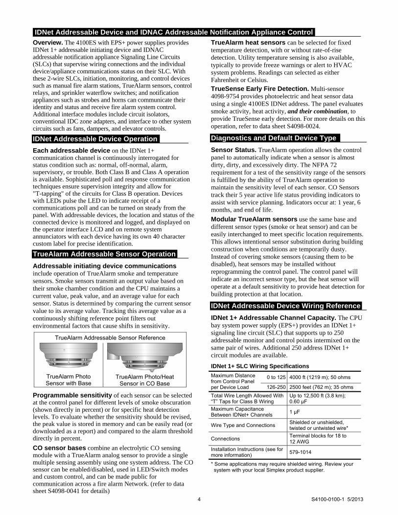
Addressable Interface Modules (refer to location reference on pages 9 and 10) Model Description Supv. Alarm
4100-3108 IDNet 1+ Module, 250 point capacity with isolated output, 1 block
With 250 IDNet devices, and 20 device LEDs in alarm 292 mA 510 mA
Module without devices 92 mA 115 mA
Loading per IDNet device (no LEDs on) 0.8 mA 1 mA
4100-3107
Quad IDNet Isolator Module; converts a single connected SLC into four isolated outputs selectable as Class A or Class B, provides advanced diagnostics for use with retrofit wiring; dual horizontal block module; (see data sheet S4100-0046 for additional details) NOTE: This module is compatible with IDNet Remote Isolators
75 mA 115 mA
Relay Modules; Nonpower-limited (for mounting in expansion bay only, refer to location reference on pages 9 and 10) Model Description Resistive Ratings Inductive Ratings Size Supv. Alarm
4100-3202 4 DPDT w/feedback 10 A @ 250 VAC 10 A @ 250 VAC 2 Slots 15 mA 175 mA
4100-3204 4 DPDT w/feedback 2 A @ 30 VDC/VAC 1/2 A @ 30 VDC/120 VAC 1 Block 15 mA 60 mA
4100-3206 8 SPDT 3 A @ 30 VDC/120 VAC 1-1/2 A @ 30 VDC/120 VAC 1 Block 15 mA 190 mA
Current Calculation Notes: 1. To determine total supervisory current, add currents of modules in panel to base system value and all external loads powered
by panel power supplies. 2. To determine total alarm current, add currents of modules in panel to base system alarm current and add all panel SLC and
NAC loads and all external loads powered from panel power supplies.
Miscellaneous Accessories Model Description
4100-1279 Single blank 2” display cover; 4100-2302 provides a single plate for a full bay
4100-9835 Termination and Address Label Kit (for module marking); provides additional labels for field installed modules
4100-6029 Smoke Management Application Guide; required for UUKL listing
4100-6034 Tamper Switch, one per cabinet assembly if required; monitors solid door for panels with solid door; monitors the internal retainer panel for panels with glass door (not the glass door); has a built-in addressable IDNet IAM
2081-9031 Series resistor for WSO, IDCs (N.O. water flow and tamper on same circuit, wires after water flow and before tamper) 470 Ω, 1 W, encapsulated, two 18 AWG leads (0.82 mm2 ), 2-1/2” L x 1-3/8” W x 1” H (64 mm x 35 mm x 25 mm)
Input Power
Enhanced Power Supplies, EPS/EPS+
120 VAC Models 4.6 A maximum @ 102 to 132 VAC, 50/60 Hz
220-240 VAC Models 2.3 A maximum @ 204 to 264 VAC, 50/60 Hz; separate taps for 220/230/240 VAC
Power Supply Output Ratings for EPS/EPS+
Total Power Supply Output Rating
Including module currents and auxiliary power outputs; 9 A total for “Special Application” appliances
Output switches to battery backup during mains AC failure or brownout conditions
IDNAC SLC Ratings 3 A, regulated 29 VRMS, 63 addresses, 75 unit loads
Auxiliary Power Tap 2 A maximum, 24 VDC nominal (19.5 to 31.1 VDC)
Compatible Special Application Appliances Simplex TrueAlert ES and TrueAlert addressable notification appliances; contact your Simplex product representative for compatible appliances
Battery Charger Ratings for EPS/EPS+ (sealed lead-acid batteries)
Battery capacity range UL listed for battery charging of 6.2 Ah up to 115 Ah (batteries larger than 50 Ah require a remote battery cabinet); ULC listed for charging up to 50 Ah batteries
Charger characteristics and performance
Temperature compensated, dual rate, recharges depleted batteries within 48 hours per UL Standard 864; to 70% capacity in 12 hours per ULC Standard S527
Environmental Operating Temperature 32° to 120°F (0° to 49° C)
Operating Humidity Up to 93% RH, non-condensing @ 90° F (32° C) maximum
Additional Technical Reference
Description Document
ES Installation Instructions 574-848
ES Operating Instructions 579-197
IDNet 1+ Module Installation Instructions 579-1014
EPS/EPS+ Installation Instructions 579-1015
DCAI Module Installation Instructions 579-1029
Module Selection Information (Continued)
General Specifications
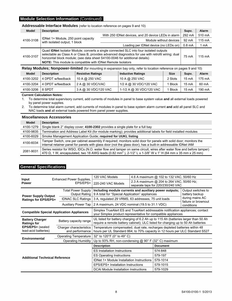
Slot 1 Slot 8Slot 7Slot 6Slot 5Slot 4Slot 3Slot 2
Expansion Bay Chassis
Block A
Block B
Block C
Block D
Block E
Block F
Block G
Block H
Size Definitions: 1 Block = 4” W x 5.65” H (102 mm x 144 mm); (often called
x 5 modules) 1 Slot = 2” W x 11.3” H (51 mm x 287 mm), typically a
motherboard with daughter card
PDI
Ma
ste
r C
on
tro
ller
Bo
ard
PDI
4x5 Module
Expansion PowerSupply
(XPS)
4x5 Module
I/O Wiring
I/O Wiring
I/O Wiring
41
00
Op
tion
41
00
Op
tion
41
00
Op
tion
Slot 1 Slot 2 Slot 3 Slot 4 Slot 5 Slot 6 Slot 7 Slot 8
(Block E)
(Block F)
(Blocks G & H)
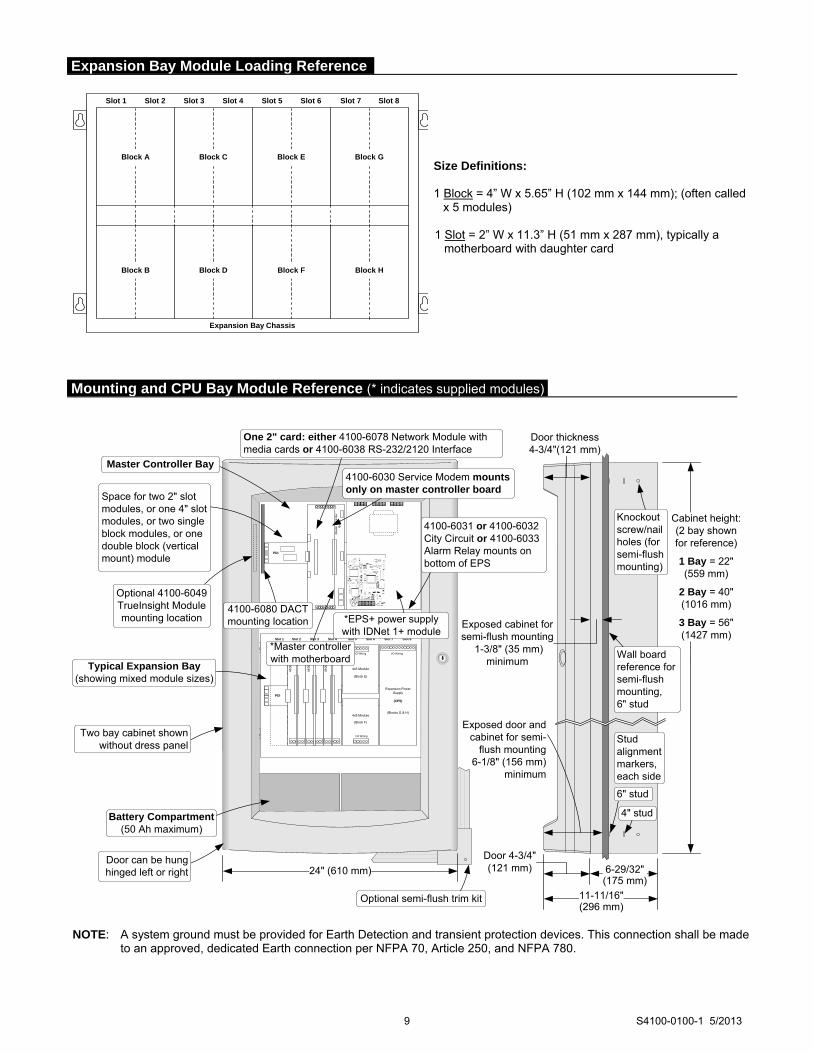
*EPS+ power supply with IDNet 1+ module
Optional semi-flush trim kit
4100-6031 or 4100-6032 City Circuit or 4100-6033Alarm Relay mounts on bottom of EPS
4100-6030 Service Modem mounts only on master controller board
One 2" card: either 4100-6078 Network Module with media cards or 4100-6038 RS-232/2120 Interface
Cabinet height:(2 bay shown for reference)
1 Bay = 22"(559 mm)
2 Bay = 40"(1016 mm)
3 Bay = 56"(1427 mm)
Stud alignment markers, each side
Knockout screw/nail holes (for semi-flush mounting)
4" stud
6" stud
Master Controller Bay
Typical Expansion Bay(showing mixed module sizes)
Battery Compartment(50 Ah maximum)
Door can be hunghinged left or right
Wall board reference for semi-flush mounting, 6" stud
Two bay cabinet shown without dress panel
11-11/16"(296 mm)
6-29/32"(175 mm)
Door thickness4-3/4"(121 mm)
Exposed cabinet forsemi-flush mounting
1-3/8" (35 mm)minimum
Exposed door and cabinet for semi-
flush mounting 6-1/8" (156 mm)
minimum
24" (610 mm)
Door 4-3/4"(121 mm)
4100-6080 DACT mounting location
*Master controller with motherboard
Space for two 2" slot modules, or one 4" slot modules, or two single block modules, or one double block (vertical mount) module
Optional 4100-6049 TrueInsight Module mounting location
NOTE: A system ground must be provided for Earth Detection and transient protection devices. This connection shall be made
to an approved, dedicated Earth connection per NFPA 70, Article 250, and NFPA 780.
9 S4100-0100-1 5/2013
Expansion Bay Module Loading Reference
Mounting and CPU Bay Module Reference (* indicates supplied modules)

Tyco Fire Protection Products • Westminster, MA • 01441-0001 • USA S4100-0100-1 5/2013
www.simplexgrinnell.com © 2013 Tyco Fire Protection Products. All rights reserved. All specifications and other information shown were current as of document revision date and are subject to change without notice.
TYCO, SIMPLEX, and the product names listed in this material are marks and/or registered marks. Unauthorized use is strictly prohibited. VESDA is a trademark of Xtralis Pty Ltd. NFPA 72 and National Fire Alarm Code are trademarks of the National Fire Protection Association (NFPA). ASHRAE and BACnet are trademarks of ASHRAE, American Society of Heating, Refrigeration, and Air Conditioning Engineers.

Features
Remote LCD annunciator for use with Simplex® model: 4100ES and 4100U fire alarm control panels Legacy products 4100, 4120, and 4020 fire alarm control
panels, and 4100/4120 Universal Transponders Information display features: Maintained display of first alarm is available with
4100ES and with 4100U at software revision 11.11 or higher
Wide viewing angle, super-twist LCD technology with green LED backlighting
Two lines of 40 characters each LED status indicators During battery backup, backlighting is disabled until
there is switch activity Controls include: Switches for system acknowledge, alarm silence, and
system reset Four programmable control switches Lamp/LCD test Wiring information: RUI (Remote Unit Interface) communications require a
single twisted wire pair (see p. 3 for more information)
Separate wiring is required for 24 VDC control panel power
Flush mount on standard electrical boxes
Options: 2975-9206, Surface mount box
4603-9111, Brushed stainless steel trim
UL Listed to Standard 864 Description
Remote Control and Annunciation is provided using an 80 character, back-lit, alphanumeric display. Information is presented in clear, descriptive English language and includes: Point Status (alarm, trouble, etc.); Alarm Type (smoke detector, manual station, etc.); Number of System Alarms, Supervisory Conditions, and Trouble Conditions; and a Custom Location Label.
Wiring. A single twisted wire pair provides serial RUI communications that also supports other Simplex serial annunciators on the same wire pair.
Multiple Indications. Alarm, Supervisory, and Trouble conditions are also indicated by dedicated LEDs and a tone-alert audible sounder. Each condition has a dedicated acknowledge push-button switch that silences the tone-alert but leaves the LED on until all conditions in that category are restored to normal. Switch operation is either globally or individually acknowledgeable, determined by the control panel operation.
4603-9101 LCD Annunciator Description (Continued)
Repeated operation of the appropriate acknowledge switch will scroll the LCD display showing activity in the sequence of occurrence. The tone-alert also pulses to indicate the operation of any of the push-button switches.
Consult local code requirements for guidance in determining applications and location of the 4603-9101 LCD annunciator.
Operation
System Controls. Notification appliances can be deactivated by pressing the “ALARM SILENCE” switch. (Exact operation is determined by the host control panel such as visible appliances remaining on until system is reset.) Pressing the “SYSTEM RESET” switch restores the system to normal operation. When system activity is normal, the LCD displays the time, date, and “SYSTEM IS NORMAL.”
Control Switches. Four programmable “CONTROL” switches and associated LEDs are included. Typical applications include manual evacuation, door holder release bypass, and elevator capture bypass.
Keyswitch Enable. All switches on the annunciator are controlled by the “ENABLE” keyswitch with a key that is removable only in the disabled position. A brief lamp/LCD test is performed whenever the keyswitch is changed from enabled to disabled.
Battery Backup Operation. During battery backup, the LED backlighting is disabled to conserve battery power. When an annunciator switch is activated, the backlighting is automatically enabled. After approximately 30 seconds of inactivity, the backlighting will again be disabled.
* This product has been approved by the California State Fire Marshal (CSFM) pursuant to
Section 13144.1 of the California Health and Safety Code. See CSFM Listing 7120-0026:0179 for allowable values and/or conditions concerning material presented in this document. It is subject to re-examination, revision, and possible cancellation. Accepted for use – City of New York Department of Buildings – MEA35-93E. Additional listings may be applicable; contact your local Simplex product supplier for the latest status. Listings and approvals under Simplex Time Recorder Co. are the property of Tyco Fire Protection Products.
System Accessories, LCD Annunciators UL, ULC Listed; FM, CSFM, 4603-9101 LCD Annunciator for and MEA (NYC) Approved* 4100ES and 4100U Fire Alarm Control Panels
S4603-0001-12 8/2012

FIREALARM
ALARM SILENCED
PRIORITY 2ALARM
SYSTEM SUPERVISORY
SYSTEM TROUBLE
POWERON
SYSTEMRESET
DISPLAYTIME
ALARMACK
ALARMACK
SUPVACK
TBLACK
ALARMSILENCE
2 X 40 LCD READOUT, green LED backlighted during normal conditions and abnormal operating conditions
SUPV ACK acknowledges System Supervisory conditions and silences the panel and all annunciator tone-alerts
TROUBLE ACK acknowledges System Troubles and silences the panel and all annunciator tone-alerts
CONTROL ENABLE KEYSWITCH controls all switch functions; key is removable only in disabled position
ALARM SILENCE causes audible notification appliances to be silenced; used after evacuation is complete and while alarm source is being investigated
SYSTEM RESET restores control panel to normal when all alarmed inputs are returned to normal
ALARM ACK/FIRE ALARM acknowledges a Fire Alarm condition and silences the panel and all annunciator tone-alerts
FOUR PROGRAMMABLE (Yellow) LEDs, each with pushbutton switch and custom labeling pocket
SIX STATUS INDICATOR LEDs provide system status indications in addition to LCD information; LEDs flash to indicate the condition and then when acknowledged, remain on steady until reset; Fire Alarm and Priority 2 Alarm are red; System Supervisory, System Trouble, and Alarm Silenced are yellow; Power On is green
DISPLAY TIME displays time of last occurrence of event list being displayed; or displays current time when viewing system status information
ALARM ACK/PRIORITY 2 acknowledges a Priority 2 Alarm condition and silences the panel and all annunciator tone-alerts
2 S4603-0001-12 8/2012
Model Description
4603-9101 Remote LCD Annunciator with beige trim
Refer to specifications on page 3 for additional details
4603-9101CF Remote LCD Annunciator with beige trim, with French keypad for Canada
4603-9111 Brushed stainless steel trim option
2975-9206 Matching surface mount box; ivory finish
2081-9044 Overvoltage protector; required where annunciator communications and power wiring exits and enters a building; refer to data sheet S2081-0016 for details
4603-9101 Operator Information
Product Selection

3 S4603-0001-12 8/2012
General Operating Specifications
Voltage 18 to 32 VDC, system supplied
Normal Operating Current 110 mA (with LED backlighting on)
Battery Standby Current 65 mA (during battery backup, LED backlighting is turned off after 30 seconds without switch activity)
Alarm Current 140 mA maximum (LED backlighting is on and tone-alert is sounding)
Operating Temperature Range 32° to 120° F (0° to 49° C)
Operating Humidity Range Up to 93% RH, non-condensing at 100° F (38° C)
Communications
4100ES/4100U Capacity, Per RUI Output
Type RUI (Remote Unit Interface) external annunciator communications line SLC (signaling line circuit)
Capacity
Up to 31 remote annunciators/MINIPLEX transponders per channel including the 4603-9101 LCD Annunciator, the 4602-9101 Status Command Unit (SCU), and 4602-9102 Remote Command Unit (RCU); refer to data sheet S4100-0031 for additional 4100ES information
Wiring Requirements
RUI Data
Standard Wiring Type Unshielded twisted pair (UTP), 18 AWG (0.82 mm2) for most applications, see below
Wiring Characteristics 0.58 µF (580 nF) maximum capacitance between conductors; 35 maximum total line resistance
Wiring Applications Requiring Shielded,
Twisted Pair (STP)
1. Wiring that leaves the building. Also requires Isolated Loop Circuit Protectors on each end, refer to data sheet S2081-0007 for 2081-9027 (200 mA), or S2081-0008 for 2081-9028 (5 A)
2. Wiring run in 500 ft (152 m) or more of conduit. 3. Wiring closely bundled with standard IDNet communications or TrueAlert
addressable communications (not required when run with IDNet+ communications).
Class B “T-Tap” wiring distance
Up to 10,000 ft (3048 m) total wiring; up to 2500 ft (762 m) to farthest device
Class X wiring distance Up to 2500 ft (762 m)
Power Wiring 18 to 12 AWG (0.82 mm2 to 3.31 mm2) wires for 24 VDC system power
Earth Wiring A dedicated earth ground connection to the electrical box is required for proper ESD and EMI protection; wire in accordance with NFPA 70 (National Electrical Code) Article 250
Mounting Information
NOTE: General Conduit Entrance Requirement
Conduit entrance must be located a minimum of 2 ¾” (70 mm) from the front of the box to clear assembly
Trim Dimensions 4 ½” H x 11 13⁄16” W (114 mm x 300 mm)
Standard Trim Finish Steel, painted beige
4603-9111, Optional Trim Brushed stainless steel (ordered separately); supplied with both slotted and tamper resistant screws
Boxes for Flush Mounting (supplied by others)
6-Gang, 3 ½” (89 mm) deep: RACO 965, 6-gang masonry box; RACO 590, gangable switch box, 6 required; or equal
2975-9206, Surface Mount Box Option (ordered separately)
Dimensions 11 31⁄32” W x 4 ⅝” H x 2 ¾” D (304 mm x 117 mm x 70 mm)
Finish Painted steel, ivory finish
4603-9101 LCD Annunciator Specifications For additional information, refer to Installation Instructions 579-979.

TYCO, SIMPLEX, and the product names listed in this material are marks and/or registered marks. Unauthorized use is strictly prohibited. National Electrical Code and NFPA are registered trademarks of the National Fire Protection Association (NFPA).
Flush Mount Masonry Box:Use RACO # 965, 3-1/2" (89 mm) deep
or equal (supplied separately)
Flush Mount Ganged Boxes:Requires 6-gang box, 3-1/2" (89 mm) min.
depth, use (6) RACO # 590 or equal (supplied separately)
FIREALARM
ALARM SILENCED
PRIORITY 2ALARM
SYSTEM SUPERVISORY
SYSTEM TROUBLE
POWERON
SYSTEMRESET
DISPLAYTIME
ALARMACK
ALARMACK
SUPVACK
TBLACK
ALARMSILENCE
Surface Mount Box:Simplex model 2975-9206
2-3/4” deep (70 mm) (ordered separately)
Trim plate
LCD Annunciator Assembly
Terminal block access at rear of
assembly, this side
Note: Review box choice with assembly layout before selecting conduit entrance location to allow easy access to terminals
Wiring Notes:
1. Communications require a single 18 AWG twisted pair.
2. Power requires two, 18 to 12 AWG wires for 24 VDC system power, plus Earth Ground to each electrical box.
3. Refer to Installation Instructions 579-979 for additional wiring specifications.
Fire Alarm Control Panel (4100ES shown)
4603-9101 LCD Annunciators
FIRE
ALARM
ALARM
SILENCED
PRIORITY 2
ALARM
SYSTEM
SUPERVISORY
SYSTEM
TROUBLE
POWER
ON
ALARMACK
SUPVACK
TBLACK
ALARMACK
ALARMSILENCE
SYSTEMRESET
DISPLAYTIME
FIRE
ALARM
ALARM
SILENCED
PRIORITY 2
ALARM
SYSTEM
SUPERVISORY
SYSTEM
TROUBLE
POWER
ON
ALARMACK
SUPVACK
TBLACK
ALARMACK
ALARMSILENCE
SYSTEMRESET
DISPLAYTIME
Tyco Fire Protection Products • Westminster, MA • 01441-0001 • USA S4603-0001-12 8/2012
www.simplexgrinnell.com © 2012 Tyco Fire Protection Products. All rights reserved. All specifications and other information shown were current as of document revision date and are subject to change without notice.
Wiring Reference
Mounting Information

Features
Individual Addressable Relay Module (Relay IAM): IDNet addressable control for use with Simplex® fire
alarm control panel models 4100ES/4100U, 4010ES, 4008, and 4010
A single addressable point provides control and status tracking of a Form “C” contact
Low power latching relay design allows IDNet communications to supply both data and module power
Compact, sealed construction: Enclosed design minimizes dust infiltration
Mounts in standard 4” (102 mm) square electrical box
Screw terminals for wiring connections
Visible LED flashes to indicate communications
Optional covers are available to allow LED to be viewed after installation
UL listed to Standard 864
Description
IDNet Relay IAMs allow fire alarm control panels to control a remotely located Form “C” contact using IDNet addressable communications for both data and module power. Typical applications would be for switching local power for control functions such as elevator capture, or control of HVAC components, pressurization fans, dampers, etc. Relay status is also communicated requiring only one device address.
Product Selection
Model Description
4090-9002 Relay IAM
Optional Trim Plates
Model Description
4090-9801 For semi-flush mounted box
Trim plate, galvanized steel, with LED viewing window; includes mounting screws 4090-9802
For surface mounted box
* This product has been approved by the California State Fire Marshal (CSFM) pursuant to
Section 13144.1 of the California Health and Safety Code. See CSFM Listing 7300-0026:223 for allowable values and/or conditions concerning material presented in this document. It is subject to re-examination, revision, and possible cancellation. Accepted for use – City of New York Department of Buildings – MEA35-93E. Additional listings may be applicable; contact your local Simplex product supplier for the latest status. Listings and approvals under Simplex Time Recorder Co. are the property of Tyco Safety Products Westminster.
4090-9002 IDNet Relay IAM Package (shown approximately 1/2 size)
Specifications
Communications IDNet communications, 1 address per device
Relay IAM Power Supplied by IDNet communications
Contact Ratings* (not rated for incandescent switching)
Type Form C, SPDT
Power-Limited 2 A @ 24 VDC, resistive from listed
fire alarm supply 1 A @ 24 VDC, inductive
Nonpower-Limited 0.5 A @ 120 VAC, resistive
* Provide circuit fusing and transient suppression as required per application. DC inductive loads can typically be diode suppressed; 120 VAC loads may require RC networks or varistors, depending on device type. Refer to Installation Instructions 574-184 for additional information.
Wire Connections Screw terminals for in/out wiring, 18 to 14 AWG wire (0.82 to 2.08 mm2)
IDNet Communications Wiring Reference
Up to 2500 ft (762 m) from control panel
Up to 10,000 ft (3048 m) total wiring distance (including T-Taps)
Compatible with Simplex 2081-9044 Overvoltage Protectors
Dimensions 4 ⅛” H x 4 ⅛” W x 1 ⅜” D (105 mm x 105 mm x 35 mm)
Housing Material Black thermoplastic
Mounting Plate Sheet metal, galvanized
Temperature Range
32° to 120° F (0° to 49° C), intended for indoor operation
Humidity Range Up to 93% RH at 100° F (38° C)
Multi-Application Peripherals UL, ULC Listed; FM, CSFM, IDNet Communicating Devices and MEA (NYC) Approved* Model 4090-9002 Relay IAM
S4090-0002-8 12/2012

TYCO, SIMPLEX, and the product names listed in this material are marks and/or registered marks. Unauthorized use is strictly prohibited.
Tyco Fire Protection Products • Westminster, MA • 01441-0001 • USA S4090-0002-8 11/2012
www.simplexgrinnell.com © 2012 Tyco Fire Protection Products. All rights reserved. All specifications and other information shown were current as of document revision date and are subject to change without notice.
4" (102 mm) square box, 2-1/8" (54 mm) minimum depth, RACO 232 or equal (supplied by others)
Double gang blank cover plate and mounting screws, for use when LED is not required to be externally viewed (supplied by others)
4090-9002 Relay IAM
Address setting under resealable label
Optional Trim Plates for Visible LED
4090-9802, Trim plate forsurface mounted box
4090-9801, Trim plate forsemi-flush mounted box
Mounting Reference, Double Gang Blank Cover Plate
4-9/16"(116 mm)
4-9/16" (116 mm)
4-5/16"(109 mm)
Light pipe for LED viewing
4-5/16" (109 mm)
Relay IAM Mounting Information

S4090-0001-10
Features
IDNet or MAPNET II addressable communications supply both data and power over a single wire pair to provide**:
Supervised Class B monitoring of normally open, dry
contacts
Total wiring distance from IAM to supervision
resistor(s) of up to 500 ft (152 m)
Monitored connection is compatible with Simplex®
2081-9044 Overvoltage Protectors for outdoor wiring or
electrically noisy applications
For use in indoor locations up to 158° F (70° C) such as
attic spaces or similar applications
For use with following Simplex control panels:
Model Series 4008, 4010, 4010ES, 4100U and 4100ES
fire alarm control panels for IDNet communications
Model Series 4100/4100U/4100ES, 4120, 4020, and
2120 Communicating Device Transponders (CDTs)
equipped with MAPNET II communications
Model 4090-9001:
Enclosed design minimizes dust infiltration
Mounts in standard single gang electrical box
Screw terminals for wiring connections
Visible LED flashes to indicate communications
Optional covers are available to allow LED to be
viewed after installation (requires mounting bracket,
ordered separately)
Model 4090-9051:
Encapsulated design for extended exposure to high
humidity (LED is not present on this model)
Color coded 18 AWG leads for wiring
IDNet communications provides current limited monitoring:
Provides monitoring of tamper switch (supervisory)
and waterflow switch (alarm) on same circuit using
one point
Available with IDNet communications only
Multiple operation modes are available and are selectable at the control panel:
Contact closure status can be tracked
Momentary contact closure conditions can be selected at
the panel to be latched or tracked (not available with the
2120 CDT)
UL listed to Standard 864
* These products have been approved by the California State Fire Marshal (CSFM) pursuant
to Section 13144.1 of the California Health and Safety Code. See CSFM Listing 7300-0026:223 for allowable values and/or conditions concerning material presented in this document. It is subject to re-examination, revision, and possible cancellation. Accepted for use – City of New York Department of Buildings – MEA35-93E. Additional listings may be applicable; contact your local Simplex product supplier for the latest status. Listings and approvals under Simplex Time Recorder Co. are the property of Tyco Safety Products Westminster.
- IDNET IN ++IDNET IN -
4090-9001 Supervised IAM (shown approximately 3/4 size)
LISTED
SIGNALING DEVICEISSUE NO.
4090-9051 Supervised IAM (shown approximately 3/4 size)
Description
Individual addressable modules (IAMs) receive
both power and communications from a two-wire
MAPNET II or IDNet circuit. They provide location
specific addressability to a single initiating device (such
as single station smoke detector alarm contacts or heat
detector contacts) or multiple devices at the same location
by monitoring normally open dry contacts and the wiring
to an end-of-line resistor.
Model 4090-9001 is packaged in a thermoplastic
housing and provides screw terminal connections and a
status indicating LED.
Model 4090-9051 is an encapsulated package with wire
leads. It does not provide a status indicating LED.
Multi-Application Peripherals
UL, ULC, CSFM Listed; FM Approved; IDNet™ and MAPNET II® Communicating Devices, MEA (NYC) Acceptance* Individual Addressable Modules (IAMs)
2 S4090-0001-10
Operation
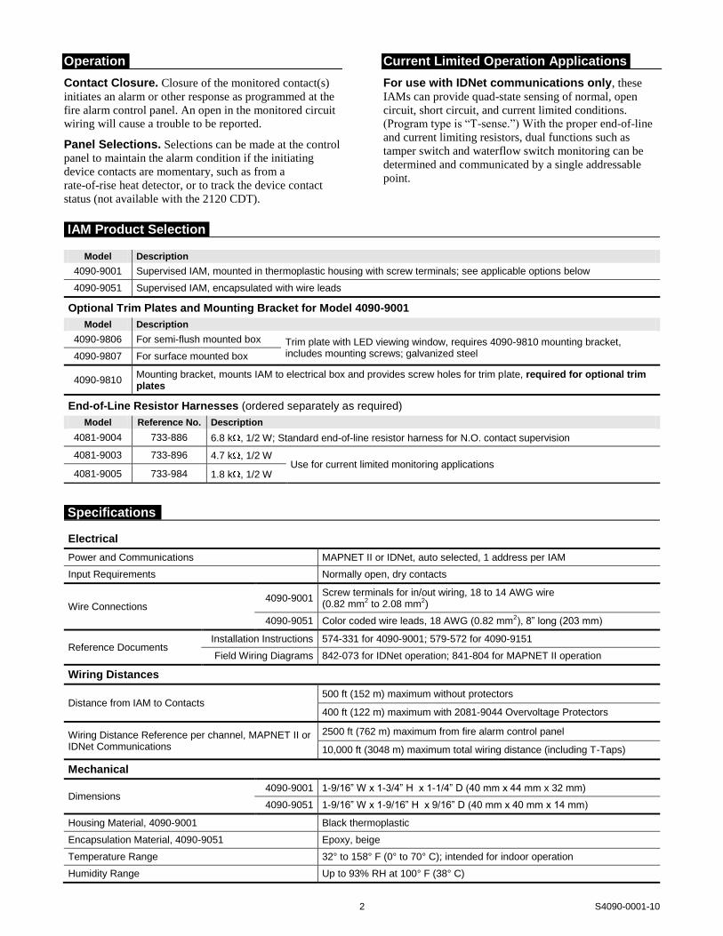
Contact Closure. Closure of the monitored contact(s)
initiates an alarm or other response as programmed at the
fire alarm control panel. An open in the monitored circuit
wiring will cause a trouble to be reported.
Panel Selections. Selections can be made at the control
panel to maintain the alarm condition if the initiating
device contacts are momentary, such as from a
rate-of-rise heat detector, or to track the device contact
status (not available with the 2120 CDT).
Current Limited Operation Applications
For use with IDNet communications only, these
IAMs can provide quad-state sensing of normal, open
circuit, short circuit, and current limited conditions.
(Program type is “T-sense.”) With the proper end-of-line
and current limiting resistors, dual functions such as
tamper switch and waterflow switch monitoring can be
determined and communicated by a single addressable
point.
Model Description
4090-9001 Supervised IAM, mounted in thermoplastic housing with screw terminals; see applicable options below
4090-9051 Supervised IAM, encapsulated with wire leads
Optional Trim Plates and Mounting Bracket for Model 4090-9001
Model Description
4090-9806 For semi-flush mounted box Trim plate with LED viewing window, requires 4090-9810 mounting bracket, includes mounting screws; galvanized steel 4090-9807 For surface mounted box
4090-9810 Mounting bracket, mounts IAM to electrical box and provides screw holes for trim plate, required for optional trim plates
End-of-Line Resistor Harnesses (ordered separately as required)
Model Reference No. Description
4081-9004 733-886 6.8 k , 1/2 W; Standard end-of-line resistor harness for N.O. contact supervision
4081-9003 733-896 4.7 k , 1/2 W Use for current limited monitoring applications
4081-9005 733-984 1.8 k , 1/2 W
Electrical
Power and Communications MAPNET II or IDNet, auto selected, 1 address per IAM
Input Requirements Normally open, dry contacts
Wire Connections 4090-9001
Screw terminals for in/out wiring, 18 to 14 AWG wire (0.82 mm2 to 2.08 mm2)
4090-9051 Color coded wire leads, 18 AWG (0.82 mm2), 8” long (203 mm)
Reference Documents Installation Instructions 574-331 for 4090-9001; 579-572 for 4090-9151
Field Wiring Diagrams 842-073 for IDNet operation; 841-804 for MAPNET II operation
Wiring Distances
Distance from IAM to Contacts 500 ft (152 m) maximum without protectors
400 ft (122 m) maximum with 2081-9044 Overvoltage Protectors
Wiring Distance Reference per channel, MAPNET II or IDNet Communications
2500 ft (762 m) maximum from fire alarm control panel
10,000 ft (3048 m) maximum total wiring distance (including T-Taps)
Mechanical
Dimensions 4090-9001 1-9/16” W x 1-3/4” H x 1-1/4” D (40 mm x 44 mm x 32 mm)
4090-9051 1-9/16” W x 1-9/16” H x 9/16” D (40 mm x 40 mm x 14 mm)
Housing Material, 4090-9001 Black thermoplastic
Encapsulation Material, 4090-9051 Epoxy, beige
Temperature Range 32° to 158° F (0° to 70° C); intended for indoor operation
Humidity Range Up to 93% RH at 100° F (38° C)
IAM Product Selection
Specifications

3 S4090-0001-10
Optional Trim Plates and Mounting Bracket for Visible LED
Single gang electrical
box 2-1/2" (64mm)
minimum depth
(supplied by others)
Single gang blank cover plate and mounting screws, for use when
LED is not required to be externally viewed (supplied by others)
4090-9001 IDNet
supervised IAMField wiring shown
for reference
Address setting under resealable label
- IDNET IN ++IDNET IN -
LED viewing port
4090-9806, Trim plate for
semi-flush mounted box
4090-9807, Trim plate for
surface mounted box
4-1/4"
(108 mm)
2-1/2"
(64 mm)
2-13/16"
(72 mm)
4-1/2"
(114 mm)
Light pipe for
LED viewing
NOTE: These mounting plates require mounting bracket 4090-9810.
4090-9810 Mounting
bracket, ordered
separately
Mounting Reference, Single Gang Blank Cover Plate
Mounting Information

Single gang electrical
box 2-1/2" (64mm)
minimum depth
(supplied by others)
Single gang blank cover plate and
mounting screws (supplied by others)
4090-9051
Encapsulated
Supervised IAM
Address setting is
at rear of housing
LISTED
SIGNALING DEVICEISSUE NO.
SimplexGrinnell LP Westminster • Westminster, MA • 01441-0001 • USA S4090-0001-10
www.simplexgrinnell.com
© 2011 Tyco. All rights reserved. All specifications and other information shown were current as of document revision date and are subject to change without notice.
Tyco is a registered trademark of Tyco International Services GmbH and is used under license. Simplex, the Simplex logo, IDNet, and MAPNET II are trademarks of Tyco
International Ltd. and its affiliates and are used under license.
4090-9051 Mounting Information

Features
UL listed under Standard 864 as Control Unit Accessory (UOXX)
Track mount package availability:
• Single relay module or four relay module, with or without cover, with SPDT or DPDT contacts
• LED indicates relay module status
• Cover provide status LED viewing ports
• Multiple coil voltage inputs, diode polarized for DC
• Modules are track mounted with snap-apart feature design allowing the four relay module to be separated
Single encapsulated SPDT relay package with color coded 18 AWG wire leads, available in two versions:
• 2088-9021 (PAM-1) Provides diode polarized multiple input voltage ability and LED indication
• 4098-9843 (PAM-SD) Provides a diode polarized 24 VDC coil with in/out wiring
Description
These multi-purpose control relays offer SPDT or DPDT, 10 A (or 7 A) contacts in a variety of mechanical packages. Models are available for coil operation by one of four input voltages allowing a single relay to be energized from a voltage source of 18-35 VDC or VAC, 120 VAC, or 230 VAC (not available with 4098-9843). Voltage selection is made by wiring to the appropriate input terminals or wire leads.
Each relay model (except model 4098-9843) contains a red LED which indicates that the relay is energized.
Mounting options are varied for application flexibility. Track mounted relays may be “snapped apart” from a standard four-module assembly and used independently if desired.
Specifications
Track Mount Relays, see page 2 for dimensions
Coil Voltage 18-35 VAC/VDC, 120, or 230 VAC
Coil Current SPDT models = 18 mA DPDT models = 40 mA
Terminal Blocks Up to 14 AWG (2.08 mm2 )
10 A @ 120 VAC
N.O. rated 1/6 HP, N.C. rated 1/8 HP Contact Ratings
7A @ 28 VDC and @ 230 VAC
Temperature Ratings
UL Listed Range 32° F to 120° F (0° C to 49° C)
Operating Range -58° F to 185° F (-50° C to 85° C)
Humidity 85% RH Non-condensing
NC C NO NC C NO
NC C NO NC C NO
ON
T1D2
+
C1
0 18/24 115 230
R2
R1
NC C NO NC C NO
NC C NO NC C NO
ON
T1D2
+
C1
0 18/24 115 230
R2
R1
NC C NO NC C NO
NC C NO NC C NO
ON
T1D2
+
C1
0 18/24 115 230
R2
R1
NC C NO NC C NO
NC C NO NC C NO
ON
T1D2
+
C1
0 18/24 115 230
R2
R1
2088-9020, MR204/C, Four DPDT Relay Package with Enclosure (shown with cover removed)
AP&C-PAM SD
WHT BLU YELRED ORG
Encapsulated Relay Package (typical of 2088-9021, PAM-1 and 4098-9843, PAM-SD)
Specifications Continued
Encapsulated Relays, see page 2 for dimensions
Connections 18 AWG (0.82 mm2 ) color-coded wire leads
Relay 2088-9021
Contact Ratings 10 A @ 120 VAC, resistive
Voltage 18-35 VAC/VDC, 120, or 240 VAC Coil Ratings Current
15 mA @ 24 VAC/VDC, & @ 120 or 230 VAC
Relay 4098-9843
Coil Ratings 18-32 VDC input, polarized, 15 mA @ 24 VDC
7 A at 0.35 p.f @ 28 VDC & 120 VAC Contact Ratings
250 µA @ 5 VDC
Temperature Ratings
UL Listed Range 32° F to 120° F (0° C to 49° C)
Operating Range -58° F to 185° F (-50° C to 85° C)
Humidity 85% RH Non-condensing * Product listings are by Air Products & Controls Inc. (www.ap-c.com) per model numbers
shown on page 2. These products are also available through Space Age Electronics Inc. (www.1sae.com) with an SSU- prefix.
System Accessories UL, CSFM Listed; Fire Alarm Control Relays, Track Mount and MEA (NYC) Acceptance* Encapsulated; Model 4098-9843 and 2088 Series
S2088-0010-8 3/2006
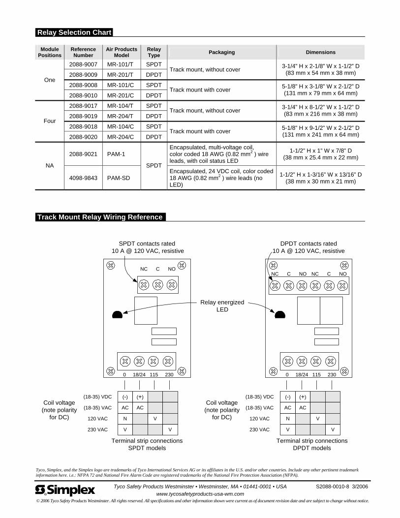
Tyco, Simplex, and the Simplex logo are trademarks of Tyco International Services AG or its affiliates in the U.S. and/or other countries. Include any other pertinent trademark information here. i.e.: NFPA 72 and National Fire Alarm Code are registered trademarks of the National Fire Protection Association (NFPA).
Module Positions
Reference Number
Air Products Model
Relay Type
Packaging Dimensions
2088-9007 MR-101/T SPDT
2088-9009 MR-201/T DPDT Track mount, without cover
3-1/4” H x 2-1/8” W x 1-1/2” D(83 mm x 54 mm x 38 mm)
2088-9008 MR-101/C SPDT One
2088-9010 MR-201/C DPDT Track mount with cover
5-1/8” H x 3-1/8” W x 2-1/2” D(131 mm x 79 mm x 64 mm)
2088-9017 MR-104/T SPDT
2088-9019 MR-204/T DPDT Track mount, without cover
3-1/4” H x 8-1/2” W x 1-1/2” D(83 mm x 216 mm x 38 mm)
2088-9018 MR-104/C SPDT Four
2088-9020 MR-204/C DPDT Track mount with cover
5-1/8” H x 9-1/2” W x 2-1/2” D(131 mm x 241 mm x 64 mm)
2088-9021 PAM-1 Encapsulated, multi-voltage coil, color coded 18 AWG (0.82 mm2 ) wire leads, with coil status LED
1-1/2” H x 1” W x 7/8” D (38 mm x 25.4 mm x 22 mm)
NA
4098-9843 PAM-SD
SPDT Encapsulated, 24 VDC coil, color coded 18 AWG (0.82 mm2 ) wire leads (no LED)
1-1/2” H x 1-3/16” W x 13/16” D(38 mm x 30 mm x 21 mm)
NC C NO
Coil voltage(note polarity
for DC)
(-) (+)
AC AC
N V
V V
(18-35) VDC
(18-35) VAC
120 VAC
230 VAC
0 18/24 115 230
SPDT contacts rated 10 A @ 120 VAC, resistive
NC C NO
(-) (+)
AC AC
N V
V V
(18-35) VDC
(18-35) VAC
120 VAC
230 VAC
0 18/24 115 230
DPDT contacts rated10 A @ 120 VAC, resistive
NC C NO
Terminal strip connectionsSPDT models
Relay energizedLED
Coil voltage(note polarity
for DC)
Terminal strip connectionsDPDT models
Tyco Safety Products Westminster • Westminster, MA • 01441-0001 • USA S2088-0010-8 3/2006
www.tycosafetyproducts-usa-wm.com © 2006 Tyco Safety Products Westminster. All rights reserved. All specifications and other information shown were current as of document revision date and are subject to change without notice.
Relay Selection Chart
Track Mount Relay Wiring Reference
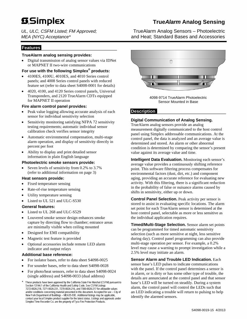
Features
TrueAlarm analog sensing provides: Digital transmission of analog sensor values via IDNet
or MAPNET II two-wire communications
For use with the following Simplex® products: 4100ES, 4100U, 4010ES, and 4010 Series control
panels; and 4008 Series control panels with reduced feature set (refer to data sheet S4008-0001 for details)
4020, 4100, and 4120 Series control panels, Universal Transponders, and 2120 TrueAlarm CDTs equipped for MAPNET II operation
Fire alarm control panel provides: Peak value logging allowing accurate analysis of each
sensor for individual sensitivity selection
Sensitivity monitoring satisfying NFPA 72 sensitivity testing requirements; automatic individual sensor calibration check verifies sensor integrity
Automatic environmental compensation, multi-stage alarm operation, and display of sensitivity directly in percent per foot
Ability to display and print detailed sensor information in plain English language
Photoelectric smoke sensors provide: Seven levels of sensitivity from 0.2% to 3.7%
(refer to additional information on page 3)
Heat sensors provide: Fixed temperature sensing
Rate-of-rise temperature sensing
Utility temperature sensing
Listed to UL 521 and ULC-S530
General features: Listed to UL 268 and ULC-S529
Louvered smoke sensor design enhances smoke capture by directing flow to chamber; entrance areas are minimally visible when ceiling mounted
Designed for EMI compatibility
Magnetic test feature is provided
Optional accessories include remote LED alarm indicator and output relays
Additional base reference: For isolator bases, refer to data sheet S4098-0025
For sounder bases, refer to data sheet S4098-0028
For photo/heat sensors, refer to data sheet S4098-0024 (single address) and S4098-0033 (dual address)
* These products have been approved by the California State Fire Marshal (CSFM) pursuant to Section 13144.1 of the California Health and Safety Code. See CSFM Listings 7272-0026:218, 7271-0026:231, 7270-0026:216, and 7300-0026:217 for allowable values and/or conditions concerning material presented in this document. Accepted for use – City of New York Department of Buildings – MEA35-93E. Additional listings may be applicable, contact your local Simplex product supplier for the latest status. Listings and approvals under Simplex Time Recorder Co. are the property of Tyco Fire Protection Products.
4098-9714 TrueAlarm Photoelectric Sensor Mounted in Base
Description
Digital Communication of Analog Sensing. TrueAlarm analog sensors provide an analog measurement digitally communicated to the host control panel using Simplex addressable communications. At the control panel, the data is analyzed and an average value is determined and stored. An alarm or other abnormal condition is determined by comparing the sensor’s present value against its average value and time.
Intelligent Data Evaluation. Monitoring each sensor’s average value provides a continuously shifting reference point. This software filtering process compensates for environmental factors (dust, dirt, etc.) and component aging, providing an accurate reference for evaluating new activity. With this filtering, there is a significant reduction in the probability of false or nuisance alarms caused by shifts in sensitivity, either up or down.
Control Panel Selection. Peak activity per sensor is stored to assist in evaluating specific locations. The alarm set point for each TrueAlarm sensor is determined at the host control panel, selectable as more or less sensitive as the individual application requires.
Timed/Multi-Stage Selection. Sensor alarm set points can be programmed for timed automatic sensitivity selection (such as more sensitive at night, less sensitive during day). Control panel programming can also provide multi-stage operation per sensor. For example, a 0.2% level may cause a warning to prompt investigation while a 2.5% level may initiate an alarm.
Sensor Alarm and Trouble LED Indication. Each sensor base’s LED pulses to indicate communications with the panel. If the control panel determines a sensor is in alarm, or is dirty or has some other type of trouble, the details are annunciated at the control panel and that sensor base’s LED will be turned on steadily. During a system alarm, the control panel will control the LEDs such that an LED indicating a trouble will return to pulsing to help identify the alarmed sensors.
TrueAlarm Analog Sensing UL, ULC, CSFM Listed; FM Approved; TrueAlarm Analog Sensors – Photoelectric MEA (NYC) Acceptance* and Heat; Standard Bases and Accessories
S4098-0019-15 4/2013
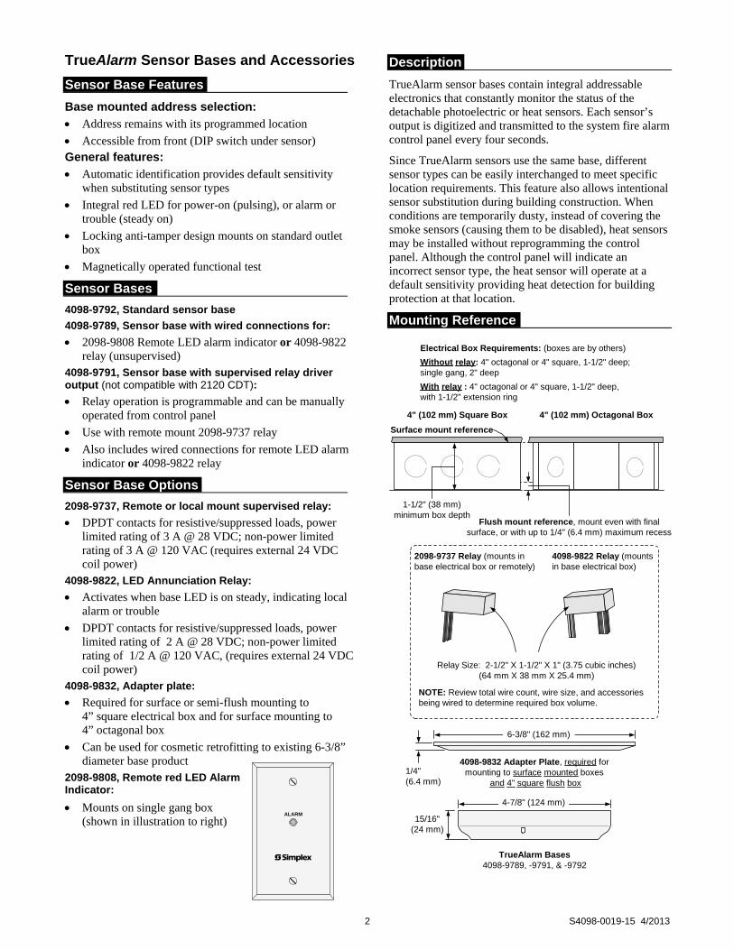
Sensor Base Features
Base mounted address selection:
Address remains with its programmed location
Accessible from front (DIP switch under sensor) General features:
Automatic identification provides default sensitivity when substituting sensor types
Integral red LED for power-on (pulsing), or alarm or trouble (steady on)
Locking anti-tamper design mounts on standard outlet box
Magnetically operated functional test
Sensor Bases
4098-9792, Standard sensor base
4098-9789, Sensor base with wired connections for:
2098-9808 Remote LED alarm indicator or 4098-9822 relay (unsupervised)
4098-9791, Sensor base with supervised relay driver output (not compatible with 2120 CDT):
Relay operation is programmable and can be manually operated from control panel
Use with remote mount 2098-9737 relay
Also includes wired connections for remote LED alarm indicator or 4098-9822 relay
Sensor Base Options
2098-9737, Remote or local mount supervised relay:
DPDT contacts for resistive/suppressed loads, power limited rating of 3 A @ 28 VDC; non-power limited rating of 3 A @ 120 VAC (requires external 24 VDC coil power)
4098-9822, LED Annunciation Relay:
Activates when base LED is on steady, indicating local alarm or trouble
DPDT contacts for resistive/suppressed loads, power limited rating of 2 A @ 28 VDC; non-power limited rating of 1/2 A @ 120 VAC, (requires external 24 VDC coil power)
4098-9832, Adapter plate:
Required for surface or semi-flush mounting to 4” square electrical box and for surface mounting to 4” octagonal box
Can be used for cosmetic retrofitting to existing 6-3/8” diameter base product
2098-9808, Remote red LED Alarm Indicator:
Mounts on single gang box (shown in illustration to right)
Description
TrueAlarm sensor bases contain integral addressable electronics that constantly monitor the status of the detachable photoelectric or heat sensors. Each sensor’s output is digitized and transmitted to the system fire alarm control panel every four seconds.
Since TrueAlarm sensors use the same base, different sensor types can be easily interchanged to meet specific location requirements. This feature also allows intentional sensor substitution during building construction. When conditions are temporarily dusty, instead of covering the smoke sensors (causing them to be disabled), heat sensors may be installed without reprogramming the control panel. Although the control panel will indicate an incorrect sensor type, the heat sensor will operate at a default sensitivity providing heat detection for building protection at that location.
Mounting Reference
Electrical Box Requirements: (boxes are by others)
Without relay: 4" octagonal or 4" square, 1-1/2" deep;single gang, 2" deep
With relay : 4" octagonal or 4" square, 1-1/2" deep,with 1-1/2" extension ring
TrueAlarm Bases4098-9789, -9791, & -9792
4-7/8" (124 mm)
15/16"(24 mm)
6-3/8" (162 mm)
1/4"(6.4 mm)
4098-9832 Adapter Plate, required formounting to surface mounted boxes
and 4" square flush box
Surface mount reference
4" (102 mm) Square Box 4" (102 mm) Octagonal Box
Flush mount reference, mount even with finalsurface, or with up to 1/4" (6.4 mm) maximum recess
2098-9737 Relay (mounts inbase electrical box or remotely)
4098-9822 Relay (mountsin base electrical box)
Relay Size: 2-1/2" X 1-1/2" X 1" (3.75 cubic inches)(64 mm X 38 mm X 25.4 mm)
NOTE: Review total wire count, wire size, and accessoriesbeing wired to determine required box volume.
1-1/2" (38 mm)minimum box depth
2 S4098-0019-15 4/2013
TrueAlarm Sensor Bases and Accessories
ALARM
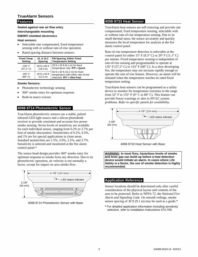
TrueAlarm Sensors
Features
Sealed against rear air flow entry
Interchangeable mounting
EMI/RFI shielded electronics
Heat sensors:
Selectable rate compensated, fixed temperature sensing with or without rate-of-rise operation
Rated spacing distance between sensors:
Fixed Temp. Setting
UL & ULC Spacing
FM Spacing, Either Fixed Temperature Setting
135° F (57.2° C)
60 ft x 60 ft (18.3 m)
20 ft x 20 ft (6.1 m) for fixed temperature only; RTI = Quick
50 ft x 50 ft (15.2 m) for fixed temperature with either rate-of-rise selection; RTI = Ultra Fast
155° F (68° C)
40 ft x 40 ft (12.2 m)
Smoke Sensors:
Photoelectric technology sensing
360° smoke entry for optimum response
Built-in insect screens
4098-9714 Photoelectric Sensor
TrueAlarm photoelectric sensors use a stable, pulsed infrared LED light source and a silicon photodiode receiver to provide consistent and accurate low power smoke sensing. Seven levels of sensitivity are available for each individual sensor, ranging from 0.2% to 3.7% per foot of smoke obscuration. Sensitivities of 0.2%, 0.5%, and 1% are for special applications in clean areas. Standard sensitivities are 1.5%, 2.0%, 2.5%, and 3.7%. Sensitivity is selected and monitored at the fire alarm control panel.*
The sensor head design provides 360° smoke entry for optimum response to smoke from any direction. Due to its photoelectric operation, air velocity is not normally a factor, except for impact on area smoke flow.
2-1/8"(54 mm)
LED status indicator
4-7/8" (124 mm)
4098-9714 Photoelectric Sensor with Base
4098-9733 Heat Sensor
TrueAlarm heat sensors are self-restoring and provide rate compensated, fixed temperature sensing, selectable with or without rate-of-rise temperature sensing. Due to its small thermal mass, the sensor accurately and quickly measures the local temperature for analysis at the fire alarm control panel.
Rate-of-rise temperature detection is selectable at the control panel for either 15° F (8.3° C) or 20° F (11.1° C) per minute. Fixed temperature sensing is independent of rate-of-rise sensing and programmable to operate at 135° F (57.2° C) or 155° F (68° C). In a slow developing fire, the temperature may not increase rapidly enough to operate the rate-of-rise feature. However, an alarm will be initiated when the temperature reaches its rated fixed temperature setting.
TrueAlarm heat sensors can be programmed as a utility device to monitor for temperature extremes in the range from 32° F to 155° F (0° C to 68° C). This feature can provide freeze warnings or alert to HVAC system problems. Refer to specific panels for availability.
2-3/8"(60 mm)
LED status indicator
4-7/8" (124 mm)
4098-9733 Heat Sensor with Base
WARNING: In most fires, hazardous levels of smoke and toxic gas can build up before a heat detection device would initiate an alarm. In cases where Life Safety is a factor, the use of smoke detection is highly recommended.
Application Reference
Sensor locations should be determined only after careful consideration of the physical layout and contents of the area to be protected. Refer to NFPA 72, the National Fire Alarm and Signaling Code. On smooth ceilings, smoke sensor spacing of 30 ft (9.1 m) may be used as a guide.*
* For detailed application information including sensitivity selection, refer to Installation Instructions 574-709.
3 S4098-0019-15 4/2013
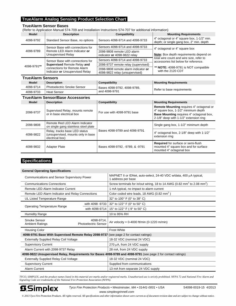
TrueAlarm Sensor Bases (Refer to Application Manual 574-709 and Installation Instructions 574-707 for additional information)
Model Description Compatibility Mounting Requirements
4098-9792 Standard Sensor Base, no options Sensors 4098-9714 and 4098-9733 4” octagonal or 4” square box, 1-1/2” min. depth; or single gang box, 2” min. depth
4098-9789 Sensor Base with connections for Remote LED Alarm Indicator or Unsupervised Relay
Sensors 4098-9714 and 4098-9733 4” octagonal or 4” square box
Note: Box depth requirements depend on total wire count and wire size, refer to accessories list below for reference.
** NOTE: 4098-9791 is NOT compatible with the 2120 CDT
2098-9808 remote LED alarm indicator or 4098-9822 relay
4098-9791**
Sensor Base with connections for Supervised Remote Relay and connections for Remote Alarm Indicator or Unsupervised Relay
Sensors 4098-9714 and 4098-9733
2098-9737 remote relay (supervised)
2098-9808 remote alarm indicator or 4098-9822 relay (unsupervised)
TrueAlarm Sensors Model Description Compatibility Mounting Requirements
4098-9714 Photoelectric Smoke Sensor Bases 4098-9792, 4098-9789, and 4098-9791
Refer to base requirements 4098-9733 Heat Sensor
TrueAlarm Sensor/Base Accessories Model Description Compatibility Mounting Requirements
2098-9737 Supervised Relay, mounts remote or in base electrical box
For use with 4098-9791 base
Remote Mounting requires 4” octagonal or 4” square box, 1-1/2” minimum depth Base Mounting requires 4” octagonal box, 2-1/8” deep with 1-1/2” extension ring
2098-9808 Remote Red LED Alarm Indicator on single gang stainless steel plate
Bases 4098-9789 and 4098-9791
Single gang box, 1-1/2” minimum depth
4098-9822 Relay, tracks base LED status (unsupervised, mounts only in base electrical box)
4” octagonal box, 2-1/8” deep with 1-1/2” extension ring
4098-9832 Adapter Plate Bases 4098-9792, -9789, & -9791 Required for surface or semi-flush mounted 4” square box and for surface mounted 4” octagonal box
TYCO, SIMPLEX, and the product names listed in this material are marks and/or registered marks. Unauthorized use is strictly prohibited. NFPA 72 and National Fire Alarm and Signaling Code are trademarks of the National Fire Protection Association (NFPA).
Tyco Fire Protection Products • Westminster, MA • 01441-0001 • USA S4098-0019-15 4/2013
www.simplexgrinnell.com © 2013 Tyco Fire Protection Products. All rights reserved. All specifications and other information shown were current as of document revision date and are subject to change without notice.
General Operating Specifications
Communications and Sensor Supervisory Power MAPNET II or IDNet, auto-select, 24-40 VDC w/data, 400 A typical, 1 address per base
Communications Connections Screw terminals for in/out wiring, 18 to 14 AWG (0.82 mm2 to 2.08 mm2)
Remote LED Alarm Indicator Current 1 mA typical, no impact to alarm current
Remote LED Alarm Indicator and Relay Connections Color coded wire leads, 18 AWG (0.82 mm2 )
UL Listed Temperature Range 32° to 100° F (0° to 38° C)
Operating Temperature Range with 4098 -9733 32° to 122° F (0° to 50° C)
with 4098-9714 15° to 122° F (-9° to 50° C)
Humidity Range 10 to 95% RH
Smoke Sensor Ambient Ratings
4098-9714, Photoelectric Sensor
Air velocity = 0-4000 ft/min (0-1220 m/min)
Housing Color Frost White
4098-9791 Base With Supervised Remote Relay 2098-9737 (see page 2 for contact ratings)
Externally Supplied Relay Coil Voltage 18-32 VDC (nominal 24 VDC)
Supervisory Current 270 A, from 24 VDC supply
Alarm Current with 2098-9737 Relay 28 mA, from 24 VDC supply
4098-9822 Unsupervised Relay, Requirements for Bases 4098-9789 and 4098-9791 (see page 2 for contact ratings) Externally Supplied Relay Coil Voltage 18-32 VDC (nominal 24 VDC)
Supervisory Current Supplied from communications
Alarm Current 13 mA from separate 24 VDC supply
TrueAlarm Analog Sensing Product Selection Chart
Specifications
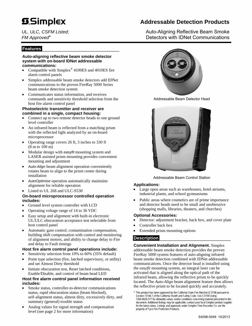
Features
Auto-aligning reflective beam smoke detector system with on-board IDNet addressable communications: Compatible with Simplex® 4100ES and 4010ES fire
alarm control panels Simplex addressable beam smoke detectors add IDNet
communications to the proven FireRay 5000 Series beam smoke detection system
Communicates status information, and receives commands and sensitivity threshold selection from the host fire alarm control panel
Photoelectric transmitter and receiver are combined in a single, compact housing: Connect up to two remote detector heads to one ground
level controller An infrared beam is reflected from a matching prism
with the reflected light analyzed by an on-board microprocessor
Operating range covers 26 ft, 3 inches to 330 ft (8 m to 100 m)
Modular design with easyfit mounting system and LASER assisted prism mounting provides convenient mounting and adjustment
Auto-Align beam alignment operation conveniently rotates beam to align to the prism center during installation
AutoOptimise operation automatically maintains alignment for reliable operation
Listed to UL 268 and ULC-S530 On-board microprocessor controlled operation includes: Ground level system controller with LCD Operating voltage range of 14 to 36 VDC Easy setup and alignment with built-in electronic
UL/ULC obscuration acceptance test selectable from host control panel
Automatic gain control; contamination compensation, building shift compensation with control and monitoring of alignment motors, and ability to change delay to Fire and delay to Fault timings
Host fire alarm control panel operations include: Sensitivity selection from 10% to 60% (35% default) Point type selection (fire, latched supervisory, or utility)
and set Almost Dirty threshold Initiate obscuration test, Reset latched conditions,
Enable/Disable, and control of beam head LED Host fire alarm control panel information received includes: Smoke status, controller-to-detector communications
status, rapid obscuration status (beam blocked), self-alignment status, almost dirty, excessively dirty, and summary (general) trouble status
Analog values for signal strength and compensation level (see page 2 for more information)
Addressable Beam Detector Head
Addressable Beam Control Station
Applications: Large open areas such as warehouses, hotel atriums,
industrial plants, and school gymnasiums
Public areas where cosmetics are of prime importance and detector heads need to be small and unobtrusive (shopping malls, libraries, theaters, and churches)
Optional Accessories: Detector: adjustment bracket, back box, and cover plate Controller back box Extended prism mounting options
Description
Convenient Installation and Alignment. Simplex addressable beam smoke detection provides the proven FireRay 5000 system features of auto-aligning infrared beam smoke detection combined with IDNet addressable communications. Once the detector head is installed using the easyfit mounting system, an integral laser can be activated that is aligned along the optical path of the infrared beam, allowing the reflective prism to be quickly located. The Auto-Align beam alignment feature then allows the reflective prism to be located quickly and accurately.
* This product has been approved by the California State Fire Marshal (CSFM) pursuant to Section 13144.1 of the California Health and Safety Code. See CSFM Listing 7260-0026:377 for allowable values and/or conditions concerning material presented in this document. Additional listings may be applicable; contact your local Simplex product supplier for the latest status. Listings and approvals under Simplex Time Recorder Co. are the property of Tyco Fire Protection Products.
Addressable Detection Products UL, ULC, CSFM Listed; Auto-Aligning Reflective Beam Smoke FM Approved* Detectors with IDNet Communications
S4098-0049 10/2013

Description (Continued)
AutoOptimise Beam Alignment. The AutoOptimise beam alignment system automatically steers and maintains the beam in the optimum position for reliable performance. The signal is generated in the transmitter element and reflected by the prism back to the receiver element, then analyzed for the presence of smoke. The beam control station determines an alarm condition when the predetermined level is reached. Alarm threshold levels are set from the host fire alarm control panel. Time to Fire and time to Fault are set at the beam control station.
Mounting Reference. The maximum distance of the Detector and Reflector from the ceiling must be 10% of the distance between floor and ceiling. Lateral detection may be up to 30 ft (9.144 m) on either side of the beam, providing a maximum total coverage area of up to 19,800 square feet (60 ft x 330 ft or 18.29 m x 100 m).
Refer to the Installation Instructions supplied with the product and to NFPA 72, the National Fire and Signaling Code for additional installation guidance.
Communications to the host control panel. The host fire alarm control panel receives status and numerical information from the beam controller to allow remote investigation of the beam head(s). The beam controller receives commands and the Smoke and Almost Dirty threshold levels are set from the host control panel.
Numerical information received includes: Signal Strength in % (to compare to alarm threshold level set by host control panel) and Compensation Level (indication of beam status and dirt accumulation).
Application Note. Reflective beam smoke detectors may not be suitable for areas with highly reflective surfaces. Separate transmitter/receiver models may be required. Refer to NFPA 72 and contact your Simplex product representative for additional applications guidance.
Beam Detector on 5000-005 Alignment Bracket
Beam Detector on 5000-011 Uni-Box 23901 Prism Reflector
One Prism on 5000-006 Mounting Bracket
Four Prisms on 5000-006 Mounting Bracket
5000-008 Single Prism Adapter on a 5000-005 Alignment Bracket
5000-201 Adjustment Bracket 5000-007 Four Prism Adapter
on 5000-005 Alignment Bracket
2 S4098-0049 10/2013
Accessory Reference (not shown to scale)

3 S4098-0049 10/2013
Addressable Beam Detector Selection Model Description Dimensions
4098-9019
IDNet Communications Addressable Reflective Auto Align Beam Smoke Detector System; Includes: one 4098-9020 controller, one 5000-031 detector head, and one 23901 prism reflector; For control of up to two detector heads
Controller 9 ¼” H x 7 ⅞” W x 2 13⁄16” D (235 mm x 200 mm x 71 mm)
Head 5 9⁄32” H x 5 5⁄16 ” W x 5 9⁄32” D (135 mm x 134 mm x 132 mm)
Prism 4 ⅛” x 3 15⁄16” x ⅜” D (105 mm x 100 mm x 9.5 mm)
4098-9020 IDNet Communications Addressable Reflective Auto Align Beam Smoke Detector Controller only, for upgrade or replacement; select detector head(s) and prism reflector(s) separately as required;
9 ¼” H x 7 ⅞” W x 2 13⁄16” D (235 mm x 200 mm x 71 mm)
Beam Detector Heads, Prisms, and Accessories
Ordering Number* Description Dimensions
5000-031 Additional Detector Head and Prism, select up to 1 additional head per 4098-9019 System
5 9⁄32” H x 5 5⁄16 ” W x 5 9⁄32” D (135 mm x 134 mm x 132 mm)
5000-011
5000 Series Detector Uni-Box back box includes: hinged cover plate, conduit knock-outs on all sides, captive screw lock on cover plate, universal back plate mounting holes, and cover plate mounting holes for optional 1000-018 wire cage; box may be surface or flush mounted
7 ⅛” square x 2 1⁄16” D (181 mm x 52 mm)
(including cover plate)
5000-012 Detector Cover Plate for mounting 5000 Series Detector to a double gang electrical box, surface or flush mount
6 7⁄16” square (164 mm) with 3⁄16” lip (5 mm)
5000-005 Alignment Bracket for detector or prism, surface mount; pivots for accurate alignment, order detector and prism parts separately
5 ¼” square footprint x 2 13⁄16” D(134 mm x 71 mm)
5000-201 Alignment Bracket for detector or prism, surface mount; provides 360° rotation plus 130° adjustment for accurate alignment, order detector and prism parts separately
3 27⁄32” H x 3 29⁄32” W (98 mm x 99.5 mm)
5000-009 Controller Back Box, surface or flush mount; mounts to single gang, double gang, or 4” square box for surface mounting
8 7⁄16” H x 7 7⁄16” W x 1 ¾” D (214 mm x 189 mm x 45 mm)
5000-010 Controller Back Box Semi-Flush Mount Trim Plate (for 5000-009 box) 10 5⁄16” H x 8 ¾” W (263 mm x 222 mm)
5000-006 Prism Wall Mount Bracket; mounts a single prism, for up to 160 ft (49 m); or four prisms, for 160 ft to 330 ft (49 m to 100 m); prisms are ordered separately
11 3⁄16” x 8 5⁄16” x ½” D (284 mm x 211 mm x 13 mm)
5000-008 Single Prism Alignment Adapter, mounts on 5000-005 Alignment Bracket; order Prism and Alignment Bracket separately
4” square (102 mm)
5000-007 Four Prism Alignment Adapter, mounts on 5000-005 Alignment Bracket; order Prisms and 5000-005 Alignment Bracket separately
8” square (204 mm)
23901.01 Replacement Prism Reflector
5000-004 Long Range Prism Kit; provides three, 23901 Prisms for distances between 160 ft and 330 ft (50 m to 100 m)
5000-014 Ceiling Pendant Mounting Bracket
1000-018 Protective Wire Cage for 5000 Series Detector Heads
1000-019 Protective Wire Cage for 5000 Series Controllers
* Internal Ordering Note: These products can be found in Job Design under Fire Fighting Enterprises, OP category OPFFE.
Controller Display Detail Reference
Product Selection and Ordering Information

TYCO, SIMPLEX, and the product names listed in this material are marks and/or registered marks. Unauthorized use is strictly prohibited. NFPA 72 and National Fire Alarm and Signaling Code are registered trademarks of the National Fire Protection Association (NFPA).
Mechanical and General Reference
Housing Flame Retardant ABS; IP rating = IP54
Finish Light Grey/Black
Simplex Addressable Interface and Host Control Panel Programming Instructions
579-1039; (Additional Operating and Installation Instructions are shipped with the product)
Head and accessories reference Fire Fighting Enterprises (A Halma Group Company); website: www.ffeuk.com/
Electrical
Input Voltage 14 to 36 VDC, supplied from agency listed fire alarm power supply
Input Current 50 mA
Power Wiring to Controller Terminal block connections; 18 to 14 AWG (0.82 mm2 to 2.08 mm2)
Wiring, Controller to Head 328 ft (100 m) maximum distance; use twisted wire pair; 18 to 16 AWG (1 mm2 to 1.5 mm2 )
Beam Optical Wavelength 850 nm
Communications Reference
Details IDNet addressable communications; communications circuit is isolated from input power, and controller-to-head communications
Compatibility Reference
(review for addition to installed systems)
IDNet Communications Source Firmware/Revision
4100ES and 4010ES Control Panels System Firmware 2.02 or higher
4100ES System Power Supplies (SPS) Firmware 3.12.05 or higher
4010ES Main System Supply (MSS) Firmware 3.12.05 or higher
Separate IDNet/IDNet+/IDNet 1+ modules Firmware 3.12.05 or higher
IDNet communications PCC Chip 746-146 Revision 2.02.03 or higher
Addressing On-board DIP switch selects a base address to communicate with the local controller and the first beam detector head; for systems with two heads per controller, the next sequential address is automatically assigned
Operating Specifications
Sensitivity Threshold Selectable from 10% to 60%; with 35% as default (this is % of beam obscuration drop from 100%); desired value is selected at host fire alarm control panel and communicated via IDNet communications
Operating Distance Range 26 ft, 3 inches to 330 ft (8 m to 100 m)
Beam Status Indicators Multi-color LED on bottom front of beam detector head: Normal = Green; Alarm = Red; Fault (Trouble) = Yellow; LED flash is every 10 seconds
Service Status Indicators One LED per detector, located under beam controller cover, indicates status of beam detector channel communications
Point Types Fire, Latched Supervisory, or Utility, selected at host fire alarm control panel
Trouble Conditions Communications fault, rapid obscuration fault (blocked beam), excessively dirty, and summary trouble (other general troubles not detailed)
UL Listed Temperature Range 32° F to 100° F (0° C to 38° C)
Operating Temperature Range -4° F to 131° F (-20° C to 55° C); for indoor use only
Operating Humidity Range 0 to 93% RH, non-condensing
Tyco Fire Protection Products • Westminster, MA • 01441-0001 • USA S4098-0049 10/2013
www.simplex-fire.com © 2013 Tyco Fire Protection Products. All rights reserved. All specifications and other information shown were current as of document revision date and are subject to change without notice.
Specifications

Features
Compact air duct sensor housing with clear cover to monitor for the presence of smoke**
Includes factory installed TrueAlarm photoelectric smoke sensor and features: Individual sensor information processed by the host
control panel to determine sensor status
Digital transmission of analog sensor values via IDNet or MAPNET II, 2-wire communications
Programmable sensitivity, consistent accuracy, environmental compensation, status testing, and monitoring of sensor dirt accumulation
Model 4098-9755: Basic duct sensor housing (no relay output) powered
by IDNet/MAPNET II communications
Model 4098-9756: Duct sensor housing with supervised output for
multiple remote relays; requires separate 24 VDC; includes one relay
Relay output is under panel control
At the panel, relay output can be activated manually or in response to a separate alarm or other input
General features: UL listed to Standard 268A
Clear cover allows visual inspection
Test ports provide functional smoke testing access with cover in place
Mounts to rectangular ducts or round ducts; minimum size is 8” (203 mm) square or 18” (457 mm) diameter
Magnetic test feature for alarm initiation at housing
Optional weatherproof enclosure is available separately (refer to data sheet S4098-0032)
Diagnostic LEDs (on interface board): Red Alarm/Trouble LED for sensor status and
communications polling display
Yellow LED for open or shorted trouble indication of supervised relay control (4098-9756 only)
Sampling tubes (ordered separately): Available in multiple lengths to match duct size
Installed and serviced with housing in place
Remote module options (ordered separately): Remote red status/alarm LED (2098-9808)
Remote test station with LED (2098-9806)
4098-9843 remote relays (refer to page 2 for details) * These products have been approved by the California State Fire Marshal (CSFM) pursuant to
Section 13144.1 of the California Health and Safety Code. See CSFM Listing 3240-0026.241 for allowable values and/or conditions concerning material presented in this document. It is subject to re-examination, revision, and possible cancellation. Accepted for use – City of New York Department of Buildings – MEA35-93E. Additional listings may be applicable; contact your local Simplex product supplier for the latest status. Listings and approvals under Simplex Time Recorder Co. are the property of Tyco Fire Protection Products.
This device is a duct smoke housing. When provided with detector, it is designed to sample the air flowpassing by it in the air duct to determine whether it contains unacceptable levels of smoke. Theeffectiveness of a duct smoke detector is highly dependent upon: the design and operating conditions of theair handling system in which it is installed, variables such as smoke dilution and stratification over whicheven the best designed systems have no control, and proper placement and positioning of the duct smokedetector, which is often compromised for practical reasons. For the reasons stated above, the effectivenessof this duct smoke detector cannot be warranted or guaranteed. Under no circumstances should this ductsmoke detector be used or regarded to be a substitute for the building's Fire alarm and detection system towhich this device is attached as a secondary detection device.
DO NOT REMOVE THIS NOTICE!
Duct Sensor Housing, Front and Bottom View
ALARM
TEST
NORM
ALARM
2098-9808 2098-9806
Remote Status/Alarm Indicator and Test Station
Introduction
Operation. Simplex® compact air duct smoke sensor housings provide TrueAlarm operation for the detection of smoke in air conditioning or ventilating ducts. Sampling tubes are installed into the duct allowing air to be directed to the smoke sensor mounted in the housing.
TrueAlarm Sensor Operation
Digital Communication of Analog Sensing. Analog information from the sensor is digitally communicated to the control panel where it is analyzed. Sensor input is stored and tracked as an average value with an alarm or abnormal condition being determined by comparing the sensor’s present value against its average.
Intelligent Data Evaluation. Monitoring each photoelectric sensor’s average value provides a software filtering process that compensates for environmental factors (dust, dirt, etc.) and component aging, providing an accurate reference for evaluating new activity. The result is a significant reduction in the probability of false or nuisance alarms caused by shifts in sensitivity, either up or down.
** Please note that smoke detection in air ducts is intended to provide notification of the presence of smoke in the duct. It is not intended to, and will not, replace smoke detection requirements for open areas or other non-duct applications.
TrueAlarm Analog Sensing UL, ULC, CSFM Listed; FM Approved; Addressable Duct Sensor Housings with TrueAlarm MEA (NYC) Acceptance* Photoelectric Sensor; Available with Multiple Relay Control
S4098-0030-9 11/2012
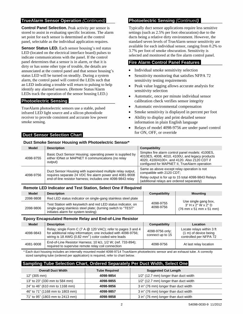
TrueAlarm Sensor Operation (Continued)
Control Panel Selection. Peak activity per sensor is stored to assist in evaluating specific locations. The alarm set point for each sensor is determined at the control panel, selectable as the individual application requires.
Sensor Status LED. Each sensor housing’s red status LED (located on the electrical interface board) pulses to indicate communications with the panel. If the control panel determines that a sensor is in alarm, or that it is dirty or has some other type of trouble, the details are annunciated at the control panel and that sensor housing’s status LED will be turned on steadily. During a system alarm, the control panel will control the LEDs such that an LED indicating a trouble will return to pulsing to help identify any alarmed sensors. (Remote Status/Alarm LEDs track the operation of the sensor housing LED.)
Photoelectric Sensing
TrueAlarm photoelectric sensors use a stable, pulsed infrared LED light source and a silicon photodiode receiver to provide consistent and accurate low power smoke sensing.
Photoelectric Sensing (Continued)
Typically duct sensor applications require less sensitive settings (such as 2.5% per foot obscuration) due to the ducts being a relative dirty environment. However, the standard seven levels of TrueAlarm sensor sensitivity are available for each individual sensor, ranging from 0.2% to 3.7% per foot of smoke obscuration. Sensitivity is selected and monitored at the fire alarm control panel.
Fire Alarm Control Panel Features
Individual smoke sensitivity selection Sensitivity monitoring that satisfies NFPA 72
sensitivity testing requirements Peak value logging allows accurate analysis for
sensitivity selection Automatic, once per minute individual sensor
calibration check verifies sensor integrity Automatic environmental compensation Smoke sensitivity is displayed in percent per foot Ability to display and print detailed sensor
information in plain English language Relays of model 4098-9756 are under panel control
for ON, OFF, or override
2 S4098-0030-9 11/2012
Duct Smoke Sensor Housing with Photoelectric Sensor* Model Description Compatibility
4098-9755 Basic Duct Sensor Housing; operating power is supplied by either IDNet or MAPNET II communications (no relay output)
Simplex fire alarm control panel models: 4100ES, 4010ES, 4008, 4010, 4100U, and legacy products 4020, 4100/4100+, and 4120. Also 2120 CDT if configured for MAPNET II, TrueAlarm operation
4098-9756 Duct Sensor Housing with supervised multiple relay output, requires separate 24 VDC fire alarm power and 4081-9008 end-of-line resistor harness; includes one 4098-9843 relay
Same as above except relay operation is not compatible with 2120 CDT; Relay output is for up to 15 total 4098-9843 Relays (additional relays are ordered separately)
Remote LED Indicator and Test Station, Select One if Required Model Description Compatibility Mounting
2098-9808 Red LED status indicator on single-gang stainless steel plate
4098-9755 4098-9756
Use single gang box, 3” H x 2” W x 2” D
(76 mm x 51 mm x 51 mm) 2098-9806 Test Station with keyswitch and red LED status indicator, on single-gang stainless steel plate; (turning switch to “TEST” initiates alarm for system testing)
Epoxy Encapsulated Remote Relay and End-of-Line Resistor Model Description Compatibility Location
4098-9843 Relay; single Form C (7 A @ 120 VAC); refer to pages 3 and 4 for additional relay information; one included with 4098-9756; wiring is 18 AWG (0.82 mm2 ) color coded wire leads
4098-9756 only; connect up to 15
Locate relays within 3 ft (1 m) of device being
controlled per NFPA 72
4081-9008 End-of-Line Resistor Harness; 10 k, 1/2 W; (ref. 733-894); required to supervise remote relay coil connection 4098-9756 At last relay location
* Each duct housing includes an internally mounted model 4098-9714 TrueAlarm photoelectric sensor and an exhaust tube. A correctly sized sampling tube (ordered per application) is required, refer to chart below.
Overall Duct Width Tube Required Suggested Cut Length
12” (305 mm) 4098-9854 1/2” (12.7 mm) longer than duct width
13” to 23” (330 mm to 584 mm) 4098-9855 1/2” (12.7 mm) longer than duct width
24” to 46” (610 mm to 1168 mm) 4098-9856 3 in” (76 mm) longer than duct width
46” to 71” (1168 mm to 1803 mm) 4098-9857 3 in” (76 mm) longer than duct width
71” to 95” (1803 mm to 2413 mm) 4098-9858 3 in” (76 mm) longer than duct width
Duct Sensor Selection Chart
Sampling Tube Selection Chart, Ordered Separately Per Duct Width, Select One
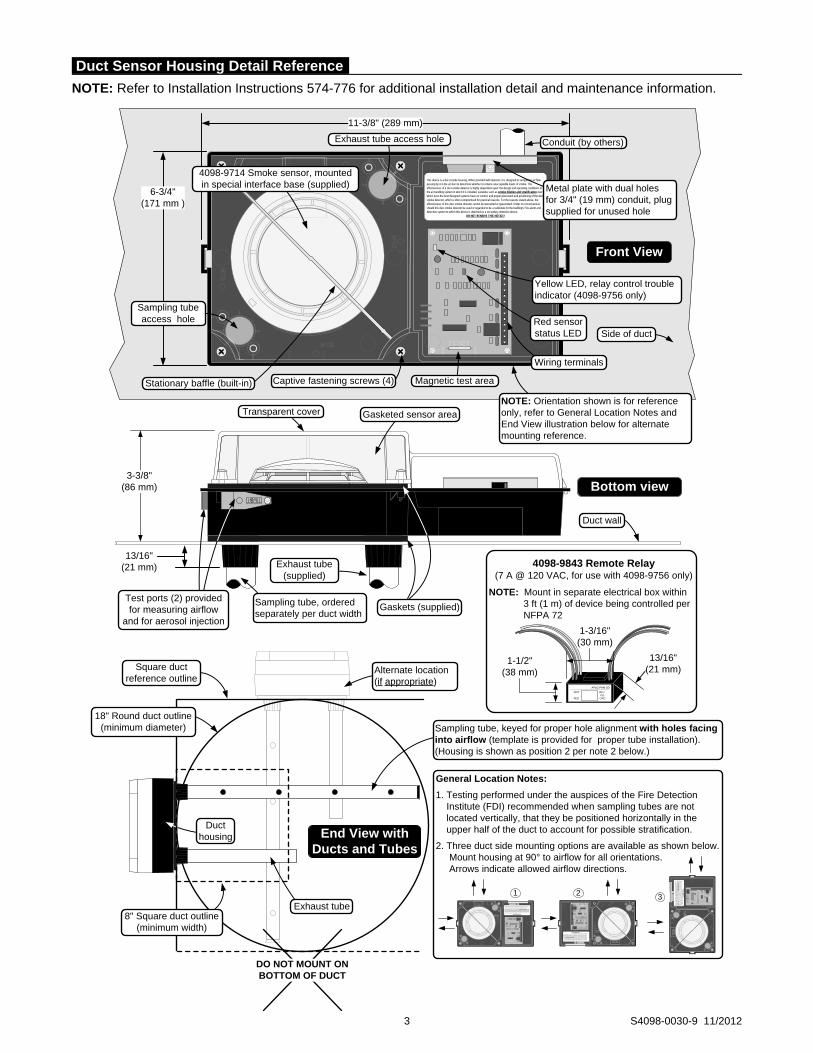
NOTE: Refer to Installation Instructions 574-776 for additional installation detail and maintenance information.
3 S4098-0030-9 11/2012
This device is a duct smoke housing. When provided with detector, it is designed to sample the air flow passing by it in the air duct to determine whether it contains unacceptable levels of smoke. The effectiveness of a duct smoke detector is highly dependent upon: the design and operating conditions of the air handling system in which it is installed, variables such as smoke dilution and stratification over which even the best designed systems have no control, and proper placement and positioning of the duct smoke detector, which is often compromised for practical reasons. For the reasons stated above, the effectiveness of this duct smoke detector cannot be warranted or guaranteed. Under no circumstances should this duct smoke detector be used or regarded to be a substitute for the building's Fire alarm and detection system to which this device is attached as a secondary detection device.
DO NOT REMOVE THIS NOTICE!
6-3/4"(171 mm )
11-3/8" (289 mm)
3-3/8"(86 mm)
Exhaust tube access hole
Captive fastening screws (4)
Metal plate with dual holes for 3/4" (19 mm) conduit, plug supplied for unused hole
Wiring terminals
Gaskets (supplied)
Conduit (by others)
Stationary baffle (built-in)
4098-9714 Smoke sensor, mounted in special interface base (supplied)
Magnetic test area
Test ports (2) provided for measuring airflow
and for aerosol injection
13/16" (21 mm)
Sampling tube, ordered separately per duct width
Exhaust tube (supplied)
NOTE: Orientation shown is for reference only, refer to General Location Notes and End View illustration below for alternate mounting reference.
Red sensor status LED
Transparent cover Gasketed sensor area
Sampling tube access hole
Duct wall
Front View
Bottom view
Yellow LED, relay control trouble indicator (4098-9756 only)
Side of duct
4098-9843 Remote Relay(7 A @ 120 VAC, for use with 4098-9756 only)
NOTE: Mount in separate electrical box within3 ft (1 m) of device being controlled perNFPA 72
AP&C-PAM SD
WHT BLUYEL
RED ORG
1-3/16"(30 mm)
1-1/2" (38 mm)
13/16" (21 mm)
Sampling tube, keyed for proper hole alignment with holes facing into airflow (template is provided for proper tube installation). (Housing is shown as position 2 per note 2 below.)
8" Square duct outline (minimum width)
18" Round duct outline (minimum diameter)
End View with Ducts and Tubes
General Location Notes:
1. Testing performed under the auspices of the Fire Detection Institute (FDI) recommended when sampling tubes are not located vertically, that they be positioned horizontally in the upper half of the duct to account for possible stratification.
2. Three duct side mounting options are available as shown below.Mount housing at 90° to airflow for all orientations. Arrows indicate allowed airflow directions.
Exhaust tube
Duct housing
Alternate location (if appropriate)
Square duct reference outline
This device is a duct smoke housing. When provided with detector, it is designed to sample the air flowpassing by it in the air duct to determine whether it contains unacceptable levels of smoke. Theeffectiveness of a duct smoke detector is highly dependent upon: the design and operating conditions of theair handling system in which it is installed, var iables such as smoke dilut ion and strat if ication over whicheven the best designed systems have no control, and proper placement and positioning of the duct smokedetector, which is often compromised for practical reasons. For the reasons stated above, the effectivenessof this duct smoke detector cannot be warranted or guaranteed. Under no circumstances should this ductsmoke detector be used or regarded to be a substitute for the building's Fire alarm and detection system towhich this device is attached as a secondary detection device.
DO NOT REMOVE THIS NOTICE!
This
dev
ice
is a
duct
sm
oke
hous
ing.
Whe
n pr
ovid
ed w
ith d
etec
tor,
it is
des
igne
d to
sam
ple
the
air f
low
pass
ing
by it
in th
e ai
r duc
t to
dete
rmin
e w
heth
er it
con
tain
s un
acce
ptab
le le
vels
of s
mok
e. T
heef
fect
iven
ess
of a
duc
t sm
oke
dete
ctor
is h
ighl
y de
pend
ent u
pon:
the
desi
gn a
nd o
pera
ting
cond
ition
s of
the
air h
andl
ing
syst
em in
whi
ch it
is in
stal
led,
var
iabl
es s
uch
as s
mok
e di
lutio
n an
d st
rati
ficat
ion
over
whi
chev
en th
e be
st d
esig
ned
syst
ems
have
no
cont
rol,
and
prop
er p
lace
men
t and
pos
ition
ing
of th
e du
ct s
mok
ede
tect
or, w
hich
is o
ften
com
prom
ised
for p
ract
ical
reas
ons.
For
the
reas
ons
stat
ed a
bove
, the
effe
ctiv
enes
sof
this
duc
t sm
oke
dete
ctor
can
not b
e w
arra
nted
or g
uara
ntee
d. U
nder
no
circ
umst
ance
s sh
ould
this
duc
tsm
oke
dete
ctor
be
used
or r
egar
ded
to b
e a
subs
titut
e fo
r th
e bu
ildin
g's
Fire
ala
rm a
nd d
etec
tion
syst
em to
whi
ch th
is d
evic
e is
atta
ched
as
a se
cond
ary
dete
ctio
n de
vice
.D
O N
OT
REM
OV
E TH
IS N
OTI
CE!
1 2 3
This device is a duct smoke housing. When provided with detector, it is designed to sample the air flowpassing by it in the air duct to determine whether it contains unacceptable levels of smoke. Theeffectiveness of a duct smoke detector is highly dependent upon: the design and operating conditions of the
air handling system in which it is installed, variables such as smoke dilution and stratificationover whicheven the best designed systems have no control, and proper placement and positioning of the duct smokedetector, which is often compromised for practical reasons. For the reasons stated above, the effectivenessof this duct smoke detector cannot be warranted or guaranteed. Under no circumstances should this ductsmoke detector be used or regarded to be a substitute for the building's Fire alarm and detection system to
which this device is attached as a secondary detection device.DO NOT REMOVE THIS NOTICE!
DO NOT MOUNT ON BOTTOM OF DUCT
Duct Sensor Housing Detail Reference

Duct Sensor Location Reference
Return Air
Supply Air
Return air damper
Filter bank
Fresh air
Do not locate sensor here
Sensor OK
Exhaust
Exhaust Damper
Sensor OKDo not locate sensor here
Additional Information. Refer to NFPA 90A, Standard for the Installation of Air Conditioning and Ventilating Systems; NFPA 72, the National Fire Alarm and Signaling Code; and the NEMA Guide for Proper Use of Smoke Detectors in Duct Applications, and Installation Instructions 574-776.
Duct Sensor Location Considerations: 1. Proper duct smoke detection location must ensure
adequate airflow within the duct housing. 2. Duct air velocity rating is 300 to 4000 ft/min (91 to
1220 m/min). Pressure differential between intake and exhaust tubes is required to be between 0.015 to 1.55 inches of water (0.381 to 39.37 mm).
3. Ensure accessibility for test and service. 4. Proper Locations: downstream side of filters to detect
fires in the filters; in return ducts, ahead of mixing areas; upstream of air humidifier and cooling coil.
5. Other locations and orientations may be required for proper duct smoke detection depending on duct access, system design, and duct airflow testing. Contact your local Simplex product supplier for assistance.
Locations to Avoid: 1. Where dampers closed for comfort control would
interfere with airflow. 2. Next to outside air inlets (unless the intent is to
monitor smoke entry from that area). 3. In return air damper branch ducts and mixing areas
where airflow may be restricted.
TYCO, SIMPLEX, and the product names listed in this material are marks and/or registered marks. Unauthorized use is strictly prohibited. NFPA 72 and National Fire Alarm and Signaling Code are registered trademarks of the National Fire Protection Association (NFPA).
General Mechanical and Environmental
Air Velocity Range (linear ft/min) 300 to 4000 ft/min (91 to 1220 m/min)
Sensor Sensitivity Range 0.2% to 3.7% per foot of obscuration, selectable at host control panel
UL Listed Temperature Range 32° F to 100° F (0° C to 38° C)
Operating Temperature Range 32° F to 122° F (0° C to 50° C)
Storage Temperature Range 0 F to 140 F (-18 C to 60 C)
Humidity Range 10% to 95% RH, non-condensing
Wiring Connections Terminal blocks, 18 to 12 AWG (0.82 mm2 to 3.31 mm2 )
Housing Color Black base with clear cover
Remote Status/Alarm LED and Test Station with Remote Status/Alarm LED
Remote Alarm LED Current 1.2 mA, no impact to 24 VDC alarm current (2098-9808 or 2098-9806)
Test Station Keyswitch Current 3.3 mA, no impact to 24 VDC alarm current (2098-9806)
Remote Alarm LED and Test Station Distance 250 ft (76 m) maximum
Addressable Operation
Data Communications IDNet or MAPNET II communications, auto-select, one address per housing; provides operating power to model 4098-9755
Model 4098-9756 with Supervised Multiple Relay Control, Requires Separate Fused 24 VDC from Fire Alarm Power Supply
Input Voltage 18-32 VDC (24 VDC nominal)
Standby Current 3 mA @ 24 VDC
Alarm Current 15 mA @ 24 VDC; add 15 mA for each 4098-9843 relay
Supervised Remote Relay Control Output For use with 4098-9843 relay only, quantity of 15 maximum; distance of 500 ft (152 m) maximum; requires 4081-9008 (ref. 733-894) 10 k, 1/2 W end-of-line resistor
4098-9843 Relay Output Ratings, Single Form C, use with Model 4098-9756 Only
Coil Current 15 mA @ 24 VDC, up to 15 maximum per relay control output
Relay Contacts 7 A at 0.35 PF @ 28 VDC & 120 VAC; 250 A @ 5 VDC
Location Distance 500 ft (152 m) maximum to relay coils; locate relays within 3 ft (1 m) of device being controlled per NFPA 72
Tyco Fire Protection Products • Westminster, MA • 01441-0001 • USA S4098-0030-9 11/2012
www.simplexgrinnell.com © 2012 Tyco Fire Protection Products. All rights reserved. All specifications and other information shown were current as of document revision date and are subject to change without notice.
Specifications

Features
Individually addressable manual fire alarm stations with: Power and data supplied via IDNet or MAPNET II
addressable communications using a single wire pair Operation that complies with ADA requirements The NO GRIP Single Action Station and Retrofit Kit
are available with a more easily operated pull lever for applications where anticipated users may find the standard station lever difficult to activate
Pull lever that protrudes when alarmed Break-rod supplied (use is optional) Models are available with single or double action
(breakglass or push) operation UL listed to Standard 38 Compatible with the following Simplex® control panels: Model Series 4100ES, 4010ES, 4008, 4010, 4100U,
4020, 4100, and 4120 fire alarm control panels equipped with either IDNet or MAPNET II communications
Model Series 2120 Communicating Device Transponders (CDTs) equipped with MAPNET II communications
Compact construction: Electronics module enclosure minimizes dust
infiltration Allows mounting in standard electrical boxes Screw terminals for wiring connections
Tamper resistant reset key lock (keyed same as Simplex fire alarm cabinets) Multiple mounting options: Surface or semi-flush with standard boxes or matching
Simplex boxes Flush mount adapter kit Adapters are available for retrofitting to commonly
available existing boxes
Description
The Simplex addressable manual station combines the familiar Simplex manual station housing with a compact communication module that is easily installed to satisfy demanding applications. Its integral individual addressable module (IAM) constantly monitors status and communicates changes to the connected control panel via IDNet or MAPNET II communications wiring. * Refer to page 2 for specific model listings. This product has been approved by the
California State Fire Marshal (CSFM) pursuant to Section 13144.1 of the California Health and Safety Code. See CSFM Listing 7150-0026:224 for allowable values and/or conditions concerning material presented in this document. It is subject to re-examination, revision, and possible cancellation. Accepted for use – City of New York Department of Buildings – MEA35-93E. Additional listings may be applicable; contact your local Simplex product supplier for the latest status. Listings and approvals under Simplex Time Recorder Co. are the property of Tyco Fire Protection Products.
4099-9001 Single action
4099-9020 NO GRIP
Single action
4099-9805 NO GRIP Retrofit kit
ALARMFIRE
BREAK GLASS PUSH
ALARMFIRE
KEY
OPERATED
ONLY
4099-9002 Breakglass
4099-9003 Push
With 2099-9828 Institutional Cover kit
Operation
Activation of the 4099-9001 single action manual station requires a firm downward pull to activate the alarm switch. Completing the action breaks an internal plastic break-rod (visible below the pull lever, use is optional). The use of a break-rod can be a deterrent to vandalism without interfering with the minimum pull requirements needed for easy activation. The pull lever latches into the alarm position and remains extended out of the housing to provide a visible indication.
Single Action NO GRIP Station 4099-9020. For applications such as California Building Code, Title 24, which requires “Controls and operating mechanisms shall be operable with one hand and shall not require tight grasping, pinching or twisting of the wrist” the model 4099-9020 station provides a more easily operated pull lever compared to standard stations. Retrofit of existing stations is available using the 4099-9805 Retrofit kit.
Double Action Stations (Breakglass) require the operator to strike the front mounted hammer to break the glass and expose the recessed pull lever. The pull lever then operates as a single action station.
Double Action Stations (Push Type) require that a spring loaded interference plate (marked PUSH) be pushed back to access the pull lever of the single action station.
Station reset requires the use of a key to reset the manual station lever and deactivate the alarm switch. (If the break-rod is used, it must be replaced.)
Station testing is performed by physical activation of the pull lever. Electrical testing can be also performed by unlocking the station housing to activate the alarm switch.
Multi-Application Peripherals UL, ULC, CSFM Listed; FM Approved; IDNet or MAPNET II Communicating Devices MEA (NYC) Acceptance* Addressable Manual Stations
S4099-0001-9 5/2012
rytorres
Highlight
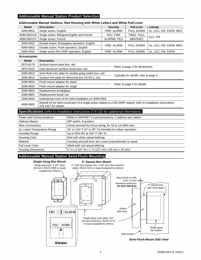
2 S4099-0001-9 5/2012
Addressable Manual Stations, Red Housing with White Letters and White Pull Lever Model Description Housing Pull Lever Listings
4099-9001 Single action, English FIRE ALARM PULL DOWN UL, ULC, FM, CSFM, MEA
4099-9001CB Single action, Bilingual English and French FEU FIRE TIREZ PULL ULC, FM
4099-9001CF Single action, French ALARME FEU ABAISSEZ
4099-9002 Double action, Breakglass operation, English FIRE ALARM PULL DOWN UL, ULC, FM, CSFM, MEA
4099-9003 Double action, Push operation, English
4099-9020 Single action NO GRIP operation, English FIRE ALARM PULL DOWN UL, ULC, FM, CSFM
Accessories Model Description
2975-9178 Surface mount steel box, red Refer to page 3 for dimensions
2975-9022 Cast aluminum surface mount box, red
2099-9813 Semi-flush trim plate for double gang switch box, red Typically for retrofit, refer to page 4
2099-9814 Surface trim plate for Wiremold box V5744-2, red
2099-9819 Flush mount adapter kit, black Refer to page 4 for details
2099-9820 Flush mount adapter kit, beige
2099-9803 Replacement breakglass
2099-9804 Replacement break-rod
2099-9828 Institutional cover kit for field installation on 4099-9001
4099-9805 Retrofit Kit for field conversion of a single action station to a NO GRIP station; refer to Installation Instructions 579-1007 for details
Power and Communications IDNet or MAPNET II communications, 1 address per station
Address Means DIP switch, 8 position
Wire Connections Screw terminal for in/out wiring, for 18 to 14 AWG wire
UL Listed Temperature Range 32° to 120° F (0° to 49° C) intended for indoor operation
Humidity Range Up to 93% RH at 100° F (38° F)
Housing Color Red with white raised lettering
Material Housing and pull lever are Lexan polycarbonate or equal
Pull Lever Color White with red raised lettering
Housing Dimensions 5” H x 3-3/4” W x 1” D (127 mm x 95 mm x 25 mm)
4" (102 mm) square box, 2-1/8" (54 mm) minimumdepth, RACO #231 or equal (supplied by others)
Single gang cover plate, 3/4"(19 mm) extension, RACO #773
or equal (supplied by others)
ALARMFIRE
PULL DOWN
4" Square Box Mount
Stationside view
Wall surface
Single gangbox outline
4" Square boxwith cover plate
Semi-Flush Mount Side View
Single Gang Box MountSingle gang box, 2-1/2" deep
(64 mm), RACO #500 or equal(supplied by others)
Mount flush or with1/16" (2 mm)
maximum extensionDO NOT RECESS
Addressable Manual Station Semi-Flush Mounting
Specifications (refer to Installation Instructions 574-332 for additional information)
Addressable Manual Station Product Selection

Preferred Mounting. For surface mounting of these addressable manual stations, the preferred electrical boxes are shown in the illustration to the right.
Additional Mounting Reference. Refer to page 4 for Wiremold box mounting compatibility.
3 S4099-0001-9 5/2012
Application Reference
Refer to NFPA 72, the National Fire Alarm and Signaling Code, and all applicable local codes for complete requirements for manual stations. The following summarizes the basic requirements.
1. Stations shall be located in the normal path of exit and distributed in the protected area such that they are unobstructed and readily accessible.
2. Mounting shall be with the operable part not less than 42 in (1.07 m) and not more than 48 in (1.22 m) above floor level.
3. At least one station shall be provided on each floor. Additional stations shall be provided to obtain a travel distance not more than 200 ft (61 m) to the nearest station from any point in the building.
4. When manual station coverage appears limited in any way, additional stations should be installed.
2975-9178 Box
5-3/16" H x 4" W x 2-3/16" D(132 mm x 102 mm x 56 mm)
(ordered separately)
Knockouts locatedtop and bottom
2975-9022 Cast Box
5" H x 3-7/8" W x 2-3/16" D(127 mm x 98 mm x 56 mm)
(ordered separately)
Access for 3/4" threadedconduit located top and bottom5"
(127 mm)
FIRE
ALARMFIRE
PULL DOWN
4099 Series Addressable Manual Station
1" (25.4 mm)
3-3/4" (95 mm)
Station coverhinges open for
installation access
Simplex 2975-9178 box(shown for reference)
Address setting underresealable label (accessible
with cover open)
Switch wiring(prewired)
Field wiring(shown for reference)
1-1/4"(32 mm)
2-5/8"(67 mm)
Addressable Manual Stations Surface Mounting
Surface Mount Side View with Internal Detail
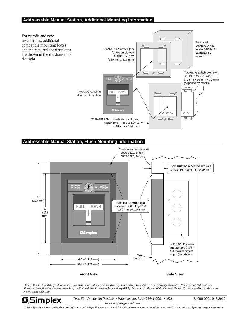
For retrofit and new installations, additional compatible mounting boxes and the required adapter plates are shown in the illustration to the right.
TYCO, SIMPLEX, and the product names listed in this material are marks and/or registered marks. Unauthorized use is strictly prohibited. NFPA 72 and National Fire Alarm and Signaling Code are trademarks of the National Fire Protection Association (NFPA). Lexan is a trademark of the General Electric Co. Wiremold is a trademark of the Wiremold Company.
8"(203 mm)
6"(152mm)
4-3/4" (121 mm)
6-3/4" (171 mm)
Front View
Flush mount adapter kit2099-9819, Black2099-9820, Beige
Wallsurface
4-11/16" (119 mm)square box, 2-1/8"(54 mm) minimumdepth (by others)
Side View
Box must be recessed into wall1" to 1-1/8" (25.4 mm to 29 mm)
Hole cutout must be aminimum of 6" H by 5" W
(152 mm by 127 mm)
2099-9814 Surface trimfor Wiremold box
5-1/8" H x 5" W(130 mm x 127 mm)
4099-9001 IDNetaddressable station
Two gang switch box, each3" H x 2" W x 2-3/4" D(76 mm x 51 mm x 70 mm)(supplied by others)
2099-9813 Semi-flush trim for 2 gangswitch box, 6" H x 4-1/2" W
(152 mm x 114 mm)
Wiremoldreceptacle boxmodel V5744-2(supplied byothers)
Tyco Fire Protection Products • Westminster, MA • 01441-0001 • USA S4099-0001-9 5/2012
www.simplexgrinnell.com © 2012 Tyco Fire Protection Products. All rights reserved. All specifications and other information shown were current as of document revision date and are subject to change without notice.
Addressable Manual Station, Additional Mounting Information
Addressable Manual Station, Flush Mounting Information
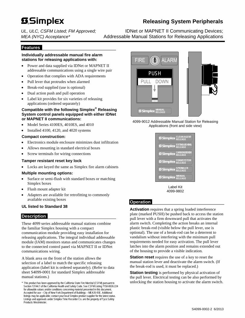
Features
Individually addressable manual fire alarm stations for releasing applications with:
Power and data supplied via IDNet or MAPNET II addressable communications using a single wire pair
Operation that complies with ADA requirements
Pull lever that protrudes when alarmed
Break-rod supplied (use is optional)
Dual action push and pull operation
Label kit provides for six varieties of releasing applications (ordered separately)
Compatible with the following Simplex® Releasing System control panels equipped with either IDNet or MAPNET II communications:
Model Series 4100ES, 4010ES, and 4010
Installed 4100, 4120, and 4020 systems
Compact construction:
Electronics module enclosure minimizes dust infiltration
Allows mounting in standard electrical boxes
Screw terminals for wiring connections
Tamper resistant reset key lock
Locks are keyed the same as Simplex fire alarm cabinets
Multiple mounting options:
Surface or semi-flush with standard boxes or matching Simplex boxes
Flush mount adapter kit
Adapters are available for retrofitting to commonly available existing boxes
UL listed to Standard 38
Description
These 4099 series addressable manual stations combine the familiar Simplex housing with a compact communication module providing easy installation for releasing applications. The integral individual addressable module (IAM) monitors status and communicates changes to the connected control panel via MAPNET II or IDNet communications wiring.
A blank area on the front of the station allows the selection of a label to match the specific releasing application (label kit is ordered separately). (Refer to data sheet S4099-0001 for standard Simplex addressable manual stations.)
* This product has been approved by the California State Fire Marshal (CSFM) pursuant to Section 13144.1 of the California Health and Safety Code. See CSFM Listing 7150-0026:224 for allowable values and/or conditions concerning material presented in this document. Accepted for use – City of New York Department of Buildings – MEA35-93E. Additional listings may be applicable; contact your local Simplex product supplier for the latest status. Listings and approvals under Simplex Time Recorder Co. are the property of Tyco Safety Products Westminster.
PUSH
MANUALRELEASE
4099-9012 Addressable Manual Station for Releasing Applications (front and side view)
CLEAN AGENTRELEASE
EXTINGUISHINGRELEASE
CARBON DIOXIDERELEASE
FOAM SYSTEMRELEASE
MANUALRELEASE
SPRINKLERRELEASE
Label Kit 4099-9802
Operation
Activation requires that a spring loaded interference plate (marked PUSH) be pushed back to access the station pull lever with a firm downward pull that activates the alarm switch. Completing the action breaks an internal plastic break-rod (visible below the pull lever, use is optional). The use of a break-rod can be a deterrent to vandalism without interfering with the minimum pull requirements needed for easy activation. The pull lever latches into the alarm position and remains extended out of the housing to provide a visible indication.
Station reset requires the use of a key to reset the manual station lever and deactivate the alarm switch. (If the break-rod is used, it must be replaced.)
Station testing is performed by physical activation of the pull lever. Electrical testing can be also performed by unlocking the station housing to activate the alarm switch.
Releasing System Peripherals UL, ULC, CSFM Listed; FM Approved; IDNet or MAPNET II Communicating Devices; MEA (NYC) Acceptance* Addressable Manual Stations for Releasing Applications
S4099-0002-2 6/2013
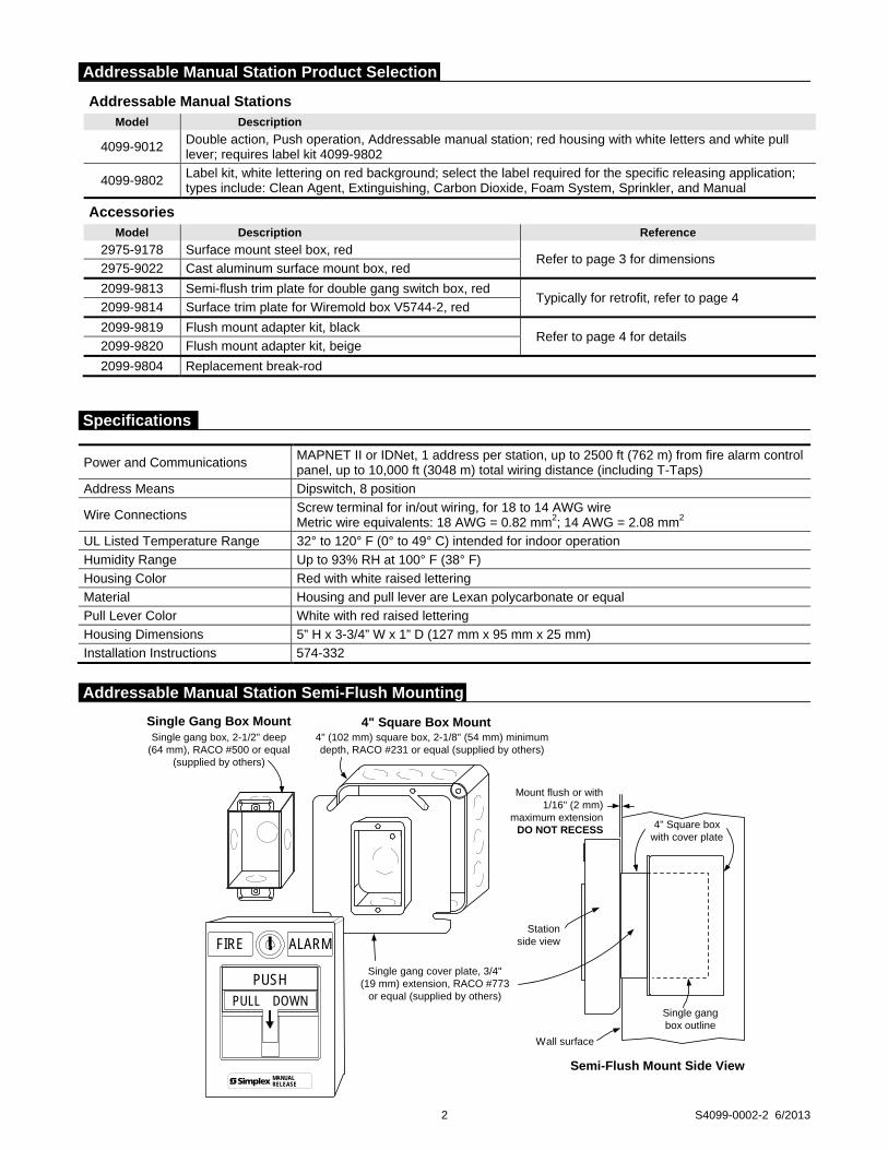
2 S4099-0002-2 6/2013
Addressable Manual Stations Model Description
4099-9012 Double action, Push operation, Addressable manual station; red housing with white letters and white pull lever; requires label kit 4099-9802
4099-9802 Label kit, white lettering on red background; select the label required for the specific releasing application; types include: Clean Agent, Extinguishing, Carbon Dioxide, Foam System, Sprinkler, and Manual
Accessories Model Description Reference
2975-9178 Surface mount steel box, red Refer to page 3 for dimensions
2975-9022 Cast aluminum surface mount box, red
2099-9813 Semi-flush trim plate for double gang switch box, red Typically for retrofit, refer to page 4
2099-9814 Surface trim plate for Wiremold box V5744-2, red
2099-9819 Flush mount adapter kit, black Refer to page 4 for details
2099-9820 Flush mount adapter kit, beige
2099-9804 Replacement break-rod
Power and Communications MAPNET II or IDNet, 1 address per station, up to 2500 ft (762 m) from fire alarm control panel, up to 10,000 ft (3048 m) total wiring distance (including T-Taps)
Address Means Dipswitch, 8 position
Wire Connections Screw terminal for in/out wiring, for 18 to 14 AWG wire Metric wire equivalents: 18 AWG = 0.82 mm2; 14 AWG = 2.08 mm2
UL Listed Temperature Range 32° to 120° F (0° to 49° C) intended for indoor operation
Humidity Range Up to 93% RH at 100° F (38° F)
Housing Color Red with white raised lettering
Material Housing and pull lever are Lexan polycarbonate or equal
Pull Lever Color White with red raised lettering
Housing Dimensions 5” H x 3-3/4” W x 1” D (127 mm x 95 mm x 25 mm)
Installation Instructions 574-332
4" (102 mm) square box, 2-1/8" (54 mm) minimumdepth, RACO #231 or equal (supplied by others)
Single gang cover plate, 3/4"(19 mm) extension, RACO #773
or equal (supplied by others)
4" Square Box Mount
Stationside view
Wall surface
Single gangbox outline
4" Square boxwith cover plate
Semi-Flush Mount Side View
Single Gang Box MountSingle gang box, 2-1/2" deep
(64 mm), RACO #500 or equal(supplied by others)
Mount flush or with1/16" (2 mm)
maximum extensionDO NOT RECESS
MANUALRELEASE
PULL DOWN
FIRE ALARM
PUSH
Addressable Manual Station Semi-Flush Mounting
Specifications
Addressable Manual Station Product Selection

Preferred Mounting. For surface mounting of these addressable manual stations, the preferred electrical boxes are shown in the illustration to the right.
Additional Mounting Reference. Refer to page 4 for Wiremold box mounting compatibility.
3 S4099-0002-2 6/2013
2975-9178 Box
5-3/16" H x 4" W x 2-3/16" D(132 mm x 102 mm x 56 mm)
(ordered separately)
Knockouts locatedtop and bottom
2975-9022 Cast Box
5" H x 3-7/8" W x 2-3/16" D(127 mm x 98 mm x 56 mm)
(ordered separately)
Access for 3/4" threadedconduit located top and bottom5"
(127 mm)
FIRE
4099 Series Addressable Manual Station
1" (25.4 mm)
3-3/4" (95 mm)
MANUALRELEASE
PULL DOWN
FIRE ALARM
PUSH
Station coverhinges open for
installation access
Simplex 2975-9178 box(shown for reference)
Address setting underresealable label (accessible
with cover open)
Switch wiring(prewired)
Field wiring(shown for reference)
1-1/4"(32 mm)
2-5/8"(67 mm)
Addressable Manual Stations Surface Mounting
Surface Mount Side View with Internal Detail

For retrofit and new installations, additional compatible mounting boxes and the required adapter plates are shown in the illustration to the right.
8"(203 mm)
6"(152mm)
4-3/4" (121 mm)
6-3/4" (171 mm)
Front View
Flush mount adapter kit2099-9819, Black2099-9820, Beige
Wallsurface
4-11/16" (119 mm)square box, 2-1/8"(54 mm) minimumdepth (by others)
Side View
Box must be recessed into wall1" to 1-1/8" (25.4 mm to 29 mm)
Hole cutout must be aminimum of 6" H by 5" W
(152 mm by 127 mm)
PUSH
MANUALRELEASE
2099-9814 Surface trimfor Wiremold box
5-1/8" H x 5" W(130 mm x 127 mm)
Two gang switch box, each3" H x 2" W x 2-3/4" D(76 mm x 51 mm x 70 mm)(supplied by others)
Wiremoldreceptacle boxmodel V5744-2(supplied byothers)
2099-9813 Semi-flush trim for2-gang switch box, 6" H x 4-1/2" W
(152 mm x 114 mm)
PUSH
MANUALRELEASE
Tyco Fire Protection Products • Westminster, MA • 01441-0001 • USA S4099-0002-2 6/2013
www.simplexgrinnell.com © 2013 Tyco Fire Protection Products. All rights reserved. All specifications and other information shown were current as of document revision date and are subject to change without notice.
TYCO, SIMPLEX, and the product names listed in this material are marks and/or registered marks. Unauthorized use is strictly prohibited. Lexan is a trademark of the General Electric Co. Wiremold is a trademark of the Wiremold Company.
Addressable Manual Station, Additional Mounting Information
Addressable Manual Station, Flush Mounting Information
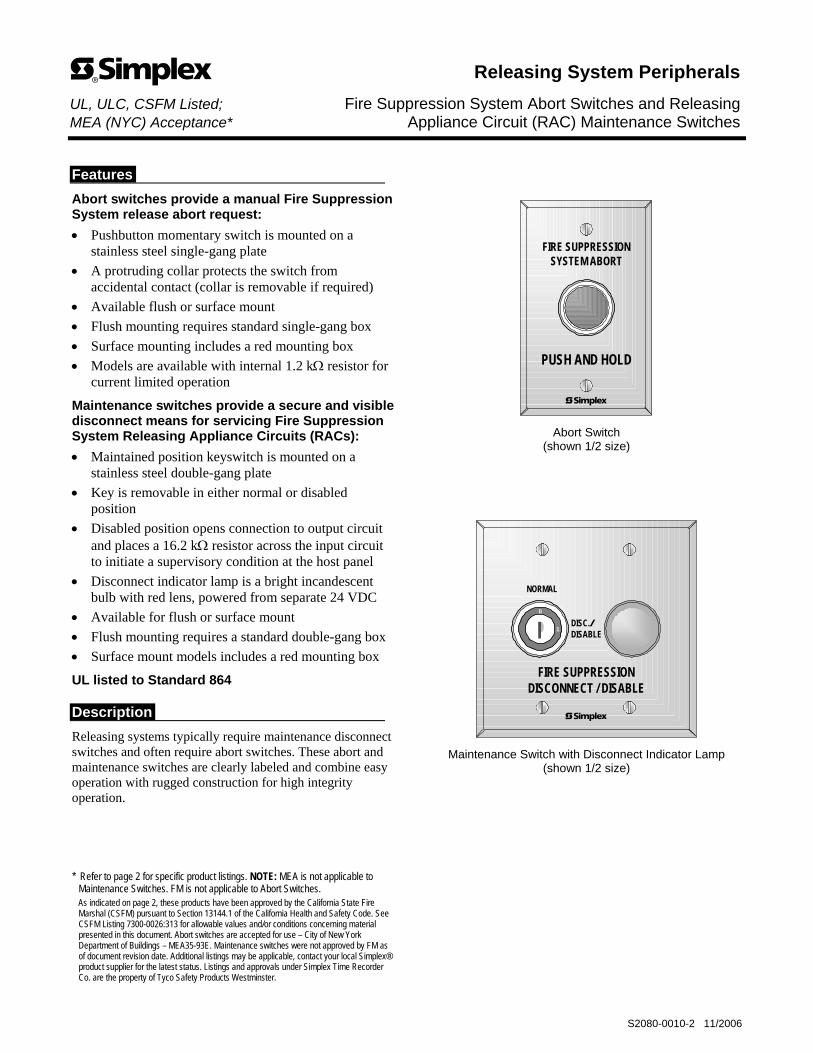
Features
Abort switches provide a manual Fire Suppression System release abort request:
• Pushbutton momentary switch is mounted on a stainless steel single-gang plate
• A protruding collar protects the switch from accidental contact (collar is removable if required)
• Available flush or surface mount
• Flush mounting requires standard single-gang box
• Surface mounting includes a red mounting box
• Models are available with internal 1.2 kΩ resistor for current limited operation
Maintenance switches provide a secure and visible disconnect means for servicing Fire Suppression System Releasing Appliance Circuits (RACs):
• Maintained position keyswitch is mounted on a stainless steel double-gang plate
• Key is removable in either normal or disabled position
• Disabled position opens connection to output circuit and places a 16.2 kΩ resistor across the input circuit to initiate a supervisory condition at the host panel
• Disconnect indicator lamp is a bright incandescent bulb with red lens, powered from separate 24 VDC
• Available for flush or surface mount
• Flush mounting requires a standard double-gang box
• Surface mount models includes a red mounting box
UL listed to Standard 864
Description
Releasing systems typically require maintenance disconnect switches and often require abort switches. These abort and maintenance switches are clearly labeled and combine easy operation with rugged construction for high integrity operation.
* Refer to page 2 for specific product listings. NOTE: MEA is not applicable to
Maintenance Switches. FM is not applicable to Abort Switches. As indicated on page 2, these products have been approved by the California State Fire
Marshal (CSFM) pursuant to Section 13144.1 of the California Health and Safety Code. See CSFM Listing 7300-0026:313 for allowable values and/or conditions concerning material presented in this document. Abort switches are accepted for use – City of New York Department of Buildings – MEA35-93E. Maintenance switches were not approved by FM as of document revision date. Additional listings may be applicable, contact your local Simplex® product supplier for the latest status. Listings and approvals under Simplex Time Recorder Co. are the property of Tyco Safety Products Westminster.
PUSH AND HOLD
FIRE SUPPRESSIONSYSTEM ABORT
Abort Switch (shown 1/2 size)
NORMAL
DISC./DISABLE
FIRE SUPPRESSIONDISCONNECT / DISABLE
0
1
Maintenance Switch with Disconnect Indicator Lamp (shown 1/2 size)
Releasing System Peripherals UL, ULC, CSFM Listed; Fire Suppression System Abort Switches and Releasing MEA (NYC) Acceptance* Appliance Circuit (RAC) Maintenance Switches
S2080-0010-2 11/2006

2 S2080-0010-2 11/2006
Abort Switches
Model Description Listing Status Details
2080-9056 Flush mount
2080-9057 Surface mount; includes red mounting box
UL, ULC, & CSFM listed; MEA (NYC) Acceptance
Single-gang size; includes 3 position contact block housing with one contact block installed
Abort Switches for 4004R Series Suppression Release Panel Current Limited Operation Model Description Listing Status Details
2080-9067 Flush mount
2080-9068 Surface mount; includes red mounting box
UL, ULC, & CSFM listed; MEA (NYC) Acceptance
Single-gang size; includes 1.2 kΩ, 1W resistor for current limited operation and 3 position contact block housing with one contact block installed
Maintenance Switches with Disconnect Indicator Lamp Model Description Listing Status Details
2080-9059 Flush mount
2080-9060 Surface mount; includes red mounting box
UL, ULC, & CSFM listed
Double-gang size; includes 3 position contact block housing with 2 contact blocks installed; disabled position opens connection to output and places a 16.2 kΩ resistor across the input circuit; resistor is removable if required for retrofit
Accessories for Field Installation Model Description
2080-9061 Additional Contact Block for Abort or Maintenance Switch; 1 Form C contact; UL recognized component for use with these switches; listings and approvals are not applicable
Box width3" (76 mm)
2-3/4"(70 mm)
Red box is supplied with surface mountAbort Switch 2080-9057 or 2080-9068
2-1/4" (56 mm) into box
Abort Switchheight 4-1/2"
(114 mm)Box height4-13/16"(122 mm)
Abort Switchwidth, 2-3/4" (70 mm)
NOTE: For flush mounting, use a 2-3/4" deep (70 mm) single-gang box
1/2"(13 mm)
Supplied gasket attaches to box;field installed for flush mount;
pre-attached for surface mount
PUSH AND HOLD
FIRE SUPPRESSIONSYSTEM ABORT
Removablecollar
Switch recessdepth 5/32"
(4 mm)
Product Selection (see page 3 for specifications)
Abort Switch Installation Reference
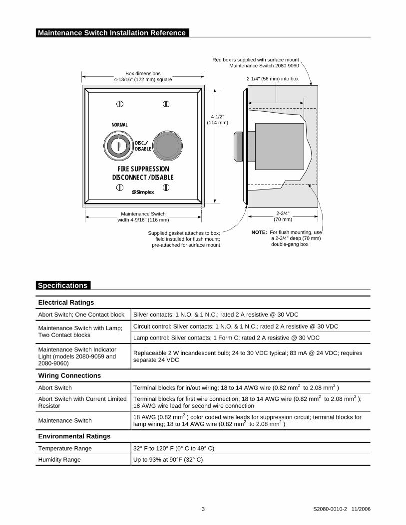
3 S2080-0010-2 11/2006
Box dimensions4-13/16" (122 mm) square
2-3/4"(70 mm)
Red box is supplied with surface mountMaintenance Switch 2080-9060
4-1/2"(114 mm)
Maintenance Switchwidth 4-9/16" (116 mm)
2-1/4" (56 mm) into box
NORMAL
DISC./DISABLE
FIRE SUPPRESSIONDISCONNECT / DISABLE
0
1
Supplied gasket attaches to box;field installed for flush mount;
pre-attached for surface mount
NOTE: For flush mounting, use a 2-3/4" deep (70 mm) double-gang box
Electrical Ratings
Abort Switch; One Contact block Silver contacts; 1 N.O. & 1 N.C.; rated 2 A resistive @ 30 VDC
Circuit control: Silver contacts; 1 N.O. & 1 N.C.; rated 2 A resistive @ 30 VDC Maintenance Switch with Lamp; Two Contact blocks Lamp control: Silver contacts; 1 Form C; rated 2 A resistive @ 30 VDC
Maintenance Switch Indicator Light (models 2080-9059 and 2080-9060)
Replaceable 2 W incandescent bulb; 24 to 30 VDC typical; 83 mA @ 24 VDC; requires separate 24 VDC
Wiring Connections
Abort Switch Terminal blocks for in/out wiring; 18 to 14 AWG wire (0.82 mm2 to 2.08 mm2 )
Abort Switch with Current Limited Resistor
Terminal blocks for first wire connection; 18 to 14 AWG wire (0.82 mm2 to 2.08 mm2 ); 18 AWG wire lead for second wire connection
Maintenance Switch 18 AWG (0.82 mm2 ) color coded wire leads for suppression circuit; terminal blocks for lamp wiring; 18 to 14 AWG wire (0.82 mm2 to 2.08 mm2 )
Environmental Ratings
Temperature Range 32° F to 120° F (0° C to 49° C)
Humidity Range Up to 93% at 90°F (32° C)
Maintenance Switch Installation Reference
Specifications

Tyco, Simplex, and the Simplex logo are trademarks of Tyco International Services AG or its affiliates in the U.S. and/or other countries
Tyco Safety Products Westminster • Westminster, MA • 01441-0001 • USA S2080-0010-2 11/2006
www.tycosafetyproducts-usa-wm.com © 2006 Tyco Safety Products Westminster. All rights reserved. All specifications and other information shown were current as of document revision date and are subject to change without notice.

Detection and Control Components
Main/Reserve Switch(IQ-318, IQ-636X-2, 542R, 542D, Z-10)
Features• Stackable, screw-terminal, contact blocks
• Compatible with AUTOPULSE control units
• Surface-mount assemblies listed by UnderwritersLaboratories, Inc.
• Components mounted on stainless steel switch plate
ApplicationsThe Main/Reserve Switch is required for main/reserve firesuppression systems. The switch position determineswhether the release circuit signal activates the main systemrelease or the reserve system release.
DescriptionThe Main/Reserve Switch assembly consists of a key-operated switch, normally-open contact block, normally-closed contact block, and stainless steel switch plate withsilk-screened label. Surface-mount assemblies include a sin-gle-gang weather-proof box with three 1/2 in. I.P.S. threadedconduit outlets and gasket.
The stackable, screw-terminal contact blocks are rated for 28VDC @ 1.1 amp make/break or 6 amp continuous carry.
Listings and Approvals
The switch is UL listed (S3623) when installed in the surface-mount box (with gasket) that is provided with the surface-mount assembly.
Ordering Information
ShippingWeight
Part No. Description lb (kg)
76496 Main/Reserve Switch, 1.0 (0.45)Surface-Mount
76497 Main/Reserve Switch, 1.0 (0.45)Flush-Mount
436983 Extra Contact Block, N.C. 0.25 (0.11)
436982 Extra Contact Block, N.O. 0.25 (0.11)
436088 Spare Key 0.25 (0.11)
3-11
MOUNTING DIMENSIONS
2 7/8 IN.(73 mm)
3 IN.(76 mm)
4 5/8 IN.(117 mm)
2 5/8 IN.(67 mm)
FIRE SUPPRESSIONSYSTEM
SELECTOR SWITCH
MAIN
RESERVE
SURFACE-MOUNT FLUSH-MOUNT
TYPICAL WIRING DIAGRAM24 VDC ACTUATORS
N.C.
N.O.
KEY-OPERATEDSELECTOR SWITCH
POLARITY IS SHOWNIN ALARM CONDITION
(+)
(–)
CONTROL UNITRELEASE CIRCUITTERMINALS ORADDRESSABLE RELEASECONTROL MODULE*
* SEE CONTROL UNIT MANUAL FOR SPECIFIC WIRING REQUIREMENTS.
007364
007363
TYCO FIRE PROTECTION PRODUCTS Copyright © 2011 Tyco Fire Protection ProductsONE STANTON STREET All rights reserved.MARINETTE, WI 54143-2542 715-735-7411 Form No. T-2007132-3
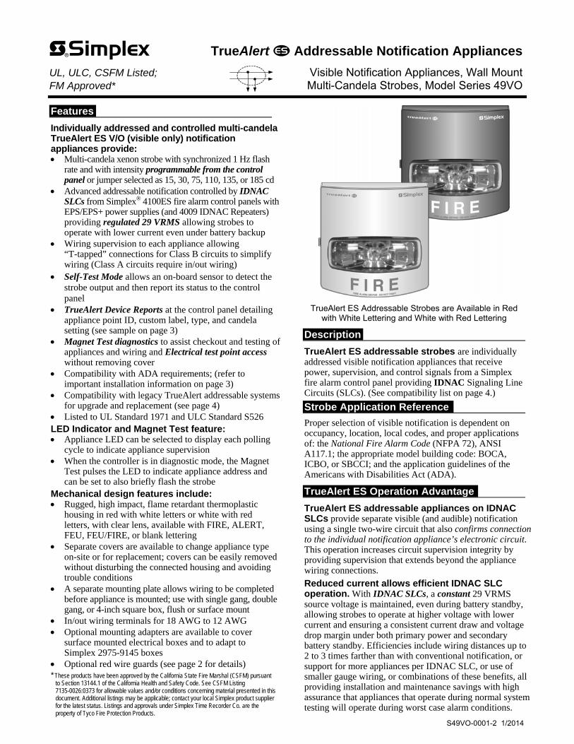
Features
Individually addressed and controlled multi-candela TrueAlert ES V/O (visible only) notification appliances provide: Multi-candela xenon strobe with synchronized 1 Hz flash
rate and with intensity programmable from the control panel or jumper selected as 15, 30, 75, 110, 135, or 185 cd
Advanced addressable notification controlled by IDNAC SLCs from Simplex® 4100ES fire alarm control panels with EPS/EPS+ power supplies (and 4009 IDNAC Repeaters) providing regulated 29 VRMS allowing strobes to operate with lower current even under battery backup
Wiring supervision to each appliance allowing “T-tapped” connections for Class B circuits to simplify wiring (Class A circuits require in/out wiring)
Self-Test Mode allows an on-board sensor to detect the strobe output and then report its status to the control panel
TrueAlert Device Reports at the control panel detailing appliance point ID, custom label, type, and candela setting (see sample on page 3)
Magnet Test diagnostics to assist checkout and testing of appliances and wiring and Electrical test point access without removing cover
Compatibility with ADA requirements; (refer to important installation information on page 3)
Compatibility with legacy TrueAlert addressable systems for upgrade and replacement (see page 4)
Listed to UL Standard 1971 and ULC Standard S526 LED Indicator and Magnet Test feature: Appliance LED can be selected to display each polling
cycle to indicate appliance supervision When the controller is in diagnostic mode, the Magnet
Test pulses the LED to indicate appliance address and can be set to also briefly flash the strobe
Mechanical design features include: Rugged, high impact, flame retardant thermoplastic
housing in red with white letters or white with red letters, with clear lens, available with FIRE, ALERT, FEU, FEU/FIRE, or blank lettering
Separate covers are available to change appliance type on-site or for replacement; covers can be easily removed without disturbing the connected housing and avoiding trouble conditions
A separate mounting plate allows wiring to be completed before appliance is mounted; use with single gang, double gang, or 4-inch square box, flush or surface mount
In/out wiring terminals for 18 AWG to 12 AWG Optional mounting adapters are available to cover
surface mounted electrical boxes and to adapt to Simplex 2975-9145 boxes
Optional red wire guards (see page 2 for details) * These products have been approved by the California State Fire Marshal (CSFM) pursuant
to Section 13144.1 of the California Health and Safety Code. See CSFM Listing 7135-0026:0373 for allowable values and/or conditions concerning material presented in this document. Additional listings may be applicable; contact your local Simplex product supplier for the latest status. Listings and approvals under Simplex Time Recorder Co. are the property of Tyco Fire Protection Products.
TrueAlert ES Addressable Strobes are Available in Red
with White Lettering and White with Red Lettering
Description
TrueAlert ES addressable strobes are individually addressed visible notification appliances that receive power, supervision, and control signals from a Simplex fire alarm control panel providing IDNAC Signaling Line Circuits (SLCs). (See compatibility list on page 4.)
Strobe Application Reference
Proper selection of visible notification is dependent on occupancy, location, local codes, and proper applications of: the National Fire Alarm Code (NFPA 72), ANSI A117.1; the appropriate model building code: BOCA, ICBO, or SBCCI; and the application guidelines of the Americans with Disabilities Act (ADA).
TrueAlert ES Operation Advantage
TrueAlert ES addressable appliances on IDNAC SLCs provide separate visible (and audible) notification using a single two-wire circuit that also confirms connection to the individual notification appliance’s electronic circuit. This operation increases circuit supervision integrity by providing supervision that extends beyond the appliance wiring connections.
Reduced current allows efficient IDNAC SLC operation. With IDNAC SLCs, a constant 29 VRMS source voltage is maintained, even during battery standby, allowing strobes to operate at higher voltage with lower current and ensuring a consistent current draw and voltage drop margin under both primary power and secondary battery standby. Efficiencies include wiring distances up to 2 to 3 times farther than with conventional notification, or support for more appliances per IDNAC SLC, or use of smaller gauge wiring, or combinations of these benefits, all providing installation and maintenance savings with high assurance that appliances that operate during normal system testing will operate during worst case alarm conditions.
TrueAlert Addressable Notification Appliances UL, ULC, CSFM Listed; Visible Notification Appliances, Wall Mount FM Approved* Multi-Candela Strobes, Model Series 49VO
S49VO-0001-2 1/2014
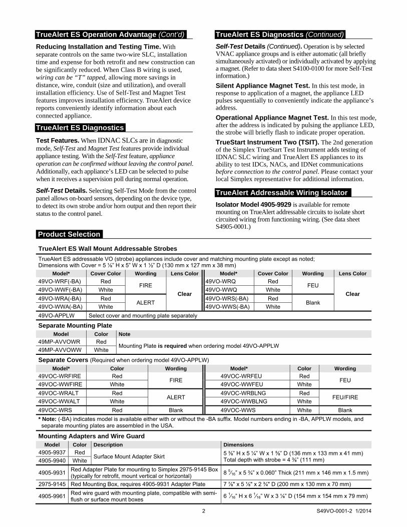
TrueAlert ES Operation Advantage (Cont’d)
Reducing Installation and Testing Time. With separate controls on the same two-wire SLC, installation time and expense for both retrofit and new construction can be significantly reduced. When Class B wiring is used, wiring can be “T” tapped, allowing more savings in distance, wire, conduit (size and utilization), and overall installation efficiency. Use of Self-Test and Magnet Test features improves installation efficiency. TrueAlert device reports conveniently identify information about each connected appliance.
TrueAlert ES Diagnostics
Test Features. When IDNAC SLCs are in diagnostic mode, Self-Test and Magnet Test features provide individual appliance testing. With the Self-Test feature, appliance operation can be confirmed without leaving the control panel. Additionally, each appliance’s LED can be selected to pulse when it receives a supervision poll during normal operation.
Self-Test Details. Selecting Self-Test Mode from the control panel allows on-board sensors, depending on the device type, to detect its own strobe and/or horn output and then report their status to the control panel.
TrueAlert ES Diagnostics (Continued)
Self-Test Details (Continued). Operation is by selected VNAC appliance groups and is either automatic (all briefly simultaneously activated) or individually activated by applying a magnet. (Refer to data sheet S4100-0100 for more Self-Test information.)
Silent Appliance Magnet Test. In this test mode, in response to application of a magnet, the appliance LED pulses sequentially to conveniently indicate the appliance’s address.
Operational Appliance Magnet Test. In this test mode, after the address is indicated by pulsing the appliance LED, the strobe will briefly flash to indicate proper operation.
TrueStart Instrument Two (TSIT). The 2nd generation of the Simplex TrueStart Test Instrument adds testing of IDNAC SLC wiring and TrueAlert ES appliances to its ability to test IDCs, NACs, and IDNet communications before connection to the control panel. Please contact your local Simplex representative for additional information.
TrueAlert Addressable Wiring Isolator
Isolator Model 4905-9929 is available for remote mounting on TrueAlert addressable circuits to isolate short circuited wiring from functioning wiring. (See data sheet S4905-0001.)
TrueAlert ES Wall Mount Addressable Strobes
TrueAlert ES addressable VO (strobe) appliances include cover and matching mounting plate except as noted; Dimensions with Cover = 5 ⅛” H x 5” W x 1 ½” D (130 mm x 127 mm x 38 mm)
Model* Cover Color Wording Lens Color Model* Cover Color Wording Lens Color
49VO-WRF(-BA) Red FIRE
Clear
49VO-WRQ Red FEU
Clear 49VO-WWF(-BA) White 49VO-WWQ White
49VO-WRA(-BA) Red ALERT
49VO-WRS(-BA) Red Blank
49VO-WWA(-BA) White 49VO-WWS(-BA) White
49VO-APPLW Select cover and mounting plate separately
Separate Mounting Plate Model Color Note
49MP-AVVOWR Red Mounting Plate is required when ordering model 49VO-APPLW
49MP-AVVOWW White
Separate Covers (Required when ordering model 49VO-APPLW) Model* Color Wording Model* Color Wording
49VOC-WRFIRE Red FIRE
49VOC-WRFEU Red FEU
49VOC-WWFIRE White 49VOC-WWFEU White
49VOC-WRALT Red ALERT
49VOC-WRBLNG Red FEU/FIRE
49VOC-WWALT White 49VOC-WWBLNG White
49VOC-WRS Red Blank 49VOC-WWS White Blank
* Note: (-BA) indicates model is available either with or without the -BA suffix. Model numbers ending in -BA, APPLW models, and separate mounting plates are assembled in the USA.
Mounting Adapters and Wire Guard Model Color Description Dimensions
4905-9937 Red Surface Mount Adapter Skirt
5 ⅜” H x 5 ¼” W x 1 ⅝” D (136 mm x 133 mm x 41 mm) Total depth with strobe = 4 ⅜” (111 mm) 4905-9940 White
4905-9931 Red Adapter Plate for mounting to Simplex 2975-9145 Box (typically for retrofit, mount vertical or horizontal)
8 5⁄16” x 5 ¾” x 0.060” Thick (211 mm x 146 mm x 1.5 mm)
2975-9145 Red Mounting Box, requires 4905-9931 Adapter Plate 7 ⅞" x 5 ⅛" x 2 ¾" D (200 mm x 130 mm x 70 mm)
4905-9961 Red wire guard with mounting plate, compatible with semi-flush or surface mount boxes
6 1⁄16” H x 6 1⁄16” W x 3 ⅛” D (154 mm x 154 mm x 79 mm)
2 S49VO-0001-2 1/2014
Product Selection

3 S49VO-0001-2 1/2014
Removable cover (when installed, use flat bladed screwdriver to release latch on left side)
Mounting is compatible with single gang, double gang, and 4" (102 mm) square boxes,
1-1/2" (38 mm) deep, supplied separately
Mounting Holes:Single gang (2)Double gang (4)4" square (4)
Magnetic test location (bottom of housing)
LED indicator location
Transparent housing assembly
Mounting plate
Electrical test point access holes(on bottom)
Wiring access hole
Wiring terminals and connection clips
Strobe intensity viewing slot on
side of appliance (not to scale)
Intensity selection plug, accessible from rear of housing; factory setting is FACP, controlled by panel
110753015
FACP135185
Address setting DIP switch, accessible
from rear of housing
NFPA 72 requires that the entire lens be not less than 80" and not greater than 96" above the finished floor (confirm with your local codes)
Electrical box outline
80" (2.03 m)minimum
IMPORTANT! WALL MOUNT INSTALLATION HEIGHT REFERENCE
Bottom of lens is either even with, or slightly above bottom of compatible boxes
TrueAlert ES Addressable Strobe
2975-9145 Box
4905-9931 Adapter Plate
4905-9931 Adapter Plate
4905-9961 Optional Wire Guard (shown here for reference only, can be used on other mounting options)
Optional 4905-9961
Wire Guard
4" square box profile,1-1/2" (38 mm) deep
(Surface mount conduit and box shown for reference)
Optional surface mount adapter skirt,1-1/2" deep: 4905-9937, Red;
4905-9940, White (conduit knockouts are provided on all four sides)
TrueAlert ES Addressable
Strobe
Surface Mount Side View Reference
2975-9145 Box Mounting Reference
Service Port Page 1REPORT 5 : TrueAlert Device Report 12:34:56am FRI 10-Jan-14 POINT ID
CUSTOM LABEL
DEVICETYPE
CANDELA
T14-1-1 Location Label . . . up to 40 characters V/O 15 T14-1-2 Break Room 5 A/V 110 T14-1-3 Boiler Room A/V 75 T14-1-4 Elec. Room 7 A/V 135
Adapter Plate and Surface Mount Installation Reference
Installation Reference
TrueAlert Device Reports Reference
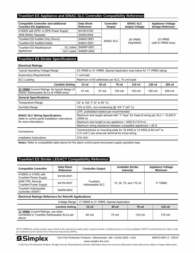
Electrical Ratings
Typical Operating Voltage Range 23 VRMS to 31 VRMS, Special Application (see below for 17 VRMS rating)
Supervisory Requirements 1 unit load
SLC Loading Maximum of 63 addresses per SLC, 75 unit loads
Candela Setting 15 cd 30 cd 75 cd 110 cd 135 cd 185 cd
23 VRMS Current Ratings, for typical design of IDNAC Addressable SLCs (6 VRMS drop)
47 mA 57 mA 100 mA 132 mA 160 mA 208 mA
General Specifications
Temperature Range 32 to 122 F (0 to 50 C)
Humidity Range 10% to 93%, non-condensing @ 104° F (40° C)
IDNAC SLC Wiring Specifications (refer to control panel installation instructions for more information)
UTP, unshielded twisted pair recommended Maximum wire length allowed with “T-Taps” for Class B wiring per SLC = 10,000 ft (3048 m) Maximum wire length to any appliance = 4000 ft (1219 m) Maximum wiring resistance between compatible appliances = 26 Ω
Connections Terminal blocks on mounting plate for 18 AWG to 12 AWG (0.82 mm2 to 3.31 mm2); two wires per terminal for in/out wiring
Installation Instructions 579-1031
Notes: Refer to compatibility table above for fire alarm control panel and power supply operation type.
TYCO, SIMPLEX, and the product names listed in this material are marks and/or registered marks. Unauthorized use is strictly prohibited. NFPA 72 and National Fire Alarm Code are trademarks of the National Fire Protection Association (NFPA).
Tyco Fire Protection Products • Westminster, MA • 01441-0001 • USA S49VO-0001-2 1/2014
www.simplex-fire.com © 2014 Tyco Fire Protection Products. All rights reserved. All specifications and other information shown were current as of document revision date and are subject to change without notice.
Compatible Controller Data Sheet Reference
Controller Output Available Strobe
Intensity Appliance Voltage
Minimum
4100ES or 4100U with TrueAlert Power Supply
S4100-0031
TrueAlert Addressable SLC
15, 30, 75, and 110 cd 17 VRMS 4009 TPS, Remote TrueAlert Power Supply
S4100-0037
TrueAlert Addressable Controller (4009T)
S4009-0003
Electrical Ratings Reference for Retrofit Applications
Voltage Range 17 VRMS to 31 VRMS, Special Application
Candela Setting 15 cd 30 cd 75 cd 110 cd
17 VRMS Current Ratings, use when connected to TrueAlert Addressable SLCs per above
62 mA 75 mA 133 mA 178 mA
Compatible Controller and additional TrueAlert ES Appliances
Data Sheet Reference
Controller Output
IDNAC SLC Output Voltage
Appliance Voltage Design Reference
4100ES with EPS+ or EPS Power Supply S4100-0100
IDNAC SLC 29 VRMS
(regulated) 23 VRMS
(with 6 VRMS drop)
4009 IDNAC Repeater S4009-0004
TrueAlert ES Audible Only (Horns) S49AO-0001
TrueAlert ES Audible/Visible S49AV-0001
TrueAlert ES Weatherproof Appliances
UL Listed S49WP-0001
ULC Listed S49WP-0002
TrueAlert ES Strobe Specifications
TrueAlert ES Strobe LEGACY Compatibility Reference
TrueAlert ES Appliance and IDNAC SLC Controller Compatibility Reference
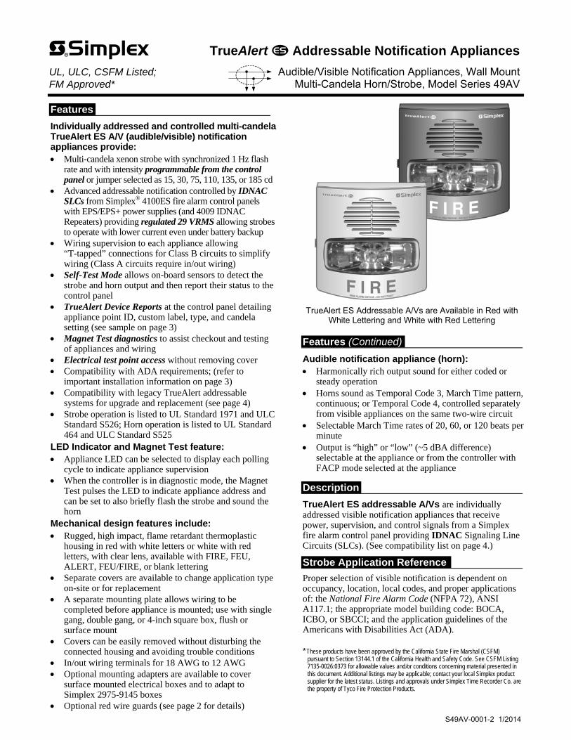
Features
Individually addressed and controlled multi-candela TrueAlert ES A/V (audible/visible) notification appliances provide: Multi-candela xenon strobe with synchronized 1 Hz flash
rate and with intensity programmable from the control panel or jumper selected as 15, 30, 75, 110, 135, or 185 cd
Advanced addressable notification controlled by IDNAC SLCs from Simplex® 4100ES fire alarm control panels with EPS/EPS+ power supplies (and 4009 IDNAC Repeaters) providing regulated 29 VRMS allowing strobes to operate with lower current even under battery backup
Wiring supervision to each appliance allowing “T-tapped” connections for Class B circuits to simplify wiring (Class A circuits require in/out wiring)
Self-Test Mode allows on-board sensors to detect the strobe and horn output and then report their status to the control panel
TrueAlert Device Reports at the control panel detailing appliance point ID, custom label, type, and candela setting (see sample on page 3)
Magnet Test diagnostics to assist checkout and testing of appliances and wiring
Electrical test point access without removing cover Compatibility with ADA requirements; (refer to
important installation information on page 3) Compatibility with legacy TrueAlert addressable
systems for upgrade and replacement (see page 4) Strobe operation is listed to UL Standard 1971 and ULC
Standard S526; Horn operation is listed to UL Standard 464 and ULC Standard S525
LED Indicator and Magnet Test feature: Appliance LED can be selected to display each polling
cycle to indicate appliance supervision When the controller is in diagnostic mode, the Magnet
Test pulses the LED to indicate appliance address and can be set to also briefly flash the strobe and sound the horn
Mechanical design features include: Rugged, high impact, flame retardant thermoplastic
housing in red with white letters or white with red letters, with clear lens, available with FIRE, FEU, ALERT, FEU/FIRE, or blank lettering
Separate covers are available to change application type on-site or for replacement
A separate mounting plate allows wiring to be completed before appliance is mounted; use with single gang, double gang, or 4-inch square box, flush or surface mount
Covers can be easily removed without disturbing the connected housing and avoiding trouble conditions
In/out wiring terminals for 18 AWG to 12 AWG Optional mounting adapters are available to cover
surface mounted electrical boxes and to adapt to Simplex 2975-9145 boxes
Optional red wire guards (see page 2 for details)
TrueAlert ES Addressable A/Vs are Available in Red with
White Lettering and White with Red Lettering Features (Continued)
Audible notification appliance (horn): Harmonically rich output sound for either coded or
steady operation Horns sound as Temporal Code 3, March Time pattern,
continuous; or Temporal Code 4, controlled separately from visible appliances on the same two-wire circuit
Selectable March Time rates of 20, 60, or 120 beats per minute
Output is “high” or “low” (~5 dBA difference) selectable at the appliance or from the controller with FACP mode selected at the appliance
Description
TrueAlert ES addressable A/Vs are individually addressed visible notification appliances that receive power, supervision, and control signals from a Simplex fire alarm control panel providing IDNAC Signaling Line Circuits (SLCs). (See compatibility list on page 4.)
Strobe Application Reference
Proper selection of visible notification is dependent on occupancy, location, local codes, and proper applications of: the National Fire Alarm Code (NFPA 72), ANSI A117.1; the appropriate model building code: BOCA, ICBO, or SBCCI; and the application guidelines of the Americans with Disabilities Act (ADA).
* These products have been approved by the California State Fire Marshal (CSFM)
pursuant to Section 13144.1 of the California Health and Safety Code. See CSFM Listing 7135-0026:0373 for allowable values and/or conditions concerning material presented in this document. Additional listings may be applicable; contact your local Simplex product supplier for the latest status. Listings and approvals under Simplex Time Recorder Co. are the property of Tyco Fire Protection Products.
TrueAlert Addressable Notification Appliances UL, ULC, CSFM Listed; Audible/Visible Notification Appliances, Wall Mount FM Approved* Multi-Candela Horn/Strobe, Model Series 49AV
S49AV-0001-2 1/2014

TrueAlert ES Operation Advantage
TrueAlert ES addressable appliances on IDNAC SLCs provide separate visible and audible notification using a single two-wire circuit that also confirms connection to the individual notification appliance’s electronic circuit. This operation increases circuit supervision integrity by providing supervision that extends beyond the appliance wiring connections.
Reduced current allows efficient IDNAC SLC operation. With IDNAC SLCs, a constant 29 VRMS source voltage is maintained, even during battery standby, allowing strobes to operate at higher voltage with lower current and ensuring a consistent current draw and voltage drop margin under both primary power and secondary battery standby. Efficiencies include wiring distances up to 2 to 3 times farther than with conventional notification, or support for more appliances per IDNAC SLC, or use of smaller gauge wiring, or combinations of these benefits, all providing installation and maintenance savings with high assurance that appliances that operate during normal system testing will operate during worst case alarm conditions.
Reducing Installation and Testing Time. With separate controls on the same two-wire SLC, installation time and expense for both retrofit and new construction can be significantly reduced. When Class B wiring is used, wiring can be “T” tapped, allowing more savings in distance, wire, conduit (size and utilization), and overall installation efficiency. Use of Self-Test and Magnet Test features improve installation efficiency. TrueAlert device reports conveniently identify information about each connected appliance.
TrueAlert ES Diagnostics
Test Features. When IDNAC SLCs are in diagnostic mode, Self-Test and Magnet Test features provide individual appliance testing. With the Self-Test feature, appliance operation can be confirmed without leaving the control panel. Additionally, each appliance’s LED can be selected to pulse when it receives a supervision poll during normal operation. Self-Test Details. Selecting Self-Test Mode from the control panel allows on-board sensors, depending on the device type, to detect its own strobe and/or horn output and then report their status to the control panel. Operation is by selected VNAC appliance groups and is either automatic (all briefly simultaneously activated) or individually activated by applying a magnet. (Refer to data sheet S4100-0100 for more Self-Test information.) Silent Appliance Magnet Test. In this test mode, in response to application of a magnet, the appliance LED pulses sequentially to conveniently indicate the appliance’s address. Operational Appliance Magnet Test. In this test mode, after the address is indicated by pulsing the appliance LED, the strobe will briefly flash and the horn will briefly sound to indicate proper operation. TrueStart Instrument Two (TSIT). The 2nd generation of the Simplex TrueStart Test Instrument adds testing of IDNAC SLC wiring and TrueAlert ES appliances to its ability to test IDCs, NACs, and IDNet communications before connection to the control panel. Please contact your local Simplex representative for additional information.
TrueAlert Addressable Wiring Isolator
Isolator Model 4905-9929 is available for remote mounting on TrueAlert addressable circuits to isolate short circuited wiring from functioning wiring. (See data sheet S4905-0001.)
TrueAlert ES Wall Mount Addressable Audible/Visible Appliances
TrueAlert ES addressable A/V appliances include cover and matching mounting plate except as noted; Dimensions with Cover = 5 ⅛” H x 5” W x 1 ½” D (130 mm x 127 mm x 38 mm)
Model* Cover Color Wording Lens Color Model* Cover Color Wording Lens Color 49AV-WRF(-BA) Red
FIRE Clear
49AV-WRS(-BA) Red Blank Clear
49AV-WWF(-BA) White 49AV-WWS-BA White
49AV-WRQ Red FEU 49AV-APPLW Select cover and mounting plate separately
Separate Mounting Plate Model Color Model Color Note
49MP-AVVOWR Red 49MP-AVVOWW White Mounting Plate is required when ordering model 49AV-APPLW
Separate Covers (Required when ordering model 49AV-APPLW) Model* Color Wording Model* Color Wording
49AVC-WRFIRE Red FIRE
49AVC-WRFEU Red FEU
49AVC-WWFIRE White 49AVC-WWFEU White
49AVC-WRALT Red ALERT
49AVC-WRBLNG Red FEU/FIRE
49AVC-WWALT White 49AVC-WWBLNG White
49AVC-WRS Red Blank 49AVC-WWS White Blank
* Note: (-BA) indicates model is available either with or without the -BA suffix. Model numbers ending in -BA, APPLW models, and separate mounting plates are assembled in the USA.
Mounting Adapters and Wire Guard Model Color Description Dimensions
4905-9937 Red Surface Mount Adapter Skirt
5 ⅜” H x 5 ¼” W x 1 ⅝” D (136 mm x 133 mm x 41 mm) Total depth with strobe = 4 ⅜” (111 mm) 4905-9940 White
4905-9931 Red Adapter Plate for mounting to Simplex 2975-9145 Box (typically for retrofit, mount vertical or horizontal) 8 5⁄16” x 5 ¾” x 0.060” Thick (211 mm x 146 mm x 1.5 mm)
2975-9145 Red Mounting Box, requires 4905-9931 Adapter Plate 7 ⅞" x 5 ⅛" x 2 ¾" D (200 mm x 130 mm x 70 mm)
4905-9961 Red wire guard with mounting plate, compatible with semi-flush or surface mount boxes
6 1⁄16” H x 6 1⁄16” W x 3 ⅛” D (154 mm x 154 mm x 79 mm)
2 S49AV-0001-2 1/2014
Product Selection

3 S49AV-0001-2 1/2014
NFPA 72 requires that the entire lens be not less than 80" and not greater than 96" above the finished floor (confirm with your local codes)
Removable cover (when installed, use flat bladed screwdriver to release latch on left side)
Mounting is compatible with single gang, double gang, and 4" (102 mm) square boxes,
1-1/2" (38 mm) deep, supplied separately
Mounting Holes:Single gang (2)Double gang (4)4" square (4)
Magnetic test location(bottom of housing)
LED indicator location
Transparent housing assembly
Mounting plate
Electrical test point access holes(on bottom)
Wiring access hole
Wiring terminals and connection clips Electrical
box outline
80" (2.03 m)minimum
IMPORTANT! WALL MOUNT INSTALLATION HEIGHT REFERENCE
Bottom of lens is either even with, or slightly above bottom of compatible boxes
Strobe intensity viewing slot on
side of appliance (not to scale)
Intensity selection plug, accessible from rear of housing; factory setting is FACP, controlled by panel
110753015
FACP135185
Address setting DIP switch, accessible
from rear of housing
A/V configuration switch
TrueAlert ES Addressable A/V
2975-9145 Box
4905-9931 Adapter Plate
4905-9931 Adapter Plate
4905-9961 Optional Wire Guard (shown here for reference only, can be used on other mounting options)
Optional 4905-9961
Wire Guard
4" square box profile,1-1/2" (38 mm) deep
(Surface mount conduit and box shown for reference)
Optional surface mount adapter skirt,1-1/2" deep: 4905-9937, Red;
4905-9940, White (conduit knockouts are provided on all four sides)
TrueAlert ES Addressable A/V
Surface Mount Side View Reference
2975-9145 Box Mounting Reference
Service Port Page 1REPORT 5 : TrueAlert Device Report 12:34:56am FRI 10-Jan-14 POINT ID
CUSTOM LABEL
DEVICETYPE
CANDELA
T14-1-1 Location Label . . . up to 40 characters V/O 15 T14-1-2 Break Room 5 A/V 110 T14-1-3 Boiler Room A/V 75 T14-1-4 Elec. Room 7 A/V 135
Adapter Plate and Surface Mount Installation Reference
Installation Reference
TrueAlert Device Reports Reference

TYCO, SIMPLEX, and the product names listed in this material are marks and/or registered marks. Unauthorized use is strictly prohibited. NFPA 72 and National Fire Alarm Code are trademarks of the National Fire Protection Association (NFPA).
Tyco Fire Protection Products • Westminster, MA • 01441-0001 • USA S49AV-0001-2 1/2014
www.simplex-fire.com © 2014 Tyco Fire Protection Products. All rights reserved. All specifications and other information shown were current as of document revision date and are subject to change without notice.
Compatible Controller Data Sheet Reference
Controller Output
Available Strobe Intensity
Available Horn Control
Appliance Voltage Minimum
4100ES or 4100U with TrueAlert Power Supply
S4100-0031
TrueAlert Addressable
SLC
15, 30, 75, and 110 cd
Continuous, Temporal Code 3, and March
Time of 60 or 120 bpm 17 VRMS
4009 TPS, Remote TrueAlert Power Supply
S4100-0037
TrueAlert Addressable Controller (4009T)
S4009-0003
Electrical Ratings Differences for Legacy Applications (refer to above specifications for other ratings)
Voltage Range 17 VRMS to 31 VRMS, Special Application
Sound Output Ratings @ 10 ft (3 m) @ 17 VRMS
Sound Type/Setting Steady/High Steady/Low Coded/High Coded/Low
Reverberant Chamber, UL 464 Test 87.8 dBA 81.6 dBA 83.4 dBA 77.0 dBA
Anechoic Chamber, ULC 525 Test 91.7 dBA 85.4 dBA 91.7 dBA 85.4 dBA
Candela Setting 15 cd 30 cd 75 cd 110 cd
17 VRMS Current Ratings, with horn on continuous at high setting, use when connected to TrueAlert Addressable SLCs per above
74 mA 85 mA 140 mA 185 mA
Compatible Controller and additional TrueAlert ES Appliances
Data Sheet Reference
Controller Output
IDNAC SLC Output Voltage
Appliance Voltage Design Reference
4100ES with EPS+ or EPS Power Supply S4100-0100
IDNAC SLC 29 VRMS
(regulated) 23 VRMS
(with 6 VRMS drop)
4009 IDNAC Repeater S4009-0004
TrueAlert ES Audible Only (Horns) S49AO-0001 TrueAlert ES Visible Only (Strobes) S49VO-0001
TrueAlert ES Weatherproof Appliances
UL Listed S49WP-0001 ULC Listed S49WP-0002
Electrical Ratings
Typical Operating Voltage Range 23 VRMS to 31 VRMS, Special Application (see below for 17 VRMS rating)
Supervisory Requirements 1 unit load
SLC Loading Maximum of 63 addresses per SLC, 75 unit loads
Sound Output Ratings @ 10 ft (3 m) @ 23 VRMS (with IDNAC SLCs)
Sound Type/Setting Steady/High Steady/Low Coded/High Coded/Low
Reverberant Chamber, UL 464 Test 90.1 dBA 83.6 dBA 85.7 dBA 80.1 dBA
Anechoic Chamber, ULC 525 Test 94.1 dBA 88.1 dBA 94.1 dBA 88.1 dBA
Sound Output Dispersion per ULC S541 Anechoic Testing
Horizontal -3 dBA @ 50°; -6 dBA @ 63°; left and right from center
Vertical -3 dBA @ 20° above, 48° below; -6 dBA @ 65° above, 60° below; ref. to center
Candela Setting 15 cd 30 cd 75 cd 110 cd 135 cd 185 cd
23 VRMS Current Ratings, with horn on continuous at high setting
59 mA 67 mA 107 mA 139 mA 166 mA 215 mA
General Specifications
Sound Characteristics 2400 to 3700 Hz sweep, modulated at 120 Hz rate
Connections
Terminal blocks on mounting plate for 18 AWG to 12 AWG (0.82 mm2 to 3.31 mm2); two wires per terminal for in/out wiring
Temperature Range 32 to 122 F (0 to 50 C)
Humidity Range 10% to 93%, non-condensing @ 104° F (40° C)
Installation Instructions 579-1031
IDNAC SLC Wiring Specifications (refer to control panel installation instructions for more information)
UTP, unshielded twisted pair recommended Maximum wire length allowed with “T-Taps” for Class B wiring per SLC = 10,000 ft (3048 m) Maximum wire length to any appliance = 4000 ft (1219 m) Maximum wiring resistance between compatible appliances = 26 Ω
Note: UL 464 test coded values are typical of the output measured with a Temporal or a March Time pattern and with a sound level meter reading on a “fast” setting. Under the same test conditions, coded horn output “peak” sound level readings are typically 4 dBA higher. Anechoic horn output ratings are typically more representative of actual installed sound output.
TrueAlert ES A/V Specifications
TrueAlert ES A/V LEGACY Compatibility Reference
TrueAlert ES Appliance and IDNAC SLC Controller Compatibility Reference
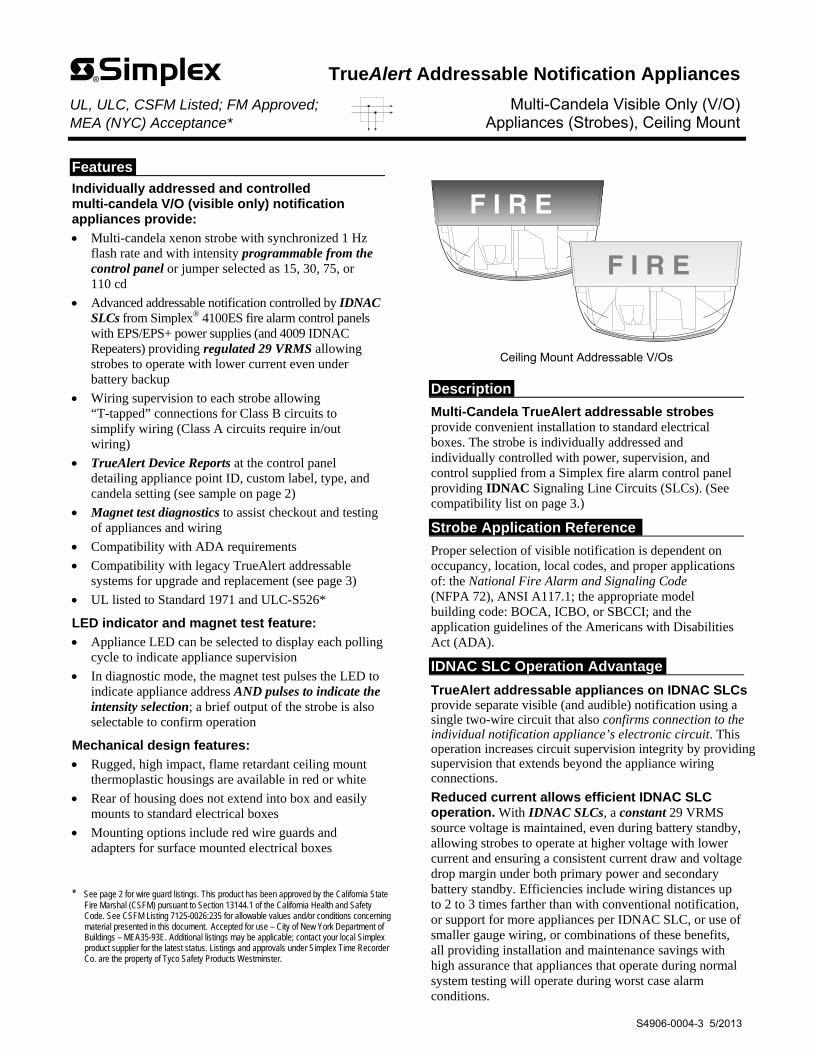
Features
Individually addressed and controlled multi-candela V/O (visible only) notification appliances provide:
Multi-candela xenon strobe with synchronized 1 Hz flash rate and with intensity programmable from the control panel or jumper selected as 15, 30, 75, or 110 cd
Advanced addressable notification controlled by IDNAC SLCs from Simplex® 4100ES fire alarm control panels with EPS/EPS+ power supplies (and 4009 IDNAC Repeaters) providing regulated 29 VRMS allowing strobes to operate with lower current even under battery backup
Wiring supervision to each strobe allowing “T-tapped” connections for Class B circuits to simplify wiring (Class A circuits require in/out wiring)
TrueAlert Device Reports at the control panel detailing appliance point ID, custom label, type, and candela setting (see sample on page 2)
Magnet test diagnostics to assist checkout and testing of appliances and wiring
Compatibility with ADA requirements
Compatibility with legacy TrueAlert addressable systems for upgrade and replacement (see page 3)
UL listed to Standard 1971 and ULC-S526*
LED indicator and magnet test feature:
Appliance LED can be selected to display each polling cycle to indicate appliance supervision
In diagnostic mode, the magnet test pulses the LED to indicate appliance address AND pulses to indicate the intensity selection; a brief output of the strobe is also selectable to confirm operation
Mechanical design features:
Rugged, high impact, flame retardant ceiling mount thermoplastic housings are available in red or white
Rear of housing does not extend into box and easily mounts to standard electrical boxes
Mounting options include red wire guards and adapters for surface mounted electrical boxes
* See page 2 for wire guard listings. This product has been approved by the California State
Fire Marshal (CSFM) pursuant to Section 13144.1 of the California Health and Safety Code. See CSFM Listing 7125-0026:235 for allowable values and/or conditions concerning material presented in this document. Accepted for use – City of New York Department of Buildings – MEA35-93E. Additional listings may be applicable; contact your local Simplex product supplier for the latest status. Listings and approvals under Simplex Time Recorder Co. are the property of Tyco Safety Products Westminster.
Ceiling Mount Addressable V/Os
Description
Multi-Candela TrueAlert addressable strobes provide convenient installation to standard electrical boxes. The strobe is individually addressed and individually controlled with power, supervision, and control supplied from a Simplex fire alarm control panel providing IDNAC Signaling Line Circuits (SLCs). (See compatibility list on page 3.)
Strobe Application Reference
Proper selection of visible notification is dependent on occupancy, location, local codes, and proper applications of: the National Fire Alarm and Signaling Code (NFPA 72), ANSI A117.1; the appropriate model building code: BOCA, ICBO, or SBCCI; and the application guidelines of the Americans with Disabilities Act (ADA).
IDNAC SLC Operation Advantage
TrueAlert addressable appliances on IDNAC SLCs provide separate visible (and audible) notification using a single two-wire circuit that also confirms connection to the individual notification appliance’s electronic circuit. This operation increases circuit supervision integrity by providing supervision that extends beyond the appliance wiring connections.
Reduced current allows efficient IDNAC SLC operation. With IDNAC SLCs, a constant 29 VRMS source voltage is maintained, even during battery standby, allowing strobes to operate at higher voltage with lower current and ensuring a consistent current draw and voltage drop margin under both primary power and secondary battery standby. Efficiencies include wiring distances up to 2 to 3 times farther than with conventional notification, or support for more appliances per IDNAC SLC, or use of smaller gauge wiring, or combinations of these benefits, all providing installation and maintenance savings with high assurance that appliances that operate during normal system testing will operate during worst case alarm conditions.
TrueAlert Addressable Notification Appliances UL, ULC, CSFM Listed; FM Approved; Multi-Candela Visible Only (V/O) MEA (NYC) Acceptance* Appliances (Strobes), Ceiling Mount
S4906-0004-3 5/2013
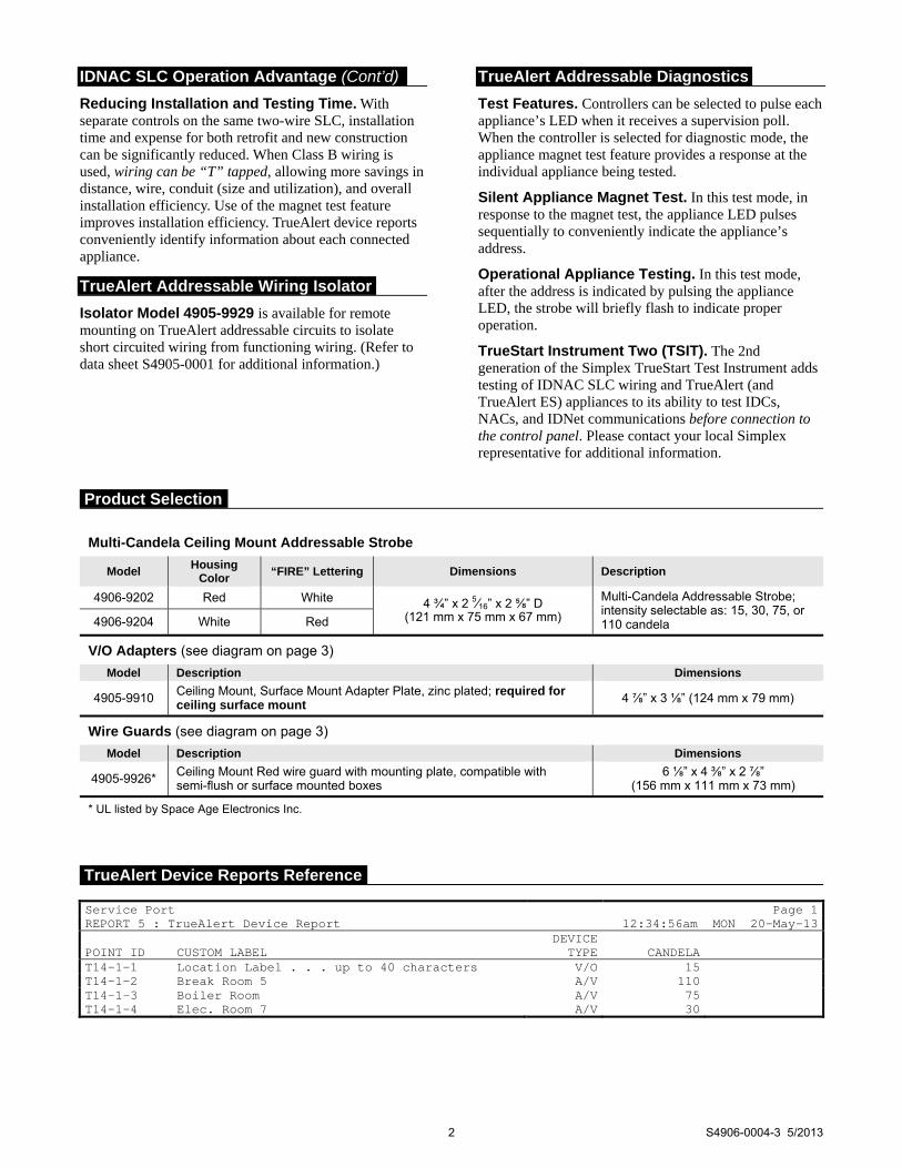
IDNAC SLC Operation Advantage (Cont’d)
Reducing Installation and Testing Time. With separate controls on the same two-wire SLC, installation time and expense for both retrofit and new construction can be significantly reduced. When Class B wiring is used, wiring can be “T” tapped, allowing more savings in distance, wire, conduit (size and utilization), and overall installation efficiency. Use of the magnet test feature improves installation efficiency. TrueAlert device reports conveniently identify information about each connected appliance.
TrueAlert Addressable Wiring Isolator
Isolator Model 4905-9929 is available for remote mounting on TrueAlert addressable circuits to isolate short circuited wiring from functioning wiring. (Refer to data sheet S4905-0001 for additional information.)
TrueAlert Addressable Diagnostics
Test Features. Controllers can be selected to pulse each appliance’s LED when it receives a supervision poll. When the controller is selected for diagnostic mode, the appliance magnet test feature provides a response at the individual appliance being tested.
Silent Appliance Magnet Test. In this test mode, in response to the magnet test, the appliance LED pulses sequentially to conveniently indicate the appliance’s address.
Operational Appliance Testing. In this test mode, after the address is indicated by pulsing the appliance LED, the strobe will briefly flash to indicate proper operation.
TrueStart Instrument Two (TSIT). The 2nd generation of the Simplex TrueStart Test Instrument adds testing of IDNAC SLC wiring and TrueAlert (and TrueAlert ES) appliances to its ability to test IDCs, NACs, and IDNet communications before connection to the control panel. Please contact your local Simplex representative for additional information.
2 S4906-0004-3 5/2013
Multi-Candela Ceiling Mount Addressable Strobe
Model Housing
Color “FIRE” Lettering Dimensions Description
4906-9202 Red White 4 ¾” x 2 5⁄16” x 2 ⅝” D (121 mm x 75 mm x 67 mm)
Multi-Candela Addressable Strobe; intensity selectable as: 15, 30, 75, or 110 candela 4906-9204 White Red
V/O Adapters (see diagram on page 3)
Model Description Dimensions
4905-9910 Ceiling Mount, Surface Mount Adapter Plate, zinc plated; required for ceiling surface mount 4 ⅞” x 3 ⅛” (124 mm x 79 mm)
Wire Guards (see diagram on page 3)
Model Description Dimensions
4905-9926* Ceiling Mount Red wire guard with mounting plate, compatible with semi-flush or surface mounted boxes
6 ⅛” x 4 ⅜” x 2 ⅞” (156 mm x 111 mm x 73 mm)
* UL listed by Space Age Electronics Inc.
Service Port Page 1REPORT 5 : TrueAlert Device Report 12:34:56am MON 20-May-13 POINT ID
CUSTOM LABEL
DEVICETYPE
CANDELA
T14-1-1 Location Label . . . up to 40 characters V/O 15 T14-1-2 Break Room 5 A/V 110 T14-1-3 Boiler Room A/V 75 T14-1-4 Elec. Room 7 A/V 30
Product Selection
TrueAlert Device Reports Reference
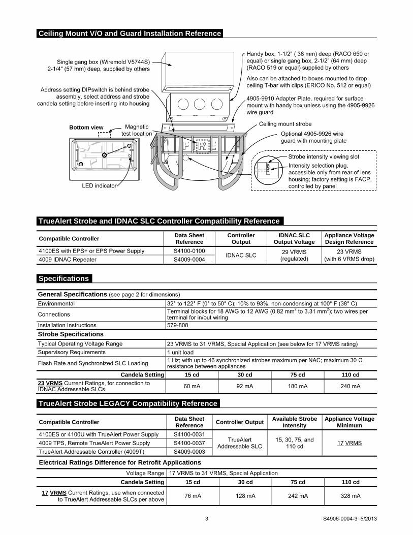
3 S4906-0004-3 5/2013
15110
75 30 FA
CP
Strobe intensity viewing slot
Intensity selection plug, accessible only from rear of lens housing; factory setting is FACP, controlled by panel
4905-9910 Adapter Plate, required for surface mount with handy box unless using the 4905-9926 wire guard
Handy box, 1-1/2" ( 38 mm) deep (RACO 650 or equal) or single gang box, 2-1/2" (64 mm) deep (RACO 519 or equal) supplied by others
Also can be attached to boxes mounted to drop ceiling T-bar with clips (ERICO No. 512 or equal)
Ceiling mount strobe
Optional 4905-9926 wire guard with mounting plate
Magnetic test location
Bottom view
LED indicator
Address setting DIPswitch is behind strobe assembly, select address and strobe
candela setting before inserting into housing
Single gang box (Wiremold V5744S) 2-1/4" (57 mm) deep, supplied by others
Compatible Controller Data Sheet Reference
Controller Output Available Strobe
Intensity Appliance Voltage
Minimum
4100ES or 4100U with TrueAlert Power Supply S4100-0031 TrueAlert
Addressable SLC 15, 30, 75, and
110 cd 17 VRMS 4009 TPS, Remote TrueAlert Power Supply S4100-0037
TrueAlert Addressable Controller (4009T) S4009-0003
Electrical Ratings Difference for Retrofit Applications
Voltage Range 17 VRMS to 31 VRMS, Special Application
Candela Setting 15 cd 30 cd 75 cd 110 cd
17 VRMS Current Ratings, use when connected to TrueAlert Addressable SLCs per above
76 mA 128 mA 242 mA 328 mA
General Specifications (see page 2 for dimensions)
Environmental 32° to 122° F (0° to 50° C); 10% to 93%, non-condensing at 100° F (38° C)
Connections Terminal blocks for 18 AWG to 12 AWG (0.82 mm2 to 3.31 mm2); two wires per terminal for in/out wiring
Installation Instructions 579-808
Strobe Specifications
Typical Operating Voltage Range 23 VRMS to 31 VRMS, Special Application (see below for 17 VRMS rating)
Supervisory Requirements 1 unit load
Flash Rate and Synchronized SLC Loading 1 Hz; with up to 46 synchronized strobes maximum per NAC; maximum 30 Ω resistance between appliances
Candela Setting 15 cd 30 cd 75 cd 110 cd
23 VRMS Current Ratings, for connection to IDNAC Addressable SLCs 60 mA 92 mA 180 mA 240 mA
Compatible Controller Data Sheet Reference
Controller Output
IDNAC SLC Output Voltage
Appliance Voltage Design Reference
4100ES with EPS+ or EPS Power Supply S4100-0100 IDNAC SLC
29 VRMS (regulated)
23 VRMS (with 6 VRMS drop)4009 IDNAC Repeater S4009-0004
Ceiling Mount V/O and Guard Installation Reference
TrueAlert Strobe LEGACY Compatibility Reference
Specifications
TrueAlert Strobe and IDNAC SLC Controller Compatibility Reference

TYCO, SIMPLEX, and the product names listed in this material are marks and/or registered marks. Unauthorized use is strictly prohibited. NFPA 72 and National Fire Alarm and Signaling Code are registered trademarks of the National Fire Protection Association (NFPA).
Tyco Fire Protection Products • Westminster, MA • 01441-0001 • USA S4906-0004-3 5/2013
www.simplexgrinnell.com © 2013 Tyco Fire Protection Products. All rights reserved. All specifications and other information shown were current as of document revision date and are subject to change without notice.

Features
Individually addressed and controlled multi-candela A/V (audible/visible) notification appliances provide: Multi-candela xenon strobe with synchronized 1 Hz
flash rate and with intensity programmable from the control panel or jumper selected as 15, 30, 75, or 110 cd
Advanced addressable notification controlled by IDNAC SLCs from Simplex® 4100ES fire alarm control panels with EPS/EPS+ power supplies (and 4009 IDNAC Repeaters) providing regulated 29 VRMS allowing strobes to operate with lower current even under battery backup
Wiring supervision to each strobe allowing “T-tapped” connections for Class B circuits to simplify wiring (Class A circuits require in/out wiring)
TrueAlert Device Reports at the control panel detailing appliance point ID, custom label, type, and candela setting (see sample on page 2)
Magnet test diagnostics to assist checkout and testing of appliances and wiring
Compatibility with ADA requirements Compatibility with legacy TrueAlert addressable
systems for upgrade and replacement (see page 4) Strobe operation listed to UL Standard 1971 and ULC
Standard S526 Horn operation listed to UL Standard 464 and ULC
Standard S525 LED indicator and magnet test feature: Appliance LED can be selected to display each polling
cycle to indicate appliance supervision In diagnostic mode, the magnet test pulses the LED to
indicate appliance address AND pulses to indicate the intensity selection; a brief output of the strobe and the horn is also selectable to confirm operation
Mechanical design features: Rugged, high impact, flame retardant thermoplastic
housings are available in red or white Rear of housing does not extend into box and easily
mounts to standard electrical boxes Mounting options include red wire guards and
adapters for surface mount electrical boxes Audible notification appliance (horn): Low current electronic horn with harmonically rich
output sound for either coded or steady operation Horns sound as Temporal or March Time pattern
(60 or 120 BPM), or on continuously, controlled separately from visible appliances on the same two-wire circuit
Output is “high” or “low” (~5 dBA difference); IDNAC SLC control selects output per device
Ceiling Mount Addressable A/Vs
Description
Multi-Candela TrueAlert addressable A/Vs provide convenient installation to standard electrical boxes. Operation is individually addressed and individually controlled with power, supervision, and control supplied from a Simplex fire alarm control panel providing IDNAC Signaling Line Circuits (SLCs). (See compatibility list on page 3.)
Strobe Application Reference
Proper selection of visible notification is dependent on occupancy, location, local codes, and proper applications of: the National Fire Alarm and Signaling Code (NFPA 72), ANSI A117.1; the appropriate model building code: BOCA, ICBO, or SBCCI; and the application guidelines of the Americans with Disabilities Act (ADA).
IDNAC SLC Operation Advantage
TrueAlert A/V Addressable Appliances on IDNAC SLCs provide audible and visible notification using a single two-wire circuit that also confirms connection to the individual notification appliance’s electronic circuit. This operation increases circuit supervision integrity by providing supervision that extends beyond the appliance wiring connections.
* See page 2 for wire guard listings. This product has been approved by the California State
Fire Marshal (CSFM) pursuant to Section 13144.1 of the California Health and Safety Code. See CSFM Listing 7125-0026:239 for allowable values and/or conditions concerning material presented in this document. Accepted for use – City of New York Department of Buildings – MEA35-93E. Additional listings may be applicable; contact your local Simplex product supplier for the latest status. Listings and approvals under Simplex Time Recorder Co. are the property of Tyco Safety Products Westminster.
TrueAlert Addressable Notification Appliances UL, ULC, CSFM Listed; FM Approved; Multi-Candela Audible/Visible MEA (NYC) Acceptance* (A/V) Appliances; Ceiling Mount
S4906-0005-3 5/2013
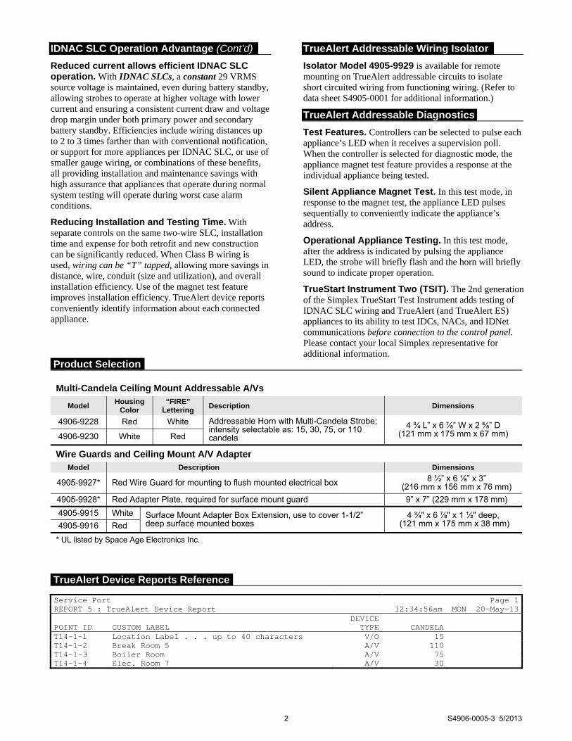
IDNAC SLC Operation Advantage (Cont’d)
Reduced current allows efficient IDNAC SLC operation. With IDNAC SLCs, a constant 29 VRMS source voltage is maintained, even during battery standby, allowing strobes to operate at higher voltage with lower current and ensuring a consistent current draw and voltage drop margin under both primary power and secondary battery standby. Efficiencies include wiring distances up to 2 to 3 times farther than with conventional notification, or support for more appliances per IDNAC SLC, or use of smaller gauge wiring, or combinations of these benefits, all providing installation and maintenance savings with high assurance that appliances that operate during normal system testing will operate during worst case alarm conditions.
Reducing Installation and Testing Time. With separate controls on the same two-wire SLC, installation time and expense for both retrofit and new construction can be significantly reduced. When Class B wiring is used, wiring can be “T” tapped, allowing more savings in distance, wire, conduit (size and utilization), and overall installation efficiency. Use of the magnet test feature improves installation efficiency. TrueAlert device reports conveniently identify information about each connected appliance.
TrueAlert Addressable Wiring Isolator
Isolator Model 4905-9929 is available for remote mounting on TrueAlert addressable circuits to isolate short circuited wiring from functioning wiring. (Refer to data sheet S4905-0001 for additional information.)
TrueAlert Addressable Diagnostics
Test Features. Controllers can be selected to pulse each appliance’s LED when it receives a supervision poll. When the controller is selected for diagnostic mode, the appliance magnet test feature provides a response at the individual appliance being tested.
Silent Appliance Magnet Test. In this test mode, in response to the magnet test, the appliance LED pulses sequentially to conveniently indicate the appliance’s address.
Operational Appliance Testing. In this test mode, after the address is indicated by pulsing the appliance LED, the strobe will briefly flash and the horn will briefly sound to indicate proper operation.
TrueStart Instrument Two (TSIT). The 2nd generation of the Simplex TrueStart Test Instrument adds testing of IDNAC SLC wiring and TrueAlert (and TrueAlert ES) appliances to its ability to test IDCs, NACs, and IDNet communications before connection to the control panel. Please contact your local Simplex representative for additional information.
2 S4906-0005-3 5/2013
Service Port Page 1REPORT 5 : TrueAlert Device Report 12:34:56am MON 20-May-13 POINT ID
CUSTOM LABEL
DEVICETYPE
CANDELA
T14-1-1 Location Label . . . up to 40 characters V/O 15 T14-1-2 Break Room 5 A/V 110 T14-1-3 Boiler Room A/V 75 T14-1-4 Elec. Room 7 A/V 30
Multi-Candela Ceiling Mount Addressable A/Vs
Model Housing
Color “FIRE”
Lettering Description Dimensions
4906-9228 Red White Addressable Horn with Multi-Candela Strobe; intensity selectable as: 15, 30, 75, or 110 candela
4 ¾ L” x 6 ⅞” W x 2 ⅝” D (121 mm x 175 mm x 67 mm) 4906-9230 White Red
Wire Guards and Ceiling Mount A/V Adapter Model Description Dimensions
4905-9927* Red Wire Guard for mounting to flush mounted electrical box 8 ½” x 6 ⅛” x 3” (216 mm x 156 mm x 76 mm)
4905-9928* Red Adapter Plate, required for surface mount guard 9” x 7” (229 mm x 178 mm)
4905-9915 White Surface Mount Adapter Box Extension, use to cover 1-1/2” deep surface mounted boxes
4 ¾" x 6 ⅞" x 1 ½" deep, (121 mm x 175 mm x 38 mm) 4905-9916 Red
* UL listed by Space Age Electronics Inc.
Product Selection
TrueAlert Device Reports Reference

3 S4906-0005-3 5/2013
110
75 30 15 FA
CP
Optional 4905-9915 (white) or 4905-9916 (red)Adapter, recommended for surface mounted box
Wiring terminals and address settingare located behind the housing
Ceiling reference,surface mounted box
Ceiling reference,flush mounted box
Strobe intensity viewing slot
Intensity selection plug,accessible only from rear oflens housing; factory setting isFACP, controlled by panel
Optional 4905-9928Adapter Plate, requiredfor surface mountedelectrical box
Optional 4905-9927Red Wire Guard
Four mounting clampsincluded, two each side
End View
Magnetic test areaLED indicator
Strobe housing straight-on view
4" (102 mm)square box,1-1/2" (38 mm)minimum depth
Compatible Controller Data Sheet Reference
Controller Output
IDNAC SLC Output Voltage
Appliance Voltage Design Reference
4100ES with EPS+ or EPS Power Supply S4100-0100 IDNAC SLC
29 VRMS (regulated)
23 VRMS (with 6 VRMS drop)4009 IDNAC Repeater S4009-0004
General Specifications (see page 2 for dimensions)
Environmental 32° to 122° F (0° to 50° C); 10% to 93%, non-condensing at 100° F (38° C)
Connections Terminal blocks for 18 AWG to 12 AWG (0.82 mm2 to 3.31 mm2); two wires per terminal for in/out wiring
Reference Installation Instructions 579-808
Electrical Specifications
Typical Operating Voltage Range 23 VRMS to 31 VRMS, Special Application (see page 4 for 17 VRMS rating)
Flash Rate and Synchronized SLC Loading 1 Hz; with up to 46 synchronized strobes maximum per NAC; maximum 30 Ω resistance between appliances
Candela Setting 15 cd 30 cd 75 cd 110 cd Horn Output Selection High Low High Low High Low High Low
23 VRMS Current Ratings, for connection to IDNAC Addressable SLCs, horn steady on 75 mA 70 m A 110 mA 105 mA 198 mA 193 mA 250 mA 245 mA
Horn Output Characteristics 2400 to 3700 Hz sweep, modulated at 120 Hz rate
Horn Output Ratings @ 10 ft (3 m)
Sound Type (see Note) Steady Coded
Setting High Low High Low
Reverberant Chamber, UL 464 Test 84.6 dBA 79.1 dBA 80.6 dBA 75.5 dBA
Anechoic Chamber 90 dBA 84 dBA 86 dBA 80 dBA
Note: Coded horn values are typical of the output measured with a Temporal or March Time pattern and with a sound level meter reading on a “fast” setting. Under the same test conditions, coded horn output “peak” sound level readings are typically 4 dBA higher.
Ceiling Mount A/V and Guard Installation Reference
TrueAlert Strobe and IDNAC SLC Controller Compatibility Reference
Specifications
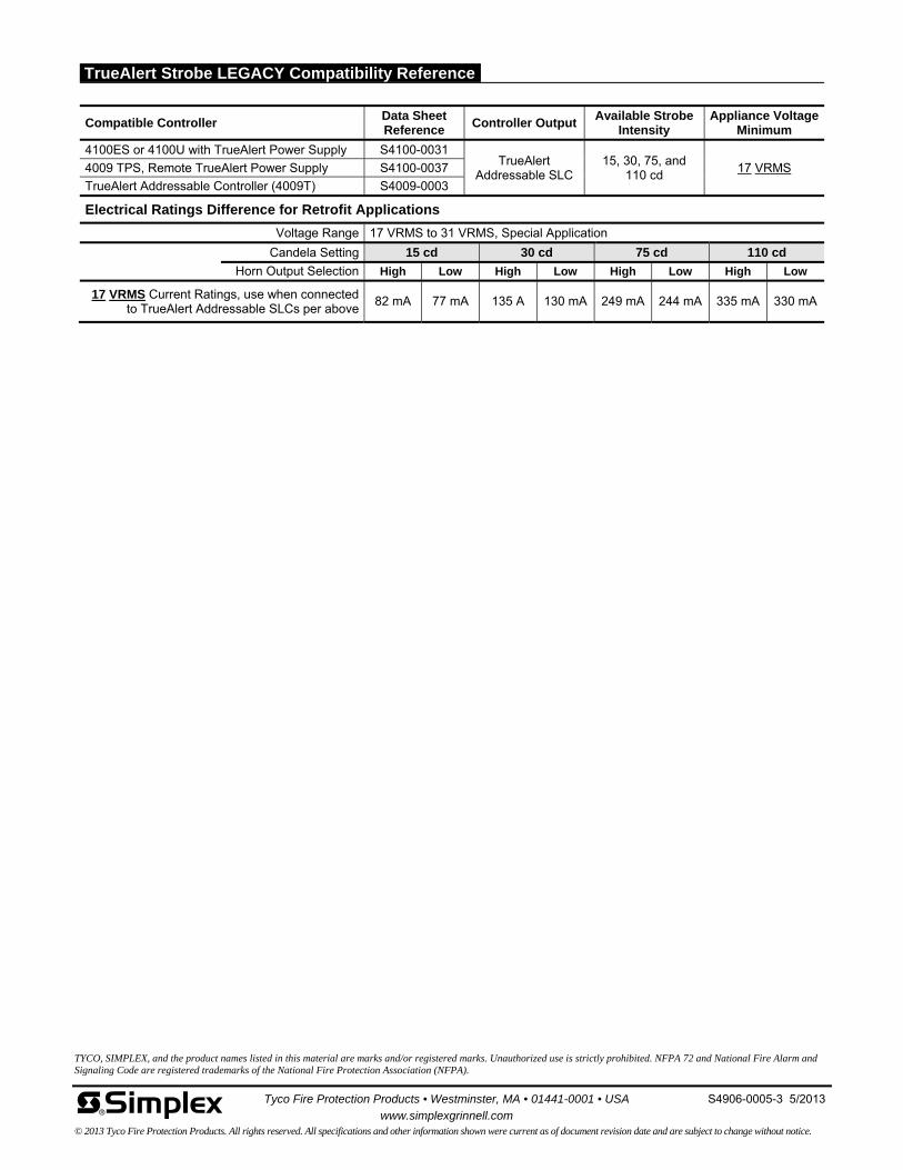
Tyco Fire Protection Products • Westminster, MA • 01441-0001 • USA S4906-0005-3 5/2013
www.simplexgrinnell.com © 2013 Tyco Fire Protection Products. All rights reserved. All specifications and other information shown were current as of document revision date and are subject to change without notice.
TYCO, SIMPLEX, and the product names listed in this material are marks and/or registered marks. Unauthorized use is strictly prohibited. NFPA 72 and National Fire Alarm and Signaling Code are registered trademarks of the National Fire Protection Association (NFPA).
Compatible Controller Data Sheet Reference
Controller Output Available Strobe
Intensity Appliance Voltage
Minimum
4100ES or 4100U with TrueAlert Power Supply S4100-0031 TrueAlert
Addressable SLC 15, 30, 75, and
110 cd 17 VRMS 4009 TPS, Remote TrueAlert Power Supply S4100-0037
TrueAlert Addressable Controller (4009T) S4009-0003
Electrical Ratings Difference for Retrofit Applications
Voltage Range 17 VRMS to 31 VRMS, Special Application
Candela Setting 15 cd 30 cd 75 cd 110 cd
Horn Output Selection High Low High Low High Low High Low
17 VRMS Current Ratings, use when connected to TrueAlert Addressable SLCs per above
82 mA 77 mA 135 A 130 mA 249 mA 244 mA 335 mA 330 mA
TrueAlert Strobe LEGACY Compatibility Reference
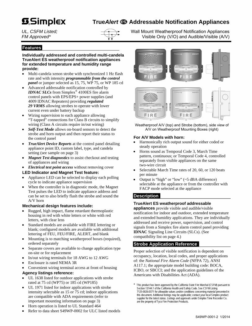
Features
Individually addressed and controlled multi-candela TrueAlert ES weatherproof notification appliances for extended temperature and humidity range provide: Multi-candela xenon strobe with synchronized 1 Hz flash
rate and with intensity programmable from the control panel or jumper selected as 15, 75, WP 75, or WP 185 cd
Advanced addressable notification controlled by IDNAC SLCs from Simplex® 4100ES fire alarm control panels with EPS/EPS+ power supplies (and 4009 IDNAC Repeaters) providing regulated 29 VRMS allowing strobes to operate with lower current even under battery backup
Wiring supervision to each appliance allowing “T-tapped” connections for Class B circuits to simplify wiring (Class A circuits require in/out wiring)
Self-Test Mode allows on-board sensors to detect the strobe and horn output and then report their status to the control panel
TrueAlert Device Reports at the control panel detailing appliance point ID, custom label, type, and candela setting (see sample on page 3)
Magnet Test diagnostics to assist checkout and testing of appliances and wiring
Electrical test point access without removing cover LED Indicator and Magnet Test feature: Appliance LED can be selected to display each polling
cycle to indicate appliance supervision When the controller is in diagnostic mode, the Magnet
Test pulses the LED to indicate appliance address and can be set to also briefly flash the strobe and sound the A/V horn
Mechanical design features include: Rugged, high impact, flame retardant thermoplastic
housing in red with white letters or white with red letters, with clear lens
Standard models are available with FIRE lettering or blank; configured models are available with additional lettering of FEU, FEU/FIRE, ALERT, and blank
Mounting is to matching weatherproof boxes (required), ordered separately
Separate covers are available to change application type on-site or for replacement
In/out wiring terminals for 18 AWG to 12 AWG Enclosure is rated NEMA 3R Convenient wiring terminal access at front of housing Agency listings reference: UL 1638 listed for outdoor applications with strobe
rated at 75 cd (WP75) or 185 cd (WP185) UL 1971 listed for indoor applications with strobe
intensity selectable as 15 or 75 cd; indoor applications are compatible with ADA requirements (refer to important mounting information on page 3)
Horn operation is listed to UL Standard 464 Refer to data sheet S49WP-0002 for ULC listed models
Weatherproof A/V (top) and Strobe (bottom), side view of A/V on Weatherproof Mounting Boxes (right)
For A/V Models with horn: Harmonically rich output sound for either coded or
steady operation Horns sound as Temporal Code 3, March Time
pattern, continuous; or Temporal Code 4, controlled separately from visible appliances on the same two-wire circuit
Selectable March Time rates of 20, 60, or 120 beats per minute
Output is “high” or “low” (~5 dBA difference) selectable at the appliance or from the controller with FACP mode selected at the appliance
Description
TrueAlert ES weatherproof addressable appliances provide visible and audible/visible notification for indoor and outdoor, extended temperature and extended humidity applications. They are individually addressed and receive power, supervision, and control signals from a Simplex fire alarm control panel providing IDNAC Signaling Line Circuits (SLCs). (See compatibility list on page 4.)
Strobe Application Reference
Proper selection of visible notification is dependent on occupancy, location, local codes, and proper applications of: the National Fire Alarm Code (NFPA 72), ANSI A117.1; the appropriate model building code: BOCA, ICBO, or SBCCI; and the application guidelines of the Americans with Disabilities Act (ADA).
* This product has been approved by the California State Fire Marshal (CSFM) pursuant to
Section 13144.1 of the California Health and Safety Code. See CSFM Listing 7125-0026:0371 for allowable values and/or conditions concerning material presented in this document. Additional listings may be applicable; contact your local Simplex product supplier for the latest status. Listings and approvals under Simplex Time Recorder Co. are the property of Tyco Fire Protection Products.
TrueAlert Addressable Notification Appliances UL, CSFM Listed; Wall Mount Weatherproof Notification Appliances FM Approved* Visible Only (V/O) and Audible/Visible (A/V)
S49WP-0001-2 1/2014

TrueAlert ES Operation Advantage
TrueAlert ES addressable appliances on IDNAC SLCs provide separate visible and audible notification using a single two-wire circuit that also confirms connection to the individual notification appliance’s electronic circuit. This operation increases circuit supervision integrity by providing supervision that extends beyond the appliance wiring connections.
Reduced current allows efficient IDNAC SLC operation. With IDNAC SLCs, a constant 29 VRMS source voltage is maintained, even during battery standby, allowing strobes to operate at higher voltage with lower current and ensuring a consistent current draw and voltage drop margin under both primary power and secondary battery standby. Efficiencies include wiring distances up to 2 to 3 times farther than with conventional notification, or support for more appliances per IDNAC SLC, or use of smaller gauge wiring, or combinations of these benefits, all providing installation and maintenance savings with high assurance that appliances that operate during normal system testing will operate during worst case alarm conditions.
Reducing Installation and Testing Time. With separate controls on the same two-wire SLC, installation time and expense for both retrofit and new construction can be significantly reduced. When Class B wiring is used, wiring can be “T” tapped, allowing more savings in distance, wire, conduit (size and utilization), and overall installation efficiency. Use of Self-Test and Magnet Test features improves installation efficiency. TrueAlert device reports conveniently identify information about each connected appliance.
TrueAlert ES Diagnostics
Test Features. When IDNAC SLCs are in diagnostic mode, Self-Test and Magnet Test features provide individual appliance testing. With the Self-Test feature, appliance operation can be confirmed without leaving the control panel. Additionally, each appliance’s LED can be selected to pulse when it receives a supervision poll during normal operation. Self-Test Details. Selecting Self-Test Mode from the control panel allows on-board sensors, depending on the device type, to detect its own strobe and/or horn output and then report their status to the control panel. Operation is by selected VNAC appliance groups and is either automatic (all briefly simultaneously activated) or individually activated by applying a magnet. (Refer to data sheet S4100-0100 for more Self-Test information.)
Silent Appliance Magnet Test. In this test mode, in response to application of a magnet, the appliance LED pulses sequentially to conveniently indicate the appliance’s address. Operational Appliance Magnet Test. In this test mode, after the address is indicated by pulsing the appliance LED, the strobe will briefly flash and the A/V horn will briefly sound to indicate proper operation. TrueStart Instrument Two (TSIT). The 2nd generation of the Simplex TrueStart Test Instrument adds testing of IDNAC SLC wiring and TrueAlert ES appliances to its ability to test IDCs, NACs, and IDNet communications before connection to the control panel. Please contact your local Simplex representative for additional information.
TrueAlert Addressable Wiring Isolator
Isolator Model 4905-9929 is available for remote mounting on TrueAlert addressable circuits to isolate short circuited wiring from functioning wiring. (Refer to data sheet S4905-0001 for additional information.)
UL Listed TrueAlert ES Addressable Weatherproof Notification Appliances
Type Model Cover Color
“FIRE” Lettering
Description Intensity Ratings
UL 1971 UL 1638
Strobe (V/O)
49VO-WRFO(-BA) Red White UL listed weatherproof TrueAlert ES addressable appliance; requires weatherproof box, see below Note: (-BA) indicates model is available either with or without the -BA suffix; model numbers ending in -BA are assembled in the USA
15 cd or
75 cd
75 cd (setting WP75)
or 185 cd (setting
WP185 )
49VO-WRSO(-BA) Red Blank
49VO-WWFO-BA White Red
49VO-APPLW-O order cover separately
Horn/Strobe (A/V)
49AV-WRFO(-BA) Red White
49AV-WWFO-BA White Red
49AV-APPLW-O order cover separately
Separate Covers (Required when ordering 49VO-APPLW-O or 49AV-APPLW-O) Wording Red VO Cover Models Red AV Cover Models White VO Cover Models White AV Cover Models
FIRE 49VOC-WRFIRE-O 49AVC-WRFIRE-O 49VOC-WWFIRE-O 49AVC-WWFIRE-O
ALERT 49VOC-WRALT-O 49AVC-WRALT-O 49VOC-WWALT-O 49AVC-WWALT-O
FEU 49VOC-WRFEU-O 49AVC-WRFEU-O 49VOC-WWFEU-O 49AVC-WWFEU-O
FEU/FIRE 49VOC-WRBLNG-O 49AVC-WRBLNG-O 49VOC-WWBLNG-O 49AVC-WWBLNG-O
Blank 49VOC-WRS-O 49AVC-WRS-O 49VOC-WWS-O 49AVC-WWS-O
Wall Mount Weatherproof Boxes (Required) Model Color Description Dimensions
49WPBB-AVVOWR Red Surface Mount Weatherproof Mounting Box (required)
5 ½” H x 6 ⅛” W x 1 ⅝” D (140 mm x 156 mm x 41 mm) 49WPBB-AVVOWW White
2 S49WP-0001-2 1/2014
Product Selection
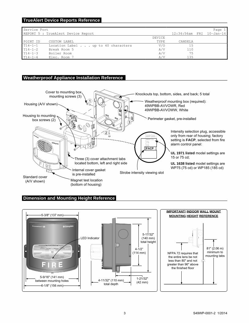
3 S49WP-0001-2 1/2014
Service Port Page 1REPORT 5 : TrueAlert Device Report 12:34:56am FRI 10-Jan-14 POINT ID
CUSTOM LABEL
DEVICETYPE
CANDELA
T14-1-1 Location Label . . . up to 40 characters V/O 15 T14-1-2 Break Room 5 A/V 110 T14-1-3 Boiler Room A/V 75 T14-1-4 Elec. Room 7 A/V 135
Housing (A/V shown)
Standard cover(A/V shown)
Weatherproof mounting box (required):49WPBB-AVVOWR, Red49WPBB-AVVOWW, White
Perimeter gasket, pre-installed
Knockouts top, bottom, sides, and back; 5 totalCover to mounting box mounting screws (3)
1
3
Housing to mounting box screws (2)
Three (3) cover attachment tabs located bottom, left and right side
Internal cover gasket is pre-installed Strobe intensity viewing slot
WP185 WP757515FACP
2
Magnet test location (bottom of housing)
UL 1971 listed model settings are 15 or 75 cd;
UL 1638 listed model settings are WP75 (75 cd) or WP185 (185 cd)
Intensity selection plug, accessible only from rear of housing; factory setting is FACP, selected from fire alarm control panel:
IMPORTANT! INDOOR WALL MOUNT
MOUNTING HEIGHT REFERENCE
aNFPA 72 requires that the entire lens be not less than 80" and not
greater than 96" above the finished floor
81" (2.06 m)minimum to
mounting tabs
5-3/8" (137 mm)
4-1/2”(114 mm)
5-17/32"(140 mm)
total height
5-9/16" (141 mm)between mounting holes
6-1/8" (156 mm)
1-21/32"(42 mm)
4-11/32" (110 mm)total depth
LED Indicator
Weatherproof Appliance Installation Reference
Dimension and Mounting Height Reference
TrueAlert Device Reports Reference
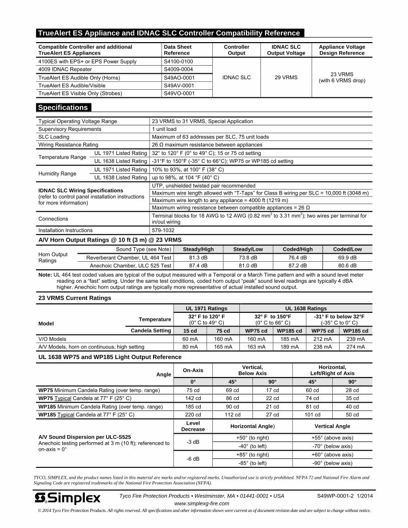
Tyco Fire Protection Products • Westminster, MA • 01441-0001 • USA S49WP-0001-2 1/2014
www.simplexg-fire.com © 2014 Tyco Fire Protection Products. All rights reserved. All specifications and other information shown were current as of document revision date and are subject to change without notice.
TYCO, SIMPLEX, and the product names listed in this material are marks and/or registered marks. Unauthorized use is strictly prohibited. NFPA 72 and National Fire Alarm and Signaling Code are registered trademarks of the National Fire Protection Association (NFPA).
Typical Operating Voltage Range 23 VRMS to 31 VRMS, Special Application
Supervisory Requirements 1 unit load
SLC Loading Maximum of 63 addresses per SLC, 75 unit loads
Wiring Resistance Rating 26 Ω maximum resistance between appliances
Temperature Range UL 1971 Listed Rating 32° to 120° F (0° to 49° C); 15 or 75 cd setting
UL 1638 Listed Rating -31°F to 150°F (-35° C to 66°C); WP75 or WP185 cd setting
Humidity Range UL 1971 Listed Rating 10% to 93%, at 100° F (38° C)
UL 1638 Listed Rating up to 98%, at 104 °F (40° C)
IDNAC SLC Wiring Specifications (refer to control panel installation instructions for more information)
UTP, unshielded twisted pair recommended Maximum wire length allowed with “T-Taps” for Class B wiring per SLC = 10,000 ft (3048 m) Maximum wire length to any appliance = 4000 ft (1219 m) Maximum wiring resistance between compatible appliances = 26 Ω
Connections Terminal blocks for 18 AWG to 12 AWG (0.82 mm2 to 3.31 mm2); two wires per terminal for in/out wiring
Installation Instructions 579-1032
A/V Horn Output Ratings @ 10 ft (3 m) @ 23 VRMS
Horn Output Ratings
Sound Type (see Note) Steady/High Steady/Low Coded/High Coded/Low
Reverberant Chamber, UL 464 Test 81.3 dB 73.8 dB 76.4 dB 69.9 dB
Anechoic Chamber, ULC 525 Test 87.4 dB 81.0 dB 87.2 dB 80.6 dB
Note: UL 464 test coded values are typical of the output measured with a Temporal or a March Time pattern and with a sound level meter reading on a “fast” setting. Under the same test conditions, coded horn output “peak” sound level readings are typically 4 dBA higher. Anechoic horn output ratings are typically more representative of actual installed sound output.
23 VRMS Current Ratings
UL 1971 Ratings UL 1638 Ratings
Model Temperature 32° F to 120° F
(0° C to 49° C) 32° F to 150°F (0° C to 66° C)
-31° F to below 32°F (-35° C to 0° C)
Candela Setting 15 cd 75 cd WP75 cd WP185 cd WP75 cd WP185 cd
V/O Models 60 mA 160 mA 160 mA 185 mA 212 mA 239 mA
A/V Models, horn on continuous, high setting 80 mA 165 mA 163 mA 189 mA 238 mA 274 mA
UL 1638 WP75 and WP185 Light Output Reference
AngleOn-Axis
Vertical, Below Axis
Horizontal, Left/Right of Axis
0° 45° 90° 45° 90°
WP75 Minimum Candela Rating (over temp. range) 75 cd 69 cd 17 cd 60 cd 28 cd
WP75 Typical Candela at 77° F (25° C) 142 cd 86 cd 22 cd 74 cd 35 cd
WP185 Minimum Candela Rating (over temp. range) 185 cd 90 cd 21 cd 81 cd 40 cd
WP185 Typical Candela at 77° F (25° C) 220 cd 112 cd 27 cd 101 cd 50 cd
A/V Sound Dispersion per ULC-S525 Anechoic testing performed at 3 m (10 ft); referenced to on-axis = 0°
Level Decrease
Horizontal Angle) Vertical Angle
-3 dB +50° (to right) +55° (above axis)
-40° (to left) -70° (below axis)
-6 dB +85° (to right) +60° (above axis)
-85° (to left) -90° (below axis)
Compatible Controller and additional TrueAlert ES Appliances
Data Sheet Reference
Controller Output
IDNAC SLC Output Voltage
Appliance Voltage Design Reference
4100ES with EPS+ or EPS Power Supply S4100-0100
IDNAC SLC 29 VRMS 23 VRMS
(with 6 VRMS drop)
4009 IDNAC Repeater S4009-0004
TrueAlert ES Audible Only (Horns) S49AO-0001
TrueAlert ES Audible/Visible S49AV-0001
TrueAlert ES Visible Only (Strobes) S49VO-0001
Specifications
TrueAlert ES Appliance and IDNAC SLC Controller Compatibility Reference
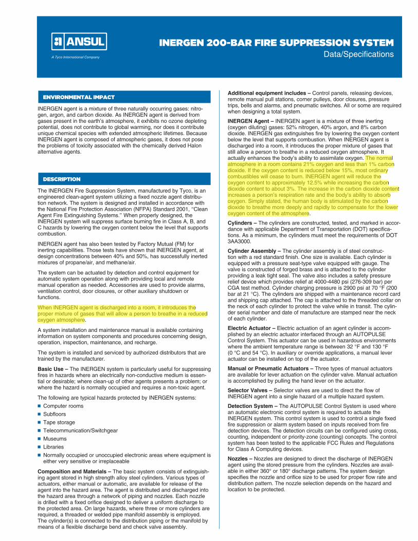
ENVIRONMENTAL IMPACT
INERGEN agent is a mixture of three naturally occurring gases: nitro-gen, argon, and carbon dioxide. As INERGEN agent is derived from gases present in the earth’s atmosphere, it exhibits no ozone depleting potential, does not contribute to global warming, nor does it contribute unique chemical species with extended atmospheric lifetimes. Because INERGEN agent is composed of atmospheric gases, it does not pose the problems of toxicity associated with the chemically derived Halon alternative agents.
DESCRIPTION
The INERGEN Fire Suppression System, manufactured by Tyco, is an engineered clean-agent system utilizing a fixed nozzle agent distribu-tion network. The system is designed and installed in accordance with the National Fire Protection Association (NFPA) Standard 2001, ‘‘Clean Agent Fire Extinguishing Systems.’’ When properly designed, the INERGEN system will suppress surface burning fire in Class A, B, and C hazards by lowering the oxygen content below the level that supports combustion.
INERGEN agent has also been tested by Factory Mutual (FM) for inerting capabilities. Those tests have shown that INERGEN agent, at design concentrations between 40% and 50%, has successfully inerted mixtures of propane/air, and methane/air.
The system can be actuated by detection and control equipment for automatic system operation along with providing local and remote manual operation as needed. Accessories are used to provide alarms, ventilation control, door closures, or other auxiliary shutdown or functions.
When INERGEN agent is discharged into a room, it introduces the proper mixture of gases that will allow a person to breathe in a reduced oxygen atmosphere.
A system installation and maintenance manual is available containing information on system components and procedures concerning design, operation, inspection, maintenance, and recharge.
The system is installed and serviced by authorized distributors that are trained by the manufacturer.
Basic Use – The INERGEN system is particularly useful for suppressing fires in hazards where an electrically non-conductive medium is essen-tial or desirable; where clean-up of other agents presents a problem; or where the hazard is normally occupied and requires a non-toxic agent.
The following are typical hazards protected by INERGEN systems:
n Computer rooms
n Subfloors
n Tape storage
n Telecommunication/Switchgear
n Museums
n Libraries
n Normally occupied or unoccupied electronic areas where equipment is either very sensitive or irreplaceable
Composition and Materials – The basic system consists of extinguish-ing agent stored in high strength alloy steel cylinders. Various types of actuators, either manual or auto matic, are available for release of the agent into the hazard area. The agent is distributed and discharged into the hazard area through a network of piping and nozzles. Each nozzle is drilled with a fixed orifice designed to deliver a uniform discharge to the protected area. On large hazards, where three or more cylinders are required, a threaded or welded pipe manifold assembly is employed. The cylinder(s) is connected to the distribution piping or the manifold by means of a flexible discharge bend and check valve assembly.
Additional equipment includes – Control panels, releasing devices, remote manual pull stations, corner pulleys, door closures, pressure trips, bells and alarms, and pneumatic switches. All or some are required when designing a total system.
INERGEN Agent – INERGEN agent is a mixture of three inerting (oxygen diluting) gases: 52% nitrogen, 40% argon, and 8% carbon dioxide. INERGEN gas extinguishes fire by lowering the oxygen content below the level that supports combustion. When INERGEN agent is discharged into a room, it introduces the proper mixture of gases that still allow a person to breathe in a reduced oxygen atmosphere. It actually enhances the body’s ability to assimilate oxygen. The normal atmosphere in a room contains 21% oxygen and less than 1% carbon dioxide. If the oxygen content is reduced below 15%, most ordinary combustibles will cease to burn. INERGEN agent will reduce the oxygen content to approximately 12.5% while increasing the carbon dioxide content to about 3%. The increase in the carbon dioxide content increases a person’s respiration rate and the body’s ability to absorb oxygen. Simply stated, the human body is stimulated by the carbon dioxide to breathe more deeply and rapidly to compensate for the lower oxygen content of the atmosphere.
Cylinders – The cylinders are constructed, tested, and marked in accor-dance with applicable Department of Transportation (DOT) specifica-tions. As a minimum, the cylinders must meet the requirements of DOT 3AA3000.
Cylinder Assembly – The cylinder assembly is of steel construc-tion with a red standard finish. One size is available. Each cylinder is equipped with a pressure seat-type valve equipped with gauge. The valve is constructed of forged brass and is attached to the cylinder pro viding a leak tight seal. The valve also includes a safety pressure relief device which provides relief at 4000-4480 psi (276-309 bar) per CGA test method. Cylinder charging pressure is 2900 psi at 70 °F (200 bar at 21 °C). The cylinders are shipped with a maintenance record card and shipping cap attached. The cap is attached to the threaded collar on the neck of each cylinder to protect the valve while in transit. The cylin-der serial number and date of manufacture are stamped near the neck of each cylinder.
Electric Actuator – Electric actuation of an agent cylinder is accom-plished by an electric actuator interfaced through an AUTOPULSE Control System. This actuator can be used in hazardous environments where the ambient temperature range is between 32 °F and 130 °F (0 °C and 54 °C). In auxiliary or override applications, a manual lever actuator can be installed on top of the actuator.
Manual or Pneumatic Actuators – Three types of manual actuators are available for lever actuation on the cylinder valve. Manual actuation is accomplished by pulling the hand lever on the actuator.
Selector Valves – Selector valves are used to direct the flow of INERGEN agent into a single hazard of a multiple hazard system.
Detection System – The AUTOPULSE Control System is used where an automatic electronic control system is required to actuate the INERGEN system. This control system is used to control a single fixed fire suppression or alarm system based on inputs received from fire detection devices. The detection circuits can be configured using cross, counting, independent or priority-zone (counting) concepts. The control system has been tested to the applicable FCC Rules and Regulations for Class A Computing devices.
Nozzles – Nozzles are designed to direct the discharge of INERGEN agent using the stored pressure from the cylinders. Nozzles are avail-able in either 360° or 180° discharge patterns. The system design specifies the nozzle and orifice size to be used for proper flow rate and distribution pattern. The nozzle selection depends on the hazard and location to be protected.
INERGEN 200-BAR FIRE SUPPRESSION SYSTEMData/Specifications
rytorres
Highlight
rytorres
Highlight

Pressure Reducer – The pressure reducer is required in the distribution piping to restrict the flow of INERGEN agent, thus reducing the agent pressure down stream of the reducer. The pressure reducer contains a stainless steel orifice plate which is drilled to the specific size hole required based on the hydraulic calculation. The orifice plate provides readily visible orifice identification. The pressure reducer is available in nine sizes: 1/2 in., 3/4 in., 1 in., 1 1/4 in., 1 1/2 in., 2 in., 2 1/2 in., 3 in., and 4 in. NPT.
DESCRIPTION
Pipe and Fittings – System manifold piping must be constructed to withstand a minimum pressure of 3000 psi (206.9 bar). Distribution piping downstream from the orifice union must be constructed to with-stand the maximum downstream pressure as determined by the flow calculation.
Limitations – The INERGEN system must be designed and installed within the guidelines of the manufacturer’s design, installation, operation, inspection, recharge, and maintenance manual. The ambient temper-ature limitations are 32 °F to 130 °F (0 °C to 54 °C). All AUTOPULSE Control Systems are designed for indoor applications and for tempera-ture ranges between 32 °F and 120 °F (0 °C and 49 °C).
TECHNICAL DATA
Applicable Standards: The INERGEN system complies with NFPA Standard 2001, Standard for Clean Agent Fire Extinguishing Systems, and EPA Program SNAP, Significant New Alternate Policy.
The INERGEN System is listed by Underwriters Laboratories, Inc. (UL) and Underwriters Laboratories of Canada (ULC), and is approved by Factory Mutual (FM).
INERGEN Agent is listed by Underwriters Laboratories, Inc. (UL) and Underwriters Laboratories of Canada (ULC), and is approved by Factory Mutual (FM).
INSTALLATIONS
All system components and accessories must be installed by personnel trained by the manufacturer. All installations must be performed accord-ing to the guidelines stated in the manufacturer’s design, installation, operation, inspection, recharge, and maintenance manual.
AVAILABILITY AND COST
Availability – INERGEN Systems are sold and serviced through a network of independent distributors located in many countries.
Cost – Cost varies with type of system specified, size, and design.
MAINTENANCE
Maintenance is a vital step in the performance of a fire suppression system. As such, it must be performed by an authorized ANSUL distribu-tor in accordance with NFPA 2001 and the manufacturer’s design, instal-lation, recharge, and maintenance manual. When replacing components on the ANSUL system, use only ANSUL approved parts.
Copyright © 2011 Tyco Fire Protection ProductsAll rights reserved
Form No. F-2001292-03
One Stanton StreetMarinette, WI 54143-2542
+1-715-735-7411www.ansul.com

CV-98 INERGEN Valve
The CV-98 valve has a ten (10) year warranty. The valverequires no internal maintenance. The valve is sealedclosed and must not be disassembled. If there is ever amalfunction of the CV-98 valve, the complete valve must besent back to ANSUL for warranty replacement. If the exter-nal seal is broken, the warranty is voided.
System ComponentsUL EX-4510 2-1-12 Page 1-1
REV. 2
Note: Use Flexible Discharge Bend (Part No. 427082) when attachingvalve to supply pipe or manifold.
Description
The cylinder is factory filled with INERGEN agent. A singlecylinder may be used or multiple cylinders can be manifoldedtogether to obtain the required quantity of agent for total flood-ing. The cylinder valve can be actuated electrically, pneumati-cally, and/or manually with approved valve actuation compo-nents. All valves are equipped with an anti-recoil feature.
The cylinders are shipped with a maintenance record cardand protective shipping cap attached to the threaded neckof each cylinder. This cap entirely encloses and protectsthe valve while in shipment.
The equivalent length of the valve is equal to 38 ft (11.6 m)of 1/2 in. Sch. 40 pipe.
CV-98 Valve / Cylinder Shipping Assembly
Component Material Approvals
Cylinder Steel Meets DOT 3AA3000;Meets TC3AAM230
Valve Brass
Safety Relief Valve Brass
Valve/Cylinder UL Listed (EX-4510);Assembly Listed for use with
FM Approved systems
Shipping Cap Steel
Shipping Nominal Cylinder Actual INERGEN Approximate Dimension DimensionAssembly Size Agent Quantity Weight A BPart No. ft3 (m3) ft3 m3 lb (kg) in. (mm) in. (mm)
430952 (LC) 575 (16.3) 572 (16.2) 322 (146.0) 68.5 (1740) 11.0 (279)
432874 575 (16.3) 572 (16.2) 347 (157.4) 69.2 (1758) 11.1 (282)
PRESSUREGAUGE
SAFETYRELIEFVALVE
002252
VALVE
HEIGHT TO OUTLETCENTER
002251
RECORDTAG
PRESSUREGAUGE
CYLINDERSHIPPING CAP
VALVE SHIPPING CAP
B
A
ANSUL®
Copyright © 2012 Tyco Fire Products LP.All rights reserved.
Form No. F-2001249-2
One Stanton Street +1-715-735-7411Marinette, WI 54143-2542 www.ansul.com
rytorres
Highlight

System ComponentsUL EX-4510 2-1-12 Page 1-21
REV. 2
Description
Discharge nozzles are designed to direct the discharge ofINERGEN agent using the stored pressure from the cylin-ders. Ten sizes of nozzles are available. The system designspecifies the orifice size to be used for proper flow rate anddistribution pattern*. The nozzle selection depends on thehazard and location to be protected. Standard nozzles areconstructed of brass.
Note: 2, 2 1/2, and 3 in. nozzles are not recommended inareas that are subject to damage by high velocity dis-charges, such as suspended ceiling tiles.
* Orifice diameter must be specified when ordering nozzle.
360° Discharge Nozzle
Shipping AssemblyPart No. Description
417908 1/4 in. NPT nozzle417723 3/8 in. NPT nozzle417362 1/2 in. NPT nozzle417363 3/4 in. NPT nozzle417364 1 in. NPT nozzle417365 1 1/4 in. NPT nozzle417366 1 1/2 in. NPT nozzle426155 2 in. NPT nozzle426156 2 1/2 in. NPT nozzle426137 3 in. NPT nozzle
Size A-In. B-In. C-In. Hex
1/4 in. 5/8 1 9/16 21/32 5/83/8 in. 3/4 1 5/8 23/32 3/41/2 in. 15/16 1 31/32 27/32 15/163/4 in. 1 1/8 2 5/32 7/8 1 1/81 in. 1 13/32 2 9/16 1 1 7/161 1/4 in. 1 3/4 2 3/4 1 1/16 1 3/41 1/2 in. 2 2 31/32 1 1/16 22 in. 2 3/8 3 1 2 3/82 1/2 in. 3 3 1/2 1 33 in. 3 1/2 4 1/8 1 1/4 3 1/2
BC
A
002199
Note: Refer to “Nozzle/Pressure Reducer Range Chart” inDesign Section for detailed orifice range information.
ANSUL®
Component Material Thread Size Approvals
Nozzle Body: 1/4, 3/8, 1/2, UL ListedBrass 3/4, 1, 1 1/4, (EX-4510);
1 1/2, 2, Listed for 2 1/2, 3 NPT use with FM
Approvedsystems
Copyright © 2012 Tyco Fire Products LP.All rights reserved.
Form No. F-2001272-2
One Stanton Street +1-715-735-7411Marinette, WI 54143-2542 www.ansul.com

System ComponentsUL EX-4510 2-1-12 Page 1-22
REV. 2
Description
Discharge nozzles are designed to direct the discharge ofINERGEN agent using the stored pressure from the cylin-ders. Ten sizes of nozzles are available. The systemdesign specifies the orifice size to be used for proper flowrate and distribution pattern*. The nozzle selectiondepends on the hazard and location to be protected. The180° nozzle is commonly used when nozzle placement isat the wall. Standard nozzles are constructed of brass.
An index mark is stamped on the bottom of the nozzle toindicate the aiming direction.
180° Discharge Nozzle
Shipping AssemblyPart No. Description
426138 1/4 in. NPT nozzle426139 3/8 in. NPT nozzle426140 1/2 in. NPT nozzle426141 3/4 in. NPT nozzle426142 1 in. NPT nozzle426143 1 1/4 in. NPT nozzle426157 1 1/2 in. NPT nozzle426144 2 in. NPT nozzle426145 2 1/2 in. NPT nozzle426146 3 in. NPT nozzle
C
002742
002743
Component Material Thread Size Approvals
Nozzle Body: 1/4, 3/8, 1/2, UL ListedBrass 3/4, 1, 1 1/4, (EX-4510);
1 1/2, 2, 2 1/2, Listed for use3 NPT with FM
Approvedsystems
Size A-In. B-In. C-In.
1/4 in. 5/8 1 9/16 21/323/8 in. 3/4 1 5/8 23/321/2 in. 15/16 1 31/32 27/323/4 in. 1 1/8 2 5/32 7/81 in. 1 13/32 2 9/16 11 1/4 in. 1 3/4 2 3/4 1 1/161 1/2 in. 2 2 31/32 1 1/162 in. 2 3/8 3 12 1/2 in. 3 3 1/2 13 in. 3 1/2 4 1/8 1 1/4
22.5%
A
B
INDEXMARK
Note: Refer to “Nozzle/Pressure Reducer Range Chart” inDesign Section for detailed orifice range information.
ANSUL®
* Orifice diameter must be specified when ordering nozzle.
Copyright © 2012 Tyco Fire Products LP.All rights reserved.
Form No. F-2001273-2
One Stanton Street +1-715-735-7411Marinette, WI 54143-2542 www.ansul.com

System ComponentsUL EX-4510 2-1-12 Page 1-15
REV. 2
Description
The valve Flexible Discharge Bend (Part No. 427082) is a5/8 in. (1.59 cm) I.D. extra-heavy flexible hose which con-nects the valve discharge outlet to the fixed piping or head-er manifold. The discharge bend has a special femalethread for connecting to the valve outlet and a male 1/2 in.NPT thread for connecting to the fixed piping or manifold.The discharge bend will withstand a pressure of 9000 psi(621 bar). Its flexible connection allows for easy alignmentof multiple cylinder banks to fixed piping. Each bend has abuilt-in check valve that prevents loss of agent should thesystem discharge while any cylinder is removed.
The equivalent length of this hose is equal to 18 ft (5.5 m)of 1/2 in. Sch. 40 pipe.
Flexible Discharge Bend
Shipping AssemblyPart No. Description
427082 Flexible discharge bend
42430 Washer
Thread Size/Type
Component Material Valve End Manifold End Approvals
5/8 in. Flexible SAE 100 R2 Special to 1/2 in. NPT Male UL Listed (EX-4510);Discharge Bend Type AT mate with Listed for use with
CV-98 Valve FM Approved systems
18 7/8 IN.(47.9 cm)
MANIFOLD/END
000658
1/2 IN. NPTMALE COUPLING
FEMALE ADAPTOR(BRASS)
VALVE END
CHECK
WASHER
SWAGE ON
ANSUL®
Copyright © 2012 Tyco Fire Products LP.All rights reserved.
Form No. F-2001263-2
One Stanton Street +1-715-735-7411Marinette, WI 54143-2542 www.ansul.com

System ComponentsUL EX-4510 2-1-12 Page 1-23
REV. 2
Description
The INERGEN system nozzle deflector shield is used tocontrol the pattern of the discharge of the INERGEN agent.The deflector shield helps keep the agent discharge awayfrom false ceiling tiles and fragile light fixtures, avoidingdamage to them.
The deflector shields are constructed of steel and paintedwith a cameo cream colored paint. They are available infive sizes.
Nozzle Deflector Shield
Component Material Approvals
Nozzle Steel UL Listed (EX-4510);Deflector Listed for use withShield FM Approved systems
Shipping A B C D EAssembly Inlet Length of Overall Deflector CouplingPart No. NPT Coupling Length O.D. O.D.
417708 1/2 in. 1 7/8 in. 3 in. 3 3/8 in. 1 1/8 in.(4.8 cm) (7.6 cm) (8.6 cm) (2.9 cm)
417711 3/4 in. 2 in. 3 1/4 in. 3 3/8 in. 1 3/8 in.(5.1 cm) (8.3 cm) (8.6 cm) (3.5 cm)
417714 1 in. 2 3/8 in. 3 13/16 in. 4 7/8 in. 1 3/4 in.(6.0 cm) (9.7 cm) (12.4 cm) (4.4 cm)
417717 1 1/4 in. 2 5/8 in. 4 3/16 in. 4 7/8 in. 2 1/4 in.(6.7 cm) (10.6 cm) (12.4 cm) (5.7 cm)
417720 1 1/2 in. 3 1/8 in. 4 29/32 in. 5 21/32 in. 2 1/2 in.(7.9 cm) (12.5 cm) (14.4 cm) (6.4 cm)
D
B
A
C
E
003651
NOTE: There are no deflector shields available for the 2, 2 1/2, or 3 in. models.
ANSUL®
Copyright © 2012 Tyco Fire Products LP.All rights reserved.
Form No. F-2001274-2
One Stanton Street +1-715-735-7411Marinette, WI 54143-2542 www.ansul.com


System ComponentsUL EX-4510 2-1-12 Page 1-19
REV. 2
Description
The pressure reducer/union is required to restrict the flowof INERGEN agent thus reducing the agent pressure downstream of the union. The 3000 psi (206.9 bar) NSCWPunion contains a stainless steel orifice plate which is drilledto the specific size hole required based on the flow calcula-tion.* The orifice plate provides readily visible orifice identi-fication. The orifice union is available in six sizes:1/2 in., 3/4 in., 1 in., 1 1/4 in., 1 1/2 in., and 2 in. NPT.
All pressure reducer/unions must be installed in the pipingwith the orifice identification tab on the pressure inlet sideof the system. The 1 1/4 in., 1 1/2 in. and 2 in. orificeunions must be installed per the direction of the flow arrowstamped on the body.
Pressure Reducer/Union
Shipping AssemblyPart No. Description A B C
416677 1/2 in. NPT pressure reducer/union 2.06 in. (5.2 cm) 1.18 in. (2.9 cm) 1.95 in. (4.9 cm)416678 3/4 in. NPT pressure reducer/union 2.38 in. (6.1 cm) 1.50 in. (3.8 cm) 2.38 in. (6.1 cm)416679 1 in. NPT pressure reducer/union 2.63 in. (6.7 cm) 1.78 in. (4.5 cm) 2.77 in. (7.0 cm)416680 1 1/4 in. NPT pressure reducer/union 2.94 in. (7.5 cm) 2.04 in. (5.2 cm) 3.31 in. (8.4 cm)416681 1 1/2 in. NPT pressure reducer/union 3.31 in. (8.4 cm) 2.31 in. (5.9 cm) 3.70 in. (9.4 cm)416682 2 in. NPT pressure reducer/union 3.56 in. (9.0 cm) 2.85 in. (7.2 cm) 4.39 in. (11.2 cm)
Component Material Thread Size Approvals
Pressure Reducer/ Body: Forged 1/2, 3/4, 1, UL Listed (EX-4510); Listed for useUnion Steel 1 1/4, 1 1/2, with FM Approved systems
2 in. NPTOrifice Plate:
StainlessSteel
VISIBLE ORIFICEIDENTIFICATION 002197
DIRECTIONOF FLOW
C
A
B
Note: Refer to “Nozzle/Pressure Reducer Range Chart” inDesign Section for detailed orifice range information.
* Orifice diameter must be specified when placing order.
ANSUL®
Copyright © 2012 Tyco Fire Products LP.All rights reserved.
Form No. F-2001267-2
One Stanton Street +1-715-735-7411Marinette, WI 54143-2542 www.ansul.com

System ComponentsUL EX-4510 12-1-01 Page 1-20
Description
The flanged pressure reducer assembly is required torestrict the flow of INERGEN® agent thus reducing theagent pressure down stream of the pressure reducer. Theflanged pressure reducer assembly contains a stainlesssteel orifice plate which is drilled to the specific size holerequired based on the flow calculation.* The orifice plateprovides readily visible orifice identification. The flangedpressure reducer assembly is available in three sizes; 21/2, 3, and 4 in. Each size is available in threaded, slip-on,and weld neck flange.
All orifice plates must be installed in the piping system withthe orifice identification information on the tab facing thepressure inlet side of the system.
Flanged Pressure Reducer
ShippingAssemblyPart No. Description A B C D E427880 2 1/2 in Threaded 5.98 in. 9.62 in. 12.10 in. 7.50 in. 1.12 in. (8)
(152 mm) (244 mm) (307 mm) (191 mm) (28 mm)
427881 3 in. Threaded 6.24 in. 10.50 in. 12.65 in. 8.00 in. 1.25 in. (8)(158 mm) (267 mm) (321 mm) (203 mm) (32 mm)
427882 4 in. Threaded 7.60 in. 12.25 in. 14.22 in. 9.50 in. 1.38 in.(8)(193 mm) (311 mm) (362 mm) (241 mm) (35 mm)
427883 2 1/2 in. Slip-on 5.98 in. 9.62 in. 12.10 in. 7.50 in. 1.12 in. (8)(152 mm) (244 mm) (307 mm) (191 mm) (28 mm)
427884 3 in. Slip-on 6.74 in. 10.50 in. 12.65 in. 8.00 in. 1.25 in. (8)(171 mm) (267 mm) (321 mm) (203 mm) (32 mm)
427885 4 in. Slip-on 8.10 in. 12.25 in. 14.22 in. 9.50 in. 1.38 in. (8)(206 mm) (311 mm) (362 mm) (241 mm) (35 mm)
427886 2 1/2 in. Weld Neck 9.22 in. 9.62 in. 12.10 in. 7.50 in. 1.12 in. (8)(234 mm) (244 mm) (307 mm) (191 mm) (28 mm)
427887 3 in. Weld Neck 10.22 in. 10.50 in. 12.65 in. 8.00 in. 1.25 in. (8)(260 mm) (267 mm) (321 mm) (203 mm) (32 mm)
427888 4 in. Weld Neck 10.74 in. 12.25 in. 14.22 in. 9.50 in. 1.38 in. (8)(273 mm) (311 mm) (362 mm) (241 mm) (35 mm)
Component Material Approvals
Flange Forged Steel UL ListedFlange Gasket Stainless Steel (EX-4510)Orifice Plate Stainless SteelBolts Plated Steel,
Grade 7B
NOTE: Refer to “Nozzle/Pressure Reducer Range Chart” inDesign Section for detailed orifice range information.
* Orifice diameter must be specified when placing order.
ANSUL®
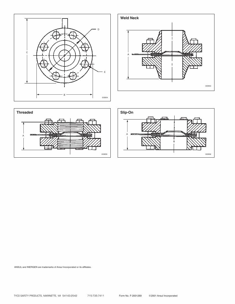
TYCO SAFETY PRODUCTS, MARINETTE, WI 54143-2542 715-735-7411 Form No. F-2001269 ©2001 Ansul Incorporated
Threaded
A
003655
Slip-On
A
003656
Weld Neck
A
003653
C
B003654
D
E
ANSUL and INERGEN are trademarks of Ansul Incorporated or its affiliates.
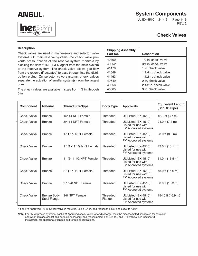
System ComponentsUL EX-4510 2-1-12 Page 1-16
REV. 2
Description
Check valves are used in main/reserve and selector valvesystems. On main/reserve systems, the check valve pre-vents pressurization of the reserve system manifold byblocking the flow of INERGEN agent from the main systemto the reserve system. The check valve allows gas flowfrom the reserve (if actuated) to pass through into the distri-bution piping. On selector valve systems, check valves separate the actuation of smaller system(s) from the largestones.
The check valves are available in sizes from 1/2 in. through3 in.
Check Valves
Shipping AssemblyPart No. Description
40860 1/2 in. check valve*40852 3/4 in. check valve41470 1 in. check valve41549 1 1/4 in. check valve41463 1 1/2 in. check valve40649 2 in. check valve40656 2 1/2 in. check valve40665 3 in. check valve
Component Material Thread Size/Type Body Type ApprovalsEquivalent Length(Sch. 80 Pipe)
Check Valve Bronze 1/2-14 NPT Female Threaded UL Listed (EX-4510) 12. 0 ft (3.7 m)
Check Valve Bronze 3/4-14 NPT Female Threaded UL Listed (EX-4510); 24.0 ft (7.3 m)Listed for use withFM Approved systems
Check Valve Bronze 1-11 1/2 NPT Female Threaded UL Listed (EX-4510); 28.0 ft (8.5 m)Listed for use withFM Approved systems
Check Valve Bronze 1 1/4 -11 1/2 NPT Female Threaded UL Listed (EX-4510); 43.0 ft (13.1 m)Listed for use withFM Approved systems
Check Valve Bronze 1 1/2-11 1/2 NPT Female Threaded UL Listed (EX-4510); 51.0 ft (15.5 m)Listed for use withFM Approved systems
Check Valve Bronze 2-11 1/2 NPT Female Threaded UL Listed (EX-4510); 48.0 ft (14.6 m)Listed for use withFM Approved systems
Check Valve Bronze 2 1/2-8 NPT Female Threaded UL Listed (EX-4510); 60.0 ft (18.3 m)Listed for use withFM Approved systems
Check Valve Bronze Body 3-8 NPT Female Threaded UL Listed (EX-4510); 154.0 ft (46.9 m)Steel Flange Flange Listed for use with
FM Approved systems
ANSUL®
* If an FM Approved 1/2 in. Check Valve is required, use a 3/4 in. and reduce the inlet and outlet to 1/2 in.
Note: For FM Approved systems, each FM Approved check valve, after discharge, must be disassembled, inspected for corrosionand wear, replace gasket and parts as necessary, and reassembled. For 2, 2 1/2, and 3 in. valves, see Section VI,Installation, for appropriate flanged bolt torque specifications.
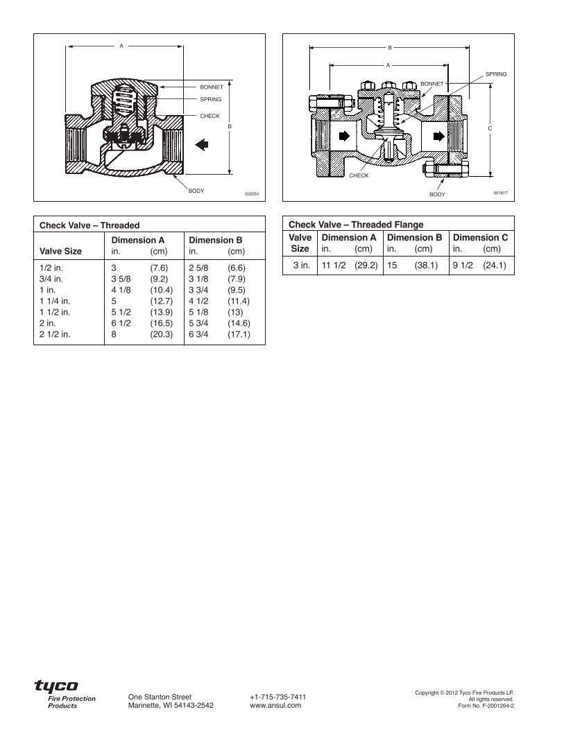
Check Valve – Threaded
Dimension A Dimension BValve Size in. (cm) in. (cm)
1/2 in. 3 (7.6) 2 5/8 (6.6)3/4 in. 3 5/8 (9.2) 3 1/8 (7.9)1 in. 4 1/8 (10.4) 3 3/4 (9.5)1 1/4 in. 5 (12.7) 4 1/2 (11.4)1 1/2 in. 5 1/2 (13.9) 5 1/8 (13)2 in. 6 1/2 (16.5) 5 3/4 (14.6)2 1/2 in. 8 (20.3) 6 3/4 (17.1)
Check Valve – Threaded FlangeValve Dimension A Dimension B Dimension CSize in. (cm) in. (cm) in. (cm)
3 in. 11 1/2 (29.2) 15 (38.1) 9 1/2 (24.1)
A
B
BONNET
BODY
SPRING
CHECK
A
C
B
CHECK
BODY
BONNET
SPRING
001817002254
Copyright © 2012 Tyco Fire Products LP.All rights reserved.
Form No. F-2001264-2
One Stanton Street +1-715-735-7411Marinette, WI 54143-2542 www.ansul.com
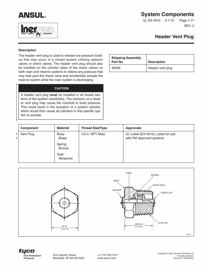
Description
The header vent plug is used to release low pressure build-up that may occur in a closed system utilizing selectorvalves or check valves. The header vent plug should alsobe installed on the cylinder sides of the check valves onboth main and reserve systems to relieve any pressure thatmay leak past the check valve and accidentally actuate thereserve system while the main system is discharging.
System ComponentsUL EX-4510 2-1-12 Page 1-17
REV. 2
Header Vent Plug
Shipping AssemblyPart No. Description
40309 Header vent plug
Component Material Thread Size/Type Approvals
Vent Plug Body: 1/2 in. NPT Male UL Listed (EX-4510); Listed for useBrass with FM Approved systems
Spring:Bronze
Seal:Neoprene
SPRING
CHECK SEAL
CHECK CUP
1/2 IN. NPT
000707
STEM
BODY
WASHER
29/32 IN.(2.3 cm)7/8 IN.
(2.2 cm)
ANSUL®
Copyright © 2012 Tyco Fire Products LP.All rights reserved.
Form No. F-2001265-2
One Stanton Street +1-715-735-7411Marinette, WI 54143-2542 www.ansul.com
CAUTION
A header vent plug must be installed in all closed sec-tions of the system manifold(s). The omission of a head-er vent plug may cause the manifold to build pressure.This could result in the actuation of a system cylinder,which would then cause all cylinders in that specific sys-tem to actuate.

Description
The manifold relief valve is used to release high pressurebuild-up that may occur in a closed system utilizing selectorvalves or check valves.
Internal safety disc will rupture between 4000-4480 psi(276-309 bar).
System ComponentsUL EX-4510 2-1-12 Page 1-17a
REV. 1
Manifold Relief Valve – 200 Bar
Shipping AssemblyPart No. Description
431700 Manifold Relief Valve
Component Material Thread Size/Type Approvals
Manifold Relief Valve Body: 1/2 in. NPT Male UL Listed (EX-4510); Listed for useBrass with FM Approved systems
BODY
SAFETYDISC
SAFETY NUT
007032007033
ANSUL®
Copyright © 2012 Tyco Fire Products LP.All rights reserved.
Form No. F-2004098-1
One Stanton Street +1-715-735-7411Marinette, WI 54143-2542 www.ansul.com

4 1/2 IN.(114 mm)
2 1/4 IN.(57 mm)
System ComponentsUL EX-4510 2-1-12 Page 1-7
REV. 2
Description
Electrical actuation is accomplished by an HF electricActuator, Part No. 73327, interfaced through anAUTOPULSE Control System. This actuator can be used inhazardous, indoor environments where the ambient tem-perature range is between 0 °F to 130 °F (–18 °C to 54 °C).The HF electric actuator meets the requirements of N.E.C.Class I, Div. 1, Groups B, C, D and Class II, Div. 1, GroupsE, F, G. A maximum of two HF electric actuators can beused on a single AUTOPULSE release circuit. When utiliz-ing only one HF electric actuator, an in-line resistor, PartNo. 73606, is required in the supervised release circuit.
In auxiliary or override applications, a manual-local overridevalve actuator or a manual cable pull actuator can beinstalled on top of the HF electric actuator by removing thesafety cap.
An arming tool, Part No. 75433, is required to reset theactuator after operation. The actuator contains a standard1/2 in. threaded female straight connector for electrical con-duit hookup.
Technical Information
Nominal Voltage: . . . . . . . . . . . . . . . . 12 VDC @ 0.57 amps
Rated Voltage:Minimum: . . . . . . . . . . . . . . . . . . . . . . . . . . . . . 12.0 VDCMaximum:. . . . . . . . . . . . . . . . . . . . . . . . . . . . . 14.0 VDC
Thread Size/Type: . . . . . . . . . . . . 1/2 in. straight female forelectrical conduit hookup
Material:Body: . . . . . . . . . . . . . . . . . . . . . . . . . . . . . . . . . . . . BrassPlunger:. . . . . . . . . . . . . . . . . . . . . . . . . . . Stainless Steel
Listings and ApprovalsUL. . . . . . . . . . . . . . . . . . . . . . . . . . . . . . . . . . . . . . . E91021
Listed for use with FM Approved systems
HF Electric Actuator
006361
1 1/4 – 18
ANSUL®
1 1/4 – 18
Copyright © 2012 Tyco Fire Products LP.All rights reserved.
Form No. F-2001255-2
One Stanton Street +1-715-735-7411Marinette, WI 54143-2542 www.ansul.com

Description
The Booster Actuator, Part No. 428949, is used when elec-tric actuation is required on the 1 in. selector valve, 2 in.selector valve, or the CV-98 cylinder valve. The actuatormounts directly to the component and then a HF electricactuator mounts to the top of the booster actuator.
The Booster Actuator requires resetting after actuation. AReset Tool, Part No. 429847, is available for this use.
System ComponentsUL EX-4510 2-1-12 Page 1-6
REV. 2
Booster Actuator
006037
Ø 2.50
3.025
1 1/4 – 18 UNEF
1 1/8 – 18 UNEF
Component Material Approvals
Booster Stainless Steel UL Listed (EX-4510);Actuator and Brass Listed for use with FM
Approved systems
ANSUL®
Copyright © 2012 Tyco Fire Products LP.All rights reserved.
Form No. F-2001254-2
One Stanton Street +1-715-735-7411Marinette, WI 54143-2542 www.ansul.com

System ComponentsUL EX-4510 2-1-12 Page 1-4
REV. 3
Description
Selector valves are used to direct the flow of INERGEN intoa single hazard of a multiple hazard system.
When pneumatic actuation is required for the 1 in. and 2 in.valves, a Stackable Actuator Assembly, Part No. 428566,must be ordered separately.
When electric actuation is required for the 1 in. and 2 in.valves, a Booster Actuator, Part No. 428949, must beordered separately.
Selector valves can be manually operated by mounting alever actuator either directly onto the valve or onto the topof the electric actuator. See Lever Release ActuatorComponent Sheet for correct actuator.
Selector Valves
Component Material Thread Size/Type ApprovalsEquivalent Length(Sch. 80 Pipe)
1 in. Selector Valve Bronze 1 in. NPT Female UL (EX-4510); 1/2 in. – 1.9 ft (0.6 m)(Used for 1/2 in., 3/4 in. Listed for use with 3/4 in. – 6.4 ft (1.9 m)and 1 in. pipe sizes) FM Approved systems 1 in. – 10.4 ft (3.2 m)
2 in. Selector Valve Bronze 2 in. NPT Female UL (EX-4510); 1 1/4 in. – 16.2 ft (4.9 m)(Used for 1 1/4 in., 1 1/2 in. Listed for use with 1 1/2 in. – 22.4 ft (6.8 m)and 2 in. pipe sizes) FM Approved systems 2 in. – 67.4 ft (20.5 m)
Shipping AssemblyPart No. Description
427185 1 in. selector valve – threaded
427150 2 in. selector valve – threaded
428566 Pressure operatedstackable actuator
ANSUL®
A B CValve Size Body in. (mm) in. (mm) in. (mm)
1 in. Threaded – 5 1/2 (140) 2 9/16 (67) 7 (178)1 in. NPT female
2 in. Threaded – 7 1/2 (191) 3 1/2 (89) 8 9/16 (218)2 in. NPT female
0060351 IN. AND 2 IN. THREADED VALVE
A
B
C
1 1/8 – 18 UNEF
Copyright © 2012 Tyco Fire Products LP.All rights reserved.
Form No. F-2001252-3
One Stanton Street +1-715-735-7411Marinette, WI 54143-2542 www.ansul.com

System ComponentsUL EX-4510 2-1-12 Page 1-30
REV. 2
Description
The ʻʻMAINʼʼ nameplate is available for labeling compo-nents and/or remote pull stations to distinguish them fromreserve system components. The nameplate is furnishedwith four mounting holes for ease of installation.
Nameplate – MAIN
Shipping AssemblyPart No. Description
41942 Nameplate – MAIN
Component Material Mounting Hole Size Approvals
Nameplate Aluminum 13/64 in. (.52 cm) UL Listed (EX-4510); Listed for usewith FM Approved systems
MAIN
5 1/2 IN.(13.9 cm)
4 7/8 IN.(12.4 cm)
1 7/8 IN.(4.7 cm)
2 1/2 IN.(6.4 cm)
5/16 IN.(.8 cm)
5/16 IN.(.8 cm)
PART NO. 41942
4 – 13/64 IN. (.5 cm)DIAMETER HOLES
ANSUL®
Copyright © 2012 Tyco Fire Products LP.All rights reserved.
Form No. F-2001283-2
One Stanton Street +1-715-735-7411Marinette, WI 54143-2542 www.ansul.com

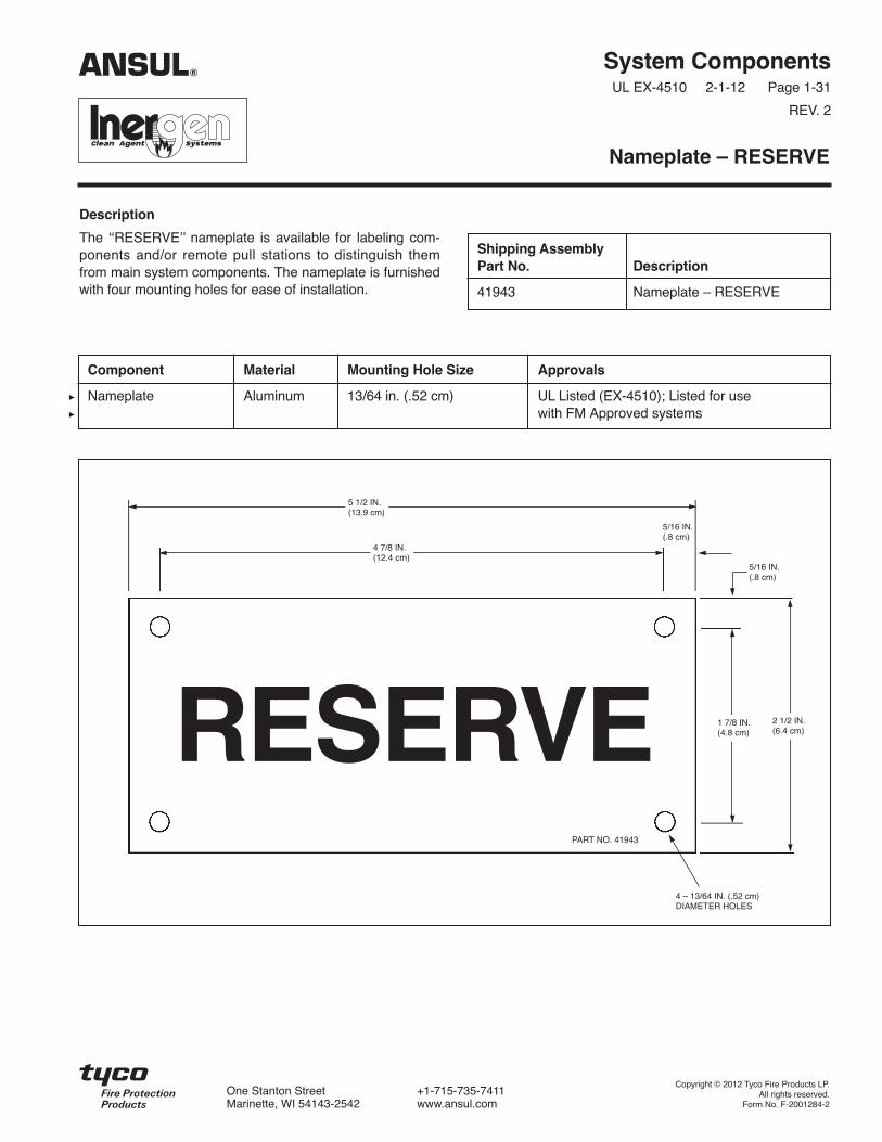
System ComponentsUL EX-4510 2-1-12 Page 1-31
REV. 2
Description
The ʻʻRESERVEʼ nameplate is available for labeling com-ponents and/or remote pull stations to distinguish themfrom main system components. The nameplate is furnishedwith four mounting holes for ease of installation.
Nameplate – RESERVE
Shipping AssemblyPart No. Description
41943 Nameplate – RESERVE
Component Material Mounting Hole Size Approvals
Nameplate Aluminum 13/64 in. (.52 cm) UL Listed (EX-4510) ; Listed for usewith FM Approved systems
RESERVE
5 1/2 IN.(13.9 cm)
4 7/8 IN.(12.4 cm)
1 7/8 IN.(4.8 cm)
2 1/2 IN.(6.4 cm)
5/16 IN.(.8 cm)
5/16 IN.(.8 cm)
PART NO. 41943
4 – 13/64 IN. (.52 cm)DIAMETER HOLES
ANSUL®
Copyright © 2012 Tyco Fire Products LP.All rights reserved.
Form No. F-2001284-2
One Stanton Street +1-715-735-7411Marinette, WI 54143-2542 www.ansul.com