Devin, Please see the attached submittal regarding the Thor ...
83
Devin, Please see the attached submittal regarding the Thor Stacker Thanks, Mike Livingston Pacific Tank Solutions Pacific States Environmental Contractors (925) 361-1539 - Office (925) 200-5409 - Cell [email protected] Tags: 612110, Pacific States Environmental Contractors, 5-24-2013, DPR Construction, Submittal 63 From: "Michael Livingston" <[email protected]> Sent: Friday, May 24, 2013 2:18:37 PM To: "Devin Durborow" <[email protected]> Cc: "DPR CRT Team" <[email protected]>, "Keith Wayne" <[email protected]>, "Brian Eychner" <[email protected]>, "Chris Deluca" <[email protected]>, <[email protected]> Subject: Submittal #63 - Thor Stacker JHA and Manual Attachments: 063 Submittal Thor Stacker JHA and Manual.pdf
-
Upload
khangminh22 -
Category
Documents
-
view
3 -
download
0
Transcript of Devin, Please see the attached submittal regarding the Thor ...

Devin, Please see the attached submittal regarding the Thor Stacker Thanks,
Mike Livingston
Pacific Tank Solutions
Pacific States Environmental Contractors
(925) 361-1539 - Office
(925) 200-5409 - Cell [email protected]
Tags: 612110, Pacific States Environmental Contractors, 5-24-2013, DPR Construction, Submittal 63
From: "Michael Livingston" <[email protected]>Sent: Friday, May 24, 2013 2:18:37 PMTo: "Devin Durborow" <[email protected]>Cc: "DPR CRT Team" <[email protected]>, "Keith Wayne" <[email protected]>, "Brian Eychner"
<[email protected]>, "Chris Deluca" <[email protected]>, <[email protected]> Subject: Submittal #63 - Thor Stacker JHA and ManualAttachments: 063 Submittal Thor Stacker JHA and Manual.pdf
Computational Research & Theory (CRT) Facility – Berkeley SUBMITTAL TRANSMITTAL
PACIFIC STATES ENVIRONMENTAL CONTRACTORS, INC.
1 of 1
Submittal Description: Thor Stacker Submittal No: 063 Spec Section:
Routing Sent Received
AGENCY: DPR Construction Contractor/CM
CM/Engineer PROJECT: CRT Facility – Berkeley, CA
Engineer/CM CONTRACTOR: Pacific States Environmental Contractors, Inc. 11555 Dublin Blvd Dublin, CA (925) 803-4333
CM/Contractor
We are sending you Attached Under separate cover via . Submittals for review and comment Product data for information only Remarks: .
Item Copies Date Section No. Description Review actiona
Reviewer initials
Review comments attached
063 1 5/23/13 Thor Stacker JHA 063 1 5/23/13 Thor Stacker Manual
aNote: NET = No exceptions taken; MCN = Make corrections noted; A&R = Amend and resubmit; R = Rejected Attach additional sheets if necessary. Contractor Certify either A or B:
A. We have verified that the material or equipment contained in the submittal meets all the requirements, including coordination with all related work, specified (no exceptions).
B. We have verified that the material or equipment contained in this submittal meets all the requirements specified except for the attached deviations.
No. Deviation
Certified by: Contractor’s Signature Mike Livingston Phone: (925) 803-4333
C/M or P/M Reviewed:
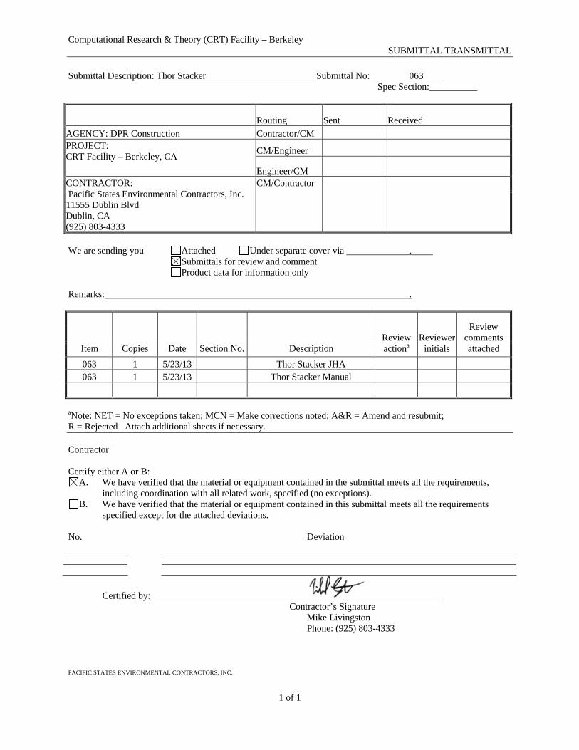
Signature: CONSTRUCTION JOB HAZARDS ANALYSIS DPR Construction CRTF Project, Berkeley
Building & Room(s): Contractor/Subcontract or Name: Pacific States Environmental Project: LBNL CRTF Project Date: 05/21/2012
Scope of Work Potential Safety Risks/Issues Safety Controls
1 of 1
Contact with other equipment Before starting this conveyor, the operator(s) must check for obstructions, or personnel that may come in contact with the wheel drive path or the telescopic portion of the conveyor. Ensure only trained, competent personnel operate and maintain this equipment.
Mechanical Failure Inspect all “wear points” and safety-related devices regularly. Assure that all parts are in safe operating condition prior to use.
Operation of Conveyor Never allow personnel or equipment to pass under the conveyor while running. Observe all possible pinch points. Spotter to notify ground personnel when conveyor is clear and stopped before working in spillway area.
Working below/around conveyor Wear all necessary PPE. Have a spotter to communicate with operator on where to place soil. Crew to stay clear of spillway area during operation. Do not start work until instructed to do so by the spotter or conveyor operator.
Blind Spots Maintain eye contact between ground crew and spotters. Ensure that area is clear before moving equipment or material.
Telescopic Thor Stacker: Use of Thor Stacker for soil layering.
Loading Soil into Conveyor Observe the area for blind spots before moving equipment. Communicate work plan with crews in area prior to starting task
JHA Review & Approval Signatures: Date: Employ ee Signatures: Date: Employee Signatures: Date:
Contractor/Subcontractor Supervisor
LBNL Construction/Project Manager
LBNL Construction Safety
(Use Reverse To Add Additional Signatures)
A signed copy of this JHA must be posted while the applicable subcontractor is working on-site and be available to any LBNL employee upon request.
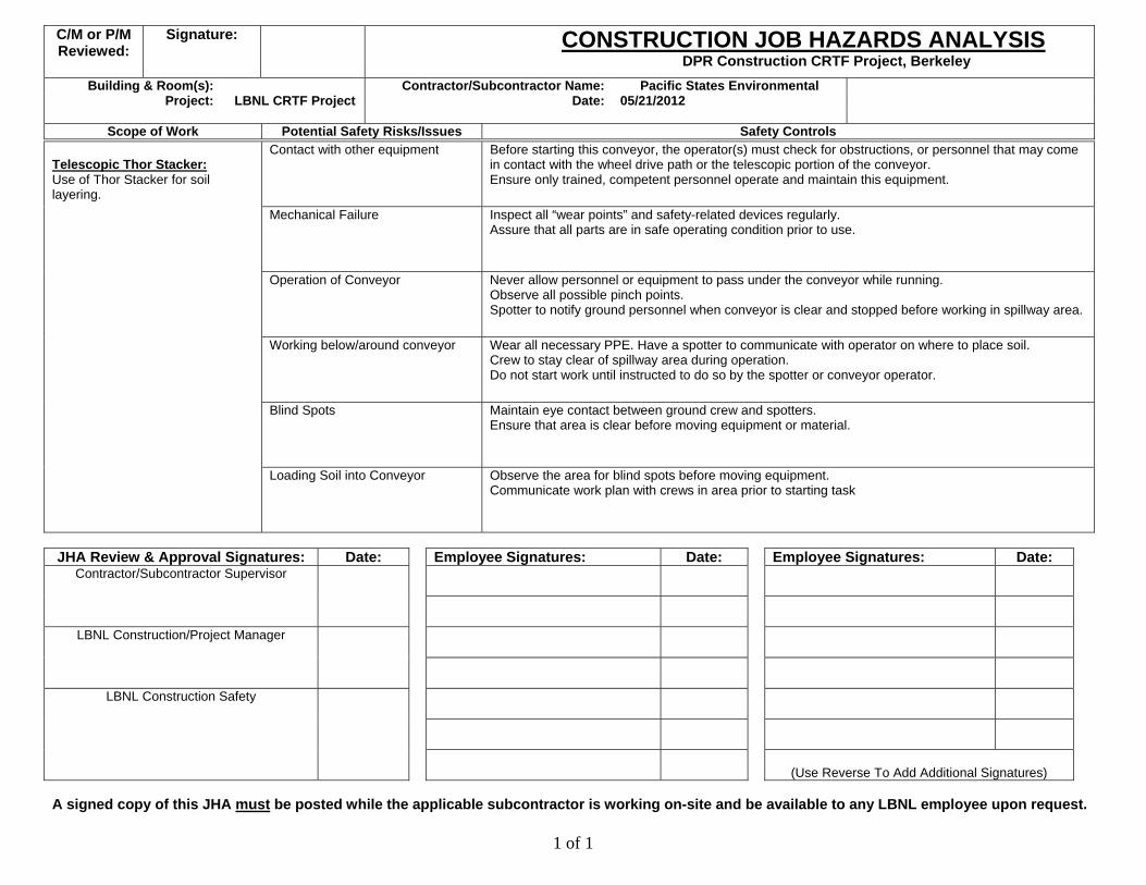
OPERATING INSTRUCTION MANUAL
2009
Thor Global Enterprises Ltd. 839 Westport Crescent Mississauga, Ontario, Canada L5T 1E7 Toll Free: 1.888.801.THOR (8467) Local: 905.564.0440 Facsimile: 905.564.9602 www.thor-global.com Manual should be kept with the conveyor .
S/N: Notice The information in this document is subject to change without notice. No part of this document may be photocopied, reproduced, or translated to another language without prior written consent of Thor Global Enterprises Ltd. Thor Global Enterprises Ltd. shall not be liable for errors contained herein or for incidental or consequential damages in connection with the furnishing, performance or use of the material herein.

TTTAAABBBLLLEEE OOOFFF CCCOOONNNTTTEEENNNTTTSSS
WARNING 1Guidelines for proper operation of your Thor conveyor.
GENERAL SAFETY STANDARDS 2Important information and instructions on the safe use of your Thor conveyor.
SET-UP 3Introduction to the conveyor and detailed instructions to have the conveyor prepared for operation.
OPERATIONS 4Instructions for operation and explanation of controls.
TROUBLESHOOTING 5Troubleshooting tips and FAQ's.
ELECTRICAL INFORMATION 6Electrical requirements, specifications and schematics.
HYDRAULICS INFORMATION 7Detailed hydraulic schematics.
MAINTENANCE 8Minimum guidelines for regular inspection and maintenance for your Thor conveyor. Information in this chapter is essential for your warranty.
TECHNICAL INFORMATION 9Technical data and dimensions for your Thor conveyor.
PARTS MANUAL 10Information regarding replacements parts.
Thor Global Enterprises Ltd. www.thor-global.com

AAA NNNOOOTTTEEE TTTOOO TTTHHHOOORRR OOOPPPEEERRRAAATTTOOORRRSSS
Thank you for choosing a Thor conveyor. We at Thor design and build conveyors with complete customer satisfaction in mind. To help ensure efficient and trouble-free operation of your Thor conveyor, read this manual carefully and follow its recommendations as well as any further advice from your Thor Service Technician.
Thank you for choosing a Thor conveyor. We at Thor design and build conveyors with complete customer satisfaction in mind. To help ensure efficient and trouble-free operation of your Thor conveyor, read this manual carefully and follow its recommendations as well as any further advice from your Thor Service Technician. IMPORTANT IMPORTANT Keep this manual inside the electrical panel as a handy reference for the safe use and proper maintenance of your Thor conveyor. Keep this manual inside the electrical panel as a handy reference for the safe use and proper maintenance of your Thor conveyor. All specifications and descriptions are accurate at the time of printing. Because improvement is a constant goal at Thor, we reserve the right to make changes in specifications at any time without notice and without obligation.
All specifications and descriptions are accurate at the time of printing. Because improvement is a constant goal at Thor, we reserve the right to make changes in specifications at any time without notice and without obligation. Please be aware that this manual applies to all models. As a result you may find some explanations, drawings, specifications and parts listings that do not pertain to your conveyor.
Please be aware that this manual applies to all models. As a result you may find some explanations, drawings, specifications and parts listings that do not pertain to your conveyor. You will find several CAUTION's in this manual. You will find several CAUTION's in this manual.
A CAUTION indicates a situation in which bodily injury or damage to your conveyor, or both, could result if the caution is ignored.
A CAUTION indicates a situation in which bodily injury or damage to your conveyor, or both, could result if the caution is ignored.
© 2006 Thor Global Enterprises Ltd. Printed in Canada
Thor Global Enterprises Ltd. www.thor-global.com
WWWAAARRRNNNIIINNNGGG 111---111
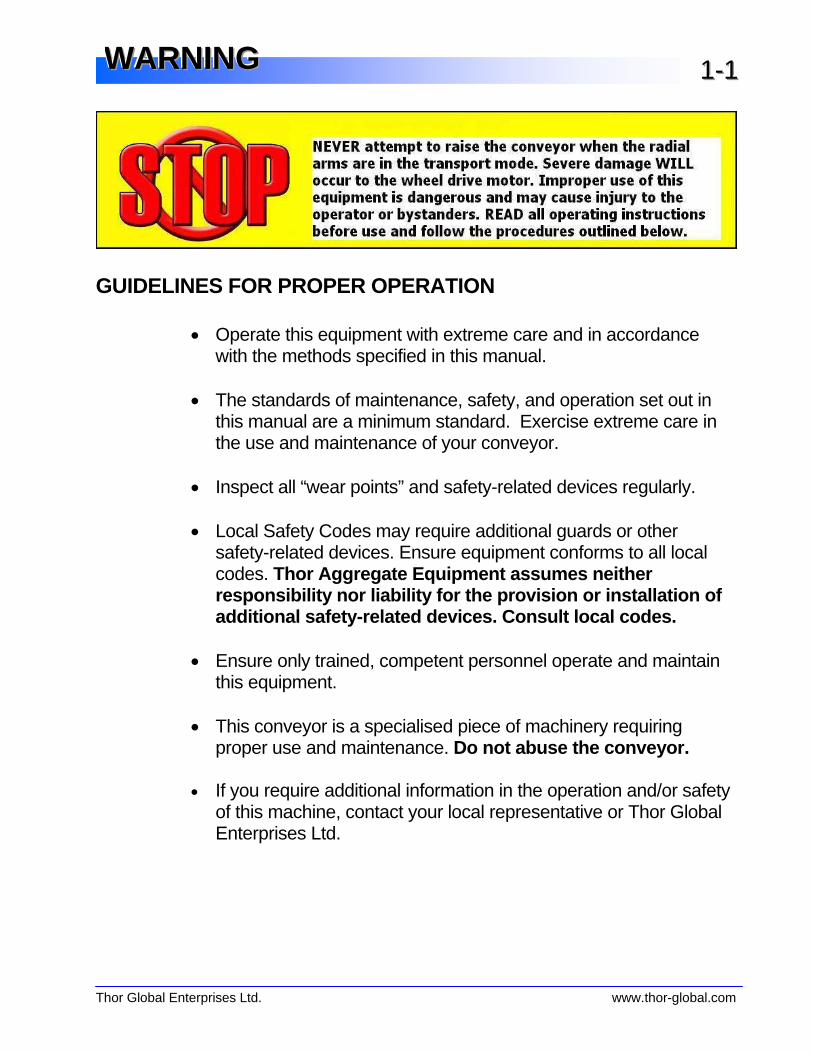
GUIDELINES FOR PROPER OPERATION • Operate this equipment with extreme care and in accordance
with the methods specified in this manual. • The standards of maintenance, safety, and operation set out in
this manual are a minimum standard. Exercise extreme care in the use and maintenance of your conveyor.
• Inspect all “wear points” and safety-related devices regularly. • Local Safety Codes may require additional guards or other
safety-related devices. Ensure equipment conforms to all local codes. Thor Aggregate Equipment assumes neither responsibility nor liability for the provision or installation of additional safety-related devi ces. Consult local codes.
• Ensure only trained, competent personnel operate and maintain this equipment.
• This conveyor is a specialised piece of machinery requiring proper use and maintenance. Do not abuse the conveyor.
• If you require additional information in the operation and/or safety
of this machine, contact your local representative or Thor Global Enterprises Ltd.
Thor Global Enterprises Ltd. www.thor-global.com

This page is intentionally blank.
Thor Global Enterprises Ltd. www.thor-global.com
SSSAAAFFFEEETTTYYY 222---111
GENERAL CONVEYOR SAFETY
CONVEYORS CAN BE DEADLY
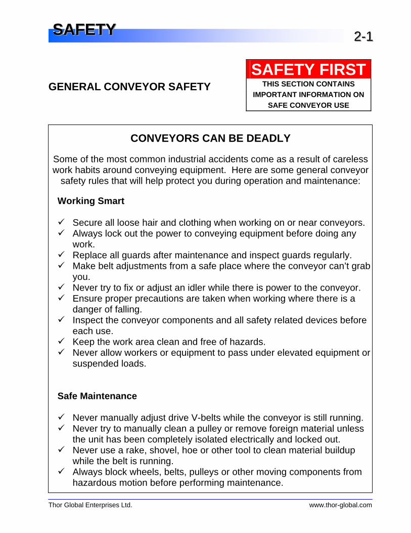
Some of the most common industrial accidents come as a result of careless work habits around conveying equipment. Here are some general conveyor
safety rules that will help protect you during operation and maintenance:
Working Smart X Secure all loose hair and clothing when working on or near conveyors. X Always lock out the power to conveying equipment before doing any
work. X Replace all guards after maintenance and inspect guards regularly. X Make belt adjustments from a safe place where the conveyor can’t grab
you. X Never try to fix or adjust an idler while there is power to the conveyor. X Ensure proper precautions are taken when working where there is a
danger of falling. X Inspect the conveyor components and all safety related devices before
each use. X Keep the work area clean and free of hazards. X Never allow workers or equipment to pass under elevated equipment or
suspended loads. Safe Maintenance X Never manually adjust drive V-belts while the conveyor is still running. X Never try to manually clean a pulley or remove foreign material unless
the unit has been completely isolated electrically and locked out. X Never use a rake, shovel, hoe or other tool to clean material buildup
while the belt is running. X Always block wheels, belts, pulleys or other moving components from
hazardous motion before performing maintenance.
SAFETY FIRSTTHIS SECTION CONTAINS
IMPORTANT INFORMATION ON SAFE CONVEYOR USE
Thor Global Enterprises Ltd. www.thor-global.com
SSSAAAFFFEEETTTYYY 222---222
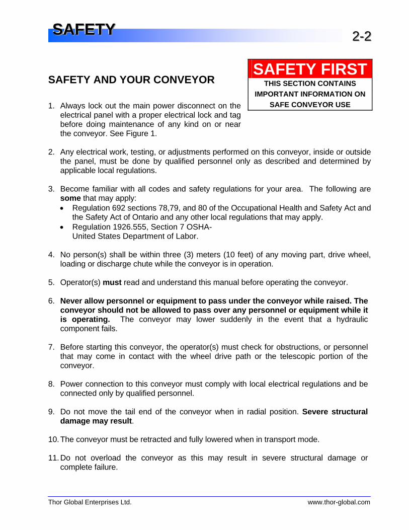
SAFETY AND YOUR CONVEYOR 1. Always lock out the main power disconnect on the
electrical panel with a proper electrical lock and tag before doing maintenance of any kind on or near the conveyor. See Figure 1.
2. Any electrical work, testing, or adjustments performed on this conveyor, inside or outside
the panel, must be done by qualified personnel only as described and determined by applicable local regulations.
3. Become familiar with all codes and safety regulations for your area. The following are
some that may apply: • Regulation 692 sections 78,79, and 80 of the Occupational Health and Safety Act and the Safety Act of Ontario and any other local regulations that may apply. • Regulation 1926.555, Section 7 OSHA-
United States Department of Labor. 4. No person(s) shall be within three (3) meters (10 feet) of any moving part, drive wheel,
loading or discharge chute while the conveyor is in operation. 5. Operator(s) must read and understand this manual before operating the conveyor. 6. Never allow personnel or equipment to pa ss under the conveyor while raised. The
conveyor should not be allowed to pass ov er any personnel or equipment while it is operating. The conveyor may lower suddenly in the event that a hydraulic component fails.
7. Before starting this conveyor, the operator(s) must check for obstructions, or personnel
that may come in contact with the wheel drive path or the telescopic portion of the conveyor.
8. Power connection to this conveyor must comply with local electrical regulations and be
connected only by qualified personnel.
9. Do not move the tail end of the conveyor when in radial position. Severe structural damage may result .
10. The conveyor must be retracted and fully lowered when in transport mode. 11. Do not overload the conveyor as this may result in severe structural damage or
complete failure.
SAFETY FIRSTTHIS SECTION CONTAINS
IMPORTANT INFORMATION ON SAFE CONVEYOR USE
Thor Global Enterprises Ltd. www.thor-global.com
SSSAAAFFFEEETTTYYY 222---333
12. When pivoting the conveyor unit 90 degrees or more, retract the telescopic (inner) conveyor and lower the entire unit completely whenever possible.
13. If the red fault light is illuminated: • HIT EMERGENCY STOP BUTTON. • Identify the fault light. • Only then, proceed to correct the problem.
14. If the unit has been operating in an extended position for a long period of time, remove any build-up of material on the structure and trailing cable before retracting the telescopic conveyor.
15. It is essential that the area around the pivot point and concrete pad be kept clear to ensure unobstructed operation.
16. The winch cable must be properly maintained to ensure the smooth operation of the equipment and the safety of those who operate it. See the section on cable tightening.
17. To ensure safety, this conveyor must be operated with the supplied ground pin attached to a concrete pad or a portable pad (See fig 2 in the Set-up section).
WARNING: It is not warranted that guards on the tail pulley area, portable anchor pad, V-belt drive guards, return idler guards, pinch points and nip guards on drive pulleys, will meet all local codes. It is the responsibility of the end user to have these items verified for compliance with local codes.

This page is intentionally blank.

Thor Global Enterprises Ltd. www.thor-global.com
SSSEEETTT---UUUPPP
Getting To Know Your Conveyor 3-1Conveyor Components Hydraulic Control Station Electrical Panel Pile Detection Sensor Receiving Hopper & Ultrasonic Material Sensor Absolute Radial Limit Switch Emergency Braking System Hydraulic Flow Control Valve
Constructing the Concrete Foundation 3-5 Setting-Up Upon Arrival On Site 3-5 Setting-Up For Operation 3-7Pin Locations
Thor Global Enterprises Ltd. www.thor-global.com
SSSEEETTT---UUUPPP 333---111
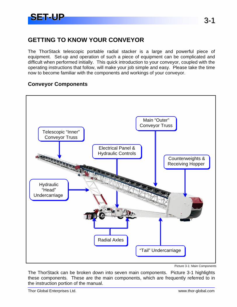
GETTING TO KNOW YOUR CONVEYOR The ThorStack telescopic portable radial stacker is a large and powerful piece of equipment. Set-up and operation of such a piece of equipment can be complicated and difficult when performed initially. This quick introduction to your conveyor, coupled with the operating instructions that follow, will make your job simple and easy. Please take the time now to become familiar with the components and workings of your conveyor. Conveyor Components The ThorStack can be broken down into seven main components. Picture 3-1 highlights these components. These are the main components, which are frequently referred to in the instruction portion of the manual.
Picture 3-1: Main Components
Telescopic “Inner” Conveyor Truss
Electrical Panel & Hydraulic Controls
Main “Outer” Conveyor Truss
Counterweights &Receiving Hopper
“Tail” Undercarriage
Radial Axles
Hydraulic “Head”
Undercarriage

Thor Global Enterprises Ltd. www.thor-global.com
SSSEEETTT---UUUPPP 333---222
The following section provides information about some of the other parts on your ThorStack Conveyor. Hydraulic Control Station The Hydraulic Control Station is located on the tail undercarriage. This station is used to raise and lower the jacking cylinders. The jacking cylinders are used to raise and lower the stacker to swing the wheels into radial and transport positions. Electrical Panel The Electrical Panel is located on the tail undercarriage adjacent to the Hydraulic Control Station. The main power switch, emergency stop, lights are located on the electrical panel. Please refer to the Operations and Electrical Information Sections of this manual for additional information about the electrical panel. Pile Detection Limit Switch The ThorStack is equipped with a limit switch located under 3’ the head pulley of the telescopic conveyor (Picture 3-4). The limit switch will ensure that the head of the conveyor maintains a minimum 3’ drop height of the material conveyed to the top of the stockpile. If the limit switch detects material within 3’ for a continuous 2-second period, it will automatically raise.
Picture 3-2: Hydraulic Control Station
Pump & Motor
Jacking Cylinder Controls Pressure Gauge
Pump Push Start Button
Picture 3-4: Ultrasonic Pile Detection Sensor
Pile Detection Switch

Thor Global Enterprises Ltd. www.thor-global.com
SSSEEETTT---UUUPPP 333---333
Receiving Hopper & Ultrasonic Material Sensor
The Stone Box, located at the rear (tail) of the conveyor, is the material transfer point from the feed conveyor. The standard with the ThorStack is the Stone Box shown. Tapered chutes are also available. The Ultrasonic Material Sensor is located in front of the hopper. The sensor detects the presence of material on the belt. If material flow is discontinued for more than four seconds, the sensor will stop radial travel (in Automatic Mode). The belts will continue to run. Radial travel will continue and Automatic Mode will resume as soon as the sensor detects that material is present on the belt. Absolute Radial Limit Switch If in the unlikely event that the conveyor travels beyond the operators predetermined radial arc in Automatic Mode, the Absolute Radial Limit Switch will be tripped and the radial travel of the conveyor will stop. The Absolute Radial Limit Switch is located on the tail undercarriage near the radial axle as indicated in Picture 4-1. The Absolute Radial Limit Switch is included with your ThorStack as a safety feature and is recommended for use when operating the conveyor in Automatic Mode. Place a heavy object (such as a concrete block) at the outer perimeters of the predetermined arc. Ensure that the objects are placed within the path of the Radial Limit Switch and are high enough to trip it but not higher than the bottom edge of the tail undercarriage. We recommend using a concrete block with the dimensions: 12”H x 12”W x 24”L for use as a tripping object. Some models have a bolt-on type sensor, which needs to be rotated 180° before the conveyor can be used (see Picture 3-7 & 3-8). The open-end of the enclosure must face down and towards the feed direction.
Picture 3-6: Stone BoxUltrasonic
Material Sensor
Picture 4-1: Radial Limit Switch
Radial Limit Switch

Thor Global Enterprises Ltd. www.thor-global.com
SSSEEETTT---UUUPPP 333---444
Emergency Telescoping Braking System
The Emergency Braking System is located adjacent to the Cable Ratchet System on the telescopic (inner) conveyor. The Emergency Braking System is a safety system designed to stop the inner conveyor truss from “crashing” backwards in the unlikely event of a winch cable break. A brake-activated limit switch is used in this system to alert and inform the operator if the system is engaged. For information on maintenance of the Emergency Braking System please refer to Chapter 8 – Maintenance. Hydraulic Flow Control Valve All hydraulic systems will show pressure loss due to seepage over extended periods of time, particularly as the components age. The ThorStack hydraulic system is no different. This “creeping” is insignificant and unnoticeable during operation, however if the conveyor were to be left extended and raised for a long period of time it may slowly lower. To prevent this, the conveyor is equipped with a Flow Control Valve that restricts the flow of hydraulic fluid back into the tank. This valve is located between the radial arms and below the hydraulic cylinders (Picture 3-10, 3-11). The Flow Control Valve is equipped with a by-pass that allows the conveyor to raise with the valve closed but prevents it from lowering.
Picture 3-9: Emergency Braking System (without cover)
Braking Plunger
Limit Switch
Cable Ratchet System
Picture 3-10: Hydraulic Flow Control Valve
Hydraulic Flow Control Valve
Picture 3-7: Material Sensor
Material Sensor Transport Mode
Picture 3-8: Material Sensor
Material Sensor Working Mode

Thor Global Enterprises Ltd. www.thor-global.com
SSSEEETTT---UUUPPP 333---555
Since normal conveyor operation, whether in Automatic Mode or operating the conveyor manually, does not require the conveyor to lower, we recommend that the operator leave the valve closed at all times. Simply open the valve 1 ½ turns before lowering the conveyor when stacking is complete. Do not open the Flow Control Valve more than 1 ½ turns as this may permit the conveyor to lower too quickly and may cause damage and/or injury.
CONSTRUCTING THE CONCRETE FOUNDATION A concrete foundation or “Concrete Anchor Pad” must be erected prior to the set-up and use of the ThorStack conveyor. Refer to Chapter 9 - Technical Information for suggested specifications for the concrete anchor pad.
1. Disconnect the ground pad from the bottom of the flip box by removing the ∅1” bolt and thrust ring.
2. Pour the concrete anchor pad as per the specifications outlined in the Chapter 9 - Technical Information making sure that the top of the concrete anchor pad is 1’-0” higher than the runway (for runway information refer to Chapter 9 - Technical Information).
3. Insert the ground pad and a check for level. Allow proper time for the concrete to cure prior to setting the conveyor in place.
SETTING-UP ON ARRIVAL ON SITE 1. Disconnect the air-lines from the tractor and
release the pressure from the conveyor unit’s air tank. The air tank is located at the head of the tail undercarriage between the radial arms.
2. Ensure that the tank is completely emptied
and that the auxiliary axle airbags are also depressurized. The auxiliary axles will not raise if not completely depressurized.
3. Use a lifting device (loader, lift truck, etc.) to
raise the two auxiliary axles into (locking) position. These axles are held in place with a pin connection located near the top of the
Picture 3-12: Air Tank Assembly
Valve
Air Tank
Picture 3-11: Adjusting the Hydraulic Flow Control

Thor Global Enterprises Ltd. www.thor-global.com
SSSEEETTT---UUUPPP 333---666
auxiliary axle. Do not proceed to lower the unit until the auxiliary axles have been raised. Failure to depressurize and raise the auxiliary axles before lowering the unit from the truck will result in blown airbags.
4. Lift the conveyor off the truck using the
supplied lifting holes (located at the top of the counterweights).
5. Remove pins “E” (Figure 3-1) with chain.
This will allow the fifth wheel assembly (flip box) to swivel. Turn the flip box up into operating position (hole towards the ground).
6. Lower the tail end of the conveyor and set
the flip box onto the concrete anchor pad so that the ground pad pin goes through the hole in the flip box.
7. Place the thrust ring around the ground pad
pin and then install the ∅1” bolt supplied to secure the conveyor to the concrete anchor pad.
8. Wire the conveyor to the source that supplies the required electrical power as set out by
local electrical regulations.
NOTE: To check for proper rotation – turn the Main Power Switch to the “ON” position. Touch the TEL.OUT. functi on button on the Touch Screen. If the telescopic conveyor extends outwards, rotation is correct. If the telescopic conveyor retracts inward , the two leads from the incoming power supply will need to be switched to obtain correct rotation.
9. RE-CHECK: • The elevation at the point where the bottom of the tail end of the stacker meets the
top of the concrete pad is no more than one foot (1'-0”) higher than ground elevation at the base of the wheels. • The runway for the radial wheels is level and free of obstruction. •
WARNING! The ThorStack conveyor shoul d never be operated unless it is secured to a proper fo undation. Never operate the conveyor without the ground pad pin secured with a minimum ∅1” bolt.
Picture 3-13: Auxiliary Axle Airbag
Picture 3-14: Flip Box
Pins “E”
Thor Global Enterprises Ltd. www.thor-global.com
SSSEEETTT---UUUPPP 333---777
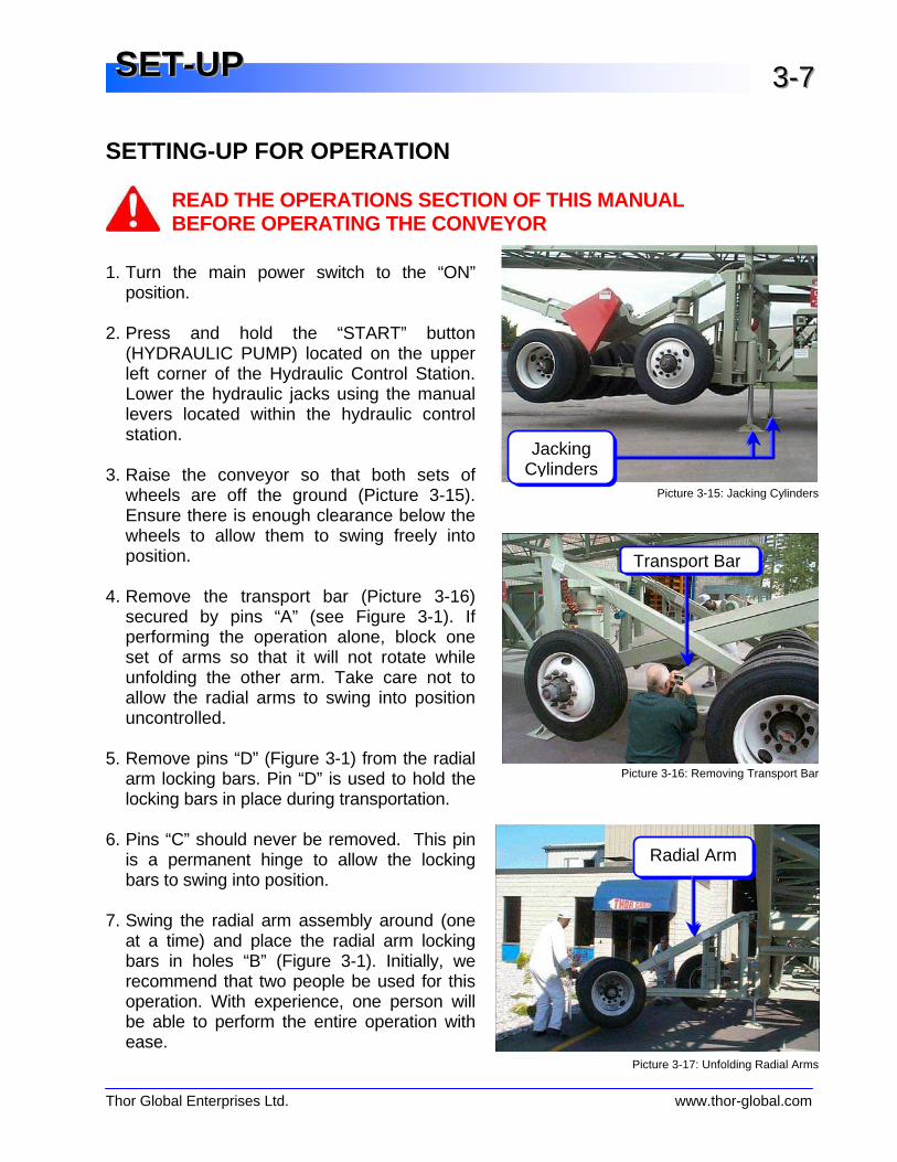
SETTING-UP FOR OPERATION
READ THE OPERATIONS SECTION OF THIS MANUAL BEFORE OPERATING THE CONVEYOR
1. Turn the main power switch to the “ON”
position. 2. Press and hold the “START” button
(HYDRAULIC PUMP) located on the upper left corner of the Hydraulic Control Station. Lower the hydraulic jacks using the manual levers located within the hydraulic control station.
3. Raise the conveyor so that both sets of
wheels are off the ground (Picture 3-15). Ensure there is enough clearance below the wheels to allow them to swing freely into position.
4. Remove the transport bar (Picture 3-16)
secured by pins “A” (see Figure 3-1). If performing the operation alone, block one set of arms so that it will not rotate while unfolding the other arm. Take care not to allow the radial arms to swing into position uncontrolled.
5. Remove pins “D” (Figure 3-1) from the radial
arm locking bars. Pin “D” is used to hold the locking bars in place during transportation.
6. Pins “C” should never be removed. This pin
is a permanent hinge to allow the locking bars to swing into position.
7. Swing the radial arm assembly around (one
at a time) and place the radial arm locking bars in holes “B” (Figure 3-1). Initially, we recommend that two people be used for this operation. With experience, one person will be able to perform the entire operation with ease.
Jacking Cylinders
Picture 3-15: Jacking Cylinders
Picture 3-17: Unfolding Radial Arms
Radial Arm
Picture 3-16: Removing Transport Bar
Transport Bar

Thor Global Enterprises Ltd. www.thor-global.com
SSSEEETTT---UUUPPP 333---888
8. Check sure that all pins are in place and that all cotter pins have properly installed. 9. Lower the conveyor by fully retracting the jacking cylinders. Now that the conveyor is in
radial position the drive chain must be attached to the wheel drive. Before attempting this procedure the main disconnect should be turned off to prevent inadvertent movement of the drive while working on the unit. Install the drive chain using the following procedure:
1) Remove the guarding covering the radial drive. 2) Layout the drive chain in line with the radial arm. Slide the chain between the tires where the large drive sprocket is located. If working in sand or other fine material, lay down some form of sheeting to protect the chain from contamination. 3) Pull the chain up and feed it around the smaller sprocket installed on the radial drive unit. 4) Pull the drive chain up and around the larger drive sprocket mounted on the axle. Attach the two chain ends using the “Quick-Link” pin provided as shown in Picture 3-20. 5) Replace the guarding for the radial drive. Note: Two Wing Nuts are provided in the electrical panel to allow for quick removal of the radial drive guarding.
Picture 3-18: Installing Drive Chain
Picture 3-19: Installing Drive Chain
Picture 3-20: Installing Drive Chain
Picture 3-21: Installing Drive Chain
Thor Global Enterprises Ltd. www.thor-global.com
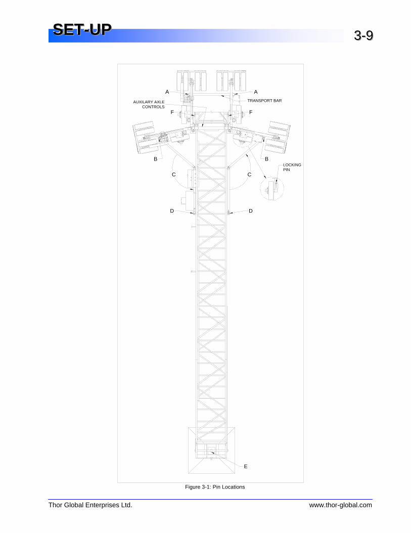
SSSEEETTT---UUUPPP 333---999
E
B
AUXILARY AXLECONTROLS
D D
TRANSPORT BAR
C
F
C
B
F
A
LOCKINGPIN
Figure 3-1: Pin Locations
Thor Global Enterprises Ltd. www.thor-global.com
OOOPPPEEERRRAAATTTIIIOOONNNSSS
Operation of your Conveyor 4-1 Control Panel Description 4-2 Operating the Conveyer in Automatic Mode 4-3 Automatic Mode 4-3 Manual Mode 4-4 At The End of the Operating Day 4-6 At The Beginning of the Operating Day 4-6 Moving the Telescopic Conveyor 4-7
Thor Global Enterprises Ltd. www.thor-global.com
OOOPPPEEERRRAAATTTIIIOOONNNSSS 444---111
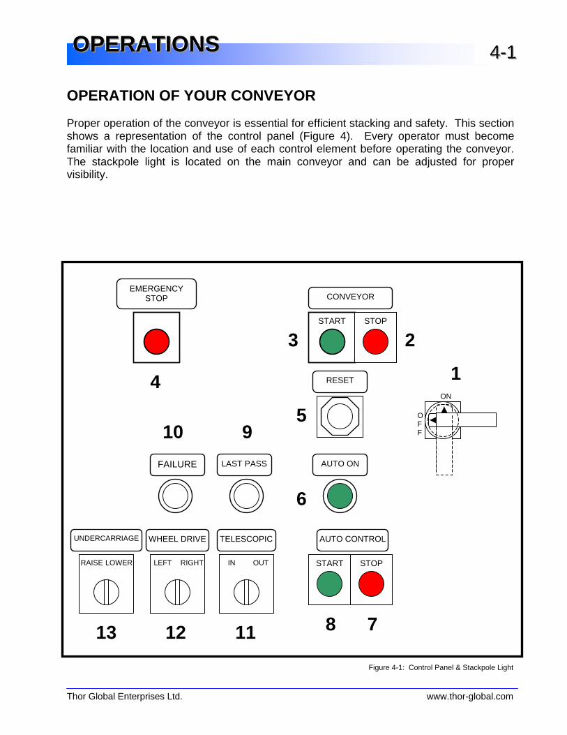
Figure 4-1: Control Panel & Stackpole Light
OPERATION OF YOUR CONVEYOR Proper operation of the conveyor is essential for efficient stacking and safety. This section shows a representation of the control panel (Figure 4). Every operator must become familiar with the location and use of each control element before operating the conveyor. The stackpole light is located on the main conveyor and can be adjusted for proper visibility.
CONVEYOR EMERGENCY
STOP
10 9OF F
ON
1
RAISE LOWER
UNDERCARRIAGE
13
LEFT RIGHT
WHEEL DRIVE
12
TELESCOPIC
IN OUT
11
AUTO CONTROL
8 7
FAILURE LAST PASS AUTO ON
RESET
START STOP
START STOP
4
3 2
5
6

Thor Global Enterprises Ltd. www.thor-global.com
OOOPPPEEERRRAAATTTIIIOOONNNSSS 444---222
CONTROL PANEL DESCRIPTION Refer to Figure 4-1
1 ON/OFF MAIN DISCONNECT – To shut off power supply to all components inside control panel
2 CONVEYOR STOP RED STOP BUTTON – To stop all conveyors. Will also stop
automatic mode if in use.
3 CONVEYOR START GREEN START BUTTON – To start all conveyors
4 EMERGENCY STOP RED MUSHROOM HEAD BUTTON – Will de-energize all outputs and stop all movements.
5 RESET The reset button has two (2) functions.
1) Holding for 6 seconds resets the PLC counter 2) Momentarily pressing resets the alarm horn and fault
conditions
6 AUTO ON GREEN INDICATION LIGHT – Lit when in Automatic mode
7 AUTO CONTROL STOP GREEN PUSH BUTTON – Starts AUTO mode. Once this button is pushed the telescopic conveyor will begin to build a pile if there is material on the belt
8 AUTO CONTROL START RED PUSH BUTTON – Stops AUTO mode. Enters manual mode
(Radial & Telescopic movement stops, conveyor still runs)
9 LAST PASS LIGHT If this indicator is illuminated and the horn sounds intermittently, this indicates that the stacker is building the final layer of the pile. When the pile is complete the conveyor will be put automatically into manual mode.
10 FAILURE LIGHT If this indicator is illuminated and the horn sounds intermittently this
indicates that there is a malfunction in one of the limit switches and/or that on overload in the electrical panel has been tripped. Refer to the fault code sheet located in the panel door or in the TROUBLE SHOOTING section of this manual
11 TELESCOPIC IN/OUT SELECTOR SWITCH – Used to telescope IN or OUT. The switch
must be held on either IN or OUT for the conveyor to telescope as desired. NOTE – will not work in AUTO mode
12 WHEEL DRIVE SELECTOR SWITCH – Used to move conveyor to the RIGHT or
LEFT. Switch must be held at either RIGHT or LEFT for the conveyor to move radially as desired NOTE – will not work in AUTO mode
13 UNDERCARRIAGE
RAISE/LOWER SELECTOR SWITCH – Used to raise or lower the conveyor. Switch
must be held on either RAISE or LOWER until conveyor is at desired height. Must be used in conjunction with WHEEL DRIVE

Thor Global Enterprises Ltd. www.thor-global.com
OOOPPPEEERRRAAATTTIIIOOONNNSSS 444---333
OPERATING THE CONVEYOR IN AUTOMATIC MODE
1. Set-Up limit switch tripping device. (See next section) 2. Turn main disconnect (item 1) to the ON position. Make sure the emergency STOP
button (item 4) is pulled out.
3. Turn the TELESCOPIC IN/OUT switch (item 11) to the telescopic IN position until the telescopic part of the conveyor is all the way in.
4. Turn the WHEEL DRIVE switch (item 12) to the LEFT position until conveyor is to
the left-hand side of the radius.
5. Turn and hold the undercarriage control switch (item 13) on either RAISE or LOWER until the desired height is achieved. NOTE: always start in the lowest position unless restarting a partially completed pile.
6. Push the RESET button (item 5) for a minimum of 6 seconds to rest the internal
PLC counter. This action must always be performed when starting a new pile; otherwise the outside edge of the pile will build too quickly.
7. Press the CONVEYOR START button (item 3) to start the belts. Once both belts
have been started press the AUTO CONTROL START button (item 8) to start AUTO mode. Automatic mode will commence when material is sensed on the belt.
NOTE: When the belts are started an alarm will sound. You will also notice that the inner conveyor belt will start first and the outer belt will start after a 3-second delay. This is done to prevent a surge of material from the outer to the inner belt.
AUTOMATIC MODE
• Once the AUTO CONTROL START button has been pressed the conveyor will start to index out and then move to the right • Upon hitting the right hand limit tripping device, the conveyor will start to index out and then move to the left. • This process will continue until the telescopic conveyor has reached its final OUT position. • The first time the conveyor reaches the final OUT position the conveyor will make 4 passes before automatic retraction occurs. Every time the final OUT position is reached the number of passes will increase by 1 pass (i.e. 5 passes on the second time out, 6 passes on the third time out, etc) • This process will continue until stopped. • The conveyor is equipped with a sensor that will automatically raise the conveyor if material is sensed within 3 ft of the inner conveyor.

Thor Global Enterprises Ltd. www.thor-global.com
OOOPPPEEERRRAAATTTIIIOOONNNSSS 444---444
• Once the maximum height is reached the stacker will sound a horn as a warning and the LAST PASS light will flash.
NOTE : If AUTO mode is stopped and restarted without any other operation in between, the conveyor will continue in the same direction from the same location where it was stopped. STOPPING AUTO MODE If auto mode must be stopped: follow ONE of these three steps:
1. Press the AUTO CONTROL STOP button (item 7) . This will stop the radial movement but the conveyor will continue to run.
2. Push the STOP CONVEYOR button (item 2) . This will stop the conveyor belts and
radial movements.
3. Push the EMERGENCY STOP button (item 4) . This will stop everything. RESTARTING AUTO MODE • If the conveyor was stopped in AUTO mode and there were no other operations in
between, simply press AUTO CONTROL START (item 8) to restart. The conveyor will continue the pile in the same direction from where it left off but will index out.
• If the conveyor was moved to a different position
o Move the conveyor approximately to the same position where the AUTO mode was interrupted and press the AUTO CONTROL START button (item 7)
o Move the conveyor to the far left, retract inner completely, press RESET
(Item 5) and then press AUTO CONTROL START (item 7). MANUAL MODE If you plan to use your THOR telescopic conveyor for manual stacking operations in order to maximize effectiveness and minimize wear on the conveyor we suggest that you utilize the full range of telescopic motion (TELESCOPIC IN/OUT) whenever possible. This wil ensure that you maintain an equal structural load distribution over the life of the machine.
Thor Global Enterprises Ltd. www.thor-global.com
OOOPPPEEERRRAAATTTIIIOOONNNSSS 444---555
MANUAL MODE OPERATIONS LEFT: Turn WHEEL DRIVE selector switch (item 12) to LEFT and hold until desired
position is reached. RIGHT: Turn WHEEL DRIVE selector switch (item 12) to RIGHT and hold until
desired position is reached. When raising and lowering the conveyor always move the conveyor radially. Failure to do so will cause the wheels to drag which in turn will over stress the radial arms and pivot point resulting in sever structural damage IN: Turn TELESCOPE IN/OUT selector switch (item 11) to IN and hold until
desired position is reached. OUT: Ensure that the flow control valve at the bottom of the main cylinders have
been opened 1 ½ turns. DO NOT OPEN VALVES ALL THE WAY as this may result in the conveyor lowering too fast and causing injury. Turn TELESCOPE IN/OUT selector switch (item 11) to OUT and hold until desired position is reached.
Refer to page 3-4 Hydraulic Flow Control START: Push CONVEYOR START button (item 3) STOP: Push CONVEYOR STOP button (item 2) or push the EMERGENCY STOP
button (item 4). NOTE: When the start button is activated a horn will sound for 3 seconds after which the telescopic conveyor will start. Once the inner conveyor has started there will be a 3-4 second delay before the main conveyor will start.
Thor Global Enterprises Ltd. www.thor-global.com
OOOPPPEEERRRAAATTTIIIOOONNNSSS 444---666
AT THE END OF AN OPERATING DAY
1. Ensure that the belts are unloaded. The conveyor belts should be run until there is no longer any material present on the belts. Never leave the machine dormant with material on the belt.
2. Whenever possible, ensure that the telescopic conveyor is fully retracted. 3. Make sure that the Hydraulic Flow Control Valve is closed whenever the machine
cannot be completely lowered to ensure that no hydraulic fluid bleeds through this valve causing the conveyor to creep down. For more information refer to page 3-4, Hydraulic Flow Control Valve.
AT THE BEGINNING OF AN OPERATING DAY
1. Perform a general visual inspection of the conveyor to ensure that all limit switches and guards are in place and that all moving parts are free from obstruction. Visually inspect the Winch Cable System to ensure the winch cable is tight and the springs are compressed. For additional information, please refer to the Maintenance chapter of this manual.
2. Make certain that the radial path of travel for the conveyor is free from obstruction.
3. If the Hydraulic Flow Control Valve was closed the previous day, open it one and a
half (1 ½) turns if you intend to raise or lower the conveyor and/or use Automatic Mode.
4. If you are continuing construction of the same stockpile from the previous day,
return the conveyor to approximately the same position where it had stopped. If a new stockpile is to be built, please refer to the instructions outlined earlier in this chapter (Operating the Conveyor in Automatic Mode - page 4-8).
5. Start the conveyor belts and touch the AUTO RUN function button to resume
Automatic Mode or begin construction of a new stockpile.
NEVER TRY TO LOWER THE CONVEYOR WITH THE HYDRAULIC FLOW CONTROL VALVE CLOSED. THIS WILL RESULT IN EXTENSIVE DAMAGE TO THE HYDRAULIC PUMP.
Thor Global Enterprises Ltd. www.thor-global.com
OOOPPPEEERRRAAATTTIIIOOONNNSSS 444---777
MOVING THE TELESCOPIC CONVEYOR
The conveyor must be returned to the transport position before it can be moved. The following procedure is simply the reverse of the set-up instructions. Refer to Chapter 3 – Set-Up for more detail if necessary. 1. Fully retract the telescopic conveyor5. 2. Remove the drive chain. Remove by using the proper connection coupling on the
chain6. 3. Lower the hydraulic jacking cylinders to raise the conveyor axles from the ground. 4. Remove pins "B" (Figure 3-1) from the radial arm locking bars and return to their
original position, replace pins "D". 5. Swing the axle assembly to the transport position and replace the transport bar as well
as pins "A" (Figure 3-1). We recommend that two people perform this operation. 6. Raise the hydraulic lifting jacks to lower the conveyor axles to the ground. 7. Use a lifting device (loader, lift truck, etc.) to remove the auxiliary arm locking pins and
lower the two auxiliary axles into transport position. This step is only necessary if transporting via public roadway where required by law7.
8. Ensure that all pins and cotter pins are properly installed. 9. Remove the bolt connecting the flip box to the concrete pad. 10. Proceed to lift the tail end of the conveyor by using the lifting lugs holes on the top of
the counterweight. Remove pins “E” (Figure 3-1), rotate the flip box so that the king pin is down, and then replace pins "E".
11. The conveyor can now be transported to the desired location.
DO NOT MOVE TAIL END OF CONVEYOR AT ANY TIME UNLESS IT HAS BEEN RETURNED TO THE TRANSPORT POSITION.
5 Never attempt to move the conveyor while it is still elevated and/or extended. 6 Failure to remove the chain from the radial drive before transportation can cause extensive damage to the radial drive. 7 If transporting the conveyor via public roadway, be sure to re-energize the auxiliary axles if required by law.

Thor Global Enterprises Ltd. www.thor-global.com
TTTRRROOOUUUBBBLLLEEESSSHHHOOOOOOTTTIIINNNGGG
Troubleshooting 5-1 Conveyor Faults 5-2 Fault Codes 5-5 Installing New EEPROM 5-7 Contact Information 5-8

Thor Global Enterprises Ltd. www.thor-global.com
TTTRRROOOUUUBBBLLLEEESSSHHHOOOOOOTTTIIINNNGGG 555---111
TROUBLE SHOOTING Problem Probable Cause Solution Fault light is flashing in a sequence and the alarm horn sounds
The conveyor is experiencing a problem which is recognized by the program
Refer to FAULT CODE TABLE
Auto Controls will not operate
Auto controls won’t operate if the conveyors aren’t running
Push CONVEYOR START (item 3) and then AUTO CONTROL START (item 7)
Conveyor will not travel in AUTO mode
No material is present on the belt or the material sensor needs adjustment
1) Determine why there is no material being fed to the belt
2) If material is present then refer to material sensor adjustment guide in the maintenance section
Warning buzzer sounds at start-up
Buzzer is designed to sound for 1-2 seconds at start-up as a warning
This is normal
Hydraulic pump runs but the conveyor will not raise in manual mode
Conveyor must be moving radially for the conveyor to raise
Engage radial motion when raising or lowering the conveyor manually
Conveyor will not lower Flow valve is closed Open flow valve between cylinders by 1 ½ turns MAXIMUM
Horn sounds intermittently and LAST PASS light illuminates
This indicates that the conveyor is building the last layer of the pile
Upon completion of the pile move conveyor to a new location or use the variable limits
Drive belts are slipping or making noise
V-belts are too loose See the section in manual on V-Belt tightening
Fixed limit trips unexpectedly
Limit tripping on structural parts of conveyor
Set limit arm back ONE STEP ONLY and run conveyor again. If problem persists repeat the process. Ensure that the limit arm is not spaced too far from the fixed trippers
Thor Global Enterprises Ltd. www.thor-global.com
TTTRRROOOUUUBBBLLLEEESSSHHHOOOOOOTTTIIINNNGGG 555---222
CONVEYOR FAULTS
The electrical cabinet should be serviced by a qualified electrician or author ized personnel only . Tampering by unqualified, or unauthorized personnel may void your warranty and cause serious injury, even death.
Problem: The red light is illuminated on th e PLC Power Supply but not on any of the input cards.
NOTE: The PLC Power Supply is independent from the 120VAC control voltage that
supplies power to the limit switches, starters and proximity sensors. The power for the PLC Power Supply flows from the Sola MCR to the Islatrol and then to the PLC Power Supply.
1. Examine the voltage directly supplying the control transformer to ensure the correct
input voltage is present, if no input voltage is present check the two 5-Amp fuses protecting the transformer.
2. If the fuses are good, and the input voltage is present, but there is no output voltage (120VAC) present, the transformer has most likely failed. Test and replace the transformer if necessary.
3. If the voltage is present, check the neutral side of the input card to ensure the neutral wire is properly connected.
Problem: The red lights are illuminated on the PLC input cards but there is no
power at the PLC Power Supply. NOTE: The PLC Power Supply is independent from the 120VAC control voltage that
supplies power to the limit switches, starters and proximity sensors. The power for the PLC Power Supply flows from the MCR to the Islatrol and then to the PLC Power Supply.
1. Check the power coming from the 24VDC power supply to confirm that there is a
120VAC output. 2. Check the fuses that protect the 24VDC power supply to ensure that the fuses are
not blown. If the fuses protecting the 24VDC power supply are working, but there is no power on the line side of the Islatrol, test the 24VDC power supply and replace if necessary.
3. Check the line side of the Islatrol for 120VAC. 4. If 120VAC is present on the line side of the Islatrol, examine the output side of the
Islatrol to ensure the same voltage is present.
Thor Global Enterprises Ltd. www.thor-global.com
TTTRRROOOUUUBBBLLLEEESSSHHHOOOOOOTTTIIINNNGGG 555---333
5. If there is 120VAC on the Islatrol output, check for 120VAC on the PLC Power Supply.
6. If 120VAC is present on the PLC Power Supply input, but there is still no power, check the 3-Amp glass fuse on the Power Supply.
7. If the 3-Amp fuse appears in working condition, remove the 3-Amp fuse from the Power Supply and do a continuity check on the fuse.
8. If the fuse is blown, replace. 9. If the fuse is working, then the Power Supply should be tested and replaced if
necessary. When installing a new Power Supply, always make certain that the jumper is set for 120VAC.
Problem: The Automatic Mode program has become corrupt Lightning or “dirty power” can sometimes cause the program to not respond as it was designed. If the conveyor is behaving erratically it is possible that the program needs to be restored. Refer to page 5-6 for instructions on changing the EEPROM. Problem: The hydraulic undercarriage pump stays on after the conveyor is fully
lowered The pump will automatically shut off after 90 seconds. If it continues to stay on after a period of 3 minutes, contact Thor Aggregate Equipment service department. Problem: The conveyor will no t radial in manual mode
1. Check to make certain that the Absolute Radial Limit Switch is not activated, or “stuck” in the off position.
2. Check to make sure that the PLC Power Supply and PLC input/output cards have power (the red indicator lights will illuminate). If these components do not have power, the conveyor will not operate.
3. If there is power present on both the PLC Power Supply and the input cards, check to make certain that there is power to the coil of the starter that operates your desired direction of radial motion (check the left and right radial contactor coil).
4. If there is sufficient power to the coil (120VAC) but the contactor will not pull in, check to ensure that the coil circuit is not open on the overload relay.
5. Check that the second side of the coil (the side connected to the neutral) is a continuous path leading back to the neutral side of the transformer (120VAC output). If the connections are secure, but the contactor will not pull in, have the contactor tested and replace if necessary.
Thor Global Enterprises Ltd. www.thor-global.com
TTTRRROOOUUUBBBLLLEEESSSHHHOOOOOOTTTIIINNNGGG 555---444
Problem: The conveyor will not stop at it’s preset point in manual mode This situation is not caused by any fault. The conveyor will not stop radial travel at any time until the operator pushes the Emergency Stop Button. The presets only work when the conveyor is in Automatic Mode. Problem: The Conveyor will not raise when the pile detection limit switch is
activated at the top of the stockpile
1. Check to make certain that when the limit switch is tripped that the light #6 on the first input card on the PLC is illuminated.
2. If light #6 is not illuminated when the limit switch is tripped, check the relay connected to wire #106. Check the line side of that relay coil to ensure that 110VAC is coming from the pile detection limit switch sensor to the coil.
3. If there is no power on the relay coil lock out the machine and check the limit switch.
Problem: The conveyor will no t radial in Automatic Mode when material is on the
belt
1. Check to make certain that light #13 on the first PLC input card is constantly illuminated (not flashing) and that the stackpole green light is illuminated (the green light indicates the conveyor is operating in Automatic Mode). If the conveyor is not in Automatic Mode the conveyor will not radial.
2. If light #13 appears constantly illuminated, the problem is most likely with one of the radial starters. Have the radial starters tested and replace if necessary.
3. If light #13 is not illuminated, check the wires to make sure that they are secure. 4. If the wires are secure check the 24VDC relay connected to wire #113. Ensure
that there is 24VDC present on the coil of the relay. 5. If 24VDC is present on the coil of the relay, but light #13 is still not illuminated, test
the relay and replace if necessary. 6. If the relay is not at fault, check to make certain that wire #10 on the relay is
receiving 120VAC. 7. If material is flowing over the belt and the conveyor will not radial, check to make
sure the ultrasonic material sensor is clean. If cleaning the sensor does not remedy the situation, contact Thor Aggregate Equipment service department.
Thor Global Enterprises Ltd. www.thor-global.com
TTTRRROOOUUUBBBLLLEEESSSHHHOOOOOOTTTIIINNNGGG 555---555
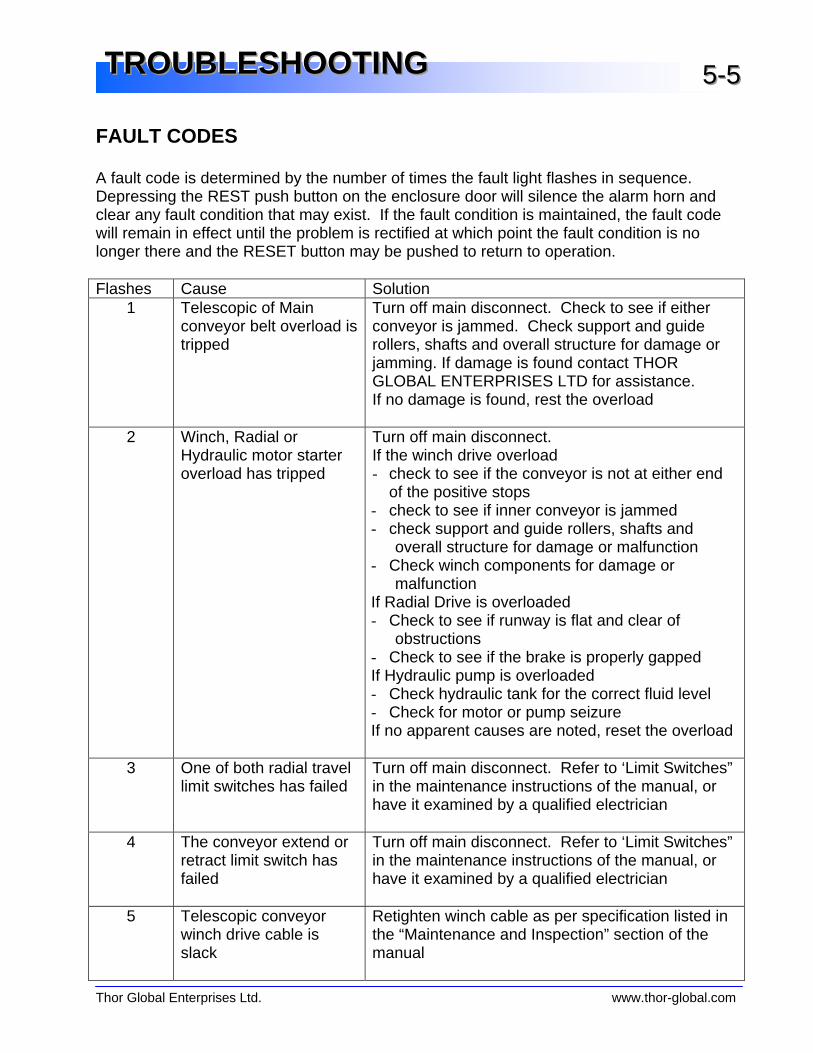
FAULT CODES A fault code is determined by the number of times the fault light flashes in sequence. Depressing the REST push button on the enclosure door will silence the alarm horn and clear any fault condition that may exist. If the fault condition is maintained, the fault code will remain in effect until the problem is rectified at which point the fault condition is no longer there and the RESET button may be pushed to return to operation. Flashes Cause Solution
1 Telescopic of Main conveyor belt overload is tripped
Turn off main disconnect. Check to see if either conveyor is jammed. Check support and guide rollers, shafts and overall structure for damage or jamming. If damage is found contact THOR GLOBAL ENTERPRISES LTD for assistance. If no damage is found, rest the overload
2 Winch, Radial or Hydraulic motor starter overload has tripped
Turn off main disconnect. If the winch drive overload - check to see if the conveyor is not at either end
of the positive stops - check to see if inner conveyor is jammed - check support and guide rollers, shafts and
overall structure for damage or malfunction - Check winch components for damage or
malfunction If Radial Drive is overloaded - Check to see if runway is flat and clear of
obstructions - Check to see if the brake is properly gapped If Hydraulic pump is overloaded - Check hydraulic tank for the correct fluid level - Check for motor or pump seizure If no apparent causes are noted, reset the overload
3 One of both radial travel limit switches has failed
Turn off main disconnect. Refer to ‘Limit Switches” in the maintenance instructions of the manual, or have it examined by a qualified electrician
4 The conveyor extend or retract limit switch has failed
Turn off main disconnect. Refer to ‘Limit Switches” in the maintenance instructions of the manual, or have it examined by a qualified electrician
5 Telescopic conveyor winch drive cable is slack
Retighten winch cable as per specification listed in the “Maintenance and Inspection” section of the manual
Thor Global Enterprises Ltd. www.thor-global.com
TTTRRROOOUUUBBBLLLEEESSSHHHOOOOOOTTTIIINNNGGG 555---666
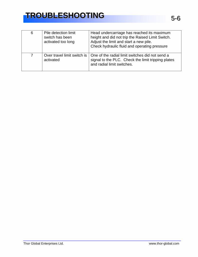
6 Pile detection limit switch has been activated too long
Head undercarriage has reached its maximum height and did not trip the Raised Limit Switch. Adjust the limit and start a new pile. Check hydraulic fluid and operating pressure
7 Over travel limit switch is activated
One of the radial limit switches did not send a signal to the PLC. Check the limit tripping plates and radial limit switches.
Thor Global Enterprises Ltd. www.thor-global.com
TTTRRROOOUUUBBBLLLEEESSSHHHOOOOOOTTTIIINNNGGG 555---777
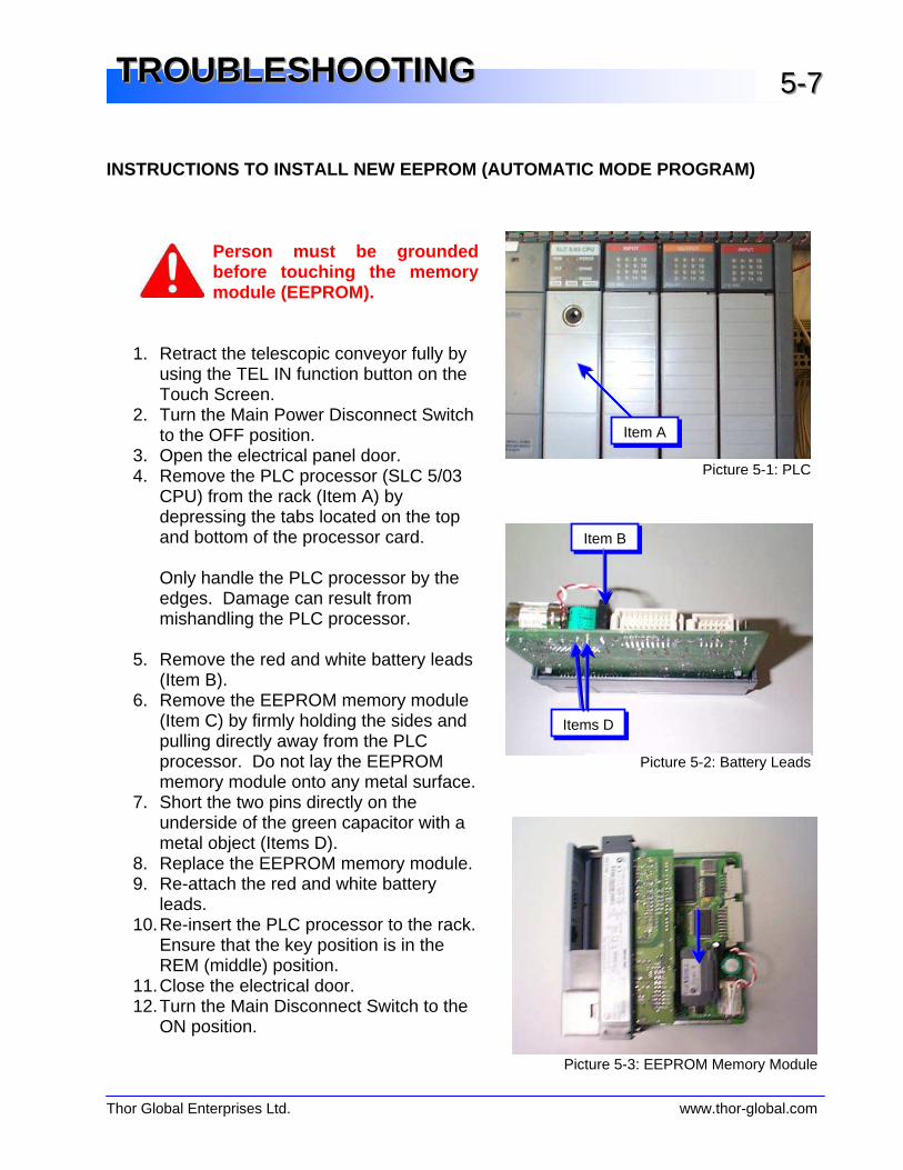
INSTRUCTIONS TO INSTALL NEW EEPROM (AUTOMATIC MODE PROGRAM)
Person must be grounded before touching the memory module (EEPROM).
1. Retract the telescopic conveyor fully by
using the TEL IN function button on the Touch Screen.
2. Turn the Main Power Disconnect Switch to the OFF position.
3. Open the electrical panel door. 4. Remove the PLC processor (SLC 5/03
CPU) from the rack (Item A) by depressing the tabs located on the top and bottom of the processor card.
Only handle the PLC processor by the edges. Damage can result from mishandling the PLC processor.
5. Remove the red and white battery leads
(Item B). 6. Remove the EEPROM memory module
(Item C) by firmly holding the sides and pulling directly away from the PLC processor. Do not lay the EEPROM memory module onto any metal surface.
7. Short the two pins directly on the underside of the green capacitor with a metal object (Items D).
8. Replace the EEPROM memory module. 9. Re-attach the red and white battery
leads. 10. Re-insert the PLC processor to the rack.
Ensure that the key position is in the REM (middle) position.
11. Close the electrical door. 12. Turn the Main Disconnect Switch to the
ON position.
Item C
Item A
Picture 5-1: PLC
Item B
Items D
Picture 5-2: Battery Leads
Picture 5-3: EEPROM Memory Module
Thor Global Enterprises Ltd. www.thor-global.com
TTTRRROOOUUUBBBLLLEEESSSHHHOOOOOOTTTIIINNNGGG 555---888
CONTACT INFORMATION
Thor Global Enterprises Ltd. is dedicated to customer satisfaction and will assist you to ensure your ThorStack is operating at its peak performance. For any additional service and/or maintenance issues please contact Thor Global Enterprises Ltd. service department (Monday-Friday, 9-5 EST).
Thor Global Enterprises Ltd. 839 Westport Crescent Mississauga, Ontario L5T 1E7 Canada Toll Free: 1.888.801.THOR (8467) Local: 905.564.0440 Facsimile: 905.564.9602 www.thor-global.com

This page is intentionally blank.

Thor Global Enterprises Ltd. www.thor-global.com
EEELLLEEECCCTTTRRRIIICCCAAALLL IIINNNFFFOOORRRMMMAAATTTIIIOOONNN 666---111
ELECTRICAL REQUIREMENTS The following tables show the electrical conductor requirements for each ThorStack model. Have a certified, licensed electrician perform the necessary connections to the proper power supply.
ELECTRICAL SCHEMATIC Please see attached pouch for full size electrical schematic (Figure 6-2). For additional electrical parts information, please refer to Chapter 10 - Parts Manual.
Any electrical work, t esting or adjustments performed on this convey or must be done by qualified personnel only.
575V, 50 Hz
Model Total Power (hp) Maximum F.L.A. (Amps)
Minimum Wire Gauge
T127-12
95 100 1

This page is intentionally blank.
Thor Global Enterprises Ltd. www.thor-global.com
HHHYYYDDDRRRAAAUUULLLIIICCCSSS IIINNNFFFOOORRRMMMAAATTTIIIOOONNN 777---111
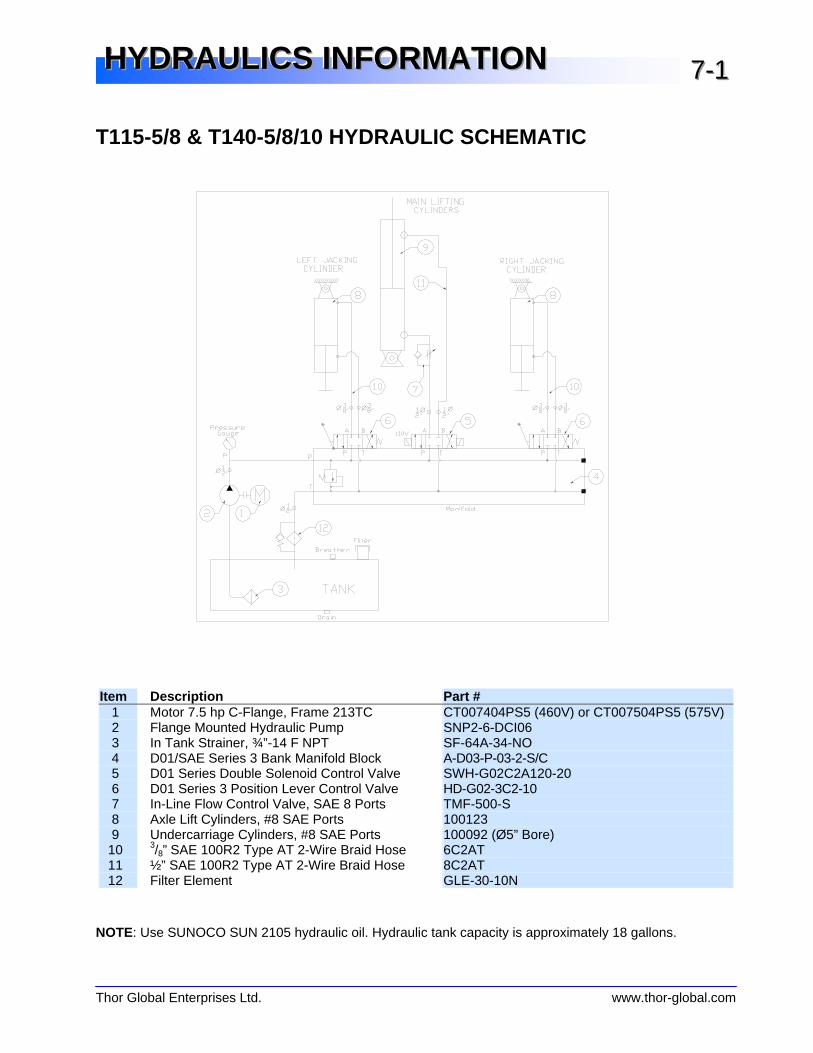
T115-5/8 & T140-5/8/10 HYDRAULIC SCHEMATIC
Item Description Part #
1 Motor 7.5 hp C-Flange, Frame 213TC CT007404PS5 (460V) or CT007504PS5 (575V) 2 Flange Mounted Hydraulic Pump SNP2-6-DCI06 3 In Tank Strainer, ¾”-14 F NPT SF-64A-34-NO 4 D01/SAE Series 3 Bank Manifold Block A-D03-P-03-2-S/C 5 D01 Series Double Solenoid Control Valve SWH-G02C2A120-20 6 D01 Series 3 Position Lever Control Valve HD-G02-3C2-10 7 In-Line Flow Control Valve, SAE 8 Ports TMF-500-S 8 Axle Lift Cylinders, #8 SAE Ports 100123 9 Undercarriage Cylinders, #8 SAE Ports 100092 (Ø5” Bore)
10 3/8” SAE 100R2 Type AT 2-Wire Braid Hose 6C2AT 11 ½” SAE 100R2 Type AT 2-Wire Braid Hose 8C2AT 12 Filter Element GLE-30-10N
NOTE: Use SUNOCO SUN 2105 hydraulic oil. Hydraulic tank capacity is approximately 18 gallons.

This page is intentionally blank.
Thor Global Enterprises Ltd. www.thor-global.com
MMMAAAIIINNNTTTEEENNNAAANNNCCCEEE
Maintenance and Inspection 8-1 Winch Cable Maintenance 8-1 Winch Cable Tightening Instructions 8-2 Lubrication 8-4Wheel Hubs Speed Reducers
Ultrasonic Material Sensor 8-6 V-Belt Drives 8-6 Limit Switches 8-7 Inspections 8-8Daily (or every 12 operating hours) Monthly (or every 180 operating hours)
Daily Inspection Checklist 8-9 Maintenance Log 8-10
Thor Global Enterprises Ltd. www.thor-global.com
MMMAAAIIINNNTTTEEENNNAAANNNCCCEEE 888---111
MAINTENANCE AND INSPECTION Like any other hardworking piece of equipment, your ThorStack conveyor requires regular inspection and maintenance. Regularly scheduled service and maintenance will ensure a longer and more reliable life for your conveyor. The information provided in this section represents the minimum guidelines for inspection and maintenance and these steps are an essential part of your warranty.
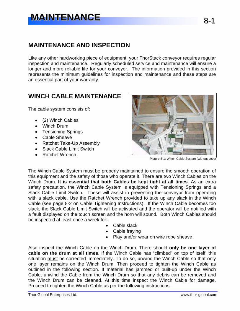
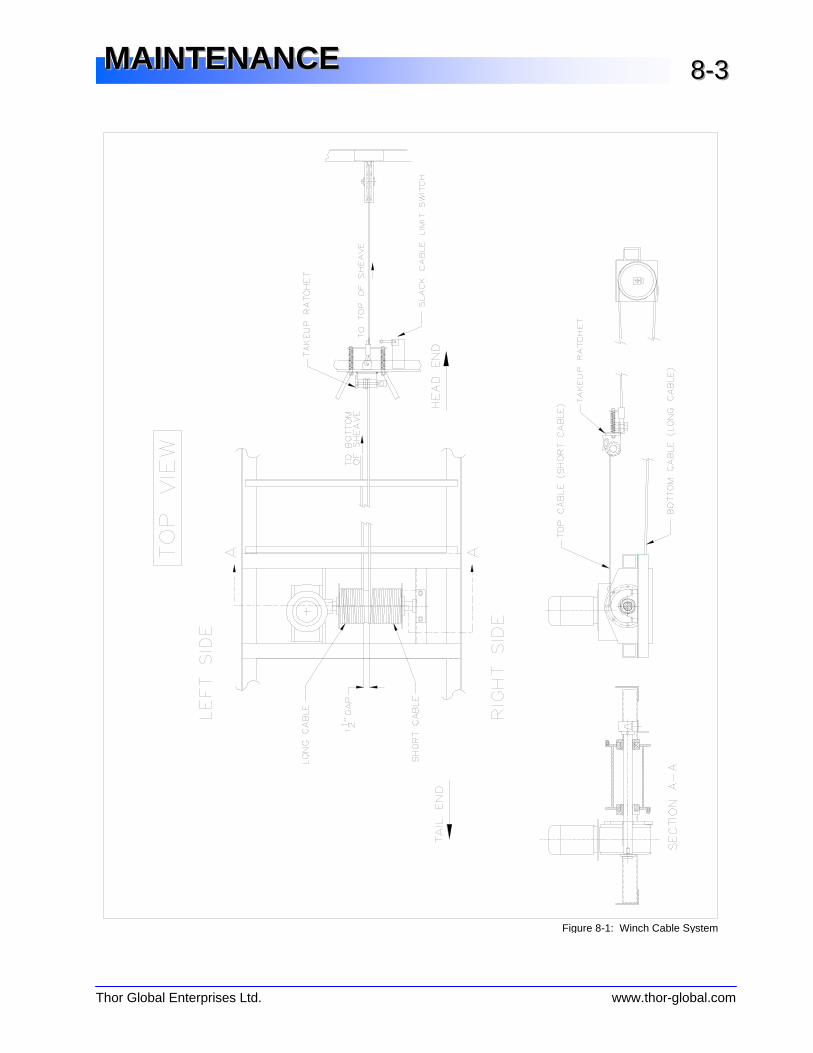
WINCH CABLE MAINTENANCE The cable system consists of: • (2) Winch Cables • Winch Drum • Tensioning Springs • Cable Sheave • Ratchet Take-Up Assembly • Slack Cable Limit Switch • Ratchet Wrench The Winch Cable System must be properly maintained to ensure the smooth operation of this equipment and the safety of those who operate it. There are two Winch Cables on the Winch Drum. It is essential that both Cables be kept tight at all times . As an extra safety precaution, the Winch Cable System is equipped with Tensioning Springs and a Slack Cable Limit Switch. These will assist in preventing the conveyor from operating with a slack cable. Use the Ratchet Wrench provided to take up any slack in the Winch Cable (see page 8-2 on Cable Tightening Instructions). If the Winch Cable becomes too slack, the Slack Cable Limit Switch will be activated and the operator will be notified with a fault displayed on the touch screen and the horn will sound. Both Winch Cables should be inspected at least once a week for: • Cable slack • Cable fraying • Play and/or wear on wire rope sheave Also inspect the Winch Cable on the Winch Drum. There should only be one layer of cable on the drum at all times . If the Winch Cable has “climbed” on top of itself, this situation must be corrected immediately. To do so, unwind the Winch Cable so that only one layer remains on the Winch Drum. Then proceed to tighten the Winch Cable as outlined in the following section. If material has jammed or built-up under the Winch Cable, unwind the Cable from the Winch Drum so that any debris can be removed and the Winch Drum can be cleaned. At this time inspect the Winch Cable for damage. Proceed to tighten the Winch Cable as per the following instructions.
Picture 8-1: Winch Cable System (without cover)
Thor Global Enterprises Ltd. www.thor-global.com
MMMAAAIIINNNTTTEEENNNAAANNNCCCEEE 888---222
WINCH CABLE TIGHTENING INSTRUCTIONS 1. Lower the conveyor completely. 2. Fully extend the telescopic conveyor. 3. Turn the Main Disconnect Switch to the OFF position. 4. Place a bracing device between the braces of the inner and the outer conveyors to
prevent the inner conveyor from moving inward while under maintenance. We recommend an HSS 3”x1½”x¼” or equivalent piece of material (the transport bar provided may be used). It is important that the bracing device be placed in the vicinity of the tail pulley of the inner conveyor where the uprights are stronger.
5. Inspect the Winch Cable for fraying, kinks or damage. If the cable is damaged, it must
be replaced. Ensure that the Winch Cable is properly seated on the Winch Drum. If there is no damage and the Winch Cable is properly seated, then proceed to tension the cable using the Ratchet Take-Up Assembly. When tightening, ensure that there is at least one wrap of Winch Cable on the Ratchet Take-Up Assembly before the Winch Cable becomes taught.
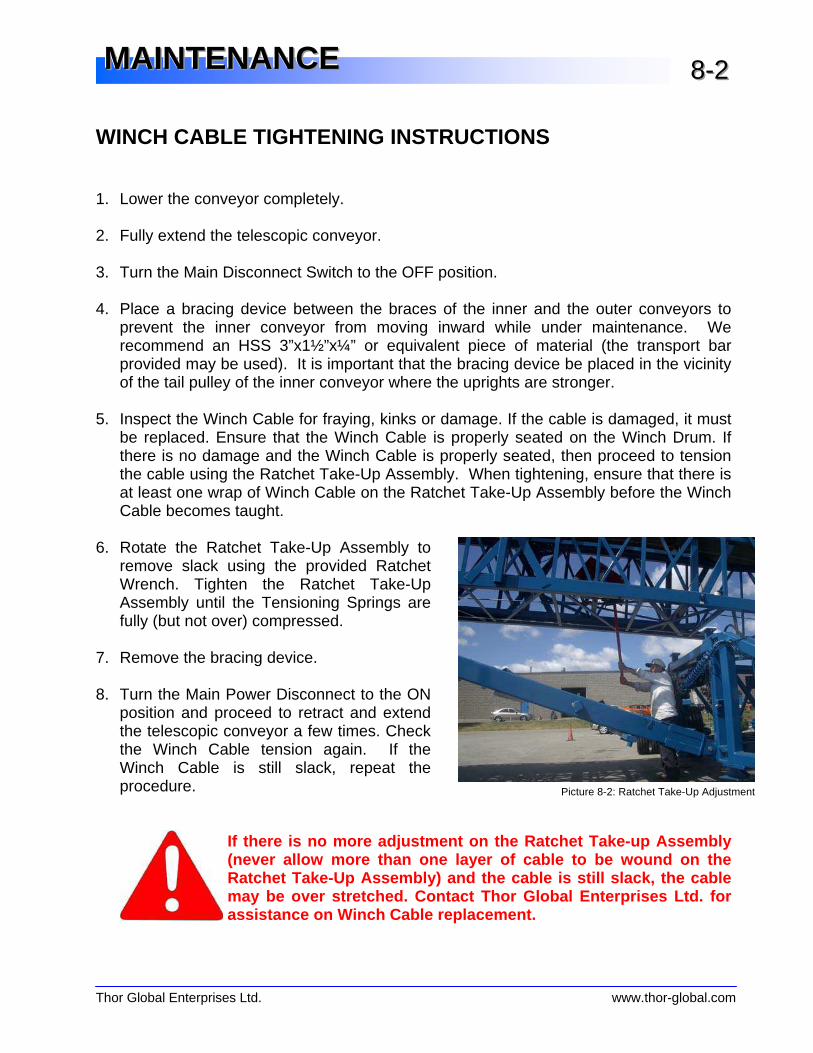
6. Rotate the Ratchet Take-Up Assembly to
remove slack using the provided Ratchet Wrench. Tighten the Ratchet Take-Up Assembly until the Tensioning Springs are fully (but not over) compressed.
7. Remove the bracing device. 8. Turn the Main Power Disconnect to the ON
position and proceed to retract and extend the telescopic conveyor a few times. Check the Winch Cable tension again. If the Winch Cable is still slack, repeat the procedure.
If there is no more adjustment on the Ratchet Take-up Assembly (never allow more than one laye r of cable to be wound on the Ratchet Take-Up Assembly) and the cable is still slack, the cable may be over stretched. Contact Thor Global Enterprises Ltd. for assistance on Winch Cable replacement.
Picture 8-2: Ratchet Take-Up Adjustment
Thor Global Enterprises Ltd. www.thor-global.com
MMMAAAIIINNNTTTEEENNNAAANNNCCCEEE 888---333
Figure 8-1: Winch Cable System
Thor Global Enterprises Ltd. www.thor-global.com
MMMAAAIIINNNTTTEEENNNAAANNNCCCEEE 888---444
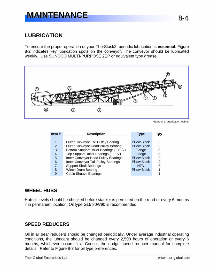
LUBRICATION To ensure the proper operation of your ThorStack2, periodic lubrication is essential . Figure 8-2 indicates key lubrication spots on the conveyor. The conveyor should be lubricated weekly. Use SUNOCO MULTI-PURPOSE 2EP or equivalent type grease.
Item # Description Type Qty 1 Outer Conveyor Tail Pulley Bearing Pillow Block 2 2 Outer Conveyor Head Pulley Bearing Pillow Block 2 3 Bottom Support Roller Bearings (L.E.S.) Flange 8 4 Top Support Roller Bearings (L.E.S.) Flange 8 5 Inner Conveyor Head Pulley Bearings Pillow Block 2 6 Inner Conveyor Tail Pulley Bearings Pillow Block 2 7 Support Shaft Bearings NTN 8 8 Winch Drum Bearing Pillow Block 1 9 Cable Sheave Bearings - 1
WHEEL HUBS
Hub oil levels should be checked before stacker is permitted on the road or every 6 months if in permanent location. Oil type GL5 80W90 is recommended.
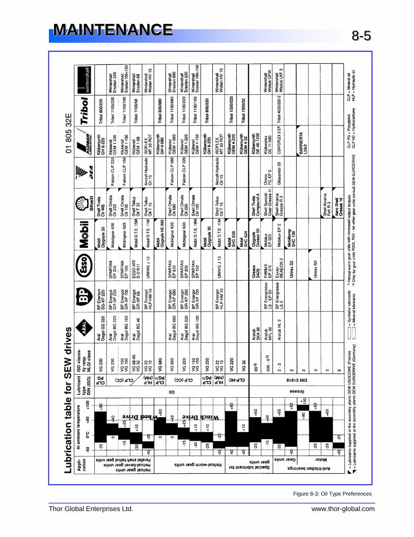
SPEED REDUCERS Oil in all gear reducers should be changed periodically. Under average industrial operating conditions, the lubricant should be changed every 2,500 hours of operation or every 6 months, whichever occurs first. Consult the dodge speed reducer manual for complete details. Refer to Figure 8-3 for oil type preferences.
Figure 8-2: Lubrication Points
Thor Global Enterprises Ltd. www.thor-global.com
MMMAAAIIINNNTTTEEENNNAAANNNCCCEEE 888---555
Figure 8-3: Oil Type Preferences
Thor Global Enterprises Ltd. www.thor-global.com
MMMAAAIIINNNTTTEEENNNAAANNNCCCEEE 888---666
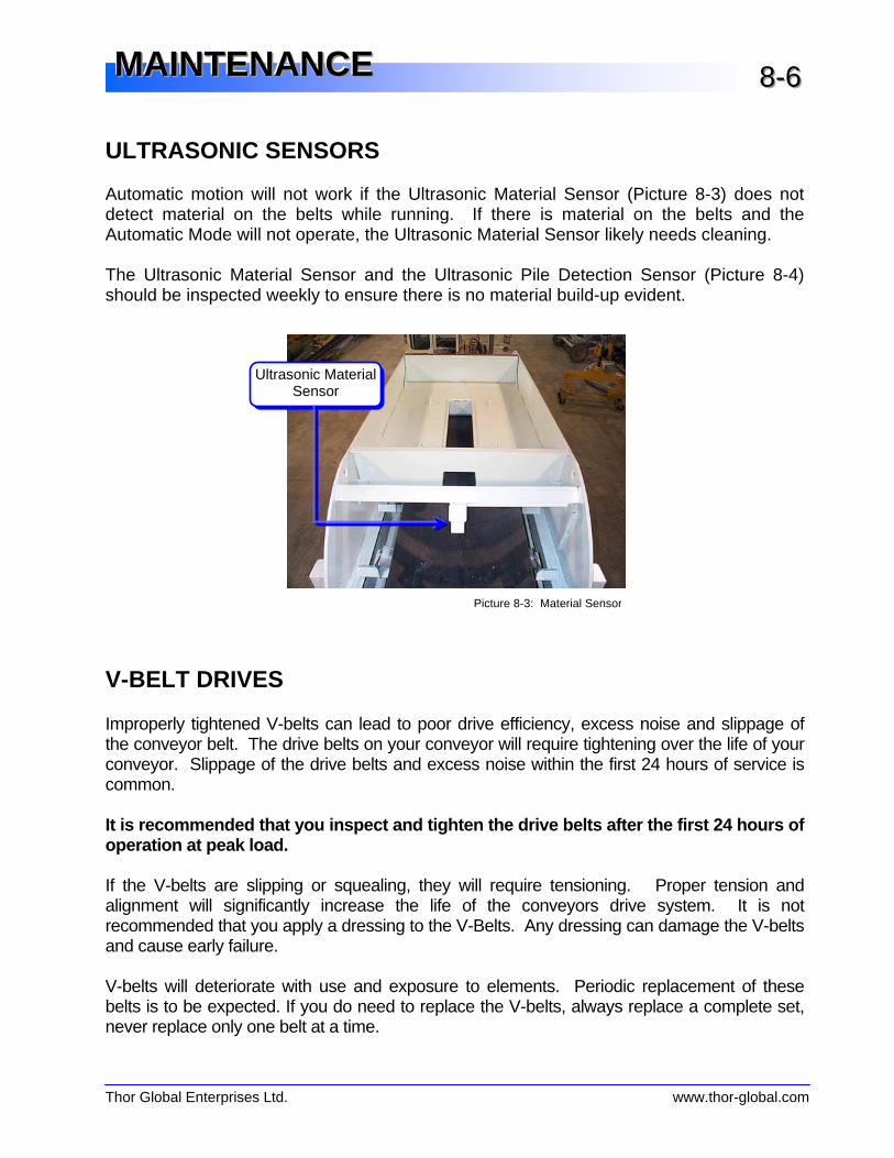
ULTRASONIC SENSORS Automatic motion will not work if the Ultrasonic Material Sensor (Picture 8-3) does not detect material on the belts while running. If there is material on the belts and the Automatic Mode will not operate, the Ultrasonic Material Sensor likely needs cleaning. The Ultrasonic Material Sensor and the Ultrasonic Pile Detection Sensor (Picture 8-4) should be inspected weekly to ensure there is no material build-up evident.
V-BELT DRIVES Improperly tightened V-belts can lead to poor drive efficiency, excess noise and slippage of the conveyor belt. The drive belts on your conveyor will require tightening over the life of your conveyor. Slippage of the drive belts and excess noise within the first 24 hours of service is common. It is recommended that you inspect and tigh ten the drive belts after the first 24 hours of operation at peak load. If the V-belts are slipping or squealing, they will require tensioning. Proper tension and alignment will significantly increase the life of the conveyors drive system. It is not recommended that you apply a dressing to the V-Belts. Any dressing can damage the V-belts and cause early failure. V-belts will deteriorate with use and exposure to elements. Periodic replacement of these belts is to be expected. If you do need to replace the V-belts, always replace a complete set, never replace only one belt at a time.
Picture 8-3: Material Sensor
Ultrasonic Material Sensor
Thor Global Enterprises Ltd. www.thor-global.com
MMMAAAIIINNNTTTEEENNNAAANNNCCCEEE 888---777
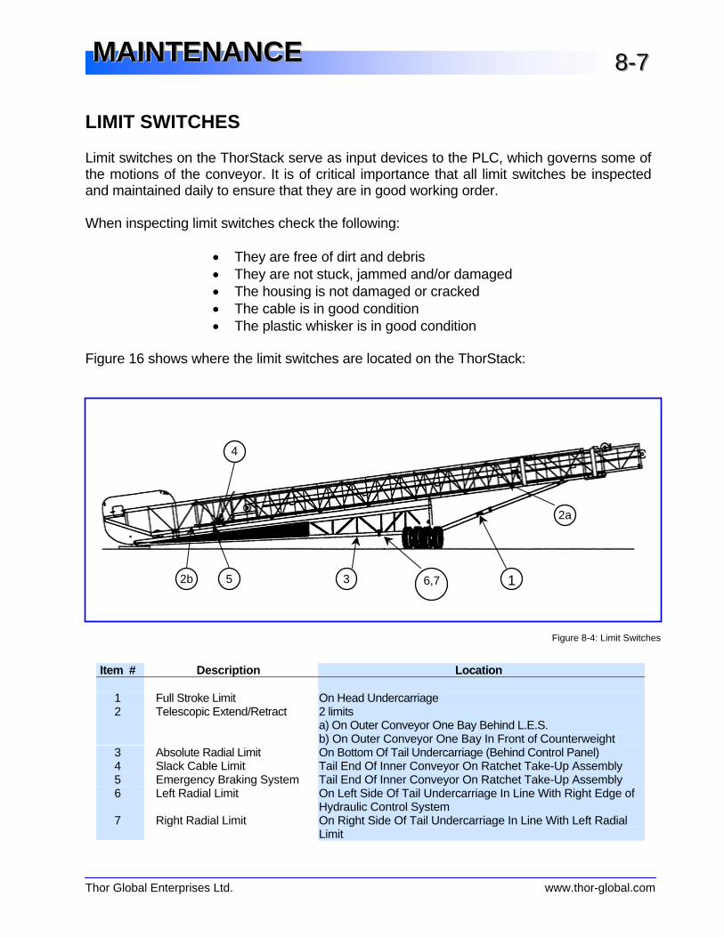
LIMIT SWITCHES Limit switches on the ThorStack serve as input devices to the PLC, which governs some of the motions of the conveyor. It is of critical importance that all limit switches be inspected and maintained daily to ensure that they are in good working order. When inspecting limit switches check the following: • They are free of dirt and debris • They are not stuck, jammed and/or damaged • The housing is not damaged or cracked • The cable is in good condition • The plastic whisker is in good condition Figure 16 shows where the limit switches are located on the ThorStack:
Item # Description Location 1 Full Stroke Limit On Head Undercarriage 2 Telescopic Extend/Retract 2 limits
a) On Outer Conveyor One Bay Behind L.E.S. b) On Outer Conveyor One Bay In Front of Counterweight
3 Absolute Radial Limit On Bottom Of Tail Undercarriage (Behind Control Panel) 4 Slack Cable Limit Tail End Of Inner Conveyor On Ratchet Take-Up Assembly 5 Emergency Braking System Tail End Of Inner Conveyor On Ratchet Take-Up Assembly 6 Left Radial Limit On Left Side Of Tail Undercarriage In Line With Right Edge of
Hydraulic Control System 7 Right Radial Limit On Right Side Of Tail Undercarriage In Line With Left Radial
Limit
Figure 8-4: Limit Switches
1 2b
2a
3
4
5 6,7
Thor Global Enterprises Ltd. www.thor-global.com
MMMAAAIIINNNTTTEEENNNAAANNNCCCEEE 888---888
INSPECTIONS
DAILY INSPECTION (or every 12 operating hours) To ensure safety and trouble free operation the following items should be inspected in a daily “walk-around” inspection: X Safety features – Check that all guards and covers are secure and that all warnings
are visible. X Drive Belts – Visually inspect the condition of all V-belts. X Limit switches – See section on limit switches (page 8-8). X Tires – Ensure tires are properly inflated and in good condition. X Structure – Perform a visual inspection of the structure for damage or distortion. X Conveyor Belting – Ensure belts are aligned and in good condition. X Winch Cable System – Visually inspect the winch system for slack, damage, or
misalignment. X Hazards – Check the surrounding area for personnel, equipment or foreign material. X Sensor – Visually inspect to ensure the sensors are clean. Included in appendix A is a optional “daily inspection checklist” that you may wish to remove, copy and use to assist you in your daily inspections.
MONTHLY INSPECTION (or every 180 operating hours) It is recommended that once a month (or approximately every 180 operating hours) the ThorStack2 is inspected by a qualified person for each of the following: X Drive belts – Physically check all drive belts for wear and damage. Also check for
proper tension and alignment. X Motors and Gearboxes – Physically inspect the components of the drive system for
damage, wear or improper operation. X Lubrication – Ensure that all components requiring lubrication have been properly
serviced. See the section on lubrication (page 8-5). X Conveyor belts – Physically inspect all belts, idlers, pulleys, and scrapers for damage
or malfunction. Also ensure they are free of debris and obstruction. X Structure – Perform a detailed inspection of the conveyor structure for damage, wear,
distortion or other evidence of stress. X Hydraulics – Perform a detailed inspection of all hydraulic components for, damage,
wear, cracking, malfunction, fluid level and proper operation. X Electrical – inspect all wiring for damage or fraying. Inspect the enclosure to ensure
that the control components are in good condition and protected from the elements. X Sensors – Visually inspect to ensure the sensors are clean.
Thor Global Enterprises Ltd. www.thor-global.com
MMMAAAIIINNNTTTEEENNNAAANNNCCCEEE 888---999
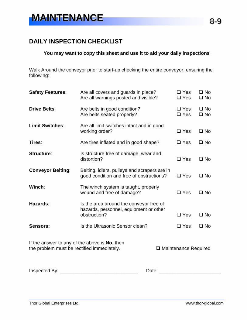
DAILY INSPECTION CHECKLIST You may want to copy this sheet and use it to aid your daily inspections Walk Around the conveyor prior to start-up checking the entire conveyor, ensuring the following: Safety Features : Are all covers and guards in place? ̌ Yes ̌ No Are all warnings posted and visible? ̌ Yes ̌ No Drive Belts : Are belts in good condition? ̌ Yes ̌ No Are belts seated properly? ̌ Yes ̌ No Limit Switches : Are all limit switches intact and in good
working order? ̌ Yes ̌ No Tires : Are tires inflated and in good shape? ̌ Yes ̌ No Structure : Is structure free of damage, wear and
distortion? ̌ Yes ̌ No Conveyor Belting : Belting, idlers, pulleys and scrapers are in
good condition and free of obstructions? ̌ Yes ̌ No Winch : The winch system is taught, properly
wound and free of damage? ̌ Yes ̌ No Hazards : Is the area around the conveyor free of
hazards, personnel, equipment or other obstruction? ̌ Yes ̌ No
Sensors: Is the Ultrasonic Sensor clean? ̌ Yes ̌ No If the answer to any of the above is No, then the problem must be rectified immediately. ̌ Maintenance Required Inspected By: _____________________________ Date: _______________________

Thor Global Enterprises Ltd. www.thor-global.com
MMMAAAIIINNNTTTEEENNNAAANNNCCCEEE 888---111000
MAINTENANCE LOG Serviced By Work/Comments Date

Thor Global Enterprises Ltd. www.thor-global.com
MMMAAAIIINNNTTTEEENNNAAANNNCCCEEE 888---111111
MAINTENANCE LOG Serviced By Work/Comments Date

Thor Global Enterprises Ltd. www.thor-global.com
MMMAAAIIINNNTTTEEENNNAAANNNCCCEEE 888---111222
MAINTENANCE LOG Serviced By Work/Comments Date

This page is intentionally blank.

Thor Global Enterprises Ltd. www.thor-global.com
TTTEEECCCHHHNNNIIICCCAAALLL IIINNNFFFOOORRRMMMAAATTTIIIOOONNN
Drive Specifications 9-1 Belting & Pulley Specifications 9-1 Component Overview 9-3 Conveyor Dimensions 9-4 Stockpile Specifications 9-7 Stockpile Capacities 9-7 Transportation Specifications 9-8Transport Dimensions Transport Weights
Concrete Pad Layout 9-9

Thor Global Enterprises Ltd. www.thor-global.com
TTTEEECCCHHHNNNIIICCCAAALLL IIINNNFFFOOORRRMMMAAATTTIIIOOONNN 999---111
DRIVE SPECIFICATIONS Main (Outer) Conveyor
Model Motor Reducer Motor Sheave Reducer Sheave Shafting (Drive) V-Belts T127-12 50 hp TXT715 - - - (3) 5V900
Telescopic (Inner) Conveyor
Model Motor Reducer Motor Sheave Reducer Sheave Shafting (Drive) V-Belts T127-12 40 hp TXT615 3/5V-8.5 3/5V-10 ∅3 7/16“ (4) 5V670
BELTING & PULLEY SPECIFICATIONS
Main (Outer) Conveyor Model Belting Belt Speed Head Pulley Tail Pulley T127-12 Goodyear 42” 330PIW 3 Ply 351 fpm -. ∅18”x44”
Telescopic (Inner) Conveyor
Model 1 Belting Belt Speed Head Pulley Tail Pulley T127-12 Goodyear 42” x 330PIW 3 Ply 411 fpm ∅18”x44”, ½” Diamond Lag. ∅16”x44”
Thor Global Enterprises Ltd. www.thor-global.com
TTTEEECCCHHHNNNIIICCCAAALLL IIINNNFFFOOORRRMMMAAATTTIIIOOONNN 999---222
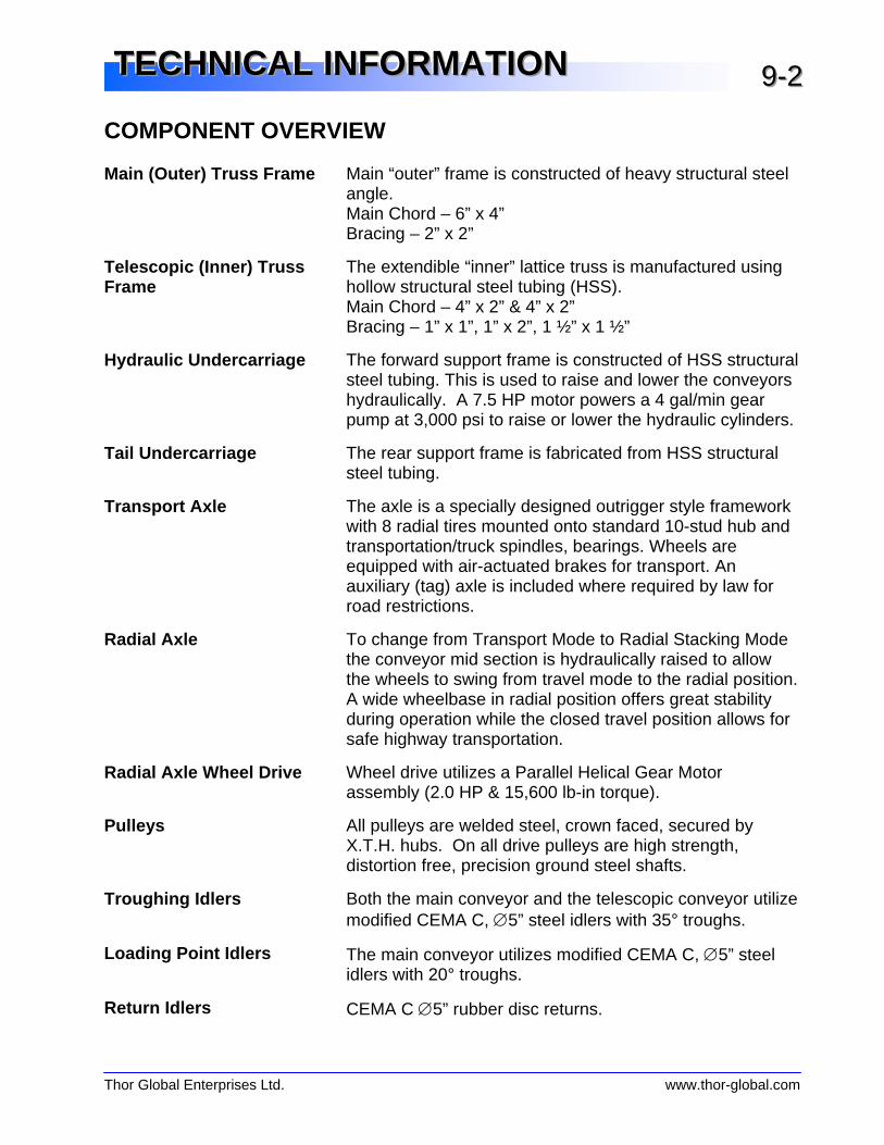
COMPONENT OVERVIEW Main (Outer) Truss Frame Main “outer” frame is constructed of heavy structural steel
angle. Main Chord – 6” x 4” Bracing – 2” x 2”
Telescopic (Inner) Truss Frame
The extendible “inner” lattice truss is manufactured using hollow structural steel tubing (HSS). Main Chord – 4” x 2” & 4” x 2” Bracing – 1” x 1”, 1” x 2”, 1 ½” x 1 ½”
Hydraulic Undercarriage The forward support frame is constructed of HSS structural steel tubing. This is used to raise and lower the conveyors hydraulically. A 7.5 HP motor powers a 4 gal/min gear pump at 3,000 psi to raise or lower the hydraulic cylinders.
Tail Undercarriage The rear support frame is fabricated from HSS structural steel tubing.
Transport Axle The axle is a specially designed outrigger style framework with 8 radial tires mounted onto standard 10-stud hub and transportation/truck spindles, bearings. Wheels are equipped with air-actuated brakes for transport. An auxiliary (tag) axle is included where required by law for road restrictions.
Radial Axle To change from Transport Mode to Radial Stacking Mode the conveyor mid section is hydraulically raised to allow the wheels to swing from travel mode to the radial position. A wide wheelbase in radial position offers great stability during operation while the closed travel position allows for safe highway transportation.
Radial Axle Wheel Drive Wheel drive utilizes a Parallel Helical Gear Motor assembly (2.0 HP & 15,600 lb-in torque).
Pulleys All pulleys are welded steel, crown faced, secured by X.T.H. hubs. On all drive pulleys are high strength, distortion free, precision ground steel shafts.
Troughing Idlers Both the main conveyor and the telescopic conveyor utilize modified CEMA C, ∅5” steel idlers with 35° troughs.
Loading Point Idlers The main conveyor utilizes modified CEMA C, ∅5” steel idlers with 20° troughs.
Return Idlers CEMA C ∅5” rubber disc returns.

Thor Global Enterprises Ltd. www.thor-global.com
TTTEEECCCHHHNNNIIICCCAAALLL IIINNNFFFOOORRRMMMAAATTTIIIOOONNN 999---333
Conveyor Belting Goodyear premium quality, high tensile strength, to support the load and the designed horsepower. Standard covers are 3/16” x 1/16” 3 ply with vulcanized splice.
Electrical Panel NEMA 4 (weather-proof) enclosure with 460/575V, 3 phase, 60 Hz, Allen Bradley starters.
Automation The unit can be fully automated or manually operated with the use of an Allen Bradley SLC 500 series processor, ultrasonic sensors and inductive proximity sensors.
Telescopic Extend/Retract Telescopic action is activated by an ∅8 5/8” drum (1.5 HP & 16,600 lb-in torque) and ∅9/16” cable winch package which moves the conveyor approximately 8.8 fpm.
Winch Ratchet System This system utilizes the PLC to constantly monitor the tension of the winch cables to ensure proper function.
Load Equalizing System (L.E.S.)
This patented system is exclusive to the ThorStack and is designed to handle the constantly changing loads as the inner conveyor extends and retracts.
Transport Hitch Kingpin, counterweight and side plate assemblies are designed to allow ample turning clearance for most 5th wheel tractors.
Guarding Safety guards at all pinch points and galvanized steel mesh (on main conveyor) are standard.
Thor Global Enterprises Ltd. www.thor-global.com
TTTEEECCCHHHNNNIIICCCAAALLL IIINNNFFFOOORRRMMMAAATTTIIIOOONNN 999---444
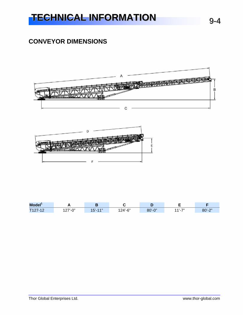
CONVEYOR DIMENSIONS
Model 1 A B C D E F T127-12 127’-0” 15’-11” 124’-6” 80’-0” 11’-7” 80’-2”

Thor Global Enterprises Ltd. www.thor-global.com
TTTEEECCCHHHNNNIIICCCAAALLL IIINNNFFFOOORRRMMMAAATTTIIIOOONNN 999---555
Model 1 A D G H I J T127-12 127’-0” 80’-0” 41’-7” 118’-10” 28’-2” 76’-3”

Thor Global Enterprises Ltd. www.thor-global.com
TTTEEECCCHHHNNNIIICCCAAALLL IIINNNFFFOOORRRMMMAAATTTIIIOOONNN 999---666
Model 1 A B G K L M T127-12 127’-0” 80’-0” 41’-7” 38’-4” 170’-6” 36’-10” Model 1 “A” Stone
Box “B” Chute
Opening C D E F G
T127-12 7’-0” 5’-0” 9’-3” - 9’-8” - -
Thor Global Enterprises Ltd. www.thor-global.com
TTTEEECCCHHHNNNIIICCCAAALLL IIINNNFFFOOORRRMMMAAATTTIIIOOONNN 999---777
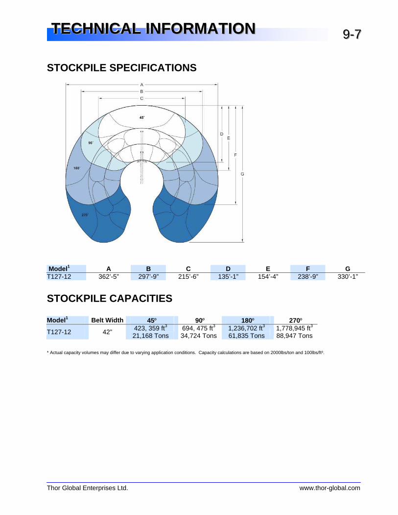
STOCKPILE SPECIFICATIONS Model 1 A B C D E F G T127-12 362’-5” 297’-9” 215’-6” 135’-1” 154’-4” 238’-9” 330’-1”
STOCKPILE CAPACITIES Model 1 Belt Width 45° 90° 180° 270° T127-12 42” 423, 359 ft3
21,168 Tons 694, 475 ft3 34,724 Tons
1,236,702 ft3 61,835 Tons
1,778,945 ft3 88,947 Tons
* Actual capacity volumes may differ due to varying application conditions. Capacity calculations are based on 2000lbs/ton and 100lbs/ft³.
Thor Global Enterprises Ltd. www.thor-global.com
TTTEEECCCHHHNNNIIICCCAAALLL IIINNNFFFOOORRRMMMAAATTTIIIOOONNN 999---888
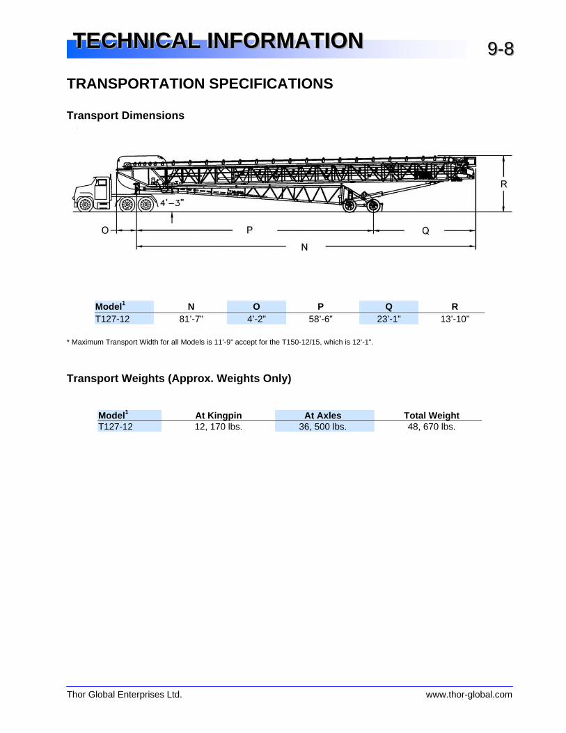
TRANSPORTATION SPECIFICATIONS Transport Dimensions
Model 1 N O P Q R T127-12 81’-7” 4’-2” 58’-6” 23’-1” 13’-10”
* Maximum Transport Width for all Models is 11’-9” accept for the T150-12/15, which is 12’-1”.
Transport Weights (Approx. Weights Only)
Model 1 At Kingpin At Axles Total Weight T127-12 12, 170 lbs. 36, 500 lbs. 48, 670 lbs.
Thor Global Enterprises Ltd. www.thor-global.com
TTTEEECCCHHHNNNIIICCCAAALLL IIINNNFFFOOORRRMMMAAATTTIIIOOONNN 999---999
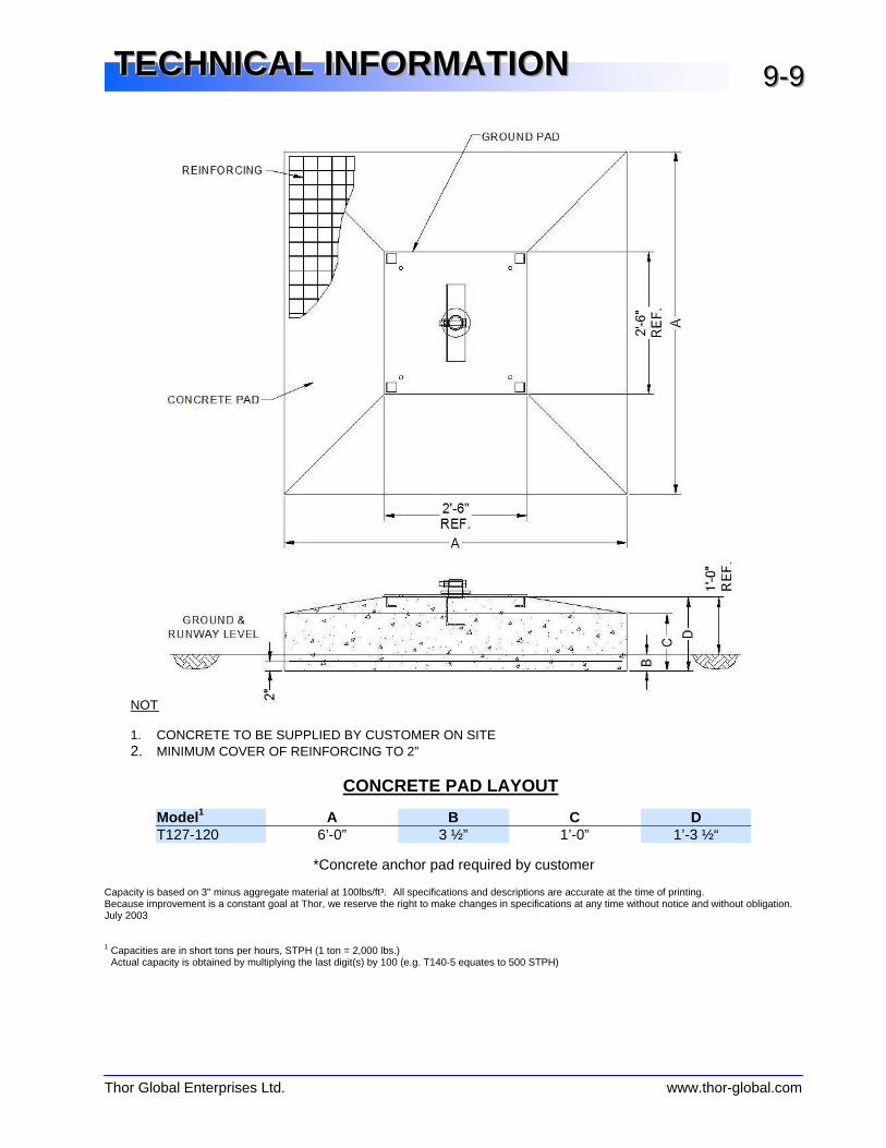
NOTE: 1. CONCRETE TO BE SUPPLIED BY CUSTOMER ON SITE 2. MINIMUM COVER OF REINFORCING TO 2”
CONCRETE PAD LAYOUT
Model 1 A B C D T127-120 6’-0” 3 ½” 1’-0” 1’-3 ½“
*Concrete anchor pad required by customer
Capacity is based on 3" minus aggregate material at 100lbs/ft³. All specifications and descriptions are accurate at the time of printing. Because improvement is a constant goal at Thor, we reserve the right to make changes in specifications at any time without notice and without obligation. July 2003
1 Capacities are in short tons per hours, STPH (1 ton = 2,000 lbs.) Actual capacity is obtained by multiplying the last digit(s) by 100 (e.g. T140-5 equates to 500 STPH)

OUTER CONVEYOR
Thor Global Enterprises Ltd. www.thor-global.com
PPPAAARRRTTTSSS MMMAAANNNUUUAAALLL 111000---111
Component Model Part # Manufacturer Details
Drive Motor T115-5, T140-5, T150-5, T170-5
HT030404P1
HT030504P2
WEG 30 hp, TEFC, 460/575VAC, 1765 rpm, 3 Ph,
60 Hz, 286T Frame, ∅1 7/8” Shaft
Gear Reducer T115-5, T140-5, T150-5, T170-5
245551 Reducer 245112 Bushing 245154 Backstop
Dodge TXT515T, Shaft Mount, 15.40:1 Ratio, ∅2 15
/16“, Tapered Bushing w/ Backstop
Sheave/Bushing on Motor
T115-5, T140-5 T150-5
455249 120435
Dodge 2 Groove QD, 5V, 7.5” O.D. SK Sheave ∅1 7/8” SK Bushing
Sheave/Bushing on Motor
T115-8, T140-8, T150-8
455254 120439
Dodge 2 Groove QD, 5V, 9.75” O.D. SK Sheave ∅2 1/8” SK Bushing
V-belts T115-5/8, T140-5/8, T150-5/8
3110900 M.B.L. 5V-900, 90” Outside Length (2 units)
Head Pulley T115-5/8, T140-5/8/10, T150-5/8/10, T170-5/8/10
D16CF38XT40DL Strongco ∅16”x38” Crown Face, XT40 Hub, ½” Diamond Lagging
Tail Pulley T115-5/8, T140-5/8/10, T150-5/8/10, T170-5/8/10
D14CF38XT35 Strongco ∅14”x38” Crown Face, XTH35 Hub
Head Pulley Shaft
T115-5, T140-5, T150-5, T170-5
100031 Kaz ∅3 7/16” x 73” Lg. AISI C1045 H.S.D.F. w/
One Step at ∅2 15
/16”
Tail Pulley Shaft T115-5/8, T140-5/8/10, T150-5/8/10, T170-5/8/10
- Thor ∅2 15
/16” x 56 ½ “ Lg. AISI C1018 Cold Rolled
Bearings (Head End)
T115-5/8, T140-5/8/10, T150-5/8/10, T170-5/8
2004035 Link-Belt 2 Bolt Spherical Roller Pillow Block ∅3 7/16”
Bore
Bearings (Tail end)
T115-5/8, T140-5/8/10, T150-5/8/10, T170-5/8/10
2003995 Link-Belt 2 Bolt Spherical Roller Pillow Block ∅2 15
/16” Bore
Troughing Idlers T115-5/8 32502-36MLA Strongco ∅5”x36”x35° 32000 Series CEMA C Modified Frames (15 units)
Receiving Idlers T115-5/8, T140-5/8/10, T150-5/8/10, T170-5/8/10
32501-36MLA Strongco ∅5”x36”x20° 32000 Series CEMA C Modified Frames (7 units)
Return Idlers T115-5/8 32539-36 Strongco ∅5”x36”x0° 32000 Series CEMA C Rubber Disc Roller (5 units)
Conveyor Belt T115-5/8 Call Goodyear 36”x154’-0”, 3/16“ &
1/16“ Covers, 3 ply,
Plylon, 330 PIW
Take-Up All MD20-24 Strongco 24” Top Mounted, Sliding, ACME Threaded Rod (2 units)
Guide Rollers All 100052 Thor ∅3" x 4 1/8” UHMW Polyethylene (8 units,
10 units for T170-8/10)
Support Rollers T115-5/8, T140-5/8/10, T150-5/8/10, T170-5/8/10
200182 Thor ∅2” x 58" Lg. w/ (2) Pillow Block Ball Bearings (3 units, 4 units for T170-5/8/10)
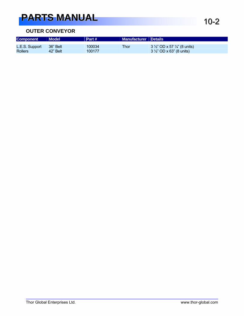
OUTER CONVEYOR
Thor Global Enterprises Ltd. www.thor-global.com
PPPAAARRRTTTSSS MMMAAANNNUUUAAALLL 111000---222
Component Model Part # Manufacturer Details
L.E.S. Support Rollers
36” Belt 42” Belt
100034 100177
Thor 3 ½” OD x 57 ¼” (8 units) 3 ½” OD x 63” (8 units)
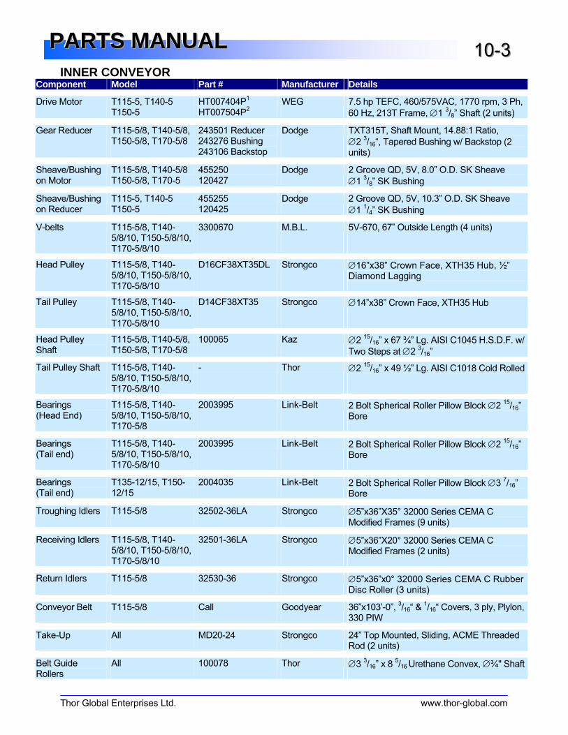
INNER CONVEYOR
Thor Global Enterprises Ltd. www.thor-global.com
PPPAAARRRTTTSSS MMMAAANNNUUUAAALLL 111000---333
Component Model Part # Manufacturer Details
Drive Motor T115-5, T140-5 T150-5
HT007404P1
HT007504P2
WEG 7.5 hp TEFC, 460/575VAC, 1770 rpm, 3 Ph,
60 Hz, 213T Frame, ∅1 3/8” Shaft (2 units)
Gear Reducer T115-5/8, T140-5/8, T150-5/8, T170-5/8
243501 Reducer 243276 Bushing 243106 Backstop
Dodge TXT315T, Shaft Mount, 14.88:1 Ratio, ∅2 3/16“, Tapered Bushing w/ Backstop (2
units)
Sheave/Bushing on Motor
T115-5/8, T140-5/8 T150-5/8, T170-5
455250 120427
Dodge 2 Groove QD, 5V, 8.0” O.D. SK Sheave ∅1 3/8” SK Bushing
Sheave/Bushing on Reducer
T115-5, T140-5 T150-5
455255 120425
Dodge 2 Groove QD, 5V, 10.3” O.D. SK Sheave ∅1 1/4” SK Bushing
V-belts T115-5/8, T140-5/8/10, T150-5/8/10, T170-5/8/10
3300670
M.B.L. 5V-670, 67” Outside Length (4 units)
Head Pulley T115-5/8, T140-5/8/10, T150-5/8/10, T170-5/8/10
D16CF38XT35DL Strongco ∅16”x38” Crown Face, XTH35 Hub, ½” Diamond Lagging
Tail Pulley T115-5/8, T140-5/8/10, T150-5/8/10, T170-5/8/10
D14CF38XT35 Strongco ∅14”x38” Crown Face, XTH35 Hub
Head Pulley Shaft
T115-5/8, T140-5/8, T150-5/8, T170-5/8
100065 Kaz ∅2 15
/16” x 67 ¾” Lg. AISI C1045 H.S.D.F. w/
Two Steps at ∅2 3/16”
Tail Pulley Shaft T115-5/8, T140-5/8/10, T150-5/8/10, T170-5/8/10
- Thor ∅2 15
/16” x 49 ½” Lg. AISI C1018 Cold Rolled
Bearings (Head End)
T115-5/8, T140-5/8/10, T150-5/8/10, T170-5/8
2003995 Link-Belt 2 Bolt Spherical Roller Pillow Block ∅2 15
/16” Bore
Bearings (Tail end)
T115-5/8, T140-5/8/10, T150-5/8/10, T170-5/8/10
2003995 Link-Belt 2 Bolt Spherical Roller Pillow Block ∅2 15
/16” Bore
Bearings (Tail end)
T135-12/15, T150-12/15
2004035 Link-Belt 2 Bolt Spherical Roller Pillow Block ∅3 7/16”
Bore
Troughing Idlers T115-5/8 32502-36LA Strongco ∅5”x36”X35° 32000 Series CEMA C Modified Frames (9 units)
Receiving Idlers T115-5/8, T140-5/8/10, T150-5/8/10, T170-5/8/10
32501-36LA Strongco ∅5”x36”X20° 32000 Series CEMA C Modified Frames (2 units)
Return Idlers T115-5/8 32530-36 Strongco ∅5”x36”x0° 32000 Series CEMA C Rubber Disc Roller (3 units)
Conveyor Belt T115-5/8 Call Goodyear 36”x103’-0”, 3/16“ &
1/16“ Covers, 3 ply, Plylon,
330 PIW
Take-Up All MD20-24 Strongco 24” Top Mounted, Sliding, ACME Threaded Rod (2 units)
Belt Guide Rollers
All 100078 Thor ∅3 3/16” x 8
5/16 Urethane Convex, ∅¾" Shaft
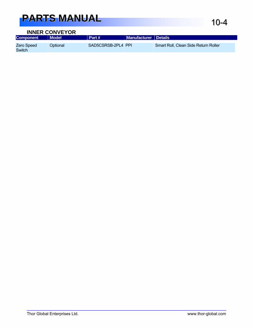
INNER CONVEYOR
Thor Global Enterprises Ltd. www.thor-global.com
PPPAAARRRTTTSSS MMMAAANNNUUUAAALLL 111000---444
Component Model Part # Manufacturer Details
Zero Speed Switch
Optional SAD5CSRSB-2PL4 PPI Smart Roll, Clean Side Return Roller
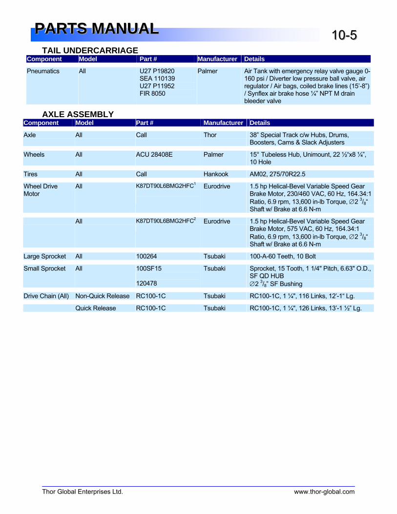
TAIL UNDERCARRIAGE
Thor Global Enterprises Ltd. www.thor-global.com
PPPAAARRRTTTSSS MMMAAANNNUUUAAALLL 111000---555
Component Model Part # Manufacturer Details
Pneumatics All U27 P19820 SEA 110139 U27 P11952 FIR 8050
Palmer Air Tank with emergency relay valve gauge 0-160 psi / Diverter low pressure ball valve, air regulator / Air bags, coiled brake lines (15’-8”) / Synflex air brake hose ¼” NPT M drain bleeder valve
AXLE ASSEMBLY Component Model Part # Manufacturer Details
Axle All Call Thor 38” Special Track c/w Hubs, Drums, Boosters, Cams & Slack Adjusters
Wheels All ACU 28408E Palmer 15° Tubeless Hub, Unimount, 22 ½“x8 ¼”, 10 Hole
Tires All Call Hankook AM02, 275/70R22.5
Wheel Drive Motor
All K87DT90L6BMG2HFC1
Eurodrive 1.5 hp Helical-Bevel Variable Speed Gear Brake Motor, 230/460 VAC, 60 Hz, 164.34:1
Ratio, 6.9 rpm, 13,600 in-lb Torque, ∅2 3/8“
Shaft w/ Brake at 6.6 N-m
All K87DT90L6BMG2HFC2
Eurodrive 1.5 hp Helical-Bevel Variable Speed Gear
Brake Motor, 575 VAC, 60 Hz, 164.34:1
Ratio, 6.9 rpm, 13,600 in-lb Torque, ∅2 3/8“
Shaft w/ Brake at 6.6 N-m
Large Sprocket All 100264 Tsubaki 100-A-60 Teeth, 10 Bolt
Small Sprocket All 100SF15 120478
Tsubaki Sprocket, 15 Tooth, 1 1/4" Pitch, 6.63" O.D., SF QD HUB ∅2
3/8” SF Bushing
Drive Chain (All) Non-Quick Release RC100-1C Tsubaki RC100-1C, 1 ¼", 116 Links, 12’-1“ Lg.
Quick Release RC100-1C Tsubaki RC100-1C, 1 ¼", 126 Links, 13’-1 ½” Lg.

WINCH ASSEMBLY
Thor Global Enterprises Ltd. www.thor-global.com
PPPAAARRRTTTSSS MMMAAANNNUUUAAALLL 111000---666
Component Model Part # Manufacturer Details
Winch Motor T115-5/8, T140-5/8/10, T150-5/8/10
SA87DT90L6BMG2HF
Eurodrive 1.5 hp Shaft Mounted Helical Worm Gear Brake Motor, 230/460VAC, 60 Hz, 288:1
Ratio, 4.0 rpm, 16,500 in-lbs Torque, ∅2 3/8“
Hollow Bore w/ Brake at 20 N-m
T170-5/8/10, T135-12/15, T150-12/
SA87.57DT90L4BMG2HF
Eurodrive 2.0 hp Shaft Mounted Helical Worm Gear Brake Motor, 230/460VAC, 60 Hz, 435:1
Ratio, 4.0 rpm, 20,600 in-lbs Torque, ∅2 3/8“
Hollow Bore w/ Brake at 20 N-m
Winch Bearing All 2003920 Link-Belt 2 Bolt Spherical Roller Pillow Block ∅2 3/16”
Bore
Winch Drum All 100013 Thor 8 ⅝” O.D. ½” Wall x 1’ 9 3/8“ Lg.
Hub Bushing
All Call 120513
Strongco Dodge
E QD Weld-on Hub 6 1/4" O.D. ∅2 7/16” E QD Bushing
Winch Shaft All 100015 Thor ∅2 7/16” x 3’ 5
5/8” Lg. AISI C1045 Cold
Rolled, Step at ∅2 3/16“ & ∅2
3/8“
Wire Rope T115-5/8 Call Thor ∅9/16”, 6x26, Galvanized Steel Core IWRC
Wire Rope & Thimble (113’ & 62’ Lengths)
Thor Ratchet All Call Thor Thor Fabricated Ratchet & Handle
Cable Sheave All S10.250-ACF Canbear 10 1/4“ O.D. x 8
3/4“ I.D. ∅9
/16“ Groove
Trailing Cable T115-5/8 Call Thor ∅3/8”, 7 x 19, Galvanized Wire Rope, Thimble
Splice One End (60’)
T140-5/8/10 Call Thor ∅3/8”, 7 x 19, Galvanized Wire Rope, Thimble
Splice One End (70’)
T150-5/8/10 Call Thor ∅3/8”, 7 x 19, Galvanized Wire Rope, Thimble
Splice One End (79’)
T170-5/8/10 Call Thor ∅3/8”, 7 x 19, Galvanized Wire Rope, Thimble
Splice One End (91’)
T135-12/15 Call Thor ∅3/8”, 7 x 19, Galvanized Wire Rope, Thimble
Splice One End (75’)
T150-12/15 Call Thor ∅3/8”, 7 x 19, Galvanized Wire Rope, Thimble
Splice One End (80’)
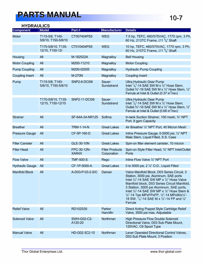
HYDRAULICS
Thor Global Enterprises Ltd. www.thor-global.com
PPPAAARRRTTTSSS MMMAAANNNUUUAAALLL 111000---777
Component Model Part # Manufacturer Details
Motor T115-5/8, T140-5/8/10, T150-5/8/10
CT007404PS5
WEG 7.5 hp, TEFC, 460/575VAC, 1770 rpm, 3 Ph,
60 Hz, 213TC Frame, ∅1 3/8” Shaft
T170-5/8/10, T135-12/15, T150-12/
CT010404PS5 WEG 10 hp, TEFC, 460/575VAC, 1770 rpm, 3 Ph,
60 Hz, 215TC Frame, ∅1 3/8” Shaft
Housing All M-182522A Magnalloy Bell Housing
Motor Coupling All M200-11210 Magnalloy Motor Coupling
Pump Coupling All M200-02005 Magnalloy Hydraulic Pump Coupling
Coupling Insert All M-270N Magnalloy Coupling Insert
Pump T115-5/8, T140-5/8/10, T150-5/8/10
SNP2-6-DCI06 Sauer-Sundstrand
Ultra Hydraulic Gear Pump Inlet
7/8”-14 SAE SW M x ½” Hose Stem,
Outlet ¾”-16 SAE SW M x ½” Hose Stem, ½” Ferrule at Inlet & Outlet (0.37 in
3/rev)
T170-5/8/10, T135-12/15, T150-12/15
SNP2-11-DCI06 Sauer-Sundstrand
Ultra Hydraulic Gear Pump Inlet
7/8”-14 SAE SW M x ½” Hose Stem,
Outlet ¾”-16 SAE SW M x ½” Hose Stem, ½” Ferrule at Inlet & Outlet (0.66 in
3/rev)
Strainer All SF-64A-34-NR125 Sofima In-tank Suction Strainer, 100 mesh, ¾” NPT Port, 8 gpm Capacity
Breather All TRM-1-14-N Great Lakes Air Breather ¼” NPT Port, 40 Micron Mesh
Pressure Gauge All CF-5P-160-D Great Lakes Inline Pressure Gauge, 0-5000 psi, ¼” NPT Male Stem, Liquid Filled, S.S. Case
Filter Canister All GLE-30-10N Great Lakes Spin-on filter element canister, 10 micron
Filter Head All FPC-30-12N-XAR4X
Filter Products Corporation
Spin-on Style Filter Head, ¾“ NPT Inlet/Outlet Ports
Flow Valve All TMF-500-S Rego Inline Flow Valve ½“ NPT Port
Hydraulic Gauge All CF-1P-5000-A Great Lakes 0 to 5000 psi, 2 ½” O.D., Liquid Filled
Manifold Block All A-D03-P-03-2-S/C Daman Valve Manifold Block, D03 Series Circuit, 3 Station, 3000 psi, Aluminum, SAE ports Inlet ½”-14 SAE SW MP x ½” Hose Valve Manifold block, D03 Series Circuit Manifold, 3 Station, 3000 psi Aluminum, SAE ports, Inlet ½”-14 SAE SW MP x ½” Hose Stem & ½”-14 Tee MPxFPxFP, ½”-14 MPx90x¼”-18 SW,
7/4”-14 SAE M x ½”-14 FP and ½”
Ferrule
Relief Valve All RD102S30 Parker Hannifin
Direct Acting Poppet Style Cartridge Relief Valve, 3000 psi max, Adjustable
Solenoid Valve All SWH-G02-C2-A120-20
Northman High Pressure Flow Double Solenoid Directional Valve, D03 Sub Plate Mount, 120VAC, C6 Spool Type
Manual Valve All HD-G02-3C2-10 Northman Lever Operated Directional Control Valves, D03 Sub Plate Mount, 3 Position
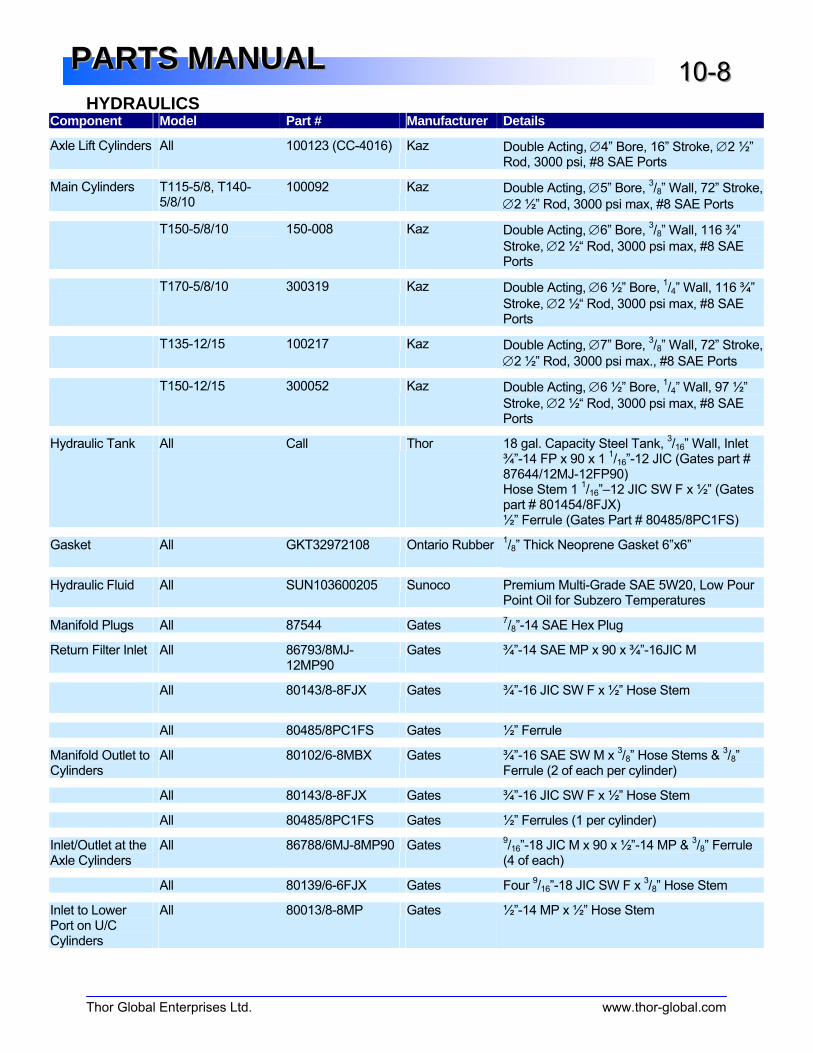
HYDRAULICS
Thor Global Enterprises Ltd. www.thor-global.com
PPPAAARRRTTTSSS MMMAAANNNUUUAAALLL 111000---888
Component Model Part # Manufacturer Details
Axle Lift Cylinders All 100123 (CC-4016) Kaz Double Acting, ∅4” Bore, 16” Stroke, ∅2 ½” Rod, 3000 psi, #8 SAE Ports
Main Cylinders T115-5/8, T140-5/8/10
100092 Kaz Double Acting, ∅5” Bore, 3/8” Wall, 72” Stroke, ∅2 ½” Rod, 3000 psi max, #8 SAE Ports
T150-5/8/10
150-008 Kaz Double Acting, ∅6” Bore, 3/8” Wall, 116 ¾”
Stroke, ∅2 ½“ Rod, 3000 psi max, #8 SAE Ports
T170-5/8/10 300319 Kaz Double Acting, ∅6 ½” Bore, 1/4” Wall, 116 ¾”
Stroke, ∅2 ½“ Rod, 3000 psi max, #8 SAE Ports
T135-12/15 100217 Kaz Double Acting, ∅7” Bore, 3/8” Wall, 72” Stroke, ∅2 ½” Rod, 3000 psi max., #8 SAE Ports
T150-12/15 300052 Kaz Double Acting, ∅6 ½” Bore, 1/4” Wall, 97 ½”
Stroke, ∅2 ½“ Rod, 3000 psi max, #8 SAE Ports
Hydraulic Tank All Call Thor 18 gal. Capacity Steel Tank, 3/16” Wall, Inlet
¾”-14 FP x 90 x 1 1/16”-12 JIC (Gates part #
87644/12MJ-12FP90) Hose Stem 1
1/16”–12 JIC SW F x ½” (Gates
part # 801454/8FJX) ½” Ferrule (Gates Part # 80485/8PC1FS)
Gasket All GKT32972108 Ontario Rubber1/8” Thick Neoprene Gasket 6”x6”
Hydraulic Fluid All SUN103600205 Sunoco Premium Multi-Grade SAE 5W20, Low Pour Point Oil for Subzero Temperatures
Manifold Plugs All 87544 Gates 7/8”-14 SAE Hex Plug
Return Filter Inlet All 86793/8MJ-12MP90
Gates ¾”-14 SAE MP x 90 x ¾”-16JIC M
All 80143/8-8FJX Gates ¾”-16 JIC SW F x ½” Hose Stem
All 80485/8PC1FS Gates ½” Ferrule
Manifold Outlet to Cylinders
All 80102/6-8MBX Gates ¾”-16 SAE SW M x 3/8” Hose Stems &
3/8”
Ferrule (2 of each per cylinder)
All 80143/8-8FJX Gates ¾”-16 JIC SW F x ½” Hose Stem
All 80485/8PC1FS Gates ½” Ferrules (1 per cylinder)
Inlet/Outlet at the Axle Cylinders
All 86788/6MJ-8MP90 Gates 9/16”-18 JIC M x 90 x ½”-14 MP &
3/8” Ferrule
(4 of each)
All 80139/6-6FJX Gates Four 9/16”-18 JIC SW F x
3/8” Hose Stem
Inlet to Lower Port on U/C Cylinders
All 80013/8-8MP Gates ½”-14 MP x ½” Hose Stem

HYDRAULICS
Thor Global Enterprises Ltd. www.thor-global.com
PPPAAARRRTTTSSS MMMAAANNNUUUAAALLL 111000---999
Component Model Part # Manufacturer Details
Inlet to Lower Port on U/C Cylinders
All 80039/8-8MPX Gates ½”-14 SW MP x ½” Hose Stem
Inlet to upper Port on U/C Cylinder
All 65715/8FP-8MP-8FP
Gates ½”-14 Tee SW MP x FP x FP
Misc. Tank Items All 310460 Garth ¾”-14 Galvanized Square Head Plug
Misc. Tank Items All 321570 Garth ¾”-14 MP x 90 x FP Galvanized Elbow
Misc. Tank Items All 32780 Garth ½”-11 ½” Galvanized Tank Cap
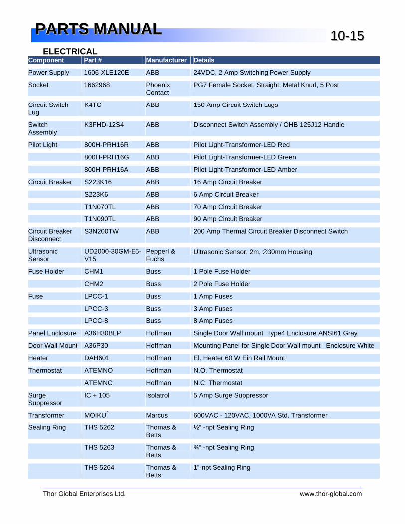
ELECTRICAL
Thor Global Enterprises Ltd. www.thor-global.com
PPPAAARRRTTTSSS MMMAAANNNUUUAAALLL 111000---111555
Component Part # Manufacturer Details
Power Supply 1606-XLE120E ABB 24VDC, 2 Amp Switching Power Supply
Socket 1662968 Phoenix Contact
PG7 Female Socket, Straight, Metal Knurl, 5 Post
Circuit Switch Lug
K4TC ABB 150 Amp Circuit Switch Lugs
Switch Assembly
K3FHD-12S4 ABB Disconnect Switch Assembly / OHB 125J12 Handle
Pilot Light 800H-PRH16R ABB Pilot Light-Transformer-LED Red
800H-PRH16G ABB Pilot Light-Transformer-LED Green
800H-PRH16A ABB Pilot Light-Transformer-LED Amber
Circuit Breaker S223K16 ABB 16 Amp Circuit Breaker
S223K6 ABB 6 Amp Circuit Breaker
T1N070TL ABB 70 Amp Circuit Breaker
T1N090TL ABB 90 Amp Circuit Breaker
Circuit Breaker Disconnect
S3N200TW ABB 200 Amp Thermal Circuit Breaker Disconnect Switch
Ultrasonic Sensor
UD2000-30GM-E5-V15
Pepperl & Fuchs
Ultrasonic Sensor, 2m, ∅30mm Housing
Fuse Holder CHM1 Buss 1 Pole Fuse Holder
CHM2 Buss 2 Pole Fuse Holder
Fuse LPCC-1 Buss 1 Amp Fuses
LPCC-3 Buss 3 Amp Fuses
LPCC-8 Buss 8 Amp Fuses
Panel Enclosure A36H30BLP Hoffman Single Door Wall mount Type4 Enclosure ANSI61 Gray
Door Wall Mount A36P30 Hoffman Mounting Panel for Single Door Wall mount Enclosure White
Heater DAH601 Hoffman El. Heater 60 W Ein Rail Mount
Thermostat ATEMNO Hoffman N.O. Thermostat
ATEMNC Hoffman N.C. Thermostat
Surge Suppressor
IC + 105 Isolatrol 5 Amp Surge Suppressor
Transformer MOIKU2 Marcus 600VAC - 120VAC, 1000VA Std. Transformer
Sealing Ring THS 5262 Thomas & Betts
½“ -npt Sealing Ring
THS 5263 Thomas & Betts
¾“ -npt Sealing Ring
THS 5264 Thomas & Betts
1”-npt Sealing Ring

ELECTRICAL
Thor Global Enterprises Ltd. www.thor-global.com
PPPAAARRRTTTSSS MMMAAANNNUUUAAALLL 111000---111666
Strain Relief SR-503 O-Z Gedney ½” Straight Male Strain Relief .200”-.300" ABB sensors
SR-504 O-Z Gedney ½” Straight Male Strain Relief .300”-.400" ABB Proximity
SR-505 O-Z Gedney ½” Straight Male Strain Relief .400”-.500"
SR-755 O-Z Gedney ¾” Straight Male Strain Relief .400”-.500"
SR-1009 O-Z Gedney 1" Straight Male Strain Relief .900”-1.00"
SR-1008 O-Z Gedney 1" Straight Male Strain Relief .700”-.800”
Fan 028279 (SU2A5) Comair Rotron Tubeaxial 20VAC Fan, 3.14" sq. 34 cfm
Grill 476143 Comair Rotron Metal Grill/Finger Guard for Tubeaxial fan
Filter Guard 554142 Comair Rotron Filter Guard Assembly for Tubeaxial fan
Ground Terminal Block
101010 Weidmuller WDU-4 Ground Terminal Block
Terminal Block 102000 Weidmuller WDU-2.5 Terminal Block
102010 Weidmuller WDU-4 Terminal Block
Terminal Jumper 105206 Weidmuller Terminal Jumper
Contactor 100-A75ND3 Allen-Bradley 75 Amp Contactor, 120VAC Coil
100-A60ND3 Allen-Bradley 60 Amp Contactor, 120VAC Coil
100-A12ND3 Allen-Bradley 12 Amp Contactor, 120VAC Coil
Reversing Contactor
104-A09ND3 Allen-Bradley Reversing Contactor IEC 9A, 120 VAC Control
Surge Suppressor
199-FSMA10 Allen-Bradley Contactor Surge Suppressor
Chassis 1746-A4 Allen-Bradley 4 Slot Chassis
Input Module 1746-IA16 Allen-Bradley 16 Bit, 120VAC Input Module
Output Module 1746-OW16 Allen-Bradley 16 Bit, Relay Output Module
Power Supply 1746-P3 Allen-Bradley 24VDC Power Supply
Power Block 1423572 Marathon Power Block Distribution Block
PLC Processor 1747-L532 Allen-Bradley SLC5/03 Processor
EEPROM 1747-M13 Allen-Bradley Processor EPROM
Relay 193-A1K3 Allen-Bradley Solid State Overload Relay 25-75 Amps
193-A1F1 Allen-Bradley Solid State Overload Relay 3.7-12 Amps
193-A1E1 Allen-Bradley Solid State Overload Relay 1.5-5 Amps
Din Rail 199-DR1 Allen-Bradley Din Rail
Din Rail KT2DIN Allen-Bradley T-Max DIN rail base kit for T1 & T2
Relay Coil 700-HK32A1 Allen-Bradley 120VAC Relay Coil, 8 Blades
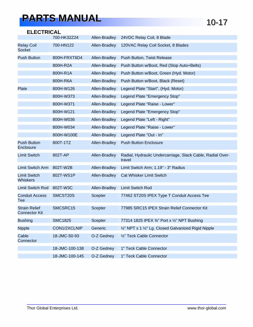
ELECTRICAL
Thor Global Enterprises Ltd. www.thor-global.com
PPPAAARRRTTTSSS MMMAAANNNUUUAAALLL 111000---111777
700-HK32Z24 Allen-Bradley 24VDC Relay Coil, 8 Blade
Relay Coil Socket
700-HN122 Allen-Bradley 120VAC Relay Coil Socket, 8 Blades
Push Button 800H-FRXT6D4 Allen-Bradley Push Button, Twist Release
800H-R2A Allen-Bradley Push Button w/Boot, Red (Stop Auto+Belts)
800H-R1A Allen-Bradley Push Button w/Boot, Green (Hyd. Motor)
800H-R6A Allen-Bradley Push Button w/Boot, Black (Reset)
Plate 800H-W126 Allen-Bradley Legend Plate "Start", (Hyd. Motor)
800H-W373 Allen-Bradley Legend Plate "Emergency Stop"
800H-W371 Allen-Bradley Legend Plate "Raise - Lower"
800H-W121 Allen-Bradley Legend Plate "Emergency Stop"
800H-W036 Allen-Bradley Legend Plate "Left - Right"
800H-W034 Allen-Bradley Legend Plate "Raise - Lower"
800H-W100E Allen-Bradley Legend Plate "Out - In"
Push Button Enclosure
800T-1TZ Allen-Bradley Push Button Enclosure
Limit Switch 802T-AP Allen-Bradley Radial, Hydraulic Undercarriage, Slack Cable, Radial Over-travel
Limit Switch Arm 802T-W2B Allen-Bradley Limit Switch Arm; 1.19" - 3" Radius
Limit Switch Whiskers
802T-WS1P Allen-Bradley Cat Whisker Limit Switch
Limit Switch Rod 802T-W3C Allen-Bradley Limit Switch Rod
Conduit Access Tee
SMCST20S Scepter 77462 ST20S IPEX Type T Conduit Access Tee
Strain Relief Connector Kit
SMCSRC15 Scepter 77985 SRC15 IPEX Strain Relief Connector Kit
Bushing SMC1825 Scepter 77314 1825 IPEX ¾” Port x ½” NPT Bushing
Nipple CON1/2XCLNIP Generic ½” NPT x 1 ½" Lg. Closed Galvanized Rigid Nipple
Cable Connector
18-JMC-50-93 O-Z Gedney ½” Teck Cable Connector
18-JMC-100-138 O-Z Gedney 1" Teck Cable Connector
18-JMC-100-145 O-Z Gedney 1" Teck Cable Connector

This page is intentionally blank.

Publication No. T2.16.JIJanuary 2009
Printed in CanadaCopyright © Thor Global Enterprises Ltd., 2002
All Rights Reserved
Thor Global Enterprises Ltd. has been recognized forquality and product innovation in the aggregateprocessing industry since 1969. Thor was theinnovator of the telescopic portable radial stacker,thus becoming the world leader in creating value fortheir customers through continuous innovation inbulk material handling technology. Thor productsare engineered and built to be flexible, efficient,versatile and safe. All of this ensures increasedproductivity and ultimately profitability for youroperations.