Planning Application AR-20-05 Applicant Record Submittal
289
Planning Application AR-20-05 Applicant Record Submittal
-
Upload
khangminh22 -
Category
Documents
-
view
5 -
download
0
Transcript of Planning Application AR-20-05 Applicant Record Submittal

Planning Application AR-20-05 Applicant Record Submittal
Jennifer M. Bragar 121 SW Morrison St, Suite 1850Attorney Portland, Oregon 97204Admitted in Oregon, Washington, Tel 503-894-9900and California Fax [email protected] www.tomasilegal.com
July 22, 2020
BY EMAIL
Chair Salvage and Planning Commissionersc/o Kelly Hart925 Main StreetLebanon, OR 97355
Re: Applicant's Open Record SubmittalFile No. AR 20-05
Dear Chair Salvage and Commissioners:
As you know this office represents the applicant, Farmworker Housing Development Corporation ("Applicant" or "FHDC"), in the above-referenced file. The proposed developmentof 24-units of affordable housing is located at the western terminus of Weldwood Drive ("subject property" or "site"). FHDC has named the development Colonia Paz I. After considering comments made at the public hearing, and reviewing comments submitted to the record throughJuly 15, 2020, the Applicant provides this additional information in response. Please accept these comments and additional information that further supports approval of this application and include this letter and the attachments in the record.
I. Colonia Paz Operations
While many comments did not address land use criteria, in an effort to be responsive to the range of information provided in public comments, the Applicant offers additional information to explain how the subject property is well-suited for the proposed use and how FHDC will offer services for the residents of Colonia Paz I. Before this description, FHDC alerts the Planning Commission to protections under the Fair Housing Act as amended ("FHA"). Since the comments the Applicant responds to here can be construed to be race-based comments, this letter points out that review of this application cannot be decided on race-basedcharacteristics of the individuals who will live at the site, but must be based on the ability of the Applicant to meet the applicable land use approval criteria.
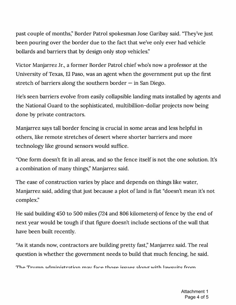
The FHA declares that "it is the policy of the United States to provide, within constitutional limitations, for fair housing throughout the United States." 42 U.S.C. § 3601. To achieve this goal, the FHA makes it unlawful to "make unavailable or deny, a dwelling to any person because of race, color, religion, sex, familial status, or national origin. 42 U.S.C. § 3604(a). A denial here based on comments such as the request to build a "wall" that is 10-20 feet, when the Lebanon Development Code ("LDC") provides for a maximum height of 8 feet if a developer uses masonry fencing under LDC 16.150.030.D and prohibits hedges over 8 feet tall
TOMASI SALYER MARTIN
Lebanon Planning CommissionPage 2
under LDC 16.15.060.A.4.c could violate the FHA. In Applicant's view, the commenter is submitting barely veiled race-based comments with reference to a wall being constructed in the southern United States to hinder illegal migration. See Attachment 1. These types of comments, as well as references to English as a second language for children who may live in Colonia Paz;fear that the neighborhood will no longer be quiet or safe; claims that property value will be reduced; that the residents themselves should be counseled about cultural differences, laws and rules "for their own protection;" potential threats of violence against farmworker residents; and requests for a "liaison officer" are race-based comments that do not address land use criteria. The comment about second language students, in addition to focusing on race, also violates the FHA as a comment based on familial status of the potential residents of the development. Further, comments that raise questions like "what kind of farmworkers would be housing in our area" also show unfounded race-based fears about the development. Given this background, the Applicant offers the following description of its development.
Tellingly, FHDC proposed the name Colonia Paz for this development. Colonia Paz translates to "Community of Peace." Based on its over 30 years of experience, FHDC is well-placed to begin development of the subject property with farmworker housing, with much financial support through the United States Department of Agriculture ("USDA"). The USDA will fund site acquisition and development. See Attachment 2, an excerpt of the government funding application the development, reflecting USDA's award of funds and the need for affordable housing in this poverty hotspot. Colonia Paz is targeted to farmworkers and their families earning less than 70% area median income ("AMI"), with 62% of the units targeted to families with incomes below 50% AMI, and 10% to families at or below 30% AMI. Colonia Paz has received Rental Assistance from USDA Rural Development, ensuring most tenants pay no more than 30% of their income toward rent. The operations of Colonia Paz are explained below to clarify any misconceptions and to provide a better understanding of the proposed use as stable housing for area farmworkers and attendant services, including benefits to surrounding property owners.
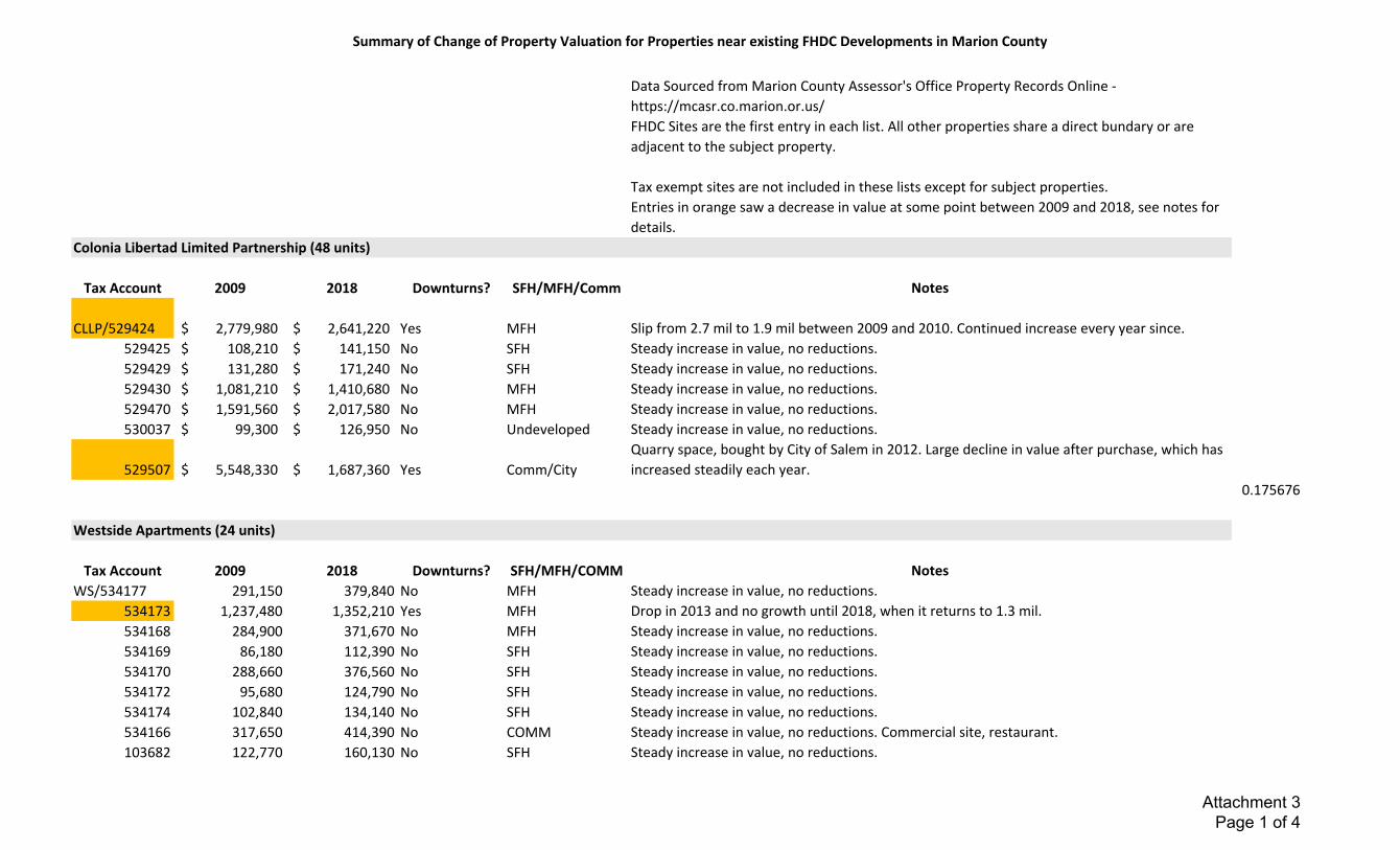
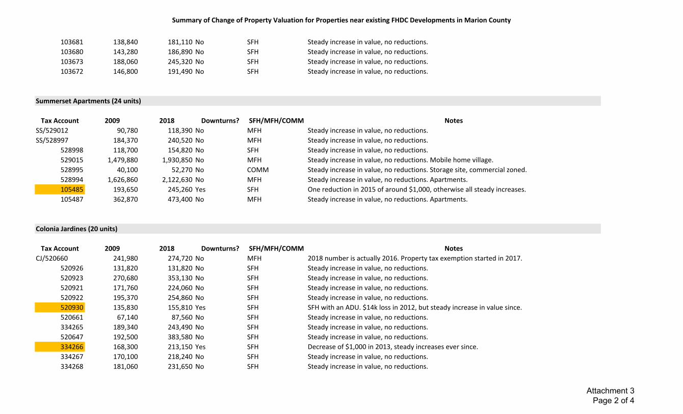
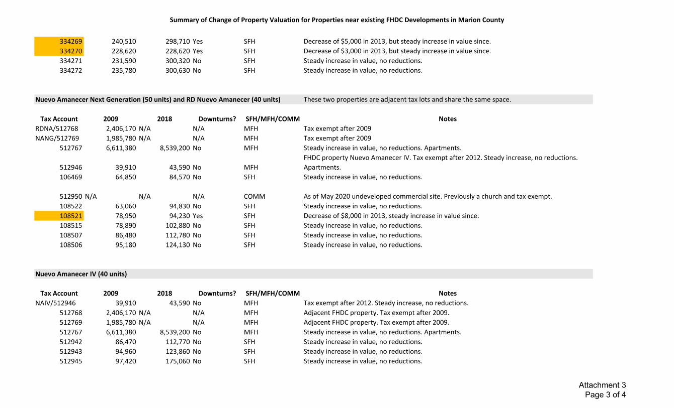
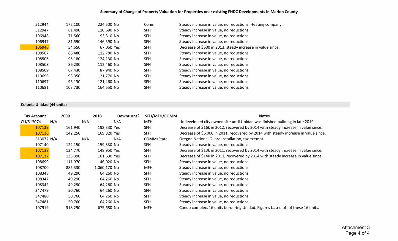
The consideration of surrounding property values are not one of the approval criteria for this development and in the context of the comments made improperly focus on the character of the potential residents at Colonia Paz. Nonetheless, FHDC reviewed property valuation for properties that share a direct boundary or are adjacent to an existing FHDC development in Marion County. See Attachment 3. For each property listed, the values have steadily increased over the summarized nine year period from 2009 – 2018. The only exception is an old quarry site that is now government owned, and is not comparable to any site near the proposed application. While 17 out of 74 properties in Attachment 3 show some reduction over the time period, all non-FHDC properties, including those with reductions, have equal or greater value than they did in 2009. These reductions are mentioned as reported facts, not as a correlation to the FHDC developments, as there are many reasons why a single property could see a reduction in value. Overall, the properties surrounding FHDC developments have increased in value over time, benefiting in wealth generation for the subject owners from the new construction and well-maintained FHDC developments.

TOMASI SALYER MARTIN
Lebanon Planning CommissionPage 3
FHDC is committed, as it has done across all of its developed properties in Oregon, to create a community. The development is intended to serve year-round agricultural workers in and near Lebanon. This community building is shown through the design elements that include pedestrian friendly design, ample bicycle parking, and outdoor recreation space including a covered eating area and children's' playground.
In addition, the funding for the development will include a budget for an onsite property manager to maintain the property in good repair, as well as fund a resident service coordinator. The resident service coordinator will link residents to service providers, including health providers, school representatives, and other resources to help the farmworkers stabilize other aspects of their lives and participate in Lebanon activities. Further, FHDC typically has neighborhood meetings to invite neighboring property owners to meet and learn about the farmworker community. Such activities have included community discussions, shared use of onsite garden harvests, community celebrations and other activities. Some of these activities to build community connections will be implemented at Colonia Paz.
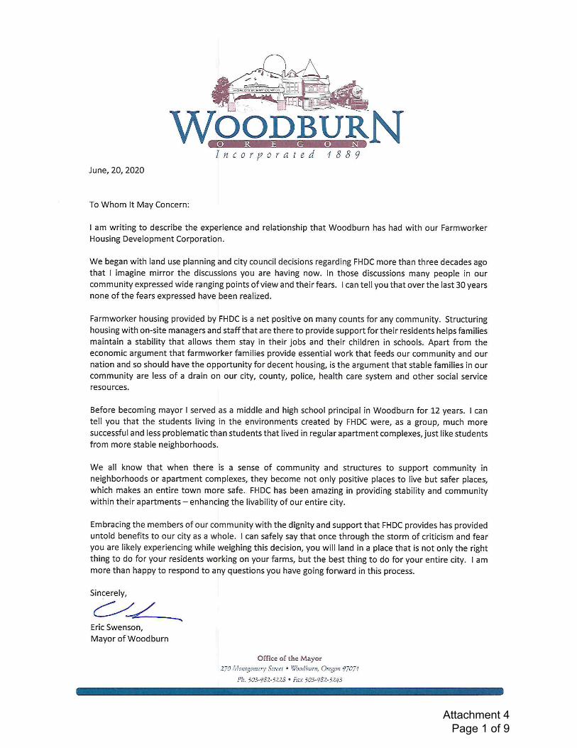
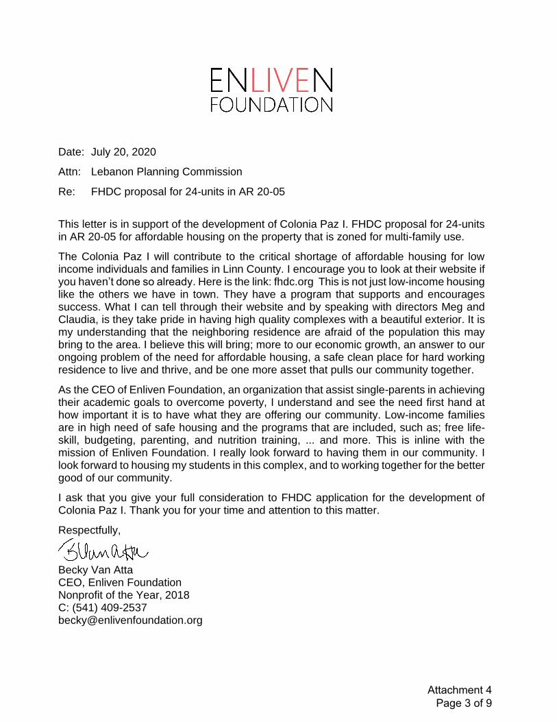
As described at the Planning Commission hearing, FHDC has engaged with community leaders over the past year, including the school district, local volunteer-organizations, and faith-based communities, to learn about the fabric of support that will be available for future residents at Colonia Paz. Letters of support from community partners and individuals are included here as Attachment 4. Each letter has a consistent theme – that FHDC's developments do create a community that helps farmworkers and their families by providing new opportunities to help them reach the American Dream, while they work daily to feed America.
II. Only clear and objective standards can be applied to this proposal.
The application is for multifamily units that qualify as needed housing under state law. See ORS 197.303(1)(a). As a result, the Applicant reserves the right to request that the Cityapply only "clear and objective standards, conditions, and procedures" to the development. ORS 197.307(4). As a result of public comment, the Applicant is submitting a supplement narrative. See Attachment 5. The Applicant specifically identifies those criteria that do not contain clear and objective standards in the supplemental narrative and objects to the use of such standards in review of this application.
III. FHDC addresses soil conditions and confirms the onsite stormwater control system is designed to collect runoff from new impervious surfaces and to better control offsite runoff.
A member of the public, Ronald Edwards, generally raised concerns about whether the Applicant had performed a geotechnical study to determine the subject property could be developed as proposed. In addition, another comment raised concerns about whether the particular onsite soils would have poor infiltration.
The Applicant's materials included a preliminary grading and drainage plan as Sheet C-2.1. In addition, the Applicant performed a Geotechnical Report and provides findings pertinent

TOMASI SALYER MARTIN
Lebanon Planning CommissionPage 4
to Colonia Paz I in Attachment 6. This report concludes that the site can be engineered to address soil and groundwater conditions and recommends certain actions that the Applicant can feasibly undertake during development to address geotechnical matters.
All stormwater will be captured onsite. In addition, Applicant's civil engineer describes that water will infiltrate through landscaped bioswales, and underground infiltration chambersafter capture, but will not change the course of natural flow from the predevelopment site conditions. Prior to release through infiltration, surface waters will run through sumps or swalesto prevent pollutants from entering the environment. Attachment 7. The proposed development will not impact offsite flow direction, but will control stormwater on site through the drainage plan that is designed to capture runoff from new impervious surface.
Based on the Geotechnical Report included in this open record submittal and other application materials in the record, the proposed engineered stormwater system on the subject property provides information in the record to show the development can feasibly be constructed to meet the code requirements and addresses the vague concerns raised by the public.
IV. Well and Wetland Concerns
Several neighbors signed a joint letter raising concerns about potential impacts to their well water from development of this property. Other comments questioned whether the proposed development would adversely affect a wetland located northwest of the proposed development. FHDC attaches its Wetlands Delineation Report as Attachment 8. On page 45 of Attachment 8, the delineated wetlands area is depicted. The Applicant retained a EVREN Northwest, Inc. ("EVREN") to prepare a limited hydrogeological evaluation to analyze FHDC's Geotechnical Report, Wetlands Delineation, proposed stormwater design, and data about surrounding wells. The EVREN Technical Memorandum is attached hereto as Attachment 9.
As the memorandum describes and concludes:
"nearby wells derive their water from a regional ground water aquifer at depths that are hydraulically separated from overlying perched ground water and local infiltration. The regional aquifer covers a broad geographic area and is likely recharged from areas distal to the site. Very little if an replenishment of the aquifer is from surface infiltration near the proposed development site."
Based on this review, EVREN concludes the development will not have a significant impact on surrounding well water quantity or quality.
Further, the memorandum describes the location of nearby wetlands and concludes that based on the storm water design, treatment plan, and infiltration, the shallow groundwater hydrology that feeds the wetlands will not be significantly impacted by the proposed development. Therefore, this application will not have significant impact on surrounding wells or wetlands.
TOMASI SALYER MARTIN
Lebanon Planning CommissionPage 5
V. Other neighborhood concerns are addressed.
Many public comments seek to direct the development of traffic improvements related to access, traffic impacts, and onsite parking. The Applicant has addressed the applicable criteria in greater detail in the attached supplemental narrative. Attachment 5, see especially Applicant's response to specific criteria raised in public comments, including LDC 16.12.030.G and I. Moreover, any future development on property surrounding the subject property will be required to submit application materials and be reviewed on its own merits.
In addition, all onsite parking requirements have been met. Although some comments make vague remarks about on-street parking demands, on-street parking is equally available to anyone who desires to use the spaces at a particular time. The City of Lebanon will govern on-street parking allowances on the extension of Weldwood Drive. Further, some comments were made about connecting Weldwood as a through street. However, the Applicant will not connect the Weldwood extension through the private road portion of Weldwood as it traverses the nearby manufactured home park. Therefore, the extension of Weldwood Drive will be limited to traffic impacts from this development, and there is no indication that pedestrians will be unable to follow traffic patterns associated with the driveway access to the proposed development, as both the right-of-way for Weldwood Drive, and the driveway width meet LDC requirements.
One comment related to maintenance of landscaped area. Under the code, failure to maintain landscaping is a code violation and subject to enforcement. Therefore, no separate condition of approval or response from Applicant is required.
Applicant's civil engineer and the City's environmental management staff corresponded about the availability of water and sewer to serve the proposed development. See Attachment 10. In addition, as this proposed development is an allowed use under the zoning, the City has planned adequate public facilities to serve the site as part of its comprehensive plan, and its facilities master plan. The City may rely on its own staff's expertise to find that adequate public facilities are available to serve this development.
Further, the public facilities approval criteria relate to utilities like water and sewer. The City's definition of public facilities does not include schools. The Lebanon Community Schoolshas been notified of this application and did not provide comments about interference with school planning and capacity. Further, the school district had an opportunity to comment when zoning decisions were made, and yet this parcel has been zoned for mixed use, where the multi-family use proposed here is listed as an allowed use. For these reasons, the Applicant is not required to take further action in meeting school district planning capacity. Notwithstanding the foregoing, the Applicant notes that the school district, in its Student Investment Action Grant Application, has requested nearly $1 million in funds to reduce class size. Attachment 11.
One public comment raised a question about why no archaeological study was included in the application materials. The subject property is not on the Lebanon historic register and has no identified historic resource of statewide significance, therefore, no archaeological study is
TOMASI SALYER MARTIN
Lebanon Planning CommissionPage 6
required. See also Attachment 5, Applicant's supplemental narrative with additional response to LDC 16.31.040.
Several comments suggest that the Applicant should be subject to the approval criteria for a planned development. Under LDC 16.23.010.E an applicant may elect to develop a project as a planned development. However, FHDC did not elect to apply for a planned development. Therefore, LDC Ch. 16.23 does not apply to this application.
Finally, other public comments appear to request direct application of Comprehensive Plan policies. However, the LDC implements the City's Comprehensive Plan for allowed uses, such as this proposed development, and no applicable code provision requires direct application of the Comprehensive Plan.
Based on the foregoing, none of the public comments raised during the review process provide grounds to deny the application.
VI. FHDC Requests Modification of the Conditions of Approval.
The Applicant requests a number of modifications of the conditions of approval to address concerns raised by the public, as well as to more accurately reflect the proposed development under consideration in this application.
First, for the reasons set forth in the supplement narrative in Attachment 5, condition of approval 1.a should be modified to reflect the Applicant's proposal and read as follows:
1.a. A landscape plan shall be submitted in compliance with Chapter 16.15 andapproved prior to the issuance of a building permit, without application of subjectivestandards. The landscape plan shall include a six-foot tall site obscuring fence of chainlink with vinyl slats along the south and east property lines as delineated in the MinorLand Partition in condition 1.d, with a minimum five foot landscape buffer.
Second, the Applicant's supplemental narrative in Attachment 5 proposes particular landscaping and illumination specifications. Based on this submittal, condition of approval 3Engineering Department e should be modified to read,
1.e. Provide a landscape and illumination plan as part of the engineering site planreview plan set consistent with the Applicant's representations about landscaping andillumination in its supplemental narrative submitted July 22, 2020.
Third, the Applicant requests removal of conditions of approval 3, Transportation, c and d. As the staff report, and information requested in Applicant's July 16, 2020 letter to thePlanning Director indicate, staff determines whether a traffic impact analysis is required. Sincethe staff determined no traffic impact analysis is required, the conditions of approval should notdiscuss the traffic impact analysis that will be required at a later date when the Applicant pursues

Attachment #1

Attachment 1 Page 1 of 5

Attachment 1 Page 2 of 5

Attachment 1 Page 3 of 5
Attachment 1 Page 4 of 5

Attachment 1 Page 5 of 5

Attachment #2

Project Name: 4.1A: Questionnaire
Colonia Paz
Scoring Criteria:
Severity of Need Measures: city / county vs State
3 points 2 points 1 point -1 point
(B) If New Construction or Acq/Rehab: Describe the numeric and percentage gap between your target population group and the funded affordable housing to serve that group in your community (county or city as listed above). If a project is scattered site, address this question for each project site. Housing Inventory available online here: http://www.oregon.gov/ohcs/Pages/research-multifamily-housing-inventory-data.aspx
If Preservation; describe what percentage of the target geographies affordable housing is represented in this project. If a project is scattered site, address this question for each project site.
Colonia Paz is a new construction project. According to the OHCS affordable housing inventory, there is a shortage of 1,744 affordable housing units in Linn County. Linn County's equitable distribution is 2.7% when compared to the entire number of affordable hosuing units at the state level. Based on this inequitable distribution estimate in Linn County, even if we added 24 units of afforable housing per year, not adjusting for population growth, it would take the next 73 years to equitable distribution. Realistically, due to population growth and the limited resources for affordable housing, Linn County is likely to remain underserved for at least the next three decades. The addition of Colonia Paz's 24 units of affordable housing is particularly critical to address the need in Linn County.
According to OHCS data, most of the current rental stock in Linn County is newer than 1950 (81%), however, over 25% in Linn County are severly rent burdened, paying more than 50% of household income on rent. Additionally, 24% of the Lebanon's population received Food Stamps/SNAP benefits, and 11% are without health insurance, also considerably above County and State percentages. The majority of Farmworker Housing Development Corporation's (FHDC) communities are rurally located, low-income families averaging approximately $26,000 a year for a family of four.
According to the Linn-Benton Housing Authority (LBHA), there are 2,882 households on its waiting list for housing assistance, including 443 households in Lebanon, including 139 families with children. LBHA provided a letter of support for the development of Colonia Paz, and it's included in section 2 of this application.
Colonia Paz will be the first affordable housing property for agricultural workers and their families in Linn County. Colonia Paz will help ease the burden providing, quality affordable housing and create workforce housing critical to the agricultural industry in Linn County.
In September 2018, Colonia Paz received a $3,000,000 loan and grant combination from USDA Rural Development, and 23 units of Rental Assistance. This allows us to serve the lowest income farmworkers in Linn County.
FHDC HOME NOFA #5003 4 - 1
Attachment 2 Page 1 of 1

Attachment #3
Summary of Change of Property Valuation for Properties near existing FHDC Developments in Marion County
Data Sourced from Marion County Assessor's Office Property Records Online ‐ https://mcasr.co.marion.or.us/FHDC Sites are the first entry in each list. All other properties share a direct bundary or are adjacent to the subject property.
Tax exempt sites are not included in these lists except for subject properties.Entries in orange saw a decrease in value at some point between 2009 and 2018, see notes for details.
Colonia Libertad Limited Partnership (48 units)
Tax Account 2009 2018 Downturns? SFH/MFH/Comm Notes
CLLP/529424 2,779,980$ 2,641,220$ Yes MFH Slip from 2.7 mil to 1.9 mil between 2009 and 2010. Continued increase every year since.529425 108,210$ 141,150$ No SFH Steady increase in value, no reductions.529429 131,280$ 171,240$ No SFH Steady increase in value, no reductions.529430 1,081,210$ 1,410,680$ No MFH Steady increase in value, no reductions.529470 1,591,560$ 2,017,580$ No MFH Steady increase in value, no reductions.530037 99,300$ 126,950$ No Undeveloped Steady increase in value, no reductions.
529507 5,548,330$ 1,687,360$ Yes Comm/CityQuarry space, bought by City of Salem in 2012. Large decline in value after purchase, which has increased steadily each year.
0.175676
Westside Apartments (24 units)
Tax Account 2009 2018 Downturns? SFH/MFH/COMM NotesWS/534177 291,150 379,840 No MFH Steady increase in value, no reductions.
534173 1,237,480 1,352,210 Yes MFH Drop in 2013 and no growth until 2018, when it returns to 1.3 mil.534168 284,900 371,670 No MFH Steady increase in value, no reductions.534169 86,180 112,390 No SFH Steady increase in value, no reductions.534170 288,660 376,560 No SFH Steady increase in value, no reductions.534172 95,680 124,790 No SFH Steady increase in value, no reductions.534174 102,840 134,140 No SFH Steady increase in value, no reductions.534166 317,650 414,390 No COMM Steady increase in value, no reductions. Commercial site, restaurant.103682 122,770 160,130 No SFH Steady increase in value, no reductions.
Attachment 3 Page 1 of 4
Summary of Change of Property Valuation for Properties near existing FHDC Developments in Marion County
103681 138,840 181,110 No SFH Steady increase in value, no reductions.103680 143,280 186,890 No SFH Steady increase in value, no reductions.103673 188,060 245,320 No SFH Steady increase in value, no reductions.103672 146,800 191,490 No SFH Steady increase in value, no reductions.
Summerset Apartments (24 units)
Tax Account 2009 2018 Downturns? SFH/MFH/COMM NotesSS/529012 90,780 118,390 No MFH Steady increase in value, no reductions.SS/528997 184,370 240,520 No MFH Steady increase in value, no reductions.
528998 118,700 154,820 No SFH Steady increase in value, no reductions.529015 1,479,880 1,930,850 No MFH Steady increase in value, no reductions. Mobile home village.528995 40,100 52,270 No COMM Steady increase in value, no reductions. Storage site, commercial zoned.528994 1,626,860 2,122,630 No MFH Steady increase in value, no reductions. Apartments.105485 193,650 245,260 Yes SFH One reduction in 2015 of around $1,000, otherwise all steady increases.105487 362,870 473,400 No MFH Steady increase in value, no reductions. Apartments.
Colonia Jardines (20 units)
Tax Account 2009 2018 Downturns? SFH/MFH/COMM NotesCJ/520660 241,980 274,720 No MFH 2018 number is actually 2016. Property tax exemption started in 2017.
520926 131,820 131,820 No SFH Steady increase in value, no reductions.520923 270,680 353,130 No SFH Steady increase in value, no reductions.520921 171,760 224,060 No SFH Steady increase in value, no reductions.520922 195,370 254,860 No SFH Steady increase in value, no reductions.520930 135,830 155,810 Yes SFH SFH with an ADU. $14k loss in 2012, but steady increase in value since.520661 67,140 87,560 No SFH Steady increase in value, no reductions.334265 189,340 243,490 No SFH Steady increase in value, no reductions.520647 192,500 383,580 No SFH Steady increase in value, no reductions.334266 168,300 213,150 Yes SFH Decrease of $1,000 in 2013, steady increases ever since.334267 170,100 218,240 No SFH Steady increase in value, no reductions.334268 181,060 231,650 No SFH Steady increase in value, no reductions.
Attachment 3 Page 2 of 4
Summary of Change of Property Valuation for Properties near existing FHDC Developments in Marion County
334269 240,510 298,710 Yes SFH Decrease of $5,000 in 2013, but steady increase in value since.334270 228,620 228,620 Yes SFH Decrease of $3,000 in 2013, but steady increase in value since.334271 231,590 300,320 No SFH Steady increase in value, no reductions.334272 235,780 300,630 No SFH Steady increase in value, no reductions.
Nuevo Amanecer Next Generation (50 units) and RD Nuevo Amanecer (40 units) These two properties are adjacent tax lots and share the same space.
Tax Account 2009 2018 Downturns? SFH/MFH/COMM NotesRDNA/512768 2,406,170 N/A N/A MFH Tax exempt after 2009NANG/512769 1,985,780 N/A N/A MFH Tax exempt after 2009
512767 6,611,380 8,539,200 No MFH Steady increase in value, no reductions. Apartments.
512946 39,910 43,590 No MFHFHDC property Nuevo Amanecer IV. Tax exempt after 2012. Steady increase, no reductions. Apartments.
106469 64,850 84,570 No SFH Steady increase in value, no reductions.
512950 N/A N/A N/A COMM As of May 2020 undeveloped commercial site. Previously a church and tax exempt.108522 63,060 94,830 No SFH Steady increase in value, no reductions.108521 78,950 94,230 Yes SFH Decrease of $8,000 in 2013, steady increase in value since.108515 78,890 102,880 No SFH Steady increase in value, no reductions.108507 86,480 112,780 No SFH Steady increase in value, no reductions.108506 95,180 124,130 No SFH Steady increase in value, no reductions.
Nuevo Amanecer IV (40 units)
Tax Account 2009 2018 Downturns? SFH/MFH/COMM NotesNAIV/512946 39,910 43,590 No MFH Tax exempt after 2012. Steady increase, no reductions.
512768 2,406,170 N/A N/A MFH Adjacent FHDC property. Tax exempt after 2009.512769 1,985,780 N/A N/A MFH Adjacent FHDC property. Tax exempt after 2009.512767 6,611,380 8,539,200 No MFH Steady increase in value, no reductions. Apartments.512942 86,470 112,770 No SFH Steady increase in value, no reductions.512943 94,960 123,860 No SFH Steady increase in value, no reductions.512945 97,420 175,060 No SFH Steady increase in value, no reductions.
Attachment 3 Page 3 of 4
Summary of Change of Property Valuation for Properties near existing FHDC Developments in Marion County
512944 172,100 224,500 No Comm Steady increase in value, no reductions. Heating company.512947 61,490 110,690 No SFH Steady increase in value, no reductions.106948 71,560 93,310 No SFH Steady increase in value, no reductions.106947 81,590 146,590 No SFH Steady increase in value, no reductions.106946 54,550 67,050 Yes SFH Decrease of $600 in 2013, steady increase in value since.108507 86,480 112,780 No SFH Steady increase in value, no reductions.108506 95,180 124,130 No SFH Steady increase in value, no reductions.108508 86,230 112,460 No SFH Steady increase in value, no reductions.108509 67,430 87,940 No SFH Steady increase in value, no reductions.110696 93,350 121,770 No SFH Steady increase in value, no reductions.110697 93,130 121,460 No SFH Steady increase in value, no reductions.110681 103,730 164,550 No SFH Steady increase in value, no reductions.
Colonia Unidad (44 units)
Tax Account 2009 2018 Downturns? SFH/MFH/COMM NotesCU/513074 N/A N/A N/A MFH Undeveloped city owned site until Unidad was finished building in late 2019.
107139 161,940 193,330 Yes SFH Decrease of $16k in 2012, recovered by 2014 with steady increase in value since.107136 142,250 169,820 Yes SFH Decrease of $6,000 in 2011, recovered by 2014 with steady increase in value since.513072 N/A N/A N/A COMM/State Oregon National Guard installation, tax exempt.107140 122,150 159,330 No SFH Steady increase in value, no reductions.107138 124,770 148,950 Yes SFH Decrease of $13k in 2011, recovered by 2014 with steady increase in value since.107137 135,390 161,630 Yes SFH Decrease of $14K in 2011, recovered by 2014 with steady increase in value since.108699 111,970 146,020 No SFH Steady increase in value, no reductions.108700 885,330 1,060,170 No MFH Steady increase in value, no reductions.108348 49,290 64,260 No SFH Steady increase in value, no reductions.108347 49,290 64,260 No SFH Steady increase in value, no reductions.108342 49,290 64,260 No SFH Steady increase in value, no reductions.347479 50,760 64,260 No SFH Steady increase in value, no reductions.347480 50,760 64,260 No SFH Steady increase in value, no reductions.347481 50,760 64,260 No SFH Steady increase in value, no reductions.107919 518,290 675,680 No MFH Condo complex, 16 units bordering Unidad. Figures based off of these 16 units.
Attachment 3 Page 4 of 4

Attachment #4
Attachment 4 Page 1 of 9

1435 SW 35th StreetCorvallis, OR 97333Telephone: 541-766-4863executive.director@casalatinosunidos.orgwww.casalatinosunidos.org
7/18/2020
To Whom it May Concern,
Casa Latinos Unidos mission is to Build Our Community Together. We have been part of
the community for over 10 years and we provide critical services to the Latinx
community in Linn and Benton Counties. Today, I am writing in support of the
development of Colonia Paz I. FHDC proposal for 24-units in AR 20-05. This project will
contribute to the critical shortage of affordable housing for low income individuals and
families in Linn County.
We, as a Community-Based Organization, have witnessed the affordable housing crisis
through our direct contact with the community and this project will help alleviate some
of that. Low-income families deserve a safe, comfortable, and affordable home to live.
That is why, we support this housing project and we believe it will benefit not only the
families but also the community-at-large and Lebanon’s overall economy.
I hope you will consider FHDC application for the development of Colonia Paz I and
please do not hesitate in contacting me if you have any questions.
Thank you,
Claudia Torres
ED, Casa Latinos Unidos
Attachment 4 Page 2 of 9
Date: July 20, 2020
Attn: Lebanon Planning Commission
Re: FHDC proposal for 24-units in AR 20-05
This letter is in support of the development of Colonia Paz I. FHDC proposal for 24-units in AR 20-05 for affordable housing on the property that is zoned for multi-family use.
The Colonia Paz I will contribute to the critical shortage of affordable housing for low income individuals and families in Linn County. I encourage you to look at their website if you haven’t done so already. Here is the link: fhdc.org This is not just low-income housing like the others we have in town. They have a program that supports and encourages success. What I can tell through their website and by speaking with directors Meg and Claudia, is they take pride in having high quality complexes with a beautiful exterior. It is my understanding that the neighboring residence are afraid of the population this may bring to the area. I believe this will bring; more to our economic growth, an answer to our ongoing problem of the need for affordable housing, a safe clean place for hard working residence to live and thrive, and be one more asset that pulls our community together.
As the CEO of Enliven Foundation, an organization that assist single-parents in achieving their academic goals to overcome poverty, I understand and see the need first hand at how important it is to have what they are offering our community. Low-income families are in high need of safe housing and the programs that are included, such as; free life-skill, budgeting, parenting, and nutrition training, ... and more. This is inline with the mission of Enliven Foundation. I really look forward to having them in our community. I look forward to housing my students in this complex, and to working together for the better good of our community.
I ask that you give your full consideration to FHDC application for the development of Colonia Paz I. Thank you for your time and attention to this matter.
Respectfully,
Becky Van Atta CEO, Enliven Foundation Nonprofit of the Year, 2018 C: (541) 409-2537 [email protected]
Attachment 4 Page 3 of 9
Albany Regional Office250 Broadalbin St. SW,Suite 2AAlbany, OR 97321541.928.6335
Corvallis Regional Office545 SW 2nd St., Suite ACorvallis, OR 97333541.752.1010
Newport Regional Office120 NW Avery St.Newport, OR 97365541.265.8505
Lincoln County Head Start2130 SW Lee St., P.O. Box GLincoln City, OR 97367541.996.3028
1
Helping People. Changing Lives.July 17, 2020
City of Lebanon Planning Commission925 S. Main St.Lebanon, OR 97355
Dear Commissioners:
Community Services Consortium is the state and federally designated community action agency
for Linn, Benton, and Lincoln Counties. We have been active in the community, serving the
most vulnerable populations, for the past 40 years. Over the past two years, we have been
working with FHDC, making plans to provide supportive services for the residents of Lebanon
who will live in Colonia Paz I. As you well know, there is a tremendous need for affordable
housing in Lebanon. I am writing this letter to demonstrate CSC’s support of the development of
Colonia Paz I, FHDC’s proposal for 24-units in AR 20-05. This project will go a long way to
meeting the affordable housing need on a property that is already zoned for multi-family housing
and reflects an application that meets all the requisite code provisions.
Over the last 30-years, FHDC has worked to build and manage an average of 400 units in seven
different cities in Polk and Marion County. FHDC’s expertise in working with low-income
families shows in their building design. These developments include a community room/center
that supports many educational events and supportive services activities. The community
rooms/centers are open to other social services organizations at no cost too. The centers have
become heart of the community for youth summer and after school activities, early child
education, adult education, and today a critical point for COVID 19 testing, food boxes
distribution, PPE distribution and education about the virus. FHDC brings not only housing but
an entire support system for its residents.
On a personal note, I have lived down the street from several FHDC properties for the past ten
years. These properties are clean, well maintained, and a home to a wonderful group of residents.
If you drive by and take a look at these sites, you will see they are an asset to the neighborhood.
CSC enthusiastically supports the development of Colonia Paz I.
Sincerely,
Pegge McGuireActing Director
Attachment 4 Page 4 of 9

Attachment 4 Page 5 of 9
July 18, 2020 Dear City of Lebanon Planning Commission: Thank you for the opportunity to provide testimony in strong support of Colonia Paz I to be developed by Farm Worker Housing Development Corporation (FHDC). Oregon is in an unprecedented housing crisis, with high unemployment due to COVID 19 and stagnant wages; 49.5% of renters spend more than 30% of their gross monthly income on rent and utilities, making Oregon the 37th least affordable state for renters. As Commissioners, you are well aware of the challenges faced by many in Oregon who lack affordable housing. Colonia Paz I will contribute to the critical shortage of affordable housing for low-income individuals and families in Linn County. DevNW has had the opportunity to partner with FHDC over the years. They have a very impressive track record, developing quality affordable housing, and working with community stakeholders to integrate underserved families and individuals into the larger community. The community rooms are available to residents and other social services agencies. The community rooms are used for youth summer and after school activities, early childhood education, adult education, and today is a critical point for COVID 19 testing, food boxes distribution, PPE distribution, and education about the virus. FHDC brings not only housing but an entire support system for their residents. Please approve the FHDC application for the development of Colonia Paz I. Thank you for your time and service to the City of Lebanon. Sincerely, Brigetta Olson, COO
Attachment 4 Page 6 of 9

From: Miguel Arellano [mailto:[email protected]] Sent: Friday, July 17, 2020 3:46 PMTo: [email protected]; Claudia CantuCc: Brigetta OlsonSubject: Letter of support for City of Lebanon
________
City of Lebanon,
My name is Miguel Arellano. I currently serve as the Basic Needs Navigator at Oregon State University. My role is dedicated to serving students who are homeless, food-insecure, and low-income. I serve quite a number of students from the Lebanon community.
As someone who grew up in low-income housing for farmworkers, and as a current board member for DevNW, I was excited to learn about the new development of affordable housing for farmworkers in Lebanon.
As a child, my earliest memories were formed under filbert orchards and in the berry fields of Marion county. My parents could not afford childcare, and with no other option, they would take me to work. In the summer, when it would become unbearably hot, my mom would make me a shelter out of the plastic berry crates so I can sleep and play underneath. My parents were homeless for some time- growing they would always point to the filbert orchards where they would park their car and live with some of my siblings. These were same orchards they tended to and harvested to feed America.
Eventually, through the support of FHDC, my parents got into permanent housing. The fondest memory I have growing up was moving into a brand new apartment complex- Nuevo Amanecer, a FHDC farmworker housing property! I was 4 or 5. Every day, I would go outside to look at the newly planted grass seeds sprouting. If you have ever planted grass seeds, you know how satisfying and calming it is to gently touch it and look at it. While everything around me was chaotic and uncertain, what I felt while watching the seeds sprout, is what I assumed home felt like- calm, peaceful, and at ease. I felt that through my stay at Nuevo Amanecer, until FHDC supported my parents in purchasing their own home in 1998.
If it was not for Farmworker housing- I would not be where I am today. I would see a glimpse of the American dream, if there is even such a thing. Through my parent's hard work ethic and perseverance, they were able to get out of homelessness, buy a home, and send their kids to college. Helping individuals in poverty is in the fabric of our American values. Farmworkers play a vital role in our society, economy, and community. And just like the rest of us, we all deserve a place to call home.
I am certain that my family and I would not be where we are today if it was not for FHDC. They gave us a roof over our heads, so we can thrive. I ask us today, please do
Attachment 4 Page 7 of 9

the right thing. Kids in our community deserve a roof over their heads so they can learn and thrive.
Thank you,Miguel Arellano
Attachment 4 Page 8 of 9

Attachment 4 Page 9 of 9

Attachment #5

1
FHDC Supplemental Narrative Addressing the Lebanon Development CodeJuly 22, 2020
This narrative is submitted by the Applicant to supplement information in the record and staff report. The information contained herein, reflects further response to comments raised by members of the public, as well as identifying standards that should not apply to the application for needed housing because they are not clear and objective.
Bold language preceding "Applicant's Response" are quotes from the Lebanon Development Code. The un-bolded text following "Applicant's Response" contain responsive text from FHDC.
16.20.110.B. When a Traffic Impact Study is Required. The city or other road
authority with jurisdiction may require a traffic impact study (TIS) as part of an
application for development, a change in use, or a change in access. A TIS may
be required when a land use application involves one or more of the following
actions:
3. An increase in site traffic volume generation by three hundred average
daily trips (ADT) or more;
Applicant Response: The application requests approval for 24-units. The City has
conferred with its traffic engineer to determine that the increase in traffic volume will not
exceed 300 ADT. On July 16, 2020, Applicant requested the City staff include
additional information in the record to verify that the proposed 24 units will not reach a
300 ADT threshold. Further information is expected to be included during this open
record submittal.
16.20.110.B. When a Traffic Impact Study is Required. The city or other road
authority with jurisdiction may require a traffic impact study (TIS) as part of an
application for development, a change in use, or a change in access. A TIS may
be required when a land use application involves one or more of the following
actions:
7. A change in internal traffic patterns that may cause safety problems,
such as back up onto a street or greater potential for traffic accidents.
Applicant Response: This criterion cannot be applied to this application for needed
housing because the terms "may cause safety problems" are subjective terms.
Therefore the Applicant objects to this criterion. Notwithstanding Applicant's objection,
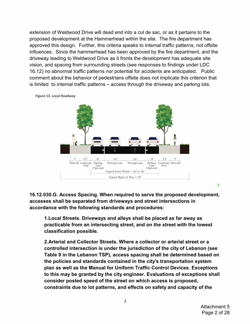
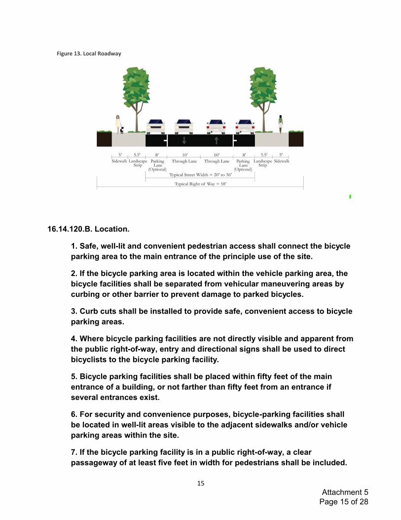
Weldwood Drive extension is designed as a local road per Figure 13 below with a sixty
foot right of way. See also Applicant's Response to LDC 16.12.030.G and 16.13.020.B.
Further, the City of Lebanon requested that this extension be designed not to connect to
the private road portion of Weldwood to the Northeast of the subject property. This
Attachment 5 Page 1 of 28
2
extension of Weldwood Drive will dead end into a cul de sac, or as it pertains to the
proposed development at the Hammerhead within the site. The fire department has
approved this design. Further, this criteria speaks to internal traffic patterns, not offsite
influences. Since the hammerhead has been approved by the fire department, and the
driveway leading to Weldwood Drive as it fronts the development has adequate site
vision, and spacing from surrounding streets (see responses to findings under LDC
16.12) no abnormal traffic patterns nor potential for accidents are anticipated. Public
comment about the behavior of pedestrians offsite does not implicate this criterion that
is limited to internal traffic patterns – access through the driveway and parking lots.
16.12.030.G. Access Spacing. When required to serve the proposed development,
accesses shall be separated from driveways and street intersections in
accordance with the following standards and procedures:
1.Local Streets. Driveways and alleys shall be placed as far away as
practicable from an intersecting street, and on the street with the lowest
classification possible.
2.Arterial and Collector Streets. Where a collector or arterial street or a
controlled intersection is under the jurisdiction of the city of Lebanon (see
Table 9 in the Lebanon TSP), access spacing shall be determined based on
the policies and standards contained in the city's transportation system
plan as well as the Manual for Uniform Traffic Control Devices. Exceptions
to this may be granted by the city engineer. Evaluations of exceptions shall
consider posted speed of the street on which access is proposed,
constraints due to lot patterns, and effects on safety and capacity of the
Attachment 5 Page 2 of 28

3
adjacent public street, bicycle and pedestrian facilities. Access spacing on
State Highways 20 and 34 (defined as principal arterials in the Lebanon
TSP, as per Table 9) is subject to the requirements of applicable Oregon
Administrative Rules as determined by Oregon Department of
Transportation.
3.Special Provisions for All Streets. Direct street access may be restricted
for some land uses, in conformance with the provisions of Chapters 16.05
through 16.11. For example, access consolidation, shared access, and/or
access separation greater than that specified by subsections (G)(1) and (2)
above, may be required for access to the city, county or state roadways for
the purpose of protecting the function, safety and operation of the facility
for all users (See Subsection "I," below). In some cases, directional
connections (i.e., right in/out, right in only, or right out only) may be
required.
Applicant Response: The TSP states that Weldwood Drive should be constructed as
a collector with sidewalks and bike lanes. This use of "should" provides the City with
flexibility, as necessary here because Weldwood Drive does not need to be constructed
as a collector. The City staff's exercise of flexibility here makes sense because there is
no way to connect Weldwood Drive through the private roadway portion, and as
proposed the extension will end in a cul de sac. Since the street is not going to function
as a collector street that connects to the broader street network, the City staff required
the Applicant to design the Weldwood Drive extension as a local roadway. See also
Applicant's Response to LDC 16.13.020.B below. The required spacing for a local
roadway is a minimum block size of 150 feet, and minimum driveway spacing. The
proposed development driveway is located 335 feet from the intersection of Cascade
Drive and Weldwood, see figure below, and meets the minimum driveway spacing.
Therefore these criteria have been meet.
Attachment 5 Page 3 of 28
4
16.12.030.H. Clear Vision Requirements. All street access points must meet the
applicable clear vision requirements noted below.
1. Except within the central business commercial zone (Z-CCM), vision
clearance areas shall be provided at intersections of all streets and at
intersections of driveways and alleys with streets to promote pedestrian,
bicycle and vehicular safety. The extent of vision clearance to be provided
shall be determined from standards listed below, and as otherwise adopted
by the city to further take into account functional classification of the
streets involved, type of traffic control present at the intersection, street
configuration, clear sight distance needed to see on coming traffic (motor
vehicles, pedestrians, and bicyclists), and designated speed for the streets.
2. A clear vision area shall consist of a triangular area, two sides of which
are lot lines measured from the corner intersection of the street lot lines for
a distance specified in this regulation, and the third side of which is a line
across the corner of the lot joining the nonintersecting ends of the other
two sides. Where the lot lines have rounded corners, the lot lines shall be
extended in a straight line to a point of intersection and so measured. In
situations involving driveways, the two sides shall include the sides of the
driveway and the adjacent property line or access easement line.
3. A clear-vision area shall contain no plantings, fences, walls, structures,
utility pedestals, or temporary or permanent obstruction exceeding two and
one-half feet in height, measured from the top of the curb, or where no curb
exists, from the established street center line grade. Trees exceeding this
height may be located in this area, provided all branches or foliage are
removed to a height of eight feet above grade.4.The following
measurements shall establish a clear vision area:
a. Corner Lots. The clear visions area for corner lots shall be twenty
feet along the right-of-way of each intersecting street.
b. Street-Driveway. The clear vision area for a street-driveway
intersection shall be ten feet along the driveway from its intersection
with the street right-of-way and twenty feet along the street right-of-
way at the point of intersection with the driveway.
c. Street-Alley. The clear vision area for street-alley intersections
shall be ten feet along the alley from its intersection with the street
right-of-way and twenty feet along the street right-of-way at the point
of intersection with the alley.
Attachment 5 Page 4 of 28
5
d. Street-Private Access Easement. The clear vision area for street-
access easement intersections shall be ten feet along the access
easement from its intersection with the street right-of-way and
twenty feet along the street right-of-way at the point of intersection
with the access easement.
e. Dimension Exceptions. When the angle of intersection between
streets, other than an alley, is less than thirty degrees, the distance
shall be twenty-five feet. Dimensions for clear vision areas for new
development in the Central Business Commercial Zone (Z-CCM),
shall be specified by the city engineer on a site by site basis given
the near total build out of that zone.
5.Exceptions Within Vision Clearance Areas. Traffic control devices,
streetlights, and utility installations meeting approval by the city engineer
are permitted within vision clearance areas.
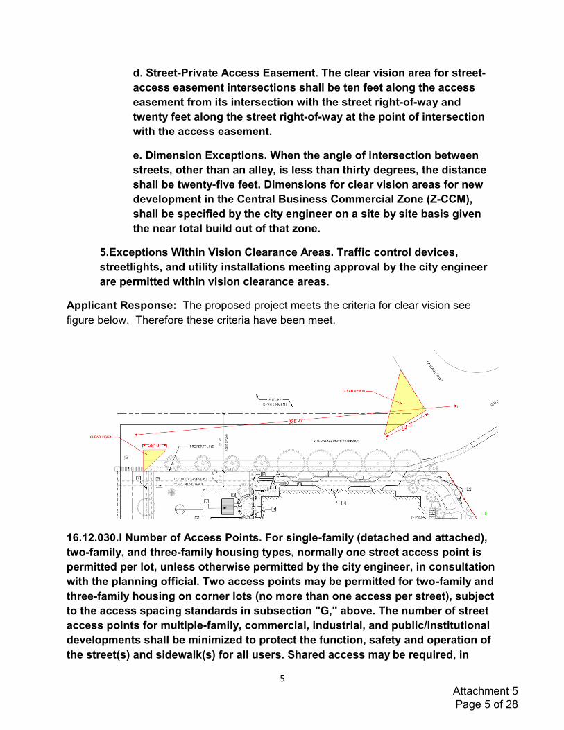
Applicant Response: The proposed project meets the criteria for clear vision see
figure below. Therefore these criteria have been meet.
16.12.030.I Number of Access Points. For single-family (detached and attached),
two-family, and three-family housing types, normally one street access point is
permitted per lot, unless otherwise permitted by the city engineer, in consultation
with the planning official. Two access points may be permitted for two-family and
three-family housing on corner lots (no more than one access per street), subject
to the access spacing standards in subsection "G," above. The number of street
access points for multiple-family, commercial, industrial, and public/institutional
developments shall be minimized to protect the function, safety and operation of
the street(s) and sidewalk(s) for all users. Shared access may be required, in
Attachment 5 Page 5 of 28
6
conformance with subsection "J," below, in order to maintain the required access
spacing, and minimize the number of access points.
Applicant Response: Consistent with these criteria for multifamily development, the
Applicant has minimized street access points to one access point on the extension of
Weldwood Drive, with a fire department approved hammerhead, ensuring safe access
to the subject property and the function and operation of the newly extended Weldwood
Drive for all users. As evidenced in the Applicant's submittals the driveway and right of
way area for Weldwood will be designed to meet the requirements of the LDC.
16.12.030.K. Requirements for Street Connectivity and Formation of Blocks. In
order to promote efficient vehicular and pedestrian circulation throughout the
city, new land divisions and large site developments shall produce complete
blocks bounded by a connecting network of public and/or private streets, in
accordance with the following standards (see Figure 16.12.030-1):
1. Block Length and Perimeter. The maximum block length and perimeter
(measured along the edge of the right-of-way) should not exceed:
c. Six hundred to eight hundred feet length and one thousand six
hundred to two thousand feet perimeter in the highway commercial
zone (Z-HCM), and mixed-use zone (Z-MU), except as required for
commercial developments subject to other provisions of this code or
the subdivision ordinance;
Applicant Response: The proposed development is for an infill lot with only one
access point to a public right of way. The future dead-end street will be designed to
meet the 600-800 foot cul-de sac maximum length requirements outlined in the
Transportation System Plan and the Development Code for the City of Lebanon. The
current extension of Weldwood measures 335 feet, falling within the limitation for block
length.
16.12.030.L. Driveway Approaches. Driveway approaches or curb cuts shall be
adequate width to provide safe and efficient access. The following standards (i.e.,
as measured where the front property line meets the sidewalk or right-of-way) are
required to provide adequate site access, minimize surface water runoff, ensure
an exiting vehicle with an unobstructed view, avoid conflicts between vehicles
and pedestrians, and have appropriate signage for one-way connections. Unless
otherwise permitted by the city engineer, in consultation with the planning
official, or, for State Highways 20 and 34, by Oregon Department of
Transportation, minimum driveway widths shall be as follows:
Attachment 5 Page 6 of 28
7
4. Access widths for all other uses shall be based on twelve feet of width
for every travel lane, except that driveways providing direct access to
parking spaces shall conform to the parking area standards in Chapter
16.14 (Off-Street Parking Requirements) of this code;
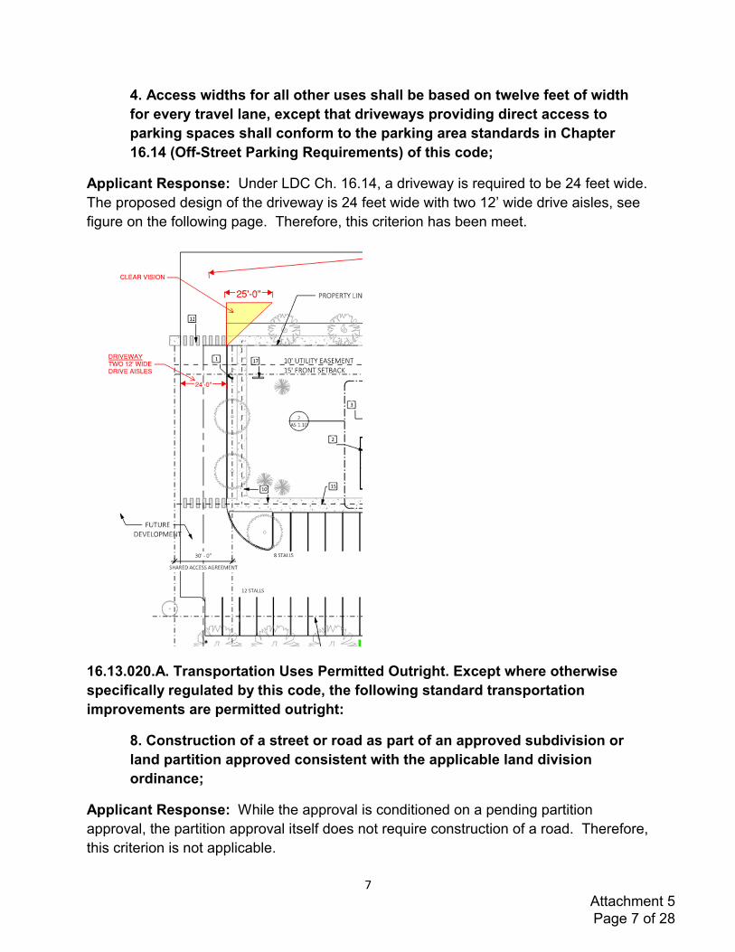
Applicant Response: Under LDC Ch. 16.14, a driveway is required to be 24 feet wide.
The proposed design of the driveway is 24 feet wide with two 12’ wide drive aisles, see
figure on the following page. Therefore, this criterion has been meet.
16.13.020.A. Transportation Uses Permitted Outright. Except where otherwise
specifically regulated by this code, the following standard transportation
improvements are permitted outright:
8. Construction of a street or road as part of an approved subdivision or
land partition approved consistent with the applicable land division
ordinance;
Applicant Response: While the approval is conditioned on a pending partition
approval, the partition approval itself does not require construction of a road. Therefore,
this criterion is not applicable.
Attachment 5 Page 7 of 28
8
16.13.020.B. Transportation Conditional Uses Permitted.
1.Conditionally permitted transportation improvements include construction,
reconstruction, or widening of highways, roads, bridges, or other transportation
projects that:
b. Change the character, function, or operation of an existing
transportation-related facility as proposed or designated in the
transportation system plan (TSP). Such projects shall comply with the
overall standards of the TSP and other applicable standards, and shall
address the following criteria:
i .The project is designed to be compatible with existing land use and
social patterns, including noise generation, safety and zoning,
ii. The project is designed to minimize avoidable environmental
impacts to identified wetlands, wildlife habitat, air and water quality,
cultural resources and scenic qualities,
iii. The project preserves or improves the safety and function of the
facility through access management, traffic calming, or other design
features,
iv. The project includes provisions for bicycle and pedestrian
circulation as consistent with the applicable requirements of the
ordinance codified in this chapter.
Applicant Response: As stated above, the TSP describes that Weldwood Drive
should be designed as a collector street. However, the City staff determined that local
roadway design would better fit the Weldwood Drive extension at this location because
the collector characteristics will not be achieved. Collector street characteristics cannot
be achieved because Weldwood Drive cannot be extended through the private roadway
section that runs through the nearby manufactured home park to connect with the
broader city street system. This local roadway design makes sense because the
proposed development will be reached on the Weldwood Drive extension that will end in
a cul de sac Comments raised early in the public review process of this application
opposing a full extension of Weldwood Drive to connect with the broader city street
system support this approach because it will be compatible with surrounding land uses,
including the private road section of Weldwood Drive. Further, cul-de-sac design of the
Weldwood Drive extension will keep noise from surrounding neighborhoods. No more
environmental impact is expected by reducing the street designation from collector to
local roadway as it is not located near surrounding wetlands, wildlife habitat, air or water
quality, or cultural or scenic qualities. To the extent that environmental benefits are
Attachment 5 Page 8 of 28

9
gained by reducing the right-of-way width for a local roadway as compared to a
collector, those environmental benefits favor the approach taken here. As described in
other responses, the project preserves safety and function with the design of the
roadway to meet the City's standards, and the fire department's approved hammerhead
for emergency response within the development. Further, the local roadway design
provides pedestrian connectivity, and bicycles on a local roadway are acceptable in this
location because of the short roadway length to Cascade, and the limited potential for
additional surrounding development. For these reasons, these criteria are met.
16.13.030.A. General Development Standards. Development shall not occur
unless the development has frontage or approved access to a public street, in
conformity with the provisions of Section 16.12.020 in Chapter 16.12, and the
following additional standards are met:
1.Streets within or adjacent to a development shall be improved to city
standards in accordance with the transportation system plan, public
improvement standards, and the provisions of this chapter;
2.Development of new streets, additional street width or improvements
planned as a portion of an existing street, shall be improved in accordance
with this chapter, and other applicable city standards;
3.All driveway approaches and driveways shall be paved, as per adopted
city engineering standards;
4.Minor sections of non-contiguous street improvements may be deferred
until contiguous to city standard street improvements as determined by the
city engineer.
Applicant Response: The proposed development applies the design from City of
Lebanon Transportation System Plan for a Local Roadway, see figure below and
Applicant's Response to LDC 16.12.030.G and 16.13.020.B. No non-contiguous street
improvements are proposed. Therefore, these criteria are met.
Attachment 5 Page 9 of 28
10
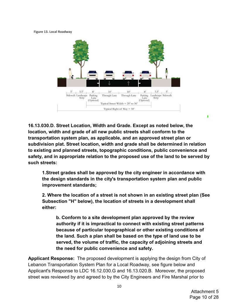
16.13.030.D. Street Location, Width and Grade. Except as noted below, the
location, width and grade of all new public streets shall conform to the
transportation system plan, as applicable, and an approved street plan or
subdivision plat. Street location, width and grade shall be determined in relation
to existing and planned streets, topographic conditions, public convenience and
safety, and in appropriate relation to the proposed use of the land to be served by
such streets:
1.Street grades shall be approved by the city engineer in accordance with
the design standards in the city's transportation system plan and public
improvement standards;
2. Where the location of a street is not shown in an existing street plan (See
Subsection "H" below), the location of streets in a development shall
either:
b. Conform to a site development plan approved by the review
authority if it is impractical to connect with existing street patterns
because of particular topographical or other existing conditions of
the land. Such a plan shall be based on the type of land use to be
served, the volume of traffic, the capacity of adjoining streets and
the need for public convenience and safety.
Applicant Response: The proposed development is applying the design from City of
Lebanon Transportation System Plan for a Local Roadway, see figure below and
Applicant's Response to LDC 16.12.030.G and 16.13.020.B. Moreover, the proposed
street was reviewed by and agreed to by the City Engineers and Fire Marshal prior to
Attachment 5 Page 10 of 28
11
submitting the land use application. The application materials contain Sheet C-2.1 and
C-2.2 showing that the design adequately addresses the grading requirements for
streets and driveways. Therefore, these criteria have been meet.
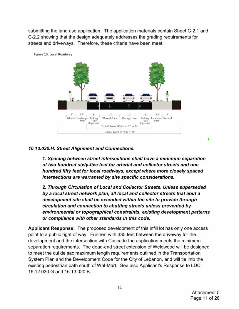
16.13.030.H. Street Alignment and Connections.
1. Spacing between street intersections shall have a minimum separation
of two hundred sixty-five feet for arterial and collector streets and one
hundred fifty feet for local roadways, except where more closely spaced
intersections are warranted by site specific considerations.
2. Through Circulation of Local and Collector Streets. Unless superseded
by a local street network plan, all local and collector streets that abut a
development site shall be extended within the site to provide through
circulation and connection to abutting streets unless prevented by
environmental or topographical constraints, existing development patterns
or compliance with other standards in this code.
Applicant Response: The proposed development of this infill lot has only one access
point to a public right of way. Further, with 335 feet between the driveway for the
development and the intersection with Cascade the application meets the minimum
separation requirements. The dead-end street extension of Weldwood will be designed
to meet the cul de sac maximum length requirements outlined in the Transportation
System Plan and the Development Code for the City of Lebanon, and will tie into the
existing pedestrian path south of Wal-Mart. See also Applicant's Response to LDC
16.12.030.G and 16.13.020.B.
Attachment 5 Page 11 of 28
12
16.13.030.L. Cul-de-sacs.
1. The length of a cul-de-sac street shall not exceed four hundred feet.
However, cul-de-sacs may be up to six hundred feet in length with a
pedestrian/bicycle accessway to neighboring streets and/or pathways for
connectivity that includes a dedicated right-of-way for utilities, and subject
to approval of the Lebanon fire district.
2. The length of a cul-de-sac is measured from the edge of the street right-
of-way along the length of the "stem" to the back of the "bulb."
3. All cul-de-sacs of more than one hundred fifty feet in length shall
terminate with a circular turnaround. Such emergency vehicle turnarounds
shall be constructed in compliance with the Oregon Fire Code and Lebanon
fire district's requirements.
4. Also see Section 16.12.030(K)(7) (Chapter 16.12), and Table 16.13.030-1
(in this chapter).
Applicant Response: The proposed development of this infill lot has only one access
point to a public right of way. The dead-end street extension of Weldwood will be
designed to meet the cul-de sac maximum length requirements outlined in the
Transportation System Plan and the Development Code for the City of Lebanon, and
will tie into the existing pedestrian path South of Wal-Mart. Moreover, the internal
driveways are designed in a manner that meets the Oregon Fire Code for fire truck turn
arounds and been approved by the fire department.
16.13.030.M. Development Adjoining Arterial Streets. Where a development
adjoins or is crossed by an existing or proposed arterial street, the development
design shall separate residential access and through traffic, and shall minimize
traffic conflicts. The design shall include one or more of the following:
* * *
Applicant Response: This section is not applicable, the proposed development does
not interact with an Arterial Street.
16.13.030.N Private Streets Standards.
* * *
Applicant Response: This section does not apply, no private streets are proposed.
Attachment 5 Page 12 of 28
13
16.14.060.B Grading. All parking areas, except those in conjunction with a single-
family or two-family dwelling, shall be graded (as approved by the city engineer)
so as not to drain stormwater over sidewalks or onto any abutting property.
Applicant Response: All parking areas are graded to a low point onsite that will collect
all site runoff. See application sheet C-2.1 and C-2.2. The onsite stormwater will be
collected and infiltrated via underground storm chambers. See also Attachment 7.
16.14.060.I Off-Street Parking Areas Within or Abutting Residential Zones. All off-
street parking areas within or abutting residential zones shall be provided with
both of the following:
1. Sight-obscuring fence, wall or hedge as approved by the planning official
to minimize disturbances to adjacent residents. The minimum height for
this fence, wall or hedge shall be five feet;
2. Five-foot landscaped buffer in addition to the fence, hedge, or wall as
required above.
Applicant Response: To the extent that this criteria allows for subjective approval by
the planning official, the applicant objects. However, the Applicant is willing to accept a
revised condition of approval where condition of approval 1.a will read:
a. A landscape plan shall be submitted in compliance with Chapter 16.15
and approved prior to the issuance of a building permit, without
application of subjective standards. The landscape plan shall include a
six-foot tall site obscuring fence of chain link with vinyl slats along the
south and east property lines as delineated in the Minor Land Partition
in condition 1.d, with a minimum five foot landscape buffer.
As conditioned, these criteria are met.
16.14.060.J Lighting of Off-Street Parking Facilities. Per Section 16.19.050 (in
Chapter 16.19), exterior lighting shall be designed, constructed, located, shielded,
and directed in such a manner so as to not face directly, shine, or reflect glare
onto an adjacent residences, streets, and other land uses. Also see airport
overlay zones (in Chapter 16.11) for additional lighting standards for that zone.
Applicant Response: Site pole lighting is designed to include cut offs/shields that
prevent light from pointing directly to, shining on, or reflecting glare onto an adjacent
residences, streets, and other land uses. See figure below for example. Therefore, this
criterion has been meet.
Attachment 5 Page 13 of 28

14
16.14.080.B Vehicular Access to City Streets and Alleys.
2. Access Location and Design.
a. Location and design of all accesses to and/or from city streets are
subject to review and approval by the city engineer.
b. Access spacing on collector and arterial streets, and at controlled
intersections, shall be determined based on the policies and
standards in the city's transportation system plan, city public
improvement standards, as well as Manual for Uniform Traffic
Control Devices.
c. Exceptions may be granted by the city engineer.
d. Evaluations of exceptions shall consider posted speed of the
street on which access is proposed, constraints due to lot patterns,
and effects on safety and capacity of the adjacent public street,
bicycle and pedestrian facilities.
Applicant Response: The proposed development includes the design of the street
based on the City of Lebanon Transportation System Plan for a Local Roadway, see
figure below and Applicant's Response to LDC 16.12.030.G and 16.13.020.B.
Therefore, these criteria are met.
Attachment 5 Page 14 of 28
15
16.14.120.B. Location.
1. Safe, well-lit and convenient pedestrian access shall connect the bicycle
parking area to the main entrance of the principle use of the site.
2. If the bicycle parking area is located within the vehicle parking area, the
bicycle facilities shall be separated from vehicular maneuvering areas by
curbing or other barrier to prevent damage to parked bicycles.
3. Curb cuts shall be installed to provide safe, convenient access to bicycle
parking areas.
4. Where bicycle parking facilities are not directly visible and apparent from
the public right-of-way, entry and directional signs shall be used to direct
bicyclists to the bicycle parking facility.
5. Bicycle parking facilities shall be placed within fifty feet of the main
entrance of a building, or not farther than fifty feet from an entrance if
several entrances exist.
6. For security and convenience purposes, bicycle-parking facilities shall
be located in well-lit areas visible to the adjacent sidewalks and/or vehicle
parking areas within the site.
7. If the bicycle parking facility is in a public right-of-way, a clear
passageway of at least five feet in width for pedestrians shall be included.
Attachment 5 Page 15 of 28
16
Applicant Response: The proposed development's outdoor bicycle parking areas are
adjacent to the building with a connecting sidewalk to the two main entrances, away
from the vehicle parking area. They are all safely located by placement within fifty feet
of entryways, and are visible from the public right-of-way and the development's
vehicular parking lot In addition, the bicycle parking is located under well-lit canopies or
enclosed inside the dwelling unit patio storage rooms for most of the units. Therefore,
these criteria are met.
16.14.120.C. Dimensions.
1. Bicycle parking spaces shall be a minimum of six feet in length and two
feet in width.
2. Overhead clearance in covered areas shall be at least seven feet.
3. A minimum five-foot wide aisle shall be provided beside or between each
row of bicycle parking.
D. Rack/Enclosure Standards.
1. Bicycle parking facilities shall consist of either a lockable enclosure
(locker) in which the bicycle is stored or a stationary object (rack) to which
the bicycle may be locked.
2. Lockers and racks shall be securely anchored to the pavement or a
structure.
3. Racks requiring user-supplied locks shall accommodate both cable and
U-shaped locks. Racks shall be designed and installed to permit the frame
and both wheels to be secured.
4. Bicycle racks shall be designed to hold bicycles securely by means of
the frame, in a manner that will not cause damage to the wheels.
E. Covering (Roofing).
1. All required bicycle parking must be covered, unless more than eight
spaces are required, in which case half of the total may be uncovered as
long as a minimum of eight spaces are covered.
2. Covering for bicycle parking facilities shall be permanent and shall
provide protection from weather.
3. Covering may be provided by an independent outdoor structure, a
parking garage, a wide roof overhang, or a wide awning, or other suitable
Attachment 5 Page 16 of 28
17
protective covering. Bicycle parking facilities may also be located within
buildings in secure, well-lit and accessible spaces, provided the other
requirements of this section are met.
F. Lighting.
1. For security and convenience purposes, lighting shall be provided in
bicycle parking areas such that all facilities are thoroughly illuminated and
visible from adjacent sidewalks and/or vehicle parking areas during all
hours of use.
2. As noted in Section 16.19.050 (Chapter 16.19), exterior lighting shall be
designed, constructed, located, shielded, and directed in such a manner so
as to not face directly, shine, or reflect glare onto an adjacent residences,
streets, and other land uses. Also see Airport Overlay Zones (in Chapter
16.11) for additional lighting standards for that zone.
Applicant Response: All bicycle parking spaces conform to the required dimensions
and clearance. The outdoor bicycle parking will have racks secured to the concrete
pavement below and will accommodate both cable and U-shaped locks. They also will
have a five-foot minimum aisle adjacent to the spaces for access. All required and most
bicycle parking spaces are covered by either the well-lit canopies or enclosed inside the
unit patio storage rooms. Therefore, these criteria have been met.
16.15.020.C. Landscaping and Screening Standards.
2. Applicability.
b. Landscape Areas.
ii. Parking Lots. Parking lots shall have landscaped islands
(that include trees) at the ends of parking rows at a minimum
to facilitate movement of traffic and to break large areas of
parking surface. Open parking areas should include
landscaping and trees distributed throughout, and long rows
(thirty or more spaces) of parking spaces shall be interrupted
by landscape breaks.
Applicant Response: Parking has been designed with landscape buffers and islands
that break up stalls of greater than 30 stalls, see landscape plans attached to the
application as L.3.00 and L3.01. Therefore this criterion is met.
16.15.020.C. Landscaping and Screening Standards.
2. Applicability.
Attachment 5 Page 17 of 28
18
f. Buffering and Screening Required for Parking Lots and Service
Areas. Buffering and screening are required under the following
conditions, except for single-family dwellings:
i. Parking/Maneuvering Area Adjacent to Buildings.
(A) Where a parking or maneuvering area, or driveway,
is adjacent to a building, the area shall be separated
from the building by a curb or landscaped strip and a
raised walkway, plaza, landscaped buffer not less than
five feet in width, or other approved structure or feature.
(B) Raised curbs or landscaped strips, bollards, wheel
stops, or other design features shall be used to protect
pedestrians, landscaping, and buildings from being
damaged by vehicles.
(C) At a minimum, where parking areas are located
adjacent to residential ground-floor living space, a four-
foot wide landscape buffer with a curb, or other
approved structure or feature.
(D) Parking lots shall be screened from abutting
residential land uses by fencing, walls, landscaping, or a
combination thereof adequate to provide privacy and
separation for the abutting land use.
(E) Where parking areas project into required yards, the
remaining yard shall be landscaped to provide
screening of the parking area.
Applicant Response: Applicant objects to the application of subsection (D) above
because it is not clear and objective as "privacy" is a subjective term. Notwithstanding
this objection, earlier in this submittal the Applicant proposed revision to condition of
approval 1.a and that proposed revision also addresses subsection (D) here. In
addition, parking has been designed with landscape buffers and islands that break up
stalls of greater than 30 stalls. See landscape plans attached to the application
materials as Sheets L.3.00 and L3.01. Moreover, each parking area is surrounded by
curbs and landscaping that buffer the building from the parking area. Therefore, these
criteria are met.
16.15.020.C. Landscaping and Screening Standards.
2. Applicability.
Attachment 5 Page 18 of 28
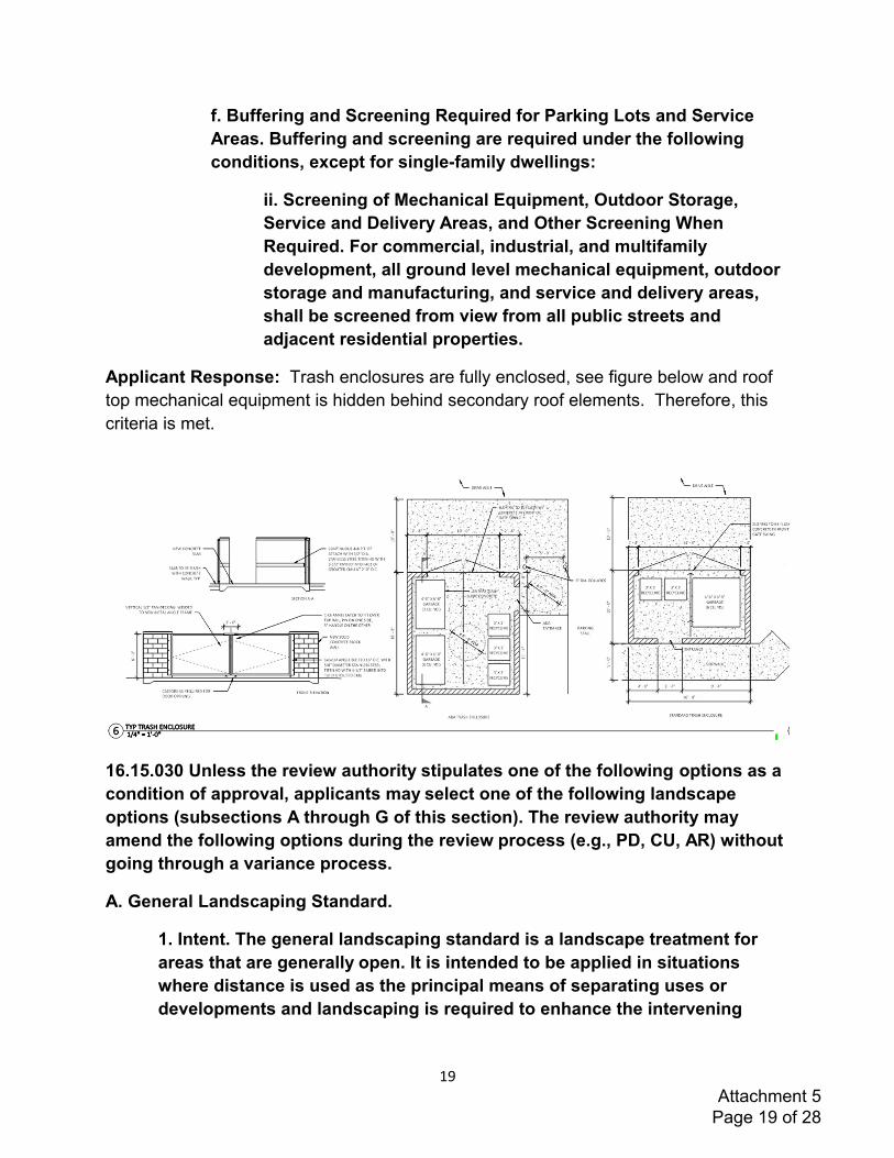
19
f. Buffering and Screening Required for Parking Lots and Service
Areas. Buffering and screening are required under the following
conditions, except for single-family dwellings:
ii. Screening of Mechanical Equipment, Outdoor Storage,
Service and Delivery Areas, and Other Screening When
Required. For commercial, industrial, and multifamily
development, all ground level mechanical equipment, outdoor
storage and manufacturing, and service and delivery areas,
shall be screened from view from all public streets and
adjacent residential properties.
Applicant Response: Trash enclosures are fully enclosed, see figure below and roof
top mechanical equipment is hidden behind secondary roof elements. Therefore, this
criteria is met.
16.15.030 Unless the review authority stipulates one of the following options as a
condition of approval, applicants may select one of the following landscape
options (subsections A through G of this section). The review authority may
amend the following options during the review process (e.g., PD, CU, AR) without
going through a variance process.
A. General Landscaping Standard.
1. Intent. The general landscaping standard is a landscape treatment for
areas that are generally open. It is intended to be applied in situations
where distance is used as the principal means of separating uses or
developments and landscaping is required to enhance the intervening
Attachment 5 Page 19 of 28
20
space. Landscaping may include a mixture of groundcover, evergreen and
deciduous shrubs, and coniferous and deciduous trees.
2. Required Materials. Shrubs and trees, other than street trees, may be
grouped. Groundcover plants must fully cover the remainder of the
landscaped area (see Figure 16.15.030-1: General Landscaping). The
general landscaping standard has two different requirements for trees and
shrubs:
a. Where the landscaped area is less than thirty feet deep, one tree is
required for every thirty linear feet;
b. Where the landscaped area is thirty feet deep or greater, one tree
is required for every eight hundred square feet and two high shrubs
or three low shrubs are required for every four hundred square feet.
Figure 16.15.030-1: General Landscaping
* * *
C. High Screen Landscaping Standard.
1. Intent. The high screen landscaping standard is a landscape treatment
that relies primarily on screening to separate uses or developments. It is
intended to be applied in situations where visual separation is required.
High screen treatments are at least six feet in height. A high screen
landscaped buffer may not be less than five feet in width.
2 .Required Materials.
a. The high screen landscaping standard requires sufficient high
shrubs to form a continuous screen at least six at maturity, feet high
and sight-obscuring, year-round.
b. Groundcover plants or other approved landscaping treatments
must fully cover the landscaped area.
c. A six-foot high masonry wall or a berm may be substituted for the
shrubs, but the trees and groundcover plants are still required.
d. When applied along street lot lines, the screen or wall is to be
placed along the interior side of the landscaped area. (See Figure
16.15.030-3: High Screen Landscaping).
Attachment 5 Page 20 of 28
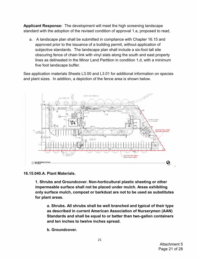
21
Applicant Response: The development will meet the high screening landscape
standard with the adoption of the revised condition of approval 1.a, proposed to read,
a. A landscape plan shall be submitted in compliance with Chapter 16.15 and
approved prior to the issuance of a building permit, without application of
subjective standards. The landscape plan shall include a six-foot tall site
obscuring fence of chain link with vinyl slats along the south and east property
lines as delineated in the Minor Land Partition in condition 1.d, with a minimum
five foot landscape buffer.
See application materials Sheets L3.00 and L3.01 for additional information on species
and plant sizes. In addition, a depiction of the fence area is shown below.
16.15.040.A. Plant Materials.
1. Shrubs and Groundcover. Non-horticultural plastic sheeting or other
impermeable surface shall not be placed under mulch. Areas exhibiting
only surface mulch, compost or barkdust are not to be used as substitutes
for plant areas.
a. Shrubs. All shrubs shall be well branched and typical of their type
as described in current American Association of Nurserymen (AAN)
Standards and shall be equal to or better than two-gallon containers
and ten inches to twelve inches spread.
b. Groundcover.
Attachment 5 Page 21 of 28
22
i. Shall be equal to or better than the following depending on
the type of plant materials used: gallon containers spaced at
four feet on center minimum, four inches pot spaced two feet
on center minimum, 2.25" pots spaced at eighteen-inch on
center minimum.
ii. No bare root planting shall be permitted.
iii. Where wildflower seeds are designated for use as a
groundcover, the city may require annual reseeding as
necessary.
2.Non-Street Trees. All non-street trees should be well-branched and
typical of their type as described in current American Association of
Nurserymen (AAN) Standards and preferably be balled and burlapped. Non-
street trees may be categorized as follows:
a. Primary Trees. Primary trees that define, outline or enclose major
spaces, such as Oak, Maple, Linden, and Seedless Ash, shall be a
minimum of two inches caliper;
b. Secondary Trees. Secondary trees that define, outline or enclose
interior areas, such as Columnar Red Maple, Flowering Pear, Flame
Ash, and Honeylocust, shall be a minimum of 1.75" to two inches
caliper;
c. Accent Trees. Accent trees are used to add color, variation and
accent to architectural features, such as Flowering- Pear and Kousa
Dogwood, shall be 1.75" minimum caliper;
d. Large Conifers. Large conifer trees such as Douglas-Fir, Deodar
Cedar, Shore Pine, Western Red Cedar, or Mountain Hemlock shall
be installed at a minimum height of six feet.
3. Street Trees. For references to the city's policies and standards
regarding street trees, please see the following section in this Chapter
(16.15.050: Street Trees).
4.Tree Credits (Reduction in Required New Trees).
a. Existing trees in required landscaped areas that are in good
health, as certified by an arborist at the end of construction, may
count for landscaping tree credit as follows in Table 16.15.040-1
Attachment 5 Page 22 of 28
23
(measured at four and one-half feet above grade and rounded to the
nearest inch):
Table 16.15.040-1: Tree Credits
b. It is the responsibility of the owner to use reasonable care to
maintain preserved trees. Trees preserved under this section may
only be removed if approved by the planning official. Required
mitigation for removal shall be replacement with the number of trees
credited to the preserved and removed tree.
6. Compliance with Standards. The burden of proof is on the applicant to
show that proposed landscaping materials will comply with the purposes
and standards of this chapter. Landscape materials that exceed the
minimum standards of this section are encouraged, provided that height
and vision clearance requirements are met.
B. Installation and Maintenance.
1. Installation. Plant materials shall be installed to current industry
standards and shall be properly staked to assure survival. Support devices
(guy wires, etc.) may not interfere with normal pedestrian or vehicular
movement.
2. Maintenance. Maintenance of landscaped areas is the on-going
responsibility of the property owner. Any landscaping installed to meet the
requirements of this code, or any condition of approval established by a
city decision-making body acting on an application, shall be continuously
maintained in a healthy, vital and acceptable manner. Required
landscaping that dies is to be replaced in kind, within one growing season,
unless appropriate substitute species are approved by the city. Failure to
maintain landscaping as required in this chapter constitutes a violation of
this code for which appropriate legal remedies, including the revocation of
any applicable land development permits, may result (see Chapter 16.02,
Section 16.02.030: Enforcement).
3. Irrigation. Irrigation is required of all new development, except single-
family homes. The intent of this standard is to assure that plants will
survive the critical establishment period when they are most vulnerable
due to a lack of watering and also to assure that water is not wasted
through unnecessary or inefficient irrigation. Approved irrigation system
plans shall specify one of the following:
Attachment 5 Page 23 of 28
24
a. A permanent, built-in, irrigation system with an automatic
controller. Either a spray or drip irrigation system, or a combination
of the two, may be specified;
b. A permanent or temporary system designed by a licensed
professional in the field of landscape architecture or irrigation
system design, sufficient to assure that the plants will become
established and drought-tolerant;
c. Other irrigation system approved by the planning official.
C. Protection of Landscaped Areas. All required landscape areas, including all
trees and shrubs, shall be protected from potential damage by conflicting uses or
activities including vehicle parking and the storage of materials.
D. Landscaping on Corner Lots. All landscaping on corner lots shall meet the
vision clearance standards of Section 16.12.030(H) in Chapter 16.12
(Transportation Access, Access Management, and Circulation). If high screening
would ordinarily be required by this code, low screening shall be substituted
within vision clearance areas. Taller screening may be required outside of the
vision clearance area to mitigate for the reduced height within it.
E. Landscape Plans. Except for single-family dwelling on a single lot (but not
excluding subdivisions), landscape plans shall be submitted showing all existing
and proposed landscape areas. Plans must be drawn to scale and show the type,
installation size, number and placement of materials. Plans shall include a plant
material list. Plants are to be identified by both their scientific and common
names. The condition of any existing plants and the proposed method of
irrigation are also to be indicated.
F. Completion of Landscaping.
1. The installation of plant materials may be deferred for a period of time
specified by the review authority acting on an application, in order to avoid
hot summer or cold winter periods, or in response to water shortages.
2. Except for single-family dwelling on a single lot (but not excluding
subdivisions), a final certificate of occupancy shall not be granted until
either landscaping is completed or an adequate bond or other security is
posted for the completion of the landscaping, and the city is given written
authorization to enter the property.
G. Street Trees Not Typically Part of Site Landscaping. Street trees are not
subject to the requirements of this section and are not counted toward the
Attachment 5 Page 24 of 28
25
required standards of this section. However, the review authority may, by
granting a waiver or variance, allow for special landscaping within the right-of-
way to compensate for a lack of appropriate on-site locations for landscaping.
Applicant Response: See application materials Sheets L3.00 and L3.01 for information
on species and plant sizes. Further, proposed revisions to condition of approval 1.a
requires applicant to meet these standards and based on the landscape plan contained
in the application materials, these requirements can be met.
16.15.050 For the city's provisions regarding street trees, please refer to the
following:
A. Lebanon Municipal Code Chapter 12.16: Street Trees;
B. City of Lebanon (Public Works Department):
1. Street Tree Policy and Potential Street Tree Guide;
2. Acceptable Street Tree List, Including: Trees for Use Under Power Lines
and Pruning Guide.
Applicant Response: Along Weldwood Drive Applicant proposes a six-foot-wide
planting strip without overhead utilities where nine medium size trees at thirty feet on
center will be planted. Applicant proposes planting five Green Vase Zelkovas and four
Armstrong Maples, both on the City of Lebanon Acceptable Street Tree List. They are
all 2” caliper which meets the size requirements under the LDC.
16.15.060.A. General Standards. Construction of fences and walls shall conform
to all of the following requirements:
4. Materials.
a. Permitted fence and wall materials: wood; metal; chain-link;
bricks, concrete blocks stone; stucco, or similar masonry, and non-
prohibited evergreen plants.
b. Prohibited fence and wall materials, except where explicitly
allowed under other provisions of the Lebanon Municipal Code:
straw bales; barbed or razor wire; and scrap materials.
c. Prohibited fence and wall materials: hedges over eight feet in
required yards.
d. Fences or walls constructed of brick or masonry exceeding four
feet in height shall be subject to review and approval by the city
Attachment 5 Page 25 of 28
26
engineer. Those that are taller than six feet also require a building
permit.
Applicant Response: The development will meet these standards with the adoption of
the revised condition of approval 1.a, proposed to read,
a. A landscape plan shall be submitted in compliance with Chapter 16.15 and
approved prior to the issuance of a building permit, without application of
subjective standards. The landscape plan shall include a six-foot tall site
obscuring fence of chain link with vinyl slats along the south and east property
lines as delineated in the Minor Land Partition in condition 1.d, with a minimum
five foot landscape buffer.
16.16.020.C Adequacy of utility and infrastructure facilities is based on the
standards established in the city's adopted master facility plans (e.g., stormwater
and drainage, parks, wastewater).
Applicant Response: The Applicant coordinated with the City staff regarding the
availability of water and sewer capacity to determine the development falls within the
City's adopted master facility plans. See Attachment 10. Further the proposed
development is in close proximity to Weldwood Park and will also include construction
of its own playground equipment to serve residents.
16.16.040.E. Existing Watercourse.
1. Where a proposed development is traversed by a watercourse, drainage
way, channel, or stream that is proposed or required to remain in its
current condition and/or function, there shall be provided to the city a
stormwater easement or drainage right-of-way (ROW). The easement or
ROW shall include provisions for access and maintenance.
2. The easement or ROW shall conform substantially with the lines of the
watercourse and additional width adequate for stormwater conveyance and
maintenance of the stormwater conveyance to protect the public health and
safety, and adjacent properties, as determined by the city engineer.
F. Stormwater Release Rate. All new site development shall maintain pre-
development peak historic stormwater discharge rates as per city standards. The
applicant for a development proposal shall demonstrate through calculations
acceptable to the city engineer that this standard will be met by the proposed
development.
Applicant Response: As stated in the attached the EVREN Northwest, Inc. Technical
Memorandum, Attachment 9, subsurface flows to the nearby wetland will not be
Attachment 5 Page 26 of 28
27
significantly impacted because the Applicant is infiltrating stormwater onsite. Since the
source of water to the wetlands is subsurface, no easement or right of way is required
for a drainageway, and the site development will maintain pre-development peak
historic stormwater discharge rates. As set forth in Attachment 7, stormwater design
can be achieved to meet City standards for discharge rate. A full drainage report with
calculations will be submitted to the city engineer with the construction documents.
16.16.050.A. Placement and Installation of Utilities.
1. Underground Placement. Unless otherwise exempted by subsection B of
this section, all new utility lines including, but not limited to, those required
for natural gas, electric, communication, lighting, and cable television
services and related facilities shall be placed underground, except for
surface-mounted transformers, surface-mounted connection boxes and
meter cabinets (which may be placed above ground). Temporary utility
service facilities, during construction, may also be placed above ground.
2. Installation. The following additional standards apply to all new utility
installation, in order to facilitate underground placement of utilities.
a. The developer shall coordinate site improvements with the serving
utility to provide the underground services. Above ground utility
service facilities and equipment shall not obstruct vision clearance
areas for vehicular traffic (See Section 16.12.030(H) in Chapter 16.12
of this code).
b. All underground utilities, including sanitary sewers, storm drains
and water lines installed in streets by the developer, shall be
constructed prior to the surfacing of the streets.
c. Stubs for service connections shall be long enough to avoid
disturbing the street improvements when service connections are
made.
3. City Approval for any Surface-Mounted Utility Support Facilities. The city
reserves the right to approve the location of all surface-mounted utility
support facilities, subject to department of public works permit.
B. Exception to Underground Placement Requirement.
1. An exception to the underground placement requirement may be granted
by the city engineer due to physical constraints, such as steep topography,
or existing development conditions.
Attachment 5 Page 27 of 28

28
2. High capacity electrical transmission lines that are infeasible to site
underground are exempted from the underground placement requirement.
C. Provision of Utility Services to All New Residential Subdivisions. All lots in
residential subdivisions shall be provided with access to natural gas, electrical
power, cable TV, and landline phone facilities provided such utilities can
reasonably be made available to the site, in addition to the public utilities
provided for in this chapter.
Applicant Response: All new utilities are proposed to be buried. No exceptions are
anticipated.
16.31.040.G .Employing the procedures and decision criteria in Sections
16.31.070 and 16.31.080 of this chapter, the commission shall review and act
upon applications for the alteration, relocation, or demolition of designated
landmarks, or the major exterior alteration, relocation, or demolition of historic
resources of statewide significance.
1.When such applications are received, the city shall send official notice to
the state office of historical preservation (SHPO) and local historical
preservation groups that request such notification.
2.The city shall invite and encourage SHPO and any local historical
preservation groups to submit written testimony and present verbal
testimony at the hearings. Such testimony shall be taken into account by
the commission in its decision-making on these applications.
3.Final decisions on demolitions shall be made by the city council after
conducting required public hearings.
Applicant Response: One public comment raised a question about why no
archaeological study was included in the application materials. The subject property is
not on the Lebanon historic register and has no identified historic resource of statewide
significance, therefore, no archaeological study is required. This criteria is not
applicable.
Attachment 5 Page 28 of 28

Attachment #6
Carlson Geotechnical • 4060 Hudson Ave NE, Salem, Oregon 97301
Carlson Geotechnical A division of Carlson Testing, Inc. Phone: (503) 589-1252 www.carlsontesting.com
Bend Office Eugene Office Salem Office Tigard Office
(541) 330-9155 (541) 345-0289 (503) 589-1252 (503) 684-3460
Updated Geotechnical
Report of
Geotechnical Investigation
Colonia Paz 1
Weldwood Drive & Cascade Drive
Lebanon, Oregon
CGT Project Number G2005323 Prepared for Claudia Cantu Farmworkers Housing Development Corporation 1274 5th Street, Suite 1-A Woodburn, Oregon 97071 July 22, 2020
Attachment 6 Page 1 of 34
Attachment 6 Page 2 of 34
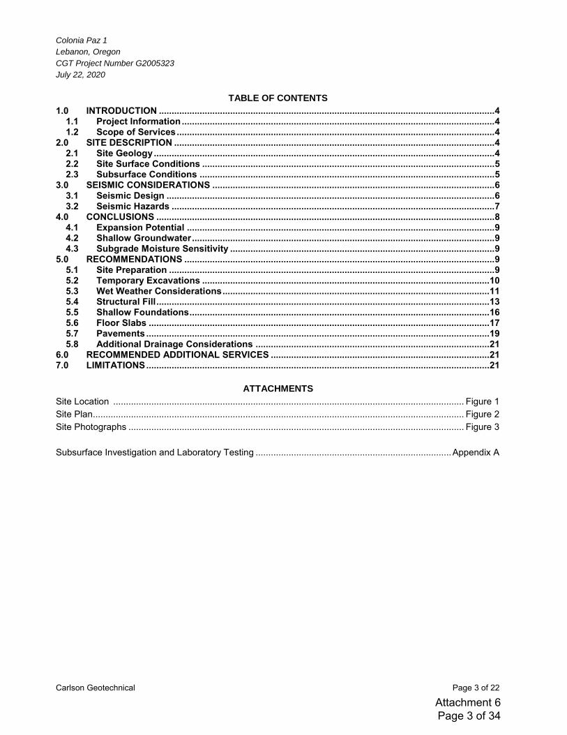
Colonia Paz 1
Lebanon, Oregon
CGT Project Number G2005323
July 22, 2020
Carlson Geotechnical Page 3 of 22
TABLE OF CONTENTS
1.0 INTRODUCTION .................................................................................................................................... 4 1.1 Project Information ........................................................................................................................... 4 1.2 Scope of Services ............................................................................................................................. 4
2.0 SITE DESCRIPTION .............................................................................................................................. 4 2.1 Site Geology ...................................................................................................................................... 4 2.2 Site Surface Conditions ................................................................................................................... 5 2.3 Subsurface Conditions .................................................................................................................... 5
3.0 SEISMIC CONSIDERATIONS ............................................................................................................... 6 3.1 Seismic Design ................................................................................................................................. 6 3.2 Seismic Hazards ............................................................................................................................... 7
4.0 CONCLUSIONS ..................................................................................................................................... 8 4.1 Expansion Potential ......................................................................................................................... 9 4.2 Shallow Groundwater ....................................................................................................................... 9 4.3 Subgrade Moisture Sensitivity ........................................................................................................ 9
5.0 RECOMMENDATIONS .......................................................................................................................... 9 5.1 Site Preparation ................................................................................................................................ 9 5.2 Temporary Excavations ................................................................................................................. 10 5.3 Wet Weather Considerations ......................................................................................................... 11 5.4 Structural Fill ................................................................................................................................... 13 5.5 Shallow Foundations ...................................................................................................................... 16 5.6 Floor Slabs ...................................................................................................................................... 17 5.7 Pavements ....................................................................................................................................... 19 5.8 Additional Drainage Considerations ............................................................................................ 21
6.0 RECOMMENDED ADDITIONAL SERVICES ...................................................................................... 21 7.0 LIMITATIONS ....................................................................................................................................... 21
ATTACHMENTS
Site Location .......................................................................................................................................... Figure 1 Site Plan.................................................................................................................................................. Figure 2 Site Photographs .................................................................................................................................... Figure 3 Subsurface Investigation and Laboratory Testing ............................................................................. Appendix A
Attachment 6 Page 3 of 34
Colonia Paz 1
Lebanon, Oregon
CGT Project Number G2005323
July 22, 2020
Carlson Geotechnical Page 4 of 22
1.0 INTRODUCTION
Carlson Geotechnical (CGT), a division of Carlson Testing, Inc. (CTI), is pleased to submit this report summarizing the results of our updated geotechnical for the proposed Colonia Paz 1 project. The site is located southwest of the intersection of Weldwood Drive and Cascade Drive in Lebanon, Oregon, as shown on the attached Site Location, Figure 1. CGT previously performed a geotechnical investigation for the FHDC Lebanon Housing Project, the results of which were presented in our January 3, 2019 report titled “Report of Geotechnical Investigation”, CGT
Project number G1804982. The Colonia Paz 1 project site is located within the southeast portion of that development area on a 1.39-acre lot.
1.1 Project Information
Based on our review of the provided development plans for the site, prepared by Pinnacle Architecture, dated June 12, 2020, development proposed within the subject 1.39-acre lot is consistent with that understood in the referenced 2019 report. The project will include construction of a multi-story residential building with an appurtenant parking lot and utilities. The project will also include construction of an extension of Weldwood Drive along the north site frontage. A lot-specific geotechnical report was requested for the referenced project. Updated geotechnical recommendations for seismic design have been presented later in this report recognizing a newer building code, 2019 Oregon Structural Specialty Code (2019 OSSC), was used to design the proposed building.
1.2 Scope of Services
Our scope of work included the following:
Visit the site to confirm site conditions are consistent with those observed during our previous (2018) field investigation.
Prepare this written geotechnical report that provides: o Updated seismic design parameters based on the 2019 OSSC. o Updated retaining wall design parameters based on the updated seismic design parameters. o Lot-specific geotechnical recommendations for site preparation and earthwork, wet weather
construction, temporary excavations, and recommendations for design and construction of shallow foundations, floor slabs, and pavements.
2.0 SITE DESCRIPTION
2.1 Site Geology
Based on available geologic mapping1 of the area, the site is underlain by Quaternary (Upper Pleistocene to Holocene) reworked gravel (Qrg) deposited by Willamette River tributaries. The gravel deposits consist of unconsolidated gravel with some sand, silt, and clay that form broad fans and terraces about 30 to 60 feet thick. Areas adjacent to the site are mapped as (Holocene and Pleistocene) reworked silt considered to have been derived largely from Willamette Silt.
1 O’Connor, Jim E. et al., 2001. Origin, extent, and thickness of Quaternary geologic units in the Willamette Valley, Oregon: U.S.
Geological Survey Professional Paper; 1620.
Attachment 6 Page 4 of 34
Colonia Paz 1
Lebanon, Oregon
CGT Project Number G2005323
July 22, 2020
Carlson Geotechnical Page 5 of 22
The reworked gravel is underlain by the lower Oligocene and middle Eocene Fisher Formation (Teof) of the Little Butte Volcanic Series. The Fisher Formation undivided consists of light gray to brown to light yellow, fine grained feldspathic sandstone and pebbly tuffaceous sandstone. The Fisher Formation is characterized by massive bedding, as well as finely laminated, fine-grained sandstone and siltstone, interbedded mafic lava flows and silicic ash-flow tuff. Beds and laminations include wood debris, bentonitic claystone, and minor coal beds. The Fisher Formation is commonly interfingered with gray-black, porphyritic Basaltic andesite, and light gray to brown to light yellow arkosic and tuffaceous marine sandstone and siltstone interbeds of the Eugene Formation.
2.2 Site Surface Conditions
CGT visited the site on July 21, 2020 to observe existing conditions. Site surface conditions were generally consistent with those described in our January 3, 2019, report. The roughly triangular, 1.39-acre site was bordered by grass fields to the north, Weldwood Drive to the east, a lightly forested area to the south and west. At the time of our site visit, the relatively level to very gently sloped site was vacant and vegetated primarily with grasses and scattered trees. Photographs taken during our recent site visit are shown on the attached Figure 3.
2.3 Subsurface Conditions
2.3.1 Subsurface Investigation & Laboratory Testing
Our 2018 subsurface investigation of the FHDC development site consisted of twenty-four test pits (TP-1 through TP-24) excavated on December 12 and 13, 2018. Test pits TP-6, TP-7, TP-8, TP-9, and TP-12 were located within the current project area; their approximate locations are shown on the attached Site Plan. In summary, those test pits excavated to depths ranging from about 6 to 9¾ feet bgs. Details regarding the subsurface investigation, logs of the explorations, and results of laboratory testing are presented in Appendix A. Subsurface conditions encountered during our investigation are summarized below.
2.3.2 Subsurface Materials
Logs of the referenced 2018 explorations have been reproduced and are presented in Appendix A. The following describes each of the subsurface materials encountered at the site. Organic Soil (OL)
Organic Soil was encountered at the surface of the test pits. The organic soil was typically dark brown, moist, exhibited medium plasticity, and contained rootlets. This soil extended to depths ranging from about ½ to 1½ feet bgs in the test pits. Fat Clay (CH)
Native fat clay was encountered below the organic soil in test pits TP-6 through TP-9 and extended to depths ranging from 2 to 5¾ feet bgs. This material was generally stiff to hard, brown, moist, exhibited high plasticity, and included trace subrounded to subangular gravel up to ¾ inch in diameter. Lean Clay (CL)
Lean clay soil was encountered below the organic soil in test pit TP-12 and extended to a depth of 3½ feet bgs. The lean clay was generally medium stiff to very stiff, brown, moist, exhibited medium to high plasticity, and included trace subrounded to subangular gravel up to 3 inches in diameter.
Attachment 6 Page 5 of 34
Colonia Paz 1
Lebanon, Oregon
CGT Project Number G2005323
July 22, 2020
Carlson Geotechnical Page 6 of 22
Poorly Graded Gravel with Cobbles and Silt (GP)
Poorly graded gravel with cobbles and silt was encountered below the lean clay in TP-12, and extended to approximately 5½ feet bgs. This soil was encountered below the fat clay in TP-6 through TP-9, and extended to the full depths explored in those test pits, approximately 6 to 9½ feet bgs. The gravel was generally dense to very dense, moist, subrounded to subangular, up to 3 inches in diameter, and included subrounded to rounded cobbles up to 5 inches in diameter and trace coarse-grained sand. Poorly Graded Sand with Cobbles (SP)
Poorly graded sand with cobbles was encountered below the poorly graded gravel with cobbles and silt in TP-12, and extended to the depth explored, approximately 6 feet bgs. This material was generally dense to very dense, gray-brown, moist, non-plastic, and included some subrounded to subangular gravel up to ¾ inch in diameter and trace cobbles up to 5 inches in diameter. The soils encountered during our subsurface investigation were consistent with the reworked gravel and silt deposits described in Section 2.1. The fat clay (CH) and lean clay (CL) have a high percentage of fines and are referred to as “fine-grained deposits” throughout the remainder of this report. Likewise, the poorly graded gravel with cobbles and silt (GP) and poorly graded sand with cobbles (SP) are referred to as “coarse-grained deposits” throughout the remainder of this report.
2.3.3 Groundwater
Groundwater was encountered in test pits TP-6, TP-7, and TP-9 at depths ranging from about 4½ to 8 feet bgs on December 12 and 13, 2018. Groundwater was not encountered within the depths explored in the remaining test pits. To determine approximate regional groundwater levels in the area, we researched well logs available on the Oregon Water Resources Department (OWRD)2 website for wells located within Section 23, Township 12 South, Range 2 West, Willamette Meridian. Our review indicated that groundwater levels in the area generally ranged from about 5 to 35 feet bgs. It should be noted groundwater levels vary with local topography. In addition, the groundwater levels reported on the OWRD logs often reflect the purpose of the well, so water well logs may only report deeper, confined groundwater, while geotechnical or environmental borings will often report any groundwater encountered, including shallow, unconfined groundwater. Therefore, the levels reported on the OWRD well logs referenced above are considered generally indicative of local water levels and may not reflect actual groundwater levels at the project site. We anticipate that groundwater levels will fluctuate due to seasonal and annual variations in precipitation, changes in site utilization, or other factors. In addition, the fine-grained deposits (CH, CL) are conducive to the formation of perched groundwater.
3.0 SEISMIC CONSIDERATIONS
3.1 Seismic Design
Section 1613.2.2 of the 2019 Oregon Structural Specialty Code (2019 OSSC) requires that the determination of the seismic site class be in accordance with Chapter 20 of the American Society of Civil Engineers Minimum Design Loads for Buildings and Other Structures (ASCE 7-16). We have assigned the site as Site Class D (“Stiff Soil”) based on geologic mapping and subsurface conditions encountered during our investigation. 2 Oregon Water Resources Department, 2020. Well Log Records, accessed July 2020, from OWRD web site:
http://apps.wrd.state.or.us/apps/gw/well_log/.
Attachment 6 Page 6 of 34
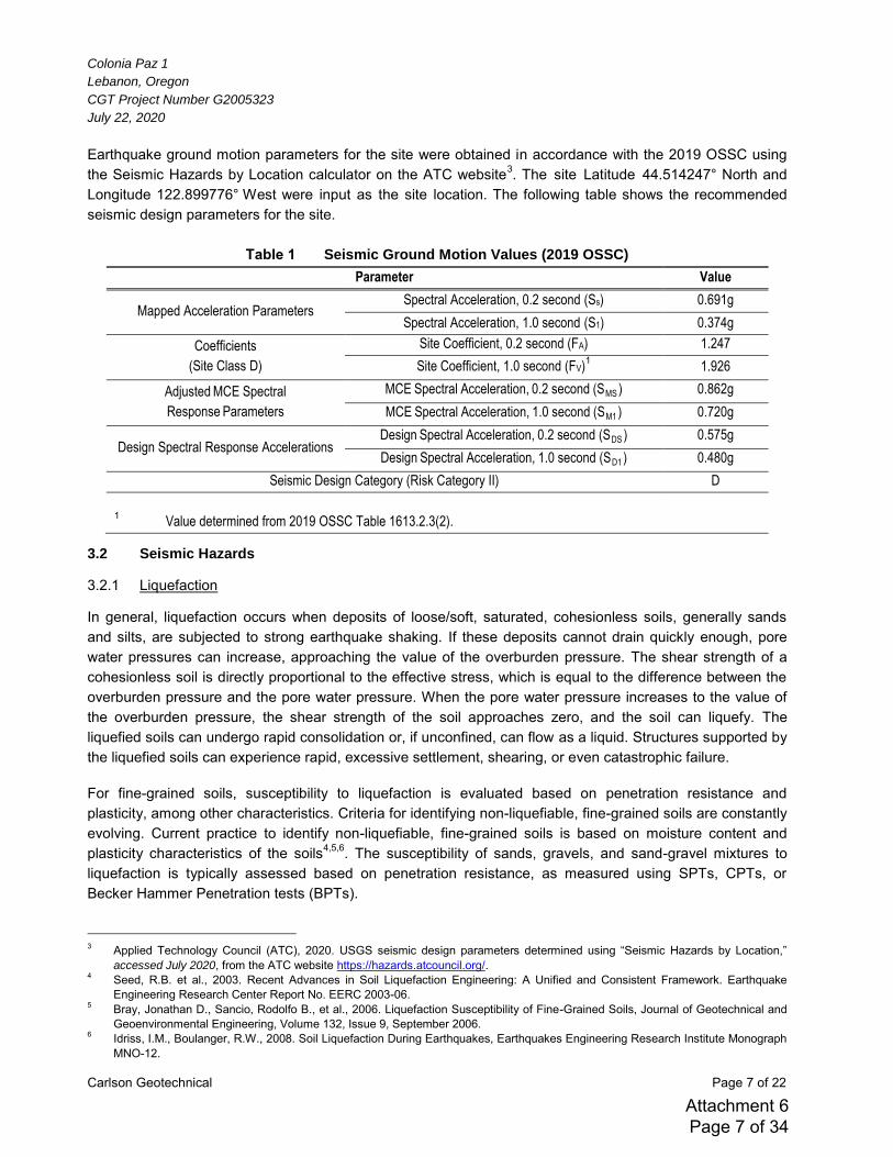
Colonia Paz 1
Lebanon, Oregon
CGT Project Number G2005323
July 22, 2020
Carlson Geotechnical Page 7 of 22
Earthquake ground motion parameters for the site were obtained in accordance with the 2019 OSSC using the Seismic Hazards by Location calculator on the ATC website3. The site Latitude 44.514247° North and Longitude 122.899776° West were input as the site location. The following table shows the recommended seismic design parameters for the site.
Table 1 Seismic Ground Motion Values (2019 OSSC)
Parameter Value
Mapped Acceleration Parameters Spectral Acceleration, 0.2 second (Ss) 0.691g
Spectral Acceleration, 1.0 second (S1) 0.374g
Coefficients
(Site Class D)
Site Coefficient, 0.2 second (FA) 1.247
Site Coefficient, 1.0 second (FV)1 1.926
Adjusted MCE Spectral
Response Parameters
MCE Spectral Acceleration, 0.2 second (SMS ) 0.862g
MCE Spectral Acceleration, 1.0 second (SM1 ) 0.720g
Design Spectral Response Accelerations Design Spectral Acceleration, 0.2 second (SDS ) 0.575g
Design Spectral Acceleration, 1.0 second (SD1 ) 0.480g
Seismic Design Category (Risk Category II) D
1 Value determined from 2019 OSSC Table 1613.2.3(2).
3.2 Seismic Hazards
3.2.1 Liquefaction
In general, liquefaction occurs when deposits of loose/soft, saturated, cohesionless soils, generally sands and silts, are subjected to strong earthquake shaking. If these deposits cannot drain quickly enough, pore water pressures can increase, approaching the value of the overburden pressure. The shear strength of a cohesionless soil is directly proportional to the effective stress, which is equal to the difference between the overburden pressure and the pore water pressure. When the pore water pressure increases to the value of the overburden pressure, the shear strength of the soil approaches zero, and the soil can liquefy. The liquefied soils can undergo rapid consolidation or, if unconfined, can flow as a liquid. Structures supported by the liquefied soils can experience rapid, excessive settlement, shearing, or even catastrophic failure. For fine-grained soils, susceptibility to liquefaction is evaluated based on penetration resistance and plasticity, among other characteristics. Criteria for identifying non-liquefiable, fine-grained soils are constantly evolving. Current practice to identify non-liquefiable, fine-grained soils is based on moisture content and plasticity characteristics of the soils4,5,6. The susceptibility of sands, gravels, and sand-gravel mixtures to liquefaction is typically assessed based on penetration resistance, as measured using SPTs, CPTs, or Becker Hammer Penetration tests (BPTs). 3 Applied Technology Council (ATC), 2020. USGS seismic design parameters determined using “Seismic Hazards by Location,”
accessed July 2020, from the ATC website https://hazards.atcouncil.org/. 4 Seed, R.B. et al., 2003. Recent Advances in Soil Liquefaction Engineering: A Unified and Consistent Framework. Earthquake
Engineering Research Center Report No. EERC 2003-06. 5 Bray, Jonathan D., Sancio, Rodolfo B., et al., 2006. Liquefaction Susceptibility of Fine-Grained Soils, Journal of Geotechnical and
Geoenvironmental Engineering, Volume 132, Issue 9, September 2006. 6 Idriss, I.M., Boulanger, R.W., 2008. Soil Liquefaction During Earthquakes, Earthquakes Engineering Research Institute Monograph
MNO-12.
Attachment 6 Page 7 of 34
Colonia Paz 1
Lebanon, Oregon
CGT Project Number G2005323
July 22, 2020
Carlson Geotechnical Page 8 of 22
The Oregon Department of Geology and Mineral Industries’ Oregon Statewide Geohazards Viewer (HazVu)7
shows no hazard for liquefaction at the site. The Oregon Hazard Explorer for Lifelines Program (O-HELP)8 show no hazard for liquefaction for the site or immediate vicinity due to a M9.0 Cascadia Subduction Zone earthquake. Based on their plasticity characteristics, the fine-grained deposits (CH, CL) encountered within our explorations are considered non-liquefiable. Based on their dense to very dense relative density, the coarse-grained deposits (GP, SP) are also considered non-liquefiable. Based on review of geologic mapping and our previous experience in the area, we do not anticipate liquefiable conditions are present at depths below those explored as part of this assignment.
3.2.2 Slope Instability
Due to the relatively level topography at and surrounding the site, the risk of slope instability at the site is considered low. The proposed grading includes relatively minimal planned changes in site grades and is not anticipated to increase this significantly risk.
3.2.3 Surface Rupture
3.2.3.1 Faulting
Although the site is situated in a region of the country with known active faults and historic seismic activity, no known faults exist on or immediately adjacent to the site. Therefore, the risk of surface rupture at the site due to faulting is considered low.
3.2.3.2 Lateral Spread
Surface rupture due to lateral spread can occur on sites underlain by liquefiable soils that are located on or immediately adjacent to slopes steeper than about 3 degrees (20H:1V), and/or adjacent to a free face, such as a stream bank or the shore of an open body of water. During lateral spread, the materials overlying the liquefied soils are subject to lateral movement downslope or toward the free face. Based on the relatively level topography at the site and the non-liquefiable nature of the soils at the site, the risk of damage associated with lateral spread is very low to negligible
4.0 CONCLUSIONS
Based on the results of our field explorations and analyses, the site may be developed as described in Section 1.1 of this report, provided the recommendations presented in this report are incorporated into the design and development. The following are the primary geotechnical considerations for the project:
The presence of potentially expansive soils near the surface of the site, The presence of shallow groundwater within proposed excavation depths, and The presence of near-surface, moisture-sensitive soils that are susceptible to disturbance during wet
weather. These considerations are described in more detail in the following sections.
7 Oregon Department of Geology and Mineral Industries, 2020. Oregon Statewide Geohazards Viewer, accessed July 2020, from
DOGAMI web site: http://www.oregongeology.org/sub/hazvu/index.htm. 8 Oregon State University College of Engineering, 2020. Oregon Hazard Explorer for Lifelines Program (O-HELP), accessed July
2020, from O-HELP web site: http://ohelp.oregonstate.edu/#&ui-state=dialog.
Attachment 6 Page 8 of 34
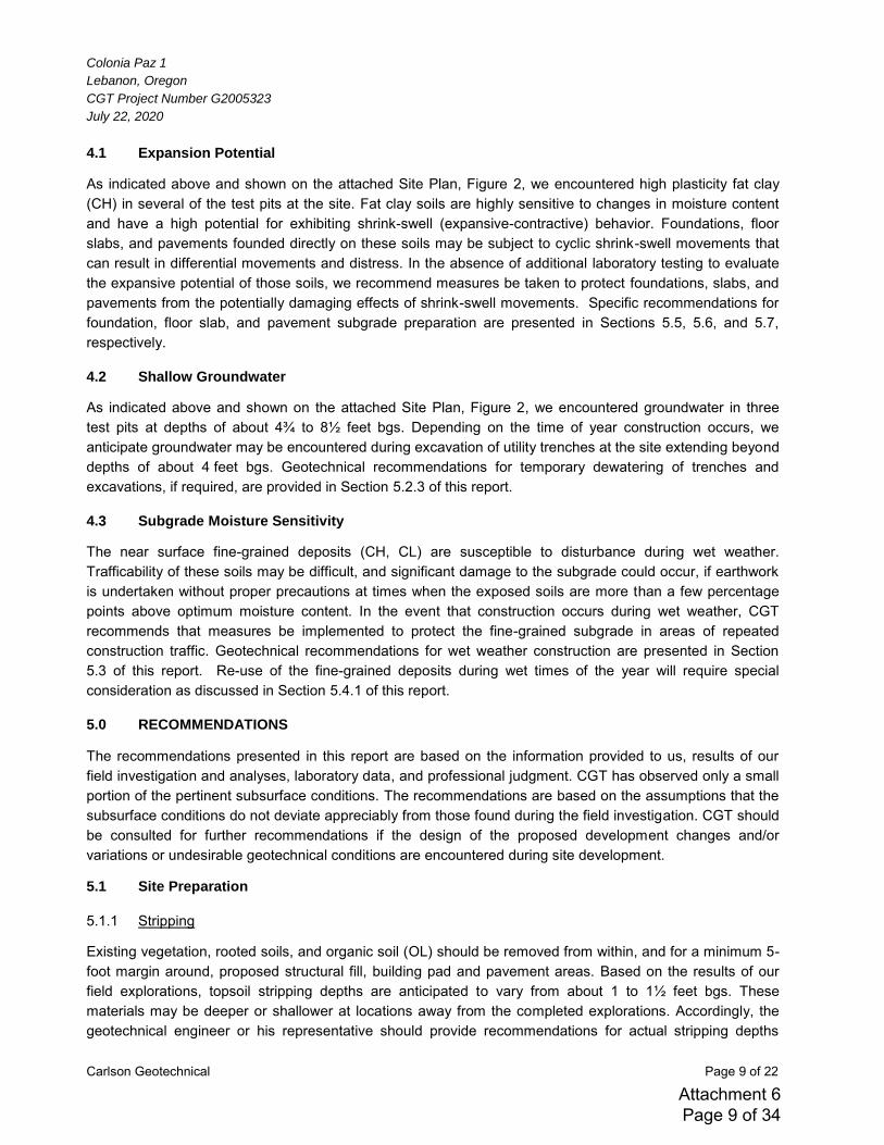
Colonia Paz 1
Lebanon, Oregon
CGT Project Number G2005323
July 22, 2020
Carlson Geotechnical Page 9 of 22
4.1 Expansion Potential
As indicated above and shown on the attached Site Plan, Figure 2, we encountered high plasticity fat clay (CH) in several of the test pits at the site. Fat clay soils are highly sensitive to changes in moisture content and have a high potential for exhibiting shrink-swell (expansive-contractive) behavior. Foundations, floor slabs, and pavements founded directly on these soils may be subject to cyclic shrink-swell movements that can result in differential movements and distress. In the absence of additional laboratory testing to evaluate the expansive potential of those soils, we recommend measures be taken to protect foundations, slabs, and pavements from the potentially damaging effects of shrink-swell movements. Specific recommendations for foundation, floor slab, and pavement subgrade preparation are presented in Sections 5.5, 5.6, and 5.7, respectively.
4.2 Shallow Groundwater
As indicated above and shown on the attached Site Plan, Figure 2, we encountered groundwater in three test pits at depths of about 4¾ to 8½ feet bgs. Depending on the time of year construction occurs, we anticipate groundwater may be encountered during excavation of utility trenches at the site extending beyond depths of about 4 feet bgs. Geotechnical recommendations for temporary dewatering of trenches and excavations, if required, are provided in Section 5.2.3 of this report.
4.3 Subgrade Moisture Sensitivity
The near surface fine-grained deposits (CH, CL) are susceptible to disturbance during wet weather. Trafficability of these soils may be difficult, and significant damage to the subgrade could occur, if earthwork is undertaken without proper precautions at times when the exposed soils are more than a few percentage points above optimum moisture content. In the event that construction occurs during wet weather, CGT recommends that measures be implemented to protect the fine-grained subgrade in areas of repeated construction traffic. Geotechnical recommendations for wet weather construction are presented in Section 5.3 of this report. Re-use of the fine-grained deposits during wet times of the year will require special consideration as discussed in Section 5.4.1 of this report.
5.0 RECOMMENDATIONS
The recommendations presented in this report are based on the information provided to us, results of our field investigation and analyses, laboratory data, and professional judgment. CGT has observed only a small portion of the pertinent subsurface conditions. The recommendations are based on the assumptions that the subsurface conditions do not deviate appreciably from those found during the field investigation. CGT should be consulted for further recommendations if the design of the proposed development changes and/or variations or undesirable geotechnical conditions are encountered during site development.
5.1 Site Preparation
5.1.1 Stripping
Existing vegetation, rooted soils, and organic soil (OL) should be removed from within, and for a minimum 5-foot margin around, proposed structural fill, building pad and pavement areas. Based on the results of our field explorations, topsoil stripping depths are anticipated to vary from about 1 to 1½ feet bgs. These materials may be deeper or shallower at locations away from the completed explorations. Accordingly, the geotechnical engineer or his representative should provide recommendations for actual stripping depths
Attachment 6 Page 9 of 34
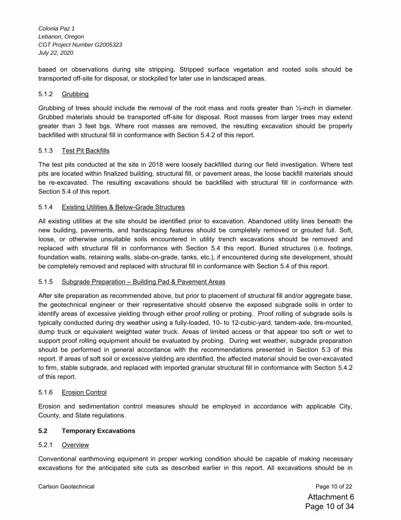
Colonia Paz 1
Lebanon, Oregon
CGT Project Number G2005323
July 22, 2020
Carlson Geotechnical Page 10 of 22
based on observations during site stripping. Stripped surface vegetation and rooted soils should be transported off-site for disposal, or stockpiled for later use in landscaped areas.
5.1.2 Grubbing
Grubbing of trees should include the removal of the root mass and roots greater than ½-inch in diameter. Grubbed materials should be transported off-site for disposal. Root masses from larger trees may extend greater than 3 feet bgs. Where root masses are removed, the resulting excavation should be properly backfilled with structural fill in conformance with Section 5.4.2 of this report.
5.1.3 Test Pit Backfills
The test pits conducted at the site in 2018 were loosely backfilled during our field investigation. Where test pits are located within finalized building, structural fill, or pavement areas, the loose backfill materials should be re-excavated. The resulting excavations should be backfilled with structural fill in conformance with Section 5.4 of this report.
5.1.4 Existing Utilities & Below-Grade Structures
All existing utilities at the site should be identified prior to excavation. Abandoned utility lines beneath the new building, pavements, and hardscaping features should be completely removed or grouted full. Soft, loose, or otherwise unsuitable soils encountered in utility trench excavations should be removed and replaced with structural fill in conformance with Section 5.4 this report. Buried structures (i.e. footings, foundation walls, retaining walls, slabs-on-grade, tanks, etc.), if encountered during site development, should be completely removed and replaced with structural fill in conformance with Section 5.4 of this report.
5.1.5 Subgrade Preparation – Building Pad & Pavement Areas
After site preparation as recommended above, but prior to placement of structural fill and/or aggregate base, the geotechnical engineer or their representative should observe the exposed subgrade soils in order to identify areas of excessive yielding through either proof rolling or probing. Proof rolling of subgrade soils is typically conducted during dry weather using a fully-loaded, 10- to 12-cubic-yard, tandem-axle, tire-mounted, dump truck or equivalent weighted water truck. Areas of limited access or that appear too soft or wet to support proof rolling equipment should be evaluated by probing. During wet weather, subgrade preparation should be performed in general accordance with the recommendations presented in Section 5.3 of this report. If areas of soft soil or excessive yielding are identified, the affected material should be over-excavated to firm, stable subgrade, and replaced with imported granular structural fill in conformance with Section 5.4.2 of this report.
5.1.6 Erosion Control
Erosion and sedimentation control measures should be employed in accordance with applicable City, County, and State regulations.
5.2 Temporary Excavations
5.2.1 Overview
Conventional earthmoving equipment in proper working condition should be capable of making necessary excavations for the anticipated site cuts as described earlier in this report. All excavations should be in
Attachment 6 Page 10 of 34
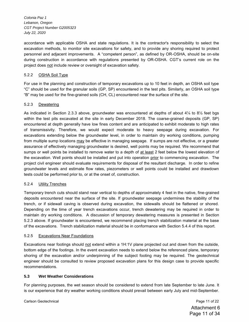
Colonia Paz 1
Lebanon, Oregon
CGT Project Number G2005323
July 22, 2020
Carlson Geotechnical Page 11 of 22
accordance with applicable OSHA and state regulations. It is the contractor's responsibility to select the excavation methods, to monitor site excavations for safety, and to provide any shoring required to protect personnel and adjacent improvements. A “competent person”, as defined by OR-OSHA, should be on-site during construction in accordance with regulations presented by OR-OSHA. CGT’s current role on the project does not include review or oversight of excavation safety.
5.2.2 OSHA Soil Type
For use in the planning and construction of temporary excavations up to 10 feet in depth, an OSHA soil type “C” should be used for the granular soils (GP, SP) encountered in the test pits. Similarly, an OSHA soil type “B” may be used for the fine-grained soils (CH, CL) encountered near the surface of the site.
5.2.3 Dewatering
As indicated in Section 2.3.3 above, groundwater was encountered at depths of about 4¼ to 8½ feet bgs within the test pits excavated at the site in early December 2018. The coarse-grained deposits (GP, SP) encountered at depth generally have low fines content and are anticipated to exhibit moderate to high rates of transmissivity. Therefore, we would expect moderate to heavy seepage during excavation. For excavations extending below the groundwater level, in order to maintain dry working conditions, pumping from multiple sump locations may be effective in managing seepage. If sumps are not effective, or a greater assurance of effectively managing groundwater is desired, well points may be required. We recommend that sumps or well points be installed to remove water to a depth of at least 2 feet below the lowest elevation of the excavation. Well points should be installed and put into operation prior to commencing excavation. The project civil engineer should evaluate requirements for disposal of the resultant discharge. In order to refine groundwater levels and estimate flow rates, piezometers or well points could be installed and drawdown tests could be performed prior to, or at the onset of, construction.
5.2.4 Utility Trenches
Temporary trench cuts should stand near vertical to depths of approximately 4 feet in the native, fine-grained deposits encountered near the surface of the site. If groundwater seepage undermines the stability of the trench, or if sidewall caving is observed during excavation, the sidewalls should be flattened or shored. Depending on the time of year trench excavations occur, trench dewatering may be required in order to maintain dry working conditions. A discussion of temporary dewatering measures is presented in Section 5.2.3 above. If groundwater is encountered, we recommend placing trench stabilization material at the base of the excavations. Trench stabilization material should be in conformance with Section 5.4.4 of this report.
5.2.5 Excavations Near Foundations
Excavations near footings should not extend within a 1H:1V plane projected out and down from the outside, bottom edge of the footings. In the event excavation needs to extend below the referenced plane, temporary shoring of the excavation and/or underpinning of the subject footing may be required. The geotechnical engineer should be consulted to review proposed excavation plans for this design case to provide specific recommendations.
5.3 Wet Weather Considerations
For planning purposes, the wet season should be considered to extend from late September to late June. It is our experience that dry weather working conditions should prevail between early July and mid-September.
Attachment 6 Page 11 of 34
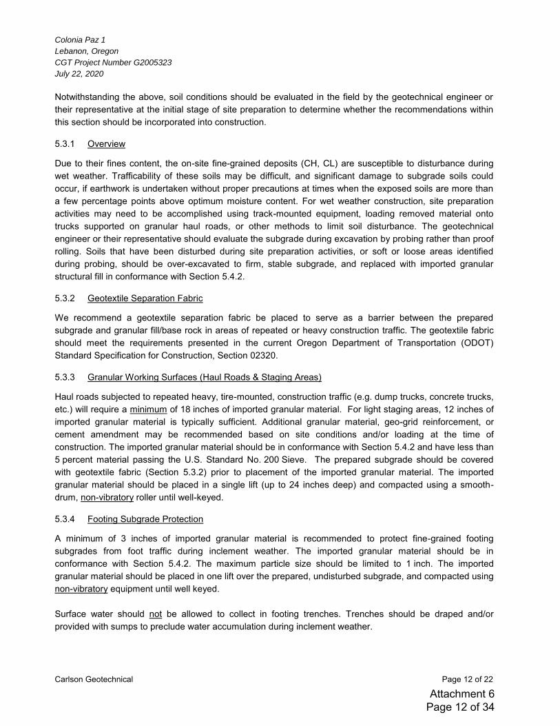
Colonia Paz 1
Lebanon, Oregon
CGT Project Number G2005323
July 22, 2020
Carlson Geotechnical Page 12 of 22
Notwithstanding the above, soil conditions should be evaluated in the field by the geotechnical engineer or their representative at the initial stage of site preparation to determine whether the recommendations within this section should be incorporated into construction.
5.3.1 Overview
Due to their fines content, the on-site fine-grained deposits (CH, CL) are susceptible to disturbance during wet weather. Trafficability of these soils may be difficult, and significant damage to subgrade soils could occur, if earthwork is undertaken without proper precautions at times when the exposed soils are more than a few percentage points above optimum moisture content. For wet weather construction, site preparation activities may need to be accomplished using track-mounted equipment, loading removed material onto trucks supported on granular haul roads, or other methods to limit soil disturbance. The geotechnical engineer or their representative should evaluate the subgrade during excavation by probing rather than proof rolling. Soils that have been disturbed during site preparation activities, or soft or loose areas identified during probing, should be over-excavated to firm, stable subgrade, and replaced with imported granular structural fill in conformance with Section 5.4.2.
5.3.2 Geotextile Separation Fabric
We recommend a geotextile separation fabric be placed to serve as a barrier between the prepared subgrade and granular fill/base rock in areas of repeated or heavy construction traffic. The geotextile fabric should meet the requirements presented in the current Oregon Department of Transportation (ODOT) Standard Specification for Construction, Section 02320.
5.3.3 Granular Working Surfaces (Haul Roads & Staging Areas)
Haul roads subjected to repeated heavy, tire-mounted, construction traffic (e.g. dump trucks, concrete trucks, etc.) will require a minimum of 18 inches of imported granular material. For light staging areas, 12 inches of imported granular material is typically sufficient. Additional granular material, geo-grid reinforcement, or cement amendment may be recommended based on site conditions and/or loading at the time of construction. The imported granular material should be in conformance with Section 5.4.2 and have less than 5 percent material passing the U.S. Standard No. 200 Sieve. The prepared subgrade should be covered with geotextile fabric (Section 5.3.2) prior to placement of the imported granular material. The imported granular material should be placed in a single lift (up to 24 inches deep) and compacted using a smooth-drum, non-vibratory roller until well-keyed.
5.3.4 Footing Subgrade Protection
A minimum of 3 inches of imported granular material is recommended to protect fine-grained footing subgrades from foot traffic during inclement weather. The imported granular material should be in conformance with Section 5.4.2. The maximum particle size should be limited to 1 inch. The imported granular material should be placed in one lift over the prepared, undisturbed subgrade, and compacted using non-vibratory equipment until well keyed. Surface water should not be allowed to collect in footing trenches. Trenches should be draped and/or provided with sumps to preclude water accumulation during inclement weather.
Attachment 6 Page 12 of 34
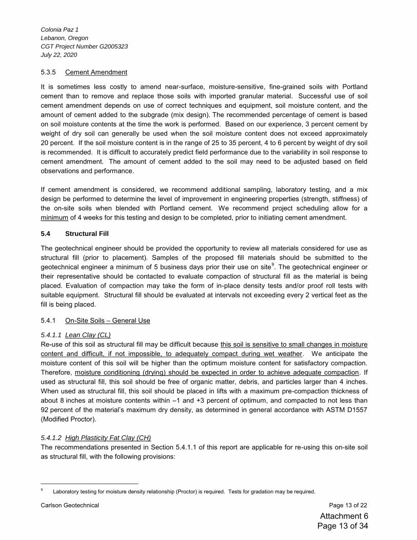
Colonia Paz 1
Lebanon, Oregon
CGT Project Number G2005323
July 22, 2020
Carlson Geotechnical Page 13 of 22
5.3.5 Cement Amendment
It is sometimes less costly to amend near-surface, moisture-sensitive, fine-grained soils with Portland cement than to remove and replace those soils with imported granular material. Successful use of soil cement amendment depends on use of correct techniques and equipment, soil moisture content, and the amount of cement added to the subgrade (mix design). The recommended percentage of cement is based on soil moisture contents at the time the work is performed. Based on our experience, 3 percent cement by weight of dry soil can generally be used when the soil moisture content does not exceed approximately 20 percent. If the soil moisture content is in the range of 25 to 35 percent, 4 to 6 percent by weight of dry soil is recommended. It is difficult to accurately predict field performance due to the variability in soil response to cement amendment. The amount of cement added to the soil may need to be adjusted based on field observations and performance. If cement amendment is considered, we recommend additional sampling, laboratory testing, and a mix design be performed to determine the level of improvement in engineering properties (strength, stiffness) of the on-site soils when blended with Portland cement. We recommend project scheduling allow for a minimum of 4 weeks for this testing and design to be completed, prior to initiating cement amendment.
5.4 Structural Fill
The geotechnical engineer should be provided the opportunity to review all materials considered for use as structural fill (prior to placement). Samples of the proposed fill materials should be submitted to the geotechnical engineer a minimum of 5 business days prior their use on site9. The geotechnical engineer or their representative should be contacted to evaluate compaction of structural fill as the material is being placed. Evaluation of compaction may take the form of in-place density tests and/or proof roll tests with suitable equipment. Structural fill should be evaluated at intervals not exceeding every 2 vertical feet as the fill is being placed.
5.4.1 On-Site Soils – General Use
5.4.1.1 Lean Clay (CL)
Re-use of this soil as structural fill may be difficult because this soil is sensitive to small changes in moisture content and difficult, if not impossible, to adequately compact during wet weather. We anticipate the moisture content of this soil will be higher than the optimum moisture content for satisfactory compaction. Therefore, moisture conditioning (drying) should be expected in order to achieve adequate compaction. If used as structural fill, this soil should be free of organic matter, debris, and particles larger than 4 inches. When used as structural fill, this soil should be placed in lifts with a maximum pre-compaction thickness of about 8 inches at moisture contents within –1 and +3 percent of optimum, and compacted to not less than 92 percent of the material’s maximum dry density, as determined in general accordance with ASTM D1557
(Modified Proctor). 5.4.1.2 High Plasticity Fat Clay (CH)
The recommendations presented in Section 5.4.1.1 of this report are applicable for re-using this on-site soil as structural fill, with the following provisions:
9 Laboratory testing for moisture density relationship (Proctor) is required. Tests for gradation may be required.
Attachment 6 Page 13 of 34
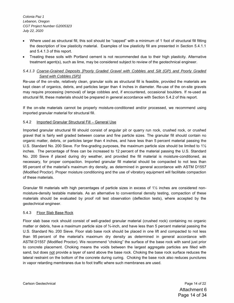
Colonia Paz 1
Lebanon, Oregon
CGT Project Number G2005323
July 22, 2020
Carlson Geotechnical Page 14 of 22
Where used as structural fill, this soil should be “capped” with a minimum of 1 foot of structural fill fitting the description of low plasticity material. Examples of low plasticity fill are presented in Section 5.4.1.1 and 5.4.1.3 of this report.
Treating these soils with Portland cement is not recommended due to their high plasticity. Alternative treatment agent(s), such as lime, may be considered subject to review of the geotechnical engineer.
5.4.1.3 Coarse-Grained Deposits [Poorly Graded Gravel with Cobbles and Silt (GP) and Poorly Graded
Sand with Cobbles (SP)]
Re-use of the on-site, relatively clean, granular soils as structural fill is feasible, provided the materials are kept clean of organics, debris, and particles larger than 4 inches in diameter. Re-use of the on-site gravels may require processing (removal) of large cobbles and, if encountered, occasional boulders. If re-used as structural fill, these materials should be prepared in general accordance with Section 5.4.2 of this report. If the on-site materials cannot be properly moisture-conditioned and/or processed, we recommend using imported granular material for structural fill.
5.4.2 Imported Granular Structural Fill – General Use
Imported granular structural fill should consist of angular pit or quarry run rock, crushed rock, or crushed gravel that is fairly well graded between coarse and fine particle sizes. The granular fill should contain no organic matter, debris, or particles larger than 4 inches, and have less than 5 percent material passing the U.S. Standard No. 200 Sieve. For fine-grading purposes, the maximum particle size should be limited to 1½ inches. The percentage of fines can be increased to 12 percent of the material passing the U.S. Standard No. 200 Sieve if placed during dry weather, and provided the fill material is moisture-conditioned, as necessary, for proper compaction. Imported granular fill material should be compacted to not less than 95 percent of the material’s maximum dry density, as determined in general accordance with ASTM D1557 (Modified Proctor). Proper moisture conditioning and the use of vibratory equipment will facilitate compaction of these materials. Granular fill materials with high percentages of particle sizes in excess of 1½ inches are considered non-moisture-density testable materials. As an alternative to conventional density testing, compaction of these materials should be evaluated by proof roll test observation (deflection tests), where accepted by the geotechnical engineer.
5.4.3 Floor Slab Base Rock
Floor slab base rock should consist of well-graded granular material (crushed rock) containing no organic matter or debris, have a maximum particle size of ¾-inch, and have less than 5 percent material passing the U.S. Standard No. 200 Sieve. Floor slab base rock should be placed in one lift and compacted to not less than 95 percent of the material’s maximum dry density as determined in general accordance with
ASTM D1557 (Modified Proctor). We recommend “choking” the surface of the base rock with sand just prior to concrete placement. Choking means the voids between the largest aggregate particles are filled with sand, but does not provide a layer of sand above the base rock. Choking the base rock surface reduces the lateral restraint on the bottom of the concrete during curing. Choking the base rock also reduces punctures in vapor retarding membranes due to foot traffic where such membranes are used.
Attachment 6 Page 14 of 34
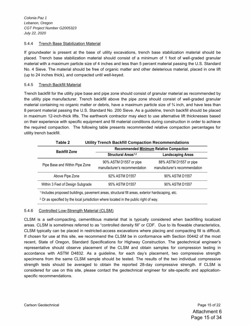
Colonia Paz 1
Lebanon, Oregon
CGT Project Number G2005323
July 22, 2020
Carlson Geotechnical Page 15 of 22
5.4.4 Trench Base Stabilization Material
If groundwater is present at the base of utility excavations, trench base stabilization material should be placed. Trench base stabilization material should consist of a minimum of 1 foot of well-graded granular material with a maximum particle size of 4 inches and less than 5 percent material passing the U.S. Standard No. 4 Sieve. The material should be free of organic matter and other deleterious material, placed in one lift (up to 24 inches thick), and compacted until well-keyed.
5.4.5 Trench Backfill Material
Trench backfill for the utility pipe base and pipe zone should consist of granular material as recommended by the utility pipe manufacturer. Trench backfill above the pipe zone should consist of well-graded granular material containing no organic matter or debris, have a maximum particle size of ¾ inch, and have less than 8 percent material passing the U.S. Standard No. 200 Sieve. As a guideline, trench backfill should be placed in maximum 12-inch-thick lifts. The earthwork contractor may elect to use alternative lift thicknesses based on their experience with specific equipment and fill material conditions during construction in order to achieve the required compaction. The following table presents recommended relative compaction percentages for utility trench backfill.
Table 2 Utility Trench Backfill Compaction Recommendations
Backfill Zone Recommended Minimum Relative Compaction
Structural Areas1,2 Landscaping Areas
Pipe Base and Within Pipe Zone 90% ASTM D1557 or pipe
manufacturer’s recommendation
88% ASTM D1557 or pipe
manufacturer’s recommendation
Above Pipe Zone 92% ASTM D1557 90% ASTM D1557
Within 3 Feet of Design Subgrade 95% ASTM D1557 90% ASTM D1557
1 Includes proposed buildings, pavement areas, structural fill areas, exterior hardscaping, etc.
2 Or as specified by the local jurisdiction where located in the public right of way.
5.4.6 Controlled Low-Strength Material (CLSM)
CLSM is a self-compacting, cementitious material that is typically considered when backfilling localized areas. CLSM is sometimes referred to as “controlled density fill” or CDF. Due to its flowable characteristics,
CLSM typically can be placed in restricted-access excavations where placing and compacting fill is difficult. If chosen for use at this site, we recommend the CLSM be in conformance with Section 00442 of the most recent, State of Oregon, Standard Specifications for Highway Construction. The geotechnical engineer’s
representative should observe placement of the CLSM and obtain samples for compression testing in accordance with ASTM D4832. As a guideline, for each day’s placement, two compressive strength
specimens from the same CLSM sample should be tested. The results of the two individual compressive strength tests should be averaged to obtain the reported 28-day compressive strength. If CLSM is considered for use on this site, please contact the geotechnical engineer for site-specific and application-specific recommendations.
Attachment 6 Page 15 of 34
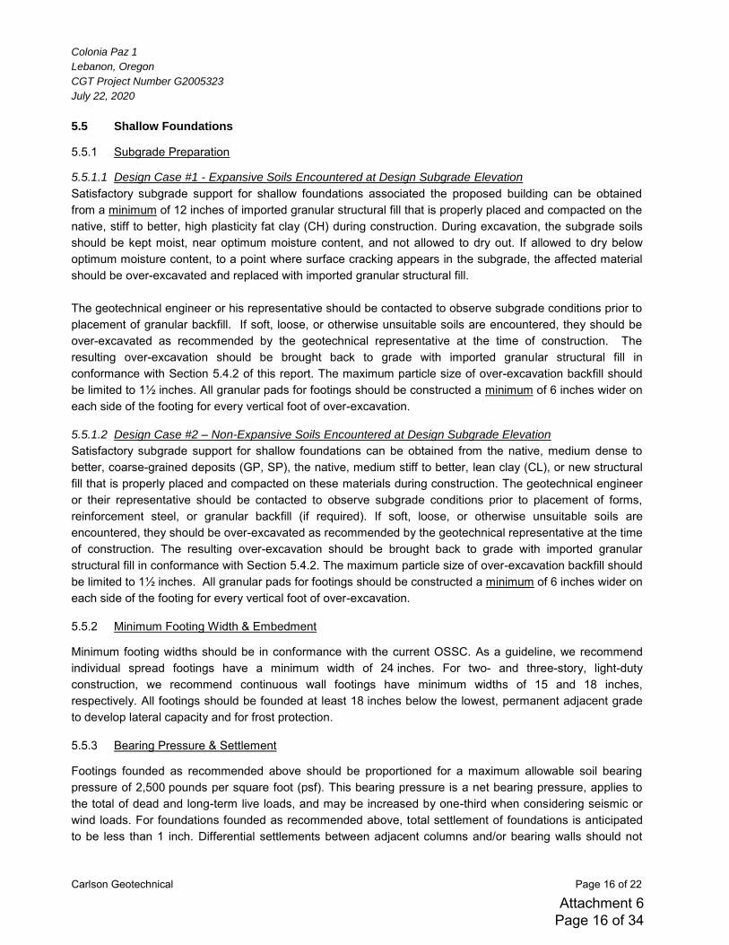
Colonia Paz 1
Lebanon, Oregon
CGT Project Number G2005323
July 22, 2020
Carlson Geotechnical Page 16 of 22
5.5 Shallow Foundations
5.5.1 Subgrade Preparation
5.5.1.1 Design Case #1 - Expansive Soils Encountered at Design Subgrade Elevation
Satisfactory subgrade support for shallow foundations associated the proposed building can be obtained from a minimum of 12 inches of imported granular structural fill that is properly placed and compacted on the native, stiff to better, high plasticity fat clay (CH) during construction. During excavation, the subgrade soils should be kept moist, near optimum moisture content, and not allowed to dry out. If allowed to dry below optimum moisture content, to a point where surface cracking appears in the subgrade, the affected material should be over-excavated and replaced with imported granular structural fill. The geotechnical engineer or his representative should be contacted to observe subgrade conditions prior to placement of granular backfill. If soft, loose, or otherwise unsuitable soils are encountered, they should be over-excavated as recommended by the geotechnical representative at the time of construction. The resulting over-excavation should be brought back to grade with imported granular structural fill in conformance with Section 5.4.2 of this report. The maximum particle size of over-excavation backfill should be limited to 1½ inches. All granular pads for footings should be constructed a minimum of 6 inches wider on each side of the footing for every vertical foot of over-excavation.
5.5.1.2 Design Case #2 – Non-Expansive Soils Encountered at Design Subgrade Elevation
Satisfactory subgrade support for shallow foundations can be obtained from the native, medium dense to better, coarse-grained deposits (GP, SP), the native, medium stiff to better, lean clay (CL), or new structural fill that is properly placed and compacted on these materials during construction. The geotechnical engineer or their representative should be contacted to observe subgrade conditions prior to placement of forms, reinforcement steel, or granular backfill (if required). If soft, loose, or otherwise unsuitable soils are encountered, they should be over-excavated as recommended by the geotechnical representative at the time of construction. The resulting over-excavation should be brought back to grade with imported granular structural fill in conformance with Section 5.4.2. The maximum particle size of over-excavation backfill should be limited to 1½ inches. All granular pads for footings should be constructed a minimum of 6 inches wider on each side of the footing for every vertical foot of over-excavation.
5.5.2 Minimum Footing Width & Embedment
Minimum footing widths should be in conformance with the current OSSC. As a guideline, we recommend individual spread footings have a minimum width of 24 inches. For two- and three-story, light-duty construction, we recommend continuous wall footings have minimum widths of 15 and 18 inches, respectively. All footings should be founded at least 18 inches below the lowest, permanent adjacent grade to develop lateral capacity and for frost protection.
5.5.3 Bearing Pressure & Settlement
Footings founded as recommended above should be proportioned for a maximum allowable soil bearing pressure of 2,500 pounds per square foot (psf). This bearing pressure is a net bearing pressure, applies to the total of dead and long-term live loads, and may be increased by one-third when considering seismic or wind loads. For foundations founded as recommended above, total settlement of foundations is anticipated to be less than 1 inch. Differential settlements between adjacent columns and/or bearing walls should not
Attachment 6 Page 16 of 34
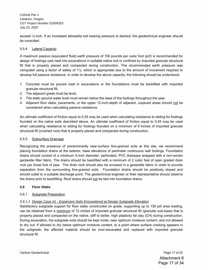
Colonia Paz 1
Lebanon, Oregon
CGT Project Number G2005323
July 22, 2020
Carlson Geotechnical Page 17 of 22
exceed ½-inch. If an increased allowable soil bearing pressure is desired, the geotechnical engineer should be consulted.
5.5.4 Lateral Capacity
A maximum passive (equivalent fluid) earth pressure of 150 pounds per cubic foot (pcf) is recommended for design of footings cast neat into excavations in suitable native soil or confined by imported granular structural fill that is properly placed and compacted during construction. The recommended earth pressure was computed using a factor of safety of 1½, which is appropriate due to the amount of movement required to develop full passive resistance. In order to develop the above capacity, the following should be understood: 1. Concrete must be poured neat in excavations or the foundations must be backfilled with imported
granular structural fill, 2. The adjacent grade must be level, 3. The static ground water level must remain below the base of the footings throughout the year. 4. Adjacent floor slabs, pavements, or the upper 12-inch-depth of adjacent, unpaved areas should not be
considered when calculating passive resistance. An ultimate coefficient of friction equal to 0.35 may be used when calculating resistance to sliding for footings founded on the native soils described above. An ultimate coefficient of friction equal to 0.45 may be used when calculating resistance to sliding for footings founded on a minimum of 6 inches of imported granular structural fill (crushed rock) that is properly placed and compacted during construction.
5.5.5 Subsurface Drainage
Recognizing the presence of predominantly near-surface fine-grained soils at this site, we recommend placing foundation drains at the exterior, base elevations of perimeter continuous wall footings. Foundation drains should consist of a minimum 4-inch diameter, perforated, PVC drainpipe wrapped with a non-woven geotextile filter fabric. The drains should be backfilled with a minimum of 2 cubic feet of open graded drain rock per lineal foot of pipe. The drain rock should also be encased in a geotextile fabric in order to provide separation from the surrounding fine-grained soils. Foundation drains should be positively sloped and should outlet to a suitable discharge point. The geotechnical engineer or their representative should observe the drains prior to backfilling. Roof drains should not be tied into foundation drains.
5.6 Floor Slabs
5.6.1 Subgrade Preparation
5.6.1.1 Design Case #1 - Expansive Soils Encountered at Design Subgrade Elevation
Satisfactory subgrade support for floor slabs constructed on grade, supporting up to 150 psf area loading, can be obtained from a minimum of 12 inches of imported granular structural fill (granular sub-base) that is properly placed and compacted on the native, stiff to better, high plasticity fat clay (CH) during construction. During excavation, the subgrade soils should be kept moist, near optimum moisture content, and not allowed to dry out. If allowed to dry below optimum moisture content, to a point where surface cracking appears in the subgrade, the affected material should be over-excavated and replaced with imported granular structural fill.
Attachment 6 Page 17 of 34
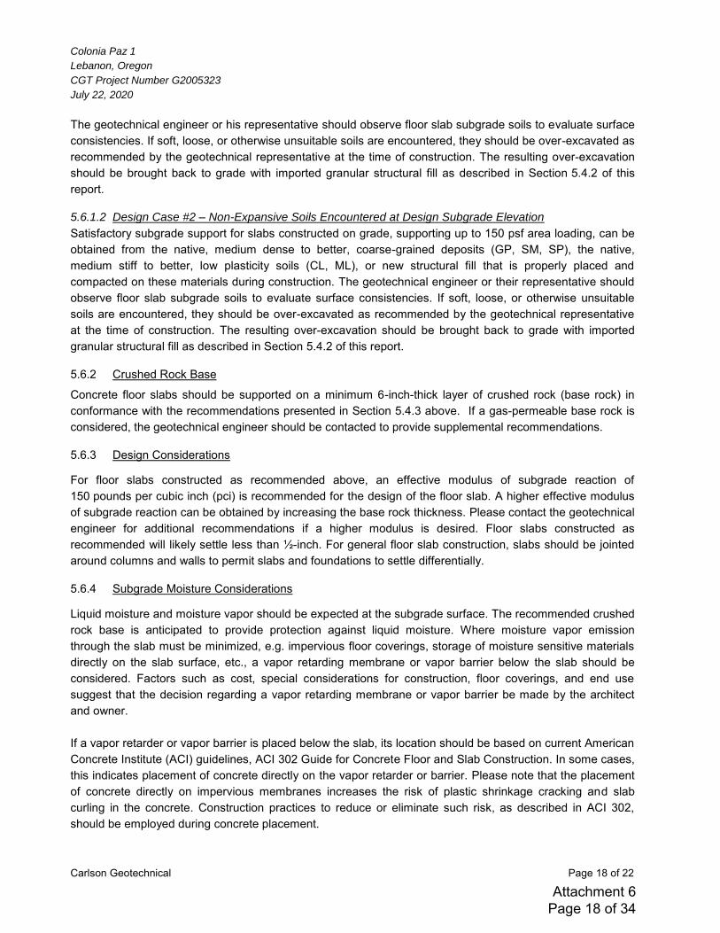
Colonia Paz 1
Lebanon, Oregon
CGT Project Number G2005323
July 22, 2020
Carlson Geotechnical Page 18 of 22
The geotechnical engineer or his representative should observe floor slab subgrade soils to evaluate surface consistencies. If soft, loose, or otherwise unsuitable soils are encountered, they should be over-excavated as recommended by the geotechnical representative at the time of construction. The resulting over-excavation should be brought back to grade with imported granular structural fill as described in Section 5.4.2 of this report.
5.6.1.2 Design Case #2 – Non-Expansive Soils Encountered at Design Subgrade Elevation
Satisfactory subgrade support for slabs constructed on grade, supporting up to 150 psf area loading, can be obtained from the native, medium dense to better, coarse-grained deposits (GP, SM, SP), the native, medium stiff to better, low plasticity soils (CL, ML), or new structural fill that is properly placed and compacted on these materials during construction. The geotechnical engineer or their representative should observe floor slab subgrade soils to evaluate surface consistencies. If soft, loose, or otherwise unsuitable soils are encountered, they should be over-excavated as recommended by the geotechnical representative at the time of construction. The resulting over-excavation should be brought back to grade with imported granular structural fill as described in Section 5.4.2 of this report.
5.6.2 Crushed Rock Base
Concrete floor slabs should be supported on a minimum 6-inch-thick layer of crushed rock (base rock) in conformance with the recommendations presented in Section 5.4.3 above. If a gas-permeable base rock is considered, the geotechnical engineer should be contacted to provide supplemental recommendations.
5.6.3 Design Considerations
For floor slabs constructed as recommended above, an effective modulus of subgrade reaction of 150 pounds per cubic inch (pci) is recommended for the design of the floor slab. A higher effective modulus of subgrade reaction can be obtained by increasing the base rock thickness. Please contact the geotechnical engineer for additional recommendations if a higher modulus is desired. Floor slabs constructed as recommended will likely settle less than ½-inch. For general floor slab construction, slabs should be jointed around columns and walls to permit slabs and foundations to settle differentially.
5.6.4 Subgrade Moisture Considerations
Liquid moisture and moisture vapor should be expected at the subgrade surface. The recommended crushed rock base is anticipated to provide protection against liquid moisture. Where moisture vapor emission through the slab must be minimized, e.g. impervious floor coverings, storage of moisture sensitive materials directly on the slab surface, etc., a vapor retarding membrane or vapor barrier below the slab should be considered. Factors such as cost, special considerations for construction, floor coverings, and end use suggest that the decision regarding a vapor retarding membrane or vapor barrier be made by the architect and owner. If a vapor retarder or vapor barrier is placed below the slab, its location should be based on current American Concrete Institute (ACI) guidelines, ACI 302 Guide for Concrete Floor and Slab Construction. In some cases, this indicates placement of concrete directly on the vapor retarder or barrier. Please note that the placement of concrete directly on impervious membranes increases the risk of plastic shrinkage cracking and slab curling in the concrete. Construction practices to reduce or eliminate such risk, as described in ACI 302, should be employed during concrete placement.
Attachment 6 Page 18 of 34
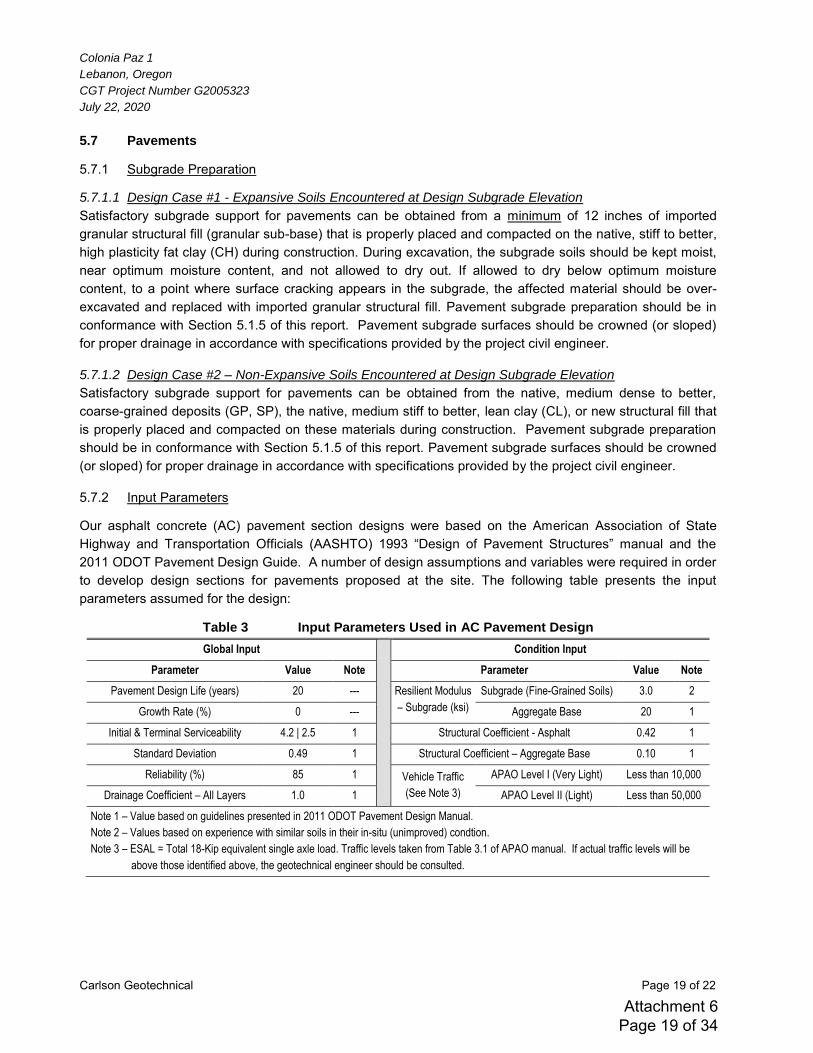
Colonia Paz 1
Lebanon, Oregon
CGT Project Number G2005323
July 22, 2020
Carlson Geotechnical Page 19 of 22
5.7 Pavements
5.7.1 Subgrade Preparation
5.7.1.1 Design Case #1 - Expansive Soils Encountered at Design Subgrade Elevation
Satisfactory subgrade support for pavements can be obtained from a minimum of 12 inches of imported granular structural fill (granular sub-base) that is properly placed and compacted on the native, stiff to better, high plasticity fat clay (CH) during construction. During excavation, the subgrade soils should be kept moist, near optimum moisture content, and not allowed to dry out. If allowed to dry below optimum moisture content, to a point where surface cracking appears in the subgrade, the affected material should be over-excavated and replaced with imported granular structural fill. Pavement subgrade preparation should be in conformance with Section 5.1.5 of this report. Pavement subgrade surfaces should be crowned (or sloped) for proper drainage in accordance with specifications provided by the project civil engineer.
5.7.1.2 Design Case #2 – Non-Expansive Soils Encountered at Design Subgrade Elevation
Satisfactory subgrade support for pavements can be obtained from the native, medium dense to better, coarse-grained deposits (GP, SP), the native, medium stiff to better, lean clay (CL), or new structural fill that is properly placed and compacted on these materials during construction. Pavement subgrade preparation should be in conformance with Section 5.1.5 of this report. Pavement subgrade surfaces should be crowned (or sloped) for proper drainage in accordance with specifications provided by the project civil engineer.
5.7.2 Input Parameters
Our asphalt concrete (AC) pavement section designs were based on the American Association of State Highway and Transportation Officials (AASHTO) 1993 “Design of Pavement Structures” manual and the
2011 ODOT Pavement Design Guide. A number of design assumptions and variables were required in order to develop design sections for pavements proposed at the site. The following table presents the input parameters assumed for the design:
Table 3 Input Parameters Used in AC Pavement Design
Global Input Condition Input
Parameter Value Note Parameter Value Note
Pavement Design Life (years) 20 --- Resilient Modulus
– Subgrade (ksi)
Subgrade (Fine-Grained Soils) 3.0 2
Growth Rate (%) 0 --- Aggregate Base 20 1
Initial & Terminal Serviceability 4.2 | 2.5 1 Structural Coefficient - Asphalt 0.42 1
Standard Deviation 0.49 1 Structural Coefficient – Aggregate Base 0.10 1
Reliability (%) 85 1 Vehicle Traffic
(See Note 3)
APAO Level I (Very Light) Less than 10,000
Drainage Coefficient – All Layers 1.0 1 APAO Level II (Light) Less than 50,000
Note 1 – Value based on guidelines presented in 2011 ODOT Pavement Design Manual.
Note 2 – Values based on experience with similar soils in their in-situ (unimproved) condtion.
Note 3 – ESAL = Total 18-Kip equivalent single axle load. Traffic levels taken from Table 3.1 of APAO manual. If actual traffic levels will be
above those identified above, the geotechnical engineer should be consulted.
Attachment 6 Page 19 of 34
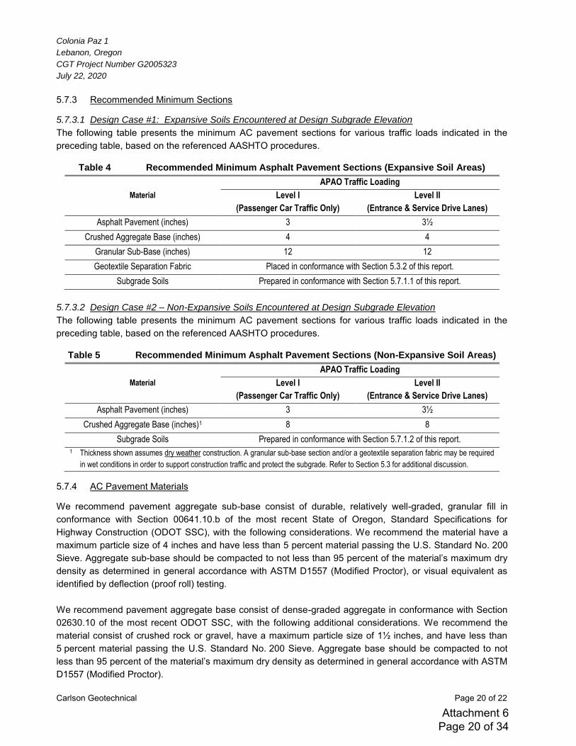
Colonia Paz 1
Lebanon, Oregon
CGT Project Number G2005323
July 22, 2020
Carlson Geotechnical Page 20 of 22
5.7.3 Recommended Minimum Sections
5.7.3.1 Design Case #1: Expansive Soils Encountered at Design Subgrade Elevation
The following table presents the minimum AC pavement sections for various traffic loads indicated in the preceding table, based on the referenced AASHTO procedures.
Table 4 Recommended Minimum Asphalt Pavement Sections (Expansive Soil Areas)
Material
APAO Traffic Loading
Level I
(Passenger Car Traffic Only)
Level II
(Entrance & Service Drive Lanes)
Asphalt Pavement (inches) 3 3½
Crushed Aggregate Base (inches) 4 4
Granular Sub-Base (inches) 12 12
Geotextile Separation Fabric Placed in conformance with Section 5.3.2 of this report.
Subgrade Soils Prepared in conformance with Section 5.7.1.1 of this report.
5.7.3.2 Design Case #2 – Non-Expansive Soils Encountered at Design Subgrade Elevation
The following table presents the minimum AC pavement sections for various traffic loads indicated in the preceding table, based on the referenced AASHTO procedures.
Table 5 Recommended Minimum Asphalt Pavement Sections (Non-Expansive Soil Areas)
Material
APAO Traffic Loading
Level I
(Passenger Car Traffic Only)
Level II
(Entrance & Service Drive Lanes)
Asphalt Pavement (inches) 3 3½
Crushed Aggregate Base (inches)1 8 8
Subgrade Soils Prepared in conformance with Section 5.7.1.2 of this report.
1 Thickness shown assumes dry weather construction. A granular sub-base section and/or a geotextile separation fabric may be required
in wet conditions in order to support construction traffic and protect the subgrade. Refer to Section 5.3 for additional discussion.
5.7.4 AC Pavement Materials
We recommend pavement aggregate sub-base consist of durable, relatively well-graded, granular fill in conformance with Section 00641.10.b of the most recent State of Oregon, Standard Specifications for Highway Construction (ODOT SSC), with the following considerations. We recommend the material have a maximum particle size of 4 inches and have less than 5 percent material passing the U.S. Standard No. 200 Sieve. Aggregate sub-base should be compacted to not less than 95 percent of the material’s maximum dry
density as determined in general accordance with ASTM D1557 (Modified Proctor), or visual equivalent as identified by deflection (proof roll) testing. We recommend pavement aggregate base consist of dense-graded aggregate in conformance with Section 02630.10 of the most recent ODOT SSC, with the following additional considerations. We recommend the material consist of crushed rock or gravel, have a maximum particle size of 1½ inches, and have less than 5 percent material passing the U.S. Standard No. 200 Sieve. Aggregate base should be compacted to not less than 95 percent of the material’s maximum dry density as determined in general accordance with ASTM
D1557 (Modified Proctor).
Attachment 6 Page 20 of 34
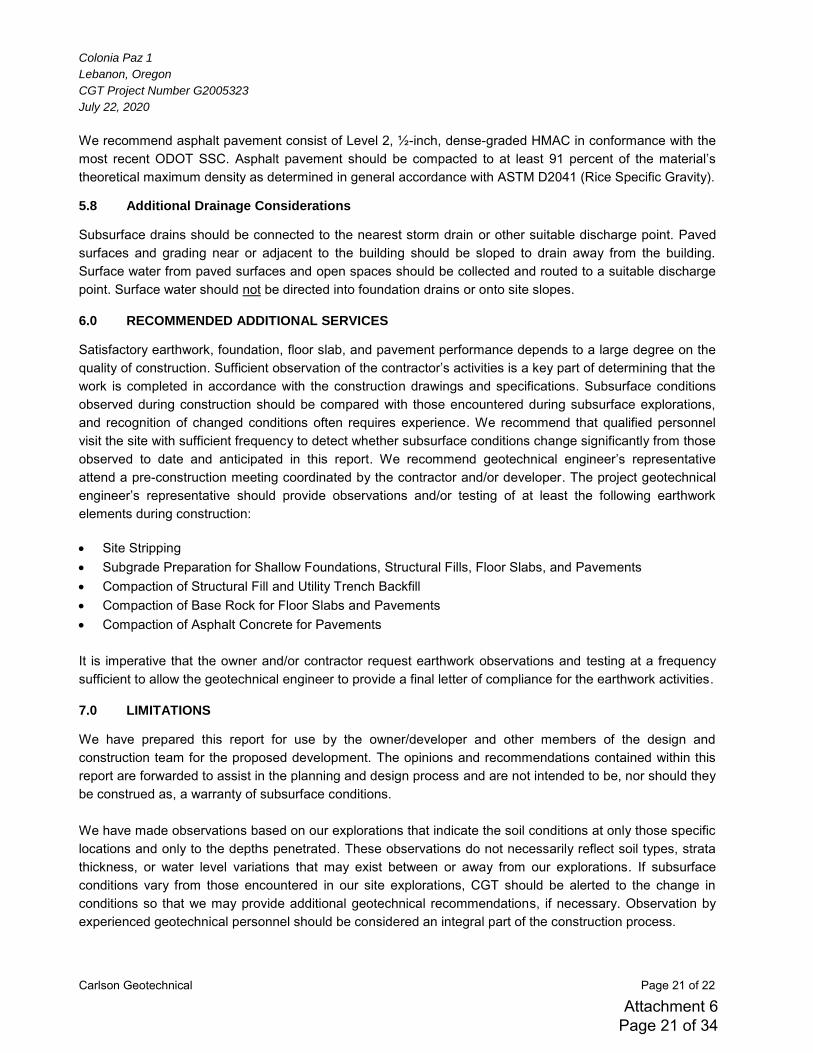
Colonia Paz 1
Lebanon, Oregon
CGT Project Number G2005323
July 22, 2020
Carlson Geotechnical Page 21 of 22
We recommend asphalt pavement consist of Level 2, ½-inch, dense-graded HMAC in conformance with the most recent ODOT SSC. Asphalt pavement should be compacted to at least 91 percent of the material’s
theoretical maximum density as determined in general accordance with ASTM D2041 (Rice Specific Gravity).
5.8 Additional Drainage Considerations
Subsurface drains should be connected to the nearest storm drain or other suitable discharge point. Paved surfaces and grading near or adjacent to the building should be sloped to drain away from the building. Surface water from paved surfaces and open spaces should be collected and routed to a suitable discharge point. Surface water should not be directed into foundation drains or onto site slopes.
6.0 RECOMMENDED ADDITIONAL SERVICES
Satisfactory earthwork, foundation, floor slab, and pavement performance depends to a large degree on the quality of construction. Sufficient observation of the contractor’s activities is a key part of determining that the
work is completed in accordance with the construction drawings and specifications. Subsurface conditions observed during construction should be compared with those encountered during subsurface explorations, and recognition of changed conditions often requires experience. We recommend that qualified personnel visit the site with sufficient frequency to detect whether subsurface conditions change significantly from those observed to date and anticipated in this report. We recommend geotechnical engineer’s representative attend a pre-construction meeting coordinated by the contractor and/or developer. The project geotechnical engineer’s representative should provide observations and/or testing of at least the following earthwork elements during construction: Site Stripping Subgrade Preparation for Shallow Foundations, Structural Fills, Floor Slabs, and Pavements Compaction of Structural Fill and Utility Trench Backfill Compaction of Base Rock for Floor Slabs and Pavements Compaction of Asphalt Concrete for Pavements It is imperative that the owner and/or contractor request earthwork observations and testing at a frequency sufficient to allow the geotechnical engineer to provide a final letter of compliance for the earthwork activities.
7.0 LIMITATIONS
We have prepared this report for use by the owner/developer and other members of the design and construction team for the proposed development. The opinions and recommendations contained within this report are forwarded to assist in the planning and design process and are not intended to be, nor should they be construed as, a warranty of subsurface conditions. We have made observations based on our explorations that indicate the soil conditions at only those specific locations and only to the depths penetrated. These observations do not necessarily reflect soil types, strata thickness, or water level variations that may exist between or away from our explorations. If subsurface conditions vary from those encountered in our site explorations, CGT should be alerted to the change in conditions so that we may provide additional geotechnical recommendations, if necessary. Observation by experienced geotechnical personnel should be considered an integral part of the construction process.
Attachment 6 Page 21 of 34

Colonia Paz 1
Lebanon, Oregon
CGT Project Number G2005323
July 22, 2020
Carlson Geotechnical Page 22 of 22
The owner/developer is responsible for ensuring that the project designers and contractors implement our recommendations. When the design has been finalized, prior to releasing bid packets to contractors, we recommend that the design drawings and specifications be reviewed by our firm to see that our recommendations have been interpreted and implemented as intended. If design changes are made, we request that we be retained to review our conclusions and recommendations and to provide a written modification or verification. Design review and construction phase testing and observation services are beyond the scope of our current assignment, but will be provided for an additional fee. The scope of our services does not include services related to construction safety precautions, and our recommendations are not intended to direct the contractor’s methods, techniques, sequences, or procedures, except as specifically described in our report for consideration in design. Geotechnical engineering and the geologic sciences are characterized by a degree of uncertainty. Professional judgments presented in this report are based on our understanding of the proposed construction, familiarity with similar projects in the area, and on general experience. Within the limitations of scope, schedule, and budget, our services have been executed in accordance with the generally accepted practices in this area at the time this report was prepared; no warranty, expressed or implied, is made. This report is subject to review and should not be relied upon after a period of three years.
Attachment 6 Page 22 of 34
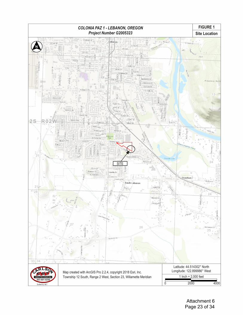
Scale (F8) Topo!Image by 64.23%
Site LocationCARLSON
GEOTECHNICAL503-601-8250
1 Inch = 2,000 feet
0 2000 4000
FIGURE 1
SITE
Latitude: 44.514302° NorthLongitude: 122.899986° West
N
COLONIA PAZ 1 - LEBANON, OREGONProject Number G2005323
Drafted by: AET
Map created with ArcGIS Pro 2.2.4, copyright 2018 Esri, Inc.Township 12 South, Range 2 West, Section 23, Willamette Meridian
Attachment 6 Page 23 of 34
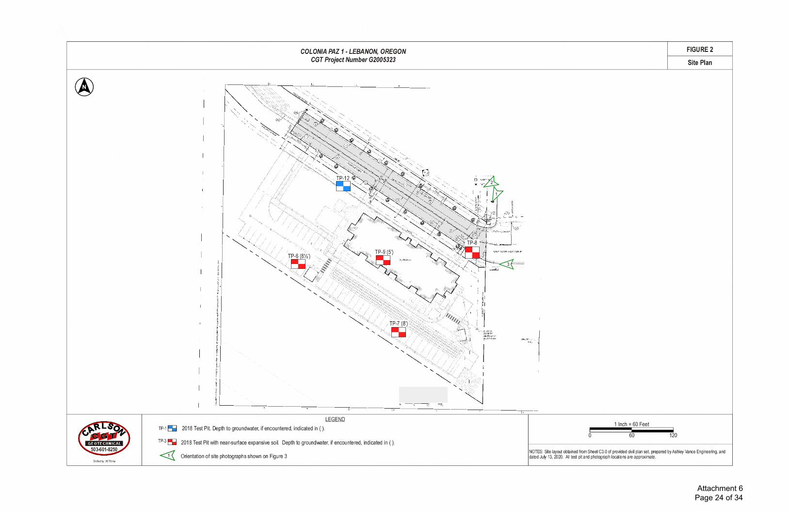
1
2
3
Attachment 6 Page 24 of 34
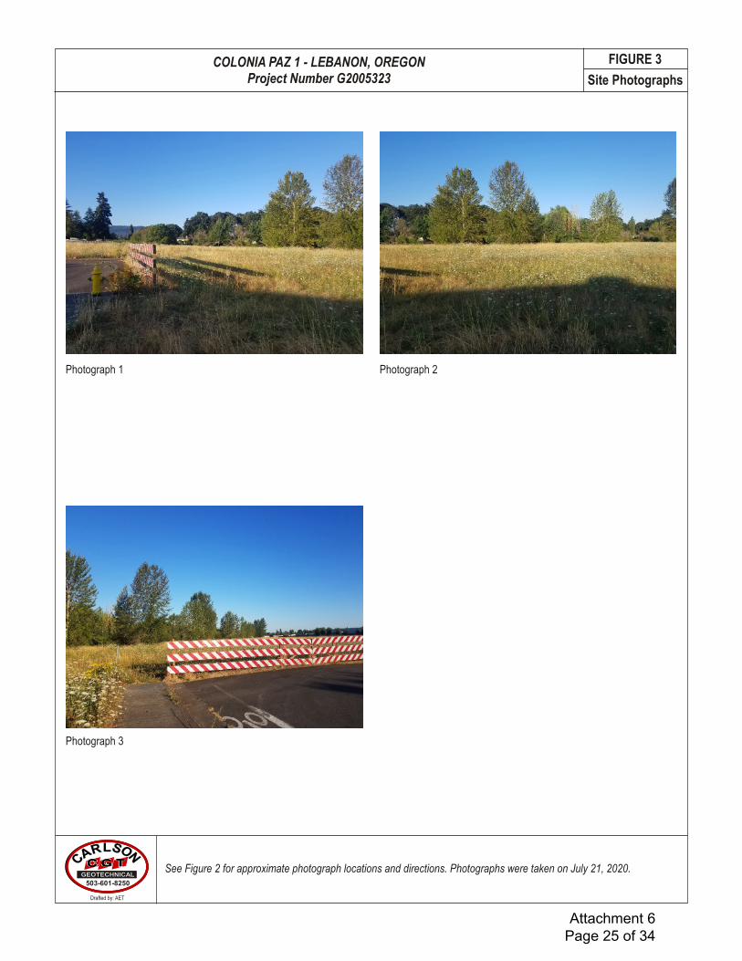
Site PhotographsCARLSON
GEOTECHNICAL503-601-8250
See Figure 2 for approximate photograph locations and directions. Photographs were taken on July 21, 2020.
Photograph 1 Photograph 2
FIGURE 3
Photograph 3
COLONIA PAZ 1 - LEBANON, OREGONProject Number G2005323
Drafted by: AET
Attachment 6 Page 25 of 34
Office: 18270 SW Boones Ferry Road, Suite 6, Durham, Oregon 97224
Mailing: P.O. Box 230997, Tigard, Oregon 97281
Carlson Geotechnical A division of Carlson Testing, Inc. Phone: (503) 601-8250 www.carlsontesting.com
Bend Office Eugene Office Salem Office Tigard Office
(541) 330-9155 (541) 345-0289 (503) 589-1252 (503) 684-3460
Form Letters1Job Number
Appendix A: Subsurface Investigation and
Laboratory Testing
Colonia Paz 1
Weldwood Drive and Cascade Drive
Lebanon, Oregon
CGT Project Number G2005323
July 22, 2020
Prepared For:
Ms. Maria Guerra Farmworker Housing Development Corporation
1274 A North Fifth Street Woodburn, Oregon 97071
Prepared by
Carlson Geotechnical
Exploration Key ..................................................................................................................................... Figure A1 Soil Classification .................................................................................................................................. Figure A2 Test Pit Logs ............................................................................................................................... Figures A3 – A7
Attachment 6 Page 26 of 34
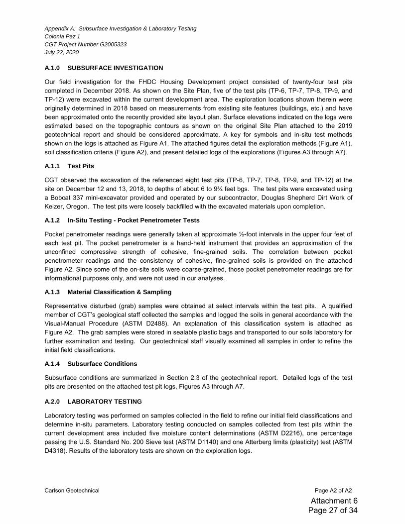
Appendix A: Subsurface Investigation & Laboratory Testing
Colonia Paz 1
CGT Project Number G2005323
July 22, 2020
Carlson Geotechnical Page A2 of A2
A.1.0 SUBSURFACE INVESTIGATION
Our field investigation for the FHDC Housing Development project consisted of twenty-four test pits completed in December 2018. As shown on the Site Plan, five of the test pits (TP-6, TP-7, TP-8, TP-9, and TP-12) were excavated within the current development area. The exploration locations shown therein were originally determined in 2018 based on measurements from existing site features (buildings, etc.) and have been approximated onto the recently provided site layout plan. Surface elevations indicated on the logs were estimated based on the topographic contours as shown on the original Site Plan attached to the 2019 geotechnical report and should be considered approximate. A key for symbols and in-situ test methods shown on the logs is attached as Figure A1. The attached figures detail the exploration methods (Figure A1), soil classification criteria (Figure A2), and present detailed logs of the explorations (Figures A3 through A7).
A.1.1 Test Pits
CGT observed the excavation of the referenced eight test pits (TP-6, TP-7, TP-8, TP-9, and TP-12) at the site on December 12 and 13, 2018, to depths of about 6 to 9¾ feet bgs. The test pits were excavated using a Bobcat 337 mini-excavator provided and operated by our subcontractor, Douglas Shepherd Dirt Work of Keizer, Oregon. The test pits were loosely backfilled with the excavated materials upon completion.
A.1.2 In-Situ Testing - Pocket Penetrometer Tests
Pocket penetrometer readings were generally taken at approximate ½-foot intervals in the upper four feet of each test pit. The pocket penetrometer is a hand-held instrument that provides an approximation of the unconfined compressive strength of cohesive, fine-grained soils. The correlation between pocket penetrometer readings and the consistency of cohesive, fine-grained soils is provided on the attached Figure A2. Since some of the on-site soils were coarse-grained, those pocket penetrometer readings are for informational purposes only, and were not used in our analyses.
A.1.3 Material Classification & Sampling
Representative disturbed (grab) samples were obtained at select intervals within the test pits. A qualified member of CGT’s geological staff collected the samples and logged the soils in general accordance with the Visual-Manual Procedure (ASTM D2488). An explanation of this classification system is attached as Figure A2. The grab samples were stored in sealable plastic bags and transported to our soils laboratory for further examination and testing. Our geotechnical staff visually examined all samples in order to refine the initial field classifications.
A.1.4 Subsurface Conditions
Subsurface conditions are summarized in Section 2.3 of the geotechnical report. Detailed logs of the test pits are presented on the attached test pit logs, Figures A3 through A7.
A.2.0 LABORATORY TESTING
Laboratory testing was performed on samples collected in the field to refine our initial field classifications and determine in-situ parameters. Laboratory testing conducted on samples collected from test pits within the current development area included five moisture content determinations (ASTM D2216), one percentage passing the U.S. Standard No. 200 Sieve test (ASTM D1140) and one Atterberg limits (plasticity) test (ASTM D4318). Results of the laboratory tests are shown on the exploration logs.
Attachment 6 Page 27 of 34
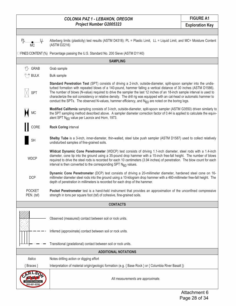
MCPL LL
MC
SPT
CORE
SH
GRAB
FINES CONTENT (%)
WDCP
DCP
GEOTECHNICAL LABORATORY TESTING
SAMPLING
CONTACTS
Observed (measured) contact between soil or rock units.
Inferred (approximate) contact between soil or rock units.
Transitional (gradational) contact between soil or rock units.
POCKETPEN. (tsf)
Pocket Penetrometer test is a hand-held instrument that provides an approximation of the unconfined compressivestrength in tons per square foot (tsf) of cohesive, fine-grained soils.
Dynamic Cone Penetrometer (DCP) test consists of driving a 20-millimeter diameter, hardened steel cone on 16-millimeter diameter steel rods into the ground using a 10-kilogram drop hammer with a 460-millimeter free-fall height. Thedepth of penetration in millimeters is recorded for each drop of the hammer.
Wildcat Dynamic Cone Penetrometer (WDCP) test consists of driving 1.1-inch diameter, steel rods with a 1.4-inchdiameter, cone tip into the ground using a 35-pound drop hammer with a 15-inch free-fall height. The number of blowsrequired to drive the steel rods is recorded for each 10 centimeters (3.94 inches) of penetration. The blow count for eachinterval is then converted to the corresponding SPT N60 values.
Shelby Tube is a 3-inch, inner-diameter, thin-walled, steel tube push sampler (ASTM D1587) used to collect relativelyundisturbed samples of fine-grained soils.
Rock Coring interval
Modified California sampling consists of 3-inch, outside-diameter, split-spoon sampler (ASTM G3550) driven similarly tothe SPT sampling method described above. A sampler diameter correction factor of 0.44 is applied to calculate the equiv-alent SPT N60 value per Lacroix and Horn, 1973.
Standard Penetration Test (SPT) consists of driving a 2-inch, outside-diameter, split-spoon sampler into the undis-turbed formation with repeated blows of a 140-pound, hammer falling a vertical distance of 30 inches (ASTM D1586).The number of blows (N-value) required to drive the sampler the last 12 inches of an 18-inch sample interval is used tocharacterize the soil consistency or relative density. The drill rig was equipped with an cat-head or automatic hammer toconduct the SPTs. The observed N-values, hammer efficiency, and N60 are noted on the boring logs.
Grab sample
Percentage passing the U.S. Standard No. 200 Sieve (ASTM D1140)
Atterberg limits (plasticity) test results (ASTM D4318): PL = Plastic Limit, LL = Liquid Limit, and MC= Moisture Content(ASTM D2216)
ADDITIONAL NOTATIONS
Notes drilling action or digging effort
Interpretation of material origin/geologic formation (e.g. { Base Rock } or { Columbia River Basalt })
Italics
{ Braces }
All measurements are approximate.
Exploration KeyCARLSON
GEOTECHNICAL503-601-8250
Bulk sampleBULK
FIGURE A1COLONIA PAZ 1 - LEBANON, OREGONProject Number G2005323
Attachment 6 Page 28 of 34

References:ASTM D2487 Standard Practice for Classification of Soils for Engineering Purposes (Unified Soil Classification System)ASTM D2488 Standard Practice for Description and Identification of Soils (Visual-Manual Procedure)Terzaghi, K., and Peck, R.B., 1948, Soil Mechanics in Engineering Practice, John Wiley & Sons.
Classification of Terms and ContentNAME: Group Name and Symbol
Relative Density or ConsistencyColorMoisture ContentPlasticityOther ConstituentsOther: Grain Shape, Approximate GradationOrganics, Cement, Structure, Odor, etc.Geologic Name or Formation
Grain Size<#200 (0.075 mm)
FineMediumCoarseFineCoarse
3 to 12 inchesBoulders
Coarse-Grained (Granular) SoilsRelative Density
SPTN60-Value Density
SPTN60-Value
Torvane tsfShear Strength
0.13 - 0.25
>2.00
0.25 - 0.500.50 - 1.001.00 - 2.00
<0.13
Pocket Pen tsfUnconfined
0.25 - 0.50
>4.00
0.50 - 1.001.00 - 2.002.00 - 4.00
<0.25
Consistency
Soft
Hard
Medium StiffStiff
Very Stiff
Very Soft
Manual Penetration Test
Thumb penetrates about 1 inch
Difficult to indent by thumbnail
Thumb penetrates about ¼ inchThumb penetrates less than ¼ inch
Readily indented by thumbnail
Thumb penetrates more than 1 inch2 - 4
>30
Moisture Content
Stratified: Alternating layers of material or color >6 mm thick
Plasticity Dry Strength Dilatancy Toughness
Visual-Manual Classification
CoarseGrained
Soils:More than
50% retainedon No. 200
sieve
Fine-GrainedSoils:
50% or morePasses No.200 Sieve
Gravels: 50% or moreretained onthe No. 4 sieve
Sands: More than50% passing theNo. 4 sieve
Silt and ClaysLow Plasticity Fines
Silt and ClaysHigh Plasticity Fines
CleanGravelsGravelswith FinesCleanSandsSandswith Fines
Highly Organic Soils
GW Well-graded gravels and gravel/sand mixtures, little or no finesGP Poorly-graded gravels and gravel/sand mixtures, little or no finesGM Silty gravels, gravel/sand/silt mixturesGC Clayey gravels, gravel/sand/clay mixturesSW Well-graded sands and gravelly sands, little or no finesSP Poorly-graded sands and gravelly sands, little or no finesSM Silty sands, sand/silt mixturesSC Clayey sands, sand/clay mixturesML Inorganic silts, rock flour, clayey siltsCL Inorganic clays of low to medium plasticity, gravelly clays, sandy clays, lean claysOL Organic soil of low plasticityMH Inorganic silts, clayey siltsCH Inorganic clays of high plasticity, fat claysOH Organic soil of medium to high plasticityPT Peat, muck, and other highly organic soils
4 - 88 - 15
15 - 30
<2
#200 - #40 (0.425 mm)#40 - #10 (2 mm)#10 - #4 (4.75 mm)
Sand
> 12 inches
Gravel #4 - 0.75 inch0.75 inch - 3 inches
Cobbles
Fines
0 - 4 Very Loose4 - 10 Loose
10 - 30 Medium Dense30 - 50 Dense
>50 Very Dense
Major Divisions GroupSymbols Typical Names
Structure
Homogeneous: Same color and appearance throughoutLenses: Has small pockets of different soils, note thickness
Blocky: Cohesive soil that can be broken down into small angular lumpswhich resist further breakdown
Slickensided: Striated, polished, or glossy fracture planesFissured: Breaks along definite fracture planesLaminated: Alternating layers < 6 mm thick
MLCLMHCH
Non to LowLow to MediumMedium to HighMedium to High
Non to LowMedium to HighLow to Medium
High to Very High
Slow to RapidNone to SlowNone to Slow
None
Low, can’t rollMedium
Low to MediumHigh
Wet: Visible free water, likely from below water tableMoist: Leaves moisture on handDry: Absence of moisture, dusty, dry to the touch
Soil ClassificationU.S. Standard Sieve
Fine-Grained (Cohesive) Soils
Minor ConstituentsPercent
by Volume Descriptor Example
0 - 5%
5 - 15%
15 - 49%
“Trace” as part of soil description
“With” as part of group name
Modifier to group name
“trace silt”
“POORLY GRADED SAND WITH SILT”
“SILTY SAND”
Minor ConstituentsPercent
by Volume Descriptor Example
0 - 5% “Trace” as part of soil description
15 - 30% “With” as part of group name5 - 15% “Some” as part of soil description
30 - 49% Modifier to group name
“trace fine-grained sand”
“SILT WITH SAND”“some fine-grained sand”
“SANDY SILT”
CARLSON
GEOTECHNICAL503-601-8250
FIGURE A2COLONIA PAZ 1 - LEBANON, OREGONProject Number G2005323
Attachment 6 Page 29 of 34
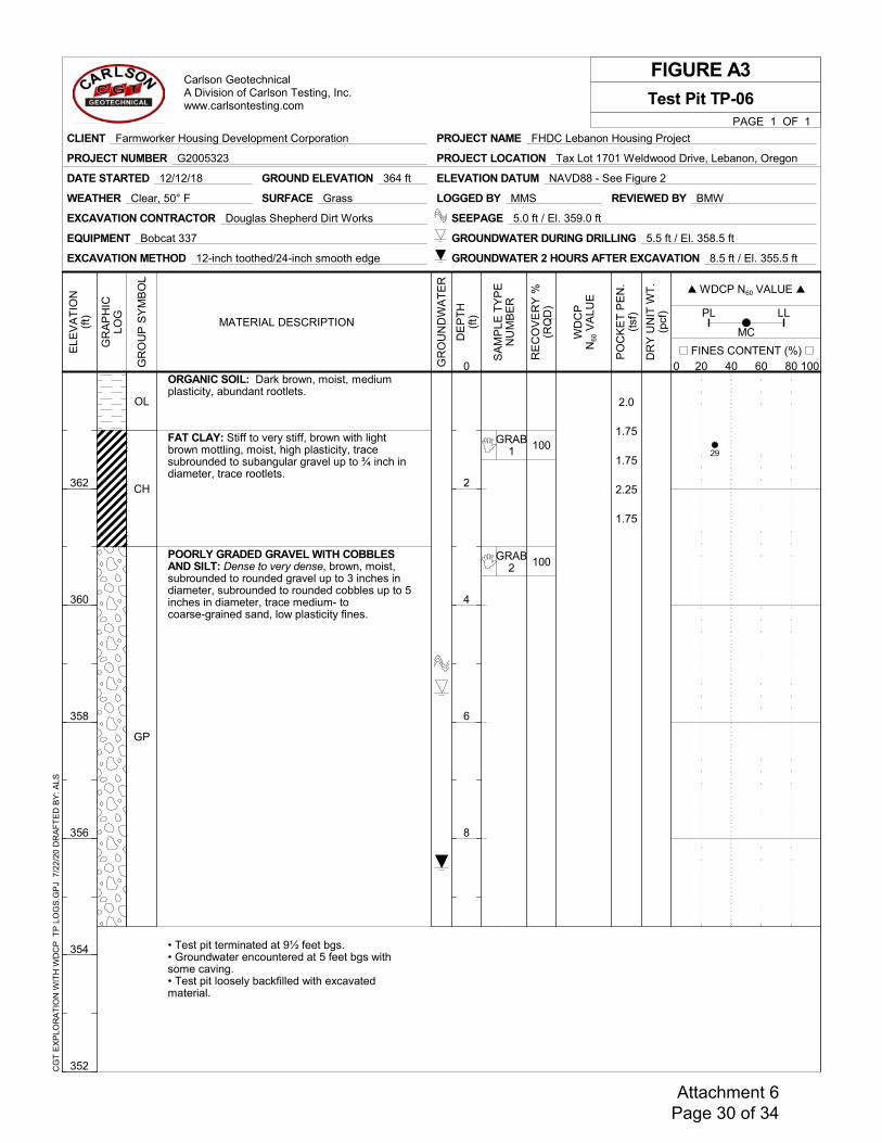
100
100
GRAB1
GRAB2
2.0
1.75
1.75
2.25
1.75
ORGANIC SOIL: Dark brown, moist, mediumplasticity, abundant rootlets.
FAT CLAY: Stiff to very stiff, brown with lightbrown mottling, moist, high plasticity, tracesubrounded to subangular gravel up to ¾ inch indiameter, trace rootlets.
POORLY GRADED GRAVEL WITH COBBLESAND SILT: Dense to very dense, brown, moist,subrounded to rounded gravel up to 3 inches indiameter, subrounded to rounded cobbles up to 5inches in diameter, trace medium- tocoarse-grained sand, low plasticity fines.
• Test pit terminated at 9½ feet bgs.• Groundwater encountered at 5 feet bgs withsome caving.• Test pit loosely backfilled with excavatedmaterial.
OL
CH
GP
LOGGED BY MMS
GROUND ELEVATION 364 ft ELEVATION DATUM NAVD88 - See Figure 2DATE STARTED 12/12/18
SEEPAGE 5.0 ft / El. 359.0 ft
GROUNDWATER 2 HOURS AFTER EXCAVATION 8.5 ft / El. 355.5 ft
REVIEWED BY BMW
EXCAVATION METHOD 12-inch toothed/24-inch smooth edge
EQUIPMENT Bobcat 337
EXCAVATION CONTRACTOR Douglas Shepherd Dirt Works
WEATHER Clear, 50° F SURFACE Grass
GROUNDWATER DURING DRILLING 5.5 ft / El. 358.5 ft
FIGURE A3
RE
CO
VE
RY
%(R
QD
)
SA
MP
LE T
YP
EN
UM
BE
R
PO
CK
ET
PE
N.
(tsf
)
DR
Y U
NIT
WT
.(p
cf)
DE
PT
H(f
t)
0
2
4
6
8
MC20 40 60 80
PL LL
PAGE 1 OF 1
Test Pit TP-06
WDCP N60 VALUE 20 40 60 80
MATERIAL DESCRIPTION
WD
CP
N60
VA
LUE
GR
OU
ND
WA
TE
R
ELE
VA
TIO
N(f
t)
362
360
358
356
354
352
FINES CONTENT (%) 20 40 60 800 100G
RO
UP
SY
MB
OL
GR
AP
HIC
LOG
PROJECT NAME FHDC Lebanon Housing Project
PROJECT LOCATION Tax Lot 1701 Weldwood Drive, Lebanon, Oregon
CLIENT Farmworker Housing Development Corporation
PROJECT NUMBER G2005323
Carlson GeotechnicalA Division of Carlson Testing, Inc.www.carlsontesting.com
CG
T E
XP
LOR
AT
ION
WIT
H W
DC
P T
P L
OG
S.G
PJ
7/2
2/20
DR
AF
TE
D B
Y: A
LS
29
Attachment 6 Page 30 of 34
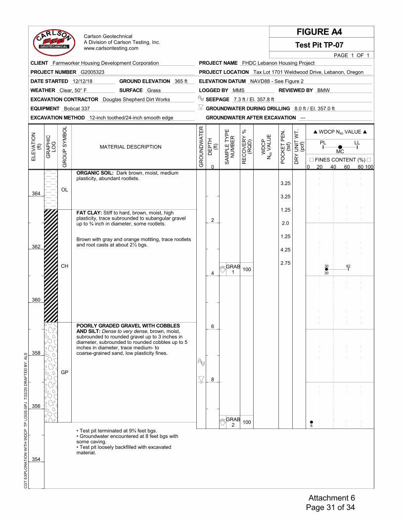
100
100
GRAB1
GRAB2
3.25
3.25
1.25
2.0
1.25
4.25
2.75
ORGANIC SOIL: Dark brown, moist, mediumplasticity, abundant rootlets.
FAT CLAY: Stiff to hard, brown, moist, highplasticity, trace subrounded to subangular gravelup to ¾ inch in diameter, some rootlets.
Brown with gray and orange mottling, trace rootletsand root casts at about 2½ bgs.
POORLY GRADED GRAVEL WITH COBBLESAND SILT: Dense to very dense, brown, moist,subrounded to rounded gravel up to 3 inches indiameter, subrounded to rounded cobbles up to 5inches in diameter, trace medium- tocoarse-grained sand, low plasticity fines.
• Test pit terminated at 9¾ feet bgs.• Groundwater encountered at 8 feet bgs withsome caving.• Test pit loosely backfilled with excavatedmaterial.
OL
CH
GP
LOGGED BY MMS
GROUND ELEVATION 365 ft ELEVATION DATUM NAVD88 - See Figure 2DATE STARTED 12/12/18
SEEPAGE 7.3 ft / El. 357.8 ft
GROUNDWATER AFTER EXCAVATION ---
REVIEWED BY BMW
EXCAVATION METHOD 12-inch toothed/24-inch smooth edge
EQUIPMENT Bobcat 337
EXCAVATION CONTRACTOR Douglas Shepherd Dirt Works
WEATHER Clear, 50° F SURFACE Grass
GROUNDWATER DURING DRILLING 8.0 ft / El. 357.0 ft
FIGURE A4
RE
CO
VE
RY
%(R
QD
)
SA
MP
LE T
YP
EN
UM
BE
R
PO
CK
ET
PE
N.
(tsf
)
DR
Y U
NIT
WT
.(p
cf)
DE
PT
H(f
t)
0
2
4
6
8
MC20 40 60 80
PL LL
PAGE 1 OF 1
Test Pit TP-07
WDCP N60 VALUE 20 40 60 80
MATERIAL DESCRIPTION
WD
CP
N60
VA
LUE
GR
OU
ND
WA
TE
R
ELE
VA
TIO
N(f
t)
364
362
360
358
356
354
FINES CONTENT (%) 20 40 60 800 100G
RO
UP
SY
MB
OL
GR
AP
HIC
LOG
PROJECT NAME FHDC Lebanon Housing Project
PROJECT LOCATION Tax Lot 1701 Weldwood Drive, Lebanon, Oregon
CLIENT Farmworker Housing Development Corporation
PROJECT NUMBER G2005323
Carlson GeotechnicalA Division of Carlson Testing, Inc.www.carlsontesting.com
CG
T E
XP
LOR
AT
ION
WIT
H W
DC
P T
P L
OG
S.G
PJ
7/2
2/20
DR
AF
TE
D B
Y: A
LS
30
8
30 62
Attachment 6 Page 31 of 34
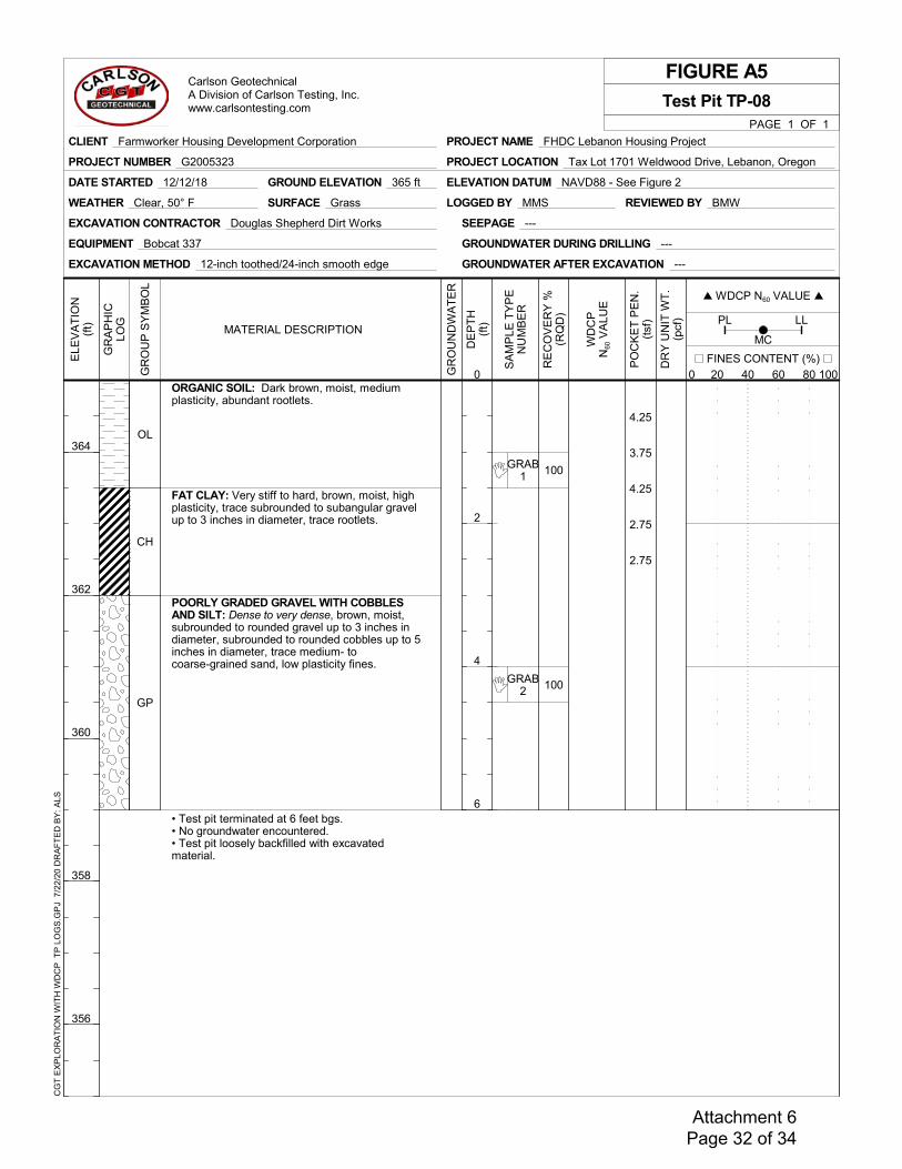
100
100
GRAB1
GRAB2
4.25
3.75
4.25
2.75
2.75
ORGANIC SOIL: Dark brown, moist, mediumplasticity, abundant rootlets.
FAT CLAY: Very stiff to hard, brown, moist, highplasticity, trace subrounded to subangular gravelup to 3 inches in diameter, trace rootlets.
POORLY GRADED GRAVEL WITH COBBLESAND SILT: Dense to very dense, brown, moist,subrounded to rounded gravel up to 3 inches indiameter, subrounded to rounded cobbles up to 5inches in diameter, trace medium- tocoarse-grained sand, low plasticity fines.
• Test pit terminated at 6 feet bgs.• No groundwater encountered.• Test pit loosely backfilled with excavatedmaterial.
OL
CH
GP
LOGGED BY MMS
GROUND ELEVATION 365 ft ELEVATION DATUM NAVD88 - See Figure 2DATE STARTED 12/12/18
SEEPAGE ---
GROUNDWATER AFTER EXCAVATION ---
REVIEWED BY BMW
EXCAVATION METHOD 12-inch toothed/24-inch smooth edge
EQUIPMENT Bobcat 337
EXCAVATION CONTRACTOR Douglas Shepherd Dirt Works
WEATHER Clear, 50° F SURFACE Grass
GROUNDWATER DURING DRILLING ---
FIGURE A5
RE
CO
VE
RY
%(R
QD
)
SA
MP
LE T
YP
EN
UM
BE
R
PO
CK
ET
PE
N.
(tsf
)
DR
Y U
NIT
WT
.(p
cf)
DE
PT
H(f
t)
0
2
4
6
MC20 40 60 80
PL LL
PAGE 1 OF 1
Test Pit TP-08
WDCP N60 VALUE 20 40 60 80
MATERIAL DESCRIPTION
WD
CP
N60
VA
LUE
GR
OU
ND
WA
TE
R
ELE
VA
TIO
N(f
t)
364
362
360
358
356
FINES CONTENT (%) 20 40 60 800 100G
RO
UP
SY
MB
OL
GR
AP
HIC
LOG
PROJECT NAME FHDC Lebanon Housing Project
PROJECT LOCATION Tax Lot 1701 Weldwood Drive, Lebanon, Oregon
CLIENT Farmworker Housing Development Corporation
PROJECT NUMBER G2005323
Carlson GeotechnicalA Division of Carlson Testing, Inc.www.carlsontesting.com
CG
T E
XP
LOR
AT
ION
WIT
H W
DC
P T
P L
OG
S.G
PJ
7/2
2/20
DR
AF
TE
D B
Y: A
LS
Attachment 6 Page 32 of 34
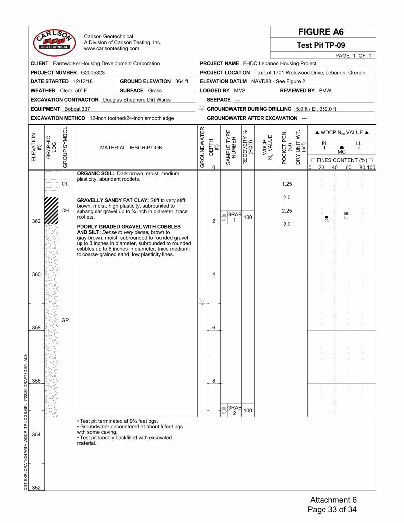
100
100
GRAB1
GRAB2
1.25
2.0
2.25
3.0
ORGANIC SOIL: Dark brown, moist, mediumplasticity, abundant rootlets.
GRAVELLY SANDY FAT CLAY: Stiff to very stiff,brown, moist, high plasticity, subrounded tosubangular gravel up to ¾ inch in diameter, tracerootlets.
POORLY GRADED GRAVEL WITH COBBLESAND SILT: Dense to very dense, brown togray-brown, moist, subrounded to rounded gravelup to 3 inches in diameter, subrounded to roundedcobbles up to 6 inches in diameter, trace medium-to coarse-grained sand, low plasticity fines.
• Test pit terminated at 9¼ feet bgs.• Groundwater encountered at about 5 feet bgswith some caving.• Test pit loosely backfilled with excavatedmaterial.
OL
CH
GP
LOGGED BY MMS
GROUND ELEVATION 364 ft ELEVATION DATUM NAVD88 - See Figure 2DATE STARTED 12/12/18
SEEPAGE ---
GROUNDWATER AFTER EXCAVATION ---
REVIEWED BY BMW
EXCAVATION METHOD 12-inch toothed/24-inch smooth edge
EQUIPMENT Bobcat 337
EXCAVATION CONTRACTOR Douglas Shepherd Dirt Works
WEATHER Clear, 50° F SURFACE Grass
GROUNDWATER DURING DRILLING 5.0 ft / El. 359.0 ft
FIGURE A6
RE
CO
VE
RY
%(R
QD
)
SA
MP
LE T
YP
EN
UM
BE
R
PO
CK
ET
PE
N.
(tsf
)
DR
Y U
NIT
WT
.(p
cf)
DE
PT
H(f
t)
0
2
4
6
8
MC20 40 60 80
PL LL
PAGE 1 OF 1
Test Pit TP-09
WDCP N60 VALUE 20 40 60 80
MATERIAL DESCRIPTION
WD
CP
N60
VA
LUE
GR
OU
ND
WA
TE
R
ELE
VA
TIO
N(f
t)
362
360
358
356
354
352
FINES CONTENT (%) 20 40 60 800 100G
RO
UP
SY
MB
OL
GR
AP
HIC
LOG
PROJECT NAME FHDC Lebanon Housing Project
PROJECT LOCATION Tax Lot 1701 Weldwood Drive, Lebanon, Oregon
CLIENT Farmworker Housing Development Corporation
PROJECT NUMBER G2005323
Carlson GeotechnicalA Division of Carlson Testing, Inc.www.carlsontesting.com
CG
T E
XP
LOR
AT
ION
WIT
H W
DC
P T
P L
OG
S.G
PJ
7/2
2/20
DR
AF
TE
D B
Y: A
LS
28
56
Attachment 6 Page 33 of 34
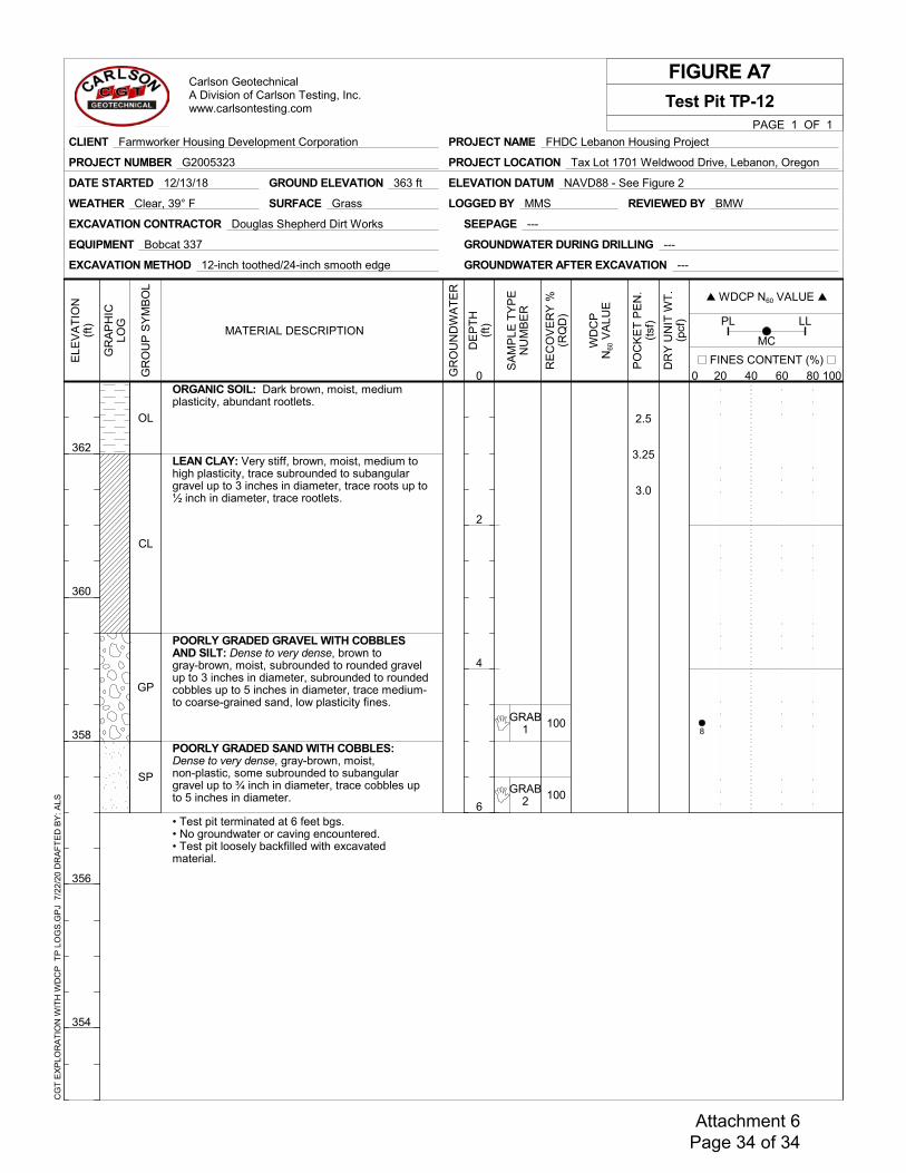
100
100
GRAB1
GRAB2
2.5
3.25
3.0
ORGANIC SOIL: Dark brown, moist, mediumplasticity, abundant rootlets.
LEAN CLAY: Very stiff, brown, moist, medium tohigh plasticity, trace subrounded to subangulargravel up to 3 inches in diameter, trace roots up to½ inch in diameter, trace rootlets.
POORLY GRADED GRAVEL WITH COBBLESAND SILT: Dense to very dense, brown togray-brown, moist, subrounded to rounded gravelup to 3 inches in diameter, subrounded to roundedcobbles up to 5 inches in diameter, trace medium-to coarse-grained sand, low plasticity fines.
POORLY GRADED SAND WITH COBBLES:Dense to very dense, gray-brown, moist,non-plastic, some subrounded to subangulargravel up to ¾ inch in diameter, trace cobbles upto 5 inches in diameter.
• Test pit terminated at 6 feet bgs.• No groundwater or caving encountered.• Test pit loosely backfilled with excavatedmaterial.
OL
CL
GP
SP
LOGGED BY MMS
GROUND ELEVATION 363 ft ELEVATION DATUM NAVD88 - See Figure 2DATE STARTED 12/13/18
SEEPAGE ---
GROUNDWATER AFTER EXCAVATION ---
REVIEWED BY BMW
EXCAVATION METHOD 12-inch toothed/24-inch smooth edge
EQUIPMENT Bobcat 337
EXCAVATION CONTRACTOR Douglas Shepherd Dirt Works
WEATHER Clear, 39° F SURFACE Grass
GROUNDWATER DURING DRILLING ---
FIGURE A7
RE
CO
VE
RY
%(R
QD
)
SA
MP
LE T
YP
EN
UM
BE
R
PO
CK
ET
PE
N.
(tsf
)
DR
Y U
NIT
WT
.(p
cf)
DE
PT
H(f
t)
0
2
4
6
MC20 40 60 80
PL LL
PAGE 1 OF 1
Test Pit TP-12
WDCP N60 VALUE 20 40 60 80
MATERIAL DESCRIPTION
WD
CP
N60
VA
LUE
GR
OU
ND
WA
TE
R
ELE
VA
TIO
N(f
t)
362
360
358
356
354
FINES CONTENT (%) 20 40 60 800 100G
RO
UP
SY
MB
OL
GR
AP
HIC
LOG
PROJECT NAME FHDC Lebanon Housing Project
PROJECT LOCATION Tax Lot 1701 Weldwood Drive, Lebanon, Oregon
CLIENT Farmworker Housing Development Corporation
PROJECT NUMBER G2005323
Carlson GeotechnicalA Division of Carlson Testing, Inc.www.carlsontesting.com
CG
T E
XP
LOR
AT
ION
WIT
H W
DC
P T
P L
OG
S.G
PJ
7/2
2/20
DR
AF
TE
D B
Y: A
LS
8
Attachment 6 Page 34 of 34

Attachment #7
33 NW Franklin Ave., Ste. 110Bend, OR 97703
(541) 647-1445
C I V I L • S TRUCTURALwww.ashleyvance.com
July 21, 2020
Claudia Cantu, Deputy DirectorFarmworker Housing Development Corporation1274 5th Street, Suite 1-A, Woodburn, OR 97071
RE: Stormwater Drainage Facilities at the Colonia Paz I Apartment Development in Lebanon, Oregon
Dear Claudia,
The Colonia Paz 1 Apartment development in Lebanon, Oregon is proposed on a vacant site off of Weldwood Drive just south of the Walmart Supercenter. The City of Lebanon code requires the following for stormwater drainage design:
Storm drainage facilities must be designed and constructed to ensure historical rates of discharge are not exceeded. Storm drain capacity shall be determined by the Rational Method for a 10-year event with a 15-minute minimum durations time using the curve (fig 5.3) in the master plan. A detailed design including engineering calculations shall be submitted as part of site plan review.
Ashley & Vance Engineering, Inc has designed a system the exceeds the City’s standards. All stormwater runoff for the 25-year storm event will be collected and infiltrated onsite. No stormwater will overflow off of the site. As shown on the attached plans, C-4.0 and C-4.1, runoff from the proposed building roof and half of the parking lot will flow to new stormwater swales. Structures in the swales will then divert the runoff to underground stormwater chambers that will detain and infiltrate the stormwater. Runoff from the other half of the parking lot will be collected in catch basins and then piped to the storm chambers. The catch basins have 2-foot deep sumps, and there are manholes upstream of the chambers with 2-foot sumps as well. These sumps and the swales provide treatment of the runoff and system redundancy to eliminate pollutants and sediments from entering the chambers and the ground.
The proposed stormwater drainage system for the Colonia Paz 1 Apartments meets and exceeds the City of Lebanon and Oregon DEQ standards. Please let me know if you have any further questions or comments.
Sincerely,
Jim Lord, PE
Oregon PE No. 77331
Attachment 7 Page 1 of 3
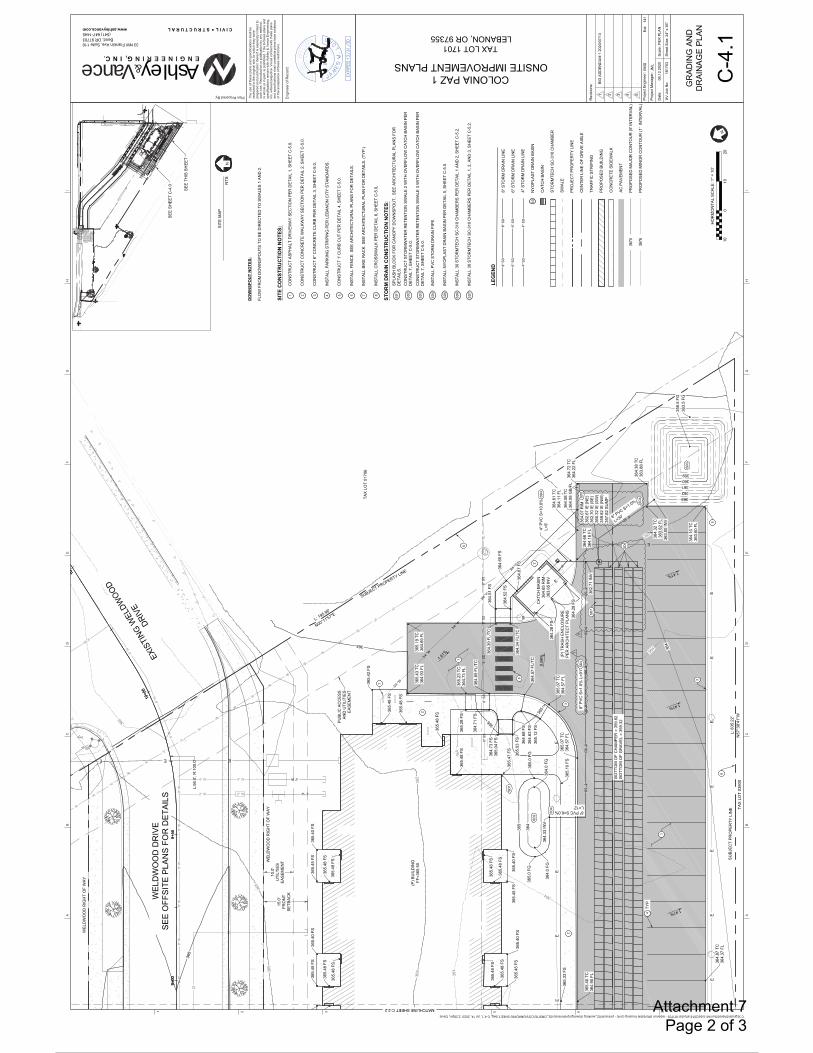
SD
SD
SD
SD
SD
PMPM
PMPM
TR
TR
8'' W
8'' W
BOTT
OM O
F CH
AMPE
R =
359.
82
BOTT
OM O
F GRA
VEL
= 35
9.32
BOTT
OM O
F CH
AMPE
R =
359.
82
BOTT
OM O
F GRA
VEL
= 35
9.32
E E E
EE
EE
EE
E
EE
EE
EE
E
E
E
SD
6'' SD
8'' SD8'' SD
8'' SD8'' SD
8'' SD8'' SD
9+00
9+50
10+0
0
10+
L:56
.0',
R:1
00.0
'
8'' W
8'' W
8'' W
8'' W
8'' W
8'' W
8'' W
8'' W
8'' W
8'' W
G
6'' S
S6'
' SS
6'' S
S6'
' SS
6'' S
S
4'' W
2'' W
3/4 ''W
3/4 ''W
3/4 ''W
3/4 ''W
3/4 ''W
2'' W 2'' W
4'' W 4'' W
G
N00°11'57"EL: 195.98'
N57
°38'
41"W
L: 8
35.2
2'
BOTT
OM
OF
CH
AMPE
R =
359
.82
BOTT
OM
OF
GR
AVEL
= 3
59.3
2
9+00
9+50
10+0
0
10+
AB
CD
EF
GH
I
AB
CD
EF
GH
I
1 2 3 4 5 6 7
C:\Egnyte\Shared\Sun\All Jobs\2018 all jobs\181703 - lebanon affordable housing (civil) - pinnacle\02_working drawings\preliminary\02_ONSITE\CD's\GRADING SHEET.dwg, C-4.1, Jul 14, 2020 2:28pm, Davis
Engi
neer
of R
ecor
d:
Plan Prepared By: The
use
of th
ese
plan
s an
d sp
ecifi
catio
ns s
hall
bere
stric
ted
to th
e or
igin
al s
ite fo
r whi
ch th
ey w
ere
prep
ared
and
pub
licat
ion
ther
eof i
s ex
pres
sly
limite
d to
such
use
. Rep
rodu
ctio
n or
pub
licat
ion
by a
ny m
etho
d,in
who
le o
r in
part,
is p
rohi
bite
d. T
itle
to th
ese
plan
s an
dsp
ecifi
catio
ns re
mai
n w
ith A
shle
y &
Vanc
e En
gine
erin
g,In
c. w
ithou
t pre
judi
ce. V
isua
l con
tact
with
thes
e pl
ans
and
spec
ifica
tions
sha
ll co
nstit
ute
prim
a fa
cie
evid
ence
of th
e ac
cept
ance
of t
hese
rest
rictio
ns.
Ashley&Vance G, C
www.ashleyvance.com C I V I L S T R U C T U R A L
33 NW Franklin Ave, Suite 110Bend, OR 97703 (541) 647-1445
ENGINEER
JUL 11, 200
6
Rev
isio
ns:
Proj
ect E
ngin
eer:
Proj
ect M
anag
er:
Dat
e:
AV J
ob N
o:
Scal
e:PE
R P
LAN
Shee
t Siz
e:24
" x 3
6"
Ext:
N
COLONIA PAZ 1ONSITE IMPROVEMENT PLANS
TAX LOT 1701LEBANON, OR 97355
EMD
JML
06.1
2.20
20
1817
03
GR
ADIN
G A
ND
DR
AIN
AGE
PLAN
C-4
.1
1BI
D A
DD
END
UM
1 2
020/
07/1
3
2.
3.
4.
5.
141
N0
1010
20
HO
RIZ
ON
TAL
SCAL
E: 1
" = 1
0'
1
1
3
3
2
2
MATCHLINE SHEET C-2.2
PUBL
IC A
CC
ESS
AND
UTI
LITI
ESEA
SEM
ENT
SD3
SD2
(P) T
RAS
H E
NC
LOSU
RE
PER
AR
CH
ITEC
T PL
ANS
EXIS
TING
WEL
DWOO
D
DRIV
E
SEE
SHEE
T C
-4.0
SEE
THIS
SH
EET
(P) B
UIL
DIN
GFF
=365
.50
5
TYP
4
SD1
10.0
'U
TILT
IES
EASE
MEN
T15
.0'
FRO
NT
SETB
ACK
WEL
DW
OO
D R
IGH
T O
F W
AY
WEL
DW
OO
D R
IGH
T O
F W
AY
SITE
CO
NST
RU
CTI
ON
NO
TES:
CO
NST
RU
CT
ASPH
ALT
DR
IVEW
AY S
ECTI
ON
PER
DET
AIL
1, S
HEE
T C
-5.0
.
CO
NST
RU
CT
CO
NC
RET
E W
ALKW
AY S
ECTI
ON
PER
DET
AIL
2, S
HEE
T C
-5.0
.
CO
NST
RU
CT
6" C
ON
CR
ETE
CU
RB
PER
DET
AIL
3, S
HEE
T C
-5.0
.
INST
ALL
PAR
KIN
G S
TRIP
ING
PER
LEB
ANO
N C
ITY
STAN
DAR
DS.
CO
NST
RU
CT
1' C
UR
B C
UT
PER
DET
AIL
4, S
HEE
T C
-5.0
.
INST
ALL
FEN
CE.
SEE
AR
CH
ITEC
TUR
AL P
LAN
S FO
R D
ETAI
LS.
INST
ALL
BIKE
RAC
K. S
EE A
RC
HIT
ECTU
RAL
PLA
N F
OR
DET
AILS
. (TY
P.)
INST
ALL
CR
OSS
WAL
K PE
R D
ETAI
L 6,
SH
EET
C-5
.0,
1 2 3 4 5 6 7 8
SITE
MAP
NTS
STO
RM
DR
AIN
CO
NST
RU
CTI
ON
NO
TES:
SPLA
SH B
LOC
K FO
R C
ANO
PY D
OW
NSP
OU
T. S
EE A
RC
HIT
ECTU
RAL
PLA
NS
FOR
DET
AILS
.C
ON
STR
UC
T ST
OR
MW
ATER
RET
ENTI
ON
SW
ALE
2 W
ITH
OVE
RFL
OW
CAT
CH
BAS
IN P
ERD
ETAI
L 7,
SH
EET
C-5
.0.
CO
NST
RU
CT
STO
RM
WAT
ER R
ETEN
TIO
N S
WAL
E 3
WIT
H O
VER
FLO
W C
ATC
H B
ASIN
PER
DET
AIL
7, S
HEE
T C
-5.0
.
INST
ALL
PVC
STO
RM
DR
AIN
PIP
E.
INST
ALL
NYO
PLAS
T D
RAI
N B
ASIN
PER
DET
AIL
5, S
HEE
T C
-5.0
.
INST
ALL
30 S
TOR
MTE
CH
SC
-310
CH
AMBE
RS
PER
DET
AIL
1 AN
D 2
, SH
EET
C-5
.2.
INST
ALL
30 S
TOR
MTE
CH
SC
-310
CH
AMBE
RS
PER
DET
AIL
1, 2
, AN
D 3
, SH
EET
C-5
.2.
SD1
SD2
SD3
SD4
SD5
SD6
SD7
8" P
VC S
=1.0
% L
=91'
8" PVC S=6.0%L=12'
SD4
SD4
6" PVC S=1.0%
L=30'
SD4SD
5
SD7
SD6
6
6
7
LEG
END
8" S
TOR
M D
RAI
N L
INE
6" S
TOR
M D
RAI
N L
INE
4" S
TOR
M D
RAI
N L
INE
NYO
PLAS
T D
RAI
N B
ASIN
CAT
CH
BAS
IN
STO
RM
TEC
H S
C-3
10 C
HAM
BER
SWAL
E
PRO
JEC
T PR
OPE
RTY
LIN
E
CEN
TER
LIN
E O
F D
RIV
E AI
SLE
TRAF
FIC
STR
IPIN
G
PRO
POSE
D B
UIL
DIN
G
CO
NC
RET
E SI
DEW
ALK
AC P
AVEM
ENT
PRO
POSE
D M
AJO
R C
ON
TOU
R (5
' IN
TER
VAL)
PRO
POSE
D M
INO
R C
ON
TOU
R (1
' IN
TER
VAL)
8'' S
D8'
' SD
4'' S
D4'
' SD
SD
WEL
DW
OO
D D
RIV
ESE
E O
FFSI
TE P
LAN
S FO
R D
ETAI
LS
4" P
VC S
=10.
0%L=
9'SD
4
8
SUBJECT PROPERTY LINE
TAX
LOT
0170
6
6'' S
D6'
' SD
2
TAX
LOT
0380
0
SUBJ
ECT
PRO
PER
TY L
INE
DO
WN
SPO
UT
NO
TES:
FLO
W F
RO
M D
OW
NSP
OU
TS T
O B
E D
IREC
TED
TO
SW
ALES
1 A
ND
2.
11
1
Attachment 7 Page 2 of 3

EE
E
E
EE
EE
E
EE
EE
E
8'' SD
8'' SD8'' SD
8'' SD8'' SD
8'' SD8'' SD
8'' SD8'' SD
SD
4'' SD
8'' SD8'' SD
12'' W
12'' W
12'' W
12'' W
SD SD
12'' W
12'' W SD
8'' SD
7+00
7+50
8+00
8+50
8'' W
8'' W
8'' W
8'' W
8'' W
8'' W
8'' W
8'' W
8'' W
8'' W
8'' W
8'' W
8'' W
8'' W
8'' W
8'' W
8'' W
GG
GG
GG
GG
GG
6'' W
8'' W
3/4 ''W3/4 ''W3/4 ''W3/4 ''W
BOTT
OM
OF
CH
AMPE
R =
359
.82
BOTT
OM
OF
GR
AVEL
= 3
59.3
2
N57
°38'
41"W
L: 8
35.2
2'
7+00
7+50
8+00
8+50
SD
SD
SD
SD
SD
PMPM
PMPM
TR
TR
8'' W
8'' W
BOTT
OM O
F CH
AMPE
R =
359.
82
BOTT
OM O
F GR
AVEL
= 3
59.3
2
N57°
38'41
"W
L: 8
35.2
2'
N00°11'57"EL: 195.98'
N57°
38'41
"W
L: 8
35.2
2'
BOTT
OM O
F CH
AMPE
R =
359.
82
BOTT
OM O
F GR
AVEL
= 3
59.3
2
AB
CD
EF
GH
I
AB
CD
EF
GH
I
1 2 3 4 5 6 7
C:\Egnyte\Shared\Sun\All Jobs\2018 all jobs\181703 - lebanon affordable housing (civil) - pinnacle\02_working drawings\preliminary\02_ONSITE\CD's\GRADING SHEET.dwg, C-4.0, Jul 14, 2020 2:47pm, Davis
Engi
neer
of R
ecor
d:
Plan Prepared By: The
use
of th
ese
plan
s an
d sp
ecifi
catio
ns s
hall
bere
stric
ted
to th
e or
igin
al s
ite fo
r whi
ch th
ey w
ere
prep
ared
and
pub
licat
ion
ther
eof i
s ex
pres
sly
limite
d to
such
use
. Rep
rodu
ctio
n or
pub
licat
ion
by a
ny m
etho
d,in
who
le o
r in
part,
is p
rohi
bite
d. T
itle
to th
ese
plan
s an
dsp
ecifi
catio
ns re
mai
n w
ith A
shle
y &
Vanc
e En
gine
erin
g,In
c. w
ithou
t pre
judi
ce. V
isua
l con
tact
with
thes
e pl
ans
and
spec
ifica
tions
sha
ll co
nstit
ute
prim
a fa
cie
evid
ence
of th
e ac
cept
ance
of t
hese
rest
rictio
ns.
Ashley&Vance G, C
www.ashleyvance.com C I V I L S T R U C T U R A L
33 NW Franklin Ave, Suite 110Bend, OR 97703 (541) 647-1445
ENGINEER
JUL 11, 200
6
Rev
isio
ns:
Proj
ect E
ngin
eer:
Proj
ect M
anag
er:
Dat
e:
AV J
ob N
o:
Scal
e:PE
R P
LAN
Shee
t Siz
e:24
" x 3
6"
Ext:
010
1020
HO
RIZ
ON
TAL
SCAL
E: 1
" = 1
0'
COLONIA PAZ 1ONSITE IMPROVEMENT PLANS
TAX LOT 1701LEBANON, OR 97355
EMD
JML
06.1
2.20
20
1817
03
GR
ADIN
G A
ND
DR
AIN
AGE
PLAN
C-4
.0
1.
2.
3.
4.
5.
141
N
N
STO
RM
DR
AIN
CO
NST
RU
CTI
ON
NO
TES:
INST
ALL
CAT
CH
BAS
IN P
ER C
ITY
OF
LEBA
NO
N S
TD. D
WG
004
00-0
8, 0
0400
-09.
CO
NST
RU
CT
STO
RM
WAT
ER R
ETEN
TIO
N S
WAL
E 1
WIT
H O
VER
FLO
W C
ATC
H B
ASIN
PER
DET
AIL
7, S
HEE
T C
-5.0
.
INST
ALL
PVC
STO
RM
DR
AIN
PIP
E.
INST
ALL
30 S
TOR
MTE
CH
SC
-310
CH
AMBE
RS
PER
DET
AIL
1 AN
D 2
, SH
EET
C-5
.2.
INST
ALL
30 S
TOR
MTE
CH
SC
-310
CH
AMBE
RS
PER
DET
AIL
1, 2
, AN
D 3
, SH
EET
C-5
.2.
INST
ALL
NYO
PLAS
T D
RAI
N B
ASIN
PER
DET
AIL
5, S
HEE
T C
-5.0
.
INST
ALL
TEM
POR
ARY
24'X
14' S
TOR
MW
ATER
RET
ENTI
ON
SW
ALE
AT 3
' DEE
P TO
DAY
LIG
HT
PRO
POSE
D 8
" OVE
R F
LOW
PIP
E.
SD1
SD2
SD3
SD4
SD5
SD6
SD7
SITE
CO
NST
RU
CTI
ON
NO
TES:
CO
NST
RU
CT
ASPH
ALT
DR
IVEW
AY S
ECTI
ON
PER
DET
AIL
1, S
HEE
T C
-5.0
.
CO
NST
RU
CT
CO
NC
RET
E W
ALKW
AY S
ECTI
ON
PER
DET
AIL
2, S
HEE
T C
-5.0
.
CO
NST
RU
CT
6" C
ON
CR
ETE
CU
RB
PER
DET
AIL
3, S
HEE
T C
-5.0
.
INST
ALL
PAR
KIN
G S
TRIP
ING
PER
LEB
ANO
N C
ITY
STAN
DAR
DS.
INST
ALL
FEN
CE.
SEE
AR
CH
ITEC
TUR
AL P
LAN
S FO
R D
ETAI
LS.
INST
ALL
BIKE
RAC
K. S
EE A
RC
HIT
ECTU
RAL
PLA
N F
OR
DET
AILS
. (TY
P.)
INST
ALL
CR
OSS
WAL
K PE
R D
ETAI
L 6,
SH
EET
C-5
.0,
INST
ALL
BOLL
ARD
S PE
R C
ITY
OF
LEBA
NO
N S
TD. D
WG
008
00-0
1. (T
YP. 2
)
1 2 3 4 5 6 7 8
11
1
TYP
2
2
3
3
3
3
2
MATCHLINE SHEET C-2.2
(P) B
UIL
DIN
GFF
=365
.50
SEE
THIS
SH
EET
SEE
SHEE
T C
-4.1
4
(P) T
RAS
H E
NC
LOSU
RE
PER
AR
CH
ITEC
T PL
ANS
(P) F
ENC
E PE
RAR
CH
ITEC
T PL
ANS
10.0
'U
TILT
IES
EASE
MEN
T15
.0'
FRO
NT
SETB
ACK
WEL
DW
OO
D R
IGH
T O
F W
AY
WEL
DW
OO
D R
IGH
T O
F W
AY
SD2
SITE
MAP
NTS
8" PVC S=6.0%L=16'
8" P
VC S
=0.5
% L
=116
'SD
3
SD3
SD5
SD4
SD6
5
SD1
4" PVC S=12.2% L=26'
SD3
6
LEG
END
8" S
TOR
M D
RAI
N L
INE
4" S
TOR
M D
RAI
N L
INE
NYO
PLAS
T D
RAI
N B
ASIN
CAT
CH
BAS
IN
STO
RM
TEC
H S
C-3
10 C
HAM
BER
SWAL
E
PRO
JEC
T PR
OPE
RTY
LIN
E
CEN
TER
LIN
E O
F D
RIV
E AI
SLE
TRAF
FIC
STR
IPIN
G
PRO
POSE
D B
UIL
DIN
G
CO
NC
RET
E SI
DEW
ALK
AC P
AVEM
ENT
PRO
POSE
D M
AJO
R C
ON
TOU
R (5
' IN
TER
VAL)
PRO
POSE
D M
INO
R C
ON
TOU
R (1
' IN
TER
VAL)
8'' S
D8'
' SD
4'' S
D4'
' SD
SD
7
8" P
VC S
=0.5
% L
=33'
SD3
SD1
SUBJ
ECT
PRO
PER
TY L
INE
TAX
LOT
0380
0
WEL
DW
OO
D D
RIV
ESE
E O
FFSI
TE P
LAN
S FO
R D
ETAI
LS
3
2
8
3
DO
WN
SPO
UT
NO
TES:
FLO
W F
RO
M D
OW
NSP
OU
TS T
O B
E D
IREC
TED
TO
SW
ALES
1 A
ND
2.
8" P
VC S
=1.0
% L
=21'
SD3
SD7
Attachment 7 Page 3 of 3

Attachment #8
12965 SW Herman Road, Suite 100Tualatin, OR 97062
(503) 563 6151
Colonia Paz Housing ComplexLebanon, Oregon
Wetland Delineation Report
Date: November 26, 2018
Prepared for: Farmworker Housing Development Corporation1274 5th Street, Suite 1 A
Woodburn, OR 97071
Prepared By: AKS Engineering & Forestry, LLCSonya Templeton and
Stacey Reed, PWS, Senior Wetland Scientist
Site Information: T12S, R2W, Section 23B, Tax Lot 1701Lebanon, Linn County, Oregon
Attachment 8 Page 1 of 49
Colonia Paz Hosing Complex (AKS Job 7138) November 2018Wetland Delineation Report Page 2
Table of ContentsIntroduction ............................................................................................................................... ................... 3
A. Landscape Setting and Land Use .............................................................................................................. 3
B. Site Alterations............................................................................................................................... ........... 4
C. Precipitation Data and Analysis ................................................................................................................ 4
D. Delineation Methods ............................................................................................................................... . 4
E. Description of All Wetlands and Other Non Wetland Waters.................................................................. 5
Wetland A ............................................................................................................................... .................. 5
Artificial Pond............................................................................................................................... ............. 5
F. Deviation from National Wetland Inventory ............................................................................................ 6
G. Mapping Method............................................................................................................................... ....... 6
H. Additional Information ............................................................................................................................. 6
I. Summary of Results and Conclusions ........................................................................................................ 7
J. Required Disclaimer............................................................................................................................... .... 7
K. List of Preparers ............................................................................................................................... ......... 7
Literature Cited and Referenced................................................................................................................... 8
TablesTable 1. Precipitation Data – Observed Rainfall (Inches) the Day of Site Visits and within the Two
Weeks Prior
Table 2. Precipitation Data – Monthly Averages Based on the Climate Period 1971 2000 (Inches)
Table 3. Summary of Study Results and Conclusions
Appendicesi. Figure 1. USGS Vicinity Mapii. Figure 2. Tax Mapiii. Figure 3. NRCS Soil Survey Mapiv. Figure 4. National Wetland Inventory Mapv. Figures 5. Wetland Delineation Map
Appendix A.WD#1994 0430 and WD#2001 0118 DSL Concurrence Letter
Appendix B. Google Earth Aerial Photographs
Appendix C. Precipitation Data
Appendix D.Wetland Determination Data Forms
Appendix E. Photo Location Map and Site Photographs
Attachment 8 Page 2 of 49

Colonia Paz Hosing Complex (AKS Job 7138) November 2018Wetland Delineation Report Page 3
IntroductionThis report was prepared by AKS Engineering & Forestry, LLC (AKS) in accordance with OregonAdministrative Rules (OAR) 141 090 0030 and 141 090 0035 (1 17) and describes the results of a wetlanddelineation conducted on a site south of Weldwood Drive in Lebanon, Linn County, Oregon (Figure 1). Thewetland delineation study area is approximately ±9.53 acres in size and includes Tax Lot 1701 of LinnCounty’s Assessor’s Tax Map 12S 2W 23B (Figure 2). The on site boundaries of one palustrine forested(PFO) wetland (referred to as Wetland A) located in the southwestern portion of the site and an isolatedartificial pond were delineated in the study area. Our investigation determined that approximately ±0.55acres of potentially jurisdictional wetlands are present within the study area.
A wetland delineation was previously conducted on the site in April of 1994 (which also included an offsite area to the south) by Jay Lorenz of A.G. Crook Company. The 1994 delineation received concurrenceby the Oregon Department of State Lands (DSL) under DSL File WD# 1994 0430. Our delineation generallyagrees with the 1994 boundaries delineated for Wetland A and the artificial pond; however, we did notdocument isolated wetland conditions in the central portion of the site that were previously present onthe site.
Mr. Lorenz conducted an updated delineation for the adjacent tax lot to the south (tax lot 3800) in 2001.Mr. Lorenz determined site conditions on the adjacent tax lot had not significantly changed since hisoriginal 1994 wetland delineation. Although the updated delineation was for the adjacent site to thesouth, Mr. Lorenz implied wetland conditions for the entire wetland (including subject site) had notchanged. DSL confirmed the updated 2001 wetland delineation boundaries under DSL File WD#20010118. The DSL concurrence letters are included in Appendix A for reference.
The western portion of the site contains a compensatory mitigation site associated with the SantiamVillage project, DSL File FP 13676. The mitigation site included 22,242 square feet/0.51 acres of wetlandcreation located adjacent to the PFOwetland delineated in the southern portion of the site. Themitigationsite was not protected under a deed restriction. We did not document wetland conditions within thecompensatory mitigation area; however, this area is still protected as a compensatory mitigation site byDSL. The mitigation area is shown on the attached delineation figure. Any amount of removal or fill withinthe mitigation site requires authorization from DSL.
A. Landscape Setting and Land UseThe study area consists of an undeveloped field. An old farm road run through the central portion of thestudy area. The field is dominated with planted pasture grasses consisting of tall false rye grass(Schedonorus arundinaceus; FAC) and colonial bent (Agrostis capillaris; FAC), as well as scatteredHimalayan blackberry (Rubus armeniacus; FAC), Queen Anne’s lace (Daucus carota; FACU), Englishplantain (Plantago lanceolata; FACU), and common dandelion (Taraxacum officinale; FACU). Fewscattered balsam poplar (Populus balsamifera; FAC) are present in the field and around Wetland A.
General topography in the study area is flat (less than 5% overall slope), with a subtle southerly slopetowards Wetland A.
The following soil units are mapped within the study area, according to the Natural ResourcesConservation Service (NRCS) Linn, County Area Soil Survey Map and hydric soil list (Figure 3)
(Unit 23) Clackamas gravelly silt loam – Non hydric; and
(Unit 2224A) Courtney gravelly silty clay loam, 0% to 3% slopes –Hydric
Attachment 8 Page 3 of 49
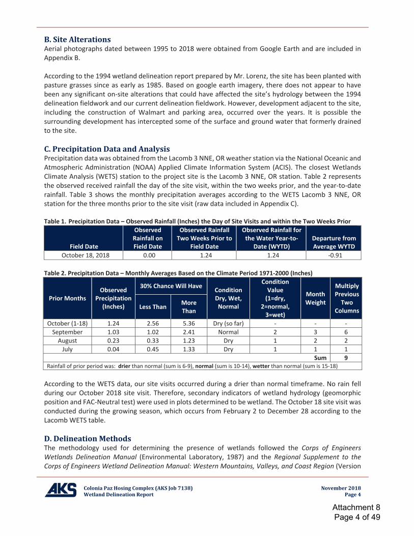
Colonia Paz Hosing Complex (AKS Job 7138) November 2018Wetland Delineation Report Page 4
B. Site AlterationsAerial photographs dated between 1995 to 2018 were obtained from Google Earth and are included inAppendix B.
According to the 1994 wetland delineation report prepared by Mr. Lorenz, the site has been planted withpasture grasses since as early as 1985. Based on google earth imagery, there does not appear to havebeen any significant on site alterations that could have affected the site’s hydrology between the 1994delineation fieldwork and our current delineation fieldwork. However, development adjacent to the site,including the construction of Walmart and parking area, occurred over the years. It is possible thesurrounding development has intercepted some of the surface and ground water that formerly drainedto the site.
C. Precipitation Data and AnalysisPrecipitation data was obtained from the Lacomb 3 NNE, OR weather station via the National Oceanic andAtmospheric Administration (NOAA) Applied Climate Information System (ACIS). The closest WetlandsClimate Analysis (WETS) station to the project site is the Lacomb 3 NNE, OR station. Table 2 representsthe observed received rainfall the day of the site visit, within the two weeks prior, and the year to daterainfall. Table 3 shows the monthly precipitation averages according to the WETS Lacomb 3 NNE, ORstation for the three months prior to the site visit (raw data included in Appendix C).
Table 1. Precipitation Data – Observed Rainfall (Inches) the Day of Site Visits and within the Two Weeks Prior
Field Date
ObservedRainfall onField Date
Observed RainfallTwo Weeks Prior to
Field Date
Observed Rainfall forthe Water Year to
Date (WYTD)Departure fromAverage WYTD
October 18, 2018 0.00 1.24 1.24 0.91
Table 2. Precipitation Data – Monthly Averages Based on the Climate Period 1971 2000 (Inches)
Prior MonthsObserved
Precipitation(Inches)
30% Chance Will Have ConditionDry, Wet,Normal
ConditionValue(1=dry,
2=normal,3=wet)
MonthWeight
MultiplyPreviousTwo
ColumnsLess Than MoreThan
October (1 18) 1.24 2.56 5.36 Dry (so far)September 1.03 1.02 2.41 Normal 2 3 6August 0.23 0.33 1.23 Dry 1 2 2July 0.04 0.45 1.33 Dry 1 1 1
Sum 9Rainfall of prior period was: drier than normal (sum is 6 9), normal (sum is 10 14), wetter than normal (sum is 15 18)
According to the WETS data, our site visits occurred during a drier than normal timeframe. No rain fellduring our October 2018 site visit. Therefore, secondary indicators of wetland hydrology (geomorphicposition and FAC Neutral test) were used in plots determined to be wetland. The October 18 site visit wasconducted during the growing season, which occurs from February 2 to December 28 according to theLacomb WETS table.
D. Delineation MethodsThe methodology used for determining the presence of wetlands followed the Corps of EngineersWetlands Delineation Manual (Environmental Laboratory, 1987) and the Regional Supplement to theCorps of Engineers Wetland Delineation Manual: Western Mountains, Valleys, and Coast Region (Version
Attachment 8 Page 4 of 49
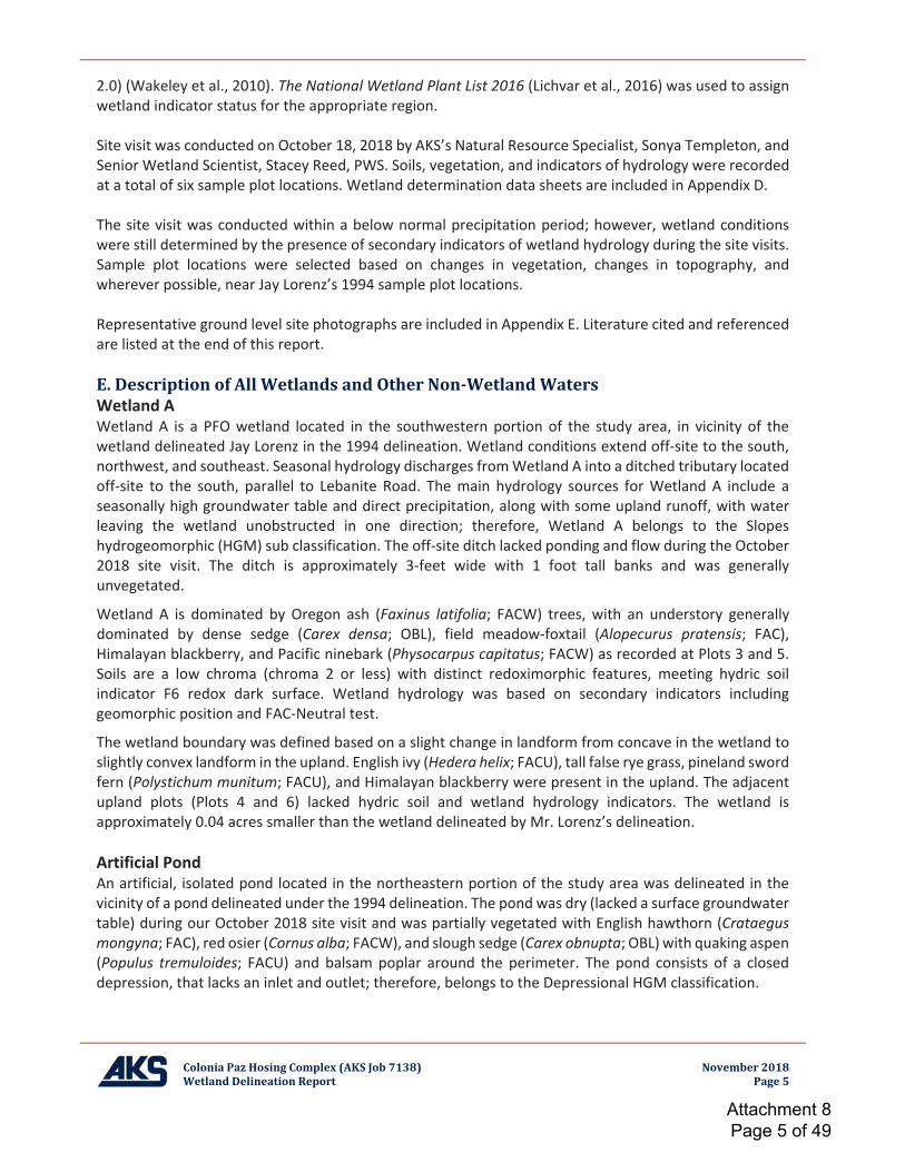
Colonia Paz Hosing Complex (AKS Job 7138) November 2018Wetland Delineation Report Page 5
2.0) (Wakeley et al., 2010). The National Wetland Plant List 2016 (Lichvar et al., 2016) was used to assignwetland indicator status for the appropriate region.
Site visit was conducted on October 18, 2018 by AKS’s Natural Resource Specialist, Sonya Templeton, andSenior Wetland Scientist, Stacey Reed, PWS. Soils, vegetation, and indicators of hydrology were recordedat a total of six sample plot locations. Wetland determination data sheets are included in Appendix D.
The site visit was conducted within a below normal precipitation period; however, wetland conditionswere still determined by the presence of secondary indicators of wetland hydrology during the site visits.Sample plot locations were selected based on changes in vegetation, changes in topography, andwherever possible, near Jay Lorenz’s 1994 sample plot locations.
Representative ground level site photographs are included in Appendix E. Literature cited and referencedare listed at the end of this report.
E. Description of All Wetlands and Other Non WetlandWatersWetland AWetland A is a PFO wetland located in the southwestern portion of the study area, in vicinity of thewetland delineated Jay Lorenz in the 1994 delineation. Wetland conditions extend off site to the south,northwest, and southeast. Seasonal hydrology discharges fromWetland A into a ditched tributary locatedoff site to the south, parallel to Lebanite Road. The main hydrology sources for Wetland A include aseasonally high groundwater table and direct precipitation, along with some upland runoff, with waterleaving the wetland unobstructed in one direction; therefore, Wetland A belongs to the Slopeshydrogeomorphic (HGM) sub classification. The off site ditch lacked ponding and flow during the October2018 site visit. The ditch is approximately 3 feet wide with 1 foot tall banks and was generallyunvegetated.
Wetland A is dominated by Oregon ash (Faxinus latifolia; FACW) trees, with an understory generallydominated by dense sedge (Carex densa; OBL), field meadow foxtail (Alopecurus pratensis; FAC),Himalayan blackberry, and Pacific ninebark (Physocarpus capitatus; FACW) as recorded at Plots 3 and 5.Soils are a low chroma (chroma 2 or less) with distinct redoximorphic features, meeting hydric soilindicator F6 redox dark surface. Wetland hydrology was based on secondary indicators includinggeomorphic position and FAC Neutral test.
The wetland boundary was defined based on a slight change in landform from concave in the wetland toslightly convex landform in the upland. English ivy (Hedera helix; FACU), tall false rye grass, pineland swordfern (Polystichum munitum; FACU), and Himalayan blackberry were present in the upland. The adjacentupland plots (Plots 4 and 6) lacked hydric soil and wetland hydrology indicators. The wetland isapproximately 0.04 acres smaller than the wetland delineated by Mr. Lorenz’s delineation.
Artificial PondAn artificial, isolated pond located in the northeastern portion of the study area was delineated in thevicinity of a pond delineated under the 1994 delineation. The pond was dry (lacked a surface groundwatertable) during our October 2018 site visit and was partially vegetated with English hawthorn (Crataegusmongyna; FAC), red osier (Cornus alba; FACW), and slough sedge (Carex obnupta; OBL) with quaking aspen(Populus tremuloides; FACU) and balsam poplar around the perimeter. The pond consists of a closeddepression, that lacks an inlet and outlet; therefore, belongs to the Depressional HGM classification.
Attachment 8 Page 5 of 49
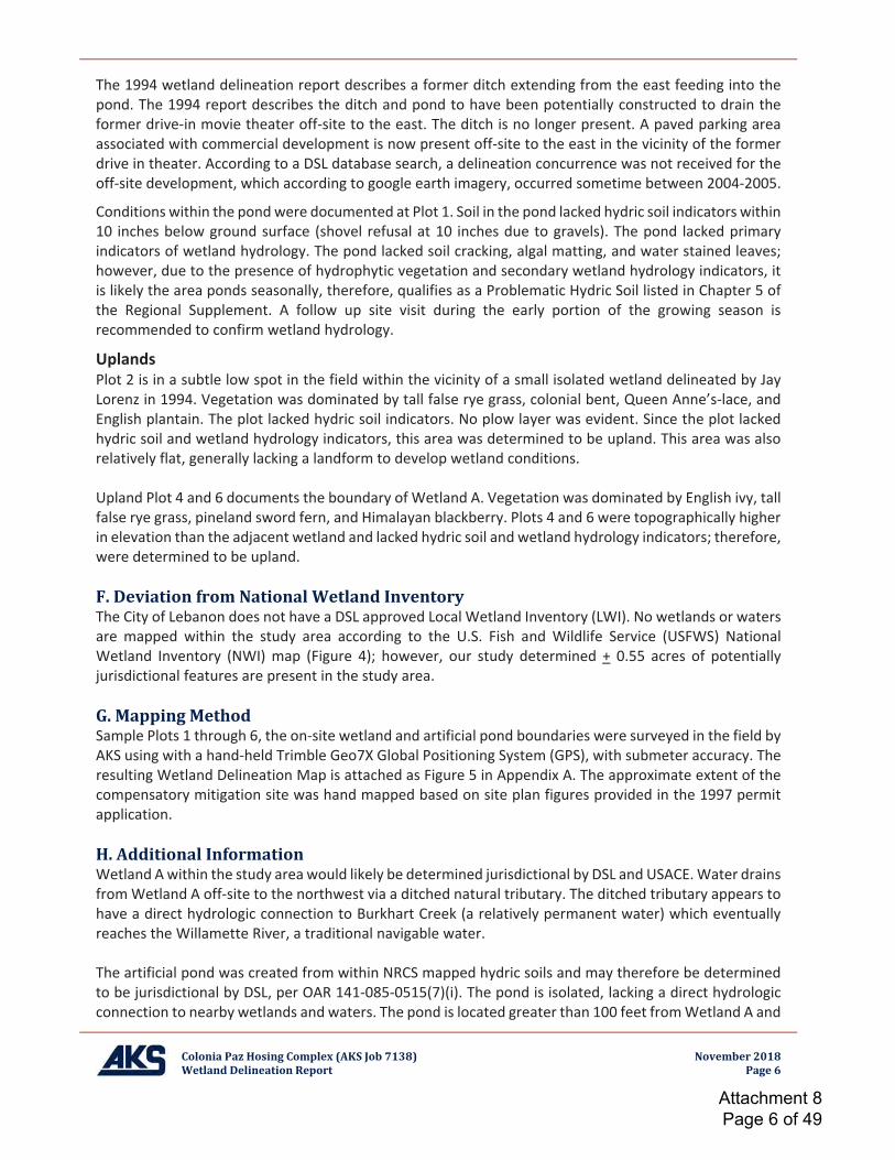
Colonia Paz Hosing Complex (AKS Job 7138) November 2018Wetland Delineation Report Page 6
The 1994 wetland delineation report describes a former ditch extending from the east feeding into thepond. The 1994 report describes the ditch and pond to have been potentially constructed to drain theformer drive in movie theater off site to the east. The ditch is no longer present. A paved parking areaassociated with commercial development is now present off site to the east in the vicinity of the formerdrive in theater. According to a DSL database search, a delineation concurrence was not received for theoff site development, which according to google earth imagery, occurred sometime between 2004 2005.
Conditions within the pondwere documented at Plot 1. Soil in the pond lacked hydric soil indicators within10 inches below ground surface (shovel refusal at 10 inches due to gravels). The pond lacked primaryindicators of wetland hydrology. The pond lacked soil cracking, algal matting, and water stained leaves;however, due to the presence of hydrophytic vegetation and secondary wetland hydrology indicators, itis likely the area ponds seasonally, therefore, qualifies as a Problematic Hydric Soil listed in Chapter 5 ofthe Regional Supplement. A follow up site visit during the early portion of the growing season isrecommended to confirm wetland hydrology.
UplandsPlot 2 is in a subtle low spot in the field within the vicinity of a small isolated wetland delineated by JayLorenz in 1994. Vegetation was dominated by tall false rye grass, colonial bent, Queen Anne’s lace, andEnglish plantain. The plot lacked hydric soil indicators. No plow layer was evident. Since the plot lackedhydric soil and wetland hydrology indicators, this area was determined to be upland. This area was alsorelatively flat, generally lacking a landform to develop wetland conditions.
Upland Plot 4 and 6 documents the boundary of Wetland A. Vegetation was dominated by English ivy, tallfalse rye grass, pineland sword fern, and Himalayan blackberry. Plots 4 and 6 were topographically higherin elevation than the adjacent wetland and lacked hydric soil and wetland hydrology indicators; therefore,were determined to be upland.
F. Deviation from National Wetland InventoryThe City of Lebanon does not have a DSL approved Local Wetland Inventory (LWI). No wetlands or watersare mapped within the study area according to the U.S. Fish and Wildlife Service (USFWS) NationalWetland Inventory (NWI) map (Figure 4); however, our study determined + 0.55 acres of potentiallyjurisdictional features are present in the study area.
G. Mapping MethodSample Plots 1 through 6, the on site wetland and artificial pond boundaries were surveyed in the field byAKS using with a hand held Trimble Geo7X Global Positioning System (GPS), with submeter accuracy. Theresulting Wetland Delineation Map is attached as Figure 5 in Appendix A. The approximate extent of thecompensatory mitigation site was hand mapped based on site plan figures provided in the 1997 permitapplication.
H. Additional InformationWetland Awithin the study area would likely be determined jurisdictional by DSL and USACE.Water drainsfromWetland A off site to the northwest via a ditched natural tributary. The ditched tributary appears tohave a direct hydrologic connection to Burkhart Creek (a relatively permanent water) which eventuallyreaches the Willamette River, a traditional navigable water.
The artificial pond was created from within NRCS mapped hydric soils and may therefore be determinedto be jurisdictional by DSL, per OAR 141 085 0515(7)(i). The pond is isolated, lacking a direct hydrologicconnection to nearby wetlands and waters. The pond is located greater than 100 feet fromWetland A and
Attachment 8 Page 6 of 49

Colonia Paz Hosing Complex (AKS Job 7138) November 2018Wetland Delineation Report Page 7
is not located within or in part of a 100 year floodplain; therefore, is not adjacent to waters of the U.S.The pond is located within 4,000 feet of Wetland A; therefore, the pond may have a significant nexus tonearby waters of the U.S.
Under OAR 141 085 0520 (3), the compensatory mitigation site is protected and any amount of removaland/or fill or other ground alteration may require a permit from DSL. It is unknown whether this area isalso documented as a compensatory mitigation site with USACE.
I. Summary of Results and ConclusionsTable 3 below provides a summary of the on site areas of each feature, hydrologic connections to othernearby waters, the Cowardin and HGM classifications for the wetlands, and our prediction of whethereach feature would likely be determined jurisdictional by DSL or the USACE.
Table 3. Summary of Features Delineated on the SitePotentiallyJurisdictional
Feature
Latitude,Longitude Size
(acres)CowardinClass
HGMSubclass/
Flow Regime
HydrologicConnection toOther Waters
USACE/DSLPredictedJurisdiction
Wetland A 44.515294,122.903060 ±0.53 PFO Slope Burkart Creek DSL and USACE
Artificial Pond 44.515759,122.899801 ±0.02 PSS Depressional None. Isolated. Potentially DSL
and USACE
J. Required DisclaimerThis report documents the investigation, best professional judgment, and conclusions of the investigators.It is correct and complete to the best of our knowledge. It should be considered a Preliminary JurisdictionalDetermination of wetlands and other waters and used at your own risk, unless it has been reviewed andapproved in writing by the Oregon Department of State Lands in accordance with Oregon AdministrativeRules (OAR) 141 090 0005 through 141 090 0055.
K. List of Preparers
Sonya Templeton Stacey Reed, PWSNatural Resource Specialist Senior Wetland ScientistFieldwork and Report Preparation Fieldwork and Report QA/QC
Attachment 8 Page 7 of 49
Colonia Paz Housing Complex (AKS Job 7138) November 2018Wetland Delineation Report
Appendix A: DSL Concurrence Letters
Attachment 8 Page 8 of 49
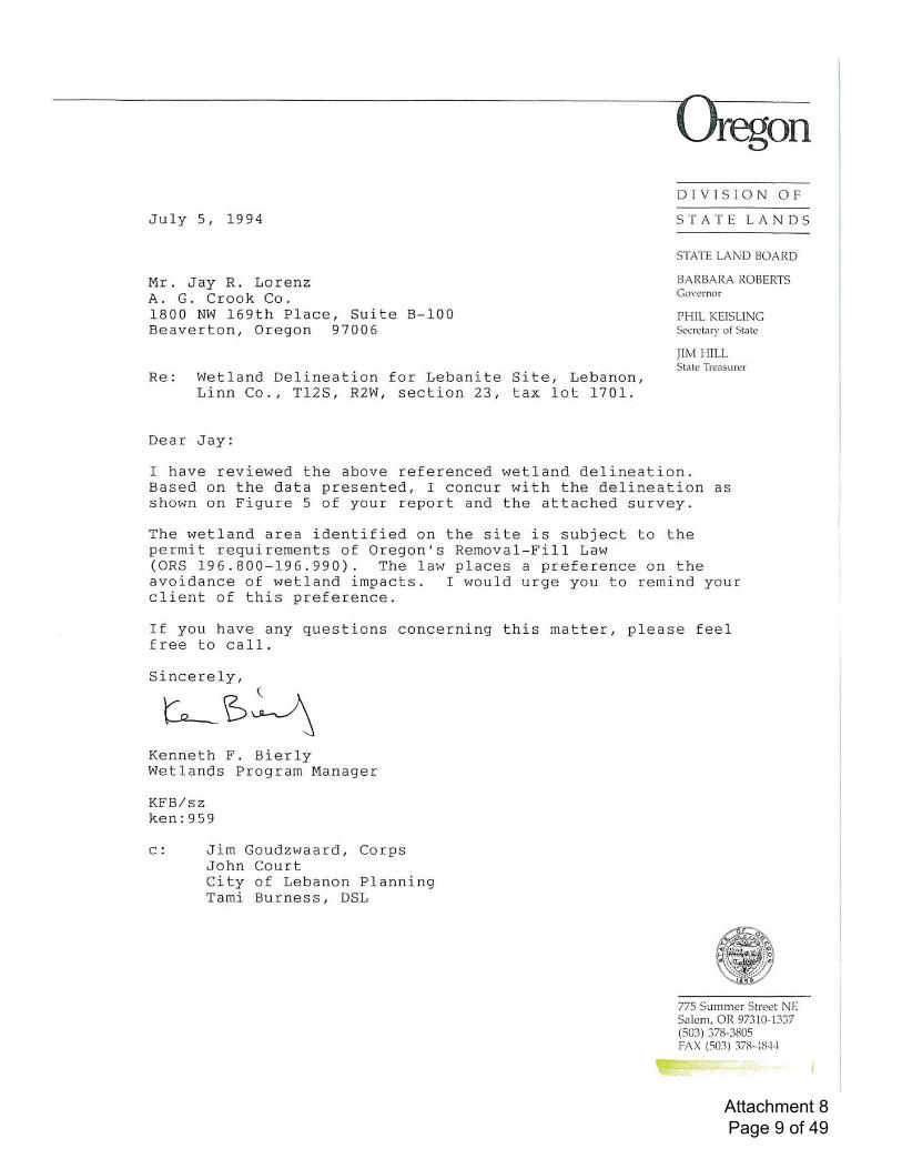
Attachment 8 Page 9 of 49
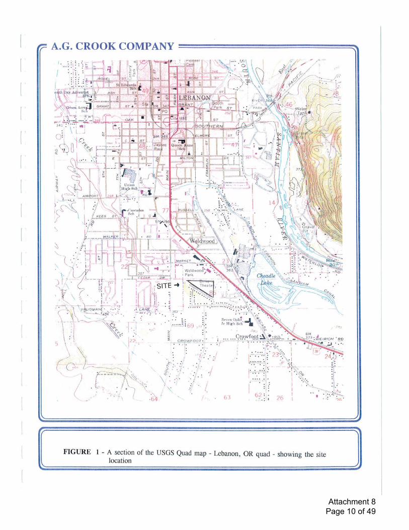
Attachment 8 Page 10 of 49
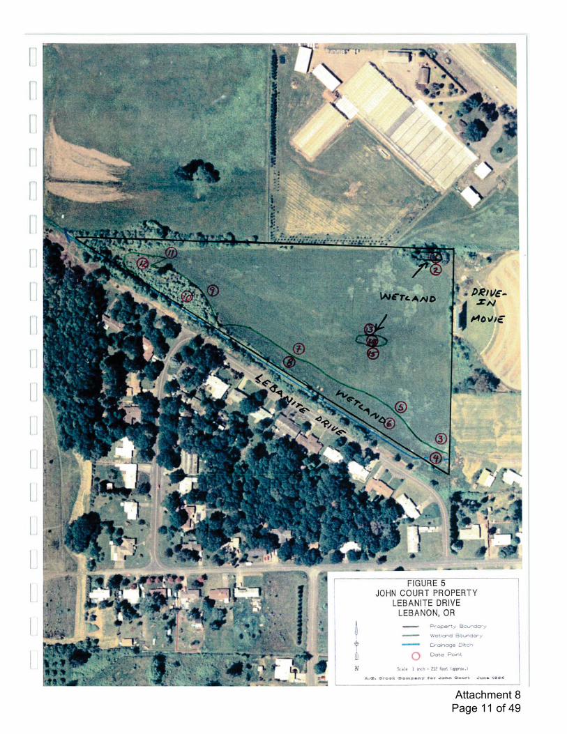
Attachment 8 Page 11 of 49
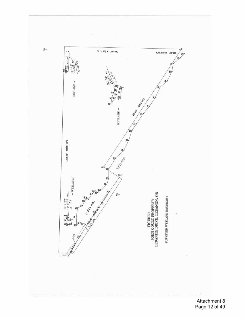
Attachment 8 Page 12 of 49
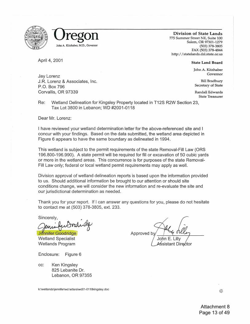
Attachment 8 Page 13 of 49
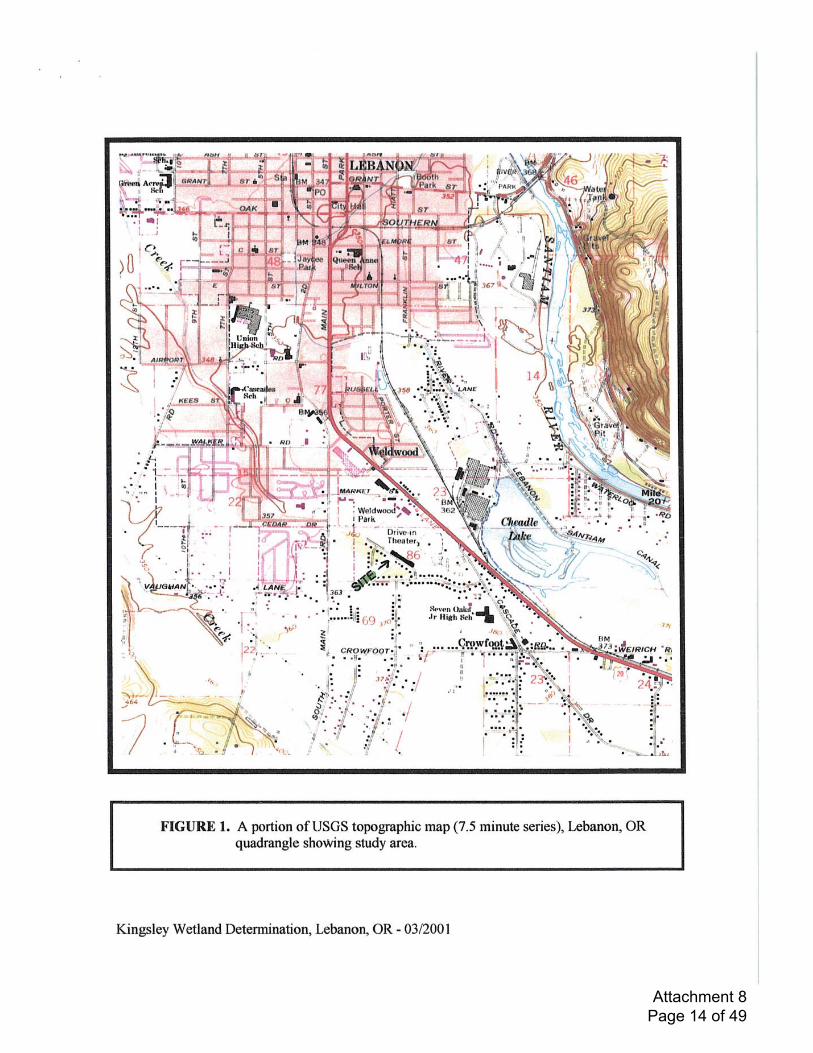
Attachment 8 Page 14 of 49
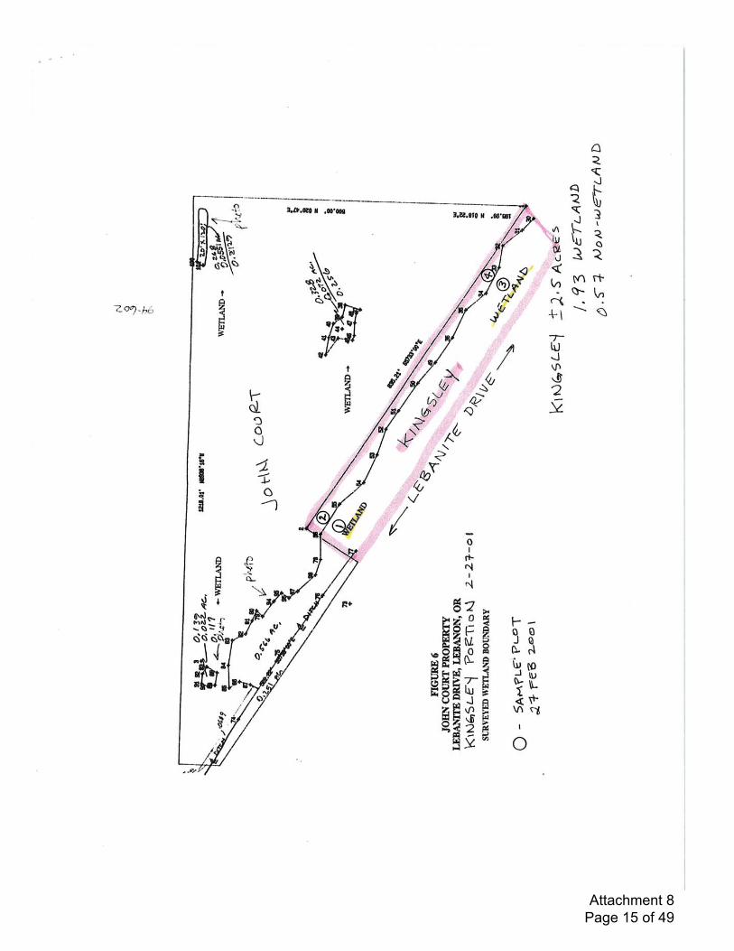
Attachment 8 Page 15 of 49

Colonia Paz Housing Complex (AKS Job 7138) November 2018Wetland Delineation Report
Appendix B: Google Earth Aerials
Attachment 8 Page 16 of 49
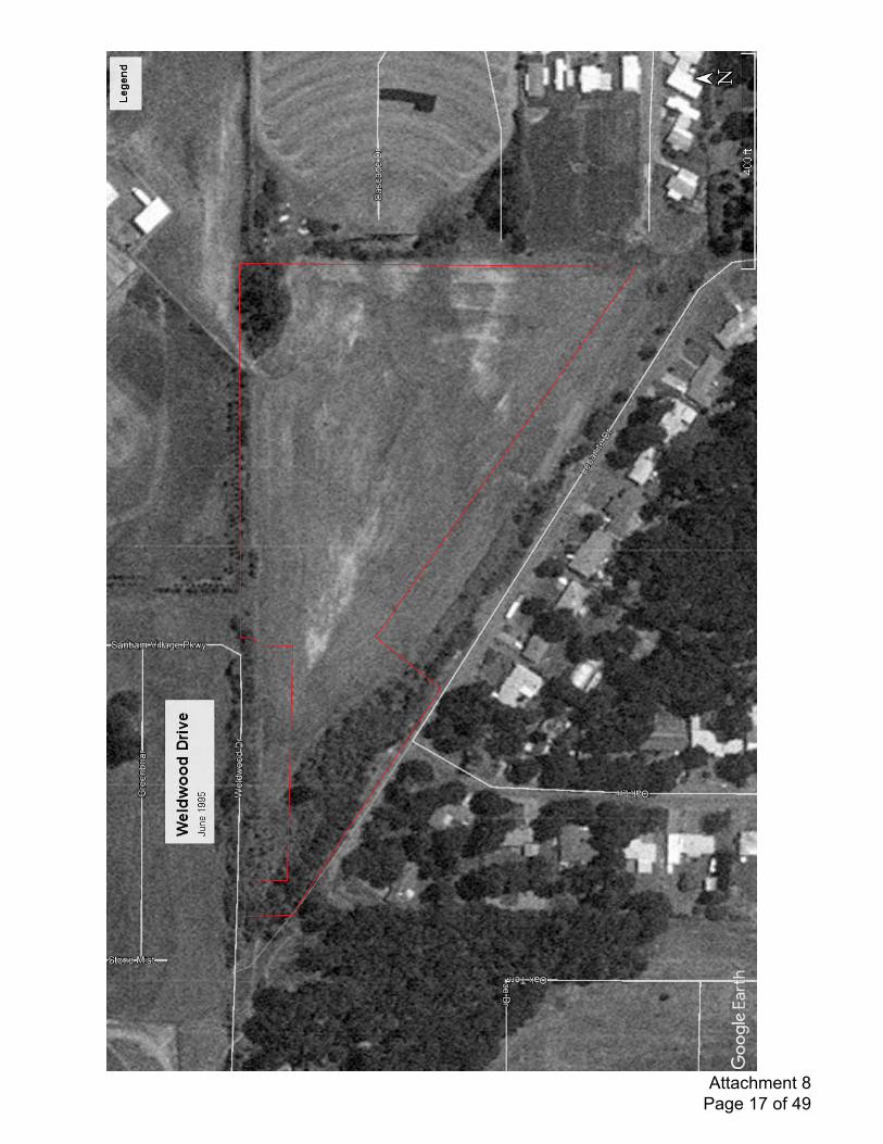
Attachment 8 Page 17 of 49
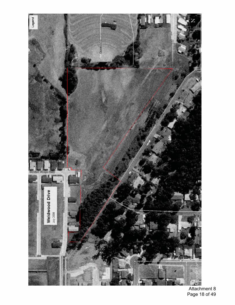
Attachment 8 Page 18 of 49
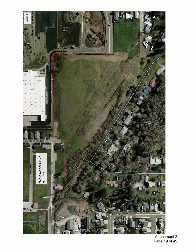
Attachment 8 Page 19 of 49
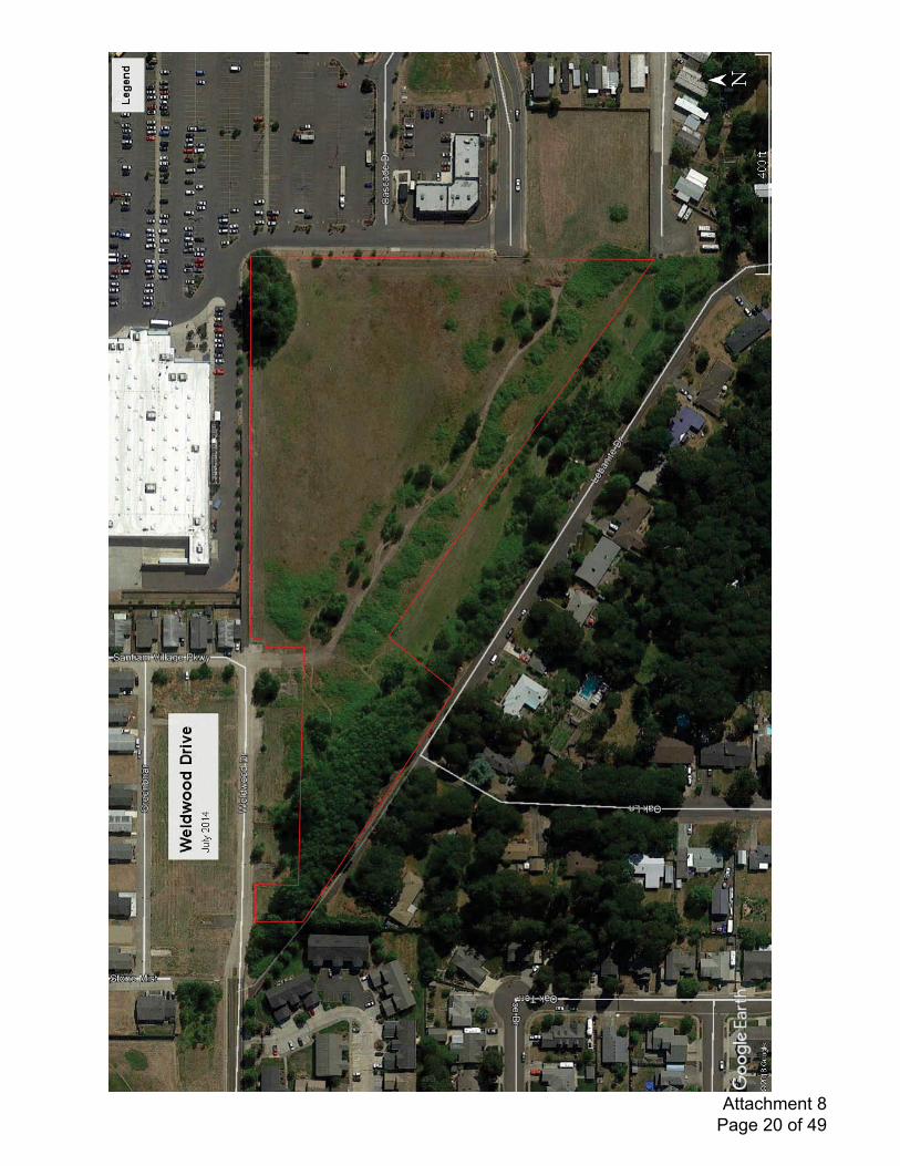
Attachment 8 Page 20 of 49
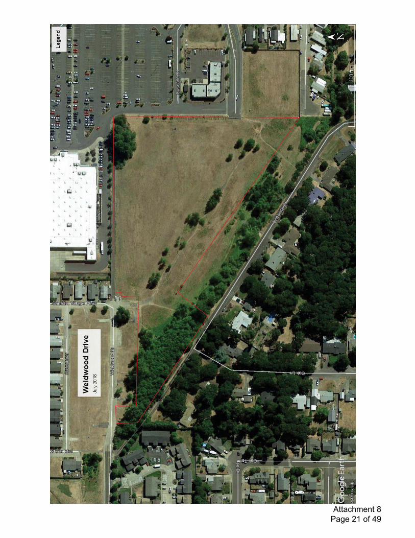
Attachment 8 Page 21 of 49

Colonia Paz Housing Complex (AKS Job 7138) November 2018Wetland Delineation Report
Appendix C: Precipitation Data
Attachment 8 Page 22 of 49
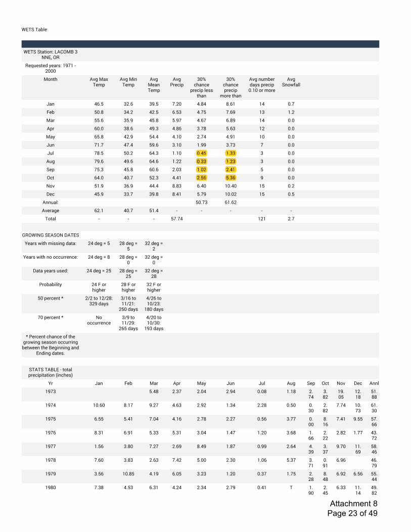
!"#$%#&'()
! ! ! ! ! ! ! ! ! ! ! ! ! !
!"#$%$*&*+,-.%/01234%5%66"7%28
8)9:);*)<%=)&>;.%?@A?%B%CDDD
3,-*E 0FG%3&H%#)IJ
0FG%3+-%#)IJ
0FG%3)&-%#)IJ
0FG%K>)L+J
5DM%LE&-L)%
J>)L+J%();;%*E&-
5DM%LE&-L)%J>)L+J%
I,>)%*E&-
0FG%-:I')>%<&=;%J>)L+J%
DN?D%,>%I,>)
0FG%$-,OP&((
Q&- RSNT 5CNS 5@NT ANCD RNUR UNS? ?R DNA
V)' TDNU 5RNC RCNT SNT5 RNAT ANS@ ?5 ?NC
3&> TTNS 5TN@ RTNU TN@A RNSA SNU@ ?R DND
0J> SDND 5UNS R@N5 RNUS 5NAU TNS5 ?C DND
3&= STNU RCN@ TRNR RN?D CNAR RN@? ?D DND
Q:- A?NA RANR T@NS 5N?D ?N@@ 5NA5 A DND
Q:( AUNT TDNC SRN5 ?N?D DNRT ?N55 5 DND
0:G A@NS R@NS SRNS ?NCC DN55 ?NC5 5 DND
$)J ATN5 RTNU SDNS CND5 ?NDC CNR? T DND
2L* SRND RDNA TCN5 RNR? CNTS TN5S @ DND
6,F T?N@ 5SN@ RRNR UNU5 SNRD ?DNRD ?T DNC
W)L RTN@ 55NA 5@NU UNR? TNA@ ?DNDC ?T DNT
0--:&(. TDNA5 S?NSC
0F)>&G) SCN? RDNA T?NR B B B B B
#,*&( B B B TANAR ?C? CNA
X
Y82!Z6Y%$"0$26%W0#"$
[)&>;%O+*E%I+;;+-G%<&*&. CR%<)G%\%T CU%<)G%\%T
5C%<)G%\%C
[)&>;%O+*E%-,%,LL:>>)-L). CR%<)G%\%U CU%<)G%\%D
5C%<)G%\%D
W&*&%=)&>;%:;)<. CR%<)G%\%CT CU%<)G%\%CT
5C%<)G%\%CU
K>,'&'+(+*= CR%V%,>%E+GE)>
CU%V%,>%E+GE)>
5C%V%,>%E+GE)>
TD%J)>L)-*%] C^C%*,%?C^CU.%5C@%<&=;
5^?S%*,%??^C?.%
CTD%<&=;
R^CS%*,%?D^C5.%
?UD%<&=;
AD%J)>L)-*%] 6,%,LL:>>)-L)
5^@%*,%??^C@.%
CST%<&=;
R^CD%*,%?D^5D.%
?@5%<&=;
]%K)>L)-*%LE&-L)%,P%*E)%G>,O+-G%;)&;,-%,LL:>>+-G%')*O))-%*E)%4)G+--+-G%&-<%
"-<+-G%<&*);N
X
$#0#$%#04/"%B%*,*&(%J>)L+J+*&*+,-%_+-LE);`
[> Q&- V)' 3&> 0J> 3&= Q:- Q:( 0:G $)J 2L* 6,F W)L 0--(
?@A5 X X TNRU CN5A CNDR CN@R DNDU ?N?U CNAR
5NUC
?@NDT
?CN?U
T?NUU
?@AR ?DNSD UN?A @NCA RNS5 CN@C ?N5R CNCU DNTD DN5D
CNUC
ANAR ?DNA5
S?N5D
?@AT SNTT TNR? ANDR RN?S CNAU CNCA DNTS 5NAA DNDD
UN?S
ANR? @NTT TANSS
?@AS UN5? SN@? TN55 TN5? 5NDR ?NRA ?NCD 5NSU ?NSS
CNCC
CNUC ?NAA R5NAC
?@AA ?NTS 5NUD ANCA CNS@ UNR@ ?NUA DN@@ CNSR RN5@
5N5A
@NAD ??NS@
TUNRS
?@AU ANSD 5NU5 CNS5 ANRC TNDD CN5D ?NDS TN5A 5NA?
DN@?
SN@S X RSNA@
?@A@ 5NTS ?DNUT RN?@ SNDT 5NC5 ?NCD DN5A ?NAT CNCU
UNRU
SN@C SNTS TTNRR
?@UD AN5U RNT5 SN5? RNCR CN5R CNA@ DNR? # ?N@D
CNRT
SN55 ??N?R
R@NUC
CNTS TN5S
?NDC CNR?
DN55 ?NC5
DNRT ?N55
Attachment 8 Page 23 of 49
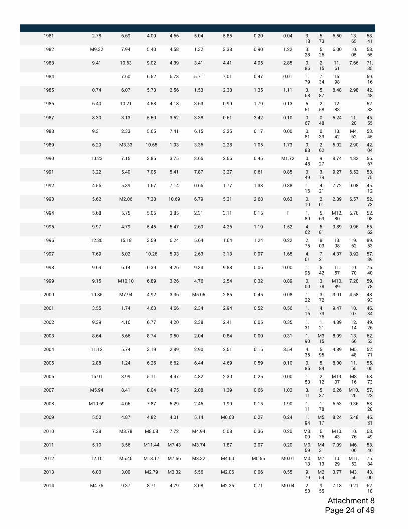
! ! ! ! ! ! ! ! ! ! ! ! ! !
?@U? CNAU SNS@ RND@ RNSS TNDR TNUT DNCD DNDR 5N?U
TNA5
SNTD ?5NST
TUNR?
?@UC 3@N5C AN@R TNRD RNTU ?N5C 5N5U DN@D ?NCC 5NCU
TNCS
SNDD ?DNDT
TUNST
?@U5 @NR? ?DNS5 @NDC RN5@ 5NR? RNR? RN@T CNUT DNUS
CN?T
??NS?
ANSS A?N5T
?@UR X ANSD SNTC SNA5 TNA? AND? DNRA DND? ?NA@
AN5R
?TN@U
X T@N?S
?@UT DNAR SNDA TNA5 CNTS ?NT5 CN5U ?N5T ?N?? 5NSU
TNUA
UNRU CN@U RCNRU
?@US SNRD ?DNC? RNTU RN?U 5NS5 DN@@ ?NA@ DN?5 TNT?
CNTU
?CNU5
X TCNU5
?@UA UN5D 5N?5 TNTD 5NTC 5N5U DNS? 5NRC DN?D DNSA
DNRU
TNCR ??NCD
RTNTT
?@UU @N5? CN55 TNST ANR? SN?T 5NCT DN?A DNDD DNU?
DN55
?5NRC
3RNSC
T5NRT
?@U@ SNC@ 35N55 ?DNST ?N@5 5N5S CNCU ?NDT ?NA5 DNUU
CNSC
TNDC CN@D RCNDR
?@@D ?DNC5 AN?T 5NUT 5NAT 5NST CNTS DNRT 3?NAC DNRU
@NCA
UNAR RNUC TSNSA
?@@? 5NCC TNRD ANDT TNR? ANUA 5NCA DNS? DNUT DNR@
5NA@
@NCA SNTC T5NAT
?@@C RNTS TN5@ ?NSA AN?R DNSS ?NAA ?N5U DN5U ?N?S
RNC?
ANAC @NDU RTN?C
?@@5 TNSC 3CNDS AN5U ?DNS@ SNA@ TN5? CNSU DNS5 DN?D
CND?
CNU@ SNTA TCNA5
?@@R TNSU TNAT TNDT 5NUT CN5? 5N?? DN?T # ?NU@
TNS5
3?CNUD
SNAS TCN@U
?@@T @N@A RNA@ TNRT TNRA CNS@ RNCS ?N?@ ?NTC RNSC
TNU?
@NU@ @N@S STNSC
?@@S ?CN5D ?TN?U 5NT@ SNCR TNSR ?NSR ?NCR DNCC CNAT
UND5
?5NDU
?@NSC
U@NT5
?@@A ANS@ TNDC ?DNCS TN@5 CNS5 5N?5 DN@A ?NST RNS?
ANC?
RN5A 5N@C TAN5@
?@@U @NS@ SN?R SN5@ RNCS @N55 @NUU DNDS DNDD ?N@S
TNRC
??NTA
?DNAD
ATNRD
?@@@ @N?T 3?DN?D SNU@ 5NCS RNAS CNTR DN5C DNU@ DNDD
5NAU
3?DNU@
ANCD T@NAU
CDDD ?DNUT 3AN@R RN@C 5N5S 3TNDT CNUT DNRT DNDU ?NCC
5NAC
5N@? RNTU RUN@5
CDD? 5NTT ?NAR RNSD RNSS CN5R CN@R DNTC DNTS ?N?S
RNA5
@NRA ?DNDA
RSN5R
CDDC @N5@ RN?S SNAA RNCD CN5U CNR? DNDT DN5T ?N5?
?NC?
RNU@ ?CN?R
R@NCS
CDD5 UNSR TNSS UNAR @NTD CNDR DNUR DNDD DN5? ?N@D
35N?T
UND@ ?5NSS
SCNT5
CDDR ??N?C TNAR 5N?@ CNU@ CN@D CNT? DN?T 5NTR RN5T
TN@T
RNU@ 3TNRU
TCNA?
CDDT CNUU ?NCR SNCT SNSC SNRR RNS@ DNT@ DN?D DNUT
TNUR
UNDD ??NTT
TTNDT
CDDS ?SN@? 5N@@ TN?? RNRA RNUC CN5D DNCT DNDD ?NT5
CN?C
3?@NDA
3UN?S
SUNA5
CDDA 3TN@R UNR? UNDR RNAT CNDU ?N5@ DNSS ?NDC 5N??
TN5A
SNCS 3?DNCD
TANC5
CDDU 3?DNS@ RNDS ANUA TNC@ CNRT ?N@@ DN?T ?N@D ?N??
?NAU
SNS5 @N5S T5NCU
CDD@ TNTD RNUA RNUC RND? TN?R 3DNS5 DNCA DNCR ?N@R
3TN?A
UNCR TNRU RSN5?
CD?D AN5U 35NAU 3UNDU ANAC 3RN@R TNDU DN5S DNCD 35NDD
SNAS
3?DNR5
?DNAS
SUNR@
CD?? TN?D 5NTS 3??NRR 3ANR5 35NAR ?NUA CNDA DNCD 3DNT@
3RN5?
AND@ 3SNDS
T5NRS
CD?C ?CN?D 3TNRS 3?5N?A 3ANTS 35N5C 3RNSD 3DNTT 3DND? 3DN?5
3AN?5
?DNC@
3??NTC
ATNUR
CD?5 SNDD 5NDD 3CNA@ 35N5C TNTS 3CNDS DNDS DNTT @NA@
3CNTR
5NAA 35NTS
R5NDD
CD?R 3RNAS @N5A UNA? RNA@ 5NDU 3CNCT DNA? 3DNDR CNT5
@NTT
AN?U @NC? SCN?U
Attachment 8 Page 24 of 49
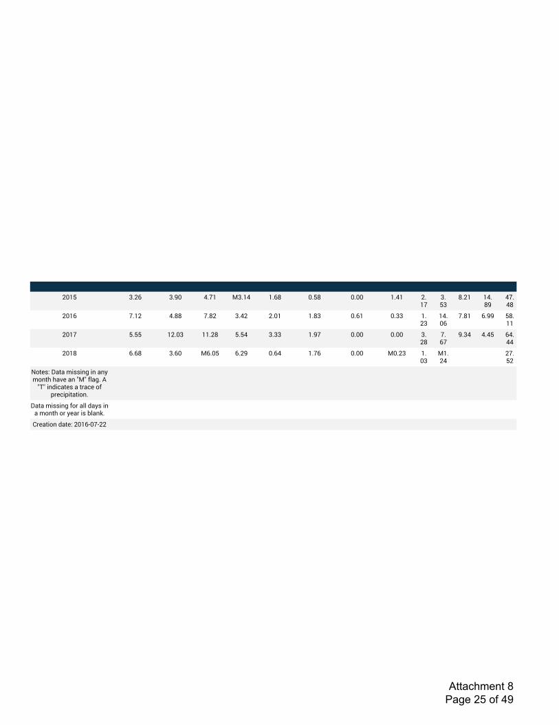
! ! ! ! ! ! ! ! ! ! ! ! ! !
CD?T 5NCS 5N@D RNA? 35N?R ?NSU DNTU DNDD ?NR? CN?A
5NT5
UNC? ?RNU@
RANRU
CD?S AN?C RNUU ANUC 5NRC CND? ?NU5 DNS? DN55 ?NC5
?RNDS
ANU? SN@@ TUN??
CD?A TNTT ?CND5 ??NCU TNTR 5N55 ?N@A DNDD DNDD 5NCU
ANSA
@N5R RNRT SRNRR
CD?U SNSU 5NSD 3SNDT SNC@ DNSR ?NAS DNDD 3DNC5 ?ND5
3?NCR
X X CANTC
6,*);.%W&*&%I+;;+-G%+-%&-=%I,-*E%E&F)%&-%a3a%P(&GN%0%
a#a%+-<+L&*);%&%*>&L)%,P%J>)L+J+*&*+,-N
W&*&%I+;;+-G%P,>%&((%<&=;%+-%&%I,-*E%,>%=)&>%+;%'(&-bN
1>)&*+,-%<&*).%CD?SBDABCC
Attachment 8 Page 25 of 49
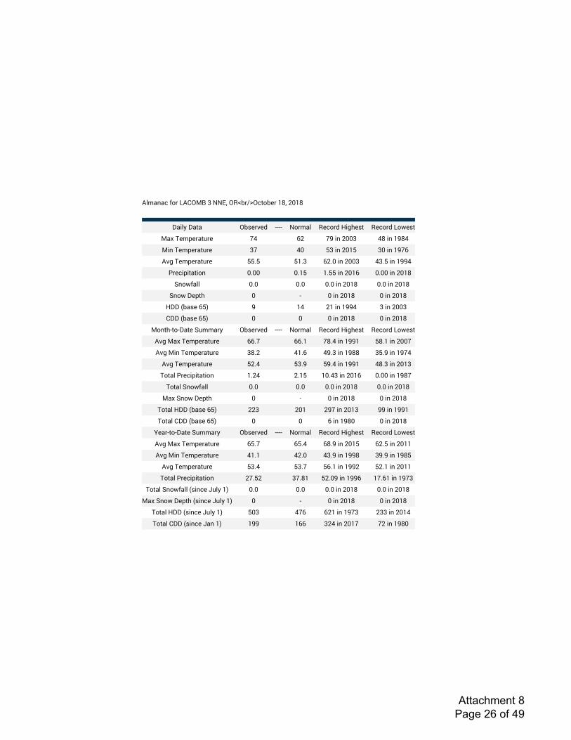
!"#$%$&'()*'+!,-./'0'1123'-456*78-&9)6:*';<3'=>;<
?$@"A'?$9$ -6B:*C:D EEEE 1)*#$" 4:&)*D'F@GH:B9 4:&)*D'+)I:B9
.$J'K:#L:*$9M*: NO P= NQ'@%'=>>0 O<'@%';Q<O
.@%'K:#L:*$9M*: 0N O> R0'@%'=>;R 0>'@%';QNP
!CG'K:#L:*$9M*: RRSR R;S0 P=S>'@%'=>>0 O0SR'@%';QQO
T*:&@L@9$9@)% >S>> >S;R ;SRR'@%'=>;P >S>>'@%'=>;<
U%)I($"" >S> >S> >S>'@%'=>;< >S>'@%'=>;<
U%)I'?:L9H > E >'@%'=>;< >'@%'=>;<
F??'V6$B:'PRW Q ;O =;'@%';QQO 0'@%'=>>0
,??'V6$B:'PRW > > >'@%'=>;< >'@%'=>;<
.)%9HE9)E?$9:'UM##$*A -6B:*C:D EEEE 1)*#$" 4:&)*D'F@GH:B9 4:&)*D'+)I:B9
!CG'.$J'K:#L:*$9M*: PPSN PPS; N<SO'@%';QQ; R<S;'@%'=>>N
!CG'.@%'K:#L:*$9M*: 0<S= O;SP OQS0'@%';Q<< 0RSQ'@%';QNO
!CG'K:#L:*$9M*: R=SO R0SQ RQSO'@%';QQ; O<S0'@%'=>;0
K)9$"'T*:&@L@9$9@)% ;S=O =S;R ;>SO0'@%'=>;P >S>>'@%';Q<N
K)9$"'U%)I($"" >S> >S> >S>'@%'=>;< >S>'@%'=>;<
.$J'U%)I'?:L9H > E >'@%'=>;< >'@%'=>;<
K)9$"'F??'V6$B:'PRW ==0 =>; =QN'@%'=>;0 QQ'@%';QQ;
K)9$"',??'V6$B:'PRW > > P'@%';Q<> >'@%'=>;<
X:$*E9)E?$9:'UM##$*A -6B:*C:D EEEE 1)*#$" 4:&)*D'F@GH:B9 4:&)*D'+)I:B9
!CG'.$J'K:#L:*$9M*: PRSN PRSO P<SQ'@%'=>;R P=SR'@%'=>;;
!CG'.@%'K:#L:*$9M*: O;S; O=S> O0SQ'@%';QQ< 0QSQ'@%';Q<R
!CG'K:#L:*$9M*: R0SO R0SN RPS;'@%';QQ= R=S;'@%'=>;;
K)9$"'T*:&@L@9$9@)% =NSR= 0NS<; R=S>Q'@%';QQP ;NSP;'@%';QN0
K)9$"'U%)I($""'VB@%&:'YM"A';W >S> >S> >S>'@%'=>;< >S>'@%'=>;<
.$J'U%)I'?:L9H'VB@%&:'YM"A';W > E >'@%'=>;< >'@%'=>;<
K)9$"'F??'VB@%&:'YM"A';W R>0 ONP P=;'@%';QN0 =00'@%'=>;O
K)9$"',??'VB@%&:'Y$%';W ;QQ ;PP 0=O'@%'=>;N N='@%';Q<>
Attachment 8 Page 26 of 49
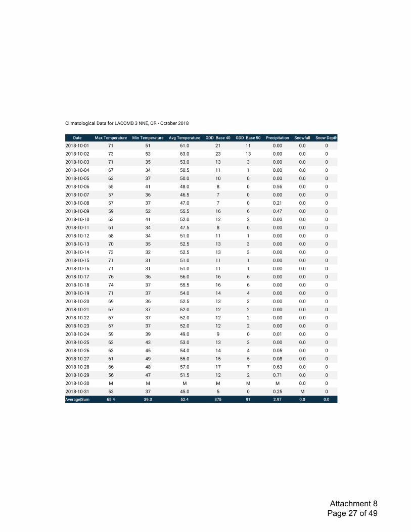
!"#$%&'"'(#)%"*+%&%*,'-*./!012*3*4456*07*8*0)&'9:-*;<=>
!"#$ %"&'($)*$+"#,+$ %-.'($)*$+"#,+$ /01'($)*$+"#,+$ 2!!''3"4$'56 2!!''3"4$'76 8+$9-*-#"#-:. ;.:<=">> ;.:<'!$*#?
;<=>8=<8<= ?= @= A=B< ;= == <B<< <B< <
;<=>8=<8<; ?3 @3 A3B< ;3 =3 <B<< <B< <
;<=>8=<8<3 ?= 3@ @3B< =3 3 <B<< <B< <
;<=>8=<8<C A? 3C @<B@ == = <B<< <B< <
;<=>8=<8<@ A3 3? @<B< =< < <B<< <B< <
;<=>8=<8<A @@ C= C>B< > < <B@A <B< <
;<=>8=<8<? @? 3A CAB@ ? < <B<< <B< <
;<=>8=<8<> @? 3? C?B< ? < <B;= <B< <
;<=>8=<8<D @D @; @@B@ =A A <BC? <B< <
;<=>8=<8=< A3 C= @;B< =; ; <B<< <B< <
;<=>8=<8== A= 3C C?B@ > < <B<< <B< <
;<=>8=<8=; A> 3C @=B< == = <B<< <B< <
;<=>8=<8=3 ?< 3@ @;B@ =3 3 <B<< <B< <
;<=>8=<8=C ?3 3; @;B@ =3 3 <B<< <B< <
;<=>8=<8=@ ?= 3= @=B< == = <B<< <B< <
;<=>8=<8=A ?= 3= @=B< == = <B<< <B< <
;<=>8=<8=? ?A 3A @AB< =A A <B<< <B< <
;<=>8=<8=> ?C 3? @@B@ =A A <B<< <B< <
;<=>8=<8=D ?= 3? @CB< =C C <B<< <B< <
;<=>8=<8;< AD 3A @;B@ =3 3 <B<< <B< <
;<=>8=<8;= A? 3? @;B< =; ; <B<< <B< <
;<=>8=<8;; A? 3? @;B< =; ; <B<< <B< <
;<=>8=<8;3 A? 3? @;B< =; ; <B<< <B< <
;<=>8=<8;C @D 3D CDB< D < <B<= <B< <
;<=>8=<8;@ A3 C3 @3B< =3 3 <B<< <B< <
;<=>8=<8;A A3 C@ @CB< =C C <B<@ <B< <
;<=>8=<8;? A= CD @@B< =@ @ <B<> <B< <
;<=>8=<8;> AA C> @?B< =? ? <BA3 <B< <
;<=>8=<8;D @A C? @=B@ =; ; <B?= <B< <
;<=>8=<83< 1 1 1 1 1 1 <B< <
;<=>8=<83= @3 3? C@B< @ < <B;@ 1 </0$+"1$@;,) A7B5 CDBC 7EB5 CF7 DG EBDF 6B6 6B6
Attachment 8 Page 27 of 49
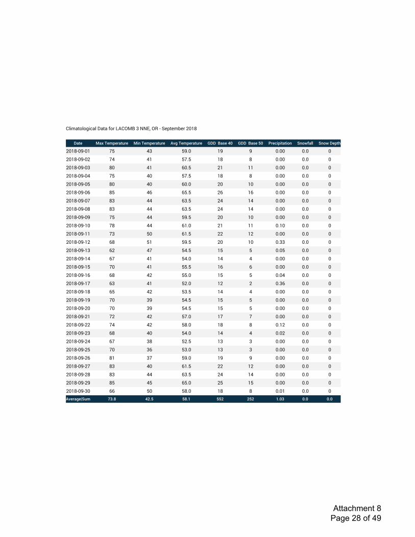
!"#$%&'"'(#)%"*+%&%*,'-*./!012*3*4456*07*8*9:;&:$<:-*=>?@
!"#$ %"&'($)*$+"#,+$ %-.'($)*$+"#,+$ /01'($)*$+"#,+$ 2!!''3"4$'56 2!!''3"4$'76 8+$9-*-#"#-:. ;.:<=">> ;.:<'!$*#?
=>?@8>A8>? BC D3 CAE> ?A A >E>> >E> >
=>?@8>A8>= BD D? CBEC ?@ @ >E>> >E> >
=>?@8>A8>3 @> D? F>EC =? ?? >E>> >E> >
=>?@8>A8>D BC D> CBEC ?@ @ >E>> >E> >
=>?@8>A8>C @> D> F>E> => ?> >E>> >E> >
=>?@8>A8>F @C DF FCEC =F ?F >E>> >E> >
=>?@8>A8>B @3 DD F3EC =D ?D >E>> >E> >
=>?@8>A8>@ @3 DD F3EC =D ?D >E>> >E> >
=>?@8>A8>A BC DD CAEC => ?> >E>> >E> >
=>?@8>A8?> B@ DD F?E> =? ?? >E?> >E> >
=>?@8>A8?? B3 C> F?EC == ?= >E>> >E> >
=>?@8>A8?= F@ C? CAEC => ?> >E33 >E> >
=>?@8>A8?3 F= DB CDEC ?C C >E>C >E> >
=>?@8>A8?D FB D? CDE> ?D D >E>> >E> >
=>?@8>A8?C B> D? CCEC ?F F >E>> >E> >
=>?@8>A8?F F@ D= CCE> ?C C >E>D >E> >
=>?@8>A8?B F3 D? C=E> ?= = >E3F >E> >
=>?@8>A8?@ FC D= C3EC ?D D >E>> >E> >
=>?@8>A8?A B> 3A CDEC ?C C >E>> >E> >
=>?@8>A8=> B> 3A CDEC ?C C >E>> >E> >
=>?@8>A8=? B= D= CBE> ?B B >E>> >E> >
=>?@8>A8== BD D= C@E> ?@ @ >E?= >E> >
=>?@8>A8=3 F@ D> CDE> ?D D >E>= >E> >
=>?@8>A8=D FB 3@ C=EC ?3 3 >E>> >E> >
=>?@8>A8=C B> 3F C3E> ?3 3 >E>> >E> >
=>?@8>A8=F @? 3B CAE> ?A A >E>> >E> >
=>?@8>A8=B @3 D> F?EC == ?= >E>> >E> >
=>?@8>A8=@ @3 DD F3EC =D ?D >E>> >E> >
=>?@8>A8=A @C DC FCE> =C ?C >E>> >E> >
=>?@8>A83> FF C> C@E> ?@ @ >E>? >E> >/0$+"1$@;,) ABCD 5EC7 7DCF 77E E7E FC6B 6C6 6C6
Attachment 8 Page 28 of 49

!"#$%&'"'(#)%"*+%&%*,'-*./!012*3*4456*07*8*/9(9:&*;<=>
!"#$ %"&'($)*$+"#,+$ %-.'($)*$+"#,+$ /01'($)*$+"#,+$ 2!!''3"4$'56 2!!''3"4$'76 8+$9-*-#"#-:. ;.:<=">> ;.:<'!$*#?
;<=>8<>8<= ?< @? A?BC 3< ;< <B<< <B< <
;<=>8<>8<; >D @? A>B< ;> => <B<< <B< <
;<=>8<>8<3 D3 C@ A3BC ;@ =@ <B<< <B< <
;<=>8<>8<@ DD @> A;BC ;3 =3 <B<< <B< <
;<=>8<>8<C >@ @> AAB< ;A =A <B<< <B< <
;<=>8<>8<A >D @? A>B< ;> => <B<< <B< <
;<=>8<>8<D >> C3 D<BC 3= ;= <B<< <B< <
;<=>8<>8<> ?; C@ D3B< 33 ;3 <B<< <B< <
;<=>8<>8<? ?; C@ D3B< 33 ;3 <B<< <B< <
;<=>8<>8=< ?@ C@ D@B< 3@ ;@ <B<< <B< <
;<=>8<>8== ?< CD D3BC 3@ ;@ <B<< <B< <
;<=>8<>8=; D> @? A3BC ;@ =@ <B<< <B< <
;<=>8<>8=3 1 1 1 1 1 1 <B< <
;<=>8<>8=@ ?C @? D;B< 3; ;; <B<< <B< <
;<=>8<>8=C >? C; D<BC 3= ;= <B<< <B< <
;<=>8<>8=A >@ C@ A?B< ;? =? <B<< <B< <
;<=>8<>8=D >= @D A@B< ;@ =@ <B<< <B< <
;<=>8<>8=> >< @3 A=BC ;; =; <B<< <B< <
;<=>8<>8=? >C @3 A@B< ;@ =@ <B<< <B< <
;<=>8<>8;< >A @> ADB< ;D =D <B<< <B< <
;<=>8<>8;= >< C< ACB< ;C =C <B<< <B< <
;<=>8<>8;; ?C C< D;BC 33 ;3 <B<< <B< <
;<=>8<>8;3 ?= C< D<BC 3= ;= <B<< <B< <
;<=>8<>8;@ A@ @> CAB< =A A <B<< <B< <
;<=>8<>8;C D3 @= CDB< =D D <B<< <B< <
;<=>8<>8;A D@ @= CDBC => > <B<3 <B< <
;<=>8<>8;D A? CA A;BC ;3 =3 <B;< <B< <
;<=>8<>8;> DA @C A<BC ;= == <B<< <B< <
;<=>8<>8;? >D @C AAB< ;A =A <B<< <B< <
;<=>8<>83< >C @D AAB< ;A =A <B<< <B< <
;<=>8<>83= A> @> C>B< => > <B<< <B< </0$+"1$@;,) ABCD 5ECF GGCF HED 5ED 6CFB 6C6 6C6
Attachment 8 Page 29 of 49
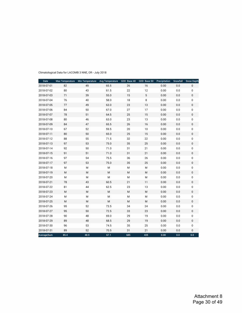
!"#$%&'"'(#)%"*+%&%*,'-*./!012*3*4456*07*8*9:";*<=>?
!"#$ %"&'($)*$+"#,+$ %-.'($)*$+"#,+$ /01'($)*$+"#,+$ 2!!''3"4$'56 2!!''3"4$'76 8+$9-*-#"#-:. ;.:<=">> ;.:<'!$*#?
<=>?8=@8=> ?< AB CDED <C >C =E== =E= =
<=>?8=@8=< ?= A3 C>ED << >< =E== =E= =
<=>?8=@8=3 @> 3B DDE= >D D =E== =E= =
<=>?8=@8=A @C A= D?E= >? ? =E== =E= =
<=>?8=@8=D @@ AB C3E= <3 >3 =E== =E= =
<=>?8=@8=C ?A D= C@E= <@ >@ =E== =E= =
<=>?8=@8=@ @? D> CAED <D >D =E== =E= =
<=>?8=@8=? ?= AC C3E= <3 >3 =E== =E= =
<=>?8=@8=B ?A A@ CDED <C >C =E== =E= =
<=>?8=@8>= C@ D< DBED <= >= =E== =E= =
<=>?8=@8>> ?= D= CDE= <D >D =E== =E= =
<=>?8=@8>< ?? DD @>ED 3< << =E== =E= =
<=>?8=@8>3 B@ D3 @DE= 3D <D =E== =E= =
<=>?8=@8>A B< D= @>E= 3> <> =E== =E= =
<=>?8=@8>D B> D> @>E= 3> <> =E== =E= =
<=>?8=@8>C B@ DA @DED 3C <C =E== =E= =
<=>?8=@8>@ B@ D3 @DE= 3D <D =E== =E= =
<=>?8=@8>? 1 1 1 1 1 =E== =E= =
<=>?8=@8>B 1 1 1 1 1 =E== =E= =
<=>?8=@8<= 1 1 1 1 1 =E== =E= =
<=>?8=@8<> @? A3 C=ED <> >> =E== =E= =
<=>?8=@8<< ?> AA C<ED <3 >3 =E== =E= =
<=>?8=@8<3 1 1 1 1 1 =E== =E= =
<=>?8=@8<A 1 1 1 1 1 =E== =E= =
<=>?8=@8<D 1 1 1 1 1 =E== =E= =
<=>?8=@8<C BD D< @3ED 3A <A =E== =E= =
<=>?8=@8<@ BD D= @<ED 33 <3 =E== =E= =
<=>?8=@8<? B= A? CBE= <B >B =E== =E= =
<=>?8=@8<B ?B A? C?ED <B >B =E== =E= =
<=>?8=@83= BC D3 @AED 3D <D =E== =E= =
<=>?8=@83> ?B D< @=ED 3> <> =E== =E= =/0$+"1$@;,) A7B5 5ABC DEBF DA7 5G7 6B66 6B6 6B6
Attachment 8 Page 30 of 49
Colonia Paz Housing Complex (AKS Job 7138) November 2018Wetland Delineation Report
Appendix D: Wetland Determination DataForms
Attachment 8 Page 31 of 49

Project/Site: Sampling Date:
Applicant/Owner: State: Sampling Point:
Investigator(s): Section, Township, Range:
Landform (hillslope, terrace, etc.): Artifical Pond Local relief (concave, convex, none): Slope (%):
Subregion (LRR): Lat: Long: Datum:
Soil Map Unit Name: NWI classification:
Are climatic / hydrologic conditions on the site typical for this time of year? Yes No (If no, explain in Remarks)
Are Vegetation 0 , Soil 0 , or Hydrology significantly disturbed? Are “Normal Circumstances” present? Yes X No 0
Are Vegetation 0 , Soil 0 , or Hydrology naturally problematic? (If needed, explain any answers in Remarks.)
SUMMARY OF FINDINGS – Attach site map showing sampling point locations, transects, important features, etc. Hydrophytic Vegetation Present? Yes X No 0 Hydric Soil Present? Yes X No 0 Is the Sampled Area
Wetland Hydrology Present? Yes X No 0 within a Wetland? Yes No
Absolute Dominant Indicator Dominance Test worksheet:% Cover Species? Status Number of Dominant Species
1. 25% Yes FACU That Are OBL, FACW, or FAC: (A)
2. 0
3. 0 Total Number of Dominant
4. 0 Species Across All Strata: (B)
25% = Total Cover
Percent of Dominant Species
1. 10% Yes FACW That Are OBL, FACW, or FAC: (A/B)
2. 0 Prevalence Index worksheet:3. 0 Total % Cover of: Multiply by:
4. 0 OBL species x 1 =
5. 0 FACW species x 2 =
10% = Total Cover FAC species x 3 =
FACU species x 4 =
1. 30% Yes OBL UPL species x 5 =
2. 0 Column Totals: (A) (B)
3. 0 Prevalence Index = B/A =
4. 0 Hydrophytic Vegetation Indicators: 5. 0 1 - Rapid Test for Hydrophytic Vegetation
6. 0 X 2 - Dominance Test is >50%
7. 0 X 3 - Prevalence Index is 3.01
8. 0 4 - Morphological Adaptations1 (Provide supporting
9. 0 data in Remarks or on a separate sheet)
10. 0 5 - Wetland Non-Vascular Plants1
11. 0
30% = Total Cover1Indicators of hydric soil and wetland hydrology must
Woody Vine Stratum (Plot Size: 10' r or ______) be present.
1. 0
2. 0 Hydrophytic0% = Total Cover Vegetation Yes X No
% Bare Ground in Herb Stratum 70% Present?
Remarks:Plot is located within isolated pond.
Remarks:
Problematic Hydrophytic Vegetation (Explain)1
50
67%
10
0
0
0
40
30
0Carex obnupta
1.25
2
Sec. 23, T. 12S., R. 2W
Colonia Paz Housing Complex
Farmworker Housing Development Corporation
Lebanon/Linn 10/18/2018
OR 1
WETLAND DETERMINATION DATA FORM – Western Mountains, Valleys and Coast Region
Sapling/Shrub Stratum (Plot Size: 10' r or ______)
Herb Stratum (Plot Size: 5' r or ______)
20
Concave <3%
VEGETATION
0
0
X
Populus tremuloides
0
None
According to the AgACIS, Lacomb 3 NNE, OR station, 0.00 inches of rainfall was received on the day of the site visit and 1.24 inches within the two weeks prior.
Unit: 2224A, Courtney gravelly silty clay loam, 0% to 3% slopes
A, Northwest Forests and Coast
X0
Tree Stratum (Plot Size: 30' r or ______)
0
0
30
Cornus alba
3
City/County:
Stacey Reed and Sonya Templeton
Precipitation:
AKS Job 7138
USACE Western Mountains, Valleys and Coast - Version 2.0
Attachment 8 Page 32 of 49
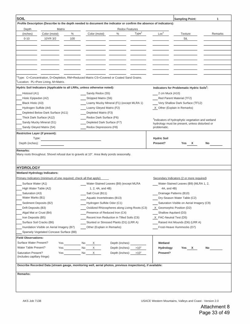
% % Type1
100
Hydric Soil Indicators (Applicable to all LRRs, unless otherwise noted): Indicators for Problematic Hydric Soils3:
Histosol (A1) Sandy Redox (S5) 2 cm Muck (A10)
Histic Epipedon (A2) Stripped Matrix (S6) Red Parent Material (TF2)
Black Histic (A3) Loamy Mucky Mineral (F1) (except MLRA 1) Very Shallow Dark Surface (TF12)
Hydrogen Sulfide (A4) Loamy Gleyed Matrix (F2) X Other (Explain in Remarks)
Depleted Below Dark Surface (A11) Depleted Matrix (F3)
Thick Dark Surface (A12) Redox Dark Surface (F6)
Sandy Mucky Mineral (S1) Depleted Dark Surface (F7)
Sandy Gleyed Matrix (S4) Redox Depressions (F8)
Restrictive Layer (if present):Hydric Soil
Depth (inches): Present? Yes X No
Wetland Hydrology Indicators:
Primary Indicators (minimum of one required; check all that apply) Secondary Indicators (2 or more required)
Surface Water (A1) Water-Stained Leaves (B9) (except MLRA Water-Stained Leaves (B9) (MLRA 1, 2,
High Water Table (A2) 1, 2, 4A, and 4B) 4A, and 4B)
Saturation (A3) Salt Crust (B11) Drainage Patterns (B10)
Water Marks (B1) Aquatic Invertebrates (B13) Dry-Season Water Table (C2)
Sediment Deposits (B2) Hydrogen Sulfide Odor (C1) Saturation Visible on Aerial Imagery (C9)
Drift Deposits (B3) Oxidized Rhizospheres along Living Roots (C3) X Geomorphic Position (D2)
Algal Mat or Crust (B4) Presence of Reduced Iron (C4) Shallow Aquitard (D3)
Iron Deposits (B5) Recent Iron Reduction in Tilled Soils (C6) X FAC-Neutral Test (D5)
Surface Soil Cracks (B6) Stunted or Stressed Plants (D1) (LRR A) Raised Ant Mounds (D6) (LRR A)
Inundation Visible on Aerial Imagery (B7) Other (Explain in Remarks) Frost-Heave Hummocks (D7)
Sparsely Vegetated Concave Surface (B8)
Field Observations: Surface Water Present? Yes No X Wetland Water Table Present? Yes No X >10" Hydrology Yes X No
Saturation Present? Yes No X >10" Present? (includes capillary fringe)
Remarks:
Color (moist)
Remarks:Many roots throughout. Shovel refusal due to gravels at 10". Area likely ponds seasonally.
Describe Recorded Data (stream gauge, monitoring well, aerial photos, previous inspections), if available:
1
HYDROLOGY
(inches)
Type:
SOIL Profile Description (Describe to the depth needed to document the indicator or confirm the absence of indicators):
Color (moist) Loc2
Texture Remarks
SiL
Redox Features Depth
Sampling Point:
10YR 3/2
Matrix
Depth (inches):
Depth (inches):
Depth (inches):
0-10
1Type: C=Concentration, D=Depletion, RM=Reduced Matrix CS=Covered or Coated Sand Grains.
2Location: PL=Pore Lining, M=Matrix.
3Indicators of hydrophytic vegetation and wetland
hydrology must be present, unless disturbed or
problematic.
AKS Job 7138
USACE Western Mountains, Valleys and Coast - Version 2.0
Attachment 8 Page 33 of 49

Project/Site: Sampling Date:
Applicant/Owner: State: Sampling Point:
Investigator(s): Section, Township, Range:
Landform (hillslope, terrace, etc.): Terrace Local relief (concave, convex, none): Slope (%):
Subregion (LRR): Lat: Long: Datum:
Soil Map Unit Name: NWI classification:
Are climatic / hydrologic conditions on the site typical for this time of year? Yes No (If no, explain in Remarks)
Are Vegetation 0 , Soil 0 , or Hydrology significantly disturbed? Are “Normal Circumstances” present? Yes X No 0
Are Vegetation 0 , Soil 0 , or Hydrology naturally problematic? (If needed, explain any answers in Remarks.)
SUMMARY OF FINDINGS – Attach site map showing sampling point locations, transects, important features, etc. Hydrophytic Vegetation Present? Yes X No 0 Hydric Soil Present? Yes 0 No X Is the Sampled Area
Wetland Hydrology Present? Yes 0 No X within a Wetland? Yes No
Absolute Dominant Indicator Dominance Test worksheet:% Cover Species? Status Number of Dominant Species
1. 0 That Are OBL, FACW, or FAC: (A)
2. 0
3. 0 Total Number of Dominant
4. 0 Species Across All Strata: (B)
0% = Total Cover
Percent of Dominant Species
1. 5% Yes FAC That Are OBL, FACW, or FAC: (A/B)
2. 2% Yes FAC Prevalence Index worksheet:3. 0 Total % Cover of: Multiply by:
4. 0 OBL species x 1 =
5. 0 FACW species x 2 =
7% = Total Cover FAC species x 3 =
FACU species x 4 =
1. 20% Yes FACU UPL species x 5 =
2. 20% Yes FACU Column Totals: (A) (B)
3. 20% Yes FAC Prevalence Index = B/A =
4. 20% Yes FAC Hydrophytic Vegetation Indicators: 5. 5% No FAC 1 - Rapid Test for Hydrophytic Vegetation
6. 5% No FAC X 2 - Dominance Test is >50%
7. 5% No FACU 3 - Prevalence Index is 3.01
8. 5% No FAC 4 - Morphological Adaptations1 (Provide supporting
9. 0 data in Remarks or on a separate sheet)
10. 0 5 - Wetland Non-Vascular Plants1
11. 0
100% = Total Cover1Indicators of hydric soil and wetland hydrology must
Woody Vine Stratum (Plot Size: 10' r or ______) be present.
1. 0
2. 0 Hydrophytic0% = Total Cover Vegetation Yes X No
% Bare Ground in Herb Stratum 0% Present?
Problematic Hydrophytic Vegetation (Explain)1
Remarks:
Schedonorus arundinaceus 3.42
Agrostis capillaris
Cirsium arvense
Holcus lanatus
Leucanthemum vulgare
Trifolium repens
Herb Stratum (Plot Size: 5' r or ______) 45 180
Plantago lanceolata 0 0
Daucus carota 107 366
Crataegus monogyna
0 0
0 0
62 186
Tree Stratum (Plot Size: 30' r or ______)
4
6
Sapling/Shrub Stratum (Plot Size: 10' r or ______)
Rubus armeniacus 67%
0
0
X
Precipitation:According to the AgACIS, Lacomb 3 NNE, OR station, 0.00 inches of rainfall was received on the day of the site visit and 1.24 inches within the two weeks prior.
Remarks:Plot is located in vicinity of wetland delineated under the 1994 delineation by Jay Lorenz.
VEGETATION
Sl. Concave <3%
A, Northwest Forests and Coast 0
Unit: 2224A, Courtney gravelly silty clay loam, 0% to 3% slopes None
0 X
WETLAND DETERMINATION DATA FORM – Western Mountains, Valleys and Coast RegionColonia Paz Housing Complex City/County: Lebanon/Linn 10/18/2018
Farmworker Housing Development Corporation OR 2Stacey Reed and Sonya Templeton Sec. 23, T. 12S., R. 2W
AKS Job 7138
USACE Western Mountains, Valleys and Coast - Version 2.0
Attachment 8 Page 34 of 49
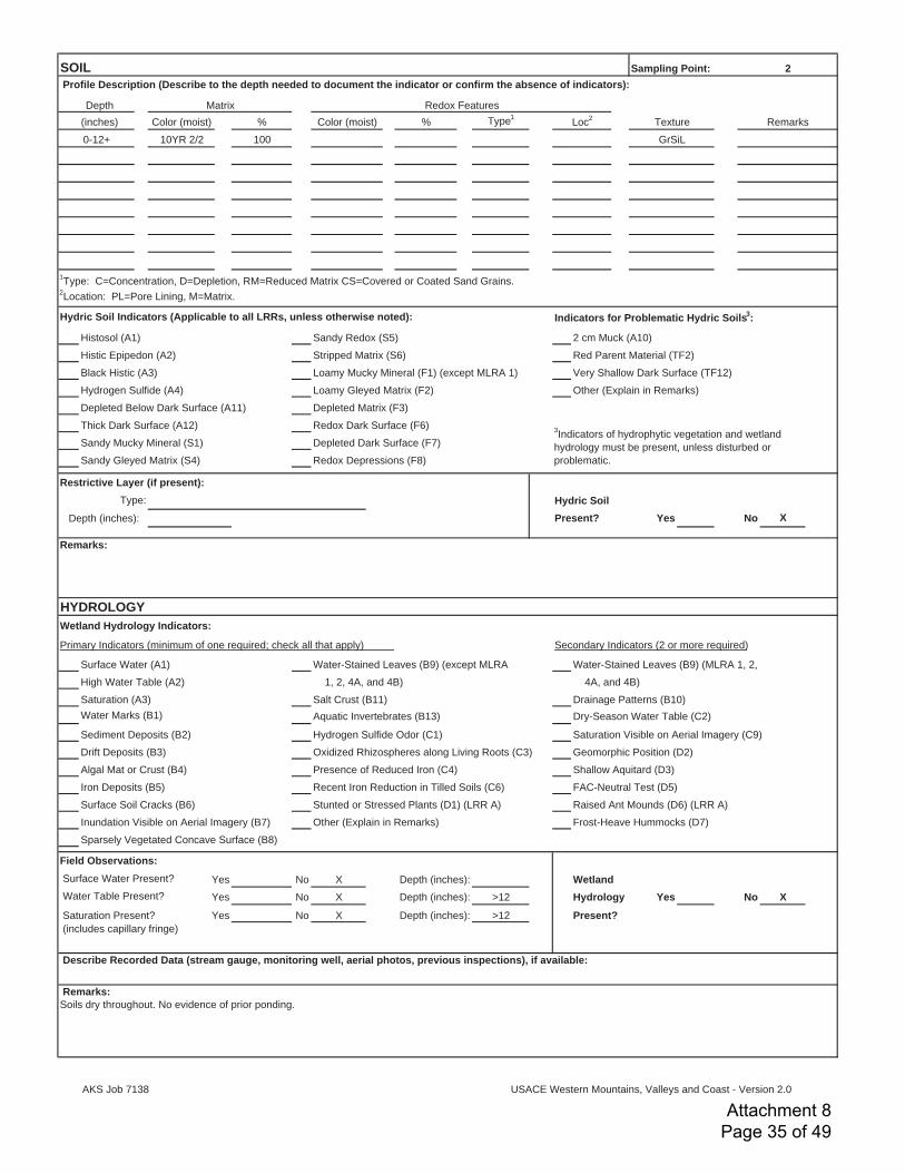
% % Type1
100
Hydric Soil Indicators (Applicable to all LRRs, unless otherwise noted): Indicators for Problematic Hydric Soils3:
Histosol (A1) Sandy Redox (S5) 2 cm Muck (A10)
Histic Epipedon (A2) Stripped Matrix (S6) Red Parent Material (TF2)
Black Histic (A3) Loamy Mucky Mineral (F1) (except MLRA 1) Very Shallow Dark Surface (TF12)
Hydrogen Sulfide (A4) Loamy Gleyed Matrix (F2) Other (Explain in Remarks)
Depleted Below Dark Surface (A11) Depleted Matrix (F3)
Thick Dark Surface (A12) Redox Dark Surface (F6)
Sandy Mucky Mineral (S1) Depleted Dark Surface (F7)
Sandy Gleyed Matrix (S4) Redox Depressions (F8)
Restrictive Layer (if present):Hydric Soil
Depth (inches): Present? Yes No
Wetland Hydrology Indicators:
Primary Indicators (minimum of one required; check all that apply) Secondary Indicators (2 or more required)
Surface Water (A1) Water-Stained Leaves (B9) (except MLRA Water-Stained Leaves (B9) (MLRA 1, 2,
High Water Table (A2) 1, 2, 4A, and 4B) 4A, and 4B)
Saturation (A3) Salt Crust (B11) Drainage Patterns (B10)
Water Marks (B1) Aquatic Invertebrates (B13) Dry-Season Water Table (C2)
Sediment Deposits (B2) Hydrogen Sulfide Odor (C1) Saturation Visible on Aerial Imagery (C9)
Drift Deposits (B3) Oxidized Rhizospheres along Living Roots (C3) Geomorphic Position (D2)
Algal Mat or Crust (B4) Presence of Reduced Iron (C4) Shallow Aquitard (D3)
Iron Deposits (B5) Recent Iron Reduction in Tilled Soils (C6) FAC-Neutral Test (D5)
Surface Soil Cracks (B6) Stunted or Stressed Plants (D1) (LRR A) Raised Ant Mounds (D6) (LRR A)
Inundation Visible on Aerial Imagery (B7) Other (Explain in Remarks) Frost-Heave Hummocks (D7)
Sparsely Vegetated Concave Surface (B8)
Field Observations: Surface Water Present? Yes No X Wetland Water Table Present? Yes No X >12 Hydrology Yes No
Saturation Present? Yes No X >12 Present? (includes capillary fringe)
Depth (inches):
Depth (inches): X
Depth (inches):
Describe Recorded Data (stream gauge, monitoring well, aerial photos, previous inspections), if available:
Remarks: Soils dry throughout. No evidence of prior ponding.
1Type: C=Concentration, D=Depletion, RM=Reduced Matrix CS=Covered or Coated Sand Grains.
2Location: PL=Pore Lining, M=Matrix.
3Indicators of hydrophytic vegetation and wetland
hydrology must be present, unless disturbed or
problematic.
Type:
X
Remarks:
HYDROLOGY
0-12+ 10YR 2/2 GrSiL
Profile Description (Describe to the depth needed to document the indicator or confirm the absence of indicators):
Depth Matrix Redox Features
(inches) Color (moist) Color (moist) Loc2
Texture Remarks
SOIL Sampling Point: 2
AKS Job 7138
USACE Western Mountains, Valleys and Coast - Version 2.0
Attachment 8 Page 35 of 49

Project/Site: Sampling Date:
Applicant/Owner: State: Sampling Point:
Investigator(s): Section, Township, Range:
Landform (hillslope, terrace, etc.): Terrace Local relief (concave, convex, none): Slope (%):
Subregion (LRR): Lat: Long: Datum:
Soil Map Unit Name: NWI classification:
Are climatic / hydrologic conditions on the site typical for this time of year? Yes No (If no, explain in Remarks)
Are Vegetation 0 , Soil 0 , or Hydrology significantly disturbed? Are “Normal Circumstances” present? Yes X No 0
Are Vegetation 0 , Soil 0 , or Hydrology naturally problematic? (If needed, explain any answers in Remarks.)
SUMMARY OF FINDINGS – Attach site map showing sampling point locations, transects, important features, etc. Hydrophytic Vegetation Present? Yes X No 0 Hydric Soil Present? Yes X No 0 Is the Sampled Area
Wetland Hydrology Present? Yes X No 0 within a Wetland? Yes No
Absolute Dominant Indicator Dominance Test worksheet:% Cover Species? Status Number of Dominant Species
1. 40% Yes FACW That Are OBL, FACW, or FAC: (A)
2. 0
3. 0 Total Number of Dominant
4. 0 Species Across All Strata: (B)
40% = Total Cover
Percent of Dominant Species
1. 10% Yes FAC That Are OBL, FACW, or FAC: (A/B)
2. 2% No FAC Prevalence Index worksheet:3. 0 Total % Cover of: Multiply by:
4. 0 OBL species x 1 =
5. 0 FACW species x 2 =
12% = Total Cover FAC species x 3 =
FACU species x 4 =
1. UPL species x 5 =
2. 0 Column Totals: (A) (B)
3. 0 Prevalence Index = B/A =
4. 0 Hydrophytic Vegetation Indicators: 5. 0 1 - Rapid Test for Hydrophytic Vegetation
6. 0 X 2 - Dominance Test is >50%
7. 0 X 3 - Prevalence Index is 3.01
8. 0 4 - Morphological Adaptations1 (Provide supporting
9. 0 data in Remarks or on a separate sheet)
10. 0 5 - Wetland Non-Vascular Plants1
11. 0
0% = Total Cover1Indicators of hydric soil and wetland hydrology must
Woody Vine Stratum (Plot Size: 10' r or ______) be present.
1. 0
2. 0 Hydrophytic0% = Total Cover Vegetation Yes X No
% Bare Ground in Herb Stratum 100% Present?
Problematic Hydrophytic Vegetation (Explain)1
Remarks:Bare ground covered by leaf litter.
2.23
Herb Stratum (Plot Size: 5' r or ______) 0 0
0 0
52 116
Rosa pisocarpa
0 0
40 80
12 36
Tree Stratum (Plot Size: 30' r or ______)
Fraxinus latifolia 2
2
Sapling/Shrub Stratum (Plot Size: 10' r or ______)
Rubus armeniacus 100%
0
0
X
Precipitation:According to the AgACIS, Lacomb 3 NNE, OR station, 0.00 inches of rainfall was received on the day of the site visit and 1.24 inches within the two weeks prior.
Remarks:Wetland A
VEGETATION
Sl. Concave <3%
A, Northwest Forests and Coast 0
Unit: 23, Clackamas gravelly silt loam None
0 X
WETLAND DETERMINATION DATA FORM – Western Mountains, Valleys and Coast RegionColonia Paz Housing Complex City/County: Lebanon/Linn 10/18/2018
Farmworker Housing Development Corporation OR 3Stacey Reed and Sonya Templeton Sec. 23, T. 12S., R. 2W
AKS Job 7138
USACE Western Mountains, Valleys and Coast - Version 2.0
Attachment 8 Page 36 of 49

% % Type1
100
95 5 C
Hydric Soil Indicators (Applicable to all LRRs, unless otherwise noted): Indicators for Problematic Hydric Soils3:
Histosol (A1) Sandy Redox (S5) 2 cm Muck (A10)
Histic Epipedon (A2) Stripped Matrix (S6) Red Parent Material (TF2)
Black Histic (A3) Loamy Mucky Mineral (F1) (except MLRA 1) Very Shallow Dark Surface (TF12)
Hydrogen Sulfide (A4) Loamy Gleyed Matrix (F2) Other (Explain in Remarks)
Depleted Below Dark Surface (A11) Depleted Matrix (F3)
Thick Dark Surface (A12) X Redox Dark Surface (F6)
Sandy Mucky Mineral (S1) Depleted Dark Surface (F7)
Sandy Gleyed Matrix (S4) Redox Depressions (F8)
Restrictive Layer (if present):Hydric Soil
Depth (inches): Present? Yes X No
Wetland Hydrology Indicators:
Primary Indicators (minimum of one required; check all that apply) Secondary Indicators (2 or more required)
Surface Water (A1) Water-Stained Leaves (B9) (except MLRA Water-Stained Leaves (B9) (MLRA 1, 2,
High Water Table (A2) 1, 2, 4A, and 4B) 4A, and 4B)
Saturation (A3) Salt Crust (B11) Drainage Patterns (B10)
Water Marks (B1) Aquatic Invertebrates (B13) Dry-Season Water Table (C2)
Sediment Deposits (B2) Hydrogen Sulfide Odor (C1) Saturation Visible on Aerial Imagery (C9)
Drift Deposits (B3) Oxidized Rhizospheres along Living Roots (C3) X Geomorphic Position (D2)
Algal Mat or Crust (B4) Presence of Reduced Iron (C4) Shallow Aquitard (D3)
Iron Deposits (B5) Recent Iron Reduction in Tilled Soils (C6) X FAC-Neutral Test (D5)
Surface Soil Cracks (B6) Stunted or Stressed Plants (D1) (LRR A) Raised Ant Mounds (D6) (LRR A)
Inundation Visible on Aerial Imagery (B7) Other (Explain in Remarks) Frost-Heave Hummocks (D7)
Sparsely Vegetated Concave Surface (B8)
Field Observations: Surface Water Present? Yes No X Wetland Water Table Present? Yes No X >11" Hydrology Yes X No
Saturation Present? Yes No X >11" Present? (includes capillary fringe)
Depth (inches):
Depth (inches):
Depth (inches):
Describe Recorded Data (stream gauge, monitoring well, aerial photos, previous inspections), if available:
Remarks:
1Type: C=Concentration, D=Depletion, RM=Reduced Matrix CS=Covered or Coated Sand Grains.
2Location: PL=Pore Lining, M=Matrix.
3Indicators of hydrophytic vegetation and wetland
hydrology must be present, unless disturbed or
problematic.
Type:
Remarks:
HYDROLOGY
0-8 10YR 3/1 GrSiL
8-11 10YR 3/1 7.5YR 3/4 M GrSiL
Profile Description (Describe to the depth needed to document the indicator or confirm the absence of indicators):
Depth Matrix Redox Features
(inches) Color (moist) Color (moist) Loc2
Texture Remarks
SOIL Sampling Point: 3
AKS Job 7138
USACE Western Mountains, Valleys and Coast - Version 2.0
Attachment 8 Page 37 of 49
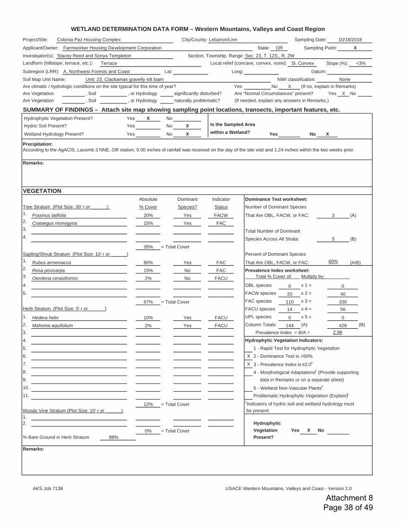
Project/Site: Sampling Date:
Applicant/Owner: State: Sampling Point:
Investigator(s): Section, Township, Range:
Landform (hillslope, terrace, etc.): Terrace Local relief (concave, convex, none): Slope (%):
Subregion (LRR): Lat: Long: Datum:
Soil Map Unit Name: NWI classification:
Are climatic / hydrologic conditions on the site typical for this time of year? Yes No (If no, explain in Remarks)
Are Vegetation 0 , Soil 0 , or Hydrology significantly disturbed? Are “Normal Circumstances” present? Yes X No 0
Are Vegetation 0 , Soil 0 , or Hydrology naturally problematic? (If needed, explain any answers in Remarks.)
SUMMARY OF FINDINGS – Attach site map showing sampling point locations, transects, important features, etc. Hydrophytic Vegetation Present? Yes X No 0 Hydric Soil Present? Yes 0 No X Is the Sampled Area
Wetland Hydrology Present? Yes 0 No X within a Wetland? Yes No
Absolute Dominant Indicator Dominance Test worksheet:% Cover Species? Status Number of Dominant Species
1. 20% Yes FACW That Are OBL, FACW, or FAC: (A)
2. 15% Yes FAC
3. 0 Total Number of Dominant
4. 0 Species Across All Strata: (B)
35% = Total Cover
Percent of Dominant Species
1. 80% Yes FAC That Are OBL, FACW, or FAC: (A/B)
2. 15% No FAC Prevalence Index worksheet:3. 2% No FACU Total % Cover of: Multiply by:
4. 0 OBL species x 1 =
5. 0 FACW species x 2 =
97% = Total Cover FAC species x 3 =
FACU species x 4 =
1. 10% Yes FACU UPL species x 5 =
2. 2% Yes FACU Column Totals: (A) (B)
3. 0 Prevalence Index = B/A =
4. 0 Hydrophytic Vegetation Indicators: 5. 0 1 - Rapid Test for Hydrophytic Vegetation
6. 0 X 2 - Dominance Test is >50%
7. 0 X 3 - Prevalence Index is 3.01
8. 0 4 - Morphological Adaptations1 (Provide supporting
9. 0 data in Remarks or on a separate sheet)
10. 0 5 - Wetland Non-Vascular Plants1
11. 0
12% = Total Cover1Indicators of hydric soil and wetland hydrology must
Woody Vine Stratum (Plot Size: 10' r or ______) be present.
1. 0
2. 0 Hydrophytic0% = Total Cover Vegetation Yes X No
% Bare Ground in Herb Stratum 88% Present?
Problematic Hydrophytic Vegetation (Explain)1
Remarks:
2.96
Herb Stratum (Plot Size: 5' r or ______) 14 56
Hedera helix 0 0
Mahonia aquifolium 144 426
Rosa pisocarpa
Oemleria cerasiformis
0 0
20 40
110 330
Tree Stratum (Plot Size: 30' r or ______)
Fraxinus latifolia 3
Crataegus monogyna
5
Sapling/Shrub Stratum (Plot Size: 10' r or ______)
Rubus armeniacus 60%
0
0
X
Precipitation:According to the AgACIS, Lacomb 3 NNE, OR station, 0.00 inches of rainfall was received on the day of the site visit and 1.24 inches within the two weeks prior.
Remarks:
VEGETATION
Sl. Convex <3%
A, Northwest Forests and Coast 0
Unit: 23, Clackamas gravelly silt loam None
0 X
WETLAND DETERMINATION DATA FORM – Western Mountains, Valleys and Coast RegionColonia Paz Housing Complex City/County: Lebanon/Linn 10/18/2018
Farmworker Housing Development Corporation OR 4Stacey Reed and Sonya Templeton Sec. 23, T. 12S., R. 2W
AKS Job 7138
USACE Western Mountains, Valleys and Coast - Version 2.0
Attachment 8 Page 38 of 49

% % Type1
100
Hydric Soil Indicators (Applicable to all LRRs, unless otherwise noted): Indicators for Problematic Hydric Soils3:
Histosol (A1) Sandy Redox (S5) 2 cm Muck (A10)
Histic Epipedon (A2) Stripped Matrix (S6) Red Parent Material (TF2)
Black Histic (A3) Loamy Mucky Mineral (F1) (except MLRA 1) Very Shallow Dark Surface (TF12)
Hydrogen Sulfide (A4) Loamy Gleyed Matrix (F2) Other (Explain in Remarks)
Depleted Below Dark Surface (A11) Depleted Matrix (F3)
Thick Dark Surface (A12) Redox Dark Surface (F6)
Sandy Mucky Mineral (S1) Depleted Dark Surface (F7)
Sandy Gleyed Matrix (S4) Redox Depressions (F8)
Restrictive Layer (if present):Hydric Soil
Depth (inches): Present? Yes No
Wetland Hydrology Indicators:
Primary Indicators (minimum of one required; check all that apply) Secondary Indicators (2 or more required)
Surface Water (A1) Water-Stained Leaves (B9) (except MLRA Water-Stained Leaves (B9) (MLRA 1, 2,
High Water Table (A2) 1, 2, 4A, and 4B) 4A, and 4B)
Saturation (A3) Salt Crust (B11) Drainage Patterns (B10)
Water Marks (B1) Aquatic Invertebrates (B13) Dry-Season Water Table (C2)
Sediment Deposits (B2) Hydrogen Sulfide Odor (C1) Saturation Visible on Aerial Imagery (C9)
Drift Deposits (B3) Oxidized Rhizospheres along Living Roots (C3) Geomorphic Position (D2)
Algal Mat or Crust (B4) Presence of Reduced Iron (C4) Shallow Aquitard (D3)
Iron Deposits (B5) Recent Iron Reduction in Tilled Soils (C6) FAC-Neutral Test (D5)
Surface Soil Cracks (B6) Stunted or Stressed Plants (D1) (LRR A) Raised Ant Mounds (D6) (LRR A)
Inundation Visible on Aerial Imagery (B7) Other (Explain in Remarks) Frost-Heave Hummocks (D7)
Sparsely Vegetated Concave Surface (B8)
Field Observations: Surface Water Present? Yes No X Wetland Water Table Present? Yes No X >12" Hydrology Yes No
Saturation Present? Yes No X >12" Present? (includes capillary fringe)
Depth (inches):
Depth (inches): X
Depth (inches):
Describe Recorded Data (stream gauge, monitoring well, aerial photos, previous inspections), if available:
Remarks:
1Type: C=Concentration, D=Depletion, RM=Reduced Matrix CS=Covered or Coated Sand Grains.
2Location: PL=Pore Lining, M=Matrix.
3Indicators of hydrophytic vegetation and wetland
hydrology must be present, unless disturbed or
problematic.
Type:
X
Remarks:Shovel refusal at 10" due to dense gravels.
HYDROLOGY
0-12 10YR 3/1 GrSiL
Profile Description (Describe to the depth needed to document the indicator or confirm the absence of indicators):
Depth Matrix Redox Features
(inches) Color (moist) Color (moist) Loc2
Texture Remarks
SOIL Sampling Point: 4
AKS Job 7138
USACE Western Mountains, Valleys and Coast - Version 2.0
Attachment 8 Page 39 of 49

Project/Site: Sampling Date:
Applicant/Owner: State: Sampling Point:
Investigator(s): Section, Township, Range:
Landform (hillslope, terrace, etc.): Terrace Local relief (concave, convex, none): Slope (%):
Subregion (LRR): Lat: Long: Datum:
Soil Map Unit Name: NWI classification:
Are climatic / hydrologic conditions on the site typical for this time of year? Yes No (If no, explain in Remarks)
Are Vegetation 0 , Soil 0 , or Hydrology significantly disturbed? Are “Normal Circumstances” present? Yes X No 0
Are Vegetation 0 , Soil 0 , or Hydrology naturally problematic? (If needed, explain any answers in Remarks.)
SUMMARY OF FINDINGS – Attach site map showing sampling point locations, transects, important features, etc. Hydrophytic Vegetation Present? Yes X No 0 Hydric Soil Present? Yes X No 0 Is the Sampled Area
Wetland Hydrology Present? Yes X No 0 within a Wetland? Yes No
Absolute Dominant Indicator Dominance Test worksheet:% Cover Species? Status Number of Dominant Species
1. 40% Yes FACW That Are OBL, FACW, or FAC: (A)
2. 0
3. 0 Total Number of Dominant
4. 0 Species Across All Strata: (B)
40% = Total Cover
Percent of Dominant Species
1. 5% Yes FAC That Are OBL, FACW, or FAC: (A/B)
2. 5% Yes FAC Prevalence Index worksheet:3. 5% Yes FACW Total % Cover of: Multiply by:
4. 0 OBL species x 1 =
5. 0 FACW species x 2 =
15% = Total Cover FAC species x 3 =
FACU species x 4 =
1. 8% Yes OBL UPL species x 5 =
2. 5% No FAC Column Totals: (A) (B)
3. 0 Prevalence Index = B/A =
4. 0 Hydrophytic Vegetation Indicators: 5. 0 1 - Rapid Test for Hydrophytic Vegetation
6. 0 X 2 - Dominance Test is >50%
7. 0 X 3 - Prevalence Index is 3.01
8. 0 4 - Morphological Adaptations1 (Provide supporting
9. 0 data in Remarks or on a separate sheet)
10. 0 5 - Wetland Non-Vascular Plants1
11. 0
13% = Total Cover1Indicators of hydric soil and wetland hydrology must
Woody Vine Stratum (Plot Size: 10' r or ______) be present.
1. 0
2. 0 Hydrophytic0% = Total Cover Vegetation Yes X No
% Bare Ground in Herb Stratum 87% Present?
Problematic Hydrophytic Vegetation (Explain)1
Remarks:Bareground covered by leaf litter.
2.10
Herb Stratum (Plot Size: 5' r or ______) 0 0
Carex densa 0 0
Alopecurus pratensis 68 143
Crataegus monogyna
Physocarpus capitatus
8 8
45 90
15 45
Tree Stratum (Plot Size: 30' r or ______)
Fraxinus latifolia 5
5
Sapling/Shrub Stratum (Plot Size: 10' r or ______)
Rubus armeniacus 100%
0
0
X
Precipitation:According to the AgACIS, Lacomb 3 NNE, OR station, 0.00 inches of rainfall was received on the day of the site visit and 1.24 inches within the two weeks prior.
Remarks:Wetland A
VEGETATION
Sl. Concave <3%
A, Northwest Forests and Coast 0
Unit: 23, Clackamas gravelly silt loam None
0 X
WETLAND DETERMINATION DATA FORM – Western Mountains, Valleys and Coast RegionColonia Paz Housing Complex City/County: Lebanon/Linn 10/18/2018
Farmworker Housing Development Corporation OR 5Stacey Reed and Sonya Templeton Sec. 23, T. 12S., R. 2W
AKS Job 7138
USACE Western Mountains, Valleys and Coast - Version 2.0
Attachment 8 Page 40 of 49
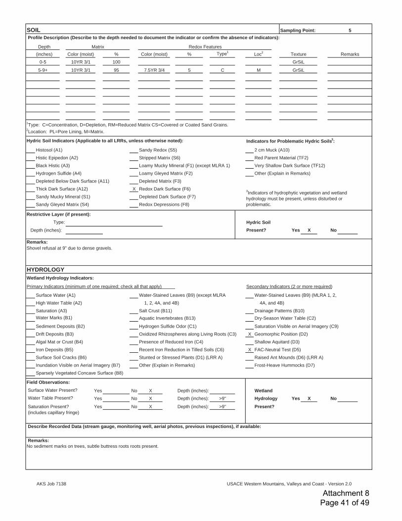
% % Type1
100
95 5 C
Hydric Soil Indicators (Applicable to all LRRs, unless otherwise noted): Indicators for Problematic Hydric Soils3:
Histosol (A1) Sandy Redox (S5) 2 cm Muck (A10)
Histic Epipedon (A2) Stripped Matrix (S6) Red Parent Material (TF2)
Black Histic (A3) Loamy Mucky Mineral (F1) (except MLRA 1) Very Shallow Dark Surface (TF12)
Hydrogen Sulfide (A4) Loamy Gleyed Matrix (F2) Other (Explain in Remarks)
Depleted Below Dark Surface (A11) Depleted Matrix (F3)
Thick Dark Surface (A12) X Redox Dark Surface (F6)
Sandy Mucky Mineral (S1) Depleted Dark Surface (F7)
Sandy Gleyed Matrix (S4) Redox Depressions (F8)
Restrictive Layer (if present):Hydric Soil
Depth (inches): Present? Yes X No
Wetland Hydrology Indicators:
Primary Indicators (minimum of one required; check all that apply) Secondary Indicators (2 or more required)
Surface Water (A1) Water-Stained Leaves (B9) (except MLRA Water-Stained Leaves (B9) (MLRA 1, 2,
High Water Table (A2) 1, 2, 4A, and 4B) 4A, and 4B)
Saturation (A3) Salt Crust (B11) Drainage Patterns (B10)
Water Marks (B1) Aquatic Invertebrates (B13) Dry-Season Water Table (C2)
Sediment Deposits (B2) Hydrogen Sulfide Odor (C1) Saturation Visible on Aerial Imagery (C9)
Drift Deposits (B3) Oxidized Rhizospheres along Living Roots (C3) X Geomorphic Position (D2)
Algal Mat or Crust (B4) Presence of Reduced Iron (C4) Shallow Aquitard (D3)
Iron Deposits (B5) Recent Iron Reduction in Tilled Soils (C6) X FAC-Neutral Test (D5)
Surface Soil Cracks (B6) Stunted or Stressed Plants (D1) (LRR A) Raised Ant Mounds (D6) (LRR A)
Inundation Visible on Aerial Imagery (B7) Other (Explain in Remarks) Frost-Heave Hummocks (D7)
Sparsely Vegetated Concave Surface (B8)
Field Observations: Surface Water Present? Yes No X Wetland Water Table Present? Yes No X >9" Hydrology Yes X No
Saturation Present? Yes No X >9" Present? (includes capillary fringe)
Depth (inches):
Depth (inches):
Depth (inches):
Describe Recorded Data (stream gauge, monitoring well, aerial photos, previous inspections), if available:
Remarks: No sediment marks on trees, subtle buttress roots roots present.
1Type: C=Concentration, D=Depletion, RM=Reduced Matrix CS=Covered or Coated Sand Grains.
2Location: PL=Pore Lining, M=Matrix.
3Indicators of hydrophytic vegetation and wetland
hydrology must be present, unless disturbed or
problematic.
Type:
Remarks:Shovel refusal at 9" due to dense gravels.
HYDROLOGY
0-5 10YR 3/1 GrSiL
5-9+ 10YR 3/1 7.5YR 3/4 M GrSiL
Profile Description (Describe to the depth needed to document the indicator or confirm the absence of indicators):
Depth Matrix Redox Features
(inches) Color (moist) Color (moist) Loc2
Texture Remarks
SOIL Sampling Point: 5
AKS Job 7138
USACE Western Mountains, Valleys and Coast - Version 2.0
Attachment 8 Page 41 of 49

Project/Site: Sampling Date:
Applicant/Owner: State: Sampling Point:
Investigator(s): Section, Township, Range:
Landform (hillslope, terrace, etc.): Terrace Local relief (concave, convex, none): Slope (%):
Subregion (LRR): Lat: Long: Datum:
Soil Map Unit Name: NWI classification:
Are climatic / hydrologic conditions on the site typical for this time of year? Yes No (If no, explain in Remarks)
Are Vegetation 0 , Soil 0 , or Hydrology significantly disturbed? Are “Normal Circumstances” present? Yes X No 0
Are Vegetation 0 , Soil 0 , or Hydrology naturally problematic? (If needed, explain any answers in Remarks.)
SUMMARY OF FINDINGS – Attach site map showing sampling point locations, transects, important features, etc. Hydrophytic Vegetation Present? Yes X No 0 Hydric Soil Present? Yes 0 No X Is the Sampled Area
Wetland Hydrology Present? Yes 0 No X within a Wetland? Yes No
Absolute Dominant Indicator Dominance Test worksheet:% Cover Species? Status Number of Dominant Species
1. 20% Yes FACW That Are OBL, FACW, or FAC: (A)
2. 0
3. 0 Total Number of Dominant
4. 0 Species Across All Strata: (B)
20% = Total Cover
Percent of Dominant Species
1. 15% Yes FAC That Are OBL, FACW, or FAC: (A/B)
2. 10% Yes FAC Prevalence Index worksheet:3. 5% No FACU Total % Cover of: Multiply by:
4. 0 OBL species x 1 =
5. 0 FACW species x 2 =
30% = Total Cover FAC species x 3 =
FACU species x 4 =
1. 20% Yes FAC UPL species x 5 =
2. 8% Yes FAC Column Totals: (A) (B)
3. 5% No FACU Prevalence Index = B/A =
4. 2% No FACU Hydrophytic Vegetation Indicators: 5. 0 1 - Rapid Test for Hydrophytic Vegetation
6. 0 X 2 - Dominance Test is >50%
7. 0 X 3 - Prevalence Index is 3.01
8. 0 4 - Morphological Adaptations1 (Provide supporting
9. 0 data in Remarks or on a separate sheet)
10. 0 5 - Wetland Non-Vascular Plants1
11. 0
35% = Total Cover1Indicators of hydric soil and wetland hydrology must
Woody Vine Stratum (Plot Size: 10' r or ______) be present.
1. 0
2. 0 Hydrophytic0% = Total Cover Vegetation Yes X No
% Bare Ground in Herb Stratum 65% Present?
Problematic Hydrophytic Vegetation (Explain)1
Remarks:
Polystichum munitum 2.91
Hedera helix
Herb Stratum (Plot Size: 5' r or ______) 12 48
Schedonorus arundinaceus 0 0
Holcus lanatus 85 247
Crataegus douglasii
Quercus garryana
0 0
20 40
53 159
Tree Stratum (Plot Size: 30' r or ______)
Fraxinus latifolia 5
5
Sapling/Shrub Stratum (Plot Size: 10' r or ______)
Rubus armeniacus 100%
0
0
X
Precipitation:According to the AgACIS, Lacomb 3 NNE, OR station, 0.00 inches of rainfall was received on the day of the site visit and 1.24 inches within the two weeks prior.
Remarks:Plot is approximately 4-6" higher than Plot 5.
VEGETATION
Sl. Convex <3%
A, Northwest Forests and Coast 0
Unit: 23, Clackamas gravelly silt loam13 None
0 X
WETLAND DETERMINATION DATA FORM – Western Mountains, Valleys and Coast RegionColonia Paz Housing Complex City/County: Lebanon/Linn 10/18/2018
Farmworker Housing Development Corporation OR 6Stacey Reed and Sonya Templeton Sec. 23, T. 12S., R. 2W
AKS Job 7138
USACE Western Mountains, Valleys and Coast - Version 2.0
Attachment 8 Page 42 of 49

% % Type1
100
Hydric Soil Indicators (Applicable to all LRRs, unless otherwise noted): Indicators for Problematic Hydric Soils3:
Histosol (A1) Sandy Redox (S5) 2 cm Muck (A10)
Histic Epipedon (A2) Stripped Matrix (S6) Red Parent Material (TF2)
Black Histic (A3) Loamy Mucky Mineral (F1) (except MLRA 1) Very Shallow Dark Surface (TF12)
Hydrogen Sulfide (A4) Loamy Gleyed Matrix (F2) Other (Explain in Remarks)
Depleted Below Dark Surface (A11) Depleted Matrix (F3)
Thick Dark Surface (A12) Redox Dark Surface (F6)
Sandy Mucky Mineral (S1) Depleted Dark Surface (F7)
Sandy Gleyed Matrix (S4) Redox Depressions (F8)
Restrictive Layer (if present):Hydric Soil
Depth (inches): Present? Yes No
Wetland Hydrology Indicators:
Primary Indicators (minimum of one required; check all that apply) Secondary Indicators (2 or more required)
Surface Water (A1) Water-Stained Leaves (B9) (except MLRA Water-Stained Leaves (B9) (MLRA 1, 2,
High Water Table (A2) 1, 2, 4A, and 4B) 4A, and 4B)
Saturation (A3) Salt Crust (B11) Drainage Patterns (B10)
Water Marks (B1) Aquatic Invertebrates (B13) Dry-Season Water Table (C2)
Sediment Deposits (B2) Hydrogen Sulfide Odor (C1) Saturation Visible on Aerial Imagery (C9)
Drift Deposits (B3) Oxidized Rhizospheres along Living Roots (C3) Geomorphic Position (D2)
Algal Mat or Crust (B4) Presence of Reduced Iron (C4) Shallow Aquitard (D3)
Iron Deposits (B5) Recent Iron Reduction in Tilled Soils (C6) FAC-Neutral Test (D5)
Surface Soil Cracks (B6) Stunted or Stressed Plants (D1) (LRR A) Raised Ant Mounds (D6) (LRR A)
Inundation Visible on Aerial Imagery (B7) Other (Explain in Remarks) Frost-Heave Hummocks (D7)
Sparsely Vegetated Concave Surface (B8)
Field Observations: Surface Water Present? Yes No X Wetland Water Table Present? Yes No X >12" Hydrology Yes No
Saturation Present? Yes No X >12" Present? (includes capillary fringe)
Depth (inches):
Depth (inches): X
Depth (inches):
Describe Recorded Data (stream gauge, monitoring well, aerial photos, previous inspections), if available:
Remarks:
1Type: C=Concentration, D=Depletion, RM=Reduced Matrix CS=Covered or Coated Sand Grains.
2Location: PL=Pore Lining, M=Matrix.
3Indicators of hydrophytic vegetation and wetland
hydrology must be present, unless disturbed or
problematic.
Type:
X
Remarks:
HYDROLOGY
0-12 10YR 3/2 GrSiL
Profile Description (Describe to the depth needed to document the indicator or confirm the absence of indicators):
Depth Matrix Redox Features
(inches) Color (moist) Color (moist) Loc2
Texture Remarks
SOIL Sampling Point: 6
AKS Job 7138
USACE Western Mountains, Valleys and Coast - Version 2.0
Attachment 8 Page 43 of 49

Colonia Paz Housing Complex (AKS Job 7138) November 2018Wetland Delineation Report
Appendix E: Photo Location Map and SitePhotographs
Attachment 8 Page 44 of 49
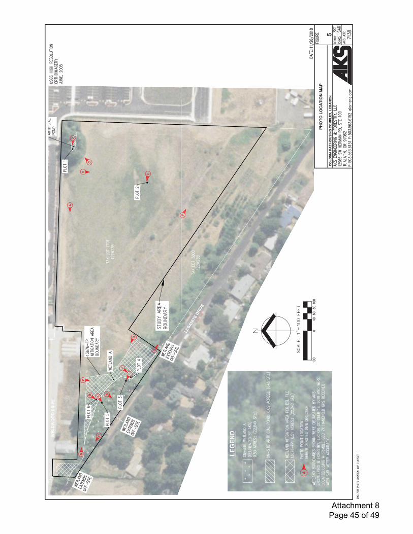
Attachment 8 Page 45 of 49
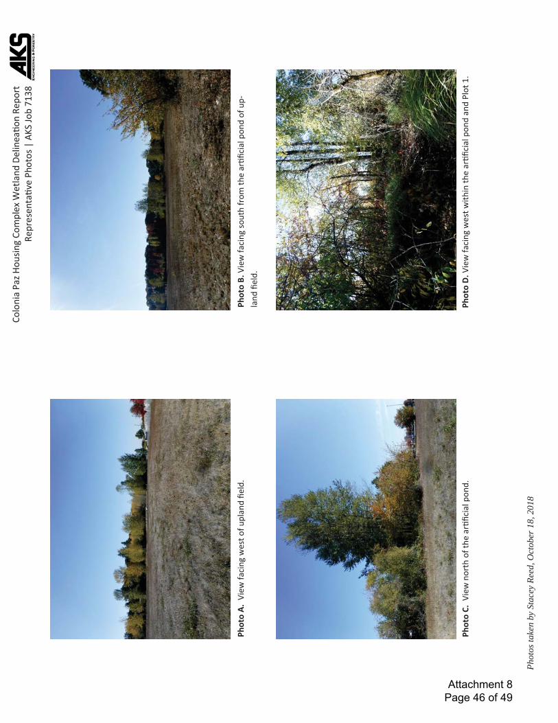
C
olon
ia P
az H
ousin
g Co
mpl
ex W
etla
nd D
elin
eaon
Rep
ort
Repr
esen
tave
Pho
tos |
AKS
Job
7138
Phot
os ta
ken
by S
tace
y Re
ed, O
ctob
er 1
8, 2
018
Phot
o D.
Vie
w fa
cing
wes
t with
in th
e ar
ficia
l pon
d an
d Pl
ot 1
.
Phot
o A.
Vie
w fa
cing
wes
t of u
plan
d fie
ld.
Phot
o C.
Vie
w n
orth
of t
he a
rfic
ial p
ond.
Phot
o B.
Vie
w fa
cing
sout
h fr
om th
e ar
ficia
l pon
d of
up-
land
fiel
d.
Attachment 8 Page 46 of 49
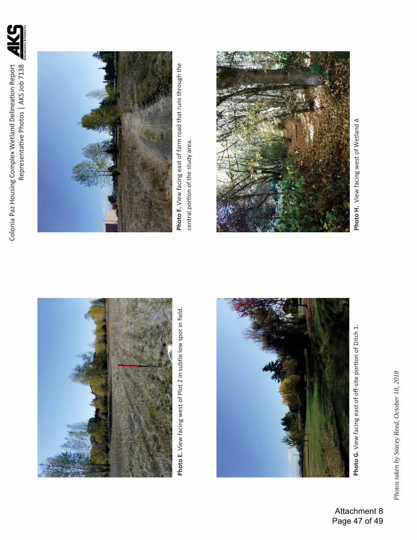
C
olon
ia P
az H
ousin
g Co
mpl
ex W
etla
nd D
elin
eaon
Rep
ort
Repr
esen
tave
Pho
tos |
AKS
Job
7138
Phot
os ta
ken
by S
tace
y Re
ed, O
ctob
er 1
8, 2
018
Phot
o F.
Vie
w fa
cing
eas
t of f
arm
road
that
runs
thro
ugh
the
cent
ral p
oron
of t
he st
udy
area
.
Phot
o H.
Vie
w fa
cing
wes
t of W
etla
nd A
Phot
o E.
Vie
w fa
cing
wes
t of P
lot 2
in su
btle
low
spot
in fi
eld.
Phot
o G.
Vie
w fa
cing
eas
t of off-
site
por
on o
f Ditc
h 1.
Wet
land
A b
ound
ary
Attachment 8 Page 47 of 49
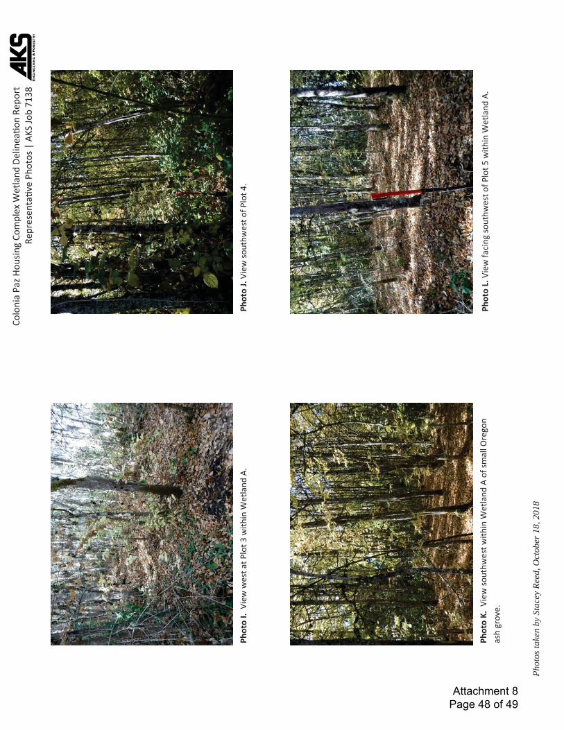
C
olon
ia P
az H
ousin
g Co
mpl
ex W
etla
nd D
elin
eaon
Rep
ort
Repr
esen
tave
Pho
tos |
AKS
Job
7138
Phot
os ta
ken
by S
tace
y Re
ed, O
ctob
er 1
8, 2
018
Phot
o K.
Vie
w so
uthw
est w
ithin
Wet
land
A o
f sm
all O
rego
n as
h gr
ove.
Ph
oto
L. V
iew
faci
ng so
uthw
est o
f Plo
t 5 w
ithin
Wet
land
A.
Phot
o J.
View
sout
hwes
t of P
lot 4
. Ph
oto
I. V
iew
wes
t at P
lot 3
with
in W
etla
nd A
.
Wet
land
A
boun
dary
Attachment 8 Page 48 of 49
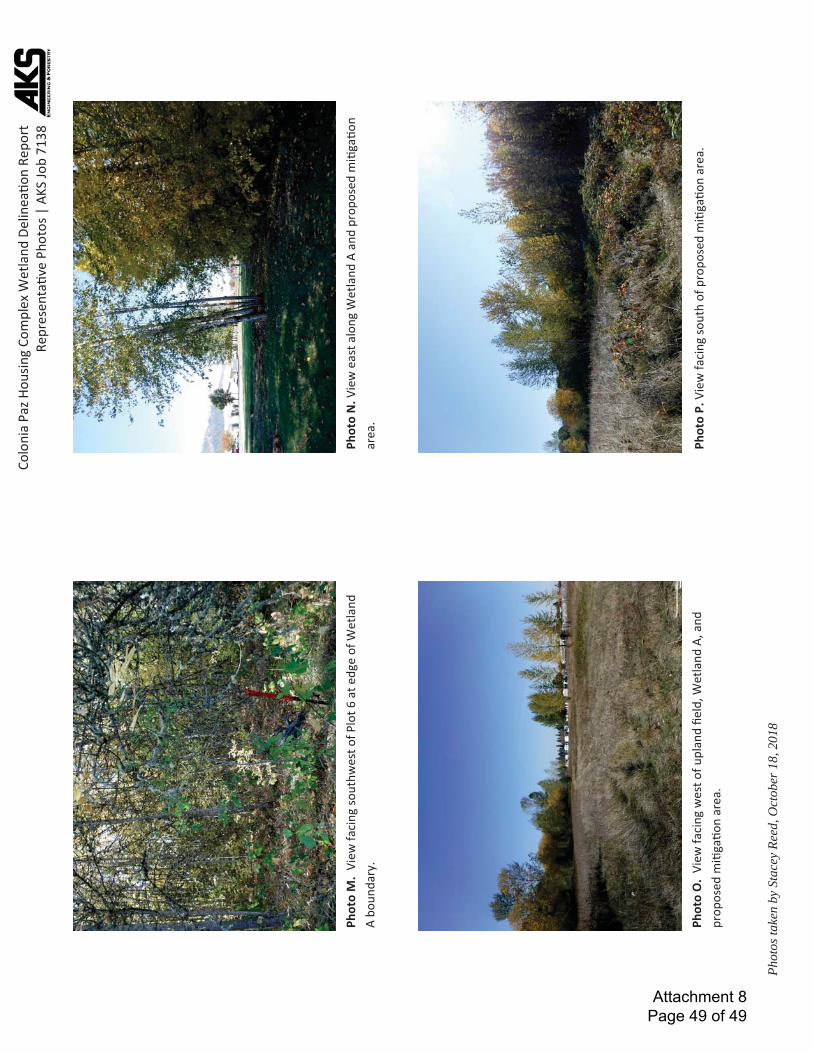
C
olon
ia P
az H
ousin
g Co
mpl
ex W
etla
nd D
elin
eaon
Rep
ort
Repr
esen
tave
Pho
tos |
AKS
Job
7138
Phot
os ta
ken
by S
tace
y Re
ed, O
ctob
er 1
8, 2
018
Phot
o O
. Vi
ew fa
cing
wes
t of u
plan
d fie
ld, W
etla
nd A
, and
pr
opos
ed m
iga
on a
rea.
Ph
oto
P. V
iew
faci
ng so
uth
of p
ropo
sed
mi
gaon
are
a.
Phot
o N
. Vie
w e
ast a
long
Wet
land
A a
nd p
ropo
sed
mi
gaon
ar
ea.
Phot
o M
. Vi
ew fa
cing
sout
hwes
t of P
lot 6
at e
dge
of W
etla
nd
A bo
unda
ry.
Flow
of D
itch
1
Flow
of off-
site
irrig
aon
ditc
h
Attachment 8 Page 49 of 49

Attachment #9
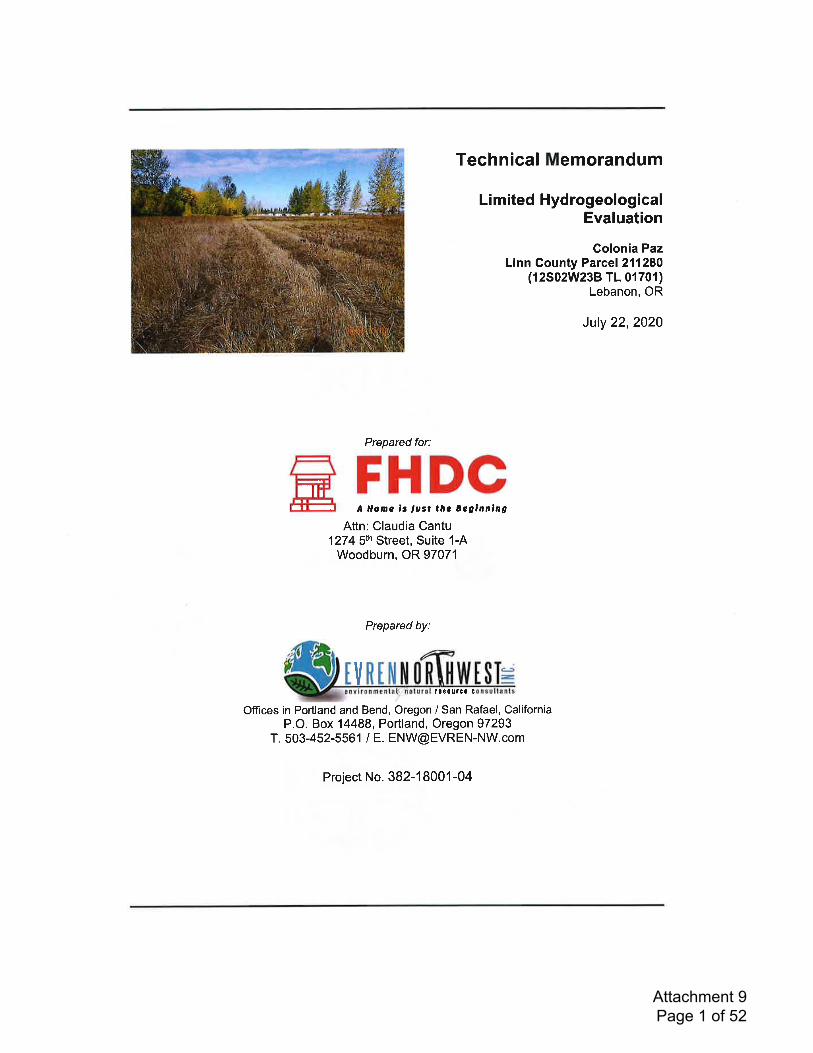
Technical Memorandum
Limited HydrogeologicalEvaluation
Colonia PazLinn Gounty Parcel 211280
(12S02W23B TL 01701)Lebanon, OR
July 22,202O
Prepared for:
1274 sth Street, Suite 1-AWoodburn, OR 97071
Prepared by:
t080urc0 t
FHDCA Homo 13 ,ost lhc Eegtnntng
Attn: Claudia Cantu
v
Offices in Portland and Bend, Oregon / San Rafael, CaliforniaP.O. Box 14488, Portland, Oregon 97293
T. 503-452-5561 / E. [email protected]
Project No. 382-1 8001 -04
tlI-:
Attachment 9 Page 1 of 52
Technical Memorandum
Limited Hydrogeologic Evaluation
Colonia PazLinn County Parcel 211280
(12S02W238 TL 01701)Lebanon, Oregon
Prepared for:
FHDCA lrame ir ,ust tlre 8e gtnnlng
Attn: Claudia Cantu1274 5th Street, Suite 1-A
Woodburn, OR 97071
By:
ttt$dulca
'L
Lynn G pal Engineering Geologist
/Crz-Erik RD Cha
\ \,'
EVREN Northwest, lnc.Project No. 382-1 8001 -04
July 22,2020Revision 0
Attachment 9 Page 2 of 52
Gontents1.0 tNTRODUCT|ON.....
1.1 Background
1
1
,l
2
2
3
2.0
3.0
stTE sETT|NG............
Review of Well Log Records.
3.1 Water Well Records....
3.2 Monitoring Well Records ........
Planned Storm Water Management (Future Development)...................................4
lmpact of Development on Ground Water Resources .......4
lmpact of Development on Wetland Areas 4
Conclusion......... 5
LtMTTATIONS ..... 5
Figures (after text)Site Vicinity Map
Site Plan
Well Location Diagram
AttachmentsA Well Gonstruction Reports
4.0
5.0
6.0
7.0
8.0
1
2
3
EVREN Northwest, lnc.Project No. 382-'1 8001 -04
il July 22,2020Revision 0
Attachment 9 Page 3 of 52
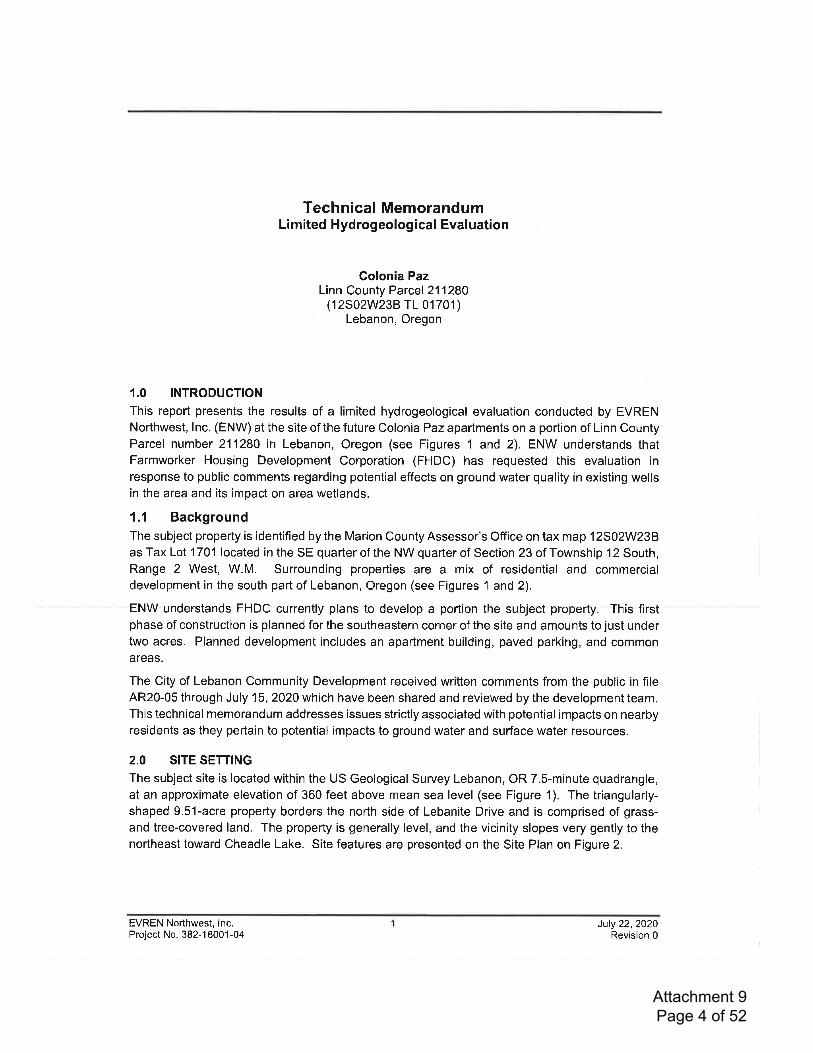
Technical MemorandumLimited Hydrogeological Evaluation
Colonia PazLinn County Parcel 211280
(12S02W238 TL 01701)Lebanon, Oregon
1.0 INTRODUCTION
This report presents the results of a limited hydrogeological evaluation conducted by EVRENNorthwest, lnc. (ENW) at the site of the future Colonia Paz aparlments on a portion of Linn CountyParcel number 211280 in Lebanon, Oregon (see Figures 1 and 2). ENW understands thatFarmworker Housing Development Corporation (FHDC) has requested this evaluation in
response to public comments regarding potential effects on ground water quality in existing wellsin the area and its impact on area wetlands.
1.1 BackgroundThe subject property is identified by the Marion County Assessor's Office on tax map 12S02W23Bas Tax Lot 1701 located in the SE quarter of the NW quarter of Section 23 of Township 12 South,Range 2 West, W.M. Surrounding properties are a mix of residential and commercialdevelopment in the sourth part of Lebanon, Oregon (see Figures 1 and 2),
ENW understands FHDC currently plans to develop a portion the subject property. This firstphase of construction is planned for the southeastern corner of the site and amounts to just undertwo acres. Planned development includes an apartment building, paved parking, and commonareas.
The City of Lebanon Community Development received written comments from the public in fileAR20-05 through July 15, 2020 which have been shared and reviewed by the development team.This technical memorandum addresses issues strictly associated with potential impacts on nearbyresidents as they pertain to potential impacts to ground water and surface water resources.
2.0 SITE SETTING
The subject site is located within the US Geological Survey Lebanon, OR 7.S-minute quadrangle,at an approximate elevation of 360 feet above mean sea level (see Figure 1). The triangularly-shaped 9.51-acre property borders the north side of Lebanite Drive and is comprised of grass-and tree-covered land. The property is generally level, and the vicinity slopes very gently to thenortheast toward Cheadle Lake. Site features are presented on the Site Plan on Figure 2.
EVREN Norlhwest, lnc.Project No. 382-1 8001-04
July 22,2020Revision 0
Attachment 9 Page 4 of 52
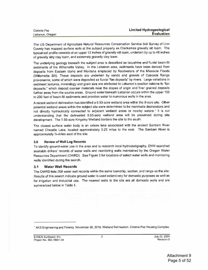
Colonia Paz
Lebanon, Oregon
Li mited HydrogeologicalEvaluation
The US Department of Agriculture Natural Resources Conservation Service Soil Survey of Linn
County has mapped surface soils at the subject property as Clackamas gravelly silt loam. The
typical soil profile consists of an upper 12 inches of gravelly silt loam, underlain by up to 48 inches
of gravelly silty clay loam, and extremely gravelly clay loam.
The underlying geology beneath the subject area is described as lacustrine and fluvial basin-fill
sediments of the Willamette Valley. ln the Lebanon area, sediments have been derived from
deposits from Eastern ldaho and Montana emplaced by floodwaters of the Missoula Floods
(Willamette Silt). These deposits are underlain by sands and gravels of Cascade Range
provenance, some of which were deposited as fluvial "fan deposits" by rivers. Large variations in
sediment textures, mineralogy and grain size are attributed to Lebanon's position relative to "fan
deposits," which deposit coarser materials near the slopes of origin and finer grained deposits
further away from the source areas. Ground water beneath Lebanon occurs within the upper 100
to 200 feet of basin-fill sediments and provides water to numerous wells in the area.
A recent wetland delineation has identified a 0.S3-acre wetland area within the 9-acre site. Other
potential wetland areas within the subject site were determined to be manmade depressions and
not directly hydraulically connected to adjacent wetland areas or nearby waters.llt is our
understanding that the delineated 0.S3-acre wetland area will be preserved during site
development. The 1.93-acre Kingsley Wetland borders the site to the south.
The closest surface water body is an oxbow lake associated with the ancient Santiam River
named Cheadle Lake, located approximately 0.25 miles to the east. The Santiam River is
approximately %-miles east of the site.
3.0 Review of Well Log Records
To identify ground-water use in the area and to research local hydrostatigraphy, ENW searched
available drillers' records of water wells and monitoring wells maintained by the Oregon Water
Resources Department (OWRD). See Figure 3 for locations of select water wells and monitoring
wells identified during the search.
3.1 Water Well RecordsThe OWRD lists 208 water well records within the same township, section, and range as the site.
Results of this search indicate ground water is used extensively for domestic purposes as well as
for irrigation and industrial use. The nearest wells to the site are all domestic wells and are
summarized below in Table 1.
l AKS Engineering and Foresty. November 26,2018. Wetland Delineation. Colonia Paz Housing Complex.
EVREN Northwest, lnc.Project No. 382-1 8001-04
2 July 22,2020Revision 0
Attachment 9 Page 5 of 52
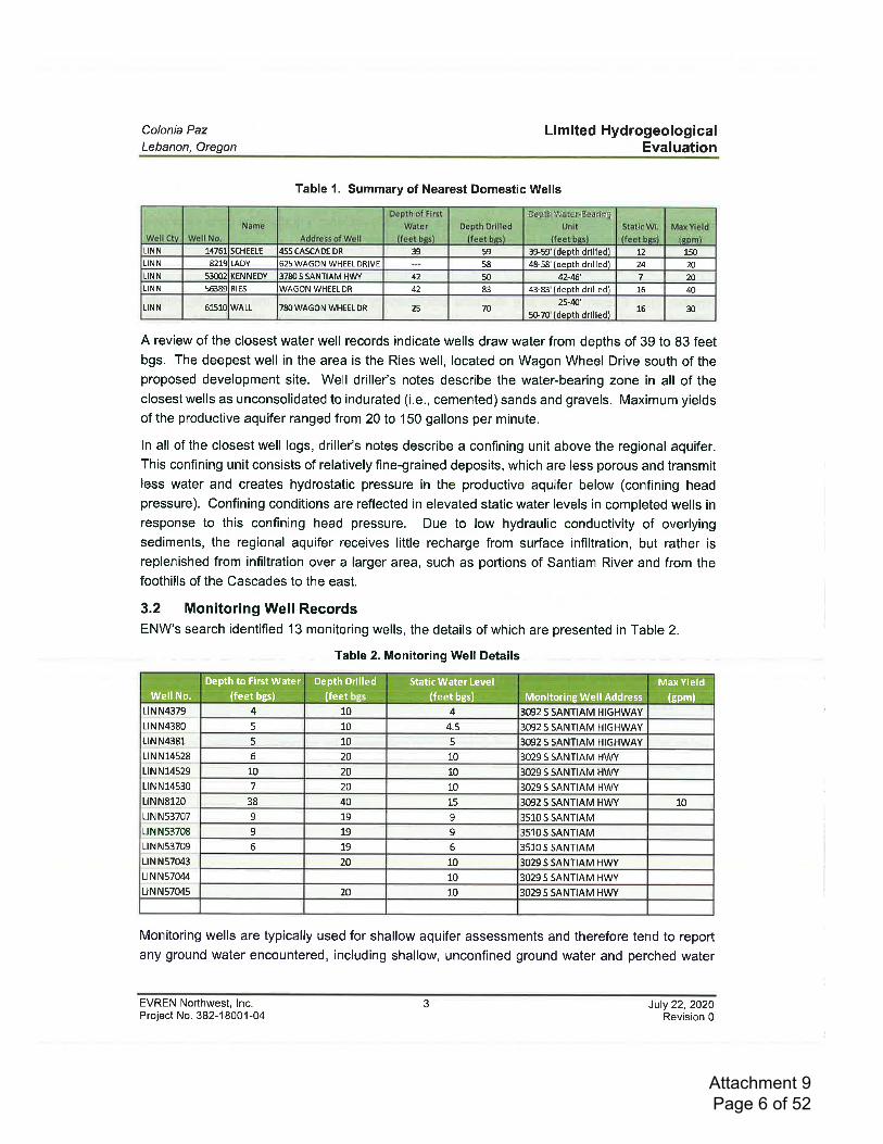
Colonia PazLebanon, Oregon
Limited HydrogeologicalEvaluation
Table 1. Summary of Nearest Domestic Wells
A review of the closest water well records indicate wells draw water from depths of 39 to 83 feetbgs. The deepest well in the area is the Ries well, located on Wagon Wheel Drive south of theproposed development site. Well driller's notes describe the water-bearing zone in all of theclosest wells as unconsolidated to indurated (i.e., cemented) sands and gravels. Maximum yields
of the productive aquifer ranged 'from 20 to 150 gallons per minute.
ln all of the closest well logs, driller's notes describe a conflning unit above the regional aquifer.This confining unit consists of relatively fine-grained deposits, which are less porous and transmitless water and creates hydrostatic pressure in the productive aquifer below (confining headpressure). Confining conditions are reflected in elevated static water levels in completed wells inresponse to this confining head pressure. Due to low hydraulic conductivity of overlyingsediments, the regional aquifer receives little recharge from surface infiltration, but rather isreplenished from infiltration over a larger area, such as portions of Santiam River and from thefoothills of the Cascades to the east.
3.2 Monitoring Well RecordsENW's search identified 13 monitoring wells, the details of which are presented in Table 2.
Table 2. Monitoring Well Details
Monitoring wells are typically used for shallow aquifer assessments and therefore tend to reportany ground water encountered, including shallow, unconfined ground water and perched water
EVREN Northwest, lnc.Project No. 382-'l 8001-04
3 July 22,2020Revision 0
UNN 14761 SCHEELE 1455CA'SCADEDR 39 59 39-59'{deoth drilledl 72 150LIN N 82L9 LADY I625 WAGON WHEEL DRIVE 58 48-58'(deoth drilled) 24 20LINN 53002 KENNEDY I378Os SANTIAM I,IWY 42 50 42-46' 7 10LIN N 5638q RrEs lwnooru wHEEL DR 42 83 43-83'ldeoth drilled) 16 q
LINN 6151( WHEEL DRWALL lr**ouo,u 25 7025-m'
5G70'(deoth drilled!16 30
:';i,ir,iiii, rlll
i; i 1.i i.r;1:;; iitr,r,'i,
i ri li iilii l{i, i ;';iil i iL{,\!iiili,:r!t :l ;.1r, { lij.iiilir,l:l
' rl,t,n,ti.ill,:ii, :i ll.liii
frrll"lj: t:jI,!i ilr Il i: rr,,' ,i11,.:,ii iir'' lr
4 10 4 3092S SANTIAM HIGHWAY
5 10 4.5 3092 S SANTIAM HIGHWAY
5 10 5 3092 S SANTIAM HIGHWAY
LlNN4379
Lt N N4380
LtNN4381
LtN N14528 6 20 10 3029 S SANTIAM HWY
10 20 10 3029 S SANTIAM HWY
7 20 10 3029 S SANTIAM HWY
38 40 15 3092 S SANTIAM HWY 10
9 19 9 3510 S SANTIAM
9 19 9 3510 S SANTIAM
6 19 6 3510 S SANTIAM
20 10 3029 S SANTIAM HWY
10 3029 S SANTIAM HWY
LtN N14529
Lt N N14530
LtNN8120
Lt N N53707
LtNN53708
Lt N N53709
LrN N57043
Lt N N57044
LtNN57045 20 10 3029 S SANTIAM HWY
Depth to First Water(feet bgs)
Static Wat€r Level
(feet bgs)
Max YieldMonitoring Well Address (epm)Well No.
Depth Drilled(feet
Attachment 9 Page 6 of 52
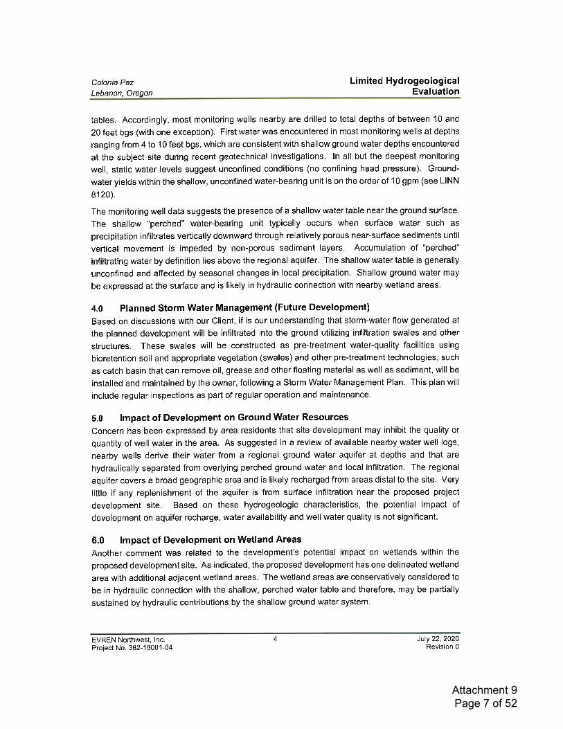
Colonia PazLebanon, Oregon
Li mited HydrogeologicalEvaluation
tables. Accordingly, most monitoring wells nearby are drilled to total depths of between 10 and
20 feet bgs (with one exception). First water was encountered in most monitoring wells at depths
ranging from 4 to 10 feet bgs, which are consistent with shallow ground water depths encountered
at the subject site during recent geotechnical investigations. ln all but the deepest monitoring
well, static water levels suggest unconfined conditions (no confining head pressure). Ground-
water yields within the shallow, unconfined water-bearing unit is on the order of 10 gpm (see LINN
8120).
The monitoring well data suggests the presence of a shallow water table near the ground surface.
The shallow "perched" water-bearing unit typically occurs when surface water such as
precipitation infiltrates vertically downward through relatively porous near-surface sediments until
vertical movement is impeded by non-porous sediment layers. Accumulation of "perched"
infiltrating water by definition lies above the regional aquifer. The shallow water table is generally
unconfined and affected by seasonal changes in local precipitation. Shallow ground water may
be expressed at the surface and is likely in hydraulic connection with nearby wetland areas.
4.0 Planned Storm Water Management (Future Development)
Based on discussions with our Client, if is our understanding that storm-water flow generated at
the planned development will be infiltrated into the ground utilizing infiltration swales and other
structures. These swales will be constructed as pre-treatment water-quality facilities using
bioretention soil and appropriate vegetation (swales) and other pre-treatment technologies, such
as catch basin that can remove oil, grease and other floating material as well as sediment, will be
installed and maintained by the owner, following a Storm Water Management Plan. This plan will
include regular inspections as part of regular operation and maintenance.
5.0 lmpact of Development on Ground Water Resources
Concern has been expressed by area residents that site development may inhibit the quality or
quantity of well water in the area. As suggested in a review of available nearby water well logs,
nearby wells derive their water from a regional ground water aquifer at depths and that are
hydraulically separated from overlying perched ground water and local infiltration. The regional
aquifer covers a broad geographic area and is likely recharged from areas distal to the site. Very
little if any replenishment of the aquifer is from surface infiltration near the proposed project
development site. Based on these hydrogeologic characteristics, the potential impact of
development on aquifer recharge, water availability and well water quality is not significant.
6.0 lmpact of Development on Wetland Areas
Another comment was related to the development's potential impact on wetlands within the
proposed development site. As indicated, the proposed development has one delineated wetland
area with additional adjacent wetland areas. The wetland areas are conservatively considered to
be in hydraulic connection with the shallow, perched water table and therefore, may be partially
sustained by hydraulic contributions by the shallow ground water system.
EVREN Nofthwest, lnc.Project No. 382-1 8001-04
4 July 22,2020Revision 0
Attachment 9 Page 7 of 52
Colonia Paz
Lebanon, OregonLi mited Hydrogeological
Evaluation
As outlined in Section 4.0, surface water recharge to wetlands will be maintained by diverting all
storm water falling on hardscape surfaces (paved areas and roofs) to a water quality infiltration
structures. These features gather the storm water, treat it for potential contaminants (i.e., oil andgrease, suspended solids and other pollutants that are typical of parking lot runoff), and infiltrate
the treated storm water into the subsurface. Since storm water system will be regularly monitored,
inspected and maintained under an approved Storm Water Management Plan, the potential
impact of development on shallow ground-water hydrology is not significant.
7.0 ConclusionBased on our review of available information, it is our opinion that:
r The presence of low-porosity strata above the regional ground water aquifer, the broadoccurrence of the regional aquifer, and substantial area from which ground water sources
are replenished, the proposed development is not anticipated to adversely impact ground
water quality or availability.. The planned storm water treatment and management will employ engineered means of
pretreating and infiltrating storm water into the subsurface, and therefore replenish
shallow ground water hydrology to the adjacent and other local wetland areas nearby.
8.0 LIMITATIONS
The scope of this Technical Memorandum is limited to observations made during previous on-sitework; interviews with knowledgeable sources; and review of readily available published and
unpublished reports and literature. As a result, these conclusions are based on information
supplied by others as well as interpretations by qualified parties.
No subsurface exploration has been performed in conducting this assessment, and detailed
mapping has not been completed. Figures and findings presented herein are based on limited
site reconnaissance. Conclusion and recommendation presented in this assessment wereprepared in accordance with generally accepted professional geologic engineering principals andpractice. We make no warranty, either express or implied.
We have performed our services for this project in accordance with our agreement andunderstanding with the Client. This document and the information contained herein have beenprepared solely for the use of the Client. We have performed this study under a limited scope ofservices per our agreement. lt is possible, despite the use of reasonable care and interpretation
that we may have failed to identify the presence of geological hazards other than those specificallymentioned in this assessment. We assume no responsibility for conditions that we did not
specifically evaluate, or conditions that were not generally recognized at the time this report wasprepared.
EVREN Northwest, lnc.Project No. 382-1 8001-04
5 July 22,2020Revision 0
Attachment 9 Page 8 of 52

FIGURES
Attachment 9 Page 9 of 52
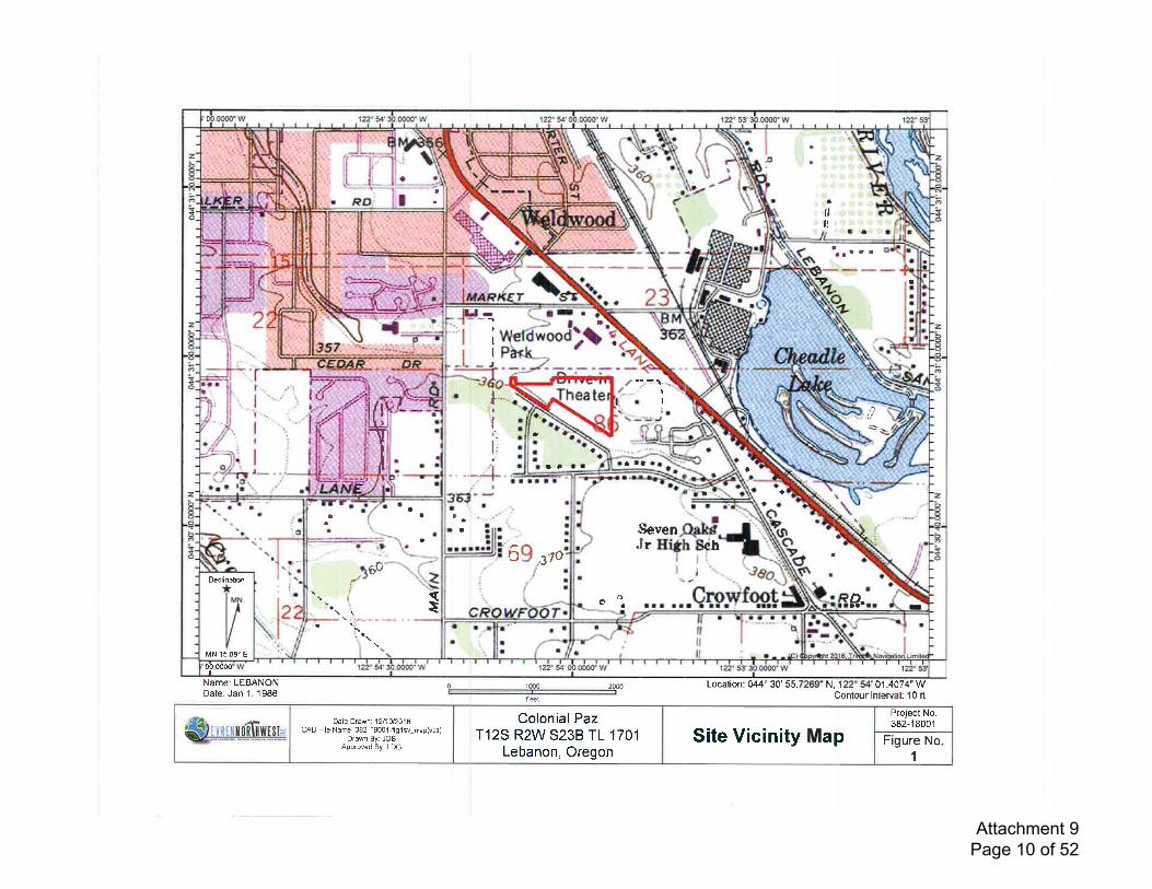
rt
Taaaa
!aa t t I
a
ilu
aa
I
I
t
Ig.
)
I
I
t
lt
I1,
ar ta at t
0a
I
a
t
I
1.t
taaa
hHrttrI
r$evenJ
aaata
+a
a
Sa al
tt
a
III
.I
rlI
tat
aaa
aI
aII
I
l,IIi.
tj
I
f0
,,.
-
"*r4
a
I
at
a)
6$ ",
3o
{
a
t
{E
II
I
I
\ . !^,--,-
-16CI
(
MN 15.09" Er
Declination
oO.oooo
z
+-o
Name: LEBANONDate: Jan'1,1986
0 1000 2000ffi
N, 1 01.4074" W
Fei
Project No.382-18001
Figure No1
Site Vicinity MapColonial Paz
T12S R2W S23B TL 1701Lebanon, Oregon
Date Drawn: 1211012018CAD File Name: 382-18001-fig1 sv_map(vo1)
Drawn By: JOBApproved By: LDG
&Huffi$l*
Location: 044' 30' 55-Contour lnterval: 10 fl
Attachment 9 Page 10 of 52
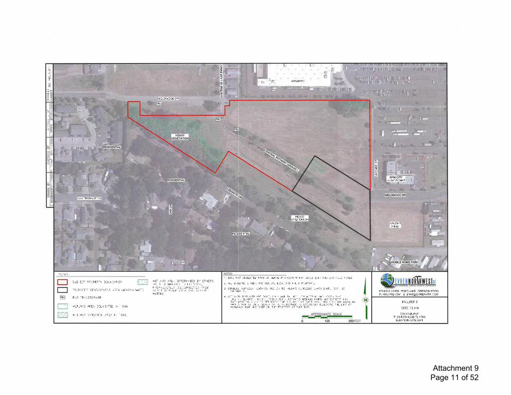
-&Uo
tl
FzWELDWOOD DR
fut
RESIDENTIAL
xouoo
o SPIN CITYRESID.ENTIAL UUNDROMAT
t"rrr\WELDWOOD DR
OAK TERRACE DR
z
o
VEGETATIONVACANT
FIELD
RESIDENTIAL
:.l
.,. I'OBILE HOM-E PARK
8lr'
',.. &iiHEA\A/
VEGETATION
t'.-,1
PO BOX 14488. PORTLAND, OREGON 97293P: (503)452-5561, E: ENW@EVREN-NW COl,l
FIGURE 2
SITE PLAN
COLONIA PMT125 R2W S23B TL 1701
LEBANON. OREGON
LIOE N D:], BASE VAP DEVELOPED FROM AN AERAL PHOTOGRAPH MAP DATED 20]7 AND ENW FELD NOTES.n
t_li*r
:iL,]ts.JLC I PROPLR IY tsOUNDAR LS
PROPOSTD DEVELCtr\IENI AREA (APFIROX MATE)
PAD TRANSFORMIR
WTTLAND AREA DELNEATED N 1996
WL_TLAND IVIIIGAT ON AREA IN ] 996
IVEIL-AND ARIA DtltR[4rNED BY OTHTRSIO BE A MANMADE DEPRESSON,HYDRAULCALLY LISCONNECTID FRCMOTF]ER IIITLAND AREA AND NEARBYWATtRS.
) ^ E r D -a-t-. d\D cr^_ o- Lor^1to\- io[ dooo \rvart
3. SYMBOLS REPRESENT LOCAI]ON AND DO NOT ALWAYS RIPRISINT EXACT SHAPE, SZT, ORORIENTAI ON.
4. WITFNDS DSPLAYTD ARE BASED ON A MAP BY UDELL ENGNEER]NG AND STATES THAT'TtsE DTLNTATON iIAT DETIRMNID THI LLUS]RATED WETLAND LMITS HAS EXPRED'' ANDTHIY MAKE NO CLAM TO REPRESENT TI]E AC'URACY OF THER MAP. iTEY ALSO RECOMMTNDEDTHAT A NEW WETLAND DELNIATION BE PERFORMED TO ACCIRATELY DTTIRMNT- ]tsE L]M]T OFWITUNDS THAT MAY EXST ON TtsE PROPIRTY A]
'HAT TME.
zt
o
Attachment 9 Page 11 of 52
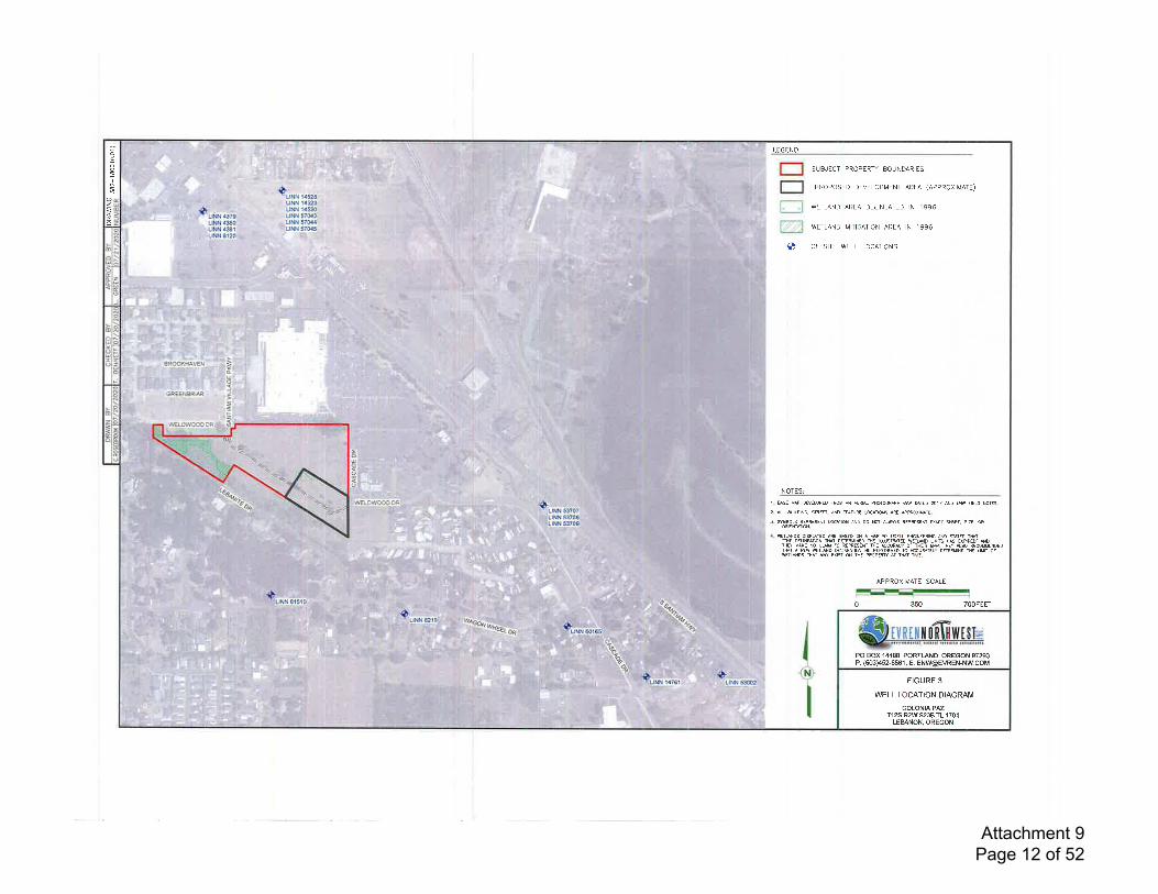
Stvnnrffiwtst=
--*-*'PO BOX 11,188, PORTLAND, OREGON 97293P: (503)452-5561, E: ENW@EVREN-NWCOM
FIGURE 3
WELL LOCATION DIAGRAM
COLONIA PAZTt2S R2W S23B TL 1701
LEBANON. OREGON
PROPOSED DEVELOPMENT AREA (APPROXIMATE)
1. SSE MAP OEVELOPED FROM AN AERII PHOTOGRAPB MP MI€O 2017 AND EM FELO NOTES.
2. ALL A!]LDING, SNEF, AND FUTURE LOCANON5 ARE APPFOX]MAIE,
3. NMSLS REPRESTM LOCAT]ON AND OO NOT ALWAYS REPRISENT EXACT SUPE. SIZE, OR
WiTUNDS DISPilYED ARE NED ON A MP S UOELL EN6]NEER]NG ANO STATES IM'AHE DELINEATION TMT DtrTRMIN€D ]HE JLLUSTfuTED WETND LIM]TS HS ryPIR€D" NDTHry MAKE NO CUIM 1O REPRESENI THE ACCURg OF iNEIR MF. THry 4SO RECOMMENDEDTMT A N& WFSNO DEL}NEATION 8E PERFOFMED TO ACCURAIELY DMRM]N! TH! LISIT OFWFSDS iHAT MAY qX]SI ON TAE PROPERT AT frAT ]IME.
APPROX]MATE SCALE
SUBJECT PROPTRTY BOUNDAR S
LEGEND:
700FErr350t-=]!l!E-0
+
NOTES:
WETLAND AREA DEL]NEATED IN 19S6
WETLAND MITIGATION AREA IN 1996
OFFS]TI WELL LOCA'IONS
I
ze
Attachment 9 Page 12 of 52
ATTACHMENT A
WELL REPORTS
Attachment 9 Page 13 of 52
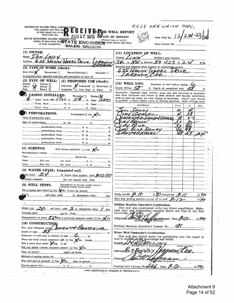
OA/ /-/ d/1/F aJ4 t ra aa&/,T
>dah zw
(u1
State Well No.
State Permit No.
WELL:(1) OWNER:Name
Addressnumber
wTYPE OF**ry(
tr)r'tr
and lrom
New
ff
($) TYPE OF IVELL:RotaryCable
Deepenlng E' Recondiuonlng E Abandon Edescribe mEterlal and in Item 12.
Drlven !Jetted DBored E
(4) PROPOSED USE (check):Domestic ,f ,ruu.r"r", E Muntctpel E|Irrlgation'6 test Well ! Other D
(12) WELL LOG:Depth driued -dt
Dlameter of welt below .^tin1 ....b.......,..,.,....ft. Depttr of completed well ft.
Formetlon: Describe cotor, texture, grain slze- and structure of materials;and show thickness and nature of each stratum and aquifer penetrat€d;wlth at least one entry tor each change of forrnation. Reporf each changein positlon of Statlc Water Level as drilling proceeds. Note drilling rates.
MATERIAL Swl,
Woik startdd $rdDate well drilling machlne moved off of wel! 19
Drllllng Machine Operator,s Certllicafion:This well underrials used
knowledge
" Dlam.
INSTALLE-D! rrrreaded f-l weldecl tftro .-...f.7.-t4t. rc ...&i-8--- ,,. o"r" 2*.A.
Gage .-..-..,.--.-...-..-..--
Jr nnnroRATroNS: Perforated? tr vesr(rvo.TYpe of perforator used
Size ol ln. by ln,perforations lrom
perforatlons from .........-....-....--..,....... ft. to .--.........................---- ft.perforations lrom
ft. to -...,....,.........,..-...-.._ ft.
IIt. to -.................-..-........... tt.
(7) SCREENS: well screen rnstaued? [J yes If""Manufactufer's Name ...._.
ft.
to .....---.,........---.-. lt.(8) WATEn Completed well.
Date
pressure lbs. per square lnch Date
(e) WELL TESTS: Drawdown ls amount water tevet isIowered below staflc levetWas a
test wlth ft.
WeIl seal*MaterlalDepth of seal ......
Dlameter of wett bore to bottom ol g€al
Were any loose strata cemented otf? [f f.es DeptJrw€s a drlve stroe usedr ffiee ENo
strata contaln Yes
lYne of water? deDth ol
u
Artesian llow g.p,m.- D-ate ,. .. .-. . -
Temperature ot water.SBE^ras a chemicaJ, aratysts ryd- O y"1$!(10)
hrs.
ft,
o^tuf,r.&...-, Ls.fu
Drilling Machine Operator's License No. ...
tn.
Water Well Gontractor's Certifieatlon:This
true toNAME
Address
and this report is
Method of seallnE strata offt", *"U r""r., O".n"O, E Contractor)
......-.......-;;..-..-..... ft,. Contractor's License
From Ao
-A ,rt D r) 1, aa-fudr.*; - 4 2f,+ za
-*-'ff}#WPBFAaa'#,np, - 2.t Z'ZIt,u e .-fu.-torl -t7/^ aeLPF4lel" UT sv ,t4
Completed
Gravel ptaced lrom ...................._---------. lt. to
(USE ADDITIqNAL SFIEETS IF NECESSARY)
or
under
Date
(Tvpe
1e.u5
Attachment 9 Page 14 of 52
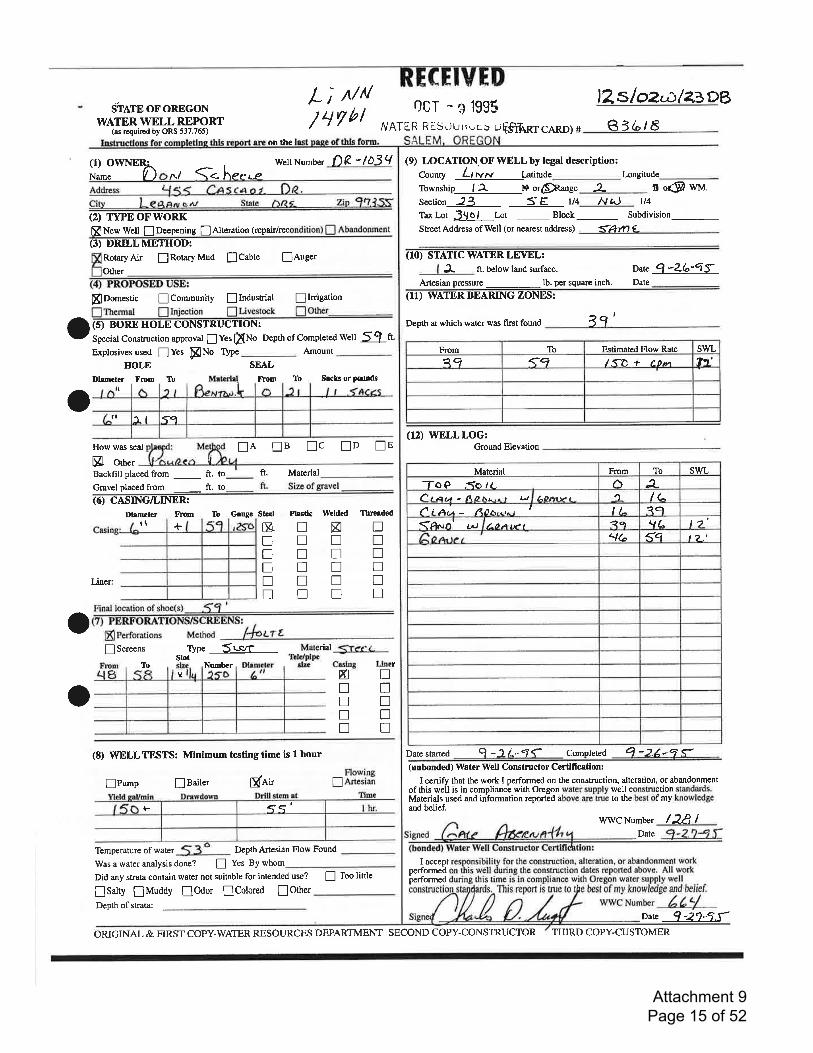
ShATpoFoREcoNWATER WELL REPORT
(ar rcquircd by ORS 537.765)
RECEIVEDOCr - e 1995
/VATER RL Sr)u rrvr.> u€$'thnr ceno) +
tz sloz:.;.lazDB
e3L/5Li uu/ 4 rt'i
on the
WellNumber f)R "tD3q(1) oWNERiName t) n/ {. he.'."-eaaress tJ55 Cqscn o z F€.cry t-egnry""l . = s"" O(2) TYPEOFWORKffi New Well I Derpening ! Alteration (repairireconditiont ! 4laoggn*til
al
How was s€a] lA nB nc nD nEp ot"'BacKill placed from _ ft. ft. Material
Gravelplacedfrom
-
ft. to- ft. Sizcofgravel
i6iTAIxrmet€r FrDm To Grugc St!€t Ptrgdc Welded Threrdsd
(9) LOCATION.OF WELL by legal description:county ll rvrv Latitude-Longitude-Township_____..j-2. 14 or$ange 2_ n o*9 wtvt.
section -fl_ S E rl4___8 t\)_ tt4
Tar Lot 39 o I Lot..- Block _ SuMivision-street Addrcss ofWell (or nearest address) <M1 (
(TO) STATIC WATER LEVEL:
^3- ft. below land surface, Date Q -ZG-4tArtesian pressure _ lb. per square inch. Date
-
(I1) WATER BEARING ZONES:
Depth at which water was first found 19'
(12) WELLLOG:Ground Elevation
Dare starred q -3-L.-'7C Comoleted 4'ZZ-q f
Roury Air ! Rotary Mud I Cabte
Other
!Auger
o
o
ffiDomestic ICommunity nlndustrial !InigationnThermal n Injection n Livestock nOtler-(5) BOREHOLECONSTRUCTION:Special Construction approval ! Yes fiNo Depth of Completed Well 5 9 t.Explosivesused f]ves pNo fYpe
HOLEDhmeter From To
SEAL
trlom
Amount
To Sects orpoudsat
to
t\ nnnnnu
Knntrnu
nnnnntr
&nnnnn
+
nnn!n
annnn
Liner:
^ Finallocationof shoe(s) 59' =.t "' d?H:H:''-T'"1f".' r+.",
! Scrcens type Sls,TSlot
Numberx
Material :irer. t-TbJe/plpe
8lz. Cslng lfterllo
o(8) WELLTESTS: Minimum tnstingtime is t hour
nPurnp lnailer ginit(unbonded) Watrr WelI Constructor Certllication:
I cenify that the work I performed on tle construction, alteration, or abandonmentof this weil is in complianc-e with Orcgon water supply well construction standards.Materials used and information reported above are true to the best of my knowledgeand belief.
Flowingf] nttcsian
{-
Temperature of water Depth Artesian Flow Found
Was a water analysis done? ! Yes By whom-Did any strata contain water not suitable for intended use?
[Salty flMuddy lOdor lColored [OtherI Toolittle
Dept! of strata:
I acceptperformedperformed
wwCNumber /2f,IDate
oare 1-2i4S-
From IO Estimated Flow Rate swL?q <q l.Sn + f 0m 2n',
tI sg
Material From To swL-1-oO ,{o lc 6 A-Ct aut - Ao t:u,u r r-! AO|JIP t t_ IGf i rqu - Ao6l.ttt t ll- ?cl(A^rnt LL) /-O * tx'a ?.f 1l L. t'?'
q6 gq t 2,t
<q'
OzuGINAL & FIRST COPY-WATER RESOI.IRCES DEPARTMENT SECOND COPY-CONSTRUCTOR THIRD COPY-CUSTOMER
Attachment 9 Page 15 of 52
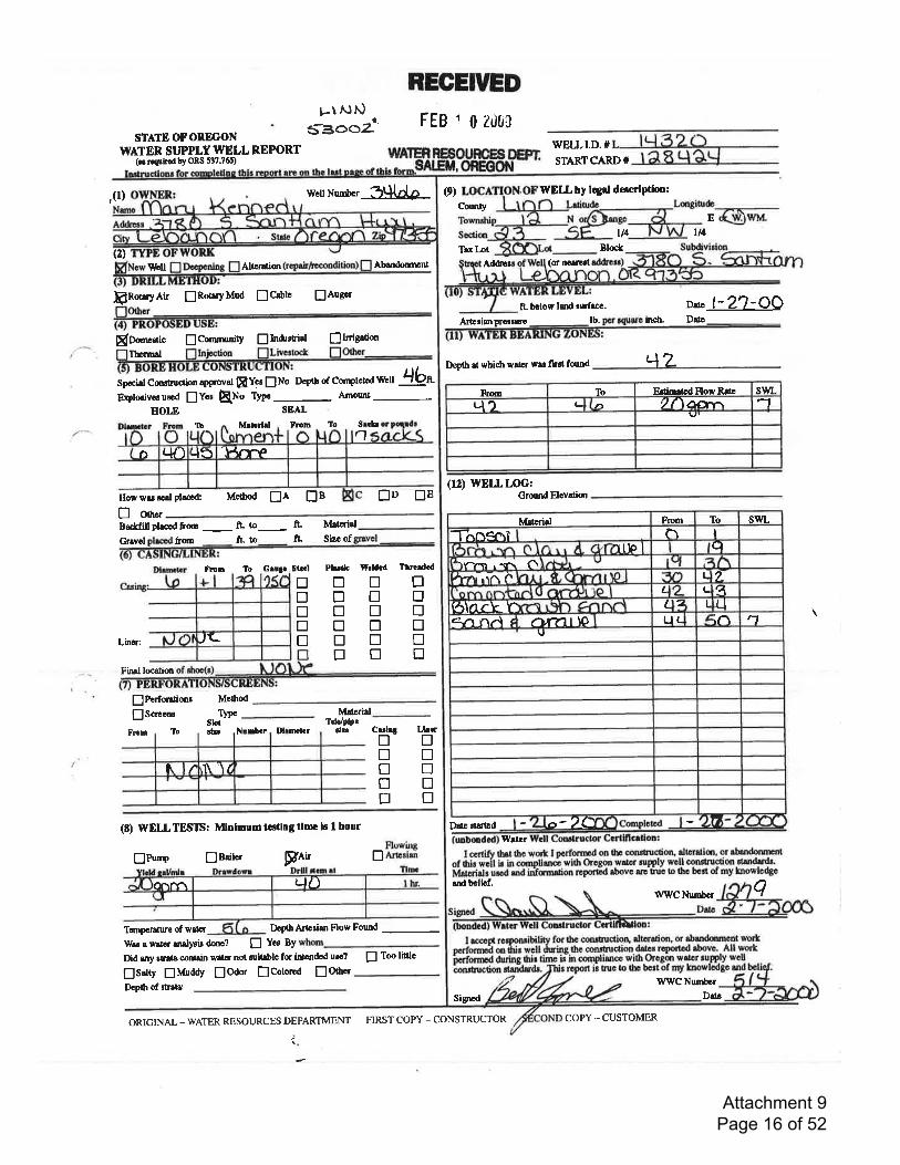
REGEIVED
FEB 1 0 20a0
FRdryAir flRotryMud flcablc flAugcrf-'l0thor
$Oomcrric trCannu*V flIndr'tirl flInigation
STATEOFORDGONWATER SI.'PPLY WELL REPORT
(r. ro$imd bY ORS t37.?6t)
!-\ Ni.)5300y''
.,(l) wcllNurnbcr 3Lild,p (e)
(2)\\bll Altlralion Abendormnt
Ifrrmrl
Spocial Cmdruction apPmv0l [LYp f]No Dcpth of Cottplclod Wcll -!16"Brplosivcruscd lYcr [No ryP"- Amont-
HOLE SEAL
FllnIb M.ltrlrl lio Srcb
Howwurcalplaccd Mclhod EA EB [D E]E
E oo.rBactfrllphccdfrom
-
fL to- ft Matldd-Gravol &ont ftto fl. Sizc of
honr llo
Lher:
Find locatim
WELLT.D.#
STARTCARD#
WELL by lqrl deecrlPilon:
CoutyE
ll4Tex Lot Blo*
Ad&trr (or noltllt
ft- bclow lerd rtnfrcc. D"' l- 2?-OOArterirn prorruro tb. indr, Drtc
Deplh al whidr wlt r was frrt fdnd qz
(r2) WELLLOG:Grumd Elevatian
Drr. dallcdWrtcr
end bclief.WWC NuDbGr
q
WrilC Nunbor
Signod
t14
11
Pbth Wrldcd Tlrcd.dtrtrtrtrtrtrtrtrtrtrtrtrtrntrtrtrtr
Sr.Gl
Itrtrtrtr
Gm3c
Crdr! Lbcrfl Dtrtrtrtrntrtrtr
!PoforrtionrIScrcons
From To NrnS:r Dl.tn lrr
(E) WELLTESTS: Mnlmum tecting time lc I hour
tlPw" fJBailcr FAtt
TanporrNe of waLr DodhnncrirnFlow Found
Wasewareranalyeirdanc? [ Yoo BY
Did rny srat& conl,rin wallr not cuilslc fc irtadod uro? [ Too littlc
lSrlty flMuddy flOdor flColoroa lO0rerDeplh of ttata.:
FluwirBlArarian t ccrtify thrt tbc vo't I mrformd ontlr conttuction, dbrarim, or ahndornrnt
of lhij wcil il in comptimcc with Orogon wat r nlpPly woll conctrudion .tEndrds.tiarcrirti urca a"a dtmnation rcponia rbovc art-iub to tho bcat of my knowhdgc
Mo0rod
Tclc/plprdt
sloarh.
IYp. Matcrid
ORIGINAL - WATER RESOURCES DEPARTMENT
;
Fm To EdinrtodFlow Ralc swl_Lt? t) 2()ar -7
-.l.{rFpD r.l/') q5
,,\-
tvfdlrid Fnn To swL-Thosoi n I
'l ll0 I cl\rrn.rn O4?'r-.t^ a L L
L I L q6\ar}- f L 2 t ,qqn n.l , atrTtr lo Lt( in r't
U
o'7O
N'1\
'\ I
L)D
FIRST COPY _ CONSTRUCTOR COPY -CUSTOMER
Drtr
Attachment 9 Page 16 of 52
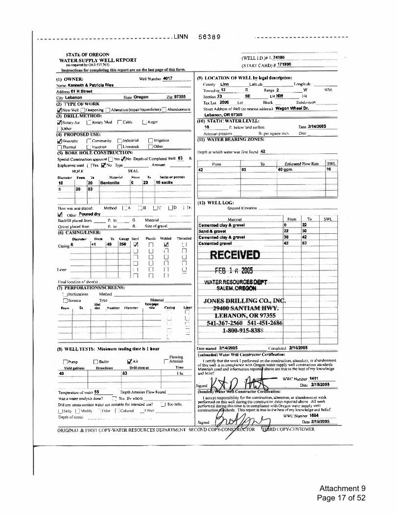
STATE OF OREGONWATER SUPPLY WELL REPORT
(as required by ORS 53?.765)
(r) owNER:Name Kennoth & Patrlcla Ries
Well Number 4lll7
Address 6l H Stroet
Cttv Lobanon Sute Orcgon Z
(2) TYPEOT.'WORKWell Deepening
BlRotaryAir [Rotary Mud lCable lAugerOther
L|NN 56389
(WELLr.D.)# L71190
(srARr CARD) # r7t900
(9) LOCATION OFWELL by legal description:
Comty Llnn Latitude Longitude_
the
Tomship 12 S Range 2 W
23 SE l/4 NYU t/4
wM.
Alteration (repair/recondttion) Abandonment Street Address of Well (or nearest address) YYason Ullhrel Dr.Tulot 2000 Lot Block __. SuMivision_.
Lobanon, OR 97355
(10) STATIC WATER LEVELT16 ft. below land surface. Date 2I14Z0OS
flDomesticI Thermal
ICommunityE lnjection
Ilndustrial ! lnigtion
f]Livesock D9l"t_
Artesian pressure _.,-..- -. lb. per square inch. Date ---. ,-
with Oregon water supplythe best of my knowlcdge
(SITOFEEOLF. coNSiRUCTIoN :
SpecialConsfiuctionappmval lYesflNo Depthofcomplet€dWell 83 R.
Explosivesused lYes fluo Type- Amount-HOLE
Diameaer From To
SEAL
Maaedal To
l0 20
Howwassealplaced: Method LjA EB fjc l-JD 1_]E
EI oth", Poured dry
Backfill ptaced from _ ft. to- {i. Material _-Gravel placed from ft. to ft. Size ofgravel
Depth at which water was first found 42
Estimated FlowFrom
12 B3 '40 gpm 16
(r2) WELLLOG:Ground Elevation
Frem
0
Sacks or pounds
'16 sacks
q
Dlsncter From To Gaugc
250
Liner:
I lerforations Method
[screens TypeSlot
Fm0 To rbc tNubar I DbDGtar
Final location of sho(s)---(
Material
Cemented clay & gravcl 0 x2
Sand & gravel 22 30
C€mented clay & gravol 30 112
Gemented gravul t2 83
I(EUEIUELIrFn I n 4hllEI r._i, r rl lgur,
IAIA?TE, DEG'.tlIDNEQ fIC!Falr Elr ralllatSt
-JOT{E$DruLLII\IG COD FI(
LE|tAI\(,N, (,t( y'lJt)s4t-367 -2ffi0 541-451-2686
__ t-800-9t5.g3gg
To SWL
Date started 2l'14/.2005 Completed 2t1lt2W5
(unbonded) Wetcr Well Constructor Ccrtilicrtion:I certi!
of rhis wellthat the work I performed on the constructior\ alteration, or abgndonmentis in compliance with well construction standards.
Materials used and informationand belief
to the b€st ofmy knowledge
WWC Nmber l4llSigne.d Date 21512005
I acc€ptperformedperformed
for the construction, alteration, or abandonmenl workwell the construction dates repo(ed above, All workthis time well
and belief.
WWC Number 1684------Date Zl5l2005
Sted Phsiic Wcldcd
v1rslnntrInntrnnL]NUnrn
Thrsdcd
itInnUil
Material_-Tckr'pipc!lr. Culng Liaer
nnunn
i!
tt
(8) WELLTESTS: Minimum testing timc is I hour
lPump [Bailer EIarFlowing
n Arlesian
Tirc.10 I hr.
Temperature of water 55 Depth Artesian Flow Foud
Was a water analysis done? [- Yes ny whom---_'-Did any strala contain water not suitable for intended use? ! 'Ioo little
flSalty ["'luuddy i]oaor llColored [_]otherDepth ofsfata:
Signed
83
ORIGINAL & FIRST COPY.WATER RESOURCES DEPARTMENT SECOND
on
This
COPY.CUSTOMER
Attachment 9 Page 17 of 52
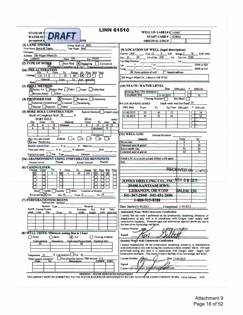
LINN 6{ 5{ OSTATE OFWATTR(rr rtgtlrrd
(l) Oq'ner Well ffizFintNorne_Dsvid & Tryy_ Last Name wdlCompany
Address
(2) TYPE OF Wcll Convenion
WELLI.D. LABEL#STARTCARD#
ORIGINAL LOG #
(9) LOCATION OF WELL (legel decription)County utl-- Twpl2... *S p75 nangel--!l- EAVWMS€c 23 SE ll4 ofthe NW 174 Tax Lot 5100
Tax Map Number _ LotLat
Long
or DMS or DD
DMS orDDor(2r)
(4)
(3)
Stl Plstc Wd Thrd
r.r-n tr !uuo flcabte [nug". flc.utuuuo
(T Streetaddressofwell Nearest oddresg
(10) STATTCWATERLEVELDatc
Flowing
TER BEARJNGZONES
Ihy Hole?
+
Depth uater was fint found 25 -
Est Flow SWL(psi) + SWL(ft)
is in conpliancc with Oregon watcr supply wellbest ofmy knowledge and belief.
Air
Rotary
trI"lsril trc"r*riryEocu,at"ring
SWL Date From To
(5) BORE HOLE CONSTRUCTIONDepth of Completed Welt ?o R.
BORE HOLE
Special Shdard LI (Atrach
SEAL
Method nn fls []c En
I t42-20t5 &I r.02-20t5 50 ?0 30
l) WELL LOG Grourd Elevation
sacks/
How was
Elor".seal placed:
Pour€d dry Brown clayCmcrrcted sard & cravel 9 35
Brown sandv clav 35 50
lcmontcd sand & crsvel J
Pulled s 20 drive Doint out and drilled in the same
hole
IJ(rNtts t t(rLLrN(i utt.. lNU.l \,Y' U U I UIJ
all,lntl A tl'Tlf l/r IfIIIl.r
LtlrtAl\lrl\r (rt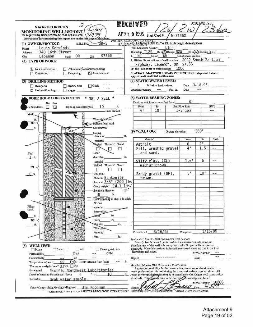
STATE OF'OREGON EMOI\TITORIN G WELL REPORT(as requtrred by ORS 537.765 & OAR 690-240-095)
RT(EEYFP 2/,r)ls APR r e lggs Staft Card
J EM
DC01 .95E
rNM
(1) OWNER/PROJECT:Noma lorris SchwindtAddress
(2) TYPE OFWORK:
ffi New construction
! Convenion
! RotaryAir nffi Hollow StemAug-r !
t
! Aiteration @epair/Recondition)_
! Deepening I Ab*doo."o,
Rotary Mud ! Catte
OF' WELL By legal description
Hiohwav- Lebanon.0R s7355or Tbx lot number of well rnnqtinn 12n0
3. rfBCH MAPWIIH LOCAf,ION IDENTII'IED. Map shnll lncludeapprodmate scale and north arrow
WELLNO.
V,bll Location: County Li nn -....
frwnsnip T1ZS Cr.ro@nange R2IIJ @d@s*ti.g-ag!- -1 NE l/4 of Nl'l l/4 of above section'
2. Either stre€taddressofwelllocation 3092 SOUth Santiam
CONSTRUCTION * NOT A WELL *No
tE Depth qf completed=weU t0 ft.
land surfacc
flush vault
I-ocking cap
Cas_ing
diameter
Tbreaded Glued
T ingl
diameter
material
4 Ft. below landsurface.
Artesian Pressure Ib/sq. in.
(8) WATER. BEARING ZOITIES:Depth at which water was first
Date
Date
3-16-95Other
3:__" $t^,, -J 4r
rrihult
Seal
1n.
TO
10 n.
rn.
From lar Est- Flow Rate swL4t l0r 1-3 cnm
(9) WELLLOG: Gn:und
Date started Completed
- - funbonded),Mqnitor V'bll Cbnstructdr'Certificaiion:I certify &at the work I performed on the construction, alteration, or
abandonment of this well is in compliance with Oregon well construction
o
ln-
\trblded Threaded Glued
! u n.\[bll seal:
Material Benton'i tee-ooo, T/-6r-T2o-6lbscrour weisht 14. 1 I bs/Borehole diamcter gal .
Bin- -n"otofii" orTe at teas,.: fr, rnrcx.
-^JScrecn
material
From
To-To-
in.st:ze
Filter
Material_Size in.
Filter
d,.70
ft.
(5) WELLTEST! Pu-p
= lBailer E nq*ng4n"si1n-- -
PH Si$ed --------- . Datr--lbmperature of water Depth artesian flow found - - ft.
Was water analysis done? Yes No @onded) Monitor lfibll Constructor Cenification:
By *horn? Paci f i c Northwest i-9S-- work performed on this well duriugI accept responsibility for the construction, alteration, or abardonment
the construction dates reported above. AIIDepth of strata to be analyzed. F-t!-----4- ft. to 10 ft. - w=ork performed time is in with Oregon well construction
to the best ndbehef.
MWC Number 102884/16795-
- !Ai' -
Yield
sfatrdards. Materials used ald information reported above are true to the bestknowledge and belief. MWC Number
NameofsupewisirgGeologist/Engireer Jim KoOimanORIGINAL & FIRST COPY-WAIER RESOURCES DEPARTMENT
Material From lb SWL
Acnhal t 0 4r'Fi11 - cr"rrchcd oravel 4rt 1-5'
1-51 6rSilf,v elav- (Cl )mod i um hr"ot*n
(andrr nratre'l cp) - 6l 101hrorun
standards.
TI{IRD COPY-CUSTOMER
Attachment 9 Page 19 of 52
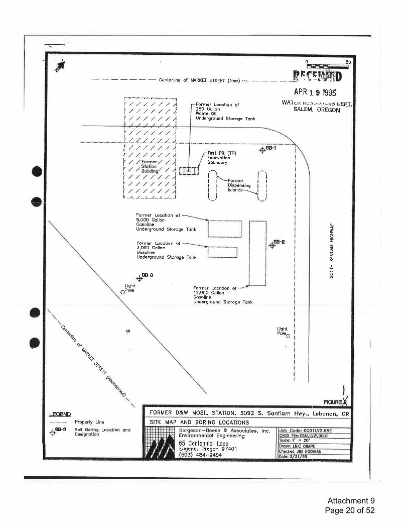
e'i'#F
a
o
o
a
FORMER D&W MOBIL STATION, 5092 S. Santiqm Hwy., Lebonon, OR
SITE MAP AND BORING LOCATIONS
ERIC
Checked:
Fr20EF|rEE==
FH{q!er4D-
Conterlino of MARKEI STREET (New) - - -
- 3\ ' tt * c
o
r+*r--r----1/,///./A////f
,/ ,/ ,/ ./
Formor Locotion of2BO GollonWoste OilUndcrground Storoge Tonk
APR r s tggsW,\l cn nrcuuNwE,S
SALEM, OREcoN;(/ltY/
't
I
I
I
)
I
I
)
v
LvI(vI
r
IV
I(
,/' ./' /' ./' ./ ,/' )1-.t.1 /.-/.J-i.-,/,/.////)l,/,/.//,/,/,4,z ,z F.orryer / / )t tl"tuffir / 1l,/,/,///./4./,/,//,/,/,4,/,/,/,///)
Test Pit (TP) +*tExcovotionBoundory
f
^1"-Former IDispensing Ilslonds
L--z-t-z--t-z--L-J
Former Locotion of5,000 GollonGosolineUnderground Storoge Tonk
Former Locotion of5,000 GollonGosolineUnderground Storoge Tonk
Former Locotion of12,O00 GollonGosolineUnderground Storogo Tonk
+oo
F:lTgr
F2-6:EF.fogt+oo
LishtgPole
[+LiehtPoleO
of
LECET\E
d*
o*^
%'{).
Property Line
Soil Boring Locotion ondDoaignotion
Bergeson-Boese & Aeoociotes, lnc,Environmentol Engineering
65 Centenniol LoonEugene, Oregon g7401
484-9484
Attachment 9 Page 20 of 52
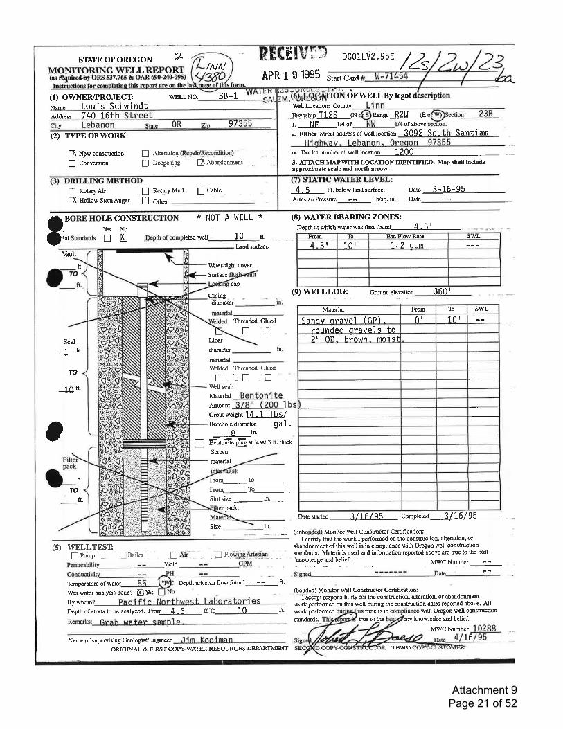
STNTEOFOREGON 7 DC01LV2.95E
APR L S 1995 Start Card
OFWELLBylegal\[Ell Location: County
fuvphrp TL2S oi na"ge R2l.lJ ter. NE v+ ot of above
2. Either Sreetaddressofweillocation 3092 Sou Santi am
Highway, Lebanon, 0regon 97355or lbxlotnumberofwelllocation 12003. ITTACH MAPWIH LOCAIION IDENTIFIBD. Map shall lncludeapprorimate scale and north arrow.
(H /Z(t) owrlERlPRoJECTNnmc Loui s Schwi
/NN
WEIINO. sB-Lndt
Address 7 40 L6th
(2) TY"EOFWORK:
S N_gwconsrucdon
! Conversion
! RotaryAii nfl HollowStemAuger !
\6uit
ft.
Seal
1ft.
TO
--10ft'
! atgratiog (Rebaii[tco4ilitio4)
! Ueepening' f, eban-donment-.,
Rotqry Mud ! Cgble 4 - 5 _.. Ft. below land surfage.
Artesian Pressure - lb/sq. in.
oate 3-16-95Date
9
Other
o BORE HOLE CONSTRUCTION
Oi" Standards n n p--epthof completed
* NOT A bJELL *
well 10 ft.
I-,and surface
\ hter-tight coYer
Surfacc
cap
Cqling =
dianreter
(8) WATER BEARTNG ZONES:Depth at which water was first founq--4-5f-
hirom lo Est. Flow Rate swL4 5l 101 1 -2 onm
(9) WELLLOG: Ground elevation 360 |
Material From 'Ib swL
Sandv flravcl fGP) - 0r 101
rounded oravel s to2" nn^ hrown- moist
Tlreaded GluednnLiner
diameter
materialVrblded Tbreaded Gluednnn\trhll seal:
ln.
Benton i te3/9" (2oo lbs
Material
Amount
ocroutlveisht14.l lbS/Borehole diameter gal .
B in.
- -Bento-nite o'ili at least 3 ft. thick
-'JScreen
material
From_To_F o^-To-Stotsize_in...__
pack:
Size
ft.
TO
ft.
Datestarted 3/16/95 complgtea 3/16/95
_ (unbon{e4) Mqnitor \r.b[ Construcltoi Certification-:I certi$ that the work I performed on lhe constructio:r, alteration, or
abandonment of this well is in compliance with Oregon well constructionstandards. Matcrials used and information reported above are true to the best
lnowledge-and belief. MWC Number --lBaitef- .n Aii-_ -= .E Fl9*ggAtt!l_c. ,
neld
Tbmperature of water Dcpthartesian flow found * ft.
Was water analysis done? ffiYesBywho-? Paqific Northwest LDepth of sEata to be analyzed. F oL-4-.5- ft. to 10
Name of supervising Gmlogist/Engineer .'l i m Koo i ma nORIGINAL & EIRST COPY-WATER RESOURCES DEPARTMENT
m.
(5) WELLTEST!n P".p--"
(bo[ded) Modtor Well Constructor Ccrtification:- -l=iccept
responsibility for the'construction" alteration, or abandonment
work perfonned on this well during the construction dates reported above. AllfL workperformed time is in with Oregon well construction
my knowledge and belief.
MWC Number
siandards. true to the
TI{IRD16
Attachment 9 Page 21 of 52
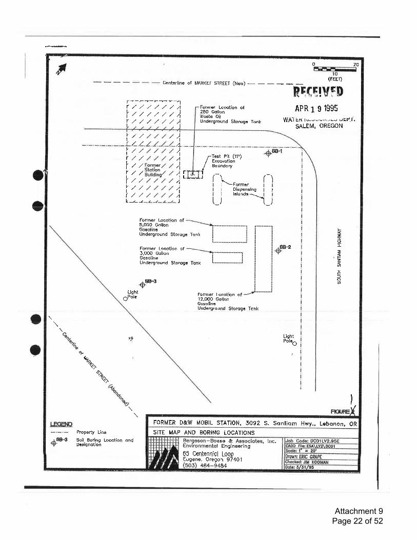
o
o
o
FORMER D&W MOBIL STATION, 5092 S. Sqntiqm H Lebqnon, ORwY.'
SITE MAP AND BORING LOCATIONS
DCOt
Drownr
Fro 20
r---a-7----.1r./,/,/./,/,//lzt///,/f
Conterlino of MARKEI STREET (New) -
.ilrs:==(FEFr)
Rtd[[vFDAPR 1 s lg95
WAI itt lrug-*,.'-u r.rEP.f
SALEM, OREGON
Former Locotlon of280 GollonfVosts OilUnderground Storogo TonkY,/,/./
lrt////1.L/-.1././ J-/-rtlzr////)lr,//,//,/,/A
i I l'ir#iJ tllzzztztll//t.tztf(//,//,/,/4L.-z-z-t--t-z-s,J
{
Test Pit (rP)ExcovotionBoundory
l----
+*trt J (^ ^l
I
I
I
)
i
I
)
(Former IDispensing I
lslonds--.- 1-t
Former locotion of5,000 GollonGoeolinoUnderground Storoge Tonk
Former Locotion of5,000 GollonGosolineUnderground Storoge Tonk
Former Locotion of12.0O0 GollonGosolineUnderground Storogo Tonk
€o
-tII
cF26IFfo<h+oo
Llsht6Polo
LiehtPolSrl*
q-to-.
'/6-ooF
%\
o+^'Qoa
'uJ
LECEhD
+9B-3
Property Line
Soil Eoring Locotion ondDcsignotion
Bergeson-BoeEnvironmentol
05 Centenniol LooDEugene, Oreqon g7401
lnc,ae &Eng ineering
484-9484
Attachment 9 Page 22 of 52
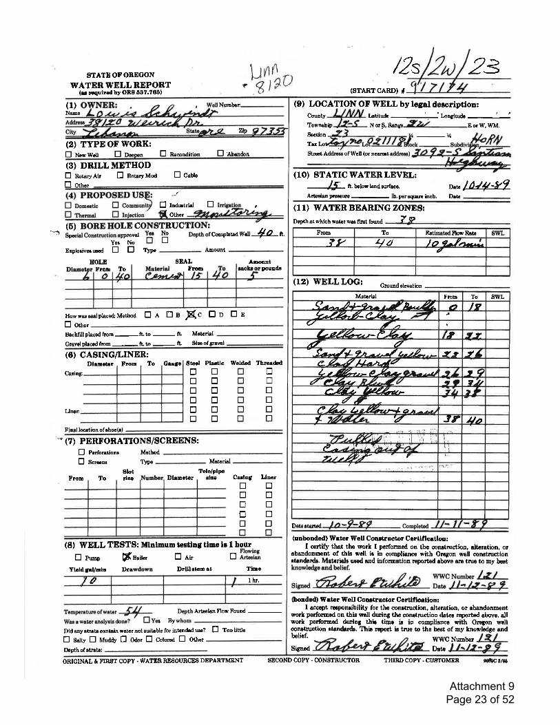
/2s 23STATEOFOBEGON
WATER WELL REPORT(er rcqulreil by ORg 6C7.766)
(1)Nane
(2) TYPE OF WORK:fl Newwall tr n*mn ERnmndition EnU*aon
(3) DRILL METHODE notawnit E not".yuoO E c.bl"f-'l r*r-.
.V,\t'Number:- (9) LOCATTON OF WELL by legal description:
(STARTCARD) #
Iatitude '. ilo4itu&Notf',tunge 9.2) EorW,WM.
-uStrc€t Addro$ of Well (or nearmt addreao)
zip
County
Townrhip
Section
Tar
(1O) STATIC WATER LEVEL:
-15-
ft. below land eurface. lf4*7Date
Datc
wet 1O a.
Erplosiv€6usod tr tr $pe-AmountHOLD SEAL
FronAnou[t
Fron To Douldr
How was teal placed. Method Er trn Sc tro EeE otn"tBaclfrllphcedfron-ft.to- ft Matorial
Gravelphcedfron-ft.to
-
fL Sizeofgrarol
-
(6) CASING/LINER:Dlenct r Fron To Geulrc Steel Plstlc Wsldod Thrged€d
Casinf
Liner:
Final location of choc(o)
"" (7) PERFORATIONS/SCREENS:E Perforationa Mcthod
E s"t""nt T!"€
-
Matcrial
Slot Tcla/plpeJuFron To Dlanctor
(6) BORE HOLE CONSTRUCTION:"a s*.iulcon"""r't:ooil;" "S H DepthofConpletad
(8) WELL TESTS: Mlnlnumtectlngtlmols t hour
E nu-p [n.ru, E li, tr ff;Tf,Ylctd SaVnln Drrwdown Drlll rton ot Tlmc
Arteaian preseure lb. perrquaro inch,
(11) WATER BEARING ZONES:
Depth at which waler war fint found 7w
(12) WELL LOG: Groundetevation
Date gtartod
(unbondcd) Wder Well Conrtructor Certlflcatlon:I certify that the worl I perfonaed on the conetruction, alteration, or
abandonnent of this woll is in comptiancs with Oregon well congtructionatandadr. Matorialg uaed and information reportad abovo are tnre to my bertlnowledge and belief.
s*A./-??A/Zn Wfj&$onded) Water Well Conetructor Certlflcation:
I accept respongibility for the constnrction, alteration, or abandonmentwork perforued on this well dwing tJre congtmction dator reported above. allworl perforrned dwing this timc ig in compliance with Oregon wellcongtruction gtandads. Thir rcport is true to the best of my hnowledge andbelief. WWCNumber
E Induetriat trfl. on"'
trtrtrtrtrtr
trtrtrtrtrtr
trtrtrtrtrtr
LluorCuln5eltetrtrtrtrtr
trtrtrtrtr
I hr.
Temperaturaofw^t, Sll Depth
Waeawataranalyeisdone?' EY"" Bywhom
Artesian Flow Found
-Did any strata contain water not suitable for intandod ure? E Too little
E satv tr rrlraO E ooot E cotor"a E ott"t fr/', l4rDepth of stnta: Sign€d Date
Flom To EstinrtodFlow Rat€ swL?v aa 1a e--/.t-.,!-
a
Material From To swL
^\'r^j+9h^ n{fur4- a T9?-%6&/.' ;V t
(/ ty'nL,&+-zt-1"-5*-u 7t J}
,{7 v-
. f-t-Jr' 9t - ---/ L- t/- - - .t^, -/r'?,4,-VA/,.a;14L t-%--- ?hz-Orn.-tl tq
ftryzt PZ.ZI q)"2M/--%zp ,Q_r'9
e-Azt bz,%'zt4 o jrzt t /* 74&&L T JT lltt
Vt-ffi:oii', il i*j il'lP - -a)i)L-t: h,/LrL:at/ il
7:,tz-4/ 7
ta
ORIGINAL & FIR{IT COPY . WATER RESOURCES DEPARTMENT SECOND COPY . CONSTRUCTOR THIRD COPY - CUSTOMER e6c8/t8
Attachment 9 Page 23 of 52
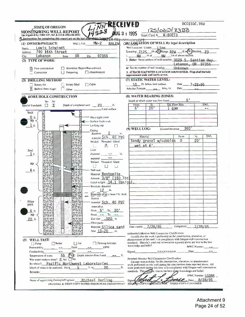
DCo1SGC. 95U,.STNIEOFOREGON
MONITORING WELLREPORT(as rtquired by ORS 537.765 & OAR 6$.240-095)
(1) OWNER/PROJECT wELLNo. Ml,l-
tZslokD[zze33 t 1995 Start Card # !{-80273
,mI OF WELLBy legal dcscription
Name Loui Schwi ndt Well Location: County
Township T12S (N Rzt^l (E
l/4 of abovel. _$[_l/a of2. Either Strcet address of well location 3029 S , Santiam HWy,
or Tax lot number of well location Un known3. ATTACH MAPWITH LOCAI'ION IDENTIFIED. Map shall includeapproximale scale and north arrow.
Address 7 40 I5th Street
(2) TYPE OFWORK:
l'Xl New constmction
! Conversion
G ME'In RotaryAir !ffi Hollow StemAuger n
Vault
I Alteration (Repair/Recondition)
! Deepening ! Abandonment
Rotary Mud ! Cable Ft. below land surface.
Artesian Pressure -
lb/sq. in'
Date 7-2q-OEDateOther
o BORE HOLE CONSTRUCTION
-pecialstandards ! m Depthofcompletedwell 20
(8) WATER BEARING ZONES:Depth at which water was first found 6 1
fr
Land surface
Est. Flow RateFrom LO
I onmSWL
6r 20,
Seal
1n.
TO
4n
Watcr-tight cover
Surface flush vault
Locking cap
Casinsdiam-eter 2 i".
,nu,.."i4 Sih.?-o PVcWelded Tlreaded GluedtrEnLiner
diameter : - in.
material
Welded Threaded Glued
! t_l LtWell seal:
uareria Bentoni t€l-ount 3/8't (150 lbscrout weisht 14 . 1 1 bs/ gBorehole diameter
19 in.
Benronite olup at least J ft. thick
-r-Screen
material SCh. 40 PVC
interval(s):
From 5r to_1fl _From-__ --__To___5 --Slot size .020 in.
Filter pack:
naateriat Silica sandsize 10- 20 in.
(9)WELLLOG: Groundelevation
Material From To swL
Sandy qrave w/cobbl e s0 20'wct at 6r .
rl
Date started 1 / 28/35 conpteted 7 f ?8f g\
(unbonded) Monitor Well Constructor Certification:I certify that the work I performed on the construction, alteration, or
abandonment of this well is in compliance with Oregon well construction
sEndards. Materials used and information reponed above are true to the best
knowledge and belief. MWC Number
s
o' Filter
pack
O+-20 rt
(5) WELLTESTI Pump llailer
Permeability --fl Ai'
YieldI FlowingArtesian
CPM
Temperature of water
Was water analysis done?
Depth artesian go* 1ou66 -- ft.(bonded) Monitor Well Constructor Cenification:
I accept responsibility for the construction, alteration, or abandonment
work performed on this well during the construction dates reponed above. AllBy whom r Pacific Nort-hwest I ahnr afnr^i ecDepth of strata to be analyzed, F.or1----5-- ft. to 20
Name of supervising Geologist/Engineer Mi Chael Daf l i ng
ffives
Remarks: standards
work performed this time is in compliance with Orcgon well construction
true to the best knowledge and belief.
MWC Number 10288_
fr,
ORICINAL & FIRST COPY-WATER RES OURCES DEPARTMENT THIRD COPY-CUSTOMER
Attachment 9 Page 24 of 52
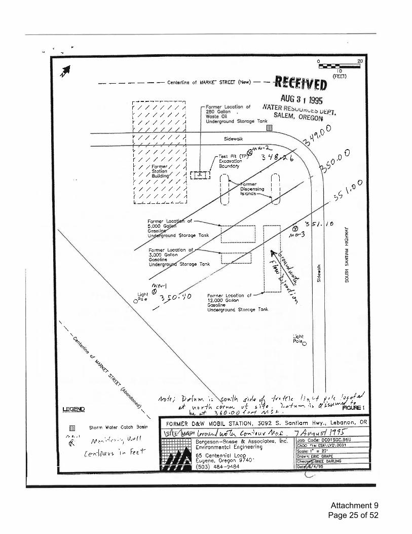
FORMER D&W MOBIL STATION, 5092 S. Ssniiom Hwy., Lebonon, 0R
w{0^ Cr}tuv /1/'6,a A n?rIt vl
5Ue: DC011CAOD File:
= 20'n:
Beroeson-Boese & Associotes,Environmentol En gineering
65 Centenniql LooPEugene, Oregon 9740t
484-948+
0
Fr
0
10
,0
- Centerline of MARKEI STREEI (New)
- - dfeffvrD (FEEI)
AUS a I l99f
[1$:{*:.:: _,",":ATsX.?i; "; ff il,il
oo,(vI
Y
,/,/////./ ./ ,/ ,/ ,/ ,/
)l,/ ,/ ./ ,/ ,/ ,/vI
,//./,/,/,//1I)
_/- J-z- J- z -L- J
@p 3L/ I
0qt
,//,////)l,/,/,///,/A,t ,l Forqcr / ,t )z zlit;ffit / 1r,,/,//,//./A/,/,////1,/,/,////a
vI(,I
Y
Iv
IV
Test PitLxcovotionBoundory
rv-
Dispensinglslonds
L
3
0
3 l0
0
,1
\I
I
(I
I
I
aJo0
)
\,
=II4F
IA
IF
oQ
Jo,o.9a
tq
Former5,000 GoGosolU
of
Storogc Tonk
Storoge lonk
t.
Former LocotionJ,0O0 GollonGosolinc
q4^w-l6Light
gPole 'j0alo' Former Locotion of'l 2,000 GollonGosoline
c{
LiqhtPoleO
Underground Storoge Tonk
rho/t ; D*1,^r^n ',, onlh i,rl.c 7r,ft1, / j,r i'v-o rlh
,out{o d .V1 9L
);ol * *, 'i stt lOY v*\- 3
,h,
*\'ls
Go-
%--'(>
.lrAx\/^
Ga^-\'v I l!/,
tl't tt'rlurr//
*/ roFIGI.JRE 1T.EGEND
m
\
Storm Woter Cotch Bosin
,Alrr''''-{r' "', ite ||
Cynl1uy, t^ Feef6
Sidewolk
Attachment 9 Page 25 of 52
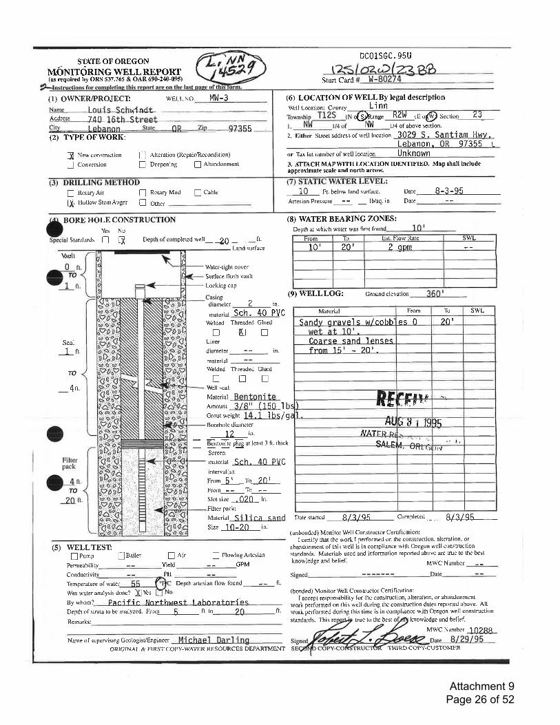
STATE OFOREGONnndr.uronrN G wELL REPORT(as rtquirtd by ORS 537.765 & OAR 690-240-095)
(1) OWNERIPROJECTNane Louis Schr+indl
wELLNo. MW-3
Address ll,icitv
-Lebanon-
5(2) TYPEOFWORK;
DCO1SGC. 95U
Start Card
(6) LOCATION OFWELLBy legal descriptionWell Location: County Li nn
.{sffiI"" RZlt{ rE o(S) Secrion Z3v4 of above section.
3029 S. Santiam Hwv.2. Either Street address of well location
ffi New construction
! Conversion
! RotaryAir !ffi Hollow StemAuger !
\rAult
! Alteration (Repair/Recondition)
I Deepening ! Abandonment
Rotary Mud ! Cable
Other
Lebanon. 97355 L
or Tax lot number of well to.oti
3. ATTACH MAPWITH LOCATION IDENTIFIED. Map shall includeapproximate scale and north arrow.
10 Ft. below land surface oate 8-3-95DateArtesian Pressure
(8) WATER BEARING ZONES:Depth al which water was first fou
tsrom To Est. Flow Rate WL
101 ?o' 2 onm
(9) WELL LOG: Ground elevation
oBoRE HOLE COT{STRLCTION
fecial Standards ! H Depth of completed well 20
Seal1 lt.
TO
4t'
Filterpack
}J2Q rt'
ft.
Land surface
Water-tight cover
Surface flush vault
Locking cap
Casinsdiam-eter 2 in.
material Sch. 40 PVC
Welded Threaded Glued
!HnLiner
diameter - - in.
material
Welded Threaded Gluednnnrfibll seal;
Material BentOni teAmounr 3/8r' ( 150Grout weight 14.1 1 bs/gBorehole diameter
L2 i"
- 8,";i. p'iig at least 3 ft. thick
I
o
From To SWLMaterial
ps0 201Sandv oravels w/cobb'
Cnarqo qand l rrnqtrq?olfnnm 151
F lFrr r'D[,I F ..'rl&'l
Hllr 1l ]EftLIVATFP pr
". ItSAI tr'rr vatt-(:l , l.{
Screen
material Sch. 40 PVC
interval(s):
From 5r to_f{ll _From__35_ To-_5__Slot size .020 in.
Filtcr pack:
Material Silica sandsize I0-20 in.
(5) WELLTEST! Pump ! oailer ! nir ! FlowingArtesian
Permeability Yield GPM
Conducti PH
Temperature of water Depth artesian flow found - - ft.
Was water analysis done? ffi Yes
By whom? Prni fi n hlnn*huracf Irhnpr*nnDepth of strata to be analyzed. Fro4-__-5- fr. to ,i fr
Remarks:
Name of supervisingGeologist/Engineer M j Chael Darl i ng
Date started B/3/qE completed 8/3/95
(unbonded) Monitor Well Constructor Certiltcation:I certify that the work I performed on the construction, alteration, or
abandonment of this well is in compliance with Oregon well constructionstandards. Materials used and information reported above are true to the best
knowledge and belief. N,IWC Number
S
(bonded) Monitor \lbll Constructor Certifi cation:I accepl responsibility for the construction, alteration, or abandonment
work performed on this well during the construction dates reported above. Allwork performed during this time is in compliance with Oregon well construction
knowledge and belief.
MWC Number 10288
true to the best
a
ORICINAL & EIRST COPY-WATER RESOURCES DEPARTMENT
standards. This
THIRD COPY-CUSTOMER
Attachment 9 Page 26 of 52
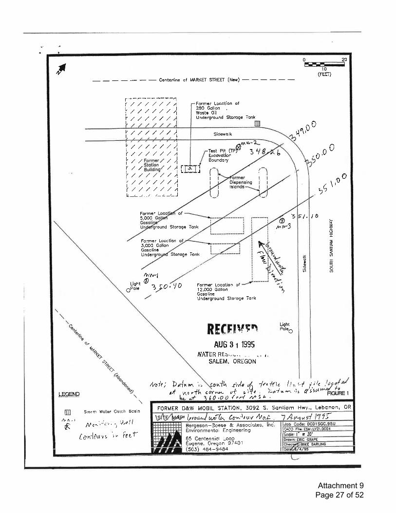
FORMER D&W MOBIL STATION, 5092 S. Sontiom Hwy ., Lebonon, OR
wrfu to' 4ouv r1t'6r2 A "s+?fl"
1CADD Flle:
= 20'
Beroeson-Boese & Associqtes,Environmentol Engineering
65 Centenniol LoopEugene, Oregon 97401505) 484-9484
"lt (FEE]',)
,00
20
o
- Centerline of MARKEf STREE| (New)
-
f+----?----1,//,/,/,/./,4 Former Locotion of
280 GallonWqsle OilUnderground Storoge Tonk
(vI
Y
/,/,/,/,/,//,//,/,/,/
),
),v /,//,/,/,/
./,/,////)l./,/,///A
-rlrest Pit (TPFExcovotionBoundory
0r{t
3 lo
,0
tl/-I(,I
Y
IV
I(t.
3ry L
t
1
,(,
0/ F.orr1er / /, Stotion , ,/ Building/ /
./////,/,///,/,/,///,/
I1i4
14)
J faI
I
-LJ-LJ-,/--',-
Dislg
Former Locotion of12.O00 GollonGosolineUnderground Storoge Tonk
AUG 31 1995
/vATER REb*,.,. -,. ..., I
SALEM, OREGON
o\'
Former of5.000
round Storoge Tonk
Former Locotion5,000 GollonGosolincUndc Storoge Tonk
4^w-l6
'10oP 7)o'
t.k=LI=
F
6
foa
xo'(,Pa
z
Lightole
RE(F[!lq4 Hsr:
oF
Qto't>
%^'i>
r1n/t; Dr{nrn ',. ou-{hut no rih C OY v\L\-
0'
j,,le $ ir,/{le liu,,f i,;/,ut c il e );al n*t 'i s fl'Lltt{otl nA5t^\
\Storm Woter Cotch Bosin
/! ,r'"' '' it: '' ' '', \)tl I I
fe"nl0r,ryr I^ Fezf
tu*//'-/ h
FIGI.JRE ILrcEND
m
I
Sidewolk
Attachment 9 Page 27 of 52
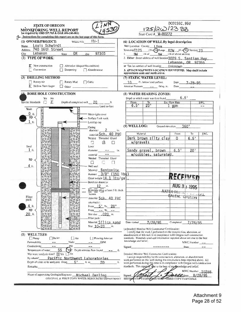
DColSGC.95U. STNIEOFOREGON
MONITORINGWELLREPORT(ar rrquired by ORS 537,765 & OAR 690.240.095)
t25' D/23Start Card # w-8a272F the
(1) OWNER/PROJECT WELL No. l'!tl- 1
Na'n" Louis SchwindtAddress 740 16th Street
non 55(2) TYPE OFWORK:
(6) LOCATION OFWELLBy legal descriptionWell Location: County linnTownshipfll$_(N o(3)nunee R2l^l t" "@ Secrion 23l. NW I/4 of Ntrt l/4 ofabove section.
2. Either Street address of well
or Tax lot numberofwell locati
3. AITACH MAPWITH LOCATION IDENTIFIED. Map shall includeapproximate scale and north armw.
(7) STATIC WATER
ffi New construction
I Conversion
! RotaryAir nffi Hollow Stem Auger tr
I Alteration (Repair/Recondition)
I Deepening I Abandonment
Rotary Mud ! CaUte Ft. below land surface.
Artesian Pressure _ lb/sq. in.
Date
Date
7 -24-OEOther
o BoRE
"otj coNsrRucrro\*
Special Standards ! m Depth of completed well 20 fr.
(8) WATER BEARING ZONES:Depth ar which water was flrst founO 6 . 5 |
From lo Est. Flow Rate SWLb.5 ZU 1 qpmLand surface
\6ult
Seal
L rt.
TO
4 rt.
Water-tight cover
Surface flush vault
Locking cap
Casinsdiam"eter 2 in.
'u,.riur S-ch. 40 PVC
Welded Threaded Cluedtrf,nLiner
diameter - - in.
material
\lblded Threaded Clued[truWell seal:
Materiat Ben to n i teAmounr 3/8" (150 Ibcrout weight H-illS/gBorehole diameter
L2 i"'
_ B-gn,oI!. plug at least 3 ft. thick
Screen
materiat SCh. 40 PVCinterval(s):
nrom 5r To_1fl _P'191n : f6 :Slot size .020 in.
Filter pack:
lvtateriat Si I i ca s.andSize 10-20 in.
(9) WELLLOG: Ground elevation i60 I
Datestarted 7129,/qq complered 7/28/ 95
(unbonded) Monitor Well Constructor Certifi cation:I certify that the work I performed on the construction, alteration, or
abandonment of tlis well is in compliance with Oregon well constructionstandards. Materials used and information reported above are true to the bestknowledge and belief, MWC Number
oFilterPack
O-;20 n.
(5) WELLTEST:! Pump
Permeability!Bailer ! a,ir
YieldI FlowingArtesian
CPM
s'[bmperature of Depth artesian flow found -- ft.
Was water analysis done? ffi Yes No
By whom? Paeific Nnnfhwo t Ial-roratori eqDepth of strata to be analyzed. ?oRemarks:
Name of supervising Geologist/Engi neer Mi eha ol n r^'l i nn
(bonded) Monitor Well Constructor Certitication :
I accept responsibility for the construction, alteration, or abandonmentwork performed on this well during the construction dates reported above. AII
fr. work performed during this time is in compliance with Oregon well constructionto the best of and belief.
MWC Number 10288
From 5r ft.to
Material From To swL
Dark brown siltv clal 0 6-5'w/oravel s
-Sandv orfrvFl - hr"nwn 6 5t ?olw/cnhhleq- satrrrefp I
) LDrrI Ef. F iEf4t
r 1008
\
liATrq-l
, rrL!vlr L xc.(iolv.r l.
ORIGINAL & FIRST COPY-WATER RESOURCES DEPARTMENT
standards, This
aCOFY.CUSTOMER
Attachment 9 Page 28 of 52
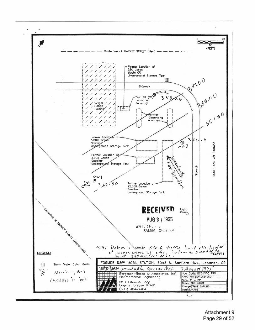
FORMER D&W MOBIL STATION, 5092 S. Sontiqm Hwy., Lebonon, 0R
Cc'^.Jtur tb 7Sbro.t^ tJn) usiJob SGC.95U
Scole: l' = 20'
Bergeson-3oese & Associqtes,Environmenioi Engineering
tenniol LoooOregon 97401
65 CenEugene,505) 484-?484
Ir0
q1,00
3 lo
,(t\,
10(FEEr)
- Centerline of lrtARKFl STREFI (New)
l=----?-,-"-1I
vI
Y
//4,/,/)
,/,/,/A Former Locotion of28O GcllonWoste OilUnderground Storoge Tonk
,/ ,/ ,/ ,/r// )l
lrr////)lf,/,/,/,/,/,//1I z zFpr4cr. 7 )| / /3l,fi?1, , 4iI t z / / ,/ / l'lzz////1(/,//,r//a
-r\Aiest Pit (TPpLxcovotionBoundory
Dispensinglslonds
3'/ L 0U
0
)II
((I
I
J
ez
oo
V -z- -z - z- -t- z- -r* J
Former5,000 GoGosol
round Storoge Tonk
Formcr LocotionJ,00O GollonGosoline
Storoge Tonk
Liqht
6Polc
4nw,l6 2at./
of
.j0
o3
c(
I,
=I9r
FzvlEF-oU''
J<o
'oE(n
0
t1n/t; Drf"rrr ',,
ut
Formcr Locotion of12.000 GotlonGosoiineUnderground Storoge Tonk
,.6t7c
o.
RECHvsn H:E
AUG S 1 1995
J\r,qTER R!., '.
SALEM, Ok; ('iir'r"l
"1h j, rlc irt tt)c li ,r,',f lu "o/
o/*u/ /,
Qo,'Qr.-
'/A'o
oa
*"+,
.lt'.p^
c<>
4o^oon
to) ,tlle'ic,,,LrcEND
m
6
\\
Storm Woter Cotch Bosin
fl ,1 ^',J,: ' ''' UtPII
(vrrlluvt lh Fezf
o ,1h cov^tn- ,4 I );n1 * nt '\ s tl FIGiIJRE I,o lpd aaSt-
Sidewclk
Attachment 9 Page 29 of 52
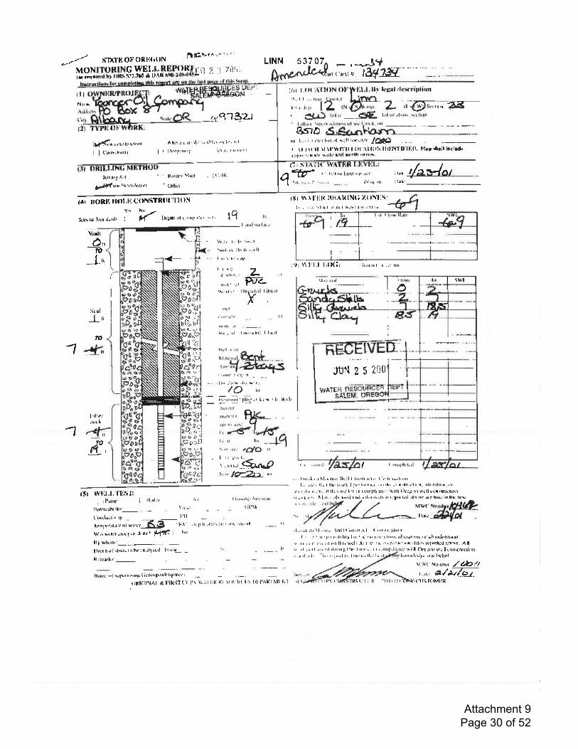
-*-- r{TAl'ri o}'oRri{ittN J'lE+'*" "
MONITORING WEIls rrqillnd Dl lllf\ FJt'?16 t
.I,REP{}Rft:n '; 'l 7il{ii(t1ll11.l|_l4nit,tai-'r r, .,
L|HN 53 7 07 - . -J*ftiritr+. lSfxs{
I ltNailk
('n
(.r r I.t l( rl l fi lN ()f F l,:l,l,llt lrpal dt*riplifin
,.,, ,,,, .12 ,*Sffi Z .';Gt.,*;';-5E[-
I i{.f} tr.t rr'
-gf;fi
lL.l rrr,rlrrrv, rr'iltrrr.-tri:4'lS'?.l
A ll.'t-{r.41'!t" "' t'Ili, ! ,"r I r 'r il' I
I I llrrT ur; rlr 'r' rrrr rrr'' l
ffi
UF'
lldru Lntlrltrrtrrrnt
I | {iillr.'rqFlt
Itillru J AIr
1,',1{ri'h" lll rll i\rlr'rI
8,stDrrl 1..' I I rltr'trlrL't rtl w.'ll lrqr,llrir' jfla|t)r tl I,tt ll \1,\ltl*11ll | {r! .11ll}i\ IIltiN'l l}IHll, Flrp {rll ltttlttd,tl'l[r,rrtrrillr rrrlld hnd lildh tr.nl*
(tl ie.*Jatqv
I rllri { 'rrl\
l . li. Xl* lnnd \u.l,h1'
\rl.,:. r. l1 \\..t,I l{tilirr Vltril
rIrrlrrrl ..lrl.
Jlirt {ll
I lntI I'rl.'
14r ll{)Rt{ rlfil'l{ C{}llliTRl ll:'llt}li
5r,r.,ur $r.nr*1,,,.1. J [j,i/ '*,*nI'l(
'r'rl'r'{'l $" lq
rllr 114l'l'ilt Itl':nklNf ; 7.rltl';5:lr , . r .r. r.lrr.l q.ilrl +,1\ lrl\"i|. ..
Vrnlt
-\r ul
l-'t
-1 4,
4-d,,IO
l.'t
lr.
i .'rnl !ril l.tru
l\,'.t, ti .ln r$\rr
\{rl,,a llil,h \.,rlll
I !r lrtr' ! Jll
| | trr:,
lllJt" ,ll
rl
I i!,rrnl lr . r' llnL.rri t\l l.l tIt(i:
- lLil:
?l
cc0o
b
F-t-I hr{.hl.al I il'ri'l
I,l..l r rrttrl
oa
l)*c
G
tt
nul, -"1 I rr' -rrlrLl t il.rLllD
t: I
..i
|l
ll-',,tEEsL -,,,*.f-€rta1S,
l rl1rl
JUI{ ? 5 ?fjoll,' -:r'L (l'.rllH r
/o rrr
: Il' ':1 |fi;''rt lrrr"r ilr urhl'
l"i:, Hlr-rtll lr, ill\: q
r,*-dl'-/f-r, ,, ,,, _lq{r.., .il. r1f/$ rr 'L '. ,,.'. r.t, r",.., -$L44? -t,," lffiJ_. u'
{;rrr'L
-1 {
fttlt ,'
g
tto
ll( lrtl' .ilT.\rrrr I r.'q lrrt rlrl
I
,.' . ,1r' ,.rl
t trrl,{r' rtl 'lrrrilJlthr'lrrtrr''. r r,.ilr.11,
.'',1 .'.1. l,. '.t"ql t' ltrl r" lli. l"
Iltl!{'
I lrtt
:q,,,,*1rtrfl&fr4{H
I r{l'tilrit(l
, r r lrr"lt '.r hl.rrlrr i\rll I rr'\1r.r.1,.r t flrlr.,rlr.4rI .
' i'.! rl',.t 'lI. 1+rFl, I fi{ lril rr( tl,,! rn! r'rr.r.l.til lr. tr. :rlli ridrrh. rrr
.rr,,.: .1.,:nr-,r. ,rl ll.'! *q'l ri rr (irililllr.ntr r' rtlrll tllril,Il Nrll arln.lIU{lll'll,r,,,,t,r'h hl.'r-,'.rhtr*rl ilrrlilrlrillr'.rlrr:r.lxrtLll ,rl!IvrntrttNhrtltulEtt{st wFx,l. fF;!i'tl
. lltDll{l i ,tl nl;r
Itfltr{ilrtlilv_ . .._ \'rr'rl
Iirnluurivitr I'll
ti.'n ;*n'tutr: *l-*,',"r-E$- "n
w.,r uirtLr 'rnrtly'F drrnf.l iL{rilt I ttrr
Ilt wlkltri---.-. --llslllh +l rltrrtl lrr lY :ttt'tltlrtl l'r"trt-,, -
ftrrrrrrl''
I LrR'ri .1ilr'rt.nt
.- t ilrrri
rl
H'rtrrF,ll \illr!r'errhF titDlllFrtLlllrfln('(iI ll{ltit!] Al, *, rlt{iiT ( ( rl '\' \r.1 I l:H Rl 5l lL l{t l 5 I rl ftnlf| Nlt'h 1
, 1,,,.!'[ \! I l.l..t1tha +\ll { i.t1'il trr l, r I ({(.lr- itlrrtrL .. r, " .t,,nFtlithtf lilr 'ltL rr{rqrt't! r','tr. ill:rtrrtrrD. 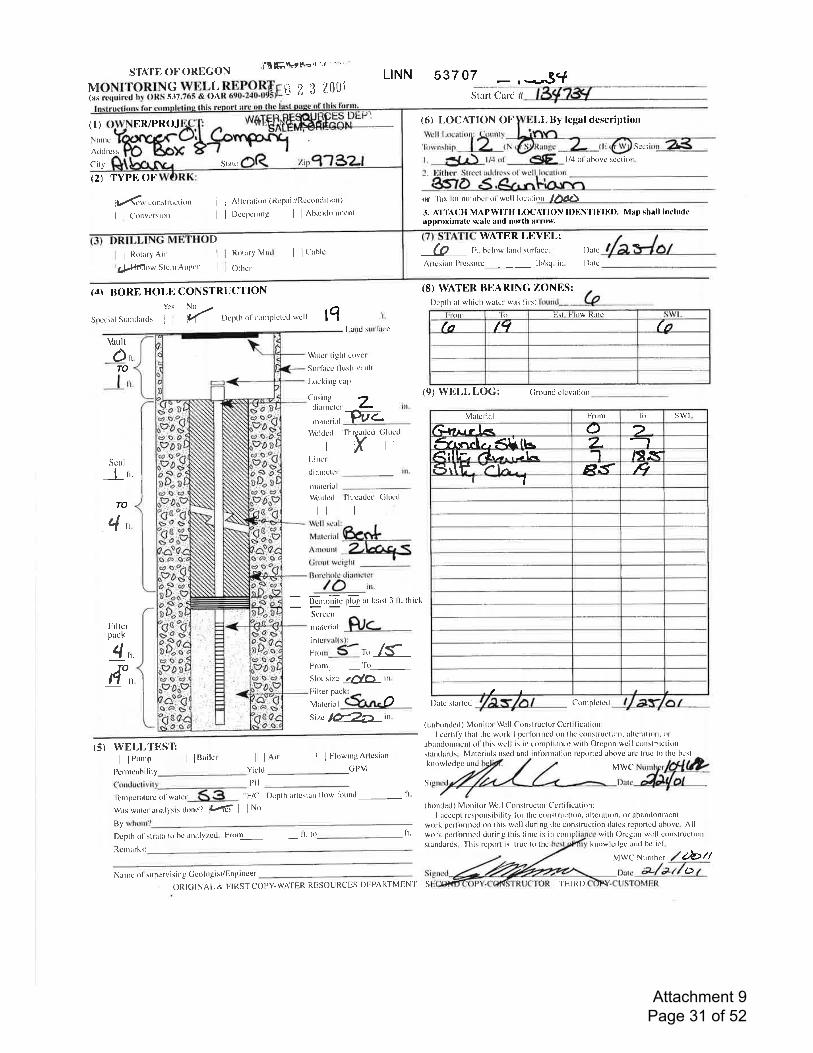
srArEoFOREcoN imF\"'r-'l
MoNrroRrNG wELLS,TJo.,?SSrtj 2; 3 1'-0rii(as requircd hy ORS 5-17.765 I
L|NN 537 07 _ , _3V,Stalt Cald #
(6) L0CA]'|ON OF ,L By legal description
Hi,lil:]zi,1. 3,) ll+ot'
(t) ER/PROJ
Nlrrrc
Adtlrcss
(:i ry
(2) TYPII OF
N Scct
I /4 ol ilbovc rcc(i0n.
!()n
I I RotxrY Airl1,rl{ttll()w Slcnr Augcr
(dI BORN, HOI,E CONSTRUCTIONYcs
Spccirl Strnthrtls i
j ; Altcntion (Rcpair/Rccondition)
I ll)ce'pcning I lAbantlurrncnt
I i t'ablc
DcPth ol cooll)lctc(l wcll lq
r)r 'fax l()( nuttthcr ol we ll location /d1t15.3. AT'lhCH MAPWIt'H I,OCAIION ll)}lN'Ill"ll')). Map shall includeapproximate scale and north arrow.
WATER LEVEL:(e Ft. bclow hnrJ surlitcc.
Arlesiarr l'tcssurc lb/sq. in.
knowlcdge lld bclie'1'
MWC Nuntbcr
frl1(tcrv consl ntct itt n
I ('ortversitlt
Vault
C)"TO
Scul
I n.
Ii.
I -rld surlirec
Wirter-light c0vcr
Surlircc llush vattlt
l-oeking calr
Crsingdianrcter -W--rnalcrial
Wcldcrl
lll.incr
diilrDcter
rrrittct ial
Wcltlcrl fhrcadetl (iluc<l
l| li
illil,l1k",,rSFront Ttr
,Slor sizc rnlor in.
F'ilter pac
Mutcrial
Sirc ld2A' in.
'l'hrcrdcd (ilucrlX,
D
I
I
MnrlRotrly
Othcr
[)illc
I)atc
'R'nrpctaturc' ol walcr
wils wtle r rnalysis tlonc ? it'td I I No
tlvDcpth ol'slrtlx lo hc atlalvzcd. Fnrn li. to
"F/C Dcpth rtlcsian llow lirund- li.
(8) TVATER BITARING ZONES:l)cpth at whiclt wilte r wr\ lirst
lironl lo l-.-\1. Fl()w ltrlc
fa fcl (t
(9) WEl,L l,OG: Crouncl clcvarion
o l)rtc strrtcd Conrplctcd
( unborrded ) Mulitu wcll Const|uclor Ccrtificittion:I ccrtily thal thc work I pcllirt-ntcd on lhc c()nstruction. altcralion. or
ilblndonnrcnt ol'this wcll is in crlnpliancc' with Oregon wcll ctrnrtrttcliottslan(lards. Matcrials uscd und intinnation rcpotlcd abovc atc tluc t() thc hcst
knowlcdgc und MWC
Si
(hrndcd) Monilor Wcll Construclor Ccrtil ication:I lcccpt rcsponsihility li)r thc conslluction. altcration, tx aband0nntcnl
work pcrlirrnred orr this wcll tluring thc construction (latcs rcportcd:tbovc. Allri. work pcrlirrnrcd during this lirnc is in cotttpl with C)rcgon wcll crnstruction
standards. 'fhis rcJrrxt 's
truc to thc
abtt
i7
z I tl-
tn.
TO
4n
I'illerpack
4nTO
11 n
illl"llle.*O,,r.ru,t, ZERCr'out wcighl I
Borclrolc diattrctcr
lO in.
- -:=_=:--'-BcntoDitc plug tl lcirsl 3 lt. lhiek
Serccn
rrrrtcrial
(5) WEI,I,TBSTI lPunrP I lBait':t
Pcnrtcahi I it y_..-.--_I lnir i ]FkrwingAltcsian
Yield
PH
GPM
Rt:rrrrrks:
Narne ol supervisilg Ccologist/Ettgineer
Statc
ljrorl 'lir swlMatcrill
/Atarlr L<. C) 2.6arf.."ef., <lilLs 7_Rllliu ra.-..-L- -'l lSl.Ef.Srlf; -?l.- - P^f tq-l 1
t
ORIGINAI- & FIRSTCOPY.WATER RESOURCES DEPAI{TMEN'I' S THIRD
o
Attachment 9 Page 31 of 52
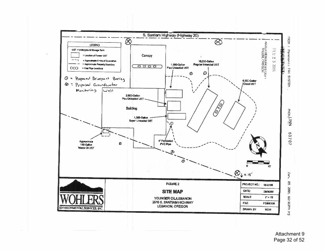
PROGGT t{O.: 9${115
OATE: 0&:ntgs
I'a 15'SCAI-E:
FG990r06FII.E:
ORAltN 8Y: MDw
SITE MAPYOUNGER OIUI.EEANON
3510 S. SANTIAM HIGHWAYLEEANON, OREGON
FIGIJRE2
Canopy
r*r<\12,00Oprllon
Pfue Unlceded UST
EuildtuB
Snper Unlcded UST
l.00GGrlbn
S. Santian Highway (Highway 20)
LEGEND
USf . Und.qround Sb.tgr lank
: Latin dFqnnr UST
- - 1 = Apgrorinrtr Limlti of Et€rvdion
= A|orcrimflr p,Egdty Bourdery
OOC : vcrrt Plr L€crt'on!
1,500€rtlonPlur Unlcaded USf
'10.000cClonReguler Unlo€dod UST
I"ai 'r-,,,L
in# i:5V.j^L/c<,:-sa.'!C N.bJr a=3ur7-
nrIl
J
ooa&
= Prq"r.ol lricpoal $"rin; \/'t, ,r'
l/
6,000€dbl-- Prop"f.rl Gro.,
f*l.o"i*o.J^)^dur-{-,
lrsT
I
I
o\t I
tI
I\\Apprqim.b
lSOGallon$lrrtc Oil UST
a Pl/C Plp6 \ --/*_
o0 15'
&,^ Et
ENVIRONMENNL SER/ICES.INC,
-nno:1lq,lOJaoloTlDXt5
a-{m3
TIozrri=,z
('lu){o{
qqJ
ls(nNaa
Nt9N(,ll31lUJ
Attachment 9 Page 32 of 52
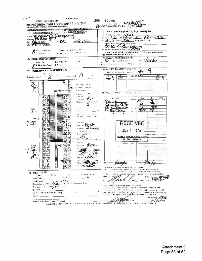
sTdll'. tlu olaH{itll{MONITORIN(; WELT, B.I']POR fiii *,i.l.ra il oxr J'+?.?ir * {}Al"lrtl4'll'llirFl
I t*' r.. F
ift I r ?ttt'it
,lllrllrltr r t lr"lr.,llill. ' rnnl l' 'l'r
r l\tlu rlrt' \l'..nrl rr{r Jtl'
L|HN 537 08- g;"*ft,,,',,u-!ra*HLF ' -
H lfir I.tlt'.{l'l(}I (ll' F.l.l. B1 kgul rltmriplirrtrr I {lwNHlul}llfill:c1} \t'1il
NilrF q('i.lr
TY
/( N! s r rnlSfXr'lllkl
i rillrr'l rlllll
lrl
al
l# ill il|tr'tc IrL:,rtrr.
{.,r,lf
-r \t-I:lr'il it,rl'rull'H Lfll'.111111 lllliTllllllll- ltlf,F rh{ll ltrrhdirlrlrl'l'\hltillr {xlt lrr(l ilrrlh cr'trrs-
t7tI r hf llrs l;ull sil1,il (
l.l{.xrrlAit | , l{'n'il'Itrl"'l
llrrlk'+!i:rrrrA+$rr I i tl'h"'
rat llttllll HOLI tl(lF{!t'l'ltut:tlt}N
q 1il,,r il, l't('\+rn
I rr: -tril.rl
I t;rla
I 1,t.,
-b1Jtr'\rl "r
tlr (itl Sltnrl{lll' fr\Iull
s
l}r,ntn ttl . rrr,lrlr tr '.'r I
os
l.ilt! tr l .rL''
tq
$.il,1 tt't:.rr+ r- \ ,' lx(t l.r\t '.{,1.
| .r, r, t1' ' .'1t
i .t{l'! a
L!'ir \t r'l'liB ltliARlr(i /'()ffI'lliI tr t't :: rilr' X *rl!r sih I I n I'r'.1flil
ill ffI'.1 1. l.illll .,.,,rrtrt tr.\.,[,,i
!,rr r rr.r I
,i\a
110
II
J
1fr
Filt,"'lrrurh1+i-ioft,
\{r'l,lr'rl i -r
Pu{ -,' -,'lr': { llr;rl
X
4-#"
Il,'rr i r.. ti,til[ l, llall,
'il n'.. bh"! ,rl e.,\l i lr lilr\
ir,r.! I rill Fr+-
ftn{-.,f br*
ir#r,' t{-\l'i ',,r I Dii,a
o'o
+t
| 1.rnr
{t''{!'.a:t,l
t
r)
4,
I:.'
rE
I rr'tI' nli. r I
''rr,1 :'lL\..n,al I ir r,'rl$l t;ltRrl
'o
h:
B
n
q
I iJla Jr:
-l
#
ard,
t".
ii1t, 1
5!I tll( trd
\1,il( r l.tl'@g.,fr
r rr, r,..r,I| 11,'" '' \+'ill tilFl[,tl(h I (t tr[ttr{t.L, r r] t!,.r1 . k dll{ I llrlftiilr rrl,trr llrr r,,ll.llrlclrlr. ilkfr}lsil!,rI'
J "r. .n' ra.r.'l . rr' *t'll tr rrrr.trltL.r,rr.{tlhth' l!'4' krll t\trtrtfnlttrtnlirJlilrr' r(lqrl:Hl,rllr rr.l .ilt' lrH' lil llte ltUt5r WHl.l''l'l:Sn
I'utrrtr , ; Hatlrr
Itnn!ilhrhrt-...
-.
YI 'ltlr'!l
"l i(
I lt r I tr ltl!\t.tt
.__ r;l'hl '-d,fa-"f.!ofr,r, t ,l.r ,: \'nl. t trlr',liFl rltrl tni""i I lll r' .lll.l
tril fttll ("'fi\lilr l.n f'r'rlrlr(.rlr(t'l
lr ...',1 n I rL.rl,tntrttr lh,r'!'1,.. t trl
rt.,rol rrl. I trt tr'llrrti ta lrtr{ "l
t'.'lh 'lr(-t I lR rl
l.l.rl u( lilIltrllrr'ft rrrJun{ult' ul urlr'tlvts siltt'r urtillyl'5 rklllt .'
1IT vrhrmt r -.
llslrtlr.rl .lilrl.rlrr h iHlilltl{t[. l nrlt'.
Rrlil,rtsli _
Nlrqc *[ rrLlr*rri.ilg (iutlttg,xtlllrSrttrl --{llrl{il,'{Al..t }lkril ('rrtt\ \tnll l{ lll \ill r{1. tr} l,lrl4HTnll \ |
\ IB
iul, ',
r',.''..,. ll,,r lrrrrr,l
lN, I .... rr,r"l.rtl.ilitv lirrrln r rlrrllUr lF{1. irllcr{l['n. I'r'drurrl{nrilSnl,..,4[ ! r ilr!.!l In lrllr trrllrlrtrrnt, llr Lril11[il,-lHilrrl;rl\'! rrlirrrtJ uhtH. AlL
I'lr iltrr' w{lr L lrr,Ir[ *!'ll rlllllnEtit$', tnf lnr,th'd::r'rnrl l*lrtll
\,!Wl lunrlyr /F{rtn:81ful O./
ltxtt t tlt,1 {-t 5Iilvl:l{
SALEM. OfiEFOI{
Fr D
lt/AlEti
I tl,I I
Attachment 9 Page 33 of 52
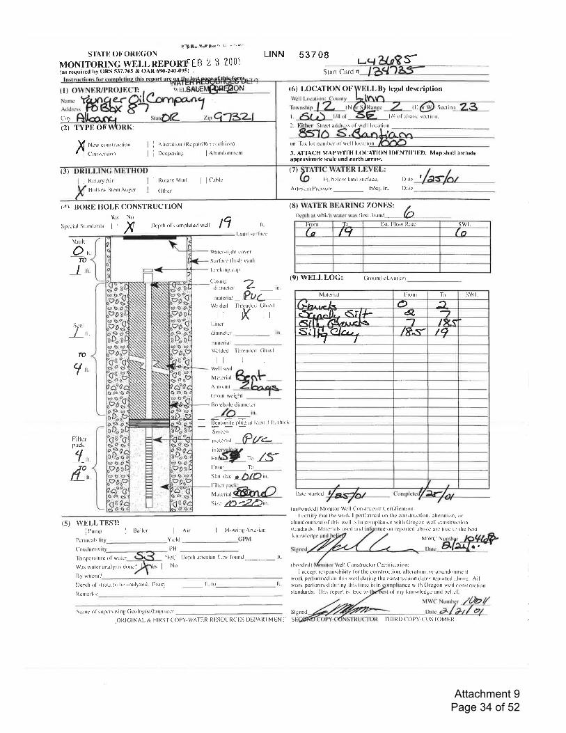
U]***l*or' "' '^-'*s'rAt'll ot'ORlt(;oN
MONITORINGWELLREPORXTIB 2 3 2(]tj1(as requircd by ORS 537.765 & OAR 690'240-095)
City
(2) TYPE OF K:
x Ncw e()|slructioll
Cotrvctsiort
I j Altcratiirn lRcpair/Rccontlitirrt)
I i t)ccpcning I lAbandurrrtcnt
(3)
i Rolaty Air
Holkrw Stcnt Augct l I Otn"'
.,1\ BORI' HOI,E CONSTRUCTIONYcs No
LINN 537 08 l-Sturt Card #
(6) |,OCAilON Ot- By lcgal description
rWcll l-ocalion: Cortn(v
'n,wnrtrip I Z f
l. c(Lr-\ tr+,,tN tl Sect irrr
l/4 ol abovc scelion.
Wrtcr-tight coVcr
Surlitce'llush vrtrlt
l-rrcking eap
Casing -tdiuletcr L in.
,rrrrr"rr^r-PU7'l'hrcarlctl Cluc'rl
XlWcltlcd
L1l.ittr'r
diirlrcler
nutclial\\'cltlerl Thleadcd Cluecl
It llWbll scrlr
Matcrial
ArroIDt
Grout wcight
Borcholc dinnrclcr
ln.
llcnlonitu plug.rt lcusl .l 11. thiek
Strcct rddrcss ol wcll lorrtion1
| ]lloraryMud I lCrblc
or 'lirx Iot rurnhe t ol wcll Ir:crtior
3. AI"IACH MAP!Vl'l'H l.OCAI'ION II)liNTll,'l!ll). Map shall inrludrapproximate scale and north arrow,
(7)
lit. bc'low land surlircc l)rtc f
Arlcsiarr Prcrsurc_ lb/sry. in. Dalc_
(II) \\ATER BEARING ZONF]S: /l)cpth at which wiltcr wit\ Iirst liruntl (O
Spccial Standitlds i i X I)cpth ol' conll)lclc(i wcll
"F'/C Depth ilrtcsirn llow lirund_ ft.
Fnlrn 'Rr Hst. l.low l{atc swl_fn(tt Iq
(9) WEI-t-LO(; (;K)un(i clcvntiol
l)ate slartcd
(urrhontled) Monitor We ll Cons{ructor Ccrtilication:I ccrtil),thill the work I pcrlinlcd (nr thc conslrucli0n, alteration. tr'
ahaldonurcll ol'this well is in cotnpliuncc with Orcgon wcll conslructionstilndilrds. Matcrials uscd tnd iltion rcporlr-d nhovc ilrc truc t() thc bcstk now lc.tlgc MWC N
o.
( bondcd ) Well C0nstruetor Certillcnlion:I acccpt rcsponsibilily lin lhc corrslrucli()n, ultcrllion.0r lhund()nnl!.nl
wrrrk pcrlirnrcd on this wcll durirrg the conslruclion drte\ reported abovc. All
tq ti.
l-antl surl ncc
Vrult
OnTO
I r,.
7"',,. ln.
TO
</,
Filtcrpack
'f^14o,,,
,::ll;:1, Pr.-lll,Hl'", zsFrorn Ttr
stor sizc o O/Oin.
ilHli@m^A-si'c ,b-ZDh.
(5) WELI,TES'lij jnunrp ' iBailcr
Pcn ncrhi I
Corrdue tivi'lcrlllcrilturc ()l willer
Wits wulct anirlYsis tlottc.l
| ]Air I lFlowingArtcsianYieltl
PH
I I ttlu
By wlrom.)
I)cptlr ol sllitt{ to hu rttllyzcd. Frotn li. lo li. wrrk pcrlirrrncd during this tinlcstlndards. Tbis report is truc t()
Signcd
cc with Orc'gon wtll conslruelionknowledge antl hcliul'.Rentarhs:
Narne ol supcrvising (icologist/linginecr
ol rtry
Matcrirl F'rtnr Tir SWI-
"!u.,- l- o a)
e.aS.;ll]. 6.r/J- -)R.IIT- Rlrn.rl.s -l /x^(S:.lL-Qla-. f*-< fQ
1t
pRlcrNAL & FIRST COPY-WATER RliSOLrRCl".S DDPAKfMENI' S
ls tn
1'H I ITD COP\'-CUSTOM h,R
Attachment 9 Page 34 of 52
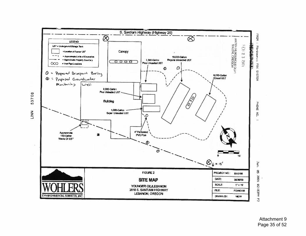
@of.-(f)lo
zz=
SITE MAPYOUNGER OII.JI.EBANON
3510S. SANTIAM HIGHWAYLEBANON, OREGON
ENVIRONMENNLS EF ICES,tNC.
FIGURE2
ORAWN 8Y:
PROGCI ilO.:
FILE:
OATE:
SCAI.E:
MDW
99{rqt
FG990r06
08/3ry93
l'r 15'
S. Santiar Higtway (Highway 20)
UST = Un&rytound S1o.rF Tank
s tHlim ol Farn f USf
- - 1 = ApFrori'Etr l,imilt qt Er€rvalioo
= Ape.oridl{r p.oprty gourdery
OOO s Vcel br Locrlionr
TEGENO
l.500G.tlonPlut Unleadod USf
10.0OSGdlonRegular Untcaded UST
taD 1-,Ptr-ir# (r>qj (v'J-uI.,{C'lJr
-J@ C'
n."T@o
@ = ppp"s.oc [r'.c"ponl S+-int \ItI
0.000€glkr& -- p;op":.1 G
lvo"i{r=t.n2
tsT
\I,I
o\ItI
II
Approrin.lelSOGallon
t{ertcOil UST
(st F/C Plpc
/--s
-tt
'---
- g>-
o0 {c,
&,^ 15'
Canopy
ur<\1
Bulldlng
Super Unlcaded UST
t.(l04allon
2,OOOGrllonPhe Unlcaded UST
-nno:tlqluaoloflD
aa-lm3
1ITozm
zo
LrNlsuNsssNaut-It3-0GI
Attachment 9 Page 35 of 52
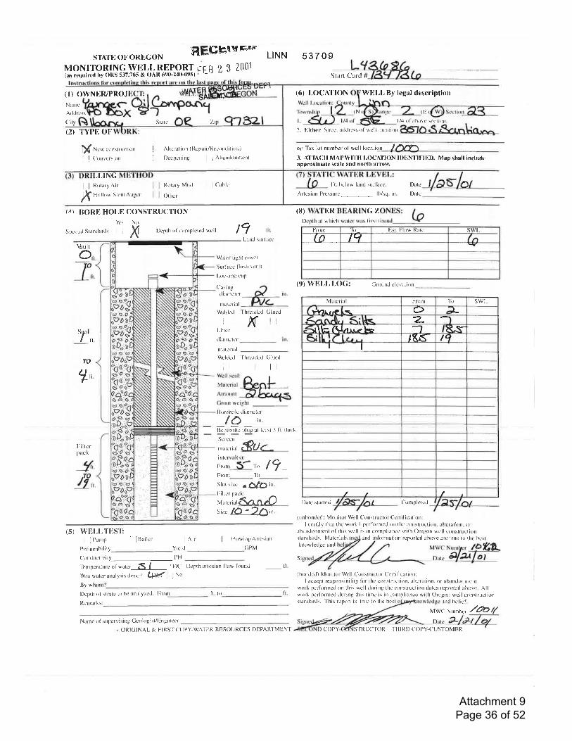
STATI.] OI'ORI'GONMONITORING WELL REPORT(as rcquirtd hy ORS 537.765 & OAR 690-2'10'0951
(l) OWNER/PROJNarnc
A rld rcss
Cir Slrtc
(2) TYPL OF
l$ N"* c()rts{*rcti()n
' | (irrrvcrsion
REGHqvr'n" LINN s37 o9
Ftti 2 3 2001Start Card
(6) r,ocAl'loN WliLL By legal description
,::l,l;i;"""i'2'"'1r SL^L) u+.,r' l/4 ol abovc scction.'1,1
Ilrtaly Mutl j Cahlc
N t;
j I Altcration tll.cprir/Rccondition)' I l)ccpcning I lAhantlonrnertl
2. Either Strcet addrcss ol wcll loertiol
or Tax lol nunrbcr ol wcll locarion I fYn3. {l"lAcH MAPWI'I'H l-()CAl)ON ll)l.lNl'l},-llll). Map shall includcapproximatc scale and north arrolr,
Ft. bclow larui surlircc
,I,INGj I ltrrtaty Ait'
,t Holt.,w Stcrtt Augcr Othcr Artcsirn Pressutc_ lh/sq. in.
l)atc
lh(c
(8) WATER BEARING ZONES: I -l)cpth rrt whi' h urler wirs llrst lirrrrxl (€
J,Ti BORE HOI,E CONS'I'RUCTION
Spccirl Strntlrrrtls i i
Ycs No
X l)epth ol cornplctc(l wcll t7
sac lO '2!Ai't
(5) WELI,TESIi'Punrp Iluaitcr L lnir I l];krwingArtcsian
Yieltl (;PVt
Frorn 'lir Est. Flow Ilrte
@ tq
(9) Wlil,Lr,oc Grotutd r'levatirln
l)atc stnrtL'd Cornplcted
(unbondccl) Monitor Well Construclor Ccrtilicrtion:I ce'rtil.v that thc wrfk I pcrlirrrned orr the conslructiorr. rltcraliorr. or
ilhirnd()nnlent ol this wcll is in cornpliancc with Olcgon wcll conslructionstilndlrds, Matcrials und i lilrnrltion rc'prlrlcd abovc atc truc to thc hcslknowletlge and
Vrult
O,,
_r,,
Lrncl sLrrlircc
W:rtc'r-tight covcr
Surlncc l'lush vault
l-ocking cap
('rsi ngtlirnrctcr
i
'l'hrc:xlcrl (ilrrctlrurlcri al
Wcklctl
ill-incr
tlilrnctcr
Ktl..'
TO
ll.
rnincrirlWcltlctl'['hrcrtlcd (iluctl
I,l^ l;]].il&Ft_llll,i-:,,;fa*ts
Filtcrpack
llorcholc tliiLntcterlO ,'.
Ei,,,E fiQ rt lcast -1 li. thick
iil,l.iil .*u._lilil_L. r?Fronr_ 1ir
Slor siz.c r t14h in.
lriltr'r rrrel:
It,,r"riutcaztnzO
_fi'4,,
Pcrnrcabi litv(i)nductivity PH
MWC Nunrfcr /?tO-o,,r" 42Vot
'l.rnrpcralulc 0l wutcr---_1f,--1-- 'F7C Dcpth artcsian l'low iirulcl- li.
Was watcrrnrlvsis Llonc'? lf.,pftf : No
llv w
l)cplh ol slralil to bc analyzctl. lllrlr
Rcnrrrks
Narle ol suJrcrlising Gcokrgist/llngineer
Si
(btxrded) Monitu Wcll C()nslructor Ccrtil'icillir)n:I acccpt responsibility lor the'construction. al(cration. or abtn(l()nlr)errt
work pcrlirrnrcd on this wcll drrring thc construclion datL.s lcp()rtcd irbovc. r\llwork perlirrnred during this tinrc is in conrpliance with Orcgtlr wcll conslrrrulirrrstrrrdards. 'l his lcport is truc to thc hcst rnd hclicl.
MwCNuntcr /fu
fi. to l(.
lVl atcrial Front 'lit swr'Jvnrp c) L
I a-v.I\h,rllJ ar.rz Ie -l F
,K^(s l1I I
ORICINAL & FIRS'f ('OPY-WATER RESOURCES DEPARTMENT COPY STRTJCTOR TIIIRD ('OPY-('T]STOMIIR
Attachment 9 Page 36 of 52
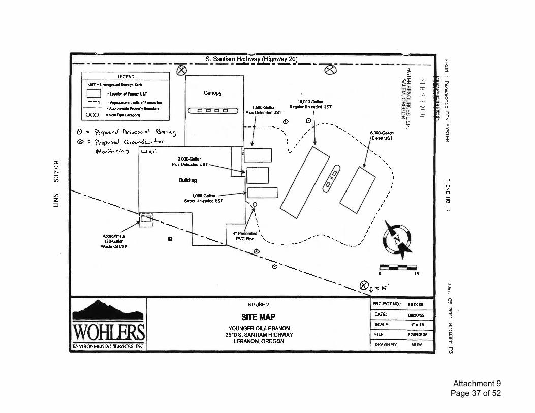
o,oF*COro
zz=
WOHTTRSENv IRONMENAL SERTTICES, lNC.
SITE MAPYOUNGER OII,JLEBANON
3510S. SANTIAM HIGHWAYLEBANON, OREGON
FIGURE2
ORAWN 8Y: MOw
FILE: FG9g0r06
l'e t5'SCALE:
OATE: 0&:nB9
PRO.,ECT l{O.: 9S41(n
S. Santianr njg!g.Lfl!s.l'19!zg)_ _
UST ' Undcrltolnd furrgo lrnk
= Lelixr d Fcrro UST
= &FolirEtc Limib ot Ercrvdioo
= fetreriftda P.pp.tt Eoqndary
= Vttt P[r Localion!ooo
LEGENO
l,SOOGetlonPlus Unleaded UST
10.00Gctlb{rRegulE Unleadod UST
EqD rri>*illd
=i#'^o
!? n:J(h7-rn:
't1:T-ri=
N-
IIi
*
oo\ \\
II
1tl/
O = ppp"reao [ri.{cpo.n} S.rnt; 6.000€€lb1
,y) Grorr.dc.-{<rDlescl IJST& -- pr"p
lv.o".t r.'n2
tItI
1
I\\
\------Apprclirn.lel50Grllon
Wa{GOil UST
rya F/C Pipc
-^ g>-
CI FFE=0 15'
&je 15'
Canopy
ur<\1
Bulldlng
S$er UnlGaded UST1.000€rlhn
2,000GrllonPhe Untcaded UST
-nno:TOJ)aaofonDXUI
ul--lm=
-0Iozm
zI
({qJ
Isut
NNa
sPNt^l1l31lC,J
Attachment 9 Page 37 of 52
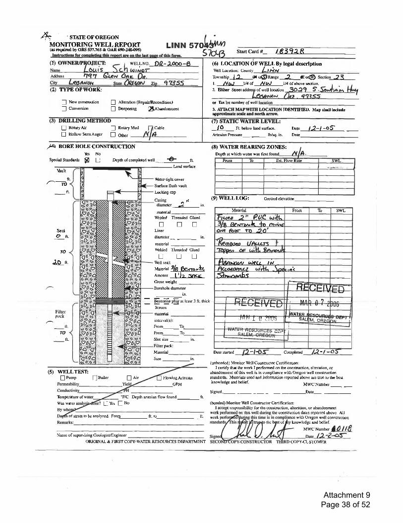
+ -srilrEoFoREGON
MONITORING WELLREPORT(rs rrqutrcd by ORS 537.765 & OAR 5qI'24C095)
LrNN 57ohiuv4s Start Card # / 83 92 I
description
a<
(1) wBr-r-No. D2-I-OOO-6 (o LOCAflONOTWELL By legallrlbll tacation: County /-'Township 12 Go@nange 2 €or@L NI*t ll4of llN l/4ofabovescction.2. Flthcr Stcet of well location
Addrcss
(2) Tr"E OFIYORK:
n Newconsauction
I Conversion
/' loft.
SealOft.
fo
J.o r.
Filterpack
! Alreration (Repair/Recondition)
! Deepening fiAb"ndoo*"nt
or Tirx lot numbcr of well
3. ATTACH MAPWITH LOCATION IDEMIFIED. Mep shrlt lncludeeppmdmrte scde rDd trorth arrew.
(7>
! RotaryAir E Rota"y
! HollowstemAuger E Orn",
Cable
Wbter+ight cover
Surface flush vault
Locking cap
Casing n ildrameter -J rn.
material
-'.-Welded Threaded GluedtrnnLiner
diameter_ in.
material\a&ldcd Threaded Gluednntr\rftll seal:
Material
Amount
Grout weight
Borehole diameter
-in.
Blntog!3 plgg at leasr 3 ft. thick
Screen
nar.dal
interval(s):
Ftom_To_Ftorn_ To_Slot size in.
pu"t --Material
Size ln.
[,Lir Flowing Artesiar
CPM
"F/C Depth artesian flow found_ ft.
lO Ft. bclowland surface.
Artesian Prcssure_ lb/sq. in.
nare /J-l -oSDate
Mud
/T4I BOREHOLE CONSTRUCTIONYes No
Special Standards fl n Depth of complered wel €- 1.
Land surface\hult
ft.
(t) WATER BEARTNG ZOrrrES:Depth at which water was first
(9)WELLLOG! Groundelevation
Materid From To SWL
3t I Rerr+z'r.rlt 'ln rn,ar"r
* Rh$lr^tlt lrJQtt ,r.I
".a<h.r,.lAAbf
HF I:F \ Er\Iftrf,iE$fiF:F{ ItA t hi e
rbvf-"t V l*lJ c JUU
I MA:rFo t
..rr.i,!Y I u fl'rLrn SAL :M. OiF; :lr,l i
,,,,, ut rnsDUUt1Uc.S D[p
2 -'4 -oDate sarrcd
,le ku ,h['1. gc(.
fr.
TO
ft.
(s) WELLTESTn Purnp lBailer
'Ibmp€ratur€ ofWas water
workof strata to be analyzed. Fror1__ fi. to_ fL work
Name of supervising Ceologist/Engineer
Completed
(unbonded) Monitor ld,bll Consructor Certificadon:I cenify that fte work I perforrned on the constructiorl alteration, or
abandonment of Ois well is in compliance with Oregon well constructionstandards. Materials used and information reported above are true to the bestknowledge and belief. MWC Number _signed-Date-
(bonded) Monitor V&ll Constructor Certification:responsibility for the conslruction, alteration, or abandonment
construction dates reponed above. Allwith Oregon well conskuction
knowledge and belief.
MWCNumber a0ll8
lYes ! No
By
'th!rcm Est. I.low Rate sll
ORICINAL & FIRST COPY-WATER RESOURCES DEPARTMENT
on this
the of
COPY-CUSTOMER
Attachment 9 Page 38 of 52
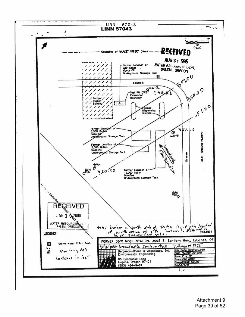
-
L|NN 57 043
, , j L|NN57O43 n^l
FORMER D&w MOBIL STATION, 5092 S. Sonliom
464-e484
,uv&,
140
., Lcbqnon, 0R
I020FEIIF-I
to
- Gcnbrrhc or uARKET srREEr (N.r,) f,fiftlVED(FEEI)
r(,Iv
+--r-?+?-1///.//,/A Looot'rm of
At6s, t99So*Sl,.[i,:tftfifi"'.////////////
2lO GdlonWortr 0llUrCrgruund Sbmgc
t{tp0
Irt///r.////,//)t
/)
ill/4-r- J
Sr-o3ry L 0 0
itftwltt///ltt///ltt///L-z-.2-tt-a
o o
,(,\,
_)
Formor ol 3 l, t0Storogc Tonk ta
t-ttd
Et5an
Forncr l.ocotbn
Tonk IItlafi
4^w4
o*,l' t aJo, 'j0 Fonncr Locotlon ol
112.000 GollonGonllnrUndcqrourd Storcgc Tcnk
UchtPolcO
V
JAN 1q#06WATER FESO ;:,7 lorn/J
,JJ }CFrr'El
SALEM, t1n/t; Prl."n l. sI/o l, ln!(tc ltiY, , )rr?*'-.',vlIt
nt l 1!tcil ll'99tttu:FEIirt arl no r{h COtv\L^-\
\Storm wotGr Cotch Ecrln
0
mA.'t.r
1nrr.'.{e', "-rV,zll
Ce".,rlhu"v 't^ tccf
////// Sidodk
6
Attachment 9 Page 39 of 52

regon Water Resources DepartmentNorth Mall Office Building
725 Summer Street NE, Suite ASalem, OR-9730l-1271
503-985-0900FAX 503-985-0904
Theodore R. Kuiongoski, Govemor
December 20,2005
NUGENT DRILLING CO.CHARLES D NUGENT MWC 1011836969 ROCKHILLDRLBBANON OR 97355
F'INAL ORDBRDear Chuck:
The Special Standard re4uests you submitted for owner: Louis Sphwindt, Start Card numbers183927 , 183928 and I 83929, are hereby approved for the following: You may abandon these wellsin place as described in OAR 690-240-05 10(2). If you plan on abandoning the wells using bentonitethen the placement of the bentonite shall conform to the Departnent's rules and the manufacturersspecifications and result in a seal that is free ofvoids or bridges. Care shall be taken to minimize theintroduction ofbentonite dust. Only sodium bentonite chips manufactured to be greater th an l/4 nchor tablets shall be used below the water level in the sealing interval. Copies of your Special StandardRequest forms are attached.
The Well Construction Standards serve to protect ground waterresources. By approving and issuingthis special consfiuction standard the Oregon Water'Resources Departnent is not representing thata well constructed in accordance with this condition will maintain structural integrity or that it meetsengineering standards. The well constructor/or landowner is responsible for ensuring that a well isconstructed in a manner that protects ground water resources as required under OregonAdministrative Rules 690-200 through 690-240.
If you have any questions regarding this letter, I may be contacted at (503) 986-0851, or by e-mailat [email protected].
Sincerely,
ell Construction Program Coordinator'Enforcemeni Section
enclosure
cc: John Unger, NW Region Well LrspectorFile
,|
This is a final order in other than a contested case. This order is subject tojudicial review undef ORS 183.484. Anypetition for judicial rcview must be filed within the 60 day time period specified by ORS 183.484(2). Pursuant to ORS536.075 and OAR 137-004-0080 you may either petition for judicial review or petition the Director for reconsiderationofthis order. A petition for reconsideration may be granted or denied by the director, and if no action is taken within 69days following the date the petition was filed, the petition shall be deemed denied.
Attachment 9 Page 40 of 52
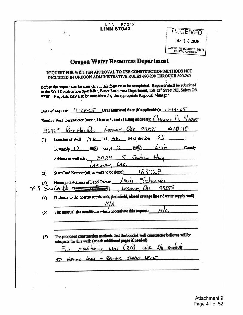
LINN 57 043LINN 57043 fi f; E D
JAN 1 0 2006
Oregon lVster Resourcec IDepertment
REQT,TEST FOR WRITTEN APPROVAL TO USE OONSTRUCnON METHODS NOT
ncurpeo nl onecoN ADMIMSTRATnTB RLTIES 69C200 THROUCII 6W240
Drtc of rcquor I | ^ZF-OS: Onl rpprovd dilc (f ryplheblc): -o
Bonded Wcll Conslrructor (nrmg llccnrc #, rnd mrlllng
Bcforc g,c rcquest csn bc cursidcrcd, tbir form must bc cmplacd" noqttcltJrh.ilte nrbmitled
to tbe ufcll Construction Spccialist, \ivtcr Rcsorrcq pceutmcol' 158 l2r Srcd Nq Seknr OR
9730t. Rcqucsts mry rlsobc considerod by thc approprirtc Rcgioorl Mrnrgcr'
&(l) Locarion ofWoll: /VLJ tt4 NvJ l/4of Sictin 23 ,,
Toumsbip la @ Rrngcj D@ 1,*N Conty
Addr€st at wcll sitc:
L"n ^ou.Arr
t
(2) Srart CudNurrbcr(o[for wott to bc I R31L
Addrcss of lrnd Ocmcn ,f ("h tNOf
lq'r'u*Namc and
h_&..(4) Distancc to thc ncarcst $ptic trnlt' clood tc*lgp linc (if e&rnryply trcll)
(5) Tho unuanl ritc oonditionr wbicb nocc$inb tur iestclt
(6) Thc propotod cfistucdm nceo& erladequna for tbis welh (rttrcb dditimd
tb bildd'rtll mr[rrF btic'ug ;ill bc
Drgpt iflodod)
I4"1 Ln{(r,
Attachment 9 Page 41 of 52
L|NN 57 043LINN 57043
J
(7) Diarnn sbowing rhc patincnt fcrnrcs of rbc pmporcd *lctl dcdgp rnd coolructim:
(.n;.h rdditioarl Pogcs ifDocdd)
JAN 1 0 2006
WATER RESOIJRCES DEPTSALEM, OREGON
iII
II
(l) TbcWcllConrtnrc0onStrndrrdl$ryctoprotcctgP.*.'.!."rcrourtcrByilr;;;g ."d tn6;thlt rp*frl conrtr.cdor dtrd|lt Oc Orrgon Wrtcr
Rctourc* ncpnttrfrtitioi t pttcnt1ager! I rrdl coffiictGd h mrdrncc
wlth tbb condldon rrtlt nrtntrtn drucfi;l 1o13g'lty or 6rt lt ucb cqlnccrlng
rttndtrdr. mc t.li-conrtrgctor/or nnAowlcr I nlpondbtc for cnrur{n3 thl1 rwcll lr conrtructcd f-o t tiootn ttrt protcctr gr*oq-q|: nlourcGl u rcqulrcd
ffi;; sirg* .tenLrririuvc nuu 39trnn Qqorlh @2.l0'
(2) If lt rbould bG dctcrnlncd lt ronc fiturc drtc ttrt 6c rdl' duc !o tb correrrcdon'
lr dlonlng ground wttcr conUnflr-tion, t q o-r h|| of rrtalm plt||!rct thc
onaedgna riJt-rcturn ro tbc rltc rnd rocdfy thc problcm.
(3) If orrt rpprovrl wu gnnto$ r wlttro rcquq nld bc rlbnlfrtd lo Oc
Dcprrrmcniaii.iritun orcc oi*rt t"il.v_rof ttcdilcof ryprovrl or prlor to
tho conptct* "itt. rtro.f.tA'#af mtdf.hrnc b rubnlt e lrlttcn rcqlot '
dorcrlbcd lbovc mryvold prlor onl rpprovd'
Ihrvcrcrdudmdcrrtrndtbcrbovcldorurtloultbrllcrrttdtbrtthclnforurdonp-"faa b rccuntc to 6c bot of ny Inorlodga
Eondcd @nrtngtor 8[nrtrn:
rlngrtr/}n
Attachment 9 Page 42 of 52
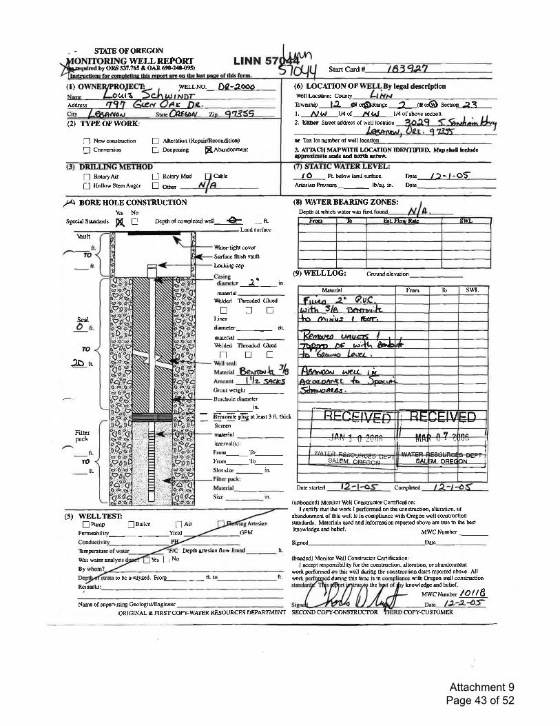
(1)
ST{TEOFOREGONWELLREPORT
by ORS 537.765 & OAn 6qF24ll-0!)s)LINN
WELLNo. Dz-aooo
! Alteration (Repsir/Recondition)
I Deepening ffiAbandonment
Start Card
(6) LOCAIIONOF n "Lli1r*ar
descrlption
K\Irbll Location: County
ruwnstrip 12, Oor$n*ge 2 (ror@ sectio4--f,1-Address
(2) IYPEOFWORK:t. Al W rl4of N lN tl42, Either Streetaddress of well location
of above scction.
n NewconsEuction
I Convcrsion
ft.
Seal
lD-r
Temperature
Was water analysis Yes ! No
By
tobeanalyzed. Fror1_ft.Remarks:
or Taxlotnumberofwell
3. AITACH MAPWITII LOCATION IDENTIFIED. Map shell lmludesppmximat scrle rtrd north rrroe.
n RotaryAir fl Rotary Mud Cable
! Hollow StcmAuger ! Ot".
/Jr'r BOREHOLE CONSTRUCTIONYes No
Spccialsrandards R I Depth of completed weU-- .+--.fLLand surface
\rlult
(E) WATER BEARING ZONES:Depth at which water was first
(9)WELLLOG: Groundelevation
Material From To swL
+A rlrr iu-r t G.rr.
k-nrdltv?r hC !4.. L 8r.& *
I BadDr, ulatt t i
.dta".vraci:
F{ Fflf; \/Er\- Ti trl -lFl\l It-l
nll a{/,:lr.lUi.U'.,iJ lilnt
lll/a?ei
s..rt sir- -n"i t':i^,"e t' l sar rM .)ElFa AN
Date stafled Completed
(unbonded) Monilor rJrbll Constructor Certification:I certr$ that the work I pcrformed on the construction, alteration, or
abandonment of this well is in compliance with Oregon well constructionstandards. Materials used and information reported above are rue to the bestknowledge and belief. MWC Number _Signed Date-
(bondcd) Monitor rtrhll Construcor Cenification:I accept responsibility for the consruction, alteration, or abandonment
work performed on this well during tbe consuuctioD dates reponed above. All
Ft. below land surface.
Artesian Prcssure lb/sq. in.
Date
Date
/)-,-ot
Filterpack
TO
fL
(s) WELLTESTEPo.p lBaller ! eit
Permeability_Yield
1{,hter-tight cover
Surface flush vault
Locking cap
Casing - rdiameter J' in.
^.t i"
-
\Lblded Threaded GlucdtrnnLiner
diameter in.
materialtiblded Threaded Glued
!n!rlbll seal:
r'r"tri"r Begtalk Jb
nmoont lllz :Snc&:iGrout weight
Borehole diameter
m.
Bentonite plug at least 3 ft. thick
Screen
mrterial
interval(s):
From_To_From_To_Slot size in.
Artesian
GPM
Depth artesian flow ft.
ft. work
ln.Size
during tbis time is in with Oregon well constructionthe knowledge and belief.
MWCNumber l0llSName of supervising Geologist/Engin.er
-
a,(l S
Ftm 'to llst Flou llrE swL
ORIGINAL & FIRST COPY-}VATER RESOURCES DEPARTMENT SECOND COPY.CONSTRUCTOR COPY.CUSTOMER
Attachment 9 Page 43 of 52
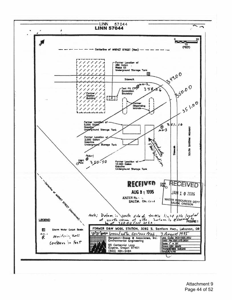
-
L|NN 57 044LINN 570,44)
4
Sidcclk
I
*gt.g{,
I 0 2006
OEPT
FORMER 0&w MOBIL STAflON, 5092 S. Soniiom Hwy., Lrbonon, OR
)tuv
Ir020ItrttrIF--t
to
- Crnbrlirr of IARKET SnEEf (Nil)(FEET)
rr
+-F1-?-t-1
////,//A Locotion of///,/,/./)l/,///,//)
zfiWo3tr oilUndrground Slorrgr Tonk
, ////,// I q1p 0
ltlt?./ltit
////////// .a C*F* jry t .0
o/F.on4r/ / )-Stotttr. . I/ auitdlnc/ / 4,/,/,///A
/////)/////)
0
J (II
-lo o
0bpcnrlng \,L,-t-t-t-t-t :-J _) t(,
Fontrr af 3 toStcrugr Tcnk lvt *c
,2fi3oo
Storogc Tonk
rltur"luehtO- -
6Pdc )) o, lo Forrns locotbn ol12.00O GoilonGorollnr 1Undcrgound Stoogr Tont
RECEIUFN,%o, AUG s 1 l9S
IUATER Rt.'. ....
SALEtil, Okl tit rr{%\ o\
tuth; Drfrwr ',. n{h dr/r#
1n tf 3 I nLK-TiD \
\Storm Wot r Cctch Eodn
.t nr r{h aOYv*L ol a 7-ri ta
3 ,.
m/1| G-l
./\f ry^''J1:r:w Woll
Cen{auvs \, Fecf6 Ecrgaron-Bocse l! Arsociotcs.
Environmcntol Engincringaaa af ,tlft.rrialt1<
afr.t't.1 ,
aatltttalltt
Attachment 9 Page 44 of 52
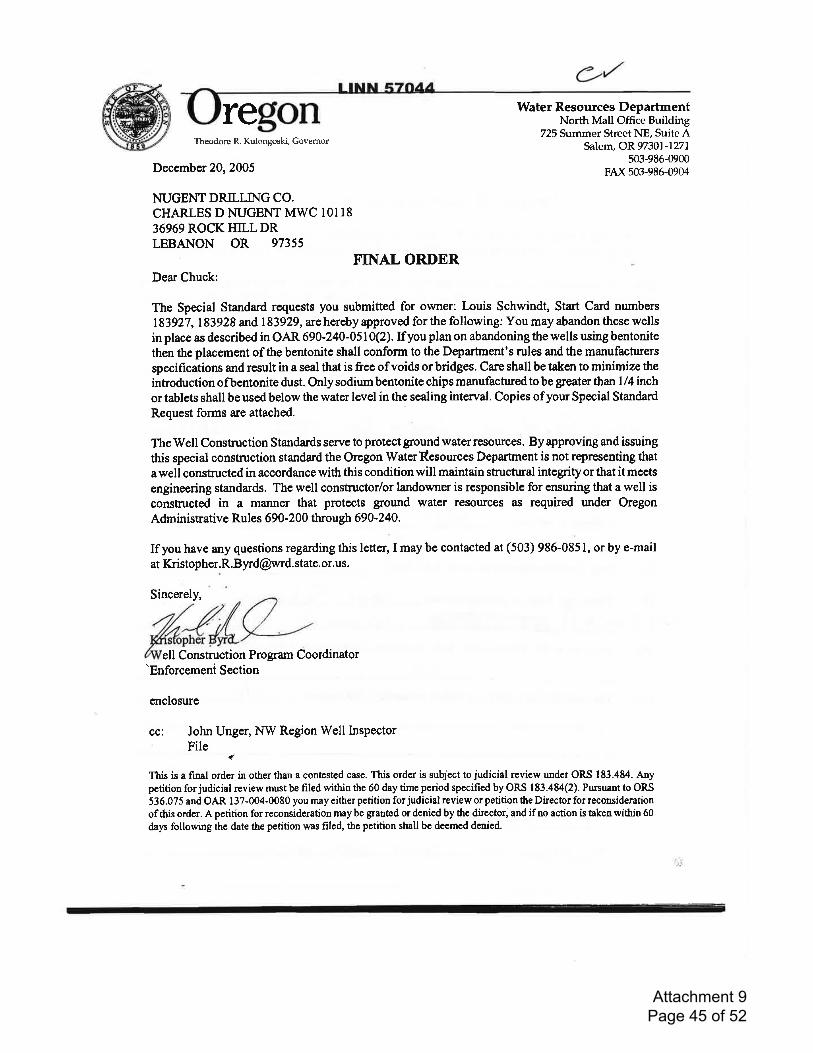
regon Water Resources DepartmentNorth Mall Office Buildhg
725 Summer Street NE, Suite ASalem, OR97301.-1277
503-986-0900FAX 503-986-0904
Theodore R. Kulongoski, Governor
December 20,2005
NUGENT DRILLING CO.CHARLES D NUGENT MWC IOI1836969 ROCKHILLDRLEBANON OR 97355
F'INAL ORDERDear Chuck:
The Special Standard requests you submitted for owner: Louis Schwindt, Start Card numbers
183927,183928 and 183929, are hereby approved for the following: You may abandon these wellsin place as described in OAR 690 -240-0510Q). If you plan on abandoning the wells using bentonite
then the placement of the bentonite shall confonn to the Deparfrnent's rules and the manufacturers
specifications and result in a seal that is free of voids or bridges. Care shall be taken to minimize the
introduction ofbentonite dust. Only sodium bentonite chips manufactrued to be greater th an I /4 inchor tablets shall be used below the water level in the sealing interval. Copies ofyour Special Standard
Request forms are attached.
The Well Construction Standards serve to protect ground water resources. By approving and issuing
this special constnrction standard the Oregon WaterResources Departrnent is not representing that
a well constnrcted in accordance with this condition will maintain stnrctrual integrity or that it meets
engineering standards. The well constructor/or landowner is responsible for ensuring that a well isconstructed in a manner that protects ground water resources as required under OregonA&ninistrative Rules 69A-200 through 690-240.
If you have any questions regarding this letter, I may be contacted at (503) 986-0851, or by e-mailat Kristopher.R.Byrd@wrd. state,or.us.
Sincerely,
ell Construction Program Coordinator'Enforcerneni Section
enclosure
cci John Unger, NW Region Well InspectorFile
q'
This is a final ordcr in other than a contcsted case. This order is subject to judicial review undct ORS I 83.484. Anypetition for judicial review must be filed within the 60 day time period specified by ORS 183.484(2). Pursuant to ORS
536.075 and OAR 137-004.0080 you may either petition forjudicial review or petifion the Director for reconsideration
ofthis order. A pctition for reconsideration may be granted or denied by the director, and ifno action is taken within 66
days following thc date the petition was filed, the petition shall be deemed denicd.
Attachment 9 Page 45 of 52
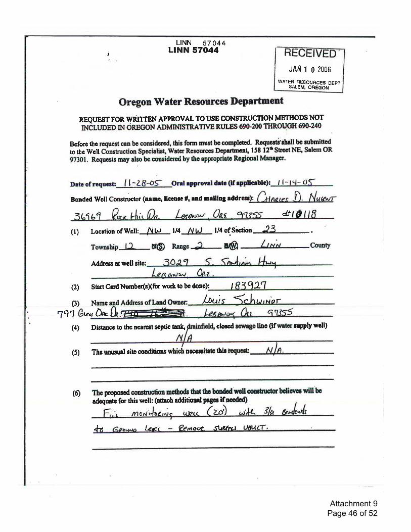
LINN 57 044LINN 570,44j
JAN 1 0 2006
WATEF RESOUFCES DEPTSALEM, OREGON
Oregon lVater Resources Depertment
REQUEST FOR U/RITTEN APPROVAL TO USE CONSTRUC',TION METHODS NOT
rNinroep IN oREctoN ADMIMSTRATT\IE RLrtEs 690"200 THRoUGH 690'240
Bcforc thc rcqucst crn bc considc,trd, this form must be courplctod. RcqucAi'rhdltc rubrnittod
to tbc Wcll Construction Spccielist, Wrtcr Rcsourccs Dcprrtnrc'nl l5t l2t Strect NE Salem OR
9?301. Re4ucsts may also be considcrod by thc approprirtc Rcgionrl Mrorgcr.
Drtcof rcquc*: I l-28+9- Onlrpprornldrtc(lf rpfllcrblc)s , l-l"l- df
Bondcd Wcll Constructor (nrmg llccnrc #, md mrlllng ,diir*
4(l) Location ofWclt AltJ t/l N l/4 of Siction
-8-,Township la d@ Rangc P-. @ Lin County
Addrgs!twcll
(2) StutCadNumbcr(sXfor wortbbcdono): I lq2rl(3) Nlmc Address oflend Loui <.1" t.trNar
,791 Avu M.(4) Distancc to tlrc ncarcst ecptic tanl$ clocod rewrgo linc (if wrtcr nryply wcll)
(5) Tbcrmusualsitccoaditions nccsitrtcfirroqucrt:
.tr-a
(6) Thcproposod cmscuction mctbodc thsttb bondd rcll mrtsuctor bclicrtl will bc
adcqrutc for this wclh (attrch dditiond Fgpf ifncdd)
+?t
0
l-ent o(N SlrCthct
Attachment 9 Page 46 of 52
LINN 57 A44LINN 57044j
(7) Diarram sbowing tbc pcrrincnt fgturu of thc propolod wcll dcrign rnd construction:
6r,i'tl edditionai Pogcs if nccdod)
JAN t 0 2008
WATER RESOUFCES DEPTSALEM, OREGON
(1)ThctWcllConrtructlonStrndrrdrrcrrctoPlotGctgroundwrtcrtuourcclByrpprovlng;;i;;il;hit rpc.rjr con*rufton rnnerrd thc orcgon wrtcr
RcgourccrDcprrtmcntlcoot'.p'o*oogthrtrwcllconrtnctcdlneccordrnccwrth thls .r""Jil;;;ili ;;ilil;t-.r"t-.1 lntcgruv or rbrr u mcctr cngbccrtng
otrndrrdr. Thc wclt conrtructotl* itnCotott ll rcrpondblc for olrurlng thrt r
wcll ls constructcd ln r mlnncr fiilri-ct g.und-wetcr rcrourccl * rcqulrcd
undcr or.goi iJriltttJi"; nuU blOZlXl througb 691)'240'
(2) If lt rhould bc dctcrnlncd et ronrc futurc drtc tht thc wcll' duc to ltr conrtrucdon'\Lt ,JJ:'#;isHflH'fi ilHTll'sl"ffi iliil;i#*rn
prc$urs thc
(3) If onl rpprovrl wm grrntcd' r wrlttcn rtqug nlf bc nbntfrcd to thc
Dcprrrncniirtr., *ittm tnrcc irJ;ryt gy.l o! thc drtc of rpprovd or prlor to
thc comptcttr" oi tn. irioctrtodlJcll totf"- f.fuurc to rubnlt e wrlttcn rcquot *dgcrlbcd .ii". mry vold prlor ord rpplovrL
Ihrvcrcedrndundcrrtrndtbcrbovclnforuedon.Ifrr{Lcrrtlattbrttbclnfornrdonprovtdcd lr rccuntc to thc butof my Inowlodga
Bondcd Conrilrnctor Sfnrturc:
rrtdnMtffi
Attachment 9 Page 47 of 52
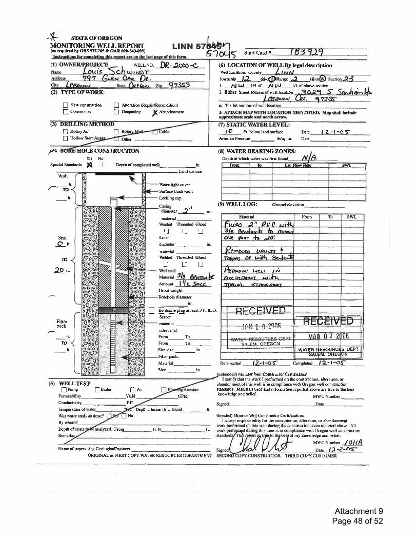
+ sr{rEoFoREGoNMOMI1ORING WELLREPORT(es rtquind by ORS 537.765 & OAR 69G20{195)
(1)
(2) TI"E OFWORK
! Newconstruction
I Conversion
LTNN 56'l Start Card #
WELLNO. D2-lm-<- (6) LOCATTONOF\lbll Location: County
WEIrL B.5r legal descriptionLrpN
rbwnship -12 ot@nang" J (@l. A, l4J ll4 of N llJ l/4 of abovc scction.
2. Elther Sts€€tad&€ss well location
or Tax lot number of wellI Alteration @epair/Recondition)
I Oeepening fr aUandonment
f
! RotaryAir
! Hollow Stem!
HOLE CONSIRUCTIONYes No
Spccialsunrlards [[ n Depthofcompbtedwcll_ft-Land surface
16ult
ft. Iihtef-tight cover.ToSurface flush vault
ft. lncking cap
Seal
On.
Tt)
2O t.
Filterpack
ft'TO
ft.
(s) WELLTESTnPurnp lBailer n Ait
held CPM
Conductiviw PH
Temperature ofWas water analysis done? No
By
Depth of From ft.
3. AfnACH MAPWTIH LOCAIION IDENTIHED. Map shell incldcappnoilmeta scele end norlt rrmw.
D ft. below land surfme. Dste I Z-L-oSArtcsian hessurc lb/sq. in, Date_
(8) WATER BEARING ZOIIIES:Dcpft at which watcr was first
tHli",", jltt ,n.
(9)WELLLOG: croundetevation
maErial
-
ll'blded Threaded GluednnnLiner
diameter in.
material
ltblded Threaded Glnodnnn\\bll seal:
r',r"rdur 3/0 6gA{c^r.ka-ounr lllt- SaccGrout weight
Borehole diameter
in'
_ rytogjjB plC at least 3 ft. thick
Screen
matcrial
interval(s):
Frorn_To_From_To--Slot size _ in.
Filter pack:
Material_Size in.
Date started C-ompleted 2-lMonitor \lbll Conshuctor Certification:
I certify that the work I performed on the construction, alteration, orabandonment of this well is in eompliance with Oregon well constructionstrndards. Materials used and information reported above are tsue to the bestknowledge and belief.
MWC Numbet
Dcpth ancsian flow ft.(bonded) Monitor \l&U Constructor Cenification:
I accept responsibility for the construction, alteration, or abandonmentwork performed on this well during the constnrction dates reported above. All
ft. with Oregon well constmctionmy knowledge and belief.
MWCNumber /Ot(AName of supcrvising Geologist/Engineer _
ORIGINAL & FIRST COPY-WATER RESOURCES DEPARTMENT
Other
ftom Ib E8t FlosRre JIYL
Material From To swLrrtLafr 2t' OU.(. t,,ilL
8rr arc h. )At
(pn**n tta.,,.4i +
4-n* t* tN;lL R'^l-;
h lo*odu atel. t *
s,k;1- <T:',^oara?
ElHN-HI\/EN
'r.r - r r1n/lD IrtE JE-'V =LJ'Jt-i!\ I U LU''-'
MA] I n'l 7 0fi<NI FM OFEGON I
gst tElnaWATEF I S O€PTstN5AL :M, UHE!
work this time is in
THIRD COPY.CUSTOMER
Attachment 9 Page 48 of 52
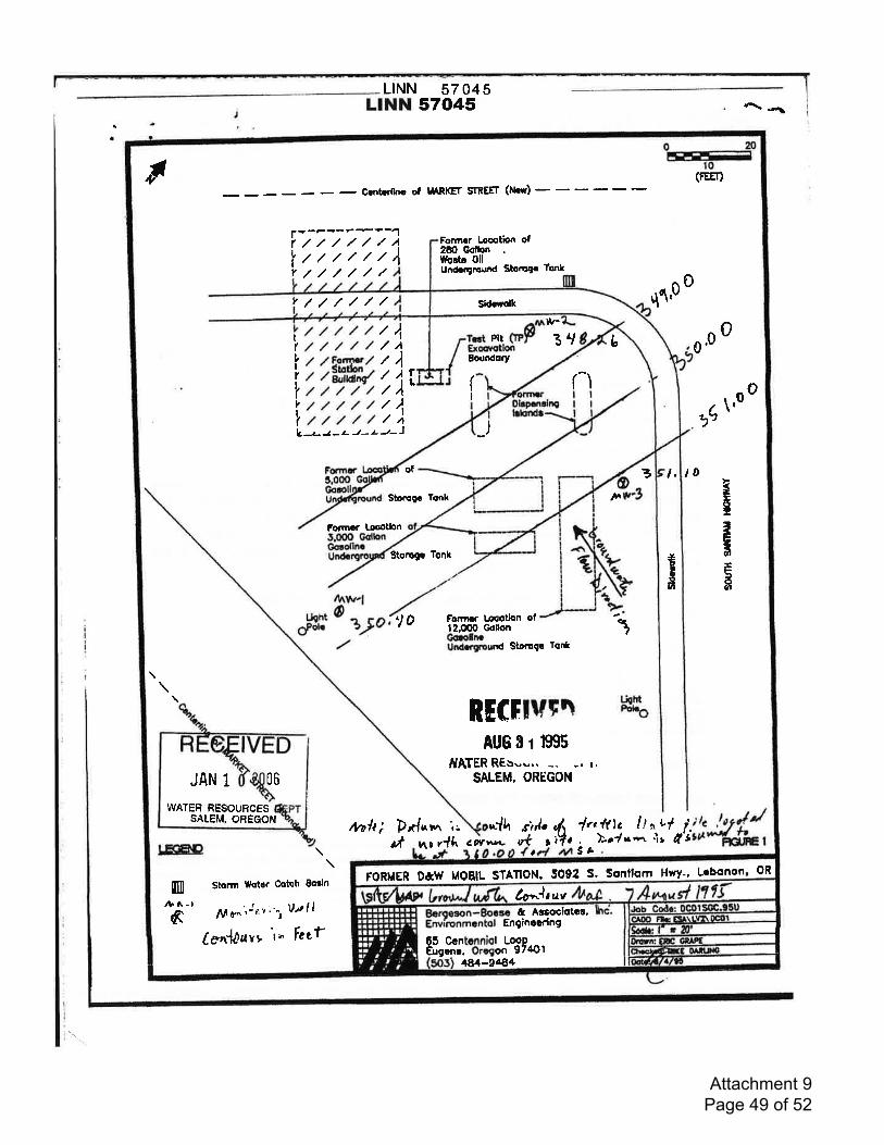
LILINN 57 045NN 57045
a
STATION, RononLoboSsntlqmS.5092 HwyMOEILD&lvFORMER
b)trv
65 Ccntcnniol LooPEugrnc. Orcaon 974O1
Enginccring& Agsociqtoe,
484-9484
020rffir0,t (FEE[)
- &ntldho of uARl(Er SrnEEr (Nd)
+-F--?+?-1//////A//////4
rIvIv
Formcr Loet'pn of2tO GoftcnWodr OilUn-ngmurd Sborq. Tonf//////
///,///
Form.f, lrcotlon
v
BourdorY
rlr-
jry
$
q'\p 0
3 t, t0
0b
r-\
/,/,///////// /.V,[ffi/,/ / alnw'i{////,////,/////,///
\rc,9
k-tI;tsdcl
vgtaB
Plt/,1
/),
iil,Jt-J
0 oI(vIrIv
IL
(I
oo
,-LJ-z-J-.4-
of
Strotogc Tonh
Storogr Tonk
to
pf nc t{h
-)
ForYn r Loootlon ofl2.dX) Gclon
corv*t vt3;t2 .157e//*#mt
*r
UghtOFol.
nAr\r,lo alo 1Gorotm
Undcqround Storogc Tol{t
RECrrurD Hl'"
AUq I 1 ffi15JYATER REs--'. -,- -. r.
SALEM, OREGONJAN 1 06
WATER BESOURCES
\\
Stonn Wot.r Cotch Eorin
ff ,ff 6n 'Jt: r "',
1)l I I
tenl1uvv \" tczf
SAIEM, OREGON mh; Drfrr,n ',. *'{h ri/. .lr,ftlc lt "
+'l l.. )zt|*.r it ll't
usaD
m,t. 1-t
a 3h
Sid.tolk
Attachment 9 Page 49 of 52

regon Water Resources DepartmentNorth Mall Office Building
725 Summer Street NE, Suite ASalem, OR97307-1271
503-986-0900FAX 503-985-0904
Theodore R. Kulongoski, Govemor
December 20,2005
NUGENT DRILLING CO.CHARLES D NUGENT MWC IOI 18
36969 ROCK HILL DRLEBANON OR 97355
F'INAL ORDERDear Chuck:
The Special Standard requests you submitted for owner: Louis Schwindt, Start Card numbers183927,183928 and 183929, are hereby approved for the following: You may abandon these wellsin place as described in OAR 690-240-0510(2). If you plan on abandoning the wells using bentonitethen the placement of the bentonite shall conform to the Department's rules and the manufacturersspecifications and result in a seal that is free of voids or bridges. Care shall be taken to minimize theintroduction ofbentonite dust. Only sodium bentonite chips manufactured to be greater than l/4 inchor tablets shall be used below the water level in the sealing interval. Copies of your Special StandardRequest forms are attached.
The Well Construction Standards serrre to protect ground water resourcei. By approving and issuingthis special construction standard the Oregon Water Resources Deparfinent is not representing thatawell constucted in accordancewiththis conditionwill maintain stuctural integrityorthat itmeetsengineering standards. The well constructor/or landowner is responsible for ensuring that a well isconstructed in a manner that protects ground water resources as required under OregonAdministrative Rules 690-200 through 690-240.
If you have any questions regarding this letter, I may be contacted at (503) 986-0851, or by e-rnailat [email protected].
SincerelS
Construction Program Coordinator''Enforcemenl
Section
enclosure
cc: John Unger, NW Region Well InspectorFile
!This is a fural order in other than a contested case. This order is subject tojudicial review undet ORS 183.484. Anypetition forjudicial rcview must be frled within the 60 day time period specified by ORS 183.484(2). Pursuant to ORS536.075 and OAR 137-004-0080 you may either petition forjudicial revicw or petition the Director for reconsiderationofthis order. A petition for reconsideration may be granted or denied by the director, and ifno action is taken \rdthin 60days following the date the petition was filed, the petition shall be deemed denied.
Attachment 9 Page 50 of 52
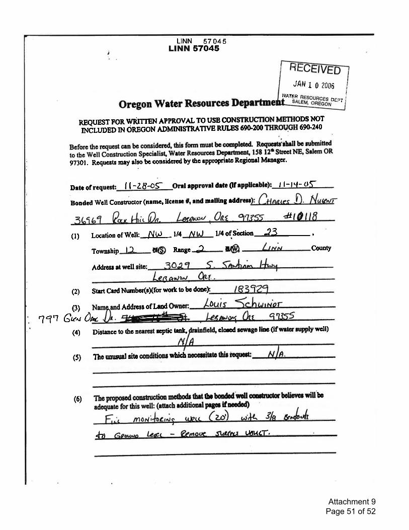
L|NN 57 045LINN 57045
JAN 1 0 2006
WATER
Oregon Water Resourcee
REQUESTFORu/RTTTEN APPROVAL TO USE CONSTRUCTION METIIODS NOT
ttrdlUpep nq ORECON ADMIMSTRATI\IE RT LES 69C200 THROUGH 69G240
DEPT
Bcforc thc rcqucst can bc considcre4 thir fomr mwt bc conptacd" Rcqu!ilt'fulltc rubmitted
to rhe Wcll Coostruction Spccialisf Wrtcr Rcsourpcc ocprtmcof 158 12' Sscct NB Srlcm OR
97301. Rcqucsls may also bc considcrod by the approprirto Rcgioaal Mrnagcr'
Drtc of ll ^2849 onl rpprovd dttc (lf I l-tq-orBondcdWcllConstructor(nlmGtllccnrc#,mdmelllng,dd,*
(l) Location of W,cil:JNhl- l/4 N t^) l/4ofSirtiw-,,L,Toumship r_1- @ Rangc 3 @ County
Addrc$ rt wcll
(2) StartCrrdNumbcr(cXfor wort o bc dmc):
(3) Addrcss oflrnd
#
0
?1'? Gau 0N,
(4) Distancc to tbc neuest rcptic trnk, ctoccd rorngc linc (if qng elpply well)
(5) Thc rrnunnl sito coditionr f,'hicb ffiihla lhbiequod:
(6) ThoFoposGd amstnodm oc&o& 6il.Aoi-i for this wcll: (rtlrcb rddidonrl
oc bodd ndl ducb bdbes xill bG
pqrifnccdcd)
+"t UAVLT,
Attachment 9 Page 51 of 52
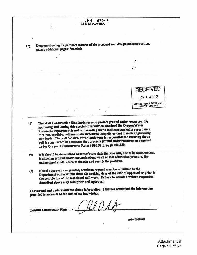
LINN 57 045LINN 570,45
Dirgranr sborring tho D€rliD0ol fcilrl3 of rbc p|Qomd wcll dcrip rnd cmrrctim:(attacb additiond plgcs ifnccdod)
n.
I
(7)
(l) Tbc lllcll conrtncdon stenfirdt tcrlvc to prctcct tFolrd;rtcr rclouru By
epprovlng ..e rnorog thlr rpcchl conrtrucflol findrrd tf,c orcgon wltcrRetourc' O.pittt.it h uo't rcpracndng-qt! I rdl conrtlcbd ln eccotdrncc
wlth thb "ooOifioo
wlll nrlntrln rtructurd lltl8dty or ttlt lt rccrr crylnccrlu3
ilrndtrdl, Tbc wcll conrtnrctor/or lrndo*acr I ru'ondblc for cnruln3 tbrt Iwclt lc conrtructcd ln r mlnncr thrt protcctr grnmd-lrtrr l.Gfout.Gcr rt rcqulrcd
;,i.i Ot goo Admldrtrrdvc Ruh| 69F200 tlnX$ O&.2t0'
(2) If lt rbould bc dctcrmlncd et ronc ffiurc dr!3 ort ttol4 duc b lb oulncdo$I dlowlng Sronnd rrtcr contrnhrdor, nrdc or hl of rrlalm prrrrorg thc
unCcr4,nfi rhdl ttturn to lho rltc rnd rccdfy ttc problcn.
(3) If ont tpprovdwr| greltcd, r rvtlttrn r.qecd D|ltb3rbDlfr.d totbc
Deprrtmcnifuo ritnn thrcc (3) worlihg dryr of thc drto of rpprovrl or prlor to
inc conptcUoi of tf. uroclrtcd Jclt rcrh Fdlurc b nbmlt r rrlttcl rcqucil udocrlbcd rbovc nryvold prlor orrl rpprovll'
I hrvc rerd end uldorrtrnd 6c rbovo bforrrdou I tbfu rtr.nt llrt tc hforurtlon
piovlOcd lr rccurrtc to thc bcrt of ny lnonlodga
JAN 1 0 200$
Eondcd Conrlrrdr Sjnrtlrc:
;Ynllilil.
Attachment 9 Page 52 of 52

Attachment #10
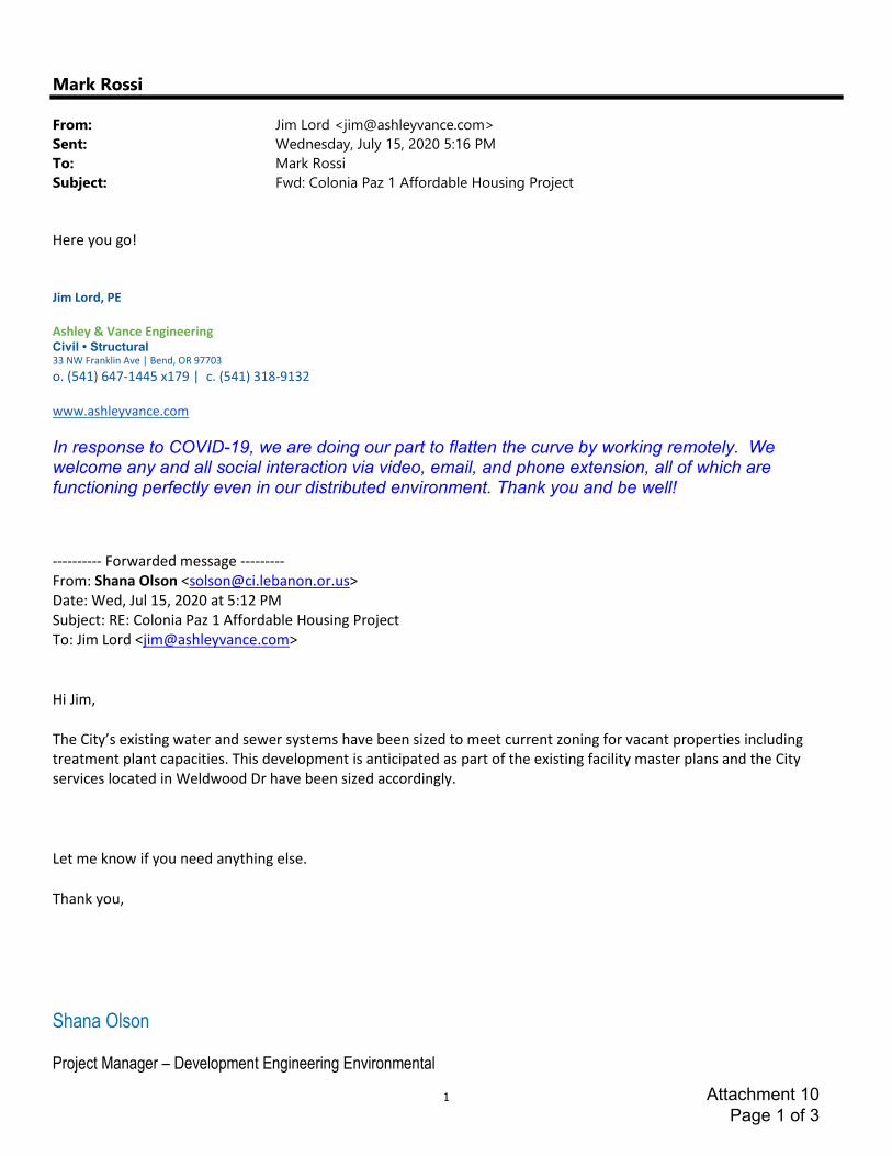
1
Mark Rossi
From: Jim Lord <[email protected]>
Sent: Wednesday, July 15, 2020 5:16 PM
To: Mark Rossi
Subject: Fwd: Colonia Paz 1 Affordable Housing Project
Here you go!
Jim Lord, PE
Ashley & Vance Engineering
Civil • Structural 33 NW Franklin Ave | Bend, OR 97703
o. (541) 647-1445 x179 | c. (541) 318-9132
www.ashleyvance.com
In response to COVID-19, we are doing our part to flatten the curve by working remotely. We welcome any and all social interaction via video, email, and phone extension, all of which are functioning perfectly even in our distributed environment. Thank you and be well!
---------- Forwarded message ---------
From: Shana Olson <[email protected]>
Date: Wed, Jul 15, 2020 at 5:12 PM
Subject: RE: Colonia Paz 1 Affordable Housing Project
To: Jim Lord <[email protected]>
Hi Jim,
The City’s existing water and sewer systems have been sized to meet current zoning for vacant properties including
treatment plant capacities. This development is anticipated as part of the existing facility master plans and the City
services located in Weldwood Dr have been sized accordingly.
Let me know if you need anything else.
Thank you,
Shana Olson
Project Manager – Development Engineering Environmental
Attachment 10 Page 1 of 3
2
City of Lebanon | 925 Main Street | Lebanon OR 97355
Tel: 541.258.4265 | Fax: 541.258.4955
From: Jim Lord <[email protected]>
Sent: Wednesday, July 15, 2020 4:50 PM
To: Shana Olson <[email protected]>
Subject: Colonia Paz 1 Affordable Housing Project
[NOTICE: This message originated outside of your organization -- DO NOT CLICK on links or open attachments unless you
are sure the content is safe.]
Hi Shana,
I know we have discussed this in meetings and over the phone, but can you provide me a written response (email reply
is fine) that the existing sewer main and water line in Weldwood Drive that we will be connecting to the new apartment
building too has sufficient capacity to support this development?
Let me know if you need any additional information from me.
Thanks!
Jim Lord, PE
Ashley & Vance Engineering
Civil • Structural
Attachment 10 Page 2 of 3

3
33 NW Franklin Ave | Bend, OR 97703
o. (541) 647-1445 x179 | c. (541) 318-9132
www.ashleyvance.com
In response to COVID-19, we are doing our part to flatten the curve by working remotely. We welcome any and all social interaction via video, email, and phone extension, all of which are functioning perfectly even in our distributed environment. Thank you and be well!
Attachment 10 Page 3 of 3

Attachment #11
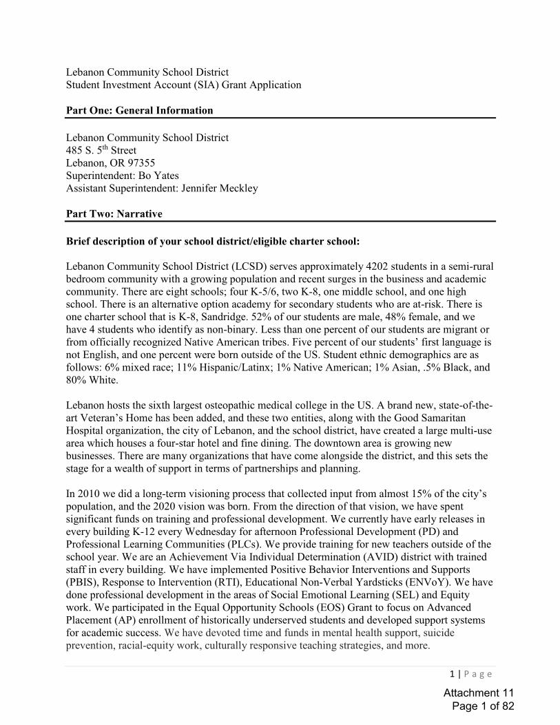
����������
��� ��� ����������� ������������������������������ �������� �!������""������ ���#$%&�'()*�+)()%$,�-(./%0$&1/(����� ��� ����������� �����������234��5�4����������� �6�78�9:;44���"��������<�= �>����������������"��������<�?���@��A�B����#$%&�CD/*�E$%%$&1F)��G%1).�H)IJ%1K&1/(�/.�L/M%�IJN//,�H1I&%1J&O),1P1Q,)�JN$%&)%�IJN//,*����� ��� ����������� ���������������� �������""� R�������2STS�����������������U�������� ��� ��������V������W� V��W�" "����� ��������������W���������������������������� �������5�X�������W������ ��Y�@ ���ZU4[\6��V �ZU36� ����������� �6����� ����W����� �5�X������������������� "�� ���������@ ���� ��������������V� ������U���B5�X������ ������������ ����������ZU36��������W5�4S]� @� �����������������6�23]�@���6�����V�����2���������V� ������@������ �U�����5���������� ��"����� @� ����������������W����� ��@� �� @@���������� W����_�����������������5����"����� @� ����������a�@��������W��W����� ��b�W����6����� ��"�����V�� ��� ������ @����c�5���������������� W��"�����������@ �� V�<�\]���R�����Y�dd]�e��"����[�����RY�d]�_������������Y�d]������6�54]�=���B6�����3T]�f���5����� ��� ���������R������W��� �� "�������������� ��W�������c�5���������V6�����U @U��U����g����a��e ������������6����������V �������6��� �W�V�������! ������������e �"����� �W������ �6��������� @���� �6����������� ����������6����������������W������U�������V������ ������@ ��U������ �������@��������W5�X��� V�� V���������W� V��W��V��������5�X����������� �W������ ������������� ���� �W���������������6��������������������W�@ ����V����� @���"" ����������� @�"��������"������"������W5������STdT�V�������� �WU�������� ���W�"� ���������� ��������"���@� ����� ���d4]� @��������a��" "����� �6��������STST����� ��V��� ��5�� ����������� �� @���������� �6�V������"�����W��@������@����� ���������W�����"� @��� ������� "���5�f��������������������������������������W�ZUdS�����f�������@ ���@��� ��h� @��� ������� "�����h� �����h� @��� ����������W�� ����������h��� 5�f�"� �����������W�@ ���V�������� ������ @������� �����5�f����������������g����������������������� ����g�� ����������V��������������@@��������������W5�f�������"������h ������=���� ���������� ���������"" �����h=�� 6�8�" ���� ��������� ���8X� 6�b������ ����_ �Ug����>�������B���b_g > 5�f������ ��"� @��� ������� "��������������� @�� �����b� �� ����������W���b� �����bi�����V �B5�f�"������"����������bi����7"" ����������� ����b7� �!������ �@ ���� ����������h���������h ��� ������ @����� �������������������������������� "����"" ����������@ ����������������5�f������� �����������@����������������������"" ��6��������"����� �6�������Ui�����V �B6��������������" �����������W������W��6������ �5��Attachment 11
Page 1 of 82

����������
������ ���������������� ��� �� ������������������ ���������� ������ ����!"�#$�� ���"� ��%��&������ ��'($����� ���������� �� ��� ���������)*($����������������+,-.� ����� ���/�!"������������#��� ����#��'($�������� � �������0�� ��)*�"� �/���12+��� ����������� �������33������ ��3�� ���� ��3������� ��� ����33���������������!������ ����������� �0��4��5��� 3�� ������ ��� ������ ���������3�� ����6����� ����������7���� ���� ���� �������8����4���5��� ��� ��������� �� ����������3���� ������������������� ��0������ ������ ������ �� ��� ���3���������� ������� ���������3 �������������� ����3���9����3������� ���� �������33������������� �� ��������� ������� ���� ������ � � ������ �� ���� �����������:�����;��������� � ����� ���!������4����������"� �;�������� ���� ��������� ����� �������������+3��� ��&�� �����)+3��/��12+��� ���'$����������������������������;������ ��������� ������������ ��"��,� ����� ���� ��� ������;� ����� !����"�������� ����� ������� ��3������� ����������5�������������������3��"��� ������� ����������� ������� ���33����!���� � �� ��� ���!�� ��� �����������5�� �� �"�� �����������3�������� ��������3 ���;�� �����;� ���3�� �� 3�� ��� ������ !�������������������������+����;����������� ������������������;����� � �� ��� ������� �� ���� ����� �������� ���3������������������������ ���������� ����33����,���� ���������� ��������� ������������� �������������3������������ 3�� ��������3�� �;��"��� �;� ���3��������������������� ���!����� ���������� ���3����������;�!���������3������� ������������� ������ �������������<=>?@�ABBCDEF�GH�IEEJBDEF�KLM�NJACIAO�PIQQ�>CCHBEE�>E�GJ@QIABC�IA�RGJH�@SHBBTRB>H�UQ>A�>AC�>E�I@�HBQ>@BE�@G�@SB�@PG�UJHUGEBE�E@>@BC�IA�@SB�Q>P�DVBB@IAO�E@JCBA@EW�VBA@>Q�X�YBS>ZIGH>Q�SB>Q@S�ABBCE�>AC�HBCJ?IAO�CIEU>HI@IBE�>AC�IA?HB>EIAO�>?>CBVI?�>?SIBZBVBA@F��[ ������������ � ����� ������������� ���������3������ ���� �����;����4������ ������ � ����� ��� ������ �� ������������ \�6����� ����� �������]3�3 �����\�& �"�1��� �"�60#����������&�������1 �� ��� �9��������\�+��� �;�� ����� �;� ��� �;� ���!�� ��� ���33��������������\� ���� ��� ���"������ ����� �3�������� ��������������� ��;�������� �� ��������!��"���;� ���� 3���������������������������!0��3���\�-�����0������3�� ��� ������ ���� � �� ��� ����8� 0���� ��33������������ ����������� ����8������ ��������� �����������!"� ���� �����! ������6����� ����� �������������� ��!�� ��;� �����������������������3 � �������&�� �����)��&/�6����� ���0� �������� � �12+��� �������������6����� ����� ������������������������";� ���1����2���"���������������������������� ����5���������� ������������ � �� ������� ���������� ����������������������� ������ ������ ������ �����������������Attachment 11
Page 2 of 82

����������
������ ������������ ���� ���� ��������������������������������������������������������������� ����������!������������������"�#���� ������������� ��������������$ ���������%"&�'#���()����� � ���$����������������������������� ���* � ������*+������������������$ �����������,� � � ������������������� ������ ��������� ���������������� �����������"�-�������.������ ����)�� ������/.)�+� ������0 ���������������������������� ����������������������� ���������������������� �������� � ��� ��������� ����� � ����� ����������������������������������"�-������$����������������� �����.)�������������1��������������������������� ��� ���������� ������� ���"�2 ������������ ������ ������ ������$ �������������������������$��� ���������������������� �������� � 3�� ������� �����$������������������ ���������������������� ������ ��������������� 3�"�#����� � �������! � �����.)�$ ���� �� � ������ �����������������*���������� ������������������� ��������������,� � � ��"��4����������������5��������������������$ ������$������ �� ��������� ��� �������������� ������������� ������� �����������6������� �� � ���� ������ ��"�4������������$ ���������������������������� ������������$���������� ���6!��$�������������� �$� �������������������� ��������� ��"���7����������!�����������������$ ���!��� �� ���� �8���� ��� ��������� ������ �� ��4��� ������� ��"�#������19����������� �������0 �������������������������4��� ������� ���.�� � ��������� ���:����/.�:�+�$ ����&��������� ���������������������������;&���<���������!��������!������������������������������"�7�����=%%�4�������������061; �;;������!��� ��������������.�:"�4������������������ ������ ��������!����������� �������� ��� �����5���� �������������������� 3�������� ������� ����������������������!�����"�)�����4�������������������������*�������������������������������������� ��� ��������������������� ����$�������������� ����$��������������4������� � ���������$��� ��� ���� �� ����������*��������������,� ��� ��������$���"�4����.)����� ���������� ����������.�:��,� ���������������������������� ������ ���"��#�����������!��� ���������� �������������#74)��$������ ���� ���,� ������>������?������ �������$ ������$������ �� ���������3�����������������������������,� ���������� �������� ������$ �������������������������������������� ���� ����������� ��������� ��,� � ��������������!���������������������������������������� ��"�@�$��� ������!��� ��������������������������������������� � 3���������"�2��������������� � ��������������������$ ��������� ��������������������!��� �����$�����!��� ������� ����� ����������� ������� ������ � �����"�#����� �� ������������ ���������������������� ��� ������������� � ���������������������"���#���#74)��$ ���$�A�$ �����������������������������/:*.4 �?#. �)B.C ����"+��������������������� ���!� �� ���������������������� ������������� ��������������� ������ �� ������$��������������!�������������� ����$ ������� ��������� ��������� ������������������������������ �����,� �!���$� ����� �������!����������"�.����� � ��� ���������������!����������$ ���������� ������� ������� �������������A���������������������� ��������������������������������� ���"���Attachment 11
Page 3 of 82

����������
����� � ���������������������������� ������� ��������������������������������������������� ����������� ���������������������� ���������������������������������������������������������������������� ����������������� ����� � ������������� ��� ������� ������� �� ���������� �� �������!�"�� � ���������� �������������������������� �� ������������ ������ ��������������������� ������� ��������������������������������� ����!��#$"%���������� ���������������&�� ����'����� ���(&')��*�� �������$����������� ����'����� ���($�')����������� �������������������+����� ���������(+�')������������������������������ ��������������������&'�������������������������������������������� � ������������ ������������������������� ��!�,�� � ��������������� ���������� �������������������������� � ������-������ ��������������������������������������������� ������������� ������������������������������ ������������� ������������������� ��������� �������!�&��� � ���������� ���������� � � ��� ��� ������������� ��� ������������ ������������������� �� ������ � ���!��.���������������� ���������� ��������� ������� ��������������������� �������� �������������������� ��� ���� ����� � �� ������������������!�/������������ ����������� ���������������"��� ������0 ���� ������#�� �-������!������������1 � ������# � ���� ��� ������������ ��!�$����� ��� ���� ����� � ������������ �� ��� ������� ��� ������������� ����������������������������� � ���2� ������ ������ ���������������������� ������������� � � ������������������ ������� ��� ��������� �������!�,��������������� ������ � �������� � ������������� ��� ��� ��"��� �� �� ��������������������������������������������������� �!�,��������������� ������� ��������� ����� ��� �������� ������ ��������1 � ������# � ���� ������ �������������������� ��� ������ �������������������!�� ��������� ����� ���������������� ��� ��������������������� �������� �������������� ��������������� ��� ������������� �������������!��3456�675889�:;<<=>?@A�8>BCBD<D>@�C>E�F>G=@���HDIJK?LD�A;=K�CGGK;CJM�@;�J;<<=>?@A�D>BCBD<D>@N�F>JO=ED�PM;�A;=�D>BCBDEQ�RKDS=D>JAT;JJ=KKD>JDQ�M;P�A;=�D>I=KDE�D>BCBD<D>@�;R�I@CRR�C>E�R;JCO�I@=ED>@�BK;=GIQ�UDA�?>R;K<C@?;>�A;=�J;OODJ@DEQ�PM;�A;=�GCK@>DKDE�P?@M�?>�@MD�D>BCBD<D>@�DRR;K@IN�VWXY�P;KEI�;K�ODIIZ��$����� ��������������������������� ������������� ���� ������� ������ ��� �����������������!�[�������� ����������� �������������� ����������(����������������� ���������������� ������� � �������� �������������������)\�"�� ���'����� ��]�����"'"]�* ��� � �]����������������� ������������������ � �� �!��������� ����� ����� �������� ���� ���������� ����� ���������]������������ ������ ����� ���� �� ����� ��������� ��� ��!�.������������� �������� ������������������������ ���������������� ��� ��������� ������ �� ���������!��_������������� ��� ������������������������ ��� �� ��� ������� ���� ����������������������������� ��� ����� ����� ����� ������������������������� �� ����������������� ����� ���������� ��������� � ���!�_����� ���� ��������������� ����� �������Attachment 11
Page 4 of 82

����������
���� ����������������������������� ������� �������������������� �������� ������������������������������� ������������������������ �������� ������������������ �� � ������� ������!�"�������� ��!�#��������$����� ��!�$��� ���%����� ��!�& � ��� ��'���� ��"�� ��( ���!������� ������� ��������)�������������������!� ������� ��*�+��*�����*�� ������������ ���������� �����+����� ����������+������������������������� �������������� ���� ������ �������� ������������������+���)���������)� �����+��� ��������������������������� ���� �����������#�����+�� ����� �������� �������� ������� ������������������������������������,���� ����� �������������������������� ��* �����������)������������� �������������������-�� ������� ���+������������� ����������� ��� ���������� ������ +�� ���+������������������� ����� ���+������+�������./012344/445/67�389:7�7;/�<:30=7>�36?�637:@/�91�>9:@�/6A3A/5/67�91�19B30�47:?/674C�135=0=/4C�36?�47311D�E1�7;/�A930�=4�5/36=6A1:0C�3:7;/67=BC�36?�96A9=6A�B955:6=7>�/6A3A/5/67C�F;/@/�3@/�>9:�37�=6�7;37�G@9B/44H�I;37�83@@=/@4C�=1�36>C�F/@/�/JG/@=/6B/?C�36?�;9F�5=A;7�>9:�367=B=G37/�36?�@/490K/�7;/4/�=44:/4�=6�1:7:@/�/6A3A/5/674H�LMNN�F9@?4�9@�0/44O����������������������� ������� ���������+�)������� +��� ����� ������������� ������������������������������� ����� ��������������� �������� ����������������� ����������"������� �� ������������������,���!������������� ��� ����������������������� �������������� �������������� ������������������������������������������������ ����� �����������P� ��������������������� ���&���� ��-�� �����������!����������������� ��������)���� +�� �������)������� ���� ���������!������������ �����������������Q���������� ��)����������)���������!��������������� �������� ������������������������������������������� ����!��������+��������������!� ��)�� �����������������R�+�������� �������������������� ����� ������������������������������ ���������������+�� �������������&� ���� ���������+�������+���)����������������������+��� ����)� �����+����������������+����������� ����� � �������� ��������������� ���� +����+������������� �������� ����������������� ������������������������������������������ ������������������������������� ���������� ���������� ��� �������� ������ ������������� �����������+���� �������� ��������������������+������������(����S���� ������� ����������+���� ������������� ����� ������������������������ �������� ���)�������������������)� �����+��������� ����T����������������� ������� ������� ��� ��)������+������������������������� �� ������������ ����#��� ���������������)�������������������������� ������������������������������� ����������� ������ �������� �����������������������+������� ��� +�������������������������� �������+�� ����������������� ����,���� ������� ���� �����+��������� ���������������������������������� ��� �����������������������+����� ������ ������������������ ������ ����� ����������������� �������+����� �� ���� ������+����� ����� �U������������� �� ��� � ����������������Attachment 11
Page 5 of 82

����������
����� ������������������ ������ ���������������� ����� � ������������������������������� ����������� �������������� ��! �� ���� �� ����������������� � ��! �� ������������������� ��������� � �"������������ ������ �������������������� � � ���������� ����� ������������ ���������#��$%&'�()*&'+,-.%+/.�,(�/&('-)(.%+/.�0+**�1,2�32*'+4&')�',�+5/(,4)�62'2()�)-7&7)5)-'8�9:;<�0,(=.�,(�*)..>��?�������������"������� ����������� ���������@����������� ��A� ���� �B��������A��� �C�������A��� �C���� ��D�����A��� �E � ��� �F� ��� �G������ABHI�J����� ��������K�LCAA �L����L����L�� ������������� ����� �A�������L�� � �M���� N��F��� � ���������� ��H������� �� ����� ���#��G��@��������������@����@��������� ��@��������������������������������#�G�� ���� ����������O��� ��O �� ��PQ��������������������� ����� ��������������������� �������� ��@������������� ��������E�R��������� ���#��G������ ��� ���@���� ����� ���������������������������������#�LAES�@������������� ����������������� ��@���������������#�G��@���������T����� ��������������� ���� ������������������� �� ������ �����������������������������#�G���������� ���� �� ��@�������������������@������������������������������������������� ����� ���������� �������������@�������������� ����������� ����!������������ ������������ ��@���� ����������� ����������� ��������������������#���$%&'�().,2(3).�0,2*=�)-%&-3)�1,2(�)-7&7)5)-'�)66,('.8�U,0�3&-�VWX�.2//,('�1,2(�3,-'+-2,2.�+5/(,4)5)-'8�9:;<�0,(=.�,(�*)..>��E����������� ���������������������������������������� ����� ���������Y��������ECRA� ���������� ������������������� �������������� ��� ��� ����������������������������� � ������ ����� ���� �������� ��� ������������������� �������� ������ �� ���������� ����������� ����������Q������!���������������� ������������ � ������������@����������� ����������������� � � ������� ������ ������������ ���� ������������Q���������������� ������������ �������� ��������������� ������������������� ����������#���R�������������� ��� ����� ��������BSP�@��������� ���� ������� ������ ���������������������������������������@� ���������������������� ������������� ���@���������������� ��@���#�R������������������������� ��� ���������� ���� ���������� ������� ����������������� ������������������@����� ����������������������������������������������������� ��� ������#���W+.'(+3'.�&()�()Z2+()=�',�2/*,&=�;�&('+6&3'.�,6�)-7&7)5)-'�9.2(4)1�=&'&[�5))'+-7�5+-2').[�/%,',.[�,'%)(�=,325)-'.[�)'3\>\�$%1�=+=�1,2�.)*)3'�'%)�&('+6&3'.�1,2�=+=8�U,0�=,�'%)1�.%,0�)4+=)-3)�,6�)-7&7+-7�.'2=)-'�/,/2*&'+,-.[�6&5+*+).[�&-=�'%)�3,552-+'18�9];<�0,(=.�,(�*)..>��R���� ����_�I ���D� ��� �E������a�A��������E�������O��������� ��E��� ��������b� ��� �����O���������O ��� ��Y�?���������������@���������������������� ���@���� ������ ��������������������������� ���� ��� �Jcde���������K� ���������������Jfg���������K������#�����������������Attachment 11
Page 6 of 82
����������
������ ����������������������� ��������������� �� ������ ������������������� ������� ������ �������������� �� ���� �� ���������������� ������������������������������� ����������������� ������������������������������������ ����!�� �� �������������������� ����� ����������������������"����������������������� ��� ���������� �#� �� �������� �$� ����������� �������������"��� ���%��"��� ���&�'�(�������(�����$�)�������$� ���(��� �������*� ��� ����)���������) ��� ��+� ����������������������������������,-,.����������� ����������%&.���������/�������� ����� ������������������� ��������� ������������������������������ ��������������� ��� � ����������������#� �� ����� � ������������� ����������"��� ���%������ �� ������ ������������������ ������� ������ �������������� �� ���� �� ���������������� ������������������������������� ����������������������� ��� ���������� �#� �� �������� �� ����������� �������������"��� ���%���"��� ���0�'�(� ���(�����$�)�������$� ���(��� �������*� ��� ����)���������) ��� ��+� ������������������������������������,01��� ������������������������������ ����������������������� ��������������� �� �� ���������������� ������������������������������� ����������������� �������������������������������������� ����������������������� ����� �������������������� ����"����������������������� ��� ���������� �#� �� �������� �$� ����������� �������������"��� ���%��"��� ���.�'�*� �� ����2 � �"� ����� ���(��� ����) ��� ��+�� ������������������ ����� ������������ ��������������� ��� �����������������$������������$������� ����$� ���������������������� ������������������������������������������� �����������3�������������������+������ ���������$�����$�4��������������� �5����4����������� �� ��������56��3������� �� ���������� �����������������$�����$�4� ���������� ���������56���$���#��������� ����������������$�����$�4����������������������5��7 ������������������ ����� ��� �����8���������������������� ���������#� ��� ���� � �����9����$��� �����$�����$���� ��$�����:� ��� �� ������������������������ ����������������������� �����"��� ���%�'�;�����������;������ ����� ���<�����=����>������ ������) ��� ��+� �������������������� ����� ������������ ������������������������ ���������� ���������������� ����� ��������������������� ������ �������������������� �������� ������������� ����������� ��������������� ����������� �������������� ����� ��������� ���� �����������?@ABCDE@�FG@�AFCHF@ID@A�JHF�K@HAF�FLMN�FGHF�OMP�@Q@BPF@R�FM�@SIHI@�@HBG�MT�FG@�TMBHK�AFPR@SF�ICMPUAV�HSR�FG@DC�THWDKD@A�UC@A@SF�LDFGDS�OMPC�RDAFCDBF�HSR�BMWWPSDFOX�YMPC�C@AUMSA@�AGMPKR�DSBKPR@�LGO�FG@�AFCHF@ID@A�L@C@�PA@RX�JZ[[�LMCRA�MC�K@AANX���Attachment 11
Page 7 of 82

����������
��� ���������� �������������������������������������������������������� �������������� �������������������!���"��������� � ����������������������������#�!����� ����$��%���� �������������� �����������#�!�������&������� '�!�����������!�� �������������(�!������������!��������� ���� ����(�!�������������������(������!��������������������������������!��������$�)!������� ��*����������� ������������*����+!�������������������,�����������!� �������������!����� ��������������!����&�������$�)!������� ��*���������������������!�������������������!��-������������������������!�����#�� ���������������������#�!�����$��.�������'�/���� ������!� �������������������������� �����&������!��������������������� ����������!�� ����������������!�������������������!���������������$�)!������� �������������������������������!���#�!����� �����������������������������������������������������$����)!��������������������������������������!���� �� ������������*���� �����������!������!����*������� �������������������������������������������������������������������������#�!�����$�0���������������*��������������� ��+*�!������� ��������� �������������,����������� ������� ��������+*�!������� ����������,������������������������#�!����� ����$�1���������������*�������������������������������!����������������������������������!������$�%������������������������������������������*�������*!����������������������������������!�����������$����� ��2���3��������������������������� ������������������������ � ����������������������#�!�����$��/���������!�����������������������������������������������������!���������������������������������������������������*���������������*�*�#��������������������!�� �$�)!����!������������+�� ���������� ������������� ����,����������������������!����� ��������������!����&�������$�4�����������������������!��������������������������������������������� �������!������������������������������$�.�������'�/���������������!�������������!��������������������!����������������������������������� �!�����������������������������!��������5���������������������������� �� ������ ����������$�6��������"����� ��� � ��������!������������������� ������������������������ � ��������!�������������*���������!���������$���789:;<=8�>?8�@ABCDCBCEF�GH>�I8H9>�>JKL�>?H>�MKN�8O8:N>8P�>K�8QRHR8�8H:?�KS�>?8�SK:HI�9>NP8Q>�R;KNT9�HQP�>?8<;�SHU<I<89V�WKN;�;89TKQ98�9?KNIP�<Q:INP8�J?M�>?8�H:><X<><89�J8;8�N98PV�GYZZ�JK;P9�K;�I899L��4�� �������1�����������1����������*���������������� ���������������������� �!����!��������+������,��������!��� ���� ��+��������,$�1�������������������!�����������������# �������������!����������!�������[���������������������� ��������������������������������������!������������������������������������� ��������!���� �� ����������������$�/���������Attachment 11
Page 8 of 82

����������
���� �� ������� �� ������� �������������� ������� � � ����� ������������ �������� ��������� ������� ���������� �� ����������������������� ������ ������ ������� �������� ��� ������������������� � ���� ����!���������������������������������� �����������!�� �����������������"� �������� � �� ������#������������$����������� ������!���� ���%����� &�' �������� ���!����������������� � ������ � �������� � ��� � ��!��� ��� ������ ������������ ������������ ��"� �������� � ���������� ���� ��!���������������� ������ �� � ���!� !!��� ����� ��!����� � ������������� ��������������� ��� ���� ��!����� � ��������������������������(��������)�*�+����'������+�����������!���� ������!����������!����� ���!���� �� � �� ��������������������� ����������,��� ��-���� � �����,!���� -��'������������� ���������� ������ �������� ������.�� �� � ��/ ������ !� ����� �� ��� ������������%����� &�+���������������!������ ��������������� �� �� �������!���� � ���������'������!������������ ��������� 0������������������ � �� ������� ���������������� �!��� ����� ���������!��� �� ��� ��'��������������� ��� ����!�����!�������������������!���!��/������� ���������+������������� ������ ��������������������� ���� ��������� ������� ������ ���(��������1�2�$��� ���(�����������*���������� ��� � � ���������� � ��������!����������� �������� ����������� �� ������ ��������������� ������� ����������!����� ����� ��3� � �� � �������� *����� ��!���*��*�� *���/������� �* �� ���� �������%����� &�$��� ��!����������� ���������������!����!��� ���� ���!��/�������� ���������$��� ������������ ����4 ����������� �������������� ����5���� ����� ��� �����,������� *����� �� ���-����� ��!������������ �������6� �* �� ���� ��������� ��!���� ������� ��� ����� ��������������������789:;<=8�>?8�@ABCADEFD@�GH>�I8H9>�>JKL�>?H>�MKN�N98O�>K�8PQHQ8�9>HRRS�TKN;�;89UKP98�9?KNIO�<P:INO8�J?M�>?8�9>;H>8Q<89�J8;8�N98OS�GVWW�JK;O9�K;�I899L��$��� ���X�2� ��������!����������������������������������� ��!���������!����� �� �� ��!��� ��� � ���!�����!!���Y �� � ��� ���� � �!�������/ ���� �� 0�������&��� �� ��!������� ������������������� ������ ��!��� ����������������� ���� ����� ��!��������� Z������� �!���� ������������ ������������ ������ ����� ��3� �� � ����� �� ��� ����������������� ��,����������� � �������-�!�������� ���������������!��� �������� ���� ������� �� 0�� ��������Attachment 11
Page 9 of 82
�����������
�� ����������������� ��������������� �������������� ������������������ ��������� ����� ����������������������������������������������������������� ��� ����������� �!������������������ ����������������� �������"�� ������� ����������#�� ������#����������������������� ������ ��!��������� ������������ ��������$��������������� ����������������$ ���������������#������������� ��������� ����������� ��� ��������� �%�������� ���� ��$������������������&����� ������ ���� ������� ��&���������������� ������������������ �'���������� ���� ��$������������������ �������������� ��� �(���������� ���� ������� �� ����� ���������������$��������$�������������������������� ���� � ��)�����#�*�+�, �������������-� ��� �� ����������� ����������� ����� ���� ����������� ���������� ������������� ���������� ������ ���������� ������� ����������������� ����$��������� �����$�$ �"�� ����� ���� ������������� �!������� ���� ��������.�����#�&���������&����� ������ ���/��������#���������������������������������������������������� � �0��������� ��� ���������������� �����������#� ������ ������ �������� �������������� ��� ����#�������� ������ ������������ ���� ������������������#��� ��������������� ����������&��������&��������������� �������������������������������#� ���������� ���1�� �� ������������������#�� ���������� ���������� ��� �2��#��#���3��������������������������� �������� �������� �� ������#�� ������������������������������ ��������$������������������� � ���456789:5�;<5�=>?@A@?@BC�DE;�F5E6;�;GHI�;<E;�JHK�K65L�;H�5MNEN5�6;EOOP�QHK8�856RHM65�6<HKFL�9M7FKL5�G<J�;<5�E7;9S9;956�G585�K65LP�DTUU�GH8L6�H8�F566I��0������#�V�+�'�������� ���'�������� ���$��������� �����������������$ �"�# �'�������� ������������������� ���� �����"�� ����������������� �����������������W����������� ������������������ ������ �� ��������� ���� ��� ������������������ �� ������� ����#������ �������������������������������#��������������� ���� ���� ��$������������������������ ������������#��������������������������� ������#&��3���#&������ ���������&�� ���1�� �� ���������&��� � �����������#&� �� �������������� �������� �X������������������� ��&������$������������� ���� ��� ����� ���������������� ���� ������ ���������1� �#� ���$#� ���� �����Y�������������� ���� �� ���$�����������#��������#�� �������$������� �������������������� �� ����������� ���������� �'�������� ���$����������#��������� ��� �������� ������� ����������� �����������#&����� ������������� �&�������������#�� ��������������� ��� ������������� �� ���� ����� ������� ��0������#�*�+�Y� ���������X��������������������������� ��&������������������������������ �����$����3����� �� �Z ����$�����"���� ����������������� ������������� ���� �����Y� ���� ������� ���� $��� ������������ ����� ������������� ��� ������ �, ���������#&����������������� ���� ����������������#������� �������� ������������������������� ������Attachment 11 Page 10 of 82

�����������
��� ���������� ������ ��������������������������� ��� ��������������� ��� ���� ��� ����������������� �!������ � ������������� ������� ������ �������������������"��� #����#�������� ��������������������� �����������������$�������������%�����&�����%� %��%'�� �&�� ���� % ���"���� ���(���� ��)�!��������������������� �� � ������������������ �� ��&���� �&�� ���� ��� �����!����������������'�� ���*��"�� ����������� ��"�������������+����������"���� �,�������%�����&����-������������"�� ��������� ������.� % ���"���� ������������� ���������� �� ����� ������ �� ����������/0123450�678�84194::�;<69�=>?�:063708�@3>A�=>?3�2>AA?749=�678�196@@B�C<69�=>?�:063708�>3�630�6294D0:=�:063747EB�F>;�=>?�6GG:408�9<0�47G?9�9>�47@>3A�=>?3�G:67747E�HIJKLJKK�;>381M��+N!O���������������������������#������$����� �&�����&���� �&�� ������� ����#���������������������������� �������� ���������������"�� ��������� ��"����������� �������� ��!��� ��� ����������#������ ���������� ���������� �������������������� ������#������ �������#������� ������ ����#�����"����������� �������� ���� P�QRQS���� ��%��TUV����� �)�STW����������� &��TW���� #�����&�QRW������������'��������������������� ��X������������������ #���)�������&�� ��������&�����&�'����� #&����&��� #�#� �&�� ���������������������������'Y����P�ZSZ�������#�������� ��%�QR�R����� �)��VW�������&��[W���� #�����&�U�W������������'�������X������������������ #���)�������&�� ����� &�'����� #���&���������������� �&��� #�#� �&�� ���������������������P�R\[���� ��%�QQ�T����� �)�RRW�������&���W���� #�����&�QW�'������� ��� ���X������������������ #���)������ ������ &�������&�� ����� &�'����� #&�� ���� � �%�����������P�QZ\������ �ZQT����� �)�Q�W�������&�[TW���� #�������X������������������ #���)�����%����&����]��� � #����&������� ��������� �&�� ���� #�� ������� ������&�� ������� #�'��������P�ST�N���� ������'�� ���Z����� �)�TW�������&�V�W���� #�������X������������������ #���)�����#%�������������� &������ ������ &�� ��������"���������$���� �� #�����' �� ����������� �����!����� �� ����������� #����)�� Q�� ������������������#����������'���������'������������ ������ #��#%����������������������'�����'��� #����+���� &������� �����&�� ����� #�#� �������� ������. #�� #������ ���� #�#� �������'������������������_���� #������������� ������� �������'����� #�� �������������&���������� �������������� �������� ��������������������#���������� �������������������#������U��N�����&�'������&�� ��������������'������������$.!�������� ������� ���� ��������� #������������#�����a ���������������� �������������������������$������ ������������ ����#������� �������� ������������������#���������Attachment 11 Page 11 of 82

�����������
��� ���������������������� ������������������ ������� �������������� �� ��������!�������� "� ��������������������#� ���$�������%������������ ��������#� �� ���������� �"�� �������������� ����������# #����������� ���#� ��������#�� ���� ������� �������� ���#��������� ������#� ����� ���������&����������������������� �������� ������������������& ����� �����# #�����������������'()*�+,-).�/010�(2034565���/75896:7�1;7�<010�5=>9875�>57<�02<�;=?�1;7�<010�62@=9A5�7B>614C:057<�<78656=2�A0D62E�FGHI�?=9<5J��K � �����������������L����� ��&�������������K � �M�N�O��P �"ONQ���R�STU�N�� &��� ��K � �M�V���������� ����K � TU��� �����������&������M���W� ���X���� �"� ���Q ����Y���W� ���Z�%R� �[��W� �� �����S ���TU� ������&�"�S��������� ���� �� ����������#�����\ ���������� �� ���������������"�M]� ���� ��&�� ���]� ��� ��&�T���� ��� ��������������� �������� �� ��#������� ���������� �"�� � �������� ���������&���������� � ���������%������������ ����#�� �������������������� ��� ������� ��� ����� ��������������&��������� ��� ������#���� �������V��������� ������ ��"��� ��������� ����������������������������� ���������������� �� �� ���������&���� ��� ��� �������������� ������ ����&���������������#�������� �"�����#������� ����� ���� ���� ������ ����� �������� ������ �#������������������ ��� ������� �� ��#������������� � ������������������� �����#�� �� ����������� �������� ���#����� �������&��� ����&��������&����� �������&���"������ � � ������ ������� �\������� �����������������#������ ����&������# ����_-*a�b cd.�/75896:7�;=?�4=>�>57<�1;7�7B>614�3725�=9�1==3�FeHI�?=9<5�=9�3755J��X�� ����O�������"��������K��������� �� �������"�� ���� ##��# ���#�� � ����������������%#�������&����������������# ��� ��������� ����f��� ���������������������������� ��������� ��"���������&�������� ������R����f���"������� ����&�������"���������#� ���������#��� �� ����������� ������� ����� �������&��&������������# #�������������������� � ������������ ��� � �"����� ��������&�� �����#�����#��� ���������������� �� �����������#� ��������� � �� ����&�����������#���� ������f���"������������ �� ������� �������#������� ���������������������&��������������# #������ ���� � � � �"���� ����� ��������������������� �ZKP� ����������������������������� ���� �� ��� �����#� ���R�������� ��� ������� ������������� ���� �� ������� ����������������� ������ ������&���������#�"������������� �������������������#������� ��������������������� ���� �������� ��#�������"�� &��������� ���������������� �#���� �����g��������� ����������� �"�����������������&�������������Z�������������� ����&��&������&����#�����#���� �������������������� �� ��"��� �����������#��#������#� ������������������������������� ��������� ����������� ��"���������&��� ���� �#�� ��g�������� ������������������� ���#��� ������ &��������� ��������O����� ��"�S�������&��R� ����#��� �������������%P������ ��X� ����#�������������S �� ��Pf���"��� �������� ���Phi�j���� &����� � #��������� ��#������������������ ���&��"���������� �� ���� ��������� ���������������� "��#�Attachment 11 Page 12 of 82

�����������
�� ������� ��������������� �������������������� �������� ����� �������� ������ ����������������� ��������������� �!"#$%�&'()*+'�"+,*-'.*+'��//0(+'�1&"�2��34+�5('/0.*-%���5('/0.*�67%�8����������� ���� �������9���������:� ����� �������� ������� ��� ��� ���9��� ��� 9 ������������������5('/0.*�6;<�=���������>���������?��� �����������������5('/0.*�6@<�A��� ���B����� C�D����������7EF0G�4H*�'I*�H*-0(H/*�4330/4'J0+-�J+�K0(H�L()M*'�H*N3*/'J,*�0N�'I*�0('/0.*-�K0(�4H*�'HKJ+M�'0�4/IJ*,*O��A��������������C������C�� ���������������������� ���������������������������P������QR�� � ��������?S� � ��� ������A9�����:�RT:�����������9:��������?������ ��� �����8��U���V:����������� ���C�9��� ���WW�Q�XYD������������Z���9������ ��������S�����C�� ��� �����[������9������� ��� �������9���� �������\]Q :___:�� a�������� 9 ���������C����� ���� � �� ����RR��9������� �������9���������������������a�������C���������� ���������� �������������9� ���������������9���������99� ���9 ����C�������� ?�����������8�9��� ����������9����������������� ������� �� ����� �����������9����� ����� �������������9�������9������������ ���?������ ���������������9��99 ��:�?��� ���?�������������99�� ���� ���������������������� ��� ��?�������Y�������� ���� ��U���V�������� � �������������C�9� � ���\]W_:___����� ����\]Tb_:___��������������\��������S��� ����9�����9���������������Z���Y����C��9�V� ���9������c����<�89�������� ������������99������� d��������������������:������� ���?���99 � ��� ��������� � C����99����������V�� ����C:������ � ���� �������������C��� ����������� ���9��������9������������� � ������ ����C� �������������;EeI*H*�)0�K0(�*fg*/'�'0�g('�.0-'�0N�K0(H�N0/(-h�H*-0(H/*-�4+)�*+*HMK�J+�'I*�NJH-'�K*4HO��A����� �� ���9������9 ���C��������9������<�� T��[99 ����9������� ������������9 ����� �������������������Z�����������?�9��������R��Ui����� � ������������9 ��� C��9� ������� ���b��B��������� �����������9������������������������� ���� �� �����Z���B���?�� ���9������� ���Q��8������� ����9����9����� ��<���Da�������C��������������������������Attachment 11 Page 13 of 82

�����������
��� ����������������������������������������� ������ ������������� �! ���������������"#����$ ���� ! �������������� �%��� ������&�&�������� ���&�$����������� ����� ���� � ����'(�)*�+,-.�+-/0�123,.�/456�762462.280�0,29.�+2.,2*�/456�7:-*�;-08<�4*�680456=8�->-2:-;2:2./?��@�� �����������A���������������������A ����� �B���� ����C����&��� ����� ������ ���A ���D%���E ���! �F�A � ��� ��A �� ������������!��� �"��� �! �������B �B�������� � ������B��C���B���� ��A��� �G�� H�I����� "I �� � ��&���� ��F�����������F� �� ���������F���� ����� ����� J ����K��#�� ��� ����� A�!��������� � ���&������� J ���������������K�D ���� � ��������!�� ���� �&���������� �����B��C��������!�� �� ���� ����������H�I�������L "B��C��������� ��K�DA�� ����������������&&F����A ���A���� ����� ��K���� ������������� � �������" ������ ��K�����!��� ��&����� � ����B��A���A �����&&�������!�� ��� �"������������ �K����!�� �� ���� � ��&���� �������� !� B"���� ������ ��� ������ ������� ���������C �� �� �������&����������������� ����������� � � ��&���� ������K�D ���� � ��������!�� ���� �&���������� �����B��C��������!�� �� ���� ����������H�D �� ��D�A����K�%��� �� ����!��! � ���B��A���A ��������L��������K�DA�� �����&&����&���BA�� �������������A ���A��� ��������� ��&���K�# �� �� ������ �K�# �� �� ����� ��K�D ���� � ��������!�� ���� �&���������� �����B��C��������!�� �� ���� ����������H����� ����� �������������K��M� �� ��� �������������&���� �� ��� ����� ��K�� ����������&&�����&���!���������������� ���� ��&������������C��� ����� ���� � ����K��#���������������&����&&�������!�� �����!�� ���������������� ����� �! �������&����� � ����BA���� ������ ����&�����A����K�D ���� � ��������!�� ���� �&���������� �����B��C��������!�� �� ���� ����������H���������� �����K�N��� �� ! ������������ �� ���� � ��� ��A�� �������������� �����������K��M� �� �������������� ��&�� �� ��� ����� �����B��C����� ��� ����������K�DA�� ��� ����� ���������� ! ������ ��������K��O%#������ �� ���#�&������ ������ ��P�����Q������� R����� �������� � ����BA������! � �� ������ �� ! ��K�D ���� � ��������!�� ���� �&���������� �����B��C��������!�� �� ���� ����������Attachment 11 Page 14 of 82

�����������
��� ������������������ �������� �������������������� ����������������� ���� ������������������������� ���� ������� ��� ��� �!"����������������������������������������� ���� � ����������������� ��������� ������ �!������������������ � ������������������� �����#��������������� �$� �� ����� ������������� �%���� ���������&�� � �������������� ����������� �����#����������������� ������ �!"�����'�� � ��������������� ������������������ ��#���� ��� ���� � ��������(����������%�� ��#���� ����#����������������������� �)���������������������������� ���� �!"#'�� � ������������������������ ���� � ��� ������������������� ���� �%���� ���������&�� � �������������� ����������� �����#����������������� ��������&������� �������� �����%�����������������������*�������������������*� �+���������,� �-�������������������. �*�����/����������������� ��������������0�������12����������,� �%���� ���������&�� � �������������� ����������� �����#����������������� ��������3���*�������������� �������� ���������������� � ��� �%������������������������ �� ���� �%� �������������������������������������(�������������������� �-��� ����������� ���� �%�������������(���(������������������������ �-���� ������������������������������� � ������������������� ���� ���( �������������� 4�� ���� �%���� ���������&�� � �������������� ����������� �����#����������������� �������56789:6�;:<9=6>9:6�?@@A7:6B�C9DE�F:9G�HID:�?�JKLKLMKLKNO���FPQ�F76@A>9�RNB�S�������������� ����� ��������������������T� ����� �������� ��������� ������ ���� � ������� ���� � ��������������������UV5P�56ED69WX�RNB�YZ:89EWDE69:�[ED:=Z6ZA:�HEAWED>��[\9AEX�A]�?@6ZA:B�S��(������������* ������������������������������ ��������� ��#���� ��������� ����T�(�������������������� ��������� ������������������������ ����������������������������� ���� ������� ���� � ��,��_9D=7E9=�A]�Q<Z89:@9�]AE�56ED69WX�RN��1,�" ��������������������+������ ��&����� �����������a,�!������������ ���������� �������� �����*���������� ��� �������� �������� ����b,�'��������������+�������������� ����������������������c,�d��������������������������������������������������������,��&�� � ���1,1�e�HE9MY�[ED:=Z6ZA:�HEAWED>�M�_D69EZDI=�f�g9=A7E@9=��FPQ�F76@A>9�RN�JVA:6hO��Attachment 11 Page 15 of 82

�����������
����� �� ��������������� ��������������������� �!� ��"��#$�%&�$'()*�'+�,-.&/0(1�-+�.2&�&0/,1�3/04&*5�6'/&�*.)4&+.*�%-,,�7&�'+�./0(8�71�.2&�&+4�'$�.2-/4�3/04&�0+4�/&041�.'�9/'3/&**�0.�.2&�099/'9/-0.&�,&:&,;��<��������� ��=�>�"��� ���� �� ��������� ?;�@-*033/&30.&4�7&+(260/8�40.0�-+�ABC�$'/�3/04&*�D-+4&/30/.&+�.2/')32�E2-/4�F/04&;�G;�@&(/&0*-+3�+)67&/*�'$�*.)4&+.*�+&&4-+3�-+.&/:&+.-'+*;�H;�C,-3+&4�*1*.&6*�0+4�9/'3/06*�I*('9&�0+4�*&J)&+(&5�&.(;K�L;�M)67&/�'$�*.)4&+.*�0.�3/04&�,&:&,�-+�&0(2�3/04&�0.�.2&�&+4�'$�&0(2�1&0/;��C(.-:-.1�G;?�N��O�������>��� ��"�����������">�P"� ��� ��"���!���� �" ��QP!�R� ���"�>��"��ST���U�� ���">��� �������V��O�"��=��������"��O��� �����G;?0�W�GL�W�DWH/4�F/04&�#C*�I'+&�-+�&0(2�D-+4&/30/.&+5�0+4�'+&�9&/�3/04&�,&:&,K�G;?7�W�X')/�N�Y.2WZ.2�F/04&�#C*��G;?(�W�X')/�N�[9&(-0,�A4)(0.-'+�./0-+&4�#C*�G;?4�N�\;]�XEA�A _ABC�E&0(2&/�G;?&�N�+&�N�[9&(-0,�A4)(0.-'+�E&0(2&/�./0-+&4�-+�A 5�AJ)-.1�0+4�a),.)/0,,1��b&*9'+*-:&�E&0(2-+3�9/0(.-(&*��C(.-:-.1�G;G�N��"�������"������!�U���� ��"���OO�� ��G;G0�+&�7-,-+3)0,�#C�G;G7�b&*')/(&*�$'/�A _ABC�-+*./)(.-'+�0+4�*)99'/.��C(.-:-.1�G;H�N���cc���������d�e �">�>�����f�����c��G;H0�N�??�W�DWY�*)66&/�*(2'',�0+4�&g.&+4&4�401�(&/.-$-&4�-+*./)(.'/*�G;H7�N�??�W�DWY�*)66&/�*(2'',�0+4�&g.&+4&4�401�#C*�G;H(�W�b&*')/(&*�$'/�*)66&/�*(2'',�0+4�&g.&+4&4�401�-+*./)(.-'+�0+4�*)99'/.�G;H4�N�X)+4-+3�$'/�a20/.&/�[(2'',�[)66&/�[(2'',�0+4�Ag.&+4&4�@01�h/'3/06��C(.-:-.1�G;L�N��!�P" ��=�" ��"�V���������DWH/4�F/04&�9/'3/06*�$'/�ABC�-+.&/:&+.-'+*��C(.-:-.1�G;]�N�f�� �����"�����=���Oc�" �G;]0�W�C,-3+6&+.�'$�9/0(.-(&*�G;]7�W�E&06%'/8�0+4�a',,07'/0.-'+�G;](�N�E/0-+-+3�G;]4�W�h,0++-+3�0+4�#69,&6&+.0.-'+��i���i� ��c���j�Q�" kR������� �� �����l��!�����c�" ����>�"� ��"���������� �!� ��"��Attachment 11 Page 16 of 82

�����������
���� ������������������������������������������ ����������������������������������������������������������������������� ��������������� ����� �������� ��������������������������������������������������������!��"#$%&'#%�()�*+,-#./#�)('�01'$1#23�45�� 6!�7��������8����������9������������ ����������������������������:���������������� ������������������ ������� ��;��������������������������!�<!�=��������������������������������>:6<�?!�=�������������������������������������������������������@!�=�������������������������������������������������������A� ������!�B!�=������������������������������������������������������� ����������8��������?!6�C�D,'#�EFG�HI*�J%%#%%K#.1�L(('-,.$1('��8��������?!<�C�*+$M&$1#�/&''#.1�$%%#%%K#.1�N'$/1,/#%�$.-�%3%1#K%��8��������?!?�C�O#1#'K,.#�/P$.2#%�,.�N'(2'$K��8��������?!@�C�O#+#M(N�/(KN'#P#.%,+#�N'(2'$K�$.-�/$M#.-$'��8��������?!B�C�O#+#M(N�M(.2,1&-,.$M�K$,.1#.$./#�()�-$1$�N'(/#%%��QO*�Q&1/(K#�4RS�T������������U�����������;� �������� ���� ��������VL0O�01'$1#23�4WS�I#$/P#'%�(.�0N#/,$M�J%%,2.K#.1�XIQ0J%Y���IP#('3�()�J/1,(.S�������;� �����������������;��������;���:������������������������ ���������� ��������������������Z������������������������ ������������������������������!������������;� ���������������������������� ������������������������������� �����������������������;������������������������������������������������������������A���������������������������������������������;�����������;��!��"#$%&'#%�()�*+,-#./#�)('�01'$1#23�4W��� 6!�7��������[\]8��� �����������������;���:����������Z������������������������������������A���� ������������� �;� �������������������� ������������������������� ������� ������������������;� ������������������������� ���������������������������������������������� ��������������� �� ����������U����������� ��������������������������������������������������������������������������!�<!�=����������������������������;��[\]8��?!�9����;���������������������� �_]��a[��_=������������� ���������� ���@!�=��������������������������������������������������������������������B!� � ������������������������������������Attachment 11 Page 17 of 82

�����������
�� ����������������������������� �������������� !�"�#$�%&�'�"&��(&))#*&�#+�&!�*�+%��!�+�#$��#!,�)�#,���-�.���� ������/�����+��$�!��,#+#�(&))�(+�&!�#!,�#!#)0����.�&(������� ������������#�!�+�#$���!�(&))#*&�#+�&!��1.�(+#+�&!��#!,�&2+(&$������ ������3�������)&.��0�+�$�"&��&! &�! ������%�%�+-�()�#���2*��(�"&����#)2#+�! �.�& �#$���� ������3�4��! &�! �5�&"����&!#)�����)&.$�!+����6��2+(&$��78�9:&!+;<���=:����+�#+� 0�7>?��%&����+��(+@A�,��B�!+#)���#)+-��.�(�#)��+����-�&�0�&"��(+�&!?�CD�EF�GH F�IFJ�HK�GFHK�G�LMF�HK�L�L��GH��HJ�HNNOFLL�IPOF�LFO�PQL��LLQFL�E��G�L�QNFJ�LR�PQJLFKPOLR�SMF�HK�TNQH��PJ�S�HDDR�HJN�P�GFO�UQ�KN�JVWKF FK�MFOLPJJFK�HJ�MOP �NF�LFO �FL�HJN�FDDF�� F�L�L�FIL�DPO��GF�VFJFOHK�MPMQKH��PJ�PD��GF�LGPPK�HJN�OFH�F�L�HU�K�������B�#�2����&"�6��,�!(��"&���+�#+� 0�7>�� ���X�O�JV�PD�SMF�HK�L�L����YFDFOOHK��JDPOIH��PJ�/��ZH�H�OFKH�FN��P�L�QNFJ�L�LFO FN���� ����3�����������%&�B�!+#)���#)+-��.�(�#)��+����� ����3�����5�&��,��+�#�!�! �#!,�5����)#+�,�+&�,��+��(+�.�& �#$��#!,��0�+�$����� ����3�/�������)&.�#���"���#)�.�&(������� ����3�����:&))�(+�#!,�#!#)0[��,#+#���)#+�,�+&�+-��.�& �#$����6��2+(&$��78�9:&!+;<���=:����+�#+� 0�7\?��)+��!#+����6,2(#+�&!�5�& �#$�"&����&.@�2+�5����!+�&!�#+�+-����(&!,#�0�=���)���-�&�0�&"��(+�&!?�CD�EF�MOP �NF�H�MOPVOHI��GH��IFF�L��GF�JFFNL�PD�H�WO�L]�L�QNFJ�L�U��MOP �N�JV�HMMOPMO�H�F�LQMMPO�L�HJN�OFLPQOFLR�L�QNFJ�L�E�KK�UF�HUKF��P�PIMKF�F�DPOIHK�LFPJNHO��FNQH��PJ�E��G�H�Z�MKPIH�PO�TZ���B�#�2����&"�6��,�!(��"&���+�#+� 0�7\�Attachment 11 Page 18 of 82

�����������
� ��� ���������������������������������������������������������������� ������!�"� ��������� #���������������#�������$�%������#��������&�#��������' #�#�#������()�*��+��# #���,�-�./012340561�789�:;2<=>?@0�A2161305<3�.8B535C0240<2��+��# #���,��-�./012340561�789�:;2<=>?@0�A2161305<3�D<@3C1/<2��+��# #���,!�-�E1651F�8404�<3�40>25CG�C0@8130C�H�;1012B531�3118��+��# #���,$�-�;161/<=�I<B=21J13C561�=2<K24B�F:�CLC01B�M<2�8404�I<//1I05<3�438�434/LC5C��+��# #���,N�-�D21401�8<I@B130C�OJ438P<<GC�10I9Q�M<2�I<BB@35I405<3��+��# #���,,�-�;1012B531�CLC01BC�M<2�I<<2853405<3�M<2�C0@8130�0<�13012�438�1R50�=2<K24B��?;7�?@0I<B1�ST�OD<309Q���UDV;�V02401KL�SWX�Y1//>E<@3818�78@I405<34/�VLC01B��ZJ1<2L�<M�.I05<3X�[��\����� #����� ��#����������]������������# #�#������������������������#����������� �����_����������\#�]�\#������ ��������������������� #���\#���#���� �a���]�]������#��������#�������#�]�\#���#�������a�]��� ��#���������\#���#�������a������ ���������#�# #�����\�����������_������#����#��_���������b#��]��\#������ ����c14C@21C�<M�765813I1�M<2�V02401KL�SW�� �d��� #���������������#���������%�#����e)�]�]������� � ����!�(��� ��#���������+��# #���f�-�DZ7�Z14IJ12��+��# #���f��-�A7�D/4CC2<<B��+��# #���f!�-�A/4LK2<@38�.214��+��# #���f$�-�g3C02@B130C�M<2�0J1�c@C5I�A2<K24B��?;7�?@0I<B1�Sh�i�]�#�]�%��� �#���)�]�]�������UDV;�V02401KL�SjX�D@/0@24//L�E1C=<3C561�E1C<@2I1C��Attachment 11 Page 19 of 82

�����������
�� ���������������������������� ��!�"#�� ��$%����&#��#����#�&���'$(&�"#%��$%�%#)#���#%�*("+�($�'"������������&������'����$%��"+#���"�,#+��%#���($�����$$#��"+�"��#��#&"��&'�"'��� �#"+$(& ���&(�� ��$%��"+#����&(������($%()(%'���!�%#"#��($#%�(%#$"(�(#�� ��'���&+�����*(���-#�*#�&��($���$%�#$���($�������"'%#$"���$%����(�(#�.�/""#$%�$&#��$%�#$���#�#$"�*(���($&�#��# �*+(&+�*(������("()#�!�(���&"�-#+�)(�� ��&�%#�(&�($)#�"�#$"��$%��&+(#)#�#$" ��$%�&����#"(�$�����#&�$%��!��������#%'&�"(�$.��0�123 �2����45�6������� �7� 1��8��9:�� ;.�<(�($�������-(�($�'���=���'$("!�>(�(��$�"���&"������&���'$(&�"����$%��#��'�&#��������(�(#���$%��"'%#$"��?.�=�$"��&"���"��$���"���"�����%'&#�%�&'�#$"��($�@��$(�+��$%��&"������&���'$(&�"���($�&���%($�"(�$�*("+�"+#�$##%�����"+#�A(�"�(&"�B.�=�$"��&"($���$�C$���#�#$"�=���%($�"����D.�=�(��"#EC$���#�#$"��'�)#!��F.�=���'$(&�"(�$�%�&'�#$"��G.�@!�"#���&�#�"#%������$��($���#��#&"(�$��$%�($�'"�H.�I(�($�'����#��'�&#��J.�I'(�%($���$%�A(�"�(&"�*#-�("#���/&"()("!�J.;�K�L�M��831M�N�1�2����/&"()("!�J.?�K�O��� 1���6� 1�2M1�� ��/&"()("!�J.B�K�P�5�M�Q�1���RQ ���2�5��2��Q�����S� T��� �L�M��831M�N�1�2����/&"()("!�J.D�K� 1�2M1��� �M�51���6��3R���2�1�6�QM1���� ���8���8�3Q61��2��/&"()("!�J.F�K�UQ61���V3�M6��8�1�6�6�2� ����S�V2���2�1�6�QM1���� �3Q61��2��WP4�W3���R��9X�YO���Z[���NO7P�7� 1��8��9\��7�1T��M6� �1�6�]��1M� �3Q�4�818�R������� ����������������*#�+�)#���&���%($�"����������#$���#�#$"��&"()("(#��*+��&�$�%#)#�����$%�(���#�#$"��$��$$'���&�(��"#E#$���#�#$"��'�)#!��$%�"+#$��$��!_#��$%��#���"��'"�"+#��($%($���"���"�,#+��%#���($���&����#+#$�()#��$%�($�����"()#���$$#� �*#�*(���&�#�"#���&�(��"#����&���'$(&�"(�$��$%��#��#&"����������"�,#+��%#��.��0�123 �2����45�6������� �7� 1��8��9\��;.�=�$"��&"��$�#$���#�#$"�&���%($�"���"��%#)#��� �(���#�#$"��$%���($"�($��$��$$'����'�)#!��$%��"+#���$��($��#$���#�#$"��&"()("(#��?.�=�(��"#EC$���#�#$"��'�)#!��B.�=���'$(&�"(�$�%�&'�#$"��D.�@!�"#���&�#�"#%������$��($���#��#&"(�$��$%�($�'"�Attachment 11 Page 20 of 82

�����������
��� �������������������� ������������������ ���� ��� ����� �!"#$%&'$()�*#+&+(,(#$�!""%)-#&$"%���� ��� ���.� �/(0(1"2,(#$�"3�&##4&1�54%0(67�2%"'(557�&#)�-,21(,(#$&$-"#�21&#���� ��� ���8� �94%0(6�-,21(,(#$&$-"#���� ��� ���:� �;#&165-5�"3�54%0(65�&#)�%('",,(#)&$-"#5�$"�1(&)(%5<-2���� ��� ���� �/(0(1"2,(#$�"3�'",,4#-'&$-"#�21&#�3"%�)-55(,-#&$-#+�-#3"%,&$-"#��
Attachment 11 Page 21 of 82

Attachment 11 Page 22 of 82
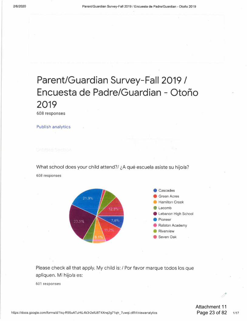
Attachment 11 Page 23 of 82
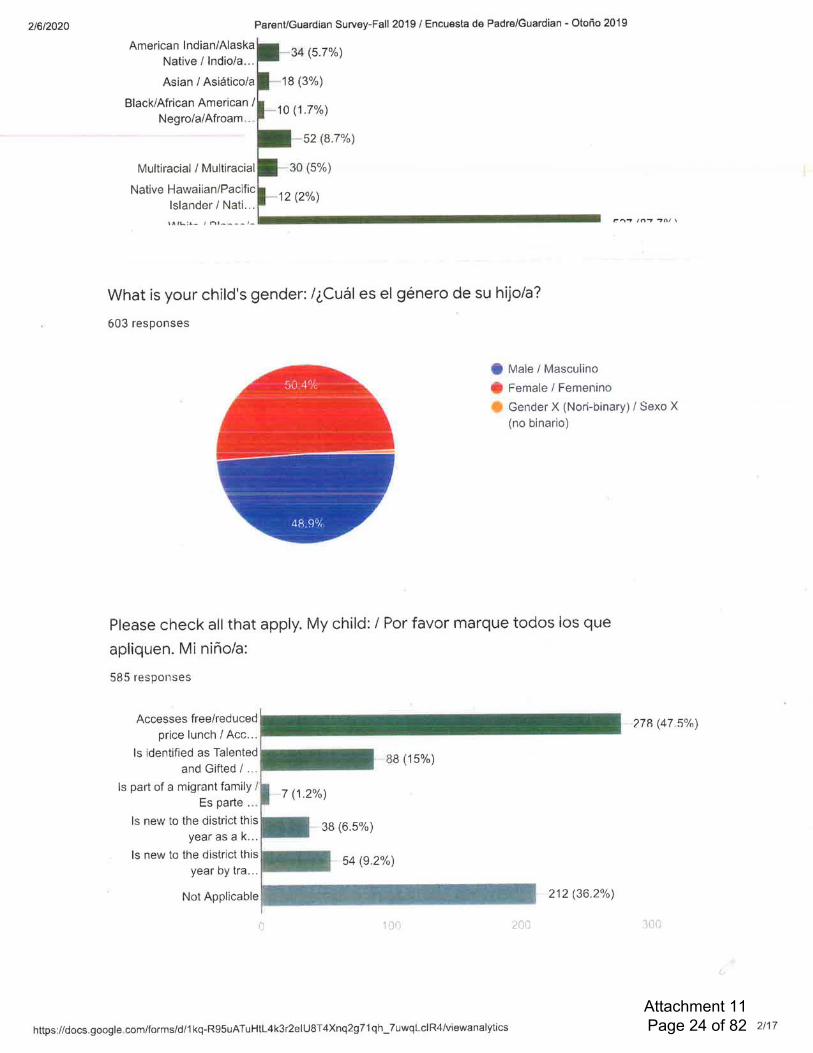
Attachment 11 Page 24 of 82

Attachment 11 Page 25 of 82
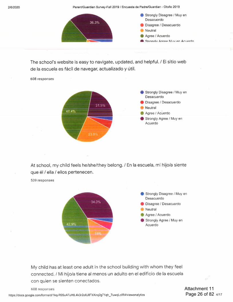
Attachment 11 Page 26 of 82
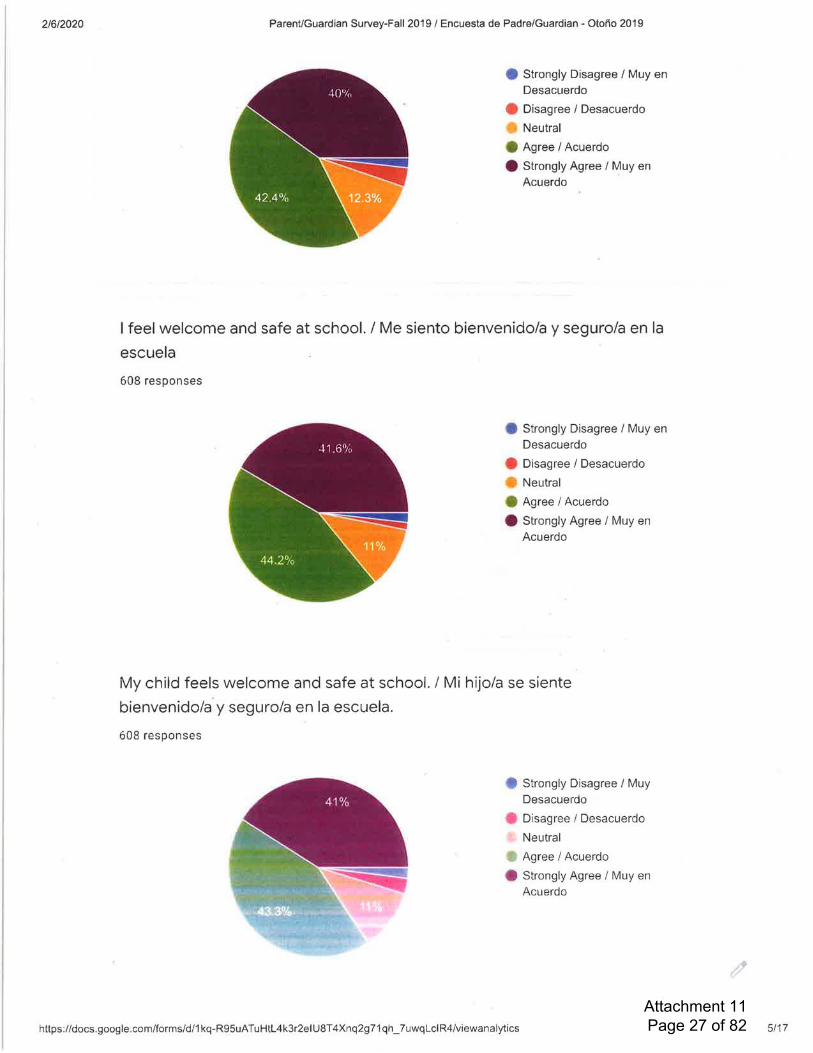
Attachment 11 Page 27 of 82

Attachment 11 Page 28 of 82

Attachment 11 Page 29 of 82

Attachment 11 Page 30 of 82

Attachment 11 Page 31 of 82
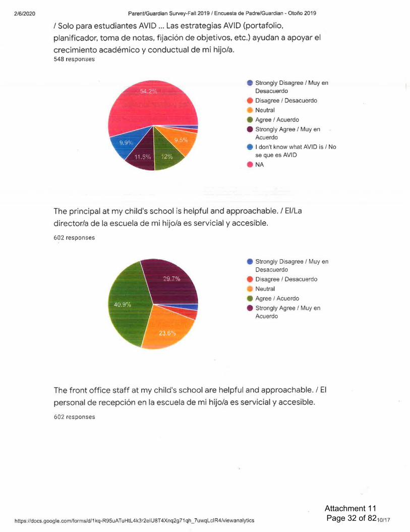
Attachment 11 Page 32 of 82

Attachment 11 Page 33 of 82
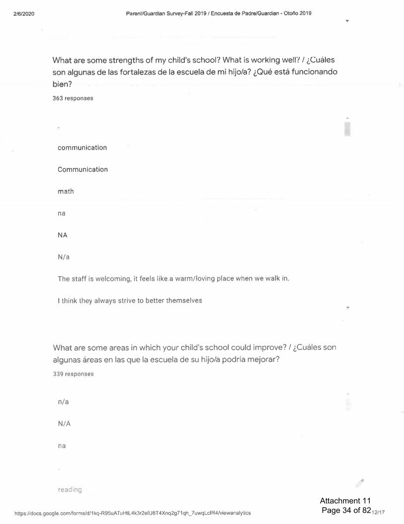
Attachment 11 Page 34 of 82
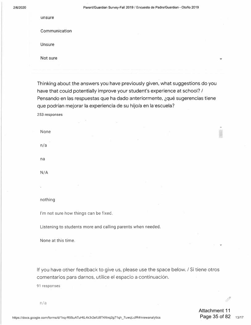
Attachment 11 Page 35 of 82

Attachment 11 Page 36 of 82
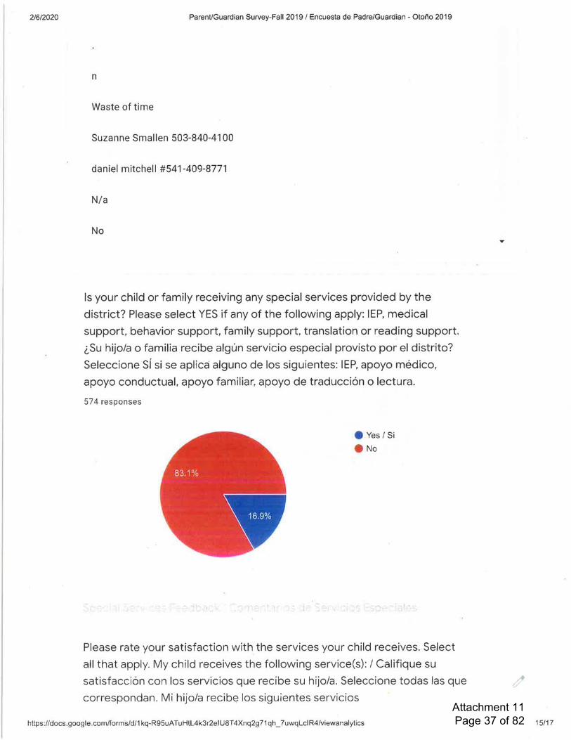
Attachment 11 Page 37 of 82

Attachment 11 Page 38 of 82

Attachment 11 Page 39 of 82
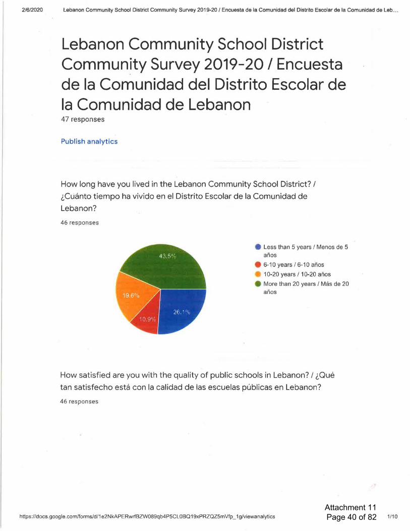
Attachment 11 Page 40 of 82
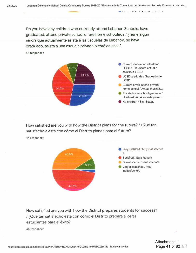
Attachment 11 Page 41 of 82
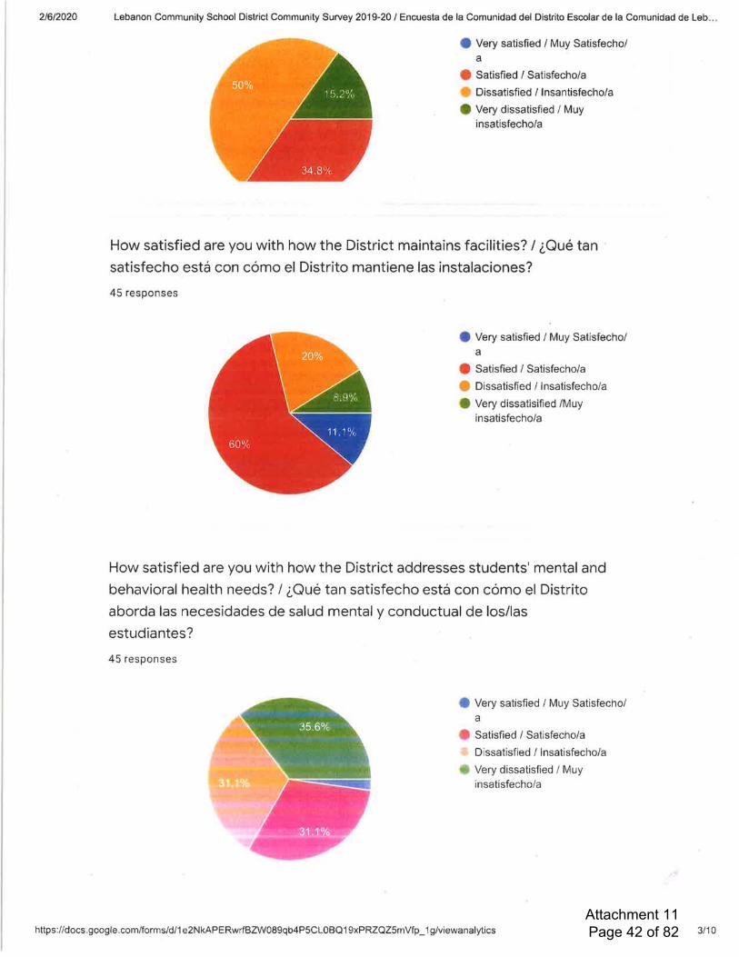
Attachment 11 Page 42 of 82
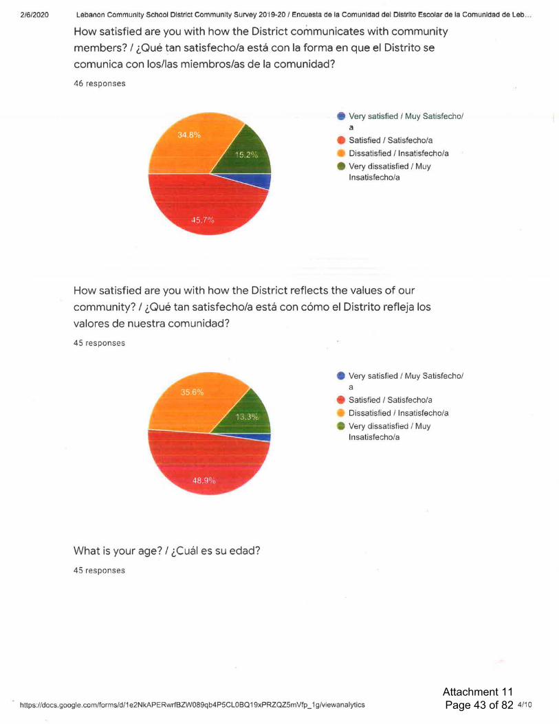
Attachment 11 Page 43 of 82
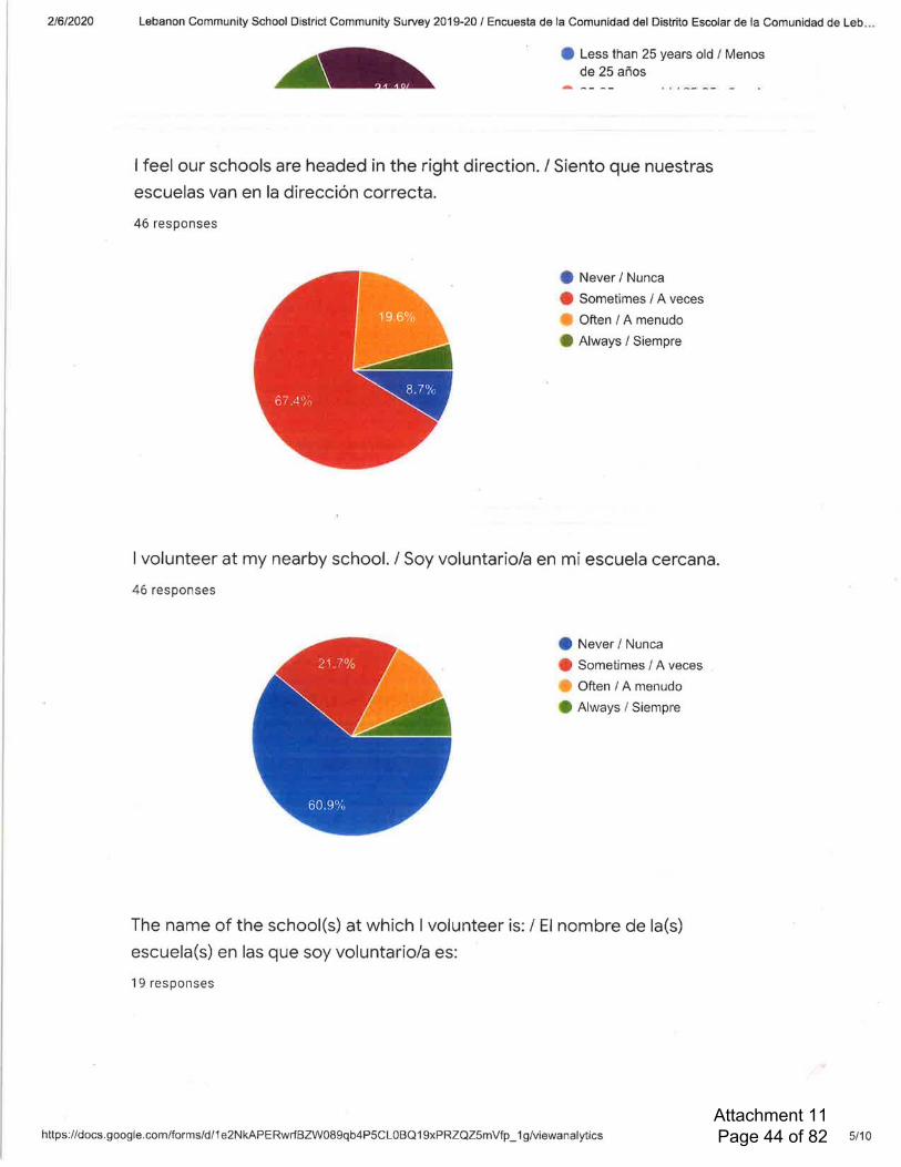
Attachment 11 Page 44 of 82
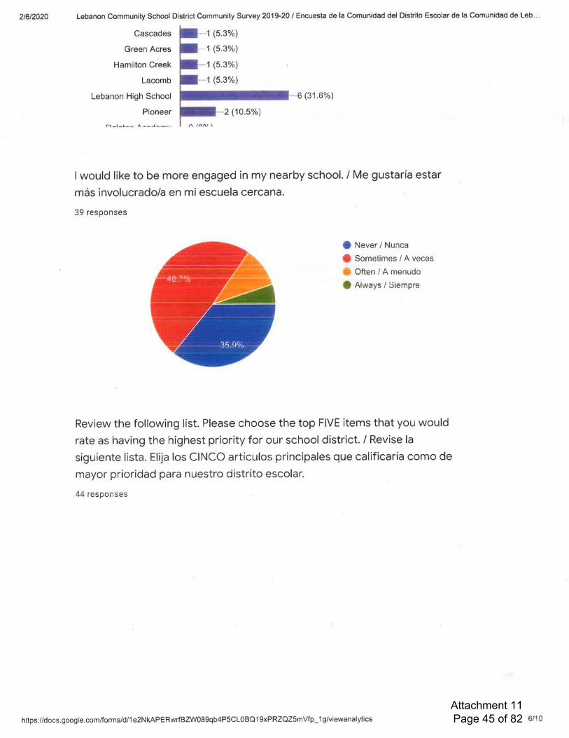
Attachment 11 Page 45 of 82

Attachment 11 Page 46 of 82

Attachment 11 Page 47 of 82

Attachment 11 Page 48 of 82

Attachment 11 Page 49 of 82

Attachment 11 Page 50 of 82
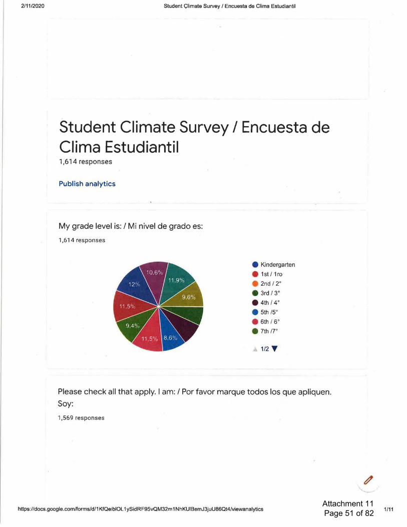
Attachment 11 Page 51 of 82
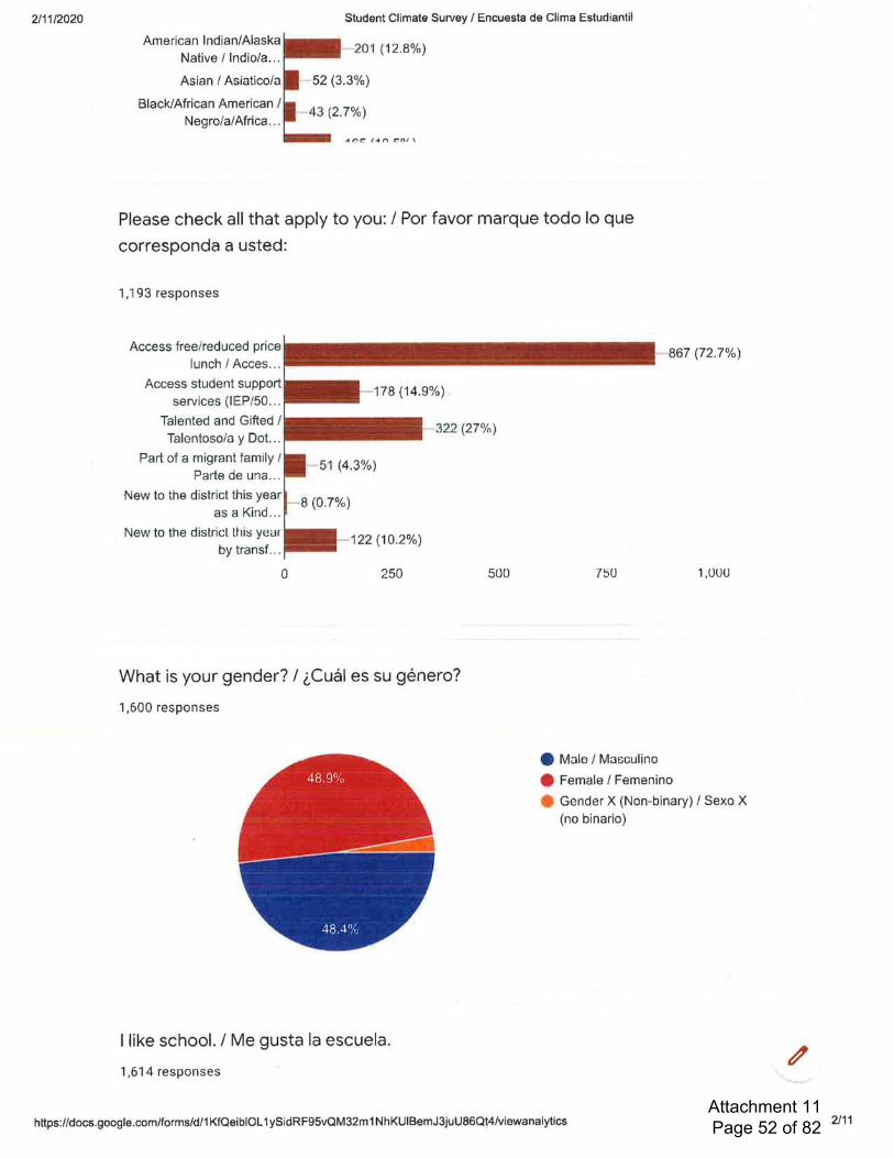
Attachment 11 Page 52 of 82
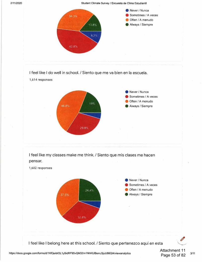
Attachment 11 Page 53 of 82

Attachment 11 Page 54 of 82
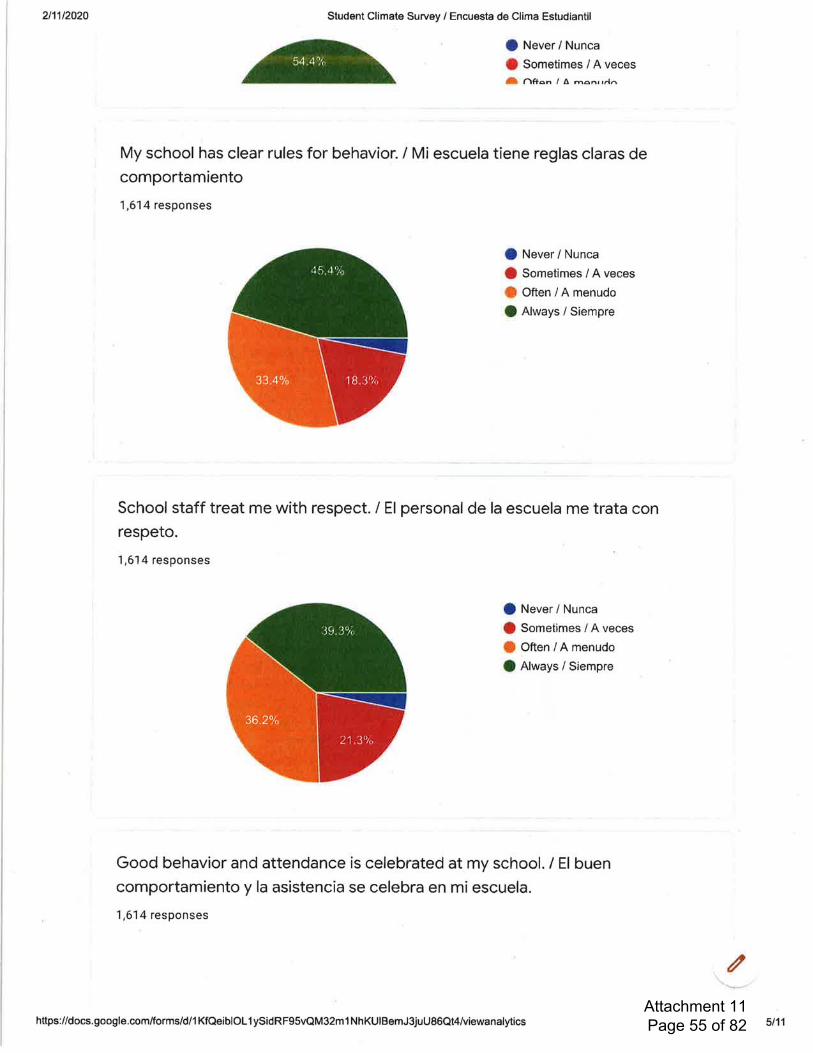
Attachment 11 Page 55 of 82

Attachment 11 Page 56 of 82
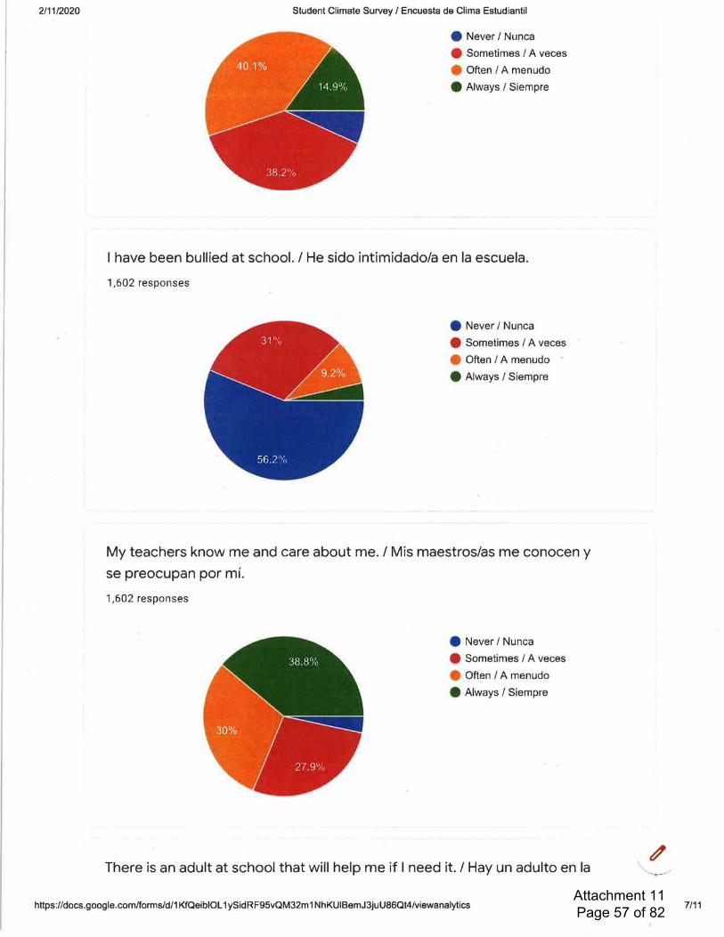
Attachment 11 Page 57 of 82
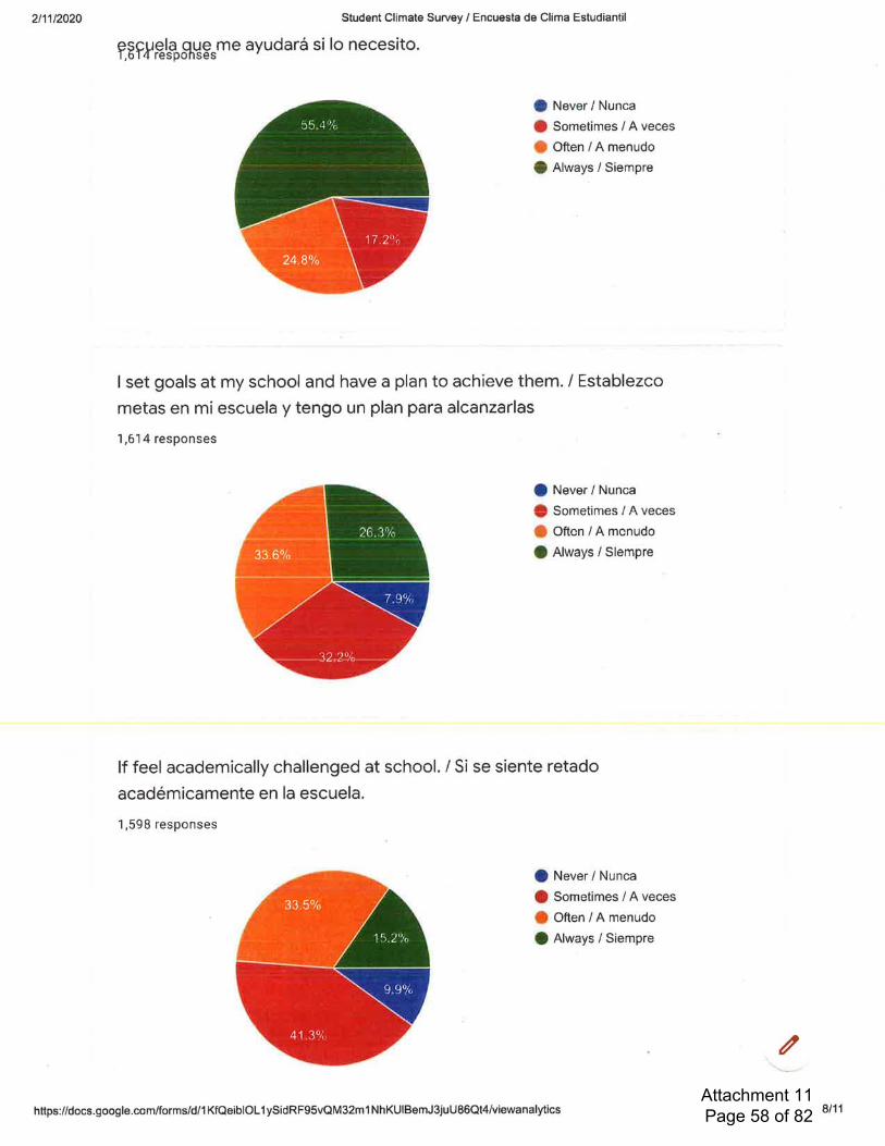
Attachment 11 Page 58 of 82
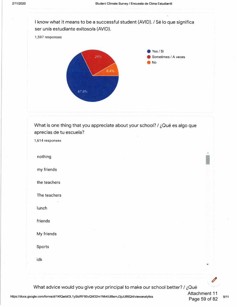
Attachment 11 Page 59 of 82
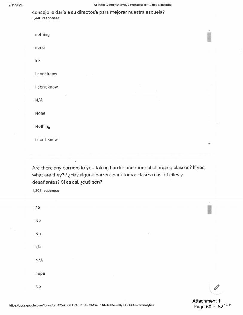
Attachment 11 Page 60 of 82

Attachment 11 Page 61 of 82

Attachment 11 Page 62 of 82
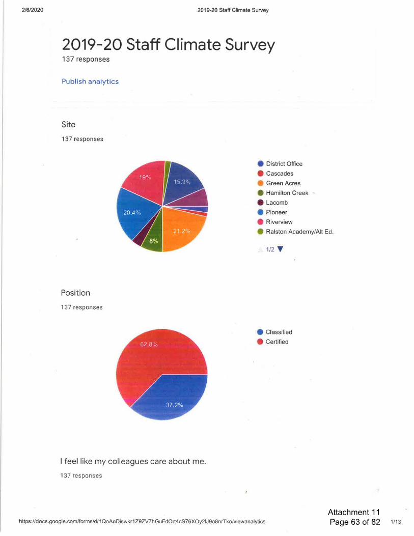
Attachment 11 Page 63 of 82

Attachment 11 Page 64 of 82

Attachment 11 Page 65 of 82

Attachment 11 Page 66 of 82

Attachment 11 Page 67 of 82

Attachment 11 Page 68 of 82

Attachment 11 Page 69 of 82
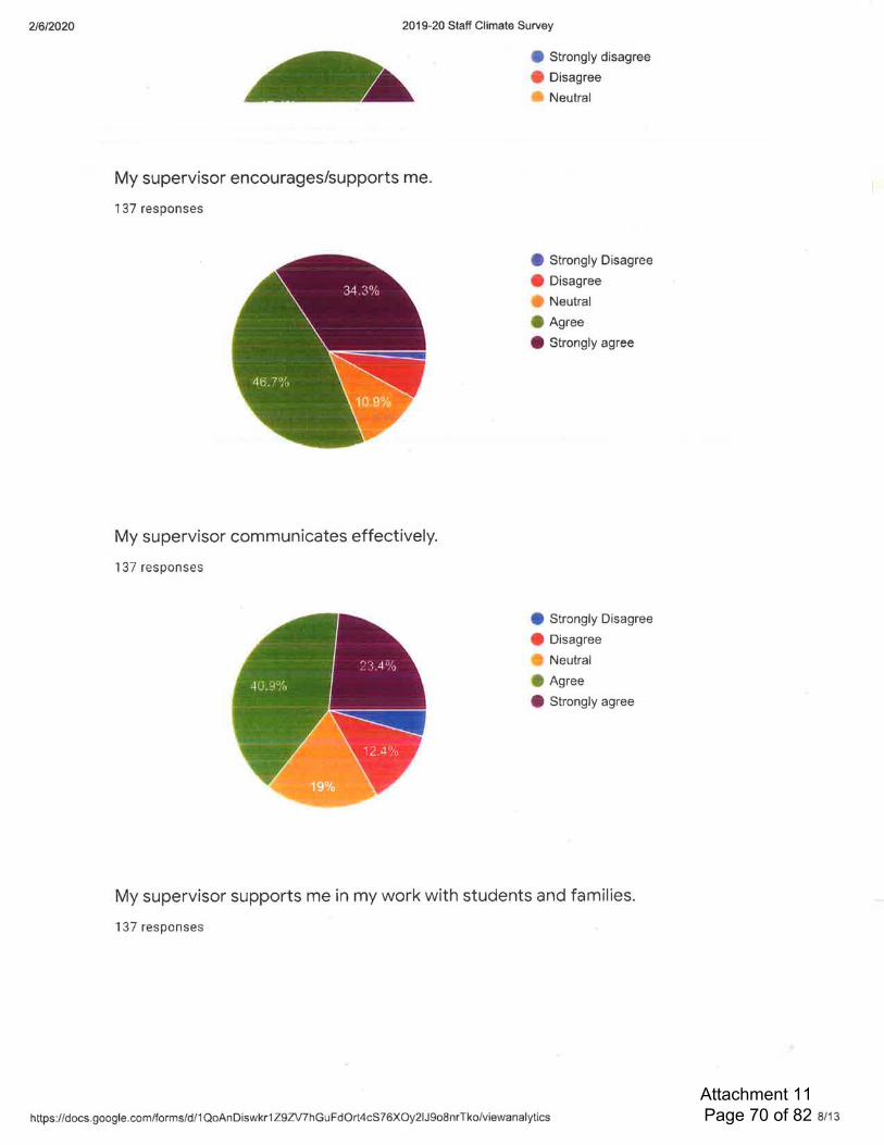
Attachment 11 Page 70 of 82

Attachment 11 Page 71 of 82

Attachment 11 Page 72 of 82

Attachment 11 Page 73 of 82

Attachment 11 Page 74 of 82
Attachment 11 Page 75 of 82

Attachment 11 Page 76 of 82
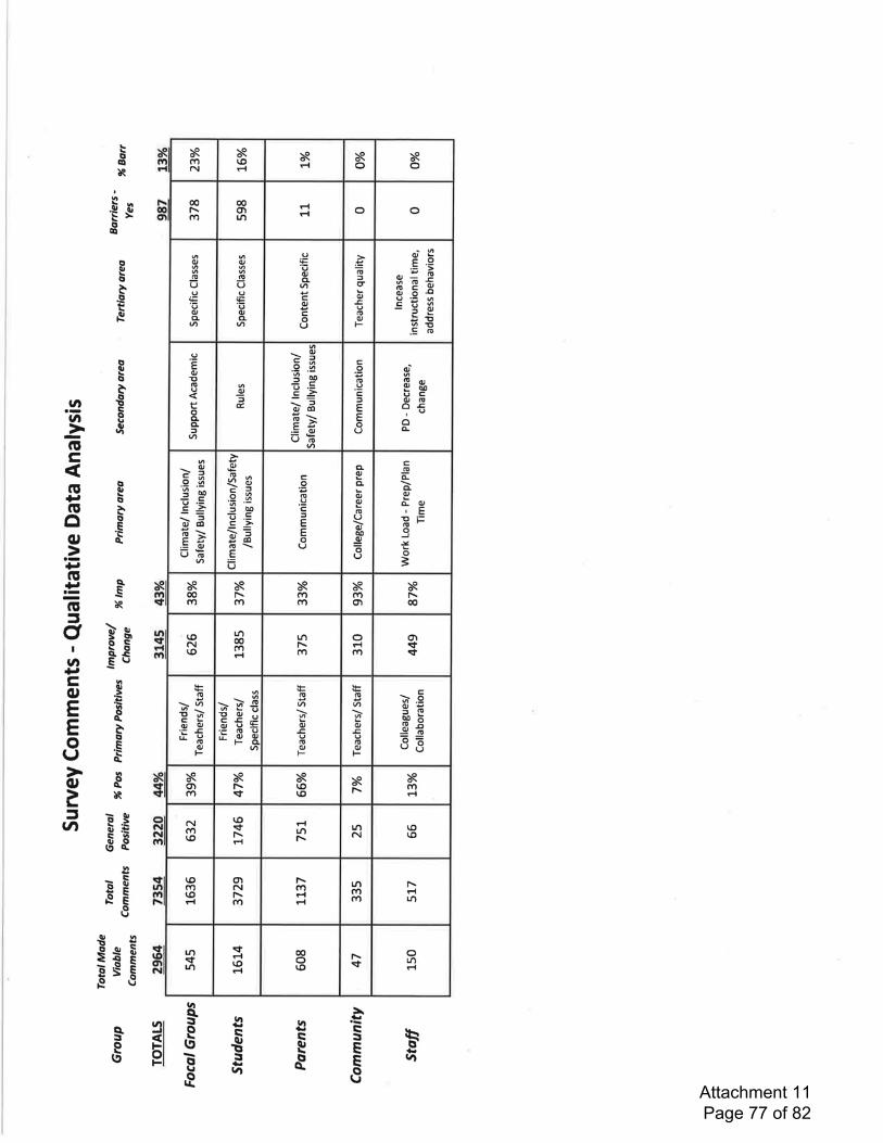
Attachment 11 Page 77 of 82
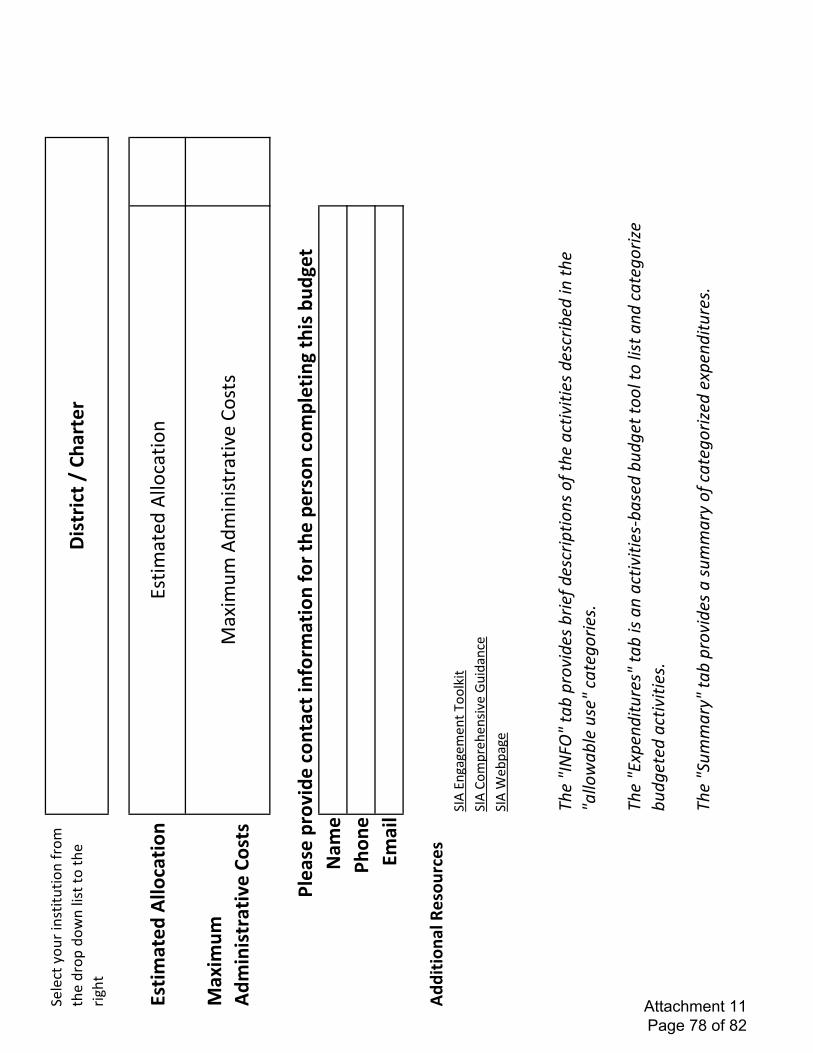
������������ ������������
��������������� ���������
���� �������������� ����!" ���#����$����#����
%�&��'�� ����!���(���)��*�� ��+#,����$����� �#��-�
�.� � /��� 01�!� ����� �������!���2���'( ��
�3$�"��#�������4���5�� �3$�.������� �-��6��#���
�3$�7�8�#�� 9:;�<=>?@<�ABC�DEFGHI;J�CEH;K�I;JLEHDAHFMJ�FK�A:;�BL
AHGHAH;J�I;JLEHC;I�HM�A:;�<BNNFOBCN;�PJ;<�LBA;QFEH;
JR9:;�<STD;MIHAPE;J<�ABC�HJ
�BM�BLAHGHAH;JUCBJ;I�CPIQ;A�AFFN�AF�NHJA�BMI�LBA;QFE
HV;�CPIQ;A;I�BLAHGHAH;JR 9:;�<WPXXBEY<�ABC�DEFGH
I;J�B�JPXXBEY�FK�LBA;QFEHV;I�;TD;MIHAPE;JRZ���(� ��[�*1�(��(
0������\(�)���� �!�� ���!]�(�����!�]�(��1��\�(��!
� ��\����!��1���_'���
Attachment 11 Page 78 of 82

��� ������������� ���������� ��������������������������������� ���!��������"��#�$����������������� �"��#����� ���%��&��#!������������������#"��"�����'(() *�+,��-�.*�- ,�+ ����/0���12345263789:;23:8<7=>6??43@32A38?7BC4D234238DE437F522G@32A38?7=H4F592G2AIF8GI9J47E?49E7E58E?I9I?IK4FG877EI?4674:D23877477?49E78:?I9I7E434:E27E6:49E7=LMN *�O,�P���Q �.�� R��/ STQ�U� �>2FI8G89:4?2EI298GG4839I9AVE386?8WI9D23?4:@38FEIF47B7E6:49E?49E8G89:C458JI238G548GE5=X�N Y�.�+���/�--Q�Z�[744JI:49F4WC874:F3IE43I8E24976348@@32@3I8E47E6:49EWE48F54338EI27237E8DDF874G28:7B\9F3487I9AE546742DI97E36FEI298G877I7E89E7=]X _�//Y���.�.�.�+� ���a4J4G2@?49E8GG<8@@32@3I8E489:F6GE638GG<347@297IJ4483G<GIE438F<@38FEIF4789:@32A38?7I9@34WbE5326A5E5I3:A38:4=c6GE638GG<347@297IJ4@32A38?789:@38FEIF47I9A38:47dWeVI9FG6:I9AG4839I9AVF26974GI9A89:7E6:49E76@@23EE58EI7F2994FE4:E2F2GG4A4789:F834437=f328:494:F633IF6G832@EI2978E8GGA38:4G4J4G7I9FG6:I9Agh3EV167IFVijV>Hj1VcHjV49A8AI9A4G4FEIJ47V8FF4G438E4:F2GG4A4F34:IE@32A38?7VI9FG6:I9A:68GF34:IEV\fVhiVkID4>lIGG7VHhmV:32@26E89:@34J49EI29@32A38?7V89:E3897IEI2976@@23E7=hFF477E2GIF4974:4:6F8E237nIE58GIC383<?4:I849:2374?49E=opq(r s.����- ,� �P�*�.�,�+ �- -
t�!�u�"�%"�� ����"�#������ ����� �v��!!�u������������#�"����������v�������"���!��������v�w������x����������������'
Attachment 11 Page 79 of 82

������������ ������������������� ���������������
��������� ������������������
��� ����!�������"������������������������ ������
���������������� ��������������
����#����� ������������������
$%�&� ������'��������������������� ����������������
����� �������������$('��
)����������������&� �� ����������������*���� ��$%+,
�-'������� ������������������
&������ ���������������� .��������/+�*�������������� ������ ��������� ���������
��������������0�����������"����������
���������$/'��1��2�����������������������
��&������ ��������������� �������������"����������
���������$,'�����+��������� ������
������������"������������������"�������%�3��+�
���������� ���
�4����567886888988�:;<=>?�@;A?BCBDE?BFG�HEIIE?BJ
>+�����K����������L
�M����#*#N1*O#O�OO��M�������������������������������������������������
��������������������������������������������������*000*0OO�OO�
�� ������������������������L
�M���������������������������������������������������������������������������������������
���������������#N*NN0�OO�!����"�����/����L
�M������#*NPO�OO�2��������� �����
QRQSSTUQVWXYZ[�\]�[_YXabX\
Y_�TXb_c\]_�WX]aXbd�e���������fghgggRgg�i��(
���������� ����j�����"����������������� ����������
�� ����*�����i����������������������
�����������������kRQbklmnoQQ
k [ZUX �pXbY�Sqc�r]_Y�_�Ybst�[_YXabX\Y_h�b
_�]_Y�uYX�aXbY�vYwYvx�e�������ylzhgggRgg�{�������)����� ��������
����������)��������� ��j�����"������ �������
�� ����������������������������� ������������������
����������� ��� ����������������������������
��� ��������������*�������� �����)������
"��������� ������"��#�� �����������������������������
�����������kRQ|lmnoQQ
k y\t Zz\t �pXbY�Sqc��e�������QgzhgggRgg�}��
���� ���������� ����������������� �������������
������������ �������������1���"����������
���������"���������~������������������ �����
�� ���������������������������������� ���*��� �����
�"������� ������~��kRQslmnoQQ
kouYsbv���sb\]_�\Xb_Y�Sqc
�e�������QgzhgggRgg������)����������������������"��
������)�2��������������������������
����������� ���������� ���
kRQQmnoQQQ �����q�TYbstYX
�e���������k�h�ggRgg�+�������������������"�� ��������� ���������O�0
�/+���i����� ������ ��� ������������������
����������"��"�����"�����������������������
������"��"��� ����������������������"����������
�� ������"�������������"������� ������ �
��������kRQYkmnoQQ
QouYsbv���sb\]_�TYbstYX�\Xb_Y�_���h����
\��b_�n�v\�Xbvv��mYcu]_cwY�TYbst_a�uXb
s\sYc�e�����������hgggRgg�����"������������������
���������������������������������������
�������������������� ������������������������
� ���������������*���� ��������������������
� ������������ ���� ���������������������������
�������������������������������� ���
kRkbQmnoQQk�_Y�|v_a�bv�Sq
�e���������k�h�ggRgg�������"���)�� ����"���� ���
��� ���������������������������������
���������"������������"�������"��"��� ���������
kRUbQQSSTQQQ[Zy�c�ddYX�cst]]v�
b_�YV\Y_Y�b��sYX\�Y�_c\X�s\]Xc
�e���������k�h�ggRgg�{������������ ������������
���������������������� �������""�*�"��
��� ����� ��������*� �� ������������������������
����������"kRU|QQSSTQQ
k[Zy�c�ddYX�cst]]v�b_�YV\Y_Y�b��Sqc
�e���������k�h�ggRgg�{�������)���������������� ��
������������������������������������������
��������"������������������������ �����
URQgR�SSTQQQqccYccdY_\�n]]X_
b\]X�\]�YwYv]u�b�uX]aXbd�b_�sbvY_bX�\tb\�
c\XYbdv_Yc�bccYccdY_\�b_�d_d�Yc�\tY��cY�]��_c\
X�s\]_bv�\dY��]X�\Yc\_aR
�e���������k�h�ggRgg�{����������������������"��
������ �����������������������
���������������������~�������������������� ������
���������������"�lRQ���oQQ
Q�X_a�]��T�oqc��t]�bXY�\Xb_Y�_�|Yc\ZuXbs\
sY�Y��\��uX]sYccYc�b_�uX]sY�XYc�\]��]X���
\t�c\�Y_\c��\t�|Ytbw]Xbv�cc�Yc�b_�\tYX�
�bdvYc�e�������kl�h�ggRgg�{��
������������������� ����� ���������������� ���
����������������������� �� ������������
������ ������������� ���������� ���� ����
��������� ������������������� �����������������
������������������
�D?BJB?��� ������F�E��>��A>��E?>=FI� ���>D?��F<>
Attachment 11 Page 80 of 82
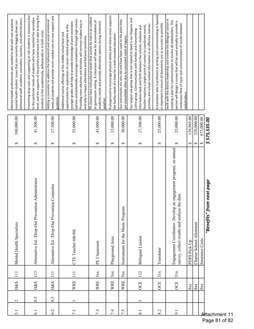
������������� ��� ������
�� ���������������������������
������������ !"�##$!���#�� �����%�%��!�%����&$����!
�'�(�%�)$(�)�������������#�*%�����$#
#*�#������� ��(* ����+�,!--$�-�%!&��!* �
,���.$! ���#��""/��(�%�)$(�(!*�#��! #/����(�� #/���
%��%)$�$#� ��! #01����������
23 �4���5�67��894:�;<=��>45��:�37?��
��4��:4�����������@���������A �.���$�-�% !�'!*�#���%
�#*��! �$�-���' $#B�#�*%���#�$#���(�##� +�%*��
�!������� �$(*�� ����%#�!"�#�*%���#�&�!���.�� ��(�
�%�����#�(!�%� +���.��/���%�����#*��! �#�!"
������ $)� +���.���&� ���!���,����!�, $�-�����
#�*%���#�$���$����(�%�)$(���+/�,���.$! ���+�! �$��,!
���� ��#01����������
�3 �4���5�67��894:�;<=��>45��:�C:=�
:4������������D��������E%%
$�-���(!*�#��! ��!��%% �##�����,���.$! �����%�#!($�
�'�)!�$!�������%#�!"�#�*%���#�&$���� !
.$%��)*(�����%�%�!��'!�'!���#*��! ����%�
-*$%��(�0D���FG6��
�CH6�H���4�1��;I��
���������������������E%%$�$!����(!* #��!""� $�-#��������)$%%���#(�!!����.
�����%�!��! �*�$�$�#�"! ��J��! �
�$!��!"�(� �� ' �����%�� !- �)#��������
+!*�-� �- �%�#�&$���������!�� !.$%��B�!&��%-��!"�
�!#�'#�(!�%� +�!��$!�#���%��!����$���+��
�(!* �-��(!)����$!���� !*-���$-�'#(�!!�0�
A !.$%$�-�)! �����(�$.�#���%��(�$.$�$�#�&$���$�( ��#
��#�*%����,*+'$����%�������!�$)��(�������%
��(����%�,���.$! ��!#$�$.��+0
D�2FG6�KK>6�C ���4::?
�����������@���������AL�(��##�#���.��$�#� *(�$!�������%#������(���!��,��
)���$�����!*�%!! �! �-+)��#$*)�#���$�-0�E�
(��## !!)�&$������!&�"! ��(!!)!%��$!��!"�
�(�%�)$(����%#���%�� !.$%������ ���$.��!��$!�#�%*
$�-�$�(��)����&����� 0
D�@FG6�KK> �MN4:=7�34�
���������������������E����+- !*�%��!���(!* �-���
�+#$(�����$.$�+���%� ��$�.��#� �##�#*��! �#�
����"�($�$�+����%#�!"���,�#��"! ���&���' !*�%�%��%*(
��$!�D��FG6�KK
O��4=?���P:4�����=����>4:N4�?
�����������2���������Q* �$�#� *)���#�� ��.� +�!�%�
��%���.��,����*#�%��!������!$������+�
� ��*��.�$��,���!"����%*���!�(!�#$#��������%�!"� ��
�$ #0I���<C6��
�R� �N=� �S����:������������D��������Q* ��� -�#��#*,'- !*�����
��$#��!�� �����%��!�T��%�$#�!* ��$#���$(���%�
U��$�J�- !*�0�V!))*�$(��$!��&$���"�)$�$�#���%�� �
�#)$��$�-�$�"! )��$!��,�(B���%�"!
���,��&��������#(�!!�#/�#�*%���#���%�
"�)$�$�#� �W*$ �#���#$�-��'�!$���!"�(!���(���!�(!! %
$������.���#/��(�$.$�$�#���%�#(�!!�' ����
�%�$�"! )��$!��$������""�(�$.��)���� 0�
I��<C62�KH4�� ��:4
���������������������E�� ��#���! �&�!�$#�� !"$($�����
��& $�$�-���%�(!))*�$(��$�-�$��T���$#��
$#�$)�! ������!���#* ������%!(*)���#�� ���#��((* �
����#��!##$,��0X��<C62�
K6N�N?��C::47���:4Y�95 :����N�N
?���4:N4�?�����=� ��=45M���: ���4�= ����7
��� MZ����7�������������������������&! B�&$�������%$#� $(�����
%� #�$����%�$�.!�.������[$�$�-*���U$�$#!��$��
( ���$�-��������"! �(!))*�$(��$!���!�$�.!�.������#�
�B��!�%� #0�\�$#��� #!��&$���%�#$-����#* .�
+������&$���,��*#�%����*���+��!�� !.$%����
(!��$�*!*#�"�!&�!"�$��*����%�(!))*�$(��$!��!"� �
#*��#�,��&����#��B��!�%� #0
IKK>6G��>��];�
����������2X�XX�����IKKC��4�4���
�:: �3 :�?���������������������
IKKO�=4���C:���
1D����������������_abacdef_�cghi�baje�klm
a�n�opoqorostt�
Attachment 11 Page 81 of 82
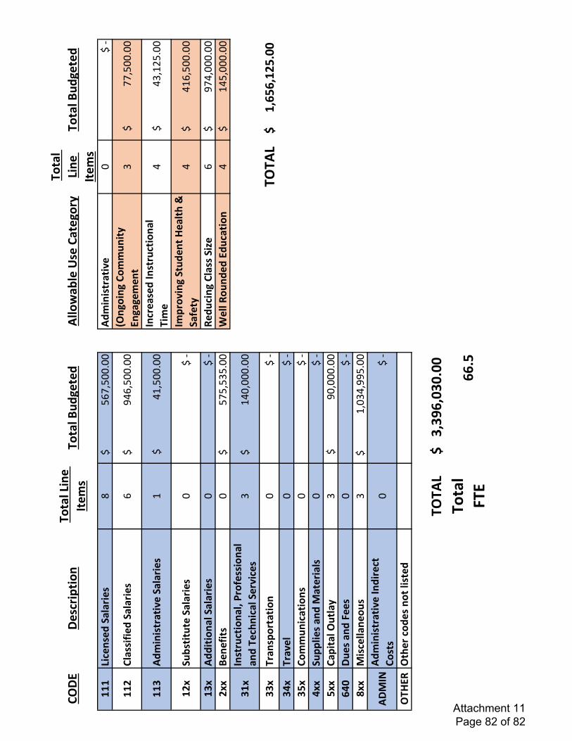
����������� ������� �� ���������������
�������������������������������� � �� �������
������������������ �����������
�!�����������������"#$%"&&'&&���� �����
(�&�!�)�
��*�����+����������#�!�����������������,-#%
"&&'&&�.� �� ������� ��� � ������ �
/�!���������������$$%"&&'&&�
��0��� �����(���������1
�!�������������������-1%"&&'&&�� ��������� ������� ��� ���
-�!���������������-/%12"'&&�
�*3�����������������&
!�)����( ������� ��4����5�6� ��+���
-�!�������������-1#%"&&'&&�
�03����� ����������&
!�)7���� ���������8�#
�!�������������,$-%&&&'&&�*33�� �+��
&�!�����������������"$"%"/"'&&�9����7�� �
���������� -�!�������������1-"%&&&'&&�
0�3� ������� ��:�;��+���� ��� � �����5 �������(���
/�!�����������������1-&%&&&'&&�
003��� ������� &
!�)������<������:=>=:�*>?@@�
0A3���(��&
!�)0>3����� ���� �
&!�)
A33������� ��B�������&
!�)>33������������
/�!�������������������,&%&&&'&&�
=A@������ ��C���&
!�)D33B������ ����
/�!��������������1%&/-%,,"'&&�
��B�E��� �����(��� ������ �����
&!�)
��4�7��5��������� �������� ������<���0:0F=:@0@?@
@� ������ C��==?>Attachment 11 Page 82 of 82