DCS 2017 BP24 High School Chiller Submittal
48
Submittal Documents For: Dexter High School YorkYK Water Cooled Chiller (1 x 670-Ton) Prepared For: Granger and Dexter School District Prepared By: Jim Kavanaugh –Account Executive 2875 High Meadow Circle Auburn Hills, MI 48326 (248) 276-6000 – main Submitted For: Approval Date: October 21, 2019
-
Upload
khangminh22 -
Category
Documents
-
view
1 -
download
0
Transcript of DCS 2017 BP24 High School Chiller Submittal

Submittal Documents For:
Dexter High School
YorkYK Water Cooled Chiller (1 x 670-Ton)
Prepared For: Granger and Dexter School District
Prepared By: Jim Kavanaugh –Account Executive
2875 High Meadow Circle Auburn Hills, MI 48326 (248) 276-6000 – main
Submitted For: Approval Date: October 21, 2019
smrak
Rectangle
smrak
Text Box
NOTE MARKINGS
smrak
Text Box
NOTE MARKINGS RESUBMIT
smrak
Text Box
ELEC BY
smrak
Line
smrak
Text Box
DATE
smrak
Line
smrak
Text Box
MECH BY
smrak
Text Box
DATE
smrak
Text Box
smrak
Text Box
smrak
Text Box
smrak
Text Box
smrak
Text Box
NOTE MARKINGS PARTIAL RESUBMIT
smrak
Text Box
T.C. BY
smrak
Text Box
DATE
smrak
Line
smrak
Line
smrak
Line
smrak
Line
smrak
Text Box
WJU
smrak
Text Box
NO EXCEPTIONS TAKEN
smrak
Text Box
X
smrak
Text Box
REJECT
smrak
Text Box
SVM
smrak
Text Box
STP
smrak
Image
smrak
Text Box
PETER BASSO ASSOCIATES, INC. This review is only for general conformance with the design concept and the information given in the Construction Documents. Notations or comments made on the shop drawings during this review do not relieve the contractor from compliance with the requirements of the plans and specifications and applicable laws, codes and regulations. Review of a specific item shall not include review of an assembly of which the item is a component. The Contractor is responsible for: dimensions to be confirmed and correlated at the job site; information that pertains solely to the fabrication processes or to the means, methods, techniques, sequences and procedures of construction; coordination of the Work with that of all other trades and performing all Work in a safe and satisfactory manner.
smrak
Text Box
10-22-19
smrak
Text Box
10-22-19
smrak
Text Box
10-22-19

Submittal Documents For:
Dexter High School
Table of Contents
Section #1 – General Notes
Section #2 – YK Chiller Specification Section #3 – YK Drawings and Performance Section #4 – Chiller Rigging and Installation
Section #5 – Electrical Information
10/21/2019BZ
1710-00

Submittal Documents For:
Dexter High School
Section #1 – General Notes
_____________________________________________________________________________________
2875 High Meadow Circle, Auburn Hills, MI 48326 Telephone (248) 276-6000 Fax (248) 276-6001
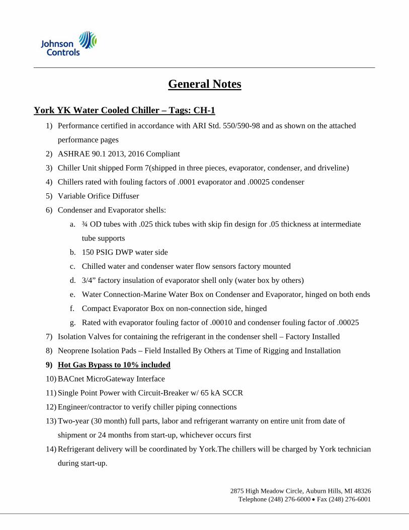
General Notes
York YK Water Cooled Chiller – Tags: CH-1
1) Performance certified in accordance with ARI Std. 550/590-98 and as shown on the attached
performance pages
2) ASHRAE 90.1 2013, 2016 Compliant
3) Chiller Unit shipped Form 7(shipped in three pieces, evaporator, condenser, and driveline)
4) Chillers rated with fouling factors of .0001 evaporator and .00025 condenser
5) Variable Orifice Diffuser
6) Condenser and Evaporator shells:
a. ¾ OD tubes with .025 thick tubes with skip fin design for .05 thickness at intermediate
tube supports
b. 150 PSIG DWP water side
c. Chilled water and condenser water flow sensors factory mounted
d. 3/4” factory insulation of evaporator shell only (water box by others)
e. Water Connection-Marine Water Box on Condenser and Evaporator, hinged on both ends
f. Compact Evaporator Box on non-connection side, hinged
g. Rated with evaporator fouling factor of .00010 and condenser fouling factor of .00025
7) Isolation Valves for containing the refrigerant in the condenser shell – Factory Installed
8) Neoprene Isolation Pads – Field Installed By Others at Time of Rigging and Installation
9) Hot Gas Bypass to 10% included
10) BACnet MicroGateway Interface
11) Single Point Power with Circuit-Breaker w/ 65 kA SCCR
12) Engineer/contractor to verify chiller piping connections
13) Two-year (30 month) full parts, labor and refrigerant warranty on entire unit from date of
shipment or 24 months from start-up, whichever occurs first
14) Refrigerant delivery will be coordinated by York.The chillers will be charged by York technician
during start-up.

Submittal Documents For:
Dexter High School
Section #2 – YK Chiller Specification

YK MAXE CHILLERPBA-Dexter High School
GENERAL
Furnish YORK MaxE Centrifugal Liquid Chilling-Unit(s) as indicated on the drawings.
Each unit shall produce a capacity of 670.0 tons, cooling 1603 gpm of WATER from 55.00 to 45.00 °F when suppliedwith 1999 gpm of condenser water at 85.00°F. Power input shall not exceed 372.2 KW with an NPLV of 0.3507. Thecooler shall be selected for 0.000100 fouling factor and a maximum liquid pressure drop of 16.9 ft H2O. Water side shallbe designed for 150 psig working pressure. The condenser shall be selected for 0.000250 fouling factor and maximumliquid pressure drop of 20.9 ft H2O. Water side shall be designed for 150 psig working pressure. Power shall besupplied to the compressor motor at 460 volts – 3 phase - 60 Hertz and controls at 115 volts – 1-phase - 60 Hertz. Thechiller shall use R-134a.
Each unit will be completely factory-packaged including evaporator, unit mounted starter, condenser, sub-cooler,compressor, open motor, lubrication system, Optiview control center, and all interconnecting unit piping and wiring. Thechiller will be painted prior to shipment.
Ratings outside the scope of AHRI Standard 550/590. Only chillers that are listed in the AHRI Certification Program forCentrifugal and Rotary Screw Water Chillers are acceptable.
The initial charge of refrigerant and oil will be supplied, shipped in containers and cylinders for field installation or factorycharged in the chiller.
COMPRESSOR
The compressor will be a single-stage centrifugal type powered by an open-drive electric motor. The housing will be fullyaccessible with vertical circular joints, with the complete operating assembly removable from the compressor and scrollhousing. Compressor castings will be designed for 235 psig working pressure and hydrostatically pressure tested at 355psig for R-134a units. The rotor assembly will consist of a heat-treated alloy steel drive shaft and impeller shaft with acast aluminum, fully shrouded impeller. The impeller will be designed for balanced thrust, dynamically balanced andoverspeed tested for smooth, vibration-free operation. Insert-type journal and thrust bearings will be fabricated ofaluminum alloy, precision bored and axially grooved.
Internal single helical gears with crowned teeth will be designed so that more than one tooth is in contact at all times toprovide even load distribution and quiet operation. Each gear will be individually mounted in its own journal and thrustbearings to isolate it from impeller and motor forces. Shaft seal shall be provided in double bellows, double-seal,cartridge type. A gravity-fed oil reservoir will be built into the top of the compressor to provide lubrication duringcoastdown in the event of a power failure.
Capacity control will be achieved by use of prerotation vanes to provide fully modulating control from maximum tominimum load. The unit will be capable of operating with lower temperature cooling tower water during part-loadoperation in accordance with AHRI Standard 550/590. Prerotation vane position will be automatically controlled by anexternal electric actuator to maintain constant leaving chilled water temperature.
LUBRICATION SYSTEM
Lubrication oil shall be force-fed to all compressor bearings, gears, and rotating surfaces by an external variable speedoil pump. The oil pump shall vary oil flow to the compressor based on operating and stand-by conditions, ensuringadequate lubrication at all times. The oil pump shall operate prior to start-up, during compressor operation and duringcoastdown. Compressor shall have an auxiliary reservoir to provide lubrication during coastdown in the event of a powerfailure.
An oil reservoir, separate from the compressor, shall contain the submersible 2 HP oil pump and a 3000 watt oil heater,thermostatically controlled to remove refrigerant from the oil. The oil reservoir shall be designed in accordance withapplicable pressure vessel code and listed as part of the chiller by a nationally recognized testing laboratory.
Oil shall be filtered by an externally mounted ½ micron replaceable cartridge oil filter equipped with service valves. Oilcooling shall be done via a refrigerant cooled oil cooler, with all piping factory installed. Oil side of the oil cooler shall be
Printed: 10/21/2019 at 8:10 Reference: 160.76-EG1Filename: spechdr.rtf Page 1 of 8

YK MAXE CHILLERPBA-Dexter High School
provided with service valves. An automatic oil return system to recover any oil that may have migrated to the evaporatorshall be provided. Oil piping shall be completely factory installed and tested.
MOTOR DRIVELINE
The compressor motor will be an open drip-proof, squirrel cage, induction type operating at 3570 RPM.
The open motor shall be provided with a D-flange, bolted to a cast iron adapter mounted on the compressor to allow themotor to be rigidly coupled to the compressor to provide factory alignment of motor and compressor shafts.
Motor drive shaft will be directly connected to the compressor shaft with a flexible disc coupling. Coupling will have allmetal construction with no wearing parts to assure long life, and no lubrication requirements to provide low maintenance.
For units utilizing remote electro-mechanical starters, a large steel terminal box with gasketed front access cover will beprovided for field connected conduit. Overload/overcurrent transformers will be furnished with all units. (For units fur-nished with factory packaged Solid State Starters, refer to the options section.)
EVAPORATOR
Evaporator will be of the shell-and-tube, flooded type designed for 235 psig working pressure on the refrigerant side.Shell will be fabricated from rolled carbon steel plate with fusion welded seams; have carbon steel tube sheets, drilledand reamed to accommodate the tubes; and intermediate tube supports spaced no more than four feet apart. Therefrigerant side will be designed, tested and stamped in accordance with ASME Boiler and Pressure Vessel Code,Section VIII- Division 1 . Tubes shall be high-efficiency, internally and externally enhanced type having plain copperlands at all intermediate tube supports to provide maximum tube wall thickness at the support area. Each tube will beroller expanded into the tube sheets providing a leak-proof seal, and be individually replaceable. Water velocity throughthe tubes will not exceed 12 fps. Two liquid level sight glasses will be located on the side of the shell to aid indetermining proper refrigerant charge. Suction baffles will be located above the tube bundle to prevent liquid refrigerantcarryover to the compressor. The evaporator will have a refrigerant relief device sized to meet the requirements ofASHRAE 15 Safety Code for Mechanical Refrigeration.
Water boxes and cover plates will be removable to permit tube cleaning and replacement. Stubout water connectionshaving victaulic grooves will be provided. Vent and drain connections with plugs will be provided on each water box.
CONDENSER
Condenser will be of the shell-and-tube type, designed for 235 psig working pressure on the refrigerant side. Shell willbe fabricated from rolled carbon steel plate with fusion welded seams; have carbon steel tube sheets, drilled and reamedto accommodate the tubes; and intermediate tube supports spaced no more than four feet apart. The refrigerant side willbe designed, tested and stamped in accordance with ASME Boiler and Pressure Vessel Code, Section VIII- Division 1.Tubes shall be high-efficiency, internally and externally enhanced type having plain copper lands at all intermediate tubesupports to provide maximum tube wall thickness at the support area. Each tube will be roller expanded into the tubesheets providing a leak-proof seal, and be individually replaceable. Water velocity through the tubes will not exceed 12fps.
Water boxes and cover plates will be removable to permit tube cleaning and replacement. Stubout water connectionshaving victaulic grooves will be provided. Vent and drain connections with plugs will be provided on each water box.
REFRIGERANT FLOW CONTROL
Refrigerant flow to the evaporator will be controlled by a variable orifice for improving unloading capabilities.
GRAPHIC CONTROL CENTER
General: The chiller shall be controlled by a stand-alone microprocessor based control center. The chiller controlpanel shall provide control of chiller operation and monitoring of chiller sensors, actuators, relays and switches.
Printed: 10/21/2019 at 8:10 Reference: 160.76-EG1Filename: spechdr.rtf Page 2 of 8

YK MAXE CHILLERPBA-Dexter High School
Control panel: The control panel shall include a 10.4 in. diagonal color liquid crystal display (LCD) surrounded by“soft” keys which are redefined based on the screen displayed at that time. This shall be mounted in the middle of akeypad interface and installed in a locked enclosure. The screen shall detail all operations and parameters, using agraphical representation of the chiller and its major components. Panel verbiage shall be available in other languagesas an option with English always available. Data shall be displayed in either English or Metric units. Smart FreezePoint Protection shall run the chiller at 36.00°F leaving chilled water temperature, and not have nuisance trips on lowwater temperature. The sophisticated program and sensor shall monitor the chiller water temperature to preventfreeze up. When needed Hot Gas Bypass is available as an option. The panel shall display countdown timermessages so the operator knows when functions are starting and stopping. Every programmable point shall have apop-up screen with the allowable ranges, so that the chiller can not be programmed to operate outside of its designlimits.
The chiller control panel shall also provide:
1. System operating information including: a. return and leaving chilled water temperature b. return and leaving condenser water temperature c. evaporator and condenser saturation temperature d. differential oil pressure e. percent motor current f. evaporator and condenser pressure g. compressor discharge temperature h. oil reservoir temperature i. compressor thrust bearing positioning and oil temperature j. operating hours k. number of compressor starts
2. Digital programming of setpoints through the universal keypad including:a. leaving chilled water temperatureb. percent current limitc. pull-down demand limitingd. six-week schedule for starting and stopping the chiller, pumps and towere. remote reset temperature range
3. Status messages indicating:a. system ready to startb. system runningc. system coastdownd. system safety shutdown-manual restarte. system cycling shutdown-auto restartf. system prelubeg. start inhibit
4. The text displayed within the system status and system details field shall be displayed as a color coded message to indicate severity: red for safety fault, orange for cycling faults, yellow for warnings, and green for normal messages.
5. Safety shutdowns enunciated through the display and the status bar, and consist of system status, system details, day, time, cause of shutdown, and type of restart required. Safety shutdowns with a fixed speed drive shall include:
a. evaporator – low pressure
Printed: 10/21/2019 at 8:10 Reference: 160.76-EG1Filename: spechdr.rtf Page 3 of 8

YK MAXE CHILLERPBA-Dexter High School
b. evaporator – transducer or leaving liquid probec. evaporator – transducer or temperature sensord. condenser – high pressure contacts opene. condenser – high pressuref. condenser – pressure transducer out of rangeg. auxiliary safety – contacts closedh. discharge – high temperaturei. discharge – low temperaturej. oil – high temperaturek. oil – low differential pressurel. oil – high differential pressurem. oil – sump pressure transducer out of rangen. oil – differential pressure calibrationo. oil – variable speed pump – pressure setpoint not achievedp. control panel – power failureq. motor or starter – current imbalancer. thrust bearing – proximity probe clearances. thrust bearing - proximity probe out – of – ranget. thrust bearing – high oil temperatureu. thrust bearing – oil temperature sensorv. watchdog – software reboot
5.1 Safety shutdowns with a VSD Shall include:a. VSD shutdown – requesting fault datab. VSD – stop contacts openc. VSD – 105% motor current overloadd. VSD – high phase A, B,C inverter heatsink temp.e. VSD – high converter heatsink temperature
(Filter Option Only)h. harmonic filter – high heatsink temperatureg. harmonic filter – high total demand distribution
6. Cycling shutdowns enunciated through the display and the status bar, and consists of system status, system details, day, time, cause of shutdown, and type of restart required. Cycling shutdowns with a fixed speed drive shall include:
a. multiunit cycling – contacts openb. system cycling - contacts openc. oil - low temperature differentiald. oil – low temperaturee. control panel - power failuref. leaving chilled liquid - low temperatureg. leaving chilled liquid - flow switch openh. motor controller – contacts openi. motor controller – loss of currentj. power faultk. control panel - schedulel. starter – low supply line voltagem. starter – high supply line voltagen. proximity probe – low supply voltageo. oil - variable speed pump - drive contacts open
Printed: 10/21/2019 at 8:10 Reference: 160.76-EG1Filename: spechdr.rtf Page 4 of 8

YK MAXE CHILLERPBA-Dexter High School
6.1 Cycling shutdowns with a VSD shall include:a. VSD shutdown – requesting fault datab. VSD – stop contacts openc. VSD initialization failedd. VSD - high phase A,B,C instantaneous currente. VSD – phase A,B,C gate driverf. VSD – single phase input powerg. VSD – high DC bus voltageh. VSD – pre charge DC bus voltage imbalancei. VSD – high internal ambient temperaturej. VSD – invalid current scale selectionk. VSD – low phase A, B, C inverter heatsink temp.l. VSD – low converter heatsink temperaturem. VSD – pre-charge - low DC bus voltagen. VSD – logic board processoro. VSD – run signalp. VSD – serial communications
(Filter Option Only)q. harmonic filter – logic board or communicationsr. harmonic filter – high DC bus voltages. harmonic filter – high phase A, B, C currentt. harmonic filter – phase locked loopu. harmonic filter – precharge – low DC bus voltagev. harmonic filter – DC bus voltage imbalancew. harmonic filter – 110% input current overloadx. harmonic filter – logic board power supplyy. harmonic filter – run signalz. harmonic filter – DC current transformer 1aa. harmonic filter – DC current transformer 2
7. Security access to prevent unauthorized change of setpoints, to allow local or remote control of the chiller, and to allow manual operation of the prerotation vanes and oil pump. Access shall be through ID and password recognition, which is defined by three different levels of user competence: view, operator, and service.
8. Trending data with the ability to customize points of once every second to once every hour. The panel shall trend up to 6 different parameters from a list of over 140, without the need of an external monitoring system.
9. The operating program stored in non-volatile memory (EPROM) to eliminate reprogramming the chiller due to AC power failure or battery discharge. Programmed setpoints shall be retained in lithium battery-backed RTC memory for a minimum of 11 years with power removed from the system.
10. A fused connection through a transformer in the compressor motor starter to provide individual over- current protected power for all controls.
11. A numbered terminal strip for all required field interlock wiring.
12. An RS-232 port to output all system operating data, shutdown / cycling message, and a record of the last 10 cycling or safety shutdowns to a field-supplied printer. Data logs to a printer at a set programmable interval. This data can be preprogrammed to print from 1minute to 1day.
Printed: 10/21/2019 at 8:10 Reference: 160.76-EG1Filename: spechdr.rtf Page 5 of 8

YK MAXE CHILLERPBA-Dexter High School
13. The capability to interface with a building automation system to provide:a. remote chiller start and stopb. remote leaving chiller liquid temperature adjustc. remote current limit setpoint adjustd. remote ready to start contactse. safety shutdown contactsf. cycling shutdown contactsg. run contacts
STARTUP AND OPERATOR TRAINING
The services of a factory trained, field service representative will be provided to supervise the final leak testing, chargingand the initial startup and conduct concurrent operator instruction.
FACTORY INSULATION
Factory-applied, anti-sweat insulation will be attached to the cooler shell, flow chamber, tube sheets, suctionconnection, and (as necessary) to the auxiliary tubing. The insulation will be a flexible, closed-cell plastic type, 3/4inch thick, applied with vapor-proof cement. The insulation will normally prevent sweating in environments withrelative humidities up to 75% and dry bulb temperatures ranging from 50 to 90 °F.
EXTERNAL ENERGY EFFICIENT HOT GAS BY-PASS SYSTEM
The hot gas by-pass system will be supplied for operation down to 10% of design load. The hot gas bypass systemshall be completely factory piped and wired. It will consist of a hot gas valve, external electric (115V – 1 Ph –60/50Hz) operator and linkage, and a solid state sensing control. This control will measure entering and leaving chilledwater temperature to indicate load and measure refrigerant condensing temperature to indicate head. These signalsshall be compared to a reference point (adjustable) to activate the hot gas valve. Hot gas will be actuated only whennecessary and in only the amount required for stable and efficient chiller operation.
ISOLATION MOUNTING
Included with the unit are 4 vibration isolation mounts, consisting of 1" thick neoprene isolation pads, for fieldmounting. The pads are to be mounted under the steel mounting pads on the tube sheets. Suitable for ground floorinstallation.
SHIPMENT FORM #7Prior to shipment from the factory the unit will be assembled, refrigerant piped, wired, leak tested and air run testedthen dismantled for shipment. The compressor (including suction line)/open motor assembly will be removed from theshell and skidded. The evaporator/condenser shell (including heat recovery condenser if ordered) will be separatedat the tube sheets and shipped as two pieces. The shells are not skidded unless the option for skids is ordered. Theshells are not designed for vertical rigging. The evaporator shell is not insulated at the factory to avoid damage. Theinsulation of the evaporator shell should be done at the job site. Refrigerant lines between shells are flanged andcapped; tube sheets are also bolted, requiring no welding. All openings on the compressor and shells will be closedand charged with dry nitrogen (2 to 3 psig).
The remaining material will be shipped as follows:
Control panel – one box
All wiring harnesses, except that which is integral to the compressor, will be removed from shell – one box
Printed: 10/21/2019 at 8:10 Reference: 160.76-EG1Filename: spechdr.rtf Page 6 of 8

YK MAXE CHILLERPBA-Dexter High School
All small tubing will be removed from shells – one boxAll fittings, controls, oil, nuts & bolts and miscellaneous material – one boxThe refrigerant charge will be shipped concurrently or separately in cylinders
The units will be re-assembled by, or under the supervision of, a YORK representative, including charging the unitwith refrigerant.
The evaporator/condenser shell is not skidded unless the option for skids is ordered.
COMPRESSOR MOTOR STARTER
A variable speed drive will be factory installed on the chiller. It will vary the compressor motor speed by controllingthe frequency and voltage of the electrical power to the motor. The adaptive capacity control logic shall automaticallyadjust motor speed and compressor pre-rotation vane position independently for maximum part-load efficiency byanalyzing information fed to it by sensors located throughout the chiller.
Drive will be PWM type utilizing IGBT’s with a power factor of 0.95 or better at all loads and speeds.
The variable speed drive will be unit mounted in a NEMA 1 enclosure with all power and control wiring between thedrive and chiller factory installed, including power to the chiller oil pump. Field power wiring shall be a single pointconnection and electrical lugs for incoming power wiring will be provided. The entire chiller package will be UL listed.
The following features will be provided:
Door interlocked circuit breaker capable of being padlocked.UL listed ground fault protection.Over voltage and under voltage protection.3-phase sensing motor over current protection.Single phase protection.Insensitive to phase rotation.Over temperature protection.Digital readout at the chiller unit control panel of output frequency, output voltage, 3-phase output current,input Kilowatts and Kilowatt-hours, self-diagnostic service parameters. Separate meters for this informationwill not be acceptable.
KW Meter - The unit’s input power consumption will be measured and displayed digitally via the unit’s controlpanel. The KW meter accuracy is typically +/- 3% of reading. KW meter scale is 0 - 788 KW
KWh Meter – The unit’s cumulative input power consumption is measured and displayed digitally via theunit’s control panel. The KWh meter is resetable and it’s accuracy is typically +/- 3% of reading. KWh meterscale is 0 – 999,999 kWh.
Ammeter – Simultaneous three-phase true RMS digital readout via the unit control panel. Three currenttransformers provide isolated sensing. The ammeter accuracy is typically +/- 3% of readming. Ammeterscale is 0 - 545 A RMS .
Voltmeter – Simultaneous three-phase true RMS digital readout via the unit control panel. The voltmeteraccuracy is typically +/- 3% of reading. Voltmeter scale is 0 – 670 VAC.
Elapsed Time Meter – Digital readout of the unit’s elapsed running time (0 – 876,600 hours, resetable) isdisplayed via the unit control panel.
Printed: 10/21/2019 at 8:10 Reference: 160.76-EG1Filename: spechdr.rtf Page 7 of 8

YK MAXE CHILLERPBA-Dexter High School
A harmonic filter that limits electrical power supply distortion for the variable speed drive to comply with the guidelinesof IEEE Std. 519-1992 will be provided. The filter will be unit mounted within the same NEMA-1 enclosure and will beUL listed. The following digital readouts shall be provided at the chiller unit control panel as part of the filter package;input KVA, total power factor, 3 phase input voltage, 3 phase input current, 3 phase input voltage total harmonicdistortion (THD), 3 phase current total demand distortion (TDD), self diagnostic service parameters. Separate metersfor this information will not be acceptable.
Printed: 10/21/2019 at 8:10 Reference: 160.76-EG1Filename: spechdr.rtf Page 8 of 8

Submittal Documents For:
Dexter High School
Section #3 – YK Drawing And Performance

YK MAXE CHILLERPERFORMANCE SPECIFICATION
Unit Tag Qty Model No.Net Capacity
(tons)Power Refrigerant
CH-1 1 YKG3EKP8-ETH 670.0 460/3/60.0 R-134a
PINYKG3EKP8-ETHXRNMNE3VVB0670571351CRARY1MRGBXW00X41MRGBXW00XXXXXXA3XAUNTXXXXXSMXYXXXBXAXXKXXXXXXXXPXXDXBXXSXXXXX
│Basic Model │Extended Model │Evaporator Heat │Condenser Heat│ │ │Exchanger │Exchanger│ │ │ │ Y K G 3 E K P 8 - E T H X R N M N E 3 V V B 0 6 7 0 5 7 1 3 5 1 C R A R Y 1 M R G B X W 0 0 X 4 1 M R G B X W└─┴─┴─┴─┴┬┴─┴─┴─┴─┴┬┴─┴─┴─┴─┴┬┴─┴─┴─┴─┴┬┴─┴─┴─┴─┴┬┴─┴─┴─┴─┴┬┴─┴─┴─┴─┴┬┴─┴─┴─┴─┴┬┴─┴─┴─┴─┴┬┴─┴─┴─┴─┴┬┴─┴─┴─┴─┴┬┘ 5 10 15 20 25 30 35 40 45 50 55
Condenser Heat │Unit Options │Motor │Power │Doc & Testing│Ship │Warranty │MiscExchanger (Cont)│ │Options │Options│Options │Options│Options │Options │ │ │ │ │ │ │ 0 0 X X X X X X A 3 X A U N T X X X X X S M X Y X X X B X A X X K X X X X X X X X P X X D X B X X S X X X X X└─┴─┴─┴─┴┬┴─┴─┴─┴─┴┬┴─┴─┴─┴─┴┬┴─┴─┴─┴─┴┬┴─┴─┴─┴─┴┬┴─┴─┴─┴─┴┬┴─┴─┴─┴─┴┬┴─┴─┴─┴─┴┬┴─┴─┴─┴─┴┬┴─┴─┴─┴─┴┬┴─┴─┴─┴─┴┬┘ 60 65 70 75 80 85 90 95 100 105 110
Unit Data Evaporator Condenser
EWT (°F): 55.00 85.00 LWT (°F): 45.00 94.30 Flow Rate (gpm): 1603 1999 Pressure Drop (ft H2O): 16.9 20.9 Fluid Type (%): WATER WATER Circuit No. of Passes: 2 2 Fouling Factor (ft² °F hr / Btu): 0.000100 0.000250 Tube No. / Description: 656 - 0.025" Enhanced Copper (1") 471 - 0.025" Enhanced Copper (3/4") Design Working Pressure (psig): 150 150 Entering Water Nozzle @ Location: R R Leaving Water Nozzle @ Location: R R Water Box Weight, ea (lb)(1): 570 513 Cover Plate Weight , ea (lb): 618 410 Return Head Weight (lb): 126 96 Water Weight (lb): 1752 1697Water Volume(gal): 210 204
Performance Data Electrical Data OtherHeat RejectionCapacity(mbtu/hr): 9.256 Job FLA: 495 Operating Wt. (lb): 26183Job KW: 382.4 Motor FLA: 538 Per Isolator (lb): 6546Motor KW: 372.2 LRA: 3500 Refrigerant Wt. (lb): 980KW/Ton.R: 0.5708 Oil Charge (gal): 17NPLV.IP(KW/Ton.R): 0.3507 Min Circuit Ampacity (Amps): 619 Motor Wt. (lb): 2469Gear Code: RN Max Fuse/Breaker: 1200 Compressor Wt. (lb): 3200OptiSound Cntrl: YES Starter Wt. (lb): 1103Shaft HP: 477 Ship Wt - Evap (lb): 7060Isolation Valves: YES Ship Wt - Cond (lb): 7200
Oil Cooler Type: StandardShip Wt - Driveline(lb): 6069
Project Name: PBA-Dexter High School York Contract No.:Printed: 10/21/2019 at 8:15 Unit Ver.: 19.04b (LTC Version: v1_188.idd) CH-1 PerformanceUnit Folder: CH-1-IEEE YORKworks 19.04b Page 1 of 2

YK MAXE CHILLERPERFORMANCE SPECIFICATION
Condenser Inlet: Standard Type Starter: VSD w/ IEEE filterVSD Model: VSD503KFT-46
(1) Not including cover plate on marine water boxes.
AHRI Message:Auxiliary components included in total KW - oil pump & heater, chiller controls.
Certified in accordance with the AHRI Water-Cooled Water Chilling and Heat Pump Water-Heating Packages UsingVapor Compression Cycle Certification Program, which is based on AHRI Standard 550/590 (I-P) and AHRIStandard 551/591 (SI). Certified units may be found in the AHRI Directory at www.ahridirectory.org.
Project Name: PBA-Dexter High School York Contract No.:Printed: 10/21/2019 at 8:15 Unit Ver.: 19.04b (LTC Version: v1_188.idd) CH-1 PerformanceUnit Folder: CH-1-IEEE YORKworks 19.04b Page 2 of 2

SALES REPORT
Project:
Unit Tag:
Engineer:
Customer:
Rating Program: LTC v1_188.iddSoftware Version: YW 19.04b
Date: 10/07/19 09:52:11
Unit Specifications
Model YKG3EKP8-ETH Gear Code RN
Rated Net Capacity (Tons) 670.0 Specified Net Capacity (Tons) 670.0
Heat Rejection Capacity (MBtu/h) 9.256
NPLV.IP (kW/Ton.R) 0.3507 Refrigerant Type/Charge (lb) R-134a/980
Full Load (kW/Ton.R) 0.5708 A-Weighted SPL (dBA) 82
Input Power (kW) 382.4 Max Motor Load (kW) 384.0
Voltage / Hz (Input) 460 / 60.0 Oil Cooler Refrig clr
Condenser Gas Inlet Type Baffle
Job FLA (Amps) 495 OptiSound Control Y
Isolation Valve Y
LRA (Amps) 3500 Variable Orifice VALVE:3
Min Circuit Ampacity 619 Starter Type VSD w/ Filter
Max Circuit Breaker Amps 1200 Starter Model VSD503KFT-46
Evaporator Condenser
Fluid Water* Water*
Tube MTI No. 656 471 / 471
Passes 2* 2*
Fouling Factor (hr-ft²-°F/Btu) 0.000100* 0.000250*
Entering Fluid Temp (°F) 55.00 85.00*
Leaving Fluid Temp (°F) 45.00* 94.30
Fluid Flow (gpm) 1603 1999
Fluid Pressure Drop (ft H2O) 16.9 20.9
(*) Designates User Specified Input
Certified in accordance with the AHRI Water-Cooled Water Chilling and Heat Pump Water-Heating Packages Using Vapor Compression Cycle Certification Program, which is based on
AHRI Standard 550/590 (I-P) and AHRI Standard 551/591 (SI). Certified units may be found in the AHRI Directory at www.ahridirectory.org.
Compliant with ASHRAE 90.1 - 2007.Compliant with ASHRAE 90.1 - 2010.Compliant with ASHRAE 90.1 - 2013.Compliant with ASHRAE 90.1 - 2016.
Compliant with the requirements of the LEED Energy and Atmosphere Enhanced Refrigerant Management Credit (EAc4).
Materials and construction per mechanical specifications - Form 160.76-EG1.Auxiliary components included in total KW - oil pump & heater, chiller controls.
Page 1 of 3

Project:
Unit Tag:
Engineer:
Customer:
Rating Program: LTC v1_188.iddSoftware Version: YW 19.04b
Date: 10/07/19 09:52:11
Partload Data (User Defined - Specific Point)
% LoadNet Capacity
(Tons) % Power Input Power
(kW) EEFT(°F)
ELFT(°F)
CEFT(°F)
CLFT(°F) kW/Ton.R
100 670.0 100 382.4 55.00 45.00 85.00 94.30 0.5708
100 670.0 98 375.1 55.00 45.00 84.00 93.28 0.5598
100 670.0 95 361.5 55.00 45.00 82.00 91.23 0.5395
90 603.0 78 298.9 54.00 45.00 80.00 88.22 0.4957
80 536.0 64 245.0 53.00 45.00 78.00 85.24 0.4571
70 469.0 51 193.9 52.00 45.00 75.00 81.26 0.4134
60 402.0 38 145.0 51.00 45.00 71.00 76.29 0.3606
50 335.0 29 110.4 50.00 45.00 68.00 72.37 0.3297
40 268.0 22 85.72 49.00 45.00 66.00 69.48 0.3199
30 201.0 18 68.35 48.00 45.00 65.00 67.61 0.3401
20 134.0 13 50.82 47.00 45.00 64.00 65.75 0.3793
Certified in accordance with the AHRI Water-Cooled Water Chilling and Heat Pump Water-Heating Packages Using Vapor Compression Cycle Certification Program, which is based on
AHRI Standard 550/590 (I-P) and AHRI Standard 551/591 (SI). Certified units may be found in the AHRI Directory at www.ahridirectory.org.
Compliant with ASHRAE 90.1 - 2007.Compliant with ASHRAE 90.1 - 2010.Compliant with ASHRAE 90.1 - 2013.Compliant with ASHRAE 90.1 - 2016.
Compliant with the requirements of the LEED Energy and Atmosphere Enhanced Refrigerant Management Credit (EAc4).
Materials and construction per mechanical specifications - Form 160.76-EG1.Auxiliary components included in total KW - oil pump & heater, chiller controls.
Page 2 of 3

Project:
Unit Tag:
Engineer:
Customer:
Rating Program: LTC v1_188.iddSoftware Version: YW 19.04b
Date: 10/07/19 09:52:11
Certified in accordance with the AHRI Water-Cooled Water Chilling and Heat Pump Water-Heating Packages Using Vapor Compression Cycle Certification Program, which is based on
AHRI Standard 550/590 (I-P) and AHRI Standard 551/591 (SI). Certified units may be found in the AHRI Directory at www.ahridirectory.org.
Compliant with ASHRAE 90.1 - 2007.Compliant with ASHRAE 90.1 - 2010.Compliant with ASHRAE 90.1 - 2013.Compliant with ASHRAE 90.1 - 2016.
Compliant with the requirements of the LEED Energy and Atmosphere Enhanced Refrigerant Management Credit (EAc4).
Materials and construction per mechanical specifications - Form 160.76-EG1.Auxiliary components included in total KW - oil pump & heater, chiller controls.
Page 3 of 3

Dexter Community Schools Manufacturer:
Proposed Pre-Purchased Chiller Performance Model Number:
Parameters
Chilled Water Ent./Lvg. Temp. 55°F/45°F Pump BHP = (8.34xGPMxPD)/(0.8x33000)
Cooling Tower Fan BHP: BHP
50 @100% Fan Speed
Annual Operating Hours 3066 21 @75% Fan Speed
Tons 670 6.25 @50% Fan Speed
Electric Rate: Consumption $/KWH = $0.073 1.35 @30% Fan Speed
(Cost = Annual operating hrs. x KW x $/KWH) KW = BHP/0.7457
CWS Temp °F = Based on Cooling Tower Performance Curves.
= User Input Required Select Low Range based on Table at Right
= Project Conditions Then Update Fan Speed/Cooling Tower Energy Calc Below.
1. Chiller Energy Cost
ASHRAE DB Temp Bin °F 95-99 90-95 85-90 80-85 75-80 70-75 65-70 60-65 55-60 50-55
Average WB Temp °F 75 74 72 70 67 65 61 57 52 48
CWS Temp. °F 84 82 80 78 75 71 68 66 65 64
% Chiller Load 100 100 90 80 70 60 50 40 30 20
Annual Operating Hours 1 31 86 233 388 538 295 526 568 400
Chiller Energy
Tons 670 670 603 536 469 402 335 268 201 134
KW/Ton 0.5598 0.5395 0.4957 0.4571 0.4134 0.3606 0.3297 0.3199 0.3401 0.3793
Cost $ $27 $821 $1,883 $4,182 $5,510 $5,713 $2,387 $3,303 $2,844 $1,489
Chiller Energy Cost - Sum of above annual costs for each temperature bin $28,159
Cooling Tower Energy
Fan Speed 100 100 100 100 100 100 100 50% 50% 50%
BHP 50 50 50 50 50 50 50 6 6 6
KW 67 67 67 67 67 67 67 8 8 8
Cost $ $5 $152 $422 $1,144 $1,906 $2,642 $1,449 $323 $349 $246
Cooling Tower Energy Cost - Sum of above annual costs for each temperature bin $8,638
Total Chiller Energy Cost - Sum of chiller and cooling tower Total Energy Cost $36,797
2. Primary Chilled Water Pump Energy Cost
Chilled Water Flow (GPM) 1610 gpm
Pipe System Press. Drop, ft. 0
Evaporator Pressure Drop, ft. 16.9
Total System Press. Drop, ft. 16.9
Pump Motor BHP 1 @ 8.6
KW (total) 11.53
Annual Operating Hours 3066
Cost $ $2,589
3. Condenser Water Pump Energy Cost
Condenser Water Flow (GPM) 1999 gpm
Pipe System Press. Drop, ft. 0
Condenser Pressure Drop, ft. 20.9
Total System Press. Drop, ft. 20.9
Pump Motor BHP 1 @ 13.2
KW 17.7
Annual Operating Hours 3066
Cost $ $3,975
4. Grand Total Annual Operating Cost
Sum of 1, 2 and 3 $43,362
Johnson Controls
YKG3EKP8-ETH


Submittal Documents For:
Dexter High School
Section #4 – Chiller Rigging and Installation

MODEL YK (STYLE H)R-134a or R-513A
WITH OPTIVIEW CONTROL CENTERFOR ELECTROMECHANICAL STARTER,
SOLID STATE STARTER, AND VARIABLE SPEED DRIVE
CENTRIFUGAL LIQUID CHILLERS
INSTALLATION INSTRUCTIONS Supersedes: 160.76-N1 (419) Form 160.76-N1 (619)
Issue Date: June 21, 2019

JOHNSON CONTROLS4
FORM 160.76-N1 ISSUE DATE: 06/21/2019
NOMENCLATURE
* Refer to YK Engineering Guide for (Form 160.76-EG1) Shell/Motor/Compressor combinations.
LD28273
SYSTEM NOMENCLATURE
MODEL*
CONDENSER CODE*EVAPORATOR CODE*
STYLE (Design Level)
COMPRESSOR CODE* POWER SUPPLY– for 60 Hz5 for 50 Hz
MOTOR CODE
YK 6A 6Q Q7 – EM H

7
FORM 160.76-N1 ISSUE DATE: 06/21/2019
1SECTION 1 - INTRODUCTION
The services of a Johnson Controls representative will be furnished to check the installation, supervise the initial start-up and operation of all chillers installed within the Continental United States.
The Johnson Controls Warranty may be voided if the following restrictions are not adhered to:
• Do not open valves or connections under any cir-cumstances, as such action will result in loss of the factory nitrogen charge.
• Do not dismantle or open the chiller for any rea-son except under the supervision of a Johnson Controls representative.
• When the units are shipped dismantled, notify the nearest Johnson Controls office in ample time for a Johnson Controls representative to supervise rigging the unit to its operating position and the assembly of components.
• Do not make final power supply connections to the compressor motor or control center.
LD15222
CONDENSER
CONTROL CENTER
COMPRESSOR
VSD PANEL
EVAPORATOR
FIGURE 1 - MODEL YK CHILLER
GENERALThis manual describes the installation of a YORK YK Mod "H" Centrifugal Chiller. This unit can be shipped as a single factory assembled, piped, wired package, requiring a minimum of field labor to make chilled water connections, condenser water connections, re-frigerant atmospheric relief connections, and electri-cal power connections. Refrigerant and oil charges are shipped separately unless optional condenser isolation valves are ordered.
Chillers can also be shipped dismantled when required by rigging conditions, but generally it is more econom-ical to enlarge access openings to accommodate the factory assembled unit. Chillers shipped dismantled MUST be field assembled under the supervision of a Johnson Controls representative, but otherwise instal-lation is as described in this instruction.
FIELD ASSEMBLED UNITS ONLYUse Unit - Installation Instructions (Form 160.76-N3) in conjunction with this installation instruction. This in-struction is furnished with all units that are assembled in the field.

JOHNSON CONTROLS8
FORM 160.76-N1 ISSUE DATE: 06/21/2019SECTION 1 - INTRODUCTION
• Do not charge the compressor with oil.
• Do not charge the unit with refrigerant.
• Do not attempt to start the system.
• Do not run hot water (110°F / 43°C max) or steamthrough the evaporator or condenser at any time.
SHIPMENT
Form 7 – Split Shells – Shipped as three major assem-blies. Unit first factory assembled, refriger-ant piped, wired and leak tested; then dis-mantled for shipment.
• Compressor/motor assembly removed fromshells and skidded.
• The evaporator and condenser shells are sep-arated at tube sheets and are not skidded. Therefrigerant lines between shells are flangedand capped, requiring no welding.
• All wiring integral with compressor is left onit. All wiring harnesses on the shells are re-moved. All openings on the compressor andshells are closed and charged with dry nitro-gen (2 psig to 3 psig) (115/122 kPa).
• Miscellaneous packaging of control center,tubing, water temperature controls, wiring,oil isolators, solid state starter (option), etc.;refrigerant charge shipped separately.
Units shipped dismantled MUST be re-assembled by, or under the supervision of, a Johnson Controls representative. Refer to Installation - Unit (Form 160.76-N3)
When more than one chiller is involved, the major parts of each unit are marked to prevent mixing of as-semblies. (Piping and Wiring Drawings to be furnished by Johnson Controls)

9
SECTION 1 - INTRODUCTIONFORM 160.76-N1 ISSUE DATE: 06/21/2019
1INSPECTION – DAMAGE – SHORTAGEThe unit shipment should be checked on arrival to see that all major pieces, boxes and crates are received. Check each unit on the trailer or rail car when received, before unloading, for any visible signs of damage. Re-port any damage or signs of possible damage to the transportation company immediately for their inspec-tion. Johnson Controls is not be responsible for any damage in shipment, at job site, or loss of parts. (Refer to Shipping Damage Claims, Form 50.15-NM.)
When received at the job site, open all containers and check contents against the packing list. Any material shortage should be reported to Johnson Controls im-mediately. (Refer to Shipping Damage Claims, Form 50.15-NM.)
CHILLER DATA PLATEA unit data plate is mounted on the control center as-sembly of each unit, giving unit model number; design working pressure; water passes; refrigerant charge; se-rial numbers; and motor power characteristics and con-nection diagrams.
Additional information may be found on the motor data plate. Include this information when contacting the fac-tory on any problem relating to the motor.
LONG-TERM STORAGETo protect the waterbox of pressure vessels from rust-ing, the tube side (water side) is purged and charged with nitrogen to a positive pressure of 5 psig to 7 psig.
Do not break the seal or remove closures until ready for set up. Use the following procedure to relieve pres-sure (see Figure 3 on page 10).
Failure to follow the following procedures will cause severe personal injury or death to operators themselves or people on-site. It is the obligation and responsibility of operators to identify and recognize the inherent hazards of material under pres-sure and to protect themselves.

JOHNSON CONTROLS10
FORM 160.76-N1 ISSUE DATE: 06/21/2019SECTION 1 - INTRODUCTION
LD29123
Nozzle with flange150 lb and 300 lb closures
1
2
34
5
6
7
Nozzle without flanges(Lines 4 in. through 12 in.)
Nozzle without flanges(Lines 14 in. through 24 in.)
89
8
9
ITEM DESCRIPTION1 Tag Warning Dennison 8E2 Gauge Press 2 Dia 0-303 Tag GlvSt Wire Speed4 Bush Pipe 3/4 - 14 NPTE X5 Valve, Transducer 1/4 NPTE X6 Flange Cover7 Gasket8 Victaulic Coupling9 Sealing Cap
FIGURE 3 - LONG TERM STORAGE - TUBE SIDE

11
SECTION 1 - INTRODUCTIONFORM 160.76-N1 ISSUE DATE: 06/21/2019
1To relieve pressure, complete the following steps:
1. Check that the working space is open and has good ventilation. If not, it does not have good ven-tilation, and you should connect a hose or pipe to the valve (Item 5) and route it to outside.
2. Slowly open the valve (Item 5) until fully opened.
3. Monitor the pressure gauge (Item 2). The pressure should decline gradually.
4. When the pointer of pressure gauge stops moving and no nitrogen is released from the valve (Item 5), no positive pressure exists in the waterbox.
5. When there is no positive pressure in the water-box, it is safe to remove the flange cover (Item 6) or sealing cap (Item 9).
6. Close the valve (Item 5) and remove the warning tag (Item 1).
Shipment Form 2/3/7/9All openings on the compressor, shells including evap-orator and condenser, and oil reservoir are closed and charged with nitrogen (2 psig to 3 psig). To remove the closures, sealing caps, or sealing plug under pressure is extremely dangerous, and may cause severe injury or death to the operator or people on-site.
Before trying to remove the closures, caps, or plugs on compressor and shells, relieve the pressure in compressor, shells, or system that are charged with nitrogen by opening the valves on them slowly until fully open.
When relieving the pressure from com-pressor, shells, or system, conduct the nitrogen to outside to prevent the potential risk of asphyxiation..
Shipment Form 1/10The unit is shipped with refrigerant charge; it is not necessary to relieve the pressure. DO NOT try to open any valves to relieve pressure or open closures, cap, or plugs on the compressor, shells, and elsewhere on the system.
Reclaim the refrigerant in the system before carrying out any service activities on the refrigeration system. Fully relieve system pressure and then repair.
The unit is charged with tons of refriger-ant; if an uncontrollable leak is found, inform all of the relevant people to evacu-ate from the building to prevent risk of asphyxiation.
Never touch the refrigerant that is leak-ing, especially the liquid refrigerant; this will cause severe freezing to your hands or body.

JOHNSON CONTROLS12
FORM 160.76-N1 ISSUE DATE: 06/21/2019SECTION 1 - INTRODUCTION
Rigging and lifting should only be done by a professional rigger in accordance with a written rigging and lifting plan. The most appropriate rigging and lifting method depends on job specific factors, such as the rigging equipment available and site needs. Therefore, a professional rigger must deter-mine the rigging and lifting method to be used, and it is beyond the scope of this manual to specify rigging and lifting details.
LD19197
RIGGINGThe complete standard chiller is shipped without skids. (When optional skids are used it may be necessary to remove the skids so riggers skates can be used under the unit end sheets to reduce overall height.)
Each unit has four (4) lifting holes (two in each end) in the end sheets, which should be used to lift the unit.
Care should be taken at all times during rigging and handling of the chiller to avoid damage to the unit and its external connections. Lift only using holes shown in Figure 4 on page 13.
Do not lift the unit with slings around motor/compressor assembly or by means of eyebolts in the tapped holes of the compressor motor assembly. Do not turn a unit on its side for rigging. Do not rig vertically.
The rigging and operating weights and overall dimen-sions are given from page 26 as a guide in determin-ing the clearances required for rigging. Add 6 in. (15 cm) to overall height for optional skidded unit.
LOCATIONYORK Chillers are furnished with vibration isola-tor mounts for basement or ground level installations. Units may be located on upper floor levels providing the floor is capable of supporting the total unit operat-ing weight and optional spring isolators are used.
Sufficient clearance to facilitate normal service and maintenance work must be provided all around and above the unit and particularly space provided at either end to permit cleaning or replacement of evaporator and condenser tubes – see Clearance. A doorway or other sufficiently large opening properly located may be used. The chiller should be located in an indoor location where temperatures range from 40°F to 110°F (4.4°C to 43.3°C).

13
SECTION 1 - INTRODUCTIONFORM 160.76-N1 ISSUE DATE: 06/21/2019
1
FIGURE 4 - RIGGINGLD19569
MOTORSThe YK open motor is air cooled. Check state, local, and other codes for ventilation requirements.
The minimum clearance to the nearest wall must be at least one-quarter of the length of the fan cover diame-ter. Check the cooling fan condition. Clean the air inlet and outlet openings to ensure that there is free airflow over the motor.
For units that are shipped disassembled, before rigging is completed, make sure that the eyebolts are properly selected and tightened. Use all of the designed eyebolts to lift the motor. The coupling alignment must be ful-filled correctly.
FOUNDATIONA level floor, mounting pad or foundation must be pro-vided by others, capable of supporting the operating weight of the unit.
CLEARANCEClearances should be adhered to as follows:
• Rear and above unit – 2 ft (61 cm).
• Front of unit – 3 ft (91 cm).
• Tube Removal – 12 ft (4.3 m) (either end)
Tube removal - 12*ft (3.6 m) (either end)
*14 ft (4.3 m) on shell codes; K-F, H-F, K-K, O-O, M-K, Q-Q
*16 ft (4.9 m) on shell codes; L-L, P-P, N-L, R-R
JOHNSON CONTROLS14
FORM 160.76-N1 ISSUE DATE: 06/21/2019SECTION 1 - INTRODUCTION
MountingBracket
Pad
3/8”(10)
3/4”(19)
DETAIL A
LD28109
See Detail A
LD28108
See Detail A
LD28107
See Detail A
LD28106
See Detail A
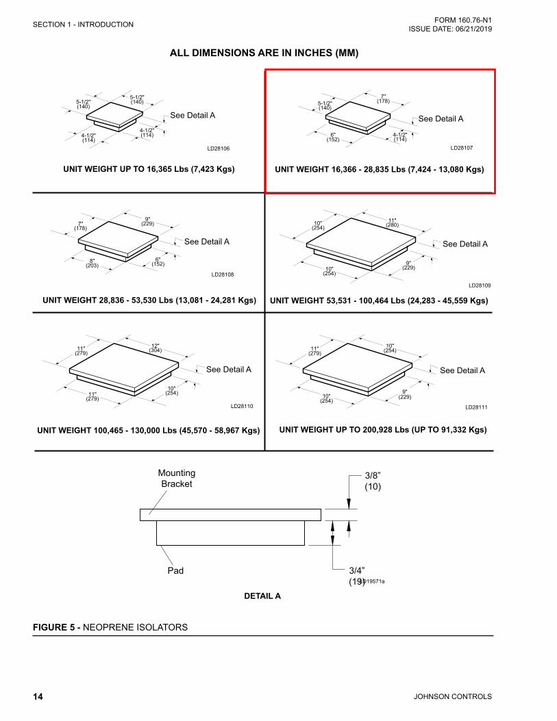
ALL DIMENSIONS ARE IN INCHES (MM)
UNIT WEIGHT 53,531 - 100,464 Lbs (24,283 - 45,559 Kgs)
UNIT WEIGHT UP TO 16,365 Lbs (7,423 Kgs) UNIT WEIGHT 16,366 - 28,835 Lbs (7,424 - 13,080 Kgs)
UNIT WEIGHT 28,836 - 53,530 Lbs (13,081 - 24,281 Kgs)
FIGURE 5 - NEOPRENE ISOLATORS
LD28110
See Detail A
UNIT WEIGHT 100,465 - 130,000 Lbs (45,570 - 58,967 Kgs) UNIT WEIGHT UP TO 200,928 Lbs (UP TO 91,332 Kgs)
LD28111
9"(229)
See Detail A
LD19571a

15
SECTION 1 - INTRODUCTIONFORM 160.76-N1 ISSUE DATE: 06/21/2019
1
LD28112
SHELL
END SHEETDIA.
HOLE
LD28113
SHELL
END SHEETDIA. HOLE
Compressor Code - Q, P, H, K1 - K3 Shipment Forms 1, 2, 3, 7, 9, 10
Compressor Code - K4, K7 Shipment Forms 1, 2, 3, 7, 9, 10
FIGURE 6 - NEOPRENE ISOLATOR SUPPORTS WITHOUT/WITH SKIDS

19
FORM 160.76-N1 ISSUE DATE: 06/21/2019
2
SECTION 2 - INSTALLATION
RIGGING UNIT TO FINAL LOCATIONRig the unit to its final location on the floor or mount-ing pad, lift the unit (or shell assembly) by means of an overhead lift, and lower the unit to its mounting posi-tion. If optional shipping skids are used, remove them before lowering the chiller to its mounting position.
At this point units shipped dismantled should be assembled under the supervi-sion of a Johnson Controls representative.
If the evaporator is to be field insulated, apply the insu-lation to the evaporator before the unit is placed in po-sition while the unit is in the lift position. Be sure unit is properly supported. (See Figure 4 on page 13)
LOCATING AND INSTALLING ISOLATOR PADSInstall the isolator pad mounts in the location shown in Figure 5 on page 14 (rubber side down).
After the isolator pads have been placed into position on the floor, lower the chiller onto the pads. When the unit is in place, remove the rigging equipment and check that the unit is level. The unit should be level within 1/4 in. (6 mm) from one end to the other end and from front to the rear. If the chiller is not level within the amount specified, lift it and place shims between the isolation pad and the chiller tube sheets. (Shims furnished by the installer.) Lower unit again and re-check to see that it is level.
CHECKING THE ISOLATION PAD DEFLECTIONCheck all isolation pads for the proper deflection while also checking to see if the unit is level. Each pad must be deflected approximately 0.10 in. (2.5 mm) to 0.20 in. (5 mm). If an isolation pad is under-deflected, shims must be placed between the unit tube sheet and the top of the pad to equally deflect all pads.
LEVELING THE UNITThe longitudinal alignment of the unit should be checked by placing a level on the top center of the evaporator shell under the compressor/motor assem-bly. Transverse alignment should be checked by plac-ing a level on top of the shell end sheets.
INSTALLING OPTIONAL SPRING ISOLATORSWhen ordered, spring type isolator assemblies are fur-nished with the unit. The 4 assemblies are identical and can be placed at any of the 4 corners of the unit.
While the unit is still suspended by the rigging, the iso-lators should be bolted to the unit by inserting the cap screws through the holes in the mounting bracket into the tapped hole in the top of the isolator leveling bolts. Then the unit can be lowered onto the floor.
The adjusting bolts should now be rotated one (1) turn at a time, in sequence, until the unit end sheets are clear of the floor by the dimension shown in Figure 7 on page 16 and the unit is level. Check that the unit is level, both longitudinally and transversely (see Leveling the Unit). If the leveling bolts are not long enough to level unit due to an uneven or sloping floor or foundation, steel shims (grouted, if necessary) must be added beneath the isolator assemblies as necessary.
After the unit is leveled, wedge and shim under each corner to solidly support the unit in this position while piping connections are being made, pipe hangers ad-justed and connections checked for alignment. Then the unit is filled with water and checked for leaks. The leveling bolts should now be finally adjusted until the wedges and shims can be removed. The unit should now be in correct level position, clear of the floor or foundation and without any effect from the weight of the piping.
PIPING CONNECTIONSAfter the unit is leveled (and wedged in place for op-tional spring isolators) the piping connections may be made; chilled water, condenser water and refrigerant relief. The piping should be arranged with offsets for flexibility, and adequately supported and braced inde-pendently of the unit to avoid strain on the unit and vibration transmission. The hangers must allow for alignment of pipe. Isolators (by others) in the piping and hangers are highly desirable, and may be required by specifications, in order to effectively utilize the vi-bration isolation characteristics of the vibration isola-tion mounts of the unit.
Check for piping alignment – Upon completion of piping, a connection in each line as close to the unit as possible should be opened, by removing the flange bolts or coupling and checked for piping alignment. If

JOHNSON CONTROLS20
FORM 160.76-N1 ISSUE DATE: 06/21/2019SECTION 2 - INSTALLATION
any of the bolts are bound in their holes, or if the con-nection springs are out of alignment, the misalignment must be corrected by properly supporting the piping or by applying heat to anneal the pipe.
If the piping is annealed to relieve stress, the inside of the pipe must be cleaned of scale before it is finally bolted in place.
EVAPORATOR AND CONDENSER WATER PIPINGThe evaporator and condenser liquid heads of the chill-er have nozzles which are grooved, suitable for weld-ing 150 psig DWP flanges or the use of flexible cou-plings. Factory mounted flanges are optional.
The nozzles and water pass arrangements are furnished in accordance with the job requirements (refer to Prod-uct Drawings) furnished with the job. Standard units are designed for 150 psig DWP on the water side. If job re-quirements are for greater than 150 psig DWP, check the unit data plate before applying pressure to evaporator or condenser to determine if the chiller has provisions for the required DWP.
Inlet and outlet connections are identified by labels placed adjacent to each nozzle.
The coolant temperature inside any JCI-supplied liquid-cooled motor starter must be maintained above the dewpoint temperature in the equipment room to prevent condensing water vapor inside the starter cabinet. Therefore, an addi-tional temperature-controlled throttle valve is needed in the
flow path for the starter heat exchanger to regulate cooling above the equipment room dewpoint for applications using cooling sources other than evaporative air-exchange meth-ods, such as wells, bodies of water, and chilled water. The temperature control valve should be the type to open on in-creasing drive coolant temperature, fail-closed, and set for a temperature above dewpoint. It can be requested as factory- supplied on a chiller order by special quotation.
Chilled WaterForeign objects which could lodge in, or block flow through, the evaporator and condenser tubes must be kept out of the water circuit. All water piping must be cleaned or flushed before being connected to the chiller pumps, or other equipment.
Permanent strainers (supplied by others) are required in both the evaporator and condenser water circuits to protect the chiller as well as the pumps, tower spray nozzles, chilled water coils and controls, etc. The strainer must be installed in the entering chilled water line, directly upstream of the chiller.
Water piping circuits should be arranged so that the pumps discharge through the chiller, and should be controlled as necessary to maintain essentially constant chilled and condenser water flows through the unit at all load conditions.
If pumps discharge through the chiller, the strainer may be located upstream from pumps to protect both pump and chiller. (Piping between strainer, pump and chill-er must be very carefully cleaned before start-up.) If pumps are remotely installed from the chiller, strainers should be located directly upstream of the chiller.
FIGURE 8 - SCHEMATIC OF A TYPICAL PIPING ARRANGEMENTLD08529
EVAPORATOR
CONDENSER
STRAINER
STRAINER
COOLING TOWER
COOLING UNIT
C = COMPRESSORM = MOTOR
FLOW SWITCH
CHILLED WATER PUMP
COOLING TOWER PUMP
COOLING UNIT CODEPAK
CONTROLLED COOLING TOWER BYPASS VALVE (IF NECESSARY)
21
SECTION 2 - INSTALLATIONFORM 160.76-N1 ISSUE DATE: 06/21/2019
2
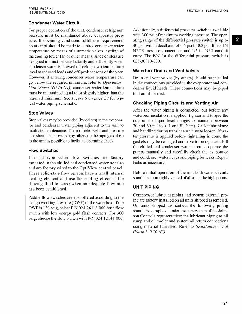
Condenser Water CircuitFor proper operation of the unit, condenser refrigerant pressure must be maintained above evaporator pres-sure. If operating conditions fulfill this requirement, no attempt should be made to control condenser water temperature by means of automatic valves, cycling of the cooling tower fan or other means, since chillers are designed to function satisfactorily and efficiently when condenser water is allowed to seek its own temperature level at reduced loads and off-peak seasons of the year. However, if entering condenser water temperature can go below the required minimum, refer to Operation - Unit (Form 160.76-O1); condenser water temperature must be maintained equal to or slightly higher than the required minimum. See Figure 8 on page 20 for typ-ical water piping schematic.
Stop ValvesStop valves may be provided (by others) in the evapora-tor and condenser water piping adjacent to the unit to facilitate maintenance. Thermometer wells and pressure taps should be provided (by others) in the piping as close to the unit as possible to facilitate operating check.
Flow SwitchesThermal type water flow switches are factory mounted in the chilled and condensed water nozzles and are factory wired to the OptiView control panel. These solid-state flow sensors have a small internal heating element and use the cooling effect of the flowing fluid to sense when an adequate flow rate has been established.
Paddle flow switches are also offered according to the design working pressure (DWP) of the waterbox. If the DWP is 150 psig, select P/N 024-26116-000 for a flow switch with low energy gold flash contacts. For 300 psig, choose the flow switch with P/N 024-12144-000.
Additionally, a differential pressure switch is available with 300 psi of maximum working pressure. The oper-ating range of the differential pressure switch is up to 40 psi, with a deadband of 0.5 psi to 0.8 psi. It has 1/4 NPTE pressure connections and 1/2 in. NPT conduit entry. The P/N for the differential pressure switch is 025-30919-000.
Waterbox Drain and Vent ValvesDrain and vent valves (by others) should be installed in the connections provided in the evaporator and con-denser liquid heads. These connections may be piped to drain if desired.
Checking Piping Circuits and Venting AirAfter the water piping is completed, but before any waterbox insulation is applied, tighten and torque the nuts on the liquid head flanges to maintain between 30 and 60 ft. lbs. (41 and 81 N·m). Gasket shrinkage and handling during transit cause nuts to loosen. If wa-ter pressure is applied before tightening is done, the gaskets may be damaged and have to be replaced. Fill the chilled and condenser water circuits, operate the pumps manually and carefully check the evaporator and condenser water heads and piping for leaks. Repair leaks as necessary.
Before initial operation of the unit both water circuits should be thoroughly vented of all air at the high points.
UNIT PIPINGCompressor lubricant piping and system external pip-ing are factory installed on all units shipped assembled. On units shipped dismantled, the following piping should be completed under the supervision of the John-son Controls representative: the lubricant piping to oil sump and oil cooler and system oil return connections using material furnished. Refer to Installation - Unit (Form 160.76-N3).

JOHNSON CONTROLS22
FORM 160.76-N1 ISSUE DATE: 06/21/2019SECTION 2 - INSTALLATION
REFRIGERANT RELIEF PIPINGEach unit is equipped with pressure relief valves lo-cated on the condenser and on the evaporator for the purpose of quickly relieving excess pressure of the re-frigerant charge to the atmosphere as a safety precau-tion in case of an emergency, such as fire.
Refrigerant relief vent piping (by others), from the re-lief valves to the outside of the building, is required
by code in most areas and should be installed on all chillers. The vent line should be sized in accordance with the ANSI/ASHRAE-15, or local code. The vent line must include a dirt trap in the vertical leg to in-tercept and permit clean out and to trap any vent stack condensation. The piping MUST be arranged to avoid strain on the relief valves, using a flexible connection, if necessary.
FIGURE 9 - TYPICAL REFRIGERANT VENT PIPING
FLANGED JOINTTO PERMIT PIPINGDISASSEMBLY
CONDENSATIONTRAP
DUAL RELIEFVALVES
VENT TO ATMOSPHERE
SUPPORT VENT PIPING TO AVOIDSTRAIN ON RELIEF PIPING
FLEXIBLE CONNECTOR
CONDENSER
EVAPORATOR
SEE NOTE
NOTE: SHELLS MAY BE FURNISHED WITH ONE OR TWO RELIEF VALVES, DEPENDING ON SHELL SIZE.
LD03863
When installing relief piping there must NOT be any piping strain. Relief piping must be properly aligned and supported to eliminate any possible piping strain.
When installing relief piping an ANSI flange or a piping union must be used to make a servicable piping connection.
HorizontalMis-aligned
VerticalOffset
Compressed
LD16677

23
SECTION 2 - INSTALLATIONFORM 160.76-N1 ISSUE DATE: 06/21/2019
2
CONTROL PANEL POSITIONINGOn large YK chillers equipped with H9 and K1-K7 compressors, the control panel height can be adjusted. Chillers equipped with P and Q compressors the control panel height is NOT adjustable. The OptiV-iew™ Control Center is placed in a position above the evaporator for shipping. To move the control center into position for operation, proceed as follows:
1. While supporting the control center, remove the hardware between the support arms and the evap-orator.
2. Swing the control center into a vertical position.
3. Slide the control center down the guide rails to the proper position. Tighten securely.
4. Discard unused hardware.
SUPPORTARMS
PANELTRACK
FIGURE 10 - CONTROL PANEL POSITIONING
LD03826
CONTROL WIRINGOn units shipped disassembled, after installation of the control center, control wiring must be completed be-tween unit components and control center, solid state starter, or variable speed drive, when used, using wir-ing harnesses furnished. Refer to Installation - Unit (Form 160.76-N3).
Field wiring connections for commonly encountered control modifications (by others) if required, are shown on Wiring Diagram – Unit (Style H) Field Con-trol Modifications (Form 160.76-PW4).
No deviations in unit wiring from that shown on drawings furnished shall be made without prior approval of the John-son Controls representative.
POWER WIRING
Chiller with Electromechanical StarterA 115 volt – single phase – 60 or 50 Hertz power sup-ply of 20 amperes must be furnished to the control center, from the control transformer (2 KVA required) included with the compressor motor starter. Do NOT make final power connections to control center until approved by YORK representative.
OIL PUMP – 3 PHASE STARTERSeparate wiring or a fused disconnect switch should be supplied by the installer.
Remote Electromechanical starters for the chiller must be furnished in accor-dance with YORK Starter Specifications Product Drawing Form 160.76-PW5 to provide the features necessary for the starter to function properly with the YORK control system.
Each chiller unit is furnished for a specific electrical power supply as stamped on the Unit Data Plate, which also details the motor connection diagrams.
To insure proper motor rotation the starter power input and starter to motor con-nections must be checked with a phase sequence indicator in the presence of the Johnson Controls representative.
DO NOT cut wires to final length or make final connections to motor terminals or starter power input terminals until ap-proved by the Johnson Controls repre-sentative.
YK Motors (Electromechanical Starter)Motor leads are furnished with a crimp type connection having a clearance hole for a 3/8 in. bolt, motor termi-nal lugs are not furnished. Refer to Wiring Labels in motor terminal box for hook-up to suit motor voltage and amperage for power wiring connections.

JOHNSON CONTROLS24
FORM 160.76-N1 ISSUE DATE: 06/21/2019SECTION 2 - INSTALLATION
Chiller with Solid State Starter or Variable Speed DriveA chiller equipped with a factory mounted Solid State Starter or Variable Speed Drive does not require wiring to the compressor motor. The motor power wiring is factory connected to the Solid State Starter or Variable Speed Drive. Refer to the Field Wiring Diagram. All wiring to the control panel and the oil pump starter is completed by the factory. A control transformer is fur-nished with the Solid State Starter or Variable Speed Drive.
Copper Conductors – Only connect cop-per conductors to compressor motors and starters. Aluminum conductors have proven to be unsatisfactory when con-nected to copper lugs. Aluminum oxide and the difference in thermal conductiv-ity between copper and aluminum mean the required tight connection cannot be guaranteed over a long period of time.
INSULATIONDO NOT field insulate until the unit has been leak tested under the supervision of the Johnson Controls representative.
Insulation of the type specified for the job, or mini-mum thickness to prevent sweating of 30°F (-1°C) sur-faces should be furnished (by others) and applied to the evaporator shell, end sheets, liquid feed line to flow chamber, compressor suction connection, and evapo-rator liquid heads and connections. The liquid head flange insulation must be removable, to allow head re-moval for the tube maintenance. Details of areas to be insulated are given on the Product Drawing.
Units are furnished factory anti-sweat insulated on or-der at additional cost. This includes all low tempera-ture surfaces except the two (2) cooler liquid heads.
INSTALLATION CHECK – REQUEST FOR START-UP SERVICEThe services of a Johnson Controls representative will be furnished to check the installation and supervise the initial start-up and operation on all chillers installed within the Continental United States.
After the unit is installed, piped and wired as described in this Instruction, but before any attempt is made to start the unit, the Johnson Controls District Office should be advised so that the start-up service, included in the contract price, can be scheduled. Use the In-stallation Checklist and Request for startup, (Form 160.76-CL1).

Submittal Documents For:
Dexter High School
Section #5 – Electrical Information

JOHNSON CONTROLS2
FORM 160.76-PW7 ISSUE DATE: 8/3/2018
This equipment is a relatively complicated apparatus. During rigging, installation, operation, maintenance, or service, individuals may be exposed to certain com-ponents or conditions including, but not limited to: heavy objects, refrigerants, materials under pressure, rotating components, and both high and low voltage. Each of these items has the potential, if misused or handled improperly, to cause bodily injury or death. It is the obligation and responsibility of rigging, instal-lation, and operating/service personnel to identify and recognize these inherent hazards, protect themselves, and proceed safely in completing their tasks. Failure to comply with any of these requirements could result in serious damage to the equipment and the property in
IMPORTANT!READ BEFORE PROCEEDING!
GENERAL SAFETY GUIDELINES
which it is situated, as well as severe personal injury or death to themselves and people at the site.
This document is intended for use by owner-authorized rigging, installation, and operating/service personnel. It is expected that these individuals possess independent training that will enable them to perform their assigned tasks properly and safely. It is essential that, prior to performing any task on this equipment, this individual shall have read and understood the on-product labels, this document and any referenced materials. This in-dividual shall also be familiar with and comply with all applicable industry and governmental standards and regulations pertaining to the task in question.
SAFETY SYMBOLS
The following symbols are used in this document to alert the reader to specific situations:
Indicates a possible hazardous situation which will result in death or serious injury if proper care is not taken.
Indicates a potentially hazardous situa-tion which will result in possible injuries or damage to equipment if proper care is not taken.
damage to the machine, damage to other equipment and/or environmental pollu-tion if proper care is not taken or instruc-tions and are not followed.
Highlights additional information useful to the technician in completing the work being performed properly.
to be connected inside the control cabinet. Devices such as relays, switches, transducers and controls and any external wiring must not be installed inside the micro panel. All wiring must be in accor-
electrician. Johnson Controls will NOT be responsible for damage/problems resulting from improper connections to the controls or application of improper control signals. Failure to follow this warn-

JOHNSON CONTROLS 3
FORM 160.76-PW7 ISSUE DATE: 8/3/2018
CHANGEABILITY OF THIS DOCUMENT
In complying with Johnson Controls’ policy for con-tinuous product improvement, the information con-tained in this document is subject to change without notice. Johnson Controls makes no commitment to update or provide current information automatically to the manual or product owner. Updated manuals, if applicable, can be obtained by contacting the nearest Johnson Controls Service office or accessing the John-son Controls QuickLIT website at http://cgproducts.johnsoncontrols.com.
It is the responsibility of rigging, lifting, and operating/ service personnel to verify the applicability of these documents to the equipment. If there is any question
regarding the applicability of these documents, rig-ging, lifting, and operating/service personnel should verify whether the equipment has been modified and if current literature is available from the owner of the equipment prior to performing any work on the chiller.
CHANGE BARS
Revisions made to this document are indicated with a line along the left or right hand column in the area the revision was made. These revisions are to technical information and any other changes in spelling, gram-mar or formatting are not included.

JOHNSON CONTROLS4
FORM 160.76-PW7 ISSUE DATE: 8/3/2018
NOTES
1. current edition of the National Electrical Code (N.E.C.) as well as all other applicable codes and
2.
PROPER GROUNDING IS REQUIRED:
• Variable Speed Drive (VSD) shall be grounded in accordance with the 2017 NEC (Paragraph 250.118).
• Ground wires must be copper only and sized per the NEC See Table 250.122.
• A separate grounding conductor shall be run in each conduit or for each 3 phase bundle within a cable tray. See Figure 1 on page 5.
• Each ground wire shall be connected directly between the supply transformer’s secondary ground and the VSD ground lug.
• Flexible conduit is required for final connection to the VSD for vibration isolation.
• Conduit is not an acceptable grounding means.
• See Table 2 on page 5 for VSD ground lug sizing.
3. Wiring, electrical conduit, junction boxes, fused disconnect switches (FDS), or circuit breakers, starters (M), pushbutton stations (PB), manual-
control relays furnished by others unless other-
4. Items marked * furnished by Johnson Controls.
5. Items marked ** available from Johnson Controls at additional cost.
6. Control power supply 115V - 50/60Hz, 2.0 KVA capacity for control center only, is sup-plied by a control power transformer(s) (1T)mounted inside the VSD, 380V, 60Hz chiller motor codes EF-EP or 460V, 60Hz chiller motor codes EF-ET or 575V 60Hz chiller motor codes EF-ER or 380-415V 50Hz chiller motor codes 5EC-5E0.
7. -tions to VSD. Multiple conduits shall contain an equal number of wires from each phase in each conduit to prevent overheating per the 2017 NEC (Paragraph 300.20(a)). Use copper conductors only; DO NOT USE aluminum conductors. See Table 2 on page 5 and Note 8 for factory furnished VSD terminal lug wire rang-es and conduit connection provisions.
8. A removable cover plate with pilot knockouts is supplied for connection of power supply conduits.
TABLE 1 - POWER SUPPLY CONDUITS
INPUT VOLTAGE/ FREQUENCY
CHILLER MOTOR CODE
NUMBER OF CONDUITS
– MAX T
575V/600V/60Hz EF-ER
(2) 2-1/2 in.
440V/460V/480V/60Hz EF-EN
380V/60Hz EF-EK
415V/50Hz 5EC-5EI
380V/400V/50Hz5CC-5CI,
5EC-5EI
575V/600V/60Hz ES-ET
(2) 3 in.
440V/460V/480V/60HzCP-CT,
EP-ET
380V/60Hz EL-EP
415V/50Hz 5EJ-5EM
380V/400V/50Hz 5CJ-5CM,
5EJ-5EM
The following terminal lugs are factory furnished for field wiring supply connections. All lugs are rated AL-9CU.

JOHNSON CONTROLS 5
FORM 160.76-PW7 ISSUE DATE: 8/3/2018
TABLE 2 - TERMINAL LUGS
INPUT VOLTAGE/
FREQUENCY
CHILLER MOTOR CODE AND VSD
CIRCUIT BREAKER RATING
LINE SIDE LUGS BBL
PER TERMINAL
WIRE RANGE
GROUNDING LUG WIRE RANGE, QUANTITY
575V/600V/60HzEF-ER, 400A
2#2 AWG - 500 kcmil.
#6 AWG to 250 kcmil, two bbl.
440V/460V/480V/60HzEF-EN, 400A
380V/60HzEF-EK, 400A
415V/50Hz5EC-5EI,
400A
380V/400V/50Hz5EC-5EI,
400A
575V/600V/60HzES-ET
600A
2 3/0-500 kcmil.#6 AWG to 250 kcmil,
two bbl.
440V/460V/480V/60HzEP-ET, 600A
380V/60HzEL-EP, 600A
415V/50Hz5EJ-5EM,
600A
380V/400V/50Hz5EJ-5EM,
600A
LD27401
Each conduit shall contain a copper conductor of each phase and a copper ground wire.
Wire tray shall contain bundles of copper wire with one conductor per phase and a copper ground wire in each bundle.
Ground
ABC
Conduit
ConduitTransformer
Terminal Block
VSDTerminal
Block
Neutral (if applicable)
Ground Ground
Phase A*
Phase B*
Phase C*
*See Note 7.
C GA B
C GA B
C GA B
C GA B
FIGURE 1 - GROUNDING VSD

JOHNSON CONTROLS6
FORM 160.76-PW7 ISSUE DATE: 8/3/2018
9. Condenser water pump motor starter (3M) hold-ing coil to be furnished for 115V - 50/60Hz. The power requirements for the water pump starter (3M) must be a maximum of 1 Amp holding and 10 Amps inrush. If power requirements exceed this value, furnish coil for line voltage, and con-trol relay with 115V coil.
10. -nection of harnesses to control center, power wir-ing between compressor motor and VSD, and oil pump starter to VSD. These harnesses and power
conduit with necessary connectors, and contain the wires (shown in Note 13) properly terminated and marked.
11. Wire #14 AWG copper for one way distance of less than 175 feet. Wire #12 AWG copper for one way distance of more than 175 feet, but less than 300 feet.
12. Wiring diagram for YORK control center Form
Form 160.76-PW4. Wiring diagrams for YORK Variable Speed Drive Forms 160.00-O1 and 160.00-O4.
13. The following interconnecting wires are factory supplied when a YORK Variable Speed Drive is used.
a. VSD to control center – L, 2, 16, 24, 53; 3-conductor shielded cable; 4-conductor shielded cable (VSD harmonic filter option only).
b. VSD to oil pump motor starter – 72, 73, 74.
14. 60Hz oil pump motor for compressor is 2 HP. Full load amperes for oil pump drive panel (furnished by Johnson Controls with VSD factory wired) 2.0 KVA control power transformer(s) (furnished by Johnson Controls and factory wired) are:
TABLE 3 - OIL PUMP
3-PHASE VOLTAGE
HZ
OIL PUMP DRIVE PANEL (AMPS)
CONTROL POWER TRANSFORMER(S)
(AMPS)
MOTOR CODES
575/600 60 2.9 5.2 EF-ET
440/460/
48060 3.6 6.5 EF-ET
380 60 4.3 7.5 EF-EP
380/400/
41550 4.3 7.5 5EC-5EO
15. The branch circuit overcurrent protection device for the YORK VSD must be a time delay type with a rating which is the standard fuse/circuit
wiring conductors per the N.E.C.
Motor overload protection is provided by the York VSD according to UL 508C. The York VSD does not have provisions to provide motor tempera-ture sensing, thermal memory, or thermal reten-tion protection for motor overload conditions as a standard offering. If thermal overload protection is desired, an optional motor monitoring board and resistance thermometer devices or thermis-tors are available.
16. The YORK Variable Speed Drive power supply wiring ampacity shall be calculated as follows.
Model YK minimum circuit ampacity:
Ampacity = 1.25 (Job FLA)
Where 125% factor per 2014 N.E.C. (Para. 440-33).
17. The VSD is equipped with a U.L. Listed ground fault sensing circuit breaker sized per the follow-ing table. Fast acting semiconductor fuses are employed after the circuit breaker to provide ad-ditional protection to the VSD. The ground fault sensor is factory set to trip instantaneously when a ground fault is detected.
18. Control circuit wiring for 3M condenser water pump motor starter is shown for cooling only ap-plication. The condenser water pump should be wired to terminals 2, 22, 150 and 151. See 160.76-PW6 Wiring Diagram.

JOHNSON CONTROLS 7
FORM 160.76-PW7 ISSUE DATE: 8/3/2018
TABLE 4 - CIRCUIT BREAKER
INPUT VOLTAGE/ FREQUENCY
CHILLER MOTOR CODE
VSD CIRCUIT BREAKER RATING (AMPS) @ 600VAC, 60HZ OR 480VAC, 60HZ OR
400VAC, 50/60HZ TRIP
SEMI-CONDUCTOR FUSE RATING
(AMPS) @ 700VAC WITHSTAND
GROUND FAULT
TRIP (AMPS)
TRIP WITHSTAND
575V/600V/60Hz EF-ER 400 35,000*+
N/A 120
440V/460V/480V/60Hz EF-EN
400 65,000*+380V/60Hz EF-EK
415V/50Hz 5EC-5EI
380V/400V/50Hz 5EC-5EI
575V/600V/60Hz ES-ET 600 50,000*+
N/A 160
440V/460V/480V/60Hz EP-ET
600 100,000*+380V/60Hz EL-EP
415V/50Hz 5EJ-5EM
380V/400V/50Hz 5EJ-5EM
* Per U.L. Listing of VSD
† RMS Symmetrical Amperes
19. The main power transformer should be ad-equately sized such that the transformer voltage drop does not exceed 10% during unit start-up. The supply voltage, at VSD input terminals, dur-ing start-up must be maintained above 489 volts for 575V/600V, 391 volts for 440V/460V/480V, 323 volts for 380V 60Hz units and 323 volts for 380V/400V, 353 volts for 415V 50Hz units. The allowable supply voltage range during normal operation is 520 to 635VAC, 3-Phase 575V/600V, 60Hz or 414 to 508VAC, 3-Phase, 440V/460V/480V 60Hz or 342 to 423VAC, 3-Phase,380V/400V 50/60Hz, or 374 to 456VAC, 3-Phase, 415 50Hz.
20. Automatic control of the chilled water pump by the control center is shown. Chilled water pump motor starter (5M) holding coil to be furnished for 115V – 50/60Hz. The power requirements for the water pump starter (5M) must be a maximum of 2 Amp holding and 10 Amps inrush. If power requirements exceed this value, furnish coil for line voltage, and control relay with 115V coil (see Note 21).
The pumps operate during oil pump prerun, dur-ing compressor operation and during cycling shutdown.
For manual chilled water pump control, connect a manual start/stop switch as shown in the Field Connections diagram on page 3 or 5 for 115VAC coils only.
21. relay coil, motor starter coil, etc. shall have a tran-sient suppressor wired (by others) in parallel with its coil, physically located at the coil. Spare tran-sient suppressors are factory supplied in a bag at-tached to the keypad cable clamp in the OptiView Control Center.
22. The Condenser Flow Switch is optional. If not present, a jumper must be installed between TB4-11 and TB4-1.
23. A jumper is installed between terminals 21 and 24 for normal operation. To check motor rotation on initial start-up, the jumper may be removed as a momentary switch installed between terminals 21 and 24 . Press the start key on the display screen on the control panel. After completion of the pre lube sequence jog the motor with the mo-mentary switch. When proper rotation is obtained, replace the momentary switch with a jumper. The momentary switch must have a minimum contact rating of 1 FLA, 10 LRA at 115 volts AC.

JOHNSON CONTROLS8
FORM 160.76-PW7 ISSUE DATE: 8/3/2018
FIGURE 2 - WIRING DIAGRAM – FIELD CONNECTIONS (VARIABLE SPEED DRIVE - MOTOR CODES EF-ET (440V/460V/480V) OR EF-ET (575V/600V) OR EF-ET (380V) OR 5EC-5EO (380V/400V) OR 5EC-5EO (415V)
FO
RM
160
.54-
PW
6
SUPR
SUPR
4T2
4T1
4T3
FD
S2**
NO
TE
S 5
& 1
5
L1
L3
L2
PO
WE
R S
UP
PLY
(N
OT
E 1
9)
FD
S4
FD
S5
FD
S3
5M
SE
EN
OT
E21
SE
EN
OT
E20 C
HIL
LE
DW
AT
ER
PU
MP
MO
TO
RW
IRE
# 1
4 A
WG
CO
PP
ER
NO
TE
S 1
1 &
18
CH
ILLE
D W
AT
ER
FLO
W S
WIT
CH
**
N
OT
E 5
FLS
WIR
E #
14 A
WG
CO
PP
ER
NO
TE
11
WIR
E# 1
4 A
WG
CO
PP
ER
NO
TE
11
OP
TIV
IEW
CO
NT
RO
L C
EN
TE
R *
GR
D.
SC
RE
WS
*
CO
ND
EN
SE
R W
AT
ER
PU
MP
MO
TO
RC
OO
LIN
G T
OW
ER
FA
N M
OT
OR
3M
S4M
SE
EN
OT
E21
NO
TE
9
AU
TO
MA
N
OFF
VO
LT
PH
AS
E 3
HE
RT
Z
5T1
5T2
5T3
3T1
3T2
3T3
5LL1
5LL2
5LL3
3LL1
3LL2
3LL3
4LL1
4LL2
4LL3
2LL1
2LL2
2LL3
TB
4*
19
51
82
111
31
91
13
12
12
019
18
71
TB
2*
44
45
55
56
26
27
42
43
40
41
150
151
153
154
155
164
36
35
156
157
152
TB
6*
34
51
51
62
55
31
11
1L
2
CO
ND
EN
SE
R W
AT
ER
FLO
W S
WIT
CH
N
OT
E 2
2
TB
4-1
TB
4-1
1
#14 A
WG
(NO
TE
11)
NO
TE
7,
16
CO
PP
ER
CO
ND
UC
TO
RS
ON
LY
DO
NO
T U
SE
AL
UM
INU
MC
ON
DU
CT
OR
S.
GR
DL2
L1
L3
NO
TE
S 2
& 8
NO
TE
S 4
& 6
1T
*
T2
*T
1*
T3
*
CO
MP
RE
SS
OR
MO
TO
R*
2M
YO
RK
VS
DN
OT
ES
4 &
13
WIR
E #
14 A
WG
CO
PP
ER
, N
OT
E 1
1
NO
TE
8
T2
T1
T3
TB
5*
22
25
23
22
2L
L21
24
See
Not
e 23
LD16110A