DCS A-10C Warthog Guide - VIRTAVIA
94
1 By Chuck DCS GUIDE A-10C WARTHOG LAST UPDATED: 08/08/2016
-
Upload
khangminh22 -
Category
Documents
-
view
0 -
download
0
Transcript of DCS A-10C Warthog Guide - VIRTAVIA

1
By Chuck
DCS GUIDEA-10C WARTHOG
LAST UPDATED: 08/08/2016

TABLE OF CONTENT• PART 1 – INTRODUCTION & TRAINING STRUCTURE• PART 2 – CONTROLS SETUP• PART 3 – COCKPIT & GAUGES• PART 4 – START-UP PROCEDURE• PART 5 – MISSION PREPARATION & TAKEOFF• PART 6 – LANDING • PART 7 – ENGINE MANAGEMENT• PART 8 – UNDERSTANDING HOW SYSTEMS WORK• PART 9 – UNDERSTANDING HOTAS
2
PART 10 – OFFENCE: WEAPONS & ARMAMENTPART 11 – DEFENCE: RWR AND COUNTERMEASURESPART 12 – RADIO TUTORIALPART 13 – AUTOPILOTPART 14 – NAVIGATION & ILS LANDINGPART 15 – AIR-TO-AIR REFUELINGPART 16 – OTHER RESOURCES

3
PAR
T 1 –
CO
NTR
OLS
SET
UP
PAR
T 1 –
INTR
OD
UC
TIO
N
RTFM, or “Read The F*cking Manual”, is probably one of the most commonly used expressions in DCS… especially when the Fairchild Republic A-10C ThunderboltII “Warthog” is involved.
These four letters represent what I hate the most about the flight sim community. “RTFM” is what you say to someone who asks for help when you want to get ridof him. The philosophy behind this is that experienced pilots expect new guys to do their homework before they ask questions, since 99 % of the time the answerwill lie somewhere in the 671 pages long manual.
Is it fair? Yes and no. Some people genuinely dislike training new guys: it is a demanding task, it takes a lot of time and patience, and you need a structured approachand exceptional communication skills to keep it somewhat interesting. On the other hand, giving a complex answer to someone who does not have a basicunderstanding of aircraft systems may be a futile exercise. Sometimes, it is about ego: why would I give a new guy the answer when I had to read through the wholebloody manual to know this stuff?
Whatever the reason, I think that the “RTFM” philosophy only works with someone who already has a background in aviation and is already aware of what he needsto know to fly the aircraft. I believe that someone who has little to no background in aviation needs a little more handholding. There’s nothing wrong with that: reallife Warthog pilots are trained for weeks before they earn their wings. I don’t expect you to reach that level of proficiency. After all, flight simulation is not a full-timejob: it is just a hobby.
The Warthog manual is a terrific resource, but it is a long, tedious and dry read. It is easy to feel discouraged and give up on the A-10C. I can’t tell you how manypeople I know who bought the A-10C, and realized with horror that they had to go through a huge paper brick to be able to do anything. Where to start? What isimportant? Is everything relevant? Can I skip some parts? Why do I need to learn this or that? All these questions overwhelm the majority of newcomers who giveup and let the A-10 gather dust on their hard drive, cursing the Flight Sim gods for their cruelty and the 40 bucks that went down the drain.
Therefore, I decided to create this guide to help the average Joe to be able to operate the Hog to a decent level. The structure of this document is how I would give acourse to someone who starts from scratch. Follow the guide section by section, and you should be able to know how to set up your controls, how the aircraftsystems work, how to operate your machine, how to use your weapons, how to navigate and how to stay alive.
I highly recommend that you fly the A-10C with a Thrustmaster Warthog throttle and HOTAS (Hands On Throttle-and-Stick). It’s expensive (550 bucks, yikes!), but foran aircraft like the Warthog with so many switches… it is a necessity more than a nice-to-have. In my opinion, it is an investment that is completely worth it if youare interested in flight sims since the quality and craftsmanship are top notch, and it just makes your life so much easier. You can fly the A-10C with a normaljoystick, but be aware that you will have a LOT (read: shit-ton) of key bindings to remember. So, just remember… stay calm, don’t panic, we’ll go through it together.
We will first see what controls you will be playing with and a general layout of the cockpit. After, we’ll see how to choose your loadout, fire up the aircraft, takeoff,fly and navigate. We’ll get to know some fancy acronyms, see a couple of systems and how they work. Once you have all that unsavoury stuff crammed into yourbrain, we’ll blow some stuff up (yay!), see how not to end up in a smoldering pile of ashes and how to get back on the ground in one piece.
Still awake? All right, let’s get to it, shall we?

CONTROLS SETUP
4
PAR
T 1 –
CO
NTR
OLS
SET
UP
PAR
T 2 –
CO
NTR
OLS
SET
UP
Zoom In Slow: L_Shift+TMS UPZoom Out Slow: L_Shift+TMS DOWN
HOTAS: “Hands On Throttle-And-Stick”

CONTROLS SETUP
5
PAR
T 1 –
CO
NTR
OLS
SET
UP
PAR
T 2 –
CO
NTR
OLS
SET
UP
ASSIGNING PROPER AXIS IS IMPORTANT. HERE ARE A COUPLE OF TIPS.
NOTE: IN YOUR CONTROLS, MAKE SURE YOU CHECK YOUR “TRIM” CONTROLS SINCE THE DEFAULT VERSION OF THE GAME HAS YOUR TRIM HAT SET TO CHANGING YOUR VIEW RATHER THAN TRIM THE AIRCRAFT. SINCE MOST OF YOU ARE PROBABLY EQUIPPED WITH A TRACKIR ALREADY, I SUGGEST YOU MAKE SURE THE TRIM HAT SWITCH IS SET UP PROPERLY.
TO ASSIGN AXIS, CLICK ON AXIS ASSIGN. YOU CAN ALSO SELECT “AXIS COMMANDS” IN THE UPPER SCROLLING MENU.
6
TO MODIFY CURVES AND SENSITIVITIES OF AXES, CLICK ON THE AXIS YOU WANT TO MODIFY AND THEN CLICK AXIS TUNE
PAR
T 1 –
CO
NTR
OLS
SET
UP CONTROLS SETUP
PAR
T 2 –
CO
NTR
OLS
SET
UP

BIND THE FOLLOWING AXES:
7
• PITCH (DEADZONE AT 0, SATURATION X AT 100, SATURATION Y AT 100, CURVATURE AT 0)
• ROLL (DEADZONE AT 0, SATURATION X AT 100, SATURATION Y AT 100, CURVATURE AT 0)
• RUDDER (DEADZONE AT 0, SATURATION X AT 100, SATURATION Y AT 100, CURVATURE AT 0)
• THROTTLE BOTH – CONTROLS ENGINE RPM
• WHEEL BRAKE LEFT / RIGHT
• HOTAS SLEW HORIZONTAL / VERTICAL – CONTROLS YOUR TGP (TARGETING POD) ORIENTATION
• NOTE: TO TURN ON THE GROUND, MAKE SURE NOSEWHEEL STEERING IS ENGAGED (GREY NOSEWHEEL STEERING BUTTON ON YOUR HOTAS, WHERE YOUR PINKY FINGER SHOULD BE)
PAR
T 2 –
CO
NTR
OLS
SET
UP CONTROLS SETUP

8
PAR
T 2 –
CO
NTR
OLS
SET
UP CONTROLS SETUP
USE THIS PIN TO SEPARATE OR LINK LEFT AND RIGHT THROTTLES TOGETHER.
LOCK MOVES SIDEWAYS
9PAR
T 3 –
CO
CKP
IT &
GA
UG
ES
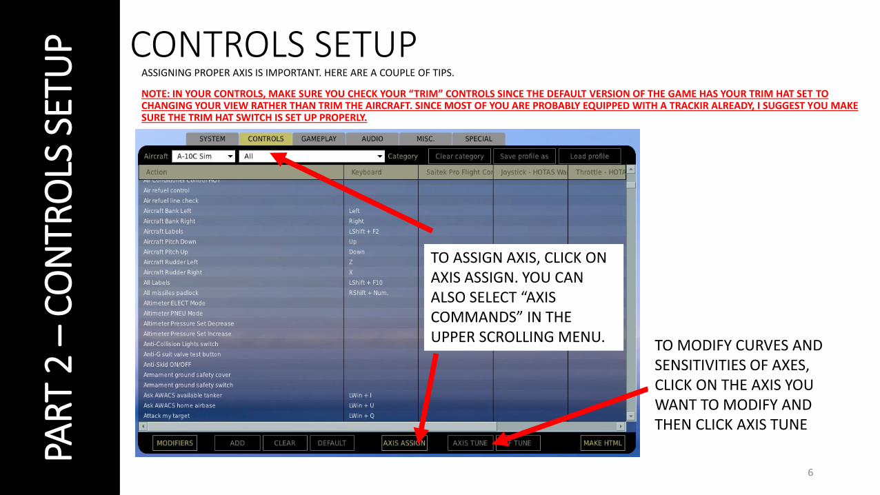
ILS: Instrumented Landing System Control Panel
HARS: Heading and Attitude Reference Systems Control Panel
TACAN Operation and Control Panel
AAP: Auxiliary Avionics Panel
Lighting Control Panel
Windshield de-fog/de-ice
Canopy De-Fog Control
Windshield rain remove/wash
Bleed Air Control
Pitot Heat
Cabin Air Conditioning Controls
Cabin Pressure Altitude
Formation Lights Brightness Control
Anti-Collision Lights ON/OFF
Auxiliary Instruments Lights Brightness Control
Accelerometer & Compass Light Switch
Nose Floodlight & Nose Illumination Switch
Console Light Brightness Control
Flight InstrumentsLight BrightnessFlood light brightness
Position Lights switch
Engine Instruments Lights Brightness
Signal LightsSwitch

10PAR
T 3 –
CO
CKP
IT &
GA
UG
ES
CDU: Control Display Unit
Oxygen Supply Lever ON/OFF
Oxygen Supply Pressure (PSI)
Oxygen Dilution Lever
Oxygen Quantity Indicator (L)
Oxygen Indicator Test Switch
Oxygen Flow IndicatorEmergency Oxygen Lever

11PAR
T 3 –
CO
CKP
IT &
GA
UG
ESCanopy Switch
Boarding Ladder Button
Canopy Jettison Handle
CAUTION light panel
APU Generator
AC Instrument Inverter
Emergency Flood Lights
Battery Switch
AC Generators
CMS: Countermeasures Panel

12PAR
T 3 –
CO
CKP
IT &
GA
UG
ES
Engine Oil Pressure Indicator (PSI)
APU RPM (%)APU EGT (Exhaust Gas Temperature) Indicator (deg C)
Fuel Quantity Display SelectorInternal/Main/Wing/External Wing/External Centerline
Fuel Indicator Test Switch
Fuel Indicator (lbs x 1000)
Hydraulic System Pressure Gauges (x1000 psi)
Fuel Flow Indicator (pounds per hour PPH)
Engine Fan Speed (RPM)
Engine Core Speed (RPM)
Engine ITT: InterstageTurbine Temperature (deg C)
13PAR
T 3 –
CO
CKP
IT &
GA
UG
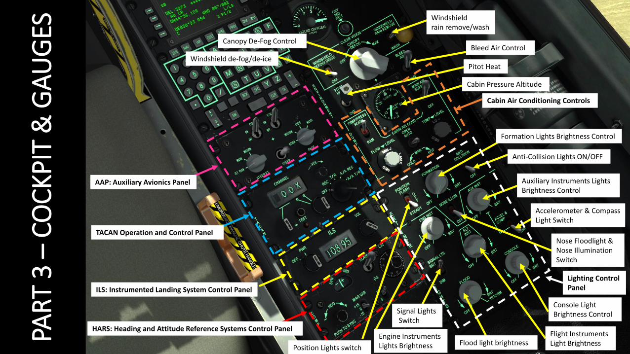
ESVertical Velocity (x1000 ft/min)
Right MFCD (Multi-Function Color Display)
Altimeter (ft) Right MFCD ModeDay/Night/OFF
Fire Extinguisher Discharge Switch

14PAR
T 3 –
CO
CKP
IT &
GA
UG
ES

15PAR
T 3 –
CO
CKP
IT &
GA
UG
ES
Gun ARMED and Nosewheel Steering Indicators
RWR: Radar Warning Receiver Airspeed Indicator (x100 kts)White needle: Current airspeedHashed needle: Max airspeedYellow index: max flap & gear extension speed (200 kts)
ADI: Attitude Director Indicator)
Left Engine Fire Extinguisher
APU Fire Extinguisher
Right Engine Fire Extinguisher
UFC (Up Front Controller)
CMSC ( Countermeasures Set Control)
Vertical Velocity (x1000 ft/min)
Altimeter (ft)

16PAR
T 3 –
CO
CKP
IT &
GA
UG
ESNMSP/NIMSIP: NAVIGATION MODE SELECT PANELa) HARS (Heading Attitude Reference System)b) EGI (Embedded GPS INS)c) TISL (Target Identification Set Laser)d) TCN (TACAN)e) ILS (Instrumented Landing System)f) STR PT (Steer Point) – Course Deviator Indicator (CDI) on the
Horizontal Situation Indicator (HSI) operates in relationship to a steer point.
g) ANCHR (Anchor Point / Bullseye) – HSI and Attitude Director Indicator (ADI) needles will point to the Anchor Point (Bullseye).
• HARS and EGI send data to HUD, ADI and HSI and cannot be used at the same time. HARS is usually used as a backup system to EGI.
• TISL, TACAN and ILS use beacons and stations to navigate to and cannot be used at the same time.
UHF Radio Frequency Repeater
Clock
AOA (Angle of Attack) Indicator
TISL Mode SelectorOFF/CAGE/DIVE/LVL NAR/LVL WIDE/
HSI (Horizontal Situation Indicator)
Course Selector Indicator
Range to selected Steer Point or TACAN station (nautical miles)
TISL slant range selection OVER 10 nm/5-10 nm/UNDER 5 nm
TISL slant range selection OVER 10 nm/5-10 nm/UNDER 5 nm
TISL Altitude Above Target Indicator (x1000 ft)
TISL code select (what system searches for entered laser code)TISL/BOTH/AUX
ENTER / OVER TEMP / BITE (test) / TRACK

17PAR
T 3 –
CO
CKP
IT &
GA
UG
ES
CIRCUIT BREAKER PANEL
18PAR
T 3 –
CO
CKP
IT &
GA
UG
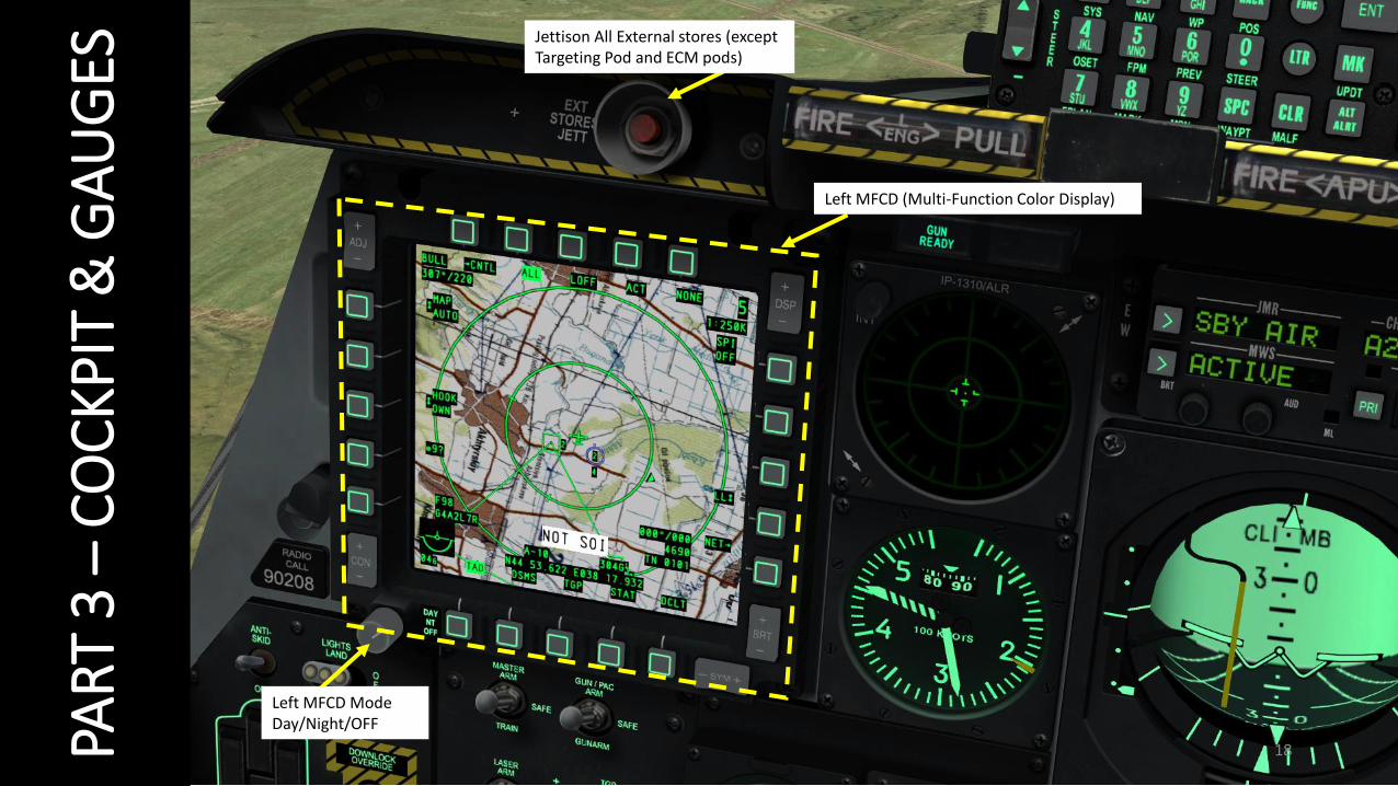
ESJettison All External stores (except Targeting Pod and ECM pods)
Left MFCD (Multi-Function Color Display)
Left MFCD ModeDay/Night/OFF

19PAR
T 3 –
CO
CKP
IT &
GA
UG
ESLanding Gear Indicator Light
TV Function (Not functional)
Flaps Indicator
TEMS (Turbine Engine Monitoring System) Switch
Landing Gear Lever
Anti-Skid Switch
Landing Lights Switch
Downlock Solenoid Override Button
Master Arm SwitchARM/SAFE/TRAIN
SAI: Standby Attitude Indicator
TGP (Targeting Pod) power switch
AHCP (Armament HUD Control Panel)
LASER ARM
GUN/PAC ARM
HUD modesNormal/Standby
HUD modesDay/Night
IFFCC (Integrated Flight & Fire Control Computer)
JTRS (Joint Tactical Radio System)CICU (Central Interface Control Unit)
ALT SCE
HARS Fast Erect (corrects HARS errors)
Video Selector TV/HUD(Not Functional)
Seat Height Adjustment

20PAR
T 3 –
CO
CKP
IT &
GA
UG
ESRefueling & Indexer Light Brightness
Night Vision Imaging System (NVIS) Control
HARS/SAS Override
Signal Light Test
Fire Detect Bleed Air Leak Test
Weapon Station Dimmer (Not Functional)
Main boost pumps
Wing boost pumps
Internal Fuel Tank Gate Open/Close
Crossfeed Switch
Transfer fuel from external wing tanks
Signal Amplifier Switch (not functional)
Fuel Line Check (not functional)
Air Refueling Control Lever (open/close refueling port slipway door)
Fill Wing Tank Disable (used when battle damage is sustained)
Fill Main Tank Disable (used when battle damage is sustained)
Exterior Lighting Brightness (used to help during aerial refueling)
Transfer fuel from external fuselage tank

21PAR
T 3 –
CO
CKP
IT &
GA
UG
ESSAS (Stability Augmentation System)PITCH ENGAGESAS (Stability Augmentation System)
YAW ENGAGE
Yaw Trim Control Knob
Monitor Test Switch (Not Functional)
Takeoff Trim Control Button
Flaps Control
Lights Switch (On left throttle)
Microphone
Airbrakes Control
Boat Switch
China Hat Switch
Landing Gear Warning Silence Switch
Throttle Friction Control
APU Starter Switch(Auxiliary Power Unit)
Engine Operate SwitchesIGN: Manual Engine IgnitionNORM: Normal Engine IgnitionMOTOR: Purge Engine Combustion Chamber
Engine Flow SwitchesNORM: No exceeding ITT is possibleOVERRIDE: Exceeding ITT is possible

22PAR
T 3 –
CO
CKP
IT &
GA
UG
ESIFF (Identify Friend or Foe) Panel
Emergency Flight Control Panel
AN/ARC-164 UHF Radio Control Panel
AN/ARC-186(V) VHF AM Radio #1 Control Panel
LASTE (Low Altitude Safety and Targeting Enhancement) Control Panela) EAC: Enhanced Attitude Controlb) Radar Altimeterc) Autopilot Mode Select
• PATH: Keep current flight path• ALT/HDG: Keep current altitude + heading• ALT: Keep current bank angle and altitude
d) Autopilot Engage/Disengage
23PAR
T 3 –
CO
CKP
IT &
GA
UG
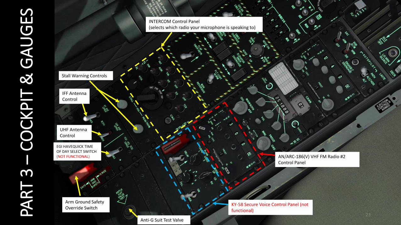
ES INTERCOM Control Panel(selects which radio your microphone is speaking to)
AN/ARC-186(V) VHF FM Radio #2 Control Panel
Stall Warning Controls
KY-58 Secure Voice Control Panel (not functional)
Anti-G Suit Test Valve
EGI HAVEQUICK TIME OF DAY SELECT SWITCH (NOT FUNCTIONAL)
Arm Ground SafetyOverride Switch
IFF Antenna Control
UHF Antenna Control

24PAR
T 3 –
CO
CKP
IT &
GA
UG
ESNIGHT VISION GOGGLESON/OFF: RSHIFT + HBRIGHTNESS + : RCTRL + RSHIFT + H BRIGHTNESS - : RALT + RSHIFT + H
25PAR
T 4
–ST
AR
T-U
P P
RO
CED
UR
E1
23
4
5
6
7
8
9
10c
10b
10a
11
11
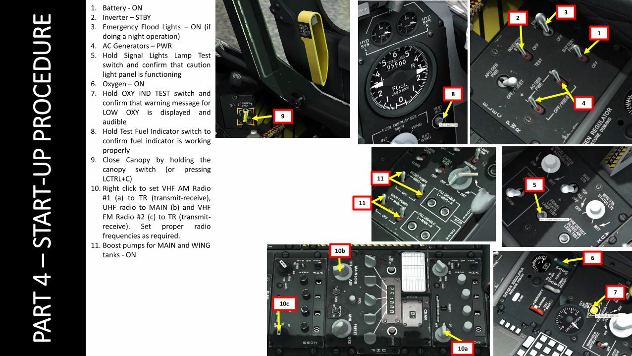
1. Battery - ON2. Inverter – STBY3. Emergency Flood Lights – ON (if
doing a night operation)4. AC Generators – PWR5. Hold Signal Lights Lamp Test
switch and confirm that cautionlight panel is functioning
6. Oxygen – ON7. Hold OXY IND TEST switch and
confirm that warning message forLOW OXY is displayed andaudible
8. Hold Test Fuel Indicator switch toconfirm fuel indicator is workingproperly
9. Close Canopy by holding thecanopy switch (or pressingLCTRL+C)
10. Right click to set VHF AM Radio#1 (a) to TR (transmit-receive),UHF radio to MAIN (b) and VHFFM Radio #2 (c) to TR (transmit-receive). Set proper radiofrequencies as required.
11. Boost pumps for MAIN and WING tanks - ON

26PAR
T 4
–ST
AR
T-U
P P
RO
CED
UR
E
12. APU switch – START13. APU Generator – ON (when APU RPM = 100 %)14. Crank up left engine by moving left throttle from
OFF to IDLE (RALT+HOME).Note: On Warthog Throttle, you need to physicallyraise/pull up the throttle.
15. Wait until engine spools up to a stabilized core fanRPM of 60 % when idling on the ground. MonitorLeft Hydraulic system pressure build-up, whichshould normalize between 2,800 and 3,350 PSI.When Master Caution warning sound is heard,click on “MASTER CAUTION” switch.
16. Crank up right engine by moving right throttlefrom OFF to IDLE (RCTRL +HOME).Note: On Warthog Throttle, you need to physicallyraise/pull up the throttle.
17. Wait until engine spools up to idle settings asshown in step 15).
18. APU Generator – OFF/RESET19. APU switch – OFF
1218
13
15
15
19
14 IDLE POSITION
OFF POSITION13
15

27PAR
T 4
–ST
AR
T-U
P P
RO
CED
UR
E
20. EGI, CDU & Pitot Heat switch – ON (alignment will take approx. 4 minutes)21. Uncage Standby Attitude Indicator (SAI)22. Turn ON left and right MFCD (Multi-Function Color Display) screens by left-
clicking twice on each power switch.23. CICU (Central Interface Control Unit) – ON24. JTRS (Joint Tactical Radio System) – ON
• Powers Situational Awareness Datalink (SADL), which helps you toidentify and see friendly/enemy forces on your monitors
25. IFFCC (Integrated Flight & Fire Control Computer) – TEST (middle position)26. Press “ENT” on the UFC (Up Front Controller) to engage preflight BIT
• This will run an automated BIT (Built-In Test), which will take about1 minute. The IFFCC does all these fancy calculations for weaponrelease, attitude control and HUD indications.
27. Pitch and Yaw SAS (Stability Augmentation System) switches – ON• Dampens pitch/yaw controls for a more stable flight
28. Hold TAKEOFF TRIM switch for 1-2 seconds to set aircraft to takeoff trim29. Once you have a “DTS UPLOAD” notice on your MFCD, press the OSB
(“Option Selection Button” on side of the screen) next to “Load All”. Thiswill load the DTS (Data Transfer System) cartridge in your flight computer,which stocks your mission waypoints, bullseye and other navigation dataset up from the mission editor.
• NOTE: Data transfer will take about 15 seconds
20
21
22
23
24 25
2627
28
29

28PAR
T 4
–ST
AR
T-U
P P
RO
CED
UR
E
30. DTS cartridge is loaded when there are asterisks nextto every menu.
31. Once BIT is complete, press “ENT” on the UFC to exitthe PREFLIGHT BIT menu.
32. Scroll down HUD menus using the SEL button andselect EXIT by pressing the “ENT” button on the UFC.
33. Select the OSB next to “CDU” (Control Display Unit)on the right MFCD to display CDU data on thisscreen.
• Once the timer T = 4.0 0.8, the EGI and CDU are aligned.
34. IFFCC switch – ON
30
31
32
3433

29PAR
T 4
–ST
AR
T-U
P P
RO
CED
UR
E
35. Select the OSB next to “TAD” (Tactical AwarenessDisplay) on the left MFCD to display TAD data on thisscreen.
36. Set STEERPOINT selector to FLIGHT PLAN. This willallow you to use waypoints on your HUD and TAD tonavigate.
37. On the right MFCD where CDU data is displayed,select NAV mode by pressing the OSB next to the NAVmenu. Once NAV mode is selected, an asterisk willappear next to it.
38. Set CMS (Countermeasures) mode to “MAN” and turnon MWS (Missile Warning System), JMR (ElectronicCountermeasures Jammer), RWR (Radar WarningReceiver) and DISP (Countermeasure Dispenser)switches ON.
39. Engage Nosewheel Steering (pinky switch on HOTAS)stick). You can also use the “INSERT” key.
35
36
37
37
38
39

30PAR
T 4
–ST
AR
T-U
P P
RO
CED
UR
E
40. Select EGI (Embedded GPS Inertial Navigation System) navigation mode.41. Anti-Skid – ON42. EAC (Enhanced Attitude Control) – ARMED43. RDR ALTM (Radar Altimeter) – NORMAL44. Arm Ejection Seat45. Check your Caution Panel: any message displayed on it will tell you if you forgot
something.
44
41
42
43
40
45

31PAR
T 5
–M
ISSI
ON
PR
EPA
RAT
ION
A
ND
TA
KEO
FF
PRE-FLIGHT – WHAT YOU NEED TO DO, AND WHY IT MATTERS
Some people start their aircraft and are up in the air 10 minutes later.
Some people start their aircraft and are up in the air 1 hour later.
It’s not always a matter of how “quickly” you can go through the start-up procedure. It is mostly a matter of flying your aircraft “smartly”. The A-10C is anincredibly complex module, and it is no surprise that the DCS manual is more than 650 pages long. This guide will not teach you everything a real life A-10C pilotdoes: it would probably take much more than 1000 pages and months to learn. This guide is meant to be a quick n’ dirty tutorial to start the machine,communicate and operate with other players, fly and destroy targets while staying alive. You will not learn how to use every bomb. You will not learn how to useadvanced functionalities of the CDU. You will not learn every tactic, every manoeuver, every emergency procedure… What you’ll learn is the basics that allow youto build a solid knowledge basis that will allow you to expand upon it by reading the manual.
Many new pilots complain about the length of the start-up procedure and think that doing the pre-flight checks we’re about to do is a huge waste of time sinceyou spend 5 to 10 more minutes on the ground instead of flying. In all honesty, I thought that way too at the beginning. I wanted action, and I just thought thatfiring up the Hog and taking off as quickly as possible was the most efficient way to go find some trouble. Experience taught me that it is better to spend 5additional minutes on the ground to prepare your systems in a relaxed environment than to spent 10 minutes in the air in a stressful situation to do the sametask. You are much more likely to make mistakes and start panicking when you are in a stressful situation, just like pilots in real life. Be structured, be prepared,and you will be amazed to realize how much more efficient you can be.
One of the key things I tell new guys is to concentrate on your systems when you are on the ground and to concentrate on flying when you are in the air. One ofthe biggest challenges for modern aircraft is the workload: it is critical to manage this workload properly if you do not want to be overwhelmed by it. Set up yoursystems properly on the ground so you don’t have to worry about them in the air.
There are the things you can do on the ground that will save you precious time and brain cells:1. Identify yourself on the TAD (Tactical Awareness Display) and identify your wingmen2. Programming your weapons using the DSMS (Digital Stores Management System)3. Setting up your countermeasure programs (or simply use a preset program that suits your needs).4. Set up your radio frequencies (usually given through mission briefing)5. Get to know your flight plan in advance (consult waypoints/steerpoints on your TAD)
Example of full mission in multiplayer: https://www.youtube.com/watch?v=zRgoUqfiO5I

32PAR
T 5
–M
ISSI
ON
PR
EPA
RAT
ION
A
ND
TA
KEO
FF
PRE-FLIGHT – IDENTIFYING YOURSELF ON THE TAD
The TAD (Tactical Awareness Display) is a marvellous invention: it allows you to know where you are, and who is next to you.
In a single-player mission, you are unlikely to fully appreciate the functionality behind the TAD. A multiplayer session allows you to better understand why theTAD is so useful and how it should be used to give you information that is both precise, concise and relevant. A common practice to do when your TAD is loadedis to set your own ID. You have both a GROUP ID and a personal OWN ID. You don’t really need to touch the GROUP ID (apart from situations where there areway too many planes in a same sector, which is unlikely to happen in DCS), but setting up your OWN ID is useful for your wingman. Why? Because if you set yourown ID, all members with your same GROUP ID will be able to see your OWN ID pop up on their TAD. For instance, if I set my OWN ID to “19” and my GROUP IDto “1”, every person in GROUP ID #1 will see an icon with “19” pop on their TAD. This way, they can know where I am. They can even send me messages, targetlocations and track my position using the HUD and their flight computers!To set up your own ID:1. Click on “NET” OSB on your TAD.2. Enter your desired ID number on your UFC (Up Front Controller)3. Press the “OWN ID” OSB to set your OWN ID to the number you just entered through the UFC.4. You can go back to the TAD by clicking the “TAD” OSB.
1
3
2
4
33PAR
T 5
–M
ISSI
ON
PR
EPA
RAT
ION
A
ND
TA
KEO
FF
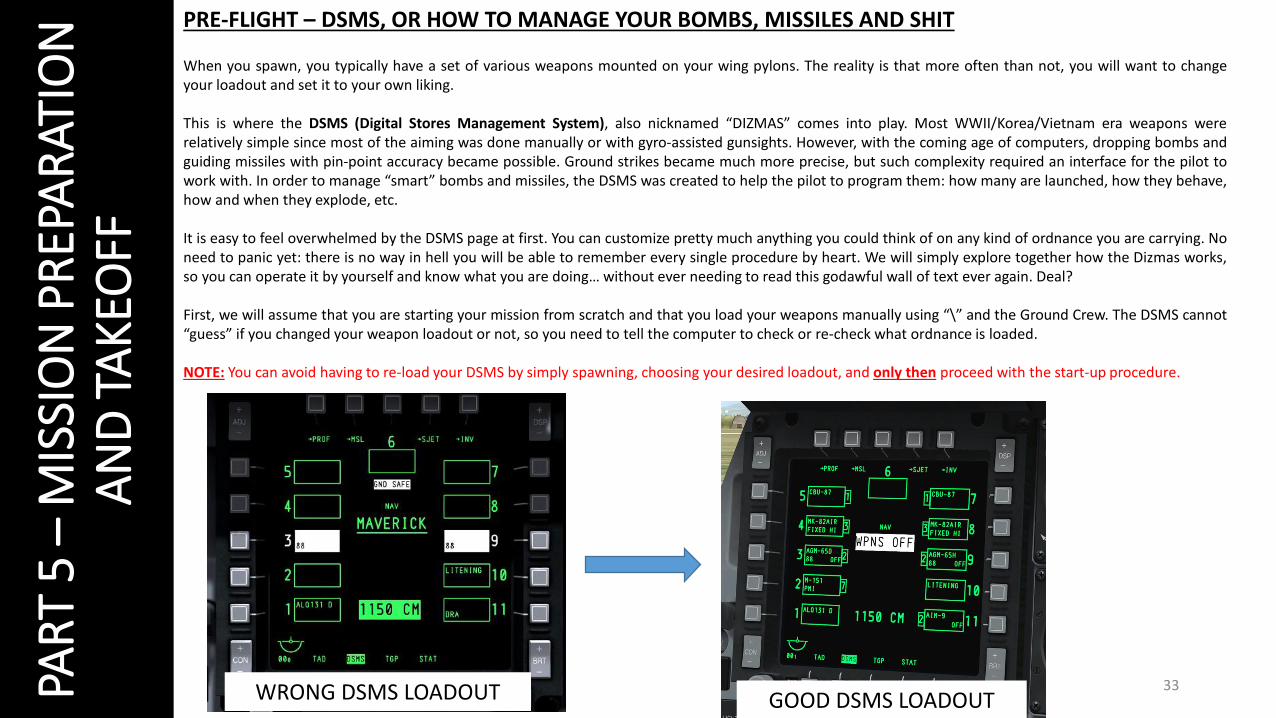
PRE-FLIGHT – DSMS, OR HOW TO MANAGE YOUR BOMBS, MISSILES AND SHIT
When you spawn, you typically have a set of various weapons mounted on your wing pylons. The reality is that more often than not, you will want to changeyour loadout and set it to your own liking.
This is where the DSMS (Digital Stores Management System), also nicknamed “DIZMAS” comes into play. Most WWII/Korea/Vietnam era weapons wererelatively simple since most of the aiming was done manually or with gyro-assisted gunsights. However, with the coming age of computers, dropping bombs andguiding missiles with pin-point accuracy became possible. Ground strikes became much more precise, but such complexity required an interface for the pilot towork with. In order to manage “smart” bombs and missiles, the DSMS was created to help the pilot to program them: how many are launched, how they behave,how and when they explode, etc.
It is easy to feel overwhelmed by the DSMS page at first. You can customize pretty much anything you could think of on any kind of ordnance you are carrying. Noneed to panic yet: there is no way in hell you will be able to remember every single procedure by heart. We will simply explore together how the Dizmas works,so you can operate it by yourself and know what you are doing… without ever needing to read this godawful wall of text ever again. Deal?
First, we will assume that you are starting your mission from scratch and that you load your weapons manually using “\” and the Ground Crew. The DSMS cannot“guess” if you changed your weapon loadout or not, so you need to tell the computer to check or re-check what ordnance is loaded.
NOTE: You can avoid having to re-load your DSMS by simply spawning, choosing your desired loadout, and only then proceed with the start-up procedure.
WRONG DSMS LOADOUT GOOD DSMS LOADOUT

34PAR
T 5
–M
ISSI
ON
PR
EPA
RAT
ION
A
ND
TA
KEO
FF
1 2
3
4
5
6
1) Click on “CDU” menu OSB on right MFCD 2) Click and hold “MSG” OSB until you see the menus appear next to the right OSBs.
3) Click on “Load” OSB on the right menus4) Click on lower “MSG” OSB. OSB will change from “MSG” to “LOAD”.
5) Click on the new lower “LOAD” OSB menu.6) Click on “LOAD ALL” OSB on the right to reload all DSMS stations. Reload is complete when asterisks appear next to every menu.
HOW TO RELOAD DSMS

35PAR
T 5
–M
ISSI
ON
PR
EPA
RAT
ION
A
ND
TA
KEO
FF
DSMS MENUS
MAIN DSMS MENU
JETTISON DSMS MENU
WEAPON PROFILE DSMS MENU MISSILE CONTROL DSMS MENU
INVENTORY DSMS MENU
From the main DSMS menu, you canaccess 4 sub-menus. You can go back tothe main menu by clicking the “STAT” OSB(upper left corner).

36PAR
T 5
–M
ISSI
ON
PR
EPA
RAT
ION
A
ND
TA
KEO
FF
HOW TO MODIFYWEAPON PROFILES 2
3
5
4
6
7
1. From the MAIN DSMS menu, select “PROF” OSB.
2. Move green cursor using the OSBs to the left to cycle through weapon profiles.
3. Once green cursor is next to desired weapon profile, select “VIEW PRO” OSB to open profile settings/options.
4. Select appropriate firing mode (Ripple Single is recommended) and choose what setting on the right OSB row you want to modify.
5. Using the UFC scratch pad, enter in the HUD the new value for the setting you want to modify (ex: “1” for RIPPLE QUANTITY)
6. Select appropriate OSB for the setting you want to change (ex: “RIP QTY”).
7. Click “Save” OSB to save profile once all settings are OK.
1
2
CURSOR
NUMBERS ENTERED FROM UFC
“CLEAR” UFC IF YOU MADE A MISTAKE OR GET THE “ERR” NOTICE ON HUD.
NOTE: In other words, you modify a profile setting by entering the new setting value from the scratch pad first, and THEN you select the setting you want to apply this value to. Note that some settings like CCRP/CCIP weapon release mode do not require user input from UFC scratch pad: you can just click the OSB next to the parameter to toggle it.
NOTE: You can click “CHANGE SETTINGS” to access additional weapon release settings.

37PAR
T 5
–M
ISSI
ON
PR
EPA
RAT
ION
A
ND
TA
KEO
FF
RECOMMENDED WEAPON LOADOUT
STATION STORE DESCRIPTION
1 AN/ALQ-131 ECM JAMMER POD Electronic Countermeasures Jammer Pod
2 7 x 2.75 in M-151 Rockets Unguided Rocket Pod
3 2 x AGM-65D MAVERICK Air-to-Ground Missile 125 lbsD variant: Infrared Seeker
4 3 x MK-82 General Purpose Unguided Bomb
5 1 x GBU-38 Guided Bomb (JDAM)
6 EMPTY
7 1 x GBU-38 Guided Bomb (JDAM)
8 3 x MK82 General Purpose Unguided Bomb
9 2 x AGM-65H MAVERICK Air-to-Ground Missile 125 lbsH variant: Electro-Optical Seeker
10 AN/AAQ-28 LITENING POD Targeting Pod (TGP)
11 2 x AIM-9M SIDEWINDER Air-to-Air Missile
GUN 1150 rounds GAU-8 30 MM GUNCombat Mix
FLARE DISPENSER 120 Disrupts IR heat-seeking missiles
CHAFF DISPENSER 240 Disrupts semi-active radar homing missiles
FUEL 75 %
MISSION LOADOUT
ESSENTIAL
ESSENTIAL
38PAR
T 5
–M
ISSI
ON
PR
EPA
RAT
ION
A
ND
TA
KEO
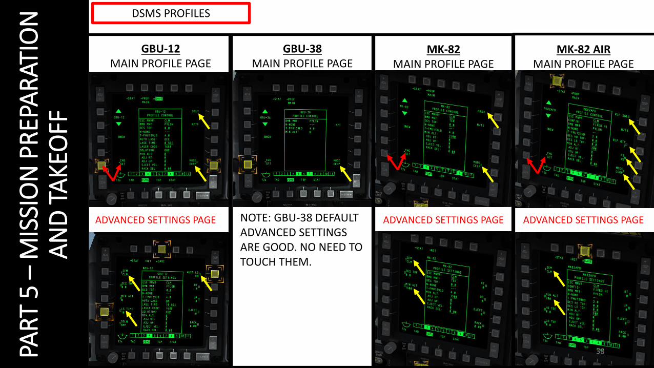
FFGBU-12
MAIN PROFILE PAGEGBU-38
MAIN PROFILE PAGEMK-82
MAIN PROFILE PAGE
NOTE: GBU-38 DEFAULT ADVANCED SETTINGS ARE GOOD. NO NEED TO TOUCH THEM.
MK-82 AIRMAIN PROFILE PAGE
ADVANCED SETTINGS PAGE ADVANCED SETTINGS PAGE ADVANCED SETTINGS PAGE
DSMS PROFILES

39PAR
T 5
–M
ISSI
ON
PR
EPA
RAT
ION
A
ND
TA
KEO
FFMAVERICK AIR-TO-GROUND MISSILE
Maverick missiles require a certain time for alignment. It is more practical tostart the alignment procedure on the ground than to do it in the air. On yourleft MFCD, select the “MSL” menu. Then, set your EO ON. Alignment willtake about 3 minutes. Afterwards, select the MAV (Maverick Missile) menuon the right MFCD, press “2” on the UFC and click on the “SLEW” OSB.
DSMS PROFILES
2
3
5
4
1

40PAR
T 5
–M
ISSI
ON
PR
EPA
RAT
ION
A
ND
TA
KEO
FF1. Ensure ANTI-SKID is on.2. Taxi using toe brakes with Nosewheel Steering ON (keyboard binding:
“INSERT”).3. Make sure your Pitot Heat is ON during cold conditions.4. Press the TAKEOFF TRIM switch to ensure you are trimmed for takeoff.5. Set flaps for takeoff (7 deg) and ensure speedbrakes are closed.6. Hold down brakes, MAX throttle.7. Release brakes and start rolling.8. Disengage Nosewheel Steering (OFF) when you reach 70 kts. 9. Rotate at 135 kts. Landing Gear and Flaps UP.10. Start climbing at a 10 deg AoA (Angle of Attack) angle. Do not yank
back on the stick to get airborne: let it fly off the runway by itself.
TAKEOFF
NOSEWHEEL STEERING
41
PAR
T 6
–LA
ND
ING
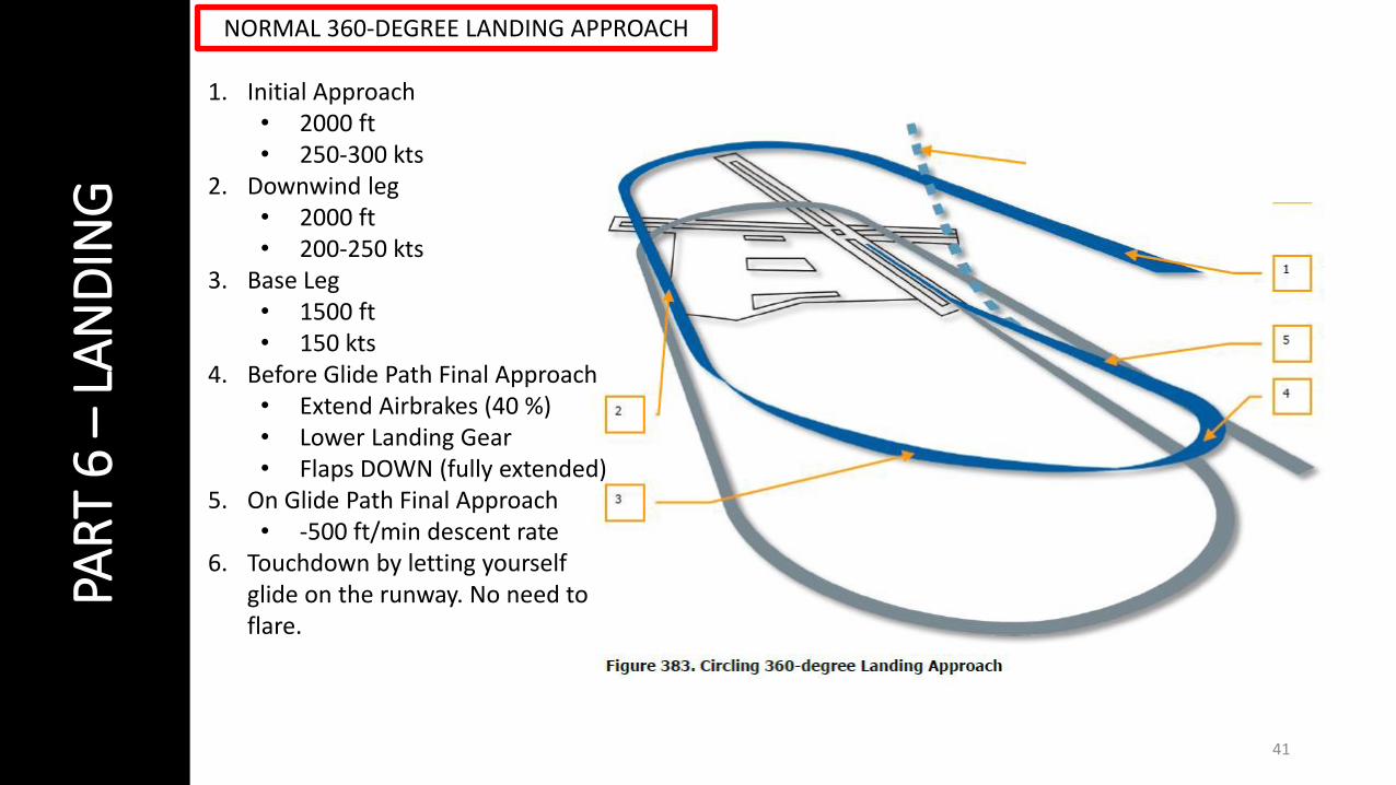
1. Initial Approach• 2000 ft• 250-300 kts
2. Downwind leg• 2000 ft• 200-250 kts
3. Base Leg• 1500 ft• 150 kts
4. Before Glide Path Final Approach• Extend Airbrakes (40 %)• Lower Landing Gear• Flaps DOWN (fully extended)
5. On Glide Path Final Approach• -500 ft/min descent rate
6. Touchdown by letting yourself glide on the runway. No need to flare.
NORMAL 360-DEGREE LANDING APPROACH

42PAR
T 7
–EN
GIN
E M
AN
AG
EMEN
TYou’re in luck, there is really not much for you to learn regarding engine management. Yay!
It is always wise to check on the front panel the RPM, EGT and ITT gauges to make sure they are all in thegreen, but engine management is fairly simple and does not require much of your attention (unlike themillion other armament and navigation systems you need to deal with).
The TF-34-GE-100A engines of the A-10C are placed in a rather unusual configuration: they are mountedhigh on the rear fuselage between the wings and the rear stabilizers. The vertical stabs provide additionalprotection against small arms fire: it is an intelligent design choice when you consider the fact that the A-10C is a ground-pounder and sometimes has to go pretty close to provide accurate close air support (CAS)to the troops on the ground.
Some of the advantages are quite interesting:
• The high mounting reduces the likelihood of the engines ingesting Foreign Object Debris (FOD) whenoperating from rough, forward bases in war-time.
• Engines can remain running when aircraft is being rearmed and refueled. This leads to faster missionturn-around.
• Ease of servicing the engines.• Reduced IR signature from below due to the shielding of the horizontal stabilizer.

43
PAR
T 8
–U
ND
ERST
AN
DIN
G H
OW
SY
STEM
S W
OR
K
THE MYSTERY OF THE HUD AND MULTI-FUNCTION COLOR DISPLAYS
The MFCDs often seem to confuse new pilots. It is hard to go from a prop plane to an aircraft that works just like a computer, isn’t it? So manydifferent programs, so many switches, so many settings… It is easy to feel at loss when you have no idea what is under the hood.
The trick in understanding how the HUD and MFCDs work is to think of them like computer monitors. In fact, it works almost exactly like acomputer. While you are used to have Google Chrome, Itunes, Word and other programs running simultaneously on a single screen, you canswitch between different windows, right? Well, this time you’re flying an A-10C, not a PC or a Mac. The TAD, TGP, MAV, CDU and DSMS are alldifferent systems that can run at the same time (just like the computer programs and apps a la Candy Crush that you use in your everydaylife). The MFCDs can only “display” two system interfaces at once, though… it kind of makes sense since you only have two screens, doesn’tit? Just like in a computer, you can choose what you want to show on any screen.
A computer screen is pretty, but it isuseless if you cannot use it. This is whyyou have a mouse and keyboard.However, the A-10C does not have amouse and keyboard: instead, it hassets of grey OSBs (Option Select Button)around each MFCD, a UFC (Up FrontController) on your front dash, anotherkeyboard next to your CDU (ControlDisplay Unit) on the right console and ithas a HOTAS (Hand On Throttle-and-Stick), which are the fancy buttons onyour joystick and throttle.
With the HOTAS, UFC, CDU keyboardand OSBs, you can easily control yoursystems. It’s like having an old Nintendo64 controller: if you want to play, youneed to know how to use it properly.

44
PAR
T 8
–U
ND
ERST
AN
DIN
G H
OW
SY
STEM
S W
OR
K
THE MYSTERY OF THE HUD AND MULTI-FUNCTION COLOR DISPLAYS
SCREEN
CONTROLLER
CONTROLLERS
SCREENS

45
PAR
T 8
–U
ND
ERST
AN
DIN
G H
OW
SY
STEM
S W
OR
K
THE MYSTERY OF THE SOI AND SPI
You will hear these terms all the time: SOI, which means “Sensor of Interest” and SPI, which means “Sensor Point of Interest”.
The A-10C can “see” in many ways: you can look through the canopy, but you can also use different sensors like the TGP (Targeting Pod), theMAV (Maverick Air-to-Ground missile), the TAD (Tactical Awareness Display) or even the HUD (Heads Up Display). They are all differentsensors that can be controlled with the different “controls” we spoke about earlier... like the HOTAS. Making a sensor SOI basically means thatyou take control of this sensor. In “computer terms”, it is the equivalent of using Alt-Tab to select which window you want to use your mouseand keyboard in. If you want to control the infrared camera embedded in your TGP, you need to select the TGP by “making it your SOI”.
A SPI, on the other hand, is where your SOI (the Sensor of Interest that youare currently controlling) is pointing. It is basically your mouse’s cursor. Inother words, you use a SPI to lock on targets and throw shit at it that blowsup. In order to use a weapon, the procedure is always the same: choose aSensor of Interest (SOI) like your TGP, your HUD or a MAVerick Missile’sseeker head, and once you have made this sensor your SOI, control your SPI(camera “cursor”), move it on a target, slave your sensors to this SPI, lockyour target and fire your weapons according to the procedures elaborated inthe WEAPONS part of this guide.
TAD Sensor TGP Sensor MAV Sensor HUD Sensor
NOT SOI
GREEN SQUARE LINE = SENSOR IS SOI
ASTERISK = SENSOR IS SOI
TGP: TARGETING POD

46
PAR
T 9
–U
ND
ERST
AN
DIN
G H
OTA
S
HOTAS: HOW TO USE IT
The philosophy of concept of “Hands on Throttle-and-Stick” (HOTAS) is thatyou can access the majority of your systems by keeping on hands on yourthrottle and your joystick 99 % of the time.
These controls are ESSENTIAL to remember!
• TMS SWITCH: Target Management System• Typically used to lock on targets and set your SPI…
• DMS SWITCH: Data Management Switch• Used to zoom in/out, cycle through waypoints or weapons…
• SLEW CONTROL• Used to control where your Sensor of Interest (SOI) is looking
• COOLIE HAT• Controls DSMS (what weapons you want to use), swaps MFCD
screens (like an ALT+TAB), lets you pick a Sensor of Interest (SOI),etc…
• BOAT SWITCH• Cycle through different FLIR (forward looking infrared) camera
modes• CHINA HAT
• Set different FOV (field of view) angles and slave all sensors toyour SPI (your cameras and missiles will be looking at where youtell them to look, like a target)
Based on what sensor is selected (SOI), these switches will do differentthings.
Not only do these switches do different things based on your Sensor ofInterest, but they also do different things based on how long you hold theswitch.
For example, TMS UP LONG means that you press the TMS switch UP for 1 to3 seconds. DMS RIGHT SHORT means that you press the DMS switch RIGHTfor a very short duration of time (less than 1 second), or like a simple buttonpress.

47
PAR
T 9
–U
ND
ERST
AN
DIN
G H
OTA
S

48
PAR
T 9
–U
ND
ERST
AN
DIN
G H
OTA
S

49
PAR
T 1
0 –
OFF
ENC
EW
EAPO
NS
& A
RM
AM
ENT
THE WEAPONS
The A-10C can use a HUGE variety of weapons.
A good loadout is not necessarily the biggest bomb: a good loadout is the onethat you know how to use and are most comfortable with… and yet thatremains flexible enough to allow you to adapt to different targets andsituations.
There is a mindblowing selection of ordnance to pick from and it is easy to feellost by the sheer number of different bombs. We will briefly explore the typesof bombs together to help you understand what they are all about.
• Unguided rockets• Guns• Air-to-Ground Missile
• Ex: AGM-65 MAVERICK (AGM = Air-to-Ground Missile)• Air-to-Air Missile
• AIM-9 SIDEWINDER• Unguided bombs
• Ex: Mk-82, Mk-82AIR, Mk-84• PGM: Precision Guided Munition
• LGB: Laser-Guided Bombs / GBU (Guided Bomb Unit)• Bomb is guided by a laser beam from operators on the ground,
a JTAC or your own TGP (targeting pod).• Ex: GBU-10, GBU-12
• IAM: Inertially Aided Munition• JDAM (Joint Directed Attack Munition)
• Bomb is guided by a GPS satellite. Fire & Forget.• Ex: GBU-38, GBU-31
• WCMD (Wind Corrected Munition Dispenser)• Guided by INS (Inertial Navigation System) . Fire &
Forget.• Ex: CBU-87, CBU-97, CBU-105

50
PAR
T 1
0 –
OFF
ENC
EW
EAPO
NS
& A
RM
AM
ENT
THE PROCEDURES
These are the steps you must do in order to fire a weapon.
Note: Rob10 from the DCS forums did a couple of lists and detailed procedures on how to use each weapon type. Thesecharts are listed at the end of this section, so I recommend that you print them out. This is good, useful stuff.
There is also another tutorial by Sim that shows weapon employments with lots of pretty pictures.http://simhq.com/forum/ubbthreads.php/topics/3171145/How_to_use_weapons_Picture_gui.html#Post3171145
1. Select a weapon using your DSMS2. Arm selected weapon and sensors3. Select delivery mode (CCIP or CCRP)4. Use one of your sensors (by making it SOI) to find
a target, move your SPI over your target, slave allyour sensors to the SPI/target and lock it.
5. Fire weapon when you have a firing solution.
An excellent weapons tutorial by Robert Sogomonianhttps://www.youtube.com/watch?v=-MDNcdFJ8x0

51
PAR
T 1
0 –
OFF
ENC
EW
EAPO
NS
& A
RM
AM
ENT
STEP 1: PICK A WEAPON
• To use default weapon profiles (not the ones you modified): Select desired weapon by selecting the DSMS (Digital Stores Management System) page on yourMFCD and by clicking on the OSB next to weapon stations. You can select multiple stations at once provided that they are loaded with the same kind ofbomb/weapon.
• To use the weapon profiles you just modified: Make HUD SOI (COOLIE HAT UP SHORT) and cycle through weapons using DMS RIGHT SHORT or DMS LEFTSHORT. You will see what weapon you selected on the HUD.
STEP 2: ARM WEAPON & SENSORS
Arm your weapons and sensors by turning on the MASTER ARM, GUNPAC, LASER ARM and TGP (Targeting Pod). It is a good idea to do this step before you takeoff.

52
PAR
T 1
0 –
OFF
ENC
EW
EAPO
NS
& A
RM
AM
ENT
STEP 3: PICK DELIVERY MODE - CCRP VS CCIP
There are 2 ways to deliver a weapon: CCRP or CCIP modes.
CCIP mode is the traditional dive bombing approach: you dive on target and thereticle will tell you where the bomb will impact.
However, dive bombing is a risky business, especially if anti-air defences aresurrounding your target. The lower you go, the more vulnerable you are. This iswhy CCRP release mode was invented.
CCRP mode allows you to fly straight and level without having to dive down. TheHUD will tell you when to release your bomb for the target you have designatedwith your Targeting Pod (TGP). It is a much safer way to release a bomb, but asyou may have guessed already, it is a bit less precise.
Using CCRP or CCIP is up to you and the situation you are in. Some pilots prefer touse CCIP, while others would not touch CCRP with a 10-ft pole. Both deliverymodes work, and only experience will teach you what you prefer to use, and inwhich situations. As shown previously, CCRP or CCIP delivery can be setthroughout the DSMS during the PREFLIGHT phase.
Your delivery mode can be set throughout your DSMS in your weapon profiles.
CCIP: Continuously Computed Impact Point
CCRP: Continuously Computed Release Point

53
PAR
T 1
0 –
OFF
ENC
EW
EAPO
NS
& A
RM
AM
ENT
STEP 4: PICK A TARGET
OPTION 1: USING THE HUD AS SOI (COOLIE HAT UP)OPTION 2: USING THE TARGETING POD (TGP) AS SOIOPTION 3: USE THE MAVERICK SEEKER HEAD (MAVERICK MISSILE ONLY) AS SOI
TRICK: if your target is on a set waypoint, youcan make your HUD SOI (coolie hat up), selectdesired waypoint (DMS UP SHORT), and slave allsensors to this waypoint by pressing China HatFWD LONG)

54
PAR
T 1
0 –
OFF
ENC
EW
EAPO
NS
& A
RM
AM
ENT
STEP 4: PICK A TARGET
OPTION 1: USING THE HUD AS SOIOPTION 2: USING THE TARGETING POD (TGP) AS SOI (COOLIE HAT LONG LEFT OR RIGHT DEPENDING ON WHICH MFCD TGP IS SET TO)OPTION 3: USE THE MAVERICK SEEKER HEAD (MAVERICK MISSILE ONLY) AS SOI
TRICK: if your target is on a set waypoint, youcan make your HUD SOI (coolie hat up), selectdesired waypoint (DMS UP SHORT), and slave allsensors to this waypoint by pressing China HatFWD LONG)

55
PAR
T 1
0 –
OFF
ENC
EW
EAPO
NS
& A
RM
AM
ENT
STEP 4: PICK A TARGET
OPTION 1: USING THE HUD AS SOIOPTION 2: USING THE TARGETING POD (TGP) AS SOIOPTION 3: USE THE MAVERICK SEEKER HEAD (MAVERICK MISSILE ONLY) AS SOI (COOLIE HAT LONG LEFT OR RIGHT DEPENDING ON WHICH MFCD MAV IS SET TO)
TRICK: if your target is on a set waypoint, youcan make your HUD SOI (coolie hat up), selectdesired waypoint (DMS UP SHORT), and slave allsensors to this waypoint by pressing China HatFWD LONG)
56
PAR
T 1
0 –
OFF
ENC
EW
EAPO
NS
& A
RM
AM
ENT
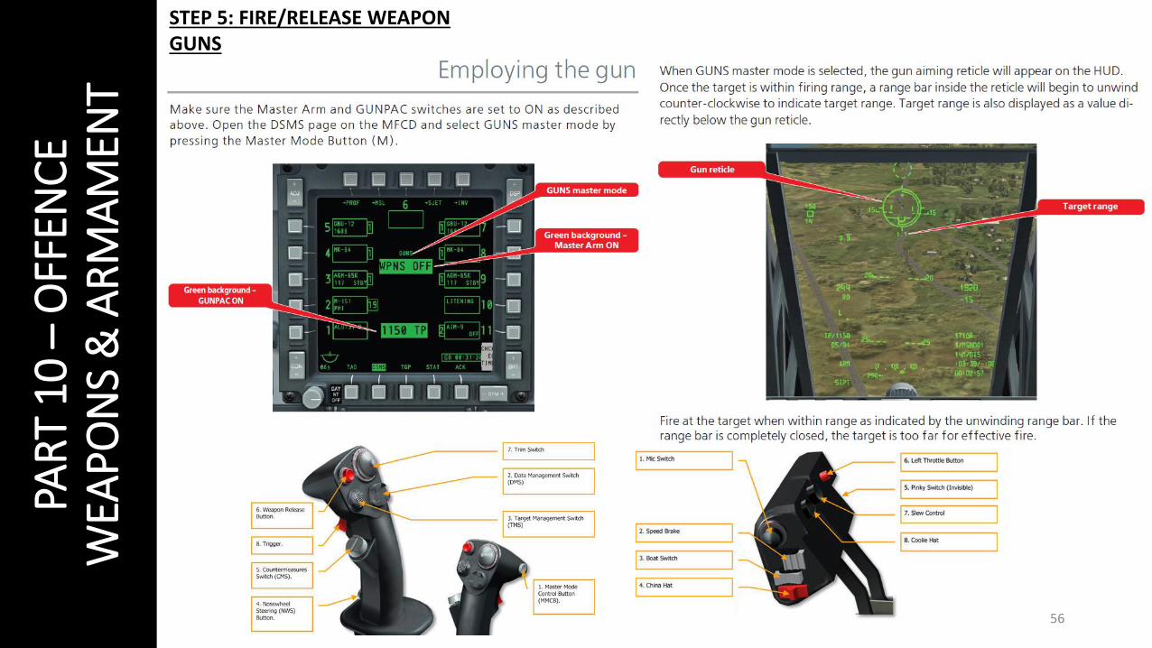
STEP 5: FIRE/RELEASE WEAPON GUNS

57
PAR
T 1
0 –
OFF
ENC
EW
EAPO
NS
& A
RM
AM
ENT
STEP 5: FIRE/RELEASE WEAPONROCKETS - CCIP
1. Set the HUD your SOI by pressing COOLIEHAT UP.
2. Select CCIP mode with Master Mode button.CCRP is not very precise and notrecommended for rockets.
3. Select rocket profile using DMS LEFT SHORTor DMS RIGHT SHORT.
4. Dive on target and press WEAPONS RELEASEbutton to fire rockets.

58
PAR
T 1
0 –
OFF
ENC
EW
EAPO
NS
& A
RM
AM
ENT
STEP 5: FIRE/RELEASE WEAPON UNGUIDED BOMBS - CCIP
59
PAR
T 1
0 –
OFF
ENC
EW
EAPO
NS
& A
RM
AM
ENT
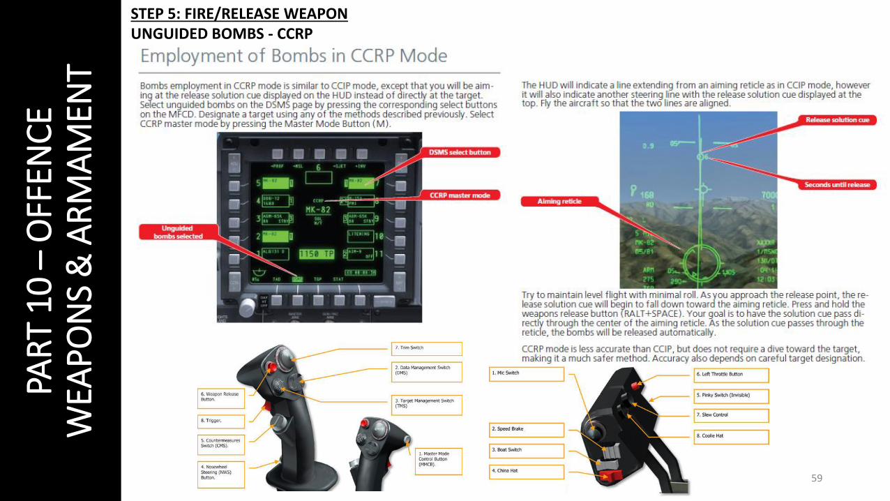
STEP 5: FIRE/RELEASE WEAPON UNGUIDED BOMBS - CCRP
60
PAR
T 1
0 –
OFF
ENC
EW
EAPO
NS
& A
RM
AM
ENT
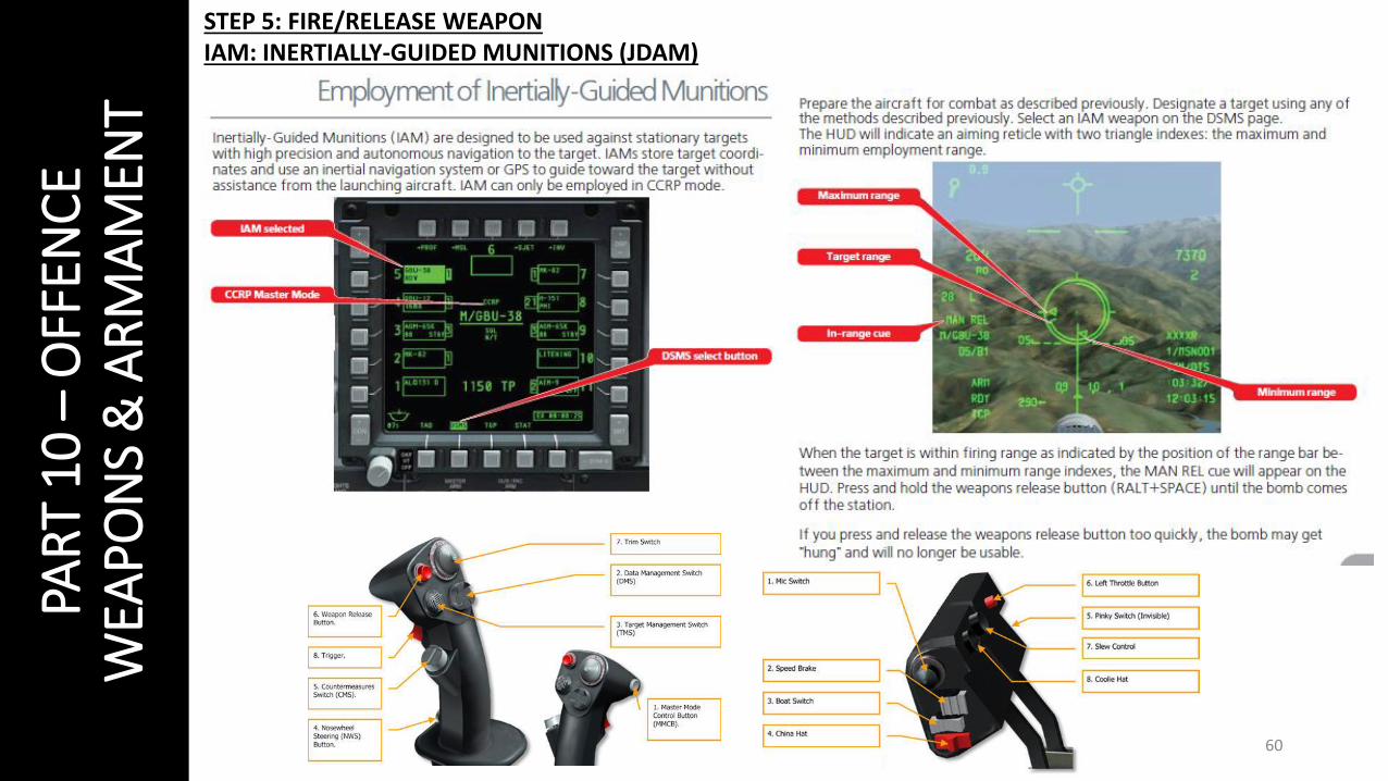
STEP 5: FIRE/RELEASE WEAPON IAM: INERTIALLY-GUIDED MUNITIONS (JDAM)
61
PAR
T 1
0 –
OFF
ENC
EW
EAPO
NS
& A
RM
AM
ENT
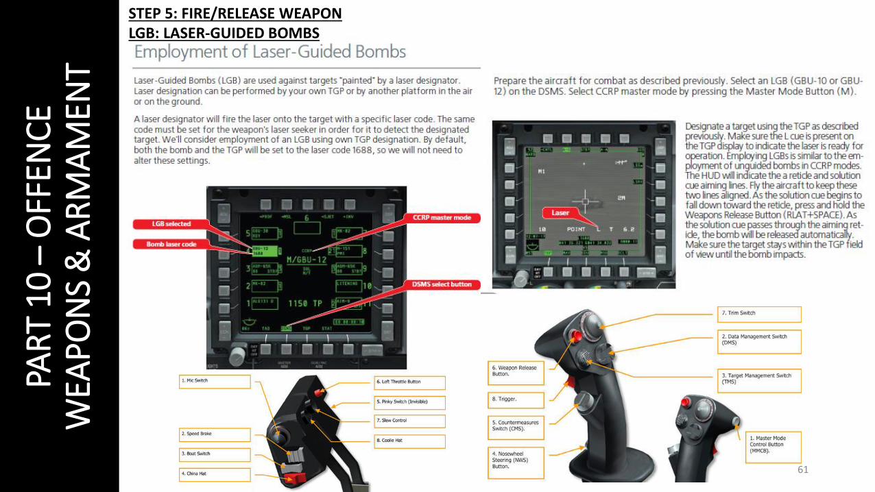
STEP 5: FIRE/RELEASE WEAPON LGB: LASER-GUIDED BOMBS
62
PAR
T 1
0 –
OFF
ENC
EW
EAPO
NS
& A
RM
AM
ENT
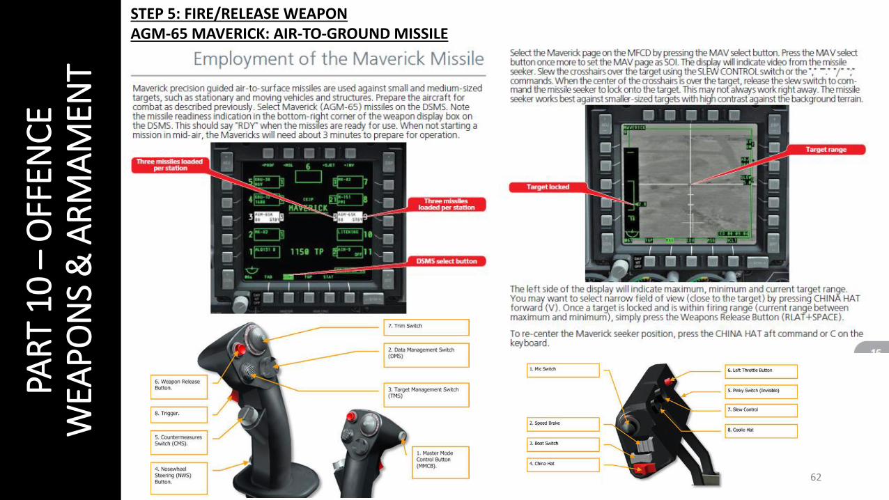
STEP 5: FIRE/RELEASE WEAPON AGM-65 MAVERICK: AIR-TO-GROUND MISSILE

63
PAR
T 1
0 –
OFF
ENC
EW
EAPO
NS
& A
RM
AM
ENT
STEP 5: FIRE/RELEASE WEAPON AIM-9 SIDEWINDER: AIR-TO-AIR MISSILE

64
PAR
T 1
0 –
OFF
ENC
EW
EAPO
NS
& A
RM
AM
ENT

65
PAR
T 1
0 –
OFF
ENC
EW
EAPO
NS
& A
RM
AM
ENT

66
PAR
T 1
0 –
OFF
ENC
EW
EAPO
NS
& A
RM
AM
ENT

67
PAR
T 1
0 –
OFF
ENC
EW
EAPO
NS
& A
RM
AM
ENT
68
PAR
T 1
1 –
DEF
ENC
ER
WR
& C
OU
NTE
RM
EASU
RES
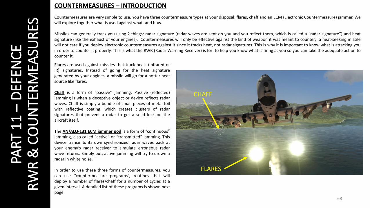
COUNTERMEASURES – INTRODUCTION
Countermeasures are very simple to use. You have three countermeasure types at your disposal: flares, chaff and an ECM (Electronic Countermeasure) jammer. Wewill explore together what is used against what, and how.
Missiles can generally track you using 2 things: radar signature (radar waves are sent on you and you reflect them, which is called a “radar signature”) and heatsignature (like the exhaust of your engines). Countermeasures will only be effective against the kind of weapon it was meant to counter; a heat-seeking missilewill not care if you deploy electronic countermeasures against it since it tracks heat, not radar signatures. This is why it is important to know what is attacking youin order to counter it properly. This is what the RWR (Radar Warning Receiver) is for: to help you know what is firing at you so you can take the adequate action tocounter it.
Flares are used against missiles that track heat (infrared orIR) signatures. Instead of going for the heat signaturegenerated by your engines, a missile will go for a hotter heatsource like flares.
Chaff is a form of “passive” jamming. Passive (reflected)jamming is when a deceptive object or device reflects radarwaves. Chaff is simply a bundle of small pieces of metal foilwith reflective coating, which creates clusters of radarsignatures that prevent a radar to get a solid lock on theaircraft itself.
The AN/ALQ-131 ECM jammer pod is a form of “continuous”jamming, also called “active” or “transmitted” jamming. Thisdevice transmits its own synchronized radar waves back atyour enemy’s radar receiver to simulate erroneous radarwave returns. Simply put, active jamming will try to drown aradar in white noise.
In order to use these three forms of countermeasures, youcan use “countermeasure programs”, routines that willdeploy a number of flares/chaff for a number of cycles at agiven interval. A detailed list of these programs is shown nextpage.
FLARES
CHAFF

69
PAR
T 1
1 –
DEF
ENC
ER
WR
& C
OU
NTE
RM
EASU
RES
COUNTERMEASURE PROGRAMS
Your Countermeasure switch has 5 functions.• PRESSED DOWN: ECM ON/OFF• PRESSED FORWARD: Initiate countermeasure program (deploys
flares/chaff routine)• PRESSED AFT: Terminate countermeasure program (cancels
flares/chaff routine)• PRESSED RIGHT: Next countermeasure program• PRESSED LEFT: Previous countermeasure program
You can program your own “countermeasure program” if you wish, itis explained in the main DCS A-10C manual.
The four main programs you should be using are:• Program A: Old generation radar SAM site• Program B: New generation radar SAM site• Program C: IR heat-seeking SAM site• Program D: Unknown/Miscellaneous
You can choose between a MANUAL mode (recommended) or theAUTO mode, which automatically chooses the best countermeasureprogram for you. I generally select program D since it counters prettymuch anything. It might consume a significant number offlares/chaff, but it is better to be out of countermeasures than to beout of A-10.
COUNTERMEASURE SWITCH
COUNTERMEASURE MODE SELECTOR

70
PAR
T 1
1 –
DEF
ENC
ER
WR
& C
OU
NTE
RM
EASU
RES
ELECTRONIC COUNTERMEASURE (ECM) JAMMER
You have four main ECM jammer modes:
• AIR: counters most air-to-air radars• SAM1: counters older-generation SAM systems like the SA-3, SA-6 and SA-8• SAM2: counters newer-generation SAM systems like 2S6, SA-16, SA-11, SA-10 and
SA-15• AAA: counters radar-directed gun systems like the ZSU-23-4 and the ZU-23.
You can switch between jammer modes using the jammer mode selector button nextto the RWR. The jammer mode indicator tells you the mode you are using and thestatus of the jammer. For instance, “OPR SAM1” means that you are using (operating)your ECM program SAM1. “SBY” means that your ECM is not actively jamming enemyradar. Keep that in mind.
JAMMER MODESELECTOR
JAMMER MODEINDICATOR
COUNTERMEASURE PROGRAM # CHAFF # FLARES
MWS: MISSILE WARNING SYSTEM
The MWS will indicate whether a missile is heading straight toyour face or not. If the MWS warning light (red) is lit,immediately start evasive manoeuvers and deploycountermeasures ASAP. You can have three different messages:
• ACTIVE: MWS system is active• LAUNCH: A missile is launched and heading towards you• OFF: Your MWS system is off
MWS MESSAGE
WARNING LIGHT

71
PAR
T 1
1 –
DEF
ENC
ER
WR
& C
OU
NTE
RM
EASU
RES
RWR: RADAR WARNING RECEIVER
Your RWR will tell you what is around you with a top-down view, both friendly and enemy contacts. The closer the symbol to the center of the circle, thestronger the radar signal strength.
A symbol without a circle around it means that the radar is in search mode (in other words: not tracking you yet).
A symbol with a steady circle around it indicates that the radar is tracking/locked on to your aircraft. A missile is not heading your way yet, but it can be anysecond now if the symbol is an enemy SAM site.
A symbol with a flashing circle around it indicates that the radar is supporting a missile that has been launched at you. You are about to receive a missileright up the arse. This is where you pop chaff, flares, ECM and start your evasive manoeuvers.
SEP: Separates contactsPRI: Show 5 highest priority contacts

72
PAR
T 1
1 –
DEF
ENC
ER
WR
& C
OU
NTE
RM
EASU
RES
RWR SYMBOL LISTList made by .408-X~RAY
Note: “U” symbol stands for “Unknown”, which is sometimes attributed to ships.

73
PAR
T 1
1 –
DEF
ENC
ER
WR
& C
OU
NTE
RM
EASU
RES
THE ART OF DEFEATING A MISSILE
Evading missiles is an art: this is what we call “defeating a missile”. There are many videos that explain it well (much better than I could in one page or 2), so here is a list of useful resources you can consult.
DCS A-10 MISSILE AVOIDANCE, by A Kaiserhttps://www.youtube.com/watch?v=ak6EgzDwiGs
AIR POWER AUSTRALIA – EVADING THE GUIDED MISSILE, by Carlo Kopphttp://www.ausairpower.net/TE-Evading-Missiles.html
A PRACTICAL GUIDE TO MISSILE EVASION – TRAINING IN FALCON 4.0, by Mark “Boxer” Doranhttp://www.simhq.com/_air/air_016a.html
FIGHTER COMBAT – TACTICS AND MANOEUVERING, by Robert L. Shawhttp://www.amazon.ca/Fighter-Combat-Maneuvering-Robert-Shaw/dp/0870210599

74
PAR
T 1
2 –
RA
DIO
TU
TOR
IAL
You have three main radios on your left console. • The AN/ARC-186(V) VHF AM # 1 radio set is used for air and ground units
• frequencies between 116.00 and 151.975 MHz• The AN/ARC-186(V) VHF FM #2 radio set is used for communications with JTAC units
• frequencies between 36.000 and 76.000 MHz • The AN/ARC-164 UHF radio set is used for wingmen, support flights, air traffic controllers
• frequencies between 225.000 and 399.975 MHz• The Intercom Panel allows you to choose which radio set
you communicate on.Advanced radio tutorial:http://en.wiki.eagle.ru/w/images/e/e4/DCS_A-10C_Warthog_Radio_Tutorial.pdf

75
PAR
T 1
2 –
RA
DIO
TU
TOR
IAL
RADIO FREQUENCIES – AIRFIELDS
LOCATION FREQUENCY
Anapa 121.0
Batumi 131.0
Beslan 141.0
Gelendzhik 126.0
Gudauta 130.0
Kobuleti 133.0
Kutaisi 134.0
Krasnodar Center 122.0
Krasnodar Pashkovsky 128.0
Krymsk 124.0
Maykop 125.0
Mineral’nye Vody 135.0
Mozdok 137.0
Nalchik 136.0
Novorossiysk 123.0
Senaki 132.0
Sochi 127.0
Soganlug 139.0
Sukhumi 129.0
Tblisi 138.0
Vaziani 140.0

76
PAR
T 1
3 –
AU
TOPI
LOT
The Auto-Pilot is fairly simple: select one of the three auto-pilot modes (PATH, ALT/HDG or ALT) and engage auto-pilot. Be advised: auto-pilot will only engage if you are flying level (+/- 5 degrees). If auto-pilot is engaged, the mode will be displayed on your HUD.
Generally, the only auto-pilot mode I use is the “ALT/HDG” mode, especially when I need to use my DSMS, my TGP or other systems that require my attention away from the flight controls.
Autopilot Modes
Engage/Disengage AutopilotAutopilot mode
ENGAGED.

77
PAR
T 1
4 –
NA
VIG
ATIO
N &
ILS
LAN
DIN
G
THE HUD AND TACTICAL AWARENESS DISPLAY (TAD)
The TAD is one of the most important tools at your disposal for navigation.
On the TAD, you can see friendly contacts and the different waypoints. Generally, amission is planned by setting waypoints that will show your mission’s flight plan. If amission maker is smart, he will make sure that these waypoints are set properly in themission file. The difference between a steerpoint and a waypoint is that a steerpoint isthe waypoint you are currently selecting and flying towards. Your CDU (flight computer)can stock hundreds of waypoints, yet your HUD can only track one waypoint at a time,which is what we call a steerpoint. Of course, you can also change, add or removewaypoints manually if you want, but I will let you check the A-10C manual for that.
You can zoom in or zoom out in the TAD by making it your SOI (COOLIE HAT LEFT LONG ifyour TAD is set up on your left MFCD) and pressing your DMS switch UP or DOWN. Mostof your navigation information is also displayed on the HUD. We will come back to thislater on.

78
PAR
T 1
4 –
NA
VIG
ATIO
N &
ILS
LAN
DIN
G
NAVIGATION SYSTEMS: NMSP, EGI, HARS, TISL, TACAN & ILS
NMSP/NIMSIP, or the Navigation Mode Select Panel, allows you to choose which navigation system to use.
EGI (pronounced “eggi”) is an Embedded GPS/INS navigation system. This is your primary system for navigation, using the waypointsand flight plan database stocked in the CDU (Control Display Unit).
HARS is a Heading Attitude Reference System, a legacy system of the A-10A. It is used as a backup gyro-system to EGI that providesheading and attitude aircraft state.
TISL is a “Target Identification Set, Laser” system that detects and tracks reflected laser energy. In real life, TISL system is used totrack targets that are laser designated by other assets like aircraft or ground forces. This system is not fully implemented in DCS.
TACAN is a Tactical Air Navigation System used by the military. TACAN beacons can be placed on ground stations, airfields or evenaircraft themselves like tankers. A TACAN beacon will provide you line-of-sight bearing and range to the selected TACAN station. Wewill explore TACAN functionality in the Air-to-Air refueling section.
ILS (Instrumented Landing System) is typically used during night and/or foul weather. This system will give you indications on whatheading and what gliding slope to take in order to make a successful approach to an airfield.
The following slides will show you how to use these systems. Obviously, we won’t explore all their functionalities: it could take yetanother few hundred pages… and ain’t nobody got time for that.

79
PAR
T 1
4 –
NA
VIG
ATIO
N &
ILS
LAN
DIN
G
WAYPOINT, STEERPOINT AND CDU
The CDU (Control Display Unit) is the brain of your aircraft. This is where all therelevant information that we are too lazy to remember is stocked. I’m pretty surethat you could program your coffee machine from the CDU if you had one installedin the A-10C: it is a tool that is just that powerful.
We have seen before what a waypoint and a steerpoint are. You can cycle throughyour waypoints by making your HUD SOI (COOLIE HAT UP SHORT) and using yourDMS switch UP or DOWN to cycle through your waypoints. Each time you have aselected steerpoint, your HUD will display you a TVV (Total Velocity Vector) for youto follow in order to get to this waypoint.
But what if you are completely lost and want to head to a particular airfield? Whatif you have no idea of where it is, the radio tower frequency, if there is an ILSsystem installed or not? Well, the CDU can help you with that. I told you that wewouldn’t really go in-depth with the CDU, but this trick is just too cool not to talkabout. Yes, I lied… sue me.
We will see it next page.

80
PAR
T 1
4 –
NA
VIG
ATIO
N &
ILS
LAN
DIN
G
WAYPOINT, STEERPOINT AND CDU
If you are lost, you can use the CDU to help you find aplace to land.
1. Make your HUD SOI by pressing COOLIE HAT UPSHORT.
2. On the UFC, press “FUNC” (function) and “2” (NAVfunctions)
3. On the CDU page, a new NAV menu will appear.Press the OSB to select the “DIVERT” menu.
4. The divert menu will display the closest airfields toyou. If we want to go to Batumi, just by having aquick look at it, we know that Batumi is alreadystocked in our computer in WAYPOINT 61. We alsoknow that we need to go to a heading of 218 for37.8 nautical miles, with a TTG (time to go) ofabout 7 minutes 44 seconds. If we select theBatumi OSB, we can have even more details.
5. The advanced menu for Batumi shows us thatthere are two runways (one oriented at 130 andthe other one at 310), that there is an ILS system inplace set at frequency 110.30, that there is aTACAN station set to 16 and that the radiofrequency to communicate with the control toweris 131.000.
6. Even better: if you look at your HUD you will nowsee that Batumi is your current steerpoint and thatthe HUD is showing you where to go to find it. Ifyou want to find another airfield or follow anotherwaypoint, since your HUD is already SOI you cansimply use DMS UP SHORT or DMS DOWN SHORTto cycle through more waypoints.
2
3
4
56

81
PAR
T 1
4 –
NA
VIG
ATIO
N &
ILS
LAN
DIN
G
ILS TUTORIAL
1. ILS approach 2. Final Approach3. Outer ILS marker4. Inner ILS marker5. Missed Approach

82
PAR
T 1
4 –
NA
VIG
ATIO
N &
ILS
LAN
DIN
G
ILS TUTORIAL
Our ILS approach will be done to Batumi airfield. Using our CDU trick learned in the “Waypoint, Steerpoint & CDU” slide, we can easily find the ILS frequency (110.30), runway heading (130) and radio tower frequency (131.000).

83
PAR
T 1
4 –
NA
VIG
ATIO
N &
ILS
LAN
DIN
G
ILS TUTORIAL
1. Set your VHF radio to TR (transmit-receive), set frequency to 131.000 and call the tower for inbound request.
2. Enter ILS frequency 110.30 rotating the PWR and VOL knobs with the mousewheel. Turn ILS system power ON by right clicking on the PWR switch.
3. Set your HSI (Horizontal Situation Indicator) course to 130 (runway heading) with your mousewheel.
4. On the NMSP panel, set homing mode to ILS and navigate towards runway.
1
2
34

84
PAR
T 1
4 –
NA
VIG
ATIO
N &
ILS
LAN
DIN
G
ILS TUTORIAL
5. Align yourself with the runway using the ADI (Attitude DirectorIndicator) and the HSI.
• The yellow line on the HSI will help you align yourself withthe runway.
6. When lined up with the runway, deploy flaps and airbrakes asrequired to get a good landing speed Adjust glide slope accordingto AoA Indexer (green circle = good speed) and lights on therunway. Touchdown like you normally do.
• white lights = above glide slope = OK• red lights = under glide slope = NOT OK
5
6
AOA INDEXER:GOING TOO FAST WHITE LIGHTS:
ABOVE GLIDE SLOPE = OK
YELLOW LINEALIGNED & CENTERED WITH HSI
ADI COURSEALIGNED WITH ILS
AOA INDEXER:AOA & SPEED = OK

85
PAR
T 1
4 –
NA
VIG
ATIO
N &
ILS
LAN
DIN
G
86PAR
T 1
5 –
AIR
-TO
-AIR
REF
UEL
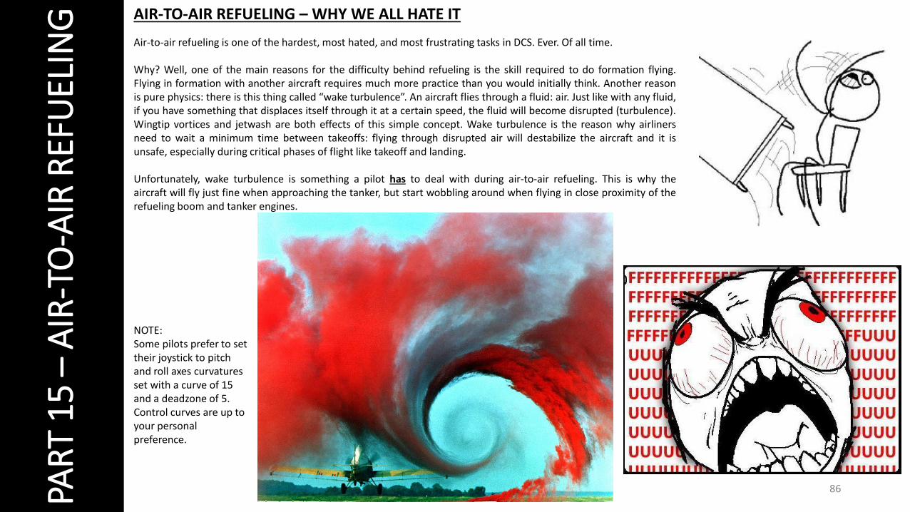
ING AIR-TO-AIR REFUELING – WHY WE ALL HATE IT
Air-to-air refueling is one of the hardest, most hated, and most frustrating tasks in DCS. Ever. Of all time.
Why? Well, one of the main reasons for the difficulty behind refueling is the skill required to do formation flying.Flying in formation with another aircraft requires much more practice than you would initially think. Another reasonis pure physics: there is this thing called “wake turbulence”. An aircraft flies through a fluid: air. Just like with any fluid,if you have something that displaces itself through it at a certain speed, the fluid will become disrupted (turbulence).Wingtip vortices and jetwash are both effects of this simple concept. Wake turbulence is the reason why airlinersneed to wait a minimum time between takeoffs: flying through disrupted air will destabilize the aircraft and it isunsafe, especially during critical phases of flight like takeoff and landing.
Unfortunately, wake turbulence is something a pilot has to deal with during air-to-air refueling. This is why theaircraft will fly just fine when approaching the tanker, but start wobbling around when flying in close proximity of therefueling boom and tanker engines.
NOTE:Some pilots prefer to set their joystick to pitch and roll axes curvatures set with a curve of 15 and a deadzone of 5. Control curves are up to your personal preference.

87PAR
T 1
5 –
AIR
-TO
-AIR
REF
UEL
ING AIR-TO-AIR REFUELING – HOW TO
1. Read your mission briefing to know the TACAN station channel of yourKC-135 Tanker (10X) and the VHF AM channel frequency you cancommunicate with it (150.000).
2. Set your TACAN to “A/A T/R” and to tanker TACAN frequency (10X) byscrolling the mousewheel.
3. On the NMSP panel, press “TCN” to slave the HSI to the TACAN beacon.4. Set your VHF AM radio to T/R and channel 150.000.5. Press Mic Switch FWD and contact tanker (F6).6. Select “Intent to refuel” in the tanker menu. The tanker will give you an
altitude (usually 20,000 ft) to rendezvous at.7. Use the HSI and ADI to line up with the KC-135 tanker. Needle with a
“1” on it points towards the tanker. Distance to tanker is displayed onthe HSI.
1
5
6
4
2
3
7
7
ALMOST LINED UP!
88PAR
T 1
5 –
AIR
-TO
-AIR
REF
UEL
ING AIR-TO-AIR REFUELING – HOW TO
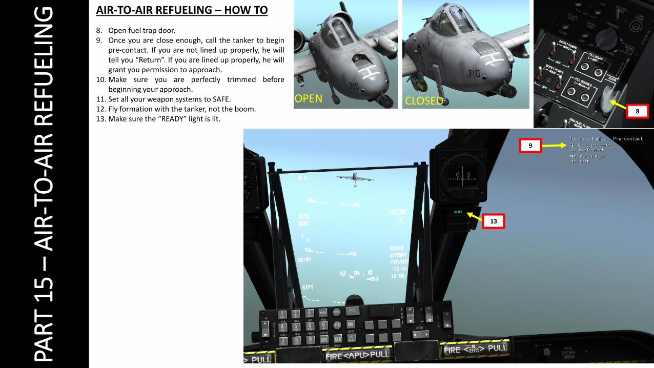
8. Open fuel trap door.9. Once you are close enough, call the tanker to begin
pre-contact. If you are not lined up properly, he willtell you “Return”. If you are lined up properly, he willgrant you permission to approach.
10. Make sure you are perfectly trimmed beforebeginning your approach.
11. Set all your weapon systems to SAFE.12. Fly formation with the tanker, not the boom.13. Make sure the “READY” light is lit.
8
OPEN
13
CLOSED
9

89PAR
T 1
5 –
AIR
-TO
-AIR
REF
UEL
ING AIR-TO-AIR REFUELING – HOW TO
14. Once contact with the boom is done, you will have a “LATCHED” notice. Use the tanker’s engines as a reference to maintain contact.15. If you disconnect the boom prematurely (and it WILL happen, trust me), make sure that you press your “Nosewheel Steering” pinky switch on your HOTAS
joystick (or “INSERT” key binding) to reset your fuel trap door. If you fail to reset it, the boom operator will not be able to make contact with your trap dooragain (refueling light will display “READY” again)..
14

90PAR
T 1
5 –
AIR
-TO
-AIR
REF
UEL
ING AIR-TO-AIR REFUELING – HOW TO
16. Refueling procedure will be done when you have the “DISCONNECT” warning light.17. Close fuel trap door and resume flight.
Here is a nice Air-to-Air refueling example: https://www.youtube.com/watch?v=2qFrmfNEilMSpecial thanks to Derbysieger for creating a helpful written tutorial as well http://steamcommunity.com/sharedfiles/filedetails/?id=170423297

91
PAR
T 1
6 –
OTH
ER R
ESO
UR
CES
RESOURCESBunyap’s Youtube Channelhttps://www.youtube.com/user/4023446/playlists
Gerry Abbott’s Youtube Channel https://www.youtube.com/playlist?list=PL8E198A311F28EA74
Ralfidude’s Idiot Guide to the A-10C: Quick Tipshttps://www.youtube.com/watch?v=9M8yiAjQ7ps
Eagle Dynamics A-10C Wikihttp://en.wiki.eagle.ru/wiki/DCS_A-10C_Guides,_Tutorials_and_Reference_Documents
A-10C Manuals and Books (awesometacular resource!)http://forums.eagle.ru/showthread.php?t=60293
VTAG Handbookhttp://vtacticalairgroup.net/downloads/common/VTAG%20Handbook.pdf
VTAG SOP (Standard Operating Procedures)http://vtacticalairgroup.net/downloads/a-10/VTAG%20SOP.pdf
476th Virtual Fighter Group Databasehttp://www.476vfightergroup.com/downloads.php
476th Virtual Fighter Group Guideshttp://www.476vfightergroup.com/downloads.php?do=cat&id=43
476th Virtual Fighter Group Youtube Channelhttps://www.youtube.com/user/476vFG/videos
Rob10’s Weapon Listhttp://forums.eagle.ru/showthread.php?t=73752

92
PAR
T 1
6 –
OTH
ER R
ESO
UR
CES
ACRONYM TABLE (1/2)
A-A Air-to-Air ASL Azimuth Steering Line CMSP Countermeasure Set Panel
EGT Exhaust Gas Temperature GS Ground Speed
A-G Air-to-Ground ATC Air Traffic Control CR Coordinate Ranging EHE Expected Horizontal Error IAM Inertially Aided Munition
AAP Auxiliary Avionics Panel BATA Bullets at Target Altitude CR Consent to Release EMI Engine Monitoring Instruments
IAS Indicated Airspeed
AAS Air-to-Air Submenu BHOT Black Hot DLZ Dynamic Launch Zone EO Electro Optical IFF Identify Friend or Foe
ACP Armament Control Panel
BIT Built In Test DMS Data Management Switch ET Elapsed Time IFFCC Integrated Flight and Fire Control Computer
ADF Automatic Direction Finding
CADC Central Air Data Computer
DP Display Page EVE Expected Vertical Error ILS Instrumented Landing System
ADI Attitude Direction Indicator
CATM Captive Air Training Missile
DRA Dual Rail Adapter FA Fault Acknowledge INS Inertial Navigation System
AGL Above Ground Level CBU Cluster Bomb Unit DRC Desired Release Cue FEDS Firing Evaluation Display System
ITT Interstage Turbine Temperature
AGM Air-to-Ground Missile CCD Charged Coupled Device DSMS Digital Stores Management System
FLIR Forward Looking Infrared HARS Heading Attitude Reference System
AHCPArmament HUD Control Panel
CCIP Continuously Computed Impact Point
DTOT Desired Time On Target FM Frequency Modulation HEI High Explosive, Incendiary
AIM Air Intercept Missile CCRP Continuously Computed Release Point
DTS Data Transfer System FOM Figure of Merit HOF Height of Function
AM Amplitude Modulation CDI Course Deviation Indicator
DTSAS Digital Terrain System Application Software
FOV Field of View HOTAS Hands On Throttle and Stick
AMIL Air Mass Impact Line CDU Control Display Unit DTTG Desired Time To Go GBL Gun Bore Line HPU Horizontal Position Uncertainty
AOA Angle of Attack CICU Central Interface Control Unit
EAC Enhanced Attitude Control
GBU Guided Bomb Unit HSI Horizontal Situation Indicator
APU Auxiliary Power Unit CM Combat Mix ECM Electronic Countermeasures
GCAS Ground Collision Avoidance System
HUD Heads Up Display
AR Aerial Refueling CMS Countermeasure Set EFC Emergency Flight Control GMT Greenwich Mean Time JDAM Joint Directed Attack Munition
ARS Attitude Reference Symbol
CMSC Countermeasure Set Control
EGI Embedded GPS INS GPS Global Positioning System JTAC Joint Terminal Attack Controller

93
PAR
T 1
6 –
OTH
ER R
ESO
UR
CES
ACRONYM TABLE (2/2)
JTRS Joint Tactical Radio System NMSP Navigation Mode Select Panel SER Single Ejector Rack TVV Total Velocity Vector
KIAS Knots Indicated Airspeed NWS Nosewheel Steering SOI Sensor of Interest UFC Up Front Controller
LAAP Low Altitude Autopilot NVIS Night Vision Imaging System SPI Sensor Point of Interest UHF Ultra High Frequency
LAR Look Aside Ranging ORP Optimal Release Point SPJ Self Protection Jammer VHF Very High Frequency
LASTE Low Altitude Safety and Targeting Enhancement
OSB Option Select Button SRU Shop Replaceable Unit VPU Vertical Position Uncertainty
LOS Line Of Sight OWC Obstacle Warning Cue TAD Tactical Awareness Display
VVI Vertical Velocity Indicator
LRU Line Replaceable Unit PAC Precision Attitude Control TAS True Airspeed WCMD Wind Corrected Munition Dispensor
MAP Missed Approach Point PBIL Projected Bomb Impact Line TDC Target Designation Cursor WCN Warning, Caution, and Notes
MFCD Multifunction Color Display PR Passive Ranging TER Triple Ejector Rack
MGRS Military Grid Reference System PRF Pulse Repetition Frequency TGP Targeting Pod
MMCB Master Mode Control Button RGS Required Ground Speed TISL Target Identification Set Laser
MRC Minimum Range Cue RIAS Required Indicated Airspeed TMS Target Management Switch
MRFCS Manual Reversion Flight Control System RTAS Required True Airspeed TOF Time of Fall / Time of Flight
MRGS Multiple Reference Gunsight RWR Radar Warning Receiver TOT Time On Target
MRS Minimum Range Staple SADL Situational Awareness Datalink TP Target Practice
MSL Mean Sea Level SAI Standby Attitude Indicator TTG Time To Go
MWS Missile Warning System SAS Stability Augmentation System TTRN Time to Release Numeric

94