dcs a-10c warthog - Digital Combat Simulator
216
DCS A-10C WARTHOG Graphical User Interface
-
Upload
khangminh22 -
Category
Documents
-
view
2 -
download
0
Transcript of dcs a-10c warthog - Digital Combat Simulator
DCS [A-10C WARTHOG]
0 TABLE OF CONTENTS | GRAPHICAL USER INTERFACE
DCS A-10C WARTHOG Graphical User Interface
DCS [A-10C WARTHOG]
1 TABLE OF CONTENTS | GRAPHICAL USER INTERFACE
TABLE OF CONTENTS MAIN MENU ............................................................................................................... 6
INSTANT ACTION......................................................................................................... 8
LOGBOOK ................................................................................................................. 10
Pilot Page ......................................................................................................................... 11
Nation, Squadron, and Awards Page ................................................................................. 13
Page Navigation ............................................................................................................... 13
OPTIONS ................................................................................................................... 15
System Options ................................................................................................................ 16 Graphics Settings ................................................................................................................................. 17 Auxiliary Settings ................................................................................................................................. 18
Controls Settings .............................................................................................................. 19 Modifiers ......................................................................................................................................... 22 Switches........................................................................................................................................... 22
Gameplay Settings ........................................................................................................... 27 Difficulties ............................................................................................................................................ 27 F10 View Options ................................................................................................................................. 29 Additional Settings ............................................................................................................................... 31 Presets ................................................................................................................................................. 31
Audio Settings .................................................................................................................. 32
Miscellaneous .................................................................................................................. 33
TRAINING ................................................................................................................. 35
MISSION ................................................................................................................... 38
REPLAY ..................................................................................................................... 42
Create Fast Mission ................................................................................................... 45
Advanced Mode ........................................................................................................... 47 Options ................................................................................................................................................ 47 Forces ................................................................................................................................................... 47 Battle Location ..................................................................................................................................... 48 Briefing ................................................................................................................................................. 48
MISSION EDITOR ....................................................................................................... 50
Starting the Mission Editor ............................................................................................... 50
The Mission Editor Map and Navigation ............................................................................ 50 The World Map .................................................................................................................................... 51 Navigating the Map ............................................................................................................................. 52 The Mission and Map Bar .................................................................................................................... 52
The System Bar ................................................................................................................ 53
DCS [A-10C WARTHOG]
2 TABLE OF CONTENTS | GRAPHICAL USER INTERFACE
File ....................................................................................................................................................... 53 Edit ....................................................................................................................................................... 56 Flight .................................................................................................................................................... 56 Campaign Editor .................................................................................................................................. 58 Customize ............................................................................................................................................ 58
Mission Options ............................................................................................................................... 58 Map Options .................................................................................................................................... 61
Mission Generator ............................................................................................................................... 62 Misc ...................................................................................................................................................... 62
The Tool Bar ..................................................................................................................... 63
Create New Mission ......................................................................................................... 64
Open Mission ................................................................................................................... 64
Save Mission .................................................................................................................... 64
Create Briefing ................................................................................................................. 64
Weather Tool ................................................................................................................... 66 Standard weather ................................................................................................................................ 66 Dynamic weather ................................................................................................................................. 69
Set Triggers ...................................................................................................................... 71 Triggers List .......................................................................................................................................... 72 Conditions ............................................................................................................................................ 74 Trigger Actions ..................................................................................................................................... 79 Practical Exercise ................................................................................................................................. 82
Set Mission Goals ............................................................................................................. 88
Mission Options ............................................................................................................... 90
Fly.................................................................................................................................... 90
Task Planning for Unit Groups .......................................................................................... 91 General Concepts ................................................................................................................................. 91
Example 1 ........................................................................................................................................ 95 Example 2 ........................................................................................................................................ 97 Example 3 ........................................................................................................................................ 98 Example 5 ...................................................................................................................................... 100 Example 6 ...................................................................................................................................... 101
Place Airplane and Helicopter Group .............................................................................. 104 Payload mode ................................................................................................................................ 112 Triggered Actions mode ................................................................................................................ 115 Summary mode ............................................................................................................................. 115 Failures mode ................................................................................................................................ 116
Advanced Actions Mode for Aircraft Groups ................................................................... 118 Triggered Actions .......................................................................................................................... 122
Action Properties Panel ..................................................................................................................... 123 Tasks .............................................................................................................................................. 129 Enroute Tasks ................................................................................................................................ 139
Perform Command ............................................................................................................................ 148 Ground crew support at airbases .................................................................................................. 156
DCS [A-10C WARTHOG]
3 TABLE OF CONTENTS | GRAPHICAL USER INTERFACE
Place Ship ...................................................................................................................... 157 Route mode ................................................................................................................................... 159 Triggered Actions mode ................................................................................................................ 161 SUMMARY mode ........................................................................................................................... 161 Advanced Actions Mode for Naval Groups ................................................................................... 162 Tasks .............................................................................................................................................. 163 Enroute Tasks ................................................................................................................................ 163 Perform Command ........................................................................................................................ 163 Set Option ...................................................................................................................................... 163
Place Ground Unit .......................................................................................................... 164 Triggered Actions mode ................................................................................................................ 171 Summary mode ............................................................................................................................. 171 Advanced Actions Mode for Ground Groups ................................................................................ 172 Tasks .............................................................................................................................................. 172 Enroute Tasks ................................................................................................................................ 173 Perform Command ........................................................................................................................ 173
Place Static Object .......................................................................................................... 176
DEAD. In addition to the normal static object, you may also populate the world with the destroyed version of the object by checking the DEAD box.Initial Point ............................................................................................................ 177
Initial Point .................................................................................................................... 178
Bullseye ......................................................................................................................... 179
Create Area Trigger Zone ................................................................................................ 180
Create Unit Template ..................................................................................................... 182
Area Trigger Zone List ..................................................................................................... 184
Unit List ......................................................................................................................... 186
Delete Unit/Object ......................................................................................................... 187
Map Options .................................................................................................................. 187
Distance Tool ................................................................................................................. 187
Exit Mission Editor ......................................................................................................... 187
View Debriefing ............................................................................................................. 188
CAMPAIGN ............................................................................................................. 191
CAMPAIGN BUILDER ............................................................................................... 194
ENCYCLOPEDIA ....................................................................................................... 198
EXIT ........................................................................................................................ 200
MULTIPLAYER ......................................................................................................... 202
Main Multiplayer Window .............................................................................................. 203 Server List .......................................................................................................................................... 205 Lower Bar ........................................................................................................................................... 205
DCS [A-10C WARTHOG]
4 TABLE OF CONTENTS | GRAPHICAL USER INTERFACE
New Server .................................................................................................................... 206
Options .......................................................................................................................... 208
Join ................................................................................................................................ 209 Joining a Mission ................................................................................................................................ 209
From Server List ............................................................................................................................. 209 Connect by IP ................................................................................................................................. 209 Join Window .................................................................................................................................. 210
In Mission Commands........................................................................................................................ 214
EXIT ............................................................................................................................... 214
REFERENCES ............................................................................................................ 215

DCS [A-10C WARTHOG]
5 / MAIN MENU | GRAPHICAL USER INTERFACE
MAIN MENU
DCS [A-10C WARTHOG]
6 / MAIN MENU | GRAPHICAL USER INTERFACE
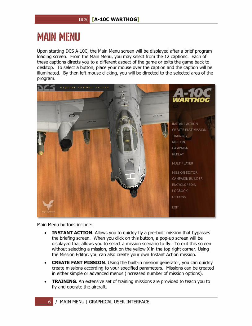
MAIN MENU Upon starting DCS A-10C, the Main Menu screen will be displayed after a brief program loading screen. From the Main Menu, you may select from the 12 captions. Each of these captions directs you to a different aspect of the game or exits the game back to desktop. To select a button, place your mouse over the caption and the caption will be illuminated. By then left mouse clicking, you will be directed to the selected area of the program.
Main Menu buttons include:
INSTANT ACTION. Allows you to quickly fly a pre-built mission that bypasses the briefing screen. When you click on this button, a pop-up screen will be displayed that allows you to select a mission scenario to fly. To exit this screen without selecting a mission, click on the yellow X in the top right corner. Using the Mission Editor, you can also create your own Instant Action mission.
CREATE FAST MISSION. Using the built-in mission generator, you can quickly create missions according to your specified parameters. Missions can be created in either simple or advanced menus (increased number of mission options).
TRAINING. An extensive set of training missions are provided to teach you to fly and operate the aircraft.
DCS [A-10C WARTHOG]
7 / MAIN MENU | GRAPHICAL USER INTERFACE
MISSION. Open a single mission. Using the built-in Mission Editor, you can build your own missions or download them from the Internet. You can access such missions from this screen.
CAMPAIGN. To select a campaign to fly or continue an existing one, select this option. Unlike Missions, Campaigns are a series of missions linked together in a logical way resulting from your mission outcomes.
REPLAY. After each mission you fly, you have the option to save the mission as a replay file (Track file). You can access these replay files from this screen.
MULTIPLAYER. Open the multiplayer interface to host or join an online game.
MISSION EDITOR. The Mission Editor allows you to create missions big and small. These missions can then be used as single player missions, multiplayer missions, training missions, or to populate a campaign. This is a powerful tool and is the same one used to create the missions and campaigns included with the game.
CAMPAIGN BUILDER. Using missions created in the Editor, you may use the Campaign Builder to create your own campaigns that you can play yourself or share with friends.
ENCYCLOPEDIA. The Encyclopedia is a resource that provides data and images of all the air, land, and sea units in the game.
LOGBOOK. From this screen you may create a pilot persona(s) and track their accomplishments and statistics.
OPTIONS. The Options screen consists of five tabs and allows you to customize your graphics, audio, input, and game play options.
EXIT. To exit the game, press the red Exit button.
DCS [A-10C WARTHOG]
8 INSTANT ACTION | GRAPHICAL USER INTERFACE
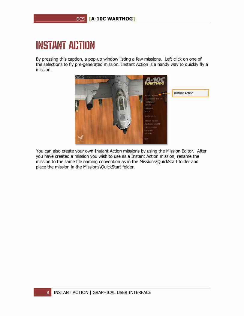
INSTANT ACTION By pressing this caption, a pop-up window listing a few missions. Left click on one of the selections to fly pre-generated mission. Instant Action is a handy way to quickly fly a mission.
You can also create your own Instant Action missions by using the Mission Editor. After you have created a mission you wish to use as a Instant Action mission, rename the mission to the same file naming convention as in the Missions\QuickStart folder and place the mission in the Missions\QuickStart folder.
Instant Action
DCS [A-10C WARTHOG]
9 / LOGBOOK | GRAPHICAL USER INTERFACE
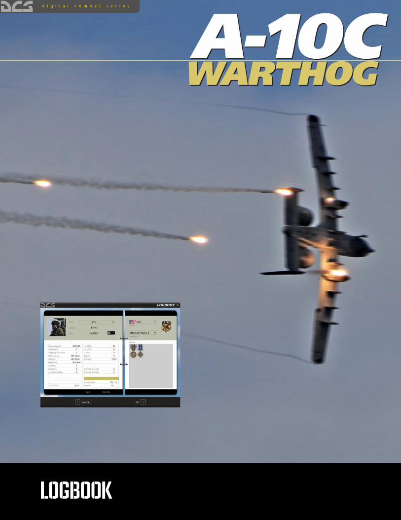
LOGBOOK
DCS [A-10C WARTHOG]
10 / LOGBOOK | GRAPHICAL USER INTERFACE
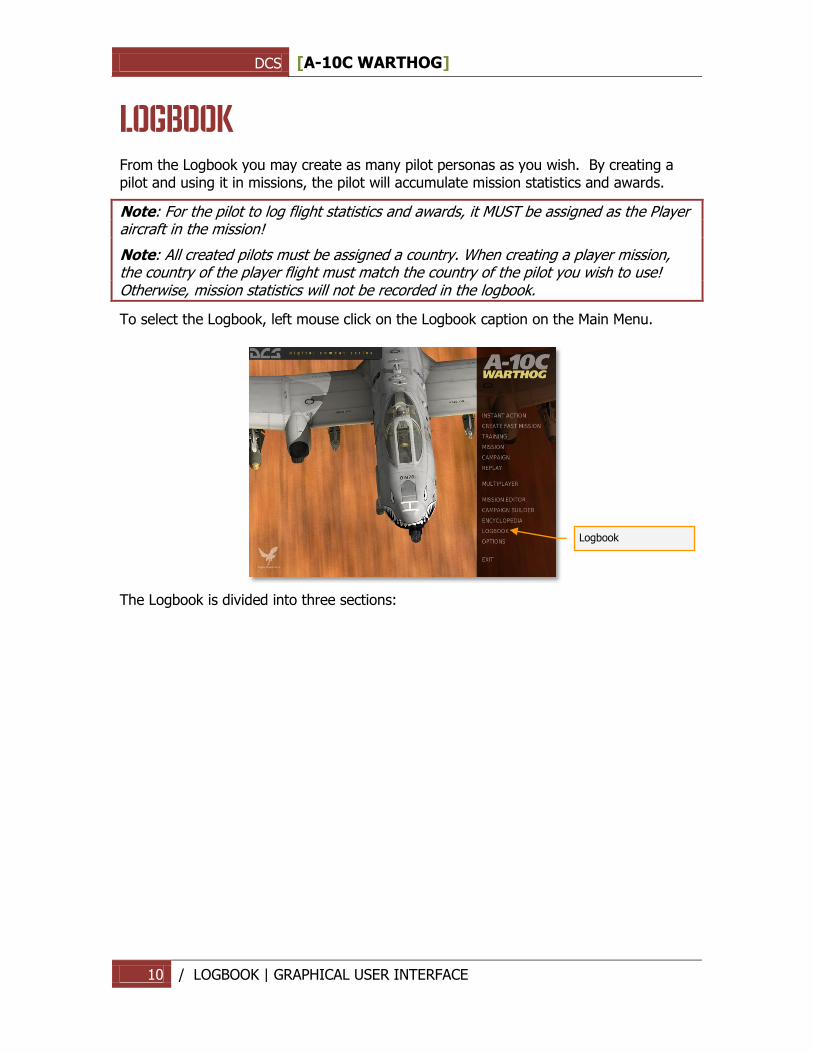
LOGBOOK From the Logbook you may create as many pilot personas as you wish. By creating a pilot and using it in missions, the pilot will accumulate mission statistics and awards.
Note: For the pilot to log flight statistics and awards, it MUST be assigned as the Player aircraft in the mission!
Note: All created pilots must be assigned a country. When creating a player mission, the country of the player flight must match the country of the pilot you wish to use! Otherwise, mission statistics will not be recorded in the logbook.
To select the Logbook, left mouse click on the Logbook caption on the Main Menu.
The Logbook is divided into three sections:
Logbook
DCS [A-10C WARTHOG]
11 / LOGBOOK | GRAPHICAL USER INTERFACE
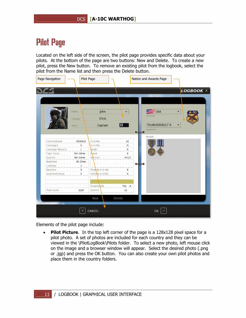
Pilot Page
Located on the left side of the screen, the pilot page provides specific data about your pilots. At the bottom of the page are two buttons: New and Delete. To create a new pilot, press the New button. To remove an existing pilot from the logbook, select the pilot from the Name list and then press the Delete button.
Elements of the pilot page include:
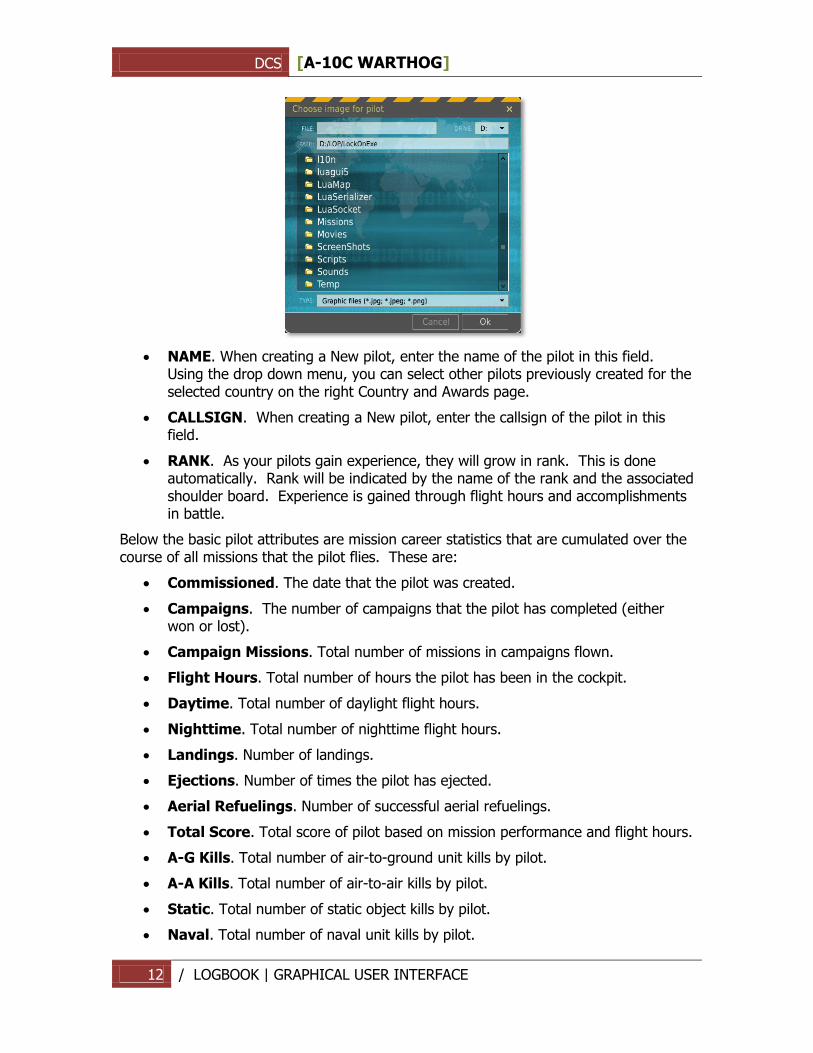
Pilot Picture. In the top left corner of the page is a 128x128 pixel space for a pilot photo. A set of photos are included for each country and they can be viewed in the \PilotLogBook\Pilots folder. To select a new photo, left mouse click on the image and a browser window will appear. Select the desired photo (.png or .jgp) and press the OK button. You can also create your own pilot photos and place them in the country folders.
Pilot Page
Page Navigation
Nation and Awards Page
DCS [A-10C WARTHOG]
12 / LOGBOOK | GRAPHICAL USER INTERFACE
NAME. When creating a New pilot, enter the name of the pilot in this field. Using the drop down menu, you can select other pilots previously created for the selected country on the right Country and Awards page.
CALLSIGN. When creating a New pilot, enter the callsign of the pilot in this field.
RANK. As your pilots gain experience, they will grow in rank. This is done automatically. Rank will be indicated by the name of the rank and the associated shoulder board. Experience is gained through flight hours and accomplishments in battle.
Below the basic pilot attributes are mission career statistics that are cumulated over the course of all missions that the pilot flies. These are:
Commissioned. The date that the pilot was created.
Campaigns. The number of campaigns that the pilot has completed (either won or lost).
Campaign Missions. Total number of missions in campaigns flown.
Flight Hours. Total number of hours the pilot has been in the cockpit.
Daytime. Total number of daylight flight hours.
Nighttime. Total number of nighttime flight hours.
Landings. Number of landings.
Ejections. Number of times the pilot has ejected.
Aerial Refuelings. Number of successful aerial refuelings.
Total Score. Total score of pilot based on mission performance and flight hours.
A-G Kills. Total number of air-to-ground unit kills by pilot.
A-A Kills. Total number of air-to-air kills by pilot.
Static. Total number of static object kills by pilot.
Naval. Total number of naval unit kills by pilot.
DCS [A-10C WARTHOG]
13 / LOGBOOK | GRAPHICAL USER INTERFACE
Kill Ratio. This ratio compares the number of times the pilot has died compared to the number of victories (player deaths / enemy kills).
Friendly A-G Kills. Total number of friendly ground units destroyed by pilot.
Friendly A-A Kills. Total number of friendly air units destroyed by pilot.
The STATUS of the pilot is indicated in the lower left portion of the pilot page.
Invulnerable. This can either be set to YES or NO and determines if the pilot can be killed in action.
Deaths. If Invulnerable is set to YES, then each time the pilot would have been killed is kept track of in this field.
Nation, Squadron, and Awards Page
The left side page indicates the nation, armed forces branch (squadron), and awards of the selected pilot.
Nation. Use the drop down list to assign the pilot to a country.
Squadron. Use the drop down list to select the armed forces branch or squadron to assign the pilot. These will be dependent upon the selected nation.
Awards. In this large field will be displayed medals the pilot has earned.
Page Navigation
Along the very bottom of the screen are the CANCEL button which will return you to the Main Menu without saving any changes to the Logbook, and the OK button which will return you to the Main Menu page but will save your changes.
You can also exit the Logbook by pressing the yellow X in the top right of the screen.
DCS [A-10C WARTHOG]
14 / OPTIONS | GRAPHICAL USER INTERFACE
OPTIONS
DCS [A-10C WARTHOG]
15 / OPTIONS | GRAPHICAL USER INTERFACE
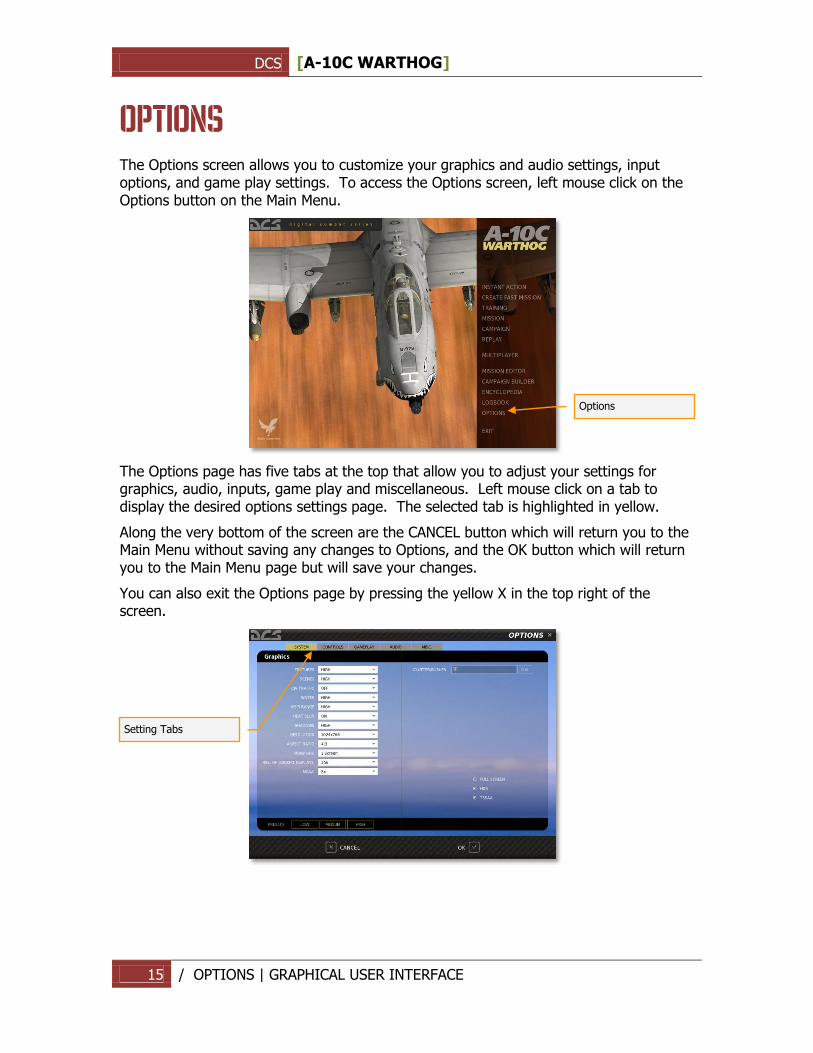
OPTIONS The Options screen allows you to customize your graphics and audio settings, input options, and game play settings. To access the Options screen, left mouse click on the Options button on the Main Menu.
The Options page has five tabs at the top that allow you to adjust your settings for graphics, audio, inputs, game play and miscellaneous. Left mouse click on a tab to display the desired options settings page. The selected tab is highlighted in yellow.
Along the very bottom of the screen are the CANCEL button which will return you to the Main Menu without saving any changes to Options, and the OK button which will return you to the Main Menu page but will save your changes.
You can also exit the Options page by pressing the yellow X in the top right of the screen.
Options
Setting Tabs
DCS [A-10C WARTHOG]
16 / OPTIONS | GRAPHICAL USER INTERFACE
System Options
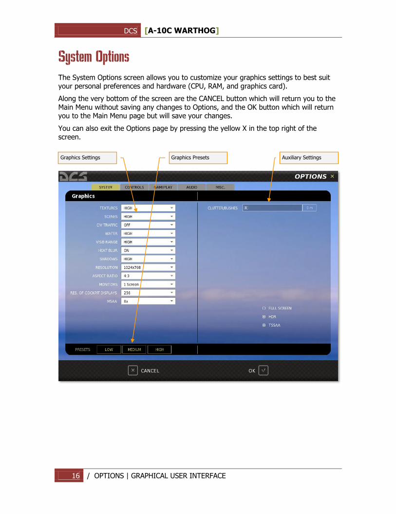
The System Options screen allows you to customize your graphics settings to best suit your personal preferences and hardware (CPU, RAM, and graphics card).
Along the very bottom of the screen are the CANCEL button which will return you to the Main Menu without saving any changes to Options, and the OK button which will return you to the Main Menu page but will save your changes.
You can also exit the Options page by pressing the yellow X in the top right of the screen.
Graphics Settings
Graphics Presets
Auxiliary Settings
DCS [A-10C WARTHOG]
17 / OPTIONS | GRAPHICAL USER INTERFACE
Graphics Settings
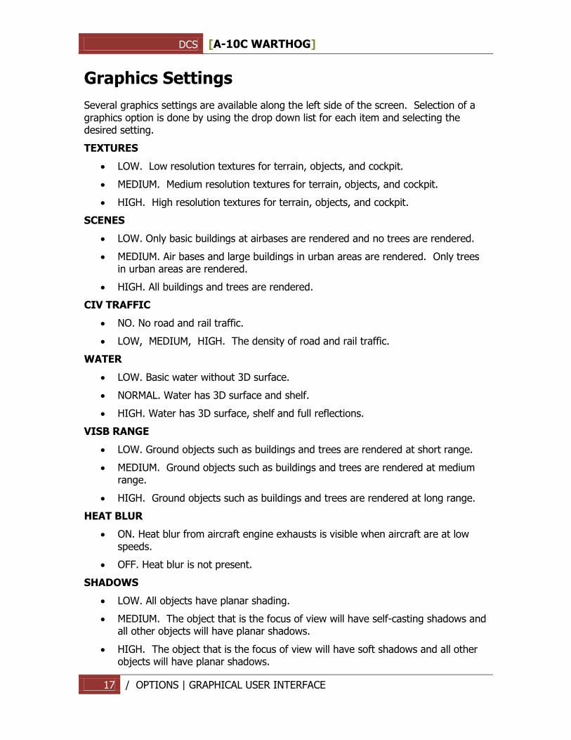
Several graphics settings are available along the left side of the screen. Selection of a graphics option is done by using the drop down list for each item and selecting the desired setting.
TEXTURES
LOW. Low resolution textures for terrain, objects, and cockpit.
MEDIUM. Medium resolution textures for terrain, objects, and cockpit.
HIGH. High resolution textures for terrain, objects, and cockpit.
SCENES
LOW. Only basic buildings at airbases are rendered and no trees are rendered.
MEDIUM. Air bases and large buildings in urban areas are rendered. Only trees in urban areas are rendered.
HIGH. All buildings and trees are rendered.
CIV TRAFFIC
NO. No road and rail traffic.
LOW, MEDIUM, HIGH. The density of road and rail traffic.
WATER
LOW. Basic water without 3D surface.
NORMAL. Water has 3D surface and shelf.
HIGH. Water has 3D surface, shelf and full reflections.
VISB RANGE
LOW. Ground objects such as buildings and trees are rendered at short range.
MEDIUM. Ground objects such as buildings and trees are rendered at medium range.
HIGH. Ground objects such as buildings and trees are rendered at long range.
HEAT BLUR
ON. Heat blur from aircraft engine exhausts is visible when aircraft are at low speeds.
OFF. Heat blur is not present.
SHADOWS
LOW. All objects have planar shading.
MEDIUM. The object that is the focus of view will have self-casting shadows and all other objects will have planar shadows.
HIGH. The object that is the focus of view will have soft shadows and all other objects will have planar shadows.
DCS [A-10C WARTHOG]
18 / OPTIONS | GRAPHICAL USER INTERFACE
RESOLUTION. Select the resolution that the game will be played in. Note that the Aspect radio will automatically be set to best match the selected resolution.
ASPECT. The aspect ratio of the display will automatically be set to the current Resolution, but it may also be set manually between 4:3, 3:2, 5:4, 19:9, and 16:10.
MONITORS. The game allows you to output the video to one, two, or three separate monitors. Options include:
1 Screen. All video will be displayed on a single monitor (default)
3 Screen. Video will be equally spread between three separate monitors.
MFCD
RES. OF COCKPIT DISPLAYS. Set the resolution of cockpit displays such as mirrors, targeting video indicators, multifunction displays, moving maps, etc. Note that higher resolution settings can negatively impact the smoothness of game play.
MSAA. Select the antialiasing level for game picture.
Note: If you wish to increase frame rates, the most import graphics settings to adjust lower are VISB RANGE, WATER, and SHADOWS.
Auxiliary Settings
CLUTTER/BUSHES. This slider adjusts the range from the camera at which grass/bushes are rendered on the ground.
FULL SCREEN. Check this box if you wish the game to fill up the entire screen. If your desktop resolution is greater than your game resolution and you do not have this box selected, then the game will be run in windowed mode.
HDR. Check this box to enable High Dynamic Range visual effects.
TSSAA. Check this box to enable antialiasing of transparent objects.
DCS [A-10C WARTHOG]
19 / OPTIONS | GRAPHICAL USER INTERFACE
Controls Settings
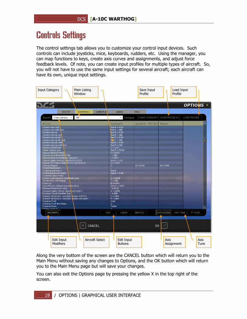
The control settings tab allows you to customize your control input devices. Such controls can include joysticks, mice, keyboards, rudders, etc. Using the manager, you can map functions to keys, create axis curves and assignments, and adjust force feedback levels. Of note, you can create input profiles for multiple types of aircraft. So, you will not have to use the same input settings for several aircraft; each aircraft can have its own, unique input settings.
Along the very bottom of the screen are the CANCEL button which will return you to the Main Menu without saving any changes to Options, and the OK button which will return you to the Main Menu page but will save your changes.
You can also exit the Options page by pressing the yellow X in the top right of the screen.
Input Category
Main Listing Window
Save Input Profile
Load Input Profile
Edit Input Modifiers
Aircraft Select
Edit Input Buttons
Axis Assignment
Axis Tune
DCS [A-10C WARTHOG]
20 / OPTIONS | GRAPHICAL USER INTERFACE
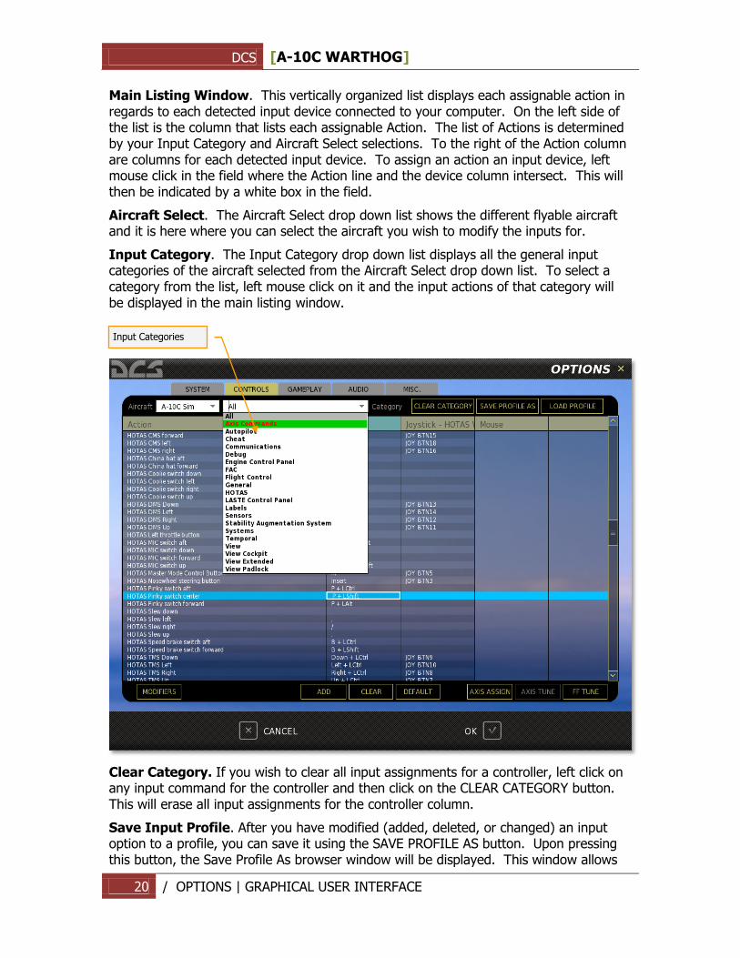
Main Listing Window. This vertically organized list displays each assignable action in regards to each detected input device connected to your computer. On the left side of the list is the column that lists each assignable Action. The list of Actions is determined by your Input Category and Aircraft Select selections. To the right of the Action column are columns for each detected input device. To assign an action an input device, left mouse click in the field where the Action line and the device column intersect. This will then be indicated by a white box in the field.
Aircraft Select. The Aircraft Select drop down list shows the different flyable aircraft and it is here where you can select the aircraft you wish to modify the inputs for.
Input Category. The Input Category drop down list displays all the general input categories of the aircraft selected from the Aircraft Select drop down list. To select a category from the list, left mouse click on it and the input actions of that category will be displayed in the main listing window.
Clear Category. If you wish to clear all input assignments for a controller, left click on any input command for the controller and then click on the CLEAR CATEGORY button. This will erase all input assignments for the controller column.
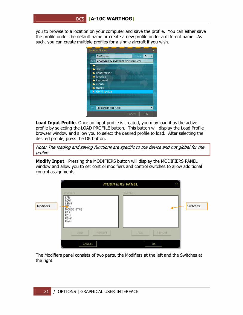
Save Input Profile. After you have modified (added, deleted, or changed) an input option to a profile, you can save it using the SAVE PROFILE AS button. Upon pressing this button, the Save Profile As browser window will be displayed. This window allows
Input Categories
DCS [A-10C WARTHOG]
21 / OPTIONS | GRAPHICAL USER INTERFACE
you to browse to a location on your computer and save the profile. You can either save the profile under the default name or create a new profile under a different name. As such, you can create multiple profiles for a single aircraft if you wish.
Load Input Profile. Once an input profile is created, you may load it as the active profile by selecting the LOAD PROFILE button. This button will display the Load Profile browser window and allow you to select the desired profile to load. After selecting the desired profile, press the OK button.
Note: The loading and saving functions are specific to the device and not global for the profile
Modify Input. Pressing the MODIFIERS button will display the MODIFIERS PANEL window and allow you to set control modifiers and control switches to allow additional control assignments.
The Modifiers panel consists of two parts, the Modifiers at the left and the Switches at the right.
Modifiers
Switches
DCS [A-10C WARTHOG]
22 / OPTIONS | GRAPHICAL USER INTERFACE
Modifiers
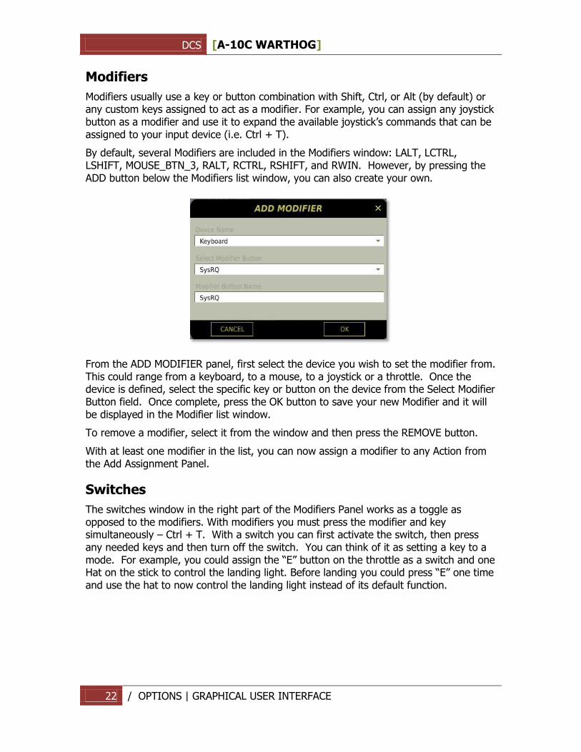
Modifiers usually use a key or button combination with Shift, Ctrl, or Alt (by default) or any custom keys assigned to act as a modifier. For example, you can assign any joystick button as a modifier and use it to expand the available joystick‟s commands that can be assigned to your input device (i.e. Ctrl + T).
By default, several Modifiers are included in the Modifiers window: LALT, LCTRL, LSHIFT, MOUSE_BTN_3, RALT, RCTRL, RSHIFT, and RWIN. However, by pressing the ADD button below the Modifiers list window, you can also create your own.
From the ADD MODIFIER panel, first select the device you wish to set the modifier from. This could range from a keyboard, to a mouse, to a joystick or a throttle. Once the device is defined, select the specific key or button on the device from the Select Modifier Button field. Once complete, press the OK button to save your new Modifier and it will be displayed in the Modifier list window.
To remove a modifier, select it from the window and then press the REMOVE button.
With at least one modifier in the list, you can now assign a modifier to any Action from the Add Assignment Panel.
Switches
The switches window in the right part of the Modifiers Panel works as a toggle as opposed to the modifiers. With modifiers you must press the modifier and key simultaneously – Ctrl + T. With a switch you can first activate the switch, then press any needed keys and then turn off the switch. You can think of it as setting a key to a mode. For example, you could assign the “E” button on the throttle as a switch and one Hat on the stick to control the landing light. Before landing you could press “E” one time and use the hat to now control the landing light instead of its default function.
DCS [A-10C WARTHOG]
23 / OPTIONS | GRAPHICAL USER INTERFACE
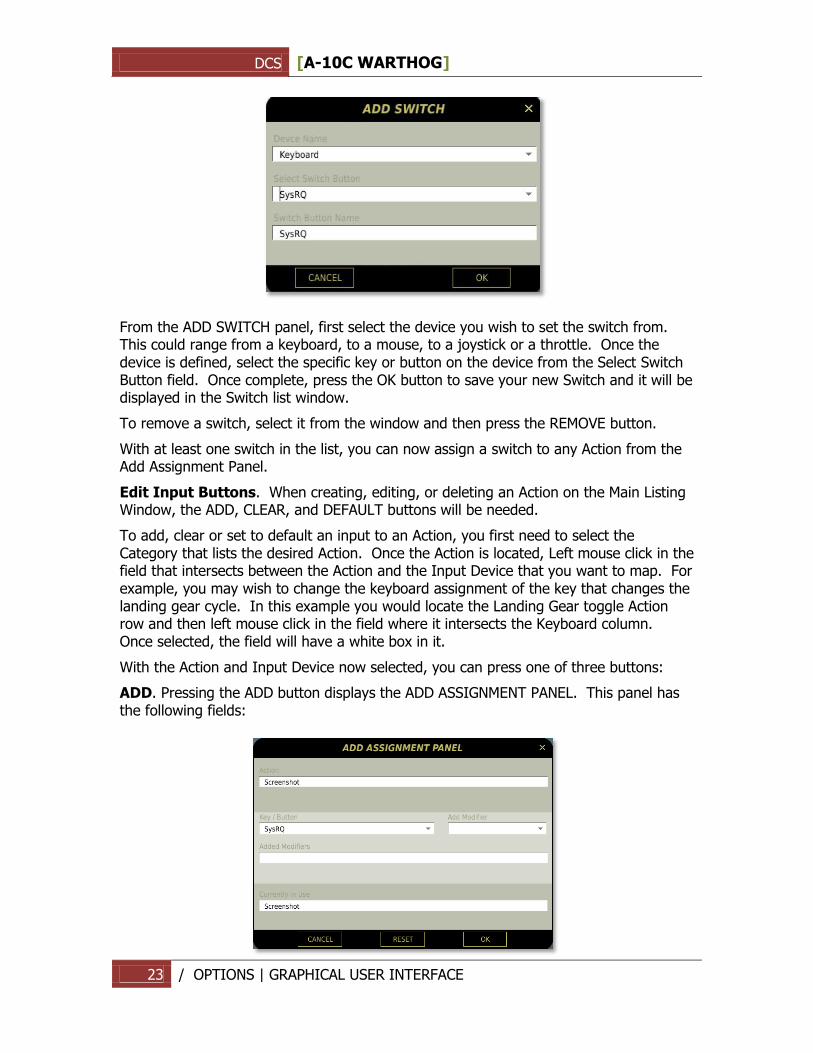
From the ADD SWITCH panel, first select the device you wish to set the switch from. This could range from a keyboard, to a mouse, to a joystick or a throttle. Once the device is defined, select the specific key or button on the device from the Select Switch Button field. Once complete, press the OK button to save your new Switch and it will be displayed in the Switch list window.
To remove a switch, select it from the window and then press the REMOVE button.
With at least one switch in the list, you can now assign a switch to any Action from the Add Assignment Panel.
Edit Input Buttons. When creating, editing, or deleting an Action on the Main Listing Window, the ADD, CLEAR, and DEFAULT buttons will be needed.
To add, clear or set to default an input to an Action, you first need to select the Category that lists the desired Action. Once the Action is located, Left mouse click in the field that intersects between the Action and the Input Device that you want to map. For example, you may wish to change the keyboard assignment of the key that changes the landing gear cycle. In this example you would locate the Landing Gear toggle Action row and then left mouse click in the field where it intersects the Keyboard column. Once selected, the field will have a white box in it.
With the Action and Input Device now selected, you can press one of three buttons:
ADD. Pressing the ADD button displays the ADD ASSIGNMENT PANEL. This panel has the following fields:
DCS [A-10C WARTHOG]
24 / OPTIONS | GRAPHICAL USER INTERFACE
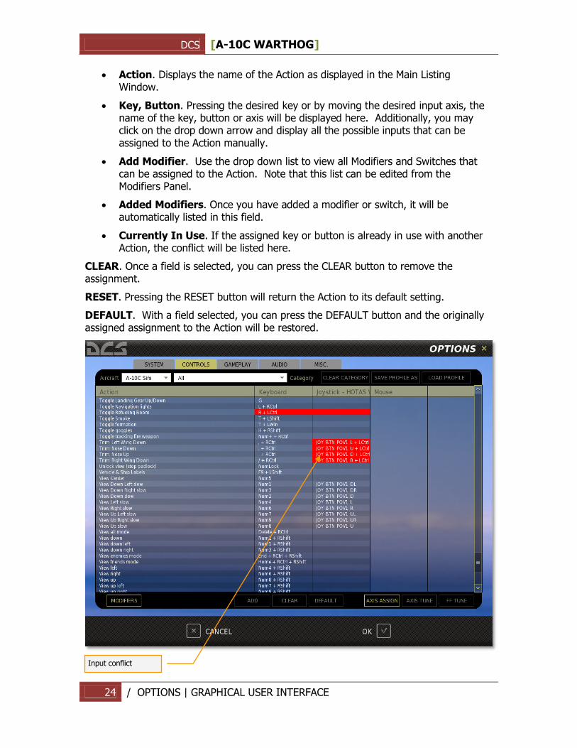
Action. Displays the name of the Action as displayed in the Main Listing Window.
Key, Button. Pressing the desired key or by moving the desired input axis, the name of the key, button or axis will be displayed here. Additionally, you may click on the drop down arrow and display all the possible inputs that can be assigned to the Action manually.
Add Modifier. Use the drop down list to view all Modifiers and Switches that can be assigned to the Action. Note that this list can be edited from the Modifiers Panel.
Added Modifiers. Once you have added a modifier or switch, it will be automatically listed in this field.
Currently In Use. If the assigned key or button is already in use with another Action, the conflict will be listed here.
CLEAR. Once a field is selected, you can press the CLEAR button to remove the assignment.
RESET. Pressing the RESET button will return the Action to its default setting.
DEFAULT. With a field selected, you can press the DEFAULT button and the originally assigned assignment to the Action will be restored.
Input conflict
DCS [A-10C WARTHOG]
25 / OPTIONS | GRAPHICAL USER INTERFACE
Red conflict text appears when there are incorrect modifiers. For example, if you delete one of the present modifiers, then all strings with this modifier will be shown in red
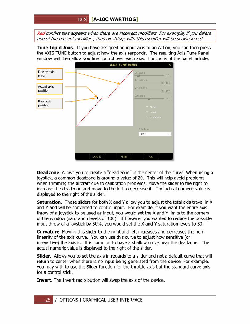
Tune Input Axis. If you have assigned an input axis to an Action, you can then press the AXIS TUNE button to adjust how the axis responds. The resulting Axis Tune Panel window will then allow you fine control over each axis. Functions of the panel include:
Deadzone. Allows you to create a “dead zone” in the center of the curve. When using a joystick, a common deadzone is around a value of 20. This will help avoid problems when trimming the aircraft due to calibration problems. Move the slider to the right to increase the deadzone and move to the left to decrease it. The actual numeric value is displayed to the right of the slider.
Saturation. These sliders for both X and Y allow you to adjust the total axis travel in X and Y and will be converted to control input. For example, if you want the entire axis throw of a joystick to be used as input, you would set the X and Y limits to the corners of the window (saturation levels of 100). If however you wanted to reduce the possible input throw of a joystick by 50%, you would set the X and Y saturation levels to 50.
Curvature. Moving this slider to the right and left increases and decreases the non-linearity of the axis curve. You can use this curve to adjust how sensitive (or insensitive) the axis is. It is common to have a shallow curve near the deadzone. The actual numeric value is displayed to the right of the slider.
Slider. Allows you to set the axis in regards to a slider and not a default curve that will return to center when there is no input being generated from the device. For example, you may with to use the Slider function for the throttle axis but the standard curve axis for a control stick.
Invert. The Invert radio button will swap the axis of the device.
Device axis curve
Raw axis position
Actual axis position
DCS [A-10C WARTHOG]
26 / OPTIONS | GRAPHICAL USER INTERFACE
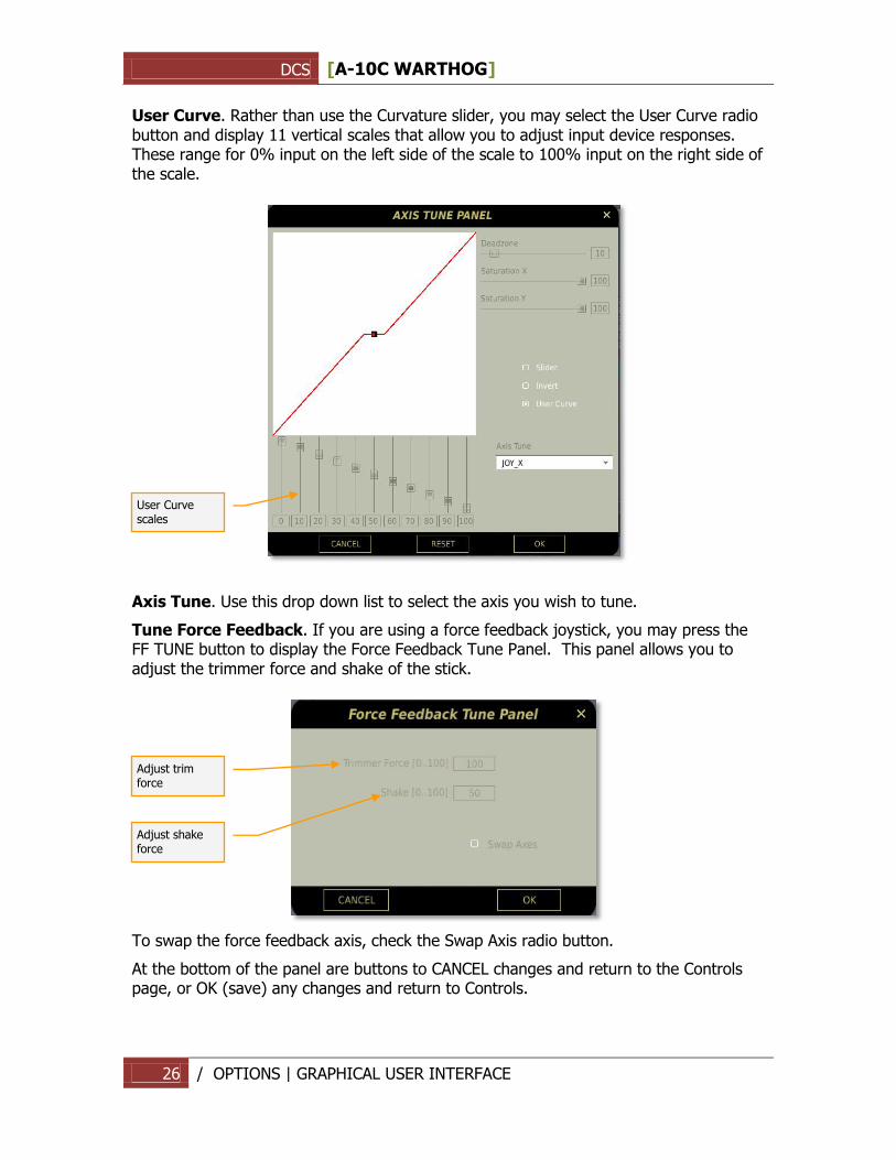
User Curve. Rather than use the Curvature slider, you may select the User Curve radio button and display 11 vertical scales that allow you to adjust input device responses. These range for 0% input on the left side of the scale to 100% input on the right side of the scale.
Axis Tune. Use this drop down list to select the axis you wish to tune.
Tune Force Feedback. If you are using a force feedback joystick, you may press the FF TUNE button to display the Force Feedback Tune Panel. This panel allows you to adjust the trimmer force and shake of the stick.
To swap the force feedback axis, check the Swap Axis radio button.
At the bottom of the panel are buttons to CANCEL changes and return to the Controls page, or OK (save) any changes and return to Controls.
User Curve scales
Adjust trim force
Adjust shake force
DCS [A-10C WARTHOG]
27 / OPTIONS | GRAPHICAL USER INTERFACE
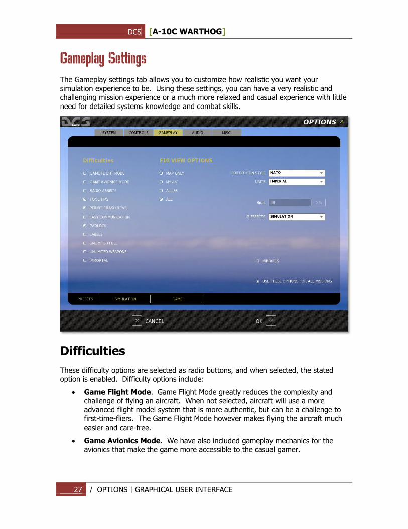
Gameplay Settings
The Gameplay settings tab allows you to customize how realistic you want your simulation experience to be. Using these settings, you can have a very realistic and challenging mission experience or a much more relaxed and casual experience with little need for detailed systems knowledge and combat skills.
Difficulties
These difficulty options are selected as radio buttons, and when selected, the stated option is enabled. Difficulty options include:
Game Flight Mode. Game Flight Mode greatly reduces the complexity and challenge of flying an aircraft. When not selected, aircraft will use a more advanced flight model system that is more authentic, but can be a challenge to first-time-fliers. The Game Flight Mode however makes flying the aircraft much easier and care-free.
Game Avionics Mode. We have also included gameplay mechanics for the avionics that make the game more accessible to the casual gamer.
DCS [A-10C WARTHOG]
28 / OPTIONS | GRAPHICAL USER INTERFACE
Radio Assist. When enabled, you will get audio alerts informing you of incoming missiles, when you are within valid weapon use parameters, and information on the location of enemy units.
Tool Tips. When in the cockpit, you may hover your mouse over a control and a brief note indicating the function of the control will be displayed.
Permit Crash Rcvr. Crash recovery will allow you to respawn in your aircraft if you eject or are killed during the mission.
External Views. When enabled, external views outside your cockpit are possible. Note; see also the MISC tab for addition view options.
Padlock. The padlock system allows you to keep your virtual eyes locked (padlocked) to either an air or surface point as long as the target is within visual constraints when viewed from within the cockpit. In addition to units and the ground, you may also padlock incoming missiles.
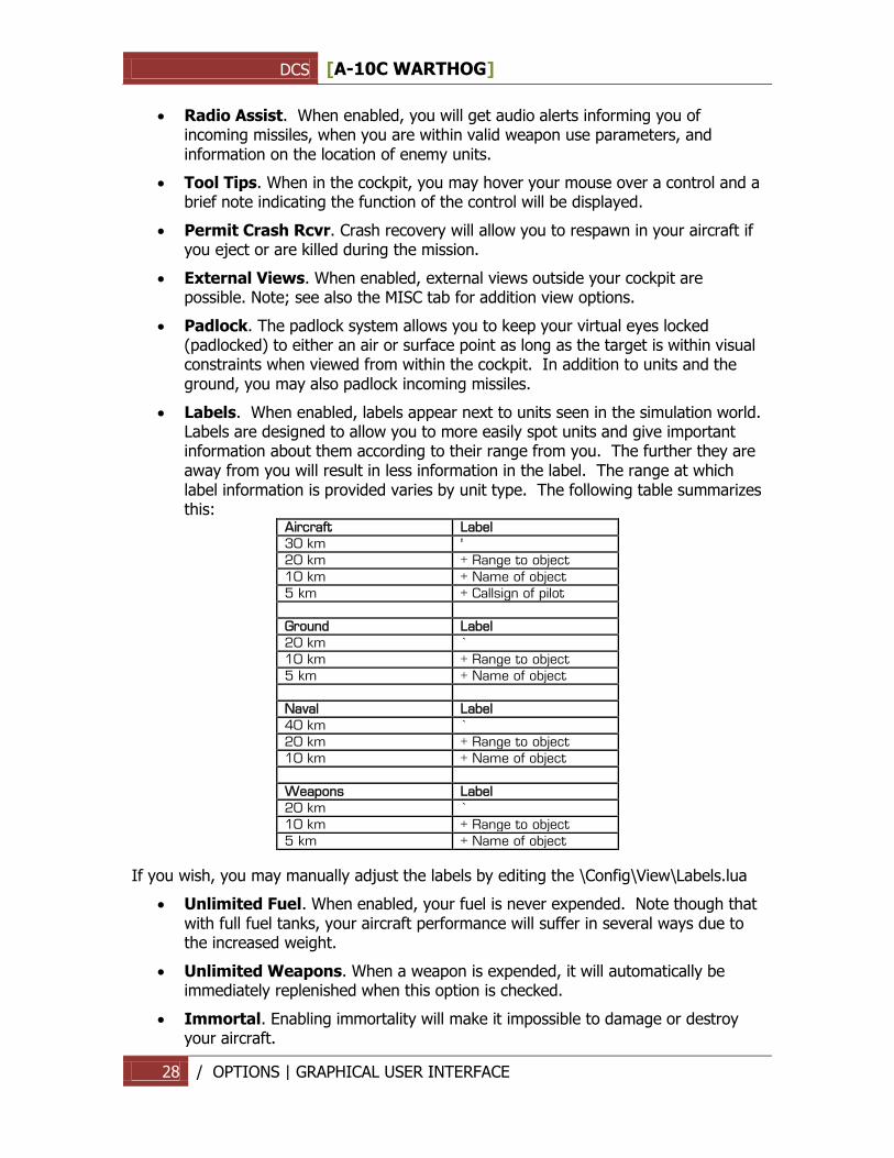
Labels. When enabled, labels appear next to units seen in the simulation world. Labels are designed to allow you to more easily spot units and give important information about them according to their range from you. The further they are away from you will result in less information in the label. The range at which label information is provided varies by unit type. The following table summarizes this:
Aircraft Label
30 km '
20 km + Range to object
10 km + Name of object
5 km + Callsign of pilot
Ground Label
20 km `
10 km + Range to object
5 km + Name of object
Naval Label
40 km `
20 km + Range to object
10 km + Name of object
Weapons Label
20 km `
10 km + Range to object
5 km + Name of object
If you wish, you may manually adjust the labels by editing the \Config\View\Labels.lua
Unlimited Fuel. When enabled, your fuel is never expended. Note though that with full fuel tanks, your aircraft performance will suffer in several ways due to the increased weight.
Unlimited Weapons. When a weapon is expended, it will automatically be immediately replenished when this option is checked.
Immortal. Enabling immortality will make it impossible to damage or destroy your aircraft.
DCS [A-10C WARTHOG]
29 / OPTIONS | GRAPHICAL USER INTERFACE
F10 View Options
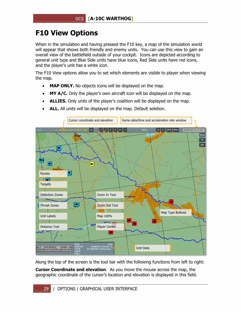
When in the simulation and having pressed the F10 key, a map of the simulation world will appear that shows both friendly and enemy units. You can use this view to gain an overall view of the battlefield outside of your cockpit. Icons are depicted according to general unit type and Blue Side units have blue icons, Red Side units have red icons, and the player‟s unit has a white icon.
The F10 View options allow you to set which elements are visible to player when viewing the map.
MAP ONLY. No objects icons will be displayed on the map.
MY A/C. Only the player's own aircraft icon will be displayed on the map.
ALLIES. Only units of the player's coalition will be displayed on the map.
ALL. All units will be displayed on the map. Default seletion.
Along the top of the screen is the tool bar with the following functions from left to right:
Cursor Coordinate and elevation. As you move the mouse across the map, the geographic coordinate of the cursor‟s location and elevation is displayed in this field.
Unit Data
Cursor coordinate and elevation
Game data/time and acceleration rate window
Detection Zones
Threat Zones
Unit Labels
Distance Tool
Zoom In Tool
Zoom Out Tool
Map 100%
Player Center
Map Type Buttons
Targets
Routes
DCS [A-10C WARTHOG]
30 / OPTIONS | GRAPHICAL USER INTERFACE
Detection Zones. When enabled, the detection zones of air defense units are displayed as circles around the units.
Threat Zones. When enabled, zones around air defense units that indicate the engagement range of the unit are displayed.
Unit Labels. When enabled, a label that indicates unit type is displayed next to each unit on the map.
Distance Tool. By left mouse clicking on the map and then dragging the cursor to a new location, a line will be drawn between the two points. Right of the Distance Tool button will be displayed the distance of the line and next to the HDG (heading) label will be displayed the heading from the start point to the end point of the line.
Zoom In Tool. To zoom in on the map, click this button and the cursor will become a magnifying glass with a “+” symbol in the center. Left click on the map where you want to zoom in to and re-center your map on. To disable this mode, you must click this button a second time.
Zoom Out Tool. To zoom out of the map, click this button and the cursor will become a magnifying glass with a “-” symbol in the center. Left click on the map where you want to zoom out from and re-center your map on. To disable this mode, you must click this button a second time.
Map 100%. To quickly zoom the map out to its full, 100% size, press this button.
Player Center. To center the map screen on the player, press this button.
To gather more information about a unit displayed on the map, you may left click on it and the Unit Data window will appear. The selected unit‟s icon will turn yellow. This is an information-only window that can display the following information, depending on the unit type:
Unit type
Side
Unit callsign
Group task
Unit altitude
Unit speed
Unit heading
Unit‟s current coordinates
Map Type. In the top right portion of the screen are three choices of map type. These include:
MAP. Displays map view of world without elevation data.
ALT. Displays map view but with elevation data relief.
SAT. Displays satellite map view of world.
DCS [A-10C WARTHOG]
31 / OPTIONS | GRAPHICAL USER INTERFACE
Additional Settings
On the right side of the screen are several more options that allow you to better customize the gameplay options of the simulation. These include:
Editor Icon Style. When placing units and points on the map using the mission editor, you can either use western-style military icons or Russian-style. Select between the two using this drop down list.
Units. Using the drop down menu, you may select either Imperial or Metric units of measurement. This selection will determine the units of measurement used in the Mission Editor.
Birds. Use this slider to adjust the likelihood of bird strikes when flying at very low altitudes.
G-Effect. Depending on the amount of G you are loading on the aircraft, the effect of the G-force can have different effects according to the level you select from the drop down list. Options include: None, Reduced, and Realistic. Note that the G-model accounts for rapid-G onset which can be much more demanding on the pilot (you). As such, when using the Realistic setting, ease into the G rather than pulling very quickly.
Mirrors. Check this box to enable rear view mirrors. Note that mirrors can have a significant effect on system performance.
Use These Options For All Missions. When checked, this option will force any mission you fly to use the Options you personally set. If, however, this box is unchecked, the Options used when the mission was created will be used.
Presets
In the lower left portion of the screen are the two Preset buttons. These allow you to quickly set the gameplay options to provide either a realistic SIMULATION experience or a GAME experience. Press either button to quickly configure your options or manually select them to your own personal preferences.
Along the very bottom of the screen are the CANCEL button which will return you to the Main Menu without saving any changes to Options, and the OK button which will return you to the Main Menu page but will save your changes.
You can also exit the Options page by pressing the yellow X in the top right of the screen.
DCS [A-10C WARTHOG]
32 / OPTIONS | GRAPHICAL USER INTERFACE
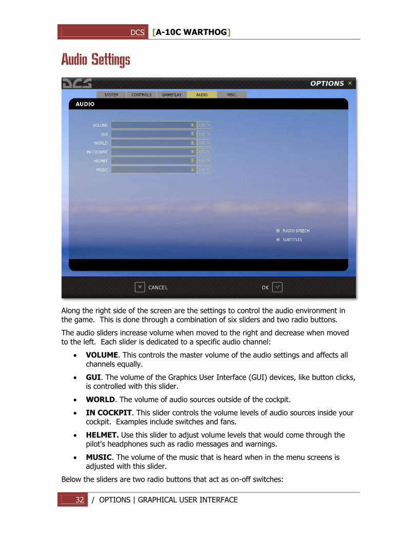
Audio Settings
Along the right side of the screen are the settings to control the audio environment in the game. This is done through a combination of six sliders and two radio buttons.
The audio sliders increase volume when moved to the right and decrease when moved to the left. Each slider is dedicated to a specific audio channel:
VOLUME. This controls the master volume of the audio settings and affects all channels equally.
GUI. The volume of the Graphics User Interface (GUI) devices, like button clicks, is controlled with this slider.
WORLD. The volume of audio sources outside of the cockpit.
IN COCKPIT. This slider controls the volume levels of audio sources inside your cockpit. Examples include switches and fans.
HELMET. Use this slider to adjust volume levels that would come through the pilot's headphones such as radio messages and warnings.
MUSIC. The volume of the music that is heard when in the menu screens is adjusted with this slider.
Below the sliders are two radio buttons that act as on-off switches:
DCS [A-10C WARTHOG]
33 / TRAINING | GRAPHICAL USER INTERFACE
RADIO SPEECH. Turn all radio speech on or off.
SUBTITLES. Turn all text subtitles on or off.
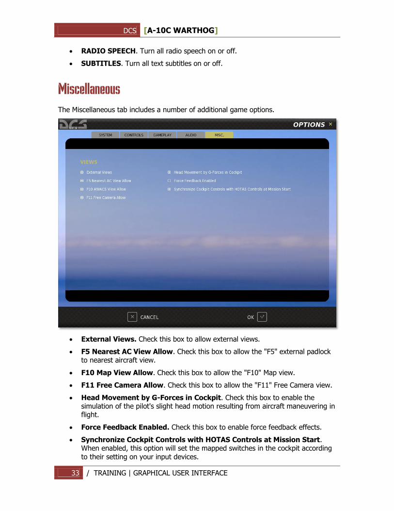
Miscellaneous
The Miscellaneous tab includes a number of additional game options.
External Views. Check this box to allow external views.
F5 Nearest AC View Allow. Check this box to allow the "F5" external padlock to nearest aircraft view.
F10 Map View Allow. Check this box to allow the "F10" Map view.
F11 Free Camera Allow. Check this box to allow the "F11" Free Camera view.
Head Movement by G-Forces in Cockpit. Check this box to enable the simulation of the pilot's slight head motion resulting from aircraft maneuvering in flight.
Force Feedback Enabled. Check this box to enable force feedback effects.
Synchronize Cockpit Controls with HOTAS Controls at Mission Start. When enabled, this option will set the mapped switches in the cockpit according to their setting on your input devices.
DCS [A-10C WARTHOG]
34 / TRAINING | GRAPHICAL USER INTERFACE
TRAINING
DCS [A-10C WARTHOG]
35 / TRAINING | GRAPHICAL USER INTERFACE
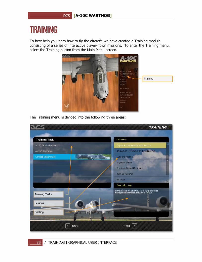
TRAINING To best help you learn how to fly the aircraft, we have created a Training module consisting of a series of interactive player-flown missions. To enter the Training menu, select the Training button from the Main Menu screen.
The Training menu is divided into the following three areas:
Training
Training Tasks
Lessons
Briefing
DCS [A-10C WARTHOG]
36 / TRAINING | GRAPHICAL USER INTERFACE
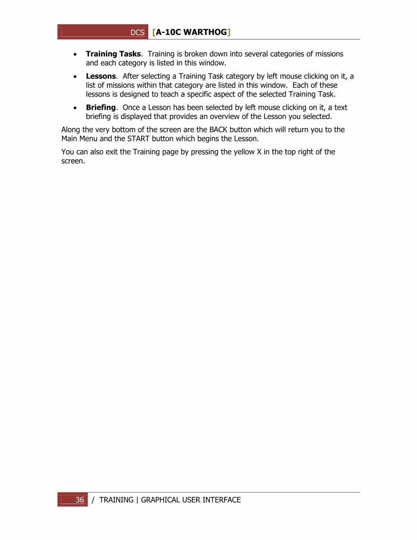
Training Tasks. Training is broken down into several categories of missions and each category is listed in this window.
Lessons. After selecting a Training Task category by left mouse clicking on it, a list of missions within that category are listed in this window. Each of these lessons is designed to teach a specific aspect of the selected Training Task.
Briefing. Once a Lesson has been selected by left mouse clicking on it, a text briefing is displayed that provides an overview of the Lesson you selected.
Along the very bottom of the screen are the BACK button which will return you to the Main Menu and the START button which begins the Lesson.
You can also exit the Training page by pressing the yellow X in the top right of the screen.
DCS [A-10C WARTHOG]
37 / MISSION | GRAPHICAL USER INTERFACE
MISSION
DCS [A-10C WARTHOG]
38 / MISSION | GRAPHICAL USER INTERFACE
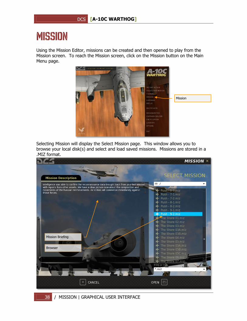
MISSION Using the Mission Editor, missions can be created and then opened to play from the Mission screen. To reach the Mission screen, click on the Mission button on the Main Menu page.
Selecting Mission will display the Select Mission page. This window allows you to browse your local disk(s) and select and load saved missions. Missions are stored in a .MIZ format.
Mission
Mission Briefing
Browser
DCS [A-10C WARTHOG]
39 / MISSION | GRAPHICAL USER INTERFACE
Using standard Windows file browser functionality, you may select the DRIVE you wish to search using the DRIVE field in the top right of the window and then select the desired mission from the folder/file listing.
Once you have selected the desired mission by left mouse button clicking on it, press the OPEN button at the bottom of the window to load it. When the mission is selected, any briefing written for the mission will be displayed in the left side Mission Description window.
You may also exit the window without loading a mission by pressing the CANCEL button at the bottom of the window or the X button in the top right corner.
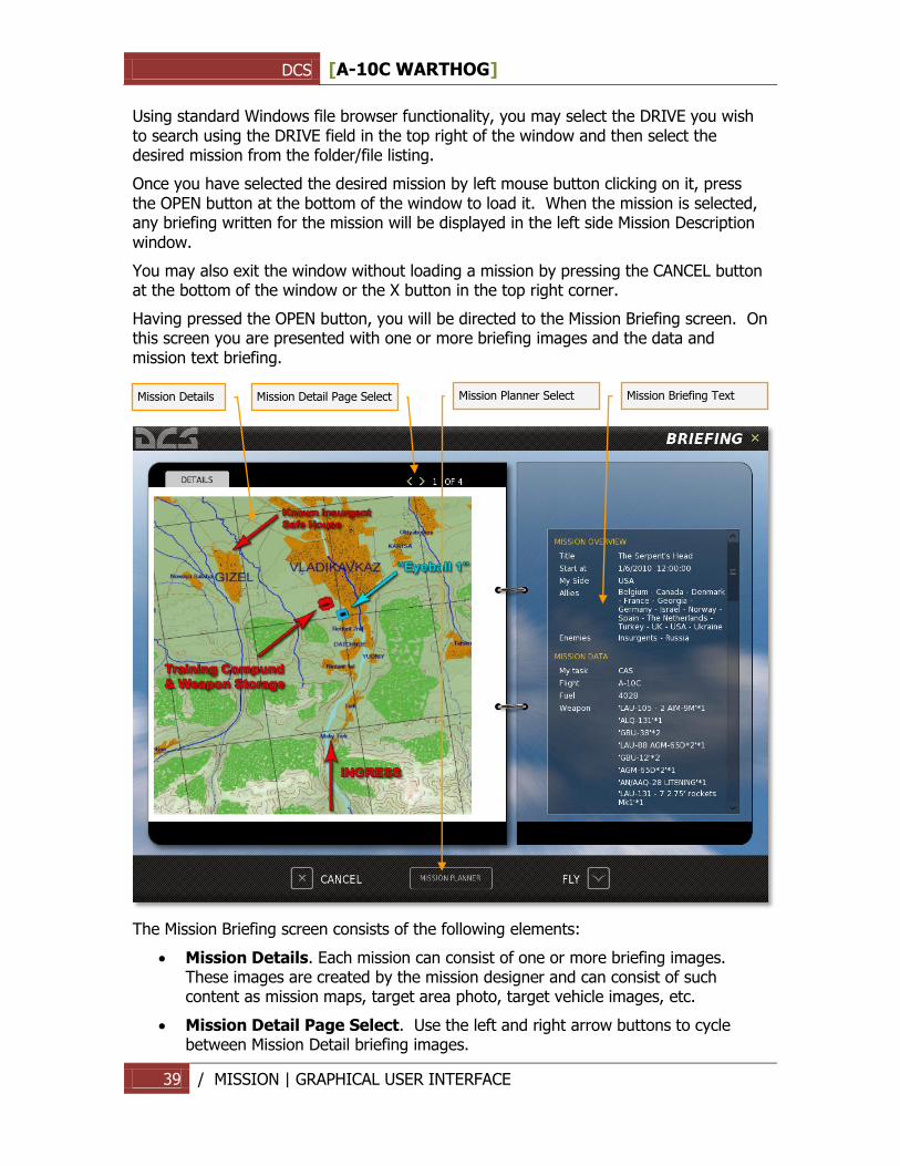
Having pressed the OPEN button, you will be directed to the Mission Briefing screen. On this screen you are presented with one or more briefing images and the data and mission text briefing.
The Mission Briefing screen consists of the following elements:
Mission Details. Each mission can consist of one or more briefing images. These images are created by the mission designer and can consist of such content as mission maps, target area photo, target vehicle images, etc.
Mission Detail Page Select. Use the left and right arrow buttons to cycle between Mission Detail briefing images.
Mission Details
Mission Detail Page Select
Mission Briefing Text
Mission Planner Select
DCS [A-10C WARTHOG]
40 / MISSION | GRAPHICAL USER INTERFACE
Mission Briefing Text. The scrollable text block on the right side of the screen consists of automatically generated mission data such as sides, flight information, and mission start times. Additionally, a textual briefing can also be included in the Description portion.
At the bottom of the page are three additional buttons.
CANCEL. Press the cancel button to return to the Mission page. You can also cancel the mission by pressing the yellow X in the top right corner of the page.
FLY. Press the FLY button to start the mission and enter the simulation.
MISSION PLANER. Pressing the Mission Planer button will open the selected mission in the Mission Planer and allow you to view it in detail, edit route and weapons of your flight.
DCS [A-10C WARTHOG]
41 / REPLAY | GRAPHICAL USER INTERFACE
REPLAY
DCS [A-10C WARTHOG]
42 / REPLAY | GRAPHICAL USER INTERFACE
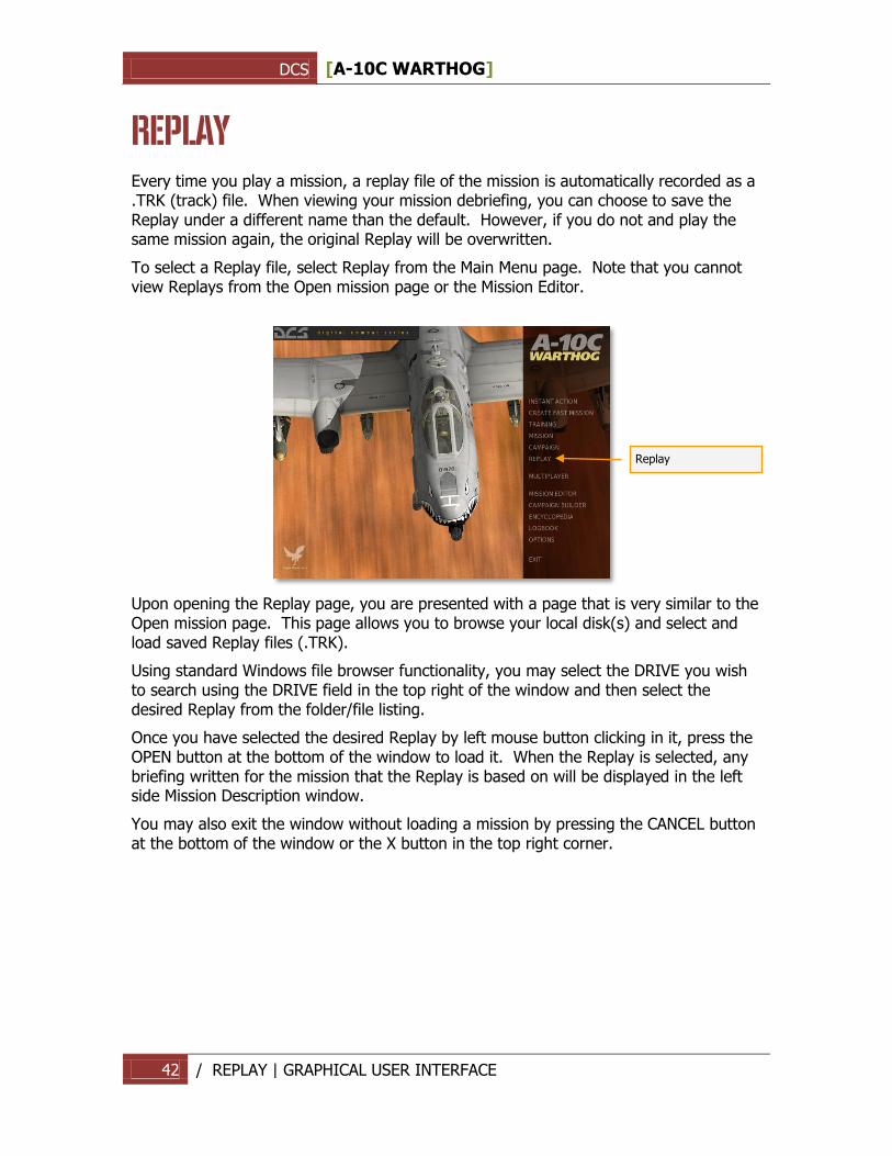
REPLAY Every time you play a mission, a replay file of the mission is automatically recorded as a .TRK (track) file. When viewing your mission debriefing, you can choose to save the Replay under a different name than the default. However, if you do not and play the same mission again, the original Replay will be overwritten.
To select a Replay file, select Replay from the Main Menu page. Note that you cannot view Replays from the Open mission page or the Mission Editor.
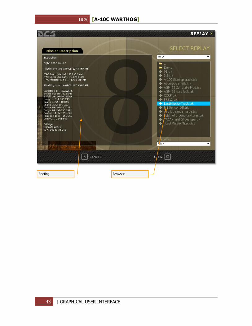
Upon opening the Replay page, you are presented with a page that is very similar to the Open mission page. This page allows you to browse your local disk(s) and select and load saved Replay files (.TRK).
Using standard Windows file browser functionality, you may select the DRIVE you wish to search using the DRIVE field in the top right of the window and then select the desired Replay from the folder/file listing.
Once you have selected the desired Replay by left mouse button clicking in it, press the OPEN button at the bottom of the window to load it. When the Replay is selected, any briefing written for the mission that the Replay is based on will be displayed in the left side Mission Description window.
You may also exit the window without loading a mission by pressing the CANCEL button at the bottom of the window or the X button in the top right corner.
Replay
DCS [A-10C WARTHOG]
43 | GRAPHICAL USER INTERFACE
Briefing
Browser
DCS [A-10C WARTHOG]
44 / | GRAPHICAL USER INTERFACE
DCS [A-10C WARTHOG]
45 Create Fast Mission | GRAPHICAL USER INTERFACE
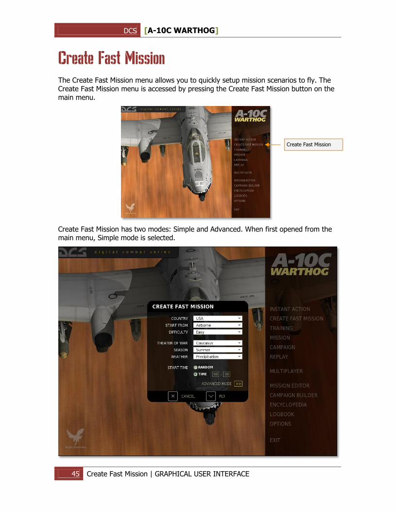
Create Fast Mission The Create Fast Mission menu allows you to quickly setup mission scenarios to fly. The Create Fast Mission menu is accessed by pressing the Create Fast Mission button on the main menu.
Create Fast Mission has two modes: Simple and Advanced. When first opened from the main menu, Simple mode is selected.
Create Fast Mission
DCS [A-10C WARTHOG]
46 Create Fast Mission | GRAPHICAL USER INTERFACE
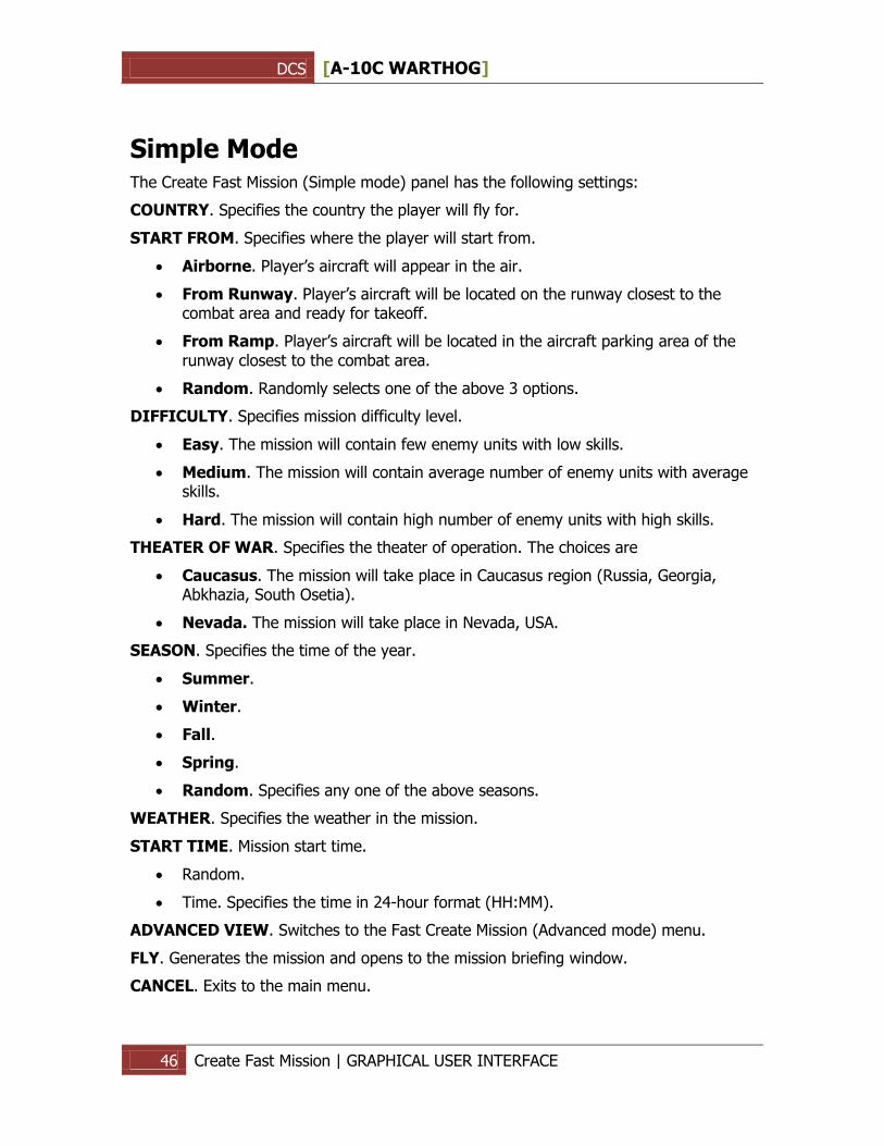
Simple Mode The Create Fast Mission (Simple mode) panel has the following settings:
COUNTRY. Specifies the country the player will fly for.
START FROM. Specifies where the player will start from.
Airborne. Player‟s aircraft will appear in the air.
From Runway. Player‟s aircraft will be located on the runway closest to the combat area and ready for takeoff.
From Ramp. Player‟s aircraft will be located in the aircraft parking area of the runway closest to the combat area.
Random. Randomly selects one of the above 3 options.
DIFFICULTY. Specifies mission difficulty level.
Easy. The mission will contain few enemy units with low skills.
Medium. The mission will contain average number of enemy units with average skills.
Hard. The mission will contain high number of enemy units with high skills.
THEATER OF WAR. Specifies the theater of operation. The choices are
Caucasus. The mission will take place in Caucasus region (Russia, Georgia, Abkhazia, South Osetia).
Nevada. The mission will take place in Nevada, USA.
SEASON. Specifies the time of the year.
Summer.
Winter.
Fall.
Spring.
Random. Specifies any one of the above seasons.
WEATHER. Specifies the weather in the mission.
START TIME. Mission start time.
Random.
Time. Specifies the time in 24-hour format (HH:MM).
ADVANCED VIEW. Switches to the Fast Create Mission (Advanced mode) menu.
FLY. Generates the mission and opens to the mission briefing window.
CANCEL. Exits to the main menu.
DCS [A-10C WARTHOG]
47 Create Fast Mission | GRAPHICAL USER INTERFACE
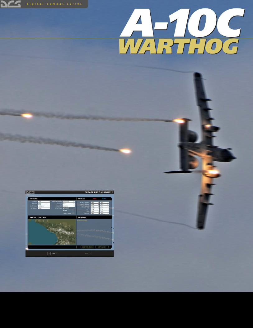
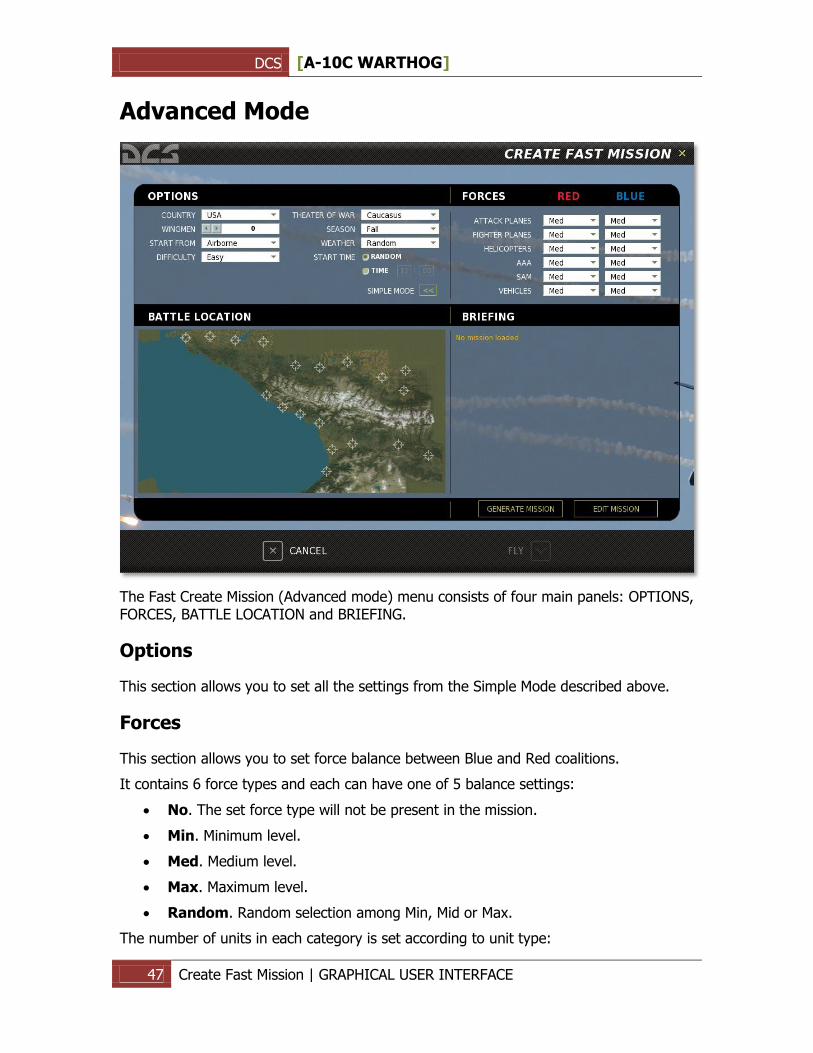
Advanced Mode
The Fast Create Mission (Advanced mode) menu consists of four main panels: OPTIONS, FORCES, BATTLE LOCATION and BRIEFING.
Options
This section allows you to set all the settings from the Simple Mode described above.
Forces
This section allows you to set force balance between Blue and Red coalitions.
It contains 6 force types and each can have one of 5 balance settings:
No. The set force type will not be present in the mission.
Min. Minimum level.
Med. Medium level.
Max. Maximum level.
Random. Random selection among Min, Mid or Max.
The number of units in each category is set according to unit type:
DCS [A-10C WARTHOG]
48 Create Fast Mission | GRAPHICAL USER INTERFACE
ATTACK PLANES. Sets the number of attack planes such as Su-25 or A-10.
FIGHTER PLANES. Sets the number of fighter planes such as Su-27, Mig-29, F-15.
HELICOPTERS. Sets the number of helicopters such as Ka-50, Mi-24, AH-64.
AAA. Sets the number of Anti-Aircraft Artillery units such as ZU-23, ZSU-23, Vulcan.
SAM. Sets the number of SAM units such as M6, Hawk, Stinger, Igla, Osa, Buk, Strela-1.
VEHICLES. Sets number of vehicles such as tanks, BMP‟s, BTR‟s, trucks.
The tactical dynamics of combat between Red and Blue forces will depend on the settings in this section.
Battle Location
This panel allows you to choose the general location of combat. To specify the area simply click on it using the mouse.
Briefing
The Briefing windows will display the mission briefing once the mission is generated.
Two buttons are located under the briefing text area:
GENERATE MISSION. Generates the mission.
EDIT MISSION. Opens the full mission editor that allows you to fine-tune the generated mission.
Two buttons are located at the bottom of the screen:
CANCEL. Exits to the main menu.
FLY. Starts the mission.
DCS [A-10C WARTHOG]
49 / MISSION EDITOR | GRAPHICAL USER INTERFACE
MISSION EDITOR
DCS [A-10C WARTHOG]
50 / MISSION EDITOR | GRAPHICAL USER INTERFACE
MISSION EDITOR The Mission Editor (ME) of allows you to create stand-alone missions, campaign missions, training missions, and multiplayer missions. The ME consists of the following primary elements:
1. Interactive mapping system
2. Unit placement tools
3. Weather editor
4. File management system
5. Goal creation tool
6. Trigger system tool
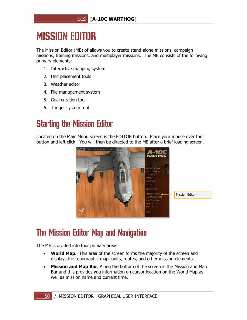
Starting the Mission Editor
Located on the Main Menu screen is the EDITOR button. Place your mouse over the button and left click. You will then be directed to the ME after a brief loading screen.
The Mission Editor Map and Navigation
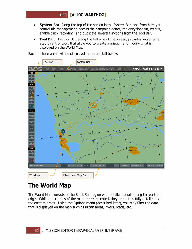
The ME is divided into four primary areas:
World Map. This area of the screen forms the majority of the screen and displays the topographic map, units, routes, and other mission elements.
Mission and Map Bar. Along the bottom of the screen is the Mission and Map Bar and this provides you information on cursor location on the World Map as well as mission name and current time.
Mission Editor
DCS [A-10C WARTHOG]
51 / MISSION EDITOR | GRAPHICAL USER INTERFACE
System Bar. Along the top of the screen is the System Bar, and from here you control file management, access the campaign editor, the encyclopedia, credits, enable track recording, and duplicate several functions from the Tool Bar.
Tool Bar. The Tool Bar, along the left side of the screen, provides you a large assortment of tools that allow you to create a mission and modify what is displayed on the World Map.
Each of these areas will be discussed in more detail below.
The World Map
The World Map consists of the Black Sea region with detailed terrain along the eastern edge. While other areas of the map are represented, they are not as fully detailed as the eastern areas. Using the Options menu (described later), you may filter the data that is displayed on the map such as urban areas, rivers, roads, etc.
Tool Bar
System Bar
World Map
Mission and Map Bar
DCS [A-10C WARTHOG]
52 / MISSION EDITOR | GRAPHICAL USER INTERFACE
Navigating the Map
A right mouse button hold while moving the mouse will pan the view and rotating the mouse wheel controls the zoom level. Selecting an object or unit is done by clicking with the left mouse button. To zoom in on a specific location on the map, place the cursor over the desired location and rotate the mouse wheel forward.
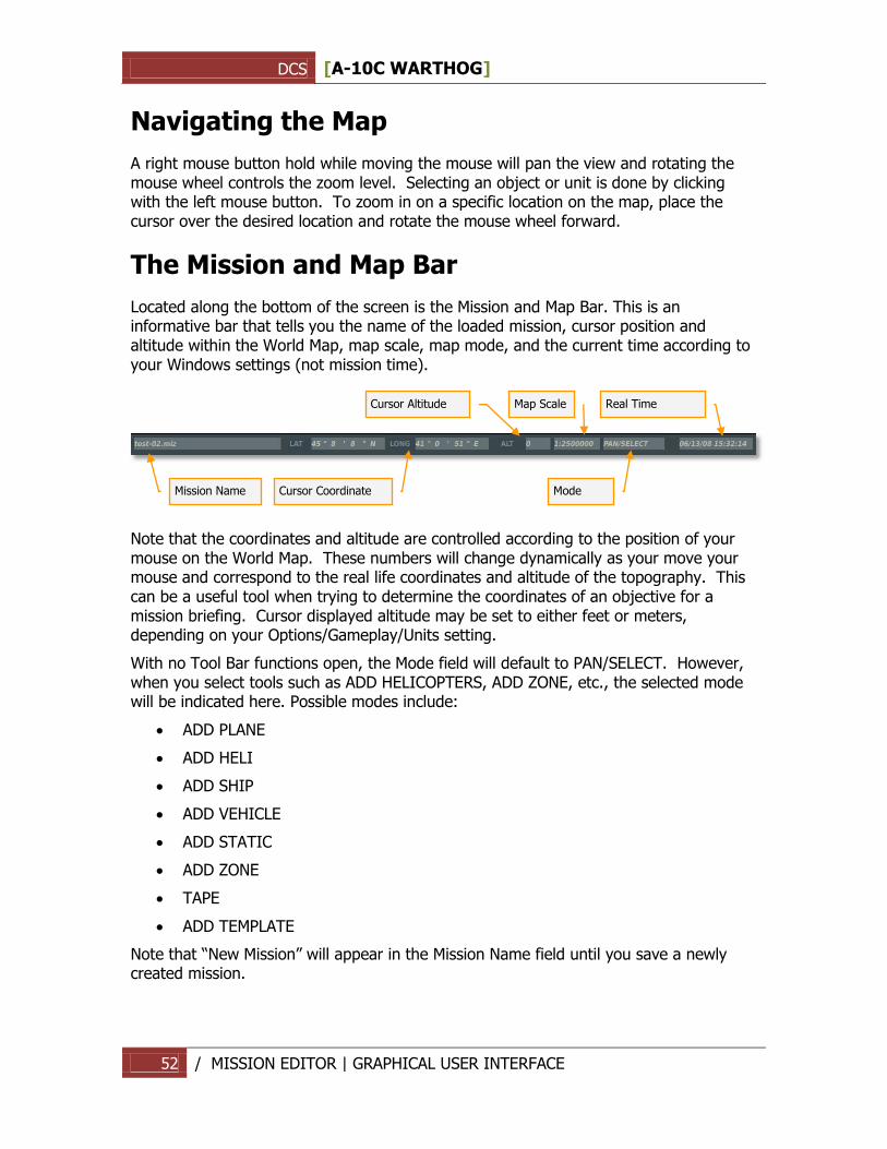
The Mission and Map Bar
Located along the bottom of the screen is the Mission and Map Bar. This is an informative bar that tells you the name of the loaded mission, cursor position and altitude within the World Map, map scale, map mode, and the current time according to your Windows settings (not mission time).
Note that the coordinates and altitude are controlled according to the position of your mouse on the World Map. These numbers will change dynamically as your move your mouse and correspond to the real life coordinates and altitude of the topography. This can be a useful tool when trying to determine the coordinates of an objective for a mission briefing. Cursor displayed altitude may be set to either feet or meters, depending on your Options/Gameplay/Units setting.
With no Tool Bar functions open, the Mode field will default to PAN/SELECT. However, when you select tools such as ADD HELICOPTERS, ADD ZONE, etc., the selected mode will be indicated here. Possible modes include:
ADD PLANE
ADD HELI
ADD SHIP
ADD VEHICLE
ADD STATIC
ADD ZONE
TAPE
ADD TEMPLATE
Note that “New Mission” will appear in the Mission Name field until you save a newly created mission.
Cursor Altitude
Map Scale
Real Time
Mission Name
Cursor Coordinate
Mode
DCS [A-10C WARTHOG]
53 / MISSION EDITOR | GRAPHICAL USER INTERFACE
The System Bar
Located along the top of the screen is the System Bar. The System Bar consists of several pull down menus. These are: FILE, EDIT, FLIGHT, CAMPAIGN, CUSTOMIZE, MISSION GENERATOR and MISC. To select one of these pull down menus, place your mouse over the text and left mouse click.
The System Bar pull down menus provide the following functions:
File
The File functions provide you basic file management of missions. These include:
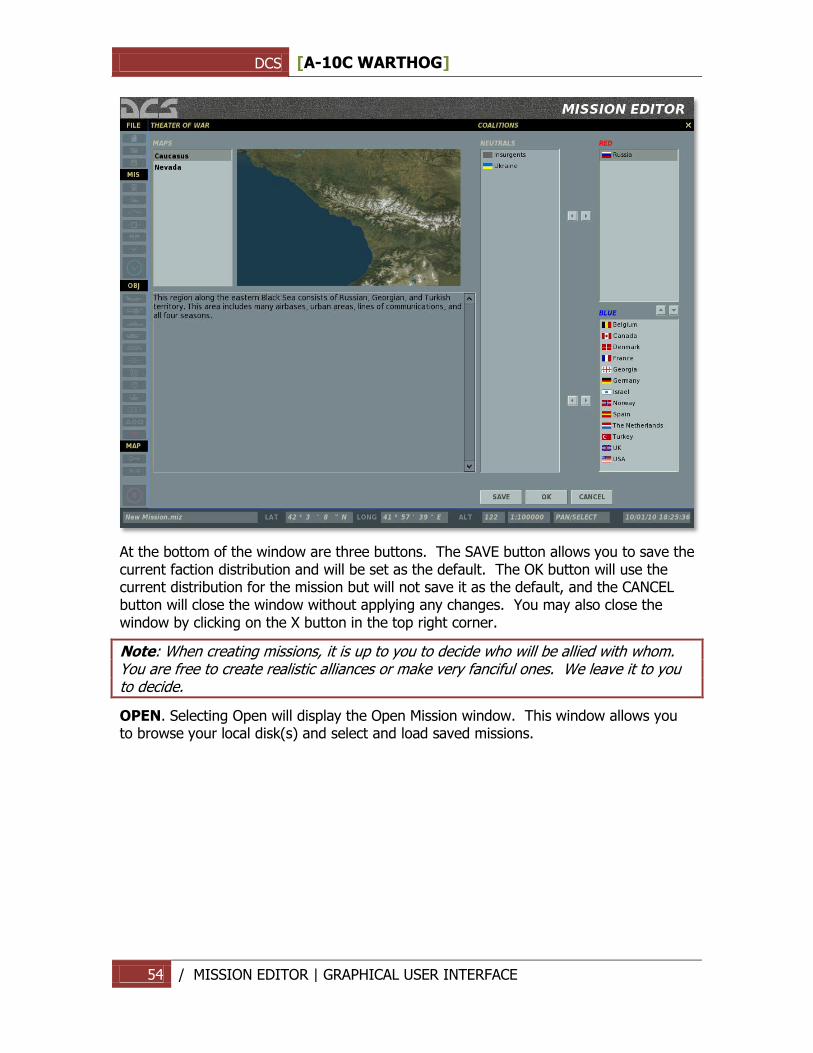
NEW. Selecting New will allow you to exit the current mission loaded and start a new one from scratch. Before proceeding though, a consent message box is provided to you so that you do not accidentally lose a mission you are working on. After creating a new mission, you will be displayed the THEATER OF WAR and COALITIONS window. This window allows you to define a map (Caucasus or Nevada) and what countries (factions) will be assigned to one of the two sides. Unassigned countries will not take part in the mission. In the left side window all unassigned factions are listed; in the top right window the RED side factions are listed; and in the lower right window all BLUE side factions are listed. To move a faction, left click on the desired faction and then press either the left or right arrow button to move it between the unassigned window and a side window or press the up and down arrows to move the faction to the other side directly.
DCS [A-10C WARTHOG]
54 / MISSION EDITOR | GRAPHICAL USER INTERFACE
At the bottom of the window are three buttons. The SAVE button allows you to save the current faction distribution and will be set as the default. The OK button will use the current distribution for the mission but will not save it as the default, and the CANCEL button will close the window without applying any changes. You may also close the window by clicking on the X button in the top right corner.
Note: When creating missions, it is up to you to decide who will be allied with whom. You are free to create realistic alliances or make very fanciful ones. We leave it to you to decide.
OPEN. Selecting Open will display the Open Mission window. This window allows you to browse your local disk(s) and select and load saved missions.
DCS [A-10C WARTHOG]
55 / MISSION EDITOR | GRAPHICAL USER INTERFACE
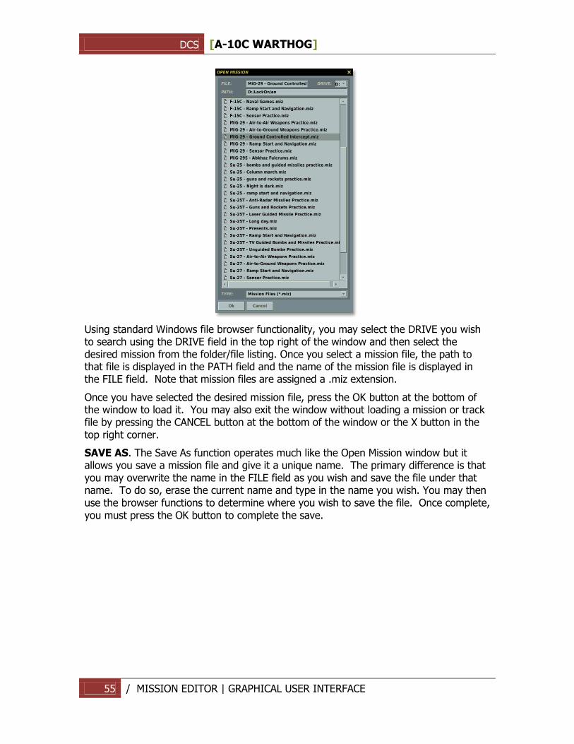
Using standard Windows file browser functionality, you may select the DRIVE you wish to search using the DRIVE field in the top right of the window and then select the desired mission from the folder/file listing. Once you select a mission file, the path to that file is displayed in the PATH field and the name of the mission file is displayed in the FILE field. Note that mission files are assigned a .miz extension.
Once you have selected the desired mission file, press the OK button at the bottom of the window to load it. You may also exit the window without loading a mission or track file by pressing the CANCEL button at the bottom of the window or the X button in the top right corner.
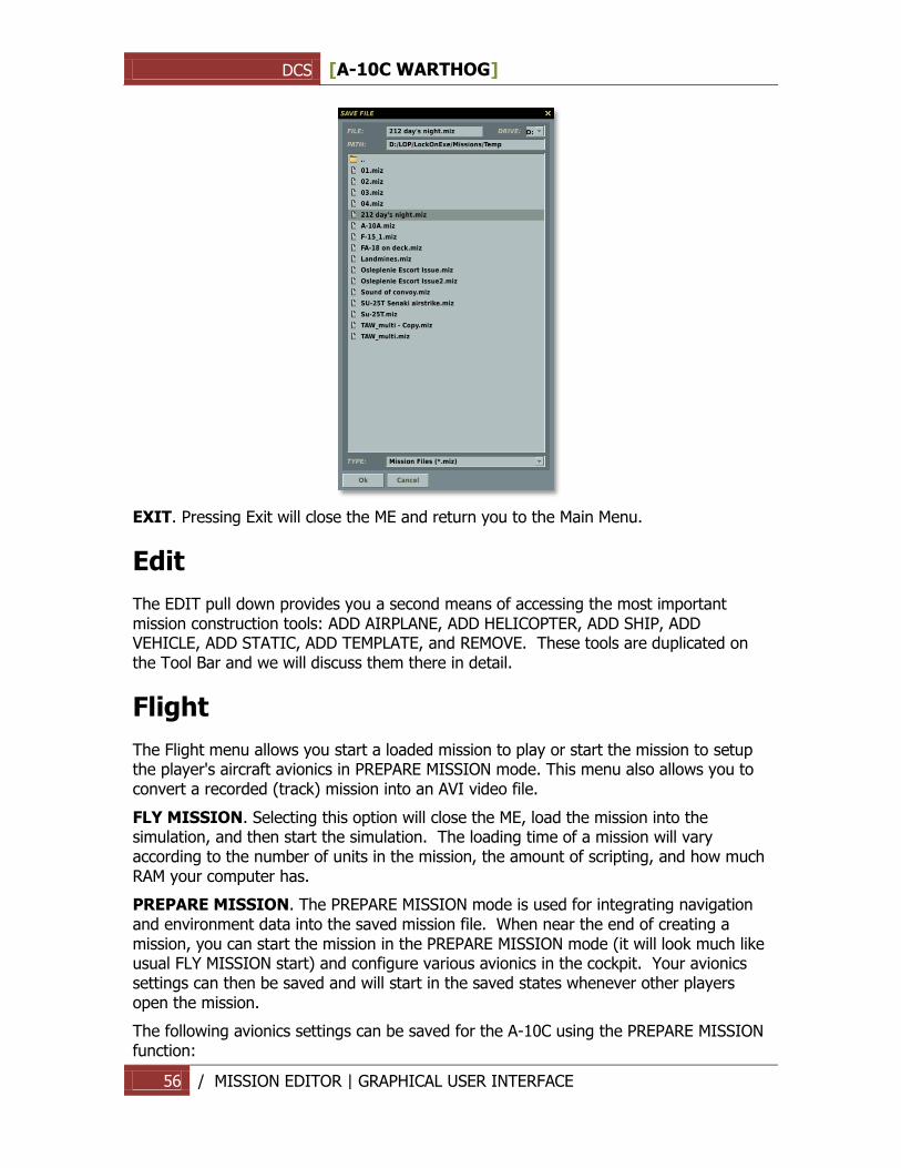
SAVE AS. The Save As function operates much like the Open Mission window but it allows you save a mission file and give it a unique name. The primary difference is that you may overwrite the name in the FILE field as you wish and save the file under that name. To do so, erase the current name and type in the name you wish. You may then use the browser functions to determine where you wish to save the file. Once complete, you must press the OK button to complete the save.
DCS [A-10C WARTHOG]
56 / MISSION EDITOR | GRAPHICAL USER INTERFACE
EXIT. Pressing Exit will close the ME and return you to the Main Menu.
Edit
The EDIT pull down provides you a second means of accessing the most important mission construction tools: ADD AIRPLANE, ADD HELICOPTER, ADD SHIP, ADD VEHICLE, ADD STATIC, ADD TEMPLATE, and REMOVE. These tools are duplicated on the Tool Bar and we will discuss them there in detail.
Flight
The Flight menu allows you start a loaded mission to play or start the mission to setup the player's aircraft avionics in PREPARE MISSION mode. This menu also allows you to convert a recorded (track) mission into an AVI video file.
FLY MISSION. Selecting this option will close the ME, load the mission into the simulation, and then start the simulation. The loading time of a mission will vary according to the number of units in the mission, the amount of scripting, and how much RAM your computer has.
PREPARE MISSION. The PREPARE MISSION mode is used for integrating navigation and environment data into the saved mission file. When near the end of creating a mission, you can start the mission in the PREPARE MISSION mode (it will look much like usual FLY MISSION start) and configure various avionics in the cockpit. Your avionics settings can then be saved and will start in the saved states whenever other players open the mission.
The following avionics settings can be saved for the A-10C using the PREPARE MISSION function:
DCS [A-10C WARTHOG]
57 / MISSION EDITOR | GRAPHICAL USER INTERFACE
CDU. All adjustments except the flight plan from mission editor.
IFFCC. TEST menu settings.
MFCD. Lower line OSB assignments.
SADL. User ID and other NET adjustments.
TAD. TAD profiles.
TGP. Laser code, integration, calibration method, gain settings, TAAF altitude.
DSMS. Mission Control Page data, weapon profiles.
Radio manual and preset frequencies.
Once your avionics are setup as desired for the mission, exit the mission and press the SAVE button in the ME once again to save all of the prepared data in the mission file.
NOTE for mission makers
If you use prepare mission mode, please indicate in the briefing that user should not to use a mission planner. If he'll change route or weapons the avionics scripts in the mission file will conflict with new mission assignments. If you want to give a freedom of action to the user that he used the mission planner, don't use mission preparing mode.
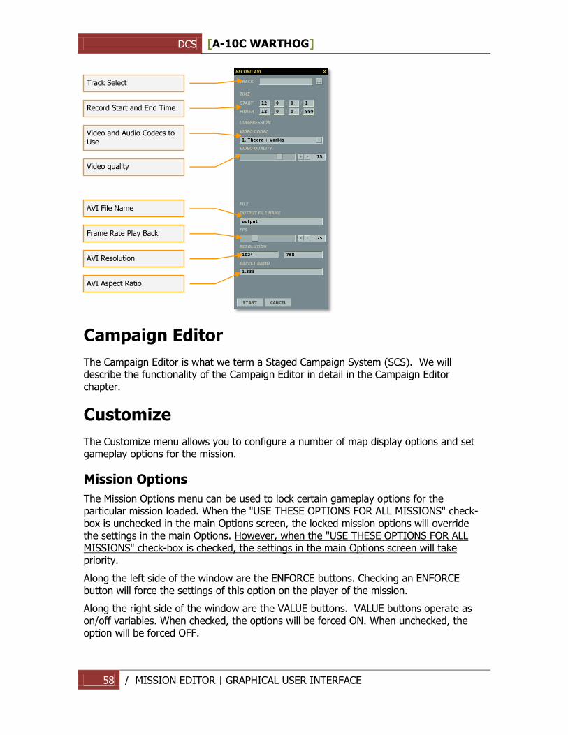
RECORD AVI. This option allows you to convert a Track file (which can only be viewed in the game) to an AVI video file that can be viewed by anyone using video playback software.
Once a Track file has been created, you may load the file into this tool and then set the video quality of the AVI video output. A few notes:
Because the AVI tools render the Track file frame by frame and NOT in real-time, you can create an AVI with higher or lower frame rates than when the track was originally recorded.
The higher the video quality and longer the recording, the longer it will take to render the AVI. Setting the FPS slider too high will also lengthen the time it takes. Please note that rendering long, high-quality AVIs can be a very time consuming process.
Once the AVI is created, you may then play it back outside of the game or convert and compress it with other codecs.
Using the START and FINISH fields, you can create an AVI out of just one part of a larger Track file.
DCS [A-10C WARTHOG]
58 / MISSION EDITOR | GRAPHICAL USER INTERFACE
Campaign Editor
The Campaign Editor is what we term a Staged Campaign System (SCS). We will describe the functionality of the Campaign Editor in detail in the Campaign Editor chapter.
Customize
The Customize menu allows you to configure a number of map display options and set gameplay options for the mission.
Mission Options
The Mission Options menu can be used to lock certain gameplay options for the particular mission loaded. When the "USE THESE OPTIONS FOR ALL MISSIONS" check-box is unchecked in the main Options screen, the locked mission options will override the settings in the main Options. However, when the "USE THESE OPTIONS FOR ALL MISSIONS" check-box is checked, the settings in the main Options screen will take priority.
Along the left side of the window are the ENFORCE buttons. Checking an ENFORCE button will force the settings of this option on the player of the mission.
Along the right side of the window are the VALUE buttons. VALUE buttons operate as on/off variables. When checked, the options will be forced ON. When unchecked, the option will be forced OFF.
Frame Rate Play Back
AVI Aspect Ratio
Track Select
Video and Audio Codecs to Use
Record Start and End Time
AVI File Name
AVI Resolution
Video quality
DCS [A-10C WARTHOG]
59 / MISSION EDITOR | GRAPHICAL USER INTERFACE
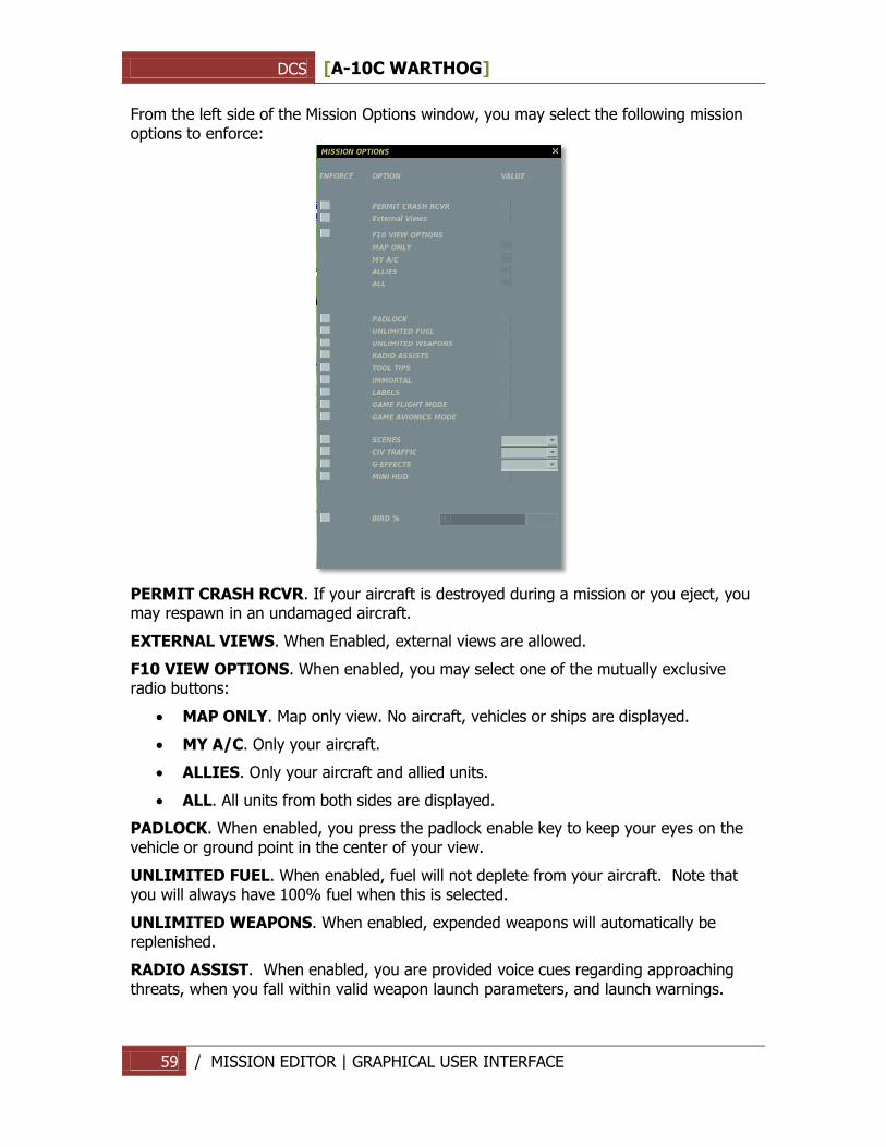
From the left side of the Mission Options window, you may select the following mission options to enforce:
PERMIT CRASH RCVR. If your aircraft is destroyed during a mission or you eject, you may respawn in an undamaged aircraft.
EXTERNAL VIEWS. When Enabled, external views are allowed.
F10 VIEW OPTIONS. When enabled, you may select one of the mutually exclusive radio buttons:
MAP ONLY. Map only view. No aircraft, vehicles or ships are displayed.
MY A/C. Only your aircraft.
ALLIES. Only your aircraft and allied units.
ALL. All units from both sides are displayed.
PADLOCK. When enabled, you press the padlock enable key to keep your eyes on the vehicle or ground point in the center of your view.
UNLIMITED FUEL. When enabled, fuel will not deplete from your aircraft. Note that you will always have 100% fuel when this is selected.
UNLIMITED WEAPONS. When enabled, expended weapons will automatically be replenished.
RADIO ASSIST. When enabled, you are provided voice cues regarding approaching threats, when you fall within valid weapon launch parameters, and launch warnings.
DCS [A-10C WARTHOG]
60 / MISSION EDITOR | GRAPHICAL USER INTERFACE
TOOL TIPS. When enabled and when you hover your mouse over a control in the cockpit (button, switch, dial, or lever), you will be shown a brief tool tip of the function of the control.
IMMORTAL. When enabled your aircraft cannot be destroyed or even damaged.
LABELS. When enabled, you can display easy-to-spot labels about friendly and enemy units. Close units will display the unit type name and the range from you. Units at medium range will only show the range to unit. Units at long range will only be marked with a tic-mark.
GAME FLIGHT MODE. Easy flight makes the aircraft much easier to fly when enabled and more analogous to an arcade game.
GAME AVIONICS MODE. This option allows simple targeting, an all-seeing sensor, and additional threat warnings. For a detailed explanation of Easy Avionics mode, please consult the Options/Gameplay portion of this manual.
SCENES. When enabled, there are three levels of scenes you can choose from. Scenes consist of the object population on the map which consists of buildings, trees, power lines, etc. Your scene setting can have a big impact on how smooth your gamepaly is. If you have choppy gameplay, you may wish to lower this setting. Possible settings include LOW, MEDIUM, and HIGH.
CIV TRAFFIC. When enabled, the world can be populated by moving cars, trucks and trains throughout the detailed world area. If enabled, possible settings include OFF, LOW, MEDIUM, and HIGH.
G-EFFECT. When enabled, you may select the level of G-effect. Possible settings include: NONE, GAME, and SIMULATION.
BIRDS. This adjust the probability of a bird strikes when flying at altitude below 200 meters. 100% is the default bird strike probability. 0% - no birds. 1000% - the bird strike probability multiplier 10 times.
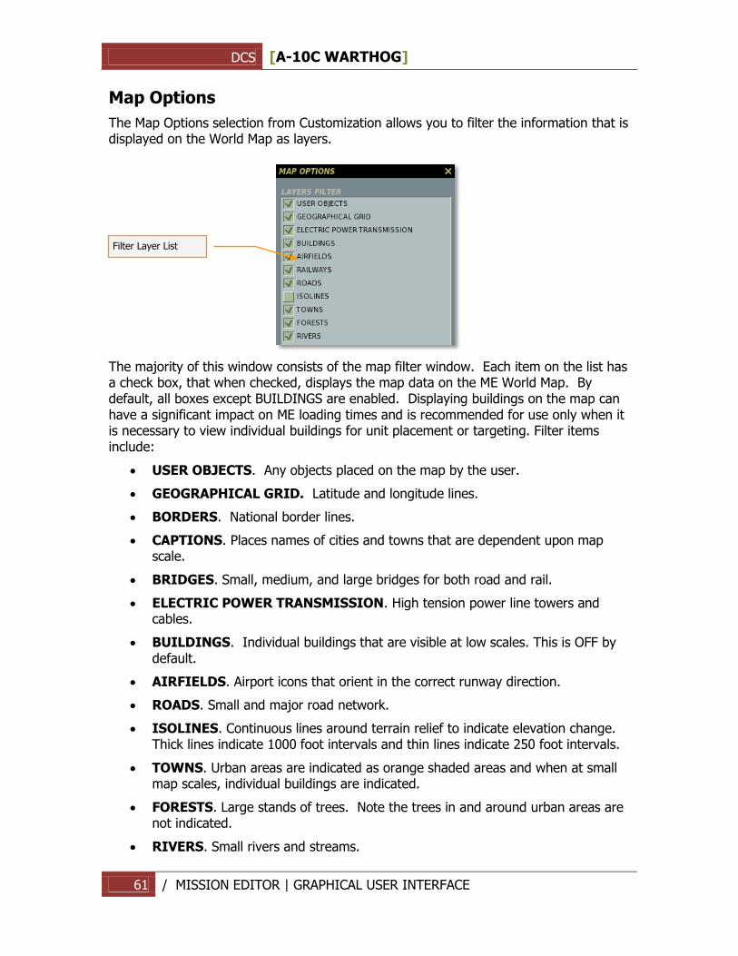
DCS [A-10C WARTHOG]
61 / MISSION EDITOR | GRAPHICAL USER INTERFACE
Map Options
The Map Options selection from Customization allows you to filter the information that is displayed on the World Map as layers.
The majority of this window consists of the map filter window. Each item on the list has a check box, that when checked, displays the map data on the ME World Map. By default, all boxes except BUILDINGS are enabled. Displaying buildings on the map can have a significant impact on ME loading times and is recommended for use only when it is necessary to view individual buildings for unit placement or targeting. Filter items include:
USER OBJECTS. Any objects placed on the map by the user.
GEOGRAPHICAL GRID. Latitude and longitude lines.
BORDERS. National border lines.
CAPTIONS. Places names of cities and towns that are dependent upon map scale.
BRIDGES. Small, medium, and large bridges for both road and rail.
ELECTRIC POWER TRANSMISSION. High tension power line towers and cables.
BUILDINGS. Individual buildings that are visible at low scales. This is OFF by default.
AIRFIELDS. Airport icons that orient in the correct runway direction.
ROADS. Small and major road network.
ISOLINES. Continuous lines around terrain relief to indicate elevation change. Thick lines indicate 1000 foot intervals and thin lines indicate 250 foot intervals.
TOWNS. Urban areas are indicated as orange shaded areas and when at small map scales, individual buildings are indicated.
FORESTS. Large stands of trees. Note the trees in and around urban areas are not indicated.
RIVERS. Small rivers and streams.
Filter Layer List
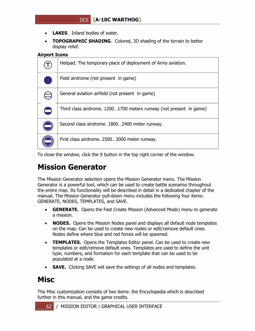
DCS [A-10C WARTHOG]
62 / MISSION EDITOR | GRAPHICAL USER INTERFACE
LAKES. Inland bodies of water.
TOPOGRAPHIC SHADING. Colored, 3D shading of the terrain to better display relief.
Airport Icons
Helipad. The temporary place of deployment of Army aviation.
Field airdrome (not present in game)
General aviation airfield (not present in game)
Third class airdrome. 1200…1700 meters runway (not present in game)
Second class airdrome. 1800…2400 meter runway.
First class airdrome. 2500…3000 meter runway.
To close the window, click the X button in the top right corner of the window.
Mission Generator
The Mission Generator selection opens the Mission Generator menu. The Mission Generator is a powerful tool, which can be used to create battle scenarios throughout the entire map. Its functionality will be described in detail in a dedicated chapter of the manual. The Mission Generator pull-down menu includes the following four items: GENERATE, NODES, TEMPLATES, and SAVE.
GENERATE. Opens the Fast Create Mission (Advanced Mode) menu to generate a mission.
NODES. Opens the Mission Nodes panel and displays all default node templates on the map. Can be used to create new nodes or edit/remove default ones. Nodes define where blue and red forces will be spawned.
TEMPLATES. Opens the Templates Editor panel. Can be used to create new templates or edit/remove default ones. Templates are used to define the unit type, numbers, and formation for each template that can be used to be populated at a node.
SAVE. Clicking SAVE will save the settings of all nodes and templates.
Misc
The Misc customization consists of two items: the Encyclopedia which is described further in this manual, and the game credits.
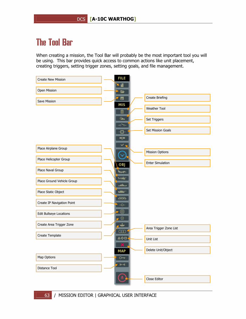
DCS [A-10C WARTHOG]
63 / MISSION EDITOR | GRAPHICAL USER INTERFACE
The Tool Bar
When creating a mission, the Tool Bar will probably be the most important tool you will be using. This bar provides quick access to common actions like unit placement, creating triggers, setting trigger zones, setting goals, and file management.
Create New Mission
Open Mission
Save Mission
Create Briefing
Weather Tool Set Triggers Set Mission Goals
Mission Options Enter Simulation
Place Airplane Group
Place Helicopter Group
Place Naval Group
Place Ground Vehicle Group
Place Static Object
Create Area Trigger Zone
Create Template
Area Trigger Zone List
Unit List
Delete Unit/Object
Map Options Distance Tool
Close Editor
Create IP Navigation Point
Edit Bullseye Locations
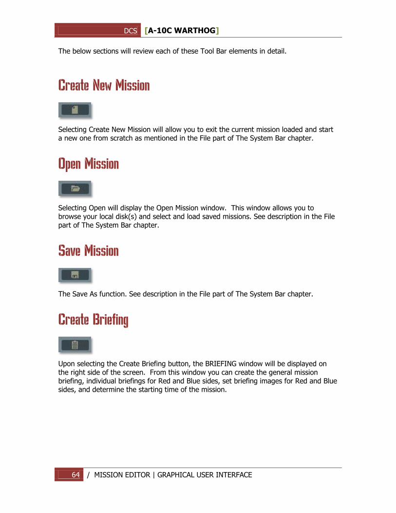
DCS [A-10C WARTHOG]
64 / MISSION EDITOR | GRAPHICAL USER INTERFACE
The below sections will review each of these Tool Bar elements in detail.
Create New Mission
Selecting Create New Mission will allow you to exit the current mission loaded and start a new one from scratch as mentioned in the File part of The System Bar chapter.
Open Mission
Selecting Open will display the Open Mission window. This window allows you to browse your local disk(s) and select and load saved missions. See description in the File part of The System Bar chapter.
Save Mission
The Save As function. See description in the File part of The System Bar chapter.
Create Briefing
Upon selecting the Create Briefing button, the BRIEFING window will be displayed on the right side of the screen. From this window you can create the general mission briefing, individual briefings for Red and Blue sides, set briefing images for Red and Blue sides, and determine the starting time of the mission.
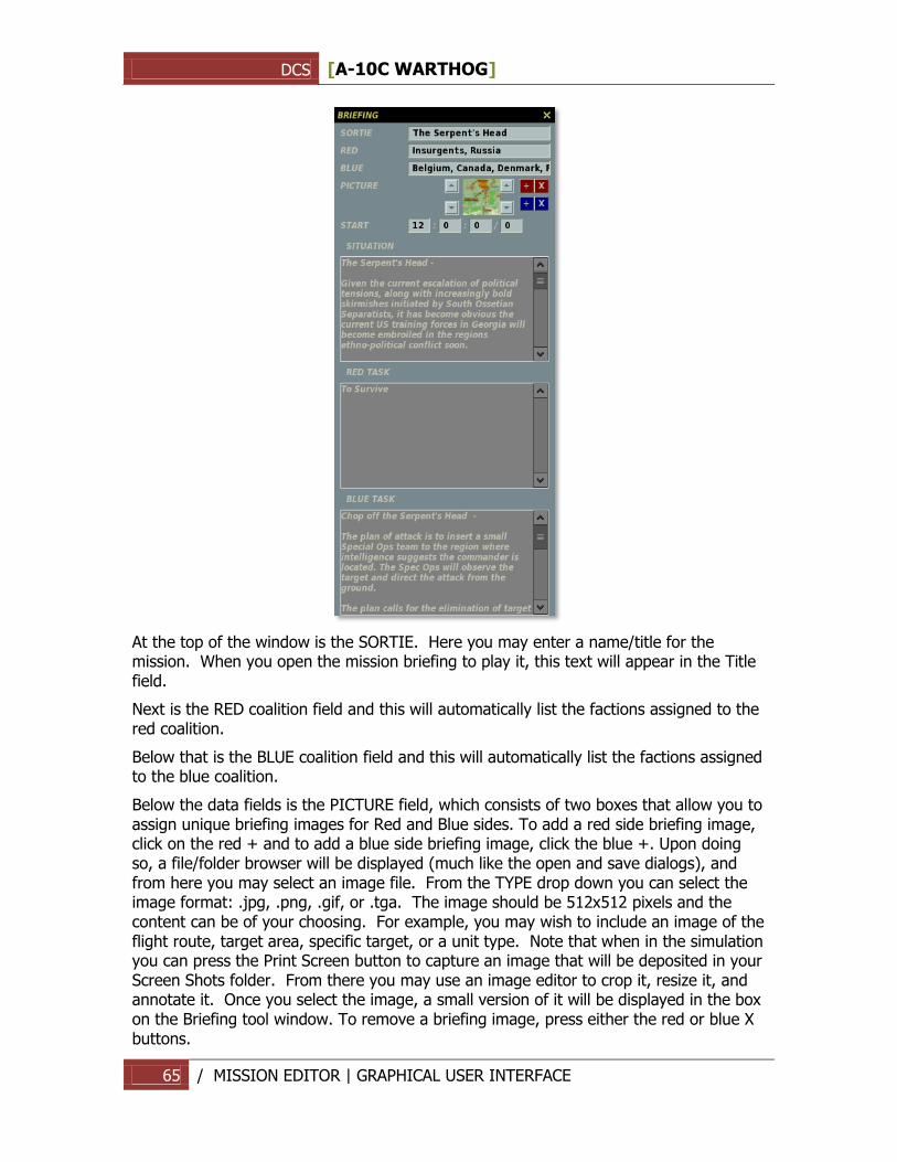
DCS [A-10C WARTHOG]
65 / MISSION EDITOR | GRAPHICAL USER INTERFACE
At the top of the window is the SORTIE. Here you may enter a name/title for the mission. When you open the mission briefing to play it, this text will appear in the Title field.
Next is the RED coalition field and this will automatically list the factions assigned to the red coalition.
Below that is the BLUE coalition field and this will automatically list the factions assigned to the blue coalition.
Below the data fields is the PICTURE field, which consists of two boxes that allow you to assign unique briefing images for Red and Blue sides. To add a red side briefing image, click on the red + and to add a blue side briefing image, click the blue +. Upon doing so, a file/folder browser will be displayed (much like the open and save dialogs), and from here you may select an image file. From the TYPE drop down you can select the image format: .jpg, .png, .gif, or .tga. The image should be 512x512 pixels and the content can be of your choosing. For example, you may wish to include an image of the flight route, target area, specific target, or a unit type. Note that when in the simulation you can press the Print Screen button to capture an image that will be deposited in your Screen Shots folder. From there you may use an image editor to crop it, resize it, and annotate it. Once you select the image, a small version of it will be displayed in the box on the Briefing tool window. To remove a briefing image, press either the red or blue X buttons.
DCS [A-10C WARTHOG]
66 / MISSION EDITOR | GRAPHICAL USER INTERFACE
In the START field, you may edit the start time of the mission in hour : minutes : seconds / day format. Note that the mission start time will be used as the default starting time for all groups placed on the map. You can change a group's starting time using the group properties panels (described in detail further). Also note, the calendar starts with June 1st as day 0. For example, to set the mission date to July 1, set the day value to 30. To set the mission date to November 1, set the day value to 153. The default starting time for all missions is 12:00:00/0 (12:00 pm, June 1st). Changing the starting time and date will affect the position and motion of the sun, moon and stars to correspond to the time of day and year set.
Note: If you wish to adjust the darkness of night missions, you can adjust the mission start date to a date when the moon is less visible.
The three text boxes that comprise the lower portion of the window allow you to enter a general mission briefing and individual briefings for Red and Blue sides (handy for multiplayer missions). Enter text in the DESCRIPTION box and this text will appear in the DESCRIPTION field when the mission briefing is displayed. Enter text in the RED TASK and BLUE TASK boxes to have unique text for each side that will be displayed in the MISSION GOAL field of each mission briefing.
Weather Tool
The weather tool panel provides two options for setting the weather for the mission: Standard weather and Dynamic weather.
1. Standard weather. Standard static weather formed by user settings.
2. Dynamic weather. Weather formed by differences in the atmospheric pressure and dynamically changing during the mission.
Standard weather
The weather panel is divided into six functional sections: Season, Clouds and Atmosphere, Wind, Turbulence, Fog, and Weather Templates.
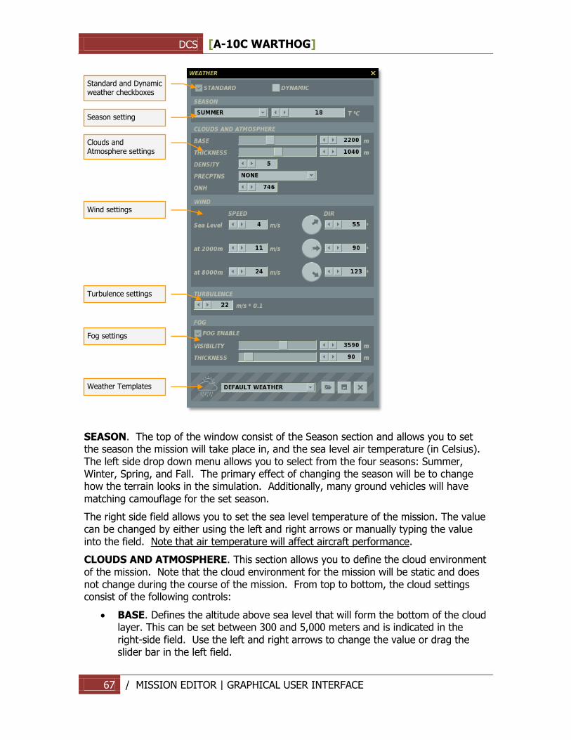
DCS [A-10C WARTHOG]
67 / MISSION EDITOR | GRAPHICAL USER INTERFACE
SEASON. The top of the window consist of the Season section and allows you to set the season the mission will take place in, and the sea level air temperature (in Celsius). The left side drop down menu allows you to select from the four seasons: Summer, Winter, Spring, and Fall. The primary effect of changing the season will be to change how the terrain looks in the simulation. Additionally, many ground vehicles will have matching camouflage for the set season.
The right side field allows you to set the sea level temperature of the mission. The value can be changed by either using the left and right arrows or manually typing the value into the field. Note that air temperature will affect aircraft performance.
CLOUDS AND ATMOSPHERE. This section allows you to define the cloud environment of the mission. Note that the cloud environment for the mission will be static and does not change during the course of the mission. From top to bottom, the cloud settings consist of the following controls:
BASE. Defines the altitude above sea level that will form the bottom of the cloud layer. This can be set between 300 and 5,000 meters and is indicated in the right-side field. Use the left and right arrows to change the value or drag the slider bar in the left field.
Season setting Clouds and Atmosphere settings
Wind settings
Turbulence settings
Fog settings
Weather Templates
Standard and Dynamic weather checkboxes
DCS [A-10C WARTHOG]
68 / MISSION EDITOR | GRAPHICAL USER INTERFACE
THICKNESS. Defines cloud layer thickness from the base level. For example, if the Base were set at 2,000 meters and the Thickness was set to 1,000 meters, you would have clouds between 2,000 and 3,000 meters above sea level. Note that thickness only applies to a solid cloud deck (Density 9 and 10) and not scattered clouds (Density 1 through 8). The cloud layer thickness can be adjusted using the left and right arrows or the slider bar. The selected thickness is displayed in the right side field in meters.
DENSITY. The Density defines the population density of clouds in the mission. Note that cloud cover is uniform throughout the simulation world. Density is according to a 0 to 10 scale. 0 defines no clouds; 1 through 8 defines scattered clouds with increasing levels of density; and 9 and 10 define a solid cloud layer deck (overcast). Use the left and right arrows to select the desired density setting.
PRECPTNS (Precipitations). The precipitation drop down menu allows you to set what type, if any, of precipitation will fall during the mission. Choices include: None, Rain, Thunderstorm, Snow, and Snowstorm. The selections will vary according to the selected season, temperature and cloud density.
QNH. Also referred to as “Q Code”, this value sets the barometric air pressure in the mission. This is in reference to mmHg (millimeters of mercury) with Russian altimeters.
WIND. Rather than a single wind direction and speed, the wind function allows you to set three distinct wind altitude bands: sea level, 2,000 meters, and 8,000 meters. These are indicated by the three lines within the Wind section of the Weather Tool. To set the speed in meters per-second (m/s), use the left and right arrows. Note that wind will be as a constant force without gusting. To the right of the wind speed setting is the wind direction setting. This can be set in two ways. The first is to click on the radial dial to denote the direction you want the wind to blow in (North is indicated as the top of the dial). The second option is to input the value using the left and right arrow buttons. The set direction that wind will blow in is indicated in the right field in degrees. For example, when set to 0 degrees (due north), the wind in the mission will blow from the south to the north.
TURBULENCE. You may set air turbulence at 0.1 m/s increments at ground level. Turbulence will then decrease as altitude increases.
FOG. The fog setting controls:
FOG ENABLE. Set fog on or off.
VISIBILITY. Visibility in meters of objects obscured by fog.
THICKNESS. Use the scroll bar or left and right arrows to set how thick the fog layer will be. A 0 (zero) setting denotes sea level. For example, setting a value of 50 would place a uniform fog layer in the simulation world from 0 to 50 meters from sea level.
WEATHER TEMPLATES. Rather than require you to create weather conditions each time you create a mission, the editor provides you the means to load saved weather templates and even modify them. These can be useful tools to save time when creating missions for a campaign. The Weather Template section has the following elements:
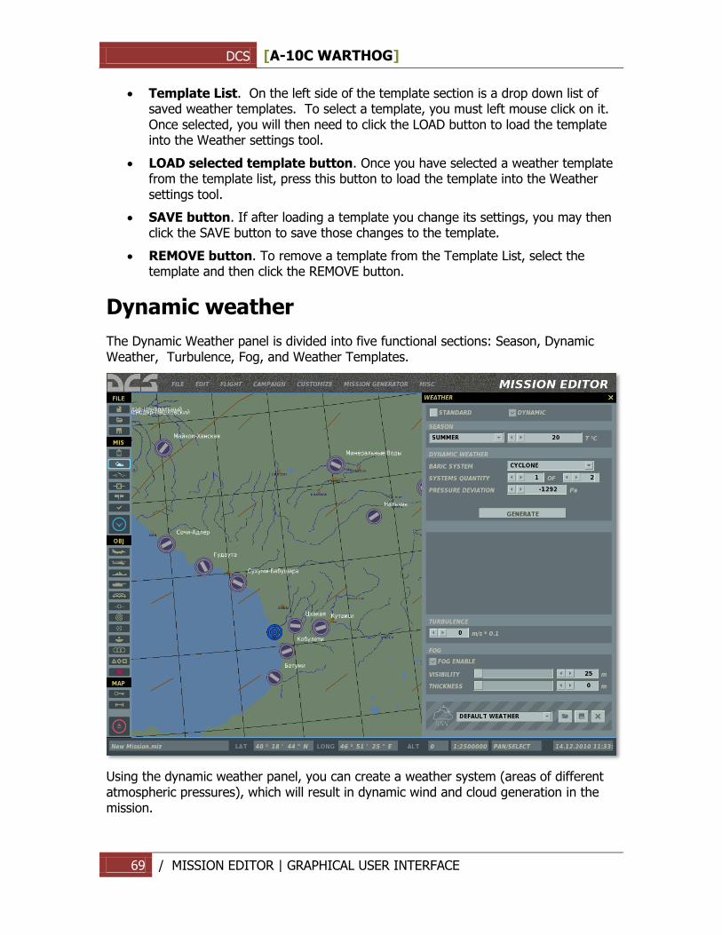
DCS [A-10C WARTHOG]
69 / MISSION EDITOR | GRAPHICAL USER INTERFACE
Template List. On the left side of the template section is a drop down list of saved weather templates. To select a template, you must left mouse click on it. Once selected, you will then need to click the LOAD button to load the template into the Weather settings tool.
LOAD selected template button. Once you have selected a weather template from the template list, press this button to load the template into the Weather settings tool.
SAVE button. If after loading a template you change its settings, you may then click the SAVE button to save those changes to the template.
REMOVE button. To remove a template from the Template List, select the template and then click the REMOVE button.
Dynamic weather
The Dynamic Weather panel is divided into five functional sections: Season, Dynamic Weather, Turbulence, Fog, and Weather Templates.
Using the dynamic weather panel, you can create a weather system (areas of different atmospheric pressures), which will result in dynamic wind and cloud generation in the mission.
DCS [A-10C WARTHOG]
70 / MISSION EDITOR | GRAPHICAL USER INTERFACE
SEASON. The top of the window consist of the Season section and allows you to set the season the mission will take place in, and the sea level air temperature (in Celsius). The left side drop down menu allows you to select from the four seasons: Summer, Winter, Spring, and Fall. The primary effect of changing the season will be to change how the terrain looks in the simulation. Additionally, many ground vehicles will have matching camouflage for the set season.
The right side field allows you to set the sea level temperature of the mission. The value can be changed by either using the left and right arrows or manually typing the value into the field. Note that air temperature will affect aircraft performance.
DYNAMIC WEATHER. Settings of the dynamic weather system parameters.
BARIC SYSTEM. Selection between cyclone (low pressure systems), anticyclone (high pressure systems) or none.
SYSTEMS QUANTITY. Quantity of baric systems on the map.
PRESSURE DEVIATION. Pressure deviation in the center of the selected pressure system from ISA International Standard Atmosphere, in Pascals.
GENERATE. Generate a randomized weather system using the set parameters.
Clouds and winds are generated on the entire map dynamically in the mission according to the type, locations and pressure deviations of the pressure systems. Wind conditions evolve during the mission according to the changes in the pressures and locations of the pressure systems.
TURBULENCE. You may set air turbulence at 0.1 m/s increments at ground level. Turbulence will then decrease as altitude increases.
Fog Setting. The fog setting controls:
FOG ENABLE. Set fog on or off.
VISIBILITY. Visibility in meters of objects obscured by fog.
THICKNESS. Use the scroll bar or left and right arrows to set how thick the fog layer will be. A 0 (zero) setting denotes sea level. For example, setting a value of 50 would place a uniform fog layer in the simulation world from 0 to 50 meters from sea level.
Weather Templates. Rather than require you to create weather conditions each time you create a mission, the editor provides you the means to load saved weather templates and even modify them.
At the bottom of the window are the OK and CANCEL buttons. Press the OK button to save weather changes to the mission and close the window, or press the CANCEL button to close the window without saving any weather changes. You can also cancel the window by pressing the yellow X in the top right corner of the window.
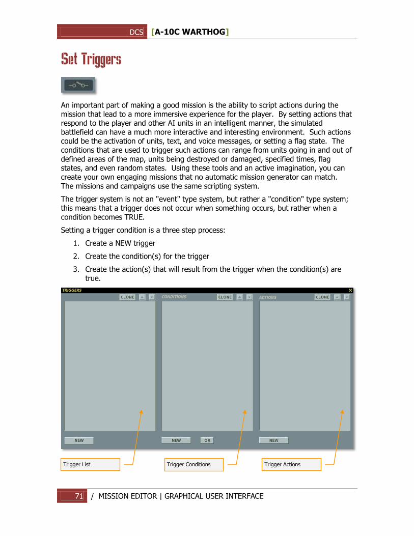
DCS [A-10C WARTHOG]
71 / MISSION EDITOR | GRAPHICAL USER INTERFACE
Set Triggers
An important part of making a good mission is the ability to script actions during the mission that lead to a more immersive experience for the player. By setting actions that respond to the player and other AI units in an intelligent manner, the simulated battlefield can have a much more interactive and interesting environment. Such actions could be the activation of units, text, and voice messages, or setting a flag state. The conditions that are used to trigger such actions can range from units going in and out of defined areas of the map, units being destroyed or damaged, specified times, flag states, and even random states. Using these tools and an active imagination, you can create your own engaging missions that no automatic mission generator can match. The missions and campaigns use the same scripting system.
The trigger system is not an "event" type system, but rather a "condition" type system; this means that a trigger does not occur when something occurs, but rather when a condition becomes TRUE.
Setting a trigger condition is a three step process:
1. Create a NEW trigger
2. Create the condition(s) for the trigger
3. Create the action(s) that will result from the trigger when the condition(s) are true.
Trigger List
Trigger Conditions
Trigger Actions
DCS [A-10C WARTHOG]
72 / MISSION EDITOR | GRAPHICAL USER INTERFACE
Upon selecting the set Triggers button, the TRIGGERS window will appear. There are three primary elements to creating a mission trigger and each has its own pane in the window:
Triggers List
This left-most pane is used to create new triggers and list existing ones. In the triggers listing pane, each trigger will be listed as a Type of trigger and then the name of the trigger in parenthesis. For example: “ONCE (Set Area 01)”.
At the bottom of the trigger list pane are four controls that allow you to manage your triggers.
NEW button. Press the NEW button to create a new trigger. When you create a new trigger, you will need to set the TYPE and give it a unique name that briefly describes its function. Be careful in naming your triggers so that there is not mass-confusion when you have a long list of triggers!
DELETE button. Press the DELETE button to remove a trigger from the list. You will first need to click on the trigger you wish to remove before pressing the DELETE button.
TYPE drop down field. Using this drop down, you can set when and how the trigger event will be cued. For example, you may want the trigger to only happen once, or you may want it to happen each time defined conditions are met. You have four options:
1. ONCE. The trigger will be executed only once after the condition is evaluated as true. Once set as true, the condition is removed from memory. For example, if you want a message to show only the first time an aircraft enters an area, you would use the ONCE option.
Trigger Behavior:
Condition: Evaluated Continuously, until it is evaluated as "True". Then removed from the list of evaluations. Action: Activated Once, when condition is "true".
Example:
You want to spawn a AAA backup-group when another Armor-group is dead.
Add a "ONCE" Trigger.
Add a "Group Dead" condition and select the Armored-group that must be dead.
Add a "Activate Group" and select the AAA-group you want to activate.
The group being activated will be activated once when the first group is dead. Hint: Remember to set the AAA-group to 23-hours of delay, so it stays inactive until activated.
2. CONTINUOUS ACTION. The Continuous Action trigger checks the trigger's conditions each second. Each second the conditions return true, the actions are performed; each second the conditions are false, no action is not performed.
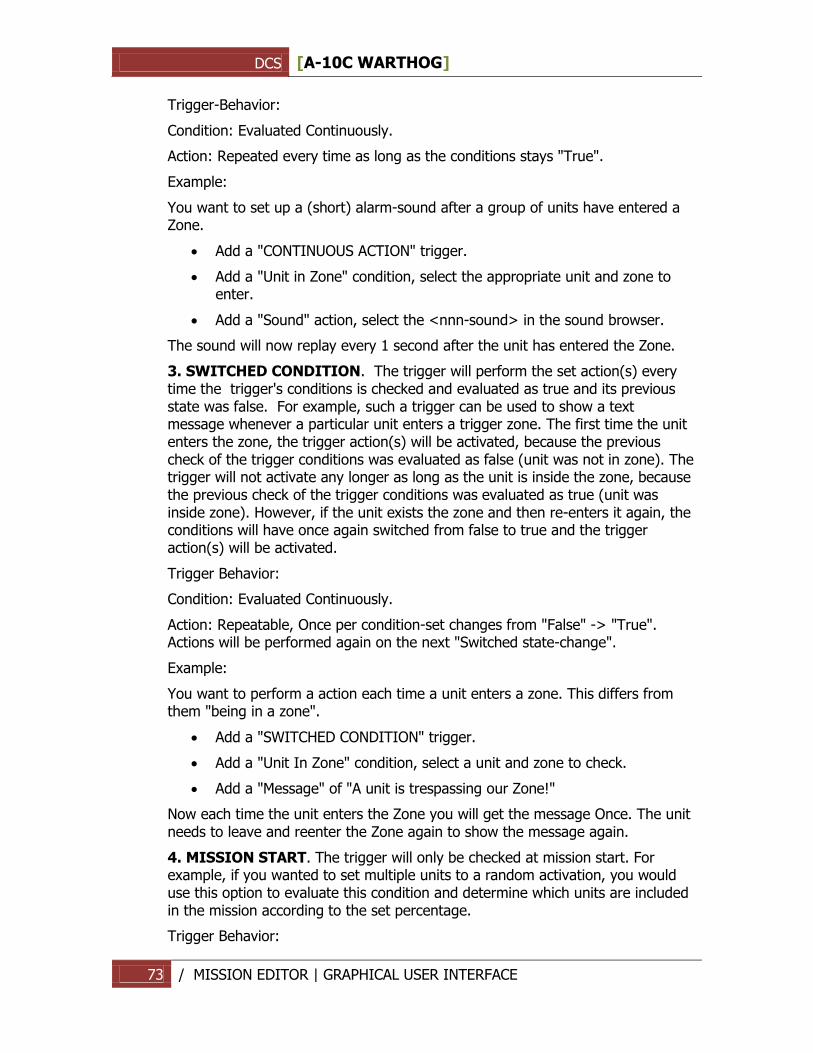
DCS [A-10C WARTHOG]
73 / MISSION EDITOR | GRAPHICAL USER INTERFACE
Trigger-Behavior:
Condition: Evaluated Continuously.
Action: Repeated every time as long as the conditions stays "True".
Example:
You want to set up a (short) alarm-sound after a group of units have entered a Zone.
Add a "CONTINUOUS ACTION" trigger.
Add a "Unit in Zone" condition, select the appropriate unit and zone to enter.
Add a "Sound" action, select the <nnn-sound> in the sound browser.
The sound will now replay every 1 second after the unit has entered the Zone.
3. SWITCHED CONDITION. The trigger will perform the set action(s) every time the trigger's conditions is checked and evaluated as true and its previous state was false. For example, such a trigger can be used to show a text message whenever a particular unit enters a trigger zone. The first time the unit enters the zone, the trigger action(s) will be activated, because the previous check of the trigger conditions was evaluated as false (unit was not in zone). The trigger will not activate any longer as long as the unit is inside the zone, because the previous check of the trigger conditions was evaluated as true (unit was inside zone). However, if the unit exists the zone and then re-enters it again, the conditions will have once again switched from false to true and the trigger action(s) will be activated.
Trigger Behavior:
Condition: Evaluated Continuously.
Action: Repeatable, Once per condition-set changes from "False" -> "True". Actions will be performed again on the next "Switched state-change".
Example:
You want to perform a action each time a unit enters a zone. This differs from them "being in a zone".
Add a "SWITCHED CONDITION" trigger.
Add a "Unit In Zone" condition, select a unit and zone to check.
Add a "Message" of "A unit is trespassing our Zone!"
Now each time the unit enters the Zone you will get the message Once. The unit needs to leave and reenter the Zone again to show the message again.
4. MISSION START. The trigger will only be checked at mission start. For example, if you wanted to set multiple units to a random activation, you would use this option to evaluate this condition and determine which units are included in the mission according to the set percentage.
Trigger Behavior:
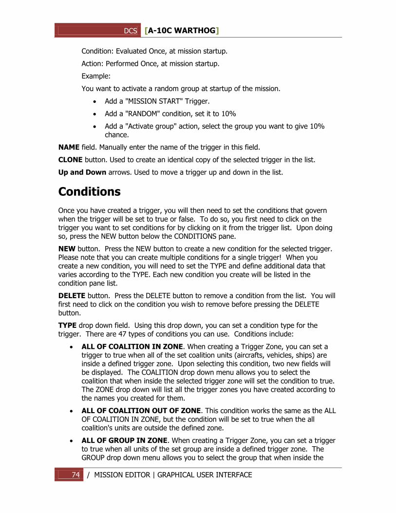
DCS [A-10C WARTHOG]
74 / MISSION EDITOR | GRAPHICAL USER INTERFACE
Condition: Evaluated Once, at mission startup.
Action: Performed Once, at mission startup.
Example:
You want to activate a random group at startup of the mission.
Add a "MISSION START" Trigger.
Add a "RANDOM" condition, set it to 10%
Add a "Activate group" action, select the group you want to give 10% chance.
NAME field. Manually enter the name of the trigger in this field.
CLONE button. Used to create an identical copy of the selected trigger in the list.
Up and Down arrows. Used to move a trigger up and down in the list.
Conditions
Once you have created a trigger, you will then need to set the conditions that govern when the trigger will be set to true or false. To do so, you first need to click on the trigger you want to set conditions for by clicking on it from the trigger list. Upon doing so, press the NEW button below the CONDITIONS pane.
NEW button. Press the NEW button to create a new condition for the selected trigger. Please note that you can create multiple conditions for a single trigger! When you create a new condition, you will need to set the TYPE and define additional data that varies according to the TYPE. Each new condition you create will be listed in the condition pane list.
DELETE button. Press the DELETE button to remove a condition from the list. You will first need to click on the condition you wish to remove before pressing the DELETE button.
TYPE drop down field. Using this drop down, you can set a condition type for the trigger. There are 47 types of conditions you can use. Conditions include:
ALL OF COALITION IN ZONE. When creating a Trigger Zone, you can set a trigger to true when all of the set coalition units (aircrafts, vehicles, ships) are inside a defined trigger zone. Upon selecting this condition, two new fields will be displayed. The COALITION drop down menu allows you to select the coalition that when inside the selected trigger zone will set the condition to true. The ZONE drop down will list all the trigger zones you have created according to the names you created for them.
ALL OF COALITION OUT OF ZONE. This condition works the same as the ALL OF COALITION IN ZONE, but the condition will be set to true when the all coalition's units are outside the defined zone.
ALL OF GROUP IN ZONE. When creating a Trigger Zone, you can set a trigger to true when all units of the set group are inside a defined trigger zone. The GROUP drop down menu allows you to select the group that when inside the
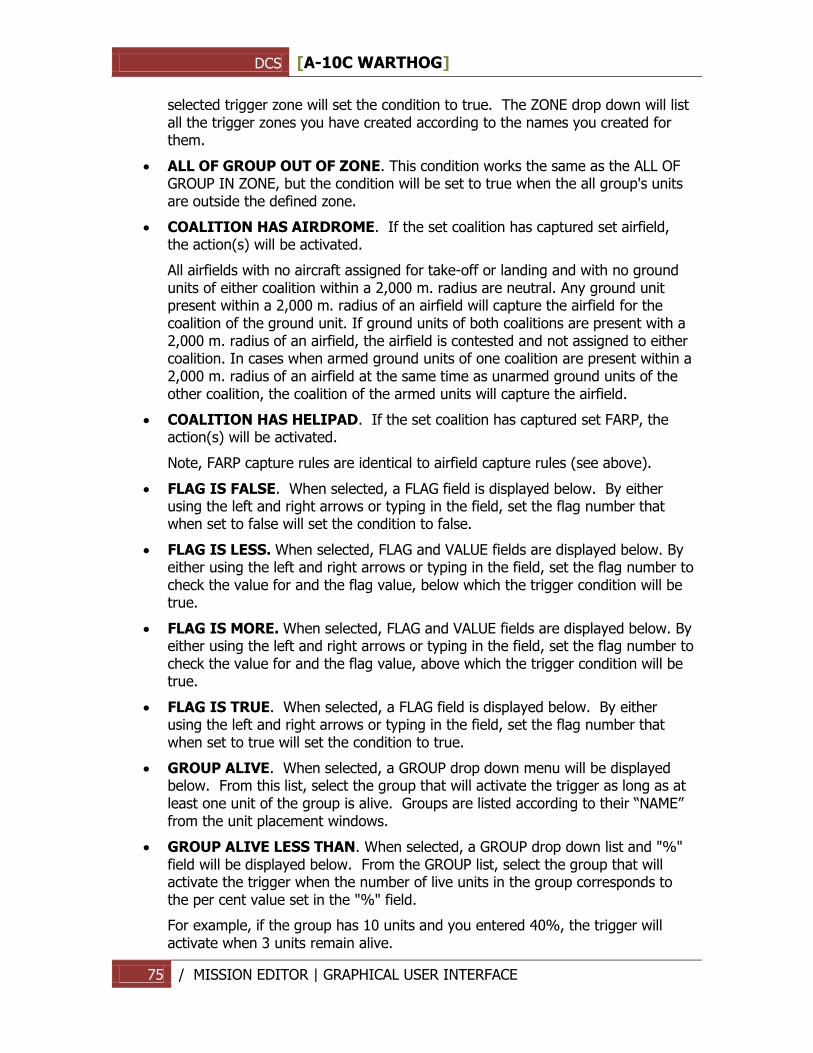
DCS [A-10C WARTHOG]
75 / MISSION EDITOR | GRAPHICAL USER INTERFACE
selected trigger zone will set the condition to true. The ZONE drop down will list all the trigger zones you have created according to the names you created for them.
ALL OF GROUP OUT OF ZONE. This condition works the same as the ALL OF GROUP IN ZONE, but the condition will be set to true when the all group's units are outside the defined zone.
COALITION HAS AIRDROME. If the set coalition has captured set airfield, the action(s) will be activated.
All airfields with no aircraft assigned for take-off or landing and with no ground units of either coalition within a 2,000 m. radius are neutral. Any ground unit present within a 2,000 m. radius of an airfield will capture the airfield for the coalition of the ground unit. If ground units of both coalitions are present with a 2,000 m. radius of an airfield, the airfield is contested and not assigned to either coalition. In cases when armed ground units of one coalition are present within a 2,000 m. radius of an airfield at the same time as unarmed ground units of the other coalition, the coalition of the armed units will capture the airfield.
COALITION HAS HELIPAD. If the set coalition has captured set FARP, the action(s) will be activated.
Note, FARP capture rules are identical to airfield capture rules (see above).
FLAG IS FALSE. When selected, a FLAG field is displayed below. By either using the left and right arrows or typing in the field, set the flag number that when set to false will set the condition to false.
FLAG IS LESS. When selected, FLAG and VALUE fields are displayed below. By either using the left and right arrows or typing in the field, set the flag number to check the value for and the flag value, below which the trigger condition will be true.
FLAG IS MORE. When selected, FLAG and VALUE fields are displayed below. By either using the left and right arrows or typing in the field, set the flag number to check the value for and the flag value, above which the trigger condition will be true.
FLAG IS TRUE. When selected, a FLAG field is displayed below. By either using the left and right arrows or typing in the field, set the flag number that when set to true will set the condition to true.
GROUP ALIVE. When selected, a GROUP drop down menu will be displayed below. From this list, select the group that will activate the trigger as long as at least one unit of the group is alive. Groups are listed according to their “NAME” from the unit placement windows.
GROUP ALIVE LESS THAN. When selected, a GROUP drop down list and "%" field will be displayed below. From the GROUP list, select the group that will activate the trigger when the number of live units in the group corresponds to the per cent value set in the "%" field.
For example, if the group has 10 units and you entered 40%, the trigger will activate when 3 units remain alive.
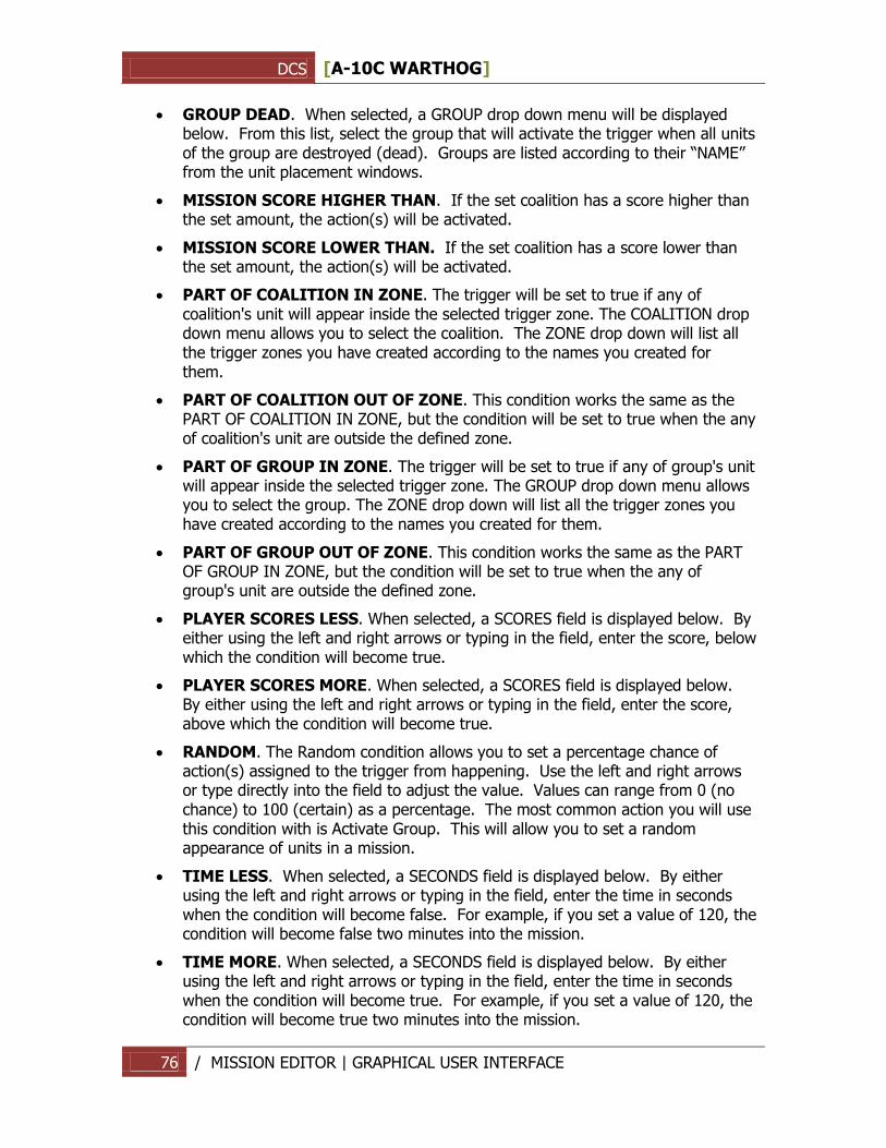
DCS [A-10C WARTHOG]
76 / MISSION EDITOR | GRAPHICAL USER INTERFACE
GROUP DEAD. When selected, a GROUP drop down menu will be displayed below. From this list, select the group that will activate the trigger when all units of the group are destroyed (dead). Groups are listed according to their “NAME” from the unit placement windows.
MISSION SCORE HIGHER THAN. If the set coalition has a score higher than the set amount, the action(s) will be activated.
MISSION SCORE LOWER THAN. If the set coalition has a score lower than the set amount, the action(s) will be activated.
PART OF COALITION IN ZONE. The trigger will be set to true if any of coalition's unit will appear inside the selected trigger zone. The COALITION drop down menu allows you to select the coalition. The ZONE drop down will list all the trigger zones you have created according to the names you created for them.
PART OF COALITION OUT OF ZONE. This condition works the same as the PART OF COALITION IN ZONE, but the condition will be set to true when the any of coalition's unit are outside the defined zone.
PART OF GROUP IN ZONE. The trigger will be set to true if any of group's unit will appear inside the selected trigger zone. The GROUP drop down menu allows you to select the group. The ZONE drop down will list all the trigger zones you have created according to the names you created for them.
PART OF GROUP OUT OF ZONE. This condition works the same as the PART OF GROUP IN ZONE, but the condition will be set to true when the any of group's unit are outside the defined zone.
PLAYER SCORES LESS. When selected, a SCORES field is displayed below. By either using the left and right arrows or typing in the field, enter the score, below which the condition will become true.
PLAYER SCORES MORE. When selected, a SCORES field is displayed below. By either using the left and right arrows or typing in the field, enter the score, above which the condition will become true.
RANDOM. The Random condition allows you to set a percentage chance of action(s) assigned to the trigger from happening. Use the left and right arrows or type directly into the field to adjust the value. Values can range from 0 (no chance) to 100 (certain) as a percentage. The most common action you will use this condition with is Activate Group. This will allow you to set a random appearance of units in a mission.
TIME LESS. When selected, a SECONDS field is displayed below. By either using the left and right arrows or typing in the field, enter the time in seconds when the condition will become false. For example, if you set a value of 120, the condition will become false two minutes into the mission.
TIME MORE. When selected, a SECONDS field is displayed below. By either using the left and right arrows or typing in the field, enter the time in seconds when the condition will become true. For example, if you set a value of 120, the condition will become true two minutes into the mission.
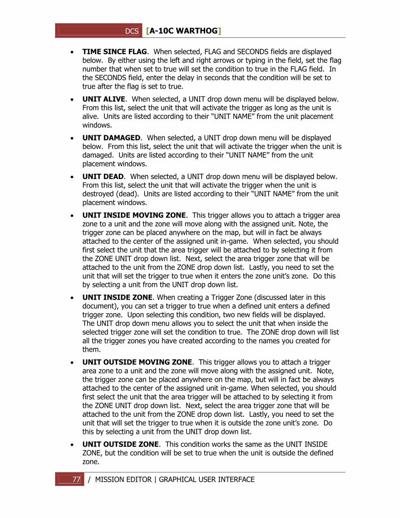
DCS [A-10C WARTHOG]
77 / MISSION EDITOR | GRAPHICAL USER INTERFACE
TIME SINCE FLAG. When selected, FLAG and SECONDS fields are displayed below. By either using the left and right arrows or typing in the field, set the flag number that when set to true will set the condition to true in the FLAG field. In the SECONDS field, enter the delay in seconds that the condition will be set to true after the flag is set to true.
UNIT ALIVE. When selected, a UNIT drop down menu will be displayed below. From this list, select the unit that will activate the trigger as long as the unit is alive. Units are listed according to their “UNIT NAME” from the unit placement windows.
UNIT DAMAGED. When selected, a UNIT drop down menu will be displayed below. From this list, select the unit that will activate the trigger when the unit is damaged. Units are listed according to their “UNIT NAME” from the unit placement windows.
UNIT DEAD. When selected, a UNIT drop down menu will be displayed below. From this list, select the unit that will activate the trigger when the unit is destroyed (dead). Units are listed according to their “UNIT NAME” from the unit placement windows.
UNIT INSIDE MOVING ZONE. This trigger allows you to attach a trigger area zone to a unit and the zone will move along with the assigned unit. Note, the trigger zone can be placed anywhere on the map, but will in fact be always attached to the center of the assigned unit in-game. When selected, you should first select the unit that the area trigger will be attached to by selecting it from the ZONE UNIT drop down list. Next, select the area trigger zone that will be attached to the unit from the ZONE drop down list. Lastly, you need to set the unit that will set the trigger to true when it enters the zone unit‟s zone. Do this by selecting a unit from the UNIT drop down list.
UNIT INSIDE ZONE. When creating a Trigger Zone (discussed later in this document), you can set a trigger to true when a defined unit enters a defined trigger zone. Upon selecting this condition, two new fields will be displayed. The UNIT drop down menu allows you to select the unit that when inside the selected trigger zone will set the condition to true. The ZONE drop down will list all the trigger zones you have created according to the names you created for them.
UNIT OUTSIDE MOVING ZONE. This trigger allows you to attach a trigger area zone to a unit and the zone will move along with the assigned unit. Note, the trigger zone can be placed anywhere on the map, but will in fact be always attached to the center of the assigned unit in-game. When selected, you should first select the unit that the area trigger will be attached to by selecting it from the ZONE UNIT drop down list. Next, select the area trigger zone that will be attached to the unit from the ZONE drop down list. Lastly, you need to set the unit that will set the trigger to true when it is outside the zone unit‟s zone. Do this by selecting a unit from the UNIT drop down list.
UNIT OUTSIDE ZONE. This condition works the same as the UNIT INSIDE ZONE, but the condition will be set to true when the unit is outside the defined zone.
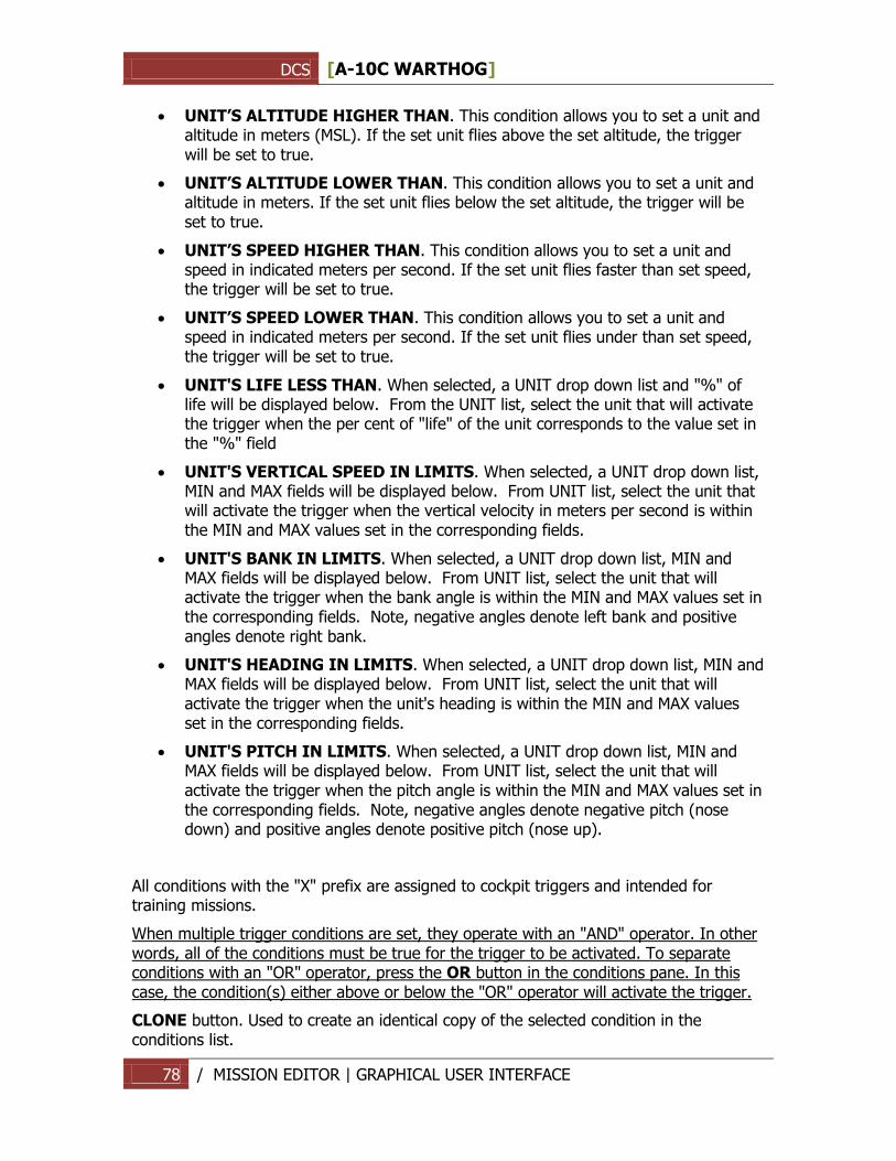
DCS [A-10C WARTHOG]
78 / MISSION EDITOR | GRAPHICAL USER INTERFACE
UNIT’S ALTITUDE HIGHER THAN. This condition allows you to set a unit and altitude in meters (MSL). If the set unit flies above the set altitude, the trigger will be set to true.
UNIT’S ALTITUDE LOWER THAN. This condition allows you to set a unit and altitude in meters. If the set unit flies below the set altitude, the trigger will be set to true.
UNIT’S SPEED HIGHER THAN. This condition allows you to set a unit and speed in indicated meters per second. If the set unit flies faster than set speed, the trigger will be set to true.
UNIT’S SPEED LOWER THAN. This condition allows you to set a unit and speed in indicated meters per second. If the set unit flies under than set speed, the trigger will be set to true.
UNIT'S LIFE LESS THAN. When selected, a UNIT drop down list and "%" of life will be displayed below. From the UNIT list, select the unit that will activate the trigger when the per cent of "life" of the unit corresponds to the value set in the "%" field
UNIT'S VERTICAL SPEED IN LIMITS. When selected, a UNIT drop down list, MIN and MAX fields will be displayed below. From UNIT list, select the unit that will activate the trigger when the vertical velocity in meters per second is within the MIN and MAX values set in the corresponding fields.
UNIT'S BANK IN LIMITS. When selected, a UNIT drop down list, MIN and MAX fields will be displayed below. From UNIT list, select the unit that will activate the trigger when the bank angle is within the MIN and MAX values set in the corresponding fields. Note, negative angles denote left bank and positive angles denote right bank.
UNIT'S HEADING IN LIMITS. When selected, a UNIT drop down list, MIN and MAX fields will be displayed below. From UNIT list, select the unit that will activate the trigger when the unit's heading is within the MIN and MAX values set in the corresponding fields.
UNIT'S PITCH IN LIMITS. When selected, a UNIT drop down list, MIN and MAX fields will be displayed below. From UNIT list, select the unit that will activate the trigger when the pitch angle is within the MIN and MAX values set in the corresponding fields. Note, negative angles denote negative pitch (nose down) and positive angles denote positive pitch (nose up).
All conditions with the "X" prefix are assigned to cockpit triggers and intended for training missions.
When multiple trigger conditions are set, they operate with an "AND" operator. In other words, all of the conditions must be true for the trigger to be activated. To separate conditions with an "OR" operator, press the OR button in the conditions pane. In this case, the condition(s) either above or below the "OR" operator will activate the trigger.
CLONE button. Used to create an identical copy of the selected condition in the conditions list.
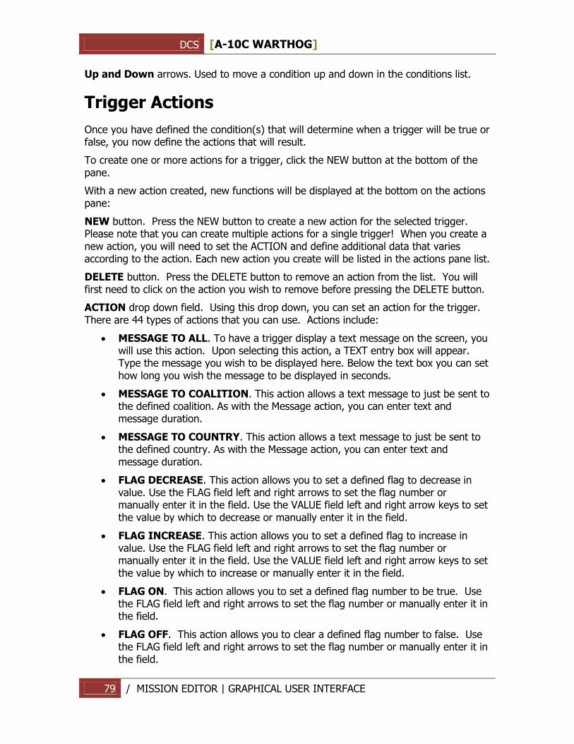
DCS [A-10C WARTHOG]
79 / MISSION EDITOR | GRAPHICAL USER INTERFACE
Up and Down arrows. Used to move a condition up and down in the conditions list.
Trigger Actions
Once you have defined the condition(s) that will determine when a trigger will be true or false, you now define the actions that will result.
To create one or more actions for a trigger, click the NEW button at the bottom of the pane.
With a new action created, new functions will be displayed at the bottom on the actions pane:
NEW button. Press the NEW button to create a new action for the selected trigger. Please note that you can create multiple actions for a single trigger! When you create a new action, you will need to set the ACTION and define additional data that varies according to the action. Each new action you create will be listed in the actions pane list.
DELETE button. Press the DELETE button to remove an action from the list. You will first need to click on the action you wish to remove before pressing the DELETE button.
ACTION drop down field. Using this drop down, you can set an action for the trigger. There are 44 types of actions that you can use. Actions include:
MESSAGE TO ALL. To have a trigger display a text message on the screen, you will use this action. Upon selecting this action, a TEXT entry box will appear. Type the message you wish to be displayed here. Below the text box you can set how long you wish the message to be displayed in seconds.
MESSAGE TO COALITION. This action allows a text message to just be sent to the defined coalition. As with the Message action, you can enter text and message duration.
MESSAGE TO COUNTRY. This action allows a text message to just be sent to the defined country. As with the Message action, you can enter text and message duration.
FLAG DECREASE. This action allows you to set a defined flag to decrease in value. Use the FLAG field left and right arrows to set the flag number or manually enter it in the field. Use the VALUE field left and right arrow keys to set the value by which to decrease or manually enter it in the field.
FLAG INCREASE. This action allows you to set a defined flag to increase in value. Use the FLAG field left and right arrows to set the flag number or manually enter it in the field. Use the VALUE field left and right arrow keys to set the value by which to increase or manually enter it in the field.
FLAG ON. This action allows you to set a defined flag number to be true. Use the FLAG field left and right arrows to set the flag number or manually enter it in the field.
FLAG OFF. This action allows you to clear a defined flag number to false. Use the FLAG field left and right arrows to set the flag number or manually enter it in the field.
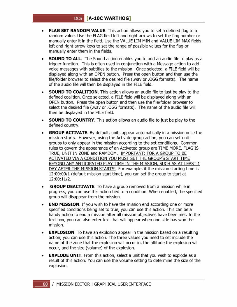
DCS [A-10C WARTHOG]
80 / MISSION EDITOR | GRAPHICAL USER INTERFACE
FLAG SET RANDOM VALUE. This action allows you to set a defined flag to a random value. Use the FLAG field left and right arrows to set the flag number or manually enter it in the field. Use the VALUE LIM MIN and VALUE LIM MAX fields left and right arrow keys to set the range of possible values for the flag or manually enter them in the fields.
SOUND TO ALL. The Sound action enables you to add an audio file to play as a trigger function. This is often used in conjunction with a Message action to add voice messages with subtitles to the mission. Once selected, a FILE field will be displayed along with an OPEN button. Press the open button and then use the file/folder browser to select the desired file (.wav or .OGG formats). The name of the audio file will then be displayed in the FILE field.
SOUND TO COALITION. This action allows an audio file to just be play to the defined coalition. Once selected, a FILE field will be displayed along with an OPEN button. Press the open button and then use the file/folder browser to select the desired file (.wav or .OGG formats). The name of the audio file will then be displayed in the FILE field.
SOUND TO COUNTRY. This action allows an audio file to just be play to the defined country.
GROUP ACTIVATE. By default, units appear automatically in a mission once the mission starts. However, using the Activate group action, you can set unit groups to only appear in the mission according to the set conditions. Common rules to govern the appearance of an Activated group are TIME MORE, FLAG IS TRUE, UNIT IN ZONE and RAMDOM. IMPORTANT: FOR A GROUP TO BE ACTIVATED VIA A CONDITION YOU MUST SET THE GROUP‟S START TIME BEYOND ANY ANTICIPATED PLAY TIME IN THE MISSION, SUCH AS AT LEAST 1 DAY AFTER THE MISSION STARTS! For example, if the mission starting time is 12:00:00/1 (default mission start time), you can set the group to start at 12:00:11/2.
GROUP DEACTIVATE. To have a group removed from a mission while in progress, you can use this action tied to a condition. When enabled, the specified group will disappear from the mission.
END MISSION. If you wish to have the mission end according one or more specified conditions being set to true, you can use this action. This can be a handy action to end a mission after all mission objectives have been met. In the text box, you can also enter text that will appear when one side has won the mission.
EXPLOSION. To have an explosion appear in the mission based on a resulting action, you can use this action. The three values you need to set include the name of the zone that the explosion will occur in, the altitude the explosion will occur, and the size (volume) of the explosion.
EXPLODE UNIT. From this action, select a unit that you wish to explode as a result of this action. You can use the volume setting to determine the size of the explosion.
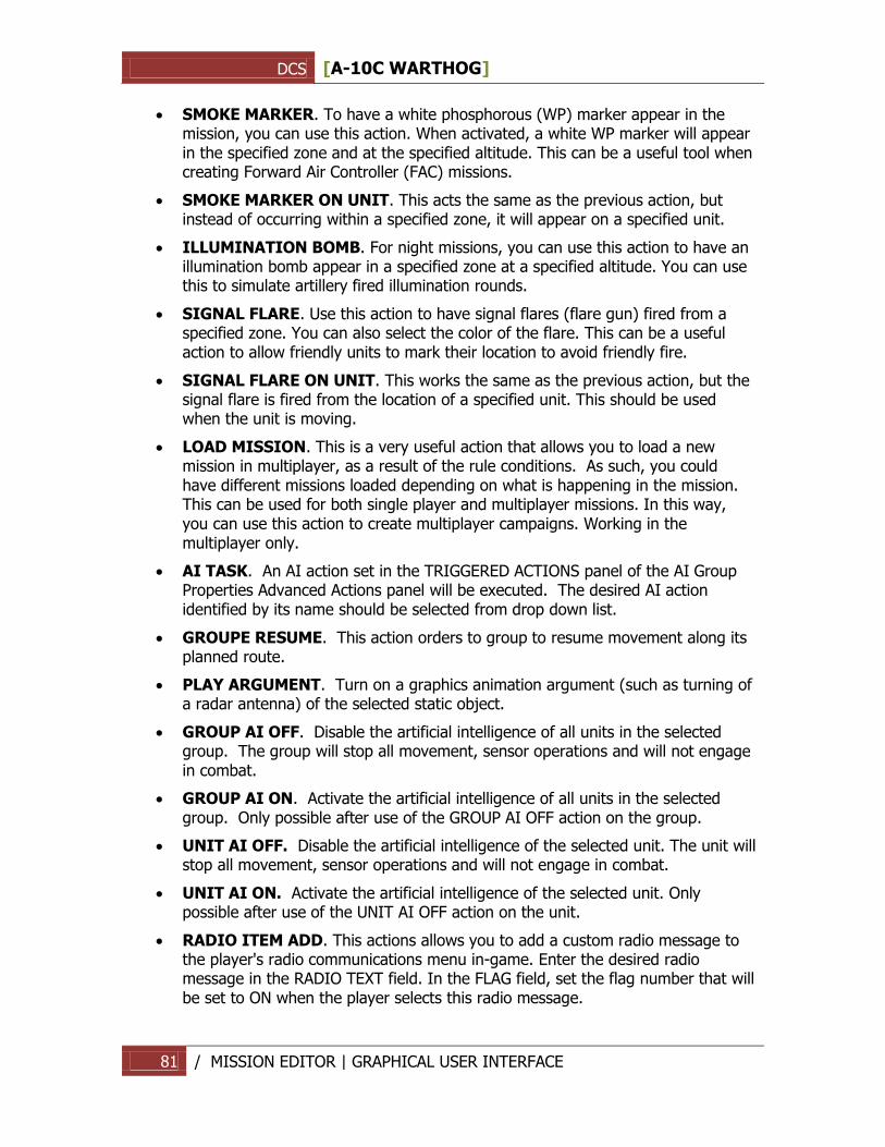
DCS [A-10C WARTHOG]
81 / MISSION EDITOR | GRAPHICAL USER INTERFACE
SMOKE MARKER. To have a white phosphorous (WP) marker appear in the mission, you can use this action. When activated, a white WP marker will appear in the specified zone and at the specified altitude. This can be a useful tool when creating Forward Air Controller (FAC) missions.
SMOKE MARKER ON UNIT. This acts the same as the previous action, but instead of occurring within a specified zone, it will appear on a specified unit.
ILLUMINATION BOMB. For night missions, you can use this action to have an illumination bomb appear in a specified zone at a specified altitude. You can use this to simulate artillery fired illumination rounds.
SIGNAL FLARE. Use this action to have signal flares (flare gun) fired from a specified zone. You can also select the color of the flare. This can be a useful action to allow friendly units to mark their location to avoid friendly fire.
SIGNAL FLARE ON UNIT. This works the same as the previous action, but the signal flare is fired from the location of a specified unit. This should be used when the unit is moving.
LOAD MISSION. This is a very useful action that allows you to load a new mission in multiplayer, as a result of the rule conditions. As such, you could have different missions loaded depending on what is happening in the mission. This can be used for both single player and multiplayer missions. In this way, you can use this action to create multiplayer campaigns. Working in the multiplayer only.
AI TASK. An AI action set in the TRIGGERED ACTIONS panel of the AI Group Properties Advanced Actions panel will be executed. The desired AI action identified by its name should be selected from drop down list.
GROUPE RESUME. This action orders to group to resume movement along its planned route.
PLAY ARGUMENT. Turn on a graphics animation argument (such as turning of a radar antenna) of the selected static object.
GROUP AI OFF. Disable the artificial intelligence of all units in the selected group. The group will stop all movement, sensor operations and will not engage in combat.
GROUP AI ON. Activate the artificial intelligence of all units in the selected group. Only possible after use of the GROUP AI OFF action on the group.
UNIT AI OFF. Disable the artificial intelligence of the selected unit. The unit will stop all movement, sensor operations and will not engage in combat.
UNIT AI ON. Activate the artificial intelligence of the selected unit. Only possible after use of the UNIT AI OFF action on the unit.
RADIO ITEM ADD. This actions allows you to add a custom radio message to the player's radio communications menu in-game. Enter the desired radio message in the RADIO TEXT field. In the FLAG field, set the flag number that will be set to ON when the player selects this radio message.
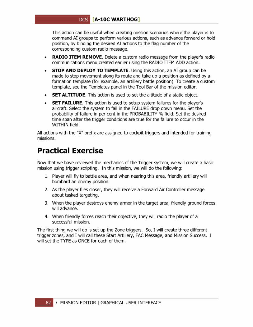
DCS [A-10C WARTHOG]
82 / MISSION EDITOR | GRAPHICAL USER INTERFACE
This action can be useful when creating mission scenarios where the player is to command AI groups to perform various actions, such as advance forward or hold position, by binding the desired AI actions to the flag number of the corresponding custom radio message.
RADIO ITEM REMOVE. Delete a custom radio message from the player's radio communications menu created earlier using the RADIO ITEM ADD action.
STOP AND DEPLOY TO TEMPLATE. Using this action, an AI group can be made to stop movement along its route and take up a position as defined by a formation template (for example, an artillery battle position). To create a custom template, see the Templates panel in the Tool Bar of the mission editor.
SET ALTITUDE. This action is used to set the altitude of a static object.
SET FAILURE. This action is used to setup system failures for the player's aircraft. Select the system to fail in the FAILURE drop down menu. Set the probability of failure in per cent in the PROBABILITY % field. Set the desired time span after the trigger conditions are true for the failure to occur in the WITHIN field.
All actions with the "X" prefix are assigned to cockpit triggers and intended for training missions.
Practical Exercise
Now that we have reviewed the mechanics of the Trigger system, we will create a basic mission using trigger scripting. In this mission, we will do the following:
1. Player will fly to battle area, and when nearing this area, friendly artillery will bombard an enemy position.
2. As the player flies closer, they will receive a Forward Air Controller message about tasked targeting.
3. When the player destroys enemy armor in the target area, friendly ground forces will advance.
4. When friendly forces reach their objective, they will radio the player of a successful mission.
The first thing we will do is set up the Zone triggers. So, I will create three different trigger zones, and I will call these Start Artillery, FAC Message, and Mission Success. I will set the TYPE as ONCE for each of them.
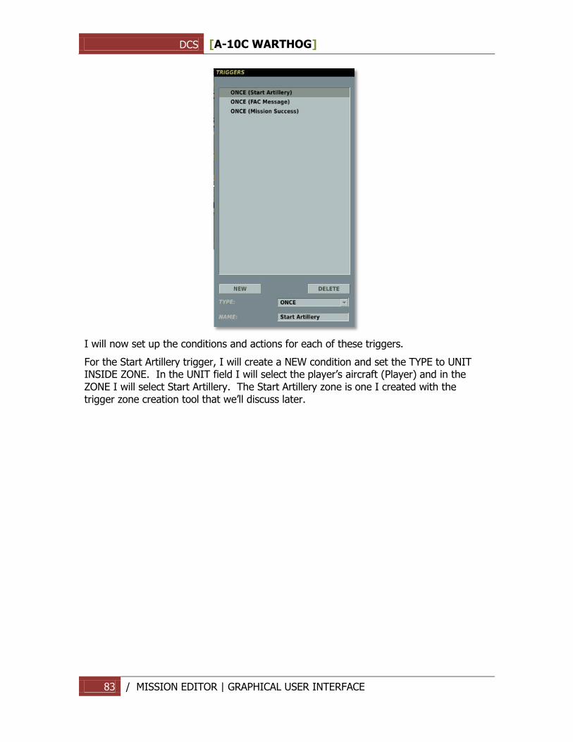
DCS [A-10C WARTHOG]
83 / MISSION EDITOR | GRAPHICAL USER INTERFACE
I will now set up the conditions and actions for each of these triggers.
For the Start Artillery trigger, I will create a NEW condition and set the TYPE to UNIT INSIDE ZONE. In the UNIT field I will select the player‟s aircraft (Player) and in the ZONE I will select Start Artillery. The Start Artillery zone is one I created with the trigger zone creation tool that we‟ll discuss later.
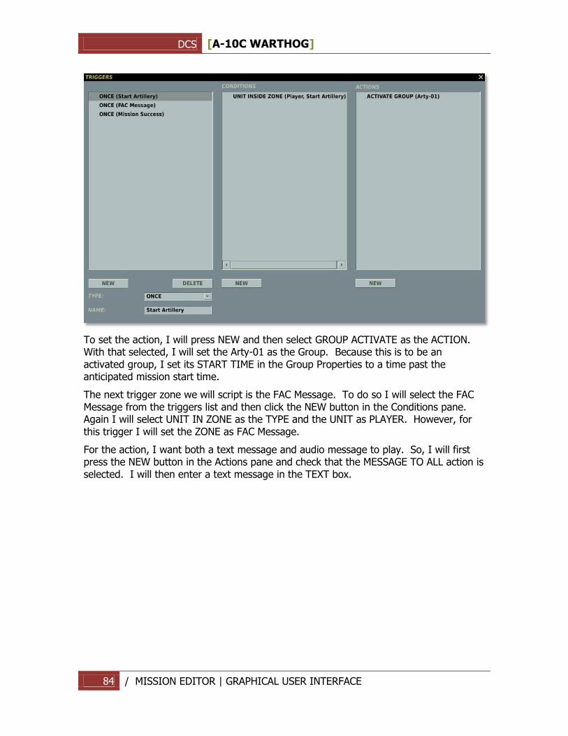
DCS [A-10C WARTHOG]
84 / MISSION EDITOR | GRAPHICAL USER INTERFACE
To set the action, I will press NEW and then select GROUP ACTIVATE as the ACTION. With that selected, I will set the Arty-01 as the Group. Because this is to be an activated group, I set its START TIME in the Group Properties to a time past the anticipated mission start time.
The next trigger zone we will script is the FAC Message. To do so I will select the FAC Message from the triggers list and then click the NEW button in the Conditions pane. Again I will select UNIT IN ZONE as the TYPE and the UNIT as PLAYER. However, for this trigger I will set the ZONE as FAC Message.
For the action, I want both a text message and audio message to play. So, I will first press the NEW button in the Actions pane and check that the MESSAGE TO ALL action is selected. I will then enter a text message in the TEXT box.
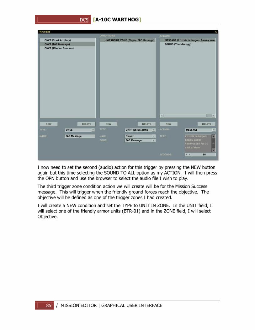
DCS [A-10C WARTHOG]
85 / MISSION EDITOR | GRAPHICAL USER INTERFACE
I now need to set the second (audio) action for this trigger by pressing the NEW button again but this time selecting the SOUND TO ALL option as my ACTION. I will then press the OPN button and use the browser to select the audio file I wish to play.
The third trigger zone condition action we will create will be for the Mission Success message. This will trigger when the friendly ground forces reach the objective. The objective will be defined as one of the trigger zones I had created.
I will create a NEW condition and set the TYPE to UNIT IN ZONE. In the UNIT field, I will select one of the friendly armor units (BTR-01) and in the ZONE field, I will select Objective.
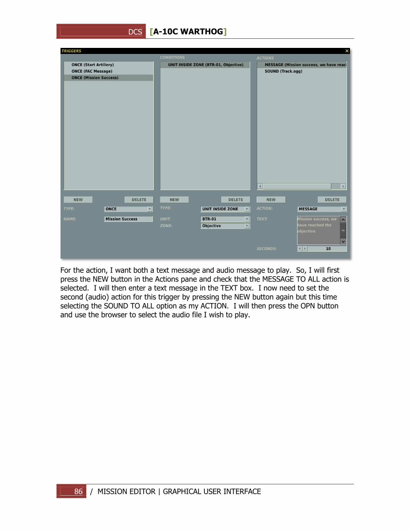
DCS [A-10C WARTHOG]
86 / MISSION EDITOR | GRAPHICAL USER INTERFACE
For the action, I want both a text message and audio message to play. So, I will first press the NEW button in the Actions pane and check that the MESSAGE TO ALL action is selected. I will then enter a text message in the TEXT box. I now need to set the second (audio) action for this trigger by pressing the NEW button again but this time selecting the SOUND TO ALL option as my ACTION. I will then press the OPN button and use the browser to select the audio file I wish to play.
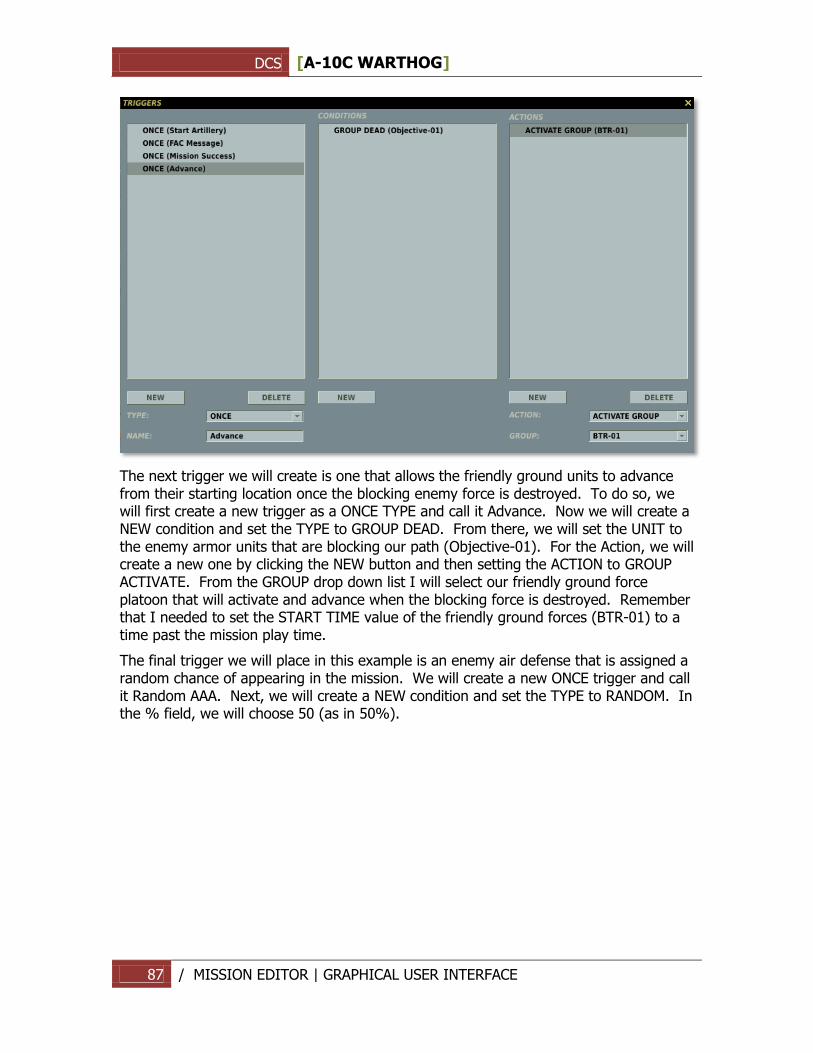
DCS [A-10C WARTHOG]
87 / MISSION EDITOR | GRAPHICAL USER INTERFACE
The next trigger we will create is one that allows the friendly ground units to advance from their starting location once the blocking enemy force is destroyed. To do so, we will first create a new trigger as a ONCE TYPE and call it Advance. Now we will create a NEW condition and set the TYPE to GROUP DEAD. From there, we will set the UNIT to the enemy armor units that are blocking our path (Objective-01). For the Action, we will create a new one by clicking the NEW button and then setting the ACTION to GROUP ACTIVATE. From the GROUP drop down list I will select our friendly ground force platoon that will activate and advance when the blocking force is destroyed. Remember that I needed to set the START TIME value of the friendly ground forces (BTR-01) to a time past the mission play time.
The final trigger we will place in this example is an enemy air defense that is assigned a random chance of appearing in the mission. We will create a new ONCE trigger and call it Random AAA. Next, we will create a NEW condition and set the TYPE to RANDOM. In the % field, we will choose 50 (as in 50%).
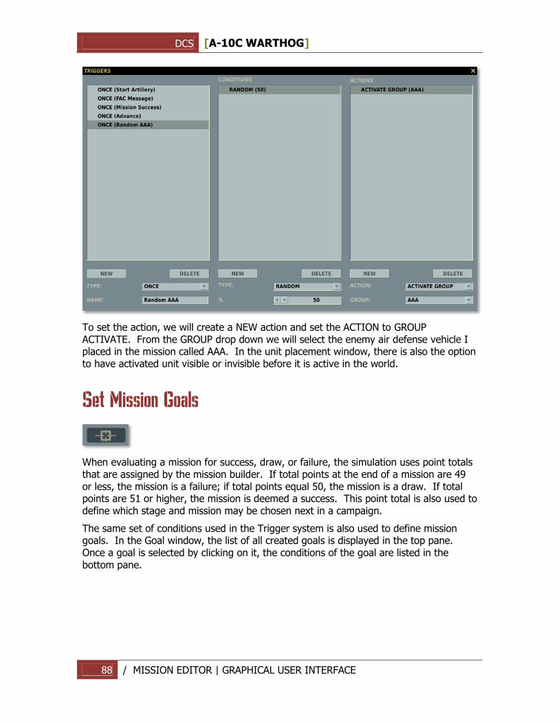
DCS [A-10C WARTHOG]
88 / MISSION EDITOR | GRAPHICAL USER INTERFACE
To set the action, we will create a NEW action and set the ACTION to GROUP ACTIVATE. From the GROUP drop down we will select the enemy air defense vehicle I placed in the mission called AAA. In the unit placement window, there is also the option to have activated unit visible or invisible before it is active in the world.
Set Mission Goals
When evaluating a mission for success, draw, or failure, the simulation uses point totals that are assigned by the mission builder. If total points at the end of a mission are 49 or less, the mission is a failure; if total points equal 50, the mission is a draw. If total points are 51 or higher, the mission is deemed a success. This point total is also used to define which stage and mission may be chosen next in a campaign.
The same set of conditions used in the Trigger system is also used to define mission goals. In the Goal window, the list of all created goals is displayed in the top pane. Once a goal is selected by clicking on it, the conditions of the goal are listed in the bottom pane.
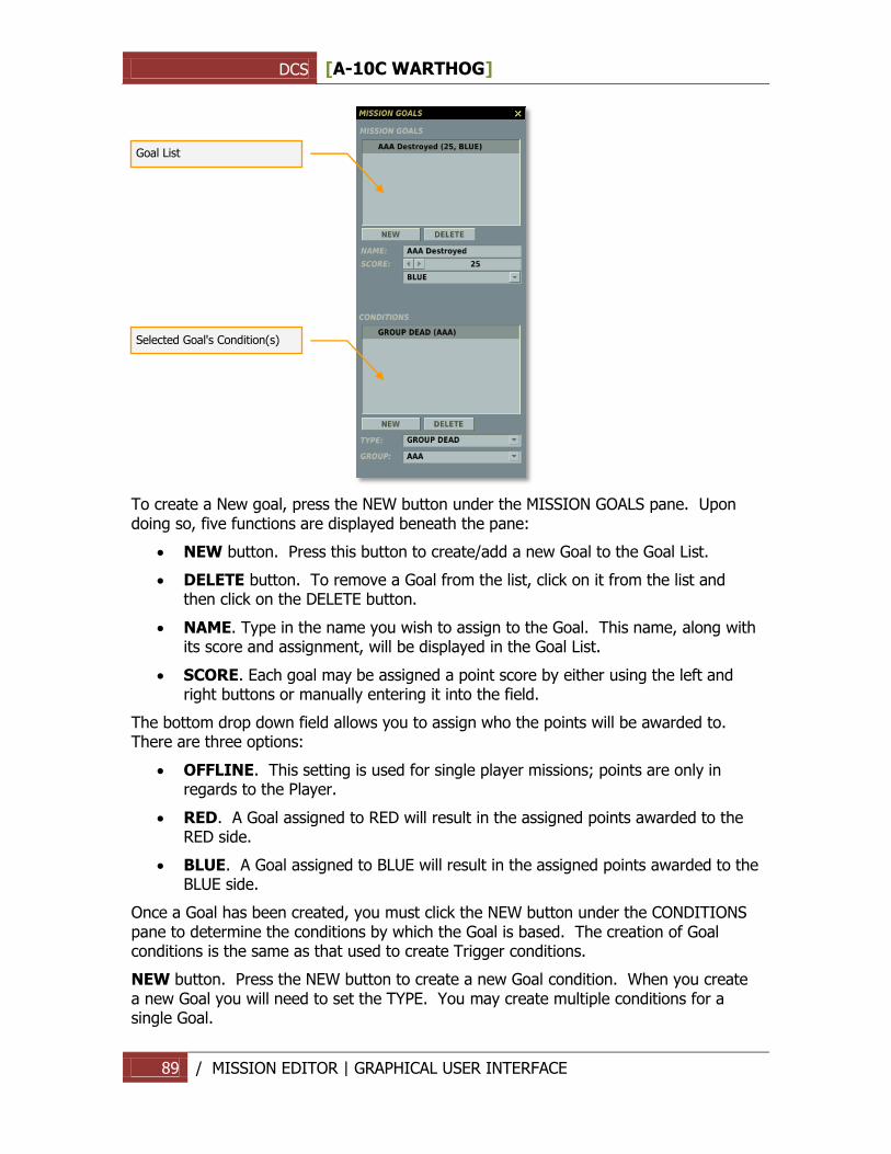
DCS [A-10C WARTHOG]
89 / MISSION EDITOR | GRAPHICAL USER INTERFACE
To create a New goal, press the NEW button under the MISSION GOALS pane. Upon doing so, five functions are displayed beneath the pane:
NEW button. Press this button to create/add a new Goal to the Goal List.
DELETE button. To remove a Goal from the list, click on it from the list and then click on the DELETE button.
NAME. Type in the name you wish to assign to the Goal. This name, along with its score and assignment, will be displayed in the Goal List.
SCORE. Each goal may be assigned a point score by either using the left and right buttons or manually entering it into the field.
The bottom drop down field allows you to assign who the points will be awarded to. There are three options:
OFFLINE. This setting is used for single player missions; points are only in regards to the Player.
RED. A Goal assigned to RED will result in the assigned points awarded to the RED side.
BLUE. A Goal assigned to BLUE will result in the assigned points awarded to the BLUE side.
Once a Goal has been created, you must click the NEW button under the CONDITIONS pane to determine the conditions by which the Goal is based. The creation of Goal conditions is the same as that used to create Trigger conditions.
NEW button. Press the NEW button to create a new Goal condition. When you create a new Goal you will need to set the TYPE. You may create multiple conditions for a single Goal.
Goal List
Selected Goal's Condition(s)

DCS [A-10C WARTHOG]
90 / MISSION EDITOR | GRAPHICAL USER INTERFACE
DELETE button. Press the DELETE button to remove a condition from the Goal. You will first need to click on the condition you wish to remove before pressing the DELETE button.
TYPE drop down field. Using this drop down, you can set the condition by which the Goal is accomplished.
Mission Options
The Mission Options panel has been described in detail previously in the System Bar chapter of the manual.
Fly
Press the blue flight button to exit the Mission Editor and open the mission Briefing menu in preparation for the flight.
DCS [A-10C WARTHOG]
91 / MISSION EDITOR | GRAPHICAL USER INTERFACE
Task Planning for Unit Groups
General Concepts
Mission building involves creating unit groups, planning of group routes and combat tasks, and developing a dynamic battlefield atmosphere using triggered events, mission weather and time of day settings.
When designing a mission, you can choose one of two basic approaches to creating battle scenarios:
1. Simple: Place and route groups with minimal adjustments of default route and task settings (actions to determine behavior will be created automatically).
2. Advanced: Use the Advanced Actions Panel of the Group Properties Menu for precise manual control over group actions.
The first method requires minimum use of the interface to create simple missions with the idea that AI groups will act generally as envisioned by the designer, but using automatic behavior actions programmed into the AI based on factors such as presence of enemy units, contact range, etc. In this approach, the AI will generally move along its route and engage enemy units as soon as they are within engagement range, which can vary based on the unit type and task (in case of aircraft groups).
However, the automated AI actions created by default may not always produce the desired results. In particular, if the mission calls for complex AI actions, for example attacking only certain types of ground units in different target areas or restrictions on the use of particular weapons, the desired behavior may be achieved more effectively by using the Advanced Actions Panel to create and configure group actions in detail. Although more time consuming and complex, this allows for much greater flexibility and control in scripting AI behavior in the mission.
Actions refer to the various behaviors a mission designer can script for the AI to perform in the mission. Before we describe all of the actions in detail, you should understand the following terms: Group Artificial Intelligence, Task, Enroute Task, Command and Option.
Tasks and Enroute Tasks are the primary combat actions and include a number of different targeting and engagement options for air, ground and naval groups. For example, a task to attack an enemy group or to act as a Forward Air Controller (FAC) in providing targeting commands to other friendly units. All Tasks and Enroute Tasks are actions performed over a period of time. Commands are instantaneous actions, such as setting a radio frequency for the group. Options are rules or limitations imposed on the group in executing an action.
All actions include a number of conditions the mission designer can set to control the starting and ending of the action. These include setting a mission time for starting and/or ending the action, action duration time, flag states (on/off), action activation probability, and custom scripting in LUA code language.
DCS [A-10C WARTHOG]
92 / MISSION EDITOR | GRAPHICAL USER INTERFACE
Group Artificial Intelligence (AI)
Group Artificial Intelligence is a virtual object (represented by the lead unit of a group) that controls game units or a group of units. The AI executes the actions set for the group in the mission editor. In doing so, the object follows behavior rules programmed into the simulation by the developers, however its behavior can also be adjusted by the mission designer using the tasking options available in the Advanced Actions Panel. Note, actions are set for entire groups only and not for individual units within a group. When creating a group route, the mission designer can add or edit the actions for the group to perform at each waypoint (WP) of the route. Actions of a given waypoint are activated once the group leader reaches the waypoint. The actions are performed sequentially based on their order and/or priority setting. Priority is set as a whole number, starting with 0 as the highest priority value. Actions can also be set in the Trigger Menu of the mission editor to be activated independently of the route waypoints.
Task
Task actions involve combat engagement, targeting and maneuvering. By setting a Task, the mission designer commands the AI to perform a specific combat function at a specific point in the mission. For example: orbit on station, engage an enemy group, provide targeting to other groups as a FAC. Tasks have the highest execution priority for the AI and are generally used to set the primary group action for a waypoint. The AI will perform multiple Tasks one at a time according to their order or priority setting.
Task execution can be ended either by the AI automatically in-game or according to the action stop conditions set by the mission designer. For example, the AI will cease to attack a designated group of enemy vehicles when all of the vehicles in the group are destroyed or the AI group has exhausted its supply of usable weapons. Alternatively, the AI can be forced to cease the attack by setting an action stop condition, such as an action duration time limit.
Enroute Task
Like Tasks, Enroute Tasks are combat actions that involve targeting or engagement actions. However, Enroute Tasks are designed to be active for the length of the group's route and can be executed multiple times and in multiple locations as long as the conditions for executing the Enroute Task are in effect and the AI is able to execute the action. As such, Enroute Tasks assume periodic interruptions of route navigation to perform the action, such as attacking "pop-up" enemy units detected along the route.
Whereas Tasks involve definitely known and pre-set targets, Enroute Tasks allow for some uncertainty in target type or location. The key phrase to keep in mind when using Enroute Tasks is "Search For...". This means the AI will actively search for the target and perform an attack only when the target is detected.
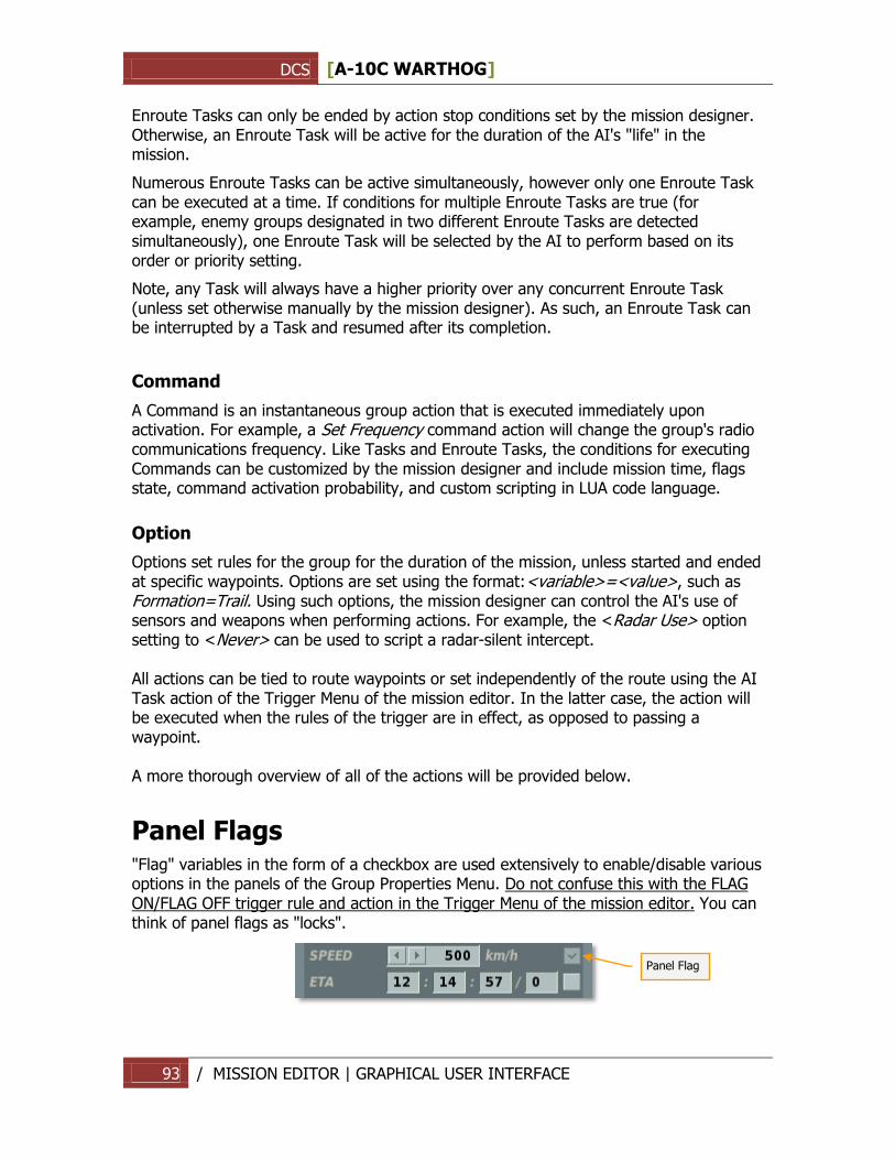
DCS [A-10C WARTHOG]
93 / MISSION EDITOR | GRAPHICAL USER INTERFACE
Enroute Tasks can only be ended by action stop conditions set by the mission designer. Otherwise, an Enroute Task will be active for the duration of the AI's "life" in the mission.
Numerous Enroute Tasks can be active simultaneously, however only one Enroute Task can be executed at a time. If conditions for multiple Enroute Tasks are true (for example, enemy groups designated in two different Enroute Tasks are detected simultaneously), one Enroute Task will be selected by the AI to perform based on its order or priority setting.
Note, any Task will always have a higher priority over any concurrent Enroute Task (unless set otherwise manually by the mission designer). As such, an Enroute Task can be interrupted by a Task and resumed after its completion.
Command
A Command is an instantaneous group action that is executed immediately upon activation. For example, a Set Frequency command action will change the group's radio communications frequency. Like Tasks and Enroute Tasks, the conditions for executing Commands can be customized by the mission designer and include mission time, flags state, command activation probability, and custom scripting in LUA code language.
Option
Options set rules for the group for the duration of the mission, unless started and ended at specific waypoints. Options are set using the format:<variable>=<value>, such as Formation=Trail. Using such options, the mission designer can control the AI's use of sensors and weapons when performing actions. For example, the <Radar Use> option setting to <Never> can be used to script a radar-silent intercept. All actions can be tied to route waypoints or set independently of the route using the AI Task action of the Trigger Menu of the mission editor. In the latter case, the action will be executed when the rules of the trigger are in effect, as opposed to passing a waypoint. A more thorough overview of all of the actions will be provided below.
Panel Flags "Flag" variables in the form of a checkbox are used extensively to enable/disable various options in the panels of the Group Properties Menu. Do not confuse this with the FLAG ON/FLAG OFF trigger rule and action in the Trigger Menu of the mission editor. You can think of panel flags as "locks".
Panel Flag
DCS [A-10C WARTHOG]
94 / MISSION EDITOR | GRAPHICAL USER INTERFACE
In conclusion, some of the main steps in creating a mission include: creating a unit group, placing the group route on the map, setting the group task (for fixed-wing and helicopter groups), configuring the group actions using the Advanced Actions Panel (Tasks, Enroute Tasks, Commands, Options), creating triggers to script certain group actions in addition to those set with route waypoints.
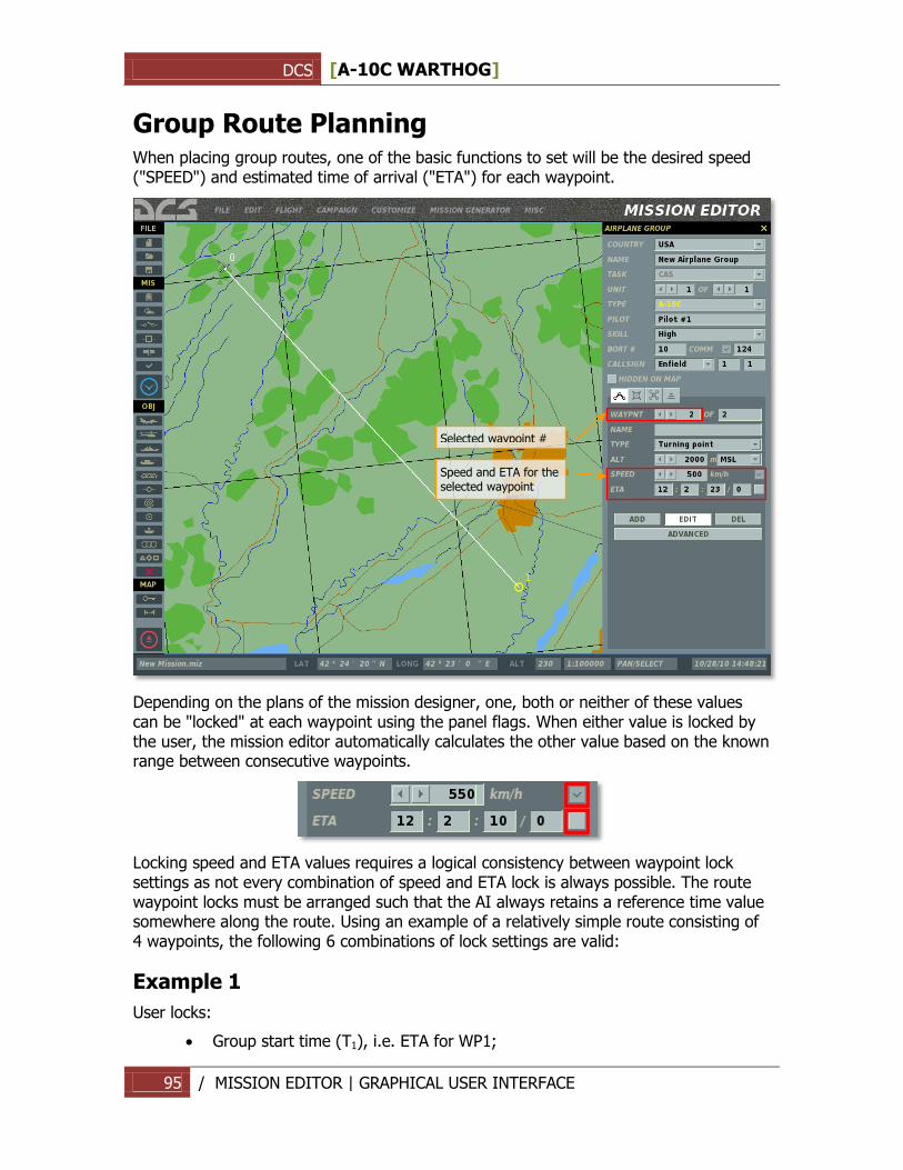
DCS [A-10C WARTHOG]
95 / MISSION EDITOR | GRAPHICAL USER INTERFACE
Group Route Planning
When placing group routes, one of the basic functions to set will be the desired speed ("SPEED") and estimated time of arrival ("ETA") for each waypoint.
Depending on the plans of the mission designer, one, both or neither of these values can be "locked" at each waypoint using the panel flags. When either value is locked by the user, the mission editor automatically calculates the other value based on the known range between consecutive waypoints.
Locking speed and ETA values requires a logical consistency between waypoint lock settings as not every combination of speed and ETA lock is always possible. The route waypoint locks must be arranged such that the AI always retains a reference time value somewhere along the route. Using an example of a relatively simple route consisting of 4 waypoints, the following 6 combinations of lock settings are valid:
Example 1
User locks:
Group start time (Т1), i.e. ETA for WP1;
Speed and ETA for the selected waypoint
Selected waypoint #
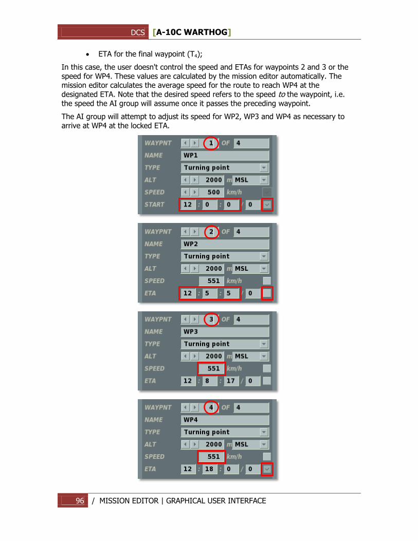
DCS [A-10C WARTHOG]
96 / MISSION EDITOR | GRAPHICAL USER INTERFACE
ETA for the final waypoint (Т4);
In this case, the user doesn't control the speed and ETAs for waypoints 2 and 3 or the speed for WP4. These values are calculated by the mission editor automatically. The mission editor calculates the average speed for the route to reach WP4 at the designated ETA. Note that the desired speed refers to the speed to the waypoint, i.e. the speed the AI group will assume once it passes the preceding waypoint.
The AI group will attempt to adjust its speed for WP2, WP3 and WP4 as necessary to arrive at WP4 at the locked ETA.
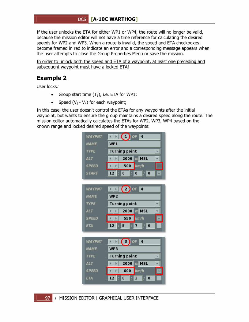
DCS [A-10C WARTHOG]
97 / MISSION EDITOR | GRAPHICAL USER INTERFACE
If the user unlocks the ETA for either WP1 or WP4, the route will no longer be valid, because the mission editor will not have a time reference for calculating the desired speeds for WP2 and WP3. When a route is invalid, the speed and ETA checkboxes become framed in red to indicate an error and a corresponding message appears when the user attempts to close the Group Properties Menu or save the mission.
In order to unlock both the speed and ETA of a waypoint, at least one preceding and subsequent waypoint must have a locked ETA!
Example 2
User locks:
Group start time (Т1), i.e. ETA for WP1;
Speed (V1 - V4) for each waypoint;
In this case, the user doesn't control the ETAs for any waypoints after the initial waypoint, but wants to ensure the group maintains a desired speed along the route. The mission editor automatically calculates the ETAs for WP2, WP3, WP4 based on the known range and locked desired speed of the waypoints:
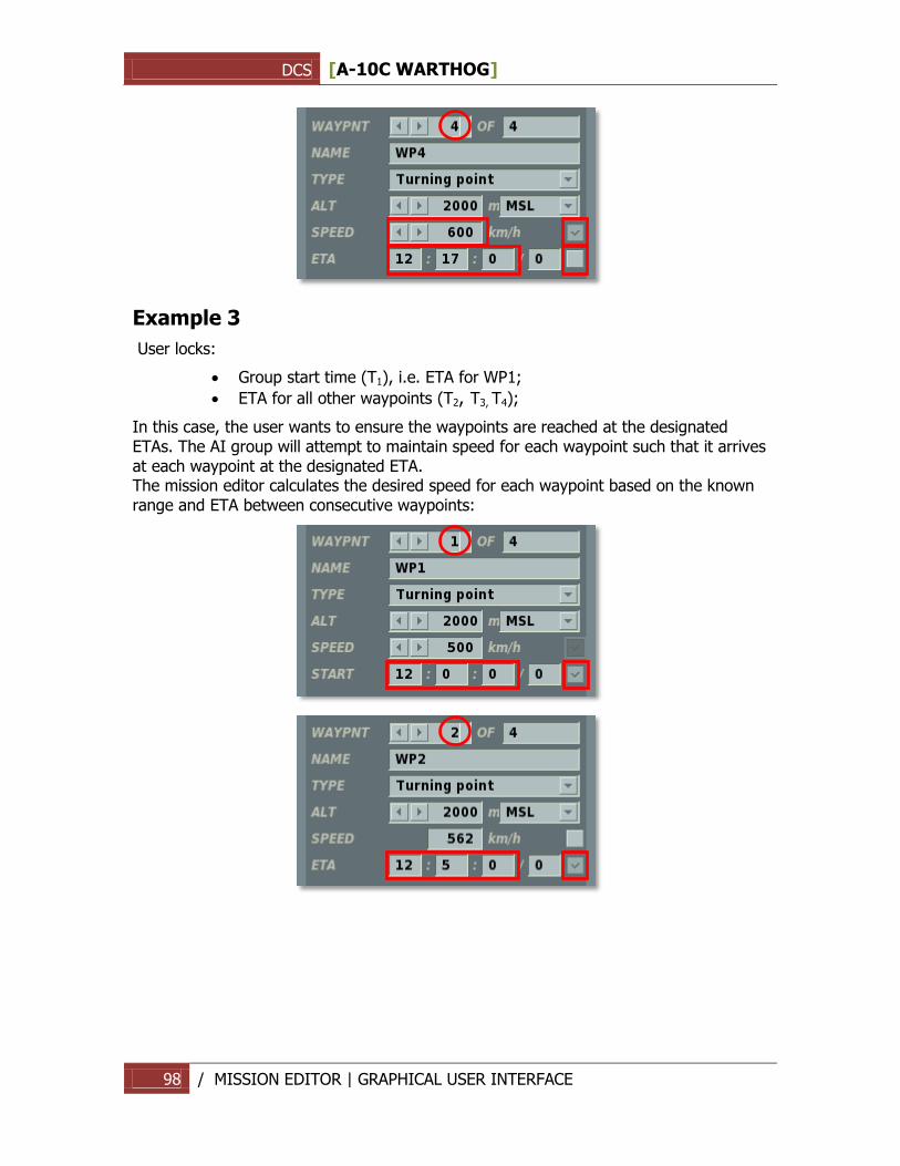
DCS [A-10C WARTHOG]
98 / MISSION EDITOR | GRAPHICAL USER INTERFACE
Example 3
User locks:
Group start time (Т1), i.e. ETA for WP1;
ETA for all other waypoints (Т2, Т3, Т4);
In this case, the user wants to ensure the waypoints are reached at the designated ETAs. The AI group will attempt to maintain speed for each waypoint such that it arrives at each waypoint at the designated ETA. The mission editor calculates the desired speed for each waypoint based on the known range and ETA between consecutive waypoints:
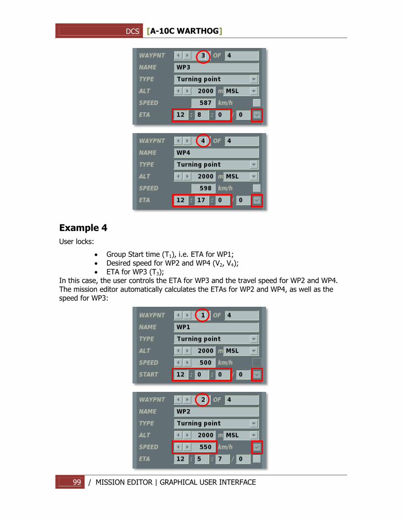
DCS [A-10C WARTHOG]
99 / MISSION EDITOR | GRAPHICAL USER INTERFACE
Example 4
User locks:
Group Start time (Т1), i.e. ETA for WP1; Desired speed for WP2 and WP4 (V2, V4); ETA for WP3 (Т3);
In this case, the user controls the ETA for WP3 and the travel speed for WP2 and WP4. The mission editor automatically calculates the ETAs for WP2 and WP4, as well as the speed for WP3:
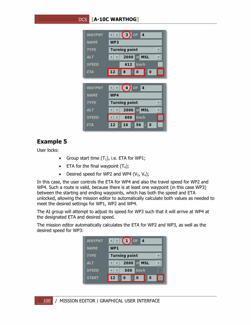
DCS [A-10C WARTHOG]
100 / MISSION EDITOR | GRAPHICAL USER INTERFACE
Example 5
User locks:
Group start time (Т1), i.e. ETA for WP1;
ETA for the final waypoint (Т4);
Desired speed for WP2 and WP4 (V2, V4);
In this case, the user controls the ETA for WP4 and also the travel speed for WP2 and WP4. Such a route is valid, because there is at least one waypoint (in this case WP3) between the starting and ending waypoints, which has both the speed and ETA unlocked, allowing the mission editor to automatically calculate both values as needed to meet the desired settings for WP1, WP2 and WP4.
The AI group will attempt to adjust its speed for WP3 such that it will arrive at WP4 at the designated ETA and desired speed.
The mission editor automatically calculates the ETA for WP2 and WP3, as well as the desired speed for WP3:
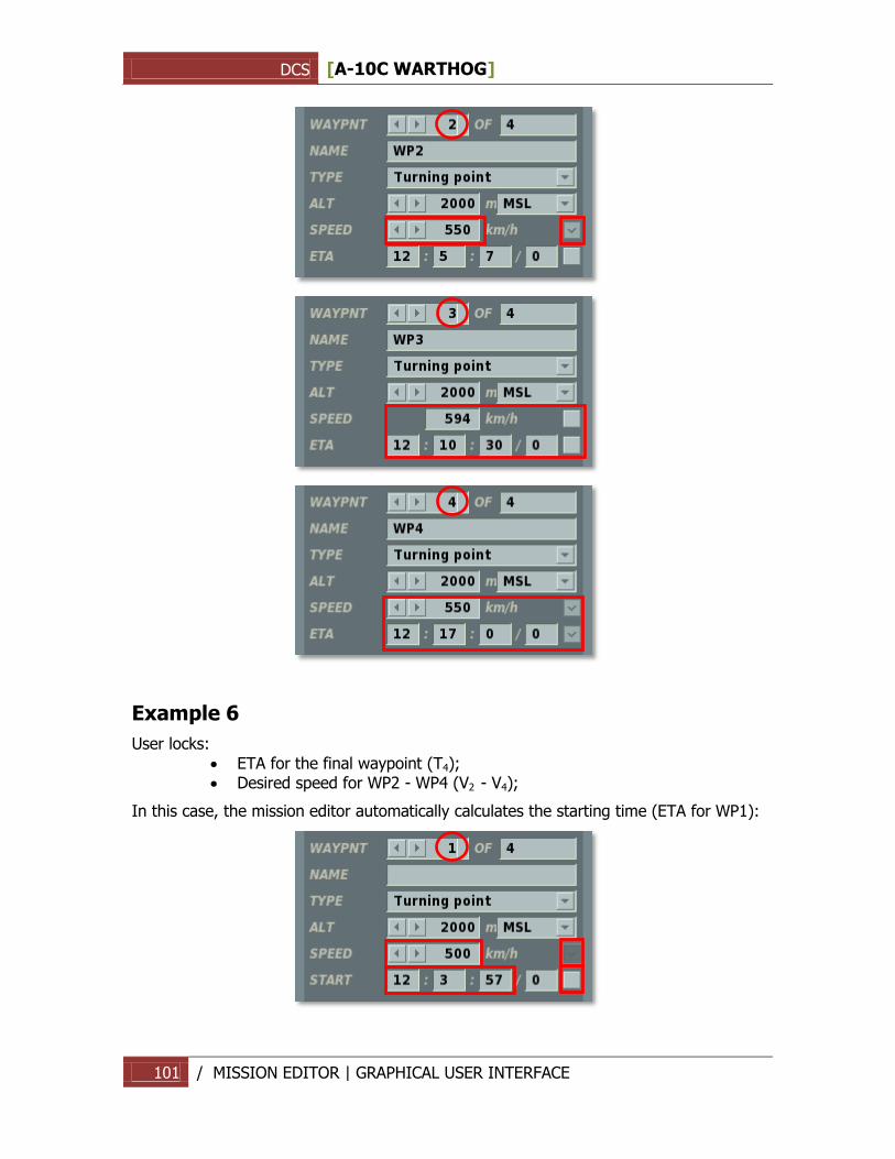
DCS [A-10C WARTHOG]
101 / MISSION EDITOR | GRAPHICAL USER INTERFACE
Example 6
User locks:
ETA for the final waypoint (Т4); Desired speed for WP2 - WP4 (V2 - V4);
In this case, the mission editor automatically calculates the starting time (ETA for WP1):
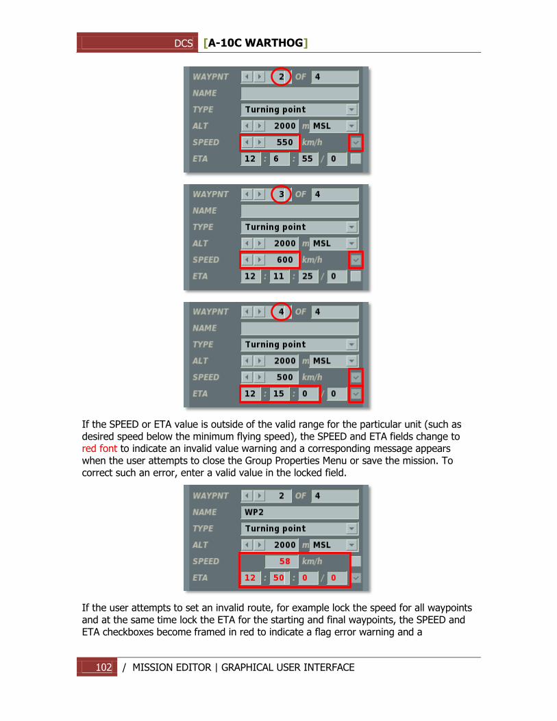
DCS [A-10C WARTHOG]
102 / MISSION EDITOR | GRAPHICAL USER INTERFACE
If the SPEED or ETA value is outside of the valid range for the particular unit (such as desired speed below the minimum flying speed), the SPEED and ETA fields change to red font to indicate an invalid value warning and a corresponding message appears when the user attempts to close the Group Properties Menu or save the mission. To correct such an error, enter a valid value in the locked field.
If the user attempts to set an invalid route, for example lock the speed for all waypoints and at the same time lock the ETA for the starting and final waypoints, the SPEED and ETA checkboxes become framed in red to indicate a flag error warning and a
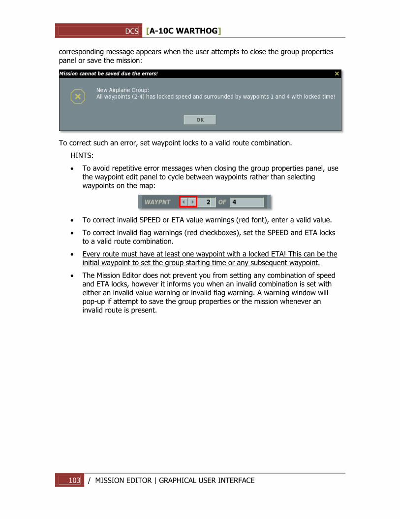
DCS [A-10C WARTHOG]
103 / MISSION EDITOR | GRAPHICAL USER INTERFACE
corresponding message appears when the user attempts to close the group properties panel or save the mission:
To correct such an error, set waypoint locks to a valid route combination.
HINTS:
To avoid repetitive error messages when closing the group properties panel, use the waypoint edit panel to cycle between waypoints rather than selecting waypoints on the map:
To correct invalid SPEED or ETA value warnings (red font), enter a valid value.
To correct invalid flag warnings (red checkboxes), set the SPEED and ETA locks to a valid route combination.
Every route must have at least one waypoint with a locked ETA! This can be the initial waypoint to set the group starting time or any subsequent waypoint.
The Mission Editor does not prevent you from setting any combination of speed and ETA locks, however it informs you when an invalid combination is set with either an invalid value warning or invalid flag warning. A warning window will pop-up if attempt to save the group properties or the mission whenever an invalid route is present.
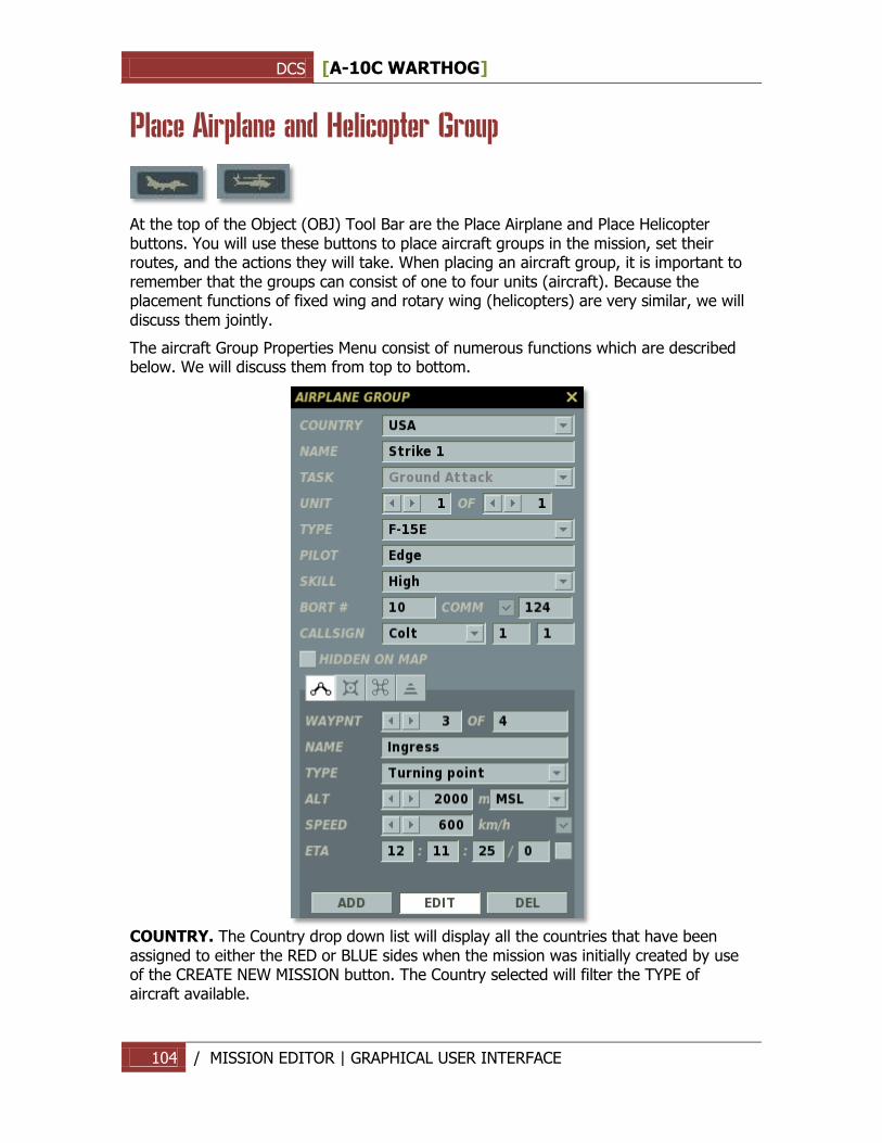
DCS [A-10C WARTHOG]
104 / MISSION EDITOR | GRAPHICAL USER INTERFACE
Place Airplane and Helicopter Group
At the top of the Object (OBJ) Tool Bar are the Place Airplane and Place Helicopter buttons. You will use these buttons to place aircraft groups in the mission, set their routes, and the actions they will take. When placing an aircraft group, it is important to remember that the groups can consist of one to four units (aircraft). Because the placement functions of fixed wing and rotary wing (helicopters) are very similar, we will discuss them jointly.
The aircraft Group Properties Menu consist of numerous functions which are described below. We will discuss them from top to bottom.
COUNTRY. The Country drop down list will display all the countries that have been assigned to either the RED or BLUE sides when the mission was initially created by use of the CREATE NEW MISSION button. The Country selected will filter the TYPE of aircraft available.
DCS [A-10C WARTHOG]
105 / MISSION EDITOR | GRAPHICAL USER INTERFACE
NAME. In the Name field, you may enter in a unique name for the aircraft group. If you do not enter one, a default name will be generated. The Name you create will be used when assigning some types of Triggers such as a Group Dead condition. Always be careful not to assign more than one group with the same Name.
TASK. The Task drop down menu allows you to select the group task. This setting will be in effect for the group for the duration of the mission. Note, the group task serves as a filter of available and automatically generated actions in the Advanced Actions Panel as well as the default payloads available.
NOTHING. This mission task assumes a non-combat flight along a route. Such
an aircraft does not take part in any active actions against enemy forces and just follows its route. Under the threat of an enemy attack the aircraft will try to evade it.
RUNWAY ATTACK. This is a specialized form of ground attack that will allow the aircraft to automatically align the axis of its attack along the length of the targeted runway. This is most useful when deploying runway denial weapons. To do so, set the Targeting area over the airfield to attack and select Airfields from the Target Categories.
GROUND ATTACK. This mission task is used to attack enemy ground targets using a variety of air to surface weapons. This type of mission usually involves unguided bombs weighing from 500 to 20000 lbs. and unguided rockets. Unless otherwise set in the advanced tasking options, the AI will generally prioritize use of longer-range weapons, such as guided air-to-surface missiles, over shorter-range weapons, such as unguided rockets and cannon.
AWACS. (Airborne Warning and Control System). The AWACS aircraft flies according to a planned straight or circular route using looped waypoints, and it alerts allied aircraft, SAM sites, and ships when it detects enemy aircraft. Certain SAM systems can receive targeting data directly from the AWACS even when their own acquisition radar systems have been destroyed. Note that AWACS detection can be limited by range, very low target altitudes, and terrain masking.
REFUELING. This mission task is reserved for aerial tankers. An aircraft assigned this mission will refuel any thirsty allied aircraft during its flight.
FIGHTER SWEEP. The fighter sweep mission task is a combat task that involves penetrating enemy air space to attack enemy fighters or other types of aircraft. The main objective of a fighter sweep is winning air superiority and to ensure unimpeded use of the air space by friendly aircraft. Since the aircraft taking part in a fighter sweep may find themselves at a considerable distance from their airfields and take part in prolonged dogfights, their fuel load will be a crucial factor.
CAS (Close Air Support). CAS involves actively searching for enemy ground targets on the battlefield and destroying them in support of friendly ground units under fire. This task is most suitable for dedicated attack aircraft and helicopters.
CAP (Combat Air Patrol). The CAP mission task implies flying a large race-track pattern using looped waypoints around a defined route to defend an area from
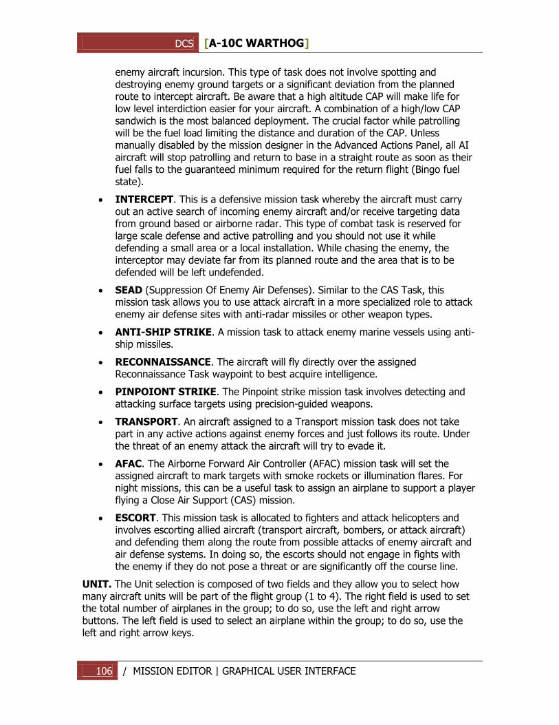
DCS [A-10C WARTHOG]
106 / MISSION EDITOR | GRAPHICAL USER INTERFACE
enemy aircraft incursion. This type of task does not involve spotting and destroying enemy ground targets or a significant deviation from the planned route to intercept aircraft. Be aware that a high altitude CAP will make life for low level interdiction easier for your aircraft. A combination of a high/low CAP sandwich is the most balanced deployment. The crucial factor while patrolling will be the fuel load limiting the distance and duration of the CAP. Unless manually disabled by the mission designer in the Advanced Actions Panel, all AI aircraft will stop patrolling and return to base in a straight route as soon as their fuel falls to the guaranteed minimum required for the return flight (Bingo fuel state).
INTERCEPT. This is a defensive mission task whereby the aircraft must carry out an active search of incoming enemy aircraft and/or receive targeting data from ground based or airborne radar. This type of combat task is reserved for large scale defense and active patrolling and you should not use it while defending a small area or a local installation. While chasing the enemy, the interceptor may deviate far from its planned route and the area that is to be defended will be left undefended.
SEAD (Suppression Of Enemy Air Defenses). Similar to the CAS Task, this mission task allows you to use attack aircraft in a more specialized role to attack enemy air defense sites with anti-radar missiles or other weapon types.
ANTI-SHIP STRIKE. A mission task to attack enemy marine vessels using anti-ship missiles.
RECONNAISSANCE. The aircraft will fly directly over the assigned Reconnaissance Task waypoint to best acquire intelligence.
PINPOIONT STRIKE. The Pinpoint strike mission task involves detecting and attacking surface targets using precision-guided weapons.
TRANSPORT. An aircraft assigned to a Transport mission task does not take part in any active actions against enemy forces and just follows its route. Under the threat of an enemy attack the aircraft will try to evade it.
AFAC. The Airborne Forward Air Controller (AFAC) mission task will set the assigned aircraft to mark targets with smoke rockets or illumination flares. For night missions, this can be a useful task to assign an airplane to support a player flying a Close Air Support (CAS) mission.
ESCORT. This mission task is allocated to fighters and attack helicopters and involves escorting allied aircraft (transport aircraft, bombers, or attack aircraft) and defending them along the route from possible attacks of enemy aircraft and air defense systems. In doing so, the escorts should not engage in fights with the enemy if they do not pose a threat or are significantly off the course line.
UNIT. The Unit selection is composed of two fields and they allow you to select how many aircraft units will be part of the flight group (1 to 4). The right field is used to set the total number of airplanes in the group; to do so, use the left and right arrow buttons. The left field is used to select an airplane within the group; to do so, use the left and right arrow keys.
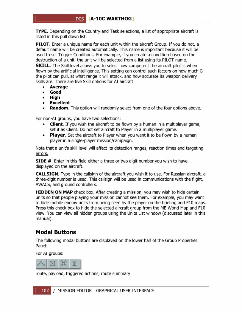
DCS [A-10C WARTHOG]
107 / MISSION EDITOR | GRAPHICAL USER INTERFACE
TYPE. Depending on the Country and Task selections, a list of appropriate aircraft is listed in this pull down list.
PILOT. Enter a unique name for each unit within the aircraft Group. If you do not, a default name will be created automatically. This name is important because it will be used to set Trigger Conditions. For example, if you create a condition based on the destruction of a unit, the unit will be selected from a list using its PILOT name.
SKILL. The Skill level allows you to select how competent the aircraft pilot is when
flown by the artificial intelligence. This setting can control such factors on how much G the pilot can pull, at what range it will attack, and how accurate its weapon delivery skills are. There are five Skill options for AI aircraft:
Average Good High Excellent Random. This option will randomly select from one of the four options above.
For non-AI groups, you have two selections:
Client. If you wish the aircraft to be flown by a human in a multiplayer game, set it as Client. Do not set aircraft to Player in a multiplayer game.
Player. Set the aircraft to Player when you want it to be flown by a human
player in a single-player mission/campaign.
Note that a unit's skill level will affect its detection ranges, reaction times and targeting errors.
SIDE #. Enter in this field either a three or two digit number you wish to have displayed on the aircraft.
CALLSIGN. Type in the callsign of the aircraft you wish it to use. For Russian aircraft, a three-digit number is used. This callsign will be used in communications with the flight, AWACS, and ground controllers.
HIDDEN ON MAP check box. After creating a mission, you may wish to hide certain units so that people playing your mission cannot see them. For example, you may want to hide mobile enemy units from being seen by the player on the briefing and F10 maps. Press this check box to hide the selected aircraft group from the ME World Map and F10 view. You can view all hidden groups using the Units List window (discussed later in this manual).
Modal Buttons
The following modal buttons are displayed on the lower half of the Group Properties Panel:
For AI groups:
route, payload, triggered actions, route summary
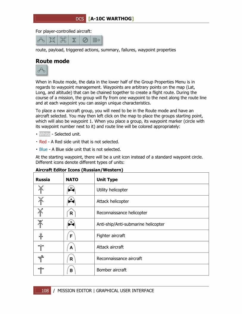
DCS [A-10C WARTHOG]
108 / MISSION EDITOR | GRAPHICAL USER INTERFACE
For player-controlled aircraft:
route, payload, triggered actions, summary, failures, waypoint properties
Route mode
When in Route mode, the data in the lower half of the Group Properties Menu is in regards to waypoint management. Waypoints are arbitrary points on the map (Lat, Long, and altitude) that can be chained together to create a flight route. During the course of a mission, the group will fly from one waypoint to the next along the route line and at each waypoint you can assign unique characteristics.
To place a new aircraft group, you will need to be in the Route mode and have an aircraft selected. You may then left click on the map to place the groups starting point, which will also be waypoint 1. When you place a group, its waypoint marker (circle with its waypoint number next to it) and route line will be colored appropriately:
White - Selected unit.
Red - A Red side unit that is not selected.
Blue - A Blue side unit that is not selected.
At the starting waypoint, there will be a unit icon instead of a standard waypoint circle. Different icons denote different types of units:
Aircraft Editor Icons (Russian/Western)
Russia NATO Unit Type
Utility helicopter
Attack helicopter
Reconnaissance helicopter
Anti-ship/Anti-submarine helicopter
Fighter aircraft
Attack aircraft
Reconnaissance aircraft
Bomber aircraft
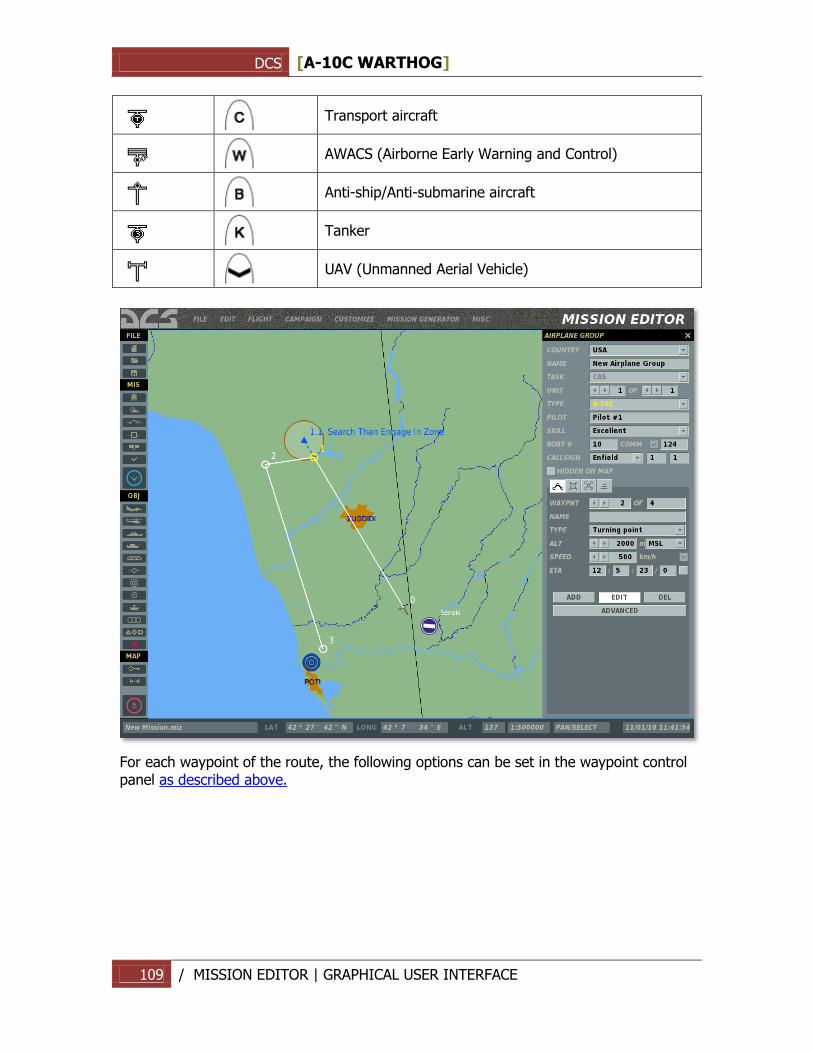
DCS [A-10C WARTHOG]
109 / MISSION EDITOR | GRAPHICAL USER INTERFACE
Transport aircraft
AWACS (Airborne Early Warning and Control)
Anti-ship/Anti-submarine aircraft
Tanker
UAV (Unmanned Aerial Vehicle)
For each waypoint of the route, the following options can be set in the waypoint control panel as described above.
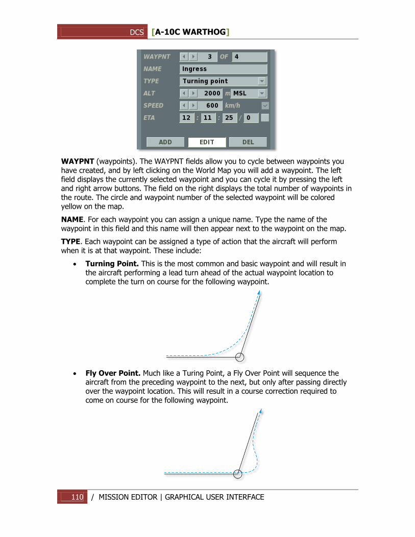
DCS [A-10C WARTHOG]
110 / MISSION EDITOR | GRAPHICAL USER INTERFACE
WAYPNT (waypoints). The WAYPNT fields allow you to cycle between waypoints you have created, and by left clicking on the World Map you will add a waypoint. The left field displays the currently selected waypoint and you can cycle it by pressing the left and right arrow buttons. The field on the right displays the total number of waypoints in the route. The circle and waypoint number of the selected waypoint will be colored yellow on the map.
NAME. For each waypoint you can assign a unique name. Type the name of the waypoint in this field and this name will then appear next to the waypoint on the map.
TYPE. Each waypoint can be assigned a type of action that the aircraft will perform when it is at that waypoint. These include:
Turning Point. This is the most common and basic waypoint and will result in the aircraft performing a lead turn ahead of the actual waypoint location to complete the turn on course for the following waypoint.
Fly Over Point. Much like a Turing Point, a Fly Over Point will sequence the aircraft from the preceding waypoint to the next, but only after passing directly over the waypoint location. This will result in a course correction required to come on course for the following waypoint.
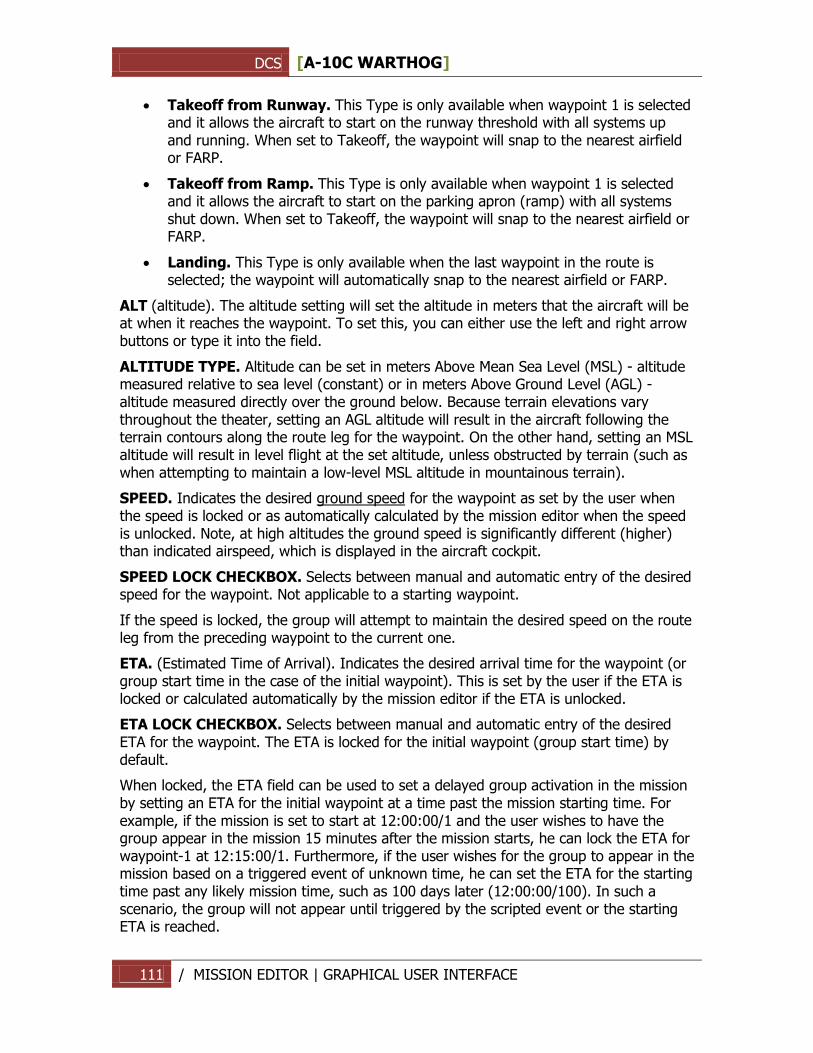
DCS [A-10C WARTHOG]
111 / MISSION EDITOR | GRAPHICAL USER INTERFACE
Takeoff from Runway. This Type is only available when waypoint 1 is selected and it allows the aircraft to start on the runway threshold with all systems up and running. When set to Takeoff, the waypoint will snap to the nearest airfield or FARP.
Takeoff from Ramp. This Type is only available when waypoint 1 is selected and it allows the aircraft to start on the parking apron (ramp) with all systems shut down. When set to Takeoff, the waypoint will snap to the nearest airfield or FARP.
Landing. This Type is only available when the last waypoint in the route is selected; the waypoint will automatically snap to the nearest airfield or FARP.
ALT (altitude). The altitude setting will set the altitude in meters that the aircraft will be at when it reaches the waypoint. To set this, you can either use the left and right arrow buttons or type it into the field.
ALTITUDE TYPE. Altitude can be set in meters Above Mean Sea Level (MSL) - altitude measured relative to sea level (constant) or in meters Above Ground Level (AGL) - altitude measured directly over the ground below. Because terrain elevations vary throughout the theater, setting an AGL altitude will result in the aircraft following the terrain contours along the route leg for the waypoint. On the other hand, setting an MSL altitude will result in level flight at the set altitude, unless obstructed by terrain (such as when attempting to maintain a low-level MSL altitude in mountainous terrain).
SPEED. Indicates the desired ground speed for the waypoint as set by the user when the speed is locked or as automatically calculated by the mission editor when the speed is unlocked. Note, at high altitudes the ground speed is significantly different (higher) than indicated airspeed, which is displayed in the aircraft cockpit.
SPEED LOCK CHECKBOX. Selects between manual and automatic entry of the desired speed for the waypoint. Not applicable to a starting waypoint.
If the speed is locked, the group will attempt to maintain the desired speed on the route leg from the preceding waypoint to the current one.
ETA. (Estimated Time of Arrival). Indicates the desired arrival time for the waypoint (or group start time in the case of the initial waypoint). This is set by the user if the ETA is locked or calculated automatically by the mission editor if the ETA is unlocked.
ETA LOCK CHECKBOX. Selects between manual and automatic entry of the desired ETA for the waypoint. The ETA is locked for the initial waypoint (group start time) by default.
When locked, the ETA field can be used to set a delayed group activation in the mission by setting an ETA for the initial waypoint at a time past the mission starting time. For example, if the mission is set to start at 12:00:00/1 and the user wishes to have the group appear in the mission 15 minutes after the mission starts, he can lock the ETA for waypoint-1 at 12:15:00/1. Furthermore, if the user wishes for the group to appear in the mission based on a triggered event of unknown time, he can set the ETA for the starting time past any likely mission time, such as 100 days later (12:00:00/100). In such a scenario, the group will not appear until triggered by the scripted event or the starting ETA is reached.
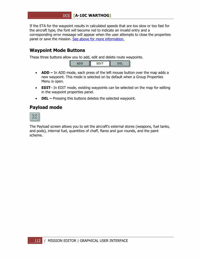
DCS [A-10C WARTHOG]
112 / MISSION EDITOR | GRAPHICAL USER INTERFACE
If the ETA for the waypoint results in calculated speeds that are too slow or too fast for the aircraft type, the font will become red to indicate an invalid entry and a corresponding error message will appear when the user attempts to close the properties panel or save the mission. See above for more information.
Waypoint Mode Buttons
These three buttons allow you to add, edit and delete route waypoints.
ADD – In ADD mode, each press of the left mouse button over the map adds a new waypoint. This mode is selected on by default when a Group Properties Menu is open.
EDIT– In EDIT mode, existing waypoints can be selected on the map for editing in the waypoint properties panel.
DEL – Pressing this buttons deletes the selected waypoint.
Payload mode
The Payload screen allows you to set the aircraft's external stores (weapons, fuel tanks, and pods), internal fuel, quantities of chaff, flares and gun rounds, and the paint scheme.
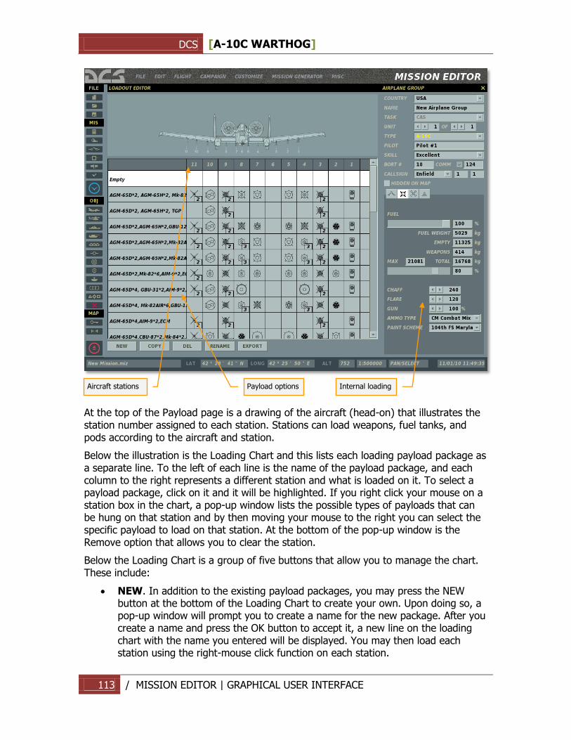
DCS [A-10C WARTHOG]
113 / MISSION EDITOR | GRAPHICAL USER INTERFACE
At the top of the Payload page is a drawing of the aircraft (head-on) that illustrates the station number assigned to each station. Stations can load weapons, fuel tanks, and pods according to the aircraft and station.
Below the illustration is the Loading Chart and this lists each loading payload package as a separate line. To the left of each line is the name of the payload package, and each column to the right represents a different station and what is loaded on it. To select a payload package, click on it and it will be highlighted. If you right click your mouse on a station box in the chart, a pop-up window lists the possible types of payloads that can be hung on that station and by then moving your mouse to the right you can select the specific payload to load on that station. At the bottom of the pop-up window is the Remove option that allows you to clear the station.
Below the Loading Chart is a group of five buttons that allow you to manage the chart. These include:
NEW. In addition to the existing payload packages, you may press the NEW button at the bottom of the Loading Chart to create your own. Upon doing so, a pop-up window will prompt you to create a name for the new package. After you create a name and press the OK button to accept it, a new line on the loading chart with the name you entered will be displayed. You may then load each station using the right-mouse click function on each station.
Aircraft stations
Payload options
Internal loading
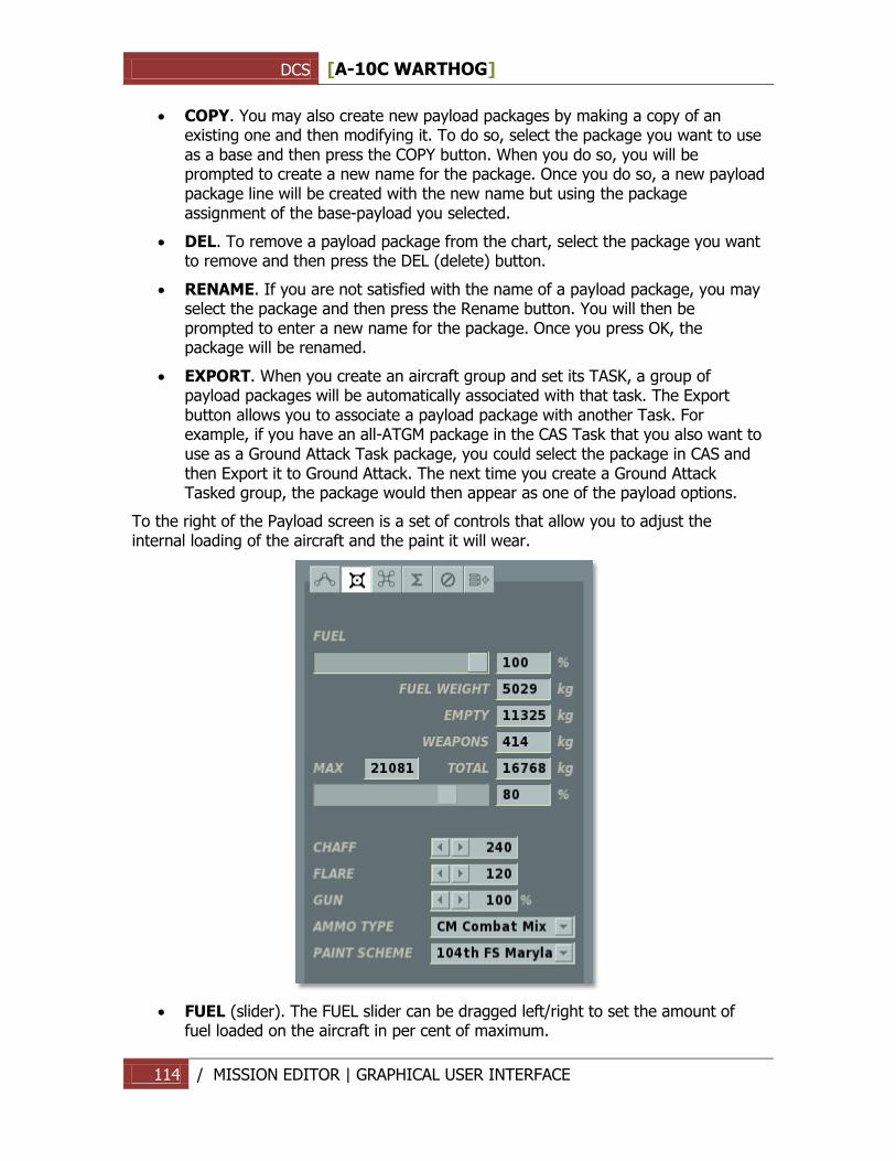
DCS [A-10C WARTHOG]
114 / MISSION EDITOR | GRAPHICAL USER INTERFACE
COPY. You may also create new payload packages by making a copy of an existing one and then modifying it. To do so, select the package you want to use as a base and then press the COPY button. When you do so, you will be prompted to create a new name for the package. Once you do so, a new payload package line will be created with the new name but using the package assignment of the base-payload you selected.
DEL. To remove a payload package from the chart, select the package you want to remove and then press the DEL (delete) button.
RENAME. If you are not satisfied with the name of a payload package, you may select the package and then press the Rename button. You will then be prompted to enter a new name for the package. Once you press OK, the package will be renamed.
EXPORT. When you create an aircraft group and set its TASK, a group of payload packages will be automatically associated with that task. The Export button allows you to associate a payload package with another Task. For example, if you have an all-ATGM package in the CAS Task that you also want to use as a Ground Attack Task package, you could select the package in CAS and then Export it to Ground Attack. The next time you create a Ground Attack Tasked group, the package would then appear as one of the payload options.
To the right of the Payload screen is a set of controls that allow you to adjust the internal loading of the aircraft and the paint it will wear.
FUEL (slider). The FUEL slider can be dragged left/right to set the amount of fuel loaded on the aircraft in per cent of maximum.
DCS [A-10C WARTHOG]
115 / MISSION EDITOR | GRAPHICAL USER INTERFACE
FUEL WEIGHT. Loaded internal fuel as a kilogram (kg) value.
EMPTY. Empty weight of the aircraft without fuel and payload package in kilograms.
WEAPONS. Total weight of all loaded stores on stations in kilograms.
MAX. This field displays the maximum, safe total weight of the aircraft in kilograms.
TOTAL. Total weight of aircraft to include empty weight, fuel weight, and payload package weight in kilograms.
The non-interactive slider bar below the MAX and TOTAL fields provides a visual indication of the maximum percent of loading on the aircraft as a percentage.
Non-fuel internal loading of the aircraft is listed next: CHAFF. Number of chaff bundles loaded. This can be decreased/increased using
the "<" - ">" arrow buttons.
FLARE. Number of flares loaded. This can be decreased/increased using the "<" - ">" arrow buttons. Note, the total number of chaff and flares is limited by the number of countermeasure cartridges on the aircraft, so increasing one will decrease the other.
GUN. Percent of maximum number of cannon rounds that can be loaded.
AMMO TYPE. Selection of the ammunition type loaded for the gun.
COLOR SCHEME. Selection of the aircraft paint scheme ("skin"). The number of
choices depends on the aircraft.
Triggered Actions mode
The Triggered Actions button opens the Triggered Actions Panel. This panel can be used to add or edit group actions analogous to the Advanced Actions Panel, but activated based on trigger rules as scripted in the Triggers Menu using the AI TASK trigger action.
Summary mode
The Summary panel provides information on the entire flight route of the selected air group.
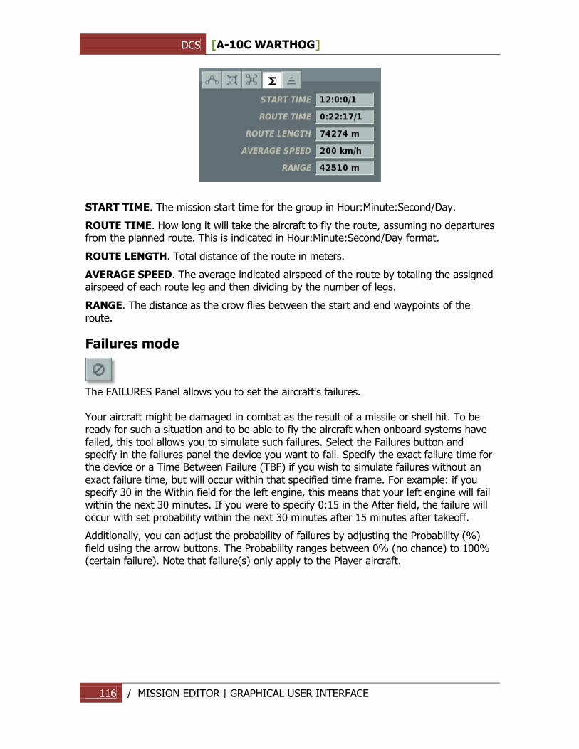
DCS [A-10C WARTHOG]
116 / MISSION EDITOR | GRAPHICAL USER INTERFACE
START TIME. The mission start time for the group in Hour:Minute:Second/Day.
ROUTE TIME. How long it will take the aircraft to fly the route, assuming no departures from the planned route. This is indicated in Hour:Minute:Second/Day format.
ROUTE LENGTH. Total distance of the route in meters.
AVERAGE SPEED. The average indicated airspeed of the route by totaling the assigned airspeed of each route leg and then dividing by the number of legs.
RANGE. The distance as the crow flies between the start and end waypoints of the route.
Failures mode
The FAILURES Panel allows you to set the aircraft's failures. Your aircraft might be damaged in combat as the result of a missile or shell hit. To be ready for such a situation and to be able to fly the aircraft when onboard systems have failed, this tool allows you to simulate such failures. Select the Failures button and specify in the failures panel the device you want to fail. Specify the exact failure time for the device or a Time Between Failure (TBF) if you wish to simulate failures without an exact failure time, but will occur within that specified time frame. For example: if you specify 30 in the Within field for the left engine, this means that your left engine will fail within the next 30 minutes. If you were to specify 0:15 in the After field, the failure will occur with set probability within the next 30 minutes after 15 minutes after takeoff.
Additionally, you can adjust the probability of failures by adjusting the Probability (%) field using the arrow buttons. The Probability ranges between 0% (no chance) to 100% (certain failure). Note that failure(s) only apply to the Player aircraft.
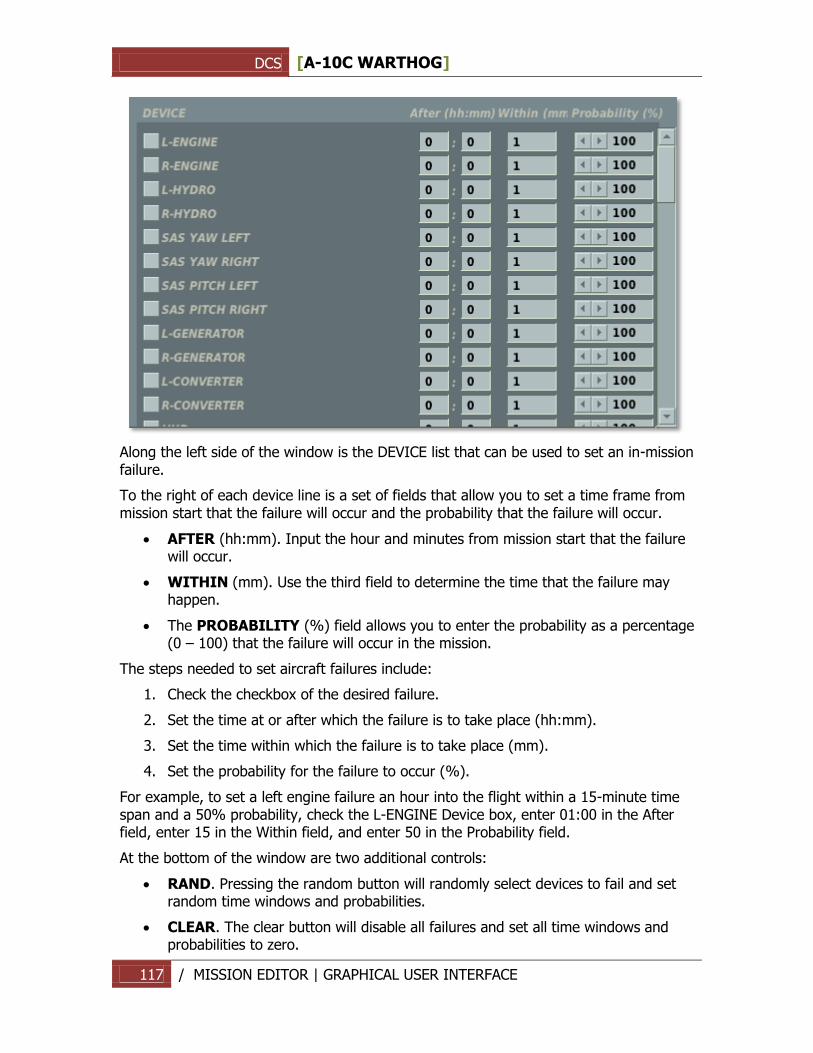
DCS [A-10C WARTHOG]
117 / MISSION EDITOR | GRAPHICAL USER INTERFACE
Along the left side of the window is the DEVICE list that can be used to set an in-mission failure.
To the right of each device line is a set of fields that allow you to set a time frame from mission start that the failure will occur and the probability that the failure will occur.
AFTER (hh:mm). Input the hour and minutes from mission start that the failure will occur.
WITHIN (mm). Use the third field to determine the time that the failure may happen.
The PROBABILITY (%) field allows you to enter the probability as a percentage (0 – 100) that the failure will occur in the mission.
The steps needed to set aircraft failures include:
1. Check the checkbox of the desired failure.
2. Set the time at or after which the failure is to take place (hh:mm).
3. Set the time within which the failure is to take place (mm).
4. Set the probability for the failure to occur (%).
For example, to set a left engine failure an hour into the flight within a 15-minute time span and a 50% probability, check the L-ENGINE Device box, enter 01:00 in the After field, enter 15 in the Within field, and enter 50 in the Probability field.
At the bottom of the window are two additional controls:
RAND. Pressing the random button will randomly select devices to fail and set random time windows and probabilities.
CLEAR. The clear button will disable all failures and set all time windows and probabilities to zero.
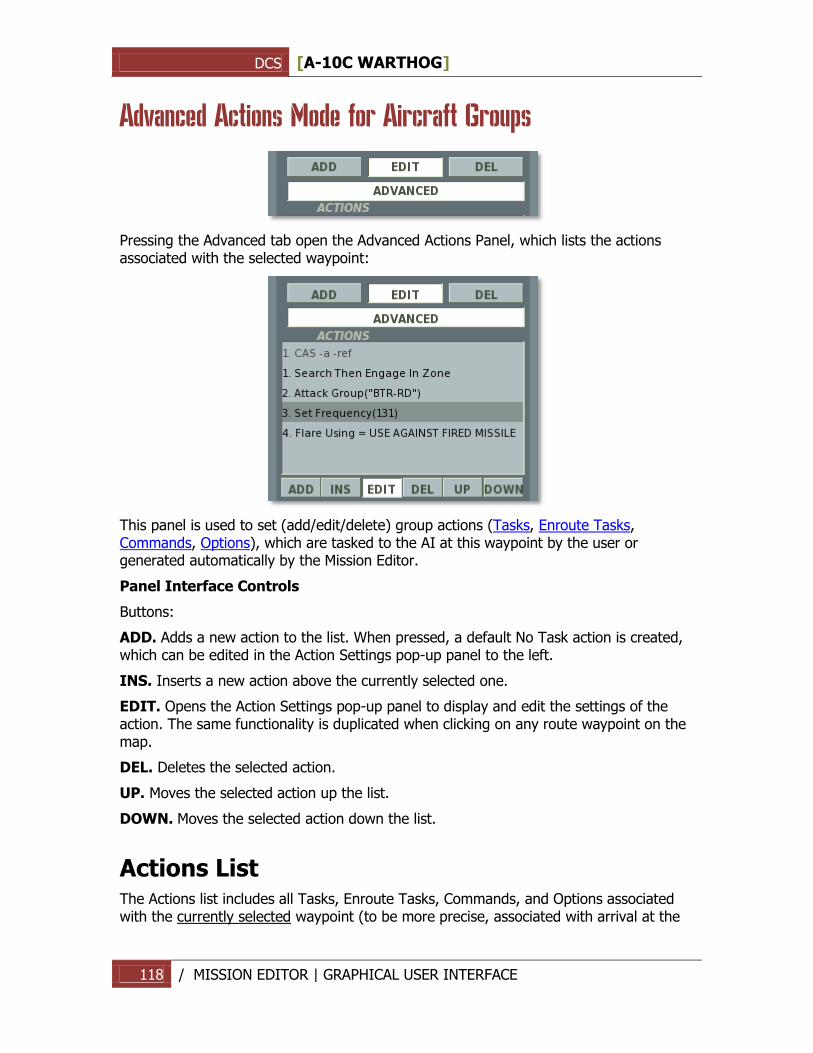
DCS [A-10C WARTHOG]
118 / MISSION EDITOR | GRAPHICAL USER INTERFACE
Advanced Actions Mode for Aircraft Groups
Pressing the Advanced tab open the Advanced Actions Panel, which lists the actions associated with the selected waypoint:
This panel is used to set (add/edit/delete) group actions (Tasks, Enroute Tasks, Commands, Options), which are tasked to the AI at this waypoint by the user or generated automatically by the Mission Editor.
Panel Interface Controls
Buttons:
ADD. Adds a new action to the list. When pressed, a default No Task action is created, which can be edited in the Action Settings pop-up panel to the left.
INS. Inserts a new action above the currently selected one.
EDIT. Opens the Action Settings pop-up panel to display and edit the settings of the action. The same functionality is duplicated when clicking on any route waypoint on the map.
DEL. Deletes the selected action.
UP. Moves the selected action up the list.
DOWN. Moves the selected action down the list.
Actions List The Actions list includes all Tasks, Enroute Tasks, Commands, and Options associated with the currently selected waypoint (to be more precise, associated with arrival at the
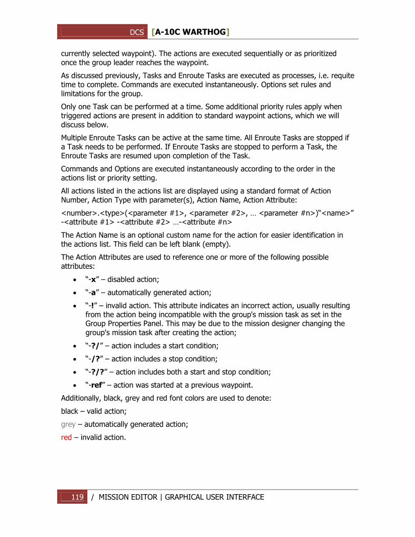
DCS [A-10C WARTHOG]
119 / MISSION EDITOR | GRAPHICAL USER INTERFACE
currently selected waypoint). The actions are executed sequentially or as prioritized once the group leader reaches the waypoint.
As discussed previously, Tasks and Enroute Tasks are executed as processes, i.e. requite time to complete. Commands are executed instantaneously. Options set rules and limitations for the group.
Only one Task can be performed at a time. Some additional priority rules apply when triggered actions are present in addition to standard waypoint actions, which we will discuss below.
Multiple Enroute Tasks can be active at the same time. All Enroute Tasks are stopped if a Task needs to be performed. If Enroute Tasks are stopped to perform a Task, the Enroute Tasks are resumed upon completion of the Task.
Commands and Options are executed instantaneously according to the order in the actions list or priority setting.
All actions listed in the actions list are displayed using a standard format of Action Number, Action Type with parameter(s), Action Name, Action Attribute:
<number>.<type>(<parameter #1>, <parameter #2>, … <parameter #n>)“<name>” -<attribute #1> -<attribute #2> …-<attribute #n>
The Action Name is an optional custom name for the action for easier identification in the actions list. This field can be left blank (empty).
The Action Attributes are used to reference one or more of the following possible attributes:
“-x” – disabled action;
“-a” – automatically generated action;
“-!” – invalid action. This attribute indicates an incorrect action, usually resulting from the action being incompatible with the group's mission task as set in the Group Properties Panel. This may be due to the mission designer changing the group's mission task after creating the action;
“-?/” – action includes a start condition;
“-/?” – action includes a stop condition;
“-?/?” – action includes both a start and stop condition;
“-ref” – action was started at a previous waypoint.
Additionally, black, grey and red font colors are used to denote:
black – valid action;
grey – automatically generated action;
red – invalid action.
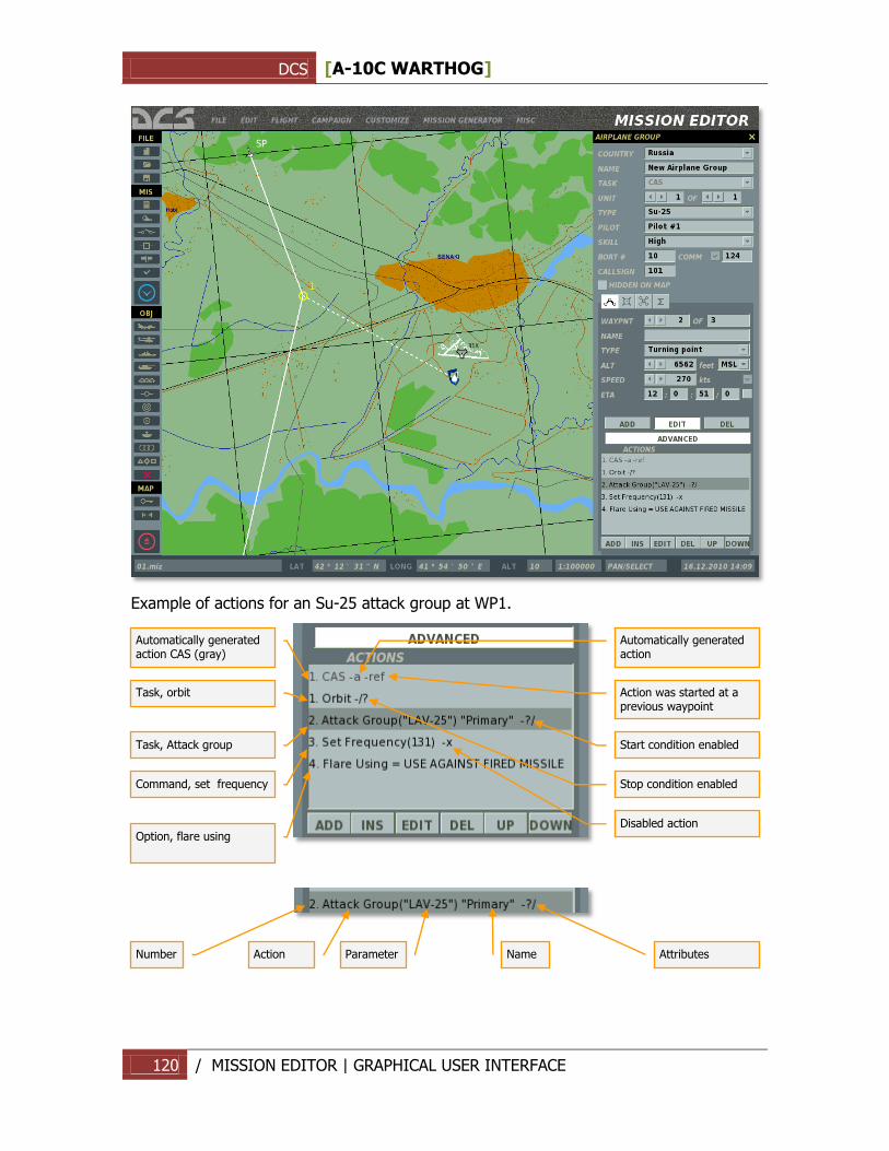
DCS [A-10C WARTHOG]
120 / MISSION EDITOR | GRAPHICAL USER INTERFACE
Example of actions for an Su-25 attack group at WP1.
Automatically generated action CAS (gray)
Task, orbit
Task, Attack group
Command, set frequency
Option, flare using
Action was started at a previous waypoint
Stop condition enabled
Start condition enabled
Disabled action
Automatically generated action
Number
Action
Parameter
Name
Attributes
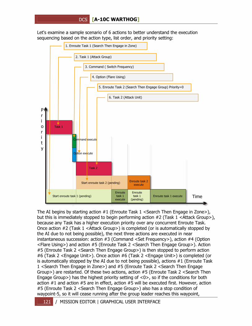
DCS [A-10C WARTHOG]
121 / MISSION EDITOR | GRAPHICAL USER INTERFACE
Let's examine a sample scenario of 6 actions to better understand the execution sequencing based on the action type, list order, and priority setting:
The AI begins by starting action #1 (Enroute Task 1 <Search Then Engage in Zone>), but this is immediately stopped to begin performing action #2 (Task 1 <Attack Group>), because any Task has a higher execution priority over any concurrent Enroute Task. Once action #2 (Task 1 <Attack Group>) is completed (or is automatically stopped by the AI due to not being possible), the next three actions are executed in near instantaneous succession: action #3 (Command <Set Frequency>), action #4 (Option <Flare Using>) and action #5 (Enroute Task 2 <Search Then Engage Group>). Action #5 (Enroute Task 2 <Search Then Engage Group>) is then stopped to perform action #6 (Task 2 <Engage Unit>). Once action #6 (Task 2 <Engage Unit>) is completed (or is automatically stopped by the AI due to not being possible), actions #1 (Enroute Task 1 <Search Then Engage in Zone>) and #5 (Enroute Task 2 <Search Then Engage Group>) are restarted. Of these two actions, action #5 (Enroute Task 2 <Search Then Engage Group>) has the highest priority setting of <0>, so if the conditions for both action #1 and action #5 are in effect, action #5 will be executed first. However, action #5 (Enroute Task 2 <Search Then Engage Group>) also has a stop condition of waypoint-5, so it will cease running after the group leader reaches this waypoint,
Priorit
y
Time
Task 1
Command execute
Option execute
Task 2
Start enroute task 2 (pending)
Enroute task 2 execute
Start enroute task 1 (pending)
Enroute task 1
execute
Enroute task 1 execute
Enroute task 1
(pending)
2. Task 1 (Attack Group)
5. Enroute Task 2 (Search Then Engage Group) Priority=0
3. Command ( Switch Frequency)
4. Option (Flare Using)
6. Task 2 (Attack Unit)
1. Enroute Task 1 (Search Then Engage in Zone)
DCS [A-10C WARTHOG]
122 / MISSION EDITOR | GRAPHICAL USER INTERFACE
returning the AI to executing action #1 (Enroute Task 1 <Search Then Engage in Zone>).
Triggered Actions
Tasks activated by a trigger will have a higher execution priority over waypoint Tasks. For example, if a triggered Task is activated while a waypoint Task is under way, the waypoint Task will be stopped and stacked in memory while the AI switches to the triggered Task. Once the triggered Task is completed (or skipped due to not being possible), the previously running waypoint Task will be resumed.
Enroute Tasks activated by a trigger will be added to the list of currently active Enroute Tasks. As with waypoint Enroute Tasks, triggered Enroute Tasks remain active until stopped by a stop condition.
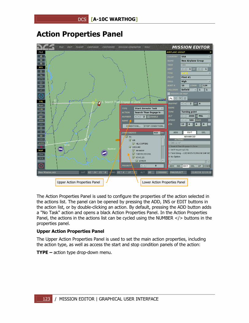
DCS [A-10C WARTHOG]
123 / MISSION EDITOR | GRAPHICAL USER INTERFACE
Action Properties Panel
The Action Properties Panel is used to configure the properties of the action selected in the actions list. The panel can be opened by pressing the ADD, INS or EDIT buttons in the action list, or by double-clicking an action. By default, pressing the ADD button adds a "No Task" action and opens a black Action Properties Panel. In the Action Properties Panel, the actions in the actions list can be cycled using the NUMBER </> buttons in the properties panel.
Upper Action Properties Panel
The Upper Action Properties Panel is used to set the main action properties, including the action type, as well as access the start and stop condition panels of the action:
TYPE – action type drop-down menu.
Upper Action Properties Panel
Lower Action Properties Panel
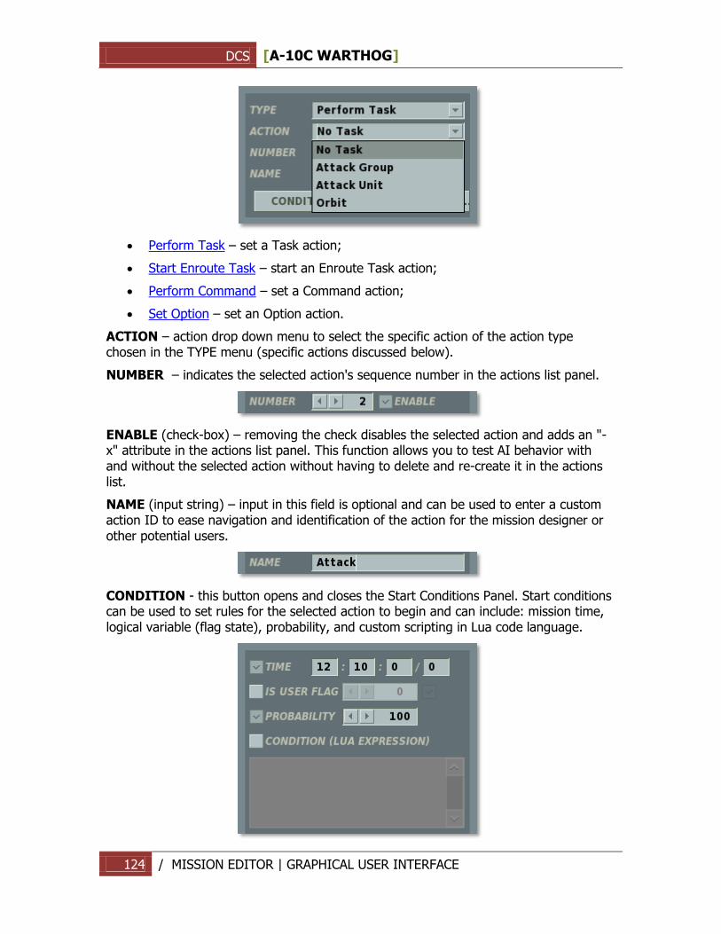
DCS [A-10C WARTHOG]
124 / MISSION EDITOR | GRAPHICAL USER INTERFACE
Perform Task – set a Task action;
Start Enroute Task – start an Enroute Task action;
Perform Command – set a Command action;
Set Option – set an Option action.
ACTION – action drop down menu to select the specific action of the action type chosen in the TYPE menu (specific actions discussed below).
NUMBER – indicates the selected action's sequence number in the actions list panel.
ENABLE (check-box) – removing the check disables the selected action and adds an "-x" attribute in the actions list panel. This function allows you to test AI behavior with and without the selected action without having to delete and re-create it in the actions list.
NAME (input string) – input in this field is optional and can be used to enter a custom action ID to ease navigation and identification of the action for the mission designer or other potential users.
CONDITION - this button opens and closes the Start Conditions Panel. Start conditions can be used to set rules for the selected action to begin and can include: mission time, logical variable (flag state), probability, and custom scripting in Lua code language.
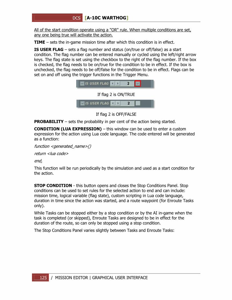
DCS [A-10C WARTHOG]
125 / MISSION EDITOR | GRAPHICAL USER INTERFACE
All of the start condition operate using a "OR" rule. When multiple conditions are set, any one being true will activate the action.
TIME – sets the in-game mission time after which this condition is in effect.
IS USER FLAG – sets a flag number and status (on/true or off/false) as a start condition. The flag number can be entered manually or cycled using the left/right arrow keys. The flag state is set using the checkbox to the right of the flag number. If the box is checked, the flag needs to be on/true for the condition to be in effect. If the box is unchecked, the flag needs to be off/false for the condition to be in effect. Flags can be set on and off using the trigger functions in the Trigger Menu.
If flag 2 is ON/TRUE
If flag 2 is OFF/FALSE
PROBABILITY – sets the probability in per cent of the action being started.
CONDITION (LUA EXPRESSION) – this window can be used to enter a custom expression for the action using Lua code language. The code entered will be generated as a function:
function <generated_name>()
return <lua code>
end,
This function will be run periodically by the simulation and used as a start condition for the action.
STOP CONDITION - this button opens and closes the Stop Conditions Panel. Stop conditions can be used to set rules for the selected action to end and can include: mission time, logical variable (flag state), custom scripting in Lua code language, duration in time since the action was started, and a route waypoint (for Enroute Tasks only).
While Tasks can be stopped either by a stop condition or by the AI in-game when the task is completed (or skipped), Enroute Tasks are designed to be in effect for the duration of the route, so can only be stopped using a stop condition.
The Stop Conditions Panel varies slightly between Tasks and Enroute Tasks:
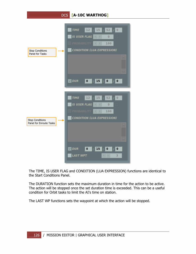
DCS [A-10C WARTHOG]
126 / MISSION EDITOR | GRAPHICAL USER INTERFACE
The TIME, IS USER FLAG and CONDITION (LUA EXPRESSION) functions are identical to the Start Conditions Panel. The DURATION function sets the maximum duration in time for the action to be active. The action will be stopped once the set duration time is exceeded. This can be a useful condition for Orbit tasks to limit the AI's time on station. The LAST WP functions sets the waypoint at which the action will be stopped.
Stop Conditions
Panel for Tasks
Stop Conditions Panel for Enroute Tasks

DCS [A-10C WARTHOG]
127 / MISSION EDITOR | GRAPHICAL USER INTERFACE
Configuring Advanced Actions Once an action is selected in the ACTION drop down menu of the Upper Action Properties Panel, the action properties appear in the Lower Action Properties Panel and can be customized by the mission designer.
The specific actions available for selection depend on the type of group being edited and the group task (CAS, Intercept, etc.). If the group task is changed after initial group creation, it may conflict with the actions already set in the actions list. In such cases, the invalid action(s) will be presented in red font and a "!" attribute will be added to indicate an invalid action. An error window will also pop up if the user attempts to close the Group Properties Panel or save the mission.
Altered group task
Invalid actions after altered group task
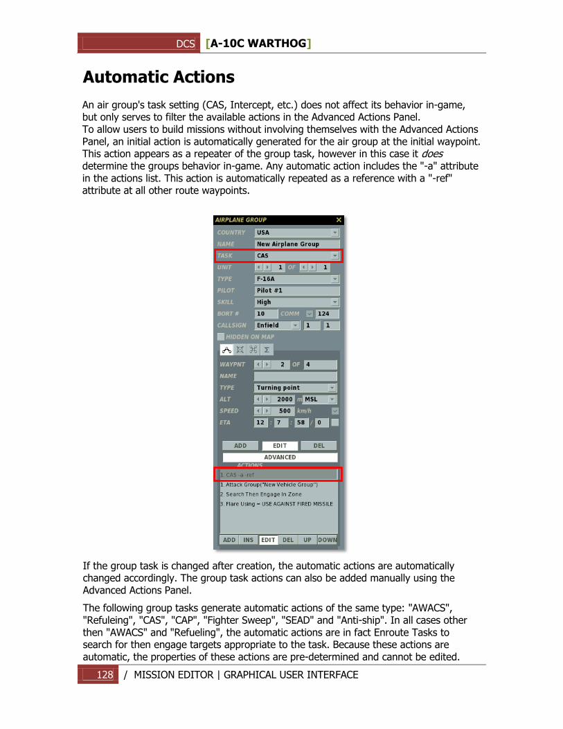
DCS [A-10C WARTHOG]
128 / MISSION EDITOR | GRAPHICAL USER INTERFACE
Automatic Actions An air group's task setting (CAS, Intercept, etc.) does not affect its behavior in-game, but only serves to filter the available actions in the Advanced Actions Panel. To allow users to build missions without involving themselves with the Advanced Actions Panel, an initial action is automatically generated for the air group at the initial waypoint. This action appears as a repeater of the group task, however in this case it does determine the groups behavior in-game. Any automatic action includes the "-a" attribute in the actions list. This action is automatically repeated as a reference with a "-ref" attribute at all other route waypoints.
If the group task is changed after creation, the automatic actions are automatically changed accordingly. The group task actions can also be added manually using the Advanced Actions Panel.
The following group tasks generate automatic actions of the same type: "AWACS", "Refuleing", "CAS", "CAP", "Fighter Sweep", "SEAD" and "Anti-ship". In all cases other then "AWACS" and "Refueling", the automatic actions are in fact Enroute Tasks to search for then engage targets appropriate to the task. Because these actions are automatic, the properties of these actions are pre-determined and cannot be edited.
DCS [A-10C WARTHOG]
129 / MISSION EDITOR | GRAPHICAL USER INTERFACE
Tasks As mentioned above, the Tasks available for a group depend on the group type and the group task.
The following Tasks may be available, depending on the group task:
No Task
Attack Group
Attack Unit
Attack Map Object
Bombing
Bombing Runway
Orbit
FAC - Assign Group
No Task
Available for all group types and all mission tasks. A No Task action does not set any action for the group to perform.
Attack Group
Attack a specific enemy air, ground or naval group as designated by the mission designer. Applicable to:
Group type(s): fixed wing and helicopter groups;
Group Task(s): "SEAD", "CAS", "AFAC" (can only designate ground groups as targets), "Anti-ship" (can only designate naval groups as targets), "Intercept" (can only designate air groups as targets).
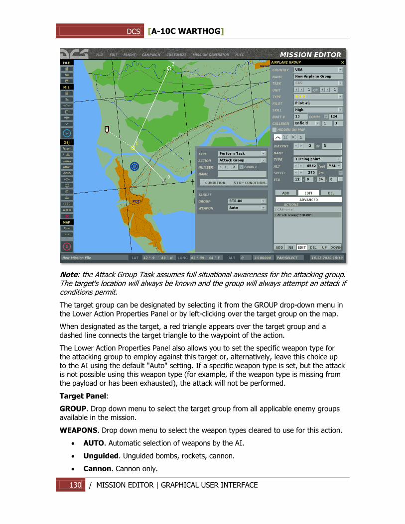
DCS [A-10C WARTHOG]
130 / MISSION EDITOR | GRAPHICAL USER INTERFACE
Note: the Attack Group Task assumes full situational awareness for the attacking group. The target's location will always be known and the group will always attempt an attack if conditions permit.
The target group can be designated by selecting it from the GROUP drop-down menu in the Lower Action Properties Panel or by left-clicking over the target group on the map.
When designated as the target, a red triangle appears over the target group and a dashed line connects the target triangle to the waypoint of the action.
The Lower Action Properties Panel also allows you to set the specific weapon type for the attacking group to employ against this target or, alternatively, leave this choice up to the AI using the default "Auto" setting. If a specific weapon type is set, but the attack is not possible using this weapon type (for example, if the weapon type is missing from the payload or has been exhausted), the attack will not be performed.
Target Panel:
GROUP. Drop down menu to select the target group from all applicable enemy groups available in the mission.
WEAPONS. Drop down menu to select the weapon types cleared to use for this action.
AUTO. Automatic selection of weapons by the AI.
Unguided. Unguided bombs, rockets, cannon.
Cannon. Cannon only.
DCS [A-10C WARTHOG]
131 / MISSION EDITOR | GRAPHICAL USER INTERFACE
Rockets. Unguided rockets only.
Light Rockets. Low-caliber unguided rockets.
Heavy Rockets. High-caliber unguided rockets.
Bombs. Unguided bombs only.
Iron Bombs. General-purpose free-fall bombs.
Cluster Bombs. Cluster bombs only.
Candle Bombs. Illumination bombs only.
Guided. Guided munitions (bombs, missiles).
Guided Bombs. Guided bombs only.
Missiles. Guided air to surface missiles.
ATGM. Anti-tank guided missiles only.
ASM. Anti-ship missiles only.
Cruise Missiles. Cruise missiles only.
Note, by limiting the AI on the types of weapons cleared for use in the action, you may prevent the AI from successfully executing it (for example, when the weapon type has been exchausted).
Attack Unit
Similar to the Attack Group Task, but allows the mission designer to designate a specific unit within the target group to attack.
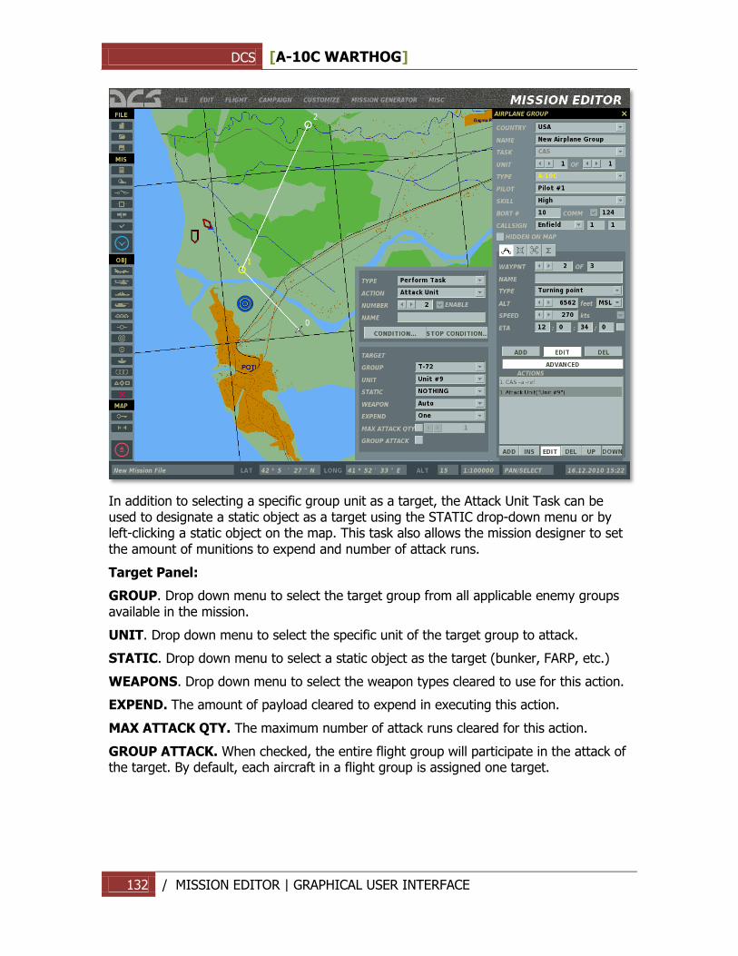
DCS [A-10C WARTHOG]
132 / MISSION EDITOR | GRAPHICAL USER INTERFACE
In addition to selecting a specific group unit as a target, the Attack Unit Task can be used to designate a static object as a target using the STATIC drop-down menu or by left-clicking a static object on the map. This task also allows the mission designer to set the amount of munitions to expend and number of attack runs.
Target Panel:
GROUP. Drop down menu to select the target group from all applicable enemy groups available in the mission.
UNIT. Drop down menu to select the specific unit of the target group to attack.
STATIC. Drop down menu to select a static object as the target (bunker, FARP, etc.)
WEAPONS. Drop down menu to select the weapon types cleared to use for this action.
EXPEND. The amount of payload cleared to expend in executing this action.
MAX ATTACK QTY. The maximum number of attack runs cleared for this action.
GROUP ATTACK. When checked, the entire flight group will participate in the attack of the target. By default, each aircraft in a flight group is assigned one target.
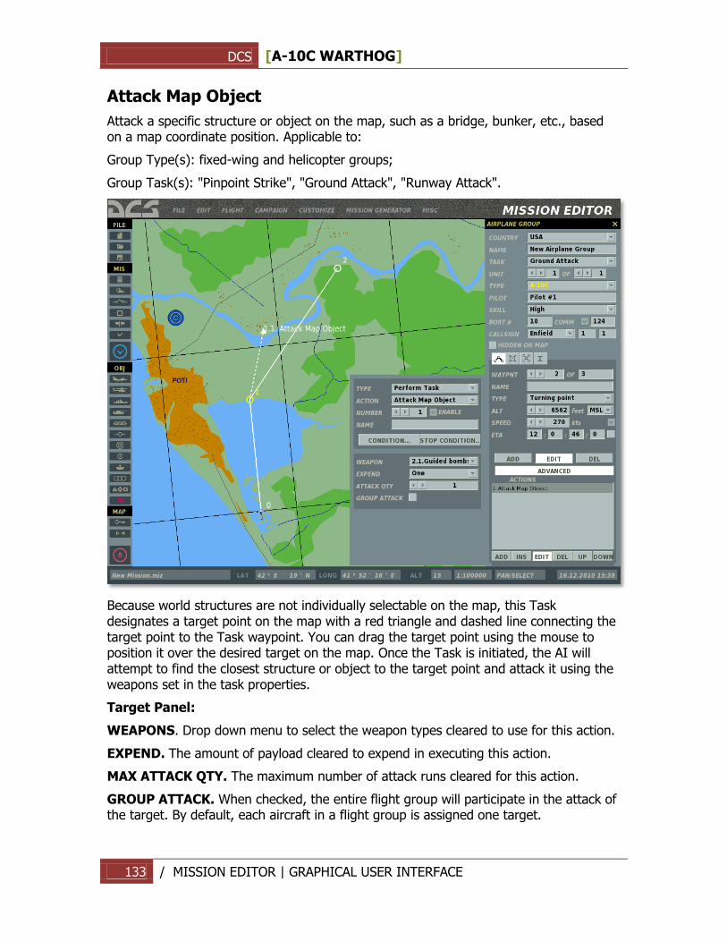
DCS [A-10C WARTHOG]
133 / MISSION EDITOR | GRAPHICAL USER INTERFACE
Attack Map Object
Attack a specific structure or object on the map, such as a bridge, bunker, etc., based on a map coordinate position. Applicable to:
Group Type(s): fixed-wing and helicopter groups;
Group Task(s): "Pinpoint Strike", "Ground Attack", "Runway Attack".
Because world structures are not individually selectable on the map, this Task designates a target point on the map with a red triangle and dashed line connecting the target point to the Task waypoint. You can drag the target point using the mouse to position it over the desired target on the map. Once the Task is initiated, the AI will attempt to find the closest structure or object to the target point and attack it using the weapons set in the task properties.
Target Panel:
WEAPONS. Drop down menu to select the weapon types cleared to use for this action.
EXPEND. The amount of payload cleared to expend in executing this action.
MAX ATTACK QTY. The maximum number of attack runs cleared for this action.
GROUP ATTACK. When checked, the entire flight group will participate in the attack of the target. By default, each aircraft in a flight group is assigned one target.
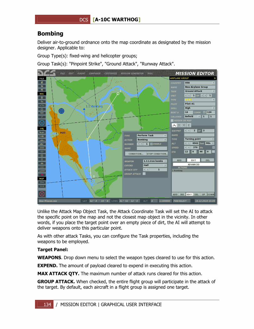
DCS [A-10C WARTHOG]
134 / MISSION EDITOR | GRAPHICAL USER INTERFACE
Bombing
Deliver air-to-ground ordnance onto the map coordinate as designated by the mission designer. Applicable to:
Group Type(s): fixed-wing and helicopter groups;
Group Task(s): "Pinpoint Strike", "Ground Attack", "Runway Attack".
Unlike the Attack Map Object Task, the Attack Coordinate Task will set the AI to attack the specific point on the map and not the closest map object in the vicinity. In other words, if you place the target point over an empty piece of dirt, the AI will attempt to deliver weapons onto this particular point.
As with other attack Tasks, you can configure the Task properties, including the weapons to be employed.
Target Panel:
WEAPONS. Drop down menu to select the weapon types cleared to use for this action.
EXPEND. The amount of payload cleared to expend in executing this action.
MAX ATTACK QTY. The maximum number of attack runs cleared for this action.
GROUP ATTACK. When checked, the entire flight group will participate in the attack of the target. By default, each aircraft in a flight group is assigned one target.
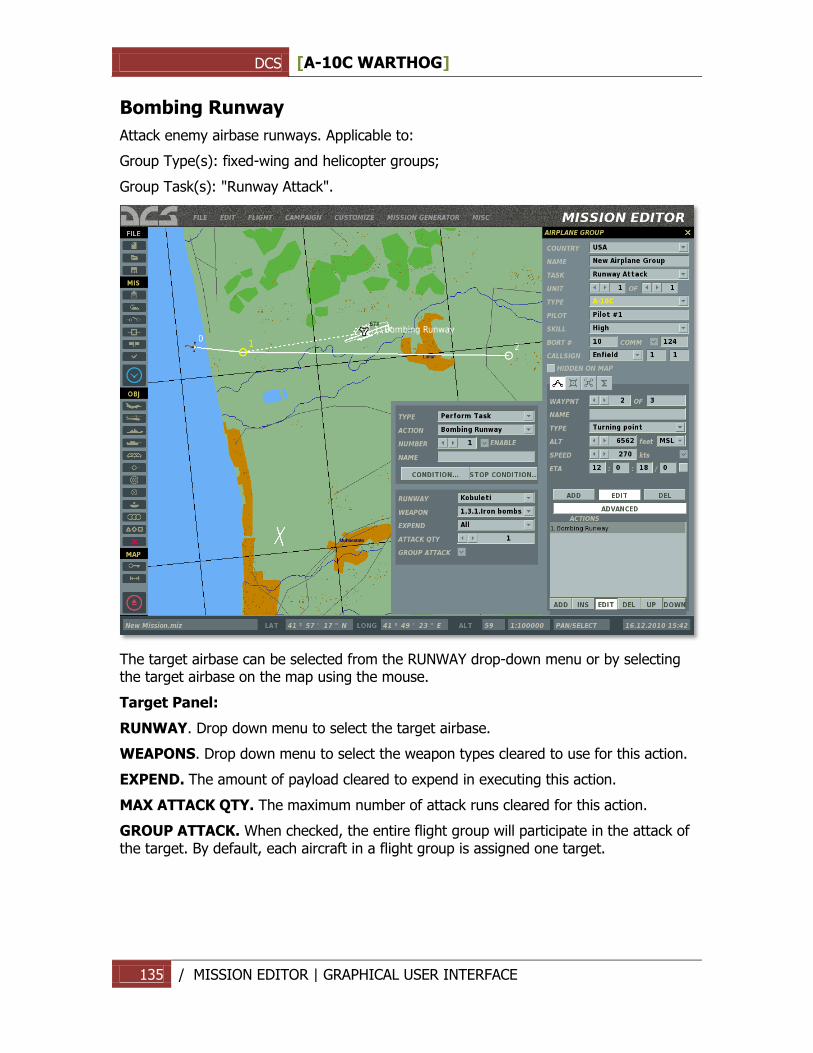
DCS [A-10C WARTHOG]
135 / MISSION EDITOR | GRAPHICAL USER INTERFACE
Bombing Runway
Attack enemy airbase runways. Applicable to:
Group Type(s): fixed-wing and helicopter groups;
Group Task(s): "Runway Attack".
The target airbase can be selected from the RUNWAY drop-down menu or by selecting the target airbase on the map using the mouse.
Target Panel:
RUNWAY. Drop down menu to select the target airbase.
WEAPONS. Drop down menu to select the weapon types cleared to use for this action.
EXPEND. The amount of payload cleared to expend in executing this action.
MAX ATTACK QTY. The maximum number of attack runs cleared for this action.
GROUP ATTACK. When checked, the entire flight group will participate in the attack of the target. By default, each aircraft in a flight group is assigned one target.
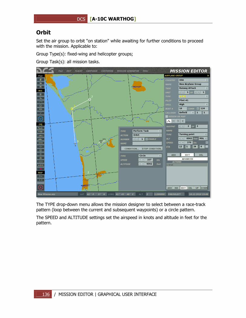
DCS [A-10C WARTHOG]
136 / MISSION EDITOR | GRAPHICAL USER INTERFACE
Orbit
Set the air group to orbit "on station" while awaiting for further conditions to proceed with the mission. Applicable to:
Group Type(s): fixed-wing and helicopter groups;
Group Task(s): all mission tasks.
The TYPE drop-down menu allows the mission designer to select between a race-track pattern (loop between the current and subsequent waypoints) or a circle pattern.
The SPEED and ALTITUDE settings set the airspeed in knots and altitude in feet for the pattern.
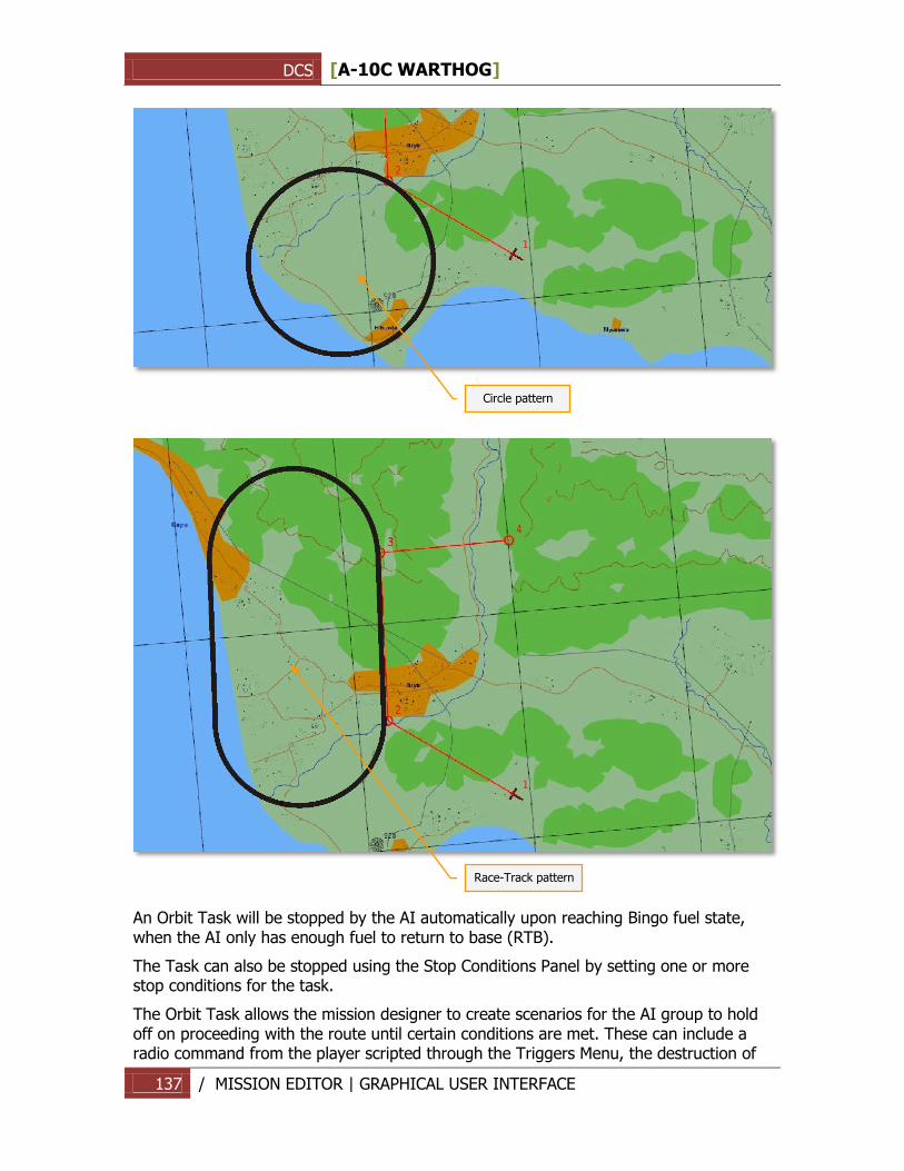
DCS [A-10C WARTHOG]
137 / MISSION EDITOR | GRAPHICAL USER INTERFACE
An Orbit Task will be stopped by the AI automatically upon reaching Bingo fuel state, when the AI only has enough fuel to return to base (RTB).
The Task can also be stopped using the Stop Conditions Panel by setting one or more stop conditions for the task.
The Orbit Task allows the mission designer to create scenarios for the AI group to hold off on proceeding with the route until certain conditions are met. These can include a radio command from the player scripted through the Triggers Menu, the destruction of
Circle pattern
Race-Track pattern
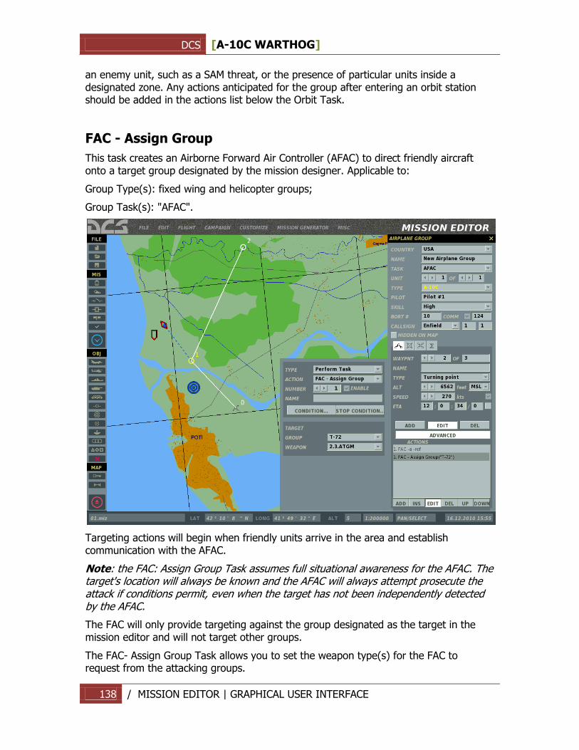
DCS [A-10C WARTHOG]
138 / MISSION EDITOR | GRAPHICAL USER INTERFACE
an enemy unit, such as a SAM threat, or the presence of particular units inside a designated zone. Any actions anticipated for the group after entering an orbit station should be added in the actions list below the Orbit Task.
FAC - Assign Group
This task creates an Airborne Forward Air Controller (AFAC) to direct friendly aircraft onto a target group designated by the mission designer. Applicable to:
Group Type(s): fixed wing and helicopter groups;
Group Task(s): "AFAC".
Targeting actions will begin when friendly units arrive in the area and establish communication with the AFAC.
Note: the FAC: Assign Group Task assumes full situational awareness for the AFAC. The target's location will always be known and the AFAC will always attempt prosecute the attack if conditions permit, even when the target has not been independently detected by the AFAC.
The FAC will only provide targeting against the group designated as the target in the mission editor and will not target other groups.
The FAC- Assign Group Task allows you to set the weapon type(s) for the FAC to request from the attacking groups.
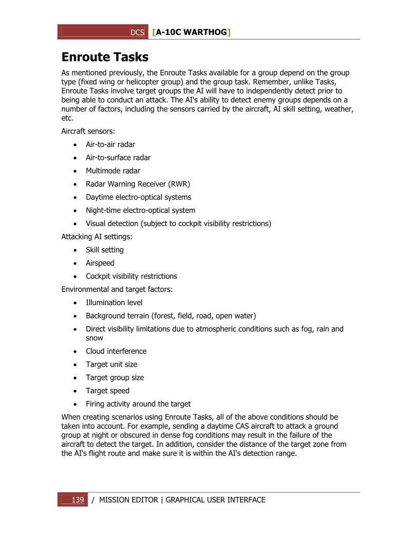
DCS [A-10C WARTHOG]
139 / MISSION EDITOR | GRAPHICAL USER INTERFACE
Enroute Tasks As mentioned previously, the Enroute Tasks available for a group depend on the group type (fixed wing or helicopter group) and the group task. Remember, unlike Tasks, Enroute Tasks involve target groups the AI will have to independently detect prior to being able to conduct an attack. The AI's ability to detect enemy groups depends on a number of factors, including the sensors carried by the aircraft, AI skill setting, weather, etc.
Aircraft sensors:
Air-to-air radar
Air-to-surface radar
Multimode radar
Radar Warning Receiver (RWR)
Daytime electro-optical systems
Night-time electro-optical system
Visual detection (subject to cockpit visibility restrictions)
Attacking AI settings:
Skill setting
Airspeed
Cockpit visibility restrictions
Environmental and target factors:
Illumination level
Background terrain (forest, field, road, open water)
Direct visibility limitations due to atmospheric conditions such as fog, rain and snow
Cloud interference
Target unit size
Target group size
Target speed
Firing activity around the target
When creating scenarios using Enroute Tasks, all of the above conditions should be taken into account. For example, sending a daytime CAS aircraft to attack a ground group at night or obscured in dense fog conditions may result in the failure of the aircraft to detect the target. In addition, consider the distance of the target zone from the AI's flight route and make sure it is within the AI's detection range.
DCS [A-10C WARTHOG]
140 / MISSION EDITOR | GRAPHICAL USER INTERFACE
The following Enroute Tasks may be available, depending on the group type and task:
No Enroute Task
Search Then Engage
Search Then Engage in Zone
Search Then Engage Group
Search Then Engage Unit
Refueling
AWACS
FAC
FAC - Engage Group
No Enroute Task
Available for all group types and all mission tasks. A No Enroute Task action does not set any action for the group to perform.
Search Then Engage
As long as the action is in effect, the AI will actively search for the target types set in the task properties and engage as soon as possible without conflicting with other tasks. Applicable to:
Group Type(s): fixed wing and helicopter groups.
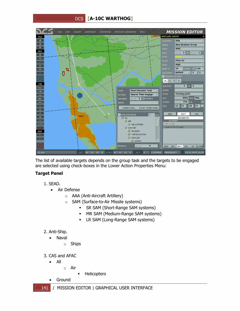
DCS [A-10C WARTHOG]
141 / MISSION EDITOR | GRAPHICAL USER INTERFACE
The list of available targets depends on the group task and the targets to be engaged are selected using check-boxes in the Lower Action Properties Menu:
Target Panel
1. SEAD.
Air Defense
o AAA (Anti-Aircraft Artillery)
o SAM (Surface-to-Air Missile systems)
SR SAM (Short-Range SAM systems)
MR SAM (Medium-Range SAM systems)
LR SAM (Long-Range SAM systems)
2. Anti-Ship.
Naval
o Ships
3. CAS and AFAC
All
o Air
Helicopters
Ground
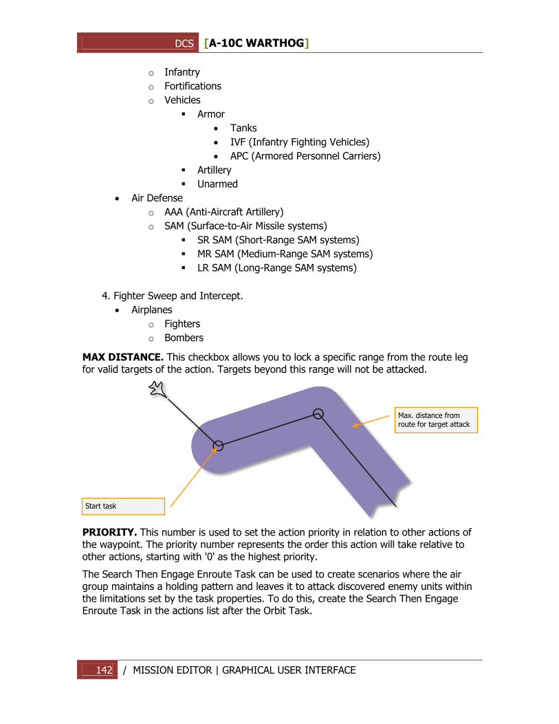
DCS [A-10C WARTHOG]
142 / MISSION EDITOR | GRAPHICAL USER INTERFACE
o Infantry
o Fortifications
o Vehicles
Armor
Tanks
IVF (Infantry Fighting Vehicles)
APC (Armored Personnel Carriers)
Artillery
Unarmed
Air Defense
o AAA (Anti-Aircraft Artillery)
o SAM (Surface-to-Air Missile systems)
SR SAM (Short-Range SAM systems)
MR SAM (Medium-Range SAM systems)
LR SAM (Long-Range SAM systems)
4. Fighter Sweep and Intercept.
Airplanes
o Fighters
o Bombers
MAX DISTANCE. This checkbox allows you to lock a specific range from the route leg for valid targets of the action. Targets beyond this range will not be attacked.
PRIORITY. This number is used to set the action priority in relation to other actions of the waypoint. The priority number represents the order this action will take relative to other actions, starting with '0' as the highest priority.
The Search Then Engage Enroute Task can be used to create scenarios where the air group maintains a holding pattern and leaves it to attack discovered enemy units within the limitations set by the task properties. To do this, create the Search Then Engage Enroute Task in the actions list after the Orbit Task.
Start task
Max. distance from route for target attack
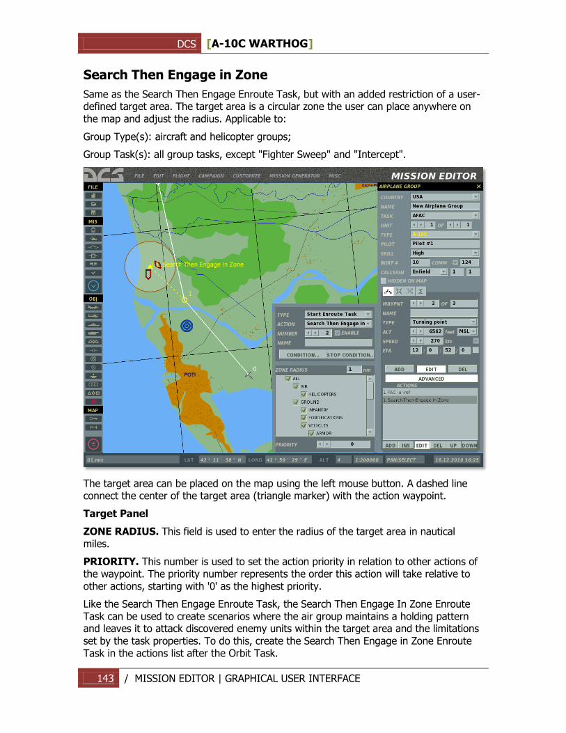
DCS [A-10C WARTHOG]
143 / MISSION EDITOR | GRAPHICAL USER INTERFACE
Search Then Engage in Zone
Same as the Search Then Engage Enroute Task, but with an added restriction of a user-defined target area. The target area is a circular zone the user can place anywhere on the map and adjust the radius. Applicable to:
Group Type(s): aircraft and helicopter groups;
Group Task(s): all group tasks, except "Fighter Sweep" and "Intercept".
The target area can be placed on the map using the left mouse button. A dashed line connect the center of the target area (triangle marker) with the action waypoint.
Target Panel
ZONE RADIUS. This field is used to enter the radius of the target area in nautical miles.
PRIORITY. This number is used to set the action priority in relation to other actions of the waypoint. The priority number represents the order this action will take relative to other actions, starting with '0' as the highest priority.
Like the Search Then Engage Enroute Task, the Search Then Engage In Zone Enroute Task can be used to create scenarios where the air group maintains a holding pattern and leaves it to attack discovered enemy units within the target area and the limitations set by the task properties. To do this, create the Search Then Engage in Zone Enroute Task in the actions list after the Orbit Task.
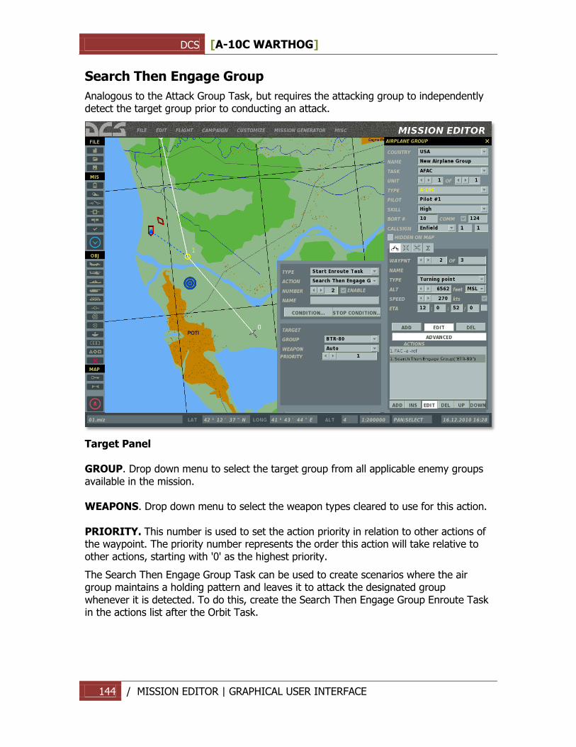
DCS [A-10C WARTHOG]
144 / MISSION EDITOR | GRAPHICAL USER INTERFACE
Search Then Engage Group
Analogous to the Attack Group Task, but requires the attacking group to independently detect the target group prior to conducting an attack.
Target Panel GROUP. Drop down menu to select the target group from all applicable enemy groups available in the mission. WEAPONS. Drop down menu to select the weapon types cleared to use for this action. PRIORITY. This number is used to set the action priority in relation to other actions of the waypoint. The priority number represents the order this action will take relative to other actions, starting with '0' as the highest priority.
The Search Then Engage Group Task can be used to create scenarios where the air group maintains a holding pattern and leaves it to attack the designated group whenever it is detected. To do this, create the Search Then Engage Group Enroute Task in the actions list after the Orbit Task.
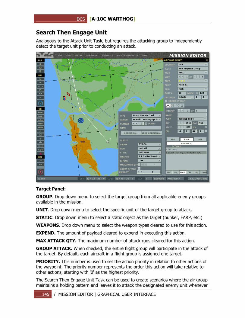
DCS [A-10C WARTHOG]
145 / MISSION EDITOR | GRAPHICAL USER INTERFACE
Search Then Engage Unit
Analogous to the Attack Unit Task, but requires the attacking group to independently detect the target unit prior to conducting an attack.
Target Panel:
GROUP. Drop down menu to select the target group from all applicable enemy groups available in the mission.
UNIT. Drop down menu to select the specific unit of the target group to attack.
STATIC. Drop down menu to select a static object as the target (bunker, FARP, etc.)
WEAPONS. Drop down menu to select the weapon types cleared to use for this action.
EXPEND. The amount of payload cleared to expend in executing this action.
MAX ATTACK QTY. The maximum number of attack runs cleared for this action.
GROUP ATTACK. When checked, the entire flight group will participate in the attack of the target. By default, each aircraft in a flight group is assigned one target.
PRIORITY. This number is used to set the action priority in relation to other actions of the waypoint. The priority number represents the order this action will take relative to other actions, starting with '0' as the highest priority.
The Search Then Engage Unit Task can be used to create scenarios where the air group maintains a holding pattern and leaves it to attack the designated enemy unit whenever
DCS [A-10C WARTHOG]
146 / MISSION EDITOR | GRAPHICAL USER INTERFACE
it is detected. To do this, create the Search Then Engage Group Enroute Task in the actions list after the Orbit Task.
Refueling
The aircraft will perform aerial refueling. Applicable to:
Group Type(s): airborne tanker aircraft, including IL-78 and KC-135;
Group Task(s): Refueling.
When the Refueling Mission Task is created, a Refueling Enroute Task is created automatically as an automatic action at the initial waypoint. This action cannot be deleted or edited.
AWACS
The aircraft will perform Airborne Warning and Control for friendly units. Applicable to:
Group Type(s): dedicated AWACS aircraft, including A-50, E-2, E-3;
Group Task(s): AWACS.
When the AWACS Mission Task is created, an AWACS Enroute Task is created automatically as an automatic action at the initial waypoint. This action cannot be deleted or edited.
FAC
The aircraft will act as an Airborne Forward Air Controller (AFAC) to provide targeting orders for friendly units in the area. Applicable to:
Group Type(s): fixed wing and helicopter groups;
Mission Task(s): AFAC.
Under a FAC Enroute Task, the FAC will automatically prioritize targets for the player or attacking AI groups and issue targeting orders throughout the attack phase.
Note: The FAC's target selection may not correspond to the targets intended for the player or attacking AI by the mission designer, because no specific target group is selected.
FAC - Engage Group
Analogous to the FAC Enroute Task, except in this case a specific enemy group is selected by the mission designer for the AFAC to target. Applicable to:
Group Type(s): fixed-wing and helicopter groups;
Mission Task(s): AFAC.
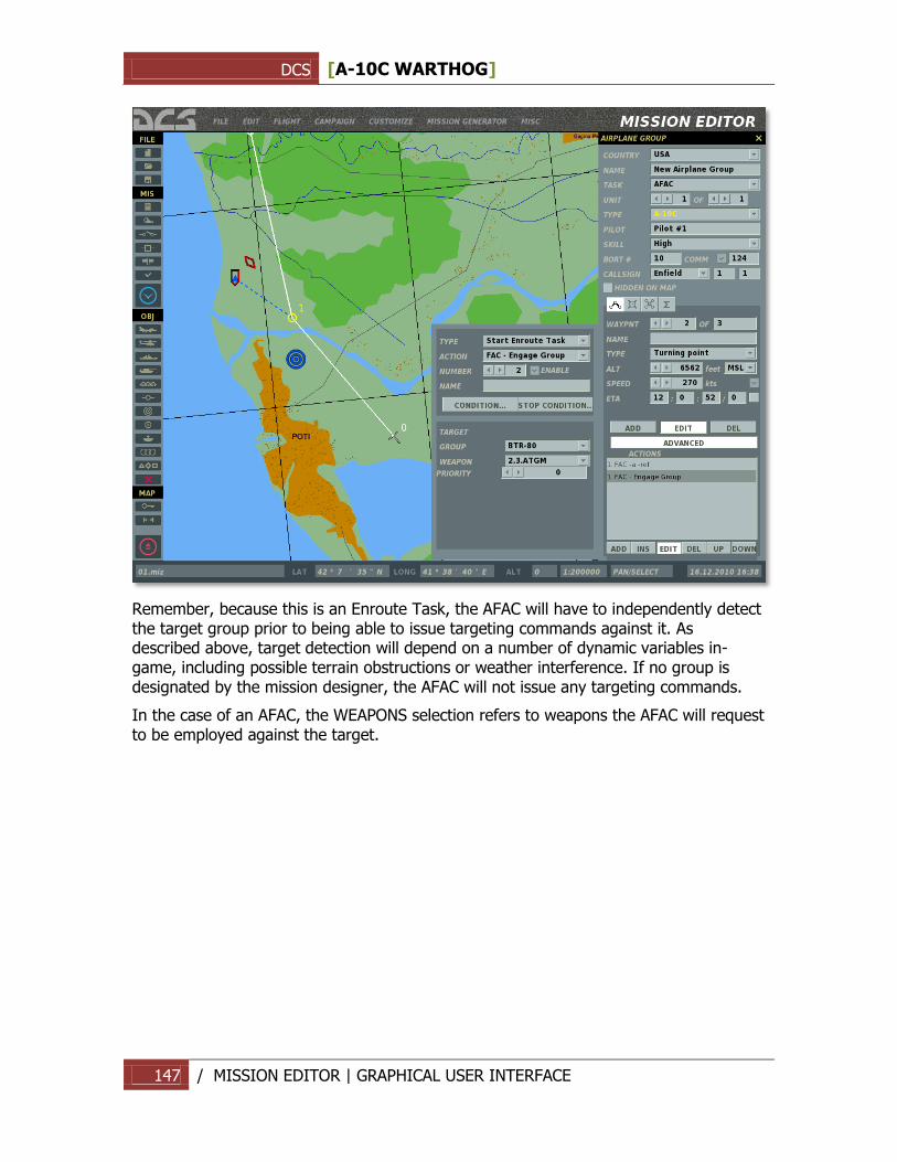
DCS [A-10C WARTHOG]
147 / MISSION EDITOR | GRAPHICAL USER INTERFACE
Remember, because this is an Enroute Task, the AFAC will have to independently detect the target group prior to being able to issue targeting commands against it. As described above, target detection will depend on a number of dynamic variables in-game, including possible terrain obstructions or weather interference. If no group is designated by the mission designer, the AFAC will not issue any targeting commands.
In the case of an AFAC, the WEAPONS selection refers to weapons the AFAC will request to be employed against the target.
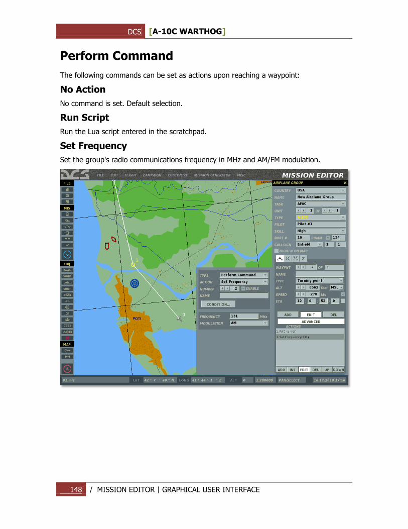
DCS [A-10C WARTHOG]
148 / MISSION EDITOR | GRAPHICAL USER INTERFACE
Perform Command
The following commands can be set as actions upon reaching a waypoint:
No Action
No command is set. Default selection.
Run Script
Run the Lua script entered in the scratchpad.
Set Frequency
Set the group's radio communications frequency in MHz and AM/FM modulation.
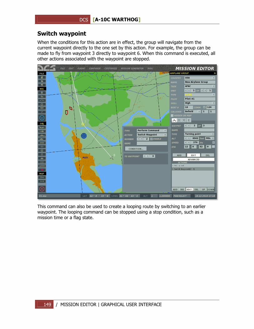
DCS [A-10C WARTHOG]
149 / MISSION EDITOR | GRAPHICAL USER INTERFACE
Switch waypoint
When the conditions for this action are in effect, the group will navigate from the current waypoint directly to the one set by this action. For example, the group can be made to fly from waypoint 3 directly to waypoint 6. When this command is executed, all other actions associated with the waypoint are stopped.
This command can also be used to create a looping route by switching to an earlier waypoint. The looping command can be stopped using a stop condition, such as a mission time or a flag state.
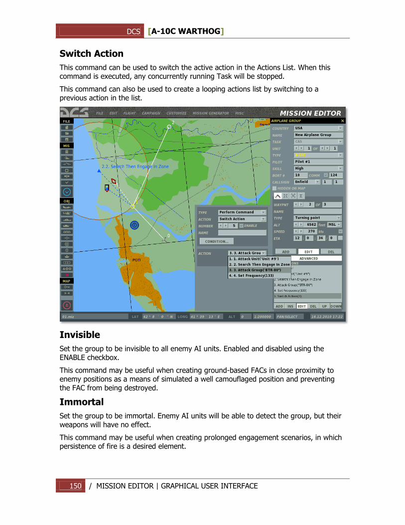
DCS [A-10C WARTHOG]
150 / MISSION EDITOR | GRAPHICAL USER INTERFACE
Switch Action
This command can be used to switch the active action in the Actions List. When this command is executed, any concurrently running Task will be stopped.
This command can also be used to create a looping actions list by switching to a previous action in the list.
Invisible
Set the group to be invisible to all enemy AI units. Enabled and disabled using the ENABLE checkbox.
This command may be useful when creating ground-based FACs in close proximity to enemy positions as a means of simulated a well camouflaged position and preventing the FAC from being destroyed.
Immortal
Set the group to be immortal. Enemy AI units will be able to detect the group, but their weapons will have no effect.
This command may be useful when creating prolonged engagement scenarios, in which persistence of fire is a desired element.
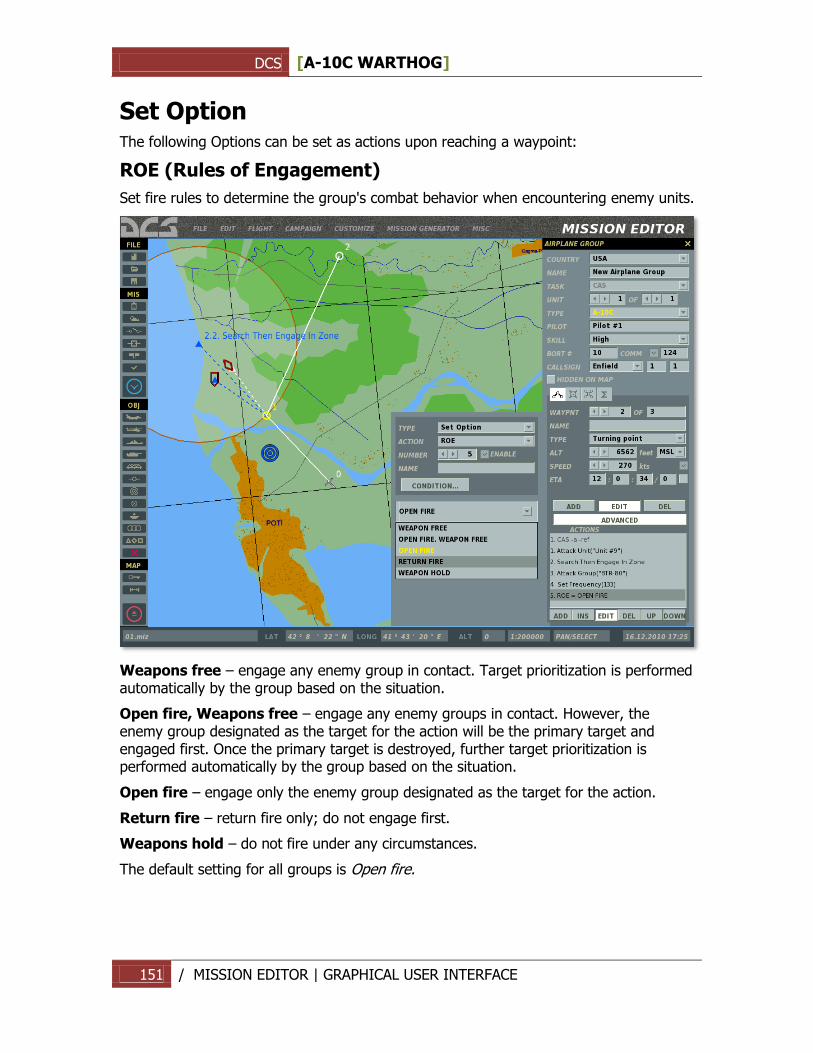
DCS [A-10C WARTHOG]
151 / MISSION EDITOR | GRAPHICAL USER INTERFACE
Set Option The following Options can be set as actions upon reaching a waypoint:
ROE (Rules of Engagement)
Set fire rules to determine the group's combat behavior when encountering enemy units.
Weapons free – engage any enemy group in contact. Target prioritization is performed automatically by the group based on the situation.
Open fire, Weapons free – engage any enemy groups in contact. However, the enemy group designated as the target for the action will be the primary target and engaged first. Once the primary target is destroyed, further target prioritization is performed automatically by the group based on the situation.
Open fire – engage only the enemy group designated as the target for the action.
Return fire – return fire only; do not engage first.
Weapons hold – do not fire under any circumstances.
The default setting for all groups is Open fire.
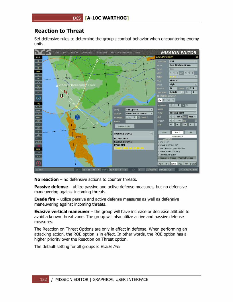
DCS [A-10C WARTHOG]
152 / MISSION EDITOR | GRAPHICAL USER INTERFACE
Reaction to Threat
Set defensive rules to determine the group's combat behavior when encountering enemy units.
No reaction – no defensive actions to counter threats.
Passive defense – utilize passive and active defense measures, but no defensive maneuvering against incoming threats.
Evade fire – utilize passive and active defense measures as well as defensive maneuvering against incoming threats.
Evasive vertical maneuver – the group will have increase or decrease altitude to avoid a known threat zone. The group will also utilize active and passive defense measures.
The Reaction on Threat Options are only in effect in defense. When performing an attacking action, the ROE option is in effect. In other words, the ROE option has a higher priority over the Reaction on Threat option.
The default setting for all groups is Evade fire.
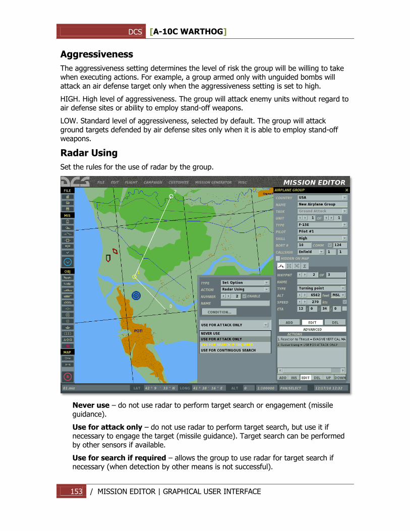
DCS [A-10C WARTHOG]
153 / MISSION EDITOR | GRAPHICAL USER INTERFACE
Aggressiveness
The aggressiveness setting determines the level of risk the group will be willing to take when executing actions. For example, a group armed only with unguided bombs will attack an air defense target only when the aggressiveness setting is set to high.
HIGH. High level of aggressiveness. The group will attack enemy units without regard to air defense sites or ability to employ stand-off weapons.
LOW. Standard level of aggressiveness, selected by default. The group will attack ground targets defended by air defense sites only when it is able to employ stand-off weapons.
Radar Using
Set the rules for the use of radar by the group.
Never use – do not use radar to perform target search or engagement (missile guidance).
Use for attack only – do not use radar to perform target search, but use it if necessary to engage the target (missile guidance). Target search can be performed by other sensors if available.
Use for search if required – allows the group to use radar for target search if necessary (when detection by other means is not successful).
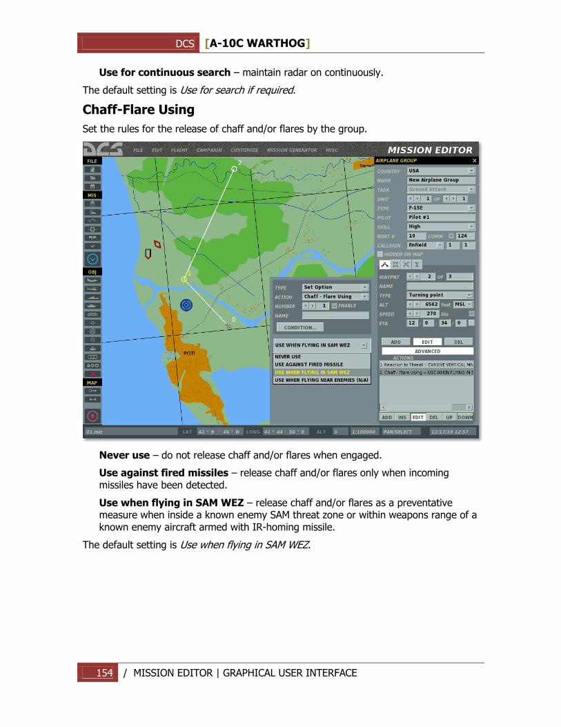
DCS [A-10C WARTHOG]
154 / MISSION EDITOR | GRAPHICAL USER INTERFACE
Use for continuous search – maintain radar on continuously.
The default setting is Use for search if required.
Chaff-Flare Using
Set the rules for the release of chaff and/or flares by the group.
Never use – do not release chaff and/or flares when engaged.
Use against fired missiles – release chaff and/or flares only when incoming missiles have been detected.
Use when flying in SAM WEZ – release chaff and/or flares as a preventative measure when inside a known enemy SAM threat zone or within weapons range of a known enemy aircraft armed with IR-homing missile.
The default setting is Use when flying in SAM WEZ.
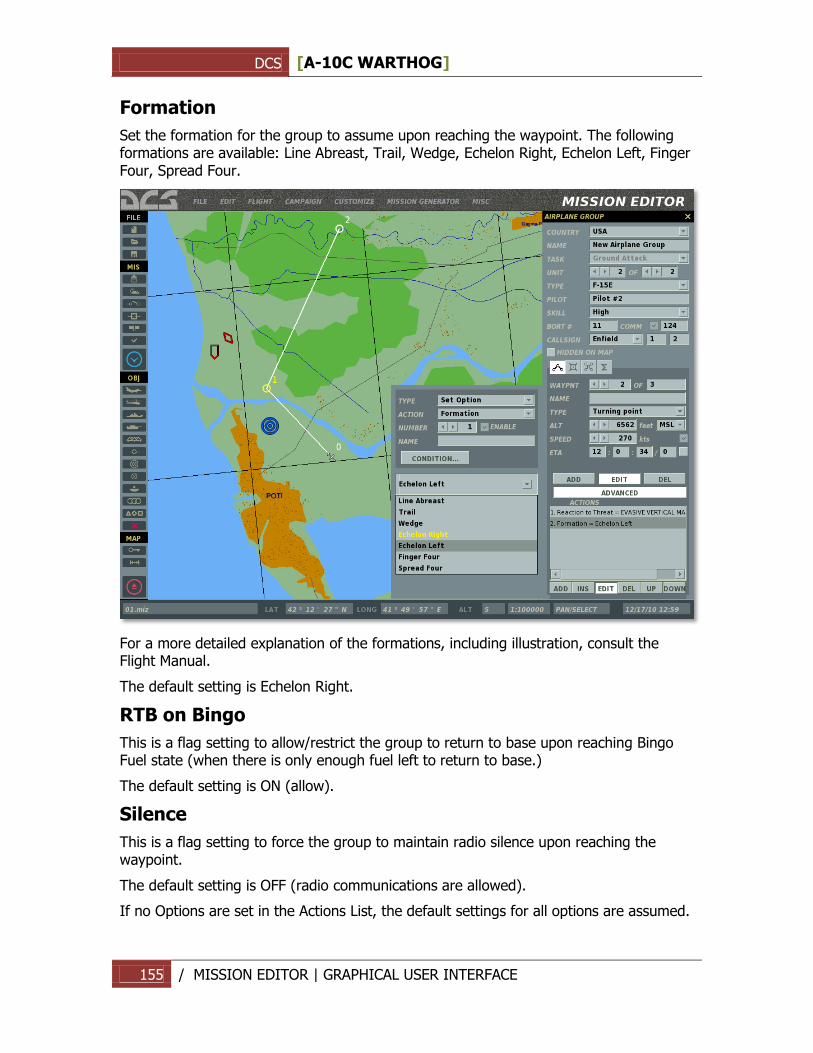
DCS [A-10C WARTHOG]
155 / MISSION EDITOR | GRAPHICAL USER INTERFACE
Formation
Set the formation for the group to assume upon reaching the waypoint. The following formations are available: Line Abreast, Trail, Wedge, Echelon Right, Echelon Left, Finger Four, Spread Four.
For a more detailed explanation of the formations, including illustration, consult the Flight Manual.
The default setting is Echelon Right.
RTB on Bingo
This is a flag setting to allow/restrict the group to return to base upon reaching Bingo Fuel state (when there is only enough fuel left to return to base.)
The default setting is ON (allow).
Silence
This is a flag setting to force the group to maintain radio silence upon reaching the waypoint.
The default setting is OFF (radio communications are allowed).
If no Options are set in the Actions List, the default settings for all options are assumed.
DCS [A-10C WARTHOG]
156 / MISSION EDITOR | GRAPHICAL USER INTERFACE
Ground crew support at airbases
When positioned on a friendly airbase, the following ground support services are available:
1. Aircraft repair 3 minutes after engine shut-down.
2. Refueling by ground personnel contacted through the intercom.
3. Rearming by ground personnel contacted through the intercom.
For more details on contacting ground personnel, see the Radio Communications section in the Flight Manual.
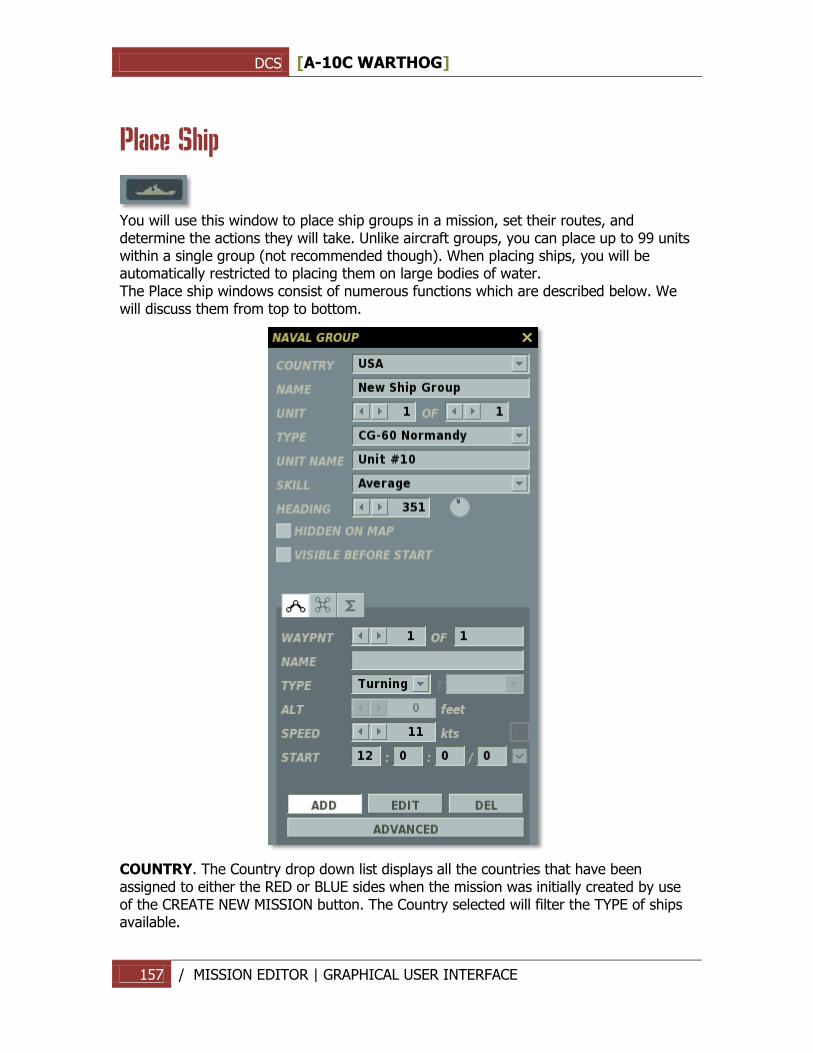
DCS [A-10C WARTHOG]
157 / MISSION EDITOR | GRAPHICAL USER INTERFACE
Place Ship
You will use this window to place ship groups in a mission, set their routes, and determine the actions they will take. Unlike aircraft groups, you can place up to 99 units within a single group (not recommended though). When placing ships, you will be automatically restricted to placing them on large bodies of water. The Place ship windows consist of numerous functions which are described below. We will discuss them from top to bottom.
COUNTRY. The Country drop down list displays all the countries that have been assigned to either the RED or BLUE sides when the mission was initially created by use of the CREATE NEW MISSION button. The Country selected will filter the TYPE of ships available.
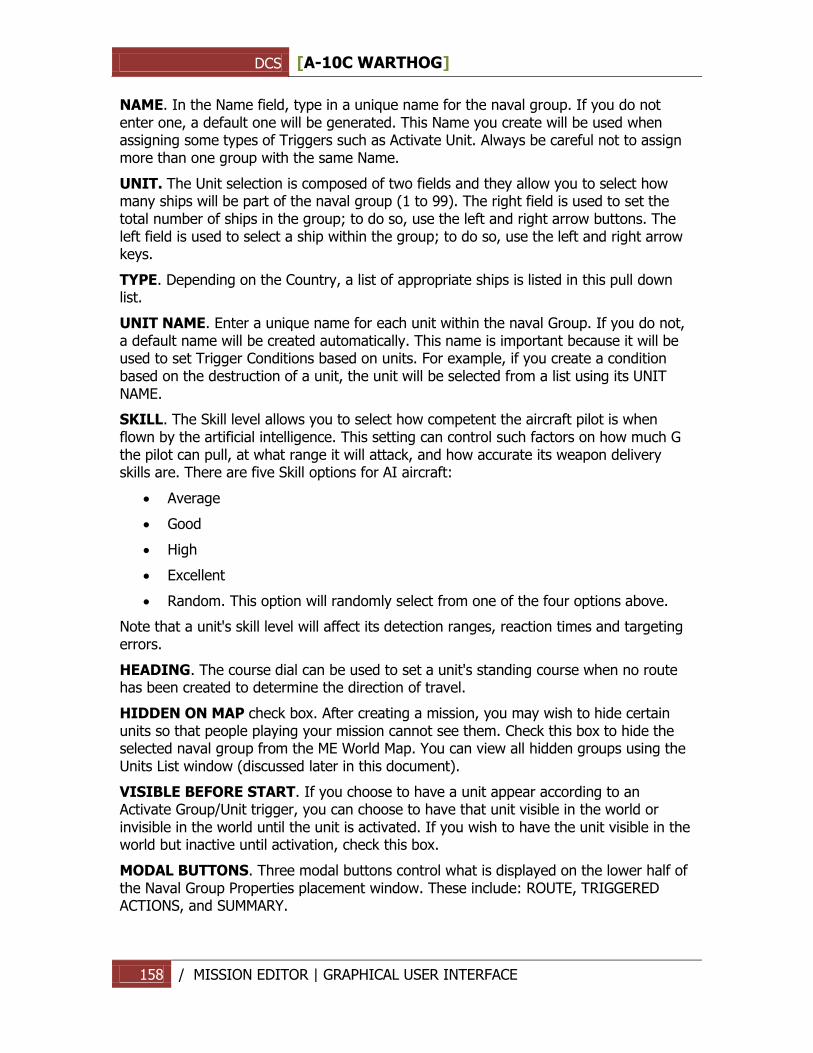
DCS [A-10C WARTHOG]
158 / MISSION EDITOR | GRAPHICAL USER INTERFACE
NAME. In the Name field, type in a unique name for the naval group. If you do not enter one, a default one will be generated. This Name you create will be used when assigning some types of Triggers such as Activate Unit. Always be careful not to assign more than one group with the same Name.
UNIT. The Unit selection is composed of two fields and they allow you to select how many ships will be part of the naval group (1 to 99). The right field is used to set the total number of ships in the group; to do so, use the left and right arrow buttons. The left field is used to select a ship within the group; to do so, use the left and right arrow keys.
TYPE. Depending on the Country, a list of appropriate ships is listed in this pull down list.
UNIT NAME. Enter a unique name for each unit within the naval Group. If you do not, a default name will be created automatically. This name is important because it will be used to set Trigger Conditions based on units. For example, if you create a condition based on the destruction of a unit, the unit will be selected from a list using its UNIT NAME.
SKILL. The Skill level allows you to select how competent the aircraft pilot is when flown by the artificial intelligence. This setting can control such factors on how much G the pilot can pull, at what range it will attack, and how accurate its weapon delivery skills are. There are five Skill options for AI aircraft:
Average
Good
High
Excellent
Random. This option will randomly select from one of the four options above.
Note that a unit's skill level will affect its detection ranges, reaction times and targeting errors.
HEADING. The course dial can be used to set a unit's standing course when no route has been created to determine the direction of travel.
HIDDEN ON MAP check box. After creating a mission, you may wish to hide certain units so that people playing your mission cannot see them. Check this box to hide the selected naval group from the ME World Map. You can view all hidden groups using the Units List window (discussed later in this document).
VISIBLE BEFORE START. If you choose to have a unit appear according to an Activate Group/Unit trigger, you can choose to have that unit visible in the world or invisible in the world until the unit is activated. If you wish to have the unit visible in the world but inactive until activation, check this box.
MODAL BUTTONS. Three modal buttons control what is displayed on the lower half of the Naval Group Properties placement window. These include: ROUTE, TRIGGERED ACTIONS, and SUMMARY.
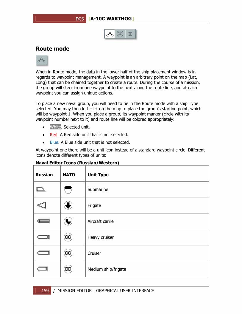
DCS [A-10C WARTHOG]
159 / MISSION EDITOR | GRAPHICAL USER INTERFACE
Route mode
When in Route mode, the data in the lower half of the ship placement window is in regards to waypoint management. A waypoint is an arbitrary point on the map (Lat, Long) that can be chained together to create a route. During the course of a mission, the group will steer from one waypoint to the next along the route line, and at each waypoint you can assign unique actions. To place a new naval group, you will need to be in the Route mode with a ship Type selected. You may then left click on the map to place the group's starting point, which will be waypoint 1. When you place a group, its waypoint marker (circle with its waypoint number next to it) and route line will be colored appropriately:
White. Selected unit.
Red. A Red side unit that is not selected.
Blue. A Blue side unit that is not selected.
At waypoint one there will be a unit icon instead of a standard waypoint circle. Different icons denote different types of units:
Naval Editor Icons (Russian/Western)
Russian NATO Unit Type
Submarine
Frigate
Aircraft carrier
Heavy cruiser
Cruiser
Medium ship/frigate
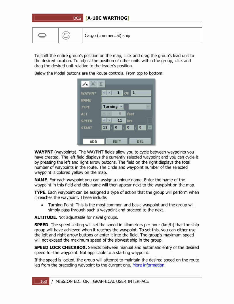
DCS [A-10C WARTHOG]
160 / MISSION EDITOR | GRAPHICAL USER INTERFACE
Cargo (commercial) ship
To shift the entire group's position on the map, click and drag the group's lead unit to the desired location. To adjust the position of other units within the group, click and drag the desired unit relative to the leader's position.
Below the Modal buttons are the Route controls. From top to bottom:
WAYPNT (waypoints). The WAYPNT fields allow you to cycle between waypoints you have created. The left field displays the currently selected waypoint and you can cycle it by pressing the left and right arrow buttons. The field on the right displays the total number of waypoints in the route. The circle and waypoint number of the selected waypoint is colored yellow on the map.
NAME. For each waypoint you can assign a unique name. Enter the name of the waypoint in this field and this name will then appear next to the waypoint on the map.
TYPE. Each waypoint can be assigned a type of action that the group will perform when it reaches the waypoint. These include:
Turning Point. This is the most common and basic waypoint and the group will simply pass through such a waypoint and proceed to the next.
ALTITUDE. Not adjustable for naval groups.
SPEED. The speed setting will set the speed in kilometers per hour (km/h) that the ship group will have achieved when it reaches the waypoint. To set this, you can either use the left and right arrow buttons or enter it into the field. The group's maximum speed will not exceed the maximum speed of the slowest ship in the group.
SPEED LOCK CHECKBOX. Selects between manual and automatic entry of the desired speed for the waypoint. Not applicable to a starting waypoint.
If the speed is locked, the group will attempt to maintain the desired speed on the route leg from the preceding waypoint to the current one. More information.
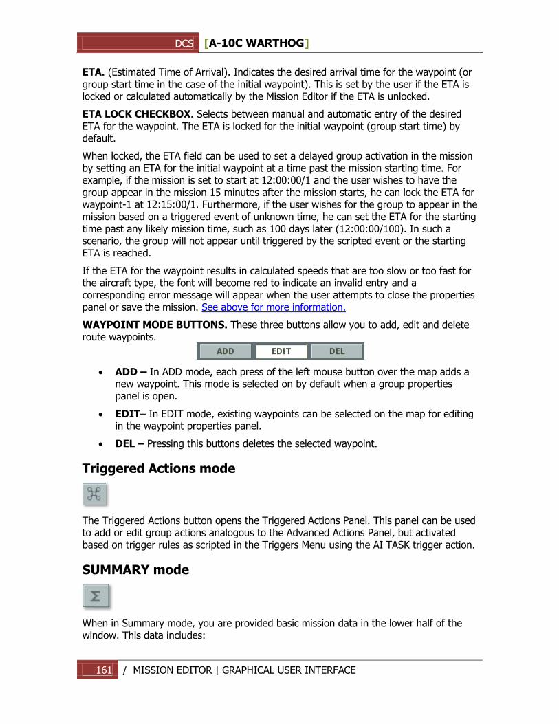
DCS [A-10C WARTHOG]
161 / MISSION EDITOR | GRAPHICAL USER INTERFACE
ETA. (Estimated Time of Arrival). Indicates the desired arrival time for the waypoint (or group start time in the case of the initial waypoint). This is set by the user if the ETA is locked or calculated automatically by the Mission Editor if the ETA is unlocked.
ETA LOCK CHECKBOX. Selects between manual and automatic entry of the desired ETA for the waypoint. The ETA is locked for the initial waypoint (group start time) by default.
When locked, the ETA field can be used to set a delayed group activation in the mission by setting an ETA for the initial waypoint at a time past the mission starting time. For example, if the mission is set to start at 12:00:00/1 and the user wishes to have the group appear in the mission 15 minutes after the mission starts, he can lock the ETA for waypoint-1 at 12:15:00/1. Furthermore, if the user wishes for the group to appear in the mission based on a triggered event of unknown time, he can set the ETA for the starting time past any likely mission time, such as 100 days later (12:00:00/100). In such a scenario, the group will not appear until triggered by the scripted event or the starting ETA is reached.
If the ETA for the waypoint results in calculated speeds that are too slow or too fast for the aircraft type, the font will become red to indicate an invalid entry and a corresponding error message will appear when the user attempts to close the properties panel or save the mission. See above for more information.
WAYPOINT MODE BUTTONS. These three buttons allow you to add, edit and delete route waypoints.
ADD – In ADD mode, each press of the left mouse button over the map adds a new waypoint. This mode is selected on by default when a group properties panel is open.
EDIT– In EDIT mode, existing waypoints can be selected on the map for editing in the waypoint properties panel.
DEL – Pressing this buttons deletes the selected waypoint.
Triggered Actions mode
The Triggered Actions button opens the Triggered Actions Panel. This panel can be used to add or edit group actions analogous to the Advanced Actions Panel, but activated based on trigger rules as scripted in the Triggers Menu using the AI TASK trigger action.
SUMMARY mode
When in Summary mode, you are provided basic mission data in the lower half of the window. This data includes:
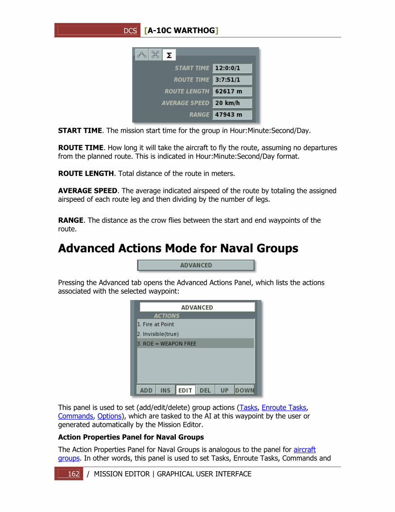
DCS [A-10C WARTHOG]
162 / MISSION EDITOR | GRAPHICAL USER INTERFACE
START TIME. The mission start time for the group in Hour:Minute:Second/Day. ROUTE TIME. How long it will take the aircraft to fly the route, assuming no departures from the planned route. This is indicated in Hour:Minute:Second/Day format. ROUTE LENGTH. Total distance of the route in meters. AVERAGE SPEED. The average indicated airspeed of the route by totaling the assigned airspeed of each route leg and then dividing by the number of legs.
RANGE. The distance as the crow flies between the start and end waypoints of the route.
Advanced Actions Mode for Naval Groups
Pressing the Advanced tab opens the Advanced Actions Panel, which lists the actions associated with the selected waypoint:
This panel is used to set (add/edit/delete) group actions (Tasks, Enroute Tasks, Commands, Options), which are tasked to the AI at this waypoint by the user or generated automatically by the Mission Editor.
Action Properties Panel for Naval Groups
The Action Properties Panel for Naval Groups is analogous to the panel for aircraft groups. In other words, this panel is used to set Tasks, Enroute Tasks, Commands and
DCS [A-10C WARTHOG]
163 / MISSION EDITOR | GRAPHICAL USER INTERFACE
Options for the group to perform, as well as the starting and ending conditions of the actions. However, the specific types of actions available for naval groups differs from aircraft groups.
Tasks
No Task - no action is assigned to the group to perform.
Fire at Point - fire against a coordinate point on the map as designated by the mission designer. The ZONE RADIUS value sets the radius of the target area. When firing artillery, the ship will spread rounds within the entire target area. When firing cruise missiles, the ship will target the center coordinate of the target area.
Enroute Tasks
Naval groups cannot be assigned any Enroute Task actions. Therefore, the only available selection is No Enroute Task.
Perform Command
The following commands can be set as actions upon reaching a waypoint:
No Action – No command is set.
Run Script – run the Lua script entered in the scratchpad.
Invisible - set the group to be invisible to all enemy AI units. Enabled and disabled using the ENABLE checkbox.
Immortal - set the group to be immortal. Enemy AI units will be able to detect the group, but their weapons will have no effect.
Set Option
The following Options can be set as actions upon reaching a waypoint:
ROE (Rules of Engagement) - set fire rules to determine the group's combat behavior when encountering enemy units.
WEAPONS FREE – engage any enemy group in contact. Target prioritization is performed automatically by the group based on the situation.
RETURN FIRE – return fire only; do not engage first.
WEAPONS HOLD – do not fire under any circumstances.
The default setting is WEAPONS FREE.
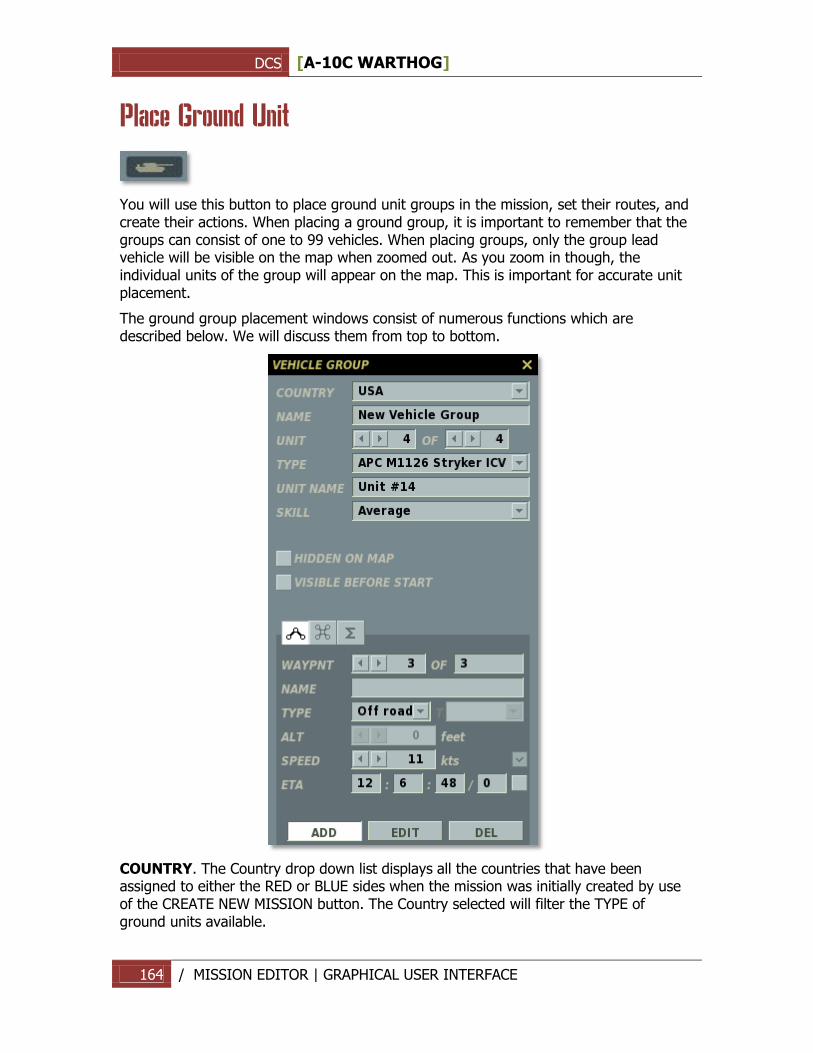
DCS [A-10C WARTHOG]
164 / MISSION EDITOR | GRAPHICAL USER INTERFACE
Place Ground Unit
You will use this button to place ground unit groups in the mission, set their routes, and create their actions. When placing a ground group, it is important to remember that the groups can consist of one to 99 vehicles. When placing groups, only the group lead vehicle will be visible on the map when zoomed out. As you zoom in though, the individual units of the group will appear on the map. This is important for accurate unit placement.
The ground group placement windows consist of numerous functions which are described below. We will discuss them from top to bottom.
COUNTRY. The Country drop down list displays all the countries that have been assigned to either the RED or BLUE sides when the mission was initially created by use of the CREATE NEW MISSION button. The Country selected will filter the TYPE of ground units available.
DCS [A-10C WARTHOG]
165 / MISSION EDITOR | GRAPHICAL USER INTERFACE
NAME. In the Name field, you may enter a unique name for the vehicle group. If you do not enter one, a default one will be generated. The Name you create will be used when assigning some types of Triggers such as Activate Unit. Always be careful not to assign more than one group with the same Name.
UNIT. The Unit selection is composed of two fields and they allow you to select how many ground units will be part of the group (1 to 99). The right field is used to set the total number of vehicles in the group; to do so, use the left and right arrow buttons. The left field is used to select a vehicle unit within the group; to do so, use the left and right arrow keys.
Note: For Surface to Air Missile (SAM) batteries like SA-10, SA-11, etc., all the needed units of the SAM battery must all be part of the same Vehicle Group.
Note: If you place a ground unit to act as a JTAC, use a unit that is armed and has sensors. The armed HMMWV is a good choice.
TYPE. Depending on the Country selection, a list of appropriate ground units will populate this pull down list.
UNIT NAME. Enter a unique name for each unit within the Group. If you do not, a default name will be created automatically. This name is important because it will be used to set some Trigger Conditions. For example, if you create a condition based on the destruction of a unit, the unit will be selected from a list using its UNIT NAME.
SKILL. The Skill level allows you to select how competent the unit is controlled by the artificial intelligence. This setting can control such factors as what range it will attack from, and how accurate its weapon delivery skills are. There are five Skill options for AI ground units:
Average
Good
High
Excellent
Random. This option will randomly select from one of the four options above.
Note: A unit's skill level will affect its detection ranges, reaction times and targeting errors.
Note: Regardless of skill level, AI aircraft will have great difficulty spotting infantry units unless the infantry unit is moving or firing weapons.
HEADING. The course dial can be used to set a unit's standing course when no route has been created to determine the direction of travel.
HIDDEN ON MAP check box. After creating a mission, you may wish to hide certain units so that people playing your mission cannot see them. Check this box to hide the selected ground group from the ME World Map. You can view all hidden groups using the Units List window (discussed later in this document).
VISIBLE BEFORE START. If you choose to have a unit appear according to an Activate Group/Unit trigger, you can choose to have that unit visible in the world or
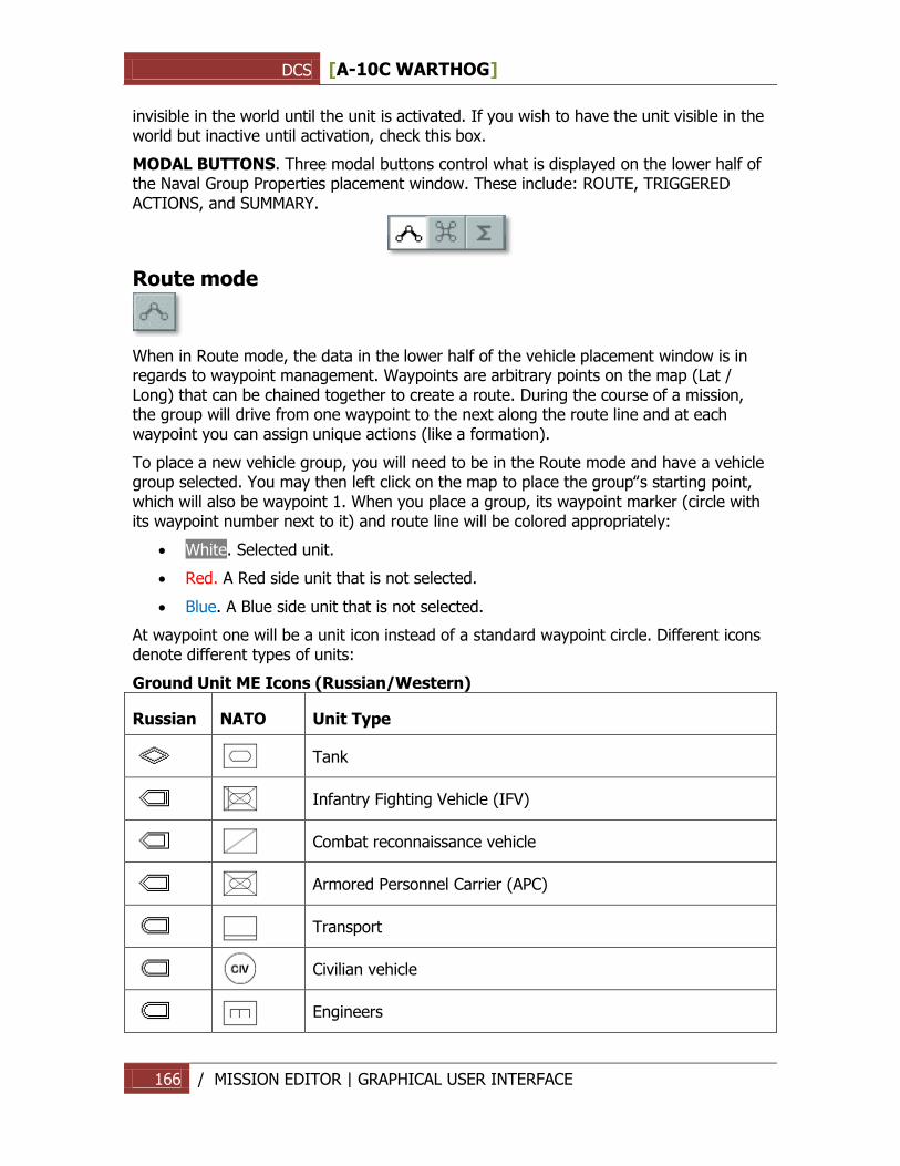
DCS [A-10C WARTHOG]
166 / MISSION EDITOR | GRAPHICAL USER INTERFACE
invisible in the world until the unit is activated. If you wish to have the unit visible in the world but inactive until activation, check this box.
MODAL BUTTONS. Three modal buttons control what is displayed on the lower half of the Naval Group Properties placement window. These include: ROUTE, TRIGGERED ACTIONS, and SUMMARY.
Route mode
When in Route mode, the data in the lower half of the vehicle placement window is in regards to waypoint management. Waypoints are arbitrary points on the map (Lat / Long) that can be chained together to create a route. During the course of a mission, the group will drive from one waypoint to the next along the route line and at each waypoint you can assign unique actions (like a formation).
To place a new vehicle group, you will need to be in the Route mode and have a vehicle group selected. You may then left click on the map to place the group‟s starting point, which will also be waypoint 1. When you place a group, its waypoint marker (circle with its waypoint number next to it) and route line will be colored appropriately:
White. Selected unit.
Red. A Red side unit that is not selected.
Blue. A Blue side unit that is not selected.
At waypoint one will be a unit icon instead of a standard waypoint circle. Different icons denote different types of units:
Ground Unit ME Icons (Russian/Western)
Russian NATO Unit Type
Tank
Infantry Fighting Vehicle (IFV)
Combat reconnaissance vehicle
Armored Personnel Carrier (APC)
Transport
Civilian vehicle
Engineers
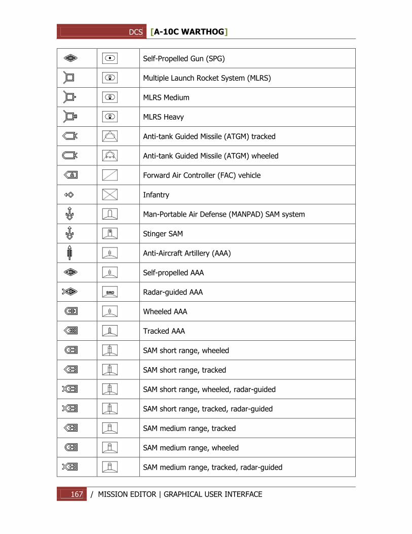
DCS [A-10C WARTHOG]
167 / MISSION EDITOR | GRAPHICAL USER INTERFACE
Self-Propelled Gun (SPG)
Multiple Launch Rocket System (MLRS)
MLRS Medium
MLRS Heavy
Anti-tank Guided Missile (ATGM) tracked
Anti-tank Guided Missile (ATGM) wheeled
Forward Air Controller (FAC) vehicle
Infantry
Man-Portable Air Defense (MANPAD) SAM system
Stinger SAM
Anti-Aircraft Artillery (AAA)
Self-propelled AAA
Radar-guided AAA
Wheeled AAA
Tracked AAA
SAM short range, wheeled
SAM short range, tracked
SAM short range, wheeled, radar-guided
SAM short range, tracked, radar-guided
SAM medium range, tracked
SAM medium range, wheeled
SAM medium range, tracked, radar-guided
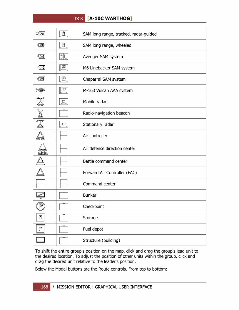
DCS [A-10C WARTHOG]
168 / MISSION EDITOR | GRAPHICAL USER INTERFACE
SAM long range, tracked, radar-guided
SAM long range, wheeled
Avenger SAM system
M6 Linebacker SAM system
Chaparral SAM system
M-163 Vulcan AAA system
Mobile radar
Radio-navigation beacon
Stationary radar
Air controller
Air defense direction center
Battle command center
Forward Air Controller (FAC)
Command center
Bunker
Checkpoint
Storage
Fuel depot
Structure (building)
To shift the entire group's position on the map, click and drag the group's lead unit to the desired location. To adjust the position of other units within the group, click and drag the desired unit relative to the leader's position.
Below the Modal buttons are the Route controls. From top to bottom:
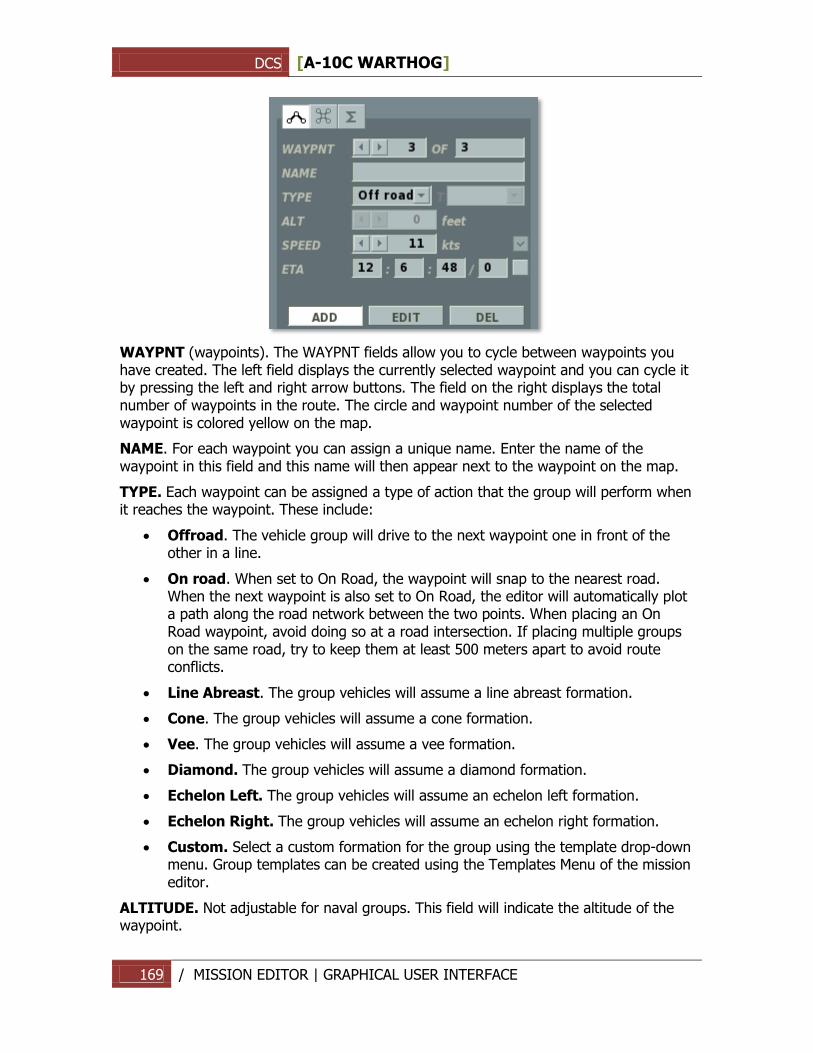
DCS [A-10C WARTHOG]
169 / MISSION EDITOR | GRAPHICAL USER INTERFACE
WAYPNT (waypoints). The WAYPNT fields allow you to cycle between waypoints you have created. The left field displays the currently selected waypoint and you can cycle it by pressing the left and right arrow buttons. The field on the right displays the total number of waypoints in the route. The circle and waypoint number of the selected waypoint is colored yellow on the map.
NAME. For each waypoint you can assign a unique name. Enter the name of the waypoint in this field and this name will then appear next to the waypoint on the map.
TYPE. Each waypoint can be assigned a type of action that the group will perform when it reaches the waypoint. These include:
Offroad. The vehicle group will drive to the next waypoint one in front of the other in a line.
On road. When set to On Road, the waypoint will snap to the nearest road. When the next waypoint is also set to On Road, the editor will automatically plot a path along the road network between the two points. When placing an On Road waypoint, avoid doing so at a road intersection. If placing multiple groups on the same road, try to keep them at least 500 meters apart to avoid route conflicts.
Line Abreast. The group vehicles will assume a line abreast formation.
Cone. The group vehicles will assume a cone formation.
Vee. The group vehicles will assume a vee formation.
Diamond. The group vehicles will assume a diamond formation.
Echelon Left. The group vehicles will assume an echelon left formation.
Echelon Right. The group vehicles will assume an echelon right formation.
Custom. Select a custom formation for the group using the template drop-down menu. Group templates can be created using the Templates Menu of the mission editor.
ALTITUDE. Not adjustable for naval groups. This field will indicate the altitude of the waypoint.
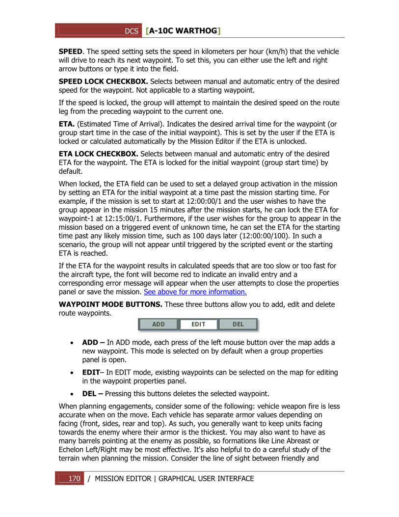
DCS [A-10C WARTHOG]
170 / MISSION EDITOR | GRAPHICAL USER INTERFACE
SPEED. The speed setting sets the speed in kilometers per hour (km/h) that the vehicle will drive to reach its next waypoint. To set this, you can either use the left and right arrow buttons or type it into the field.
SPEED LOCK CHECKBOX. Selects between manual and automatic entry of the desired speed for the waypoint. Not applicable to a starting waypoint.
If the speed is locked, the group will attempt to maintain the desired speed on the route leg from the preceding waypoint to the current one.
ETA. (Estimated Time of Arrival). Indicates the desired arrival time for the waypoint (or group start time in the case of the initial waypoint). This is set by the user if the ETA is locked or calculated automatically by the Mission Editor if the ETA is unlocked.
ETA LOCK CHECKBOX. Selects between manual and automatic entry of the desired ETA for the waypoint. The ETA is locked for the initial waypoint (group start time) by default.
When locked, the ETA field can be used to set a delayed group activation in the mission by setting an ETA for the initial waypoint at a time past the mission starting time. For example, if the mission is set to start at 12:00:00/1 and the user wishes to have the group appear in the mission 15 minutes after the mission starts, he can lock the ETA for waypoint-1 at 12:15:00/1. Furthermore, if the user wishes for the group to appear in the mission based on a triggered event of unknown time, he can set the ETA for the starting time past any likely mission time, such as 100 days later (12:00:00/100). In such a scenario, the group will not appear until triggered by the scripted event or the starting ETA is reached.
If the ETA for the waypoint results in calculated speeds that are too slow or too fast for the aircraft type, the font will become red to indicate an invalid entry and a corresponding error message will appear when the user attempts to close the properties panel or save the mission. See above for more information.
WAYPOINT MODE BUTTONS. These three buttons allow you to add, edit and delete route waypoints.
ADD – In ADD mode, each press of the left mouse button over the map adds a new waypoint. This mode is selected on by default when a group properties panel is open.
EDIT– In EDIT mode, existing waypoints can be selected on the map for editing in the waypoint properties panel.
DEL – Pressing this buttons deletes the selected waypoint.
When planning engagements, consider some of the following: vehicle weapon fire is less accurate when on the move. Each vehicle has separate armor values depending on facing (front, sides, rear and top). As such, you generally want to keep units facing towards the enemy where their armor is the thickest. You may also want to have as many barrels pointing at the enemy as possible, so formations like Line Abreast or Echelon Left/Right may be most effective. It's also helpful to do a careful study of the terrain when planning the mission. Consider the line of sight between friendly and
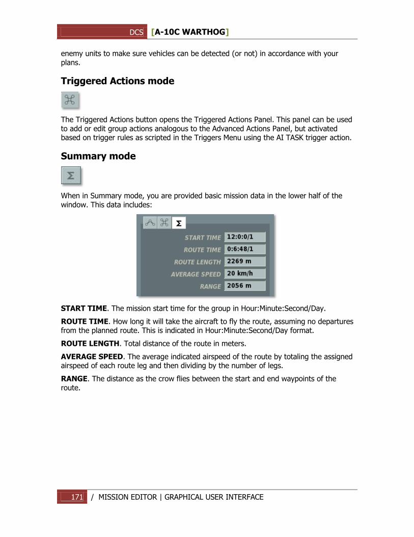
DCS [A-10C WARTHOG]
171 / MISSION EDITOR | GRAPHICAL USER INTERFACE
enemy units to make sure vehicles can be detected (or not) in accordance with your plans.
Triggered Actions mode
The Triggered Actions button opens the Triggered Actions Panel. This panel can be used to add or edit group actions analogous to the Advanced Actions Panel, but activated based on trigger rules as scripted in the Triggers Menu using the AI TASK trigger action.
Summary mode
When in Summary mode, you are provided basic mission data in the lower half of the window. This data includes:
START TIME. The mission start time for the group in Hour:Minute:Second/Day.
ROUTE TIME. How long it will take the aircraft to fly the route, assuming no departures from the planned route. This is indicated in Hour:Minute:Second/Day format.
ROUTE LENGTH. Total distance of the route in meters.
AVERAGE SPEED. The average indicated airspeed of the route by totaling the assigned airspeed of each route leg and then dividing by the number of legs.
RANGE. The distance as the crow flies between the start and end waypoints of the route.
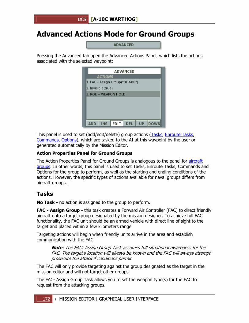
DCS [A-10C WARTHOG]
172 / MISSION EDITOR | GRAPHICAL USER INTERFACE
Advanced Actions Mode for Ground Groups
Pressing the Advanced tab open the Advanced Actions Panel, which lists the actions associated with the selected waypoint:
This panel is used to set (add/edit/delete) group actions (Tasks, Enroute Tasks, Commands, Options), which are tasked to the AI at this waypoint by the user or generated automatically by the Mission Editor.
Action Properties Panel for Ground Groups
The Action Properties Panel for Ground Groups is analogous to the panel for aircraft groups. In other words, this panel is used to set Tasks, Enroute Tasks, Commands and Options for the group to perform, as well as the starting and ending conditions of the actions. However, the specific types of actions available for naval groups differs from aircraft groups.
Tasks
No Task - no action is assigned to the group to perform.
FAC - Assign Group - this task creates a Forward Air Controller (FAC) to direct friendly aircraft onto a target group designated by the mission designer. To achieve full FAC functionality, the FAC unit should be an armed vehicle with direct line of sight to the target and placed within a few kilometers range.
Targeting actions will begin when friendly units arrive in the area and establish communication with the FAC.
Note: The FAC: Assign Group Task assumes full situational awareness for the FAC. The target's location will always be known and the FAC will always attempt prosecute the attack if conditions permit.
The FAC will only provide targeting against the group designated as the target in the mission editor and will not target other groups.
The FAC- Assign Group Task allows you to set the weapon type(s) for the FAC to request from the attacking groups.
DCS [A-10C WARTHOG]
173 / MISSION EDITOR | GRAPHICAL USER INTERFACE
Fire at Point - fire against a coordinate point on the map as designated by the mission designer.
Hold - stop at the waypoint location and maintain position as long as the action is in effect. The Lower Action Properties Panel can be used to select a custom formation for the group to take while holding.
This function may be useful for various combat tasks, such as post patrols or artillery fire. For example, an artillery battery can be set to hold in a fire mission formation to conduct fire.
Enroute Tasks
No Enroute Task - a No Enroute Task action does not set any action for the group to perform.
FAC – the group will act as a Forward Air Controller (FAC) to provide targeting orders for friendly units in the area.
Under a FAC Enroute Task, the FAC will automatically prioritize targets for the player or attacking AI groups and issue targeting orders throughout the attack phase.
Note: The FAC's target selection may not correspond to the targets intended for the player or attacking AI by the mission designer.
The PRIORITY number is used to set the action priority in relation to other actions of the waypoint. The priority number represents the order this action will take relative to other actions, starting with '0' as the highest priority.
FAC - Engage Group - analogous to the FAC Enroute Task, except in this case a specific enemy group is selected by the mission designer for the FAC to target.
Remember, because this is an Enroute Task, the FAC will have to independently detect the target group prior to being able to issue targeting commands against it. As described above, target detection will depend on a number of dynamic variables in-game, including possible terrain obstructions or weather interference. If no group is designated by the mission designer, the FAC will not issue any targeting commands.
The PRIORITY number is used to set the action priority in relation to other actions of the waypoint. The priority number represents the order this action will take relative to other actions, starting with '0' as the highest priority.
Perform Command
The following commands can be set as actions upon reaching a waypoint:
No Action – No command is set.
Run Script – run the Lua script entered in the scratchpad.
Set Callsign - set the group's callsign. For Western units, the callsign consists of a primary designation and a numerical ID. For example, "Colt 4".
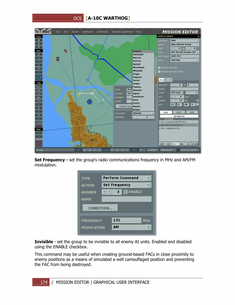
DCS [A-10C WARTHOG]
174 / MISSION EDITOR | GRAPHICAL USER INTERFACE
Set Frequency - set the group's radio communications frequency in MHz and AM/FM modulation.
Invisible - set the group to be invisible to all enemy AI units. Enabled and disabled using the ENABLE checkbox.
This command may be useful when creating ground-based FACs in close proximity to enemy positions as a means of simulated a well camouflaged position and preventing the FAC from being destroyed.
DCS [A-10C WARTHOG]
175 / MISSION EDITOR | GRAPHICAL USER INTERFACE
Immortal - set the group to be immortal. Enemy AI units will be able to detect the group, but their weapons will have no effect.
Set Option
The following Options can be set as actions upon reaching a waypoint:
ROE (Rules of Engagement) - set fire rules to determine the group's combat behavior when encountering enemy units.
WEAPONS FREE – engage any enemy group in contact. Target prioritization is performed automatically by the group based on the situation.
RETURN FIRE – return fire only; do not engage first.
WEAPONS HOLD – do not fire under any circumstances.
The default setting is WEAPONS FREE.
Dispersal Under Fire - when enabled, this option will allow the group to disperse when under attack.
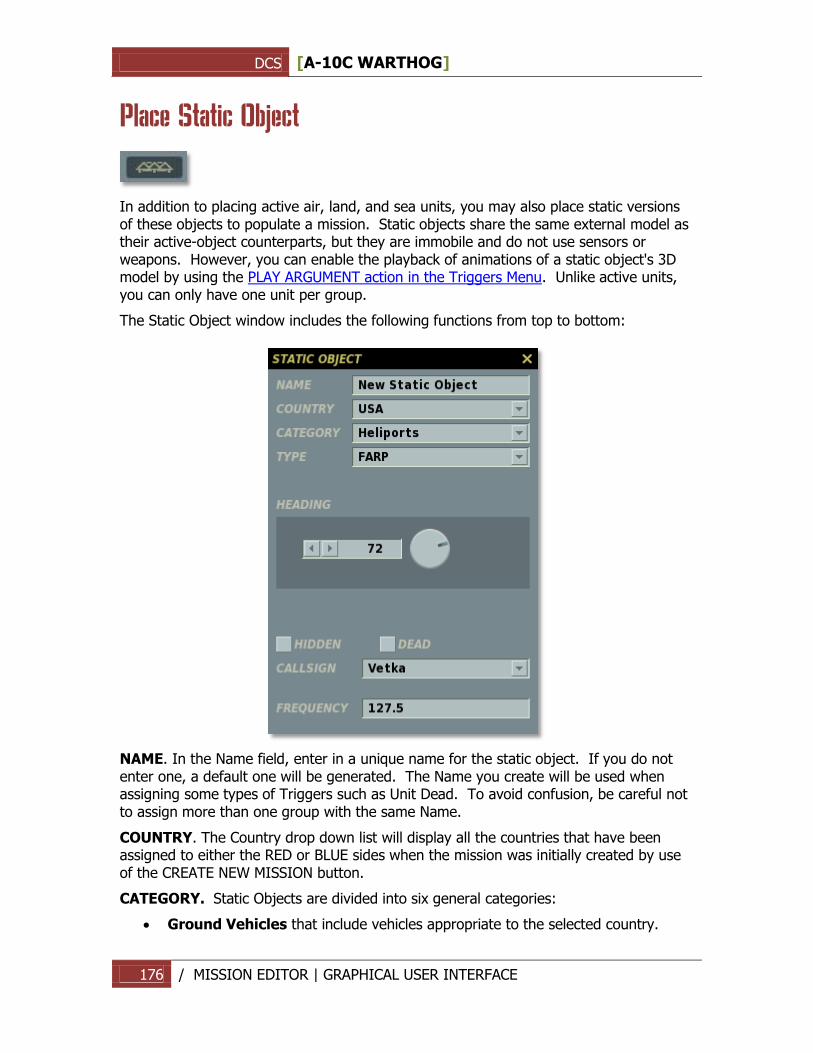
DCS [A-10C WARTHOG]
176 / MISSION EDITOR | GRAPHICAL USER INTERFACE
Place Static Object
In addition to placing active air, land, and sea units, you may also place static versions of these objects to populate a mission. Static objects share the same external model as their active-object counterparts, but they are immobile and do not use sensors or weapons. However, you can enable the playback of animations of a static object's 3D model by using the PLAY ARGUMENT action in the Triggers Menu. Unlike active units, you can only have one unit per group.
The Static Object window includes the following functions from top to bottom:
NAME. In the Name field, enter in a unique name for the static object. If you do not enter one, a default one will be generated. The Name you create will be used when assigning some types of Triggers such as Unit Dead. To avoid confusion, be careful not to assign more than one group with the same Name.
COUNTRY. The Country drop down list will display all the countries that have been assigned to either the RED or BLUE sides when the mission was initially created by use of the CREATE NEW MISSION button.
CATEGORY. Static Objects are divided into six general categories:
Ground Vehicles that include vehicles appropriate to the selected country.
DCS [A-10C WARTHOG]
177 / MISSION EDITOR | GRAPHICAL USER INTERFACE
Helicopters that include those belonging to the selected country.
Heliports that allow the placement of a Forward Arming and Refueling Point (FARP) for forward helicopter operations. When setting a FARP, you can choose the FARP callsign for radio communications from the CALLSIGN drop-down menu and set the radio frequency in MHz in the FREQUENCY field.
Planes that include fixed-wing aircraft of the selected country.
Ships that belong to the selected country.
Structures which includes pill boxes and many other types of buildings (military and civil).
TYPE. Depending on the Category selection, a list of appropriate units is listed in this pull down list.
HEADING. You may use this control to set the heading of the unit in the simulation world. You can do this by either using the left and right arrow keys, typing in the heading value, or clicking on the heading dial.
HIDDEN. If you wish to hide the static object on the World Map and make it invisible to
players in the briefing map, check this box.
DEAD. In addition to the normal static object, you may also populate the world with the destroyed version of the object by checking the DEAD box.
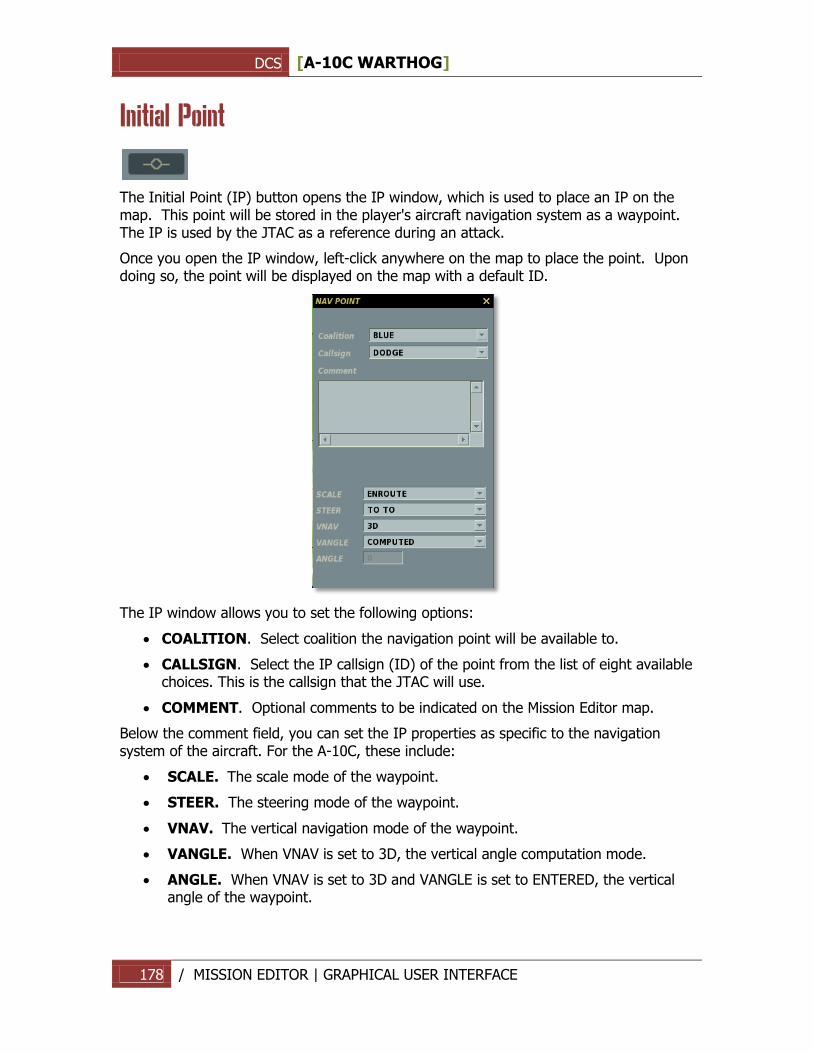
DCS [A-10C WARTHOG]
178 / MISSION EDITOR | GRAPHICAL USER INTERFACE
Initial Point
The Initial Point (IP) button opens the IP window, which is used to place an IP on the map. This point will be stored in the player's aircraft navigation system as a waypoint. The IP is used by the JTAC as a reference during an attack.
Once you open the IP window, left-click anywhere on the map to place the point. Upon doing so, the point will be displayed on the map with a default ID.
The IP window allows you to set the following options:
COALITION. Select coalition the navigation point will be available to.
CALLSIGN. Select the IP callsign (ID) of the point from the list of eight available choices. This is the callsign that the JTAC will use.
COMMENT. Optional comments to be indicated on the Mission Editor map.
Below the comment field, you can set the IP properties as specific to the navigation system of the aircraft. For the A-10C, these include:
SCALE. The scale mode of the waypoint.
STEER. The steering mode of the waypoint.
VNAV. The vertical navigation mode of the waypoint.
VANGLE. When VNAV is set to 3D, the vertical angle computation mode.
ANGLE. When VNAV is set to 3D and VANGLE is set to ENTERED, the vertical angle of the waypoint.
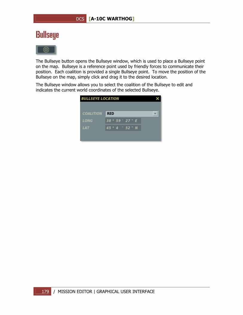
DCS [A-10C WARTHOG]
179 / MISSION EDITOR | GRAPHICAL USER INTERFACE
Bullseye
The Bullseye button opens the Bullseye window, which is used to place a Bullseye point on the map. Bullseye is a reference point used by friendly forces to communicate their position. Each coalition is provided a single Bullseye point. To move the position of the Bullseye on the map, simply click and drag it to the desired location.
The Bullseye window allows you to select the coalition of the Bullseye to edit and indicates the current world coordinates of the selected Bullseye.
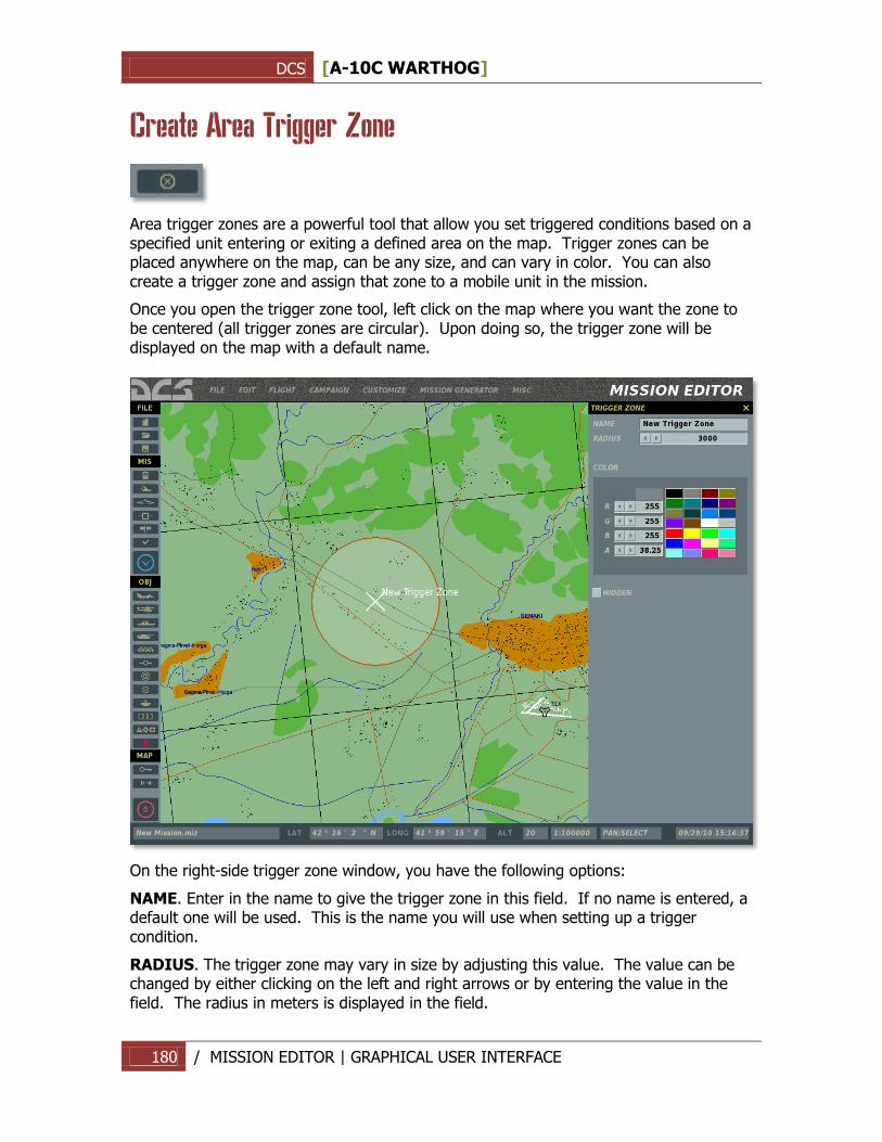
DCS [A-10C WARTHOG]
180 / MISSION EDITOR | GRAPHICAL USER INTERFACE
Create Area Trigger Zone
Area trigger zones are a powerful tool that allow you set triggered conditions based on a specified unit entering or exiting a defined area on the map. Trigger zones can be placed anywhere on the map, can be any size, and can vary in color. You can also create a trigger zone and assign that zone to a mobile unit in the mission.
Once you open the trigger zone tool, left click on the map where you want the zone to be centered (all trigger zones are circular). Upon doing so, the trigger zone will be displayed on the map with a default name.
On the right-side trigger zone window, you have the following options:
NAME. Enter in the name to give the trigger zone in this field. If no name is entered, a default one will be used. This is the name you will use when setting up a trigger condition.
RADIUS. The trigger zone may vary in size by adjusting this value. The value can be changed by either clicking on the left and right arrows or by entering the value in the field. The radius in meters is displayed in the field.
DCS [A-10C WARTHOG]
181 / MISSION EDITOR | GRAPHICAL USER INTERFACE
COLOR. To help distinguish trigger zones from each other, you may use the default colors or create a custom one. To select a default color, click on one of the 24 colors. To create a custom color, use the left and right arrows of the R (red), G (green), and B (blue) color values. The A (alpha) value adjusts the transparency. The selected/created color is displayed in the RGB values.
HIDDEN. When the mission is played by others, you will probably not want the trigger areas to be visible on the map. To hide them you must check this box.
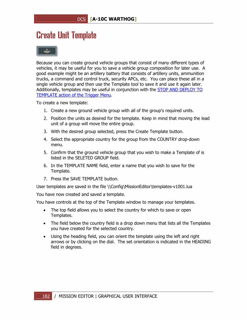
DCS [A-10C WARTHOG]
182 / MISSION EDITOR | GRAPHICAL USER INTERFACE
Create Unit Template
Because you can create ground vehicle groups that consist of many different types of vehicles, it may be useful for you to save a vehicle group composition for later use. A good example might be an artillery battery that consists of artillery units, ammunition trucks, a command and control truck, security APCs, etc. You can place these all in a single vehicle group and then use the Template tool to save it and use it again later. Additionally, templates may be useful in conjunction with the STOP AND DEPLOY TO TEMPLATE action of the Trigger Menu.
To create a new template:
1. Create a new ground vehicle group with all of the group's required units.
2. Position the units as desired for the template. Keep in mind that moving the lead unit of a group will move the entire group.
3. With the desired group selected, press the Create Template button.
4. Select the appropriate country for the group from the COUNTRY drop-down menu.
5. Confirm that the ground vehicle group that you wish to make a Template of is listed in the SELETED GROUP field.
6. In the TEMPLATE NAME field, enter a name that you wish to save for the Template.
7. Press the SAVE TEMPLATE button.
User templates are saved in the file \\Config\MissionEditor\templates-v1001.lua
You have now created and saved a template.
You have controls at the top of the Template window to manage your templates.
The top field allows you to select the country for which to save or open Templates.
The field below the country field is a drop down menu that lists all the Templates you have created for the selected country.
Using the heading field, you can orient the template using the left and right arrows or by clicking on the dial. The set orientation is indicated in the HEADING field in degrees.
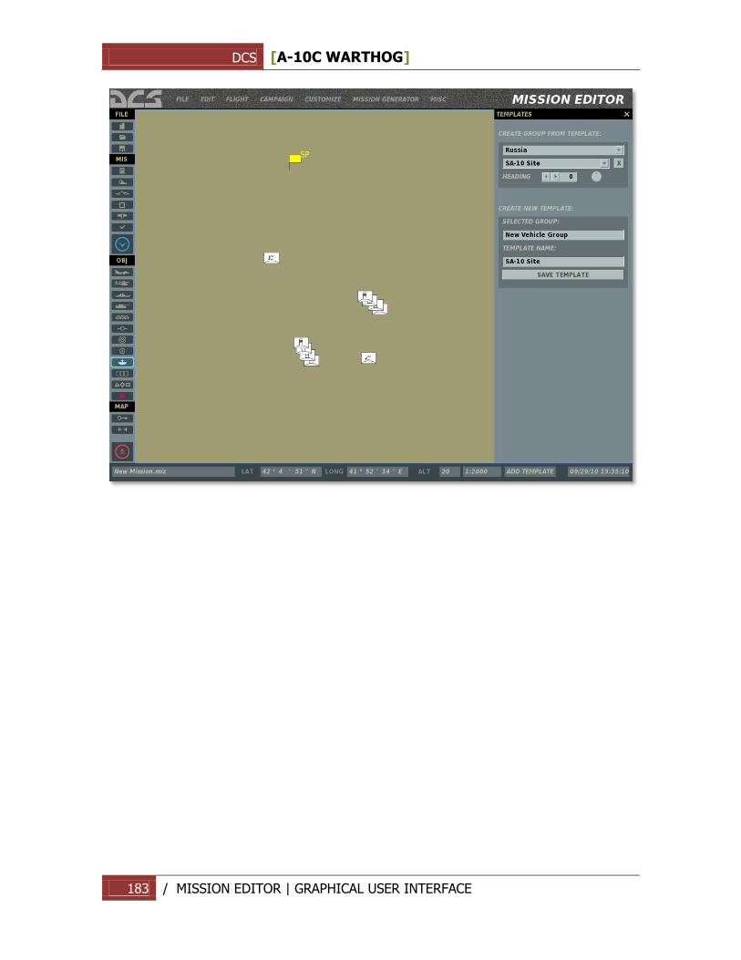
DCS [A-10C WARTHOG]
183 / MISSION EDITOR | GRAPHICAL USER INTERFACE
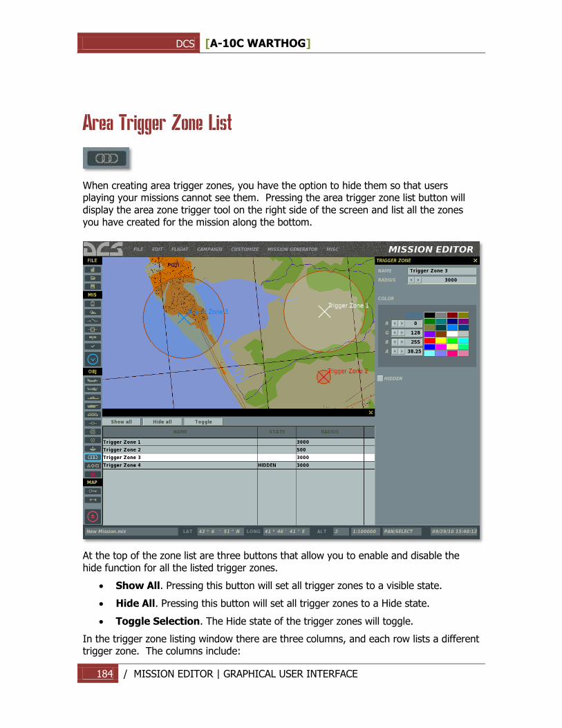
DCS [A-10C WARTHOG]
184 / MISSION EDITOR | GRAPHICAL USER INTERFACE
Area Trigger Zone List
When creating area trigger zones, you have the option to hide them so that users playing your missions cannot see them. Pressing the area trigger zone list button will display the area zone trigger tool on the right side of the screen and list all the zones you have created for the mission along the bottom.
At the top of the zone list are three buttons that allow you to enable and disable the hide function for all the listed trigger zones.
Show All. Pressing this button will set all trigger zones to a visible state.
Hide All. Pressing this button will set all trigger zones to a Hide state.
Toggle Selection. The Hide state of the trigger zones will toggle.
In the trigger zone listing window there are three columns, and each row lists a different trigger zone. The columns include:
DCS [A-10C WARTHOG]
185 / MISSION EDITOR | GRAPHICAL USER INTERFACE
NAME. The name of the trigger zone as entered in the NAME field.
STATE. This can either be blank (indicating a visible state) or HIDDEN to indicate that the trigger zone is currently hidden.
RADIUS. The radius of the trigger zone in meters.
To close the widow, you may press the X button in the top right corner of the window.
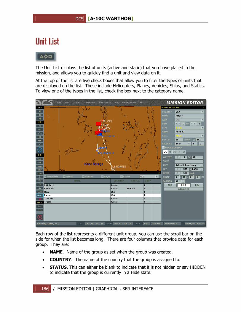
DCS [A-10C WARTHOG]
186 / MISSION EDITOR | GRAPHICAL USER INTERFACE
Unit List
The Unit List displays the list of units (active and static) that you have placed in the mission, and allows you to quickly find a unit and view data on it.
At the top of the list are five check boxes that allow you to filter the types of units that are displayed on the list. These include Helicopters, Planes, Vehicles, Ships, and Statics. To view one of the types in the list, check the box next to the category name.
Each row of the list represents a different unit group; you can use the scroll bar on the side for when the list becomes long. There are four columns that provide data for each group. They are:
NAME. Name of the group as set when the group was created.
COUNTRY. The name of the country that the group is assigned to.
STATUS. This can either be blank to indicate that it is not hidden or say HIDDEN to indicate that the group is currently in a Hide state.
DCS [A-10C WARTHOG]
187 / MISSION EDITOR | GRAPHICAL USER INTERFACE
QNTY. Many groups may consist of multiple units (particularly for aircraft and ground vehicles). This column lists the number of units that comprise the group.
When you click on an entry in the list, the group will be centered on the map above the list and the groups placement window will be displayed on the right.
Note: To quickly Hide or Show a group, you may double-click on it.
Delete Unit/Object
To remove a group entirely from the mission, including waypoints, select the group and then press the Delete button.
Map Options
The Map Options panel has been described in detail previously in the System Bar chapter of the manual.
Distance Tool
You can use the Distance Tool to measure distance on the World Map. When enabled by pressing the Distance Tool button, left mouse button click, and hold and drag to measure a distance. The distance line is drawn in blue and the distance (in meters) and bearing (degrees) are in black. You must press the Distance Tool button again in order to disable it, and resume normal map functioning.
Exit Mission Editor
To exit the Mission Editor without saving changes, press the Exit button.
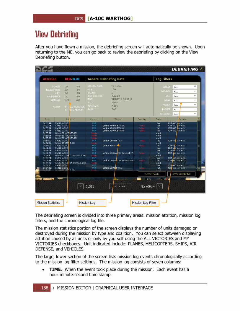
DCS [A-10C WARTHOG]
188 / MISSION EDITOR | GRAPHICAL USER INTERFACE
View Debriefing
After you have flown a mission, the debriefing screen will automatically be shown. Upon returning to the ME, you can go back to review the debriefing by clicking on the View Debriefing button.
The debriefing screen is divided into three primary areas: mission attrition, mission log filters, and the chronological log file.
The mission statistics portion of the screen displays the number of units damaged or destroyed during the mission by type and coalition. You can select between displaying attrition caused by all units or only by yourself using the ALL VICTORIES and MY VICTORIES checkboxes. Unit indicated include: PLANES, HELICOPTERS, SHIPS, AIR DEFENSE, and VEHICLES.
The large, lower section of the screen lists mission log events chronologically according to the mission log filter settings. The mission log consists of seven columns:
TIME. When the event took place during the mission. Each event has a hour:minute:second time stamp.
Mission Statistics
Mission Log
Mission Log Filter
DCS [A-10C WARTHOG]
189 / CAMPAIGN | GRAPHICAL USER INTERFACE
INITIATOR. The name of the unit that took the action of the event (i.e. fired a weapon, crashed, landed, etc.).
COUNTRY. Country that the initiator was assigned to.
TARGET. If the initiator was attacking a unit or object, the name of that target is listed here.
COUNTRY. Country that the target was assigned to.
EVENT. The type of event that took place. Types include: shot, hit, dead, etc.
WEAPON. Name of the weapon type that the initiator used to attack the target.
The log filter section in the top right portion of the screen allows you to filter what log events are displayed in the mission log list. Each of these has a drop down menu that allows you to define what data is displayed.
OBJECT. List of objects.
WEAPON. Lists all weapons that were used by initiator units in the mission.
SIDE. All, Red, or Blue.
EVENT. All, Dead, Hit, or Shot.
TRG SIDE (target side). All, Red, or Blue.
TARGET. Lists all units and objects that were targeted during the mission.
INITIATOR. Lists all active units in the mission.
The debriefing screen can be a handy tool to determine who did what, when it happened, and with what weapon. Most often you may use this to determine who attacked you in single and multiplayer missions.
Below the log filter section are two buttons: SAVE TRACK and SAVE DEBRIEFING.
SAVE TRACK. By pressing this button the file save screen is displayed, and in the FILE field you may enter a name for the track file that was automatically recorded during the mission. Note that all missions have a track file recorded. When you re-fly the same mission, the track file is overwritten unless you save it under a new name. The SAVE TRACK button allows you to do this.
SAVE DEBRIEFING. Press this button to save the Log (.log) file of the mission debriefing.
At the bottom of the screen are three buttons: CLOSE, WATCH TRACK and FLY AGAIN
CLOSE. Press this button to exit the debriefing screen and return to the Mission Editor.
WATCH TRACK. Press this button to watch a recording (track) of the mission you have just ended.
FLY AGAIN. Press this button to re-fly the mission. Note, unless you save the current track and debriefing, they will be lost once you hit FLY AGAIN or exit the briefing.
DCS [A-10C WARTHOG]
190 / CAMPAIGN | GRAPHICAL USER INTERFACE
CAMPAIGN
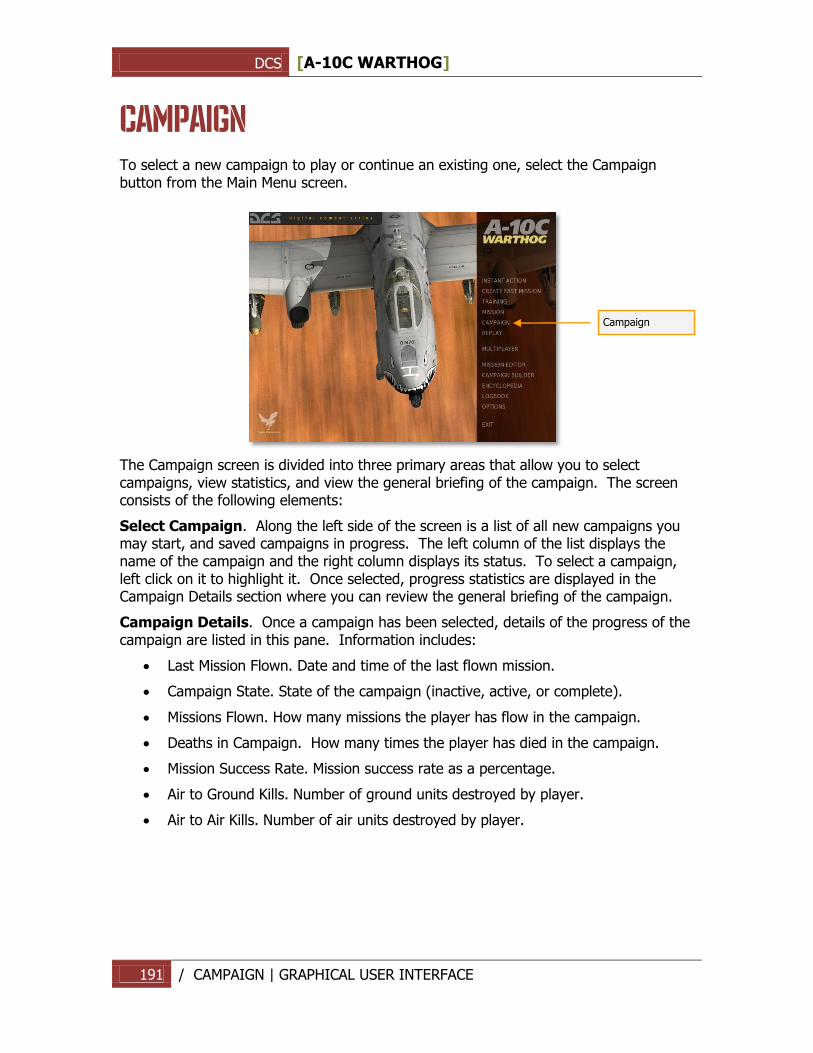
DCS [A-10C WARTHOG]
191 / CAMPAIGN | GRAPHICAL USER INTERFACE
CAMPAIGN To select a new campaign to play or continue an existing one, select the Campaign button from the Main Menu screen.
The Campaign screen is divided into three primary areas that allow you to select campaigns, view statistics, and view the general briefing of the campaign. The screen consists of the following elements:
Select Campaign. Along the left side of the screen is a list of all new campaigns you may start, and saved campaigns in progress. The left column of the list displays the name of the campaign and the right column displays its status. To select a campaign, left click on it to highlight it. Once selected, progress statistics are displayed in the Campaign Details section where you can review the general briefing of the campaign.
Campaign Details. Once a campaign has been selected, details of the progress of the campaign are listed in this pane. Information includes:
Last Mission Flown. Date and time of the last flown mission.
Campaign State. State of the campaign (inactive, active, or complete).
Missions Flown. How many missions the player has flow in the campaign.
Deaths in Campaign. How many times the player has died in the campaign.
Mission Success Rate. Mission success rate as a percentage.
Air to Ground Kills. Number of ground units destroyed by player.
Air to Air Kills. Number of air units destroyed by player.
Campaign
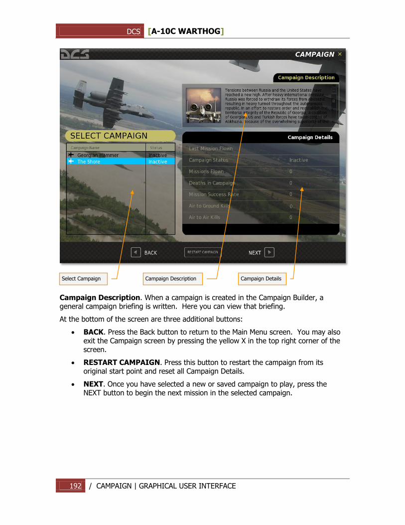
DCS [A-10C WARTHOG]
192 / CAMPAIGN | GRAPHICAL USER INTERFACE
Campaign Description. When a campaign is created in the Campaign Builder, a general campaign briefing is written. Here you can view that briefing.
At the bottom of the screen are three additional buttons:
BACK. Press the Back button to return to the Main Menu screen. You may also exit the Campaign screen by pressing the yellow X in the top right corner of the screen.
RESTART CAMPAIGN. Press this button to restart the campaign from its original start point and reset all Campaign Details.
NEXT. Once you have selected a new or saved campaign to play, press the NEXT button to begin the next mission in the selected campaign.
Select Campaign
Campaign Description
Campaign Details
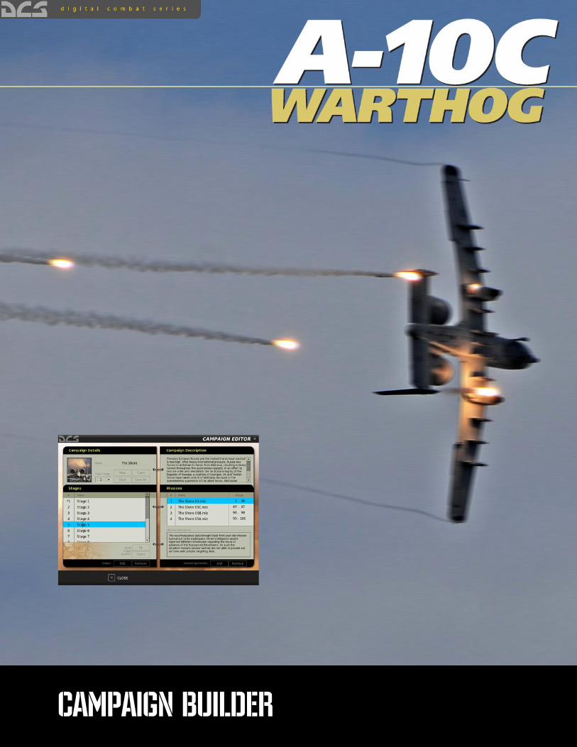
DCS [A-10C WARTHOG]
193 / CAMPAIGN BUILDER | GRAPHICAL USER INTERFACE
CAMPAIGN BUILDER
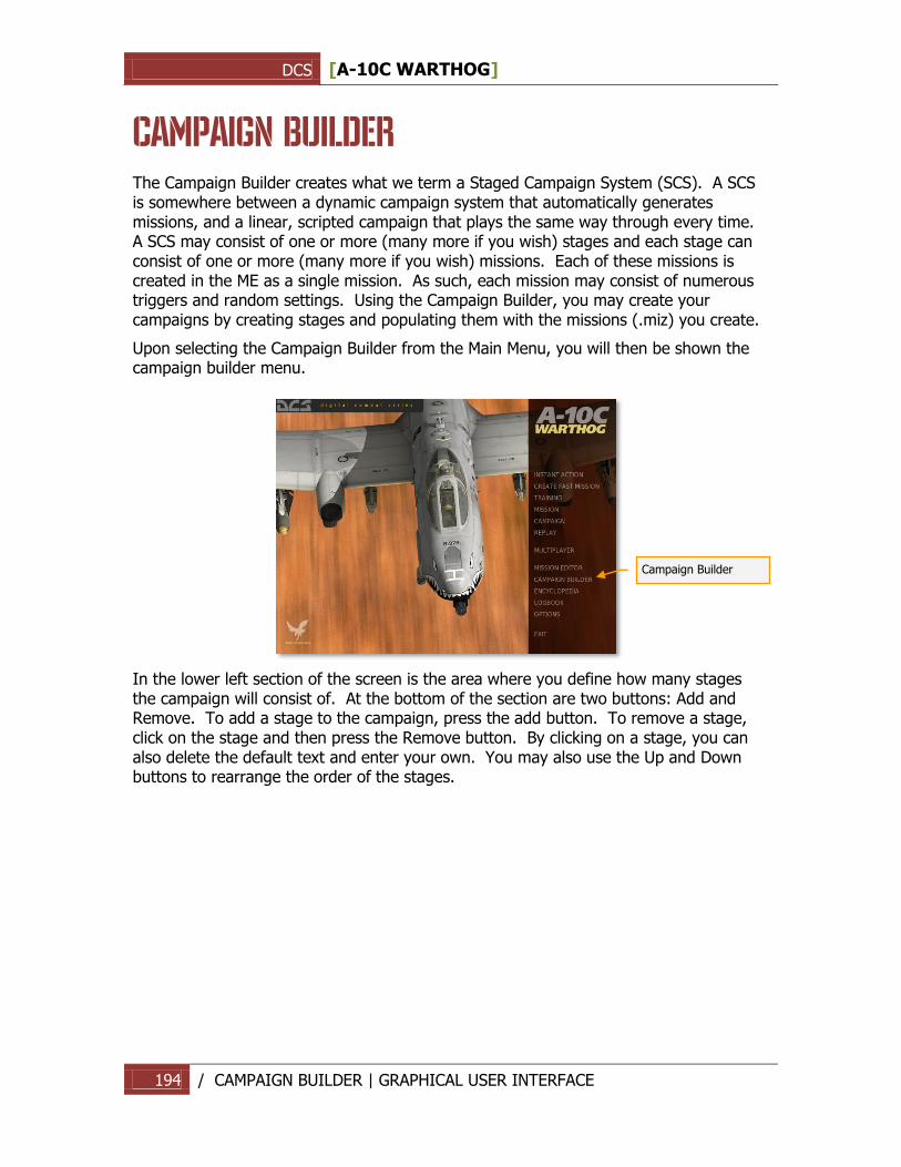
DCS [A-10C WARTHOG]
194 / CAMPAIGN BUILDER | GRAPHICAL USER INTERFACE
CAMPAIGN BUILDER The Campaign Builder creates what we term a Staged Campaign System (SCS). A SCS is somewhere between a dynamic campaign system that automatically generates missions, and a linear, scripted campaign that plays the same way through every time. A SCS may consist of one or more (many more if you wish) stages and each stage can consist of one or more (many more if you wish) missions. Each of these missions is created in the ME as a single mission. As such, each mission may consist of numerous triggers and random settings. Using the Campaign Builder, you may create your campaigns by creating stages and populating them with the missions (.miz) you create.
Upon selecting the Campaign Builder from the Main Menu, you will then be shown the campaign builder menu.
In the lower left section of the screen is the area where you define how many stages the campaign will consist of. At the bottom of the section are two buttons: Add and Remove. To add a stage to the campaign, press the add button. To remove a stage, click on the stage and then press the Remove button. By clicking on a stage, you can also delete the default text and enter your own. You may also use the Up and Down buttons to rearrange the order of the stages.
Campaign Builder
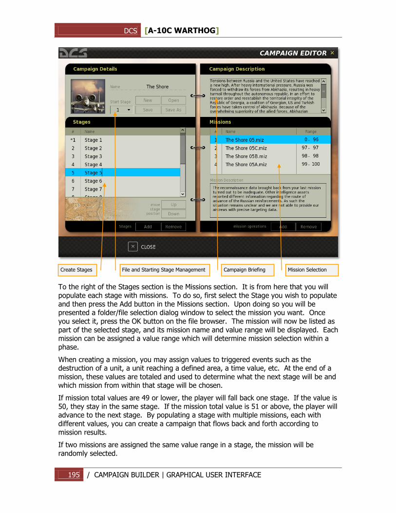
DCS [A-10C WARTHOG]
195 / CAMPAIGN BUILDER | GRAPHICAL USER INTERFACE
To the right of the Stages section is the Missions section. It is from here that you will populate each stage with missions. To do so, first select the Stage you wish to populate and then press the Add button in the Missions section. Upon doing so you will be presented a folder/file selection dialog window to select the mission you want. Once you select it, press the OK button on the file browser. The mission will now be listed as part of the selected stage, and its mission name and value range will be displayed. Each mission can be assigned a value range which will determine mission selection within a phase.
When creating a mission, you may assign values to triggered events such as the destruction of a unit, a unit reaching a defined area, a time value, etc. At the end of a mission, these values are totaled and used to determine what the next stage will be and which mission from within that stage will be chosen.
If mission total values are 49 or lower, the player will fall back one stage. If the value is 50, they stay in the same stage. If the mission total value is 51 or above, the player will advance to the next stage. By populating a stage with multiple missions, each with different values, you can create a campaign that flows back and forth according to mission results.
If two missions are assigned the same value range in a stage, the mission will be randomly selected.
File and Starting Stage Management
Create Stages
Campaign Briefing
Mission Selection
DCS [A-10C WARTHOG]
196 / CAMPAIGN BUILDER | GRAPHICAL USER INTERFACE
The assigned value range of a mission within a stage is listed in the Range column. Below the mission listing for a stage is a field that displays the briefing created for the mission.
At the bottom of the section, next to the Add button, is the Remove button. Use this to remove a mission from a stage.
Above the mission selection area is a field where you may enter a campaign briefing.
In the top left corner are functions to manage the files and set the stage that the campaign will start on. From here you may Open an existing campaign, Save the current campaign as is, create a New campaign, or Save the current campaign As a new file. From the start stage field you may set the starting stage for the campaign. You generally will not want to start the campaign on stage 1 in case the player loses the first mission and subsequently loses the campaign! The starting stage for the campaign will be marked with an asterisk (*) on the stage listing.
Some notes about campaign building:
The more stages you put in a mission and the more missions you place in each stage, reduces the chances of mission repetition.
When creating a stage, it can often save time by creating a template for the stage. This “template” mission would include general force layouts so that you could simply add to and/or modify the mission many times resulting in unique missions for a particular stage.
Use random settings and triggers as much as you can. These can be used to create unpredictable force set ups including air defense units and variable AI skill settings.
By placing front lines adjacent to each other over several stages, you can reproduce a front line that moves back and forth according to mission results.
DCS [A-10C WARTHOG]
197 / ENCYCLOPEDIA | GRAPHICAL USER INTERFACE
ENCYCLOPEDIA
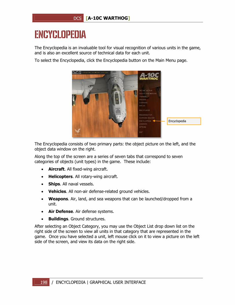
DCS [A-10C WARTHOG]
198 / ENCYCLOPEDIA | GRAPHICAL USER INTERFACE
ENCYCLOPEDIA The Encyclopedia is an invaluable tool for visual recognition of various units in the game, and is also an excellent source of technical data for each unit.
To select the Encyclopedia, click the Encyclopedia button on the Main Menu page.
The Encyclopedia consists of two primary parts: the object picture on the left, and the object data window on the right.
Along the top of the screen are a series of seven tabs that correspond to seven categories of objects (unit types) in the game. These include:
Aircraft. All fixed-wing aircraft.
Helicopters. All rotary-wing aircraft.
Ships. All naval vessels.
Vehicles. All non-air defense-related ground vehicles.
Weapons. Air, land, and sea weapons that can be launched/dropped from a unit.
Air Defense. Air defense systems.
Buildings. Ground structures.
After selecting an Object Category, you may use the Object List drop down list on the right side of the screen to view all units in that category that are represented in the game. Once you have selected a unit, left mouse click on it to view a picture on the left side of the screen, and view its data on the right side.
Encyclopedia
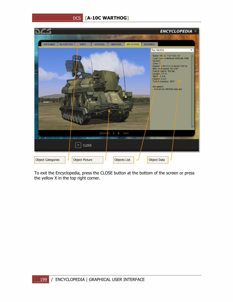
DCS [A-10C WARTHOG]
199 / ENCYCLOPEDIA | GRAPHICAL USER INTERFACE
To exit the Encyclopedia, press the CLOSE button at the bottom of the screen or press the yellow X in the top right corner.
Object Categories
Object Picture
Objects List
Object Data
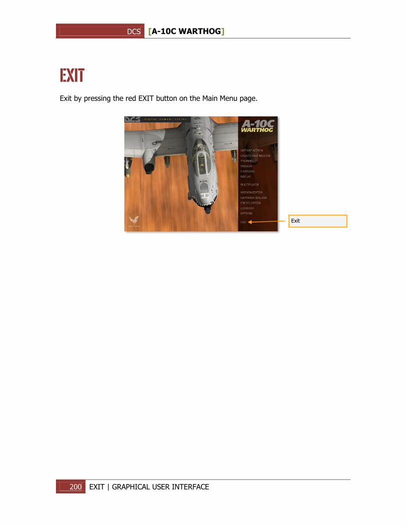
DCS [A-10C WARTHOG]
200 EXIT | GRAPHICAL USER INTERFACE
EXIT Exit by pressing the red EXIT button on the Main Menu page.
Exit
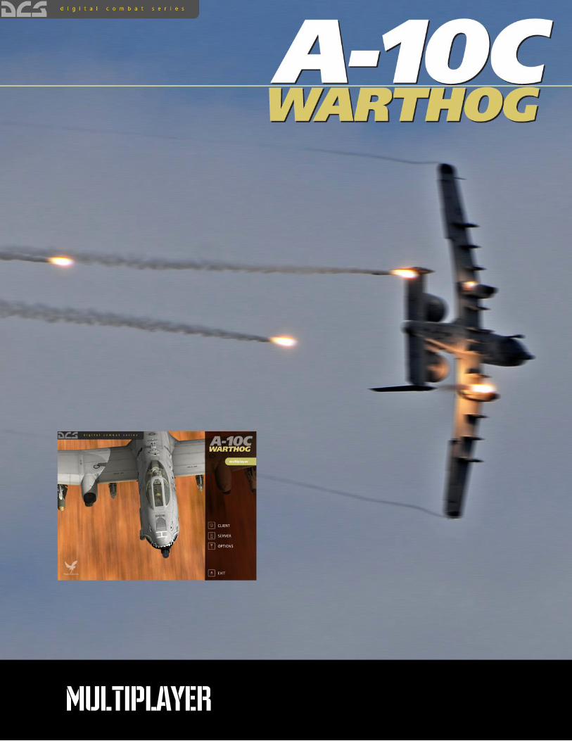
DCS [A-10C WARTHOG]
201 / MULTIPLAYER | GRAPHICAL USER INTERFACE
MULTIPLAYER
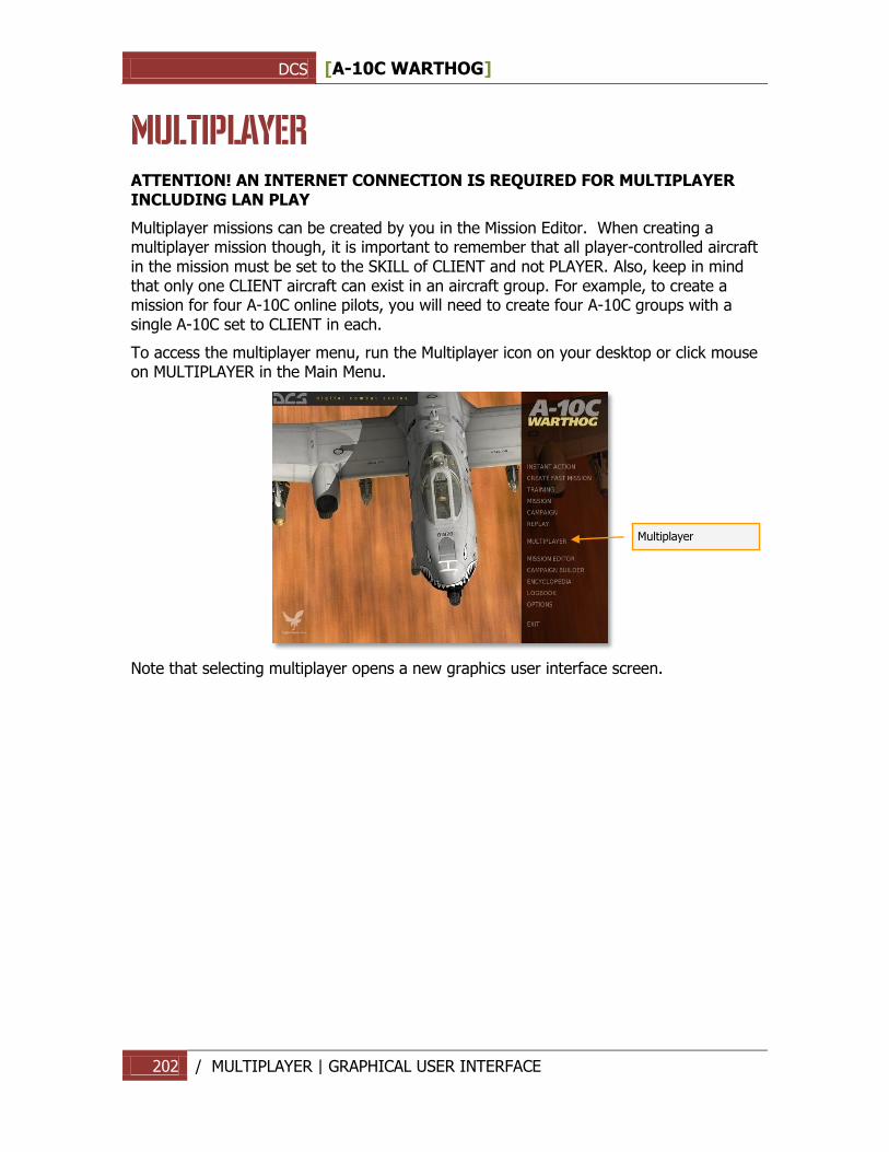
DCS [A-10C WARTHOG]
202 / MULTIPLAYER | GRAPHICAL USER INTERFACE
MULTIPLAYER ATTENTION! AN INTERNET CONNECTION IS REQUIRED FOR MULTIPLAYER INCLUDING LAN PLAY
Multiplayer missions can be created by you in the Mission Editor. When creating a multiplayer mission though, it is important to remember that all player-controlled aircraft in the mission must be set to the SKILL of CLIENT and not PLAYER. Also, keep in mind that only one CLIENT aircraft can exist in an aircraft group. For example, to create a mission for four A-10C online pilots, you will need to create four A-10C groups with a single A-10C set to CLIENT in each.
To access the multiplayer menu, run the Multiplayer icon on your desktop or click mouse on MULTIPLAYER in the Main Menu.
Note that selecting multiplayer opens a new graphics user interface screen.
Multiplayer
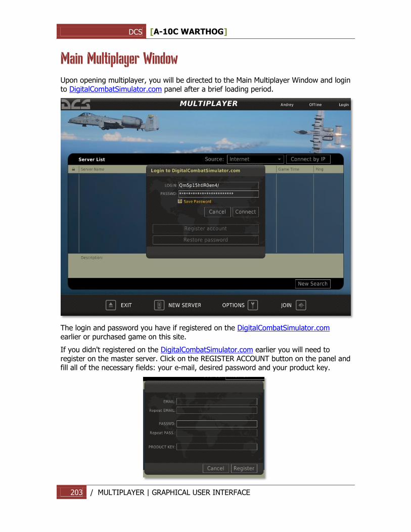
DCS [A-10C WARTHOG]
203 / MULTIPLAYER | GRAPHICAL USER INTERFACE
Main Multiplayer Window
Upon opening multiplayer, you will be directed to the Main Multiplayer Window and login to DigitalCombatSimulator.com panel after a brief loading period.
The login and password you have if registered on the DigitalCombatSimulator.com earlier or purchased game on this site.
If you didn't registered on the DigitalCombatSimulator.com earlier you will need to register on the master server. Click on the REGISTER ACCOUNT button on the panel and fill all of the necessary fields: your e-mail, desired password and your product key.
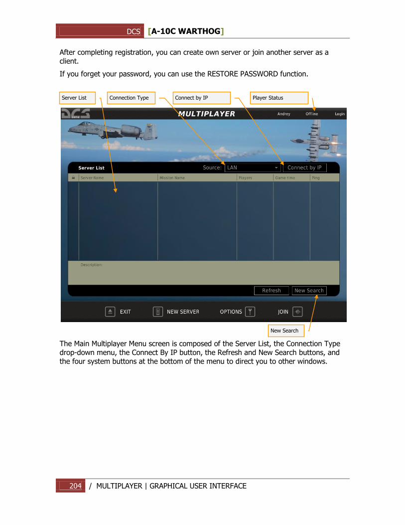
DCS [A-10C WARTHOG]
204 / MULTIPLAYER | GRAPHICAL USER INTERFACE
After completing registration, you can create own server or join another server as a client.
If you forget your password, you can use the RESTORE PASSWORD function.
The Main Multiplayer Menu screen is composed of the Server List, the Connection Type drop-down menu, the Connect By IP button, the Refresh and New Search buttons, and the four system buttons at the bottom of the menu to direct you to other windows.
Server List
Connection Type
Connect by IP
Player Status
New Search
DCS [A-10C WARTHOG]
205 / MULTIPLAYER | GRAPHICAL USER INTERFACE
Server List
The Server List displays all available servers and takes up the majority of the screen. The Server List is designed to show all detected Servers running the game over the Internet or a LAN. Each row of the Server List represents a different server. Each column in the Server List provides different information about each Server. The columns include:
Padlock symbol. This column will be marked with a padlock symbol if the server is password protected.
Server Name. The name of the server is listed in this column.
Mission Name. The title of the mission being run on the server.
Players. Maximum number of players allowed on the server and current number on it.
Game time. How long the mission has been running.
Ping. The connection latency between the player and the server. Lower numbers equate to a better Ping number.
Below the Server list is the mission Description field, which displays a description of the mission being run by the selected server.
At the bottom of the Server List are the Refresh and the New Search buttons. The Refresh button will refresh the data for the servers currently in the server list. The New Search button will check the net for new servers and update existing ones on the Server List.
Lower Bar
EXIT. The Exit button will exit Multiplayer and return you to the main menu or the desktop.
NEW SERVER. The New Server window allows you to host a mission that other players (clients) can join.
OPTIONS. The Options window allows you to create the Player Name that others will see you as in a mission and set your connection speed.
JOIN. After you have selected a server from the Server List, press the JOIN button to join the server.
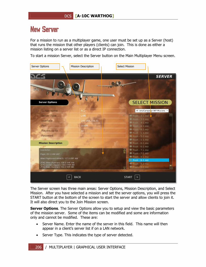
DCS [A-10C WARTHOG]
206 / MULTIPLAYER | GRAPHICAL USER INTERFACE
New Server
For a mission to run as a multiplayer game, one user must be set up as a Server (host) that runs the mission that other players (clients) can join. This is done as either a mission listing on a server list or as a direct IP connection.
To start a mission Server, select the Server button on the Main Multiplayer Menu screen.
The Server screen has three main areas: Server Options, Mission Description, and Select Mission. After you have selected a mission and set the server options, you will press the START button at the bottom of the screen to start the server and allow clients to join it. It will also direct you to the Join Mission screen.
Server Options. The Server Options allow you to setup and view the basic parameters of the mission server. Some of the items can be modified and some are information only and cannot be modified. These are:
Server Name. Enter the name of the server in this field. This name will then appear in a client‟s server list if on a LAN network.
Server Type. This indicates the type of server detected.
Select Mission
Mission Description
Server Options
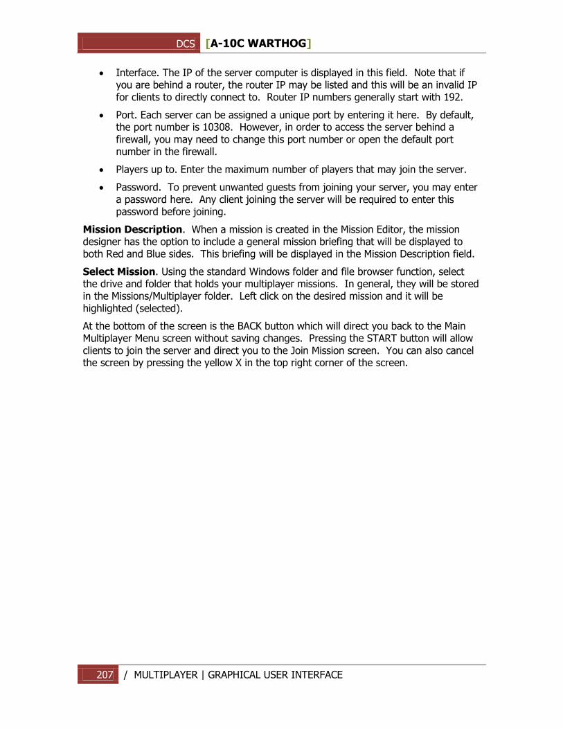
DCS [A-10C WARTHOG]
207 / MULTIPLAYER | GRAPHICAL USER INTERFACE
Interface. The IP of the server computer is displayed in this field. Note that if you are behind a router, the router IP may be listed and this will be an invalid IP for clients to directly connect to. Router IP numbers generally start with 192.
Port. Each server can be assigned a unique port by entering it here. By default, the port number is 10308. However, in order to access the server behind a firewall, you may need to change this port number or open the default port number in the firewall.
Players up to. Enter the maximum number of players that may join the server.
Password. To prevent unwanted guests from joining your server, you may enter a password here. Any client joining the server will be required to enter this password before joining.
Mission Description. When a mission is created in the Mission Editor, the mission designer has the option to include a general mission briefing that will be displayed to both Red and Blue sides. This briefing will be displayed in the Mission Description field.
Select Mission. Using the standard Windows folder and file browser function, select the drive and folder that holds your multiplayer missions. In general, they will be stored in the Missions/Multiplayer folder. Left click on the desired mission and it will be highlighted (selected).
At the bottom of the screen is the BACK button which will direct you back to the Main Multiplayer Menu screen without saving changes. Pressing the START button will allow clients to join the server and direct you to the Join Mission screen. You can also cancel the screen by pressing the yellow X in the top right corner of the screen.
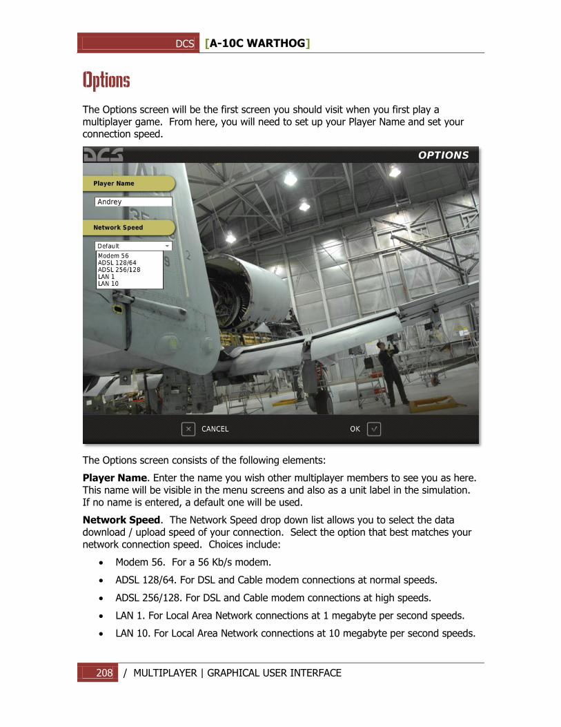
DCS [A-10C WARTHOG]
208 / MULTIPLAYER | GRAPHICAL USER INTERFACE
Options
The Options screen will be the first screen you should visit when you first play a multiplayer game. From here, you will need to set up your Player Name and set your connection speed.
The Options screen consists of the following elements:
Player Name. Enter the name you wish other multiplayer members to see you as here. This name will be visible in the menu screens and also as a unit label in the simulation. If no name is entered, a default one will be used.
Network Speed. The Network Speed drop down list allows you to select the data download / upload speed of your connection. Select the option that best matches your network connection speed. Choices include:
Modem 56. For a 56 Kb/s modem.
ADSL 128/64. For DSL and Cable modem connections at normal speeds.
ADSL 256/128. For DSL and Cable modem connections at high speeds.
LAN 1. For Local Area Network connections at 1 megabyte per second speeds.
LAN 10. For Local Area Network connections at 10 megabyte per second speeds.
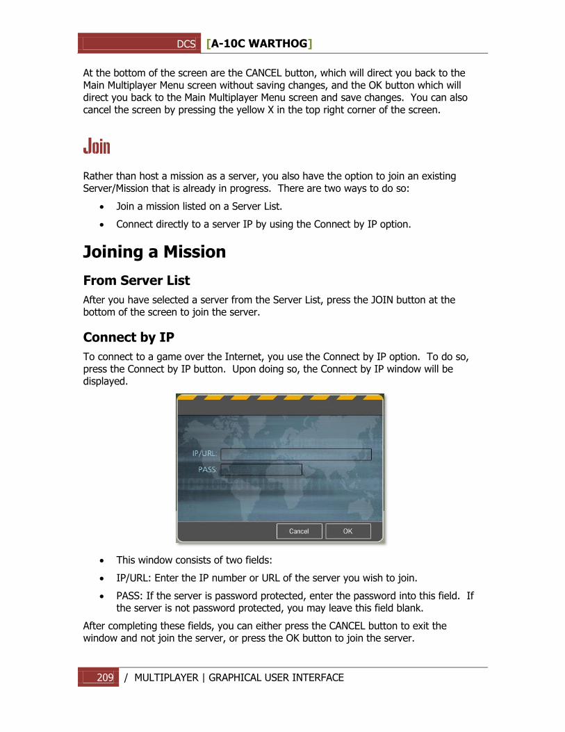
DCS [A-10C WARTHOG]
209 / MULTIPLAYER | GRAPHICAL USER INTERFACE
At the bottom of the screen are the CANCEL button, which will direct you back to the Main Multiplayer Menu screen without saving changes, and the OK button which will direct you back to the Main Multiplayer Menu screen and save changes. You can also cancel the screen by pressing the yellow X in the top right corner of the screen.
Join
Rather than host a mission as a server, you also have the option to join an existing Server/Mission that is already in progress. There are two ways to do so:
Join a mission listed on a Server List.
Connect directly to a server IP by using the Connect by IP option.
Joining a Mission
From Server List
After you have selected a server from the Server List, press the JOIN button at the bottom of the screen to join the server.
Connect by IP
To connect to a game over the Internet, you use the Connect by IP option. To do so, press the Connect by IP button. Upon doing so, the Connect by IP window will be displayed.
This window consists of two fields:
IP/URL: Enter the IP number or URL of the server you wish to join.
PASS: If the server is password protected, enter the password into this field. If the server is not password protected, you may leave this field blank.
After completing these fields, you can either press the CANCEL button to exit the window and not join the server, or press the OK button to join the server.
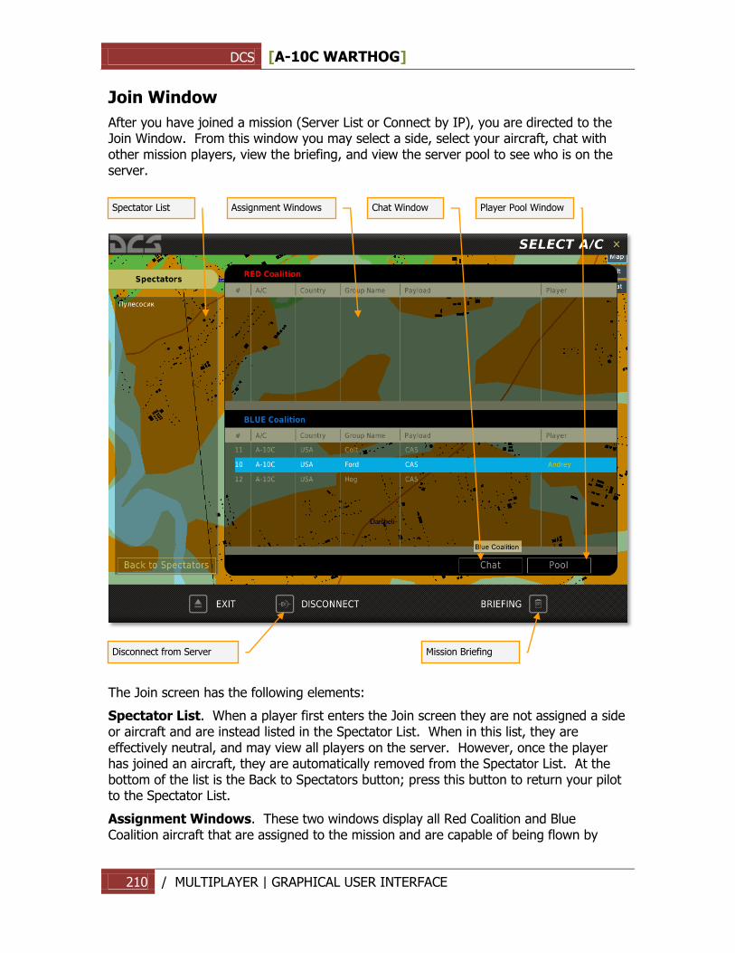
DCS [A-10C WARTHOG]
210 / MULTIPLAYER | GRAPHICAL USER INTERFACE
Join Window
After you have joined a mission (Server List or Connect by IP), you are directed to the Join Window. From this window you may select a side, select your aircraft, chat with other mission players, view the briefing, and view the server pool to see who is on the server.
The Join screen has the following elements:
Spectator List. When a player first enters the Join screen they are not assigned a side or aircraft and are instead listed in the Spectator List. When in this list, they are effectively neutral, and may view all players on the server. However, once the player has joined an aircraft, they are automatically removed from the Spectator List. At the bottom of the list is the Back to Spectators button; press this button to return your pilot to the Spectator List.
Assignment Windows. These two windows display all Red Coalition and Blue Coalition aircraft that are assigned to the mission and are capable of being flown by
Spectator List
Assignment Windows
Chat Window
Player Pool Window
Disconnect from Server
Mission Briefing
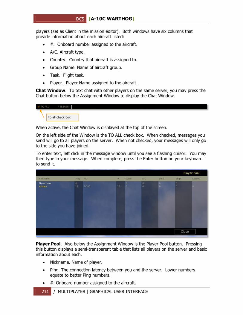
DCS [A-10C WARTHOG]
211 / MULTIPLAYER | GRAPHICAL USER INTERFACE
players (set as Client in the mission editor). Both windows have six columns that provide information about each aircraft listed:
#. Onboard number assigned to the aircraft.
A/C. Aircraft type.
Country. Country that aircraft is assigned to.
Group Name. Name of aircraft group.
Task. Flight task.
Player. Player Name assigned to the aircraft.
Chat Window. To text chat with other players on the same server, you may press the Chat button below the Assignment Window to display the Chat Window.
When active, the Chat Window is displayed at the top of the screen.
On the left side of the Window is the TO ALL check box. When checked, messages you send will go to all players on the server. When not checked, your messages will only go to the side you have joined.
To enter text, left click in the message window until you see a flashing cursor. You may then type in your message. When complete, press the Enter button on your keyboard to send it.
Player Pool. Also below the Assignment Window is the Player Pool button. Pressing this button displays a semi-transparent table that lists all players on the server and basic information about each.
Nickname. Name of player.
Ping. The connection latency between you and the server. Lower numbers equate to better Ping numbers.
#. Onboard number assigned to the aircraft.
To all check box
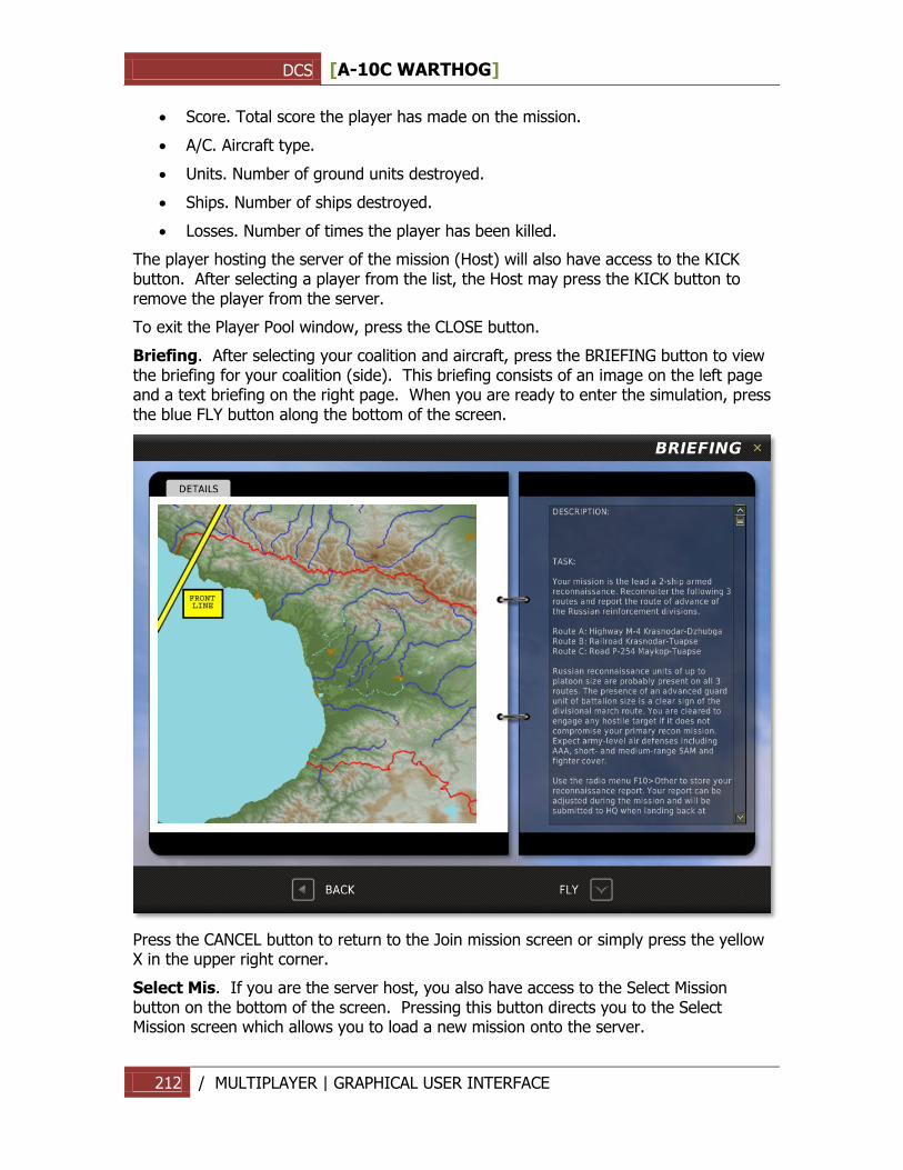
DCS [A-10C WARTHOG]
212 / MULTIPLAYER | GRAPHICAL USER INTERFACE
Score. Total score the player has made on the mission.
A/C. Aircraft type.
Units. Number of ground units destroyed.
Ships. Number of ships destroyed.
Losses. Number of times the player has been killed.
The player hosting the server of the mission (Host) will also have access to the KICK button. After selecting a player from the list, the Host may press the KICK button to remove the player from the server.
To exit the Player Pool window, press the CLOSE button.
Briefing. After selecting your coalition and aircraft, press the BRIEFING button to view the briefing for your coalition (side). This briefing consists of an image on the left page and a text briefing on the right page. When you are ready to enter the simulation, press the blue FLY button along the bottom of the screen.
Press the CANCEL button to return to the Join mission screen or simply press the yellow X in the upper right corner.
Select Mis. If you are the server host, you also have access to the Select Mission button on the bottom of the screen. Pressing this button directs you to the Select Mission screen which allows you to load a new mission onto the server.
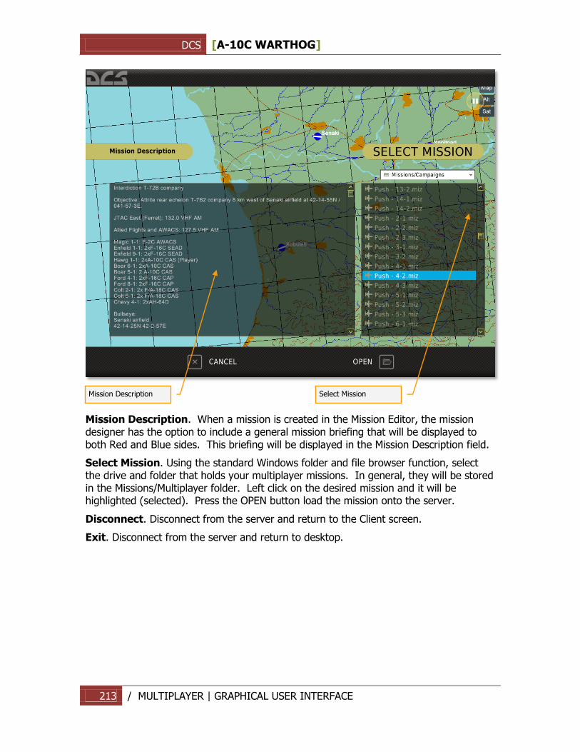
DCS [A-10C WARTHOG]
213 / MULTIPLAYER | GRAPHICAL USER INTERFACE
Mission Description. When a mission is created in the Mission Editor, the mission designer has the option to include a general mission briefing that will be displayed to both Red and Blue sides. This briefing will be displayed in the Mission Description field.
Select Mission. Using the standard Windows folder and file browser function, select the drive and folder that holds your multiplayer missions. In general, they will be stored in the Missions/Multiplayer folder. Left click on the desired mission and it will be highlighted (selected). Press the OPEN button load the mission onto the server.
Disconnect. Disconnect from the server and return to the Client screen.
Exit. Disconnect from the server and return to desktop.
Mission Description
Select Mission
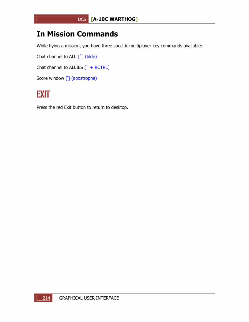
DCS [A-10C WARTHOG]
214 | GRAPHICAL USER INTERFACE
In Mission Commands
While flying a mission, you have three specific multiplayer key commands available: Chat channel to ALL [`] (tilde) Chat channel to ALLIES [` + RCTRL] Score window [„] (apostrophe)
EXIT
Press the red Exit button to return to desktop.
DCS [A-10C WARTHOG]
215 REFERENCES | GRAPHICAL USER INTERFACE
REFERENCES www.arms-expo.ru www.snariad.ru www.warships.ru www.ship.bsu.by www.militarism.fatal.ru www.military-informer.narod.ru www.rbase.new-factoria.ru www.gortransport.kharkov.ua www.denisovets.narod.ru www.mi-helicopter.ru www.airwar.ru www.aviastar.org www.worldweapon.ru www.army.lv www.aviaport.ru www.sukhoi.org www.migavia.ru www.milrus.com www.warplane.ru www.legion.wplus.net www.pvo.guns.ru www.rusarmy.com www.museum.radioscanner.ru www.armor.kiev.ua www.russarms.com www.btvt.narod.ru www.wikipedia.org www.otvaga2004.narod.ru www.army-guide.com www.walkarounds.airforce.ru www.ruspodvig.ru www.belostokskaya.ru www.otvaga.vif2.ru www.topgun.rin.ru www.worldweaponry.by.ru
©2011 THE FIGHTER COLLECTION. All rights reserved.
©2011 EAGLE DYNAMICS. All rights reserved.