TM 9-2350-277-24P - Combat Index
27
TM 9-2350-277-24P This manual supersedes TM 9-2350-277-24P, dated 25 July 1994 TECHNICAL MANUAL UNIT, DIRECT SUPPORT, AND GENERAL SUPPORT MAINTENANCE REPAIR PARTS AND SPECIAL TOOLS LIST (INCLUDING DEPOT MAINTENANCE REPAIR PARTS AND SPECIAL TOOLS LIST) FOR CARRIER, PERSONNEL, FULL-TRACKED, ARMORED, M113A3 (2350-01-219-7577) CARRIER, COMMAND POST, LIGHT TRACKED, M577A3 (2350-01-369-6085) CARRIER, SMOKE GENERATOR, FULL TRACKED, M1059A3 (2350-01-369-6083) CARRIER, ANTI-TANK (TOW), FULL TRACKED, ARMORED M901A3 (2350-01-369-7253) CARRIER, MORTAR, 120-MM M121, SELF PROPELLED, M1064A3 (2350-01-369-6082) CARRIER, STANDARDIZED INTERGRATED COMMAND POST SYSTEM (SICPS) M1068A3 (2350-01-369-6086) CARRIER, FIRE SUPPORT PERSONNEL, FULL TRACKED, ARMORED M981A3 (2350-01-369-6079) CHASSIS, MECHANIZED SMOKE OBSCURANT M58 (2350-01-418-6654) Distribution: Approved for public release; distribution is unlimited. HEADQUARTERS, DEPARTMENT OF THE ARMY SEPTEMBER, 1997
-
Upload
khangminh22 -
Category
Documents
-
view
3 -
download
0
Transcript of TM 9-2350-277-24P - Combat Index

TM 9-2350-277-24PThis manual supersedes TM 9-2350-277-24P, dated 25 July 1994
TECHNICAL MANUALUNIT, DIRECT SUPPORT, AND GENERAL SUPPORT MAINTENANCE
REPAIR PARTS AND SPECIAL TOOLS LIST(INCLUDING DEPOT MAINTENANCE REPAIR PARTS
AND SPECIAL TOOLS LIST)FOR
CARRIER, PERSONNEL, FULL-TRACKED, ARMORED,M113A3
(2350-01-219-7577)
CARRIER, COMMAND POST, LIGHT TRACKED,M577A3
(2350-01-369-6085)
CARRIER, SMOKE GENERATOR, FULL TRACKED,M1059A3
(2350-01-369-6083)
CARRIER, ANTI-TANK (TOW), FULL TRACKED, ARMOREDM901A3
(2350-01-369-7253)
CARRIER, MORTAR, 120-MM M121, SELF PROPELLED,M1064A3
(2350-01-369-6082)
CARRIER, STANDARDIZED INTERGRATED COMMAND POST SYSTEM (SICPS)M1068A3
(2350-01-369-6086)
CARRIER, FIRE SUPPORT PERSONNEL, FULL TRACKED, ARMOREDM981A3
(2350-01-369-6079)
CHASSIS, MECHANIZED SMOKE OBSCURANTM58
(2350-01-418-6654)
Distribution: Approved for public release; distribution is unlimited.
HEADQUARTERS, DEPARTMENT OF THE ARMY
SEPTEMBER, 1997

*TM 9-2350-277-24P
HEADQUARTERSTECHNICAL MANUAL DEPARTMENT OF THE ARMY
Washington D.C., 13 Sept 1997*NO. 9-2350-277-24P
TECHNICAL MANUALUNIT, DIRECT SUPPORT, AND GENERAL SUPPORT MAINTENANCE
REPAIR PARTS AND SPECIAL TOOLS LIST(INCLUDING DEPOT MAINTENANCE REPAIR PARTS
AND SPECIAL TOOLS LIST)FOR
CARRIER, PERSONNEL, FULL-TRACKED, ARMORED,M113A3
(2350-01-219-7577)
CARRIER, COMMAND POST, LIGHT TRACKED,M577A3
(2350-01-369-6085)
CARRIER, SMOKE GENERATOR, FULL TRACKED,M1059A3
(2350-01-369-6083)
CARRIER, ANTI-TANK (TOW), FULL TRACKED, ARMOREDM901A3
(2350-01-369-7253)
CARRIER, MORTAR, 120-MM M121, SELF PROPELLED,M1064A3
(2350-01-369-6082)
CARRIER, STANDARDIZED INTERGRATED COMMAND POST SYSTEM (SICPS)M1068A3
(2350-01-369-6086)
CARRIER, FIRE SUPPORT PERSONNEL, FULL TRACKED, ARMOREDM981A3
(2350-01-369-6079)
CHASSIS, MECHANIZED SMOKE OBSCURANTM58
(2350-01-418-6654)CURRENT AS OF 15 APRIL 1997
REPORTING OF ERRORSYou can help improve this manual. If you find any mistakes or if you know of a way to improve the procedures, please letus know. Mail your letter DA Form 2028 (Recommended Changes to Publications and Blank Forms) or DA Form 2n9.8-2located in the back of this manual direct to: Commander, I T S Army Tank-automotive and Armaments CommandATTN:AMSTA-AC-NML, Rock Island, IL 6122C-763i). A reply -will be furnished to you.
Distribution: Approved for public release; distribution is unlimited.
*This publication supersedes TM 9-2350-277-24P, Dated 25 July 1994

TM 9-2350-277-24PC01
TABLE OF CONTENTSILLUS
PAGE FIGURE
SECTION I INTRODUCTION ..............................................................................................................1
SECTION II REPAIR PARTS LIST.................................................................................................... 1-1
Group 01 - ENGINE0100 Engine and Container..................................................................................................... 1-1 10100 TV Modulator Cable Bracket and Attaching Hardware ..................................................... 2-1 20100 Engine Mounting Brackets and Engine Mounts ............................................................... 3-1 30101 Cylinder Block Assembly, End Plate and Related Parts ................................................... 4-1 10101 Air Box Drain and Related Parts .................................................................................... 5-1 50101 Engine Front Supports .................................................................................................. 6-1 60101 Cylinder Head Assembly and Lifting Brackets ................................................................. 7-1 70103 Pulley Assembly ............................................................................................................ 8-1 80103 Drive Plate, Flywheel, and Housing ................................................................................ 9-1 90105 Rocker Arm Covers ..................................................................................................... 10-1 100106 Engine Oil Sampling Valve, Hose, and Oil Gage Rod Clamp .......................................... 11-1 110106 Oil Cooler Assembly .................................................................................................... 12-1 120106 Oil Pan and Oil Gage Assembly.................................................................................... 13-1 130106 Oil Filter Assembly, Adapter, and Related Parts ............................................................ 14-1 140108 Exhaust Manifold ........................................................................................................ 15-1 15
Group 03 - FUEL SYSTEM0302 Fuel Pump Assembly and Drive ................................................................................... 16-1 160302 Fuel Lines and Fittings ................................................................................................ 17-1 170304 Air Cleaner Installation ................................................................................................. 18-1 180304 Air Cleaner Hoses and Fittings...................................................................................... 19-1 190304 Air Cleaner Assembly .................................................................................................. 20-1 200305 Turbocharger and Related Parts .................................................................................. 21-1 210305 Blower Drive Gear and Related Parts ........................................................................... 22-1 220305 Air Inlet Housing and Related Parts .............................................................................. 23-1 230306 Engine Fuel Supply and Fuel Return Hoses .................................................................. 24-1 240306 External Fuel Tank Components .................................................................................. 25-1 250306 External Fuel Tank Components .................................................................................. 26-1 260306 Fuel Lines, Fittings and Mounting Hardware ................................................................. 27-1 270306 Internal Left Tank Fuel Filler Neck and Lines ................................................................ 28-1 280306 Internal Right Tank Fuel Filler Neck and Lines .............................................................. 29-1 290306 Duel Fuel Tanks and Mounting Hardware ..................................................................... 30-1 300306 Duel Fuel Tanks Cross Over Tubes and Hoses ............................................................. 31-1 310306 Fuel Lines and Fittings ................................................................................................ 32-1 320306 Fuel Lines, Fittings and Mounting Hardware ................................................................. 33-1 330306 Fuel Line Fittings ......................................................................................................... 34-1 340306 Fuel Lines Fittings and Mounting Hardware .................................................................. 35-1 350306 Fuel Line Fittings ......................................................................................................... 36-1 360306 Cover, Fuel Access...................................................................................................... 37-1 370309 Fuel Filter and Strainer Assemblies and Related Parts .................................................. 38-1 380311 Air Box Heater Related Parts ....................................................................................... 39-1 390311 Air Box Heater Assembly.............................................................................................. 40-1 400311 Air Pump, Ignition Coil, and Related Parts .................................................................... 41-1 41
i

TM 9-2350-277-24PC01
TABLE OF CONTENTS (cont)ILLUS
PAGE FIGURE
0311 Glow Plug Controller and Related Parts ......................................................................41A-1 41A0312 Fuel Controls .............................................................................................................. 42-1 420312 Fuel Control Linkage .................................................................................................... 43-1 43
Group 04 - EXHAUST SYSTEM0401 Exhaust System Assembly .......................................................................................... 44-1 44
Group 05 - COOLING SYSTEM0501 Radiator and Expansion Tank ...................................................................................... 45-1 450503 Thermostat, Hoses, and Mounting Hardware ................................................................ 46-1 460503 Radiator Hoses, Tubes and Elbows .............................................................................. 47-1 470503 Radiator Hoses, Tubes and Elbows .............................................................................. 48-1 480503 Thermostat, Housing, Lines, and Fittings ...................................................................... 49-1 490504 Cooler Pump Assembly, Idler Pulley, and Belt Set ......................................................... 50-1 500505 Variable Speed Drive Hose, Pulleys, and Transmission Oil Return Hose ........................ 51-1 510505 Variable Speed Drive .................................................................................................. 52-1 520505 Fan and Drive Installation ............................................................................................. 53-1 530505 Vaneaxial Fan.............................................................................................................. 54-1 540505 Gear Box Assembly .................................................................................................... 55-1 550505 Deleted ...................................................................................................................... 56-1 56
Group 06 - ELECTRICAL SYSTEM0601 200 AMP Generator Mounting and Belt ........................................................................ 57-1 570601 200 AMP Generator .................................................................................................... 58-1 580602 Regulator and Mounting hardware ................................................................................ 59-1 590603 Starter Relay arid Leads .............................................................................................. 60-1 600603 Starter and Mounting Hardware ................................................................................... 61-1 610607 Master Switch Panel ................................................................................................... 62-1 620607 Master Switch Assembly ............................................................................................. 63-1 630607 Distribution Box .......................................................................................................... 64-1 640607 Distribution Box .......................................................................................................... 65-1 650607 Distribution Box .......................................................................................................... 66-1 660607 Instrument Panel Switches, Lights, and Gages ............................................................. 67-1 670607 Instrument Panel Switches, Lights, and Gages ............................................................. 68-1 680607 Instrument Panel Indicator Lights ................................................................................. 69-1 690607 Warning Light Panel Assembly .................................................................................... 70-1 700607 Distribution Box and Instrument Panel Mounting............................................................ 71-1 710608 Telepost and Cover ..................................................................................................... 72-1 720608 Steering Solenoid, Power Supply, and Electrical Components ....................................... 73-1 730608 Power Pack Assembly (Old Configuration ..................................................................... 74-1 740608 Power Pack Old Configuration...................................................................................... 75-1 750609 Horn, Blackout Lights, and Mounting Hardware.............................................................. 76-1 760609 Headlight..................................................................................................................... 77-1 770609 Stop and Taillight Assembly, left Side ........................................................................... 78-1 780609 Stop and Taillight Assembly, Right Side ....................................................................... 79-1 790609 Dome Lights and Mounting Hardware ........................................................................... 80-1 800609 Dome Light ................................................................................................................. 81-1 81
ii

TM 9-2350-277-24PC01
TABLE OF CONTENTS (cont)ILLUS
PAGE FIGURE
0603 Tail Light and Mounting Hardware, Right Side ............................................................... 82-1 820609 Tail Light and 'Mounting Hardware, Left Side ................................................................. 83-1 830610 Ramp Warning Switches and Buzzer ............................................................................ 84-1 840610 Power Plant Sending Units .......................................................................................... 85-1 850610 Brake Switches ........................................................................................................... 86-1 860612 Batteries and Mounting Hardware ................................................................................ 87-1 870612 Batteries and Mounting Hardware ................................................................................ 88-1 880612 Batteries and Mounting Hardware ................................................................................ 89-1 890612 Battery Box Covers and Mounting ................................................................................ 90-1 900612 Batteries and Mounting Hardware ................................................................................ 91-1 910612 Battery Box Assembly ................................................................................................. 92-1 920612 Battery Box Cover and Mounting................................................................................... 93-1 930612 Batteries and Battery Tray Slides, Left Side .................................................................. 94-1 940612 Battery Tray Assembly. .............................................................................................. 95-1 950612 Battery Box Cover and Mounting .................................................................................. 96-1 960613 Instrument Panel Electrical Components ....................................................................... 97-1 970613 Instrument Panel Utility Outlet Electrical Lead Assembly . ............................................ 98-1 980613 Utility Outlet Electrical Assembly .................................................................................. 99-1 990613 NATO Slave Receptacle Assembly ............................................................................ 100-1 1000613 Master Switch/Dome Light Electrical Lead Assembly.................................................... 101-1 1010613 Master Switch/Distribution Box Electrical Lead Assembly ............................................. 102-1 1020613 Master Switch/Distribution Box Wiring Harness Assembly ........................................... 103-1 1030613 Taillight Wiring Harness Assembly and Attaching Hardware ......................................... 104-1 1040613 Engine Wiring Harness .............................................................................................. 105-1 1050613 Transmission Wiring Harness .................................................................................... 106-1 1060613 Wiring Harness Attaching Hardware, Power Plant ....................................................... 107-1 1070613 Wiring Harness, Transmission Controller ..................................................................... 108-1 1080613 Vehicle Special Purpose Electrical Branched Cable Assembly ..................................... 109-1 1090613 Vehicle Electrical Components .................................................................................. 110-1 1100613 Vehicle Electrical Components .................................................................................. 111-1 1110613 Main Wiring Harness, Forward Section ....................................................................... 112-1 1120613 Main Wiring Harness, Forward Section ....................................................................... 113-1 1130613 Main Wiring Harness, Forward Section........................................................................ 114-1 1140613 Main Wiring Harness, Forward Section ....................................................................... 115-1 1150613 Main Wiring Harness, Rear Section ............................................................................ 116-1 1160613 Wiring Harness, Branched ......................................................................................... 117-1 1170613 Main Vehicular Wiring Harness .................................................................................. 118-1 1180613 Smoke Grenade Launcher Wiring Harness, Left Side .................................................. 119-1 1190613 Smoke Grenade Launcher Wiring Harness, Right Side ................................................ 120-1 1200613 Smoke Grenade Launcher Wiring Harness ................................................................. 121-1 1210613 Wiring Harness, Smoke Grenade Launcher ................................................................ 122-1 1220613 Smoke Grenade launcher Wiring Harness Attaching Hardware..................................... 123-1 1230613 Wiring Harness, Steering Lock Light ........................................................................... 124-1 1240613 Wiring Harness, Battery ............................................................................................. 125-1 1250613 Wiring Harness, Radio ............................................................................................... 126-1 1260613 Wiring Harness, Headlight .......................................................................................... 127-1 1270613 Cable, Special Purpose, Instrument Panel .................................................................. 128-1 1280613 Wiring Harness, Warning Panel ................................................................................. 129-1 1290613 Electrical Wiring Harness Components and Mounting Hardware .................................. 130-1 1300613 Electrical Harness Attaching Hardware ....................................................................... 131-1 131
iii

TM 9-2350-277-24PC01
TABLE OF CONTENTS (cont)ILLUS
PAGE FIGURE
0613 Electrical Harness Attaching Hardware........................................................................ 132-1 1320613 Electrical Harness Attaching Hardware ....................................................................... 133-1 1330613 Electrical harness Attaching Hardware ....................................................................... 134-1 1340613 Electrical Harness Attaching Hardware ....................................................................... 135-1 1350613 Electrical Harness Attaching Hardware ....................................................................... 136-1 1360613 Wiring Harness, Radio ............................................................................................... 137-1 1370613 Electrical Harness Attaching Hardware ....................................................................... 138-1 1380613 Electrical Harness Attaching Hardware ....................................................................... 139-1 1390613 Electrical Wiring Harness Components and Mounting Hardware ................................... 140-1 1400613 Electrical Harness Attaching Hardware ....................................................................... 141-1 1410613 Main Harness Attaching Hardware, left Side ............................................................... 142-1 1420613 Main Harness Attaching Hardware, Left Rear .............................................................. 143-1 1430613 Main Harness Attaching Hardware, Right Side ............................................................ 144-1 1440616 Ventilation Fan Assembly and Mounting Hardware ...................................................... 145-1 145
Group 07 - TRANSMISSION0700 Transmission with Container....................................................................................... 146-1 160700 Transmission Oil Drain .............................................................................................. 147-1 1470700 Transmission Mounting Parts ..................................................................................... 148-1 1480705 Electrical-Controller, Transmission (New Configuration ................................................ 149-1 1490708 Tow Start and Controls .............................................................................................. 150-1 1500710 Fill Tube Assembly .................................................................................................... 151-1 1510710 Right Hand Cover and Center Housing ....................................................................... 152-1 1520710 Output Driven Gear and Steer Shaft Drive Gear .......................................................... 153-1 1530710 Left Hand Cover ........................................................................................................ 154-1 1540710 Top Cover ................................................................................................................ 155-1 1550710 Deleted .................................................................................................................... 156-1 1560710 Center Housing and Hydrostatic Pump and Motor ....................................................... 157-1 1570710 Left Hand End Cover and Output Shaft ....................................................................... 158-1 1580710 Right Hand End Cover and Brake Apply Cam Shaft .................................................... 159-1 1590714 Governor and Governor Body .................................................................................... 160-1 1600714 G2 Backup, Priority Valve and Oil Transfer Plate ......................................................... 161-1 1610721 Transmission Oil Cooler Hoses and Sampling Valve ................................................... 162-1 1620721 Filter Cover Assembly and Filter Element ................................................................... 163-1 163
Group 08 - TRANSFER AND FINAL DRIVE ASSEMBLIES0801 Final Drive Assembly and Filler Tube ......................................................................... 164-1 1610801 Final Drive Assembly. .............................................................................................. 165-1 165
Group 09 - PROPELLER, PROPELLER SHAFT, UNIVERSAL JOINTSCOUPLER AND CLAMP ASSEMBLY
0900 Propeller Shaft and component parts ......................................................................... 166-1 166
Group 12- BRAKES1206 Brake Installation ....................................................................................................... 167-1 1671206 Lever, Manual Control . ............................................................................................ 168-1 168
iv
TM 9-2350-277-24PC01
TABLE OF CONTENTS (cont)ILLUS
PAGE FIGURE
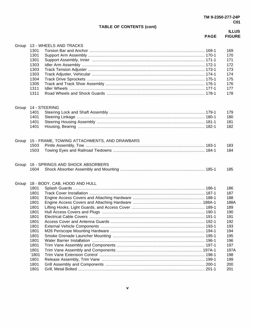
Group 13 - WHEELS AND TRACKS1301 Torsion Bar and Anchor ............................................................................................. 169-1 1691301 Support Arm Assembly .............................................................................................. 170-1 1701301 Support Assembly, Inner ........................................................................................... 171-1 1711303 Idler Arm Assembly ................................................................................................... 172-1 1721303 Track Tension Adjuster .............................................................................................. 173-1 1731303 Track Adjuster, Vehicular ........................................................................................... 174-1 1741304 Track Drive Sprockets ............................................................................................... 175-1 1751305 Track and Track Shoe Assembly ................................................................................ 176-1 1761311 Idler Wheels ............................................................................................................. 177-1 1771311 Road Wheels and Shock Guards ............................................................................... 178-1 178
Group 14 - STEERING1401 Steering Lock and Shaft Assembly ............................................................................. 179-1 1791401 Steering Linkage ....................................................................................................... 180-1 1801401 Steering Housing Assembly ....................................................................................... 181-1 1811401 Housing, Bearing ...................................................................................................... 182-1 182
Group 15 - FRAME, TOWING ATTACHMENTS, AND DRAWBARS1503 Pintle Assembly, Tow ................................................................................................ 183-1 1831503 Towing Eyes and Railroad Tiedowns .......................................................................... 184-1 184
Group 16 - SPRINGS AND SHOCK ABSORBERS1604 Shock Absorber Assembly and Mounting .................................................................... 185-1 185
Group 18 - BODY, CAB, HOOD AND HULL1801 Splash Guards .......................................................................................................... 186-1 1861801 Track Cover Installation ............................................................................................. 187-1 1871801 Engine Access Covers and Attaching Hardware .......................................................... 188-1 1881801 Engine Access Covers and Attaching Hardware ........................................................ 188A-1 188A1801 Lifting Hooks, Light Guards, and Access Cover ........................................................... 189-1 1891801 Hull Access Covers and Plugs ................................................................................... 190-1 1901801 Electrical Cable Covers ............................................................................................. 191-1 1911801 Access Cover and Antenna Guards ............................................................................ 192-1 1921801 External Vehicle Components .................................................................................... 193-1 1931801 M26 Periscope Mounting Hardware ............................................................................ 194-1 1941801 Smoke Grenade Launcher Mounting .......................................................................... 195-1 1951801 Water Barrier Installation ........................................................................................... 196-1 1961801 Trim Vane Assembly and Components ....................................................................... 197-1 1971801 Trim Vane Assembly and Components ..................................................................... 197A-1 197A`1801 Trim Vane Extension Control ..................................................................................... 198-1 1981801 Release Assembly, Trim Vane ................................................................................... 199-1 1991801 Grill Assembly and Components ................................................................................ 200-1 2001801 Grill, Metal Bolted ...................................................................................................... 201-1 201
v

TM 9-2350-277-24PC01
TABLE OF CONTENTS (cont)ILLUS
PAGE FIGURE
1801 Power Plant Door Installation ..................................................................................... 202-1 2021801 Door, Power Plant ..................................................................................................... 203-1 2031801 Hatch, Cargo Cover .................................................................................................. 204-1 2041801 Cargo Hatch Cover Assembly .................................................................................... 205-1 2051801 Cargo Hatch Components ......................................................................................... 206-1 2061801 Cargo Hatch Cover Hinges and Latches ..................................................................... 207-1 2071801 Door, Cargo Hatch .................................................................................................... 208-1 2081801 Cargo Hatch Covers and Hinges ................................................................................ 209-1 2091801 Hatch Cover External Locking Hardware .................................................................... 210-1 2101801 Turbine Access Door Assembly ............................................................................... 210A-1 210A1801 Hopper Hatch Installation ........................................................................................ 210B-1 210B1801 Hatch Cover Internal Locking Hardware ..................................................................... 211-1 2111801 Commander's Hatch Cover Assembly ........................................................................ 212-1 2121801 Commander's Hatch Cover Latches ........................................................................... 213-1 2131801 Commander's Cupola Installation ............................................................................... 214-1 2141801 Commander's Cupola Assembly ................................................................................ 215-1 2151801 Commander's Cupola Hatch and Cover Assemblies .................................................... 216-1 2161801 Commander's Cupola and Cover Latches ................................................................... 217-1 2171801 Commander's Hatch Machine Gun Mount ................................................................... 218-1 2181801 Spall Liner Installation, Right Side .............................................................................. 219-1 2191801 Spall Liner Installation, Left Side ................................................................................ 220-1 2201801 Spall Liner Brackets and Mounting Hardware .............................................................. 221-1 2211801 Floor Plate and Ramp Door Supplemental Armor ........................................................ 222-1 2221801 Ramp Assembly and Mounting Hardware ................................................................... 223-1 2231801 Ramp Assembly and Mounting Hardware ................................................................... 224-1 2241801 Ramp Door and Access Door Assembly ..................................................................... 225-1 2251801 Ramp Door and Access Door Assembly ..................................................................... 226-1 2261801 Rear Access Door Direct Vision Port .......................................................................... 227-1 2271801 Ramp Assembly and Mounting Hardware ................................................................... 228-1 2281801 Ramp Door and Access Door Assembly ..................................................................... 229-1 2291801 Ramp Lock Installation .............................................................................................. 230-1 2301801 Ramp Lock Assemblies ............................................................................................. 231-1 2311801 Ramp Lock Release Latch and Mounting Hardware .................................................... 232-1 2321801 Ramp Lock Release Handle and Mounting Hardware .................................................. 233-1 2331801 Ramp Lock Release Handle and Mounting Hardware .................................................. 234-1 2341801 Gun Shield Mounting Installation ................................................................................ 235-1 2351801 Armor Mounting Provisions ........................................................................................ 236-1 2361801 Armor Mounting Provisions ........................................................................................ 237-1 2371801 Smoke Generator Armor Installation ........................................................................... 238-1 2381801 Power Plant Door and Trim Vane Mounting Provisions ................................................ 239-1 2391801 Threaded Inserts ....................................................................................................... 240-1 2401801 SCREW Threaded Special Purpose Inserts ................................................................ 241-1 2411801 Hull SCREW Threaded Inserts .................................................................................. 242-1 2421801 SCREW Threaded Special Purpose Inserts ................................................................ 243-1 2431801 Power Train and Air Cleaner Mounting Provisions ....................................................... 244-1 2441801 Threaded Inserts ....................................................................................................... 245-1 2451801 Threaded Inserts, Suspension ................................................................................... 246-1 2461801 Threaded Inserts ....................................................................................................... 247-1 2471803 Driver's Hatch Assembly ........................................................................................... 248-1 2481803 Driver's Hatch Assembly ........................................................................................... 249-1 249
vi

TM 9-2350-277-24PC01
TABLE OF CONTENTS (cont)ILLUS
PAGE FIGURE
1803 Driver's Hatch Assembly ........................................................................................... 250-1 2501803 Driver's Hatch Cover Assembly .................................................................................. 251-1 2511803 Driver's Hatch Yoke Support Assembly ...................................................................... 252-1 2521803 Latch Assembly, Driver's Hatch .................................................................................. 253-1 2531803 Driver's Hatch and Periscope Latches ........................................................................ 254-1 2541803 Plate Assembly, Quick Release ................................................................................. 255-1 2551803 Driver's Thermal Viewer Mounting Plate DELETED ................................................... 255A-1 255A1805 Floor Plates .............................................................................................................. 256-1 2561805 Floor Plates .............................................................................................................. 257-1 2571805 Floor Plates and Cushions ......................................................................................... 258-1 2581805 Vehicle Interior Floor ................................................................................................. 259-1 2591805 Floor Plate Pads ....................................................................................................... 260-1 2601803 Floor Plates and Cushions ......................................................................................... 261-1 2611803 Floor Plates and Cushions ....................................................................................... 261A-1 261A1806 Personnel Seats and Straps ...................................................................................... 262-1 2621806 Commander's Seat, Personnel Seats and Seat Belts .................................................. 263-1 2631806 Personnel Seats and Straps ...................................................................................... 264-1 2641806 Personnel Seats and Tables Installation ..................................................................... 265-1 2651806 Personnel Seats and Tables Installation, Right ........................................................... 266-1 2661806 Personnel Seats and Tables Installation, Left .............................................................. 267-1 2671806 Personnel Seats and Straps ...................................................................................... 268-1 2681806 Smoke Generator's Operator's Seat ........................................................................... 269-1 2691806 Driver's Seat Installation ............................................................................................ 270-1 2701806 Commander's Seat and Platform................................................................................. 271-1 2711806 Commander's Seat and Platform................................................................................. 272-1 2721806 Commander's Platform Assembly .............................................................................. 273-1 2731806 Commander's Platform Components .......................................................................... 274-1 2741806 Commander's Seat and Platform................................................................................. 275-1 2751806 Driver's Seat and Radio Operator's Seat Assembly ..................................................... 276-1 2761806 Driver's Seat Mount Assembly ................................................................................... 277-1 2771806 Radio Operator's Seat ............................................................................................... 278-1 2781806 Commander's Platform Assembly .............................................................................. 279-1 2791806 Commander's Seat ................................................................................................... 280-1 2801806 Commander's Seat ................................................................................................... 281-1 2811806 Commander's Jump Seat .......................................................................................... 282-1 2821808 Stowage Components ............................................................................................... 283-1 2831808 Stowage Straps ...................................................................................................... 283A-1 283A1808 Stowage Straps and Rifle Brackets ............................................................................ 284-1 2841808 Stowage Components ............................................................................................... 285-1 2851808 Stowage Components ............................................................................................... 286-1 2861808 Right Side Stowage Straps and Mounting Hardware ................................................... 287-1 2871808 Left Side Stowage Straps and Mounting Hardware ...................................................... 288-1 2881808 Stowage Straps and Mounting Hardware .................................................................... 289-1 2891808 External Stowage Straps, Covers, and Mounting Hardware ......................................... 290-1 2901808 External Stowage Straps, Covers, and Mounting Hardware ......................................... 291-1 2911808 Internal Stowage Straps, Racks and Hardware ........................................................... 292-1 2921808 Bracket Mounting, Fire Extinguisher ........................................................................... 293-1 2931808 Stowage Straps and Mounting Hardware .................................................................... 294-1 2941808 Stowage Straps and Mounting Hardware .................................................................... 295-1 2951808 Stowage Straps, Antenna Guards and Covers . ......................................................... 296-1 296
vii

TM 9-2350-277-24PC01
TABLE OF CONTENTS (cont)ILLUS
PAGE FIGURE
1808 Internal Vehicle Components ..................................................................................... 297-1 2971808 Vehicle Straps and Components ................................................................................ 298-1 2981808 Internal Vehicle Stowage Straps ................................................................................ 299-1 2991808 Intervehicle Power Cable ........................................................................................... 300-1 3001808 Stowage Straps ........................................................................................................ 301-1 3011808 Stowage Straps ........................................................................................................ 302-1 3021808 Stowage Straps ........................................................................................................ 303-1 3031808 External Stowage Straps, Pads, and Mounting Hardware ............................................ 304-1 3041808 Stowage Components ............................................................................................... 305-1 3051808 Backpack Stowage Rack ........................................................................................... 306-1 3061808 External Stowage Mortar Base ................................................................................... 307-1 3071808 Racks, Ammunition ................................................................................................... 308-1 3081808 Racks, Ammunition ................................................................................................... 309-1 3091808 Racks Assembly, Riffle .............................................................................................. 310-1 3101808 Left Side, Internal Stowage, Racks and Hardware ....................................................... 311-1 3111808 Right Side, Internal Stowage, Racks and Hardware ..................................................... 312-1 3121808 Left Side, Internal Stowage, Racks and Hardware ....................................................... 313-1 3131808 Right Side, Internal Stowage, Racks and Hardware ..................................................... 314-1 3141808 Right Side, Internal Stowage, Racks and Hardware ..................................................... 315-1 3151808 Fire Extinguisher Mount and Related Hardware .......................................................... 316-1 3161808 Launch Tube Components ........................................................................................ 317-1 3171808 Missile Stowage Racks ............................................................................................. 318-1 3181808 Missile Stowage Racks ............................................................................................. 319-1 3191808 Tow Tripod Stowage Components ............................................................................. 320-1 3201808 Periscope Stowage Box ............................................................................................ 321-1 3211808 Electrical Equipment Rack Assembly ......................................................................... 322-1 3221808 Electrical Equipment Rack Assembly ......................................................................... 323-1 3231808 Antenna Mast Mounting Hardware ............................................................................. 324-1 324
Group 22 - BODY CHASSIS OR HULL AND ACCESSORY ITEMS2201 Blackout Curtain Assembly......................................................................................... 325-1 3252201 Extension Cover Tent Assembly ................................................................................ 326-1 3262201 Extension Cover Mounting Hardware ......................................................................... 327-1 3272201 Extension Cover Mounting Hardware ......................................................................... 328-1 3282201 Extension Cover and Boot Wall Mounting .................................................................... 329-1 3292202 Driver's Level Indicator .............................................................................................. 330-1 3302205 Bilge Pump, Front ..................................................................................................... 331-1 3312205 Bilge Pump, Rear ...................................................................................................... 332-1 3322207 Personnel Compartment Heating Unit ........................................................................ 333-1 3332207 Heater Kit Fuel Lines and Fittings .............................................................................. 334-1 3342207 Heater Kit Fuel Lines and Fittings .............................................................................. 335-1 3352207 Personnel Heater Kit Fuel Lines and Fittings ............................................................... 336-1 3362207 Personnel Heater Fuel Lines and Fittings ................................................................... 337-1 3372210 Decals and Markers .................................................................................................. 338-1 3382210 Decals and Markers ................................................................................................ 338A-1 338A2210 Decals and Markers ................................................................................................ 338B-1 338B2210 Decals and Markers .................................................................................................. 339-1 3392210 Data Plates and Decals ............................................................................................. 340-1 3402210 Data Plates and Decals ........................................................................................... 340A-1 340A
viii

TM 9-2350-277-24PC01
TABLE OF CONTENTS (cont)ILLUS
PAGE FIGURE
2210 Data Plates and Decals ............................................................................................. 341-1 3412210 Data Plates and Decals ............................................................................................. 342-1 3422210 Data Plates and Decals ............................................................................................. 343-1 3432210 Data Plates and Decals ........................................................................................... 343A-1 343A2210 Data Plates and Decals ............................................................................................. 344-1 3442210 Decals and Markers ................................................................................................ 344A-1 344A2210 Decals and Markers .................................................................................................. 345-1 3452210 Decals and Markers .................................................................................................. 346-1 3462210 Decals and Markers .................................................................................................. 347-1 3472210 Decals and Markers .................................................................................................. 348-1 3482210 Decals and Markers .................................................................................................. 349-1 349
Group 24 - HYDRAULIC LIFT COMPONENTS2401 Hydraulic Pump ........................................................................................................ 350-1 3502404 Hydraulic Lines and Fittings ....................................................................................... 351-1 3512406 Ramp Actuator Hydraulic Lines Fittings ...................................................................... 352-1 3522406 Ramp Actuator Hydraulic Lines Fittings ...................................................................... 353-1 3532406 Ramp Control Valve, Lines and Fittings ...................................................................... 354-1 3542406 Ramp Hydraulic Lines and Fittings ............................................................................. 355-1 3552406 Hydraulic Tank and Mounting .................................................................................... 356-1 356
Group 26 - TOOLS AND TEST EQUIPMENT (REPAIR PARTS)2604 Sling Assembly, Power Plant ..................................................................................... 357-1 3562604 Stand Assembly, Power Plant .................................................................................... 358-1 3582604 Stand Assembly, Power Plant .................................................................................... 359-1 359
Group 29 - AUXILIARY GENERATOR AND ENGINE AND CONTROLS2901 Auxiliary Generator Assembly and Enclosure .............................................................. 360-1 3602901 Auxiliary Generator Cover Assembly .......................................................................... 361-1 3612938 Auxiliary Generator Fuel Lines and Fittings ................................................................. 362-1 362
Group 33 - SPECIAL PURPOSE KITS3303 Engine Coolant Heater, Pump, Tubes and Fittings ...................................................... 363-1 3633303 Engine Coolant Heater Fuel Lines and Fittings ............................................................ 364-1 3643303 Engine Coolant Heater Filter and Fittings .................................................................... 365-1 3653303 Engine Coolant Heater Hoses and Fittings .................................................................. 366-1 3663303 Engine Coolant Heater Battery Box Insulation ............................................................. 367-1 3673303 Engine Coolant Heater Wiring Harness Attaching Hardware ........................................ 368-1 3683303 Heater Assembly, Coolant ......................................................................................... 369-1 3693303 Box Assembly, Control .............................................................................................. 370-1 3703303 Wiring Harness, Coolant Heater ................................................................................. 371-1 3713303 Heater Kit, Personnel ................................................................................................ 372-1 3723303 Personnel Compartment Heater Kit ............................................................................ 373-1 3733303 Heater Kit Fuel Lines and Fittings .............................................................................. 374-1 3743303 Fuel Filter/Separator ................................................................................................. 375-1 3753303 Heater Kit Fuel Lines and Fittings .............................................................................. 376-1 376
ix

TM 9-2350-277-24PC01
TABLE OF CONTENTS (cont)ILLUS
PAGE FIGURE
3303 Heater Kit Fuel Lines and Fittings .............................................................................. 377-1 3773303 Personnel Heater Duct .............................................................................................. 378-1 3783303 Covered Extension Liner ........................................................................................... 379-1 3793307 Capstan Drum and Adapter Kit ................................................................................ 379A-1 379A3307 Vehicle Anchor Kit .................................................................................................. 379B-1 379B3307 Installation Kit, Windshield ......................................................................................... 380-1 3803307 Litter Kit ................................................................................................................... 381-1 3813307 Kit, Shield ................................................................................................................. 382-1 3823307 Mount, Shield Assembly ............................................................................................ 383-1 3833307 Armor Kit (57k0467 ................................................................................................... 384-1 3843307 Armor Kit (57k0467 ................................................................................................... 385-1 3853307 Vehicular Accessories Stowage Box .......................................................................... 386-1 3863307 Armor Panel, Front Left ............................................................................................. 387-1 3873307 Armor Panel, Front Right ........................................................................................... 388-1 3883307 Armor Panel, Power Plant Door ................................................................................. 389-1 3893307 Armor Panel Bracket Assembly, Ramp ....................................................................... 390-1 3903307 Armor Panel Bracket Assembly, Ramp Door ............................................................... 391-1 3913307 Armor Kit (57k0429 ................................................................................................... 392-1 3923307 Armor Kit (57K0429 ................................................................................................... 393-1 3933307 Mine Armor Kit (57k0432............................................................................................ 394-1 3943307 NBC Kit .................................................................................................................... 395-1 3953307 NBC Kit .................................................................................................................... 396-1 3963307 NBC Kit .................................................................................................................... 397-1 3973307 NBC Cable Assy ....................................................................................................... 398-1 3983307 NBC Kit .................................................................................................................... 399-1 3993307 Heater Accessory Kit ................................................................................................ 400-1 4003307 NBC Kit .................................................................................................................... 401-1 4013307 NBC Kit .................................................................................................................. 401A-1 401A3307 NBC Kit .................................................................................................................. 401B-1 401B3307 NBC Kit ..................................................................................................................401C-1 401C3307 NBC Kit ..................................................................................................................401D-1 401D3307 NBC Kit .................................................................................................................. 401E-1 401E3307 NBC Kit .................................................................................................................. 401F-1 401F3307 NBC Kit ..................................................................................................................401G-1 401G3307 NBC Kit ..................................................................................................................401H-1 401H3307 NBC Kit ................................................................................................................... 401I-1 401I3307 NBC Kit ...................................................................................................................401J-1 401J3307 NBC Kit .................................................................................................................. 401K-1 401K3307 Smoke Generator, Supports and Covers .................................................................... 402-1 4023307 Smoke Generator Cap Assembly, Hos es and Attaching Hardware ................................ 403-1 4033307 Smoke Generator Wiring Harnesses and Attaching Hardware....................................... 404-1 4043307 Smoke Generator Wiring Harnesses, Hoses, and Attaching Hardware ......................... 405-1 4053307 Smoke Generator Cans and Straps ............................................................................ 406-1 4063307 Water/Ration Heater Kit . ....................................................................................... 406A-1 406A3307 Water/Ration Heater Accessory Kit .......................................................................... 406B-1 406B3307 ODS Straps and Covers ..........................................................................................406C-1 406C3307 Driver's Thermal Viewer .................... DELETED ..............................................406D-1 406D
x

TM 9-2350-277-24PC01
TABLE OF CONTENTS (cont)ILLUS
PAGE FIGURE
Group 42 - ELECTRICAL EQUIPMENT4202 Patch Panel Box, Roadside Data Box, and
Double V2 Printer Mount Installation .......................................................................... 407-1 4074202 Double V2 Printer Mount Assembly ............................................................................ 408-1 4084202 Roadside Data Box Assembly .................................................................................... 409-1 4094202 Patch Panel Box Assembly ........................................................................................ 410-1 4104202 Power Control Enclosure and Power Supply Storage .................................................. 411-1 4114202 Power Control Enclosure, Front Internal Views ........................................................... 412-1 4124202 Power Control Enclosure, Right Side Internal/External Views ....................................... 413-1 4134202 Power Control Enclosure, Left Side Internal Views ...................................................... 414-1 4144202 Power Control Enclosure, Faceplate Assembly ........................................................... 415-1 4154202 Inverter Housing, Tent Interface Panel,
Power Entry Box and Cable Assemblies ..................................................................... 416-1 4164202 Electrical Power and Communication System Attaching Hardware ............................... 417-1 4174202 Power Entry Box Assembly ....................................................................................... 418-1 4184202 Tent Interface Box and Panel Assembly ..................................................................... 419-1 4194202 Inverter Housing Assembly ........................................................................................ 420-1 4204202 External Communication Box, Facsimile Machine Mount,
Cable and Attaching Hardware .................................................................................. 421-1 4214202 Facsimile Machine Mount, Assembly ......................................................................... 422-1 4224202 External Communication Box Assembly ..................................................................... 423-1 4234202 Curbside Data Box, LAN Cables,
Blackout Light Adapter Cables and Attaching Hardware .............................................. 424-1 4244202 Power Distribution Box, AC Light Cord Cables and Attaching Hardware ....................... 425-1 4254202 Power Extension Box, Power Extension Cables and Attaching Hardware ..................... 426-1 4264202 AC/DC Power Boxes and Attaching Hardware ............................................................ 427-1 4274202 Power Supply Stowage Box Assembly ....................................................................... 428-1 4284202 AC/DC Power Boxes, Single Point LAN Ground Box and Cable Assembly .................... 429-1 4294202 Single Point LAN Ground Box Assembly .................................................................... 430-1 4304202 Fluorescent Lights and Mounting Hardware ................................................................ 431-1 431
Group 47 - GAGES, WEIGHING AND MEASURING DEVICES4701 Speedometer and Tachometer Installation .................................................................. 432-1 432
Group 67 - PRECISION INSTRUMENTS AND SYSTEMS, MECHANICAL,ELECTRICAL, ELECTRONIC
6715 STE-ICE Installation .................................................................................................. 433-1 4336715 STE-ICE Installation ............................................................................................................ 433A-1 433A
6715 STE-ICE Installation .................................................................................................. 434-1 4346715 STE-ICE Installation .................................................................................................. 435-1 4356715 Distribution Box, STE-ICE ......................................................................................... 436-1 4366715 Wiring Harness, STE-ICE .......................................................................................... 437-1 4376715 Wiring Harness, Crew Compartment .......................................................................... 438-1 4386715 Wiring Harness, STE-ICE .......................................................................................... 439-1 439
xi

TM 9-2350-277-24PC01
TABLE OF CONTENTS (cont)ILLUS
PAGE FIGURE
Group 68 - WARNING, SCANNING, AND SIGNALING DEVICES ANDNAVIGATIONAL INSTRUMENTS
6809 Communication System and Mounting Hardware ........................................................ 440-1 4406809 Communication Installation ...................................................................................... 440A-1 440A
Group 76 - FIRE FIGHTING EQUIPMENT COMPONENTS7639 Fire Extinguisher ....................................................................................................... 441-1 4417639 Fire Extinguisher, Engine and Turbine ...................................................................... 441A-1 441A
Group 91-CHEMICAL, BIOLOGICAL, AND RADIOLOGICAL (CBR) EQUIPMENT9111 Ventilation Face Mask Installation .............................................................................. 442-1 4429111 Ventilation Face Mask Installation .............................................................................. 443-1 4439111 Ventilation Face Mask Installation .............................................................................. 444-1 4449111 Ventilation Face Mask Installation .............................................................................. 445-1 4459111 Ventilation Face Mask Control Panel .......................................................................... 446-1 4469111 NBC Installation ...................................................................................................... 446A-1 446A9111 Shock Mount Installation, CBR.................................................................................... 447-1 4479131 Chemical Agent Auto Alarm Kit .................................................................................. 448-1 4489131 Distribution Box, Chemical Agent Auto Alarm Kit ......................................................... 449-1 449
Group 94 - REPAIR KITS9401 Kits........................................................................................................................... Kits-1 Kits
Group 95 - BULK MATERIALS9501 Bulk ........................................................................................................................ Bulk-1 Bulk
SECTION III SPECIAL TOOLS LIST................................................................................................... 450-1
Group 26 - TOOLS AND TEST EQUIPMENT2604 Organizational Tool Kit, Full Track .............................................................................. 450-1 4502604 Organizational Tool Kit, Full Track ............................................................................. 451-1 4512604 Direct Support Tool Kit, Full Track .............................................................................. 452-1 4522604 Direct Support Tool Kit, Full Track .............................................................................. 453-1 4532604 General Support Tool Kit, Thread Installer .................................................................. 454-1 4542604 Special Tools, Engine ................................................................................................ 455-1 4552604 Special Tools, Engine ................................................................................................ 456-1 4562604 Special Tools, Transmission ...................................................................................... 457-1 457
SECTION IV CROSS REFERENCE INDEXES ........................................................................................ I-1NATIONAL STOCK NUMBER INDEX.......................................................................................... I-1PART NUMBER INDEX............................................................................................................... I-1FIGURE AND ITEM NUMBER INDEX.......................................................................................... I-1
xii

SECTION I TM 9-2350-277-24P
UNIT MAINTENANCE,DIRECT SUPPORT AND
GENERAL SUPPORT MAINTENANCEREPAIR PARTS AND SPECIAL TOOLS LIST
(INCLUDING DEPOT MAINTENANCE PARTS)
SECTION I. INTRODUCTION
1. ScopeThis RPSTL lists and authorizes spares and repair parts;special tools; special test, measurement, and diagnosticequipment (TMDE); and other special support equipmentrequired for performance of Unit, Direct Support andGeneral Support Maintenance of the M113A3, M981A3,M1064A3, M1068A3, M577A3, M1059A3 and M901 A3vehicles. It authorizes the requisitioning, issue, anddisposition of spares, repair parts and special tools asindicated by the source, maintenance and recoverability(SMR) code.
2. GeneralIn addition to Section I. Introduction, this Repair Partsand Special Tools List is divided into the followingsections:
a. Section II. Repair Parts Lists. A list of sparesand repair parts authorized by this RPSTL for use in theperformance of maintenance. The list also includes partswhich must be removed for replacement of theauthorized parts. Parts lists are composed of functionalgroups in ascending alphanumeric sequence, with theparts in each group listed in ascending figure and itemnumber sequence. Bulk materials are listed in itemname sequence. Repair kits are listed separately in theirown functional group within Section II. Repair parts forrepairable special tools are also listed in the section.Items listed are shown on the associated illustration(s)/figure(s).
b. Section III. Special Tools List. A list of specialtools, special TMDE, and other special supportequipment authorized by this RPSTL (as indicated byBasis of Issue (BOI) information in DESCRIPTION ANDUSABLE ON CODE column) for the performance ofmaintenance.
c. Section IV. Cross-reference Indexes. A list, inNational Item Identification Number (NIIN) sequence, ofall National stock numbered items appearing in thelisting, followed by a list in alphanumeric sequence of allpart numbers appearing in the listings. National stocknumbers and part numbers are cross-referenced to eachillustration, figure and item number appearance. Thefigure and item number index lists figure and item
numbers in alphanumeric sequence and cross-referenceNSN, CAGE and part number.
3. Explanation of Columns (Sections II and III).a. ITEM NO. (Column (1)). Indicates the number
used to identify items called out in the illustration.b. SMR CODE (Column (2)). The Source,
Maintenance, and Recoverability (SMR) code is a 5-position code containing supply/requisitioninginformation, maintenance category authorization criteriaand disposition instructions, as shown in the followingbreakout:
Source Code
1st two positions XXxxx
How you get an item
Maintenance Code
xxXXx
3rd position 4th positionWho can install, Who canreplace or use do completethe item repair on the item
Recoverability Code
xxxxX
Who determines disposition action onan unserviceable item
*Complete Repair. Maintenance capacity, capability, andauthority to perform all corrective maintenance tasks ofthe "Repair function in a use/user environment in order torestore serviceability to a failed item.
1
SECTION I TM 9-2350-277-24P
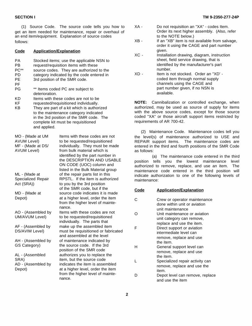
(1) Source Code. The source code tells you how toget an item needed for maintenance, repair or overhaul ofan end item/equipment. Explanation of source codesfollows:
Code Application/Explanation
PA Stocked items; use the applicable NSN toPB request/requisition items with thesePC** source codes. They are authorized to thePD category indicated by the code entered inPE 3rd position of the SMR code.PFPG ** Items coded PC are subject to
deterioration.KD Items with these codes are not to beKF requested/requisitioned individually.KB They are part of a kit which is authorized
to the maintenance category indicatedin the 3rd position of the SMR code. Thecomplete kit must be requisitionedand applied.
MO - (Made at UM Items with these codes are notAVUM Level) to be requested/requisitionedMF - (Made at DS/ individually. They must be madeAVUM Level) from bulk material which is
identified by the part number inthe DESCRIPTION AND USABLEON CODE (UOC) column andlisted in the Bulk Material group
ML - (Made at of the repair parts list in thisSpecialized Repair RPSTL. If the item is authorizedAct (SRA)) to you by the 3rd position
of the SMR code, but if theMD - (Made at source code indicates it is madeDepot) at a higher level, order the item
from the higher level of mainte-nance.
AO - (Assembled by Items with these codes are notUM/AVUM Level) to be requested/requisitioned
individually. The parts thatAF - (Assembled by make up the assembled itemDS/AVIM Level) must be requisitioned or fabricated
and assembled at the levelAH - (Assembled by of maintenance indicated byGS Category) the source code. If the 3rd
position of the SMR codeAL - (Assembled authorizes you to replace theSRA) item, but the source codeAD - (Assembled by indicates the item is assembledDepot) at a higher level, order the item
from the higher level of mainte-nance.
XA - Do not requisition an "XA" - codes Item.Order its next higher assembly. (Also, referto the NOTE below.)
XB - If an "XB" item is not available from salvage,order it using the CAGE and part numbergiven.
XC - Installation drawing, diagram, instructionsheet, field service drawing, that isidentified by the manufacturer's partnumber.
XD - Item is not stocked. Order an "XD' -coded item through normal supplychannels using the CAGE andpart number given, if no NSN isavailable.
NOTE: Cannibalization or controlled exchange, whenauthorized, may be used as source of supply for itemswith the above source codes, except for those sourcecoded "XA" or those aircraft support items restricted byrequirements of AR 700-42.
(2) Maintenance Code. Maintenance codes tell youthe level(s) of maintenance authorized to USE andREPAIR support items. The maintenance codes areentered in the third and fourth positions of the SMR Codeas follows:
(a) The maintenance code entered in the thirdposition tells you the lowest maintenance levelauthorized to remove, replace, and use an item. Themaintenance code entered in the third position willindicate authorization to one of the following levels ofmaintenance:
Code Application/Explanation
C Crew or operator maintenancedone within unit or aviationunit maintenance
O Unit maintenance or aviationunit category can remove,replace and use the item.
F Direct support or aviationintermediate level canremove, replace and usethe item.
H General support level canremove, replace and usethe item.
L Specialized repair activity canremove, replace and use theitem.
D Depot level can remove, replaceand use the item
2

SECTION I TM 9-2350-277-24P
(b) The maintenance code entered in thefourth position tells whether or not the item is to berepaired and identifies the lowest maintenance level withthe capability to do complete repair (i.e. perform allauthorized repair functions.) (NOTE: Some limited repairmay be done on the item at a lower level of maintenance,if authorized by the Maintenance Allocation Chart (MAC)and SMR codes.) This position will contain one of thefollowing maintenance codes:
Code Application/Explanation
O Unit maintenance or aviation unitis the lowest level that can do completerepair of the item.
F Direct support or aviation intermediateis the lowest level that can do completerepair of the item.
H General support is the lowest level that cando complete repair of the item.
L Specialized repair activity is the lowestlevel that can do complete repair of theitem.
D Depot is the lowest level that can docomplete repair of the item.
Z Nonreparable. No repair is authorized.B No repair is authorized. (No parts or special
tools are authorized for the maintenanceof a "B" coded item). However, the itemmay be reconditioned by adjusting,lubrication, etc, at the user level.
(3) Recoverability Code. Recoverability codes areassigned to items to indicate the disposition action onunserviceable items. The recoverability code is enteredin the fifth position of the SMR code as follows:
Code Application/Explanation
Z Nonreparable item. When unserviceable,condemn and dispose of the item at thelevel of maintenance shown in the 3rdposition of the SMR code.
O Reparable item. When uneconomicallyreparable, condemn and dispose of theitem at unit maintenance or aviationunit level.
F Reparable item. When uneconomicallyreparable, condemn and dispose of theitem at the direct support or aviationintermediate level.
H Reparable item. When uneconomicallyreparable, condemn and dispose of theitem at the general support level.
D Reparable item. When beyond lowerlevel repair capability, return to depot.Condemnation and disposal of item notauthorized below depot level.
L Reparable item. Condemnation anddisposal of item not authorized belowspecialized repair activity (SRA).
A Item requires special handling orcondemnation procedure because ofspecific reasons (e.g. precious metalcontent, high dollar value, criticalmaterial, or hazardous material).Refer to appropriate manuals/directives for specific instructions.
c. CAGEC (Column (3)). The Commercial andGovernment Entity (CAGE) Code (C) is a 5-digitalphanumeric code which is used to identify themanufacturer, distributor or Government agency, etc.that supplied the item.
d. PART NUMBER (Column (4)). Indicates theprimary number used by the manufacturer (individual,company, firm, corporation or Government activity),which controls the design and characteristics of the itemby means of its engineering drawings, specificationsstandards and inspection requirements to identify an itemor range of items.
NOTE: When you use a NSN to requisition an item, theitem you receive may have a different part number fromthe part ordered.
e. DESCRIPTION AND USABLE ON CODE (UOC)(Column (5)). This column includes the followinginformation:
(1) The Federal item name and, whenrequired, a minimum description to identify the item.
(2) Physical security classification. Notapplicable.
(3) Items that are included in kits and sets arelisted below the name of the kit or set on Figure KIT.
(4) Spare/repair parts that make up anassembled item are listed immediately following theassembled item line entry.
(5) Part numbers for bulk materials arereferenced in this column in the line entry for the item tobe manufactured/fabricated.
(6) When the item is not used with all serialnumbers of the same model, the effective serial numbersare shown on the last line(s) of the description (beforeUOC). Not applicable.
(7) The usable on code, when applicable (seeparagraph 5, Special information).
(8) In the Special Tools List section, the basisof issue (BOI) appears as the last line(s) in the entry foreach special tool, special TMDE and other special
3

SECTION I TM 9-2350-277-24P
support equipment. When density of equipmentsupported exceeds density spread indicated in the basisof issue, the total authorization is increasedproportionately.
(9) The statement “END OF FIGURE"appears just below the last item description in Column 5for a given figure in both Section II and Section III.
f. QTY (Column (6)). The QTY (quantity per figurecolumn) indicates the quantity of the item used in thebreakout shown on the illustration figure, which isprepared for a functional group, subfunctional group oran assembly. A "V" appearing in this column in lieu of aquantity indicates that the quantity is variable and thequantity may vary from application to application.
4. Explanation of Columns (Section IV).a. NATIONAL STOCK NUMBER (NSN) INDEX.
(1) STOCK NUMBER column. This columnlists the NSN by National item identification number(NIIN) sequence. The NIIN consists of the last nine
NSNdigits of the NSN (i.e., 5305-01-674-1467)
NIIN
When using this column to locate an item, ignore the first4 digits of the NSN. However, the complete NSN shouldbe used when ordering items by stock number.
(2) FIG. column. This column lists the numberof the Figure where the item is identified/located. Thefigures are in numerical order in Section II and Section Ill.
(3) ITEM column. The item number identifiesthe item associated with the figure listed in the adjacentFIG. column. This item is also identified by the NSNlisted on the same line.
b. PART NUMBER INDEX. Part numbers in thisindex are listed by part number in ascendingalphanumeric sequence (i.e., vertical arrangement ofletter and number combination which places the firstletter or digit of each group in order A through Z, followedby the numbers 0 through 9 and each following letter ordigit in like order.)
(1) CAGEC column. The Commercial andGovernment Entity (CAGE) Code (C) is a 5-digitalphanumeric code used to identify the manufacturer,distributor or Government agency, etc., that supplies theitem.
(2) PART NUMBER column. Indicates theprimary number used by the manufacturer (individual,firm, corporation or Government activity), which controlsthe design and characteristics of the item by means of itsengineering drawings, specifications standards, andinspection requirements to identify an item or range ofitems.
(3) STOCK NUMBER column. This columnlists the NSN for the associated part number and
manufacturer identified in the PART NUMBER andCAGEC columns to the left.
(4) FIG. column. This column lists the numberof the figure where the item is identified/located inSections II and III.
(5) ITEM column. The item number is thatnumber assigned to the item as it appears in the figurereferenced in the adjacent figure number column.
c. FIGURE AND ITEM NUMBER INDEX.(1) FIG. column. This column lists the number
of the figure where the item is identified/located inSections II and III.
(2) ITEM column. The item number is thatnumber assigned to the item as it appears in the figurereferenced in the adjacent figure number column.
(3) STOCK NUMBER column. This columnlists the NSN for the item.
(4) CAGEC column. The Commercial andGovernment Entity (CAGEC) Code (C) is a 5 digitalphanumeric code used to identify the manufacturer,distributor or Government agency, etc., that supplies theitem.
(5) PART NUMBER column. Indicates theprimary number used by the manufacturer (individual,firm, corporation or Government activity), which controlsthe design and characteristics of the item by means of itsengineering drawings, specifications standards andinspection requirements to identify an item or range ofitems.
5. Special Information.
Use the following subparagraphs as applicable:
a. USABLE ON CODE. The usable on codeappears in the lower left comer of the DescriptionColumn heading. Usable on codes are shown as UOC:in the Description Column (justified left) on the first linefollowing applicable item description/nomenclature.Uncoded items are applicable to all models.Identification of the usable on codes used in the RPSTLare:
Code Used On
APC M113A3AP1 M981A3AP2 M1064A3AP3 M1068A3AP5 M577A3AP6 M1059A3AP7 M901A3
4

SECTION I TM 9-2350-277-24P
b. FABRICATION INSTRUCTIONS . Bulk materialsrequired to manufacture items are listed in the BulkMaterial Functional Group of this RPSTL. Part numbersfor bulk materials are also referenced in the descriptioncolumn of the line item entry for the item to bemanufactured/fabricated. Detailed fabricationinstructions for items source coded to be manufacturedor fabricated are found in TM 9-2350-277-20P.
c. ASSEMBLY INSTRUCTION. Detailed assemblyinstructions for items source coded to be assembled fromcomponent spare/repair parts are found in TM 92350-277-20-1 and 20-2, and TM 9-2350-277-34. Items thatmake up the assembly are listed immediately followingthe assembly item entry or reference is made to anapplicable figure.
d. KITS. Line item entries for repair parts kitsappear in group 9401 in Section II.
e. INDEX NUMBERS. Items which have the wordBULK in the figure column will have an index numbershown in the item number column. This index number isa cross-reference between the National Stock Number/Part Number Index and the bulk material list in Section II.
f. ASSOCIATED PUBLICATIONS . Thepublications listed below pertain to the PersonnelCarriers M113A3, M981A3, M1064A3, M1068A3,M577A3, M1059A3, and M901A3 vehicles and theirComponents:
Publication Short Title
LO 9-2350-277-12 Lubrication Order;M113A3 FOV
TM 9-2350-277-10 Operator's Manual;M113A3 FOV
TM 9-2350-277-20-1 Unit Maintenance;M113A3 FOV
TM 9-2350-277-20-2 Unit Maintenance;M 113A3 FOV
TM 9-2350-277-34 DS/GS Maintenance;M 113A3 FOV
TM 9-2520-238-34 DS/GS Maintenance(Components)
TM 9-2520-238-34P Component RPSTLTM 9-2520-272-34 DS/GS Maintenance;
TransmissionTM 9-2520-272-34P DS/GS RPSTL;
Transmission
TM 9-2815-205-34 DS/GS Maintenance;Engine
TM 9-2815-205-34P DS/GS RPSTL; EngineTM 9-2920-257-30&P DS Maintenance/RPSTI;
Generator (200Amp)TM 9-6115-596-14 (AP5) Unit/DS/GS Maintenance
Generator Set, GasolineDriven
TM 9-6115-596-14 (AP5) Unit/DS/GS RPSTL;Generator Set, GasolineDriven
6. How to Locate Repair Partsa. When National Stock Number or Part Number is
Not Known.(1) First. Using the table of contents,
determine the assembly group or subassembly group towhich the item belongs. This is necessary since figuresare prepared for assembly groups and subassemblygroups, and listings are divided into the same groups.
(2) Second. Find the figure covering theassembly group or subassembly group to which the itembelongs.
(3) Third. Identify the item on the figure anduse the Figure and Item Number Index to find the NSN.
b. When National Stock Number or Part Number isKnown.
(1) First. Using the National Stock Number orthe Part Number Index, find the pertinent National StockNumber or part Number. The NSN index is in NationalItem Identification Number (NIIN) sequence (see 4.a(1)).The part numbers in the Part Number index are listed inascending alphanumeric sequence (see 4.b). Bothindexes cross-reference you to the illustration/figure anditem number of the item you are looking for.
(2) Second. Turn to the figure and itemnumber, verify that the item is the one you're looking for,then locate the item number in the repair parts list for thefigure.
7. Abbreviations
For standard abbreviations see MIL-STD-12D, MilitaryStandard Abbreviations for Use On Drawings,Specifications, Standards and In Technical Documents.
5

SECTION II TM 9-2350-277-24P
Figure 1. Engine and Container

SECTION II TM 9-2350-277-24P
(1) (2) (3) (4) (5) (6)ITEM SMR PARTNO CODE CAGE NUMBER DESCRIPTION AND USABLE ON CODE (UOC) QTY
GROUP 01 ENGINEGROUP 0100 ENGINE ASSEMBLYFIG. 1 ENGINE AND CONTAINER
1 PAFHD 19207 5705597 ENGINE, W CONTAINER REFER TO TM9-2815-205-34P FORCOMPONENT PARTS OTHER THAN UNIT MAINTENANCE WHICHARE LISTED IN THIS MANUAL ........................................................................... 1
END OF FIGURE
1-1

SECTION II TM 9-2350-277-24P
Figure 2. TV Modulator Cable Bracket and Attaching Hardware

SECTION II TM 9-2350-277-24P
(1) (2) (3) (4) (5) (6)ITEM SMR PARTNO CODE CAGE NUMBER DESCRIPTION AND USABLE ON CODE (UOC) QTY
GROUP 0100 ENGINE ASSEMBLY CONTINUED
FIG. 2 TV MODULATOR CABLE BRACKET
AND ATTACHING HARDWARE
1 PAFZZ 19207 12313452 BRACKET, CABLE, MODUL................................................................................ 1
2 PAOZZ 96906 MS35207-265 SCREW, MACHINE ........................................................................................... 2
3 PAOZZ 96906 MS27183-8 WASHER , FLAT ............................................................................................... 2
4 PAFZZ 19207 12354868 BRACKET, ANGLE............................................................................................. 1
5 PAOZZ 96906 MS21919WDG28 CLAMP, LOOP................................................................................................... 1
6 PAOZZ 96906 MS21044N3 NUT, SELF-LOCKING, HE ................................................................................. 1
7 PAFZZ 96906 MS90725-109 SCREW, CAP HEXAGON H ............................................................................... 1
8 PAOZZ 96906 MS27183-18 WASHER, FLAT................................................................................................. 2
END OF FIGURE
2-1

SECTION II TM 9-2350-277-24P
Figure 3. Engine Mounting Brackets and Engine Mounts

SECTION II TM 9-2350-277-24P
(1) (2) (3) (4) (5) (6)ITEM SMR PARTNO CODE CAGE NUMBER DESCRIPTION AND USABLE ON CODE (UOC) QTY
GROUP 0100 ENGINE ASSEMBLY CONTINUED
FIG. 3 ENGINE MOUNTING BRACKETS AND
ENGINE MOUNTS
1 PAOZZ 96906 MS51922-57 NUT, SELF-LOCKING, HE ................................................................................. 2
2 PAFZZ 96906 MS27183-23 WASHER, FLAT................................................................................................. 4
3 PAOZZ 19207 12358541 BRACKET, MOUNTING...................................................................................... 1
4 PAFZZ 80204 B1821BH075C325N SCREW, CAP, HEXAGON H ............................................................................... 2
5 PAOZZ 80204 B1821BH063C600N SCREW, CAP, HEXAGON H ............................................................................... 2
6 PAOZZ 96906 MS27183-21 WASHER, FLAT................................................................................................. 4
7 PAOZZ 19207 12313346 WASHER, FLAT................................................................................................. 2
8 PAOZZ 19207 10863416-1 MOUNT, RESILIENT........................................................................................... 4
9 PAOZZ 19207 12313343 BLOCK ENGINE MOUNT.................................................................................... 2
10 PAOZZ 96906 MS27114-18R COUPLING, CLAMP, GROO ............................................................................... 2
11 PAOZZ 19207 10861316-1 WASHER, CONVEX .......................................................................................... 2
12 PAOZZ 96906 MS51922-49 NUT, SELF-LOCKING, HE ................................................................................. 2
END OF FIGURE
3-1

SECTION II TM 9-2350-277-24P
Figure 4. Cylinder Block Assembly, End Plate, and Related Parts

SECTION II TM 9-2350-277-24P
(1) (2) (3) (4) (5) (6)ITEM SMR PARTNO CODE CAGE NUMBER DESCRIPTION AND USABLE ON CODE (UOC) QTY
GROUP 0101 CRANKCASE, BLOCK,
CYLINDER HEAD
FIG. 4 CYLINDER BLOCK ASSEMBLY, END
PLATE, AND RELATED PARTS
18 PAOZZ 19207 12258932-5 TRANSMITTER, PRESSUR TRANSDUCER .......................................................... 1
END OF FIGURE
4-1