Mark VIe Controller DCS Block Library - GE Digital Support
661
GEI-100679U Mark* VIe Controller DCS Block Library These instructions do not purport to cover all details or variations in equipment, nor to provide for every possible contingency to be met during installation, operation, and maintenance. The information is supplied for informational purposes only, and GE makes no warranty as to the accuracy of the information included herein. Changes, modifications, and/or improvements to equipment and specifications are made periodically and these changes may or may not be reflected herein. It is understood that GE may make changes, modifications, or improvements to the equipment referenced herein or to the document itself at any time. This document is intended for trained personnel familiar with the GE products referenced herein. Public – This document is approved for public disclosure. GE may have patents or pending patent applications covering subject matter in this document. The furnishing of this document does not provide any license whatsoever to any of these patents. GE provides the following document and the information included therein as is and without warranty of any kind, expressed or implied, including but not limited to any implied statutory warranty of merchantability or fitness for particular purpose. For further assistance or technical information, contact the nearest GE Sales or Service Office, or an authorized GE Sales Representative. Revised: July 2018 Issued: April 2008 © 2008 – 2018 General Electric Company. ___________________________________ * Indicates a trademark of General Electric Company and/or its subsidiaries. All other trademarks are the property of their respective owners. We would appreciate your feedback about our documentation. Please send comments or suggestions to [email protected] For public disclosure
-
Upload
khangminh22 -
Category
Documents
-
view
0 -
download
0
Transcript of Mark VIe Controller DCS Block Library - GE Digital Support

GEI-100679U
Mark* VIe ControllerDCS Block Library
These instructions do not purport to cover all details or variations in equipment, nor to provide for every possiblecontingency to be met during installation, operation, and maintenance. The information is supplied for informationalpurposes only, and GE makes no warranty as to the accuracy of the information included herein. Changes, modifications,and/or improvements to equipment and specifications are made periodically and these changes may or may not be reflectedherein. It is understood that GE may make changes, modifications, or improvements to the equipment referenced herein or tothe document itself at any time. This document is intended for trained personnel familiar with the GE products referencedherein.
Public – This document is approved for public disclosure.
GE may have patents or pending patent applications covering subject matter in this document. The furnishing of thisdocument does not provide any license whatsoever to any of these patents.
GE provides the following document and the information included therein as is and without warranty of any kind,expressed or implied, including but not limited to any implied statutory warranty of merchantability or fitness forparticular purpose.
For further assistance or technical information, contact the nearest GE Sales or Service Office, or an authorized GE SalesRepresentative.
Revised: July 2018Issued: April 2008
© 2008 – 2018 General Electric Company.___________________________________* Indicates a trademark of General Electric Company and/or its subsidiaries.All other trademarks are the property of their respective owners.
We would appreciate your feedback about our documentation.Please send comments or suggestions to [email protected]
For public disclosure

Document UpdatesRevision Updated Description
U Throughout the document Updates for consistency across block librarydocumentation
TMotor Operated Valve Version 4 (M_O_V_V4)
New blocksMotor Operated Valve with Jog Version 3 (M_O_V_JOG_V3)
2 GEI-100679U Mark VIe Controller DCS Block LibraryFor public disclosure

Contents1 Introduction.................................................................................................................................................51.1 Block Data Type .....................................................................................................................................61.2 Change Data Type of Variant Block............................................................................................................7
2 Analog Input (AI) .........................................................................................................................................83 Analog Output (AO).................................................................................................................................... 154 Analog Step Drum (ASTEPDRUM)............................................................................................................... 195 Breaker (BREAKER) .................................................................................................................................. 216 Breaker Version 2 (BREAKER_V2) ............................................................................................................... 407 Convert (CONVERT) .................................................................................................................................. 588 Digital Step Drum (DSTEPDRUM) ............................................................................................................... 639 Dual Select (DUALSEL).............................................................................................................................. 6510 Dual Select Version 2 (DUALSEL_V2)......................................................................................................... 7311 Enthalpy of Superheated Steam (ENTHALPY_STM) ...................................................................................... 8112 Enthalpy of Subcooled Water (ENTHALPY_WTR)......................................................................................... 8213 First In-First Out (FIFO)............................................................................................................................. 8314 Flow Calculator (FLOW_CALC) ................................................................................................................. 8515 Force (FORCE) ........................................................................................................................................ 8716 Gain Bias (GAIN_BIAS)............................................................................................................................ 9117 Group (GRP)............................................................................................................................................ 9218 Group Version 2 (GRP_V2) .......................................................................................................................10019 Group Version 3 (GRP_V3) .......................................................................................................................10720 Heartbeat (HEARTBEAT) .........................................................................................................................11321 High and Low Monitor (HI_LO_MON) .......................................................................................................11422 Level Compensation (LVL_COMP).............................................................................................................11623 Motor Operated Valve (M_O_V).................................................................................................................12024 Motor Operated Valve Version 2 (M_O_V_V2) .............................................................................................14225 Motor Operated Valve Version 3 (M_O_V_V3) .............................................................................................16326 Motor Operated Valve Version 4 (M_O_V_V4) .............................................................................................18127 Motor Operated Valve with Jog (M_O_V_JOG).............................................................................................19828 Motor Operated Valve with Jog Version 2 (M_O_V_JOG_V2) .........................................................................23029 Motor Operated Valve with Jog Version 3 (M_O_V_JOG_V3) .........................................................................26030 Massflow Gas (MASSFLOW_GAS)............................................................................................................29031 Massflow Steam (MASSFLOW_STM) ........................................................................................................29332 Massflow Water (MASSFLOW_WTR) ........................................................................................................29633 Median Select (MEDSEL) .........................................................................................................................29934 Median Select Version 2 (MEDSEL_V2)......................................................................................................30935 Multiplexer (MUX) ..................................................................................................................................31936 Override (OVERRIDE) .............................................................................................................................32137 Override Station Enhanced (OVR_ST_ENH) ................................................................................................32638 Override Station Enhanced Version 2 (OVR_ST_ENH_V2) .............................................................................36239 Permit (PERMIT) ....................................................................................................................................39840 Proportional Integral Derivative Enhanced (PID_MA_ENH) ............................................................................40541 Proportional Integral Derivative Enhanced Version 2 (PID_MA_ENH_V2).........................................................45542 Proportional Gain (PROP_GAIN) ...............................................................................................................50843 Quad Select (QUADSEL)..........................................................................................................................510
Instruction Guide GEI-100679U 3For public disclosure

44 Quad Select Version 2 (QUADSEL_V2).......................................................................................................52245 Quality Average (QUAL_AVG) ..................................................................................................................53446 Run Timer (RUN_TIMER) ........................................................................................................................53647 Solenoid Operated Valve (S_O_V) ..............................................................................................................53748 Solenoid Operated Valve Version 2 (S_O_V_V2) ...........................................................................................55349 Solenoid Operated Valve Version 3 (S_O_V_V3) ...........................................................................................56850 Saturation Pressure (SAT_PRESSURE)........................................................................................................58251 Saturation Temperature (SAT_TEMP)..........................................................................................................58352 Setpoint Station (SETPOINT_ST) ...............................................................................................................58453 Starter (STARTER) ..................................................................................................................................58854 Starter Version 2 (STARTER_V2) ...............................................................................................................60955 Starter Version 3 (STARTER_V3) ...............................................................................................................62656 Steamtable (STEAMTABLE) .....................................................................................................................64457 Superheat of Steam (SUPERHEAT).............................................................................................................64958 Pulse Totalizer (TOTALIZER_PULSE)........................................................................................................65259 Rate Totalizer (TOTALIZER_RATE)...........................................................................................................65360 Track (TRACK).......................................................................................................................................65461 Transfer (TRANSFER) .............................................................................................................................65762 Volume of Water (VOL_WATER) ...............................................................................................................65963 Vote (VOTE)...........................................................................................................................................661
4 GEI-100679U Mark VIe Controller DCS Block LibraryFor public disclosure

1 IntroductionBlocks are software subroutines that are included in the tasks to be run in the controller. Within the ToolboxST* application,the connections are accomplished graphically using pins and wires to form a data flow diagram. The blocks run in the orderlisted in the task. The connections between the blocks are RAM memory elements through which data is passed. Theseelements are referred to as variables. Each variable has a defined data type and must be connected to pins of the same datatype. Some block pins accept multiple data types and others are capable of converting from one data type to another.
Each block entry in the library consists of the following:
• Block name and category• Block description• Block diagram• Pin definitions• Application notes (optional)
Each block has a full name and a simple name. The full name is descriptive and too long to display in a block diagram. Forthis reason, all blocks have a simple name. The simple name is displayed in the ToolboxST application.
Floating point (REAL and LREAL) values conform to IEEE® 754. The standard defines certain computational exceptions thatmay produce non-standard results, such as divide by zero. These non-standard values include infinities and Not a Numbers(NaNs), which, if used in subsequent calculations, produce additional non-standard results. The software has been designed toprevent the production and proliferation of such values. Function block descriptions may include additional details concerningfloating point exception handling where needed.
Block Libraries also contain rubber blocks, which are sized according to the number of pins used. Within the library, theblocks are grouped functionally to simplify the task of converting ideas into blocks. For example, the Controller Monitor(CTRLR_MON) block is a member of the System category.
Note Pin names are given modifiers that provide additional information about the pin.
A graphical representation of the software for each block is provided in the form of a block diagram that includes the simpleblock name and block configuration pins and variable pins, which transfer data in and out of the block. The pins are locatedon the block diagram according to their usage. All input pins (pins read by the block) and block configuration pins are listedon the left. All output pins (pins written by the block) and state pins (pins read and written by the block) are listed on theright. The pin name is listed beside each pin inside the block diagram border.
Pin Name Modifiers Description^ prefixed with a carat (^ONREQ) Pin is rising-edge sensitive
[ ] suffixed with square brackets (STATE[4]) Pin expects a variable that is an array of the size indicatedwithin the brackets
Instruction Guide GEI-100679U 5For public disclosure

1.1 Block Data TypeThe pin data type identifier is listed beside the pin outside of the block diagram border. The basic data types used in the blocklibraries are BOOL, INT, UINT, REAL, LREAL, DINT and UDINT. Blocks with data types ANY_NUM and ANY must havethe Block Data Type set to match the intended data type of the block output.
Note The default value of Boolean inputs is False unless the input is a block Enable, in which case the default is True andthe default value of inputs with data types INT, UINT, DINT, UDINT, REAL and LREAL is 0, until otherwise specified.
The block content provides tables to define the input and output pins. Each entry includes the block name for the variable,basic data type, typical scaling units, and a description of the variable. Typical scaling units are supplied for reference only;specific applications may use other scaling units as appropriate.
Data Type Identifier Basic Data Type DescriptionA Any (ANY) Any data typeB Boolean (BOOL) 8-bit BooleanI Integer (INT) 16-bit (Short) Signed IntegerDI Double Integer (DINT) 32-bit (Long) Signed Integer
R Real (REAL) 32-bit Floating Point
LR Long Real (LREAL) 64-bit (Long) Floating PointUI Unsigned Integer (UINT) 16-bit (Short) Unsigned IntegerUDI Unsigned Double Integer (UDINT) 32-bit (Long) Unsigned IntegerN Numeric (ANY_NUM) Any data type except BooleanS Analog or Boolean (Simple) Any simple data type
Data Type Identifier Type Definition Modifier Description# m Build time constant
Note The Block Data Type is set in the block Property Editor.
6 GEI-100679U Mark VIe Controller DCS Block LibraryFor public disclosure

1.2 Change Data Type of Variant BlockThere are few blocks that support more than one data type as an input and/or output.
➢➢ To change the block data type
1. Select the block for which to change the data type.
2. From the Block Properties window, expand the General section.
3. From the Property Editor, select the Block Data Type.
4. From the Block Data Type drop-down box, select a valid data type for the block.
From the Block Data Typedrop down list , select a valid data type for the block.
Instruction Guide GEI-100679U 7For public disclosure

2 Analog Input (AI)Block Category: Analog Operations
Note This block should only be used with Analog I/O (including Modbus Ethernet communications).
The Analog Input (AI) block is used for the following purposes:
• Instantiates the status variable into the system• Monitors analog I/O point health, engineering unit range violations, and process limit violations and propagates that
information through the output status variable• I/O scaling when a linear scale or flow extraction is required
Block Configuration
The AI_TYPE enumeration controls the method of I/O scaling to be performed. The values are described as follows:
DIRECT requires the inputs IN, EU_MAX, and EU_MIN. The value of IN is transferred to OUTwithout modification. OUTis only calculated if IN is greater than the low cutout, IN_LCO. If IN is less than IN_LCO, then OUT equals EU_MIN.
Where Lag is First-order lag Filter, the lag time constant is expressed in seconds by TC. The transfer function of the filter isof the form 1 / (1 + TCs).
INDIRECT_SCL requires the inputs IN, EU_MAX, EU_MIN, IN_H_SCL, and IN_L_SCL. The block calculates OUT bylinearly scaling IN based on these inputs. OUT is only calculated if IN is greater than the low cutout, IN_LCO. If IN is lessthan IN_LCO, then OUT equals EU_MIN. If IN < IN_L_SCL then IN is clamped to IN_L_SCL and the OUT is to EU_MIN.
Where Lag is First-order lag Filter, the lag time constant is expressed in seconds by TC. The transfer function of the filter isof the form 1 / (1 + TCs).
INDIRECT_SQRT requires the inputs IN, EU_MAX, EU_MIN, IN_H_SCL, IN_L_SCL, and IN_LCO. OUT is thecalculated flow for non-compressible fluids through a differential head flow meter. IN_H_SCL is the maximum design DPand IN_L_SCL is the minimum design DP. EU_MAX is the maximum design flow and EU_MIN is the minimum designflow. OUT is only calculated if IN is greater than the low cutout, IN_LCO. If IN is less than IN_LCO, then OUT equals EU_MIN. If IN < IN_L_SCL then IN is clamped to IN_L_SCL and the OUT is set EU_MIN.
Where Lag is First-order lag Filter, the lag time constant is expressed in seconds by TC. The transfer function of the filter isof the form 1 / (1 + TCs).
8 GEI-100679U Mark VIe Controller DCS Block LibraryFor public disclosure

STATUS CALCULATION
The AI block monitors the I/O point health, I/O pack health, EGD link status, engineering unit range violations, andprocess limit range violations to calculate the output status for an I/O point. The block begins the status calculation byobtaining the health status of the input specified. The status output provides the instantaneous status of the variable input. AHealthy value on the status output implies a Healthy input pin. All Ethernet communication links have a bit error rate, sooccasional loss of a single EGD packet on an Ethernet network is considered normal and expected. The status will becomeUncertain for the configured health delay period before becoming Unhealthy.
A period refers to the time between consecutive transmissions of the variable. For most variables from I/O packs, theperiod corresponds to the frame rate, although certain I/O packs such as PSCA do not always transmit at frame rate. Forvariables that derive their health from the health of a received EGD page from another controller, the period depends on theframe rate of the transmitting source and the associated page period multiplier. From the ToolboxST application, select theEGD tab to view Period information. For detailed timing information refer to the section Output Health Status Details .Refer to theMark VIe Controller Standard Block Library (GEI-100682), the Status Monitoring (STATUS_MONITORING)block.
The output status is generated using the following rules:
• If an input pin has a value of NaN (Not a Number), the output status is set to NOT_LIMITED__BAD [0], [1], or [2].• If the Page health and point health is Uncertain, the output status will not exceed NOT_LIMITED__LAST_KNOWN_
VALUE__UNCERTAIN [68]. Page health refers to the health of the I/O pack, IONet EGD, or EGD link OK statusassociated with the input point.
• If the Page health is bad, the output status will not exceed NOT_LIMITED__NO_COMM_WITH_NO_USABLE_VALUE__BAD [24].
• If the Page health is Healthy or Uncertain, but Point health is not Healthy, the output status will not exceed NOT_LIMITED__SENSOR_FAILURE__BAD [16]. In this case, Point health refers to the health of the I/O pack point statusassociated with the input point.
• If the type, AI_TYPE, is unknown or if the scaling is such that the maximum is less than the minimum, the outputstatus is limited to NOT_LIMITED__CONFIGURATION_ERROR__BAD [4].
• If the output is out of PROCESS LIMITwhen limit checking is enabled, that is, PROC_LIM = True, the output statusis limited to NOT_LIMITED__UNCERTAIN [64].
• If the output is out of OUTPUT SCALE limits, the output status is limited to NOT_LIMITED__ENGINEERING_UNIT_RANGE_VIOLATION__UNCERTAIN [84].
• If none of these conditions exists, NOT_LIMITED-GOODNC [128] will be the output status.
Instruction Guide GEI-100679U 9For public disclosure

ToolboxST Configuration
When an AI block is inserted into the application code, the ToolboxST application displays the following window.
Changing Default Attributes
When the user clicks OK, the block and pin connections will be configured automatically. Once the block is added, a globalpin is added. (Refer to the table Global Variable.) The block output is the value of the Device Attribute Name, 00AI1000.Additionally, the description, AI Description in this example, becomes the block output description. The FormatSp AttributeName Value, TempFS, is the format specification of the block output. If a valid format specification attribute is entered, theEngineering Maximum and Engineering Minimum values of that format specification are used to calculate OUT anddetermine engineering unit violations. If no format specification attribute is entered or is invalid, the values of EU_MAX andEU_MIN pins are used to calculate OUT and determine engineering unit violations. All references to EU_MAX and EU_MINin this section are based on this concept.
AI Block
10 GEI-100679U Mark VIe Controller DCS Block LibraryFor public disclosure

Inputs
Name Description Data Type Initial Value Visibility Interface TypeAI_TYPE Input scaling parameter UINT (ENUM) DIRECT Always Value OnlyEU_MAX Output high scale REAL 100 Always Value OnlyEU_MIN Output low scale REAL 0 Always Value OnlyIN Input variable REAL 0 Always Value OnlyIN_H_SCL Input high scale REAL 100 Always Value OnlyIN_L_SCL Input low scale REAL 0 Always Value OnlyIN_LCO Low cutout value REAL 0 Always Value OnlyPROC_LIM Process limits evaluated BOOL False Always Value OnlyPROC_MAX Process limit maximum REAL 100 Always Value OnlyPROC_MIN Process limit minimum REAL 0 Always Value OnlyTC Filter time constant in
secondsREAL 0 Always Value Only
QLTY_DLY Bad quality to good qualitydelay, msec
UINT 1000 Always Value Only
BAD_QLTY_DLY† Good quality to bad qualitydelay, msec
UINT -1 Always Value Only
† This pin does not impact block operation and should no longer be used. The health drop out delay is controlled by the globalsetting network health delay from the Hardware tab in the ToolboxSTapplication. Refer to GEH-6700, ToolboxST User Guidefor Mark VIe Control, Chapter 6 Mark VIe Component Editor, the section Health Delay.
Output
Name Description Data Type Initial Value Visibility Interface Type{Device} {Desc} REAL 0 Always Value with Status
Global VariablePin Name Description Alarm Alarm
ClassEvent EGD Page External
Access11AI1000 HP Feedwater
PressureNot Alarmed False $Default ReadOnly
Instruction Guide GEI-100679U 11For public disclosure

Analog Alarm Configuration
To configure analog alarms on a variable, the Alarm Property must be configured for that variable. This enables theconfiguration of Bad Quality (BQ), Rate of change high (RH), High Deviation (DH), H, HH, HHH (or 3H), L, LL, and LLL(or 3L).
Note AnalogAlarmDefault should be used when a variable is to be used as an alarm. Enabling this turns on more options forthis variable in the Alarms and Events Property Editor.
Enabling Analog Alarms on a Variable
Additional Options in Alarms and Events Property Editor
12 GEI-100679U Mark VIe Controller DCS Block LibraryFor public disclosure

➢➢ To enable the H Alarm: in the property grid, set the H property to True to add the variables displayed in the followingfigure to the variable list.
H Variables
H_SP is the setpoint for the High alarm on the variable. H_T is the delay time (in ms). When the comparison between thesetpoint and the value is done, it waits H_T milliseconds before issuing the alarm. HYST is the Hysteresis of the alarm values.Set the initial values to effectively use them. 00AI1000.H is the actual variable name that generates the alarm.
Output Health Status Details
For I/O pack variable sources, the AI output status goes bad during the first period, in which the controller receives anindication from the I/O pack that the variable is bad. It will go Uncertain the first period in which the controller does notreceive the variable, as follows:
• For a network with simplex redundancy, the AI output status goes Uncertain after the loss of the only input data packetfor the health delay period before becoming bad.
• For a network with dual redundancy, the AI output status goes Uncertain after the loss of both input data packets for thehealth delay period before becoming bad.
• For a network with TMR redundancy, the AI output status goes Uncertain after the loss of the second input data packetfor one period before becoming bad.
This Unhealthy status could be caused by a communication failure with the I/O pack or by the I/O pack's determination thatthe signal is Unhealthy based on conditions specific to that type of I/O pack and input.
For external network/EGD page sources, including variables received over the Unit Data Highway (UDH) or Control DataHighway (CDH) using EGD pages, the AI output status on the AI block for an input variable does not go Unhealthy after theloss of a single input data packet containing that variable. Instead, the corresponding AI status output goes Unhealthy duringthe fourth Unhealthy period. Since EGD pages may be configured to run at different rates, the health of the variable is verifiedonce each period as configured for that EGD exchange. Each time an EGD exchange is received, the associated inputvariables in that exchange are set to Healthy status and a timeout timer for that exchange is set to four. The timeout timer isthen decremented each time the configured time interval occurs. If the timeout timer reaches zero, all input variables in thatexchange are set with an Unhealthy status and the counter remains at zero until the EGD exchange is successfully receivedagain.
Inputs transition from Unhealthy to Healthy on the first frame they are received as Healthy from an I/O module orexternal/UDH/CDH source.
Note For input health information to be viewable in a live data display, for example in Live View, Trender, or the blockwareeditor, the input must be connected to either a VAR_HEALTH or AI block.
Instruction Guide GEI-100679U 13For public disclosure

Single Network I/O Pack Input Response to Loss of Input
When a network input on an I/O pack is no longer received, the input is marked Uncertain and the value holds the previousHealthy input state for the configured base health delay number of periods. After this, the value is set to the default value andmarked Unhealthy.
Responses to Loss of Input (Base Health Delay = 3)
Loss of InputFrame 1 2 3 4 5Health Uncertain UnhealthyValues Hold last Default
Dual Network I/O Pack Input Response to Loss of Input
When both network inputs on an I/O pack are no longer received, the input is marked Uncertain and the value holds theprevious Healthy input state for the configured base health delay number of periods. After this, the input value is set to thedefault value and is marked Unhealthy. If only one input goes Unhealthy, the input value remains Healthy.
Responses to Loss of Input
Loss of 1st Input Loss of 2nd InputFrame 1 2 3 4 5 Frame 1 2 3 4 5Health Healthy Health Uncertain Unhealthy
Values2ndinput Values Hold last Default
TMR Network I/O Pack Input Response to Loss of Input
The input value is always calculated from the voted value of the three network inputs. Thus, if more than one input goesUnhealthy, the input value is voted to Unhealthy. If only one input goes Unhealthy, the input value remains Healthy.
Responses to Loss of Input
Loss of 1st Input Loss of 2nd InputFrame 1 2 3 4 5 Frame 1 2 3 4 5
Health Healthy Health UncertainUnheal-thy
Values Voted Values Voted Default (from vote)
External Network/EGD Page Response to Loss of Input
When an EGD page is no longer received, the input is marked Uncertain and the previous Healthy input state is held. Afterfour periods, the input is marked Unhealthy.
Responses to Loss of Input
Loss of InputFrame 1 2 3 4 5Health Uncertain UnhealthyValues Hold last Hold last
14 GEI-100679U Mark VIe Controller DCS Block LibraryFor public disclosure

3 Analog Output (AO)Block Category: Analog Operations
The Analog Output (AO) block monitors and propagates the quality status of analog output variables connected to CVand/orSV. When the output variable statuses are not bad, the value and status of TRK_OUT is equal to the value and status of IN. IfAO_TYPE equals SPLIT RANGE, AO outputs CV, SV, and TRK_OUT. If AO_TYPE equals NORMAL, AO outputs CVandTRK_OUT.
AO Block
CVand SVare characterized outputs with a POP feature enabled by default. The characterization of IN to CVand IN to SV isdetermined by the array value relationships for CV_X to CV_Yand SV_X to SV_Y, respectively. CV_X, CV_Y, SV_X, andSV_Yare Local array type variables with 13 elements each; whose initial values can be modified for characterizationpurposes. The POP feature is designed to provide a valve closing hysteresis loop. This prevents a control valve fromthrottling on the valve seat, reducing control valve wear. In the decreasing direction, the feature does not allow CV to becomeless than the value of CL until the characterized value of IN becomes less than CR. When the characterized value of INbecomes less than CR, CV is set to CMN. In the increasing direction, CV remains equal to CMN until the characterized valueof IN becomes greater than the value of CL. Once the characterized value of IN is greater than CL, CV will POP to the valueof CL and CV will follow the characterized value of IN as long as it is above CL. The POP feature is enabled whenCL>CR>CMN and disabled when CL=CR=CMN, where CMN is the control variable minimum desired output value. ThisPOP concept also applies to SV by setting the values of SL, SR and SMN.
Note The CMN and SMN must be greater than or equal to the first element of the array.
AO_TYPE enumerations control the nature of the pins available.
AO_TYPE Enumerations
Enumeration DescriptionNORMAL Normal - single outputSPLIT_RANGE Split range - two outputs
NORMAL— requires inputs IN, CL, CMN, CR, CV_X and CV_Yand provides outputs CVand TRK_OUT.
SPLIT RANGE— requires inputs IN, CL, CMN, CR, CV_X, CV_Y, SL, SMN, SR, SV_X and SV_Y, and provides outputsCV,SV, and TRK_OUT.
Instruction Guide GEI-100679U 15For public disclosure

Direct Characterization
16 GEI-100679U Mark VIe Controller DCS Block LibraryFor public disclosure

Reverse Characterization
The AO block propagates quality status. Status option cannot be disabled on this block.
Block status modifications:The analog output variables attached to CVand SVare monitored for quality status, resulting in the following possibleTRK_OUT statuses:
• I/O Pack Health Failed – NOT_LIMITED-DEVICE_FAILURE-BAD [12]• I/O Pack Health Failed – NOT_LIMITED-SENSOR_FAILURE-BAD [16]• If none of the above conditions exist, it is equal to IN statusFor further details on single input/single output blocks, refer to theMark VIe Controller Standard Block Library(GEI-100682), the Status Monitoring (STATUS_MONITORING) block.
Instruction Guide GEI-100679U 17For public disclosure

InputsName Description Data Type Initial Value Visibility Interface TypeAO_TYPE Output type (0=Normal; 1=
Split range)UINT (ENUM) Normal Parameter Value Only
CL CV pop level REAL 7 Parameter Value Only
CMN Minimum CV REAL -5 Parameter Value OnlyCR CV reset to min level REAL 0.1 Parameter Value OnlyCV_X Input characterization for CV REAL -10,0,10,20,30,40,
50,60,70,80,90,100,110
Parameter Value Only
CV_Y Output characterization forCV
REAL -10,0,10,20,30,40,50,60,70,80,90,100,110
Parameter Value Only
IN Input value REAL 0 Always Value with StatusSL SV pop level REAL 7 Parameter Value OnlySMN Minimum SV REAL -5 Parameter Value OnlySR SV reset to min level REAL 0.1 Parameter Value OnlySV_X Input characterization for SV REAL -10,0,10,20,30,40,
50,60,70,80,90,100,110
Parameter Value Only
SV_Y Output characterization for SV REAL -10,0,10,20,30,40,50,60,70,80,90,100,110
Parameter Value Only
Outputs
Name Description Data Type Initial Value Visibility Interface TypeCV CV output REAL -5 Always Value OnlySV SV output REAL 0 Always Value OnlyTRK_OUT Tracking output REAL 0 Always Value with Status
18 GEI-100679U Mark VIe Controller DCS Block LibraryFor public disclosure

4 Analog Step Drum (ASTEPDRUM)Block Category: Analog Operations
The Analog Step Drum (ASTEPDRUM) block is a software drum controller with one analog output value and up to 32 steps(if 2OUT = False), or two analog output values and up to 16 steps each (if 2OUT = True). The output selected is based on thecurrent step number and its corresponding N value(s).
The maximum number of steps is initialized with NMAX (up to 32 when 2OUT = False, up to 16 when 2OUT = True).
In tracking mode (TRK_MOD is True), the current step number, STEP, is equal to TRK_STEP. If TRK_STEP is equal to zeroor greater than NMAX, the selecting mode TRK_MOD is ignored and the block switches to Manual mode. MN_REJbecomes True.
In Manual mode (TRK_MOD = False), the selected step is increased or decreased (with each False to True transition of INCor DEC). If the step number is equal to the maximum number of steps, NMAX, then the next transition of INC will cause thestep number to reset to one. If the current step number is equal to one, then all transitions of DEC will be ignored. If INC andDEC transition from False to True on the same scan, then the current step is maintained.
Note This is a variant block that supports any one the following block data types: Integer, Double Integer, Real, Long Real,Unsigned Integer, Unsigned Double Integer. The default data type is REAL. Refer to the section Change Data Type of VariantBlock.
ASTEPDRUM Block
ASTEPDRUM Block Expanded
Instruction Guide GEI-100679U 19For public disclosure

Inputs
Name Description Data Type Initial Value Visibility Interface Type2OUT Analog output pair selected BOOL False Always Value OnlyDEC Decrements the current step
number in manual modeBOOL False Always Value Only
INC Increments the current stepnumber in manual mode
BOOL False Always Value Only
N1 Output1 value for step 1 REAL 0 Always Value Only↓ ↓ ↓ ↓ ↓ Value OnlyN16 Output1 value for step 16 REAL 0 Always Value OnlyN17 Output1 value for step 17 (if
2OUT is False) OR Output2 forstep 1 (if 2OUT is True)
REAL 0 Always Value Only
↓ ↓ ↓ ↓ ↓ Value OnlyN32 Output1 value for step 32 (if
2OUT is False) OR Output2 forstep 16 (if 2OUT is True)
REAL 0 Always Value Only
NMAX Maximum number of steps UNIT 1 Parameter Value OnlyTRK_MOD Enable tracking mode BOOL False Always Value OnlyTRK_STEP Selected step number for
tracking modeUNIT 1 Parameter Value Only
Outputs
Name Description Data Type Initial Value Visibility Interface TypeMN_REJ Reject to manual mode BOOL False Always Value OnlyOUT1 Output1 value for
corresponding step numberREAL 0 Always Value Only
OUT2 Output2 value forcorresponding step number
REAL 0 Always Value Only
STEP Current step number INT 1 Always Value Only
20 GEI-100679U Mark VIe Controller DCS Block LibraryFor public disclosure

5 Breaker (BREAKER)Block Category: Legacy, Device Control
Note Legacy Status— The BREAKER block is not supported for use in new Mark VIe control systems (ControlSTsoftware suite V05.02 or later). It is in place to support the maintenance of legacy Mark VIe control systems (prior toControlST software suite V05.02). For new Mark VIe control systems, use the BREAKER_V2 block; it provides equivalentfunctionality.
The Breaker (BREAKER) block controls a low-voltage (LV) or medium-voltage (MV) breaker. The block provides pulseoutputs, OP_ORD, to open, or CL_ORD, to close the breaker. The block requires the inputs OPEN and CLOSED from thelimit switches of the breaker. The block will generate a failed-to-open alarm, FL_OP_A, a failed-to-close alarm, FL_CL_A,and a limit switch congruency alarm, CONGR_A, that alarms when the breaker limit switches indicate that the breaker isopen and closed at the same time or if neither position is indicated.
Block Configuration
The BREAKER block has various enumerations that are used to control block operation.
Control Word
Control (CTL) is an enumeration set by the HMI operator for breaker control. The commands available from the HMI allowmanual and automatic breaker control capability and/or lockout capability if the block property MODE_OPT enumerationselected allows the auto and/or lock mode. The breaker may be opened or closed in Manual mode by the OPEN_CMD orCLOSE_CMD commands, respectively.
CTL EnumerationsEnumeration Command DefinitionsNO_CMD No command
AUTO_CMD Auto commandMANUAL_CMD Manual commandLOCK_CMD Lock commandUNLOCK_CMD Unlock commandOPEN_CMD Open commandCLOSE_CMD Close commandRESET_CMD Fault reset commandTC_RESET_CMD TC reset command
Instruction Guide GEI-100679U 21For public disclosure

Block Property Enumerations and Functionality
IO_OPT, MODE_OPT, and IO_MON enumerations control how the object behaves. For example, if the breaker has controlpower and available inputs, fuse monitoring, and has the capability for auto and lockout operation, the IO_OPT selection isCP_OK-AVAIL, MODE_OPT is AUTO-LOCK, and IO_MON is FUSE.
IO_OPT
IO_OPT enumerations are listed in the following table.
Note Refer to the section Appendix for a complete list of possible combinations.
IO_OPT Enumerations (Short List)
Enumeration DescriptionNone No capabilities are availableCP_OK Breaker has a hard-wired control power monitoring inputREM Breaker has a hard-wired remote/local inputAVAIL Breaker has hard-wired available input; "ready to go indicator"PR_TRP Breaker has a hard-wired protection trip capability with a protective relay controlling the breakerRCKD_IN Breaker has a hard-wired racked-in detection input and can detect when it is physically
connected to the busTRIP_ONLY No breaker close capability; can only trip the breaker, not close it
NONE—when IO_OPT is none, then inputs CP_OK, AVAIL, PR_TRP, RCKD_IN, REM and TRIP_ONLYare not used.
CP_OK— select for a breaker that provides a control power monitoring I/O capability. When the CP_OK enumeration isselected, the output CP_OK_P is True. The Boolean control power monitoring connection is to the CP_OK input of the blockand is True when no control power failure is detected. When the CP_OK input is False, the control power failure alarm, CP_F_A, is activated. If the breaker is in AUTO mode and the duration of CP_F _A being True has exceeded the PWR_FL_TMR,the breaker will switch to Manual mode and the manual reject alarm, MN_REJ_A, will be activated, (delayed by 2 seconds).
AVAIL— select for a breaker that require an available capability. When the AVAIL enumeration is selected, the outputAVAIL_P is True. The Boolean available connection is to the AVAIL input of the block and is True when the breaker isavailable. When AVAIL is False, the available alarm, AVAIL_A, is activated. If the starter is in AUTO mode and the durationof AVAIL_A being True has exceeded the PWR_FL_TMR, the breaker will switch to Manual mode and the manual rejectalarm, MN_REJ_A, will be activated, (delayed by 2 seconds).
PR_TRP— select for a breaker that has protection trip capability. When the PR_TRP enumeration is selected, the outputPR_TRP_P is True. The Boolean Protection Trip input is connected to the PR_TRP input and is False when no breaker trip isdetected. When PR_TRP is True, the protection trip alarm, PR_TR_A, is activated. If the breaker is in AUTO mode and PR_TRP_P is True, the breaker will switch to Manual mode and the manual reject alarm, MN_REJ_A, will be activated, (delayedby 2 seconds).
REM— select for a breaker that has remote/local capability. When the REM enumeration is selected, the output REM_P isTrue. The Boolean remote/local connection is to the REMOTE input of the block and is True when the breaker is in remotemode. When REMOTE is False, the output LOCAL is True and breaker control from the HMI is disabled. If the breaker is inAUTO mode and LOCAL becomes True and the breaker will switch to Manual mode and the manual reject alarm, MN_REJ_A, will be activated, (delayed by 2 seconds).
RCKD_IN— select for a breaker that has a racked-in detection capability. When the RCKD_IN enumeration is selected, theoutput RCKD_IN _P is True. The Boolean racked-in connection is to the RCKD_IN input of the block and is True when thebreaker is racked-in. When RCKD_IN is False, the racked-out alarm, RCKD_OT, is activated. If the breaker is in AUTOmode and the duration of RCKD_OT being True has exceeded the PWR_FL_TMR, the breaker will switch to Manual modeand the manual reject alarm, MN_REJ_A, will be activated, (delayed by 2 seconds).
22 GEI-100679U Mark VIe Controller DCS Block LibraryFor public disclosure

TRIP_ONLY— select for a breaker which does not have a remote breaker close capability. When the TRIP_ONLYenumeration is selected, the output TRIP_ONLY _P is True. If TRIP_ONLY_P is True, the breaker can only be commandedopen remotely by the OPEN_CMD enumeration, and the breaker close command, enumeration CLOSE_CMD, is disabled.
MODE_OPT
MODE_OPT enumerations are listed in the following table.
MODE_OPT Enumerations
Enumeration Mode Option DescriptionNONE NoneAUTO AutoLOCK LockAUTO-LOCK Auto and lockBK_OP Breaker openAUTO-BK_OP Auto and breaker openLOCK-BK_OP Lock an breaker openAUTO-LOCK-BK_OP Auto and lock and breaker open
NONE— if TRIP_ONLY _P is False, the breaker can be opened or closed manually by the HMI operator.
AUTO— provides auto control capability for the breaker. Selecting the AUTO mode property will set AUTO_P to True,indicating the auto mode property of the block is enabled. When AUTO_P is True the breaker can be commanded to auto byeither CTL enumeration AUTO_CMD or a rising edge on AU_SEL providing PMT_AU is True. The HMI operator maycommand the breaker from Auto to Manual mode at any time with the CTL enumeration, MANUAL_CMD.
Note Refer to GEH-6721_Vol_II, Mark VIe Control, Volume II System Hardware Guide for descriptions of hardwareboards.
When AUTO is True, the AU_OP and AU_CL inputs control the automatic opening and closing of the breaker, provided,PMT_OP or PMT_CL, respectively, is True. If AU_OP or AU_SEL become True, the breaker is in Manual mode, and thebreaker position is not in the state of the requested command, the Auto Request alarm (AU_REQ), will be activated. If AU_CL becomes True, TRIP_ONLY_P is False, the breaker is in Manual mode, and the breaker position is not closed, the AutoRequest alarm (AU_REQ), will be activated.
Note PMT_AU is described in the section Auto/Open/Close Permissives.
LOCK— provides software lock-out capability for the breaker. Selecting the LOCK mode property will set LOCK_P toTrue, and enable the LOCK_CMD and UNLOCK_CMD to control the lockout mode functionality. The breaker must beopened before the block can be set to lockout mode. Feedback to the HMI operator of this mode is provided by LOCK. TheHMI operator is prevented from operating the breaker from the control faceplate when LOCK is True, and auto mode isdisabled.
Note The Lock button can also be configured to use the WorkstationST Lock function. Refer toWorkstationST/CIMPLICITYAdvanced Viewer Integration Instruction Guide (GEI-100697), the section HMI Tagout.
Note The lockout indication is provided for indication only. This action will not lockout the equipment, it will only indicatelockout status. The owner's lockout procedures must be followed to safely lock equipment out.
BK_OP— provides a alarm when the breaker is open. Selecting the BK_OP mode property will set BK_OP _P to True.When BK_OP_P is True and OPEN is True, the breaker alarm, BK_OP_A, is activated.
Instruction Guide GEI-100679U 23For public disclosure

IO_MON
IO_MON enumerations are digital output monitor types. Monitoring is only available for the outputs OP_ORD and CL_ORD(if TRIP_ONLY_P is False). If the hardware card used with OP_ORD and CL_ORD can perform diagnostic monitoring, IO_MON is used to select the type of diagnostic monitoring. When diagnostic monitoring is used (FUSE or VOLT), thediagnostic variable from the OP_ORD output is connected to RDY_OPN and the diagnostic variable for the CL_ORD (ifTRIP_ONLY_P is False) is connected to RDY_CLS. IO_MON enumerations are listed in the following table.
IO_MON Enumerations
Enumeration Monitor Option DescriptionNONE None
FUSE Fuse MonitoringVOLT Voltage Monitoring
NONE— no circuit monitoring is available RDY_OPN and RDY_CLS inputs are not used.
FUSE— fuse monitoring determines the breaker circuit failure. If FUSE is selected, FUSE_MON_P is True. The fusemonitoring card points provide fuse status to the block. These points are connected to RDY_OPN and RDY_CLS inputs. Ifthere is a fuse failure, RDY_OPN and RDY_CLS will become False. The block requires these inputs to be True for normaloperation. If RDY_OPN or RDY_CLS become False,OP_FLR or CL_FLR become True, respectively. When OP_FLR orCL_FLR becomes True, PMT_CL and PMT_OP are False and PMT_AU, becomes False, delayed by PWR_FL_TMR. IfAUTO is True when this occurs, AUTO will become False and the manual reject alarm, MN_REJ_A, will be activated,(delayed by 2 seconds). Note, to prevent an unwanted automatic switch from Auto to Manual mode, for example, anAutomatic bus transfer or Power supply transfer, the power supply transfer time should not exceed PWR_FL_TMR. If thepower supply transfer time exceeds the PWR_FL_TMR, the breaker will transfer from Auto to Manual mode and MN_REJ_A, will be activated.
VOLT— voltage monitoring determines the valve circuit failure. If VOLT is selected. VOLT_MON_P is True. The Booleanvoltage monitoring input is True when there is no voltage failure and is connected to the RDY_OPN and RDY_CL inputs.
When OP_FLR becomes True, PMT_CL, becomes False and PMT_AU becomes False, delayed by PWR_FL_TMR.
• RDY_OPN is False• OP_ORD is False• CP_OK is True (if the IO_OPT, enumeration CP_OK is selected)• REMOTE is True (if the IO_OPT, enumeration REM is selected)• RCKD_IN is True (if the IO_OPT, enumeration RCKD_IN is selected)• OPEN is False• TK is False• AVAIL is True (if the IO_OPT, enumeration AVAIL is selected)
When OP_FLR becomes True, PMT_CL, becomes False and PMT_AU becomes False, delayed by PWR_FL_TMR.
CL_FLR is True, (delayed by 2 seconds), when the following conditions exist:
• RDY_CLS is False• CL_ORD is False• CP_OK is True (if the IO_OPT, enumeration CP_OK is selected)• REMOTE is True (if the IO_OPT, enumeration REM is selected)• CLOSE is False• TK is False• RCKD_IN is True (if the IO_OPT, enumeration RCKD_IN is selected)• TRIP_ONLY_P is False• AVAIL is True (if the IO_OPT, enumeration AVAIL is selected)
When CL_FLR becomes True, PMT_CL, becomes False and PMT_AU becomes False, delayed by PWR_FL_TMR.
24 GEI-100679U Mark VIe Controller DCS Block LibraryFor public disclosure
If AUTO is True when CL_FLR or OP_FLR occurs, AUTO will become False and the manual reject alarm, MN_REJ_A, willbe activated, (delayed by 2 seconds). Note, to prevent an unwanted automatic switch to Manual mode, in case of anAutomatic bus transfer or Power supply transfer, the power supply transfer time should not exceed PWR_FL_TMR. If thepower supply transfer time exceeds the PWR_FL_TMR, the breaker will transfer from Auto to Manual mode and MN_REJ_A, will be activated.
Override Control
The block provides override control using a Trip Override input enumeration, TRP_OVR, and a Manual Reject inputenumeration, MN_REJ. The possible values for these enumerations are provided in the following table.
MN_REJ and TRP_OVR Enumerations
Enumeration Override Option DescriptionNO_OVR-NO-BLOCK No override and no override is blockedOVR-NO_BLOCK Override active and no override is blockedNO_OVR-BLOCK No override and a override is blockedOVR-BLOCK Override active and a override is blocked
When TRP_OVR indicates Override Active, the breaker prevented from closing in any mode. The breaker is rejected tomanual when either TRP_OVR or MN_REJ indicate Override Active and the manual reject alarm, MN_REJ_A, will beactivated, (delayed by 2 seconds).
TRP_OVR and MN_REJ (if used) are driven from an Override (OVERRIDE) block. Each connected input of the OVERRIDEblock has the ability (when enabled) to be blocked by the HMI operator, which is accessed from associated tab of the permitHMI screen display. When TRP_OVR or MN_REJ enumeration contains BLOCK, the HMI operator has blocked at least oneoverride. BREAKER does not use the block information, but passes it to the HMI for display.
Force Control
The block provides the force enumerations Force Open input (OP_FRC), and Force Close input (CL_FRC). The possiblevalues are provided in the following table.
CL_FRC and OP_FRC Enumerations
Enumeration Force Option DescriptionNO_FORCE-NO-BLOCK No force and no force is blockedFORCE-NO_BLOCK Force active and no force is blockedNO_FORCE-BLOCK No force and a force is blockedFORCE-BLOCK Force active and a force is blocked
OP_FRC or CL_FRC force the breaker open or close in any mode except when an TRP_OVR indicates Override Active. Thebreaker does not reject to manual if a close occurs.
OP_FRC and CL_FRC (if used) are driven from a Force (FORCE) block. Each connected input of the FORCE block has theability (when enabled) to be blocked by the HMI operator, which is accessed from associated tab of the permit HMI screendisplay. When OP_FRC or CL_FRC enumeration contains BLOCK, the HMI operator has blocked at least one force.BREAKER does not use the block information, but passes it to the HMI for display.
Instruction Guide GEI-100679U 25For public disclosure

Auto/Open/Close Permissives
If FL_CL_A is False, the block provides the permissive input Auto, Close, and Open Permit enumerations AU_PMT, OP_PMT, and CL_PMT. The possible values are provided in the following table.
AU_PMT, CL_PMT, and OP_PMT Enumerations
Enumeration Permit Option DescriptionNO_PERM-NO-BYPASS No permit and no permit is bypassedPERM-NO_BYPASS Permit ok and no permit is bypassedNO_PERM-BYPASS No permit and a permit is bypassedPERM-BYPASS Permit ok and A permit is bypassed
The permit inputs, AU_PMT, OP_PMT, and CL_PMT, combine with internal permissives to generate PMT_AU, PMT_OP,and PMT_CL, permitted indications.
PMT_AU is True when the following conditions exist:
• AU_PMT indicates Permit OK• MN_REJ indicates No Override• FL_OP_A is False• FL_CL_A is False• TRIPPED is False• REMOTE is True (if REM_P is True)• LOCK is False (if LOCK_P is True)• OP_FLR, CL_FLR, RCKD_OT, AVAIL_A, CP_F_A is False (or the duration of being True has not exceeded the PWR_
FL_TMR)• TRP_OVR indicates no override
If the BREAKER block is in Auto mode and any of the above conditions (except AU_PMT) do not meet this criteria, thebreaker will be placed to Manual mode (that is the outputs, AUTO and PMT_AU are set to False) and the manual rejectalarm, MN_REJ_A, will be activated.
PMT_OP is True when the following conditions exist:
• OP_PMT indicates Permit OK• REMOTE is True (if REM_P is True)• TK is False• FL_OP_A is False
26 GEI-100679U Mark VIe Controller DCS Block LibraryFor public disclosure

PMT_CL is True when the following conditions exist:
• CL_PMT indicates Permit OK• TRIPPED is False• REMOTE is True (if REM_P is True)• RCKD_IN is True (if RCKD_IN_P is True)• CL_FLR is False• OP_FLR is False• LOCK is False (if LOCK_P is True)• CP_OK is True (if CP_OK_P is True)• TRP_OVR indicates No Override• PR_TRP is False• AVAIL is True (if AVAIL_P is True)• TK is False• FL_CL_A is False• OP_FRC indicates No Force
Permissives AU_PMT, OP_PMT, and CL_PMT (if used) are driven from a Permit (PERMIT) block. Each connected input ofthe PERMIT block has the ability (when enabled) to be bypassed by the HMI operator, which is accessed from associated tabof the permit HMI screen display. When AU_PMT, OP_PMT, or CL_PMT enumeration contains BYPASS, the HMI operatorhas bypassed at least one permit. The BREAKER block does not use the bypass information, but passes it to the HMI fordisplay.
Instruction Guide GEI-100679U 27For public disclosure

Diagnostic Alarms
If the breaker fails to open or close in the time specified by the fail-to-open time,FL_OP_T, or fail-to-close time, FL_CL_T, the BREAKER block will generate a failed-to-open alarm, FL_OP_A or afailed-to-close alarm, FL_CL_A. These alarms (as well as the TRIPPED alarm) may be reset when FAULT_RESET is True orif the CTL enumeration equals RESET_CMD.
The BREAKER block has a limit switch congruency alarm, CONGR_A, that generates alarms when the breaker limitswitches indicate the breaker is open (OPEN is True) and closed (CLOSED is True) at the same time. The CONGR_A alarmmay be reset when the condition causing the alarm is cleared.
The output, FAULT, is True when a fault is detected. FAULT limit is True when any of the following condition exists:
• FL_OP_A is True• FL_CL_A is True• OP_FLR is True• CL_FLR is True• CONGR_A is True• CP_F_A is True• PR_TRP is True• AVAIL_A is True• RCKD_IN is False• TRIPPED is True
Counter (CRT) block output is the count of the number of times the CLOSED input has transitioned to True. The countermay be reset when the CTL enumeration equals TC_RESET_CMD.
Push-button Status
The BREAKER block push-button status output, PBSTATE, indicates the last HMI operator initiated CTL enumerationOPEN_CMD or CLOSE_ CMD command. PBSTATE is True if the last CTL enumeration was CLOSE_CMD.
28 GEI-100679U Mark VIe Controller DCS Block LibraryFor public disclosure

Operating mode (MODE) is an output that defines the block-operating mode. The enumerations are listed in the followingtable.
MODE EnumerationsEnumeration DescriptionMANUAL-OPENED Manual and openedAUTO-OPENED Auto and openedMANUAL-REMOTE-OPENED Manual and remote and openedAUTO-REMOTE-OPENED Auto and remote and openedMANUAL-LOCAL-OPENED Manual and local and openedAUTO-LOCAL-OPENED Auto and local and openedMANUAL-OVERRIDE-OPENED Manual and override and openedAUTO-OVERRIDE-OPENED Auto and override and openedMANUAL-OPENING Manual and openingAUTO-OPENING Auto and openingMANUAL-REMOTE-OPENING Manual and remote and openingAUTO-REMOTE-OPENING Auto and remote and openingMANUAL-LOCAL-OPENING Manual and local and openingAUTO-LOCAL-OPENING Auto and local and openingMANUAL-OVERRIDE-OPENING Manual and override and openingAUTO-OVERRIDE-OPENING Auto and override and openingMANUAL-CLOSED Manual and closedAUTO-CLOSED Auto and closedMANUAL-REMOTE-CLOSED Manual and remote and closedAUTO-REMOTE-CLOSED Auto and remote and closedMANUAL-LOCAL-CLOSED Manual and local and closedAUTO-LOCAL-CLOSED Auto and local and closedMANUAL-OVERRIDE-CLOSED Manual and override and closedAUTO-OVERRIDE-CLOSED Auto and override and closedMANUAL-CLOSING Manual and closingAUTO-CLOSING Auto and closingMANUAL-REMOTE-CLOSING Manual and remote and closingAUTO-REMOTE-CLOSING Auto and remote and closingMANUAL-LOCAL-CLOSING Manual and local and closingAUTO-LOCAL-CLOSING Auto and local and closingMANUAL-OVERRIDE-CLOSING Manual and override and closingAUTO-OVERRIDE-CLOSING Auto and override and closingMANUAL-FAULTED Manual and faultedAUTO-FAULTED Auto and faultedMANUAL-REMOTE-FAULTED Manual and remote and faultedAUTO-REMOTE-FAULTED Auto and remote and faultedMANUAL-LOCAL-FAULTED Manual and local and faultedAUTO-LOCAL-FAULTED Auto and local and faultedMANUAL-OVERRIDE-FAULTED Manual and override and faultedAUTO-OVERRIDE-FAULTED Auto and override and faultedMANUAL-OPENED-LOCKED Manual and opened and lockedAUTO-OPENED-LOCKED Auto and opened and lockedMANUAL-REMOTE-OPENED-LOCKED Manual and remote and opened and lockedAUTO-REMOTE-OPENED-LOCKED Auto and remote and opened and lockedMANUAL-LOCAL-OPENED-LOCKED Manual and local and opened and lockedAUTO-LOCAL-OPENED-LOCKED Auto and local and opened and locked
Instruction Guide GEI-100679U 29For public disclosure

MODE Enumerations (continued)
Enumeration DescriptionMANUAL-OVERRIDE-OPENED-LOCKED Manual and override and opened and lockedAUTO-OVERRIDE-OPENED-LOCKED Auto and override and opened and lockedMANUAL-OPENING-LOCKED Manual and opening and lockedAUTO-OPENING-LOCKED Auto and opening and lockedMANUAL-REMOTE-OPENING-LOCKED Manual and remote and opening and lockedAUTO-REMOTE-OPENING-LOCKED Auto and remote and opening and lockedMANUAL-LOCAL-OPENING-LOCKED Manual and local and opening and lockedAUTO-LOCAL-OPENING-LOCKED Auto and local and opening and lockedMANUAL-OVERRIDE-OPENING-LOCKED Manual and override and opening and lockedAUTO-OVERRIDE-OPENING-LOCKED Auto and override and opening and lockedMANUAL-CLOSED-LOCKED Manual and closed and lockedAUTO-CLOSED-LOCKED Auto and closed and lockedMANUAL-REMOTE-CLOSED-LOCKED Manual and remote and closed and lockedAUTO-REMOTE-CLOSED-LOCKED Auto and remote and closed and lockedMANUAL-LOCAL-CLOSED-LOCKED Manual and local and closed and lockedAUTO-LOCAL-CLOSED-LOCKED Auto and local and closed and lockedMANUAL-OVERRIDE-CLOSED-LOCKED Manual and override and closed and lockedAUTO-OVERRIDE-CLOSED-LOCKED Auto and override and closed and lockedMANUAL-CLOSING-LOCKED Manual and closing and lockedAUTO-CLOSING-LOCKED Auto and closing and lockedMANUAL-REMOTE-CLOSING-LOCKED Manual and remote and closing and lockedAUTO-REMOTE-CLOSING-LOCKED Auto and remote and closing and lockedMANUAL-LOCAL-CLOSING-LOCKED Manual and local and closing and lockedAUTO-LOCAL-CLOSING-LOCKED Auto and local and closing and lockedMANUAL-OVERRIDE-CLOSING-LOCKED Manual and override and closing and lockedAUTO-OVERRIDE-CLOSING-LOCKED Auto and override and closing and lockedMANUAL-FAULTED-LOCKED Manual and faulted and lockedAUTO-FAULTED-LOCKED Auto and faulted and lockedMANUAL-REMOTE-FAULTED-LOCKED Manual and remote and faulted and lockedAUTO-REMOTE-FAULTED-LOCKED Auto and remote and faulted and lockedMANUAL-LOCAL-FAULTED-LOCKED Manual and local and faulted and lockedAUTO-LOCAL-FAULTED-LOCKED Auto and local and faulted and lockedMANUAL-OVERRIDE-FAULTED-LOCKED Manual and override and faulted and lockedAUTO-OVERRIDE-FAULTED-LOCKED Auto and override and faulted and locked
30 GEI-100679U Mark VIe Controller DCS Block LibraryFor public disclosure

ToolboxST Configuration
Inserting a BREAKER block into the application code displays the following window.
Default Attribute Values
When the user clicks OK, the block and pin connections will be configured automatically. Pin names are in the form {Device}.Input_Name, where {Device} is the attribute value 00BREAKER1000 and Input_Name is the block input/output name.Additionally, the {Description}, BREAKER description becomes the prefix of the block input/output descriptions.
Note Refer to the table Global Variables.
BREAKER Block
Instruction Guide GEI-100679U 31For public disclosure

Inputs
Name Global Description Data Type Initial Value Visibility InterfaceType
AU_CL Auto close command BOOL False Always Value OnlyAU_OP Auto open command
Auto open commandBOOL False Always Value Only
AU_PMT Yes Auto permit UINT(ENUM)
PERM-NO_BYPASS Always Value Only
AU_SEL Auto mode select BOOL False Always Value OnlyAVAIL Available input BOOL True Always Value OnlyCL_FRC Yes Force close UINT
(ENUM)NO_FORCE-NO_BLOCK
Always Value Only
CL_INP Yes Closed BOOL False Always Value OnlyCL_PMT Yes Close permit UINT
(ENUM)PERM-NO_BYPASS Always Value Only
CP_OK Control power OKinput
BOOL True Always Value Only
CTL Yes {Desc} Control word UINT(ENUM)
NO_CMD Always Value Only
FAULT_RESET Fault/trip reset BOOL True Always Value OnlyFL_CL_T Fail to close time UDINT 3000 Parameter Value OnlyFL_OP_T Fail to open time UDINT 3000 Parameter Value OnlyIO_MON Breaker I/O monitor
optionsUINT(ENUM)
NONE Always Value Only
IO_OPT Breaker I/O options UINT(ENUM)
NONE Always Value Only
MN_REJ Yes Manual reject UINT(ENUM)
NO_OVR-NO_BLOCK Always Value Only
MODE_OPT Breaker mode options UINT(ENUM)
NONE Always Value Only
OP_FRC Yes Force open UINT(ENUM)
NO_FORCE-NO_BLOCK
Always Value Only
OP_INP Yes Open BOOL False Always Value OnlyOP_PMT Yes Open permit UINT
(ENUM)PERM-NO_BYPASS Always Value Only
PR_TRP Protective trip input BOOL False Always Value OnlyPWR_FL_TMR Manual reject power
fail timerUDINT 5000 Parameter Value Only
RCKD_IN Racked IN input BOOL True Always Value OnlyRDY_CLS Output MON ready to
closeBOOL True Always Value Only
RDY_OPN Output MON ready toopen
BOOL True Always Value Only
REMOTE Remote mode input BOOL True Always Value OnlyTK Yes {Desc} Tracking
enabledBOOL False Always Value Only
TRP_OVR Yes Override trip UINT(ENUM)
NO_OVR-NO_BLOCK Always Value Only
32 GEI-100679U Mark VIe Controller DCS Block LibraryFor public disclosure

OutputsName Global Description Data Type Initial Value Visibility Interface
Type{Device} {Desc} BOOL False Internal Value OnlyAU_REQ Yes {Desc} auto request BOOL False Always Value OnlyAUTO Yes {Desc} Auto BOOL False Always Value OnlyAUTO_P Yes {Desc} Auto property BOOL False Always Value OnlyAVAIL_A Yes {Desc} Not available BOOL False Always Value OnlyAVAIL_P Yes {Desc} Available
propertyBOOL False Always Value Only
BK_OP_A Yes {Desc} Breaker open BOOL False Always Value OnlyBK_OP_P Yes {Desc} Open alarm
propertyBOOL False Always Value Only
CL_FLR Yes {Desc} Close circuit fail BOOL False Always Value OnlyCL_ORD Close order/command BOOL False Always Value OnlyCLOSED Yes {Desc} Closed BOOL False Always Value OnlyCONGR_A Yes {Desc} Congruency BOOL False Always Value OnlyCP_F_A Yes {Desc} control power
failBOOL False Always Value Only
CP_OK_P Yes {Desc} control powerproperty
BOOL False Always Value Only
CTR Yes {Desc} CLOSECOUNTER
DINT 0 Always Value Only
FAULT Yes {Desc} Fault indication BOOL False Always Value OnlyFL_CL_A Yes {Desc} Fail to close BOOL False Always Value OnlyFL_OP_A Yes {Desc} Fail to open BOOL False Always Value OnlyFRC_CL Yes {Desc} Force close BOOL False Always Value OnlyFRC_CLB Yes {Desc} Close force
block statusBOOL False Internal Value Only
FRC_OP Yes {Desc} Force open BOOL False Always Value OnlyFRC_OPB Yes {Desc} Open force
block statusBOOL False Internal Value Only
FUSE_MON_P Yes {Desc} Output fusemonitor property
BOOL False Always Value Only
LOCAL Yes {Desc} Local mode BOOL False Always Value OnlyLOCK Yes {Desc} Locked BOOL False Always Value OnlyLOCK_P Yes {Desc} Lock property BOOL False Always Value OnlyMN_REJ_A Yes {Desc} Manual reject BOOL False Always Value OnlyMODE Block mode UINT (ENUM) MANUAL-FAULTED Always Value OnlyOP_FLR Yes {Desc} Open circuit fail BOOL False Always Value OnlyOP_ORD Open order/command BOOL False Always Value OnlyOPEN Yes {Desc} Open BOOL False Always Value OnlyOVR_TRP Yes {Desc} Override trip BOOL False Always Value OnlyOVR_TRPB Yes {Desc} Override trip
block statusBOOL False Internal Value Only
PBSTATE Yes {Desc} Last PB state BOOL False Internal Value OnlyPMT_AU Yes {Desc} Auto permit BOOL False Always Value OnlyPMT_AUB Yes {Desc} Auto permit
bypass statusBOOL False Internal Value Only
PMT_CL Yes {Desc} Permit to close BOOL True Always Value OnlyPMT_CLB Yes {Desc} Close permit
bypass statusBOOL False Internal Value Only
PMT_OP Yes {Desc} Permit to open BOOL True Always Value OnlyPMT_OPB Yes {Desc} Open permit
bypass statusBOOL False Internal Value Only
Instruction Guide GEI-100679U 33For public disclosure

Outputs (continued)Name Global Description Data Type Initial Value Visibility Interface
TypePR_TR_A Yes {Desc} Protective trip BOOL False Always Value OnlyPR_TRP_P Yes {Desc} Protective trip
propertyBOOL False Always Value Only
RCKD_IN_P Yes {Desc} Racked INproperty
BOOL False Always Value Only
RCKD_OT Yes {Desc} Racked OUT BOOL False Always Value OnlyREJ_MN Yes {Desc} Manual reject BOOL False Always Value OnlyREJ_MNB Yes {Desc} Manual reject
bypass statusBOOL False Internal Value Only
REM_P Yes {Desc} Remoteproperty
BOOL False Always Value Only
TRIP_ONLY_P Yes {Desc} Trip onlyproperty
BOOL False Always Value Only
TRIPPED Yes {Desc} Tripped BOOL False Always Value OnlyVOLT_MON_P Yes {Desc} Output volt
monitor propertyBOOL False Always Value Only
34 GEI-100679U Mark VIe Controller DCS Block LibraryFor public disclosure

Global VariablesPin Name Description Alarm Alarm
ClassEvent EGD
PageExternalAccess
00BREAKER1000 BREAKER description Not Alarmed False $Default ReadOnly00BREAKER1000.AU_REQ BREAKER description
auto requestAlarmed LVL_4 False $Default ReadOnly
00BREAKER1000.AUTO BREAKER descriptionauto
Not Alarmed False $Default ReadOnly
00BREAKER1000.AUTO_P BREAKER descriptionauto property
Not Alarmed False $Default ReadOnly
00BREAKER1000.AVAIL_A BREAKER descriptionnot available
Alarmed LVL_4 False $Default ReadOnly
00BREAKER1000.AVAIL_P BREAKER descriptionavailable property
Not Alarmed False $Default ReadOnly
00BREAKER1000.BK_OP_A BREAKER description -Breaker open
Not Alarmed False $Default ReadOnly
00BREAKER1000.BK_OP_P BREAKER descriptionopen alarm property
Not Alarmed False $Default ReadOnly
00BREAKER1000.CL_FLR BREAKER descriptionclose circuit fail
Alarmed LVL_4 False $Default ReadOnly
00BREAKER1000.CLOSED BREAKER descriptionclosed
Not Alarmed False $Default ReadOnly
00BREAKER1000.CONGR_A BREAKER descriptioncongruency
Alarmed LVL_4 False $Default ReadOnly
00BREAKER1000.CP_F_A BREAKER descriptioncontrol power fail
Alarmed LVL_3 False $Default ReadOnly
00BREAKER1000.CP_OK_P BREAKER descriptioncontrol power property
Not Alarmed False $Default ReadOnly
00BREAKER1000.CTL BREAKER descriptioncontrol word
Not Alarmed False $Default ReadOnly
00BREAKER1000.CTR BREAKER descriptionclose counter
Not Alarmed False $Default ReadOnly
00BREAKER1000.FAULT BREAKER descriptionfault indication
Not Alarmed False $Default ReadOnly
00BREAKER1000.FL_CL_A BREAKER descriptionfail to close
Alarmed LVL_4 False $Default ReadOnly
00BREAKER1000.FL_OP_A BREAKER descriptionfail to open
Alarmed LVL_4 False $Default ReadOnly
00BREAKER1000.FRC_CL BREAKER descriptionforce close
Not Alarmed False $Default ReadOnly
00BREAKER1000.FRC_CLB BREAKER descriptionclose force block status
Not Alarmed False $Default ReadOnly
00BREAKER1000.FRC_OP BREAKER descriptionforce open
Not Alarmed False $Default ReadOnly
00BREAKER1000.FRC_OPB BREAKER descriptionopen force block status
Not Alarmed False $Default ReadOnly
00BREAKER1000.FUSE_MON_P BREAKER descriptionoutput fuse monitorproperty
Not Alarmed False $Default ReadOnly
00BREAKER1000.LOCAL BREAKER descriptionlocal mode
Alarmed LVL_4 False $Default ReadOnly
00BREAKER1000.LOCK BREAKER descriptionlocked
Not Alarmed True $Default ReadOnly
00BREAKER1000.LOCK_P BREAKER descriptionlock property
Not Alarmed False $Default ReadOnly
00BREAKER1000.MN_REJ_A BREAKER descriptionmanual reject
Alarmed LVL_4 False $Default ReadOnly
00BREAKER1000.OP_FLR BREAKER descriptionopen circuit fail
Alarmed LVL_4 False $Default ReadOnly
00BREAKER1000.OPEN BREAKER descriptionopen
Not Alarmed False $Default ReadOnly
Instruction Guide GEI-100679U 35For public disclosure
Global Variables (continued)Pin Name Description Alarm Alarm
ClassEvent EGD
PageExternalAccess
00BREAKER1000.OVR_TRP BREAKER descriptionoverride trip
Not Alarmed False $Default ReadOnly
00BREAKER1000.OVR_TRPB BREAKER descriptionoverride trip block status
Not Alarmed False $Default ReadOnly
00BREAKER1000.PBSTATE BREAKER descriptionlast PB state
Not Alarmed False $Default ReadOnly
00BREAKER1000.PMT_AU BREAKER descriptionauto permit
Not Alarmed False $Default ReadOnly
00BREAKER1000.PMT_AUB BREAKER descriptionauto permit bypassstatus
Not Alarmed False $Default ReadOnly
00BREAKER1000.PMT_CL BREAKER descriptionpermit to close
Not Alarmed False $Default ReadOnly
00BREAKER1000.PMT_CLB BREAKER descriptionclose permit bypassstatus
Not Alarmed False $Default ReadOnly
00BREAKER1000.PMT_OP BREAKER descriptionpermit to open
Not Alarmed False $Default ReadOnly
00BREAKER1000.PMT_OPB BREAKER descriptionopen permit bypassstatus
Not Alarmed False $Default ReadOnly
00BREAKER1000.PR_TR_A BREAKER descriptionprotective trip
Alarmed LVL_3 False $Default ReadOnly
00BREAKER1000.PR_TRP_P BREAKER descriptionprotective trip property
Not Alarmed False $Default ReadOnly
00BREAKER1000.RCKD_IN_P BREAKER descriptionracked in property
Not Alarmed False $Default ReadOnly
00BREAKER1000.RCKD_OT BREAKER descriptionracked out
Alarmed LVL_4 False $Default ReadOnly
00BREAKER1000.REJ_MN BREAKER descriptionmanual reject
Not Alarmed False $Default ReadOnly
00BREAKER1000.REJ_MNB BREAKER descriptionmanual reject bypassstatus
Not Alarmed False $Default ReadOnly
00BREAKER1000.REM_P BREAKER descriptionremote property
Not Alarmed False $Default ReadOnly
00BREAKER1000.TK BREAKER descriptiontracking enabled
Not Alarmed False $Default ReadOnly
00BREAKER1000.TRIP_ONLY_P BREAKER descriptiontrip only property
Not Alarmed False $Default ReadOnly
00BREAKER1000.TRIPPED BREAKER descriptiontripped
Alarmed LVL_2 False $Default ReadOnly
00BREAKER1000.VOLT_MON_P BREAKER descriptionoutput volt monitorproperty
Not Alarmed False $Default ReadOnly
36 GEI-100679U Mark VIe Controller DCS Block LibraryFor public disclosure

HMI Configuration (CIMPLICITY)
The Object name for the HMI is the same as the device name specified in the ToolboxST configuration.
Typical HMI Object for a BREAKER
BREAKER Faceplate
Instruction Guide GEI-100679U 37For public disclosure

Appendix
The following table lists all possible enumeration combinations.
IO_OPT Enumerations
Enumeration DescriptionNONE NoneCP_OK Control power okREM Remote modeCP_OK-REM Control power ok and remote modeAVAIL AvailableCP_OK-AVAIL Control power ok and availableREM-AVAIL Remote mode and availableCP_OK-REM-AVAIL Control power ok and remote mode and availablePR_TRP Protection tripCP_OK-PR_TRP Control power ok and protection tripREM-PR_TRP Remote mode and protection tripCP_OK-REM-PR_TRP Control power ok and remote and protection tripAVAIL-PR_TRP Available and protection tripCP_OK-AVAIL-PR_TRP Control power ok and available and protection tripREM-AVAIL-PR_TRP Remote mode and available and protection tripCP_OK-REM-AVAIL-PR_TRP Control power ok and remote and available and potection tripRCKD_IN Racked inCP_OK-RCKD_IN Control power ok and racked inREM-RCKD_IN Remote mode and racked inCP_OK-REM-RCKD_IN Control power ok and remote mode and racked inAVAIL-RCKD_IN Available and racked inCP_OK-AVAIL-RCKD_IN Control power ok and available and racked inREM-AVAIL-RCKD_IN Remote mode and available and racked inCP_OK-REM-AVAIL-RCKD_IN Control power ok and remote mode and available and racked inPR_TRP-RCKD_IN Protection trip and racked inCP_OK-PR_TRP-RCKD_IN Control power ok and protection trip and racked inREM-PR_TRP-RCKD_IN Remote and protection trip and racked in.CP_OK-REM-PR_TRP-RCKD_IN Control power ok and remote mode and protection trip and racked inAVAIL-PR_TRP-RCKD_IN Available and protection trip and racked inCP_OK-AVAIL-PR_TRP-RCKD_IN Control power ok and available and protection trip and racked inREM-AVAIL-PR_TRP-RCKD_IN Remote mode and available and protection trip and racked inCP_OK-REM-AVAIL-PR_TRP-RCKD_IN Control power ok and remote mode and available and protection trip
and racked inTRIP_ONLY Trip onlyCP_OK-TRIP_ONLY Control power ok and trip onlyREM-TRIP_ONLY Remote mode and trip onlyCP_OK-REM-TRIP_ONLY Control power ok and remote and trip onlyAVAIL-TRIP_ONLY Available and trip onlyCP_OK-AVAIL-TRIP_ONLY Control power ok and available and trip onlyREM-AVAIL-TRIP_ONLY Remote mode and available and trip onlyCP_OK-REM-AVAIL-TRIP_ONLY Control power ok and remote mode and available and trip onlyPR_TRP-TRIP_ONLY Protection trip and trip onlyCP_OK-PR_TRP-TRIP_ONLY Control power ok and protection trip and trip onlyREM-PR_TRP-TRIP_ONLY Remote mode and protection trip and trip only
38 GEI-100679U Mark VIe Controller DCS Block LibraryFor public disclosure

IO_OPT Enumerations (continued)
Enumeration DescriptionCP_OK-REM-PR_TRP-TRIP_ONLY Control power ok and remote mode and protection trip and trip onlyAVAIL-PR_TRP-TRIP_ONLY Available and protection trip and trip onlyCP_OK-AVAIL-PR_TRP-TRIP_ONLY Control power ok and available and protection trip and trip onlyREM-AVAIL-PR_TRP-TRIP_ONLY Remote mode available and trip onlyCP_OK-REM-AVAIL-PR_TRP-TRIP_ONLY Control power ok and remote and available and portection trip and
trip onlyRCKD_IN-TRIP_ONLY Racked in and trip onlyCP_OK-RCKD_IN-TRIP_ONLY Control power ok and racked in and trip onlyREM-RCKD_IN-TRIP_ONLY Remote mode and racked in and trip onlyCP_OK-REM-RCKD_IN-TRIP_ONLY Control power ok and remote and racked in and trip only
AVAIL-RCKD_IN-TRIP_ONLY Available and racked in and trip onlyCP_OK-AVAIL-RCKD_IN-TRIP_ONLY Control power ok and available and racked in and trip onlyREM-AVAIL-RCKD_IN-TRIP_ONLY Remote mode and available and racked in and trip onlyCP_OK-REM-AVAIL-RCKD_IN-TRIP_ONLY Control power ok and remote mode and available and racked in and
trip onlyPR_TRP-RCKD_IN-TRIP_ONLY Protection trip and racked in and trip onlyCP_OK-PR_TRP-RCKD_IN-TRIP_ONLY Control power ok and protection trip and racked in and trip onlyREM-PR_TRP-RCKD_IN-TRIP_ONLY Remote mode and protection trip and racked in and trip onlyCP_OK-REM-PR_TRP-RCKD_IN-TRIP_ONLY Control power ok and remote and protection trip and racked in and
trip onlyAVAIL-PR_TRP-RCKD_IN-TRIP_ONLY Available and protection trip and racked in and trip onlyCP_OK-AVAIL-PR_TRP-RCKD_IN-TRIP_ONLY Control power ok and available and protection trip and trip onlyREM-AVAIL-PR_TRP-RCKD_IN-TRIP_ONLY Remote mode and available and protection trip and racked in and
trip onlyCP_OK-REM-AVAIL-PR_TRP-RCKD_IN-TRIP_ONLY Control power ok and available and protection trip and racked in and
trip only
Instruction Guide GEI-100679U 39For public disclosure

6 Breaker Version 2 (BREAKER_V2)Block Category: Device Control
The Breaker Version 2 (BREAKER_V2) block controls a low-voltage (LV) or medium-voltage (MV) breaker. The blockprovides pulse outputs, OP_ORD, to open, or CL_ORD, to close the breaker. The block requires the inputs OPEN andCLOSED from the limit switches of the breaker. The block will generate a failed-to-open alarm, FL_OP_A, a failed-to-closealarm, FL_CL_A, and a limit switch congruency alarm, CONGR_A, that alarms when the breaker limit switches indicate thatthe breaker is open and closed at the same time, or if neither position is indicated.
Block Configuration
This block has various enumerations that are used to control block operation.
Control Word
Control (CTL) is an enumeration set by the HMI operator for breaker control. The commands available from the HMI allowmanual and automatic breaker control capability and/or lockout capability if the block property Mode Option (MODE_OPT)enumeration selected allows the auto and/or lock mode. The breaker may be opened or closed in Manual mode by the OPEN_CMD or CLOSE_CMD commands, respectively. The command enumerations are defined in the following table.
CTL EnumerationsEnumeration Command DefinitionsNO_CMD No command
AUTO_CMD Auto commandMANUAL_CMD Manual commandLOCK_CMD Lock commandUNLOCK_CMD Unlock commandOPEN_CMD Open commandCLOSE_CMD Close commandRESET_CMD Fault reset commandTC_RESET_CMD TC reset command
40 GEI-100679U Mark VIe Controller DCS Block LibraryFor public disclosure

Block Property Enumerations and Functionality
IO_OPT, MODE_OPT, and IO_MON enumerations control how the object behaves. For example, if the breaker has controlpower and available inputs, fuse monitoring, and has the capability for auto and lockout operation, the IO_OPT selection isCP_OK-AVAIL, MODE_OPT is AUTO-LOCK, and IO_MON is FUSE.
IO_OPT
IO_OPT enumerations are listed in the following table.
IO_OPT Enumerations (Short List)
Enumeration DescriptionNone No capabilities are availableCP_OK Hard-wired control power monitoring inputREM Hard-wired remote/local inputAVAIL Hard-wired available input (Ready to Go indicator)PR_TRP Hard-wired protection trip capability — there is a protective relay controlling the
breakerRCKD_IN Hard-wired racked-in detection input that can detect when it is physically connected to
the busTRIP_ONLY No close capability; can only trip the breaker, but can't close it
Note Refer to the section Appendix for a list of all possible combinations.
NONE—when IO_OPT is none, CP_OK, AVAIL, PR_TRP, RCKD_IN, REM and TRIP_ONLY inputs are not used.
CP_OK— select for a breaker that provides a control power monitoring IO capability. When the CP_OK enumeration isselected, the output CP_OK_P is True. The Boolean control power monitoring connection is to the CP_OK input of the blockand is True when no control power failure is detected. When the CP_OK input is False, the control power failure alarm, CP_F_A, is activated. If the breaker is in AUTO mode and the duration of CP_F _A being True has exceeded the PWR_FL_TMR,the breaker will switch to Manual mode and the manual reject alarm, MN_REJ_A, will be activated, (delayed by 2 seconds).
AVAIL— select for a breaker that require an available capability. When the AVAIL enumeration is selected, the outputAVAIL_P is True. The Boolean available connection is to the AVAIL input of the block and is True when the breaker isavailable. When AVAIL is False, the available alarm, AVAIL_A, is activated. If the starter is in AUTO mode and the durationof AVAIL_A being True has exceeded the PWR_FL_TMR, the breaker will switch to Manual mode and the manual rejectalarm, MN_REJ_A, will be activated, (delayed by 2 seconds).
PR_TRP— select for a breaker that has protection trip capability. When the PR_TRP enumeration is selected, the outputPR_TRP_P is True. The Boolean protection trip input is connected to the PR_TRP input and is False when no breaker trip isdetected. When PR_TRP is True, the protection trip alarm, PR_TR_A, is activated. If the breaker is in AUTO mode and PR_TRP_P is True, the breaker will switch to Manual mode and the manual reject alarm, MN_REJ_A, will be activated, (delayedby 2 seconds).
REM— select for a breaker that has remote/local capability. When the REM enumeration is selected, the output REM_P isTrue. The Boolean remote/local connection is to the REMOTE input of the block and is True when the breaker is in remotemode. When REMOTE is False, the output LOCAL is True and breaker control from the HMI is disabled. If the breaker is inAUTO mode and LOCAL becomes True and the breaker will switch to Manual mode and the manual reject alarm, MN_REJ_A, will be activated, (delayed by 2 seconds).
RCKD_IN— select for a breaker that has a racked-in detection capability. When the RCKD_IN enumeration is selected, theoutput RCKD_IN _P is True. The Boolean racked-in connection is to the RCKD_IN input of the block and is True when thebreaker is racked-in. When RCKD_IN is False, the racked-out alarm, RCKD_OT, is activated. If the breaker is in AUTOmode and the duration of RCKD_OT being True has exceeded the PWR_FL_TMR, the breaker will switch to Manual modeand the manual reject alarm, MN_REJ_A, will be activated, (delayed by 2 seconds).
Instruction Guide GEI-100679U 41For public disclosure

TRIP_ONLY— select for a breaker which does not have a remote breaker close capability. When the TRIP_ONLYenumeration is selected, the output TRIP_ONLY _P is True. If TRIP_ONLY_P is True, the breaker can only be commandedopen remotely by the OPEN_CMD enumeration, and the breaker close command, enumeration CLOSE_CMD, is disabled.
Mode Option (MODE_OPT)
MODE_OPT options listed in the following table.
MODE_OPT Enumerations
Enumeration DescriptionNONE NoneAUTO AutoLOCK LockAUTO-LOCK Auto and lockBK_OP Breaker openAUTO-BK_OP Auto and breaker openLOCK-BK_OP Lock and breaker openAUTO-LOCK-BK_OP Auto and lock and breaker open
NONE— if TRIP_ONLY _P is False, the breaker can be opened or closed manually by the HMI operator.
AUTO— provides auto control capability for the breaker. Selecting the AUTO mode property will set AUTO_P to True,indicating the auto mode property of the block is enabled. When AUTO_P is True the breaker can be commanded to auto byeither CTL enumeration AUTO_CMD or a rising edge on AU_SEL providing PMT_AU is True. The HMI operator maycommand the breaker from Auto to Manual mode at any time with the CTL enumeration MANUAL_CMD.
Note PMT_AU is described in the section Auto/Open/Close Permissives.
When AUTO is True, the AU_OP and AU_CL inputs control the automatic opening and closing of the breaker, provided,PMT_OP or PMT_CL, respectively, is True. If AU_OP or AU_SEL become True, the breaker is in Manual mode, and thebreaker position is not in the state of the requested command, the auto request alarm, AU_REQ, will be activated. If AU_CLbecome True, TRIP_ONLY_P is False, the breaker is in Manual mode, and the breaker position is not closed, the auto requestalarm, AU_REQ, will be activated.
LOCK— provides software lock-out capability for the breaker. Selecting the LOCK mode property will set LOCK_P toTrue, and enable the LOCK_CMD and UNLOCK_CMD to control the lockout mode functionality. The breaker must beopened before the block can be set to lockout mode. Feedback to the HMI operator of this mode is provided by LOCK. TheHMI operator is prevented from operating the breaker from the control faceplate when LOCK is True, and auto mode isdisabled.
Note The Lock button can also be configured to use the WorkstationST Lock function. Refer toWorkstationST/CIMPLICITYAdvanced Viewer Integration Instruction Guide (GEI-100697), the section HMI Tagout.
Note The lockout indication is provided for indication only. This action will not lockout the equipment, it will only indicatelockout status. The owner's lockout procedures must be followed to safely lock equipment out.
BK_OP— enables an alarm when the breaker is open. Selecting the BK_OP mode property will set BK_OP _P to True.When BK_OP_P is True and OPEN is True, the breaker alarm, BK_OP_A, is activated.
42 GEI-100679U Mark VIe Controller DCS Block LibraryFor public disclosure

IO Monitor (IO_MON)
IO_MON enumerations are digital output monitor types. Monitoring is only available for the outputs OP_ORD and CL_ORD(if TRIP_ONLY_P is False). If the hardware card used with OP_ORD and CL_ORD can perform diagnostic monitoring, IO_MON is used to select the type of diagnostic monitoring. When diagnostic monitoring is used (FUSE or VOLT), thediagnostic variable from the OP_ORD output is connected to RDY_OPN and the diagnostic variable for the CL_ORD (ifTRIP_ONLY_P is False) is connected to RDY_CLS.
Note Refer to theMark VIe and Mark VIeS Control Volume II System Guide (GEH-6721_Vol_II).
IO_MON Enumerations
Enumeration DescriptionNONE None
FUSE Fuse MonitoringVOLT Voltage Monitoring
NONE— no circuit monitoring is available RDY_OPN and RDY_CLS inputs are not used.
FUSE— fuse monitoring determines the breaker circuit failure. If FUSE is selected, FUSE_MON_P is True. The fusemonitoring card points provide fuse status to the block. These points are connected to RDY_OPN and RDY_CLS inputs. Ifthere is a fuse failure, RDY_OPN and RDY_CLS will become False. The block requires these inputs to be True for normaloperation. If RDY_OPN or RDY_CLS become False, OP_FLR or CL_FLR become True, respectively. When OP_FLR orCL_FLR becomes True, PMT_CL and PMT_OP are False and PMT_AU, becomes False, delayed by PWR_FL_TMR. IfAUTO is True when this occurs, AUTO will become False and the manual reject alarm, MN_REJ_A, will be activated,(delayed by 2 seconds). Note, to prevent an unwanted automatic switch from Auto to Manual mode, for example, anAutomatic bus transfer or Power supply transfer, the power supply transfer time should not exceed PWR_FL_TMR. If thepower supply transfer time exceeds the PWR_FL_TMR, the breaker will transfer from Auto to Manual mode and MN_REJ_A, will be activated.
VOLT— voltage monitoring determines the valve circuit failure. If VOLT is selected VOLT_MON_P is True. The Booleanvoltage monitoring input is True when there is no voltage failure and is connected to the RDY_OPN and RDY_CL inputs.
When OP_FLR becomes True, PMT_CL, becomes False and PMT_AU becomes False, delayed by PWR_FL_TMR.
• RDY_OPN is False• OP_ORD is False• CP_OK is True (if the IO_OPT, enumeration CP_OK is selected)• REMOTE is True (if the IO_OPT, enumeration REM is selected)• RCKD_IN is True (if the IO_OPT, enumeration RCKD_IN is selected)• OPEN is False• TK is False• AVAIL is True (if the IO_OPT, enumeration AVAIL is selected)
When OP_FLR becomes True, PMT_CL, becomes False and PMT_AU becomes False, delayed by PWR_FL_TMR.
CL_FLR is True, (delayed by 2 seconds), when the following conditions exist:
• RDY_CLS is False• CL_ORD is False• CP_OK is True (if the IO_OPT, enumeration CP_OK is selected)• REMOTE is True (if the IO_OPT, enumeration REM is selected)• CLOSE is False• TK is False• RCKD_IN is True (if the IO_OPT, enumeration RCKD_IN is selected)• TRIP_ONLY_P is False
Instruction Guide GEI-100679U 43For public disclosure

• AVAIL is True (if the IO_OPT, enumeration AVAIL is selected)
When CL_FLR becomes True, PMT_CL, becomes False and PMT_AU becomes False, delayed by PWR_FL_TMR.
If AUTO is True when CL_FLR or OP_FLR occurs, AUTO will become False and the manual reject alarm, MN_REJ_A, willbe activated, (delayed by 2 seconds). Note, to prevent an unwanted automatic switch to Manual mode, in case of anAutomatic bus transfer or Power supply transfer, the power supply transfer time should not exceed PWR_FL_TMR. If thepower supply transfer time exceeds the PWR_FL_TMR, the breaker will transfer from Auto to Manual mode and MN_REJ_A, will be activated.
Override Control
The block provides override control through a Trip Override input enumeration,TRP_OVR, and a Manual Reject input enumeration, MN_REJ. The possible values are provided in the following table.
MN_REJ and TRP_OVR Enumerations
Enumeration Override Option DescriptionNO_OVR-NO-BLOCK No override and no override is blockedOVR-NO_BLOCK Override active and no override is blockedNO_OVR-BLOCK No override and a override is blockedOVR-BLOCK Override active and a override is blocked
When TRP_OVR indicates Override Active, the breaker is prevented from closing in any mode. The breaker is rejected tomanual when either TRP_OVR or MN_REJ indicate Override Active and the manual reject alarm, MN_REJ_A, will beactivated, (delayed by 2 seconds).
TRP_OVR and MN_REJ (if used) are driven from an Override (OVERRIDE) block. Each connected input of the OVERRIDEblock has the ability (when enabled) to be blocked by the HMI operator, which is accessed from associated tab of the permitHMI screen display. When TRP_OVR or MN_REJ enumeration contains BLOCK, the HMI operator has blocked at least oneoverride. BREAKER does not use the block information, but passes it to the HMI for display.
Force Control
The BREAKER block provides force control through a Force Open input (OP_FRC), and Force Close input (CL_FRC). Thepossible values are provided in the following table.
CL_FRC and OP_FRC Enumerations
Enumeration DescriptionNO_FORCE-NO-BLOCK No force and no force is blockedFORCE-NO_BLOCK Force active and no force is blockedNO_FORCE-BLOCK No force and a force is blockedFORCE-BLOCK Force active and a force is blocked
OP_FRC or CL_FRC force the breaker open or close in any mode except when an TRP_OVR indicates Override Active. Thebreaker does not reject to manual if a close occurs.
OP_FRC and CL_FRC (if used) are driven from a Force (FORCE) block. Each connected input of the FORCE block has theability (when enabled) to be blocked by the HMI operator, which is accessed from associated tab of the permit HMI screendisplay. When OP_FRC or CL_FRC enumeration contains BLOCK, the HMI operator has blocked at least one force.BREAKER_V2 does not use the block information, but passes it to the HMI for display.
44 GEI-100679U Mark VIe Controller DCS Block LibraryFor public disclosure

Auto/Open/Close Permissives
When FL_CL_A is False, the block provides permissive input enumerations AU_PMT, OP_PMT, and CL_PMT. The possiblevalues are provided in the following table.
AU_PMT, CL_PMT, and OP_PMT Enumerations
Enumeration Permit DescriptionNO_PERM-NO-BYPASS No permit and no permit is bypassedPERM-NO_BYPASS Permit ok and no permit is bypassedNO_PERM-BYPASS No permit and a permit is bypassedPERM-BYPASS Permit ok and A permit is bypassed
The permit inputs, AU_PMT, OP_PMT, and CL_PMT, combine with internal permissives to generate PMT_AU, PMT_OP,and PMT_CL, permitted indications.
PMT_AU is True when the following conditions exist:
• AU_PMT indicates Permit OK• MN_REJ indicates No Override• FL_OP_A is False• FL_CL_A is False• TRIPPED is False• REMOTE is True (if REM_P is True)• LOCK is False (if LOCK_P is True)• OP_FLR, CL_FLR, RCKD_OT, AVAIL_A, CP_F_A is False (or the duration of being True has not exceeded the PWR_
FL_TMR)• TRP_OVR indicates No Override
If the breaker is in Auto mode and any of these conditions (except AU_PMT do not meet this criteria, the breaker will beplaced to Manual mode (that is the outputs, AUTO and PMT_AU are set to False) and the manual reject alarm, MN_REJ_A,will be activated.
PMT_OP is True when the following conditions exist:
• OP_PMT indicates Permit OK• REMOTE is True (if REM_P is True)• TK is False• FL_OP_A is False
PMT_CL is True when the following conditions exist:
• CL_PMT indicates Permit OK• TRIPPED is False• REMOTE is True (if REM_P is True)• RCKD_IN is True (if RCKD_IN_P is True)• CL_FLR is False• OP_FLR is False• LOCK is False (if LOCK_P is True)• CP_OK is True (if CP_OK_P is True)• TRP_OVR indicates No Override• PR_TRP is False• AVAIL is True (if AVAIL_P is True)• TK is False• FL_CL_A is False• OP_FRC indicates No Force
Instruction Guide GEI-100679U 45For public disclosure

AU_PMT, OP_PMT, and CL_PMT (if used) are driven from a Permit (PERMIT) block. Each connected input of the PERMITblock has the ability (when enabled) to be bypassed by the HMI operator, which is accessed from associated tab of the permitHMI screen display. When AU_PMTOP_PMT, or CL_PMT enumeration contains BYPASS, the HMI operator has bypassedat least one permit. BREAKER_V2 does not use the bypass information, but passes it to the HMI for display.
Diagnostic Alarms
Failed-to-open alarm (FL_OP_A)/ Failed-to-close alarm (FL_CL_A)— if the breaker fails to open or close in the timespecified by the fail-to-open time (FL_OP_T) or fail-to-close time (FL_CL_T), the block will generate a failed-to-open alarm,FL_OP_A, or a failed-to-close alarm, FL_CL_A. These alarms (as well as a TRIPPED alarm) may be reset when FAULT_RESET is True or if the CTL enumeration equals RESET_CMD.
Congruency Alarm (CONGR_A)— a limit switch congruency alarm that alarms when the breaker limit switches indicatethe breaker is open (OPEN is True), and closed (CLOSED is True), at the same time. The CONGR_A alarm may be resetwhen the condition causing the alarm is cleared.
The output, FAULT, is True when a fault is detected. FAULT limit is True when any of the following condition exists:
• FL_OP_A is True• FL_CL_A is True• OP_FLR is True• CL_FLR is True• CONGR_A is True• CP_F_A is True• PR_TRP is True• AVAIL_A is True• RCKD_IN is False• TRIPPED is True
46 GEI-100679U Mark VIe Controller DCS Block LibraryFor public disclosure

Counter (CTR)— the block output CTR is the count of the number of times the CLOSED input has transitioned to True.The counter may be reset when the CTL enumeration equals TC_RESET_CMD.
Push-button Status (PBSTATE)— the BREAKER_V2 block push-button status output, PBSTATE, indicateS the last HMIoperator initiated CTL enumeration OPEN_CMD or CLOSE_ CMD command. PBSTATE is True if the last CTLenumeration was CLOSE_CMD.
Operating Mode (MODE) output defines the block-operating mode. The operating mode enumerations are defined in thefollowing table.
MODE EnumerationsEnumeration Operating ModeMANUAL-OPENED Manual and openedAUTO-OPENED Auto and openedMANUAL-REMOTE-OPENED Manual and remote and openedAUTO-REMOTE-OPENED Auto and remote and openedMANUAL-LOCAL-OPENED Manual and local and openedAUTO-LOCAL-OPENED Auto and local and openedMANUAL-OVERRIDE-OPENED Manual and override and openedAUTO-OVERRIDE-OPENED Auto and override and openedMANUAL-OPENING Manual and openingAUTO-OPENING Auto and openingMANUAL-REMOTE-OPENING Manual and remote and openingAUTO-REMOTE-OPENING Auto and remote and openingMANUAL-LOCAL-OPENING Manual and local and openingAUTO-LOCAL-OPENING Auto and local and openingMANUAL-OVERRIDE-OPENING Manual and override and openingAUTO-OVERRIDE-OPENING Auto and override and openingMANUAL-CLOSED Manual and closedAUTO-CLOSED Auto and closedMANUAL-REMOTE-CLOSED Manual and remote and closedAUTO-REMOTE-CLOSED Auto and remote and closedMANUAL-LOCAL-CLOSED Manual and local and closedAUTO-LOCAL-CLOSED Auto and local and closedMANUAL-OVERRIDE-CLOSED Manual and override and closedAUTO-OVERRIDE-CLOSED Auto and override and closedMANUAL-CLOSING Manual and closingAUTO-CLOSING Auto and closingMANUAL-REMOTE-CLOSING Manual and remote and closingAUTO-REMOTE-CLOSING Auto and remote and closingMANUAL-LOCAL-CLOSING Manual and local and closingAUTO-LOCAL-CLOSING Auto and local and closingMANUAL-OVERRIDE-CLOSING Manual and override and closingAUTO-OVERRIDE-CLOSING Auto and override and closingMANUAL-FAULTED Manual and faultedAUTO-FAULTED Auto and faultedMANUAL-REMOTE-FAULTED Manual and remote and faultedAUTO-REMOTE-FAULTED Auto and remote and faultedMANUAL-LOCAL-FAULTED Manual and local and faultedAUTO-LOCAL-FAULTED Auto and local and faultedMANUAL-OVERRIDE-FAULTED Manual and override and faultedAUTO-OVERRIDE-FAULTED Auto and override and faultedMANUAL-OPENED-LOCKED Manual and opened and lockedAUTO-OPENED-LOCKED Auto and opened and lockedMANUAL-REMOTE-OPENED-LOCKED Manual and remote and opened and locked
Instruction Guide GEI-100679U 47For public disclosure

MODE Enumerations (continued)Enumeration Operating ModeAUTO-REMOTE-OPENED-LOCKED Auto and remote and opened and lockedMANUAL-LOCAL-OPENED-LOCKED Manual and local and opened and lockedAUTO-LOCAL-OPENED-LOCKED Auto and local and opened and lockedMANUAL-OVERRIDE-OPENED-LOCKED Manual and override and opened and lockedAUTO-OVERRIDE-OPENED-LOCKED Auto and override and opened and lockedMANUAL-OPENING-LOCKED Manual and opening and lockedAUTO-OPENING-LOCKED Auto and opening and lockedMANUAL-REMOTE-OPENING-LOCKED Manual and remote and opening and lockedAUTO-REMOTE-OPENING-LOCKED Auto and remote and opening and lockedMANUAL-LOCAL-OPENING-LOCKED Manual and local and opening and lockedAUTO-LOCAL-OPENING-LOCKED Auto and local and opening and lockedMANUAL-OVERRIDE-OPENING-LOCKED Manual and override and opening and lockedAUTO-OVERRIDE-OPENING-LOCKED Auto and override and opening and lockedMANUAL-CLOSED-LOCKED Manual and closed and lockedAUTO-CLOSED-LOCKED Auto and closed and lockedMANUAL-REMOTE-CLOSED-LOCKED Manual and remote and closed and lockedAUTO-REMOTE-CLOSED-LOCKED Auto and remote and closed and lockedMANUAL-LOCAL-CLOSED-LOCKED Manual and local and closed and lockedAUTO-LOCAL-CLOSED-LOCKED Auto and local and closed and lockedMANUAL-OVERRIDE-CLOSED-LOCKED Manual and override and closed and lockedAUTO-OVERRIDE-CLOSED-LOCKED Auto and override and closed and lockedMANUAL-CLOSING-LOCKED Manual and closing and lockedAUTO-CLOSING-LOCKED Auto and closing and lockedMANUAL-REMOTE-CLOSING-LOCKED Manual and remote and closing and lockedAUTO-REMOTE-CLOSING-LOCKED Auto and remote and closing and lockedMANUAL-LOCAL-CLOSING-LOCKED Manual and local and closing and lockedAUTO-LOCAL-CLOSING-LOCKED Auto and local and closing and lockedMANUAL-OVERRIDE-CLOSING-LOCKED Manual and override and closing and lockedAUTO-OVERRIDE-CLOSING-LOCKED Auto and override and closing and lockedMANUAL-FAULTED-LOCKED Manual and faulted and lockedAUTO-FAULTED-LOCKED Auto and faulted and lockedMANUAL-REMOTE-FAULTED-LOCKED Manual and remote and faulted and lockedAUTO-REMOTE-FAULTED-LOCKED Auto and remote and faulted and lockedMANUAL-LOCAL-FAULTED-LOCKED Manual and local and faulted and lockedAUTO-LOCAL-FAULTED-LOCKED Auto and local and faulted and lockedMANUAL-OVERRIDE-FAULTED-LOCKED Manual and override and faulted and lockedAUTO-OVERRIDE-FAULTED-LOCKED Auto and override and faulted and locked
48 GEI-100679U Mark VIe Controller DCS Block LibraryFor public disclosure

ToolboxST Configuration
Inserting a BREAKER_V2 block into the application code displays the following window.
Changing Default Attribute Values
When the user clicks OK, the block and pin connections will be configured automatically. Pin names are in the form {Device}.Input_Name, where {Device} is the attribute value 00BREAKER1000 and Input_Name is the block input/output names.Additionally, the {Description}, BREAKER_V2 Description becomes the prefix of the block input/output descriptions.
Note Refer to the table Global Variables.
BREAKER_V2 Block
Instruction Guide GEI-100679U 49For public disclosure

InputsName Global Description Data Type Initial Value Visibility Interface
TypeAU_CL Auto close command BOOL False Always Value OnlyAU_OP Auto open command BOOL False Always Value OnlyAU_PMT Yes Auto permit UINT (ENUM) PERM-NO_BYPASS Always Value OnlyAU_SEL Auto mode select BOOL False Always Value OnlyAVAIL Available input BOOL True Always Value OnlyCL_FRC Yes Force close UINT (ENUM) NO_FORCE-NO_
BLOCKAlways Value Only
CL_INP Yes Closed BOOL False Always Value OnlyCL_PMT Yes Close permit UINT (ENUM) PERM-NO_BYPASS Always Value OnlyCP_OK Control power OK input BOOL True Always Value OnlyCTL Yes {Desc} Control word UINT (ENUM) NO_CMD Always Value OnlyFAULT_RESET Fault/trip reset BOOL True Always Value OnlyFL_CL_T Fail to close time UDINT 3000 Parameter Value OnlyFL_OP_T Fail to open time UDINT 3000 Parameter Value OnlyIO_MON Breaker I/O monitor
optionsUINT (ENUM) NONE Always Value Only
IO_OPT Breaker I/O options UINT (ENUM) NONE Always Value OnlyMN_REJ Yes Manual reject UINT (ENUM) NO_OVR-NO_BLOCK Always Value OnlyMODE_OPT Breaker mode options UINT (ENUM) NONE Always Value OnlyOP_FRC Yes Force open UINT (ENUM) NO_FORCE-NO_
BLOCKAlways Value Only
OP_INP Yes Open BOOL False Always Value OnlyOP_PMT Yes Open permit UINT (ENUM) PERM-NO_BYPASS Always Value OnlyPR_TRP Protective trip input BOOL False Always Value OnlyPWR_FL_TMR Manual reject power fail
timerUDINT 5000 Parameter Value Only
RCKD_IN Racked IN input BOOL True Always Value OnlyRDY_CLS Output MON ready to
closeBOOL True Always Value Only
RDY_OPN Output MON ready toopen
BOOL True Always Value Only
REMOTE Remote mode input BOOL True Always Value OnlyTK Yes {Desc} Tracking
enabledBOOL False Always Value Only
TRP_OVR Yes Override trip UINT (ENUM) NO_OVR-NO_BLOCK Always Value Only
50 GEI-100679U Mark VIe Controller DCS Block LibraryFor public disclosure

OutputsName Global Description Data Type Initial Value Visibility Interface
Type{Device} Yes {Desc} BOOL False Internal Value OnlyAU_REQ Yes {Desc} auto request BOOL False Always Value OnlyAUTO Yes {Desc} AUTO BOOL False Always Value OnlyAUTO_P Yes {Desc} AUTO property BOOL False Always Value OnlyAVAIL_A Yes {Desc} NOTAVAILABLE BOOL False Always Value OnlyAVAIL_P Yes {Desc} AVAILABLE
propertyBOOL False Always Value Only
BK_OP_A Yes {Desc} Breaker open BOOL False Always Value OnlyBK_OP_P Yes {Desc} Open alarm
propertyBOOL False Always Value Only
CL_FLR Yes {Desc} Close circuit fail BOOL False Always Value OnlyCL_ORD {Desc} Close
order/commandBOOL False Always Value Only
CLOSED Yes {Desc} Closed BOOL False Always Value OnlyCONGR_A Yes {Desc} Congruency BOOL False Always Value OnlyCP_F_A Yes {Desc} Control power
failBOOL False Always Value Only
CP_OK_P Yes {Desc} control powerproperty
BOOL False Always Value Only
CTR Yes {Desc} CLOSECOUNTER
DINT 0 Always Value Only
FAULT Yes {Desc} Fault indication BOOL False Always Value OnlyFL_CL_A Yes {Desc} Fail to close BOOL False Always Value OnlyFL_OP_A Yes {Desc} Fail to open BOOL False Always Value OnlyFRC_CL Yes {Desc} Force close BOOL False Always Value OnlyFRC_CLB Yes {Desc} Close force
block statusBOOL False Internal Value Only
FRC_OP Yes {Desc} Force open BOOL False Always Value OnlyFRC_OPB Yes {Desc} Open force block
statusBOOL False Internal Value Only
FUSE_MON_P Yes {Desc} Output fusemonitor property
BOOL False Always Value Only
LOCAL Yes {Desc} Local mode BOOL False Always Value OnlyLOCK Yes {Desc} Locked BOOL False Always Value OnlyLOCK_P Yes {Desc} Lock property BOOL False Always Value OnlyMN_REJ_A Yes {Desc} Manual reject BOOL False Always Value OnlyMODE Block mode UINT (ENUM) MANUAL-FAULTED Always Value OnlyOP_FLR Yes {Desc} Open circuit fail BOOL False Always Value OnlyOP_ORD Open order/command BOOL False Always Value OnlyOPEN Yes {Desc} Open BOOL False Always Value OnlyOVR_TRP Yes {Desc} Override trip BOOL False Always Value OnlyOVR_TRPB Yes {Desc} Override trip
block statusBOOL False Internal Value Only
PBSTATE Yes {Desc} Last PB state BOOL False Internal Value OnlyPMT_AU Yes {Desc} Auto permit BOOL False Always Value OnlyPMT_AUB Yes {Desc} Auto permit
bypass statusBOOL False Internal Value Only
PMT_CL Yes {Desc} Permit to close BOOL True Always Value OnlyPMT_CLB Yes {Desc} Close permit
bypass statusBOOL False Internal Value Only
PMT_OP Yes {Desc} Permit to open BOOL True Always Value Only
Instruction Guide GEI-100679U 51For public disclosure

Outputs (continued)Name Global Description Data Type Initial Value Visibility Interface
TypePMT_OPB Yes {Desc} Open permit
bypass statusBOOL False Internal Value Only
PR_TR_A Yes {Desc} Protective trip BOOL False Always Value OnlyPR_TRP_P Yes {Desc} Protective trip
propertyBOOL False Always Value Only
RCKD_IN_P Yes {Desc} Racked INproperty
BOOL False Always Value Only
RCKD_OT Yes {Desc} Racked OUT BOOL False Always Value OnlyREJ_MN Yes {Desc} Manual reject BOOL False Always Value OnlyREJ_MNB Yes {Desc} Manual reject
bypass statusBOOL False Internal Value Only
REM_P Yes {Desc} Remote property BOOL False Always Value OnlyTRIP_ONLY_P Yes {Desc} Trip only
propertyBOOL False Always Value Only
TRIPPED Yes {Desc} Tripped BOOL False Always Value OnlyVOLT_MON_P Yes {Desc} Output volt
monitor propertyBOOL False Always Value Only
52 GEI-100679U Mark VIe Controller DCS Block LibraryFor public disclosure

Global VariablesPin Name Description Alarm Alarm
ClassEvent EGD
PageExternalAccess
00BREAKER1000 BREAKER description Not Alarmed False $Default ReadOnly00BREAKER1000.AU_REQ BREAKER description
auto requestNot Alarmed False $Default ReadOnly
00BREAKER1000.AUTO BREAKER descriptionauto
Not Alarmed True $Default ReadOnly
00BREAKER1000.AUTO_P BREAKER descriptionauto property
Not Alarmed False $Default ReadOnly
00BREAKER1000.AVAIL_A BREAKER descriptionnot available
Alarmed LVL_3 False $Default ReadOnly
00BREAKER1000.AVAIL_P BREAKER descriptionavailable property
Not Alarmed False $Default ReadOnly
00BREAKER1000.BK_OP_A BREAKER description -breaker open
Not Alarmed False $Default ReadOnly
00BREAKER1000.BK_OP_P BREAKER descriptionopen alarm property
Not Alarmed False $Default ReadOnly
00BREAKER1000.CL_FLR BREAKER descriptionclose circuit fail
Alarmed Alert False $Default ReadOnly
00BREAKER1000.CLOSED BREAKER descriptionclosed
Not Alarmed False $Default ReadOnly
00BREAKER1000.CONGR_A BREAKER descriptioncongruency
Alarmed Alert False $Default ReadOnly
00BREAKER1000.CP_F_A BREAKER descriptioncontrol power fail
Alarmed Alert False $Default ReadOnly
00BREAKER1000.CP_OK_P BREAKER descriptioncontrol power property
Not Alarmed False $Default ReadOnly
00BREAKER1000.CTL BREAKER descriptionControl word
Not Alarmed False $Default ReadOnly
00BREAKER1000.CTR BREAKER descriptionCLOSE COUNTER
Not Alarmed False $Default ReadOnly
00BREAKER1000.FAULT BREAKER descriptionfault indication
Not Alarmed False $Default ReadOnly
00BREAKER1000.FL_CL_A BREAKER descriptionfail to close
Alarmed LVL_3 False $Default ReadOnly
00BREAKER1000.FL_OP_A BREAKER descriptionfail to open
Alarmed LVL_3 False $Default ReadOnly
00BREAKER1000.FRC_CL BREAKER descriptionForce close
Not Alarmed True $Default ReadOnly
00BREAKER1000.FRC_CLB BREAKER descriptionclose force block status
Not Alarmed False $Default ReadOnly
00BREAKER1000.FRC_OP BREAKER descriptionforce open
Not Alarmed True $Default ReadOnly
00BREAKER1000.FRC_OPB BREAKER descriptionopen force block status
Not Alarmed False $Default ReadOnly
00BREAKER1000.FUSE_MON_P BREAKER descriptionoutput fuse monitorproperty
Not Alarmed False $Default ReadOnly
00BREAKER1000.LOCAL BREAKER descriptionlocal mode
Not Alarmed True $Default ReadOnly
00BREAKER1000.LOCK BREAKER descriptionlocked
Not Alarmed True $Default ReadOnly
00BREAKER1000.LOCK_P BREAKER descriptionlock property
Not Alarmed False $Default ReadOnly
Instruction Guide GEI-100679U 53For public disclosure

Global Variables (continued)Pin Name Description Alarm Alarm
ClassEvent EGD
PageExternalAccess
00BREAKER1000.MN_REJ_A BREAKER descriptionmanual reject
Alarmed LVL_3 False $Default ReadOnly
00BREAKER1000.OP_FLR BREAKER descriptionopen circuit fail
Alarmed Alert False $Default ReadOnly
00BREAKER1000.OPEN BREAKER descriptionopen
Not Alarmed False $Default ReadOnly
00BREAKER1000.OVR_TRP BREAKER descriptionoverride trip
Not Alarmed True $Default ReadOnly
00BREAKER1000.OVR_TRPB BREAKER descriptionoverride trip blockstatus
Not Alarmed False $Default ReadOnly
00BREAKER1000.PBSTATE BREAKER descriptionlast PB state
Not Alarmed False $Default ReadOnly
00BREAKER1000.PMT_AU BREAKER descriptionauto permit
Not Alarmed False $Default ReadOnly
00BREAKER1000.PMT_AUB BREAKER descriptionauto permit bypassstatus
Not Alarmed False $Default ReadOnly
00BREAKER1000.PMT_CL BREAKER descriptionpermit to close
Not Alarmed False $Default ReadOnly
00BREAKER1000.PMT_CLB BREAKER descriptionclose permit bypassstatus
Not Alarmed False $Default ReadOnly
00BREAKER1000.PMT_OP BREAKER descriptionpermit to open
Not Alarmed False $Default ReadOnly
00BREAKER1000.PMT_OPB BREAKER descriptionopen permit bypassstatus
Not Alarmed False $Default ReadOnly
00BREAKER1000.PR_TR_A BREAKER descriptionprotective trip
Alarmed Alert False $Default ReadOnly
00BREAKER1000.PR_TRP_P BREAKER descriptionProtective trip property
Not Alarmed False $Default ReadOnly
00BREAKER1000.RCKD_IN_P BREAKER descriptionracked in property
Not Alarmed False $Default ReadOnly
00BREAKER1000.RCKD_OT BREAKER descriptionracked out
Not Alarmed True $Default ReadOnly
00BREAKER1000.REJ_MN BREAKER descriptionmanual reject
Not Alarmed False $Default ReadOnly
00BREAKER1000.REJ_MNB BREAKER descriptionmanual reject bypassstatus
Not Alarmed False $Default ReadOnly
00BREAKER1000.REM_P BREAKER descriptionremote property
Not Alarmed False $Default ReadOnly
00BREAKER1000.TK BREAKER descriptiontracking enabled
Not Alarmed False $Default ReadOnly
00BREAKER1000.TRIP_ONLY_P BREAKER descriptiontrip only property
Not Alarmed False $Default ReadOnly
00BREAKER1000.TRIPPED BREAKER descriptiontripped
Alarmed LVL_2 False $Default ReadOnly
00BREAKER1000.VOLT_MON_P BREAKER descriptionoutput volt monitorproperty
Not Alarmed False $Default ReadOnly
54 GEI-100679U Mark VIe Controller DCS Block LibraryFor public disclosure

HMI Configuration (CIMPLICITY)
The Object name for the HMI is the same as the device name specified in the ToolboxST configuration.
Typical HMI Object for a BREAKER_V2
BREAKER_V2 Faceplate
Instruction Guide GEI-100679U 55For public disclosure

Appendix
The following table lists all possible enumeration combinations.
IO_OPT Enumerations
Enumeration DescriptionNONE NoneCP_OK Control power okREM Remote modeCP_OK-REM Control power ok and remote modeAVAIL AvailableCP_OK-AVAIL Control power ok and availableREM-AVAIL Remote mode and availableCP_OK-REM-AVAIL Control power ok and remote mode and availablePR_TRP Protection tripCP_OK-PR_TRP Control power ok and protection tripREM-PR_TRP Remote mode and protection tripCP_OK-REM-PR_TRP Control power ok and remote and protection tripAVAIL-PR_TRP Available and protection tripCP_OK-AVAIL-PR_TRP Control power ok and available and protection tripREM-AVAIL-PR_TRP Remote mode and available and protection tripCP_OK-REM-AVAIL-PR_TRP Control power ok and remote and available and protection tripRCKD_IN Racked inCP_OK-RCKD_IN Control power ok and racked inREM-RCKD_IN Remote mode and racked inCP_OK-REM-RCKD_IN Control power ok and remote mode and racked inAVAIL-RCKD_IN Available and racked inCP_OK-AVAIL-RCKD_IN Control power ok and available and racked inREM-AVAIL-RCKD_IN Remote mode and available and racked inCP_OK-REM-AVAIL-RCKD_IN Control power ok and remote mode and available and racked inPR_TRP-RCKD_IN Protection trip and racked inCP_OK-PR_TRP-RCKD_IN Control power ok and protection trip and racked inREM-PR_TRP-RCKD_IN Remote and protection trip and racked in.CP_OK-REM-PR_TRP-RCKD_IN Control power ok and remote mode and protection trip and racked inAVAIL-PR_TRP-RCKD_IN Available and protection trip and racked inCP_OK-AVAIL-PR_TRP-RCKD_IN Control power ok and available and protection trip and racked inREM-AVAIL-PR_TRP-RCKD_IN Remote mode and available and protection trip and racked inCP_OK-REM-AVAIL-PR_TRP-RCKD_IN Control power ok and remote mode and available and protection trip
and racked inTRIP_ONLY Trip onlyCP_OK-TRIP_ONLY Control power ok and trip onlyREM-TRIP_ONLY Remote mode and trip onlyCP_OK-REM-TRIP_ONLY Control power ok and remote and trip onlyAVAIL-TRIP_ONLY Available and trip onlyCP_OK-AVAIL-TRIP_ONLY Control power ok and available and trip onlyREM-AVAIL-TRIP_ONLY Remote mode and available and trip onlyCP_OK-REM-AVAIL-TRIP_ONLY Control power ok and remote mode and available and trip onlyPR_TRP-TRIP_ONLY Protection trip and trip onlyCP_OK-PR_TRP-TRIP_ONLY Control power ok and protection trip and trip onlyREM-PR_TRP-TRIP_ONLY Remote mode and protection trip and trip only
56 GEI-100679U Mark VIe Controller DCS Block LibraryFor public disclosure

IO_OPT Enumerations (continued)
Enumeration DescriptionCP_OK-REM-PR_TRP-TRIP_ONLY Control power ok and remote mode and protection trip and trip onlyAVAIL-PR_TRP-TRIP_ONLY Available and protection trip and trip onlyCP_OK-AVAIL-PR_TRP-TRIP_ONLY Control power ok and available and protection trip and trip onlyREM-AVAIL-PR_TRP-TRIP_ONLY Remote mode available and trip onlyCP_OK-REM-AVAIL-PR_TRP-TRIP_ONLY Control power ok and remote and available and protection trip and
trip onlyRCKD_IN-TRIP_ONLY Racked in and trip onlyCP_OK-RCKD_IN-TRIP_ONLY Control power ok and racked in and trip onlyREM-RCKD_IN-TRIP_ONLY Remote mode and racked in and trip onlyCP_OK-REM-RCKD_IN-TRIP_ONLY Control power ok and remote and racked in and trip only
AVAIL-RCKD_IN-TRIP_ONLY Available and racked in and trip onlyCP_OK-AVAIL-RCKD_IN-TRIP_ONLY Control power ok and available and racked in and trip onlyREM-AVAIL-RCKD_IN-TRIP_ONLY Remote mode and available and racked in and trip onlyCP_OK-REM-AVAIL-RCKD_IN-TRIP_ONLY Control power ok and remote mode and available and racked in and
trip onlyPR_TRP-RCKD_IN-TRIP_ONLY Protection trip and racked in and trip onlyCP_OK-PR_TRP-RCKD_IN-TRIP_ONLY Control power ok and protection trip and racked in and trip onlyREM-PR_TRP-RCKD_IN-TRIP_ONLY Remote mode and protection trip and racked in and trip onlyCP_OK-REM-PR_TRP-RCKD_IN-TRIP_ONLY Control power ok and remote and protection trip and racked in and
trip onlyAVAIL-PR_TRP-RCKD_IN-TRIP_ONLY Available and protection trip and racked in and trip onlyCP_OK-AVAIL-PR_TRP-RCKD_IN-TRIP_ONLY Control power ok and available and protection trip and trip onlyREM-AVAIL-PR_TRP-RCKD_IN-TRIP_ONLY Remote mode and available and protection trip and racked in and
trip onlyCP_OK-REM-AVAIL-PR_TRP-RCKD_IN-TRIP_ONLY Control power ok and available and protection trip and racked in and
trip only
Instruction Guide GEI-100679U 57For public disclosure

7 Convert (CONVERT)Block Category: Equations and Conversions
The Convert (CONVERT) block converts the units of the input to the desired output units. The conversion type is chosen withthe functions NUM, DENOM1 and DENOM2. The default value of NUM, DENOM1, and DENOM2 is NOT_USED (unity).If DENOM1 and DENOM2 are used, they will be multiplied together. For example, to convert 70 °F/(lb x sec) to °C/(kg xmin), use the following equation:
IN = 70 (°F/(lb x sec))NUM = °F_°C (conversion function from °F to °C)DENOM1 = lb_kg (conversion function from lb to kg)DENOM2 = sec_min (conversion function from sec to min)OUT=2793.21 (°C/(kg x min))
Note This is a variant block that supports any one the following block data types: Real, Long Real. The default data type isREAL. To modify the data type, refer to the section Change Data Type of Variant Block.
CONVERT Block
CONVERT Block Expanded
58 GEI-100679U Mark VIe Controller DCS Block LibraryFor public disclosure

Enumerations, Equations and Input RangesEnumeration Equation Valid Input RangesNOT_USED Unity N/A°C_°F °F=°C x 1.8+32 °C > -273.15°C_K K=°C + 273.15 °C > -273.15°C_°R °R=°C x 1.8 + 491.67 °C > -273.15°F_°C °C=5/9 x (°F - 32) °F > -459.67°F_K K=5/9 x (°F + 459.67) °F > -459.67°F_°R °R=°F + 459.67 °F > -459.67°R_°C °C=°R x (5/9) - 273.15 R > 0°R_°F °F=°R - 459.67 R > 0°R_K K=°R x (5/9) R > 0bar_inH2O inH2O=bar x 401.463078662 bara > 0bar_inHg inHg=bar x 29.529983071 bara > 0bar_mbar mbar=bar x 1000 bara > 0bar_mmH2O mmH2O=bar x 10197.162129779 bara > 0bar_mmHg mmHg=bar x 750.0616827042 bara > 0bar_Pa Pa=bar x 100000 bara > 0bar_psi psi=bar x 14.5038 bara > 0BTU_Kcal Kcal=BTU x 0.25205597649 BTU > 0BTU_kJ kJ=BTU x 1.05505585262 BTU > 0cm_ft ft=cm x 0.0328083989501 cm > 0cm_in in=cm x 0.393700787402 cm > 0cm_m m=cm x 0.01 cm > 0cm_mils mils=cm x 393.700787402 cm > 0cm_mm mm=cm x 10 cm > 0cm2_ft2 ft2=cm2 x 0.001076391 cm2 > 0cm2_in2 in2=cm2 x 0.15500031 cm2 > 0cm2_m2 m2=cm2 x 0.0001 cm2 > 0ft_cm cm=ft x 30.48 ft > 0ft_in in=ft x 12 ft > 0ft_m m=ft x 0.3048 ft > 0ft_mils mils=ft x 12000 ft > 0ft_mm mm=ft x 304.8 ft > 0ft2_cm2 cm2=ft2 x 929.0304 ft2 > 0ft2_in2 in2=ft2 x 144 ft2 > 0ft2_m2 m2=ft2 x 0.09290304 ft2 > 0ft3_gallon gallon=ft3 x 7.480519481 ft3 > 0ft3_liter liter=ft3 x 28.316846712 ft3 > 0ft3_m3 m3=ft3 x 0.028316847 ft3 > 0gallon_ft3 ft3=gallon x 0.133680556 gallon > 0gallon_liter liter=gallon x 3.7854118 gallon > 0gallon_m3 m3=gallon x 0.003785412 gallon > 0hour_min min=hour x 60 hour > 0hour_sec sec=hour x 3600 hour > 0in_cm cm=in x 2.54 in > 0in_ft ft=in x (1/12) in > 0in_m m=in x 0.0254 in > 0in_mils mils=in x 1000 in > 0in_mm mm=in x 25.4 in > 0iin2_cm2 cm2=in2 x 6.4516 in2 > 0in2_ft2 ft2=in2 x 0.0069444444 in2 > 0in2_m2 m2=in2 x 0.00064516 in2 > 0
Instruction Guide GEI-100679U 59For public disclosure

Enumerations, Equations and Input Ranges (continued)Enumeration Equation Valid Input RangesinH2O_bar bar=inH2O x 0.002490889 inH2Oa > 0inH2O_inHg inHg=inH2O x 0.073555912 inH2Oa > 0inH2O_mbar mbar=inH2O x 2.490889083 inH2Oa > 0inH2O_mmH2O mmH2O=inH2O x 25.39999983 inH2Oa > 0inH2O_mmHg mmHg=inH2O x 1.86832015 inH2Oa > 0inH2O_Pa Pa=inH2O x 249.088908333 inH2Oa > 0inH2O_psi psi=inH2O x 0.036127292 inH2Oa > 0inHg_bar bar=inHg x 0.033863887 inHga > 0inHg_inH2O inH2O=inHg x 13.595100197 inHga > 0inHg_mbar mbar=inHg x 33.863886667 inHga > 0inHg_mmH2O mmH2O=inHg x 345.315542684 inHga > 0inHg_mmHg mmHg=inHg x 25.4 inHga > 0inHg_Pa Pa=inHg x 3386.388666667 inHga > 0inHg_psi psi=inHg x 0.491154152 inHga > 0K_°C °C=K-273.15 K > 0K_°F °F=K x 1.8-459.67 K > 0K_°R °R=K x 1.8 K > 0kcal_BTU BTU=Kcal x 3.968320541 kcal > 0kcal_kJ kJ=Kcal x 4.1868 kcal > 0kg_lb lb=kg x 2.204622622 kg > 0kJ_BTU BTU=kJ x 0.947817078 kJ > 0kJ_kcal Kcal=kJ x 0.238845897 kJ > 0lb_kg kg=lb x 0.45359237 lb > 0liter_ft3 ft3=liter x 0.035314667 l > 0liter_gallon gallon=liter x 0.264172051 l > 0liter_m3 m3=liter x 0.001 l > 0m_cm cm=m x 100 m > 0m_ft ft=m x 3.280839895 m > 0m_in in=m x 0.0254 m > 0m_mils mils=m x 39370.078740157 m > 0m_mm mm=m x 1000 m > 0m2_cm2 cm2=m2 x 10000 m2 > 0m2_ft2 ft2=m2 x 10.763910417 m2 > 0m2_in2 in2=m2 x 1550.003100006 m2 > 0m3_ft3 ft3=m3 x 35.314666572 m3 > 0m3_gallon gallon=m3 x 264.172051242 m3 > 0m3_liter liter=m3 x 1000 m3 > 0mbar_bar bar=mbar x 0.001 mbara > 0mbar_inH2O inH2O=mbar x 0.401463079 mbara > 0mbar_inHg inHg=mbar x 0.029529983 mbara > 0mbar_mmH2O mmH2O=mbar x 10.19716213 mbara > 0mbar_mmHg mmHg=mbar x 0.750061561 mbara > 0mbar_Pa Pa=mbar x 100 mbara > 0mbar_psi psi=mbar x 0.014503774 mbara > 0mils_cm cm=mils x 0.00254 mils > 0mils_ft ft=mils x 0.000083333 mils > 0mils_in in=mils x 0.001 mils > 0mils_m m=mils x 0.0000254 mils > 0mils_mm mm=mils x 0.0254 mils > 0min_hour hour=min x (1/60) m > 0min_sec sec=min x 60 min > 0
60 GEI-100679U Mark VIe Controller DCS Block LibraryFor public disclosure

Enumerations, Equations and Input Ranges (continued)Enumeration Equation Valid Input Rangesmm_cm cm=mm x 0.1 mm > 0mm_ft ft=mm x 0.00328084 mm > 0mm_in in=mm x 0.03937 mm > 0mm_m m=mm x 0.001 mm > 0mm_mils mils=mm x 39.37007874 mm > 0mmH2O_inH2O inH2O=mmH2O x 0.039370079 mmH2Oa > 0mmH2O_mmHg mmHg=mmH2O x 0.073555912 mmH2Oa > 0mmH2O_psi psi=mmH2O x 0.001422334 mmH2Oa > 0mmH2O_bar bar=mmH2O x 0.000098067 mmH2Oa > 0mmH2O_inHg inHg=mmH2O x 0.002895902 mmH2Oa > 0mmH2O_mbar mbar=mmH2O x 0.098066 mmH2Oa > 0mmH2O_Pa Pa=mmH2O x 9.8066 mmH2Oa > 0mmHg_bar bar=mmHg x 0.001333224 mmHga > 0mmHg_inH2O inH2O=mmHg x 0.535240171 mmHga > 0mmHg_inHg inHg=mmHg x 0.039370079 mmHga > 0mmHg_mbar mbar=mmHg x 1.3332239 mmHga > 0mmHg_mmH2O mmH2O=mmHg x 13.595100264 mmHga > 0mmHg_Pa Pa=mmHg x 133.32239 mmHga > 0mmHg_psi psi=mmHg x 0.019336778 mmHga > 0Pa_bar bar=Pa x 0.00001 Paa > 0Pa_inH2O inH2O=Pa x 0.004014631 Paa > 0Pa_inHg inHg=Pa x 0.0002952998 Paa > 0Pa_mbar mbar=Pa x 0.01 Paa > 0Pa_mmH2O mmH2O=Pa x 0.101971621 Paa > 0Pa_mmHg mmHg=Pa x 0.007500616 Paa > 0Pa_psi psi=Pa x 0.000145038 Paa > 0psi_bar bar=psi x 0.068947573 psia > 0psi_inH2O inH2O=psi x 27.679904843 psia > 0psi_inHg inHg=psi x 2.036020658 psia > 0psi_mbar mbar=psi x 68.9475728 psia > 0psi_mmH2O mmH2O=psi x 703.069578296 psia > 0psi_mmHg mmHg=psi x 51.714924102 psia > 0psi_Pa Pa=psi x 6894.75728 psia > 0sec_hour hour=sec x (1/3600) sec > 0sec_min min=sec x (1/60) sec > 0
Note All pressure conversions related to water (H2O) are at 4°C (39.2 °F) and all pressure conversions related to mercury(Hg) are at 0°C (32 °F).
This block propagates quality status if the status operations are enabled.
Block status modification: If the input value exceeds the conversion boundary conditions, such as negative distance, weightor negative absolute temperature (-4°K), the output status will be set to NOT_LIMITED-CONFIGURATION_ERROR-BAD [4].
For further details on Single Input/Single Output blocks, refer to the Mark VIe Controller Standard Block Library(GEI-100682), the Status Monitoring (STATUS_MONITORING) block.
Instruction Guide GEI-100679U 61For public disclosure

Inputs
Name Description Data Type Initial Value Visibility Interface TypeDENOM1 First conversion function
of denominatorINT (ENUM) NOT_USED Parameter Value Only
DENOM2 Second conversionfunction of denominator
INT (ENUM) NOT_USED Parameter Value Only
IN Input value to convert REAL, LREAL† 0 Always Value OnlyNUM Conversion function of
numeratorINT (ENUM) NOT_USED Parameter Value Only
† Value with status (if status option is enabled)
Outputs
Name Description Data Type Initial Value Visibility Interface TypeOUT Converted value REAL, LREAL† N/A Always Value Only† Value with status (if status option is enabled)
62 GEI-100679U Mark VIe Controller DCS Block LibraryFor public disclosure

8 Digital Step Drum (DSTEPDRUM)Block Category: Boolean Operations
The Digital Step Drum (DSTEPDRUM) algorithm block is a software drum controller with up to 32 digital output values andup to 32 steps. Each of the 32 steps is assigned an integer step value. Depending on the step number selected, the blockconverts the corresponding integer into a binary format and outputs the bits to the corresponding Boolean outputs. Thenumber of Boolean outputs is selected by adding addition output pin groups.
Input Ranges
Number of Outputs Range of the Input Integer1 0 - 12 0 - 33 0 - 74 0 - 155 0 - 316 0 - 637 0 - 1278 0 - 2559 0 - 51110 0 - 102311 0 - 204712 0 - 409513 0 - 819114 0 - 1638315 0 - 3276716 0 - 6553517 0 - 13107118 0 - 26214319 0 - 52428720 0 - 104857521 0 - 209715122 0 - 419430323 0 - 838860724 0 - 1677721525 0 - 3355443126 0 - 6710886327 0 - 13421772728 0 - 26843545529 0 - 53687091130 0 - 107374182331 0 - 214748364732 0 - 4294967295
If the integer value of the selected step cannot be represented by the number of Boolean outputs, all the outputs are set toFalse for that step. For example, if OUT1 through OUT4 are selected (valid step value range, 0 to15), N1 = 16 and STEP = 1,then all outputs are set to False. The maximum number of steps is initialized with NMAX (1<NMAX≤32).
In tracking mode (TRK_MOD = True), the current step number, STEP, is tracked to a selected step, TRK_STEP. If TRK_STEP is equal to zero or greater than NMAX, the selecting mode TRK_MOD is ignored and the block switches to Manualmode and MN_REJ becomes True.
In Manual mode (TRK_MOD = False), the selected step is increased or decreased (with each False to True transition of INCor DEC). If the step number is equal to the maximum number of steps, NMAX, then the next transition of INC will cause thestep number to reset to one. If the current step number is equal to one, then all transitions of DEC will be ignored. If INC andDEC transition from False to True on the same scan, then the current step is maintained.
Instruction Guide GEI-100679U 63For public disclosure

DSTEPDRUM Block
Inputs
Name Description Data Type Initial Value Visibility Interface TypeDEC Decrements the current step
number in manual modeBOOL False Always Value Only
INC Increments the current stepnumber in manual mode
BOOL False Always Value Only
N1 Output value for step 1 UDINT 0 Always Value Only↓ ↓ ↓ v ↓ ↓N32 Output value for step 32 UDINT 0 Always Value OnlyNMAX Maximum number of steps UINT 1 Parameter Value OnlyTRK_MOD Enable tracking mode BOOL False Always Value OnlyTRK_STEP Selected step number UINT 1 Parameter Value Only
Outputs
Name Description Data Type Initial Value Visibility Interface TypeMN_REJ Reject to manual mode BOOL False Always Value OnlyOUT1 Most significant output bit BOOL False Always Value Only↓ ↓ ↓ ↓ ↓ ↓OUT32 Least significant output bit BOOL False Always Value OnlySTEP Current step number INT 1 Always Value Only
64 GEI-100679U Mark VIe Controller DCS Block LibraryFor public disclosure

9 Dual Select (DUALSEL)Block Category: Legacy, Analog Operations
Note Legacy Status— The DUALSEL block is not supported for use in new Mark VIe control systems (ControlSTsoftware suite V05.02 or later). It is in place to support the maintenance of legacy Mark VIe control systems (prior toControlST software suite V05.02). For new Mark VIe control systems, use the DUALSEL_V2 block; it provides equivalentfunctionality.
The Dual Select (DUALSEL) block transfers the average, minimum, or maximum of two analog signals to output ({Device}).The user can disable one transmitter. If one transmitter is disabled, the output will be the value of the remaining transmitter.
Block Configuration
Disabling Transmitters
When the quality status of transmitter A is in the BAD region, ABQ and AD become True and transmitter A is automaticallydisabled. Once the quality status of transmitter A becomes GOOD or UNCERTAIN, ABQ becomes False. If AU_EN_P isFalse, input A remains disabled (AD remains True) and must be enabled by the HMI operator. If AU_EN_P is True and thequality status of transmitter A becomes GOOD or UNCERTAIN and the value of input A is within the deviation limits set bythe user, AD becomes False and A is automatically enabled. This concept also applies to input B.
Note AU_EN_P does not have any effect on the enabling of a manually disabled input. A manually disabled input must bemanually enabled.
Note Refer to theMark VIe Controller Standard Block Library (GEI-100682), the Status Monitoring (STATUS_MONITORING) block.
A transmitter can be manually disabled using the DUALSEL faceplate. If input A and B are both enabled and have a GOODor UNCERTAIN quality status and A is manually disabled, then the corresponding output, AD, becomes True to indicate thatinput A is disabled. If input A is enabled and B is disabled then BD is True.
Note The HMI operator is only allowed to disable one transmitter at any time from the faceplate.
Output Bad Quality Indication (OBQ)
When two transmitters are disabled and/or in a BAD quality state, OBQ becomes True, the default value, DF, is automaticallytransferred to output, quality status of OUT is set to NOT_LIMITED-BAD, [0], and MODE is set to DEFAULT. If AU_EN_Pis True, OBQ becomes False when the quality status of either input becomes GOOD or UNCERTAIN. The GOOD orUNCERTAIN quality input will be enabled and transferred to the output. However, if AU_EN_P is False, OUTwill be equalto DF until the HMI operator manually enables the GOOD or UNCERTAIN quality input.
This block propagates quality status. Status option cannot be disabled on this block. For further details on Relationalblocks, refer to theMark VIe Controller Standard Block Library (GEI-100682), the Status Monitoring (STATUS_MONITORING) block.
Block status modification: When OBQ is True, the quality status of {Device} is NOT_LIMITED-BAD [0].
Instruction Guide GEI-100679U 65For public disclosure

Control Word
Control word (CTL) is used by the HMI operator for manual control. The manual commands from the HMI allow each inputto be enabled or disabled. The command enumerations are defined in the following table.
Note A manually disabled transmitter may be manually enabled, regardless of its deviation status.
CTL EnumerationsEnumeration CommandNO_CMD No CommandEN_A_CMD Enable Input A CommandDIS_A_CMD Disable Input A CommandEN_B_CMD Enable Input B CommandDIS_B_CMD Disable Input B Command
Commands are only accepted by the block if a transition from NO_CMD to a command value is detected. After a command isaccepted by the block, the CTL pin is ignored for a period of one second after which the variable connected to the CTL inputpin is automatically reset to NO_CMD by the block. The next command value will be accepted as a command.
Block Function Enumerations
Dual Select (DS) mode defines the block function mode. The DS enumerations are defined in the following table.
DS Mode EnumerationsEnumeration FunctionAVG Average of A and BMIN Minimum of A and BMAX Maximum of A and B
Operating mode (MODE) is the block-operating mode that depends on DS and the quality status of the inputs. The operatingmode enumerations are defined in the following table.
MODE EnumerationsEnumeration Operating ModeAVG Average of A and BMIN_A-B Minimum of A and BMAX_A-B Maximum of A and BA Input AB Input BDEFAULT Input DF
66 GEI-100679U Mark VIe Controller DCS Block LibraryFor public disclosure

Examples
• AVG,MIN_A-B, orMAX_A-B is the operating mode when both transmitters are not BAD quality and are enabled.• A mode is selected when transmitter B is manually disabled or determined to be BAD quality.• B mode is selected when transmitter A is manually disabled or determined to be BAD quality.• DEFAULT is the operating mode selected automatically when both transmitters are determined to be bad quality and/or
disabled.
Deviation Alarms
A and B values are compared to determine if the absolute value of their difference is greater than or equal to the deviationlimit, DL. If so, the deviation high alarm, ODH, becomes True, delayed by the deviation time delay, DT. The deviation alarmwill not become False until the absolute difference between A and B is less than the value of DL minus DLDB (deviationlimit dead band) or either input is disabled.
Note The deviation high output, ODH, becomes True when at least one transmitter is in deviation. Also, if a transmitterinput is disabled, the deviation alarm for that transmitter is disabled.
Note Use the deviation alarms that are configured from within the block instead of the deviation high configuration of theanalog alarm. Refer to the section Analog Alarm Configuration.
In general, the deviation alarm only sets Boolean outputs and has no influence on the functionality of the block (that is, thetransmitter in deviation with the output is not automatically disabled, and the block mode does not change).
Rate of Change Restriction
The rate of change of OUT is only restricted by the value of RATE when the block operating mode changes. RATE is inengineering units per second. For example, if RATE = 1, A = 10 (enabled), and B = 25 (disabled), so MODE = A, and themode of the block is changed by enabling input B and disabling input A. Now, MODE = B and output will increase from 10to 25 engineering units in 15 seconds. At this point, output equals B, the block operating mode transition from A to B iscomplete and the rate of change restriction on output is removed until the block operating mode changes, again.
Instruction Guide GEI-100679U 67For public disclosure

ToolboxST Configuration
Inserting the DUALSEL block into the application program will generate the window displayed in the following figure. Thisprompts the user to Enter Device Description, Enter Device Name, and Enter Format Specification in the Values column.
Changing Default Attributes
When the user clicks OK, the block will automatically set the appropriate attributes for each variable (for example, Type andFormat Specification). Any variables that need to be on EGD will be automatically placed on the $Default EGD page.
Note Each Device Name used in a controller must be unique.
The block and pin connections will be configured automatically and the object will display in the ToolboxST application.
DUALSEL Block
Pin names are in the form Device Value.Pin Name, where Device Value has is the attribute value 00DUALSEL1000 and pinName is the block input/output pin names. The description, DUALSEL Description, becomes the prefix of the blockinput/output descriptions. The FormatSp Attribute Name Value, TempFS is the format specification of the block output.
Note The only exception to the rule is the output pin ({Device}) where the global pin name is in the form Device Value pinname without the " ".
68 GEI-100679U Mark VIe Controller DCS Block LibraryFor public disclosure

Note Refer to the table Global Variables.
InputsName Global Description Data Type Initial Value Visibility Interface TypeA Yes {Desc} Trans A input REAL 0 Always Value with StatusAU_EN_P Auto enable BQ XMTR BOOL True Parameter Value OnlyB Yes {Desc} Trans B input REAL 0 Always Value with StatusCTL Yes {Desc} Control word UINT (ENUM) NO_CMD Always Value OnlyDF Default output if both
transmitters are badREAL 0 Parameter Value Only
DL Deviation alarm limit REAL 5 Parameter Value OnlyDLDB Deviation alarm limit
deadbandREAL 2 Parameter Value Only
DS Dual select modeproperty
UINT (ENUM) AVG Parameter Value Only
DT Deviation alarm delay UDINT 1000 Parameter Value OnlyIN_ABQ Yes Trans A bad quality BOOL False Always Value OnlyIN_BBQ Yes Trans B bad quality BOOL False Always Value OnlyRATE Selection change rate
limitREAL 1 Parameter Value Only
OutputsName Global Description Data Type Initial Value Visibility Interface Type{Device} Yes {Desc} REAL 0 Always Value with StatusABQ Yes {Desc} Trans A bad
qualityBOOL False Always Value Only
AD Yes {Desc} Trans A disabled BOOL False Always Value OnlyBBQ Yes {Desc} Trans B bad
qualityBOOL False Always Value Only
BD Yes {Desc} Trans B disabled BOOL False Always Value OnlyMODE Yes {Desc} Block mode UINT (ENUM) AVG_AB Always Value OnlyOBQ Yes {Desc} Bad quality BOOL False Always Value OnlyODH Yes {Desc} High deviation BOOL False Always Value OnlySEL_P Yes {Desc} Select type
propertyUINT (ENUM) DUAL Internal Value Only
Instruction Guide GEI-100679U 69For public disclosure

Global VariablesPin Name Description Alarm Alarm
ClassEvent EGD Page External
AccessDUALSEL1001 TANK 1001 TEMP Not Alarmed False $Default ReadOnlyDUALSEL1001.A TANK 1001 TEMP Trans A
inputNot Alarmed False $Default ReadOnly
DUALSEL1001.ABQ TANK 1001 TEMP Trans Abad quality
Not Alarmed False $Default ReadOnly
DUALSEL1001.AD TANK 1001 TEMP Trans Adeselected
Not Alarmed True $Default ReadOnly
DUALSEL1001.B TANK 1001 TEMP Trans Binput
Not Alarmed False $Default ReadOnly
DUALSEL1001.BBQ TANK 1001 TEMP Trans Bbad quality
Not Alarmed False $Default ReadOnly
DUALSEL1001.BD TANK 1001 TEMP Trans Bdeselected
Not Alarmed True $Default ReadOnly
DUALSEL1001.CTL TANK 1001 TEMP Controlword
Not Alarmed False $Default ReadOnly
DUALSEL1001.MODE
TANK 1001 TEMP Blockmode
Not Alarmed False $Default ReadOnly
DUALSEL1001.OBQ TANK 1001 TEMP Badquality
Not Alarmed False $Default ReadOnly
DUALSEL1001.ODH TANK 1001 TEMP highdeviation
Alarmed LVL_2 False $Default ReadOnly
DUALSEL1001.SEL_P
TANK 1001 TEMP Selecttype property
Not Alarmed False $Default ReadOnly
Analog Alarm Configuration
To set up analog alarms on a signal, configure the Alarm property for that signal. This allows the configuration of BQ (BadQuality), RH (Rate of change high), DH (High Deviation), H, HH, HHH (or 3H), L, LL, and LLL (or 3L). The followingfigures display to how enable alarms on a signal.
Note AnalogAlarmDefault should normally be used when a signal is to be used as an alarm. Enabling this turns on moreoptions in the Alarms and Events section in the properties of that signal.
Enabling Analog Alarms on a Signal
Note Configuring the analog alarm for deviation high is not recommended as the block already alarms on deviation high foreach input. Refer to the section Deviation Alarms.
70 GEI-100679U Mark VIe Controller DCS Block LibraryFor public disclosure

Additional Options in Alarms and Events Property Editor
➢➢ To enable the H Alarm: in the property grid, set the H property to True to add the variables displayed in the followingfigure to the variable list.
H Variables
H_SP is the setpoint for the high alarm on the signal. H_T is the delay time (in ms). When the comparison between thesetpoint and the value is done, it waits H_T milliseconds before issuing the alarm. HYST is the Hysteresis of the alarm values.Set the initial values to effectively use them. 00DUALSEL1000.H is the actual variable name that generates the alarm.
Instruction Guide GEI-100679U 71For public disclosure

HMI Configuration (CIMPLICITY)
The Object name for the HMI is the same as the Device name specified in the ToolboxST Configuration.
Typical HMI Object for a DUALSEL
DUALSEL Faceplate
72 GEI-100679U Mark VIe Controller DCS Block LibraryFor public disclosure

10 Dual Select Version 2 (DUALSEL_V2)Block Category: Analog Operations
The Dual Select Version 2 (DUALSEL_V2) block transfers the average, minimum, or maximum of two analog signals tooutput ({Device}). The user has the option to disable one transmitter. If one transmitter is disabled, the output will be the valueof the remaining transmitter.
Block Configuration
Disabling Transmitters
When the quality status of transmitter A (IN_ABQ) is BAD (False), ABQ and AD become True and transmitter A isautomatically disabled. Once the quality status of transmitter A becomes GOOD (True) or UNCERTAIN, ABQ becomesFalse. If AU_EN_P is False, input A remains disabled (AD remains True) and must be enabled by the HMI operator. If AU_EN_P is True and the quality status of transmitter A becomes GOOD or UNCERTAIN and the value of input A is within thedeviation limits set by the user, AD becomes False and A is automatically enabled. This concept also applies to input B.
Note AU_EN_P does not have any effect on the enabling of a manually disabled input. A manually disabled input must bemanually enabled.
A transmitter can be manually disabled using the DUALSEL_V2 faceplate. If input A and B are both enabled and have aGOOD or UNCERTAIN quality status and A is manually disabled, then the corresponding output, AD, becomes True toindicate that input A is disabled. If input A is enabled and B is disabled then BD is True.
Note The HMI operator is only allowed to disable one transmitter at any time from the faceplate.
Output Bad Quality Indication (OBQ)
When two transmitters are disabled and/or in a BAD quality state, OBQ becomes True, the default value, DF, is automaticallytransferred to output, quality status of OUT is set to NOT_LIMITED-BAD, [0], and MODE is set to DEFAULT. If AU_EN_Pis True, OBQ becomes False when the quality status of either input becomes GOOD or UNCERTAIN. The GOOD orUNCERTAIN quality input will be enabled and transferred to the output. However, if AU_EN_P is False, OUTwill be equalto DF until the HMI operator manually enables the GOOD or UNCERTAIN quality input.
This block propagates quality status. Status option cannot be disabled on this block.
Block status modification: When OBQ is True, the quality status of {Device} is NOT_LIMITED-BAD [0].
For further details on Relational blocks, refer to the Mark VIe Controller Standard Block Library (GEI-100682), the StatusMonitoring (STATUS_MONITORING) block.
Instruction Guide GEI-100679U 73For public disclosure

Control Word
Control word (CTL) is used by the HMI operator for manual control. The manual commands from the HMI allow each inputto be enabled or disabled. A manually disabled transmitter can be manually enabled, regardless of its deviation status. Thecommand enumerations are defined in the following table.
CTL EnumerationsEnumeration CommandNO_CMD No CommandEN_A_CMD Enable Input A CommandDIS_A_CMD Disable Input A CommandEN_B_CMD Enable Input B CommandDIS_B_CMD Disable Input B Command
Commands are only accepted by the block if a transition from NO_CMD to a command value is detected. After a command isaccepted by the block, the CTL pin is ignored for a period of one second after which the variable connected to the CTL inputpin is automatically reset to NO_CMD by the block. The next command value will be accepted as a command.
Block Function Enumerations
Dual Select (DS) mode defines the block function mode. The function mode enumerations are defined in the following table.
DS Mode EnumerationsEnumeration FunctionAVG Average of A and BMIN Minimum of A and BMAX Maximum of A and B
Operating mode (MODE) is a block-operating mode that depends on DS and the quality status of the inputs. The operatingmode enumerations are defined in the following table.
MODE EnumerationsEnumeration Operating ModeAVG Average of A and BMIN_A-B Minimum of A and BMAX_A-B Maximum of A and BA Input AB Input BDEFAULT Input DF
Examples
• AVG,MIN_A-B, orMAX_A-B is the operating mode when both transmitters are not BAD quality and are enabled.• A mode is selected when transmitter B is manually disabled or determined to be BAD quality.• B mode is selected when transmitter A is manually disabled or determined to be BAD quality.• DEFAULT is the operating mode selected automatically when both transmitters are determined to be bad quality and/or
disabled.
74 GEI-100679U Mark VIe Controller DCS Block LibraryFor public disclosure

Deviation Alarms
A and B values are compared to determine if the absolute value of their difference is greater than or equal to the deviationlimit, DL. If so, the deviation high alarm, ODH, becomes True, delayed by the deviation time delay, DT. The deviation alarmwill not become False until the absolute difference between A and B is less than the value of DL minus DLDB (deviationlimit dead band)or either input is disabled.
Note The deviation high output, ODH, becomes True when at least one transmitter is in deviation. Also, if a transmitterinput is disabled, the deviation alarm for that transmitter is disabled.
In general, the deviation alarm only sets Boolean outputs and has no influence on the functionality of the block (that is, thetransmitter in deviation with the output is not automatically disabled, and the block mode does not change).
Note Use the deviation alarms that are configured from within the block instead of the deviation high configuration of theanalog alarm. Refer to the section Analog Alarm Configuration.
Rate of Change Restriction
The rate of change of OUT is only restricted by the value of RATE when the block operating mode changes.
RATE is in engineering units per second. For example, if RATE = 1, A = 10 (enabled), and B = 25 (disabled), so MODE = A,and the mode of the block is changed by enabling input B and disabling input A. Now, MODE = B and output will increasefrom 10 to 25 engineering units in 15 seconds. At this point, output equals B, the block operating mode transition from A to Bis complete and the rate of change restriction on output is removed until the block operating mode changes, again.
Instruction Guide GEI-100679U 75For public disclosure

ToolboxST Configuration
Inserting this block into the application program will generate the window displayed in the following figure. This prompts theuser to Enter Device Description, Enter Device Name, and Enter Format Specification in the Values column.
Changing Default Attributes
When the user clicks OK, the block will automatically set the appropriate attributes for each variable (for example, Type andFormat Specification). Any variables that need to be on EGD will be automatically placed on the $Default EGD page.
Note Each Device Name used in a controller must be unique.
The block and pin connections are configured automatically. The object will display in the ToolboxST application.
DUALSEL_V2 Block
76 GEI-100679U Mark VIe Controller DCS Block LibraryFor public disclosure

Pin names are in the form Device Value.Pin Name, where Device Value has the attribute value 00DUALSEL1000 and pinName is the block input/output pin name. The description, DUALSEL_V2 Description becomes the prefix of the blockinput/output descriptions. The FormatSp Attribute Name Value, TempFS, is the format specification of the block output. TheDLFormatSp Attribute Name Value, TempDiffFS is the format specification of the block DL pin output.
Note The only exception to the rule is the output pin ({Device}) where the global pin name is in the form Device Value pinname without the " ".
Note Refer to the table Global Variables.
Inputs
Name Global Description Data Type Initial Value Visibility Interface TypeA Yes {Desc} Trans A input REAL 0 Always Value with StatusAU_EN_P Auto enable BQ XMTR BOOL True Parameter Value OnlyB Yes {Desc} Trans B input REAL 0 Always Value with StatusCTL Yes {Desc} Control word UINT (ENUM) NO_CMD Always Value OnlyDF Default output if both
transmitters are badREAL 0 Parameter Value Only
DL Deviation alarm limit REAL 5 Parameter Value OnlyDLDB Deviation alarm limit
deadbandREAL 2 Parameter Value Only
DS Dual select modeproperty
UINT (ENUM) AVG Parameter Value Only
DT Deviation alarm delay UDINT 1000 Parameter Value OnlyIN_ABQ Yes Trans A bad quality BOOL False Always Value OnlyIN_BBQ Yes Trans B bad quality BOOL False Always Value OnlyRATE Selection change rate
limitREAL 1 Parameter Value Only
Outputs
Name Global Description Data Type Initial Value Visibility Interface Type{Device} Yes {Desc} REAL 0 Always Value with
StatusABQ Yes {Desc} Trans A bad
qualityBOOL False Always Value Only
AD Yes {Desc} Trans A disabled BOOL False Always Value OnlyBBQ Yes {Desc} Trans B bad
qualityBOOL False Always Value Only
BD Yes {Desc} Trans B disabled BOOL False Always Value OnlyMODE Yes {Desc} Block mode UINT (ENUM) AVG_AB Always Value OnlyOBQ Yes {Desc} Bad quality BOOL False Always Value OnlyODH Yes {Desc} High deviation BOOL False Always Value OnlySEL_P Yes {Desc} Select type
propertyUINT (ENUM) DUAL Internal Value Only
Instruction Guide GEI-100679U 77For public disclosure
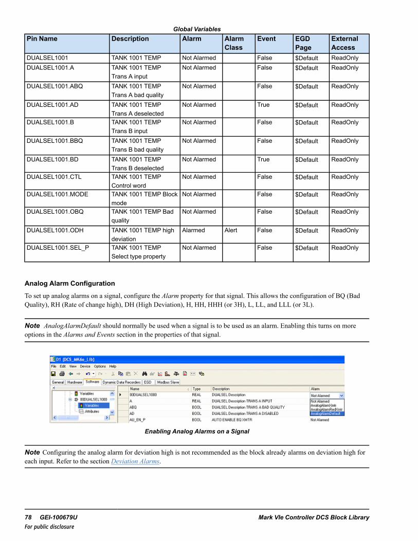
Global VariablesPin Name Description Alarm Alarm
ClassEvent EGD
PageExternalAccess
DUALSEL1001 TANK 1001 TEMP Not Alarmed False $Default ReadOnlyDUALSEL1001.A TANK 1001 TEMP
Trans A inputNot Alarmed False $Default ReadOnly
DUALSEL1001.ABQ TANK 1001 TEMPTrans A bad quality
Not Alarmed False $Default ReadOnly
DUALSEL1001.AD TANK 1001 TEMPTrans A deselected
Not Alarmed True $Default ReadOnly
DUALSEL1001.B TANK 1001 TEMPTrans B input
Not Alarmed False $Default ReadOnly
DUALSEL1001.BBQ TANK 1001 TEMPTrans B bad quality
Not Alarmed False $Default ReadOnly
DUALSEL1001.BD TANK 1001 TEMPTrans B deselected
Not Alarmed True $Default ReadOnly
DUALSEL1001.CTL TANK 1001 TEMPControl word
Not Alarmed False $Default ReadOnly
DUALSEL1001.MODE TANK 1001 TEMP Blockmode
Not Alarmed False $Default ReadOnly
DUALSEL1001.OBQ TANK 1001 TEMP Badquality
Not Alarmed False $Default ReadOnly
DUALSEL1001.ODH TANK 1001 TEMP highdeviation
Alarmed Alert False $Default ReadOnly
DUALSEL1001.SEL_P TANK 1001 TEMPSelect type property
Not Alarmed False $Default ReadOnly
Analog Alarm Configuration
To set up analog alarms on a signal, configure the Alarm property for that signal. This allows the configuration of BQ (BadQuality), RH (Rate of change high), DH (High Deviation), H, HH, HHH (or 3H), L, LL, and LLL (or 3L).
Note AnalogAlarmDefault should normally be used when a signal is to be used as an alarm. Enabling this turns on moreoptions in the Alarms and Events section in the properties of that signal.
Enabling Analog Alarms on a Signal
Note Configuring the analog alarm for deviation high is not recommended as the block already alarms on deviation high foreach input. Refer to the section Deviation Alarms.
78 GEI-100679U Mark VIe Controller DCS Block LibraryFor public disclosure

Additional Options in Alarms and Events Property Editor
Instruction Guide GEI-100679U 79For public disclosure

➢➢ To enable the H Alarm: in the property grid, set the H property to True to add the variables displayed in the followingfigure to the variable list.
H Variables
H_SP is the setpoint for the High alarm on the signal. H_T is the delay time (in ms). When the comparison between thesetpoint and the value is done, it waits H_T milliseconds before issuing the alarm. HYST is the Hysteresis of the alarm values.Set the initial values to effectively use them. 00DUALSEL1000.H is the actual variable name that generates the alarm.
HMI Configuration (CIMPLICITY)
The Object name for the HMI is the same as the Device name specified in the ToolboxST Configuration.
Typical HMI Object for a DUALSEL_V2
DUALSEL_V2 Faceplate
80 GEI-100679U Mark VIe Controller DCS Block LibraryFor public disclosure

11 Enthalpy of Superheated Steam (ENTHALPY_STM)Block Category: Equations and Conversions
The Enthalpy of Superheated Steam (ENTHALPY_STM) block resolves the enthalpy of superheated steam given the steamgauge pressure, IN_P, temperature, IN_T, and atmospheric pressure, IN_PATM.
ENTHALPY_STM Block
Ranges/Units
MEAS_SYS English S.I.IN_P PSIg bargIN_T 95 - 1500 °F 35 - 816°CIN_PATM PSI barOUT BTU/lb KJ/kgThe steam table lookup uses the sum of IN_P and IN_PATM (absolute pressure). The sum of IN_P and IN_PATM must be inthe range of 0.8 - 3200 PSIA (0.0552 - 220.6322 bara).
This block propagates quality status if the status operations are enabled.
Block status modifications:
• Due to the nature of the steam table, some input combinations may lead to a result outside of the superheated steamregion. This results in an output status of NOT_LIMITED-LAST_USABLE_VALUE-UNCERTAIN [68].
• If the input temperature or pressure value exceeds the range in the given table above, the output status will be eitherLOW_LIMITED-LAST_USABLE_VALUE-UNCERTAIN [69] or HIGH_LIMITED-LAST_USABLE_VALUE-UNCERTAIN [70].
For further details on Relational blocks, refer to the Mark VIe Controller Standard Block Library (GEI-100682), the StatusMonitoring (STATUS_MONITORING) block.
InputsName Description Data Type Initial Value Visibility Interface TypeIN_P Input pressure (gauge) REAL† 0 Always Value with StatusIN_PATM Input atmospheric
pressureREAL† 14.696 Parameter Value with Status
IN_T Input temperature REAL† 220 Always Value with StatusMEAS_SYS Measurement system UINT (ENUM) English Parameter Value Only† Value with Status (if status option is enabled)
OutputName Description Data Type Initial Value Visibility Interface TypeOUT Steam enthalpy REAL† N/A Always Value with Status
† Value with Status (if status option is enabled)
Instruction Guide GEI-100679U 81For public disclosure

12 Enthalpy of Subcooled Water (ENTHALPY_WTR)Block Category: Equations and Conversions
The Enthalpy of Subcooled Water (ENTHALPY_WTR) block resolves the enthalpy of subcooled water given the water gaugepressure, IN_P, temperature, IN_T, and atmospheric pressure, IN_PATM.
ENTHALPY_WTR Block
Ranges/Units
MEAS_SYS English S.I.IN_P PSIg bargIN_T 32 - 705 °F 0 - 374°CIN_PATM PSI barOUT BTU/lb KJ/kgThe steam table lookup uses the sum of IN_P and IN_PATM (absolute pressure). The sum of IN_P and IN_PATMmust be in the range of 0.8 - 3200 PSIA (0.0552 - 220.6322 bara).
This block propagates quality status if the status operations are enabled.
Block status modifications:
• Due to the nature of the steam table, some input combinations may lead to a result outside of the superheated steamregion. This results in an output status of NOT_LIMITED-LAST_USABLE_VALUE-UNCERTAIN [68].
• If the input temperature or pressure value exceeds the range in the given table above, the output status will be eitherLOW_LIMITED-LAST_USABLE_VALUE-UNCERTAIN [69] or HIGH_LIMITED-LAST_USABLE_VALUE-UNCERTAIN [70].
For further details on Relational blocks, refer to the Mark VIe Controller Standard Block Library (GEI-100682), the StatusMonitoring (STATUS_MONITORING) block.
Inputs
Name Description Data Type Initial Value Visibility Interface TypeIN_P Input pressure (gauge) REAL† 0 Always Value with StatusIN_PATM Input atmospheric pressure REAL† 14.696 Always Value with StatusIN_T Input temperature REAL† 220 Always Value with StatusMEAS_SYS Measurement system UINT (ENUM) English Always Value Only† Value with Status (if status option is enabled)
Outputs
Name Description Data Type Initial Value Visibility Interface TypeOUT Steam enthalpy REAL† N/A Always Value with Status† Value with Status (if status option is enabled)
82 GEI-100679U Mark VIe Controller DCS Block LibraryFor public disclosure

13 First In-First Out (FIFO)Block Category: Analog Operations
The First In-First Out (FIFO) block is an expandable block that performs a basic first in, first out operation of up to 32 inputs.The block scans the inputs sequentially and the FIFO order is stored using the input number of the associated input (that is, 1for IN1, 2 for IN2, 3 for IN3, and so forth). The order in which any of the digital inputs transition from False to True ispreserved in a memory in which up to 32 transitions can be stored. Once 32 transitions have been stored, all other transitionsare ignored.
FIFO Block
For each successive False to True transition of the rotate input, RTAT, the first input number stored in the FIFO will beremoved from internal storage and that numerical value will be written to the output, OUT. When the memory is empty, OUTis set to zero.
A False to True transition on the clear input, CLR, will cause the output and all the internal FIFO entries to be set to zero, andwill remain zero as long as the clear input, CLR, is True.
The FLAG output is set to True when the FIFO is not empty.
Instruction Guide GEI-100679U 83For public disclosure

Examples
Initial condition : OUT equals to 0, FLAG is False.
Scan1: IN8 transitions to True, FLAG is True
Scan2: IN1 transitions to True, FLAG is True
Scan3: IN2 and IN4 transitions to True, FLAG is True
Scan4: RTAT transitions from False to True, then OUT equals 8, FLAG is True
Scan5: RTAT transitions from True to False, FLAG is True
Scan6: RTAT transitions from False to True, then OUT equals 1, FLAG is True
Scan7: RTAT transitions from True to False, FLAG is TRUE
Scan8: RTAT transitions from False to True, then OUT equals 2, FLAG is True
Scan9: RTAT transitions from True to False, FLAG is True
Scan10: RTAT transitions from False to True, then OUT equals 4, FLAG is False
Scan11: RTAT transitions from True to False, FLAG is False
Scan12: RTAT transitions from False to True, then OUT equals 0, register is empty, FLAG is False
Inputs
Name Description Data Type Initial Value Visibility Interface TypeCLR Clear intern memory BOOL False Always Value OnlyIN1 First input BOOL False Always Value Only↓ ↓ ↓ ↓ ↓ ↓IN32 Last input BOOL False Always Value OnlyRTAT Rotate (remove the oldest
input number from thememory to the OUT)
BOOL False Always Value Only
Outputs
Name Description Data Type Initial Value Visibility Interface TypeFLAG FLAG is True if the memory
is NOTemptyBOOL False Always Value Only
OUT Output UINT 0 Always Value Only
84 GEI-100679U Mark VIe Controller DCS Block LibraryFor public disclosure

14 Flow Calculator (FLOW_CALC)Block Category: Equations and Conversions
The Flow Calculator (FLOW_CALC) block calculates the flow for non-compressible fluids through a differential pressureflow meter. The block is expandable for up to four transmitters. It requires the meter design pressure specifications, IHS andILS, as well as the flow specifications, OHS and OLS, to calculate the output. Furthermore, the OUTn is only calculated if theINn is greater than the low cutout value, LCO. If the input variable INn is less than or equal to LCO, then the OUTn will be 0.
FLOW_CALC Block
This block propagates quality status if the status operations are enabled.
OUTn status = INn status.
Block status modifications: If (INn > LCO) < ILS, or IHS ≤ ILS, or OHS ≤ OLS,then the value of outputs OUTn = 0 and their status = NOT_LIMITED-CONFIGURATION_ERROR-BAD [4]
Refer to theMark VIe Controller Standard Block Library (GEI-100682), the Status Monitoring (STATUS_MONITORING)block.
Instruction Guide GEI-100679U 85For public disclosure

Inputs
Name Description Data Type Initial Value Visibility Interface TypeIHS Input high scale REAL 100 Always Value OnlyILS Input low scale REAL 0 Always Value OnlyIN1 Input differential pressure 1 REAL† 0 Always Value with Status↓ ↓ ↓ ↓ ↓ ↓IN4 Input differential pressure 4 REAL† 0 Always Value with StatusLCO Low cutout REAL 0 Always Value OnlyOHS Output high scale REAL 100 Always Value OnlyOLS Output low scale REAL 0 Always Value Only† Value with status (if status option is enabled)
Outputs
Name Description Data Type Initial Value Visibility Interface TypeOUT1 Output variable 1 REAL† N/A Always Value with Status↓ ↓ ↓ ↓ ↓ ↓OUT4 Output variable 4 REAL† N/A Always Value with Status† Value with Status (if status option is enabled)
86 GEI-100679U Mark VIe Controller DCS Block LibraryFor public disclosure

15 Force (FORCE)Block Category: Legacy, Permits and Overrides
Note Legacy Status— The FORCE block is not supported for use in new Mark VIe control systems (ControlST softwaresuite V05.02 or later). It is in place to support the maintenance of legacy Mark VIe control systems (prior to ControlSTsoftware suite V05.02). For new Mark VIe control systems, use the LOGIC_BUILDER or LOGIC_BUILDER_SC block (useif first out/state change feature is required); these blocks provide equivalent functionality. Refer to theMark VIe ControllerStandard Block Library (GEI-100682).
The Force (FORCE) block is an expandable block of up to 32 force inputs which functions like an OR block. Each connectedinput can be blocked by the HMI operator from the force tab of the associated permit screen. This blocking function must beenabled by setting FRCnBE to True. If force blocking is enabled for an input, an event is generated on the HMI alarm/eventscreen whenever the operator blocks the FORCE.
FORCE Block
Each input has the capability of inheriting the description of a connected global variable or a global variable connectedthrough a NOT block. When a connection is made to one of the input pins, the description of the global variable is inheritedby default. If this inherited description is undesirable, it must be disabled by setting the Inherit Description option to False inthe input variable properties. The description can be replaced with a desirable description by entering an appropriatedescription in the description field of the input variable of the FORCE block (replace FORCE #1 with the desired overridedescription for the source connected to FRC1). The description is not copied from the connected variable immediately; theinput's description is set when the library or device containing the input is validated or built.
Note Refer to the table Global Variables.
Block Configuration
ForceType enumerations are listed in the following table.
ForceType Enumerations
Enumeration DescriptionCL_FRC Close forceOP_FRC Open forceINT_FRC Intermediate forceSTR_FRC Start forceSTP_FRC Stop forceCMD_FRC Command/setpoint forceON_FRC On forceOFF_FRC Off force
Instruction Guide GEI-100679U 87For public disclosure

OUT enumeration pin values are provided in the following table.
OUT EnumerationsEnumeration Force Output DescriptionNO_FORCE-NO-BLOCK No force and no force is blockedFORCE-NO_BLOCK Force active and no force is blockedNO_FORCE-BLOCK No force and a force is blockedFORCE-BLOCK Force active and a force is blocked
ToolboxST Configuration
Inserting this block into the application program will generate a window as displayed in the following figure. This promptsthe user to Enter Device Name and Select ForceType in the Value column of the window (the force type is a drop-down listselection.
Changing Default Attributes
Note Refer to the table ForceType Enumerations.
The block will automatically create the necessary variables and provide the appropriate attributes for each variable (forexample, Type and Format Spec variables that need to be on EGD will be automatically placed on the $Default EGD page,and so forth). If additional pin groups are added, the necessary new variables will be automatically created during a build ofthe application program.
When the user clicks OK, the block and pin connections will be configured automatically. This will generate Global pins.
Note Refer to the table Global Variables. The defaults listed are for example only. Be sure to change the block name.
There are two things to remember when installing a FORCE block. The first is that the Device Name of the block shouldmatch the name of the block that it will be connected to. If this block is controlling an MOV block, then the names shouldmatch. If the blocks are connected correctly, but named incorrectly, the force block will work normally, but the HMI screencannot tell you why the signal is or isn’t forced.
The second thing to remember is to select the correct Force Type. If the user selects CL_FRC, but connects it to an OP_FRC,the permissive will act like a force close but displays in the Open force window.
Input pin names are in the form Device Value ForceType Value pin name. Output pin names are in the form Device ValueForceType Value.OUT, Device Value ForceType Value.FRC, and Device Value ForceType Value.FRCB.
Example
If Device Value = 00FORCE1000 and ForceType Value = CL_FRC.
88 GEI-100679U Mark VIe Controller DCS Block LibraryFor public disclosure

Inputs
Name Description Data Type Initial Value Visibility Interface TypeFRC1 Force input 1 BOOL False Always Value OnlyFRC1B Force input block 1 BOOL False Always Value OnlyFRC1BE Force input block enable 1 BOOL False Always Value Only↓ ↓ ↓ ↓ ↓ ↓FRC32 Force input 32 BOOL False Always Value OnlyFRC32B Force input block 32 BOOL False Always Value OnlyFRC32BE Force input block enable 32 BOOL False Always Value Only
Outputs
Name Description Data Type Initial Value Visibility Interface TypeFRC Force BOOL False Always Value OnlyFRCB Force block BOOL False Always Value OnlyOUT Output UINT (ENUM) NO_FORCE-NO_BLOCK Always Value Only
Global VariablesPin Name Description Alarm Alarm
ClassEvent EGD Page External
Access00FORCE1000CL_FRC.FRC Force Not Alarmed False ReadOnly00FORCE1000CL_FRC.FRCB Force block Not Alarmed False ReadOnly00FORCE1000CL_FRC.OUT Output Not Alarmed False ReadOnly↓ ↓ ↓ ↓ ↓ ↓ ↓00FORCE1000CL_FRC.FRC1 Force input Not Alarmed True $DEFAULT ReadOnly00FORCE1000CL_FRC.FRC1B Force input
blockNot Alarmed True $DEFAULT ReadWrite
00FORCE1000CL_FRC.FRC1BE Force inputblock enable
Not Alarmed False $DEFAULT ReadOnly
↓ ↓ ↓ ↓ ↓ ↓ ↓00FORCE1000CL_FRC.FRCn Force input Not Alarmed True $DEFAULT ReadOnly00FORCE1000CL_FRC.FRCnB Force input
blockNot Alarmed True $DEFAULT ReadWrite
00FORCE1000CL_FRC.FRCnBE Force inputblock enable
Not Alarmed False $DEFAULT ReadOnly
Instruction Guide GEI-100679U 89For public disclosure

HMI Configuration (CIMPLICITY)
A FORCE block does not directly have an HMI object. The block displays on the Permits faceplate when used. The followingfigure displays the Permits faceplate for a PID_MA block. This displays the presence of the FORCE block, as well as adescription from the controlling variable. The FORCE description displays as green because the FORCE is not active.
Permits Faceplate for PID_MA
90 GEI-100679U Mark VIe Controller DCS Block LibraryFor public disclosure

16 Gain Bias (GAIN_BIAS)Block Category: Math
The Gain Bias (GAIN_BIAS) block multiplies IN and GAIN and adds BIAS:
OUT = IN x GAIN + BIAS
GAIN_BIAS Block
This block propagates quality status if the status operations are enabled.
For further details on Relational blocks, refer to the Mark VIe Controller Standard Block Library (GEI-100682), the StatusMonitoring (STATUS_MONITORING) block.
Inputs
Name Description Data Type Initial Value Visibility Interface TypeBIAS Offsets the product of IN and GAIN REAL† 0 Always Value with StatusGAIN Value to multiply the input REAL† 1 Always Value with StatusIN Analog input signal REAL† 0 Always Value with Status† Value with Status (if status option is enabled)
Output
Name Description Data Type Initial Value Visibility Interface TypeOUT Product of the input and gain summed
with the biasREAL† N/A Always Value with Status
† Value with Status (if status option is enabled)
Instruction Guide GEI-100679U 91For public disclosure

17 Group (GRP)Block Category: Device Control
Note Legacy Status— The GRP block is not supported for use in new Mark VIe control systems (ControlST softwaresuite V05.02 or later). It is in place to support the maintenance of legacy Mark VIe control systems (prior to ControlSTsoftware suite V05.02). For new Mark VIe control systems, use the GRP_V3 block; it provides equivalent functionality.
The Group (GRP) block enables and/or sequences groups of equipment such as motor starters, motor operated valves, controlvalves, and so forth. The block provides a maintained output ON which is energized/de-energized to control the groupsequencing.
Note This block features only the interface, not the sequence.
GRP Block
Block Configuration
Control Word
Control (CTL) is an enumeration set by the HMI operator for group control. The commands available from the HMI allowmanual and automatic push-button control capability. The group may be started or stopped in Manual mode by the ON_PB orOFF_PB commands, respectively. The command enumerations are defined in the following table.
CTL EnumerationsEnumeration CommandNO_CMD No commandAUTO_CMD Auto commandMANUAL_CMD Manual commandON_CMD On cmdOFF_CMD Off cmd
92 GEI-100679U Mark VIe Controller DCS Block LibraryFor public disclosure

Mode of Operation (Mode_OPT)
MODE_OPT enumerations are listed in the following table.
MODE_OPT Enumerations
Enumeration Operating ModeNONE NoneAUTO Auto
NONE— the group may be started or stopped manually by the HMI operator, no other mode options are available.
Note PMT_AU is described in the section Auto/On/Off Permissives.
AUTO— provides auto control capability for the GROUP. Selecting the AUTO mode property will set AUTO_P to True,indicating the auto mode property of the block is enabled. The block provides an auto permitted indication input, AU_PMT,which can be driven by external logic. When AUTO_P is True, the group can be commanded to auto by either CTLenumeration AUTO_CMD providing PMT_AU is True.
When AUTO is True, the AU_ON and AU_OFF inputs control the automatic on/off operation of the block, provided, PMT_ON or PMT_OFF, respectively, is True. If AU_ON, AU_OFF, or AU_SEL become True, the group is in Manual mode, andthe group output (ON) is not in the state of the requested command, the auto request alarm, AU_REQ, will be activated.
Override Control
The block provides override control through a Manual Reject input enumeration, MN_REJ. The possible values are listed inthe following table.
MN_REJ Enumerations
Enumeration CommandOR-NO_BLOCK Override Active And No Override Is BlockedNO_OVR-BLOCK No Override And A Override Is BlockedOVR-BLOCK Override Active And A Override Is BlockedNO_OVR-NO-BLOCK No Override And No Override Is Blocked
The group is rejected to manual when MN_REJ indicates Override Active and the manual reject alarm, MN_REJ_A, will beactivated, (delayed by 2 seconds).
MN_REJ (if used) is driven from an Override (OVERRIDE) block. Each connected input of the OVERRIDE block has theability (when enabled) to be blocked by the HMI operator, which is accessed from associated tab of the permit HMI screendisplay. When MN_REJ enumeration contains BLOCK, the HMI operator has blocked at least one override. GRP does notuse the block information, but passes it to the HMI for display.
Instruction Guide GEI-100679U 93For public disclosure
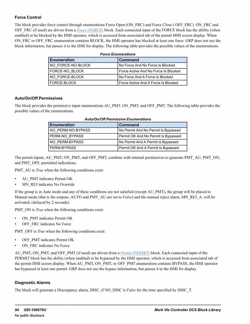
Force Control
The block provides force control through enumerations Force Open (ON_FRC) and Force Close ( OFF_FRC). ON_FRC andOFF_FRC (if used) are driven from a Force (FORCE) block. Each connected input of the FORCE block has the ability (whenenabled) to be blocked by the HMI operator, which is accessed from associated tab of the permit HMI screen display. WhenON_FRC or OFF_FRC enumeration contains BLOCK, the HMI operator has blocked at least one force. GRP does not use theblock information, but passes it to the HMI for display. The following table provides the possible values of the enumerations.
Force EnumerationsEnumeration CommandNO_FORCE-NO-BLOCK No Force And No Force Is BlockedFORCE-NO_BLOCK Force Active And No Force Is BlockedNO_FORCE-BLOCK No Force And A Force Is BlockedFORCE-BLOCK Force Active And A Force Is Blocked
Auto/On/Off Permissives
The block provides the permissive input enumerations AU_PMT, ON_PMT, and OFF_PMT. The following table provides thepossible values of the enumerations.
Auto/On/Off Permissive EnumerationsEnumeration CommandNO_PERM-NO-BYPASS No Permit And No Permit Is BypassedPERM-NO_BYPASS Permit OK And No Permit Is BypassedNO_PERM-BYPASS No Permit And A Permit Is BypassedPERM-BYPASS Permit OK And A Permit Is Bypassed
The permit inputs, AU_PMT, ON_PMT, and OFF_PMT, combine with internal permissives to generate PMT_AU, PMT_ON,and PMT_OFF, permitted indications.
PMT_AU is True when the following conditions exist:
• AU_PMT indicates Permit OK• MN_REJ indicates No Override
If the group is in Auto mode and any of these conditions are not satisfied (except AU_PMT), the group will be placed toManual mode (that is the outputs, AUTO and PMT_AU are set to False) and the manual reject alarm, MN_REJ_A, will beactivated, (delayed by 2 seconds).
PMT_ON is True when the following conditions exist:
• ON_PMT indicates Permit OK• OFF_FRC indicates No Force
PMT_OFF is True when the following conditions exist:
• OFF_PMT indicates Permit OK• ON_FRC indicates No Force
AU_PMT, ON_PMT, and OFF_PMT (if used) are driven from a Permit (PERMIT) block. Each connected input of thePERMIT block has the ability (when enabled) to be bypassed by the HMI operator, which is accessed from associated tab ofthe permit HMI screen display. When AU_PMT, ON_PMT, or OFF_PMT enumeration contains BYPASS, the HMI operatorhas bypassed at least one permit. GRP does not use the bypass information, but passes it to the HMI for display.
Diagnostic Alarms
The block will generate a Discrepancy alarm, DISC, if NO_DISC is False for the time specified by DISC_T.
94 GEI-100679U Mark VIe Controller DCS Block LibraryFor public disclosure
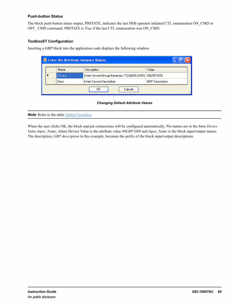
Push-button Status
The block push-button status output, PBSTATE, indicates the last HMI operator initiated CTL enumeration ON_CMD orOFF_ CMD command. PBSTATE is True if the last CTL enumeration was ON_CMD.
ToolboxST Configuration
Inserting a GRP block into the application code displays the following window.
Changing Default Attribute Values
Note Refer to the table Global Variables.
When the user clicks OK, the block and pin connections will be configured automatically. Pin names are in the form DeviceValue.Input_Name, where Device Value is the attribute value 00GRP1000 and Input_Name is the block input/output names.The description, GRP description in this example, becomes the prefix of the block input/output descriptions.
Instruction Guide GEI-100679U 95For public disclosure

Inputs
Name Global Description Data Type Initial Value Visibility InterfaceType
AU_OFF AUTO OFF CMD BOOL False Always Value OnlyAU_ON AUTO ON CMD BOOL False Always Value Only
AU_PMT Yes Auto permit UINT (ENUM) PERM-NO_BYPASS Always Value OnlyAU_SEL Yes {Desc} Auto select BOOL False Always Value OnlyCTL Yes {Desc} Control word UINT (ENUM) NO_CMD Always Value OnlyDISC_T Discrepancy time UDINT 5000 Parameter Value OnlyMN_REJ Manual reject UINT (ENUM) NO_OVR-NO_BLOCK Always Value OnlyMODE_OPT
Mode options UINT (ENUM) NONE Always Value Only
NO_DISC No discrepancy BOOL True Always Value OnlyOFF_FRC Yes Force off UINT (ENUM) NO_FORCE-NO_BLOCK Always Value OnlyOFF_PMT Yes OFF permit UINT (ENUM) PERM-NO_BYPASS Always Value OnlyON_FRC Yes Force on UINT (ENUM) NO_FORCE-NO_BLOCK Always Value OnlyON_PMT Yes ON permit UINT (ENUM) PERM-NO_BYPASS Always Value Only
96 GEI-100679U Mark VIe Controller DCS Block LibraryFor public disclosure

Outputs
Name Global Description Data Type Initial Value Visibility InterfaceType
{Device} Yes {Desc} BOOL False Internal Value OnlyAU_ORD Yes {Desc} Auto order BOOL False Always Value OnlyAU_REQ Yes {Desc} Auto request BOOL False Always Value OnlyAUTO Yes {Desc} Auto BOOL False Always Value OnlyAUTO_P Yes {Desc} Auto property BOOL False Always Value OnlyDISC Yes {Desc} Discrepancy BOOL False Always Value OnlyFRC_OFF Yes {Desc} Force off BOOL False Always Value OnlyFRC_OFFB Yes {Desc} OFF FORCE block status BOOL False Internal Value OnlyFRC_ON Yes {Desc} Force on BOOL False Always Value OnlyFRC_ONB Yes {Desc} ON FORCE block status BOOL False Internal Value OnlyMN_REJ_A Yes {Desc} Manual reject BOOL False Always Value OnlyOFF Yes {Desc} OFF BOOL True Always Value OnlyON Yes {Desc} ON BOOL False Always Value OnlyPBSTATE Yes {Desc} Last PB state BOOL False Internal Value OnlyPMT_AU Yes {Desc} Auto permit BOOL False Always Value OnlyPMT_AUB Yes {Desc} Auto permit bypass status BOOL False Internal Value OnlyPMT_OFF Yes {Desc} OFF permit BOOL True Always Value OnlyPMT_OFFB Yes {Desc} OFF permit bypass status BOOL False Internal Value OnlyPMT_ON Yes {Desc} ON permit BOOL True Always Value OnlyPMT_ONB Yes {Desc} ON permit bypass status BOOL False Internal Value OnlyREJ_MN Yes {Desc} Manual reject BOOL False Always Value OnlyREJ_MNB Yes {Desc} Manual reject bypass status BOOL False Internal Value Only
Instruction Guide GEI-100679U 97For public disclosure

Global VariablesPin Name Description Alarm Alarm
ClassEvent EGD
PageExternalAccess
00GRP1000 GRP description Not Alarmed False $Default ReadOnly00GRP1000.AU_ORD GRP description auto order Not Alarmed False ReadOnly00GRP1000.AU_REQ GRP description auto request Alarmed LVL_4 False $Default ReadOnly00GRP1000.AU_SEL GRP description auto select Not Alarmed False ReadOnly00GRP1000.AUTO GRP description auto Not Alarmed False $Default ReadOnly00GRP1000.AUTO_P GRP description auto
propertyNot Alarmed False $Default ReadOnly
00GRP1000.CTL GRP description control word Not Alarmed False $Default ReadWrite00GRP1000.DISC GRP description discrepancy Alarmed LVL_4 False $Default ReadOnly00GRP1000.FRC_OFF GRP description force off Not Alarmed False $Default ReadOnly00GRP1000.FRC_OFFB GRP description OFF
FORCE block statusNot Alarmed False $Default ReadOnly
00GRP1000.FRC_ON GRP description force on Not Alarmed False $Default ReadOnly00GRP1000.FRC_ONB GRP description ON FORCE
block statusNot Alarmed False $Default ReadOnly
00GRP1000.MN_REJ_A GRP description manualreject
Alarmed LVL_4 False $Default ReadOnly
00GRP1000.OFF GRP description OFF Not Alarmed False $Default ReadOnly00GRP1000.ON GRP description ON Not Alarmed False $Default ReadOnly00GRP1000.PBSTATE GRP description last PB state Not Alarmed False $Default ReadOnly00GRP1000.PMT_AU GRP description Auto permit Not Alarmed False $Default ReadOnly00GRP1000.PMT_AUB GRP description Auto permit
bypass statusNot Alarmed False $Default ReadOnly
00GRP1000.PMT_OFF GRP description OFF permit Not Alarmed False $Default ReadOnly00GRP1000.PMT_OFFB GRP description OFF permit
bypass statusNot Alarmed False $Default ReadOnly
00GRP1000.PMT_ON GRP description ON permit Not Alarmed False $Default ReadOnly00GRP1000.PMT_ONB GRP description ON permit
bypass statusNot Alarmed False $Default ReadOnly
00GRP1000.REJ_MN GRP description Manualreject
Not Alarmed False $Default ReadOnly
00GRP1000.REJ_MNB GRP description Manualreject bypass status
Not Alarmed False $Default ReadOnly
98 GEI-100679U Mark VIe Controller DCS Block LibraryFor public disclosure

HMI Configuration (CIMPLICITY)
The Object name for the HMI is the same as the Device name specified in the ToolboxST configuration.
Typical HMI Object for a GRP
GRP Faceplate
Instruction Guide GEI-100679U 99For public disclosure

18 Group Version 2 (GRP_V2)Block Category: Legacy, Device Control
Note Legacy Status— The GRP_V2 block is not supported for use in new Mark VIe control systems (ControlSTsoftware suite V05.02 or later). It is in place to support the maintenance of legacy Mark VIe control systems (prior toControlST software suite V05.02). For new Mark VIe control systems, use the GRP_V3 block; it provides equivalentfunctionality.
The Group Version 2 (GRP_V2) block enables and/or sequences groups of equipment, such as motor starters, motor operatedvalves, control valves, and so forth. The block provides a maintained output, ON, which is energized/de-energized to controlthe group sequencing.
Note This block features only the interface, not the sequence.
The GRP_V2 block is displayed in the following figure. However, not all variable pins are displayed because most areauto-hidden.
GRP_V2 Block
100 GEI-100679U Mark VIe Controller DCS Block LibraryFor public disclosure

Block Configuration
Control Word
Control (CTL) is an enumeration set by the HMI operator for group control. The commands available from the HMI allowmanual and automatic push-button control capability. The group may be started or stopped in Manual mode by the ON_PB orOFF_PB commands, respectively. The command enumerations are defined in the following table.
Note This block has various enumerations that are configured for control block operation.
CTL EnumerationsEnumeration CommandNO_CMD No command
AUTO_CMD Auto commandMANUAL_CMD Manual commandON_CMD On cmdOFF_CMD Off cmd
Mode of Operation (Mode_OPT)
Mode_OPT is the mode in which the GRP_V2 block is configured to operate: Manual or Automatic (Auto) mode. Manualmode allows commands from the operator interface, while Auto mode allows the control logic to command the solenoid. Theallowable modes of operation are specified by the parameter, MODE_OPT.
Available Modes for MODE_OPT Selections
MODE_OPT
MANUAL AUTOMODE_OPT MANUAL ONLY X
MANUAL-AUTO X XAUTO ONLY X
Manual mode— enables the block to respond to operator ON and OFF commands from a faceplate on the HMI. Given thatthe permits are satisfied, the block operates in accordance with the manual command. The permit for the ON command is setby the ON permit input, ON_PMT, and the permit for the OFF command is set by the OFF permit input, OFF_PMT. Theseinputs may be set to fixed values or driven by the LOGIC_BUILDER block. The possible conditions that place the block intoManual mode are as follows:
Note Refer to theMark VIe Controller Standard Block Library (GEI-100682), the Logic Builder (LOGIC_BUILDER) block.
• Manual mode selected from the HMI faceplate• Manual Rejection from the logic (MN_REJ)
Note Manual mode is always available unless MODE_OPT is set to AUTO ONLYor AUTO-LOCK.
Instruction Guide GEI-100679U 101For public disclosure

Auto mode— enables the block to respond to Open and Close commands from the logic. Given that the permits are satisfied,the block operates in accordance with the command from the logic. The permit for the ON command is set by the ON permitinput, ON_PMT, and the permit for the OFF command is set by the OFF permit input, OFF_PMT. The ON_PMT and OFF_PMT inputs may be set to fixed values or driven by the LOGIC_BUILDER block. The logic commands are input to the blockthrough the automatic open, AU_ON, and automatic close, AU_OFF, inputs. The block may be placed in Auto mode either bya command from the HMI or a pulse to the automatic select input, AU_SEL. Given that the permits are satisfied, the block isplaced into Auto mode. The permit for Auto mode is set by the Auto permit input, AU_PMT. The AU_PMT input may be setto a fixed value or also driven by the LOGIC_BUILDER block.
MANUAL-AUTO mode— selection provides manual and automatic functionality. A selection of AUTO ONLYorAUTO-LOCK for MODE_OPT provides automatic functionality ONLY. While residing in Automatic mode, the block willcontrol based on external logic. Automated control from external logic interfaces to the AU_ON and AU_OFF pins. Similarto Manual mode, Auto mode action only operates with the proper permits. If AUTO ONLY mode is selected, the block willpermanently reside in Automatic mode. If MANUAL-AUTO is selected, only two conditions will transfer the block fromManual mode into Auto mode. Unlike the transferring to Manual mode, here, certain permits must be satisfied to enter intoAuto mode. This means that the block is always able to enter Manual mode, but not always able to enter Auto mode. Theseconditions depend on the mode options selected for the block.
All three of the following conditions must be met for the block to enter Auto mode:
• No demand to transition to Manual mode• MODE_OPT must be set to MANUAL-AUTO• AUTO push-button from operator graphic or Auto select from logic (AU_SEL)
Inputs and Outputs
At a minimum, the block requires no feedback. However, discrepancy feedbacks can be run through.
The GRP_V2 block has one Auto Order output that places all downstream devices in Auto mode. ON and OFF status outputscan also drive downstream devices through the Auto ON and OFF input pins. Additional outputs from this block indicatestatus, alarms, and manual rejections. Much of this information is displayed on the HMI faceplate.
Diagnostic Alarms
When an alarm is active, the block may have limited control. For example, manual rejection would prevent the block fromgoing into Auto mode. All alarms are held true until the alarm is cleared. Examples of potential alarms are as follows:
Discrepancy (DISC)— the input pin (NO_DISC) becomes False and gives feedback that not all items are in Auto or ON.Return NO_DISC to value True to clear the alarm.
Auto Request (AU_REQ)— the block is in Manual mode but the Auto logic requests that the block state be different thanits current state. This has no effect on block operation and is an alarm message only. The alarm is cleared if the block isplaced into Auto mode, manually ordered to the requested state, or the auto action is removed.
Manual Rejected (MN_REJ_A)— the GRP_V2 is rejected to manual due to a conditional alarm or input pin (MN_REJbecomes True). The block will only respond to manual commands. The alarm is cleared after the conditions return to normaland the MN_REJ becomes False and a reset command is given.
102 GEI-100679U Mark VIe Controller DCS Block LibraryFor public disclosure

Force Control
During any condition, the GRP_V2 block may be forced to a state that bypasses normal operation. The force is driven fromthe ON_FRC or OFF_FRC pins in the logic. The block will send the respective condition and remain until the force isremoved. While a force condition is active, the block may freely transfer from Auto to Manual mode following the normalpermits. However, no manual command will supersede the force. Once the force is removed, it will continue normaloperation.
Permits
Due to the nature of Auto and forcing action, the following table displays the permits that are required for operation.
Permits
Name Description
On ON_PMT is True (ON_PMT is technically a UINT)
Off OFF_PMT is True (OFF_PMT is technically a UINT)
On Force None
Off Force None
Instruction Guide GEI-100679U 103For public disclosure

Inputs
Name Global Description FunctionAU_SEL Yes Auto Select Pulses the valve into auto (provided all permits are met)AU_ OP Yes Auto Open Automatically opens the valve (provided all permits are met); device must be in
Auto mode
AU_CL Auto Close Auto closes the valve (provided all permits are met); device must be in Automode
AU_PMT Yes Auto permit Permit required for external logic to permit the valve to enter Auto modeON_PMT Yes ON permit Permit required for external logic to enter the ON permitOFF_PMT Yes OFF permit Permit required for external logic to enter the OFF permitMN_REJ Yes Manual
RejectionPermit required for external logic to manually reject the block
OFF_FRC Yes Off Force Permit required for external logic to force off the blockON_FRC Yes On Force Permit required for external logic to force on the blockNO_DISC No Discrepancy Permit required for external logic to write to a discrepancy alarm that is
indicated on the screen (does not affect block action)
ParametersName Global Description FunctionCTL Yes Control Used by the operator graphic to control the valveMODE_OPT Mode options Designates whatmodes the device can enter
Outputs
Name Global Description FunctionAU_ORD Yes Auto order Auto order to downstream device (2 second pulse on transition to Auto)AUTO Yes Automatic mode Auto mode activeOFF Yes Device off Can be written to downstream device to turn offON Yes Device on Can be written to downstream device to turn onPMT_AU Yes Auto permit Auto permitPMT_OFF Yes OFF permit OFF permitPMT_ON Yes ON permit ON permitFRC_OFF Yes Off Force Off forceFRC_ON Yes On Force On forceAU_REQ Yes Auto Request Auto logic wishes to turn device on or offDISC Yes Discrepancy Discrepancy alarmMN_REJ_A Yes Manual rejection
alarmManual rejection alarm
104 GEI-100679U Mark VIe Controller DCS Block LibraryFor public disclosure

Global VariablesPin Name Description Alarm Alarm
ClassEvent EGD
PageExternalAccess
00GRP1000 GRP description Not Alarmed False $Default ReadOnly00GRP1000.AU_ORD GRP description auto
orderNot Alarmed False ReadOnly
00GRP1000.AU_REQ GRP description autorequest
Alarmed LVL_4 False $Default ReadOnly
00GRP1000.AU_SEL GRP description autoselect
Not Alarmed False ReadOnly
00GRP1000.AUTO GRP description auto Not Alarmed False $Default ReadOnly00GRP1000.AUTO_P GRP description auto
propertyNot Alarmed False $Default ReadOnly
00GRP1000.CTL GRP description controlword
Not Alarmed False $Default ReadWrite
00GRP1000.DISC GRP descriptionDiscrepancy
Alarmed LVL_4 False $Default ReadOnly
00GRP1000.FRC_OFF GRP description force off Not Alarmed False $Default ReadOnly00GRP1000.FRC_OFFB GRP description OFF
FORCE block statusNot Alarmed False $Default ReadOnly
00GRP1000.FRC_ON GRP description force on Not Alarmed False $Default ReadOnly00GRP1000.FRC_ONB GRP description ON
FORCE block statusNot Alarmed False $Default ReadOnly
00GRP1000.MN_REJ_A GRP description Manualreject
Alarmed LVL_4 False $Default ReadOnly
00GRP1000.OFF GRP description OFF Not Alarmed False $Default ReadOnly00GRP1000.ON GRP description ON Not Alarmed False $Default ReadOnly00GRP1000.PBSTATE GRP description last PB
stateNot Alarmed False $Default ReadOnly
00GRP1000.PMT_AU GRP description autopermit
Not Alarmed False $Default ReadOnly
00GRP1000.PMT_AUB GRP description autopermit bypass status
Not Alarmed False $Default ReadOnly
00GRP1000.PMT_OFF GRP description OFFpermit
Not Alarmed False $Default ReadOnly
00GRP1000.PMT_OFFB GRP description OFFpermit bypass status
Not Alarmed False $Default ReadOnly
00GRP1000.PMT_ON GRP description ONpermit
Not Alarmed False $Default ReadOnly
00GRP1000.PMT_ONB GRP description ONpermit bypass status
Not Alarmed False $Default ReadOnly
00GRP1000.REJ_MN GRP description Manualreject
Not Alarmed False $Default ReadOnly
00GRP1000.REJ_MNB GRP description Manualreject bypass status
Not Alarmed False $Default ReadOnly
Instruction Guide GEI-100679U 105For public disclosure
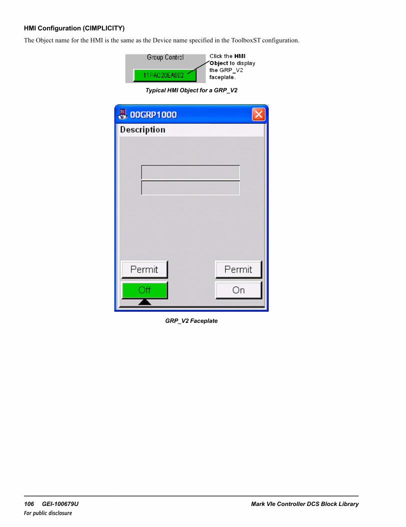
HMI Configuration (CIMPLICITY)
The Object name for the HMI is the same as the Device name specified in the ToolboxST configuration.
Typical HMI Object for a GRP_V2
GRP_V2 Faceplate
106 GEI-100679U Mark VIe Controller DCS Block LibraryFor public disclosure

19 Group Version 3 (GRP_V3)Block Category: Device Control
The Group Version 3 (GRP_V3) block enables and/or sequences groups of equipment, such as motor starters, motor operatedvalves, control valves, and so forth. The block provides a maintained output, ON, which is energized/de-energized to controlthe group sequencing.
Note This block features only the interface, not the sequence.
The GRP_V3 block is displayed in the following figure. However, not all variable pins are displayed because most areauto-hidden.
GRP_V3 Block
Block Configuration
Control Word
Control (CTL) is an enumeration set by the HMI operator for group control. The commands available from the HMI allowmanual and automatic push-button control capability. The group may be started or stopped in Manual mode by the ON_PB orOFF_PB commands, respectively. The command enumerations are defined in the following table.
Note This block has various enumerations that are configured for control block operation.
Instruction Guide GEI-100679U 107For public disclosure

CTL Enumerations
Enumeration CommandNO_CMD No command
AUTO_CMD Auto command
MANUAL_CMD Manual command
ON_CMD On cmd
OFF_CMD Off cmd
Mode of Operation (Mode_OPT)
Mode_OPT is the mode in which the GRP_V3 block is configured to operate: Manual or Automatic (Auto) mode. Manualmode allows commands from the operator interface, while Auto mode allows the control logic to command the solenoid. Theallowable modes of operation are specified by the parameter, MODE_OPT.
Available Modes for MODE_OPT Selections
MODE_OPT
MANUAL AUTOMODE_OPT MANUAL ONLY X
MANUAL-AUTO X XAUTO ONLY X
MANUAL mode— enables the block to respond to operator ON and OFF commands from a faceplate on the HMI. Giventhat the permits are satisfied, the block operates in accordance with the manual command. The permit for the ON command isset by the ON permit input, ON_PMT, and the permit for the OFF command is set by the OFF permit input, OFF_PMT. Theseinputs may be set to fixed values or driven by the LOGIC_BUILDER block. The possible conditions that place the block intoManual mode are as follows:
Note Refer to theMark VIe Controller Standard Block Library, the Logic Builder (LOGIC_BUILDER) block.
• Manual mode selected from the HMI faceplate• Manual Rejection from the logic (MN_REJ)
Note Manual mode is always available unless MODE_OPT is set to AUTO ONLYor AUTO-LOCK.
AUTO mode— enables the block to respond to Open and Close commands from the logic. Given that the permits aresatisfied, the block operates in accordance with the command from the logic. The permit for the ON command is set by theON permit input, ON_PMT, and the permit for the OFF command is set by the OFF permit input, OFF_PMT. The ON_PMTand OFF_PMT inputs may be set to fixed values or driven by the LOGIC_BUILDER block. The logic commands are input tothe block through the automatic open, AU_ON, and automatic close, AU_OFF, inputs. The block may be placed in Automode either by a command from the HMI or a pulse to the automatic select input, AU_SEL. Given that the permits aresatisfied, the block is placed into Auto mode. The permit for Auto mode is set by the Auto Permit input, AU_PMT. The AU_PMT input may be set to a fixed value or also driven by the LOGIC_BUILDER block.
108 GEI-100679U Mark VIe Controller DCS Block LibraryFor public disclosure

MANUAL-AUTO mode— selection provides manual and automatic functionality. A selection of AUTO ONLYorAUTO-LOCK for MODE_OPT provides automatic functionality ONLY. While residing in Automatic mode, the block willcontrol based on external logic. Automated control from external logic interfaces to the AU_ON and AU_OFF pins. Similarto Manual mode, Auto mode action only operates with the proper permits. If AUTO ONLY mode is selected, the block willpermanently reside in Automatic mode. If MANUAL-AUTO is selected, only two conditions will transfer the block fromManual mode into Auto mode. Unlike the transferring to Manual mode, here, certain permits must be satisfied to enter intoAuto mode. This means that the block is always able to enter Manual mode, but not always able to enter Auto mode. Theseconditions depend on the mode options selected for the block.
All three of the following conditions must be met for the block to enter Auto mode:
• No demand to transition to Manual mode• MODE_OPT must be set to MANUAL-AUTO• AUTO push-button from operator graphic or Auto select from logic (AU_SEL)
Inputs and Outputs
At a minimum, the block requires no feedback. However, discrepancy feedbacks can be run through.
The GRP_V3 block has one Auto Order output that places all downstream devices in Auto mode. ON and OFF status outputscan also drive downstream devices through the Auto ON and OFF input pins. Additional outputs from this block indicatestatus, alarms, and manual rejections. Much of this information is displayed on the HMI faceplate.
Diagnostic Alarms
When an alarm is active, the block may have limited control. For example, manual rejection would prevent the block fromgoing into Auto mode. All alarms are held true until the alarm is cleared. Examples of potential alarms are as follows:
Discrepancy (DISC)— the input pin (NO_DISC) becomes False and gives feedback that not all items are in Auto or ON.Return NO_DISC to value True to clear the alarm.
Auto Request (AU_REQ)— the block is in Manual mode but the Auto logic requests that the block state be different thanits current state. This has no effect on block operation and is an alarm message only. The alarm is cleared if the block isplaced into Auto mode, manually ordered to the requested state, or the auto action is removed.
Manual Rejected (MN_REJ_A)— the GRP_V3 block is rejected to manual due to a conditional alarm or input pin (MN_REJ becomes True). The block will only respond to manual commands. The alarm is cleared after the conditions return tonormal and the MN_REJ becomes False and a reset command is given.
Instruction Guide GEI-100679U 109For public disclosure

Force Control
During any condition, the GRP_V3 block may be forced to a state that bypasses normal operation. The force is driven fromthe ON_FRC or OFF_FRC pins in the logic. The block will send the respective condition and remain until the force isremoved. While a force condition is active, the block may freely transfer from Auto to Manual mode following the normalpermits. However, no manual command will supersede the force. Once the force is removed, it will continue normaloperation.
Permits
Due to the nature of Auto and forcing action, the following table displays the permits that are required for operation.
PermitsName Operating ModeOn ON_PMT is True (ON_PMT is technically a UINT)Off OFF_PMT is True (OFF_PMT is technically a UINT)On Force NoneOff Force None
Inputs
Name Global Description FunctionAU_SEL Yes Auto Select Pulses the valve into auto (provided all permits are met)AU_ OP Auto Open Automatically opens the valve (provided all permits are met); device must be
in Auto mode
AU_CL Auto Close Auto closes the valve (provided all permits are met); device must be in Automode
AU_PMT Auto permit Permit required for external logic to permit the valve to enter Auto modeON_PMT ON permit Permit required for external logic to enter the ON permitOFF_PMT OFF permit Permit required for external logic to enter the OFF permitMN_REJ Yes Manual
RejectionPermit required for external logic to manually reject the block
OFF_FRC Yes Off Force Permit required for external logic to force off the blockON_FRC Yes On Force Permit required for external logic to force on the blockNO_DISC No Discrepancy Permit required for external logic to write to a discrepancy alarm that is
indicated on the screen (does not affect block action)
ParametersName Global Description FunctionCTL Yes Control Used by the operator graphic to control the valveMODE_OPT Mode options Designates what modes the device can enter
110 GEI-100679U Mark VIe Controller DCS Block LibraryFor public disclosure

Outputs
Name Global Description FunctionAU_ORD Yes Auto order Auto order to downstream device (2 second pulse on transition to Auto)AUTO Yes Automatic mode Auto mode activeOFF Yes Device off Can be written to downstream device to turn offON Yes Device on Can be written to downstream device to turn onPMT_AU Yes Auto permit Auto permitPMT_OFF Yes OFF permit OFF permitPMT_ON Yes ON permit ON permitFRC_OFF Yes Off force Off forceFRC_ON Yes On force On forceAU_REQ Yes Auto request Auto logic wishes to turn device on or offDISC Yes Discrepancy Discrepancy alarmMN_REJ_A Yes Manual rejection
alarmManual rejection alarm
Global Variables
Pin Name Description Alarm AlarmClass
Event EGDPage
ExternalAccess
00GRP1000 GRP description Not Alarmed False $Default ReadOnly
00GRP1000.AU_ORD GRP description autoorder
Not Alarmed False ReadOnly
00GRP1000.AU_REQ GRP description autorequest
Alarmed Alert False $Default ReadOnly
00GRP1000.AU_SEL GRP description autoselect
Not Alarmed False ReadOnly
00GRP1000.AUTO GRP description auto Not Alarmed False $Default ReadOnly
00GRP1000.AUTO_P GRP description autoproperty
Not Alarmed False $Default ReadOnly
00GRP1000.CTL GRP description Controlword
Not Alarmed False $Default ReadWrite
00GRP1000.DISC GRP descriptiondiscrepancy
Alarmed Alert False $Default ReadOnly
00GRP1000.FRC_OFF GRP description force off Not Alarmed True $Default ReadOnly
00GRP1000.FRC_OFFB GRP description OFFFORCE block status
Not Alarmed False $Default ReadOnly
00GRP1000.FRC_ON GRP description force on Not Alarmed True $Default ReadOnly
00GRP1000.FRC_ONB GRP description ONFORCE block status
Not Alarmed False $Default ReadOnly
00GRP1000.MN_REJ_A GRP description manualreject
Alarmed LVL_3 False $Default ReadOnly
00GRP1000.OFF GRP description off Not Alarmed False $Default ReadOnly
00GRP1000.ON GRP description on Not Alarmed False $Default ReadOnly
00GRP1000.PBSTATE GRP description last PBstate
Not Alarmed False $Default ReadOnly
Instruction Guide GEI-100679U 111For public disclosure

Global Variables (continued)
Pin Name Description Alarm AlarmClass
Event EGDPage
ExternalAccess
00GRP1000.PMT_AU GRP description autopermit
Not Alarmed False $Default ReadOnly
00GRP1000.PMT_AUB GRP description autopermit bypass status
Not Alarmed False $Default ReadOnly
00GRP1000.PMT_OFF GRP description OFFpermit
Not Alarmed False $Default ReadOnly
00GRP1000.PMT_OFFB GRP description OFFpermit bypass status
Not Alarmed False $Default ReadOnly
00GRP1000.PMT_ON GRP description ONpermit
Not Alarmed False $Default ReadOnly
00GRP1000.PMT_ONB GRP description ONpermit bypass status
Not Alarmed False $Default ReadOnly
00GRP1000.REJ_MN GRP description Manualreject
Not Alarmed False $Default ReadOnly
00GRP1000.REJ_MNB GRP description Manualreject bypass status
Not Alarmed False $Default ReadOnly
HMI Configuration (CIMPLICITY)
The Object name for the HMI is the same as the Device name specified in the ToolboxST configuration.
Click the HMI Object to display the GRP_V3 faceplate.
Group Control
11PAC20EA002
Typical HMI Object for a GRP_V3
GRP_V3 Faceplate
112 GEI-100679U Mark VIe Controller DCS Block LibraryFor public disclosure

20 Heartbeat (HEARTBEAT)Block Category: System
The Heartbeat (HEARTBEAT) block determines the communication health status between two devices. When OPTION is setto PASS_THRU, IN is passed to OUT. When OPTION is set to GENERATE, the block generates a varying output based onthe block data type. If the block data type is INT, DINT, UINT or UDINT, OUTwill be a Sawtooth function ranging from 0 to60 at 1 second increments. If the block data type is BOOL, then OUTwill be a pulse train based on PULSE_ON (ms) andPULSE_OFF (ms). IN is monitored every scan for change, regardless of OPTION setting. When there is no change detectedwithin the time limit specified by BQ_TIME (ms), COMM_BQ is set to True. COMM_BQ will remain True untilcommunication recovery (when change is detected).
HEARTBEAT Block
Note This is a variant block that supports any one the following block data types: Boolean, Integer, Double Integer,Unsigned Integer or Unsigned Double Integer. The default data type is INT. Refer to the section Change Data Type of VariantBlock.
InputsName Description Data Type Initial Value Visibility Interface TypeBQ_TIME Bad communication detection
time constantUDINT 0 Parameter Value Only
IN Varying input BOOL, INT, DINT,UINT, UDINT
0 Always Value Only
OPTION PASS_THRU or GENERATEselection
UINT (ENUM) PASS_THRU Parameter Value Only
PULSE_OFF Time for the output to be False(ms)
UDINT 0 Parameter Value Only
PULSE_ON Time for the output to be True(ms)
UDINT 0 Parameter Value Only
OutputsName Description Data Type Initial Value Visibility Interface TypeCOMM_BQ Communication bad quality
statusBOOL True Always Value Only
OUT Heartbeat output BOOL, INT, DINT,UINT, UDINT
0 Always Value Only
Instruction Guide GEI-100679U 113For public disclosure

21 High and Low Monitor (HI_LO_MON)Block Category: Comparison
The High and Low Monitor (HI_LO_MON) block sets the values of LL and LH based on the comparison of IN to thesetpoints LS and HS, respectively. Hysteresis is included within these comparisons.
Note This is a variant block that supports any one the following block data types: Integer, Double Integer, Real, Long Real,Unsigned Integer, Unsigned Double Integer. The default data type is REAL. Refer to the section Change Data Type of VariantBlock.
HI_LO_MON Block
114 GEI-100679U Mark VIe Controller DCS Block LibraryFor public disclosure

Inputs
Name Description Data Type Initial Value Visibility Interface Type
HS High setpoint ANY_NUM 0 Parameter Value Only
HYST Hysteresis value ANY_NUM 0 Parameter Value Only
IN Input value ANY_NUM 0 Always Value Only
LS Low setpoint ANY_NUM 0 Parameter Value Only
Outputs
Name Description Data Type Initial Value Visibility Interface Type
LH Value high status BOOL True Always Value Only
LL Value low status BOOL True Always Value Only
Instruction Guide GEI-100679U 115For public disclosure
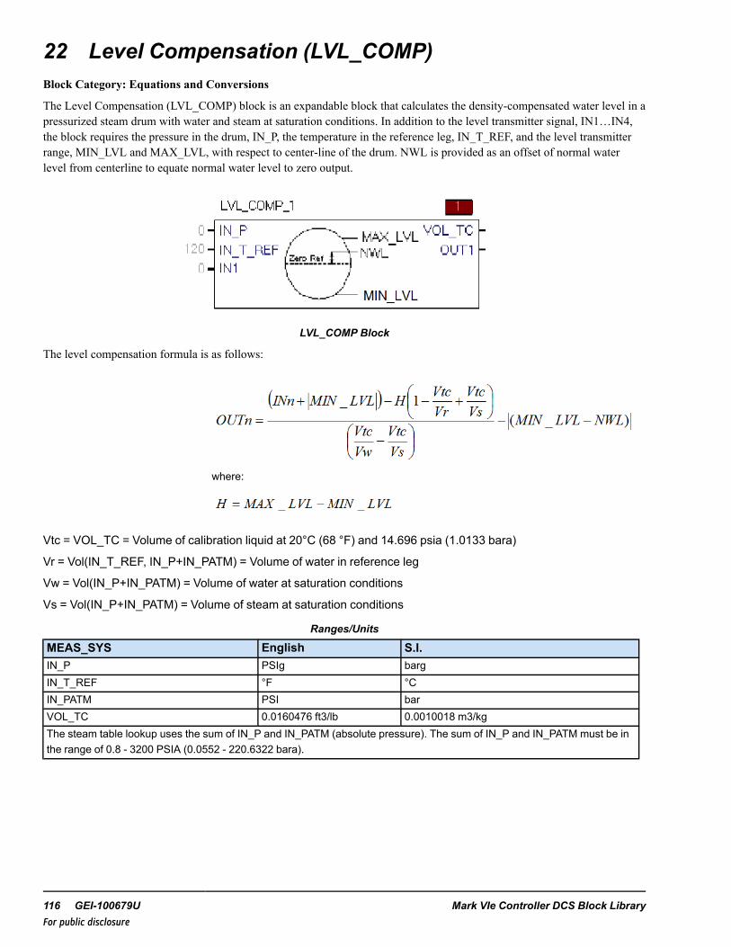
22 Level Compensation (LVL_COMP)Block Category: Equations and Conversions
The Level Compensation (LVL_COMP) block is an expandable block that calculates the density-compensated water level in apressurized steam drum with water and steam at saturation conditions. In addition to the level transmitter signal, IN1…IN4,the block requires the pressure in the drum, IN_P, the temperature in the reference leg, IN_T_REF, and the level transmitterrange, MIN_LVL and MAX_LVL, with respect to center-line of the drum. NWL is provided as an offset of normal waterlevel from centerline to equate normal water level to zero output.
LVL_COMP Block
The level compensation formula is as follows:
where:
Vtc = VOL_TC = Volume of calibration liquid at 20°C (68 °F) and 14.696 psia (1.0133 bara)
Vr = Vol(IN_T_REF, IN_P+IN_PATM) = Volume of water in reference leg
Vw = Vol(IN_P+IN_PATM) = Volume of water at saturation conditions
Vs = Vol(IN_P+IN_PATM) = Volume of steam at saturation conditions
Ranges/Units
MEAS_SYS English S.I.IN_P PSIg bargIN_T_REF °F °CIN_PATM PSI barVOL_TC 0.0160476 ft3/lb 0.0010018 m3/kgThe steam table lookup uses the sum of IN_P and IN_PATM (absolute pressure). The sum of IN_P and IN_PATM must be inthe range of 0.8 - 3200 PSIA (0.0552 - 220.6322 bara).
116 GEI-100679U Mark VIe Controller DCS Block LibraryFor public disclosure

This block propagates quality status if the status operations are enabled.
Block status modification: Due to the nature of the steam table, some input combinations may lead to a result outside of theselected steamtable region. This results in an output status of NOT_LIMITED-LAST_USABLE_VALUE-UNCERTAIN[68].
For further details on Relational blocks, refer to the Mark VIe Controller Standard Block Library (GEI-100682), the StatusMonitoring (STATUS_MONITORING) block.
ToolboxST Configuration
When a new block is inserted into the ToolboxST application, it assigns default initial values to some attributes. These areassumed to be in English units. If the unit system is changed from English to SI, then these initial values must also bechanged.
Initial English Values and Suggested SI Initial Values
Attribute English SI
Reference Leg Temperature 120 °F 48.8 °C
Atmospheric Pressure 14.696 psi 1.0133 bar
Instruction Guide GEI-100679U 117For public disclosure

Example
In this example, the transmitters range from -800 to 300 mm (-31.5 to 11.8 in). The normal water level would be on an offsetsomewhere between the centerline and the maximum. The drum NWL parameter of the block is set based on the placement ofthe minimum and maximum drum taps, with respect to centerline and the normal water level specified by the drum vendor.
1800 mm
900 mm
Centerline
NWLC *
Max. Level
Min. Level-800 mm 4 (mA)
300 mm(20 mA)
200 mm
500 mm
Zero Level(Reference)CL+100mm
transmitterreads 0mm,we are 100mm abovecenterline
Therefore, NWLwould be at -75 mm
75 mm
25 mm
500 mm (17 in)
Max level 300 mm (12 in)
(20 mA)
75 mm (3 in)
Zero level (reference)CL + 100 mm (4 in) -When transmitter reads 0 mm (0 in), we are 100 (4 in) above centerline
Therefore, NWL would be at -75 mm (-3 in)
-800 mm (31 in) (4 mA) min level
200 mm (8 in)
† NWLC is normal water level with respect to centerline, per specification of drum vendor.
900 mm (35 in)
25 mm (1 in)
1800 mm (71 in)
NWLC�
Centerline
Drum NWL Configuration
118 GEI-100679U Mark VIe Controller DCS Block LibraryFor public disclosure

Inputs
Name Description Data Type Initial Value Visibility Interface Type
IN_P Pressure in the drum REAL† 0 Always Value with Status
IN_PATM Atmospheric Pressure REAL 14.696 Parameter Value Only
IN_T_REF Reference legtemperature
REAL† 120 Always Value with Status
IN1 Signal of the water leveltransmitter 1
REAL† N/A Always Value with Status
↓ ↓ ↓ ↓ ↓ ↓
IN4 Signal of the water leveltransmitter 4
REAL† N/A Always Value with Status
MAX_LVL Maximum transmitterwater level
REAL 15 Parameter Value Only
MEAS_SYS Measurement system UINT (ENUM) ENGLISH Parameter Value Only
MIN_LVL Minimum transmitterwater level
REAL -45 Parameter Value Only
NWL Normal Water Level REAL 0 Parameter Value Only
† Value with Status (if status option is enabled)
Outputs
Name Description Data Type Initial Value Visibility Interface Type
OUT1 Compensated waterlevel of transmitter 1
REAL† N/A Always Value with Status
↓ ↓ ↓ ↓ ↓ ↓
OUT4 Compensated waterlevel of transmitter 4
REAL† N/A Always Value with Status
VOL_TC Volume of transmittercalibration liquid (14.696psia, 68 °F)
REAL 0.0160476 Always Value Only
† Value with Status (if status option is enabled)
Instruction Guide GEI-100679U 119For public disclosure

23 Motor Operated Valve (M_O_V)Block Category: Legacy, Device Control
Note Legacy Status— The M_O_V block is not supported for use in new Mark VIe control systems (ControlST softwaresuite V05.02 or later). It is in place to support the maintenance of legacy Mark VIe control systems (prior to ControlSTsoftware suite V05.02). For new Mark VIe control systems, use the M_O_V_V3 block; it provides equivalent functionality.
The Motor Operated Valve (M_O_V) block controls a motor-operated valve or a motor-operated valve with intermediateposition, powered from a low-voltage reversing starter. The motor-operated valve with intermediate position has a limitswitch set mid travel to enable the valve to be positioned intermediately.
Block Configuration
Depending on the control type enumeration property selected; the block provides open and close output commands, OP_ORDand CL_ORD, or an analog output command, POS_ORD, that are used to operate the valve.
Note This block has various enumerations that are used to control block operation.
The block requires the inputs OPEN and CLOSED from the limit switches of the valve. The block will generate afailed-to-open alarm, FL_OP_A, failed-to-close alarm, FL_CL_A, and a limit switch congruency alarm, CONGR_A, thatalarms when the valve limit switches indicate that the valve is open and closed at the same time.
If the valve is a motor operated valve with intermediate position, the IO option attribute, IO Options (IO_OPT) enumerationINT is selected and the intermediate property output INT_P is set to TrueWhen INT_P is True, the block requires anadditional input to determine the intermediate position. This is either the intermediate position limit switch input, INT_ZS, orthe analog position feedback POS, depending on the analog output property ANA_OUT_P. The block generates afailed-to-intermediate alarm, FL_INT_A. if the intermediate position is not reached within the fail to intermediate time (eitherFL_I_OT or FL_I_CT depending on the direction the valve is moving). When the valve is in a closed position, CLOSED\ isTrue, commanding the valve to the intermediate position (if the intermediate permit, PMT_INT is True), will set the OP_ORDto True. The OP_ORD will remain True until the intermediate position is reached (INT_ZS becomes True or POS > INT_SETP) or the transit time has not exceeded the fail to open to intermediate position time, FL_I_OT. If the valve is thencommanded be fully open, the OPN_CMD will remain True until the OPEN input is True (if using INT_ZS it will remainTrue).
When the valve is in an open position, OPEN is True, commanding the valve to the intermediate position (if the intermediatepermit, PMT_INT is True), will set the CL_ORD to True. The CL_ORD will remain True until the intermediate position isreached (INT_ZS becomes False or POS< INT_SETP) or the transit time has not exceeded the fail to close to intermediateposition time, FL_I_CT. If the valve is then commanded be fully closed, the CL_ORD will remain True until the CLOSEDinput is True (if using INT_ZS it will remain False).
A limit switch congruency alarm, CONGR_A, is activated when the valve limit switches are in an illogical state (OPEN isTrue and CLOSED is True, or OPEN is True and INT_ZS is False, or CLOSED is True and INT_ZS is True). CONGR_Aalso alarms if the valve is not at a known position, providing there is no output command active and no position failure (FL_OP_A, FL_CL_A, or FL_INT_A) active (this condition is delayed by 5 seconds).
The block provides open, OP_ORD, close, CL_ORD, and position, POS_ORD (if ANA_OUT_P is True), output commandsthat are used to operate the valve. This block has various enumerations that are used to control block operation.
120 GEI-100679U Mark VIe Controller DCS Block LibraryFor public disclosure

Control Word
Control (CTL) is an enumeration set by the HMI operator for valve control. The commands available from the HMI allowmanual and automatic valve control capability and/or lockout capability if the block property MODE_OPT enumerationselected allows the Auto and/or Lock mode. The valve may be opened or closed in Manual mode by the OPEN_CMD orCLOSE_CMD enumerations, respectively. If the valve is a motor-operated valve with intermediate position, INT_P is True,the valve may also be commanded to the intermediate position in Manual mode by the OPEN_CMD or CLOSE_CMDenumeration (depending on starting position). The command enumerations are defined in the following table.
CTL Enumerations
Enumeration CommandNO_CMD No command
AUTO_CMD Auto command
MANUAL_CMD Manual command
LOCK_CMD Lock command
UNLOCK_CMD Unlock command
OPEN_CMD Open command
CLOSE_CMD Close command
INT_CMD Intermediate command
RESET_CMD Fault reset command
Example
If the valve has a position feedback input, control power monitoring input, fuse monitoring and has the capability for auto andlockout, operation. Then the CTRL_TYPE selection is DIG_CTRL-DIG_OUT-DIG_IN-POS, IO_OPT selection is CP_OK,MODE_OPT is AUTO-LOCK, and IO_MON is FUSE.
Instruction Guide GEI-100679U 121For public disclosure

Modes of Control (CTRL_TYPE)
CTRL_TYPE enumerations are as listed in the following table.
CTRL_TYPE Enumerations
Enumeration Control Option Description
DIG_CTRL-DIG_OUT-DIG_IN Digital input control with digital outputs and no analog position feedback input
DIG_CTRL-DIG_OUT-DIG_IN-POS Digital input control with digital outputs and an analog position feedback input
DIG_CTRL-ANA_OUT-DIG_IN-POS Digital input control with analog output and an analog position feedback input
DIG_CTRL-DIG_OUT-DIG_IN— select for valves that do not provide an analog position feedback. When the DIG_CTRL-DIG_OUT-DIG_IN enumeration is selected, the output POSFB_P is False.
DIG_CTRL-ANA_OUT-DIG_IN-POS— elect for valves that provide digital inputs, an analog output, and an analogposition feedback. The OPEN and CLOSED inputs from the limit switches of the valve are required. When the DIG_CTRL-ANA_OUT-DIG_IN-POS enumeration is selected, the outputs DIG_CTRL_P, ANA_OUT_P, DIG_IN_P, andPOSFB_P are True.
DIG_CTRL-DIG_OUT-DIG_IN-POS— select for valves that provide an analog position feedback, which is used by theHMI objects and faceplates to display the valve open percentage. When the DIG_CTRL-DIG_OUT-DIG_IN-POSenumeration is selected, the output POSFB_P is True.
IO Options (IO_OPT) enumerations are listed in the following table.
IO_OPT Enumerations
Enumeration DescriptionNone No capabilities are availableCP_OK M_O_V has a hard-wired control power monitoring inputREM M_O_V has a hard-wired remote/local inputAVAIL M_O_V has hard-wired available input, a 'Ready to go indicator'TRANS M_O_V has a hard-wired valve-in-transit inputINT M_O_V has a hard-wired intermediate position input and knows where it is in the trackTQ_LIM M_O_V has hard-wired torque limiting input
NONE—when IO_OPT is none, then CP_OK, REMOTE, AVAIL, TRANSIT, POS, and INT_ZS inputs are not used.
CP_OK— select for valves that provide a control power monitoring IO capability. When the CP_OK enumeration isselected, the output CP_OK_P is True. The Boolean control power monitoring connection is to the CP_OK input of the blockand is True when no control power failure is detected. When the CP_OK input is False, the control power failure alarm, CP_F_A, is activated. If the valve is in AUTO mode and the duration of CP_F _A being True has exceeded the PWR_FL_TMR,the valve will switch to MANUAL mode and the manual reject alarm, MN_REJ_A, will be activated, (delayed by 2 seconds).
REM— select for valves that have remote/local capability. When the REM enumeration is selected, the output REM_P isTrue. The Boolean remote/local connection is to the REMOTE input of the block and is True when the valve is in remotemode. When REMOTE is False, the output LOCAL is True and valve control from the HMI is disabled. If the valve is inAUTO mode and LOCAL is True, the valve will switch to MANUAL mode and the manual reject alarm, MN_REJ_A, will beactivated, (delayed by 2 seconds).
AVAIL— select for valves that require an available capability. When the AVAIL enumeration is selected, the output AVAIL_P is True. The Boolean available connection is to the AVAIL input of the block and is True when the valve is available. WhenAVAIL is False, the available alarm, AVAIL_A, is activated. If the valve is in AUTO mode and the duration of AVAIL_Abeing True has exceeded the PWR_FL_TMR, the valve will switch to MANUAL mode and the manual reject alarm, MN_REJ_A, will be activated, (delayed by 2 seconds).
122 GEI-100679U Mark VIe Controller DCS Block LibraryFor public disclosure

TQ_LIM— select for valves that require torque limiting capability. When the TQ_LIM enumeration is selected, the outputTQ_LIM_P is True. The Boolean torque limiting open and torque limiting close signals are connected to the TL_OP and TL_CL inputs of the block. When either TL_OP or TL_CL are True, the torque limiting alarm, TL_A, is activated. If the valve isin AUTO mode and the duration of TL_A being True has exceeded 2 seconds, the valve will switch to MANUAL mode andthe manual reject alarm, MN_REJ_A, will be activated (delayed by 2 seconds).
TRANS— select for valves that provide capability to determine when the valve is in transit. When the TRANS enumerationis selected, the output TRANS_P is True. The Boolean, valve in transit, connection is to the TRANSIT input of the block, andis True when the valve is in transit. When the TRANSIT input is True, the transit indication output, TRN_IND, is True. If theTRANS_P is False, TRN_IND is True whenever OP_ORD or CL_ORD is True.
INT— select for valves is a motor-operated valve with intermediate position. When INT is selected, INT_P is set to True,and requires the input, INT_ZS, the intermediate position limit switch input. The intermediate indication output INT is Truewhen the valve is in the intermediate position. INT_SENS allows the range to be set in which the intermediate position isTrue. The block will also generate a limit switch congruency alarm, CONGR_A, which activates when the valve limitswitches are in an illogical state (OPEN is True and CLOSED is True, or if INT_P is True, OPEN is True and INT_ZS isFalse or CLOSED is True and INT_ZS is True). In addition, the block will generate a failed-to-intermediate alarm, FL_INT_A, which activates when the valves fails to move to the intermediate position, by the time specified by FL_I_OT,failed-to-intermediate open time or FL_I_CT, failed-to-intermediate close time, depending on the direction of movement.
Mode Options (MODE_OPT)
MODE_OPT enumerations are listed in the following table.
MODE_OPT Enumerations
Enumeration Mode Option DescriptionNONE NoneAUTO Auto modeLOCK Lock modeAUTO-LOCK Auto mode and lock mode
NONE— the valve can be opened or closed manually by the HMI operator, no other mode options are available.
AUTO— provides auto control capability of the valve. Selecting the AUTO mode property will set AUTO_P to True,indicating the auto mode property of the block is enabled. When AUTO_P is True, the valve can be commanded to auto byeither CTL enumeration AUTO_CMD or a rising edge on AU_SEL providing PMT_AU is True. The HMI operator maycommand the valve from Auto to Manual mode at any time with the CTL enumeration MANUAL_CMD.
Note PMT_AU is described in the section Auto/Open/Close/Intermediate Permissives.
When AUTO is True, the AU_OP, AU_CL, and AU_INT (if INT_P is True) inputs control the automatic opening, closing,intermediate positioning of the valve, provided, PMT_OP, PMT_CL, or PMT_INT, respectively, is True. If AU_OP, AU_CL,or AU_INT (if INT_P is True) become True, the valve is in manual mode, and the valve position is not in the state of therequested command, the auto request alarm, AU_REQ, will be activated.
LOCK— provides software lock-out capability for the valve. Selecting the LOCK mode property will set LOCK_P to True,and enable the LOCK_CMD and UNLOCK_CMD to control the lockout mode functionality. The valve must be OPEN orCLOSED or not in TRANSIT (if TRANS_P is True) before the block can be set to lockout mode. Feedback to the HMIoperator of this mode is provided by LOCK. The HMI operator is prevented from operating valve from the control faceplatewhen LOCK is True, and auto mode is disabled.
Instruction Guide GEI-100679U 123For public disclosure

Note The lockout indication is provided for indication only. This action will not lockout the equipment, it will only indicatelockout status. The owner's lockout procedures must be followed to safely lock equipment out.
The Lock button can also be configured to use the WorkstationST Lock function. Refer to the WorkstationST/CIMPLICITYAdvanced Viewer Integration Instruction Guide (GEI-100697), the section HMI Tagout.
Note Refer to theMark VIe and Mark VIe Control Volume II System Guide (GEH-6721_Vol_II) for descriptions of hardwareboards.
IO Monitor
IO_MON enumerations are digital output monitor types. Monitoring is only available for the outputs OP_ORD, and CL_ORD. If the hardware card used with OP_ORD, and CL_ORD can perform diagnostic monitoring, IO_MON is used to selectthe type of diagnostic monitoring. When diagnostic monitoring is used (FUSE or VOLT), the diagnostic variable from thedigital output card associated with OP_ORD, and CL_ORD is connected to RDY_OP and RDY_CL, respectively.
IO_MON Enumerations
Enumeration Description
NONE None
FUSE Fuse monitoring
VOLT Voltage monitoring
NONE— no circuit monitoring is available, RDY_OP and RDY_CL are not used.
FUSE— fuse monitoring determines the valve circuit failure. If FUSE is selected FUSE_MON_P is True. The Boolean fusemonitoring input is True when there is no fuse failure and is connected to the RDY_OP and RDY_CL inputs. If there is a fusefailure, RDY_OP or RDY_CL becomes False and OP_FLR or CL_FLR becomes True. When OP_FLR or CL_FLR becomesTrue, PMT_OP or PMT_CL becomes False, respectively and PMT_AU becomes False, delayed by PWR_FL_TMR. If theIO option attribute, IO_OPT enumeration INT is selected, INT_P is True, and OP_FLR is False and the valve is closed,CLOSED is True, or CL_FLR is False and the valve is open, OPEN is True, PMT_INT is False. If AUTO is True when thisoccurs, AUTO will become False and the manual reject alarm, MN_REJ_A, will be activated, (delayed by 2 seconds).
Note To prevent an unwanted automatic switch to Manual mode, in case of an Automatic bus transfer or Power supplytransfer, the power supply transfer time should not exceed PWR_FL_TMR. If the power supply transfer time exceeds thePWR_FL_TMR, the valve will transfer from auto to manual mode and MN_REJ_A, will be activated.
VOLT— voltage monitoring determines the valve circuit failure. If VOLT is selected VOLT_MON_P is True. The Booleanvoltage monitoring input is True when there is no voltage failure and is connected to the RDY_OP and RDY_CL inputs.
OP_FLR is True, (delayed by 2 seconds), when the following conditions exist:
• RDY_OP is False• OP_ORD is False• CP_OK is True (if the IO_OPT, enumeration CP_OK is selected)• REMOTE is True (if the IO_OPT, enumeration REM is selected)• OPEN is False• TRANSIT is False (if the IO_OPT, enumeration TRANS is selected)• AVAIL is True (if the IO_OPT, enumeration AVAIL is selected)• CL_ORD is False
124 GEI-100679U Mark VIe Controller DCS Block LibraryFor public disclosure

When OP_FLR is True, PMT_OP is False and PMT_AU becomes False, delayed by PWR_FL_TMR.
CL_FLR is True, (delayed by 2 seconds), when the following conditions exist:
• RDY_CL is False• CL_ORD is False• CP_OK is True (if the IO_OPT, enumeration CP_OK is selected)• REMOTE is True (if the IO_OPT, enumeration REM is selected)• CLOSED is False• TRANSIT is False (if the IO_OPT, enumeration TRANS is selected)• AVAIL is True (if the IO_OPT, enumeration AVAIL is selected)• OP_ORD is False
When CL_FLR is True, PMT_CL is False and PMT_AU becomes False, delayed by PWR_FL_TMR.
If the IO option attribute, IO_OPT enumeration INT is selected, INT_P is True, andOP_FLR is False and the valve is closed,CLOSED is True, or CL_FLR is False and the valve is open, OPEN is True, PMT_INT is False. If AUTO is True when thisoccurs, AUTO will become False and the manual reject alarm, MN_REJ_A, will be activated, (delayed by 2 seconds).
Note To prevent an unwanted automatic switch to manual mode, in case of an automatic bus transfer or power supplytransfer, the power supply transfer time should not exceed PWR_FL_TMR. If the power supply transfer time exceeds thePWR_FL_TMR, the valve will transfer from auto to manual mode and MN_REJ_A, will be activated.
MODE is the block-operating mode. The operating mode enumerations are defined in the following table.
Note Refer to the section Appendix for a complete list of all possible combinations.
MODE EnumerationsEnumeration CommandMANUAL Valve opens and closes under manual controlAUTO Valve opens and closes automatically.REMOTE Valve can be controlled remotelyLOCAL Valve can be controlled locallyOVERRIDE Valve control has been overridenOPENED Valve is openOPENING Valve is openingCLOSED Valve is closedCLOSING Valve is closingFAULTED Valve has conflicting statusLOCKED Valve is not accepting control commandsINT Valve is in intermittent position
Instruction Guide GEI-100679U 125For public disclosure

Override Control
The block provides override control through Override input enumerations Override Open, OP_OVR, Override Close, CL_OVR, Override Intermediate, INT_OVR (if INT_P is True) and a Manual Reject input enumeration, MN_REJ. The possiblevalues are provided in the following table.
OP_OVR, CL_OVR, INT_OVR, and MN_REJ Enumerations
Enumeration CommandNO_OVER_NO_BLOCK No override and no override is blocked
OVER_NO_BLOCK Override active and no override is blocked
NO_OVER_BLOCK No override and a override is blocked
OVER_BLOCK Override active and a override is blocked
OP_OVR, CL_OVR, or INT_OVR will open, close, or move the valve to the intermediate position, respectively, and preventit from reclosing/reopening in any mode. If the valve is in auto mode (AUTO is True), it rejects to manual and the manualreject alarm, MN_REJ_A, will be activated, (delayed by 2 seconds).
OP_OVR, CL_OVR, and INT_OVR (if used) are driven from an Override (OVERRIDE) block. Each connected input of theOVERRIDE block has the ability (when enabled) to be blocked by the HMI operator, which is accessed from associated tabof the permit HMI screen display. When OP_OVR, CL_OVR, or INT_OVR enumeration contains BLOCK, the HMI operatorhas blocked at least one override. M_O_V does not use the block information, but passes it to the HMI for display.
Force Control
The block provides force control through force enumerations Force Open input (OP_FRC), Force Close input (CL_FRC), anda Force Intermediate input (INT_FRC) (if INT_P is True). The possible values are provided in the following table.
OP_FRC, CL_FRC, and INT_FRC Enumerations
Enumeration CommandNO_FORCE-NO-BLOCK No force and no force is blocked
FORCE-NO_BLOCK Force active and no force is blocked
NO_FORCE-BLOCK No force and a force is blocked
FORCE-BLOCK Force active and a force is blocked
OP_FRC, CL_FRC, or INT_FRC force the valve open, close, or to the intermediate position in any mode except when OP_OVR, CL_OVR, or INT_OVR indicates Override Active. The valve does not reject to manual if a force occurs.
OP_FRC, CL_FRC, and INT_FRC (if used) are driven from a Force (FORCE) block. Each connected input of the FORCEblock has the ability (when enabled) to be blocked by the HMI operator, which is accessed from associated tab of the permitHMI screen display. When OP_FRC, CL_FRC, or INT_FRC enumeration contains BLOCK, the HMI operator has blocked atleast one force. M_O_V does not use the block information, but passes it to the HMI for display.
126 GEI-100679U Mark VIe Controller DCS Block LibraryFor public disclosure

Auto/Open/Close/Intermediate Permissives
The block provides permissive input enumerations AU_PMT, OP_PMT, CL_PMT, and INT_PMT. The possible values areprovided in the following table.
Permit Enumerations
Enumeration Description
NO_PERM-NO-BYPASS No permit and no permit is bypassed
PERM-NO_BYPASS Permit ok and no permit is bypassed
NO_PERM-BYPASS No permit and a permit is bypassed
PERM-BYPASS Permit ok and a permit is bypassed
The block permit inputs, OP_PMT, CL_PMT, and INT_PMT, combine with internal permissives to generate PMT_OP, PMT_CL, and PMT_INT, permitted indications (intermediate permits are available when INT_P is True).
If the valve is in Auto mode and any of the conditions listed are not satisfied (except AU_PMT) the valve will be placed toManual mode (that is the outputs, AUTO and PMT_AU are set to False) and the manual reject alarm, MN_REJ_A, will beactivated, (delayed by 2 seconds).
PMT_OP is True when the following conditions exist:
• OP_PMTis True• REMOTE is True• CL_OVR is False• OP_FLR is False• LOCK is False (if LOCK_P is True)• CP_OK is True (if CP_OK_P is True)• OVR_INT is False (if NT_P is True)• AVAIL is True (if AVAIL_P is True)• FL_OP_A is False• TL_A is False• CL_FRC indicates No Force• INT_FRC indicates No Force
Instruction Guide GEI-100679U 127For public disclosure

PMT_CL is True when the following conditions exist:
• CL_PMT is True• REMOTE is True• OVR_OP is False• CL_FLR is False• LOCK is False (if LOCK_P is True)• CP_OK is True (if CP_OK_P is True)• OVR_INT is False (if INT_P is True)• AVAIL is True (if AVAIL_P is True)• FL_CL_A is False• TL_A is False• OP_FRC indicates No Force• INT_FRC indicates No Force
If the IO option attribute, IO_OPT enumeration INT is selected, INT_P is True:
PMT_INT is True when the following conditions exist:
• INT_PMT is True• REMOTE is True• OP_FLR is False and INT_ZS is False or CL_FLR is False and INT_ZS is True• OVR_OP is False• CL_OVR is False• LOCK is False (if LOCK_P is True)• CP_OK is True (if CP_OK_P is True)• AVAIL is True (if AVAIL_P is True)• FL_INT_A is False• TL_A is False• OP_FRC indicates No Force• CL_FRC indicates No Force
AU_PMT, OP_PMT, CL_PMT, and INT_PMT (If used) are driven from a Permit (PERMIT) block. Each connected input ofthe PERMIT block has the ability (when enabled) to be bypassed by the HMI operator, which is accessed from associated tabof the permit HMI screen display. When AU_PMT, OP_PMT, CL_PMT, orINT_PMT enumeration contains BYPASS, theHMI operator has bypassed at least one permit. M_O_V does not use the bypass information, but passes it to the HMI fordisplay.
128 GEI-100679U Mark VIe Controller DCS Block LibraryFor public disclosure

Diagnostic Alarms
The block will generate a failed-to-open alarm, FL_OP_A, a failed-to-close alarm, FL_CL_A, and a failed-to-intermediate,FL_INT_A (if INT_P is True), if the valve fails to open, close, or move to the intermediate position in the time specified bythe fail to open time, FL_OP_T, fail to close time, FL_CL_T, fail to open to intermediate time, FL_I_OT, or fail to close tointermediate time, FL_I_CT. These alarms are reset when FAULT_RESET is True or if the CTL enumeration equals RESET_CMD.
The block has a limit switch congruency alarm, CONGR_A that alarms when the valve limit switches are in an illogical state(OPEN is True and CLOSED is True, or if INT_P is True, OPEN is True and INT_ZS is False or CLOSED is True and INT_ZS is True). The CONGR_A alarm is reset when the condition that caused the alarm is cleared. The output, FAULT, is Truewhen a fault is detected.
FAULT is True when the any of the following conditions exist:
• FL_OP_A is True• FL_CL_A is True• OP_FLR is True• CONGR_A is True• CP_F_A is True• FL_INT_A is True• AVAIL_A is True• TL_A is True
Push-button Status
The block has two push-button status outputs, PBSTATE and PBSTATE2, to indicate the last HMI operator initiated CTLenumeration. PBSTATE is True when the last HMI CTL enumeration was INT_CMD (if INT_P is True). PBSTATE is Falsewhen the last HMI CTL enumeration was CLOSE_CMD. PBSTATE2 is True when the last HMI CTL enumeration wasOPEN_CMD.
ToolboxST Configuration
Inserting a M_O_V into the application code displays the following window in the ToolboxST application.
Default Attribute Values
Instruction Guide GEI-100679U 129For public disclosure

When the user clicks OK, the block and pin connections will be configured automatically. This generates Global pins. Pinnames are in the form Device Value.Input_Name, where Device Value is the attribute value 00M_O_V1000 and Input_Name isthe block input/output names. The description, M_O_V Description becomes the prefix of the block input/output descriptions.
Note Refer to the table Global Variables
TIM
ER
INP
UT
M_O_V Block
130 GEI-100679U Mark VIe Controller DCS Block LibraryFor public disclosure

Inputs
Name Global Description Data Type Initial Value Visibili-ty
InterfaceType
AU_CL Auto close command BOOL False Always Value OnlyAU_INT Auto INTcommand BOOL False Always Value OnlyAU_OP Auto open command BOOL False Always Value OnlyAU_PMT Yes Auto permit UINT (ENUM) PERM-NO_BYPASS Always Value OnlyAU_SEL Auto select input BOOL False Always Value OnlyAVAIL Available input BOOL True Always Value OnlyCL_FRC Yes Force close UINT (ENUM) NO_FORCE-NO_BLOCK Always Value OnlyCL_INP Yes Closed BOOL False Always Value OnlyCL_OVR Yes Close override UINT (ENUM) NO_OVR-NO_BLOCK Always Value OnlyCL_PMT Yes Close permit UINT (ENUM) PERM-NO_BYPASS Always Value OnlyCP_OK Control power OK input BOOL True Always Value OnlyCTL Yes {Desc} Control word UINT (ENUM) NO_CMD Always Value OnlyCTRL_TYPE Valve I/O control type UINT (ENUM) DIG_CTRL-DIG_
OUT-DIG_INAlways Value Only
FAULT_RESET Fault/trip reset BOOL False Always Value OnlyFL_CL_T Fail to close time UDINT 30000 Parame-
terValue Only
FL_I_CT Fail to close INT time UDINT 15000 Parame-ter
Value Only
FL_I_OT Fail to open INT time UDINT 15000 Parame-ter
Value Only
FL_OP_T Fail to open time UDINT 30000 Parame-ter
Value Only
INT_FRC Yes Force INT UINT (ENUM) NO_FORCE-NO_BLOCK Always Value OnlyINT_OVR Yes INToverride UINT (ENUM) NO_OVR-NO_BLOCK Always Value OnlyINT_PMT Yes INT permit UINT (ENUM) PERM-NO_BYPASS Always Value OnlyINT_SENS INT pos sensitivity REAL 3 Always Value OnlyINT_SETP INT pos setp REAL 50 Always Value with
StatusINT_ZS INT position input BOOL False Always Value OnlyIO_MON Valve I/O monitor
optionsUINT (ENUM) NONE Always Value Only
IO_OPT Valve I/O options UINT (ENUM) NONE Always Value OnlyMN_REJ Yes Manual reject UINT (ENUM) NO_OVR-NO_BLOCK Always Value OnlyMODE_OPT Valve mode options UINT (ENUM) NONE Always Value OnlyOP_FRC Yes Force open UINT (ENUM) NO_FORCE-NO_BLOCK Always Value OnlyOP_INP Yes Open BOOL False Always Value OnlyOP_OVR Yes Open override UINT (ENUM) NO_OVR-NO_BLOCK Always Value OnlyOP_PMT Yes Open permit UINT (ENUM) PERM-NO_BYPASS Always Value OnlyPOS Yes {Desc} Position
feedbackREAL 0 Always Value with
StatusPWR_FL_TMR Manual reject power fail
timerUDINT 5000 Parame-
terValue Only
RDY_CL Output MON ready toclose
BOOL True Always Value Only
RDY_OP Output MON ready toopen
BOOL True Always Value Only
Instruction Guide GEI-100679U 131For public disclosure

Inputs (continued)
Name Global Description Data Type Initial Value Visibili-ty
InterfaceType
REMOTE Remote mode input BOOL True Always Value OnlyTL_CL Close torque limit BOOL False Always Value OnlyTL_OP Open torque limit BOOL False Always Value OnlyTRANSIT Valve in transit input BOOL False Always Value Only
Outputs
Name Global Description Data Type Initial Value Visibility InterfaceType
{Device} Yes {Desc} BOOL False Internal Value OnlyANA_OUT_P Yes {Desc} Analog out property BOOL False Always Value OnlyAU_REQ Yes {Desc} Auto request BOOL False Always Value OnlyAUTO Yes {Desc} AUTO BOOL False Always Value OnlyAUTO_P Yes {Desc} AUTO property BOOL False Always Value OnlyAVAIL_A Yes {Desc} NOTAVAILABLE BOOL False Always Value OnlyAVAIL_P Yes {Desc} AVAILABLE
propertyBOOL False Always Value Only
CL_FLR Yes {Desc} Close circuit fail BOOL False Always Value OnlyCL_ORD Yes {Desc} Close
order/commandBOOL False Always Value Only
CLOSED Yes {Desc} Closed BOOL False Always Value OnlyCONGR_A Yes {Desc} Congruency BOOL False Always Value OnlyCP_F_A Yes {Desc} control power fail BOOL False Always Value OnlyCP_OK_P Yes {Desc} control power
propertyBOOL False Always Value Only
FAULT Yes {Desc} Fault indication BOOL False Always Value OnlyFL_CL_A Yes {Desc} Fail to close BOOL False Always Value OnlyFL_INT_A Yes {Desc} Fail to INT BOOL False Always Value OnlyFL_OP_A Yes {Desc} Fail to open BOOL False Always Value OnlyFRC_CL Yes {Desc} Force close BOOL False Always Value OnlyFRC_CLB Yes {Desc} Close force block
statusBOOL False Internal Value Only
FRC_INT Yes {Desc} Force INT BOOL False Always Value OnlyFRC_INTB Yes {Desc} INT force block
statusBOOL False Internal Value Only
FRC_OP Yes {Desc} Force open BOOL False Always Value OnlyFRC_OPB Yes {Desc} Open force block
statusBOOL False Internal Value Only
FUSE_MON_P Yes {Desc} Output fuse monitorproperty
BOOL False Always Value Only
INT Yes {Desc} INT position BOOL False Always Value OnlyINT_CMD Yes {Desc} INTcommand BOOL False Internal Value OnlyINT_P Yes {Desc} INT property BOOL False Always Value OnlyLOCAL Yes {Desc} local mode BOOL False Always Value OnlyLOCK Yes {Desc} Locked BOOL False Always Value OnlyLOCK_P Yes {Desc} Lock property BOOL False Always Value OnlyMN_REJ_A Yes {Desc} Manual reject BOOL False Always Value Only
132 GEI-100679U Mark VIe Controller DCS Block LibraryFor public disclosure

Outputs (continued)
Name Global Description Data Type Initial Value Visibility InterfaceType
MODE Block mode UINT(ENUM)
MANUAL-OPENED Always Value Only
OP_FLR Yes {Desc} Open circuit fail BOOL False Always Value OnlyOP_ORD Yes {Desc} Open
order/commandBOOL False Always Value Only
OPEN Yes {Desc} Open BOOL False Always Value OnlyOVR_CL Yes {Desc} Close override BOOL False Always Value OnlyOVR_CLB Yes {Desc} Close override
block statusBOOL False Internal Value Only
OVR_INT Yes {Desc} INToverride BOOL False Always Value OnlyOVR_INTB Yes {Desc} INToverride block
statusBOOL False Internal Value Only
OVR_OP Yes {Desc} Open override BOOL False Always Value OnlyOVR_OPB Yes {Desc} Open override
block statusBOOL False Internal Value Only
PBSTATE Yes {Desc} Last PB state BOOL False Internal Value OnlyPBSTATE2 Yes {Desc} Last PB state BOOL False Internal Value OnlyPMT_AU Yes {Desc} Auto permit BOOL False Always Value OnlyPMT_AUB Yes {Desc} Auto permit bypass
statusBOOL False Internal Value Only
PMT_CL Yes {Desc} Permit to close BOOL True Always Value OnlyPMT_CLB Yes {Desc} Close permit
bypass statusBOOL False Internal Value Only
PMT_INT Yes {Desc} Permit to INT BOOL False Always Value OnlyPMT_INTB Yes {Desc} INT permit bypass
statusBOOL False Internal Value Only
PMT_OP Yes {Desc} Permit to open BOOL True Always Value OnlyPMT_OPB Yes {Desc} Open permit
bypass statusBOOL False Internal Value Only
POS_ORD Yes {Desc} Positionorder/commandorder/command
REAL 0 Always Value Only
POSFB_P Yes {Desc} Position feedbackproperty
BOOL False Always Value Only
REJ_MN Yes {Desc} Manual reject BOOL False Always Value OnlyREJ_MNB Yes {Desc} Manual reject
bypass statusBOOL False Internal Value Only
REM_P Yes {Desc} Remote property BOOL False Always Value OnlyTL_A Yes {Desc} Torque limit BOOL False Always Value OnlyTQ_LIM_P Yes {Desc} Torque limit
propertyBOOL False Always Value Only
TRANS_P Yes {Desc} TRANSIT property BOOL False Always Value OnlyTRN_IND Yes {Desc} TRANSIT IND BOOL False Always Value OnlyVOLT_MON_P Yes {Desc} Output volt monitor
propertyBOOL False Always Value Only
Instruction Guide GEI-100679U 133For public disclosure

Global VariablesPin Name Description Alarm Alarm
ClassEvent EGD
PageExternalAccess
STEAM1001 Steam release valve NotAlarmed
False $Default ReadOnly
STEAM1001.ANA_OUT_P Steam release valveanalog out property
NotAlarmed
False ReadOnly
STEAM1001.AU_REQ Steam release valve autorequest
Alarmed LVL_4 False $Default ReadOnly
STEAM1001.AUTO Steam release valve auto NotAlarmed
False $Default ReadOnly
STEAM1001.AUTO_P Steam release valve autoproperty
NotAlarmed
False $Default ReadOnly
STEAM1001.AVAIL_A Steam release valve notavailable
Alarmed LVL_4 False $Default ReadOnly
STEAM1001.AVAIL_P Steam release valveavailable property
NotAlarmed
False $Default ReadOnly
STEAM1001.CL_FLR Steam release valve closecircuit fail
Alarmed LVL_4 False $Default ReadOnly
STEAM1001.CL_ORD Steam release valve closeorder/cmd
NotAlarmed
False $Default ReadOnly
STEAM1001.CLOSED Steam release valveclosed
NotAlarmed
False $Default ReadOnly
STEAM1001.CONGR_A Steam release valvecongruency
Alarmed LVL_4 False $Default ReadOnly
STEAM1001.CP_F_A Steam release valvecontrol power fail
Alarmed LVL_3 False $Default ReadOnly
STEAM1001.CP_OK_P Steam release valvecontrol power property
NotAlarmed
False $Default ReadOnly
STEAM1001.CTL Steam release valvecontrol word
NotAlarmed
False $Default ReadWrite
STEAM1001.FAULT Steam release valve faultindication
NotAlarmed
False $Default ReadOnly
STEAM1001.FL_CL_A Steam release valve fail toclose
Alarmed LVL_4 False $Default ReadOnly
STEAM1001.FL_INT_A Steam release valve fail toint
Alarmed LVL_4 False $Default ReadOnly
STEAM1001.FL_OP_A Steam release valve fail toopen
Alarmed LVL_4 False $Default ReadOnly
STEAM1001.FRC_CL Steam release valve forceclose
NotAlarmed
False $Default ReadOnly
STEAM1001.FRC_CLB Steam release valve closeforce block sts
NotAlarmed
False $Default ReadOnly
STEAM1001.FRC_INT Steam release valve forceint
NotAlarmed
False $Default ReadOnly
STEAM1001.FRC_INTB Steam release valve intforce block sts
NotAlarmed
False $Default ReadOnly
STEAM1001.FRC_OP Steam release valve forceopen
NotAlarmed
False $Default ReadOnly
STEAM1001.FRC_OPB Steam release valve openforce block sts
NotAlarmed
False $Default ReadOnly
STEAM1001.FUSE_MON_P Steam release valveoutput fuse mon property
NotAlarmed
False $Default ReadOnly
134 GEI-100679U Mark VIe Controller DCS Block LibraryFor public disclosure

Global Variables (continued)
Pin Name Description Alarm AlarmClass
Event EGDPage
ExternalAccess
STEAM1001.INT Steam release valve intposition
NotAlarmed
False $Default ReadOnly
STEAM1001.INT_CMD Steam release valve intcmd
NotAlarmed
False $Default ReadOnly
STEAM1001.INT_P Steam release valve intproperty
NotAlarmed
False $Default ReadOnly
STEAM1001.LOCAL Steam release valve localmode
Alarmed LVL_4 False $Default ReadOnly
STEAM1001.LOCK Steam release valvelocked
NotAlarmed
True $Default ReadOnly
STEAM1001.LOCK_P Steam release valve lockproperty
NotAlarmed
False $Default ReadOnly
STEAM1001.MN_REJ_A Steam release valvemanual reject
Alarmed LVL_4 False $Default ReadOnly
STEAM1001.OP_FLR Steam release valve opencircuit fail
Alarmed LVL_4 False $Default ReadOnly
STEAM1001.OP_ORD Steam release valve openorder/cmd
NotAlarmed
False $Default ReadOnly
STEAM1001.OPEN Steam release valve open NotAlarmed
False $Default ReadOnly
STEAM1001.OVR_CL Steam release valve closeoverride
NotAlarmed
False $Default ReadOnly
STEAM1001.OVR_CLB Steam release valve closeoverride block sts
NotAlarmed
False $Default ReadOnly
STEAM1001.OVR_INT Steam release valve intoverride
NotAlarmed
False $Default ReadOnly
STEAM1001.OVR_INTB Steam release valve intoverride block sts
NotAlarmed
False $Default ReadOnly
STEAM1001.OVR_OP Steam release valve openoverride
NotAlarmed
False $Default ReadOnly
STEAM1001.OVR_OPB Steam release valve openoverride block sts
NotAlarmed
False $Default ReadOnly
STEAM1001.PBSTATE Steam release valve lastpb state
NotAlarmed
False $Default ReadOnly
STEAM1001.PBSTATE2 Steam release valve lastpb state
NotAlarmed
False $Default ReadOnly
STEAM1001.PMT_AU Steam release valve autopermit
NotAlarmed
False $Default ReadOnly
STEAM1001.PMT_AUB Steam release valve autopermit bypass sts
NotAlarmed
False $Default ReadOnly
STEAM1001.PMT_CL Steam release valvepermit to close
NotAlarmed
False $Default ReadOnly
STEAM1001.PMT_CLB Steam release valve closepermit bypass sts
NotAlarmed
False $Default ReadOnly
STEAM1001.PMT_INT Steam release valvepermit to int
NotAlarmed
False $Default ReadOnly
STEAM1001.PMT_INTB Steam release valve intpermit bypass sts
NotAlarmed
False $Default ReadOnly
Instruction Guide GEI-100679U 135For public disclosure

Global Variables (continued)
Pin Name Description Alarm AlarmClass
Event EGDPage
ExternalAccess
STEAM1001.PMT_OP Steam release valvepermit to open
NotAlarmed
False $Default ReadOnly
STEAM1001.PMT_OPB Steam release valve openpermit bypass sts
NotAlarmed
False $Default ReadOnly
STEAM1001.POS Steam release valveposition fdbk
NotAlarmed
False $Default ReadOnly
STEAM1001.POS_ORD Steam release valveposition order/cmd
NotAlarmed
False $Default ReadOnly
STEAM1001.POSFB_P Steam release valveposition fdbk property
NotAlarmed
False $Default ReadOnly
STEAM1001.REJ_MN Steam release valvemanual reject
NotAlarmed
False $Default ReadOnly
STEAM1001.REJ_MNB Steam release valvemanual reject bypass sts
NotAlarmed
False $Default ReadOnly
STEAM1001.REM_P Steam release valveremote property
NotAlarmed
False $Default ReadOnly
STEAM1001.TL_A Steam release valvetorque limit
Alarmed LVL_4 False $Default ReadOnly
STEAM1001.TQ_LIM_P Steam release valvetorque limit property
NotAlarmed
False $Default ReadOnly
STEAM1001.TRANS_P Steam release valvetransit property
NotAlarmed
False $Default ReadOnly
STEAM1001.TRN_IND Steam release valvetransit ind
NotAlarmed
False $Default ReadOnly
STEAM1001.VOLT_MON_P Steam release valveoutput volt mon property
NotAlarmed
False $Default ReadOnly
136 GEI-100679U Mark VIe Controller DCS Block LibraryFor public disclosure

HMI Configuration (CIMPLICITY)
The Object name for the HMI is the same as the Device name specified in the ToolboxST configuration.
Typical HMI Object for a MOV
MOV Faceplate
Instruction Guide GEI-100679U 137For public disclosure

Appendix
The following tables provide a complete list of all possible enumeration combinations.
IO_OPT Enumerations
Enumeration DescriptionNONE NoneCP_OK Control power ok
REM Remote modeCP_OK-REM Control power ok and remote modeAVAIL Remote modeCP_OK-AVAIL Control power ok and remote modeREM-AVAIL Remote mode and remote modeCP_OK-REM-AVAIL Control power ok and remote mode and remote modeTRANS Valve in transitCP_OK-TRANS Control power ok and valve in transitREM-TRANS Remote mode and valve in transitCP_OK-REM-TRANS Control power ok and remote mode and valve in transitAVAIL-TRANS Remote mode and valve in transitCP_OK-AVAIL-TRANS Control power ok and remote mode and valve in transitREM-AVAIL-TRANS Remote mode and remote mode and valve in transitCP_OK-REM-AVAIL-TRANS Control power ok and remote mode and remote mode and valve in transitINT Intermediate indicationCP_OK-INT Control power ok and intermediate indicationREM-INT Remote mode and intermediate indicationCP_OK-REM-INT Control power ok and remote mode and intermediate indicationAVAIL-INT Remote mode and intermediate indicationCP_OK-AVAIL-INT Control power ok and remote mode and intermediate indicationREM-AVAIL-INT Remote mode and remote mode and intermediate indicationCP_OK-REM-AVAIL-INT Control power ok and remote mode and remote mode and intermediate
indicationTRANS-INT Valve in transit and intermediate indicationCP_OK-TRANS-INT Control power ok and valve in transit and intermediate indicationREM-TRANS-INT Remote mode and valve in transit and intermediate indicationCP_OK-REM-TRANS-INT Control power ok and remote mode and valve in transit and intermediate
indicationAVAIL-TRANS-INT Remote mode and valve in transit and intermediate indicationCP_OK-AVAIL-TRANS-INT Control power ok and remote mode and valve in transit and intermediate
indicationREM-AVAIL-TRANS-INT Remote mode and remote mode and valve in transit and intermediate
indicationCP_OK-REM-AVAIL-TRANS-INT Control power ok and remote mode and remote mode and valve in transit
and intermediate indicationTQ_LIM Torque limitingCP_OK-TQ_LIM Control power ok and torque limitingREM-TQ_LIM Remote and torque limitingCP_OK-REM-TQ_LIM Control power ok and remote and torque limitingAVAIL-TQ_LIM Valve available and torque limitingCP_OK-AVAIL-TQ_LIM Control power ok and valve available and torque limitingREM-AVAIL-TQ_LIM Remote and valve available and torque limitingCP_OK-REM-AVAIL-TQ_LIM Control power ok and remote and valve available and torque limitingTRANS-TQ_LIM Valve in transit and torque limiting
138 GEI-100679U Mark VIe Controller DCS Block LibraryFor public disclosure

IO_OPT Enumerations (continued)
Enumeration DescriptionCP_OK-TRANS-TQ_LIM Control power ok and valve in transit and torque limitingREM-TRANS-TQ_LIM Remote and valve in transit and torque limitingCP_OK-REM-TRANS-TQ_LIM Control power ok and remote and valve in transit and torque limitingAVAIL-TRANS-TQ_LIM Valve available and valve in transit and torque limitingCP_OK-AVAIL-TRANS-TQ_LIM Control power ok and valve available and valve in transit and torque limitingREM-AVAIL-TRANS-TQ_LIM Remote and valve available and valve in transit and torque limitingCP_OK-REM-AVAIL-TRANS-TQ_LIM Control power ok and remote and valve available and valve in transit and
torque limitingINT-TQ_LIM Intermediate position and torque limitingCP_OK-INT-TQ_LIM Control power ok and intermediate position and torque limitingREM-INT-TQ_LIM Remote and intermediate position and torque limitingCP_OK-REM-INT-TQ_LIM Control power ok and remote and intermediate position and torque limitingAVAIL-INT-TQ_LIM Valve available and intermediate position and torque limitingCP_OK-AVAIL-INT-TQ_LIM Control power ok and valve available and intermediate position and torque
limitingREM-AVAIL-INT-TQ_LIM Remote and valve available and intermediate position and torque limitingCP_OK-REM-AVAIL-INT-TQ_LIM Control power ok and remote and valve available and intermediate position
and torque limitingTRANS-INT-TQ_LIM Valve in transit and intermediate position and torque limitingCP_OK-TRANS-INT-TQ_LIM Control power ok and valve in transit and intermediate position and torque
limitingREM-TRANS-INT-TQ_LIM Remote and valve in transit and intermediate position and torque limitingCP_OK-REM-TRANS-INT-TQ_LIM Control power ok and remote and valve in transit and intermediate position
and torque limitingAVAIL-TRANS-INT-TQ_LIM Valve available and valve in transit and intermediate position and torque
limitingCP_OK-AVAIL-TRANS-INT-TQ_LIM Control power ok and valve available and valve in transit and intermediate
position and torque limitingREM-AVAIL-TRANS-INT-TQ_LIM Remote and valve available and valve in transit and intermediate position
and torque limitingCP_OK-REM-AVAIL-TRANS-INT-TQ_LIM Control power ok and remote and valve available and valve in transit and
intermediate position and torque limiting
Instruction Guide GEI-100679U 139For public disclosure

MODE EnumerationsEnumeration DescriptionMANUAL-OPENED Valve in manual and openedAUTO-OPENED Valve in auto and openedMANUAL-REMOTE-OPENED Valve in manual and remote and openedAUTO-REMOTE-OPENED Valve in auto and remote and openedMANUAL-LOCAL-OPENED Valve in manual and local and openedAUTO-LOCAL-OPENED Valve in auto and local and openedMANUAL-OVERRIDE-OPENED Valve in manual and override and openedAUTO-OVERRIDE-OPENED Valve in auto and override and openedMANUAL-OPENING Valve in manual and openingAUTO-OPENING Valve in auto and openingMANUAL-REMOTE-OPENING Valve in manual and remote and openingAUTO-REMOTE-OPENING Valve in auto and remote and openingMANUAL-LOCAL-OPENING Valve in manual and local and openingAUTO-LOCAL-OPENING Valve in auto and local and openingMANUAL-OVERRIDE-OPENING Valve in manual and override and openingAUTO-OVERRIDE-OPENING Valve in auto and override and openingMANUAL-CLOSED Valve in manual and closedAUTO-CLOSED Valve in auto and closedMANUAL-REMOTE-CLOSED Valve in manual and remote and closedAUTO-REMOTE-CLOSED Valve in auto and remote and closedMANUAL-LOCAL-CLOSED Valve in manual and local and closedAUTO-LOCAL-CLOSED Valve in auto and local and closedMANUAL-OVERRIDE-CLOSED Valve in manual and override and closedAUTO-OVERRIDE-CLOSED Valve in auto and override and closedMANUAL-CLOSING Valve in manual and closingAUTO-CLOSING Valve in auto and closingMANUAL-REMOTE-CLOSING Valve in manual and remote and closingAUTO-REMOTE-CLOSING Valve in auto and remote and closingMANUAL-LOCAL-CLOSING Valve in manual and local and closingAUTO-LOCAL-CLOSING Valve in auto and local and closingMANUAL-OVERRIDE-CLOSING Valve in manual and override and closingAUTO-OVERRIDE-CLOSING Valve in auto and override and closingMANUAL-INT Valve in manual and intAUTO-INT Valve in auto and intMANUAL-REMOTE-INT Valve in manual and remote and intAUTO-REMOTE-INT Valve in auto and remote and intMANUAL-LOCAL-INT Valve in manual and local and intAUTO-LOCAL-INT Valve in auto and local and intMANUAL-OVERRIDE-INT Valve in manual and override and intAUTO-OVERRIDE-INT Valve in auto and override and intMANUAL-FAULTED Valve in manual and faultedAUTO-FAULTED Valve in auto and faultedMANUAL-REMOTE-FAULTED Valve in manual and remote and faultedAUTO-REMOTE-FAULTED Valve in auto and remote and faultedMANUAL-LOCAL-FAULTED Valve in manual and local and faultedAUTO-LOCAL-FAULTED Valve in auto and local and faultedMANUAL-OVERRIDE-FAULTED Valve in manual and override and faultedAUTO-OVERRIDE-FAULTED Valve in auto and override and faultedMANUAL-OPENED-LOCKED Valve in manual and opened and locked
140 GEI-100679U Mark VIe Controller DCS Block LibraryFor public disclosure

MODE Enumerations (continued)
Enumeration DescriptionAUTO-OPENED-LOCKED Valve in auto and opened and lockedMANUAL-REMOTE-OPENED-LOCKED Valve in manual and remote and opened and lockedAUTO-REMOTE-OPENED-LOCKED Valve in auto and remote and opened and lockedMANUAL-LOCAL-OPENED-LOCKED Valve in manual and local and opened and lockedAUTO-LOCAL-OPENED-LOCKED Valve in auto and local and opened and lockedMANUAL-OVERRIDE-OPENED-LOCKED Valve in manual and override and opened and lockedAUTO-OVERRIDE-OPENED-LOCKED Valve in auto and override and opened and lockedMANUAL-OPENING-LOCKED Valve in manual and opening and lockedAUTO-OPENING-LOCKED Valve in auto and opening and lockedMANUAL-REMOTE-OPENING-LOCKED Valve in manual and remote and opening and lockedAUTO-REMOTE-OPENING-LOCKED Valve in auto and remote and opening and lockedMANUAL-LOCAL-OPENING-LOCKED Valve in manual and local and opening and lockedAUTO-LOCAL-OPENING-LOCKED Valve in auto and local and opening and lockedMANUAL-OVERRIDE-OPENING-LOCKED Valve in manual and override and opening and lockedAUTO-OVERRIDE-OPENING-LOCKED Valve in auto and override and opening and lockedMANUAL-CLOSED-LOCKED Valve in manual and closed and lockedAUTO-CLOSED-LOCKED Valve in auto and closed and lockedMANUAL-REMOTE-CLOSED-LOCKED Valve in manual and remote and closed and lockedAUTO-REMOTE-CLOSED-LOCKED Valve in auto and remote and closed and lockedMANUAL-LOCAL-CLOSED-LOCKED Valve in manual and local and closed and lockedAUTO-LOCAL-CLOSED-LOCKED Valve in auto and local and closed and lockedMANUAL-OVERRIDE-CLOSED-LOCKED Valve in manual and override and closed and lockedAUTO-OVERRIDE-CLOSED-LOCKED Valve in auto and override and closed and lockedMANUAL-CLOSING-LOCKED Valve in manual and closing and lockedAUTO-CLOSING-LOCKED Valve in auto and closing and lockedMANUAL-REMOTE-CLOSING-LOCKED Valve in manual and remote and closing and lockedAUTO-REMOTE-CLOSING-LOCKED Valve in auto and remote and closing and lockedMANUAL-LOCAL-CLOSING-LOCKED Valve in manual and local and closing and lockedAUTO-LOCAL-CLOSING-LOCKED Valve in auto and local and closing and lockedMANUAL-OVERRIDE-CLOSING-LOCKED Valve in manual and override and closing and lockedAUTO-OVERRIDE-CLOSING-LOCKED Valve in auto and override and closing and lockedMANUAL-INT-LOCKED Valve in manual and int and lockedAUTO-INT-LOCKED Valve in auto and int and lockedMANUAL-REMOTE-INT-LOCKED Valve in manual and remote and int and lockedAUTO-REMOTE-INT-LOCKED Valve in auto and remote and int and lockedMANUAL-LOCAL-INT-LOCKED Valve in manual and local and int and lockedAUTO-LOCAL-INT-LOCKED Valve in auto and local and int and lockedMANUAL-OVERRIDE-INT-LOCKED Valve in manual and override and int and lockedAUTO-OVERRIDE-INT-LOCKED Valve in auto and override and int and lockedMANUAL-FAULTED-LOCKED Valve in manual and faulted and lockedAUTO-FAULTED-LOCKED Valve in auto and faulted and lockedMANUAL-REMOTE-FAULTED-LOCKED Valve in manual and remote and faulted and lockedAUTO-REMOTE-FAULTED-LOCKED Valve in auto and remote and faulted and lockedMANUAL-LOCAL-FAULTED-LOCKED Valve in manual and local and faulted and lockedAUTO-LOCAL-FAULTED-LOCKED Valve in auto and local and faulted and lockedMANUAL-OVERRIDE-FAULTED-LOCKED Valve in manual and override and faulted and lockedAUTO-OVERRIDE-FAULTED-LOCKED Valve in auto and override and faulted and locked
Instruction Guide GEI-100679U 141For public disclosure

24 Motor Operated Valve Version 2 (M_O_V_V2)Block Category: Legacy, Device Control
Note Legacy Status— The M_O_V_V2 block is not supported for use in new Mark VIe control systems (ControlSTsoftware suite V05.02 or later). It is in place to support the maintenance of legacy Mark VIe control systems (prior toControlST software suite V05.02). For new Mark VIe control systems, use the M_O_V_V3 block; it provides equivalentfunctionality.
The Motor Operated Valve Version 2 (M_O_V_V2) block is a logic block that interfaces with the inputs and outputs of amodulating motor operated valve (MOV). The M_O_V_V2 block can be configured for a wide variety of valve types andseveral operating modes. The type of MOV being driven by the block determines the configuration mode of the block. Theoutput control mode of the block may be configured for digital open and/or close operation, analog out (position demand %),or both. The selected mode determines the type of input status pins that appear on the block. M_O_V_V2 blocks that arefieldbus-capable have several diagnostic alarm parameters that can be tied to some of the input pins of the block. Theseparameters may be used for open and/or close permissives, alarms, and so forth. For example, an open and/or close torquelimit is a valve status parameter that has specific input pins on the M_O_V_V2 block. These parameters may be set to alarmor tied to some other custom logic. The block also has force open and/or close or intermediate position capability.
The M_O_V_V2 block is displayed in the following figure. However, not all variable pins are displayed because most areauto-hidden.
Note All pins are not required to have inputs for normal operation.
142 GEI-100679U Mark VIe Controller DCS Block LibraryFor public disclosure

M_O_V_V2 Block
The M_O_V_V2 block may be configured to operate in Manual or Automatic (Auto) mode. The block also enables the userto lock the device, thus disabling any operation while in this mode. The block is used in conjunction with the PERMIT,FORCE, OVERRIDE, LOGIC_BUILDER, and LOGIC_BUILDER_SC blocks to provide complete and comprehensivedevice control. A predefined HMI faceplate is available, which provides the operator interface to the valve.
Note Refer to theMark VIe Controller Standard Block Library (GEI-100682), the Logic Builder (LOGIC_BUILDER) block.
Block Configuration
Control Word
Control (CTL) is an enumeration set by the HMI operator for valve control. The commands available from the HMI allowmanual and automatic valve control capability and/or lockout capability if the block property MODE_OPT enumerationselected allows the auto and/or lock mode. The valve may be opened or closed in Manual mode by the OPEN_CMD orCLOSE_CMD enumerations, respectively. If the valve is a motor-operated valve with intermediate position, INT_P is True,the valve may also be commanded to the intermediate position in Manual mode by the OPEN_CMD or CLOSE_CMDenumeration (depending on starting position).
Instruction Guide GEI-100679U 143For public disclosure

The command enumerations are defined in the following table.
Note This block has various enumerations that are configured for control block operations.
CTL EnumerationsEnumeration CommandNO_CMD No commandAUTO_CMD Auto commandMANUAL_CMD Manual commandLOCK_CMD Lock commandUNLOCK_CMD Unlock commandOPEN_CMD Open commandCLOSE_CMD Close commandINT_CMD Intermediate commandRESET_CMD Fault reset command
Modes of Control (CTRL_TYPE)
CTRL_TYPE enumerations are as listed in the following table.
CTRL_TYPE Enumerations
Enumeration Control Option Description
DIG_CTRL-DIG_OUT-DIG_IN Digital input control with digital outputs and no analog position feedback input
DIG_CTRL-DIG_OUT-DIG_IN-POS Digital input control with digital outputs and an analog position feedback input
DIG_CTRL-ANA_OUT-DIG_IN-POS Digital input control with analog output and an analog position feedback input
DIG_CTRL-DIG_OUT-DIG_IN— select for valves that do not provide an analog position feedback. When the DIG_CTRL-DIG_OUT-DIG_IN enumeration is selected, the output POSFB_P is False.
DIG_CTRL-ANA_OUT-DIG_IN-POS— select for valves that provide digital inputs, an analog output, and an analogposition feedback. The OPEN and CLOSED inputs from the limit switches of the valve are required. When the DIG_CTRL-ANA_OUT-DIG_IN-POS enumeration is selected, the outputs DIG_CTRL_P, ANA_OUT_P, DIG_IN_P, andPOSFB_P are True.
DIG_CTRL-DIG_OUT-DIG_IN-POS— select for valves that provide an analog position feedback, which is used by theHMI objects and faceplates to display the valve open percentage. When the DIG_CTRL-DIG_OUT-DIG_IN-POSenumeration is selected, the output POSFB_P is True.
144 GEI-100679U Mark VIe Controller DCS Block LibraryFor public disclosure

Inputs and Outputs
At a minimum, the M_O_V_V2 block requires open and/or close position feedback, and valve order output. However, otherinputs may be used for automatic control, valve forcing, manual rejection, and such.
Depending on the block configuration, the output could be a single percent demand (POS_ORD), open and/or close (CL_ORD, OP_ORD), or intermediate position (INT_ORD). The intermediate setpoint (INT_SETP) may be set with an immediatevalue or variable that may be the result of an equation or condition. The M_O_V_V2 intermediate position can be achievedusing either output method, as well as the position input (POS) to determine if the intermediate position has been reached.The following figures are logic representations of the Open command logic. The Close and Int command logic is similar, butreplaces the Open text with Close or Int text.
Open Command Logic
Open Command Digital Control Output
Instruction Guide GEI-100679U 145For public disclosure

Modes of Operation (MODE_OPT) is the mode in which the M_O_V_V2 block is configured to operate: Manual or Automode, and disallow any operation while in Lock mode. Manual mode allows commands from the operator interface, whileAuto mode allows the control logic to command the valve. In either mode there are inputs that may bypass or override theactive mode of operation. Lock mode is intended to be used when maintenance work is being performed on the valve and theoperator wants to prohibit any logic from operating the valve. The allowable modes of operation are specified by the ModeOptions parameter, MODE_OPT. The following table provides a visual presentation of the modes available based on theMODE_OPT selection.
Available Modes for MODE_OPT Selections
MODE_OPTMODE_OPT MANUAL AUTO LOCK
MANUAL ONLY XMANUAL-AUTO X XMANUAL-LOCK X XMANUAL-AUTO-LOCK X X XAUTO ONLY XAUTO-LOCK X X
Manual mode— enables the block to respond to operator Open and Close commands from an HMI faceplate. Given that thepermits are satisfied, the block operates in accordance with the Manual command. The permit for the Open command is set bythe Open permit input, OP_PMT, and the permit for the Close command is set by the Close permit input, CL_PMT. Similarly,the same is true for INT_PMT. These inputs may be set to fixed values or driven by the LOGIC_BUILDER block. Thepossible conditions that place the block into Manual mode are:
Note Manual mode is always available unless MODE_OPT is set to AUTO ONLYor AUTO-LOCK.
• Manual mode selected from the HMI faceplate• Device is locked from the HMI faceplate• Manual Rejection from the logic (MN_REJ)• Override Close, Int, or Open from the logic (OVR_CL, OVR_INT, OVR_OP)• Open or close circuit failure (RDY_CL, RDY_OP)• Valve at torque limit reached (TL_OP, TL_CL)• M_O_V_V2 not Available (AVAIL)• M_O_V_V2 not in Remote (REMOTE)• Congruency alarm
Note Some of these conditions require block parameters to be specifically configured. For example, the block does notdepend on the AVAIL pin unless IO_OPT is set to AVAIL.
146 GEI-100679U Mark VIe Controller DCS Block LibraryFor public disclosure
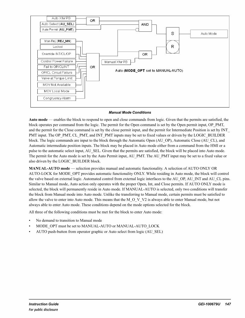
Manual Mode Conditions
Auto mode— enables the block to respond to open and close commands from logic. Given that the permits are satisfied, theblock operates per command from the logic. The permit for the Open command is set by the Open permit input, OP_PMT,and the permit for the Close command is set by the close permit input, and the permit for Intermediate Position is set by INT_PMT input. The OP_PMT, CL_PMT, and INT_PMT inputs may be set to fixed values or driven by the LOGIC_BUILDERblock. The logic commands are input to the block through the Automatic Open (AU_OP), Automatic Close (AU_CL), andAutomatic intermediate position inputs. The block may be placed in Auto mode either from a command from the HMI or apulse to the automatic select input, AU_SEL. Given that the permits are satisfied, the block will be placed into Auto mode.The permit for the Auto mode is set by the Auto Permit input, AU_PMT. The AU_PMT input may be set to a fixed value oralso driven by the LOGIC_BUILDER block.
MANUAL-AUTO mode— selection provides manual and automatic functionality. A selection of AUTO ONLY ORAUTO-LOCK for MODE_OPT provides automatic functionality ONLY. While residing in Auto mode, the block will controlthe valve based on external logic. Automated control from external logic interfaces to the AU_OP, AU_INT and AU_CL pins.Similar to Manual mode, Auto action only operates with the proper Open, Int, and Close permits. If AUTO ONLY mode isselected, the block will permanently reside in Auto mode. If MANUAL-AUTO is selected, only two conditions will transferthe block from Manual mode into Auto mode. Unlike the transferring to Manual mode, certain permits must be satisfied toallow the valve to enter into Auto mode. This means that the M_O_V_V2 is always able to enter Manual mode, but notalways able to enter Auto mode. These conditions depend on the mode options selected for the block.
All three of the following conditions must be met for the block to enter Auto mode:
• No demand to transition to Manual mode• MODE_OPT must be set to MANUAL-AUTO or MANUAL-AUTO_LOCK• AUTO push-button from operator graphic or Auto select from logic (AU_SEL)
Instruction Guide GEI-100679U 147For public disclosure

Auto Only mode— selected using the MODE_OPT pin. All of the Auto Open or Auto Close commands work as previouslydescribed, however, all of the Trip, Override, and Reject to Manual features are disabled, including the ability of the operatorto select the Manual mode from the HMI faceplate. Once Auto Only Mode is selected, the corresponding options (Auto,Manual, Start, and Stop) displayed on the faceplate are removed.
Lock mode—may only be selected when the solenoid is in the de-energized state. In this mode, the block forces the outputso that the solenoid remains de-energized. Upon being placed in locked mode, if currently in Auto mode, it will transfer toManual mode. At this time no open commands, forces, or overrides will be accepted. Upon removing the lock, Manual modewill then be active. Similarly, AUTO ONLYand AUTO-LOCK (no open commands) will be accepted. However, uponremoval of Lock mode, the block will return to Auto mode.
Note At any time, the block may go into Lock mode as long as it is residing in its fail-safe position. Only the operator mayplace block into Lock mode.
Modes of I/O (IO_OPT) is the mode in which M_O_V_V2 block may be configured to allow input I/O states for the device.All I/O are digital or analog inputs received from the valve device. Each I/O input indicates the current status. Device statusincludes control power available, device not available, and device in remote. Depending on the I/O properties enabled, theblock will act differently. The I/O configurations are specified by the I/O Options parameter, IO_OPT. The following tableprovides a visual presentation of the modes available based on the IO_OPT selection. Any enumeration of the I/O pins isavailable. However, not all are displayed because there are too many to display in the table.
I/O pins available for IO_OPT Selections
I/OIO_OPT Ctrl Pwr OK Remote Avail Transit INT TQ LIM
AVAIL XAVAIL-TQ_LIM X XAVAIL-INT-TQ_LIM X X XAVAIL XAVAIL-TRANS X XAVAIL-TRANS-TQ_LIM X X XCP_OK-REM X XCP_OK-REM-AVAIL X X XCP_OK-REM-AVAIL-TQ_LIM X X X X
CP_OK-REM-AVAIL-TRANS-INT-TQ_LIM X X X X X X
Control Power OK— allows the device I/O input from CP_OK. If this input goes False, a Control Power Fail alarm isgenerated that trips the device and places it in Manual.
Remote— allows the device I/O input from REMOTE. If this input goes False, a device in Local alarm is generated thatplaces it in Manual mode.
Available— allows the device I/O input from AVAIL. If this input goes False, a Device not available alarm is generated thatplaces it in Manual mode.
Transit— allows the device I/O input from TRANSIT. If this input goes True, a valve is in Transit and moving or changingpositions.
Int— allows the device I/O input from INT. If this input goes True, the valve has reached its intermediate limit position.
Torque Limit— allows the device I/O input from TQ_LIM. If this input goes True, the valve has exceeded the maximumallowed torque value while trying to open or close. An alarm is generated and the valve is placed in Manual mode.
Additional outputs from this block indicate status, failures, alarms, forces, and overrides. Much of this information isdisplayed on the HMI faceplate.
148 GEI-100679U Mark VIe Controller DCS Block LibraryFor public disclosure

Diagnostic Alarms
When an alarm is active, the M_O_V_V2 block could have limited action of movement. For example, a Fail to Open willinhibit the valve from opening again. In this case, an Alarm Reset must be issued so the valve may continue normal operation.Some alarms are held True until the alarm is cleared, while others require an Alarm Reset to remove the indication. The alarmmay be reset at any time from the logic or an operator push-button. However, the reset must occur after the alarm has beencleared. Otherwise, the alarm will stay active. For Unit Controls, this Alarm Reset pin may be connected to the Master Resetparameter. The alarms that may occur are as follows:
Fail to Open (FL_OP_A)+—when commanded Open, the valve fails to reach the open limit within the allotted time (FL_OP_T). The block cannot reissue an Open command while the alarm is active. Reset the alarm. In Auto Only mode, the initialAUTO ONLY-LOCK indication of Fail to Open will remove the Open command. The Open command can then be reissued atany time and will not affect valve operation.
Fail to Open (FL_OP_A)
Fail to Close (FL_CL_A)+—when commanded Open, the valve fails to reach the closed limit within the allotted time (FL_CL_T). The block cannot reissue a close command while the alarm is active. Reset the alarm. In Auto Only mode, the initialAUTO ONLY-LOCK indication of Fail to Close will remove the Close command. The Close command can then be reissuedat any time and will not affect valve operation.
Fail to INT (FL_INT_A)+—when commanded to INPT position, the valve fails to reach the Intermediate location withinthe allotted time (FL_I_T). The block cannot reissue an INT command while the alarm is active. Reset the alarm.
Congruency Alarm (CONGR_A)+— the valve has both open and closed limits at the same time, or for the allotted time theblock is neither open nor closed. The block could be rejected to manual depending on its configuration. The alarm is clearedwhen the valve reaches either of its limits.
Open Circuit Failure (OP_FLR)— power is lost to the circuit that opens the M_O_V_V2 (RDY_OP becomes False) for atleast 2 seconds. This pin is a reserved parameter that monitors the health of the I/O. The block rejects to manual+. Anoperator cannot reissue an Open command while the alarm is active. The alarm is cleared when RDY_OP becomes True.
Close Circuit Failure (CL_FLR)— power is lost to the circuit that closes the M_O_V_V2 (RDY_CL becomes False) for atleast 2 seconds. This pin is a reserved parameter that monitors the health of the I/O. The block rejects to manual**. Anoperator cannot reissue a Close command while the alarm is active. The alarm is cleared when RDY_CL becomes True.
Control Power Failure (CP_F_A)+— power is lost to the motor (CP_OK becomes False). After 0.5 seconds, the block willreject to manual. An operator cannot reissue an OP/CL/INT command while the alarm is active. The alarm is cleared whenCP_OK becomes True. In Auto Only/AUTO ONLY-LOCK mode, Control Power Failure will not affect Force Close/Openaction.
Instruction Guide GEI-100679U 149For public disclosure
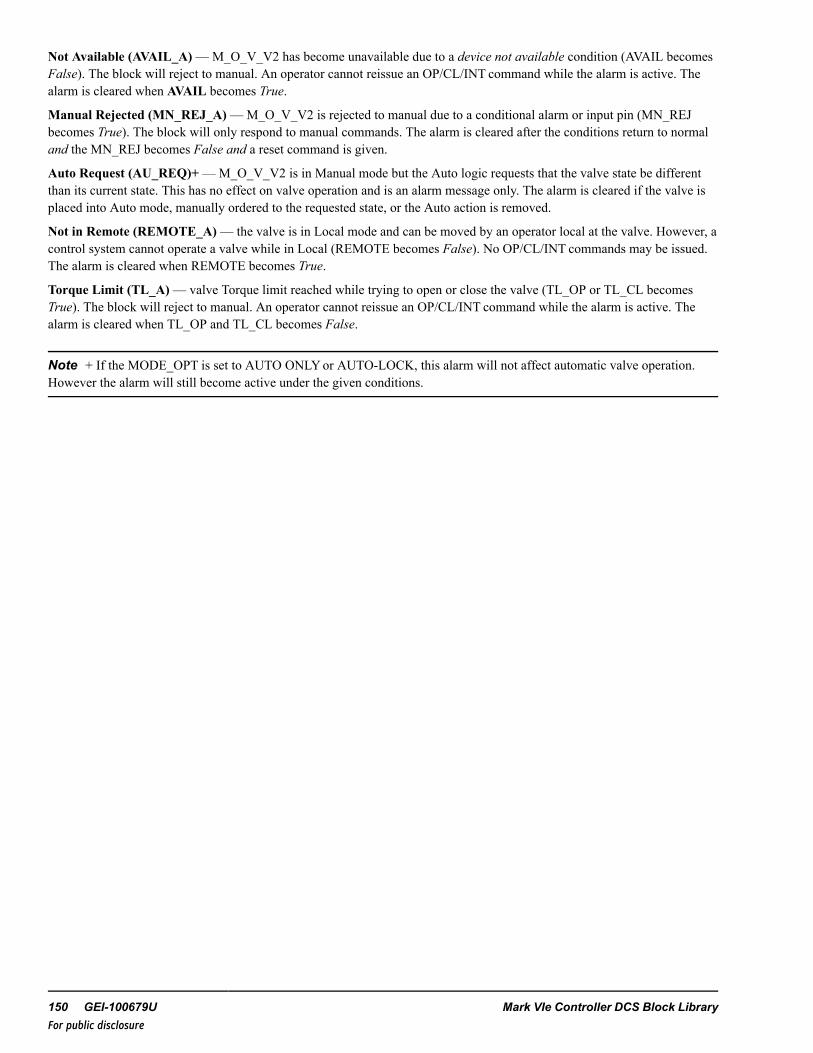
Not Available (AVAIL_A)—M_O_V_V2 has become unavailable due to a device not available condition (AVAIL becomesFalse). The block will reject to manual. An operator cannot reissue an OP/CL/INT command while the alarm is active. Thealarm is cleared when AVAIL becomes True.
Manual Rejected (MN_REJ_A)—M_O_V_V2 is rejected to manual due to a conditional alarm or input pin (MN_REJbecomes True). The block will only respond to manual commands. The alarm is cleared after the conditions return to normaland the MN_REJ becomes False and a reset command is given.
Auto Request (AU_REQ)+—M_O_V_V2 is in Manual mode but the Auto logic requests that the valve state be differentthan its current state. This has no effect on valve operation and is an alarm message only. The alarm is cleared if the valve isplaced into Auto mode, manually ordered to the requested state, or the Auto action is removed.
Not in Remote (REMOTE_A)— the valve is in Local mode and can be moved by an operator local at the valve. However, acontrol system cannot operate a valve while in Local (REMOTE becomes False). No OP/CL/INT commands may be issued.The alarm is cleared when REMOTE becomes True.
Torque Limit (TL_A)— valve Torque limit reached while trying to open or close the valve (TL_OP or TL_CL becomesTrue). The block will reject to manual. An operator cannot reissue an OP/CL/INT command while the alarm is active. Thealarm is cleared when TL_OP and TL_CL becomes False.
Note + If the MODE_OPT is set to AUTO ONLYor AUTO-LOCK, this alarm will not affect automatic valve operation.However the alarm will still become active under the given conditions.
150 GEI-100679U Mark VIe Controller DCS Block LibraryFor public disclosure

Force and Override Control
During any condition, M_O_V_V2 may be forced to a position that bypasses normal operation. The force is driven from theCL_FRC, INT_FRC or OP_FRC pins in the logic. The valve will move to the force position and remain there until the forceis removed. For example, if the valve is forced open, there must be no Override Close, Circuit Failure, or Failed to Open.While a force condition is active, the valve may freely transfer from Auto to Manual following the normal permits. However,no manual command will supersede the force. Once the force is removed, the valve will continue normal operation.
Note Refer to the figure Open Command Logic to view the logic for a force.
An override will supersede a force and place the valve into the overridden state. For example, if the valve is overriddenclosed, the valve will issue a close order irrelevant of any forces, provided there are no Circuit Failure and Failed to Closealarms. The M_O_V_V2 block will take precedence from the override command, then the force command, and then themanual or auto command. Upon entering an overridden state, the valve is placed into Manual mode. Once the override isremoved, the valve will remain in Manual mode until changed by the operator.
Although forces and overrides bypass normal permits, if the valve is locked, forces and overrides will have no effect on theblock. The block must be removed from Lock mode before the forces and overrides affect block operation. Additionally, if theMODE_OPT is set to AUTO ONLYor AUTO-LOCK, the override pins will be disabled and will have no effect on the block.
Permits
Due to the nature of auto and forcing action, permits are required for valve operation. Built into the blocks are special devicepermits that may be enabled or disabled with certain pins in the block, as follows:
Note For basic operations, most of the device permits will be disabled.
• Open− OP_PMT is True (OP_PMT is technically a UINT)− M_O_V_V2 not Failed to Open**+− M_O_V_V2 not Control Power Fail (if CP_OK property enabled)− M_O_V_V2 not in Local (if REMOTE property enabled)− I/O ready to Open M_O_V_V2 or not Open Circuit Failure (if FUSE Monitoring/Voltage Monitoring Property
enabled)− M_O_V_V2 not in Lock mode− Breaker to M_O_V_V2 is not Not Available (if AVAIL property enabled)− M_O_V_V2 not Forced Close or Forced INT− M_O_V_V2 not Override Close or Override INT+− M_O_V_V2 not at Torque Limit (if TQ_LIM property enabled)
• Close− CL_PMT is True (CL_PMT is technically a UINT)− M_O_V_V2 not Failed to Close**+− M_O_V_V2 not Control Power Fail (if CP_OK property enabled)− M_O_V_V2 not in Local (if REMOTE property enabled)− I/O ready to Close M_O_V_V2 or not Close Circuit Failure (if FUSE Monitoring/Voltage Monitoring Property
enabled)− M_O_V_V2 not in Lock mode− Breaker to M_O_V_V2 not Not Available (if AVAIL property enabled)− M_O_V_V2 not Forced Open or Forced INT− M_O_V_V2 not Override Open or Override INT+− M_O_V_V2 not at Torque Limit (if TQ_LIM property enabled)
• INT− INT_PMT is True (INT_PMT is technically a UINT)
Instruction Guide GEI-100679U 151For public disclosure

− M_O_V_V2 not Failed to INT**+− M_O_V_V2 not Control Power Fail (if CP_OK property enabled)− M_O_V_V2 not in Local (if REMOTE property enabled)− I/O ready to Close M_O_V_V2 or not Close Circuit Failure (if FUSE Monitoring/Voltage Monitoring Property
enabled)− I/O ready to Open M_O_V_V2 or not Open Circuit Failure (if FUSE Monitoring/Voltage Monitoring Property
enabled)− M_O_V_V2 not in Lock mode− Breaker to M_O_V_V2 not Not Available (if AVAIL property enabled)− M_O_V_V2 not Forced Open or Forced Close− M_O_V_V2 not Override Open or Override Close+− M_O_V_V2 not at Torque Limit (if TQ_LIM property enabled)
• Open Force− M_O_V_V2 not Failed to Open**+− M_O_V_V2 not in Local (if REMOTE property enabled)− I/O ready to Open M_O_V_V2 or not Open Circuit Failure (if FUSE Monitoring/Voltage Monitoring Property
enabled)− M_O_V_V2 not in Lock mode− M_O_V_V2 not Forced Close or Forced INT− M_O_V_V2 not Override Close or Override INT+− M_O_V_V2 not Control Power Fail (if CP_OK property enabled)+
• Close Force− M_O_V_V2 not Failed to Close**+− M_O_V_V2 not in Local (if REMOTE property enabled)− I/O ready to Close M_O_V_V2 or not Close Circuit Failure (if FUSE Monitoring/Voltage Monitoring Property
enabled)− M_O_V_V2 not in Lock mode− M_O_V_V2 not Forced Open or Forced INT− M_O_V_V2 not Override Open or Override INT+− M_O_V_V2 not Control Power Fail (if CP_OK property enabled)+
• INT Force− M_O_V_V2 not Failed to INT**+− M_O_V_V2 not in Local (if REMOTE property enabled)− I/O ready to Close M_O_V_V2 or not Close Circuit Failure (if FUSE Monitoring/Voltage Monitoring Property
enabled)− I/O ready to Open M_O_V_V2 or not Open Circuit Failure (if FUSE Monitoring/Voltage Monitoring Property
enabled)− M_O_V_V2 not in Lock mode− M_O_V_V2 not Forced Open or Forced Close− M_O_V_V2 not Override Open or Override Close+− M_O_V_V2 not Control Power Fail (if CP_OK property enabled)+
• Open Override+− M_O_V_V2 not Failed to Open**− M_O_V_V2 not in Local (if REMOTE property enabled)− I/O ready to Open M_O_V_V2 or not Open Circuit Failure (if FUSE Monitoring/Voltage Monitoring Property
enabled)− M_O_V_V2 not in Lock mode− M_O_V_V2 not Override Close or Override INT− M_O_V_V2 not Control Power Fail (if CP_OK property enabled)
• Close Override+− M_O_V_V2 not Failed to Close**− M_O_V_V2 not in Local (if REMOTE property enabled)
152 GEI-100679U Mark VIe Controller DCS Block LibraryFor public disclosure

− I/O ready to Close M_O_V_V2 or not Close Circuit Failure (if FUSE Monitoring/Voltage Monitoring Propertyenabled)
− M_O_V_V2 not in Lock mode− M_O_V_V2 not Override Open or Override INT+− M_O_V_V2 not Control Power Fail (if CP_OK property enabled)
• INT Override− M_O_V_V2 not Failed to INT**− M_O_V_V2 not in Local (if REMOTE property enabled)− I/O ready to Close M_O_V_V2 or not Close Circuit Failure (if FUSE Monitoring/Voltage Monitoring Property
enabled)− I/O ready to Open M_O_V_V2 or not Open Circuit Failure (if FUSE Monitoring/Voltage Monitoring Property
enabled)− M_O_V_V2 not in Lock mode− M_O_V_V2 not Override Open or Override Close+− M_O_V_V2 not Control Power Fail (if CP_OK property enabled)
Note **Indicates a condition that is internally generated to the block. Otherwise, the condition comes from a direct input.
+ Indicates a condition bypassed when MODE_OPT is set to AUTO ONLYor AUTO-LOCK mode.
Instruction Guide GEI-100679U 153For public disclosure

Inputs
Name Global Description FunctionAU_SEL Yes Auto Select Pulses the valve into Auto (provided all permits are met)AU_ OP Auto Open Opens the valve (provided all permits are met); device must be
in Auto modeAU_CL Auto Close Auto closes the valve (provided all permits are met); device
must be in Auto modeAU_INT Auto Intermediate Auto moves the valve to the intermediate position (provided all
permits are met); device must be in Auto modeAU_PMT Yes Auto permit Permit required for external logic to place the valve in Auto
modeOP_PMT Yes Open Permit Permit required for external logic to prevent the valve from
openingCL_PMT Yes Close Permit Permit required for external logic to prevent the valve from
closingINT_PMT Yes Intermediate Permit Permit required for external logic to prevent the valve to go to
the intermediate positionRDY_CL Ready to Close M_O_V_V2 I/O monitoring of the circuit to the close command to the valveRDY_OP Ready to Open M_O_V_V2 I/O monitoring of the circuit to the open command to the valveOP_OVR Yes Open Override Permit required for external logic to override open the valveCL_OVR Yes Close Override Permit required for external logic to override close the valveINT_OVR Yes Intermediate Override Permit required for external logic to override intermediate
command to the valveMN_REJ Yes Manual Rejection Permit required for external logic to manually reject the valve
RDY_CL Ready to Close M_O_V_V2 I/O monitoring of the circuit to the close command of the valveRDY_OP Ready to Open M_O_V_V2 I/O monitoring of the circuit to the open command of the valveCL_INP Closed Input Connects to the closed feedback of the valveOP_INP Open Input Connects to the open feedback of the valveCL_FRC Yes Close Force Permit required for external logic to force close the valveOP_FRC Yes Open Force Permit required for external logic to force open the valveINT_FRC Yes Intermediate Force Permit required for external logic to force intermediate
command to the valveALARM_RESET Alarm Reset Permit required for external logic to reset alarms on the valveCP_OK Yes Control Power OK Tied to the I/O that monitors the control power for the valveAVAIL Yes M_O_V_V2 Available Tied to the I/O that has the M_O_V_V2 availability feedbackREMOTE Yes M_O_V_V2 in Remote Tied to the I/O that has the M_O_V_V2 local/remote statusTL_CL Yes Close Torque limit Tied to the I/O that indicates if the M_O_V_V2 has reached its
torque limit upon closingTL_OP Yes Open Torque limit Tied to the I/O that indicates if the M_O_V_V2 has reached its
torque limit upon openingTRANSIT Yes Valve in Transit Tied to the I/O that indicates the M_O_V_V2 is in motionPOS Yes Position Tied to the valve position feedbackINT_ZS† Yes Intermediate Position input Tied to the Boolean I/O that indicates the M_O_V_V2 has
reached the INT positionINT_SETP† Intermediate Position Setpoint Intermediate position setpoint that the valve is to travel
towards, given the INTcommand† The block will use either INT_ZS or POS for indication if the valve has reached intermediate position. At least one must beavailable when using the intermediate position.
154 GEI-100679U Mark VIe Controller DCS Block LibraryFor public disclosure

Parameters
Name Global Description Function
CTL Yes Control Used by the operator graphic to control the valve
FL_OP_T Fail to Open Time Time allotted for the valve to open. (If the motor takes 30seconds to open, ~35000 msec is sufficient time to allow thevalve to reach its open state.)
FL_CL_T Fail to Close Time Time allotted for the valve to close. (If the motor takes 30seconds to close, ~35000 msec is sufficient time to allow thevalve to reach its close state.)
FL_I_CT Fail to Close to IntermediateTime
Time allotted for the valve to close to the IntermediatePosition. (If the valve takes 20 seconds to close, ~25000msec is sufficient time to allow the valve to reach itsintermediate state.)
FL_I_OT Fail to Open to IntermediateTime
Time allotted for the valve to open to the IntermediatePosition. (If the valve takes 20 seconds to open, ~25000msec is sufficient time to allow the valve to reach itsintermediate state.)
PWR_FL_TMR Manual Reject Power FailureTime
Time allotted for the M_O_V_V2 to lose power before itrejects the valve to manual
IO_MON I/O Monitor Options Allow the I/O monitoring feature to be enabled. This pin canbe set to either Volt or Fuse monitoring.
IO_OPT Valve I/O Options Designates what type of I/O options are available for thevalve
MODE_OPT Valve Mode Options Designates whichmodes the valve can enter
CTRL_TYPE Control Type Designates how the valve is controlled. Either Analog outputor digital output may be used. Position feedback is requiredfor analog output.
INT_SENS Intermediate PositionSensitivity
Range in which the valve position may reside to beconsidered at INT position (which is ± 2%)
Instruction Guide GEI-100679U 155For public disclosure

Outputs
Name Global Description
OP_ORD Yes Open orderCL_ORD Yes Close orderINT_CMD Intermediate orderPOS_ORD Yes Position orderAUTO_P Yes Property for Auto mode availableLOCK_P Yes Property for Lock mode availableANA_OUT_P Yes Property for analog outputVOLT_MON_P Yes Property for volt monitoring I/OFUSE_MON_P Yes Property for fuse monitoring I/OPOSFB_P Yes Property for position feedback I/OREM_P Yes Property for local or remote I/OAVAIL_P Yes Property for valve availability I/OCP_OK_P Yes Property for control power I/OTQ_LIM_P Yes Property for torque limit I/OTRANS_P Yes Property for transit I/OAUTO Yes Auto mode activeCLOSED Yes M_O_V_V2 closedOPEN Yes M_O_V_V2 openedINT Yes Valve has reached intermediate positionLOCK Yes Lock mode activePMT_AU Yes Auto permitPMT_CL Yes Close permitPMT_OP Yes Open PermitALARM Alarm activeMODE Current valve statusTRN_IND Yes Valve in transitOVR_CL Yes Close overrideOVR_OP Yes Open overrideOVR_INT Yes Intermediate overrideFRC_CL Yes Close forceFRC_OP Yes Open forceFRC_INT Yes Intermediate forceCL_FLR Yes Close circuit failureOP_FLR Yes Open circuit failureAU_REQ Yes Auto request (Auto logic wishes to open or close M_O_V_V2)CONGR_A Yes Congruency alarmAVAIL_A Yes Valve not available alarmFL_CL_A Yes Failed to close alarmFL_OP_A Yes Failed to open alarmFL_INT_A Yes Failed to Int alarmTL_A Yes Torque limit alarmMN_REJ_A Yes Manual rejection alarmCP_F_A Yes Control power failure alarmREMOTE_A Valve not in remote alarm
156 GEI-100679U Mark VIe Controller DCS Block LibraryFor public disclosure

Global VariablesPin Name Description Alarm Alarm
ClassEvent EGD Page External
AccessSTEAM1001 Steam release valve Not Alarmed False $Default ReadOnlySTEAM1001.ANA_OUT_P Steam release valve
analog out propertyNot Alarmed False ReadOnly
STEAM1001.AU_REQ Steam release valveauto request
Alarmed LVL_4 False $Default ReadOnly
STEAM1001.AUTO Steam release valveauto
Not Alarmed False $Default ReadOnly
STEAM1001.AUTO_P Steam release valveauto property
Not Alarmed False $Default ReadOnly
STEAM1001.AVAIL_A Steam release valve notavailable
Alarmed LVL_4 False $Default ReadOnly
STEAM1001.AVAIL_P Steam release valveavailable property
Not Alarmed False $Default ReadOnly
STEAM1001.CL_FLR Steam release valveclose circuit fail
Alarmed LVL_4 False $Default ReadOnly
STEAM1001.CL_ORD Steam release valveclose order/cmd
Not Alarmed False $Default ReadOnly
STEAM1001.CLOSED Steam release valveclosed
Not Alarmed False $Default ReadOnly
STEAM1001.CONGR_A Steam release valvecongruency
Alarmed LVL_4 False $Default ReadOnly
STEAM1001.CP_F_A Steam release valvecontrol power fail
Alarmed LVL_3 False $Default ReadOnly
STEAM1001.CP_OK_P Steam release valvecontrol power property
Not Alarmed False $Default ReadOnly
STEAM1001.CTL Steam release valvecontrol word
Not Alarmed False $Default ReadWrite
STEAM1001.FAULT Steam release valvefault indication
Not Alarmed False $Default ReadOnly
STEAM1001.FL_CL_A Steam release valve failto close
Alarmed LVL_4 False $Default ReadOnly
STEAM1001.FL_INT_A Steam release valve failto int
Alarmed LVL_4 False $Default ReadOnly
STEAM1001.FL_OP_A Steam release valve failto open
Alarmed LVL_4 False $Default ReadOnly
STEAM1001.FRC_CL Steam release valveforce close
Not Alarmed False $Default ReadOnly
STEAM1001.FRC_CLB Steam release valveclose force block sts
Not Alarmed False $Default ReadOnly
STEAM1001.FRC_INT Steam release valveforce int
Not Alarmed False $Default ReadOnly
STEAM1001.FRC_INTB Steam release valve intforce block sts
Not Alarmed False $Default ReadOnly
STEAM1001.FRC_OP Steam release valveforce open
Not Alarmed False $Default ReadOnly
STEAM1001.FRC_OPB Steam release valveopen force block sts
Not Alarmed False $Default ReadOnly
STEAM1001.FUSE_MON_P Steam release valveoutput fuse monproperty
Not Alarmed False $Default ReadOnly
STEAM1001.INT Steam release valve intposition
Not Alarmed False $Default ReadOnly
STEAM1001.INT_CMD Steam release valve intcmd
Not Alarmed False $Default ReadOnly
Instruction Guide GEI-100679U 157For public disclosure

Global Variables (continued)Pin Name Description Alarm Alarm
ClassEvent EGD Page External
AccessSTEAM1001.INT_P Steam release valve int
propertyNot Alarmed False $Default ReadOnly
STEAM1001.LOCAL Steam release valvelocal mode
Alarmed LVL_4 False $Default ReadOnly
STEAM1001.LOCK Steam release valvelocked
Not Alarmed True $Default ReadOnly
STEAM1001.LOCK_P Steam release valvelock property
Not Alarmed False $Default ReadOnly
STEAM1001.MN_REJ_A Steam release valvemanual reject
Alarmed LVL_4 False $Default ReadOnly
STEAM1001.OP_FLR Steam release valveopen circuit fail
Alarmed LVL_4 False $Default ReadOnly
STEAM1001.OP_ORD Steam release valveopen order/cmd
Not Alarmed False $Default ReadOnly
STEAM1001.OPEN Steam release valveopen
Not Alarmed False $Default ReadOnly
STEAM1001.OVR_CL Steam release valveclose override
Not Alarmed True $Default ReadOnly
STEAM1001.OVR_CLB Steam release valveclose override block sts
Not Alarmed False $Default ReadOnly
STEAM1001.OVR_INT Steam release valve intoverride
Not Alarmed False $Default ReadOnly
STEAM1001.OVR_INTB Steam release valve intoverride block sts
Not Alarmed False $Default ReadOnly
STEAM1001.OVR_OP Steam release valveopen override
Not Alarmed False $Default ReadOnly
STEAM1001.OVR_OPB Steam release valveopen override block sts
Not Alarmed False $Default ReadOnly
STEAM1001.PBSTATE Steam release valve lastpb state
Not Alarmed False $Default ReadOnly
STEAM1001.PBSTATE2 Steam release valve lastpb state
Not Alarmed False $Default ReadOnly
STEAM1001.PMT_AU Steam release valveauto permit
Not Alarmed False $Default ReadOnly
STEAM1001.PMT_AUB Steam release valveauto permit bypass sts
Not Alarmed False $Default ReadOnly
STEAM1001.PMT_CL Steam release valvepermit to close
Not Alarmed False $Default ReadOnly
STEAM1001.PMT_CLB Steam release valveclose permit bypass sts
Not Alarmed False $Default ReadOnly
STEAM1001.PMT_INT Steam release valvepermit to int
Not Alarmed False $Default ReadOnly
STEAM1001.PMT_INTB Steam release valve intpermit bypass sts
Not Alarmed False $Default ReadOnly
STEAM1001.PMT_OP Steam release valvepermit to open
Not Alarmed False $Default ReadOnly
STEAM1001.PMT_OPB Steam release valveopen permit bypass sts
Not Alarmed False $Default ReadOnly
STEAM1001.POS Steam release valveposition fdbk
Not Alarmed False $Default ReadOnly
STEAM1001.POS_ORD Steam release valveposition order/cmd
Not Alarmed False $Default ReadOnly
158 GEI-100679U Mark VIe Controller DCS Block LibraryFor public disclosure

Global Variables (continued)Pin Name Description Alarm Alarm
ClassEvent EGD Page External
AccessSTEAM1001.POSFB_P Steam release valve
position fdbk propertyNot Alarmed False $Default ReadOnly
STEAM1001.REJ_MN Steam release valvemanual reject
Not Alarmed False $Default ReadOnly
STEAM1001.REJ_MNB Steam release valvemanual reject bypass sts
Not Alarmed False $Default ReadOnly
STEAM1001.REM_P Steam release valveremote property
Not Alarmed False $Default ReadOnly
STEAM1001.TL_A Steam release valvetorque limit
Alarmed LVL_4 False $Default ReadOnly
STEAM1001.TQ_LIM_P Steam release valvetorque limit property
Not Alarmed False $Default ReadOnly
STEAM1001.TRANS_P Steam release valvetransit property
Not Alarmed False $Default ReadOnly
STEAM1001.TRN_IND Steam release valvetransit ind
Not Alarmed False $Default ReadOnly
STEAM1001.VOLT_MON_P Steam release valveoutput volt mon property
Not Alarmed False $Default ReadOnly
Instruction Guide GEI-100679U 159For public disclosure

HMI Configuration (CIMPLICITY)
The Object name for the HMI is the same as the Device name specified in the ToolboxST configuration.
Typical HMI Object for a M_O_V_V2
M_O_V_V2 Faceplate
160 GEI-100679U Mark VIe Controller DCS Block LibraryFor public disclosure

Appendix
The following tables provide a complete list of all possible enumeration combinations.
IO_OPT Enumerations
Enumeration IO Option Description
NONE None
CP_OK Control power ok
REM Remote mode
CP_OK-REM Control power ok and remote mode
AVAIL Remote mode
CP_OK-AVAIL Control power ok and remote mode
REM-AVAIL Remote mode and remote mode
CP_OK-REM-AVAIL Control power ok and remote mode and remote mode
TRANS Valve in transit
CP_OK-TRANS Control power ok and valve in transit
REM-TRANS Remote mode and valve in transit
CP_OK-REM-TRANS Control power ok and remote mode and valve in transit
AVAIL-TRANS Remote mode and valve in transit
CP_OK-AVAIL-TRANS Control power ok and remote mode and valve in transit
REM-AVAIL-TRANS Remote mode and remote mode and valve in transit
CP_OK-REM-AVAIL-TRANS Control power ok and remote mode and remote mode and valve in transit
INT Intermediate indication
CP_OK-INT Control power ok and intermediate indication
REM-INT Remote mode and intermediate indication
CP_OK-REM-INT Control power ok and remote mode and intermediate indication
AVAIL-INT Remote mode and intermediate indication
CP_OK-AVAIL-INT Control power ok and remote mode and intermediate indication
REM-AVAIL-INT Remote mode and remote mode and intermediate indication
CP_OK-REM-AVAIL-INT Control power ok and remote mode and remote mode and intermediate indication
TRANS-INT Valve in transit and intermediate indication
CP_OK-TRANS-INT Control power ok and valve in transit and intermediate indication
REM-TRANS-INT Remote mode and valve in transit and intermediate indication
CP_OK-REM-TRANS-INT Control power ok and remote mode and valve in transit and intermediateindication
AVAIL-TRANS-INT Remote mode and valve in transit and intermediate indication
CP_OK-AVAIL-TRANS-INT Control power ok and remote mode and valve in transit and intermediateindication
REM-AVAIL-TRANS-INT Remote mode and remote mode and valve in transit and intermediate indication
CP_OK-REM-AVAIL-TRANS-INT Control power ok and remote mode and remote mode and valve in transit andintermediate indication
TQ_LIM Torque limiting
Instruction Guide GEI-100679U 161For public disclosure

IO_OPT Enumerations (continued)
Enumeration IO Option Description
CP_OK-TQ_LIM Control power ok and torque limiting
REM-TQ_LIM Remote and torque limiting
CP_OK-REM-TQ_LIM Control power ok and remote and torque limiting
AVAIL-TQ_LIM Valve available and torque limiting
CP_OK-AVAIL-TQ_LIM Control power ok and valve available and torque limiting
REM-AVAIL-TQ_LIM Remote and valve available and torque limiting
CP_OK-REM-AVAIL-TQ_LIM Control power ok and remote and valve available and torque limiting
TRANS-TQ_LIM Valve in transit and torque limiting
CP_OK-TRANS-TQ_LIM Control power ok and valve in transit and torque limiting
REM-TRANS-TQ_LIM Remote and valve in transit and torque limiting
CP_OK-REM-TRANS-TQ_LIM Control power ok and remote and valve in transit and torque limiting
AVAIL-TRANS-TQ_LIM Valve available and valve in transit and torque limiting
CP_OK-AVAIL-TRANS-TQ_LIM Control power ok and valve available and valve in transit and torque limiting
REM-AVAIL-TRANS-TQ_LIM Remote and valve available and valve in transit and torque limiting
CP_OK-REM-AVAIL-TRANS-TQ_LIM Control power ok and remote and valve available and valve in transit and torquelimiting
INT-TQ_LIM Intermediate position and torque limiting
CP_OK-INT-TQ_LIM Control power ok and intermediate position and torque limiting
REM-INT-TQ_LIM Remote and intermediate position and torque limiting
CP_OK-REM-INT-TQ_LIM Control power ok and remote and intermediate position and torque limiting
AVAIL-INT-TQ_LIM Valve available and intermediate position and torque limiting
CP_OK-AVAIL-INT-TQ_LIM Control power ok and valve available and intermediate position and torque limiting
REM-AVAIL-INT-TQ_LIM Remote and valve available and intermediate position and torque limiting
CP_OK-REM-AVAIL-INT-TQ_LIM Control power ok and remote and valve available and intermediate position andtorque limiting
TRANS-INT-TQ_LIM Valve in transit and intermediate position and torque limiting
CP_OK-TRANS-INT-TQ_LIM Control power ok and valve in transit and intermediate position and torque limiting
REM-TRANS-INT-TQ_LIM Remote and valve in transit and intermediate position and torque limiting
CP_OK-REM-TRANS-INT-TQ_LIM Control power ok and remote and valve in transit and intermediate position andtorque limiting
AVAIL-TRANS-INT-TQ_LIM Valve available and valve in transit and intermediate position and torque limiting
CP_OK-AVAIL-TRANS-INT-TQ_LIM Control power ok and valve available and valve in transit and intermediateposition and torque limiting
REM-AVAIL-TRANS-INT-TQ_LIM Remote and valve available and valve in transit and intermediate position andtorque limiting
CP_OK-REM-AVAIL-TRANS-INT-TQ_LIM
Control power ok and remote and valve available and valve in transit andintermediate position and torque limiting
162 GEI-100679U Mark VIe Controller DCS Block LibraryFor public disclosure

25 Motor Operated Valve Version 3 (M_O_V_V3)Block Category: Device Control
The Motor Operated Valve Version 3 (M_O_V_V3) block is a logic block that interfaces with the inputs and outputs of amodulating motor operated valve (MOV). The block can be configured for a wide variety of valve types and several operatingmodes. The type of MOV being driven by the block determines the configuration mode of the block. The output control modeof the block may be configured for digital open and/or close operation, analog out (position demand %), or both. The selectedmode determines the type of input status pins that appear on the block. M_O_V_V3 blocks that are fieldbus-capable haveseveral diagnostic alarm parameters that can be tied to some of the input pins of the block. These parameters may be used foropen and/or close permissives, alarms, and so forth. For example, an open and/or close torque limit is a valve status parameterthat has specific input pins on the M_O_V_V3 block. These parameters may be set to alarm or tied to some other customlogic. The block also has force open and/or close or intermediate position capability.
The M_O_V_V3 block is displayed in the following figure. However, not all variable pins are displayed because most areauto-hidden.
Note All pins are not required to have inputs for normal operation.
M_O_V_V3 Block
The M_O_V_V3 block may be configured to operate in Manual or Automatic (Auto) mode. The block also enables the userto lock the device, thus disabling any operation while in this mode. The block is used in conjunction with the PERMIT,FORCE, OVERRIDE, LOGIC_BUILDER, and LOGIC_BUILDER_SC blocks to provide complete and comprehensivedevice control. A predefined HMI faceplate is available, which provides the operator interface to the valve.
Instruction Guide GEI-100679U 163For public disclosure

Note Refer to theMark VIe Controller Standard Block Library (GEI-100682), the Logic Builder (LOGIC_BUILDER) block.
Block Configuration
Control Word
Control (CTL) is an enumeration set by the HMI operator for valve control. The commands available from the HMI allowmanual and automatic valve control capability and/or lockout capability if the block property MODE_OPT enumerationselected allows the auto and/or lock mode. The valve may be opened or closed in Manual mode by the OPEN_CMD orCLOSE_CMD enumerations, respectively. If the valve is a motor-operated valve with intermediate position, INT_P is True,the valve may also be commanded to the intermediate position in Manual mode by the OPEN_CMD or CLOSE_CMDenumeration (depending on starting position). The command enumerations are defined in the following table.
Note This block has various enumerations that are configured for control block operations.
CTL Enumerations
Enumeration CommandNO_CMD No command
AUTO_CMD Auto command
MANUAL_CMD Manual command
LOCK_CMD Lock command
UNLOCK_CMD Unlock command
OPEN_CMD Open command
CLOSE_CMD Close command
INT_CMD Intermediate command
RESET_CMD Fault reset command
Modes of Control (CTRL_TYPE)
CTRL_TYPE enumerations are as listed in the following table.
CTRL_TYPE Enumerations
Enumeration Control Option Description
DIG_CTRL-DIG_OUT-DIG_IN Digital input control with digital outputs and no analog position feedback input
DIG_CTRL-DIG_OUT-DIG_IN-POS Digital input control with digital outputs and an analog position feedback input
DIG_CTRL-ANA_OUT-DIG_IN-POS Digital input control with analog output and an analog position feedback input
DIG_CTRL-DIG_OUT-DIG_IN— select for valves that do not provide an analog position feedback. When the DIG_CTRL-DIG_OUT-DIG_IN enumeration is selected, the output POSFB_P is False.
DIG_CTRL-ANA_OUT-DIG_IN-POS— select for valves that provide digital inputs, an analog output, and an analogposition feedback. The OPEN and CLOSED inputs from the limit switches of the valve are required. When the DIG_CTRL-ANA_OUT-DIG_IN-POS enumeration is selected, the outputs DIG_CTRL_P, ANA_OUT_P, DIG_IN_P, andPOSFB_P are True.
DIG_CTRL-DIG_OUT-DIG_IN-POS— select for valves that provide an analog position feedback, which is used by theHMI objects and faceplates to display the valve open percentage. When the DIG_CTRL-DIG_OUT-DIG_IN-POSenumeration is selected, the output POSFB_P is True.
164 GEI-100679U Mark VIe Controller DCS Block LibraryFor public disclosure

Inputs and Outputs
At a minimum, the M_O_V_V3 block requires open and/or close position feedback, and valve order output. However, otherinputs may be used for automatic control, valve forcing, manual rejection, and such.
Depending on the block configuration, the output could be a single percent demand (POS_ORD), open and/or close (CL_ORD, OP_ORD), or intermediate position (INT_ORD). The intermediate setpoint (INT_SETP) may be set with an immediatevalue or variable that may be the result of an equation or condition. The M_O_V_V3 intermediate position can be achievedusing either output method, as well as the position input (POS) to determine if the intermediate position has been reached.The following figures are logic representations of the Open command logic. The Close and Int command logic is similar, butreplaces the Open text with Close or Int text.
Open Command Logic
Open Command Digital Control Output
Instruction Guide GEI-100679U 165For public disclosure

Modes of Operation (MODE_OPT) are the modes in which the M_O_V_V3 block may be configured to operate in Manual orAuto mode, and disallow any operation while in Lock mode. Manual mode allows commands from the operator interface,while Auto mode allows the control logic to command the valve. In either mode there are inputs that may bypass or overridethe active mode of operation. Lock mode is intended to be used when maintenance work is being performed on the valve andthe operator wants to prohibit any logic from operating the valve. The allowable modes of operation are specified by theMode Options parameter, MODE_OPT. The following table provides a visual presentation of the modes available based onthe MODE_OPT selection.
Available Modes for MODE_OPT Selections
MODE_OPT
MODE_OPT MANUAL AUTO LOCK
MANUAL ONLY X
MANUAL-AUTO X X
MANUAL-LOCK X X
MANUAL-AUTO--LOCK
X X X
AUTO ONLY X
AUTO-LOCK X X
Manual mode— enables the block to respond to operator Open and Close commands from an HMI faceplate. Given that thepermits are satisfied, the block operates in accordance with the Manual command. The permit for the Open command is set bythe Open permit input, OP_PMT, and the permit for the Close command is set by the Close permit input, CL_PMT. Similarly,the same is true for INT_PMT. These inputs may be set to fixed values or driven by the LOGIC_BUILDER block. Thepossible conditions that place the block into Manual mode are:
Note Manual mode is always available unless MODE_OPT is set to AUTO ONLYor AUTO-LOCK
Some of these conditions require block parameters to be specifically configured. For example, the block does not depend onthe AVAIL pin unless IO_OPT is set to AVAIL.
• Manual mode selected from the HMI faceplate• Device is locked from the HMI faceplate• Manual Rejection from the logic (MN_REJ)• Override Close, Int, or Open from the logic (OVR_CL, OVR_INT, OVR_OP)• Open or close circuit failure (RDY_CL, RDY_OP)• Valve at torque limit reached (TL_OP, TL_CL)• M_O_V_V3 not Available (AVAIL)• M_O_V_V3 not in Remote (REMOTE)• Congruency alarm
166 GEI-100679U Mark VIe Controller DCS Block LibraryFor public disclosure

Manual Mode Conditions
Auto mode— enables the block to respond to open and close commands from logic. Given that the permits are satisfied, theblock operates per command from the logic. The permit for the Open command is set by the Open permit input, OP_PMT,and the permit for the Close command is set by the close permit input, and the permit for Intermediate Position is set by INT_PMT input. The OP_PMT, CL_PMT, and INT_PMT inputs may be set to fixed values or driven by the LOGIC_BUILDERblock. The logic commands are input to the block through the Automatic Open (AU_OP), Automatic Close (AU_CL), andAutomatic intermediate position inputs. The block may be placed in Auto mode either from a command from the HMI or apulse to the automatic select input, AU_SEL. Given that the permits are satisfied, the block will be placed into Auto mode.The permit for the Auto mode is set by the Auto Permit input, AU_PMT. The AU_PMT input may be set to a fixed value oralso driven by the LOGIC_BUILDER block.
MANUAL-AUTO mode— selection provides manual and automatic functionality.
AUTO ONLY or AUTO-LOCK— selection provides automatic functionality only.
While residing in Auto mode, the block will control the valve based on external logic. Automated control from external logicinterfaces to the AU_OP, AU_INT and AU_CL pins. Similar to Manual mode, Auto action only operates with the properOpen, Int, and Close permits. If AUTO ONLY mode is selected, the block will permanently reside in Auto mode. IfMANUAL-AUTO is selected, only two conditions will transfer the block from Manual mode into Auto mode. Unlike thetransferring to Manual mode, certain permits must be satisfied to allow the valve to enter into Auto mode. This means that theM_O_V_V3 is always able to enter Manual mode, but not always able to enter Auto mode. These conditions depend on themode options selected for the block.
All three of the following conditions must be met for the block to enter Auto mode:
• No demand to transition to Manual mode• MODE_OPT must be set to MANUAL-AUTO or MANUAL-AUTO_LOCK• AUTO push-button from operator graphic or Auto select from logic (AU_SEL)
Instruction Guide GEI-100679U 167For public disclosure

Auto Only mode— is selected using the MODE_OPT pin. All of the Auto Open or Auto Close commands work aspreviously described, however, all of the Trip, Override, and Reject to Manual features are disabled, including the ability ofthe operator to select the Manual mode from the HMI faceplate. Once Auto Only Mode is selected, the corresponding options(Auto, Manual, Start, and Stop) displayed on the faceplate are removed.
Lock mode—may only be selected when the solenoid is in the de-energized state. In this mode, the block forces the outputso that the solenoid remains de-energized. Upon being placed in locked mode, if currently in Auto mode, it will transfer toManual mode. At this time no open commands, forces, or overrides will be accepted. Upon removing the lock, Manual modewill then be active. Similarly, AUTO ONLYand AUTO-LOCK (no open commands) will be accepted. However, uponremoval of Lock mode, the block will return to Auto mode.
Note At any time, the block may go into Lock mode as long as it is residing in its fail-safe position. Only the operator mayplace block into Lock mode.
Modes of I/O (IO_OPT) are the modes in which the M_O_V_V3 block may be configured to allow input I/O states for thedevice. All I/O are digital or analog inputs received from the valve device. Each I/O input indicates the current status. Devicestatus includes control power available, device not available, and device in remote. Depending on the I/O properties enabled,the block will act differently. The I/O configurations are specified by the I/O Options parameter, IO_OPT. The following tableprovides a visual presentation of the modes available based on the IO_OPT selection. Any enumeration of the I/O pins isavailable. However, not all are displayed because there are too many to display in the table.
I/O pins available for IO_OPT Selections
I/OIO_OPT Ctrl Pwr OK Remote Avail Transit INT TQ LIM
AVAIL XAVAIL-TQ_LIM X XAVAIL-INT-TQ_LIM X X XAVAIL XAVAIL-TRANS X XAVAIL-TRANS-TQ_LIM X X XCP_OK-REM X XCP_OK-REM-AVAIL X X XCP_OK-REM-AVAIL-TQ_LIM X X X X
CP_OK-REM-AVAIL-TRANS-INT-TQ_LIM X X X X X X
Control Power OK— allows the device I/O input from CP_OK. If this input goes False, a Control Power Fail alarm isgenerated that trips the device and places it in Manual.
Remote— allows the device I/O input from REMOTE. If this input goes False, a device in Local alarm is generated thatplaces it in Manual mode.
Available— allows the device I/O input from AVAIL. If this input goes False, a Device not available alarm is generated thatplaces it in Manual mode.
Transit— allows the device I/O input from TRANSIT. If this input goes True, a valve is in Transit and moving or changingpositions.
Int— allows the device I/O input from INT. If this input goes True, the valve has reached its intermediate limit position.
Torque Limit— allows the device I/O input from TQ_LIM. If this input goes True, the valve has exceeded the maximumallowed torque value while trying to open or close. An alarm is generated and the valve is placed in Manual mode.
Additional outputs from this block indicate status, failures, alarms, forces, and overrides. Much of this information isdisplayed on the HMI faceplate.
168 GEI-100679U Mark VIe Controller DCS Block LibraryFor public disclosure
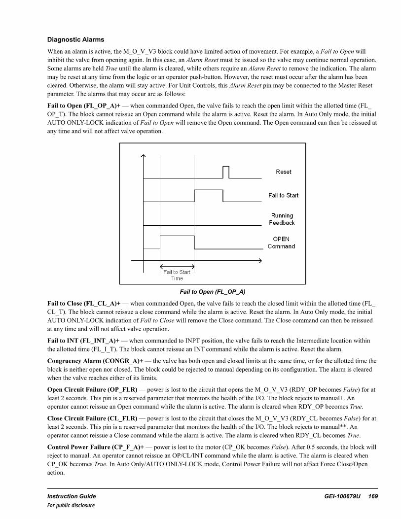
Diagnostic Alarms
When an alarm is active, the M_O_V_V3 block could have limited action of movement. For example, a Fail to Open willinhibit the valve from opening again. In this case, an Alarm Reset must be issued so the valve may continue normal operation.Some alarms are held True until the alarm is cleared, while others require an Alarm Reset to remove the indication. The alarmmay be reset at any time from the logic or an operator push-button. However, the reset must occur after the alarm has beencleared. Otherwise, the alarm will stay active. For Unit Controls, this Alarm Reset pin may be connected to the Master Resetparameter. The alarms that may occur are as follows:
Fail to Open (FL_OP_A)+—when commanded Open, the valve fails to reach the open limit within the allotted time (FL_OP_T). The block cannot reissue an Open command while the alarm is active. Reset the alarm. In Auto Only mode, the initialAUTO ONLY-LOCK indication of Fail to Open will remove the Open command. The Open command can then be reissued atany time and will not affect valve operation.
Fail to Open (FL_OP_A)
Fail to Close (FL_CL_A)+—when commanded Open, the valve fails to reach the closed limit within the allotted time (FL_CL_T). The block cannot reissue a close command while the alarm is active. Reset the alarm. In Auto Only mode, the initialAUTO ONLY-LOCK indication of Fail to Close will remove the Close command. The Close command can then be reissuedat any time and will not affect valve operation.
Fail to INT (FL_INT_A)+—when commanded to INPT position, the valve fails to reach the Intermediate location withinthe allotted time (FL_I_T). The block cannot reissue an INT command while the alarm is active. Reset the alarm.
Congruency Alarm (CONGR_A)+— the valve has both open and closed limits at the same time, or for the allotted time theblock is neither open nor closed. The block could be rejected to manual depending on its configuration. The alarm is clearedwhen the valve reaches either of its limits.
Open Circuit Failure (OP_FLR)— power is lost to the circuit that opens the M_O_V_V3 (RDY_OP becomes False) for atleast 2 seconds. This pin is a reserved parameter that monitors the health of the I/O. The block rejects to manual+. Anoperator cannot reissue an Open command while the alarm is active. The alarm is cleared when RDY_OP becomes True.
Close Circuit Failure (CL_FLR)— power is lost to the circuit that closes the M_O_V_V3 (RDY_CL becomes False) for atleast 2 seconds. This pin is a reserved parameter that monitors the health of the I/O. The block rejects to manual**. Anoperator cannot reissue a Close command while the alarm is active. The alarm is cleared when RDY_CL becomes True.
Control Power Failure (CP_F_A)+— power is lost to the motor (CP_OK becomes False). After 0.5 seconds, the block willreject to manual. An operator cannot reissue an OP/CL/INT command while the alarm is active. The alarm is cleared whenCP_OK becomes True. In Auto Only/AUTO ONLY-LOCK mode, Control Power Failure will not affect Force Close/Openaction.
Instruction Guide GEI-100679U 169For public disclosure

Not Available (AVAIL_A)—M_O_V_V3 has become unavailable due to a device not available condition (AVAIL becomesFalse). The block will reject to manual. An operator cannot reissue an OP/CL/INT command while the alarm is active. Thealarm is cleared when AVAIL becomes True.
Manual Rejected (MN_REJ_A)—M_O_V_V3 is rejected to manual due to a conditional alarm or input pin (MN_REJbecomes True). The block will only respond to manual commands. The alarm is cleared after the conditions return to normaland the MN_REJ becomes False and a reset command is given.
Auto Request (AU_REQ)+—M_O_V_V3 is in Manual mode but the Auto logic requests that the valve state be differentthan its current state. This has no effect on valve operation and is an alarm message only. The alarm is cleared if the valve isplaced into Auto mode, manually ordered to the requested state, or the Auto action is removed.
Not in Remote (REMOTE_A)— the valve is in Local mode and can be moved by an operator local at the valve. However, acontrol system cannot operate a valve while in Local (REMOTE becomes False). No OP/CL/INT commands may be issued.The alarm is cleared when REMOTE becomes True.
Torque Limit (TL_A)— valve Torque limit reached while trying to open or close the valve (TL_OP or TL_CL becomesTrue). The block will reject to manual. An operator cannot reissue an OP/CL/INT command while the alarm is active. Thealarm is cleared when TL_OP and TL_CL becomes False.
Note + If the MODE_OPT is set to AUTO ONLYor AUTO-LOCK, this alarm will not affect automatic valve operation.However the alarm will still become active under the given conditions.
170 GEI-100679U Mark VIe Controller DCS Block LibraryFor public disclosure

Force and Override Control
During any condition, M_O_V_V3 may be forced to a position that bypasses normal operation. The force is driven from theCL_FRC, INT_FRC or OP_FRC pins in the logic. The valve will move to the force position and remain there until the forceis removed. For example, if the valve is forced open, there must be no Override Close, Circuit Failure, or Failed to Open.While a force condition is active, the valve may freely transfer from Auto to Manual following the normal permits. However,no manual command will supersede the force. Once the force is removed, the valve will continue normal operation.
Note Refer to the figure Open Command Logic to view the logic for a force.
An override will supersede a force and place the valve into the overridden state. For example, if the valve is overriddenclosed, the valve will issue a close order irrelevant of any forces, provided there are no Circuit Failure and Failed to Closealarms. The M_O_V_V3 block will take precedence from the override command, then the force command, and then themanual or auto command. Upon entering an overridden state, the valve is placed into Manual mode. Once the override isremoved, the valve will remain in Manual mode until changed by the operator.
Although forces and overrides bypass normal permits, if the valve is locked, forces and overrides will have no effect on theblock. The block must be removed from Lock mode before the forces and overrides affect block operation. Additionally, if theMODE_OPT is set to AUTO ONLYor AUTO-LOCK, the override pins will be disabled and will have no effect on the block.
Permits
Due to the nature of auto and forcing action, permits are required for valve operation. Built into the blocks are special devicepermits that may be enabled or disabled with certain pins in the block, as follows:
Note For basic operations, most of the device permits will be disabled.
• Open− OP_PMT is True (OP_PMT is technically a UINT)− M_O_V_V3 not Failed to Open**+− M_O_V_V3 not Control Power Fail (if CP_OK property enabled)− M_O_V_V3 not in Local (if REMOTE property enabled)− I/O ready to Open M_O_V_V3 or not Open Circuit Failure (if FUSE Monitoring/Voltage Monitoring Property
enabled)− M_O_V_V3 not in Lock mode− Breaker to M_O_V_V3 is not Not Available (if AVAIL property enabled)− M_O_V_V3 not Forced Close or Forced INT− M_O_V_V3 not Override Close or Override INT+− M_O_V_V3 not at Torque Limit (if TQ_LIM property enabled)
• Close− CL_PMT is True (CL_PMT is technically a UINT)− M_O_V_V3 not Failed to Close**+− M_O_V_V3 not Control Power Fail (if CP_OK property enabled)− M_O_V_V3 not in Local (if REMOTE property enabled)− I/O ready to Close M_O_V_V3 or not Close Circuit Failure (if FUSE Monitoring/Voltage Monitoring Property
enabled)− M_O_V_V3 not in Lock mode− Breaker to M_O_V_V3 not Not Available (if AVAIL property enabled)− M_O_V_V3 not Forced Open or Forced INT− M_O_V_V3 not Override Open or Override INT+− M_O_V_V3 not at Torque Limit (if TQ_LIM property enabled)
• INT
Instruction Guide GEI-100679U 171For public disclosure

− INT_PMT is True (INT_PMT is technically a UINT)− M_O_V_V3 not Failed to INT**+− M_O_V_V3 not Control Power Fail (if CP_OK property enabled)− M_O_V_V3 not in Local (if REMOTE property enabled)− I/O ready to Close M_O_V_V3 or not Close Circuit Failure (if FUSE Monitoring/Voltage Monitoring Property
enabled)− I/O ready to Open M_O_V_V3 or not Open Circuit Failure (if FUSE Monitoring/Voltage Monitoring Property
enabled)− M_O_V_V3 not in Lock mode− Breaker to M_O_V_V3 not Not Available (if AVAIL property enabled)− M_O_V_V3 not Forced Open or Forced Close− M_O_V_V3 not Override Open or Override Close+− M_O_V_V3 not at Torque Limit (if TQ_LIM property enabled)
• Open Force− M_O_V_V3 not Failed to Open**+− M_O_V_V3 not in Local (if REMOTE property enabled)− I/O ready to Open M_O_V_V3 or not Open Circuit Failure (if FUSE Monitoring/Voltage Monitoring Property
enabled)− M_O_V_V3 not in Lock mode− M_O_V_V3 not Forced Close or Forced INT− M_O_V_V3 not Override Close or Override INT+− M_O_V_V3 not Control Power Fail (if CP_OK property enabled)+
• Close Force− M_O_V_V3 not Failed to Close**+− M_O_V_V3 not in Local (if REMOTE property enabled)− I/O ready to Close M_O_V_V3 or not Close Circuit Failure (if FUSE Monitoring/Voltage Monitoring Property
enabled)− M_O_V_V3 not in Lock mode− M_O_V_V3 not Forced Open or Forced INT− M_O_V_V3 not Override Open or Override INT+− M_O_V_V3 not Control Power Fail (if CP_OK property enabled)+
• INT Force− M_O_V_V3 not Failed to INT**+− M_O_V_V3 not in Local (if REMOTE property enabled)− I/O ready to Close M_O_V_V3 or not Close Circuit Failure (if FUSE Monitoring/Voltage Monitoring Property
enabled)− I/O ready to Open M_O_V_V3 or not Open Circuit Failure (if FUSE Monitoring/Voltage Monitoring Property
enabled)− M_O_V_V3 not in Lock mode− M_O_V_V3 not Forced Open or Forced Close− M_O_V_V3 not Override Open or Override Close+− M_O_V_V3 not Control Power Fail (if CP_OK property enabled)+
• Open Override+− M_O_V_V3 not Failed to Open**− M_O_V_V3 not in Local (if REMOTE property enabled)− I/O ready to Open M_O_V_V3 or not Open Circuit Failure (if FUSE Monitoring/Voltage Monitoring Property
enabled)− M_O_V_V3 not in Lock mode− M_O_V_V3 not Override Close or Override INT− M_O_V_V3 not Control Power Fail (if CP_OK property enabled)
• Close Override+− M_O_V_V3 not Failed to Close**
172 GEI-100679U Mark VIe Controller DCS Block LibraryFor public disclosure

− M_O_V_V3 not in Local (if REMOTE property enabled)− I/O ready to Close M_O_V_V3 or not Close Circuit Failure (if FUSE Monitoring/Voltage Monitoring Property
enabled)− M_O_V_V3 not in Lock mode− M_O_V_V3 not Override Open or Override INT+− M_O_V_V3 not Control Power Fail (if CP_OK property enabled)
• INT Override− M_O_V_V3 not Failed to INT**− M_O_V_V3 not in Local (if REMOTE property enabled)− I/O ready to Close M_O_V_V3 or not Close Circuit Failure (if FUSE Monitoring/Voltage Monitoring Property
enabled)− I/O ready to Open M_O_V_V3 or not Open Circuit Failure (if FUSE Monitoring/Voltage Monitoring Property
enabled)− M_O_V_V3 not in Lock mode− M_O_V_V3 not Override Open or Override Close+− M_O_V_V3 not Control Power Fail (if CP_OK property enabled)
Note **Indicates a condition that is internally generated to the block. Otherwise, the condition comes from a direct input.
+ Indicates a condition bypassed when MODE_OPT is set to AUTO ONLYor AUTO-LOCK mode.
Instruction Guide GEI-100679U 173For public disclosure

Inputs
Name Global Description FunctionAU_SEL Auto select Pulses the valve into Auto (provided all permits are met)AU_ OP Auto open Opens the valve (provided all permits are met); device must be
in Auto modeAU_CL Auto close Auto closes the valve (provided all permits are met); device
must be in Auto modeAU_INT Auto intermediate Auto moves the valve to the intermediate position (provided all
permits are met); device must be in Auto modeAU_PMT Yes Auto permit Permit required for external logic to place the valve in Auto
modeOP_PMT Yes Open permit Permit required for external logic to prevent the valve from
openingCL_PMT Yes Close permit Permit required for external logic to prevent the valve from
closingINT_PMT Yes Intermediate permit Permit required for external logic to prevent the valve to go to
the intermediate positionRDY_CL Ready to close I/O monitoring of the circuit to the close command to the valveRDY_OP Ready to open I/O monitoring of the circuit to the open command to the valveOP_OVR Yes Open override Permit required for external logic to override open the valveCL_OVR Yes Close override Permit required for external logic to override close the valveINT_OVR Yes Intermediate override Permit required for external logic to override intermediate
command to the valveMN_REJ Yes Manual rejection Permit required for external logic to manually reject the valve
CL_INP Closed input Connects to the closed feedback of the valveOP_INP Open input Connects to the open feedback of the valveCL_FRC Yes Close force Permit required for external logic to force close the valveOP_FRC Yes Open force Permit required for external logic to force open the valveINP_FRC Yes Intermediate force Permit required for external logic to force intermediate
command to the valveALARM_RESET Alarm reset Permit required for external logic to reset alarms on the valveCP_OK Control power OK Tied to the I/O that monitors the control power for the valveAVAIL Block available Tied to the I/O that has the M_O_V_V3 availability feedbackREMOTE Block remote Tied to the I/O that has the M_O_V_V3 local/remote statusTL_CL Close torque limit Tied to the I/O that indicates if the M_O_V_V3 has reached its
torque limit upon closingTL_OP Open torque limit Tied to the I/O that indicates if the block has reached its torque
limit upon openingTRANSIT Valve in transit Tied to the I/O that indicates the block is in motionPOS Yes Position Tied to the valve position feedbackINT_ZS† Intermediate position input Tied to the Boolean I/O that indicates the block has reached
the INT positionINT_SETP† Intermediate position setpoint Intermediate position setpoint that the valve is to travel
towards, given the INTcommand† The block will use either INT_ZS or POS for indication if the valve has reached intermediate position. At least one must beavailable when using the intermediate position.
174 GEI-100679U Mark VIe Controller DCS Block LibraryFor public disclosure

ParametersName Global Description FunctionCTL Yes Control Used by the operator graphic to control the valveFL_OP_T Fail to Open Time Time allotted for the valve to open. (If the motor takes 30
seconds to open, ~35000 msec is sufficient time to allow thevalve to reach its open state.)
FL_CL_T Fail to Close Time Time allotted for the valve to close. (If the motor takes 30seconds to close, ~35000 msec is sufficient time to allow thevalve to reach its close state.)
FL_I_CT Fail to Close to IntermediateTime
Time allotted for the valve to close to the Intermediate Position.(If the valve takes 20 seconds to close, ~25000 msec issufficient time to allow the valve to reach its intermediate state.)
FL_I_OT Fail to Open to IntermediateTime
Time allotted for the valve to open to the Intermediate Position.(If the valve takes 20 seconds to open, ~25000 msec issufficient time to allow the valve to reach its intermediate state.)
PWR_FL_TMR Manual Reject Power FailureTime
Time allotted for the M_O_V_V3 to lose power before it rejectsthe valve to manual
IO_MON I/O Monitor Options Allow the I/O monitoring feature to be enabled. This pin can beset to either Volt or Fuse monitoring.
IO_OPT Valve I/O Options Designates what type of I/O options are available for the valveMODE_OPT Valve Mode Options Designates which modes the valve can enterCTRL_TYPE Control Type Designates how the valve is controlled. Either Analog output or
digital output may be used. Position feedback is required foranalog output.
INT_SENS Intermediate PositionSensitivity
Range in which the valve position may reside to be consideredat INT position (which is ± 2%)
Instruction Guide GEI-100679U 175For public disclosure

Outputs
Name Global Description
OP_ORD Yes Open orderCL_ORD Yes Close orderINT_CMD Yes Intermediate orderPOS_ORD Yes Position orderAUTO_P Yes Property for Auto mode availableLOCK_P Yes Property for Lock mode availableANA_OUT_P Yes Property for analog outputVOLT_MON_P Yes Property for volt monitoring I/OFUSE_MON_P Yes Property for fuse monitoring I/OPOSFB_P Yes Property for position feedback I/OREM_P Yes Property for local or remote I/OAVAIL_P Yes Property for valve availability I/OCP_OK_P Yes Property for control power I/OTQ_LIM_P Yes Property for torque limit I/OTRANS_P Yes Property for transit I/OAUTO Yes Auto mode activeCLOSED Yes Block closedOPEN Yes Block openedINT Yes Valve has reached intermediate positionLOCK Yes Lock mode activePMT_AU Yes Auto permitPMT_CL Yes Close permitPMT_OP Yes Open PermitALARM Alarm activeMODE Current valve statusTRN_IND Yes Valve in transitOVR_CL Yes Close overrideOVR_OP Yes Open overrideOVR_INT Yes Intermediate overrideFRC_CL Yes Close forceFRC_OP Yes Open forceFRC_INT Yes Intermediate forceCL_FLR Yes Close circuit failureOP_FLR Yes Open circuit failureAU_REQ Yes Auto request (Auto logic wishes to open or close M_O_V_V3)CONGR_A Yes Congruency alarmAVAIL_A Yes Valve not available alarmFL_CL_A Yes Failed to close alarmFL_OP_A Yes Failed to open alarmFL_INT_A Yes Failed to Int alarmTL_A Yes Torque limit alarmMN_REJ_A Yes Manual rejection alarmCP_F_A Yes Control power failure alarmREMOTE_A Valve not in remote alarm
176 GEI-100679U Mark VIe Controller DCS Block LibraryFor public disclosure

Global VariablesGlobal Pin Name Description Alarm Alarm
ClassEvent EGD Page External
AccessSTEAM1001 Steam release valve Not
AlarmedFalse $Default ReadOnly
STEAM1001.ANA_OUT_P Steam release valveanalog out property
NotAlarmed
False ReadOnly
STEAM1001.AU_REQ Steam release valve autorequest
NotAlarmed
False $Default ReadOnly
STEAM1001.AUTO Steam release valve auto NotAlarmed
True $Default ReadOnly
STEAM1001.AUTO_P Steam release valve autoproperty
NotAlarmed
False $Default ReadOnly
STEAM1001.AVAIL_A Steam release valve notavailable
Alarmed LVL_3 False $Default ReadOnly
STEAM1001.AVAIL_P Steam release valveavailable property
NotAlarmed
False $Default ReadOnly
STEAM1001.CL_FLR Steam release valve closecircuit fail
Alarmed Alert False $Default ReadOnly
STEAM1001.CL_ORD Steam release valve closeorder/cmd
NotAlarmed
False $Default ReadOnly
STEAM1001.CLOSED Steam release valveclosed
NotAlarmed
False $Default ReadOnly
STEAM1001.CONGR_A Steam release valvecongruency
Alarmed Alert False $Default ReadOnly
STEAM1001.CP_F_A Steam release valvecontrol power fail
Alarmed Alert False $Default ReadOnly
STEAM1001.CP_OK_P Steam release valvecontrol power property
NotAlarmed
False $Default ReadOnly
STEAM1001.CTL Steam release valvecontrol word
NotAlarmed
False $Default ReadWrite
STEAM1001.FAULT Steam release valve faultindication
NotAlarmed
False $Default ReadOnly
STEAM1001.FL_CL_A Steam release valve failto close
Alarmed LVL_3 False $Default ReadOnly
STEAM1001.FL_INT_A Steam release valve failto int
Alarmed LVL_3 False $Default ReadOnly
STEAM1001.FL_OP_A Steam release valve failto open
Alarmed LVL_3 False $Default ReadOnly
STEAM1001.FRC_CL Steam release valve forceclose
NotAlarmed
True $Default ReadOnly
STEAM1001.FRC_CLB Steam release valve closeforce block sts
NotAlarmed
False $Default ReadOnly
STEAM1001.FRC_INT Steam release valve forceint
NotAlarmed
True $Default ReadOnly
STEAM1001.FRC_INTB Steam release valve intforce block sts
NotAlarmed
False $Default ReadOnly
STEAM1001.FRC_OP Steam release valve forceopen
NotAlarmed
True $Default ReadOnly
STEAM1001.FRC_OPB Steam release valve openforce block sts
NotAlarmed
False $Default ReadOnly
STEAM1001.FUSE_MON_P Steam release valveoutput fuse mon property
NotAlarmed
False $Default ReadOnly
Instruction Guide GEI-100679U 177For public disclosure

Global Variables (continued)
Global Pin Name Description Alarm AlarmClass
Event EGD Page ExternalAccess
STEAM1001.INT Steam release valve intposition
NotAlarmed
False $Default ReadOnly
STEAM1001.INT_CMD Steam release valve intcmd
NotAlarmed
False $Default ReadOnly
STEAM1001.INT_P Steam release valve intproperty
NotAlarmed
False $Default ReadOnly
STEAM1001.LOCAL Steam release valve localmode
NotAlarmed
True $Default ReadOnly
STEAM1001.LOCK Steam release valvelocked
NotAlarmed
True $Default ReadOnly
STEAM1001.LOCK_P Steam release valve lockproperty
NotAlarmed
False $Default ReadOnly
STEAM1001.MN_REJ_A Steam release valvemanual reject
Alarmed LVL_3 False $Default ReadOnly
STEAM1001.OP_FLR Steam release valve opencircuit fail
Alarmed Alert False $Default ReadOnly
STEAM1001.OP_ORD Steam release valve openorder/cmd
NotAlarmed
False $Default ReadOnly
STEAM1001.OPEN Steam release valve open NotAlarmed
False $Default ReadOnly
STEAM1001.OVR_CL Steam release valve closeoverride
NotAlarmed
True $Default ReadOnly
STEAM1001.OVR_CLB Steam release valve closeoverride block sts
NotAlarmed
False $Default ReadOnly
STEAM1001.OVR_INT Steam release valve intoverride
NotAlarmed
True $Default ReadOnly
STEAM1001.OVR_INTB Steam release valve intoverride block sts
NotAlarmed
False $Default ReadOnly
STEAM1001.OVR_OP Steam release valve openoverride
NotAlarmed
True $Default ReadOnly
STEAM1001.OVR_OPB Steam release valve openoverride block sts
NotAlarmed
False $Default ReadOnly
STEAM1001.PBSTATE Steam release valve lastpb state
NotAlarmed
False $Default ReadOnly
STEAM1001.PBSTATE2 Steam release valve lastpb state
NotAlarmed
False $Default ReadOnly
STEAM1001.PMT_AU Steam release valve autopermit
NotAlarmed
False $Default ReadOnly
STEAM1001.PMT_AUB Steam release valve autopermit bypass sts
NotAlarmed
False $Default ReadOnly
STEAM1001.PMT_CL Steam release valvepermit to close
NotAlarmed
False $Default ReadOnly
STEAM1001.PMT_CLB Steam release valve closepermit bypass sts
NotAlarmed
False $Default ReadOnly
STEAM1001.PMT_INT Steam release valvepermit to int
NotAlarmed
False $Default ReadOnly
STEAM1001.PMT_INTB Steam release valve intpermit bypass sts
NotAlarmed
False $Default ReadOnly
178 GEI-100679U Mark VIe Controller DCS Block LibraryFor public disclosure

Global Variables (continued)
Global Pin Name Description Alarm AlarmClass
Event EGD Page ExternalAccess
STEAM1001.PMT_OP Steam release valvepermit to open
NotAlarmed
False $Default ReadOnly
STEAM1001.PMT_OPB Steam release valve openpermit bypass sts
NotAlarmed
False $Default ReadOnly
STEAM1001.POS Steam release valveposition fdbk
NotAlarmed
False $Default ReadOnly
STEAM1001.POS_ORD Steam release valveposition order/cmd
NotAlarmed
False $Default ReadOnly
STEAM1001.POSFB_P Steam release valveposition fdbk property
NotAlarmed
False $Default ReadOnly
STEAM1001.REJ_MN Steam release valvemanual reject
NotAlarmed
False $Default ReadOnly
STEAM1001.REJ_MNB Steam release valvemanual reject bypass sts
NotAlarmed
False $Default ReadOnly
STEAM1001.REM_P Steam release valveremote property
NotAlarmed
False $Default ReadOnly
STEAM1001.TL_A Steam release valvetorque limit
NotAlarmed
True $Default ReadOnly
STEAM1001.TQ_LIM_P Steam release valvetorque limit property
NotAlarmed
False $Default ReadOnly
STEAM1001.TRANS_P Steam release valvetransit property
NotAlarmed
False $Default ReadOnly
STEAM1001.TRN_IND Steam release valvetransit ind
NotAlarmed
False $Default ReadOnly
STEAM1001.VOLT_MON_P Steam release valveoutput volt mon property
NotAlarmed
False $Default ReadOnly
Instruction Guide GEI-100679U 179For public disclosure

HMI Configuration (CIMPLICITY)
The Object name for the HMI is the same as the Device name specified in the ToolboxST configuration.
Click the Object to display the
faceplate. M_O_V_V 3
M_O_V_V3 Faceplate
180 GEI-100679U Mark VIe Controller DCS Block LibraryFor public disclosure
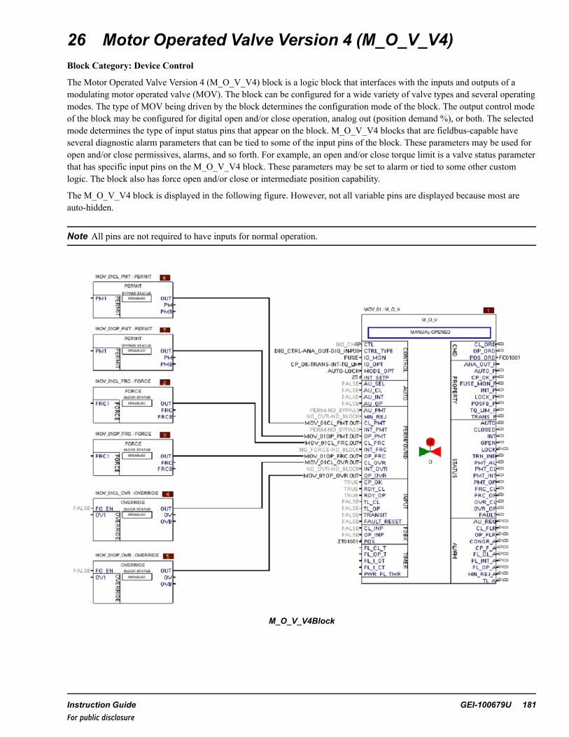
26 Motor Operated Valve Version 4 (M_O_V_V4)Block Category: Device Control
The Motor Operated Valve Version 4 (M_O_V_V4) block is a logic block that interfaces with the inputs and outputs of amodulating motor operated valve (MOV). The block can be configured for a wide variety of valve types and several operatingmodes. The type of MOV being driven by the block determines the configuration mode of the block. The output control modeof the block may be configured for digital open and/or close operation, analog out (position demand %), or both. The selectedmode determines the type of input status pins that appear on the block. M_O_V_V4 blocks that are fieldbus-capable haveseveral diagnostic alarm parameters that can be tied to some of the input pins of the block. These parameters may be used foropen and/or close permissives, alarms, and so forth. For example, an open and/or close torque limit is a valve status parameterthat has specific input pins on the M_O_V_V4 block. These parameters may be set to alarm or tied to some other customlogic. The block also has force open and/or close or intermediate position capability.
The M_O_V_V4 block is displayed in the following figure. However, not all variable pins are displayed because most areauto-hidden.
Note All pins are not required to have inputs for normal operation.
M_O_V_V4Block
Instruction Guide GEI-100679U 181For public disclosure

The M_O_V_V4 block may be configured to operate in Manual or Automatic (Auto) mode. The block also enables the userto lock the device, thus disabling any operation while in this mode. The block is used in conjunction with the PERMIT,FORCE, OVERRIDE, LOGIC_BUILDER, and LOGIC_BUILDER_SC blocks to provide complete and comprehensivedevice control. A predefined HMI faceplate is available, which provides the operator interface to the valve.
Note Refer to theMark VIe Controller Standard Block Library (GEI-100682), the Logic Builder (LOGIC_BUILDER) block.
Block Configuration
Control Word
Control (CTL) is an enumeration set by the HMI operator for valve control. The commands available from the HMI allowmanual and automatic valve control capability and/or lockout capability if the block property MODE_OPT enumerationselected allows the auto and/or lock mode. The valve may be opened or closed in Manual mode by the OPEN_CMD orCLOSE_CMD enumerations, respectively. If the valve is a motor-operated valve with intermediate position, INT_P is True,the valve may also be commanded to the intermediate position in Manual mode by the OPEN_CMD or CLOSE_CMDenumeration (depending on starting position). The command enumerations are defined in the following table.
Note This block has various enumerations that are configured for control block operations.
CTL EnumerationsEnumeration CommandNO_CMD No commandAUTO_CMD Auto commandMANUAL_CMD Manual commandLOCK_CMD Lock commandUNLOCK_CMD Unlock commandOPEN_CMD Open commandCLOSE_CMD Close commandINT_CMD Intermediate commandRESET_CMD Fault reset command
Modes of Control (CTRL_TYPE)
CTRL_TYPE enumerations are as listed in the following table.
CTRL_TYPE Enumerations
Enumeration Control Option DescriptionDIG_CTRL-DIG_OUT-DIG_IN Digital input control with digital outputs and no analog position feedback inputDIG_CTRL-DIG_OUT-DIG_IN-POS Digital input control with digital outputs and an analog position feedback inputDIG_CTRL-ANA_OUT-DIG_IN-POS Digital input control with analog output and an analog position feedback input
DIG_CTRL-DIG_OUT-DIG_IN— select for valves that do not provide an analog position feedback. When the DIG_CTRL-DIG_OUT-DIG_IN enumeration is selected, the output POSFB_P is False.
DIG_CTRL-ANA_OUT-DIG_IN-POS— select for valves that provide digital inputs, an analog output, and an analogposition feedback. The OPEN and CLOSED inputs from the limit switches of the valve are required. When the DIG_CTRL-ANA_OUT-DIG_IN-POS enumeration is selected, the outputs DIG_CTRL_P, ANA_OUT_P, DIG_IN_P, andPOSFB_P are True.
182 GEI-100679U Mark VIe Controller DCS Block LibraryFor public disclosure

DIG_CTRL-DIG_OUT-DIG_IN-POS— select for valves that provide an analog position feedback, which is used by theHMI objects and faceplates to display the valve open percentage. When the DIG_CTRL-DIG_OUT-DIG_IN-POSenumeration is selected, the output POSFB_P is True.
Inputs and Outputs
At a minimum, the M_O_V_V4 block requires open and/or close position feedback, and valve order output. However, otherinputs may be used for automatic control, valve forcing, manual rejection, and such.
Depending on the block configuration, the output could be a single percent demand (POS_ORD), open and/or close (CL_ORD, OP_ORD), or intermediate position (INT_ORD). The intermediate setpoint (INT_SETP) may be set with an immediatevalue or variable that may be the result of an equation or condition. The M_O_V_V4 intermediate position can be achievedusing either output method, as well as the position input (POS) to determine if the intermediate position has been reached.The following figures are logic representations of the Open command logic. The Close and Int command logic is similar, butreplaces the Open text with Close or Int text.
Open Command Logic
Open Command Digital Control Output
Instruction Guide GEI-100679U 183For public disclosure

Modes of Operation (MODE_OPT)
MODE_OPT are the modes in which the M_O_V_V4 block may be configured to operate in Manual or Auto mode, anddisallow any operation while in Lock mode. Manual mode allows commands from the operator interface, while Auto modeallows the control logic to command the valve. In either mode there are inputs that may bypass or override the active mode ofoperation. Lock mode is intended to be used when maintenance work is being performed on the valve and the operator wantsto prohibit any logic from operating the valve. The allowable modes of operation are specified by the Mode Optionsparameter, MODE_OPT. The following table provides a visual presentation of the modes available based on the MODE_OPTselection.
Available Modes for MODE_OPT Selections
MODE_OPT
MODE_OPT MANUAL AUTO LOCK
MANUAL ONLY X
MANUAL-AUTO X X
MANUAL-LOCK X X
MANUAL-AUTO--LOCK
X X X
AUTO ONLY X
AUTO-LOCK X X
Manual mode— enables the block to respond to operator Open and Close commands from an HMI faceplate. Given that thepermits are satisfied, the block operates in accordance with the Manual command. The permit for the Open command is set bythe Open permit input, OP_PMT, and the permit for the Close command is set by the Close permit input, CL_PMT. Similarly,the same is true for INT_PMT. These inputs may be set to fixed values or driven by the LOGIC_BUILDER block. Thepossible conditions that place the block into Manual mode are:
Note Manual mode is always available unless MODE_OPT is set to AUTO ONLYor AUTO-LOCK.
Some of these conditions require block parameters to be specifically configured. For example, the block does not depend onthe AVAIL pin unless IO_OPT is set to AVAIL.
• Manual mode selected from the HMI faceplate• Device is locked from the HMI faceplate• Manual Rejection from the logic (MN_REJ)• Override Close, Int, or Open from the logic (OVR_CL, OVR_INT, OVR_OP)• Open or close circuit failure (RDY_CL, RDY_OP)• Valve at torque limit reached (TL_OP, TL_CL)• M_O_V_V4 not Available (AVAIL)• M_O_V_V4 not in Remote (REMOTE)• Congruency alarm
184 GEI-100679U Mark VIe Controller DCS Block LibraryFor public disclosure

Manual Mode Conditions
Auto mode— enables the block to respond to open and close commands from logic. Given that the permits are satisfied, theblock operates per command from the logic. The permit for the Open command is set by the Open permit input, OP_PMT,and the permit for the Close command is set by the close permit input, and the permit for Intermediate Position is set by INT_PMT input. The OP_PMT, CL_PMT, and INT_PMT inputs may be set to fixed values or driven by the LOGIC_BUILDERblock. The logic commands are input to the block through the Automatic Open (AU_OP), Automatic Close (AU_CL), andAutomatic intermediate position inputs. The block may be placed in Auto mode either from a command from the HMI or apulse to the automatic select input, AU_SEL. Given that the permits are satisfied, the block will be placed into Auto mode.The permit for the Auto mode is set by the Auto Permit input, AU_PMT. The AU_PMT input may be set to a fixed value oralso driven by the LOGIC_BUILDER block.
MANUAL-AUTO mode— selection provides manual and automatic functionality.
AUTO ONLY or AUTO-LOCK— selection provides automatic functionality only.
While residing in Auto mode, the block will control the valve based on external logic. Automated control from external logicinterfaces to the AU_OP, AU_INT and AU_CL pins. Similar to Manual mode, Auto action only operates with the properOpen, Int, and Close permits. If AUTO ONLY mode is selected, the block will permanently reside in Auto mode. IfMANUAL-AUTO is selected, only two conditions will transfer the block from Manual mode into Auto mode. Unlike thetransferring to Manual mode, certain permits must be satisfied to allow the valve to enter into Auto mode. This means that theM_O_V_V4 is always able to enter Manual mode, but not always able to enter Auto mode. These conditions depend on themode options selected for the block.
All three of the following conditions must be met for the block to enter Auto mode:
• No demand to transition to Manual mode• MODE_OPT must be set to MANUAL-AUTO or MANUAL-AUTO_LOCK• AUTO push-button from operator graphic or Auto select from logic (AU_SEL)
Auto Only mode— is selected using the MODE_OPT pin. All of the Auto Open or Auto Close commands work aspreviously described, however, all of the Trip, Override, and Reject to Manual features are disabled, including the ability ofthe operator to select the Manual mode from the HMI faceplate. Once Auto Only Mode is selected, the corresponding options(Auto, Manual, Start, and Stop) displayed on the faceplate are removed.
Lock mode—may only be selected when the solenoid is in the de-energized state. In this mode, the block forces the outputso that the solenoid remains de-energized. Upon being placed in locked mode, if currently in Auto mode, it will transfer toManual mode. At this time no open commands, forces, or overrides will be accepted. Upon removing the lock, Manual modewill then be active. Similarly, AUTO ONLYand AUTO-LOCK (no open commands) will be accepted. However, uponremoval of Lock mode, the block will return to Auto mode.
Instruction Guide GEI-100679U 185For public disclosure

Note At any time, the block may go into Lock mode as long as it is residing in its fail-safe position. Only the operator mayplace block into Lock mode.
Modes of I/O (IO_OPT)
IO_OPT are the modes in which the M_O_V_V4 block may be configured to allow input I/O states for the device. All I/O aredigital or analog inputs received from the valve device. Each I/O input indicates the current status. Device status includescontrol power available, device not available, and device in remote. Depending on the I/O properties enabled, the block willact differently. The I/O configurations are specified by the I/O Options parameter, IO_OPT. The following table provides avisual presentation of the modes available based on the IO_OPT selection. Any enumeration of the I/O pins is available.However, not all are displayed because there are too many to display in the table.
I/O Pins Available for IO_OPT Selections
I/OIO_OPT Ctrl Pwr OK Remote Avail Transit INT TQ LIM
AVAIL XAVAIL-TQ_LIM X XAVAIL-INT-TQ_LIM X X XAVAIL XAVAIL-TRANS X XAVAIL-TRANS-TQ_LIM X X XCP_OK-REM X XCP_OK-REM-AVAIL X X XCP_OK-REM-AVAIL-TQ_LIM X X X X
CP_OK-REM-AVAIL-TRANS-INT-TQ_LIM X X X X X X
Control Power OK— allows the device I/O input from CP_OK. If this input goes False, a Control Power Fail alarm isgenerated that trips the device and places it in Manual.
Remote— allows the device I/O input from REMOTE. If this input goes False, a device in Local alarm is generated thatplaces it in Manual mode.
Available— allows the device I/O input from AVAIL. If this input goes False, a Device not available alarm is generated thatplaces it in Manual mode.
Transit— allows the device I/O input from TRANSIT. If this input goes True, a valve is in Transit and moving or changingpositions.
Int— allows the device I/O input from INT. If this input goes True, the valve has reached its intermediate limit position.
Torque Limit— allows the device I/O input from TQ_LIM. If this input goes True, the valve has exceeded the maximumallowed torque value while trying to open or close. An alarm is generated and the valve is placed in Manual mode.
Additional outputs from this block indicate status, failures, alarms, forces, and overrides. Much of this information isdisplayed on the HMI faceplate.
Diagnostic Alarms
When an alarm is active, the M_O_V_V4 block could have limited action of movement. For example, a Fail to Open willinhibit the valve from opening again. In this case, an Alarm Reset must be issued so the valve may continue normal operation.Some alarms are held True until the alarm is cleared, while others require an Alarm Reset to remove the indication. The alarmmay be reset at any time from the logic or an operator push-button. However, the reset must occur after the alarm has beencleared. Otherwise, the alarm will stay active. For Unit Controls, this Alarm Reset pin may be connected to the Master Resetparameter. The alarms that may occur are as follows:
186 GEI-100679U Mark VIe Controller DCS Block LibraryFor public disclosure

Fail to Open (FL_OP_A)+—when commanded Open, the valve fails to reach the open limit within the allotted time(FL_OP_T) and if in transit then also within the allotted time (FL_TRANS_T). The block cannot reissue an Open commandwhile the alarm is active. Reset the alarm. In Auto Only mode, the initial AUTO ONLY-LOCK indication of Fail to Open willremove the Open command. The Open command can then be reissued at any time and will not affect valve operation.
Fail to Open (FL_OP_A)
Fail to Close (FL_CL_A)+—when commanded Open, the valve fails to reach the closed limit within the allotted time(FL_CL_T) and if in transit then also within the allotted time (FL_TRANS_T). The block cannot reissue a close commandwhile the alarm is active. Reset the alarm. In Auto Only mode, the initial AUTO ONLY-LOCK indication of Fail to Closewill remove the Close command. The Close command can then be reissued at any time and will not affect valve operation.
Fail to INT (FL_INT_A)+—when commanded to INPT position, the valve fails to reach the Intermediate location withinthe allotted time (FL_I_T). The block cannot reissue an INT command while the alarm is active. Reset the alarm.
Congruency Alarm (CONGR_A)+— the valve has both open and closed limits at the same time, or for the allotted time theblock is neither open nor closed. The block could be rejected to manual depending on its configuration. The alarm is clearedwhen the valve reaches either of its limits.
Open Circuit Failure (OP_FLR)— power is lost to the circuit that opens the M_O_V_V4 (RDY_OP becomes False) for atleast 2 seconds. This pin is a reserved parameter that monitors the health of the I/O. The block rejects to manual+. Anoperator cannot reissue an Open command while the alarm is active. The alarm is cleared when RDY_OP becomes True.
Close Circuit Failure (CL_FLR)— power is lost to the circuit that closes the M_O_V_V4 (RDY_CL becomes False) for atleast 2 seconds. This pin is a reserved parameter that monitors the health of the I/O. The block rejects to manual**. Anoperator cannot reissue a Close command while the alarm is active. The alarm is cleared when RDY_CL becomes True.
Control Power Failure (CP_F_A)+— power is lost to the motor (CP_OK becomes False). After 0.5 seconds, the block willreject to manual. An operator cannot reissue an OP/CL/INT command while the alarm is active. The alarm is cleared whenCP_OK becomes True. In Auto Only/AUTO ONLY-LOCK mode, Control Power Failure will not affect Force Close/Openaction.
Not Available (AVAIL_A)—M_O_V_V4 has become unavailable due to a device not available condition (AVAIL becomesFalse). The block will reject to manual. An operator cannot reissue an OP/CL/INT command while the alarm is active. Thealarm is cleared when AVAIL becomes True.
Manual Rejected (MN_REJ_A)—M_O_V_V4 is rejected to manual due to a conditional alarm or input pin (MN_REJbecomes True). The block will only respond to manual commands. The alarm is cleared after the conditions return to normaland the MN_REJ becomes False and a reset command is given.
Instruction Guide GEI-100679U 187For public disclosure

Auto Request (AU_REQ)+—M_O_V_V4 is in Manual mode but the Auto logic requests that the valve state be differentthan its current state. This has no effect on valve operation and is an alarm message only. The alarm is cleared if the valve isplaced into Auto mode, manually ordered to the requested state, or the Auto action is removed.
Not in Remote (REMOTE_A)— the valve is in Local mode and can be moved by an operator local at the valve. However, acontrol system cannot operate a valve while in Local (REMOTE becomes False). No OP/CL/INT commands may be issued.The alarm is cleared when REMOTE becomes True.
Torque Limit (TL_A)— valve Torque limit reached while trying to open or close the valve (TL_OP or TL_CL becomesTrue). The block will reject to manual. An operator cannot reissue an OP/CL/INT command while the alarm is active. Thealarm is cleared when TL_OP and TL_CL becomes False.
Note + If the MODE_OPT is set to AUTO ONLYor AUTO-LOCK, this alarm will not affect automatic valve operation.However the alarm will still become active under the given conditions.
Force and Override Control
During any condition, M_O_V_V4 may be forced to a position that bypasses normal operation. The force is driven from theCL_FRC, INT_FRC or OP_FRC pins in the logic. The valve will move to the force position and remain there until the forceis removed. For example, if the valve is forced open, there must be no Override Close, Circuit Failure, or Failed to Open.While a force condition is active, the valve may freely transfer from Auto to Manual following the normal permits. However,no manual command will supersede the force. Once the force is removed, the valve will continue normal operation.
Note Refer to the figure Open Command Logic to view the logic for a force.
An override will supersede a force and place the valve into the overridden state. For example, if the valve is overriddenclosed, the valve will issue a close order irrelevant of any forces, provided there are no Circuit Failure and Failed to Closealarms. The M_O_V_V4 block will take precedence from the override command, then the force command, and then themanual or auto command. Upon entering an overridden state, the valve is placed into Manual mode. Once the override isremoved, the valve will remain in Manual mode until changed by the operator.
Although forces and overrides bypass normal permits, if the valve is locked, forces and overrides will have no effect on theblock. The block must be removed from Lock mode before the forces and overrides affect block operation. Additionally, if theMODE_OPT is set to AUTO ONLYor AUTO-LOCK, the override pins will be disabled and will have no effect on the block.
Permits
Due to the nature of auto and forcing action, permits are required for valve operation. Built into the blocks are special devicepermits that may be enabled or disabled with certain pins in the block, as follows:
Note For basic operations, most of the device permits will be disabled.
• Open− OP_PMT is True (OP_PMT is technically a UINT)− M_O_V_V4 not Failed to Open**+− M_O_V_V4 not Control Power Fail (if CP_OK property enabled)− M_O_V_V4 not in Local (if REMOTE property enabled)− I/O ready to Open M_O_V_V4 or not Open Circuit Failure (if FUSE Monitoring/Voltage Monitoring Property
enabled)− M_O_V_V4 not in Lock mode− Breaker to M_O_V_V4 is not Not Available (if AVAIL property enabled)− M_O_V_V4 not Forced Close or Forced INT
188 GEI-100679U Mark VIe Controller DCS Block LibraryFor public disclosure

− M_O_V_V4 not Override Close or Override INT+− M_O_V_V4 not at Torque Limit (if TQ_LIM property enabled)
• Close− CL_PMT is True (CL_PMT is technically a UINT)− M_O_V_V4 not Failed to Close**+− M_O_V_V4 not Control Power Fail (if CP_OK property enabled)− M_O_V_V4 not in Local (if REMOTE property enabled)− I/O ready to Close M_O_V_V4 or not Close Circuit Failure (if FUSE Monitoring/Voltage Monitoring Property
enabled)− M_O_V_V4 not in Lock mode− Breaker to M_O_V_V4 not Not Available (if AVAIL property enabled)− M_O_V_V4 not Forced Open or Forced INT− M_O_V_V4 not Override Open or Override INT+− M_O_V_V4 not at Torque Limit (if TQ_LIM property enabled)
• INT− INT_PMT is True (INT_PMT is technically a UINT)− M_O_V_V4 not Failed to INT**+− M_O_V_V4 not Control Power Fail (if CP_OK property enabled)− M_O_V_V4 not in Local (if REMOTE property enabled)− I/O ready to Close M_O_V_V4 or not Close Circuit Failure (if FUSE Monitoring/Voltage Monitoring Property
enabled)− I/O ready to Open M_O_V_V4 or not Open Circuit Failure (if FUSE Monitoring/Voltage Monitoring Property
enabled)− M_O_V_V4 not in Lock mode− Breaker to M_O_V_V4 not Not Available (if AVAIL property enabled)− M_O_V_V4 not Forced Open or Forced Close− M_O_V_V4 not Override Open or Override Close+− M_O_V_V4 not at Torque Limit (if TQ_LIM property enabled)
• Open Force− M_O_V_V4 not Failed to Open**+− M_O_V_V4 not in Local (if REMOTE property enabled)− I/O ready to Open M_O_V_V4 or not Open Circuit Failure (if FUSE Monitoring/Voltage Monitoring Property
enabled)− M_O_V_V4 not in Lock mode− M_O_V_V4 not Forced Close or Forced INT− M_O_V_V4 not Override Close or Override INT+− M_O_V_V4 not Control Power Fail (if CP_OK property enabled)+
• Close Force− M_O_V_V4 not Failed to Close**+− M_O_V_V4 not in Local (if REMOTE property enabled)− I/O ready to Close M_O_V_V4 or not Close Circuit Failure (if FUSE Monitoring/Voltage Monitoring Property
enabled)− M_O_V_V4 not in Lock mode− M_O_V_V4 not Forced Open or Forced INT− M_O_V_V4 not Override Open or Override INT+− M_O_V_V4 not Control Power Fail (if CP_OK property enabled)+
• INT Force− M_O_V_V4 not Failed to INT**+− M_O_V_V4 not in Local (if REMOTE property enabled)− I/O ready to Close M_O_V_V4 or not Close Circuit Failure (if FUSE Monitoring/Voltage Monitoring Property
enabled)
Instruction Guide GEI-100679U 189For public disclosure

− I/O ready to Open M_O_V_V4 or not Open Circuit Failure (if FUSE Monitoring/Voltage Monitoring Propertyenabled)
− M_O_V_V4 not in Lock mode− M_O_V_V4 not Forced Open or Forced Close− M_O_V_V4 not Override Open or Override Close+− M_O_V_V4 not Control Power Fail (if CP_OK property enabled)+
• Open Override+− M_O_V_V4 not Failed to Open**− M_O_V_V4 not in Local (if REMOTE property enabled)− I/O ready to Open M_O_V_V4 or not Open Circuit Failure (if FUSE Monitoring/Voltage Monitoring Property
enabled)− M_O_V_V4 not in Lock mode− M_O_V_V4 not Override Close or Override INT− M_O_V_V4 not Control Power Fail (if CP_OK property enabled)
• Close Override+− M_O_V_V4 not Failed to Close**− M_O_V_V4 not in Local (if REMOTE property enabled)− I/O ready to Close M_O_V_V4 or not Close Circuit Failure (if FUSE Monitoring/Voltage Monitoring Property
enabled)− M_O_V_V4 not in Lock mode− M_O_V_V4 not Override Open or Override INT+− M_O_V_V4 not Control Power Fail (if CP_OK property enabled)
• INT Override− M_O_V_V4 not Failed to INT**− M_O_V_V4 not in Local (if REMOTE property enabled)− I/O ready to Close M_O_V_V4 or not Close Circuit Failure (if FUSE Monitoring/Voltage Monitoring Property
enabled)− I/O ready to Open M_O_V_V4 or not Open Circuit Failure (if FUSE Monitoring/Voltage Monitoring Property
enabled)− M_O_V_V4 not in Lock mode− M_O_V_V4 not Override Open or Override Close+− M_O_V_V4 not Control Power Fail (if CP_OK property enabled)
Note **Indicates a condition that is internally generated to the block. Otherwise, the condition comes from a direct input.
+ Indicates a condition bypassed when MODE_OPT is set to AUTO ONLYor AUTO-LOCK mode.
190 GEI-100679U Mark VIe Controller DCS Block LibraryFor public disclosure

Inputs
Name Global Description FunctionAU_SEL Auto select Pulses the valve into Auto (provided all permits are met)AU_ OP Auto open Opens the valve (provided all permits are met); device must be
in Auto modeAU_CL Auto close Auto closes the valve (provided all permits are met); device
must be in Auto modeAU_INT Auto intermediate Auto moves the valve to the intermediate position (provided all
permits are met); device must be in Auto modeAU_PMT Yes Auto permit Permit required for external logic to place the valve in Auto
modeOP_PMT Yes Open permit Permit required for external logic to prevent the valve from
openingCL_PMT Yes Close permit Permit required for external logic to prevent the valve from
closingINT_PMT Yes Intermediate permit Permit required for external logic to prevent the valve to go to
the intermediate positionRDY_CL Ready to close I/O monitoring of the circuit to the close command to the valveRDY_OP Ready to open I/O monitoring of the circuit to the open command to the valveOP_OVR Yes Open override Permit required for external logic to override open the valveCL_OVR Yes Close override Permit required for external logic to override close the valveINT_OVR Yes Intermediate override Permit required for external logic to override intermediate
command to the valveMN_REJ Yes Manual rejection Permit required for external logic to manually reject the valve
CL_INP Closed input Connects to the closed feedback of the valveOP_INP Open input Connects to the open feedback of the valveCL_FRC Yes Close force Permit required for external logic to force close the valveOP_FRC Yes Open force Permit required for external logic to force open the valveINP_FRC Yes Intermediate force Permit required for external logic to force intermediate
command to the valveALARM_RESET Alarm reset Permit required for external logic to reset alarms on the valveCP_OK Control power OK Tied to the I/O that monitors the control power for the valveAVAIL Block available Tied to the I/O that has the M_O_V_V4 availability feedbackREMOTE Block remote Tied to the I/O that has the M_O_V_V4 local/remote statusTL_CL Close torque limit Tied to the I/O that indicates if the M_O_V_V4 has reached its
torque limit upon closingTL_OP Open torque limit Tied to the I/O that indicates if the block has reached its torque
limit upon openingTRANSIT Valve in transit Tied to the I/O that indicates the block is in motionPOS Yes Position Tied to the valve position feedbackINT_ZS† Intermediate position input Tied to the Boolean I/O that indicates the block has reached
the INT positionINT_SETP† Intermediate position setpoint Intermediate position setpoint that the valve is to travel
towards, given the INTcommand† The block will use either INT_ZS or POS for indication if the valve has reached intermediate position. At least one must beavailable when using the intermediate position.
Instruction Guide GEI-100679U 191For public disclosure

ParametersName Global Description FunctionCTL Yes Control Used by the operator graphic to control the valveFL_OP_T Fail to Open Time Time allotted for the valve to open.
(If the motor takes 30 seconds to open, ~35000 msec issufficient time to allow the valve to reach its open state.)
FL_CL_T Fail to Close Time Time allotted for the valve to close. (If the motor takes 30seconds to close, ~35000 msec is sufficient time to allow thevalve to reach its close state.)
FL_I_CT Fail to Close to IntermediateTime
Time allotted for the valve to close to the Intermediate Position.(If the valve takes 20 seconds to close, ~25000 msec issufficient time to allow the valve to reach its intermediate state.)
FL_I_OT Fail to Open to IntermediateTime
Time allotted for the valve to open to the Intermediate Position.(If the valve takes 20 seconds to open, ~25000 msec issufficient time to allow the valve to reach its intermediate state.)
FL_TRANS_T Fail to Transit Time Time allotted for the valve to transit to Open/Close. (If themotor takes 30 seconds to close, ~35000 msec is sufficienttime to allow the valve to reach the requested state.)
PWR_FL_TMR Manual Reject Power FailureTime
Time allotted for the M_O_V_V4 to lose power before it rejectsthe valve to manual
IO_MON I/O Monitor Options Allow the I/O monitoring feature to be enabled. This pin can beset to either Volt or Fuse monitoring.
IO_OPT Valve I/O Options Designates what type of I/O options are available for the valveMODE_OPT Valve Mode Options Designates which modes the valve can enterCTRL_TYPE Control Type Designates how the valve is controlled. Either Analog output or
digital output may be used. Position feedback is required foranalog output.
INT_SENS Intermediate PositionSensitivity
Range in which the valve position may reside to be consideredat INT position (which is ± 2%)
192 GEI-100679U Mark VIe Controller DCS Block LibraryFor public disclosure

Outputs
Name Global Description
OP_ORD Yes Open orderCL_ORD Yes Close orderINT_CMD Yes Intermediate orderPOS_ORD Yes Position orderAUTO_P Yes Property for Auto mode availableLOCK_P Yes Property for Lock mode availableANA_OUT_P Yes Property for analog outputVOLT_MON_P Yes Property for volt monitoring I/OFUSE_MON_P Yes Property for fuse monitoring I/OPOSFB_P Yes Property for position feedback I/OREM_P Yes Property for local or remote I/OAVAIL_P Yes Property for valve availability I/OCP_OK_P Yes Property for control power I/OTQ_LIM_P Yes Property for torque limit I/OTRANS_P Yes Property for transit I/OAUTO Yes Auto mode activeCLOSED Yes Block closedOPEN Yes Block openedINT Yes Valve has reached intermediate positionLOCK Yes Lock mode activePMT_AU Yes Auto permitPMT_CL Yes Close permitPMT_OP Yes Open PermitALARM Alarm activeMODE Current valve statusTRN_IND Yes Valve in transitOVR_CL Yes Close overrideOVR_OP Yes Open overrideOVR_INT Yes Intermediate overrideFRC_CL Yes Close forceFRC_OP Yes Open forceFRC_INT Yes Intermediate forceCL_FLR Yes Close circuit failureOP_FLR Yes Open circuit failureAU_REQ Yes Auto request (Auto logic wishes to open or close M_O_V_V4)CONGR_A Yes Congruency alarmAVAIL_A Yes Valve not available alarmFL_CL_A Yes Failed to close alarmFL_OP_A Yes Failed to open alarmFL_INT_A Yes Failed to Int alarmTL_A Yes Torque limit alarmMN_REJ_A Yes Manual rejection alarmCP_F_A Yes Control power failure alarmREMOTE_A Valve not in remote alarm
Instruction Guide GEI-100679U 193For public disclosure

Global VariablesGlobal Pin Name Description Alarm Alarm
ClassEvent EGD Page External
AccessSTEAM1001 Steam release valve Not
AlarmedFalse $Default ReadOnly
STEAM1001.ANA_OUT_P Steam release valveanalog out property
NotAlarmed
False ReadOnly
STEAM1001.AU_REQ Steam release valve autorequest
NotAlarmed
False $Default ReadOnly
STEAM1001.AUTO Steam release valve auto NotAlarmed
True $Default ReadOnly
STEAM1001.AUTO_P Steam release valve autoproperty
NotAlarmed
False $Default ReadOnly
STEAM1001.AVAIL_A Steam release valve notavailable
Alarmed LVL_3 False $Default ReadOnly
STEAM1001.AVAIL_P Steam release valveavailable property
NotAlarmed
False $Default ReadOnly
STEAM1001.CL_FLR Steam release valve closecircuit fail
Alarmed Alert False $Default ReadOnly
STEAM1001.CL_ORD Steam release valve closeorder/cmd
NotAlarmed
False $Default ReadOnly
STEAM1001.CLOSED Steam release valveclosed
NotAlarmed
False $Default ReadOnly
STEAM1001.CONGR_A Steam release valvecongruency
Alarmed Alert False $Default ReadOnly
STEAM1001.CP_F_A Steam release valvecontrol power fail
Alarmed Alert False $Default ReadOnly
STEAM1001.CP_OK_P Steam release valvecontrol power property
NotAlarmed
False $Default ReadOnly
STEAM1001.CTL Steam release valvecontrol word
NotAlarmed
False $Default ReadWrite
STEAM1001.FAULT Steam release valve faultindication
NotAlarmed
False $Default ReadOnly
STEAM1001.FL_CL_A Steam release valve failto close
Alarmed LVL_3 False $Default ReadOnly
STEAM1001.FL_INT_A Steam release valve failto int
Alarmed LVL_3 False $Default ReadOnly
STEAM1001.FL_OP_A Steam release valve failto open
Alarmed LVL_3 False $Default ReadOnly
STEAM1001.FRC_CL Steam release valve forceclose
NotAlarmed
True $Default ReadOnly
STEAM1001.FRC_CLB Steam release valve closeforce block sts
NotAlarmed
False $Default ReadOnly
STEAM1001.FRC_INT Steam release valve forceint
NotAlarmed
True $Default ReadOnly
STEAM1001.FRC_INTB Steam release valve intforce block sts
NotAlarmed
False $Default ReadOnly
STEAM1001.FRC_OP Steam release valve forceopen
NotAlarmed
True $Default ReadOnly
STEAM1001.FRC_OPB Steam release valve openforce block sts
NotAlarmed
False $Default ReadOnly
STEAM1001.FUSE_MON_P Steam release valveoutput fuse mon property
NotAlarmed
False $Default ReadOnly
194 GEI-100679U Mark VIe Controller DCS Block LibraryFor public disclosure

Global Variables (continued)
Global Pin Name Description Alarm AlarmClass
Event EGD Page ExternalAccess
STEAM1001.INT Steam release valve intposition
NotAlarmed
False $Default ReadOnly
STEAM1001.INT_CMD Steam release valve intcmd
NotAlarmed
False $Default ReadOnly
STEAM1001.INT_P Steam release valve intproperty
NotAlarmed
False $Default ReadOnly
STEAM1001.LOCAL Steam release valve localmode
NotAlarmed
True $Default ReadOnly
STEAM1001.LOCK Steam release valvelocked
NotAlarmed
True $Default ReadOnly
STEAM1001.LOCK_P Steam release valve lockproperty
NotAlarmed
False $Default ReadOnly
STEAM1001.MN_REJ_A Steam release valvemanual reject
Alarmed LVL_3 False $Default ReadOnly
STEAM1001.OP_FLR Steam release valve opencircuit fail
Alarmed Alert False $Default ReadOnly
STEAM1001.OP_ORD Steam release valve openorder/cmd
NotAlarmed
False $Default ReadOnly
STEAM1001.OPEN Steam release valve open NotAlarmed
False $Default ReadOnly
STEAM1001.OVR_CL Steam release valve closeoverride
NotAlarmed
True $Default ReadOnly
STEAM1001.OVR_CLB Steam release valve closeoverride block sts
NotAlarmed
False $Default ReadOnly
STEAM1001.OVR_INT Steam release valve intoverride
NotAlarmed
True $Default ReadOnly
STEAM1001.OVR_INTB Steam release valve intoverride block sts
NotAlarmed
False $Default ReadOnly
STEAM1001.OVR_OP Steam release valve openoverride
NotAlarmed
True $Default ReadOnly
STEAM1001.OVR_OPB Steam release valve openoverride block sts
NotAlarmed
False $Default ReadOnly
STEAM1001.PBSTATE Steam release valve lastpb state
NotAlarmed
False $Default ReadOnly
STEAM1001.PBSTATE2 Steam release valve lastpb state
NotAlarmed
False $Default ReadOnly
STEAM1001.PMT_AU Steam release valve autopermit
NotAlarmed
False $Default ReadOnly
STEAM1001.PMT_AUB Steam release valve autopermit bypass sts
NotAlarmed
False $Default ReadOnly
STEAM1001.PMT_CL Steam release valvepermit to close
NotAlarmed
False $Default ReadOnly
STEAM1001.PMT_CLB Steam release valve closepermit bypass sts
NotAlarmed
False $Default ReadOnly
STEAM1001.PMT_INT Steam release valvepermit to int
NotAlarmed
False $Default ReadOnly
STEAM1001.PMT_INTB Steam release valve intpermit bypass sts
NotAlarmed
False $Default ReadOnly
Instruction Guide GEI-100679U 195For public disclosure

Global Variables (continued)
Global Pin Name Description Alarm AlarmClass
Event EGD Page ExternalAccess
STEAM1001.PMT_OP Steam release valvepermit to open
NotAlarmed
False $Default ReadOnly
STEAM1001.PMT_OPB Steam release valve openpermit bypass sts
NotAlarmed
False $Default ReadOnly
STEAM1001.POS Steam release valveposition fdbk
NotAlarmed
False $Default ReadOnly
STEAM1001.POS_ORD Steam release valveposition order/cmd
NotAlarmed
False $Default ReadOnly
STEAM1001.POSFB_P Steam release valveposition fdbk property
NotAlarmed
False $Default ReadOnly
STEAM1001.REJ_MN Steam release valvemanual reject
NotAlarmed
False $Default ReadOnly
STEAM1001.REJ_MNB Steam release valvemanual reject bypass sts
NotAlarmed
False $Default ReadOnly
STEAM1001.REM_P Steam release valveremote property
NotAlarmed
False $Default ReadOnly
STEAM1001.TL_A Steam release valvetorque limit
NotAlarmed
True $Default ReadOnly
STEAM1001.TQ_LIM_P Steam release valvetorque limit property
NotAlarmed
False $Default ReadOnly
STEAM1001.TRANS_P Steam release valvetransit property
NotAlarmed
False $Default ReadOnly
STEAM1001.TRN_IND Steam release valvetransit ind
NotAlarmed
False $Default ReadOnly
STEAM1001.VOLT_MON_P Steam release valveoutput volt mon property
NotAlarmed
False $Default ReadOnly
196 GEI-100679U Mark VIe Controller DCS Block LibraryFor public disclosure

HMI Configuration (CIMPLICITY)
The Object name for the HMI is the same as the Device name specified in the ToolboxST configuration.
Click the Object to display the faceplate.
M_O_V_V4 Faceplate
Instruction Guide GEI-100679U 197For public disclosure

27 Motor Operated Valve with Jog (M_O_V_JOG)Block Category: Legacy, Device Control
Note Legacy Status— The M_O_V_JOG block is not supported for use in new Mark VIe control systems (ControlSTsoftware suite V05.02 or later). It is in place to support the maintenance of legacy Mark VIe control systems (prior toControlST software suite V05.02). For new Mark VIe control systems, use the M_O_V_JOG_V2 block; it provides equivalentfunctionality.
The Motor Operated Valve with Jog (M_O_V_JOG) block controls a motor-operated valve powered from a low-voltagereversing starter when the valve must be capable of being manually positioned anywhere in mid-travel.
Note This block has various enumerations that are used to control block operation.
Depending on the control type enumeration property selected; the block provides open and close output commands, OP_ORDand CL_ORD, or an analog output command, POS_ORD, that are used to operate the valve. The OPEN and CLOSED inputsare required. The control type enumeration property selected determines if the POS input is required for proper blockfunctionality.
The block will generate a failed-to-open alarm, FL_OP_A, failed-to-close alarm, FL_CL_A, failed-to-stop alarm, FL_STP_A,and a limit switch congruency alarm, CONGR_A, that alarms when the valve limit switches indicate that the valve is openand closed at the same time.
Although not required, a starter auxiliary contact input, TRANSIT, is used to indicate when the valve is in transit, enhancesthe block’s functionality. The valve in transit input, TRANSIT, is required if the IO option attribute, IO_OPT, enumerationTRANS is selected.
Block Configuration
Control Word
Control (CTL) is an enumeration set by the HMI operator for valve control. The commands available from the HMI allowmanual and automatic valve control capability and/or lockout capability if the block property MODE_OPT enumerationselected allows the auto and/or lock mode. The valve may be opened, closed, or stopped in manual mode by the OPEN_CMD, CLOSE_CMD, or STOP_CMD enumerations, respectively. The command enumerations are defined in the followingtable.
CTL EnumerationsEnumeration CommandNO_CMD No commandAUTO_CMD Auto commandMANUAL_CMD Manual commandLOCK_CMD Lock commandUNLOCK_CMD Unlock commandSTOP_CMD Stop commandOPEN_CMD Open commandCLOSE_CMD Close commandRESET_CMD Fault reset command
198 GEI-100679U Mark VIe Controller DCS Block LibraryFor public disclosure

Example
If the valve requires analog input for auto and manual control with analog output with position feedback, control powermonitoring input, fuse monitoring and has the capability for auto and lockout, operation. The CTRL_TYPE selection isMAN_ANA_CTRL-AUTO_ANA_CTRL-ANA_OUT-POS. IO_OPT selection is CP_OK, MODE_OPT is AUTO-LOCK.IO_MON is FUSE.
Functionality of Block Attribute Enumerations
Control Type (CTRL_TYPE)
CTRL_TYPE Enumerations
Enumeration Control Option Description
MAN_DIG_CTRL-AUTO_DIG_CTRL-DIG_OUT-DIG_IN Manual digital control and auto digital control anddigital outputs and digital inputs
MAN_DIG_CTRL-AUTO_DIG_CTRL-DIG_OUT-DIG_IN-POS Manual digital control and auto digital control anddigital outputs and digital inputs and position feedback
MAN_ANA_CTRL-AUTO_DIG_CTRL-DIG_OUT-DIG_IN-POS Manual analog control and auto digital control anddigital outputs and digital inputs and position feedback
MAN_DIG_CTRL-AUTO_ANA_CTRL-DIG_OUT-DIG_IN-POS Manual digital control and auto analog control anddigital outputs and digital inputs and position feedback
MAN_DIG_CTRL-AUTO_DIG_CTRL-ANA_OUT-DIG_IN-POS Manual digital control and auto digital control andanalog output and digital inputs and position feedback
MAN_ANA_CTRL-AUTO_DIG_CTRL-ANA_OUT-DIG_IN-POS Manual analog control and auto digital control andanalog output and digital inputs and position feedback
MAN_DIG_CTRL-AUTO_ANA_CTRL-ANA_OUT-DIG_IN-POS Manual digital control and auto analog control andanalog output and digital inputs and position feedback
MAN_ANA_CTRL-AUTO_ANA_CTRL-DIG_OUT-POS Manual analog control and auto analog control anddigital outputs and position feedback
MAN_ANA_CTRL-AUTO_ANA_CTRL-ANA_OUT-POS Manual analog control and auto analog control andanalog output and position feedback
MAN_DIG_CTRL-AUTO_DIG_CTRL-DIG_OUT-DIG_IN— select for valves that provide digital inputs and digitaloutputs for both auto and manual control. The OPEN and CLOSED inputs from the limit switches of the valve are required.When the MAN_DIG_CTRL-AUTO_DIG_CTRL-DIG_OUT-DIG_IN enumeration is selected, the outputs MAN_DIG_CTRL_P, AUTO_DIG_CTRL_P, DIG_IN_P, and DIG_OUT_P are True; the MAN_ANA_CTRL_P, AUTO_ANA_CTRL_P,ANA_CTRL_P, ANA_OUT_P, and POSFB_P are False and the following inputs and outputs become available:
• OP_OVR: the open override• CL_OVR: the close override• ST_OVR: the stop override• OP_FRC: the open force• CL_FRC: the close force• STP_FRC: the stop force• AU_OP: the auto open†• AU_CL: the auto close†• AU_STP: the auto stop†• OP_ORD: the open order/command• CL_ORD: the close order/command
Instruction Guide GEI-100679U 199For public disclosure
MAN_DIG_CTRL-AUTO_DIG_CTRL-DIG_OUT-DIG_IN-POS— select for valves that provide position feedback,digital inputs and digital outputs for both auto and manual control. The analog input position feedback for the valve, POS, andthe OPEN and CLOSED inputs from the limit switches of the valve are required. When the MAN_DIG_CTRL-AUTO_DIG_CTRL-DIG_OUT-DIG_IN-POS enumeration is selected, the outputs MAN_DIG_CTRL_P, AUTO_DIG_CTRL_P, DIG_IN_P, DIG_OUT_P, and POSFB_P are True; the MAN_ANA_CTRL_P, AUTO_ANA_CTRL_P, ANA_CTRL_P, and ANA_OUT_P, are False and the following inputs and outputs become available:
• OP_OVR: the open override• CL_OVR: the close override• ST_OVR: the stop override• OP_FRC: the open force• CL_FRC: the close force• STP_FRC: the stop force• AU_OP: the auto open†• AU_CL: the auto close†• AU_STP: the auto stop†• OP_ORD: the open order/command• CL_ORD: the close order/command
MAN_ANA_CTRL-AUTO_DIG_CTRL-DIG_OUT-DIG_IN-POS— select for valves that provide position feedback formanual control, digital inputs for auto control and digital outputs for both auto and manual control. The analog input positionfeedback for the valve, POS, is required for manual control and is used to display the valve open percentage on the HMI. TheOPEN and CLOSED inputs from the limit switches of the valve are required. When the MAN_ANA_CTRL-AUTO_DIG_CTRL-DIG_OUT-DIG_IN-POS enumeration is selected, the outputs MAN_ANA_CTRL_P, ANA_CTRL_P (when the valveis not in AUTO mode†), DIG_CTRL_P (when the valve is in AUTO mode†), AUTO_DIG_CTRL_P, DIG_IN_P, DIG_OUT_P, and POSFB_P are True, the MAN_DIG_CTRL_P, AUTO_ANA_CTRL_P, ANA_CTRL_P (when the valve is in AUTOmode†), DIG_CTRL_P (when the valve is not in AUTO mode†), and ANA_OUT_P, are False and the following inputs andoutputs become available:
• MN_SETP: the manual position setpoint; tracks POS when the value is in OVERRIDE, FORCE, or AUTO mode, if used• CMD_OVR: the override command• OV: the override position setpoint• OP_OVR: the open override• CL_OVR: the close override• ST_OVR: the stop override• CMD_FRC: the force command• FV: the force position setpoint• OP_FRC: the open force• CL_FRC: the close force• STP_FRC: the stop force• POS_CR: the position close rate in percent per second• POS_OR: the position open rate in percent per second• POS_DB: the position deadband in percent• POS_NT: the minimum on time in seconds• POS_FT: the minimum off time in seconds• POS_HY: the position control hysteresis in percent• AU_OP: the auto open†• AU_CL: the auto close†• AU_STP: the auto stop†• OP_ORD: the open order/command• CL_ORD: the close order/command
200 GEI-100679U Mark VIe Controller DCS Block LibraryFor public disclosure

MAN_DIG_CTRL-AUTO_ANA_CTRL-DIG_OUT-DIG_IN-POS— select for valves that provide position feedback forauto control, digital inputs for manual control and digital outputs for both auto and manual control. The analog input positionfeedback for the valve, POS, is required for auto control and is used to display the valve open percentage on the HMI. TheOPEN and CLOSED inputs from the limit switches of the valve are required. When the MAN_DIG_CTRL-AUTO_AUTO_CTRL-DIG_OUT-DIG_IN-POS enumeration is selected, the outputs AUTO_ANA_CTRL_P, ANA_CTRL_P (when thevalve is in AUTO mode†), DIG_CTRL_P (when the valve is not in AUTO mode†), MAN_DIG_CTRL_P, DIG_IN_P, DIG_OUT_P, and POSFB_P are True, the MAN_ANA_CTRL_P, AUTO_DIG_CTRL_P, ANA_CTRL_P (when the valve is not inAUTO mode†), DIG_CTRL_P (when the valve is in AUTO mode†), and ANA_OUT_P, are False and the following inputsand outputs become available:
• AU_SETP: the auto position setpoint†• CMD_OVR: the override command• OV: the override position setpoint• OP_OVR: the open override• CL_OVR: the close override• ST_OVR: the stop override• CMD_FRC: the force command in auto mode†• FV: the force position setpoint in auto mode†• OP_FRC: the open force• CL_FRC: the close force• STP_FRC: the stop force• POS_CR: the position close rate in percent per second• POS_OR: the position open rate in percent per second• POS_DB: the position deadband in percent• POS_NT: the minimum on time in seconds• POS_FT: the minimum off time in seconds• POS_HY: the position control hysteresis in percent• OP_ORD: the open order/command• CL_ORD: the close order/command
Instruction Guide GEI-100679U 201For public disclosure

MAN_ANA_CTRL-AUTO_ANA_CTRL-DIG_OUT-POS— select for valves that provide position feedback for auto andmanual control, and digital outputs for both auto and manual control. The analog input position feedback for the valve, POS,is required for both auto and manual control and is used to display the valve open percentage on the HMI. The OPEN andCLOSED inputs from the limit switches of the valve are required. When the MAN_ANA_CTRL-AUTO_ANA_CTRL-DIG_OUT-POS enumeration is selected, the outputs MAN_ANA_CTRL_P, AUTO_ANA_CTRL_P, ANA_CTRL_P, DIG_OUT_P, DIG_IN_P and POSFB_P are True, the MAN_DIG_CTRL_P, AUTO_DIG_CTRL_P, DIG_CTRL_P and ANA_OUT_P,are False and the following inputs and outputs become available:
• AU_SETP: the auto position setpoint†• MN_SETP: the manual position setpoint; tracks POS when the value is in OVERRIDE, FORCE, or AUTO mode, if used• CMD_OVR: the override command• OV: the override position setpoint• OP_OVR: the open override• CL_OVR: the close override• ST_OVR: the stop override• CMD_FRC: the force command• FV: the force position setpoint• OP_FRC: the open force• CL_FRC: the close force• STP_FRC: the stop force• POS_CR: the position close rate in percent per second• POS_OR: the position open rate in percent per second• POS_DB: the position deadband in percent• POS_NT: the minimum on time in seconds• POS_FT: the minimum off time in seconds• POS_HY: the position control hysteresis in percent• OP_ORD: the open order/command• CL_ORD: the close order/command
202 GEI-100679U Mark VIe Controller DCS Block LibraryFor public disclosure

MAN_DIG_CTRL-AUTO_DIG_CTRL-ANA_OUT-DIG_IN-POS— select for valves that provide position feedback,digital inputs for auto and manual control and an analog output for both auto and manual control. The analog input positionfeedback for the valve, POS, is used to display the valve open percentage on the HMI. The OPEN and CLOSED inputs fromthe limit switches of the valve are required. When the MAN_DIG_CTRL-AUTO_DIG_CTRL-ANA_OUT-DIG_IN-POSenumeration is selected, the outputs MAN_DIG_CTRL_P, AUTO_DIG_CTRL_P, ANA_CTRL_P, ANA_OUT_P, DIG_IN_P, and POSFB_P are True, the MAN_ANA_CTRL_P, AUTO_ANA_CTRL_P, DIG_CTRL_P and DIG_OUT_P, are Falseand the following inputs and outputs become available:
• OP_OVR: the open override• CL_OVR: the close override• ST_OVR: the stop override• OP_FRC: the open force• CL_FRC: the close force• STP_FRC: the stop force• AU_OP: the auto open†• AU_CL: the auto close†• AU_STP: the auto stop†• POS_ORD: the position order/command
Instruction Guide GEI-100679U 203For public disclosure

MAN_ANA_CTRL-AUTO_DIG_CTRL-ANA_OUT-DIG_IN-POS— select for valves that provide position feedback,analog inputs for manual control and digital inputs for auto control and an analog output for both auto and manual control.The analog input position feedback for the valve, POS, is used to display the valve open percentage on the HMI. The OPENand CLOSED inputs from the limit switches of the valve are required. When the MAN_ANA_CTRL-AUTO_DIG_CTRL-ANA_OUT-DIG_IN-POS enumeration is selected, the outputs MAN_ANA_CTRL_P, AUTO_DIG_CTRL_P, ANA_CTRL_P (when the valve is not in AUTO mode), ANA_OUT_P, DIG_IN_P, DIG_CTRL_P (when the valve is in AUTOmode†), and POSFB_P are True, the AN_DIG_CTRL_P, AUTO_ANA_CTRL_P, ANA_CTRL_P (when the valve is inAUTO mode†), DIG_CTRL_P (when the valve is not in AUTO mode†) and DIG_OUT_P, are False and the following inputsand outputs become available:
• MN_SETP: the manual position setpoint; tracks POS when the value is in OVERRIDE, FORCE, or AUTO mode, if used• OP_OVR: the open override• CL_OVR: the close override• ST_OVR: the stop override• CMD_OVR: the override command• OV: the override position setpoint• CMD_FRC: the force command in manual mode• FV: the force position setpoint in manual mode• OP_FRC: the open force• CL_FRC: the close force• STP_FRC: the stop force• POS_CR: the position close rate in percent per second• POS_OR: the position open rate in percent per second• POS_DB: the position deadband in percent• POS_NT: the minimum on time in seconds• POS_FT: the minimum off time in seconds• POS_HY: the position control hysteresis in percent• OP_ORD: the open order/command• CL_ORD: the close order/command• AU_OP: the auto open†• AU_CL: the auto close†• AU_STP: the auto stop†• POS_ORD: the position order/command
204 GEI-100679U Mark VIe Controller DCS Block LibraryFor public disclosure

MAN_DIG_CTRL-AUTO_ANA_CTRL-ANA_OUT-DIG_IN-POS, select for valves that provide position feedback,digital inputs for manual control and analog inputs for auto control and an analog output for both auto and manual control.The analog input position feedback for the valve, POS, is used to display the valve open percentage on the HMI. The OPENand CLOSED inputs from the limit switches of the valve are required. When the MAN_DIG_CTRL-AUTO_ANA_CTRL-ANA_OUT-DIG_IN-POS enumeration is selected, the outputs MAN_DIG_CTRL_P, AUTO_DIG_CTRL_P, ANA_CTRL_P, ANA_OUT_P, DIG_IN_P, DIG_CTRL_P (when the valve is in AUTO mode†), and POSFB_P are True, the MAN_DIG_CTRL_P, AUTO_ANA_CTRL_P, DIG_CTRL_P (when the valve is not in AUTO mode†) and DIG_OUT_P, are Falseand the following inputs and outputs become available:
• AU_SETP: the auto position setpoint†• OP_OVR: the open override• CL_OVR: the close override• ST_OVR: the stop override• CMD_FRC: the force command in auto mode†• FV: the force position setpoint in auto mode†• OP_FRC: the open force• CL_FRC: the close force• STP_FRC: the stop force• POS_CR: the position close rate in percent per second• POS_OR: the position open rate in percent per second• POS_DB: the position deadband in percent• POS_NT: the minimum on time in seconds• POS_FT: the minimum off time in seconds• POS_HY: the position control hysteresis in percent• OP_ORD: the open order/command• CL_ORD: the close order/command• POS_ORD: the position order/command
Instruction Guide GEI-100679U 205For public disclosure
MAN_ANA_CTRL-AUTO_ANA_CTRL-ANA_OUT, select for valves that provide analog inputs and analog outputs forboth auto and manual control. The OPEN and CLOSED inputs from the limit switches of the valve are required. When theMAN_ANA_CTRL-AUTO_ANA_CTRL-ANA_OUT enumeration is selected, the outputs MAN_ANA_CTRL_P, AUTO_ANA_CTRL_P, and DIG_IN_P, and are True; the MAN_DIG_CTRL_P, AUTO_DIG_CTRL_P, ANA_CTRL_P, ANA_OUT_P, DIG_OUT_P, and POSFB_P are False and the following inputs and outputs become available:
• AU_SETP: the auto position setpoint†• MN_SETP: the manual position setpoint• CMD_OVR: the override command• OV: the override position setpoint• OP_OVR: the open override• CL_OVR: the close override• ST_OVR: the stop override• CMD_FRC: the force command in manual mode• FV: the force position setpoint in manual mode• OP_FRC: the open force• CL_FRC: the close force• STP_FRC: the stop force• POS_CR: the position close rate in percent per second• POS_OR: the position open rate in percent per second• POS_DB: the position deadband in percent• POS_NT: the minimum on time in seconds• POS_FT: the minimum off time in seconds• POS_HY: the position control hysteresis in percent• POS_ORD: the position order/command
Note † The enumeration MODE_OPT must contain AUTO for the valve to have automatic functionality.
206 GEI-100679U Mark VIe Controller DCS Block LibraryFor public disclosure

IO Options (IO_OPT)
IO_OPT enumerations are listed in the following table.
IO_OPT Enumerations
Enumeration Description
None No capabilities are available
CP_OK M_O_V_JOG has a hard-wired control power monitoring input.
REM M_O_V_JOG has a hard-wired remote/local input.
AVAIL M_O_V_JOG has hard-wired available input. This is a Ready to go indicator.
TRANS M_O_V_JOG has a hard-wired valve-in-transit input.
TQ_LIM M_O_V_JOG has hard-wired torque limiting input.
Note A complete list of all possible combinations of enumeration elements is included in the section Appendix.
NONE—when IO_OPT is none, then CP_OK, REMOTE, AVAIL, and TRANSIT inputs are not used.
CP_OK— select for valves that provide a control power monitoring IO capability. When the CP_OK enumeration isselected, the output CP_OK_P is True. The Boolean control power monitoring connection is to the CP_OK input of the blockand is True when no control power failure is detected. When the CP_OK input is False, the control power failure alarm, CP_F_A, is activated. If the valve is in AUTO mode and the duration of CP_F _A being True has exceeded the PWR_FL_TMR,the valve will switch to MANUAL mode and the manual reject alarm, MN_REJ_A, will be activated, (delayed by 2 seconds).
REM— select for valves that have remote/local capability. When the REM enumeration is selected, the output REM_P isTrue. The Boolean remote/local connection is to the REMOTE input of the block and is True when the valve is in remotemode. When REMOTE is False, the output LOCAL is True and valve control from the HMI is disabled. If the valve is inAUTO mode and LOCAL becomes True, the valve will switch to MANUAL mode and the manual reject alarm, MN_REJ_A,will be activated, (delayed by 2 seconds).
AVAIL— select for valves that require an available capability. When the AVAIL enumeration is selected, the output AVAIL_P is True. The Boolean available connection is to the AVAIL input of the block and is True when the valve is available. WhenAVAIL is False, the available alarm, AVAIL_A, is activated. If the valve is in AUTO mode and the duration ofAVAIL_Abeing True has exceeded the PWR_FL_TMR, the valve will switch to MANUAL mode and the manual reject alarm, MN_REJ_A, will be activated, (delayed by 2 seconds).
TQ_LIM— select for valves that require torque limiting capability. When the TQ_LIM enumeration is selected, the outputTQ_LIM_P is True. The Boolean torque limiting open and torque limiting close signals are connected to the TL_OP and TL_CL inputs of the block. When either TL_OP or TL_CL are True, the torque limiting alarm, TL_A, is activated. If the valve isin AUTO mode and the duration of TL_A being True has exceeded 2 seconds, the valve will switch to MANUAL mode andthe manual reject alarm, MN_REJ_A, will be activated, (delayed by 2 seconds).
TRANS— select for valves that provide capability to determine when the valve is in transit. When the TRANS enumerationis selected, the output TRANS_P is True. The Boolean, valve in transit, connection is to the TRANSIT input of the block, andis True when the valve is in transit. When the TRANSIT input is True, the transit indication output, TRN_IND, is True. If theTRANS_P is False, TRN_IND is True whenever OP_ORD or CL_ORD is True.
Instruction Guide GEI-100679U 207For public disclosure

MODE_OPT
MODE_OPT enumerations are listed in the following table.
MODE_OPT Enumerations
Enumeration Mode Option Description
NONE None
AUTO Auto mode
LOCK Lock mode
AUTO-LOCK Auto mode and lock mode
NONE— the valve can be opened or closed manually by the HMI operator, no other mode options are available.
AUTO— provides auto control capability of the valve. Selecting the AUTO mode property will set AUTO_P to True,indicating the auto mode property of the block is enabled. When AUTO_P is True, the valve can be commanded to auto byeither CTL enumeration AUTO_CMD or a rising edge on AU_SEL providing PMT_AU is True. The HMI operator maycommand the valve from auto to manual mode at any time with the CTL enumeration MANUAL_CMD.
Note PMT_AU is described in the section Auto/Open/Close Permissives
When AUTO is True and DIG_CTRL_P is True, the AU_OP, AU_CL, and AU_STOP inputs control the automatic opening,closing, and stopping the movement of the valve, provided, PMT_OP or PMT_CL, for the respective command is True. IfAU_OP or AU_CL, become True, the valve is in manual mode, and the valve position is not in the state of the requestedcommand or valve is in transit, TRN_IND is True, and AU_STOP becomes True, the auto request alarm, AU_REQ, will beactivated. When AUTO is True and ANA_CTRL_P is True the valve is controlled automatically by the AU_SETP input.
Note The Lock button can also be configured to use the WorkstationST Lock function. Refer to theWorkstationST/CIMPLICITY Advanced Viewer Integration Instruction Guide (GEI-100697), the section HMI Tagout.
LOCK— provides software lock-out capability for the valve. Selecting the LOCK mode property will set LOCK_P to True,and enable the LOCK_CMD and UNLOCK_CMD to control the lockout mode functionality. If DIG_CTRL_P is True, thevalve must be OPEN or CLOSED or not in TRANSIT (if TRANS_P is True) before the block can be set to lockout mode. IfANA_CTRL_P is True, the POS_ORD must less 0.5% before the block can be set to lockout mode. Feedback to the HMIoperator of this mode is provided by LOCK. The HMI operator is prevented from operating valve from the control faceplatewhen LOCK is True, and auto mode is disabled.
Note The lockout indication is provided for indication only. This action will not lockout the equipment, it will only indicatelockout status. The owner's lockout procedures must be followed to safely lock equipment out.
208 GEI-100679U Mark VIe Controller DCS Block LibraryFor public disclosure

IO_MON
IO_MON is used to select the type of diagnostic monitoring. Digital output monitor types are available when DIG_OUT_P isTrue. Monitoring is only available for the outputs OP_ORD, and CL_ORD. If the hardware board used with OP_ORD, andCL_ORD can perform diagnostic monitoring. When diagnostic monitoring is used (FUSE or VOLT), the diagnostic variablefrom the digital output card associated with OP_ORD, and CL_ORD is connected to RDY_OP and RDY_CL, respectively.
Note Refer to theMark VIe and Mark VIeS Control Volume II System Guide (GEH-6721_Vol_II) for descriptions ofhardware boards.
IO_MON Enumerations
Enumeration Monitor Option Description
NONE None
FUSE Fuse monitoring
VOLT Voltage monitoring
NONE— no circuit monitoring is available, RDY_OP and RDY_CL are not used.
FUSE— fuse monitoring determines the valve circuit failure. If FUSE is selected FUSE_MON_P is True. The Boolean fusemonitoring input is True when there is no fuse failure and is connected to the RDY_OP and RDY_CL inputs. If there is a fusefailure, RDY_OP or RDY_CL becomes False and OP_FLR or CL_FLR becomes True. When OP_FLR or CL_FLR becomesTrue, PMT_OP or PMT_CL becomes False, respectively and PMT_AU becomes False, delayed by PWR_FL_TMR. IfAUTO is True when this occurs, AUTO will become False and the manual reject alarm, MN_REJ_A, will be activated,(delayed by 2 seconds). Note, to prevent an unwanted automatic switch to Manual mode, in case of an Automatic bus transferor Power supply transfer, the power supply transfer time should not exceed PWR_FL_TMR. If the power supply transfer timeexceeds the PWR_FL_TMR, the valve will transfer from auto to manual mode and MN_REJ_A, will be activated.
VOLT— voltage monitoring determines the valve circuit failure. If VOLT is selected VOLT_MON_P is True. The Booleanvoltage monitoring input is True when there is no voltage failure and is connected to the RDY_OP and RDY_CL inputs.
OP_FLR is True, (delayed by 2 seconds), when the following conditions exist:
• DIG_OUT_P is True• RDY_OP is False• OP_ORD is False• CP_OK is True (if the IO_OPT, enumeration CP_OK is selected)• REMOTE is True (if the IO_OPT, enumeration REM is selected)• OPEN is False• TRANSIT is False (if the IO_OPT, enumeration TRANS is selected)• AVAIL is True (if the IO_OPT, enumeration AVAIL is selected)• CL_ORD is False• VOLT_MON_P is True
When OP_FLR is True, PMT_OP is False and PMT_AU becomes False, delayed by PWR_FL_TMR.
Instruction Guide GEI-100679U 209For public disclosure

CL_FLR is True, (delayed by 2 seconds), when the following conditions exist:
• DIG_OUT_P is True• RDY_CL is False• CL_ORD is False• CP_OK is True (if the IO_OPT, enumeration CP_OK is selected)• REMOTE is True (if the IO_OPT, enumeration REM is selected)• CLOSED is False• TRANSIT is False (if the IO_OPT, enumeration TRANS is selected)• AVAIL is True (if the IO_OPT, enumeration AVAIL is selected)• OP_ORD is False• VOLT_MON_P is True
When CL_FLR is True, PMT_CL is False and PMT_AU becomes False, delayed by PWR_FL_TMR.
If AUTO is True when this occurs, AUTO will become False and the manual reject alarm, MN_REJ_A, will be activated,(delayed by 2 seconds). Note, to prevent an unwanted automatic switch to Manual mode, in case of an Automatic bus transferor Power supply transfer, the power supply transfer time should not exceed PWR_FL_TMR. If the power supply transfer timeexceeds the PWR_FL_TMR, the valve will transfer from auto to manual mode and MN_REJ_A, will be activated.
Override Control
The block provides override input enumerations override open, OP_OVR, override close, CL_OVR, a dominant overridestop, STP_OVR, override setpoint/command, CMD_OVR, and a manual reject input enumeration, MN_REJ. The followingtable provides the possible values of the enumerations.
CL_OVR, OP_OVR, STP_OVR, and CMD_OVR, and MN_REJ Enumerations
Name Override Option DescriptionNO_OVR-NO-BLOCK No override and no override is blockedOVR-NO_BLOCK Override active and no override is blockedNO_OVR-BLOCK No override and a override is blockedOVR-BLOCK Override active and a override is blocked
When DIG_OUT_P is True, OP_OVR, CL_OVR, or STP_OVR will open, close, or stop the movement of the valve,respectively, and prevent it from reopening/reclosing/moving in any mode. Note that STP_OVR is the dominate override.When ANA_OUT_P is True and CMD_OVR indicates Override Active, the valve will move to the position assigned to theOV input. If the valve is in auto mode (AUTO is True), it rejects to manual and the manual reject alarm, MN_REJ_A, will beactivated, (delayed by 2 seconds).
OVR_OP, CL_OVR, STP_OVR, and CMD_OVR (if used) are driven from an OVERRIDE block. Each connected input ofthe OVERRIDE block has the ability (when enabled) to be blocked by the HMI operator, which is accessed from associatedtab of the permit HMI screen display. When OP_OVR, CL_OVR, STP_OVR, or CMD_OVR enumeration contains BLOCK,the HMI operator has blocked at least one override. M_O_V_JOG does not use the block information, but passes it to theHMI for display.
210 GEI-100679U Mark VIe Controller DCS Block LibraryFor public disclosure

Force Control
The block provides force input enumerations Force Open (OP_FRC), Force Close (CL_FRC), Force Stop (STP_FRC), andForce Setpoint/Command (CMD_FRC). The following table provides the possible values of the enumerations.
CL_FRC, OP_FRC, STP_FRC, and CMD_FRC Enumerations
Name Force Option Description
NO_FORCE-NO-BLOCK No force and no force is blocked
FORCE-NO_BLOCK Force active and no force is blocked
NO_FORCE-BLOCK No force and a force is blocked
FORCE-BLOCK Force active and a force is blocked
When DIG_OUT_P is True, OP_FRC, CL_FRC, or STP_FRC force the valve to open, close, or stop in any mode exceptwhen OP_OVR, CL_OVR, or STP_OVR indicate Override Active. When ANA_OUT_P is True and CMD_FRC indicatesForce Active, the valve will move to the position assigned to the FV input except when CMD_OVR indicate Override Active.The valve does not reject to manual if a force occurs.
OP_FRC, CL_FRC, STP_FRC, and CMD_FRC (If used) are driven from a FORCE block. Each connected input of theFORCE block has the ability (when enabled) to be blocked by the HMI operator, which is accessed from associated tab of thepermit HMI screen display. When OP_FRC, CL_FRC, STP_FRC, or CMD_FRC enumeration contains BLOCK, the HMIoperator has blocked at least one force. M_O_V_JOG does not use the block information, but passes it to the HMI for display.
Instruction Guide GEI-100679U 211For public disclosure

Auto/Open/Close Permissives
The block provides permissive input enumerations AU_PMT, OP_PMT, CL_PMT. The following table provides the possiblevalues of the enumerations.
AU_PMT, CL_PMT, OP_PMT, and INT_PMT Enumerations
Enumeration Permit Option Description
NO_PERM-NO-BYPASS No permit and no permit is bypassed
PERM-NO_BYPASS Permit ok and no permit is bypassed
NO_PERM-BYPASS No permit and a permit is bypassed
PERM-BYPASS Permit ok and a permit is bypassed
The permit inputs, AU_PMT, OP_PMT, and CL_PMT, combine with internal permissives to generatePMT_AU, PMT_OP,and PMT_CL, permitted indications. Note that OP_PMT and CL_PMT are only used for digital control (DIG_CTRL_P =True).
PMT_AU is True when the following conditions exist:
• AU_PMT enumeration indicates PERM• AUTO_P is True• MN_REJ is False• LOCK is False• OVR_OP is False• CL_OVR is False• OVR_STP is False• OVR_CMD is False• FL_OP_A is False• FL_CL_A is False• FL_STP_A is False• CONGR_A is False• REMOTE is True (if REM_P is True)• CP_F_A, OP_FLR, CL_FLR, and AVAIL_A are False (or the duration of any of them being True has not exceeded the
PWR_FL_TMR)• TL_A is False
If the valve is in auto mode and any of the conditions listed are not satisfied (except AU_PMT) the valve will be placed tomanual mode (That is, the outputs, AUTO and PMT_AU are set to False) and the manual reject alarm, MN_REJ_A, will beactivated, (delayed by 2 seconds).
PMT_OP is True when the following conditions exist:
• OP_PMT is True• REMOTE is True• CL_OVR is False• OP_FLR is False• LOCK is False (if LOCK_P is True)• CP_OK is True (if CP_OK_P is True)• OVR_STP is False• AVAIL is True (if AVAIL_P is True)• FL_OP_A is False• TL_A is False• CL_FRC indicates No Force• STP_FRC indicates No Force
212 GEI-100679U Mark VIe Controller DCS Block LibraryFor public disclosure

PMT_CL is True when the following conditions exist:
• CL_PMT is True• REMOTE is True• OVR_OP is False• CL_FLR is False• LOCK is False (if LOCK_P is True)• CP_OK is True (if CP_OK_P is True)• OVR_STP is False• AVAIL is True (if AVAIL_P is True)• FL_CL_A is False• TL_A is False• OP_FRC indicates No Force• STP_FRC indicates No Force
AU_PMT, OP_PMT, and CL_PMT (if used) are driven from a PERMIT block. Each connected input of the PERMIT blockhas the ability (when enabled) to be bypassed by the HMI operator, which is accessed from associated tab of the permit HMIscreen display. When AU_PMT, OP_PMT, or CL_PMT enumeration contains BYPASS, the HMI operator has bypassed atleast one permit. M_O_V_JOG does not use the bypass information, but passes it to the HMI for display.
Diagnostic Alarms
When the DIG_CTLR_P is True, the block will generate a failed-to-open alarm, FL_OP_A, a failed-to-close alarm, FL_CL_A, and a failed-to-stop alarm, FL_STP_A, if the valve fails to open or close, in the time specified by the fail to open time, FL_OP_T, or fail to close time, FL_CL_T, or the valve movement fails to stop in 3 seconds, respectively. These alarms are resetwhen FAULT_RESET is True or if the CTL enumeration equals RESET_CMD.
The block has a limit switch congruency alarm, CONGR_A that alarms when the valve limit switches indicate the valve isopen, OPEN is True, and closed, CLOSED is True, at the same time. The CONGR_A alarm is reset when the condition thatcaused the alarm is cleared. The output, FAULT, is True when a fault is detected.
FAULT is True when the any of the following conditions exist:
• FL_OP_A is True• FL_CL_A is True• OP_FLR is True• CONGR_A is True• CP_F_A is True• FL_STP_A is True• AVAIL_A is True• TL_A is True
Push-button Status
The block has two push-button status outputs, PBSTATE and PBSTATE2, to indicate the last HMI operator initiated CTLenumeration, which are valid when the CTRL_TYPE enumeration contains MAN_DIG_CTRL. PBSTATE is True andPBSTATE2 is False when the last HMI CTL enumeration was STOP_CMD. PBSTATE is False and PBSTATE2 is Falsewhen the last HMI CTL enumeration was CLOSE_CMD. PBSTATE is False and PBSTATE2 is True when the last HMI CTLenumeration was OPEN_CMD.
Instruction Guide GEI-100679U 213For public disclosure

Operating Mode (MODE)
MODE is the block-operating mode. The MODE enumerations are defined in the following table.
Note For a complete list of all possible combinations of MODE enumeration elements is provided in the section Appendix.
MODE EnumerationsEnumeration DescriptionMANUAL Valve opens and closes under manual controlAUTO Valve opens and closes automatically.REMOTE Valve can be controlled remotelyLOCAL Valve can be controlled locallyOVERRIDE Valve control has been overridenOPENED Valve is openOPENING Valve is openingCLOSED Valve is closedCLOSING Valve is closingFAULTED Valve has conflicting statusLOCKED Valve is not accepting control commands
ToolboxST Configuration
Inserting a M_O_V_JOG into the application code displays the following window.
Changing Default Attribute Values
When the user clicks OK, the block and pin connections will be configured automatically. The previous example will generateGlobal pins. Pin names are in the form Device Value.Input_Name, where Device Value is the attribute value 00M_O_V_JOG1000 and Input_Name is the block input/output names. The description,M_O_V_JOG description in this example,becomes the prefix of the block input/output descriptions. Once the object has been added successfully, the block displays inthe ToolboxST application.
Note Refer to the table Global Variables.
214 GEI-100679U Mark VIe Controller DCS Block LibraryFor public disclosure

M_O_V_JOG Block
InputsName Global Description Data Type Initial Value Visibility Interface
TypeAU_CL Auto close command BOOL False Always Value OnlyAU_OP Auto open command BOOL False Always Value OnlyAU_PMT Auto permit UINT (ENUM) PERM-NO_BYPASS Always Value OnlyAU_SEL Auto select input BOOL False Always Value OnlyAU_SETP Yes {Desc} Auto position setup REAL 0 Always Value OnlyAU_STOP Auto stop command BOOL False Always Value OnlyAVAIL Available input BOOL True Always Value OnlyCL_FRC Yes Force close UINT (ENUM) NO_FORCE-NO_
BLOCKAlways Value Only
CL_INP Yes Closed BOOL False Always Value OnlyCL_OVR Yes Close override UINT (ENUM) NO_OVR-NO_BLOCK Always Value OnlyCL_PMT Yes Close permit UINT (ENUM) PERM-NO_BYPASS Always Value OnlyCMD_FRC Yes Force command UINT (ENUM) NO_FORCE-NO_
BLOCKAlways Value Only
CMD_OVR Yes Override command UINT (ENUM) NO_OVR-NO_BLOCK Always Value OnlyCP_OK Control power OK input BOOL True Always Value OnlyCTL Yes {Desc} Control word UINT (ENUM) NO_CMD Always Value OnlyCTRL_TYPE Valve I/O control type UINT (ENUM) MAN_DIG_CTRL-
AUTO_DIG_CTRL-DIG_OUT-DIG_IN-POS
Always Value Only
FAULT_RESET Fault/trip reset BOOL False Always Value OnlyFL_CL_T Fail to close time UDINT 30000 Parameter Value OnlyFL_OP_T Fail to open time UDINT 30000 Parameter Value OnlyFV Force value REAL 0 Always Value OnlyIO_MON VALVE I/O MONITOR
OPTIONSUINT (ENUM) NONE Always Value Only
Instruction Guide GEI-100679U 215For public disclosure

Inputs (continued)Name Global Description Data Type Initial Value Visibility Interface
TypeIO_OPT VALVE I/O OPTIONS UINT (ENUM) NONE Always Value OnlyMN_REJ Yes Manual reject UINT (ENUM) NO_OVR-NO_BLOCK Always Value OnlyMN_SETP Yes {Desc} Manual position
setupREAL 0 Always Value Only
MODE_OPT Valve mode options UINT (ENUM) NONE Always Value OnlyOP_FRC Yes Force open UINT (ENUM) NO_FORCE-NO_
BLOCKAlways Value Only
OP_INP Yes Open BOOL False Always Value OnlyOP_OVR Yes Open override UINT (ENUM) NO_OVR-NO_BLOCK Always Value OnlyOP_PMT Yes Open permit UINT (ENUM) PERM-NO_BYPASS Always Value OnlyOV Override value REAL 0 Always Value OnlyPOS Yes {Desc} Position feedback REAL 0 Always Value with
StatusPOS_CR Position control close rate REAL 5 Parameter Value OnlyPOS_DB Position control deadband REAL 1 Parameter Value OnlyPOS_FT Position control off/dead
timeREAL 3 Parameter Value Only
POS_HY Position control hyteresis REAL 0.5 Parameter Value OnlyPOS_NT Position control min on time REAL 0.4 Parameter Value OnlyPOS_OR Position control open rate REAL 5 Parameter Value OnlyPWR_FL_TMR Manual reject power fail
timerUDINT 5000 Parameter Value Only
RDY_CL Output MON ready to close BOOL True Always Value OnlyRDY_OP Output MON ready to open BOOL True Always Value OnlyREMOTE Remote input BOOL True Always Value OnlySTP_FRC Force stop UINT (ENUM) NO_FORCE-NO_
BLOCKAlways Value Only
STP_OVR Stop override UINT (ENUM) NO_OVR-NO_BLOCK Always Value OnlyTL_CL Close torque limit BOOL False Always Value OnlyTL_OP Open torque limit BOOL False Always Value OnlyTRANSIT Valve in transit input BOOL False Always Value Only
216 GEI-100679U Mark VIe Controller DCS Block LibraryFor public disclosure

Outputs
Name Global Description Data Type Initial Value Visibility InterfaceType
{Device} Yes {Desc} BOOL False Internal Value OnlyANA_CTRL_P Yes {Desc} Analog control
propertyBOOL False Always Value Only
ANA_OUT_P Yes {Desc} Analog outproperty
BOOL False Always Value Only
AU_REQ Yes {Desc} Auto request BOOL False Always Value OnlyAUTO Yes {Desc} Auto BOOL False Always Value OnlyAUTO_ANA_CTRL_P
Yes {Desc} Auto analog control BOOL False Always Value Only
AUTO_DIG_CTRL_P
Yes {Desc} Auto digital control BOOL True Always Value Only
AUTO_P Yes {Desc} Auto property BOOL False Always Value OnlyAVAIL_A Yes {Desc} Not available
propertyBOOL False Always Value Only
AVAIL_P Yes {Desc} Available property BOOL False Always Value OnlyCL_FLR Yes {Desc} Close circuit fail BOOL False Always Value OnlyCL_ORD Yes {Desc} Close
order/commandBOOL False Always Value Only
CLOSED Yes {Desc} Closed BOOL False Always Value OnlyCONGR_A Yes {Desc} Congruency BOOL False Always Value OnlyCP_F_A Yes {Desc} control power fail BOOL False Always Value OnlyCP_OK_P Yes {Desc} control power
propertyBOOL False Always Value Only
DIG_CTRL_P Yes {Desc} Digital controlproperty
BOOL True Always Value Only
DIG_IN_P Yes {Desc} Digital ins property BOOL True Always Value OnlyDIG_OUT_P Yes {Desc} Digital outs
propertyBOOL True Always Value Only
FAULT Yes {Desc} Fault indication BOOL False Always Value OnlyFL_CL_A Yes {Desc} Fail to close BOOL False Always Value OnlyFL_OP_A Yes {Desc} Fail to open BOOL False Always Value OnlyFL_STP_A Yes {Desc} Fail to stop BOOL False Always Value OnlyFRC_CL Yes {Desc} BOOL False Always Value OnlyFRC_CLB Yes {Desc} Close force block
statusBOOL False Internal Value Only
FRC_CMD Yes {Desc} Force command BOOL False Always Value OnlyFRC_CMDB Yes {Desc} Force command
block statusBOOL False Internal Value Only
FRC_OP Yes {Desc} Force open BOOL False Always Value OnlyFRC_OPB Yes {Desc} Open force block
statusBOOL False Internal Value Only
FRC_STP Yes {Desc} Force stop BOOL False Always Value OnlyFRC_STPB Yes {Desc} Force stop block
statusBOOL False Internal Value Only
FUSE_MON_P Yes {Desc} Output fusemonitor property
BOOL False Always Value Only
IN_POS In position BOOL False Always Value Only
Instruction Guide GEI-100679U 217For public disclosure

Outputs (continued)
Name Global Description Data Type Initial Value Visibility InterfaceType
LOCAL Yes {Desc} Local mode BOOL False Always Value OnlyLOCK Yes {Desc} Locked BOOL False Always Value OnlyLOCK_P Yes {Desc} Lock property BOOL False Always Value OnlyMAN_ANA_CTRL_P
Yes {Desc} Manual analogcontrol
BOOL False Always Value Only
MAN_DIG_CTRL_P
Yes {Desc} Manual digitalcontrol
BOOL True Always Value Only
MN_REJ_A Yes {Desc} Manual reject BOOL False Always Value OnlyMODE Block mode UINT (ENUM) MANUAL-IDLE Always Value OnlyOP_FLR Yes {Desc} Open circuit fail BOOL False Always Value OnlyOP_ORD Yes {Desc} Open
order/commandBOOL False Always Value Only
OPEN Yes {Desc} Open BOOL False Always Value OnlyOVR_CL Yes {Desc} Close override BOOL False Always Value OnlyOVR_CLB Yes {Desc} Close override
block statusBOOL False Internal Value Only
OVR_CMD Yes {Desc} Override command BOOL False Always Value Only
OVR_CMDB Yes {Desc} Override commandblock status
BOOL False Internal Value Only
OVR_OP Yes {Desc} Open override BOOL False Always Value OnlyOVR_OPB Yes {Desc} Open override
block statusBOOL False Internal Value Only
OVR_STP Yes {Desc} Stop override BOOL False Always Value OnlyOVR_STPB Yes {Desc} Stop override block
statusBOOL False Internal Value Only
PBSTATE Yes {Desc} Last PB state BOOL False Internal Value OnlyPBSTATE2 Yes {Desc} Last PB state BOOL False Internal Value OnlyPMT_AU Yes {Desc} Auto permit BOOL False Always Value OnlyPMT_AUB Yes {Desc} Auto permit bypass
statusBOOL False Internal Value Only
PMT_CL Yes {Desc} Permit to close BOOL True Always Value OnlyPMT_CLB Yes {Desc} Close permit
bypass statusBOOL False Internal Value Only
PMT_OP Yes {Desc} Permit to open BOOL True Always Value OnlyPMT_OPB Yes {Desc} Open permit
bypass statusBOOL False Internal Value Only
POS_BQ Yes {Desc} Position feedbackBad quality
BOOL False Always Value Only
POS_ORD Yes {Desc} Positionorder/command
REAL 0 Always Value Only
POSFB_P Yes {Desc} Position feedbackproperty
BOOL True Always Value Only
REJ_MN Yes {Desc} Manual reject BOOL False Always Value OnlyREJ_MNB Yes {Desc} Manual reject
bypass statusBOOL False Internal Value Only
REM_P Yes {Desc} Remote property BOOL False Always Value Only
218 GEI-100679U Mark VIe Controller DCS Block LibraryFor public disclosure

Outputs (continued)
Name Global Description Data Type Initial Value Visibility InterfaceType
TL_A Yes {Desc} Torque limit BOOL False Always Value Only
TQ_LIM_P Yes {Desc} Torque limitproperty
BOOL False Always Value Only
TRANS_P Yes {Desc} Transit property BOOL False Always Value OnlyTRN_IND Yes {Desc} Transit IND BOOL False Always Value OnlyVOLT_MON_P Yes {Desc} Output volt monitor
propertyBOOL False Always Value Only
Instruction Guide GEI-100679U 219For public disclosure

Global VariablesPin Name Description Alarm Alarm
ClassEvent EGD Page External
Access00M_O_V_JOG1000 M_O_V_JOG
descriptionNotAlarmed
False $Default ReadOnly
00M_O_V_JOG1000.ANA_CTRL_P
M_O_V_JOGdescription analogcontrol property
NotAlarmed
False ReadOnly
00M_O_V_JOG1000.ANA_OUT_P
M_O_V_JOGdescription analog outproperty
NotAlarmed
False ReadOnly
00M_O_V_JOG1000.AU_REQ M_O_V_JOGdescription autorequest
Alarmed LVL_4 False $Default ReadOnly
00M_O_V_JOG1000.AU_SETP M_O_V_JOGdescription autoposition setup
NotAlarmed
False $Default ReadOnly
00M_O_V_JOG1000.AUTO M_O_V_JOGdescription auto
NotAlarmed
False $Default ReadOnly
00M_O_V_JOG1000.AUTO_ANA_CTRL_P
M_O_V_JOGdescription autoanalog control
NotAlarmed
False $Default ReadOnly
00M_O_V_JOG1000.AUTO_DIG_CTRL_P
M_O_V_JOGdescription auto digitalcontrol
NotAlarmed
False $Default ReadOnly
00M_O_V_JOG1000.AUTO_P M_O_V_JOGdescription autoproperty
NotAlarmed
False $Default ReadOnly
00M_O_V_JOG1000.AVAIL_A M_O_V_JOGdescription notavailable
Alarmed LVL_4 False $Default ReadOnly
00M_O_V_JOG1000.AVAIL_P M_O_V_JOGdescription availableproperty
NotAlarmed
False $Default ReadOnly
00M_O_V_JOG1000.CL_FLR M_O_V_JOGdescription closecircuit fail
Alarmed LVL_4 False $Default ReadOnly
00M_O_V_JOG1000.CL_ORD M_O_V_JOGdescription Closeorder/command
NotAlarmed
False $Default ReadOnly
00M_O_V_JOG1000.CLOSED M_O_V_JOGdescription closed
NotAlarmed
False $Default ReadOnly
00M_O_V_JOG1000.CONGR_A
M_O_V_JOGdescriptioncongruency
Alarmed LVL_4 False $Default ReadOnly
00M_O_V_JOG1000.CP_F_A M_O_V_JOGdescription controlpower fail
Alarmed LVL_3 False $Default ReadOnly
00M_O_V_JOG1000.CP_OK_P
M_O_V_JOGdescription controlpower property
NotAlarmed
False $Default ReadOnly
00M_O_V_JOG1000.CTL M_O_V_JOGdescription controlword
NotAlarmed
False $Default ReadWrite
220 GEI-100679U Mark VIe Controller DCS Block LibraryFor public disclosure

Global Variables (continued)Pin Name Description Alarm Alarm
ClassEvent EGD Page External
Access00M_O_V_JOG1000.DIG_CTRL_P
M_O_V_JOGdescription digitalcontrol property
NotAlarmed
False $Default ReadOnly
00M_O_V_JOG1000.DIG_IN_P M_O_V_JOGdescription digital insproperty
NotAlarmed
False $Default ReadOnly
00M_O_V_JOG1000.DIG_OUT_P
M_O_V_JOGdescription digital outsproperty
NotAlarmed
False $Default ReadOnly
00M_O_V_JOG1000.FAULT M_O_V_JOGdescription faultindication
NotAlarmed
False $Default ReadOnly
00M_O_V_JOG1000.FL_CL_A M_O_V_JOGdescription fail to close
Alarmed LVL_4 False $Default ReadOnly
00M_O_V_JOG1000.FL_OP_A M_O_V_JOGdescription fail to open
Alarmed LVL_4 False $Default ReadOnly
00M_O_V_JOG1000.FL_STP_A
M_O_V_JOGdescription fail to stop
Alarmed LVL_4 False $Default ReadOnly
00M_O_V_JOG1000.FRC_CL M_O_V_JOGdescription
NotAlarmed
False $Default ReadOnly
00M_O_V_JOG1000.FRC_CLB M_O_V_JOGdescription close forceblock status
NotAlarmed
False $Default ReadOnly
00M_O_V_JOG1000.FRC_CMD
M_O_V_JOGdescription forcecommand
NotAlarmed
False $Default ReadOnly
00M_O_V_JOG1000.FRC_CMDB
M_O_V_JOGdescription forcecommand block status
NotAlarmed
False $Default ReadOnly
00M_O_V_JOG1000.FRC_OP M_O_V_JOGdescription Force open
NotAlarmed
False $Default ReadOnly
00M_O_V_JOG1000.FRC_OPB
M_O_V_JOGdescription open forceblock status
NotAlarmed
False $Default ReadOnly
00M_O_V_JOG1000.FRC_STP M_O_V_JOGdescription force stop
NotAlarmed
False $Default ReadOnly
00M_O_V_JOG1000.FRC_STPB
M_O_V_JOGdescription force stopblock status
NotAlarmed
False $Default ReadOnly
00M_O_V_JOG1000.FUSE_MON_P
M_O_V_JOGdescription output fusemonitor property
NotAlarmed
False $Default ReadOnly
00M_O_V_JOG1000.LOCAL M_O_V_JOGdescription local mode
Alarmed LVL_4 False $Default ReadOnly
00M_O_V_JOG1000.LOCK M_O_V_JOGdescription locked
NotAlarmed
True $Default ReadOnly
00M_O_V_JOG1000.LOCK_P M_O_V_JOGdescription lockproperty
NotAlarmed
False $Default ReadOnly
00M_O_V_JOG1000.MAN_ANA_CTRL_P
M_O_V_JOGdescription manualanalog control
NotAlarmed
False $Default ReadOnly
Instruction Guide GEI-100679U 221For public disclosure

Global Variables (continued)Pin Name Description Alarm Alarm
ClassEvent EGD Page External
Access00M_O_V_JOG1000.MAN_DIG_CTRL_P
M_O_V_JOGdescription manualdigital control
NotAlarmed
False $Default ReadOnly
00M_O_V_JOG1000.MN_REJ_A
M_O_V_JOGdescription manualreject
Alarmed LVL_4 False $Default ReadOnly
00M_O_V_JOG1000.MN_SETP
M_O_V_JOGdescription manualposition setup
NotAlarmed
False $Default ReadWrite
00M_O_V_JOG1000.OP_FLR M_O_V_JOGdescription opencircuit fail
Alarmed LVL_4 False $Default ReadOnly
00M_O_V_JOG1000.OP_ORD M_O_V_JOGdescription openorder/command
NotAlarmed
False $Default ReadOnly
00M_O_V_JOG1000.OPEN M_O_V_JOGdescription open
NotAlarmed
False $Default ReadOnly
00M_O_V_JOG1000.OVR_CL M_O_V_JOGdescription closeoverride
NotAlarmed
False $Default ReadOnly
00M_O_V_JOG1000.OVR_CLB
M_O_V_JOGdescription closeoverride block status
NotAlarmed
False $Default ReadOnly
00M_O_V_JOG1000.OVR_CMD
M_O_V_JOGdescription overridecommand
NotAlarmed
False $Default ReadOnly
00M_O_V_JOG1000.OVR_CMDB
M_O_V_JOGdescription overridecommand block status
NotAlarmed
False $Default ReadOnly
00M_O_V_JOG1000.OVR_OP M_O_V_JOGdescription openoverride
NotAlarmed
False $Default ReadOnly
00M_O_V_JOG1000.OVR_OPB
M_O_V_JOGdescription openoverride block status
NotAlarmed
False $Default ReadOnly
00M_O_V_JOG1000.OVR_STP
M_O_V_JOGdescription stopoverride
NotAlarmed
False $Default ReadOnly
00M_O_V_JOG1000.OVR_STPB
M_O_V_JOGdescription stopoverride block status
NotAlarmed
False $Default ReadOnly
00M_O_V_JOG1000.PBSTATE M_O_V_JOGdescription last PBstate
NotAlarmed
False $Default ReadOnly
00M_O_V_JOG1000.PBSTATE2
M_O_V_JOGdescription last PBstate
NotAlarmed
False $Default ReadOnly
00M_O_V_JOG1000.PMT_AU M_O_V_JOGdescription auto permit
NotAlarmed
False $Default ReadOnly
00M_O_V_JOG1000.PMT_AUB
M_O_V_JOGdescription auto permitbypass status
NotAlarmed
False $Default ReadOnly
222 GEI-100679U Mark VIe Controller DCS Block LibraryFor public disclosure

Global Variables (continued)Pin Name Description Alarm Alarm
ClassEvent EGD Page External
Access00M_O_V_JOG1000.PMT_CL M_O_V_JOG
description permit toclose
NotAlarmed
False $Default ReadOnly
00M_O_V_JOG1000.PMT_CLB
M_O_V_JOGdescription closepermit bypass status
NotAlarmed
False $Default ReadOnly
00M_O_V_JOG1000.PMT_OP M_O_V_JOGdescription permit toopen
NotAlarmed
False $Default ReadOnly
00M_O_V_JOG1000.PMT_OPB
M_O_V_JOGdescription openpermit bypass status
NotAlarmed
False $Default ReadOnly
00M_O_V_JOG1000.POS M_O_V_JOGdescription positionfeedback
NotAlarmed
False $Default ReadOnly
00M_O_V_JOG1000.POS_ORD
M_O_V_JOGdescription positionorder/command
NotAlarmed
False $Default ReadOnly
00M_O_V_JOG1000.POSFB_P
M_O_V_JOGdescription positionfeedback property
NotAlarmed
False $Default ReadOnly
00M_O_V_JOG1000.REJ_MN M_O_V_JOGdescription manualreject
NotAlarmed
False $Default ReadOnly
00M_O_V_JOG1000.REJ_MNB
M_O_V_JOGdescription manualreject bypass status
NotAlarmed
False $Default ReadOnly
00M_O_V_JOG1000.REM_P M_O_V_JOGdescription remoteproperty
NotAlarmed
False $Default ReadOnly
00M_O_V_JOG1000.TL_A M_O_V_JOGdescription torque limit
Alarmed LVL_4 True $Default ReadOnly
00M_O_V_JOG1000.TQ_LIM_P
M_O_V_JOGdescription torque limitproperty
NotAlarmed
False $Default ReadOnly
00M_O_V_JOG1000.TRANS_P
M_O_V_JOGdescription transitproperty
NotAlarmed
False $Default ReadOnly
00M_O_V_JOG1000.TRN_IND M_O_V_JOGdescription transit IND
NotAlarmed
False $Default ReadOnly
00M_O_V_JOG1000.VOLT_MON_P
M_O_V_JOGdescription output voltmonitor property
NotAlarmed
False $Default ReadOnly
Instruction Guide GEI-100679U 223For public disclosure

HMI Configuration (CIMPLICITY)
The Object name for the HMI is the same as the Device name specified in the ToolboxST configuration.
Typical HMI Object for a MOV_JOG
Manual Digital Control Mode
MOV Faceplate
224 GEI-100679U Mark VIe Controller DCS Block LibraryFor public disclosure

Changing Analog Setpoint
Instruction Guide GEI-100679U 225For public disclosure

Appendix
The following tables provide a complete list of all possible enumeration combinations.
IO_OPT Enumerations
Enumeration Mode Option Description
NONE None
CP_OK Control power ok
REM Remote mode
CP_OK-REM Control power ok and remote mode
AVAIL Valve available
CP_OK-AVAIL Control power ok and valve available
REM-AVAIL Remote mode and valve available
CP_OK-REM-AVAIL Control power ok and remote mode and valve available
TRANS Valve in transit
CP_OK-TRANS Control power ok and valve in transit
REM-TRANS Remote mode and valve in transit
CP_OK-REM-TRANS Control power ok and remote mode and valve in transit
AVAIL-TRANS Valve available and valve in transit
CP_OK-AVAIL-TRANS Control power ok and valve available and valve in transit
REM-AVAIL-TRANS Remote mode and valve available and valve in transit
CP_OK-REM-AVAIL-TRANS Control power ok and remote mode and valve available and valve in transit
TQ_LIM Torque limiting
CP_OK-TQ_LIM Control power ok and torque limiting
REM-TQ_LIM Remote mode and torque limiting
CP_OK-REM-TQ_LIM Control power ok and remote mode and torque limiting
AVAIL-TQ_LIM Valve available and torque limiting
CP_OK-AVAIL-TQ_LIM Control power ok and valve available and torque limiting
REM-AVAIL-TQ_LIM Remote mode and valve available and torque limiting
CP_OK-REM-AVAIL-TQ_LIM Control power ok and remote mode and valve available and torque limiting
TRANS-TQ_LIM Valve in transit and torque limiting
CP_OK-TRANS-TQ_LIM Control power ok and valve in transit and torque limiting
REM-TRANS-TQ_LIM Remote mode and valve in transit and torque limiting
CP_OK-REM-TRANS-TQ_LIM Control power ok and remote mode and valve in transit and torque limiting
AVAIL-TRANS-TQ_LIM Valve available and valve in transit and torque limiting
CP_OK-AVAIL-TRANS-TQ_LIM Control power ok and valve available and valve in transit and torque limiting
REM-AVAIL-TRANS-TQ_LIM Remote mode and valve available and valve in transit and torque limiting
CP_OK-REM-AVAIL-TRANS-TQ_LIM Control power ok and remote mode and valve available and valve in transit andtorque limiting
226 GEI-100679U Mark VIe Controller DCS Block LibraryFor public disclosure

MODE Enumerations
Enumeration Operating Mode
MANUAL-OPENED Valve in manual and opened
AUTO-OPENED Valve in auto and opened
MANUAL-REMOTE-OPENED Valve in manual and remote and opened
AUTO-REMOTE-OPENED Valve in auto and remote and opened
MANUAL-LOCAL-OPENED Valve in manual and local and opened
AUTO-LOCAL-OPENED Valve in auto and local and opened
MANUAL-OVERRIDE-OPENED Valve in manual and override and opened
AUTO-OVERRIDE-OPENED Valve in auto and override and opened
MANUAL-OPENING Valve in manual and opening
AUTO-OPENING Valve in auto and opening
MANUAL-REMOTE-OPENING Valve in manual and remote and opening
AUTO-REMOTE-OPENING Valve in auto and remote and opening
MANUAL-LOCAL-OPENING Valve in manual and local and opening
AUTO-LOCAL-OPENING Valve in auto and local and opening
MANUAL-OVERRIDE-OPENING Valve in manual and override and opening
AUTO-OVERRIDE-OPENING Valve in auto and override and opening
MANUAL-CLOSED Valve in manual and closed
AUTO-CLOSED Valve in auto and closed
MANUAL-REMOTE-CLOSED Valve in manual and remote and closed
AUTO-REMOTE-CLOSED Valve in auto and remote and closed
MANUAL-LOCAL-CLOSED Valve in manual and local and closed
AUTO-LOCAL-CLOSED Valve in auto and local and closed
MANUAL-OVERRIDE-CLOSED Valve in manual and override and closed
AUTO-OVERRIDE-CLOSED Valve in auto and override and closed
MANUAL-CLOSING Valve in manual and closing
AUTO-CLOSING Valve in auto and closing
MANUAL-REMOTE-CLOSING Valve in manual and remote and closing
AUTO-REMOTE-CLOSING Valve in auto and remote and closing
MANUAL-LOCAL-CLOSING Valve in manual and local and closing
AUTO-LOCAL-CLOSING Valve in auto and local and closing
MANUAL-OVERRIDE-CLOSING Valve in manual and override and closing
AUTO-OVERRIDE-CLOSING Valve in auto and override and closing
MANUAL-FAULTED Valve in manual and faulted
AUTO-FAULTED Valve in auto and faulted
MANUAL-REMOTE-FAULTED Valve in manual and remote and faulted
AUTO-REMOTE-FAULTED Valve in auto and remote and faulted
MANUAL-LOCAL-FAULTED Valve in manual and local and faulted
Instruction Guide GEI-100679U 227For public disclosure

MODE Enumerations (continued)
Enumeration Operating Mode
AUTO-LOCAL-FAULTED Valve in auto and local and faulted
MANUAL-OVERRIDE-FAULTED Valve in manual and override and faulted
AUTO-OVERRIDE-FAULTED Valve in auto and override and faulted
MANUAL-OPENED-LOCKED Valve in manual and opened and locked
AUTO-OPENED-LOCKED Valve in auto and opened and locked
MANUAL-REMOTE-OPENED-LOCKED Valve in manual and remote and opened and locked
AUTO-REMOTE-OPENED-LOCKED Valve in auto and remote and opened and locked
MANUAL-LOCAL-OPENED-LOCKED Valve in manual and local and opened and locked
AUTO-LOCAL-OPENED-LOCKED Valve in auto and local and opened and locked
MANUAL-OVERRIDE-OPENED-LOCKED Valve in manual and override and opened and locked
AUTO-OVERRIDE-OPENED-LOCKED Valve in auto and override and opened and locked
MANUAL-OPENING-LOCKED Valve in manual and opening and locked
AUTO-OPENING-LOCKED Valve in auto and opening and locked
MANUAL-REMOTE-OPENING-LOCKED Valve in manual and remote and opening and locked
AUTO-REMOTE-OPENING-LOCKED Valve in auto and remote and opening and locked
MANUAL-LOCAL-OPENING-LOCKED Valve in manual and local and opening and locked
AUTO-LOCAL-OPENING-LOCKED Valve in auto and local and opening and locked
MANUAL-OVERRIDE-OPENING-LOCKED Valve in manual and override and opening and locked
AUTO-OVERRIDE-OPENING-LOCKED Valve in auto and override and opening and locked
MANUAL-CLOSED-LOCKED Valve in manual and closed and locked
AUTO-CLOSED-LOCKED Valve in auto and closed and locked
MANUAL-REMOTE-CLOSED-LOCKED Valve in manual and remote and closed and locked
AUTO-REMOTE-CLOSED-LOCKED Valve in auto and remote and closed and locked
MANUAL-LOCAL-CLOSED-LOCKED Valve in manual and local and closed and locked
AUTO-LOCAL-CLOSED-LOCKED Valve in auto and local and closed and locked
MANUAL-OVERRIDE-CLOSED-LOCKED Valve in manual and override and closed and locked
AUTO-OVERRIDE-CLOSED-LOCKED Valve in auto and override and closed and locked
MANUAL-CLOSING-LOCKED Valve in manual and closing and locked
AUTO-CLOSING-LOCKED Valve in auto and closing and locked
MANUAL-REMOTE-CLOSING-LOCKED Valve in manual and remote and closing and locked
AUTO-REMOTE-CLOSING-LOCKED Valve in auto and remote and closing and locked
MANUAL-LOCAL-CLOSING-LOCKED Valve in manual and local and closing and locked
AUTO-LOCAL-CLOSING-LOCKED Valve in auto and local and closing and locked
MANUAL-OVERRIDE-CLOSING-LOCKED Valve in manual and override and closing and locked
AUTO-OVERRIDE-CLOSING-LOCKED Valve in auto and override and closing and locked
MANUAL-FAULTED-LOCKED Valve in manual and faulted and locked
AUTO-FAULTED-LOCKED Valve in auto and faulted and locked
228 GEI-100679U Mark VIe Controller DCS Block LibraryFor public disclosure

MODE Enumerations (continued)
Enumeration Operating Mode
MANUAL-REMOTE-FAULTED-LOCKED Valve in manual and remote and faulted and locked
AUTO-REMOTE-FAULTED-LOCKED Valve in auto and remote and faulted and locked
MANUAL-LOCAL-FAULTED-LOCKED Valve in manual and local and faulted and locked
AUTO-LOCAL-FAULTED-LOCKED Valve in auto and local and faulted and locked
MANUAL-OVERRIDE-FAULTED-LOCKED Valve in manual and override and faulted and locked
AUTO-OVERRIDE-FAULTED-LOCKED Valve in auto and override and faulted and locked
Instruction Guide GEI-100679U 229For public disclosure

28 Motor Operated Valve with Jog Version 2(M_O_V_JOG_V2)Block Category: Device Control
The Motor Operated Valve with Jog Version 2 (M_O_V_JOG_V2) block controls a motor-operated valve powered from alow-voltage reversing starter when the valve must be capable of being manually positioned anywhere in mid-travel.
Note This block has various enumerations that are used to control block operation.
Depending on the control type enumeration property selected; the block provides open and close output commands, OP_ORDand CL_ORD, or an analog output command, POS_ORD, that are used to operate the valve. The OPEN and CLOSED inputsare required. The control type enumeration property selected determines if the POS input is required for proper blockfunctionality.
The block will generate a failed-to-open alarm, FL_OP_A, failed-to-close alarm, FL_CL_A, failed-to-stop alarm, FL_STP_A,and a limit switch congruency alarm, CONGR_A, that alarms when the valve limit switches indicate that the valve is openand closed at the same time.
Although not required, a starter auxiliary contact input, TRANSIT, is used to indicate when the valve is in transit, enhancesthe block’s functionality. The valve in transit input, TRANSIT, is required if the IO option attribute, IO_OPT, enumerationTRANS is selected.
Block Configuration
Control Word
Control (CTL) is an enumeration set by the HMI operator for valve control. The commands available from the HMI allowmanual and automatic valve control capability and/or lockout capability if the block property MODE_OPT enumerationselected allows the auto and/or lock mode. The valve may be opened, closed, or stopped in manual mode by the OPEN_CMD, CLOSE_CMD, or STOP_CMD enumerations, respectively. The command enumerations are defined in the followingtable.
CTL EnumerationsEnumeration CommandNO_CMD No commandAUTO_CMD Auto commandMANUAL_CMD Manual commandLOCK_CMD Lock commandUNLOCK_CMD Unlock commandSTOP_CMD Stop commandOPEN_CMD Open commandCLOSE_CMD Close commandRESET_CMD Fault reset command
Example
If the valve requires analog input for auto and manual control with analog output with position feedback, control powermonitoring input, fuse monitoring and has the capability for auto and lockout, operation. Then the CTRL_TYPE selection isMAN_ANA_CTRL-AUTO_ANA_CTRL-ANA_OUT-POS, IO_OPT , selection is CP_OK, MODE_OPT is AUTO-LOCK,and IO_MON is FUSE.
Functionality of Block Attribute Enumerations
Control Type (CTRL_TYPE)
CTRL_TYPE enumerations are listed in the following table.
230 GEI-100679U Mark VIe Controller DCS Block LibraryFor public disclosure
CTRL_TYPE Enumerations
Enumeration Control Option DescriptionMAN_DIG_CTRL-AUTO_DIG_CTRL-DIG_OUT-DIG_IN Manual digital control and auto digital control and
digital outputs and digital inputsMAN_DIG_CTRL-AUTO_DIG_CTRL-DIG_OUT-DIG_IN-POS Manual digital control and auto digital control and
digital outputs and digital inputs and position feedbackMAN_ANA_CTRL-AUTO_DIG_CTRL-DIG_OUT-DIG_IN-POS Manual analog control and auto digital control and
digital outputs and digital inputs and position feedbackMAN_DIG_CTRL-AUTO_ANA_CTRL-DIG_OUT-DIG_IN-POS Manual digital control and auto analog control and
digital outputs and digital inputs and position feedbackMAN_DIG_CTRL-AUTO_DIG_CTRL-ANA_OUT-DIG_IN-POS Manual digital control and auto digital control and
analog output and digital inputs and position feedbackMAN_ANA_CTRL-AUTO_DIG_CTRL-ANA_OUT-DIG_IN-POS Manual analog control and auto digital control and
analog output and digital inputs and position feedbackMAN_DIG_CTRL-AUTO_ANA_CTRL-ANA_OUT-DIG_IN-POS Manual digital control and auto analog control and
analog output and digital inputs and position feedbackMAN_ANA_CTRL-AUTO_ANA_CTRL-DIG_OUT-POS Manual analog control and auto analog control and
digital outputs and position feedbackMAN_ANA_CTRL-AUTO_ANA_CTRL-ANA_OUT-POS Manual analog control and auto analog control and
analog output and position feedback
MAN_DIG_CTRL-AUTO_DIG_CTRL-DIG_OUT-DIG_IN— select for valves that provide digital inputs and digitaloutputs for both auto and manual control. The OPEN and CLOSED inputs from the limit switches of the valve are required.When the MAN_DIG_CTRL-AUTO_DIG_CTRL-DIG_OUT-DIG_IN enumerations is selected, the outputs MAN_DIG_CTRL_P, AUTO_DIG_CTRL_P, DIG_IN_P, and DIG_OUT_P are True; the MAN_ANA_CTRL_P, AUTO_ANA_CTRL_P,ANA_CTRL_P, ANA_OUT_P, and POSFB_P are False and the following inputs and outputs become available:
• OP_OVR: the open override• CL_OVR: the close override• ST_OVR: the stop override• OP_FRC: the open force• CL_FRC: the close force• STP_FRC: the stop force• AU_OP: the auto open†• AU_CL: the auto close†• AU_STP: the auto stop†• OP_ORD: the open order/command• CL_ORD: the close order/command
Instruction Guide GEI-100679U 231For public disclosure

MAN_DIG_CTRL-AUTO_DIG_CTRL-DIG_OUT-DIG_IN-POS— select for valves that provide position feedback,digital inputs and digital outputs for both auto and manual control. The analog input position feedback for the valve, POS, andthe OPEN and CLOSED inputs from the limit switches of the valve are required. When the MAN_DIG_CTRL-AUTO_DIG_CTRL-DIG_OUT-DIG_IN-POS enumeration is selected, the outputs MAN_DIG_CTRL_P, AUTO_DIG_CTRL_P, DIG_IN_P, DIG_OUT_P, and POSFB_P are True; the MAN_ANA_CTRL_P, AUTO_ANA_CTRL_P, ANA_CTRL_P, and ANA_OUT_P, are False and the following inputs and outputs become available:
• OP_OVR: the open override• CL_OVR: the close override• ST_OVR: the stop override• OP_FRC: the open force• CL_FRC: the close force• STP_FRC: the stop force• AU_OP: the auto open†• AU_CL: the auto close†• AU_STP: the auto stop†• OP_ORD: the open order/command• CL_ORD: the close order/command
MAN_ANA_CTRL-AUTO_DIG_CTRL-DIG_OUT-DIG_IN-POS— select for valves that provide position feedback formanual control, digital inputs for auto control and digital outputs for both auto and manual control. The analog input positionfeedback for the valve, POS, is required for manual control and is used to display the valve open percentage on the HMI. TheOPEN and CLOSED inputs from the limit switches of the valve are required. When the MAN_ANA_CTRL-AUTO_DIG_CTRL-DIG_OUT-DIG_IN-POS enumeration is selected, the outputs MAN_ANA_CTRL_P, ANA_CTRL_P (when the valveis not in AUTO mode†), DIG_CTRL_P (when the valve is in AUTO mode†), AUTO_DIG_CTRL_P, DIG_IN_P, DIG_OUT_P, and POSFB_P are True, the MAN_DIG_CTRL_P, AUTO_ANA_CTRL_P, ANA_CTRL_P (when the valve is in AUTOmode†), DIG_CTRL_P (when the valve is not in AUTO mode†), and ANA_OUT_P, are False and the following inputs andoutputs become available:
• MN_SETP: the manual position setpoint; tracks POS when the value is in OVERRIDE, FORCE, or AUTO mode, if used• CMD_OVR: the override command• OV: the override position setpoint• OP_OVR: the open override• CL_OVR: the close override• ST_OVR: the stop override• CMD_FRC: the force command• FV: the force position setpoint• OP_FRC: the open force• CL_FRC: the close force• STP_FRC: the stop force• POS_CR: the position close rate in percent per second• POS_OR: the position open rate in percent per second• POS_DB: the position deadband in percent• POS_NT: the minimum on time in seconds• POS_FT: the minimum off time in seconds• POS_HY: the position control hysteresis in percent• AU_OP: the auto open†• AU_CL: the auto close†• AU_STP: the auto stop†• OP_ORD: the open order/command• CL_ORD: the close order/command
232 GEI-100679U Mark VIe Controller DCS Block LibraryFor public disclosure

MAN_DIG_CTRL-AUTO_ANA_CTRL-DIG_OUT-DIG_IN-POS— select for valves that provide position feedback forauto control, digital inputs for manual control and digital outputs for both auto and manual control. The analog input positionfeedback for the valve, POS, is required for auto control and is used to display the valve open percentage on the HMI. TheOPEN and CLOSED inputs from the limit switches of the valve are required. When the MAN_DIG_CTRL-AUTO_AUTO_CTRL-DIG_OUT-DIG_IN-POS enumeration is selected, the outputs AUTO_ANA_CTRL_P, ANA_CTRL_P (when thevalve is in AUTO mode†), DIG_CTRL_P (when the valve is not in AUTO mode†), MAN_DIG_CTRL_P, DIG_IN_P, DIG_OUT_P, and POSFB_P are True, the MAN_ANA_CTRL_P, AUTO_DIG_CTRL_P, ANA_CTRL_P (when the valve is not inAUTO mode†), DIG_CTRL_P (when the valve is in AUTO mode†), and ANA_OUT_P, are False and the following inputsand outputs become available:
• AU_SETP: the auto position setpoint†• CMD_OVR: the override command• OV: the override position setpoint• OP_OVR: the open override• CL_OVR: the close override• ST_OVR: the stop override• CMD_FRC: the force command in auto mode†• FV: the force position setpoint in auto mode†• OP_FRC: the open force• CL_FRC: the close force• STP_FRC: the stop force• POS_CR: the position close rate in percent per second• POS_OR: the position open rate in percent per second• POS_DB: the position deadband in percent• POS_NT: the minimum on time in seconds• POS_FT: the minimum off time in seconds• POS_HY: the position control hysteresis in percent• OP_ORD: the open order/command• CL_ORD: the close order/command
Instruction Guide GEI-100679U 233For public disclosure
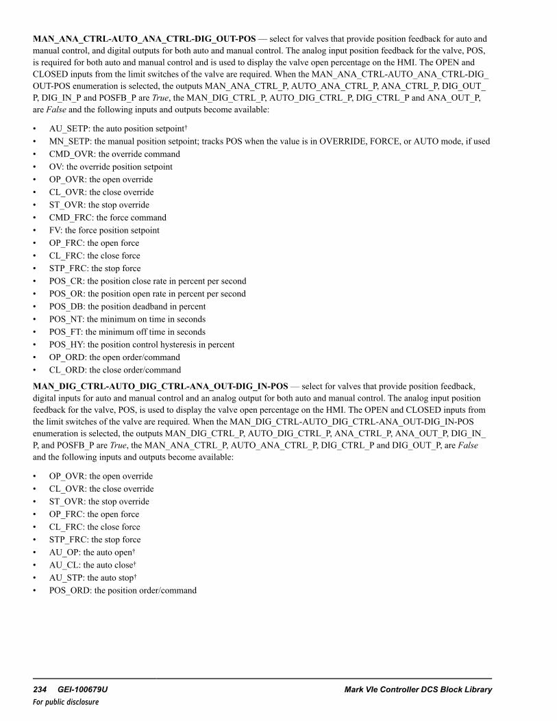
MAN_ANA_CTRL-AUTO_ANA_CTRL-DIG_OUT-POS— select for valves that provide position feedback for auto andmanual control, and digital outputs for both auto and manual control. The analog input position feedback for the valve, POS,is required for both auto and manual control and is used to display the valve open percentage on the HMI. The OPEN andCLOSED inputs from the limit switches of the valve are required. When the MAN_ANA_CTRL-AUTO_ANA_CTRL-DIG_OUT-POS enumeration is selected, the outputs MAN_ANA_CTRL_P, AUTO_ANA_CTRL_P, ANA_CTRL_P, DIG_OUT_P, DIG_IN_P and POSFB_P are True, the MAN_DIG_CTRL_P, AUTO_DIG_CTRL_P, DIG_CTRL_P and ANA_OUT_P,are False and the following inputs and outputs become available:
• AU_SETP: the auto position setpoint†• MN_SETP: the manual position setpoint; tracks POS when the value is in OVERRIDE, FORCE, or AUTO mode, if used• CMD_OVR: the override command• OV: the override position setpoint• OP_OVR: the open override• CL_OVR: the close override• ST_OVR: the stop override• CMD_FRC: the force command• FV: the force position setpoint• OP_FRC: the open force• CL_FRC: the close force• STP_FRC: the stop force• POS_CR: the position close rate in percent per second• POS_OR: the position open rate in percent per second• POS_DB: the position deadband in percent• POS_NT: the minimum on time in seconds• POS_FT: the minimum off time in seconds• POS_HY: the position control hysteresis in percent• OP_ORD: the open order/command• CL_ORD: the close order/command
MAN_DIG_CTRL-AUTO_DIG_CTRL-ANA_OUT-DIG_IN-POS— select for valves that provide position feedback,digital inputs for auto and manual control and an analog output for both auto and manual control. The analog input positionfeedback for the valve, POS, is used to display the valve open percentage on the HMI. The OPEN and CLOSED inputs fromthe limit switches of the valve are required. When the MAN_DIG_CTRL-AUTO_DIG_CTRL-ANA_OUT-DIG_IN-POSenumeration is selected, the outputs MAN_DIG_CTRL_P, AUTO_DIG_CTRL_P, ANA_CTRL_P, ANA_OUT_P, DIG_IN_P, and POSFB_P are True, the MAN_ANA_CTRL_P, AUTO_ANA_CTRL_P, DIG_CTRL_P and DIG_OUT_P, are Falseand the following inputs and outputs become available:
• OP_OVR: the open override• CL_OVR: the close override• ST_OVR: the stop override• OP_FRC: the open force• CL_FRC: the close force• STP_FRC: the stop force• AU_OP: the auto open†• AU_CL: the auto close†• AU_STP: the auto stop†• POS_ORD: the position order/command
234 GEI-100679U Mark VIe Controller DCS Block LibraryFor public disclosure

MAN_ANA_CTRL-AUTO_DIG_CTRL-ANA_OUT-DIG_IN-POS— select for valves that provide position feedback,analog inputs for manual control and digital inputs for auto control and an analog output for both auto and manual control.The analog input position feedback for the valve, POS, is used to display the valve open percentage on the HMI. The OPENand CLOSED inputs from the limit switches of the valve are required. When the MAN_ANA_CTRL-AUTO_DIG_CTRL-ANA_OUT-DIG_IN-POS enumeration is selected, the outputs MAN_ANA_CTRL_P, AUTO_DIG_CTRL_P, ANA_CTRL_P (when the valve is not in AUTO mode), ANA_OUT_P, DIG_IN_P, DIG_CTRL_P (when the valve is in AUTOmode†), and POSFB_P are True, the MAN_DIG_CTRL_P, AUTO_ANA_CTRL_P, ANA_CTRL_P (when the valve is inAUTO mode†), DIG_CTRL_P (when the valve is not in AUTO mode†) and DIG_OUT_P, are False and the following inputsand outputs become available:
• MN_SETP: the manual position setpoint; tracks POS when the value is in OVERRIDE, FORCE, or AUTO mode, if used• OP_OVR: the open override• CL_OVR: the close override• ST_OVR: the stop override• CMD_OVR: the override command• OV: the override position setpoint• CMD_FRC: the force command in manual mode• FV :the force position setpoint in manual mode• OP_FRC: the open force• CL_FRC: the close force• STP_FRC: the stop force• POS_CR: the position close rate in percent per second• POS_OR: the position open rate in percent per second• POS_DB: the position deadband in percent• POS_NT: the minimum on time in seconds• POS_FT: the minimum off time in seconds• POS_HY: the position control hysteresis in percent• OP_ORD: the open order/command• CL_ORD: the close order/command• AU_OP: the auto open†• AU_CL: the auto close†• AU_STP: the auto stop†• POS_ORD: the position order/command
Instruction Guide GEI-100679U 235For public disclosure

MAN_DIG_CTRL-AUTO_ANA_CTRL-ANA_OUT-DIG_IN-POS— select for valves that provide position feedback,digital inputs for manual control and analog inputs for auto control and an analog output for both auto and manual control.The analog input position feedback for the valve, POS, is used to display the valve open percentage on the HMI. The OPENand CLOSED inputs from the limit switches of the valve are required. When the MAN_DIG_CTRL-AUTO_ANA_CTRL-ANA_OUT-DIG_IN-POS enumeration is selected, the outputs MAN_DIG_CTRL_P, AUTO_DIG_CTRL_P, ANA_CTRL_P, ANA_OUT_P, DIG_IN_P, DIG_CTRL_P (when the valve is in AUTO mode†), and POSFB_P are True, the MAN_DIG_CTRL_P, AUTO_ANA_CTRL_P, DIG_CTRL_P (when the valve is not in AUTO mode†) and DIG_OUT_P, are Falseand the following inputs and outputs become available:
• AU_SETP: the auto position setpoint†• OP_OVR: the open override• CL_OVR: the close override• ST_OVR: the stop override• CMD_FRC: the force command in auto mode†• FV: the force position setpoint in auto mode†• OP_FRC: the open force• CL_FRC: the close force• STP_FRC: the stop force• POS_CR: the position close rate in percent per second• POS_OR: the position open rate in percent per second• POS_DB: the position deadband in percent• POS_NT: the minimum on time in seconds• POS_FT: the minimum off time in seconds• POS_HY: the position control hysteresis in percent• OP_ORD: the open order/command• CL_ORD: the close order/command• POS_ORD: the position order/command
236 GEI-100679U Mark VIe Controller DCS Block LibraryFor public disclosure

MAN_ANA_CTRL-AUTO_ANA_CTRL-ANA_OUT— select for valves that provide analog inputs and analog outputs forboth auto and manual control. The OPEN and CLOSED inputs from the limit switches of the valve are required. When theMAN_ANA_CTRL-AUTO_ANA_CTRL-ANA_OUT enumeration is selected, the outputs MAN_ANA_CTRL_P, AUTO_ANA_CTRL_P, and DIG_IN_P, and are True; the MAN_DIG_CTRL_P, AUTO_DIG_CTRL_P, ANA_CTRL_P, ANA_OUT_P, DIG_OUT_P, and POSFB_P are False and the following inputs and outputs become available:
• AU_SETP: the auto position setpoint†• MN_SETP: the manual position setpoint• CMD_OVR: the override command• OV: the override position setpoint• OP_OVR: the open override• CL_OVR: the close override• ST_OVR: the stop override• CMD_FRC: the force command in manual mode• FV: the force position setpoint in manual mode• OP_FRC: the open force• CL_FRC: the close force• STP_FRC: the stop force• POS_CR: the position close rate in percent per second• POS_OR: the position open rate in percent per second• POS_DB: the position deadband in percent• POS_NT: the minimum on time in seconds• POS_FT: the minimum off time in seconds• POS_HY: the position control hysteresis in percent• POS_ORD: the position order/command
Note † The enumeration MODE_OPT must contain AUTO for the valve to have automatic functionality.
Instruction Guide GEI-100679U 237For public disclosure

IO Options (IO_OPT)
IO_OPT enumerations are listed in the following table.
IO_OPT Enumerations
Enumeration Description
None No capabilities are available
CP_OK M_O_V_JOG_V2 has a hard-wired control power monitoring input.
REM M_O_V_JOG_V2 has a hard-wired remote/local input.
AVAIL M_O_V_JOG_V2 has hard-wired available input. This is a Ready to go indicator.
TRANS M_O_V_JOG_V2 has a hard-wired valve-in-transit input.
TQ_LIM M_O_V_JOG_V2 has hard-wired torque limiting input.
NONE—when IO_OPT is none, then CP_OK, REMOTE, AVAIL, and TRANSIT inputs are not used.
CP_OK— select for valves that provide a control power monitoring IO capability. When the CP_OK enumeration isselected, the output CP_OK_P is True. The Boolean control power monitoring connection is to the CP_OK input of the blockand is True when no control power failure is detected. When the CP_OK input is False, the control power failure alarm, CP_F_A, is activated. If the valve is in AUTO mode and the duration of CP_F _A being True has exceeded the PWR_FL_TMR,the valve will switch to MANUAL mode and the manual reject alarm, MN_REJ_A, will be activated, (delayed by 2 seconds).
REM— select for valves that have remote/local capability. When the REM enumeration is selected, the output REM_P isTrue. The Boolean remote/local connection is to the REMOTE input of the block and is True when the valve is in remotemode. When REMOTE is False, the output LOCAL is True and valve control from the HMI is disabled. If the valve is inAUTO mode and LOCAL becomes True, the valve will switch to MANUAL mode and the manual reject alarm, MN_REJ_A,will be activated, (delayed by 2 seconds).
AVAIL— select for valves that require an available capability. When the AVAIL enumeration is selected, the output AVAIL_P is True. The Boolean available connection is to the AVAIL input of the block and is True when the valve is available. WhenAVAIL is False, the available alarm, AVAIL_A, is activated. If the valve is in AUTO mode and the duration of AVAIL_Abeing True has exceeded the PWR_FL_TMR, the valve will switch to MANUAL mode and the manual reject alarm, MN_REJ_A, will be activated, (delayed by 2 seconds).
TQ_LIM— select for valves that require torque limiting capability. When the TQ_LIM enumeration is selected, the outputTQ_LIM_P is True. The Boolean torque limiting open and torque limiting close signals are connected to the TL_OP and TL_CL inputs of the block. When either TL_OP or TL_CL are True, the torque limiting alarm, TL_A, is activated. If the valve isin AUTO mode and the duration of TL_A being True has exceeded 2 seconds, the valve will switch to MANUAL mode andthe manual reject alarm, MN_REJ_A, will be activated, (delayed by 2 seconds).
TRANS— select for valves that provide capability to determine when the valve is in transit. When the TRANS enumerationis selected, the output TRANS_P is True. The Boolean, valve in transit, connection is to the TRANSIT input of the block, andis True when the valve is in transit. When the TRANSIT input is True, the transit indication output, TRN_IND, is True. If theTRANS_P is False, TRN_IND is True whenever OP_ORD or CL_ORD is True.
MODE_OPT
MODE_OPT enumerations are listed in the following table.
Note A complete list of all possible combinations of enumeration elements is included in the section Appendix.
238 GEI-100679U Mark VIe Controller DCS Block LibraryFor public disclosure

MODE_OPT Enumerations
Enumeration Mode Option Description
NONE None
AUTO Auto mode
LOCK Lock mode
AUTO-LOCK Auto mode and lock mode
NONE— the valve can be opened or closed manually by the HMI operator, no other mode options are available.
AUTO— provides auto control capability of the valve. Selecting the AUTO mode property will set AUTO_P to True,indicating the auto mode property of the block is enabled. When AUTO_P is True, the valve can be commanded to auto byeither CTL enumeration AUTO_CMD or a rising edge on AU_SEL providing PMT_AU is True. The HMI operator maycommand the valve from auto to manual mode at any time with the CTL enumeration MANUAL_CMD.
Note PMT_AU is described in the section Auto/Open/Close Permissives.
When AUTO is True and DIG_CTRL_P is True, the AU_OP, AU_CL, and AU_STOP inputs control the automatic opening,closing, and stopping the movement of the valve, provided, PMT_OP or PMT_CL, for the respective command is True. IfAU_OP or AU_CL, become True, the valve is in manual mode, and the valve position is not in the state of the requestedcommand or valve is in transit, TRN_IND is True, and AU_STOP becomes True, the auto request alarm, AU_REQ, will beactivated. When AUTO is True and ANA_CTRL_P is True the valve is controlled automatically by the AU_SETP input.
LOCK— provides software lock-out capability for the valve. Selecting the LOCK mode property will set LOCK_P to True,and enable the LOCK_CMD and UNLOCK_CMD to control the lockout mode functionality. If DIG_CTRL_P is True, thevalve must be OPEN or CLOSED or not in TRANSIT (if TRANS_P is True) before the block can be set to lockout mode. IfANA_CTRL_P is True, the POS_ORD must less 0.5% before the block can be set to lockout mode. Feedback to the HMIoperator of this mode is provided by LOCK. The HMI operator is prevented from operating valve from the control faceplatewhen LOCK is True, and auto mode is disabled.
Note The lockout indication is provided for indication only. This action will not lockout the equipment, it will only indicatelockout status. The owner's lockout procedures must be followed to safely lock equipment out.
The Lock button can also be configured to use the WorkstationST Lock function. Refer to the WorkstationST/CIMPLICITYAdvanced Viewer Integration Instruction Guide (GEI-100697), the section HMI Tagout.
Instruction Guide GEI-100679U 239For public disclosure

IO_MON
IO_MON digital output monitor types are available when DIG_OUT_P is True. Monitoring is only available for the outputsOP_ORD, and CL_ORD. If the hardware baord used with OP_ORD, and CL_ORD can perform diagnostic monitoring, IO_MON is used to select the type of diagnostic monitoring. When diagnostic monitoring is used (FUSE or VOLT), thediagnostic variable from the digital output card associated with OP_ORD, and CL_ORD is connected to RDY_OP and RDY_CL, respectively.
Note Refer to theMark VIe and Mark VIeS Control Volume II System Guide (GEH-6721_Vol_II) for descriptions ofhardware boards.A complete list of all possible enumeration combinations is provided in the section Appendix.
IO_MON Enumerations
Enumeration Monitor Option Description
NONE None
FUSE Fuse monitoring
VOLT Voltage monitoring
NONE— no circuit monitoring is available, RDY_OP and RDY_CLare not used.
FUSE— fuse monitoring determines the valve circuit failure. If FUSE is selected FUSE_MON_P is True. The Boolean fusemonitoring input is True when there is no fuse failure and is connected to the RDY_OP and RDY_CL inputs. If there is a fusefailure, RDY_OPor RDY_CL becomes False and OP_FLR or CL_FLR becomes True. When OP_FLR or CL_FLR becomesTrue, PMT_OP or PMT_CL becomes False, respectively and PMT_AU becomes False, delayed by PWR_FL_TMR. IfAUTO is True when this occurs, AUTO will become False and the manual reject alarm, MN_REJ_A, will be activated,(delayed by 2 seconds). Note, to prevent an unwanted automatic switch to Manual mode, in case of an Automatic bus transferor Power supply transfer, the power supply transfer time should not exceed PWR_FL_TMR. If the power supply transfer timeexceeds the PWR_FL_TMR, the valve will transfer from auto to manual mode and MN_REJ_A, will be activated.
VOLT— voltage monitoring determines the valve circuit failure. If VOLT is selected VOLT_MON_P is True. The Booleanvoltage monitoring input is True when there is no voltage failure and is connected to the RDY_OP and RDY_CL inputs.
OP_FLR is True, (delayed by 2 seconds), when the following conditions exist:
• DIG_OUT_P is True• RDY_OP is False• OP_ORD is False• CP_OK is True (if the IO_OPT, enumeration CP_OK is selected)• REMOTE is True (if the IO_OPT, enumeration REM is selected)• OPEN is False• TRANSIT is False (if the IO_OPT, enumeration TRANS is selected)• AVAIL is True (if the IO_OPT, enumeration AVAIL is selected)• CL_ORD is False• VOLT_MON_P is True
When OP_FLR is True, PMT_OP is False and PMT_AU becomes False, delayed by PWR_FL_TMR.
240 GEI-100679U Mark VIe Controller DCS Block LibraryFor public disclosure

CL_FLR is True, (delayed by 2 seconds), when the following conditions exist:
• DIG_OUT_P is True• RDY_CL is False• CL_ORD is False• CP_OK is True (if the IO_OPT enumeration CP_OK is selected)• REMOTE is True (if the IO_OPT enumeration REM is selected)• CLOSED is False• TRANSIT is False (if the IO_OPT enumeration TRANS is selected)• AVAIL is True (if the IO_OPT enumeration AVAIL is selected)• OP_ORD is False• VOLT_MON_P is True
When CL_FLR is True, PMT_CL is False and PMT_AU becomes False, delayed by PWR_FL_TMR.
If AUTO is True when this occurs, AUTO will become False and the manual reject alarm, MN_REJ_A, will be activated,(delayed by 2 seconds). Note, to prevent an unwanted automatic switch to Manual mode, in case of an Automatic bus transferor Power supply transfer, the power supply transfer time should not exceed PWR_FL_TMR. If the power supply transfer timeexceeds the PWR_FL_TMR, the valve will transfer from auto to manual mode and MN_REJ_A, will be activated.
Override Control
The block provides override input enumerations override open, OP_OVR, override close, CL_OVR, a dominant overridestop, STP_OVR, override setpoint/command, CMD_OVR, and a manual reject input enumeration, MN_REJ. The followingtable provides the possible values of the enumerations.
CL_OVR, OP_OVR, STP_OVR, and CMD_OVR, and MN_REJ Enumerations
Name Override Option Description
NO_OVR-NO-BLOCK No override and no override is blocked
OVR-NO_BLOCK Override active and no override is blocked
NO_OVR-BLOCK No override and a override is blocked
OVR-BLOCK Override active and a override is blocked
When DIG_OUT_P is True, OP_OVR, CL_OVR, or STP_OVR will open, close, or stop the movement of the valve,respectively, and prevent it from reopening/reclosing/moving in any mode. Note that STP_OVR is the dominate override.When ANA_OUT_P is True and CMD_OVR indicates Override Active, the valve will move to the position assigned to theOV input. If the valve is in auto mode (AUTO is True), it rejects to manual and the manual reject alarm, MN_REJ_A, will beactivated, (delayed by 2 seconds).
OVR_OP, CL_OVR, STP_OVR, and CMD_OVR (if used) are driven from an OVERRIDE block. Each connected input ofthe OVERRIDE block has the ability (when enabled) to be blocked by the HMI operator, which is accessed from associatedtab of the permit HMI screen display. When OP_OVR, CL_OVR, STP_OVR, or CMD_OVR enumeration contains BLOCK,the HMI operator has blocked at least one override. M_O_V_JOG_V2 does not use the block information, but passes it to theHMI for display.
Instruction Guide GEI-100679U 241For public disclosure

Force Control
The block provides force input enumerations Force Open (OP_FRC), Force Close (CL_FRC), Force Stop (STP_FRC), andForce Setpoint/Command (CMD_FRC). The following table provides the possible values of the enumerations.
CL_FRC, OP_FRC, STP_FRC, and CMD_FRC Enumerations
Name Force Option Description
NO_FORCE-NO-BLOCK No force and no force is blocked
FORCE-NO_BLOCK Force active and no force is blocked
NO_FORCE-BLOCK No force and a force is blocked
FORCE-BLOCK Force active and a force is blocked
When DIG_OUT_P is True, OP_FRC, CL_FRC, or STP_FRC force the valve to open, close, or stop in any mode exceptwhen OP_OVR, CL_OVR, or STP_OVR indicate Override Active. When ANA_OUT_P is True and CMD_FRC indicatesForce Active, the valve will move to the position assigned to the FV input except when CMD_OVR indicate Override Active.The valve does not reject to manual if a force occurs.
OP_FRC, CL_FRC, STP_FRC, and CMD_FRC (If used) are driven from a FORCE block. Each connected input of theFORCE block has the ability (when enabled) to be blocked by the HMI operator, which is accessed from associated tab of thepermit HMI screen display. When OP_FRC, CL_FRC, STP_FRC, or CMD_FRC enumeration contains BLOCK, the HMIoperator has blocked at least one force. M_O_V_JOG_V2 does not use the block information, but passes it to the HMI fordisplay.
Auto/Open/Close Permissives
The block provides permissive input enumerations AU_PMT, OP_PMT, CL_PMT. The following table provides the possiblevalues of the enumerations.
AU_PMT, CL_PMT, OP_PMT, and INT_PMT Enumerations
Enumeration Permit Option Description
NO_PERM-NO-BYPASS No permit and no permit is bypassed
PERM-NO_BYPASS Permit ok and no permit is bypassed
NO_PERM-BYPASS No permit and a permit is bypassed
PERM-BYPASS Permit ok and a permit is bypassed
The permit inputs, AU_PMT, OP_PMT, and CL_PMT, combine with internal permissives to generate PMT_AU, PMT_OP,and PMT_CL, permitted indications. Note that OP_PMT and CL_PMT are only used for digital control (DIG_CTRL_P =True).
242 GEI-100679U Mark VIe Controller DCS Block LibraryFor public disclosure

PMT_AU is True when the following conditions exist:
• AU_PMT enumeration indicates PERM• AUTO_P is True• MN_REJ is False• LOCK is False• OVR_OP is False• CL_OVR is False• OVR_STP is False• OVR_CMD is False• FL_OP_A is False• FL_CL_A is False• FL_STP_A is False• CONGR_A is False• REMOTE is True (if REM_P is True)• CP_F_A, OP_FLR, CL_FLR, and AVAIL_A are False (or the duration of any of them being True has not exceeded the
PWR_FL_TMR)• TL_A is False
If the valve is in auto mode and any of the conditions listed are not satisfied (except AU_PMT) the valve will be placed tomanual mode (That is, the outputs, AUTO and PMT_AU are set to False) and the manual reject alarm, MN_REJ_A, will beactivated, (delayed by 2 seconds).
PMT_OP is True when the following conditions exist:
• OP_PMT is True• REMOTE is True• CL_OVR is False• OP_FLR is False• LOCK is False (if LOCK_P is True)• CP_OK is True (if CP_OK_P is True)• OVR_STP is False• AVAIL is True (if AVAIL_P is True)• FL_OP_A is False• TL_A is False• CL_FRC indicates No Force• STP_FRC indicates No Force
Instruction Guide GEI-100679U 243For public disclosure

PMT_CL is True when the following conditions exist:
• CL_PMT is True• REMOTE is True• OVR_OP is False• CL_FLR is False• LOCK is False (if LOCK_P is True)• CP_OK is True (if CP_OK_P is True)• OVR_STP is False• AVAIL is True (if AVAIL_P is True)• FL_CL_A is False• TL_A is False• OP_FRC indicates No Force• STP_FRC indicates No Force
AU_PMT, OP_PMT, and CL_PMT (If used) are driven from a PERMIT block. Each connected input of the PERMIT blockhas the ability (when enabled) to be bypassed by the HMI operator, which is accessed from associated tab of the permit HMIscreen display. When AU_PMT, OP_PMT, or CL_PMT enumeration contains BYPASS, the HMI operator has bypassed atleast one permit. M_O_V_JOG_V2 does not use the bypass information, but passes it to the HMI for display.
Valve Diagnostic Alarms
When the DIG_CTLR_P is True, the block will generate a failed-to-open alarm, FL_OP_A, a failed-to-close alarm, FL_CL_A, and a failed-to-stop alarm, FL_STP_A, if the valve fails to open or close, in the time specified by the fail to open time, FL_OP_T, or fail to close time, FL_CL_T, or the valve movement fails to stop in 3 seconds, respectively. These alarms are resetwhen FAULT_RESET is True or if the CTL enumeration equals RESET_CMD.
The block has a limit switch congruency alarm, CONGR_A that alarms when the valve limit switches indicate the valve isopen, OPEN is True, and closed, CLOSED is True, at the same time. The CONGR_A alarm is reset when the condition thatcaused the alarm is cleared. The output, FAULT, is True when a fault is detected.
FAULT is True when the any of the following conditions exist:
• FL_OP_A is True• FL_CL_A is True• OP_FLR is True• CONGR_A is True• CP_F_A is True• FL_STP_A is True• AVAIL_A is True• TL_A is True
244 GEI-100679U Mark VIe Controller DCS Block LibraryFor public disclosure

Push-button Status
The block has two push-button status outputs, PBSTATE and PBSTATE2, to indicate the last HMI operator initiated CTLenumeration, which are valid when the CTRL_TYPE enumeration contains MAN_DIG_CTRL. PBSTATE is True andPBSTATE2 is False when the last HMI CTL enumeration was STOP_CMD. PBSTATE is False and PBSTATE2 is Falsewhen the last HMI CTL enumeration was CLOSE_CMD. PBSTATE is False and PBSTATE2 is True when the last HMI CTLenumeration was OPEN_CMD.
Operating Mode (MODE)
MODE is the block-operating mode. The operating mode enumerations are defined in the following table.
Note A complete list of all possible combinations of MODE enumeration elements is provided in the section Appendix.
MODE EnumerationsEnumeration DescriptionMANUAL Valve opens and closes under manual controlAUTO Valve opens and closes automatically.REMOTE Valve can be controlled remotelyLOCAL Valve can be controlled locallyOVERRIDE Valve control has been overridenOPENED Valve is openOPENING Valve is openingCLOSED Valve is closedCLOSING Valve is closingFAULTED Valve has conflicting statusLOCKED Valve is not accepting control commands
ToolboxST Configuration
Inserting a M_O_V_JOG_V2 into the application code displays the following window.
Changing Default Attribute Values
Instruction Guide GEI-100679U 245For public disclosure

When the user clicks OK, the block and pin connections will be configured automatically. The previous example will generateGlobal pins. Pin names are in the form Device Value.Input_Name, where Device Value is the attribute value 00M_O_V_JOG1000 and Input_Name is the block input/output names. The description,M_O_V_JOG_V2 Description in this example,becomes the prefix of the block input/output descriptions. Once the object has been added successfully, the block displays inthe ToolboxST application.
Note Refer to the table Global Variables.
M_O_V_JOG_V2 Block
246 GEI-100679U Mark VIe Controller DCS Block LibraryFor public disclosure

Inputs
Name Global Description Data Type Initial Value Visibility InterfaceType
AU_CL Auto close command BOOL False Always Value OnlyAU_OP Auto open command BOOL False Always Value OnlyAU_PMT Yes Auto permit UINT (ENUM) PERM-NO_BYPASS Always Value OnlyAU_SEL Auto select input BOOL False Always Value OnlyAU_SETP Yes Auto position setup REAL 0 Always Value OnlyAU_STOP Auto stop command BOOL False Always Value OnlyAVAIL Available input BOOL True Always Value OnlyCL_FRC Yes Force close UINT (ENUM) NO_FORCE-NO_
BLOCKAlways Value Only
CL_INP Yes Closed BOOL False Always Value OnlyCL_OVR Yes Close override UINT (ENUM) NO_OVR-NO_BLOCK Always Value OnlyCL_PMT Yes Close permit UINT (ENUM) PERM-NO_BYPASS Always Value OnlyCMD_FRC Yes Force command UINT (ENUM) NO_FORCE-NO_
BLOCKAlways Value Only
CMD_OVR Yes Override command UINT (ENUM) NO_OVR-NO_BLOCK Always Value OnlyCP_OK Control power OK input BOOL True Always Value OnlyCTL Yes Control word UINT (ENUM) NO_CMD Always Value OnlyCTRL_TYPE Valve I/O control type UINT (ENUM) MAN_DIG_CTRL-
AUTO_DIG_CTRL-DIG_OUT-DIG_IN-POS
Always Value Only
FAULT_RESET Fault/trip reset BOOL False Always Value OnlyFL_CL_T Fail to close time UDINT 30000 Parameter Value OnlyFL_OP_T Fail to open time UDINT 30000 Parameter Value OnlyFV Force value REAL 0 Always Value OnlyIO_MON VALVE I/O MONITOR
OPTIONSUINT (ENUM) NONE Always Value Only
IO_OPT VALVE I/O OPTIONS UINT (ENUM) NONE Always Value OnlyMN_REJ Yes Manual reject UINT (ENUM) NO_OVR-NO_BLOCK Always Value OnlyMN_SETP Yes Manual position setup REAL 0 Always Value OnlyMODE_OPT Valve mode options UINT (ENUM) NONE Always Value OnlyOP_FRC Yes Force open UINT (ENUM) NO_FORCE-NO_
BLOCKAlways Value Only
OP_INP Yes Open BOOL False Always Value OnlyOP_OVR Yes Open override UINT (ENUM) NO_OVR-NO_BLOCK Always Value OnlyOP_PMT Yes Open permit UINT (ENUM) PERM-NO_BYPASS Always Value OnlyOV Override value REAL 0 Always Value OnlyPOS Yes Position feedback REAL 0 Always Value with
StatusPOS_CR Position control close rate REAL 5 Parameter Value OnlyPOS_DB Position control deadband REAL 1 Parameter Value OnlyPOS_FT Position control off/dead
timeREAL 3 Parameter Value Only
POS_HY Position control hyteresis REAL 0.5 Parameter Value OnlyPOS_NT Position control min on
timeREAL 0.4 Parameter Value Only
Instruction Guide GEI-100679U 247For public disclosure

Inputs (continued)
Name Global Description Data Type Initial Value Visibility InterfaceType
POS_OR Position control open rate REAL 5 Parameter Value OnlyPWR_FL_TMR Manual reject power fail
timerUDINT 5000 Parameter Value Only
RDY_CL Output MON ready toclose
BOOL True Always Value Only
RDY_OP Output MON ready toopen
BOOL True Always Value Only
REMOTE Remote input BOOL True Always Value OnlySTP_FRC Yes Force stop UINT (ENUM) NO_FORCE-NO_
BLOCKAlways Value Only
STP_OVR Yes Stop override UINT (ENUM) NO_OVR-NO_BLOCK Always Value OnlyTL_CL Close torque limit BOOL False Always Value OnlyTL_OP Open torque limit BOOL False Always Value OnlyTRANSIT Valve in transit input BOOL False Always Value Only
Outputs
Name Global Description Data Type Initial Value Visibility InterfaceType
{Device} Yes {Desc} BOOL False Internal Value OnlyANA_CTRL_P Yes Analog control property BOOL False Always Value OnlyANA_OUT_P Yes Analog out property BOOL False Always Value OnlyAU_REQ Yes Auto request BOOL False Always Value OnlyAUTO Yes Auto BOOL False Always Value OnlyAUTO_ANA_CTRL_P
Yes Auto analog control BOOL False Always Value Only
AUTO_DIG_CTRL_P
Yes Auto digital control BOOL True Always Value Only
AUTO_P Yes Auto property BOOL False Always Value OnlyAVAIL_A Yes Not available property BOOL False Always Value OnlyAVAIL_P Yes Available property BOOL False Always Value OnlyCL_FLR Yes Close circuit fail BOOL False Always Value OnlyCL_ORD Yes Close order/command BOOL False Always Value OnlyCLOSED Yes Closed BOOL False Always Value OnlyCONGR_A Yes Congruency BOOL False Always Value OnlyCP_F_A Yes Control power fail BOOL False Always Value OnlyCP_OK_P Yes Control power property BOOL False Always Value OnlyDIG_CTRL_P Yes Digital control property BOOL True Always Value OnlyDIG_IN_P Yes Digital ins property BOOL True Always Value OnlyDIG_OUT_P Yes Digital outs property BOOL True Always Value OnlyFAULT Yes Fault indication BOOL False Always Value OnlyFL_CL_A Yes Fail to close BOOL False Always Value OnlyFL_OP_A Yes Fail to open BOOL False Always Value OnlyFL_STP_A Yes Fail to stop BOOL False Always Value OnlyFRC_CL Yes Force close BOOL False Always Value OnlyFRC_CLB Yes Close force block status BOOL False Internal Value OnlyFRC_CMD Yes Force command BOOL False Always Value Only
248 GEI-100679U Mark VIe Controller DCS Block LibraryFor public disclosure

Outputs (continued)
Name Global Description Data Type Initial Value Visibility InterfaceType
FRC_CMDB Yes Force command blockstatus
BOOL False Internal Value Only
FRC_OP Yes Force open BOOL False Always Value OnlyFRC_OPB Yes Open force block status BOOL False Internal Value OnlyFRC_STP Yes Force stop BOOL False Always Value OnlyFRC_STPB Yes Force stop block status BOOL False Internal Value OnlyFUSE_MON_P Yes Output fuse monitor
propertyBOOL False Always Value Only
IN_POS In position BOOL False Always Value OnlyLOCAL Yes Local mode BOOL False Always Value OnlyLOCK Yes Locked BOOL False Always Value OnlyLOCK_P Yes Lock property BOOL False Always Value OnlyMAN_ANA_CTRL_P
Manual analog control BOOL False Always Value Only
MAN_DIG_CTRL_P
Manual digital control BOOL True Always Value Only
MN_REJ_A Manual reject BOOL False Always Value OnlyMODE Block mode UINT (ENUM) MANUAL-IDLE Always Value OnlyOP_FLR Open circuit fail BOOL False Always Value OnlyOP_ORD Open order/command BOOL False Always Value OnlyOPEN Open BOOL False Always Value OnlyOVR_CL Close override BOOL False Always Value OnlyOVR_CLB Close override block
statusBOOL False Internal Value Only
OVR_CMD Override command BOOL False Always Value Only
OVR_CMDB Override command blockstatus
BOOL False Internal Value Only
OVR_OP Open override BOOL False Always Value OnlyOVR_OPB Open override block
statusBOOL False Internal Value Only
OVR_STP Stop override BOOL False Always Value OnlyOVR_STPB Stop override block status BOOL False Internal Value OnlyPBSTATE Last PB state BOOL False Internal Value OnlyPBSTATE2 Last PB state BOOL False Internal Value OnlyPMT_AU Auto permit BOOL False Always Value OnlyPMT_AUB Auto permit bypass status BOOL False Internal Value OnlyPMT_CL Permit to close BOOL True Always Value OnlyPMT_CLB Close permit bypass
statusBOOL False Internal Value Only
PMT_OP Permit to open BOOL True Always Value OnlyPMT_OPB Open permit bypass
statusBOOL False Internal Value Only
POS_BQ Position feedback badquality
BOOL False Always Value Only
POS_ORD Position order/command REAL 0 Always Value Only
Instruction Guide GEI-100679U 249For public disclosure

Outputs (continued)
Name Global Description Data Type Initial Value Visibility InterfaceType
POSFB_P Position feedbackproperty
BOOL True Always Value Only
REJ_MN {Desc} Manual reject BOOL False Always Value OnlyREJ_MNB Manual reject bypass
statusBOOL False Internal Value Only
REM_P Remote property BOOL False Always Value OnlyTL_A {Desc} Torque limit BOOL False Always Value Only
TQ_LIM_P {Desc} Torque limitproperty
BOOL False Always Value Only
TRANS_P {Desc} Transit property BOOL False Always Value OnlyTRN_IND {Desc} Transit IND BOOL False Always Value OnlyVOLT_MON_P {Desc} Output volt monitor
propertyBOOL False Always Value Only
250 GEI-100679U Mark VIe Controller DCS Block LibraryFor public disclosure

Global VariablesPin Name Description Alarm Alarm
ClassEvent EGD Page External
Access00M_O_V_JOG1000 M_O_V_JOG_V2
descriptionNotAlarmed
False $Default ReadOnly
00M_O_V_JOG1000.ANA_CTRL_P
M_O_V_JOG_V2description analog controlproperty
NotAlarmed
False ReadOnly
00M_O_V_JOG1000.ANA_OUT_P
M_O_V_JOG_V2description analog outproperty
NotAlarmed
False ReadOnly
00M_O_V_JOG1000.AU_REQ M_O_V_JOG_V2description Auto request
NotAlarmed
False $Default ReadOnly
00M_O_V_JOG1000.AU_SETP
M_O_V_JOG_V2description auto positionsetup
NotAlarmed
False $Default ReadOnly
00M_O_V_JOG1000.AUTO M_O_V_JOG_V2description auto
NotAlarmed
True $Default ReadOnly
00M_O_V_JOG1000.AUTO_ANA_CTRL_P
M_O_V_JOG_V2description auto analogcontrol
NotAlarmed
False $Default ReadOnly
00M_O_V_JOG1000.AUTO_DIG_CTRL_P
M_O_V_JOG_V2description auto digitalcontrol
NotAlarmed
False $Default ReadOnly
00M_O_V_JOG1000.AUTO_P M_O_V_JOG_V2description auto property
NotAlarmed
False $Default ReadOnly
00M_O_V_JOG1000.AVAIL_A M_O_V_JOG_V2description not available
Alarmed LVL_3 False $Default ReadOnly
00M_O_V_JOG1000.AVAIL_P M_O_V_JOG_V2description availableproperty
NotAlarmed
False $Default ReadOnly
00M_O_V_JOG1000.CL_FLR M_O_V_JOG_V2description close circuitfail
Alarmed Alert False $Default ReadOnly
00M_O_V_JOG1000.CL_ORD M_O_V_JOG_V2Description closeorder/command
NotAlarmed
False $Default ReadOnly
00M_O_V_JOG1000.CLOSED M_O_V_JOG_V2description closed
NotAlarmed
False $Default ReadOnly
00M_O_V_JOG1000.CONGR_A
M_O_V_JOG_V2description congruency
Alarmed Alert False $Default ReadOnly
00M_O_V_JOG1000.CP_F_A M_O_V_JOG_V2description control powerfail
Alarmed Alert False $Default ReadOnly
00M_O_V_JOG1000.CP_OK_P
M_O_V_JOG_V2description control powerproperty
NotAlarmed
False $Default ReadOnly
00M_O_V_JOG1000.CTL M_O_V_JOG descriptioncontrol word
NotAlarmed
False $Default ReadWrite
00M_O_V_JOG1000.DIG_CTRL_P
M_O_V_JOG_V2description digital controlproperty
NotAlarmed
False $Default ReadOnly
00M_O_V_JOG1000.DIG_IN_P
M_O_V_JOG_V2Description Digital insproperty
NotAlarmed
False $Default ReadOnly
Instruction Guide GEI-100679U 251For public disclosure

Global Variables (continued)Pin Name Description Alarm Alarm
ClassEvent EGD Page External
Access00M_O_V_JOG1000.DIG_OUT_P
M_O_V_JOG_V2description digital outsproperty
NotAlarmed
False $Default ReadOnly
00M_O_V_JOG1000.FAULT M_O_V_JOG_V2description faultindication
NotAlarmed
False $Default ReadOnly
00M_O_V_JOG1000.FL_CL_A M_O_V_JOG_V2description fail to close
Alarmed LVL_3 False $Default ReadOnly
00M_O_V_JOG1000.FL_OP_A M_O_V_JOG descriptionfail to open
Alarmed LVL_3 False $Default ReadOnly
00M_O_V_JOG1000.FL_STP_A
M_O_V_JOG_V2description fail to stop
Alarmed LVL_3 False $Default ReadOnly
00M_O_V_JOG1000.FRC_CL M_O_V_JOG_V2description
NotAlarmed
True $Default ReadOnly
00M_O_V_JOG1000.FRC_CLB
M_O_V_JOG_V2description close forceblock status
NotAlarmed
False $Default ReadOnly
00M_O_V_JOG1000.FRC_CMD
M_O_V_JOG_V2description forcecommand
NotAlarmed
False $Default ReadOnly
00M_O_V_JOG1000.FRC_CMDB
M_O_V_JOG_V2description forcecommand block status
NotAlarmed
False $Default ReadOnly
00M_O_V_JOG1000.FRC_OP M_O_V_JOG_V2description force open
NotAlarmed
True $Default ReadOnly
00M_O_V_JOG1000.FRC_OPB
M_O_V_JOG_V2description open forceblock status
NotAlarmed
False $Default ReadOnly
00M_O_V_JOG1000.FRC_STP
M_O_V_JOG_V2Description force stop
NotAlarmed
True $Default ReadOnly
00M_O_V_JOG1000.FRC_STPB
M_O_V_JOG_V2description force stopblock status
NotAlarmed
False $Default ReadOnly
00M_O_V_JOG1000.FUSE_MON_P
M_O_V_JOG_V2description Output fusemonitor property
NotAlarmed
False $Default ReadOnly
00M_O_V_JOG1000.LOCAL M_O_V_JOG_V2description local mode
NotAlarmed
True $Default ReadOnly
00M_O_V_JOG1000.LOCK M_O_V_JOG_V2description locked
NotAlarmed
True $Default ReadOnly
00M_O_V_JOG1000.LOCK_P M_O_V_JOG_V2description lock property
NotAlarmed
False $Default ReadOnly
00M_O_V_JOG1000.MAN_ANA_CTRL_P
M_O_V_JOG_V2description manualanalog control
NotAlarmed
False $Default ReadOnly
00M_O_V_JOG1000.MAN_DIG_CTRL_P
M_O_V_JOG_V2description manual digitalcontrol
NotAlarmed
False $Default ReadOnly
00M_O_V_JOG1000.MN_REJ_A
M_O_V_JOG_V2description manual reject
Alarmed LVL_3 False $Default ReadOnly
00M_O_V_JOG1000.MN_SETP
M_O_V_JOG descriptionmanual position setup
NotAlarmed
False $Default ReadWrite
252 GEI-100679U Mark VIe Controller DCS Block LibraryFor public disclosure

Global Variables (continued)Pin Name Description Alarm Alarm
ClassEvent EGD Page External
Access00M_O_V_JOG1000.OP_FLR M_O_V_JOG_V2
description open circuitfail
Alarmed Alert False $Default ReadOnly
00M_O_V_JOG1000.OP_ORD M_O_V_JOG_V2description openorder/command
NotAlarmed
False $Default ReadOnly
00M_O_V_JOG1000.OPEN M_O_V_JOG_V2description open
NotAlarmed
False $Default ReadOnly
00M_O_V_JOG1000.OVR_CL M_O_V_JOG_V2description Closeoverride
NotAlarmed
True $Default ReadOnly
00M_O_V_JOG1000.OVR_CLB
M_O_V_JOG_V2description Closeoverride block status
NotAlarmed
False $Default ReadOnly
00M_O_V_JOG1000.OVR_CMD
M_O_V_JOG_V2description overridecommand
NotAlarmed
False $Default ReadOnly
00M_O_V_JOG1000.OVR_CMDB
M_O_V_JOG_V2description overridecommand block status
NotAlarmed
False $Default ReadOnly
00M_O_V_JOG1000.OVR_OP M_O_V_JOG_V2description open override
NotAlarmed
True $Default ReadOnly
00M_O_V_JOG1000.OVR_OPB
M_O_V_JOG_V2description open overrideblock status
NotAlarmed
False $Default ReadOnly
00M_O_V_JOG1000.OVR_STP
M_O_V_JOG_V2description stop override
NotAlarmed
True $Default ReadOnly
00M_O_V_JOG1000.OVR_STPB
M_O_V_JOG_V2description stop overrideblock status
NotAlarmed
False $Default ReadOnly
00M_O_V_JOG1000.PBSTATE M_O_V_JOG_V2description last PB state
NotAlarmed
False $Default ReadOnly
00M_O_V_JOG1000.PBSTATE2
M_O_V_JOG_V2description last PB state
NotAlarmed
False $Default ReadOnly
00M_O_V_JOG1000.PMT_AU M_O_V_JOG_V2description auto permit
NotAlarmed
False $Default ReadOnly
00M_O_V_JOG1000.PMT_AUB
M_O_V_JOG _V2Description auto permitbypass status
NotAlarmed
False $Default ReadOnly
00M_O_V_JOG1000.PMT_CL M_O_V_JOG_V2description permit toclose
NotAlarmed
False $Default ReadOnly
00M_O_V_JOG1000.PMT_CLB
M_O_V_JOG_V2description close permitbypass status
NotAlarmed
False $Default ReadOnly
00M_O_V_JOG1000.PMT_OP M_O_V_JOG_V2description permit to open
NotAlarmed
False $Default ReadOnly
00M_O_V_JOG1000.PMT_OPB
M_O_V_JOG_V2description open permitbypass status
NotAlarmed
False $Default ReadOnly
00M_O_V_JOG1000.POS M_O_V_JOG_V2description positionfeedback
NotAlarmed
False $Default ReadOnly
Instruction Guide GEI-100679U 253For public disclosure

Global Variables (continued)Pin Name Description Alarm Alarm
ClassEvent EGD Page External
Access00M_O_V_JOG1000.POS_ORD
M_O_V_JOG_V2description positionorder/command
NotAlarmed
False $Default ReadOnly
00M_O_V_JOG1000.POSFB_P
M_O_V_JOG_V2description positionfeedback property
NotAlarmed
False $Default ReadOnly
00M_O_V_JOG1000.REJ_MN M_O_V_JOG_V2description manual reject
NotAlarmed
False $Default ReadOnly
00M_O_V_JOG1000.REJ_MNB
M_O_V_JOG_V2description manual rejectbypass status
NotAlarmed
False $Default ReadOnly
00M_O_V_JOG1000.REM_P M_O_V_JOG_V2description remoteproperty
NotAlarmed
False $Default ReadOnly
00M_O_V_JOG1000.TL_A M_O_V_JOG descriptiontorque limit
NotAlarmed
True $Default ReadOnly
00M_O_V_JOG1000.TQ_LIM_P
M_O_V_JOG_V2description torque limitproperty
NotAlarmed
False $Default ReadOnly
00M_O_V_JOG1000.TRANS_P
M_O_V_JOG_V2description transitproperty
NotAlarmed
False $Default ReadOnly
00M_O_V_JOG1000.TRN_IND M_O_V_JOG_V2description transit IND
NotAlarmed
False $Default ReadOnly
00M_O_V_JOG1000.VOLT_MON_P
M_O_V_JOG_V2description output voltmonitor property
NotAlarmed
False $Default ReadOnly
254 GEI-100679U Mark VIe Controller DCS Block LibraryFor public disclosure

HMI Configuration (CIMPLICITY)
The Object name for the HMI is the same as the Device name specified in the ToolboxST configuration.
Click the display the
faceplate.MOV_ JOG ���
Object to
Typical HMI Object for a MOV_JOG_V2
Manual Digital Control Mode
M_O_V_JOG_V2 Faceplate
Instruction Guide GEI-100679U 255For public disclosure

Changing Analog Setpoint
256 GEI-100679U Mark VIe Controller DCS Block LibraryFor public disclosure

Appendix
The following tables provide a complete list of all possible enumeration combinations.
IO_OPT Enumerations
Enumeration Mode Option DescriptionNONE NoneCP_OK Control power okREM Remote modeCP_OK-REM Control power ok and remote modeAVAIL Valve availableCP_OK-AVAIL Control power ok and valve availableREM-AVAIL Remote mode and valve availableCP_OK-REM-AVAIL Control power ok and remote mode and valve availableTRANS Valve in transitCP_OK-TRANS Control power ok and valve in transitREM-TRANS Remote mode and valve in transitCP_OK-REM-TRANS Control power ok and remote mode and valve in transitAVAIL-TRANS Valve available and valve in transitCP_OK-AVAIL-TRANS Control power ok and valve available and valve in transitREM-AVAIL-TRANS Remote mode and valve available and valve in transitCP_OK-REM-AVAIL-TRANS Control power ok and remote mode and valve available and valve in transitTQ_LIM Torque limitingCP_OK-TQ_LIM Control power ok and torque limitingREM-TQ_LIM Remote mode and torque limitingCP_OK-REM-TQ_LIM Control power ok and remote mode and torque limitingAVAIL-TQ_LIM Valve available and torque limitingCP_OK-AVAIL-TQ_LIM Control power ok and valve available and torque limitingREM-AVAIL-TQ_LIM Remote mode and valve available and torque limitingCP_OK-REM-AVAIL-TQ_LIM Control power ok and remote mode and valve available and torque limitingTRANS-TQ_LIM Valve in transit and torque limitingCP_OK-TRANS-TQ_LIM Control power ok and valve in transit and torque limitingREM-TRANS-TQ_LIM Remote mode and valve in transit and torque limitingCP_OK-REM-TRANS-TQ_LIM Control power ok and remote mode and valve in transit and torque limitingAVAIL-TRANS-TQ_LIM Valve available and valve in transit and torque limitingCP_OK-AVAIL-TRANS-TQ_LIM Control power ok and valve available and valve in transit and torque limitingREM-AVAIL-TRANS-TQ_LIM Remote mode and valve available and valve in transit and torque limitingCP_OK-REM-AVAIL-TRANS-TQ_LIM Control power ok and remote mode and valve available and valve in transit and
torque limiting
Instruction Guide GEI-100679U 257For public disclosure

MODE EnumerationsEnumeration Operating ModeMANUAL-OPENED Valve in manual and openedAUTO-OPENED Valve in auto and openedMANUAL-REMOTE-OPENED Valve in manual and remote and openedAUTO-REMOTE-OPENED Valve in auto and remote and openedMANUAL-LOCAL-OPENED Valve in manual and local and openedAUTO-LOCAL-OPENED Valve in auto and local and openedMANUAL-OVERRIDE-OPENED Valve in manual and override and openedAUTO-OVERRIDE-OPENED Valve in auto and override and openedMANUAL-OPENING Valve in manual and openingAUTO-OPENING Valve in auto and openingMANUAL-REMOTE-OPENING Valve in manual and remote and openingAUTO-REMOTE-OPENING Valve in auto and remote and openingMANUAL-LOCAL-OPENING Valve in manual and local and openingAUTO-LOCAL-OPENING Valve in auto and local and openingMANUAL-OVERRIDE-OPENING Valve in manual and override and openingAUTO-OVERRIDE-OPENING Valve in auto and override and openingMANUAL-CLOSED Valve in manual and closedAUTO-CLOSED Valve in auto and closedMANUAL-REMOTE-CLOSED Valve in manual and remote and closedAUTO-REMOTE-CLOSED Valve in auto and remote and closedMANUAL-LOCAL-CLOSED Valve in manual and local and closedAUTO-LOCAL-CLOSED Valve in auto and local and closedMANUAL-OVERRIDE-CLOSED Valve in manual and override and closedAUTO-OVERRIDE-CLOSED Valve in auto and override and closedMANUAL-CLOSING Valve in manual and closingAUTO-CLOSING Valve in auto and closingMANUAL-REMOTE-CLOSING Valve in manual and remote and closingAUTO-REMOTE-CLOSING Valve in auto and remote and closingMANUAL-LOCAL-CLOSING Valve in manual and local and closingAUTO-LOCAL-CLOSING Valve in auto and local and closingMANUAL-OVERRIDE-CLOSING Valve in manual and override and closingAUTO-OVERRIDE-CLOSING Valve in auto and override and closingMANUAL-FAULTED Valve in manual and faultedAUTO-FAULTED Valve in auto and faultedMANUAL-REMOTE-FAULTED Valve in manual and remote and faultedAUTO-REMOTE-FAULTED Valve in auto and remote and faultedMANUAL-LOCAL-FAULTED Valve in manual and local and faultedAUTO-LOCAL-FAULTED Valve in auto and local and faultedMANUAL-OVERRIDE-FAULTED Valve in manual and override and faultedAUTO-OVERRIDE-FAULTED Valve in auto and override and faultedMANUAL-OPENED-LOCKED Valve in manual and opened and lockedAUTO-OPENED-LOCKED Valve in auto and opened and lockedMANUAL-REMOTE-OPENED-LOCKED Valve in manual and remote and opened and lockedAUTO-REMOTE-OPENED-LOCKED Valve in auto and remote and opened and lockedMANUAL-LOCAL-OPENED-LOCKED Valve in manual and local and opened and lockedAUTO-LOCAL-OPENED-LOCKED Valve in auto and local and opened and lockedMANUAL-OVERRIDE-OPENED-LOCKED Valve in manual and override and opened and lockedAUTO-OVERRIDE-OPENED-LOCKED Valve in auto and override and opened and lockedMANUAL-OPENING-LOCKED Valve in manual and opening and locked
258 GEI-100679U Mark VIe Controller DCS Block LibraryFor public disclosure

MODE Enumerations (continued)
Enumeration Operating ModeAUTO-OPENING-LOCKED Valve in auto and opening and lockedMANUAL-REMOTE-OPENING-LOCKED Valve in manual and remote and opening and lockedAUTO-REMOTE-OPENING-LOCKED Valve in auto and remote and opening and lockedMANUAL-LOCAL-OPENING-LOCKED Valve in manual and local and opening and lockedAUTO-LOCAL-OPENING-LOCKED Valve in auto and local and opening and lockedMANUAL-OVERRIDE-OPENING-LOCKED Valve in manual and override and opening and lockedAUTO-OVERRIDE-OPENING-LOCKED Valve in auto and override and opening and lockedMANUAL-CLOSED-LOCKED Valve in manual and closed and lockedAUTO-CLOSED-LOCKED Valve in auto and closed and lockedMANUAL-REMOTE-CLOSED-LOCKED Valve in manual and remote and closed and lockedAUTO-REMOTE-CLOSED-LOCKED Valve in auto and remote and closed and lockedMANUAL-LOCAL-CLOSED-LOCKED Valve in manual and local and closed and lockedAUTO-LOCAL-CLOSED-LOCKED Valve in auto and local and closed and lockedMANUAL-OVERRIDE-CLOSED-LOCKED Valve in manual and override and closed and lockedAUTO-OVERRIDE-CLOSED-LOCKED Valve in auto and override and closed and lockedMANUAL-CLOSING-LOCKED Valve in manual and closing and lockedAUTO-CLOSING-LOCKED Valve in auto and closing and lockedMANUAL-REMOTE-CLOSING-LOCKED Valve in manual and remote and closing and lockedAUTO-REMOTE-CLOSING-LOCKED Valve in auto and remote and closing and lockedMANUAL-LOCAL-CLOSING-LOCKED Valve in manual and local and closing and lockedAUTO-LOCAL-CLOSING-LOCKED Valve in auto and local and closing and lockedMANUAL-OVERRIDE-CLOSING-LOCKED Valve in manual and override and closing and lockedAUTO-OVERRIDE-CLOSING-LOCKED Valve in auto and override and closing and lockedMANUAL-FAULTED-LOCKED Valve in manual and faulted and lockedAUTO-FAULTED-LOCKED Valve in auto and faulted and lockedMANUAL-REMOTE-FAULTED-LOCKED Valve in manual and remote and faulted and lockedAUTO-REMOTE-FAULTED-LOCKED Valve in auto and remote and faulted and lockedMANUAL-LOCAL-FAULTED-LOCKED Valve in manual and local and faulted and lockedAUTO-LOCAL-FAULTED-LOCKED Valve in auto and local and faulted and lockedMANUAL-OVERRIDE-FAULTED-LOCKED Valve in manual and override and faulted and lockedAUTO-OVERRIDE-FAULTED-LOCKED Valve in auto and override and faulted and locked
Instruction Guide GEI-100679U 259For public disclosure

29 Motor Operated Valve with Jog Version 3(M_O_V_JOG_V3)Block Category: Device Control
The Motor Operated Valve with Jog Version 3 (M_O_V_JOG_V3) block controls a motor-operated valve powered from alow-voltage reversing starter when the valve must be capable of being manually positioned anywhere in mid-travel.
Depending on the control type enumeration property selected; the block provides open and close output commands, OP_ORDand CL_ORD, or an analog output command, POS_ORD, that are used to operate the valve. The OPEN and CLOSED inputsare required. The control type enumeration property selected determines if the POS input is required for proper blockfunctionality.
Note This block has various enumerations that are used to control block operation.
The block will generate a failed-to-open alarm, FL_OP_A, failed-to-close alarm, FL_CL_A, failed-to-stop alarm, FL_STP_A,and a limit switch congruency alarm, CONGR_A, that alarms when the valve limit switches indicate that the valve is openand closed at the same time.
Although not required, a starter auxiliary contact input, TRANSIT, is used to indicate when the valve is in transit, enhancesthe block’s functionality. The valve in transit input, TRANSIT, is required if the IO option attribute, IO_OPT, enumerationTRANS is selected.
Block Configuration
Control (CTL)
Control (CTL) is an enumeration set by the HMI operator for valve control. The commands available from the HMI allowmanual and automatic valve control capability and/or lockout capability if the block property MODE_OPT enumerationselected allows the auto and/or lock mode. The valve may be opened, closed, or stopped in manual mode by the OPEN_CMD, CLOSE_CMD, or STOP_CMD enumerations, respectively. The command enumerations are defined in the followingtable.
CTL EnumerationsEnumeration CommandNO_CMD No commandAUTO_CMD Auto commandMANUAL_CMD Manual commandLOCK_CMD Lock commandUNLOCK_CMD Unlock commandSTOP_CMD Stop commandOPEN_CMD Open commandCLOSE_CMD Close commandRESET_CMD Fault reset command
260 GEI-100679U Mark VIe Controller DCS Block LibraryFor public disclosure

Example
If the valve requires analog input for auto and manual control with analog output with position feedback, control powermonitoring input, fuse monitoring and has the capability for auto and lockout, operation. Then the CTRL_TYPE selection isMAN_ANA_CTRL-AUTO_ANA_CTRL-ANA_OUT-POS, IO_OPT , selection is CP_OK, MODE_OPT is AUTO-LOCK,and IO_MON is FUSE.
Functionality of Block Attribute Enumerations
Control Type (CTRL_TYPE)
Control Type (CTRL_TYPE) enumerations are listed in the following table.
CTRL_TYPE Enumerations
Enumeration Control Option DescriptionMAN_DIG_CTRL-AUTO_DIG_CTRL-DIG_OUT-DIG_IN Manual digital control and auto digital control and
digital outputs and digital inputsMAN_DIG_CTRL-AUTO_DIG_CTRL-DIG_OUT-DIG_IN-POS Manual digital control and auto digital control and
digital outputs and digital inputs and position feedbackMAN_ANA_CTRL-AUTO_DIG_CTRL-DIG_OUT-DIG_IN-POS Manual analog control and auto digital control and
digital outputs and digital inputs and position feedbackMAN_DIG_CTRL-AUTO_ANA_CTRL-DIG_OUT-DIG_IN-POS Manual digital control and auto analog control and
digital outputs and digital inputs and position feedbackMAN_DIG_CTRL-AUTO_DIG_CTRL-ANA_OUT-DIG_IN-POS Manual digital control and auto digital control and
analog output and digital inputs and position feedbackMAN_ANA_CTRL-AUTO_DIG_CTRL-ANA_OUT-DIG_IN-POS Manual analog control and auto digital control and
analog output and digital inputs and position feedbackMAN_DIG_CTRL-AUTO_ANA_CTRL-ANA_OUT-DIG_IN-POS Manual digital control and auto analog control and
analog output and digital inputs and position feedbackMAN_ANA_CTRL-AUTO_ANA_CTRL-DIG_OUT-POS Manual analog control and auto analog control and
digital outputs and position feedbackMAN_ANA_CTRL-AUTO_ANA_CTRL-ANA_OUT-POS Manual analog control and auto analog control and
analog output and position feedback
MAN_DIG_CTRL-AUTO_DIG_CTRL-DIG_OUT-DIG_IN— select for valves that provide digital inputs and digitaloutputs for both auto and manual control. The OPEN and CLOSED inputs from the limit switches of the valve are required.When the MAN_DIG_CTRL-AUTO_DIG_CTRL-DIG_OUT-DIG_IN enumerations is selected, the outputs MAN_DIG_CTRL_P, AUTO_DIG_CTRL_P, DIG_IN_P, and DIG_OUT_P are True; the MAN_ANA_CTRL_P, AUTO_ANA_CTRL_P,ANA_CTRL_P, ANA_OUT_P, and POSFB_P are False and the following inputs and outputs become available:
• OP_OVR: the open override• CL_OVR: the close override• ST_OVR: the stop override• OP_FRC: the open force• CL_FRC: the close force• STP_FRC: the stop force• AU_OP: the auto open†• AU_CL: the auto close†• AU_STP: the auto stop†• OP_ORD: the open order/command• CL_ORD: the close order/command
Instruction Guide GEI-100679U 261For public disclosure

MAN_DIG_CTRL-AUTO_DIG_CTRL-DIG_OUT-DIG_IN-POS— select for valves that provide position feedback,digital inputs and digital outputs for both auto and manual control. The analog input position feedback for the valve, POS, andthe OPEN and CLOSED inputs from the limit switches of the valve are required. When the MAN_DIG_CTRL-AUTO_DIG_CTRL-DIG_OUT-DIG_IN-POS enumeration is selected, the outputs MAN_DIG_CTRL_P, AUTO_DIG_CTRL_P, DIG_IN_P, DIG_OUT_P, and POSFB_P are True; the MAN_ANA_CTRL_P, AUTO_ANA_CTRL_P, ANA_CTRL_P, and ANA_OUT_P, are False and the following inputs and outputs become available:
• OP_OVR: the open override• CL_OVR: the close override• ST_OVR: the stop override• OP_FRC: the open force• CL_FRC: the close force• STP_FRC: the stop force• AU_OP: the auto open†• AU_CL: the auto close†• AU_STP: the auto stop†• OP_ORD: the open order/command• CL_ORD: the close order/command
MAN_ANA_CTRL-AUTO_DIG_CTRL-DIG_OUT-DIG_IN-POS— select for valves that provide position feedback formanual control, digital inputs for auto control and digital outputs for both auto and manual control. The analog input positionfeedback for the valve, POS, is required for manual control and is used to display the valve open percentage on the HMI. TheOPEN and CLOSED inputs from the limit switches of the valve are required. When the MAN_ANA_CTRL-AUTO_DIG_CTRL-DIG_OUT-DIG_IN-POS enumeration is selected, the outputs MAN_ANA_CTRL_P, ANA_CTRL_P (when the valveis not in AUTO mode†), DIG_CTRL_P (when the valve is in AUTO mode†), AUTO_DIG_CTRL_P, DIG_IN_P, DIG_OUT_P, and POSFB_P are True, the MAN_DIG_CTRL_P, AUTO_ANA_CTRL_P, ANA_CTRL_P (when the valve is in AUTOmode†), DIG_CTRL_P (when the valve is not in AUTO mode†), and ANA_OUT_P, are False and the following inputs andoutputs become available:
• MN_SETP: the manual position setpoint; tracks POS when the value is in OVERRIDE, FORCE, or AUTO mode, if used• CMD_OVR: the override command• OV: the override position setpoint• OP_OVR: the open override• CL_OVR: the close override• ST_OVR: the stop override• CMD_FRC: the force command• FV: the force position setpoint• OP_FRC: the open force• CL_FRC: the close force• STP_FRC: the stop force• POS_CR: the position close rate in percent per second• POS_OR: the position open rate in percent per second• POS_DB: the position deadband in percent• POS_NT: the minimum on time in seconds• POS_FT: the minimum off time in seconds• POS_HY: the position control hysteresis in percent• AU_OP: the auto open†• AU_CL: the auto close†• AU_STP: the auto stop†• OP_ORD: the open order/command• CL_ORD: the close order/command
262 GEI-100679U Mark VIe Controller DCS Block LibraryFor public disclosure

MAN_DIG_CTRL-AUTO_ANA_CTRL-DIG_OUT-DIG_IN-POS— select for valves that provide position feedback forauto control, digital inputs for manual control and digital outputs for both auto and manual control. The analog input positionfeedback for the valve, POS, is required for auto control and is used to display the valve open percentage on the HMI. TheOPEN and CLOSED inputs from the limit switches of the valve are required. When the MAN_DIG_CTRL-AUTO_AUTO_CTRL-DIG_OUT-DIG_IN-POS enumeration is selected, the outputs AUTO_ANA_CTRL_P, ANA_CTRL_P (when thevalve is in AUTO mode†), DIG_CTRL_P (when the valve is not in AUTO mode†), MAN_DIG_CTRL_P, DIG_IN_P, DIG_OUT_P, and POSFB_P are True, the MAN_ANA_CTRL_P, AUTO_DIG_CTRL_P, ANA_CTRL_P (when the valve is not inAUTO mode†), DIG_CTRL_P (when the valve is in AUTO mode†), and ANA_OUT_P, are False and the following inputsand outputs become available:
• AU_SETP: the auto position setpoint†• CMD_OVR: the override command• OV: the override position setpoint• OP_OVR: the open override• CL_OVR: the close override• ST_OVR: the stop override• CMD_FRC: the force command in auto mode†• FV: the force position setpoint in auto mode†• OP_FRC: the open force• CL_FRC: the close force• STP_FRC: the stop force• POS_CR: the position close rate in percent per second• POS_OR: the position open rate in percent per second• POS_DB: the position deadband in percent• POS_NT: the minimum on time in seconds• POS_FT: the minimum off time in seconds• POS_HY: the position control hysteresis in percent• OP_ORD: the open order/command• CL_ORD: the close order/command
Instruction Guide GEI-100679U 263For public disclosure

MAN_ANA_CTRL-AUTO_ANA_CTRL-DIG_OUT-POS— select for valves that provide position feedback for auto andmanual control, and digital outputs for both auto and manual control. The analog input position feedback for the valve, POS,is required for both auto and manual control and is used to display the valve open percentage on the HMI. The OPEN andCLOSED inputs from the limit switches of the valve are required. When the MAN_ANA_CTRL-AUTO_ANA_CTRL-DIG_OUT-POS enumeration is selected, the outputs MAN_ANA_CTRL_P, AUTO_ANA_CTRL_P, ANA_CTRL_P, DIG_OUT_P, DIG_IN_P and POSFB_P are True, the MAN_DIG_CTRL_P, AUTO_DIG_CTRL_P, DIG_CTRL_P and ANA_OUT_P,are False and the following inputs and outputs become available:
• AU_SETP: the auto position setpoint†• MN_SETP: the manual position setpoint; tracks POS when the value is in OVERRIDE, FORCE, or AUTO mode, if used• CMD_OVR: the override command• OV: the override position setpoint• OP_OVR: the open override• CL_OVR: the close override• ST_OVR: the stop override• CMD_FRC: the force command• FV: the force position setpoint• OP_FRC: the open force• CL_FRC: the close force• STP_FRC: the stop force• POS_CR: the position close rate in percent per second• POS_OR: the position open rate in percent per second• POS_DB: the position deadband in percent• POS_NT: the minimum on time in seconds• POS_FT: the minimum off time in seconds• POS_HY: the position control hysteresis in percent• OP_ORD: the open order/command• CL_ORD: the close order/command
MAN_DIG_CTRL-AUTO_DIG_CTRL-ANA_OUT-DIG_IN-POS— select for valves that provide position feedback,digital inputs for auto and manual control and an analog output for both auto and manual control. The analog input positionfeedback for the valve, POS, is used to display the valve open percentage on the HMI. The OPEN and CLOSED inputs fromthe limit switches of the valve are required. When the MAN_DIG_CTRL-AUTO_DIG_CTRL-ANA_OUT-DIG_IN-POSenumeration is selected, the outputs MAN_DIG_CTRL_P, AUTO_DIG_CTRL_P, ANA_CTRL_P, ANA_OUT_P, DIG_IN_P, and POSFB_P are True, the MAN_ANA_CTRL_P, AUTO_ANA_CTRL_P, DIG_CTRL_P and DIG_OUT_P, are Falseand the following inputs and outputs become available:
• OP_OVR: the open override• CL_OVR: the close override• ST_OVR: the stop override• OP_FRC: the open force• CL_FRC: the close force• STP_FRC: the stop force• AU_OP: the auto open†• AU_CL: the auto close†• AU_STP: the auto stop†• POS_ORD: the position order/command
264 GEI-100679U Mark VIe Controller DCS Block LibraryFor public disclosure
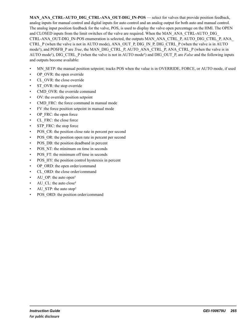
MAN_ANA_CTRL-AUTO_DIG_CTRL-ANA_OUT-DIG_IN-POS— select for valves that provide position feedback,analog inputs for manual control and digital inputs for auto control and an analog output for both auto and manual control.The analog input position feedback for the valve, POS, is used to display the valve open percentage on the HMI. The OPENand CLOSED inputs from the limit switches of the valve are required. When the MAN_ANA_CTRL-AUTO_DIG_CTRL-ANA_OUT-DIG_IN-POS enumeration is selected, the outputs MAN_ANA_CTRL_P, AUTO_DIG_CTRL_P, ANA_CTRL_P (when the valve is not in AUTO mode), ANA_OUT_P, DIG_IN_P, DIG_CTRL_P (when the valve is in AUTOmode†), and POSFB_P are True, the MAN_DIG_CTRL_P, AUTO_ANA_CTRL_P, ANA_CTRL_P (when the valve is inAUTO mode†), DIG_CTRL_P (when the valve is not in AUTO mode†) and DIG_OUT_P, are False and the following inputsand outputs become available:
• MN_SETP: the manual position setpoint; tracks POS when the value is in OVERRIDE, FORCE, or AUTO mode, if used• OP_OVR: the open override• CL_OVR: the close override• ST_OVR: the stop override• CMD_OVR: the override command• OV: the override position setpoint• CMD_FRC: the force command in manual mode• FV :the force position setpoint in manual mode• OP_FRC: the open force• CL_FRC: the close force• STP_FRC: the stop force• POS_CR: the position close rate in percent per second• POS_OR: the position open rate in percent per second• POS_DB: the position deadband in percent• POS_NT: the minimum on time in seconds• POS_FT: the minimum off time in seconds• POS_HY: the position control hysteresis in percent• OP_ORD: the open order/command• CL_ORD: the close order/command• AU_OP: the auto open†• AU_CL: the auto close†• AU_STP: the auto stop†• POS_ORD: the position order/command
Instruction Guide GEI-100679U 265For public disclosure

MAN_DIG_CTRL-AUTO_ANA_CTRL-ANA_OUT-DIG_IN-POS— select for valves that provide position feedback,digital inputs for manual control and analog inputs for auto control and an analog output for both auto and manual control.The analog input position feedback for the valve, POS, is used to display the valve open percentage on the HMI. The OPENand CLOSED inputs from the limit switches of the valve are required. When the MAN_DIG_CTRL-AUTO_ANA_CTRL-ANA_OUT-DIG_IN-POS enumeration is selected, the outputs MAN_DIG_CTRL_P, AUTO_DIG_CTRL_P, ANA_CTRL_P, ANA_OUT_P, DIG_IN_P, DIG_CTRL_P (when the valve is in AUTO mode†), and POSFB_P are True, the MAN_DIG_CTRL_P, AUTO_ANA_CTRL_P, DIG_CTRL_P (when the valve is not in AUTO mode†) and DIG_OUT_P, are Falseand the following inputs and outputs become available:
• AU_SETP: the auto position setpoint†• OP_OVR: the open override• CL_OVR: the close override• ST_OVR: the stop override• CMD_FRC: the force command in auto mode†• FV: the force position setpoint in auto mode†• OP_FRC: the open force• CL_FRC: the close force• STP_FRC: the stop force• POS_CR: the position close rate in percent per second• POS_OR: the position open rate in percent per second• POS_DB: the position deadband in percent• POS_NT: the minimum on time in seconds• POS_FT: the minimum off time in seconds• POS_HY: the position control hysteresis in percent• OP_ORD: the open order/command• CL_ORD: the close order/command• POS_ORD: the position order/command
266 GEI-100679U Mark VIe Controller DCS Block LibraryFor public disclosure
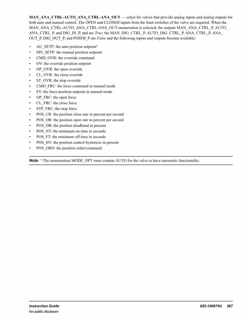
MAN_ANA_CTRL-AUTO_ANA_CTRL-ANA_OUT— select for valves that provide analog inputs and analog outputs forboth auto and manual control. The OPEN and CLOSED inputs from the limit switches of the valve are required. When theMAN_ANA_CTRL-AUTO_ANA_CTRL-ANA_OUT enumeration is selected, the outputs MAN_ANA_CTRL_P, AUTO_ANA_CTRL_P, and DIG_IN_P, and are True; the MAN_DIG_CTRL_P, AUTO_DIG_CTRL_P, ANA_CTRL_P, ANA_OUT_P, DIG_OUT_P, and POSFB_P are False and the following inputs and outputs become available:
• AU_SETP: the auto position setpoint†• MN_SETP: the manual position setpoint• CMD_OVR: the override command• OV: the override position setpoint• OP_OVR: the open override• CL_OVR: the close override• ST_OVR: the stop override• CMD_FRC: the force command in manual mode• FV: the force position setpoint in manual mode• OP_FRC: the open force• CL_FRC: the close force• STP_FRC: the stop force• POS_CR: the position close rate in percent per second• POS_OR: the position open rate in percent per second• POS_DB: the position deadband in percent• POS_NT: the minimum on time in seconds• POS_FT: the minimum off time in seconds• POS_HY: the position control hysteresis in percent• POS_ORD: the position order/command
Note † The enumeration MODE_OPT must contain AUTO for the valve to have automatic functionality.
Instruction Guide GEI-100679U 267For public disclosure

IO Options (IO_OPT)
IO_OPT enumerations are listed in the following table.
IO_OPT Enumerations
Enumeration Description
None No capabilities are available
CP_OK M_O_V_JOG_V3 has a hard-wired control power monitoring input.
REM M_O_V_JOG_V3 has a hard-wired remote/local input.
AVAIL M_O_V_JOG_V3 has hard-wired available input. This is a Ready to go indicator.
TRANS M_O_V_JOG_V3 has a hard-wired valve-in-transit input.
TQ_LIM M_O_V_JOG_V3 has hard-wired torque limiting input.
NONE—when IO_OPT is none, then CP_OK, REMOTE, AVAIL, and TRANSIT inputs are not used.
CP_OK— select for valves that provide a control power monitoring IO capability. When the CP_OK enumeration isselected, the output CP_OK_P is True. The Boolean control power monitoring connection is to the CP_OK input of the blockand is True when no control power failure is detected. When the CP_OK input is False, the control power failure alarm, CP_F_A, is activated. If the valve is in AUTO mode and the duration of CP_F _A being True has exceeded the PWR_FL_TMR,the valve will switch to MANUAL mode and the manual reject alarm, MN_REJ_A, will be activated, (delayed by 2 seconds).
REM— select for valves that have remote/local capability. When the REM enumeration is selected, the output REM_P isTrue. The Boolean remote/local connection is to the REMOTE input of the block and is True when the valve is in remotemode. When REMOTE is False, the output LOCAL is True and valve control from the HMI is disabled. If the valve is inAUTO mode and LOCAL becomes True, the valve will switch to MANUAL mode and the manual reject alarm, MN_REJ_A,will be activated, (delayed by 2 seconds).
AVAIL— select for valves that require an available capability. When the AVAIL enumeration is selected, the output AVAIL_P is True. The Boolean available connection is to the AVAIL input of the block and is True when the valve is available. WhenAVAIL is False, the available alarm, AVAIL_A, is activated. If the valve is in AUTO mode and the duration of AVAIL_Abeing True has exceeded the PWR_FL_TMR, the valve will switch to MANUAL mode and the manual reject alarm, MN_REJ_A, will be activated, (delayed by 2 seconds).
TQ_LIM— select for valves that require torque limiting capability. When the TQ_LIM enumeration is selected, the outputTQ_LIM_P is True. The Boolean torque limiting open and torque limiting close signals are connected to the TL_OP and TL_CL inputs of the block. When either TL_OP or TL_CL are True, the torque limiting alarm, TL_A, is activated. If the valve isin AUTO mode and the duration of TL_A being True has exceeded 2 seconds, the valve will switch to MANUAL mode andthe manual reject alarm, MN_REJ_A, will be activated, (delayed by 2 seconds).
TRANS— select for valves that provide capability to determine when the valve is in transit. When the TRANS enumerationis selected, the output TRANS_P is True. The Boolean, valve in transit, connection is to the TRANSIT input of the block, andis True when the valve is in transit. When the TRANSIT input is True, the transit indication output, TRN_IND, is True. If theTRANS_P is False, TRN_IND is True whenever OP_ORD or CL_ORD is True.
268 GEI-100679U Mark VIe Controller DCS Block LibraryFor public disclosure

MODE_OPT
MODE_OPT enumerations are listed in the following table.
Note A complete list of all possible combinations of enumeration elements is included in the section Appendix.
MODE_OPT Enumerations
Enumeration Mode Option DescriptionNONE NoneAUTO Auto modeLOCK Lock modeAUTO-LOCK Auto mode and lock mode
NONE— the valve can be opened or closed manually by the HMI operator, no other mode options are available.
AUTO— provides auto control capability of the valve. Selecting the AUTO mode property will set AUTO_P to True,indicating the auto mode property of the block is enabled. When AUTO_P is True, the valve can be commanded to auto byeither CTL enumeration AUTO_CMD or a rising edge on AU_SEL providing PMT_AU is True. The HMI operator maycommand the valve from auto to manual mode at any time with the CTL enumeration MANUAL_CMD.
Note PMT_AU is described in the section Auto/Open/Close Permissives.
When AUTO is True and DIG_CTRL_P is True, the AU_OP, AU_CL, and AU_STOP inputs control the automatic opening,closing, and stopping the movement of the valve, provided, PMT_OP or PMT_CL, for the respective command is True. IfAU_OP or AU_CL, become True, the valve is in manual mode, and the valve position is not in the state of the requestedcommand or valve is in transit, TRN_IND is True, and AU_STOP becomes True, the auto request alarm, AU_REQ, will beactivated. When AUTO is True and ANA_CTRL_P is True the valve is controlled automatically by the AU_SETP input.
LOCK— provides software lock-out capability for the valve. Selecting the LOCK mode property will set LOCK_P to True,and enable the LOCK_CMD and UNLOCK_CMD to control the lockout mode functionality. If DIG_CTRL_P is True, thevalve must be OPEN or CLOSED or not in TRANSIT (if TRANS_P is True) before the block can be set to lockout mode. IfANA_CTRL_P is True, the POS_ORD must less 0.5% before the block can be set to lockout mode. Feedback to the HMIoperator of this mode is provided by LOCK. The HMI operator is prevented from operating valve from the control faceplatewhen LOCK is True, and auto mode is disabled.
Note The lockout indication is provided for indication only. This action will not lockout the equipment, it will only indicatelockout status. The owner's lockout procedures must be followed to safely lock equipment out.
The Lock button can also be configured to use the WorkstationST Lock function. Refer to the WorkstationST/CIMPLICITYAdvanced Viewer Integration Instruction Guide (GEI-100697), the section HMI Tagout.
Instruction Guide GEI-100679U 269For public disclosure

IO_MON
IO_MON digital output monitor types are available when DIG_OUT_P is True. Monitoring is only available for the outputsOP_ORD, and CL_ORD. If the hardware baord used with OP_ORD, and CL_ORD can perform diagnostic monitoring, IO_MON is used to select the type of diagnostic monitoring. When diagnostic monitoring is used (FUSE or VOLT), thediagnostic variable from the digital output card associated with OP_ORD, and CL_ORD is connected to RDY_OP and RDY_CL, respectively.
Note A complete list of all possible enumeration combinations is provided in the section Appendix.
IO_MON Enumerations
Enumeration Monitor Option Description
NONE None
FUSE Fuse monitoring
VOLT Voltage monitoring
Note Refer to theMark VIe and Mark VIeS Control Volume II System Guide (GEH-6721_Vol_II) for descriptions ofhardware boards.
NONE— no circuit monitoring is available, RDY_OP and RDY_CLare not used.
FUSE— fuse monitoring determines the valve circuit failure. If FUSE is selected FUSE_MON_P is True. The Boolean fusemonitoring input is True when there is no fuse failure and is connected to the RDY_OP and RDY_CL inputs. If there is a fusefailure, RDY_OPor RDY_CL becomes False and OP_FLR or CL_FLR becomes True. When OP_FLR or CL_FLR becomesTrue, PMT_OP or PMT_CL becomes False, respectively and PMT_AU becomes False, delayed by PWR_FL_TMR. IfAUTO is True when this occurs, AUTO will become False and the manual reject alarm, MN_REJ_A, will be activated,(delayed by 2 seconds). Note, to prevent an unwanted automatic switch to Manual mode, in case of an Automatic bus transferor Power supply transfer, the power supply transfer time should not exceed PWR_FL_TMR. If the power supply transfer timeexceeds the PWR_FL_TMR, the valve will transfer from auto to manual mode and MN_REJ_A, will be activated.
VOLT— voltage monitoring determines the valve circuit failure. If VOLT is selected VOLT_MON_P is True. The Booleanvoltage monitoring input is True when there is no voltage failure and is connected to the RDY_OP and RDY_CL inputs.
OP_FLR is True, (delayed by 2 seconds), when the following conditions exist:
• DIG_OUT_P is True• RDY_OP is False• OP_ORD is False• CP_OK is True (if the IO_OPT, enumeration CP_OK is selected)• REMOTE is True (if the IO_OPT, enumeration REM is selected)• OPEN is False• TRANSIT is False (if the IO_OPT, enumeration TRANS is selected)• AVAIL is True (if the IO_OPT, enumeration AVAIL is selected)• CL_ORD is False• VOLT_MON_P is True
When OP_FLR is True, PMT_OP is False and PMT_AU becomes False, delayed by PWR_FL_TMR.
270 GEI-100679U Mark VIe Controller DCS Block LibraryFor public disclosure
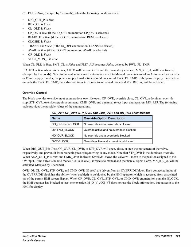
CL_FLR is True, (delayed by 2 seconds), when the following conditions exist:
• DIG_OUT_P is True• RDY_CL is False• CL_ORD is False• CP_OK is True (if the IO_OPT enumeration CP_OK is selected)• REMOTE is True (if the IO_OPT enumeration REM is selected)• CLOSED is False• TRANSIT is False (if the IO_OPT enumeration TRANS is selected)• AVAIL is True (if the IO_OPT enumeration AVAIL is selected)• OP_ORD is False• VOLT_MON_P is True
When CL_FLR is True, PMT_CL is False and PMT_AU becomes False, delayed by PWR_FL_TMR.
If AUTO is True when this occurs, AUTO will become False and the manual reject alarm, MN_REJ_A, will be activated,(delayed by 2 seconds). Note, to prevent an unwanted automatic switch to Manual mode, in case of an Automatic bus transferor Power supply transfer, the power supply transfer time should not exceed PWR_FL_TMR. If the power supply transfer timeexceeds the PWR_FL_TMR, the valve will transfer from auto to manual mode and MN_REJ_A, will be activated.
Override Control
The block provides override input enumerations override open, OP_OVR, override close, CL_OVR, a dominant overridestop, STP_OVR, override setpoint/command, CMD_OVR, and a manual reject input enumeration, MN_REJ. The followingtable provides the possible values of the enumerations.
CL_OVR, OP_OVR, STP_OVR, and CMD_OVR, and MN_REJ Enumerations
Name Override Option Description
NO_OVR-NO-BLOCK No override and no override is blocked
OVR-NO_BLOCK Override active and no override is blocked
NO_OVR-BLOCK No override and a override is blocked
OVR-BLOCK Override active and a override is blocked
When DIG_OUT_P is True, OP_OVR, CL_OVR, or STP_OVR will open, close, or stop the movement of the valve,respectively, and prevent it from reopening/reclosing/moving in any mode. Note that STP_OVR is the dominate override.When ANA_OUT_P is True and CMD_OVR indicates Override Active, the valve will move to the position assigned to theOV input. If the valve is in auto mode (AUTO is True), it rejects to manual and the manual reject alarm, MN_REJ_A, will beactivated, (delayed by 2 seconds).
OVR_OP, CL_OVR, STP_OVR, and CMD_OVR (if used) are driven from an OVERRIDE block. Each connected input ofthe OVERRIDE block has the ability (when enabled) to be blocked by the HMI operator, which is accessed from associatedtab of the permit HMI screen display. When OP_OVR, CL_OVR, STP_OVR, or CMD_OVR enumeration contains BLOCK,the HMI operator has blocked at least one override. M_O_V_JOG_V3 does not use the block information, but passes it to theHMI for display.
Instruction Guide GEI-100679U 271For public disclosure
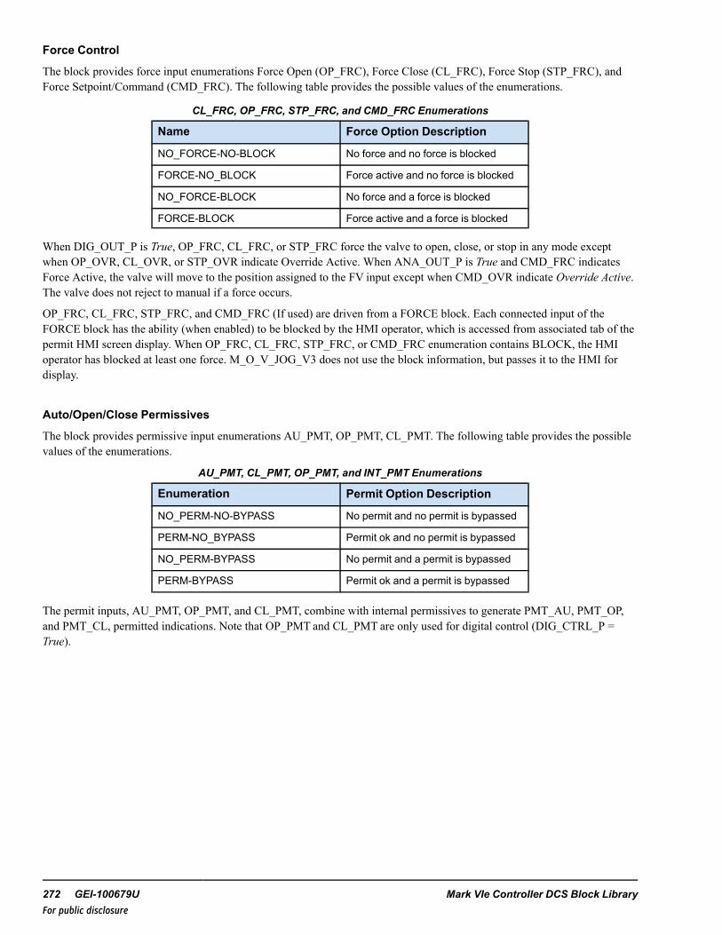
Force Control
The block provides force input enumerations Force Open (OP_FRC), Force Close (CL_FRC), Force Stop (STP_FRC), andForce Setpoint/Command (CMD_FRC). The following table provides the possible values of the enumerations.
CL_FRC, OP_FRC, STP_FRC, and CMD_FRC Enumerations
Name Force Option Description
NO_FORCE-NO-BLOCK No force and no force is blocked
FORCE-NO_BLOCK Force active and no force is blocked
NO_FORCE-BLOCK No force and a force is blocked
FORCE-BLOCK Force active and a force is blocked
When DIG_OUT_P is True, OP_FRC, CL_FRC, or STP_FRC force the valve to open, close, or stop in any mode exceptwhen OP_OVR, CL_OVR, or STP_OVR indicate Override Active. When ANA_OUT_P is True and CMD_FRC indicatesForce Active, the valve will move to the position assigned to the FV input except when CMD_OVR indicate Override Active.The valve does not reject to manual if a force occurs.
OP_FRC, CL_FRC, STP_FRC, and CMD_FRC (If used) are driven from a FORCE block. Each connected input of theFORCE block has the ability (when enabled) to be blocked by the HMI operator, which is accessed from associated tab of thepermit HMI screen display. When OP_FRC, CL_FRC, STP_FRC, or CMD_FRC enumeration contains BLOCK, the HMIoperator has blocked at least one force. M_O_V_JOG_V3 does not use the block information, but passes it to the HMI fordisplay.
Auto/Open/Close Permissives
The block provides permissive input enumerations AU_PMT, OP_PMT, CL_PMT. The following table provides the possiblevalues of the enumerations.
AU_PMT, CL_PMT, OP_PMT, and INT_PMT Enumerations
Enumeration Permit Option Description
NO_PERM-NO-BYPASS No permit and no permit is bypassed
PERM-NO_BYPASS Permit ok and no permit is bypassed
NO_PERM-BYPASS No permit and a permit is bypassed
PERM-BYPASS Permit ok and a permit is bypassed
The permit inputs, AU_PMT, OP_PMT, and CL_PMT, combine with internal permissives to generate PMT_AU, PMT_OP,and PMT_CL, permitted indications. Note that OP_PMT and CL_PMT are only used for digital control (DIG_CTRL_P =True).
272 GEI-100679U Mark VIe Controller DCS Block LibraryFor public disclosure

PMT_AU is True when the following conditions exist:
• AU_PMT enumeration indicates PERM• AUTO_P is True• MN_REJ is False• LOCK is False• OVR_OP is False• CL_OVR is False• OVR_STP is False• OVR_CMD is False• FL_OP_A is False• FL_CL_A is False• FL_STP_A is False• CONGR_A is False• REMOTE is True (if REM_P is True)• CP_F_A, OP_FLR, CL_FLR, and AVAIL_A are False (or the duration of any of them being True has not exceeded the
PWR_FL_TMR)• TL_A is False
If the valve is in auto mode and any of the conditions listed are not satisfied (except AU_PMT) the valve will be placed tomanual mode (That is, the outputs, AUTO and PMT_AU are set to False) and the manual reject alarm, MN_REJ_A, will beactivated, (delayed by 2 seconds).
PMT_OP is True when the following conditions exist:
• OP_PMT is True• REMOTE is True• CL_OVR is False• OP_FLR is False• LOCK is False (if LOCK_P is True)• CP_OK is True (if CP_OK_P is True)• OVR_STP is False• AVAIL is True (if AVAIL_P is True)• FL_OP_A is False• TL_A is False• CL_FRC indicates No Force• STP_FRC indicates No Force
Instruction Guide GEI-100679U 273For public disclosure

PMT_CL is True when the following conditions exist:
• CL_PMT is True• REMOTE is True• OVR_OP is False• CL_FLR is False• LOCK is False (if LOCK_P is True)• CP_OK is True (if CP_OK_P is True)• OVR_STP is False• AVAIL is True (if AVAIL_P is True)• FL_CL_A is False• TL_A is False• OP_FRC indicates No Force• STP_FRC indicates No Force
AU_PMT, OP_PMT, and CL_PMT (If used) are driven from a PERMIT block. Each connected input of the PERMIT blockhas the ability (when enabled) to be bypassed by the HMI operator, which is accessed from associated tab of the permit HMIscreen display. When AU_PMT, OP_PMT, or CL_PMT enumeration contains BYPASS, the HMI operator has bypassed atleast one permit. M_O_V_JOG_V3 does not use the bypass information, but passes it to the HMI for display.
Valve Diagnostic Alarms
When the DIG_CTLR_P is True, the block will generate a failed-to-open alarm, FL_OP_A, a failed-to-close alarm,FL_CL_A, and a failed-to-stop alarm, FL_STP_A, if the valve fails to open or close, in the time specified by the fail to opentime, FL_OP_T, or fail to close time, FL_CL_T, or the valve movement fails to stop in 3 seconds, respectively. Fail toOpen/Close alarms will also occur if in Transit mode and the valve fails to transit in the Fail to Transit Time, FL_TRANS_T.These alarms are reset when FAULT_RESET is True or if the CTL enumeration equals RESET_CMD.
The block has a limit switch congruency alarm, CONGR_A that alarms when the valve limit switches indicate the valve isopen, OPEN is True, and closed, CLOSED is True, at the same time. The CONGR_A alarm is reset when the condition thatcaused the alarm is cleared. The output, FAULT, is True when a fault is detected.
FAULT is True when the any of the following conditions exist:
• FL_OP_A is True• FL_CL_A is True• OP_FLR is True• CONGR_A is True• CP_F_A is True• FL_STP_A is True• AVAIL_A is True• TL_A is True
274 GEI-100679U Mark VIe Controller DCS Block LibraryFor public disclosure

Push-button Status
The block has two push-button status outputs, PBSTATE and PBSTATE2, to indicate the last HMI operator initiated CTLenumeration, which are valid when the CTRL_TYPE enumeration contains MAN_DIG_CTRL. PBSTATE is True andPBSTATE2 is False when the last HMI CTL enumeration was STOP_CMD. PBSTATE is False and PBSTATE2 is Falsewhen the last HMI CTL enumeration was CLOSE_CMD. PBSTATE is False and PBSTATE2 is True when the last HMI CTLenumeration was OPEN_CMD.
Operating Mode (MODE)
Operating Mode (MODE) is the block-operating mode. The operating mode enumerations are defined in the following table.
Note A complete list of all possible combinations of MODE enumeration elements is provided in the section Appendix.
MODE EnumerationsEnumeration DescriptionMANUAL Valve opens and closes under manual controlAUTO Valve opens and closes automatically.REMOTE Valve can be controlled remotelyLOCAL Valve can be controlled locallyOVERRIDE Valve control has been overridenOPENED Valve is openOPENING Valve is openingCLOSED Valve is closedCLOSING Valve is closingFAULTED Valve has conflicting statusLOCKED Valve is not accepting control commands
ToolboxST Configuration
Inserting a M_O_V_JOG_V3 into the application code displays the following window.
Changing Default Attribute Values
Instruction Guide GEI-100679U 275For public disclosure

When the user clicks OK, the block and pin connections will be configured automatically. The previous example will generateGlobal pins. Pin names are in the form Device Value.Input_Name, where Device Value is the attribute value 00M_O_V_JOG1000 and Input_Name is the block input/output names. The description,M_O_V_JOG_V3 description in this example,becomes the prefix of the block input/output descriptions. Once the object has been added successfully, the block displays inthe ToolboxST application.
Note Refer to the table Global Variables.
M_O_V_JOG_V3 Block
276 GEI-100679U Mark VIe Controller DCS Block LibraryFor public disclosure

Inputs
Name Global Description Data Type Initial Value Visibility InterfaceType
AU_CL Auto close command BOOL False Always Value OnlyAU_OP Auto open command BOOL False Always Value OnlyAU_PMT Yes Auto permit UINT (ENUM) PERM-NO_BYPASS Always Value OnlyAU_SEL Auto select input BOOL False Always Value OnlyAU_SETP Yes Auto position setup REAL 0 Always Value OnlyAU_STOP Auto stop command BOOL False Always Value OnlyAVAIL Available input BOOL True Always Value OnlyCL_FRC Yes Close force UINT (ENUM) NO_FORCE-NO_
BLOCKAlways Value Only
CL_INP Yes Closed BOOL False Always Value OnlyCL_OVR Yes Close override UINT (ENUM) NO_OVR-NO_BLOCK Always Value OnlyCL_PMT Yes Close permit UINT (ENUM) PERM-NO_BYPASS Always Value OnlyCMD_FRC Yes Force command UINT (ENUM) NO_FORCE-NO_
BLOCKAlways Value Only
CMD_OVR Yes Override command UINT (ENUM) NO_OVR-NO_BLOCK Always Value OnlyCP_OK Control power OK input BOOL True Always Value OnlyCTL Yes Control word UINT (ENUM) NO_CMD Always Value OnlyCTRL_TYPE Valve I/O control type UINT (ENUM) MAN_DIG_CTRL-
AUTO_DIG_CTRL-DIG_OUT-DIG_IN-POS
Always Value Only
FAULT_RESET Fault/trip reset BOOL False Always Value OnlyFL_CL_T Fail to close time UDINT 30000 Parameter Value OnlyFL_OP_T Fail to open time UDINT 30000 Parameter Value OnlyFL_TRANS_T Fail to Transit Time UDINT 3000 Parameter Value OnlyFV Force value REAL 0 Always Value OnlyIO_MON VALVE I/O MONITOR
OPTIONSUINT (ENUM) NONE Always Value Only
IO_OPT VALVE I/O OPTIONS UINT (ENUM) NONE Always Value OnlyMN_REJ Yes Manual reject UINT (ENUM) NO_OVR-NO_BLOCK Always Value OnlyMN_SETP Yes Manual position setup REAL 0 Always Value OnlyMODE_OPT Valve mode options UINT (ENUM) NONE Always Value OnlyOP_FRC Yes Force open UINT (ENUM) NO_FORCE-NO_
BLOCKAlways Value Only
OP_INP Yes Open BOOL False Always Value OnlyOP_OVR Yes Open override UINT (ENUM) NO_OVR-NO_BLOCK Always Value OnlyOP_PMT Yes Open permit UINT (ENUM) PERM-NO_BYPASS Always Value OnlyOV Override value REAL 0 Always Value OnlyPOS Yes Position feedback REAL 0 Always Value with
StatusPOS_CR Position control close rate REAL 5 Parameter Value OnlyPOS_DB Position control deadband REAL 1 Parameter Value OnlyPOS_FT Position control off/dead
timeREAL 3 Parameter Value Only
POS_HY Position control hyteresis REAL 0.5 Parameter Value Only
Instruction Guide GEI-100679U 277For public disclosure

Inputs (continued)
Name Global Description Data Type Initial Value Visibility InterfaceType
POS_NT Position control min ontime
REAL 0.4 Parameter Value Only
POS_OR Position control open rate REAL 5 Parameter Value OnlyPWR_FL_TMR Manual reject power fail
timerUDINT 5000 Parameter Value Only
RDY_CL Output MON ready toclose
BOOL True Always Value Only
RDY_OP Output MON ready toopen
BOOL True Always Value Only
REMOTE Remote input BOOL True Always Value OnlySTP_FRC Yes Force stop UINT (ENUM) NO_FORCE-NO_
BLOCKAlways Value Only
STP_OVR Yes Stop override UINT (ENUM) NO_OVR-NO_BLOCK Always Value OnlyTL_CL Close torque limit BOOL False Always Value OnlyTL_OP Open torque limit BOOL False Always Value OnlyTRANSIT Valve in transit input BOOL False Always Value Only
Outputs
Name Global Description Data Type Initial Value Visibility InterfaceType
{Device} Yes {Desc} BOOL False Internal Value OnlyANA_CTRL_P Yes Analog control property BOOL False Always Value OnlyANA_OUT_P Yes Analog out property BOOL False Always Value OnlyAU_REQ Yes Auto request BOOL False Always Value OnlyAUTO Yes Auto BOOL False Always Value OnlyAUTO_ANA_CTRL_P
Yes Auto analog control BOOL False Always Value Only
AUTO_DIG_CTRL_P
Yes Auto digital control BOOL True Always Value Only
AUTO_P Yes Auto property BOOL False Always Value OnlyAVAIL_A Yes Not available BOOL False Always Value OnlyAVAIL_P Yes Available property BOOL False Always Value OnlyCL_FLR Yes Close circuit fail BOOL False Always Value OnlyCL_ORD Yes Close order/command BOOL False Always Value OnlyCLOSED Yes Closed BOOL False Always Value OnlyCONGR_A Yes Congruency BOOL False Always Value OnlyCP_F_A Yes Control power fail BOOL False Always Value OnlyCP_OK_P Yes Control power property BOOL False Always Value OnlyDIG_CTRL_P Yes Digital control property BOOL True Always Value OnlyDIG_IN_P Yes Digital ins property BOOL True Always Value OnlyDIG_OUT_P Yes Digital outs property BOOL True Always Value OnlyFAULT Yes Fault indication BOOL False Always Value OnlyFL_CL_A Yes Fail to close BOOL False Always Value OnlyFL_OP_A Yes Fail to open BOOL False Always Value OnlyFL_STP_A Yes Fail to stop BOOL False Always Value OnlyFRC_CL Yes Force close BOOL False Always Value OnlyFRC_CLB Yes Close force block status BOOL False Internal Value Only
278 GEI-100679U Mark VIe Controller DCS Block LibraryFor public disclosure

Outputs (continued)
Name Global Description Data Type Initial Value Visibility InterfaceType
FRC_CMD Yes Force command BOOL False Always Value OnlyFRC_CMDB Yes Force command block
statusBOOL False Internal Value Only
FRC_OP Yes Force open BOOL False Always Value OnlyFRC_OPB Yes Open force block status BOOL False Internal Value OnlyFRC_STP Yes Force stop BOOL False Always Value OnlyFRC_STPB Yes Force stop block status BOOL False Internal Value OnlyFUSE_MON_P Yes Output fuse monitor
propertyBOOL False Always Value Only
IN_POS In position BOOL False Always Value OnlyLOCAL Yes Local mode BOOL False Always Value OnlyLOCK Yes Locked BOOL False Always Value OnlyLOCK_P Yes Lock property BOOL False Always Value OnlyMAN_ANA_CTRL_P
manual analog control BOOL False Always Value Only
MAN_DIG_CTRL_P
Manual digital control BOOL True Always Value Only
MN_REJ_A Manual reject BOOL False Always Value OnlyMODE Block mode UINT (ENUM) MANUAL-IDLE Always Value OnlyOP_FLR Open circuit fail BOOL False Always Value OnlyOP_ORD Open order/command BOOL False Always Value OnlyOPEN Open BOOL False Always Value OnlyOVR_CL Close override BOOL False Always Value OnlyOVR_CLB Close override block
statusBOOL False Internal Value Only
OVR_CMD Override command BOOL False Always Value Only
OVR_CMDB Override command blockstatus
BOOL False Internal Value Only
OVR_OP Open override BOOL False Always Value OnlyOVR_OPB Open override block
statusBOOL False Internal Value Only
OVR_STP Stop override BOOL False Always Value OnlyOVR_STPB Stop override block status BOOL False Internal Value OnlyPBSTATE Last PB state BOOL False Internal Value OnlyPBSTATE2 Last PB state BOOL False Internal Value OnlyPMT_AU Auto permit BOOL False Always Value OnlyPMT_AUB Auto permit bypass status BOOL False Internal Value OnlyPMT_CL Permit to close BOOL True Always Value OnlyPMT_CLB Close permit bypass
statusBOOL False Internal Value Only
PMT_OP Permit to open BOOL True Always Value OnlyPMT_OPB Open permit bypass
statusBOOL False Internal Value Only
POS_BQ Position feedback badquality
BOOL False Always Value Only
Instruction Guide GEI-100679U 279For public disclosure

Outputs (continued)
Name Global Description Data Type Initial Value Visibility InterfaceType
POS_ORD Position order/command REAL 0 Always Value OnlyPOSFB_P Position feedback
propertyBOOL True Always Value Only
REJ_MN {Desc} Manual reject BOOL False Always Value OnlyREJ_MNB Manual reject bypass
statusBOOL False Internal Value Only
REM_P Remote property BOOL False Always Value OnlyTL_A {Desc} Torque limit BOOL False Always Value Only
TQ_LIM_P {Desc} Torque limitproperty
BOOL False Always Value Only
TRANS_P {Desc} Transit property BOOL False Always Value OnlyTRN_IND {Desc} Transit IND BOOL False Always Value OnlyVOLT_MON_P {Desc} Output volt monitor
propertyBOOL False Always Value Only
280 GEI-100679U Mark VIe Controller DCS Block LibraryFor public disclosure

Global VariablesPin Name Description Alarm Alarm
ClassEvent EGD Page External
Access00M_O_V_JOG1000 M_O_V_JOG_V3
descriptionNotAlarmed
False $Default ReadOnly
00M_O_V_JOG1000.ANA_CTRL_P
M_O_V_JOG_V3description analog controlproperty
NotAlarmed
False ReadOnly
00M_O_V_JOG1000.ANA_OUT_P
M_O_V_JOG_V3description analog outproperty
NotAlarmed
False ReadOnly
00M_O_V_JOG1000.AU_REQ M_O_V_JOG_V3description auto request
NotAlarmed
False $Default ReadOnly
00M_O_V_JOG1000.AU_SETP
M_O_V_JOG_V3description auto positionsetup
NotAlarmed
False $Default ReadOnly
00M_O_V_JOG1000.AUTO M_O_V_JOG_V3description auto
NotAlarmed
True $Default ReadOnly
00M_O_V_JOG1000.AUTO_ANA_CTRL_P
M_O_V_JOG_V3description auto analogcontrol
NotAlarmed
False $Default ReadOnly
00M_O_V_JOG1000.AUTO_DIG_CTRL_P
M_O_V_JOG_V3description auto digitalcontrol
NotAlarmed
False $Default ReadOnly
00M_O_V_JOG1000.AUTO_P M_O_V_JOG_V3description auto property
NotAlarmed
False $Default ReadOnly
00M_O_V_JOG1000.AVAIL_A M_O_V_JOG_V3description not available
Alarmed LVL_3 False $Default ReadOnly
00M_O_V_JOG1000.AVAIL_P M_O_V_JOG_V3description availableproperty
NotAlarmed
False $Default ReadOnly
00M_O_V_JOG1000.CL_FLR M_O_V_JOG_V3description close circuitfail
Alarmed Alert False $Default ReadOnly
00M_O_V_JOG1000.CL_ORD M_O_V_JOG_V3description closeorder/command
NotAlarmed
False $Default ReadOnly
00M_O_V_JOG1000.CLOSED M_O_V_JOG_V3description closed
NotAlarmed
False $Default ReadOnly
00M_O_V_JOG1000.CONGR_A
M_O_V_JOG_V3description congruency
Alarmed Alert False $Default ReadOnly
00M_O_V_JOG1000.CP_F_A M_O_V_JOG_V3description control powerfail
Alarmed Alert False $Default ReadOnly
00M_O_V_JOG1000.CP_OK_P
M_O_V_JOG_V3description control powerproperty
NotAlarmed
False $Default ReadOnly
00M_O_V_JOG1000.CTL M_O_V_JOG descriptionControl word
NotAlarmed
False $Default ReadWrite
00M_O_V_JOG1000.DIG_CTRL_P
M_O_V_JOG_V3description digital controlproperty
NotAlarmed
False $Default ReadOnly
00M_O_V_JOG1000.DIG_IN_P
M_O_V_JOG_V3description digital insproperty
NotAlarmed
False $Default ReadOnly
Instruction Guide GEI-100679U 281For public disclosure

Global Variables (continued)Pin Name Description Alarm Alarm
ClassEvent EGD Page External
Access00M_O_V_JOG1000.DIG_OUT_P
M_O_V_JOG_V3description digital outsproperty
NotAlarmed
False $Default ReadOnly
00M_O_V_JOG1000.FAULT M_O_V_JOG_V3description faultindication
NotAlarmed
False $Default ReadOnly
00M_O_V_JOG1000.FL_CL_A M_O_V_JOG_V3description fail to close
Alarmed LVL_3 False $Default ReadOnly
00M_O_V_JOG1000.FL_OP_A M_O_V_JOG descriptionfail to open
Alarmed LVL_3 False $Default ReadOnly
00M_O_V_JOG1000.FL_STP_A
M_O_V_JOG_V3description fail to stop
Alarmed LVL_3 False $Default ReadOnly
00M_O_V_JOG1000.FRC_CL M_O_V_JOG_V3description
NotAlarmed
True $Default ReadOnly
00M_O_V_JOG1000.FRC_CLB
M_O_V_JOG_V3description close forceblock status
NotAlarmed
False $Default ReadOnly
00M_O_V_JOG1000.FRC_CMD
M_O_V_JOG_V3description forcecommand
NotAlarmed
False $Default ReadOnly
00M_O_V_JOG1000.FRC_CMDB
M_O_V_JOG_V3description forcecommand block status
NotAlarmed
False $Default ReadOnly
00M_O_V_JOG1000.FRC_OP M_O_V_JOG_V3description Force open
NotAlarmed
True $Default ReadOnly
00M_O_V_JOG1000.FRC_OPB
M_O_V_JOG_V3description open forceblock status
NotAlarmed
False $Default ReadOnly
00M_O_V_JOG1000.FRC_STP
M_O_V_JOG_V3description force stop
NotAlarmed
True $Default ReadOnly
00M_O_V_JOG1000.FRC_STPB
M_O_V_JOG_V3description force stopblock status
NotAlarmed
False $Default ReadOnly
00M_O_V_JOG1000.FUSE_MON_P
M_O_V_JOG_V3description output fusemonitor property
NotAlarmed
False $Default ReadOnly
00M_O_V_JOG1000.LOCAL M_O_V_JOG_V3description local mode
NotAlarmed
True $Default ReadOnly
00M_O_V_JOG1000.LOCK M_O_V_JOG_V3description locked
NotAlarmed
True $Default ReadOnly
00M_O_V_JOG1000.LOCK_P M_O_V_JOG_V3description lock property
NotAlarmed
False $Default ReadOnly
00M_O_V_JOG1000.MAN_ANA_CTRL_P
M_O_V_JOG_V3description manualanalog control
NotAlarmed
False $Default ReadOnly
00M_O_V_JOG1000.MAN_DIG_CTRL_P
M_O_V_JOG_V3description manual digitalcontrol
NotAlarmed
False $Default ReadOnly
00M_O_V_JOG1000.MN_REJ_A
M_O_V_JOG_V3description manual reject
Alarmed LVL_3 False $Default ReadOnly
00M_O_V_JOG1000.MN_SETP
M_O_V_JOG descriptionmanual position setup
NotAlarmed
False $Default ReadWrite
282 GEI-100679U Mark VIe Controller DCS Block LibraryFor public disclosure

Global Variables (continued)Pin Name Description Alarm Alarm
ClassEvent EGD Page External
Access00M_O_V_JOG1000.OP_FLR M_O_V_JOG_V3
description open circuitfail
Alarmed Alert False $Default ReadOnly
00M_O_V_JOG1000.OP_ORD M_O_V_JOG_V3description openorder/command
NotAlarmed
False $Default ReadOnly
00M_O_V_JOG1000.OPEN M_O_V_JOG_V3description open
NotAlarmed
False $Default ReadOnly
00M_O_V_JOG1000.OVR_CL M_O_V_JOG_V3description close override
NotAlarmed
True $Default ReadOnly
00M_O_V_JOG1000.OVR_CLB
M_O_V_JOG_V3description close overrideblock status
NotAlarmed
False $Default ReadOnly
00M_O_V_JOG1000.OVR_CMD
M_O_V_JOG_V3description overridecommand
NotAlarmed
False $Default ReadOnly
00M_O_V_JOG1000.OVR_CMDB
M_O_V_JOG_V3description overridecommand block status
NotAlarmed
False $Default ReadOnly
00M_O_V_JOG1000.OVR_OP M_O_V_JOG_V3description open override
NotAlarmed
True $Default ReadOnly
00M_O_V_JOG1000.OVR_OPB
M_O_V_JOG_V3description open overrideblock status
NotAlarmed
False $Default ReadOnly
00M_O_V_JOG1000.OVR_STP
M_O_V_JOG_V3description stop override
NotAlarmed
True $Default ReadOnly
00M_O_V_JOG1000.OVR_STPB
M_O_V_JOG_V3description stop overrideblock status
NotAlarmed
False $Default ReadOnly
00M_O_V_JOG1000.PBSTATE M_O_V_JOG_V3description last PB state
NotAlarmed
False $Default ReadOnly
00M_O_V_JOG1000.PBSTATE2
M_O_V_JOG_V3description last PB state
NotAlarmed
False $Default ReadOnly
00M_O_V_JOG1000.PMT_AU M_O_V_JOG_V3description auto permit
NotAlarmed
False $Default ReadOnly
00M_O_V_JOG1000.PMT_AUB
M_O_V_JOG_V3description auto permitbypass status
NotAlarmed
False $Default ReadOnly
00M_O_V_JOG1000.PMT_CL M_O_V_JOG_V3description permit toclose
NotAlarmed
False $Default ReadOnly
00M_O_V_JOG1000.PMT_CLB
M_O_V_JOG_V3description close permitbypass status
NotAlarmed
False $Default ReadOnly
00M_O_V_JOG1000.PMT_OP M_O_V_JOG_V3description permit to open
NotAlarmed
False $Default ReadOnly
00M_O_V_JOG1000.PMT_OPB
M_O_V_JOG_V3description open permitbypass status
NotAlarmed
False $Default ReadOnly
00M_O_V_JOG1000.POS M_O_V_JOG_V3description positionfeedback
NotAlarmed
False $Default ReadOnly
Instruction Guide GEI-100679U 283For public disclosure

Global Variables (continued)Pin Name Description Alarm Alarm
ClassEvent EGD Page External
Access00M_O_V_JOG1000.POS_ORD
M_O_V_JOG_V3description positionorder/command
NotAlarmed
False $Default ReadOnly
00M_O_V_JOG1000.POSFB_P
M_O_V_JOG_V3description positionfeedback property
NotAlarmed
False $Default ReadOnly
00M_O_V_JOG1000.REJ_MN M_O_V_JOG_V3description manual reject
NotAlarmed
False $Default ReadOnly
00M_O_V_JOG1000.REJ_MNB
M_O_V_JOG_V3description manual rejectbypass status
NotAlarmed
False $Default ReadOnly
00M_O_V_JOG1000.REM_P M_O_V_JOG_V3description remoteproperty
NotAlarmed
False $Default ReadOnly
00M_O_V_JOG1000.TL_A M_O_V_JOG_V3description torque limit
NotAlarmed
True $Default ReadOnly
00M_O_V_JOG1000.TQ_LIM_P
M_O_V_JOG_V3description torque limitproperty
NotAlarmed
False $Default ReadOnly
00M_O_V_JOG1000.TRANS_P
M_O_V_JOG_V3description transitproperty
NotAlarmed
False $Default ReadOnly
00M_O_V_JOG1000.TRN_IND M_O_V_JOG_V3description transit IND
NotAlarmed
False $Default ReadOnly
00M_O_V_JOG1000.VOLT_MON_P
M_O_V_JOG_V3description output voltmonitor property
NotAlarmed
False $Default ReadOnly
284 GEI-100679U Mark VIe Controller DCS Block LibraryFor public disclosure

HMI Configuration (CIMPLICITY)
The Object name for the HMI is the same as the Device name specified in the ToolboxST configuration.
Click the Object to display the faceplate.
Typical HMI Object for a MOV_JOG_V3
Manual Digital Control Mode
M_O_V_JOG_V3 Faceplate
Instruction Guide GEI-100679U 285For public disclosure

Changing Analog Setpoint
286 GEI-100679U Mark VIe Controller DCS Block LibraryFor public disclosure

Appendix
The following tables provide a complete list of all possible enumeration combinations.
IO_OPT Enumerations
Enumeration Mode Option DescriptionNONE NoneCP_OK Control power okREM Remote modeCP_OK-REM Control power ok and remote modeAVAIL Valve availableCP_OK-AVAIL Control power ok and valve availableREM-AVAIL Remote mode and valve availableCP_OK-REM-AVAIL Control power ok and remote mode and valve availableTRANS Valve in transitCP_OK-TRANS Control power ok and valve in transitREM-TRANS Remote mode and valve in transitCP_OK-REM-TRANS Control power ok and remote mode and valve in transitAVAIL-TRANS Valve available and valve in transitCP_OK-AVAIL-TRANS Control power ok and valve available and valve in transitREM-AVAIL-TRANS Remote mode and valve available and valve in transitCP_OK-REM-AVAIL-TRANS Control power ok and remote mode and valve available and valve in transitTQ_LIM Torque limitingCP_OK-TQ_LIM Control power ok and torque limitingREM-TQ_LIM Remote mode and torque limitingCP_OK-REM-TQ_LIM Control power ok and remote mode and torque limitingAVAIL-TQ_LIM Valve available and torque limitingCP_OK-AVAIL-TQ_LIM Control power ok and valve available and torque limitingREM-AVAIL-TQ_LIM Remote mode and valve available and torque limitingCP_OK-REM-AVAIL-TQ_LIM Control power ok and remote mode and valve available and torque limitingTRANS-TQ_LIM Valve in transit and torque limitingCP_OK-TRANS-TQ_LIM Control power ok and valve in transit and torque limitingREM-TRANS-TQ_LIM Remote mode and valve in transit and torque limitingCP_OK-REM-TRANS-TQ_LIM Control power ok and remote mode and valve in transit and torque limitingAVAIL-TRANS-TQ_LIM Valve available and valve in transit and torque limitingCP_OK-AVAIL-TRANS-TQ_LIM Control power ok and valve available and valve in transit and torque limitingREM-AVAIL-TRANS-TQ_LIM Remote mode and valve available and valve in transit and torque limitingCP_OK-REM-AVAIL-TRANS-TQ_LIM Control power ok and remote mode and valve available and valve in transit and
torque limiting
Instruction Guide GEI-100679U 287For public disclosure

MODE EnumerationsEnumeration Operating ModeMANUAL-OPENED Valve in manual and openedAUTO-OPENED Valve in auto and openedMANUAL-REMOTE-OPENED Valve in manual and remote and openedAUTO-REMOTE-OPENED Valve in auto and remote and openedMANUAL-LOCAL-OPENED Valve in manual and local and openedAUTO-LOCAL-OPENED Valve in auto and local and openedMANUAL-OVERRIDE-OPENED Valve in manual and override and openedAUTO-OVERRIDE-OPENED Valve in auto and override and openedMANUAL-OPENING Valve in manual and openingAUTO-OPENING Valve in auto and openingMANUAL-REMOTE-OPENING Valve in manual and remote and openingAUTO-REMOTE-OPENING Valve in auto and remote and openingMANUAL-LOCAL-OPENING Valve in manual and local and openingAUTO-LOCAL-OPENING Valve in auto and local and openingMANUAL-OVERRIDE-OPENING Valve in manual and override and openingAUTO-OVERRIDE-OPENING Valve in auto and override and openingMANUAL-CLOSED Valve in manual and closedAUTO-CLOSED Valve in auto and closedMANUAL-REMOTE-CLOSED Valve in manual and remote and closedAUTO-REMOTE-CLOSED Valve in auto and remote and closedMANUAL-LOCAL-CLOSED Valve in manual and local and closedAUTO-LOCAL-CLOSED Valve in auto and local and closedMANUAL-OVERRIDE-CLOSED Valve in manual and override and closedAUTO-OVERRIDE-CLOSED Valve in auto and override and closedMANUAL-CLOSING Valve in manual and closingAUTO-CLOSING Valve in auto and closingMANUAL-REMOTE-CLOSING Valve in manual and remote and closingAUTO-REMOTE-CLOSING Valve in auto and remote and closingMANUAL-LOCAL-CLOSING Valve in manual and local and closingAUTO-LOCAL-CLOSING Valve in auto and local and closingMANUAL-OVERRIDE-CLOSING Valve in manual and override and closingAUTO-OVERRIDE-CLOSING Valve in auto and override and closingMANUAL-FAULTED Valve in manual and faultedAUTO-FAULTED Valve in auto and faultedMANUAL-REMOTE-FAULTED Valve in manual and remote and faultedAUTO-REMOTE-FAULTED Valve in auto and remote and faultedMANUAL-LOCAL-FAULTED Valve in manual and local and faultedAUTO-LOCAL-FAULTED Valve in auto and local and faultedMANUAL-OVERRIDE-FAULTED Valve in manual and override and faultedAUTO-OVERRIDE-FAULTED Valve in auto and override and faultedMANUAL-OPENED-LOCKED Valve in manual and opened and lockedAUTO-OPENED-LOCKED Valve in auto and opened and lockedMANUAL-REMOTE-OPENED-LOCKED Valve in manual and remote and opened and lockedAUTO-REMOTE-OPENED-LOCKED Valve in auto and remote and opened and lockedMANUAL-LOCAL-OPENED-LOCKED Valve in manual and local and opened and lockedAUTO-LOCAL-OPENED-LOCKED Valve in auto and local and opened and lockedMANUAL-OVERRIDE-OPENED-LOCKED Valve in manual and override and opened and lockedAUTO-OVERRIDE-OPENED-LOCKED Valve in auto and override and opened and lockedMANUAL-OPENING-LOCKED Valve in manual and opening and locked
288 GEI-100679U Mark VIe Controller DCS Block LibraryFor public disclosure

MODE Enumerations (continued)
Enumeration Operating ModeAUTO-OPENING-LOCKED Valve in auto and opening and lockedMANUAL-REMOTE-OPENING-LOCKED Valve in manual and remote and opening and lockedAUTO-REMOTE-OPENING-LOCKED Valve in auto and remote and opening and lockedMANUAL-LOCAL-OPENING-LOCKED Valve in manual and local and opening and lockedAUTO-LOCAL-OPENING-LOCKED Valve in auto and local and opening and lockedMANUAL-OVERRIDE-OPENING-LOCKED Valve in manual and override and opening and lockedAUTO-OVERRIDE-OPENING-LOCKED Valve in auto and override and opening and lockedMANUAL-CLOSED-LOCKED Valve in manual and closed and lockedAUTO-CLOSED-LOCKED Valve in auto and closed and lockedMANUAL-REMOTE-CLOSED-LOCKED Valve in manual and remote and closed and lockedAUTO-REMOTE-CLOSED-LOCKED Valve in auto and remote and closed and lockedMANUAL-LOCAL-CLOSED-LOCKED Valve in manual and local and closed and lockedAUTO-LOCAL-CLOSED-LOCKED Valve in auto and local and closed and lockedMANUAL-OVERRIDE-CLOSED-LOCKED Valve in manual and override and closed and lockedAUTO-OVERRIDE-CLOSED-LOCKED Valve in auto and override and closed and lockedMANUAL-CLOSING-LOCKED Valve in manual and closing and lockedAUTO-CLOSING-LOCKED Valve in auto and closing and lockedMANUAL-REMOTE-CLOSING-LOCKED Valve in manual and remote and closing and lockedAUTO-REMOTE-CLOSING-LOCKED Valve in auto and remote and closing and lockedMANUAL-LOCAL-CLOSING-LOCKED Valve in manual and local and closing and lockedAUTO-LOCAL-CLOSING-LOCKED Valve in auto and local and closing and lockedMANUAL-OVERRIDE-CLOSING-LOCKED Valve in manual and override and closing and lockedAUTO-OVERRIDE-CLOSING-LOCKED Valve in auto and override and closing and lockedMANUAL-FAULTED-LOCKED Valve in manual and faulted and lockedAUTO-FAULTED-LOCKED Valve in auto and faulted and lockedMANUAL-REMOTE-FAULTED-LOCKED Valve in manual and remote and faulted and lockedAUTO-REMOTE-FAULTED-LOCKED Valve in auto and remote and faulted and lockedMANUAL-LOCAL-FAULTED-LOCKED Valve in manual and local and faulted and lockedAUTO-LOCAL-FAULTED-LOCKED Valve in auto and local and faulted and lockedMANUAL-OVERRIDE-FAULTED-LOCKED Valve in manual and override and faulted and lockedAUTO-OVERRIDE-FAULTED-LOCKED Valve in auto and override and faulted and locked
Instruction Guide GEI-100679U 289For public disclosure

30 Massflow Gas (MASSFLOW_GAS)Block Category: Equations and Conversions
The Massflow Gas (MASSFLOW_GAS) block calculates the corrected measured gas flow and density given a fluid meterhead measurement or flow input, IN, temperature, IN_T, pressure, IN_P, IN_PATM, barometric pressure, gas constant, IN_R,design flow, Q_D, a design fluid meter head measurement, DP_D, a design density, D_D, a design atmospheric pressure,PATM_D, an input low cut out, LCO and temperature low cut out, TCO.
MASSFLOW_GAS Block
The measurement system can be selected with enumerated input MEAS_SYS. The required Engineering UNITS forMASSFLOW_GAS are displayed in the following table.
UnitsMEAS_SYS English SIIN_P PSIg bargIN_T °F °CD_D lb/ft3 kg/m3IN_R lbft/lb°R Nm/kg°KDENS lb/ft3 kg/m3P_D PSIg bargT_D °F °CIN_PATM PSIg bargPATM_D PSIg bargTCO °F °C
290 GEI-100679U Mark VIe Controller DCS Block LibraryFor public disclosure

IN_TYPE: FLOW requires MEAS_SYS, IN, IN_P, P_D, IN_PATM, PATM_D, IN_T, T_D, D_D, and LCO as inputs. IN,and LCO must be in the same units. The inputs Q_D and DP_D are not used.
Where: ρ = Density = (IN_P + IN_PATM)/(IN_R x IN_T), IN > LCO.
If IN < LCO, OUT = 0.
The units of OUTwill be in the same units as IN.
IN_TYPE: DP requires MEAS_SYS, IN, IN_P, P_D, IN_PATM, PATM_D, IN_T, T_D, D_D, LCO, DP_D, and Q_D asinputs. IN, DP_D, and LCO must be in the same units.
Where: ρ = Density = (IN_P + IN_PATM)/(IN_R x IN_T), IN > LCO.
If IN < LCO, OUT = 0.
The units of OUTwill be in the same units as Q_D.
Note The non-status version of the block does not substitute the design values P_D for IN_P and/or T_D for IN_T.
This block propagates quality status if the status operations are enabled.
Block status modifications:
• Design pressures, P_D and PATM_D, and design temperature, T_D, substitute for IN_P and IN_PATM, and IN_T,respectively, if the corresponding input is bad quality. This results in an output status of NOT_LIMITED-SUBSTITUTE-UNCERTAIN [72].
• If the input Temperature IN_T (or T_D if IN_T is bad quality) < TCO then the output is equal to the Last Value. Thisresults in an output status of NOT_LIMITED-LAST_USABLE_VALUE-UNCERTAIN [68].
• If IN < 0, (0 > IN > LCO), DENS < 0, D_D ≤ 0, or DP_D ≤ 0 then the output status is NOT_LIMITED-CONFIGURATION_ERROR-BAD [4].
For further details on Relational blocks, refer to the Mark VIe Controller Standard Block Library (GEI-100682), the StatusMonitoring (STATUS_MONITORING) block.
Instruction Guide GEI-100679U 291For public disclosure

Inputs
Name Description Data Type Initial Value Visibility Interface TypeD_D Design density REAL 1 Parameter Value OnlyDP_D Design differential
pressureREAL 1 Parameter Value Only
IN Flow input or Differentialpressure
REAL†† 0 Always Value with Status
IN_P Input pressure REAL†† 0 Always Value with StatusIN_PATM Input atmospheric
pressureREAL†† 14.696 Always Value with Status
IN_R Gas Constant REAL 53.44 Parameter Value OnlyIN_T Input temperature REAL†† 0 Always Value with StatusIN_TYPE Measurement input type UINT (ENUM) DP Always Value OnlyLCO Low cut out REAL 0 Parameter Value OnlyMEAS_SYS Measurement system UINT (ENUM) English Parameter Value OnlyP_D Design pressure set as
default value in case ofIN_P bad quality
REAL 1 Parameter Value Only
PATM_D Design atmosphericpressure set as defaultvalue in case of IN_PATMbad quality
REAL 0 Parameter Value Only
Q_D Design flow REAL 1 Parameter Value OnlyT_D Design temperature set as
default value in case ofIN_T bad quality
REAL 0 Parameter Value Only
TCO Temperature cut out REAL 417† Parameter Value Only† TCO example values:For Nitrogen (N2) the TCO = 189 °K = 340 °R = -119.67 °F = -84.26°CFor Hydrogen (H2) the TCO = 50 °K = 90 °R = -369.67 °F = -223.15°CFor Air the TCO = 232 °K = 417 °R = -42.67 °F = -41.48°CFor any other gases not mentioned above multiply their Critical Temperature by 1.5 to get the TCO.
††Value with Status (if status option is enabled)
Outputs
Name Description Data Type Initial Value Visibility Interface Type
DENS †† Gas density REAL† N/A Always Value with Status
OUT Compensated gas flow REAL† N/A Always Value with Status
† Value with Status (f status option is enabled)}†† When using status with MASSFLOW_GAS, If IN_T < TCO and DENS_S = 34, DENS will hold the last good value.
292 GEI-100679U Mark VIe Controller DCS Block LibraryFor public disclosure
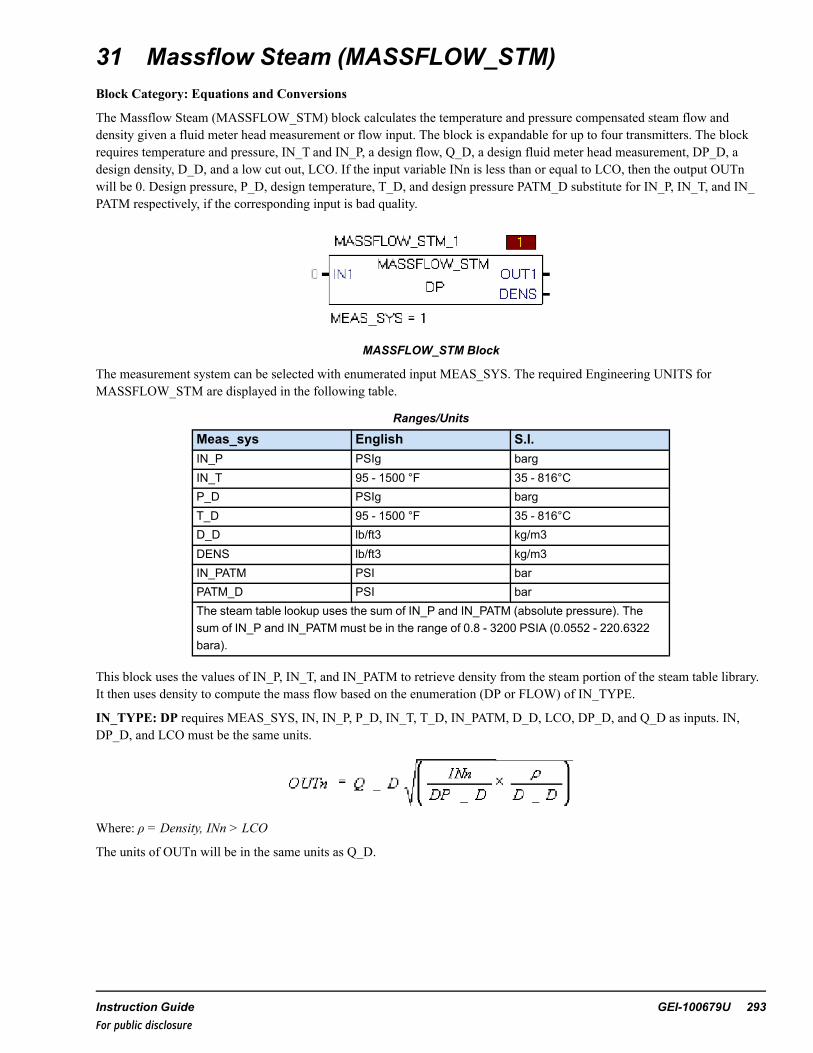
31 Massflow Steam (MASSFLOW_STM)Block Category: Equations and Conversions
The Massflow Steam (MASSFLOW_STM) block calculates the temperature and pressure compensated steam flow anddensity given a fluid meter head measurement or flow input. The block is expandable for up to four transmitters. The blockrequires temperature and pressure, IN_T and IN_P, a design flow, Q_D, a design fluid meter head measurement, DP_D, adesign density, D_D, and a low cut out, LCO. If the input variable INn is less than or equal to LCO, then the output OUTnwill be 0. Design pressure, P_D, design temperature, T_D, and design pressure PATM_D substitute for IN_P, IN_T, and IN_PATM respectively, if the corresponding input is bad quality.
MASSFLOW_STM Block
The measurement system can be selected with enumerated input MEAS_SYS. The required Engineering UNITS forMASSFLOW_STM are displayed in the following table.
Ranges/Units
Meas_sys English S.I.IN_P PSIg bargIN_T 95 - 1500 °F 35 - 816°CP_D PSIg bargT_D 95 - 1500 °F 35 - 816°CD_D lb/ft3 kg/m3DENS lb/ft3 kg/m3IN_PATM PSI barPATM_D PSI barThe steam table lookup uses the sum of IN_P and IN_PATM (absolute pressure). Thesum of IN_P and IN_PATM must be in the range of 0.8 - 3200 PSIA (0.0552 - 220.6322bara).
This block uses the values of IN_P, IN_T, and IN_PATM to retrieve density from the steam portion of the steam table library.It then uses density to compute the mass flow based on the enumeration (DP or FLOW) of IN_TYPE.
IN_TYPE: DP requires MEAS_SYS, IN, IN_P, P_D, IN_T, T_D, IN_PATM, D_D, LCO, DP_D, and Q_D as inputs. IN,DP_D, and LCO must be the same units.
Where: ρ = Density, INn > LCO
The units of OUTn will be in the same units as Q_D.
Instruction Guide GEI-100679U 293For public disclosure

IN_TYPE: FLOW requires MEAS_SYS, IN, IN_P, P_D, IN_T, T_D, IN_PATM, D_D, and LCO as inputs. IN, and LCOmust be the same units. The inputs Q_D and DP_D are not used.
Where: ρ = Density, INn > LCO
The units of OUTn will be in the same units as IN.
Note The non-status version of the block does not substitute the design values P_D for IN_P and/or T_D for IN_T.
This block propagates quality status if the status operations are enabled.
Block status modifications:
• Design pressures, P_D and PATM_D, and design temperature, T_D, substitute for IN_P and IN_ATM, and IN_T,respectively, if the corresponding input is bad quality. This results in an output status of NOT_LIMITED-SUBSTITUTE-UNCERTAIN [72].
• Due to the nature of the steam table, some input combinations may lead to a result outside of the steam region. Thisresults in an output status of NOT_LIMITED-LAST_USABLE_VALUE-UNCERTAIN [68].
• If the input temperature or pressure value exceeds the range in the table Ranges/Units, the output status will be eitherLOW_LIMITED-LAST_USABLE_VALUE-UNCERTAIN [69] or HIGH_LIMITED-LAST_USABLE_VALUE-UNCERTAIN [70].
• If IN < 0, (0 > IN > LCO), DENS < 0, D_D ≤ 0, or DP_D ≤ 0 then the output status is NOT_LIMITED-CONFIGURATION_ERROR-BAD [4].
For further details on Relational blocks, refer to the Mark VIe Controller Standard Block Library (GEI-100682), the StatusMonitoring (STATUS_MONITORING) block.
294 GEI-100679U Mark VIe Controller DCS Block LibraryFor public disclosure

Inputs
Name Description Data Type Initial Value Visibility Interface TypeD_D Design density REAL 28.4 Parameter Value OnlyDP_D Design differential pressure REAL 100 Parameter Value OnlyIN_P Input pressure REAL 0 Parameter Value OnlyIN_PATM Input atmospheric pressure REAL 14.696 Parameter Value OnlyIN_T Input temperature REAL 0 Parameter Value OnlyIN_TYPE Measurement input type UINT (ENUM) DP Parameter Value OnlyIN1 Differential pressure or Flow input 1 REAL† 0 Always Value with Status↓ ↓ ↓ ↓ ↓ ↓IN4 Differential pressure or Flow input 4 REAL† 0 Always Value with StatusLCO Low cut out REAL 0 Parameter Value OnlyMEAS_SYS Measurement system UINT (ENUM) English Parameter Value OnlyP_D Design pressure set as default value
in case of IN_P bad qualityREAL 0 Parameter Value Only
PATM_D Design atmospheric pressure set asdefault value in case of IN_PATM badquality
REAL 0 Parameter Value Only
Q_D Design flow REAL 100 Parameter Value OnlyT_D Design temperature set as default
value in case of IN_T bad qualityREAL 127 Parameter Value Only
† Value with Status (if status option is enabled)
Outputs
Name Description Data Type Initial Value Visibility Interface Type
DENS Steam density REAL† N/A Always Value with Status
OUT1 Compensated steam flow 1 REAL† N/A Always Value with Status
↓ ↓ ↓ ↓ ↓ ↓
OUT4 Compensated steam flow 4 REAL† N/A Always Value with Status
† Value with Status (if status option is enabled)
Instruction Guide GEI-100679U 295For public disclosure

32 Massflow Water (MASSFLOW_WTR)Block Category: Equations and Conversions
The Massflow Water (MASSFLOW_WTR) block calculates the temperature and pressure compensated water flow anddensity given a fluid meter head measurement or flow input. The block is expandable for up to 4 transmitters. The blockrequires temperature and pressure, IN_T and IN_P, a design flow, Q_D, a design fluid meter head measurement, DP_D, adesign density, D_D, and a low cut out, LCO. If the input variable IN is less than or equal to LCO, then the output will be 0.Design pressure, P_D, design temperature, T_D, and design pressure PATM_D substitute for IN_P, IN_T, and IN_PATMrespectively, if the corresponding input is bad quality (quality status value < 64).
MASSFLOW_WTR Block
The measurement system can be selected with enumerated input MEAS_SYS. The required Engineering UNITS forMASSFLOW_WTR are displayed in the following table.
Ranges/Units
Meas_sys English S.I.IN_P PSIg bargIN_T 32 - 705 °F 0 - 374°CP_D PSIg bargT_D 32 - 705 °F 0 - 374°CD_D lb/ft3 kg/m3DENS lb/ft3 kg/m3IN_PATM PSI barPATM_D PSI barThe steam table lookup uses the sum of IN_P and IN_PATM (absolute pressure). Thesum of IN_P and IN_PATM must be in the range of 0.8 - 3200 PSIA (0.0552 - 220.6322bara).
This block uses the values of IN_P, IN_T, and IN_PATM to retrieve density from the liquid portion of the steam table library.It then uses density to compute the mass flow based on the enumeration (DP or FLOW) of IN_TYPE.
IN_TYPE: DP requires MEAS_SYS, IN, IN_P, P_D, IN_T, T_D, IN_PATM, D_D, LCO, DP_D, and Q_D as inputs. IN,DP_D, and LCO must be the same units.
Where: ρ = Density, INn > LCO. If IN < LCO, OUT = 0
The units of OUTwill be in the same units as Q_D.
IN_TYPE: FLOW requires the inputs: MEAS_SYS, IN, IN_P, P_D, IN_T, T_D, IN_PATM, D_D, and LCO as inputs. IN,and LCO must be the same units. The inputs Q_D and DP_D are not used.
296 GEI-100679U Mark VIe Controller DCS Block LibraryFor public disclosure

Where: ρ = Density, INn > LCO. If IN < LCO, OUT = 0
The units of OUTn will be in the same units as IN.
Note In the above cases, if IN_P is not connected to a signal, the value of P_D needs to be used on IN_P.
Note The non-status version of the block does not substitute the design values P_D for IN_P and/or T_D for IN_T.
This block propagates quality status if the status operations are enabled.
Block status modifications:
• Design pressure, P_D, design temperature, T_D, and design atmospheric pressure PATM_D substitute for IN_P, IN_T,and IN_PATM respectively, if the corresponding input is bad quality. This results in an output status of NOT_LIMITED-SUBSTITUTE_UNCERTAIN [72].
• Due to the nature of the steam table, some input combinations may lead to a result outside of the liquid region. Thisresults in an output status of NOT_LIMITED-LAST_USABLE_VALUE-UNCERTAIN [68].
• If the input temperature or pressure value exceeds the range in the table, Ranges/Units, the output status will be eitherLOW_LIMITED-LAST_USABLE_VALUE-UNCERTAIN [69] or HIGH_LIMITED-LAST_USABLE_VALUE-UNCERTAIN [70].
• If IN < 0, (0 > IN > LCO), DENS < 0, D_D ≤ 0, or DP_D ≤ 0 then the output status is NOT_LIMITED-CONFIGURATION_ERROR-BAD [4].
For further details on Relational blocks, refer to the Mark VIe Controller Standard Block Library (GEI-100682), the StatusMonitoring (STATUS_MONITORING) block.
Instruction Guide GEI-100679U 297For public disclosure

Inputs
Name Description Data Type Initial Value Visibility Interface Type
D_D Design density REAL 61.8 Parameter Value Only
DP_D Design differential pressure REAL 100 Parameter Value Only
IN_P Input pressure REAL 0 Parameter Value Only
IN_PATM Input barometric pressure REAL 14.696 Parameter Value Only
IN_T Input temperature REAL 0 Parameter Value Only
IN_TYPE Measurement input type UINT (ENUM) DP Parameter Value Only
INDP1 Differential pressure or Flowinput 1
REAL† 0 Always Value with Status
↓ ↓ ↓ ↓ ↓ ↓
INDP4 Differential pressure or Flowinput 4
REAL† 0 Always Value with Status
LCO Low cut out REAL 0 Parameter Value Only
MEAS_SYS Measurement system UINT (ENUM) English Parameter Value Only
P_D Design pressure set as defaultvalue in case of IN_P badquality
REAL 0 Parameter Value Only
PATM_D Design atmospheric pressureset as default value in case ofIN_PATM bad quality
REAL 0 Parameter Value Only
Q_D Design flow REAL 100 Parameter Value Only
T_D Design temperature set asdefault value in case of IN_Tbad quality
REAL 0 Parameter Value Only
† Value with Status (if status option is enabled)
Outputs
Name Description Data Type InitialValue
Visibility Interface Type
DENS Water density REAL† N/A Always Value with Status
OUT1 Compensated water flow 1 REAL† N/A Always Value with Status
↓ ↓ ↓ ↓ ↓ ↓
OUT4 Compensated water flow 4 REAL† N/A Always Value with Status
† Value with Status (if status option is enabled)
298 GEI-100679U Mark VIe Controller DCS Block LibraryFor public disclosure

33 Median Select (MEDSEL)Block Category: Legacy, Analog Operations
Note Legacy Status— The MEDSEL block is not supported for use in new Mark VIe control systems (ControlSTsoftware suite V05.02 or later). It is in place to support the maintenance of legacy Mark VIe control systems (prior toControlST software suite V05.02). For new Mark VIe control systems, use the MEDSEL_V2 block; it provides equivalentfunctionality.
The Median Select (MEDSEL) block selects the median or average of three analog signals based on the enumerated value ofthe input TS and transfers the selection to the output ({Device}). The user has the option to disable up to two transmitters. Ifone transmitter is disabled, the output will be either the minimum, maximum, or average of the two remaining transmittersbased on the enumerated value of the input DS. If the one transmitter allowed property, 1XMTR_P, is True, two transmitterscan be disabled and the output will be the value of the remaining transmitter.
Block Configuration
Disabling Transmitters
When the quality status of transmitter A is in the BAD region then ABQ and AD become True and transmitter A isautomatically disabled and depending on the DS enumeration selected, the average, minimum, or maximum of inputs B and Cis transferred to OUT. Once the quality status of transmitter A becomes GOOD or UNCERTAIN, ABQ becomes False. If AU_EN_P is False, input A remains disabled (AD remains True) and must be enabled by an HMI operator. If AU_EN_P is Trueand the quality status of transmitter A becomes GOOD or UNCERTAIN and the value of input A is within the deviation limitsset by the user, AD becomes False and A is automatically enabled. This concept also applies to inputs B and C.
Note AU_EN_P does not have any effect on the enabling of a manually disabled input. A manually disabled input must bemanually enabled.
A transmitter can be manually disabled through the pop-up MEDSEL faceplate. If input A, B, and C are all enabled and havea GOOD or UNCERTAIN quality status and A is manually disabled, then the corresponding output, AD, becomes True toindicate that input A is disabled. If input A is enabled and B is disabled then BD is True. If input B is enabled and C is disabledthen CD is True.
Note The HMI operator is allowed to disable one transmitter at any time from the faceplate when 1XMTR_P, is False. When1XMTR_P, is True, the operator is allowed to disable up to two transmitters.
Note Refer to theMark VIe Controller Standard Block Library(GEI-100682), the Status Monitoring (STATUS_MONITORING) block.
Output Bad Quality Indication (OBQ) functionality is as follows:
If 1XMTR_P, is True, when three transmitters are disabled and/or in a BAD quality state, OBQ becomes True, the defaultvalue, DF, is automatically transferred to the output, quality status of the output is set to NOT_LIMITED-BAD[0], andMODE is set to DEFAULT.
If AU_EN_P is True, OBQ becomes False when the quality status of any input becomes GOOD or UNCERTAIN. TheGOOD or UNCERTAIN quality input will be enabled and transferred to the output. However, if AU_EN_P is False, OUTwill be equal to DF until the HMI operator manually enables the GOOD or UNCERTAIN quality input.
Instruction Guide GEI-100679U 299For public disclosure

If 1XMTR_P, is False:
When two or three transmitters are disabled and/or in a BAD quality state, OBQ becomes True, the default value, DF, isautomatically transferred to output, quality status of OUT is set to NOT_LIMITED-BAD[0], and MODE is set to DEFAULT.If AU_EN_P is True, OBQ becomes False when the quality status of 2 inputs become GOOD or UNCERTAIN. The GOODor UNCERTAIN quality inputs will be enabled and based on the DS enumeration selected, the average, minimum, ormaximum of the GOOD or UNCERTAIN quality inputs is transferred to the output. However, if AU_EN_P is False, theoutput will be equal to DF until the HMI operator manually enables the GOOD or UNCERTAIN quality inputs.
This block propagates quality status. Status option cannot be disabled on this block.
Block status modifications: When OBQ is True, the quality status of OUT is NOT_LIMITED-BAD[0].
For further details on relational blocks, refer to theMark VIe Controller Standard Block Library (GEI-100682), theStatus Monitoring (STATUS_MONITORING) block.
Control Word
Control word (CTL) is used by the HMI operator for manual control. The manual commands from the HMI allow each inputto be enabled or disabled. The command enumerations are defined in the following table.
Note A manually disabled transmitter can be manually enabled, regardless of its deviation status. An exception is when theblock is in average mode. Refer to the section Deviation Alarms.
CTL Enumerations
Enumeration CommandNO_CMD No Command
EN_A_CMD Enable Input A Command
DIS_A_CMD Disable Input A Command
EN_B_CMD Enable Input B Command
DIS_B_CMD Disable Input B Command
EN_C_CMD Enable Input C Command
DIS_C_CMD Disable Input C Command
Commands are only accepted by the block if a transition from NO_CMD to a command value is detected. After a command isaccepted by the block, the CTL pin is ignored for a period of one second after which the variable connected to the CTL inputpin is automatically reset to NO_CMD by the block. The next command value will be accepted as a command.
300 GEI-100679U Mark VIe Controller DCS Block LibraryFor public disclosure

Block Function Enumerations
Function is defined by two modes:
• Dual Select (DS) mode• Three Select (TS) mode
DS Enumerations
Enumeration FunctionAVG Average of A and B
MIN Minimum of A and B
MAX Maximum of A and B
TS Mode Enumerations
Enumeration FunctionAVG Average of A, B and C
MEDIAN Median of A, B and C
Operating mode (MODE) is the block-operating mode that depends on DS, TS and the quality status of the inputs. Theoperating mode enumerations are defined in the following table.
MODE Enumerations
Enumeration Operating Mode
MIN_B-C Minimum of B and C
MIN_A-B Minimum of A and B
MIN_A-C Minimum of A and C
MAX_B-C Maximum of B and C
MAX_A-B Maximum of A and B
MAX_A-C Maximum of A and C
AVG_A-B Average of A and B
AVG_A-C Average of A and C
AVG_B-C Average of B and C
AVG_ABC Average of A, B and C
MEDIAN Median of A, B and C
A Input A
B Input B
C Input C
DEFAULT Input DF
Instruction Guide GEI-100679U 301For public disclosure

Examples
MEDIAN or AVG_ABC mode is selected when none of the transmitters have a BAD quality status.
AVG_A-B mode is selected when a BAD quality is detected on transmitter C or when C is manually disabled, and the DSenumeration is AVG.
MIN_A-B mode is selected when a BAD quality is detected on transmitter C or when C is manually disabled, and the DSenumeration is MIN.
MAX_A-B mode is selected when a BAD quality is detected on transmitter C or when C is manually disabled, and the DSenumeration is MAX.
A mode is selected when 1XMTR_P is True and B and C transmitters are disabled.
DEFAULT mode is selected when all transmitters are BAD quality and/or disabled or 1XMTR_P is False and twotransmitters are BAD quality and/or disabled.
Deviation Alarms
Each transmitter value is compared with the output to determine if it is outside of the deviation limit, DL. If so, the deviationhigh alarm for the deviant input either DA, DB, or DC, for transmitters A, B, or C respectively, and ODH, become True. Thedeviation alarms will not become False until the absolute difference between the deviant input and the output is less than thevalue of DL minus DLDB (deviation limit dead band) or the deviant input is disabled.
Note Use the deviation alarms that are configured from within the block instead of the deviation high configuration of theanalog alarm. Refer to the section Analog Alarm Configuration.
Note The deviation high output, ODH, becomes True when at least one transmitter is in deviation. Also, if a transmitterinput is disabled, the deviation alarm for that transmitter is disabled.
In general, the deviation alarm only sets Boolean outputs and has no influence on the functionality of the block (for example,the transmitter in deviation with the output is not automatically disabled, and the block mode does not change).
However, if the block is calculating the average of all three transmitters (all three transmitters are Enabled and TS = AVG), atransmitter that gets a high deviation will be automatically disabled. It can be enabled by the operator or automatically (AU_EN_P = True) when the absolute difference between the deviant input and the output is less than the value of DL minusDLDB (deviation limit dead band).
Rate of Change Restriction
The rate of change of the output is only restricted by the value of RATE when the block operating mode changes.
RATE is in engineering units per second. For example, if 1XMTR_P = True, RATE = 1, A = 10 (enabled), B = 25 (disabled),and C = 50 (disabled), so MODE = A, and the mode of the block is changed by enabling input B and disabling input A. Now,MODE = B and the output will increase from 10 to 25 engineering units in 15 seconds. At this point, the output equals B, theblock operating mode transition from A to B is complete and the rate of change restriction on the output is removed until theblock operating mode changes, again.
302 GEI-100679U Mark VIe Controller DCS Block LibraryFor public disclosure

ToolboxST Configuration
Inserting this block into the application program will generate a window titled Enter the Attribute Instance Values, promptingthe user to Enter Device Description, Enter Device Name, and Enter Format Specification in the Values column of thewindow. The block will then automatically create the variables associated with the block and provide the appropriateattributes for each variable (for example, Type and Format Spec variables that need to be on EGD will be automaticallyplaced on the $Default EGD page, and so on).
Note Each Device Name used in a controller must be unique.
Inserting a MEDSEL into the application program displays the following window.
Changing Default Attribute Values
For this example, accept the default options for these attributes. The Device name is 00MEDSEL1000, the description isMEDSEL Description, and the Format Spec is TempFS.
When the user clicks OK, the block and pin connections will be configured automatically. The previous example will generateGlobal pins. The pin names are in the form Device Value.pin Name, where Device Value has the attribute value00MEDSEL1000 and Input_Name is the block input/output names. The description, MEDSEL Description in this example,becomes the prefix of the block input/output descriptions. The FormatSp Attribute Name Value, TempFS, in the previousexample, is the format specification of the block output.
Note The only exception to the above rule is the output pin ({Device}) where the global pin name is in the form DeviceValue pin name without the " ".
Note Refer to the table Global Variables.
Once the object has been added successfully, the block displays in the ToolboxST application as displayed in the followingfigure.
Instruction Guide GEI-100679U 303For public disclosure

MEDSEL Block
InputsName Global Description Data Type Initial Value Visibility Interface Type1XMTR_P Allow one transmitter
operationBOOL False Parameter Value Only
A Yes {Desc} Trans A input REAL 0 Always Value with StatusAU_EN_P Auto enable BQ XMTR BOOL True Parameter Value OnlyB Yes {Desc} Trans B input REAL 0 Always Value with StatusC Yes {Desc} Trans C input REAL 0 Always Value with StatusCTL Yes {Desc} Control word UINT (ENUM) NO_CMD Always Value OnlyDF Default output if all
transmitters are badREAL 0 Parameter Value Only
DL Deviation alarm limit REAL 5 Parameter Value OnlyDLDB Deviation alarm limit
deadbandREAL 2 Parameter Value Only
DS Dual select mode property UINT (ENUM) AVG Parameter Value OnlyDT Deviation alarm delay UDINT 1000 Parameter Value OnlyIN_ABQ Yes Trans A bad quality BOOL False Always Value OnlyIN_BBQ Yes Trans B bad quality BOOL False Always Value OnlyIN_CBQ Yes Trans C bad quality BOOL False Always Value OnlyRATE Selection change rate limit REAL 1 Internal Value OnlyTS 3-XMTR Select mode
propertyUINT (ENUM) MEDIAN Parameter Value Only
304 GEI-100679U Mark VIe Controller DCS Block LibraryFor public disclosure

OutputsName Global Description Data Type Initial Value Visibility Interface Type{Device} Yes {Desc} REAL 0 Always Value with StatusABQ Yes {Desc} Trans A bad quality BOOL False Always Value OnlyAD Yes {Desc} Trans A disabled BOOL False Always Value OnlyBBQ Yes {Desc} Trans B bad quality BOOL False Always Value OnlyBD Yes {Desc} Trans B disabled BOOL False Always Value OnlyCBQ Yes {Desc} Trans C bad quality BOOL False Always Value OnlyCD Yes {Desc} Trans C disabled BOOL False Always Value OnlyDA Yes {Desc} Trans A high
deviationBOOL False Always Value Only
DB Yes {Desc} Trans B highdeviation
BOOL False Always Value Only
DC Yes {Desc} Trans C highdeviation
BOOL False Always Value Only
MODE Yes {Desc} Block mode UINT (ENUM) MEDIAN Always Value OnlyOBQ Yes {Desc} Bad quality BOOL False Always Value OnlyODH Yes {Desc} High deviation BOOL False Always Value OnlySEL_P Yes {Desc} Select type property UINT (ENUM) MEDIAN Internal Value Only
Instruction Guide GEI-100679U 305For public disclosure

Global VariablesPin Name Description Alarm Alarm
ClassEvent EGD Page External
Access00MEDSEL1000 MEDSEL Description Not Alarmed False $Default ReadOnly00MEDSEL1000.A MEDSEL Description Trans
A inputNot Alarmed False $Default ReadOnly
00MEDSEL1000.A.Status
MEDSEL Description TransA input status
Not Alarmed False ReadOnly
00MEDSEL1000.ABQ MEDSEL Description TransA bad quality
Not Alarmed False $Default ReadOnly
00MEDSEL1000.AD MEDSEL Description TransA disabled
Not Alarmed True $Default ReadOnly
00MEDSEL1000.B MEDSEL Description TransB input
Not Alarmed False $Default ReadOnly
00MEDSEL1000.B.Status
MEDSEL Description TransB input status
Not Alarmed False ReadOnly
00MEDSEL1000.BBQ MEDSEL Description TransB bad quality
Not Alarmed False $Default ReadOnly
00MEDSEL1000.BD MEDSEL Description TransB disabled
Not Alarmed False $Default ReadOnly
00MEDSEL1000.C MEDSEL Description TransC input
Not Alarmed False $Default ReadOnly
00MEDSEL1000.C.Status
MEDSEL Description TransC input status
Not Alarmed False ReadOnly
00MEDSEL1000.CBQ MEDSEL Description TransC bad quality
Not Alarmed False $Default ReadOnly
00MEDSEL1000.CD MEDSEL Description TransC disabled
Not Alarmed True $Default ReadOnly
00MEDSEL1000.CTL MEDSEL Description Controlword
Not Alarmed False $Default ReadOnly
00MEDSEL1000.DA MEDSEL Description TransA high deviation
Alarmed LVL_2 False $Default ReadOnly
00MEDSEL1000.DB MEDSEL Description TransB high deviation
Alarmed LVL_2 False $Default ReadOnly
00MEDSEL1000.DC MEDSEL Description TransC high deviation
Alarmed LVL_2 False $Default ReadOnly
00MEDSEL1000.MODE MEDSEL Description Blockmode
Not Alarmed False $Default ReadOnly
00MEDSEL1000.OBQ MEDSEL Description Badquality
Not Alarmed False $Default ReadOnly
00MEDSEL1000.ODH MEDSEL Description highdeviation
Not Alarmed False $Default ReadOnly
00MEDSEL1000.SEL_P MEDSEL Description Selecttype property
Not Alarmed False $Default ReadOnly
00MEDSEL1000.Status MEDSEL Description status Not Alarmed False ReadOnly
306 GEI-100679U Mark VIe Controller DCS Block LibraryFor public disclosure

Analog Alarm Configuration
To set up analog alarms on a signal, configure the Alarm property for that signal. This allows the configuration of BQ (BadQuality), RH (Rate of change high), DH (High Deviation), H, HH, HHH (or 3H), L, LL, and LLL (or 3L).
Note AnalogAlarmDefault should normally be used when a signal is to be used as an alarm. Enabling this turns on moreoptions in the Alarms and Events section in the properties of that signal.
Note Configuring the analog alarm for deviation high is not recommended as the block already alarms on deviation high foreach input. Refer to the section Deviation Alarms.
Enabling Analog Alarms on a Signal
Additional Options in Alarms and Events Property Editor
Instruction Guide GEI-100679U 307For public disclosure

➢➢ To enable the H Alarm: in the property grid, set the H property to True to add the variables displayed in the followingfigure to the variable list.
H Variable
H_SP is the setpoint for the High alarm on the signal. H_T is the delay time (in ms). When the comparison between thesetpoint and the value is done, it waits H_T milliseconds before issuing the alarm. HYST is the Hysteresis of the alarm values.Set the initial values to effectively use them. 00MEDSEL1000.H is the actual variable name that generates the alarm.
HMI Configuration (CIMPLICITY)
The Object name for the HMI is the same as the Device name specified in the ToolboxST configuration.
Typical HMI Object for a MEDSEL
MEDSEL Faceplate
308 GEI-100679U Mark VIe Controller DCS Block LibraryFor public disclosure

34 Median Select Version 2 (MEDSEL_V2)Block Category: Analog Operations
The Median Select Version 2 (MEDSEL_V2) block selects the median or average of three analog signals based on theenumerated value of the input TS and transfers the selection to the output ({Device}). The user has the option to disable up totwo transmitters. If one transmitter is disabled, the output will be either the minimum, maximum, or average of the tworemaining transmitters based on the enumerated value of the input DS. If the one transmitter allowed property, 1XMTR_P, isTrue, two transmitters can be disabled and the output will be the value of the remaining transmitter.
Block Configuration
Disabling Transmitters
When the quality status of transmitter A is BAD (False), then ABQ and AD become True and transmitter A is automaticallydisabled. Also, depending on the DS enumeration selected, the average, minimum, or maximum of inputs B and C istransferred to OUT. Once the quality status of transmitter A becomes GOOD (True) or UNCERTAIN, ABQ becomes False. IfAU_EN_P is False, input A remains disabled (AD remains True) and must be enabled by an HMI operator. If AU_EN_P isTrue and the quality status of transmitter A becomes GOOD (True) or UNCERTAIN and the value of input A is within thedeviation limits set by the user, AD becomes False and A is automatically enabled. This concept also applies to inputs B andC.
Note AU_EN_P does not have any effect on the enabling of a manually disabled input. A manually disabled input must bemanually enabled.
A transmitter can be manually disabled through the pop-up MEDSEL_V2 faceplate. If input A, B, and C are all enabled andhave a GOOD or UNCERTAIN quality status and A is manually disabled, then the corresponding output, AD, becomes Trueto indicate that input A is disabled. If input A is enabled and B is disabled then BD is True. If input B is enabled and C isdisabled then CD is True.
Note The HMI operator is allowed to disable one transmitter at any time from the faceplate when 1XMTR_P is False. When1XMTR_P is True, the operator is allowed to disable up to two transmitters.
Note Refer to theMark VIe Controller Standard Block Library (GEI-100682), the Status Monitoring (STATUS_MONITORING) block.
Output Bad Quality Indication (OBQ) functionality is as follows:
If 1XMTR_P, is True, when three transmitters are disabled and/or in a BAD quality state, OBQ becomes True, the defaultvalue, DF, is automatically transferred to the output, quality status of the output is set to NOT_LIMITED-BAD[0], andMODE is set to DEFAULT.
If AU_EN_P is True, OBQ becomes False when the quality status of any input becomes GOOD or UNCERTAIN. TheGOOD or UNCERTAIN quality input will be enabled and transferred to the output. However, if AU_EN_P is False, OUTwill be equal to DF until the HMI operator manually enables the GOOD or UNCERTAIN quality input.
If 1XMTR_P, is False, when two or three transmitters are disabled and/or in a BAD quality state, OBQ becomes True, thedefault value, DF , is automatically transferred to output, quality status of OUT is set to NOT_LIMITED-BAD[0], and MODEis set to DEFAULT.
If AU_EN_P is True, OBQ becomes False when the quality status of 2 inputs become GOOD or UNCERTAIN. The GOODor UNCERTAIN quality inputs will be enabled and based on the DS enumeration selected, the average, minimum, ormaximum of the GOOD or UNCERTAIN quality inputs is transferred to the output. However, if AU_EN_P is False, theoutput will be equal to DF until the HMI operator manually enables the GOOD or UNCERTAIN quality inputs.
Instruction Guide GEI-100679U 309For public disclosure

This block propagates quality status. Status option cannot be disabled on this block.
Block status modification: When OBQ is True, the quality status of OUT is NOT_LIMITED-BAD[0].
For further details on relational blocks, refer to theMark VIe Controller Standard Block Library(GEI-100682), the Status Monitoring (STATUS_MONITORING) block.
Control Word
Control word (CTL) is used by the HMI operator for manual control. The manual commands from the HMI allow each inputto be enabled or disabled. The command enumerations are defined in the following table.
Note A manually disabled transmitter may be manually enabled, regardless of its deviation status, unless the block is inaverage mode. Refer to the section Deviation Alarms.
CTL Enumerations
Enumeration CommandNO_CMD No Command
EN_A_CMD Enable Input A Command
DIS_A_CMD Disable Input A Command
EN_B_CMD Enable Input B Command
DIS_B_CMD Disable Input B Command
EN_C_CMD Enable Input C Command
DIS_C_CMD Disable Input C Command
Commands are only accepted by the block if a transition from NO_CMD to a command value is detected. After a command isaccepted by the block, the CTL pin is ignored for a period of one second after which the variable connected to the CTL inputpin is automatically reset to NO_CMD by the block. The next command value will be accepted as a command.
Block Function Enumerations
Function is defined by two modes:
• Dual Select (DS) mode• Three Select (TS) mode
DS Enumerations
Enumeration FunctionAVG Average of A and B
MIN Minimum of A and B
MAX Maximum of A and B
TS Mode Enumerations
Enumeration FunctionAVG Average of A, B and C
MEDIAN Median of A, B and C
310 GEI-100679U Mark VIe Controller DCS Block LibraryFor public disclosure

Operating mode (MODE) is the block-operating mode that depends on DS, TS and the quality status of the inputs. Theoperating mode enumerations are defined in the following table.
MODE Enumerations
Enumeration Operating Mode
MIN_B-C Minimum of B and C
MIN_A-B Minimum of A and B
MIN_A-C Minimum of A and C
MAX_B-C Maximum of B and C
MAX_A-B Maximum of A and B
MAX_A-C Maximum of A and C
AVG_A-B Average of A and B
AVG_A-C Average of A and C
AVG_B-C Average of B and C
AVG_ABC Average of A, B and C
MEDIAN Median of A, B and C
A Input A
B Input B
C Input C
DEFAULT Input DF
Examples
MEDIAN or AVG_ABC mode is selected when none of the transmitters have a BAD quality status.
AVG_A-B mode is selected when a BAD quality is detected on transmitter C or when C is manually disabled, and the DSenumeration is AVG.
MIN_A-B mode is selected when a BAD quality is detected on transmitter C or when C is manually disabled, and the DSenumeration is MIN.
MAX_A-B mode is selected when a BAD quality is detected on transmitter C or when C is manually disabled, and the DSenumeration is MAX.
A mode is selected when 1XMTR_P is True and B and C transmitters are disabled.
DEFAULT mode is selected when all transmitters are BAD quality and/or disabled or 1XMTR_P is False and twotransmitters are BAD quality and/or disabled.
Instruction Guide GEI-100679U 311For public disclosure

Deviation Alarms
Each transmitter value is compared with the output to determine if it is outside of the deviation limit, DL. If so, the deviationhigh alarm for the deviant input either DA, DB, or DC, for transmitters A, B, or C respectively, and ODH, become True. Thedeviation alarms will not become False until the absolute difference between the deviant input and the output is less than thevalue of DL minus DLDB (deviation limit deadband) or the deviant input is disabled.
Note Use the deviation alarms that are configured from within the block instead of the deviation high configuration of theanalog alarm. Refer to the section Analog Alarm Configuration.
Note The deviation high output, ODH, becomes True when at least one transmitter is in deviation. Also, if a transmitterinput is disabled, the deviation alarm for that transmitter is disabled.
In general, the deviation alarm only sets Boolean outputs and has no influence on the functionality of the block (for example,the transmitter in deviation with the output is not automatically disabled, and the block mode does not change).
However, if the block is calculating the average of all three transmitters (all three transmitters are Enabled and TS = AVG), atransmitter that gets a high deviation will be automatically disabled. It can be enabled by the operator or automatically (AU_EN_P = True) when the absolute difference between the deviant input and the output is less than the value of DL minusDLDB (deviation limit dead band).
Rate of Change Restriction
The rate of change of the output is only restricted by the value of RATE when the block operating mode changes.
RATE is in engineering units per second. For example, if 1XMTR_P = True, RATE = 1, A = 10 (enabled), B = 25 (disabled),and C = 50 (disabled), so MODE = A, and the mode of the block is changed by enabling input B and disabling input A. Now,MODE = B and the output will increase from 10 to 25 engineering units in 15 seconds. At this point, the output equals B, theblock operating mode transition from A to B is complete and the rate of change restriction on the output is removed until theblock operating mode changes, again.
312 GEI-100679U Mark VIe Controller DCS Block LibraryFor public disclosure

ToolboxST Configuration
Inserting this block into the application program will generate a window titled Enter the Attribute Instance Values, promptingthe user to Enter Device Description, Enter Device Name, and Enter Format Specification in the Values column of thewindow. The block will then automatically create the variables associated with the block and provide the appropriateattributes for each variable (for example, Type and Format Spec variables that need to be on EGD will be automaticallyplaced on the $Default EGD page, and so on).
Note Each Device Name used in a controller must be unique.
Inserting a MEDSEL_V2 block into the application program displays the following window.
Changing Default Attribute Values
For this example, accept the default options for these attributes. The Device name is 00MEDSEL1000, the description isMEDSEL_V2 Description, and the format specification is TempFS.
When the user clicks OK, the block and pin connections will be configured automatically and generates Global pins. Pinnames are in the form Device Value.pin Name, where Device Value has the attribute value 00MEDSEL1000 and Input_Nameis the block input/output name. The description,MEDSEL_V2 Description in this example, becomes the prefix of the blockinput/output descriptions. The FormatSp Attribute Name Value, TempFS, in the previous example, is the format specificationof the block output. The DLFormatSp Attribute Name Value, TempDiffFS is the format specification of the block DL pinoutput.
Note The only exception to the above rule is the output pin ({Device}) where the global pin name is in the form DeviceValue pin name without the " ".
Note Refer to the table Global Variables.
Once the object has been added successfully, the block displays in the ToolboxST application as displayed in the followingfigure.
Instruction Guide GEI-100679U 313For public disclosure

MEDSEL_V2 Block
Inputs
Name Global Description Data Type Initial Value Visibility InterfaceType
1XMTR_P Allow one transmitteroperation
BOOL False Parameter Value Only
A Yes {Desc} Trans A input REAL 0 Always Value withStatus
AU_EN_P Auto enable BQ XMTR BOOL True Parameter Value OnlyB Yes {Desc} Trans B input REAL 0 Always Value with
StatusC Yes {Desc} Trans C input REAL 0 Always Value with
StatusCTL Yes {Desc} Control word UINT (ENUM) NO_CMD Always Value OnlyDF Default output if all
transmitters are badREAL 0 Parameter Value Only
DL Deviation alarm limit REAL 5 Parameter Value OnlyDLDB Deviation alarm limit
deadbandREAL 2 Parameter Value Only
DS Dual select mode property UINT (ENUM) AVG Parameter Value OnlyDT Deviation alarm delay UDINT 1000 Parameter Value OnlyIN_ABQ Yes Trans A bad quality BOOL False Always Value OnlyIN_BBQ Yes Trans B bad quality BOOL False Always Value OnlyIN_CBQ Yes Trans C bad quality BOOL False Always Value OnlyRATE Selection change rate limit REAL 1 Internal Value OnlyTS 3-XMTR Select mode
propertyUINT (ENUM) MEDIAN Parameter Value Only
314 GEI-100679U Mark VIe Controller DCS Block LibraryFor public disclosure

Outputs
Name Global Description Data Type Initial Value Visibility InterfaceType
{Device} Yes {Desc} REAL 0 Always Value withStatus
ABQ Yes {Desc} Trans A bad quality BOOL False Always Value OnlyAD Yes {Desc} Trans A disabled BOOL False Always Value OnlyBBQ Yes {Desc} Trans B bad quality BOOL False Always Value OnlyBD Yes {Desc} Trans B disabled BOOL False Always Value OnlyCBQ Yes {Desc} Trans C bad quality BOOL False Always Value OnlyCD Yes {Desc} Trans C disabled BOOL False Always Value OnlyDA Yes {Desc} Trans A high
deviationBOOL False Always Value Only
DB Yes {Desc} Trans B highdeviation
BOOL False Always Value Only
DC Yes {Desc} Trans C highdeviation
BOOL False Always Value Only
MODE Yes {Desc} Block mode UINT (ENUM) MEDIAN Always Value OnlyOBQ Yes {Desc} Bad quality BOOL False Always Value OnlyODH Yes {Desc} High deviation BOOL False Always Value OnlySEL_P Yes {Desc} Select type property UINT (ENUM) MEDIAN Internal Value Only
Instruction Guide GEI-100679U 315For public disclosure

Global VariablesPin Name Description Alarm Alarm
ClassEvent EGD
PageExternalAccess
00MEDSEL1000 MEDSEL_V2 Description Not Alarmed False $Default ReadOnly00MEDSEL1000.A MEDSEL_V2 Description
Trans A inputNot Alarmed False $Default ReadOnly
00MEDSEL1000.A.Status
MEDSEL_V2 DescriptionTrans A input status
Not Alarmed False ReadOnly
00MEDSEL1000.ABQ MEDSEL_V2 DescriptionTrans A bad quality
Not Alarmed False $Default ReadOnly
00MEDSEL1000.AD MEDSEL_V2 DescriptionTrans A disabled
Not Alarmed True $Default ReadOnly
00MEDSEL1000.B MEDSEL_V2 DescriptionTrans B input
Not Alarmed False $Default ReadOnly
00MEDSEL1000.B.Status
MEDSEL_V2 DescriptionTrans B input status
Not Alarmed False ReadOnly
00MEDSEL1000.BBQ MEDSEL_V2 DescriptionTrans B bad quality
Not Alarmed False $Default ReadOnly
00MEDSEL1000.BD MEDSEL_V2 DescriptionTrans B disabled
Not Alarmed True $Default ReadOnly
00MEDSEL1000.C MEDSEL_V2 DescriptionTrans C input
Not Alarmed False $Default ReadOnly
00MEDSEL1000.C.Status
MEDSEL_V2 DescriptionTrans C input status
Not Alarmed False ReadOnly
00MEDSEL1000.CBQ MEDSEL_V2 DescriptionTrans C bad quality
Not Alarmed False $Default ReadOnly
00MEDSEL1000.CD MEDSEL_V2 DescriptionTrans C disabled
Not Alarmed True $Default ReadOnly
00MEDSEL1000.CTL MEDSEL_V2 DescriptionControl word
Not Alarmed False $Default ReadOnly
00MEDSEL1000.DA MEDSEL_V2 DescriptionTrans A high deviation
Alarmed Alert False $Default ReadOnly
00MEDSEL1000.DB MEDSEL_V2 DescriptionTrans B high deviation
Alarmed Alert False $Default ReadOnly
00MEDSEL1000.DC MEDSEL_V2 DescriptionTrans C high deviation
Alarmed Alert False $Default ReadOnly
00MEDSEL1000.MODE
MEDSEL_V2 DescriptionBlock mode
Not Alarmed False $Default ReadOnly
00MEDSEL1000.OBQ MEDSEL_V2 Description Badquality
Not Alarmed False $Default ReadOnly
00MEDSEL1000.ODH MEDSEL_V2 Descriptionhigh deviation
Not Alarmed False $Default ReadOnly
00MEDSEL1000.SEL_P
MEDSEL_V2 DescriptionSelect type property
Not Alarmed False $Default ReadOnly
00MEDSEL1000.Status MEDSEL_V2 Descriptionstatus
Not Alarmed False ReadOnly
316 GEI-100679U Mark VIe Controller DCS Block LibraryFor public disclosure

Analog Alarm Configuration
To set up analog alarms on a signal, configure the Alarm property for that signal. This allows the configuration of BQ (BadQuality), RH (Rate of change high), DH (High Deviation), H, HH, HHH (or 3H), L, LL, and LLL (or 3L).
Note Configuring the analog alarm for deviation high is not recommended as the block already alarms on deviation high foreach input. Refer to the section Deviation Alarms.
Note AnalogAlarmDefault should normally be used when a signal is to be used as an alarm. Enabling this turns on moreoptions in the Alarms and Events section in the properties of that signal.
Enabling Analog Alarms on a Signal
Additional Options in Alarms and Events Property Editor
Instruction Guide GEI-100679U 317For public disclosure

➢➢ To enable the H Alarm: in the property grid, set the H property to True to add the variables displayed in the followingfigure to the variable list.
H Variables
H_SP is the setpoint for the High alarm on the signal. H_T is the delay time (in ms). When the comparison between thesetpoint and the value is done, it waits H_T milliseconds before issuing the alarm. HYST is the Hysteresis of the alarm values.Set the initial values to effectively use them. 00MEDSEL1000.H is the actual variable name that generates the alarm.
HMI Configuration (CIMPLICITY)
The Object name for the HMI is the same as the Device name specified in the ToolboxST configuration.
Click MED ABC to display the MEDSEL _V2faceplate.
MEDSEL_V2 Faceplate
318 GEI-100679U Mark VIe Controller DCS Block LibraryFor public disclosure

35 Multiplexer (MUX)Block Category: Sequencing
The Multiplexer (MUX) block is an expandable block that outputs one of up to 32 input signals based on the value of SEL.SEL must be an integer number between 1 and the number of the N’th input. An invalid SEL (less than one or greater than theN’th input number) will be disregarded and the current selection will be maintained.
MUX Block
When SEL is one, OUT equals IN1. When SEL is two, OUT equals IN2 and so on. The inputs and output data types must bethe same.
Note This is a variant block that supports any one the following block data types: Boolean, Integer, Double Integer, Real,Long Real, Unsigned Integer, Unsigned Double Integer. The default data type is REAL. Refer to the section Change DataType of Variant Block.
This block propagates quality status if the status operations are enabled.
Block status modification: If SEL is determined to be invalid, the status output will be NOT_LIMITED-LAST_USABLE_VALUE-UNCERTAIN [68] or NOT_LIMITED-BAD [0] if the last usable value’s status is in the bad range.
For further details on Single Input/Single Output blocks, refer to the Mark VIe Controller Standard Block Library(GEI-100682), the Status Monitoring (STATUS_MONITORING) block.
Instruction Guide GEI-100679U 319For public disclosure

Inputs
Name Description Data Type Initial Value Visibility Interface Type
IN1 Multiplexer input 1 ANY† 0 Always Value with Status
↓ ↓ ↓ ↓ ↓ ↓
IN32 Multiplexer input32
ANY† 0 Always Value with Status
SEL Multiplexerselector
UINT 0 Always Value Only
† Value with Status (Value only for Boolean block type) (if status option is enabled)
Output
Name Description Data Type Initial Value Visibility Interface Type
OUT Multiplexer output ANY† N/A Always Value with Status
† Value with Status (Value only for Boolean block type) (if status option is enabled)
320 GEI-100679U Mark VIe Controller DCS Block LibraryFor public disclosure

36 Override (OVERRIDE)Block Category: Legacy, Permits and Overrides
Note Legacy Status— The OVERRIDE block is not supported for use in new Mark VIe control systems (ControlSTsoftware suite V05.02 or later). It is in place to support the maintenance of legacy Mark VIe control systems (prior toControlST software suite V05.02). For new Mark VIe control systems, LOGIC_BUILDER or LOGIC_BUILDER_SC block(use if first out/state change feature is required); these blocks provide equivalent functionality. Refer to the Mark VIeController Standard Block Library (GEI-100682).
The Override (OVERRIDE) block is an expandable block of up to 32 override inputs which functions like an OR block. Eachconnected input can be blocked by the HMI operator from the override display, which is accessed from Override tab of theassociated permit screen. This blocking function must be enabled by setting OVnBE to True. If override blocking is enabledfor an input, an event is generated on the HMI alarm/event screen whenever the operator blocks the override.
When FO_EN is True, the first out option is enabled. This causes the block to store the number of the first input that becomesTrue in the output FO. The FO value is stored until the HMI operator resets it from the override display. After a RESET, FO is0 until one of the connected inputs is True for at least one scan. A blocked Override is not considered in the FO detection.
Each input has the capability of inheriting the description of a connected global variable or a global variable connectedthrough a NOT block. When a connection is made to one of the input pins, the description of the global variable is inheritedby default. If this description is undesirable, it must be disabled by setting the Inherit Description option to False in the inputvariable properties. The description can be replaced with a desirable description by entering an appropriate description in thedescription field of the input variable of the OVERRIDE block (replace OVERRIDE #1 with the desired override descriptionfor the source connected to OV1). The description is not copied from the connected variable immediately; the input'sdescription is set when the library or device containing the input is validated or built.
Block Configuration
Override Type (OVR_TYPE)
OVR_TYPE enumerations are listed in the following table.
OVR_TYPE Enumerations
Description Override Option Description
CL_OVR Close override
OP_OVR Open override
INT_OVR Intermediate override
TRP_OVER Trip override
MN_REJ Manual reject
STP_OVER Stop override
CMD_OVR Command/Setpoint override
Instruction Guide GEI-100679U 321For public disclosure

OUT
OUT pin enumeration values for OUT are provided in the following table.
OUT EnumerationsEnumeration Override Output Description
NO_OVR-NO-BLOCK No override and no override is blockedOVR-NO_BLOCK Override active and no override is blockedNO_OVR-BLOCK No override and a override is blockedOVR-BLOCK Override active and a override is blocked
ToolboxST Configuration
Inserting this block into the application program will generate a pop-up window titled Enter the Attribute Instance Values.This prompts the user to Enter Device Name and Select OvrType in the Value column of the window (the override type is adrop-down menu selection). The block will then automatically create the necessary variables and provides the appropriateattributes for each variable (for example, Type and Format Spec variables that need to be on EGD will be automaticallyplaced on the $Default EGD page, and so on).
Note Each combination of Device Name and Override enumeration type selected used in a controller must be unique.
If additional Pin Groups are added, the necessary new variables will be automatically created during a build of the applicationprogram.
Inserting an OVERRIDE into the application software, for example, displays the following window in the ToolboxSTapplication.
Changing Default Attribute Values
When the user clicks OK, the block and pin connections will be configured automatically. The previous example generatesGlobal pins. Once the object has been added successfully, the block displays in the ToolboxST application.
Note Refer to the table Global Variables.
322 GEI-100679U Mark VIe Controller DCS Block LibraryFor public disclosure

OVERRIDE Block
There are three things to remember when installing an OVERRIDE block. The first is that the Device Name of the blockshould match the name of the block that it will be connected to. If this block is controlling an MOV block, then the namesshould match. If the blocks are connected correctly, but named incorrectly, the block will work normally, but the HMI screencannot tell you why something is or isn’t overridden.
Note Override blocks have a mode for manual rejects.
The other thing to remember is to select the correct Override Type. If you select MN_REJ, but connect it to a CL_OVR, thenthe override will act like an close override, but show up as a manual reject.
Input pin names are in the form the Device Value OvrType Value.pin name.
Output pin names are in the form Device Value OvrType Value.OUT and Device Value OvrType Value.FO, Device ValueOvrType Value.OV, Device Value OvrType Value.OVB.
Example
Note The defaults here are for example only. Be sure to change the block name.
If Device Value = 00OVERRIDE1000 and Ovr_Type Value = CL_OVR.
Instruction Guide GEI-100679U 323For public disclosure

Inputs
Name Description Data Type Initial Value Visibility InterfaceType
FO_EN First out logic trap enable BOOL False Always Value OnlyOV1 Override input 1 BOOL False Always Value OnlyOV1B Override input block 1 BOOL False Always Value OnlyOV1BE Override input block enable 1 BOOL False Always Value Only↓ ↓ ↓ ↓ ↓ ↓OV32 Override input 32 BOOL False Always Value OnlyOV32B Override input block 32 BOOL False Always Value OnlyRESET First out trap logic reset BOOL False Internal Value Only
Outputs
Name Description Data Type Initial Value Visibility InterfaceType
FO First out bit number of trip 1 - 32 UINT 0 Always Value OnlyOUT Output UINT (ENUM) NO_OVR-NO_BLOCK Always Value OnlyOV Override BOOL False Always Value OnlyOVB Override block BOOL False Always Value Only
Global VariablesPin Name Description Alarm Alarm
ClassEvent EGD
PageExternalAccess
00OVERRIDE1000CL_OVR.FO First out bit number of trip 1- 32
NotAlarmed
False $DEFAULT ReadOnly
00OVERRIDE1000CL_OVR.OUT Output NotAlarmed
False ReadOnly
00OVERRIDE1000CL_OVR.OV Override NotAlarmed
False ReadOnly
00OVERRIDE1000CL_OVR.OV1 Override #1 (or theconnected Global variabledescription)
NotAlarmed
False $DEFAULT ReadOnly
00OVERRIDE1000CL_OVR.OV1B Override block #1 NotAlarmed
True $DEFAULT ReadWrite
00OVERRIDE1000CL_OVR.OV1BE Override block enable #1 NotAlarmed
False $DEFAULT ReadOnly
↓ ↓ ↓ ↓ ↓ ↓ ↓00OVERRIDE1000CL_OVR.OVn Override #n (or the
connected Global variabledescription)
NotAlarmed
False $DEFAULT ReadOnly
00OVERRIDE1000CL_OVR.OVnB Override block #n NotAlarmed
True $DEFAULT ReadWrite
00OVERRIDE1000CL_OVR.OVnBE Override block enable #n NotAlarmed
False $DEFAULT ReadOnly
↓ ↓ ↓ ↓ ↓ ↓ ↓00OVERRIDE1000CL_OVR.RESET First out trap logic reset Not
AlarmedFalse $DEFAULT ReadWrite
324 GEI-100679U Mark VIe Controller DCS Block LibraryFor public disclosure

HMI Configuration (CIMPLICITY)
An OVERRIDE block does not directly have an HMI object. The block displays on the Permits faceplate when used. Thefollowing figure displays the Permits faceplate for a PID_MA block. This shows the presence of the OVERRIDE block, aswell as a description from the controlling variable. The override description displays as green because the override is notactive.
PERMIT Faceplate for PID_MA
Instruction Guide GEI-100679U 325For public disclosure

37 Override Station Enhanced (OVR_ST_ENH)Block Category: Legacy, Controls (DCS)
Note Legacy Status— The OVR_ST_ENH block is not supported for use in new Mark VIe control systems (ControlSTsoftware suite V05.02 or later). It is in place to support the maintenance of legacy Mark VIe control systems (prior toControlST software suite V05.02). For new Mark VIe control systems, use the OVR_ST_ENH_V2 block; it providesequivalent functionality.
The Override Station Enhanced (OVR_ST_ENH) block is an enhanced override station that controls up to three cascaded ornon-cascaded PID_MA_ENH block loops. The inputs and outputs of the OVR_ST_ENH block can be monitored andcontrolled by the operator using the CIMPLICITY graphical interface. The block’s various functional capabilities are definedby three separate enumerated inputs: Block Option (BLOCK_OPT),Mode Option (MODE_OPT), and Station Option(STATION_OPT). The user must first identify the functions needed for the application for which the block will be used, andthen choose the appropriate enumeration for each input to provide the desired block functionality. The Enhanced blockperforms quality status monitoring of input and output signals and propagates the quality status to the outputs: controlvariable output (CVO), CV, and SV.
Block Configuration
BLOCK_OPT
BLOCK_OPT enumerations are listed in the following table.
BLOCK_OPT Input Enumerations
Name Description
OVR_ST_MA OVR_ST with manual / auto setpoint control
OVR_ST_REM OVR_ST with manual / auto control and local / remote setpoint
OVR_ST_EXT OVR_ST with manual / auto control and external setpoint
OVR_ST_MA— used only when manual / auto setpoint control is needed. It sets the output property (OVR_ST_P) to True.
OVR_ST_REM— used when a remote setpoint value is needed and sets the output property (OVR_ST_REM_P) to True.The remote setpoint is connected to the OVR_ST_ENH block remote setpoint (RSP) input. This enumeratiON permits a localsetpoint and a remote setpoint, either of which can be selected by the operator using the graphical interface, or by the OVR_ST_ENH block remote setpoint select pulsed (RSP_SEL) input.
OVR_ST_EXT— used when an external setpoinat input value is to be used as the setpoint value and sets the output property(OVR_ST_EXT_P) to True. The remote setpoint is connected to the RSP input. This enumeration does not allow a localsetpoint, only an external setpoint that is connected to the RSP input. When this enumeration is used, the operator cannotselect a local setpoint value from the graphical interface and the RSP_SEL input is disabled.
326 GEI-100679U Mark VIe Controller DCS Block LibraryFor public disclosure

Mode Option (MODE_OPT)
(MODE_OPT enumerations are listed in the following table.
MODE_OPT Input Enumerations
Name Description
NONE None
LOCK Lock mode
POS Position feedback
LOCK-POS Lock mode and position feedback
SPLIT Split range
SPLIT-LOCK Split range and block mode
SPLIT-POS Split range and position feedback
SPLIT-LOCK-POS Split range, lock mode and position feedback
NONE— indicates no mode options are enabled.
LOCK— sets the lock property (LOCK_P) to True, which allows software lockout of the controller to be implemented bythe operator using the CIMPLICITY graphical interface. The valve output, CVO, must be within 5 units of the initial position(INIT_POS) input value before the block can be set to lockout mode. When LOCK becomes True, the block is in lockoutmode and the block outputs, CVO, CV, and, if applicable, SV, are prohibited from modulating. If the block is in auto modeand LOCK becomes True, the block will be put into manual mode and the manual reject alarm (MAN_REJ_A) will beactivated. The operator’s ability to switch to auto mode is disabled until the block is removed from lockout mode.Additionally, the local auto setpoint will track the process variable (PV) input when the block is in lockout mode.
Note The lockout indication is provided for indication only. This action will not lock out the equipment, it will only indicatelockout status. Follow the owner's lockout procedures to safely lockout equipment.
The Lock button can also be configured to use the WorkstationST Lock function. Refer to the WorkstationST/CIMPLICITYAdvanced Viewer Integration Instruction Guide (GEI-100697), the section HMI Tagout.
POS— used when feedback is available from the controlled device. Normally, feedback is the valve position feedback, butthe POS enumeration can also be used for motor speed or a variety of other device feedbacks. The position feedback value isconnected to the block POS_CV input and, if the MODE_OPT enumeration SPLIT is selected, the position feedback from thesecondary device is connected to the POS_SV block input.
Instruction Guide GEI-100679U 327For public disclosure

When the POS enumeration is used, the block POSFB_P output is True, the feedback value is displayed on the CIMPLICITYfaceplate, and, when the cursor is placed over the feedback area, CV Pos Feedback = the instantaneous value) displays.
POS Enumeration Faceplate
SPLIT— indicates that the controller will output to two different devices using block outputs, CVand SV, either or both ofwhich may be characterized by a 13 element array that enables each output to be customized to fit the requirements of aspecific control application.
The default characterization arrays for both CVand SVare linear and are as follows:
• CV_X and SV_X = -10, 0, 10, 20, 30, 40, 50, 60, 70, 80, 90, 100, 1000000• CV_Yand SV_Y = -10, 0, 10, 20, 30, 40, 50, 60, 70, 80, 90, 100, 1000000
If the CV_X 13 element array does not contain the same 13 array elements in the same order as the CV_Yarray, or the SV_X13 element array does not contain the same 13 array elements in the same order as the SV_Yarray, the characterizationproperty (CHAR_P) will be True and the graphical interface displays a button in the lower, right corner of the faceplate.
328 GEI-100679U Mark VIe Controller DCS Block LibraryFor public disclosure

When the cursor is placed over the feedback area, Show Characterization displays.
SPLIT Enumeration Faceplate
The following characterized outputs are applied:
• CV_X = -10, 0, 10, 20, 30, 40, 50, 60, 70, 80, 90, 100, 1000000• CV_Y = -10, 0, 10, 20, 30, 40, 50, 60, 70, 80, 90, 100, 1000000• SV_X = -10, 0, 10, 20, 30, 40, 50, 60, 70, 80, 90, 100, 1000000• SV_Y = -10, 0, 10, 20, 30, 40, 50, 60, 70, 80, 90, 100, 1000000
Instruction Guide GEI-100679U 329For public disclosure

SPLIT Enumeration Faceplate with Characterizations
MODE_OPT Output Properties
OVR_ST_ENH output properties control the appearance of the corresponding graphical interface based on the MODE_OPTenumeration. The OVR_ST_ENH output properties and their functions are as follows:
• NONE sets LOCK_P, POSFB_P, and SPLIT_P property to False• LOCK sets LOCK_P property to True• POS sets POSFB_P property to True• SPLIT sets SPLIT_P property to True
330 GEI-100679U Mark VIe Controller DCS Block LibraryFor public disclosure

STATION_OPT
STATION_OPT enumerations are listed in the following table.
STATION_OPT Input Enumerations
Name Description
SELECT_2_INPUTS Station output is selected from two inputs
MIN_2_INPUTS Station output is minimum of two inputs
MAX_2_INPUTS Station output is maximum of two inputs
SELECT_3_INPUTS Station output is selected from three inputs
MIN_3_INPUTS Station output is minimum of three inputs
MAX_3_INPUTS Station output is maximum of three inputs
SELECT_2_INPUTS— indicates that two inputs, CVI1 and CVI2, can be selected by the maintained inputs, SEL1 andSEL2, and used to calculate the outputs, CVO, CV, and, if applicable, SVof the OVR_ST_ENH block. If both SEL1 andSEL2 inputs are False, the block defaults to the value of CVI1. If both SEL1 and SEL2 inputs are True, the block uses thevalue of CVI1. When this enumeration is used, the three input property output (3_INPUT_P) is False.
MIN_2_INPUTS— indicates that the minimum of the two inputs, CVI1 and CVI2, are used to calculate the outputs CVO,CV, and, if applicable, SVof the OVR_ST_ENH block. The inputs SEL1 and SEL2 are ignored. When this enumeration isused, the 3_INPUT_P output is False.
MAX_2_INPUTS— indicates that the maximum of the two inputs, CVI1 and CVI2, are used to calculate the outputs CVO,CV, and, if applicable, SVof the OVR_ST_ENH block. The inputs SEL1 and SEL2 are ignored. When this enumeration isused, the 3_INPUT_P output is False.
SELECT_3_INPUTS— indicates that three inputs, CVI1, CVI2, and CVI3, can be selected by the maintained inputs SEL1,SEL2, and SEL3, and used to calculate the outputs CVO, CV, and, if applicable, SVof the OVR_ST_ENH block. If SEL1,SEL2 and SEL3 inputs are False, the block defaults to the value of CVI1. If more than one of the selected inputs is True, thefirst True value in the following order has precedence: SEL1; SEL2; then SEL3. When this enumeration is used, the 3_INPUT_P output is True.
MIN_3_INPUTS— indicates that the minimum of the three inputs, CVI1CVI2, and CVI3, are used to calculate the outputsCVO, CV, and, if applicable, SVof the OVR_ST_ENH block. The inputs SEL1, SEL2, and SEL3 are ignored. When thisenumeration is used, the 3_INPUT_P output is True.
MAX_3_INPUTS— indicates that the maximum of the three inputs, CVI1, CVI2, and CVI3, is used to calculate the outputsCVO, CV, and, if applicable, SVof the OVR_ST_ENH block. The inputs SEL1, SEL2, and SEL3 are ignored. When thisenumeration is used, the 3_INPUT_P output is True.
Instruction Guide GEI-100679U 331For public disclosure

CVI Selected input enumerations are as follows:
The CVI operator graphical interface uses the NSEL1, NSEL2, and NSEL3 outputs to indicate which input is being used tocalculate the block outputs. The block ensures only one of the three outputs is False, which identifies the input being used.
OVR_ST_ENH Faceplate with CVI2 Selected
OVR_CTRL1, OVR_CTRL2, and OVR_CTRL3
OVR_ST_ENH block outputs, OVR_CTRL1, OVR_CTRL2, and, if applicable, OVR_CTRL3, are connected to thecorresponding OVR_CTRL inputs of the PID_MA_ENH blocks. Information is passed from the OVR_ST_ENH block usingthese outputs to control the method each connected PID_MA_ENH block uses to calculate the CVO output. The individualCVO values of the PID_MA_ENH blocks are used by the control variable inputs, CVI1, CVI2, and, if applicable, CVI3, ofthe OVR_ST_ENH block to determine the output values (CVO, CV, and, if applicable, SV) of the OVR_ST_ENH block.
332 GEI-100679U Mark VIe Controller DCS Block LibraryFor public disclosure

OVR_CTRL1, OVR_CTRL2, and OVR_CTRL3 Output Enumerations
Name Description
NONE None
OVR_CTRL OVR_ST in use
OVR_CTRL-ER OVR_ST in use and external reset
OVR_CTRL-TRACK OVR_ST in use and track
OVR_CTRL-SELECTED OVR_ST in use and selected
OVR_CTRL-ER-SELECTED OVR_ST in use and external reset and selected
OVR_CTRL-TRACK-SELECTED OVR_ST in use and track and selected
NONE— default enumeration for all three outputs but is never used when the block is running in the control sequence code.
OVR_CTRL— is always present when the OVR_ST_ENH block is running in control application code. It transfersinformation from the OVR_ST_ENH block to the connected PID_MA_ENH blocks. OVR_CTRL relays information to theconnected PID_MA_ENH blocks that the OVR_ST_ENH block is controlling.
External reset (ER)— sent to the PID_MA_ENH blocks that are not selected for calculating the OVR_ST_ENH output,CVO, when STATION_OPT contains MIN or MAX and OVR_ST_ENH is not in tracking mode (TK_OUT is False). Thisenumeration causes the PID_MA_ENH block to use the external reset value (EV) to calculate its outputs.
TRACK— applies when the following criteria are met:
• Station option (STATION_OPT) is SELECT_2_INPUTS or SELECT_3_INPUTS and the control variable input 1 is notselected (NSEL1 is True)
• Track status (TK_OUT) is True• Control variable input 1 is selected (NSEL1 is False and the process high or low limits have been enabled (EN_PROC_
LIM_HIGH)• EN_PROC_LIM_LOW is True) and CVI1 exceeds either the process high limits (PROC_LIM_HIGH) or low enabled
limits (PROC_LIM_LOW)
Note The TRACK concept also applies OVR_CTRL2 and OVR_CTRL3.
When the criteria are met, the enumerated output, OVR_CTRL1, contains TRACK, indicating the override station iscommanding PID_MA_ENH to calculate the outputs from its tracking value (TK) input.
SELECTED— indicates that PID_MA_ENH block control variable output (CVO) is selected by OVR_ST_ENHand used tocalculate CVO, CV, and, if applicable, SVoutputs of OVR_ST_ENH.
Process high limits (EN_PROC_LIM_HIGH) and process low limits (EN_PROC_LIM_LOW)— allow the user tocontrol process regulation limits while allowing force and override values to operate independently on the OVR_ST_ENHlower (L) and upper (H) limits. The user can limit the process control range further using PROC_LIM_LOWand PROC_LIM_HIGH parameters, which are enabled by their respective enable parameters, EN_PROC_LIM_LOWand EN_PROC_LIM_HIGH. When EN_PROC_LIM_LOWor EN_PROC_LIM_HIGH are True, PROC_LIM_LOWand PROC_LIM_HIGHreplace the corresponding L or H limit values.
Setpoint High (SH) and Setpoint Low (SL)— limits values (block inputs) bound the block output, setpoint (SP).
Setpoint adjustment ramp rate (SR)— input value restricts the SP output rate of change in units/sec. The SP output ispassed without rate limit restrictions directly to the SP when the controller is powered up.
Internal Setpoint (SI)— the value of the setpoint before the SR is applied. For example, if the setpoint changes from 0 to 10instantaneously, then SI changes from 0 to 10 instantaneously and SP ramps from 0 to 10 in 10 seconds if SR is set at 1unit/sec. SI is also bound by the SH and SL inputs.
Instruction Guide GEI-100679U 333For public disclosure

Setpoint Track (SP_TRACK)— if True, tracks PV in manual mode and RSP in auto-remote mode. If the SP_TRACKparameter is False, the setpoint tracks RSP in remote mode and RS is True. Otherwise, the operator controls the setpoint valueusing the graphical interface.
The output setpoint (SP) contains status. The status value for SP is equal to the minimum of:
• The status of PV if SP_TRACK is True, else 128.• The status of RSP when RSP_BQ is True, else 128.
Remote Select (RSP_SEL)— a pulsed input that instructs the block to use the remote setpoint (RSP) input to calculate blockoutputs CVO, CV, and, if applicable, SV when the block is in auto mode. The input must be pulsed.
Manual adjustment rate (MR)— restricts the rate of change of the CVO in units/sec.
Tracking status (TK_OUT)— block output set to True when the following input conditions are met:
• RSP input bad quality• Output bad quality• Selected CVI input override or bad quality• Priority increase or decrease• Manual mode• Force command• Override command• Increase or decrease inhibit• Lock• MN_REJ input enumeration contains OVR• Track command (CMD_TK) input contains TRACK• RS output changes state, causing a setpoint realignment• Auto mode (AUTO) output changes state, causing a setpoint realignment• Permit to modulate (MOD_PMT) is False (enumeration contains no permit [NO_PERM]).
When TK_OUT is True, the OVR_ ST_ENH is in tracking mode and block output CVO tracks the appropriate value based onthe parameter that set TK_OUT to True. The value used for tracking may be the override value (OV), the force value (FV)while a priority increase or decrease command moves to the H or L limit output values at the priority increase rate (PR_INC_RT) or decrease rate (PR_DEC_RT). The value used for tracking may also be the track value (TV) or the initial position(INIT_POS) value. If there is no priority increase or decrease active, PR_INC and PR_DEC are False, and, if an inhibitincrease or decrease command is present, the block output INC_INH or DEC_INH is True, then TK_OUT is True as the valueof CVO modulates in the direction of the inhibit request.
Note CVO also includes CV_X and, if applicable, SV_X, for characterized outputs CVand SV, respectively.
The H and L values are dependent on enable process limit inputs EN_PROC_LIM_HIGH and EN_PROC_LIM_LOW, andthe PROC_LIM_HIGH and PROC_LIM_LOW limits, respectively.
334 GEI-100679U Mark VIe Controller DCS Block LibraryFor public disclosure

Auto Permit (AU_PMT)
Auto Permit (AU_PMT) input is driven by an auto permit-type block that associates its input status with the graphicalinterface of the PID_MA_ENH block, which allows the operator to view the individual inputs that provide a permit to placethe block in auto mode. The AU_PMT graphical interface enables the operator to bypass logic driven inputs to obtain an autopermit condition through the graphical interface.
AU_PMT Input Enumerations
Name DescriptionNO_PERM-NO_BYPASS No permit and no permit is bypassedPERM-NO_BYPASS Permit is okay and no permit is bypassedNO_PERM-BYPASS No permit and a permit is bypassedPERM-BYPASS Permit okay and a permit is bypassed
NO_PERM— indicates the permit that allows the block to be placed in auto mode has not been met, and the Auto Permit(PMT_AU) output is False.
Note # indicates the number can be 1, 2, or 3 for CVI.
PERM— indicates all block permits to be placed in auto mode have been met and PMT_AU is True, provided there is alsono bad quality detected (OBQ, selected CVI#_BQ, selected CVI#_OV, and RSP_BQ are False) when the reject to manualinput (BQ_MAN) is True and block outputs REJ_MN, OVR_CMD, LOCK, and FF_IMAN are all False.
NO-BYPASS— indicates the operator has not invoked a bypass of any of the associated logic driven inputs to the AU_PMTblock. When this enumeration is used, the Auto Permit Bypass (PMT_AUB) output is False.
BYPASS— indicates the operator has invoked a bypass of at least one of the associated logic driven inputs to the AU_PMTblock. When this enumeration is used, PMT_AUB is True.
Modulate Permit (MOD_PMT)
Modulate Permit (MOD_PMT) input is driven by a modulate permit-type block that associates its input status with the OVR_ST_ENH block graphical interface. This enables the operator to view the individual inputs that provide a permit that allowsthe block to modulate the output. The MOD_PMT graphical interface enables the operator to bypass logic driven inputs toobtain a modulate permit condition through the graphical interface.
MOD_PMT Enumerations
Name DescriptionNO_PERM-NO_BYPASS No permit and no permit is bypassedPERM-NO_BYPASS Permit okay and no permit is bypassedNO_PERM-BYPASS No permit and a permit is bypassedPERM-BYPASS Permit is okay and a permit is bypassed
NO_PERM— indicates a permit that allows the block to modulate the output, CVO, has not been met and the permit tomodulate (PMT_MOD) output is False. If the MOD_PMT input enumeration contains NO_PERM, then CVO equals theINIT_POS input value.
PERM— indicates all permits that allow the block to modulate the output, CVO, have been met and PMT_MOD is True.
NO-BYPASS— indicates the operator has not invoked a bypass of any of the associated logic driven inputs to the MOD_PMT block. When this enumeration is used, the modulate permit bypass (PMT_MODB) output is True.
BYPASS— indicates the operator has invoked a bypass of at least one of the associated logic driven inputs to the MOD_PMT block. When this enumeration is used, PMT_MODB is True.
Instruction Guide GEI-100679U 335For public disclosure

Command Force (CMD_FRC)
Command Force (CMD_FRC) input is driven by a force-type block that associates its input status with the OVR_ST_ENHblock graphical interface, which enables the operator to view the individual inputs that place the block into force mode. TheCMD_FRC graphical interface enables the operator to block logic driven inputs to release the force condition through thegraphical interface.
CMD_FRC Enumerations
Name Description
NO_FORCE-NO_BLOCK No force and no force is blocked
FORCE-NO_BLOCK Force active and no force is blocked
NO_FORCE-BLOCK No force and a force is blocked
FORCE-BLOCK Force active and a force is blocked
NO_FORCE— indicates no force command is active and the force command output (FRC_CMD) is False.
FORCE— indicates a force command is active and, if the CMD_OVR enumerated input does not contain OVR (OVR_CMDis False), then FRC_CMD is True.
NO-BLOCK— indicates the operator has not invoked a block of any of the associated logic driven inputs to the force-typeblock. When this enumeration is used, the FORCE-BLOCK output, FRC_CMDB, is False.
BLOCK— indicates the operator has invoked a block of at least one of the associated logic driven inputs to the force-typeblock and sets FRC_CMDB to True.
If the OVR_ST_ENH block CMD_FRC input enumeration contains FORCE, FRC_CMD exists and the output CVO movesto the FV input value.
Note An override command (the CMD_OVR enumeration contains OVR) has precedence over a force command.
Command Track (CMD_TK)
Command Track (CMD_TK) input is driven by a track-type block that associates its input status with the OVR_ST_ENHblock graphical interface, which allows the operator to view the individual inputs that place the block into track mode. Thetrack graphical interface enables the operator to block logic driven inputs to release the track condition through the graphicalinterface.
CMD_TK Enumerations
Name Description
NO_TRACK-NO_BLOCK No track and no track is blocked
TRACK-NO_BLOCK Track active and no track is blocked
NO_TRACK-BLOCK No track and a track is blocked
TRACK-BLOCK Track active and a track is blocked
NO_TRACK— indicates no track command is active and the track status output, TK_OUT, is False.
TRACK— indicates a track command is active and the track status output (TK_OUT) is True.
NO-BLOCK— indicates the operator has not invoked a block of any of the associated logic driven inputs to the track-typeblock. When this enumeration is used, the TRACK-BLOCKED output, TK_CMDB, is False.
BLOCK— indicates the operator has invoked a block of at least one of the associated logic driven inputs to the track-typeblock. When this enumeration is used, TK_CMDB is True.
336 GEI-100679U Mark VIe Controller DCS Block LibraryFor public disclosure

If the OVR_ST_ENH block is in Auto mode and a validated CMD_TK input enumeration contains TRACK, then a trackcommand exists and enumerated outputs OVR_CTRL1, OVR_CTRL2, and OVR_CTRL3 contain TRACK, commanding theconnected PID_MA_ENH blocks to tracking mode.
Command Override (CMD_OVR)
Command Override (CMD_OVR) input is driven by an override-type block that associates its input status with the OVR_ST_ENH block graphical interface, which allows the operator to view the individual inputs that place the block in override mode.The override graphical interface enables the operator to block logic driven inputs to release the override condition through thegraphical interface.
CMD_OVR Enumerations
Name Description
NO_OVR-NO_BLOCK No override and no override is blocked
OVR-NO_BLOCK Override active and no override is blocked
NO_OVR-BLOCK No override and an override is blocked
OVR-BLOCK Override active and an override is blocked
NO_OVR— indicates no override command is active and the command override output (OVR_CMD) is False.
OVR— indicates an override command is active and OVR_CMD is True.
NO-BLOCK— indicates the operator has not invoked a block of any of the associated logic driven inputs to the overridetype block. When this enumeration is used, OVR_CMDB is False.
BLOCK— indicates the operator has invoked a block of at least one of the associated logic driven inputs to the override-typeblock. When this enumeration is used, OVR_CMDB is True.
If the OVR_ST_ENH block is in auto mode and a validated CMD_OVR input enumeration contains OVR, an overridecommand exists and the manual reject alarm (MN_REJ_A) is activated and the output moves to the input value of theoverride value (OV). The OVR_ST_ENH block is removed from auto mode and placed in manual mode and the local autosetpoint, if available, tracks PV.
Note An override command (the enumeration of CMD_OVR contains OVR) has precedence over a force command.
Control Word
Control Word (CTL) enumerations are listed in the following table.
CTL EnumerationsName DescriptionNO_CMD No commandAUTO_CMD Auto commandMANUAL_CMD Manual commandLOCK_CMD Lock commandUNLOCK_CMD Unlock commandREMOTE_CMD Remote SP commandLOCAL_CMD Local SP command
Instruction Guide GEI-100679U 337For public disclosure

The operator controls the PID_MA_ENH block by clicking buttons on the CIMPLICITY graphical interface faceplate.Certain faceplate buttons carry an enumerated value represented in the OVR_ST_ENH block input, CTL. The faceplatetransfers enumerated values to the OVR_ST_ENH block through the EGD using the CTL. When the faceplate sends acommand to the OVR_ST_ENH block, the block performs the command (after one second), overwrites the CTL input withthe NO_CMD enumeration, and resets itself for the next CTL command.
Note Faceplate commands using the CTL are dependent on BLOCK_OPT and MODE_OPT enumerations. For example,LOCK_CMD and UNLOCK_CMD enumerations are not used if MODE_OPT does not contain the LOCK enumeration.
NO_CMD— indicates no command is present
AUTO_CMD— switches the block into auto mode from manual mode using the graphical interface faceplate. The autosetpoint is local, remote, or external depending on the BLOCK_OPT enumeration and the operator selection, if applicable, islocal or remote. When the block is in auto mode the output, AUTO, is True.
MANUAL_CMD— switches the block into manual mode from auto mode using the graphical interface faceplate. Theoperator manually sets the output to the controlled device. When the block is in manual mode, AUTO is True.
LOCK_CMD— indicates the block is in lock mode, which occurs when the block output, CVO, is within 5 units of theinitial position (INIT_POS) value. This enumeration removes the block from auto mode, places it in manual mode, and setsMN_REJ_A to True. When the block is in lock mode, the output, LOCK, is True.
UNLOCK_CMD— removes the block from lock mode and sets LOCK to False.
REMOTE_CMD— directs the block (when in auto mode) to use the RS value connected to block input pin RSP as the autosetpoint. When the block is in remote mode, the RS output is True.
LOCAL_CMD— directs the block (when in auto mode) to use the operator defined local setpoint. When the block is inlocal mode, RS is False.
Manual Reject (MN_REJ) input is driven by an override-type block that associates its input status with the OVR_ST_ENHblock graphical interface, which allows the operator to view the individual inputs that place the block in manual reject mode.The override graphical interface enables the operator to block logic driven inputs to release the override condition through thegraphical interface.
MN_REJ
MN_REJ enumerations are listed in the following table.
MN_REJ Enumerations
Name Description
NO_OVR-NO_BLOCK No override and no override is blocked
OVR-NO_BLOCK Override active and no override is blocked
NO_OVR-BLOCK No override and an override is blocked
OVR-BLOCK Override active and an override is blocked
NO_OVR— indicates no manual reject command is active and the manual reject output, REJ_MN, is False.
OVR— indicates a manual reject command is active and REJ_MN is True.
NO-BLOCK— indicates the operator has not invoked a block of any of the associated logic driven inputs to theoverride-type block. When NO-BLOCK is active, the output, REJ_MNB, is False.
BLOCK— indicates the operator has invoked a block of at least one of the associated logic driven inputs to the override-typeblock. The BLOCK enumeration is not used by OVR_ST_ENH, but the block passes the information it to the graphicalinterface for display purposes using REJ_MNB. When a block is active, REJ_MNB is True.
338 GEI-100679U Mark VIe Controller DCS Block LibraryFor public disclosure

If the OVR_ST_ENH block is in auto mode and a validated MN_REJ input enumeration contains OVR, then the block isremoved from auto mode and placed in manual mode, and MN_REJ_A is activated, and enumerated outputs OVR_CTRL1,OVR_CTRL2, and OVR_CTRL3 contain TRACK, which commands the connected PID_MA_ENH blocks into trackingmode.
CASC_IN1, CASC_IN2, and CASC_IN3 input enumerations are listed in the following table.
CASC_IN1, CASC_IN2, and CASC_IN3 Input Enumerations
Name DescriptionDIRECT Direct actionREVERSE Reverse actionDIRECT-TRACK Direct action and TRACKREVERSE-TRACK Reverse action and TRACKDIRECT-LOW_LIMITED Direct action and LOW _LIMITEDREVERSE-LOW_LIMITED Reverse action and LOW _LIMITEDDIRECT-TRACK-LOW_LIMITED Direct action, TRACK, and LOW_LIMITEDREVERSE-TRACK-LOW_LIMITED Reverse action, TRACK, and LOW_LIMITEDDIRECT-HI_LIMITED Direct action and HI_LIMITEDREVERSE-HI_LIMITED Reverse action and HI_LIMITEDDIRECT-TRACK-HI_LIMITED Direct action, TRACK, and HI_LIMITEDREVERSE-TRACK-HI_LIMITED Reverse action, TRACK, and HI_LIMITEDDIRECT-LOW_LIMITED-HI_LIMITED Direct action, LOW _LIMITED, and HI_LIMITEDREVERSE-LOW_LIMITED-HI_LIMITED Reverse action, LOW _LIMITED, and HI_LIMITEDDIRECT-TRACK-LOW_LIMITED-HI_LIMITED Direct action, TRACK, LOW_LIMITED, and HI_LIMITEDREVERSE-TRACK-LOW_LIMITED-HI_LIMITED Reverse action, TRACK, LOW_LIMITED, and HI_LIMITEDDIRECT-TUNE_INNER Direct action and TUNE_INNERREVERSE-TUNE_INNER Reverse action and TUNE_INNERDIRECT-TRACK-TUNE_INNER Direct action, TRACK, and TUNE_INNERREVERSE-TRACK-TUNE_INNER Reverse action, TRACK, and TUNE_INNERDIRECT-LOW_LIMITED-TUNE_INNER Direct action, LOW _LIMITED, and TUNE_INNERREVERSE-LOW_LIMITED-TUNE_INNER Reverse action, LOW _LIMITED, and TUNE_INNERDIRECT-TRACK-LOW_LIMITED-TUNE_INNER Direct action, TRACK, LOW_LIMITED, and TUNE_INNERREVERSE-TRACK-LOW_LIMITED-TUNE_INNER Reverse action, TRACK, LOW_LIMITED, and TUNE_INNERDIRECT-HI_LIMITED-TUNE_INNER Direct action, HI_LIMITED, and TUNE_INNERREVERSE-HI_LIMITED-TUNE_INNER Reverse action, HI_LIMITED, and TUNE_INNERDIRECT-TRACK-HI_LIMITED-TUNE_INNER Direct action, TRACK, HI_LIMITED, and TUNE_INNERREVERSE-TRACK-HI_LIMITED-TUNE_INNER Reverse action, TRACK, HI_LIMITED, and TUNE_INNERDIRECT-LOW_LIMITED-HI_LIMITED-TUNE_INNER Direct action, LOW _LIMITED, HI_LIMITED, and TUNE_
INNERREVERSE-LOW_LIMITED-HI_LIMITED-TUNE_INNER Reverse action, LOW _LIMITED, HI_LIMITED, and TUNE_
INNERDIRECT-TRACK-LOW_LIMITED-HI_LIMITED-TUNE_INNER
Direct action, TRACK, LOW_LIMITED, HI_LIMITED, andTUNE_INNER
REVERSE-TRACK-LOW_LIMITED-HI_LIMITED-TUNE_INNER
Reverse action, TRACK, LOW_LIMITED, HI_LIMITED, andTUNE_INNER
DIRECT-TUNE_OUTER Direct action and TUNE_OUTERREVERSE-TUNE_OUTER Reverse action and TUNE_OUTERDIRECT-TRACK-TUNE_OUTER Direct action, TRACK, and TUNE_OUTERREVERSE-TRACK-TUNE_OUTER Reverse action, TRACK, and TUNE_OUTERDIRECT-LOW_LIMITED-TUNE_OUTER Direct action, LOW _LIMITED, and TUNE_OUTER
Instruction Guide GEI-100679U 339For public disclosure

CASC_IN1, CASC_IN2, and CASC_IN3 Input Enumerations (continued)
Name DescriptionREVERSE-LOW_LIMITED-TUNE_OUTER Reverse action, LOW _LIMITED, and TUNE_OUTERDIRECT-TRACK-LOW_LIMITED-TUNE_OUTER Direct action, TRACK, LOW_LIMITED, and TUNE_OUTERREVERSE-TRACK-LOW_LIMITED-TUNE_OUTER Reverse action, TRACK, LOW_LIMITED, and TUNE_OUTERDIRECT-HI_LIMITED-TUNE_OUTER Direct action, HI_LIMITED, and TUNE_OUTERREVERSE-HI_LIMITED-TUNE_OUTER Reverse action, HI_LIMITED, and TUNE_OUTERDIRECT-TRACK-HI_LIMITED-TUNE_OUTER Direct action, TRACK, HI_LIMITED, and TUNE_OUTERREVERSE-TRACK-HI_LIMITED-TUNE_OUTER Reverse action, TRACK, HI_LIMITED, and TUNE_OUTERDIRECT-LOW_LIMITED-HI_LIMITED-TUNE_OUTER Direct action, LOW _LIMITED, HI_LIMITED, and TUNE_
OUTERREVERSE-LOW_LIMITED-HI_LIMITED-TUNE_OUTER Reverse action, LOW _LIMITED, HI_LIMITED, and TUNE_
OUTERDIRECT-TRACK-LOW_LIMITED-HI_LIMITED-TUNE_OUTER
Direct action, TRACK, LOW_LIMITED, HI_LIMITED, andTUNE_OUTER
REVERSE-TRACK-LOW_LIMITED-HI_LIMITED-TUNE_OUTER
Reverse action, TRACK, LOW_LIMITED, HI_LIMITED, andTUNE_OUTER
DIRECT-TUNE_INNER-TUNE_OUTER Direct action, TUNE_INNER, and TUNE_OUTERREVERSE-TUNE_INNER-TUNE_OUTER Reverse action, TUNE_INNER, and TUNE_OUTERDIRECT-TRACK-TUNE_INNER-TUNE_OUTER Direct action, TRACK, TUNE_INNER, and TUNE_OUTERREVERSE-TRACK-TUNE_INNER-TUNE_OUTER Reverse action, TRACK, TUNE_INNER, and TUNE_OUTERDIRECT-LOW_LIMITED-TUNE_INNER-TUNE_OUTER Direct action, LOW _LIMITED, TUNE_INNER, and TUNE_
OUTERREVERSE-LOW_LIMITED-TUNE_INNER-TUNE_OUTER Reverse action, LOW _LIMITED, TUNE_INNER, and TUNE_
OUTERDIRECT-TRACK-LOW_LIMITED-TUNE_INNER-TUNE_OUTER
Direct action, TRACK, LOW_LIMITED, TUNE_INNER, andTUNE_OUTER
REVERSE-TRACK-LOW_LIMITED-TUNE_INNER-TUNE_OUTER
Reverse action, TRACK, LOW_LIMITED, TUNE_INNER, andTUNE_OUTER
DIRECT-HI_LIMITED-TUNE_INNER-TUNE_OUTER Direct action, HI_LIMITED, TUNE_INNER, and TUNE_OUTER
REVERSE-HI_LIMITED-TUNE_INNER-TUNE_OUTER Reverse action, HI_LIMITED, TUNE_INNER, and TUNE_OUTER
DIRECT-TRACK-HI_LIMITED-TUNE_INNER-TUNE_OUTER Direct action, TRACK, HI_LIMITED, TUNE_INNER, andTUNE_OUTER
REVERSE-TRACK-HI_LIMITED-TUNE_INNER-TUNE_OUTER
Reverse action, TRACK, HI_LIMITED, TUNE_INNER, andTUNE_OUTER
DIRECT-LOW_LIMITED-HI_LIMITED-TUNE_INNER-TUNE_OUTER
Direct action, LOW _LIMITED, HI_LIMITED, TUNE_INNER,and TUNE_OUTER
REVERSE-LOW_LIMITED-HI_LIMITED-TUNE_INNER-TUNE_OUTER
Reverse action, LOW _LIMITED, HI_LIMITED, TUNE_INNER,and TUNE_OUTER
DIRECT-TRACK-LOW_LIMITED-HI_LIMITED-TUNE_INNER-TUNE_OUTER
Direct action, TRACK, LOW_LIMITED, HI_LIMITED, TUNE_INNER, and TUNE_OUTER
REVERSE-TRACK-LOW_LIMITED-HI_LIMITED-TUNE_INNER-TUNE_OUTER
Reverse action, TRACK, LOW_LIMITED, HI_LIMITED,TUNE_INNER, and TUNE_OUTER
NO_CASC No cascade
340 GEI-100679U Mark VIe Controller DCS Block LibraryFor public disclosure

Note Although the enumerated inputs contain all enumerations discussed in this section, the OVR_ST_ENH block is onlyaffected when the input enumerations contain TUNE_INNER or TUNE_OUTER.
All enumerated values in this section transfer information between cascaded PID_MA_ENH blocks, but the OVR_ST_ENHblock only needs the TUNE_INNER or TUNE_OUTER enumeration to ensure proper block functionality.
The enumerated OVR_ST_ENH block inputs, CASC_IN1, CASC_IN2, and, if applicable, CASC_IN3, receive informationfrom the PID_MA_ENH block output, override controlled (CASC_OUT). The enumeration information instructs the OVR_ST_ENH block on how to properly calculate the value and status of outputs CVO, CV, and, if applicable, SV.
NO_CASC— is the default value but has no effect on the OVR_ST_ENH block. However, PID_MA_ENH output CASC_OUT is never NO_CASC when the controller is running. If no connection is made to the CASC_IN3 input, the defaultenumeration of CASC_IN3 is NO_CASC and the STATION_OPT input enumeration indicates three inputs are not beingused. Of the three inputs being used, property (3_INPUT_P) is False.
The following blocks are not in the OVR_ST_ENH block:
• DIRECT• REVERSE• TRACK• LOW_LIMITED• HIGH_LIMITED
TUNE_INNER— indicates the operator has selected the override controlled inner loop of a cascaded PID_MA_ENH blockfrom the graphical interface to be in tuning mode.
TUNE_OUTER— indicates the operator has selected the override controlled outer loop of a cascaded PID_MA_ENH blockfrom the graphical interface to be in tuning mode. If a non-cascaded PID_MA_ENH block is used in an override controlscenario with an OVR_ST_ENH block, this enumeration is contained in the CASC_OUT output of the PID_MA_ENH blockwhen it is placed in tuning mode.
Instruction Guide GEI-100679U 341For public disclosure

Tuning Mode of Override Controlled PID_MA_ENH Blocks
When an override controlled PID_MA_ENH block is in tuning mode, the corresponding OVR_ST_ENH enumerated input,CASC_IN1, CASC_IN2, or CASC_IN3, contains TUNE_INNER, TUNE_OUTER, or TUNE_INNER-TUNE_OUTER. TheOVR_ST_ENH block selects the PID_MA_ENH block in tuning mode for output. If more than one of the controlled PID_MA_ENH blocks are in tuning mode at the same time, the input used to calculate the output of the OVR_ST_ENH block isprioritized by CASC_IN1, CASC_IN2, and CASC_IN3 (in this order), which contain the enumerations TUNE_INNER,TUNE_OUTER or TUNE_INNER-TUNE_OUTER.
Priority Increase (PR_INC) and Decrease Commands (PR_DEC)
Whenever the OVR_ST_ENH block input PR_INC is True, the output CVO increases to the high limit (H) value at the ratedefined by the PR_INC rate value, PR_INC_RT (default value is 1 unit/sec).
Whenever the OVR_ST_ENH block input PR_DEC is True and PR_INC is False, the output CVO decreases to the low limit(L) value at the rate defined by the PR_DEC rate value, PR_DEC_RT (default value is 1 unit/sec).
Program both inputs, PR_INC and PR_DEC, to be mutually exclusive events. However, if at any time they both become True,then PR_INC is the dominate input and the CVO value increases to the H value at the rate defined by the PR_INC rate value,PR_INC_RT.
Note A force command (CMD_FRC contains FORCE), or an override command (CMD_OVR contains OVR) haveprecedence over the PR_INC and PR_DEC inputs.
Inhibit Increase (INH_INC) and Decrease Commands (INH_DEC)
OVR_ST_ENH is capable of inhibiting the output control variable (CVO) from increasing or decreasing in value without aforce or override command (FORCE from the enumerated CMD_FRC input or OVR from the enumerated CMD_OVR input).
Inhibiting the increase of the CVO output occurs when INH_INC input is True and neither of the priority increase or prioritydecrease input pins, PR_INC or PR_DEC are True.Inhibiting the decrease of the CVO output occurs when INH_DEC input isTrue and neither of the PR_INC or PR_DEC input pins are True.
CVO, CV, and SV Output Status Propagation and Bad Quality Determination
OVR_ST_ENH monitors the quality status values of various inputs and connected outputs to determine the quality statusvalue of CVO, CV, and SV (if the MODE_OPT enumeration contains SPLIT then the split output property, SPLIT_P, is True).
The quality status value of control variable output CV is either the quality status value of CVO or, if SPLIT_P is True and thequality status value of BKCAL_IN_CV > 200 and < 203, then the quality status value of CV is assigned a quality status valueof 196, NOT_LIMITED-INTIALIZATION_ACKNOWLEDGE-GOODC.
The quality status value of the split range control variable output, SV, is either the quality status value of CVO or, if SPLIT_Pis True and the quality status value of BKCAL_IN_SV is > 200 and < 203, then the quality status value of SV is assigned aquality status value of 196, NOT_LIMITED-INTIALIZATION_ACKNOWLEDGE-GOODC.
OVR_ST_ENH calculates the quality status value of CVO from appropriate inputs with quality status values, inputparameters values, and the connected hard I/O quality status values of CVand, if MODE_OPT contains SPLIT (the splitproperty, SPLIT_P is True), SV. The analog output variables attached to CVand SVare monitored for quality status, whichresults in the following possible CVO quality status values: 12 - I/O Pack Health Failed – NOT_LIMITED-DEVICE_FAILURE-BAD, 16 - I/O Pack Health Failed – NOT_LIMITED-SENSOR_FAILURE-BAD.
If none of these conditions exist, the quality status value of CVO is calculated by OVR_ST_ENH to be 192 to 198, dependingon numerous variables used in the quality status calculation, which results in the following values:
• Status value 192 indicates CVO is NOT_LIMITED_GOODC• Status value 193 indicates CVO is LOW_LIMITED_GOODC• Status value 194 indicates CVO is HIGH_LIMITED_GOODC• Status value 195 indicates CVO is CONSTANT_GOODC• Status value indicates CVO is NOT_LIMITED-INITIALIZED_ACKNOWLEDGE-GOODC• Status value 197 indicates CVO is LOW_LIMITED-INITIALIZED_ACKNOWLEDGE-GOODC
342 GEI-100679U Mark VIe Controller DCS Block LibraryFor public disclosure

• Status value 198 indicates CVO is HIGH_LIMITED-INITIALIZED_ACKNOWLEDGE-GOODC
When using FOUNDATION fieldbus, if the split range mode is not selected, SPLIT_P is False, and the quality status value ofBKCAL_IN_CVor BKCAL_IN_SV is > 200 and < 203, then the quality status value of CVO is assigned a quality statusvalue of 196 when the low limit (LS) and upper limit (US) are False. If the split range mode is selected, SPLIT_P is True andthe FOUNDATION fieldbus initialization acknowledgment is provided, which indicates the quality status of CVand SV.
If RSP_BQ, selected CVI_BQ, and selected CVI_OVare False, and the value of CVO is < the low limit, then LS is True and1 is added to the CVO status value.
If RSP_BQ, selected CVI_BQ, selected CVI_OV, and the value of CVO is > the high limit, then US is True and 2 is added tothe CVO status value.
This block propagates quality status. The status option cannot be disabled.
CVO status is based upon the following, in order of priority:
• Analog output variables attached to CVand SVare monitored for quality status, resulting in the following possibleCVO status:− I/O Pack Health Failed – NOT_LIMITED-DEVICE_FAILURE-BAD [12]− I/O Pack Health Failed – NOT_LIMITED-SENSOR_FAILURE-BAD [16]
• If RSP_BQ, selected CVI#_BQ, or selected CVI#_OV is True, then the value of CVO status is CONSTANT-GOODC[195].
• If RSP_BQ, selected CVI#_BQ, and selected CVI#_OVare False, and the value of CVO is < the low limit, then LS isTrue and 1 is added to the CVO status value.
• If RSP _BQ, selected CVI#_BQ, and selected CVI#_OVare False, and the value of CVO is > the high limit, then USis True and 2 is added to the CVO status value.
• The default quality status of CVO is NOT_LIMITED-GOODC [192].For further details on relational blocks, refer to the Mark VIe Controller Standard Block Library (GEI-100682), the StatusMonitoring (STATUS_MONITORING) block.
Input Quality Status Monitoring
OVR_ST_ENH monitors and propagates the health or quality status of I/O points CVI1, CVI2, CVI3, RSP, BKCAL_IN_CV,BKCAL_IN_SV, POS_CV, and POS_SVand determines when action must be taken because of a bad quality related input.
Control variable inputs CVI1 and CVI2 are always monitored for bad quality. If the STATION_OPT enumeration isSELECT_3_INPUTS, MAX_3_INPUTS or MIN_3_INPUTS, then CVI3 is also monitored for bad quality. If bad qualityexists for any of the CVI1, CVI2, or CVI3 inputs, the corresponding output CVI1_BQ, CVI2_BQ, or CVI3_BQ is set to True.If bad quality exists for the selected CVI input (CVI1 while SEL1, CVI2 while SEL2, or CVI3 while SEL3) , the blockresponse is the same. For example, if BQ_MAN is True, the block is in auto, CVI1 is the selected input, and CVI1 is badquality (CVI1_BQ = True), the block rejects to manual mode and MN_REJ_A is activated. However, if BQ_MAN is True,the block is in auto, CVI1 is the selected input, and CVI2 is bad quality (CVI1_BQ = True), the block will remain in auto andwill continue to operate.
The following inputs are monitored for quality status based on MODE_OPT containing POS:
• POS_CV input determines if bad quality (OS_CV_BQ) is present and if there is a significant difference between thefeedback value and the requested value, CV, to warrant an enabled high differential alarm, POS_CV_DH.
• POS_SV input determines if bad quality (POS_SV_BQ) is present and if there is a significant difference between thefeedback value and the requested value, SV, to warrant an enabled high differential alarm, POS_SV_DH.
Note OVR_ST_REM or OVR_ST_EXT are the only block option enumerations that allow RSP bad quality to affect blockoperation.
Instruction Guide GEI-100679U 343For public disclosure

Bad Quality Outputs
Control Variable PID Track Value Bad Quality (BKCAL_IN_CV_BQ) is set to True when the control variable PID trackvalue input, BKCAL_IN_CV, is determined to be of bad quality (a quality status value < 64).
Split Range Variable PID Track Value Bad Quality (BKCAL_IN_SV_BQ) is set to True when the split range PID track valueinput, BKCAL_IN_SV, is determined to be of bad quality (a quality status value < 64).
Output Bad Quality (OBQ) is determined by the following conditions:
• BKCAL_IN_CV_BQ is True• BKCAL_IN_SV_BQ is True• Status value of FOUNDATION fieldbus inputs BKCAL_IN_CVor BKCAL_IN_SV, if used, are > 196 and < 227.• CVO is determined to be of bad quality (a quality status value < 64).
Control Variable Input Bad Quality (CVI1_BQ, CVI2_BQ, or CVI3_BQ) is determined when the corresponding controlvariable input, CVI1, CVI2, or CVI3, is determined to be of bad quality (a quality status value < 64). If bad quality exists forany of the CVI1, CVI2, or CVI3 inputs, the corresponding output CVI1_BQ, CVI2_BQ, or CVI3_BQ is set to True. If badquality exists for the selected CVI input (CVI1 while SEL1, CVI2 while SEL2, or CVI3 while SEL3) , the block response isthe same. For example, if BQ_MAN is True, the block is in auto, CVI1 is the selected input, and CVI1 is bad quality (CVI1_BQ = True), the block rejects to manual mode and MN_REJ_A is activated. However, if BQ_MAN is True, the block is inauto, CVI1 is the selected input, and CVI2 is bad quality (CVI1_BQ = True), the block will remain in auto and will continueto operate.
Note The STATION_OPT enumeration must contain SELECT_3_INPUTS, MAX_3_INPUTS, or MIN_3_INPUTS, forCVI3 to be monitored for bad quality.
Control Variable Input Override (CVI1_OV, CVI2_OV, or CVI3_OV) is set to True when the corresponding control variableinput, CVI1, CVI2, or CVI3 status value is equal to 195, CONSTANT-GOODC.
Note The STATION_OPT enumeration must contain SELECT_3_INPUTS, MAX_3_INPUTS or MIN_3_INPUTS, forCVI3 to be monitored for an override condition. If an override condition exists for any of the CVI1, CVI2, or CVI3 inputs,the corresponding output CVI1_OV, CVI2_OV, or CVI3_OV is set to True. If an override condition exists for the selectedCVI input, the block response is the same. For example, if BQ_MAN is True, the block is in auto, CVI1 is the selected input,and CVI1 is bad quality (CVI1_BQ = True), the block rejects to manual mode and MN_REJ_A is activated. However, if BQ_MAN is True, the block is in auto, CVI1 is the selected input, and CVI2 is bad quality (CVI1_BQ = True), the block willremain in auto and will continue to operate.
344 GEI-100679U Mark VIe Controller DCS Block LibraryFor public disclosure

RSP_BQ is determined by the following conditions:
• BLOCK_OPT is OVR_ST_REM or OVR_ST_EXT, OVR_ST_REM_P or OVR_ST_EXT_ is True, respectively, andRSP is determined to be of bad quality (a quality status value < 64).
• FOUNDATION fieldbus Command to Manual (FF_IMAN) operation is set to True when the status of a FOUNDATION fieldbusAO quality status is > 196 and < 227. FF_IMAN rejects the OVR_ST_ENH block to a manual and/or tracking state,indicating that a downstream FFAO is requesting to initialize a control output, or it is in a fault state or is not inviting theOVR_ST_ENH to participate in the control process. It is a requirement that BK_CAL_IN_CV be connected to thecorresponding BK_CAL_OUT of the FFAO that is driven by CV. The corresponding requirement exists for BK_CAL_IN_SV when split range control is used.
Control Variable Position Feedback Bad Quality Alarms (POS_CV_BQ and POS_SV_BQ)
POS_CV_BQ is determined when control variable position feedback value input POS_CV is determined to be of bad quality(a quality status value < 64), and the enumerated input MODE_OPT contains POS, then the position feedback property,POSFB_P, is True.
POS_SV_BQ is determined when split range variable position feedback value input POS_SV is determined to be of badquality (a quality status value < 64), and the enumerated input MODE_OPTcontains POS, the position feedback property,POSFB_P, is True.
Note POS_CV_BQ and POS_SV_BQ generate a LVL_4 alarm when bad quality is detected.
When activated, the following output points generate a LVL_4 alarm:
• POS_CV_DH• POS_SV_DH• MN_REJ_A• POS_CV_BQ• POS_SV_BQ
Instruction Guide GEI-100679U 345For public disclosure

Position Deviation High Alarms (POS_CV_DH and POS_SV_DH)
Under certain conditions, the position deviation high alarm, POS_CV_DH or POS_SV_DH, for CVor SV, respectively,become True when the corresponding feedback value, POS_CVor POS_SV, exceeds a deviation high set point (POS_DH_SP)value for a time period in milliseconds given by the POS_DH_T input parameter (the default value of POS_DH_T is 5000milliseconds).
Note If the POS_DH_T parameter is set to zero, then both POS_CV_DH and POS_SV_DH will be disabled.
The conditions required for the position deviation high alarm are:
• Position deviation time delay (POS_DH_T) must be greater than zero.• LOCK must be False (the block is not in lock mode).• Position feedback property, POSFB_P, must be True (MODE_OPT must contain POS).• Status of the input variable, POS_CVor POS_SV, must NOT have a BAD quality status indication for the corresponding
alarm to be activated (BAD quality status range value is from 0 – 63).
Manual Reject Alarm (MN_REJ_A)
The following conditions activate MN_REJ_A:
• When enumerated MN_REJ input enumeration from a manual reject type block contains OVR, then the OVR_ST_ENHblock rejects from auto mode to manual control and generates MN_REJ_A.
• When enumerated CMD_OVR input from an override-type block contains OVR, then OVR_ST_ENH rejects from automode to manual control and generates MN_REJ_A.
• When input parameter BQ_MAN is set to True causing OVR_ST_ENH rejects from auto mode to manual control andgenerates MN_REJ_A, when any of the bad quality or override indicators, OBQ, CVI1_BQ, CVI2_BQ, CVI3_BQ,CVI1_OV, CVI2_OV, CVI3_OV, or RSP_BQ, become True, and/or when BQ_MAN is False, then the block is placed intracking mode and TK_OUT is True.
• When OVR_ST_ENH is in auto mode and the operator can and does place the block into lock mode (LOCK is set toTrue), then the block is placed in manual mode and MN_REJ_A is activated.
• When the FF_IMAN is True, then OVR_ST_ENH rejects from auto mode to manual control and generates MN_REJ_A.
Local and Remote Setpoint (RS) Mode
RS output indicates when OVR_ST_ENH is using the remote setpoint input, RSP (when the block is in auto mode) as thesetpoint to calculate CVO. A reset dominant latched output, which is decided by the following conditions, determines theBoolean value of RS:
• When BLOCK_OPT is OVR_ST_EXT, the setpoint mode is set to REMOTE (RS is True), and the operator cannot selecta local setpoint from the graphical interface.
• When BLOCK_OPT is OVR_ST_REM, the operator selects (using the graphical interface) remote or local setpointmode, or the block can be externally commanded to the remote setpoint mode by the pulsed RSP_SEL input.
POP (CV_L, CV_R, CV_MN, SV_L, SV_R, and SV_MN) Values
The POP feature provides a valve closing hysteresis loop to prevent a control valve from throttling on the valve seat, thusreducing control valve wear. In the decreasing direction, the feature does not allow CV to become less than the pop levelvalue of CV_L until the characterized value of CVO becomes less than reset value, CV_R. When the characterized value ofCVO becomes less than CV_R, then CV is set to minimum desired output value, CV_MN. In the increasing direction, CVremains equal to CV_MN until the characterized value of CVO becomes greater than the value of CV_L. Once thecharacterized value of CVO is greater than CV_L, then CV will POP to the value of CV_L and CV follows the characterizedvalue of CVO as long as it is above CV_L. The POP feature is enabled when CV_L > CV_R > CV_MN and disabled whenCV_L = CV_R = CV_MN.
346 GEI-100679U Mark VIe Controller DCS Block LibraryFor public disclosure

The POP concept also applies to SV. When the MODE_OPT input enumeration contains SPLIT, then SPLIT_P is True andthe values of SV_L, SV_R and SV_MN are set.
The following figure displays the typical OVR_ST_ENH block pin connections with three override controlled PID_MA_ENH blocks. In this example, the STATION_OPT input enumeration is SELECT_3_INPUTS.
Instruction Guide GEI-100679U 347For public disclosure

PID_MA_ENH_1
PID_MA_ENH_2
PID_MA_ENH_3
CVO
CASC_OUTOVR_CTRL
TV
CVO
CASC_OUTOVR_CTRL
TV
CVO
CASC_OUTOVR_CTRL
TV
CVO
OVR_CTRL1
OVR_CTRL2
OVR_CTRL3
CVI1
CASC_IN1
CVI2
CASC_IN2
CVI3
CASC_IN3
SEL1
SEL2
SEL3
SELECTIONLOGIC
SEL1
SEL2
SEL3
OVR_ST_ENH
STATION_OPTSELECT_3_INPUTS
348 GEI-100679U Mark VIe Controller DCS Block LibraryFor public disclosure

The following figure displays the typical OVR_ST_ENH block pin connections using a Min/Max configuration with threeoverride controlled PID_MA_ENH blocks.
PID_MA_ENH_1
PID_MA_ENH_2 OVR_ST_ENH
OVR_ CTRL = TRUE
CVO
CVO
CASC_OUT
PID_MA_ENH_3
CVO
OVR _ CTRL1
OVR_ CTRL2
OVR_ CTRL3
CVO
CV
SV
SP
OVR_ CTRL
OVR_ CTRL
OVR_ CTRL
TV
RSP
TV
RSP
TV
RSP
CVI1
CVI2
CVI3
CASC_IN1
CASC_IN2
CASC _IN3
CASC_OUT
CASC _OUT
EV
EV
EV
STATION _OPTMAX_3_ INPUTS
** A connection to EV is required when OVR_ST_ENH block STATION_OPTenumeration is set to MIN_2_INPUTS,MIN_3_INPUTS, MAX_2_INPUTS, orMAX_3_INPUTS.
†
†
†
Instruction Guide GEI-100679U 349For public disclosure

Note For external commands, when PID_MA_ENH blocks are connected to and receiving inputs from the OVR_ST_ENHblock, it is recommended to use the OVR_ST_ENH block for any external commands, such as CMD_OVR, CMD_FRC, orCMD_TK actions, for the PID controller. Do not connect the CMD_OVR, CMD_FRC, and CMD_TK blocks to the PID_MA_ENH blocks if using an OVR_ST_ENH block. Instead, use the capability of the OVR_ST_ENH block for these actions.
ToolboxSTApplication Configuration
When installing an OVR_ST_ENH block into the ToolboxST application code, the ToolboxST application generates awindow that prompts the user to enter the Device Name, Device Description, Format Specification for the process variable(PV) and the Format Specification for the control variable (CV). The block automatically creates the variables associated withthe block and provides the appropriate attributes for each variable. For example, Type, Format Spec, and the variables thatneed to be on the EGD are automatically placed on the $Default EGD page.
Note Each Device Name used in a controller must be unique.
OVR_ST_ENH Default Attribute Values
OVR_ST_ENH Block
350 GEI-100679U Mark VIe Controller DCS Block LibraryFor public disclosure

InputsName Global Description Data
TypeArray Initial Value Visibility Interface
TypeAU_PMT Auto permit UINT 0 PERM-NO_BYPASS Always Value OnlyAU_SEL Auto mode select BOOL 0 False Always Value OnlyBKCAL_IN_CV Control variable PID
track value and statusREAL 0 0 Always Analog with
StatusBKCAL_IN_SV Split range variable PID
track value and statusREAL 0 0 Always Analog with
StatusBLOCK_OPT Block options UINT 0 OVR_ST_MA Always Value OnlyBQ_MAN Reject to manual on BQ
(True) / Track on BQ(False)
BOOL 0 False Parameter Value Only
CASC_IN1 Cascade in enumerationstatus
UINT 0 NO_CASC Always Value Only
CASC_IN2 Cascade in enumerationstatus
UINT 0 NO_CASC Always Value Only
CASC_IN3 Cascade in enumerationstatus
UINT 0 NO_CASC Always Value Only
CMD_FRC Force command UINT 0 NO_FORCE-NO_BLOCK
Always Value Only
CMD_OVR Override command UINT 0 NO_OVR-NO_BLOCK Always Value OnlyCMD_TK Track command UINT 0 NO_TRACK-NO_
BLOCKAlways Value Only
CTL Yes {Desc} Control word UINT 0 NO_CMD Always Value OnlyCV_L Yes {Desc} CV pop level REAL 0 7 Parameter Value OnlyCV_MN Yes {Desc} CV pop level
minimumREAL 0 -5 Parameter Value Only
CV_R Yes {Desc} CV pop reset tominimum level
REAL 0 0.1 Parameter Value Only
CV_X Yes {Desc} CV X CHARarray
REAL 13 -10,0,10,20,30,40,50,6-0,70,80,90,100,1000000
Parameter Value Only
CV_Y Yes {Desc} CV Y CHARarray
REAL 13 -10,0,10,20,30,40,50,6-0,70,80,90,100,1000000
Parameter Value Only
CVI1 Control variable input 1 REAL 0 0 Always Analog withStatus
CVI2 Control variable input 2 REAL 0 0 Always Analog withStatus
CVI3 Control variable input 3 REAL 0 0 Always AnalogWith Status
EN_PROC_LIM_HIGH
Yes {Desc} Enable processdependent high limit
BOOL 0 False Parameter Value Only
EN_PROC_LIM_LOW
Yes {Desc} Enable processdependent low limit
BOOL 0 False Parameter Value Only
FV Force value REAL 0 0 Always Value OnlyH Yes {Desc} Output upper limit REAL 0 100 Parameter Value OnlyINH_DEC Yes Inhibit DEC BOOL 0 False Always Value OnlyINH_INC Yes Inhibit INC BOOL 0 False Always Value Only
Instruction Guide GEI-100679U 351For public disclosure

Inputs (continued)Name Global Description Data
TypeArray Initial Value Visibility Interface
TypeINIT_POS Yes {Desc} Initial position for
lock and release tomodulate
REAL 0 0 Parameter Value Only
L Yes {Desc} Output lower limit REAL 0 0 Parameter Value OnlyMC Yes {Desc} Manual setpoint REAL 0 0 Always Value OnlyMN_REJ Yes Manual reject UINT 0 NO_OVR-NO_BLOCK Always Value OnlyMOD_PMT Yes Modulate permit UINT 0 PERM-NO_BYPASS Always Value OnlyMODE_OPT Mode options UINT 0 NONE Always Value OnlyMR Manual adjustment rate REAL 0 10 Parameter Value OnlyOV {Desc} Override value REAL 0 0 Always Value OnlyPOS_CV Yes {Desc} CV position
feedbackREAL 0 0 Always Analog with
StatusPOS_DH_SP {Desc} Position dev high
spREAL 0 10 Parameter Value Only
POS_DH_T {Desc} Position dev highdelay
UDINT 0 5000 Parameter Value Only
POS_SV Yes {Desc} SV positionfeedback
REAL 0 0 Always Analog withStatus
PR_DEC Yes {Desc} Priority DEC BOOL 0 False Always Value OnlyPR_DEC_RT Priority DEC rate REAL 0 1 Parameter Value OnlyPR_INC Yes {Desc} Priority INC BOOL 0 False Always Value OnlyPR_INC_RT Priority INC rate REAL 0 1 Parameter Value OnlyPROC_LIM_HIGH
Yes {Desc} Processdependent high limit
REAL 0 100 Always Value Only
PROC_LIM_LOW
Yes {Desc} Processdependent low limit
REAL 0 0 Always Value Only
PV Yes {Desc} Process variable REAL 0 0 Always Analog withStatus
RSP Yes {Desc} Remote setpoint REAL 0 0 Always Analog withStatus
RSP_SEL Remote sp select BOOL 0 False Always Value OnlySC Yes {Desc} Setpoint REAL 0 0 Always Value OnlySEL1 Select CVI1 in Selection
modeBOOL 0 False Always Value Only
SEL2 Select CVI2 in Selectionmode
BOOL 0 False Always Value Only
SEL3 Select CVI3 in Selectionmode
BOOL 0 False Always Value Only
SH Yes {Desc} Setpoint upperlimit
REAL 0 100 Always Value Only
SL Yes {Desc} Setpoint lowerlimit
REAL 0 0 Always Value Only
SP_TRACK Yes {Desc} setpoint tracksPV in manual and RSPin auto-remote
BOOL 0 True Parameter Value Only
SR Setpoint adjustment rate REAL 0 10 Parameter Value OnlySTATION_OPT Station operation options UINT 0 SELECT_2_INPUTS Always Value OnlySV_L Yes {Desc} SV pop level REAL 0 7 Parameter Value OnlySV_MN Yes {Desc} SV pop level
minimumREAL 0 -5 Parameter Value Only
SV_R Yes {Desc} SV pop reset tominimum
REAL 0 0.1 Parameter Value Only
352 GEI-100679U Mark VIe Controller DCS Block LibraryFor public disclosure

Inputs (continued)Name Global Description Data
TypeArray Initial Value Visibility Interface
TypeSV_X Yes {Desc} SV X CHAR
arrayREAL 13 -10,0,10,20,30,40,50,6-
0,70,80,90,100,1000000
Parameter Value Only
SV_Y Yes {Desc} SV Y CHARarray
REAL 13 -10,0,10,20,30,40,50,6-0,70,80,90,100,1000000
Parameter Value Only
OutputsName Global Description Data Type Array Initial
ValueVisibility Interface
Type{Device} Yes {Desc} BOOL 0 False Internal Value Only3_INPUT_P Yes {Desc} OVR_ST in 3 Input mode BOOL 0 False Always Value OnlyAUTO Yes {Desc} Auto BOOL 0 False Always Value OnlyCHAR_P Yes {Desc} Out characterization
propertyBOOL 0 False Always Value Only
CV Yes {Desc} Characterized CV output REAL 0 0 Always Analog withStatus
CVI1_BQ Yes {Desc} Control variable input 1 BQ BOOL 0 False Always Value OnlyCVI1_OV Yes {Desc} Control variable input 1
overrideBOOL 0 False Always Value Only
CVI2_BQ Yes {Desc} Control variable input 2 BQ BOOL 0 False Always Value OnlyCVI2_OV Yes {Desc} Control variable input 2
overrideBOOL 0 False Always Value Only
CVI3_BQ Yes {Desc} Control variable input 3 BQ BOOL 0 False Always Value OnlyCVI3_OV Yes {Desc} Control variable input 3
overrideBOOL 0 False Always Value Only
CVO Yes {Desc} Control variable output REAL 0 0 Always Analog withStatus
DEC_INH Yes {Desc} Inhibit DEC BOOL 0 False Always Value OnlyFRC_CMD Yes {Desc} Force command BOOL 0 False Always Value OnlyFRC_CMDB Yes {Desc} Force command block
statusBOOL 0 False Always Value Only
INC_INH Yes {Desc} Inhibit INC BOOL 0 False Always Value OnlyLOCK Yes {Desc} Locked BOOL 0 False Always Value OnlyLOCK_P Yes {Desc} Lock property BOOL 0 False Always Value OnlyLS Yes {Desc} At lower limit BOOL 0 False Always Value OnlyMN_REJ_A Yes {Desc} Manual reject BOOL 0 False Always Value OnlyNSEL1 Yes {Desc} CVI1 not selected BOOL 0 False Always Value OnlyNSEL2 Yes {Desc} CVI2 not selected BOOL 0 False Always Value OnlyNSEL3 Yes {Desc} CVI3 not selected BOOL 0 False Always Value OnlyOBQ Yes {Desc} Output BQ BOOL 0 False Always Value OnlyOVR_CMD Yes {Desc} Override command BOOL 0 False Always Value OnlyOVR_CMDB Yes {Desc} Override command block
statusBOOL 0 False Always Value Only
OVR_CTRL1 OVR_ST Control status for CVI 1 UINT 0 NONE Always Value OnlyOVR_CTRL2 OVR_ST Control status for CVI 2 UINT 0 NONE Always Value OnlyOVR_CTRL3 OVR_ST Control status for CVI 3 UINT 0 NONE Always Value OnlyOVR_ST_EXT_P Yes {Desc} OVR_STexternal SP mode BOOL 0 False Always Value OnlyOVR_ST_P Yes {Desc} OVR_ST - Auto SP &
manual SP modeBOOL 0 False Always Value Only
Instruction Guide GEI-100679U 353For public disclosure

Outputs (continued)Name Global Description Data Type Array Initial
ValueVisibility Interface
TypeOVR_ST_REM_P Yes {Desc} OVR_ST - Remote SP &
local SPBOOL 0 False Always Value Only
PMT_AU Yes {Desc} Auto permit BOOL 0 True Always Value OnlyPMT_AUB Yes {Desc} Auto permit bypass status BOOL 0 False Always Value OnlyPMT_MOD Yes {Desc} Modulate permit BOOL 0 True Always Value OnlyPMT_MODB Yes {Desc} Modulate permit bypass
statusBOOL 0 False Always Value Only
POS_CV_BQ Yes {Desc} CV position feedback badquality
BOOL 0 False Always Value Only
POS_CV_DH Yes {Desc} CV position dev high alarm BOOL 0 False Always Value OnlyPOS_SV_BQ Yes {Desc} SV position feedback Bad
qualityBOOL 0 False Always Value Only
POS_SV_DH Yes {Desc} SV position dev high alarm BOOL 0 False Always Value OnlyPOSFB_P Yes {Desc} Position feedback property BOOL 0 False Always Value OnlyREJ_MN Yes {Desc} Manual reject BOOL 0 False Always Value OnlyREJ_MNB Yes {Desc} Manual reject bypass
statusBOOL 0 False Always Value Only
RS Yes {Desc} Remote setpoint mode BOOL 0 False Always Value OnlyRSP_BQ Yes {Desc} Remote setpoint BQ BOOL 0 False Always Value OnlySI Yes {Desc} Setpoint (internal before
ramp)REAL 0 0 Always Value Only
SP Yes {Desc} Setpoint REAL 0 0 Always Analog withStatus
SPLIT_P Yes {Desc} Split range property BOOL 0 False Always Value OnlySV Yes {Desc} Split range characterized
outputREAL 0 0 Always Analog with
StatusTK_CMDB Yes {Desc} Track command block
statusBOOL 0 False Always Value Only
TK_OUT Yes {Desc} Track status BOOL 0 False Always Value OnlyTUN1 Yes {Desc} PID 1 tuning mode BOOL 0 False Always Value OnlyTUN2 Yes {Desc} PID 2 tuning mode BOOL 0 False Always Value OnlyTUN3 Yes {Desc} PID 3 tuning mode BOOL 0 False Always Value OnlyUS Yes {Desc} At upper limit BOOL 0 False Always Value Only
354 GEI-100679U Mark VIe Controller DCS Block LibraryFor public disclosure

Global Variables (Automatically Generated)
Pin Name Description Alarm AlarmClass
Event EGDPage
ExternalAccess
00OVR_ST_ENH1000 00OVR_ST_ENH1000description
NotAlarmed
False $DEFAULT Read Only
00OVR_ST_ENH1000.3_INPUT_P
00OVR_ST_ENH1000description OVR_ST in 3 inputmode
NotAlarmed
False $DEFAULT Read Only
00OVR_ST_ENH1000.AUTO 00OVR_ST_ENH1000description auto
NotAlarmed
False $DEFAULT Read Only
00OVR_ST_ENH1000.CHAR_P 00OVR_ST_ENH1000description outcharacterization property
NotAlarmed
False $DEFAULT Read Only
00OVR_ST_ENH1000.CTL 00OVR_ST_ENH1000description control word
NotAlarmed
False $DEFAULT Read Write
00OVR_ST_ENH1000.CV 00OVR_ST_ENH1000description characterized CVoutput
NotAlarmed
False $DEFAULT Read Only
00OVR_ST_ENH1000.CV_L 00OVR_ST_ENH1000description CV pop level
NotAlarmed
False Read Only
00OVR_ST_ENH1000.CV_MN 00OVR_ST_ENH1000description CV pop levelminimum
NotAlarmed
False Read Only
00OVR_ST_ENH1000.CV_R 00OVR_ST_ENH1000description CV pop reset tominimum level
NotAlarmed
False Read Only
00OVR_ST_ENH1000.CV_X 00OVR_ST_ENH1000description CV X CHAR array
NotAlarmed
False Read Only
00OVR_ST_ENH1000.CV_Y 00OVR_ST_ENH1000description CV Y CHAR array
NotAlarmed
False Read Only
00OVR_ST_ENH1000.CVI1_BQ 00OVR_ST_ENH1000description control variableinput 1 BQ
NotAlarmed
False $DEFAULT Read Only
00OVR_ST_ENH1000.CVI1_OV 00OVR_ST_ENH1000description control variableinput 1 override
NotAlarmed
False $DEFAULT Read Only
00OVR_ST_ENH1000.CVI2_BQ 00OVR_ST_ENH1000description control variableinput 2 BQ
NotAlarmed
False $DEFAULT Read Only
00OVR_ST_ENH1000.CVI2_OV 00OVR_ST_ENH1000description control variableinput 2 override
NotAlarmed
False $DEFAULT Read Only
00OVR_ST_ENH1000.CVI3_BQ 00OVR_ST_ENH1000description control variableinput 3 BQ
NotAlarmed
False $DEFAULT Read Only
00OVR_ST_ENH1000.CVI3_OV 00OVR_ST_ENH1000description control variableinput 3 override
NotAlarmed
False $DEFAULT Read Only
00OVR_ST_ENH1000.CVO 00OVR_ST_ENH1000description control variableoutput
NotAlarmed
False $DEFAULT Read Only
Instruction Guide GEI-100679U 355For public disclosure

Global Variables (Automatically Generated) (continued)
Pin Name Description Alarm AlarmClass
Event EGDPage
ExternalAccess
00OVR_ST_ENH1000.DEC_INH
00OVR_ST_ENH1000description Inhibit DEC
NotAlarmed
False $DEFAULT Read Only
00OVR_ST_ENH1000.EN_PROC_LIM_HIGH
00OVR_ST_ENH1000description enable processdependent high limit
NotAlarmed
False $DEFAULT Read Only
00OVR_ST_ENH1000.EN_PROC_LIM_LOW
00OVR_ST_ENH1000description enable processdependent low limit
NotAlarmed
False $DEFAULT Read Only
00OVR_ST_ENH1000.FRC_CMD
00OVR_ST_ENH1000description force command
NotAlarmed
False $DEFAULT Read Only
00OVR_ST_ENH1000.FRC_CMDB
00OVR_ST_ENH1000description force commandblock status
NotAlarmed
False $DEFAULT Read Only
00OVR_ST_ENH1000.H 00OVR_ST_ENH1000description output upper limit
NotAlarmed
False $DEFAULT Read Only
00OVR_ST_ENH1000.INC_INH 00OVR_ST_ENH1000description inhibit INC
NotAlarmed
False $DEFAULT Read Only
00OVR_ST_ENH1000.INIT_POS
00OVR_ST_ENH1000description initial position forlock and release to modulate
NotAlarmed
False $DEFAULT Read Only
00OVR_ST_ENH1000.L 00OVR_ST_ENH1000description Output lower limit
NotAlarmed
False $DEFAULT Read Only
00OVR_ST_ENH1000.LOCK 00OVR_ST_ENH1000description locked
NotAlarmed
True $DEFAULT Read Only
00OVR_ST_ENH1000.LOCK_P 00OVR_ST_ENH1000description lock property
NotAlarmed
False $DEFAULT Read Only
00OVR_ST_ENH1000.LS 00OVR_ST_ENH1000description at lower limit
NotAlarmed
False $DEFAULT Read Only
00OVR_ST_ENH1000.MC 00OVR_ST_ENH1000description manual setpoint
NotAlarmed
False $DEFAULT Read Write
00OVR_ST_ENH1000.MN_REJ_A
00OVR_ST_ENH1000description manual reject
Alarmed LVL_4 False $DEFAULT Read Only
00OVR_ST_ENH1000.NSEL1 00OVR_ST_ENH1000description CVI1 not selected
NotAlarmed
False $DEFAULT Read Only
00OVR_ST_ENH1000.NSEL2 00OVR_ST_ENH1000description CVI2 not selected
NotAlarmed
False $DEFAULT Read Only
00OVR_ST_ENH1000.NSEL3 00OVR_ST_ENH1000description CVI3 not selected
NotAlarmed
False $DEFAULT Read Only
00OVR_ST_ENH1000.OBQ 00OVR_ST_ENH1000description output BQ
NotAlarmed
False $DEFAULT Read Only
00OVR_ST_ENH1000.OVR_CMD
00OVR_ST_ENH1000description override command
NotAlarmed
False $DEFAULT Read Only
00OVR_ST_ENH1000.OVR_CMDB
00OVR_ST_ENH1000description override commandblock status
NotAlarmed
False $DEFAULT Read Only
00OVR_ST_ENH1000.OVR_ST_EXT_P
00OVR_ST_ENH1000description OVR_STexternalSP mode
NotAlarmed
False $DEFAULT Read Only
356 GEI-100679U Mark VIe Controller DCS Block LibraryFor public disclosure
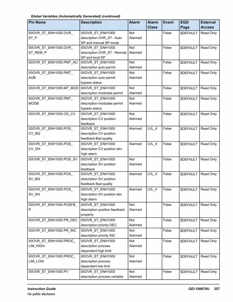
Global Variables (Automatically Generated) (continued)
Pin Name Description Alarm AlarmClass
Event EGDPage
ExternalAccess
00OVR_ST_ENH1000.OVR_ST_P
00OVR_ST_ENH1000description OVR_ST - AutoSP and manual SP mode
NotAlarmed
False $DEFAULT Read Only
00OVR_ST_ENH1000.OVR_ST_REM_P
00OVR_ST_ENH1000description OVR_ST - RemoteSP and local SP
NotAlarmed
False $DEFAULT Read Only
00OVR_ST_ENH1000.PMT_AU 00OVR_ST_ENH1000description auto permit
NotAlarmed
False $DEFAULT Read Only
00OVR_ST_ENH1000.PMT_AUB
00OVR_ST_ENH1000description auto permitbypass status
NotAlarmed
False $DEFAULT Read Only
00OVR_ST_ENH1000.MT_MOD 00OVR_ST_ENH1000description modulate permit
NotAlarmed
False $DEFAULT Read Only
00OVR_ST_ENH1000.PMT_MODB
00OVR_ST_ENH1000description modulate permitbypass status
NotAlarmed
False $DEFAULT Read Only
00OVR_ST_ENH1000.OS_CV 00OVR_ST_ENH1000description CV positionfeedback
NotAlarmed
False $DEFAULT Read Only
00OVR_ST_ENH1000.POS_CV_BQ
00OVR_ST_ENH1000description CV positionfeedback Bad quality
Alarmed LVL_4 False $DEFAULT Read Only
00OVR_ST_ENH1000.POS_CV_DH
00OVR_ST_ENH1000description CV position devhigh alarm
Alarmed LVL_4 False $DEFAULT Read Only
00OVR_ST_ENH1000.POS_SV 00OVR_ST_ENH1000description SV positionfeedback
NotAlarmed
False $DEFAULT Read Only
00OVR_ST_ENH1000.POS_SV_BQ
00OVR_ST_ENH1000description SV positionfeedback Bad quality
Alarmed LVL_4 False $DEFAULT Read Only
00OVR_ST_ENH1000.POS_SV_DH
00OVR_ST_ENH1000description SV position devhigh alarm
Alarmed LVL_4 False $DEFAULT Read Only
00OVR_ST_ENH1000.POSFB_P
00OVR_ST_ENH1000description position feedbackproperty
NotAlarmed
False $DEFAULT Read Only
00OVR_ST_ENH1000.PR_DEC 00OVR_ST_ENH1000description priority DEC
NotAlarmed
False $DEFAULT Read Only
00OVR_ST_ENH1000.PR_INC 00OVR_ST_ENH1000description priority INC
NotAlarmed
False $DEFAULT Read Only
00OVR_ST_ENH1000.PROC_LIM_HIGH
00OVR_ST_ENH1000description processdependent high limit
NotAlarmed
False $DEFAULT Read Only
00OVR_ST_ENH1000.PROC_LIM_LOW
00OVR_ST_ENH1000description processdependent low limit
NotAlarmed
False $DEFAULT Read Only
00OVR_ST_ENH1000.PV 00OVR_ST_ENH1000description process variable
NotAlarmed
False $DEFAULT Read Only
Instruction Guide GEI-100679U 357For public disclosure

Global Variables (Automatically Generated) (continued)
Pin Name Description Alarm AlarmClass
Event EGDPage
ExternalAccess
00OVR_ST_ENH1000.REJ_MN 00OVR_ST_ENH1000description manual reject
NotAlarmed
False $DEFAULT Read Only
00OVR_ST_ENH1000.REJ_MNB
00OVR_ST_ENH1000description manual rejectbypass status
NotAlarmed
False $DEFAULT Read Only
00OVR_ST_ENH1000.RS 00OVR_ST_ENH1000description remote setpointmode
NotAlarmed
False $DEFAULT Read Only
00OVR_ST_ENH1000.RSP 00OVR_ST_ENH1000description remote setpoint
NotAlarmed
False $DEFAULT Read Only
00OVR_ST_ENH1000.RSP_BQ 00OVR_ST_ENH1000description remote setpointBQ
NotAlarmed
False $DEFAULT Read Only
00OVR_ST_ENH1000.SC 00OVR_ST_ENH1000description setpoint
NotAlarmed
False $DEFAULT Read Write
00OVR_ST_ENH1000.SH 00OVR_ST_ENH1000description setpoint upper limit
NotAlarmed
False $DEFAULT Read Only
00OVR_ST_ENH1000.SI 00OVR_ST_ENH1000description setpoint (internalbefore ramp)
NotAlarmed
False $DEFAULT Read Only
00OVR_ST_ENH1000.SL 00OVR_ST_ENH1000description setpoint lower limit
NotAlarmed
False $DEFAULT Read Only
00OVR_ST_ENH1000.SP 00OVR_ST_ENH1000description setpoint
NotAlarmed
False $DEFAULT Read Only
00OVR_ST_ENH1000.SP_TRACK
00OVR_ST_ENH1000description setpoint tracks PVin manual and RSP inauto-remote
NotAlarmed
False $DEFAULT Read Only
00OVR_ST_ENH1000.SPLIT_P 00OVR_ST_ENH1000description split rangeproperty
NotAlarmed
False $DEFAULT Read Only
00OVR_ST_ENH1000.SV 00OVR_ST_ENH1000description split rangecharacterized output
NotAlarmed
False $DEFAULT Read Only
00OVR_ST_ENH1000.SV_L 00OVR_ST_ENH1000description SV pop level
NotAlarmed
False Read Only
00OVR_ST_ENH1000.SV_MN 00OVR_ST_ENH1000description SV pop levelminimum
NotAlarmed
False Read Only
00OVR_ST_ENH1000.SV_R 00OVR_ST_ENH1000description SV pop reset tominimum
NotAlarmed
False Read Only
00OVR_ST_ENH1000.SV_X 00OVR_ST_ENH1000description SV X CHAR array
NotAlarmed
False Read Only
00OVR_ST_ENH1000.SV_Y 00OVR_ST_ENH1000description SV Y CHAR array
NotAlarmed
False Read Only
00OVR_ST_ENH1000.TK_CMDB
00OVR_ST_ENH1000description track commandblock status
NotAlarmed
False $DEFAULT Read Only
358 GEI-100679U Mark VIe Controller DCS Block LibraryFor public disclosure
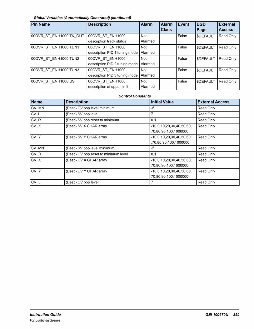
Global Variables (Automatically Generated) (continued)
Pin Name Description Alarm AlarmClass
Event EGDPage
ExternalAccess
00OVR_ST_ENH1000.TK_OUT 00OVR_ST_ENH1000description track status
NotAlarmed
False $DEFAULT Read Only
00OVR_ST_ENH1000.TUN1 00OVR_ST_ENH1000description PID 1 tuning mode
NotAlarmed
False $DEFAULT Read Only
00OVR_ST_ENH1000.TUN2 00OVR_ST_ENH1000description PID 2 tuning mode
NotAlarmed
False $DEFAULT Read Only
00OVR_ST_ENH1000.TUN3 00OVR_ST_ENH1000description PID 3 tuning mode
NotAlarmed
False $DEFAULT Read Only
00OVR_ST_ENH1000.US 00OVR_ST_ENH1000description at upper limit
NotAlarmed
False $DEFAULT Read Only
Control ConstantsName Description Initial Value External AccessCV_MN {Desc} CV pop level minimum -5 Read OnlySV_L {Desc} SV pop level 7 Read OnlySV_R {Desc} SV pop reset to minimum 0.1 Read OnlySV_X {Desc} SV X CHAR array -10,0,10,20,30,40,50,60,
70,80,90,100,1000000Read Only
SV_Y {Desc} SV Y CHAR array -10,0,10,20,30,40,50,60,70,80,90,100,1000000
Read Only
SV_MN {Desc} SV pop level minimum -5 Read OnlyCV_R {Desc} CV pop reset to minimum level 0.1 Read OnlyCV_X {Desc} CV X CHAR array -10,0,10,20,30,40,50,60,
70,80,90,100,1000000Read Only
CV_Y {Desc} CV Y CHAR array -10,0,10,20,30,40,50,60,70,80,90,100,1000000
Read Only
CV_L {Desc} CV pop level 7 Read Only
Instruction Guide GEI-100679U 359For public disclosure

HMI Configuration (CIMPLICITY)
In edit mode, an OVR_ST_ENH block can be directly inserted into the CIMPLICITY screen from the ToolboxST applicationcode using the drop and drag method. The CIMPLICITYobject created depends on the HMILinkSource andHMILinkedObject information contained in the PID_MA_ENH attributes.
In edit mode, select an attribute to insert into the CIMPLICITY screen.
OVR_ST_ENH Attributes
Note The CIMPLICITYobjects to choose from for OVR_ST_ ENH are dependent on the path.
360 GEI-100679U Mark VIe Controller DCS Block LibraryFor public disclosure

OVR_ST_ENH CIMPLICITY Objects
OVR_ST_ENH CIMPLICITY Faceplate
Instruction Guide GEI-100679U 361For public disclosure

38 Override Station Enhanced Version 2(OVR_ST_ENH_V2)Block Category: Controls (DCS)
The Override Station Enhanced Version 2 (OVR_ST_ENH_V2) block is an enhanced override station that controls up to threecascaded or non-cascaded PID_MA_ENH_V2 block loops. The inputs and outputs of the OVR_ST_ENH_V2 block can bemonitored and controlled by the operator using the CIMPLICITY graphical interface. The block’s various functionalcapabilities are defined by three separate enumerated inputs: Block Option (BLOCK_OPT), Mode Option (MODE_OPT),and Station Option (STATION_OPT). The user must first identify the functions needed for the application for which the blockwill be used, and then choose the appropriate enumeration for each input to provide the desired block functionality. TheEnhanced block performs quality status monitoring of input and output signals and propagates the quality status to theoutputs: control variable output (CVO), CV, and SV.
Note Refer to the sections BLOCK_OPT, MODE_OPT, and STATION_OPT.
Block Configuration
BLOCK_OPT
BLOCK_OPT enumerations are listed in the following table.
BLOCK_OPT Input Enumerations
Name DescriptionOVR_ST_MA OVR_STwith manual / auto setpoint controlOVR_ST_REM OVR_STwith manual / auto control and local / remote setpointOVR_ST_EXT OVR_STwith manual / auto control and external setpoint
OVR_ST_MA— used only when manual / auto setpoint control is needed. It sets the output property (OVR_ST_P) to True.
OVR_ST_REM— used when a remote setpoint value is needed and sets the output property (OVR_ST_REM_P) to True.The remote setpoint is connected to the OVR_ST_ENH_V2 block remote setpoint (RSP) input. This enumeratiON permits alocal setpoint and a remote setpoint, either of which can be selected by the operator using the graphical interface, or by theOVR_ST_ENH_V2 block remote setpoint select pulsed (RSP_SEL) input.
OVR_ST_EXT— used when an external setpoinat input value is to be used as the setpoint value and sets the output property(OVR_ST_EXT_P) to True. The remote setpoint is connected to the RSP input. This enumeration does not allow a localsetpoint, only an external setpoint that is connected to the RSP input. When this enumeration is used, the operator cannotselect a local setpoint value from the graphical interface and the RSP_SEL input is disabled.
362 GEI-100679U Mark VIe Controller DCS Block LibraryFor public disclosure

MODE_OPT
MODE_OPT enumerations are listed in the following table.
MODE_OPT Input Enumerations
Name DescriptionNONE NoneLOCK Lock modePOS Position feedbackLOCK-POS Lock mode and position feedbackSPLIT Split rangeSPLIT-LOCK Split range and block modeSPLIT-POS Split range and position feedbackSPLIT-LOCK-POS Split range, lock mode and position feedback
NONE—indicates no mode options are enabled.
LOCK— sets the lock property (LOCK_P) to True, which allows software lockout of the controller to be implemented bythe operator using the CIMPLICITY graphical interface. The valve output, CVO, must be within 5 units of the initial position(INIT_POS) input value before the block can be set to lockout mode. When LOCK becomes True, the block is in lockoutmode and the block outputs, CVO, CV, and, if applicable, SV, are prohibited from modulating. If the block is in auto modeand LOCK becomes True, the block will be put into manual mode and the manual reject alarm (MAN_REJ_A) will beactivated. The operator’s ability to switch to auto mode is disabled until the block is removed from lockout mode.Additionally, the local auto setpoint will track the process variable (PV) input when the block is in lockout mode.
Note The lockout indication is provided for indication only. This action will not lock out the equipment, it will only indicatelockout status. Follow the owner's lockout procedures to safely lockout equipment.
The Lock button can also be configured to use the WorkstationST Lock function. Refer toWorkstationST/CIMPLICITYAdvanced Viewer Integration Instruction Guide (GEI-100697), the section HMI Tagout.
POS— used when feedback is available from the controlled device. Normally, feedback is the valve position feedback, butthe POS enumeration can also be used for motor speed or a variety of other device feedbacks. The position feedback value isconnected to the block POS_CV input and, if the MODE_OPT enumeration SPLIT is selected, the position feedback from thesecondary device is connected to the POS_SV block input. When the POS enumeration is used, the block POSFB_P output isTrue, the feedback value is displayed on the CIMPLICITY faceplate, and, when the cursor is placed over the feedback area,CV Pos Feedback = the instantaneous value) displays.
Instruction Guide GEI-100679U 363For public disclosure

POS Enumeration Faceplate
SPLIT— indicates that the controller will output to two different devices using block outputs, CVand SV, either or both ofwhich may be characterized by a 13 element array that enables each output to be customized to fit the requirements of aspecific control application.
The default characterization arrays for both CVand SVare linear and are as follows:
• CV_X and SV_X = -10, 0, 10, 20, 30, 40, 50, 60, 70, 80, 90, 100, 1000000• CV_Yand SV_Y = -10, 0, 10, 20, 30, 40, 50, 60, 70, 80, 90, 100, 1000000
If the CV_X 13 element array does not contain the same 13 array elements in the same order as the CV_Yarray, or the SV_X13 element array does not contain the same 13 array elements in the same order as the SV_Yarray, the characterizationproperty (CHAR_P) will be True and the graphical interface displays a button in the lower, right corner of the faceplate.
364 GEI-100679U Mark VIe Controller DCS Block LibraryFor public disclosure

When the cursor is placed over the feedback area, Show Characterization displays.
SPLIT Enumeration Faceplate
The following characterized outputs are applied:
• CV_X = -10, 0, 10, 20, 30, 40, 50, 60, 70, 80, 90, 100, 1000000• CV_Y = -10, 0, 10, 20, 30, 40, 50, 60, 70, 80, 90, 100, 1000000• SV_X = -10, 0, 10, 20, 30, 40, 50, 60, 70, 80, 90, 100, 1000000• SV_Y = -10, 0, 10, 20, 30, 40, 50, 60, 70, 80, 90, 100, 1000000
Instruction Guide GEI-100679U 365For public disclosure

SPLIT Enumeration Faceplate with Characterizations
MODE_OPT Output Properties
OVR_ST_ENH_V2 output properties control the appearance of the corresponding graphical interface based on the MODE_OPT enumeration. The OVR_ST_ENH_V2 output properties and their functions are as follows:
• NONE sets LOCK_P, POSFB_P, and SPLIT_P property to False• LOCK sets LOCK_P property to True• POS sets POSFB_P property to True• SPLIT sets SPLIT_P property to True
366 GEI-100679U Mark VIe Controller DCS Block LibraryFor public disclosure

STATION_OPT
STATION_OPT enumerations are listed in the following table.
STATION_OPT Input Enumerations
Name DescriptionSELECT_2_INPUTS Station output is selected from two inputsMIN_2_INPUTS Station output is minimum of two inputsMAX_2_INPUTS Station output is maximum of two inputsSELECT_3_INPUTS Station output is selected from three inputsMIN_3_INPUTS Station output is minimum of three inputsMAX_3_INPUTS Station output is maximum of three inputs
SELECT_2_INPUTS— indicates that two inputs, CVI1 and CVI2, can be selected by the maintained inputs, SEL1 andSEL2, and used to calculate the outputs, CVO, CV, and, if applicable, SVof the OVR_ST_ENH_V2 block. If both SEL1 andSEL2 inputs are False, the block defaults to the value of CVI1. If both SEL1 and SEL2 inputs are True, the block uses thevalue of CVI1. When this enumeration is used, the three input property output (3_INPUT_P) is False.
MIN_2_INPUTS— indicates that the minimum of the two inputs, CVI1 and CVI2, are used to calculate the outputs CVO,CV, and, if applicable, SVof the OVR_ST_ENH_V2 block. The inputs SEL1 and SEL2 are ignored. When this enumerationis used, the 3_INPUT_P output is False.
MAX_2_INPUTS— indicates that the maximum of the two inputs, CVI1 and CVI2, are used to calculate the outputs CVO,CV, and, if applicable, SVof the OVR_ST_ENH_V2 block. The inputs SEL1 and SEL2 are ignored. When this enumerationis used, the 3_INPUT_P output is False.
SELECT_3_INPUTS— indicates that three inputs, CVI1, CVI2, and CVI3, can be selected by the maintained inputs SEL1,SEL2, and SEL3, and used to calculate the outputs CVO, CV, and, if applicable, SVof the OVR_ST_ENH_V2 block. IfSEL1, SEL2 and SEL3 inputs are False, the block defaults to the value of CVI1. If more than one of the selected inputs isTrue, the first True value in the following order has precedence: SEL1; SEL2; then SEL3. When this enumeration is used, the3_INPUT_P output is True.
MIN_3_INPUTS— indicates that the minimum of the three inputs, CVI1, CVI2, and CVI3, are used to calculate the outputsCVO, CV, and, if applicable, SVof the OVR_ST_ENH_V2 block. The inputs SEL1, SEL2, and SEL3 are ignored. When thisenumeration is used, the 3_INPUT_P output is True.
MAX_3_INPUTS— indicates that the maximum of the three inputs, CVI1, CVI2, and CVI3, is used to calculate the outputsCVO, CV, and, if applicable, SVof the OVR_ST_ENH_V2 block. The inputs SEL1, SEL2, and SEL3 are ignored. When thisenumeration is used, the 3_INPUT_P output is True.
Instruction Guide GEI-100679U 367For public disclosure

CVI Selected Input enumerations are listed in the following table.
The CVI operator graphical interface uses the NSEL1, NSEL2, and NSEL3 outputs to indicate which input is being used tocalculate the block outputs. The block ensures only one of the three outputs is False, which identifies the input being used.
OVR_ST_ENH_V2 Faceplate with CVI2 Selected
368 GEI-100679U Mark VIe Controller DCS Block LibraryFor public disclosure
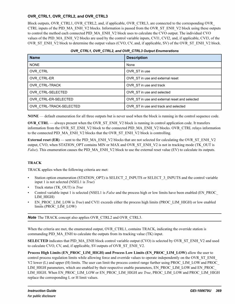
OVR_CTRL1, OVR_CTRL2, and OVR_CTRL3
Block outputs, OVR_CTRL1, OVR_CTRL2, and, if applicable, OVR_CTRL3, are connected to the corresponding OVR_CTRL inputs of the PID_MA_ENH_V2 blocks. Information is passed from the OVR_ST_ENH_V2 block using these outputsto control the method each connected PID_MA_ENH_V2 block uses to calculate the CVO output. The individual CVOvalues of the PID_MA_ENH_V2 blocks are used by the control variable inputs, CVI1, CVI2, and, if applicable, CVI3, of theOVR_ST_ENH_V2 block to determine the output values (CVO, CV, and, if applicable, SV) of the OVR_ST_ENH_V2 block.
OVR_CTRL1, OVR_CTRL2, and OVR_CTRL3 Output Enumerations
Name Description
NONE None
OVR_CTRL OVR_ST in use
OVR_CTRL-ER OVR_ST in use and external reset
OVR_CTRL-TRACK OVR_ST in use and track
OVR_CTRL-SELECTED OVR_ST in use and selected
OVR_CTRL-ER-SELECTED OVR_ST in use and external reset and selected
OVR_CTRL-TRACK-SELECTED OVR_ST in use and track and selected
NONE— default enumeration for all three outputs but is never used when the block is running in the control sequence code.
OVR_CTRL— always present when the OVR_ST_ENH_V2 block is running in control application code. It transfersinformation from the OVR_ST_ENH_V2 block to the connected PID_MA_ENH_V2 blocks. OVR_CTRL relays informationto the connected PID_MA_ENH_V2 blocks that the OVR_ST_ENH_V2 block is controlling.
External reset (ER)— sent to the PID_MA_ENH_V2 blocks that are not selected for calculating the OVR_ST_ENH_V2output, CVO, when STATION_OPT contains MIN or MAX and OVR_ST_ENH_V2 is not in tracking mode (TK_OUT isFalse). This enumeration causes the PID_MA_ENH_V2 block to use the external reset value (EV) to calculate its outputs.
TRACK
TRACK applies when the following criteria are met:
• Station option enumeration (STATION_OPT) is SELECT_2_INPUTS or SELECT_3_INPUTS and the control variableinput 1 is not selected (NSEL1 is True)
• Track status (TK_OUT) is True• Control variable input 1 is selected (NSEL1 is False and the process high or low limits have been enabled (EN_PROC_
LIM_HIGH)• EN_PROC_LIM_LOW is True) and CVI1 exceeds either the process high limits (PROC_LIM_HIGH) or low enabled
limits (PROC_LIM_LOW)
Note The TRACK concept also applies OVR_CTRL2 and OVR_CTRL3.
When the criteria are met, the enumerated output, OVR_CTRL1, contains TRACK, indicating the override station iscommanding PID_MA_ENH to calculate the outputs from its tracking value (TK) input.
SELECTED indicates that PID_MA_ENH block control variable output (CVO) is selected by OVR_ST_ENH_V2 and usedto calculate CVO, CV, and, if applicable, SVoutputs of OVR_ST_ENH_V2.
Process High Limits (EN_PROC_LIM_HIGH) and Process Low Limits (EN_PROC_LIM_LOW) allow the user tocontrol process regulation limits while allowing force and override values to operate independently on the OVR_ST_ENH_V2 lower (L) and upper (H) limits. The user can limit the process control range further using PROC_LIM_LOWand PROC_LIM_HIGH parameters, which are enabled by their respective enable parameters, EN_PROC_LIM_LOWand EN_PROC_LIM_HIGH. When EN_PROC_LIM_LOWor EN_PROC_LIM_HIGH are True, PROC_LIM_LOWand PROC_LIM_HIGHreplace the corresponding L or H limit values.
Instruction Guide GEI-100679U 369For public disclosure

Setpoint High (SH and Setpoint Low (SL) limit values (block inputs)— bound the block output, setpoint (SP).
Setpoint adjustment ramp rate (SR)— input value restricts the SP output rate of change in units/sec. The SP output ispassed without rate limit restrictions directly to the SP when the controller is powered up.
Internal Setpoint (SI)— value of the setpoint before the SR is applied. For example, if the setpoint changes from 0 to 10instantaneously, then SI changes from 0 to 10 instantaneously and SP ramps from 0 to 10 in 10 seconds if SR is set at 1unit/sec. SI is also bound by the SH and SL inputs.
Setpoint Track (SP_TRACK)— if True, tracks PV in manual mode and RSP in auto-remote mode. If the SP_TRACKparameter is False, the setpoint tracks RSP in remote mode and RS is True. Otherwise, the operator controls the setpoint valueusing the graphical interface.
Remote Select (RSP_SEL)— pulsed input that instructs the block to use the remote setpoint (RSP) input to calculate blockoutputs CVO, CV, and, if applicable, SV when the block is in auto mode. The input must be pulsed.
Manual adjustment rate (MR)— restricts the rate of change of the CVO in units/sec.
Tracking status (TK_OUT)— block output is set to True when the following input conditions are met:
• RSP input bad quality• Output bad quality• Selected CVI input override or bad quality• Priority increase or decrease• Manual mode• Force command• Override command• Increase or decrease inhibit• Lock• MN_REJ input enumeration contains OVR• Track command (CMD_TK) input contains TRACK• RS output changes state, causing a setpoint realignment• Auto mode (AUTO) output changes state, causing a setpoint realignment• Permit to modulate (MOD_PMT) is False (enumeration contains no permit [NO_PERM]).
When TK_OUT is True, the OVR_ ST_ENH_V2 is in tracking mode and block output CVO tracks the appropriate valuebased on the parameter that set TK_OUT to True. The value used for tracking may be the override value (OV), the force value(FV) while a priority increase or decrease command moves to the H or L limit output values at the priority increase rate (PR_INC_RT) or decrease rate (PR_DEC_RT). The value used for tracking may also be the track value (TV) or the initial position(INIT_POS) value. If there is no priority increase or decrease active, PR_INC and PR_DEC are False, and, if an inhibitincrease or decrease command is present, the block output INC_INH or DEC_INH is True, then TK_OUT is True as the valueof CVO modulates in the direction of the inhibit request.
Note CVO also includes CV_X and, if applicable, SV_X, for characterized outputs CVand SV, respectively.The H and Lvalues are dependent on enable process limit inputs EN_PROC_LIM_HIGH and EN_PROC_LIM_LOW, and the PROC_LIM_HIGH and PROC_LIM_LOW limits, respectively.
370 GEI-100679U Mark VIe Controller DCS Block LibraryFor public disclosure
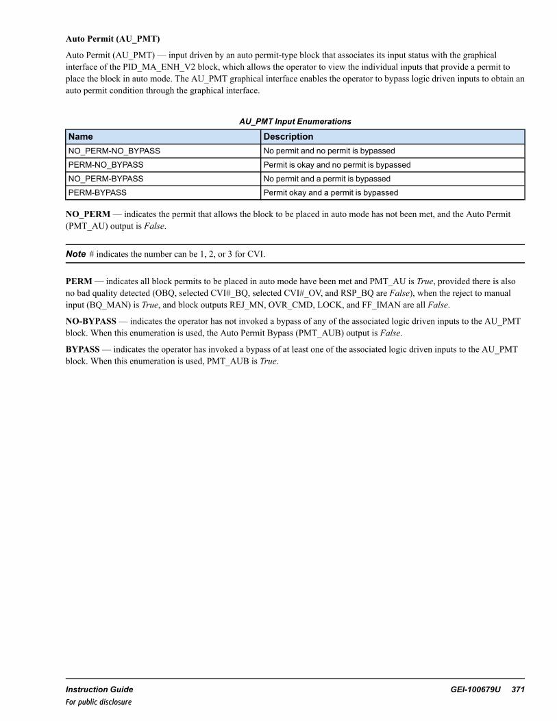
Auto Permit (AU_PMT)
Auto Permit (AU_PMT) — input driven by an auto permit-type block that associates its input status with the graphicalinterface of the PID_MA_ENH_V2 block, which allows the operator to view the individual inputs that provide a permit toplace the block in auto mode. The AU_PMT graphical interface enables the operator to bypass logic driven inputs to obtain anauto permit condition through the graphical interface.
AU_PMT Input Enumerations
Name DescriptionNO_PERM-NO_BYPASS No permit and no permit is bypassed
PERM-NO_BYPASS Permit is okay and no permit is bypassed
NO_PERM-BYPASS No permit and a permit is bypassedPERM-BYPASS Permit okay and a permit is bypassed
NO_PERM— indicates the permit that allows the block to be placed in auto mode has not been met, and the Auto Permit(PMT_AU) output is False.
Note # indicates the number can be 1, 2, or 3 for CVI.
PERM— indicates all block permits to be placed in auto mode have been met and PMT_AU is True, provided there is alsono bad quality detected (OBQ, selected CVI#_BQ, selected CVI#_OV, and RSP_BQ are False), when the reject to manualinput (BQ_MAN) is True, and block outputs REJ_MN, OVR_CMD, LOCK, and FF_IMAN are all False.
NO-BYPASS— indicates the operator has not invoked a bypass of any of the associated logic driven inputs to the AU_PMTblock. When this enumeration is used, the Auto Permit Bypass (PMT_AUB) output is False.
BYPASS— indicates the operator has invoked a bypass of at least one of the associated logic driven inputs to the AU_PMTblock. When this enumeration is used, PMT_AUB is True.
Instruction Guide GEI-100679U 371For public disclosure

Modulate Permit (MOD_PMT)
Modulate Permit (MOD_PMT) input is driven by a modulate permit-type block that associates its input status with the OVR_ST_ENH_V2 block graphical interface. This enables the operator to view the individual inputs that provide a permit thatallows the block to modulate the output. The MOD_PMT graphical interface enables the operator to bypass logic driveninputs to obtain a modulate permit condition through the graphical interface.
MOD_PMT Enumerations
Name Description
NO_PERM-NO_BYPASS No permit and no permit is bypassed
PERM-NO_BYPASS Permit okay and no permit is bypassed
NO_PERM-BYPASS No permit and a permit is bypassed
PERM-BYPASS Permit is okay and a permit is bypassed
NO_PERM— indicates a permit that allows the block to modulate the output, CVO, has not been met and the permit tomodulate (PMT_MOD) output is False. If theMOD_PMT input enumeration contains NO_PERM , CVOequals the INIT_POS input value.
PERM indicates all permits that allow the block to modulate the output, CVO, have been met and PMT_MOD is True.
NO-BYPASS— indicates the operator has not invoked a bypass of any of the associated logic driven inputs to the MOD_PMT block. When this enumeration is used, the modulate permit bypass (PMT_MODB) output is True.
BYPASS— indicates the operator has invoked a bypass of at least one of the associated logic driven inputs to the MOD_PMT block. When this enumeration is used, PMT_MODB is True.
372 GEI-100679U Mark VIe Controller DCS Block LibraryFor public disclosure

Command Force (CMD_FRC)
Command Force (CMD_FRC) input is driven by a force-type block that associates its input status with the OVR_ST_ENH_V2 block graphical interface, which enables the operator to view the individual inputs that place the block into force mode.The CMD_FRC graphical interface enables the operator to block logic driven inputs to release the force condition through thegraphical interface.
CMD_FRC Enumerations
Name Description
NO_FORCE-NO_BLOCK No force and no force is blocked
FORCE-NO_BLOCK Force active and no force is blocked
NO_FORCE-BLOCK No force and a force is blocked
FORCE-BLOCK Force active and a force is blocked
NO_FORCE— indicates no force command is active and the force command output (FRC_CMD) is False.
FORCE— indicates a force command is active and, if the CMD_OVR enumerated input does not contain OVR (OVR_CMDis False), then FRC_CMD is True.
NO-BLOCK— indicates the operator has not invoked a block of any of the associated logic driven inputs to the force-typeblock. When this enumeration is used, the FORCE-BLOCK output, FRC_CMDB, is False.
BLOCK— indicates the operator has invoked a block of at least one of the associated logic driven inputs to the force-typeblock and sets FRC_CMDB to True.
If the OVR_ST_ENH_V2 block CMD_FRC input enumeration contains FORCE, FRC_CMD exists and the output CVOmoves to the FV input value.
Note An override command (the CMD_OVR enumeration contains OVR) has precedence over a force command.
Command Track (CMD_TK)
Command Track (CMD_TK) input is driven by a track-type block that associates its input status with the OVR_ST_ENHblock graphical interface, which allows the operator to view the individual inputs that place the block into track mode. Thetrack graphical interface enables the operator to block logic driven inputs to release the track condition through the graphicalinterface.
CMD_TK Enumerations
Name Description
NO_TRACK-NO_BLOCK No track and no track is blocked
TRACK-NO_BLOCK Track active and no track is blocked
NO_TRACK-BLOCK No track and a track is blocked
TRACK-BLOCK Track active and a track is blocked
NO_TRACK— indicates no track command is active and the track status output, TK_OUT, is False.
TRACK— indicates a track command is active and the track status output (TK_OUT) is True.
NO-BLOCK— indicates the operator has not invoked a block of any of the associated logic driven inputs to the track-typeblock. When this enumeration is used, the TRACK-BLOCKED output, TK_CMDB, is False.
BLOCK— indicates the operator has invoked a block of at least one of the associated logic driven inputs to the track-typeblock. When this enumeration is used, TK_CMDB is True.
Instruction Guide GEI-100679U 373For public disclosure

If the OVR_ST_ENH block is in auto mode and a validated CMD_TK input enumeration contains TRACK, then a trackcommand exists and enumerated outputs OVR_CTRL1, OVR_CTRL2, and OVR_CTRL3 contain TRACK, commanding theconnected PID_MA_ENH_V2 blocks to tracking mode.
Command Override (CMD_OVR)
Command Override (CMD_OVR) input is driven by an override-type block that associates its input status with the OVR_ST_ENH_V2 block graphical interface, which allows the operator to view the individual inputs that place the block in overridemode. The override graphical interface enables the operator to block logic driven inputs to release the override conditionthrough the graphical interface.
CMD_OVR Enumerations
Name Description
NO_OVR-NO_BLOCK No override and no override is blocked
OVR-NO_BLOCK Override active and no override is blocked
NO_OVR-BLOCK No override and an override is blocked
OVR-BLOCK Override active and an override is blocked
NO_OVR— indicates no override command is active and the command override output (OVR_CMD) is False.
OVR— indicates an override command is active and OVR_CMD is True.
NO-BLOCK— indicates the operator has not invoked a block of any of the associated logic driven inputs to the overridetype block. When this enumeration is used, OVR_CMDB is False.
BLOCK— indicates the operator has invoked a block of at least one of the associated logic driven inputs to the override-typeblock. When this enumeration is used, OVR_CMDB is True.
If the OVR_ST_ENH_V2 block is in auto mode and a validated CMD_OVR input enumeration contains OVR, an overridecommand exists and the manual reject alarm (MN_REJ_A) is activated and the output moves to the input value of theoverride value (OV). The OVR_ST_ENH_V2 block is removed from auto mode and placed in manual mode and the localauto setpoint, if available, tracks PV.
Note An override command (the enumeration of CMD_OVR contains OVR) has precedence over a force command.
Control Word
Control Word (CTL) enumerations are listed in the following table.
The operator controls the PID_MA_ENH_V2 block by clicking buttons on the CIMPLICITY graphical interface faceplate.Certain faceplate buttons carry an enumerated value represented in the OVR_ST_ENH_V2 block input, CTL. The faceplatetransfers enumerated values to the OVR_ST_ENH_V2 block through the EGD using the CTL. When the faceplate sends acommand to the OVR_ST_ENH_V2 block, the block performs the command (after one second), overwrites the CTL inputwith the NO_CMD enumeration, and resets itself for the next CTL command.
Note Faceplate commands using the CTL are dependent on BLOCK_OPT and MODE_OPT enumerations. For example,LOCK_CMD and UNLOCK_CMD enumerations are not used if MODE_OPT does not contain the LOCK enumeration.
CTL Enumerations
Name Description
NO_CMD No command
AUTO_CMD Auto command
374 GEI-100679U Mark VIe Controller DCS Block LibraryFor public disclosure

CTL Enumerations (continued)
Name Description
MANUAL_CMD Manual command
LOCK_CMD Lock command
UNLOCK_CMD Unlock command
REMOTE_CMD Remote SP command
LOCAL_CMD Local SP command
NO_CMD— indicates no command is present.
AUTO_CMD— switches the block into auto mode from manual mode using the graphical interface faceplate. The autosetpoint is local, remote, or external depending on the BLOCK_OPT enumeration and the operator selection, if applicable, islocal or remote. When the block is in auto mode the output, AUTO, is True.
MANUAL_CMD— switches the block into manual mode from auto mode using the graphical interface faceplate. Theoperator manually sets the output to the controlled device. When the block is in manual mode, AUTO is True.
LOCK_CMD— indicates the block is in lock mode, which occurs when the block output, CVO, is within 5 units of theinitial position (INIT_POS) value. This enumeration removes the block from auto mode, places it in manual mode, and setsMN_REJ_A to True. When the block is in lock mode, the output, LOCK, is True.
UNLOCK_CMD— removes the block from lock mode and sets LOCK to False.
REMOTE_CMD— directs the block (when in auto mode) to use the RS value connected to block input pin RSP as the autosetpoint. When the block is in remote mode, the RS output is True.
LOCAL_CMD— directs the block (when in auto mode) to use the operator defined local setpoint. When the block is inlocal mode, RS is False.
Manual Reject (MN_REJ)
Manual Reject (MN_REJ) input is driven by an override-type block that associates its input status with the OVR_ST_ENH_V2 block graphical interface, which allows the operator to view the individual inputs that place the block in manual rejectmode. The override graphical interface enables the operator to block logic driven inputs to release the override conditionthrough the graphical interface.
MN_REJ Enumerations
Name Description
NO_OVR-NO_BLOCK No override and no override is blocked
OVR-NO_BLOCK Override active and no override is blocked
NO_OVR-BLOCK No override and an override is blocked
OVR-BLOCK Override active and an override is blocked
NO_OVR— indicates no manual reject command is active and the manual reject output, REJ_MN, is False.
OVR— indicates a manual reject command is active and REJ_MN is True.
NO-BLOCK— indicates the operator has not invoked a block of any of the associated logic driven inputs to theoverride-type block. When NO-BLOCK is active, the output, REJ_MNB, is False.
BLOCK— indicates the operator has invoked a block of at least one of the associated logic driven inputs to the override-typeblock. The BLOCK enumeration is not used by OVR_ST_ENH_V2, but the block passes the information it to the graphicalinterface for display purposes using REJ_MNB. When a block is active, REJ_MNB is True.
Instruction Guide GEI-100679U 375For public disclosure

If the OVR_ST_ENH_V2 block is in auto mode and a validated MN_REJ input enumeration contains OVR, then the block isremoved from auto mode and placed in manual mode, and MN_REJ_A is activated, and enumerated outputs OVR_CTRL1,OVR_CTRL2, and OVR_CTRL3 contain TRACK, which commands the connected PID_MA_ENH_V2 blocks into trackingmode.
CASC_IN1, CASC_IN2, and CASC_IN3
Note Although the enumerated inputs contain all enumerations discussed in this section, the OVR_ST_ENH_V2 block isonly affected when the input enumerations contain TUNE_INNER or TUNE_OUTER.
The enumerated OVR_ST_ENH_V2 block inputs, CASC_IN1, CASC_IN2, and, if applicable, CASC_IN3, receiveinformation from the PID_MA_ENH_V2 block output, override controlled (CASC_OUT). The enumeration informationinstructs the OVR_ST_ENH_V2 block on how to properly calculate the value and status of outputs CVO, CV, and, ifapplicable, SV.
CASC_IN1, CASC_IN2, and CASC_IN3 Input Enumerations
Name DescriptionDIRECT Direct actionREVERSE Reverse actionDIRECT-TRACK Direct action and TRACKREVERSE-TRACK Reverse action and TRACKDIRECT-LOW_LIMITED Direct action and LOW _LIMITEDREVERSE-LOW_LIMITED Reverse action and LOW _LIMITEDDIRECT-TRACK-LOW_LIMITED Direct action, TRACK, and LOW_LIMITEDREVERSE-TRACK-LOW_LIMITED Reverse action, TRACK, and LOW_LIMITEDDIRECT-HI_LIMITED Direct action and HI_LIMITEDREVERSE-HI_LIMITED Reverse action and HI_LIMITEDDIRECT-TRACK-HI_LIMITED Direct action, TRACK, and HI_LIMITEDREVERSE-TRACK-HI_LIMITED Reverse action, TRACK, and HI_LIMITEDDIRECT-LOW_LIMITED-HI_LIMITED Direct action, LOW _LIMITED, and HI_LIMITEDREVERSE-LOW_LIMITED-HI_LIMITED Reverse action, LOW _LIMITED, and HI_LIMITEDDIRECT-TRACK-LOW_LIMITED-HI_LIMITED Direct action, TRACK, LOW_LIMITED, and HI_LIMITEDREVERSE-TRACK-LOW_LIMITED-HI_LIMITED Reverse action, TRACK, LOW_LIMITED, and HI_LIMITEDDIRECT-TUNE_INNER Direct action and TUNE_INNERREVERSE-TUNE_INNER Reverse action and TUNE_INNERDIRECT-TRACK-TUNE_INNER Direct action, TRACK, and TUNE_INNERREVERSE-TRACK-TUNE_INNER Reverse action, TRACK, and TUNE_INNERDIRECT-LOW_LIMITED-TUNE_INNER Direct action, LOW _LIMITED, and TUNE_INNERREVERSE-LOW_LIMITED-TUNE_INNER Reverse action, LOW _LIMITED, and TUNE_INNERDIRECT-TRACK-LOW_LIMITED-TUNE_INNER Direct action, TRACK, LOW_LIMITED, and TUNE_INNERREVERSE-TRACK-LOW_LIMITED-TUNE_INNER Reverse action, TRACK, LOW_LIMITED, and TUNE_INNERDIRECT-HI_LIMITED-TUNE_INNER Direct action, HI_LIMITED, and TUNE_INNERREVERSE-HI_LIMITED-TUNE_INNER Reverse action, HI_LIMITED, and TUNE_INNERDIRECT-TRACK-HI_LIMITED-TUNE_INNER Direct action, TRACK, HI_LIMITED, and TUNE_INNERREVERSE-TRACK-HI_LIMITED-TUNE_INNER Reverse action, TRACK, HI_LIMITED, and TUNE_INNERDIRECT-LOW_LIMITED-HI_LIMITED-TUNE_INNER Direct action, LOW _LIMITED, HI_LIMITED, and TUNE_
INNERREVERSE-LOW_LIMITED-HI_LIMITED-TUNE_INNER Reverse action, LOW _LIMITED, HI_LIMITED, and TUNE_
INNER
376 GEI-100679U Mark VIe Controller DCS Block LibraryFor public disclosure

CASC_IN1, CASC_IN2, and CASC_IN3 Input Enumerations (continued)
Name DescriptionDIRECT-TRACK-LOW_LIMITED-HI_LIMITED-TUNE_INNER
Direct action, TRACK, LOW_LIMITED, HI_LIMITED, andTUNE_INNER
REVERSE-TRACK-LOW_LIMITED-HI_LIMITED-TUNE_INNER
Reverse action, TRACK, LOW_LIMITED, HI_LIMITED, andTUNE_INNER
DIRECT-TUNE_OUTER Direct action and TUNE_OUTERREVERSE-TUNE_OUTER Reverse action and TUNE_OUTERDIRECT-TRACK-TUNE_OUTER Direct action, TRACK, and TUNE_OUTERREVERSE-TRACK-TUNE_OUTER Reverse action, TRACK, and TUNE_OUTERDIRECT-LOW_LIMITED-TUNE_OUTER Direct action, LOW _LIMITED, and TUNE_OUTERREVERSE-LOW_LIMITED-TUNE_OUTER Reverse action, LOW _LIMITED, and TUNE_OUTERDIRECT-TRACK-LOW_LIMITED-TUNE_OUTER Direct action, TRACK, LOW_LIMITED, and TUNE_OUTERREVERSE-TRACK-LOW_LIMITED-TUNE_OUTER Reverse action, TRACK, LOW_LIMITED, and TUNE_OUTERDIRECT-HI_LIMITED-TUNE_OUTER Direct action, HI_LIMITED, and TUNE_OUTERREVERSE-HI_LIMITED-TUNE_OUTER Reverse action, HI_LIMITED, and TUNE_OUTERDIRECT-TRACK-HI_LIMITED-TUNE_OUTER Direct action, TRACK, HI_LIMITED, and TUNE_OUTERREVERSE-TRACK-HI_LIMITED-TUNE_OUTER Reverse action, TRACK, HI_LIMITED, and TUNE_OUTERDIRECT-LOW_LIMITED-HI_LIMITED-TUNE_OUTER Direct action, LOW _LIMITED, HI_LIMITED, and TUNE_
OUTERREVERSE-LOW_LIMITED-HI_LIMITED-TUNE_OUTER Reverse action, LOW _LIMITED, HI_LIMITED, and TUNE_
OUTERDIRECT-TRACK-LOW_LIMITED-HI_LIMITED-TUNE_OUTER
Direct action, TRACK, LOW_LIMITED, HI_LIMITED, andTUNE_OUTER
REVERSE-TRACK-LOW_LIMITED-HI_LIMITED-TUNE_OUTER
Reverse action, TRACK, LOW_LIMITED, HI_LIMITED, andTUNE_OUTER
DIRECT-TUNE_INNER-TUNE_OUTER Direct action, TUNE_INNER, and TUNE_OUTERREVERSE-TUNE_INNER-TUNE_OUTER Reverse action, TUNE_INNER, and TUNE_OUTERDIRECT-TRACK-TUNE_INNER-TUNE_OUTER Direct action, TRACK, TUNE_INNER, and TUNE_OUTERREVERSE-TRACK-TUNE_INNER-TUNE_OUTER Reverse action, TRACK, TUNE_INNER, and TUNE_OUTERDIRECT-LOW_LIMITED-TUNE_INNER-TUNE_OUTER Direct action, LOW _LIMITED, TUNE_INNER, and TUNE_
OUTERREVERSE-LOW_LIMITED-TUNE_INNER-TUNE_OUTER Reverse action, LOW _LIMITED, TUNE_INNER, and TUNE_
OUTERDIRECT-TRACK-LOW_LIMITED-TUNE_INNER-TUNE_OUTER
Direct action, TRACK, LOW_LIMITED, TUNE_INNER, andTUNE_OUTER
REVERSE-TRACK-LOW_LIMITED-TUNE_INNER-TUNE_OUTER
Reverse action, TRACK, LOW_LIMITED, TUNE_INNER, andTUNE_OUTER
DIRECT-HI_LIMITED-TUNE_INNER-TUNE_OUTER Direct action, HI_LIMITED, TUNE_INNER, and TUNE_OUTER
REVERSE-HI_LIMITED-TUNE_INNER-TUNE_OUTER Reverse action, HI_LIMITED, TUNE_INNER, and TUNE_OUTER
DIRECT-TRACK-HI_LIMITED-TUNE_INNER-TUNE_OUTER Direct action, TRACK, HI_LIMITED, TUNE_INNER, andTUNE_OUTER
REVERSE-TRACK-HI_LIMITED-TUNE_INNER-TUNE_OUTER
Reverse action, TRACK, HI_LIMITED, TUNE_INNER, andTUNE_OUTER
DIRECT-LOW_LIMITED-HI_LIMITED-TUNE_INNER-TUNE_OUTER
Direct action, LOW _LIMITED, HI_LIMITED, TUNE_INNER,and TUNE_OUTER
REVERSE-LOW_LIMITED-HI_LIMITED-TUNE_INNER-TUNE_OUTER
Reverse action, LOW _LIMITED, HI_LIMITED, TUNE_INNER,and TUNE_OUTER
Instruction Guide GEI-100679U 377For public disclosure

CASC_IN1, CASC_IN2, and CASC_IN3 Input Enumerations (continued)
Name DescriptionDIRECT-TRACK-LOW_LIMITED-HI_LIMITED-TUNE_INNER-TUNE_OUTER
Direct action, TRACK, LOW_LIMITED, HI_LIMITED, TUNE_INNER, and TUNE_OUTER
REVERSE-TRACK-LOW_LIMITED-HI_LIMITED-TUNE_INNER-TUNE_OUTER
Reverse action, TRACK, LOW_LIMITED, HI_LIMITED,TUNE_INNER, and TUNE_OUTER
NO_CASC No cascade
Note All enumerated values in this section transfer information between cascaded PID_MA_ENH_V2 blocks, but the OVR_ST_ENH_V2 block only needs the TUNE_INNER or TUNE_OUTER enumeration to ensure proper block functionality.
NO_CASC— default value but has no effect on the OVR_ST_ENH_V2 block. However, PID_MA_ENH_V2 outputCASC_OUT is never NO_CASC when the controller is running. If no connection is made to the CASC_IN3 input, the defaultenumeration of CASC_IN3 is NO_CASC and the STATION_OPT input enumeration indicates three inputs are not beingused. Of the three inputs being used, property (3_INPUT_P) is False.
The following are not used in the OVR_ST_ENH_V2 block:
• DIRECT• REVERSE• TRACK• LOW_LIMITED• HIGH_LIMITED
TUNE_INNER— indicates the operator has selected the override controlled inner loop of a cascaded PID_MA_ENH_V2block from the graphical interface to be in tuning mode.
TUNE_OUTER— indicates the operator has selected the override controlled outer loop of a cascaded PID_MA_ENH_V2block from the graphical interface to be in tuning mode. If a non-cascaded PID_MA_ENH_V2 block is used in an overridecontrol scenario with an OVR_ST_ENH block, this enumeration is contained in the CASC_OUT output of the PID_MA_ENH_V2 block when it is placed in tuning mode.
378 GEI-100679U Mark VIe Controller DCS Block LibraryFor public disclosure

Tuning Mode of Override Controlled PID_MA_ENH_V2 Blocks
When an override controlled PID_MA_ENH_V2 block is in tuning mode, the corresponding OVR_ST_ENH_V2 enumeratedinput, CASC_IN1, CASC_IN2, or CASC_IN3, contains TUNE_INNER, TUNE_OUTER, or TUNE_INNER-TUNE_OUTER. The OVR_ST_ENH_V2 block selects the PID_MA_ENH_V2 block in tuning mode for output. If more than one ofthe controlled PID_MA_ENH_V2 blocks are in tuning mode at the same time, the input used to calculate the output of theOVR_ST_ENH_V2 block is prioritized by CASC_IN1, CASC_IN2, and CASC_IN3 (in this order), which contain theenumerations TUNE_INNER, TUNE_OUTER or TUNE_INNER-TUNE_OUTER.
Priority Increase (PR_INC) and Decrease Commands (PR_DEC)
Whenever the OVR_ST_ENH_V2 block input PR_INC is True, the output CVO increases to the high limit (H) value at therate defined by the PR_INC rate value, PR_INC_RT (default value is 1 unit/sec).
Whenever the OVR_ST_ENH_V2 block input PR_DEC is True and PR_INC is False, the output CVO decreases to the lowlimit (L) value at the rate defined by the PR_DEC rate value, PR_DEC_RT (default value is 1 unit/sec).
Program both inputs, PR_INC and PR_DEC, to be mutually exclusive events. However, if at any time they both become True,then PR_INC is the dominate input and the CVO value increases to the H value at the rate defined by the PR_INC rate value,PR_INC_RT.
Note A force command (CMD_FRC contains FORCE), or an override command (CMD_OVR contains OVR) haveprecedence over the PR_INC and PR_DEC inputs.
Inhibit Increase (INH_INC) and Decrease commands (INH_DEC)
OVR_ST_ENH_V2 is capable of inhibiting the output control variable (CVO) from increasing or decreasing in value withouta force or override command (FORCE from the enumerated CMD_FRC input or OVR from the enumerated CMD_OVRinput).
Inhibiting the increase of the CVO output occurs when INH_INC input is True and neither of the priority increase or prioritydecrease input pins, PR_INC or PR_DEC are True.
Inhibiting the decrease of the CVO output occurs when INH_DEC input is True and neither of the PR_INC or PR_DEC inputpins are True.
CVO, CV, and SV Output Status Propagation and Bad Quality Determination
OVR_ST_ENH_V2 monitors the quality status values of various inputs and connected outputs to determine the quality statusvalue of CVO, CV, and SV (if the MODE_OPT enumeration contains SPLIT then the split output property, SPLIT_P, is True).
The quality status value of control variable output CV is either the quality status value of CVO or, if SPLIT_P is True and thequality status value of BKCAL_IN_CV > 200 and < 203, then the quality status value of CV is assigned a quality status valueof 196, NOT_LIMITED-INTIALIZATION_ACKNOWLEDGE-GOODC.
The quality status value of the split range control variable output, SV, is either the quality status value of CVO or, if SPLIT_Pis True and the quality status value of BKCAL_IN_SV is > 200 and < 203, then the quality status value of SV is assigned aquality status value of 196, NOT_LIMITED-INTIALIZATION_ACKNOWLEDGE-GOODC.
OVR_ST_ENH calculates the quality status value of CVO from appropriate inputs with quality status values, inputparameters values, and the connected hard I/O quality status values of CVand, if MODE_OPT contains SPLIT (the splitproperty, SPLIT_P is True), SV. The analog output variables attached to CVand SVare monitored for quality status, whichresults in the following possible CVO quality status values: 12 - I/O Pack Health Failed – NOT_LIMITED-DEVICE_FAILURE-BAD, 16 - I/O Pack Health Failed – NOT_LIMITED-SENSOR_FAILURE-BAD.
If none of these conditions exist, the quality status value of CVO is calculated by OVR_ST_ENH_V2 to be 192 to 198,depending on numerous variables used in the quality status calculation, which results in the following values:
• Status value 192 indicates CVO is NOT_LIMITED_GOODC• Status value 193 indicates CVO is LOW_LIMITED_GOODC• Status value 194 indicates CVO is HIGH_LIMITED_GOODC
Instruction Guide GEI-100679U 379For public disclosure

• Status value 195 indicates CVO is CONSTANT_GOODC• Status value indicates CVO is NOT_LIMITED-INITIALIZED_ACKNOWLEDGE-GOODC• Status value 197 indicates CVO is LOW_LIMITED-INITIALIZED_ACKNOWLEDGE-GOODC• Status value 198 indicates CVO is HIGH_LIMITED-INITIALIZED_ACKNOWLEDGE-GOODC
When using FOUNDATION fieldbus, if the split range mode is not selected, SPLIT_P is False, and the quality status value ofBKCAL_IN_CVor BKCAL_IN_SV is > 200 and < 203, then the quality status value of CVO is assigned a quality statusvalue of 196 when the low limit (LS) and upper limit (US) are False. If the split range mode is selected, SPLIT_P is True andthe FOUNDATION fieldbus initialization acknowledgment is provided, which indicates the quality status of CVand SV.
If RSP_BQ, selected CVI_BQ and selected CVI_OVare False, and the value of CVO is < the low limit, then LS is True and 1is added to the CVO status value.
If RSP_BQ, selected CVI_BQ and selected CVI_OVare False, and the value of CVO is > the high limit, then US is True and2 is added to the CVO status value.
This block propagates quality status. The status option cannot be disabled.
CVO status is based upon the following, in order of priority:
• Analog output variables attached to CVand SVare monitored for quality status, resulting in the following possibleCVO status:− I/O Pack Health Failed – NOT_LIMITED-DEVICE_FAILURE-BAD [12]− I/O Pack Health Failed – NOT_LIMITED-SENSOR_FAILURE-BAD [16]
• If RSP_BQ, selected CVI#_BQ, or selected CVI#_OV is True, then the value of CVO status is CONSTANT-GOODC[195].
• If RSP_BQ, selected CVI#_BQ, and CVI#_OVare False, and the value of CVO is < the low limit, then LS is True and1 is added to the CVO status value.
• If RSP _BQ, selected CVI#_BQ, and selected CVI#_OVare False, and the value of CVO is > the high limit, then USis True and 2 is added to the CVO status value.
• The default quality status of CVO is NOT_LIMITED-GOODC [192].For further details on Relational blocks refer to the Mark VIe Controller Standard Block Library (GEI-100682), the StatusMonitoring (STATUS_MONITORING) block.
Input Quality Status Monitoring
OVR_ST_ENH_V2 monitors and propagates the health or quality status of I/O points CVI1, CVI2, CVI3, RSP, BKCAL_IN_CV, BKCAL_IN_SV, POS_CV, and POS_SVand determines when action must be taken because of a bad quality relatedinput.
Control variable inputs CVI1 and CVI2 are always monitored for bad quality. If the STATION_OPT enumeration isSELECT_3_INPUTS, MAX_3_INPUTS or MIN_3_INPUTS, then CVI3 is also monitored for bad quality. If bad qualityexists for any of the CVI1, CVI2, or CVI3 inputs, the corresponding output CVI1_BQ, CVI2_BQ, or CVI3_BQ is set to True.If bad quality exists for the selected CVI input (CVI1 while SEL1, CVI2 while SEL2, or CVI3 while SEL3), the blockresponse is the same. For example, if BQ_MAN is True, the block is in auto, CVI1 is the selected input, and CVI1 is badquality (CVI1_BQ = True), the block rejects to manual mode and MN_REJ_A is activated. However, if BQ_MAN is True,the block is in auto, CVI1 is the selected input, and CVI2 is bad quality (CVI1_BQ = True), the block will remain in auto andwill continue to operate.
380 GEI-100679U Mark VIe Controller DCS Block LibraryFor public disclosure

The following inputs are monitored for quality status based on MODE_OPT containing POS:
• POS_CV input determines if bad quality (POS_CV_BQ) is present and if there is a significant difference between thefeedback value and the requested value, CV, to warrant an enabled high differential alarm, POS_CV_DH.
• POS_SV input determines if bad quality (POS_SV_BQ) is present and if there is a significant difference between thefeedback value and the requested value, SV, to warrant an enabled high differential alarm, POS_SV_DH.
Note OVR_ST_REM or OVR_ST_EXT are the only block option enumerations that allow RSP bad quality to affect blockoperation.
Bad Quality Outputs
Control Variable PID Track Value Bad Quality (BKCAL_IN_CV_BQ) is set to True when the control variable PID trackvalue input, BKCAL_IN_CV, is determined to be of bad quality (a quality status value < 64).
Split Range Variable PID Track Value Bad Quality (BKCAL_IN_SV_BQ) is set to True when the split range PID track valueinput, BKCAL_IN_SV, is determined to be of bad quality (a quality status value < 64).
Output Bad Quality (OBQ) is determined by the following conditions:
• BKCAL_IN_CV_BQ is True• BKCAL_IN_SV_BQ is True• Status value of FOUNDATION fieldbus inputs BKCAL_IN_CVor BKCAL_IN_SV, if used, are > 196 and < 227.• CVO is determined to be of bad quality (a quality status value < 64).
Control Variable Input Bad Quality (CVI1_BQ, CVI2_BQ, or CVI3_BQ) is determined when the corresponding controlvariable input, CVI1, CVI2, or CVI3, is determined to be of bad quality (a quality status value < 64).
Note The STATION_OPT enumeration must contain SELECT_3_INPUTS, MAX_3_INPUTS, or MIN_3_INPUTS, forCVI3 to be monitored for bad quality.
If bad quality exists for any of the CVI1, CVI2, or CVI3 inputs, the corresponding output CVI1_BQ, CVI2_BQ, or CVI3_BQis set to True. If bad quality exists for the selected CVI input (CVI1 while SEL1, CVI2 while SEL2, or CVI3 while SEL3), theblock response is the same. For example, if BQ_MAN is True, the block is in auto, CVI1 is the selected input, and CVI1 isbad quality (CVI1_BQ = True), the block rejects to manual mode and MN_REJ_A is activated. However, if BQ_MAN isTrue, the block is in auto, CVI1 is the selected input, and CVI2 is bad quality (CVI1_BQ = True), the block will remain inauto and will continue to operate.
Control Variable Input Override (CVI1_OV, CVI2_OV, or CVI3_OV) is set to True when the corresponding control variableinput, CVI1, CVI2, or CVI3 status value is equal to 195, CONSTANT-GOODC.
Note The STATION_OPT enumeration must contain SELECT_3_INPUTS, MAX_3_INPUTS or MIN_3_INPUTS, forCVI3 to be monitored for an override condition. If an override condition exists for any of the CVI1, CVI2, or CVI3 inputs,the corresponding output CVI1_OV, CVI2_OV, or CVI3_OV is set to True. If an override condition exists for the selectedCVI input, the block response is the same. For example, if BQ_MAN is True, the block is in auto, CVI1 is the selected input,and CVI1 is bad quality (CVI1_BQ = True), the block rejects to manual mode and MN_REJ_A is activated. However, if BQ_MAN is True, the block is in auto, CVI1 is the selected input, and CVI2 is bad quality (CVI1_BQ = True), the block willremain in auto and will continue to operate.
RSP_BQ is determined by the following conditions:
• BLOCK_OPT is OVR_ST_REM or OVR_ST_EXT, OVR_ST_REM_P or OVR_ST_EXT_P is True, respectively, andRSP is determined to be of bad quality (a quality status value < 64).
• FOUNDATION fieldbus Command to Manual (FF_IMAN) operation is set to True when the status of a FOUNDATION fieldbusAO quality status is > 196 and < 227. FF_IMAN rejects the OVR_ST_ENH_V2 block to a manual and/or tracking state,indicating that a downstream FFAO is requesting to initialize a control output, or it is in a fault state or is not inviting the
Instruction Guide GEI-100679U 381For public disclosure

OVR_ST_ENH_V2 to participate in the control process. It is a requirement that BK_CAL_IN_CV be connected to thecorresponding BK_CAL_OUT of the FFAO that is driven by CV. The corresponding requirement exists for BK_CAL_IN_SV when split range control is used.
Control Variable Position Feedback Bad Quality Alarms (POS_CV_BQ and POS_SV_BQ)
POS_CV_BQ is determined when control variable position feedback value input POS_CV is determined to be of bad quality(a quality status value < 64), and the enumerated input MODE_OPT contains POS, then the position feedback property,POSFB_P, is True.
POS_SV_BQ is determined when split range variable position feedback value input POS_SV is determined to be of badquality (a quality status value < 64), and the enumerated input MODE_OPT contains POS, the position feedback property,POSFB_P, is True.
Note POS_CV_BQ and POS_SV_BQ generate a LVL_4 alarm when bad quality is detected.
Alarmed Points
When activated, the following output points generate a LVL_4 alarm:
• POS_CV_DH• POS_SV_DH• MN_REJ_A• POS_CV_BQ• POS_SV_BQ
382 GEI-100679U Mark VIe Controller DCS Block LibraryFor public disclosure

Position Deviation High Alarms (POS_CV_DH and POS_SV_DH)
Under certain conditions, the position deviation high alarm, POS_CV_DH or POS_SV_DH, for CVor SV, respectively,become True when the corresponding feedback value, POS_CVor POS_SV, exceeds a deviation high set point (POS_DH_SP)value for a time period in milliseconds given by the POS_DH_T input parameter (the default value of POS_DH_T is 5000milliseconds).
Note If the POS_DH_T parameter is set to zero, then both POS_CV_DH and POS_SV_DH will be disabled.
The conditions required for the position deviation high alarm are:
• Position deviation time delay (POS_DH_T) must be greater than zero.• LOCK must be False (the block is not in lock mode).• Position feedback property, POSFB_P, must be True (MODE_OPT must contain POS).• Status of the input variable, POS_CVor POS_SV, must NOT have a BAD quality status indication for the corresponding
alarm to be activated (BAD quality status range value is from 0 – 63).
Manual Reject Alarm (MN_REJ_A)
The following conditions activate MN_REJ_A:
• When enumerated MN_REJ input enumeration from a manual reject type block contains OVR, then the OVR_ST_ENH_V2 block rejects from auto mode to manual control and generates MN_REJ_A.
• When enumerated CMD_OVR input from an override-type block contains OVR, then OVR_ST_ENH_V2 rejects fromauto mode to manual control and generates MN_REJ_A.
• When input parameter BQ_MANis set to True causing OVR_ST_ENH_V2 rejects from auto mode to manual control andgenerates MN_REJ_A, when any of the bad quality or override indicators, OBQ, CVI1_BQ, CVI2_BQ, CVI3_BQ,CVI1_OV, CVI2_OV, CVI3_OV, or RSP_BQ, become True, and/or when BQ_MAN is False, then the block is placed intracking mode and TK_OUT is True.
• When OVR_ST_ENH_V2 is in auto mode and the operator can and does place the block into lock mode (LOCK is set toTrue), then the block is placed in manual mode and MN_REJ_A is activated.
• When the FF_IMAN is True, then OVR_ST_ENH_V2 rejects from auto mode to manual control and generates MN_REJ_A.
Instruction Guide GEI-100679U 383For public disclosure

Local and Remote Setpoint (RS) Mode
RS output indicates when OVR_ST_ENH_V2 is using the remote setpoint input, RSP (when the block is in auto mode) as thesetpoint to calculate CVO. A reset dominant latched output, which is decided by the following conditions, determines theBoolean value of RS:
• When BLOCK_OPT is OVR_ST_EXT, the setpoint mode is set to REMOTE (RS is True), and the operator cannot selecta local setpoint from the graphical interface.
• When BLOCK_OPT is OVR_ST_REM, the operator selects (using the graphical interface) remote or local setpointmode, or the block can be externally commanded to the remote setpoint mode by the pulsed RSP_SEL input.
POP (CV_L, CV_R, CV_MN, SV_L, SV_R, and SV_MN) Values
The POP feature provides a valve closing hysteresis loop to prevent a control valve from throttling on the valve seat, thusreducing control valve wear. In the decreasing direction, the feature does not allow CV to become less than the pop levelvalue of CV_L until the characterized value of CVO becomes less than reset value, CV_R. When the characterized value ofCVO becomes less than CV_R, then CV is set to minimum desired output value, CV_MN. In the increasing direction, CVremains equal to CV_MN until the characterized value of CVO becomes greater than the value of CV_L. Once thecharacterized value of CVO is greater than CV_L, then CV will POP to the value of CV_L and CV follows the characterizedvalue of CVO as long as it is above CV_L. The POP feature is enabled when CV_L > CV_R > CV_MN and disabled whenCV_L = CV_R = CV_MN.
The POP concept also applies to SV. When the MODE_OPT input enumeration contains SPLIT, then SPLIT_P is True andthe values of SV_L, SV_R and SV_MN are set.
384 GEI-100679U Mark VIe Controller DCS Block LibraryFor public disclosure

The following figure displays the typical OVR_ST_ENH_V2 block pin connections with three override controlled PID_MA_ENH_V2 blocks. In this example, the STATION_OPT input enumeration is SELECT_3_INPUTS.
PID_MA_ENH_V2_1
PID_MA_ENH_V2_2
PID_MA_ENH_V2_3
CVO
CASC_OUTOVR_CTRL
TV
CVO
CASC_OUTOVR_CTRL
TV
CVO
CASC_OUTOVR_CTRL
TV
CVO
OVR_CTRL1
OVR_CTRL2
OVR_CTRL3
CVI1
CASC_IN1
CVI2
CASC_IN2
CVI3
CASC_IN3
SEL1
SEL2
SEL3
SELECTIONLOGIC
SEL1
SEL2
SEL3
OVR_ST_ENH_V2
STATION_OPTSELECT_3_INPUTS
Instruction Guide GEI-100679U 385For public disclosure

The following figure displays the typical OVR_ST_ENH_V2 block pin connections using a Min/Max configuration withthree override controlled PID_MA_ENH_V2 blocks.
PID_MA_ENH_V2_1
OVR_ CTRL = TRUE
CVO
CVO
CASC_OUT
CVO
OVR _ CTRL1
OVR_ CTRL2
OVR_ CTRL3
CVO
CV
SV
SP
OVR_ CTRL
OVR_ CTRL
OVR_ CTRL
TV
RSP
TV
RSP
TV
RSP
CVI1
CVI2
CVI3
CASC_IN1
CASC_IN2
CASC _IN3
CASC_OUT
CASC _OUT
EV
EV
EV
STATION _OPTMAX_3_ INPUTS
† A connection to EV is required when the OVR_ST_ENH_V2 block STATION_OPTenumeration is set to MIN_2_INPUTS,MIN_3_INPUTS, MAX_2_INPUTS, orMAX_3_INPUTS.
†
†
†
PID_MA_ENH_V2_2
PID_MA_ENH_V2_3
OVR_ST_ENH_V2
386 GEI-100679U Mark VIe Controller DCS Block LibraryFor public disclosure

Note For external commands, when PID_MA_ENH_V2 blocks are connected to and receiving inputs from the OVR_ST_ENH_V2 block, it is recommended to use the OVR_ST_ENH_V2 block for any external commands, such as CMD_OVR,CMD_FRC, or CMD_TK actions, for the PID controller. Do not connect the CMD_OVR, CMD_FRC, and CMD_TK blocksto the PID_MA_ENH_V2 blocks if using an OVR_ST_ENH block. Instead, use the capability of the OVR_ST_ENH_V2block for these actions.
ToolboxST Configuration
When installing an OVR_ST_ENH_V2 block into the ToolboxST application code, the ToolboxST application generates awindow that prompts the user to enter the Device Name, Device Description, Format Specification for the process variable(PV) and the Format Specification for the control variable (CV). The block automatically creates the variables associated withthe block and provides the appropriate attributes for each variable. For example, Type, Format Spec, and the variables thatneed to be on the EGD are automatically placed on the $Default EGD page.
Note Each Device Name used in a controller must be unique.
OVR_ST_ENH_V2 Default Attribute Values
OVR_ST_ENH_V2 Block
Instruction Guide GEI-100679U 387For public disclosure

InputsName Global Description Data
TypeArray Initial Value Visibility Interface
TypeAU_PMT Auto permit UINT 0 PERM-NO_BYPASS Always Value OnlyAU_SEL Auto mode select BOOL 0 False Always Value OnlyBKCAL_IN_CV Control variable PID track
value and statusREAL 0 0 Always Analog with
StatusBKCAL_IN_SV Split range variable PID
track value and statusREAL 0 0 Always Analog with
StatusBLOCK_OPT Block options UINT 0 OVR_ST_MA Always Value OnlyBQ_MAN Reject to manual on BQ
(True) / Track on BQ (False)BOOL 0 False Parameter Value Only
CASC_IN1 Cascade in enumerationstatus
UINT 0 NO_CASC Always Value Only
CASC_IN2 Cascade in enumerationstatus
UINT 0 NO_CASC Always Value Only
CASC_IN3 Cascade in enumerationstatus
UINT 0 NO_CASC Always Value Only
CMD_FRC Force command UINT 0 NO_FORCE-NO_BLOCK
Always Value Only
CMD_OVR Override command UINT 0 NO_OVR-NO_BLOCK
Always Value Only
CMD_TK Track command UINT 0 NO_TRACK-NO_BLOCK
Always Value Only
CTL Yes {Desc} Control word UINT 0 NO_CMD Always Value OnlyCV_L Yes {Desc} CV pop level REAL 0 7 Parameter Value OnlyCV_MN Yes {Desc} CV pop level
minimumREAL 0 -5 Parameter Value Only
CV_R Yes {Desc} CV pop reset tominimum level
REAL 0 0.1 Parameter Value Only
CV_X Yes {Desc} CV X CHAR array REAL 13 -10,0,10,20,30,40,50,-60,70,80,90,100,100000-0
Parameter Value Only
CV_Y Yes {Desc} CV Y CHAR array REAL 13 -10,0,10,20,30,40,50,-60,70,80,90,100,100000-0
Parameter Value Only
CVI1 Control variable input 1 REAL 0 0 Always Analog withStatus
CVI2 Control variable input 2 REAL 0 0 Always Analog withStatus
CVI3 Control variable input 3 REAL 0 0 Always Analog WithStatus
EN_PROC_LIM_HIGH
Yes {Desc} Enable processdependent high limit
BOOL 0 False Parameter Value Only
EN_PROC_LIM_LOW
Yes {Desc} Enable processdependent low limit
BOOL 0 False Parameter Value Only
FV Force value REAL 0 0 Always Value OnlyH Yes {Desc} Output upper limit REAL 0 100 Parameter Value OnlyINH_DEC Yes Inhibit DEC BOOL 0 False Always Value Only
388 GEI-100679U Mark VIe Controller DCS Block LibraryFor public disclosure

Inputs (continued)Name Global Description Data
TypeArray Initial Value Visibility Interface
TypeINH_INC Yes Inhibit INC BOOL 0 False Always Value OnlyINIT_POS Yes {Desc} Initial position for
lock and release tomodulate
REAL 0 0 Parameter Value Only
L Yes {Desc} Output lower limit REAL 0 0 Parameter Value OnlyMC Yes {Desc} Manual setpoint REAL 0 0 Always Value OnlyMN_REJ Yes Manual reject UINT 0 NO_OVR-NO_
BLOCKAlways Value Only
MOD_PMT Yes Modulate permit UINT 0 PERM-NO_BYPASS Always Value OnlyMODE_OPT Mode options UINT 0 NONE Always Value OnlyMR Manual adjustment rate REAL 0 10 Parameter Value OnlyOV {Desc} Override value REAL 0 0 Always Value OnlyPOS_CV Yes {Desc} CV position
feedbackREAL 0 0 Always Analog with
StatusPOS_DH_SP {Desc} position dev high sp REAL 0 10 Parameter Value OnlyPOS_DH_T {Desc} position dev high
delayUDINT 0 5000 Parameter Value Only
POS_SV Yes {Desc} SV positionfeedback
REAL 0 0 Always Analog withStatus
PR_DEC Yes {Desc} Priority DEC BOOL 0 False Always Value OnlyPR_DEC_RT Priority DEC rate REAL 0 1 Parameter Value OnlyPR_INC Yes {Desc} Priority INC BOOL 0 False Always Value OnlyPR_INC_RT Priority INC rate REAL 0 1 Parameter Value OnlyPROC_LIM_HIGH
Yes {Desc} Process dependenthigh limit
REAL 0 100 Always Value Only
PROC_LIM_LOW
Yes {Desc} Process dependentlow limit
REAL 0 0 Always Value Only
PV Yes {Desc} Process variable REAL 0 0 Always Analog withStatus
RSP Yes {Desc} Remote setpoint REAL 0 0 Always Analog withStatus
RSP_SEL Remote SP select BOOL 0 False Always Value OnlySC Yes {Desc} Setpoint REAL 0 0 Always Value OnlySEL1 Select CVI1 in Selection
modeBOOL 0 False Always Value Only
SEL2 Select CVI2 in Selectionmode
BOOL 0 False Always Value Only
SEL3 Select CVI3 in Selectionmode
BOOL 0 False Always Value Only
SH Yes {Desc} Setpoint upper limit REAL 0 100 Always Value OnlySL Yes {Desc} Setpoint lower limit REAL 0 0 Always Value OnlySP_TRACK Yes {Desc} Setpoint tracks PV
in manual and RSP inauto-remote
BOOL 0 True Parameter Value Only
SR Setpoint adjustment rate REAL 0 10 Parameter Value OnlySTATION_OPT Station operation options UINT 0 SELECT_2_INPUTS Always Value OnlySV_L Yes {Desc} SV pop level REAL 0 7 Parameter Value OnlySV_MN Yes {Desc} SV pop level
minimumREAL 0 -5 Parameter Value Only
SV_R Yes {Desc} SV pop reset tominimum
REAL 0 0.1 Parameter Value Only
Instruction Guide GEI-100679U 389For public disclosure

Inputs (continued)Name Global Description Data
TypeArray Initial Value Visibility Interface
TypeSV_X Yes {Desc} SV X CHAR array REAL 13 -10,0,10,20,30,40,50,-
60,70,80,90,100,100000-0
Parameter Value Only
SV_Y Yes {Desc} SV Y CHAR array REAL 13 -10,0,10,20,30,40,50,-60,70,80,90,100,100000-0
Parameter Value Only
Outputs
Name Global Description Data Type Array InitialValue
Visibility Interface Type
{Device} Yes {Desc} BOOL 0 False Internal Value Only3_INPUT_P Yes {Desc} OVR_ST in 3 Input
modeBOOL 0 False Always Value Only
AUTO Yes {Desc} Auto BOOL 0 False Always Value OnlyCHAR_P Yes {Desc} Out
characterization propertyBOOL 0 False Always Value Only
CV Yes {Desc} Characterized CVoutput
REAL 0 0 Always Analog withStatus
CVI1_BQ Yes {Desc} Control variableinput 1 BQ
BOOL 0 False Always Value Only
CVI1_OV Yes {Desc} Control variableinput 1 override
BOOL 0 False Always Value Only
CVI2_BQ Yes {Desc} Control variableinput 2 BQ
BOOL 0 False Always Value Only
CVI2_OV Yes {Desc} Control variableinput 2 override
BOOL 0 False Always Value Only
CVI3_BQ Yes {Desc} Control variableinput 3 BQ
BOOL 0 False Always Value Only
CVI3_OV Yes {Desc} Control variableinput 3 override
BOOL 0 False Always Value Only
CVO Yes {Desc} Control variableoutput
REAL 0 0 Always Analog withStatus
DEC_INH Yes {Desc} Inhibit DEC BOOL 0 False Always Value OnlyFRC_CMD Yes {Desc} Force command BOOL 0 False Always Value OnlyFRC_CMDB Yes {Desc} Force command
block statusBOOL 0 False Always Value Only
INC_INH Yes {Desc} Inhibit INC BOOL 0 False Always Value OnlyLOCK Yes {Desc} Locked BOOL 0 False Always Value OnlyLOCK_P Yes {Desc} Lock property BOOL 0 False Always Value OnlyLS Yes {Desc} At lower limit BOOL 0 False Always Value OnlyMN_REJ_A Yes {Desc} Manual reject BOOL 0 False Always Value OnlyNSEL1 Yes {Desc} CVI1 not selected BOOL 0 False Always Value OnlyNSEL2 Yes {Desc} CVI2 not selected BOOL 0 False Always Value OnlyNSEL3 Yes {Desc} CVI3 not selected BOOL 0 False Always Value OnlyOBQ Yes {Desc} Output BQ BOOL 0 False Always Value Only
390 GEI-100679U Mark VIe Controller DCS Block LibraryFor public disclosure

Outputs (continued)
Name Global Description Data Type Array InitialValue
Visibility Interface Type
OVR_CMD Yes {Desc} Override command BOOL 0 False Always Value OnlyOVR_CMDB Yes {Desc} Override command
block statusBOOL 0 False Always Value Only
OVR_CTRL1 OVR_ST Control status forCVI 1
UINT 0 NONE Always Value Only
OVR_CTRL2 OVR_ST Control status forCVI 2
UINT 0 NONE Always Value Only
OVR_CTRL3 OVR_ST Control status forCVI 3
UINT 0 NONE Always Value Only
OVR_ST_EXT_P
Yes {Desc} OVR_STexternalSP mode
BOOL 0 False Always Value Only
OVR_ST_P Yes {Desc} OVR_ST - Auto SP& manual SP mode
BOOL 0 False Always Value Only
OVR_ST_REM_P
Yes {Desc} OVR_ST - RemoteSP & local SP
BOOL 0 False Always Value Only
PMT_AU Yes {Desc} Auto permit BOOL 0 True Always Value OnlyPMT_AUB Yes {Desc} Auto permit bypass
statusBOOL 0 False Always Value Only
PMT_MOD Yes {Desc} Modulate permit BOOL 0 True Always Value OnlyPMT_MODB Yes {Desc} Modulate permit
bypass statusBOOL 0 False Always Value Only
POS_CV_BQ Yes {Desc} CV Positionfeedback Bad quality
BOOL 0 False Always Value Only
POS_CV_DH Yes {Desc} CV position devhigh alarm
BOOL 0 False Always Value Only
POS_SV_BQ Yes {Desc} SV Positionfeedback Bad quality
BOOL 0 False Always Value Only
POS_SV_DH Yes {Desc} SV position devhigh alarm
BOOL 0 False Always Value Only
POSFB_P Yes {Desc} Position feedbackproperty
BOOL 0 False Always Value Only
REJ_MN Yes {Desc} Manual reject BOOL 0 False Always Value OnlyREJ_MNB Yes {Desc} Manual reject
bypass statusBOOL 0 False Always Value Only
RS Yes {Desc} Remote setpointmode
BOOL 0 False Always Value Only
RSP_BQ Yes {Desc} Remote setpointBQ
BOOL 0 False Always Value Only
SI Yes {Desc} Setpoint (internalbefore ramp)
REAL 0 0 Always Value Only
SP Yes {Desc} Setpoint REAL 0 0 Always Analog withStatus
SPLIT_P Yes {Desc} Split range property BOOL 0 False Always Value OnlySV Yes {Desc} Split range
characterized outputREAL 0 0 Always Analog with
StatusTK_CMDB Yes {Desc} Track command
block statusBOOL 0 False Always Value Only
TK_OUT Yes {Desc} Track status BOOL 0 False Always Value Only
Instruction Guide GEI-100679U 391For public disclosure

Outputs (continued)
Name Global Description Data Type Array InitialValue
Visibility Interface Type
TUN1 Yes {Desc} PID 1 tuning mode BOOL 0 False Always Value OnlyTUN2 Yes {Desc} PID 2 tuning mode BOOL 0 False Always Value OnlyTUN3 Yes {Desc} PID 3 tuning mode BOOL 0 False Always Value OnlyUS Yes {Desc} At upper limit BOOL 0 False Always Value Only
Global Variables (Automatically Generated)
Pin Name Description Alarm AlarmClass
Event EGD Page ExternalAccess
00OVR_ST_ENH1000 00OVR_ST_ENH1000description
NotAlarmed
False $DEFAULT Read Only
00OVR_ST_ENH1000.3_INPUT_P
00OVR_ST_ENH1000description OVR_ST in 3 inputmode
NotAlarmed
False $DEFAULT Read Only
00OVR_ST_ENH1000.AUTO
00OVR_ST_ENH1000description auto
NotAlarmed
True $DEFAULT Read Only
00OVR_ST_ENH1000.CHAR_P
00OVR_ST_ENH1000description out characterizationproperty
NotAlarmed
False $DEFAULT Read Only
00OVR_ST_ENH1000.CTL
00OVR_ST_ENH1000description control word
NotAlarmed
False $DEFAULT Read Write
00OVR_ST_ENH1000.CV
00OVR_ST_ENH1000description characterized CVoutput
NotAlarmed
False $DEFAULT Read Only
00OVR_ST_ENH1000.CV_L
00OVR_ST_ENH1000description CV pop level
NotAlarmed
False Read Only
00OVR_ST_ENH1000.CV_MN
00OVR_ST_ENH1000description CV pop levelminimum
NotAlarmed
False Read Only
00OVR_ST_ENH1000.CV_R
00OVR_ST_ENH1000description CV pop reset tominimum level
NotAlarmed
False Read Only
00OVR_ST_ENH1000.CV_X
00OVR_ST_ENH1000description CV X CHAR array
NotAlarmed
False Read Only
00OVR_ST_ENH1000.CV_Y
00OVR_ST_ENH1000description CV Y CHAR array
NotAlarmed
False Read Only
00OVR_ST_ENH1000.CVI1_BQ
00OVR_ST_ENH1000description control variable input1 BQ
NotAlarmed
False $DEFAULT Read Only
00OVR_ST_ENH1000.CVI1_OV
00OVR_ST_ENH1000description control variable input1 override
NotAlarmed
False $DEFAULT Read Only
00OVR_ST_ENH1000.CVI2_BQ
00OVR_ST_ENH1000description control variable input2 BQ
NotAlarmed
False $DEFAULT Read Only
00OVR_ST_ENH1000.CVI2_OV
00OVR_ST_ENH1000description Control variableinput 2 override
NotAlarmed
False $DEFAULT Read Only
392 GEI-100679U Mark VIe Controller DCS Block LibraryFor public disclosure

Global Variables (Automatically Generated) (continued)
Pin Name Description Alarm AlarmClass
Event EGD Page ExternalAccess
00OVR_ST_ENH1000.CVI3_BQ
00OVR_ST_ENH1000description Control variableinput 3 BQ
NotAlarmed
False $DEFAULT Read Only
00OVR_ST_ENH1000.CVI3_OV
00OVR_ST_ENH1000description Control variableinput 3 override
NotAlarmed
False $DEFAULT Read Only
00OVR_ST_ENH1000.CVO
00OVR_ST_ENH1000description Control variableoutput
NotAlarmed
False $DEFAULT Read Only
00OVR_ST_ENH1000.DEC_INH
00OVR_ST_ENH1000description Inhibit DEC
NotAlarmed
False $DEFAULT Read Only
00OVR_ST_ENH1000.EN_PROC_LIM_HIGH
00OVR_ST_ENH1000description enable processdependent high limit
NotAlarmed
False $DEFAULT Read Only
00OVR_ST_ENH1000.EN_PROC_LIM_LOW
00OVR_ST_ENH1000description enable processdependent low limit
NotAlarmed
False $DEFAULT Read Only
00OVR_ST_ENH1000.FRC_CMD
00OVR_ST_ENH1000description force command
NotAlarmed
True $DEFAULT Read Only
00OVR_ST_ENH1000.FRC_CMDB
00OVR_ST_ENH1000description force commandblock status
NotAlarmed
False $DEFAULT Read Only
00OVR_ST_ENH1000.H 00OVR_ST_ENH1000description output upper limit
NotAlarmed
False $DEFAULT Read Only
00OVR_ST_ENH1000.INC_INH
00OVR_ST_ENH1000description Inhibit INC
NotAlarmed
False $DEFAULT Read Only
00OVR_ST_ENH1000.INIT_POS
00OVR_ST_ENH1000description initial position forlock and release to modulate
NotAlarmed
False $DEFAULT Read Only
00OVR_ST_ENH1000.L 00OVR_ST_ENH1000description output lower limit
NotAlarmed
False $DEFAULT Read Only
00OVR_ST_ENH1000.LOCK
00OVR_ST_ENH1000description locked
NotAlarmed
True $DEFAULT Read Only
00OVR_ST_ENH1000.LOCK_P
00OVR_ST_ENH1000description lock property
NotAlarmed
False $DEFAULT Read Only
00OVR_ST_ENH1000.LS 00OVR_ST_ENH1000description at lower limit
NotAlarmed
False $DEFAULT Read Only
00OVR_ST_ENH1000.MC
00OVR_ST_ENH1000description manual setpoint
NotAlarmed
False $DEFAULT Read Write
00OVR_ST_ENH1000.MN_REJ_A
00OVR_ST_ENH1000description manual reject
Alarmed LVL_3 False $DEFAULT Read Only
00OVR_ST_ENH1000.NSEL1
00OVR_ST_ENH1000description CVI1 not selected
NotAlarmed
False $DEFAULT Read Only
00OVR_ST_ENH1000.NSEL2
00OVR_ST_ENH1000description CVI2 not selected
NotAlarmed
False $DEFAULT Read Only
00OVR_ST_ENH1000.NSEL3
00OVR_ST_ENH1000description CVI3 not selected
NotAlarmed
False $DEFAULT Read Only
Instruction Guide GEI-100679U 393For public disclosure

Global Variables (Automatically Generated) (continued)
Pin Name Description Alarm AlarmClass
Event EGD Page ExternalAccess
00OVR_ST_ENH1000.OBQ
00OVR_ST_ENH1000description output BQ
NotAlarmed
False $DEFAULT Read Only
00OVR_ST_ENH1000.OVR_CMD
00OVR_ST_ENH1000description override command
NotAlarmed
True $DEFAULT Read Only
00OVR_ST_ENH1000.OVR_CMDB
00OVR_ST_ENH1000description override commandblock status
NotAlarmed
False $DEFAULT Read Only
00OVR_ST_ENH1000.OVR_ST_EXT_P
00OVR_ST_ENH1000description OVR_STexternalSP mode
NotAlarmed
False $DEFAULT Read Only
00OVR_ST_ENH1000.OVR_ST_P
00OVR_ST_ENH1000description OVR_ST - Auto SPand manual SP mode
NotAlarmed
False $DEFAULT Read Only
00OVR_ST_ENH1000.OVR_ST_REM_P
00OVR_ST_ENH1000description OVR_ST - RemoteSP and local SP
NotAlarmed
False $DEFAULT Read Only
00OVR_ST_ENH1000.PMT_AU
00OVR_ST_ENH1000description auto permit
NotAlarmed
False $DEFAULT Read Only
00OVR_ST_ENH1000.PMT_AUB
00OVR_ST_ENH1000description auto permit bypassstatus
NotAlarmed
False $DEFAULT Read Only
00OVR_ST_ENH1000.PMT_MOD
00OVR_ST_ENH1000description modulate permit
NotAlarmed
False $DEFAULT Read Only
00OVR_ST_ENH1000.PMT_MODB
00OVR_ST_ENH1000description modulate permitbypass status
NotAlarmed
False $DEFAULT Read Only
00OVR_ST_ENH1000.POS_CV
00OVR_ST_ENH1000description CV positionfeedback
NotAlarmed
False $DEFAULT Read Only
00OVR_ST_ENH1000.POS_CV_BQ
00OVR_ST_ENH1000description CV positionfeedback Bad quality
Alarmed Alert False $DEFAULT Read Only
00OVR_ST_ENH1000.POS_CV_DH
00OVR_ST_ENH1000description CV position dev highalarm
Alarmed Alert False $DEFAULT Read Only
00OVR_ST_ENH1000.POS_SV
00OVR_ST_ENH1000description SV positionfeedback
NotAlarmed
False $DEFAULT Read Only
00OVR_ST_ENH1000.POS_SV_BQ
00OVR_ST_ENH1000description SV positionfeedback Bad quality
Alarmed Alert False $DEFAULT Read Only
00OVR_ST_ENH1000.POS_SV_DH
00OVR_ST_ENH1000description SV position dev highalarm
Alarmed Alert False $DEFAULT Read Only
00OVR_ST_ENH1000.POSFB_P
00OVR_ST_ENH1000description position feedbackproperty
NotAlarmed
False $DEFAULT Read Only
00OVR_ST_ENH1000.PR_DEC
00OVR_ST_ENH1000description priority DEC
NotAlarmed
False $DEFAULT Read Only
394 GEI-100679U Mark VIe Controller DCS Block LibraryFor public disclosure

Global Variables (Automatically Generated) (continued)
Pin Name Description Alarm AlarmClass
Event EGD Page ExternalAccess
00OVR_ST_ENH1000.PR_INC
00OVR_ST_ENH1000description priority INC
NotAlarmed
False $DEFAULT Read Only
00OVR_ST_ENH1000.PROC_LIM_HIGH
00OVR_ST_ENH1000description process dependenthigh limit
NotAlarmed
False $DEFAULT Read Only
00OVR_ST_ENH1000.PROC_LIM_LOW
00OVR_ST_ENH1000description process dependentlow limit
NotAlarmed
False $DEFAULT Read Only
00OVR_ST_ENH1000.PV
00OVR_ST_ENH1000description process variable
NotAlarmed
False $DEFAULT Read Only
00OVR_ST_ENH1000.REJ_MN
00OVR_ST_ENH1000description manual reject
NotAlarmed
False $DEFAULT Read Only
00OVR_ST_ENH1000.REJ_MNB
00OVR_ST_ENH1000description manual rejectbypass status
NotAlarmed
False $DEFAULT Read Only
00OVR_ST_ENH1000.RS
00OVR_ST_ENH1000description remote setpointmode
NotAlarmed
False $DEFAULT Read Only
00OVR_ST_ENH1000.RSP
00OVR_ST_ENH1000description remote setpoint
NotAlarmed
False $DEFAULT Read Only
00OVR_ST_ENH1000.RSP_BQ
00OVR_ST_ENH1000description remote setpoint BQ
NotAlarmed
False $DEFAULT Read Only
00OVR_ST_ENH1000.SC
00OVR_ST_ENH1000description setpoint
NotAlarmed
False $DEFAULT Read Write
00OVR_ST_ENH1000.SH
00OVR_ST_ENH1000description setpoint upper limit
NotAlarmed
False $DEFAULT Read Only
00OVR_ST_ENH1000.SI 00OVR_ST_ENH1000description setpoint (internalbefore ramp)
NotAlarmed
False $DEFAULT Read Only
00OVR_ST_ENH1000.SL 00OVR_ST_ENH1000description setpoint lower limit
NotAlarmed
False $DEFAULT Read Only
00OVR_ST_ENH1000.SP
00OVR_ST_ENH1000description setpoint
NotAlarmed
False $DEFAULT Read Only
00OVR_ST_ENH1000.SP_TRACK
00OVR_ST_ENH1000description setpoint tracks PV inmanual and RSP in auto-remote
NotAlarmed
False $DEFAULT Read Only
00OVR_ST_ENH1000.SPLIT_P
00OVR_ST_ENH1000description split range property
NotAlarmed
False $DEFAULT Read Only
00OVR_ST_ENH1000.SV
00OVR_ST_ENH1000description split rangecharacterized output
NotAlarmed
False $DEFAULT Read Only
00OVR_ST_ENH1000.SV_L
00OVR_ST_ENH1000description SV pop level
NotAlarmed
False Read Only
00OVR_ST_ENH1000.SV_MN
00OVR_ST_ENH1000description SV pop levelminimum
NotAlarmed
False Read Only
00OVR_ST_ENH1000.SV_R
00OVR_ST_ENH1000description SV pop reset tominimum
NotAlarmed
False Read Only
Instruction Guide GEI-100679U 395For public disclosure

Global Variables (Automatically Generated) (continued)
Pin Name Description Alarm AlarmClass
Event EGD Page ExternalAccess
00OVR_ST_ENH1000.SV_X
00OVR_ST_ENH1000description SV X CHAR array
NotAlarmed
False Read Only
00OVR_ST_ENH1000.SV_Y
00OVR_ST_ENH1000description SV Y CHAR array
NotAlarmed
False Read Only
00OVR_ST_ENH1000.TK_CMDB
00OVR_ST_ENH1000description track commandblock status
NotAlarmed
False $DEFAULT Read Only
00OVR_ST_ENH1000.TK_OUT
00OVR_ST_ENH1000description track status
NotAlarmed
False $DEFAULT Read Only
00OVR_ST_ENH1000.TUN1
00OVR_ST_ENH1000description PID 1 tuning mode
NotAlarmed
False $DEFAULT Read Only
00OVR_ST_ENH1000.TUN2
00OVR_ST_ENH1000description PID 2 tuning mode
NotAlarmed
False $DEFAULT Read Only
00OVR_ST_ENH1000.TUN3
00OVR_ST_ENH1000description PID 3 tuning mode
NotAlarmed
False $DEFAULT Read Only
00OVR_ST_ENH1000.US
00OVR_ST_ENH1000description at upper limit
NotAlarmed
False $DEFAULT Read Only
Control ConstantsName Description Initial Value External AccessCV_MN {Desc} CV pop level minimum -5 Read OnlySV_L {Desc} SV pop level 7 Read OnlySV_R {Desc} SV pop reset to minimum 0.1 Read OnlySV_X {Desc} SV X CHAR array -10,0,10,20,30,40,50,60,
70,80,90,100,1000000Read Only
SV_Y {Desc} SV Y CHAR array -10,0,10,20,30,40,50,60,70,80,90,100,1000000
Read Only
SV_MN {Desc} SV pop level minimum -5 Read OnlyCV_R {Desc} CV pop reset to minimum level 0.1 Read OnlyCV_X {Desc} CV X CHAR array -10,0,10,20,30,40,50,60,
70,80,90,100,1000000Read Only
CV_Y {Desc} CV Y CHAR array -10,0,10,20,30,40,50,60,70,80,90,100,1000000
Read Only
CV_L {Desc} CV pop level 7 Read Only
HMI Configuration (CIMPLICITY)
In edit mode, an OVR_ST_ENH_V2 block can be directly inserted into the CIMPLICITY screen from the ToolboxSTapplication code using the drop and drag method. The CIMPLICITYobject created depends on the HMILinkSource andHMILinkedObject information contained in the PID_MA_ENH_V2 attributes.
In edit mode, select an attribute to insert into the CIMPLICITY screen.
396 GEI-100679U Mark VIe Controller DCS Block LibraryFor public disclosure
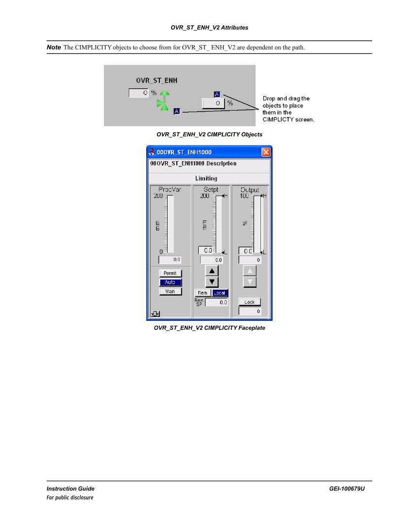
OVR_ST_ENH_V2 Attributes
Note The CIMPLICITYobjects to choose from for OVR_ST_ ENH_V2 are dependent on the path.
OVR_ST_ENH_V2 CIMPLICITY Objects
OVR_ST_ENH_V2 CIMPLICITY Faceplate
Instruction Guide GEI-100679UFor public disclosure

39 Permit (PERMIT)Block Category: Legacy, Permits and Overrides
Note Legacy Status— The PERMIT block is not supported for use in new Mark VIe control systems (ControlSTsoftware suite V05.02 or later). It is in place to support the maintenance of legacy Mark VIe control systems (prior toControlST software suite V05.02). For new Mark VIe control systems, use the LOGIC_BUILDER or LOGIC_BUILDER_SCblock (use if first out/state change feature is required); these blocks provide equivalent functionality. Refer to theMark VIeController Standard Block Library (GEI-100682).
The Permit (PERMIT) block is an expandable block of up to 32 permit inputs. This block functions like an AND block, allpermit inputs must be True for the output, OUT, to be True. Each connected input can be bypassed by the HMI operator,which is accessed from associated permit tab of the permit screen display. This bypass function must be enabled by settingPMnBE to True. If permit bypassing is enabled for an input, an event is generated on the HMI alarm/event screen wheneverthe operator bypasses the permit.
PERMIT Block
Each input has the capability of inheriting the description of a connected global variable or a global variable connectedthrough a NOT block. When a connection is made to one of the input pins, the description of the global variable is inheritedby default. If this description is undesirable, it must be disabled by setting the Inherit Description option to False in the inputvariable properties. The description can be replaced with a desirable description by entering an appropriate description in thedescription field of the input variable of the PERMIT block (replace PERMIT #1 with the desired permit description for thesource connected to PM1). The description is not copied from the connected variable immediately; the input's description isset when the library or device containing the input is validated or built.
The PERMIT block can also be configured as a ready list. In this mode, the block can be used to display a list of signals asready to go or not.
398 GEI-100679U Mark VIe Controller DCS Block LibraryFor public disclosure
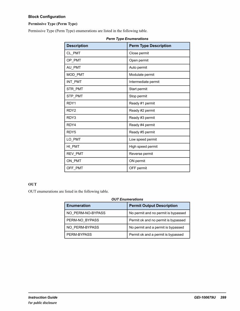
Block Configuration
Permissive Type (Perm Type)
Permissive Type (Perm Type) enumerations are listed in the following table.
Perm Type Enumerations
Description Perm Type Description
CL_PMT Close permit
OP_PMT Open permit
AU_PMT Auto permit
MOD_PMT Modulate permit
INT_PMT Intermediate permit
STR_PMT Start permit
STP_PMT Stop permit
RDY1 Ready #1 permit
RDY2 Ready #2 permit
RDY3 Ready #3 permit
RDY4 Ready #4 permit
RDY5 Ready #5 permit
LO_PMT Low speed permit
HI_PMT High speed permit
REV_PMT Reverse permit
ON_PMT ON permit
OFF_PMT OFF permit
OUT
OUT enumerations are listed in the following table.
OUT Enumerations
Enumeration Permit Output Description
NO_PERM-NO-BYPASS No permit and no permit is bypassed
PERM-NO_BYPASS Permit ok and no permit is bypassed
NO_PERM-BYPASS No permit and a permit is bypassed
PERM-BYPASS Permit ok and a permit is bypassed
Instruction Guide GEI-100679U 399For public disclosure

ToolboxST Configuration
Inserting this block into the application software will generate a window titled, Enter the Attribute Instance Values; promptingthe user to Enter Device Name and Select Permissive Type in the Value column of the pop-up window. (The permit type is adrop-down menu selection.)
Default Attributes
Note Refer to the table PermType Enumerations.
The block will then automatically create - based on the number of pin groups exposed - the necessary variables and providesthe appropriate attributes for each variable (for example Type, Format Spec, variables that need to be on EGD will beautomatically placed on the $Default EGD page, so on). If additional Pin Groups are added, the necessary new variables willbe automatically created during a build of the application software.
There are two things that need to be checked when installing a PERMIT block. The first is that the Device Name attributeshould match the name of the block that it will be connected to. If this PERMIT block is controlling an MOV block, then thenames should match. If the blocks are connected correctly - but named incorrectly - the permit block will work normally, butthe HMI screen cannot tell you why you do or do not have permission. An example of this naming convention is displayed inthe figure, Connection and Naming Example.
The other thing to remember is to select the correct Permissive Type. If you select CL_PMT, but connect it to an OP_PMT,then the permissive will act like an open permit, but show up in the Close permissive window.
Clicking OK to accept the defaults will generate the Input pin names in the following figure. They are in the form the DeviceValue PermType Value.pin name.
Note The defaults here are for example only. Be sure to change the block name value.
Output pin names are in the form Device Value PermType Value.OUT, Device Value PermType Value.PM, and Device ValuePermType Value.PMB.
Example
If Device Value = 11FVM1401 and PermType Value =CL_PMT; the Global pins created are provided in the table GlobalVariables.
The following figure displays an example of the common usage of a PERMIT block. There is also a FORCE block displayingthe use of a not block. This example shows the PERMIT block sharing the same name as the M_O_V block that it iscontrolling. ToolboxST requires that all blocks have unique names. The PERMIT, FORCE, and OVERRIDE blocks getaround this by adding the block type to the block name. This makes them unique, links them to the block they control in theHMI, and indicates their function.
400 GEI-100679U Mark VIe Controller DCS Block LibraryFor public disclosure

Connection and Naming Example
The following figure illustrates the PERMIT faceplate for the M_O_V block and displays the presence of the PERMITblocks, as well as a description from the controlling variable. These display as green because the permit allows the block tooperate normally.
PERMIT Faceplate Example
Instruction Guide GEI-100679U 401For public disclosure

There is a second mode of operation for the PERMIT block. These blocks can be used as a ready list. In this mode, there is noblock in particular that is being controlled. Rather, the ready list is used with process level permissives. To configure thepermit block to be used in this format, insert a new block to bring up the assign attribute window displayed in the followingfigure.
Permit Block as Ready List
This brings in the block in the usual manner. However, instead of connecting the output to another block, leave itdisconnected. Instead, make a connection to the PM pin on the right side of the block. Name this the same as the block name,minus the RDY1 part - in this example, 00PERMIT1002. This needs to be a global variable, and published as read-only onEGD. Then, make your input connections on the left side.
ToolboxST Permit Block as Ready List
This block does not have a direct HMI object, but there is an object that is used for ready list purposes. The configuration forthis object is discussed in the section HMI Configuration (CIMPLICITY).
Inputs
Name Description Data Type Initial Value Visibility Interface TypePM1 Permit input 1 BOOL True Always Value OnlyPM1B Permit input bypass 1 BOOL False Always Value OnlyPM1BE Permit input bypass enable 1 BOOL False Always Value Only↓ ↓ ↓ ↓ ↓ ↓PM32 Permit input 32 BOOL True Always Value OnlyPM32B Permit input bypass 32 BOOL False Always Value OnlyPM32BE Permit input bypass enable
32BOOL False Always Value Only
Outputs
Name Description Data Type Initial Value Visibility InterfaceType
OUT Output UNIT PERM-NO-BYPASS Always Value OnlyPM Permit value BOOL True Always Value OnlyPMB Permit bypass BOOL False Always Value Only
402 GEI-100679U Mark VIe Controller DCS Block LibraryFor public disclosure

Global VariablesPin Name Description Alarm Alarm
ClassEvent EGD
PageExternalAccess
00PERMIT1000CL_PMT.OUT Output NotAlarmed
False ReadOnly
00PERMIT1000CL_PMT.PM Permit value NotAlarmed
False ReadOnly
00PERMIT1000CL_PMT.PMB Permit bypass NotAlarmed
False ReadOnly
00PERMIT1000CL_PMT.PM1 Permit input NotAlarmed
False $DEFAULT ReadOnly
00PERMIT1000CL_PMT.PM1B Permit input bypass NotAlarmed
True $DEFAULT ReadWrite
00PERMIT1000CL_PMT.PM1BE Permit input bypassenable
NotAlarmed
False $DEFAULT ReadOnly
↓ ↓ ↓ ↓ ↓ ↓ ↓00PERMIT1000CL_PMT.PMn Permit input Not
AlarmedFalse $DEFAULT ReadOnly
00PERMIT1000CL_PMT.PMnB Permit input bypass NotAlarmed
True $DEFAULT ReadWrite
00PERMIT1000CL_PMT.PMnBE Permit input bypassenable
NotAlarmed
False $DEFAULT ReadOnly
Instruction Guide GEI-100679U 403For public disclosure

HMI Configuration (CIMPLICITY)
A PERMIT block does not directly have an HMI object. But when it is used as a ready list, an object has been created tofacilitate its use.
HMI Object — Ready List
Activating this smart object displays the following window.
HMI Object — Smart Object
404 GEI-100679U Mark VIe Controller DCS Block LibraryFor public disclosure

40 Proportional Integral Derivative Enhanced(PID_MA_ENH)Block Category: Legacy, Controls (DCS)
Note Legacy Status— The PID_MA_ENH block is not supported for use in new Mark VIe control systems (ControlSTsoftware suite V05.02 or later). It is in place to support the maintenance of legacy Mark VIe control systems (prior toControlST software suite V05.02). For new Mark VIe control systems, use the PID_MA_ENH_V2 block; it providesequivalent functionality.
The Proportional Integral Derivative Enhanced (PID_MA_ENH) block is a controller that can be a parallel proportional,integral, derivative, cascaded or non-cascaded, PID, a manual/auto station, MA, and has enhanced input and output healthquality status monitoring, ENH. The versatile block can be configured to suit nearly all controller and/or manual/auto stationapplications, as well as integrated override station capabilities when used in conjunction with the enhanced override stationblock, OVR_ST_ENH. The block configuration is defined by enumerated inputs, which determine the block functionality andthe information displayed by the corresponding CIMPLICITY graphical interface(s). Additionally, the block performs qualitystatus monitoring of input signals and output signals and propagates the quality status to the outputs CVO, CV, and SV.
The programmer must first identify the functions required for the application for which the block will be used. When thecontroller function has been properly identified, the programmer must select the corresponding enumerations from theBLOCK_OPT, CTRL_ACT, and MODE_OPT inputs that will configure the PID_MA_ENH block to perform as desired.
Block Configuration
BLOCK_OPT
BLOCK_OPT enumerations are listed in the following table.
BLOCK_OPT Input Enumerations
Name DescriptionPID PID onlyMA M/A station onlyPID_MA PID with M/A stationPID_MA_EXT PID with M/A station with external setpointPID_MA_EXT_CASC PID with M/A station with external setpoint from CASCADE stationPID_MA_REM PID with M/A station with remote setpointPID_MA_REM_CASC PID with M/A station with remote setpoint from CASCADE stationMA_EXT M/A station without PID with remote setpoint with HMI SP disabledMA_REM M/A station without PID with HMI SP enabled (through remote local)MA_MAN M/A station without PID with HMI MANUAL SP enabled
Instruction Guide GEI-100679U 405For public disclosure

PID— for a proportional, integral, derivative controller. It calculates the error or difference between the process variable(PV) and the setpoint (SP), and manipulates the controller output (CVO, CV, and, if applicable, SV) to minimize thedifference between PVand SP. When the enumeration is PID only, the PID only property (PID_P) is True, AUTO is True, andthe setpoint is driven by the remote setpoint (RSP) input. The graphical interface is view only and the operator cannot modifythe setpoint or the output, as both are logic driven.The following figure displays an example of the CIMPLICITY graphicalinterface with the BLOCK_OPT enumeration PID.
PID Enumeration Faceplate
406 GEI-100679U Mark VIe Controller DCS Block LibraryFor public disclosure

MA— used for manual and auto selection. The operator selects either the auto control setpoint or manually sets the output tothe desired value. If the enumeration is MA_MAN, only manual control is available. Refer to the following figures forfaceplate examples. The following figure displays an example of the CIMPLICITY graphical interface with the BLOCK_OPT enumeration MA_MAN.
Note The PERMIT, AUTO and MANUAL push-buttons are not available on MA_MAN.
MA_MAN Enumeration Faceplate
Instruction Guide GEI-100679U 407For public disclosure
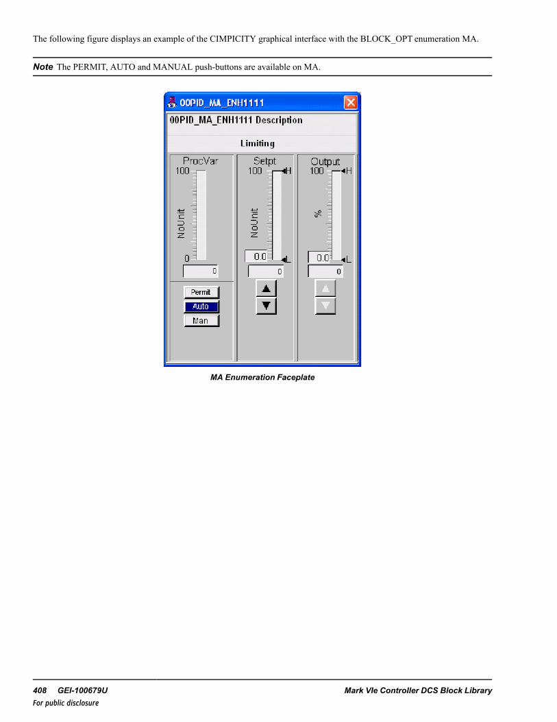
The following figure displays an example of the CIMPICITY graphical interface with the BLOCK_OPT enumeration MA.
Note The PERMIT, AUTO and MANUAL push-buttons are available on MA.
MA Enumeration Faceplate
408 GEI-100679U Mark VIe Controller DCS Block LibraryFor public disclosure

EXT— indicates that an external setpoint value from the block RSP input will be used as the auto setpoint, and can beviewed only by the operator. The following figure displays an example of the CIMPICITY graphical interface with theBLOCK_OPT enumeration MA_EXT.
MA_EXT Enumeration Faceplate
Instruction Guide GEI-100679U 409For public disclosure
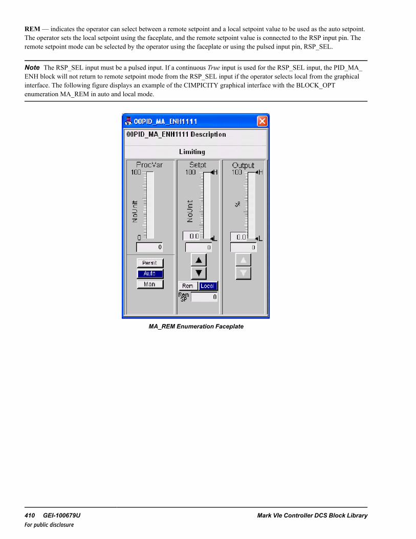
REM— indicates the operator can select between a remote setpoint and a local setpoint value to be used as the auto setpoint.The operator sets the local setpoint using the faceplate, and the remote setpoint value is connected to the RSP input pin. Theremote setpoint mode can be selected by the operator using the faceplate or using the pulsed input pin, RSP_SEL.
Note The RSP_SEL input must be a pulsed input. If a continuous True input is used for the RSP_SEL input, the PID_MA_ENH block will not return to remote setpoint mode from the RSP_SEL input if the operator selects local from the graphicalinterface. The following figure displays an example of the CIMPICITY graphical interface with the BLOCK_OPTenumeration MA_REM in auto and local mode.
MA_REM Enumeration Faceplate
410 GEI-100679U Mark VIe Controller DCS Block LibraryFor public disclosure

CASC— indicates the block is being used in conjunction with another PID_MA_ENH block in a cascade scenario; one PID_MA_ENH block, the outer loop, controls the setpoint, RSP, of the other PID_MA_ENH block, the inner loop. Usually, theouter loop controls the primary control variable and the inner loop controls a rapidly changing variable associated with theprimary variable. The PID_MA_ENH that acts as the inner loop has the CASC enumeration and the outer loop does not. Thedesignation of CASC allows the graphical interface to provide the option for the operator to view the inner loop PID_MA_ENH graphical interface, as well as call the outer loop faceplate to view the overall process loop viewed as one controller. Thefollowing figure is an inner loop cascade example of the CIMPICITY graphical interface with the BLOCK_OPT enumerationPID_MA_REM_CASC in auto and local mode.
Note Refer to the section Cascaded PID_MA_ENH Blocks.
PID_MA_REM_CASC Faceplate Enumeration
Instruction Guide GEI-100679U 411For public disclosure

The following figure is an outer loop cascade example of the CIMPICITY graphical interface with the BLOCK_OPTenumeration PID_MA, in auto mode, which is supplying the remote setpoint to the PID_MA_ENH1000 represented by thefaceplate in the figure PID_MA_REM_CASC Faceplate Enumeration.
PID_MA Faceplate Enumeration
BLOCK_OPT Exceptions
The selected BLOCK_OPT enumeration needs to be modified under certain conditions: the operator has placed the block intuning mode (TUN is True), there is participation in a PID override control scheme using an OVR_ST_ENH block, the OVR_CTRL input enumeration contains OVR_CTRL, or OVRST_CTRL is True.
Condition 1: OVRST_CTRL = True, TUN = FalseBLOCK_OPT = PID_MA or PID_MA_REM, it is modified to be PID_MA_EXTBLOCK_OPT = PID_MA_REM_CASC, it is modified to be PID_MA_EXT_CASCBLOCK_OPT = MA or MA_REM or MA_MAN, it is modified to be MA_EXT
Condition 2: TUN = TrueBLOCK_OPT = PID or PID_MA_EXT, it is modified to be PID_MA_REMBLOCK_OPT = PID_MA_EXT_CASC, it is modified to be PID_MA_REM_CASC
Condition 3: OVRST_CTRL= True, TUN = TrueBLOCK_OPT = PID_MA, it is modified to be PID_MA_REMBLOCK_OPT = MA, it is modified to be MA_REM
Note The order of priority of mode modifications is Condition 1, 2, and 3, respectively.
412 GEI-100679U Mark VIe Controller DCS Block LibraryFor public disclosure

BLOCK_OPT Output Properties
The following PID_MA_ENH output properties control the appearance of the corresponding graphical interface based on theBLOCK_OPT enumeration:
• PID enumeration sets the PID_P property to True• MA enumeration sets the MA_P property to True• PID_MA enumeration sets the PID_MA_P property to True• PID_MA_EXT enumeration sets the PID_MA_EXT_P property to True• PID_MA_EXT_CASC enumeration sets the PID_MA_EXT_C_P property to True• PID_MA_REM enumeration sets the PID_MA_REM_P property to True• PID_MA_REM_CASC enumeration sets the PID_MA_REM_C_P property to True• MA_EXT enumeration sets the MA_EXT_P property to True• MA_REM enumeration sets the MA_REM_P property to True• MA_MAN enumeration sets the MA_MAN_P property to True
CTRL_ACT enumerations are listed in the following table.
CTRL_ACT Input Enumerations
Name Description
DIRECT Direct action (PV-SP)
REVERSE Reverse action (SP-PV)
DIRECT— indicates the value of CVO increases when the value of PV is greater than the setpoint and the value of CVOdecreases when the value of PV is less than the setpoint.
REVERSE— indicates the value of CVO decreases when the value of PV is greater than the setpoint and the value of CVOincreases when the value of PV is less than the setpoint.
Instruction Guide GEI-100679U 413For public disclosure

MODE_OPT
MODE_OPT enumerations are listed in the following table.
MODE_OPT Input Enumerations
Name Description
NONE None
LOCK Lock mode
POS Position feedback
LOCK-POS Lock mode and position feedback
SPLIT Split range
SPLIT-LOCK Split range and lock mode
SPLIT-POS Split range and position feedback
SPLIT-LOCK-POS Split range, lock mode, and position feedback
NONE— used when no mode options are to be enabled.
LOCK— sets the lock property, LOCK_P, to True, allowing software lockout of the controller to be implemented by theoperator through the CIMPLICITY graphical interface.
Note The lockout indication is provided for indication only. This action will not lock out the equipment, it will only indicatelockout status. The owner's lockout procedures must be followed to safely lock equipment out.
The Lock button can also be configured to use the WorkstationST Lock function. Refer to the WorkstationST/CIMPLICITYAdvanced Viewer Integration Instruction Guide (GEI-100697), the section HMI Tagout.
The valve output CVO must be within 5 units of the initial position input (INIT_POS) value before the block can be set tolockout mode. When LOCK is True the block is in lockout mode and block outputs, CVO, CV, and, if applicable, SVareprohibited from modulating. If the block is in auto mode and not participating in an override control scheme, the VR_CTRLinput enumeration is NONE, and the BLOCK_OPT enumeration is not PID only, PID_P is False, then the block will beplaced in manual mode and the manual reject alarm, MAN_REJ_A, is activated. The operator’s ability to switch to auto modeis also disabled until the block is removed from lockout mode. If the block is in tuning mode, the tuning mode will also beremoved and disabled. Additionally, the local auto setpoint tracks the process variable input PV when the block is in lockoutmode.
POS— used when there is feedback available from the controlled device. Normally, feedback is the valve position feedback;however, the POS enumeration can also be used for motor speed or a variety of other device feedbacks. The position feedbackvalue is connected to the block input POS_CVand, if the MODE_OPT enumeration SPLIT is selected, the position feedbackfrom the secondary device is connected to the POS_SV block input. When the POS enumeration is used, the block outputPOSFB_P is True, the feedback value is displayed on the graphical interface faceplate, and, when the cursor is placed over thefeedback area, the pop up window displays the text CV Pos Feedback = the instantaneous value , as displayed in thefollowing figure.
414 GEI-100679U Mark VIe Controller DCS Block LibraryFor public disclosure

POS Enumeration Faceplate with Controlling
SPLIT— indicates that the controller will output to two different devices using the block outputs, CVand SV, either or bothof which may be characterized by a 13 element array that enables each output to be customized to fit the requirements of aspecific control application. The default characterization arrays are linear for both CVand SVand are as follows:
• CV_X and SV_X = -10, 0, 10, 20, 30, 40, 50, 60, 70, 80, 90, 100, 1000000• CV_Yand SV_Y = -10, 0, 10, 20, 30, 40, 50, 60, 70, 80, 90, 100, 1000000
If the CV_X 13 element array does not contain the same 13 array elements in the same order as the CV_Yarray, or the SV_X13 element array does not contain the same 13 array elements in the same order as the SV_Yarray, the characterizationproperty, CHAR_P, is True and the graphical interface displays a button in the lower right corner of the faceplate with the popup text Show Characterization, as displayed in the following figure.
Instruction Guide GEI-100679U 415For public disclosure

The follow characterizations are applied:
• CV_X = -10, 0, 10, 20, 30, 40, 50, 60, 70, 80, 90, 100, 1000000• CV_Y = -10, 0, 10, 20, 30, 40, 50, 60, 70, 80, 90, 100, 1000000• SV_X = -10, 0, 10, 20, 30, 40, 50, 60, 70, 80, 90, 100, 1000000• SV_Y = -10, 0, 10, 20, 30, 40, 50, 60, 70, 80, 90, 100, 1000000
416 GEI-100679U Mark VIe Controller DCS Block LibraryFor public disclosure

SPLIT Enumeration Faceplate with Characterizations
MODE_OPT Output Properties
The following PID_MA_ENH output properties control the appearance of the corresponding graphical interface based on theMODE_OPT enumeration:
• NONE enumeration sets LOCK_P, POSFB_P, and SPLIT_P property to False• LOCK enumeration sets the LOCK_P property to True• POS enumeration sets the POSFB_P property to True• SPLIT enumeration sets the SPLIT_P property to True
Instruction Guide GEI-100679U 417For public disclosure

Basic PID_MA_ENH Block Functionality
The BLOCK_OPT, CTRL_ACT, and MODE_OPT inputs enumerations described in this section are instrumental indetermining the basic PID_MA_ENH functionality. For example, the controller is required to be direct acting, have PIDfunctionality, manual or auto mode capability, ability to be software locked, and feedback is available from the controlleddevice. The input enumerations selected are:
• BLOCK_OPT, PID_MA• CTRL_ACT, DIRECT• MODE_OPT, LOCK-POS
Control Word (CTL) enumerations are listed in the following table.
The operator controls the PID_MA_ENH block by clicking buttons on the CIMPLICITY graphical interface pop up faceplate.Certain faceplate buttons carry an enumerated value represented in the PID_MA_ENH block input CTL. The enumeratedvalues are transferred from the faceplate to the block through EGD using the CTL. When a command is sent from thefaceplate to the PID_MA_ENH block, the block runs the command and then, after one second, the block overwrites the CTLinput with the NO_CMD enumeration, thus resetting itself for the next CTL command. The enumerations for CTL aredisplayed in the following table.
Note The commands are dependent on the enumerations of BLOCK_OPT and MODE_OPT. For example, LOCK_CMDand UNLOCK_CMD enumerations are not used if MODE_OPT does not contain the enumeration LOCK).
CTL Enumerations
Name Description
NO_CMD No command
AUTO_CMD Auto command
MANUAL_CMD Manual command
LOCK_CMD Lock command
UNLOCK_CMD Unlock command
TUN_ON_CMD Tune mode on command
TUN_OFF_CMD Tune mode off command
REMOTE_CMD Remote SP command
LOCAL_CMD Local SP command
NO_CMD— indicates no command is present.
AUTO_CM places the block in auto mode from manual mode using the graphical interface faceplate. The auto setpoint willbe local, remote, or external depending on the BLOCK_OPT enumeration and, if applicable, the operator selection as local orremote. When the block is in auto mode the output AUTO is True.
MANUAL_CMD— places the block in manual mode from auto mode using the graphical interface faceplate. The operatormanually sets the output to the controlled device. When the block is in manual mode the output AUTO is FLASE.
LOCK_CMD— places the block in lock mode when the block output CVO is within 5 units of the initial position value,INIT_POS. This enumeration command also removes the block from auto and places it in manual mode and sets the manualreject alarm, MN_REJ_A, to True. When the block is in lock mode the output LOCK is True.
UNLOCK_CMD— removes the block from lock mode and sets the output LOCK to False.
TUN_ON_CMD— places the block in tuning mode. The operator is not allowed to change the PID_MA_ENH block to thetuning mode when the block is already in lock mode.
418 GEI-100679U Mark VIe Controller DCS Block LibraryFor public disclosure

Once the tuning mode has been attained, it can only be reset by one of the following methods:
• Operator tune off command• Block is set to lock mode
When the block is in tuning mode, the output TUN is True.
TUN_OFF_CMD— removes the block from the tuning mode and sets TUN to False.
REMOTE_CMD— commands the block, when in auto mode, to use the remote setpoint value connected to block input pin,RSP, as the auto setpoint. When the block is in remote mode the remote setpoint output, RS, is True.
LOCAL_CMD— commands the block, when in auto mode, to use the operator defined local setpoint. When the block is inlocal setpoint mode, RS is False.
Manual Reject (MN_REJ) input is driven by an override-type block that associates its input status with the graphicalinterface of the PID_MA_ENH block, thus allowing the operator to view the individual inputs that put the block into amanual reject mode. The override graphical interface also enables the operator to block logic driven inputs to release theoverride condition through the graphical interface.
MN_REJ Enumerations
Name Description
NO_OVR-NO_BLOCK No override and no override is blocked
OVR-NO_BLOCK Override active and no override is blocked
NO_OVR-BLOCK No override and an override is blocked
OVR-BLOCK Override active and an override is blocked
NO_OVR— indicates no manual reject command is active; manual reject output REJ_MN is False
OVR— indicates a manual reject command is active; manual reject output REJ_MN is True.
NO-BLOCK— indicates the operator has not invoked a block of any of the associated logic driven inputs to theoverride-type block. When a no block is active, REJ_MNB is False.
BLOCK— indicates the operator has invoked a block of at least one of the associated logic driven inputs to the override typeblock. The BLOCK enumeration is not used by OVR_ST_ENH, but the block does pass the information it to the graphicalinterface for display purposes using the output, REJ_MNB. When a block is active, REJ_MNB is True.
Under most circumstances, if the PID_MA_ENH block is in auto mode and a validated MN_REJ input enumeration containsOVR, the block is removed from auto mode and placed in manual mode, and MN_REJ_A is activated and the local autosetpoint, if available, tracks PV. Exceptions are if the BLOCK_OPT enumeration is PID, PID_P is True, or the PID_MA_ENH block input OVR_CTLR contains the enumeration OVRST_CTRL from the OVR_ST_ENH block, indicating theoverride station controls the PID_MA_ENH block.
Other Enumerated External Commands
There are three enumerated PID_MA_ENH block inputs that provide commands from external blocks that control the PID_MA_ENH output, CVO. They are, in order of priority, CMD_OVR, CMD_FRC, and CMD_TK.
Note When PID_MA_ENH blocks are connected to and receiving inputs from the OVR_ST_ENH block, it is recommendedto use the OVR_ST_ENH block for any external commands, such as CMD_OVR, CMD_FRC, or CMD_TK actions for thePID_MA_ENH block. In other words, do not connect CMD_OVR, CMD_FRC, and CMD_TK type blocks to the PID_MA_ENH blocks when using an OVR_ST_ENH block. Instead use the capability of the OVR_ST_ENH block for these actions.
Instruction Guide GEI-100679U 419For public disclosure

Command Override (CMD_OVR) input is driven by an override-type block that associates its input status with thegraphical interface of the PID_MA_ENH block, thus allowing the operator to view the individual inputs that place the blockin override mode. The override graphical interface also enables the operator to block logic driven inputs to release theoverride condition through the graphical interface.
CMD_OVR Enumerations
Name Description
NO_OVR-NO_BLOCK No override and no override is blocked
OVR-NO_BLOCK Override active and no override is blocked
NO_OVR-BLOCK No override and an override is blocked
OVR-BLOCK Override active and an override is blocked
NO_OVR— indicates no override command is active and the command override output OVR_CMD is False.
OVR— indicates an override command is active and OVR_CMD is True.
NO-BLOCK— indicates the operator has not invoked a block of any of the associated logic driven inputs to theoverride-type block. When this enumeration is used, OVR_CMDB is False.
BLOCK— indicates the operator has invoked a block of at least one of the associated logic driven inputs to the override-typeblock. When this enumeration is used, OVR_CMDB is True.
If the PID_MA_ENH block is in auto mode and a validated CMD_OVR input enumeration contains OVR, an overridecommand exists and MN_REJ_A is activated, and the output will move to the input value of the override value, OV. Theblock is removed from auto mode and placed in manual mode and the local auto setpoint, if available, tracks PV.
Note An override command (the enumeration of CMD_OVR contains OVR) has precedence over a force command (CMD_FRC contains FORCE), and the process increase and decrease inputs, PR_INC and PR_DEC, respectively.
Command Force (CMD_FRC) input is driven by a force-type block that associates its input status with the graphicalinterface of the PID_MA_ENH block, thus allowing the operator to view the individual inputs that put the block into a forcemode. The force graphical interface also enables the operator to block logic driven inputs to release the force conditionthrough the graphical interface.
CMD_FRC Enumerations
Name Description
NO_FORCE-NO_BLOCK No force and no force is blocked
FORCE-NO_BLOCK Force active and no force is blocked
NO_FORCE-BLOCK No force and a force is blocked
FORCE-BLOCK Force active and a force is blocked
NO_FORCE— indicates no force command is active and the force command output, FRC_CMD, is False.
FORCE— indicates a force command is active and if the CMD_OVR enumerated input does not contain OVR (the outputOVR_CMD is False), then the force command output FRC_CMD is True.
NO-BLOCK— indicates the operator has not invoked a block of any of the associated logic driven inputs to the force typeblock. When this enumeration is used, the force-blocked output FRC_CMDB is False.
BLOCK— indicates the operator has invoked a block of at least one of the associated logic driven inputs to the force typeblock and sets the force-blocked output FRC_CMDB to True.
If the PID_MA_ENH block validated CMD_FRC input enumeration contains FORCE, a force command exists and the outputof the block, CVO moves to the input value of the force value, FV.
420 GEI-100679U Mark VIe Controller DCS Block LibraryFor public disclosure

Note An override command (the enumeration of CMD_OVR contains OVR) has precedence over a force command (CMD_FRC contains FORCE).
Command Track (CMD_TK) input is driven by a track-type block that associates its input status with the graphical interfaceof the PID_MA_ENH block, thus allowing the operator to view the individual inputs that places the block in track mode. Thetrack graphical interface also enables the operator to block logic driven inputs to release the track condition through thegraphical interface.
CMD_TK Enumerations
Name Description
NO_TRACK-NO_BLOCK No track and no track is blocked
TRACK-NO_BLOCK Track active and no track is blocked
NO_TRACK-BLOCK No track and a track is blocked
TRACK-BLOCK Track active and a track is blocked
NO_TRACK— indicates no track command is active and the track status output, TK_OUT, is False.
TRACK— indicates a track command is active and TK_OUT is True.
NO-BLOCK— indicates the operator has not invoked a block of any of the associated logic driven inputs to the track typeblock. When this enumeration is used, the track-blocked output TK_CMDB is False.
BLOCK— indicates the operator has invoked a block of at least one of the associated logic driven inputs to the track typeblock. When this enumeration is used, the track-blocked output TK_CMDB is True.
If the PID_MA_ENH block is in auto mode and a validated CMD_TK input enumeration contains TRACK, a track commandexists and the output of the block, CVO, tracks the block tracking value input TV.
Priority Increase (PR_INC) and Decrease (PR_DEC) Commands
When the PID_MA_ENH block input PR_INC is True, the output CVO increases to the high limit value (H) at the ratedefined by the priority increase rate value PR_INC_RT (default value is 1 unit/sec). When the PID_MA_ENH block inputPR_DEC is True and PR_INC is False, the output CVO decreases to the low limit value (L) at the rate defined by the prioritydecrease rate value PR_DEC_RT (default value is 1 unit/sec). The inputs PR_INC and PR_DEC should be programmed to bemutually exclusive events, but if at any time they both become True, then PR_INC is the dominate input and the value ofCVO increases to H at the rate defined by PR_INC_RT.
Note A force command (the enumeration of CMD_FRC contains FORCE) or an override command (the enumeration ofCMD_OVR contains OVR) have precedence over the PR_INC and PR_DEC inputs.
Instruction Guide GEI-100679U 421For public disclosure

Inhibit Increase (INH_INC) and Decrease (INH_DEC) Commands
The PID_MA_ENHis capable of inhibiting the output control variable, CVO, from increasing or decreasing in value absent aforce or override command, FORCE from the enumerated CMD_FRC input or OVR from the enumerated CMD_OVR input.
Inhibiting the increase of the CVO output occurs when INH_INC is True and one of the following is present:
• Neither PR_INC nor PR_DEC is True.• BLOCK_OPT enumeration is neither PID_MA_EXT_CASC nor PID_MA_REM_CASC, and the CASC_IN
enumeration is REVERSE and HI_LIMITED.• BLOCK_OPT enumeration is neither PID_MA_EXT_CASC nor PID_MA_REM_CASC, and the CASC_IN
enumeration is DIRECT and LOW_LIMITED.
Inhibiting the decrease of the CVO occurs when INH_DEC is True and one of the following is present:
• Neither PR_INC nor PR_DEC are True.• BLOCK_OPT enumeration is neither PID_MA_EXT_CASC nor PID_MA_REM_CASC and the ASC_IN enumeration
is DIRECT and HI_LIMITED.• BLOCK_OPT enumeration is neither PID_MA_EXT_CASC nor PID_MA_REM_CASC and the CASC_IN enumeration
is REVERSE and LOW_LIMITED.
Auto Permit (AU_PMT) input is driven by an auto permit-type block that associates its input status with the graphicalinterface of the PID_MA_ENH block, which allows the operator to view the individual inputs that provide a permit to placethe block in auto mode. The AU_PMT graphical interface enables the operator to bypass logic driven inputs to obtain an autopermit condition through the graphical interface.
AU_PMT Enumerations
Name Description
NO_PERM-NO_BYPASS No permit and no permit is bypassed
PERM-NO_BYPASS Permit OK and no permit is bypassed
NO_PERM-BYPASS No permit and a permit is bypassed
PERM-BYPASS Permit OK and a permit is bypassed
NO_PERM— indicates a permit to allow the block to be placed in auto mode has not been met and the Auto Permit output,PMT_AU, is False.
PERM— indicates all permits for the block to be placed in auto mode have been met and PMT_AU is True, provided theBLOCK_OPT is not PID only, PID_P is False, the block is not part of an override scheme, OVRST_CTRL is FASE, andthere is no bad quality detected and the reset override, RSP_OV is False, when BQ_MAN is set to True. The block outputs,REJ_MN, OVR_CMD, LOCK, and MA_MAN_P must also all be False for PMT_AU to be True.
NO-BYPASS— indicates the operator has not invoked a bypass of any of the associated logic driven inputs to the autopermit block. When this enumeration is used, the Auto Permit Bypass output (PMT_AUB) is False.
BYPASS— indicates the operator has invoked a bypass of at least one of the associated logic driven inputs to the auto permitblock. When this enumeration is used, PMT_AUB is True.
Modulate Permit (MOD_PMT) input is driven by a modulate permit-type block that associates its input status with thegraphical interface of the PID_MA_ENH block, thus allowing the operator to view the individual inputs that provide a permitto allow the block to modulate the output. The MOD_PMT graphical interface enables the operator to bypass logic driveninputs to obtain a modulate permit condition through the graphical interface.
422 GEI-100679U Mark VIe Controller DCS Block LibraryFor public disclosure

MOD_PMT Enumerations
Name Description
NO_PERM-NO_BYPASS No permit and no permit is bypassed
PERM-NO_BYPASS Permit OK and no permit is bypassed
NO_PERM-BYPASS No permit and a permit is bypassed
PERM-BYPASS Permit OK and a permit is bypassed
NO_PERM— indicates a permit to allow the block to modulate the output, CVO, has not been met and the permit tomodulate output, PMT_MOD, is False. If the MOD_PMT input enumeration contains NO_PERM, CVO equals the INIT_POS input value.
PERM— indicates all permits to allow the block to modulate the output, CVO, have been met and PMT_MOD is True.
NO-BYPASS— indicates the operator has not invoked a bypass of any of the associated logic driven inputs to the modulatepermit block. When this enumeration is used, the modulate permit bypass output, PMT_MODB, is False.
BYPASS— indicates the operator has invoked a bypass of at least one of the associated logic driven inputs to the modulatepermit block. When this enumeration is used, PMT_MODB is True.
Auto Select (AU_SEL)— a pulsed input that, if permits allow, switches the block from manual to auto mode, setting theoutput AUTO to True. The input must be pulsed.
Remote Select (RSP_SEL)— a pulsed input that instructs the block to use the remote setpoint input RSP as the setpoint usedto calculate the block outputs, CVO, CV, and, if applicable, SV, when the block is in auto mode. The input must be pulsed.
Setpoint High (SH) and Low (SL) Limit— block inputs values bound the block output, SP, the setpoint used to calculatethe error, which is used for the proportional gain portion of the PID calculations.
Instruction Guide GEI-100679U 423For public disclosure

Setpoint Adjustment Rate (SR)
The rate of change of the block setpoint, SP, used to calculate the error used in the PID calculations is restricted by the blockSR input value, in units/sec. The setpoint used for the error calculation is passed without rate limit restrictions directly to SPwhen the controller is powered up, track status, TK_OUT, is True, or the BLOCK_OPT enumeration is PID_MA_EXT_CASC or PID_MA_REM_CASC, and the remote setpoint mode, RS, is TRUE.
Setpoint Value Before Ramp (SI)
The internal setpoint block output, SI, is the value of the setpoint before the SR is applied. For example, if the setpointchanges from 0 to 10 instantaneously, SI will change from 0 to 10 instantaneously while if SR is set at 1 unit/sec, SP willramp from 0 to 10 in 10 seconds. SI is also bound by limit inputs SH and SL, respectively.
Scale Factor (SF) is used to scale the process variable, PV, and the setpoint used to calculate the error value that is used inthe PID calculations. The setpoint used for the error calculation, the block output SP, may be the value of theoperator-supplied setpoint, the value of the remote setpoint, RSP, or a tracking value, depending on the state of the block.
Setpoint Track (SP_TRACK)When is SP_TRACK is True, the setpoint tracks PV in manual or RSP in auto and remote mode, the output AUTO is Truewhen the block is in auto mode, and RS is True when the block is in remote mode. If SP_TRACK is False and RS is True, thesetpoint tracks RSP. Otherwise, the operator controls the setpoint value from the graphical interface.
Manual Adjustment Rate (MR)
The rate of change of the control variable output, CVO, is restricted by the block manual adjustment ramp rate input valueMR, in units/sec.
Square of the Error (SQR_ERR)
The square of the calculated error is used if the SQR_ERR parameter is set to True and is multiplied by PG to calculate theproportional term in the PID calculations. When the value of the error is greater than one, the square of the error provides amore robust controller response, when the error is less than one the controller will respond less aggressively.
424 GEI-100679U Mark VIe Controller DCS Block LibraryFor public disclosure

Tracking Status (TK_OUT)
The track status block output TK_OUT can be set to True by a number of input conditions, such as bad quality, priorityincrease or decrease, no permit to modulate, manual mode, force command, override command, increase or decrease inhibit,lock, track command enumeration (CASC_IN enumeration contains TRACK) or the override station tracking input (OVR_CTRL enumeration contains TRACK). When TK_OUT is True, the PID_ MA_ENH is in tracking mode and the block output,CVO (also CV_X and, if applicable, SV_X for characterized outputs CVand SV, respectively) tracks the appropriate valuebased on the parameter that set TK_OUT to True. The value may be the override value (OV), force value (FV), a priorityincrease or decrease command will move to the H or L limit values at PR_INC_RT or PR_DEC_RT, the track value (TV) orthe initial position value (INIT_POS). When the increase (DEC_INH) or decrease (INC_INH) inhibit inputs, or transitionfrom True to False, TK_OUT is True for one scan, which realigns the setpoint and the calculated PID values.
Note The H and L values are dependent on the enable process limit inputs EN_PROC_LIM_HIGH and EN_PROC_LIM_LOW, as well as the PROC_LIM_HIGH and PROC_LIM_LOW limits, respectively
Process (High EN_PROC_LIM_HIGH) and Low (EN_PROC_LIM_LOW) Limits
The user can limit the process control range further using the PROC_LIM_LOWand PROC_LIM_HIGH parameters that areenabled by their respective enable parameters, EN_PROC_LIM_LOWand EN_PROC_LIM_HIGH. This feature enables theuser to control process regulation limits while allowing force and override values to operate independently on the PID_MA_ENH limits (H and L). When EN_PROC_LIM_LOWor EN_PROC_LIM_HIGH is True, the PROC_LIM_LOWand PROC_LIM_HIGH replace the corresponding L and H limit values.
Error Deadband Equality (ERR_C), when True, enables the use of error dead band equality processing. When theabsolute value of the error is less than the input value ERR_CDB (the error dead band), the controller equates that the error iszero.
External Reset (ER) may be used to enable several PID_MA_ENH controllers to function in parallel, typically when theminimum or maximum CVO value will be selected. External reset allows all PID_MA_ENH controllers in the loop tocalculate CVO based on process conditions while preventing windup. The selected CVO is sent to the control element and tothe other PID_MA_ENH controllers in the loop. The ER command block input, or an ER enumeration from OVR_CTRLenables the external reset function. The selected CVO is connected to the external reset value (EV).
Note Refer to the section PID Track at Limit until PVand SP Cross (PV_SP_LIM_TRK).
Instruction Guide GEI-100679U 425For public disclosure

The following figure displays the typical OVR_ST_ENH block pin connections using a Min/Max configuration with twooverride controlled PID_MA_ENH blocks.
PID_MA_ENH_1
PID_MA_ENH_2 OVR_ST_ENH
CVO
CVO
CASC_OUT
OVR_CTRL1
OVR_CTRL2
CVO
CV
SV
SP
OVR_CTRL
OVR_CTRL
TV
RSP
TV
RSP
CVI1
CVI2
CASC_IN1
CASC_IN2
CASC_OUT
EV
EV
†
†
† A connection to EV is required when the OVR_ST_ENH block STATION_OPT enumeration is set to, MIN_2_INPUTS, MIN_3_INPUTS, MAX_2_INPUTS, or MAX_3_INPUTS.
426 GEI-100679U Mark VIe Controller DCS Block LibraryFor public disclosure

When the PID tracks at limit until PVand SP cross input (PV_SP_LIM_TRK) is True, and the ER command is True, the resetdoes not occur until the following conditions are all False:
• PV value becomes greater than the SP value when US is True and the controller is reverse acting• PV value becomes greater than the SP value when LS is True and the controller is direct acting• PV value becomes less than the SP value when LS is True and the controller is reverse acting• PV value becomes less than the SP value when US is True and the controller is direct acting
PID Track at Limit until PV and SP Cross (PV_SP_LIM_TRK)
If PV_SP_LIM_TRK is True, when the controller output reaches either H or L limit, the controller tracks the limit value untilPV crosses SP. Once PV crosses SP, the controller resumes the controlling action. The following graph displays PV, SP, andCVO for a PID_MA_ENH block with PV_SP_LIM_TRK both True and False. Notice that with PV_SP_LIM_TRK set toTrue (left of the black vertical line) VO remains at the limit until PV crosses SP. With PV_SP_LIM_TRK set to False (rightof the black vertical line), CVO only tracks the limit until PV changes slope.
PV_SP_LIM_TRK Set to True and False
The graph displays PV (blue sine wave), SP (green horizontal line), and CVO (brown sine wave, capped). With PV_SP_LIM_TRK set to True, the controller behaves as displayed in the graph by the data to the left of the vertical black line. With PV_SP_LIM_TRK set to False, the controller behaves as displayed by the data to the right of the vertical black line.
Each time SP and PV cross the threshold defined by the range of ERR_CDB, (the error for dead band PVand SP equality),and the error for dead band equality input, ERR_C, is True, the controller calculates the integral term from the last calculatedcontrol output value, CVO (BLOCK_OPT enumeration must contain PID).
Instruction Guide GEI-100679U 427For public disclosure

Inhibit Proportional and Derivative Action on Setpoint Change (INH_PDG)
The INH_PDG parameter, when True, inhibits proportional and derivative controller action. When the SP change is detectedto exceed a scan time calculated dead band derived from the value of the dead band setpoint to inhibit the proportional andderivative action, INH_PDG_CDB, in units/sec; the controller calculates the integral term from the last calculated controloutput value, CVO (BLOCK_OPT enumeration must contain PID).
Note If INH_PDG is True and the setpoint is constantly changing (possibly a remote setpoint) by an amount greater than thescan time calculated dead band specified by NH_PDG_CDB, then the controller is an integral only controller.
Bumpless Proportional and Integral Gain ValueChanges (PG_C and IG_C)
If the value of the proportional gain (PG) or the integral gain (IG) is variable, the input parameters PG_C and G_C providebumpless controller action when True. If the value of PG or IG exceeds the dead band PG_CDB for PG and IG_CDB for IG,and the corresponding PG_C or IG_C parameter is True, the controller calculates the integral term from the last calculatedcontrol output value, CVO (BLOCK_OPTenumeration must contain PID).
Feed Forward (FF)
When the BLOCK_OPT input enumeration contains PID the block provides a FF input that is added as a last step before theoutput value of CVO and characterized output values of CVand, if applicable, SVare output from the PID_MA_ENH block.
Status Propagation and Bad Quality Determination of CVO, CV, and SV Outputs
The PID_MA_ENH block monitors the quality status values of various inputs and connected outputs to determine the qualitystatus value of CVO, CV, and SV (if the MODE_OPT enumeration contains SPLIT then the split output property SPLIT_P isTrue).
The quality status value of the control variable output CV is either the quality status value of CVO or, if SPLIT_P is True andthe quality status value of BKCAL_IN_CV is > 200 and < 203, the quality status value of CV is assigned a quality statusvalue of 196, NOT_LIMITED-INTIALIZATION_ACKNOWLEDGE-GOODC.
The quality status value of the split range control variable output SV is either the quality status value of CVO or, if SPLIT_Pis True and the quality status value of BKCAL_IN_SV is > 200 and < 203, the quality status value of SV is assigned a qualitystatus value of 196, NOT_LIMITED-INTIALIZATION_ACKNOWLEDGE-GOODC.
The quality status value of the control variable output CVO is determined by the how the block is used. If the PID_MA_ENHblock is connected to an OVR_ST_ENH block, the enumerated OVR_CTRL input contains the enumeration OVR_CTRL, orthe block is used as the outer loop in a cascaded scenario, the outputs CVand SVare not connected to hard I/O. Therefore, thequality status values of CVand SVare not considered when the quality status value of CVO is calculated. This eliminates thepropagation of erroneous CVO quality status values that would result from CVand SVnot being connected to hard I/O points.Otherwise, the PID_MA_ENH block calculates the quality status value of CVO from appropriate inputs with quality statusvalues, input parameters values, and the connected hard I/O quality status values of CVand, if the MODE_OPT containsSPLIT and SPLIT_P is True), SV. The analog output variables attached to CVand SVare monitored for quality status,resulting in the following possible CVO quality status values:
• 12 - I/O Pack Health Failed – NOT_LIMITED-DEVICE_FAILURE-BAD• 16 - I/O Pack Health Failed – NOT_LIMITED-SENSOR_FAILURE-BAD
If neither of these conditions exists, the quality status value of CVO is calculated by the PID_MA_ENH block to be from 192to 198, depending on numerous variables used in the quality status calculation, which result in the following values:
• Status value 192 indicates CVOis NOT_LIMITED_GOODC• Status value 193 indicates CVO is LOW_LIMITED_GOODC• Status value 194 indicates CVO is HIGH_LIMITED_GOODC• Status value 195 indicates CVO is CONSTANT_GOODC• Status value 196 indicates CVO is NOT_LIMITED-INITIALIZED_ACKNOWLEDGE-GOODC• Status value 197 indicates CVO is OW_LIMITED-INITIALIZED_ACKNOWLEDGE-GOODC• Status value 198 indicates CVO is HIGH_LIMITED-INITIALIZED_ACKNOWLEDGE-GOODC
428 GEI-100679U Mark VIe Controller DCS Block LibraryFor public disclosure

When using FOUNDATION fieldbus, if the split range mode is not selected (SPLIT_P is False) and the quality status value ofBKCAL_IN_CVor BKCAL_IN_SV is > 200 and < 203, then the quality status value of CVO is assigned a quality statusvalue of 196 when LS and US are False. When split range mode is selected (SPLIT_P is True), the FOUNDATION fieldbusinitialization acknowledge provided in the previous sections indicates the quality status of CVand SV.
If CVI_BQ, EV_BQ, PV_BQ, RSP_BQ, RSP_OV, FFWD_BQ, TV_BQ, BKCALIN_CV_BQ, and BKCAL_IN_SV_BQ areFalse and the value of CVO is less than or equal to the low limit (LS is True), 1 is added to the CVO status value.
If CVI_BQ, EV_BQ, PV_BQ, RSP_BQ, RSP_OV, FFWD_BQ, TV_BQ, BKCALIN_CV_BQ, and BKCAL_IN_SV_BQ areFalse, and the value of CVO is greater than or equal to the high limit (US is True), 2 is added to the CVO status value.
This block propagates quality status. Status option cannot be disabled on this block.
CVO status is based upon the following in order of priority:
• The analog output variables attached to CVand SVare monitored for quality status. This results in the followingpossible CVO statuses:− I/O Pack Health Failed – NOT_LIMITED-DEVICE_FAILURE-BAD [12]− I/O Pack Health Failed – NOT_LIMITED-SENSOR_FAILURE-BAD [16]
• If CVI_BQ, EV_BQ, PV_BQ, RSP_BQ, RSP_OV, FFWD_BQ, TV_BQ, BKCALIN_CV_BQ , or BKCAL_IN_SV_BQ is True, the value of CVO status is CONSTANT-GOODC [195].
• If CVI_BQ, EV_BQ, PV_BQ, RSP_BQ, RSP_OV, FFWD_BQ, TV_BQ, BKCALIN_CV_BQ, or BKCAL_IN_SV_BQ is True, the value of CVO status is CONSTANT-GOODC [195]. If the following are False, CVI_BQ, EV_BQ,PV_BQ, RSP_BQ, RSP_OV, FFWD_BQ, TV_BQ, BKCALIN_CV_BQ, and BKCAL_IN_SV_BQ and the value ofCVO is greater than or equal to the high limit, US is True, 2 is added to the CVO status value.
• The default quality status of CVO is NOT_LIMITED-GOODC [192].For further details on relational blocks, refer to the Mark VIe Controller Standard Block Library (GEI-100682), the StatusMonitoring (STATUS_MONITORING) block.
Manual Auto Configuration
Typical connections for PID_MA_ENH blocks with BLOCK_OPT enumerations MA, MA_EXT, and MA_REM without acontrol variable input (CVI) available are displayed in the following figure. Note the connection of SP to VI.
PID_MA_ENH Controller with BLOCK_OPT Enumerations
Instruction Guide GEI-100679U 429For public disclosure

Input Quality Status Monitoring
The PID_MA_ENH block monitors and propagates the health or quality status of I/O points CVI, EV, FF, PV, RSP, TV,BKCAL_IN_CV, BKCAL_IN_SV, POS_CV, POS_SVand determines when action must be taken because a bad qualityrelated input.
The following inputs are monitored for quality status based on block operational mode input BLOCK_OPT:
• CVI is only used in the block calculation when the operational mode is chosen as MA, MA_EXT or MA_REM. Theseare the only modes, which allow the bad quality of CVI to affect block operation.
• EV input is only used in the block calculation when the operational mode is chosen as PID, PID_MA, PID_MA_REM,PID_MA_REM_CASC, PID_MA_EXT or PID_MA_EXT_CASC. These are the only modes that allow the bad qualityof EV to affect block operation.
• FF input is only used in the block calculation when the operational mode is chosen as PID, PID_MA, PID_MA_REM,PID_MA_REM_CASC, PID_MA_EXT or PID_MA_EXT_CASC. These are the only modes that allow the bad qualityof FF to affect block operation.
• PV input is only used in the block calculation when the operational mode is chosen as MA, MA_EXT, MA_REM, PID,PID_MA, PID_MA_REM, PID_MA_REM_CASC, PID_MA_EXT or PID_MA_EXT_CASC. These are the only modesthat allow the bad quality of PV to affect block operation.
• RSP input is only used in the block calculation when the operational mode is chosen as MA_EXT, MA_REM, PID, PID_MA_REM, PID_MA_REM_CASC, PID_MA_EXT or PID_MA_EXT_CASC. These are the only modes that allow thebad quality of RSP to affect block operation.
• TV input is only used in the block calculation when the operational mode is chosen as MA, MA_EXT, MA_REM, PID,PID_MA, PID_MA_REM, PID_MA_REM_CASC, PID_MA_EXT or PID_MA_EXT_CASC. These are the only modesthat allow the bad quality of TV to affect block operation.
The following inputs are monitored for quality status based on the mode input MODE_OPT containing POS:
• POS_CV input is used to determine if bad quality (POS_CV_BQ) is present and if there is a significant differencebetween the feedback value and the requested value CV to warrant an enabled high differential alarm, POS_CV_DH.
• POS_SV input is used to determine if bad quality (POS_SV_BQ) is present and if there is a significant differencebetween the feedback value and the requested value SV to warrant an enabled high differential alarm, POS_SV_DH.
430 GEI-100679U Mark VIe Controller DCS Block LibraryFor public disclosure

Bad Quality Outputs
Control Variable PID Track Value Bad Quality (BKCAL_IN_CV_BQ) is determined by the following conditions:
• BLOCK_OPT enumeration is MA, MA_EXT, MA_REM, PID, PID_MA, PID_MA_EXT, PID_MA_EXT_CASC, PID_MA_REM, or PID_MA_REM_CASC
• Control variable PID track value input BKCAL_IN_CV is determined to be bad quality, a quality status value < 32.
Split Range Variable PID Track Value Bad Quality (BKCAL_IN_SV_BQ) is determined by the following conditions:
• BLOCK_OPT enumeration is MA, MA_EXT, MA_REM, PID, PID_MA, PID_MA_EXT, PID_MA_EXT_CASC, PID_MA_REM, or PID_MA_REM_CASC
• Split range PID track value input BKCAL_IN_SV is determined to be bad quality (a quality status value < 32).
Output Bad Quality (OBQ) is determined by the following conditions:
• BKCAL_IN_CV_BQ is True• BKCAL_IN_SV_BQ is True• FOUNDATION fieldbus inputs BKCAL_IN_CVor BKCAL_IN_SV, if used, status values are ≥ 196 and ≤ 227.• CVO is determined to be bad quality (a quality status value < 32).
Control Variable Input Bad Quality (CVI_BQ) is determined by the following conditions:
• BLOCK_OPT enumeration is MA, MA_EXT, or MA_REM and the control variable input CVI is determined to be badquality (a quality status value < 32).
External Reset Value Bad Quality (EV_BQ) is determined by the following conditions:
• BLOCK_OPT enumeration is PID, PID_MA, PID_MA_EXT, PID_MA_EXT_CASC, PID_MA_REM, or PID_MA_REM_CASC
• EV is determined to be bad quality (a quality status value < 32).
Process Variable Bad Quality (PV_BQ) is determined by the following conditions:
• BLOCK_OPT enumeration is MA, MA_EXT, MA_REM, PID, PID_MA, PID_MA_EXT, PID_MA_EXT_CASC, PID_MA_REM, or PID_MA_REM_CASC
• PV is determined to be bad quality (a quality status value < 32).
Remote Setpoint Bad Quality (RSP_BQ) is determined by the following conditions:
• BLOCK_OPT enumeration is MA_EXT, MA_REM, PID, PID_MA, PID_MA_EXT, PID_MA_EXT_CASC, PID_MA_REM, or PID_MA_REM_CASC
• RSP is determined to be bad quality (a quality status value < 32).• RSP_OV is set to True when the status of RSP is detected as a constant value condition (195) and the block is in a
cascade mode (BLOCK_OPT is PID_MA_EXT_CASC or PID_MA_REM_CASC). This condition indicates that anupstream PID_MA_ENH has a bad quality condition and is now in manual and/or tracking mode. This is designed topropagate to all blocks that make up the loop, including the OVR_ST_ENH.
Track Value Bad Quality (TV_BQ) is determined by the following conditions:
• BLOCK_OPT enumeration is MA, MA_EXT, MA_REM, PID, PID_MA, PID_MA_EXT, PID_MA_EXT_CASC, PID_MA_REM, or PID_MA_REM_CASC
• TV is determined to be bad quality (a quality status value < 32).
Feed Forward Bad Quality (FFWD_BQ) is determined by the following conditions:
• BLOCK_OPT enumeration is PID, PID_MA, PID_MA_EXT, PID_MA_EXT_CASC, PID_MA_REM, or PID_MA_REM_CASC
• FF is determined to be bad quality (a quality status value < 32).
Instruction Guide GEI-100679U 431For public disclosure

FOUNDATION fieldbus Command to Manual Operation (FF_IMAN) is set to True when the status of a FOUNDATION fieldbus AOis quality status is detected as 196-227. FF_IMAN will reject the PID_MA_ENH block to a manual and/or tracking state. Thisstatus indicates that a downstream FFAO is requesting to initialize a control output, or it is in a fault state or is not invitingthe PID_MA_ENH to participate in the control process. It is a requirement that BK_CAL_IN_CV is connected to thecorresponding BK_CAL_OUT of the FFAO that is driven by CV. The corresponding requirement exists for BK_CAL_IN_SV when split range control is used.
Control Variable Position Feedback Bad Quality (POS_CV_BQ) is determined by the following condition: POS_CV isdetermined to be bad quality a quality status value < 32), and the enumerated input MODE_OPT contains POS (the positionfeedback property, POSFB_P, is True). This bad quality detection also generates a LVL_4 alarm.
Split Range Variable Position Feedback Bad Quality (POS_SV_BQ) is determined by the following condition: POS_SV isdetermined to be bad quality a quality status value < 32), and the enumerated input MODE_OPT contains POS (the positionfeedback property, POSFB_P is True). This bad quality detection also generates a LVL_4 alarm.
Alarmed Points
The following output points generate a LVL_4 alarm when activated:
• POS_CV_DH• POS_SV_DH• MN_REJ_A• POS_CV_BQ• POS_SV_BQ
Position Deviation High Alarms (POS_CV_DH and POS_SV_DH)
Under certain conditions, the position deviation high alarm, POS_CV_DH or POS_SV_DH, for CVor SV, respectively,become True when the corresponding feedback value, POS_CVor POS_SV, exceeds a deviation high set point (POS_DH_SP)value for a time period in milliseconds given by the POS_DH_T input parameter (the default value of POS_DH_T is 5000milliseconds).
Note If the POS_DH_T parameter is set to zero, both high deviation alarms, POS_CV_DH and POS_SV_DH, will bedisabled.
The conditions required for the position deviation high alarm are:
• Position deviation time delay (POS_DH_T) must be greater than zero.• LOCK must be False (the block is not in lock mode).• Position feedback property (POSFB_P) must be True (MODE_OPT must contain POS).• Input variable POS_CVor POS_SV have a GOOD quality status indication for the corresponding alarm to be activated
(GOOD quality status range value is from 128 to 155 or 192 to 227).
Manual Reject Alarm (MN_REJ_A)
The MN_REJ_A cannot be activated when the enumerated override station control input OVR_CTRL contains OVR_CTRLor the enumerated BLOCK_OPT input is PID only (the output PID_P is True). Otherwise, the following conditions activatethe reject to manual alarm, MN_REJ_A:
• When MN_REJ input from a manual reject-type block contains OVR, the PID_MA_ENH block will reject from automode to manual control and generate the MN_REJ_A.
• When CMD_OVR input from an override-type block contains OVR, the PID_MA_ENH block will reject from automode to manual control and generate the MN_REJ_A.
432 GEI-100679U Mark VIe Controller DCS Block LibraryFor public disclosure
• When input parameter reject to manual on bad quality, BQ_MAN, is set to True, the PID_MA_ENH block will rejectfrom auto mode to manual control and generate the MN_REJ_A, when any of the following bad quality indicatorsbecomes True:− BKCAL_CV_BQ− BKCAL_SV_BQ− OBQ− CVI_BQ− EV_BQ− PV_BQ− RSP_BQ− TV_BQ− FFWD_BQ
• If BQ_MAN is False, the block will be put into tracking mode (TK_OUTwill be True).• If the PID_MA_ENH block is in auto mode and the operator places the block in lock mode (LOCK is True), the block
will be put in manual mode and the MN_REJ_Awill be activated.• If the BLOCK_OPT enumerated input is changed to MA_MAN and the block is in auto mode, the block will reject from
auto mode to manual control and generate the MN_REJ_A.• If the block is in auto mode, the BLOCK_OPT enumerated input is PID_MA_EXT_CASC or PID_MA_REM_CASC,
and the quality status value of the remote setpoint RSP is equal to 195, CONSTANT-GOODC, then the remote setpointoverride (RSP_OVR) (when reject to manual on bad quality, BQ_MAN, is True) becomes True and the block will rejectfrom auto mode to manual control and generate the MN_REJ_A.
Position Feedback Bad Quality Alarms (POS_CV_BQ and POS_SV_BQ)
The Control Variable Position Feedback Bad Quality (POS_CV_BQ) or the Split Range Variable Position Feedback BadQuality (POS_SV_BQ) generate a LVL_4 alarm when either bad quality is detected.
Local and Remote Setpoint Mode (RS)
The output RS indicates when the PID_MA_ENH block is using the remote setpoint input, RSP (when the block is in automode), as the setpoint to calculate CVO. The Boolean value of RS is determined by a reset dominant latched output that isdetermined by the following:
• When the BLOCK_OPT enumeration is PID, PID_MA_EXT, PID_MA_EXT_CASC or MA_EXT, the setpoint mode isset to remote (RS is True).
• When the BLOCK_OPT enumeration is PID_MA or MA, the setpoint mode is set to local (RS is False).• When the BLOCK_OPT enumeration is PID_MA_REM, PID_MA_REM_CASC or MA_REM, the operator can use the
graphical interface to select remote or local setpoint mode or the block can be externally commanded to the remotesetpoint mode by the pulsed RSP_SEL input.
Instruction Guide GEI-100679U 433For public disclosure

Tracking Pulse (TRACK_SC)
When the RS changes state or the PID_MA_ENH is selected to be in auto mode, the track pulse to align the set point,TRACK_SC, becomes True; the controller calculates the integral term from the last calculated control output value.
POP values CV_L, CV_R, CV_MN, SV_L, SV_R, and SV_MN
The POP feature is designed to provide a valve closing hysteresis loop. This prevents a control valve from throttling on thevalve seat, reducing control valve wear. In the decreasing direction, the feature does not allow CV to become less than the popvalue of CV_L until the characterized value of CVO becomes less than reset value, CV_R. When the characterized value ofCVO becomes less than CV_R, CV is set to the minimum desired output value, CV_MN. In the increasing direction, CVremains equal to CV_MN until the characterized value of CVO becomes greater than the value of CV_L. Once thecharacterized value of CVO is greater than CV_L, CV will POP to the value of CV_L and CV will follow the characterizedvalue of CVO as long as it is above CV_L. The POP feature is enabled when CV_L>CV_R>CV_MN and disabled when CV_L=CV_R=CV_MN. This POP concept also applies to SV, when the MODE_OPT input enumeration contains SPLIT, SPLIT_P is True, and the values of SV_L, SV_R and SV_MN are set.
Cascaded PID_MA_ENH Blocks
Proper operation of cascaded PID_MA_ENH blocks require the inner loop PID_MA_ENH cascaded block option input,BLOCK_OPT, enumeration to be either PID_MA_REM_CASC or PID_MA_EXT_CASC and the cascaded outer loop ID_MA_ENH block option input, BLOCK_OPT, enumeration cannot be either PID_MA_REM_CASC or PID_MA_EXT_CASCThe inner loop provides the control variable output which is connected to the controlled device through a hard analogIO point, CVor, if applicable, SV. The outer loop output, CVO, drives the remote setpoint input of the inner loop, RSP. Thecascaded blocks transfer information through the CASC_OUT output of the outer loop to the CASC_IN input of the innerloop and CASC_OUT output of the inner loop to CASC_IN input of the outer loop. A cascade control loop provides tighterand more responsive control than a non-cascade control loop. However, determining which process variables to use or addcan be costly and unjustified, when a non-cascade control loop can provide sufficient control.
When the PID_MA_ENH block is used in an override control scheme in conjunction with an OVR_ST_ENH block, theCASC_OUT output of the PID_MA_ENH is connected to the desired OVR_ST_ENH block input CASC_IN1, CASC_IN2,or CASC_IN3.
434 GEI-100679U Mark VIe Controller DCS Block LibraryFor public disclosure

CASC_IN Input and CASC_OUT Output enumerations are listed in the following table.
CASC_IN Input and CASC_OUT Output Enumerations
Name DescriptionDIRECT Direct actionREVERSE Reverse actionDIRECT-TRACK Direct action and TRACKREVERSE-TRACK Reverse action and TRACKDIRECT-LOW_LIMITED Direct action and LOW _LIMITEDREVERSE-LOW_LIMITED Reverse action and LOW _LIMITEDDIRECT-TRACK-LOW_LIMITED Direct action, TRACK, and LOW_LIMITEDREVERSE-TRACK-LOW_LIMITED Reverse action, TRACK, and LOW_LIMITEDDIRECT-HI_LIMITED Direct action and HI_LIMITEDREVERSE-HI_LIMITED Reverse action and HI_LIMITEDDIRECT-TRACK-HI_LIMITED Direct action, TRACK, and HI_LIMITEDREVERSE-TRACK-HI_LIMITED Reverse action, TRACK, and HI_LIMITEDDIRECT-LOW_LIMITED-HI_LIMITED Direct action, LOW _LIMITED, and HI_LIMITEDREVERSE-LOW_LIMITED-HI_LIMITED Reverse action, LOW _LIMITED, and HI_LIMITEDDIRECT-TRACK-LOW_LIMITED-HI_LIMITED Direct action, TRACK, LOW_LIMITED, and HI_LIMITEDREVERSE-TRACK-LOW_LIMITED-HI_LIMITED Reverse action, TRACK, LOW_LIMITED, and HI_LIMITEDDIRECT-TUNE_INNER Direct action and TUNE_INNERREVERSE-TUNE_INNER Reverse action and TUNE_INNERDIRECT-TRACK-TUNE_INNER Direct action, TRACK, and TUNE_INNERREVERSE-TRACK-TUNE_INNER Reverse action, TRACK, and TUNE_INNERDIRECT-LOW_LIMITED-TUNE_INNER Direct action, LOW _LIMITED, and TUNE_INNERREVERSE-LOW_LIMITED-TUNE_INNER Reverse action, LOW _LIMITED, and TUNE_INNERDIRECT-TRACK-LOW_LIMITED-TUNE_INNER Direct action, TRACK, LOW_LIMITED, and TUNE_INNERREVERSE-TRACK-LOW_LIMITED-TUNE_INNER Reverse action, TRACK, LOW_LIMITED, and TUNE_
INNERDIRECT-HI_LIMITED-TUNE_INNER Direct action, HI_LIMITED, and TUNE_INNERREVERSE-HI_LIMITED-TUNE_INNER Reverse action, HI_LIMITED, and TUNE_INNERDIRECT-TRACK-HI_LIMITED-TUNE_INNER Direct action, TRACK, HI_LIMITED, and TUNE_INNERREVERSE-TRACK-HI_LIMITED-TUNE_INNER Reverse action, TRACK, HI_LIMITED, and TUNE_INNERDIRECT-LOW_LIMITED-HI_LIMITED-TUNE_INNER Direct action, LOW _LIMITED, HI_LIMITED, and TUNE_
INNERREVERSE-LOW_LIMITED-HI_LIMITED-TUNE_INNER Reverse action, LOW _LIMITED, HI_LIMITED, and TUNE_
INNERDIRECT-TRACK-LOW_LIMITED-HI_LIMITED-TUNE_INNER Direct action, TRACK, LOW_LIMITED, HI_LIMITED, and
TUNE_INNERREVERSE-TRACK-LOW_LIMITED-HI_LIMITED-TUNE_INNER Reverse action, TRACK, LOW_LIMITED, HI_LIMITED, and
TUNE_INNERDIRECT-TUNE_OUTER Direct action and TUNE_OUTERREVERSE-TUNE_OUTER Reverse action and TUNE_OUTERDIRECT-TRACK-TUNE_OUTER Direct action, TRACK, and TUNE_OUTERREVERSE-TRACK-TUNE_OUTER Reverse action, TRACK, and TUNE_OUTERDIRECT-LOW_LIMITED-TUNE_OUTER Direct action, LOW _LIMITED, and TUNE_OUTERREVERSE-LOW_LIMITED-TUNE_OUTER Reverse action, LOW _LIMITED, and TUNE_OUTERDIRECT-TRACK-LOW_LIMITED-TUNE_OUTER Direct action, TRACK, LOW_LIMITED, and TUNE_OUTERREVERSE-TRACK-LOW_LIMITED-TUNE_OUTER Reverse action, TRACK, LOW_LIMITED, and TUNE_
OUTERDIRECT-HI_LIMITED-TUNE_OUTER Direct action, HI_LIMITED, and TUNE_OUTER
Instruction Guide GEI-100679U 435For public disclosure

CASC_IN Input and CASC_OUT Output Enumerations (continued)
Name DescriptionREVERSE-HI_LIMITED-TUNE_OUTER Reverse action, HI_LIMITED, and TUNE_OUTERDIRECT-TRACK-HI_LIMITED-TUNE_OUTER Direct action, TRACK, HI_LIMITED, and TUNE_OUTERREVERSE-TRACK-HI_LIMITED-TUNE_OUTER Reverse action, TRACK, HI_LIMITED, and TUNE_OUTERDIRECT-LOW_LIMITED-HI_LIMITED-TUNE_OUTER Direct action, LOW _LIMITED, HI_LIMITED, and TUNE_
OUTERREVERSE-LOW_LIMITED-HI_LIMITED-TUNE_OUTER Reverse action, LOW _LIMITED, HI_LIMITED, and TUNE_
OUTERDIRECT-TRACK-LOW_LIMITED-HI_LIMITED-TUNE_OUTER Direct action, TRACK, LOW_LIMITED, HI_LIMITED, and
TUNE_OUTERREVERSE-TRACK-LOW_LIMITED-HI_LIMITED-TUNE_OUTER
Reverse action, TRACK, LOW_LIMITED, HI_LIMITED, andTUNE_OUTER
DIRECT-TUNE_INNER-TUNE_OUTER Direct action, TUNE_INNER, and TUNE_OUTERREVERSE-TUNE_INNER-TUNE_OUTER Reverse action, TUNE_INNER, and TUNE_OUTERDIRECT-TRACK-TUNE_INNER-TUNE_OUTER Direct action, TRACK, TUNE_INNER, and TUNE_OUTERREVERSE-TRACK-TUNE_INNER-TUNE_OUTER Reverse action, TRACK, TUNE_INNER, and TUNE_
OUTERDIRECT-LOW_LIMITED-TUNE_INNER-TUNE_OUTER Direct action, LOW _LIMITED, TUNE_INNER, and TUNE_
OUTERREVERSE-LOW_LIMITED-TUNE_INNER-TUNE_OUTER Reverse action, LOW _LIMITED, TUNE_INNER, and
TUNE_OUTERDIRECT-TRACK-LOW_LIMITED-TUNE_INNER-TUNE_OUTER
Direct action, TRACK, LOW_LIMITED, TUNE_INNER, andTUNE_OUTER
REVERSE-TRACK-LOW_LIMITED-TUNE_INNER-TUNE_OUTER
Reverse action, TRACK, LOW_LIMITED, TUNE_INNER,and TUNE_OUTER
DIRECT-HI_LIMITED-TUNE_INNER-TUNE_OUTER Direct action, HI_LIMITED, TUNE_INNER, and TUNE_OUTER
REVERSE-HI_LIMITED-TUNE_INNER-TUNE_OUTER Reverse action, HI_LIMITED, TUNE_INNER, and TUNE_OUTER
DIRECT-TRACK-HI_LIMITED-TUNE_INNER-TUNE_OUTER Direct action, TRACK, HI_LIMITED, TUNE_INNER, andTUNE_OUTER
REVERSE-TRACK-HI_LIMITED-TUNE_INNER-TUNE_OUTER Reverse action, TRACK, HI_LIMITED, TUNE_INNER, andTUNE_OUTER
DIRECT-LOW_LIMITED-HI_LIMITED-TUNE_INNER-TUNE_OUTER
Direct action, LOW _LIMITED, HI_LIMITED, TUNE_INNER,and TUNE_OUTER
REVERSE-LOW_LIMITED-HI_LIMITED-TUNE_INNER-TUNE_OUTER
Reverse action, LOW _LIMITED, HI_LIMITED, TUNE_INNER, and TUNE_OUTER
DIRECT-TRACK-LOW_LIMITED-HI_LIMITED-TUNE_INNER-TUNE_OUTER
Direct action, TRACK, LOW_LIMITED, HI_LIMITED, TUNE_INNER, and TUNE_OUTER
REVERSE-TRACK-LOW_LIMITED-HI_LIMITED-TUNE_INNER-TUNE_OUTER
Reverse action, TRACK, LOW_LIMITED, HI_LIMITED,TUNE_INNER, and TUNE_OUTER
NO_CASC No cascade
NO_CASC— default value of CASC_IN and CASC_OUT. However, the output CASC_OUTwill never be NO_CASC whenthe controller is running. If no connection is made to the CASC_IN input, the enumeration will be NO_CASC and the PID_MA_ENH block is not in a cascade configuration.
436 GEI-100679U Mark VIe Controller DCS Block LibraryFor public disclosure

DIRECT— determined by the CRTL_ACT enumeration. If CTRL_ACT is DIRECT, then CASC_OUTwill contain theenumeration DIRECT. This information is then transferred between the cascaded PID_MA_ENH blocks by the CASC_OUToutput of the outer loop to the CASC_IN input of the inner loop and CASC_OUT output of the inner loop to CASC_IN inputof the outer loop. This shared information is necessary to prevent the cascaded outer loop PID_MA_ENH block from windingup or down when the inner loop cascaded block reaches its upper (US) or lower (LS) limit is True, respectively.
REVERSE— determined by the CRTL_ACT enumeration. If CRTL_ACT is REVERSE, then CASC_OUTwill contain theenumeration REVERSE. This information is then transferred between the cascaded PID_MA_ENH blocks by the CASC_OUT output of the outer loop to the CASC_IN input of the inner loop and CASC_OUT output of the inner loop to CASC_INinput of the outer loop. This shared information is necessary to prevent the cascaded outer loop PID_MA_ENH block fromwinding up or down when the inner loop cascaded block reaches its US or LS limit is True, respectively.
TRACK— used by the inner loop cascade output (CASC_OUT) to command the outer loop using the cascade input (CASC_IN) to track its tracking value (TV) input. The inner loop sends this enumeration to the outer loop when inner loop outputTracking Status (TK_OUT) is True. The input CASC_IN does not validate the outer loop CASC_OUT TRACK enumeration;the TRACK information from the outer loop is not used by the inner loop.
LOW_LIMITED— used by CASC_OUT to command the outer loop using CASC_IN to inhibit the increase or decreasevalue of the outer loop CVO when the inner loop output has reached its US or LS limits outputs or the inner loop is True,respectively. When the inner loop CASC_OUT enumeration contains DIRECT and LOW_LIMITED, the outer loop respondsby inhibiting the increase in the outer loop output CVO, which is connected to the inner loop RSP. When the inner loopCASC_OUT enumeration contains REVERSE and LOW_LIMITED the outer loop responds by inhibiting the decrease in theouter loop output, CVO, which is connected to the inner loop, RSP. The input CASC_IN does not validate CASC_OUTLOW_LIMITED enumeration; the LOW_LIMITED information from the outer loop is not used by the inner loop.
HIGH_LIMITED— used by the output, CASC_OUT to command the outer loop using the cascade input, CASC_IN, toinhibit the increase or decrease value of the outer loop control variable output, CVO, when the inner loop output has reachedits US or LS limit outputs, or the inner loop is True, respectively. When CASC_OUT enumeration contains DIRECT andHIGH_LIMITED, the outer loop responds by inhibiting the decrease in the outer loop output CVO, which is connected to theinner loop RSP. When CASC_OUT enumeration contains REVERSE and HIGH_LIMITED, the outer loop responds byinhibiting the increase in the outer loop output CVO, which is connected to the inner loop RSP. The inner loop input CASC_IN does not validate the outer loop CASC_OUT HIGH_LIMITED enumeration; the HIGH_LIMITED information from theouter loop is not used by the inner loop.
TUNE_INNER— indicates the inner loop of cascaded PID_MA_ENH blocks has been selected by the operator from thegraphical interface to be in tuning mode.
TUNE_OUTER— indicates the outer loop of cascaded PID_MA_ENH blocks has been selected by the operator from thegraphical interface to be in tuning mode. If a non-cascaded PID_MA_ENH block is used in an override control scenario withan OVR_ST_ENH block, this enumeration will be contained in the CASC_OUT output when the PID_MA_ENH block is intuning mode.
The following figure displays a typical PID_MA_ENH Cascaded Controllers configuration example.
Instruction Guide GEI-100679U 437For public disclosure

Typical PID_MA_ENH Cascaded Controllers, CASC_OUT and CASC_IN Connections
438 GEI-100679U Mark VIe Controller DCS Block LibraryFor public disclosure

Override Control Using PID_MA_ENH in Conjunction with OVR_ST_ENH
The override station block OVR_ST_ENH has the capability of controlling up to three PID_MA_ENH blocks. Each PID_MA_ENH block used is connected to the OVR_ST_ENH block outputs OVR_CTRL1, OVR_CTRL2, and, if three PID_MA_ENH blocks are used, OVR_CTRL3, by the PID_MA_ENH block override control input OVR_CTRL.
Note When the PID_MA_ENH block is used in an override control scheme and is not in tuning mode (TUN is False) theblock cannot be put into manual mode.
OVR_CTRL enumerations are listed in the following table.
OVR_CTRL Input Enumerations
Name Description
NONE None
OVR_CTRL OVR_ST in use
OVR_CTRL-ER OVR_ST in use and EXTERNAL RESET
OVR_CTRL-TRACK OVR_ST in use and TRACK
OVR_CTRL-SELECTED OVR_ST in use and SELECTED
OVR_CTRL-ER-SELECTED OVR_ST in use and EXTERNAL RESETand SELECTED
OVR_CTRL-TRACK-SELECTED OVR_ST in use and TRACK and SELECTED
NONE— used when no override station block, OVR_ST_ENH, is connected to the PID_MA_ENH OVR_CTRL input.
OVR_CTRL— indicates override station block OVR_MA_ENH controls PID_MA_ENH.
ER indicates OVR_ST_ENH is requesting an external reset from PID_MA_ENHThis enumeration is equivalent to the PID_MA_ENH input ER being set to True and sets the external reset output ER_OUT to True.
TRACK— indicates OVR_ST_ENHis requesting PID_MA_ENH to use the TV input to calculate CVO.
SELECTED— indicates CVO of PID_MA_ENH is being used by OVR_ST_ENH. Up to three PID_MA_ENH blocks maybe connected to one OVR_ST_ENH block. When this enumeration is used, the override select output OVRST_SEL is True,indicating the OVR_ST_ENH block has selected this PID_MA_ENH block to calculate its outputs. Only one of the two, orthree, PID_MA_ENH blocks can be selected at any given time for use by the OVR_ST_ENH block.
Instruction Guide GEI-100679U 439For public disclosure

Manual Tuning ModeIf the BLOCK_OPT enumeration contains PID, the PID_MA_ENH faceplate enables the Tune button in the lower corner ofthe faceplate.
Tuning Faceplate
440 GEI-100679U Mark VIe Controller DCS Block LibraryFor public disclosure

The tuning faceplate enables the operator to modify the proportional gain (PG in %/%), integral gain (IG in repeats/minute),and derivative gain (DG in minutes) values, P, I and D. A number of tuning methods are available, with some more complexthan others. This document only covers basic manual tuning instructions.
Note The operator is responsible for ensuring that the system loop is in a tunable mode and all safety precautions have beenmeet before beginning a manual tuning procedure. If in doubt, contact GE for assistance.
➢➢ To modify P, I, and D
1. Begin with all gains values, PG, IG and DG, set to zero, denoted as P, I, and D in the tuning faceplate.
2. Slowly increase the value of the proportional gain, P, until the output begins to oscillate. This may take a considerableamount of time, depending on the responsiveness of the loop; a large supply tank or irrigation pond level may takeseveral hours or even days to respond. However, this is not the case for most circumstances. Wait for the loop to respond.If the system cannot tolerate an overshoot of the setpoint, the value of PG will be much less than one half the value thatcaused the output to begin oscillating.
3. When the oscillation begins, set P to approximately one half the value.
4. Increase the value of integral value, I, until the output is driven to the setpoint, in an acceptable time frame for theprocess. System instability will result if the integral value is too great.
5. The derivative gain, D, may not be necessary, but increasing the value of D causes the system loop to respond moreaggressively when there is a disturbance in the system. If D is too great, the system will respond too rapidly and theoutput will overshoot the setpoint.
If the BLOCK_OPT enumeration is PID_MA, PID_MA_REM or PID_REM_CASC, the BLOCK_OPT enumerations aremodified when TUN is True to allow output and setpoint changes while in tuning mode. If the BLOCK_OPT enumeration isPID or PID_MA_EXT, it is modified to be PID_MA_REM. If the BLOCK_OPT enumeration is PID_MA_EXT_CASC, it ismodified to be PID_MA_REM_CASC. The block returns to the original BLOCK_OPT enumeration when TUN becomesFalse.
When a PID_MA_ENH block is used in an override control scheme, the OVR_ST_ENH block ensures that the PID_MA_ENH block that is in tune mode is selected to drive the output to facilitate tuning.
Instruction Guide GEI-100679U 441For public disclosure

ToolboxST Configuration
When installing a PID_MA_ENH block into the ToolboxST application code, the ToolboxST application generates a pop upwindow that prompts the user to enter the Device Name, Device Description, Format Specification for the process variable(PV) and the Format Specification for the control variable (CV). The block automatically creates the variables associated withthe block and provides the appropriate attributes for each variable. For example, Type, Format Spec, and the variables thatneed to be on the EGD are automatically placed on the $Default EGD page.
Note Each Device name used in a controller must be unique.
PID_MA_ENH Default Attribute Values
PID_MA_ENH Block
442 GEI-100679U Mark VIe Controller DCS Block LibraryFor public disclosure

InputsName Global Description Data Type Array Initial Value Visibility Interface
DefinitionAU_PMT Yes Auto permit UNIT 0 PERM-NO_
BYPASSAlways Value Only
AU_SEL Auto mode select BOOL 0 False Always Value OnlyBKCAL_IN_CV Control variable PID
track value and statusREAL 0 0 Always Analog with
StatusBKCAL_IN_SV Split range variable PID
track value and statusREAL 0 0 Always Analog with
StatusBLOCK_OPT Block options UINT 0 PID_MA Always Value OnlyBQ_MAN Reject to manual on BQ
(True) / Track on BQ(False)
BOOL 0 False Parameter Value Only
CASC_IN Cascade in enumerationstatus
UINT 0 NO_CASC Always Value Only
CMD_FRC Yes Force command UINT 0 NO_FORCE-NO_BLOCK
Always Value Only
CMD_OVR Yes Override command UINT 0 NO_OVR-NO_BLOCK
Always Value Only
CMD_TK Track command UINT 0 NO_TRACK-NO_BLOCK
Always Value Only
CTL Yes {Desc} Control word UINT 0 NO_CMD Always Value OnlyCTRL_ACT Controller action UINT 0 DIRECT Always Value OnlyCV_L Yes {Desc} CV pop level REAL 0 7 Parameter Value OnlyCV_MN Yes {Desc} CV pop level
minimumREAL 0 -5 Parameter Value Only
CV_R Yes {Desc} CV pop reset tominimum level
REAL 0 0.1 Parameter Value Only
CV_X Yes {Desc} CV X CHARarray
REAL 13 -10,0,10,20,30,40,-50,60,70,80,90,100,100-0000
Parameter Value Only
CV_Y Yes {Desc} CV Y CHARarray
REAL 13 -10,0,10,20,30,40,-50,60,70,80,90,100,100-0000
Parameter Value Only
CVI Yes {Desc} Control variableinput
REAL 0 0 Always Analog withStatus
DG Yes {Desc} PID derivativegain
REAL 0 0 Parameter Value Only
EN_PROC_ LIM_HIGH
Yes {Desc} Enable processdependent high limit
BOOL 0 False Parameter Value Only
EN_PROC_ LIM_LOW
Yes {Desc} Enable processdependent low limit
BOOL 0 False Parameter Value Only
ER Yes PID External resetenabled
BOOL 0 False Always Value Only
ERR_C Enable error deadbandequality
BOOL 0 False Parameter Value Only
ERR_CDB Error deadband for PV_SP equality
REAL 0 0 Parameter Value Only
EV PID External reset value REAL 0 0 Always Analog withStatus
FF PID Feedforward value REAL 0 0 Always Analog withStatus
FV Force value REAL 0 0 Always Value Only
Instruction Guide GEI-100679U 443For public disclosure

Inputs (continued)Name Global Description Data Type Array Initial Value Visibility Interface
DefinitionH Yes {Desc} Output upper
limitREAL 0 100 Parameter Value Only
IG Yes {Desc} PID integral gain REAL 0 3 Parameter Value OnlyIG_C Enable bumpless IG
changesBOOL 0 True Parameter Value Only
IG_CDB IG bumpless changedeadband
REAL 0 0.1 Parameter Value Only
INH_DEC Yes Inhibit DEC BOOL 0 False Always Value OnlyINH_INC Yes Inhibit INC BOOL 0 False Always Value OnlyINH_PDG Inhibit proportional and
derivative action onsetpoint change
BOOL 0 False Parameter Value Only
INH_PDG_CDB SP deadband to inhibitproportional andderivative action onsetpoint change(EU/SEC)
REAL 0 0.000625 Parameter Value Only
INIT_POS Yes {Desc} Initial position forlock and release tomodulate
REAL 0 0 Parameter Value Only
L Yes {Desc} Output lower limit REAL 0 0 Parameter Value OnlyMC Yes {Desc} Manual setpoint REAL 0 0 Always Value OnlyMN_REJ Yes Manual reject UINT 0 NO_OVR-NO_
BLOCKAlways Value Only
MOD_PMT Yes Modulate permit UINT 0 PERM-NO_BYPASS
Always Value Only
MODE_OPT Mode options UINT 0 NONE Always Value OnlyMR Manual adjustment rate REAL 0 10 Parameter Value OnlyOV {Desc} Override value REAL 0 0 Always Value OnlyOVR_CTRL OVR_ST Control status UINT 0 NONE Always Value OnlyPG Yes {Desc} PID proportional
gainREAL 0 1 Parameter Value Only
PG_C Enable bumpless PGchanges
BOOL 0 True Parameter Value Only
PG_CDB PG bumpless changedeadband
REAL 0 1 Parameter Value Only
POS_CV Yes {Desc} CV Positionfeedback
REAL 0 0 Always Analog withStatus
POS_DH_SP {Desc} Position dev highsp
REAL 0 10 Parameter Value Only
POS_DH_T {Desc} Position dev highdelay
UDINT 0 5000 Parameter Value Only
POS_SV Yes {Desc} SV Positionfeedback
REAL 0 0 Always Analog withStatus
PR_DEC Yes {Desc} Priority DEC BOOL 0 False Always Value OnlyPR_DEC_RT Priority DEC rate REAL 0 1 Parameter Value OnlyPR_INC Yes {Desc} Priority INC BOOL 0 False Always Value OnlyPR_INC_RT Priority INC rate REAL 0 1 Parameter Value OnlyPROC_LIM_HIGH Yes {Desc} Process
dependent high limitREAL 0 100 Always Value Only
PROC_LIM_LOW Yes {Desc} Processdependent low limit
REAL 0 0 Always Value Only
444 GEI-100679U Mark VIe Controller DCS Block LibraryFor public disclosure

Inputs (continued)Name Global Description Data Type Array Initial Value Visibility Interface
DefinitionPV Yes {Desc} Process variable REAL 0 0 Always Analog with
StatusPV_SP_LIM_TRK PID TRACK AT LIMIT
UNTIL PV_SP CROSSBOOL 0 False Parameter Value Only
RSP Yes {Desc} Remote setpoint REAL 0 0 Always Analog withStatus
RSP_SEL Remote SP select BOOL 0 False Always Value OnlySC Yes {Desc} Setpoint REAL 0 0 Always Value OnlySF {Desc} PID scale factor REAL 0 1 Parameter Value OnlySH Yes {Desc} Setpoint upper
limitREAL 0 100 Always Value Only
SL Yes {Desc} Setpoint lowerlimit
REAL 0 0 Always Value Only
SP_TRACK Yes {Desc} setpoint tracksPV in manual and RSPin auto-remote
BOOL 0 True Parameter Value Only
SQR_ERR Square error used inproportional term
BOOL 0 False Parameter Value Only
SR Setpoint adjustment rate REAL 0 10 Parameter Value OnlySV_L Yes {Desc} SV pop level REAL 0 7 Parameter Value OnlySV_MN Yes {Desc} SV pop level
minimumREAL 0 -5 Parameter Value Only
SV_R Yes {Desc} SV pop reset tominimum
REAL 0 0.1 Parameter Value Only
SV_X Yes {Desc} SV X CHARarray
REAL 13 -10,0,10,20,30,40,-50,60,70,80,90,100,100-0000
Parameter Value Only
SV_Y Yes {Desc} SV Y CHARarray
REAL 13 -10,0,10,20,30,40,-50,60,70,80,90,100,100-0000
Parameter Value Only
TV PID Track value REAL 0 0 Always Analog withStatus
Instruction Guide GEI-100679U 445For public disclosure

OutputsName Global Description Data Type Array Initial
ValueVisibility Interface
Type{Device} Yes {Desc} BOOL 0 False Internal Value OnlyAUTO Yes {Desc} Auto BOOL 0 False Always Value OnlyCASC_OUT Cascade out enumeration
statusUINT 0 NO_CASC Always Value Only
CHAR_P Yes {Desc} Out characterizationproperty
BOOL 0 False Always Value Only
CV Yes {Desc} Characterized CVoutput
REAL 0 0 Always Analog withStatus
CVI_BQ Yes {Desc} Control variableinput BQ
BOOL 0 False Always Value Only
CVO Yes {Desc} Control variableoutput
REAL 0 0 Always Analog withStatus
DEC_INH Yes {Desc} Inhibit DEC BOOL 0 False Always Value OnlyER_OUT Yes {Desc} PID external reset
enabledBOOL 0 False Always Value Only
EV_BQ Yes {Desc} PID external resetvalue BQ
BOOL 0 False Always Value Only
FFWD_BQ Yes {Desc} PID Feedforwardvalue BQ
BOOL 0 False Always Value Only
FRC_CMD Yes {Desc} Force command BOOL 0 False Always Value OnlyFRC_CMDB Yes {Desc} Force command
block statusBOOL 0 False Always Value Only
INC_INH Yes {Desc} Inhibit INC BOOL 0 False Always Value OnlyLOCK_P Yes {Desc} Lock property BOOL 0 False Always Value OnlyLS Yes {Desc} At lower limit BOOL 0 False Always Value OnlyMA_EXT_P Yes {Desc} MA_ST - External
SPBOOL 0 False Always Value Only
MA_MAN_P Yes {Desc} MA_ST - manual SP BOOL 0 False Always Value OnlyMA_P Yes {Desc} MA_ST - Auto SP &
manual SPBOOL 0 False Always Value Only
MA_REM_P Yes {Desc} MA_ST - RemoteSP & local SP
BOOL 0 False Always Value Only
MN_REJ_A Yes {Desc} Manual reject BOOL 0 False Always Value OnlyOBQ Yes {Desc} Output BQ BOOL 0 False Always Value OnlyOVR_CMD Yes {Desc} Override command BOOL 0 False Always Value OnlyOVR_CMDB Yes {Desc} Override command
block statusBOOL 0 False Always Value Only
OVRST_SEL Yes OVR_ST - This PID_MA isselected
BOOL 0 False Always Value Only
PID_MA_EXT_ C_P
Yes {Desc} PID & MA_ST -external SP from CASCPID
BOOL 0 False Always Value Only
PID_MA_EXT_P Yes {Desc} PID & MA_STexternal SP
BOOL 0 False Always Value Only
PID_MA_P Yes {Desc} PID & MA_ST - AutoSP & manual SP
BOOL 0 False Always Value Only
PID_MA_REM_ C_P
Yes {Desc} PID & MA_ST -Remote SP from CASC PID& local SP
BOOL 0 False Always Value Only
PID_MA_REM_P Yes {Desc} PID & MA_ST -Remote SP & local SP
BOOL 0 False Always Value Only
PID_P Yes {Desc} PID - without MA_ST
BOOL 0 False Always Value Only
446 GEI-100679U Mark VIe Controller DCS Block LibraryFor public disclosure

Outputs (continued)Name Global Description Data Type Array Initial
ValueVisibility Interface
TypePMT_AU Yes {Desc} Auto permit BOOL 0 True Always Value OnlyPMT_AUB Yes {Desc} Auto permit bypass
statusBOOL 0 False Always Value Only
PMT_MOD Yes {Desc} Modulate permit BOOL 0 True Always Value OnlyPMT_MODB Yes {Desc} Modulate permit
bypass statusBOOL 0 False Always Value Only
POS_CV_BQ Yes {Desc} CV positionfeedback Bad quality
BOOL 0 False Always Value Only
POS_CV_DH Yes {Desc} CV position dev highalarm
BOOL 0 False Always Value Only
POS_SV_BQ Yes {Desc} SV positionfeedback Bad quality
BOOL 0 False Always Value Only
POS_SV_DH Yes {Desc} SV position dev highalarm
BOOL 0 False Always Value Only
POSFB_P Yes {Desc} Position feedbackproperty
BOOL 0 False Always Value Only
PV_BQ Yes {Desc} PID processvariable BQ
BOOL 0 False Always Value Only
REJ_MN Yes {Desc} Manual reject BOOL 0 False Always Value OnlyREJ_MNB Yes {Desc} Manual reject
bypass statusBOOL 0 False Always Value Only
RSP_BQ Yes {Desc} Remote setpoint BQ BOOL 0 False Always Value OnlyRSP_OV Yes {Desc} Remote setpoint
overrideBOOL 0 False Always Value Only
SI Yes {Desc} Setpoint (internalbefore ramp)
REAL 0 0 Always Value Only
SP Yes {Desc} Setpoint REAL 0 0 Always Value OnlySPLIT_P Yes {Desc} Split range property BOOL 0 False Always Value OnlySV Yes {Desc} Split range
characterized outputREAL 0 0 Always Analog with
StatusTK_CMDB Yes {Desc} Track command
block statusBOOL 0 False Always Value Only
TK_OUT Yes {Desc} Track status BOOL 0 False Always Value OnlyTV_BQ Yes {Desc} PID Track value BQ BOOL 0 False Always Value OnlyUS Yes {Desc} At upper limit BOOL 0 False Always Value OnlyLOCK Yes {Desc} Locked BOOL 0 False Always Value OnlyRS Yes {Desc} Remote setpoint
modeBOOL 0 False Always Value Only
TUN Yes {Desc} Tuning mode BOOL 0 False Always Value Only
Instruction Guide GEI-100679U 447For public disclosure

Global Variables (Automatically Generated)Pin Name Description Alarm Alarm
ClassEvent EGD
PageExternalAccess
00PID_MA_ENH1000 00PID_MA_ENH1000description
NotAlarmed
False $DEFAULT Read Only
00PID_MA_ENH1000. AUTO 00PID_MA_ENH1000description auto
NotAlarmed
False $DEFAULT Read Only
00PID_MA_ENH1000.CHAR_P 00PID_MA_ENH1000description outcharacterization property
NotAlarmed
False $DEFAULT Read Only
00PID_MA_ENH1000.CTL 00PID_MA_ENH1000description control word
NotAlarmed
False $DEFAULT Read Write
00PID_MA_ENH1000.CV 00PID_MA_ENH1000description characterized CVoutput
NotAlarmed
False $DEFAULT Read Only
00PID_MA_ENH1000.CV_L 00PID_MA_ENH1000description CV pop level
NotAlarmed
False Read Only
00PID_MA_ENH1000.CV_MN 00PID_MA_ENH1000description CV pop levelminimum
NotAlarmed
False Read Only
00PID_MA_ENH1000.CV_R 00PID_MA_ENH1000description CV pop reset tominimum level
NotAlarmed
False ReadOnly
00PID_MA_ENH1000.CV_X 00PID_MA_ENH1000description CV X CHAR array
NotAlarmed
False Read Only
00PID_MA_ENH1000.CV_Y 00PID_MA_ENH1000description CV Y CHAR array
NotAlarmed
False Read Only
00PID_MA_ENH1000.CVI 00PID_MA_ENH1000description control variableinput
NotAlarmed
False $DEFAULT Read Only
00PID_MA_ENH1000.CVI_BQ 00PID_MA_ENH1000description control variableinput BQ
NotAlarmed
False $DEFAULT Read Only
00PID_MA_ENH1000.CVO 00PID_MA_ENH1000description cControl variableoutput
NotAlarmed
False $DEFAULT Read Only
00PID_MA_ENH1000.DEC_INH 00PID_MA_ENH1000description inhibit DEC
NotAlarmed
False $DEFAULT Read Only
00PID_MA_ENH1000.G 00PID_MA_ENH1000description PID derivative gain
NotAlarmed
False $DEFAULT Read Write
00PID_MA_ENH1000.EN_PROC_LIM_HIGH
00PID_MA_ENH1000description enable processdependent high limit
NotAlarmed
False $DEFAULT Read Only
00PID_MA_ENH1000.EN_PROC_LIM_LOW
00PID_MA_ENH1000description enable processdependent low limit
NotAlarmed
False $DEFAULT Read Only
00PID_MA_ENH1000. R_OUT 00PID_MA_ENH1000description PID external resetenabled
NotAlarmed
False $DEFAULT Read Only
00PID_MA_ENH1000. EV_BQ 00PID_MA_ENH1000description PID external resetvalue BQ
NotAlarmed
False $DEFAULT Read Only
00PID_MA_ENH1000.FFWD_BQ 00PID_MA_ENH1000description PID feedforwardvalue BQ
NotAlarmed
False $DEFAULT Read Only
448 GEI-100679U Mark VIe Controller DCS Block LibraryFor public disclosure

Global Variables (Automatically Generated) (continued)Pin Name Description Alarm Alarm
ClassEvent EGD
PageExternalAccess
00PID_MA_ENH1000.FRC_CMD 00PID_MA_ENH1000description force command
NotAlarmed
False $DEFAULT Read Only
00PID_MA_ENH1000.FRC_CMDB
00PID_MA_ENH1000description force commandblock status
NotAlarmed
False $DEFAULT Read Only
00PID_MA_ENH1000.H 00PID_MA_ENH1000description output upper limit
NotAlarmed
False $DEFAULT Read Only
00PID_MA_ENH1000. IG 00PID_MA_ENH1000description PID integral gain
NotAlarmed
False $DEFAULT Read Write
00PID_MA_ENH1000. INC_INH 00PID_MA_ENH1000description inhibit INC
NotAlarmed
False $DEFAULT Read Only
00PID_MA_ENH1000. INIT_POS 00PID_MA_ENH1000description initial position forlock and release to modulate
NotAlarmed
False $DEFAULT Read Only
00PID_MA_ENH1000. L 00PID_MA_ENH1000description output lower limit
NotAlarmed
False $DEFAULT Read Only
00PID_MA_ENH1000. LOCK 00PID_MA_ENH1000description locked
NotAlarmed
True $DEFAULT Read Only
00PID_MA_ENH1000. LOCK_P 00PID_MA_ENH1000description lock property
NotAlarmed
False $DEFAULT Read Only
00PID_MA_ENH1000. LS 00PID_MA_ENH1000description at lower limit
NotAlarmed
False $DEFAULT Read Only
00PID_MA_ENH1000.MA_EXT_P
00PID_MA_ENH1000description MA_ST - ExternalSP
NotAlarmed
False $DEFAULT Read Only
00PID_MA_ENH1000.MA_MAN_P
00PID_MA_ENH1000description MA_ST - ManualSP
NotAlarmed
False $DEFAULT Read Only
00PID_MA_ENH1000.MA_P 00PID_MA_ENH1000description MA_ST - Auto SP& manual SP
NotAlarmed
False $DEFAULT Read Only
00PID_MA_ENH1000.MA_REM_P
00PID_MA_ENH1000description MA_ST - RemoteSP & local SP
NotAlarmed
False $DEFAULT Read Only
00PID_MA_ENH1000.MC 00PID_MA_ENH1000description manual setpoint
NotAlarmed
False $DEFAULT Read Write
00PID_MA_ENH1000.MN_REJ_A
00PID_MA_ENH1000description Manual reject
Alarmed LVL_4 False $DEFAULT Read Only
00PID_MA_ENH1000.OBQ 00PID_MA_ENH1000description output BQ
NotAlarmed
False $DEFAULT Read Only
00PID_MA_ENH1000.OVR_CMD 00PID_MA_ENH1000description override command
NotAlarmed
False $DEFAULT Read Only
00PID_MA_ENH1000.OVR_CMDB
00PID_MA_ENH1000description override commandblock status
NotAlarmed
False $DEFAULT Read Only
00PID_MA_ENH1000.OVRST_SEL
OVR_ST - This PID_MA isselected
NotAlarmed
False $DEFAULT Read Only
00PID_MA_ENH1000. PG 00PID_MA_ENH1000description PID proportionalgain
NotAlarmed
$DEFAULT Read Write
00PID_MA_ENH1000. PID_MA_EXT_C_P
00PID_MA_ENH1000description PID & MA_ST -External SP from CASC PID
NotAlarmed
False $DEFAULT Read Only
Instruction Guide GEI-100679U 449For public disclosure

Global Variables (Automatically Generated) (continued)Pin Name Description Alarm Alarm
ClassEvent EGD
PageExternalAccess
00PID_MA_ENH1000. PID_MA_EXT_P
00PID_MA_ENH1000description PID & MA_STexternal SP
NotAlarmed
False $DEFAULT Read Only
00PID_MA_ENH1000. PID_MA_P
00PID_MA_ENH1000description PID & MA_ST -Auto SP & manual SP
NotAlarmed
False $DEFAULT Read Only
00PID_MA_ENH1000. PID_MA_REM_C_P
00PID_MA_ENH1000description PID & MA_ST -Remote SP from CASC PID &local SP
NotAlarmed
False $DEFAULT Read Only
00PID_MA_ENH1000. ID_MA_REM_P
00PID_MA_ENH1000description PID & MA_ST -Remote SP & local SP
NotAlarmed
False $DEFAULT Read Only
00PID_MA_ENH1000. PID_P 00PID_MA_ENH1000description PID - without MA_ST
NotAlarmed
False $DEFAULT Read Only
00PID_MA_ENH1000. PMT_AU 00PID_MA_ENH1000description auto permit
NotAlarmed
False $DEFAULT Read Only
00PID_MA_ENH1000. PMT_AUB 00PID_MA_ENH1000description auto permit bypassstatus
NotAlarmed
False $DEFAULT Read Only
00PID_MA_ENH1000. PMT_MOD
00PID_MA_ENH1000description modulate permit
NotAlarmed
False $DEFAULT Read Only
00PID_MA_ENH1000. PMT_MODB
00PID_MA_ENH1000description modulate permitbypass status
NotAlarmed
False $DEFAULT Read Only
00PID_MA_ENH1000. POS_CV 00PID_MA_ENH1000description CV positionfeedback
NotAlarmed
False $DEFAULT Read Only
00PID_MA_ENH1000. POS_CV_BQ
00PID_MA_ENH1000description CV positionfeedback Bad quality
Alarmed LVL_4 False $DEFAULT Read Only
00PID_MA_ENH1000. POS_CV_DH
00PID_MA_ENH1000description CV position devhigh alarm
Alarmed LVL_4 False $DEFAULT Read Only
00PID_MA_ENH1000. POS_SV 00PID_MA_ENH1000description SV positionfeedback
NotAlarmed
False $DEFAULT Read Only
00PID_MA_ENH1000. POS_SV_BQ
00PID_MA_ENH1000description SV positionfeedback Bad quality
Alarmed LVL_4 False $DEFAULT Read Only
00PID_MA_ENH1000. POS_SV_DH
00PID_MA_ENH1000description SV position devhigh alarm
Alarmed LVL_4 False $DEFAULT Read Only
00PID_MA_ENH1000. POSFB_P 00PID_MA_ENH1000description position feedbackproperty
NotAlarmed
False $DEFAULT Read Only
00PID_MA_ENH1000.PR_DEC 00PID_MA_ENH1000description priority DEC
NotAlarmed
False $DEFAULT Read Only
00PID_MA_ENH1000. PR_INC 00PID_MA_ENH1000description priority INC
NotAlarmed
False $DEFAULT Read Only
450 GEI-100679U Mark VIe Controller DCS Block LibraryFor public disclosure

Global Variables (Automatically Generated) (continued)Pin Name Description Alarm Alarm
ClassEvent EGD
PageExternalAccess
00PID_MA_ENH1000. PROC_LIM_HIGH
00PID_MA_ENH1000description process dependenthigh limit
NotAlarmed
False $DEFAULT Read Only
00PID_MA_ENH1000. PROC_LIM_LOW
00PID_MA_ENH1000description process dependentlow limit
NotAlarmed
False $DEFAULT Read Only
00PID_MA_ENH1000. PV 00PID_MA_ENH1000description process variable
NotAlarmed
False $DEFAULT Read Only
00PID_MA_ENH1000. PV_BQ 00PID_MA_ENH1000description PID processvariable BQ
NotAlarmed
False $DEFAULT Read Only
00PID_MA_ENH1000.REJ_MN 00PID_MA_ENH1000description manual reject
NotAlarmed
False $DEFAULT Read Only
00PID_MA_ENH1000.REJ_MNB 00PID_MA_ENH1000description manual rejectbypass status
NotAlarmed
False $DEFAULT Read Only
00PID_MA_ENH1000.RS 00PID_MA_ENH1000description remote setpointmode
NotAlarmed
False $DEFAULT Read Only
00PID_MA_ENH1000.RSP 00PID_MA_ENH1000description remote setpoint
NotAlarmed
False $DEFAULT Read Only
00PID_MA_ENH1000.RSP_BQ 00PID_MA_ENH1000description remote setpoint BQ
NotAlarmed
False $DEFAULT Read Only
00PID_MA_ENH1000.RSP_OV 00PID_MA_ENH1000description remote setpointoverride
NotAlarmed
False $DEFAULT Read Only
00PID_MA_ENH1000. SC 00PID_MA_ENH1000description setpoint
NotAlarmed
False $DEFAULT Read Write
00PID_MA_ENH1000. SF 00PID_MA_ENH1000description PID scale factor
NotAlarmed
False $DEFAULT Read Write
00PID_MA_ENH1000. SH 00PID_MA_ENH1000description setpoint upper limit
NotAlarmed
False $DEFAULT Read Only
00PID_MA_ENH1000. SI 00PID_MA_ENH1000description setpoint (internalbefore ramp)
NotAlarmed
False $DEFAULT Read Only
00PID_MA_ENH1000. SL 00PID_MA_ENH1000description setpoint lower limit
NotAlarmed
False $DEFAULT Read Only
00PID_MA_ENH1000. P 00PID_MA_ENH1000description setpoint
NotAlarmed
False $DEFAULT Read Only
00PID_MA_ENH1000. SP_TRACK
00PID_MA_ENH1000description setpoint tracks PVin manual and RSP inauto-remote
NotAlarmed
False $DEFAULT Read Only
00PID_MA_ENH1000. SPLIT_P 00PID_MA_ENH1000description split range property
NotAlarmed
False $DEFAULT Read Only
00PID_MA_ENH1000. SV 00PID_MA_ENH1000description Split rangecharacterized output
NotAlarmed
False $DEFAULT Read Only
00PID_MA_ENH1000. SV_L 00PID_MA_ENH1000description SV pop level
NotAlarmed
False Read Only
Instruction Guide GEI-100679U 451For public disclosure

Global Variables (Automatically Generated) (continued)Pin Name Description Alarm Alarm
ClassEvent EGD
PageExternalAccess
00PID_MA_ENH1000. SV_MN 00PID_MA_ENH1000description SV pop levelminimum
NotAlarmed
False Read Only
00PID_MA_ENH1000. SV_R 00PID_MA_ENH1000description SV pop reset tominimum
NotAlarmed
False Read Only
00PID_MA_ENH1000. SV_X 00PID_MA_ENH1000description SV X CHAR array
NotAlarmed
False Read Only
00PID_MA_ENH1000. SV_Y 00PID_MA_ENH1000description SV Y CHAR array
NotAlarmed
False Read Only
00PID_MA_ENH1000. TK_CMDB 00PID_MA_ENH1000description track commandblock status
NotAlarmed
False $DEFAULT Read Only
00PID_MA_ENH1000. TK_OUT 00PID_MA_ENH1000description track status
NotAlarmed
False $DEFAULT Read Only
00PID_MA_ENH1000. TUN 00PID_MA_ENH1000description tuning mode
NotAlarmed
False $DEFAULT Read Only
00PID_MA_ENH1000. TV_BQ 00PID_MA_ENH1000description PID track value BQ
NotAlarmed
False $DEFAULT Read Only
00PID_MA_ENH1000.US 00PID_MA_ENH1000description at upper limit
NotAlarmed
False $DEFAULT Read Only
Control ConstantsName Description Initial Value External AccessCV_MN {Desc} CV pop level minimum -5 Read OnlySV_L {Desc} SV pop level 7 Read OnlySV_R {Desc} SV pop reset to minimum 0.1 Read OnlySV_X {Desc} SV X CHAR array -10,0,10,20,30,40,50,60,
70,80,90,100,1000000Read Only
SV_Y {Desc} SV Y CHAR array -10,0,10,20,30,40,50,60,70,80,90,100,1000000
Read Only
IG† {Desc} PID integral gain 3 Read/WriteSV_MN {Desc} SV pop level minimum -5 Read OnlyDG† {Desc} PID derivative gain 0 Read/WritePG† {Desc} PID proportional gain 1 Read/WriteSF† {Desc} PID scale factor 1 Read/WriteCV_R {Desc} CV pop reset to minimum level 0.1 Read OnlyCV_X {Desc} CV X CHAR array -10,0,10,20,30,40,50,60,
70,80,90,100,1000000Read Only
CV_Y {Desc} CV Y CHAR array -10,0,10,20,30,40,50,60,70,80,90,100,1000000
Read Only
CV_L {Desc} CV pop level 7 Read Only† These control constant inputs values are retained in non-volatile memory (NOVRAM).
HMI Configuration (CIMPLICITY)
452 GEI-100679U Mark VIe Controller DCS Block LibraryFor public disclosure

In edit mode, a PID_MA_ENH block can be directly inserted into the CIMPLICITY screen from the ToolboxST applicationcode using the drop and drag method. The CIMPLICITYobject created depends on the HMILinkSource andHMILinkedObject information contained in the PID_MA_ENH block attributes.
Note The CIMPLICITYobjects from which to choose for PID_MA_ENH are dependent on the path information.
In edit mode, select an attribute to insert into the CIMPLICITY screen.
PID_MA_ENH Attributes
Instruction Guide GEI-100679U 453For public disclosure

The following figures are examples of the CIMPLICITYobjects for the PID_MA_ENH block, which can be placed into aCIMPLICITY screen in edit mode, by using the drag and drop feature.
PID_MA_ENH CIMPLICITY Objects
PID_MA_ENH CIMPLICITY Faceplate
454 GEI-100679U Mark VIe Controller DCS Block LibraryFor public disclosure

41 Proportional Integral Derivative Enhanced Version 2(PID_MA_ENH_V2)Block Category: Controls (DCS)
The Proportional Integral Derivative Enhanced Version 2(PID_MA_ENH_V2) block is a controller that can be a parallel proportional, integral, derivative, cascaded or non-cascaded,PID, a manual/auto station, MA, and has enhanced input and output health quality status monitoring, ENH. The versatileblock can be configured to suit nearly all controller and/or manual/auto station applications, as well as integrated overridestation capabilities when used in conjunction with the enhanced override station block, OVR_ST_ENH_V2. The blockconfiguration is defined by enumerated inputs, which determine the block functionality and the information displayed by thecorresponding CIMPLICITY graphical interface(s). Additionally, the block performs quality status monitoring of inputsignals and output signals and propagates the quality status to the outputs CVO, CV, and SV.
The programmer must first identify the functions required for the application for which the block will be used. When thecontroller function has been properly identified, the programmer must select the corresponding enumerations from theBLOCK_OPT, CTRL_ACT, and MODE_OPT inputs that will configure the PID_MA_ENH_V2 block to perform as desired.
Block Configuration
BLOCK_OPT
BLOCK_OPT enumerations are listed in the following table.
BLOCK_OPT Input Enumerations
Name DescriptionPID PID onlyMA M/A station onlyPID_MA PID with M/A stationPID_MA_EXT PID with M/A station with external setpointPID_MA_EXT_CASC PID with M/A station with external setpoint from CASCADE stationPID_MA_REM PID with M/A station with remote setpointPID_MA_REM_CASC PID with M/A station with remote setpoint from CASCADE stationMA_EXT M/A station without PID with remote setpoint with HMI SP disabledMA_REM M/A station without PID with HMI SP enabled (through remote local)MA_MAN M/A station without PID with HMI MANUAL SP enabled
PID— used for a proportional, integral, derivative controller. It calculates the error or difference between the processvariable (PV) and the setpoint (SP), and manipulates the controller output (CVO, CV, and, if applicable, SV) to minimize thedifference between PVand SP. When the enumeration is PID only, the PID only property (PID_P) is True, AUTO is True, andthe setpoint is driven by the remote setpoint (RSP) input. The graphical interface is view only and the operator cannot modifythe setpoint or the output, as both are logic driven.
Instruction Guide GEI-100679U 455For public disclosure

The following figure displays an example of the CIMPLICITY graphical interface with the BLOCK_OPT enumeration PID.
PID Enumeration Faceplate
456 GEI-100679U Mark VIe Controller DCS Block LibraryFor public disclosure

MA— used for manual and auto selection. The operator selects either the auto control setpoint or manually sets the output tothe desired value. If the enumeration is MA_MAN, only manual control is available. Refer to the following figures forfaceplate examples. The following figure displays an example of the CIMPLICITY graphical interface with the BLOCK_OPT enumeration MA_MAN.
MA_MAN Enumeration Faceplate
Note The PERMIT, AUTO and MANUAL push-buttons are not available on MA_MAN.
Instruction Guide GEI-100679U 457For public disclosure

The following figure displays an example of the CIMPICITY graphical interface with the BLOCK_OPT enumeration MA.
MA Enumeration Faceplate
Note The PERMIT, AUTO and MANUAL push-buttons are available on MA.
458 GEI-100679U Mark VIe Controller DCS Block LibraryFor public disclosure
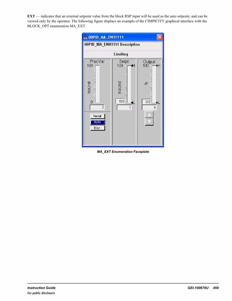
EXT— indicates that an external setpoint value from the block RSP input will be used as the auto setpoint, and can beviewed only by the operator. The following figure displays an example of the CIMPICITY graphical interface with theBLOCK_OPT enumeration MA_EXT.
MA_EXT Enumeration Faceplate
Instruction Guide GEI-100679U 459For public disclosure

REM— indicates the operator can select between a remote setpoint and a local setpoint value to be used as the auto setpoint.The operator sets the local setpoint using the faceplate, and the remote setpoint value is connected to the RSP input pin. Theremote setpoint mode can be selected by the operator using the faceplate or using the pulsed input pin, RSP_SEL.
Note The RSP_SEL input must be a pulsed input. If a continuous True input is used for the RSP_SEL input, the PID_MA_ENH_V2 block will not return to remote setpoint mode from the RSP_SEL input if the operator selects local from thegraphical interface. The following figure displays an example of the CIMPICITY graphical interface with the BLOCK_OPTenumeration MA_REM in auto and local mode.
MA_REM Enumeration Faceplate
460 GEI-100679U Mark VIe Controller DCS Block LibraryFor public disclosure

CASC— indicates the block is being used in conjunction with another PID_MA_ENH_V2 block in a cascade scenario; onePID_MA_ENH_V2 block, the outer loop, controls the setpoint, RSP, of the other PID_MA_ENH_V2 block, the inner loop.Usually, the outer loop controls the primary control variable and the inner loop controls a rapidly changing variable associatedwith the primary variable. The PID_MA_ENH_V2 that acts as the inner loop has the CASC enumeration and the outer loopdoes not. The designation of CASC allows the graphical interface to provide the option for the operator to view the inner loopPID_MA_ENH_V2 graphical interface, as well as call the outer loop faceplate to view the overall process loop viewed as onecontroller. The following figure is an inner loop cascade example of the CIMPICITY graphical interface with the BLOCK_OPT enumeration PID_MA_REM_CASC in auto and local mode.
Note Refer to the section Cascaded PID_MA_ENH_V2 Blocks.
PID_MA_REM_CASC Faceplate Enumeration
Instruction Guide GEI-100679U 461For public disclosure

The following figure is an outer loop cascade example of the CIMPICITY graphical interface with the BLOCK_OPTenumeration PID_MA, in auto mode, which is supplying the remote setpoint to the PID_MA_ENH1000 represented by thefaceplate in the figure PID_MA_REM_CASC Faceplate Enumeration.
PID_MA_ENH_V2 Faceplate Enumeration
BLOCK_OPT Exceptions
The selected BLOCK_OPT enumeration needs to be modified under certain conditions: the operator has placed the block intuning mode (TUN is True), there is participation in a PID override control scheme using an OVR_ST_ENH_V2 block, theOVR_CTRL input enumeration contains OVR_CTRL, or OVRST_CTRL is True.
Condition 1: OVRST_CTRL = True, TUN = FalseBLOCK_OPT = PID_MA or PID_MA_REM, it is modified to be PID_MA_EXTBLOCK_OPT = PID_MA_REM_CASC, it is modified to be PID_MA_EXT_CASCBLOCK_OPT = MA or MA_REM or MA_MAN, it is modified to be MA_EXT
Condition 2: TUN = TrueBLOCK_OPT = PID or PID_MA_EXT, it is modified to be PID_MA_REMBLOCK_OPT = PID_MA_EXT_CASC, it is modified to be PID_MA_REM_CASC
Condition 3: OVRST_CTRL = True, TUN = TrueBLOCK_OPT = PID_MA, it is modified to be PID_MA_REMBLOCK_OPT = MA, it is modified to be MA_REM
Note The order of priority of mode modifications is Condition 1, 2, and 3, respectively.
462 GEI-100679U Mark VIe Controller DCS Block LibraryFor public disclosure

BLOCK_OPT Output Properties
The following PID_MA_ENH_V2 output properties control the appearance of the corresponding graphical interface based onthe BLOCK_OPT enumeration:
• ID enumeration sets the PID_P property to True• MA enumeration sets the MA_P property to True• PID_MA enumeration sets the PID_MA_P property to True• PID_MA_EXT enumeration sets the PID_MA_EXT_P property to True• PID_MA_EXT_CASC enumeration sets the PID_MA_EXT_C_P property to True• PID_MA_REM enumeration sets the PID_MA_REM_P property to True• PID_MA_REM_CASC enumeration sets the PID_MA_REM_C_P property to True• MA_EXT enumeration sets the MA_EXT_P property to True• MA_REM enumeration sets the MA_REM_P property to True• MA_MAN enumeration sets the MA_MAN_P property to True
CTRL_ACT enumerations are listed in the following table.
CTRL_ACT Input Enumerations
Name Description
DIRECT Direct action (PV-SP)
REVERSE Reverse action (SP-PV)
DIRECT— indicates the value of CVO increases when the value of PV is greater than the setpoint and the value of CVOdecreases when the value of PV is less than the setpoint.
REVERSE— indicates the value of CVO decreases when the value of PV is greater than the setpoint and the value of CVOincreases when the value of PV is less than the setpoint.
Instruction Guide GEI-100679U 463For public disclosure

MODE_OPT
MODE_OPT enumerations are listed in the following table.
MODE_OPT Input Enumerations
Name Description
NONE None
LOCK Lock mode
POS Position feedback
LOCK-POS Lock mode and position feedback
SPLIT Split range
SPLIT-LOCK Split range and lock mode
SPLIT-POS Split range and position feedback
SPLIT-LOCK-POS Split range, lock mode, and position feedback
NONE— used when no mode options are to be enabled.
LOCK sets the lock property, LOCK_P, to True, allowing software lockout of the controller to be implemented by theoperator through the CIMPLICITY graphical interface.
Note The lockout indication is provided for indication only. This action will not lock out the equipment, it will only indicatelockout status. The owner's lockout procedures must be followed to safely lock equipment out.
The Lock button can also be configured to use the WorkstationST Lock function. Refer to the WorkstationST/CIMPLICITYAdvanced Viewer Integration Instruction Guide (GEI-100697), the section HMI Tagout.
The valve output CVO must be within 5 units of the initial position input (INIT_POS) value before the block can be set tolockout mode. When LOCK is True the block is in lockout mode and block outputs, CVO, CV, and, if applicable, SVareprohibited from modulating. If the block is in auto mode and not participating in an override control scheme, the OVR_CTRLinput enumeration is NONE, and the BLOCK_OPT enumeration is not PID only, PID_P is False, then the block will beplaced in manual mode and the manual reject alarm, MAN_REJ_A, is activated. The operator’s ability to switch to auto modeis also disabled until the block is removed from lockout mode. If the block is in tuning mode, the tuning mode will also beremoved and disabled. Additionally, the local auto setpoint tracks the process variable input PV when the block is in lockoutmode.
POS— used when there is feedback available from the controlled device. Normally, feedback is the valve position feedback;however, the POS enumeration can also be used for motor speed or a variety of other device feedbacks. The position feedbackvalue is connected to the block input POS_CVand, if the MODE_OPT enumeration SPLIT is selected, the position feedbackfrom the secondary device is connected to the POS_SV block input. When the POS enumeration is used, the block outputPOSFB_P is True, the feedback value is displayed on the graphical interface faceplate, and, when the cursor is placed over thefeedback area, the pop up window displays the text CV Pos Feedback = the instantaneous value, as displayed in the followingfigure.
464 GEI-100679U Mark VIe Controller DCS Block LibraryFor public disclosure

POS Enumeration Faceplate with Controlling
SPLIT— indicates that the controller will output to two different devices using the block outputs, CVand SV, either or bothof which may be characterized by a 13 element array that enables each output to be customized to fit the requirements of aspecific control application. The default characterization arrays are linear for both CVand SVand are as follows:
• CV_X and SV_X = -10, 0, 10, 20, 30, 40, 50, 60, 70, 80, 90, 100, 1000000• CV_Yand SV_Y = -10, 0, 10, 20, 30, 40, 50, 60, 70, 80, 90, 100, 1000000
Instruction Guide GEI-100679U 465For public disclosure

If the CV_X 13 element array does not contain the same 13 array elements in the same order as the CV_Yarray, or the SV_X13 element array does not contain the same 13 array elements in the same order as the SV_Yarray, the characterizationproperty, CHAR_P, is True and the graphical interface displays a button in the lower right corner of the faceplate with the popup text Show Characterization, as displayed in the following figure.
The follow characterizations are applied:
• CV_X = -10, 0, 10, 20, 30, 40, 50, 60, 70, 80, 90, 100, 1000000• CV_Y = -10, 0, 10, 20, 30, 40, 50, 60, 70, 80, 90, 100, 1000000• SV_X = -10, 0, 10, 20, 30, 40, 50, 60, 70, 80, 90, 100, 1000000• SV_Y = -10, 0, 10, 20, 30, 40, 50, 60, 70, 80, 90, 100, 1000000
466 GEI-100679U Mark VIe Controller DCS Block LibraryFor public disclosure

SPLIT Enumeration Faceplate with Characterizations
MODE_OPT Output Properties
The following PID_MA_ENH_V2 output properties control the appearance of the corresponding graphical interface based onthe MODE_OPT enumeration:
• NONE enumeration sets LOCK_P, POSFB_P, and SPLIT_P property to False• LOCK enumeration sets the LOCK_P property to True• POS enumeration sets the POSFB_P property to True• SPLIT enumeration sets the SPLIT_P property to True
Basic PID_MA_ENH_V2 Block Functionality
The BLOCK_OPT, CTRL_ACT, and MODE_OPT inputs enumerations described in this section are instrumental indetermining the basic PID_MA_ENH_V2 functionality. For example, the controller is required to be direct acting, have PIDfunctionality, manual or auto mode capability, ability to be software locked, and feedback is available from the controlleddevice. The input enumerations selected are:
• BLOCK_OPT, PID_MA• CTRL_ACT, DIRECT• MODE_OPT, LOCK-POS
Instruction Guide GEI-100679U 467For public disclosure

Control Word
Control Word (CTL) enumerations are listed in the following table.
CTL Enumerations
Name Description
NO_CMD No command
AUTO_CMD Auto command
MANUAL_CMD Manual command
LOCK_CMD Lock command
UNLOCK_CMD Unlock command
TUN_ON_CMD Tune mode on command
TUN_OFF_CMD Tune mode off command
REMOTE_CMD Remote SP command
LOCAL_CMD Local SP command
The operator controls the PID_MA_ENH_V2 block by clicking buttons on the CIMPLICITY graphical interface pop upfaceplate. Certain faceplate buttons carry an enumerated value represented in the PID_MA_ENH_V2 block input CTL. Theenumerated values are transferred from the faceplate to the PID_MA_ENH_V2 block through EGD using the CTL. When acommand is sent from the faceplate to the PID_MA_ENH_V2 block, the block runs the command and then, after one second,the block overwrites the CTL input with the NO_CMD enumeration, thus resetting itself for the next CTL command. Theenumerations for CTL are displayed in the following table.
Note The commands are dependent on the enumerations of BLOCK_OPT and MODE_OPT. For example, LOCK_CMDand UNLOCK_CMD enumerations are not used if MODE_OPT does not contain the enumeration LOCK).
NO_CMD— indicates no command is present.
AUTO_CM places the block in auto mode from manual mode using the graphical interface faceplate. The auto setpoint willbe local, remote, or external depending on the BLOCK_OPT enumeration and, if applicable, the operator selection as local orremote. When the block is in auto mode the output AUTO is True.
MANUAL_CMD places the block in manual mode from auto mode using the graphical interface faceplate. The operatormanually sets the output to the controlled device. When the block is in manual mode the output AUTO is FLASE.
LOCK_CMD— places the block in lock mode when the block output CVO is within 5 units of the initial position value,NIT_POS. This enumeration command also removes the block from auto and places it in manual mode and sets the manualreject alarm, MN_REJ_A, to True. When the block is in lock mode the output LOCK is True.
UNLOCK_CMD— removes the block from lock mode and sets the output LOCK to False.
TUN_ON_CMD— places the block in tuning mode. The operator is not allowed to change the PID_MA_ENH_V2 block tothe tuning mode when the block is already in lock mode.
468 GEI-100679U Mark VIe Controller DCS Block LibraryFor public disclosure

Once the tuning mode has been attained, it can only be reset by one of the following methods:
• Operator tune off command• Block is set to lock mode
When the block is in tuning mode, the output TUN is True.
TUN_OFF_CMD— removes the block from the tuning mode and sets TUN to False.
REMOTE_CMD— commands the block, when in auto mode, to use the remote setpoint value connected to block input pin,RSP, as the auto setpoint. When the block is in remote mode the remote setpoint output, RS, is True.
LOCAL_CMD— commands the block, when in auto mode, to use the operator defined local setpoint. When the block is inlocal setpoint mode, RS is False.
Manual Reject (MN_REJ)
Manual Reject (MN_REJ) input is driven by an override-type block that associates its input status with the graphical interfaceof the PID_MA_ENH_V2 block, thus allowing the operator to view the individual inputs that put the block into a manualreject mode. The override graphical interface also enables the operator to block logic driven inputs to release the overridecondition through the graphical interface.
MN_REJ Enumerations
Name Description
NO_OVR-NO_BLOCK No override and no override is blocked
OVR-NO_BLOCK Override active and no override is blocked
NO_OVR-BLOCK No override and an override is blocked
OVR-BLOCK Override active and an override is blocked
NO_OVR— indicates no manual reject command is active; manual reject output REJ_MN is False
OVR— indicates a manual reject command is active; manual reject output REJ_MN is True.
NO-BLOCK— indicates the operator has not invoked a block of any of the associated logic driven inputs to theoverride-type block. When a no block is active, REJ_MNB is False.
BLOCK— indicates the operator has invoked a block of at least one of the associated logic driven inputs to the override typeblock. The BLOCK enumeration is not used by OVR_ST_ENH_V2, but the block does pass the information it to thegraphical interface for display purposes using the output, REJ_MNB. When a block is active, REJ_MNB is True.
Instruction Guide GEI-100679U 469For public disclosure

Under most circumstances, if the PID_MA_ENH_V2 block is in auto mode and a validated MN_REJ input enumerationcontains OVR, the block is removed from auto mode and placed in manual mode, and MN_REJ_A is activated and the localauto setpoint, if available, tracks PV. Exceptions are if the BLOCK_OPT enumeration is PID, PID_Pis True, or the PID_MA_ENH_V2 block input OVR_CTLR contains the enumeration OVRST_CTRL from the OVR_ST_ENH_V2 block, indicatingthe override station controls the PID_MA_ENH_V2 block.
Other Enumerated External Commands
There are three enumerated PID_MA_ENH_V2 block inputs that provide commands from external blocks that control thePID_MA_ENH_V2 output, CVO. They are, in order of priority, CMD_OVR, CMD_FRC, and CMD_TK.
Note When PID_MA_ENH_V2 blocks are connected to and receiving inputs from the OVR_ST_ENH_V2 block, it isrecommended to use the OVR_ST_ENH_V2 block for any external commands, such as CMD_OVR, CMD_FRC, or CMD_TK actions for the PID_MA_ENH_V2 block. In other words, do not connect CMD_OVR, CMD_FRC, and CMD_TK typeblocks to the PID_MA_ENH_V2 blocks when using an OVR_ST_ENH_V2 block. Instead, use the capability of the OVR_ST_ENH_V2 block for these actions.
Command Override (CMD_OVR) input is driven by an override-type block that associates its input status with thegraphical interface of the PID_MA_ENH_V2 block, thus allowing the operator to view the individual inputs that place theblock in override mode. The override graphical interface also enables the operator to block logic driven inputs to release theoverride condition through the graphical interface. CMD_OVR enumerations are listed in the following table.
CMD_OVR Enumerations
Name Description
NO_OVR-NO_BLOCK No override and no override is blocked
OVR-NO_BLOCK Override active and no override is blocked
NO_OVR-BLOCK No override and an override is blocked
OVR-BLOCK Override active and an override is blocked
NO_OVR— indicates no override command is active and the command override output OVR_CMD is False.
OVR— indicates an override command is active and OVR_CMD is True.
NO-BLOCK— indicates the operator has not invoked a block of any of the associated logic driven inputs to theoverride-type block. When this enumeration is used, OVR_CMDB is False.
BLOCK— indicates the operator has invoked a block of at least one of the associated logic driven inputs to the override-typeblock. When this enumeration is used, OVR_CMDB is True.
If the PID_MA_ENH_V2 block is in auto mode and a validated CMD_OVR input enumeration contains OVR, an overridecommand exists and MN_REJ_A is activated, and the output will move to the input value of the override value, OV. Theblock is removed from auto mode and placed in manual mode and the local auto setpoint, if available, tracks PV.
Note An override command (the enumeration of CMD_OVR contains OVR) has precedence over a force command (CMD_FRC contains FORCE), and the process increase and decrease inputs, PR_INC and PR_DEC, respectively.
Command Force (CMD_FRC) input is driven by a force-type block that associates its input status with the graphicalinterface of the PID_MA_ENH_V2 block, thus allowing the operator to view the individual inputs that put the block into aforce mode. The force graphical interface also enables the operator to block logic driven inputs to release the force conditionthrough the graphical interface. CMD_FRC enumerations are listed in the following table.
470 GEI-100679U Mark VIe Controller DCS Block LibraryFor public disclosure

CMD_FRC Enumerations
Name Description
NO_FORCE-NO_BLOCK No force and no force is blocked
FORCE-NO_BLOCK Force active and no force is blocked
NO_FORCE-BLOCK No force and a force is blocked
FORCE-BLOCK Force active and a force is blocked
NO_FORCE— indicates no force command is active and the force command output, FRC_CMD, is False.
FORCE— indicates a force command is active and if the CMD_OVR enumerated input does not contain OVR (the outputOVR_CMD is False), then the force command output FRC_CMD is True.
NO-BLOCK— indicates the operator has not invoked a block of any of the associated logic driven inputs to the force typeblock. When this enumeration is used, the force-blocked output FRC_CMDB is False.
BLOCK indicates the operator has invoked a block of at least one of the associated logic driven inputs to the force type blockand sets the force-blocked output FRC_CMDB to True.
If the PID_MA_ENH_V2 block validated CMD_FRC input enumeration contains FORCE, a force command exists and theoutput of the block, CVO, moves to the input value of the force value, FV.
Note An override command (the enumeration of CMD_OVR contains OVR) has precedence over a force command (CMD_FRC contains FORCE).
Instruction Guide GEI-100679U 471For public disclosure

Command Track (CMD_TK) input is driven by a track-type block that associates its input status with the graphical interfaceof the PID_MA_ENH_V2 block, thus allowing the operator to view the individual inputs that places the block in track mode.The track graphical interface also enables the operator to block logic driven inputs to release the track condition through thegraphical interface. CMD_TK enumerations are listed in the following table.
CMD_TK Enumerations
Name Description
NO_TRACK-NO_BLOCK No track and no track is blocked
TRACK-NO_BLOCK Track active and no track is blocked
NO_TRACK-BLOCK No track and a track is blocked
TRACK-BLOCK Track active and a track is blocked
NO_TRACK— indicates no track command is active and the track status output, TK_OUT, is False.
TRACK— indicates a track command is active and TK_OUT is True.
NO-BLOCK— indicates the operator has not invoked a block of any of the associated logic driven inputs to the track typeblock. When this enumeration is used, the track-blocked output TK_CMDB is False.
BLOCK— indicates the operator has invoked a block of at least one of the associated logic driven inputs to the track typeblock. When this enumeration is used, the track-blocked output TK_CMDB is True.
If the PID_MA_ENH_V2 block is in auto mode and a validated CMD_TK input enumeration contains TRACK, a trackcommand exists and the output of the block, CVO, tracks the block tracking value input TV.
Priority Increase (PR_INC) and Decrease (PR_DEC) Commands
When the PID_MA_ENH_V2 block input PR_INC is True, the output CVO increases to the high limit value (H) at the ratedefined by the priority increase rate value R_INC_RT (default value is 1 unit/sec). When the PID_MA_ENH_V2 block inputPR_DEC is True and PR_INC is False, the output CVO decreases to the low limit value (L) at the rate defined by the prioritydecrease rate value PR_DEC_RT (default value is 1 unit/sec). The inputs PR_INC and PR_DEC should be programmed to bemutually exclusive events, but if at any time they both become True, then PR_INC is the dominate input and the value ofCVO increases to H at the rate defined by PR_INC_RT.
Note A force command (the enumeration of CMD_FRC contains FORCE) or an override command (the enumeration ofCMD_OVR contains OVR) have precedence over the PR_INC and PR_DEC inputs.
472 GEI-100679U Mark VIe Controller DCS Block LibraryFor public disclosure

Inhibit Increase (INH_INC) and Decrease (INH_DEC) Commands
The PID_MA_ENH_V2 is capable of inhibiting the output control variable, CVO, from increasing or decreasing in valueabsent a force or override command, FORCE from the enumerated CMD_FRC input or OVR from the enumerated CMD_OVR input.
Inhibiting the increase of the CVO output occurs when INH_INC is True and one of the following is present:
• Neither PR_INC nor PR_DEC is True.• BLOCK_OPT enumeration is neither PID_MA_EXT_CASC nor PID_MA_REM_CASC, and the CASC_IN
enumeration is REVERSE and HI_LIMITED.• BLOCK_OPT enumeration is neither PID_MA_EXT_CASC nor PID_MA_REM_CASC, and the CASC_IN
enumeration is DIRECT and LOW_LIMITED.
Inhibiting the decrease of the CVO occurs when INH_DEC is True and one of the following is present:
• Neither PR_INC nor PR_DEC are True.• BLOCK_OPT enumeration is neither PID_MA_EXT_CASC nor PID_MA_REM_CASC and the CASC_IN enumeration
is DIRECT and HI_LIMITED.• BLOCK_OPT enumeration is neither PID_MA_EXT_CASC nor PID_MA_REM_CASC and the CASC_IN enumeration
is REVERSE and LOW_LIMITED.
Auto Permit (AU_PMT) input is driven by an auto permit-type block that associates its input status with the graphicalinterface of the PID_MA_ENH block, which allows the operator to view the individual inputs that provide a permit to placethe block in auto mode. The AU_PMT graphical interface enables the operator to bypass logic driven inputs to obtain an autopermit condition through the graphical interface. AU_PMT enumerations are listed in the following table.
AU_PMT Enumerations
Name Description
NO_PERM-NO_BYPASS No permit and no permit is bypassed
PERM-NO_BYPASS Permit OK and no permit is bypassed
NO_PERM-BYPASS No permit and a permit is bypassed
PERM-BYPASS Permit OK and a permit is bypassed
NO_PERM— indicates a permit to allow the block to be placed in auto mode has not been met and the Auto Permit output(PMT_AU) is False.
PERM— indicates all permits for the block to be placed in auto mode have been met and PMT_AU is True, provided theBLOCK_OPT is not PID only, PID_P is False, the block is not part of an override scheme, OVRST_CTRL is FASE, andthere is no bad quality detected and the reset override, RSP_OV is False, when BQ_MAN is set to True. The block outputs,REJ_MN, OVR_CMD, LOCK, and MA_MAN_P must also all be False for PMT_AU to be True.
NO-BYPASS— indicates the operator has not invoked a bypass of any of the associated logic driven inputs to the auto permitblock. When this enumeration is used, the Auto Permit Bypass output (PMT_AUB) is False.
BYPASS— indicates the operator has invoked a bypass of at least one of the associated logic driven inputs to the auto permitblock. When this enumeration is used, PMT_AUB is True.
Modulate Permit (MOD_PMT) input is driven by a modulate permit-type block that associates its input status with thegraphical interface of the PID_MA_ENH_V2 block, thus allowing the operator to view the individual inputs that provide apermit to allow the block to modulate the output. The MOD_PMT graphical interface enables the operator to bypass logicdriven inputs to obtain a modulate permit condition through the graphical interface. MOD_PMT enumerations are listed in thefollowing table.
Instruction Guide GEI-100679U 473For public disclosure

MOD_PMT Enumerations
Name Description
NO_PERM-NO_BYPASS No permit and no permit is bypassed
PERM-NO_BYPASS Permit OK and no permit is bypassed
NO_PERM-BYPASS No permit and a permit is bypassed
PERM-BYPASS Permit OK and a permit is bypassed
NO_PERM— indicates a permit to allow the block to modulate the output, CVO, has not been met and the permit tomodulate output, PMT_MOD, is False. If the MOD_PMT input enumeration contains NO_PERM, CVO equals the INIT_POS input value.
PERM— indicates all permits to allow the block to modulate the output, CVO, have been met and PMT_MOD is True.
NO-BYPASS— indicates the operator has not invoked a bypass of any of the associated logic driven inputs to the modulatepermit block. When this enumeration is used, the modulate permit bypass output, PMT_MODB, is False.
BYPASS— indicates the operator has invoked a bypass of at least one of the associated logic driven inputs to the modulatepermit block. When this enumeration is used, PMT_MODB is True.
Auto Select (AU_SEL) is a pulsed input that, if permits allow, switches the block from manual to auto mode, setting theoutput AUTO to True. The input must be pulsed.
Remote Select (RSP_SEL) is a pulsed input that instructs the block to use the remote setpoint input RSP as the setpointused to calculate the block outputs, CVO, CV, and, if applicable, SV, when the block is in auto mode. The input must bepulsed.
Setpoint High (SH) and Low (SL) Limit Values
Block inputs SH and SL, are the setpoint high and low limits, respectively. These values bound the block output, SP, thesetpoint used to calculate the error, which is used for the proportional gain portion of the PID calculations.
474 GEI-100679U Mark VIe Controller DCS Block LibraryFor public disclosure

Setpoint Adjustment Rate (SR)
The rate of change of the block setpoint, SP, used to calculate the error used in the PID calculations is restricted by the blockSR input value, in units/sec. The setpoint used for the error calculation is passed without rate limit restrictions directly to SPwhen the controller is powered up, track status, TK_OUT, is True, or the BLOCK_OPT enumeration is PID_MA_EXT_CASC or PID_MA_REM_CASC, and the remote setpoint mode, RS, is TRUE.
Setpoint Value Before Ramp (SI)
The internal setpoint block output, SI, is the value of the setpoint before the SR is applied. For example, if the setpointchanges from 0 to 10 instantaneously, SI will change from 0 to 10 instantaneously while if SR is set at 1 unit/sec, SP willramp from 0 to 10 in 10 seconds. SI is also bound by limit inputs SH and SL, respectively.
Scale Factor (SF) is used to scale the process variable, PV, and the setpoint used to calculate the error value that is used inthe PID calculations. The setpoint used for the error calculation, the block output SP, may be the value of theoperator-supplied setpoint, the value of the remote setpoint, RSP, or a tracking value, depending on the state of the block.
Setpoint Track (SP_TRACK)
When SP_TRACK is True, the setpoint tracks PV in manual or RSP in auto and remote mode, the output AUTO is True whenthe block is in auto mode, and RS is True when the block is in remote mode. If SP_TRACK is False and RS is True, thesetpoint tracks RSP. Otherwise, the operator controls the setpoint value from the graphical interface.
Manual Adjustment Rate (MR)
The rate of change of the control variable output, CVO, is restricted by the block manual adjustment ramp rate input valueMR, in units/sec.
Square of the Error (SQR_ERR)
The square of the calculated error is used if the SQR_ERR parameter is set to True and is multiplied by PG to calculate theproportional term in the PID calculations. When the value of the error is greater than one, the square of the error provides amore robust controller response, when the error is less than one the controller will respond less aggressively.
Instruction Guide GEI-100679U 475For public disclosure

Tracking Status (TK_OUT)
The track status block output TK_OUT can be set to True by a number of input conditions, such as bad quality, priorityincrease or decrease, no permit to modulate, manual mode, force command, override command, increase or decrease inhibit,lock, track command enumeration (CASC_IN enumeration contains TRACK) or the override station tracking input (OVR_CTRL enumeration contains TRACK). When TK_OUT is True, the PID_ MA_ENH_V2 is in tracking mode and the blockoutput, CVO (also CV_X and, if applicable, SV_X for characterized outputs CVand SV, respectively) tracks the appropriatevalue based on the parameter that set TK_OUT to True. The value may be the override value (OV), force value (FV), apriority increase or decrease command will move to the H or L limit values at PR_INC_RT or PR_DEC_RT, the track value(TV) or the initial position value (INIT_POS). When the increase (DEC_INH) or decrease (INC_INH) inhibit inputs, ortransition from True to False, TK_OUT is True for one scan, which realigns the setpoint and the calculated PID values.
Note The H and L values are dependent on the enable process limit inputs EN_PROC_LIM_HIGH and EN_PROC_LIM_LOW, as well as the PROC_LIM_HIGH and PROC_LIM_LOW limits, respectively.
Process (High EN_PROC_LIM_HIGH) and Low (EN_PROC_LIM_LOW) Limits
The user can limit the process control range further using the PROC_LIM_LOWand PROC_LIM_HIGH parameters that areenabled by their respective enable parameters, EN_PROC_LIM_LOWand EN_PROC_LIM_HIGH. This feature enables theuser to control process regulation limits while allowing force and override values to operate independently on the PID_MA_ENH_V2 limits (H and L). When EN_PROC_LIM_LOWor EN_PROC_LIM_HIGH is True, the PROC_LIM_LOWandPROC_LIM_HIGH replace the corresponding L and H limit values.
Error Deadband Equality (ERR_C)
The ERR_C, when True, enables the use of error dead band equality processing. When the absolute value of the error is lessthan the input value ERR_CDB (the error dead band), the controller equates that the error is zero.
External Reset (ER) may be used to enable several PID_MA_ENH_V2 controllers to function in parallel, typically whenthe minimum or maximum CVO value will be selected. External reset allows all PID_MA_ENH_V2 controllers in the loop tocalculate CVO based on process conditions while preventing windup. The selected CVO is sent to the control element and tothe other PID_MA_ENH_V2 controllers in the loop. The ER command block input, or an ER enumeration from OVR_CTRLenables the external reset function. The selected CVO is connected to the external reset value (EV).
Note Refer to the section PID Track at Limit until PVand SP Cross (PV_SP_LIM_TRK).
476 GEI-100679U Mark VIe Controller DCS Block LibraryFor public disclosure

The following figure displays the typical OVR_ST_ENH_V2 block pin connections using a Min/Max configuration with twooverride controlled PID_MA_ENH_V2 blocks.
PID_MA_ENH_V2_1
PID_MA_ENH_V2_2 OVR_ST_ENH_V2
CVO
CVO
CASC_OUT
OVR_CTRL1
OVR_CTRL2
CVO
CV
SV
SP
OVR_CTRL
OVR_CTRL
TV
RSP
TV
RSP
CVI1
CVI2
CASC_IN1
CASC_IN2
CASC_OUT
EV
EV
†
†
† A connection to EV is required when the OVR_ST_ENH_V2 block STATION_OPT enumeration is set to, MIN_2_INPUTS, MIN_3_INPUTS, MAX_2_INPUTS, or MAX_3_INPUTS.
Instruction Guide GEI-100679U 477For public disclosure

When the PID tracks at limit until PVand SP cross input (PV_SP_LIM_TRK) is True, and the ER command is True, the resetdoes not occur until the following conditions are all False:
• PV value becomes greater than the SP value when US is True and the controller is reverse acting• PV value becomes greater than the SP value when LS is True and the controller is direct acting• PV value becomes less than the SP value when LS is True and the controller is reverse acting• PV value becomes less than the SP value when US is True and the controller is direct acting
PID Track at Limit until PV and SP Cross (PV_SP_LIM_TRK)
If PV_SP_LIM_TRK is True, when the controller output reaches either H or L limit, the controller tracks the limit value untilPV crosses SP. Once PV crosses SP, the controller resumes the controlling action. The following graph displays PV, SP, andCVO for a PID_MA_ENH_V2 block with PV_SP_LIM_TRK both True and False. Notice that with PV_SP_LIM_TRK set toTrue (left of the black vertical line) CVO remains at the limit until PV crosses SP. With PV_SP_LIM_TRK set to False (rightof the black vertical line), CVO only tracks the limit until PV changes slope.
PV_SP_LIM_TRK Set to True and False
The graph displays PV (blue sine wave), SP (green horizontal line), and CVO (brown sine wave, capped). With PV_SP_LIM_TRK set to True, the controller behaves as displayed in the graph by the data to the left of the vertical black line. With PV_SP_LIM_TRK set to False, the controller behaves as displayed by the data to the right of the vertical black line.
Each time SP and PV cross the threshold defined by the range of ERR_CDB, (the error for dead band PVand SP equality),and the error for dead band equality input, ERR_C, is True, the controller calculates the integral term from the last calculatedcontrol output value, CVO (BLOCK_OPT enumeration must contain PID).
478 GEI-100679U Mark VIe Controller DCS Block LibraryFor public disclosure

Inhibit Proportional and Derivative Action on Setpoint Change (INH_PDG)
The INH_PDG parameter, when True, inhibits proportional and derivative controller action. When the SP change is detectedto exceed a scan time calculated dead band derived from the value of the dead band setpoint to inhibit the proportional andderivative action, INH_PDG_CDB, in units/sec; the controller calculates the integral term from the last calculated controloutput value, CVO (BLOCK_OPT enumeration must contain PID).
Note If INH_PDG is True and the setpoint is constantly changing (possibly a remote setpoint) by an amount greater than thescan time calculated dead band specified by INH_PDG_CDB, then the controller is an integral only controller.
Bumpless Proportional and Integral Gain Value Changes (PG_C and IG_C)
If the value of the proportional gain (PG) or the integral gain (IG) is variable, the input parameters PG_C and IG_C providebumpless controller action when True. If the value of PG or IG exceeds the dead band PG_CDB for PG and IG_CDB for IG,and the corresponding PG_C or IG_C parameter is True, the controller calculates the integral term from the last calculatedcontrol output value, CVO (BLOCK_OPT enumeration must contain PID).
Feed Forward (FF)
When the BLOCK_OPT input enumeration contains PID the block provides a FF input that is added as a last step before theoutput value of CVO and characterized output values of CVand, if applicable, SVare output from the ID_MA_ENH block.
Instruction Guide GEI-100679U 479For public disclosure

Status Propagation and Bad Quality Determination of CVO, CV, and SV Outputs
The PID_MA_ENH_V2 block monitors the quality status values of various inputs and connected outputs to determine thequality status value of CVO, CV, and SV (if the MODE_OPT enumeration contains SPLIT then the split output propertySPLIT_P is True).
The quality status value of the control variable output CV is either the quality status value of CVO or, if SPLIT_P is True andthe quality status value of BKCAL_IN_CV is > 200 and < 203, the quality status value of CV is assigned a quality statusvalue of 196, NOT_LIMITED-INTIALIZATION_ACKNOWLEDGE-GOODC.
The quality status value of the split range control variable output SV is either the quality status value of CVO or, if SPLIT_Pis True and the quality status value of BKCAL_IN_SV is > 200 and < 203, the quality status value of SV is assigned a qualitystatus value of 196, NOT_LIMITED-INTIALIZATION_ACKNOWLEDGE-GOODC.
The quality status value of the control variable output CVO is determined by the how the block is used. If the PID_MA_ENH_V2 block is connected to an OVR_ST_ENH_V2 block, the enumerated OVR_CTRL input contains the enumerationOVR_CTRL, or the block is used as the outer loop in a cascaded scenario, the outputs CVand SVare not connected to hardI/O. Therefore, the quality status values of CVand SVare not considered when the quality status value of CVO is calculated.This eliminates the propagation of erroneous CVO quality status values that would result from CVand SV not beingconnected to hard I/O points. Otherwise, the PID_MA_ENH_V2 block calculates the quality status value of CVO fromappropriate inputs with quality status values, input parameters values, and the connected hard I/O quality status values of CVand, if the MODE_OPT contains SPLIT and SPLIT_P is True), SV. The analog output variables attached to CVand SVaremonitored for quality status, resulting in the following possible CVO quality status values:
• 12 - I/O Pack Health Failed – NOT_LIMITED-DEVICE_FAILURE-BAD• 16 - I/O Pack Health Failed – NOT_LIMITED-SENSOR_FAILURE-BAD
If neither of these conditions exists, the quality status value of CVO is calculated by the PID_MA_ENH_V2 block to be from192 to 198, depending on numerous variables used in the quality status calculation, which result in the following values:
• Status value 192 indicates CVO is NOT_LIMITED_GOODC• Status value 193 indicates CVO is LOW_LIMITED_GOODC• Status value 194 indicates CVO is HIGH_LIMITED_GOODC• Status value 195 indicates CVO is CONSTANT_GOODC• Status value 196 indicates CVO is NOT_LIMITED-INITIALIZED_ACKNOWLEDGE-GOODC• Status value 197 indicates CVO is LOW_LIMITED-INITIALIZED_ACKNOWLEDGE-GOODC• Status value 198 indicates CVO is HIGH_LIMITED-INITIALIZED_ACKNOWLEDGE-GOODC
When using FOUNDATION fieldbus, if the split range mode is not selected (SPLIT_P is False) and the quality status value ofBKCAL_IN_CVor BKCAL_IN_SV is > 200 and < 203, then the quality status value of CVO is assigned a quality statusvalue of 196 when LS and US are False. When split range mode is selected (SPLIT_P is True), the FOUNDATION fieldbusinitialization acknowledge provided in the previous sections indicates the quality status of CVand SV.
If CVI_BQ, EV_BQ, PV_BQ, RSP_BQ, RSP_OV, FFWD_BQ, TV_BQ, BKCALIN_CV_BQ, and BKCAL_IN_SV_BQ areFalse and the value of CVO is less than or equal to the low limit (LS is True), 1 is added to the CVO status value.
If CVI_BQ, EV_BQ, PV_BQ, RSP_BQ, RSP_OV, FFWD_BQ, TV_BQ, BKCALIN_CV_BQ, and BKCAL_IN_SV_BQ areFalse, and the value of CVO is greater than or equal to the high limit (US is True), 2 is added to the CVO status value.
480 GEI-100679U Mark VIe Controller DCS Block LibraryFor public disclosure

This block propagates quality status. Status option cannot be disabled on this block.
CVO status is based upon the following in order of priority:
• The analog output variables attached to CVand SVare monitored for quality status. This results in the followingpossible CVO statuses:− I/O Pack Health Failed – NOT_LIMITED-DEVICE_FAILURE-BAD [12]− I/O Pack Health Failed – NOT_LIMITED-SENSOR_FAILURE-BAD [16]
• If CVI_BQ, EV_BQ, PV_BQ, RSP_BQ, RSP_OV, FFWD_BQ, TV_BQ, BKCALIN_CV_BQ, or BKCAL_IN_SV_BQ is True, the value of CVO status is CONSTANT-GOODC [195].
• If CVI_BQ, EV_BQ, PV_BQ, RSP_BQ, RSP_OV, FFWD_BQ, TV_BQ, BKCALIN_CV_BQ, or BKCAL_IN_SV_BQ is True, the value of CVO status is CONSTANT-GOODC [195]. If the following are False, CVI_BQ, EV_BQ,PV_BQ, RSP_BQ, RSP_OV, FFWD_BQ, TV_BQ, BKCALIN_CV_BQ, and BKCAL_IN_SV_BQ and the value ofCVO is greater than or equal to the high limit, US is True, 2 is added to the CVO status value.
• The default quality status of CVO is NOT_LIMITED-GOODC [192].For further details on relational blocks, refer to the Mark VIe Controller Standard Block Library (GEI-100682), the StatusMonitoring (STATUS_MONITORING) block.
Instruction Guide GEI-100679U 481For public disclosure

Manual Auto Configuration
Typical connections for PID_MA_ENH_V2 blocks with BLOCK_OPT enumerations MA, MA_EXT, and MA_REM withouta control variable input (CVI) available are displayed in the following figure. Note the connection of SP to CVI.
PID_MA_ENH Controller with BLOCK_OPT Enumeration
Input Quality Status Monitoring
The PID_MA_ENH_V2 block monitors and propagates the health or quality status of I/O points CVI, EV, FF, PV, RSP, TV,BKCAL_IN_CV, BKCAL_IN_SV, POS_CV, POS_SVand determines when action must be taken because a bad qualityrelated input.
The following inputs are monitored for quality status based on block operational mode input BLOCK_OPT:
• CVI is only used in the block calculation when the operational mode is chosen as MA, MA_EXT or MA_REM. Theseare the only modes, which allow the bad quality of CVI to affect block operation.
• V input is only used in the block calculation when the operational mode is chosen as PID, PID_MA, PID_MA_REM,PID_MA_REM_CASC, PID_MA_EXT or PID_MA_EXT_CASC. These are the only modes that allow the bad qualityof EV to affect block operation.
• FF input is only used in the block calculation when the operational mode is chosen as PID, PID_MA, PID_MA_REM,PID_MA_REM_CASC, PID_MA_EXT or PID_MA_EXT_CASC. These are the only modes that allow the bad qualityof F to affect block operation.
• PV input is only used in the block calculation when the operational mode is chosen as MA, MA_EXT, MA_REM, PID,PID_MA, PID_MA_REM, PID_MA_REM_CASC, PID_MA_EXTor PID_MA_EXT_CASC. These are the only modesthat allow the bad quality of PV to affect block operation.
• RSP input is only used in the block calculation when the operational mode is chosen as MA_EXT, MA_REM, PID, PID_MA_REM, PID_MA_REM_CASC, PID_MA_EXT or PID_MA_EXT_CASC. These are the only modes that allow thebad quality of RSP to affect block operation.
• TV input is only used in the block calculation when the operational mode is chosen as MA, MA_EXT, MA_REM, PID,PID_MA, PID_MA_REM, PID_MA_REM_CASC, PID_MA_EXT or PID_MA_EXT_CASC. These are the only modesthat allow the bad quality of TV to affect block operation.
The following inputs are monitored for quality status based on the mode input MODE_OPT containing POS:
• POS_CV input is used to determine if bad quality (POS_CV_BQ) is present and if there is a significant differencebetween the feedback value and the requested value CV to warrant an enabled high differential alarm, POS_CV_DH.
482 GEI-100679U Mark VIe Controller DCS Block LibraryFor public disclosure

• POS_SV input is used to determine if bad quality (POS_SV_BQ) is present and if there is a significant differencebetween the feedback value and the requested value SV to warrant an enabled high differential alarm, POS_SV_DH.
Bad Quality Outputs
Control Variable PID Track Value Bad Quality (BKCAL_IN_CV_BQ) is determined by the following conditions:
• BLOCK_OPT enumeration is MA, MA_EXT, MA_REM, PID, PID_MA, PID_MA_EXT, PID_MA_EXT_CASC, PID_MA_REM, or PID_MA_REM_CASC
• Control variable PID track value input BKCAL_IN_CV is determined to be bad quality, a quality status value < 32.
Split Range Variable PID Track Value Bad Quality (BKCAL_IN_SV_BQ) is determined by the following conditions:
• BLOCK_OPT enumeration is MA, MA_EXT, MA_REM, PID, PID_MA, PID_MA_EXT, PID_MA_EXT_CASC, PID_MA_REM, or PID_MA_REM_CASC
• Split range PID track value input BKCAL_IN_SV is determined to be bad quality (a quality status value < 32).
Output Bad Quality (OBQ) is determined by the following conditions:
• BKCAL_IN_CV_BQ is True• BKCAL_IN_SV_BQ is True• FOUNDATION fieldbus inputs BKCAL_IN_CVor BKCAL_IN_SV, if used, status values are ≥ 196 and ≤ 227.• CVO is determined to be bad quality (a quality status value < 32).
Control Variable Input Bad Quality (CVI_BQ) is determined by the following conditions:
• BLOCK_OPT enumeration is MA, MA_EXT, or MA_REM and the control variable input CVI is determined to be badquality (a quality status value < 32).
Instruction Guide GEI-100679U 483For public disclosure

External Reset Value Bad Quality (EV_BQ) is determined by the following conditions:
• BLOCK_OPT enumeration is PID, PID_MA, PID_MA_EXT, PID_MA_EXT_CASC, PID_MA_REM, or PID_MA_REM_CASC
• EV is determined to be bad quality (a quality status value < 32).
Process Variable Bad Quality (PV_BQ) is determined by the following conditions:
• BLOCK_OPT enumeration is MA, MA_EXT, MA_REM, PID, PID_MA, PID_MA_EXT, PID_MA_EXT_CASC, PID_MA_REM, or PID_MA_REM_CASC
• PV is determined to be bad quality (a quality status value < 32).
Remote Setpoint Bad Quality (RSP_BQ) is determined by the following conditions:
• BLOCK_OPT enumeration is MA_EXT, MA_REM, PID, PID_MA, PID_MA_EXT, PID_MA_EXT_CASC, PID_MA_REM, or PID_MA_REM_CASC
• RSP is determined to be bad quality (a quality status value < 32).• RSP_OV is set to True when the status of RSP is detected as a constant value condition (195) and the block is in a
cascade mode (BLOCK_OPT is PID_MA_EXT_CASC or PID_MA_REM_CASC). This condition indicates that anupstream PID_MA_ENH has a bad quality condition and is now in manual and/or tracking mode. This is designed topropagate to all blocks that make up the loop, including the OVR_ST_ENH.
Track Value Bad Quality (TV_BQ) is determined by the following conditions:
• BLOCK_OPT enumeration is MA, MA_EXT, MA_REM, PID, PID_MA, PID_MA_EXT, PID_MA_EXT_CASC, PID_MA_REM, or PID_MA_REM_CASC
• TV is determined to be bad quality (a quality status value < 32).
Feed Forward Bad Quality (FFWD_BQ) is determined by the following conditions:
• BLOCK_OPT enumeration is PID, PID_MA, PID_MA_EXT, PID_MA_EXT_CASC, PID_MA_REM, or PID_MA_REM_CASC
• FF is determined to be bad quality (a quality status value < 32).
FOUNDATION fieldbus Command to Manual Operation (FF_IMAN) is set to True when the status of a FOUNDATION fieldbus AOis quality status is detected as 196-227. FF_IMAN will reject the PID_MA_ENH_V2 block to a manual and/or tracking state.This status indicates that a downstream FFAO is requesting to initialize a control output, or it is in a fault state or is notinviting the PID_MA_ENH_V2 to participate in the control process. It is a requirement that BK_CAL_IN_CV is connected tothe corresponding BK_CAL_OUT of the FFAO that is driven by CV. The corresponding requirement exists for BK_CAL_IN_SV when split range control is used.
Control Variable Position Feedback Bad Quality (POS_CV_BQ) is determined by the following condition: POS_CV isdetermined to be bad quality a quality status value < 32), and the enumerated input MODE_OPT contains POS (the positionfeedback property, POSFB_P, is True). This bad quality detection also generates a LVL_4 alarm.
Split Range Variable Position Feedback Bad Quality (POS_SV_BQ) is determined by the following condition: POS_SV isdetermined to be bad quality a quality status value < 32), and the enumerated input MODE_OPT contains POS (the positionfeedback property, POSFB_P is True). This bad quality detection also generates a LVL_4 alarm.
484 GEI-100679U Mark VIe Controller DCS Block LibraryFor public disclosure

Alarmed Points
The following output points generate a LVL_4 alarm when activated:
• POS_CV_DH• POS_SV_DH• MN_REJ_A• POS_CV_BQ• POS_SV_BQ
Position Deviation High Alarms (POS_CV_DH and POS_SV_DH)
Under certain conditions, the position deviation high alarm, POS_CV_DH or POS_SV_DH, for CVor SV, respectively,become True when the corresponding feedback value, POS_CVor POS_SV, exceeds a deviation high set point (POS_DH_SP)value for a time period in milliseconds given by the POS_DH_T input parameter (the default value of POS_DH_T is 5000milliseconds).
Note If the POS_DH_T parameter is set to zero, both high deviation alarms, POS_CV_DH and POS_SV_DH, will bedisabled.
The conditions required for the position deviation high alarm are:
• Position deviation time delay (POS_DH_T) must be greater than zero.• LOCK must be False (the block is not in lock mode).• Position feedback property (POSFB_P) must be True (MODE_OPT must contain POS).• Input variable POS_CVor POS_SV have a GOOD quality status indication for the corresponding alarm to be activated
(GOOD quality status range value is from 128 to 155 or 192 to 227).
Manual Reject Alarm (MN_REJ_A) cannot be activated when the enumerated override station control input OVR_CTRLcontains OVR_CTRL or the enumerated BLOCK_OPT input is PID only (the output PID_P is True). Otherwise, thefollowing conditions activate the reject to manual alarm, MN_REJ_A:
• When MN_REJ input from a manual reject-type block contains OVR, the PID_MA_ENH_V2 block will reject from automode to manual control and generate the MN_REJ_A.
• When CMD_OVR input from an override-type block contains OVR, the PID_MA_ENH_V2 block will reject from automode to manual control and generate the MN_REJ_A.
Instruction Guide GEI-100679U 485For public disclosure

• When input parameter reject to manual on bad quality, BQ_MAN, is set to True, the PID_MA_ENH block will rejectfrom auto mode to manual control and generate the MN_REJ_A, when any of the following bad quality indicatorsbecomes True:− BKCAL_CV_BQ− BKCAL_SV_BQ− OBQ− CVI_BQ− EV_BQ− PV_BQ− RSP_BQ− TV_BQ− FFWD_BQ
• If BQ_MAN is False, the block will be put into tracking mode (TK_OUTwill be True).• If the PID_MA_ENH_V2 block is in auto mode and the operator places the block in lock mode (LOCK is True), the
block will be put in manual mode and the MN_REJ_Awill be activated.• If the BLOCK_OPT enumerated input is changed to MA_MAN and the block is in auto mode, the block will reject from
auto mode to manual control and generate the MN_REJ_A.• If the block is in auto mode, the BLOCK_OPT enumerated input is ID_MA_EXT_CASC or PID_MA_REM_CASC, and
the quality status value of the remote setpoint RSP is equal to 195, CONSTANT-GOODC, then the remote setpointoverride (RSP_OVR) (when reject to manual on bad quality, BQ_MAN, is True) becomes True and the block will rejectfrom auto mode to manual control and generate the MN_REJ_A.
Position Feedback Bad Quality Alarms (POS_CV_BQ and POS_SV_BQ)
The Control Variable Position Feedback Bad Quality (POS_CV_BQ) or the Split Range Variable Position Feedback BadQuality (POS_SV_BQ) generate a LVL_4 alarm when either bad quality is detected.
Local and Remote Setpoint Mode (RS)
The output RS indicates when the PID_MA_ENH block is using the remote setpoint input, RSP (when the block is in automode), as the setpoint to calculate CVO. The Boolean value of RS is determined by a reset dominant latched output that isdetermined by the following:
• When the BLOCK_OPT enumeration is PID, PID_MA_EXT, PID_MA_EXT_CASC or MA_EXT, the setpoint mode isset to remote (RS is True).
• When the BLOCK_OPT enumeration is PID_MA or MA, the setpoint mode is set to local (RS is False).• When the BLOCK_OPT enumeration is PID_MA_REM, PID_MA_REM_CASC or MA_REM, the operator can use the
graphical interface to select remote or local setpoint mode or the block can be externally commanded to the remotesetpoint mode by the pulsed RSP_SEL input.
486 GEI-100679U Mark VIe Controller DCS Block LibraryFor public disclosure

Tracking Pulse (TRACK_SC)
When the RS changes state or the PID_MA_ENH_V2 is selected to be in auto mode, the track pulse to align the set point,TRACK_SC, becomes True; the controller calculates the integral term from the last calculated control output value.
POP values CV_L, CV_R, CV_MN, SV_L, SV_R, and SV_MN
The POP feature is designed to provide a valve closing hysteresis loop. This prevents a control valve from throttling on thevalve seat, reducing control valve wear. In the decreasing direction, the feature does not allow CV to become less than the popvalue of CV_L until the characterized value of CVO becomes less than reset value, CV_R. When the characterized value ofCVO becomes less than CV_R, CV is set to the minimum desired output value, CV_MN. In the increasing direction, CVremains equal to CV_MN until the characterized value of CVO becomes greater than the value of CV_L. Once thecharacterized value of CVO is greater than CV_L, CV will POP to the value of CV_L and CV will follow the characterizedvalue of CVO as long as it is above CV_L. The POP feature is enabled when CV_L>CV_R>CV_MN and disabled when CV_L=CV_R=CV_MN. This POP concept also applies to SV, when the MODE_OPT input enumeration contains SPLIT, SPLIT_P is True, and the values of SV_L, SV_R and SV_MN are set.
Cascaded PID_MA_ENH_V2 Blocks
Proper operation of cascaded PID_MA_ENH_V2 blocks require the inner loop PID_MA_ENH_V2 cascaded block optioninput, BLOCK_OPT, enumeration to be either PID_MA_REM_CASC or PID_MA_EXT_CASC and the cascaded outer loopPID_MA_ENH_V2 block option input, BLOCK_OPT, enumeration cannot be either PID_MA_REM_CASC or PID_MA_EXT_CASC. The inner loop provides the control variable output which is connected to the controlled device through a hardanalog IO point, CVor, if applicable, SV. The outer loop output, CVO, drives the remote setpoint input of the inner loop, RSP.The cascaded blocks transfer information through the CASC_OUT output of the outer loop to the CASC_IN input of the innerloop and CASC_OUT output of the inner loop to CASC_IN input of the outer loop. A cascade control loop provides tighterand more responsive control than a non-cascade control loop. However, determining which process variables to use or addcan be costly and unjustified, when a non-cascade control loop can provide sufficient control.
When the PID_MA_ENH_V2 block is used in an override control scheme in conjunction with an OVR_ST_ENH_V2 block,the CASC_OUT output of the PID_MA_ENH_V2 is connected to the desired OVR_ST_ENH_V2 block input CASC_IN1,CASC_IN2, or CASC_IN3.
Instruction Guide GEI-100679U 487For public disclosure

CASC_IN Input and CASC_OUT Output enumerations are listed in the following table.
CASC_IN Input and CASC_OUT Output Enumerations
Name Description
DIRECT Direct action
REVERSE Reverse action
DIRECT-TRACK Direct action and TRACK
REVERSE-TRACK Reverse action and TRACK
DIRECT-LOW_LIMITED Direct action and LOW _LIMITED
REVERSE-LOW_LIMITED Reverse action and LOW _LIMITED
DIRECT-TRACK-LOW_LIMITED Direct action, TRACK, and LOW_LIMITED
REVERSE-TRACK-LOW_LIMITED Reverse action, TRACK, and LOW_LIMITED
DIRECT-HI_LIMITED Direct action and HI_LIMITED
REVERSE-HI_LIMITED Reverse action and HI_LIMITED
DIRECT-TRACK-HI_LIMITED Direct action, TRACK, and HI_LIMITED
REVERSE-TRACK-HI_LIMITED Reverse action, TRACK, and HI_LIMITED
DIRECT-LOW_LIMITED-HI_LIMITED Direct action, LOW _LIMITED, and HI_LIMITED
REVERSE-LOW_LIMITED-HI_LIMITED Reverse action, LOW _LIMITED, and HI_LIMITED
DIRECT-TRACK-LOW_LIMITED-HI_LIMITED Direct action, TRACK, LOW_LIMITED, and HI_LIMITED
REVERSE-TRACK-LOW_LIMITED-HI_LIMITED Reverse action, TRACK, LOW_LIMITED, and HI_LIMITED
DIRECT-TUNE_INNER Direct action and TUNE_INNER
REVERSE-TUNE_INNER Reverse action and TUNE_INNER
DIRECT-TRACK-TUNE_INNER Direct action, TRACK, and TUNE_INNER
REVERSE-TRACK-TUNE_INNER Reverse action, TRACK, and TUNE_INNER
DIRECT-LOW_LIMITED-TUNE_INNER Direct action, LOW _LIMITED, and TUNE_INNER
REVERSE-LOW_LIMITED-TUNE_INNER Reverse action, LOW _LIMITED, and TUNE_INNER
DIRECT-TRACK-LOW_LIMITED-TUNE_INNER Direct action, TRACK, LOW_LIMITED, and TUNE_INNER
REVERSE-TRACK-LOW_LIMITED-TUNE_INNER Reverse action, TRACK, LOW_LIMITED, and TUNE_INNER
DIRECT-HI_LIMITED-TUNE_INNER Direct action, HI_LIMITED, and TUNE_INNER
REVERSE-HI_LIMITED-TUNE_INNER Reverse action, HI_LIMITED, and TUNE_INNER
DIRECT-TRACK-HI_LIMITED-TUNE_INNER Direct action, TRACK, HI_LIMITED, and TUNE_INNER
REVERSE-TRACK-HI_LIMITED-TUNE_INNER Reverse action, TRACK, HI_LIMITED, and TUNE_INNER
DIRECT-LOW_LIMITED-HI_LIMITED-TUNE_INNER Direct action, LOW _LIMITED, HI_LIMITED, and TUNE_INNER
REVERSE-LOW_LIMITED-HI_LIMITED-TUNE_INNER Reverse action, LOW _LIMITED, HI_LIMITED, and TUNE_INNER
DIRECT-TRACK-LOW_LIMITED-HI_LIMITED-TUNE_INNER Direct action, TRACK, LOW_LIMITED, HI_LIMITED, andTUNE_INNER
REVERSE-TRACK-LOW_LIMITED-HI_LIMITED-TUNE_INNER
Reverse action, TRACK, LOW_LIMITED, HI_LIMITED, andTUNE_INNER
488 GEI-100679U Mark VIe Controller DCS Block LibraryFor public disclosure

CASC_IN Input and CASC_OUT Output Enumerations (continued)
Name Description
DIRECT-TUNE_OUTER Direct action and TUNE_OUTER
REVERSE-TUNE_OUTER Reverse action and TUNE_OUTER
DIRECT-TRACK-TUNE_OUTER Direct action, TRACK, and TUNE_OUTER
REVERSE-TRACK-TUNE_OUTER Reverse action, TRACK, and TUNE_OUTER
DIRECT-LOW_LIMITED-TUNE_OUTER Direct action, LOW _LIMITED, and TUNE_OUTER
REVERSE-LOW_LIMITED-TUNE_OUTER Reverse action, LOW _LIMITED, and TUNE_OUTER
DIRECT-TRACK-LOW_LIMITED-TUNE_OUTER Direct action, TRACK, LOW_LIMITED, and TUNE_OUTER
REVERSE-TRACK-LOW_LIMITED-TUNE_OUTER Reverse action, TRACK, LOW_LIMITED, and TUNE_OUTER
DIRECT-HI_LIMITED-TUNE_OUTER Direct action, HI_LIMITED, and TUNE_OUTER
REVERSE-HI_LIMITED-TUNE_OUTER Reverse action, HI_LIMITED, and TUNE_OUTER
DIRECT-TRACK-HI_LIMITED-TUNE_OUTER Direct action, TRACK, HI_LIMITED, and TUNE_OUTER
REVERSE-TRACK-HI_LIMITED-TUNE_OUTER Reverse action, TRACK, HI_LIMITED, and TUNE_OUTER
DIRECT-LOW_LIMITED-HI_LIMITED-TUNE_OUTER Direct action, LOW _LIMITED, HI_LIMITED, and TUNE_OUTER
REVERSE-LOW_LIMITED-HI_LIMITED-TUNE_OUTER Reverse action, LOW _LIMITED, HI_LIMITED, and TUNE_OUTER
DIRECT-TRACK-LOW_LIMITED-HI_LIMITED-TUNE_OUTER Direct action, TRACK, LOW_LIMITED, HI_LIMITED, andTUNE_OUTER
REVERSE-TRACK-LOW_LIMITED-HI_LIMITED-TUNE_OUTER
Reverse action, TRACK, LOW_LIMITED, HI_LIMITED, andTUNE_OUTER
DIRECT-TUNE_INNER-TUNE_OUTER Direct action, TUNE_INNER, and TUNE_OUTER
REVERSE-TUNE_INNER-TUNE_OUTER Reverse action, TUNE_INNER, and TUNE_OUTER
DIRECT-TRACK-TUNE_INNER-TUNE_OUTER Direct action, TRACK, TUNE_INNER, and TUNE_OUTER
REVERSE-TRACK-TUNE_INNER-TUNE_OUTER Reverse action, TRACK, TUNE_INNER, and TUNE_OUTER
DIRECT-LOW_LIMITED-TUNE_INNER-TUNE_OUTER Direct action, LOW _LIMITED, TUNE_INNER, and TUNE_OUTER
REVERSE-LOW_LIMITED-TUNE_INNER-TUNE_OUTER Reverse action, LOW _LIMITED, TUNE_INNER, andTUNE_OUTER
DIRECT-TRACK-LOW_LIMITED-TUNE_INNER-TUNE_OUTER
Direct action, TRACK, LOW_LIMITED, TUNE_INNER, andTUNE_OUTER
REVERSE-TRACK-LOW_LIMITED-TUNE_INNER-TUNE_OUTER
Reverse action, TRACK, LOW_LIMITED, TUNE_INNER,and TUNE_OUTER
DIRECT-HI_LIMITED-TUNE_INNER-TUNE_OUTER Direct action, HI_LIMITED, TUNE_INNER, and TUNE_OUTER
REVERSE-HI_LIMITED-TUNE_INNER-TUNE_OUTER Reverse action, HI_LIMITED, TUNE_INNER, and TUNE_OUTER
DIRECT-TRACK-HI_LIMITED-TUNE_INNER-TUNE_OUTER Direct action, TRACK, HI_LIMITED, TUNE_INNER, andTUNE_OUTER
Instruction Guide GEI-100679U 489For public disclosure

CASC_IN Input and CASC_OUT Output Enumerations (continued)
Name Description
REVERSE-TRACK-HI_LIMITED-TUNE_INNER-TUNE_OUTER
Reverse action, TRACK, HI_LIMITED, TUNE_INNER, andTUNE_OUTER
DIRECT-LOW_LIMITED-HI_LIMITED-TUNE_INNER-TUNE_OUTER
Direct action, LOW _LIMITED, HI_LIMITED, TUNE_INNER, and TUNE_OUTER
REVERSE-LOW_LIMITED-HI_LIMITED-TUNE_INNER-TUNE_OUTER
Reverse action, LOW _LIMITED, HI_LIMITED, TUNE_INNER, and TUNE_OUTER
DIRECT-TRACK-LOW_LIMITED-HI_LIMITED-TUNE_INNER-TUNE_OUTER
Direct action, TRACK, LOW_LIMITED, HI_LIMITED,TUNE_INNER, and TUNE_OUTER
REVERSE-TRACK-LOW_LIMITED-HI_LIMITED-TUNE_INNER-TUNE_OUTER
Reverse action, TRACK, LOW_LIMITED, HI_LIMITED,TUNE_INNER, and TUNE_OUTER
NO_CASC No cascade
NO_CASC— the default value of CASC_IN and CASC_OUT. However, the output CASC_OUTwill never be NO_CASCwhen the controller is running. If no connection is made to the CASC_IN input, the enumeration will be NO_CASC and thePID_MA_ENH_V2 block is not in a cascade configuration.
DIRECT— determined by the CRTL_ACT enumeration. If CTRL_ACT is DIRECT, then CASC_OUTwill contain theenumeration DIRECT. This information is then transferred between the cascaded PID_MA_ENH_V2 blocks by the CASC_OUT output of the outer loop to the CASC_IN input of the inner loop and CASC_OUT output of the inner loop to CASC_INinput of the outer loop. This shared information is necessary to prevent the cascaded outer loop PID_MA_ENH_V2 blockfrom winding up or down when the inner loop cascaded block reaches its upper (US) or lower (LS) limit is True, respectively.
REVERSE— determined by the CRTL_ACT enumeration. If CRTL_ACT is REVERSE, then CASC_OUTwill contain theenumeration REVERSE. This information is then transferred between the cascaded PID_MA_ENH_V2 blocks by the CASC_OUT output of the outer loop to the CASC_IN input of the inner loop and CASC_OUT output of the inner loop to CASC_INinput of the outer loop. This shared information is necessary to prevent the cascaded outer loop PID_MA_ENH_V2 blockfrom winding up or down when the inner loop cascaded block reaches its US or LS limit is True, respectively.
TRACK— used by the inner loop cascade output (CASC_OUT) to command the outer loop using the cascade input (CASC_IN) to track its tracking value (TV) input. The inner loop sends this enumeration to the outer loop when inner loop outputTracking Status (TK_OUT) is True. The input CASC_IN does not validate the outer loop CASC_OUT TRACK enumeration;the TRACK information from the outer loop is not used by the inner loop.
LOW_LIMITED— used by CASC_OUT to command the outer loop using CASC_IN to inhibit the increase or decreasevalue of the outer loop CVO when the inner loop output has reached its US or LS limits outputs or the inner loop is True,respectively. When the inner loop CASC_OUT enumeration contains DIRECT and LOW_LIMITED, the outer loop respondsby inhibiting the increase in the outer loop output CVO, which is connected to the inner loop RSP. When the inner loopCASC_OUT enumeration contains REVERSE and LOW_LIMITED the outer loop responds by inhibiting the decrease in theouter loop output, CVO, which is connected to the inner loop, RSP. The input CASC_IN does not validate CASC_OUTLOW_LIMITED enumeration; the LOW_LIMITED information from the outer loop is not used by the inner loop.
HIGH_LIMITED— used by the output, CASC_OUT to command the outer loop using the cascade input, CASC_IN, toinhibit the increase or decrease value of the outer loop control variable output, CVO, when the inner loop output has reachedits US or LS limit outputs, or the inner loop is True, respectively. When CASC_OUT enumeration contains DIRECT andHIGH_LIMITED, the outer loop responds by inhibiting the decrease in the outer loop output CVO, which is connected to theinner loop RSP. When CASC_OUT enumeration contains REVERSE and HIGH_LIMITED, the outer loop responds byinhibiting the increase in the outer loop output CVO, which is connected to the inner loop RSP. The inner loop input CASC_IN does not validate the outer loop CASC_OUT HIGH_LIMITED enumeration; the HIGH_LIMITED information from theouter loop is not used by the inner loop.
490 GEI-100679U Mark VIe Controller DCS Block LibraryFor public disclosure

TUNE_INNER— indicates the inner loop of cascaded PID_MA_ENH_V2 blocks has been selected by the operator from thegraphical interface to be in tuning mode.
TUNE_OUTER— indicates the outer loop of cascaded PID_MA_ENH_V2 blocks has been selected by the operator fromthe graphical interface to be in tuning mode. If a non-cascaded PID_MA_ENH_V2 block is used in an override controlscenario with an OVR_ST_ENH_V2 block, this enumeration will be contained in the CASC_OUT output when the PID_MA_ENH_V2 block is in tuning mode.
Typical PID_MA_ENH_V2 Cascaded Controllers, CASC_OUT and CASC_IN Connections
Instruction Guide GEI-100679U 491For public disclosure

Override Control Using PID_MA_ENH_V2 in Conjunction with OVR_ST_ENH_V2
The OVR_ST_ENH_V2 block has the capability of controlling up to three PID_MA_ENH_V2 blocks. Each PID_MA_ENH_V2 block used is connected to the OVR_ST_ENH_V2 block outputs OVR_CTRL1, OVR_CTRL2, and, if three PID_MA_ENH_V2 blocks are used, OVR_CTRL3, by the PID_MA_ENH_V2 block override control input OVR_CTRL.
Note When the PID_MA_ENH_V2 block is used in an override control scheme and is not in tuning mode (TUN is False)the block cannot be put into manual mode.
OVR_CTRL enumerations are listed in the following table.
OVR_CTRL Input Enumerations
Name Description
NONE None
OVR_CTRL OVR_ST in use
OVR_CTRL-ER OVR_ST in use and EXTERNAL RESET
OVR_CTRL-TRACK OVR_ST in use and TRACK
OVR_CTRL-SELECTED OVR_ST in use and SELECTED
OVR_CTRL-ER-SELECTED OVR_ST in use and EXTERNAL RESETand SELECTED
OVR_CTRL-TRACK-SELECTED OVR_ST in use and TRACK and SELECTED
NONE— used when no override station block, OVR_ST_ENH_V2, is connected to the PID_MA_ENH_V2 OVR_CTRLinput.
OVR_CTRL— indicates override station block OVR_MA_ENH controls PID_MA_ENH_V2.
ER— indicates OVR_ST_ENH_V2 is requesting an external reset from PID_MA_ENH_V2. This enumeration is equivalentto the PID_MA_ENH_V2 input ER being set to True and sets the external reset output ER_OUT to True.
TRACK— indicates OVR_ST_ENH_V2 is requesting PID_MA_ENH_V2 to use the TV input to calculate CVO.
SELECTED— indicates CVO of PID_MA_ENH_V2 is being used by OVR_ST_ENH_V2. Up to three PID_MA_ENH_V2blocks may be connected to one OVR_ST_ENH_V2 block. When this enumeration is used, the override select outputOVRST_SEL is True, indicating the OVR_ST_ENH_V2 block has selected this PID_MA_ENH_V2 block to calculate itsoutputs. Only one of the two, or three, PID_MA_ENH_V2 blocks can be selected at any given time for use by the OVR_ST_ENH_V2 block.
492 GEI-100679U Mark VIe Controller DCS Block LibraryFor public disclosure

Manual Tuning Mode
If the BLOCK_OPT enumeration contains PID, the PID_MA_ENH_V2 faceplate enables the Tune button in the lower cornerof the faceplate.
Tuning Faceplate
Instruction Guide GEI-100679U 493For public disclosure

The tuning faceplate enables the operator to modify the proportional gain (PG in %/%), integral gain (IG in repeats/minute),and derivative gain (DG in minutes) values, P, I and D. A number of tuning methods are available, with some more complexthan others. This document only covers basic manual tuning instructions.
Note The operator is responsible for ensuring that the system loop is in a tunable mode and all safety precautions have beenmeet before beginning a manual tuning procedure. If in doubt, contact GE for assistance.
➢➢ To modify P, I, and D
1. Begin with all gains values, PG, IG and DG, set to zero, denoted as P, I, and D in the tuning faceplate.
2. Slowly increase the value of the proportional gain, P, until the output begins to oscillate. This may take a considerableamount of time, depending on the responsiveness of the loop; a large supply tank or irrigation pond level may takeseveral hours or even days to respond. However, this is not the case for most circumstances. Wait for the loop to respond.If the system cannot tolerate an overshoot of the setpoint, the value of PG will be much less than one half the value thatcaused the output to begin oscillating.
3. When the oscillation begins, set P to approximately one half the value.
4. Increase the value of integral value, I, until the output is driven to the setpoint, in an acceptable time frame for theprocess. System instability will result if the integral value is too great.
5. The derivative gain, D, may not be necessary, but increasing the value of D causes the system loop to respond moreaggressively when there is a disturbance in the system. If D is too great, the system will respond too rapidly and theoutput will overshoot the setpoint.
If the BLOCK_OPT enumeration is PID_MA, PID_MA_REM or PID_REM_CASC, the BLOCK_OPT enumerations aremodified when TUN is True to allow output and setpoint changes while in tuning mode. If the BLOCK_OPT enumeration isPID or PID_MA_EXT, it is modified to be PID_MA_REM. If the BLOCK_OPT enumeration is PID_MA_EXT_CASC, it ismodified to be PID_MA_REM_CASC. The block returns to the original BLOCK_OPT enumeration when TUN becomesFalse.
When a PID_MA_ENH_V2 block is used in an override control scheme, the OVR_ST_ENH_V2 block ensures that the PID_MA_ENH_V2 block that is in tune mode is selected to drive the output to facilitate tuning.
494 GEI-100679U Mark VIe Controller DCS Block LibraryFor public disclosure

ToolboxST Configuration
When installing a PID_MA_ENH_V2 block into the ToolboxST application code, the ToolboxST application generates a popup window that prompts the user to enter the Device Name, Device Description, Format Specification for the process variable(PV) and the Format Specification for the control variable (CV). The block automatically creates the variables associated withthe block and provides the appropriate attributes for each variable. For example, Type, Format Spec, and the variables thatneed to be on the EGD are automatically placed on the $Default EGD page.
Note Each Device name used in a controller must be unique.
PID_MA_ENH_V2 Default Attribute Values
PID_MA_ENH_V2 Block
Instruction Guide GEI-100679U 495For public disclosure

InputsName Global Description Data
TypeArray Initial Value Visibility Interface
DefinitionAU_PMT Yes Auto permit UNIT 0 PERM-NO_BYPASS Always Value OnlyAU_SEL Auto mode select BOOL 0 False Always Value OnlyBKCAL_IN_CV
Control variable PID trackvalue and status
REAL 0 0 Always Analog withStatus
BKCAL_IN_SV
Split range variable PIDtrack value and status
REAL 0 0 Always Analog withStatus
BLOCK_OPT Block options UINT 0 PID_MA Always Value OnlyBQ_MAN Reject to manual on BQ
(True) / Track on BQ(False)
BOOL 0 False Parameter Value Only
CASC_IN Cascade in enumerationstatus
UINT 0 NO_CASC Always Value Only
CMD_FRC Yes Force command UINT 0 NO_FORCE-NO_BLOCK
Always Value Only
CMD_OVR Yes Override command UINT 0 NO_OVR-NO_BLOCK Always Value OnlyCMD_TK Track command UINT 0 NO_TRACK-NO_
BLOCKAlways Value Only
CTL Yes {Desc} Control word UINT 0 NO_CMD Always Value OnlyCTRL_ACT Controller action UINT 0 DIRECT Always Value OnlyCV_L Yes {Desc} CV pop level REAL 0 7 Parameter Value OnlyCV_MN Yes {Desc} CV pop level
minimumREAL 0 -5 Parameter Value Only
CV_R Yes {Desc} CV pop reset tominimum level
REAL 0 0.1 Parameter Value Only
CV_X Yes {Desc} CV X CHAR array REAL 13 -10,0,10,20,30,40,50,60,70,80,90,100,1000000
Parameter Value Only
CV_Y Yes {Desc} CV Y CHAR array REAL 13 -10,0,10,20,30,40,50,60,70,80,90,100,1000000
Parameter Value Only
CVI Yes {Desc} Control variableinput
REAL 0 0 Always Analog withStatus
DG Yes {Desc} PID derivative gain REAL 0 0 Parameter Value OnlyEN_PROC_LIM_HIGH
Yes {Desc} Enable processdependent high limit
BOOL 0 False Parameter Value Only
EN_PROC_LIM_LOW
Yes {Desc} Enable processdependent low limit
BOOL 0 False Parameter Value Only
ER Yes PID external resetenabled
BOOL 0 False Always Value Only
ERR_C Enable error deadbandequality
BOOL 0 False Parameter Value Only
ERR_CDB Error deadband for PV_SP equality
REAL 0 0 Parameter Value Only
EV PID external reset value REAL 0 0 Always Analog withStatus
FF PID feedforward value REAL 0 0 Always Analog withStatus
FV Force value REAL 0 0 Always Value OnlyH Yes {Desc} Output upper limit REAL 0 100 Parameter Value OnlyIG Yes {Desc} PID integral gain REAL 0 3 Parameter Value OnlyIG_C Enable bumpless IG
changesBOOL 0 True Parameter Value Only
IG_CDB IG bumpless changedeadband
REAL 0 0.1 Parameter Value Only
INH_DEC Yes Inhibit DEC BOOL 0 False Always Value Only
496 GEI-100679U Mark VIe Controller DCS Block LibraryFor public disclosure

Inputs (continued)Name Global Description Data
TypeArray Initial Value Visibility Interface
DefinitionINH_INC Yes Inhibit INC BOOL 0 False Always Value OnlyINH_PDG Inhibit proportional and
derivative action onsetpoint change
BOOL 0 False Parameter Value Only
INH_PDG_CDB
SP deadband to inhibitproportional andderivative action onsetpoint change(EU/SEC)
REAL 0 0.000625 Parameter Value Only
INIT_POS Yes {Desc} Initial position forlock and release tomodulate
REAL 0 0 Parameter Value Only
L Yes {Desc} Output lower limit REAL 0 0 Parameter Value OnlyMC Yes {Desc} Manual setpoint REAL 0 0 Always Value OnlyMN_REJ Yes Manual reject UINT 0 NO_OVR-NO_BLOCK Always Value OnlyMOD_PMT Yes Modulate permit UINT 0 PERM-NO_BYPASS Always Value OnlyMODE_OPT Mode options UINT 0 NONE Always Value OnlyMR Manual adjustment rate REAL 0 10 Parameter Value OnlyOV {Desc} Override value REAL 0 0 Always Value OnlyOVR_CTRL OVR_STcontrol status UINT 0 NONE Always Value OnlyPG Yes {Desc} PID proportional
gainREAL 0 1 Parameter Value Only
PG_C Enable bumpless PGchanges
BOOL 0 True Parameter Value Only
PG_CDB PG bumpless changedeadband
REAL 0 1 Parameter Value Only
POS_CV Yes {Desc} CV Positionfeedback
REAL 0 0 Always Analog withStatus
POS_DH_SP {Desc} Position dev highSP
REAL 0 10 Parameter Value Only
POS_DH_T {Desc} Position dev highdelay
UDINT 0 5000 Parameter Value Only
POS_SV Yes {Desc} SV positionfeedback
REAL 0 0 Always Analog withStatus
PR_DEC Yes {Desc} Priority DEC BOOL 0 False Always Value OnlyPR_DEC_RT Priority DEC rate REAL 0 1 Parameter Value OnlyPR_INC Yes {Desc} Priority INC BOOL 0 False Always Value OnlyPR_INC_RT Priority INC rate REAL 0 1 Parameter Value OnlyPROC_LIM_HIGH
Yes {Desc} Processdependent high limit
REAL 0 100 Always Value Only
PROC_LIM_LOW
Yes {Desc} Processdependent low limit
REAL 0 0 Always Value Only
PV Yes {Desc} Process variable REAL 0 0 Always Analog withStatus
PV_SP_LIM_TRK
PID TRACK AT LIMITUNTIL PV_SP CROSS
BOOL 0 False Parameter Value Only
RSP Yes {Desc} Remote setpoint REAL 0 0 Always Analog withStatus
RSP_SEL Remote SP select BOOL 0 False Always Value OnlySC Yes {Desc} Setpoint REAL 0 0 Always Value OnlySF {Desc} PID scale factor REAL 0 1 Parameter Value Only
Instruction Guide GEI-100679U 497For public disclosure

Inputs (continued)Name Global Description Data
TypeArray Initial Value Visibility Interface
DefinitionSH Yes {Desc} Setpoint upper
limitREAL 0 100 Always Value Only
SL Yes {Desc} Setpoint lower limit REAL 0 0 Always Value OnlySP_TRACK Yes {Desc} setpoint tracks PV
in manual and RSP inauto-remote
BOOL 0 True Parameter Value Only
SQR_ERR Square error used inproportional term
BOOL 0 False Parameter Value Only
SR Setpoint adjustment rate REAL 0 10 Parameter Value OnlySV_L Yes {Desc} SV pop level REAL 0 7 Parameter Value OnlySV_MN Yes {Desc} SV pop level
minimumREAL 0 -5 Parameter Value Only
SV_R Yes {Desc} SV pop reset tominimum
REAL 0 0.1 Parameter Value Only
SV_X Yes {Desc} SV X CHAR array REAL 13 -10,0,10,20,30,40,50,60,70,80,90,100,1000000
Parameter Value Only
SV_Y Yes {Desc} SV Y CHAR array REAL 13 -10,0,10,20,30,40,50,60,70,80,90,100,1000000
Parameter Value Only
TV PID TRACK VALUE REAL 0 0 Always Analog withStatus
498 GEI-100679U Mark VIe Controller DCS Block LibraryFor public disclosure

OutputsName Global Description Data Type Array Initial
ValueVisibility Interface
Type{Device} Yes {Desc} BOOL 0 False Internal Value OnlyAUTO Yes {Desc} Auto BOOL 0 False Always Value OnlyCASC_OUT Cascade out enumeration
statusUINT 0 NO_CASC Always Value Only
CHAR_P Yes {Desc} Outcharacterization property
BOOL 0 False Always Value Only
CV Yes {Desc} Characterized CVoutput
REAL 0 0 Always Analog withStatus
CVI_BQ Yes {Desc} Control variableinput BQ
BOOL 0 False Always Value Only
CVO Yes {Desc} Control variableoutput
REAL 0 0 Always Analog withStatus
DEC_INH Yes {Desc} Inhibit DEC BOOL 0 False Always Value OnlyER_OUT Yes {Desc} PID external reset
enabledBOOL 0 False Always Value Only
EV_BQ Yes {Desc} PID external resetvalue BQ
BOOL 0 False Always Value Only
FFWD_BQ Yes {Desc} PID feedforwardvalue BQ
BOOL 0 False Always Value Only
FRC_CMD Yes {Desc} Force command BOOL 0 False Always Value OnlyFRC_CMDB Yes {Desc} Force command
block statusBOOL 0 False Always Value Only
INC_INH Yes {Desc} Inhibit INC BOOL 0 False Always Value OnlyLOCK_P Yes {Desc} Lock property BOOL 0 False Always Value OnlyLS Yes {Desc} At lower limit BOOL 0 False Always Value OnlyMA_EXT_P Yes {Desc} MA_ST - External
SPBOOL 0 False Always Value Only
MA_MAN_P Yes {Desc} MA_ST - ManualSP
BOOL 0 False Always Value Only
MA_P Yes {Desc} MA_ST - Auto SP& manual SP
BOOL 0 False Always Value Only
MA_REM_P Yes {Desc} MA_ST - RemoteSP & local SP
BOOL 0 False Always Value Only
MN_REJ_A Yes {Desc} Manual reject BOOL 0 False Always Value OnlyOBQ Yes {Desc} Output BQ BOOL 0 False Always Value OnlyOVR_CMD Yes {Desc} Override
commandBOOL 0 False Always Value Only
OVR_CMDB Yes {Desc} Overridecommand block status
BOOL 0 False Always Value Only
OVRST_SEL Yes OVR_ST - This PID_MA isselected
BOOL 0 False Always Value Only
PID_MA_EXT_ C_P
Yes {Desc} PID & MA_ST -External SP from CASCPID
BOOL 0 False Always Value Only
PID_MA_EXT_P
Yes {Desc} PID & MA_STexternal SP
BOOL 0 False Always Value Only
PID_MA_P Yes {Desc} PID & MA_ST -Auto SP & manual SP
BOOL 0 False Always Value Only
PID_MA_REM_ C_P
Yes {Desc} PID & MA_ST -Remote SP from CASCPID & local SP
BOOL 0 False Always Value Only
PID_MA_REM_P
Yes {Desc} PID & MA_ST -Remote SP & local SP
BOOL 0 False Always Value Only
Instruction Guide GEI-100679U 499For public disclosure

Outputs (continued)Name Global Description Data Type Array Initial
ValueVisibility Interface
TypePID_P Yes {Desc} PID - without MA_
STBOOL 0 False Always Value Only
PMT_AU Yes {Desc} Auto permit BOOL 0 True Always Value OnlyPMT_AUB Yes {Desc} Auto permit
bypass statusBOOL 0 False Always Value Only
PMT_MOD Yes {Desc} Modulate permit BOOL 0 True Always Value OnlyPMT_MODB Yes {Desc} Modulate permit
bypass statusBOOL 0 False Always Value Only
POS_CV_BQ Yes {Desc} CV positionfeedback Bad quality
BOOL 0 False Always Value Only
POS_CV_DH Yes {Desc} CV position devhigh alarm
BOOL 0 False Always Value Only
POS_SV_BQ Yes {Desc} SV Positionfeedback Bad quality
BOOL 0 False Always Value Only
POS_SV_DH Yes {Desc} SV position devhigh alarm
BOOL 0 False Always Value Only
POSFB_P Yes {Desc} Position feedbackproperty
BOOL 0 False Always Value Only
PV_BQ Yes {Desc} PID Processvariable BQ
BOOL 0 False Always Value Only
REJ_MN Yes {Desc} Manual reject BOOL 0 False Always Value OnlyREJ_MNB Yes {Desc} Manual reject
bypass statusBOOL 0 False Always Value Only
RSP_BQ Yes {Desc} Remote setpointBQ
BOOL 0 False Always Value Only
RSP_OV Yes {Desc} Remote setpointoverride
BOOL 0 False Always Value Only
SI Yes {Desc} Setpoint (internalbefore ramp)
REAL 0 0 Always Value Only
SP Yes {Desc} Setpoint REAL 0 0 Always Value OnlySPLIT_P Yes {Desc} Split range
propertyBOOL 0 False Always Value Only
SV Yes {Desc} Split rangecharacterized output
REAL 0 0 Always Analog withStatus
TK_CMDB Yes {Desc} Track commandblock status
BOOL 0 False Always Value Only
TK_OUT Yes {Desc} Track status BOOL 0 False Always Value OnlyTV_BQ Yes {Desc} PID track value BQ BOOL 0 False Always Value OnlyUS Yes {Desc} At upper limit BOOL 0 False Always Value OnlyLOCK Yes {Desc} Locked BOOL 0 False Always Value OnlyRS Yes {Desc} Remote setpoint
modeBOOL 0 False Always Value Only
TUN Yes {Desc} Tuning mode BOOL 0 False Always Value Only
500 GEI-100679U Mark VIe Controller DCS Block LibraryFor public disclosure

Global Variables (Automatically Generated)Pin Name Description Alarm Alarm
ClassEvent EGD
PageExternalAccess
00PID_MA_ENH1000 00PID_MA_ENH1000description
NotAlarmed
False $DEFAULT Read Only
00PID_MA_ENH1000. AUTO 00PID_MA_ENH1000description auto
NotAlarmed
True $DEFAULT Read Only
00PID_MA_ENH1000.CHAR_P 00PID_MA_ENH1000description outcharacterization property
NotAlarmed
False $DEFAULT Read Only
00PID_MA_ENH1000.CTL 00PID_MA_ENH1000description control word
NotAlarmed
False $DEFAULT Read Write
00PID_MA_ENH1000.CV 00PID_MA_ENH1000description characterized CVoutput
NotAlarmed
False $DEFAULT Read Only
00PID_MA_ENH1000.CV_L 00PID_MA_ENH1000description CV pop level
NotAlarmed
False Read Only
00PID_MA_ENH1000.CV_MN 00PID_MA_ENH1000description CV pop levelminimum
NotAlarmed
False Read Only
00PID_MA_ENH1000.CV_R 00PID_MA_ENH1000description CV pop reset tominimum level
NotAlarmed
False ReadOnly
00PID_MA_ENH1000.CV_X 00PID_MA_ENH1000description CV X CHAR array
NotAlarmed
False Read Only
00PID_MA_ENH1000.CV_Y 00PID_MA_ENH1000description CV Y CHAR array
NotAlarmed
False Read Only
00PID_MA_ENH1000.CVI 00PID_MA_ENH1000description Control variableinput
NotAlarmed
False $DEFAULT Read Only
00PID_MA_ENH1000.CVI_BQ 00PID_MA_ENH1000description Control variableinput BQ
NotAlarmed
False $DEFAULT Read Only
00PID_MA_ENH1000.CVO 00PID_MA_ENH1000description Control variableoutput
NotAlarmed
False $DEFAULT Read Only
00PID_MA_ENH1000.DEC_INH 00PID_MA_ENH1000description inhibit DEC
NotAlarmed
False $DEFAULT Read Only
00PID_MA_ENH1000.DG 00PID_MA_ENH1000description PID derivativegain
NotAlarmed
False $DEFAULT Read Write
00PID_MA_ENH1000.EN_PROC_LIM_HIGH
00PID_MA_ENH1000description enable processdependent high limit
NotAlarmed
False $DEFAULT Read Only
00PID_MA_ENH1000.EN_PROC_LIM_LOW
00PID_MA_ENH1000description enable processdependent low limit
NotAlarmed
False $DEFAULT Read Only
00PID_MA_ENH1000. ER_OUT 00PID_MA_ENH1000description PID external resetenabled
NotAlarmed
False $DEFAULT Read Only
00PID_MA_ENH1000. EV_BQ 00PID_MA_ENH1000description PID external resetvalue BQ
NotAlarmed
False $DEFAULT Read Only
Instruction Guide GEI-100679U 501For public disclosure

Global Variables (Automatically Generated) (continued)Pin Name Description Alarm Alarm
ClassEvent EGD
PageExternalAccess
00PID_MA_ENH1000.FFWD_BQ 00PID_MA_ENH1000description PID feedforwardvalue BQ
NotAlarmed
False $DEFAULT Read Only
00PID_MA_ENH1000.FRC_CMD 00PID_MA_ENH1000description force command
NotAlarmed
True $DEFAULT Read Only
00PID_MA_ENH1000.FRC_CMDB 00PID_MA_ENH1000description force commandblock status
NotAlarmed
False $DEFAULT Read Only
00PID_MA_ENH1000.H 00PID_MA_ENH1000description output upper limit
NotAlarmed
False $DEFAULT Read Only
00PID_MA_ENH1000. IG 00PID_MA_ENH1000description PID integral gain
NotAlarmed
False $DEFAULT Read Write
00PID_MA_ENH1000. INC_INH 00PID_MA_ENH1000description inhibit INC
NotAlarmed
False $DEFAULT Read Only
00PID_MA_ENH1000. INIT_POS 00PID_MA_ENH1000description initial position forlock and release to modulate
NotAlarmed
False $DEFAULT Read Only
00PID_MA_ENH1000. L 00PID_MA_ENH1000description output lower limit
NotAlarmed
False $DEFAULT Read Only
00PID_MA_ENH1000. LOCK 00PID_MA_ENH1000description locked
NotAlarmed
True $DEFAULT Read Only
00PID_MA_ENH1000. LOCK_P 00PID_MA_ENH1000description lock property
NotAlarmed
False $DEFAULT Read Only
00PID_MA_ENH1000. LS 00PID_MA_ENH1000description at lower limit
NotAlarmed
False $DEFAULT Read Only
00PID_MA_ENH1000.MA_EXT_P 00PID_MA_ENH1000description MA_ST - ExternalSP
NotAlarmed
False $DEFAULT Read Only
00PID_MA_ENH1000.MA_MAN_P 00PID_MA_ENH1000description MA_ST - ManualSP
NotAlarmed
False $DEFAULT Read Only
00PID_MA_ENH1000.MA_P 00PID_MA_ENH1000description MA_ST - Auto SP& manual SP
NotAlarmed
False $DEFAULT Read Only
00PID_MA_ENH1000.MA_REM_P 00PID_MA_ENH1000description MA_ST - remoteSP & local SP
NotAlarmed
False $DEFAULT Read Only
00PID_MA_ENH1000.MC 00PID_MA_ENH1000description manual setpoint
NotAlarmed
False $DEFAULT Read Write
00PID_MA_ENH1000.MN_REJ_A 00PID_MA_ENH1000description manual reject
Alarmed LVL_3 False $DEFAULT Read Only
00PID_MA_ENH1000.OBQ 00PID_MA_ENH1000description output BQ
NotAlarmed
False $DEFAULT Read Only
00PID_MA_ENH1000.OVR_CMD 00PID_MA_ENH1000description overridecommand
NotAlarmed
True $DEFAULT Read Only
00PID_MA_ENH1000.OVR_CMDB 00PID_MA_ENH1000description overridecommand block status
NotAlarmed
False $DEFAULT Read Only
00PID_MA_ENH1000.OVRST_SEL
OVR_ST - This PID_MA isselected
NotAlarmed
False $DEFAULT Read Only
502 GEI-100679U Mark VIe Controller DCS Block LibraryFor public disclosure

Global Variables (Automatically Generated) (continued)Pin Name Description Alarm Alarm
ClassEvent EGD
PageExternalAccess
00PID_MA_ENH1000. PG 00PID_MA_ENH1000description PID proportionalgain
NotAlarmed
$DEFAULT Read Write
00PID_MA_ENH1000. PID_MA_EXT_C_P
00PID_MA_ENH1000description PID & MA_ST -external SP from CASC PID
NotAlarmed
False $DEFAULT Read Only
00PID_MA_ENH1000. PID_MA_EXT_P
00PID_MA_ENH1000description PID & MA_STexternal SP
NotAlarmed
False $DEFAULT Read Only
00PID_MA_ENH1000. PID_MA_P 00PID_MA_ENH1000description PID & MA_ST -Auto SP & manual SP
NotAlarmed
False $DEFAULT Read Only
00PID_MA_ENH1000. PID_MA_REM_C_P
00PID_MA_ENH1000description PID & MA_ST -Remote SP from CASC PID& local SP
NotAlarmed
False $DEFAULT Read Only
00PID_MA_ENH1000. PID_MA_REM_P
00PID_MA_ENH1000description PID & MA_ST -Remote SP & local SP
NotAlarmed
False $DEFAULT Read Only
00PID_MA_ENH1000. PID_P 00PID_MA_ENH1000description PID - without MA_ST
NotAlarmed
False $DEFAULT Read Only
00PID_MA_ENH1000. PMT_AU 00PID_MA_ENH1000description auto permit
NotAlarmed
False $DEFAULT Read Only
00PID_MA_ENH1000. PMT_AUB 00PID_MA_ENH1000description auto permitbypass status
NotAlarmed
False $DEFAULT Read Only
00PID_MA_ENH1000. PMT_MOD 00PID_MA_ENH1000description modulate permit
NotAlarmed
False $DEFAULT Read Only
00PID_MA_ENH1000. PMT_MODB
00PID_MA_ENH1000description modulate permitbypass status
NotAlarmed
False $DEFAULT Read Only
00PID_MA_ENH1000. POS_CV 00PID_MA_ENH1000description CV Positionfeedback
NotAlarmed
False $DEFAULT Read Only
00PID_MA_ENH1000. POS_CV_BQ
00PID_MA_ENH1000description CV positionfeedback Bad quality
Alarmed Alert False $DEFAULT Read Only
00PID_MA_ENH1000. POS_CV_DH
00PID_MA_ENH1000description CV position devhigh alarm
Alarmed Alert False $DEFAULT Read Only
00PID_MA_ENH1000. POS_SV 00PID_MA_ENH1000description SV positionfeedback
NotAlarmed
False $DEFAULT Read Only
00PID_MA_ENH1000. POS_SV_BQ
00PID_MA_ENH1000description SV positionfeedback Bad quality
Alarmed Alert False $DEFAULT Read Only
00PID_MA_ENH1000. POS_SV_DH
00PID_MA_ENH1000description SV position devhigh alarm
Alarmed Alert False $DEFAULT Read Only
Instruction Guide GEI-100679U 503For public disclosure

Global Variables (Automatically Generated) (continued)Pin Name Description Alarm Alarm
ClassEvent EGD
PageExternalAccess
00PID_MA_ENH1000. POSFB_P 00PID_MA_ENH1000description position feedbackproperty
NotAlarmed
False $DEFAULT Read Only
00PID_MA_ENH1000.PR_DEC 00PID_MA_ENH1000description priority DEC
NotAlarmed
False $DEFAULT Read Only
00PID_MA_ENH1000. PR_INC 00PID_MA_ENH1000description priority INC
NotAlarmed
False $DEFAULT Read Only
00PID_MA_ENH1000. PROC_LIM_HIGH
00PID_MA_ENH1000description processdependent high limit
NotAlarmed
False $DEFAULT Read Only
00PID_MA_ENH1000. PROC_LIM_LOW
00PID_MA_ENH1000description processdependent low limit
NotAlarmed
False $DEFAULT Read Only
00PID_MA_ENH1000. PV 00PID_MA_ENH1000description process variable
NotAlarmed
False $DEFAULT Read Only
00PID_MA_ENH1000. PV_BQ 00PID_MA_ENH1000description PID processvariable BQ
NotAlarmed
False $DEFAULT Read Only
00PID_MA_ENH1000.REJ_MN 00PID_MA_ENH1000description manual reject
NotAlarmed
False $DEFAULT Read Only
00PID_MA_ENH1000.REJ_MNB 00PID_MA_ENH1000description manual rejectbypass status
NotAlarmed
False $DEFAULT Read Only
00PID_MA_ENH1000.RS 00PID_MA_ENH1000description remote setpointmode
NotAlarmed
False $DEFAULT Read Only
00PID_MA_ENH1000.RSP 00PID_MA_ENH1000description remote setpoint
NotAlarmed
False $DEFAULT Read Only
00PID_MA_ENH1000.RSP_BQ 00PID_MA_ENH1000description remote setpointBQ
NotAlarmed
False $DEFAULT Read Only
00PID_MA_ENH1000.RSP_OV 00PID_MA_ENH1000description remote setpointoverride
NotAlarmed
False $DEFAULT Read Only
00PID_MA_ENH1000. SC 00PID_MA_ENH1000description setpoint
NotAlarmed
False $DEFAULT Read Write
00PID_MA_ENH1000. SF 00PID_MA_ENH1000description PID scale factor
NotAlarmed
False $DEFAULT Read Write
00PID_MA_ENH1000. SH 00PID_MA_ENH1000description setpoint upperlimit
NotAlarmed
False $DEFAULT Read Only
00PID_MA_ENH1000. SI 00PID_MA_ENH1000description setpoint (internalbefore ramp)
NotAlarmed
False $DEFAULT Read Only
00PID_MA_ENH1000. SL 00PID_MA_ENH1000description setpoint lowerlimit
NotAlarmed
False $DEFAULT Read Only
00PID_MA_ENH1000. SP 00PID_MA_ENH1000description setpoint
NotAlarmed
False $DEFAULT Read Only
504 GEI-100679U Mark VIe Controller DCS Block LibraryFor public disclosure

Global Variables (Automatically Generated) (continued)Pin Name Description Alarm Alarm
ClassEvent EGD
PageExternalAccess
00PID_MA_ENH1000. SP_TRACK 00PID_MA_ENH1000description setpoint tracksPV in manual and RSP inauto-remote
NotAlarmed
False $DEFAULT Read Only
00PID_MA_ENH1000. SPLIT_P 00PID_MA_ENH1000description split rangeproperty
NotAlarmed
False $DEFAULT Read Only
00PID_MA_ENH1000. SV 00PID_MA_ENH1000description split rangecharacterized output
NotAlarmed
False $DEFAULT Read Only
00PID_MA_ENH1000. SV_L 00PID_MA_ENH1000description SV pop level
NotAlarmed
False Read Only
00PID_MA_ENH1000. SV_MN 00PID_MA_ENH1000description SV pop levelminimum
NotAlarmed
False Read Only
00PID_MA_ENH1000. SV_R 00PID_MA_ENH1000description SV pop reset tominimum
NotAlarmed
False Read Only
00PID_MA_ENH1000. SV_X 00PID_MA_ENH1000description SV X CHAR array
NotAlarmed
False Read Only
00PID_MA_ENH1000. SV_Y 00PID_MA_ENH1000description SV Y CHAR array
NotAlarmed
False Read Only
00PID_MA_ENH1000. TK_CMDB 00PID_MA_ENH1000description track commandblock status
NotAlarmed
False $DEFAULT Read Only
00PID_MA_ENH1000. TK_OUT 00PID_MA_ENH1000description traqck status
NotAlarmed
False $DEFAULT Read Only
00PID_MA_ENH1000. TUN 00PID_MA_ENH1000description tuning mode
NotAlarmed
False $DEFAULT Read Only
00PID_MA_ENH1000. TV_BQ 00PID_MA_ENH1000description PID track valueBQ
NotAlarmed
False $DEFAULT Read Only
00PID_MA_ENH1000.US 00PID_MA_ENH1000description at upper limit
NotAlarmed
False $DEFAULT Read Only
Instruction Guide GEI-100679U 505For public disclosure

Control Constants
Name Description Initial Value External Access
CV_MN {Desc} CV pop level minimum -5 Read Only
SV_L {Desc} SV pop level 7 Read Only
SV_R {Desc} SV pop reset to minimum 0.1 Read Only
SV_X {Desc} SV X CHAR array -10,0,10,20,30,40,50,60,70,80,90,100,1000000
Read Only
SV_Y {Desc} SV Y CHAR array -10,0,10,20,30,40,50,60,70,80,90,100,1000000
Read Only
IG† {Desc} PID integral gain 3 Read/Write
SV_MN {Desc} SV pop level minimum -5 Read Only
DG† {Desc} PID derivative gain 0 Read/Write
PG† {Desc} PID proportional gain 1 Read/Write
SF† {Desc} PID scale factor 1 Read/Write
CV_R {Desc} CV pop reset to minimal level 0.1 Read Only
CV_X {Desc} CV X CHAR array -10,0,10,20,30,40,50,60,70,80,90,100,1000000
Read Only
CV_Y {Desc} CV Y CHAR array -10,0,10,20,30,40,50,60,70,80,90,100,1000000
Read Only
CV_L {Desc} CV pop level 7 Read Only
† These control constant inputs values are retained in non-volatile memory (NOVRAM).
506 GEI-100679U Mark VIe Controller DCS Block LibraryFor public disclosure

HMI Configuration (CIMPLICITY)
In edit mode, a PID_MA_ENH_V2 block can be directly inserted into the CIMPLICITY screen from the ToolboxSTapplication code using the drop and drag method. The CIMPLICITYobject created depends on the HMILinkSource andHMILinkedObject information contained in the PID_MA_ENH_V2 block attributes.
Note The CIMPLICITYobjects from which to choose for PID_MA_ENH_V2 are dependent on the path information.
In edit mode, select an attribute to insert into the CIMPLICITY screen.
The following figures are examples of the CIMPLICITYobjects for the PID_MA_ENH_V2 block, which can be placed into aCIMPLICITY screen in edit mode, by using the drag and drop feature.
PID_MA_ENH_V2 CIMPLICITY Objects
PID_MA_ENH_V2 CIMPLICITY Faceplate
Instruction Guide GEI-100679U 507For public disclosure

42 Proportional Gain (PROP_GAIN)Block Category: Controls (DCS)
The Proportional Gain (PROP_GAIN) block generates a gain value to be use by a PID type block as its proportional gainparameter. This block is used to reduce the proportional gain of a controller as the absolute error, ABS(SP - PV), decreasesand increase the proportional gain as the absolute error increases.
PROP_GAIN Block
OUT is calculated by the following equation but cannot be greater than G_MAX or less than G_MIN.
Where: G_MAX > G_MIN, E_HIGH > E_LOWand G_MIN ≤ OUT ≤ G_MAX.
508 GEI-100679U Mark VIe Controller DCS Block LibraryFor public disclosure

This block propagates quality status if the status operations are enabled.
Block status modifications:
• The status of OUT is modified to include HIGH_LIMITED if: OUT = G_MAX• The status of OUT is modified to include LOW_LIMITED if: OUT = G_MIN• If G_MAX < 0, G_MIN < 0, G_MAX ≤ G_MIN, or E_HIGH ≤ E_LOW, then: OUT = 0, and OUT status = NOT_
LIMITED-CONFIGURATION_ERROR-BAD [4]For further details on relational blocks, refer to the Mark VIe Controller Standard Block Library (GEI-100682), the StatusMonitoring (STATUS_MONITORING) block.
Inputs
Name Description Data Type Initial Value Visibility UsageG_MAX Maximum gain value Real 0 Always InputG_MIN Minimum gain value Real 0 Always InputSP Setpoint input Real† 0 Always InputPV Process Variable input Real† 0 Always InputE_LOW Absolute error low value Real 0 Always InputE_HIGH Absolute error high value Real 0 Always Input† Value with Status (if status option is enabled)
Output
Name Description Data Type Initial Value Visibility UsageOUT Variable gain output Real† 0 Always Output† Value with Status (if status option is enabled)
Instruction Guide GEI-100679U 509For public disclosure

43 Quad Select (QUADSEL)Block Category: Legacy, Analog Operations
Note Legacy Status— The QUADSEL block is not supported for use in new Mark VIe control systems (ControlSTsoftware suite V05.02 or later). It is in place to support the maintenance of legacy Mark VIe control systems (prior toControlST software suite V05.02). For new Mark VIe control systems, use the QUADSEL_V2 block; it provides equivalentfunctionality.
The Quad Select (QUADSEL) block selects the median of four analog signals and transfers the selection to the output({Device}). When all four transmitters are enabled, the average ignores the transmitters with the minimum and maximumvalues and calculates the average of the other two transmitters. The user has the option to disable up to three transmitters. Ifone transmitter is disabled, the output equals the median or average of the three remaining transmitters based on theenumerated value of the input TS. If two transmitters are disabled, the output will be either the minimum, maximum, oraverage of the two remaining transmitters based on the enumerated value of the input DS. If the one transmitter allowedproperty, 1XMTR_P, is True, three transmitters can be disabled and the output will be the value of the remaining transmitter.
Block Configuration
Disabling Transmitters
When the quality status of transmitter A is in the BAD then ABQ and AD become True and transmitter A is automaticallydisabled and the median value of B, C, and D is transferred to OUT. Once the quality status of transmitter A becomes GOODor UNCERTAIN, ABQ becomes False. If AU_EN_P is False, input A remains disabled (AD remains True) and must beenabled by an HMI operator. If AU_EN_P is True and the quality status of transmitter A becomes GOOD or UNCERTAINand the value of input A is within the deviation limits set by the user, AD becomes False and A is automatically enabled. Thisconcept also applies to inputs B, C, and D.
Note AU_EN_P does not have any effect on the enabling of a manually disabled input. A manually disabled input must bemanually enabled.
A transmitter can be manually disabled through the pop-up QUADSEL faceplate. If input A, B, C, and D are all enabled andhave a GOOD or UNCERTAIN quality status and A is manually disabled, then the corresponding output, AD, becomes Trueto indicate that input A is disabled. If input A is enabled and B is disabled then BD is True. If input B is enabled and C isdisabled then CD is True and if input C is enabled and D is disabled then DD is True.
Note The HMI operator is allowed to disable two transmitters at any time from the faceplate when 1XMTR_P, is False.When 1XMTR_P, is True, the operator is allowed to disable up to three transmitters.
Note Refer to theMark VIe Controller Standard Block Library (GEI-100682), the Status Monitoring (STATUS_MONITORING) block.
510 GEI-100679U Mark VIe Controller DCS Block LibraryFor public disclosure

Output Bad Quality Indication (OBQ)
If 1XMTR_P is True when four transmitters are disabled and/or in a BAD quality state, OBQ becomes True, the default value,DF, is automatically transferred to OUT, quality status of OUT is set to NOT_LIMITED-BAD [0], and MODE is set toDEFAULT. If AU_EN_P is , OBQ becomes False when the quality status of any input becomes GOOD or UNCERTAIN. TheGOOD or UNCERTAIN quality input will be enabled and transferred to OUT. However, if AU_EN_P is False, OUTwill beequal to DF until the HMI operator manually enables the GOOD or UNCERTAIN quality input.
If 1XMTR_P is False when three or four transmitters are disabled and/or in a BAD quality state, OBQ becomes True, thedefault value, DF, is automatically transferred to the output, quality status of the output is set to NOT_LIMITED-BAD[0], andMODE is set to DEFAULT. If AU_EN_P is True, OBQ becomes False when the quality status of two inputs become GOODor UNCERTAIN. The GOOD or UNCERTAIN quality inputs will be enabled and based on the DS enumeration selected, theaverage, minimum, or maximum of the GOOD or UNCERTAIN quality inputs is transferred to the output. However, if AU_EN_P is False, the output will be equal to DF until the HMI operator manually enables the GOOD or UNCERTAIN qualityinputs.
This block propagates quality status. Status option cannot be disabled on this block.
Block status modification: When OBQ is True, the quality status of {Device} is NOT_LIMITED-BAD[0].
For further details on relational blocks, refer to the Mark VIe Controller Standard Block Library (GEI-100682), the StatusMonitoring (STATUS_MONITORING) block.
Control Word
Control (CTL) is used by the HMI operator for manual control. The manual commands from the HMI allow each input to beenabled or disabled. The command enumerations are defined in the following table.
Note A manually disabled transmitter can be manually enabled, regardless of its deviation status. An exception is when theblock is in average mode with three transmitters in operation. Refer to the section Deviation Alarms.
CTL EnumerationsEnumeration CommandNO_CMD No CommandEN_A_CMD Enable Input A commandDIS_A_CMD Disable Input A commandEN_B_CMD Enable Input B commandDIS_B_CMD Disable Input B commandEN_C_CMD Enable Input C commandDIS_C_CMD Disable Input C commandEN_D_CMD Enable Input D commandDIS_D_CMD Disable Input D command
Instruction Guide GEI-100679U 511For public disclosure

Block Function Enumerations
Function blocks are defined by two function modes:
• Dual Select (DS) mode• Three Select (TS) mode
DS Mode Function EnumerationEnumeration FunctionAVG Average of A and BMIN Minimum of A and BMAX Maximum of A and B
TS Mode EnumerationEnumeration FunctionAVG Average of three inputsMEDIAN Median of three inputs
512 GEI-100679U Mark VIe Controller DCS Block LibraryFor public disclosure

Operating mode (MODE) is the block-operating mode that depends on DS, TS and the quality status of the inputs.
MODE EnumerationsEnumeration Operating ModeMED_AVG Average of 2 middle inputsMED_BCD Median of B, C and DMED_ACD Median of A, C and DMED_ABD Average of A, B and DMED_ABC Average of A, B and CAVG_BCD Average of B, C and DAVG_ACD Average of A, C and DAVG_ABD Average of A, B and DAVG_ABC Average of A, B and CAVG_A-B Average of A and BAVG_A-C Average of A and CAVG_A-D Average of A and DAVG_B-C Average of B and CAVG_B-D Average of B and DAVG_C-D Average of C and DMIN_B-C Minimum of B and CMIN_A-D Minimum of A and DMIN_A-B Minimum of A and BMIN_A-C Minimum of A and CMIN_C-D Minimum of C and DMIN_B-D Minimum of B and DMAX_B-C Maximum of B and CMAX_A-D Maximum of A and DMAX_A-B Maximum of A and BMAX_A-C Maximum of A and CMAX_C-D Maximum of C and DMAX_B-D Maximum of B and DA Input AB Input BC Input CD Input DDEFAULT Input DF
Instruction Guide GEI-100679U 513For public disclosure

Examples
• MED_AVG mode is selected when all inputs are enabled and have a GOOD or UNCERTAIN quality status.• MED_BCD mode is selected when A is BAD quality or is disabled and the TS enumeration is MEDIAN.• AVG_BCD mode is selected when A is BAD quality or is disabled. and the TS enumeration is AVG.• AVG_A-B mode is selected when a BAD quality is detected on transmitter C or when C is manually disabled and a BAD
quality is detected on transmitter D or when D is manually disabled, and the DS enumeration is AVG.• MIN_A-B mode is selected when a BAD quality is detected on transmitter C or when C is manually disabled and a BAD
quality is detected on transmitter D or when D is manually disabled, and the DS enumeration is MIN.• MAX_A-B mode is selected when a BAD quality is detected on transmitter C or when C is manually disabled and a
BAD quality is detected on transmitter D or when D is manually disabled, and the DS enumeration is MAX.• A mode is selected when 1XMTR_P is True and transmitters B, C and D are disabled.• DEFAULT mode is selected when all transmitters are BAD quality and/or disabled or 1XMTR_P is False and three
transmitters are BAD quality and/or disabled.
Deviation Alarms
Each transmitter value is compared with the output, to determine if it is outside of the deviation limit, DL. If so, the deviationhigh alarm for the deviant input either DAH, DBH, DCH, or DDH for transmitters A, B, C, or D respectively, and DH,become True. The deviation alarms will not become False until the absolute difference between the deviant input and theoutput is less than the value of DL minus DLDB (deviation limit dead band) or the deviant input is disabled.
Note Use the deviation alarms that are configured from within the block instead of the deviation high configuration of theanalog alarm. Refer to the section Analog Alarm Configuration.
Note The deviation high output, DH, becomes True when at least one transmitter is in deviation. Also, if a transmitter inputis disabled, the deviation alarm for that transmitter is disabled.
In general, the deviation alarm only sets Boolean outputs and has no influence on the functionality of the block (thetransmitter in deviation with the output is not automatically disabled, and the block mode does not change).
However, if the block is calculating the average of any three transmitters (three transmitters are Enabled and TS = AVG), atransmitter that gets a high deviation will be automatically disabled. It can be enabled by the operator or automatically (AU_EN_P = True) when the absolute difference between the deviant input and the output is less than the value of DL minusDLDB (deviation limit dead band).
514 GEI-100679U Mark VIe Controller DCS Block LibraryFor public disclosure

Rate of Change Restriction
The rate of change of the output is only restricted by the value of RATE when the block operating mode changes.
RATE is in engineering units per second. For example, if 1XMTR_P = True, RATE = 1, A = 10 (enabled), B = 25 (disabled),C = 50 (disabled) and D = 50 (disabled), so MODE = A, and the mode of the block is changed by enabling input B anddisabling input A. Now, MODE = B and the output will increase from 10 to 25 engineering units in 15 seconds. At this point,the output equals B, the block operating mode transition from A to B is complete and the rate of change restriction on theoutput is removed until the block operating mode changes, again.
ToolboxST Configuration
Inserting this block into application program, will generate a window titled, Enter the Attribute Instance Values, whichprompts the user to Enter Device Description, Enter Device Name, and Enter Format Specification in the Values column ofthe window. The block will then automatically create the variables associated with the block and provide the appropriateattributes for each variable (such as Type, Format Spec, variables that need to be on EGD will be automatically placed on the$Default EGD page, and so forth).
Note Each Device name used in a controller must be unique.
Inserting a QUADSEL block into the application program, for example, displays the following window.
Default Attribute Values
When the user clicks OK, the block and pin connections will be configured automatically. The previous example will generateGlobal pins. Pin names are in the form Device Value.pin Name, where Device Value has the attribute value 00QUADSEL1000and Input_Name is the block input/output names. The description, QUADSEL Description becomes the prefix of the blockinput/output descriptions. The FormatSp Attribute Name Value, TempFS, in the previous example, is the format specificationof the block output.
Note The only exception to this rule is the output pin ({Device}) where the global pin name is in the form Device Value pinname without the " ".
Note Refer to the table Global Variables.
Instruction Guide GEI-100679U 515For public disclosure

QUADSEL Block
516 GEI-100679U Mark VIe Controller DCS Block LibraryFor public disclosure

Inputs
Name Global Description Data Type Initial Value Visibility Interface Type1XMTR_P Allow one transmitter
operationBOOL False Parameter Value Only
A Yes {Desc} Trans A input REAL 0 Always Value withStatus
AU_EN_P Auto enable BQ XMTR BOOL True Parameter Value OnlyB Yes {Desc} Trans B input REAL 0 Always Value with
StatusC Yes {Desc} Trans C input REAL 0 Always Value with
StatusCTL Yes {Desc} Control word UINT (ENUM) NO_CMD Always Value OnlyD Yes {Desc} Trans D input REAL 0 Always Value with
StatusDF Substitute value REAL 0 Parameter Value OnlyDL Deviation alarm limit REAL 5 Parameter Value OnlyDLDB Deviation alarm limit
deadbandREAL 2 Parameter Value Only
DS Dual select mode property UINT (ENUM) AVG Parameter Value OnlyDT Deviation alarm delay BOOL 1000 Parameter Value OnlyIN_ABQ Yes Trans A bad quality BOOL False Always Value OnlyIN_BBQ Yes Trans B bad quality BOOL False Always Value OnlyIN_CBQ Yes Trans C bad quality BOOL False Always Value OnlyIN_DBQ Yes Trans D bad quality BOOL False Always Value OnlyRATE Selection change rate limit REAL 1 Parameter Value OnlyTS 3-XMTR Select mode
propertyUINT (ENUM) MEDIAN Parameter Value Only
Instruction Guide GEI-100679U 517For public disclosure

Outputs
Name Global Description Data Type Initial Value Visibility InterfaceType
{Device} Yes {Desc} REAL 0 Always Value withStatus
ABQ Yes {Desc} Trans A badquality
BOOL False Always Value Only
AD Yes {Desc} Trans A disabled BOOL False Always Value OnlyBBQ Yes {Desc} Trans B bad
qualityBOOL False Always Value Only
BD Yes {Desc} Trans B disabled BOOL False Always Value OnlyCBQ Yes {Desc} Trans C bad
qualityBOOL False Always Value Only
CD Yes {Desc} Trans C disabled BOOL False Always Value OnlyDAH Yes {Desc} Trans A high
deviationBOOL False Always Value Only
DBH Yes {Desc} Trans B highdeviation
BOOL False Always Value Only
DBQ Yes {Desc} Trans D badquality
BOOL False Always Value Only
DCH Yes {Desc} Trans C highdeviation
BOOL False Always Value Only
DD Yes {Desc} Trans D disabled BOOL False Always Value OnlyDDH Yes {Desc} Trans D high
deviationBOOL False Always Value Only
MODE Yes {Desc} Block mode UINT (ENUM) MED_AVG Always Value OnlyOBQ Yes {Desc} Bad quality BOOL False Always Value OnlyODH Yes {Desc} High deviation BOOL False Always Value OnlySEL_P Yes {Desc} Select type
propertyUINT (ENUM) QUAD Internal Value Only
518 GEI-100679U Mark VIe Controller DCS Block LibraryFor public disclosure

Global VariablesPin Name Description Alarm Alarm
ClassEvent EGD Page External
Access00QUADSEL1000 QUADSEL description Not
AlarmedFalse $Default ReadOnly
00QUADSEL1000.A QUADSEL descriptionTrans A input
NotAlarmed
False $Default ReadOnly
00QUADSEL1000.A.Status QUADSEL descriptionTrans A input status
NotAlarmed
False $Default ReadOnly
00QUADSEL1000.ABQ QUADSEL descriptionTrans A bad quality
NotAlarmed
False $Default ReadOnly
00QUADSEL1000.AD QUADSEL descriptionTrans A disabled
NotAlarmed
True $Default ReadOnly
00QUADSEL1000.B QUADSEL descriptionTrans B input
NotAlarmed
False $Default ReadOnly
00QUADSEL1000.B.Status QUADSEL descriptionTrans B input status
NotAlarmed
False $Default ReadOnly
00QUADSEL1000.BBQ QUADSEL descriptionTrans B bad quality
NotAlarmed
False $Default ReadOnly
00QUADSEL1000.BD QUADSEL descriptionTrans B disabled
NotAlarmed
True $Default ReadOnly
00QUADSEL1000.C QUADSEL descriptionTrans C input
NotAlarmed
False $Default ReadOnly
00QUADSEL1000.C.Status QUADSEL descriptionTrans C input status
NotAlarmed
False $Default ReadOnly
00QUADSEL1000.CBQ QUADSEL descriptionTrans C bad quality
NotAlarmed
False $Default ReadOnly
00QUADSEL1000.CD QUADSEL descriptionTrans C disabled
NotAlarmed
True $Default ReadOnly
00QUADSEL1000.CTL QUADSEL descriptionControl word
NotAlarmed
False $Default ReadWrite
00QUADSEL1000.D QUADSEL descriptionTrans D input
NotAlarmed
False $Default ReadOnly
00QUADSEL1000.D.Status QUADSEL descriptionTrans D input status
NotAlarmed
False $Default ReadOnly
00QUADSEL1000.DAH QUADSEL descriptionTrans A high deviation
Alarmed LVL_2 False $Default ReadOnly
00QUADSEL1000.DBH QUADSEL descriptionTrans B high deviation
Alarmed LVL_2 False $Default ReadOnly
00QUADSEL1000.DBQ QUADSEL descriptionTrans D bad quality
NotAlarmed
False $Default ReadOnly
00QUADSEL1000.DCH QUADSEL descriptionTrans C high deviation
Alarmed LVL_2 False $Default ReadOnly
00QUADSEL1000.DD QUADSEL descriptionTrans D disabled
NotAlarmed
True $Default ReadOnly
00QUADSEL1000.DDH QUADSEL descriptionTrans D high deviation
Alarmed LVL_2 False $Default ReadOnly
00QUADSEL1000.MODE QUADSEL descriptionblock mode
NotAlarmed
False $Default ReadOnly
00QUADSEL1000.OBQ QUADSEL description badquality
NotAlarmed
False $Default ReadOnly
Instruction Guide GEI-100679U 519For public disclosure

Global Variables (continued)
Pin Name Description Alarm AlarmClass
Event EGD Page ExternalAccess
00QUADSEL1000.ODH QUADSEL description highdeviation
NotAlarmed
False $Default ReadOnly
00QUADSEL1000.SEL_P QUADSEL descriptionselect type property
NotAlarmed
False $Default ReadOnly
00QUADSEL1000.Status QUADSEL descriptionstatus
NotAlarmed
False $Default ReadOnly
Analog Alarm Configuration
To set up analog alarms on a signal, configure the Alarm property for that signal. This allows the configuration of BQ (BadQuality), RH (Rate of change high), DH (High Deviation), H, HH, HHH (or 3H), L, LL, and LLL (or 3L).
Note AnalogAlarmDefault should normally be used when a signal is to be used as an alarm. Enabling this turns on moreoptions in the Alarms and Events section in the properties of that signal.
Enabling Analog Alarms on a Signal
Note Configuring the analog alarm for deviation high is not recommended as the block already alarms on deviation high foreach input. Refer to the section Deviation Alarms.
Additional Options in Alarms and Events Property Editor
520 GEI-100679U Mark VIe Controller DCS Block LibraryFor public disclosure

➢➢ To enable the H Alarm: in the property grid, set the H property to True to add the variables displayed in the followingfigure to the variable list.
H Variables
H_SP is the setpoint for the High alarm on the signal. H_T is the delay time (in ms). When the comparison between thesetpoint and the value is done, it waits H_T milliseconds before issuing the alarm. HYST is the Hysteresis of the alarm values.Set the initial values to effectively use them. 00AI1000.H is the actual variable name that generates the alarm.
HMI Configuration (CIMPLICITY)
The Object name for the HMI is the same as the Device name specified in the ToolboxST configuration.
Typical HMI Object for a QUADSEL
QUADSEL Faceplate
Instruction Guide GEI-100679U 521For public disclosure
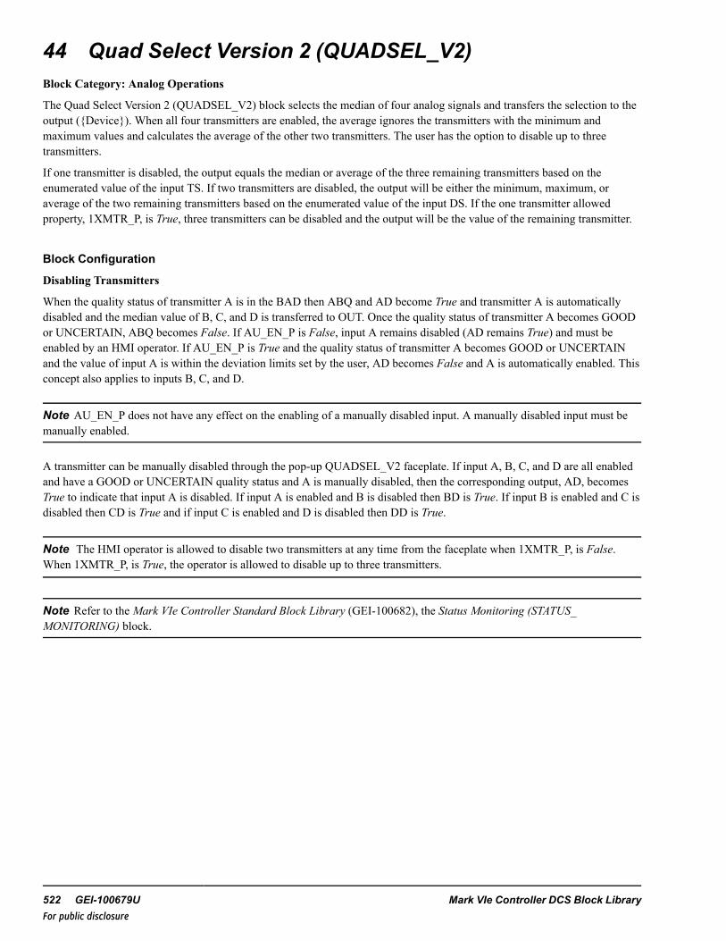
44 Quad Select Version 2 (QUADSEL_V2)Block Category: Analog Operations
The Quad Select Version 2 (QUADSEL_V2) block selects the median of four analog signals and transfers the selection to theoutput ({Device}). When all four transmitters are enabled, the average ignores the transmitters with the minimum andmaximum values and calculates the average of the other two transmitters. The user has the option to disable up to threetransmitters.
If one transmitter is disabled, the output equals the median or average of the three remaining transmitters based on theenumerated value of the input TS. If two transmitters are disabled, the output will be either the minimum, maximum, oraverage of the two remaining transmitters based on the enumerated value of the input DS. If the one transmitter allowedproperty, 1XMTR_P, is True, three transmitters can be disabled and the output will be the value of the remaining transmitter.
Block Configuration
Disabling Transmitters
When the quality status of transmitter A is in the BAD then ABQ and AD become True and transmitter A is automaticallydisabled and the median value of B, C, and D is transferred to OUT. Once the quality status of transmitter A becomes GOODor UNCERTAIN, ABQ becomes False. If AU_EN_P is False, input A remains disabled (AD remains True) and must beenabled by an HMI operator. If AU_EN_P is True and the quality status of transmitter A becomes GOOD or UNCERTAINand the value of input A is within the deviation limits set by the user, AD becomes False and A is automatically enabled. Thisconcept also applies to inputs B, C, and D.
Note AU_EN_P does not have any effect on the enabling of a manually disabled input. A manually disabled input must bemanually enabled.
A transmitter can be manually disabled through the pop-up QUADSEL_V2 faceplate. If input A, B, C, and D are all enabledand have a GOOD or UNCERTAIN quality status and A is manually disabled, then the corresponding output, AD, becomesTrue to indicate that input A is disabled. If input A is enabled and B is disabled then BD is True. If input B is enabled and C isdisabled then CD is True and if input C is enabled and D is disabled then DD is True.
Note The HMI operator is allowed to disable two transmitters at any time from the faceplate when 1XMTR_P, is False.When 1XMTR_P, is True, the operator is allowed to disable up to three transmitters.
Note Refer to theMark VIe Controller Standard Block Library (GEI-100682), the Status Monitoring (STATUS_MONITORING) block.
522 GEI-100679U Mark VIe Controller DCS Block LibraryFor public disclosure

Output Bad Quality Indication (OBQ)
If 1XMTR_P, is True, when four transmitters are disabled and/or in a BAD quality state, OBQ becomes True, the defaultvalue, DF, is automatically transferred to OUT, quality status of OUT is set to NOT_LIMITED-BAD [0], and MODE is set toDEFAULT. If AU_EN_P is True, OBQ becomes False when the quality status of any input becomes GOOD or UNCERTAIN.The GOOD or UNCERTAIN quality input will be enabled and transferred to OUT. However, if AU_EN_P is False, OUTwillbe equal to DF until the HMI operator manually enables the GOOD or UNCERTAIN quality input.
If 1XMTR_P, is False, when three or four transmitters are disabled and/or in a BAD quality state, OBQ becomes True, thedefault value, DF, is automatically transferred to the output, quality status of the output is set to NOT_LIMITED-BAD[0], andMODE is set to DEFAULT. If AU_EN_P is True, OBQ becomes False when the quality status of two inputs become GOODor UNCERTAIN. The GOOD or UNCERTAIN quality inputs will be enabled and based on the DS enumeration selected, theaverage, minimum, or maximum of the GOOD or UNCERTAIN quality inputs is transferred to the output. However, if AU_EN_P is False, the output will be equal to DF until the HMI operator manually enables the GOOD or UNCERTAIN qualityinputs.
This block propagates quality status. Status option cannot be disabled on this block.
Block status modifications: When OBQ is True, the quality status of {Device} is NOT_LIMITED-BAD[0].
For further details on relational blocks, refer to the Mark VIe Controller Standard Block Library (GEI-100682), the StatusMonitoring (STATUS_MONITORING) block.
Control Word
Control (CTL) is used by the HMI operator for manual control. The manual commands from the HMI allow each input to beenabled or disabled. The CTL command enumerations are defined in the following table.
Note A manually disabled transmitter can be manually enabled, regardless of its deviation status. An exception is when theblock is in average mode with three transmitters in operation. Refer to the section Deviation Alarms.
CTL EnumerationsEnumeration CommandNO_CMD No CommandEN_A_CMD Enable Input A commandDIS_A_CMD Disable Input A commandEN_B_CMD Enable Input B commandDIS_B_CMD Disable Input B commandEN_C_CMD Enable Input C commandDIS_C_CMD Disable Input C commandEN_D_CMD Enable Input D commandDIS_D_CMD Disable Input D command
Instruction Guide GEI-100679U 523For public disclosure

Function block is defined by two function modes:
• Dual Select Mode (DS)• Three Select Mode (TS)
DS Mode Function EnumerationEnumeration FunctionAVG Average of A and BMIN Minimum of A and BMAX Maximum of A and B
TS Mode EnumerationEnumeration FunctionAVG Average of three inputsMEDIAN Median of three inputs
524 GEI-100679U Mark VIe Controller DCS Block LibraryFor public disclosure

MODE DS is the block-operating mode that depends on TS and the quality status of the inputs. MODE enumerations arelisted in the following table.
Operating Mode Enumerations
Enumeration Operating ModeMED_AVG Average of 2 middle inputsMED_BCD Median of B, C and DMED_ACD Median of A, C and DMED_ABD Average of A, B and DMED_ABC Average of A, B and CAVG_BCD Average of B, C and DAVG_ACD Average of A, C and DAVG_ABD Average of A, B and DAVG_ABC Average of A, B and CAVG_A-B Average of A and BAVG_A-C Average of A and CAVG_A-D Average of A and DAVG_B-C Average of B and CAVG_B-D Average of B and DAVG_C-D Average of C and DMIN_B-C Minimum of B and CMIN_A-D Minimum of A and DMIN_A-B Minimum of A and BMIN_A-C Minimum of A and CMIN_C-D Minimum of C and DMIN_B-D Minimum of B and DMAX_B-C Maximum of B and CMAX_A-D Maximum of A and DMAX_A-B Maximum of A and BMAX_A-C Maximum of A and CMAX_C-D Maximum of C and DMAX_B-D Maximum of B and DA Input AB Input BC Input CD Input DDEFAULT Input DF
Instruction Guide GEI-100679U 525For public disclosure

Examples
• MED_AVG mode is selected when all inputs are enabled and have a GOOD or UNCERTAIN quality status.• MED_BCD mode is selected when A is BAD quality or is disabled and the TS enumeration is MEDIAN.• AVG_BCD mode is selected when A is BAD quality or is disabled. and the TS enumeration is AVG.• AVG_A-B mode is selected when a BAD quality is detected on transmitter C or when C is manually disabled and a BAD
quality is detected on transmitter D or when D is manually disabled, and the DS enumeration is AVG.• MIN_A-B mode is selected when a BAD quality is detected on transmitter C or when C is manually disabled and a BAD
quality is detected on transmitter D or when D is manually disabled, and the DS enumeration is MIN.• MAX_A-B mode is selected when a BAD quality is detected on transmitter C or when C is manually disabled and a
BAD quality is detected on transmitter D or when D is manually disabled, and the DS enumeration is MAX.• A mode is selected when 1XMTR_P is True and transmitters B, C, and D are disabled.• DEFAULT mode is selected when all transmitters are BAD quality and/or disabled or 1XMTR_P is False and three
transmitters are BAD quality and/or disabled.
Deviation Alarms
Each transmitter value is compared with the output, to determine if it is outside of the deviation limit, DL. If so, the deviationhigh alarm for the deviant input either DAH, DBH, DCH, or DDH for transmitters A, B, C, or D respectively, and DH,become True. The deviation alarms will not become False until the absolute difference between the deviant input and theoutput is less than the value of DL minus DLDB (deviation limit dead band) or the deviant input is disabled.
Note The deviation high output, DH, becomes True when at least one transmitter is in deviation. Also, if a transmitter inputis disabled, the deviation alarm for that transmitter is disabled.
Note Use the deviation alarms that are configured from within the block instead of the deviation high configuration of theanalog alarm. Refer to the section Analog Alarm Configuration.
In general, the deviation alarm only sets Boolean outputs and has no influence on the functionality of the block (thetransmitter in deviation with the output is not automatically disabled, and the block mode does not change).
However, if the block is calculating the average of any three transmitters (three transmitters are Enabled and TS = AVG), atransmitter that gets a high deviation will be automatically disabled. It can be enabled by the operator or automatically (AU_EN_P = True) when the absolute difference between the deviant input and the output is less than the value of DL minusDLDB (deviation limit dead band).
526 GEI-100679U Mark VIe Controller DCS Block LibraryFor public disclosure
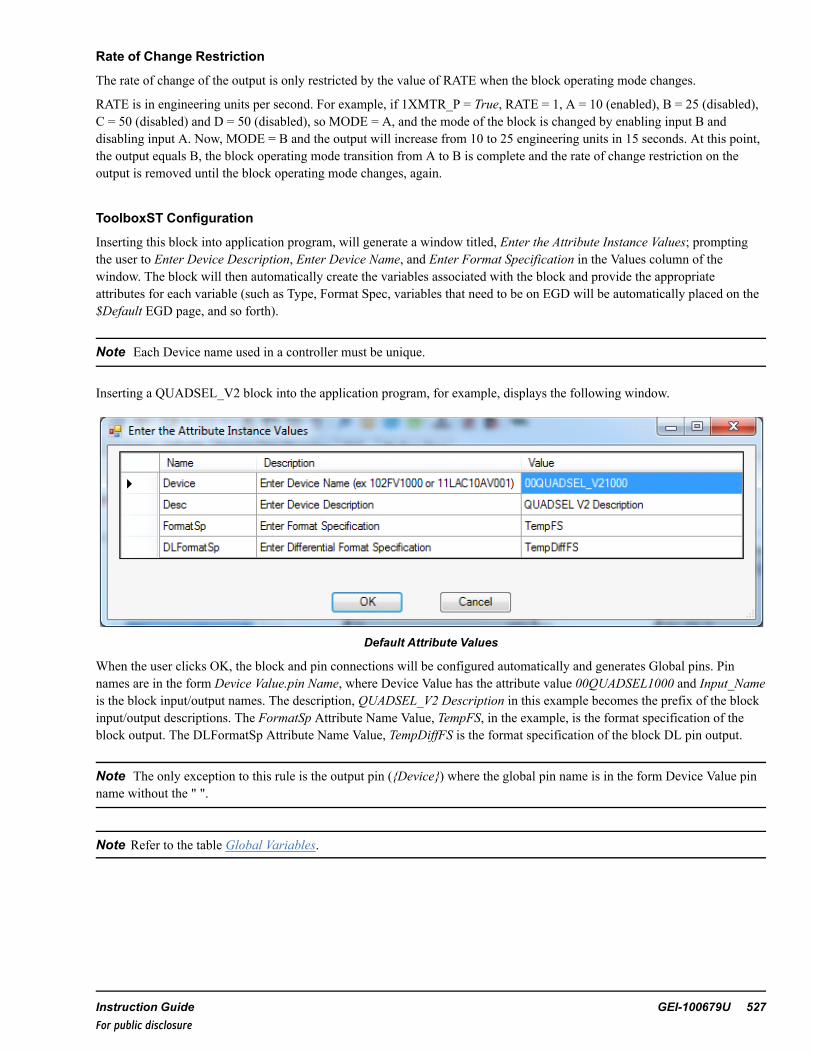
Rate of Change Restriction
The rate of change of the output is only restricted by the value of RATE when the block operating mode changes.
RATE is in engineering units per second. For example, if 1XMTR_P = True, RATE = 1, A = 10 (enabled), B = 25 (disabled),C = 50 (disabled) and D = 50 (disabled), so MODE = A, and the mode of the block is changed by enabling input B anddisabling input A. Now, MODE = B and the output will increase from 10 to 25 engineering units in 15 seconds. At this point,the output equals B, the block operating mode transition from A to B is complete and the rate of change restriction on theoutput is removed until the block operating mode changes, again.
ToolboxST Configuration
Inserting this block into application program, will generate a window titled, Enter the Attribute Instance Values; promptingthe user to Enter Device Description, Enter Device Name, and Enter Format Specification in the Values column of thewindow. The block will then automatically create the variables associated with the block and provide the appropriateattributes for each variable (such as Type, Format Spec, variables that need to be on EGD will be automatically placed on the$Default EGD page, and so forth).
Note Each Device name used in a controller must be unique.
Inserting a QUADSEL_V2 block into the application program, for example, displays the following window.
Default Attribute Values
When the user clicks OK, the block and pin connections will be configured automatically and generates Global pins. Pinnames are in the form Device Value.pin Name, where Device Value has the attribute value 00QUADSEL1000 and Input_Nameis the block input/output names. The description, QUADSEL_V2 Description in this example becomes the prefix of the blockinput/output descriptions. The FormatSp Attribute Name Value, TempFS, in the example, is the format specification of theblock output. The DLFormatSp Attribute Name Value, TempDiffFS is the format specification of the block DL pin output.
Note The only exception to this rule is the output pin ({Device}) where the global pin name is in the form Device Value pinname without the " ".
Note Refer to the table Global Variables.
Instruction Guide GEI-100679U 527For public disclosure

QUALSEL_V2 Block
528 GEI-100679U Mark VIe Controller DCS Block LibraryFor public disclosure

Inputs
Name Global Description Data Type Initial Value Visibility InterfaceType
1XMTR_P Allow one transmitteroperation
BOOL False Parameter Value Only
A Yes {Desc} Trans A input REAL 0 Always Value withStatus
AU_EN_P Auto enable BQ XMTR BOOL True Parameter Value OnlyB Yes {Desc} Trans B input REAL 0 Always Value with
StatusC Yes {Desc} Trans C input REAL 0 Always Value with
StatusCTL Yes {Desc} Control word UINT (ENUM) NO_CMD Always Value OnlyD Yes {Desc} Trans D input REAL 0 Always Value with
StatusDF Substitute value REAL 0 Parameter Value OnlyDL Deviation alarm limit REAL 5 Parameter Value OnlyDLDB Deviation alarm limit
deadbandREAL 2 Parameter Value Only
DS Dual select mode property UINT (ENUM) AVG Parameter Value OnlyDT Deviation alarm delay BOOL 1000 Parameter Value OnlyIN_ABQ Yes Trans A bad quality BOOL False Always Value OnlyIN_BBQ Yes Trans B bad quality BOOL False Always Value OnlyIN_CBQ Yes Trans C bad quality BOOL False Always Value OnlyIN_DBQ Yes Trans D bad quality BOOL False Always Value OnlyRATE Selection change rate limit REAL 1 Parameter Value OnlyTS 3-XMTR Select mode
propertyUINT (ENUM) MEDIAN Parameter Value Only
Instruction Guide GEI-100679U 529For public disclosure

Outputs
Name Global Description Data Type Initial Value Visibility InterfaceType
{Device} Yes {Desc} REAL 0 Always Value withStatus
ABQ Yes {Desc} Trans A bad quality BOOL False Always Value OnlyAD Yes {Desc} Trans A disabled BOOL False Always Value OnlyBBQ Yes {Desc} Trans B bad quality BOOL False Always Value OnlyBD Yes {Desc} Trans B disabled BOOL False Always Value OnlyCBQ Yes {Desc} Trans C bad
qualityBOOL False Always Value Only
CD Yes {Desc} Trans C disabled BOOL False Always Value OnlyDAH Yes {Desc} Trans A high
deviationBOOL False Always Value Only
DBH Yes {Desc} Trans B highdeviation
BOOL False Always Value Only
DBQ Yes {Desc} Trans D badquality
BOOL False Always Value Only
DCH Yes {Desc} Trans C highdeviation
BOOL False Always Value Only
DD Yes {Desc} Trans D disabled BOOL False Always Value OnlyDDH Yes {Desc} Trans D high
deviationBOOL False Always Value Only
MODE Yes {Desc} Block mode UINT (ENUM) MED_AVG Always Value OnlyOBQ Yes {Desc} Bad quality BOOL False Always Value OnlyODH Yes {Desc} High deviation BOOL False Always Value OnlySEL_P Yes {Desc} Select type
propertyUINT (ENUM) QUAD Internal Value Only
530 GEI-100679U Mark VIe Controller DCS Block LibraryFor public disclosure

Global VariablesPin Name Description Alarm Alarm
ClassEvent EGD Page External
Access00QUADSEL1000 QUADSEL_V2 Description Not
AlarmedFalse $Default ReadOnly
00QUADSEL1000.A QUADSEL_V2 DescriptionTrans A input
NotAlarmed
False $Default ReadOnly
00QUADSEL1000.A.Status QUADSEL_V2 DescriptionTrans A input status
NotAlarmed
False $Default ReadOnly
00QUADSEL1000.ABQ QUADSEL_V2 DescriptionTrans A bad quality
NotAlarmed
False $Default ReadOnly
00QUADSEL1000.AD QUADSEL_V2 DescriptionTrans A disabled
NotAlarmed
True $Default ReadOnly
00QUADSEL1000.B QUADSEL_V2 DescriptionTrans B input
NotAlarmed
False $Default ReadOnly
00QUADSEL1000.B.Status QUADSEL_V2 DescriptionTrans B input status
NotAlarmed
False $Default ReadOnly
00QUADSEL1000.BBQ QUADSEL_V2 DescriptionTrans B bad quality
NotAlarmed
False $Default ReadOnly
00QUADSEL1000.BD QUADSEL_V2 DescriptionTrans B disabled
NotAlarmed
True $Default ReadOnly
00QUADSEL1000.C QUADSEL_V2 DescriptionTrans C input
NotAlarmed
False $Default ReadOnly
00QUADSEL1000.C.Status QUADSEL_V2 DescriptionTrans C input status
NotAlarmed
False $Default ReadOnly
00QUADSEL1000.CBQ QUADSEL_V2 DescriptionTrans C bad quality
NotAlarmed
False $Default ReadOnly
00QUADSEL1000.CD QUADSEL_V2 DescriptionTrans C disabled
NotAlarmed
True $Default ReadOnly
00QUADSEL1000.CTL QUADSEL_V2 DescriptionControl word
NotAlarmed
False $Default ReadWrite
00QUADSEL1000.D QUADSEL_V2 DescriptionTrans D input
NotAlarmed
False $Default ReadOnly
00QUADSEL1000.D.Status QUADSEL_V2 DescriptionTrans D input status
NotAlarmed
False $Default ReadOnly
00QUADSEL1000.DAH QUADSEL_V2 DescriptionTrans A high deviation
Alarmed Alert False $Default ReadOnly
00QUADSEL1000.DBH QUADSEL_V2 DescriptionTrans B high deviation
Alarmed Alert False $Default ReadOnly
00QUADSEL1000.DBQ QUADSEL_V2 DescriptionTrans D bad quality
NotAlarmed
False $Default ReadOnly
00QUADSEL1000.DCH QUADSEL_V2 DescriptionTrans C high deviation
Alarmed Alert False $Default ReadOnly
00QUADSEL1000.DD QUADSEL_V2 DescriptionTrans D disabled
NotAlarmed
True $Default ReadOnly
00QUADSEL1000.DDH QUADSEL_V2 DescriptionTrans D high deviation
Alarmed Alert False $Default ReadOnly
00QUADSEL1000.MODE QUADSEL_V2 DescriptionBlock mode
NotAlarmed
False $Default ReadOnly
00QUADSEL1000.OBQ QUADSEL_V2 DescriptionBad quality
NotAlarmed
False $Default ReadOnly
Instruction Guide GEI-100679U 531For public disclosure

Global Variables (continued)
Pin Name Description Alarm AlarmClass
Event EGD Page ExternalAccess
00QUADSEL1000.ODH QUADSEL_V2 Descriptionhigh deviation
NotAlarmed
False $Default ReadOnly
00QUADSEL1000.SEL_P QUADSEL_V2 DescriptionSelect type property
NotAlarmed
False $Default ReadOnly
00QUADSEL1000.Status QUADSEL_V2 Descriptionstatus
NotAlarmed
False $Default ReadOnly
Analog Alarm Configuration
To set up analog alarms on a signal, configure the Alarm property for that signal. This allows the configuration of BQ (BadQuality), RH (Rate of change high), DH (High Deviation), H, HH, HHH (or 3H), L, LL, and LLL (or 3L).
Note AnalogAlarmDefault should normally be used when a signal is to be used as an alarm. Enabling this turns on moreoptions in the Alarms and Events section in the properties of that signal.
Enabling Analog Alarm Signal
Note Configuring the analog alarm for deviation high is not recommended as the block already alarms on deviation high foreach input. Refer to the section Deviation Alarms.
Additional Options in Alarms and Events Property Editor
532 GEI-100679U Mark VIe Controller DCS Block LibraryFor public disclosure

➢➢ To enable the H Alarm: in the property grid, set the H property to True to add the variables displayed in the followingfigure to the variable list.
H Variables
H_SP is the setpoint for the High alarm on the signal. H_T is the delay time (in ms). When the comparison between thesetpoint and the value is done, it waits H_T milliseconds before issuing the alarm. HYST is the Hysteresis of the alarm values.Set the initial values to effectively use them. 00AI1000.H is the actual variable name that generates the alarm.
HMI Configuration (CIMPLICITY)
The Object name for the HMI is the same as the Device name specified in the ToolboxST configuration.
Click MED A VG to display the QUADSEL faceplate.
QUADSEL_V2
Typical HMI Object for a QUADSEL_V2
QUADSEL_V2 Faceplate
Instruction Guide GEI-100679U 533For public disclosure

45 Quality Average (QUAL_AVG)Block Category: Math
The Quality Average (QUAL_AVG) block is an expandable block that performs the average of up to 32 inputs.
Note Status functionality is always enabled for this block.
Bad quality inputs are excluded from the calculated average. The outputs QUAL_BAD, QUAL_POOR, QUAL_GOODindicates the total number of inputs that are bad, uncertain, and good, respectively. If all the inputs have bad quality then theoutput is set to zero.
QUAL_AVG Block
Note This is a variant block that supports any one the following block data types: Integer, Double Integer, Real, Long Real,Unsigned Integer, Unsigned Double Integer. The default data type is Real. Refer to the section Change Data Type of VariantBlock.
This block propagates quality status. Status option cannot be disabled on this block. Block status is propagated as follows:
• If all inputs are of bad quality (QUALITY < 32), then the lowest quality of the inputs is propagated.• If any input is used in the average computation, then the lowest quality of USED inputs is propagated.For further details on Relational blocks, refer to the Mark VIe Controller Standard Block Library (GEI-100682), the StatusMonitoring (STATUS_MONITORING) block.
534 GEI-100679U Mark VIe Controller DCS Block LibraryFor public disclosure

Inputs
Name Description Data Type Initial Value Visibility Interface Type
IN1 Input 1 ANY_NUM† 0 Always Value with Status
↓ ↓ ↓ ↓ ↓ ↓
IN32 Input 32 ANY_NUM† 0 Always Value with Status
† Value with status
Outputs
Name Description Data Type Initial Value Visibility Interface Type
OUT Average of inputs ANY_NUM† N/A Always Value with Status
QUAL_BAD Number of inputs with BADquality (QUALITY < 64 )
UINT N/A Always Value Only
QUAL_GOOD Number of inputs withGOOD quality (QUALITY >127)
UINT N/A Always Value Only
QUAL_POOR Number of inputs withUNCERTAIN quality (63 <QUALITY < 128)
UINT N/A Always Value Only
† Value with status.
Instruction Guide GEI-100679U 535For public disclosure

46 Run Timer (RUN_TIMER)Block Category: Timers and Counters
The Run Timer (RUN_TIMER) block behaves as a device run timer. OUT accumulates time in hours only if IN is True andRESET is False. If IN becomes False, the timer stops and maintains the value of the accumulated time. If the RESET pin isset to True, the accumulated time is reset to zero.
RUN_TIMER Block
Inputs
Name Description Data Type Initial value Visibility Interface Type
IN Allows counting when True BOOL False Always Value Only
RESET Resets the run timer BOOL False Always Value Only
Output
Name Description Data Type Initial value Visibility Interface Type
OUT Accumulated run time LREAL 0 Always Value Only
536 GEI-100679U Mark VIe Controller DCS Block LibraryFor public disclosure

47 Solenoid Operated Valve (S_O_V)Block Category: Legacy, Device Control
Note Legacy Status— The S_O_V block is not supported for use in new Mark VIe control systems (ControlST softwaresuite V05.02 or later). It is in place to support the maintenance of legacy Mark VIe control systems (prior to ControlSTsoftware suite V05.02). For new Mark VIe control systems, use the S_O_V_V3 block; it provides equivalent functionality.
The Solenoid Operated Valve (S_O_V) block controls a solenoid-piloted pneumatic valve and provides an output to energizea solenoid valve. The block has a fail-safe open or close property, FS_OP, for those valves that are energize-to-close, springopened or FS_CL, for those valves that are energize-to-open, spring closed. The block requires the inputs OPEN andCLOSED from the limit switches of the valve. The block will generate a failed-to-open alarm, FL_OP_A, a failed-to-closealarm, FL_CL_A, and a limit switch congruency alarm, CONGR_A, that alarms when the valve limit switches indicate thatthe valve is open and closed at the same time for at least 2 seconds.
Block Configuration
Control Word
Control (CTL) is an enumeration set by the HMI operator for valve control. The commands available from the HMI allowmanual and automatic valve control capability and/or lockout capability if the block property MODE_OPT enumerationselected allows the auto and/or lock mode. The valve may be opened or closed in manual mode by the OPEN_CMD orCLOSE_CMD commands, respectively. The command enumerations are defined in the following table.
CTL EnumerationsEnumeration CommandNO_CMD No commandAUTO_CMD Auto commandMANUAL_CMD Manual commandLOCK_CMD Lock commandUNLOCK_CMD Unlock commandOPEN_CMD Open commandCLOSE_CMD Close commandRESET_CMD Fault reset command
Note This block has various enumerations that are used to control block operation. Refer to the section Block PropertyEnumerations.
Instruction Guide GEI-100679U 537For public disclosure

Block Property Enumerations
IO_OPT, MODE_OPT, and IO_MON enumerations and descriptions are displayed in the following tables.
IO Option Enumerations
Enumeration IO Option Description
FS_CL Fail safe close
DUAL Dual solenoid
FS_OP Fail safe open
MODE_OPT Enumerations
Enumeration Mode Option Description
NONE None
AUTO Auto mode
LOCK Lock mode
AUTO-LOCK Auto mode and lock mode
IO_MON Enumerations
Enumeration Monitor Option Description
NONE No fuse or voltage monitoring
FUSE Fuse monitoring
VOLT Voltage monitoring
IO_OPT— fail-safe options
FS_OP— select for solenoid valves that are energize-to-close, spring opened, fail-safe open. If FS_OP is selected FS_OP_Pis set to True. FS_CL, select for solenoid valves that are energize-to-open, spring closed, fail-safe close. If FS_CL is selectedFS_OP_P is set to False.
DUAL— select for dual solenoid valves. In this caseOP_ORD and CL_ORD (each are 3 second pulses) are used to open andclose the valve. If DUAL is selected DUAL_P is set to True.
MODE_OPT— described in the section Operating Mode.
NONE— the valve can be opened or closed manually by the HMI operator, no other mode options are available.
538 GEI-100679U Mark VIe Controller DCS Block LibraryFor public disclosure

AUTO— provides auto control capability of the solenoid valve. Selecting the AUTO property will set AUTO_P to True,indicating the auto property of the block is enabled. When AUTO_P is True, the valve can be commanded to auto by eitherCTL enumeration AUTO_CMD or a rising edge on AU_SEL providing PMT_AU is True. The HMI operator may commandthe valve from auto to manual mode at any time with the CTL enumeration MANUAL_CMD. When AUTO is True, the AU_OP and AU_CL inputs control the automatic opening and closing of the valve, provided, PMT_OP or PMT_CL, respectively,is True. If AU_OP or AU_CL or AU_SEL become True, the valve is in manual mode, and the valve position is not in the stateof the requested command, the auto request alarm, AU_REQ, will be activated.
Note PMT_AU is described in the section Auto/Open/Close Permissives.
LOCK— provides software lock-out capability for the valve. Selecting the LOCK mode property will set LOCK_P to True,and enable the LOCK_CMD and UNLOCK_CMD to control the lockout mode functionality. The valve solenoid must bede-energized before the block can be set to lockout mode. Feedback to the HMI operator of this mode is provided by LOCK.The HMI operator is prevented from energizing the solenoid operated valve from the control faceplate when LOCK is True,and auto mode is disabled.
Note The lockout indication is provided for indication only. This action will not lockout the equipment, it will only indicatelockout status. The owner's lockout procedures must be followed to safely lock equipment out.
The Lock button can also be configured to use the WorkstationST Lock function. Refer toWorkstationST/CIMPLICITYAdvanced Viewer Integration Instruction Guide (GEI-100697), the section HMI Tagout
IO_MON enumerations are digital output monitor types. Monitoring is only available for the output (SV). If the hardwarecard used with SV can perform diagnostic monitoring, IO_MON is used to select the method/type of diagnostic monitoring.When diagnostic monitoring is used (FUSE or VOLT), the diagnostic variable from the digital output card is connected toRDY_SV.
NONE— no circuit monitoring is available, RDY_SV is not used.
FUSE— fuse monitoring determines the valve circuit failure. If FUSE is selected FUSE_MON_P is True. The Boolean fusemonitoring input is True when there is no fuse failure and is connected to the RDY_SV input. If there is a fuse failure, RDY_SV becomes False and SV_FLR becomes True. When SV_FLR becomes True, PMT_OP or PMT_CL become False basedupon FS_OP_P, and PMT_AU becomes False, delayed by PWR_FL_TMR. If AUTO is True when this occurs, AUTO willbecome False, but the manual reject alarm, MN_REJ_A, will be inhibited. Note, to prevent an unwanted automatic switch toManual mode, in case of an Automatic bus transfer or Power supply transfer, the power supply transfer time should notexceed PWR_FL_TMR. If the power supply transfer time exceeds the PWR_FL_TMR, the valve will transfer from auto tomanual mode and MN_REJ_A, will be inhibited.
VOLT— voltage monitoring determines the valve circuit failure. If VOLT is selected VOLT_MON_P is True. The Booleanvoltage monitoring input is True when there is no voltage failure and is connected to the RDY_SV input. If there is a voltagefailure and the valve is not being energized (That is, SV is False), RDY_SV becomes False and SV_FLR becomes True,(delayed by 2 seconds). When SV_FLR becomes True, PMT_OP or PMT_CL become False, based upon FS_OP_P, andPMT_AU becomes False delayed by PWR_FL_TMR.
If AUTO is True when this occurs, AUTO will become False, but the manual reject alarm, MN_REJ_A, will be inhibited.Note, to prevent an unwanted automatic switch to Manual mode, in case of an Automatic bus transfer or Power supplytransfer, the power supply transfer time should not exceed PWR_FL_TMR. If the power supply transfer time exceeds thePWR_FL_TMR, the valve will transfer from auto to manual mode and MN_REJ_A, will be inhibited.
SV_FLR is True, (delayed by 2 seconds), when the following conditions exist:
• RDY_SV is False• SV_ORD is False• OPEN is False (if IO_OPT, enumeration FS_OP is not selected)
Instruction Guide GEI-100679U 539For public disclosure

• CLOSE is False (if IO_OPT, enumeration FS_OP is selected)• AVAIL is True (if the IO_OPT, enumeration AVAIL is selected)• DUAL_P is False
When OP_FLR is True, PMT_OP is False and PMT_AU becomes False, delayed by PWR_FL_TMR.
OP_FLR is True, (delayed by 2 seconds), when the following conditions exist:
• RDY_OP is False• OP_ORD is False• CP_OK is True (if the IO_OPT, enumeration CP_OK is selected)• REMOTE is True (if the IO_OPT, enumeration REM is selected)• OPEN is False• TRANSIT is False (if the IO_OPT, enumeration TRANS is selected)• AVAIL is True (if the IO_OPT, enumeration AVAIL is selected)• CL_ORD is False
When OP_FLR is True, PMT_OP is False and PMT_AU becomes False, delayed by PWR_FL_TMR.
CL_FLR is True, (delayed by 2 seconds), when the following conditions exist:
• RDY_CL is False• CL_ORD is False• CP_OK is True (if the IO_OPT, enumeration CP_OK is selected)• REMOTE is True (if the IO_OPT, enumeration REM is selected)• CLOSED is False• TRANSIT is False (if the IO_OPT, enumeration TRANS is selected)• AVAIL is True (if the IO_OPT, enumeration AVAIL is selected)• OP_ORD is False
When CL_FLR is True, PMT_CL is False and PMT_AU becomes False, delayed by PWR_FL_TMR.
Example
If the valve is fail-safe open, fuse monitoring, and has the capability for auto and lockout operation, the IO_OPT selection isFS_OP, MODE_OPT is AUTO-LOCK, and IO_MON is FUSE.
540 GEI-100679U Mark VIe Controller DCS Block LibraryFor public disclosure

Override Control
The block provides override input enumerations override open, OP_OVR, override close, CL_OVR, and a manual reject inputenumeration, MN_REJ. The following table provides the possible values of the enumerations.
CL_OVR, OP_OVR, and MN_REJ Enumerations
Enumeration Override Option Description
NO_OVR-NO-BLOCK No override and no override is blocked
OVR-NO_BLOCK Override active and no override is blocked
NO_OVR-BLOCK No override and a override is blocked
OVR-BLOCK Override active and a override is blocked
OVR_OP or CL_OVR— open or close the valve, respectively, and prevent it from reclosing/reopening in any mode. If thevalve is in auto mode (AUTO is True), it rejects to manual and the manual reject alarm,MN_REJ_A, will be activated,delayed off by 2 seconds.
OVR_OP and CL_OVR (if used) — driven from an OVERRIDE block. Each connected input of the OVERRIDE block hasthe ability (when enabled) to be blocked by the HMI operator, which is accessed from associated tab of the permit HMIscreen display. When OVR_OP or CL_OVR enumeration contains BLOCK, the HMI operator has blocked at least oneoverride. S_O_V does not use the block information, but passes it to the HMI for display.
Force Control
The block provides force enumerations Force Open input (OP_FRC) and Force Close input (CL_FRC). The following tableprovides the possible values of the enumerations.
CL_FRC, and OP_FRC Enumerations
Enumeration Force Option Description
NO_FORCE-NO-BLOCK No force and no force is blocked
FORCE-NO_BLOCK Force active and no force is blocked
NO_FORCE-BLOCK No force and a force is blocked
FORCE-BLOCK Force active and a force is blocked
OP_FRC or CL_FRC force the valve open or close in any mode except when OP_OVR or CL_OVR indicates OverrideActive. The valve does not reject to manual if a force occurs.
OP_FRC and CL_FRC (If used) are driven from a FORCE block. Each connected input of the FORCE block has the ability(when enabled) to be blocked by the HMI operator, which is accessed from associated tab of the permit HMI screen display.When OP_FRC or CL_FRC indicate a force is blocked (enumeration contains BLOCK), the HMI operator has blocked atleast one force. The S_O_V does not use the block information, but passes it to the HMI for display.
Instruction Guide GEI-100679U 541For public disclosure

Auto/Open/Close Permissives
The block provides permissive input enumerations AU_PMT, OP_PMT, and CL_PMT. The following table provides thepossible values of the enumerations.
AU_PMT, CL_PMT, and OP_PMT Enumerations
Enumeration Permit Option Description
NO_PERM-NO-BYPASS No permit and no permit is bypassed
PERM-NO_BYPASS Permit ok and no permit is bypassed
NO_PERM-BYPASS No permit and a permit is bypassed
PERM-BYPASS Permit ok and a permit is bypassed
The permit inputs, AU_PMT, OP_PMT, and CL_PMT, combine with internal permissives to generate PMT_AU, PMT_OP,and PMT_CL, permitted indications.
PMT_AU is True when the following conditions exist:
• AU_PMT indicates Permit OK• MN_REJ indicates No Override• FL_OP_A is False• FL_CL_A is False• CONGR_A is False• LOCK is False• OP_FLR, CL_FLR, and SV_FLR are False (or the duration of being True has not exceeded the PWR_FL_TMR)• TRIPPED is False• OP_OVR indicates No Override• CL_OVR indicates No Override
If the valve is in auto mode and any of the conditions listed above are not satisfied (except AU_PMT) the valve will be placedin manual mode (the outputs, AUTO and PMT_AU are set to False). If the MN_REJ input caused this action, then the manualreject alarm, MN_REJ_A, will be activated (otherwise MN_REJ_Awill be inhibited). A change in AU_PMT from True toFalse will not change the mode from AUTO to MANUAL.
542 GEI-100679U Mark VIe Controller DCS Block LibraryFor public disclosure

PMT_OP is True when the following conditions exist:
• OP_PMT is True• CL_OVR indicates No Override• LOCK is False• SV_FLR is False when FS_OP_P is False• OP_FLR is False when DUAL_P is True• CL_FRC indicates No Force• FL_OP_A is False• TRIPPED is False
PMT_CL is True when the following conditions exist:
• CL_PMT is True• OP_OVR indicates No Override• LOCK is False• SV_FLR is False when FS_OP_P is True• CL_FLR is False when DUAL_P is True• OP_FRC indicates No Force• FL_CL_A is False• TRIPPED is False
AU_PMT, OP_PMT, and CL_PMT (if used) are driven from a PERMIT block. Each connected input of the PERMIT blockhas the ability (when enabled) to be bypassed by the HMI operator, which is accessed from associated tab of the permit HMIscreen display. When AU_PMT, OP_PMT, or CL_PMT enumeration contains BYPASS, the HMI operator has bypassed atleast one permit. S_O_V does not use the bypass information, but passes it to the HMI for display.
Valve Diagnostic
The block will generate a failed-to-open alarm, FL_OP_A, and a failed-to-close alarm, FL_CL_A, if the valve fails to open orclose in the time specified by the FL_OP_T or FL_CL_T, respectively. These alarms are reset when FAULT_RESET is Trueor if the CTL enumeration equals RESET_CMD.
The block has a limit switch congruency alarm, CONGR_A that alarms when the valve limit switches indicate that the valveis open and closed at the same time. CONGR_A also alarms if the valve is not at a known position providing there is nooutput command active and no position failure (FL_OP_A or FL_CL_A) active and there is no trip alarm (TRIPPED) active –this condition is delayed by the maximum of FL_OP_T and FL_CL_T. The CONGR_A alarm is reset when the condition thatcaused the alarm is cleared.
If DIS_REJ_FL_A is False, the block operates as described above. If DIS_REJ_FL_A is True when either FL_CL_A, FL_OP_A, CONGR_A, or TRIPPED becomes True, the reject-to-manual operation is inhibited (the block remains in AUTO ifAUTO is True when this occurs).
Instruction Guide GEI-100679U 543For public disclosure

The output, FAULT, is True when a fault is detected.
FAULT is True when the any of the following conditions exist:
• FL_OP_A is True• FL_CL_A is True• CONGR_A is True• SV_FLR is True• OP_FLR is True• TRIPPED is True• CL_FLR is True
Push-button Status
The block has a push-button status output, PBSTATE, to indicate the last HMI operator initiated CTL enumeration OPEN_CMD or CLOSE_CMD command. PBSTATE is True when the last HMI CTL enumeration was OPEN_CMD. PBSTATE isFalse when the last HMI CTL enumeration was OPEN_CMD.
Operating Mode (MODE)
Operating Mode (MODE) is an output that defines the block-operating mode. The operating mode enumerations are definedin the following table.
MODE EnumerationsEnumeration DescriptionMANUAL Valve opens and closes under manual controlAUTO Valve opens and closes automatically.OVERRIDE Valve control has been overriddenOPENED Valve is openOPENING Valve is openingCLOSED Valve is closedCLOSING Valve is closingFAULTED Valve has conflicting statusLOCKED Valve is not accepting control commands
Note A complete list of all possible combinations of enumeration elements is provided in the table Appendix.
544 GEI-100679U Mark VIe Controller DCS Block LibraryFor public disclosure

ToolboxST Configuration
Inserting a S_O_V block into the application code displays the following window.
Default Attribute Values
When the user clicks OK, the block and pin connections will be configured automatically. The previous example will generateGlobal pins. Pin names are in the form of the Device Value.Input_Name, where Device Value is the attribute value 00S_O_V1000 and Input_Name is the block input/output names. The description, S_O_V DESCRIPTION, becomes the prefix of theblock input/output descriptions.
Note Refer to the table Global Variables.
S_O_V Block
Instruction Guide GEI-100679U 545For public disclosure

InputsName Global Description Data Type Initial Value Visibility Interface
TypeAU_CL Auto close command BOOL False Always Value OnlyAU_OP Auto open command BOOL False Always Value OnlyAU_PMT Yes Auto permit UINT (ENUM) PERM-
NO_BYPASSAlways Value Only
AU_SEL Auto mode select BOOL False Always Value OnlyCL_FRC Yes Force close UINT (ENUM) NO_FORCE-
NO_BLOCKAlways Value Only
CL_INP Yes Closed BOOL False Always Value OnlyCL_OVR Yes Close override UINT (ENUM) NO_OVR-
NO_BLOCKAlways Value Only
CL_PMT Yes Close permit UINT (ENUM) PERM-NO_BYPASS
Always Value Only
CTL Yes {Desc} Control word UINT (ENUM) NO_CMD Always Value OnlyDIS_REJ_FL_P Disable manual reject ON
FL_OP/CL or CONGR ortripped
BOOL False Parameter Value Only
FAULT_RESET Fault/trip reset BOOL False Always Value OnlyFL_CL_T Fail to close time UDINT 5000 Parameter Value OnlyFL_OP_T Fail to open time UDINT 5000 Parameter Value OnlyIO_MON Valve I/O monitor options UINT (ENUM) NONE Always Value OnlyIO_OPT Valve I/O options UINT (ENUM) FS_CL Always Value OnlyMN_REJ Yes Manual reject UINT (ENUM) NO_OVR-
NO_BLOCKAlways Value Only
MODE_OPT Valve Mode options UINT (ENUM) NONE Always Value OnlyOP_FRC Yes Force open UINT (ENUM) NO_FORCE-
NO_BLOCKAlways Value Only
OP_INP Yes Open BOOL False Always Value OnlyOP_OVR Yes Open override UINT (ENUM) NO_OVR-
NO_BLOCKAlways Value Only
OP_PMT Yes Open permit UINT (ENUM) PERM-NO_BYPASS
Always Value Only
PWR_FL_TMR Manual reject power failtimer
UDINT 5000 Parameter Value Only
RDY_CL Output MON ready toclose
BOOL True Always Value Only
RDY_OP Output MON ready toopen
BOOL True Always Value Only
RDY_SV Ready to operate SV BOOL True Always Value Only
546 GEI-100679U Mark VIe Controller DCS Block LibraryFor public disclosure

Outputs
Name Global Description Data Type Initial Value Visibility Interface Type{Device} Yes {Desc} BOOL False Internal Value OnlyAU_REQ Yes {Desc} Auto
requestBOOL False Always Value Only
AUTO Yes {Desc} Auto BOOL False Always Value OnlyAUTO_P Yes {Desc} Auto
propertyBOOL False Always Value Only
CL_FLR Yes {Desc} Closecircuit fail
BOOL False Always Value Only
CL_ORD Yes {Desc} Closeorder/command
BOOL False Always Value Only
CLOSED Yes {Desc} Closed BOOL False Always Value OnlyCONGR_A Yes {Desc}
CongruencyBOOL False Always Value Only
DUAL_P Yes {Desc} Dualoutput (OP/CL)property
BOOL False Always Value Only
FAULT Yes {Desc} Faultindication
BOOL False Always Value Only
FL_CL_A Yes {Desc} Fail toclose
BOOL False Always Value Only
FL_OP_A Yes {Desc} Fail toopen
BOOL False Always Value Only
FRC_CL Yes {Desc} Forceclose
BOOL False Always Value Only
FRC_CLB Yes {Desc} Closeforce block status
BOOL False Internal Value Only
FRC_OP Yes {Desc} Forceopen
BOOL False Always Value Only
FRC_OPB Yes {Desc} Openforce block status
BOOL False Internal Value Only
FS_OP_P Yes {Desc} Fail safeopen property
BOOL False Always Value Only
FUSE_MON_P Yes {Desc} Outputfuse monitorproperty
BOOL False Always Value Only
LOCK Yes {Desc} Locked BOOL False Always Value OnlyLOCK_P Yes {Desc} Lock
propertyBOOL False Always Value Only
MN_REJ_A Yes {Desc} Manualreject
BOOL False Always Value Only
MODE Block mode UINT (ENUM) MANUAL-CLOS-ING
Always Value Only
OP_FLR Yes {Desc} Opencircuit fail
BOOL False Always Value Only
OP_ORD Yes {Desc} Openorder/command
BOOL False Always Value Only
OPEN Yes {Desc} Open BOOL False Always Value Only
OVR_CL Yes {Desc} Closeoverride
BOOL False Always Value Only
Instruction Guide GEI-100679U 547For public disclosure

Outputs (continued)
Name Global Description Data Type Initial Value Visibility Interface TypeOVR_CLB Yes {Desc} Close
override blockstatus
BOOL False Internal Value Only
OVR_OP Yes {Desc} Openoverride
BOOL False Always Value Only
OVR_OPB Yes {Desc} Openoverride blockstatus
BOOL False Internal Value Only
PBSTATE Yes {Desc} Last PBstate
BOOL False Internal Value Only
PMT_AU Yes {Desc} Autopermit
BOOL False Always Value Only
PMT_AUB Yes {Desc} Autopermit bypassstatus
BOOL False Internal Value Only
PMT_CL Yes {Desc} Permit toclose
BOOL True Always Value Only
PMT_CLB Yes {Desc} Closepermit bypassstatus
BOOL False Internal Value Only
PMT_OP Yes {Desc} Permit toopen
BOOL True Always Value Only
PMT_OPB Yes {Desc} Openpermit bypassstatus
BOOL False Internal Value Only
REJ_MN Yes {Desc} Manualreject
BOOL False Always Value Only
REJ_MNB Yes {Desc} Manualreject bypassstatus
BOOL False Internal Value Only
SV_FLR Yes {Desc} Solenoidcircuit fail
BOOL False Always Value Only
SV_ORD Yes {Desc} Energizeorder
BOOL False Always Value Only
TRIPPED Yes {Desc} Tripped BOOL False Always Value OnlyVOLT_MON_P Yes {Desc} Output volt
monitor propertyBOOL False Always Value Only
548 GEI-100679U Mark VIe Controller DCS Block LibraryFor public disclosure

Global VariablesPin Name Description Alarm Alarm
ClassEvent EGD Page External
Access00S_O_V1000 S_O_V description Not
AlarmedFalse $Default ReadOnly
00S_O_V1000.AU_REQ S_O_V description autorequest
Alarmed LVL_4 False $Default ReadOnly
00S_O_V1000.AUTO S_O_V description auto NotAlarmed
False $Default ReadOnly
00S_O_V1000.AUTO_P S_O_V description autoproperty
NotAlarmed
False $Default ReadOnly
00S_O_V1000.CL_FLR S_O_V description Closecircuit fail
Alarmed LVL_4 False $Default ReadOnly
00S_O_V1000.CL_ORD S_O_V description Closeorder/command
NotAlarmed
False $Default ReadOnly
00S_O_V1000.CLOSED S_O_V descriptionClosed
NotAlarmed
False $Default ReadOnly
00S_O_V1000.CONGR_A S_O_V descriptioncongruency
Alarmed LVL_4 False $Default ReadOnly
00S_O_V1000.CTL S_O_V descriptioncontrol word
NotAlarmed
False $Default ReadWrite
00S_O_V1000.DUAL_P S_O_V description dualoutput (OP/CL) property
NotAlarmed
False $Default ReadOnly
00S_O_V1000.FAULT S_O_V description faultindication
NotAlarmed
False $Default ReadOnly
00S_O_V1000.FL_CL_A S_O_V description fail toclose
Alarmed LVL_4 False $Default ReadOnly
00S_O_V1000.FL_OP_A S_O_V description fail toopen
Alarmed LVL_4 False $Default ReadOnly
00S_O_V1000.FRC_CL S_O_V description Forceclose
NotAlarmed
False $Default ReadOnly
00S_O_V1000.FRC_CLB S_O_V description closeforce block status
NotAlarmed
False $Default ReadOnly
00S_O_V1000.FRC_OP S_O_V description forceopen
NotAlarmed
False $Default ReadOnly
00S_O_V1000.FRC_OPB S_O_V description openforce block status
NotAlarmed
False $Default ReadOnly
00S_O_V1000.FS_OP_P S_O_V description failsafe open property
NotAlarmed
False $Default ReadOnly
00S_O_V1000.FUSE_MON_P S_O_V descriptionoutput fuse monitorproperty
NotAlarmed
False $Default ReadOnly
00S_O_V1000.LOCK S_O_V descriptionlocked
NotAlarmed
True $Default ReadOnly
00S_O_V1000.LOCK_P S_O_V description lockproperty
NotAlarmed
False $Default ReadOnly
00S_O_V1000.MN_REJ_A S_O_V descriptionmanual reject
Alarmed LVL_4 False $Default ReadOnly
00S_O_V1000.OP_FLR S_O_V description opencircuit fail
Alarmed LVL_4 False $Default ReadOnly
00S_O_V1000.OP_ORD S_O_V description openorder/command
NotAlarmed
False $Default ReadOnly
Instruction Guide GEI-100679U 549For public disclosure

Global Variables (continued)
Pin Name Description Alarm AlarmClass
Event EGD Page ExternalAccess
00S_O_V1000.OPEN S_O_V description open NotAlarmed
False $Default ReadOnly
00S_O_V1000.OVR_CL S_O_V description closeoverride
NotAlarmed
False $Default ReadOnly
00S_O_V1000.OVR_CLB S_O_V description closeoverride block status
NotAlarmed
False $Default ReadOnly
00S_O_V1000.OVR_OP S_O_V description openoverride
NotAlarmed
False $Default ReadOnly
00S_O_V1000.OVR_OPB S_O_V description openoverride block status
NotAlarmed
False $Default ReadOnly
00S_O_V1000.PBSTATE S_O_V description lastPB state
NotAlarmed
False $Default ReadOnly
00S_O_V1000.PMT_AU S_O_V description autopermit
NotAlarmed
False $Default ReadOnly
00S_O_V1000.PMT_AUB S_O_V description autopermit bypass status
NotAlarmed
False $Default ReadOnly
00S_O_V1000.PMT_CL S_O_V Description ONpermit to close
NotAlarmed
False $Default ReadOnly
00S_O_V1000.PMT_CLB S_O_V description closepermit bypass status
NotAlarmed
False $Default ReadOnly
00S_O_V1000.PMT_OP S_O_V Description ONpermit to open
NotAlarmed
False $Default ReadOnly
00S_O_V1000.PMT_OPB S_O_V description openpermit bypass status
NotAlarmed
False $Default ReadOnly
00S_O_V1000.REJ_MN S_O_V descriptionmanual reject
NotAlarmed
False $Default ReadOnly
00S_O_V1000.REJ_MNB S_O_V descriptionmanual reject bypassstatus
NotAlarmed
False $Default ReadOnly
00S_O_V1000.SV_FLR S_O_V descriptionsolenoid circuit fail
Alarmed LVL_4 False $Default ReadOnly
00S_O_V1000.SV_ORD S_O_V descriptionenergize order
NotAlarmed
False $Default ReadOnly
00S_O_V1000.TRIPPED S_O_V descriptiontripped
Alarmed LVL_2 False $Default ReadOnly
00S_O_V1000.VOLT_MON_P S_O_V descriptionoutput volt monitorproperty
NotAlarmed
False $Default ReadOnly
550 GEI-100679U Mark VIe Controller DCS Block LibraryFor public disclosure

HMI Configuration (CIMPLICITY)
The Object name for the HMI is the same as the Device name specified in the ToolboxST configuration.
Typical HMI Object for a SOV
SOV Faceplate
Instruction Guide GEI-100679U 551For public disclosure

Appendix
The following table provides a complete list of all possible combinations of enumeration elements.
MODE Enumerations
Enumeration Operating Mode
MANUAL-OPENED Manual and opened
AUTO-OPENED Auto and opened
MANUAL-OVERRIDE-OPENED Manual and override and opened
AUTO-OVERRIDE-OPENED Auto and override and opened
MANUAL-OPENING Manual and opening
AUTO-OPENING Auto and opening
MANUAL-OVERRIDE-OPENING Manual and override and opening
AUTO-OVERRIDE-OPENING Auto and override and opening
MANUAL-CLOSED Manual and closed
AUTO-CLOSED Auto and closed
MANUAL-OVERRIDE-CLOSED Manual and override and closed
AUTO-OVERRIDE-CLOSED Auto and override and closed
MANUAL-CLOSING Manual and closing
AUTO-CLOSING Auto and closing
MANUAL-OVERRIDE-CLOSING Manual and override and closing
AUTO-OVERRIDE-CLOSING Auto and override and closing
MANUAL-FAULTED Manual and faulted
AUTO-FAULTED Auto and faulted
MANUAL-OVERRIDE-FAULTED Manual and override and faulted
AUTO-OVERRIDE-FAULTED Auto and override and faulted
MANUAL-OPENED-LOCKED Manual and opened and locked
AUTO-OPENED-LOCKED Auto and opened and locked
MANUAL-OVERRIDE-OPENED-LOCKED Manual and override and opened and locked
AUTO-OVERRIDE-OPENED-LOCKED Auto and override and opened and locked
MANUAL-OPENING-LOCKED Manual and opening and locked
AUTO-OPENING-LOCKED Auto and opening and locked
MANUAL-OVERRIDE-OPENING-LOCKED Manual and override and opening and locked
AUTO-OVERRIDE-OPENING-LOCKED Auto and override and opening and locked
MANUAL-CLOSED-LOCKED Manual and closed and locked
AUTO-CLOSED-LOCKED Auto and closed and locked
MANUAL-OVERRIDE-CLOSED-LOCKED Manual and override and closed and locked
AUTO-OVERRIDE-CLOSED-LOCKED Auto and override and closed and locked
MANUAL-CLOSING-LOCKED Auto and override and closed and locked
AUTO-CLOSING-LOCKED Auto and closing and locked
MANUAL-OVERRIDE-CLOSING-LOCKED Manual and override and closing and locked
552 GEI-100679U Mark VIe Controller DCS Block LibraryFor public disclosure

MODE Enumerations (continued)
Enumeration Operating Mode
AUTO-OVERRIDE-CLOSING-LOCKED Auto and override and closing and locked
MANUAL-FAULTED-LOCKED Manual and faulted and locked
AUTO-FAULTED-LOCKED Auto and faulted and locked
MANUAL-OVERRIDE-FAULTED-LOCKED Manual and override and faulted and locked
AUTO-OVERRIDE-FAULTED-LOCKED Auto and override and faulted and locked
48 Solenoid Operated Valve Version 2 (S_O_V_V2)Block Category: Legacy, Device Control
Note Legacy Status— The S_O_V_V2 block is not supported for use in new Mark VIe control systems (ControlSTsoftware suite V05.02 or later). It is in place to support the maintenance of legacy Mark VIe control systems (prior toControlST software suite V05.02). For new Mark VIe control systems, use the S_O_V_V3 block; it provides equivalentfunctionality.
The Solenoid Operated Valve Version 2 (S_O_V_V2) block is an actuator block that interfaces with an output that isconnected to a solenoid controlled valve (SOV). Solenoid valves control a fluid that opens or closes a valve directly or pilotsanother valve. Depending on the valve hardware configuration, the actuating fluid operates the valve differently. A singleacting valve stem allows the pressure to only control the valve in one direction, either open or closed. For example, anair-actuated, fail-close, single acting solenoid valve operates such that no air pressure in the valve body leaves the valveclosed. However, with pressurized air in the valve body, the valve opens. The opposite is true for a fail-open valve. The dualacting SOV uses two pressurized chambers that act on opposite sides of the valve. As a result, there must be separate Openand Close commands to the solenoid. The block has the option of either one or two command outputs to support eitherconfiguration. The block also monitors the end positions of the valve to provide alarm detection.
The S_O_V_V2 block is displayed in the following figure. However, not all variable pins are displayed because most areauto-hidden.
Instruction Guide GEI-100679U 553For public disclosure

S_O_V_V2 Block
554 GEI-100679U Mark VIe Controller DCS Block LibraryFor public disclosure

Block Configuration
This block has various enumerations that are configured for control block operation.
Control Word
Control (CTL) is an enumeration set by the HMI operator for valve control. The commands available from the HMI allowmanual and automatic valve control capability and/or lockout capability if the block propertyMode of Operation (MODE_OPT) enumeration selected allows the auto and/or lock mode. The valve may be opened or closed in manual mode by theOPEN_CMD or CLOSE_CMD commands, respectively. The command enumerations are defined in the following table.
CTL Enumerations
Enumeration CommandNO_CMD No command
AUTO_CMD Auto command
MANUAL_CMD Manual command
LOCK_CMD Lock command
UNLOCK_CMD Unlock command
OPEN_CMD Open command
CLOSE_CMD Close command
RESET_CMD Fault reset command
Instruction Guide GEI-100679U 555For public disclosure

Mode of Operation (MODE_OPT)
MODE_OPT may be configured to operate in Manual or Automatic (Auto) mode. It also enables the user to lock the device,which disables any operation while in the Lock mode. Manual mode allows commands from the operator interface, and Automode allows the control logic to command the solenoid. In either mode there are inputs that may bypass or override the activemode of operation. Lock mode is intended to be used when maintenance work is being performed on the valve and theoperator wants to prohibit any logic from energizing the valve solenoid. The allowable modes of operation are specified bythe Mode Options parameter, MODE_OPT.
Note Refer to theMark VIe Controller Standard Block Library (GEI-100682), the Logic Builder (LOGIC_BUILDER) block.
The S_O_V_V2 block can be used in conjunction with the PERMIT, FORCE, OVERRIDE, or LOGIC_BUILDER blocks toprovide a complete and comprehensive device control. A predefined HMI faceplate provides the operator interface to thevalve. The block may also be configured to control valves that are a combination of fail-safe closed or fail-safe open, andsingle or dual acting solenoid.
Available Modes for MODE_OPT Selections
MODE_OPTMANUAL AUTO LOCK
MODE_OPT MANUAL ONLY XMANUAL-AUTO X XMANUAL-LOCK X XMANUAL-AUTO-LOCK X X XAUTO ONLY XAUTO-LOCK X X
Manual mode enables the block to respond to operator Open and Close commands from a faceplate on the HMI. Given thatthe permits are satisfied, the block operates in accordance with the manual command. The permit for the Open command isset by the Open Permit input, OP_PMT, and the permit for the Close command is set by the Close Permit input, CL_PMT.These inputs may be set to fixed values or driven by the LOGIC_BUILDER block.
Note Manual mode is always available unless MODE_OPT is set to AUTO ONLYor AUTO-LOCK.
The possible conditions that place the block into Manual mode are as follows:
• Manual mode is selected from the HMI faceplate• Device is locked from the HMI faceplate• Manual Rejection from logic (MN_REJ)• Override close or open from logic (OVR_CL, OVR_OP)• Solenoid Circuit Failure from logic (RDY_SV)
− IO_OPT set to FS_OP OR FS_CL and IO_MON set to Fuse or Volt• Open Circuit Failure from logic (RDY_OP)
− IO_OPT set to Dual and IO_MON set to Fuse or Volt• Close Circuit Failure from logic (RDY_CL)
− IO_OPT set to Dual and IO_MON set to Fuse or Volt• Valve has generates alarms Failed to Open, Failed to Close, Congruency Alarm, or Tripped
− DIS_REJ_FL_P set to False
Note Some of these conditions require block parameters to be specifically configured.
556 GEI-100679U Mark VIe Controller DCS Block LibraryFor public disclosure

S_O_V_V2 Block in Manual Mode
AUTO mode enables the block to respond to Open and Close commands from logic. Given that the permits are satisfied, theblock operates in accordance with the command from the logic. The permit for the Open command is set by the Open Permitinput, OP_PMT, and the permit for the Close command is set by the Close Permit input, CL_PMT. The OP_PMT and CL_PMT inputs may be set to fixed values or driven by the LOGIC_BUILDER block. The logic commands are input to the blockthrough the Automatic Open, AU_OP, and Automatic Close, AU_CL, inputs. The block may be placed in Auto mode eitherby a command from the HMI or a pulse to the automatic select input, AU_SEL. Given that the permits are satisfied, the blockis placed into Auto mode. The permit for the Auto mode is set by the Auto Permit input (AU_PMT). The AU_PMT input maybe set to a fixed value or driven by the LOGIC_BUILDER block.
MANUAL-AUTO mode selection provides Manual and Automatic functionality. A selection of AUTO ONLYorAUTO-LOCK for MODE_OPT provides automatic functionality only. While residing in Auto mode, the block controls thevalve based on external logic. Automated control from external logic interfaces to the AU_OP and AU_CL pins. Similar tothe manual mode, Auto action only operates with the proper Open and Close permits. If AUTO ONLY mode is selected, theblock will permanently reside in Auto mode. If MANUAL-AUTO is selected, only two conditions will transfer the blockfrom Manual into Auto mode. Unlike the transferring to Manual mode, here, certain permits must be satisfied to allow thevalve to enter into Auto mode. This means that the S_O_V_V2 block is always able to enter Manual mode, but not alwaysable to enter Auto mode. These conditions depend on the mode options selected for the block. All three of the followingconditions must be met for the block to enter Auto mode:
• No demand to transition to Manual mode• MODE_OPT must be set to MANUAL-AUTO or MANUAL-AUTO_LOCK• AUTO push-button from operator graphic or Auto select from logic (AU_SEL)
LOCK mode may only be selected when the solenoid is in the de-energized state. When placed in the Lock mode, the blockforces the output so that the solenoid remains de-energized. Upon being placed in Lock mode, if currently in Auto mode, itwill be transfer to Manual mode. At this time, no open commands, forces, or overrides will be accepted. Upon removing thelock, Manual mode will be active. Similarly, AUTO ONLYand AUTO-LOCK (no open commands) will be accepted.however, upon removal of Lock mode, the block will return to Auto mode.
Note At any time, the block may go into Lock mode as long as it is residing in its fail-safe position. Only the operator mayplace this block into Lock mode.
Instruction Guide GEI-100679U 557For public disclosure

Inputs and Outputs
At a minimum, the S_O_V_V2 block requires Open and Close feedback and valve order output. However, other inputs maybe used for automatic control, valve forcing, manual rejection, and such.
Depending on the block configuration, the output could be one (SV_ORD) or two (CL_ORD, OP_ORD) commands.Normally, S_O_V_V2 blocks are one-way solenoid valves, meaning that input pin, IO_OPT, is set to either FS_CL or FS_OP.The following figure displays the logic for the Open command. The Close command logic is similar, but replaces the opentext with close text and vice versa.
Open Command Logic
One-way Acting Valves Command Logic
558 GEI-100679U Mark VIe Controller DCS Block LibraryFor public disclosure

Two-way Acting Valves Command Logic
Note Additional outputs from this block indicate status, faults, failures, alarms, forces, and overrides. Much of thisinformation is displayed on the HMI faceplate.
Diagnostic Alarms and Faults
When an alarm is active, the S_O_V_V2 block may have limited action of movement. For example, a Fail to Open alarm willinhibit the valve from opening again. In this case, a Fault Reset must be issued so that the valve can continue normaloperation. Some alarms are held true until the alarm is cleared while others require a Fault Reset to clear the alarm. The alarmmay be reset at any time from the logic or an operator push-button. However, the reset must occur after the alarm has beencleared. Otherwise, the alarm will remain active. For Unit Controls, the Fault Reset pin may be connected to the Master Resetparameter. The alarms that may occur are as follows:
Fail to Open (FL_OP_A)—when commanded open, the valve fails to reach the open limit within the allotted time (FL_OP_T). The block cannot reissue an open command while the alarm is active. Reset the alarm.
Fail to Open Alarm
Fail to Close (FL_CL_A)+—when commanded open, the valve fails to reach the closed limit within the allotted time (FL_CL_T). The block cannot reissue a close command while alarm is active. Reset the alarm.
Instruction Guide GEI-100679U 559For public disclosure

Valve Trip (TRIPPED)+— the valve is removed from its energized state but there was no command change. The blockcannot reissue an auto/manual command while alarm is active. Reset the alarm.
Valve Trip Alarm
Congruency Alarm (CONGR_A)+— the valve has both open and closed limits at the same time, or, for the allotted time,the block is neither open nor closed. The block could be rejected to manual depending on its configuration. The alarm will becleared when the valve reaches either of its limits.
Solenoid Circuit Failure for single acting SOVs (SV_FLR)— power is lost to the circuit that energizes the valve (RDY_SV becomes False). This pin is a reserved variable that monitors the health of the I/O. The block rejects to manual and cannotreissue a command while the alarm is active. The alarm is cleared when RDY_SV becomes True.
Open Circuit Failure for dual acting SOVs (OP_FLR)— power is lost to the circuit that opens the valve (RDY_OPbecomes False). This pin is a reserved variable that monitors the health of the I/O. The block rejects to manual and cannotreissue an open command while the alarm is active. The alarm is cleared when RDY_OP becomes True.
Close Circuit Failure for dual acting SOVs (CL_FLR)— power is lost to the circuit that closes the valve (RDY_CLbecomes False). This pin is a reserved variable that monitors the health of the I/O. The block rejects to manual and cannotreissue an close command while alarm is active. The alarm is cleared when RDY_CL becomes True.
Auto Request (AU_REQ)— the valve is in Manual mode but the Auto logic requests that the valve state be different than itscurrent state. This has no effect on valve operation and is an alarm message only. The alarm is cleared if the valve is placedinto Auto mode, manually ordered to the requested state, or the auto action is removed.
Manual Rejected (MN_REJ_A)— the S_O_V_V2 block is rejected to manual due to a conditional alarm or input pin (MN_REJ becomes True). The block will only respond to manual commands. The alarm is cleared after the conditions return tonormal and the MN_REJ becomes False and a reset command is given.
Note + If the MODE_OPT is set to AUTO ONLYor AUTO-LOCK, this alarm will not affect automatic valve operation.However, the alarm will still become active under the given conditions.
560 GEI-100679U Mark VIe Controller DCS Block LibraryFor public disclosure

During any condition, the S_O_V_V2 may be forced to a position that bypasses normal operation. The force is driven fromthe CL_FRC or OP_FRC pins in the logic. The valve will move to the force position, and remain there until the force isremoved. For example, for the valve to be forced open it must meet the following criteria:
• No Override Close• No Circuit Failure• No Failed to Open
While a force condition is active, the valve may freely transfer from Auto to Manual mode following the normal permits.However, no manual command will supersede the force. Once the force is removed, the valve will continue normal operation.
Note Refer to the figure Open Command Logic to view the logic for a force.
An override will supersede a force and place the valve into the overridden state. For example, irrelevant of any forces, thevalve will go to the override closed state given that there is no circuit failure and no Failed to Close alarm is active. The S_O_V_V2 block will take precedence from the override command, then the force command, and then the Manual/Auto command.Upon entering an overridden state, the valve will be placed into Manual mode. Once the override is removed, the valve willremain in Manual mode until changed by the operator.
Although forces and overrides bypass normal permits, if the valve is locked, forces and overrides will have no effect on theblock. The block must be removed from Lock mode before the forces and overrides affect block operation. Additionally, if theMODE_OPT is set to AUTO ONLYor AUTO-LOCK, the override pins will be disabled and will have no effect on the block.
Instruction Guide GEI-100679U 561For public disclosure

Permits
Due to the nature of Auto and forcing action, permits are required for valve operation. Built into the blocks are special devicepermits that may be enabled or disabled with certain pins in the block, as follows:
Note For basic operations, most of the device permits will be disabled.
• Open− OP_PMT is True (OP_PMT is technically a UINT)− Valve not Failed to Open**+− Valve not Tripped**+− OutputMon Ready to Open (if Fuse Monitoring/Voltage Monitoring Property enabled)− Ready to operate Solenoid (if Fuse Monitoring/Voltage Monitoring Property enabled)− Valve not in Lock mode
• Close− CL_PMT is True (CL_PMT is technically a UINT)− Valve not Failed to Close**+− Valve not Tripped**+− OutputMon Ready to Close (if Fuse Monitoring/Voltage Monitoring Property enabled)− Ready to operate Solenoid (if Fuse Monitoring/Voltage Monitoring Property enabled)− Valve not in Lock mode
• Open Force− Valve not Failed to Open**+− No Open Circuit Failure (if Fuse Monitoring/Voltage Monitoring Property enabled and Dual acting)− No Solenoid Circuit Failure (if Fuse Monitoring/Voltage Monitoring Property enabled and Fail Safe Close)
• Close Force− Valve not Failed to Close**+− No Close Circuit Failure (if Fuse Monitoring/Voltage Monitoring Property enabled and Dual acting)− No Solenoid Circuit Failure (if Fuse Monitoring/Voltage Monitoring Property enabled and Fail Safe Open)
• Open Override+− Valve not Failed to Open**− No Open Circuit Failure (if Fuse Monitoring/Voltage Monitoring Property enabled and Dual acting)− No Solenoid Circuit Failure (if Fuse Monitoring/Voltage Monitoring Property enabled and Fail Safe Close)
• Close Override +− Valve not Failed to Close**− No Close Circuit Failure (if Fuse Monitoring/Voltage Monitoring Property enabled and Dual acting)− No Solenoid Circuit Failure (if Fuse Monitoring/Voltage Monitoring Property enabled and Fail-Safe Open)
Note ** Indicates a condition that is internally generated to the block. Otherwise, the condition comes from a direct input.
+ If the MODE_OPT is set to AUTO ONLYor AUTO-LOCK, the condition comes from a direct input.
562 GEI-100679U Mark VIe Controller DCS Block LibraryFor public disclosure

Inputs
Name Global Description FunctionAU_SEL Auto select Pulses the valve into auto (provided all permits are met)AU_ OP Auto open Opens the valve (provided all permits are met); device must be in
Auto modeAU_CL Auto close Auto closes the valve (provided all permits are met); device must be
in Auto modeAU_PMT Yes Auto permit Permit required for external logic to prevent the valve to enter Auto
modeOP_PMT Open permit Permit required for external logic to prevent the valve from openingCL_PMT Close permit Permit required for external logic to prevent the valve from closingRDY_SV Ready to operate S_O_
V_V2I/O monitoring of the circuit to the command to the valve
OP_OVR Open override Permit required for external logic to override open the valveCL_OVR Yes Close override Permit required for external logic to override close the valveMN_REJ Yes Manual rejection Permit required for external logic to manually reject the valveRDY_CL Ready to close S_O_V_
V2I/O monitoring of the circuit to the close command of the valve
RDY_OP Ready to open S_O_V_V2
I/O monitoring of the circuit to the open command of the valve
CL_INP Closed input Connects to the closed feedback of the valveOP_INP Open input Connects to the open feedback of the valveCL_FRC Yes Close force Permit required for external logic to force close the valveOP_FRC Yes Open force Permit required for external logic to force open the valveFAULT_RESET Fault reset Permit required for external logic to reset alarms on the valve
ParametersName Global Description FunctionCTL Yes Control Used by the operator graphic to control the valveFL_OP_T Fail to open time Time allotted for the valve to open. (If the motor takes 0.5 seconds to
open, ~6000 msec is sufficient time to allow the valve to reach its openstate.)
FL_CL_T Fail to close time Time allotted for the valve to close. (If the motor takes 0.5 seconds toclose, ~6000 msec is sufficient time to allow the valve to reach its closestate.)
PWR_FL_TMR Manual reject powerfailure time
Time allotted for the S_O_V_V2 to lose power before it rejects the valveto manual
IO_MON I/O monitor options Allows the I/O monitoring feature to be enabled. This pin can be set toeither Volt or Fuse monitoring.
IO_OPT Valve I/O options Designates what type of valve it is (possible values are FS_OP, FS_CL,or DUAL)
MODE_OPT Mode options Designates what modes the valve can enterDIS_REJ_FL_P Disable manual reject
on faultsDesignates if certain alarms should reject the valve to manual. Truebypasses the alarms so that the valve will remain in Auto mode duringcertain alarms.
Instruction Guide GEI-100679U 563For public disclosure

Outputs
Name Global DescriptionSV_ORD Yes Solenoid valve orderOP_ORD Yes Open orderCL_ORD Yes Close orderAUTO_P Yes Property for Auto mode availableLOCK_P Yes Property for Lock mode availableFS_OP_P Yes Property for fail safe open S_O_V_V2DUAL_P Yes Property for dual acting S_O_V_V2VOLT_MON_P Yes Property for volt monitoring I/OFUSE_MON_P Yes Property for fuse monitoring I/OAUTO Yes Auto mode activeCLOSED Yes S_O_V_V2 closeOPEN Yes S_O_V_V2 openLOCK Yes Lock mode activePMT_AU Yes Auto permitPMT_CL Yes Close permitPMT_OP Yes Open permitFAULT Yes Fault activeMODE Current valve statusOVR_CL Yes Close overrideOVR_OP Yes Open overrideFRC_CL Yes Close forceFRC_OP Yes Open forceSV_FLR Yes Solenoid circuit failureCL_FLR Yes Close circuit failureOP_FLR Yes Open circuit failureAU_REQ Yes Auto request (auto logic wishes to open or close S_O_V_V2)CONGR_A Yes Congruency alarmFL_CL_A Yes Failed to close alarmFL_OP_A Yes Failed to open alarmMN_REJ_A Yes Manual rejection alarmTRIPPED Yes Valve tripped
564 GEI-100679U Mark VIe Controller DCS Block LibraryFor public disclosure

Global VariablesPin Name Description Alarm Alarm
ClassEvent EGD Page External
Access00S_O_V1000 S_O_V_V2 description Not
AlarmedFalse $Default ReadOnly
00S_O_V1000.AU_REQ Auto request Alarmed LVL_4 False $Default ReadOnly00S_O_V1000.AUTO Auto Not
AlarmedFalse $Default ReadOnly
00S_O_V1000.AUTO_P Auto property NotAlarmed
False $Default ReadOnly
00S_O_V1000.CL_FLR Close circuit fail Alarmed LVL_4 False $Default ReadOnly00S_O_V1000.CL_ORD Close order/command Not
AlarmedFalse $Default ReadOnly
00S_O_V1000.CLOSED Closed NotAlarmed
False $Default ReadOnly
00S_O_V1000.CONGR_A Congruency Alarmed LVL_4 False $Default ReadOnly00S_O_V1000.CTL Control word Not
AlarmedFalse $Default ReadWrite
00S_O_V1000.DUAL_P Dual output (OP/CL)property
NotAlarmed
False $Default ReadOnly
00S_O_V1000.FAULT Fault indication NotAlarmed
False $Default ReadOnly
00S_O_V1000.FL_CL_A Fail to close Alarmed LVL_4 False $Default ReadOnly00S_O_V1000.FL_OP_A Fail to open Alarmed LVL_4 False $Default ReadOnly00S_O_V1000.FRC_CL Force close Not
AlarmedFalse $Default ReadOnly
00S_O_V1000.FRC_CLB Close force block sts NotAlarmed
False $Default ReadOnly
00S_O_V1000.FRC_OP Force open NotAlarmed
False $Default ReadOnly
00S_O_V1000.FRC_OPB Open force block sts NotAlarmed
False $Default ReadOnly
00S_O_V1000.FS_OP_P Fail safe open property NotAlarmed
False $Default ReadOnly
00S_O_V1000.FUSE_MON_P Output fuse monitorproperty
NotAlarmed
False $Default ReadOnly
00S_O_V1000.LOCK Locked NotAlarmed
True $Default ReadOnly
00S_O_V1000.LOCK_P Lock property NotAlarmed
False $Default ReadOnly
00S_O_V1000.MN_REJ_A Manual reject Alarmed LVL_4 False $Default ReadOnly00S_O_V1000.OP_FLR Open circuit fail Alarmed LVL_4 False $Default ReadOnly00S_O_V1000.OP_ORD Open order/command Not
AlarmedFalse $Default ReadOnly
00S_O_V1000.OPEN Open NotAlarmed
False $Default ReadOnly
00S_O_V1000.OVR_CL Close override NotAlarmed
False $Default ReadOnly
00S_O_V1000.OVR_CLB Close override block sts NotAlarmed
False $Default ReadOnly
00S_O_V1000.OVR_OP Open override NotAlarmed
False $Default ReadOnly
Instruction Guide GEI-100679U 565For public disclosure

Global Variables (continued)
Pin Name Description Alarm AlarmClass
Event EGD Page ExternalAccess
00S_O_V1000.OVR_OPB Open override block sts NotAlarmed
False $Default ReadOnly
00S_O_V1000.PBSTATE Last PB state NotAlarmed
False $Default ReadOnly
00S_O_V1000.PMT_AU Auto permit NotAlarmed
False $Default ReadOnly
00S_O_V1000.PMT_AUB Auto permit bypass sts NotAlarmed
False $Default ReadOnly
00S_O_V1000.PMT_CL Permit to close NotAlarmed
False $Default ReadOnly
00S_O_V1000.PMT_CLB Close permit bypass sts NotAlarmed
False $Default ReadOnly
00S_O_V1000.PMT_OP Permit to open NotAlarmed
False $Default ReadOnly
00S_O_V1000.PMT_OPB Open permit bypass sts NotAlarmed
False $Default ReadOnly
00S_O_V1000.REJ_MN Manual reject NotAlarmed
False $Default ReadOnly
00S_O_V1000.REJ_MNB Manual reject bypass sts NotAlarmed
False $Default ReadOnly
00S_O_V1000.SV_FLR Solenoid circuit fail Alarmed LVL_4 False $Default ReadOnly00S_O_V1000.SV_ORD Energize order Not
AlarmedFalse $Default ReadOnly
00S_O_V1000.TRIPPED Tripped Alarmed LVL_2 False $Default ReadOnly00S_O_V1000.VOLT_MON_P Output volt monitor
propertyNotAlarmed
False $Default ReadOnly
566 GEI-100679U Mark VIe Controller DCS Block LibraryFor public disclosure

HMI Configuration (CIMPLICITY)
The Object name for the HMI is the same as the Device name specified in the ToolboxST configuration.
Typical HMI Object for a S_O_V_V2
S_O_V_V2 Faceplate
Instruction Guide GEI-100679U 567For public disclosure

49 Solenoid Operated Valve Version 3 (S_O_V_V3)Block Category: Device Control
The Solenoid Operated Valve Version 3 (S_O_V_V3) block is an actuator block that interfaces with an output that isconnected to a solenoid controlled valve (SOV). Solenoid valves control a fluid that opens or closes a valve directly or pilotsanother valve. Depending on the valve hardware configuration, the actuating fluid operates the valve differently. A singleacting valve stem allows the pressure to only control the valve in one direction, either open or closed. For example, anair-actuated, fail-close, single acting solenoid valve operates such that no air pressure in the valve body leaves the valveclosed. However, with pressurized air in the valve body, the valve opens. The opposite is true for a fail-open valve. The dualacting SOV uses two pressurized chambers that act on opposite sides of the valve. As a result, there must be separate Openand Close commands to the solenoid. The block has the option of either one or two command outputs to support eitherconfiguration. The block also monitors the end positions of the valve to provide alarm detection.
The S_O_V_V3 block is displayed in the following figure. However, not all variable pins are displayed because most areauto-hidden.
S_O_V_V3 Block
568 GEI-100679U Mark VIe Controller DCS Block LibraryFor public disclosure
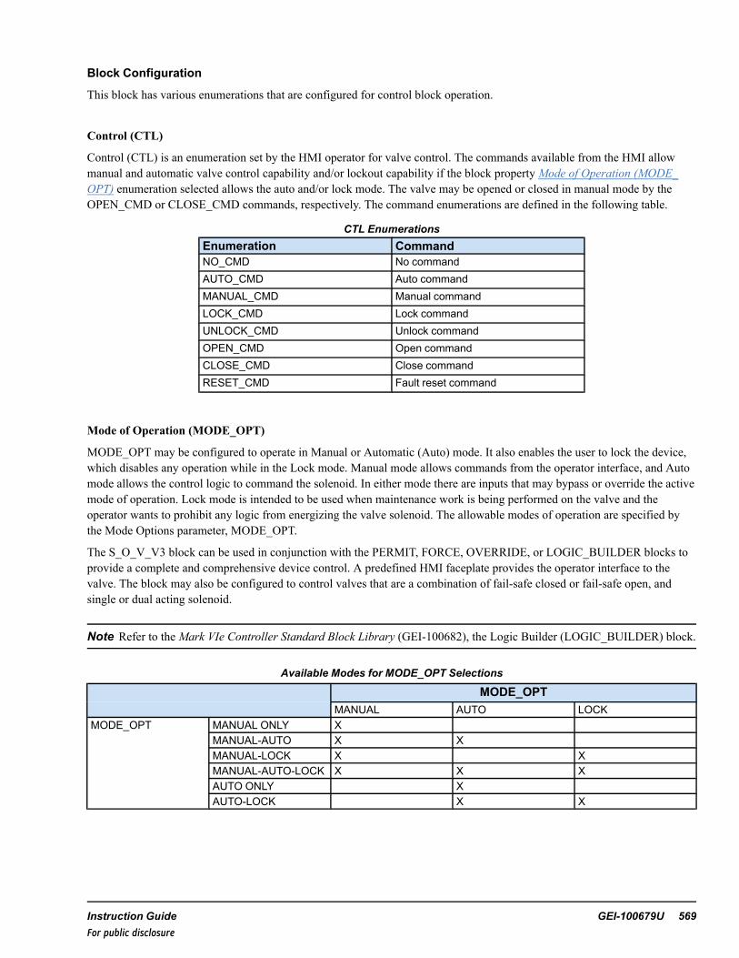
Block Configuration
This block has various enumerations that are configured for control block operation.
Control (CTL)
Control (CTL) is an enumeration set by the HMI operator for valve control. The commands available from the HMI allowmanual and automatic valve control capability and/or lockout capability if the block propertyMode of Operation (MODE_OPT) enumeration selected allows the auto and/or lock mode. The valve may be opened or closed in manual mode by theOPEN_CMD or CLOSE_CMD commands, respectively. The command enumerations are defined in the following table.
CTL EnumerationsEnumeration CommandNO_CMD No commandAUTO_CMD Auto commandMANUAL_CMD Manual commandLOCK_CMD Lock commandUNLOCK_CMD Unlock commandOPEN_CMD Open commandCLOSE_CMD Close commandRESET_CMD Fault reset command
Mode of Operation (MODE_OPT)
MODE_OPT may be configured to operate in Manual or Automatic (Auto) mode. It also enables the user to lock the device,which disables any operation while in the Lock mode. Manual mode allows commands from the operator interface, and Automode allows the control logic to command the solenoid. In either mode there are inputs that may bypass or override the activemode of operation. Lock mode is intended to be used when maintenance work is being performed on the valve and theoperator wants to prohibit any logic from energizing the valve solenoid. The allowable modes of operation are specified bythe Mode Options parameter, MODE_OPT.
The S_O_V_V3 block can be used in conjunction with the PERMIT, FORCE, OVERRIDE, or LOGIC_BUILDER blocks toprovide a complete and comprehensive device control. A predefined HMI faceplate provides the operator interface to thevalve. The block may also be configured to control valves that are a combination of fail-safe closed or fail-safe open, andsingle or dual acting solenoid.
Note Refer to theMark VIe Controller Standard Block Library (GEI-100682), the Logic Builder (LOGIC_BUILDER) block.
Available Modes for MODE_OPT Selections
MODE_OPTMANUAL AUTO LOCK
MODE_OPT MANUAL ONLY XMANUAL-AUTO X XMANUAL-LOCK X XMANUAL-AUTO-LOCK X X XAUTO ONLY XAUTO-LOCK X X
Instruction Guide GEI-100679U 569For public disclosure

MANUAL mode enables the block to respond to operator Open and Close commands from a faceplate on the HMI. Giventhat the permits are satisfied, the block operates in accordance with the manual command. The permit for the Open commandis set by the Open Permit input, OP_PMT, and the permit for the Close command is set by the Close Permit input, CL_PMT.These inputs may be set to fixed values or driven by the LOGIC_BUILDER block. The possible conditions that place theblock into Manual mode are as follows:
• Manual mode is selected from the HMI faceplate• Device is locked from the HMI faceplate• Manual Rejection from logic (MN_REJ)• Override close or open from logic (OVR_CL, OVR_OP)• Solenoid Circuit Failure from logic (RDY_SV)
− IO_OPT set to FS_OP OR FS_CL and IO_MON set to Fuse or Volt• Open Circuit Failure from logic (RDY_OP)
− IO_OPT set to Dual and IO_MON set to Fuse or Volt• Close Circuit Failure from logic (RDY_CL)
− IO_OPT set to Dual and IO_MON set to Fuse or Volt• Valve has generates alarms Failed to Open, Failed to Close, Congruency Alarm, or Tripped
− DIS_REJ_FL_P set to False
Note Some of these conditions require block parameters to be specifically configured.
S_O_V_V3 Block in Manual Mode
Note Manual mode is always available unless MODE_OPT is set to AUTO ONLYor AUTO-LOCK.
AUTO mode enables the block to respond to Open and Close commands from logic. Given that the permits are satisfied, theblock operates in accordance with the command from the logic. The permit for the Open command is set by the Open Permitinput, OP_PMT, and the permit for the Close command is set by the Close Permit input, CL_PMT. The OP_PMT and CL_PMT inputs may be set to fixed values or driven by the LOGIC_BUILDER block. The logic commands are input to the blockthrough the Automatic Open, AU_OP, and Automatic Close, AU_CL, inputs. The block may be placed in Auto mode eitherby a command from the HMI or a pulse to the automatic select input, AU_SEL. Given that the permits are satisfied, the blockis placed into Auto mode. The permit for the Auto mode is set by the Auto Permit input (AU_PMT). The AU_PMT input maybe set to a fixed value or driven by the LOGIC_BUILDER block.
570 GEI-100679U Mark VIe Controller DCS Block LibraryFor public disclosure

MANUAL-AUTO mode selection provides Manual and Automatic functionality. A selection of AUTO ONLYorAUTO-LOCK for MODE_OPT provides automatic functionality only. While residing in Auto mode, the block controls thevalve based on external logic. Automated control from external logic interfaces to the AU_OP and AU_CL pins. Similar tothe manual mode, Auto action only operates with the proper Open and Close permits. If AUTO ONLY mode is selected, theblock will permanently reside in Auto mode. If MANUAL-AUTO is selected, only two conditions will transfer the blockfrom Manual into Auto mode. Unlike the transferring to Manual mode, here, certain permits must be satisfied to allow thevalve to enter into Auto mode. This means that the S_O_V_V2 block is always able to enter Manual mode, but not alwaysable to enter Auto mode. These conditions depend on the mode options selected for the block. All three of the followingconditions must be met for the block to enter Auto mode:
• No demand to transition to Manual mode• MODE_OPT must be set to MANUAL-AUTO or MANUAL-AUTO_LOCK• AUTO push-button from operator graphic or Auto select from logic (AU_SEL)
LOCK mode may only be selected when the solenoid is in the de-energized state. When placed in the Lock mode, the blockforces the output so that the solenoid remains de-energized. Upon being placed in Lock mode, if currently in Auto mode, itwill be transfer to Manual mode. At this time, no open commands, forces, or overrides will be accepted. Upon removing thelock, Manual mode will be active. Similarly, AUTO ONLYand AUTO-LOCK (no open commands) will be accepted.however, upon removal of Lock mode, the block will return to Auto mode.
Note At any time, the block may go into Lock mode as long as it is residing in its fail-safe position. Only the operator mayplace this block into Lock mode.
Inputs and Outputs
At a minimum, the S_O_V_V3 block requires Open and Close feedback and valve order output. However, other inputs maybe used for automatic control, valve forcing, manual rejection, and such.
Depending on the block configuration, the output could be one (SV_ORD) or two (CL_ORD, OP_ORD) commands.Normally, S_O_V_V3 blocks are one-way solenoid valves, meaning that input pin, IO_OPT, is set to either FS_CL or FS_OP.The following figure displays the logic for the Open command. The Close command logic is similar, but replaces the opentext with close text and vice versa.
Open Command Logic
Instruction Guide GEI-100679U 571For public disclosure

Valve Command (SV_ORD)S
RClose CMD
Open CMD
Fail Close S_O_V_V2 (IO_OPT set to FS_CL)Fail Close S_O_V_V3
One-way Acting Valves Command Logic
Open Order (OP_ORD)
Close CMD
Open CMD
Dual acting S_O_V_V2 (IO_OPT set to DUAL)
Close Order (CL_ORD)
Dual Acting S_O_V_V3
Two-way Acting Valves Command Logic
Note Additional outputs from this block indicate status, faults, failures, alarms, forces, and overrides. Much of thisinformation is displayed on the HMI faceplate.
572 GEI-100679U Mark VIe Controller DCS Block LibraryFor public disclosure

Alarms and Faults
When an alarm is active, the S_O_V_V3 block may have limited action of movement. For example, a Fail to Open alarm willinhibit the valve from opening again. In this case, a Fault Reset must be issued so that the valve can continue normaloperation. Some alarms are held true until the alarm is cleared while others require a Fault Reset to clear the alarm. The alarmmay be reset at any time from the logic or an operator push-button. However, the reset must occur after the alarm has beencleared. Otherwise, the alarm will remain active. For Unit Controls, the Fault Reset pin may be connected to the Master Resetparameter. The alarms that may occur are as follows:
Fail to Open (FL_OP_A)—when commanded open, the valve fails to reach the open limit within the allotted time (FL_OP_T). The block cannot reissue an open command while the alarm is active. Reset the alarm.
Fail to Open Alarm
Fail to Close (FL_CL_A)+—when commanded open, the valve fails to reach the closed limit within the allotted time (FL_CL_T). The block cannot reissue a close command while alarm is active. Reset the alarm.
Valve Trip (TRIPPED)+— the valve is removed from its energized state but there was no command change. The blockcannot reissue an auto/manual command while alarm is active. Reset the alarm.
Instruction Guide GEI-100679U 573For public disclosure

Valve Trip Alarm
Congruency Alarm (CONGR_A)+— the valve has both open and closed limits at the same time, or, for the allotted time,the block is neither open nor closed. The block could be rejected to manual depending on its configuration. The alarm will becleared when the valve reaches either of its limits.
Solenoid Circuit Failure for single acting SOVs (SV_FLR)— power is lost to the circuit that energizes the valve (RDY_SV becomes False). This pin is a reserved variable that monitors the health of the I/O. The block rejects to manual and cannotreissue a command while the alarm is active. The alarm is cleared when RDY_SV becomes True.
Open Circuit Failure for dual acting SOVs (OP_FLR)— power is lost to the circuit that opens the valve (RDY_OPbecomes False). This pin is a reserved variable that monitors the health of the I/O. The block rejects to manual and cannotreissue an open command while the alarm is active. The alarm is cleared when RDY_OP becomes True.
Close Circuit Failure for dual acting SOVs (CL_FLR)— power is lost to the circuit that closes the valve (RDY_CLbecomes False). This pin is a reserved variable that monitors the health of the I/O. The block rejects to manual and cannotreissue an close command while alarm is active. The alarm is cleared when RDY_CL becomes True.
Auto Request (AU_REQ)— the valve is in Manual mode but the Auto logic requests that the valve state be different than itscurrent state. This has no effect on valve operation and is an alarm message only. The alarm is cleared if the valve is placedinto Auto mode, manually ordered to the requested state, or the auto action is removed.
Manual Rejected (MN_REJ_A)— the S_O_V_V3 block is rejected to manual due to a conditional alarm or input pin (MN_REJ becomes True). The block will only respond to manual commands. The alarm is cleared after the conditions return tonormal and the MN_REJ becomes False and a reset command is given.
Note + If the MODE_OPT is set to AUTO ONLYor AUTO-LOCK, this alarm will not affect automatic valve operation.However, the alarm will still become active under the given conditions.
574 GEI-100679U Mark VIe Controller DCS Block LibraryFor public disclosure

Force and Override Control
During any condition, the S_O_V_V3 block may be forced to a position that bypasses normal operation. The force is drivenfrom the CL_FRC or OP_FRC pins in the logic. The valve will move to the force position, and remain there until the force isremoved. For example, for the valve to be forced open it must meet the following criteria:
• No Override Close• No Circuit Failure• No Failed to Open
While a force condition is active, the valve may freely transfer from Auto to Manual mode following the normal permits.However, no manual command will supersede the force. Once the force is removed, the valve will continue normal operation.
Note Refer to the figure Open Command Logic to view the logic for a force.
An override will supersede a force and place the valve into the overridden state. For example, irrelevant of any forces, thevalve will go to the override closed state given that there is no circuit failure and no Failed to Close alarm is active. The blockwill take precedence from the override command, then the force command, and then the Manual/Auto command. Uponentering an overridden state, the valve will be placed into Manual mode. Once the override is removed, the valve will remainin Manual mode until changed by the operator.
Although forces and overrides bypass normal permits, if the valve is locked, forces and overrides will have no effect on theblock. The block must be removed from Lock mode before the forces and overrides affect block operation. Additionally, if theMODE_OPT is set to AUTO ONLYor AUTO-LOCK, the override pins will be disabled and will have no effect on the block.
Instruction Guide GEI-100679U 575For public disclosure

Permits
Due to the nature of Auto and forcing action, permits are required for valve operation. Built into the blocks are special devicepermits that may be enabled or disabled with certain pins in the block, as follows:
Note For basic operations, most of the device permits will be disabled.
• Open− OP_PMT is True (OP_PMT is technically a UINT)− Valve not Failed to Open**+− Valve not Tripped**+− OutputMon Ready to Open (if Fuse Monitoring/Voltage Monitoring Property enabled)− Ready to operate Solenoid (if Fuse Monitoring/Voltage Monitoring Property enabled)− Valve not in Lock mode
• Close− CL_PMT is True (CL_PMT is technically a UINT)− Valve not Failed to Close**+− Valve not Tripped**+− OutputMon Ready to Close (if Fuse Monitoring/Voltage Monitoring Property enabled)− Ready to operate Solenoid (if Fuse Monitoring/Voltage Monitoring Property enabled)− Valve not in Lock mode
• Open Force− Valve not Failed to Open**+− No Open Circuit Failure (if Fuse Monitoring/Voltage Monitoring Property enabled and Dual acting)− No Solenoid Circuit Failure (if Fuse Monitoring/Voltage Monitoring Property enabled and Fail Safe Close)
• Close Force− Valve not Failed to Close**+− No Close Circuit Failure (if Fuse Monitoring/Voltage Monitoring Property enabled and Dual acting)− No Solenoid Circuit Failure (if Fuse Monitoring/Voltage Monitoring Property enabled and Fail Safe Open)
• Open Override+− Valve not Failed to Open**− No Open Circuit Failure (if Fuse Monitoring/Voltage Monitoring Property enabled and Dual acting)− No Solenoid Circuit Failure (if Fuse Monitoring/Voltage Monitoring Property enabled and Fail Safe Close)
• Close Override +− Valve not Failed to Close**− No Close Circuit Failure (if Fuse Monitoring/Voltage Monitoring Property enabled and Dual acting)− No Solenoid Circuit Failure (if Fuse Monitoring/Voltage Monitoring Property enabled and Fail-Safe Open)
Note ** Indicates a condition that is internally generated to the block. Otherwise, the condition comes from a direct input.
+ If the MODE_OPT is set to AUTO ONLYor AUTO-LOCK, the condition comes from a direct input.
576 GEI-100679U Mark VIe Controller DCS Block LibraryFor public disclosure

Inputs
Name Global Description FunctionAU_SEL Auto select Pulses the valve into auto (provided all permits are met)AU_ OP Auto open Opens the valve (provided all permits are met); device must be in
Auto modeAU_CL Auto close Auto closes the valve (provided all permits are met); device must
be in Auto modeAU_PMT Yes Auto permit Permit required for external logic to prevent the valve to enter Auto
modeOP_PMT Open permit Permit required for external logic to prevent the valve from
openingCL_PMT Close permit Permit required for external logic to prevent the valve from closingRDY_SV Ready to operate S_O_V_
V3I/O monitoring of the circuit to the command to the valve
OP_OVR Open override Permit required for external logic to override open the valveCL_OVR Yes Close override Permit required for external logic to override close the valveMN_REJ Yes Manual rejection Permit required for external logic to manually reject the valveRDY_CL Ready to close S_O_V_V3 I/O monitoring of the circuit to the close command of the valveRDY_OP Ready to open S_O_V_V3 I/O monitoring of the circuit to the open command of the valveCL_INP Closed input Connects to the closed feedback of the valveOP_INP Open input Connects to the open feedback of the valveCL_FRC Yes Close force Permit required for external logic to force close the valveOP_FRC Yes Open force Permit required for external logic to force open the valveFAULT_RESET Fault reset Permit required for external logic to reset alarms on the valve
ParametersName Global Description FunctionCTL Yes Control Used by the operator graphic to control the valveFL_OP_T Fail to open time Time allotted for the valve to open. (If the motor takes 0.5 seconds
to open, ~6000 msec is sufficient time to allow the valve to reachits open state.)
FL_CL_T Fail to close time Time allotted for the valve to close. (If the motor takes 0.5 secondsto close, ~6000 msec is sufficient time to allow the valve to reachits close state.)
PWR_FL_TMR Manual reject power failuretime
Time allotted for the S_O_V_V3 to lose power before it rejects thevalve to manual
IO_MON I/O monitor options Allows the I/O monitoring feature to be enabled. This pin can beset to either Volt or Fuse monitoring.
IO_OPT Valve I/O options Designates what type of valve it is (possible values are FS_OP,FS_CL, or DUAL)
MODE_OPT Mode options Designates which modes the valve can enterDIS_REJ_FL_P Disable manual reject on
faultsDesignates if certain alarms should reject the valve to manual.True bypasses the alarms so that the valve will remain in Automode during certain alarms.
Instruction Guide GEI-100679U 577For public disclosure

Outputs
Name Global DescriptionSV_ORD Yes Solenoid valve orderOP_ORD Yes Open orderCL_ORD Yes Close orderAUTO_P Yes Auto mode available propertyLOCK_P Yes Lock mode available propertyFS_OP_P Yes Fail safe open S_O_V_V3 propertyDUAL_P Yes Dual acting S_O_V_V3 propertyVOLT_MON_P Yes Volt monitoring I/O propertyFUSE_MON_P Yes Fuse monitoring I/O propertyAUTO Yes Auto mode activeCLOSED Yes S_O_V_V3 closeOPEN Yes S_O_V_V3 openLOCK Yes Lock mode activePMT_AU Yes Auto permitPMT_CL Yes Close permitPMT_OP Yes Open permitFAULT Yes Fault activeMODE Current valve statusOVR_CL Yes Close overrideOVR_OP Yes Open overrideFRC_CL Yes Close forceFRC_OP Yes Open forceSV_FLR Yes Solenoid circuit failureCL_FLR Yes Close circuit failureOP_FLR Yes Open circuit failureAU_REQ Yes Auto request (auto logic wishes to open or close S_O_V_V3)CONGR_A Yes Congruency alarmFL_CL_A Yes Failed to close alarmFL_OP_A Yes Failed to open alarmMN_REJ_A Yes Manual rejection alarmTRIPPED Yes Valve tripped
578 GEI-100679U Mark VIe Controller DCS Block LibraryFor public disclosure
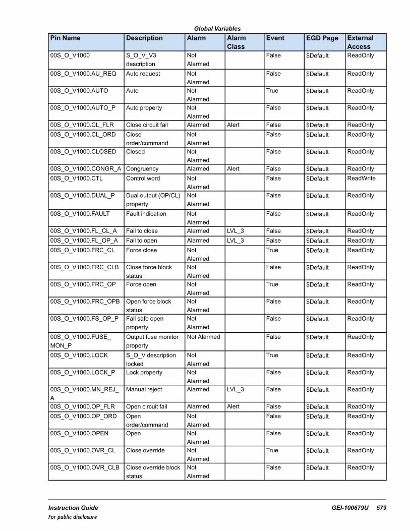
Global VariablesPin Name Description Alarm Alarm
ClassEvent EGD Page External
Access00S_O_V1000 S_O_V_V3
descriptionNotAlarmed
False $Default ReadOnly
00S_O_V1000.AU_REQ Auto request NotAlarmed
False $Default ReadOnly
00S_O_V1000.AUTO Auto NotAlarmed
True $Default ReadOnly
00S_O_V1000.AUTO_P Auto property NotAlarmed
False $Default ReadOnly
00S_O_V1000.CL_FLR Close circuit fail Alarmed Alert False $Default ReadOnly00S_O_V1000.CL_ORD Close
order/commandNotAlarmed
False $Default ReadOnly
00S_O_V1000.CLOSED Closed NotAlarmed
False $Default ReadOnly
00S_O_V1000.CONGR_A Congruency Alarmed Alert False $Default ReadOnly00S_O_V1000.CTL Control word Not
AlarmedFalse $Default ReadWrite
00S_O_V1000.DUAL_P Dual output (OP/CL)property
NotAlarmed
False $Default ReadOnly
00S_O_V1000.FAULT Fault indication NotAlarmed
False $Default ReadOnly
00S_O_V1000.FL_CL_A Fail to close Alarmed LVL_3 False $Default ReadOnly00S_O_V1000.FL_OP_A Fail to open Alarmed LVL_3 False $Default ReadOnly00S_O_V1000.FRC_CL Force close Not
AlarmedTrue $Default ReadOnly
00S_O_V1000.FRC_CLB Close force blockstatus
NotAlarmed
False $Default ReadOnly
00S_O_V1000.FRC_OP Force open NotAlarmed
True $Default ReadOnly
00S_O_V1000.FRC_OPB Open force blockstatus
NotAlarmed
False $Default ReadOnly
00S_O_V1000.FS_OP_P Fail safe openproperty
NotAlarmed
False $Default ReadOnly
00S_O_V1000.FUSE_MON_P
Output fuse monitorproperty
Not Alarmed False $Default ReadOnly
00S_O_V1000.LOCK S_O_V descriptionlocked
NotAlarmed
True $Default ReadOnly
00S_O_V1000.LOCK_P Lock property NotAlarmed
False $Default ReadOnly
00S_O_V1000.MN_REJ_A
Manual reject Alarmed LVL_3 False $Default ReadOnly
00S_O_V1000.OP_FLR Open circuit fail Alarmed Alert False $Default ReadOnly00S_O_V1000.OP_ORD Open
order/commandNotAlarmed
False $Default ReadOnly
00S_O_V1000.OPEN Open NotAlarmed
False $Default ReadOnly
00S_O_V1000.OVR_CL Close override NotAlarmed
True $Default ReadOnly
00S_O_V1000.OVR_CLB Close override blockstatus
NotAlarmed
False $Default ReadOnly
Instruction Guide GEI-100679U 579For public disclosure
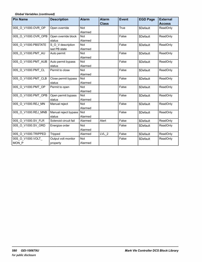
Global Variables (continued)
Pin Name Description Alarm AlarmClass
Event EGD Page ExternalAccess
00S_O_V1000.OVR_OP Open override NotAlarmed
True $Default ReadOnly
00S_O_V1000.OVR_OPB Open override blockstatus
NotAlarmed
False $Default ReadOnly
00S_O_V1000.PBSTATE S_O_V descriptionlast PB state
NotAlarmed
False $Default ReadOnly
00S_O_V1000.PMT_AU Auto permit NotAlarmed
False $Default ReadOnly
00S_O_V1000.PMT_AUB Auto permit bypassstatus
NotAlarmed
False $Default ReadOnly
00S_O_V1000.PMT_CL Permit to close NotAlarmed
False $Default ReadOnly
00S_O_V1000.PMT_CLB Close permit bypassstatus
NotAlarmed
False $Default ReadOnly
00S_O_V1000.PMT_OP Permit to open NotAlarmed
False $Default ReadOnly
00S_O_V1000.PMT_OPB Open permit bypassstatus
NotAlarmed
False $Default ReadOnly
00S_O_V1000.REJ_MN Manual reject NotAlarmed
False $Default ReadOnly
00S_O_V1000.REJ_MNB Manual reject bypassstatus
NotAlarmed
False $Default ReadOnly
00S_O_V1000.SV_FLR Solenoid circuit fail Alarmed Alert False $Default ReadOnly00S_O_V1000.SV_ORD Energize order Not
AlarmedFalse $Default ReadOnly
00S_O_V1000.TRIPPED Tripped Alarmed LVL_2 False $Default ReadOnly00S_O_V1000.VOLT_MON_P
Output volt monitorproperty
NotAlarmed
False $Default ReadOnly
580 GEI-100679U Mark VIe Controller DCS Block LibraryFor public disclosure

HMI Configuration (CIMPLICITY)
The Object name for the HMI is the same as the Device name specified in the ToolboxST configuration.
Click the object to display the S_O_V_V3 faceplate.
Typical HMI Object for a S_O_V_V3
S_O_V_V3 Faceplate
Instruction Guide GEI-100679U 581For public disclosure

50 Saturation Pressure (SAT_PRESSURE)Block Category: Equations and Conversions
The Saturation Pressure (SAT_PRESSURE) block calculates the saturation pressure of steam for a given temperature, IN_T,and atmospheric pressure, IN_PATM.
SAT_PRESSURE Block
Ranges/Units
MEAS_SYS English S.I.
IN_T 95 - 705 °F 35 - 374°C
IN_PATM PSI bar
OUT PSIq barq
This block propagates quality status if the status operations are enabled.
Block status modifications: If the input temperature value exceeds the range in the given table above, the output status willbe either LOW_LIMITED-LAST_USABLE_VALUE-UNCERTAIN [69] or HIGH_LIMITED-LAST_USABLE_VALUE-UNCERTAIN [70].
For further details on Relational blocks, refer to the Mark VIe Controller Standard Block Library (GEI-100682), the StatusMonitoring (STATUS_MONITORING) block.
Inputs
Name Description Data Type Initial Value Visibility Interface TypeIN_PATM Input atmospheric pressure REAL 14.696 Parameter Value OnlyIN_T Input temperature REAL† 150 Always Value with StatusMEAS_SYS Measurement system UINT (ENUM) English Parameter Value Only† Value with Status (if status option is enabled)
Output
Name Description Data Type Initial Value Visibility Interface TypeOUT Saturation pressure (gauge) REAL† N/A Always Value with Status† Value with Status (if status option is enabled)
582 GEI-100679U Mark VIe Controller DCS Block LibraryFor public disclosure

51 Saturation Temperature (SAT_TEMP)Block Category: Equations and Conversions
The Saturation Temperature (SAT_TEMP) block calculates the saturation temperature of steam for a given gauge pressure,IN_P, and atmospheric pressure, IN_PATM.
SAT_TEMP Block
Ranges/Units
MEAS_SYS English S.I.
IN_P PSIg barg
IN_PATM PSI bar
OUT °F °C
The steam table lookup uses the sum of IN_P and IN_PATM (absolute pressure). The sum of IN_P and IN_PATM must be inthe range of 0.8 - 3200 PSIA (0.0552 - 220.6322 bara).
This block propagates quality status if the status operations are enabled.
Block status modifications: If the input pressure value exceeds the range in the given table above, the output status will beeither LOW_LIMITED-LAST_USABLE_VALUE-UNCERTAIN [69] or HIGH_LIMITED-LAST_USABLE_VALUE-UNCERTAIN [70].
For further details on Relational blocks, refer to the Mark VIe Controller Standard Block Library (GEI-100682), the StatusMonitoring (STATUS_MONITORING) block.
Inputs
Name Description Data Type Initial Value Visibility Interface TypeIN_P Input pressure REAL† 0 Always Value with StatusIN_PATM Input atmospheric pressure REAL 14.696 Parameter Value OnlyMEAS_SYS Measurement system UINT (ENUM) English Parameter Value Only† Value with Status (if status option is enabled)
Output
Name Description Data Type Initial Value Visibility Interface TypeOUT Saturation pressure (gauge) REAL† N/A Always Value with Status† Value with Status (if status option is enabled)
Instruction Guide GEI-100679U 583For public disclosure

52 Setpoint Station (SETPOINT_ST)Block Category: Controls (DCS)
The Setpoint Station (SETPOINT_ST) block is an expandable block for up to 16 outputs. For each output there is a bias (Bn),Track (TKn), and balance gain (Gn) and feedback (PVn). Balance gains are constants that define the percentage split of theSP to the individual output. The sum of all the configured balance gains must be 100. The system generates a build errorwhen the sum of the gains is not equal to 100.
Under normal operation when all track inputs are False (TK1 … TKn) = False, then all the outputs are:
OUTn=(SP x Gn/100) + Bn
When Track is True, that is TKn = True, then the corresponding output is:
OUTn=PVn
For all other outputs that are not in track when at least one is in track, the equation is.
OUTn= ((SP-PVt) x Gn/100) +Bn + ((SP-PVt) x Gt/100)/M)
If (SP-PVt ) ≤0 then substitute the value of (SP-PVt)=0
Where PVt = sum of the PV’s for which track is True
Gt = sum of the gains for which track is True
M = number of outputs not in track.
SP_OUT is the sum of all the outputs. SH and SL define the input setpoint (SP) high and low limits.
Note SETPOINT_ST is used to split a single setpoint (SP) into multiple outputs.
ToolboxST Configuration
When a SETPOINT_ST is inserted into application code, it generates a window prompting user to enter Device Name, DeviceDescription, HMI Screen Name, and Format Specification. The block then automatically creates the variables associated withthe block and provides the appropriate attributes for each variable (for example, Type and Format Spec variables that need tobe on EGD will be automatically placed on the $Default EGD page, and so on). The HMI screen name is used as an Alarmattribute.
Note Each Device Name used in a controller must be unique.
584 GEI-100679U Mark VIe Controller DCS Block LibraryFor public disclosure

Default Attribute Values
When the user clicks OK, the block and pin connections will be configured automatically. The previous example will generateGlobal pins. Pin names are in the form Device Value.pin Name, where Device Value has the attribute value STEAM_1001 andInput _Name is the block input/output names. The description, Plant load Control in this example, becomes the prefix of theblock input/output descriptions.
SETPOINT_ST Block
Note Refer to the table Global Variables.
Instruction Guide GEI-100679U 585For public disclosure
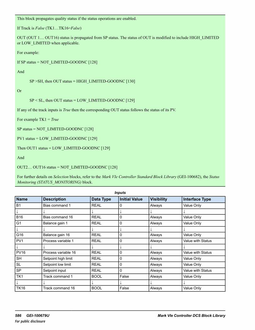
This block propagates quality status if the status operations are enabled.
If Track is False (TK1…TK16=False)
OUT (OUT 1… OUT16) status is propagated from SP status. The status of OUT is modified to include HIGH_LIMITEDor LOW_LIMITED when applicable.
For example:
If SP status = NOT_LIMITED-GOODNC [128]
And
SP >SH, then OUT status = HIGH_LIMITED-GOODNC [130]
Or
SP < SL, then OUT status = LOW_LIMITED-GOODNC [129]
If any of the track inputs is True then the corresponding OUT status follows the status of its PV.
For example TK1 = True
SP status = NOT_LIMITED-GOODNC [128]
PV1 status = LOW_LIMITED-GOODNC [129]
Then OUT1 status = LOW_LIMITED-GOODNC [129]
And
OUT2… OUT16 status = NOT_LIMITED-GOODNC [128]
For further details on Selection blocks, refer to the Mark VIe Controller Standard Block Library (GEI-100682), the StatusMonitoring (STATUS_MONITORING) block.
Inputs
Name Description Data Type Initial Value Visibility Interface TypeB1 Bias command 1 REAL 0 Always Value Only↓ ↓ ↓ ↓ ↓ ↓B16 Bias command 16 REAL 0 Always Value OnlyG1 Balance gain 1 REAL 0 Always Value Only↓ ↓ ↓ ↓ ↓ ↓G16 Balance gain 16 REAL 0 Always Value OnlyPV1 Process variable 1 REAL 0 Always Value with Status↓ ↓ ↓ ↓ ↓ ↓PV16 Process variable 16 REAL 0 Always Value with StatusSH Setpoint high limit REAL 0 Always Value OnlySL Setpoint low limit REAL 0 Always Value OnlySP Setpoint input REAL 0 Always Value with StatusTK1 Track command 1 BOOL False Always Value Only↓ ↓ ↓ ↓ ↓ ↓TK16 Track command 16 BOOL False Always Value Only
586 GEI-100679U Mark VIe Controller DCS Block LibraryFor public disclosure

Outputs
Name Description Data Type Initial Value Visibility Interface TypeN Number of split outputs UINT N/A Always Value OnlyOUT1 Output 1 REAL N/A Always Value with Status↓ ↓ ↓ ↓ ↓ ↓OUT16 Output 16 REAL N/A Always Value with StatusSP_OUT Total setpoint output REAL N/A Always Value Only
Global VariablesGlobal Pin Name Description EGD Page Scope UsageSTEAM_1001.SP Plant load setpoint input $Default Global InputSTEAM_1001.B1 Plant load bias 1 command $Default Global Input↓ $Default Global InputSTEAM_1001.Bn Plant load bias n command $Default Global InputSTEAM_1001.PV1 Plant load process variable 1 $Default Global Input↓ ↓ $Default Global InputSTEAM_1001.PVn Plant load process variable n $Default Global InputSTEAM_1001.SH Plant load setpoint high limit $Default Global InputSTEAM_1001.SL Plant load setpoint low limit $Default Global InputSTEAM_1001.OUT1 Plant load setpoint OUT 1 $Default Global Output↓ ↓ $Default Global OutputSTEAM_1001.OUTn Plant load setpoint OUT n $Default Global OutputSTEAM_1001.SP_OUT Plant load total setpoint output $Default Global Output
Instruction Guide GEI-100679U 587For public disclosure

53 Starter (STARTER)Block Category: Legacy, Device Control
Note Legacy Status— The STARTER block is not supported for use in new Mark VIe control systems (ControlSTsoftware suite V05.02 or later). It is in place to support the maintenance of legacy Mark VIe control systems (prior toControlST software suite V05.02). For new Mark VIe control systems, use the STARTER_V3 block; it provides equivalentfunctionality.
The Starter (STARTER) block controls equipment powered by a non-reversing low-voltage (LV) or medium-voltage (MV)motor starter. The block provides a maintained output for LV motors where ON_ORD is energized/de-energized to start/stopthe motor. The block may also be configured for MV starter with momentary outputs ON_ORD to start or OFF_ORD to stopthe motor.
Block Configuration
I/O Option (IO_OPT)
I/O Option (IO_OPT) enumerations are listed in the following table.
IO_OPT Enumerations
Enumeration DescriptionNone No capabilities are availableCP_OK Hard-wired control power monitoring inputREM Hard-wired Remote mode inputAVAIL Hard-wired available input (known as a Ready to go indicator)PR_TRIP Hard-wired protection trip capability; there is a protective relay controlling the breakerRCKD_IN Hard-wired racked-in detection input that can detect when it is physically connected to the busMOM_OUT Momentary on and off request outputs (versus a single maintained run output)OFF_INP_P Hard-wired Off input (in addition to the On-input) (deprecated)
NONE—when IO_OPT is none, then CP_OK, AVAIL, PR_TRP, RCKD_IN, and REM inputs are not used.
CP_OK— select for a starter that provides control power monitoring IO capability. When the CP_OK enumeration isselected, the output CP_OK_P is True. The Boolean control power monitoring connection is to the CP_OK input of the blockand is True when control power is present. When the CP_OK input is False, the control power failure alarm, CP_F_A, isactivated. If the starter is in AUTO mode and the duration of CP_F _A being True has exceeded the PWR_FL_TMR, thestarter will switch to MANUAL mode and the manual reject alarm, MN_REJ_A, will be activated, (delayed by 2 seconds).
AVAIL— select for a starter that requires an available capability. When the AVAIL enumeration is selected, the outputAVAIL_P is True. The Boolean available connection is to the AVAIL input of the block and is True when the starter isavailable. When AVAIL is False, the available alarm, AVAIL_A, is activated. If the starter is in AUTO mode and the durationof AVAIL_A being True has exceeded the PWR_FL_TMR, the starter will switch to MANUAL mode and the manual rejectalarm, MN_REJ_A, will be activated, (delayed by 2 seconds).
PR_TRP— select for a starter that has protection trip capability. When PR_TRP enumeration is selected, the output PR_TRP_P is True. The Boolean protection trip input is connected to PR_TRP input and is False when a trip does not exist on thestarter. When PR_TRP is True, the protection trip alarm, PR_TR_A, is activated. If the starter is in AUTO mode and PR_TRP_P is True, the starter will switch to MANUAL mode and the manual reject alarm, MN_REJ_A, will be activated,(delayed by 2 seconds).
588 GEI-100679U Mark VIe Controller DCS Block LibraryFor public disclosure
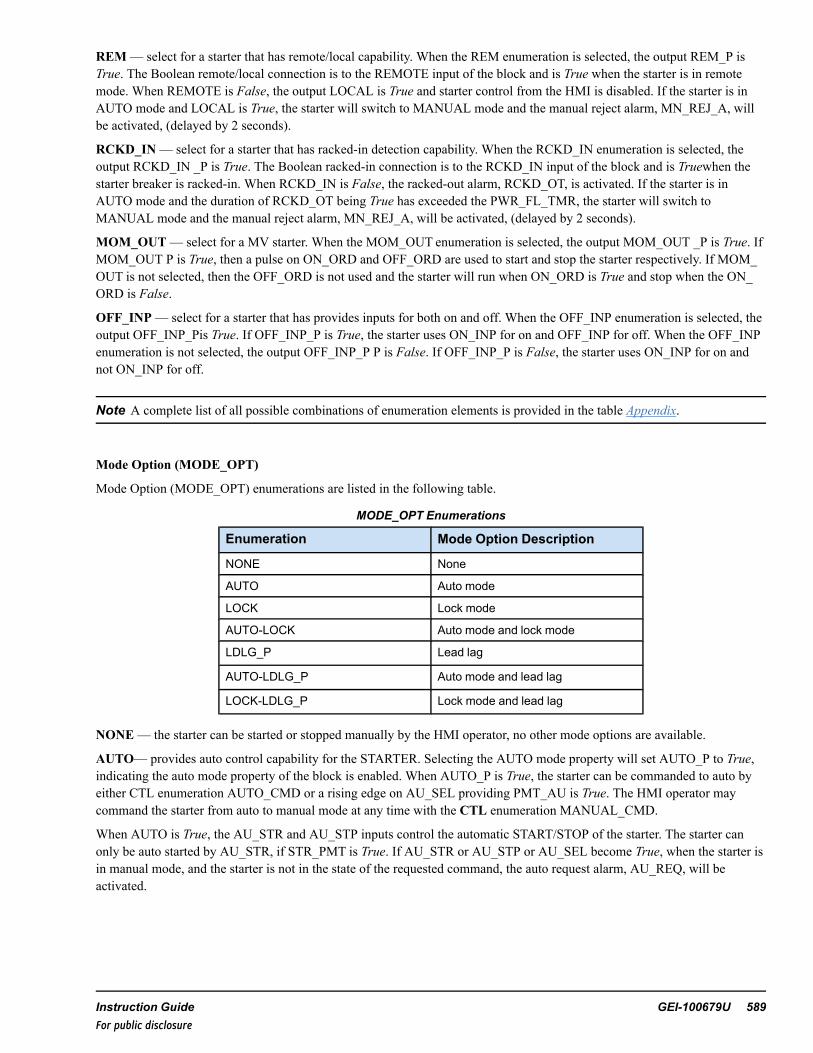
REM— select for a starter that has remote/local capability. When the REM enumeration is selected, the output REM_P isTrue. The Boolean remote/local connection is to the REMOTE input of the block and is True when the starter is in remotemode. When REMOTE is False, the output LOCAL is True and starter control from the HMI is disabled. If the starter is inAUTO mode and LOCAL is True, the starter will switch to MANUAL mode and the manual reject alarm, MN_REJ_A, willbe activated, (delayed by 2 seconds).
RCKD_IN— select for a starter that has racked-in detection capability. When the RCKD_IN enumeration is selected, theoutput RCKD_IN _P is True. The Boolean racked-in connection is to the RCKD_IN input of the block and is Truewhen thestarter breaker is racked-in. When RCKD_IN is False, the racked-out alarm, RCKD_OT, is activated. If the starter is inAUTO mode and the duration of RCKD_OT being True has exceeded the PWR_FL_TMR, the starter will switch toMANUAL mode and the manual reject alarm, MN_REJ_A, will be activated, (delayed by 2 seconds).
MOM_OUT— select for a MV starter. When the MOM_OUT enumeration is selected, the output MOM_OUT _P is True. IfMOM_OUT P is True, then a pulse on ON_ORD and OFF_ORD are used to start and stop the starter respectively. If MOM_OUT is not selected, then the OFF_ORD is not used and the starter will run when ON_ORD is True and stop when the ON_ORD is False.
OFF_INP— select for a starter that has provides inputs for both on and off. When the OFF_INP enumeration is selected, theoutput OFF_INP_Pis True. If OFF_INP_P is True, the starter uses ON_INP for on and OFF_INP for off. When the OFF_INPenumeration is not selected, the output OFF_INP_P P is False. If OFF_INP_P is False, the starter uses ON_INP for on andnot ON_INP for off.
Note A complete list of all possible combinations of enumeration elements is provided in the table Appendix.
Mode Option (MODE_OPT)
Mode Option (MODE_OPT) enumerations are listed in the following table.
MODE_OPT Enumerations
Enumeration Mode Option Description
NONE None
AUTO Auto mode
LOCK Lock mode
AUTO-LOCK Auto mode and lock mode
LDLG_P Lead lag
AUTO-LDLG_P Auto mode and lead lag
LOCK-LDLG_P Lock mode and lead lag
NONE— the starter can be started or stopped manually by the HMI operator, no other mode options are available.
AUTO— provides auto control capability for the STARTER. Selecting the AUTO mode property will set AUTO_P to True,indicating the auto mode property of the block is enabled. When AUTO_P is True, the starter can be commanded to auto byeither CTL enumeration AUTO_CMD or a rising edge on AU_SEL providing PMT_AU is True. The HMI operator maycommand the starter from auto to manual mode at any time with the CTL enumeration MANUAL_CMD.
When AUTO is True, the AU_STR and AU_STP inputs control the automatic START/STOP of the starter. The starter canonly be auto started by AU_STR, if STR_PMT is True. If AU_STR or AU_STP or AU_SEL become True, when the starter isin manual mode, and the starter is not in the state of the requested command, the auto request alarm, AU_REQ, will beactivated.
Instruction Guide GEI-100679U 589For public disclosure

LOCK— provides software lock-out capability for the starter. Selecting the LOCK mode property will set LOCK_P to True,and enable the LOCK_CMD and UNLOCK_CMD to control the lockout mode functionality. The starter must be stoppedbefore the block can be set to lockout mode. Feedback to the HMI operator of this mode is provided by LOCK. The HMIoperator is prevented from operating the starter from the control faceplate when LOCK is True, and auto mode is disabled.
Note The lockout indication is provided for indication only. This action will not lockout the equipment, it will only indicatelockout status. The owner's lockout procedures must be followed to safely lock equipment out.
The Lock button can also be configured to use the WorkstationST Lock function. Refer to the WorkstationST/CIMPLICITYAdvanced Viewer Integration Instruction Guide (GEI-100697), the section HMI Tagout.
LDLG— selecting this mode property will set LDLG_P to True. When LDLG_P is True, then the input LDLG_ORDERindicates lead/lag order on the graphic object and faceplate per the enumeration in the following table.
Lead/Lag Order (LDLG_ORDER) input is ignored if LDLG_P is not True. enumerations are listed in the following table.
LDLG_ORDER Enumerations
Enumeration Lead/Lag Order Description
Lead Lead
Lag_1 Lag 1
Lag_2 Lag 2
Lag_3 Lag 3
Lag_4 Lag 4
Lag_5 Lag 5
Lag_6 Lag 6
Lag_7 Lag 7
Lag_8 Lag 8
Lag_9 Lag 9
Lag_10 Lag 10
Lag_11 Lag 11
Lag_12 Lag 12
Lag_13 Lag 13
Lag_14 Lag 14
Lag_15 Lag 15
Lag_16 Lag 16
Lag_17 Lag 17
Lag_18 Lag 18
Lag_19 Lag 19
Lag_20 Lag 20
590 GEI-100679U Mark VIe Controller DCS Block LibraryFor public disclosure

IO_MON
IO_MON enumerations are digital output monitor types. Monitoring is only available for the outputs ON_ORD and OFF_ORD. If the hardware board used with ON_ORD and OFF_ORD can perform diagnostic monitoring, IO_MON is used toselect the type of diagnostic monitoring. When diagnostic monitoring is used (FUSE or VOLT), the diagnostic variable fromthe ON_ORD output is connected to RDY_STR and the diagnostic variable for the STP_CMD is connected to RDY_STP.
IO_MON Enumerations
Enumeration Monitor Option Description
NONE None
FUSE Fuse monitoring
VOLT Voltage monitoring
Note Refer to the Mark VIe and Mark VIeS Control Volume II System Guide (GEH-6721_Vol_II) for descriptions ofhardware boards.
NONE— no circuit monitoring is available RDY_STR and RDY_STP inputs are not used.
FUSE— fuse monitoring determines the starter circuit failure. If FUSE is selected, FUSE_MON_P is True. The fusemonitoring card points provide fuse status to the block. These points are connected to RDY_STR and RDY_STP inputs. Ifthere is a fuse failure, RDY_STR and RDY_STP will become False. Normal operation of the block requires these inputs to beTrue. If RDY_STR or RDY_STP become False, RUN_FLR or STP_FLR become True, respectively, delayed by 3 seconds.When RUN_FLR becomes True, PMT_RUN and PMT_STR are False and PMT_AU, become False, delayed by PWR_FL_TMR. If AUTO is True when this occurs, AUTO will become False and the manual reject alarm, MN_REJ_A, will beactivated. Note, to prevent an unwanted automatic switch to Manual mode, in case of an Automatic bus transfer or Powersupply transfer, the power supply transfer time should not exceed PWR_FL_TMR. If the power supply transfer time exceedsthe PWR_FL_TMR, the starter will transfer from auto to manual mode and MN_REJ_A, will be activated.
VOLT— voltage monitoring determines the valve circuit failure. If VOLT is selected VOLT_MON_P is True. The Booleanvoltage monitoring input is True when there is no voltage failure and is connected to the RDY_STR and RDY_STP inputs.
Instruction Guide GEI-100679U 591For public disclosure

RUN_FLR is True, delayed by 3 seconds, when the following conditions exist:
• RDY_STR is False• STR_CMD is False• CP_OK is True (if the IO_OPT, enumeration CP_OK is selected)• REMOTE is True (if the IO_OPT, enumeration REM is selected)• RCKN_IN is True (if the IO_OPT, enumeration RCKN_IN is selected)• RUNNING is False• TK is False• AVAIL is True (if the IO_OPT, enumeration AVAIL is selected)
When RUN_FLR becomes True, PMT_RUN and PMT_STR, become False and PMT_AU becomes False, delayed by PWR_FL_TMR.
STP_FLR is True, delayed by 3 seconds, when the following conditions exist:
• RDY_STP is False• OFF_ORD is False (if the IO_OPT, enumeration MOM_OUT is selected)• CP_OK is True (if the IO_OPT, enumeration CP_OK is selected)• REMOTE is True (if the IO_OPT, enumeration REM is selected)• OPEN is False• RCKN_IN is True (if the IO_OPT, enumeration RCKN_IN is selected)• AVAIL is True (if the IO_OPT, enumeration AVAIL is selected)
When STP_FLR becomes True, PMT_RUN and PMT_STR, become False and PMT_AU becomes False, delayed by PWR_FL_TMR.
If AUTO is True when this occurs, AUTO will become False and the manual reject alarm, MN_REJ_A, will be activated,(delayed by 2 seconds).
Note To prevent an unwanted automatic switch to Manual mode, in case of an Automatic bus transfer or Power supplytransfer, the power supply transfer time should not exceed PWR_FL_TMR. If the power supply transfer time exceeds thePWR_FL_TMR, the valve will transfer from auto to manual mode and MN_REJ_A, will be activated.
592 GEI-100679U Mark VIe Controller DCS Block LibraryFor public disclosure

Override Control
The block provides an override input enumeration, TRP_OVR and a manual reject input enumeration, MN_REJ. Thefollowing table provides the possible values of the enumerations.
Manual Reject and Trip Override (MN_REJ and TRP_OVR) Enumerations
Enumeration Override Option Description
NO_OVR-NO-BLOCK No override and no override is blocked
OVR-NO_BLOCK Override active and no override is blocked
NO_OVR-BLOCK No override and a override is blocked
OVR-BLOCK Override active and a override is blocked
When TRP_OVR indicates Override Active, the starter prevented from starting in any mode. The starter is rejected to manualwhen either TRP_OVR or MN_REJ indicate Override Active and the manual reject alarm, MN_REJ_A, will be activated,(delayed by 2 seconds). TRP_OVR and MN_REJ (if used) are driven from an OVERRIDE block. Each connected input of theOVERRIDE block has the ability (when enabled) to be blocked by the HMI operator, which is accessed from associated tabof the permit HMI screen display. When TRP_OVR or MN_REJ enumeration contains BLOCK, the HMI operator hasblocked at least one override. STARTER does not use the block information, but passes it to the HMI for display.
Force Control
The block provides force enumerations Force Open input (ON_FRC), and Force Close input (OFF_FRC). The following tableprovides the possible values of the enumerations.
OFF_FRC and ON_FRC Enumerations
Enumeration Force Option DescriptionNO_FORCE-NO-BLOCK No force and no force is blockedFORCE-NO_BLOCK Force active and no force is blockedNO_FORCE-BLOCK No force and a force is blockedFORCE-BLOCK Force active and a force is blocked
ON_FRC or OFF_FRC force the breaker open or close in any mode except when an TRP_OVR indicates Override Active.The breaker does not reject to manual if a force open or close occurs. ON_FRC and OFF_FRC (if used) are driven from aFORCE block. Each connected input of the FORCE block has the ability (when enabled) to be blocked by the HMI operator,which is accessed from associated tab of the permit HMI screen display. When ON_FRC or OFF_FRC enumeration containsBLOCK, the HMI operator has blocked at least one force. STARTER does not use the block information, but passes it to theHMI for display.
Instruction Guide GEI-100679U 593For public disclosure

Auto/Start/Run Permissives
The block provides permissive input enumerations AU_PMT, STR_PMT, and STP_PMT. The following table provides thepossible values of the enumerations.
AU_PMT, STR_PMT, and STP_PMT Enumerations
Enumeration Permit Option DescriptionNO_PERM-NO-BYPASS No permit and no permit is bypassedPERM-NO_BYPASS Permit ok and no permit is bypassedNO_PERM-BYPASS No permit and a permit is bypassedPERM-BYPASS Permit ok and a permit is bypassed
Permits
The permit inputs, AU_PMT, STR_PMT, and STP_PMT combine with internal permissives to generate PMT_AU, PMT_STR, and PMT_STP, permitted indications.
PMT_AU is True when the following conditions exist:
• AU_PMT indicates Permit OK• AUTO_P is True• MN_REJ indicates No Override• FL_ST_A is False• FL_SP_A is False• TRIPPED is False• REMOTE is True (if REM_P is True)• LOCK is False (if LOCK_P is True)• TRP_OVR indicates No Override• RUN_FLR, CP_F_A, AVAIL_A, STP_FLR, RCKD_OT are False (or the duration of any of them being True has not
exceeded the PWR_FL_TMR).
If the starter is in auto mode and any of the conditions listed for this block are not satisfied (except AU_PMT) the starter willbe placed to manual mode (the outputs, AUTO and PMT_AU are set to False) and the manual reject alarm, MN_REJ_A, willbe activated.
594 GEI-100679U Mark VIe Controller DCS Block LibraryFor public disclosure

PMT_STR is True when the following conditions exist:
• RCKN_OUT is False (if RCKD_IN_P is True)• TRIPPED is False• CP_F_A is False• RUN_FLR is False• STP_FLR is False• FL_ST_A is False• LOCK is False (if LOCK_P is True)• REMOTE is True (if REM_P is True)• TRP_OVR is No Override• PR_TRP is False• TK is False• AVAIL is True (if AVAIL_P is True)• STR_PMT is indicates Permit Ok• OFF_FRC indicates No Force
PMT_RUN is True when the following conditions exist:
• RCKN_OUT is False (if RCKD_IN_P is True)• TRIPPED is False• CP_F_A is False• RUN_FLR is False• STP_FLR is False• FL_ST_A is False• LOCKis False (if LOCK_P is True)• REMOTE is True (if REM_P is True)• TRP_OVR indicates No Override• PR_TRP is False• TK is False• STR_PMT is indicates Permit Ok or ON_INP is True• AVAIL is True
PMT_STP is True when the following conditions exist:
• REMOTE is True (if REM_P is True)• ON_FRC indicates No Force• FL_SP_A is False• STP_PMT indicates Permit OK
Instruction Guide GEI-100679U 595For public disclosure

AU_PMT, STR_PMT, and STP_PMT (if used) are driven from a PERMIT block. Each connected input of the PERMIT blockhas the ability (when enabled) to be bypassed by the HMI operator, which is accessed from associated tab of the permit HMIscreen display. When AU_PMT, STR_PMT, or STP_PMT enumeration contains BYPASS, the HMI operator has bypassed atleast one permit. STARTER does not use the bypass information, but passes it to the HMI for display.
Starter Diagnostic
The block will generate a failed-to-start alarm, FL_ST_A, and a failed-to-stop alarm, FL_SP_A, if the starter fails to start orstop in the time specified by the FL_ST_T or FL_SP_T, respectively. These alarms (as well as TRIPPED) are reset whenFAULT_RESET is True or if the CTL enumeration equals RESET_CMD. The block has a limit switch congruency alarm,CONGR_A, that alarms when the starter limit switches indicate the breaker is open, ON_INP is True, and off, OFF_INP isTrue, at the same time (note this alarm will only occur if OFF_INP_P is True). The CONGR_A alarm is reset when thecondition that caused the alarm is cleared. The output, FAULT, is True when a fault is detected.
FAULT is True when the any of the following conditions exist:
• CP_F_A.• FL_ST_A• FL_SP_A• TRIPPED• RCKD_OUT• RUN_FLR• STP_FLR• PR_TR_A• AVAIL_A• CONGR_A
Run Timer
The block has a runtimer output, TMR. It is the total time in hours for which the ON_INP input is True. The runtimer can bereset when the CTL enumeration equals TC_RESET_CMD.
Push-button Status
The block has a push-button status output, PBSTATE, to indicate the last HMI operator initiated CTL enumeration START_CMD or STOP CMD command. PBSTATE is True when the last HMI CTL enumeration was START_CMD. PBSTATE isFalse when the last HMI CTL enumeration was STOP_CMD.
596 GEI-100679U Mark VIe Controller DCS Block LibraryFor public disclosure

Operating Mode (MODE)
Operating Mode (MODE) is an output that defines the block-operating mode. The operating mode enumerations are definedin the following table.
MODE EnumerationsEnumeration Operating ModeMANUAL-RUNNING Manual and runningAUTO-RUNNING Auto and runningMANUAL-REMOTE-RUNNING Manual and remote and runningAUTO-REMOTE-RUNNING Auto and remote and runningMANUAL-LOCAL-RUNNING Manual and local and runningAUTO-LOCAL-RUNNING Auto and local and runningMANUAL-OVERRIDE-RUNNING Manual and override and runningAUTO-OVERRIDE-RUNNING Auto and override and runningMANUAL-STOPPED Manual and stoppedAUTO-STOPPED Auto and stoppedMANUAL-REMOTE-STOPPED Manual and remote and stoppedAUTO-REMOTE-STOPPED Auto and remote and stoppedMANUAL-LOCAL-STOPPED Manual and local and stoppedAUTO-LOCAL-STOPPED Auto and local and stoppedMANUAL-OVERRIDE-STOPPED Manual and override and stoppedAUTO-OVERRIDE-STOPPED Auto and override and stoppedMANUAL-FAULTED Manual and faultedAUTO-FAULTED Auto and faultedMANUAL-REMOTE-FAULTED Manual and remote and faultedAUTO-REMOTE-FAULTED Auto and remote and faultedMANUAL-LOCAL-FAULTED Manual and local and faultedAUTO-LOCAL-FAULTED Auto and local and faultedMANUAL-OVERRIDE-FAULTED Manual and override and faultedAUTO-OVERRIDE-FAULTED Auto and override and faultedMANUAL-RUNNING-LOCKED Manual and running and lockedAUTO-RUNNING-LOCKED Auto and running and lockedMANUAL-REMOTE-RUNNING-LOCKED Manual and remote and running and lockedAUTO-REMOTE-RUNNING-LOCKED Auto and remote and running and lockedMANUAL-LOCAL-RUNNING-LOCKED Manual and local and running and lockedAUTO-LOCAL-RUNNING-LOCKED Auto and local and running and lockedMANUAL-OVERRIDE-RUNNING-LOCKED Manual and override and running and lockedAUTO-OVERRIDE-RUNNING-LOCKED Auto and override and running and lockedMANUAL-STOPPED-LOCKED Manual and stopped and lockedAUTO-STOPPED-LOCKED Auto and stopped and lockedMANUAL-REMOTE-STOPPED-LOCKED Manual and remote and stopped and lockedAUTO-REMOTE-STOPPED-LOCKED Auto and remote and stopped and lockedMANUAL-LOCAL-STOPPED-LOCKED Manual and local and stopped and lockedAUTO-LOCAL-STOPPED-LOCKED Auto and local and stopped and lockedMANUAL-OVERRIDE-STOPPED-LOCKED Manual and override and stopped and lockedAUTO-OVERRIDE-STOPPED-LOCKED Auto and override and stopped and lockedMANUAL-FAULTED-LOCKED Manual and faulted and lockedAUTO-FAULTED-LOCKED Auto and faulted and lockedMANUAL-REMOTE-FAULTED-LOCKED Manual and remote and faulted and lockedAUTO-REMOTE-FAULTED-LOCKED Auto and remote and faulted and lockedMANUAL-LOCAL-FAULTED-LOCKED Manual and local and faulted and locked
Instruction Guide GEI-100679U 597For public disclosure

MODE Enumerations (continued)
Enumeration Operating ModeAUTO-LOCAL-FAULTED-LOCKED Auto and local and faulted and lockedMANUAL-OVERRIDE-FAULTED-LOCKED Manual and override and faulted and lockedAUTO-OVERRIDE-FAULTED-LOCKED Auto and override and faulted and locked
ToolboxST Configuration
Inserting a STARTER block into the application code displays the following window.
Default Attribute Values
When the user clicks OK, the block and pin connections will be configured automatically. The previous example will generateGlobal pins. Pin names are in the form Device Value.Input_Name, where Device Value is the attribute value 00STARTER1000and Input_Name is the block input/output names. The description, STARTER Description in this example, becomes the prefixof the block input/output descriptions.
Note Refer to the table Global Variables.
STARTER Block
598 GEI-100679U Mark VIe Controller DCS Block LibraryFor public disclosure

Inputs
Name Global Description Data Type Initial Value Visibility InterfaceType
AU_PMT Yes Auto permit UINT (ENUM) PERM-NO_BYPASS Always Value OnlyAU_SEL Auto mode select BOOL False Always Value OnlyAU_STP Auto stop BOOL False Always Value OnlyAU_STR Auto start BOOL False Always Value OnlyAVAIL Available input BOOL True Always Value OnlyCP_OK Control power OK BOOL True Always Value OnlyCTL Yes {Desc} Control word UINT (ENUM) NO_CMD Always Value OnlyFAULT_RESET Fault/trip reset BOOL False Always Value OnlyFL_SP_T Fail to stop time UDINT 500 Parameter Value OnlyFL_ST_T Fail to start time UDINT 500 Parameter Value OnlyIO_MON Starter I/O monitor
optionsUINT (ENUM) NONE Always Value Only
IO_OPT Starter I/O options UINT (ENUM) MOM_OUT Always Value OnlyLDLG_ORDER Yes {Desc} Lead/lag order UINT (ENUM) LEAD Always Value OnlyMN_REJ Yes Manual reject UINT (ENUM) NO_OVR-NO_BLOCK Always Value OnlyMODE_OPT Starter mode options UINT (ENUM) NONE Always Value OnlyOFF_FRC Yes Force off UINT (ENUM) NO_FORCE-NO_
BLOCKAlways Value Only
OFF_INP Not running BOOL False Always Value OnlyON_FRC Yes Force on UINT (ENUM) NO_FORCE-NO_
BLOCKAlways Value Only
ON_INP Running BOOL False Always Value OnlyPR_TRP Protective trip input BOOL False Always Value OnlyPWR_FL_TMR Manual reject power fail
timerUDINT 5000 Parameter Value Only
RCKD_IN Starter racked IN BOOL True Always Value OnlyRDY_STP Output MON ready to
stopBOOL True Always Value Only
RDY_STR Output MON ready tostart
BOOL True Always Value Only
REMOTE Remote control BOOL True Always Value OnlySTP_PMT Yes Stop permit UINT (ENUM) PERM-NO_BYPASS Always Value OnlySTR_PMT Yes Start permit UINT (ENUM) PERM-NO_BYPASS Always Value OnlyTK Yes {Desc} Tracking enabled BOOL False Always Value OnlyTRP_OVR Override trip UINT (ENUM) NO_OVR-NO_BLOCK Always Value Only
Instruction Guide GEI-100679U 599For public disclosure

Outputs
Name Global Description Data Type Initial Value Visibility InterfaceType
{Device} Yes {Desc} BOOL False Internal Value Only
AU_REQ Yes {Desc} Auto request BOOL False Always Value OnlyAUTO Yes {Desc} Auto BOOL False Always Value OnlyAUTO_P Yes {Desc} Auto property BOOL False Always Value OnlyAVAIL_A Yes {Desc} Not available BOOL False Always Value OnlyAVAIL_P Yes {Desc} Available property BOOL False Always Value OnlyCONGR_A Yes {Desc} Congruency BOOL False Always Value OnlyCP_F_A Yes {Desc} Control power fail BOOL False Always Value OnlyCP_OK_P Yes {Desc} Control power
propertyBOOL False Always Value Only
FAULT Yes {Desc} Fault indication BOOL False Always Value OnlyFL_SP_A Yes {Desc} Fail to stop BOOL False Always Value OnlyFL_ST_A Yes {Desc} FAIL TO START BOOL False Always Value OnlyFRC_OFF Yes {Desc} Force off BOOL False Always Value OnlyFRC_OFFB Yes {Desc} Force off block
statusBOOL False Internal Value Only
FRC_ON Yes {Desc} Force on BOOL False Always Value OnlyFRC_ONB Yes {Desc} Force on block
statusBOOL False Internal Value Only
FUSE_MON_P Yes {Desc} Output fusemonitor property
BOOL False Always Value Only
LDLG_P Yes {Desc} Lead/lagindication property
BOOL False Always Value Only
LOCAL Yes {Desc} Local mode BOOL False Always Value OnlyLOCK Yes {Desc} Locked BOOL False Always Value OnlyLOCK_P Yes {Desc} Lock property BOOL False Always Value OnlyMN_REJ_A Yes {Desc} Manual reject BOOL False Always Value OnlyMODE Block mode UINT (ENUM) MANUAL-STOP-
PEDAlways Value Only
MOM_OUT_P Yes {Desc} Momentary outproperty
BOOL True Always Value Only
OFF Yes {Desc} OFF/STOPPED BOOL True Always Value OnlyOFF_INP_P Yes {Desc} OFF property BOOL False Always Value OnlyOFF_ORD OFF order/command BOOL False Always Value OnlyON Yes {Desc} On/running BOOL False Always Value OnlyON_ORD ON order/command BOOL False Always Value OnlyOVR_TRP Yes {Desc} Override trip BOOL False Always Value OnlyOVR_TRPB Yes {Desc} Override trip
block statusBOOL False Internal Value Only
PBSTATE Yes {Desc} Last PB state BOOL False Internal Value OnlyPMT_AU Yes {Desc} Auto permit BOOL False Always Value OnlyPMT_AUB Yes {Desc} Auto permit
bypass statusBOOL False Internal Value Only
PMT_RUN Yes {Desc} Run permitted BOOL True Always Value OnlyPMT_STP Yes {Desc} Permit to stop BOOL True Always Value Only
600 GEI-100679U Mark VIe Controller DCS Block LibraryFor public disclosure

Outputs (continued)
Name Global Description Data Type Initial Value Visibility InterfaceType
PMT_STPB Yes {Desc} Stop permitbypass status
BOOL False Internal Value Only
PMT_STR Yes {Desc} Permit to start BOOL True Always Value OnlyPMT_STRB Yes {Desc} Start permit
bypass statusBOOL False Internal Value Only
PR_TR_A Yes {Desc} Protective trip BOOL False Always Value OnlyPR_TRP_P Yes {Desc} Protective trip
propertyBOOL False Always Value Only
RCKD_IN_P Yes {Desc} Racked inproperty
BOOL False Always Value Only
RCKD_OT Yes {Desc} Racked out BOOL False Always Value OnlyREJ_MN Yes {Desc} Manual reject BOOL False Always Value OnlyREJ_MNB Yes {Desc} Manual reject
bypass statusBOOL False Internal Value Only
REM_P Yes {Desc} Remote property BOOL False Always Value OnlyRUN_FLR Yes {Desc} Run circuit fail BOOL False Always Value OnlySTP_FLR Yes {Desc} Stop circuit fail BOOL False Always Value OnlyTMR Yes {Desc} Run time LREAL False Always Value OnlyTRIPPED Yes {Desc} Tripped BOOL False Always Value OnlyVOLT_MON_P Yes {Desc} Output volt
monitor propertyBOOL False Always Value Only
Instruction Guide GEI-100679U 601For public disclosure

Global VariablesPin Name Description Alarm Alarm
ClassEvent EGD Page External
AccessAP001 Feedwater pump Not Alarmed False $DEFAULT ReadOnlyAP001.AU_REQ Feedwater pump auto
requestAlarmed LVL_4 False $DEFAULT ReadOnly
AP001.AUTO Feedwater pump auto Not Alarmed False $DEFAULT ReadOnlyAP001.AUTO_P Feedwater pump auto
propertyNot Alarmed False $DEFAULT ReadOnly
AP001.AVAIL_A Feedwater pump notavailable
Alarmed LVL_4 False $DEFAULT ReadOnly
AP001.AVAIL_P Feedwater pump availableproperty
Not Alarmed False $DEFAULT ReadOnly
AP001.CONGR_A Feedwater pumpcongruency
Alarmed LVL_4 False $DEFAULT ReadOnly
AP001.CP_F_A Feedwater pump controlpower fail
Alarmed LVL_3 False $DEFAULT ReadOnly
AP001.CP_OK_P Feedwater pump controlpower property
Not Alarmed False $DEFAULT ReadOnly
AP001.CTL Feedwater pump controlword
Not Alarmed False $DEFAULT ReadWrite
AP001.FAULT Feedwater pump faultindication
Not Alarmed False $DEFAULT ReadOnly
AP001.FL_SP_A Feedwater pump fail to stop Alarmed LVL_4 False $DEFAULT ReadOnlyAP001.FL_ST_A Feedwater pump fail to start Alarmed LVL_4 False $DEFAULT ReadOnlyAP001.FRC_OFF Feedwater pump force off Not Alarmed False $DEFAULT ReadOnlyAP001.FRC_OFFB Feedwater pump force off
block statusNot Alarmed False $DEFAULT ReadOnly
AP001.FRC_ON Feedwater pump force on Not Alarmed False $DEFAULT ReadOnlyAP001.FRC_ONB Feedwater pump force on
block statusNot Alarmed False $DEFAULT ReadOnly
AP001.FUSE_MON_P Feedwater pump output fusemonitor property
Not Alarmed False $DEFAULT ReadOnly
AP001.LDLG_ORDER Feedwater pump lead/lagorder
Not Alarmed False $DEFAULT ReadOnly
AP001.LDLG_P Feedwater pump lead/lagindication property
Not Alarmed False $DEFAULT ReadOnly
AP001.LOCAL Feedwater pump local mode Alarmed LVL_4 False $DEFAULT ReadOnlyAP001.LOCK Feedwater pump locked Not Alarmed True $DEFAULT ReadOnlyAP001.LOCK_P Feedwater pump lock
propertyNot Alarmed False $DEFAULT ReadOnly
AP001.MN_REJ_A Feedwater pump manualreject
Alarmed LVL_4 False $DEFAULT ReadOnly
AP001.MOM_OUT_P Feedwater pump momentaryout property
Not Alarmed False $DEFAULT ReadOnly
AP001.OFF Feedwater pump off/stopped Not Alarmed False $DEFAULT ReadOnlyAP001.OFF_INP_P Feedwater pump off property Not Alarmed False $DEFAULT ReadOnlyAP001.ON Feedwater pump on/running Not Alarmed False $DEFAULT ReadOnlyAP001.OVR_TRP Override trip - Override value Not Alarmed False $DEFAULT ReadOnlyAP001.OVR_TRPB Feedwater pump override
trip block statusNot Alarmed False $DEFAULT ReadOnly
602 GEI-100679U Mark VIe Controller DCS Block LibraryFor public disclosure

Global Variables (continued)
Pin Name Description Alarm AlarmClass
Event EGD Page ExternalAccess
AP001.PBSTATE Feedwater pump last PBstate
Not Alarmed False $DEFAULT ReadOnly
AP001.PMT_AU Feedwater pump auto permit Not Alarmed False $DEFAULT ReadOnlyAP001.PMT_AUB Feedwater pump auto permit
bypass statusNot Alarmed False $DEFAULT ReadOnly
AP001.PMT_RUN Feedwater pump runpermitted
Not Alarmed False $DEFAULT ReadOnly
AP001.PMT_STP Feedwater pump permit tostop
Not Alarmed False $DEFAULT ReadOnly
AP001.PMT_STPB Feedwater pump stop permitbypass status
Not Alarmed False $DEFAULT ReadOnly
AP001.PMT_STR Feedwater pump permit tostart
Not Alarmed False $DEFAULT ReadOnly
AP001.PMT_STRB Feedwater pump start permitbypass status
Not Alarmed False $DEFAULT ReadOnly
AP001.PR_TR_A Feedwater pump protectivetrip
Alarmed LVL_3 False $DEFAULT ReadOnly
AP001.PR_TRP_P Feedwater pump protectivetrip property
Not Alarmed False $DEFAULT ReadOnly
AP001.RCKD_IN_P Feedwater pump racked INproperty
Not Alarmed False $DEFAULT ReadOnly
AP001.RCKD_OT Feedwater pump rackedOUT
Alarmed LVL_4 False $DEFAULT ReadOnly
AP001.REJ_MN Feedwater pump manualreject
Not Alarmed False $DEFAULT ReadOnly
AP001.REJ_MNB Feedwater pump manualreject bypass status
Not Alarmed False $DEFAULT ReadOnly
AP001.REM_P Feedwater pump remoteproperty
Not Alarmed False $DEFAULT ReadOnly
AP001.RUN_FLR Feedwater pump run circuitfail
Alarmed LVL_4 False $DEFAULT ReadOnly
AP001.STP_FLR Feedwater pump stop circuitfail
Alarmed LVL_4 False $DEFAULT ReadOnly
AP001.TK Feedwater pump trackingenabled
Not Alarmed False $DEFAULT ReadOnly
AP001.TMR Feedwater pump run time Not Alarmed False $DEFAULT ReadOnlyAP001.TRIPPED Feedwater pump tripped Alarmed LVL_2 False $DEFAULT ReadOnlyAP001.VOLT_MON_P Feedwater pump output volt
monitor propertyNot Alarmed False $DEFAULT ReadOnly
Instruction Guide GEI-100679U 603For public disclosure

HMI Configuration (CIMPLICITY)
The Object name for the HMI is the same as the Device name specified in the ToolboxST configuration.
Typical HMI Object for a STARTER Block
STARTER Faceplate
604 GEI-100679U Mark VIe Controller DCS Block LibraryFor public disclosure

Appendix
The following table provides a complete list of all possible enumeration combinations.
IO_OPT Enumerations
Enumeration IO Option DescriptionNONE NoneCP_OK Control power okREM Remote modeCP_OK-REM Control power ok and remote modeAVAIL AvailableCP_OK-AVAIL Control power ok and availableREM-AVAIL Remote mode and availableCP_OK-REM-AVAIL Control power ok and remote mode and availablePR_TRP Protection tripCP_OK-PR_TRP Control power ok and protection tripREM-PR_TRP Remote mode and protection tripCP_OK-REM-PR_TRP Control power ok and remote mode and protection tripAVAIL-PR_TRP Available and protection tripCP_OK-AVAIL-PR_TRP Control power ok and available and protection tripREM-AVAIL-PR_TRP Remote mode and available and protection tripCP_OK-REM-AVAIL-PR_TRP Control power ok and remote mode and available and
protection tripRCKD_IN Racked inCP_OK-RCKD_IN Control power ok and racked inREM-RCKD_IN Remote mode and racked inCP_OK-REM-RCKD_IN Control power ok and remote mode and racked inAVAIL-RCKD_IN Available and racked inCP_OK-AVAIL-RCKD_IN Control power ok and available and racked inREM-AVAIL-RCKD_IN Remote mode and available and racked inCP_OK-REM-AVAIL-RCKD_IN Control power ok and remote mode and available and racked
inPR_TRP-RCKD_IN Protection trip and racked inCP_OK-PR_TRP-RCKD_IN Control power ok and protection trip and racked inREM-PR_TRP-RCKD_IN Remote mode and protection trip and racked inCP_OK-REM-PR_TRP-RCKD_IN Control power ok and remote mode and protection trip and
racked inAVAIL-PR_TRP-RCKD_IN Available and protection trip and racked inCP_OK-AVAIL-PR_TRP-RCKD_IN Control power ok and available and protection trip and racked
inREM-AVAIL-PR_TRP-RCKD_IN Remote mode and available and protection trip and racked inCP_OK-REM-AVAIL-PR_TRP-RCKD_IN Control power ok and remote mode and available and
protection trip and racked inMOM_OUT Momentary outputsCP_OK-MOM_OUT Control power ok and momentary outputsREM-MOM_OUT Remote mode and momentary outputsCP_OK-REM-MOM_OUT Control power ok and remote mode and momentary outputsAVAIL-MOM_OUT Available and momentary outputsCP_OK-AVAIL-MOM_OUT Control power ok and available and momentary outputsREM-AVAIL-MOM_OUT Remote mode and available and momentary outputs
Instruction Guide GEI-100679U 605For public disclosure

IO_OPT Enumerations (continued)
Enumeration IO Option DescriptionCP_OK-REM-AVAIL-MOM_OUT Control power ok and remote mode and available and
momentary outputsPR_TRP-MOM_OUT Protection trip and momentary outputsCP_OK-PR_TRP-MOM_OUT Control power ok and protection trip and momentary outputsREM-PR_TRP-MOM_OUT Remote mode and protection trip and momentary outputsCP_OK-REM-PR_TRP-MOM_OUT Control power ok and remote mode and protection trip and
momentary outputsAVAIL-PR_TRP-MOM_OUT Available and protection trip and momentary outputsCP_OK-AVAIL-PR_TRP-MOM_OUT Control power ok and available and protection trip and
momentary outputsREM-AVAIL-PR_TRP-MOM_OUT Remote mode and available and protection trip and
momentary outputsCP_OK-REM-AVAIL-PR_TRP-MOM_OUT Control power ok and remote mode and available and
protection trip and momentary outputsRCKD_IN-MOM_OUT Racked in and momentary outputsCP_OK-RCKD_IN-MOM_OUT Control power ok and racked in and momentary outputsREM-RCKD_IN-MOM_OUT Remote mode and racked in and momentary outputsCP_OK-REM-RCKD_IN-MOM_OUT Control power ok and remote mode and racked in and
momentary outputsAVAIL-RCKD_IN-MOM_OUT Available and racked in and momentary outputsCP_OK-AVAIL-RCKD_IN-MOM_OUT Control power ok and available and racked in and momentary
outputsREM-AVAIL-RCKD_IN-MOM_OUT Remote mode and available and racked in and momentary
outputsCP_OK-REM-AVAIL-RCKD_IN-MOM_OUT Control power ok and remote mode and available and racked
in and momentary outputsPR_TRP-RCKD_IN-MOM_OUT Protection trip and racked in and momentary outputsCP_OK-PR_TRP-RCKD_IN-MOM_OUT Control power ok and protection trip and racked in and
momentary outputsREM-PR_TRP-RCKD_IN-MOM_OUT Remote mode and protection trip and racked in and
momentary outputsCP_OK-REM-PR_TRP-RCKD_IN-MOM_OUT Control power ok and remote mode and protection trip and
racked in and momentary outputsAVAIL-PR_TRP-RCKD_IN-MOM_OUT Available and protection trip and racked in and momentary
outputsCP_OK-AVAIL-PR_TRP-RCKD_IN-MOM_OUT Control power ok and available and protection trip and racked
in and momentary outputsREM-AVAIL-PR_TRP-RCKD_IN-MOM_OUT Remote mode and available and protection trip and racked in
and momentary outputsCP_OK-REM-AVAIL-PR_TRP-RCKD_IN-MOM_OUT Control power ok and remote mode and available and
protection trip and racked in and momentary outputsOFF_INP_P Off inputCP_OK-OFF_INP_P Control power ok and off inputREM-OFF_INP_P Remote mode and off inputCP_OK-REM-OFF_INP_P Control power ok and remote mode and off inputAVAIL-OFF_INP_P Available and off inputCP_OK-AVAIL-OFF_INP_P Control power ok and available and off inputREM-AVAIL-OFF_INP_P Remote mode and available and off input
606 GEI-100679U Mark VIe Controller DCS Block LibraryFor public disclosure

IO_OPT Enumerations (continued)
Enumeration IO Option DescriptionCP_OK-REM-AVAIL-OFF_INP_P Control power ok and remote mode and available and off
inputPR_TRP-OFF_INP_P Protection trip and off inputCP_OK-PR_TRP-OFF_INP_P Control power ok and protection trip and off inputREM-PR_TRP-OFF_INP_P Remote mode and protection trip and off inputCP_OK-REM-PR_TRP-OFF_INP_P Control power ok and remote mode and protection trip and off
inputAVAIL-PR_TRP-OFF_INP_P Available and protection trip and off inputCP_OK-AVAIL-PR_TRP-OFF_INP_P Control power ok and available and protection trip and off
inputREM-AVAIL-PR_TRP-OFF_INP_P Remote mode and available and protection trip and off inputCP_OK-REM-AVAIL-PR_TRP-OFF_INP_P Control power ok and remote mode and available and
protection trip and off inputRCKD_IN-OFF_INP_P Racked in and off inputCP_OK-RCKD_IN-OFF_INP_P Control power ok and racked in and off inputREM-RCKD_IN-OFF_INP_P Remote mode and racked in and off inputCP_OK-REM-RCKD_IN-OFF_INP_P Control power ok and remote mode and racked in and off
inputAVAIL-RCKD_IN-OFF_INP_P Available and racked in and off inputCP_OK-AVAIL-RCKD_IN-OFF_INP_P Control power ok and available and racked in and off inputREM-AVAIL-RCKD_IN-OFF_INP_P Remote mode and available and racked in and off inputCP_OK-REM-AVAIL-RCKD_IN-OFF_INP_P Control power ok and remote mode and available and racked
in and off inputPR_TRP-RCKD_IN-OFF_INP_P Protection trip and racked in and off inputCP_OK-PR_TRP-RCKD_IN-OFF_INP_P Control power ok and protection trip and racked in and off
inputREM-PR_TRP-RCKD_IN-OFF_INP_P Remote mode and protection trip and racked in and off inputCP_OK-REM-PR_TRP-RCKD_IN-OFF_INP_P Control power ok and remote mode and protection trip and
racked in and off inputAVAIL-PR_TRP-RCKD_IN-OFF_INP_P Available and protection trip and racked in and off inputCP_OK-AVAIL-PR_TRP-RCKD_IN-OFF_INP_P Control power ok and available and protection trip and racked
in and off inputREM-AVAIL-PR_TRP-RCKD_IN-OFF_INP_P Remote mode and available and protection trip and racked in
and off inputCP_OK-REM-AVAIL-PR_TRP-RCKD_IN-OFF_INP_P Control power ok and remote mode and available and
protection trip and racked in and off inputMOM_OUT-OFF_INP_P Momentary outputs and off inputCP_OK-MOM_OUT-OFF_INP_P Control power ok and momentary outputs and off inputREM-MOM_OUT-OFF_INP_P Remote mode and momentary outputs and off inputCP_OK-REM-MOM_OUT-OFF_INP_P Control power ok and remote mode and momentary outputs
and off inputAVAIL-MOM_OUT-OFF_INP_P Available and momentary outputs and off inputCP_OK-AVAIL-MOM_OUT-OFF_INP_P Control power ok and available and momentary outputs and
off inputREM-AVAIL-MOM_OUT-OFF_INP_P Remote mode and available and momentary outputs and off
inputCP_OK-REM-AVAIL-MOM_OUT-OFF_INP_P Control power ok and remote mode and available and
momentary outputs and off input
Instruction Guide GEI-100679U 607For public disclosure

IO_OPT Enumerations (continued)
Enumeration IO Option DescriptionPR_TRP-MOM_OUT-OFF_INP_P Protection trip and momentary outputs and off inputCP_OK-PR_TRP-MOM_OUT-OFF_INP_P Control power ok and protection trip and momentary outputs
and off inputREM-PR_TRP-MOM_OUT-OFF_INP_P Remote mode and protection trip and momentary outputs and
off inputCP_OK-REM-PR_TRP-MOM_OUT-OFF_INP_P Control power ok and remote mode and protection trip and
momentary outputs and off inputAVAIL-PR_TRP-MOM_OUT-OFF_INP_P Available and protection trip and momentary outputs and off
inputCP_OK-AVAIL-PR_TRP-MOM_OUT-OFF_INP_P Control power ok and available and protection trip and
momentary outputs and off inputREM-AVAIL-PR_TRP-MOM_OUT-OFF_INP_P Remote mode and available and protection trip and
momentary outputs and off inputCP_OK-REM-AVAIL-PR_TRP-MOM_OUT-OFF_INP_P Control power ok and remote mode and available and
protection trip and momentary outputs and off inputRCKD_IN-MOM_OUT-OFF_INP_P Racked in and momentary outputs and off inputCP_OK-RCKD_IN-MOM_OUT-OFF_INP_P Control power ok and racked in and momentary outputs and
off inputREM-RCKD_IN-MOM_OUT-OFF_INP_P Remote mode and racked in and momentary outputs and off
inputCP_OK-REM-RCKD_IN-MOM_OUT-OFF_INP_P Control power ok and remote mode and racked in and
momentary outputs and off inputAVAIL-RCKD_IN-MOM_OUT-OFF_INP_P Available and racked in and momentary outputs and off inputCP_OK-AVAIL-RCKD_IN-MOM_OUT-OFF_INP_P Control power ok and available and racked in and momentary
outputs and off inputREM-AVAIL-RCKD_IN-MOM_OUT-OFF_INP_P Remote mode and available and racked in and momentary
outputs and off inputCP_OK-REM-AVAIL-RCKD_IN-MOM_OUT-OFF_INP_P Control power ok and remote mode and available and racked
in and momentary outputs and off inputPR_TRP-RCKD_IN-MOM_OUT-OFF_INP_P Protection trip and racked in and momentary outputs and off
inputCP_OK-PR_TRP-RCKD_IN-MOM_OUT-OFF_INP_P Control power ok and protection trip and racked in and
momentary outputs and off inputREM-PR_TRP-RCKD_IN-MOM_OUT-OFF_INP_P Remote mode and protection trip and racked in and
momentary outputs and off inputCP_OK-REM-PR_TRP-RCKD_IN-MOM_OUT-OFF_INP_P Control power ok and remote mode and protection trip and
racked in and momentary outputs and off inputAVAIL-PR_TRP-RCKD_IN-MOM_OUT-OFF_INP_P Available and protection trip and racked in and momentary
outputs and off inputCP_OK-AVAIL-PR_TRP-RCKD_IN-MOM_OUT-OFF_INP_P Control power ok and available and protection trip and racked
in and momentary outputs and off inputREM-AVAIL-PR_TRP-RCKD_IN-MOM_OUT-OFF_INP_P Remote mode and available and protection trip and racked in
and momentary outputs and off inputCP_OK-REM-AVAIL-PR_TRP-RCKD_IN-MOM_OUT-OFF_INP_P
Control power ok and remote mode and available andprotection trip and racked in and momentary outputs and offinput
608 GEI-100679U Mark VIe Controller DCS Block LibraryFor public disclosure

54 Starter Version 2 (STARTER_V2)Block Category: Legacy, Device Control
Note Legacy Status— The STARTER_V2 block is not supported for use in new Mark VIe control systems (ControlSTsoftware suite V05.02 or later). It is in place to support the maintenance of legacy Mark VIe control systems (prior toControlST software suite V05.02). For new Mark VIe control systems, use the STARTER_V3 block; it provides equivalentfunctionality.
The Starter Version 2 (STARTER_V2) block is a logic block that interfaces with the inputs and outputs of a motor starterdevice such as a pump, fan, or motorized device. Block configuration depends on the motor device hardware. The motor canhave multiple status feedback that ties into the block. Such feedback monitors breaker status, availability, or power to thecommand circuit. Additionally, the motor has the ability to receive two separate ON and OFF commands. These are pulsedcommands sent to the device. Also, the motor can receive one command. This command would be a maintained Trueparameter for running operation or a maintained False parameter for stopped operation. The block also has pins to monitorthe feedback for alarm detection.
Note This block has various enumerations that are configured for control operation.
The STARTER_V2 block is displayed in the following figure. However, not all variable pins are displayed because most areauto-hidden.
STARTER_V2 Block
Instruction Guide GEI-100679U 609For public disclosure

The block may be configured to allow the motor to operate in Manual or Automatic (Auto) mode. The block enables the userto lock the device, thus disabling any operation while in the Lock mode. The block is used in conjunction with the PERMIT,FORCE, OVERRIDE, or LOGIC_BUILDER blocks to provide a complete and comprehensive device control. A predefinedHMI faceplate is available to provide the operator interface to the valve.
Note Refer to theMark VIe Controller Standard Block Library (GEI-100682), the Logic Builder (LOGIC_BUILDER) block.
Block Configuration
Control Word
Control (CTL) is an enumeration set by the HMI operator for group control. The commands available from the HMI allowmanual and automatic push-button control capability. The group may be started or stopped in Manual mode by the ON_PB orOFF_PB commands, respectively. The command enumerations are defined in the following table.
CTL Enumerations
Enumeration CommandNO_CMD No command
AUTO_CMD Auto command
MANUAL_CMD Manual command
ON_CMD On cmd
OFF_CMD Off cmd
Mode of Operation (MODE_OPT)
Mode of Operation (MODE_OPT) parameters specifiy allowable modes of operation. The STARTER_V2 block may beconfigured to operate in Manual or Auto mode, and disallow any operation while in the Lock mode. Manual mode allowscommands from the operator interface, and automatic mode allows the control logic to command the motor. In either mode,there are inputs that may bypass or override the active mode of operation. Lock mode is intended to be used whenmaintenance work is being performed on the valve and the operator wants to prohibit any logic from energizing the valvesolenoid. The following table provides a visual presentation of the modes available based on the MODE_OPT selection.
Available Modes for MODE_OPT Selections
MODE OPTIONMANUAL AUTO LOCK LEAD/LAG
MODE_OPT MANUAL ONLY XMANUAL-AUTO X XMANUAL-LOCK X X
MANUAL-AUTO-LOCK X X XMANUAL-LDLG X X
MANUAL-AUTO-LDLG X X XMANUAL-LOCK-LDLG X X X
MANUAL-AUTO-LOCK-LDLG X X X XAUTO ONLY XAUTO-LOCK X XAUTO-LDLG X X
AUTO-LOCK-LDLG X X X
610 GEI-100679U Mark VIe Controller DCS Block LibraryFor public disclosure

MANUAL mode enables the block to respond to operator Start and Stop commands from an HMI faceplate. Given that thepermits are satisfied, the block operates in accordance with the manual command. The permit for the Open command is set bythe Start permit input, STR_PMT, and the permit for the Stop command is set by the Stop permit input, STP_PMT. Theseinputs may be set to fixed values or driven by the LOGIC_BUILDER block. The conditions that can place the block intoManual mode are as follows:
Note Some of these conditions require block parameters to be specifically configured.
• Manual mode selected from the HMI faceplate• Device is locked from the HMI faceplate• Manual rejection from the logic (MN_REJ)• Override trip from the logic (TRP_OVR)• I/O pin from device Protective trip (PR_TRP)• I/O pin from device not in Remote mode (REMOTE)• I/O pin from device is not available (AVAIL)• I/O pin from device is not racked in (RCKD_IN)• I/O pin from device is no control power (CP_OK)• Device has generated the following alarms:
− Failed to Start− Failed to Stop− Run Failure− Stop Failure− Trip
Note Manual mode is always available unless MODE_OPT is set to AUTO ONLYor AUTO-LOCK.
STARTER_V2 in Manual Mode
AUTO mode enables the block to respond to operator Start and Stop commands from an HMI faceplate. Given that thepermits are satisfied, the block operates in accordance with the Auto command. The permit for the Open command is set bythe Start permit input, STR_PMT, and the permit for the Stop command is set by the Stop permit input, STP_PMT. Theseinputs may be set to fixed values or driven by the LOGIC_BUILDER block.
Instruction Guide GEI-100679U 611For public disclosure

A selection ofMANUAL-AUTO mode provides manual and automatic functionality. A selection of AUTO or AUTO-LOCKprovides automatic functionality only. While residing in Auto mode, the block controls the valve based on external logic.Automated control from external logic interfaces to the AU_ST and AU_SP pins. Similar to the Manual mode, Auto actiononly operates with the proper Open and Close permits.
If AUTO ONLY mode is selected, the block will permanently reside in Auto mode.
IfMANUAL-AUTO mode is selected, only two conditions will transfer the block from Manual into Auto mode. Unlike thetransferring to Manual mode, certain permits must be satisfied to allow the valve to enter into Auto mode. This means that theblock is always able to enter Manual mode, but not always able to enter Auto mode. These conditions depend on the modeoptions selected for the block. All of the following conditions must be met for the block to enter Auto mode:
• No demand to transition to Manual mode• MODE_OPT must have AUTO in the selection• AUTO push-button from operator graphic or Auto select from logic (AU_SEL)
LOCK mode may only be selected when the motor is in the OFF state. When placed in the Lock mode, the block forces theoutput so that the solenoid remains de-energized. Upon being placed in this mode, if currently in Auto mode, the block will bedeselected and indicates Manual mode. At this time, no open commands, forces, or overrides will be accepted. Uponremoving the lock, Manual mode will then be active. Similarly, AUTO ONLYand AUTO-LOCK (no open commands) willbe accepted. however, upon removal of Lock mode, the block will return to Auto mode.
Note At any time, the block may go into Lock mode as long as it is residing in its fail-safe position. Only the operator mayplace the block into Lock mode.
Lead/Lag mode selection is used for displays on the HMI object only, and does not change any block functionality. Enablingthe Lead/Lag mode allows logic to Write to a block input pin (LDLG_ORDER) that displays on the HMI faceplate themotor’s order with redundant devices (such as Lead, Lag 2, Lag 3, and so forth).
Modes of I/O
The STARTER_V2 block may be configured to allow input I/O states for the device. All I/O are digital or analog inputsreceived from the motor device. Each I/O input indicates the current status. Device status includes breaker racked in, devicenot available, and device in remote. Depending on the I/O properties enabled, the block will act differently. The I/Oconfigurations are specified by the I/O Options parameter, IO_OPT. The following table provides a visual presentation of themodes available based on the IO_OPT selection. Any enumeration of the I/O pins is available. However, not all are displayedbecause there are too many to display in the table.
612 GEI-100679U Mark VIe Controller DCS Block LibraryFor public disclosure

I/O Pins Available for IO_OPT Selections
I/OCtrl PwrOK
Remote Avail ProtectiveTrip
Racked In MomOut
OffInput
IO_OPT AVAIL XAVAIL-MOM_OUT X X
AVAIL-MOM_OUT-OFF_INP X X XAVAIL-OFF_INP X XAVAIL-PR_TRP X X
AVAIL-PR_TRP-MOM_OUT X X XAVAIL-PR_TRP-MOM_OUT-OFF_INP X X
CP_OK-REM X XCP_OK-REM-AVAIL X X
CP_OK-REM-AVAIL-MOM_OUT X X X XCP_OK-REM-AVAIL-MOM_OUT-OFF_INP_P X X X X X
CP_OK-REM-AVAIL-OFF_INP_P X X X X
Control Power OK— allows the device I/O input from CP_OK. If this input goes False, a Control Power Fail alarm isgenerated that trips the device and places it in Manual mode.
Remote— allows the device I/O input from REMOTE. If this input goes False, then a Device in Local alarm is generatedthat places it in Manual mode.
Available— allows the device I/O input from AVAIL. If this input goes False, then a Device not available alarm is generatedthat places it in Manual mode.
Protective Trip— allows the device I/O input from PR_TRP. If this input goes True, then a trip is issued to the motor.
Racked In— allows the device I/O input from RCKD_IN. If this input goes False, then a Breaker racked out alarm isgenerated that places it in Manual mode.
Momentary Output— enables the block to be configured for either a pulse ON or OFF command from the control system tothe motor device, or it may be configured with a maintained ON command. If the Momentary On feature is enabled, the blockrequires two outputs, ON_ORD andOFF_ORD. If the Momentary On feature is disabled, then the block only requires oneoutput, ON_ORD.
Off Output— allows the device I/O input from OFF_INP. The block now has the ability to detect congruency alarms if bothON_INP and OFF_INP are either True or False.
Instruction Guide GEI-100679U 613For public disclosure
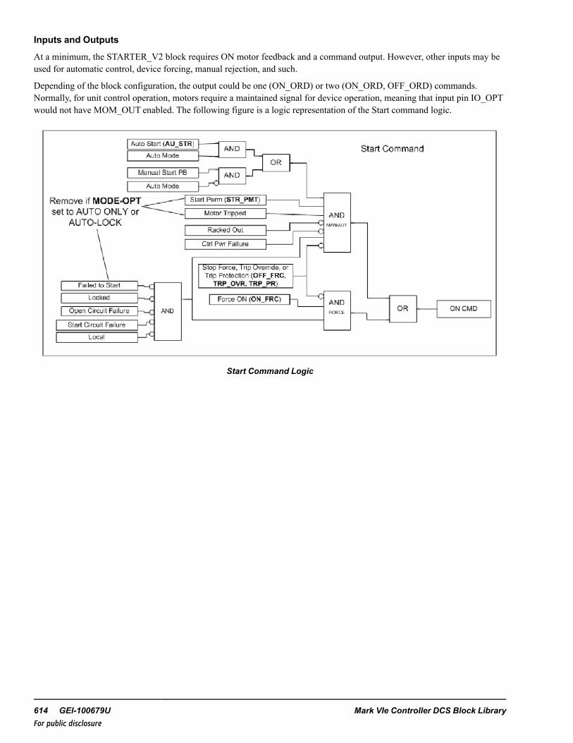
Inputs and Outputs
At a minimum, the STARTER_V2 block requires ON motor feedback and a command output. However, other inputs may beused for automatic control, device forcing, manual rejection, and such.
Depending of the block configuration, the output could be one (ON_ORD) or two (ON_ORD, OFF_ORD) commands.Normally, for unit control operation, motors require a maintained signal for device operation, meaning that input pin IO_OPTwould not have MOM_OUT enabled. The following figure is a logic representation of the Start command logic.
Start Command Logic
614 GEI-100679U Mark VIe Controller DCS Block LibraryFor public disclosure

For the Stop command, the logic varies slightly. As a fail-safe, the motor should always be ready to stop, so fewer permits aretied into the logic. The following figure is a logic representation of the Stop command logic.
Stop Command Logic
Maintained Command Motors Logic
Instruction Guide GEI-100679U 615For public disclosure

Pulsed Command Motors Logic
Additional outputs from this block indicate status, faults, failures, alarms, forces and overrides. Much of this information isdisplayed on the HMI faceplate.
Diagnostic Alarms and Faults
When an alarm is active, the STARTER_V2 block could have limited action of movement. For example, a Fail to Open alarminhibits the valve from opening again. In this case, a Fault Reset must be issued so that the valve can continue normaloperation. Some alarms are held true until the alarm is cleared, while others require a Fault Reset to remove the indication.The alarm may be reset at any time from the logic or using an operator push-button. However, the reset must occur after thealarm has been cleared. Otherwise the alarm will remain active. For Unit Controls, this Fault Reset pin may be connected tothe Master Reset variable. The alarms that may occur are as follows:
Fail to Start (FL_ST_A)+—when commanded ON, the motor fails to start within the allotted time (FL_ST_T ). The blocksends a stop command to the motor and the operator cannot reissue an ON command while the alarm is active. Reset thealarm.
Fail to Start (FL_ST_A)
Fail to Stop (FL_SP_A)+—when commanded OFF, the motor fails to stop within the allotted time (FL_SP_T). Theoperator cannot reissue an OFF command while the alarm is active. Reset the alarm.
616 GEI-100679U Mark VIe Controller DCS Block LibraryFor public disclosure
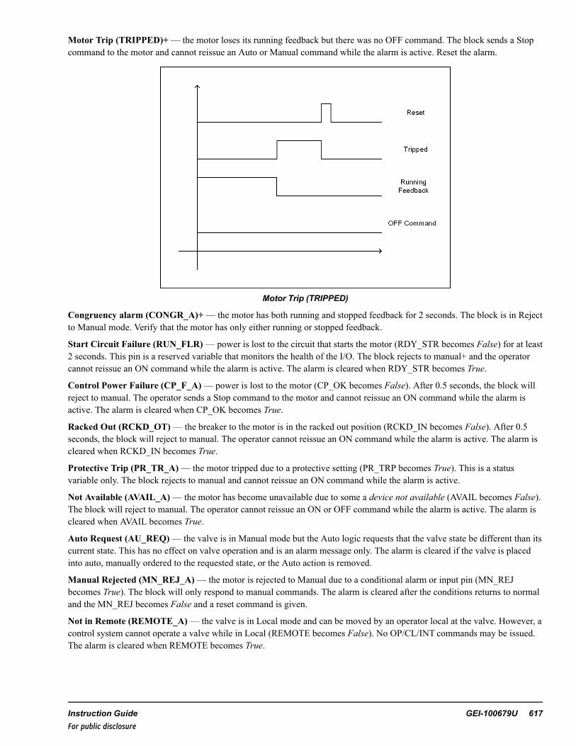
Motor Trip (TRIPPED)+— the motor loses its running feedback but there was no OFF command. The block sends a Stopcommand to the motor and cannot reissue an Auto or Manual command while the alarm is active. Reset the alarm.
Motor Trip (TRIPPED)
Congruency alarm (CONGR_A)+— the motor has both running and stopped feedback for 2 seconds. The block is in Rejectto Manual mode. Verify that the motor has only either running or stopped feedback.
Start Circuit Failure (RUN_FLR)— power is lost to the circuit that starts the motor (RDY_STR becomes False) for at least2 seconds. This pin is a reserved variable that monitors the health of the I/O. The block rejects to manual+ and the operatorcannot reissue an ON command while the alarm is active. The alarm is cleared when RDY_STR becomes True.
Control Power Failure (CP_F_A)— power is lost to the motor (CP_OK becomes False). After 0.5 seconds, the block willreject to manual. The operator sends a Stop command to the motor and cannot reissue an ON command while the alarm isactive. The alarm is cleared when CP_OK becomes True.
Racked Out (RCKD_OT)— the breaker to the motor is in the racked out position (RCKD_IN becomes False). After 0.5seconds, the block will reject to manual. The operator cannot reissue an ON command while the alarm is active. The alarm iscleared when RCKD_IN becomes True.
Protective Trip (PR_TR_A)— the motor tripped due to a protective setting (PR_TRP becomes True). This is a statusvariable only. The block rejects to manual and cannot reissue an ON command while the alarm is active.
Not Available (AVAIL_A)— the motor has become unavailable due to some a device not available (AVAIL becomes False).The block will reject to manual. The operator cannot reissue an ON or OFF command while the alarm is active. The alarm iscleared when AVAIL becomes True.
Auto Request (AU_REQ)— the valve is in Manual mode but the Auto logic requests that the valve state be different than itscurrent state. This has no effect on valve operation and is an alarm message only. The alarm is cleared if the valve is placedinto auto, manually ordered to the requested state, or the Auto action is removed.
Manual Rejected (MN_REJ_A)— the motor is rejected to Manual due to a conditional alarm or input pin (MN_REJbecomes True). The block will only respond to manual commands. The alarm is cleared after the conditions returns to normaland the MN_REJ becomes False and a reset command is given.
Not in Remote (REMOTE_A)— the valve is in Local mode and can be moved by an operator local at the valve. However, acontrol system cannot operate a valve while in Local (REMOTE becomes False). No OP/CL/INT commands may be issued.The alarm is cleared when REMOTE becomes True.
Instruction Guide GEI-100679U 617For public disclosure

Note + If the MODE_OPT is set to AUTO ONLYor AUTO-LOCK, this alarm will not affect automatic motor operation.However, the alarm will still become active under the given conditions.
Note If the MODE_OPT is set to a non-manual selection, the action will not take place.
Force and Override Control
During any condition, the motor may be forced to a state that bypasses normal operation. The force is driven from the ON_FRC or OFF_FRC pins in the logic. The motor will send the respective condition and remain there until the force is removed.However, an OFF force takes precedence over an ON force. For example, for the motor to be forced ON, there must be noTrip, OFF Force, Circuit Failure, or Fail to Start. Refer to the figure, Start Command Logic, to view the logic for a force.While a force condition is active, the motor may freely transfer from Auto to Manual mode following the normal permits.However, no manual command will supersede the force. Once the force is removed, the valve will continue normal operation.
A trip will supersede a force and turn the motor off. For example, irrelevant of any forces, the motor will immediately send aStop command. The trip override takes the utmost precedence. Upon entering a tripped state, the valve will be placed intoManual mode. Once the trip is removed and reset, the valve will remain in Manual mode until changed by the operator.
Although forces bypass normal permits, if the valve is locked, forces will have no effect on the block. The block must beremoved from Lock mode before any force affects block operation. Additionally, if the MODE_OPT is set to AUTO ONLYorAUTO-LOCK, the Trip Override pin will be disabled and will have no effect on the block.
618 GEI-100679U Mark VIe Controller DCS Block LibraryFor public disclosure

Permits
Due to the nature of auto and forcing action, permits are required for motor operation. Special device permits are built into theblocks, which may be enabled and disabled with certain pins in the block, as follows:
Note For basic operations, most of these permits will be disabled.
• Start− STR_PMT is True (STR_PMT is technically a UINT)− Motor not Failed to Start**+− Motor not Tripped**+− Breaker to motor not Racked Out− Motor not Control Power Fail− Motor not in Local− I/O ready to start Motor or not Run Circuit Failure**− I/O ready to Stop Motor or not Stop Circuit Failure**− Motor not in Lock mode− Breaker to motor not Protective Tripped− Motor not Tracking− Breaker to motor not Not Available− Motor not Forced OFF− Motor not Running− Motor not Trip Override+
• Stop− STP_PMT is True (STP_PMT is technically a UINT)− Motor not Failed to Stop**+− Motor not in Local− Motor not Forced ON− Motor not Control Power Fail− Motor not Tracking− Breaker to motor not Not Available− I/O ready to start Motor or not Run Circuit Failure**− I/O ready to Stop Motor or not Stop Circuit Failure**
• Start Force− Motor not Failed to Start**+− Motor not Tripped**+− Motor not in Local− Motor not in Lock mode− I/O ready to start Motor or not Run Circuit Failure**− Motor not Forced OFF− Motor not Trip Override+
• Stop Force− Motor not Failed to Stop**+− Motor not in Local− Motor not in Lock mode− I/O ready to Stop Motor or not Stop Circuit Failure**
• Trip Override+− None
Instruction Guide GEI-100679U 619For public disclosure

• Automatic Stop commands+− Motor Fail to Stop**− Motor Tripped**− Motor Control Power Fail− Breaker to motor Not Available− Motor in Local− Motor not Tracking
Note ** Indicates an alarm that is generated internal to the block. Otherwise, the permits are input pins to the block.
+ If the MODE_OPT is set to AUTO ONLYor AUTO-LOCK, these permissives are not required for operation.
Inputs
Name Global Description FunctionAU_SEL Auto Select Pulses the valve into auto (provided all permits are met)AU_ OP Auto Open Opens the valve (provided all permits are met); device must be in Auto
modeAU_CL Auto Close Auto closes the valve (provided all permits are met); device must be in
Auto modeAU_PMT Yes Auto permit Permit required for external logic to prevent the valve to enter Auto modeSTR_PMT Yes Start Permit Permit required for external logic to prevent the valve from startingSTP_PMT Yes Stop Permit Permit required for external logic to prevent the valve from stoppingAVAIL Motor Available Tied to the I/O that has the motor availably feedbackCP_OK Motor Control Power
OKTed to the I/O that has the motor control power
RDY_STR Ready to Start Motor I/O monitoring of the start command circuit to the motorRDY_STP Ready to Stop Motor I/O monitoring of the stop command circuit to the motorRCKD_IN Motor Breaker Racked Tied to the I/O that has the racked in status of the breakerREMOTE Motor in Remote Tied to the I/O that has the motor in remote statusTRP_OVR Trip Override Permit required for external logic to trip the motorPR_TRP Protective Trip Tied to the I/O that has the motor protective trip signalMN_REJ Yes Manual Rejection Permit required for external logic to manually reject the valveTK Yes Tracking TrackingLDLG_ORDER Yes Lead\lag order Indicates the lag order to the HMI screen (does not affect operation;
indication only)ON_INP Yes Running Feedback Connects to the running feedback of the motorOFF_INP Yes Stopped Feedback Connects to the stopped feedback of the motorOFF_FRC Yes Off Force Permit required for external logic to force off the motorON_FRC Yes On Force Permit required for external logic to force on the motorFAULT_RESET Fault Reset Permit required for external logic to reset alarms on the valve
620 GEI-100679U Mark VIe Controller DCS Block LibraryFor public disclosure
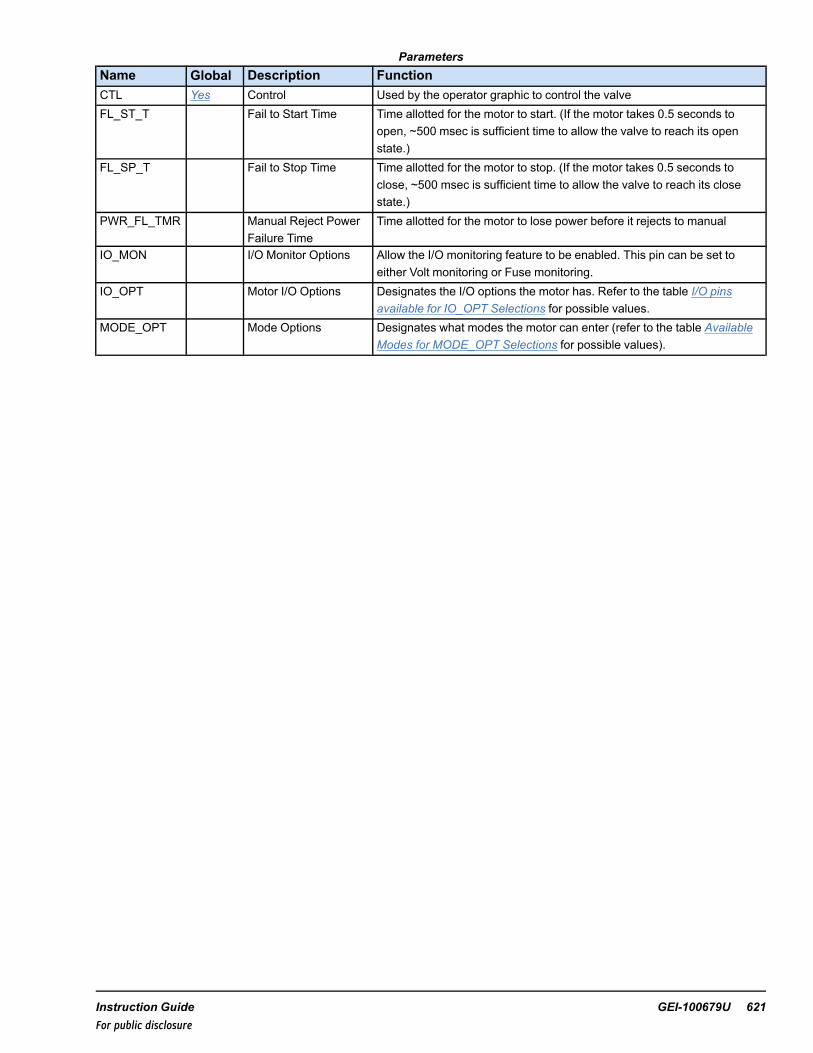
ParametersName Global Description FunctionCTL Yes Control Used by the operator graphic to control the valveFL_ST_T Fail to Start Time Time allotted for the motor to start. (If the motor takes 0.5 seconds to
open, ~500 msec is sufficient time to allow the valve to reach its openstate.)
FL_SP_T Fail to Stop Time Time allotted for the motor to stop. (If the motor takes 0.5 seconds toclose, ~500 msec is sufficient time to allow the valve to reach its closestate.)
PWR_FL_TMR Manual Reject PowerFailure Time
Time allotted for the motor to lose power before it rejects to manual
IO_MON I/O Monitor Options Allow the I/O monitoring feature to be enabled. This pin can be set toeither Volt monitoring or Fuse monitoring.
IO_OPT Motor I/O Options Designates the I/O options the motor has. Refer to the table I/O pinsavailable for IO_OPT Selections for possible values.
MODE_OPT Mode Options Designates what modes the motor can enter (refer to the table AvailableModes for MODE_OPT Selections for possible values).
Instruction Guide GEI-100679U 621For public disclosure

Outputs
Name Global DescriptionON_ORD On orderOFF_ORD Off orderAUTO_P Yes Auto propertyLOCK_P Yes Lock propertyAVAIL_P Yes Available propertyCP_OK_P Yes Control power OK propertyLDLG_P Yes Lead Lag propertyMOM_OUT_P Yes Momentary output propertyPR_TRP_P Yes Protective trip propertyRCKD_IN_P Yes Racked In propertyREM_P Yes Remote propertyOFF_INP_P Yes Off Feedback propertyVOLT_MON_P Yes Volt Monitoring I/O propertyFUSE_MON_P Yes Fuse Monitoring I/O propertyAUTO Yes Auto ModeON Yes OnOFF Yes OffPMT_AU Yes Auto permitPMT_STR Yes Start permitPMT_STP Yes Stop permitPMT_RUN Yes Run permitFRC_ON Yes ON forceFRC_OFF Yes OFF forceREJ_MN Yes Manual rejectionFAULT Yes FaultTMR Yes TimerAUTO_REQ Yes Auto requestMODE ModeFL_ST_A Yes Failed to start alarmFL_SP_A Yes Failed to stop alarmAVAIL_A Yes Motor not availableCP_F_A Yes Control power failureLOCAL Yes LocalLOCK Yes LockMN_REJ_A Yes Manual rejection alarmTRIPPED Yes TrippedPR_TR_A Yes Motor protective tripRACKD_OT Yes Breaker to motor racked outRUN_FLR Yes Run circuit failureSTP_FLR Yes Stop circuit failureCONGR_A Yes Congruency alarmOVR_TRP Yes Trip override
622 GEI-100679U Mark VIe Controller DCS Block LibraryFor public disclosure

Global VariablesPin Name Description Alarm Alarm
ClassEvent EGD Page External
AccessAP001 Feedwater pump Not Alarmed False $DEFAULT ReadOnlyAP001.AU_REQ Feedwater pump auto
requestAlarmed LVL_4 False $DEFAULT ReadOnly
AP001.AUTO Feedwater pump auto Not Alarmed False $DEFAULT ReadOnlyAP001.AUTO_P Feedwater pump auto
propertyNot Alarmed False $DEFAULT ReadOnly
AP001.AVAIL_A Feedwater pump notavailable
Alarmed LVL_4 False $DEFAULT ReadOnly
AP001.AVAIL_P Feedwater pump availableproperty
Not Alarmed False $DEFAULT ReadOnly
AP001.CONGR_A Feedwater pumpcongruency
Alarmed LVL_4 False $DEFAULT ReadOnly
AP001.CP_F_A Feedwater pump controlpower fail
Alarmed LVL_3 False $DEFAULT ReadOnly
AP001.CP_OK_P Feedwater pump controlpower property
Not Alarmed False $DEFAULT ReadOnly
AP001.CTL Feedwater pump Controlword
Not Alarmed False $DEFAULT ReadWrite
AP001.FAULT Feedwater pump faultindication
Not Alarmed False $DEFAULT ReadOnly
AP001.FL_SP_A Feedwater pump fail to stop Alarmed LVL_4 False $DEFAULT ReadOnlyAP001.FL_ST_A Feedwater pump fail to start Alarmed LVL_4 False $DEFAULT ReadOnlyAP001.FRC_OFF Feedwater pump force off Not Alarmed False $DEFAULT ReadOnlyAP001.FRC_OFFB Feedwater pump force off
block statusNot Alarmed False $DEFAULT ReadOnly
AP001.FRC_ON Feedwater pump force on Not Alarmed False $DEFAULT ReadOnlyAP001.FRC_ONB Feedwater pump force on
block statusNot Alarmed False $DEFAULT ReadOnly
AP001.FUSE_MON_P Feedwater pump output fusemonitor property
Not Alarmed False $DEFAULT ReadOnly
AP001.LDLG_ORDER Feedwater pump lead/lagorder
Not Alarmed False $DEFAULT ReadOnly
AP001.LDLG_P Feedwater pump lead/lagindication property
Not Alarmed False $DEFAULT ReadOnly
AP001.LOCAL Feedwater pump local mode Alarmed LVL_4 False $DEFAULT ReadOnlyAP001.LOCK Feedwater pump locked Not Alarmed True $DEFAULT ReadOnlyAP001.LOCK_P Feedwater pump lock
propertyNot Alarmed False $DEFAULT ReadOnly
AP001.MN_REJ_A Feedwater pump manualreject
Alarmed LVL_4 False $DEFAULT ReadOnly
AP001.MOM_OUT_P Feedwater pump momentaryout property
Not Alarmed False $DEFAULT ReadOnly
AP001.OFF Feedwater pump off/stopped Not Alarmed False $DEFAULT ReadOnlyAP001.OFF_INP_P Feedwater pump off property Not Alarmed False $DEFAULT ReadOnlyAP001.ON Feedwater pump on/running Not Alarmed False $DEFAULT ReadOnlyAP001.OVR_TRP Override trip - Override value Not Alarmed False $DEFAULT ReadOnlyAP001.OVR_TRPB Feedwater pump Override
trip block statusNot Alarmed False $DEFAULT ReadOnly
Instruction Guide GEI-100679U 623For public disclosure

Global Variables (continued)
Pin Name Description Alarm AlarmClass
Event EGD Page ExternalAccess
AP001.PBSTATE Feedwater pump last PBstate
Not Alarmed False $DEFAULT ReadOnly
AP001.PMT_AU Feedwater pump auto permit Not Alarmed False $DEFAULT ReadOnlyAP001.PMT_AUB Feedwater pump auto permit
bypass statusNot Alarmed False $DEFAULT ReadOnly
AP001.PMT_RUN Feedwater pump runpermitted
Not Alarmed False $DEFAULT ReadOnly
AP001.PMT_STP Feedwater pump Permit tostop
Not Alarmed False $DEFAULT ReadOnly
AP001.PMT_STPB Feedwater pump stop permitbypass status
Not Alarmed False $DEFAULT ReadOnly
AP001.PMT_STR Feedwater pump permit tostart
Not Alarmed False $DEFAULT ReadOnly
AP001.PMT_STRB Feedwater pump start permitbypass status
Not Alarmed False $DEFAULT ReadOnly
AP001.PR_TR_A Feedwater pump protectivetrip
Alarmed LVL_3 False $DEFAULT ReadOnly
AP001.PR_TRP_P Feedwater pump Protectivetrip property
Not Alarmed False $DEFAULT ReadOnly
AP001.RCKD_IN_P Feedwater pump racked INproperty
Not Alarmed False $DEFAULT ReadOnly
AP001.RCKD_OT Feedwater pump rackedOUT
Alarmed LVL_4 False $DEFAULT ReadOnly
AP001.REJ_MN Feedwater pump Manualreject
Not Alarmed False $DEFAULT ReadOnly
AP001.REJ_MNB Feedwater pump manualreject bypass status
Not Alarmed False $DEFAULT ReadOnly
AP001.REM_P Feedwater pump remoteproperty
Not Alarmed False $DEFAULT ReadOnly
AP001.RUN_FLR Feedwater pump run circuitfail
Alarmed LVL_4 False $DEFAULT ReadOnly
AP001.STP_FLR Feedwater pump stop circuitfail
Alarmed LVL_4 False $DEFAULT ReadOnly
AP001.TK Feedwater pump trackingenabled
Not Alarmed False $DEFAULT ReadOnly
AP001.TMR Feedwater pump run time Not Alarmed False $DEFAULT ReadOnlyAP001.TRIPPED Feedwater pump tripped Alarmed LVL_2 False $DEFAULT ReadOnlyAP001.VOLT_MON_P Feedwater pump Output volt
monitor propertyNot Alarmed False $DEFAULT ReadOnly
624 GEI-100679U Mark VIe Controller DCS Block LibraryFor public disclosure

HMI Configuration (CIMPLICITY)
The Object name for the HMI is the same as the Device name specified in the ToolboxST configuration.
Typical HMI Object for a STARTER_V2
STARTER_V2 Faceplate
Instruction Guide GEI-100679U 625For public disclosure

55 Starter Version 3 (STARTER_V3)Block Category: Device Control
The Starter Version 3 (STARTER_V3) block is a logic block that interfaces with the inputs and outputs of a motor starterdevice such as a pump, fan, or motorized device. Block configuration depends on the motor device hardware. The motor canhave multiple status feedback that ties into the block. Such feedback monitors breaker status, availability, or power to thecommand circuit. Additionally, the motor has the ability to receive two separate ON and OFF commands. These are pulsedcommands sent to the device. Also, the motor can receive one command. This command would be a maintained Trueparameter for running operation or a maintained False parameter for stopped operation. The block also has pins to monitorthe feedback for alarm detection.
Note This block has various enumerations that are configured for control operation.
The block may be configured to allow the motor to operate in Manual or Automatic (Auto) mode. The block enables the userto lock the device, thus disabling any operation while in the Lock mode. The block is used in conjunction with the PERMIT,FORCE, OVERRIDE, or LOGIC_BUILDER blocks to provide a complete and comprehensive device control. A predefinedHMI faceplate is available to provide the operator interface to the valve.
Note Refer to theMark VIe Controller Standard Block Library (GEI-100682), the Logic Builder (LOGIC_BUILDER) block.
The STARTER_V3 block is displayed in the following figure. However, not all variable pins are displayed because most areauto-hidden.
STARTER_V3 Block
626 GEI-100679U Mark VIe Controller DCS Block LibraryFor public disclosure

Block Configuration
Control Word
Control (CTL) is an enumeration set by the HMI operator for group control. The commands available from the HMI allowmanual and automatic push-button control capability. The group may be started or stopped in Manual mode by the ON_PB orOFF_PB commands, respectively. The command enumerations are defined in the following table.
CTL Enumerations
Enumeration CommandNO_CMD No command
AUTO_CMD Auto command
MANUAL_CMD Manual command
ON_CMD On cmd
OFF_CMD Off cmd
Mode of Operation (MODE_OPT)
Mode of Operation (MODE_OPT) parameter specifies the allowable modes of operation. The STARTER_V3 block may beconfigured to operate in Manual or Auto mode, and disallow any operation while in the Lock mode. Manual mode allowscommands from the operator interface, and automatic mode allows the control logic to command the motor. In either mode,there are inputs that may bypass or override the active mode of operation. Lock mode is intended to be used whenmaintenance work is being performed on the valve and the operator wants to prohibit any logic from energizing the valvesolenoid. The following table provides a visual presentation of the modes available based on the MODE_OPT selection.
Available Modes for MODE_OPT Selections
MODE OPTIONMANUAL AUTO LOCK LEAD/LAG
MODE_OPT MANUAL ONLY XMANUAL-AUTO X XMANUAL-LOCK X X
MANUAL-AUTO-LOCK X X XMANUAL-LDLG X X
MANUAL-AUTO-LDLG X X XMANUAL-LOCK-LDLG X X X
MANUAL-AUTO-LOCK-LDLG X X X XAUTO ONLY XAUTO-LOCK X XAUTO-LDLG X X
AUTO-LOCK-LDLG X X X
Instruction Guide GEI-100679U 627For public disclosure
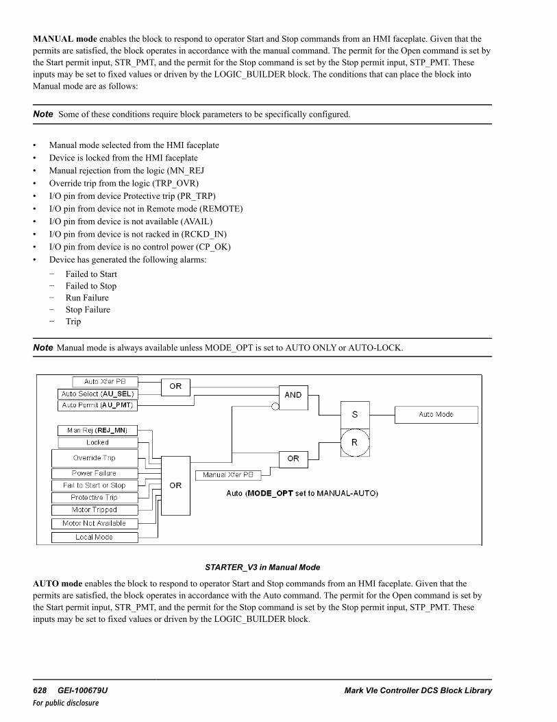
MANUAL mode enables the block to respond to operator Start and Stop commands from an HMI faceplate. Given that thepermits are satisfied, the block operates in accordance with the manual command. The permit for the Open command is set bythe Start permit input, STR_PMT, and the permit for the Stop command is set by the Stop permit input, STP_PMT. Theseinputs may be set to fixed values or driven by the LOGIC_BUILDER block. The conditions that can place the block intoManual mode are as follows:
Note Some of these conditions require block parameters to be specifically configured.
• Manual mode selected from the HMI faceplate• Device is locked from the HMI faceplate• Manual rejection from the logic (MN_REJ• Override trip from the logic (TRP_OVR)• I/O pin from device Protective trip (PR_TRP)• I/O pin from device not in Remote mode (REMOTE)• I/O pin from device is not available (AVAIL)• I/O pin from device is not racked in (RCKD_IN)• I/O pin from device is no control power (CP_OK)• Device has generated the following alarms:
− Failed to Start− Failed to Stop− Run Failure− Stop Failure− Trip
Note Manual mode is always available unless MODE_OPT is set to AUTO ONLYor AUTO-LOCK.
STARTER_V3 in Manual Mode
AUTO mode enables the block to respond to operator Start and Stop commands from an HMI faceplate. Given that thepermits are satisfied, the block operates in accordance with the Auto command. The permit for the Open command is set bythe Start permit input, STR_PMT, and the permit for the Stop command is set by the Stop permit input, STP_PMT. Theseinputs may be set to fixed values or driven by the LOGIC_BUILDER block.
628 GEI-100679U Mark VIe Controller DCS Block LibraryFor public disclosure

A selection ofMANUAL-AUTO mode provides manual and automatic functionality. A selection of AUTO or AUTO-LOCKprovides automatic functionality only. While residing in Auto mode, the block controls the valve based on external logic.Automated control from external logic interfaces to the AU_ST and AU_SP pins. Similar to the Manual mode, Auto actiononly operates with the proper Open and Close permits.
If AUTO ONLY mode is selected, the block will permanently reside in Auto mode.
IfMANUAL-AUTO mode is selected, only two conditions will transfer the block from Manual into Auto mode. Unlike thetransferring to Manual mode, certain permits must be satisfied to allow the valve to enter into Auto mode. This means that theblock is always able to enter Manual mode, but not always able to enter Auto mode. These conditions depend on the modeoptions selected for the block. All of the following conditions must be met for the block to enter Auto mode:
• No demand to transition to Manual mode• MODE_OPT must have AUTO in the selection• AUTO push-button from operator graphic or Auto select from logic (AU_SEL)
Lock mode may only be selected when the motor is in the OFF state. When placed in the Lock mode, the block forces theoutput so that the solenoid remains de-energized. Upon being placed in this mode, if currently in Auto mode, the block will bedeselected and indicates Manual mode. At this time, no open commands, forces, or overrides will be accepted. Uponremoving the lock, Manual mode will then be active. Similarly, AUTO ONLYand AUTO-LOCK (no open commands) willbe accepted. however, upon removal of Lock mode, the block will return to Auto mode.
Note At any time, the block may go into Lock mode as long as it is residing in its fail-safe position. Only the operator mayplace the block into Lock mode.
Lead/Lag mode selection is used for displays on the HMI object only, and does not change any block functionality. Enablingthe Lead/Lag mode allows logic to Write to a block input pin (LDLG_ORDER) that displays on the HMI faceplate themotor’s order with redundant devices (such as Lead, Lag 2, Lag 3, and so forth).
Modes of I/O
The STARTER_V3 block may be configured to allow input I/O states for the device. All I/O are digital or analog inputsreceived from the motor device. Each I/O input indicates the current status. Device status includes breaker racked in, devicenot available, and device in remote. Depending on the I/O properties enabled, the block will act differently. The I/Oconfigurations are specified by the I/O Options parameter, IO_OPT. The following table provides a visual presentation of themodes available based on the IO_OPT selection. Any enumeration of the I/O pins is available. However, not all are displayedbecause there are too many to display in the table.
Instruction Guide GEI-100679U 629For public disclosure

I/O Pins Available for IO_OPT Selections
I/OCtrl PwrOK
Remote Avail ProtectiveTrip
Racked In MomOut
OffInput
IO_OPT AVAIL XAVAIL-MOM_OUT X X
AVAIL-MOM_OUT-OFF_INP X X XAVAIL-OFF_INP X XAVAIL-PR_TRP X X
AVAIL-PR_TRP-MOM_OUT X X XAVAIL-PR_TRP-MOM_OUT-OFF_INP X X
CP_OK-REM X XCP_OK-REM-AVAIL X X
CP_OK-REM-AVAIL-MOM_OUT X X X XCP_OK-REM-AVAIL-MOM_OUT-OFF_INP_P X X X X X
CP_OK-REM-AVAIL-OFF_INP_P X X X X
Control Power OK (CP_OK)— allows the device I/O input from CP_OK. If this input goes False, a Control Power Failalarm is generated that trips the device and places it in Manual mode.
Remote (REMOTE)— allows the device I/O input from REMOTE. If this input goes False, then a Device in Local alarm isgenerated that places it in Manual mode.
Available (AVAIL)— allows the device I/O input from AVAIL. If this input goes False, then a Device not available alarm isgenerated that places it in Manual mode.
Protective Trip (PR_TRP)— allows the device I/O input from PR_TRP. If this input goes True, then a trip is issued to themotor.
Racked In (RCKD_IN)— allows the device I/O input from RCKD_IN. If this input goes False, then a Breaker racked outalarm is generated that places it in Manual mode.
Momentary Output— enables the block to be configured for either a pulse ON or OFF command from the control system tothe motor device, or it may be configured with a maintained ON command. If the Momentary On feature is enabled, the blockrequires two outputs, ON_ORD andOFF_ORD. If the Momentary On feature is disabled, then the block only requires oneoutput, ON_ORD.
Off Output (OFF_INP)— allows the device I/O input from OFF_INP. The block now has the ability to detect congruencyalarms if both ON_INP and OFF_INP are either True or False.
630 GEI-100679U Mark VIe Controller DCS Block LibraryFor public disclosure

Inputs and Outputs
At a minimum, the STARTER_V3 block requires ON motor feedback and a command output. However, other inputs may beused for automatic control, device forcing, manual rejection, and such. Depending of the block configuration, the output couldbe one (ON_ORD) or two (ON_ORD, OFF_ORD) commands. Normally, for unit control operation, motors require amaintained signal for device operation, meaning that input pin IO_OPTwould not have MOM_OUT enabled.
Start Command Logic
For the Stop command, the logic varies slightly. As a fail-safe, the motor should always be ready to stop, so fewer permits aretied into the logic.
Stop Command Logic
Instruction Guide GEI-100679U 631For public disclosure

Maintained Command Motors Logic
Pulsed Command Motors Logic
Additional outputs from this block indicate status, faults, failures, alarms, forces and overrides. Much of this information isdisplayed on the HMI faceplate.
632 GEI-100679U Mark VIe Controller DCS Block LibraryFor public disclosure

Alarms and Faults
When an alarm is active, the STARTER_V3 block could have limited action of movement. For example, a Fail to Open alarminhibits the valve from opening again. In this case, a Fault Reset must be issued so that the valve can continue normaloperation. Some alarms are held true until the alarm is cleared, while others require a Fault Reset to remove the indication.The alarm may be reset at any time from the logic or using an operator push-button. However, the reset must occur after thealarm has been cleared. Otherwise the alarm will remain active. For Unit Controls, this Fault Reset pin may be connected tothe Master Reset variable. The alarms that may occur are as follows:
Fail to Start (FL_ST_A)+—when commanded ON, the motor fails to start within the allotted time (FL_ST_T ). The blocksends a stop command to the motor and the operator cannot reissue an ON command while the alarm is active. Reset thealarm.
Fail to Start (FL_ST_A)
Fail to Stop (FL_SP_A)+—when commanded OFF, the motor fails to stop within the allotted time (FL_SP_T). Theoperator cannot reissue an OFF command while the alarm is active. Reset the alarm.
Motor Trip (TRIPPED)+— the motor loses its running feedback but there was no OFF command. The block sends a Stopcommand to the motor and cannot reissue an Auto or Manual command while the alarm is active. Reset the alarm.
Instruction Guide GEI-100679U 633For public disclosure

Motor Trip (TRIPPED)
Congruency alarm (CONGR_A)+— the motor has both running and stopped feedback for 2 seconds. The block is in Rejectto Manual mode. Verify that the motor has only either running or stopped feedback.
Start Circuit Failure (RUN_FLR)— power is lost to the circuit that starts the motor (RDY_STR becomes False) for at least2 seconds. This pin is a reserved variable that monitors the health of the I/O. The block rejects to manual+ and the operatorcannot reissue an ON command while the alarm is active. The alarm is cleared when RDY_STR becomes True.
Control Power Failure (CP_F_A)— power is lost to the motor (CP_OK becomes False). After 0.5 seconds, the block willreject to manual. The operator sends a Stop command to the motor and cannot reissue an ON command while the alarm isactive. The alarm is cleared when CP_OK becomes True.
Racked Out (RCKD_OT)— the breaker to the motor is in the racked out position (RCKD_IN becomes False). After 0.5seconds, the block will reject to manual. The operator cannot reissue an ON command while the alarm is active. The alarm iscleared when RCKD_IN becomes True.
Protective Trip (PR_TR_A)— the motor tripped due to a protective setting (PR_TRP becomes True). This is a statusvariable only. The block rejects to manual and cannot reissue an ON command while the alarm is active.
Not Available (AVAIL_A)— the motor has become unavailable due to some a device not available (AVAIL becomes False).The block will reject to manual. The operator cannot reissue an ON or OFF command while the alarm is active. The alarm iscleared when AVAIL becomes True.
Auto Request (AU_REQ)— the valve is in Manual mode but the Auto logic requests that the valve state be different than itscurrent state. This has no effect on valve operation and is an alarm message only. The alarm is cleared if the valve is placedinto auto, manually ordered to the requested state, or the Auto action is removed.
Manual Rejected (MN_REJ_A)— the motor is rejected to Manual due to a conditional alarm or input pin (MN_REJbecomes True). The block will only respond to manual commands. The alarm is cleared after the conditions returns to normaland the MN_REJ becomes False and a reset command is given.
Not in Remote (REMOTE_A)— the valve is in Local mode and can be moved by an operator local at the valve. However, acontrol system cannot operate a valve while in Local (REMOTE becomes False). No OP/CL/INT commands may be issued.The alarm is cleared when REMOTE becomes True.
Note + If the MODE_OPT is set to AUTO ONLYor AUTO-LOCK, this alarm will not affect automatic motor operation.However, the alarm will still become active under the given conditions.
634 GEI-100679U Mark VIe Controller DCS Block LibraryFor public disclosure

Note If the MODE_OPT is set to a non-manual selection, the action will not take place.
Force and Override Control
During any condition, the motor may be forced to a state that bypasses normal operation. The force is driven from the ON_FRC or OFF_FRC pins in the logic. The motor will send the respective condition and remain there until the force is removed.However, an OFF force takes precedence over an ON force. For example, for the motor to be forced ON, there must be noTrip, OFF Force, Circuit Failure, or Fail to Start. While a force condition is active, the motor may freely transfer from Autoto Manual mode following the normal permits. However, no manual command will supersede the force. Once the force isremoved, the valve will continue normal operation.
A trip will supersede a force and turn the motor off. For example, irrelevant of any forces, the motor will immediately send aStop command. The trip override takes the utmost precedence. Upon entering a tripped state, the valve will be placed intoManual mode. Once the trip is removed and reset, the valve will remain in Manual mode until changed by the operator.
Note Refer to the figure Start Command Logic to view the logic for a force.
Although forces bypass normal permits, if the valve is locked, forces will have no effect on the block. The block must beremoved from Lock mode before any force affects block operation. Additionally, if the MODE_OPT is set to AUTO ONLYorAUTO-LOCK, the Trip Override pin will be disabled and will have no effect on the block.
Instruction Guide GEI-100679U 635For public disclosure

Permits
Due to the nature of auto and forcing action, permits are required for motor operation. Special device permits are built into theblocks, which may be enabled and disabled with certain pins in the block, as follows:
Note For basic operations, most of these permits will be disabled.
• Start− STR_PMT is True (STR_PMT is technically a UINT)− Motor not Failed to Start**+− Motor not Tripped**+− Breaker to motor not Racked Out− Motor not Control Power Fail− Motor not in Local− I/O ready to start Motor or not Run Circuit Failure**− I/O ready to Stop Motor or not Stop Circuit Failure**− Motor not in Lock mode− Breaker to motor not Protective Tripped− Motor not Tracking− Breaker to motor not Not Available− Motor not Forced OFF− Motor not Running− Motor not Trip Override+
• Stop− STP_PMT is True (STP_PMT is technically a UINT)− Motor not Failed to Stop**+− Motor not in Local− Motor not Forced ON− Motor not Control Power Fail− Motor not Tracking− Breaker to motor not Not Available− I/O ready to start Motor or not Run Circuit Failure**− I/O ready to Stop Motor or not Stop Circuit Failure**
• Start Force− Motor not Failed to Start**+− Motor not Tripped**+− Motor not in Local− Motor not in Lock mode− I/O ready to start Motor or not Run Circuit Failure**− Motor not Forced OFF− Motor not Trip Override+
• Stop Force− Motor not Failed to Stop**+− Motor not in Local− Motor not in Lock mode− I/O ready to Stop Motor or not Stop Circuit Failure**
• Trip Override+− None
636 GEI-100679U Mark VIe Controller DCS Block LibraryFor public disclosure

• Automatic Stop commands+− Motor Fail to Stop**− Motor Tripped**− Motor Control Power Fail− Breaker to motor Not Available− Motor in Local− Motor not Tracking
Note ** Indicates an alarm that is generated internal to the block. Otherwise, the permits are input pins to the block.
+ If the MODE_OPT is set to AUTO ONLYor AUTO-LOCK, these permissives are not required for operation.
Inputs
Name Global Description FunctionAU_SEL Auto Select Pulses the valve into auto (provided all permits are met)AU_ OP Auto Open Opens the valve (provided all permits are met); device must be in Auto
modeAU_CL Auto Close Auto closes the valve (provided all permits are met); device must be in
Auto modeAU_PMT Yes Auto Permit Permit required for external logic to prevent the valve to enter Auto modeSTR_PMT Yes Start Permit Permit required for external logic to prevent the valve from startingSTP_PMT Yes Stop Permit Permit required for external logic to prevent the valve from stoppingAVAIL Motor Available Tied to the I/O that has the motor availably feedbackCP_OK Motor Control Power
OKTed to the I/O that has the motor control power
RDY_STR Ready to Start Motor I/O monitoring of the start command circuit to the motorRDY_STP Ready to Stop Motor I/O monitoring of the stop command circuit to the motorRCKD_IN Motor Breaker Racked Tied to the I/O that has the racked in status of the breakerREMOTE Motor in Remote Tied to the I/O that has the motor in remote statusTRP_OVR Yes Trip Override Permit required for external logic to trip the motorPR_TRP Protective Trip Tied to the I/O that has the motor protective trip signalMN_REJ Yes Manual Rejection Permit required for external logic to manually reject the valveTK Yes Tracking TrackingLDLG_ORDER
Yes Lead\lag order Indicates the lag order to the HMI screen (does not affect operation;indication only)
ON_INP Running Feedback Connects to the running feedback of the motorOFF_INP Stopped Feedback Connects to the stopped feedback of the motorOFF_FRC Yes Off Force Permit required for external logic to force off the motorON_FRC Yes On Force Permit required for external logic to force on the motorFAULT_RESET
Fault Reset Permit required for external logic to reset alarms on the valve
Instruction Guide GEI-100679U 637For public disclosure

ParametersName Global Description FunctionCTL Yes Control Used by the operator graphic to control the valveFL_ST_T Fail to Start Time Time allotted for the motor to start. (If the motor takes 0.5 seconds to open,
~500 msec is sufficient time to allow the valve to reach its open state.)FL_SP_T Fail to Stop Time Time allotted for the motor to stop. (If the motor takes 0.5 seconds to
close, ~500 msec is sufficient time to allow the valve to reach its closestate.)
PWR_FL_TMR
Manual Reject PowerFailure Time
Time allotted for the motor to lose power before it rejects to manual
IO_MON I/O Monitor Options Allow the I/O monitoring feature to be enabled. This pin can be set toeither Volt monitoring or Fuse monitoring.
IO_OPT Motor I/O Options Designates the I/O options I/O options the motor has.MODE_OPT Mode Options Designates whatmodes the motor can enter.
638 GEI-100679U Mark VIe Controller DCS Block LibraryFor public disclosure
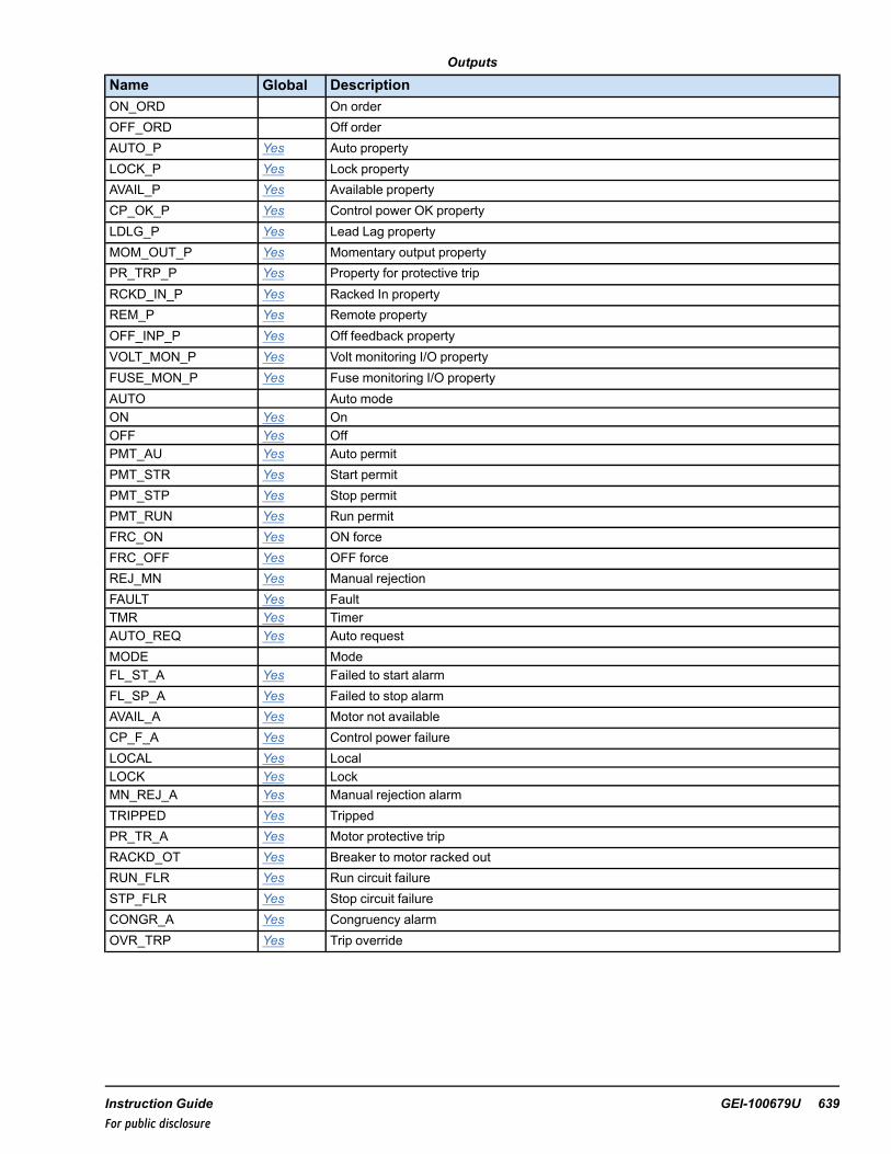
Outputs
Name Global DescriptionON_ORD On orderOFF_ORD Off orderAUTO_P Yes Auto propertyLOCK_P Yes Lock propertyAVAIL_P Yes Available propertyCP_OK_P Yes Control power OK propertyLDLG_P Yes Lead Lag propertyMOM_OUT_P Yes Momentary output propertyPR_TRP_P Yes Property for protective tripRCKD_IN_P Yes Racked In propertyREM_P Yes Remote propertyOFF_INP_P Yes Off feedback propertyVOLT_MON_P Yes Volt monitoring I/O propertyFUSE_MON_P Yes Fuse monitoring I/O propertyAUTO Auto modeON Yes OnOFF Yes OffPMT_AU Yes Auto permitPMT_STR Yes Start permitPMT_STP Yes Stop permitPMT_RUN Yes Run permitFRC_ON Yes ON forceFRC_OFF Yes OFF forceREJ_MN Yes Manual rejectionFAULT Yes FaultTMR Yes TimerAUTO_REQ Yes Auto requestMODE ModeFL_ST_A Yes Failed to start alarmFL_SP_A Yes Failed to stop alarmAVAIL_A Yes Motor not availableCP_F_A Yes Control power failureLOCAL Yes LocalLOCK Yes LockMN_REJ_A Yes Manual rejection alarmTRIPPED Yes TrippedPR_TR_A Yes Motor protective tripRACKD_OT Yes Breaker to motor racked outRUN_FLR Yes Run circuit failureSTP_FLR Yes Stop circuit failureCONGR_A Yes Congruency alarmOVR_TRP Yes Trip override
Instruction Guide GEI-100679U 639For public disclosure

Global VariablesPin Name Description Alarm Alarm
ClassEvent EGD Page External
AccessAP001 Feedwater pump Not
AlarmedFalse $DEFAULT ReadOnly
AP001.AU_REQ Feedwater pumpauto request
Not Alarmed False $DEFAULT ReadOnly
AP001.AUTO Feedwater pumpauto
NotAlarmed
True $DEFAULT ReadOnly
AP001.AUTO_P Feedwater pumpauto property
NotAlarmed
False $DEFAULT ReadOnly
AP001.AVAIL_A Feedwater pumpnot available
Alarmed LVL_3 False $DEFAULT ReadOnly
AP001.AVAIL_P Feedwater pumpavailable property
NotAlarmed
False $DEFAULT ReadOnly
AP001.CONGR_A Feedwater pumpcongruency
Alarmed Alert False $DEFAULT ReadOnly
AP001.CP_F_A Feedwater pumpcontrol power fail
Alarmed Alert False $DEFAULT ReadOnly
AP001.CP_OK_P Feedwater pumpcontrol powerproperty
NotAlarmed
False $DEFAULT ReadOnly
AP001.CTL Feedwater pumpControl word
NotAlarmed
False $DEFAULT ReadWrite
AP001.FAULT Feedwater pumpfault indication
NotAlarmed
False $DEFAULT ReadOnly
AP001.FL_SP_A Feedwater pump failto stop
Alarmed LVL_3 False $DEFAULT ReadOnly
AP001.FL_ST_A Feedwater pump failto start
Alarmed LVL_3 False $DEFAULT ReadOnly
AP001.FRC_OFF Feedwater pumpforce off
NotAlarmed
True $DEFAULT ReadOnly
AP001.FRC_OFFB Feedwater pumpforce off blockstatus
NotAlarmed
False $DEFAULT ReadOnly
AP001.FRC_ON Feedwater pumpforce on
NotAlarmed
True $DEFAULT ReadOnly
AP001.FRC_ONB Feedwater pumpforce on blockstatus
NotAlarmed
False $DEFAULT ReadOnly
AP001.FUSE_MON_P Feedwater pumpoutput fuse monitorproperty
NotAlarmed
False $DEFAULT ReadOnly
AP001.LDLG_ORDER Feedwater pumplead/lag order
NotAlarmed
False $DEFAULT ReadOnly
AP001.LDLG_P Feedwater pumplead/lag indicationproperty
NotAlarmed
False $DEFAULT ReadOnly
AP001.LOCAL Feedwater pumplocal mode
Not Alarmed True $DEFAULT ReadOnly
AP001.LOCK Feedwater pumplocked
NotAlarmed
True $DEFAULT ReadOnly
640 GEI-100679U Mark VIe Controller DCS Block LibraryFor public disclosure

Global Variables (continued)
Pin Name Description Alarm AlarmClass
Event EGD Page ExternalAccess
AP001.LOCK_P Feedwater pumplock property
NotAlarmed
False $DEFAULT ReadOnly
AP001.MN_REJ_A Feedwater pumpmanual reject
Alarmed LVL_3 False $DEFAULT ReadOnly
AP001.MOM_OUT_P Feedwater pumpmomentary outproperty
NotAlarmed
False $DEFAULT ReadOnly
AP001.OFF Feedwater pumpoff/stopped
NotAlarmed
False $DEFAULT ReadOnly
AP001.OFF_INP_P Feedwater pump offproperty
NotAlarmed
False $DEFAULT ReadOnly
AP001.ON Feedwater pumpon/running
NotAlarmed
False $DEFAULT ReadOnly
AP001.OVR_TRP Override trip -Override value
NotAlarmed
True $DEFAULT ReadOnly
AP001.OVR_TRPB Feedwater pumpoverride trip blockstatus
NotAlarmed
False $DEFAULT ReadOnly
AP001.PBSTATE Feedwater pumplast PB state
NotAlarmed
False $DEFAULT ReadOnly
AP001.PMT_AU Feedwater pumpauto permit
NotAlarmed
False $DEFAULT ReadOnly
AP001.PMT_AUB Feedwater pumpauto permit bypassstatus
NotAlarmed
False $DEFAULT ReadOnly
AP001.PMT_RUN Feedwater pumprun permitted
NotAlarmed
False $DEFAULT ReadOnly
AP001.PMT_STP Feedwater pumppermit to stop
NotAlarmed
False $DEFAULT ReadOnly
AP001.PMT_STPB Feedwater pumpstop permit bypassstatus
NotAlarmed
False $DEFAULT ReadOnly
AP001.PMT_STR Feedwater pumppermit to start
NotAlarmed
False $DEFAULT ReadOnly
AP001.PMT_STRB Feedwater pumpstart permit bypassstatus
NotAlarmed
False $DEFAULT ReadOnly
AP001.PR_TR_A Feedwater pumpprotective trip
Alarmed Alert False $DEFAULT ReadOnly
AP001.PR_TRP_P Feedwater pumpprotective tripproperty
NotAlarmed
False $DEFAULT ReadOnly
AP001.RCKD_IN_P Feedwater pumpracked IN property
NotAlarmed
False $DEFAULT ReadOnly
AP001.RCKD_OT Feedwater pumpracked OUT
Not Alarmed True $DEFAULT ReadOnly
AP001.REJ_MN Feedwater pumpManual reject
NotAlarmed
False $DEFAULT ReadOnly
Instruction Guide GEI-100679U 641For public disclosure

Global Variables (continued)
Pin Name Description Alarm AlarmClass
Event EGD Page ExternalAccess
AP001.REJ_MNB Feedwater pumpmanual rejectbypass status
NotAlarmed
False $DEFAULT ReadOnly
AP001.REM_P Feedwater pumpremote property
NotAlarmed
False $DEFAULT ReadOnly
AP001.RUN_FLR Feedwater pumprun circuit fail
Alarmed Alert False $DEFAULT ReadOnly
AP001.STP_FLR Feedwater pumpstop circuit fail
Alarmed Alert False $DEFAULT ReadOnly
AP001.TK Feedwater pumptracking enabled
NotAlarmed
False $DEFAULT ReadOnly
AP001.TMR Feedwater pumprun time
NotAlarmed
False $DEFAULT ReadOnly
AP001.TRIPPED Feedwater pumptripped
Alarmed LVL_2 False $DEFAULT ReadOnly
AP001.VOLT_MON_P Feedwater pumpoutput volt monitorproperty
NotAlarmed
False $DEFAULT ReadOnly
642 GEI-100679U Mark VIe Controller DCS Block LibraryFor public disclosure

HMI Configuration (CIMPLICITY)
The Object name for the HMI is the same as the Device name specified in the ToolboxST configuration.
Click Off to display the STARTER faceplate.
STARTER_V3
Typical HMI Object for a STARTER_V3
STARTER_V3 Faceplate
Instruction Guide GEI-100679U 643For public disclosure

56 Steamtable (STEAMTABLE)Block Category: Equations and Conversions
The Steamtable (STEAMTABLE) block extracts thermodynamic properties of water and steam according to state regioncalculations.
Note The steamtable lookup uses the sum of IN_P and IN_PATM (absolute pressure). The sum of IN_P and IN_PATM mustbe in the range of 0.8 - 3200 PSIA (0.0552 - 220.6322 bara).
STEAMTABLE Block
RegionNames
Descriptionof Region
FUNC(Enumerations)
Description ofEnumeration
MEAS_SYS ENGLISH S.I.
LiquidWater
This regionrepresents thezone wherewater is in aliquid state.
LIQ_WTR_PT Liquid Water (Pressure andTemperature as inputs):Calculates Enthalpy,Entropy and SpecificVolume from AtmosphericPressure, Gauge Pressureand Temperature.
IN_T 32 – 705.1°F 0 - 374°CIN_P PSIg bargIN_PATM PSIg bargOUT_ENTH BTU/lb kJ/kgOUT_ENTR BTU/(lb*°R) kJ/(kg*K)OUT_VOL ft3/lb m3/kgOUT_DENS lb/ft3 kg/m3
LIQ_WTR_PH Liquid Water (Pressure andEnthalpy as inputs):Calculates Temperaturefrom AtmosphericPressure, Gauge Pressureand Enthalpy.
IN_ENTH 0 - 893.85BTU/lb
0 -2079.0951kJ/kg
IN_P PSIg bargIN_PATM PSIg bargOUT_T °F °C
SaturationLiquidCurve
This regionrepresents thezone wherewater is in aliquid state.
SAT_LIQ_T Saturation Liquid Curve(Temperature as input):Calculates Enthalpy,Entropy, Specific Volumeand Gauge Pressure fromAtmospheric Pressure andTemperature.
IN_T 95 – 705.1°F 35 - 374°C
IN_PATM PSIg bargOUT_ENTH BTU/lb kJ/kgOUT_ENTR BTU/(lb*°R) kJ/(kg*K)OUT_VOL ft3/lb m3/kgOUT_P PSIg bargOUT_DENS lb/ft3 kg/m3
644 GEI-100679U Mark VIe Controller DCS Block LibraryFor public disclosure

RegionNames
Descriptionof Region
FUNC(Enumerations)
Description ofEnumeration
MEAS_SYS ENGLISH S.I.
SAT_LIQ_P Saturation Liquid Curve(Pressure as input):Calculates Enthalpy,Entropy, Specific Volumeand Temperature fromAtmospheric Pressure andGauge Pressure.
IN_P PSIg bargIN_PATM PSIg bargOUT_ENTH BTU/lb kJ/kgOUT_ENTR BTU/(lb*°R) kJ/(kg*K)OUT_VOL ft3/lb m3/kgOUT_T °F °COUT_DENS lb/ft3 kg/m3
SAT_LIQ_H Saturation Liquid Curve(Enthalpy as input):Calculates Temperature,Entropy, Specific Volumeand Gauge Pressure fromAtmospheric Pressure andEnthalpy.
IN_ENTH 62.389 -893.85BTU/lb
145.117 -2079.0951kJ/kg
IN_PATM PSIg bargOUT_T °F °COUT_ENTR BTU/(lb*°R) kJ/(kg*K)OUT_VOL ft3/lb m3/kgOUT_P PSIg bargOUT_DENS lb/ft3 kg/m3
SaturationVaporCurve
This regionrepresents thecurve ofliquid-vaporand steammixing zone.
SAT_VAP_T Saturation Vapor Curve(Temperature as input):Calculates Enthalpy,Entropy, Specific Volumeand Gauge Pressure fromAtmospheric Pressureand Temperature.
IN_T 95 – 705.1°F 35 - 374°C
IN_PATM PSIg barg
OUT_ENTH BTU/lb kJ/kg
OUT_ENTR BTU/(lb*°R) kJ/(kg*K)
OUT_VOL ft3/lb m3/kg
OUT_P PSIg barg
OUT_DENS lb/ft3 kg/m3
SAT_VAP_P Saturation Vapor Curve(Pressure as input):Calculates Enthalpy,Entropy, Specific Volumeand Temperature fromAtmospheric Pressureand Gauge Pressure.
IN_P PSIg barg
IN_PATM PSIg barg
OUT_ENTH BTU/lb kJ/kg
OUT_ENTR BTU/(lb*°R) kJ/(kg*K)
OUT_VOL ft3/lb m3/kg
OUT_T °F °C
OUT_DENS lb/ft3 kg/m3
Instruction Guide GEI-100679U 645For public disclosure

RegionNames
Descriptionof Region
FUNC(Enumerations)
Description ofEnumeration
MEAS_SYS
ENGLISH S.I.
SAT_VAP_S Saturation Vapor Curve(Entropy as input):Calculates Temperature,Enthalpy, Specific Volumeand Gauge Pressure fromAtmospheric Pressure andEntropy.
IN_ENTR 1.0569 -1.9965BTU/(lb*°R)
4.425 -8.359kJ/(kg*K)
IN_PATM PSIg bargOUT_T °F °COUT_ENTH BTU/(lb*°R) kJ/(kg*K)OUT_VOL ft3/lb m3/kgOUT_P PSIg bargOUT_DENS lb/ft3 kg/m3
SuperHeatedSteam
This regionrepresentsthe zonewhere wateris in a steamstate.
SH_STM_PT SuperHeated Steam(Pressure andTemperature as inputs):Calculates Enthalpy,Entropy and SpecificVolume fromAtmospheric Pressure,Gauge Pressure andTemperature.
IN_T 95 -1500°F 35 - 816°C
IN_P PSIg barg
IN_PATM PSIg barg
OUT_ENTH BTU/lb kJ/kg
OUT_ENTR BTU/(lb*°R) kJ/(kg*K)
OUT_VOL ft3/lb m3/kg
OUT_DENS lb/ft3 kg/m3
SH_STM_PH SuperHeated Steam(Pressure and Enthalpyas inputs): CalculatesTemperature fromAtmospheric Pressure,Gauge Pressure andEnthalpy.
IN_ENTH 1102.3 -1762BTU/lb
2563.95 -4098.41kJ/kg
IN_P PSIg barg
IN_PATM PSIg barg
OUT_T °F °C
646 GEI-100679U Mark VIe Controller DCS Block LibraryFor public disclosure

This block propagates quality status if the status operations are enabled.
Block status modifications:
• Due to the nature of the steam table, some input combinations may lead to a result outside of the selected steamtableregion. This results in an output status of NOT_LIMITED-LAST_USABLE_VALUE-UNCERTAIN [68].
• If the input temperature or pressure value exceeds the range in the given table above, the output status will be eitherLOW_LIMITED-LAST_USABLE_VALUE-UNCERTAIN [69] or HIGH_LIMITED-LAST_USABLE_VALUE-UNCERTAIN [70].
For further details on Relational blocks, refer to the Mark VIe Controller Standard Block Library (GEI-100682), the StatusMonitoring (STATUS_MONITORING) block.
Instruction Guide GEI-100679U 647For public disclosure

Inputs
Name Description Data Type Initial Value Visibility Interface TypeFUNC Steam Function UINT LIQ_WTR_PT Parameter Value OnlyIN_ENTH Input Enthalpy REAL† 0 Always Value with StatusIN_ENTR Input Entropy REAL† 0 Always Value with StatusIN_P Input Pressure REAL† 0 Always Value with StatusIN_PATM Input atmospheric pressure REAL 14.696 Parameter Value OnlyIN_T Input steam temperature REAL† 150 Always Value with StatusMEAS_SYS Measurement system UINT (ENUM) English Parameter Value Only† Value with Status (if status option is enabled)
Outputs
Name Description Data Type Initial Value Visibility Interface TypeOUT_DENS Output density REAL† N/A Always Value with StatusOUT_ENTH Output Enthalpy REAL† N/A Always Value with StatusOUT_ENTR Output Entropy REAL† N/A Always Value with StatusOUT_P Output pressure REAL† N/A Always Value with StatusOUT_T Output temperature REAL† N/A Always Value with StatusOUT_VOL Output specific volume REAL† N/A Always Value with Status† Value with Status (if status option is enabled)
648 GEI-100679U Mark VIe Controller DCS Block LibraryFor public disclosure

57 Superheat of Steam (SUPERHEAT)Block Category: Equations and Conversions
The Superheat of Steam (SUPERHEAT) block calculates the amount of superheat of steam for a given temperature, IN_T,pressure, IN_P, and atmospheric pressure, IN_PATM.
SUPERHEAT Block
Ranges/Units
MEAS_SYS English S.I.IN_P PSIg bargIN_T °F °CIN_PATM PSI barOUT °F °C
The steam table lookup uses the sum of IN_P and IN_PATM (absolutepressure). The sum of IN_P and IN_PATM must be in the range of 0.8 -3200 PSIA (0.0552 - 220.6322 bara).
The saturation temperature is subtracted from the steam temperature to calculate the amount of superheat, which is OUT. Theuser can set a superheat setpoint, SET, and a hysteresis value, HYST. When the amount of superheat is greater than thesetpoint, SET, the output flag SH is set to True. When the amount of superheat OUT goes below SET – HYST, SH is set toFalse.
Instruction Guide GEI-100679U 649For public disclosure
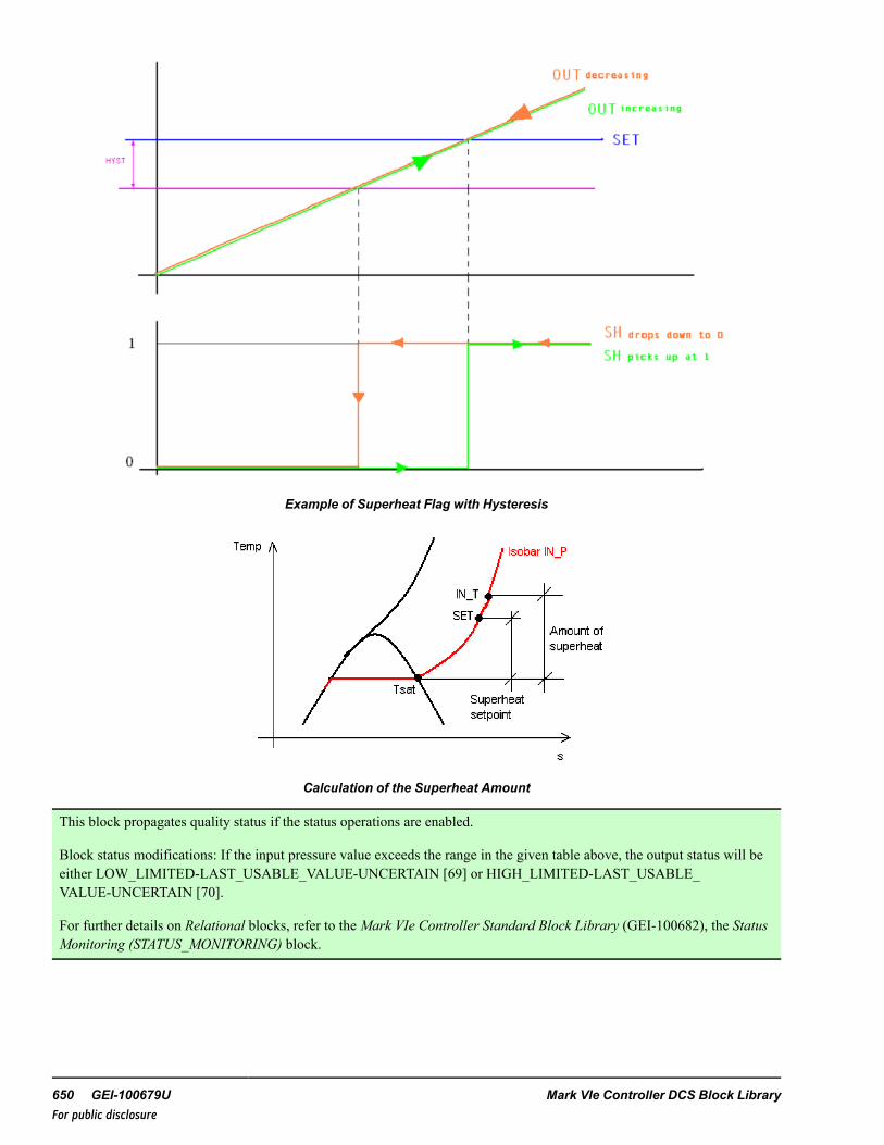
Example of Superheat Flag with Hysteresis
Calculation of the Superheat Amount
This block propagates quality status if the status operations are enabled.
Block status modifications: If the input pressure value exceeds the range in the given table above, the output status will beeither LOW_LIMITED-LAST_USABLE_VALUE-UNCERTAIN [69] or HIGH_LIMITED-LAST_USABLE_VALUE-UNCERTAIN [70].
For further details on Relational blocks, refer to the Mark VIe Controller Standard Block Library (GEI-100682), the StatusMonitoring (STATUS_MONITORING) block.
650 GEI-100679U Mark VIe Controller DCS Block LibraryFor public disclosure
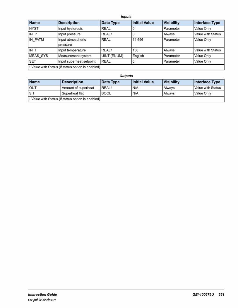
Inputs
Name Description Data Type Initial Value Visibility Interface TypeHYST Input hysteresis REAL 0 Parameter Value OnlyIN_P Input pressure REAL† 0 Always Value with StatusIN_PATM Input atmospheric
pressureREAL 14.696 Parameter Value Only
IN_T Input temperature REAL† 150 Always Value with StatusMEAS_SYS Measurement system UINT (ENUM) English Parameter Value OnlySET Input superheat setpoint REAL 0 Parameter Value Only† Value with Status (if status option is enabled)
Outputs
Name Description Data Type Initial Value Visibility Interface TypeOUT Amount of superheat REAL† N/A Always Value with StatusSH Superheat flag BOOL N/A Always Value Only† Value with Status (if status option is enabled)
Instruction Guide GEI-100679U 651For public disclosure

58 Pulse Totalizer (TOTALIZER_PULSE)Block Category: Timers and Counters
The TOTALIZER_PULSE block accumulates each rising edge of IN, if RUN is True. The accumulated value is transferred toOUT. IN and OUT are in engineering units. The GAIN parameter is used to equate the meaning of each pulse to outputengineering. If PRESET is True, OUT is equal to PR_VAL x GAIN. OUT is initialized to zero when RESET becomes True.OUT_LAST stores the last value of OUT prior to the initiation of RESET. RESET has the highest priority followed byPRESET and RUN.
TOTALIZER_PULSE Block
This block propagates quality status if the status operations are enabled.
Block status modifications:
• OUT status is propagated from either IN status or PR_VAL status, whichever is active. When IN is selected the OUTstatus defaults NOT_LIMITED-GOODNC [128] because IN is a Boolean.
• If PRESET is True, OUT status = PR_VAL status.For further details on Selection blocks, refer to the Mark VIe Controller Standard Block Library (GEI-100682), the StatusMonitoring (STATUS_MONITORING) block.
Inputs
Name Description Data Type Initial Value Visibility Interface TypeGAIN Accumulator Gain REAL 1 Parameter Value OnlyIN Pulse inputs BOOL N/A Always Value OnlyPR_VAL Initialize value REAL 0 Parameter Value with StatusPRESET Initialize command BOOL False Always Value OnlyRESET Accumulator Reset BOOL False Always Value OnlyRUN Accumulator run
commandBOOL False Always Value Only
Outputs
Name Description Data Type Initial Value Visibility Interface TypeOUT Integrator Output LREAL† N/A Always Value with StatusOUT_LST Output value at Reset LREAL† N/A Always Value with Status† Value with Status (if status option is enabled)
652 GEI-100679U Mark VIe Controller DCS Block LibraryFor public disclosure

59 Rate Totalizer (TOTALIZER_RATE)Block Category: Timers and Counters
The TOTALIZER_RATE block totalizes, when RUN is True. The totalized value is transferred to OUT. IN is in engineeringunits per sec, min or Hour and OUT is in engineering units. The output engineering units are scaled using the GAINparameter. The period multiplier can be selected by the Enumeration PERIOD. No totalization occurs if IN <= LCOparameter. If LCO<0 it is internally substituted with a zero. If PRESET is True, OUT is equal to PR_VAL x GAIN. OUT isinitialized to zero when RESET becomes True. OUT_LAST stores the last value of OUT prior to the initiation of RESET.RESET has the highest priority followed by PRESET and RUN.
TOTALIZER_RATE Block
Input Function EnumerationPERIOD Second SECPERIOD Minutes MINPERIOD Hours HOUR
This block propagates quality status if the status operations are enabled.
Block status modifications: OUT status is propagated from either IN status or PR_VAL status, whichever is active.
For further details on Selection blocks, refer to the Mark VIe Controller Standard Block Library (GEI-100682), the StatusMonitoring (STATUS_MONITORING) block.
Inputs
Name Description Data Type Initial Value Visibility Interface TypeGAIN Accumulator Gain REAL 1 Parameter Value OnlyIN Value to be integrated REAL† 0 Always Value with StatusLCO Low cut off for input REAL 0 Parameter Value OnlyPERIOD Time period enumeration UINT (ENUM) SEC Parameter Value OnlyPR_VAL Initialize value REAL 0 Parameter Value with StatusPRESET Initialize command BOOL False Always Value OnlyRESET Accumulator Reset BOOL False Always Value OnlyRUN Accumulator run command BOOL False Always Value Only† Value with Status (if status option is enabled)
Outputs
Name Description Data Type Initial Value Visibility Interface TypeOUT Accumulator Output LREAL† N/A Always Value with StatusOUT_LST Output value at Reset LREAL† N/A Always Value with Status† Value with Status (if status option is enabled)
Instruction Guide GEI-100679U 653For public disclosure

60 Track (TRACK)Block Category: Legacy, Permits and Overrides
Note Legacy Status— The TRACK block is not supported for use in new Mark VIe control systems (ControlST softwaresuite V05.02 or later). It is in place to support the maintenance of legacy Mark VIe control systems (prior to ControlSTsoftware suite V05.02). For new Mark VIe control systems, use the LOGIC_BUILDER or LOGIC_BUILDER_SC block (useif first out/state change feature is required); these blocks provide equivalent functionality. Refer to theMark VIe ControllerStandard Block Library (GEI-100682).
The Track (TRACK) block is an expandable block of up to 32 track inputs, which functions similar to the OR block. Eachconnected input can be blocked by the HMI operator using the Track tab of the associated permit screen. This blockingfunction is enabled by setting TRKnBE to True. If track blocking is enabled for an input, an event is generated on the HMIalarm/event screen whenever the operator blocks any TRACK input.
Each input has the capability of inheriting the description of a connected global variable or a global variable connectedthrough a NOT block. When a connection is made to one of the input pins, the description of the global variable is inheritedby default. If this inherited description is undesirable, it must be disabled by setting the Inherit Description option to False inthe input variable properties. The description can be replaced with a desirable description by entering an appropriatedescription in the description field of the input variable of the TRACK block (replace TRACK #1 with the desired overridedescription for the source connected to TRK1). The description is not copied from the connected variable immediately; theinput’s description is set when the library or device containing the input is validated or built.
Block Configuration
TrackType
TrackType enumerations are listed in the following table.
TrackType Enumerations
Name Description
CMD_TRK Command/setpoint track
OUT
OUT pin is an enumeration with the following values:
OUT Enumerations
Name Description
NO_TRACK-NO-BLOCK No track and no track is blocked
TRACK-NO_BLOCK Track active and no track is blocked
NO_TRACK-BLOCK No track and a track is blocked
TRACK-BLOCK Track active and a track is blocked
654 GEI-100679U Mark VIe Controller DCS Block LibraryFor public disclosure

ToolboxST Configuration
Inserting this block into the application program will display the window Enter the Attribute Instance Values. This promptsthe user to Enter Device Name and Select TrackType in the Value column. (The Track ttype is a drop-down menu selection.)block automatically creates the necessary variables and provides the appropriate attributes for each variable (for example,Type and Format Spec variables that need to be on EGD will be automatically placed on the $Default EGD page). Ifadditional pin groups are added, the necessary new variables will be automatically created during a build of the applicationprogram.
Note Refer to the table TrackType Enumerations.
When the user clicks OK to automatically configure the block and pin connections, Global pins are generated. Refer to thetable Global Variables.
Note The defaults displayed in the following table are an example only. Be sure to change the Value of the Deviceappropriately.
The Device Name of the block should match the name of the block to which it will be connected. If this block is controlling aPID_MA_ENH block, then the names should match. If the blocks are connected correctly but named incorrectly, the TRACKblock will work normally, but the HMI screen cannot indicate why the device is or is not tracking. Input pin names are in theform the Device Value TrackType Value.pin name. Output pin names are in the form Device Value TrackType Value.OUT,Device Value TrackType Value.TRK, and Device Value TrackType Value.TRKB. For example, if Device Value =00TRACK1000 and TrackType Value = CMD_TRK.
TRACK Block
Instruction Guide GEI-100679U 655For public disclosure

Inputs
Name Description Data Type Initial Value Visibility InterfaceType
TRK1 Track input 1 BOOL False Always Value OnlyTRK1B Track input block 1 BOOL False Always Value OnlyTRK1BE Track input block enable 1 BOOL False Always Value Only↓ ↓ ↓ ↓ ↓ ↓TRK32 Track input 32 BOOL False Always Value OnlyTRK32B Track input block 32 BOOL False Always Value OnlyTRK32BE Track input block enable 32 BOOL False Always Value Only
Outputs
Name Description Data Type Initial Value Visibility Interface TypeTRK TRACK BOOL False Always Value OnlyTRKB Track block BOOL False Always Value OnlyOUT Output UINT (ENUM) NO_TRACK-NO_BLOCK Always Value Only
Global VariablesPin Name Description Alarm Alarm
ClassEvent EGD Page External
Access00TRACK1000CMD_TRK.TRK Track Not Alarmed False ReadOnly00TRACK1000CMD_TRK.TRKB Track block Not Alarmed False ReadOnly00TRACK1000CMD_TRK.OUT Output Not Alarmed False ReadOnly↓ ↓ ↓ ↓ ↓ ↓ ↓00TRACK1000CMD_TRK.TRK1 Track input Not Alarmed True $DEFAULT ReadOnly00TRACK1000CMD_TRK.TRK1B Track input block
enableNot Alarmed True $DEFAULT ReadWrite
00TRACK1000CMD_TRK.TRK1BE Track input blockenable
Not Alarmed False $DEFAULT ReadOnly
↓ ↓ ↓ ↓ ↓ ↓ ↓00TRACK1000CMD_TRK.TRKn Track input Not Alarmed True $DEFAULT ReadOnly00TRACK1000CMD_TRK.TRKnB Track input block
enableNot Alarmed True $DEFAULT ReadWrite
00TRACK1000CMD_TRK.TRKnBE Track input blockenable
Not Alarmed False $DEFAULT ReadOnly
HMI Configuration (CIMPLICITY)
ATRACK block does not directly have an HMI object. The block will display on the Permits faceplate when used.
656 GEI-100679U Mark VIe Controller DCS Block LibraryFor public disclosure

61 Transfer (TRANSFER)Block Category: Selection
The Transfer (TRANSFER) block is an expandable block of up to 16 inputs that moves a selected input to the output.Working in ascending order from SEL_T1 to SEL_Tn, the first True value encountered causes the corresponding input to bemoved to the output. The Ascending transfer rate, A_RATE, and descending transfer rate, D_RATE, in Engineering Units/secdetermines the rate of change of the output when transferring between greater or lesser inputs, respectively. The transfer ratesdo not apply to Boolean transfers. When A_RATE and/or D_RATE equal 0, the corresponding transfer is instantaneous. If allthe selection pins are False, the default value, F, is transferred to the output.
TRANSFER Block
Note This is a variant block that supports any one the following block data types: Boolean, Integer, Double Integer, Real,Long Real, Unsigned Integer, Unsigned Double Integer. From the ToolboxST Block Properties window, select the data type.Refer to the section Change Data Type of Variant Block. The default data type is Real.
This block propagates quality status if the status operations are enabled. For further details on Selection blocks, refer to theMark VIe Controller Standard Block Library (GEI-100682), the Status Monitoring (STATUS_MONITORING) block.
Instruction Guide GEI-100679U 657For public disclosure

Inputs
Name Description Data Type Initial Value Visibility Interface TypeA_RATE Ascending transfer rate
(engineering_units/sec)ANY_NUM 0 Parameter Value Only
D_RATE Descending transfer rate(engineering_units/sec)
ANY_NUM 0 Parameter Value Only
ENABLE Enables block to run BOOL True Always Value OnlyF Default value ANY† 0 Always Value with StatusSEL_T1 Select point 1 BOOL False Always Value Only↓ ↓ ↓ ↓ ↓ ↓SEL_T16 Select point 16 BOOL False Always Value OnlyT1 Input 1 ANY† 0 Always Value with Status↓ ↓ ↓ ↓ ↓ ↓T16 Input 16 ANY† 0 Always Value with Status† Value with Status (if status option is enabled)
Output
Name Description Data Type Initial Value Visibility Interface TypeOUT Output ANY† N/A Always Value with Status† Value with Status (if status option is enabled)
658 GEI-100679U Mark VIe Controller DCS Block LibraryFor public disclosure

62 Volume of Water (VOL_WATER)Block Category: Equations and Conversions
The Volume of Water (VOL_WATER) block calculates the specific volume of subcooled water for a given temperature, IN_T,gauge pressure, IN_P, and atmospheric pressure, IN_PATM.
VOL_WATER
Ranges/Units
MEAS_SYS English S.I.IN_P PSIg bargIN_T 32 - 705.098 °F 0 - 373.943°COUT ft3/lb m3/kgIN_PATM PSI barThe steam table lookup uses the sum of IN_P and IN_PATM (absolute pressure). The sum ofIN_P and IN_PATM must be in the range of 0.8 - 3200 PSIA (0.0552 - 220.6322 bara).
This block propagates quality status if the status operations are enabled.
Block status modifications:
• Due to the nature of the steam table, some input combinations may lead to a result outside of the subcooled waterregion. This results in an output status of NOT_LIMITED-LAST_USABLE_VALUE-UNCERTAIN [68].
• If the input temperature or pressure value exceeds the range in the given table above, the output status will be eitherLOW_LIMITED-LAST_GOOD_VALUE-UNCERTAIN [69] or HIGH_LIMITED-LAST_USABLE_VALUE-UNCERTAIN [70].
For further details on Relational blocks, refer to the Mark VIe Controller Standard Block Library (GEI-100682), the StatusMonitoring (STATUS_MONITORING) block.
Instruction Guide GEI-100679U 659For public disclosure

Inputs
Name Description Data Type Initial Value Visibility Interface TypeIN_P Input pressure (gauge) REAL† 0 Always Value with StatusIN_PATM Input atmospheric
pressureREAL 14.696 Parameter Value Only
IN_T Input temperature REAL† 50 Always Value with StatusMEAS_SYS Measurement system UINT (ENUM) English Parameter Value Only† Value with Status (if status option is enabled)
Output
Name Description Data Type Initial Value Visibility Interface TypeOUT Specific volume of
subcooled waterREAL† N/A Always Value with Status
† Value with Status (if status option is enabled)
660 GEI-100679U Mark VIe Controller DCS Block LibraryFor public disclosure

63 Vote (VOTE)Block Category: Boolean Operations
The Vote (VOTE) block is an expandable block with up to 32 inputs that performs an M-out-of-N voting, where N is thenumber of inputs. If at least M out of the N inputs are True, then the output voting result will be True. The value for M cannotbe greater than the number of inputs.
For example, if M=2 and N=3, this block will check if at least 2 out of 3 inputs are True. If so, OUT, will be True. Otherwise,OUTwill be False.
VOTE Block
Inputs
Name Description Data Type Initial Value Visibility Interface TypeIN1 Input 1 BOOL False Always Value Only↓ ↓ ↓ ↓ ↓ ↓IN32 Input 32 BOOL False Always Value OnlyM M value of M-out-of-N voting UINT 1 Parameter Value Only
Outputs
Name Description Data Type Initial Value Visibility Interface TypeERR M value is out of range BOOL N/A Always Value OnlyOUT Result of the voting BOOL N/A Always Value Only
For public disclosure