DCS Spitfire MK IX Guide - Mudspike
147
1 DCS GUIDE SPITFIRE LF MK IX By Chuck LAST UPDATED: 16/10/2021
-
Upload
khangminh22 -
Category
Documents
-
view
0 -
download
0
Transcript of DCS Spitfire MK IX Guide - Mudspike
1
DCS GUIDE
SPITFIRE LF MK IX By Chuck
LAST UPDATED: 16/10/2021

TABLE OF CONTENTS• PART 1 – INTRODUCTION • PART 2 – CONTROLS SETUP• PART 3 – COCKPIT & GAUGES• PART 4 – START-UP PROCEDURE• PART 5 – TAKEOFF• PART 6 – LANDING • PART 7 – ENGINE & FUEL MANAGEMENT• PART 8 – AIRCRAFT LIMITATIONS• PART 9 – WEAPONS• PART 10 – RADIO• PART 11 – NAVIGATION• PART 12 – AIRCRAFT VARIANTS• PART 13 – TACTICS AND AIR COMBAT• PART 14 – TAMING TAILDRAGGERS
2Special thanks to Paul "Goldwolf" Whittingham for creating the guide icons.

3
The Supermarine Spitfire is one of the most iconic aircraft of the Second World War. The Spitfire was built in many variants, using several wing configurations, andwas produced in greater numbers than any other British aircraft. It was also the only British fighter to be in continuous production throughout the war. The Spitfirewas designed as a short-range, high-performance interceptor aircraft by R. J. Mitchell, chief designer at Supermarine Aviation Works, which operated as asubsidiary of Vickers-Armstrong from 1928.
In accordance with its role as an interceptor, Mitchell supported the development of the Spitfire's distinctive elliptical wing (designed by B. Shenstone) to have thethinnest possible cross-section; this enabled the Spitfire to have a higher top speed than several contemporary fighters, including the Hawker Hurricane. Mitchellcontinued to refine the design until his death in 1937, whereupon his colleague Joseph Smith took over as chief designer, overseeing the development of theSpitfire through its multitude of variants. Joe Smith is often forgotten, yet he has worked on no fewer than twenty-four Marks of the Spitfire.
Reginald J. Mitchell (1895-1937)
Joseph Smith(1897-1956)
PA
RT
1 –
INT
RO
DU
CT
ION
SP
ITFIR
E
MK
IX

4PA
RT
1 –
INT
RO
DU
CT
ION
SP
ITFIR
E
MK
IX
I could write about the Spitfire for days, but I prefer to let you read on it yourself. There havebeen dozens of books written on the men who flew it, tested it, built it, researched it and themark it left in the bloody pages of History. Needless to say, it remains one of the mostinteresting masterpieces of british engineering ever built. The Spitfire’s name was ironicallyhated by Mitchell himself since his boss decided to name the plane after his daughter, his“little spitfire”.
During the Battle of Britain, from July to October 1940, the public perceived the Spitfire to bethe main RAF fighter, though the more numerous Hawker Hurricane shouldered a greaterproportion of the burden against Germany’s Luftwaffe. However, Spitfire squadrons had alower attrition rate and a higher victory-to-loss ratio than those flying Hurricanes because ofthe Spitfire's higher performance. During the battle, Spitfires were generally tasked withengaging Luftwaffe fighters—mainly Messerschmitt Bf 109E-series aircraft, which were aclose match for them.
Much loved by its pilots, the Spitfire served in several roles, including interceptor, photo-reconnaissance, fighter-bomber, and trainer, and it continued to serve in these roles until the1950s. The Seafire was a carrier-based adaptation of the Spitfire that served in the Fleet AirArm from 1942 through to the mid-1950s. Although the original airframe was designed to bepowered by a Rolls-Royce Merlin engine producing 1,030 hp, it was strong enough andadaptable enough to use increasingly powerful Merlins and, in later marks, Rolls-RoyceGriffon engines producing up to 2,340 hp. As a result, the Spitfire's performance andcapabilities improved over the course of its service life.
During the Second World War, Jeffrey Quill was Vickers Supermarine's chief test pilot, incharge of flight testing all aircraft types built by Vickers Supermarine. He oversaw a groupof 10 to 12 pilots responsible for testing all developmental and production Spitfires builtby the company in the Southampton area. Quill devised the standard testing procedures,which with variations for specific aircraft designs operated from 1938. Alex Henshaw,chief test pilot at Castle Bromwich from 1940, was placed in charge of testing all Spitfiresbuilt at that factory. He coordinated a team of 25 pilots and assessed all Spitfiredevelopments. Between 1940 and 1946, Henshaw flew a total of 2,360 Spitfires andSeafires, more than 10% of total production. Henshaw wrote about flight testingSpitfires:
”I loved the Spitfire in all of her many versions. But I have to admit that the later marks,although they were faster than the earlier ones, were also much heavier and so did nothandle so well. You did not have such positive control over them. One test ofmanoeuvrability was to throw her into a flick-roll and see how many times she rolled.With the Mark II or the Mark V one got two-and-a-half flick-rolls but the Mark IX washeavier and you got only one-and-a-half. With the later and still heavier versions, one goteven less. The essence of aircraft design is compromise, and an improvement at one endof the performance envelope is rarely achieved without a deterioration somewhere else.”

5PA
RT
1 –
INT
RO
DU
CT
ION
SP
ITFIR
E
MK
IX
The Mark (variant) modelled by Eagle Dynamics and The Fighter Collection is the Spitfire LFMk IXc, powered by a Rolls-Royce Merlin 66 V-12 engine. By that time, the Spitfirecapabilities had changed a lot since the early Mk I used in 1940, mainly in response to theFocke-Wulf FW190 outclassing the Mk V from 1942. The Bf.109, FW190 and Spitfiredesigns evolved constantly throughout the war, racing towards better performance andarmament capabilities. With the Mk IX, the aircraft’s new engine dramatically increased itstop speed and climb rate over the Mk V. However, these new improvements meantaerodynamic trade-offs had to be made. The Spitfire became a less efficient turn fighter asa result.
The first Mk IX was basically a slightly strengthened Mark Vc airframe coupled to a heavierand more powerful Merlin 61 engine (fitted with a two-stage supercharger andintercooler). A four-bladed propeller was installed to harness the increased horsepower.Apart from the longer nose profile, Mk IX’s another distinctive feature was a revisedsystem of underwing radiators (which featured two symmetrical, oblong section radiatorhousings, one under each wing). Early-production Mk IXs retained the rounded fin andrudder tip of the Mark V. However, the torque produced on take-off by the new, powerfulengine was so great that it was necessary to introduce the broad-chord, pointed-tippedrudder. Early production Spitfire IXs suffered from vapour locks in the fuel lines resultingfrom fuel evaporating if the aircraft was parked in direct sunlight. As a result of this thegun-camera was moved from the port wingroot to the starboard wingroot and a fuelcooler, fed by a small round air-intake was fitted in its place.
Early Mk IXs, fitted with the ‘C’ type wing, were armed with two 20 mm Hispano cannonsand four 0.303-in machine guns. Many late-model Mark IXs, fitted with the ‘E’ type wing(which was introduced in 1944), exchanged the ineffective 0.303s for two 0.50-inBrowning machine guns (one per wing), mounted inboard of the 20 mm cannons.
From spring of 1935, when the prototype assembly began, until February 1948, when thelast Mk.24 was built, about 20,400 Spitfires were produced. (No consensus exists as to theexact number). This number does not include the Seafire variant, which remained inproduction until March 1949. The story of the Spitfire might have turned out differently,had its creator, Reginald Mitchell, still been alive. Mitchell's character was that of aninnovator, not a continuer. Most likely, he, much like Sidney Camm of Hawker, would havecreated a number of new and different aircraft instead of squeezing all the juice from theSpitfire. In any case, the Spitfire saw action from the beginning of the war until its veryend, and the Spitfire Mk.24 was regarded as one of the world's best piston engine fighters.
Compared with its prototype, the Mk.24 was a third faster, had twice the rate of climb,and its weapons' burst mass was five times more. In addition, the Mk.24's takeoff weight,in comparison with the prototype's, increased by 3080 kg, which, according to airline ruleswas equal to the mass of 30 passengers (assuming 20 kg of luggage per passenger). Thesefigures give an idea of how far the development of the aircraft has gone.

6
Pilots came from the four corners of the world to fly the Spitfire and fight the Luftwaffe. Famous aces include James “Johnnie” Johnson, Douglas Bader, Robert StanfordTuck, Paddy Finucane, George Beurling, Adolph “Sailor” Malan, Alan Deere, Colin Falkland Cray and Pierre Clostermann.
After the Battle of Britain, the Spitfire superseded the Hurricane to become the backbone of RAF Fighter Command, and saw action inthe European, Mediterranean, Pacific and the South-East Asian theatres. Much loved by its pilots, the Spitfire served in several roles, including interceptor, photo-reconnaissance, fighter-bomber and trainer, and it continued to serve in these roles until the 1950s.
There are three books that I particularly recommend reading if you are a fan of the Spitfire:
• Spitfire: The History by Eric B. Morgan and Edward Shacklady• The Big Show by Pierre Clostermann• Spitfire Mk. IX & XVI Engineered by Paul H. Monforton
PA
RT
1 –
INT
RO
DU
CT
ION
SP
ITFIR
E
MK
IX

7PA
RT
1 –
INT
RO
DU
CT
ION
SP
ITFIR
E
MK
IX

8
WHAT YOU NEED MAPPED
Weapon Release
Trim Elevator DOWNTrim Rudder RIGHTTrim Elevator UPTrim Rudder LEFT
Zoom In Slow
Zoom Out Slow
Show Fuel Contents
Drop Bomb Button(hidden grey button on right hand side)
Fire Machineguns
Fire Cannons
Guns Safety Lever (Toggle)
PA
RT
2 –
CO
NT
RO
LS
SE
TU
PS
PIT
FIR
E
MK
IX
Wheel Brakes Lever
Throttle Lever (Analog)
Engine RPM (Analog)
Flaps EXTENDFlaps RETRACT
Undercarriage (Landing Gear) - Toggle
COMM – Push-to-TalkS S
Side Door (Toggle)(RSHIFT+C)
Radiator AUTORadiator OPEN

9PA
RT
2 –
CO
NT
RO
LS
SE
TU
PS
PIT
FIR
E
MK
IX
To modify curves and sensitivities of axes, clickon the axis you want to modify and then click“Axis Tune”.
To assign axis, click on “Axis Assign”. You canalso select “Axis Commands” in the upperscrolling menu.

10PA
RT
2 –
CO
NT
RO
LS
SE
TU
PS
PIT
FIR
E
MK
IX
Bind the following axes:
• Pitch, Roll, Rudder (Deadzone at 5, Saturation X at 100, Saturation Y at 100, Curvature at 15)
• Engine RPM (Analog) – Controls RPM
• Throttle (Analog) – Controls Manifold Pressure / Boost

11PA
RT
2 –
CO
NT
RO
LS
SE
TU
PS
PIT
FIR
E
MK
IX
Set Takeoff Assist to “0”
Set Auto-Rudder to OFF (Uncheck Box)
In the “Special” menu in Options, select the Spitfire LF Mk IX menu. Make sure to have Takeoff Assist set to “0” (turned off). By default it is set to 100 (ON). This will cause you to crash and burn inexplicably during takeoff. Also uncheck the Auto-Rudder box.
12PA
RT
3 –
CO
CK
PIT
& G
AU
GES
SP
ITFIR
E
MK
IX

13PA
RT
3 –
CO
CK
PIT
& G
AU
GES
SP
ITFIR
E
MK
IX

14PA
RT
3 –
CO
CK
PIT
& G
AU
GES
SP
ITFIR
E
MK
IX
Tip: Pilot body can be toggled ON/OFF with “RSHIFT+P”

15PA
RT
3 –
CO
CK
PIT
& G
AU
GES
SP
ITFIR
E
MK
IX

16PA
RT
3 –
CO
CK
PIT
& G
AU
GES
SP
ITFIR
E
MK
IX

17PA
RT
3 –
CO
CK
PIT
& G
AU
GES
SP
ITFIR
E
MK
IX

18PA
RT
3 –
CO
CK
PIT
& G
AU
GES
SP
ITFIR
E
MK
IX

19PA
RT
3 –
CO
CK
PIT
& G
AU
GES
SP
ITFIR
E
MK
IX

20PA
RT
3 –
CO
CK
PIT
& G
AU
GES
SP
ITFIR
E
MK
IX

21
Landing Gear Emergency Release Control LeverIn the event of hydraulic system failure, undercarriage deployment isperformed by means of directing pressure from sealed high-pressurecarbon dioxide cylinder into the undercarriage operating jacks.
Prior to engaging the emergency system, the pilot must first ensurethat the landing gear selector lever is in the DOWN position.Afterwards, the pilot must push the emergency lowering lever forwardand downward.
Landing Gear Emergency Carbon Dioxide Cylinder
Oxygen Supply Cock
Windscreen De-Icing Pump Plunger
Windscreen De-Icing Fluid Cock
PA
RT
3 –
CO
CK
PIT
& G
AU
GES
SP
ITFIR
E
MK
IX
Seat Adjustment Lever

22PA
RT
3 –
CO
CK
PIT
& G
AU
GES
SP
ITFIR
E
MK
IX
IFF (Identify-Friend-or-Foe) Circuit B Switch (Not Functional)
IFF (Identify-Friend-or-Foe) Circuit B Switch (Not Functional)
IFF (Identify-Friend-or-Foe) Self-Destruction Switch Safety Cover
IFF (Identify-Friend-or-Foe) Self-Destruction Button 1
IFF (Identify-Friend-or-Foe) Self-Destruction Button 2

23
Harness Release Control
Drop Tank Fuel Cock Control Lever• FWD: OFF• MIDDLE: FUEL JETTISON• AFT: TANK FUSELAGE ON
External Fuel Drop Tank Jettison Handle
Landing Gear Control Lever
PA
RT
3 –
CO
CK
PIT
& G
AU
GES
SP
ITFIR
E
MK
IX
Landing Gear Control Unit Mechanical Indicator• UP• IDLE:• DOWN:

24
Identification Light Morse switch Used to toggle identification lights to send morse signals
Lower Identification Light Control Switch• STEADY (FWD) – Constantly illuminates• OFF (MID)• MORSE (AFT) – Illuminates when Morse switch is held
Upper Identification Light Control Switch• MORSE (FWD) – Illuminates when Morse switch is held • OFF (MID)• STEADY (AFT) – Constantly illuminates
Spare Filaments for Reflector Sight
Hand Wobble PumpManually increases fuel pressure
PA
RT
3 –
CO
CK
PIT
& G
AU
GES
SP
ITFIR
E
MK
IX

25
NOTE: Boost is also known as “engine manifold pressure”. Typical WW2-era boost units are:UK: psi (pound per square inch)US: inches of Mercury (in Hg)RUSSIA: mm of Mercury (mm Hg)GERMANY: ATA (Atmosphere absolute pressure)
ENGINE LIMITATIONS
Power Setting RPM BOOST (psi)
Max Take-Off to 1000 ft(Altitude)
3000 +12
Max Climbing Power (1 hour limit)
2840 +9
Max Rich Continuous 2650 +7
Max Weak Continuous 2650 +4
Oil Pressure (psi) 45 min 60/80 psi NORMAL
Oil Temperature (deg C) 15 min 90 deg C MAX
Coolant Temperature (deg C)
60 min 125 deg C MAX
PA
RT
3 –
CO
CK
PIT
& G
AU
GES
SP
ITFIR
E
MK
IX

26PA
RT
3 –
CO
CK
PIT
& G
AU
GES
SP
ITFIR
E
MK
IX

27
Booster Coil Button (with Cover)
Main Fuel Tank Cock Lever
Fuel Primer Handle• Mousewheel: Screw/Unscrew cap• Mouse Button: Pull Handle
Starter Cartridge Button (with Cover)
PA
RT
3 –
CO
CK
PIT
& G
AU
GES
SP
ITFIR
E
MK
IX

28
Gun Safety Pin• OUT = ARMED• IN = SAFETY IS ON
PA
RT
3 –
CO
CK
PIT
& G
AU
GES
SP
ITFIR
E
MK
IX Machinegun
Trigger
Fire All Weapons (Cannons + Machineguns) Trigger
Guns (Cannons) Trigger
Gun Safety Switch
Pneumatic connection to the guns
Joint to the upper stick part
Wheel Brake Lever
3-Stage Trigger

29
Fuel Contents ButtonMapping button control “ShowFuel Contents” to a switch onyour stick is recommended
Lower Fuel Tank Quantity Indicator (imperial gal)• Upper scale: Fuel Qty of bottom tank on Ground• Lower scale: Fuel Qty of bottom tank in Flight
Note: Fuel Quantity is only displayed when you hold the “FuelContents” button to the left of the gauge. This indicator is forthe bottom fuel tank only, which contains 37 gal. The upperfuel tank has 48 gal, which means that the Spitfire carries atotal fuel load of 85 gal. Fuel Pressuring Cock
Note: Only use if Low Fuel Pressure Warning Light is lit whileengine is running. Otherwise, always leave this switch to OFF.
Low Fuel Pressure Warning Light
PA
RT
3 –
CO
CK
PIT
& G
AU
GES
SP
ITFIR
E
MK
IX

30
Voltmeter (Volts)
Engine Tachometer (x100 RPM)
Boost Indicator (Manifold Pressure)(psi)
Coolant Temperature Indicator (deg C)
Oil Temperature Indicator (deg C)
Oil Pressure Indicator (psi)
Supercharger Mode Selector• MS: Forced Manual Shift to First Gear• AUTO: Automatic Gear Shifting
Supercharger Second Gear Warning Light
PA
RT
3 –
CO
CK
PIT
& G
AU
GES
SP
ITFIR
E
MK
IX

31
Gunsight
PA
RT
3 –
CO
CK
PIT
& G
AU
GES
SP
ITFIR
E
MK
IX

32PA
RT
3 –
CO
CK
PIT
& G
AU
GES
SP
ITFIR
E
MK
IX
Gunsight Reflector Tinted Screen
Gunsight Reflector Tinted Screen Toggle Switch

33
Gunsight Range Control (x100 yards)
Gunsight Target Wingspan Control (ft)
Gunsight Illumination Control Knob
Gunsight Reflector Power Switch• DOWN: ON• UP: OFF
Gunsight Reflector Tinted Screen Toggle Switch
PA
RT
3 –
CO
CK
PIT
& G
AU
GES
SP
ITFIR
E
MK
IX

34
Mirror
Canopy Handle
Canopy Jettison Handle
PA
RT
3 –
CO
CK
PIT
& G
AU
GES
SP
ITFIR
E
MK
IX

35PA
RT
3 –
CO
CK
PIT
& G
AU
GES
SP
ITFIR
E
MK
IX
Vertical Speed Indicator (x1000 ft/min)
Attitude Indicator
Airspeed Indicator (mph)Outer scale: airspeed from 60 to 280 mphInner scale: airspeed from 280 to 480 mph• Note: the pilot needs to determine by himself whether
the aircraft speed is within the outer or the inner scalesince there is only one airspeed needle.

36
Turn and Slip Indicator
Directional Gyro
Directional Gyro Adjustment Control Knob
AltimeterLongest needle: x100 ftMedium needle: x1000 ftShortest needle: x10000 ft
Altimeter Barometric Pressure Adjustment Knob
Example:Altitude read = 260 ft + 7000 ft = 7260 ft
PA
RT
3 –
CO
CK
PIT
& G
AU
GES
SP
ITFIR
E
MK
IX
Altimeter Barometric Pressure Setting (mBar/hPa)

37
Oxygen Pressure Indicator (psi)
Oxygen Quantity Indicator
Oxygen Valve Control (shown open)
PA
RT
3 –
CO
CK
PIT
& G
AU
GES
SP
ITFIR
E
MK
IX
Navigation Lights Switch
Flaps Control Handle
Landing Gear Indicator
Landing Gear Indicator Blind (use for night flights)
38
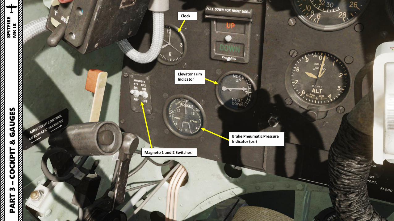
Clock
Brake Pneumatic Pressure Indicator (psi)
Magneto 1 and 2 Switches
PA
RT
3 –
CO
CK
PIT
& G
AU
GES
SP
ITFIR
E
MK
IX
Elevator Trim Indicator
39
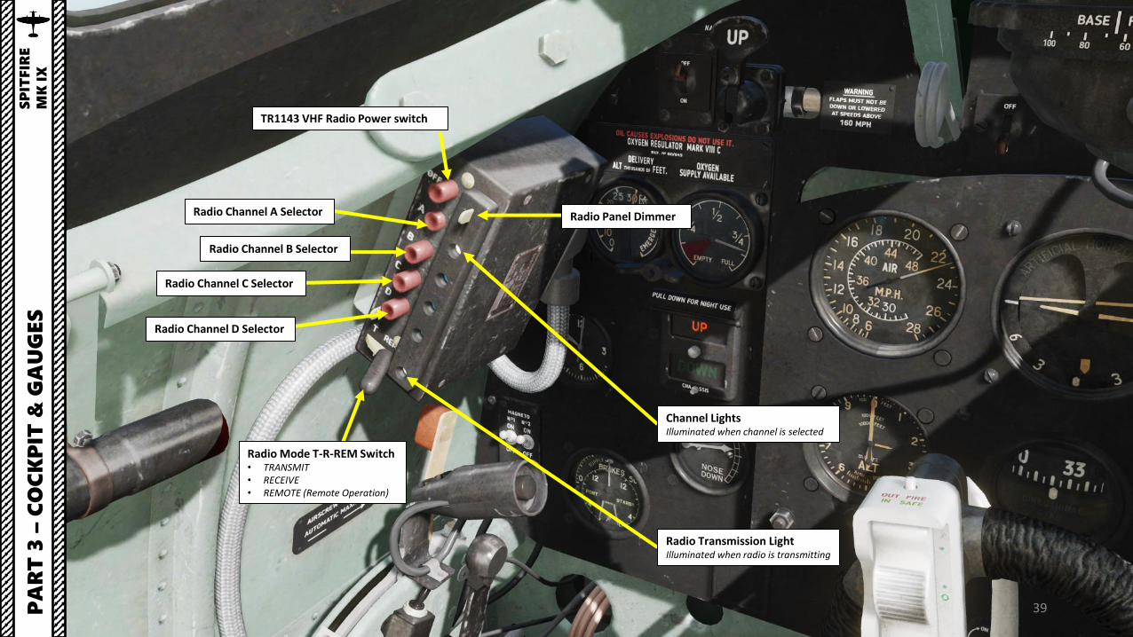
TR1143 VHF Radio Power switch
Radio Panel DimmerRadio Channel A Selector
Radio Channel B Selector
Radio Channel C Selector
Radio Channel D Selector
Radio Mode T-R-REM Switch• TRANSMIT• RECEIVE• REMOTE (Remote Operation)
PA
RT
3 –
CO
CK
PIT
& G
AU
GES
SP
ITFIR
E
MK
IX
Channel LightsIlluminated when channel is selected
Radio Transmission LightIlluminated when radio is transmitting

40
P8 Magnetic Compass
Portside (Left) Flood Lights Control Knob
Starboard (Right) Flood Lights Control Knob
PA
RT
3 –
CO
CK
PIT
& G
AU
GES
SP
ITFIR
E
MK
IX

41
Bomb Drop Push-Button
Throttle LeverMixture Control Lever• AFT: IDLE CUT-OFF• FWD: RUN/RICH
Throttle Friction Lever
RPM Control Lever
Indication Light Power Switch• FWD: ON• AFT: OFF
PA
RT
3 –
CO
CK
PIT
& G
AU
GES
SP
ITFIR
E
MK
IX

42
Elevator Trim Wheel• FWD: Nose DOWN• AFT: Nose UP
Rudder Trim Wheel• FWD: Starboard/Right• AFT: Portside/Left
Radiator Grates/Flaps Switch• ON: Manually Opens Radiator• OFF: Automatically Controls Radiator Grates
Pitot Heat Switch
Fuel Pump SwitchUse only if engine running or fuel cut-off is pulled AFT
Carburettor Air Filter Control• AFT: Normal Intake• FWD: Filter in Operation
PA
RT
3 –
CO
CK
PIT
& G
AU
GES
SP
ITFIR
E
MK
IX

43PA
RT
3 –
CO
CK
PIT
& G
AU
GES
SP
ITFIR
E
MK
IX
44PA
RT
3 –
CO
CK
PIT
& G
AU
GES
SP
ITFIR
E
MK
IX
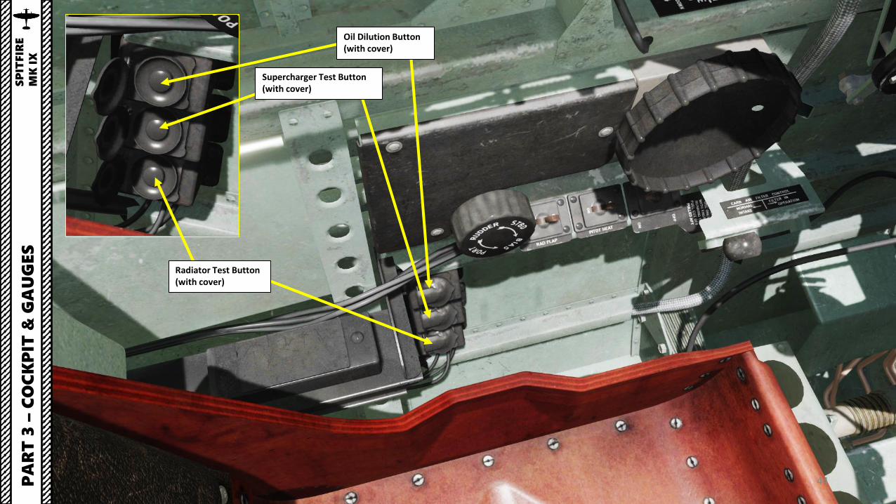
Oil Dilution Button (with cover)
Supercharger Test Button (with cover)
Radiator Test Button (with cover)

45
Side Door (Toggle)NOTE: Mapping this control to a key is recommended since handle cannot be clicked on when door is deployed)
Crowbar
PA
RT
3 –
CO
CK
PIT
& G
AU
GES
SP
ITFIR
E
MK
IX

46PA
RT
3 –
CO
CK
PIT
& G
AU
GES
SP
ITFIR
E
MK
IX

47
Mk II Hispano Cannon (20 mm)
Browning Machine-Guns (.303 in)Blanked-Off C-Wing outboard cannon muzzle fairingP
AR
T 3
–C
OC
KP
IT &
GA
UG
ES
SP
ITFIR
E
MK
IX

48PA
RT
3 –
CO
CK
PIT
& G
AU
GES
SP
ITFIR
E
MK
IX
Machinegun Cartridge Ejection Port
Machinegun Cartridge Ejection Port
Cannon Shell Ejection Port

49PA
RT
3 –
CO
CK
PIT
& G
AU
GES
SP
ITFIR
E
MK
IX
Fuel Cap

50PA
RT
3 –
CO
CK
PIT
& G
AU
GES
SP
ITFIR
E
MK
IX
Tailwheel

51
Identification Light (Upper)
Identification Light (Lower)PA
RT
3 –
CO
CK
PIT
& G
AU
GES
SP
ITFIR
E
MK
IX
Identification Light Morse switch Used to toggle identification lights to send morse signals
Lower Identification Light Control Switch• STEADY (FWD) – Constantly illuminates• OFF (MID)• MORSE (AFT) – Illuminates when Morse switch is held
Upper Identification Light Control Switch• MORSE (FWD) – Illuminates when Morse switch is held • OFF (MID)• STEADY (AFT) – Constantly illuminates
52
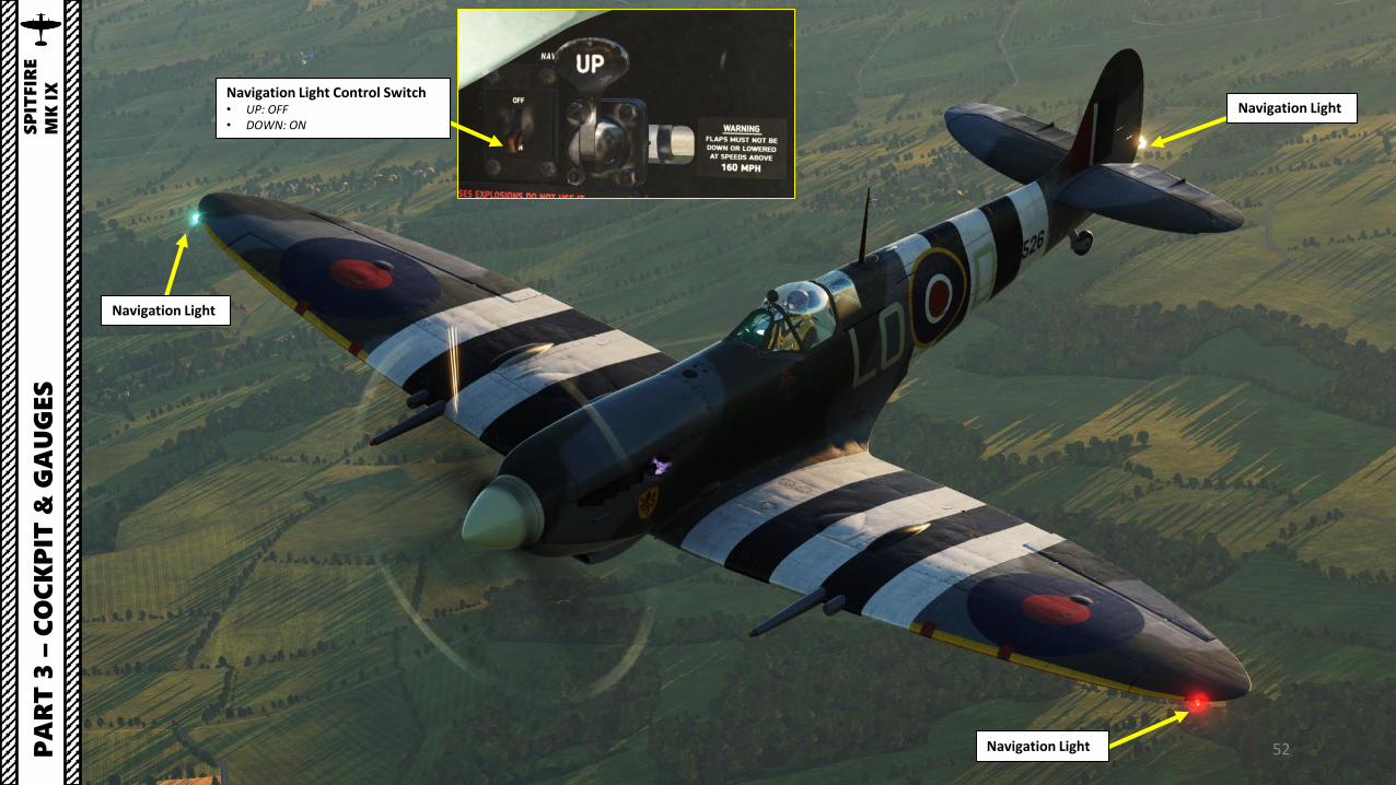
Navigation Light
Navigation Light
Navigation Light
PA
RT
3 –
CO
CK
PIT
& G
AU
GES
SP
ITFIR
E
MK
IX Navigation Light Control Switch
• UP: OFF• DOWN: ON

53PA
RT
3 –
CO
CK
PIT
& G
AU
GES
SP
ITFIR
E
MK
IX
Starboard (Right) Flood Lights Control Knob
Starboard (Right) Flood Light Lamp

54PA
RT
3 –
CO
CK
PIT
& G
AU
GES
SP
ITFIR
E
MK
IX
Portside (Left) Flood Lights Control Knob
Portside (Left) Flood Light Lamp

55PA
RT
3 –
CO
CK
PIT
& G
AU
GES
SP
ITFIR
E
MK
IX
Engine Exhaust

56
45 gallons “Slipper” External Fuel Tank
45 gallons “Torpedo” External Fuel TankP
AR
T 3
–C
OC
KP
IT &
GA
UG
ES
SP
ITFIR
E
MK
IX

57
250 Lbs Mk IV Bomb
PA
RT
3 –
CO
CK
PIT
& G
AU
GES
SP
ITFIR
E
MK
IX
500 Lbs Mk IV Bomb
250 Lbs Mk IV Bomb

58PA
RT
3 –
CO
CK
PIT
& G
AU
GES
SP
ITFIR
E
MK
IX
Invasion Stripes“Invasion stripes” were alternating blackand white bands painted onthe fuselages and wings of Allied aircraftduring World War II to reduce the chancethat they would be attacked by friendlyforces during and after the NormandyLandings. After a study concluded thatthe thousands of aircraft involved in theinvasion would saturate and break downthe IFF (Identify-Friend-or-Foe) system,the marking scheme was approved onMay 17, 1944, by Air Chief Marshal SirTrafford Leigh-Mallory, commanding theAllied Expeditionary Air Force.

59
Radio Antenna (Aerial) Mast
Mirror
PA
RT
3 –
CO
CK
PIT
& G
AU
GES
SP
ITFIR
E
MK
IX

60
Cooling Radiators
Air Intake
Pitot Tube
PA
RT
3 –
CO
CK
PIT
& G
AU
GES
SP
ITFIR
E
MK
IX

61Elevator Trim Tab
Rudder Trim Tab
PA
RT
3 –
CO
CK
PIT
& G
AU
GES
SP
ITFIR
E
MK
IX
Elevator Trim Tab

62
Flaps (shown deployed)Pneumatically actuated
Flaps Indicator(shown deployed)
PA
RT
3 –
CO
CK
PIT
& G
AU
GES
SP
ITFIR
E
MK
IX
63PA
RT
3 –
CO
CK
PIT
& G
AU
GES
SP
ITFIR
E
MK
IX
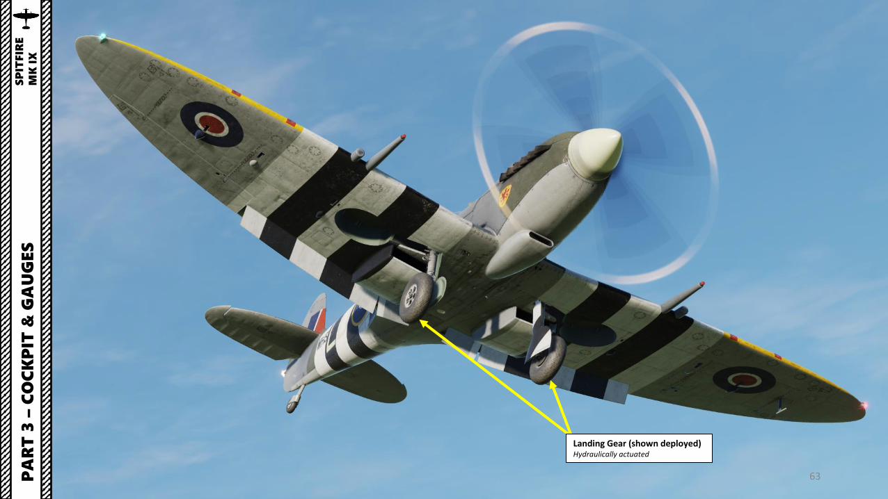
Landing Gear (shown deployed)Hydraulically actuated

64PA
RT
3 –
CO
CK
PIT
& G
AU
GES
SP
ITFIR
E
MK
IX
Landing Gear (Undercarriage) Bay Door
Landing Gear (Undercarriage) Bay Door

65
In real life, the Spitfire’s battery (called “Accumulator”)switch is actually accessible by an external panel and isturned on or off by the ground crew. By default, the batteryis always left on.
PA
RT
3 –
CO
CK
PIT
& G
AU
GES
SP
ITFIR
E
MK
IX

66PA
RT
3 –
CO
CK
PIT
& G
AU
GES
SP
ITFIR
E
MK
IX
Some variants of the Spitfire had clipped wings, which were designedto improve its combat fighting qualities by reducing the aircraft’s wingspan.

67
MH434: Aircraft Serial Number
ZD: RAF Squadron Code. “ZD” belongs to No. 222 Squadron.
In World War 2, the Royal Air Force used aircraftmarkings as identification codes. For instance, “ZD-B”means that the Aircraft B belongs to No. 222Squadron (ZD). You can set up your aircraft markingsin the Mission Editor.
B: Aircraft Identification Letter
PA
RT
3 –
CO
CK
PIT
& G
AU
GES
SP
ITFIR
E
MK
IX

68
PRE-FLIGHTP
AR
T 4
–S
TA
RT
-UP
SP
ITFIR
E
MK
IX

PRE-FLIGHT
1. Close Side Door by pressing the “SIDE DOOR (TOGGLE)” key (recommended binding: RShift+C).
2. Mixture Control Lever – CUT-OFF (FULLY AFT)3. Landing Gear Lever – DOWN 4. Drop Tank Fuel Cock Lever – OFF 5. Main Fuel Tank Cock Lever – OFF6. Fuel Tank Pressure Cock – OFF
69
1a
1b
2P
AR
T 4
–S
TA
RT
-UP
SP
ITFIR
E
MK
IX
5 3
4
6

PRE-FLIGHT
7. Ensure elevator, aileron and rudder controls are working by moving stick and rudder pedals8. Magneto Ignition M1 & M2 Switches – BOTH OFF9. Pneumatic Supply Pressure – Check no less than 220 psi (central needle displays 300 psi)10. Scroll mousewheel on the “Altimeter Barometric Pressure Setting” knob to adjust the altimeter needle to 0.11. Set Flaps Control Lever DOWN and check that mechanical flaps indicator are deployed12. Set Flaps Control Lever UP and check that mechanical flaps indicator are retracted
70
8
9
10a
10b
11
12PA
RT
4 –
ST
AR
T-U
PS
PIT
FIR
E
MK
IX

PRE-FLIGHT
13. Advance throttle forward until you physically trigger the indication light power switch. • Once Indicator Light switch is tripped forward (ON), the
Landing Gear and Low Fuel Pressure Warning lights should illuminate.
14. Retract throttle fully AFT. The indication light power switch should remain on (FWD).
15. Push the “Show Fuel Contents” button to display fuel quantity in the lower fuel tank.
71PA
RT
4 –
ST
AR
T-U
PS
PIT
FIR
E
MK
IX
13aIndicator Light Switch - OFF
1413a
13b
13bIndicator Light Switch - ON
13c
13c
15aButton Unpressed
15bButton Pressed
15b
15a

PRE-FLIGHT
16. Close Canopy by clicking on sliding hood handle (LCTRL+C)17. Scroll mousewheel on Wheel Brake lever to stick it in the PARKING position (fully to the right).
72
16aCanopy Open
16bCanopy Closed
PA
RT
4 –
ST
AR
T-U
PS
PIT
FIR
E
MK
IX
16bCanopy Handle
17aBrake Lever
DISENGAGED
17bBrake Lever
ENGAGED / ON(PARKING)
17a
17b
17a 17b

A FEW NOTES ON ENGINE START
When starting up the Spitfire, you might overprime the engine. In cases where there is excess fuel but the engine isn’t flooded, you will get flames momentarilycoming out of the exhaust. In cases where there is excess fuel in the lines and the engine is flooded, the aircraft should be sent back to the maintenance hangar.
73PA
RT
4 –
ST
AR
T-U
PS
PIT
FIR
E
MK
IX

ENGINE START
1. Main Fuel Tank Cock Lever – ON2. Set Throttle Lever – 1 INCH FORWARD3. RPM Control Lever – FULLY FORWARD4. Carburettor Air Intake Control Lever – FORWARD (FILTER IN OPERATION)5. Set both Magneto Ignition M1 & M2 switches to ON
74
1
2
4
5
PA
RT
4 –
ST
AR
T-U
PS
PIT
FIR
E
MK
IX
3

ENGINE START
6. Unscrew Primer Pump Handle Cap by scrolling mousewheel7. Click and hold primer pump handle (pull handle aft) and give 5 full strokes (push handle
forward). Consult table for required number of strokes based on Outside AirTemperature.
8. Increase fuel pressure by operating the manual wobble pump handle (10 strokes). LowFuel Pressure light will extinguish when required fuel pressure is high enough.
75
6b 6b 7
8b
Low Fuel Pressure
4
PA
RT
4 –
ST
AR
T-U
PS
PIT
FIR
E
MK
IX
Screwed Unscrewed
Primer Pump Strokes Required for OAT (Outside Air Temperature) in deg C
Fuel Pressure OK
8bWobble Pump Handle
8a

ENGINE START
9. Flip Booster Coil and Starter covers (in real life, these spring-loaded caps provide protectionagainst accidental pressing).
10. Verify that the propeller is clear and command « Clear prop! » to warn people around you thatyou are about to start the engine.
11. When ready, press and Hold Starter and Booster Coil buttons simultaneously. (Key bindingsrecommended: “DELETE” for Booster Coil button and “HOME” for Starter button).• Starter activation time should not exceed 10 seconds, after which a break of 10 - 15
seconds becomes necessary.• Fun fact: Merlin engine variants earlier than the Merlin 66 used a Coffman-type starter
cartridge, which would detonate and start the engine after the initial cranking. However,the Merlin 66 uses an electrical starter, which relies on battery power (or external groundpower) to start the propeller.
12. While pressing and holding the Booster Coil and Starter buttons with your left hand, use yourright hand to use the mouse to set the Mixture Control Lever to RUN (FULLY FORWARD) when theengine motor first sparks (you will hear an audible cough once the propeller catches up).• In real life, you would use your right hand to press the Booster Coil and Starter Buttons
76
11
9b
12a
12b
PA
RT
4 –
ST
AR
T-U
PS
PIT
FIR
E
MK
IX
9a
11

ENGINE START
13. Throttle back to avoid a prop strike (can happen if too much power is applied).14. Close the Booster Coil and Starter button covers.15. Fuel Pump switch – ON (AFT)16. Verify that the Radiator Grates/Flaps Switch is OFF. When OFF, control of the
radiator grates is automatic depending on the coolant temperature. The gratesopen at radiator temperatures above 115°C.
17. Screw the Primer Pump Handle Cap by scrolling mousewheel.
77
17b17a
16
15PA
RT
4 –
ST
AR
T-U
PS
PIT
FIR
E
MK
IX
14
ScrewedUnscrewed

POST-START
18. Pitot Heat – ON (if required)19. Oxygen Valve – OPEN20. Set the radio Transmit-Receive switch to
“REM” (Remote Operation)21. Select desired channel (A, B, C or D)
78
18
19
21
20
PA
RT
4 –
ST
AR
T-U
PS
PIT
FIR
E
MK
IX

POST-START
22. Turn the Course Setter ring of the P8 Magnetic Compass (scroll mousewheel on coursesetter ring) to align the red “N” (North Reference of the course setter) with the white “T”cross (real magnetic North of the compass). The lubber line will display your currentheading.
23. Turn the Directional Gyro adjustment knob to match the heading of the directional gyrowith the one shown by the magnetic compass’ lubber line.
79
22a
PA
RT
4 –
ST
AR
T-U
PS
PIT
FIR
E
MK
IX
22b
23
Directional Gyro Heading: 045 approx
Magnetic Compass White “T”(Real Magnetic North)
Red “N”Course Setter North Reference
Red “N” aligned with White “T”
Course Setter Ring
Lubber Line pointing to 045 approx.This is your current magnetic heading

ENGINE WARM-UP
1. Ensure oil pressure is in the 60-120 psi range.2. Adjust throttle to reach a RPM between 1000 and
1200 (IDLE range).3. Wait until engine oil warms up to at least 20 deg C
and coolant temperature is at least 60 deg C.4. Once engine is warmed up, you may start taxiing.
Note: Attempting a takeoff with low oil or coolanttemperature can lead to dire consequences. Waiting forproper engine warm-up is often overlooked by virtualpilots and the Merlin engine leaves no room for errorwhen engine temperatures are concerned.
80
2
3aOil Temperature OK
PA
RT
4 –
ST
AR
T-U
PS
PIT
FIR
E
MK
IX
1
3aCoolant Temperature TOO LOW
3bOil Temperature OK
3bCoolant Temperature OK

81
TAXI PROCEDURE
1. Ensure engine oil temperature is between 20 and 80 deg C andcoolant temperature is between 60 and 120 deg C.
2. Ensure pneumatic pressure is no less than 220 psi.3. Start taxiing when engine is warmed up by releasing the Wheel
Brake Lever from the PARKING position (press on the Brake Leverto release the brakes).
4. Set throttle to 1800 RPM and check brake effectiveness.5. Set throttle to 1500 RPM, open canopy and start taxiing. Reduce
throttle as required to maintain a safe taxi speed. While taxiing,keep the stick pulled fully aft.
6. To execute a turn, press and hold the wheel brake lever whilesimultaneously giving rudder input in the desired direction. Thebrakes are pneumatically actuated.
7. Line up on the runway, then close canopy.
Note: During taxi, keep the control stick pulled completely AFT toensure that the tailwheel remains straight.
PA
RT
5 –
TA
KEO
FF
SP
ITFIR
E
MK
IX
1
6Tailwheel
2
Coolant TemperatureOil TemperatureOil Pressure
3
Brake Lever

82
Only the left/port wheel is braking
Left rudder pedal pushedAircraft will steer left
Aircraft is steered to the left by pushing the left rudder pedal while holding the Brake LeverP
AR
T 5
–T
AK
EO
FF
SP
ITFIR
E
MK
IX
BRAKING TIPS
Braking is done by holding the braking lever while giving rudder input to steer the aircraft in thedirection you want to turn. Make sure you have adequate RPM and Boost/Manifold Pressuresettings or your turn radius will suffer. The Spitfire is a very tricky aircraft to taxi on the groundbecause of the narrow landing gear, the high power of the engine and poor cockpit visibilitywhen taxiing. The best way to move safely on the tarmac is to give very gentle throttle input toensure you maintain control of the aircraft while steering left and right once in a while to checkfor obstacles to ensure that the tailwheel remains straight.
Brake Lever

83
TAKEOFF PROCEDURE
1. Ensure RPM Control lever is fully forward2. Flaps – UP3. Set Elevator Trim for takeoff setting
• NEUTRAL for normal load (full main tanks, ammunition +45 gallon drop tank)
• 1 div. NOSE DOWN for heavy load configuration (whencarrying bombs)
4. Set Rudder Trim FULL RIGHT (no indicator, just turn the wheelin the STBD (Starboard/Right) direction
5. Ensure Supercharger Control Switch is set to AUTO-NORMALposition (DOWN).
6. Pull stick fully back to ensure that tailwheel remains straight.7. Gradually throttle up to +8 psi of boost (between +8 and +12
psi is acceptable for takeoff). Compensate engine torque (leftyaw) with rudder input (right rudder to counter left yaw).• The slower your increase the throttle, the better control
you will have over the acceleration and engine torque ofthe aircraft.
8. Slowly release control stick to center position as aircraft gainsspeed and tailwheel leaves the ground.
9. Rotate when reaching 90 mph.
3
3
4
5
PA
RT
5 –
TA
KEO
FF
SP
ITFIR
E
MK
IX
7
21

84
TAKEOFF PROCEDUREP
AR
T 5
–T
AK
EO
FF
SP
ITFIR
E
MK
IX

85
TAKEOFF PROCEDURE
10. Once in the air, raise Landing Gear (Undercarriage) using the Landing Gear Lever FWDwhen reaching 140 mph.
10FWD: Gear UpAFT: Gear Down
Gear Up
PA
RT
5 –
TA
KEO
FF
SP
ITFIR
E
MK
IX
Gear Down
Gear In Transition

86
TAKEOFF PROCEDURE
11. Start climbing and adjust power with throttle and RPM control lever• If maximum continuous rate of climb is required, use +12 psi boost and 2850 RPM.• If maximum rate of climb is not required, use +7 psi boost and 2650 RPM. Doing so conserves fuel
and increases total flight range.• In extreme situations, you can use the +18 psi boost and 3000 RPM for a maximum of 5 minutes
12. As you reach 1,000 ft or higher, set Carburettor lever to NORMAL INTAKE (AFT).
VIDEO DEMO:https://www.youtube.com/watch?v=0iEMZb-dk_E 12
13
PA
RT
5 –
TA
KEO
FF
SP
ITFIR
E
MK
IX

87
THROTTLE, STICK AND RUDDER INPUT DURING TAKEOFF
Here is an example of takeoffs at different engine power settings.
LINK: https://www.youtube.com/watch?v=Iqo7juJD3fU&feature=youtu.be
PA
RT
5 –
TA
KEO
FF
SP
ITFIR
E
MK
IX

88
LANDING PROCEDURE
1. Enter approach at 2600 RPM and +6 psi Boost. 2. Reduce throttle to -2 psi (Minus 2, yep!) Boost as you enter
downwind leg.3. Enter downwind leg at 1000 ft altitude.4. Set Carburettor control lever to FILTER IN OPERATION (FWD).
PA
RT
6 –
LA
ND
ING
SP
ITFIR
E
MK
IX
4
RAF Hawkinge

89
LANDING PROCEDURE
5. Deploy landing gear as you slow down to 150 mph.6. Once your wingtip is abeam the runway threshold, deploy flaps (at 150 mph or
less) and enter base leg with a descending turn.7. Maintain eyesight of the runway threshold as your turn and enter final at 500 ft
altitude.8. Fly over runway threshold at 90 mph.9. Gently flare for a three-point landing and maintain attitude until your touchdown
at 60-70 mph.10. Use rudder pedals to stay straight on the runway as you decelerate.11. Start using the wheel brake lever in short bursts when rudder movement becomes
ineffective.• WARNING: Excessive braking may cause the aircraft to nose over.
12. Raise flaps and taxi back to hangar.
Note: During landing, the aircraft will feel extremely floaty when flaps are deployed. Thenarrow landing gear of the Spitfire also makes it even more difficult. Controlling thespeed at which you touch the ground is essential in order to avoid nasty bounces. Avoidpulling aft on the stick when going for a three-point landing.
VIDEO DEMO: https://www.youtube.com/watch?v=0iEMZb-dk_E&t=116s
Gear Up
Gear Down
Gear In Transition
PA
RT
6 –
LA
ND
ING
SP
ITFIR
E
MK
IX
56a
6b

90
LANDING PROCEDUREP
AR
T 6
–LA
ND
ING
SP
ITFIR
E
MK
IX

91
LANDING PROCEDUREP
AR
T 6
–LA
ND
ING
SP
ITFIR
E
MK
IX

92
LANDING PROCEDUREP
AR
T 6
–LA
ND
ING
SP
ITFIR
E
MK
IX

93
AVOIDING SCRAPING YOUR WING
Your first landings in the Spitfire may often result in the following scenario: you touch the ground, think you’ve finallymade it home and then feel your wing dip down and strike the ground. The reason this happens is that many pilots willcome in slightly crabbed and reduce their throttle suddenly once they touch the ground, which causes a destabilizingyaw motion to the aircraft because of the changing torque generated by the change in engine power.
The best way to avoid this is to use your rudder trim to make sure that you come in as straight as possible. The turnand slip indicator will help you judge whether you are coming in straight or side-slipping. Minimize your side slip ontouchdown with your rudder trim wheel and you will finally nail those landings.
Too Much Side SlipBad!
Minimal Side SlipGood!
PA
RT
6 –
LA
ND
ING
SP
ITFIR
E
MK
IX

94PA
RT
7 –
EN
GIN
E &
FU
EL M
AN
AG
EM
EN
TS
PIT
FIR
E
MK
IX
THE MERLIN 66 ENGINE
The Spitfire Mk IX is powered by the Merlin 66 engine. This liquid-cooled, 12-cylinder V-twin four-stroke internal-combustion engine has a capacity of 27 liters. Itis equipped with a Bendix-Stromberg 8D-44-1 pressure carburetor capable ofoperating under negative G-loads, and a two-stage, two-speed drive centrifugalcompressor with an intercooler for cooling the air-fuel mixture supplied to thecylinders.
Upper Hood
Front Hood
Auxiliary Elements
Lower Hood
Auxiliary Elements
Side Hood
Engine Cowlings

95PA
RT
7 –
EN
GIN
E &
FU
EL M
AN
AG
EM
EN
TS
PIT
FIR
E
MK
IX
THE MERLIN 66 ENGINE
Motor Assembly
Crankcase breather connection
Engine FeetOil Thermometer Connection
Main oil supply to pressure pump
Oil Pressure Gauge Connection
Engine Feet
Connector from surge tank to main engine cooling system
Scavenge return-oil to Tank
Wheelcase Breather Connection
Magneto Earthing Connection
Magneto Booster Coil Connection
Fuel Priming Inlet

96PA
RT
7 –
EN
GIN
E &
FU
EL M
AN
AG
EM
EN
TS
PIT
FIR
E
MK
IX
THE MERLIN 66 ENGINE
The cooling system uses a mixture of 70% water and 30% ethylene glycol and has a volume of 13.5 gallons. An expansion tank in the shape of a horseshoe is mounted above the propeller gearbox.The centrifugal pump has two output lines of feed lines for each cylinder block and one output for the pump line. The pump delivers the coolant to the cylinder block, where the fluid, flowingthrough the cavity in the cylinder jackets and cylinder heads, is heated, thereby cooling the engine parts. The warmed fluid is then directed to the expansion tank, in the form of a horseshoe andmounted above the propeller gearbox.
Motor Cooling System
Expansion Tank
Expansion Tank
Thermal (radiator valves control system)
Thermometer
Thermostatic Valve
Thermostatic Valve
Thermostatic Valve
Drain Valve
Drain Valve
Section of the main cooling system radiator
Section of the main cooling system radiator
Section of the main cooling system radiator
Cooling System Pump
Cooling System Pump
Cylinder Blocks
Double-steam Valve
97PA
RT
7 –
EN
GIN
E &
FU
EL M
AN
AG
EM
EN
TS
PIT
FIR
E
MK
IX
THE MERLIN 66 ENGINE
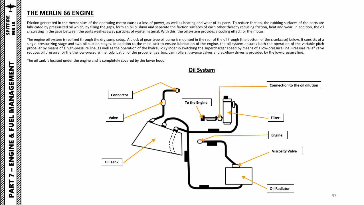
Friction generated in the mechanism of the operating motor causes a loss of power, as well as heating and wear of its parts. To reduce friction, the rubbing surfaces of the parts arelubricated by pressurized oil which, by filling the gaps, form an oil cushion and separate the friction surfaces of each other thereby reducing friction, heat and wear. In addition, the oilcirculating in the gaps between the parts washes away particles of waste material. With this, the oil system provides a cooling effect for the motor.
The engine oil system is realized through the dry sump setup. A block of gear-type oil pump is mounted in the rear of the oil trough (the bottom of the crankcase) below. It consists of asingle pressurizing stage and two oil suction stages. In addition to the main task to ensure lubrication of the engine, the oil system ensures both the operation of the variable pitchpropeller by means of a high-pressure line, as well as the operation of the hydraulic cylinder in switching the supercharger speed by means of a low-pressure line. Pressure relief valvereduces oil pressure for the the low-pressure line. Lubrication of the propeller gearbox, cam rollers, traverse valves and auxiliary drives is provided by the low-pressure line.
The oil tank is located under the engine and is completely covered by the lower hood.
Oil System
Connection to the oil dilution
Valve
Oil Tank
Connector
Oil Radiator
Viscosity Valve
Engine
Filter
To the Engine

98PA
RT
7 –
EN
GIN
E &
FU
EL M
AN
AG
EM
EN
TS
PIT
FIR
E
MK
IX
THE MERLIN 66 ENGINE
A separate cooling system is in place for reducing the temperature of the fuel-air mixture after its exit from the supercharger. This system consists of a tubular-plate intercooler, centrifugal pump,expansion tank and radiator for cooling the fluid circulating in the supercharger and intercooler. The intercooler is mounted between the supercharger and the intake manifold.
The coolant from the surge tank is fed by a separate centrifugal pump into to the radiator located in the tunnel under the right half-plane. Next, the cooled liquid washes the body of the superchargerand is supplied to the intermediate cooler. After passing through the radiator, the coolant fluid enters the surge tank. The differential pressure is provided by the radiator relief valve built into thedrainage line. The system is autonomous and does not require pilot input to function.
Supercharger Cooling System
Cooler
Pump
Radiator
Expansion Tank
2-Speed Supercharger

99PA
RT
7 –
EN
GIN
E &
FU
EL M
AN
AG
EM
EN
TS
PIT
FIR
E
MK
IX
THE MERLIN 66 ENGINERolls-Royce Speed-Density Fuel Injection Pump
Source: http://www.enginehistory.org/Accessories/HxFuelSys/FuelSysHx09.shtml

100PA
RT
7 –
EN
GIN
E &
FU
EL M
AN
AG
EM
EN
TS
PIT
FIR
E
MK
IX
THE MERLIN 66 ENGINE
Rolls-Royce Speed-Density Fuel Injection Pump SchematicSource: http://www.enginehistory.org/Accessories/HxFuelSys/FuelSysHx09.shtml
Rolls-Royce Speed-Density Engine Fuel SystemSource: http://www.enginehistory.org/Accessories/HxFuelSys/FuelSysHx09.shtml

101PA
RT
7 –
EN
GIN
E &
FU
EL M
AN
AG
EM
EN
TS
PIT
FIR
E
MK
IX
ENGINE INDICATIONS
Here is an overview of the various engine indications youhave to monitor:
• Engine Tachometer (x100 RPM): Controlled by theengine RPM lever. Indicates engine speed turning theconstant speed propeller.
• Boost Indicator (psi): Similar to a Manifold Pressureindicator, Boost indicates the difference between theabsolute pressure after the supercharger and theatmospheric pressure in psi. Positive boost valuesindicate a pressure higher than atmospheric pressure,while negative boost values indicate a pressure belowatmospheric pressure. In ISA (standard) conditions, +0Boost at sea level is roughly 14.7 psi, 760 mm Hg, 29.92in Hg, 1013.25 mBar, or 101.325 kPa.
• Coolant Temperature (deg C): indicates the water-glycolcoolant temperature. High coolant temperatures mayindicate an engine setting that is too high or a perforatedradiator leaking coolant.
• Oil Temperature (deg C): indicates the oil temperature inthe engine lubrication system.
• Oil Pressure Indicator (psi): indicates the oil pressure ofthe engine lubrication system.
• Supercharger Second Gear Warning Light: indicates thesupercharger is in second gear (Full Supercharger Mode).
Engine Tachometer (x100 RPM)
Boost Indicator (Manifold Pressure)(psi)
Coolant Temperature Indicator (deg C)
Oil Temperature Indicator (deg C)
Oil Pressure Indicator (psi)
Supercharger Second Gear Warning Light

102
Throttle Lever
Mixture Control Lever• AFT: IDLE CUT-OFF• FWD: RUN/RICH
RPM Control Lever
PA
RT
7 –
EN
GIN
E &
FU
EL M
AN
AG
EM
EN
TS
PIT
FIR
E
MK
IX
ENGINE CONTROLS
The main engine controls of the Spitfire are:
• Throttle: Controls boost pressure (manifold pressure).
• RPM Control Lever: Controls engine speed turning the constant speed propeller.
• Supercharger Mode Selector: Controls manual or automatic gear shifting of thesupercharger at high altitudes.
Throttle Friction Lever
Supercharger Mode Selector• MS: Forced Manual Shift to First Gear• AUTO: Automatic Gear Shifting

103PA
RT
7 –
EN
GIN
E &
FU
EL M
AN
AG
EM
EN
TS
PIT
FIR
E
MK
IX
Carburettor Air Filter Control• AFT: Normal Intake• FWD: Filter in Operation
Radiator Grates/Flaps Switch• ON: Manually Opens Radiator• OFF: Automatically Controls Radiator Grates
ENGINE CONTROLS
The main engine controls of the Spitfire are:
• Radiator Grates/Flaps Switch: Sets automatic control of theradiator grates/flaps. Unlike older variants of the Spitfire (whichrequired manual control of the radiators), the Spitfire Mk IX hasan automatic radiator flaps control based on measuredtemperature.
• Carburettor Air Filter Control: Controls damper coveringpassageway of the air intake to the carburettor.
• AFT: Normal Intake (Damper is Open)
• FWD: Filter In Operation (damper is shut and air comesfrom the engine compartment).

104PA
RT
7 –
EN
GIN
E &
FU
EL M
AN
AG
EM
EN
TS
PIT
FIR
E
MK
IX
ENGINE CONTROLS
The radiators of the engine cooling systems, supercharger,intermediate radiator and oil system are housed in twosymmetrical boxes located under the wings.
Under the right wing is one section of the engine radiatorand the oil cooler.
Under the left wing is the supercharger radiator and thesecond section of the motor cooling system radiator.
Supercharger Radiator
Oil Cooler IntakeEngine Coolant Radiator (first section)
Engine Coolant Radiator(second section)

105PA
RT
7 –
EN
GIN
E &
FU
EL M
AN
AG
EM
EN
TS
PIT
FIR
E
MK
IX
ENGINE CONTROLS
The radiators themselves are of a tunnel type. Adjustment of the radiator scoops is automatic(provided the Radiator Grates/Flaps Switch is set to OFF), performed by a thermostat thatopens up the flaps when the temperature begins to be too high.
Fun fact: the system blocked the activation of the second stage compressor at temperaturesclose to the maximum - 115°.
Radiators
Air Intake
Radiator Grates/Flaps OutletAutomatic Setting (Closed)
Radiator Grates/Flaps OutletManual Setting (Forced Open)
Radiator Grates/Flaps Switch• ON: Manually Opens Radiator• OFF: Automatically Controls Radiator Grates

106PA
RT
7 –
EN
GIN
E &
FU
EL M
AN
AG
EM
EN
TS
PIT
FIR
E
MK
IX
ENGINE CONTROLS
The oil system uses standard Air Force oil dilution equipment. This allows the oil to be thinned withgasoline to make the engine easier to start in ambient temperatures below 40°F or 4°C.
Thinning the oil requires allowing the engine to idle with the coolant flap open until the oil temperaturedrops to 50°C or less. Then, before stopping the engine, oil is diluted using the Dilution switch on theEngine Control panel of the front dash. This will dilute the oil until the engine is ready to be started again.Once the engine warms up, the gasoline in the oil is quickly evaporated.
Oil Dilution Button
Oil Dilution Button Cover

107PA
RT
7 –
EN
GIN
E &
FU
EL M
AN
AG
EM
EN
TS
PIT
FIR
E
MK
IX
ENGINE OPERATION & LIMITS

108
ENGINE LIMITSPower Setting RPM BOOST (psi)
Max Take-Off to 1000 ft (Altitude) 3000 +12
Max Climbing Power (1 hour limit) 2840 +9
Max Rich Continuous 2650 +7
Max Weak Continuous 2650 +4
Oil Pressure (psi)Minimum: 60 psi
Maximum: 120 psi
Oil Temperature (deg C)Minimum: 15 deg CMaximum: 90 deg C
Coolant Temperature (deg C)Minimum: 60 deg C
Maximum: 125 deg C
lb/in2
PA
RT
7 –
EN
GIN
E &
FU
EL M
AN
AG
EM
EN
TS
PIT
FIR
E
MK
IX
ENGINE OPERATION & LIMITS
If engine overheats, you can:
1. Enter a dive to increase airspeed and airflow to the engine intake.2. Reduce throttle and RPM3. Decrease rate of climb4. Set the RADIATOR switch to ON (will force the radiator flap to open manually)
CHECK YOUR ENGINE TEMPERATURES EVERY 30 SECONDS OR SO. IT WILL SAVE YOUR LIFE.

109
SUPERCHARGER BASICS
A supercharger is an engine-driven air pump or compressor that provides compressed air to the engine to provide additional pressure to the induction air so the engine canproduce additional power. It increases manifold pressure and forces the fuel/air mixture into the cylinders. The higher the manifold pressure, the more dense the fuel/air mixture, andthe more power an engine can produce.
With a normally aspirated engine, it is not possible to have manifold pressure higher than the existing atmospheric pressure. A supercharger is capable of boosting manifold pressureabove 30 "Hg. For example, at 8,000 feet a typical engine may be able to produce 75 percent of the power it could produce at mean sea level (MSL) because the air is less dense at thehigher altitude. The supercharger compresses the air to a higher density allowing a supercharged engine to produce the same manifold pressure at higher altitudes as it could produceat sea level.
Thus, an engine at 8,000 feet MSL could still produce 25” Hg of manifold pressure whereas without a supercharger it could produce only 22 "Hg. Superchargers are especially valuableat high altitudes (such as 18,000 feet) where the air density is 50 percent that of sea level. The use of a supercharger in many cases will supply air to the engine at the same density itdid at sea level. With a normally aspirated engine, it is not possible to have manifold pressure higher than the existing atmospheric pressure.
PA
RT
7 –
EN
GIN
E &
FU
EL M
AN
AG
EM
EN
TS
PIT
FIR
E
MK
IX

110
SUPERCHARGER OPERATION
The gear-driven centrifugal-type supercharger mounted on the Merlin engine has a two-stage compressor that raises air pressure at the entrance to the engine cylinders in order toincrease both the coefficient of admission and engine power, as well as to maintain a constant air pressure at the entrance to the cylinders during increases in altitude. Thesupercharger works in either low or high blower mode, selection of which can be automatic or manually set by the pilot. In normal operations, high blower mode starts automaticallyfrom 14,500 to 19,500 feet, depending on the amount of ram air being delivered through the carburetor. The supercharger increases the blower-to-engine compression ratio from alow of 5.8 to 1 to a high of 7.35 to 1.
Shifting between the first gear “M.S” (medium supercharger) and second gear “F.S” (full supercharger) speeds may be performed automatically if the 2-stage switch in the cockpit isleft in the AUTO (DOWN) position, or manually if set to M.S., forcing the supercharger in first gear.
First Gear = Low Blower = Low Manifold Pressure = used between 0 and 14500 ftSecond Gear = High Blower = High Manifold Pressure = used at 14500 ft or higher
M.S. (Medium Supercharger) Mode ActiveAltitude: 18000 ft
PA
RT
7 –
EN
GIN
E &
FU
EL M
AN
AG
EM
EN
TS
PIT
FIR
E
MK
IX
Supercharger in M.S. (Medium Supercharger) Mode (Low/First Gear when over 14,500 ft)
F.S. (Full Supercharger) Mode ActiveAltitude: 18000 ft
Supercharger in Automatic Mode (High/Second Gear when over 14,500 ft)
Boost/Manifold Pressure Increases

111
Fuel CapacityLower Fuel Tank Capacity: 37 Imperial Gal Upper Fuel Tank Capacity: 48 Imperial Gal Total Capacity: 85 Imperial Gal
Note: a drop tank (“Slipper” or “Torpedo” type) with a capacity of 45 Imperial Gal can be installed under the fuselage.
Lower Fuel Tank
Upper Fuel Tank
PA
RT
7 –
EN
GIN
E &
FU
EL M
AN
AG
EM
EN
TS
PIT
FIR
E
MK
IX
FUEL TANKS

112
Mixture Control Lever• AFT: IDLE CUT-OFF• FWD: RUN/RICH
Main Fuel Tank Cock Lever
Fuel Contents Button(Mapping button control “Show FuelContents” to a switch on your stick isrecommended)
Lower Fuel Tank Quantity Indicator (imperial gal)Upper scale: Fuel Qty of bottom tank on GroundLower scale: Fuel Qty of bottom tank in Flight
Note: Fuel Quantity is only displayed when you hold the “Fuel Contents” button to the left of the gauge. This indicator is for the bottom fuel tank only, which contains 37 gal. The upper fuel tank has 48 gal, which means that the Spitfire carries a total fuel load of 85 gal.
Fuel Pump SwitchUse only if engine running or fuel cut-off is pulled AFT
PA
RT
7 –
EN
GIN
E &
FU
EL M
AN
AG
EM
EN
TS
PIT
FIR
E
MK
IX
FUEL MANAGEMENT
The fuel system uses 100-octane fuel and obtains its supply from two banks mounted in the fuselage behind thefireproof bulkhead. One tank, of 37 gallons capacity, is mounted on the bottom of fuselage frames 6 and 7. Theother, of 48 gallons capacity, is mounted above the lower tank on four brackets on the top longerons, and isprotected by a sheet of armour covering the tank from behind the fireproof bulkhead. Fuel from the upper tankflows on its own into the lower tank. From the cock on the lower tank, a pipe leads forward to an A.G.S. type filteron the forward side of the bulkhead.
When feeding fuel from external tanks, access to the air separator is shut off by a special valve in order to preventthe upper tank from overflowing. This valve is connected to the fuel intake valve of the external tanks.
.

113
Low Fuel Pressure Warning Light
Fuel Pressuring CockNote: Only use if Low Fuel Pressure Warning Light is litwhile engine is running. Otherwise, always leave thisswitch to OFF.
PA
RT
7 –
EN
GIN
E &
FU
EL M
AN
AG
EM
EN
TS
PIT
FIR
E
MK
IX
FUEL MANAGEMENT
In order to prevent fuel boiling at high altitudes in warm weather conditions, the fuel system is equipped witha fuel tank pressurizer system that switches on automatically at altitudes above 20000 feet. An aneroid valvefeeds air, pressurized by a vacuum pump, into the fuel tanks. Pressurizing, however, impairs the self-sealing ofthe tanks and should be turned on only when the fuel pressure warning lamp lights up. In very warm weatherat very high altitudes a rich cut may occur with the tanks pressurized, and pressure must then be turned off.The pressurizing cock is on the starboard side of the cockpit immediately below the instrument panel.
The default position of the pressurizer system is OFF, and must be turned ON only when a red warning lightsignalizes that the fuel pressure has dropped below 10 psi.

114
FUEL MANAGEMENT - FLYING WITH AN EXTERNAL FUEL TANK
When flying with an external tank, make sure to do the following:
1. Set the Drop Tank Fuel Cock ON2. Set the Main Fuel Tank Cock to OFF to allow the engine to take fuel directly from the external tank.
Drop Tank Fuel Cock Control Lever• FWD: OFF• AFT: TANK FUSELAGE ON
Drop Tank Jettison Handle
1
PA
RT
7 –
EN
GIN
E &
FU
EL M
AN
AG
EM
EN
TS
PIT
FIR
E
MK
IX
2

115
3a
3b
3c
1
2
PA
RT
7 –
EN
GIN
E &
FU
EL M
AN
AG
EM
EN
TS
PIT
FIR
E
MK
IX
EXTERNAL FUEL TANK JETTISON
1. Set Main Fuel Tank Cock lever to ON2. Set Drop Tank Fuel Cock Control Lever – OFF / FUEL JETT.3. There is no indication to see the remaining external tank
fuel. Just keep in mind that both “slipper” and “torpedo”tanks contain 45 gal.
4. You can jettison external fuel tanks by raising andpushing the “drop tank” handle forward.

116
Optimal Climb Speeds
Maximum Diving Speed for Mach 0.85(without external stores)
Between SL and 20,000 ft 450 mph
Between 20,000 and 25,000 ft 430 mph
Between 25,000 and 30,000 ft 390 mph
Between 30,000 and 35,000 ft 340 mph
Above 35,000 ft 310 mph
Undercarriage down 160 mph
Flaps Down 160 mph
Maximum Weight
For take-off and gentle manoeuvres only 8,700 lbs
For landing (except in emergency) 7,450 lbs
For take-off, all forms of flying and landing 7,800 lbs
*Note: At this weight, take-off must be made only from a smooth hard runway.
PA
RT
8 –
AIR
CR
AFT
LIM
ITA
TIO
NS
SP
ITFIR
E
MK
IX

117
ARMAMENT OVERVIEW
• 4 x Colt Browning .303 Machineguns (350 rounds per gun)• 2 x Hispano Mk. II 20 mm Cannons (120 rounds per cannon)• 2 x 250 lbs bombs + 1 x 500 lbs bomb
PA
RT
9 –
WEA
PO
NS
SP
ITFIR
E
MK
IX
20 mm Hispano Mk II Cannon0.303 Browning Machineguns
500 lbs Mk IV Bomb
250 lbs Mk IV Bomb

1. Cutoff valve2. Flaps control valve3. Weapon fire button4. Flaps cylinder5. Machinegun fire, safety
mechanism and reload6. Cannon fire7. Cannon reload8. Cinegun (Camera)9. Cannon reload control valve10. Three-pointer pressure gauge11. Onboard air container12. Onboard charging nozzle
13. Heywood compressor14. Pressure reducer valve15. Oil and mist separator16. Radiator valve cylinder17. Minimum pressure valve18. Pressure reducer valve19. Electromagnetic control valve for the
radiator valve20. Supercharger speed control cylinder21. Brake differentials22. Main Landing Gear wheel23. Radiator Valve24. Air Filter 118
ARMAMENT MECHANISMS
The pneumatic system operates the wheel brakes, the Browning guns, Hispano guns,cine-camera, and flaps. Two storage cylinders are kept charged by an engine-drivencompressor and from them the supply is led to the various units in the system.
For the armament systems, pneumatic pressure controls the following components:
• Hispano cannons reload & firing mechanism• Browning machineguns’ firing, reloading & safety mechanism• Camera gun• Weapon fire buttons (on the control stick)
PA
RT
9 –
WEA
PO
NS
SP
ITFIR
E
MK
IX
Pneumatic System

119
ARMAMENT HEATING SYSTEM
Often, on early versions of aircraft, weapons malfunctioned due to frozen lubricant on the moving parts. To ensure trouble-freeoperation of weapons, aircraft began to use heating systems for their weaponry. Hot air for heating is taken past the cooling radiators issent to the machine-gun compartments by pipelines. The heating system is automated and requires no input from the pilot.
PA
RT
9 –
WEA
PO
NS
SP
ITFIR
E
MK
IX
Weapons Heating System

120
MARK II GUNSIGHT - OVERVIEW
Your gunsight will show you where to shoot and when to shoot a target.
Gunsight Specifications:
1. Reticle ring diameter – angular values: • In degrees: 6° 44’ • In thousandths (milliradians): 118
2. Reticle rings radius - angular values: • In degrees: 3° 22’ • In thousandths (milliradians): 59
3. When shooting, this ring corresponds for allowance at an aspect of 2/4 and target speed of 200 mph (322 km/h).
4. At target aspect of 1/4, target speed should be 400 mph (644 km/h) .
Gunsight Target Wingspan (Base) Scale (ft)
GunsightDiameter = 118 mil
PA
RT
9 –
WEA
PO
NS
SP
ITFIR
E
MK
IX
Gunsight Range Scale (x100 yards)

121
MARK II GUNSIGHT - TUTORIAL
To use the gunsight properly:
1. Set Reflector Power switch to ON (DOWN)2. Adjust Gunsight brightness as required3. Use Gunsight Reflector Tinted Screen if required4. Set Gunsight Wingspan to 32 ft (typical FW190 and Bf.109 wingspan)5. Set Gunsight Range to 300 yards (Typical Spitfire gun convergence was set to this value after the Battle of Britain).6. When the wing of the target fits in your gunsight, you are now in the range set in previous step.
Gunsight Target Wingspan Control (ft)Gunsight Illumination Control Knob
Gunsight Reflector Power switch
Gunsight Reflector Tinted Screen Toggle switch
5
4
2
1
PA
RT
9 –
WEA
PO
NS
SP
ITFIR
E
MK
IX
3
6
Gunsight Range Control (x100 yards)
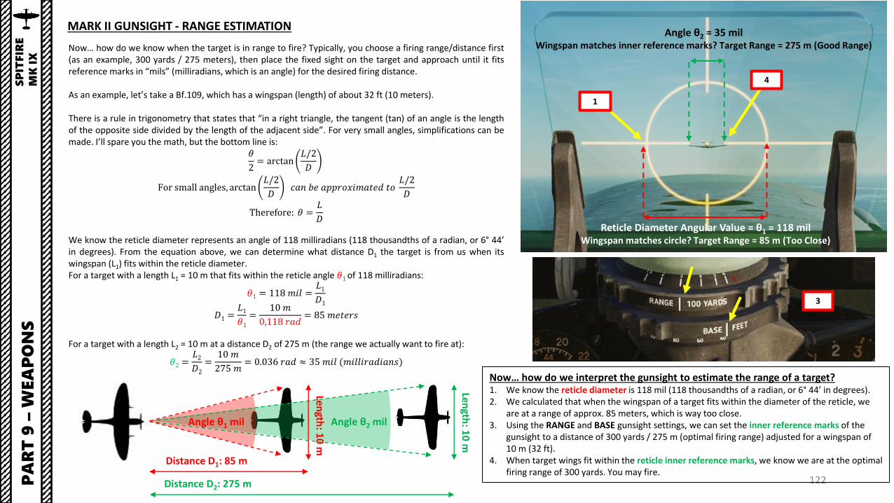
Now… how do we know when the target is in range to fire? Typically, you choose a firing range/distance first(as an example, 300 yards / 275 meters), then place the fixed sight on the target and approach until it fitsreference marks in “mils” (milliradians, which is an angle) for the desired firing distance.
As an example, let’s take a Bf.109, which has a wingspan (length) of about 32 ft (10 meters).
There is a rule in trigonometry that states that “in a right triangle, the tangent (tan) of an angle is the lengthof the opposite side divided by the length of the adjacent side”. For very small angles, simplifications can bemade. I’ll spare you the math, but the bottom line is:
𝜃
2= arctan
𝐿/2
𝐷
For small angles, arctan𝐿/2
𝐷𝑐𝑎𝑛 𝑏𝑒 𝑎𝑝𝑝𝑟𝑜𝑥𝑖𝑚𝑎𝑡𝑒𝑑 𝑡𝑜
𝐿/2
𝐷
Therefore: 𝜃 =𝐿
𝐷
We know the reticle diameter represents an angle of 118 milliradians (118 thousandths of a radian, or 6° 44’in degrees). From the equation above, we can determine what distance D1 the target is from us when itswingspan (L1) fits within the reticle diameter.For a target with a length L1 = 10 m that fits within the reticle angle 𝜃1of 118 milliradians:
𝜃1 = 118 𝑚𝑖𝑙 =𝐿1𝐷1
𝐷1 =𝐿1𝜃1
=10 𝑚
0,118 𝑟𝑎𝑑= 85 𝑚𝑒𝑡𝑒𝑟𝑠
For a target with a length L2 = 10 m at a distance D2 of 275 m (the range we actually want to fire at):
𝜃2 =𝐿2𝐷2
=10 𝑚
275 𝑚= 0.036 𝑟𝑎𝑑 ≈ 35 𝑚𝑖𝑙 (𝑚𝑖𝑙𝑙𝑖𝑟𝑎𝑑𝑖𝑎𝑛𝑠)
122
Distance D1: 85 m
Distance D2: 275 m
Length
: 10
m
Length
: 10
mAngle θ1 mil Angle θ2 mil
Angle θ2 = 35 milWingspan matches inner reference marks? Target Range = 275 m (Good Range)
Now… how do we interpret the gunsight to estimate the range of a target?1. We know the reticle diameter is 118 mil (118 thousandths of a radian, or 6° 44’ in degrees).2. We calculated that when the wingspan of a target fits within the diameter of the reticle, we
are at a range of approx. 85 meters, which is way too close.3. Using the RANGE and BASE gunsight settings, we can set the inner reference marks of the
gunsight to a distance of 300 yards / 275 m (optimal firing range) adjusted for a wingspan of 10 m (32 ft).
4. When target wings fit within the reticle inner reference marks, we know we are at the optimal firing range of 300 yards. You may fire.
MARK II GUNSIGHT - RANGE ESTIMATIONP
AR
T 9
–W
EA
PO
NS
SP
ITFIR
E
MK
IX
Reticle Diameter Angular Value = θ1 = 118 milWingspan matches circle? Target Range = 85 m (Too Close)
3
4
1

123
HISPANO 20 MM CANNONS & BROWNING 0.303 CAL MACHINEGUNS
1. Set Reflector Power switch to ON (DOWN)2. Adjust Gunsight brightness as required3. Use Gunsight Reflector Tinted Screen if required4. Set Gunsight Wingspan to 32 ft (typical FW190 and Bf.109 wingspan)5. Set Gunsight Range to 300 yards (Typical Spitfire gun convergence was set to this value after the Battle of
Britain).
PA
RT
9 –
WEA
PO
NS
SP
ITFIR
E
MK
IX
5
4
2
1
3

124
HISPANO 20 MM CANNONS & BROWNING 0.303 CAL MACHINEGUNS
6. Remove gun safety by setting the Gun Safety Lever to OUT FIRE (LSHIFT+SPACEBAR)7. When the wing of the target fits in your gunsight, you are now in the range set in previous step.8. Fire by pressing the “FIRE MACHINEGUNS AND CANNONS” button (SPACEBAR key)
6Safety Pin OFF/OUT
PA
RT
9 –
WEA
PO
NS
SP
ITFIR
E
MK
IX
Machinegun Trigger
Fire All Weapons (Cannons + Machineguns) Trigger
Guns (Cannons) Trigger
8
7

125
HISPANO 20 MM CANNONS & BROWNING 0.303 CAL MACHINEGUNSP
AR
T 9
–W
EA
PO
NS
SP
ITFIR
E
MK
IX

126
HISPANO 20 MM CANNONS & BROWNING 0.303 CAL MACHINEGUNSP
AR
T 9
–W
EA
PO
NS
SP
ITFIR
E
MK
IX

127
BOMBS
1. Approach the target by flying level at an altitudebetween 6000 and 8000 ft, with an airspeedbetween 220 and 230 mph.
2. When the target disappears under the wing on aline of about 1/3 from the end of the wing-tip,perform a gentle turn under the horizon in thedirection of the target.
3. While turning, regulate speed so that the targetremains visible. This turn has to be very steadyand made without excessive use of the rudder.
PA
RT
9 –
WEA
PO
NS
SP
ITFIR
E
MK
IX
1
2 3
Target
Target should be 1/3 from the end of the wing-tip before performing the turn towards the target.
Target is approximately 1/3 from the end of the wing-tip; start performing the turn towards the target.
Target should remain visible during the turn

128
BOMBS
4. Throttle back at idle power and perform a dive between45 and 60 degrees. The steeper the dive angle the betterprecision you will have.
5. Line up the target with the center of the gunsight reticle.6. Pull lead to bring the target slightly under the fuel cap
located on the aircraft nose.7. When target is lined up under the aircraft nose (fuel cap)
and aircraft is at an altitude of 3000 ft, release bombs bypressing the Bomb Drop button on the throttle(“RSHIFT+SPACEBAR” binding). All bombs equipped willdrop simultaneously.
PA
RT
9 –
WEA
PO
NS
SP
ITFIR
E
MK
IX
7
5Target
6Target (Under Aircraft Nose Fuel Cap)
Fuel Cap

129
BOMBS
8. Apply full power and pull away from the blast while maintaining level flight. This will allow you to get out as quickly as possible from the orbit of enemy flak.
9. After having travelled enough distance, start climbing. Climbing immediately after the release of bombs was one of the most common mistakes and resulted in:• Unnecessary danger to the pilot from the enemy flak• Black-out• Wing wrinkling
PA
RT
9 –
WEA
PO
NS
SP
ITFIR
E
MK
IX

130PA
RT
9 –
WEA
PO
NS
SP
ITFIR
E
MK
IX
220-230 mph
6000-8000 ft
Release Bomb2900-3000 ft
2000-2500 ft
Angle: 45-60 deg
Throttle UP
Target
BOMBS
Phil Style has a great tutorial on bombing in the Spitfire:https://youtu.be/4OIcNiA0M7k

131
RADIO FREQUENCY RANGE: 100 - 156 MHz
Maximum Radio Range
PA
RT
10
–R
AD
IOS
PIT
FIR
E
MK
IX
TR1143 VHF RADIO
The Spitfire Mk IX is equipped with an TR1143 type VHF radio. Radiofrequencies are preset in the mission editor in 4 different channels andcannot be tuned manually during flight; you have to use these 4 presetfrequencies.
Radio Mode Switch• LEFT: T (transmit)• MIDDLE: R (receive)• RIGHT: REM (remote operation)
TR1143 VHF Radio
Radio OFF Button
Radio Channel Lights (A, B, C, D)Illuminated when channel is selected
Radio Channel Selector Buttons (A, B, C, D)
Radio Transmission Light
Radio Lights Dimmer
Radio Mode Lock Switch

132
1
PA
RT
10
–R
AD
IOS
PIT
FIR
E
MK
IX
TR1143 VHF RADIO
To use the radio:
1. Set the radio transmit-receive switch to REM (Remote Operation)2. Select desired channel (A, B, C or D)3. Press the “COMM – Push to Talk” binding “RALT+ /” to transmit.
3
2

133PA
RT
10
–R
AD
IOS
PIT
FIR
E
MK
IX
A FEW NOTES ON THE SPITFIRE RADIO
The Spitfire variant modelled in DCS does not specifically explain the real life radio transmission procedure,nor could I find any relevant information about it. I do not know how radio transmission works exactly in thereal life variant of the Spitfire Mk IX we have in DCS, but here are a few plausible guesses:
• Guess #1: Transmission was done by pressing and holding the Radio Mode Switch to T (Transmit), whichis sprung back when released.
• Guess #2: Transmission was done by setting the Radio Mode Switch to REM (Remote) and then using aPush-to-Talk button installed on the throttle certain Spitfire variants, which is not modelled on ourvariant.
• Guess #3: Transmission was done with a throat microphone (also called “laryngophone”), which is a typeof contact microphone that absorbs vibrations directly from the wearer's throat by way of single or dualsensors worn against the neck. Transmission was done simply by talking, and the sensors would pick upthe voice and transmit it on the selected channel.
Throat Microphone
Throat Microphone
Radio Mode Switch

RADIO FREQUENCIES – AIRFIELDS
LOCATION FREQUENCY (MHz)
Anapa 121.0
Batumi 131.0
Beslan 141.0
Gelendzhik 126.0
Gudauta 130.0
Kobuleti 133.0
Kutaisi 134.0
Krasnodar Center 122.0
Krasnodar Pashkovsky 128.0
Krymsk 124.0
Maykop 125.0
Mineral’nye Vody 135.0
Mozdok 137.0
Nalchik 136.0
Novorossiysk 123.0
Senaki 132.0
Sochi 127.0
Soganlug 139.0
Sukhumi 129.0
Tblisi 138.0
Vaziani 140.0134P
AR
T 1
0 –
RA
DIO
SP
ITFIR
E
MK
IX

135
Channel A:• Plane-to-plane communication on local flights• Communication with controller in your own region.
Channel B:• Common to all VHF-equipped control towers. It is normally
used to contact the control tower for takeoff and landinginstructions
Channel C:• Frequently used in contacting homing stations
Channel D:• Plane-to-plane contact between a pilot practicing fighter
instrument flying and his safety pilot.• Normally used for plane-to-ground contact with D/F
(Directional Finding) stations. The pip-squeak (contactor),used in conjunction with the D/F fixing provides controllersand intercepts officers with an accurate minute-by-minuteposition report of your plane. The contactor clock consistsof a dial and two switches.
PA
RT
10
–R
AD
IOS
PIT
FIR
E
MK
IX

136PA
RT
11 –
NA
VIG
AT
ION
SP
ITFIR
E
MK
IX
P8 COMPASS OVERVIEW
The aircraft’s navigation equipment consists of the P.8.M (6A/726) magnetic compass installed on the centralpart of the aircraft dashboard’s lower section, as well as the Mk.1A (6A/1298) gyroscope on the instrumentpanel for instrument flying.
The main part of the compass is a magnetic compass system, which bears the name of the compass rose. Thecompass rose, a sensitive element consisting of a system of magnets, antennae, damping wires, a compass cap,centre-pin and hollow float, which reduces the weight of the compass rose in the liquid.
The gyroscope does not automatically indicate course and instead indicates the deviation from any given course,measured by the magnetic compass P8. It requires re-calibration after a few minutes of flight.
Here are two great video tutorials on the P8 compass:
Dreamsofwings Spitfire P8 Tutorial: https://youtu.be/YdDvh5zPUWI
RAF Low Flying Navigation: https://youtu.be/NQWZEVaoFKQ
P8 Magnetic Compass
Directional Gyro
Directional Gyro Adjustment Control Knob

137
1a
PA
RT
4 –
ST
AR
T-U
PS
PIT
FIR
E
MK
IX
1b
3
Directional Gyro Heading: 025 approx
Magnetic Compass White “T”(Real Magnetic North)
Red “N”Course Setter North Reference
Red “N” aligned with White “T”
Course Setter Ring
Lubber Line pointing to 025 approx.This is your current magnetic heading
P8 COMPASS TUTORIAL
1. Turn the Course Setter ring of the P8 Magnetic Compass (scroll mousewheel on course setter ring) to align thered “N” (North Reference of the course setter) with the white “T” cross (real magnetic North of the compass).
2. The lubber line will display your current heading.3. Turn the Directional Gyro adjustment knob to match the heading of the directional gyro with the one shown by
the magnetic compass’ lubber line.4. You may now use the Directional Gyro heading as a reference. You may need to re-align it with the magnetic
compass after hard manoeuvers.
2
Note: High-G manoeuvers can decalibrate your gyro and give you a wrongreading. Be aware that once you start a dogfight, your gyro can give youreadings that don’t make sense. It’s normal: it is one of the real-lifedrawbacks of this navigation system. The same issue is also recurrent intoday’s civilian acrobatic prop planes.

138
SPITFIRE VARIANTS
The basic airframe of the Spitfire proved to be extremely adaptable, capable oftaking far more powerful engines and far greater loads than its original role as ashort-range interceptor had allowed for. This would lead to 24 marks of Spitfire,and many sub-variants within the marks, being produced throughout the SecondWorld War and beyond, in continuing efforts to fulfill Royal AirForce requirements and successfully combat ever-improving enemy aircraft.
The Mk I and Mk II were famous for their role in the Battle of Britain, beingqualified as great “turn fighters”. However, these variants suffered from enginecut-out during negative Gs due to the way the carburetor was designed.
The Mk V followed and eventually added 20 mm Hispano cannons. This variantwas widely used in the Mediterranean following the Battle of Britain andretained much of the aerodynamic properties of the early Mk I.
The Focke-Wulf FW190 forced the engineers at Supermarine to rethink thedesign of the Mk V since this variant was completely outclassed.
There was much pressure to get Spitfires into production using the new two-stage supercharged Merlin 61 engine, which eventually culminated in thecreation of the Mk IX as a response to the Butcher Bird. The performanceincrease was described by Jeffrey Quill (Supermarine test pilot) as a "quantumleap" over that of the Mk VB. The first AFDU (Air Fighting Development Unit)report on the Mk IX in 1942 stated:
“The performance of the Spitfire IX is outstandingly better than the Spitfire Vespecially at heights above 20,000 feet. On the level the Spitfire is considerablyfaster and climb is exceptionally good. It will climb easily to 38,000 feet and whenlevelled off there can be made to climb in stages to above 40,000 feet by buildingup speed on the level and a slight zoom. Its manoeuvrability is as good as aSpitfire V up to 30,000 feet and above is very much better. At 38,000 feet it iscapable of a true speed of 368mph and is still able to manoeuvre well forfighting.”
Although the Mk IX's airframe did not have the aerodynamic and strengthimprovements, or the modified control surfaces of the Mk VII and VIII, the Mk IXstill proved to be an effective counter to the FW190 by 1943, which is the variantwe have in DCS.P
AR
T 1
2 –
AIR
CR
AFT
VA
RIA
NT
SS
PIT
FIR
E
MK
IX

139PA
RT
12
–A
IRC
RA
FT
VA
RIA
NT
SS
PIT
FIR
E
MK
IX
VARIANT (MARK) NOMENCLATURE – ENGINE RATING
F, LF or HF refer to the engine rating
• F (Medium Altitude Fighter) refers to the early Spitfire IX model with a Merlin 61 engine in it
• LF (Low Altitude Fighter) refers to the slightly later Spitfire IX model with a Merlin 66 engine that was tuned to switch to the second supercharger stage (the Merlin 60 series introduced a two-stage supercharger) at higher altitudes. In the cockpit on the lower right side of the main panel there is a switch and a light that indicate which stage the supercharger is at (its automaticallyengaging). The red light will appear above 16,000 ft or so. The reason for the LF modification was to match the Spitfire IX's top speed to be better than the FW190A at all altitudes.
• HF (High Altitude Fighter) refers to a very rare Spitfire IX model using a Merlin 70 engine. It is the exact opposite of the Merlin 66, meaning that its supercharger stage kicks in at a much higheraltitude. The HF is slower than the LF model until about 24,000 ft where it outperforms it significantly. Most Spitfires employed in high altitude operations were used against high flying Germanreconnaissance aircraft and thus were not really meant for fighter combat but instead for interceptor operations at higher altitudes.
Note:• FR refers to Fighter Reconnaissance (armed reconnaissance, usually low altitude)• PR refers to Photo Reconnaissance (unarmed reconnaissance, usually high altitude)

140
A WING
B WING
C WING
D WING
E WING
PA
RT
12
–A
IRC
RA
FT
VA
RIA
NT
SS
PIT
FIR
E
MK
IX
VARIANT (MARK) NOMENCLATURE – WING TYPE
A, B, C, D or E refer to the wing type
• A refers to the original wing design, the basic structure of which was unchanged until the arrival of C type wing in 1942. The only armamentable to be carried was eight .303-calibre Browning machine guns with 300 rounds per gun.
• Armament: 4x .303 machineguns per wing.• B refers to the A type wing modified to carry a 20mm Hispano cannon. One type of armament could be fitted, comprising two 20 mm-calibre
Hispano Mk II cannon, fed from drum magazines with the capacity of 60 rounds/gun, and four .303 Browning machine guns with 350 roundsper gun.
• Armament: 2x .303 machineguns and 1x 20mm cannon per wing.• C refers to the “universal wing”. This wing was structurally modified to reduce labour and manufacturing time and allow mixed armament
options; A or B type armament or a new, yet heavier combination of four 20 mm Hispano cannon.• Armament: 2x .303 machineguns and 1x 20mm cannon per wing OR 2x 20mm cannon per wing.
• D refers to the unarmed long-range wing for reconnaissance versions. Space for substantial amount of additional fuel was provided in thespace ahead of the wing spar, which together with the reinforced skin of the wing’s leading edge formed a rigid torsion box.
• Armament: None.• E refers to a structurally unchanged form of the C wing, but the outer machine gun ports were eliminated. Although the outer machine gun
bays were retained, their access doors were devoid of empty shell case ports and shell deflectors. The inner gun bays allowed for two weaponfits two 20 mm Hispano Mk II cannon with 120 rounds/gun in the outer bays and two American .50 calibre M2 Browning machine guns, with250 rounds per gun in the inner bays. Alternatively, four 20 mm Hispano cannon with 120 rounds per gun could be carried as per original C-wing production standard.
• Armament: 2 x 20mm cannons OR 1 x 20mm cannon and 2x .50 cal machineguns.

141
Spitfire Mk IXc LF (Clipped Wings)
Spitfire Mk IXc LF(Full Wings)
PA
RT
12
–A
IRC
RA
FT
VA
RIA
NT
SS
PIT
FIR
E
MK
IX
AVAILABLE VARIANTS: FULL WING & CLIPPED WING MK IXC
The Spitfire was the result of many design iterations by trial and error. The variants available in DCS are the Mk IXc LF with both a “full wings” and “clipped wings” configurations.
Clipped Wings Advantages:• small increase in the rate of roll• slight increase in speed below about 20000 ft
Clipped Wings Disadvantages:• inability to turn as fast or tight as an aircraft with normal wings due to
an increased stalling speed in the turn• small increase in take-off run• loss in maximum rate of climb at any height of 160 – 200 ft/min• lowering of the service ceiling by 1800 ft• slight decrease in speed above 20000 ft

142
Dogfighting in the Spitfire is an art that is difficult against a pilot who knows what he is doing.
You may have read countless articles on the Spitfire stating how much of a “turn and burn” fighterit is. The Spitfire’s incredible turn rate is useful for defensive fights but tight turns often come atthe price of losing valuable energy (airspeed). “Turning and burning” energy may be usefulcircumstantially, but accepting a defensive fight means that you lose the initiative and needlesslyputs you in a vulnerable position. The design philosophy between the Mk I and the Mk IX radicallychanged: the Mk I was meant to be a superb turner, while the Mk IX was a stopgap measure tocounter the FW.190A’s vastly superior climb rate. Aircraft design is always a matter of trade-offs:gaining a better climb rate will often come at a cost in terms of turning performance. The Mk IXwas such a compromise, meaning that while it could better keep up with the 190s in terms ofairspeed and climb rate, it was slowly losing that turning advantage. Most pilots preferred thiskind of compromise over the shortcomings of the Mk V that had become obsolete by late 1943.
The best Spitfire pilots used their aircraft offensively by using the combat tactics pioneered by theGerman experten throughout the war. Using “Boom and Zoom” techniques ensure a much highersurvivability and offensive capabilities, therefore I recommend that you use your Spitfire as anenergy fighter. The Spitfire is best used at altitudes of 25,000 ft and higher. This is where it willhave the greatest performance advantage over the Bf.109 and the FW190. However, mostdogfights occurring in multiplayer servers happen at lower altitudes between 5,000 and 15,000 ft,which is where the Messerschmitts and Focke-Wulfs will dominate in terms of climb rate anddiving speed. Turning tightly will be of no use if you can’t catch an opponent that dictates when,where and how fights will occur. If you happen to be forced to fight on the 109’s terms down low,you are at a serious disadvantage from the very beginning. Try to avoid that.
During dogfights, I would advise you to keep your energy state (airspeed and altitude) high at alltimes. These principles apply to every single aircraft, but particularly to the Spitfire. The Spitfire’sflaps can be used as an airbrake but are more or less impractical during a dogfight since they areused to slow the Spitfire down to a crawl for landing, which is closer to a death sentence than aproper dogfighting technique.
If you want to survive against experienced Bf.109 or FW.190 pilots, you must:• Always fly with a wingman• Always fly with a high energy state (high airspeed and altitude)• Do not attempt to outclimb or outdive a 109 or 190 unless you have a serious energy
advantage• Bring the fight to high altitudes if you can to fly your plane in the combat environment it was
designed for• Master your aircraft: know your engine limits and airspeed limits by heart and practice
manoeuvers to avoid stalls and spins.PA
RT
13
–T
AC
TIC
S &
AIR
CO
MB
AT
SP
ITFIR
E
MK
IX

143
Following the end of the Battle of Britain, RAF Fighter Command moved fromdefensive to offensive operations where they would engage German fighters onthe other side of the Channel; the operational instructions were ready byDecember 1940.
There would be two types of offensive operation:• "Rhubarb" (initially called Mosquito) in which small patrols would cross under
cover of cloudy conditions and engage any aircraft they found and on clearweather days
• "Circus" which would send several squadrons - possibly with a few bombers -in sweeps of northern France. Circus came to mean an operation withbombers.
Rhubarb patrols began in December 1940; while the pilots were allowed to attackground targets if any presented itself their primary objective was to bring downGerman aircraft. By mid-June 1941, Fighter Command had flown 149 Rhubarbpatrols (336 sorties) claiming seven enemy aircraft brought down for loss of eightpilots on the British side. Circus operations with bombers began in January andeleven had been carried out by June, the targets including docks on the Frenchcoast and airfields. More than forty sweeps without bombers had been made inthe same period.
While Fighter Command's priority was the German fighters, Bomber Commandconcentrated on destroying the ground targets. At higher level in the RAF it wasfelt that the effects on the war by damage that could be inflicted by the bomberswould be minimal; the commanders of Bomber and Fighter Commands held aconference that agreed that the purpose of a Circus was to force German fightersinto combat in circumstances that favoured the British and to that end thebombers had to do enough damage that the Luftwaffe could not ignore theattacks.
The Spitfire participated in a significant number of Rhubarb and Circus operations.It also took part in short-range “Ramrod” operations, which were similar to Circusbut with destroying a target being the principal aim. The Spitfire was primarily ashort-range interceptor and ill-suited for long-range bomber escort, but in thescope of DCS it is still a viable role since the target range rarely exceeds 150 nm inthe English Channel or Normandy maps. I still suggest you try out some escortmissions if you want to experience a very different way to fly in the Spitfire.
PA
RT
13
–T
AC
TIC
S &
AIR
CO
MB
AT
SP
ITFIR
E
MK
IX

144PA
RT
13
–T
AC
TIC
S &
AIR
CO
MB
AT
SP
ITFIR
E
MK
IX
(Taken from P-47 documentation)
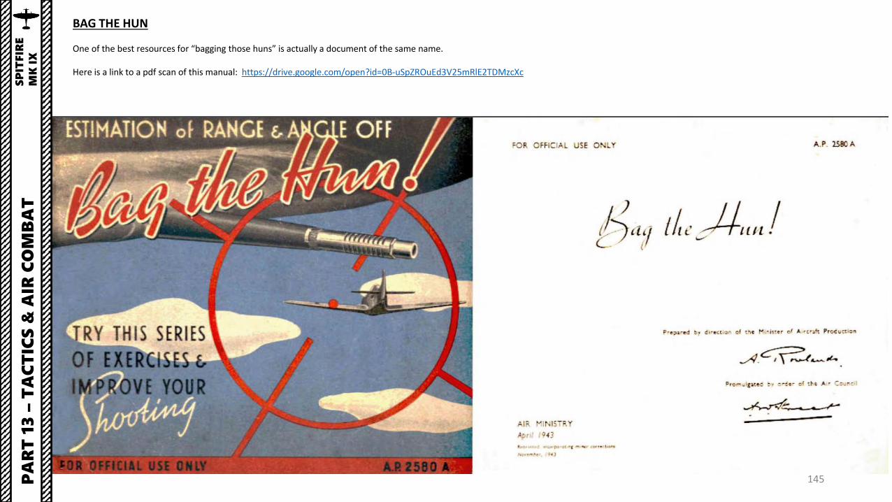
145
BAG THE HUN
One of the best resources for “bagging those huns” is actually a document of the same name.
Here is a link to a pdf scan of this manual: https://drive.google.com/open?id=0B-uSpZROuEd3V25mRlE2TDMzcXc
PA
RT
13
–T
AC
TIC
S &
AIR
CO
MB
AT
SP
ITFIR
E
MK
IX

146
Taming taildraggers is much more difficult than meets the eye, especially during the takeoff and landing phase. Here is a useful and insightful essay on the art of flying taildraggers wonderfullywritten by Chief Instructor. I highly recommend you give it a read.
Link: https://drive.google.com/open?id=0B-uSpZROuEd3V3Jkd2pfa0xRRW8
PA
RT
14
–T
AM
ING
TA
ILD
RA
GG
ER
SS
PIT
FIR
E
MK
IX

147