
SIGNA™ - GE Healthcare
68
Pulse of MR Spring 2015 ISMRM Edition Volume Eighteen SIGNA ™ Returns
-
Upload
khangminh22 -
Category
Documents
-
view
2 -
download
0
Transcript of SIGNA™ - GE Healthcare

Pulse of MR
Spring 2015
ISMRM Edition
Volume Eighteen
SIGNA™
ReturnsMR-0492-04.15-EN-US
JB30550XX
Learn more at ISMRM booth 1023 or visit collaborate.mr.gehealthcare.com
A world of MR created around a world of collaboration.
© 2015 General Electric Company. All rights reserved. GE Healthcare, a division of General
Electric Company. GE and GE monogram are trademarks of General Electric Company.

GEHEALTHCARE.COM/MR 2 SPRING 2015GEHEALTHCARE.COM/MR 2 SPRING 2015
30 | Whole Body MR for Visualizing Metastatic Prostate Cancer
35 | Two Facilities, One Goal
40 | Spectrum Imaging Leverages DV25.0 Continuum Pak Applications
46 | DV25.0 Continuum Pak Upgrade Helps Facility Reduce Breath Hold Times and Optimize Exams
Outside the Bore
4 | Welcome
5 | SIGNA Returns
5 | Economic and Quick In-field Upgrades for 10,000 GE 1.5T MR Systems to SIGNA Explorer Lift
6 | SIGNA Creator, SIGNA Explorer Receive 510(k) Clearance
6 | SIGNA Steals the Show at ECR
6 | GE MR Featured in TV News “Love Story”
In Practice
7 | The Role of IDEAL and DTI in Peripheral Nerve MR Imaging
12 | SIGNA Explorer Brings Advanced Apps to Mikuni Hospital
17 | A New Chapter Emerges in PET/MR Imaging
24 | MAVRIC SL as a Differentiator in Clinical Practice
40
60
Tech Trends
GESIGNAPULSE.COM 67 SPRING 2015
prospective motion corrected imaging,
we are helping our customers make
the most of their MR scanners.
References
1. Maclaren J, Herbst M, Speck O, Zaitsev M. Prospective motion correction in brain imaging: A review. Magnetic Resonance In Medicine 2013, 69(3), 621-636. doi:10.1002/mrm.24314.
2. White N, Roddey C, Shankaranarayanan A, et al. PROMO: Real-time prospective motion correction in MRI using image-based tracking. Magnetic Resonance In Medicine 2010, 63(1), 91-105. doi:10.1002/mrm.22176.
3. Zaitsev M, Maclaren J, Herbst M. Motion artifacts in MRI: A complex problem with many partial solutions. Journal Of Magnetic Resonance Imaging 2015. doi:10.1002/jmri.24850.
Patient motion is a problem for
everyone, and GE Healthcare is
working hard to help customers obtain
the best diagnostic image quality
possible. Customers incorporating
PROMO into their protocols are
realizing the benefits and the
possibilities for improving the efficiency
of their practice. A motion-robust
scanning protocol may be used to
help reduce sedation rates in young
or motion prone subjects. Reducing
rescans by incorporating PROMO in
protocols for elderly or severely sick
populations is certainly imaginable
(Figure 4). A comprehensive portfolio
for motion robust imaging of the
brain is an important goal for GE.
With techniques like PROPELLER (T2,
T2 FLAIR, T1 FLAIR and PD) for 2D
motion robust imaging and now Cube
T2 and T2 FLAIR with PROMO for 3D
Figure 3. A demonstration of the benefits of PROMO when used with Cube T2 FLAIR and the new (in DV25.0 Continuum Pak) T2 Preparation imaging option. High white matter/gray matter contrast and increased CNR is matched with prospective motion correction to produce artifact-free images (C & D) when a scan with similar motion and without PROMO (B) would be non-diagnostic. This example also shows the effectiveness of the discussed scan parameter optimization strategy, resulting in nearly identical image quality with (C) and without (A) PROMO. The plot (E) shows the motion corrected for by PROMO and represents two common motions experienced while scanning, a slow relaxation and a quick side rotation.
Figure 4. Cube T2 FLAIR images of patient from CHR Laennec Imaging Center, Creil, France using a MR450w. Patient motion with conventional Cube sequence will usually result in artifacts that can mask important findings (top row); incorporating PROMO into the protocol helps reduce the need for rescans and gives higher confidence no anatomy is missed.
A B C D
E

GESIGNAPULSE.COM 3 SPRING 2015
Case Studies
50 | High-resolution Breast Imaging with DV25.0 Continuum Pak and DISCO
53 | Simultaneous Imaging of Ga-68 DOTA-TOC in Patients with Neuroendocrine Tumors
56 | Imaging the Female Pelvis with FOCUS DWI and MR Spectroscopy
Tech Trends
60 | With New Release of READY View, Seeing is Believing
64 | Addressing Patient Motion in 3D Imaging
© 2015 General Electric Company, doing business as GE Healthcare. All rights reserved. The copyright, trademarks, trade names and other intellectual property rights subsisting in or used in connection with and related to this publication are, the property of GE Healthcare unless otherwise specified. Reproduction in any form is forbidden without prior written permission from GE Healthcare.
LIMITATION OF LIABILITY: The information in this magazine is intended as a general presentation of the content included herein. While every effort is made by the publishers and editorial board to see that no inaccurate or misleading data, opinion or statements occur, GE cannot accept responsibility for the completeness, currency or accuracy of the information supplied or for any opinion expressed. Nothing in this magazine should be used to diagnose or treat any disease or condition. Readers are advised to consult a healthcare professional with any questions. Products mentioned in the magazine may be subject to government regulation and may not be available in all locations. Nothing in this magazine constitutes an offer to sell any product or service.
Publications Team:
Anna BrownEditor-in-ChiefAdvertising & Promotions Director, Global MR
Margaret SnyderEditor-in-ChiefAdvertising & Promotions Specialist, Global MR
Steve LawsonClinical EditorGlobal Clinical Marketing Specialist
Bryan Mock, PhDContent SpecialistMR Marketing Strategy & Operations Leader, MR
Mary Beth MassatAssociate Editor
Jenifer McGillAssociate Editor
RocketLawnchairDesign & Production
GE Contributors:
Sylvain AdamMR Clinical Marketing Specialist
Patric BergmanExecutive Account Manager, Sales
Isabelle Dufour-ClaudeClinical Leader MR, Champion on Oncology Devices
Almos ElekesGlobal Product Marketing Manager – PET/MR, Onc and Molecular MR
Maira GavioliLead Counsel
Patrice HervoMR Visual Applications Development Leader
Jeff HopkinsSenior Architect, PSD Platform
Fredrik IllerstamField Services Engineer
Floris P. JansenChief Engineer MR/PET
Aurelie Le DeleyClinical Applications Specialist
Patti LundbergRegion Product Marketing Manager
Shoji NakagamiMR Clinical Marketing Specialist
Rob PetersMSK Manager Global MR
Fraser RobbManager RF Coils, Special Orders and Prototyping
Dimitri RooseClinical Specialist MR
Janice SichRegulatory Affairs Manager
Zac SlavensMR Reconstruction Software Architect
Mark StoeszGlobal Product Marketing Manager, Premium MR
Adam TrowaldAccount Manager Sales
Yuko UedaProduct Marketing Specialist
Guillermo ZannoliClinical Marketing Manager MR
7
46

GEHEALTHCARE.COM/MR 4 SPRING 2015
Back in GE’s MR business for eight
months now, I continue to be amazed
by our customers and how they’re
employing MR in clinical practice and
clinical research. The innovations we
launched at RSNA and those we are
talking about at ISMRM are a result
of a focus on you, our customers,
and understanding your needs. We
are exceptionally cognizant that the
healthcare industry is undergoing
tremendous change. Be confident that
you can count on GE MR more than
ever to adapt quickly and develop
capabilities that help you deliver
exceptional care while addressing
your needs for improved productivity.
Our commitment goes back to 1983
when we introduced the SIGNA™ brand
and the world’s first high-field 1.5T MR
system. SIGNA became synonymous
with innovation, proven quality, and
trust. Just as we revolutionized MR
back then, we are changing the course
of MR right now with creative, newly
designed advancements in technology
ready for you to put in practice.
This promise was brought to life at
RSNA 2014, where we unveiled four
new MR scanners under the SIGNA
brand: the SIGNA™ Pioneer‡, a 3.0T
wide bore system, leveraging novel
productivity enhancements like
Magnetic Resonance Image Compilation
(MAGiC)‡; SIGNA™ PET/MR (the world’s
first integrated TOF PET/MR); and
SIGNA™ Explorer and SIGNA™ Creator
(two versatile 1.5T scanners—with
SIGNA Explorer bringing SilentSuite to
new markets). Please be sure to
read the applicable articles in this
SIGNA Pulse of MR—ISMRM Edition.
Other amazing advancements covered
in this issue include MAVRIC SL, DISCO
in prostate and breast imaging,
FOCUS DWI at 3.0T, and Orchestra.
Along with this edition, you will find
we are once again publishing a SIGNA
Pulse of MR Academic Supplement.
The focus of this issue is on truly
transformative subjects including:
TOF PET/MR imaging for attenuation
correction and metal artifact reduction;
new synthetic MR technology allowing
multiple image contrasts in a single
scan; RF technology that receives and
integrates an MR whole body coil
signal simultaneously with a multi-
channel surface coil; an approach to
generating coils in excess of 64 channels
using MEMS technology; approaches to
gradient non-linearity correction, and
high-slew rate; and parallel imaging
and B0 shimming through a single set
of localized surface coils.
For GE, it’s exciting to hear from
the best and brightest MR minds at
ISMRM to understand where the field
is moving scientifically and where
it’s moving clinically. You inspire and
challenge us to develop the best tools
and highest-performance capabilities
that push the boundaries of magnetic
resonance imaging. That’s our purpose;
that’s what gets us up in the morning—
to help you improve patients’ lives.
If you are attending ISMRM, we
hope you take time to stop by our
booth. You’ll experience the four
new SIGNA systems and so much
more—underscoring our goal of
understanding your needs and
delivering the most innovative
solutions to enable your success.
I hope to see you there.
Eric Stahre
President and CEO
Global MR, GE Healthcare
Welcome
‡SIGNA Pioneer and MAGiC are 510(k) pending at the FDA. Not available for sale in the United States or Canada. Not yet CE marked. Not available for sale in all regions.

Outside the Bore
GESIGNAPULSE.COM 5 SPRING 2015
Outside the Bore
GE Healthcare introduced a new in-field
upgrade program‡‡ for 1.5T magnetic
resonance imaging (MRI) systems
in most regions globally. A currently
installed GE Healthcare 1.5T LCC
magnet may be upgraded to the new
SIGNA Explorer Lift so customers can
benefit from the modernized patient
comfort, workflow efficiency, and
diagnostic quality of this system. By
upgrading, customers can potentially
benefit from cost savings in multiple
ways: up to 50% in construction cost,
up to 50% savings in equipment cost1
in comparison to a new 1.5T system, and
up to 30% increase in procedures due
to increased throughput and referrals2.
“In a time when healthcare systems
are being challenged by reduced
reimbursements and longer patient
wait times.” said Eric Stahre, president
and CEO of GE Healthcare MRI, “this
upgrade program will enable them
to add new clinical capabilities and
access the increased efficiency of
SIGNA Explorer while leveraging their
currnet MR investment. By extending
their MR capacity and service lines,
clinicians may receive more referrals
and therefore potentially generate
more revenue. This program reinforces
our commitment to the GE Continuum
by providing clinicians with solutions to
avoid obsolescence and remain up-to-
date on the latest clinical offerings.”
The upgrade is possible due to the
endurance and quality of GE Healthcare’s
magnet line, which recently celebrated
it’s 10,000th magnet manufactured and
installed from a single magnet line—an
industry first.
The upgrade to SIGNA Explorer covers
an impressive range of productivity-
enhancing applications and new
features to enhance patient comfort
compared to previous generation
systems. For example, SilentScan,
GE Healthcare’s revolutionary quiet
technology, takes patient comfort to
a new level. SIGNA Explorer and the
upgrade also feature MAVRIC SL, which
brings the power of MRI to patients
with MRI-conditional metal implants
by enabling visualization of soft tissue
and bone near the implant.
In-Field Upgrades for GE 1.5T MRI Systems with SIGNA Explorer Lift
SIGNA Returns
Last fall at RSNA, GE Healthcare announced the return of SIGNA™ with the launch of four new products, the SIGNA™ PET/MR, SIGNA™ Pioneer‡, SIGNA™ Explorer, and SIGNA™ Creator. For 30 years, SIGNA embodied innovation, proven quality, and trust. Just as GE Healthcare revolutionized MR with the SIGNA brand in 1983, it is setting out to revolutionize the future of MR with exciting advancements. ‡510(k) pending at the FDA. Not available for sale in the United States or Canada. Not yet CE marked. Not available in all regions.
MR News
‡‡This upgrade will start to be made commercially available to the GE Healthcare MRI installed base during the coming months, in the U.S. and other countries where the SIGNA Explorer is available for sale (and has been approved, cleared or registered by the appropriate regulatory authorities). Offer may not be obtainable in all regions. Please contact your local GE representative with any questions about this upgrade program, including if it is available in your region. Exclusions and other terms and conditions may apply.
1. Upfront cost includes equipment, construction required for the equipment install and potential mobile cost during downtime. Actual costs will vary depending on your site’s specific circumstances
2. With the SIGNA Explorer Lift, the system may be able to scan 2-3 more patients per day due to new capabilities and productivity.

GEHEALTHCARE.COM/MR 6 SPRING 2015
Two new 1.5T MR systems built on the
proven SIGNA™ platform, the SIGNA™
Creator and SIGNA™ Explorer, have
received 510(k) clearance from the
FDA. These innovative scanners were
designed to help clinicians improve
workflow, lower cost of ownership,
and impact patient comfort—all with
exceptional diagnostic capabilities.
SIGNA Explorer is equipped with GE’s
revolutionary SilentScan technology,
reducing noise levels from the
equivalent of a rock concert to
just three decibels above ambient
for neurological exams. For more
information, see page 17.
SIGNA Steals the Show at ECRThe trend-setting, dynamic, and
service-oriented European Congress of
Radiology (ECR) is well known as one
of the most innovative meetings within
the scientific community and Europe’s
biggest medical imaging gathering. At
the 2015 event, held in Vienna, Austria,
GE MR made a splash with the return
of the storied SIGNA brand prominently
displayed in the booth. Several new MR
systems were showcased, including
SIGNA Pioneer‡, SIGNA PET/MR and
SIGNA Explorer.
Additionally, at a customer symposium
titled “Advances of MR in Oncology,”
more than 250 attendees learned
about GE MR’s clinical oncology
outcomes—courtesy of Professor
Lindsey Turnbull from the Hull Royal
Infirmary in the UK. Global CMO,
Ioannis Panagiotelis, kicked off the
event with a presentation on the
current MR landscape and GE’s vision
for developing new products and
solutions for the diagnosis, follow-up,
and treatment of cancer patients.
He also detailed new products. Also,
Dr. Marc Zins from St. Joseph Hospital
in Paris presented the clinical added
value of the Discovery™ MR750
and Optima™ MR450w with GEM in
abdominal oncology. Finally, Dr. Patrick
Veit-Haibach from the University
Hospital of Zurich—one of three sites
chosen to perform GE’s clinical trial of
the new SIGNA PET/MR—spoke about
his experience testing and using the
new technology for oncology.
Jason Polzin, General Manager of
Applications and Workflow at GE MR,
was recently featured on a TV news
segment about a love competition
conducted at Stanford University. To
visualize the presence of possible
changes in bloodflow to various parts of
the brain, researchers asked subjects
to focus on love for 15 minutes while
being scanned in a Discovery™ MR750.
Researchers analyzed increases in
blood flow to the brain's pleasure
centers. The winners were a couple
married for more than 50 years.
Read more here: visit tiny.cc/sps153
GE MR Featured in TV News “Love Story”
SIGNA Creator, SIGNA Explorer Receive 510(k) Clearance
‡SIGNA Pioneer and MAGiC are 510(k) pending at the FDA. Not available for sale in the United States or Canada. Not yet CE marked. Not available for sale in all regions.

In Practice
GESIGNAPULSE.COM 7 SPRING 2015
The Role of IDEAL and DTI in Peripheral Nerve MR ImagingBy Darryl B. Sneag, MD, Assistant Attending Radiologist, and Hollis G. Potter, MD,
Chairman and The Coleman Chair, MRI Research, Department of Radiology and Imaging,
Hospital for Special Surgery
Peripheral nerves pose diagnostic
MR imaging challenges. They are
sometimes small in caliber and
may take an oblique course through
intra- and intermuscular fascial planes
(e.g. the lumbosacral plexus within
the abdomen), making visualization
and anatomic mapping difficult with
conventional high spatial resolution
fast spin echo techniques. Another
challenge is distinguishing blood
vessels that frequently travel alongside
and may demonstrate isointense
signal to nerve fascicles.
In Practice

GEHEALTHCARE.COM/MR 8 SPRING 2015
and “water-only” images. The “water-
only” images are fat suppressed and
the “fat-only” images can be used for
fat quantification. Different weightings
can be applied to the IDEAL sequence,
available on 1.5T and 3.0T scanners,
but to enhance nerve signal and
highlight pathology, T2-weighting is
generally employed.
Clinical indications for brachial plexus
MR are numerous and include post-
traumatic injuries, typically in young
patients involved in motor vehicle
accidents, or in the setting of recent
shoulder dislocation, thoracic outlet
syndrome, tumor, and a myriad of
inflammatory conditions including
radiation plexitis and idiopathic and
hypertrophic polyneuropathies, such
as Parsonage-Turner syndrome and
chronic inflammatory demyelinating
polyneuropathy (CIDP), respectively.
IDEAL for the Brachial Plexus
The oblique course of the brachial
plexus through the neck and its
complex, branching anatomy create
difficulty in evaluating its fascicular
architecture and precisely identifying
the site of pathology. Respiratory
motion and cardiac pulsation artifacts
may obscure portions of the plexus.
The inherent curvature of the neck and
adjacent lung air make homogeneous
fat suppression difficult. In addition to
high resolution proton density imaging,
which evaluates the contour, caliber,
and signal intensity of nerve fascicles,
fat suppressed sequences are critical
to detect sometimes subtle changes in
signal intensity that may be isolated to
a particular nerve root or trunk.
Short-tau inversion recovery (STIR)
has conventionally been used for fat
suppression of the brachial plexus and
works relatively well for large field of
view imaging. STIR is limited, however,
by its low signal-to-noise ratio and
sensitivity to flow-related artifacts.
IDEAL (Iterative Decomposition of
water and fat with Echo Asymmetry
and Least-squares estimation), a
“three-point” (three-echo acquisition)
Dixon fat suppression sequence,
provides more homogeneous fat
suppression and reduced pulsation
artifact compared with STIR (Figure 1).
Dixon chemical shift imaging involves
combining “in-phase” and “out-of-
phase” sets of images, acquired with
slightly different echo times based on
the different resonance frequencies
of fat and water, to produce “fat-only”
Figure 1. A patient in their early 40s with one month of pain radiating down the right arm and paresthesias in the fingers presents for 3.0T MR. Oblique Coronal STIR image of the right brachial plexus (A) faintly demonstrates the trunks of the brachial plexus compared with the corresponding IDEAL image (B), in which visualization of the plexus is much more conspicuous. Also note the cardiac pulsation artifact on the STIR sequence that is not apparent on the IDEAL sequence. The brachial plexus was normal in this case.
A B

In Practice
GESIGNAPULSE.COM 9 SPRING 2015
Case 1
A patient in their early 70s with a long
history of slowly progressive right
arm and hand weakness, upper arm
swelling, as well as pain and numbness
of her first two fingers was referred
for MRI of the brachial plexus. The
patient was previously diagnosed
with polymyalgia rheumatica and
treated with steroids, with no relief
of symptoms, as well as with carpal
tunnel syndrome.
Using the IDEAL technique, MRI
revealed hypertrophic fascicular
architecture (Figure 2), thought
to represent an inflammatory
demyelinating polyneuropathy,
which was confirmed clinically.
Figure 2. 3.0T Coronal T2w IDEAL image demonstrates diffuse, marked thickening and signal hyperintensity of the right brachial plexus fascicles (red arrow). Compare to the normal left-sided plexus (white arrow).
Darryl B. Sneag, MD,is Assistant Attending Radiologist,
Department of Radiology and Imaging,
Hospital for Special Surgery in
New York, NY.
Hollis G. Potter, MD,is Chairman, Department of Radiology
and Imaging and The Coleman Chair,
MRI Research, Hospital for Special Surgery
in New York, NY.

GEHEALTHCARE.COM/MR 10 SPRING 2015
Figure 3. 3.0T Axial T2w IDEAL image (A) demonstrates denervation edema pattern within the anterior and lateral muscle compartments that cannot be appreciated on the corresponding STIR image (B). Thickening and abnormal signal hyperintensity of the common peroneal nerve as it courses around the fibular head are also more conspicuous on IDEAL (C) versus STIR (D) images.
A
C
B
D
IDEAL: Beyond the Plexus
The IDEAL fat suppression technique
can also be readily used as an
alternative to STIR in the extremities.
As shown in Figure 3, a critical
component of peripheral nerve
imaging is evaluating the target organ:
the muscle that each nerve innervates.
Unless denervation is chronic and
complete, in which the muscle belly
will appear completely fatty atrophied,
denervation will manifest as an
edema pattern of the muscle. IDEAL
is particularly suited to 3.0T systems,
on which the majority of our peripheral
nerve imaging exams are performed,
as potential flow-related and motion
artifacts are magnified as compared
to 1.5T.
Case 2
A 27 year-old patient with a recent
onset of myasthenia gravis presented
to her neurologist with acute
numbness along the lateral aspect
of her right lower leg and dorsum of
foot following several bouts of intense
calf cramping. The clinical diagnosis
was a common peroneal neuropathy,
confirmed with electrodiagnostic
testing. Subsequent MR imaging
(Figure 3) to evaluate the cause
of the neuropathy demonstrated
marked signal hyperintensity of
the common peroneal nerve at the
level of the fibular head, without a
compressive mass. Axial IDEAL imaging
demonstrated mild denervation
edema pattern of the anterior and
lateral compartment musculature
that could not be appreciated on the
corresponding axial STIR sequence.
Electromyography was not able to
detect muscle denervation, which
typically takes one to four weeks to
manifest.1 A diagnosis of idiopathic
entrapment of the common peroneal
nerve was made and symptoms
spontaneously resolved a week later.
IDEAL is a commercially available
pulse sequence that has a wide variety
of applications in musculoskeletal
imaging. More recently, IDEAL has
been recognized as an important
tool for peripheral nerve MR imaging
as it offers homogeneous, robust
fat suppression that is critical for
reliably evaluating nerve signal and
fascicular architecture, and detecting

In Practice
GESIGNAPULSE.COM 11 SPRING 2015
Darryl B. Sneag, MD, Assistant Attending Radiologist, Department of Radiology and Imaging, Hospital for Special Surgery, Assistant Professor of Radiology, Weill Medical College of Cornell University.
Hollis G. Potter, MD, Chairman, Department of Radiology and Imaging, The Coleman Chair, MRI Research, Hospital for Special Surgery, Professor of Radiology, Weill Medical College of Cornell University.
Hospital for Special Surgery, Founded in 1863, is the nation’s oldest orthopedic hospital. More than 25,000 surgical procedures are performed annually. HSS performs more hip surgeries and more knee replacements than any other hospital in the nation. The hospital is nationally ranked #1 in orthopedics, #3 in rheumatology, and #7 in geriatrics by U.S. News & World Report (2014-2015).
applied to the peripheral nervous
system. Normal peripheral nerves are
inherently anisotropic as their well-
organized architecture renders water
molecules more likely to traverse
along the longitudinal nerve axis than
in any other direction. Using the DTI
sequence, fractional anisotropy (FA)
values can be generated to help the
physician monitor “nerve health” or
axonal integrity. In the setting of nerve
entrapment such as carpal tunnel
syndrome2 or crush injury resulting in
Wallerian degeneration3, FA values will
generally decrease.
Another DTI technique to evaluate
the structural integrity of peripheral
nerves is through tractography. Using
muscle denervation. One limitation
of the sequence is its sensitivity to
paramagnetic susceptibility from
metallic hardware and in these cases
MAVRIC SL inversion recovery techniques
should be used. IDEAL is available for
both 3.0T and 1.5T systems.
Diffusion Tensor Imaging (DTI)
DTI is a quantitative and commercially
available, functional imaging
technique that aims to characterize
the three-dimensional motion of
water molecules in biological tissues.
DTI has historically been used to
evaluate white matter tracts in the
brain, predominantly for pre-operative
planning but more recently has been
the source DTI data, three-dimensional
tractography images can be generated
to demonstrate nerve integrity following
penetrating or crush injury as well as
to visualize regeneration following
repair, grafting or transfer procedures.4
Tractography is also valuable in defining
the trajectory of a nerve in relation to a
soft tissue tumor (Figure 4).
References
1. Tjoumakaris FP et al. Neuralgic amyotrophy (Parsonage-Turner syndrome). J Am Acad Orthop Surg. 2012; 20:443-9.
2. Guggenberger R, Markovic D, Eppenberger P, et al. Assessment of median nerve with MR neurography by using diffusion-tensor imaging: normative and pathologic diffusion values. Radiology 2012; 265:(1):194-203.
3. Yamasaki T, Fujiwara H, Oda R, et al. In vivo evaluation of rabbit sciatic nerve regeneration with diffusion tensor imaging (DTI): correlations with histology and behavior. Magn Reson Imaging 2015;33:95-101.
4. Simon NG, Narvid J, Caget T, et al. Visualizing axon regeneration after peripheral nerve injury with magnetic resonance tractography. Neurology 2014;83:1382-4.
Figure 4. Coronal proton density (A) and diffusion tractography (B) images demonstrate a peripheral nerve sheath tumor within the posterior distal thigh arising from the common peroneal nerve (white arrows) and displacing the tibial nerve (red arrow) medially.
A B

In Practice
GEHEALTHCARE.COM/MR 12 SPRING 2015
neuro exam. SilentScan, GE Healthcare’s
revolutionary technology, takes patient
comfort to a new level. Conventional
MRI scanners can generate noise in
excess of 110 decibels (dBA), the
equivalent of a rock concert or
jackhammer levels. The Silenz pulse
sequence dramatically reduces the
scan to just three dBA above ambient
noise for neuro exams, a major
differentiator for patient comfort.
Another useful sequence available on
the SIGNA Explorer is FOCUS, which
In November, 2014, the brand
name SIGNA™ returned with the
introduction of two new 1.5T MR
systems—the SIGNA™ Explorer and
SIGNA™ Creator. Both systems are
designed for improved patient comfort
and productivity and aim to address
clinicians’ pain points. The systems
help clinicians save time with an
automated workflow—including
volumetric imaging acquisitions like
Cube, automated brain exams via
READY Brain, and simplified whole body
diffusion imaging. OpTix Optical RF
technology can also help boost image
quality with premium analog to digital
signal conversion that can provide
a gain in SNR of up to 27% over
conventional analog signal receivers.
Both SIGNA Explorer and SIGNA Creator—
designed to lower total cost of
ownership—use 34% less power than
previous generation MR systems and
require a smaller footprint for installation.
SIGNA Explorer offers clinicians an
added patient-comfort touch: SilentScan
SIGNA Explorer Brings Advanced Apps to Mikuni Hospital

In Practice
GESIGNAPULSE.COM 13 SPRING 2015
Not only are the scan times shorter,
which Mr. Shibue expected, but pre-
scan time and reconstruction time
are also significantly shorter. “On the
previous system, we spent one minute
for pre-scan tuning, but now it is much
shorter, just a few seconds, and with
more robust fat suppression on the
SIGNA Explorer.”
In addition to the efficient workflow,
the new sequences and imaging
capabilities are making a big impact on
the quality of the MR exams. Mr. Shibue
recalls a case where a patient with a
cerebral aneurysm was scanned on the
prior system, then received a follow up
on the new SIGNA Explorer (Figure 2).
delivers a highly efficient method for
increasing the resolution in Single
Shot DW EPI sequences. Utilizing a
multi-dimensional selective excitation,
FOCUS supports zoomed, small field
of view imaging of specific organs
with higher diagnostic quality, lower
artifacts, and faster exam times
compared to conventional diffusion
imaging.
Sakai Municipal Mikuni Hospital
in Fukui, Japan is one of the first
worldwide users of the SIGNA Explorer
1.5T MR System. As a GE SIGNA™
Horizon LX user for 15 years, the facility
turned to GE Healthcare to replace
the aging system. The small footprint
SIGNA Explorer requires less room, so it
was the perfect solution for the space-
constrained imaging department.
“My first impression is that the system is
simply magnificent,” says Toru Shibue,
RT, a radiologic technologist at Mikuni
Hospital. “Our image quality has
improved a lot with the higher SNR and
we can see the impact of the OpTix
technology,” he says. In fact, the
hospital’s radiologists have told Mr.
Shibue that the high quality images
have helped increase their confidence
in the diagnosis.
“Without increasing examination
time, we can now acquire a lot more
valuable and important clinical
information for the radiologists, and
that helps them with their diagnosis.
They’ve specifically commented on
how much better the MRA images are
getting,” he adds.
Figure 1. A patient around 70 was referred for MR imaging of liver metastases from bile duct cancer and had difficulty lying still. PROPELLER 3.0 enabled good image quality of the liver and abdomen even with patient movement. FOCUS was utilized to evaluate if the cancer invaded the blood vessels.

GEHEALTHCARE.COM/MR 14 SPRING 2015
“On the first exam, our radiologists
suspected there was stenosis at the
origin of the internal carotid artery.
However, the follow-up MR exam
provided the information to assess
that this was not the case, due to the
improved image quality of the MRA
image. SNR increased in the other
contrast images and, providing a
clearer picture of the patient’s condition,”
Mr. Shibue explains.
Figure 2. Comparison of a patient who was initially scanned on the prior system and then again on the SIGNA Explorer for follow up of a cerebral aneurysm. On the first exam (left), a stenosis at the origin of the internal carotid artery was suspected, however MRA image quality was not sufficient for a definitive diagnosis. On the SIGNA Explorer exam (right), it was possible to rule out stenosis. Other contrast images on the SIGNA Explorer were also improved due to the increase in SNR and reduction of CSF artifact.
Toru Shibue, RT,is Chief Radiologic Technologist at Sakai
Municipal Mikuni Hospital in Fukui, Japan.
Prior system SIGNA Explorer

In Practice
GESIGNAPULSE.COM 15 SPRING 2015
Advanced applications are also
providing several clinical advantages
in difficult patient cases. Specifically,
FOCUS is highly regarded by the
radiologists for providing additional
information for diagnosis due to its
high resolution and less distorted DWI
images. “We often add the FOCUS
sequence in cases of suspicious lesions.
It doesn’t have any coil limitation, so
we can add FOCUS on any anatomy
scan,” Mr. Shibue adds.
Body Navigator is another useful tool,
particularly on patients who cannot
hold their breath. Mr. Shibue finds
the biggest benefit when performing
hepatocyte phase imaging using
Primovist EOB. He also frequently uses
Navigator 3D MRCP exams. “It’s not
only helpful for our patients, but it
helps reduce re-scans,” he says.
With a large elderly population,
patient movement is often an issue.
Mr. Shibue utilizes PROPELLER 3.0 in
abdominal scans, particularly liver
imaging. “PROPELLER 3.0 is amazing
as well. I was surprised the first time
we used it to see coronal images of
the abdominal area which was taken
by PROPELLER 3.0,” he says, adding
that PROPELLER 3.0 is now consistently
used for imaging of the abdominal area.
SIGNA Explorer’s detachable table is
also helpful with the hospital’s older
patients, as it can be lowered for the
patient to more easily get on and off
the table. The HNS coil also facilitates
imaging of the most frequent MR
Figure 3. Patient’s initial exam was performed on prior system (A); follow up exam for mass around cauda equine was performed on SIGNA Explorer (B). The FOCUS sequence (C) provided high resolution DWI and was easily added to the scan, further helping the clinician diagnose the lesions.
“ We often add the FOCUS sequence in cases of suspicious lesions. It doesn’t have any coil limitation, so we can add FOCUS on any anatomy scan.„
Mr. Toru Shibue
A B C

GEHEALTHCARE.COM/MR 16 SPRING 2015
but 3D PROMO is useful for correcting
3D movements, and we believe that
will be very beneficial.”
While volunteer scans have been
conducted using SilentScan, Mr. Shibue
sees this as an excellent sequence
when imaging young children, who
are often frightened by loud scanning
sounds. He adds, “All of our volunteers
were surprised at the reduction in
noise. When we started using the
system, I never imagined being able
to provide such quiet exams!”
studies performed at Mikuni Hospital—
head, neck, and spine. Mr. Shibue
explains, “Coil handling is now easier,
because with the HNS coil we can keep
the spine coil for head and neck studies
and keep the head and neck coil for
spine—so there is less changing of the
coils, which has reduced our patient
positioning time.”
Mikuni Hospital has only had the new
scanner operational since March, 2015,
so not all the new sequences have
been utilized. In particular, Mr. Shibue is
excited to use 3D PROMO and SilentScan.
“Shortly after we started using SIGNA
Explorer, we performed an MR scan
of a patient with a micro cerebral
infarction,” says Mr. Shibue. “Since the
patient moved during the scan, we
tried 3D PROMO. It provided robust
motion correction and enabled us to
acquire high resolution 3D images. The
small cerebral infarction could also be
well visualized.”
“Sometimes we have a patient who
can’t stop moving, so I think 3D PROMO
would be very useful,” he says. “We have
already started using PROPELLER 3.0
Toru Shibue, RT, is Chief Radiologic Technologist at Sakai Municipal Mikuni Hospital in Fukui, Japan. For 28 years he has been a radiologic technologist, with 15 years of experience in MR imaging. Mr. Shibue is also Chairperson of GE Healthcare’s MR users meeting in Japan.
Sakai Municipal Mikuni Hospital is a municipal general hospital with 105 beds that has been established as a core hospital of the region. The hospital provides a variety medical services in the departments of surgery, orthopedics, neurosurgery, dermatology, urology, internal medicine, ENT, pediatrics, obstetrics and gynecology, ophthalmology, Radiology, and more.
Figure 4. A case of an aged patient with a micro cerebral infraction (CI). The patient moved during the scan; however, 3D PROMO provided robust motion correction, which enabled the clinician to visualize the small CI.
Conventional FLAIR 3D PROMO Sagittal
3D PROMO Axial Reformat 3D PROMO Coronal Reformat

In Practice
GESIGNAPULSE.COM 17 SPRING 2015
In Practice
sensitivity; it is up to three times
more sensitive than conventional
PET technology. It also features
fast coincidence timing resolution
enabling TOF reconstruction. With
TOF reconstruction, the arrival times
of each pair of coincident events are
more precisely detected, and the time
difference between them is used to
localize the PET signal accurately. TOF
leads to improved PET image quality
with higher structural detail from the
improved signal-to-noise ratio. In
addition, sites with the Discovery™
MR750w 3.0T have the option to
upgrade to the SIGNA PET/MR.
In November, 2014, GE Healthcare
announced that the first integrated,
simultaneous, time-of-flight (TOF)
capable, whole body SIGNA™ PET/MR
received US FDA 510(k) clearance.
The SIGNA PET/MR represents a new
chapter in helping clinicians achieve
improved scan efficiency that may
lead to more effective treatment paths
for clinicians to offer their patients,
particularly for oncology, neurology,
and cardiology patients.
MR is excellent for imaging soft
tissue as well as functional and
morphological details. PET enables
clinicians to visualize cellular activity
and metabolism. When these two
powerful tools are combined, clinicians
may be able to see early cellular
changes that can be accurately
mapped onto MR images. What does
this mean? With this knowledge,
clinicians may be able to shorten the
time between diagnosis and treatment,
in addition to offering the convenience
of simultaneous PET and MR scans
for patients.
The SIGNA PET/MR features GE’s
new, exclusive MR-compatible silicon
photomultiplier detector (SiPM)
technology. This new digital detector
is characterized by its enhanced
A New Chapter Emerges in PET/MR Imaging

GEHEALTHCARE.COM/MR 18 SPRING 2015
The ability of PET/MR to perform whole
body imaging could enable Professor
Ahlström to identify an extension of the
disease or distant metastases. This
approach he calls the “one-stop shop
investigation,” providing valuable clinical
information critical to deciding the best
treatment for each individual patient.
The lack of ionizing radiation from CT
is, of course, an added benefit especially
when dealing with younger patients,
he adds.
“Previously with MR, we focused on the
primary tumor but didn’t investigate
the whole patient,” Professor Ahlström
says. Continued advancements in MR
Uppsala University Hospital
Often referred to colloquially as
"Akademiska,” Uppsala University
Hospital is an 1,100-bed teaching
hospital and tertiary referral hospital
for the Uppsala/Örebro healthcare
region in Sweden. With a rich history
as Sweden’s oldest university hospital,
Uppsala continually seeks new and
innovative technologies that can propel
its clinical research and enhance the
quality of patient care.
As one of the initial SIGNA PET/MR
pilot sites and first users of the system,
Uppsala is utilizing this system in
several clinical studies. According
to Håkan Ahlström, MD, Chairman,
Department of Radiology, Oncology,
Radiation Sciences and Professor
of Radiology at Uppsala, one of the
primary tasks is to determine how the
system will be used in clinical practice.
“Certainly, we have already seen benefits
in imaging oncology patients and of
course that is well described in the
literature,” Professor Ahlström explains.
“We believe there is the ability to obtain
more visual information than other
techniques, especially for investigating
the whole body.”
Figure 1. PET/MR is performed after PET/CT using the same injection of 18-F-FDG (329 MBq) in a patient, previously operated upon because of a renal carcinoma, with lymph node metastases in the abdomen (yellow arrow) and in the bone marrow to the right of the symphysis. The latter is not seen on the CT part of the PET/CT but seen on the T2 STIR image (red arrow) which verifies the uptake on PET.
A
D
B C

In Practice
GESIGNAPULSE.COM 19 SPRING 2015
from chest pain, he adds. MR can help
detect these cases of compromised
perfusion.
Professor Ahlström also sees potential
for using PET/MR for imaging patients
with neurodegenerative diseases.
“There is also huge potential to utilize PET/
MR to visualize prostate cancer with
11C-choline or 11C-acetate for primary
tumor and lymph node metastases
and 18F for skeletal tumors in high risk
tumors. The synergy of PET with these
tracers and MR is obvious,” he adds.
One area where Professor Ahlström
would like to see technical
improvements is in the ability of
treatment delivery systems—both
linear accelerators and proton
therapy—to be more compatible with
PET/MR systems. The need, he says,
is in dose painting, wherein certain
areas of the tumor may need a higher
radiation dose than others, particularly
if the tumor is hypoxic.
For other sites considering adding
PET/MR to diagnostic imaging offerings,
Professor Ahlström says one of the
most important considerations is to
have the staff with the right skill sets.
“This is a complicated technique that
requires staff with different knowledge
of PET and MR technologies,” he says.
At Uppsala, by having PET/MR in the
same building as the facility’s 3.0T
MR, there is an optimum environment
for collaboration.
technology now enable this type of
study to be performed in a clinically
reasonable time, he adds. “We can
image the whole body, from the feet to
the head, to capture the whole picture
of systemic disease.”
“In tumors that metastasize to the liver,
MR is excellent,” Professor Ahlström
says. “Also, for skeletal, it is very
sensitive for the visualization of bone
marrow metastases; of course, in the
head and neck regions, including the
brain, MR is more sensitive than CT.”
In several evaluations of the sensitivity
of the SIGNA PET/MR in these
anatomical areas, he notes that, “We
can find many lesions with PET/MR that
can change the patient treatment plan.”
In one patient with known metastatic
disease in the lymph nodes, PET/MR
detected additional liver and bone
metastases. Finding metastases in the
liver and bone will most often change
the patient treatment regimen, he adds.
In a patient with colonic cancer, the
whole body imaging capability of
PET/MR helped Professor Ahlström
discover another tumor in the colon
that was previously not seen, as well as
metastases in the lung. He says he can
also more clearly see the shape and
size of intestinal tumors, in particular
growths that are outside the wall of the
intestine in the mesentery fat.
Imaging neuroendocrine tumors
is another area where PET/MR
shines. Using Ga-68 DOTA-TOC‡ PET
simultaneously with MR, Professor
Ahlström is able to see very small
metastases, including ones found
in the liver. He does believe that the
longer PET detector (25cm axially) in
the SIGNA PET/MR contributes to the
higher sensitivity.
“I can see much higher resolution and
more sensitivity for small lesions with
this PET/MR,” he says. This higher
sensitivity is due to the systems
pioneering TOF technology with digital
PET detector modules based on Silicon
Photomultipliers (SiPM) with excellent
timing resolution of less than 400ps.
Scintillator crystal dimensions of 4.0mm
x 5.3mm x 25mm complemented by a
25cm axial FOV delivers exceptional
NEMA PET sensitivity of 21 cps/KBq,
three times higher than previous
generations of PET technology.
Yet, it’s not just in oncology where
Professor Ahlström says he sees
great potential. Bringing together two
functional imaging systems—PET and
MR—could be an excellent imaging
tool for evaluating cardiac function
and perfusion.
“We have performed several cases
with Oxygen 15 to examine the blood
flow in the myocardium,” he explains.
While CT angiography is excellent
for depicting morphological changes,
there are cases where the morphology
is normal yet the patient is suffering
Håkan Ahlström, MD,is Chairman, Department of Radiology,
Oncology, Radiation Sciences and
Professor of Radiology at Uppsala
University Hospital in Uppsala, Sweden.
‡Uppsala University Hospital is currently studying the potential use of Ga-68 DOTA-TOC tracer in the evaluation of certain neuroendocrine disorders. Ga-68 DOTA-TOC is not FDA approved and is being utilized in this study under an IND.

GEHEALTHCARE.COM/MR 20 SPRING 2015
PET/CT and an MR anyway, so PET/MR
could be an ideal one-stop shop
imaging approach.”
With an integrated PET/MR scan, it is
possible for the clinician to rule out or
rule in metastatic disease, Dr. Veit-
Haibach says, and that will alter the
way patients are treated. In the liver, it
is possible that PET/MR may be able to
image more metastases, as MR is an
excellent tool for imaging this organ.
Dr. Veit-Haibach’s area of expertise
is oncology, and he already performs
multi-parametric imaging with MR. He
sees tremendous potential for contrast
and even non-contrast MR perfusion
to provide the metabolic information
needed in hyperfractionated radiation
therapy. Armed with the information
from this study, it may be possible to
University Hospital Zurich
The University Hospital Zurich (USZ)
has a full complement of imaging
tools to deliver cutting-edge medicine,
including the new SIGNA PET/MR and
GE’s Trimodality PET/CT+MR solution,
consisting of a PET/CT and a Discovery™
MR750w 3.0T system. Located in
the heart of Zurich, USZ was the first
hospital in the city with a recorded
history dating back to the year 1204.
According to Patrick Veit-Haibach, MD,
Section Head PET/MR, USZ is conducting
some initial studies to determine
the effect and impact on diagnostic
accuracy of PET/MR, and how clinical
PET/MR protocols can be designed
effectively in terms of imaging.
“We are beginning to replace some
PET/CT studies on patients with head
and neck cancers with PET/MR, and
we are very confident that trend will
continue,” he explains. “We also think
we can partly replace PET/CT for
melanoma and imaging brain cancers.
These are all indications where we
typically have these patients undergo
Figure 2. Patient with a known malignant pleural mesothelioma. PET/MR was acquired to evaluate the extent of the disease and specifically to evaluate the relationship of the tumor to the pleura, the diaphragm, and the pericardium after inductive chemotherapy. Furthermore, PET/MR is able to distinguish between the metabolically active area of the tumor in contrast to only morphologically contrast-enhancing areas of the tumor.
Patrick Veit-Haibach, MD,is Section Head PET/MR and a dual-certified
Radiologist and Nuclear Medicine Physician
with the Dept. of Diagnostic and Interventional
Radiology and Dept. of Nuclear Medicine at
Zurich University Hospital in Zurich Switzerland.
A C
B

In Practice
GESIGNAPULSE.COM 21 SPRING 2015
certain indications, such as head and
neck cancers, MR diffusion imaging
is not needed, as PET can provide the
relevant information.
Even with the work that needs to be
done on optimizing the workflow, Dr.
Veit-Haiback is pleased with the initial
imaging results of the SIGNA PET/MR.
“The image quality and sensitivity is
generally quite good, although we
have three years of experience with
the Discovery MR750w so that was
nothing new to us. However, the PET
time-of-flight in a PET/MR system
is unrivaled in the industry, it is very
good. We did some measurement of
the PET sensitivity, and found the PET
component to be excellent. The PET
sensitivity should translate to better
diagnostic quality body imaging.”
better identify necrotic centers of a
tumor and then plan for a boost in
radiation to that area.
Research on neurodegenerative
diseases may also benefit from PET/
MR, he adds. Preliminary studies
have shown that intravenous
immunoglobulin (IVIG) products and
amyloid beta (Aβor Abeta) peptides
may stabilize Alzheimer’s patients. If
these initial results are proven over the
long term, then the images generated
from PET/MR scanning could play an
important role in future research and
clinical evaluations.
While clinical evaluations are
important, there is another aspect of
PET/MR that USZ has been working
on: optimizing PET/MR workflow. “We
are evaluating the MR sequences used
in a PET/MR study,” Dr. Veit-Haibach
explains. Many of the PET/MR protocols
in the literature, he says, are just
MR protocols transferred to PET/MR.
The key question is how to tailor MR
protocols to PET/MR studies and still
achieve excellent diagnostic accuracy
that is as good, or better, than PET/CT.
“We have already published our
findings that we can use a basic PET/
MR protocol, more or less in the same
time as a PET/CT study—approximately
15 minutes—for evaluating metastatic
patients with just three whole body
sequences,” he explains. The study
consists of whole body T1, T2, and a
respiratory-gated sequence for the
chest; other sequences, he says, can
be skipped. As another example,
Dr. Veit-Haibach says he feels that in
E F
D

GEHEALTHCARE.COM/MR 22 SPRING 2015
use this information for more
personalized treatments, to avoid toxic
chemotherapy with patients who don’t
need it, or to adapt the treatment by
adding chemotherapy or increasing
the dose to a specific sub volume of
the tumor,” he says.
Patrik Brynolfsson, PhD, Medical
Physicist in the Department of
Radiation Sciences at Umeå, explains
that in the Discovery MR750w, the
spine coils are fixed in the table, but in
the PET/MR it is fixed in the bore. This
presents the opportunity to overlap the
coils in the head area. Patients are
always imaged in the same position they
will receive treatment, so mimicking
that positioning in the PET/MR is critical.
One challenge moving from 1.5T to 3.0T
is that it can be more difficult to obtain
a homogeneous image due to the
dielectric effect, adds Dr. Brynolfsson.
“We also need accurate geometry
corrections in larger fields of view,” he
explains. GE has provided Umeå with
a large phantom to control geometric
distortions and evaluate them.
University Hospital of Northern Sweden
Since 2006, the University Hospital
of Northern Sweden in Umeå, has
been utilizing MR for radiation
therapy planning, primarily for target
delineation purposes. It has the largest
oncology clinic in the region and treats
all types of cancer with different types
of therapy, including radiation therapy,
chemotherapy, and antibody biological
treatment. The hospital is a pioneer and
leader in MR-based radiation therapy.
Over the last year, Björn Zackrisson,
MD, Professor in the Department
of Radiation Sciences, has been
investigating the use of functional
MR imaging for identifying the most
aggressive tumors and predicting
response to therapy. With the new
SIGNA PET/MR system, he is exploring
the combined use of functional MR
and functional PET.
“The main purpose is the imaging of
biomarkers for tumor aggressiveness
and tumor response to treatment,”
Professor Zackrisson explains. The hybrid
modality at Umeå will be used first in
patients with brain lesions, prostate
tumors, and squamous carcinoma.
Using diffusion weighted imaging
and dynamic contrast-enhanced
MR combined with the tracer uptake
information from PET, Professor
Zackrisson hopes to better define
patients with head and neck
cancers that are predictably good
responders to therapy. “We can
Björn Zackrisson, MD,is a Professor in the Department of
Radiation Sciences, at the University
Hospital of Northern Sweden
in Umeå, Sweden.
Figure 3. SIGNA PET/MR installed at University Hospital of Northern Sweden.

In Practice
GESIGNAPULSE.COM 23 SPRING 2015
Patrick Veit-Haibach, MD, is Section Head PET/MR and a dual-certified Radiologist and Nuclear Medicine Physician with the Department of Diagnostic and Interventional Radiology and Department of Nuclear Medicine at Zurich University Hospital. He obtained his medical degree from the University of Essen, Germany. In addition to his current position, Dr. Veit-Haibach has also been a resident clinician University Hospital Essen, Germany and Cantonal Hospital Lucerne, Switzerland. Dr. Veit-Haibach’s clinical research interests focus on multi-modality molecular imaging strategies, particularly combined PET/CT, perfusion imaging, and PET/MRI.
Håkan Ahlström, MD, is Chairman, Department of Radiology, Oncology, Radiation Sciences and Professor of Radiology at Uppsala University Hospital. He received his medical degree from Uppsala and continues to supervise graduate and medical students at the University. Professor Ahlström is the author of 240 scientific articles published in international scientific peer reviewed journals and is currently the editor of the Uppsala Journal of Medical Sciences. Together with two other clinicians, he holds a patent on a bone biopsy system called Bonopty and has a patent pending for Imiomics.
Björn Zackrisson, MD, is a Professor in the Department of Radiation Sciences, at the University Hospital of Northern Sweden in Umeå. He also holds positions as Head of Research and Development and as a clinical consultant for radiotherapy in the hospital’s Cancer Centre. Professor Zackrisson received his medical degree from Umeå University and is also certified as a specialist in oncology. He has been a principal investigator for several clinical studies and is Chairman of the scientific council for radiotherapy of the Swedish Radiation Safety Authority.
It is clear from talking to the
researchers at these three sites that
the SIGNA PET/MR is a very capable
new research and clinical tool,
providing excellent image quality and
ease of use. After just a few months,
it is already opening up opportunities
to further the medical field and
enhance patient care.
However, even with this challenge
the overall image quality is quite
impressive, adds Dr. Brynolfsson.
“We’ve started using FOCUS for
diffusion imaging and it is a nice
improvement from the typical diffusion
weighted sequence,” he says.
In addition to noting the quality of the
head and neck imaging, the PET image
quality is also very good says Joakim
H. Jonsson, PhD, Medical Physicist in
the Department of Radiation Sciences
at Umeå. As the first PET/MR with
time-of-flight, he sees the direct
impact of this capability on the PET
attenuation correction, which also
impacts image quality. He believes
more areas of research will be initiated
with continued evaluation of the
attenuation correction and time-of-
flight on the PET imaging component.
“It is important to look at this as a new
field, not just a fancy MR, PET or even
compare to PET/CT,” he says. “This is
very good technology that will continue
to improve in a short period of time, so
we have to think and explore new ways
to utilize it .”
Professor Zackrisson believes that
one of the most exciting new areas
warranting further research is the
exploration of new PET tracers. While
this is not yet on his roadmap, he sees
PET/MR as playing a key role in tracer
development.
Figure 4. Head and neck and body coils for MR imaging on the SIGNA PET/MR system at Umeå.

GEHEALTHCARE.COM/MR 24 SPRING 2015
In Practice
combined with thin slices, which
reduces the magnitude of slice-
selective distortions, the technique
is often referred to as the Metal-
Artifact-Reduction Sequence or the
“MARS” protocol. There is historically
some nomenclature confusion in the
clinical community on the nature of the
MARS protocols. The original “MARS”
acronym was employed in a published
paper that utilized a more advanced
It is now commonplace to refer
patients with MR Conditional implants
for MR clinical assessment. In addition,
and with increasing frequency, the
anatomic area of clinical interest is
often in the immediate vicinity of the
implanted hardware. Susceptibility
artifacts generated by the implanted
devices can substantially confound
such assessments.
The most prominent susceptibility
artifacts near MR Conditional implants
arise from distorted slice-excitation
planes and spatial displacements
in the frequency-encoded in-plane
dimension.
Historically, high pixel-bandwidth
2D fast-spin-echo (FSE) images have
been utilized to mitigate susceptibility
artifacts around implants. When
MAVRIC SL as a Differentiator in Clinical Practice
By Kevin Koch, PhD, Associate Professor, Departments of Radiology and Biophysics,
Rajeev Mannem, MD, Assistant Professor of Radiology, Scott Erickson, MD, Professor of Radiology,
and Mark Hohenwalter, MD, Associate Professor of Radiology and Vice Chair of Education,
Medical College of Wisconsin
In Practice
GESIGNAPULSE.COM 25 SPRING 2015
In order to further reduce these
artifacts, the aforementioned VAT
method, which was originally devised
to reduce chemical shift artifacts,1 was
applied to the metal artifact problem.2
VAT reduces frequency-encoded
distortions by constraining the
maximum off-resonance experienced
by any encoded spin to one-half of the
applied radio-frequency bandwidth.
This reduces bulk displacements in
the frequency-encoded dimension.
VAT can be used in conjunction with
MARS protocols. However, VAT does
not address slice-selective distortions,
nor does it address pileup artifacts in
either the slice-selective or frequency-
encoded dimensions. As a result,
MARS+VAT images often show similar
levels of artifact as MARS images.
technique know as View-Angle Tilting
(VAT),1,2 which will be discussed later
in this article. However, recent clinical
protocols and presentations often refer
to “MARS” protocols that do not use
VAT. VAT has only recently been cleared
for clinical use on MR Conditional
metal implants, whereas clinics have
been using commercially available
software to perform “MARS” protocols
for decades. Here we distinguish
MARS and MARS+VAT as separate
sequences, which is consistent with
the nomenclature currently used in the
clinical community.
Under a routine MARS protocol, a
voxel near an implant that is 4 kHz
off-resonance will still be displaced
four slice-widths in the slice-selective
dimension and roughly eight voxels in
the frequency-encoded direction. For
typical voxels of 2.5mm slice thickness
and 0.5mm in-plane resolution, this
yields a resultant distortion of roughly
12mm. In addition, the warping of
slice profiles can generate distinctive
hyperintensities in images, where
multiple slice-widths are effectively
superimposed onto one another.
These “pileup” hyperintensity artifacts
are also found in the frequency
encoded dimension, but are typically
much more prominent in the slice-
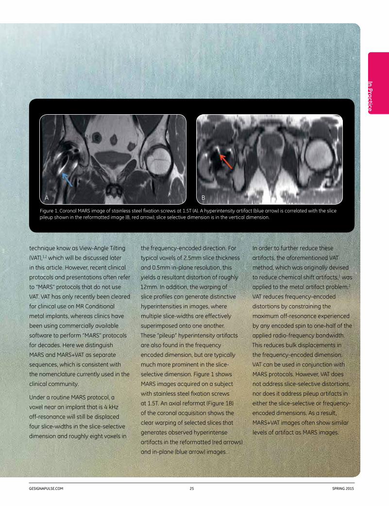
selective dimension. Figure 1 shows
MARS images acquired on a subject
with stainless steel fixation screws
at 1.5T. An axial reformat (Figure 1B)
of the coronal acquisition shows the
clear warping of selected slices that
generates observed hyperintense
artifacts in the reformatted (red arrows)
and in-plane (blue arrow) images.
Figure 1. Coronal MARS image of stainless steel fixation screws at 1.5T (A). A hyperintensity artifact (blue arrow) is correlated with the slice pileup shown in the reformatted image (B, red arrow); slice selective dimension is in the vertical dimension.
A B

GEHEALTHCARE.COM/MR 26 SPRING 2015
MAVRIC SL, GE Healthcare’s technique
cleared for imaging around MR
Conditional implants, is a third
approach to 3D-MSI that represents an
evolution of the concepts originating
in the MAVRIC and SEMAC methods.
By merging the spectral strategy
of MAVRIC and the slab-selectivity
of SEMAC, MAVRIC SL provides an
efficient, practical, and minimal-
artifact approach for MR imaging
around MR Conditional implants.5
MAVRIC SL applies a generalized 3D
extension of the VAT principle to add
slab-selectivity to overlapping spectral
bins utilized in the non-selective
MAVRIC 3D-MSI approach. In addition,
the architecture of MAVRIC SL provides
an efficient means to distribute an
arbitrary number of pre-defined
spectral images across 3D-MSI
acquisitions.6 This application design
enables flexible image contrasts and
improves the acquisition SNR efficiency.
In this article, we demonstrate Proton-
Density (PD), STIR, and T1-weighted
(T1w) image contrasts, which are
commercially available and indicated
for use on MR Conditional implants.
To exemplify the limited impact of
VAT in reducing bulk image artifacts,
consider the previously analyzed voxel
resonating at 4 kHz off-resonance.
When including VAT in the MARS
protocol, the net displacement of this
voxel is only reduced to 10mm from
the original 12mm displacement using
only MARS. This is because 10mm of
the displacement in the MARS image
was due to slice-selective warping and
only 2mm of displacement was due
to frequency-encoded distortions. In
this case, VAT would improve the net
displacement of the voxel in question
by less than 20%.
Three-dimensional multi-spectral
imaging (3D-MSI) was developed to
provide a more substantial alternative
to susceptibility artifact reduction
near metal implants. There are two
broad approaches to 3D-MSI, which
are generally known as MAVRIC3 and
SEMAC.4 Both MAVRIC and SEMAC
reduce susceptibility artifacts by
limiting off-resonance distortions to
discretely applied RF excitation windows
and utilizing phase-encoding instead
of slice-selection processes. Referring
again to the previous example of a
voxel resonating at 4 kHz off-resonance,
a typical 3D-MSI acquisition will reduce
the total displacement to roughly 1mm,
compared to the total displacement
of 10mm for MARS+VAT and 12mm
for MARS.
Like MARS and VAT, 3D-MSI cannot
eliminate pileup artifacts in the
frequency encoded direction. In
the plurality of individual spectral
images that are combined in 3D-MSI
techniques, residual pileup artifacts
manifest as concentric rings near
implant interfaces. A substantial
difference between the MAVRIC and
SEMAC approaches to 3D-MSI is the
heavy overlap of spectral image
windows utilized in the MAVRIC
approach.5 This overlap substantially
reduces the conspicuity of residual
pileup artifacts. Despite these
advantages, a significant limitation
with the MAVRIC method is its lack
of slab-selectivity, which generates
wrap artifacts in hip, spine, and
shoulder exams.5
Kevin Koch, PhD,is an Associate Professor appointed in the
departments of Biophysics and Radiology
at the Medical College of Wisconsin in
Milwaukee, WI.

In Practice
GESIGNAPULSE.COM 27 SPRING 2015
(scan plane indicated in Figure 2D) PD
MAVRIC SL image (Figure 2F) clearly
indicates the adverse local tissue
reaction (red arrow). A substantial
portion of the reaction is obscured in
the axial PD MARS image (Figure 2C).
Following the severe ALTR assessment
provided by these images, the patient
was referred for total joint replacement.
Clinical Case 1
Figure 2 presents images of a
symptomatic patient instrumented with
a cobalt-chromium hip resurfacing
implant. T1w MARS and T1w MAVRIC SL
are shown in (Figure 2A) and (Figure 2D)
respectively. The MR Conditional
implant interface is clearly visualized in
the MAVRIC SL image, as indicated in
the accompanying radiograph (Figure
2G). The yellow arrow indicates an
adverse local tissue reaction that is not
visible in the MARS image (Figure 2A).
After gadolinium contrast injection,
delayed enhancement difference images
are shown for T1w MARS (Figure 2B)
and T1w MAVRIC SL (Figure 2C). In the
MAVRIC SL difference image (Figure 2E),
gadolinium uptake is clearly visualized
in ALTR regions near the implant
interface (blue arrows) that are
obscured by artifact in the MARS
difference image (Figure 2B). An axial
Figure 2. MARS (A-C) and MAVRIC SL (D-F) images of a hip resurfacing implant at 1.5T. The use of MAVRIC SL clearly visualizes regions of adverse local tissue reaction (arrows) in the T1w (D), contrast-subtracted (E), and proton density weighted (F) images. Implant is clearly visualized in the radiograph (G).
Rajeev Mannem, MD, is an Assistant Professor of Radiology at the
Medical College of Wisconsin in Milwaukee, WI.
A
D
B
E
C
F G

GEHEALTHCARE.COM/MR 28 SPRING 2015
Clinical Case 2
Figure 3 displays images of a
symptomatic patient instrumented
with stainless steel fixation screws
used to repair a femoral fracture. A
radiograph of the instrumented joint
is shown in Figure 3A. T1w MARS and
T1w MAVRIC SL images are shown in
Figure 3B and Figure 3C, respectively.
Avascular necrosis is clearly indicated
Clinical Case 3
MAVRIC SL can also be useful for
assessment of symptomatic total knee
replacements. Figure 4 shows images
of a patient reporting significant pain
in the patellar region. A radiograph of
the knee implant is shown in Figure 4E.
Proton-density weighted MARS and
MAVRIC SL STIR images are shown in
Figure 4A and Figure 4B, respectively.
The severe disruptions of assessment
near the implant are clearly visualized
in the MARS image (Figure 4A). In the
MAVRIC SL STIR image (Figure 4B),
pockets of fluid in the patellar region,
the joint space, and under the tibial
stem are clearly identified (blue arrows).
In addition, femoral osteolysis (red
arrow) is clearly identified in a different
location on the MAVRIC SL proton
density image (Figure 4D). This region
of osteolysis is clearly lost on the
correlated MARS image (Figure 4C).
(blue arrow) in the MAVRIC SL image
(Figure 3C), but is nearly completely
obscured by artifact in the MARS image
(Figure 3B). A MAVRIC SL STIR image
(Figure 3D) demonstrates widespread
edema throughout the femoral head
(green arrow) and a fluid collection
inferior to the necrotic bone. Following
the avascular necrosis assessment
provided by these images, the patient
was referred for total joint replacement.
Figure 3. Radiograph (A), MARS (B), and MAVRIC SL (C-D) images of fixation screws at 1.5T. The use of MAVRIC SL clearly visualizes necrosis (blue arrow) in the T1w image (C), along with fluid buildup (red arrow) and widespread edema (green arrow) in the STIR image (D).
Scott Erickson, MD, is a Professor of Radiology at the Medical
College of Wisconsin in Milwaukee, WI.
Mark Hohenwalter, MD, is an Associate Professor of Radiology
at the Medical College of Wisconsin in
Milwaukee, WI.
AB C D

In Practice
GESIGNAPULSE.COM 29 SPRING 2015
Kevin Koch, PhD, is an Associate Professor appointed in the departments of Biophysics and Radiology at the Medical College of Wisconsin in Milwaukee, WI. Dr. Koch’s work focuses on solving technical challenges in clinical MR applications. He has been working for over eight years on reducing metal artifacts in MR, particularly focusing on 3D-MSI technical development and clinical application.
Rajeev Mannem, MD, is an Assistant Professor of Radiology at the Medical College of Wisconsin in Milwaukee, WI. Dr. Mannem’s clinical specialty is in body and musculoskeletal MR. Dr. Mannem is currently engaged in research investigations targeting advanced use of 3D-MSI in the clinic.
Scott Erickson, MD, is a Professor of Radiology at the Medical College of Wisconsin in Milwaukee, WI. Dr. Erickson’s clinical specialty is in body and musculoskeletal MR. Erickson is currently engaged in research investigations targeting advanced use of 3D-MSI in the clinic.
Mark Hohenwalter, MD, is an Associate Professor of Radiology at the Medical College of Wisconsin in Milwaukee, WI. Dr. Hohenwalter is the Director of Body and Musculoskeletal MRI as well as the Vice Chair of Education at the Medical College of Wisconsin. Dr. Hohenwalter is currently engaged in research investigations targeting advanced use of 3D-MSI in the clinic.
The Medical College of Wisconsin is a private, freestanding medical school and graduate school of sciences located in Milwaukee.
images in the immediate vicinity of
implant interfaces. The successful
mitigation of most artifacts in these
regions has generated more confidence
in the ability of MR to help identify the
source of a variety of conditions in
patients with MR Conditional implants
referred for diagnostic imaging.
References
1. Cho Z, Kim D, Kim Y. Total inhomogeneity correction including chemical shifts and susceptibility by view angle tilting. Med Phys 1988; 15:7–11.
2. Olsen RV, Munk PL, Lee MJ, et al. Metal artifact reduction sequence: early clinical applications. RadioGraphics 2000; 20:699–712.
3. Koch KM, Lorbiecki JE, Hinks RS, King KF. A multispectral three-dimensional acquisition technique for imaging near metal implants. Magn Reson Med 2009; 61:381–390.
4. Lu W, Pauly KB, Gold GE, Pauly JM, Hargreaves BA. SEMAC: slice encoding for metal artifact correction in MRI. Magn Reson Med 2009; 62: 66–76.
5. Koch KM, Brau ACS, Chen W, Gold G, Hargreaves B, Koff M, Potter P, and King K. Imaging near metal with a MAVRIC-SEMAC hybrid. Magn Reson Med 2011; 65:71–82.
6. Koch KM, Koff MF, Shah PH, Kanwischer A, Gui D, Potter HG, Flexible longitudinal magnetization contrast in spectrally overlapped 3D-MSI metal artifact reduction sequences: Technical considerations and clinical impact, Magn. Reson Med 2015, DOI: 10.1002/mrm.25518.
Conclusion
The preceding clinical examples
demonstrate that judicious use of
the multiple image contrasts feasible
with MAVRIC SL can enable a variety
of diagnostic capabilities that were
previously unattainable with MARS
or MARS+VAT technologies. A key
component of these differentiating
capabilities is the ability to assess
Figure 4. Images of a painful total knee replacement at 1.5T MARS proton density images (A,C), MAVRIC SL STIR image (B), MAVRIC SL proton density image (D), radiograph of implant (E). Pockets of fluid buildup are clearly identified on the MAVRIC SL STIR image (blue arrows). Femoral osteolysis is identified on the MAVRIC SL proton density image (red arrow).
A B
C D
E

GEHEALTHCARE.COM/MR 30 SPRING 2015
In Practice
Whole Body MR for Visualizing Metastatic Prostate CancerProstate cancer is the second most common cancer in men worldwide, accounting for 15% of all new cancer cases.1 Great strides have been made in the detection of prostate cancer and corresponding drop in mortality rates due to the introduction of the prostate specific antigen (PSA) test in the late 1980s. This test has led to a 65% reduction in men being initially diagnosed with metastatic cancer due to early detection of the disease.2 But metastatic disease remains a major therapeutic challenge.

In Practice
GESIGNAPULSE.COM 31 SPRING 2015
A 2012 study published in European
Urology by Professor Lecouvet and
colleagues examined the use of whole
body MR with DWI as a potential
single-test for detecting metastatic
prostate cancer compared to using
both scintigraphy and CT as the
other visualization tools. The authors
concluded that whole body MR
outperformed scintigraphy in more
clearly allowing the identification of
bone metastases and performed as
well as CT in helping clinicians with
their evaluation of enlarged lymph
nodes.3
Patients with metastatic disease may
benefit from recent advances in therapy
e.g., chemotherapy, novel endocrine
agents, and immunotherapy, which
may allow a significant prolongation
of survival but also help to improve
quality of life. These modern treatments
require optimal metastases detection
before their initiation, and monitoring
of their efficacy by evaluation of lesion
response to help the clinician in the
sequencing of these drugs.
While MR is now routinely utilized by
clinicians in determining a diagnosis
and studying the localized extent of
prostate cancer, Frederic Lecouvet,
MD, PhD, Professor of Radiology
and Head of the MRI Unit in the
Radiology Department at the Cliniques
Universitaires Saint Luc, Université
Catholique de Louvain (UCL), in
Brussels, believes that whole body
MR is an excellent tool for visualizing
metastatic disease and is one of the
more promising tools that assists the
clinician in determining the global
extent of the disease.
“Whole body MR is gaining interest
and acceptance as a tool for lesion
visualization in metastatic cancer
and hematologic malignancies,” says
Professor Lecouvet. Metastatic prostate
cancer most often manifests in the
bones and lymph nodes.
“ Whole body MR is gaining interest and acceptance as a tool for lesion visualization in metastatic cancer and hematologic malignancies.„
Professor Frederic Lecouvet
Frederic Lecouvet, MD, PhD,is a Professor of Radiology and Head of the
MRI Unit in the Radiology Department at the
Cliniques Universitaires Saint Luc, Université
Catholique de Louvain, in Brussels, Belgium.

GEHEALTHCARE.COM/MR 32 SPRING 2015
“Whole body MR that includes anatomic,
most often T1- and STIR-weighted
images, and functional sequences,
diffusion-weighted images, offers the
opportunity to target all metastases—
both bone and lymph nodes—using
only one examination,” says Professor
Lecouvet. “Whole body MR is an
effective tool we use to obtain a clear
extent of the metastatic disease in
order to determine treatment planning
decisions. There are other patient
The lack of specificity and sensitivity
of the routinely used methods to
diagnose metastases of prostate
cancer is well described in the
literature, adds Professor Lecouvet.
“Benign bone lesions, fractures,
inflammatory or degenerative joint
disease may cause false positive
observations,” he says. “When it
comes to lack of sensitivity, more
recent imaging techniques, such as
MR and choline PET, have shown
that negative observations from
previously used imaging modalities
could ignore significant lesions.
This could have major therapeutic
implications.” For example, a patient
with newly diagnosed prostate cancer
and a false negative metastatic
work-up could unnecessarily undergo
a prostatectomy when, in fact, he
has metastatic prostate cancer that
requires a different (i.e. systemic)
treatment regimen, Professor Lecouvet
explains.
Figure 1. A whole-body MR examination including anatomic T1 and functional DWI MR sequences in a patient in his 60s with newly diagnosed prostate cancer (time of acquisition: 24 minutes). Coronal whole body T1 images (A, B) show right iliac and left sacral bone metastases (arrows) and right iliac (arrowhead) and pararectal (curved arrow) node metastases. The bone (arrows) and node (arrowhead and curved arrow) are evident on whole body DWI images (C, D).
A B C

In Practice
GESIGNAPULSE.COM 33 SPRING 2015
enabled the clinicians to evaluate areas
that are typically difficult to study with
conventional 2D sequences, such as
the ribs, sternum, skull, abdomen/pelvis,
and posterior vertebral elements.4
“Scientific evaluation of the value of
3D compared to 2D sequences has
shown improvements in terms of
signal, thin sections, and multiplanar
reconstructions,” Professor Lecouvet
explains. In addition to detection
with 3D T1-weighted, it is possible
to accurately delineate the precise
benefits as well,” he explains. “The
patients are provided with optimal
information on the metastases in
one step.
While Professor Lecouvet is very excited
at the potential for utilizing whole body
MR with DWI, he also envisions a bright
future for the use of 3D (at this time
T1-weighted) MR sequences as the
primary anatomic imaging component
of an MR examination to assist clinicians
in their evaluation of metastatic
prostate cancer.
As reported by Professor Lecouvet
and his colleagues in the April, 2015,
issue of Radiology, 3D T1-weighted
MR provides significantly better SNR
and CNR compared with 2D MR
sequences. With 3D T1-weighted,
the authors reported it was as
good or better for visualizing bone
metastases and captured “significantly
more node metastases as well as
significantly more node-positive
patients,” compared to whole body
2D sequences. In particular, 3D MR
Figure 1 (cont.). Fused T1 and DWI images clearly illustrate the lesions (E, F). Sagittal reformatted slice enables reliable study of the spine showing no metastases in this case (G).
D G
F
E

GEHEALTHCARE.COM/MR 34 SPRING 2015
lymphoma, where whole body MR can
challenge FDG PET for bone and soft
tissue lesion detection, and metastatic
breast cancer, which like prostate
cancer often metastasizes to the bone.
As a result of Professor Lecouvet’s work
and others in the field, whole body MR
utilizing both functional DWI and
morphologic 3D T1-weighted sequences
could become an ideal, one-step
imaging test for metastases imaging
in patients with prostate cancer.
References.
1. World Cancer Research Fund International.
2. Aus G, Bergdahl S, Lodding P, Lilja H, Hugosson J. Prostate cancer screening decreases the absolute risk of being diagnosed with advanced prostate cancer—results from a prospective, population based randomized controlled trial. Eur Urol 2007;51:659–64.
3. Lecouvet, FE, El Mouedden J, Collette L, et al. Can Whole-body Magnetic Resonance Imaging with Diffusion-weighted Imaging Replace Tc 99m Bone Scanning and Computed Tomography for Single-step Detection of Metastases in Patients with High-risk Prostate Cancer? European Urology 62, 68–75 (2012).
4. Pasoglou, V, Michoux N, Peeters F, et al. Whole-Body 3D T1-weighted MR Imaging in Patients with Prostate Cancer: Feasibility and Evaluation in Screening for Metastatic Disease. Radiology 141242 (2014).
5. Lecouvet, FE, Larbi A, Pasoglou V, et al. MRI for response assessment in metastatic bone disease. European Radiology 2013; 23:1986–1997.
6. Dimopoulos, MA, Hillengass J, Usmani S,et al. Role of magnetic resonance imaging in the management of patients with multiple myeloma: a consensus statement. J. Clin. Oncol, 2015; 33:657–664.
location of the lesion and obtain
measurements. This capability is as
important for treatment monitoring;
anatomic MR sequences offer a high
sensitivity for evaluating treatment-
induced changes, especially in lesion
size, and are a helpful tool for the
clinician in determining if the lesion
responds, is stable, or progresses
during the course of therapy.5 This
is particularly useful for metastatic
prostate cancer, where there are
a variety of drugs that may be
successively introduced in cases
where there is a lack of response to
treatment.”
A 3D MR sequence also provides the
ability to shorten scan time by avoiding
the repetition of imaging planes and
reduces partial volume effects that
can occur with thicker image slices
and intersection gaps, he adds. At
UCL, the implementation of whole
body MR, including 3D T1-weighted
and DWI sequences, on the facility’s
Optima™ MR450w system for bone and
node visualization in prostate cancer
patients at high risk for metastases
are completed in less than 30 min.
While Professor Lecouvet
acknowledges that the lack of
reimbursement in some countries
for whole body MR may initially
limit its utilization, he believes the
overall potential financial benefit can
outweigh the initial imaging costs. “Its
cost might be attractive compared
to the sum of other, less effective
examinations used for visualizing
lesions,” he says. Add to this the cost
of unsuccessfully treating a patient
for a primary tumor when they have
metastatic disease, or continuing
expensive and potentially toxic
treatment that may not be effective,
and the health economic benefits
can be staggering.
“The ability of whole body MR to
overcome the challenges that other
imaging methods may have, such as
bone scintigraphy, is transposable to
imaging hematologic cancers, such
as multiple myeloma, where whole
body MR challenges radiographic
skeletal surveys and has been shown
to outperform for lesion detection,” he
adds.6 Professor Lecouvet also sees
potential use of MR in evaluating
Frederic Lecouvet, MD, PhD, is a Professor of Radiology and Head of the MRI Unit in the Radiology Department at the Cliniques Universitaires Saint Luc, Université Catholique de Louvain (UCL) in, Brussels, Belgium. He completed both his medical training and PhD at the UCL and has held many specialist teaching appointments focusing on imaging and specifically the use of MRI. Professor Lecouvet’s areas of expertise include imaging of the spine, joint and cartilage, orthopedic, rheumatologic and oncologic conditions, particularly bone tumors and metastases, and assessing response of lesions to modern treatments. Imaging in cancer and metastatic disease is one of the main fields of development for his research projects.
“ The ability of whole body MR to overcome the challenges that other imaging methods may have, such as bone scintigraphy, is transposable to imaging hematologic cancers, such as multiple myeloma, where whole body MR challenges radiographic skeletal surveys and has been shown to outperform for lesion detection.„
Professor Frederic Lecouvet

In Practice
GESIGNAPULSE.COM 35 SPRING 2015
Two Facilities, One GoalDirect Investigator Access to MR Image Reconstruction Environment Opens New Research Doors
Along with the continued push to develop
breakthrough MR applications comes
the need for researchers to have
comprehensive access to both pulse
sequence and image reconstruction
environments. While researchers have
been able to design and implement
their pulse sequences to run on a MR
scanner for many years, exploring
innovative and customer-based image
reconstruction ideas and generating
“readily presentable” images has always
been a challenge.
GE Healthcare’s new Orchestra
Software Development Kit (SDK)‡ now
gives customers direct access to GE’s
image reconstruction environment,
helping them develop novel
reconstruction algorithms in greatly
reduced time and with much more
consistent results.
The Orchestra SDK allows researchers
to implement the same image
reconstruction routines that are utilized
in a GE MR scanner on any computing
platform of their choice; however
hardware and software system
requirements and recommendations
should be followed to support
development. Through convenient
MATLAB® and C++ interfaces,
researchers can now apply their image
reconstruction algorithms to the raw
data from a scanner and incorporate
many previously inaccessible but
essential image reconstruction
features. Examples of these include
image un-aliasing with GE’s parallel
imaging routines (ASSET and ARC),
correction for gradient non-linearities
(GradWarp), insertion of DICOM images
into the scanner database, and much
more. The Orchestra SDK also includes
reconstruction examples from EPI to
Spectroscopy, and online help to get
In Practice
‡Orchestra SDK is not a medical device and not intended to treat, diagnose, nor cure any disease or condition. To be used for research purposes only.

GEHEALTHCARE.COM/MR 36 SPRING 2015
project, he has to utilize data from the
SWAN neuro application and apply new
processing algorithms to it . “In order
to make my prototype clinically viable,
I had to change the standard SWAN-
like pulse sequence and do some
unconventional things with it . I needed
the Orchestra reconstruction to allow
me to put that data back together so
I could refine the algorithms utilized in
this technology.”
Dr. Koch says that facilities are often
compelled to build their own imaging
software prototypes. “Researchers
need a lot of infrastructure to process
the data and do something equivalent
to the manufacturer. Until now, they
had to do that on their own. Orchestra
significantly lowers the barrier of entry
for those who want to embark on their
own research project.”
Additionally, having access to algorithms
is crucial, says Dr. Koch. “The Orchestra
code is so well commented that
researchers are now learning the
workflow of the algorithms. This gives
them an understanding for how the
reconstruction of algorithms are put
together, and how the final images are
processed. Plus, they are learning a lot
just from the comments that are in the
code itself. Orchestra really adds to the
education of researchers.”
users started—and the entire package
is available through a new customer
collaboration portal for GE research
customers.
Medical College of Wisconsin
Kevin Koch, PhD, Associate Professor,
Department of Biophysics and Radiology
at the Medical College of Wisconsin in
Milwaukee, WI, is leading two research
projects that are heavily dependent on
having access to the Orchestra SDK’s
reconstruction tools.
“These projects would have been
very difficult to accomplish before
Orchestra, because we did not have
access to the algorithms that would
allow us to examine the data offline
and put it back together to refine
our algorithms consistently with GE’s
product reconstruction,” says Dr. Koch.
“Currently, one of our big areas of
interest is to make the acquisition as
efficient as possible in order to improve
the SNR and reduce scan time.”
The first project involves reducing
susceptibility artifacts using GE
Healthcare’s MAVRIC SL—a sequence
for imaging soft tissue and bone near
MR Conditional and MR Safe metallic
implants. To conduct his research
effectively, Dr. Koch needs the ability
to alter the pulse sequence acquisition
and build new reconstruction
processing algorithms from the data
pipelines. He is also utilizing the
tool to aid in adding new contrast
mechanisms to MAVRIC SL and
improve the way fat signal is saturated,
which is typically very difficult to do
around metal implants. “We now
have some very new ideas on how to
reprocess the MAVRIC SL data in order
to try and improve fat saturation.”
The Orchestra SDK is having the
same positive influence on Dr. Koch’s
brain imaging project—Quantitative
Susceptibility Mapping (part of the
GE/NFL Head Health Initiative)—which
focuses on traumatic brain injury
research and brain cancer. In this
Kevin Koch, PhD,is an Associate Professor in the
Department of Biophysics and Radiology
at the Medical College of Wisconsin in
Milwaukee, WI.
“ Previously, the options for processing the data in an alternate way were very limited. Even while sitting on the scanner, there were many things that could not be done. Because Orchestra is offline, researchers are not forced to sit at a scanner and play with settings in order to try and get the desired images. I want to be able to pull raw data and work on a reconstruction algorithm wherever I might be.„
Dr. Kevin Koch

In Practice
GESIGNAPULSE.COM 37 SPRING 2015
Because of this, Dr. Koch feels that the
industry can expect to see an uptick
in research efforts and development.
Those who previously did not pursue
an endeavor because of a lack of
infrastructure or knowledge of the
reconstruction algorithm might be
enticed to move forward now. “The
software design is streamlined, and the
MATLAB interface is very easy to use.
That’s the real power of it—it does not
have to be somebody who’s an expert
programmer in C or C++.”
Another benefit: Researchers and
clinicians no longer need to be tied to
the workstation or scanner. “Previously,
the options for processing the data
in an alternate way were very limited.
Even while sitting on the scanner, there
were many things that could not be
done. Because Orchestra is offline,
researchers are not forced to sit at a
scanner and adjust settings in order to
try and get the desired images. I want
to be able to pull raw data and work on
a reconstruction algorithm wherever I
might be,” comments Dr. Koch.
Furthermore, Dr. Koch is pleased that
the software is available on the Apple
Macintosh® platform. “The fact that
this is available on my development
platform of choice makes the workflow
so much easier. It’s also available on
on Linux and Windows, so it does not
matter what platform a researcher
is using… that provides freedom and
flexibility.”
The Orchestra SDK Customer
Collaboration Portal, https://
collaborate.mr.gehealthcare.com,
is the primary way users can obtain
the Orchestra SDK and then engage
collaboratively with other clinicians
and representatives at GE. The
interactive portal is open to anyone
with a GE MR system. Dr. Koch uses
the portal and says, “The management
of questions has been amazingly
efficient. I think that’s been crucial to
the success of Orchestra, because
without the quick feedback, it could be
tough for some researchers to get off
the ground—especially on some of the
more detailed projects and pipelines.
The responsiveness to questions on the
portal makes access to the tool kit a lot
easier and more streamlined.”
At the Medical College of Wisconsin,
Dr. Koch is assisting with six in-process
projects that are heavily basing their
research pipelines off of the Orchestra
SDK; projects that likely would not
have taken flight as quickly without the
tool kit. In addition to the Quantitative
Susceptibility Mapping and MAVRIC SL
projects, he and his collaborators are
utilizing Orchestra in several other
projects.
Dr. Koch offers this advice to his peers:
“Get engaged on the collaboration
portal, since the GE development team
is extremely responsive. I have even
been encouraging our students and
researchers to go to the portal if they
have a question that’s even remotely
difficult, because the experts will
provide an answer quickly.”
Figure 1. QSM algorithm stabilization development using components of the Orchestra SDK. An example of a brain tumor research subject where a resection cavity confounded conventional QSM algorithms applied to the magnetic field perturbation (A) results in streaking artifacts throughout the entire frontal cortex (B). Using newly developed QSM stabilization algorithms, these streaking artifacts can be significantly reduced (C). This work is being conducted in collaboration with Dr. Kathleen Schmainda and Casey Anderson and the Medical College of Wisconsin.
A B C

GEHEALTHCARE.COM/MR 38 SPRING 2015
finds Orchestra can help enhance his
research capability because it puts
many useful and GE-proprietary image
reconstruction features at his fingertips.
This allows him to implement and easily
insert a customer reconstruction
algorithm in the image reconstruction
pipeline.
Before the Orchestra SDK, Dr. Ma
says that even though he was able to
save the raw data on a scanner, the
overhead of just reading the raw data
and putting the reconstructed images
in a format presentable to a radiologist
can be quite daunting. “In order to
read the raw data, we had to learn the
raw data file structure and modify our
software codes every time there was a
scanner upgrade. More importantly, we
spectroscopic imaging technique (in
collaboration with Haesun Choi, MD,
Professor of Diagnostic Radiology,
MD Anderson Cancer Center), and
development of phase sensitive fast
Dixon imaging techniques with a range
of pulse sequences, such as extended
LAVA Flex and extended fast triple echo
Dixon. As a collaborator of the original
LAVA Flex, he is well acquainted with
the pulse sequence development
using GE’s EPIC environment, yet he
MD Anderson Cancer Center
Jingfei Ma, PhD, Professor and Director
of the MR Applications Laboratory,
Department of Imaging Physics,
Division of Diagnostic Imaging at The
University of Texas MD Anderson
Cancer Center in Houston, is also one
of the first users of the new image
reconstruction environment. He
currently uses the Orchestra SDK for
two projects in his lab: development
of a 3.0T multi-channel prostate MR
Figure 2. Spectroscopic images (A) of a prostate acquired on a GE Discovery™ MR750 3.0T scanner using only an eight channel torso phased array coil. The spectra of each individual receiver channel are displayed in separate panels (A).
Spectra with all individual channels combined for improved SNR and quality (B-G). A customized algorithm for spectral combination was implemented in Matlab and directly integrated into GE’s MRS software to generate DICOM-compatible outputs using the Orchestra SDK environment.
Jingfei Ma, PhD,is an ABR board-certified diagnostic
radiological physicist at the MD Anderson
Cancer Center in Houston, Texas.
A
B C D
E F G

GESIGNAPULSE.COM 39 SPRING 2015
In Practice
Dr. Ma and his collaborators were
able to leverage the Orchestra SDK
and in a very short time, create a
package that is being used in a clinical
validation study. “The goal of our
project was to investigate whether
prostate spectroscopic imaging can
be clinically performed using a multi-
channel surface coil. We need to
implement and evaluate different ways
of combining spectroscopic images
from the different receive channels.
From the beginning, to providing a
usable sequence with a spectrum that
a radiologist can read, it took us only a
few weeks rather than many months or
even longer if it were not for Orchestra.”
“The Orchestra SDK has definitely
facilitated our development and
collaboration with the radiologists.
It also has potential to simplify and
enhance collaborations across
different institutions.” Dr. Ma says,
“This tool kit has been on a wish list
of many MR researchers for a long
time.”
MATLAB is a registered trademark of The MathWorks, Inc.
Mac is a trademark of Apple Inc., registered in the U.S. and other countries.
Windows is a registered trademark of Microsoft Corporation in the United States and other countries.
Third party trademarks are the property of their respective owners.
did not have access to some essential
GE image reconstruction features
such as parallel imaging, GradWarp,
and image rotation. As a result, it
was difficult to directly compare a
technique we tried to develop with an
existing technique because the lack
of parallel imaging often precludes a
breath hold acquisition and the images
from our reconstruction would appear
distorted and mis-oriented without
GradWarp and proper geometric
rotation.”
Dr. Ma continues, “Often, to develop
a clinically useful technique, we work
closely with radiologists on image
quality assessment and the technique
is optimized iteratively with their
feedback. With the Orchestra SDK, the
images we reconstructed using our
algorithm can easily be installed back
into the patient image database, with
all the correct headers so a radiologist
can read them and do comparisons
just as if they were generated from a
scanner. Orchestra saves us a lot of
development time so I can focus on
the details of our algorithm itself.”
Dr. Ma further notes the importance
of having access to features, such
as GradWarp and parallel imaging.
Firstly, implementing these features
by a researcher outside GE would take
a tremendous amount of resources.
Also, since the features provided
by Orchestra are identical to those
used by a scanner. Image differences
or improvement over an existing
technique can be more confidently
attributed to the core algorithm
he tries to develop.
Increased flexibility is another
advantage with the ability to
perform reconstruction away from
the MR scanner and to incorporate
reconstruction code in both C++ and
MATLAB. “It is important that we can
do development work in different
platforms or workstations and even
send images into a PACS. It is a major
advancement that I can now insert
my MATLAB code, without having to
convert it to C++, in a package that
can read in MR raw data and generate
completely DICOM-compatible images,”
comments Dr. Ma. He is also using the
online collaboration portal. “It provides
an efficient group discussion forum
for different users and GE to exchange
information and post questions. The
response time has usually been very
short and I find it to be quite useful for
the work I am doing.”
For the project developing a 3.0T
multi-channel prostate MR
spectroscopic imaging technique,
Kevin Koch, PhD, is an Associate Professor in the Department of Biophysics and Radiology at the Medical College of Wisconsin in Milwaukee, WI. His main research interests are metal artifact reduction methods for MR and Quantitative Susceptibility Mapping in MR.
The Medical College of Wisconsin is a private, freestanding medical school and graduate school of sciences located in Milwaukee.
Jingfei Ma, PhD, is an ABR board-certified diagnostic radiological physicist at the MD Anderson Cancer Center in Houston, Texas. His main research interests are developing novel and clinically impactful MR pulse sequences and image reconstruction algorithms, as well as using MR for cancer characterization and therapy assessment.
The University of Texas MD Anderson Cancer Center in Houston is one of the original three comprehensive cancer centers in the United States established by the National Cancer Act of 1971.

GEHEALTHCARE.COM/MR 40 SPRING 2015
In Practice
Spectrum Medical Imaging is an
independent radiology practice
providing state-of-the-art imaging
services across Eastern and South
Western Sydney, Australia since
2009. The practice has seven
imaging centers, with two flagship
sites—Liverpool and Randwick—both
located near a main teaching hospital:
Liverpool Public Hospital and Prince
of Wales Public Hospital. At these two
sites and one other, Spectrum offers
MR imaging in addition to an array of
other advanced imaging services.
Spectrum Imaging Leverages DV25.0 Continuum Pak Applications
Wales Medical Centre

In Practice
GESIGNAPULSE.COM 41 SPRING 2015
The practice’s first MR scanner was a
SIGNA™ HDe 1.5T for the Liverpool site.
“We were just starting our practice, so
it was a very economical, well valued
scanner that we could use for all the
basic body, MSK, and neuro imaging,”
says Daniel Moses, MD, a radiologist at
Spectrum. While the system performed
well, Dr. Moses says the practice
wanted to take MR imaging to the
next level and have the capability to
provide more advanced and complex
imaging, particularly for the body. “A
lot of high end body work is not done
in the hospitals, so that gives practices
like ours the opportunity to do that
imaging in the clinics.”
In 2013, Spectrum replaced the
SIGNA HDe with an Optima™ MR450w
and also acquired its first 3.0T MR,
a Discovery™ MR750w. With these
scanners, the practice was also
able to expand into prostate MR
imaging services.
“The 3.0T is what really helped us
grow the prostate imaging service
line,” explains Dr. Moses. “We perform
prostate exams on the 1.5T and it’s
very good, but the 3.0T takes the
imaging to a new level and the image
quality enables more confidence in
our diagnosis.”
Spectrum and GE Healthcare have
developed a mutually collaborative
relationship. This enabled Spectrum
to be one of the first sites in the world
to have access to and evaluate the
DV25.0 Continuum™ Pak featuring an
array of new and expanded sequences,
including DISCO, SilentSuite, MAVRIC SL
2.0, Turbo LAVA, Cube DIR, and MDE Plus.
“ The major advantage, for me as a body imager, was the addition of DISCO. In our clinic, it allows for faster imaging, so for example in the liver we can get five arterial phases in one breath hold.„
Dr. Daniel Moses

GEHEALTHCARE.COM/MR 42 SPRING 2015
It also can achieve robust fat
suppression using a two-point Dixon
fat-water reconstruction algorithm,
which appears to be better suited than
conventional fat suppression methods
for combination with irregular k-space
sampling schemes such as DISCO.
DISCO is also very useful for prostate
imaging, where Dr. Moses has been
able to get the temporal resolution
as low as 3 seconds. While TRICKS
can help reduce temporal resolution,
it’s really designed for examining the
arteries, so it doesn’t provide good
contrast enhancement in the organs,
Dr. Moses explains.
Interest in body MR continues to
increase from referring physicians,
making it an important service line
for Spectrum.
“The major advantage, for me as a body
imager, was the addition of DISCO,”
says Dr. Moses. “In our clinic, it allows
for faster imaging, so for example
in the liver we can get five arterial
phases in one breath hold.” He explains
that before DISCO (Differential Sub-
sampling with Cartesian Ordering),
there could be timing issues with
capturing this phase correctly. It’s a very
important phase that would sometimes
be missed. Now, he can see it and feel
more confident that he probably hasn’t
missed anything (Figure 1 and 2).
“We also have LAVA Flex, and that is
slightly faster than DISCO, so we can
trade off fast imaging for good spatial
resolution when needed,” he adds.
DISCO uses a dual-echo 3D SPGR
sequence with pseudo-random
variable density k-space segmentation
and a view sharing reconstruction
to achieve high spatio-temporal
resolution. DISCO samples an
elliptically ordered central k-space
region every temporal frame, and sub-
samples the outer regions in a pseudo-
random fashion rendering aliasing
artifacts from sub-sampling incoherent.
Figure 1. Three images from five arterial phases acquired in 16 seconds using DISCO. Demonstrates progressive arterial enhancement pattern of hepatocellular carcinoma.
A B C
Daniel Moses, MD,is a radiologist at Spectrum Medical
Imaging in Sydney, Australia.
“ (With DISCO) I believe there is a huge difference between 7 seconds and 3 seconds, and if something enhances early you can see it at 3 seconds. At 7 seconds it dilutes out over time, so there is an improvement.„
Dr. Daniel Moses

In Practice
GESIGNAPULSE.COM 43 SPRING 2015
“When we used DISCO, we got the
same temporal resolution and contrast
resolution as TRICKS so it really did
make a difference in seeing the
enhancement,” he says. “I believe
there is a huge difference between
7 seconds and 3 seconds, and if
something enhances early you can
see it at 3 seconds. At 7 seconds it
dilutes out over time, so there is an
improvement.”
Also, with the faster reconstruction
time with the DV25.0 Continuum Pak,
Dr. Moses says that if needed, he can
review the images and determine if
additional imaging is needed while
the patient is still in the scanner. The
reduced reconstruction time has
also helped streamline workflow. “It
makes us more efficient, so we can get
through more cases, but we are also
more confident with our reports. That
helps us do a better job, which helps
us grow our business.”
According to Dr. Moses, Spectrum has
experienced a significant increase
in referrals for prostate MR imaging,
particularly from urologists. They have
gone from scanning approximately
10 patients each month to between
80 and 100.
In prostate imaging, Dr. Moses will also
use PURE, a technique for enabling
uniformity across the field even in
areas of the body that are further from
the coil. “It’s nice to see a uniform
image across the entire field of view;
that helps us see odd things that we
could otherwise miss.”
FOCUS is also useful for imaging
the prostate and rectum, Dr. Moses
says. “The higher spatial resolution
was quickly apparent and it has made
a difference in terms of localizing
features of the lesion.” He was using
FOCUS in parallel with a standard
Figure 2. Images from a 5 arterial phase DISCO sequence acquired in approximately 3 seconds. Pre-contrast (A) and optimal arterial contrast showing FNH (B).
A
C
B
D

GEHEALTHCARE.COM/MR 44 SPRING 2015
DWI sequence, but has now dropped
the DWI as FOCUS provides him the
information he needs to make a
confident diagnosis.
Previously with DWI, he observed
frequent failed scans due to severe
geometric distortion at air-tissue
interfaces around the prostate and
rectum. In addition, many elderly
prostate cancer patients have hip
prosthesis. With FOCUS he is able to
obtain diagnostic quality DWI images
even in patients with bi-lateral hip
replacement (Figure 4).
The practice is also ramping up use of
SilentScan, especially for pediatrics. In
the DV25.0 Continuum Pak, SilentScan
can be used with T1, T2, MRA, and DWI
sequences.
Having these imaging advantages is
important for our practice, Dr. Moses
says, but it’s even more important
for our patients. “A good percentage
of patients will benefit in liver follow-
up studies with our use of DISCO,”
he says. “In radiology, having these
advancements along with some of
the best technology available is just
good for both our clinicians and
our patients.”
Figure 4. Patient with bi-lateral hip replacement. FOCUS DWI with the b-value (A); corresponding ADC map indicates hypo intense signal in the anterior part of the prostate (B); and T2 (C).
A B C
Figure 3. Images demonstrate excellent spatial and contrast resolution at 3.0T in the FOCUS diffusion weighted sequences (A), the ADC derived from FOCUS (B), and the T2w (C).
A B C
“ The higher spatial resolution (of FOCUS) was immediately apparent and it has made a difference in terms of localizing features of the lesion.„
Dr. Daniel Moses
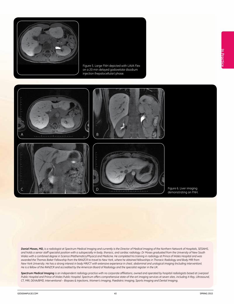
In Practice
GESIGNAPULSE.COM 45 SPRING 2015
Daniel Moses, MD, is a radiologist at Spectrum Medical Imaging and currently is the Director of Medical Imaging of the Northern Network of Hospitals, SESIAHS, and holds a senior staff specialist position with a subspecialty in body, thoracic, and cardiac radiology. Dr Moses graduated from the University of New South Wales with a combined degree in Science (Mathematics/Physics) and Medicine. He completed his training in radiology at Prince of Wales Hospital and was awarded the Thomas Baker Fellowship from the RANZCR to travel to New York, where he obtained fellowships in Thoracic Radiology and Body MRI from New York University. He has a strong interest in body MR/CT with extensive experience in chest, abdominal and urological imaging (including intervention). He is a fellow of the RANZCR and accredited by the American Board of Radiology and the specialist register in the UK.
Spectrum Medical Imaging is an independent radiology practice with no corporate affiliations, owned and operated by hospital radiologists based at Liverpool Public Hospital and Prince of Wales Public Hospital. Spectrum offers comprehensive state-of-the-art imaging services at seven sites, including X-Ray, Ultrasound, CT, MRI, DEXA/BMD, Interventional – Biopsies & Injections, Women’s Imaging, Paediatric Imaging, Sports Imaging and Dental Imaging.
Figure 5. Large FNH depicted with LAVA Flex on a 20 min delayed gadoxetate disodium injection (hepatocellular) phase.
Figure 6. Liver imaging demonstrating an FNH.
A
C
B
D

GEHEALTHCARE.COM/MR 46 SPRING 2015
In Practice
Leading MR advancements
SJHH recently upgraded to GE’s new
DV25.0 Continuum™ Pak, which provides
the facility with leading MR advancements
while expanding commitment to
patient care. The facility’s clinicians are
currently utilizing Turbo LAVA, which
provides up to 40% reduced breath
hold times compared to conventional
techniques, and DISCO (Differential
Sub-sampling with Cartesian Ordering),
which uses a dual-echo 3D SPGR
sequence with pseudo-random
variable density k-space segmentation
and a view-sharing reconstruction
to achieve high spatio-temporal
resolution.
St. Joseph’s Healthcare Hamilton
(SJHH) in Ontario, Canada is a premier
academic and research healthcare
organization. Its diagnostic imaging
department houses a state-of-the-
art imaging facility where more than
200,000 procedures and examinations
are performed annually. The MR
studies, which are done on an Optima™
MR450w with GEM from GE Healthcare,
include angiography, body, brain,
cardiac, head, MSK, and spine.
According to Ryan Rebello, MD, Director
of MRI and a radiologist at SJHH, the
outpatient department scans around
40 abdomen, pelvis, and vascular
cases each week. “We are one of the
biggest providers of MR enterography
in southwest Ontario performing more
than 20 cases each week. Additionally,
as a tertiary care nephrology and
urology center, we perform a high
volume of renal MR.”
Janet Burr, Senior MRI Technologist at
SJHH, says that because of the facility’s
patient population with multiple co-
morbidities, breath holding is often
an issue. “Anything that can increase
speed of the acquisition post-contrast
is a big benefit for us.”
DV25.0 Continuum Pak Upgrade Helps Facility Reduce Breath Hold Times and Optimize Exams

In Practice
GESIGNAPULSE.COM 47 SPRING 2015
temporal information in addition to
anatomic detail,” offers Burr.
Every MR center is challenged with the
need for efficiency while maintaining
quality, according to Burr. “DV25.0
Continuum Pak has helped us scan in
a very efficient way with reproducible
image quality produced by multiple
technologists.”
Dr. Rebello concurs. “Having a more
powerful reconstruction engine,
provided by DISCO and the upgrade
to DV25.0, has been an extra benefit
for us and our patients. In most of
our vascular protocols we use time-
resolved MRA or TRICKS, and now the
computer reconstruction time is very
fast, in terms of being able to review
the imaging and target any post-
contrast imaging, to what appears on
the MR angiogram.”
“For body imaging, we can use Turbo
LAVA Flex pre- and post-contrast, and
the images are of very good quality.
Included in this 3D acquisition we
get in- and out-of-phase information,
resulting in time savings,” says
Burr. “The breath hold times can be
decreased, so if a patient can not
hold their breath very well, we can
manipulate that time and still obtain
excellent quality images.”
For example Dr. Rebello explains, “With
Turbo LAVA, a breath hold for liver or
kidneys is now around 14 seconds…
that’s 4 or 5 seconds shorter than
before, which can make a world of
difference in some of our patients. Plus,
a lower percentage of post-Gadolinium
sequences are affected by motion
artifact. By minimizing motion artifacts,
we get a better percentage of usable
diagnostic scans for more confidence
in our reports.”
Burr continues that thought, “While it’s
difficult to get images from a certain
percentage of our patient population,
Turbo LAVA provides us with diagnostic
sequences giving us more confidence
in our reports. On the other hand, if
we have an optimal patient, we get
beautiful images. Plus, the sequences
are done quickly, as we are always
balancing efficiency versus quality.”
Furthermore, SJHH is very pleased with
DISCO. “When we received DISCO we
implemented it into as many different
protocols as possible. Wherever we
would have done a multi-phase post-
contrast sequence, we replaced the
arterial phase with the new application.
It is an opportunity for us to capture
A
C
B
D
Figure 1. Female pelvis on a patient with Ewing sarcoma of the bladder. DISCO LAVA Flex water images showing pre- and post-contrast arrival (A, B, and C). Temporal resolution for this exam was 5 seconds per phase. Turbo LAVA Flex post contrast images (D).
DISCO parameters 320 x 224 4.4mm slice thickness 5 seconds per phase 5 phases
Turbo LAVA parameters 320 x 192 4mm slice thickness 20 seconds

GEHEALTHCARE.COM/MR 48 SPRING 2015
and helps us more definitively
characterize something as HCC—if we
have multiple 4-5 second passes as
opposed to one longer arterial phase.”
Burr states, “Considering our patient
population, a failed breath hold during
the arterial phase could be considered
a non-diagnostic exam. If patients
can only hold their breath for 4 or
5 seconds, we might end up with a
successful exam if we have at least
some information in one of the arterial
phases.”
Dr. Rebello concurs. “We have a better
chance of getting a diagnostic set of
images with one of those 4 second
phases with DISCO versus 14 to 18
seconds with LAVA or Turbo LAVA. It
gives us more flexibility.”
More information, flexibility
“With the upgrade, there are so many
factors that we can change—spatial
resolution, temporal resolution, number
of phases,” states Dr. Rebello. “We
do most of our DISCO exams with
between 5 and 8 phases and we
typically aim for arterial phase imaging.
By doing so, we get more perfusion
information; for example, when
assessing disease activity in Crohn’s
patients with MR enterography. This
type of information offers us insight into
physiology and pathology in addition
to a good amount of anatomic detail.”
Dr. Rebello says that with hypervascular
lesions in the liver, such as hepatocellular
carcinoma (HCC) or neuroendocrine
metastases, if the arterial phase timing
is off or blurred by motion artifact, the
diagnosis can be missed or uncertain.
“But the DISCO upgrade gives us extra
scope to catch arterial enhancement
Ryan Rebello, MD,is the Director of MRI and a radiologist
at St. Joseph’s Healthcare Hamilton in
Ontario, Canada.
A
C
B
D
Figure 2. Kidney exam performed on a patient with von Hippel-Lindau with multiple renal and pancreatic cysts.
DISCO LAVA Flex water images showing pre- and post-contrast arrival (A, B, and C). Temporal resolution for this exam was 3 seconds per phase. Turbo LAVA Flex post contrast images (D).
DISCO parameters 256 x 192 4mm slice thickness 3.6 seconds per phase 5 phases
Turbo LAVA parameters 288 x 192 4.4mm slice thickness 16 seconds

In Practice
GESIGNAPULSE.COM 49 SPRING 2015
Ryan Rebello, MD, is the Director of MRI and a radiologist at St. Joseph’s Healthcare Hamilton in Ontario, Canada. He has been a radiologist at SJHH for 11 years, with an interest in body, vascular, and neuro imaging.
Janet Burr, is a Senior MRI Technologist at St. Joseph’s Healthcare Hamilton in Ontario, Canada. She has been a technologist for 23 years with almost 20 years of MRI experience.
St. Joseph’s Healthcare Hamilton (SJHH) in Ontario, Canada is a premier academic and research healthcare organization. Its diagnostic imaging department houses a state-of-the-art imaging facility where more than 200,000 procedures and examinations are performed annually.
neo-angiogenesis, and response to
therapy in a wide array of conditions.
DV25.0 affords us a variety of imaging
options and flexibility that can be
tailored to suit an expanding and
diversifying MR patient population.”
“Over the last several years, SJHH’s MR
exams have shifted to higher acuity
requests,” according to Burr. Dr. Rebello
states that the upgrade “allows us to
scan patients that previously we would
not have considered for MR due to long
exam times and lengthy breath holds.
Previously, we may have used an
alternative modality such as CT.”
In conclusion, Burr notes, “DV25.0
has given us increased confidence,
reproducibility, and speed.”
Dr. Rebello comments, “It allows us
to get physiological information and
reasonable spatial resolution in a short
breath hold. Furthermore, it provides
us with a better image in order for
assessment of disease activity,
Janet Burr,is a Senior MRI Technologist at St. Joseph’s
Healthcare Hamilton in Ontario, Canada.
“ (DV25.0) allows us to get physiological information and reasonable spatial resolution in a short breath hold. Furthermore, it provides us with a better image in order for assessment of disease activity, neo-angiogenesis, and response to therapy in a wide array of conditions. DV25.0 affords us a variety of imaging options and flexibility that can be tailored to suit an expanding and diversifying MR patient population.„
Dr. Ryan Rebello

Francois D’Anthouard, MD,is a radiologist at GIE IRM Creil
in Creil, France.
DIGITAL DIVEFor parameters go to tiny.cc/sps151
GEHEALTHCARE.COM/MR 50 SPRING 2015
High-resolution Breast Imaging with DV25.0 Continuum Pak and DISCO By Francois D’Anthouard, MD, Radiologist, GIE IRM Creil, France
Optima™ MR450w with GEM
Introduction
Dynamic contrast-enhanced MR (DCE MR) is commonly used for detection
and characterization of malignancies in the breast. However, suboptimal
compromises are often made between temporal and spatial resolution
in conventional breast DCE MR1. A high spatial resolution is required to
characterize lesion morphology, whereas a high temporal resolution is
required to accurately characterize contrast uptake both for semi-quantitative
and quantitative analysis of contrast enhancement kinetics.
Conventional clinical breast DCE MR often falls into either high spatial (low
temporal) resolution or high temporal (low spatial) resolution regimes,1,2
although high spatial resolution imaging is increasingly being used. The
American College of Radiology guidelines recommend 1mm in-plane spatial
resolution, slice thickness of 3mm or less, and enhancement data acquired
at intervals spaced 120 sec or less.
MR technique
Figure 1 depicts the DISCO-DCE acquisition scheme and the k-space segmentation
used in our breast DCE MR acquisitions. The innermost region A is fully sampled
while the middle annulus B is undersampled trifold as B1, B2, and B3. The
relative fractional sizes of A and B1 are 0.3 and (1–0.3)/3 = 0.23 respectively.
Figure 2 depicts the data acquisition pattern to obtain the subsequent phases
of the DISCO acquisition: A high spatial resolution pre-contrast acquisition was
acquired covering the entire k-space (includes all regions).
Following injection of contrast media, dynamic images with short temporal
resolution were acquired over a period of several minutes, where only a part of
k-space (B region) was acquired for each dynamic phase. Each phase was then
Case Study | DISCO Breast
Figure 1. Depicts the DISCO-DCE acquisition scheme.
Figure 2. Depicts the data acquisition pattern.
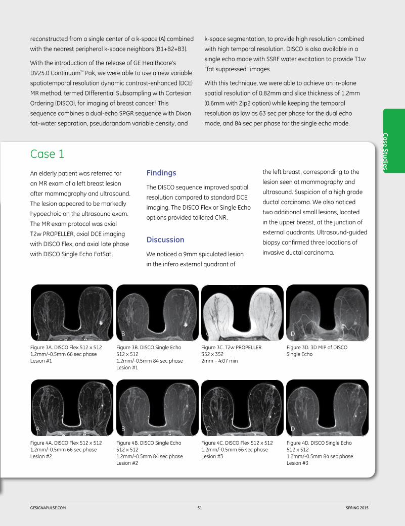
Case 1
Case Studies
GESIGNAPULSE.COM 51 SPRING 2015
reconstructed from a single center of a k-space (A) combined
with the nearest peripheral k-space neighbors (B1+B2+B3).
With the introduction of the release of GE Healthcare’s
DV25.0 Continuum™ Pak, we were able to use a new variable
spatiotemporal resolution dynamic contrast-enhanced (DCE)
MR method, termed DIfferential Subsampling with Cartesian
Ordering (DISCO), for imaging of breast cancer.2 This
sequence combines a dual-echo SPGR sequence with Dixon
fat–water separation, pseudorandom variable density, and
k-space segmentation, to provide high resolution combined
with high temporal resolution. DISCO is also available in a
single echo mode with SSRF water excitation to provide T1w
“fat suppressed” images.
With this technique, we were able to achieve an in-plane
spatial resolution of 0.82mm and slice thickness of 1.2mm
(0.6mm with Zip2 option) while keeping the temporal
resolution as low as 63 sec per phase for the dual echo
mode, and 84 sec per phase for the single echo mode.
An elderly patient was referred for
an MR exam of a left breast lesion
after mammography and ultrasound.
The lesion appeared to be markedly
hypoechoic on the ultrasound exam.
The MR exam protocol was axial
T2w PROPELLER, axial DCE imaging
with DISCO Flex, and axial late phase
with DISCO Single Echo FatSat.
Findings
The DISCO sequence improved spatial
resolution compared to standard DCE
imaging. The DISCO Flex or Single Echo
options provided tailored CNR.
Discussion
We noticed a 9mm spiculated lesion
in the infero external quadrant of
the left breast, corresponding to the
lesion seen at mammography and
ultrasound. Suspicion of a high grade
ductal carcinoma. We also noticed
two additional small lesions, located
in the upper breast, at the junction of
external quadrants. Ultrasound-guided
biopsy confirmed three locations of
invasive ductal carcinoma.
B
B
A
A
C
C
D
D
Figure 3A. DISCO Flex 512 x 512 1.2mm/-0.5mm 66 sec phase Lesion #1
Figure 4A. DISCO Flex 512 x 512 1.2mm/-0.5mm 66 sec phase Lesion #2
Figure 3B. DISCO Single Echo 512 x 512 1.2mm/-0.5mm 84 sec phase Lesion #1
Figure 4B. DISCO Single Echo 512 x 512 1.2mm/-0.5mm 84 sec phase Lesion #2
Figure 3C. T2w PROPELLER 352 x 352 2mm – 4:07 min
Figure 4C. DISCO Flex 512 x 512 1.2mm/-0.5mm 66 sec phase Lesion #3
Figure 3D. 3D MIP of DISCO Single Echo
Figure 4D. DISCO Single Echo 512 x 512 1.2mm/-0.5mm 84 sec phase Lesion #3

Case One
Case 2
350
300
250
200
150
100
50
320.1
50 300250200150100790
0
Time (s)
Sign
al %
GEHEALTHCARE.COM/MR 52 SPRING 2015
Francois D’Anthouard, MD, is a general radiologist with a particular focus on women’s imaging at GIE IRM Creil in Paris, France.
GIE IRM in Creil, France specializes in MR, ultrasound, X-ray, CT, mammography, and bone densitometry.
A female patient was temporarily
classified as BI-RADS™ category
ACR 0 from a follow-up ultrasound
and mammogram, performed one
month before the MR exam, because
of a small (4.7mm) opacity well
circumscribed within very regular
borders—located 3mm below a clip
placed four years earlier during
stereotactic macrobiopsy that
confirmed dystrophy.
Findings
Dynamic 3D DISCO, 5122 matrix, 1.2mm
slice thickness, four phases every
90 seconds. Exam is interpreted by
reviewing the native images with and
without subtraction, and analyzing
the contrast (Gd) uptake curves on AW.
Left breast: clip is visible on the MR
images due to the susceptibility signal
void it generates. A micro nodular
contrast enhancement, 3mm below
the clip, corresponds to the ultrasound
image. Borders are well delimited,
with a round anterior portion and a
rectilinear posterior portion. On the
sagittal views, the anterior borders
of the lesion are slightly less regular.
No other enhancement on the
left breast. Right breast: no focal
enhancement and no detectable
anomaly in the axillary region.
Discussion
Focal contrast enhancement right
below the clip is in agreement with the
ultrasound image that motivated the
MR exam. Ultrasound-guided biopsy
confirms invasive ductal carcinoma.
References
1. Kuhl CK, Schild HH, Morakkabati N. Dynamic bilateral contrast enhanced MR imaging of the breast: trade-off between spatial and temporal resolution. Radiology 2005; 236:789–800.
2. Saranathan M, Rettmann DW, Hargreaves BA, Clarke SE, Vasanawala SS. DIfferential subsampling with cartesian ordering (DISCO): a high spatio-temporal resolution Dixon imaging sequence for multiphasic contrast enhanced abdominal imaging. J Magn Reson Imaging 2012; 35:1484–1492.
Figure 5A. Contrast uptake of the lesion in percentage of signal intensity.
Figure 5C. DISCO water, sagittal reformat at maximum uptake time (79 sec).
Figure 5D. DISCO in-phase, sagittal reformat, initial phase.
Figure 5B. Color map of the maximum slope of signal increase.
Figure 5E. DISCO water, native axial at maximum uptake time (79 sec).
Figure 5F. Close up of left breast.
A
C
B
D E F
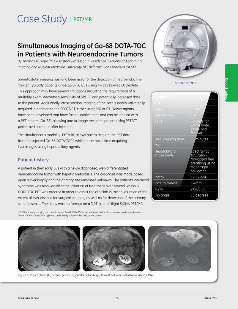
Case Studies
GESIGNAPULSE.COM 53 SPRING 2015
Case Study | PET/MR
SIGNA™ PET/MR
Simultaneous Imaging of Ga-68 DOTA-TOC in Patients with Neuroendocrine TumorsBy Thomas A. Hope, MD, Assistant Professor in Residence, Sections of Abdominal
Imaging and Nuclear Medicine, University of California, San Francisco (UCSF)
Somatostatin imaging has long been used for the detection of neuroendocrine
cancer. Typically patients undergo SPECT/CT using In-111 labeled Octreotide.
This approach may have several limitations including the requirement of a
multiday exam, decreased sensitivity of SPECT, and potentially increased dose
to the patient. Additionally, cross section imaging of the liver is nearly universally
acquired in addition to the SPECT/CT, either using MR or CT. Newer agents
have been developed that have faster uptake times and can be labeled with
a PET emitter (Ga-68), allowing one to image the same patient using PET/CT
performed one hour after injection.
The simultaneous modality, PET/MR, allows one to acquire the PET data
from the injected Ga-68 DOTA-TOC‡, while at the same time acquiring
liver images using hepatobiliary agents.
Patient history
A patient in their early 60s with a newly diagnosed, well-differentiated
neuroendocrine tumor with hepatic metastasis. The diagnosis was made based
upon a liver biopsy and the primary site remained unknown. The patient’s carcinoid
syndrome was resolved after the initiation of treatment over several weeks. A
DOTA-TOC PET was ordered in order to assist the clinician in their evaluation of the
extent of liver disease for surgical planning as well as for detection of the primary
site of disease. The study was performed on a 3.0T time-of-flight SIGNA PET/MR.
Figure 1. Pre-contrast (A), arterial phase (B), and hepatobiliary phase (C) of liver metastases using LAVA.
BA C
‡UCSF is currently studying the potential use of Ga-68 DOTA-TOC tracer in the evaluation of certain neuroendocrine disorders. Ga-68 DOTA-TOC is not FDA approved and is being utilized in this study under an IND.
Parameters
PET
Dose: 5.6 mCi
Uptake time: 2:15
Beds: Six beds for whole body, single bed for liver
Total imaging time: 58 minutes
MR
Hepatobiliary phase LAVA:
Spectral fat saturation; Navigated free breathing using diaphragm navigator
Matrix: 320 x 224
Slice thickness: 3.4mm
TE/TR: 2.04/5.59
Flip angle: 35 degrees

GEHEALTHCARE.COM/MR 54 SPRING 2015
Findings
DOTA-TOC PET/MR visualized innumerable somatostatin
receptor positive masses in the liver consistent with known
hepatic metastasis. The navigated axial LAVA hepatobiliary
phase images accurately delineate the tumor margins with
a high sensitivity. Additionally, the PET/MR imaged focal
uptake in the terminal ileum, which was not seen on a prior
CT of the abdomen and pelvis. Also, multiple avid nodules
were noted by the clinician in the mesenteric root as well as
along the splenic flexure. The patient is planned to undergo
debulking surgery to remove the primary tumor as well as
decrease the liver tumor burden.
Discussion
The simultaneous modality PET/MR is a great complement
to imaging patients with neuroendocrine tumor. Previously,
patients underwent a multiday OctreoScan SPECT study and
additionally had multiple liver specific imaging studies. With
simultaneous PET/MR imaging, patients can undergo a single
study performed in less than one hour using less radiation
dose than is associated with an OctreoScan.
Additionally, the high-resolution navigated hepatobiliary
phase imaging provides the clinician with information
to accurately delineate tumor margins and helps them
in treatment planning for surgical resection. In the liver,
the navigated imaging is acquired during normal shallow
respiration and therefore fuses more accurately to the
acquired PET data than conventional breath hold MRI.
We are just beginning to uncover the complementary benefit
of combined MR and PET imaging, and as more agents in
addition to FDG become approved for clinical use, PET/MR
will provide additional diagnostic yield to studies and improve
patient convenience.
A Figure 2. Whole body PET demonstrating the ileal primary metastases (A); ileal primary as seen with PET (B) and MR using LAVA Flex (C). Fused PET/MR images show the precise anatomic location of the ileal primary (D).
Thomas Hope, MD,is an Assistant Professor in Residence in the
Abdominal Imaging and Nuclear Medicine sections
at the University of California, San Francisco (UCSF)
and the San Francisco Veterans Affairs Medical Center
in San Francisco, CA.
CB D
Figure 3. DOTA-TOC PET/MR demonstrated innumerable somatostatin receptor positive masses in the liver consistent with known hepatic metastasis.
BA

gehealthcare.com
© 2014 General Electric Company. All rights reserved.
GE Healthcare, a division of General Electric Company.
GE, GE monogram and SIGNA are trademarks of General Electric Company.
SIGNA™ Returns.For more than 30 years, SIGNA has stood for quality, trust, and innovation. This year, SIGNA Returns with the introduction of a family of new products that bring you the trusted performance you’ve relied on for over three decades, plus powerful forward-thinking technologies to help enhance your clinical confidence.
Visit gehealthcare.com for more information.

GEHEALTHCARE.COM/MR 56 SPRING 2015
Case Study | FOCUS DWI
To assist the clinician in their ability to diagnose female pelvic tumors, MR is
frequently used as an imaging tool at Tokushima University, second only to
ultrasound. It is a helpful tool in supporting the clinician to differentiate and localize
tumors, assessing treatment effects, detecting recurrence, and distinguishing
between benign tumors, such as myoma or adenomyosis of the uterus.
Tokushima University has a 3.0T (Discovery™ MR750) and two 1.5T (Signa™ HDxt
1.5T Optima™ Edition) MR systems. In general, we utilize all three systems for pelvis
examinations. However, we now prefer the Discovery MR750 to evaluate lesions
with the addition of FOCUS DWI or for cases where MR spectroscopy can help the
clinician in providing a differential diagnosis.
High spatial resolution DWI with FOCUS in the female pelvis
DWI is a helpful tool to assist the clinician in their ability to characterize the
aggressiveness of malignant tumors. The high-contrast resolution of DWI may
improve the clinicians’ ability to detect tumors, however, its low spatial resolution
and increased susceptibility artifacts may limit its role for the clinician to evaluate
tumor extent. FOCUS provides high-resolution DWI for a small field of view with
significant reduction of susceptibility-induced distortion and loss of signal intensity.
Discussion
FOCUS DWI may be helpful in preoperative imaging of uterine endometrial cancer.
For example, in this case it helped to depict the depth of myometrial invasion.1
FOCUS DWI may also assist the clinician in their ability to accurately determine
uterine cervical cancer by allowing better visualization of tumor size and
parametrial tumor spread. In this case, when evaluating ovarian tumors,
FOCUS DWI provided the clinician with anatomical detail such as intratumoral
structures and high signal intensity solid malignant components within the mass.2
References
1. Takeuchi M et al. Diffusion-weighted magnetic resonance imaging of endometrial cancer: differentiation from benign endome-trial lesions and preoperative assessment of myometrial invasion. Acta Radiol. 2009;50(8):947-53.
2. Takeuchi M et al. Diffusion-weighted magnetic resonance imaging of ovarian tumors: differentiation of benign and malignant solid components of ovarian masses. J Comput Assist Tomogr. 2010;34(2):173-6.
Imaging the Female Pelvis with FOCUS DWI and MR SpectroscopyBy Mayumi Takeuchi, MD, PhD, Associate Professor, Tokushima University Hospital, Japan
Discovery™ MR750 3.0T
Parameters
Device: Discovery MR750 3.0T
FOV: 14 x 5.6cm - 24 x 12cm
Matrix: 160 x 80
Slice thickness: 5-6mm
B value (s/mm2): 800 s/mm2
TR: 4,000 ms
TE: 55.3-58.9 ms
NEX: 10
Parameters for Case 1 and Case 2

D
Figure 1. T2w (A) and conventional DWI (B) show a uterine corpus tumor, and the tumor/myometrial interface is indistinct. Oblique-axial (short axis of the uterus) FOCUS DWI (C) increases the conspicuity of the tumor-myometrial interface, and the residual myometrium is clearly demonstrated compatible with oblique-axial 3D CE-T1w with fat suppression (D).
A B C
Case Studies
GESIGNAPULSE.COM 57 SPRING 2015
Case 1. Endometrial cancer with deep myometrial invasion
A patient in her early 60s presented with atypical genital bleeding and was referred
for an MR exam.
Case 2. Ovarian cancer
A B C
Figure 2. Sagittal T2w with fat suppression (A) shows a large ovarian multiloculated cystic mass with solid components. Sagittal FOCUS DWI (B) reveals high signal intensity solid cancer tissues within the cystic mass consistent with the sagittal 3D CE-T1w with fat suppression (C).
A patient in her late 60s complaining of abdominal fullness
was referred for an MR exam to help determine the cause.

Case 3. Uterine sarcoma
Figure 3. Sagittal T2w (A) shows a large heterogeneous uterine mass. MRS shows bimodal high choline (Cho) and high lipid (Lip) peaks, which are suggestive of the highly malignant nature of the tumor.
ChoLip
A B
GEHEALTHCARE.COM/MR 58 SPRING 2015
Biochemical diagnostic imaging in the female pelvis using proton MR spectroscopy
Proton MR spectroscopy (MRS) can image tissue metabolite
concentrations along a spectrum based on the chemical
shift phenomenon. MRS provides metabolic information
and may add valuable information in assisting the clinician
to distinguish between benign and malignant tumors. MRS
may also aid the clinician to help them estimate the specific
histological subtypes of gynecologic pathologies.3, 4, 5, 6, 7
High choline concentration in solid tumors is suggestive
for malignancy; however, massive necrosis in high-
grade malignant tumors may reduce choline signal.
Additionally, necrosis-associated high lipid peak (1.3 ppm)
is suggestive for malignancy. Myogenic creatine (3 ppm)
for uterine leiomyomas, N-acetyl mucinous compounds
(2-2.1 ppm) for mucinous tumors, and intracellular lipid for
functioning ovarian tumors (i.e. thecomas) may provide
specific metabolic information for tissue characterization.
Acetate (1.9 ppm) and succinate (2.4 ppm) resulting from
the enhanced glycolysis and fermentative pathways are
suggestive for abscess with anaerobic infection and useful
in differentiating from aerobic or sterile abscesses, or
malignant tumors with necrosis.
A patient in her early 60s with abdominal distension was
referred to MR to help determine if the swelling was due
to air (gas), fluid, or other underlying cause.
Mayumi Takeuchi, MD, PhD,is an Associate Professor at Tokushima
University Hospital in Tokushima, Japan.
Parameters
Device: Signa™ HDxt 3.0T
Sequence: Point resolved spectroscopic sequence (PRESS)
Shimming: Automatic
Mode: Single voxel (8 mL)
TR: 2,000 ms
TE: 144 ms
Measuring time: 4:56 min.
Parameters for Case 3 and Case 4

Case 4. Pyometra with anaerobic infection
Case Studies
GESIGNAPULSE.COM 59 SPRING 2015
Discussion
High-field 3.0T MR can offer high-quality MRS due to its
ability to provide excellent spectral separation and increased
signal-to-noise ratio. MRS can provide information on the
level of choline, in this case 3.2 ppm, which is common in
active proliferating tumors.3, 4, 5, 6, 7 MRS may also be useful to
the clinician to assist them in determining specific diagnosis
of some pathologies based on the tissue characterization
with various metabolites.
References
3. Takeuchi M et al. Differentiation of benign and malignant uterine corpus tumors by using proton MR spectroscopy at 3T: preliminary study. Eur Radiol. 2011;21(4):850-6.
4. Takeuchi M et al. Preliminary observations and clinical value of N-acetyl resonances in ovarian tumours using in-vivo proton MR spectroscopy at 3T. Eur Radiol. 2011;21(12):2640-6.
5. Takeuchi M et al. Preliminary observations and diagnostic value of lipid peak in ovarian thecomas/fibrothecomas using in vivo proton MR spectroscopy at 3T. J Magn Reson Imaging. 2012;36(4):907-11.
6. Takeuchi M et al. Preliminary observations and clinical value of lipid peak in high-grade uterine sarcomas using in vivo proton MR spectroscopy. Eur Radiol. 2013;23(9):2358-63.
7. Takeuchi M et al. In vivo proton MR spectroscopy in uterine abscesses. J Magn Reson Imaging. 2013;38(4):955-7.
A B
Figure 4. Sagittal T2w (A) shows an enlarged uterus and fluid-filled endometrial cavity with air-fluid level. MRS shows high lipid (Lip), acetate (Ac) and succinate (Suc) peaks, which are suggestive of anaerobic infection.
A patient in her late 60s with atypical genital bleeding
and no fever was referred for an MR exam.
Mayumi Takeuchi, MD, PhD, is an Associate Professor at Tokushima University Hospital in Tokushima, Japan, where she also earned her medical and post-doctorate degrees. Dr. Takeuchi has received numerous awards, including three Cum Laude (most recently in March, 2015), one Magna Cum Laude from the European Society of Radiology, and eight Certificate of Merit from RSNA, most recently in December, 2013. She has published extensively on the topic of MR imaging in the female pelvis.
Tokushima University Hospital, located on Shikoku Island in Japan, was established as a national university in 1949. Since 1994, the facility has been using GE MR technology, and in 2003 became the first clinical site in Japan with a 3.0T scanner. In its fiscal year ending March 2013, the hospital provided medical services to over 214,600 inpatients and over 322,400 outpatients.
Suc
Lip
Ac

GEHEALTHCARE.COM/MR 60 SPRING 2015
Tech Trends
The primary objective of READY
View is to streamline the processing
and analysis of MR functional data
by providing intuitive and guided
workflows, intelligent display based
on smart layout technology, and full
flexibility to customize applications.
“The MR industry had a serious need for
a ‘go to’ visualization tool,” says Patrice
Hervo, MR Visualization Development
Manager with GE Healthcare. “READY
View helps clinicians get the most from
multi-parametric exams by enabling
analysis of MR data sets with multiple
images for each scan location. By
To see a more complete picture
of a patient’s condition, more
radiologists are utilizing MR exams
that combine several tests—traditional,
spectroscopic, and dynamic contrast
enhanced MR, as well as diffusion-
weighted imaging—to better assist
the clinician in disease diagnosis. Multi-
parametric MR can also help clinicians
biopsy lesions, such as in the prostate,
in a more targeted fashion.
While extremely useful, quantifying
the information from multi-parametric
MR studies can be very challenging
and time consuming. Because MR is
a unique modality that’s complex and
capability-rich, it’s critical for clinicians to
have a dedicated, accurate, easy-to-use
visualization application that supports
multi-parametric and functional
imaging analysis. To address this need
for an advanced 3D post-processing
application, GE Healthcare recently
introduced the new release of READY
View available on the AW Server 3.1.
With New Release of READY View, Seeing is Believing
DIGITAL DIVETo watch a READY View video visit: tiny.cc/sps154

Tech Trends
GESIGNAPULSE.COM 61 SPRING 2015
or institution requirements for the
review of a previously acquired data
set or any new one.
Additionally, because MR is prone to
patient motion during and between
data acquisition, image interpretation
can become quickly problematic if
series alignment is suboptimal. To
address this issue, clinicians can select
READY View’s Integrated Registration
option to retrospectively register a
series to another one defined as a
reference—either automatically at
image loading or manually by the
user during the review session. Also,
to improve Dynamic Susceptibility
Contrast Weighted outputs, intra series
rigid-body motion correction can be
applied from the BrainStat AIF protocol
to realign the brain anatomy.
To help clinicians process and analyze
MR images anytime and anywhere
there is an Internet connection, READY
View, thanks to thin client technology,
is accessible from PCs and PACS—
allowing clinicians access to process
and analyze images in any office,
meeting room, or even
at home.
READY View also offers features
that can greatly facilitate research
activities. For example, the application
simplifies workflow to define a Region
of Interest (ROI) as reference and show
designing their own protocol, clinicians
can now customize and personalize
the way they interact with the output,
which is a quantum leap toward image
analysis standardization.”
The multi-parametric approach
READY View provides a combination of
protocols, applications, and advanced
tools that enable a fast, easy, and
quantified MR analysis. In addition to
standard protocols, it offers fast and
accurate multi-parametric protocols
that boast an updated, simple, and
intuitive workflow to display all derived
functional outputs on a single screen.
Additionally, READY View allows
the clinician to process dynamic
or functional volumetric data and
generate maps that display changes
in image intensity over time, echo
time, b-value (diffusion imaging),
and frequency (spectroscopy). The
combination of acquired images,
reconstructed images, calculated
parametric images, tissue segmentation,
annotations, and measurement
performed, enables a thorough
multi-parametric analysis.
These specialized MR methods have
evolved to the point where they are
able to provide certain measurements
of tissue properties. A multi-parametric
MR approach generates images showing
zones within a lesion that reflect
heterogeneity and often display
characteristic patterns. These attributes
have proven to be useful in the detection
of tumors, monitoring tumor growth,
and guiding biopsies. Consequently,
multi-parametric studies may provide
clinically relevant information for the
clinician in the diagnosis of neurological
and oncological diseases.
Specialized MR acquisition methods
such as diffusion weighted, dynamic
contrast enhanced or dynamic
susceptibility, spectroscopy, relaxometry,
and other functional methods have
evolved to enable quantification of
tissue properties. Along with Brain
View (brain-specific imaging data
sets), Body View (time series data from
body studies), and MR Touch (identifies
variations in liver tissue stiffness),
READY View offers a very unique
combination of advanced processing
tools to analyze functional MR images.
Customize and synchronize
READY View goes well beyond the
traditional concept of user preferences by
offering customization, personalization,
and substantial flexibility. Any layout,
functional protocol, or multi-series
protocol can be edited, modified, and
saved with a new name to fit personal
“ READY View helps clinicians get the most from multi-parametric exams by enabling analysis of MR data sets with multiple images for each scan location.„
Patrice Hervo

GEHEALTHCARE.COM/MR 62 SPRING 2015
Figure 1. Example of a multi-parametric layout for a patient with alcoholic cirrhosis. Top row viewports: T2 PROP/FSE, In-Phase, Out-of-Phase. Middle row: DWI, ADC map, stiffness map. Bottom row: Dynamic LAVA, R2* map, Fat Fraction. Notice the high stiffness value (9.6 kPa) related to the high fibrosis stage, the mild Fat Fraction increase (10.3%), the normal range ADC value (1508.10-6 mm2/s), and R2* value (64.8 Hz).
Figure 2B. BrainStat AIF custom protocol: Layout was modified to display a large graph view. Different hemodynamic maps (rCBF, rCBF, Tmax) are generated and displayed with another color ramp and a larger kernel value. Once saved, a new protocol icon is added in the protocol page.
Figure 2A. BrainStat AIF factory protocol: factory icon and layout of BrainStat AIF. Hemodynamic maps (rCBV, MTT, TTP) are generated and displayed using the default color ramp and kernel size.
A
B
BrainStat AIF BrainStatAIF
BrainStat Dr. Smith BrainStatAIF

Tech Trends
GESIGNAPULSE.COM 63 SPRING 2015
tensor imaging. Additionally, cross-
modality efforts are made to provide
common functionalities to review and
process images across modalities in
order to improve user experience. This
is what drove the development of the
new release of READY View,” concludes
Hervo.
percentage statistics in other ROIs;
converts a segmented area into a ROI;
offers auto contour segmentation based
on functional threshold values; and
allows exporting of ROI details and
statistics from the summary table
into a CSV file, as well as exporting
graph data as CSV files. The READY
View Brain Spectroscopy protocol
is a perfect example, combining a
simplified and intuitive workflow with
advanced features.
“MR imaging continues to evolve rapidly,
having grown from a variety of 2D
acquisitions to a volumetric approach
that requires high performance to
manipulate large image volumes
acquired as time-resolved series, or
as functional acquisition like diffusion
Figure 3A. Top row viewports: T2 FLAIR, DWI, ADC. Bottom row viewports: FGRE T2*, EPI T2*, Tmax. Obvious inter scan motion happened between the T2 FLAIR series and other series (DWI and FGRE T2*). Severe patient motion occurred during the perfusion series that resulted in In-Phase misalignment and poor quality of the Tmax map.
Figure 3B. Integrated Registration is used to retrospectively co-register the DWI and FGRE T2* to the T2 FLAIR. Motion correction option in BrainStat AIF is selected to realign all phases of the DSC scan. Notice the recovered shape of the brain anatomy on the Tmax map.
Figure 4. Spectra are displayed on top of the combined FSE T1w + contrast image and choline/creatine map.

GEHEALTHCARE.COM/MR 64 SPRING 2015
Tech Trends
The issue of patient motion is of
particular concern when using
high-resolution three-dimensional
(3D) imaging, which is becoming a
preferred technique for imaging of
the brain for structural anomalies and
disease due to the increased detail and
potential diagnostic confidence that
it can offer radiologists. Unfortunately,
3D imaging techniques are more
sensitive to patient motion because
the spatial information is encoded over
the full acquisition rather than on a
slice-by-slice manner as is done in 2D
imaging. Because of this, any motion
that occurs during the acquisition
results in artifacts that are propagated
throughout all of the resulting images.
Patient motion has endured as one
of the most common barriers to
achieving reliable diagnostic quality
imaging, frequently requiring rescans
or even callback examinations. The
most common causes of motion in
medical imaging include respiratory,
cardiac, and bulk motion. The first two
types of motion are often addressed
using some type of physiological
gating, triggering, or optimization of
the standard MR parameters such
as frequency and phase encoding
direction. The third, bulk motion, is
more difficult to predict or prevent and
can be categorized into voluntary and
involuntary bulk motion. Voluntary
motions can often be mitigated by
instructing the patient to remain
still during the scan and by using
immobilization techniques that may
reduce patient comfort. In some
situations sedation may be a means
of addressing patient compliance;
however, this may be undesirable.
Involuntary motions, such as the
hypnic jerk that so often occurs
when the patient is falling asleep, or
more devastating causes, such as
neurodegenerative processes like
Parkinson’s disease, are more difficult
to address and can severely degrade
the diagnostic quality of the MR exam.
Addressing Patient Motion in 3D ImagingBy Dan Rettmann, Scientist MR Applications and Workflow,
and Patrick Quarterman, MR Clinical Specialist, GE Healthcare

Tech Trends
GESIGNAPULSE.COM 65 SPRING 2015
discernable effect on the imaging and
can be used to effectively measure
subject motion with a high degree
of accuracy. The navigator data is
reconstructed and analyzed using an
extended Kalman filter, a processing
algorithm that can be performed in
approximately 10 msec. The patient
pose information produced by this
processing is sent back to the pulse
sequence which corrects for the
computed patient movement in near
real-time.
Because PROMO uses image-based
navigators, the motion estimation
can be focused on the brain itself.
K-space based techniques can be
corrupted by non-rigid body motion
in the navigator’s FOV, such as jaw
or neck movement. By narrowing the
motion estimation to movement of
only the brain, common motions, such
as swallowing or the bending of the
neck, do not affect the quality of the
motion correction.
PROMO
A promising approach towards
addressing patient motion is to modify
the pulse sequence in real-time to
follow the patient’s movements during
the acquisition—commonly known
as prospective motion correction.1 A
general assumption made for motion
correction of the brain is that it moves
in a rigid fashion; that is, all portions
of the brain move in the same manner
or that it does not deform as it moves.
The jaw and neck are examples of
other anatomical features of the head
that do not move rigidly, but rather
stretch or rotate differently depending
on which portion or how much of that
anatomy is moving. Rigid body motion
can be corrected for by adjusting the
position and orientation, or pose, of the
field of view (FOV) of the acquisition.
In MR prospective motion correction,
the FOV is adjusted by modifying
the gradients and radiofrequency
(RF) to correct for the position and
orientation of the brain. Based on this
principle, GE Healthcare, collaborating
with researchers at the University of
California, San Diego, has developed
a motion correction technique called
PROspective MOtion correction2 (PROMO)
that is optimized for 3D imaging and is
currently available in the Cube T2 and
T2 FLAIR sequences. PROMO adjusts
the FOV during the scan to maintain
anatomical correspondence to the
original prescription.
Cube T2 and T2 FLAIR sequences
are based on 3D fast spin echo and
permit high resolution 3D volumetric
imaging through the use of a variable
flip angle refocusing echo train that
reduces RF power. Cube T2 and T2
FLAIR sequences both have a longer
repetition time (TR), 3 to 7 seconds,
to permit signal relaxation. PROMO
incorporates the collection of three-
plane spiral navigator images during
the inherent dead-time of the pulse
sequence to detect any changes in
patient position (Figure 1). The low
flip angle spiral navigators have no
…Cube Imaging Segment
3 plane Spiral Nav
…90 180 180 180
CUBE dead time
Cube Imaging Segment
…90 180 180 180
…
TR of CUBE T2 or T2FLAIR
TR of CUBE T2 or T2FLAIR with PROMO
FLAIR inversion
FLAIR inversion
3 plane Spiral Nav
3 plane Spiral Nav
3 plane Spiral Nav
3 plane Spiral Nav
CUBE dead time (typically > 1.5 sec)
3 plane Spiral Navigator
Navigator reconstruction & extended Kalman filter processing time
PSD FO
V U
pdate
Mask applied
Masked Reference Navigator
Real-time extended Kalman filter
Reference navigator
from beginning of scan
6 degree of freedom rigid body transformation (Tx,Ty,Tz,Rx,Ry,Rz)
Figure 1. Graphical depiction of the CUBE T2 or T2 FLAIR PROMO technique. Three-plane spiral navigators are inserted in the inherent dead-time of the pulse sequence and processed in real-time. The field of view is adjusted after each navigator to maintain anatomical correspondence to the original prescription.

GEHEALTHCARE.COM/MR 66 SPRING 2015
standard Cube T2 or T2 FLAIR protocol
(Figure 2). To address the blurring, it
is recommended that the echo train
length be reduced by about 15 and
receive bandwidth be increased by
± 20 kHz. Depending on the protocol,
this change may slightly drop signal
to noise; a small increase to the TR
(200-500 ms) can resolve this.
With the release of the DV25.0
Continuum Pak™, there is a significant
improvement to Cube T2 FLAIR,
which now permits the use of the
T2 preparation (T2 Prep) imaging
option for enhanced visualization of
white matter/gray matter contrast.
In addition, the increased contrast
to noise afforded by the use of T2
preparation enables even more
flexibility in the optimization of the
imaging parameters (e.g. the TR can be
lowered by about 1 sec, reducing scan
time). When T2 Prep is used with Cube
T2 FLAIR and PROMO a high-contrast
volumetric motion-robust scan can be
achieved (Figure 3).
Bulk motion related artifacts are
caused by a number of mechanisms3
but for 3D brain imaging these artifacts
are typically due to discontinuities
in k-space, i.e., large signal changes
between adjacent k-space lines. If
prospective motion correction is
used, and motion corrupted data
acquired over the detection period
(for Cube, a TR) is not reacquired,
k-space discontinuities will likely exist
and still result in ghosting artifacts
or blurring in the images. To address
this, a scan using PROMO can be
configured to re-acquire data that was
severely corrupted by motion using
the Maximum Rescan Time field. This
field provides the user the flexibility
to specify the maximum amount
of additional scan time they want
to use to acquire the most severely
motion-corrupted data, although if no
or minimal motion occurred then no
additional scan time will be necessary.
Re-acquisition of the motion corrupted
data will improve the resulting image
quality as compared to performing the
real-time FOV correction alone.
The main limitation encountered when
performing any prospective motion
correction is that there is no way to
know a priori the magnitude of patient
motion that the scan will have to
correct. When a scan is prescribed,
some MR parameters are internally
optimized based on the orientation
of the scan FOV with respect to the
physical gradients of the MR scanner.
To account for the unknown motion,
the pulse sequence must usually
optimize these parameters using a
worst case condition. Therefore, when
PROMO is used the echo spacing
will be slightly longer than a scan
without PROMO. The increased echo
spacing will typically result in perceived
blurring due to an increased T2 decay
over the echo train but a slight loss
of SNR is also expected. This effect
can be mitigated by appropriately
adjusting the scan parameters of a
Figure 2. An example Cube T2 protocol (no subject motion, left) to demonstrate optimization of your Cube protocol. If PROMO is added without optimizing parameters (PROMO with subject motion, middle) one can perceive increased noise and blurring. By reducing echo train length by 15, increasing bandwidth by ± 20 kHz, and increasing TR by 500 ms near original image quality can be duplicated (PROMO with subject motion, right). The Maximum Rescan Time field (arrow) may be used to control the amount of additional scan time to add for reacquiring severely motion corrupted data, if necessary.

GEHEALTHCARE.COM/MR 2 SPRING 2015GEHEALTHCARE.COM/MR 2 SPRING 2015
30 | Whole Body MR for Visualizing Metastatic Prostate Cancer
35 | Two Facilities, One Goal
40 | Spectrum Imaging Leverages DV25.0 Continuum Pak Applications
46 | DV25.0 Continuum Pak Upgrade Helps Facility Reduce Breath Hold Times and Optimize Exams
Outside the Bore
4 | Welcome
5 | SIGNA Returns
5 | Economic and Quick In-field Upgrades for 10,000 GE 1.5T MR Systems to SIGNA Explorer Lift
6 | SIGNA Creator, SIGNA Explorer Receive 510(k) Clearance
6 | SIGNA Steals the Show at ECR
6 | GE MR Featured in TV News “Love Story”
In Practice
7 | The Role of IDEAL and DTI in Peripheral Nerve MR Imaging
12 | SIGNA Explorer Brings Advanced Apps to Mikuni Hospital
17 | A New Chapter Emerges in PET/MR Imaging
24 | MAVRIC SL as a Differentiator in Clinical Practice
40
60
Tech Trends
GESIGNAPULSE.COM 67 SPRING 2015
prospective motion corrected imaging,
we are helping our customers make
the most of their MR scanners.
References
1. Maclaren J, Herbst M, Speck O, Zaitsev M. Prospective motion correction in brain imaging: A review. Magnetic Resonance In Medicine 2013, 69(3), 621-636. doi:10.1002/mrm.24314.
2. White N, Roddey C, Shankaranarayanan A, et al. PROMO: Real-time prospective motion correction in MRI using image-based tracking. Magnetic Resonance In Medicine 2010, 63(1), 91-105. doi:10.1002/mrm.22176.
3. Zaitsev M, Maclaren J, Herbst M. Motion artifacts in MRI: A complex problem with many partial solutions. Journal Of Magnetic Resonance Imaging 2015. doi:10.1002/jmri.24850.
Patient motion is a problem for
everyone, and GE Healthcare is
working hard to help customers obtain
the best diagnostic image quality
possible. Customers incorporating
PROMO into their protocols are
realizing the benefits and the
possibilities for improving the efficiency
of their practice. A motion-robust
scanning protocol may be used to
help reduce sedation rates in young
or motion prone subjects. Reducing
rescans by incorporating PROMO in
protocols for elderly or severely sick
populations is certainly imaginable
(Figure 4). A comprehensive portfolio
for motion robust imaging of the
brain is an important goal for GE.
With techniques like PROPELLER (T2,
T2 FLAIR, T1 FLAIR and PD) for 2D
motion robust imaging and now Cube
T2 and T2 FLAIR with PROMO for 3D
Figure 3. A demonstration of the benefits of PROMO when used with Cube T2 FLAIR and the new (in DV25.0 Continuum Pak) T2 Preparation imaging option. High white matter/gray matter contrast and increased CNR is matched with prospective motion correction to produce artifact-free images (C & D) when a scan with similar motion and without PROMO (B) would be non-diagnostic. This example also shows the effectiveness of the discussed scan parameter optimization strategy, resulting in nearly identical image quality with (C) and without (A) PROMO. The plot (E) shows the motion corrected for by PROMO and represents two common motions experienced while scanning, a slow relaxation and a quick side rotation.
Figure 4. Cube T2 FLAIR images of patient from CHR Laennec Imaging Center, Creil, France using a MR450w. Patient motion with conventional Cube sequence will usually result in artifacts that can mask important findings (top row); incorporating PROMO into the protocol helps reduce the need for rescans and gives higher confidence no anatomy is missed.
A B C D
E

Pulse of MR
Spring 2015
ISMRM Edition
Volume Eighteen
SIGNA™
ReturnsMR-0492-04.15-EN-US
JB30550XX
Learn more at ISMRM booth 1023 or visit collaborate.mr.gehealthcare.com
A world of MR created around a world of collaboration.
© 2015 General Electric Company. All rights reserved. GE Healthcare, a division of General
Electric Company. GE and GE monogram are trademarks of General Electric Company.