UR Controller - GE Grid Solutions
44
213 9 UR Controller Features and Benefits ■ FlexLogic™ and distributed FlexLogic™ ■ Virtual and expandable I/Os to reduce hardware costs ■ User-programmable LEDs ■ User-definable display messages ■ Flash memory for field upgrades ■ Common drawout modules to reduce spare parts costs ■ IRIG-B time synchronization ■ Peer-to-peer network connectivity using MMS/UCA2 protocol ■ Self-diagnostics – event recording and oscillography ■ Multiple settings groups Applications ■ Bay control, substation logic and substation automation ■ Stand-alone or component in automated substation control system ■ enerVista.com compatible (see page 275) Protection and Control ■ User-definable protection functions ■ Programmable logic, timers, counters ■ Distributed logic, remote I/O expansion Monitoring and Metering ■ Transducer I/O ■ Data logging User Interfaces ■ URPC software for setting and monitoring ■ RS232, RS485 and Ethernet ports Digital controller for bay control and substation automation. GE Multilin
-
Upload
khangminh22 -
Category
Documents
-
view
5 -
download
0
Transcript of UR Controller - GE Grid Solutions

213
9
UR Controller
Features and Benefits
FlexLogic™ and distributed FlexLogic™
Virtual and expandable I/Os to reducehardware costs
User-programmable LEDs
User-definable display messages
Flash memory for field upgrades
Common drawout modules to reducespare parts costs
IRIG-B time synchronization
Peer-to-peer network connectivity usingMMS/UCA2 protocol
Self-diagnostics – event recording andoscillography
Multiple settings groups
Applications
Bay control, substation logic andsubstation automation
Stand-alone or component in automatedsubstation control system
enerVista.com compatible (see page 275)
Protection and Control
User-definable protection functions
Programmable logic, timers, counters
Distributed logic, remote I/O expansion
Monitoring and Metering
Transducer I/O
Data logging
User Interfaces
URPC software for setting and monitoring
RS232, RS485 and Ethernet ports
Digital controller for bay
control and substation automation.
GE Multilin

MonitoringThe C30 is a digital controller thatprovides digital I/O and program-mable logic. As a member of theUR family, the C30 offers eventrecording, oscillography and datalogging (see page 7). The C30offers additional advanced moni-toring features such as:
Digital Counters
The digital counters are used tocount the number of state transi-tions between Logic 0 to Logic 1.The FlexLogic™ operand inputs(UP and DOWN) are provided toincrement or decrement the accu-mulated counter value. Thecounter can be utilized to countfunction operations such as thepickup or operation count of anyinternal relay element, thechanges of state of an external
contact such as a breaker auxil-iary switch, or pulses from awatt-hour meter.
Digital Elements
There are 16 user-programmabledigital elements which can beused to monitor any FlexLogic™operand to present a targetmessage and/or enable eventrecording depending on theoutput operand state. The digitalelement settings include a targetname, a blocking input from theFlexLogic™ operand, and a timerfor pickup and reset delays forthe output operand.
As an example, a digital elementin conjunction with the voltagemonitor on a Form A outputcontact can be used to supervisethe integrity of a trip circuit of abreaker.
Transducer I/O
The relay can receive signalsfrom external transducers andconvert them into a digitalformat. These inputs can be usedto monitor temperatures, DC volt-ages, transformers tap changerposition and more.
Two types of analog signals canbe received:
DCmA type signals in the range of-1 to +20 DCmA, suitable for usewith most common transducers
RTD type signals from externalresistance temperature detectors
The transducer values are avail-able locally and remotely and canbe stored in the oscillography fileor data logger.
www.GEindustrial.com/Multilin
C30 UR Controller
214
9
Single line diagram of operator interface for bay control.Single line diagram of substation automation created with the URPC software.

www.GEindustrial.com/Multilin
C30 UR Controller
215
9
Typical Wiring
TC2
Vo
ltag
e S
up
v.
+
AC or DC
DC
( D
C O
NLY
)
CONTACTS SHOWNWITH NO
CONTROL POWER
DB-9
(front)
UR COMPUTER
1
TXD RXDRXD TXD
SGND SGND
1 832
20764522
25 PINCONNECTOR
9 PINCONNECTOR
2 23 34 45 56 67 78 89 9
RS-232
1
PowerSupply
9
CPU
6
I/O
6
I/O*
I/O*
I/O*
I/O*
I/O*
MODULE ARRANGEMENT (Rear View)
JU MX LW KV BHT DN GS P FR
TC1
Vo
ltag
e &
Cu
rren
t S
up
v.
+
C30UR CONTROLLER
Remote
TwistedPair
FibreOptic
*
Co-axial
I
V
I
V
CONTACT IN 7aCONTACT IN 7cCONTACT IN 8aCONTACT IN 8c
COMMON 7b
DIG
ITA
L I/O
6B1b
2b
3b
4b
5b
6b
1a
2a
3a
4a
5a
6a
1c
2c
3c
4c
5c
6c
1
5
2
6
3
4
8a
7b
7aF
F
F
F
F
F F
F
F
F F
F
F
F
F
F
F F
F
F
F
F
F
F
F F
F F
F
F
F F
F
F
F
8c
7c
SURGE8b
CRITICALFAILURE
48 VDCOUTPUT
CONTROLPOWER
HILO
PO
WE
R S
UP
PLY
1
FILTERSURGE
3a
1b
8a
6b
8b
6a
B
B
B
B
B
B
B
B
B
B
3b
1a
2b
5b
Tx1
Tx2
Rx1
Rx2
SURGE GROUNDD7b
D6a
D4b
D5b
D3b
10BaseT
10BaseF
10BaseF
D5a
COM
C
PU
9D
COM 1
TEST ONLY
ALTERNATE
NORMAL
RS485COM 2
IRIG-B
GE Multilin
CONTACT IN 5aCONTACT IN 5cCONTACT IN 6aCONTACT IN 6c
COMMON 5b
CONTACT IN 7aCONTACT IN 7cCONTACT IN 8aCONTACT IN 8c
COMMON 7b
SURGE
6a
8a
5b
7b
8b
5aH
H
H
H
H
H
H
H
H
H
H
HHHHH
HHHHH
H
H H
H
H
H
H
H
H
H
H
H
H
H
H
H
7a
6c
8c
5c
7c
1a
2b
1c
1b
2c
2a
4a
4c
3b
3a
4b
3c
1
2
3
4
DIG
ITA
L I/O
6E
* Optional
1a
2b
1c
1b
2c
2a
4a
4c
3b
3a
4b
3c
CONTACT IN 5a
CONTACT IN 7a
CONTACT IN 5c
CONTACT IN 7c
CONTACT IN 6a
CONTACT IN 8a
CONTACT IN 6c
CONTACT IN 8c
COMMON 5b
COMMON 7b
SURGE
6a
8a
5b
7b
8b
5aM
M
M
M
M
M
M
M
M
M
M
MMMMM
MMMMM
M
MM
M
M
M
M
M
M
M
M
M
M
M
M
M
7a
6c
8c
5c
7c
1
2
3
4
I
V
I
V
I
V
I
V
DIG
ITA
L I/O
6G
6a
8a
5b
7b
5a
7a
6c
8c
5c
7c
CONTACT IN 1a
CONTACT IN 4c
COMMON 5b
COMMON 7b
COMMON 1b
COMMON 3b
CONTACT IN 2a
CONTACT IN 5a
CONTACT IN 3c
CONTACT IN 6a
CONTACT IN 8a
CONTACT IN 1c
CONTACT IN 3a
CONTACT IN 5c
CONTACT IN 7cCONTACT IN 7a
CONTACT IN 2c
SURGE
CONTACT IN 4a
CONTACT IN 6c
CONTACT IN 8c
1a
8b
4c
2c
3a
3c
1c
3b
1b
4a
2a
6DD
IGIT
AL
I/O
U
UUUUUUUU
UUUUUUUUUU
UUUUUUUUUU
UUUUUUUUUUU
U
7a
1a
2b
7c
1c
7b
1b
8c
P
PP
P
P
P
P
P
P
P
P
P
P
P
P
P
P
P
P
P
P
P
P
P
P
P
P
P
P
P
P
P
8b
2c
8a
2a
4a
5b
4c
6b
3b
3a
6a
4b
5c
5a
3c
6c
6KD
IGIT
AL
I/O
1
5
2
6
3
7
4
8
6a
8a
5b
7b
5a
7a
6c
8c
5c
7c
CONTACT IN 1a
CONTACT IN 4c
COMMON 5b
COMMON 7b
COMMON 1b
COMMON 3b
CONTACT IN 2a
CONTACT IN 5a
CONTACT IN 3c
CONTACT IN 6a
CONTACT IN 8a
CONTACT IN 1c
CONTACT IN 3a
CONTACT IN 5c
CONTACT IN 7cCONTACT IN 7a
CONTACT IN 2c
SURGE
CONTACT IN 4a
CONTACT IN 6c
CONTACT IN 8c
1a
8b
4c
2c
3a
3c
1c
3b
1b
4a
2a
6DD
IGIT
AL
I/O
W
W WW WW WW W
W WW WW WW WW W
W WW WW WW WW W
W WW WW WW WW WW
W
834700B6.CDR
GROUNDBUS
No. 10AWGMinimum
MODULES MUST BEGROUNDED IF TERMINAL IS
PROVIDED
www.GEindustrial.com/Multilin
C30 UR Controller
216
9
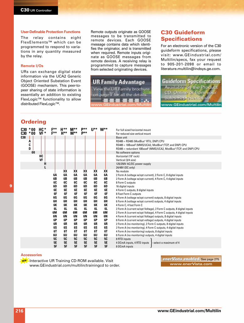
C30 GuideformSpecificationsFor an electronic version of the C30guideform specifications, pleasevisit: www.GEindustrial.com/Multilin/specs, fax your request to 905-201-2098 or email to [email protected].
OrderingC30 * 00 HC * F** H** M** P** U** W** For full sized horizontal mountC30 * 00 VF * F** H** M** P** For reduced size vertical mountC30 Base unit
A RS485 + RS485 (ModBus® RTU, DNP) CPU C RS485 + 10BaseF (MMS/UCA2, ModBus®/TCP, and DNP) CPUD RS485 + redundant 10BaseF (MMS/UCA2, ModBus®/TCP, and DNP) CPU
00 No software optionsHC Horizontal (19" rack)VF Vertical (3/4 size)
H 125/250V AC/DC power supplyL 24/48V (DC only)
XX XX XX XX XX No module6A 6A 6A 6A 6A 6A 2 Form A (voltage w/opt current), 2 Form C, 8 digital inputs6B 6B 6B 6B 6B 6B 2 Form A (voltage w/opt current), 4 Form C, 4 digital inputs6C 6C 6C 6C 6C 6C 8 Form C outputs6D 6D 6D 6D 6D 6D 16 digital inputs6E 6E 6E 6E 6E 6E 4 Form C outputs, 8 digital inputs6F 6F 6F 6F 6F 6F 8 Fast Form C outputs6G 6G 6G 6G 6G 6G 4 Form A (voltage w/opt current) outputs, 8 digital inputs6H 6H 6H 6H 6H 6H 6 Form A (voltage w/opt current) outputs, 4 digital inputs6K 6K 6K 6K 6K 6K 4 Form C, 4 fast Form C6L 6L 6L 6L 6L 6L 2 Form A (current w/opt Voltage), 2 Form C outputs, 8 digital inputs
6M 6M 6M 6M 6M 6M 2 Form A (current w/opt Voltage), 4 Form C outputs, 4 digital inputs6N 6N 6N 6N 6N 6N 4 Form A (current w/opt Voltage) outputs, 8 digital inputs6P 6P 6P 6P 6P 6P 6 Form A (current w/opt voltage) outputs, 4 digital inputs6R 6R 6R 6R 6R 6R 2 Form A (no monitoring), 2 Form C outputs, 8 digital inputs6S 6S 6S 6S 6S 6S 2 Form A (no monitoring), 4 Form C outputs, 4 digital inputs6T 6T 6T 6T 6T 6T 4 Form A (no monitoring) outputs, 8 digital inputs6U 6U 6U 6U 6U 6U 6 Form A (no monitoring) outputs, 4 digital inputs5C 5C 5C 5C 5C 5C 8 RTD inputs5E 5E 5E 5E 5E 5E 4 DCmA inputs, 4 RTD inputs select a maximum of 45F 5F 5F 5F 5F 5F 8 DCmA inputs
User-Definable Protection Functions
The relay contains eightFlexElements™ which can beprogrammed to respond to varia-tions in any quantity measuredby the relay.
Remote I/Os
URs can exchange digital stateinformation via the UCA2 GenericObject Oriented Substation Event(GOOSE) mechanism. This peer-to-peer sharing of state information isessentially an addition to existingFlexLogic™ functionality to allowdistributed FlexLogic™.
Remote outputs originate as GOOSEmessages to be transmitted toremote devices. Each GOOSEmessage contains data which identi-fies the originator, and is transmittedwhen required. Remote inputs origi-nate as GOOSE messages fromremote devices. A receiving relay isprogrammed to capture messagesfrom selected originating devices.
www.enerVista.comenerVista enabledenerVista enabled See page 275.
Accessories
Interactive UR Training CD-ROM available. Visitwww.GEindustrial.com/multilin/trainingcd to order.

217
9
COMINGSOON
UR Breaker Management Relay™
Features and Benefits
FlexLogic™ and distributed FlexLogic™
Virtual and expandable I/Os to reducehardware costs
User-programmable LEDs
User-definable display messages
Flash memory for field upgrades
Common drawout modules
IRIG-B time synchronization
Diagnostic features – event recording,oscillography and data logging
Multiple settings groups
Applications
Integrated breaker monitoring and control instand-alone applications, or component inautomated substation control system
enerVista.com compatible (see page 275)
Protection and Control
Phase undervoltage, auxiliary over andundervoltage protection, breaker failure,autoreclosure
Basic overcurrent protection
Synchronism check, dual breaker control
FlexElement™ universal comparator
Monitoring and Metering
Current, voltage, power, power factor,energy, demand, frequency
Trip circuit supervision
Fault location and reporting
Breaker pole discrepancy and contactarcing current
User Interfaces
URPC software for setting and monitoring
RS232, RS485 and Ethernet ports
Integrated breaker monitoring
and control for substation automation.
GE Multilin

Protection andControlThe C60, a digital breakermanagement relay, providesbreaker monitoring and control inone integrated package. Thismember of the Universal Relayfamily offers advanced protectionwhich includes:
Voltage Elements
The C60 includes the following: Phase undervoltage elements;
each element has three individ-ual phase undervoltagecomponents
Auxiliary overvoltage and under-voltage elements
Breaker Failure
Two independent breaker failurefunctions detect both single andthree-pole tripping schemes(selectable). Breaker auxiliarycontacts and/or current supervi-sion are used to determine abreaker fail condition. This func-tion can be initiated and blockedinternally and externally via inputcontacts or communications.
Autoreclosure
A single-pole and three-polecapable autoreclosure is providedwhich simultaneously controlstwo breakers and performssequential reclosing.
Synchronism Check
This function supervises manualand automatic breaker closing.The feature checks for permissi-ble levels of DV, DF and Df ordead source condition. Two iden-tical synchronism check elementsare included.
Breaker Control
The relay allows control of one ortwo breakers locally, throughremote communications orcontact inputs. A breaker polediscrepancy is included in thebreaker control scheme. Breakerposition is indicated by LEDs onthe faceplate.
User-Definable Protection
Functions
Eight FlexElements™ can be pro-grammed to respond to varia-
tions in any quantity measuredby the relay. Application exam-ples include: positive sequenceovercurrent, negative sequenceovervoltage, overpower, lowpower factor, temperature differ-ential, and frequency rate-of-change.
Monitoring andMeteringBasic metering of current, voltageand frequency as well as basicevent recording, oscillographyand data logging are commonacross the UR platform (seepage 7). The C60 provides addi-tional monitoring and meteringwhich includes:
Breaker Contact Arcing Current
(I2t) Monitoring
The C60 tracks the per-phase wearon the breaker contacts by measur-ing and integrating the currentsquared passing through the break-er contacts as an arc. The per-phasevalues are added to accumulatedtotals for each phase and com-pared to a programmed thresholdvalue. The measurement for eachphase is available locally andremotely and can be stored in theoscillography file or data logger.
Transducer I/O
The relay can receive signalsfrom external transducers andconvert them into digital format.These inputs can be used tomonitor temperature, DC voltage,transformer tap changer positionand more. Two types of analogsignals can be received:
DCmA type signals in the range of-1 to +20 DCmA, suitable for usewith most common transducers
RTD type signals from externalresistance temperature detectors
The transducer values are avail-able locally and remotely and canbe stored in the oscillography fileor data logger.
www.GEindustrial.com/Multilin
C60 UR Breaker Management RelayTM
218
9Functional Block Diagram
834710ab.cdr
C60 Breaker Management Relay
BF2
BF2
METERING
CLOSE
CLOSE
TRIP
TRIP
FlexElement™Transducer
Input
79
27
27
27
25
2550P1 50P2 50P3 50N1 50N2 50N3
50P1 50N150P2 50N250P3 50N3
59
52
52
www.GEindustrial.com/Multilin
C60 UR Breaker Management RelayTM
219
9
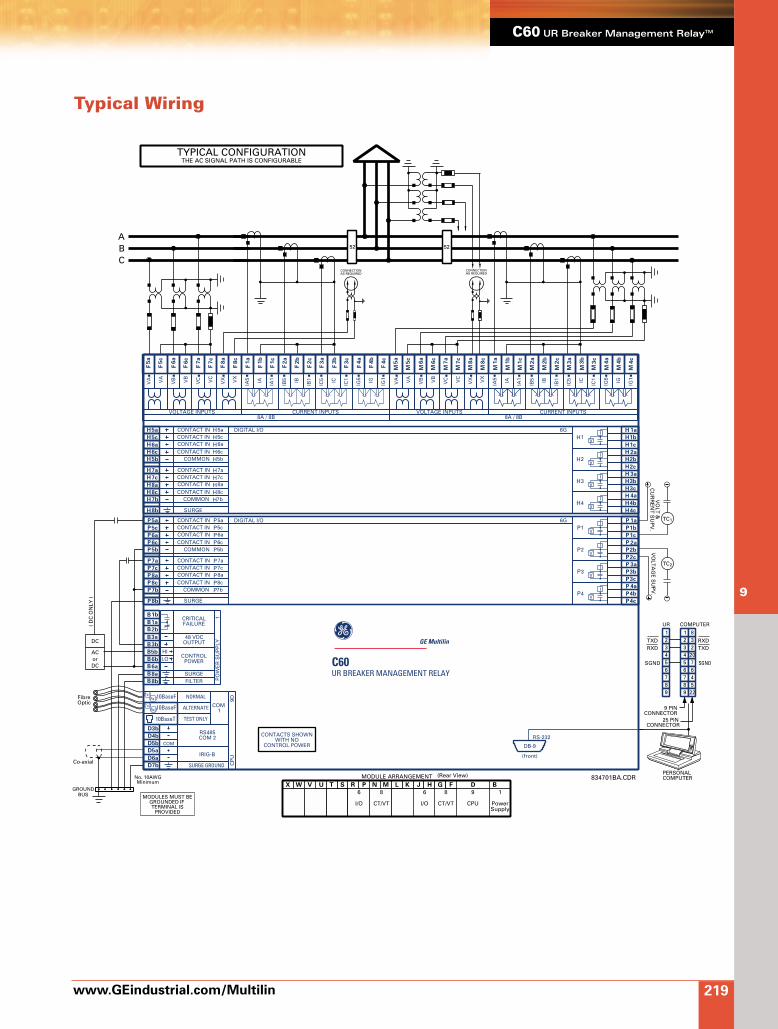
Typical Wiring
C60UR BREAKER MANAGEMENT RELAY
(Rear View)
1
PowerSupply
9
CPU
8
CT/VT
6
I/O
6
I/O
8
CT/VT
MODULE ARRANGEMENTJU MX LW KV BHT DN GS P FR
GE Multilin
ABC
CONNECTIONAS REQUIRED
CONNECTIONAS REQUIRED
52 52
TYPICAL CONFIGURATIONTHE AC SIGNAL PATH IS CONFIGURABLE
RS-232
DB-9
(front)
UR COMPUTER
1
TXD RXDRXD TXD
SGND SGND
1 832
20764522
25 PINCONNECTOR
PERSONALCOMPUTER
9 PINCONNECTOR
2 23 34 45 56 67 78 89 9
TC
TC
2
1
VO
LTA
GE
SU
PV
.V
OLT
&C
UR
RE
NT
SU
PV
.
CONTACTS SHOWNWITH NO
CONTROL POWER
834701BA.CDR
Co-axial
ACorDC
DC
( D
C O
NLY
)
GROUNDBUS
No. 10AWGMinimum
MODULES MUST BEGROUNDED IF TERMINAL IS
PROVIDED
1c
4a
MMMMMMMMMMMMMMMMMMMM
8c
8a
3c
5a
5c
7c
CURRENT INPUTS
6a
7a
6c
2c
VX
VA
VB
VC
4c
1a
4b
1b
2a
3a
2b
3b
VOLTAGE INPUTS8A / 8B
VX
VA
VB
VC IA IB IC IGIA5
IA1
IB5
IC5
IG5
IB1
IC1
IG1
1a
2b
1c
1b
2c
2a
4a
4c
3b
3a
4b
3c
CONTACT IN 5a
CONTACT IN 7a
CONTACT IN 5c
CONTACT IN 7c
CONTACT IN 6a
CONTACT IN 8a
CONTACT IN 6c
CONTACT IN 8c
COMMON 5b
COMMON 7b
SURGE
6a
8a
5b
7b
8b
5aH
H
H
H
H
H
H
H
H
H
H
HHHHH
HHHHH
H
HH
H
H
H
H
H
H
H
H
H
H
H
H
H
7a
6c
8c
5c
7c
1
2
3
4
I
V
I
V
I
V
I
V
DIGITAL I/O 6G
1a
2b
1c
1b
2c
2a
4a
4c
3b
3a
4b
3c
CONTACT IN 5a
CONTACT IN 7a
CONTACT IN 5c
CONTACT IN 7c
CONTACT IN 6a
CONTACT IN 8a
CONTACT IN 6c
CONTACT IN 8c
COMMON 5b
COMMON 7b
SURGE
6a
8a
5b
7b
8b
5aP
P
P
P
P
P
P
P
P
P
P
PPPPP
PPPPP
P
PP
P
P
P
P
P
P
P
P
P
P
P
P
P
7a
6c
8c
5c
7c
1
2
3
4
I
V
I
V
I
V
I
V
DIGITAL I/O 6G
Tx1
Tx2
Rx1
Rx2
SURGE GROUNDD7b
D6a
D4b
D5b
D3b
10BaseT
10BaseF
10BaseF
D5a
COM
C
PU
9D
COM 1
TEST ONLY
ALTERNATE
NORMAL
RS485COM 2
IRIG-B
CRITICALFAILURE
48 VDCOUTPUT
CONTROLPOWER
HILO
PO
WE
R S
UP
PLY
1
FILTERSURGE
3a
1b
8a
6b
8b
6a
B
B
B
B
B
B
B
B
B
B
3b
1a
2b
5b
1c
4a
FFFFFFFFFFFFFFFFFFFF
8c
8a
3c
5a
5c
7c
CURRENT INPUTS
6a
7a
6c
2c
VX
VA
VB
VC
4c
1a
4b
1b
2a
3a
2b
3b
VOLTAGE INPUTS8A / 8B
VX
VA
VB
VC IA IB IC IGIA5
IA1
IB5
IC5
IG5
IB1
IC1
IG1
FibreOptic

www.GEindustrial.com/Multilin
C60 UR Breaker Management RelayTM
220
9
C60 GuideformSpecificationsFor an electronic version of the C60guideform specifications, pleasevisit: www.GEindustrial.com/Multilin/specs, fax your request to 905-201-2098 or email to [email protected].
OrderingC60 * 00 HC* F** H** M** P** U** W** For full sized 19" horizontal (H)C60 * 00 VF* F** H** M** P** For reduced size vertical (V) C60 Base unit
A RS485 + RS485 (ModBus® RTU, DNP 3.0) CPU C RS485 + 10BaseF (MMS/UCA2, ModBus®/TCP, and DNP 3.0) CPUD RS485 + redundant 10BaseF (MMS/UCA2, ModBus®/TCP, and DNP 3.0) CPU
00 No software optionsHC Horizontal 19" mountVF Reduced size (3/4) vertical
H 125/250 V AC/DC power supplyL 24/48 V (DC only)
8A 8A Standard 4 CT/4 VT8B 8B Sensitive ground 4 CT/4 VT8C 8C Standard 8 CT8D 8D Sensitive ground 8 CT
XX XX XX XX No module6A 6A 6A 6A 6A 2 Form A (Voltage w/opt Current), 2 Form C outputs, 8 digital inputs6B 6B 6B 6B 6B 2 Form A (voltage w/opt current), 4 Form C outputs, 4 digital inputs6C 6C 6C 6C 6C 8 Form C outputs6D 6D 6D 6D 6D 16 digital inputs6E 6E 6E 6E 6E 4 Form C outputs, 8 digital inputs6F 6F 6F 6F 6F 8 Fast Form C outputs6G 6G 6G 6G 6G 4 Form A (voltage w/opt current) outputs, 8 digital inputs6H 6H 6H 6H 6H 6 Form A (voltage w/opt current) outputs, 4 digital inputs6K 6K 6K 6K 6K 4 Form C, 4 fast Form C outputs6L 6L 6L 6L 6L 2 Form A (current w/opt voltage) and 2 Form C outputs, 8 digital inputs
6M 6M 6M 6M 6M 2 Form A (current w/opt voltage), 4 Form C outputs, 4 digital inputs6N 6N 6N 6N 6N 4 Form A (current w/opt voltage) outputs, 8 digital inputs6P 6P 6P 6P 6P 6 Form A (current w/opt voltage) outputs, 4 digital inputs6R 6R 6R 6R 6R 2 Form A (no monitoring) and 2 Form C outputs, 8 digital inputs6S 6S 6S 6S 6S 2 Form A (no monitoring) and 4 Form C outputs, 4 digital inputs6T 6T 6T 6T 6T 4 Form A(no monitoring) outputs, 8 digital inputs6U 6U 6U 6U 6U 6 Form A (no monitoring) outputs, 4 digital inputs5C 5C 5C 5C 5C 8 RTD5E 5E 5E 5E 5E 4 DCmA inputs, 4 RTD select a maximum of 45F 5F 5F 5F 5F 8 DCmA inputs
Digital Counters
Eight digital counters are used tocount the number of state transi-tions from Logic 0 to Logic 1. TheFlexLogic™ operand inputs (UP andDOWN) are selected to incrementand decrement the accumulatedcounter value. The counter can beused to count function operationssuch as the pickup or operation ofany internal element, the changesof state of an external contact suchas a breaker auxiliary switch orpulses from a watt-hour meter.
www.enerVista.comenerVista enabledenerVista enabled See page 275.
Accessories
Interactive UR Training CD-ROM available. Visitwww.GEindustrial.com/multilin/trainingcd to order.

221
9
Power Quality Meter
Features and Benefits
Standard and portable options
Power quality analysis
Flexible control for demand loadshedding, power factor, etc.
Programmable setpoints
Four assignable output relays
Four switch inputs
Process variable measurement usinganalog input
PC connectivity
Allows for calculation of harmonicdistribution
Communicates with GE Multilin 269(MOD 508)
Applications
Continuous metering of distributionfeeders, transformers, capacitor banks,generators and motors
Medium and low voltage systems
enerVista.com compatible (see page 275)
Protection and Control
Basic alarm on overcurrent, undercurrentor voltage unbalance
Monitoring and Metering
Current, voltage, real and reactive power,energy use, cost of power, power factorand frequency
Harmonic analysis
User Interfaces
Select URPC functionality
RS232 and RS485 ports
Continuous metering of three-phase systems.
GE Multilin

www.GEindustrial.com/Multilin
PQM/PPQM Power Quality Meter
222
9
for specific applications. Simplealarm messages provide easynotification.
Communications
Integrate process, instrumenta-tion and electrical requirementsin a plant automation system byconnecting PQM meters togetherto a DCS or SCADA system. Acomputer running PQMPC canchange system setpoints, moni-tor values, status and alarms.Continuous monitoring mini-mizes process downtime byimmediately identifying potentialproblems due to faults orchanges from growth.
RS485 ModBus® 1,200 to19,200 bps
Mini RTU SCADA systemcomponent
Measure actual values Read status Issue control commands Load all setpoints from a file Change individual setpoints
The standard version PQM comescomplete with a front RS232 portwhich can be used for datacollection, printing reports orproblem analysis without disturb-ing the main communicationinterface to rear RS485 port.
Future Expansion
The PQM uses non-volatile flashmemory for firmware storage.This allows future productupgrades to be loaded via theserial port. Upgrades can also beaccessed from www.geindustri-al.com/Multilin.
Standard FeaturesThe PQM is a digital meteringdevice that provides continuousmonitoring of a three-phasesystem. It provides metering ofcurrent, voltage, real and reactivepower, energy use, cost of power,power factor and frequency.
When portable monitoring of athree-phase system is required, aPortable PQM is the ideal choice.This version offers the samefeatures as the panel mount PQMin a rugged carrying case. ThePPQM additionally acts as apower management tool, a trouble-shooting tool and a datacollection device.
In either form, the PQM canprovide users with advancedfeatures for monitoring andmetering which include:
Mounting Versatility
The panel mount with display offersan easy local interface. Standardmodels have RS485 ModBus®
communications for programmingand monitoring. Users can replaceexpensive additional devicesby adding the CONTROL, TRANS-DUCER and POWER analysisoptions to the PQM as required.
Metering
Each voltage and current issampled 64 times per cycle for0.2% accuracy true RMS TrueRMS or displacement (fundamen-tal) quantities.
Ia Ib Ic In Va Vb Vc Vab Vbc Vca
V I unbalance True PF crest and K factor Hz W var VA Wh varh VAh W cost Demand: A W var VA
A keypad and illuminated 40character display provide localsetpoint setting and monitoringvalues and status.
Alarms
Any of the assignable outputsmay be used to trigger an alarm
Initially PQM meters can be usedas stand-alone units. Open archi-tecture allows connection toother or ModBus®-compatibledevices on the same communica-tion link. These can be integratedin a complete plant wide systemfor overall process monitoringand control.
OptionsThere are a variety of optionsavailable to the user, allowing arange of custom configurations:
Transducer
Four Analog Outputs: four isolat-ed analog outputs can be used toreplace eight analog transducers.Output signals can be selectedfrom any of the measured param-eters for direct interface to a PLC.
Analog Input: with the analoginput and an output relay for selec-tion, two transducers (such astemperature or water level) can bemonitored and used for control.
Connect two 4 to 20 mA transducers forprocess variable measurement and control.
Second Rear Comm Port: an addi-tional rear RS485 comm port isprovided for simultaneous moni-toring by process, instrument,electrical or maintenance personnel.
Redundancy in high security systems isprovided by the 2nd RS485 comm port.
823803A4.cdr
PQM AUXRELAY
ANALOGINPUT
4-20 mAtransducer
4-20 mAtransducer
SIMULATION
ALARM
SELF TEST
PROGRAM
TX2
TX1
RX2
RX1
AUX2
ALARM
AUX3
AUX1
STATUS COMMUNICATE RELAYS
PQM Power Quality Meter
823777A7.CDR
PLANT CONTROL
SYSTEM
COM1RS485
COM2RS485
STATUS COMMUNICATE RELAYS
SIMULATION
ALARM
SELF TEST
PROGRAM
TX2
TX1
RX2
RX1
AUX2
ALARM
AUX3
AUX1
STATUS COMMUNICATE RELAYS
SIMULATION
ALARM
SELF TEST
PROGRAM
TX2
TX1
RX2
RX1
AUX2
ALARM
AUX3
AUX1
STATUS COMMUNICATE RELAYS
SIMULATION
ALARM
SELF TEST
PROGRAM
TX2
TX1
RX2
RX1
AUX2
ALARM
AUX3
AUX1
PQM Power Quality Meter
Ia = 100 Ib = 102
Ic = 100 AMPS
Ia = 100 Ib = 102
Ic = 100 AMPS
Ia = 100 Ib = 102
Ic = 100 AMPS
PQM Power Quality Meter PQM Power Quality Meter
CONDITIONovercurrentundercurrentneutral currentcurrent unbalanceovervoltageundervoltagephase sequenceoverfrequencyunderfrequencypower factorswitch input
APPLICATIONmotors/transformerspumps/compressorsleakage/unbalancemotorsequipment protectionmotors/load transferpumps/equipmentgeneratorsload sheddingcapacitor banksprocess control

Control
Three Output Relays and FourInputs: measured parametersfrom the standard PQM can becombined with setpoints and I/Osfor control applications. With thecontrol option, three outputrelays and four switch inputs areadded along with programmablesetpoints to make a mini RTU.Output relays can also becontrolled via the communicationport or assigned to differentsetpoints for custom program-ming to accommodate manysituations. Possibilities include:
Undercurrent alarm for pumps Over and undervoltage for
generators Unbalance alarm for rotating
machines Dual level power factor for
capacitor bank switching Underfrequency/demand output
for load shedding resulting inpower cost savings
kWh, kvarh and kVAh pulseoutput for PLC interface
Power factor setpoints and two output relayscan be used for two-level capacitor bankswitching.
Power Analysis
Data Logger (Trending): trending isuseful as a troubleshooting aidwhen a problem is detected.Measured values can be selectedand plotted with a programmablesampling rate to suit the time inter-val of interest. The generated chartrecorder screen can be printed orexported to other programs forreport writing.
www.GEindustrial.com/Multilin
PQM/PPQM Power Quality Meter
Record trends of measured parameters over time.
Harmonic Analysis: non linearloads such as variable speeddrives, computers and electronicballasts can cause harmonicswhich may lead to problems suchas nuisance breaker tripping, tele-phone interference, transformer,capacitor or motor overheating.For fault diagnosis such asdetecting undersized neutralwiring, need for a harmonic ratedtransformer, or effectiveness ofharmonic filters, details of theharmonic spectrum are usefuland available with the poweranalysis option.
Harmonic spectrum analysis can identifyproblems and ensures implemented changeswork correctly.
Waveform Capture: voltage andcurrent waveforms can becaptured and displayed on a PCusing the PQMPC programsupplied with the PQM or usingthird party software. Distortedpeaks or notches from SCRswitching provide clues for takingcorrective action.
Voltage and current waveforms providevaluable insights into system problems.
Event Recorder: alarms, setpointtriggers, input and output eventscan be stored in a 40 event recordand time and date stamped bythe internal clock. This is usefulfor diagnosing problems andsystem activity. Minimum andmaximum values are also contin-uously updated and timestamped.
Trace Memory: the PQM can beconfigured to record a maximum of36 cycles of data on all voltage andcurrent inputs based on overvolt-age, undervoltage, overcurrent orswitch input state change.
Software
PQMPC Program
PQMPC is a Windows®-basedprogram that can be used toenter setpoints, read meteredvalues, monitor status and evalu-ate power quality. All datacontinuously gathered by thePQM can be transferred to a thirdparty software program fordisplay, control or analysis viathe communications interface.
Once all setpoints have beenentered they can be downloadedinto any PQM or stored in a filewith a tag name for later reference.
Screens are available for moni-toring all measured values suchas current, voltage, or power.Status of alarms and controlsettings can also be displayed.
Voltage and current waveshape cangive important information aboutwhat is happening on a system. Forexample, non linear loads such ascomputers or variable speed drivesmay introduce distortion that indi-cates filtering is required.
Gain useful system information usingvoltage/current waveform capture.
BANK 1
Drop Out
BANK 2
Drop Out
BANK 1
Pickup
BANK 2
Pickup
BANK 2
+0.85
+0.90
+0.95
1.00
PO
WE
R F
AC
TO
R
TIME (hour)
-1.05
LE
AD
LA
G
BANK 1
DUAL CAPACITOR BANK POWER
FACTOR CONTROL
0 2 4 6 8 10 12 14 16 18 20 22 24
823757A7.cdr
OFF ON OFF
Delay 1
Delay 2
Delay 2
Delay 1
OFF ON OFF
Select waveform
for display
Analyze waveform
or copy to other
software
223
9

www.GEindustrial.com/Multilin
PQM/PPQM Power Quality Meter
224
9
Typical Wiring
1 2 3 4
V1 V 2 V3 VN
9
CO
NT
RO
L PO
WE
R
10 11 12 13 14 15 16 17 18 19 20
5A 5A 5A 5A1A 1A 1A 1ACOM COM COM COM
PHASE A PHASE B PHASE C NEUTRALCURRENT INPUTS
1 2 3 4
V1 V2 V3 VN
9 10 11 12 13 14 15 16 17 18 19 20
5A 5A 5A 5A1A 1A 1A 1ACOM COM COM COM
PHASE A PHASE B PHASE C NEUTRAL
CURRENT INPUTSVOLTAGEINPUTS
VOLTAGEINPUTS
N
N
B
N
B
B
N
N
L
LLOAD
LOAD
LOAD
A
C
B
ALOAD
A A
C
C
LOAD
LOAD
PHASE CT
PHASE A CT
PHASE B CT
PHASE C CT
2 or 3 CTssee above
2 or 3 CTssee below
2 PHASE CTs
PHASE C CT
PHASE A CT
PHASE B CT
PHASE C CT
OPTIONALNEUTRAL CT
PHASE A CT
PHASE B CT
PHASE C CT
OPTIONALNEUTRAL CT
PHASE A CT PHASE A CT
PHASE B CT
PHASE B CTPHASE C CT
PHASE C CT
OPTIONALNEUTRAL CT
OPTIONALNEUTRAL CT
L
A
A
A
A A
A A
C
C
N
B
C
B
C C
N
C
B
B B
C C
N N
B
B
N
N
SINGLE PHASE DIRECTNO VTs
3 WIRE DIRECT/120° VOLTAGENO VTs
3 WIRE DELTA/60° VOLTAGE2 VTs
4 WIRE WYE/60° VOLTAGE2 VTs (2-1/2 ELEMENTS)
4 WIRE WYE DIRECT/120° VOLTAGENO VT
4 WIRE WYE/120° VOLTAGE3 VTs
4 WIRE WYE/120° VOLTAGE3 VTs
600V MAX
600V MAX
ANY VOLTAGE
ANY VOLTAGE
600V MAX
ANY VOLTAGE
ANY VOLTAGE
LINE
LINE
LINE
LINE
LINE LOAD
LINE
LINE
VTab
VTan
VTan
VTan
VTbn
VTbn
VTcn
VTcn
VTcb
VTcn
ALTERNATIVE CT/VT CONNECTIONS
48
47
46
51
50
49
23
22
21
28
27
26
25
24
TO PLCOR
SCADASYSTEM
1+
2+
3+
4+
COM
SHIELD
_
+
COM
_
+
COM
_+
USE SHIELDED TWISTEDPAIR WIRE
COM1RS485 TO/FROM
DEVICE
COM2RS485 TO/FROM
DEVICE
4-20mATRANSDUCER
CONTROL POWER90-300 VDC
70-265 VAC 50/60 Hz
USE HEAVYGAUGE WIRE
SWITCHGEARGROUND BUS
45
44
43
42
41
40
39
38
37
36
35
34
DRYCONTACT
SWITCH INPUTS
32
31
30
29
33
SW1
SW2
SW3
SW4
+24VDC
NO
COM
NC
NO
COM
NC
NO
COM
NC
NO
COM
NC
8
7
6
5
L+
N _
SAFETYGROUNDFILTER
GROUND
ALARM
AUX1
AUX2
AUX3
OU
TP
UT
RE
LAY
S
PR
OG
RA
MM
AB
LES
WIT
CH
INP
UT
S
NOTES:
1) Relay contact state shown with control power not applied.
CAUTION:USE HRC FUSES FOR VT PRIMARY TO ENSUREADEQUATE INTERRUPTING CAPACITY.
Transducer Option
Control Option
RS
485
SE
RIA
L
CO
M 1
AN
ALO
G IN
AN
ALO
G O
UT
4-2 0
mA
CO
M 2
COM3RS232 (FRONT)
OBSERVE CT & VTPOLARITY
Perferrred 4 wire configuration
*Note: Accurate only with balanced phase voltages
Preferred 3 wire configuration
1 2 3 4
V1 V2 V3 VN
9 10 11 12 13 14 15 16 17 18 19 20
5A 5A 5A 5A1A 1A 1A 1ACOM COM COM COM
PHASE A PHASE B PHASE C NEUTRAL
CURRENT INPUTSVOLTAGEINPUTS
1 2 3 4
V1 V2 V3 VN
9 10 11 12 13 14 15 16 17 18 19 20
5A 5A 5A 5A1A 1A 1A 1ACOM COM COM COM
PHASE A PHASE B PHASE C NEUTRAL
CURRENT INPUTSVOLTAGEINPUTS
1 2 3 4
V1 V2 V3 VN
9 10 11 12 13 14 15 16 17 18 19 20
5A 5A 5A 5A1A 1A 1A 1ACOM COM COM COM
PHASE A PHASE B PHASE C NEUTRAL
CURRENT INPUTSVOLTAGEINPUTS
1 2 3 4
V1 V2 V3 VN
9 10 11 12 13 14 15 16 17 18 19 20
5A 5A 5A 5A1A 1A 1A 1ACOM COM COM COM
PHASE A PHASE B PHASE C NEUTRAL
CURRENT INPUTSVOLTAGEINPUTS
1 2 3 4
V1 V2 V3 VN
9 10 11 12 13 14 15 16 17 18 19 20
5A 5A 5A 5A1A 1A 1A 1ACOM COM COM COM
PHASE A PHASE B PHASE C NEUTRAL
CURRENT INPUTSVOLTAGEINPUTS
823807AS.CDR823753AQ.DWG
RS232 INTERFACE
PERSONALCOMPUTER RS232
PQMPC
PQM
9 PINCONNECTOR
25 PINCONNECTOR
COMPUTER
9 W
IRE
RS
2 32
22995884776667552044233322TXD RXD
RXD TXD
SGND SGND
811
PQM
Power Quality Meter
GE Multilin

www.GEindustrial.com/Multilin
PQM/PPQM Power Quality Meter
COMMUNICATIONS
COM1/COM2 type: RS485 2-wire, half duplex, isolatedCOM3 type: RS232, 9PINBaud rate: 1,200 – 19,200 bpsProtocol: ModBus® RTUFunctions: Read/write setpoints
Read actual valuesExecute commands
MONITORING
UNDERVOLTAGE MONITORINGRequired voltage: 20 V appliedPickup level: 0.50 – 0.99 in steps of 0.01 x VTDropout level: 103% of pickupTime delay: 0.5 – 600.0 in steps of 0.5 secPhases: Any one/any two/all three
(programmable) phases have to go below pickup to operate
Level accuracy: Per voltage inputTiming accuracy: -0/+1 sec
OVERVOLTAGE MONITORINGPickup level: 1.01 – 1.25 in steps of 0.01 x VTDropout level: 97% of pickupTime delay: 0.5 – 600.0 in steps of 0.5 secPhases: Any one/any two/all three
(programmable) phases have toexceed pickup to operate
Level accuracy: Per voltage inputTiming accuracy: -0/+1 sec
UNDERFREQUENCY MONITORINGRequired voltage: 20 V appliedPickup level: 20 – 70.00 in steps of 0.01 HzDropout level: Pickup +0.03 HzTime delay: 0.1 – 10.0 in steps of 0.1 secLevel accuracy: ±0.02 HzTiming accuracy: ±3 cycles
OVERFREQUENCY MONITORINGRequired voltage: 20 V appliedPickup level: 20 – 70.00 in steps of 0.01 HzDropout level: Pickup -0.03 HzTime delay: 0.1 – 10.0 in steps of 0.1 secLevel accuracy: ±0.02 HzTiming accuracy: ±3 cycles
POWER FACTOR MONITORINGRequired voltage: 20 V appliedPickup level: 0.50 lag – 0.50 lead in steps of 0.01Dropout level: 0.50 lag – 0.50 lead in steps of 0.01Time delay: 0.5 – 600.0 in steps of 0.5 secTiming accuracy: -0/+1 sec
SAMPLING MODES
SAMPLES/ INPUTS SAMPLED DURATIONCYCLE AT A TIME (CYCLES)
Metered values 64 ALL 2Trace memory 16 ALL continuous
Harmonic spectrum 256 1 1
DEMAND MONITORINGMeasured values: Phase A/B/C/N current (A)
3φreal power (kW)3φreactive power (kvar)3φapparent power (kVA)
Measurement type: Thermal exponential90% response time (programmable): 5 – 60 min, steps of 1 minBlock interval/rolling demand time in interval(programmable): 5 – 60 min, steps of 1 min
Pickup level: A: 10 – 7,500 in steps of 1kW: 0.1 – 6,500.0 in steps of 0.1kvar: 0.1 – 6,500.0 in steps of 0.1kVA: 0.1 – 6,500.0 in steps of 0.1
METERING
MEASURED VALUESACCURACY
PARAMETER (% of full scale) RESOLUTION RANGEVoltage ±0.2% 1 VOLT 20% of VT – 100% of VTCurrent ±0.2% 1 A 1% of CT – 150% of CTVoltage unbalance ±1% 0.1% 0 – 100.0%Current unbalance ±1% 0.1% 0 – 100.0%kW ±0.4% 0.01 kW 0 – 999,999.99 kWkvar ±0.4% 0.01 kvar 0 – 999,999.99 kvarkVA ±0.4% 0.01 kVA 0 – 999,999.99 kVAkWh ±0.4% 1 kWh 232 kWhkvarh ±0.4% 1 kvarh 232 kvarhkVAh ±0.4% 1 kVAh 232 kVAhPower factor 1% 0.01 ±0.0 – 1.0Frequency 0.02 Hz 0.01 Hz 20.00 – 70.00 Hzkw demand ±0.4% 0.1 kw 999,999.99 kwkvar demand ±0.4% 0.1 kvar 999,999.99 kvarkva demand ±0.4% 0.1 kva 999,999.99 kvaAmps demand ±0.2% 1 A 0 – 7,500 AAmps THD ±2.0% 0.1% 0.0 – 100.0%Volts THD ±2.0% 0.1% 0.0 – 100.0%Crest factor ±0.4% — 1 – 9.99
INPUTS
AC CURRENTConversion: True RMS, 64 samples/cycleCT input: 1 A and 5 A secondaryBurden: 0.2 VAOverload: 20 x CT for 1 sec
100 x CT for 0.2 secFull scale: 150% of CTFrequency: up to 32nd harmonicAccuracy: ±0.2% of full scale, true RMSAC VOLTAGEConversion: True RMS, 64 samples/cycleVT pri/sec: Direct or 120 – 72,000 : 69 – 240Input range: 20 – 600 VACFull scale: 150/600 VAC autoscaledBurden: <0.1 VAFrequency: up to 32nd harmonicAccuracy: ±0.2% of full scale, true RMSSWITCH INPUTSType: Dry contactResistance: 1,000 Ω max ON resistanceVoltage: 24 VDC @ 2 mADuration: 100 ms minimumANALOG INPUTRange: 4 – 20 mAAccuracy: ±1% of full scaleRelay output: Programmable 4 – 20 mAInternal burden resistance:
250 ΩPULSE INPUTMax inputs: 4Min pulse width: 150 msMin off time: 200 ms
*Specifications subject to change without notice.
PQM Technical Specifications
ENVIRONMENTAL
Humidity: 95% non-condensingTemperature: -10° C to +60° C ambientEnvironment: IEC 68-2-38
temperature/humidity cycle
PACKAGINGShipping box: 8 1/2" L x 6" H x 6" D
(215 mm x 152 mm x 152 mm)Ship weight: 5 lbs (2.3 kg)NOTE: LCD contrast impaired below -20° C
OUTPUTS
ANALOG OUTPUTSAccuracy: ±1% of full scale reading
OUTPUT0 – 1 mA (T1 Option) 0 – 20 mA and 4 – 20 mA (T20 Option)
Max load 2400 Ω 600 ΩMax output 1.1 mA 21 mAIsolation: 50 V isolated, active sourceOUTPUT RELAYS
Voltage Make/Carry Make/CarryContinuous 0.2 SEC Break
30 VDC 5 30 5Resistive 125 VDC 5 30 0.5
250 VDC 5 30 0.3 30 VDC 5 30 5
Inductive 125 VDC 5 30 0.25(Vr = 7ms) 250 VDC 5 30 0.15
120 VAC 5 30 5Resistive 250 VAC 5 30 5Inductive 120 VAC 5 30 5PF = 0.4 250 VAC 5 30 5Configuration FORM C NO/NCContact material SILVER ALLOY
PULSE OUTPUTParameters: +ve kWh, –ve kWh, +ve kvarh, –ve kvarh, kVAhInterval: 1 – 65000 in steps of 1Pulse width: 100 – 2000 ms in steps of 10 msMin pulse interval: 500 ms
APPROVALS
ISO: Manufactured to an ISO9001 registered programUL: Recognized under E83849CSA: Recognized under LR41286
: Conforms to EN 55011/CISPR 11, EN 50082-2Conforms to IEC 947-1, IEC 1010-1
TYPE TESTS
Dielectric strength: 2.0 kV for 1 min to relays, CTs, VTs, powersupply
Insulation resistance: IEC255-5 500 VDCTransients: ANSI C37.90.1 oscillatory
2.5 kV/1 MHzANSI C37.90.1 fast rise5 kV/10 nsOntario Hydro A-28M-82IEC255-4 impulse/high frequency disturbanceClass III Level
Impulse test: IEC 255-5 0.5 J 5 kVRFI: 50 MHz/15 W transmitterEMI: C37.90.2 electromagnetic interference
@ 150 MHz and 450 MHz, 10 V/mStatic: IEC 801-2 static discharge
Note: Type test report available upon request.
POWER SUPPLY
CONTROL POWERInput: 90 – 300 VDC
70 – 265 VAC 50/60 HzPower: 10 VA nominal, 20 VA maximumHoldup: 100 ms typical @ 120 VAC/VDC
Harmonic analysis can provideearly warning of problems, help-ing to prevent equipment damageor nuisance breaker tripping.
PQMPC enables waveformcapture information to be trans-ferred to other programs forinclusion in reports and printouts.Routine event logs of demand orsampled voltage can also becreated and printed out.
To verify correct installation, thesimulation mode substitutesprogrammed currents and volt-ages for real ones. This powerfultool is also an excellent trainingaid for plant personnel.
URPC Program
The Windows®-based URPCprogram allows the user to createsingle line diagrams for substa-
tion and system monitoringschemes. Additionally, annuncia-tor panel viewing, metering, andsettings changes can also beperformed using the program.With the URPC program the usercan access multiple PQMs ordifferent devices for metering inreal time. The program may beused locally through the RS232serial port or remotely throughthe other ports on the device.
225
9

www.GEindustrial.com/Multilin
PQM/PPQM Power Quality Meter
226
9
Ordering
PQM * * * (Order code for all options: PQM-T20-C-A)
PQM Basic unit with display, all current/voltage/power measurements, 1 RS485comm port, 1 RS232 comm port
T20 Transducer option; 4 isolated analog outputs 0 – 20 mA and 4 – 20 mA, assignable toall measured parameters, 4 – 20 mA analog input, 2nd RS485 comm port
T1 Transducer option; 4 isolated analog outputs 0 – 1 mA, assignable to all measuredparameters, 4 – 20 mA analog input, 2nd RS485 comm port
C Control option; 3 additional programmable output relays (total of 4),4 programmable switch inputs
A Power analysis option; harmonic analysis, triggered trace memory waveformcapture, event record, data logger
Modifications:
MOD 500: Portable test/carrying caseMOD 501: 20 – 60 VDC/20 – 48 VAC
control power MOD 502: TropicalizationMOD 504: Removable terminal blocksMOD 505: Detachable faceplateMOD 506: 4-step capacitor bank switchingMOD 507: -40 to +60° C temperature
operationMOD 508: 269 communication protocolMOD 513: Class 1, division 2 operationMOD 516: PQM remote: base unit onlyMOD 517: PQM remote: detachable
faceplate only
Accessories:
*PQMPC Windows® software **RS232 to RS485 convertor2.25" collar for limited depth mountingRS485 terminating networkPQM mounting plate to replace MTM Plus
Control Power:
90 – 300 VDC/70 – 265 VAC standard 20 – 60 VDC/20 – 48 VAC (MOD 501)* Free upon request**Required to connect a computer to the PQM RS485 ports
PPQM *150 1 A – 150 A clamp-on CT for wires 0.47" (12 mm) in diameter500 2 A – 500 A clamp-on CT for wires 1.18" (30 mm) in diameter1000 2 A – 1000 A clamp-on CT for wires 2.13" (54 mm) in diameter
PQM/PPQMGuideformSpecificationsFor an electronic version of the PQM/PPQM guideform specifications,please visit: www.GEindustrial.com/Multilin/specs, fax your request to 905-201-2098 or email to [email protected].
823762AF.DWG
7.36"(187)
0.85"(22)
3.92"(100)
MOUNTING SURFACE
7.50"(191)
4.07"(103)
Inches(mm)
4.54"(115)
7.24"(184)
(6) - 0.218" Dia. HOLES(6.00)
3.47"(88)
1.73"(44)
4.11"(104)
3.47"(88)
2.32"(59)
1.16"(29)
0.32"(8)
1.81"(46)
0.10"(2.5)6.90"
(175)
7.10"(180)
CUT-OUT
0.08" R (8 PLACES)(2)
0.85"(22)
4.35"(110)
7.36"(187)
4.35"(110)
MOUNTING B
MOUNTING A
FRONT
FRONT
SIDE
SIDE
SIDE
DETACHABLE FACE PLATE CHASSIS
REAR
USE MOUNTING B
DETACHABLE FACE PLATEUSE MOUNTING A
PANEL MOUNT WITH DISPLAYUSE MOUNTING A
DETACHABLE FACE PLATE VERSION (MOD 505)
STATUSALARM
PROGRAM
SIMULATION
SELF TEST
COMMUNICATETX1
RX1
TX2
RX2
RELAYSALARM
AUX1
AUX2
AUX3
PQM Power Quality Meter
STATUSALARM
PROGRAM
SIMULATION
SELF TEST
COMMUNICATETX1
RX1
TX2
RX2
RELAYSALARM
AUX1
AUX2
AUX3
PQM Power Quality Meter
PQM Dimensions
www.enerVista.comenerVista enabledenerVista enabled See page 275.

227
9
Features and Benefits
Advanced 16-bit microprocessor
Configurable logic, curves, digital I/Os,and LEDs
Flash memory for field upgrades
Two settings groups
Three models available for voltage,frequency and combined protection
Drawout case for easy maintenance
AC/DC power supply
Access via front panel keypad orcommunication links
Diagnostic features – event recordingand analog/digital oscillography
Compatible with M Family systems inhalf or full 19" racks
Applications
Voltage and/or frequency protection at anyvoltage in automatic transfer systems,generators, motors, lines and busbars
enerVista.com compatible (see page 275)
Protection and Control
Three-phase over and undervoltage,ground overvoltage
Voltage unbalance, over andunderfrequency
Monitoring and Metering
Frequency and per-phase voltage
User Interfaces
M+PC software for setting andmonitoring
Front RS232 and rear RS485 ports usingModBus® RTU protocol up to 19,200 bps
M Family Voltage/Frequency Relay
Three-phase and ground
voltage protection relay.
GE Multilin

ProtectionThe MIV, a member of the MFamily, is a digital device thatprovides voltage and frequencyprotection for a wide range ofapplications at any voltage level:
NOTE: The MIV1000 includes volt-age functions, the MIV2000includes frequency functions (fourunits), and the MIV3000 includesboth voltage and frequency (two)units.
Phase Overvoltage
Two separately adjustable phaseovervoltage units can be inde-pendently enabled. The pickup set-point can be set from 2 to 250 Vdepending on the model, and atime delay from 0 to 600 seconds.The protection units operate onphase-to-phase or phase-to-ground voltage magnitudes.
Phase Undervoltage
This function has the same settingsand features as the phase over-voltage protection. To avoidpermanent undervoltage trippingwhen a breaker is open and the VTs
are located on the line side, asetting is provided to enable/disable undervoltage protectionunits.
Ground Overvoltage
Two separately adjustable groundovervoltage units can be inde-pendently enabled. The pickupsetpoint can be set from 2 to250 V depending on the modeland a time delay from 0 to 600seconds.
Voltage Unbalance
This function operates on nega-tive sequence voltage, and isincluded in the MIV 3000 relay.Pickup and time delay settings arethe same as those of voltagefunctions.
Frequency Functions
Depending on the model, eithertwo or four independent definitetime frequency units are provided.Each unit can be independently set as over and underfrequency,and is supervised by an independ-ently adjustable undervoltageelement.
Configurable Logic
Up to four configurable logicschemes can be implemented viafour pre-configured logic gates andtimer cells. A graphical user inter-face provides easy configuration.The configurable logic output canbe used to configure digitaloutputs and LEDs.
MIV GuideformSpecificationsFor an electronic version of the MIVguideform specifications, pleasevisit: www.GEindustrial.com/Multilin/specs, fax your request to 905-201-2098 or email to [email protected].
www.GEindustrial.com/Multilin
MIV M Family Voltage/Frequency Relay
228
9Functional Block Diagram
2x27
MIV 3000
2x59 2x81O/81U
2x59N 47
52
BUS
3
LOAD 743751A1.ai

www.GEindustrial.com/Multilin
MIV M Family Voltage/Frequency Relay
229
9
Typical Wiring
TRIPCOIL
DIRECTION OF TRIP
>>
A
B
C
<<52a 52a
ACorDC
TRIP COILCONTROLPOWER
GROUNDBUS
-
+PROGRAMMABLE
CONTROLLER
A
B
GROUND
INPUT
INPUT
A
B
C
743750a4.ai
CAUTION: Fork or ring terminals must be used on the termainal block.NOTE: Suitable disconnect devices (switch or circuit breaker) recommended located near the relay.OVERVOLTAGE CATEGORY: II Terminals B12, A12 and B11 must be connected to SELV (safety extra-lowvoltage) parts (on the PLC). They are not to be tested for hipot test under any circumstance. The default configuration of inputs and outputs is as follows: INPUTS CC1: Block unit 78 CC2: Block voltage functions OUTPUTS OUT1: 78 Trip OUT2: 59/27 Trip OUT3:59N Trip OUT4: 81 Trip
Internally fused1A/250V fast blow
NOTE: 14 AWG wiringrecommended
A
B
C
WYE-BROKEN-DELTAVT CONNECTION
V N N N
VOLTAGE INPUTS
I VII VIII
B1 B2 B3 B4 A3 A4
ABC
B1
A5
A1 A2
A6
A8
A9
A7
A10B10
B9
B8
B7
B11(*)
A12(*)
B12(*)SDA
SDB
GND
GND
RS232
JXCC1
CC2
COM
B2 B3 B4 A3 A4
POWER
+/L -/NV N N N
VOLTAGE INPUTS
SAFETYGROUND
TR
IP
B5
B6 RE
AD
Y
CO
MO
UT
4O
UT
3O
UT
1
RS
48
5
OU
T1
/2
DIG
ITA
L O
UT
PU
TS
(**
)
DIG
ITA
LIN
TP
UT
S(*
*)
I VII VIII V N N N
VOLTAGE INPUTS
I VII VIII
SINGLE PHASE VT CONNECTION
V N N N
VOLTAGE INPUTS
I VII VIII
OPEN DELTA VT CONNECTION
MIVM-FamilyVoltage/FrequencyRelay
GE Multilin
(*)
(**)
B1 B2 B3 B4 A3 A4B1 B2 B3 B4 A3 A4
Ordering
MIV * 0 * 0 E 0 0 0 * 0 0 *MIV Voltage/frequency relay
1 Voltage functions2 Frequency functions3 Voltage + frequency functions
0 10 – 250 V setting range 1 2 – 60 V setting range
F 24 – 48 VDC auxiliary voltageH 110 – 250 VDC 110 – 230 VAC auxiliary voltage
C Individual relayS Mounted in an M+ system†
†If relays are to be mounted in an M+ system either an M050 half 19" rack or M100 full 19" rack case must be ordered. The M050 and M100 racks are provided at no additional cost.
Accessories
B1315P2 Depth reducing collar
www.enerVista.comenerVista enabledenerVista enabled See page 275.

230
9
Features and Benefits
Advanced 16-bit microprocessor
Loss of field unit to detect loss ofexcitation
Configurable logic, curves, digital I/Osand LEDs
Flash memory for field upgrades
Two settings groups
Drawout case for serviceability
Applications
Controlling power flow in alternatingcurrent generator applications of any size
enerVista.com compatible (see page 275)
Protection and Control
Reverse, forward overpower, low forwardpower
Loss of field/excitation, fuse failure
Monitoring and Metering
Power metering
User Interfaces
M+PC software for setting andmonitoring
RS232 and RS485 ports for local andremote access
M Family Directional Power/Loss of Field Relay
Directional power and loss of
field protection for generators.
GE Multilin
www.GEindustrial.com/Multilin
MIW M Family Directional Power/Loss of Field Relay
231
9
32RP
MIW
32LF 6032FP 40
52
BUS
741751A3.ai
Functional Block Diagram
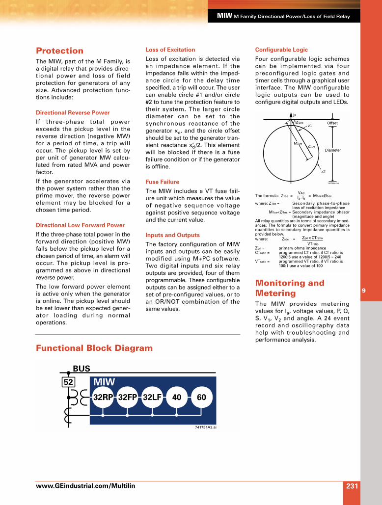
ProtectionThe MIW, part of the M Family, isa digital relay that provides direc-tional power and loss of fieldprotection for generators of anysize. Advanced protection func-tions include:
Directional Reverse Power
If three-phase total powerexceeds the pickup level in thereverse direction (negative MW)for a period of time, a trip willoccur. The pickup level is set byper unit of generator MW calcu-lated from rated MVA and powerfactor.
If the generator accelerates viathe power system rather than theprime mover, the reverse powerelement may be blocked for achosen time period.
Directional Low Forward Power
If the three-phase total power in theforward direction (positive MW)falls below the pickup level for achosen period of time, an alarm willoccur. The pickup level is pro-grammed as above in directionalreverse power.
The low forward power elementis active only when the generatoris online. The pickup level shouldbe set lower than expected gener-ator loading during normaloperations.
Loss of Excitation
Loss of excitation is detected viaan impedance element. If theimpedance falls within the imped-ance circle for the delay timespecified, a trip will occur. The usercan enable circle #1 and/or circle#2 to tune the protection feature totheir system. The larger circlediameter can be set to thesynchronous reactance of thegenerator xd, and the circle offsetshould be set to the generator tran-sient reactance x’d /2. This elementwill be blocked if there is a fusefailure condition or if the generatoris offline.
Fuse Failure
The MIW includes a VT fuse fail-ure unit which measures the valueof negative sequence voltageagainst positive sequence voltageand the current value.
Inputs and Outputs
The factory configuration of MIWinputs and outputs can be easilymodified using M+PC software.Two digital inputs and six relayoutputs are provided, four of themprogrammable. These configurableoutputs can be assigned either to aset of pre-configured values, or toan OR/NOT combination of thesame values.
Configurable Logic
Four configurable logic schemescan be implemented via fourpreconfigured logic gates andtimer cells through a graphical userinterface. The MIW configurablelogic outputs can be used toconfigure digital outputs and LEDs.
Monitoring andMeteringThe MIW provides meteringvalues for Ia, voltage values, P, Q,S, V1, V2 and angle. A 24 eventrecord and oscillography datahelp with troubleshooting andperformance analysis.
z2
z1
Z1oe
Offset
jx
M1oe
Ø1oe
Diameter
741752A1.ai
The formula: Z1oe = VAB
= M1oe<Ø1oeIA - IB
where: Z1oe = Secondary phase-to-phaseloss of excitation impedance
M1oe<Ø1oe = Secondary impedance phasor(magnitude and angle)
All relay quantities are in terms of secondary imped-ances. The formula to convert primary impedancequantities to secondary impedance quantities isprovided below.where: Zsec = Zpri X CTratio
VTratio
Zpri = primary ohms impedanceCTratio = programmed CT ratio, if CT ratio is
1200:5 use a value of 1200/5 = 240VTratio = programmed VT ratio, if VT ratio is
100:1 use a value of 100

www.GEindustrial.com/Multilin
MIW M Family Directional Power/Loss of Field Relay
232
9
MIW GuideformSpecificationsFor an electronic version of the MIWguideform specifications, pleasevisit: www.GEindustrial.com/Multilin/specs, fax your request to 905-201-2098 or email to [email protected].
TRIPCOIL
PHASE ADIRECTION OF TRIPCT
>>
A
B
C
<<52a 52a
ACorDC
TRIP COILCONTROLPOWER
GROUNDBUS
-
+
PROGRAMMABLECONTROLLER
A
B
GROUND
INPUT
INPUT
A
B
C
741750A4.ai
CAUTION: Fork or ring terminals must be used on the termainal block.NOTE: Suitable disconnect devices (switch or circuit breaker) recommended located near the relay.OVERVOLTAGE CATEGORY: II Terminals B12, A12 and B11 are not to be tested for hipot test under any circumstance In the default configuration, inputs and outputs are configured as follows: INPUTS CC1: Disable all Functions CC2: 52/b OUTPUTS OUT1: 40 Trip OUT2: 32FP Trip OUT3: 32 RP Trip OUT4: 32LF Trip
Internally fused1A/250V fast blow
NOTE: 14 AWG wiringrecommended
A
B
C
C3
A5
A1 A2
A6
A8
A9
A7
A10B10
B9
B8
B7
B11(*)
A12(*)
B12(*)SDA
SDB
GND
GND
RS232
JXCC1
CC2
COM
C4 C5 C6 C7 C8 C1 C2
POWER
CURRENTINPUT
+/L -/NV N N N N
VOLTAGE INPUTS
SAFETYGROUND
TR
IP
B5
B6 RE
AD
Y
CO
MO
UT
4O
UT
3O
UT
1
RS
48
5
OU
T1/2
DIG
ITA
L O
UT
PU
TS
(**)
DIG
ITA
LIN
TP
UT
S(*
*)
A VB VC
C3 C4 C5 C6 C7 C8
V N N N
VOLTAGE INPUTS
A VB VCIA
SINGLE PHASE VT CONNECTION
C3 C4 C5 C6 C7 C8
V N N N
VOLTAGE INPUTS
A VB VC
OPEN DELTA VT CONNECTION
MIWM-FamilyDirectional Power andLoss of Field Relay
GE Multilin
(*)
(**)
Typical Wiring
Ordering
†If relays are to be mounted in an M+ system either an M050 half 19" rack or M100 full 19" rack case must be ordered. The M050 and M100 racks are provided at no additional cost.
MIW 1 0 0 0 E 0 0 0 * 0 0 *MIW Directional power/loss of field relay
F 24 – 48 VDC (Range: 19 – 58 VDC) power supplyH 110 – 250 VDC (Range: 88 – 300 VDC) power supply and
120 – 230 VAC (Range: 88 – 264 VAC) power supplyC Individual relayS Mounted in an M+ system†
Accessories
Depth Reducing Collar: Reduces the mounting depth in 63 mm
www.enerVista.comenerVista enabledenerVista enabled See page 275.

233
9
M Family Digital Ground Protection Relay
Features and Benefits
Advanced 16-bit microprocessor
Configurable logic, curves, digital I/Osand LEDs
Flash memory for field upgrades
Two settings groups
Drawout case for easy maintenance
AC/DC power supply
Access via front panel keypad or communication links
Compatible with M Family systems inhalf or full 19" racks
Applications
Directional ground protection at anyvoltage level
Backup/auxiliary protection for line schemes
Component relay for transformers,generators and motors
enerVista.com compatible (see page 275)
Protection and Control
Ground directional time delayed andinstantaneous overcurrent
Monitoring and Metering
Ground current metering
Diagnostic features – event recording(24 events), analog/digital oscillography
User Interfaces
M+PC software for setting and monitoring
Front RS232 and rear RS485 ports usingModBus® RTU protocol up to 19,200 bps
Complete numerical ground
directional protection.
GE Multilin

ProtectionThe MIN, a member of the MFamily of protection relays, is adigital relay that provides grounddirectional protection for feedersof any voltage level and backup/auxiliary ground directionalprotection for transformers,generators and motors. The MINoffers advanced protection thatincludes:
Ground Time Overcurrent
Ground TOC protection can beset from 0.1 to 2.4 times In. Fourseparate ANSI or IEC TOC curvescan be selected in addition to auser configurable curve. ANSIand IEC curves include: definitetime, normal inverse, veryinverse, and extremely inverse.For each curve, different timemultipliers may be set. Thisallows the selection of the opti-mum curve for co-ordination withspecific equipment.
Ground IOC Units
Two separately adjustable groundIOC units can be independentlyenabled. The pickup setpoint canbe set from 0.1 to 30 times In andthe time delay from zero to 100seconds.
ALGORITHM 1: Neutral connected
to ground solidly or through a
resistor. Ground Directional Control
This unit offers directional control tothe Ground IOC Units. The supervi-sion is polarized by zero-sequencevoltage and/or current, withadjustable torque angle. The direc-tional supervision is adjustableindependently for each overcurrentunit. Programmable performancelogic for polarization voltage loss isincluded. This algorithm is used inthe MIN option E model.
ALGORITHM 2: Neutral isolated
from the ground. Isolated
Ground Directional Control
The MIN provides directional pro-tection for ungrounded systems.In this type of system the neutralis completely isolated from theground. As a result, the groundfault current value is minimal andproduced only by the line capaci-tive coupling. The algorithm is
based on the presence of thiscapacitive current plus the detec-tion of an overvoltage condition.This algorithm is used in MINoption S models.
ALGORITHM 3: Neutral connected
to ground through a Petersen Coil
The MIN provides directionalprotection for systems where theground connection is donethrough a Petersen coil. Thisscheme is known as a groundresonant circuit or ground faultneutralizer. The algorithm isbased on a real power directionalprotection unit, being intrinsicallya ground directional functionpolarized by zero sequence volt-age. The torque angle defines theoperation zone and the threemagnitudes (residual current,residual voltage and real power)define the pickup value. This algo-rithm is used in option S models.
Direct Comparison Scheme Logic
Directional comparison schemefunctionality can be used as aninstantaneous unit or a time-delayed device in pilot protectionschemes.
The MIN will work in a number ofpilot schemes in conjunction withdistance relays. Note that most ofthese schemes will require theuse of the two available digitalinputs. This logic is available inMIN-L models.
Inputs and Outputs
The factory configuration of MINinputs and outputs can be easilymodified using M+PC software.Two digital inputs and six relayoutputs are provided, four ofthem programmable. Theseconfigurable outputs can beassigned either to a set of pre-configured values, or to anOR/NOT combination of the samevalues.
www.GEindustrial.com/Multilin
MIN M Family Digital Ground Protection Relay
234
9
IhII IN
VI
Vh
VN
OPERATIONZONE
740752A1.ai
Functional Block Diagram
50GH
MIN Option E
50GL 51GH 51GL 50BF
52
740751a1.ai
METERING
BREAKER HEALTH
OSCILLOGRAPHY
EVENT RECORDING
COLD LOAD PICKUP
CONFIGURABLE I/O AND LEDS
CONFIGURABLE LOGIC
67N1 67N2
normal inverse IEC Avery inverse IEC Bextremely inv. IEC Cdefinite time definite time
ANSI IEC/BS142
www.GEindustrial.com/Multilin
MIN M Family Digital Ground Protection Relay
235
9
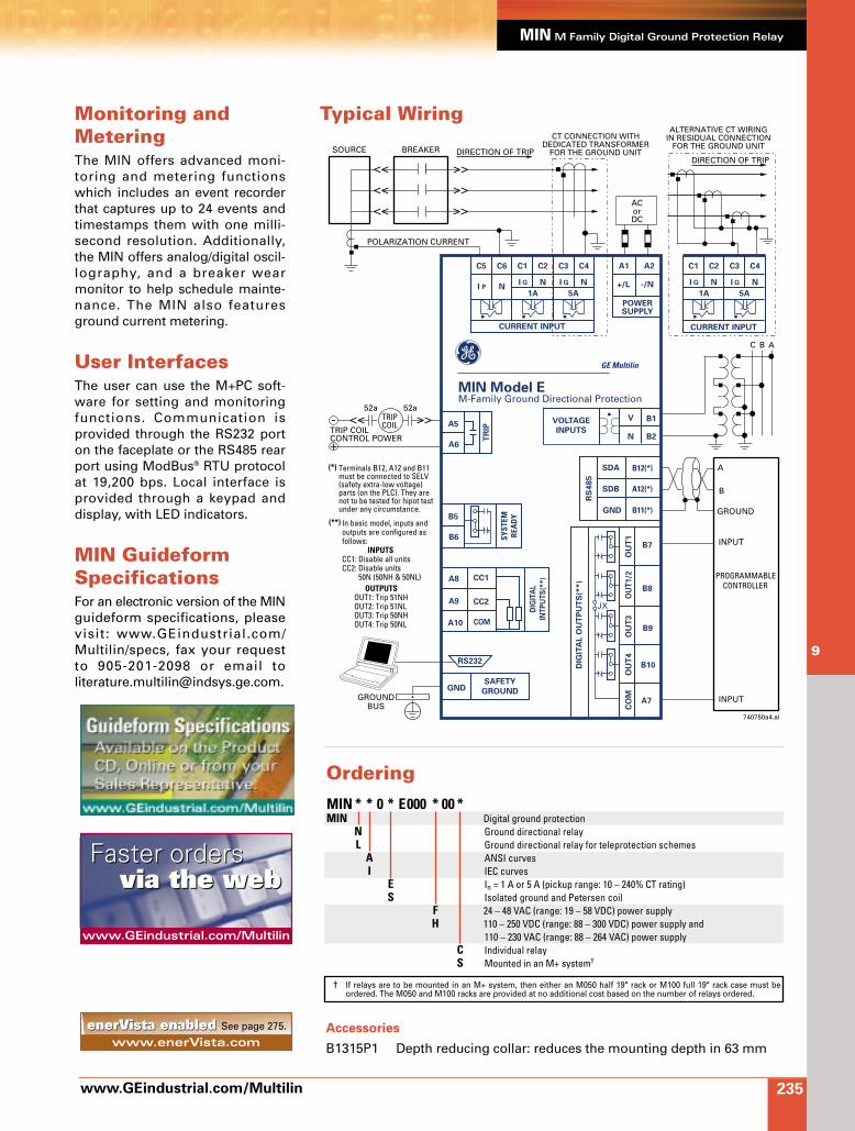
Monitoring andMeteringThe MIN offers advanced moni-toring and metering functionswhich includes an event recorderthat captures up to 24 events andtimestamps them with one milli-second resolution. Additionally,the MIN offers analog/digital oscil-lography, and a breaker wearmonitor to help schedule mainte-nance. The MIN also featuresground current metering.
User InterfacesThe user can use the M+PC soft-ware for setting and monitoringfunctions. Communication isprovided through the RS232 porton the faceplate or the RS485 rearport using ModBus® RTU protocolat 19,200 bps. Local interface isprovided through a keypad anddisplay, with LED indicators.
MIN GuideformSpecificationsFor an electronic version of the MINguideform specifications, pleasevisit: www.GEindustrial.com/Multilin/specs, fax your request to 905-201-2098 or email to [email protected].
Typical Wiring
TRIPCOIL
BREAKER
POLARIZATION CURRENT
>><<52a 52a
ACorDC
TRIP COILCONTROL POWER
GROUNDBUS
-
+
PROGRAMMABLECONTROLLER
A
B
GROUND
INPUT
INPUT
740750a4.ai
>>
>>
>>
<<
<<
ABC
<<
SOURCE
A5
A1 A2
A6
A8
A9
A7
A10
B10
B9
B8
B7
B11(*)
A12(*)
B12(*)SDA
SDB
GND
GND
RS232
JX
CC1
CC2
COM
C1 C2
POWERSUPPLY
CURRENT INPUT
+/L -/NN
SAFETY
GROUND
TR
IP
B5
B6 SYST
EMRE
AD
Y
CO
MO
UT
4O
UT
3O
UT
1
RS
48
5
OU
T1
/2
DIG
ITA
L O
UT
PU
TS
(**)
DIG
ITA
L
INT
PU
TS
(**
)
I
1A 5A
G
ALTERNATIVE CT WIRINGIN RESIDUAL CONNECTION
FOR THE GROUND UNITCT CONNECTION WITH
DEDICATED TRANSFORMERFOR THE GROUND UNIT
MIN Model EM-Family Ground Directional Protection
GE Multilin
C5 C6
NI P
C3 C4
NI G
C1 C2
CURRENT INPUT
NI
1A 5A
G
C3 C4
NI G
B1
B2
V
N
VOLTAGE
INPUTS
DIRECTION OF TRIPDIRECTION OF TRIP
In basic model, inputs and outputs are configured asfollows: INPUTSCC1: Disable all unitsCC2: Disable units 50N (50NH & 50NL)
OUTPUTSOUT1: Trip 51NHOUT2: Trip 51NLOUT3: Trip 50NHOUT4: Trip 50NL
(**)
Terminals B12, A12 and B11must be connected to SELV(safety extra-low voltage)parts (on the PLC). They arenot to be tested for hipot test under any circumstance.
(*)
MIN * * 0 * E000 * 00 *MIN Digital ground protection
N Ground directional relayL Ground directional relay for teleprotection schemes
A ANSI curvesI IEC curves
E In = 1 A or 5 A (pickup range: 10 – 240% CT rating)S Isolated ground and Petersen coil
F 24 – 48 VAC (range: 19 – 58 VDC) power supplyH 110 – 250 VDC (range: 88 – 300 VDC) power supply and
110 – 230 VAC (range: 88 – 264 VAC) power supplyC Individual relayS Mounted in an M+ system†
† If relays are to be mounted in an M+ system, then either an M050 half 19" rack or M100 full 19" rack case must be ordered. The M050 and M100 racks are provided at no additional cost based on the number of relays ordered.
Ordering
www.GEindustrial.com/Multilin
Faster ordersFaster ordersvia the webvia the web
Accessories
B1315P1 Depth reducing collar: reduces the mounting depth in 63 mmwww.enerVista.comenerVista enabledenerVista enabled See page 275.
GE Multilin 236
DRSDRSSingle and Three Phase Reclosing
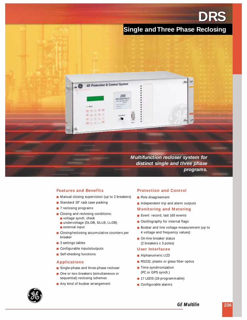
Multifunction recloser system for
distinct single and three phase
programs.
Features and Benefits Manual closing supervision (up to 2 breakers)
Standard 19" rack case packing
7 reclosing programs
Closing and reclosing conditions: voltage synch. check undervoltage (DL-DB, DL-LB, LL-DB) external input
Closing/reclosing accumulative counters perbreaker
3 settings tables
Configurable inputs/outputs
Self-checking functions
Applications Single-phase and three-phase recloser
One or two breakers (simultaneous orsequential) reclosing schemes
Any kind of busbar arrangement
Protection and Control
Pole disagreement
Independent trip and alarm outputs
Monitoring and Metering Event record, last 165 events
Oscillography for internal flags
Busbar and line voltage measurement (up to4 voltage and frequency values)
On-line breaker status (2 breakers x 3 poles)
User Interfaces Alphanumeric LCD
RS232, plastic or glass fiber optics
Time synchronization (PC or GPS synch.)
17 LEDS (16 programmable)
Configurable alarms

237 www.GEindustrial.com/Multilin
DRS single and three phase reclosing
Functionality
Recloser
The recloser portion of the DRSprovides both single pole andthree pole reclosing for one ortwo breakers. The reclosingsequence can be set to any of 7programs:
R1 - LO R3 - LO R1 - T3 - LO R3 - T3 - LO R1 - LO or R3 - LO R1 - T3 - LO or R3 - T3 - LO R1 - T3 - LO or R3 - LO
R1 = Single pole reclose
R3 = Three pole reclose
T3 = Second step three polereclose
LO = Lock-out.
The reclosing sequence is startedby the receipt of a reclose initia-tion signal. After the set timedelay, a reclose output is issued.If only one shot has been chosen,the recloser will go to lockout if asecond initiation input is received
prior to the expiration of the resettime. If two shots have beenchosen, a second delayed shotwill precede the lockout state. Therecloser can be reset from lockoutusing a command or automatical-ly after a set time. Manual closingcan be done energizing an inputto the DRS. Closing conditionswill be directed by the DRS (volt-age synchrocheck, DL-DB, DL-LB,LL-DB, external input).
Features
Pole Disagreement
A pole disagreement tripping oralarm output per breaker isprovided. The function supervisesthe breaker auxiliary contacts(per phase) status and with atimer supervision, determines if apole disagreement conditionexists.
Closing/Reclosing Conditions
Conditions are independently setfor closing and for reclosing, perbreaker. Closing/reclosing condi-
tions checked by the DRS are: Voltage synchrocheck: verifies
the magnitude, phase angle andfrequency difference betweenthe two voltage signals at bothsides of the breaker
Undervoltage conditions: DeadLine-Dead Bus, Dead Line-LiveBus, Live Line-Dead Bus(Dead/Live voltage levels aredefined by settings)
External permission: a digitalinput can be used to permit theclosure/reclosure
Outputs
The DRS has independent outputconfigurable contacts per break-er. Additionally, alarm outputs areprovided.
Easy to Configure
The DRS is configured using GE-INTRO software. This is agraphical Windows® basedprogram that allows easy config-uration. No training orprogramming skills are required.
B1
B2
B9B1B9B2
89L
RECLOSE &TRIPPING
DIGITALINPUTS
89E
TT
TT
52
LEVEL 0
RS232 LOCAL ACCESSWITH LAPTOP
LEVEL 2COMMUNICATION
GPS Sync.
TI
DRS with remote communication access.

Monitoring
Continuous Metering
On-line voltage (magnitude andangle) and frequency meteringfor each voltage value (line/bus)associated to one of two break-ers.
Breaker Status
DRS displays up to 2 breakerstatus with information per pole.
Event Record
The DRS stores up to 165 eventswith the date and time stampedto the nearest millisecond. Thisprovides the user with the infor-mation needed to determine thesequence of events, speedingdiagnosis and system recovery.Events consist of a broad rangeof state occurrences includingtrips and alarm contact opera-tions.
Oscillography
The DRS stores 4 oscillographyrecords, 264 cycles each. Eachrecord includes, at 4 samples percycle, the following information:
The 4 voltage inputs (VL1, VB1,VL2, VB2)
The status of each reclosingautomatically
All internal digital flags
DRS performance can beanalyzed using the GE-OSC andDRSTool software packages.
User Interfaces
Keypad and Display
The front of the DRS has akeypad and a backlit LCD. Thisallows the user to easily displaymetering data, settings and otherinformation.
LED Indication
The DRS includes 17 LED indica-tors on the front panel. 16 redLEDs are user configurable, whilea two-color LED reports system inservice information.
www.GEindustrial.com/Multilin
5
DRS single and three phase reclosing
238
Communication Ports
LOCAL COMMUNICATIONPORTS: A nine pin RS232 serialport (Port 1) is located on thefront of the relay and another oneon the rear. It allows the usereasy access with a laptopcomputer to get events, accesssettings, metering information,etc.
REMOTE COMMUNICATIONSPORT: One serial port is providedon the rear of the unit. This canbe either an RS232, an RS485port or a fiber optical port (glassor plastic). The ports may be setindependently for different datarates from 1,200 to 19,200 bps.
Time Synchronization
An IRIG-B input is provided whichpermits the relay to synchronizeits clock. This ensures that allevent time stamping is consistentacross the entire system.
Software
Two Windows® based softwarepackages are included with theDRS:
GE-LOCAL enables the user tovisualize the protection settings,alarms, LEDs, measurementsand status
GE-INTRO enables the user toconfigure the inputs, outputs andLEDs
Optionally GE-OSC ANDDRSTOOL enable the user tostudy the oscillography records.
These software packages are partof the GE-NESIS software (GENEtwork Substation IntegrationSystem) used by the DDS system.
APPROVALS
Compliant
TYPE TESTS
Insulation Test Voltage: 2 kV, 50/60 Hz, one minImpulse Voltage Withstand: 5 kV peak, 1 V 50 µsec, 0.5JInterferences: IEC 255-22-1 class IIIElectrostatic Discharges: IEC 255-22-2 class IV and
EN 61000-4-2, 8 kVRadiated Interference: ENV 50140, ENV50141,
ENV50204, 10 V/mFast Transient: IEC 255-22-4 and
EN 61000-4-4, class IVMagnetic Fields at Industrial Frequency:
EN 61000-4-8, 30 Av/mRF Emission: EN 55011, class B
ENVIRONMENTAL
Ambient Temperature Range:Storage: -40°C to +55°COperation: -20°C to +70°C
Humidity: Up to 95% without condensing
COMMUNICATIONS
Mode: Half duplexSpeed: 1200 to 19200 bpsPhysical Media:
RS232Plastic Fiber Optic
Type of connector: HFBR-4516Power supplied: -8 dBmReceiver’s sensitivity: -39 dBmWave length: 660 nm
Glass Fiber OpticType of connector: STAPower supplied: -17.5 dBmReceiver’s sensitivity: -24.5 dBmWave length: 820 nm
RS485 (port 2 optional)
INPUTS
Voltage: Vn = 90-220 VACThermal Ratings:
Continuous: 2 x Vn1 min: 3.5 x In
Frequency: 50 or 60 HzAuxiliary DC: 48/125 or 100/250 VDCDC Inputs: 48, 125, 220 VDCAC Burden: 0.2 VA (Vn = 90 V)DC Burden: 12 W, 8 mA per input
MONITORING
Recloser Timers:R1 Reclose: 0.01-60 sec in 0.01 sec stepsR3 Reclose: 0.01-60 sec in 0.01 sec stepsT3 Reclose: 0.1-256 sec in 0.1 sec stepsReclaim Time: 0.1-256 sec in 0.1 sec stepsReset Time: 0.1-256 sec in 0.1 sec steps
Synchronism Check:Module: 2-90 V in 1 V stepsAngle: 2°-89° in 10° stepsFrequency: 0.01-2 Hz in 0.1 Hz stepsTimer: 0.01-60 sec in 0.5 sec steps
Pole Disagreement:Timer: 0.1-256 sec in 0.1 sec steps
DRS TechnicalSpecifications
*Specifications subject to change without notice.

239 www.GEindustrial.com/Multilin
DRS single and three phase reclosing
Typical Wiring
B9
VOLTAGE INPUTS
B10 A9 A10 B7 B8 D11
CONTROLPOWER
CONTROLPOWERSUPPLY
C11
G D12
VL1 VB1 VL2 VB2
A7 A8
INP
UT
S 1
C1
D1
C2
D2
C3
D3
C4
D4
PI1PI2PI3PI4
PI5PI6PI7
52-1 A/a
52-1 A/b52-1 B/a
52-1 B/b52-1 C/a52-1 C/b
COMMON
INP
UT
S 2
R1
I1
R2
I2
R3
I3
R4
I4
PI8PI9
PI10PI11
PI12PI13PI14
SINGLE POLE INITIATE
THREE POLE INITIATETIME DELAYED TRIP
CHANGE SEQUENCE
COMMON
INP
UT
S 3
R5
I5
R6
I6
R7
I7
R8
I8
PI15PI16PI17PI18
PI19PI20PI21
52-1 CLOSE
52-2 CLOSE52-1 CLOSE PERMISSION
52-2 CLOSE PERMISSIONRECLOSE PROGRAM (1)RECLOSE PROGRAM (2)RECLOSE PROGRAM (3)COMMON
INP
UT
S 4
R9
I9
R10
I10
R11
I11
R12
I12
PI22PI23PI24PI25
PI26PI27PI28
79-1 PERMISSION
79-2 PERMISSION
ACTIVE TABLE 1ACTIVE TABLE 2EXTERNAL TRIGGER
COMMON
INP
UT
S 5
E1
F1
E2
F2
E3
F3
E4
F4
PI29PI30PI31PI32
PI33PI34PI35
COMMON
INP
UT
S 6
G1
H1
G2
H2
G3
H3
G4
H4
PI36PI37PI38PI39
PI40PI41PI42
BLOCK 79-1
BLOCK 79-2
GENERAL BLOCK
LOCKOUT RESET
COMMON
C
A
B C5
D5
D6
C7
D7
C8
D8
C9
C10
E5
E6
E7
E8
E9
E10
E11
E12
G5
G6
G7
G8
G9
G10
G11
G12
D9
D10
F5
F6
F7
F8
F9
F10
F11
F12
H5
H6
H7
H8
H9
H10
H11
H12
C6
PR
OG
RA
MM
AB
LE O
UT
PU
TS
52-1 CLOSE
52-2 CLOSE
52-2 CLOSE
52-2 TRIP
52-1 THREE POLETRIP ENABLE
52-2 THREE POLETRIP ENABLE
79-1 OUT OFSERVICE
79-1 INPROGRESS
79-2 INPROGRESS
1 PHASE 79-1 FAST RECLOSE
1 PHASE 79-2 FAST RECLOSE
3 PHASE 79-1 FAST RECLOSE
3 PHASE 79-1 TIME DELAYED
RECLOSE
3 PHASE 79-2 TIME DELAYED
RECLOSE
3 PHASE 79-2 TIME DELAYED
RECLOSE
POLEDISAGREEMENT
52-1
POLEDISAGREEMENT
52-2
79-2 OUT OFSERVICE
BOTH 79s OUT OF SERVICE
SYSTEMREADY
52-1 CLOSE
52-1 TRIP
PO1
PO3
PO4
PO5
PO6
PO7
PO8
PO9
PO10
PO11
PO12
PO13
PO14
PO15
PO16
PO17
PO18
PO19
PO20
PO21
PO22
PO2
52-2 A/a
52-2 A/b52-2 B/a
52-2 B/b52-2 C/a52-2 C/b
736750A1.ai
DRSReclosing System
GE Power Management
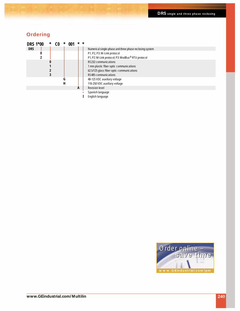
www.GEindustrial.com/Multilin
5
DRS single and three phase reclosing
240
Ordering
www.GEindustrial.com/pm
Order online –Order online –save timesave time
DRS 1*00 * C0 * 001 * *DRS Numerical single-phase and three phase reclosing system
0 P1, P2, P3: M-Link protocol2 P1, P2: M-Link protocol; P3: ModBus® RTU protocol
0 RS232 communications1 1 mm plastic fiber optic communications2 62.5/125 glass fiber optic communications3 RS485 communications
G 48-125 VDC auxiliary voltageH 110-250 VDC auxiliary voltage
A Revision level– Spanish languageI English language
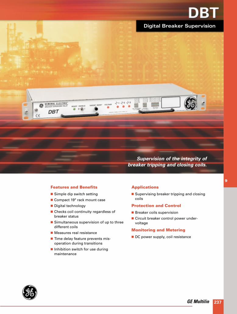
237
9
Features and Benefits
Simple dip switch setting
Compact 19" rack mount case
Digital technology
Checks coil continuity regardless ofbreaker status
Simultaneous supervision of up to threedifferent coils
Measures real resistance
Time delay feature prevents mis-operation during transitions
Inhibition switch for use during maintenance
Applications
Supervising breaker tripping and closingcoils
Protection and Control
Breaker coils supervision
Circuit breaker control power under-voltage
Monitoring and Metering
DC power supply, coil resistance
Digital Breaker Supervision
Supervision of the integrity of
breaker tripping and closing coils.
GE Multilin
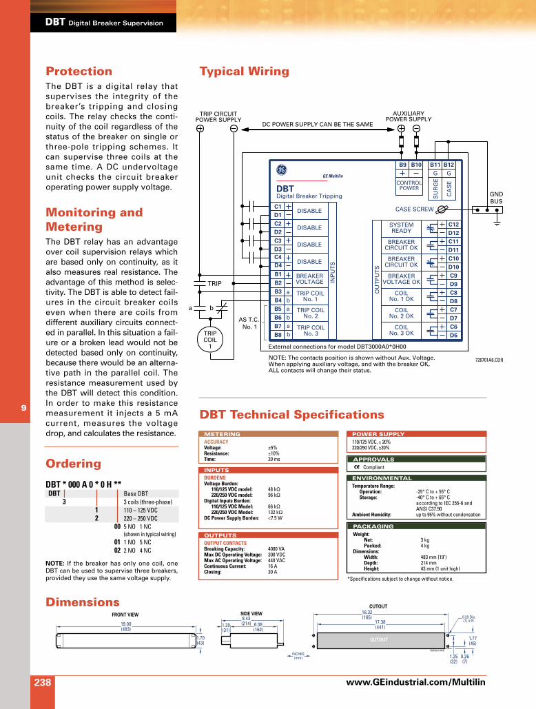
www.GEindustrial.com/Multilin
DBT Digital Breaker Supervision
238
9
DBT * 000 A 0 * 0 H **DBT Base DBT
3 3 coils (three-phase)1 110 – 125 VDC2 220 – 250 VDC
00 5 NO 1 NC (shown in typical wiring)
01 1 NO 5 NC02 2 NO 4 NC
NOTE: If the breaker has only one coil, oneDBT can be used to supervise three breakers,provided they use the same voltage supply.
PACKAGING
Weight:Net: 3 kgPacked: 4 kg
Dimensions:Width: 483 mm (19")Depth: 214 mmHeight: 43 mm (1 unit high)
ENVIRONMENTAL
Temperature Range:Operation: -25° C to + 55° CStorage: -40° C to + 65° C
according to IEC 255-6 andANSI C37.90
Ambient Humidity: up to 95% without condensation
APPROVALS
Compliant
POWER SUPPLY
110/125 VDC, ± 20%220/250 VDC, ±20%
OUTPUTS
OUTPUT CONTACTSBreaking Capacity: 4000 VAMax DC Operating Voltage: 300 VDCMax AC Operating Voltage: 440 VACContinuous Current: 16 AClosing: 30 A
INPUTS
BURDENSVoltage Burden:
110/125 VDC model: 48 kΩ220/250 VDC model: 96 kΩ
Digital Inputs Burden:110/125 VDC Model: 66 kΩ220/250 VDC Model: 132 kΩ
DC Power Supply Burden: <7.5 W
METERING
ACCURACYVoltage: ±5%Resistance: ±10%Time: 20 ms
DBT Technical Specifications
Ordering
FRONT VIEW
CUTOUT
CUTOUT
SIDE VIEW
19.00(483)
18.32(165)
17.38(441)
1.70(43)
1.20(31)
8.43(214) 6.38
(162)
0.28 Dia.(7) 4 Pl.
INCHES(mm)
1.77(45)
0.26(7)
1.25(32)
726700A1.DWG
*Specifications subject to change without notice.
Dimensions
ProtectionThe DBT is a digital relay thatsupervises the integrity of thebreaker’s tripping and closingcoils. The relay checks the conti-nuity of the coil regardless of thestatus of the breaker on single orthree-pole tripping schemes. Itcan supervise three coils at thesame time. A DC undervoltageunit checks the circuit breakeroperating power supply voltage.
Monitoring andMeteringThe DBT relay has an advantageover coil supervision relays whichare based only on continuity, as italso measures real resistance. Theadvantage of this method is selec-tivity. The DBT is able to detect fail-ures in the circuit breaker coilseven when there are coils fromdifferent auxiliary circuits connect-ed in parallel. In this situation a fail-ure or a broken lead would not bedetected based only on continuity,because there would be an alterna-tive path in the parallel coil. Theresistance measurement used bythe DBT will detect this condition.In order to make this resistancemeasurement it injects a 5 mAcurrent, measures the voltagedrop, and calculates the resistance.
C12
C11
C10
C9
C8
C7
C6
D12
D11
D10
D9
D8
D7
D6
SYSTEMREADY
BREAKERVOLTAGE OK
COILNo. 1 OK
COILNo. 2 OK
COILNo. 3 OK
BREAKERCIRCUIT OK
BREAKERCIRCUIT OK
OU
TP
UT
S
C1
B1
D1
B2
C2
a
a
a
b
b
b
B3
D2
B4
C3
B5
D3
B6
C4
B7
D4
B8
TRIP COILNo. 3
DISABLE
DISABLE
DISABLE
DISABLE CASE SCREW
TRIP COILNo. 2
TRIP COILNo. 1
BREAKERVOLTAGE
AS T.C. No. 1
External connections for model DBT3000A0*0H00
NOTE: The contacts position is shown without Aux. Voltage.When applying auxiliary voltage, and with the breaker OK, ALL contacts will change their status.
TRIPCOIL
1
b
TRIP
a
B9 B11
G
SU
RG
E
CA
SE
G
CONTROLPOWER
AUXILIARY
DC POWER SUPPLY CAN BE THE SAMEPOWER SUPPLY
B10 B12
TRIP CIRCUITPOWER SUPPLY
GNDBUS
INP
UT
S
726701A6.CDR
GE Multilin
DBTDigital Breaker Tripping
Typical Wiring

GE Multilin 239
DBFDBFDigital Breaker Failure
Phase and ground backup protection
for the primary circuit breaker.
Applications
Backup protection for primary circuitbreaker
Protection and Control
Two step instantaneous and/or time delayedbreaker failure
Independent timer per phase for the first step
Phase instantaneous overcurrent
Ground instantaneous overcurrent
Three phase direct trip
Fast tripping logic by using a second set oflevel detectors per phase and an independenttimer
Internal arcing protection
Operation failure detection
Three settings groups
14 configurable inputs
16 outputs (11 configurable)
Monitoring and Metering
Current metering
Breaker health monitoring
Event recorder, last 165 events
Oscillography, 4 records of 62 cycles
Phase sequence selection
User Interfaces
Keypad and display
17 LED indicators
3 communications ports
RS232 ports
Fiber optics available
IRIG-B input

240 www.GEindustrial.com/Multilin
DBF digital breaker failure
DescriptionThe DBF is a digital breaker fail-ure relay that provides phase andground backup protection if theprimary circuit breaker fails toclear a system fault.
Breaker failure protection is criti-cal in any backup relayingscheme. This protection musthave not only sensitivity anddependability, but also a highlevel of security because it isprotecting the busbars. The relia-bility must also be the same asthat of a busbar protection relay.
By using digital technology theoperation time of the DBF hasbeen improved.
An associated function protectsagainst electrical arcing betweenthe contacts of the breaker whenit is opened. This will help toprevent damage to the breaker.This function uses three verysensitive overcurrent detectorsset to the line capacitive current.
Three setting groups are avail-able, with the active groupselected by a setting or an input.There are 14 configurable inputsand 16 outputs (11 configurable).
The DBF meters the currentcontinuously. It also monitors thebreaker health I2t value. It has anevent recorder that can store thelast 165 events with a 1 ms reso-lution. It can store up to 4oscillography records with 66cycles each.
The local user interface includesa keypad and display. There are17 LED indicators, one a twocolored system alarm, and 16 redconfigurable to any of the 32alarms available. There are threecommunications ports, one onthe front panel and two on therear. It has 2 tripping steps.
Protection andControl
Overcurrent Protection
The DBF’s three phase overcur-rent protection (50PBF) consistsof single or three-phase breakerfailure initiation units with inde-pendent pickups and time delays.It also has three phase direct tripprotection (50XNF), which maybe used for three phase breakerfailure initiation without overcur-rent. The DBF also includesground overcurrent protection(50NBF).
Two step breaker failure opera-tion is included where each stepoperation may be activated bysingle, two or three phase over-current functions. Both steps aretime delayed and offer a widerange of settings.
Using independent timers perphase for the first step permits acorrect coordination with thesecond zone in case of evolvingfaults in single-pole trippingschemes.
The fast tripping logic permitsaccelerated tripping during three-phase faults. This is particularlyuseful in maintaining powersystem stability where selectivefast tripping is appropriate.
Internal Arcing Protection
If an electrical arc exists betweenthe contacts of an open breaker itcan eventually destroy the break-er. The DBF uses three verysensitive overcurrent detectorsset to the line capacitive currentto protect against internal arcing.
Settings Groups
Three groups of settings areavailable for the DBF. The activegroup may be selected by asetting or by an input.
Inputs and Outputs
The enhanced model DBF has 14configurable inputs, in groups of2 and 3 inputs.
There are 16 outputs with thefollowing assignments:
1 breaker failure pickup 2 breaker failure fix tripping
contacts 1 internal arc contact 1 alarm contact 5 spare configurable contacts 6 latching relay contacts (option-
al)
The logic for configurableoutputs consists of a combinationof NOT, AND, and OR gates appli-cable to trips, alarms and pickupsof all the protection and controlfunctions, internal protectionstatus, control, digital inputs, etc.
A basic DBF model is also avail-able which includes 6configurable inputs and 10outputs (5 of which are config-urable).
Monitoring andMetering
Breaker Monitoring
The breaker status is monitoredcontinuously. The cumulative I2tvalue is stored and used forbreaker health monitoring.
Event Recorder
The DBF records up to 165 eventsin non-volatile memory. Recordsinclude date and time with 1 msresolution, type of event, currentmeasurements and relay status.

Oscillography
The DBF system includes anoscillography recorder. It can beactivated by any of the protectivefunctions pickup or trip or by anexternal input. Records have aresolution of 16 samples percycle. Up to 4 records may bestored with up to 66 cycles each,with pre-fault cycles adjustablebetween 2 and 10 cycles.
The DBF can store up to 4 oscillographyrecords
Protection Status Self-checking
The DBF performs self tests bothat start up and continuously inthe background during operation.
www.GEindustrial.com/Multilin
5
DBF digital breaker failure
241
User Interfaces
Keypad and Display
The DBF has a 20 button keypadand a 2 line by 16 characteralphanumeric LCD. This allowslocal user interface without acomputer.
LED Indicators
The DBF has 17 LED indicators.One is a two color system alarm.The other 16 are red, and areconfigurable to any of the 32alarms available. Each LED canbe configured with or withoutmemory.
Communications
The DBF has three communica-tions ports, one on the frontpanel which is connected to oneon the rear panel, and a thirdindependent rear panel port.
The first two ports allow commu-nication through GE-LOCALsoftware, either locally with a
laptop computer, or remotely to aprotection dispatch center. Thissoftware allows the user to visu-alize measurements and status aswell as the relay’s time synchro-nization.
The third port connects the userto a communications network,through GE-POWER software, tothe part of a DDS integratedsystem. These applications arepart of GE-NESIS (GeneralElectric NEtwork SubstationIntegration Software) used by theDDS system.
GE-LOCAL software is provided for DBFcommunication
Dimensions
FRONT VIEW SIDE VIEWCUTOUT & DRILLING PATTERN
19.00"(483)
3.40"(87)
10.35"(263) 1.20"
(31)
0.28" Dia.(7) 4 Pl.
18.32"(465)
17.32"(440)
725700A2.dwg
3.52"(89)
3.00"(76)
0.26"(7)
INCHES(mm)

242 www.GEindustrial.com/Multilin
DBF digital breaker failure
Typical Wiring
A1
CURRENT INPUTS
OU
TP
UT
S
CO
NFI
GU
RA
BLE
-DE
FAU
LT S
ET
TIN
GS
INP
UT
S
A2 B1 B2 A3 A4 B3
52
B4 A10 A9
A12
A11C9
C11
E7
E9
E10
E12
C10
C12
E8
E8
E11
E11
CC1
CC4
CC7
CC9
CC11
CC13
CC3
CC6
CC2
CC5
CC8
CC10
CC12
CC14
COMMON
COMMON
COMMON
COMMON
COMMON
COMMON
B.F. INIT. PHASE A
52/b - A
3 PHASE B.F. INIT.
ACTIVE TABLE 0
OSCILLO TRIGGER
IRIG - B
ACTIVE TABLE 1
LATCHING RESET
FREE
GR
OU
P 4
GR
OU
P 3
GR
OU
P 2
GR
OU
P 1
GR
OU
P 5
GR
OU
P 6
52/b - C52/b - B
C2
C1
C3
B12
B11D9
D11
F7
F9
F10
F12
D10
D12D2
D1
D3
C7
D7
C8
D8
E1
F1
E2
F2
E3
F3
E4
F4
E5
F5
E6
F6
D4
C5
C6
D5
D6
C4
GND
B.F.INITIATE
TRIP 2
TRIP 1
INTERNALARC
SYSTEMREADY
TRIP
B.F.INITIATE
TRIP
TRIP 1
TRIP 2
TRIP
TRIP 1
TRIP 2
TRIP
TRIP 1
TRIP 2
725701AB.CDRPort 3 is independent from ports 1 and 2.Port 1 has priority over port 2.
CO
NFI
GU
RA
BLE
OU
TP
UT
SS
HO
WIN
G D
EFA
ULT
SE
TT
ING
SC
ON
FIG
UR
AB
LELA
TC
HE
D O
UT
PU
TS
B10
CONTROLPOWER
GROUND BUS
CONTROLPOWER
B9
Ia Ia Ib Ib Ic Ic In In
1 (FRONT) RS232
2 (REAR) RS232
3(REAR) FIBER OPTICOR
RS232DB-9
C(B)
A
A
B
C
B(C)
GE Multilin
DBFDigital Breaker Failure
Rx
Tx
DB-9
DB-9
NOT ASSIGNEDNOT ASSIGNED
B.F. INIT. PHASE B
B.F. INIT. PHASE C

DBF digital breaker failure
www.GEindustrial.com/Multilin 243
DBF Technical SpecificationsOUTPUTSSignalling contacts:
Contact Capacity:Maximum operating voltage: 380 VAC, 250 VDCContinuous current: 8 AMake and carry: 8 ABreaking capacity: 1760 VA
Tripping Contacts:Contact Capacity:
Maximum Operating Voltage: 440 VACContinuous Current: 16AMake and Carry: 30 ABreaking: 4000 VA
INPUTSBurdens:
Current Circuits: 0.5 VA for In = 5 A0.1 VA for In = 1 A
DC Burden:During operation: 12 WPer each activated input: 8 mA/1W, Vaux: 125 VDC
PACKAGINGDimensions: 3.40" H x 19" W x 10.35" D
(87 mm x 483 mm x 263 mm)Weight:
Not packaged: 16.08 lbs (6 kg)Packaged: 18.76 lbs (7 kg)
TYPE TESTSIsolation Test Voltage: 2 kV, 50/60 Hz, 1 minSurge Test Voltage: 5 kV peak, 0.5 JInterference: Class III according to IEC 255-22-1Electrostatic Discharge: Class IV according to IEC 255-22-2Radio Interference: Class III according to IEC 255-22-3Fast Transient: Class IV according to IEC 255-22-4Sinusoidal Vibration: Class II according to IEC 255-21-1Shock: Class I according to IEC 225-21-2Radio Frequency Emission:
according to IEC 41B (Sec) 81 andEN55022 class B
Emisitivity: according to EN50081-2(*)Susceptibility: according to EN50082-2(*)
ENVIRONMENTALTemperature:
Storage: -40°C to +85°COperation: -20°C to +55°C
Humidity: Up to 95% without condensing
MECHANICAL CHARACTERISTICS• Metallic package in 19" rack and 2 units high• Frontal MMI with LCD and keypad• Six rear terminal blocks• Protection class IP52 (according to IEC 529)
APPROVALS
Compliant
COMMUNICATIONSLocal Communication: LCD alphanumeric display with two lines
of 16 characters per line20 button frontal keypad
Remote Communication (local or remote PC and communication net):
Mode: half duplexSpeed: 1200 to 19200 bpsPhysical Media: RS232 (ports 1, 2 and 3)
Plastic fiber optic (port 3 optional)Type of connector: HFBR-4516Power supplied: -8 dBmReceptor’s sensitivity: -39 dBmWave length: 660 nm
Glass fiber optic (port 3 optional)Type of connector: STAPower supplied: -17.5 dBmReceptor’s sensitivity: -24.5 dBmWave length: 820 nm
Synchronization: IRIG-B• DB9 connector for RS232 ports on the front (1) and on the rear
(2)• DB9 connector for RS232 port on the rear (3), with 1 mm
plastic fiber optic or 50/125 glass fiber optic option
METERINGFrequency: 50/60 HzRated Phase Current: 0.2 - 2.4 In in steps of 0.01 A
Range DRated Ground Current: 0.1-1.2 In in steps of 0.01 A
Range DAuxiliary Voltage: 24 - 48 VDC ± 20%
110 - 250 VDC ±20%
PROTECTIONThermal Capacity:
Current circuits:Continuously: 4 x InDuring 3 sec: 50 x InDuring 1 sec: 100 x In
TIMERS1 Phase Timers T1: 0.05 - 2 sec in steps of 0.01 sec3 Phase Timers T2: 0.05 - 2 sec in steps of 0.01 sec3 Phase W/O Current Timer T3: 0.05 - 2 sec in steps of 0.01 sec2nd Stage Timer: 0.05 - 2 sec in steps of 0.01 secInternal Arc Timer T4: 0.1 - 2 sec in steps of 0.01 sec
*Specifications subject to change without notice.
OrderingTo order select the basic model and the desired features from the Selection Guide below.
DBF 1 * * * * 1 1 1 * ** ADBF DBF Digital Breaker Tripping
0 RS232 communications1 Plastic fiber optic and RS232 communications2 Glass fiber optic and RS232 communications3 RS485 and RS232 communications
B Ranges: Phase: In = 1 A (0.2-2.4 A), Ground: In = 1 A (0.2-2.4 A)C Ranges: Phase: In = 5 A (1-12 A), Ground: In = 1 A (0.2-2.4 A)D Ranges: Phase: In = 5 A (1-12 A), Ground: In = 5 A (0.5-6 A)F Ranges: Phase: In = 5 A (0.5-6 A), Ground: In = 1 A (0.2-2.4 A)G Ranges: Phase: In = 5 A (0.5-6 A), Ground: In = 1 A (0.1-1.2 A)
1 P1, P2, P3: M-Link communications protocol2 P1, P2: M-Link protocol;
P3: ModBus® RTU communications protocolM Spanish languageD English language
G 48-125 VDC power supplyH 110-250 VDC power supply
00 Standard model
Special Models:†MOD 04A: Digital inputs voltage: 48 VDC±20% MOD 05A: DIV: 110 VDC ±20%MOD 06A: DIV: 125 VDC ±20%MOD 07A: DIV: 250 VDC ±20%† In the ordering code, the last three digits are to be replaced by the MOD Code. Example: DBFwith DIV of 48 VDC: DBF****111*04A.
www.GEindustrial.com/pm
Order online –Order online –save timesave time
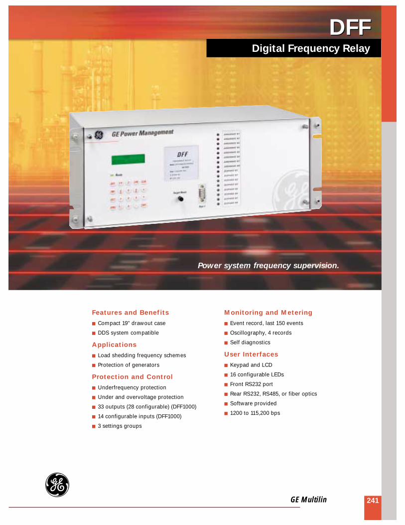
GE Multilin 241
DFFDFFDigital Frequency Relay
Power system frequency supervision.
Features and Benefits
Compact 19" drawout case
DDS system compatible
Applications
Load shedding frequency schemes
Protection of generators
Protection and Control
Underfrequency protection
Under and overvoltage protection
33 outputs (28 configurable) (DFF1000)
14 configurable inputs (DFF1000)
3 settings groups
Monitoring and Metering
Event record, last 150 events
Oscillography, 4 records
Self diagnostics
User Interfaces
Keypad and LCD
16 configurable LEDs
Front RS232 port
Rear RS232, RS485, or fiber optics
Software provided
1200 to 115,200 bps

242 www.GEindustrial.com/Multilin
DFF Digital Frequency Relay
Protection andControl
Frequency Functions
Under normal conditions, thegenerated frequency of thepower system must match withthe load requirements. Whenabnormal conditions occur thereare changes in the systemfrequency. If the changes aresmall the frequency can becorrected through the normaladjustment of the system genera-tor. However, when the load isincreased above the generatorrating the generator can nolonger correct the speed and thefrequency begins to drop. TheDFF is applied directly to thegenerator to protect againstdamage, and throughout thesystem to “shed” load in anattempt to regain frequencystability.
The DFF has 8 frequency units.Each unit can be configured as arate of change unit or as anabsolute frequency unit. Theseunits are supervised by an under-voltage unit. The number ofcycles needed to consider a tripcondition can also beprogrammed.
If the frequency unit isprogrammed as an absolute unitthe relay will trip when thefrequency is under theprogrammed value during thetime delay value. When the unitsare programmed as rate ofchange units the relay will tripwhen the frequency is under theprogrammed value and theinstantaneous variation of thefrequency with respect to time isgreater than the programmedvalue. In this case the time delayvalue will be ignored.
Voltage Functions
One overvoltage and one under-voltage unit is provided. Thevoltage functions are singlephase units. The frequency unitsare supervised by an undervolt-age unit.
Multiple Settings Groups
Three separate groups of settingsare stored in the DFF’s non-volatile memory, with only onegroup active at a given time. Thisallows the relay to respond tochanging conditions by selectingthe appropriate settings group.The active settings group can beselected via a user command orthrough a digital input. Certainsettings are common to allsettings groups.
Configurable Inputs and Outputs
There are 14 configurable inputsand 33 configurable outputs(DFP1000), providing the DFFwith high flexibility in load shed-ding schemes. AND/OR/NOT logiccan be applied to configure theoutputs. GE-INTRO software isprovided to configure the inputsand outputs.
MONITORING ANDMETERING
Event Record
The DFF has an event record thatcan store up to 150 events withthe date and time stamped to thenearest millisecond. This providesthe information needed to deter-mine the sequence of events,which helps the diagnosis ofrelay operation.
Oscillography
The DFF offers two types of oscil-lography records: voltagerecording, at 16 samples percycle, 66 cycles long (approxi-mately 1 second), and networkfrequency recording, at 2samples per cycle, with a storagecapacity of 1586 cycles (approxi-mately 30 seconds). The type ofoscillography record is selectableby a setting. GE-OSC software isprovided to allow the user todisplay and analyze the oscillog-raphy records.
The DFF can store four oscillography records

Keypad and Display
A 20 button keypad and a 2 lineby 16 character LCD is providedon the front panel for local userinterface. This interface allows theuser to assign and view protec-tion settings, alarms, LEDs,measurements, and status.
LED Indicators
The DFF has 1 LED to indicate therelay is in service, and 16 userconfigurable LEDs. AND/OR/NOTlogic can be applied to configurethe LEDs.
Communication Ports
The DFF has 2 communicationsports. The front mounted port isan RS232 port. The rear mountedport may be selected to be anRS232, RS485, plastic fiber optics,or glass fiber optics port. Thebaud rate is 1,200 to 115,200 bps.
www.GEindustrial.com/Multilin
5
DFF Digital Frequency Relay
243
Software
Three Windows® based softwarepackages are included with theDFF:
GE-LOCAL enables the user tovisualize the protection settings,alarms, LEDs, measurementsand status
GE-INTRO enables the user toconfigure the inputs, outputs andLEDs
GE-OSC enables the user tostudy the oscillography records
These software packages are partof the GE-NESIS software(General Electric NEtworkSubstation Integration System)used by the DDS system.
GE-LOCAL software is provided for DFF communication
DimensionsFRONT VIEW
19.05"(484)
7.30"(185)
10.25"(260)
INCHES(mm)
7.00"(178)
4.00"(102)
1.50"(38)
0.28" Dia.(7) 4 Pl.
18.30"(465) 17.35"
(441)
723700A2.DWG
CUTOUT
SIDE VIEW CUTOUT & DRILLING PATTERN

244 www.GEindustrial.com/Multilin
DFF Digital Frequency Relay
Typical Wiring
B7
VOLTAGE INPUTS
RS-2321
2RS-232
ORRS-485
ORFIBER-OPTIC
FRONT
REAR
PR
OG
RA
MM
AB
LE I
NP
UT
S
B8 A9 A10 B9 B10 A8 D11 A12
G GCONTROL
POWER
CONTROLPOWERSUPPLY GROUND
BUS
A7 C11 B12
E1
R1
F1
I1
F2
R2
F2
I2
F3
R3
F3
I3
F4
R4
F4
I4
VcVc Vc VnVc VnVb Va
EP1
EP8
EP2
EP9
EP3
EP10
EP4
EP11
EP5
EP12
EP6
EP13
EP7
EP14
COM
COM
TABLE (A) SELECTIONTABLE (B) SELECTION
EXTERNAL TRIGGER
723701A5.CDR
C
C B A
A
BO
UT
PU
TS
PR
OG
RA
MM
AB
LE O
UT
PU
TS
C9
E5
D9
F5
D5
F6
C6
E7
D6
F7
C7
E8
D7
F8
C8
E9
E10
E11
E12
R5
R6
R7
R8
R9
R10
R11
R12
J1
J2
J3
J4
J5
J6
J7
J8
J9
J10
J11
J12
D8
F9
F10
F11
F12
I5
I6
I7
I8
I9
I10
I11
I12
K1
K2
K3
K4
K5
K6
K7
K8
K9
K10
K11
K12
C5
E6
SELF TESTALARM
PICKUP F1
PICKUP F2
PICKUP F3
PICKUP F4
PICKUP F5
PICKUP F6
PICKUP F7
PICKUP F8
TRIP F1
TRIP F2
TRIP F3
TRIP F4
TRIP F5
TRIP F6
TRIP F7
TRIP F8
SP13
SP15
SP16
SP17
SP18
SP19
SP20
SP21
SP22
SP23
SP24
SP25
SP26
SP27
SP28
SP1
SP2
SP3
SP4
SP5
SP6
SP7
SP8
SP9
SP10
SP11
SP12
SP14
TRIP 1
TRIP 2
TRIP 3
TRIP 4
GE Power Management
DFFDigital Frequency Relay

www.GEindustrial.com/Multilin
5
DFF Digital Frequency Relay
245
COMMUNICATIONS
Mode: Half duplexSpeed: 1,200 to 115,200 bpsPhysical media:
RS232 (ports 1, 2)Plastic Fiber Optic (port 2 optional)
Type of connector: HFBR-4516Power supplied: -8 dBmReceptor's sensitivity: -39 dBmWave length: 660 nm
Glass Fiber Optic (port 2 optional)Type of connector: STAPower supplied: -17.5 dBmReceptor's sensitivity: -24.5 dBmWave length: 820 nm
RS485 (port 2 optional)
INPUTS
Digital inputs voltage: 48, 125 or 220 VDC (depending on model)
Frequency: 50 or 60 HzRated Voltage: 100/√3 - 220/√3 VACThermal Capacity:
Voltage circuits:Continuously: 2 x VnDuring 1 min: 3.5 x Vn
Burdens:Voltage circuits: 0.2 VA for Vn = 63.5 V
POWER SUPPLY
Power Supply: 48/125 VDC or 110/250 VDC) ± 20%DC Burden: 12 WPer each activated input: 8 mA (1 W Vaux = 125 VCC)
APPROVALS
Compliant
ENVIRONMENTAL
Temperature:Operation: -20° C to +55° CStorage: -40°C to +70° C
Humidity: Up to 95% without condensing
TYPE TESTS
Isolation Test Voltage: 2 kV, 50/60 Hz, 1 minSurge Test Voltage: 5 kV peak, 0.5 JInterference: Class III according to IEC 255-22-1Electrostatic Discharge: Class IV according to IEC 255-22-2Radiointerference: Class III according to IEC 255-22-3Fast Transient: Class IV according to IEC 255-22-4Sinusoidal Vibration: Class II according to IEC 255-21-1Shock: Class I according to IEC 255-21-2Radiofrequency Emission: According to IEC 41B (Sec.) 81 and
EN522 Class BEmisivity: According to EN50081-2Susceptibility: According to EN50082-2
PACKAGING
Dimensions: 19" x 10.25" x 7.7"(484 mm x 260 mm x 185 mm)
Weight:Not Packaged: 26.4 lbs (12 kg)Packaged: 28.6 lbs (13 kg)
DFF Technical Specifications
The relay shall be an integrateddigital protection system includ-ing frequency and voltageprotection, voltage monitoringand communication capabilities.
Protection functions shall include: 8 frequency units selecting the
rate of change mode or theabsolute mode
One frequency undervoltagesupervision unit
One overvoltage unit (one phase) One undervoltage unit (one
phase)
Monitoring functions shallinclude:
Voltage metering Fault voltages and frequency for
last trip Self diagnostics Pick up and trip status of each
function Oscillography (voltages and digi-
tal flags) Sequence of events (up to 150
internal events)
User interface shall include: 1 LED to indicate the relay is in
service 16 user configurable LEDs 33, 25 or 13 inputs (depending
on the model) Man-machine interface (MMI)
shall be in the form of a 2 line by16 character backlit LCD alphanumeric display and keypad toaccommodate programming andviewing of parameters
RS232, RS485 and fiber opticports shall be provided forremote or local access via apersonal computer
Ordering
DFF 1 * 0 * * C * * 00 2A *DFF Base DFF digital frequency relay
0 P1, P2: M-Link protocol2 P1: M-Link protocol; P2: ModBus® RTU protocol
0 14 inputs, 33 outputs1 7 inputs, 25 outputs2 7 inputs, 13 outputs
0 RS232 rear communications port1 Fiber optic plastic 1mm rear communications port2 Fiber optic glass 62.5/125 rear communications port3 RS485 rear communications port
0 48 VDC auxiliary voltage inputs1 125 VDC auxiliary voltage inputs2 220 VDC auxiliary voltage inputs
G 48/125 VDC power supplyH 100/250 VDC power supply
– Spanish languageI English language
To order select the basic model and the desired features from the Selection Guide below.
*Specifications subject to change without notice.
GuideformSpecifications
ACCURACY
Accuracy: ±200 PPM at 20° CRepeatability: ±50 PPMTemperature error: ±35 PPM from -20° C to +55° CAging: ±5 PPM according to MIL-C3098F
OUTPUTS
Tripping contacts:Continuous current: 16 AMake and carry: 30 A according to ANSI C37-90
Operating time: 4 ms
www.GEindustrial.com/pm
Order online –Order online –save timesave time

GE Multilin 242
15
F485F485Communication Converter
Isolated RS232 to RS485 to fiber optic
converter.
Features and Benefits Direct or modem communications Electrically isolated for reliable
communications
1,200-57,600 bps baud rates
50/125, 62.5/125 & 100/140 µm multimode fibers
Front panel LEDs for power, RS232 andRS485 transmit and receive
120 or 220 VAC adapter included
Additional power supply terminals suppliedto accept 9VAC/9VDC
Two mounting configurations
9-9 & 9-25 pin interface cables included
Applications Converts between RS232/RS485/fiber optic Fiber optic communication for data
transmission in noisy environments

243 www.GEindustrial.com/Multilin
15
F485 communication converter
DescriptionThe F485 is a self-containeddevice for converting betweenRS232, RS485 and fiber opticsignals. The F485 is electricallyisolated to improve communica-tions in noisy environments. Theconverter uses internal switchesto select the signal conversiontype and communication rates upto 57600 bps. The F485 converteruses the data on the serial portsto determine direction and there-fore requires no hardwarehandshaking signals from thecomputer. The F485 converter canbe powered via the poweradapter supplied or by connect-
ing an external 9VAC/VDC sourceto the power supply terminalslocated at the back of the case.The F485’s versatility and simpledesign makes it ideal for use withall GE Power Management prod-ucts in direct and modemcommunications.
Options
Fiber Optic Transmitter/Receiver
The fiber optic transmitter andreceiver used in the F485 convert-er utilize 820nm wavelengthtechnology and are designed tooperate with multimode fibersizes 50/125mm, 62.5/125mm and100/140mm using ST terminated
cables. The ST connectionsprovide repeatable connectionswith low attenuation.
Control Voltage
The F485 converter can bepowered by the 120 or 220 VACpower adapter supplied, or byconnecting an external 9 VAC/9VDC source. The 120 VAC adapterhas a standard North Americanplug. The 220 VAC adapter hasbeen designed for Europeanmarkets where voltage is 220VAC.
COMPUTER
RS232 FIBER OPTIC RS485 POWERPOWER
9VAC/9VDC9VAC/9VDCCOM PORT
Tx Rx+ - COM GND + -
COMPUTER
RS232 FIBER OPTIC RS485 POWERPOWER
9VAC/9VDC9VAC/9VDCCOM PORT
Tx Rx+ - COM GND + -
Up to 32 relays 2 wireshielded
twisted pair
RS232RS232
RS485
Noisy plantenvironment
Computer
805751A5.CDR
F485
F485
Electromagnetically transparentfiber optic cables
A = 0 C = 0B = 0 AMPS
489 Generator Management Relay
A = 0 C = 0B = 0 AMPS
489 Generator Management Relay
A = 0 C = 0B = 0 AMPS
489 Generator Management Relay
F485 simplifies communication between Intelligent Electronic Devices (IEDs), computers and a broad range of other combinations.

Features
RS485 direction control
Two-wire RS485 is by nature halfduplex and requires a means forswitching between a receive ortransmit state. The F485 converteruses the incoming data to controlthe direction and thereforerequires no control signals fromthe master device (RS232 orfiber) to switch from transmissionto receive mode after the lastcharacter has been transmitted.The length of time is fixed at thetime of 3.5 characters at theselected baud rate making it suit-able for use with ModBus® RTUprotocol.
www.GEindustrial.com/Multilin
5
F485 communication converter
244
15
DTE/DCE Control
The DTE/DCE setting reverses thetransmit/receive data lines on theRS232 side. For communicationsbetween a computer and a slavedevice, such as an IED, DTE(direct) should be selected. Whenconnecting the F485 converter toa modem or other data communi-cations equipment, DCE shouldbe selected.
Configuration
The converter box is configurablevia two internal dip switch bankswhich are accessible by removingthe converter box cover.Switches set the baud rate forRS485 communications, whether
the converter is DTE (RS232direct) or DCE (RS232 modemwith transmit and receivereversed) and the converterconversion mode.
Mounting
Two different mounting arrange-ments are possible. The first is byusing the two mounting holesinside the plastic case along withthe mounting screws supplied.The second and less permanentmethod is to use the Velcro®material supplied for attachmentto the side of a computer or desk.Visible LEDs on the front panelshow transmit/receive activity.
805752A7.CDR
TO RELAYS
STCONNECTOR
BAUD RATESWITCHES
TIMER DATA
DATA
DATA
RS232LED RxRS232LED Tx
DIRECTION
CONFIGURATIONSWITCH
RS485LED Tx
RS232DRIVER
DTE/DCERELAY
+5V DTE/DCESWITCH
F485 CONVERTER
GE Power Management
RS232COMPUTER
110/220 VAC
POWER ADAPTER9 V
AC
TO G
RO
UN
D
TE
RM
INA
L (4
)
POWER JACK
POWER SUPPLY
POWER
+5V
ISOLATEDRS485
CONVERTER TERMINATION AND LINE BIAS
RS485LED Rx
5V9VAC/9VDC
9VDC
+~
-
SHIELD
1
2
3
4
5
6
RS
485
GND
-
+
Tx
FIB
ER
Rx
VOLTAGE INPUT9VAC/9VDC
+
-
~
RS232 INTERFACEF485
TXD
RXD
SGND
TXD
RXD
SGND
9 PINCONNECTOR 25 PIN
CONNECTOR
1
2
3
4
5
6
7
8
9
1
2
233
4
4
5
5
6 6
7
7
8
8
9 20
20
COMPUTER
50/125 µm fiber62.5/125 µm fiber100/140 µm fiber
Wiring Diagram

F485 * *F485 Standard unit with RS485-RS232 ports plus a 9-9 pin & a 9-25 pin interface
cables plus a 120 V or 220 V power supply adapter.F With fiber optic interface
120 120 V power supply voltage220 220 V power supply voltage
245 www.GEindustrial.com/Multilin
15
F485 communication converter
Ordering
Dimensions
1.46"(74mm)
3.29"(83mm)
Inches"(mm)
2 x 0.109"(2.8mm)Dia. hole
4.13"(105mm)
4.72"(120mm) 0.29"ref.
(7mm)
1.30"(33mm)
RS232
COMPUTERRxTx
RS485FIBER OPTIC POWER
9V
AC/DC
POWER
REAR VIEW
BOTTOM VIEW
805750A5.DWG
+ +- -COM1
GND2 3 4 5 6
www.GEindustrial.com/pm
Ensure order accuracy –Ensure order accuracy –order on the weborder on the web