
GE Healthcare Life Sciences IN Cell Analyzer 6500HS ...
11
Centre for PanorOmic Sciences GE IN Cell Analyzer 6500HS SOP B-1 ver. 1 (05 Dec 2019) GE Healthcare Life Sciences IN Cell Analyzer 6500HS Standard Operating Procedure A. Overview IN Cell Analyzer 6500HS is specialized in performing repetitive imaging tasks on a microplate format. Data generated by the instrument is grouped into a folder containing TIFF images and an “.xdce” file directory storing positional metadata of the TIFF image acquired. The user can choose to view the images one by one but if one wish to analyse the images together, please keep tiff and .xdce files together. Before an imaging session. Please bring along the following: 1.1. Dimension chart of the plate the cells were seeded onto. 1.2. You have a map of the microplate you wish to image. Including positive and negative labelling control. Positive and negative treatment control. 1.3. Excitation and emission Spectra of the dyes that have been used to label the cells if possible. Otherwise, name of the dyes. You will need a nuclear stain in order to count cell with automated procedure. 1.4. Portable data storage device of >100 GB of space. B. Turn ON procedure Turn on button ① on machine beside gas inlet tubes. Turn on computer ②. Wait until orange and red indicator light are extinguished. Activate IN Cell Analyzer 6500 v7.3 software on desktop.
-
Upload
khangminh22 -
Category
Documents
-
view
4 -
download
0
Transcript of GE Healthcare Life Sciences IN Cell Analyzer 6500HS ...

Centre for PanorOmic Sciences GE IN Cell Analyzer 6500HS SOP B-1
ver. 1 (05 Dec 2019)
GE Healthcare Life Sciences IN Cell Analyzer 6500HS Standard Operating Procedure
A. Overview IN Cell Analyzer 6500HS is specialized in performing repetitive imaging tasks on a microplate format. Data generated
by the instrument is grouped into a folder containing TIFF images and an “.xdce” file directory storing positional
metadata of the TIFF image acquired. The user can choose to view the images one by one but if one wish to analyse
the images together, please keep tiff and .xdce files together.
Before an imaging session. Please bring along the following:
1.1. Dimension chart of the plate the cells were seeded onto. 1.2. You have a map of the microplate you wish to image. Including positive and negative labelling control.
Positive and negative treatment control. 1.3. Excitation and emission Spectra of the dyes that have been used to label the cells if possible. Otherwise,
name of the dyes. You will need a nuclear stain in order to count cell with automated procedure. 1.4. Portable data storage device of >100 GB of space.
B. Turn ON procedure Turn on button ① on machine beside gas inlet tubes.
Turn on computer ②.
Wait until orange and red indicator light are extinguished.
Activate IN Cell Analyzer 6500 v7.3 software on desktop.
Centre for PanorOmic Sciences GE IN Cell Analyzer 6500HS SOP B-2
ver. 1 (05 Dec 2019)
Live cell incubator (optional) if your experiment require live cell incubation, please follow these steps.
Prerequisite: IN Cell Analyzer 6500 software is activated. (Critical*) Retrieve EC cover box from cabinet. Put into a BSC hood. Open lid and invert the EC cover turn on UV irradiation for least 15 min.
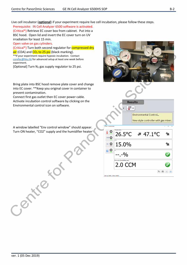
Open valve on gas cylinders. (Critical*) Turn both second regulator for compressed dry air (CDA) and CO2 to 25 psi (black marking). **If your experiment require hypoxic incubation. Contact [email protected] for advanced setup at least one week before experiment.
[Optional] Turn N2 gas supply regulator to 25 psi.
Bring plate into BSC hood remove plate cover and change into EC cover. **Keep you original cover in container to prevent contamination.
Connect first gas outlet then EC cover power cable. Activate incubation control software by clicking on the Environmental control icon on software.
A window labelled “Env control window” should appear. Turn ON heater, “CO2” supply and the humidifier heater

Centre for PanorOmic Sciences GE IN Cell Analyzer 6500HS SOP C-3
ver. 1 (05 Dec 2019)
C. IN Cell Analyzer interface
Top Left panel for functions.
Right panel for image preview. Scroll to zoom.
Lower left for plate map: scroll to zoom and double click a spot WITHIN plate area to move the lens to that position.

Centre for PanorOmic Sciences GE IN Cell Analyzer 6500HS SOP E-4
ver. 1 (05 Dec 2019)
D. Create acquisition protocol Prerequisite:
You have a list of dyes
You have information about the plate (minimum: plate product number; optimum: a manufacturer info sheet)
Click start a new protocol in the software interface.
D1__Click “Start a new (acquisition) protocol
D2__Assign a name for the protocol. Name order [PI initial’s]_[Your name]_[10 character description].
D3__Done. Please be reminded to click “save” after you have made major changes to the protocol or before starting
a scan.
D4_ to run a protocol, Press “Scan” and then assign a folder to store your images. Please note that a folder will be
created with the protocol’s name and then image folder as sub-directory.
***Chapters E,F,G,H,I describes modules you can toggle during protocol set up (J,K ARE OPTIONAL).
E. Verify Plate dimension E1__Select “Dashboard” page if you are not already on that page. Most of the setting will be done on this page.
E2__Click “Eject” to open the machine slide door for loading a plate.
E3__Insert microplate with A1 on top left corner of the sample frame.
E4__Click “Load” to close slide door.

Centre for PanorOmic Sciences GE IN Cell Analyzer 6500HS SOP E-5
ver. 1 (05 Dec 2019)
E5__Choose correct plate from list. ***Important*** If you cannot find your plate catalogue number please contact FCF technical staff for assistance.
E6_ Choose objective you wish to use. Please see below guide for reference. 4X cell cluster counting 10X individual cell counting (large amount) 20X single cell morphology quantification
40X sub-cellular morphology quantification
E7__Verify plate bottom height with the lens you are going to image with. Verify again if you now decided to use a different objective to image.
E8__ If the verify window indicates “100% of max” then decrease laser power by 4% and re-test. If blue line correctly identifies two peaks then click “Apply measured parameters”.

Centre for PanorOmic Sciences GE IN Cell Analyzer 6500HS SOP G-6
ver. 1 (05 Dec 2019)
E9_decrease laser power if needed in step E8 by adjusting slider position and then click on pencil button
F. Channel selection
F1__ Click on dashboard. Plus sign.
F2__ Select the color you wish to image. (Please hover your cursor on top of the channel to read filter specifications if required) Fluorescent channels available: “BLUE” “GREEN” “ORANGE” “FarRed” Another “Brightfield” channel available.
F3__ Click on camera icon check intensity. Adjust “Exposure” and “Laser Power” Accordingly. Please check fluorescent intensity below preview window. Maximum should be around 10,000 to 20,000 intensity units for fixed sample. Decrease laser power so that you image intensity unit of ~7,000 – 9,000 for live cell timelapse imaging to decrease phototoxicity. Quickly decrease laser power if maximum intensity reaches 65,535 units.
F4__ if you require confocal mode for deep depth of focus opticall sectioning. Contact technical staff for aperture calibration now. Aperture calibration is done every morning. F5__if IRIS confocal mode:close down aperture to 1 AU to 2 AU (AU = airy units). F6__ if EDGE confocal mode: select “Edge confocal” and close down aperture to 1AU to 2AU.
F7__monolayer cell culture works the best with “open aperture” selected. [N.B.] settings for F5 to F7 can be found here: Fluorescent image modes: “2D”, “3D” and “max intensity projection” Brightfield image modes: “2D”, “DIC”, “PH”(Phase contrast) and “3D” (please activate “3D” if you are doing IN Carta V1.10 volumetric analysis for brightfield, if activated.) F8__ if your specimen has multi-colour labels, please find a site with all of the colours and click “Auto-offset”.**
G. Field placement

Centre for PanorOmic Sciences GE IN Cell Analyzer 6500HS SOP G-7
ver. 1 (05 Dec 2019)
G1__ On left menu area, select “Fields”
G2__ select between fixed spacing, randomized placement, customized location or point list.
Fixed spacing: Please define how far the Field-of-view (FOV)s should be apart.
Tiling: Please define % overlap between FOVs (recommend no less than 10%)
Randomized placement:
You may programme the randomizer to exclude centre or border part by defining appropriate size (per mm). Make sure for randomized placement, option “order to reduce stage movement” is ON for faster capture time.
Customized and point list. It is the best to see where the FOV should be located before setup. We shall use preview function.
Click and then draw on plate map to define a small area for preview scan.
Centre for PanorOmic Sciences GE IN Cell Analyzer 6500HS SOP H-8
ver. 1 (05 Dec 2019)
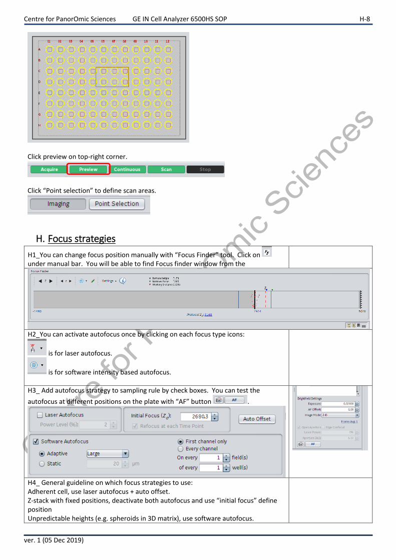
Click preview on top-right corner.
Click “Point selection” to define scan areas.
H. Focus strategies
H1_You can change focus position manually with “Focus Finder” tool. Click on under manual bar. You will be able to find Focus finder window from the
H2_You can activate autofocus once by clicking on each focus type icons:
is for laser autofocus.
is for software intensity based autofocus.
H3_ Add autofocus strategy to sampling rule by check boxes. You can test the
autofocus at different positions on the plate with “AF” button .
H4_ General guideline on which focus strategies to use: Adherent cell, use laser autofocus + auto offset. Z-stack with fixed positions, deactivate both autofocus and use “initial focus” define position Unpredictable heights (e.g. spheroids in 3D matrix), use software autofocus.

Centre for PanorOmic Sciences GE IN Cell Analyzer 6500HS SOP J-9
ver. 1 (05 Dec 2019)
I. Data transfer policies I1_ After your protocol has finished running. There should be a folder containing: 1) an .xdce file; 2) tiff images; 3) a
folder named “thumb”. Be sure to transfer the whole folder.
I2_ Go to computer (file explorer) select “IN-CARTA” under “Network”
I3_ transfer your folder to one of the IN_Carta drives.
Folder naming rule: IN_Carta drive# / [Your lab PI’s initials + “Lab”] / [Your name] / [Your image folder]
J. Z-stack setup (optional) This function would be the most useful if used together with EDGE or IRIS confocal fluorescent imaging mode.
Please refer to last section. Make sure you have selected “3D” for every channel you wish to acquire z-stack.
J1__ On left menu area, select “z-stack setup”
J2__ use “FF” focus finder tool to focus onto the structure you wish to capture. J3__ decide on z-stack optical section interval. The software will provide “Depth-of-field” in µm for each objective. Maximum z-stack interval available is 50 µm.
J4__select current z-position to set as 3D focus result height (mid-point of z-stack).
J5__ use up and down arrow to define your “Start slice” and “End slice” positions. [N.B.] The z-range is governed by z-interval and number of slices. If z-interval is changed, slice number will remain constant.

Centre for PanorOmic Sciences GE IN Cell Analyzer 6500HS SOP K-10
ver. 1 (05 Dec 2019)
K. Time series setup (optional) K1_ Select “Time Series” on menu.
K2_check acquire time series button K3_determine “Time interval”. It might be easier if “Display hh:mm:ss.ss”
function is turned on.
K4_ Determine the number of time points required.
K5_If more than one well needs to be imaged. Please switch Mode to “Multi-well”.
K6_click “Add”

Centre for PanorOmic Sciences GE IN Cell Analyzer 6500HS SOP L-11
ver. 1 (05 Dec 2019)
L. Turn OFF procedure L1_Live cell incubator shutdown (Optional, if you are working with fixed samples skip forward to step “L7”)
L2_Turn off secondary regulator of compressed dry air and CO2. Keep airflow at 100 cm3 / minute.
L3_(Critical**) Wait until both gas pressure decrease to 0. L4_Turn off all functions in “Env control window”. Then close Env control. L5_Press “Eject” button in IN Cell software L6_Unplug gas tubing and heating connector. Return the gas tubing to its holder.
L7_Turn off IN Cell Analyzer. ***Please do this step AFTER live cell incubator has been shut down (if applicable).
L8_ Eject any plate that is still left on sample holder. L9_Go to: Application-> Hardware-> Shutdown Instrument L10_Transfer data you need from IN Carta offline station. L11_Turn off computer.