SERVOPRO 4900 Multigas Analyzer
217
SERVOPRO 4900 Multigas Analyzer Installation and Operator Manual P/N: 0890000M
-
Upload
khangminh22 -
Category
Documents
-
view
4 -
download
0
Transcript of SERVOPRO 4900 Multigas Analyzer

SERVOPRO 4900 Multigas Analyzer
Installation and Operator Manual P/N: 0890000M

2 © Servomex Group Limited 2018 Rev 890000M/001/B02
IMPORTANT INFORMATION
Continued safe and reliable operation of this equipment is conditional on all installation, operation and
maintenance procedures being carried out in accordance with the appropriate manuals, by personnel having
appropriate qualifications, experience and training. Failure to observe the requirements of the manual may result
in the user being held responsible for the consequences and may invalidate any warranty. Servomex accepts no
liability for unauthorized modifications to Servomex supplied equipment.
Servomex has paid particular attention to Health and Safety throughout this manual. Where special precautions
need to be taken due to the nature of the equipment or product, an appropriate safety icon and warning
message is shown. Special attention should be made to section 2 – Safety, where all such messages are
summarized.
This document, and all specifications and drawings within the document, are the property of Servomex, unless
agreed otherwise by contract. They must not be reproduced, copied or transmitted in any form, or by any means,
or used as the basis for the manufacture or sale of apparatus, programs or services without permission.
In line with our continuous policy of research and development, we reserve the right to amend models and
specifications without prior notice therefore the information in this document is subject to change without notice
and does not represent a commitment on the part of Servomex Group Limited. This handbook is accurate at the
date of printing but will be superseded and should be disregarded if specifications or appearance are changed.
Check the internet for updates to the manual. The latest revision of this manual is available in Adobe Acrobat
format at www.servomex.com.
The customer agrees that in accepting and using this instrument Servomex’s liability arising from or in any way
connected with this instrument shall be limited exclusively to performing a new calibration or replacement or
repair of the instrument or transducer, at Servomex’s sole option, as covered by Servomex’s warranty. In no
event shall Servomex be liable for any incidental, consequential or special damages of any kind or nature
whatsoever, including but not limited to lost profits arising from or in any way connected with this instrument or
items hereunder, whether alleged to arise from breach of contract, express or implied warranty, or in tort,
including without limitation, negligence, failure to warn or strict liability.
Servomex is a registered trademark of Servomex Group Inc. The use of all trademarks in this document is
acknowledged.
North America: Europe: Representative:
Servomex Group Inc.
4 Constitution Way
Woburn MA 01801-1087
United States
Servomex Group Ltd
Jarvis Brook
Crowborough
East Sussex TN6 3FB
United Kingdom
t: +1 781 935 4600
t: +1 800 433 2552 (US toll free)
w: www.servomex.com
t: + 44 (0) 1892 652 181
w: www.servomex.com
© 2018. Servomex Group Limited. A Spectris Company. All rights reserved

Rev 890000M/001/B02 © Servomex Group Limited 2018 3
Contents
1 Introduction ................................................................................................................. 7
About this manual ......................................................................................................... 7
Applicable EU Directives, Standards, Certification ........................................................ 8
Product overview .......................................................................................................... 8
General description ....................................................................................................... 9
Recommended calibration intervals ............................................................................ 11
Automatic calibration options ...................................................................................... 12
Product identification .................................................................................................. 12
Sample requirements .................................................................................................. 14
2 Safety ......................................................................................................................... 16
General warnings ........................................................................................................ 16
Chemical warnings ..................................................................................................... 17
Electrical warnings ...................................................................................................... 17
Electromagnetic Compatibility (EMC) considerations .................................................. 18
Markings ..................................................................................................................... 19
3 Installation and set-up .............................................................................................. 20
Unpacking ................................................................................................................... 20
Mechanical Installation ................................................................................................ 22
Electrical installation ................................................................................................... 24
Sample / calibration gas connections .......................................................................... 31
4 Operation ................................................................................................................... 34
View flow levels .......................................................................................................... 34
Switch off the analyser ................................................................................................ 34
Power up .................................................................................................................... 35
5 User interface ............................................................................................................ 37
User interface overview .............................................................................................. 37
Introduction ................................................................................................................. 37
General techniques ..................................................................................................... 38
Touchscreen and Navigation overview ....................................................................... 39
Home screen .............................................................................................................. 42
Main Menu screen icons ............................................................................................. 43
System and measurement status icons and notices ................................................... 45
6 Analyzer Menu Branch Structure............................................................................. 47
Menu branch structure ................................................................................................ 47
7 Measurement branch screens ................................................................................. 59
Configuring manual calibration and Auto-Cal sequences ............................................ 62
Configuring the measurement alarms ......................................................................... 63
Configuring the User Ranges for mA Output and Screen Display ............................... 71

4 © Servomex Group Limited 2018 Rev 890000M/001/B02
Configure the measurement record option .................................................................. 79
Configuring the Measurement data filter and gas reporting units ................................ 81
Transducer Diagnostics .............................................................................................. 82
8 Diagnostics branch screen ...................................................................................... 84
Diagnostic branch icons .............................................................................................. 84
Saving the system log files ......................................................................................... 86
Testing the Relays ...................................................................................................... 86
Displaying the System or Calibration Log.................................................................... 88
9 Maintenance branch screen ..................................................................................... 89
10 Settings branch screen ............................................................................................ 90
Serial mA outputs overview ........................................................................................ 92
Assigning relay activity functions ................................................................................ 96
Assigning Password Protection ................................................................................... 99
Manual relay over-ride setting ................................................................................... 102
Setting the analyzer date .......................................................................................... 104
Setting the analyzer time .......................................................................................... 105
Setting the Inputs ...................................................................................................... 105
Screen Settings ........................................................................................................ 112
Setting the Measurement gas reporting units ............................................................ 113
11 Manual Calibration and Auto-Cal Sequences ....................................................... 114
Definition of Terms Used .......................................................................................... 114
Introduction to Calibration ......................................................................................... 114
Calibration Gas Standard Requirements ................................................................... 115
Recommended calibration periods ............................................................................ 116
Manual calibration ..................................................................................................... 116
Auto-Cal validation and calibration sequences .......................................................... 121
Auto-validation sequence steps ................................................................................ 124
Auto-Calibration Sequence Steps ............................................................................. 131
Auto-Cal Thresholds settings per sequence .............................................................. 139
Auto-Cal sequence timing setup ............................................................................... 141
Auto-calibration valve installation .............................................................................. 143
External inputs for Auto-Cal ...................................................................................... 144
Relays used for auto-calibration / validation .............................................................. 144
Calibration log file ..................................................................................................... 145
12 Technical specification .......................................................................................... 146
Mechanical specification ........................................................................................... 146
Electrical specification............................................................................................... 146
Maximum voltage ratings .......................................................................................... 147
Environmental limits .................................................................................................. 148
13 Routine maintenance .............................................................................................. 149

Rev 890000M/001/B02 © Servomex Group Limited 2018 5
Cleaning the analyzer ............................................................................................... 149
Routine checks ......................................................................................................... 149
Preventative maintenance ........................................................................................ 151
14 Troubleshooting ..................................................................................................... 152
Error codes ............................................................................................................... 152
Jam conditions .......................................................................................................... 152
15 Storage and disposal .............................................................................................. 153
Storage ..................................................................................................................... 153
Disposal .................................................................................................................... 153
16 Spares ..................................................................................................................... 154
17 Warranty .................................................................................................................. 157
Maintenance policy ................................................................................................... 158
Appendix A Compliance and standards ........................................................................ 159
A.1 Applicable EU Directives ........................................................................................... 159
A.2 Applicable standards ................................................................................................ 159
Appendix B Optional RS485 / RS232 .............................................................................. 160
B.1 Serial Communication introduction............................................................................ 160
B.2 Connections .............................................................................................................. 160
B.3 Serial set up parameters ........................................................................................... 161
B.4 Streaming RS232 output ........................................................................................... 163
Appendix C Implementation guide for Modbus communications ................................ 165
C.1 Introduction ............................................................................................................... 165
C.2 References ............................................................................................................... 165
C.3 Modbus setup ........................................................................................................... 165
C.4 Supported function codes ......................................................................................... 165
C.5 Exception codes ....................................................................................................... 166
C.6 Addressing ................................................................................................................ 166
C.7 Floating point numbers ............................................................................................. 166
C.8 System data .............................................................................................................. 167
C.9 System Settings ........................................................................................................ 168
C.10 System Control ......................................................................................................... 169
C.11 Measurements .......................................................................................................... 169
C.12 Transducer calibration data....................................................................................... 169
C.13 Transducer live info .................................................................................................. 170
C.14 Transducer settings .................................................................................................. 172
C.15 Relay control ............................................................................................................. 173
C.16 Resource live info ..................................................................................................... 173
C.17 Resource settings ..................................................................................................... 173
C.18 Transducer control .................................................................................................... 174

6 © Servomex Group Limited 2018 Rev 890000M/001/B02
Appendix D PROFIBUS ................................................................................................... 175
D.1 Safety ....................................................................................................................... 175
D.2 Description ................................................................................................................ 175
D.3 Electrical installation ................................................................................................. 175
D.4 PROFIBUS settings .................................................................................................. 176
D.5 PROFIBUS DPV0 features ....................................................................................... 177
D.6 PROFIBUS Troubleshooting ..................................................................................... 190
Appendix E Return Authorization Request .................................................................... 191
E.1 Return Authorization Product Number Request ........................................................ 191
E.2 Return Product Authorization Number (RAN) Request Form .................................... 192
E.2 Decontamination Certificate ...................................................................................... 194
Appendix F Transducer FSD values ............................................................................... 195
Appendix G Single Beam Single Wavelength (SBSW) transducer information .......... 196
G.1 Transducer low and high calibration .......................................................................... 196
Appendix H Paramagnetic transducer information ....................................................... 198
H.1 Overview of measurement errors for paramagnetic O2 transducer ............................ 199
H.2 Cross interference offsets (for paramagnetic transducer) .......................................... 200
Appendix I 1210 Gas Filter Correlation (GFX) transducer information ........................ 206
I.1 GFX transducer low and high calibration .................................................................. 206
Appendix J Sample wetted materials information ........................................................ 211
Index 213
Installation and Operator Manual P/N: 0890000M
Revision: 890000M/001/B03

Rev 890000M/001/B02 © Servomex Group Limited 2018 7
1 Introduction
About this manual
1.1.1 Scope of the manual
This manual covers the installation, operation and routine maintenance of the 4900
Multigas analyzer. It is intended for those already familiar with the installation, use and
maintenance of analytical or process instrumentation.
General information on the analyzer is given in the main body of this manual. Transducer-
specific information is contained in the relevant appendix at the rear of the manual.
A separate Quick Start Guide is also supplied with the analyzer, reference part number
0890000Q. This details software configuration and operation of the analyzer needed to get
the 4900 Multigas analyzer up and running. Extra copies may be ordered from Servomex.
1.1.2 Safety information
Read this manual and make sure you fully understand its contents before you attempt to
install, use or maintain the analyzer.
The following icons are used throughout this manual to identify any potential hazards that
could cause serious injury to people. Always follow the safety instructions and be aware of
the hazard.
This symbol warns of specific hazards which, if not taken into account,
may result in personal injury or death.
This symbol warns of specific hazards due to high voltages which, if not
taken into account, may result in personal injury or death.
This symbol warns of specific hazards due to high temperatures which, if
not taken into account, may result in personal injury or death.
This symbol warns of specific hazards due to hazardous substances
which, if not taken into account, may result in personal injury or death.
This symbol warns of specific hazards due to caustic or corrosive
substances which, if not taken into account, may result in personal injury
or death.
This symbol highlights where you must take special care to ensure the
analyzer or other equipment or property is not damaged.
8 © Servomex Group Limited 2018 Rev 890000M/001/B02
1.1.3 Other information provided by the manual
Note: Notes give extra information about the equipment.
Hint: Hints give helpful tips and highlight information which is useful for you to be
aware of, for example, specific operating conditions.
Applicable EU Directives, Standards, Certification
• Low Voltage Directive (2014/35/EU)
• Electromagnetic Compatibility (EMC) Directive (2014/30/EU)
• EN 61010-1:2010
• EN 61326-1:2013 / IEC 61326-1:2012, Class A. Intended for professional measurement
and control purposes in industrial process and industrial manufacturing environments or
is a component of such equipment. It is not intended for use in domestic applications,
the 4900 Multigas does not meet CISPR 11 class B emission limits for residential
locations, which are directly connected to low voltage power supply networks.
• Certified to MCERTS (EN15627-3) and (EN14181) QAL 1
• EN15267-3:2007 & QAL 1 as defined in EN 14181: 2014 for O2, SO2, CO and NO
• Certification Number: SIRA MC030013/11
Product overview
The 4900 Multigas Analzyer is designed to meet the needs of regulatory emissions
monitoring and providing feedback / feedforward control purposes in industrial and
combustion related processes.
The analyzer is a highly customizable, very low maintenance instrument that can monitor
up to four gases at one time. It uses ultra-stable paramagnetic and non-dispersive infrared
(NDIR) with gas filter correlation (GFX) technologies plus single beam single wavelength
infrared (SBSW IR).
The analyzer normally has one inlet and outlet stream carrying gas to all of the
transducers at the same time. If an external Nitrogen Dioxide (NO2) converter is to be
used, the analyzer can be equipped with a second inlet and outlet stream isolating the NO
transducer for direct use with the NO2 converter.
The standard unit weighs approximately 14 kg (30.9 lbs). When fitted with the extended
chassis (required when multiple GFX sensors are chosen) this increases by approximately
13.7 kg (30.2 lbs).
The analyzer can be configured as bench, panel or 19-inch rack mounted.
The dimensions of the standard analyzer (without ears for bench mounting) is 132.5mm
(5.2”) high (or 265.5 mm (10.5”) high with extended chassis), 430 mm (17”) wide and

Rev 890000M/001/B02 © Servomex Group Limited 2018 9
544.2 mm (21.4”) deep. The rack mount analyzer is 132.5 mm (5.2”) high (265.5 mm
(10.5”) high with the extended chassis), 482 mm (19”) wide and 544.2 mm (21.4”) deep.
The analyzer is not intended for use with corrosive samples and requires a gas
conditioning system if the gas stream is hot and wet. This provides protection of the
analyzer and little routine maintenance. Replacement of an external filter element, if one is
fitted, is the only maintenance item.
Calibration is essential for the accuracy of sample gas measurements and should be done
on a regular basis per recommendations in Section 1.5 for the transducers ordered, or as
required by the local regulatory body.
General description
The 4900 Multigas analyzer is simple to operate, with an intuitive user interface that will
display data from external sources. The chassis accepts up to four gas modules. It
provides power, gas connections and other support functions to the gas sensor modules
and processes their outputs to provide the sample gas concentrations. Gas measurements
are shown on the analyzer display and at the same time are sent out of the analyzer to
other devices using serial, milliamp (mA), voltage or digital communications protocols.
Note: 0-25% O2 gas module cannot be ordered on its own, it must be selected with at
least one other measurement.
The analyzer supports up to four external analog input signals that can then be displayed
on the screen as measurement signals, and output through the analog and/or the serial
outputs or accessed using Modbus or PROFIBUS protocols. These external input signals
can be recorded, used to activate relays, or trigger auto-calibration / validation routines or
low / high alarms.
Included with each analyzer ordered:
• 4 Relays contacts provided as standard (up to 8 relays per option board, 32 relays max
with 4 option boards)
Included with each transducer ordered:
• Each transducer is configured with one option board
• Two alarms are activated (up to 8 alarms per option board, 32 max with 4 option
boards)
• OUTPUT: 1 Isolated 4-20mA (1 per option board, 4 max with 4 option boards)
If Auto-Cal is purchased, then the following is included:
• 8 Relays per transducer
• 6th, 7th, 8th relays pre-assigned as Zero, Span, Sample gas per transducer
• Software to allow auto-calibration / validation based upon a timer (gas switching is via
user installed externally located valves).

10 © Servomex Group Limited 2018 Rev 890000M/001/B02
Options available per transducer:
• Additional option boards can be ordered to increase the number of each option
• A further 2 or 6 alarms (making a total of 4 or 8 alarms) per transducer
• OUTPUT: 0 – 10 VDC per transducer (1 per option board, 4 max with 4 option boards)
• INPUT: 2 Digital per transducer (2 per option board, 8 max with 4 option boards)
• INPUT: 1 Isolated 4-20mA per transducer (1 per option board, 4 max with 4 option
boards)
Other optional features are available:
• Serial Communications using RS232, RS485, RS232 & RS 485 Combo, Modbus RDU,
Profibus.
• Flow meters (floating element rotameter) to monitor and needle valves to control
sample gas flow through the instrument – a maximum of two if the dual sample inlet /
outlet option is used.
• A sample flow switch to monitor sample flow and alarm when the flow is too low – only
one allowed per analyzer.
• Second inlet and outlet gas sample stream if a user provided external NO2 converter is
added.
Note: If a flow switch is ordered and an external NO2 converter is added (this requires the
dual sample inlet / outlet option), then the flow switch is installed on the main
Stream #1 as Stream #2 will be isolated for use with the NO transducer after the
NO2 converter.
Note: It is recommended to fit an external 0.01 microns sample filter to protect the gas
transducer modules from particulate contamination
Use this manual for:
Installation: To take commissioning to the point where the analyzer is powered and
operational. The installer is advised to read this manual completely
before commencing installation.
Configuration: How to set up the clock, passwords, alarm levels, analogue outputs,
relays and other parameters.
Calibration: How to use the manual and automatic calibration/checking facilities.
Review: How to display analogue output / input settings, relay allocation, alarms,
faults and analyzer identity without changing the analyzer settings.
Rev 890000M/001/B02 © Servomex Group Limited 2018 11
Recommended calibration intervals
For optimum performance, it is necessary to routinely check the calibration of all the
internal gas transducers within the analyzer. The recommended periods for each
transducer type are shown in Section 11.4.
This manual provides details of the following:
• the requirements for and configuration of calibration ancillaries (e.g. gases)
• the setup of the auto-calibration / validation routines
• the connection of external solenoid valves (when auto-calibration is used)
• the use of the RS232 output and remote initiation of calibration
• the use of Modbus or PROFIBUS to initiate calibration
If the intended use of this equipment is to monitor process systems
critical for Health and Safety purposes, it is the sole responsibility of the
installer and operator to see that this instrument is commissioned,
maintained and calibrated in a manner consistent with the customer’s
specific application. Continued safe and reliable operation of this
equipment is conditional on all installation, operation and maintenance
procedures being carried out in accordance with the appropriate
manuals, by personnel having appropriate qualifications, experience and
training. Failure to observe the requirements of the manual may result in
the user being held responsible for the consequences. In no event shall
Servomex be liable for any incidental, consequential or special damages
of any kind or nature whatsoever, including but not limited to lost profits
arising from or in any way connected with this instruments use.

12 © Servomex Group Limited 2018 Rev 890000M/001/B02
Automatic calibration options
Two functions are provided when the optional Auto-Cal feature is ordered: Auto-calibration
and auto-validation. These functions are performed on the transducer. Auto-calibration will
change the actual calibration curve while auto-validation will only read the value to
determine if it is within the specified tolerance. Each transducer can have up to three
sequences of auto-calibration or auto-validation attached to it.
Customer supplied solenoid valves for sample, zero and span gases will be controlled by
discrete wiring to the relays for each of the transducers (see Section 0).
The automatic calibration procedure may be started by any of the following:
• A trigger from the internal instrument clock
• An external contact closure
• A Modbus or PROFIBUS command
Note: When the Auto-Cal option has been purchased, the manual calibration process will
use the Auto-Cal valves to select the required calibration gas.
Product identification
Figure 1-1: Standard 4900 Multigas Gas Analyzer configured for rack-mount

Rev 890000M/001/B02 © Servomex Group Limited 2018 13
Figure 1-2: Rear of the 4900 Multigas Gas Analyzer configured for use with an external NO2 Converter (two inlet / outlet lines included)
Note: The AquaExact 1688 port is not currently available for use in the 4900 Multigas.
Figure 1-3: The Extended Chassis version of the 4900 Multigas Gas Analyzer
Table 1-1 provides a general overview of the connectors on the back of the analyzer.
Connections for optional features will be inactive unless the optional feature has been
purchased.
Table 1-1: Rear panel connections
ID Description
ID Description
J9 – J16 Relay I/O connections
J26 – J33 Relay I/O connections
J17 DIN (1A-C / 2A-C)
J34 DIN (5A-C / 6A-C)
J18 DIN (3A-C / 4A-C)
J35 DIN (7A-C / 8A-C)

14 © Servomex Group Limited 2018 Rev 890000M/001/B02
ID Description
ID Description
J19 Option board 1&2 4-20 mA
inputs
J36 Option board 3&4 4-20mA
inputs
J20 4 – 20 mA output / voltage
output (I1± / V1±)
J37 4 – 20 mA output / analog
voltage output (I3± / V3±)
J21 4 – 20 mA output / voltage
output (I2± / V2±)
J38 4 – 20 mA output voltage
output (I4± / V4±)
PROFIBUS Profibus connector
RS-232 RS232
ETHERNET Ethernet connector
(available end of 2018)
RS-485 RS485 (Modbus)
AQUAXACT
1688
AquaXact 1688 connector
(not available at this time)
Earth (ground) connection
Sample requirements
For best performance the flow supplied to the analyzer should be kept at a constant value
and the analyzer must be freely vented to atmosphere, for both process sampling and for
calibration gas input.
Flow Rate: Nominal 1500 mL/min (Min 500 mL/min, Max 2000 mL/min)
Temperature: 5 to 45°C / 41 to 113°F
Dew point: 5°C / 9°F below minimum ambient
Condition: Oil free, non - condensing, filtered to 1m
Vent:
Warm up Time:
Connect the outlet of the analyzer to a separate atmospheric
vent, free from any back-pressure
Typically, 24 hours from cold start to 20°C / 68°F, high
sensitivity measurements may take longer
Pay particular consideration to the toxicity and asphyxiant nature of the
sample gas when selecting a vent location.
Corrosive gases are not intended to be used in these analyzers.
Make sure that if pressurized gases are used to keep the pressure below
8psig (55kPa g).

Rev 890000M/001/B02 © Servomex Group Limited 2018 15
Do not exceed the rated flow or pressure as transducer damage may
result. Best practice is to place a pressure relief valve on the inlet line,
venting any gas to a safe exhaust area.

16 © Servomex Group Limited 2018 Rev 890000M/001/B02
2 Safety
General warnings
Before you attempt to install, commission or use the 4900 Multigas
analyzer, read this manual carefully.
Do not attempt to install, commission, maintain or use the 4900 Multigas
analyzer unless you are trained and know what you are doing. The
analyzer must be maintained by a suitably skilled and competent person.
Do not connect the 4900 Multigas analyzer to a power source until all
relays, input/ output signals and plumbing connections are made.
This analyzer must be operated in a manner consistent with its intended
use and as specified in this manual.
The 4900 Multigas analyzer is only suitable for installation in safe areas.
The maximum pressure to the analyzer must be limited 8psig (55kPa g)
by means of a suitable release system such as a pressure release valve
or needle valve installed in line with the analyzer inlet streams.
Do not modify the unit, either mechanically or electrically, or the
certification and warranty of the instrument will be invalidated, and it
may not operate safely.
The 4900 Multigas analyzer includes few user-serviceable parts which,
are called out in the spare list in the appendix.
Do not use the 4900 Multigas analyzer as Personal Protective Equipment
(PPE).
Make sure that all floors or platforms where you install the 4900 Multigas
analyzer are large enough for you to move freely and to change position.
The 4900 Multigas analyzer may be attached to equipment that is hot.
Always wear the appropriate PPE to minimize the risk of burns.
Rev 890000M/001/B02 © Servomex Group Limited 2018 17
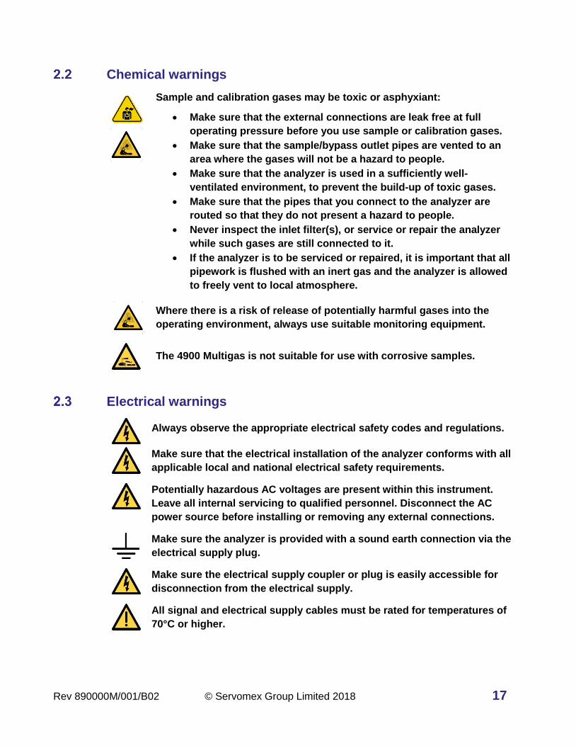
Chemical warnings
Sample and calibration gases may be toxic or asphyxiant:
• Make sure that the external connections are leak free at full
operating pressure before you use sample or calibration gases.
• Make sure that the sample/bypass outlet pipes are vented to an
area where the gases will not be a hazard to people.
• Make sure that the analyzer is used in a sufficiently well-
ventilated environment, to prevent the build-up of toxic gases.
• Make sure that the pipes that you connect to the analyzer are
routed so that they do not present a hazard to people.
• Never inspect the inlet filter(s), or service or repair the analyzer
while such gases are still connected to it.
• If the analyzer is to be serviced or repaired, it is important that all
pipework is flushed with an inert gas and the analyzer is allowed
to freely vent to local atmosphere.
Where there is a risk of release of potentially harmful gases into the
operating environment, always use suitable monitoring equipment.
The 4900 Multigas is not suitable for use with corrosive samples.
Electrical warnings
Always observe the appropriate electrical safety codes and regulations.
Make sure that the electrical installation of the analyzer conforms with all
applicable local and national electrical safety requirements.
Potentially hazardous AC voltages are present within this instrument.
Leave all internal servicing to qualified personnel. Disconnect the AC
power source before installing or removing any external connections.
Make sure the analyzer is provided with a sound earth connection via the
electrical supply plug.
Make sure the electrical supply coupler or plug is easily accessible for
disconnection from the electrical supply.
All signal and electrical supply cables must be rated for temperatures of
70°C or higher.

18 © Servomex Group Limited 2018 Rev 890000M/001/B02
The I/O terminals and connections are separated from the analyzer
mains circuits by reinforced insulation. The terminals must only be
connected to circuits that are themselves separated from mains voltages
by at least reinforced insulation.
Make sure that the cables that you connect to the analyzer are routed so
they do not present a trip hazard.
Electromagnetic Compatibility (EMC) considerations
The 4900 Multigas analyzer meets the essential requirements of the European EMC
Directive (2014/30/EU). The transducer and the 4-20 mA loop are electrically connected
but are isolated from the analyzer housing and sample cell fitting threads.
The analyzer generates and uses small amounts of radio frequency energy. There is no
guarantee that interference from radio or television signals will not occur in a particular
installation. If interference is experienced, switch off the analyzer to see if the interference
disappears. If it does, try one or more of the following methods to correct the problem:
• Re-orient the receiving antenna.
• Move the instrument with respect to the receiver.
• Place the analyzer and receiver on different AC circuits.
Always consider the following electromagnetic interference issues when installing the 4900
Multigas analyzer:
To provide an acceptable noise environment for the 4900 Multigas
analyzer or other digital equipment in the proximity of switching
inductive loads, Servomex recommends that you place varistors across
the inductors to lessen high voltage spikes that occur during transitions.
Circuitry activated by relay contacts should allow for the contact
bounce. One simple method is to place a capacitor across the relay
contacts.
Route AC power wiring as far from the analyzer and its wiring as
possible.

Rev 890000M/001/B02 © Servomex Group Limited 2018 19
Markings
Figure 2-1: Rear of the 4900 Multigas analyzer
The 4900 Multigas analyzer includes the following external markings on the rear panel and
correspond to:
Do not connect any cables carrying mains voltage or cables that have
inadequate insulation between line and mains to any of the I/O
connectors.
Earth / ground connections. These are screw terminals used to connect
the ground shields of cables plugged into the nearby connectors. Do not
connect any voltages to these connections.
This label identifies that:
• The analyzer is considered to be within the scope of the Waste Electrical and Electronic Equipment (WEEE).
• The analyzer is not intended for disposal in a municipal waste stream (such as landfill sites, domestic recycling centers and so on), but must be submitted for material recovery and recycling in accordance with the local regulations which implement the WEEE Directive.
Follow the appropriate safety instructions and be aware of any warnings about potential
hazards.

20 © Servomex Group Limited 2018 Rev 890000M/001/B02
3 Installation and set-up
Do not attempt to install, commission, maintain or use the 4900 Multigas
analyzer unless you have been trained or are an experienced instrument
technician.
The 4900 Multigas analyzer is only suitable for installation in safe areas.
Follow the instructions in this section to safely install the 4900 Multigas
analyzer.
Make sure that all floors or platforms where you install the 4900 Multigas
analyzer are large enough for you to move freely and to change position.
Do not install the unit in places subject to extreme mechanical vibration,
temperature changes or shock. If you do, measurements may not be
accurate, or the analyzer may be damaged.
Unpacking
Read this manual carefully BEFORE you remove the 4900 Multigas Gas
Analyzer from its shipping container, or you attempt to install,
commission or use the equipment.
1. Remove the analyzer and any other equipment from its packaging.
2. Remove the protective plastic covers from the sample gas inlets and outlets on the
rear of the analyzer (Figure 3-1).

Rev 890000M/001/B02 © Servomex Group Limited 2018 21
Figure 3-1: Gas inlets and outlets on rear of the analyzer
Hint: Remove the RED and BLACK protective covers before connecting to the
sample gas pipework. If you do not intend to use the analyzer immediately,
wait to remove the plastic covers until just before connecting to the sample
gas pipework.
3. Inspect the analyzer and the other items supplied and check that they are not
damaged. If any item is damaged, contact Servomex or your local Servomex agent
immediately.
4. Check the packing list to ensure you have received all the items ordered. If any item is
missing, contact Servomex or your local Servomex agent immediately.
5. If you do not intend to use the analyzer immediately:
a. Refit any protective plastic covers that you may have removed.
b. Place the analyzer and any other equipment supplied back in its protective
packaging.
c. Store the analyzer as described in section 15.1.
6. Read Section 2 – Safety before proceeding.
Hint: Keep all shipping packaging and documentation for future use when
moving, storing or returning the analyzer for service or repair.
Gas
outlets
Gas
inlets

22 © Servomex Group Limited 2018 Rev 890000M/001/B02
Mechanical Installation
3.2.1 Bench mounting
4 rubber feet beneath the analyzer allow use on a firm level bench or other suitable solid
work surface.
3.2.2 Rack mounting
Before installing the analyzer, determine where you will install it in the rack enclosure. The
standard analyzer is 3U in height and has two mounting bolts on each side.
There is an option for a sliding rack mount (Figure 3-2) as well as an extended chassis
(total 6U height) if multiple GFX transducers are ordered in one analyzer (Figure 3-3).
1 Telescopic slide 7 M4 screw
2 M5 screw 8 M4 washer
3 Slide support bracket 9 M4 locking washer
4 Cage nut 10 M4 nut
5 Slide support clamp 11 M5 cross-head screw
6 M5 waisted brass screw 12 Cup washer (plastic)
Figure 3-2: Sliding rack installation (M indicates metric value in mm)

Rev 890000M/001/B02 © Servomex Group Limited 2018 23
1 Telescopic slide 7 M4 screw
2 M5 screw 8 M4 washer
3 Slide support bracket 9 M4 locking washer
4 Cage nut 10 M4 nut
5 Slide support clamp 11 M5 cross-head screw
6 M5 waisted brass screw 12 Cup washer (plastic)
Figure 3-3: Sliding rack installation for Extended Chassis version (M indicates metric value in mm)

24 © Servomex Group Limited 2018 Rev 890000M/001/B02
Electrical installation
3.3.1 Electrical safety
Make sure that the electrical installation of the analyzer conforms with all
applicable local and national electrical safety requirements.
Make sure the electrical supply plug is easily accessible for
disconnection from the electrical supply.
Make sure the analyzer is provided with a sound earth connection via the
electrical supply plug.
All signal and electrical supply cables must be rated for temperatures of
70°C or higher.
Make sure that the cables that you connect to the analyzer are routed so
they do not present a trip hazard.
Follow the instructions given below when you install the analyzer. If you
do not, the analyzer warranty may be invalidated, the analyzer may not
operate correctly, or it may be damaged.
Make sure your electrical supply can provide the necessary maximum
power consumption.
3.3.2 Analog output signal connections
The analog output terminals are separated from the analyzer mains
circuits by reinforced insulation. The terminals must only be connected
to circuits that are themselves separated from mains voltages by at least
reinforced insulation.
To comply with EMC requirements, shielded cables must be used to
connect the analog outputs.
Refer to Table 3-1 to identify which screw terminal (J20, J21, J37, and J38) is connected
to which gas transducer position.
Table 3-1: Analog output interface connectors
Screw Terminal
Gas Transducer Screw Terminal
Gas Transducer
J20 Position / Measurement #1 J37 Position / Measurement #3
J21 Position / Measurement #2 J38 Position / Measurement #4

Rev 890000M/001/B02 © Servomex Group Limited 2018 25
Connect the cable wires to the pins on J20 (Gas #1), J21 (Gas #2), J37(Gas #3), J38
(Gas #4) for the available outputs on the transducers, as shown in Table 3-2. The (X) in
the table indicates the gas measurement location in position 1, 2, 3, or 4 that matches
the connector listed in Table 3-2 with the label on the back of the analyzer:
Table 3-2: Analog output interface connectors
Pin Use Output Configuration
Pin Use Output Configuration
1 I(X)+ mA current 4 V(X) + voltage
2 I(X) - mA current 5 V(X) - voltage
3 GND Chassis ground 6 GND Chassis ground
Connect the cable shielding to the ground point on the rear of the analyzer. The ground
points are marked with the symbol, or if more convenient the screw terminals at pins
3 and 6 may be used.
3.3.3 Analog input signal connections
The analog input terminals are separated from the analyzer mains
circuits by reinforced insulation. The terminals must only be connected
to circuits that are themselves separated from mains voltages by at least
reinforced insulation.
To comply with EMC requirements, shielded cables must be used to
connect the analog inputs.
The analyzer must supply power for any mA input devices. Do not
allow devices on the inputs to supply power or the input readings may
not be valid.
Analog input number “X” shares the same isolated reference as the
analog output with the same number. This reference is isolated from
the rest of the chassis as well as from the other analog inputs and
outputs. Do not allow equipment wired to an input number X to be
grounded to the same frame as equipment reading from output number
X, or both input and output X readings may not be valid.
Refer to Table 3-1 to identify which screw terminal (J20, J21, J37, and J38) is connected
to which gas transducer position.

26 © Servomex Group Limited 2018 Rev 890000M/001/B02
Table 3-3: Analog output interface connectors
Screw Terminal
mA Input Screw Terminal
mA Input
J19 Input #1, #2 J36 Input #3, #4
Connect the input cable wires to the pins on J19 (inputs #1 and #2), J36 (inputs #3 and
#4), as shown in Table 3-4. The (X) in the table indicates the input location in position 1,
2, 3, or 4 that matches with the label on the back of the analyzer:
Table 3-4: Analog input interface connectors
Pin Use Input
Configuration
Pin Use Input
Configuration
1 COMPL(X) Compliance out 4 COMPL(X) Compliance out
2 IN(X) + mA input return 5 IN(X) + mA input return
3 RET(X) 6 RET(X)
Connect the cable shielding to the ground point on the rear of the analyzer. The ground
points are marked with the symbol. Connect an external mA loop device “+” to the
COMPL(X) pin and connect the external device “-“ to the IN(X)+ pin. The RET(X) pins
cannot currently be used.
3.3.4 Relay connections
Figure 3-4: Rear of 4900 Multigas
The relay connections are separated from the analyzer mains circuits by
reinforced insulation. The terminals must only be connected to circuits
that are themselves separated from mains voltages by at least reinforced
insulation.

Rev 890000M/001/B02 © Servomex Group Limited 2018 27
Note: The relays do not have default settings unless Auto-Cal is selected. Users can
create alarms and assign them to any relay (Section 10.2).
Note: When Auto-Cal is purchased, each transducer has 8 relays available with 3 relays
preassigned - the 6th assigned to Zero, the 7th to Span and the 8th to the Sample
gas. The 1st to the 5th relays can be assigned to any alarm or function even if it is
not related to that particular gas transducer (Section 10.2).
The analyzer relays are accessible via the connectors J9-J16 and J26-J33. Connect one
end of your cable wire to the screw terminal for the relevant relay connector as shown in
Table 3-3. Each connector has two relays assigned to it where the “X” in XNO, XC, XNC
represents the relay number, NO is Normally Open, C is Closed and NC is Normally
Closed.
Table 3-3: 4900 Multigas relay connections
Relay Use Connector Relay Use Connector
1 1NO, 1C, 1NC J9 17 17NO, 17C,
17NC
J26
2 2NO, 2C, 2NC J9 18 18NO, 18C,
18NC
J26
3 3NO, 3C, 3NC J10 19 19NO, 19C,
19NC
J27
4 4NO, 4C, 4NC J10 20 20NO, 20C,
20NC
J27
5 5NO, 5C, 5NC J11 21 21NO, 21C,
21NC
J28
6 6NO, 6C, 6NC
Auto-Cal Zero J11 22 22NO, 22C,
22NC
Auto-Cal Zero
J28
7 7NO, 7C, 7NC
Auto-Cal Span J12 23 23NO, 23C,
23NC
Auto-Cal Span
J29
8 8NO, 8C, 8NC
Auto-Cal Sample J12 24 24NO, 24C,
24NC
Auto-Cal Sample
J29
9 9NO, 9C, 9NC J13 25 25NO, 25C,
25NC
J30

28 © Servomex Group Limited 2018 Rev 890000M/001/B02
Relay Use Connector Relay Use Connector
10 10NO, 10C, 10NC J13 26 26NO, 26C,
26NC
J30
11 11NO, 11C, 11NC J14 27 27NO, 27C,
27NC
J31
12 12NO, 12C, 12NC J14 28 28NO, 28C,
28NC
J31
13 13NO, 13C, 13NC J15 29 29NO, 29C,
29NC
J32
14 14NO, 14C, 14NC
Auto-Cal Zero J15 30 30NO, 30C,
30NC
Auto-Cal Zero
J32
15 15NO, 15C, 15NC
Auto-Cal Span J16 31 31NO, 31C,31
NC
Auto-Cal Span
J33
16 16NO, 16C, 16NC
Auto-Cal Sample J16 32 32NO, 32C,
32NC
Auto-Cal Sample
J33
Connect the wires in your cable to the screw terminals on the relevant connectors as
shown in Table 3-4 showing Relay X (J odd numbers) and Relay Y (J even numbers)
positions on the jumpers listed in Table 3-3.
Table 3-4: Relay Screw Terminal Pin Connection
Pin Use Output Configuration
1 (X) NO Normally Open Relay X
2 (X) C Close Relay X
3 (X) NC Normally Closed Relay X
4 (Y) NO Normally Open Relay Y
5 (Y) C Close Relay Y
6 (Y) NC Normally Closed Relay Y
For setting up the Zero Gas relay when Auto-Cal is purchased, connect the wires in your
cable to the screw terminals of the relevant connectors J11, J15, J28, and J32 (based
upon the number and position of the transducers in the analyzer) shown in Table 3-5. “Y”

Rev 890000M/001/B02 © Servomex Group Limited 2018 29
represents the jumper number J11 for gas #1, J15 for gas #2, J28 for gas #3 and J32 for
gas #4:
Table 3-5: Zero Gas Relay Screw Terminal Pin Connections for Auto-Cal
Pin Use Output Configuration
4 (Y) NO Normally Open Relay Y Zero Gas Relay
5 (Y) C Close Relay Y Zero Gas Relay
6 (Y) NC Normally Closed Relay Y Zero Gas Relay
For setting up the Span Gas and Sample Gas relays when Auto-Cal is purchased, connect
the wires in your cable to the screw terminals to the relevant connectors of J12, J16, J29,
and J33 as shown below to control the Span Gas Relays and / or Sample Gas Relays
shown in Table 3-6. “X” represents the connector J12 for gas #1, J16 for gas #2, J29 for
gas #3 and J33 for gas #4 and Pins 1 – 3 control the Span Gas Relays while Pins 4 – 6
control the Sample Gas Relays.
Table 3-6: Span and Sample Gas Relay Screw Terminal Pin Connections for Auto-Cal
Pin Use Output Configuration
1 (X) NO Normally Open Relay X Span Gas Relay
2 (X) C Close Relay X Span Gas Relay
3 (X) NC Normally Closed Relay X Span Gas Relay
4 (X) NO Normally Open Relay X Sample Gas Relay
5 (X) C Close Relay X Sample Gas Relay
6 (X) NC Normally Closed Relay X Sample Gas Relay

30 © Servomex Group Limited 2018 Rev 890000M/001/B02
3.3.5 Connect the electrical supply
Make sure that your external electrical supply outlet is isolated and
locked-out before you connect the conductors in the electrical supply
cable.
Only use the power supply cord provided with the unit.
Make sure the analyzer is suitable for use with your electrical supply
voltage and frequency (Section 12). If the analyzer is not suitable, it may
not operate correctly, or it may be damaged if you operate it.
The analyzer is supplied with an electrical supply cable and plug, configured for your
electrical supply. Connect the electrical supply to the analyzer as follows:
1. Turn the Power Switch on the back of the unit to OFF: press the “O“ on the On/Off
switch shown in Figure 3-5 A.
2. Fit the IEC plug on the end of the electrical supply cable provided to the electrical
supply socket on the rear of the analyzer (Figure 3-5 B).
Figure 3-5: Power switch (A) and electrical supply socket (B) on rear of analyzer
3. Plug the other end of the electrical supply cable into your electrical supply outlet.
4. Check the earth (ground) continuity between your electrical supply outlet earth
(ground) and the functional earth (ground) terminal on the rear of the analyzer.
5. If a local earth bonding is required, the functional earth stud can be used. The earth
ground cable must be kept to less than 3 meters to comply with EMC standards.
This does not replace the earth conductor on the electrical supply
socket which must always be connected. Therefore never cut or
remove any of the metal pieces from the supplied plug.
A
B
Rev 890000M/001/B02 © Servomex Group Limited 2018 31
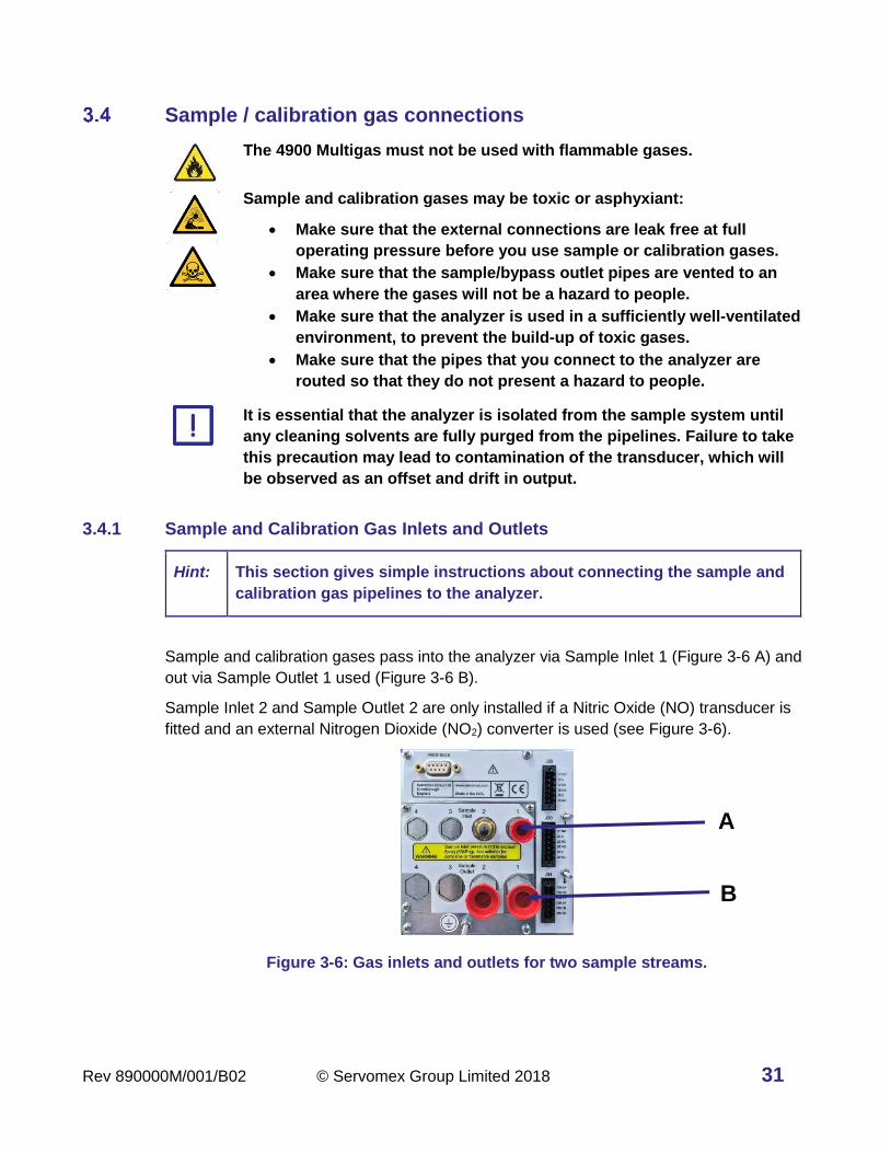
Sample / calibration gas connections
The 4900 Multigas must not be used with flammable gases.
Sample and calibration gases may be toxic or asphyxiant:
• Make sure that the external connections are leak free at full
operating pressure before you use sample or calibration gases.
• Make sure that the sample/bypass outlet pipes are vented to an
area where the gases will not be a hazard to people.
• Make sure that the analyzer is used in a sufficiently well-ventilated
environment, to prevent the build-up of toxic gases.
• Make sure that the pipes that you connect to the analyzer are
routed so that they do not present a hazard to people.
It is essential that the analyzer is isolated from the sample system until
any cleaning solvents are fully purged from the pipelines. Failure to take
this precaution may lead to contamination of the transducer, which will
be observed as an offset and drift in output.
3.4.1 Sample and Calibration Gas Inlets and Outlets
Hint: This section gives simple instructions about connecting the sample and
calibration gas pipelines to the analyzer.
Sample and calibration gases pass into the analyzer via Sample Inlet 1 (Figure 3-6 A) and
out via Sample Outlet 1 used (Figure 3-6 B).
Sample Inlet 2 and Sample Outlet 2 are only installed if a Nitric Oxide (NO) transducer is
fitted and an external Nitrogen Dioxide (NO2) converter is used (see Figure 3-6).
Figure 3-6: Gas inlets and outlets for two sample streams.
B
A

32 © Servomex Group Limited 2018 Rev 890000M/001/B02
3.4.2 Gas connections
Connect your sample/calibration gas inlet and outlet pipelines to the Sample Inlet 1 and
Sample Outlet 1 fittings on the rear of the analyzer. See Table 3-7 for the specification of
the fittings. Do not over-tighten the fittings.
An optional second stream will be plumbed on Inlet / Outlet #2 when an external NO2
converter is used.
Table 3-7: 4900 Multigas sample port fittings
Component Fitting Comment
Sample Inlet 1 1/8" NPT female Available as standard on the 4900
Sample Inlet 2 1/8" NPT female Only available when an external NO2
converter is used (customer supplied).
Sample Outlet 1 1/4" NPT female Available as standard on the 4900
Sample Outlet 2 1/4" NPT female Only available when an external NO2
converter is used (customer supplied).
Note: It is recommended an external filter is fitted (see accessories in Section 16) at the
analyzer inlet or, if preferred, at a convenient point in the sample line prior to the
inlet.
3.4.3 Gas Flow Rate
Flow control on the inlet to the analyzer must be provided by the end user using mass flow
controllers, manual adjustable valves like needle valves, or electronically controlled
metering valves.
Optional (rotameter floating element) flow meter with an integrated metering valve can be
configured with the analyzer when ordering through Servomex. In this case the flow
adjustment is made with a small screw driver inserted through the hole under the flow
meter and observing the scale indication at the top of the float (See Figure 3-7).
If two gas stream inlet / outlets are configured, then flow meter 1 on the front panel shows
the flow on stream #1 while flow meter 2 shows the flow on stream #2.
The rotameters are used only for visually checking there is gas flowing through the
analyzer and that it does not exceed the flow rate of the instrument. An optional internal
flow monitor provides a diagnostic indicator to alert locally or remotely when flow is not
going through the analyzer.
For best performance the flow supplied to the analyzer should be kept at a constant value
and the analyzer freely vented to atmosphere for both process sampling and for calibration

Rev 890000M/001/B02 © Servomex Group Limited 2018 33
gas input. A nominal flow of 1500 mL/min is recommended, with a minimum of 500 mL/min
and a maximum of 2000 mL/min.
Figure 3-7: Gas Flow Meter location on front panel of the standard analyzer

34 © Servomex Group Limited 2018 Rev 890000M/001/B02
4 Operation
See Section 1.8 for flow/pressure requirements for the sample, zero and
calibration gases. If the flow/pressure are outside the ranges specified in
Section 1.8, you must regulate the gases externally, before they enter the
analyzer.
View flow levels
The optional flow meters are visible on the front panel and are calibrated for use with air /
N2. Most other gases have molecular weights within ± 25 percent of air and will produce
valid readings. If the molecular weight of the background gas is much different from air / N2
the flowmeter reading will be less accurate. For example, Helium is a light gas therefore
the flow rate should be set to approximately one-third that of air / N2.
Switch off the analyser
Figure 4-1: On/off switch on the rear of the analyzer
To switch off the analyser, press the “O” on the On/Off switch on the rear of the analyser
(Figure 4-1 A).
If you intend to leave the analyzer off for an extended period of time, for example, when
carrying out plant maintenance and will not use the analyzer for several days:
• Turn off the analyzer and disconnect the electrical supply cable from the analyzer.
• Purge the transducers with Zero Air or Nitrogen gas to remove any sample gas.
• Close off the sample gas inlet and outlets using a shut off valve or the protective caps
supplied with the analyzer.
A
1

Rev 890000M/001/B02 © Servomex Group Limited 2018 35
Power up
Sample and calibration gases may be toxic or asphyxiant:
• Make sure that the external connections are leak free at full
operating pressure using N2 or Zero Air before you use sample or
calibration gases.
• Make sure that the sample/bypass outlet pipes are vented to an
area where the gases will not be a hazard to people.
• Make sure that the analyzer is used in a sufficiently well-ventilated
environment, to prevent the build-up of toxic gases.
• Make sure that the pipes that you connect to the analyzer are
routed so that they do not present a hazard to people.
It is essential that the analyzer is isolated from the sample system until
any cleaning solvents are fully purged from the pipelines. Failure to take
this precaution may lead to contamination of the transducer, which will
be observed as an offset and drift in output.
The analyzer can now be powered up.
Hint: When the electrical supply to the analyzer is switched on, a series of beeps
will be heard, the readings are displayed on screen and the clock in the upper
right hand corner of the screen starts running.
To power up the analyser:
1. Make sure that the analyser power cord is connected to the back of the unit.
2. Press the “I” on the On/Off switch on the rear of the analyser (Figure 4-2 A) to power
on the analyser.
Figure 4-2: On/Off switch on the rear of the analyzer, (A) points to the Power Switch “I” for ON position.
A

36 © Servomex Group Limited 2018 Rev 890000M/001/B02
When the analyzer is first switched on, the screen displays a software loading progress
bar, followed by the Home screen and the warmup signal appears in front of any
transducer which is not ready for measurement (Figure 4-3).
Figure 4-3: Home screen for a 3-transducer analyzer showing the O2 warming up
Hint: Figure 4-3 shows the unit in Warm Up mode, indicated by the three wavy lines
shown in the upper left corner encircled by the red box.

Rev 890000M/001/B02 © Servomex Group Limited 2018 37
5 User interface
User interface overview
Configuration options referred to in this manual (for example, auto-calibrate / validate)
must be specified at the time of purchase. The menus and menu options associated with
the options not purchased will appear as grey colored icon buttons (as seen in the red box
of Figure 5-1) and will be unavailable for use.
Figure 5-1: Setup Screen Icons showing 3 mA Inputs activated (purchased) and the bottom mA Input is grayed out (not purchased)
Introduction
The user interface is a touchscreen display with icon-driven menus to allow for easy and
intuitive operation of the 4900 Multigas analyzer. Figure 5-2 shows the main display for a
four-transducer analyzer with the Main Menu option icon in the lower right-hand corner.
Multigas 4900 analyzers share several standard features with optional features dependent
on the configuration of transducers, options purchased and setup preferences.
Figure 5-2: Home screen for a 4-transducer analyzer (A) is the Main Selection Touch Screen and (B) indicates the Main Menu Icon
Unpurchased Option
Purchased Options
A
B
38 © Servomex Group Limited 2018 Rev 890000M/001/B02
The user interface comprises the following as shown in Figure 5-2:
A Touchscreen display Screens, horizontal bars and icons are displayed on the
touchscreen depending on the information and operation
being engaged.
B Touchscreen icons The icons displayed depend on the current screen
capabilities / function. When touched the icons will
produce a new screen or icon list.
Note: If there are no menu interactions for 60 seconds, the display reverts back to this
Home screen. This timer can be adjusted in the Settings section.
To interact with a specific gas transducer, touch on the horizontal bar on the home screen
display for that gas transducer when more than one gas stream is displayed or touch the
single gas screen. A single screen display will show the gas transducer specific user
interactions that are available for the selected item.
Note: The remainder of the software descriptions will show a single transducer window
when appropriate.
General techniques
The general navigation route through the user interface screens is described by a
sequence of icons that you must touch to get to the desired screen. A shortened visual
description of the sequence of icons to be touched is used in this manual to help you
navigate easily to the various screens.
For example, to reach the Alarms screen (a sub-screen of the Measurement branch) you
must press the following sequence of icons:
1. Touch the icon to display the Main Menu screen.
2. Next, touch the icon to display the Measurement screen.
3. Finally, touch the icon to display the Alarms screen.
This sequence is shortened in the manual and will appear above the screen page as:
> >
Familiarity of the icons below will allow easier navigation of the menus.

Rev 890000M/001/B02 © Servomex Group Limited 2018 39
Icon Meaning Function
Home Returns to the Home screen.
Main Menu
Displays the Main Menu screen that contains the four main
branch icons: Measurement, Diagnostics, Maintenance, and
Settings.
Next
Displays the next set of functions onto the screen. The new
list will always appear in a new column to the right of the
arrow.
Return Returns to the prior screen.
Accept Touch this icon to accept any changes made.
Cancel or Exit Touch this icon to cancel or reject any changes made or exit
a screen.
Not Active In several menus this icon is used to deactivate the
selection.
Active In several menus this icon is used to activate the selection.
Touchscreen and Navigation overview
Each screen displays active icons that are relevant to that screen’s operation. To select an
icon, it is best to use the eraser end of a pencil or a stylus to touch the icon on the screen
graphic.
Note: Be sure not to press too hard or you will damage the screen; do not use the point of
a pen or pencil to touch the screen.
For example, the sequence used to arrive at the screen shown in Figure 5-3 is accessed
by touching the Main Menu icon on the Home page then touching the Measurement
icon to activate the first set of the Measurement choices.
>
The Measurement choices available are shown in Figure 5-3 and show up as icons in the
column to the right of the Main Menu list. The icon background now turns blue
indicating it is the active Main Menu choice as you navigate forward through the various
choices.
Note: The Main Menu branch stays visible all the time unless you are in a special screen
or the Home page. This allows you to access the other Main Menu choices easily.

40 © Servomex Group Limited 2018 Rev 890000M/001/B02
Figure 5-3: The user interface of the Main Menu screen with the Measurement branch active.
When a Main Menu icon is selected further icons associated with that function are
displayed as seen in Figure 5-3. New icons associated with that function will appear to the
right of the icon just touched or it may transfer you to a new screen.
In the case of the Main Menu Branch icons, if there are more functions associated with the
main function activated and they do not all fit onto one screen then the Next List key
will be present in the lower right corner or on the bottom of the list. When touched, more
functions will appear in a new list to the right of the old list for selection.
The Main Menu Branch will remain visible as the farthest column on the left. Details are
shown later in this section.
Figure 5-4 shows a Step Series of Screens that are launched when the Settings Main
Menu icon is touched:
>
• The first series of functional icons that belong to the Settings section are displayed in
the column of icons to the right of the Main Menu icons (Figure 5-4 A).
> >
• To display the next set of functions touch which brings up the second set of
Setting functions (Figure 5-4 C) to the right of the first set (Figure 5-4 A). Note that
is activated as the background color is now blue (Figure 5-4 B).
> > >
• To get the third and final set of functions touch at the bottom of the list of the last
column (Figure 5-4 C) and the third set of icons will replace the second set in the final
column position (Figure 5-4 D).
> > > >
Active icon
Next list of
functions
Main Menu
branch icons

Rev 890000M/001/B02 © Servomex Group Limited 2018 41
• To return the second set of features touch the Return icon at the top of the last
column and the middle screen in Figure 5-4 will be returned.
Note: When the Return icon is touched the Main Menu icon no longer has a blue
“activated” background. The icons displayed are still associated with the original
main menu icon selected, but the Return button removes the Main Menu
background on some of the icons.
Figure 5-4: The User Interface Menu screen with the Settings branch activated
Note: The Main Menu branch stays visible all the time even while navigating through the
three sets of functional icons of the Settings branch. In this case, the first set of
icons also remain visible and only the third colum of icons is replaced when the
Next List icon is touched.
A B C D

42 © Servomex Group Limited 2018 Rev 890000M/001/B02
Home screen
The Home screen (Figure 5-5) displays the current measurement and system status.
Figure 5-5: Single Gas Home screen components
A Bar graph showing the operable
measurement range boundaries,
current measurement and relative
to alarm set points
E Information area where messages
such as error codes, IP address,
and diagnostic information are
displayed.
B Current measurement F System status
C Transducer number
Note: 1 is always shown.
G Measurement units
D Analyte being measured H Menu icon
Hint: If no icon is pressed for 1 minute in any other menu branch, Home screen is
automatically displayed. You will also then have to re-enter your password to
access any password-protected screens. The “Home screen return” value can
be increased in the Settings Menu from 1 to 3 or 5 minutes.
A
H
B
C, D
G
F
E

Rev 890000M/001/B02 © Servomex Group Limited 2018 43
Main Menu screen icons
Main Menu Icon
Figure 5-11: Menu screen
The Main Menu icons are listed below:
Icon Meaning Function
Measurement Displays the Measurement screen where
measurement, calibration / validation and alarm
settings can be adjusted for each transducer
installed (Section 6).
Diagnostics Displays the Diagnostics screen where system-wide
diagnostic tools can be found (Section 7).
Maintenance Displays the Maintenance screen where system-
wide maintenance actions can be initiated (Section
8).
Settings Displays the Settings screen where system-wide
parameters can be defined (Section 9).
Home Touch this icon to return to the Home screen
(Section 5).
Note: The first column of icons on each menu screen is the same for all analyzers. Once
one of the four menu branches are selected that relevant icon background changes
blue to show which menu screen is active (see Figure 6-1 below).
Four Main Menu
Branches

44 © Servomex Group Limited 2018 Rev 890000M/001/B02
5.6.1 Frequently Used Touchscreen icons
The following table shows touchscreen icons that frequently appear on different screens.
The Main Menu Icons are highlighted as bold text under the “Meaning” column below.
Table 5-1: Frequently Used Touchscreen icons:
Icon Meaning Function
Menu Located on the Home screen (Figure 5-2) displays the
Menu screen of the four branches when touched.
Measurement
Displays the first set of functional icons associated with
the Measurement activities (Figure 5-3).
Diagnostics Displays the first set of functional icons associated with
the system-wide Diagnostics tools that can be activated.
Maintenance
Displays the first set of functional icons associated with
the system-wide Maintenance operations that can be
activated.
Settings
Displays the first set of functional icons associated with
configuring the system-wide parameters Settings
including the Relays.
Calibrate Displays the first set of functional icons associated with
configuring the various Calibrate functions and activities.
Alarm settings
Displays the first set of functional icons associated with
configuring the system-wide Alarm parameters and
actions.
Home This icon is used to return back to the Home screen
showing the gas transducer concentration values.
Accept Touch this icon to accept any changes made.
Cancel or Exit Touch this icon to cancel or reject any changes made or
exit a screen.
Next List Touch this icon to display the next set of functional icons
onto the screen.
Return Touch this icon to return to the prior screen.
Note: The four main menu branches are shown in bold in Table 5-1.

Rev 890000M/001/B02 © Servomex Group Limited 2018 45
System and measurement status icons and notices
The Status icon is located at the top right corner of the Home screen. If the system is
operating correctly the green OK icon is displayed (Figure 5-6).
Figure 5-6: Home screen (three gas transducers)
Note: If you touch the green OK icon it will display the date and time when the analyzer
was last started.
If a problem occurs with the system, the Status icon changes to one of the symbols shown
in the table below.
Icon Meaning Meaning
Alarm Indicates that there is an alarm on the system. Touch the icon to
display the Alarm Selection screen. An example is shown in
Figure 5-7.
Faults Indicates a fault with the transducer or analyzer: a
communication failure with the transducer, an over-temperature
condition, or out of specification where the measured value is out
of the maximum range for the transducer (see Figure 5-8). Touch
the icon to display a message in the text bar describing the fault.

46 © Servomex Group Limited 2018 Rev 890000M/001/B02
Figure 5-7: Home screen (3 transducer analyzer), showing O2 alarm
Figure 5-8: Home screen (3 transducer analyzer), showing warning screen with fault description
Note: In Figure 5-8 the Calibration icon was touched and “Reading: 20.02” was
displayed at the bottom of the screen indicating the O2 value is out of specification.

Rev 890000M/001/B02 © Servomex Group Limited 2018 47
6 Analyzer Menu Branch Structure
Menu branch structure
Section 6.1.1 describes the top-level Main Menu structure and directs you to the
subsections that show the buttons available under each of the main menu branches.
The tables in Sections 6.1.2 to 6.1.5 show the substructure buttons available for each of
the Main Branches. For example, once you navigate to one of the Main Branches
(Measurement, Diagnostics, Maintenance, or Settings) press the Level 1 button to display
the associated Level 2 buttons; press a Level 2 button to display the associated Level 3
buttons, etc. Levels beyond 4 are provided in the detailed sections of the manual only.
Shaded areas show that there are no available buttons at that level.
6.1.1 Top level structure
Home
> Menu
> Measurement
Section 6.1.2
> Diagnostics
Section 6.1.3
> Maintenance
Section 6.1.4
> Settings
Section 6.1.5
6.1.2 Measurement
Note: Each Alarm and Relay have their own settings. Only one set is shown as example.
Measurement Level 1 Button
Measurement Level 2 Button
Measurement Level 3 Button
Measurement Level 4 Button
Manual Calibration
Span Setup
Set & Run Span Calibration
Zero / Low
Span Set-up
Set & Run Zero / Low Calibration

48 © Servomex Group Limited 2018 Rev 890000M/001/B02
Measurement Level 1 Button
Measurement Level 2 Button
Measurement Level 3 Button
Measurement Level 4 Button
Manual Calibration (cont.)
Restore Factory Settings
Supports CO2% and CO% Transducers only
Alarms
Meas. Value alarm
Meas. Value High
Meas. Value Low
Meas. Alarm Value Threshold
Meas. Alarm Value Hysteresis
Audible Alarm
On / Off
Alarm Following
On / Off
Alarm Latching
On / Off
Flow Alarm
Alarm Off
Audible Alarm
On / Off
Alarm Following
On / Off

Rev 890000M/001/B02 © Servomex Group Limited 2018 49
Measurement Level 1 Button
Measurement Level 2 Button
Measurement Level 3 Button
Measurement Level 4 Button
Alarms (cont.)
Flow Alarm (cont.)
Alarm Latching
On / Off
Alarm Off
Transducer Temp Alarm
Transducer Temp Value High
Transducer Temp Value Low
Transducer Temp Alarm Value Threshold
Transducer Temp Alarm Value Hysteresis
Audible Alarm
On / Off
Alarm Following
On / Off
Alarm Latching
On / Off
Alarm Off

50 © Servomex Group Limited 2018 Rev 890000M/001/B02
Measurement Level 1 Button
Measurement Level 2 Button
Measurement Level 3 Button
Measurement Level 4 Button
Analog Output Range Setting
Expanded User Range
User High Range Value
User Low Range Value
Auto Range On / Off
Analog Output Settings
Follow Meas Value During Cal On / Off
mA Output adjust
Jam Condition
Zero
Jam Condition
2 mA
Jam Condition
21.5 mA
Jam Condition None
Show Transducer
Temp

Rev 890000M/001/B02 © Servomex Group Limited 2018 51
Measurement Level 1 Button
Measurement Level 2 Button
Measurement Level 3 Button
Measurement Level 4 Button
Measurement Record
Choose Time interval
Trash / Delete Data
Data Filtering
Filter Type 1
Filter Type 2
Filter Type 3
Filter Type 4
Filter Type 5
Filter Type 6
Filtering Off
Transducer Firmware Rev
Transducer Serial Number

52 © Servomex Group Limited 2018 Rev 890000M/001/B02
Measurement Level 1 Button
Measurement Level 2 Button
Measurement Level 3 Button
Measurement Level 4 Button
Auto-Cal Settings
Transducer Sequence Selection
(#1, #2, #3)
Auto-Validation
Setup
Run Auto-Validation Now
Abort Auto-Validation
Set Auto-Validation Date / Time / Repeats
Auto-Calibration Setup
Run Auto-Calibration Now
Abort Auto-Calibration
Set Auto-Calibration Date / Time / Repeats
Transducer Diagnostics

Rev 890000M/001/B02 © Servomex Group Limited 2018 53
6.1.3 Diagnostics
Diagnostics Level 1 Button
Diagnostics Level 2 Button
Diagnostics Level 3 Button
Diagnostics Level 4 Button
Software revision
Analyzer Electronic Temp
Analyzer SN
System File Save
Relay Test
Open / Close Relay
Display System Log
Display Calibration Log
6.1.4 Maintenance
Maintenance Level 1 Button
Maintenance Level 2 Button
Maintenance Level 3 Button
Maintenance Level 4 Button
Update Firmware
Upload System Settings Files
Clear Errors

54 © Servomex Group Limited 2018 Rev 890000M/001/B02
6.1.5 Settings
Settings Level 1 Button
Settings Level 2 Button
Settings Level 3 Button
Settings Level 4 Button
Serial Port Setup
RS232
RS485
Full Duplex
Half Duplex
RS485 only
1 Stop Bit
2 Stop Bits
Baud Rate Setting
1200, 1800, 2400, 4800, 9600, 19200,
38400, 76800, 115200
Parity
None
Even
Odd
Serial ID
RS485 Only Functions
Delta F Legacy 485
Modbus
Off
Streaming

Rev 890000M/001/B02 © Servomex Group Limited 2018 55
Settings Level 1 Button
Settings Level 2 Button
Settings Level 3 Button
Settings Level 4 Button
Serial Port Setup (cont.)
RS485 Only Functions (cont.)
Output Frequency
Modbus Word Swapping: On / OFF
Relay Assignment
Alarm Assignment
Select Transducer
Measurement #1, #2, etc.
Transducer Alarm
“Service in Progress”
Transducer Fault Alarm
Range Change
External 4-20mA Alarm
External Hi / Low Alarm
Password Setup
Master
Operator
Keystroke Recording On / Off

56 © Servomex Group Limited 2018 Rev 890000M/001/B02
Settings Level 1 Button
Settings Level 2 Button
Settings Level 3 Button
Settings Level 4 Button
Manual Relay Override
Normal Operation – Relay ON
Normal Operation – Relay OFF
Forced ON Operation – Relay ON
Forced OFF Operation – Relay
OFF
Analyzer Date
DD, MM, YYYY
Analyzer Time
HH:MM:SS
Input Setup
Analog Inputs
Specific Analog Input
Low Value
Text input
High Value
Text input
Units
Text input
Display Text / Analyte / Device
Text input
Record Analog Input
Set Alarm (High, Low, Threshold,
Hysteresis)

Rev 890000M/001/B02 © Servomex Group Limited 2018 57
Settings Level 1 Button
Settings Level 2 Button
Settings Level 3 Button
Settings Level 4 Button
Input Setup (cont.)
Analog Inputs (cont.)
Specific Analog Input (cont.)
Analog Input
On /Off
Digital Inputs
Specific Digital Input for assignment
Choose Transducer 1,2,3,4
(right side)
Choose mA Input Contact Closure
(left side)
Start Auto-Cal
Stop Auto-Cal
Start Low / Zero Cal
Start Span Cal
Declare Analog Input is in Cal
Declare Analog Input is OK
Disable Digital Input
Pump On / Off
Pump On / Off
Not available on 4900 Multigas

58 © Servomex Group Limited 2018 Rev 890000M/001/B02
Settings Level 1 Button
Settings Level 2 Button
Settings Level 3 Button
Settings Level 4 Button
Screen View
Single / Split Screens
Increase / Decrease Screen Brightness
Screen Dim Timer
1, 3, 5 min
Concentration Units
ppm
mg/m3

Rev 890000M/001/B02 © Servomex Group Limited 2018 59
7 Measurement branch screens
>
The Measurement branch has four pages of icons (shown in Figure 7-1 to Figure 7-4).
Touch the Measurement icon to see the first page of icons appear on the right of the
Measurement icon (Figure 7-1). Touch the Next icon and a new column of active
icons will appear over the last column on the right.
Note: Not all of the features are available to every transducer types, so some screens
may look different depending upon the allowed features.
Note: Page 1 displays first.
To go to the subsequent pages, press the icon.
To go back to the previous page, press the icon.
>
Figure 7-1: Measurement screen – page 1
> >
Active Menu Branch

60 © Servomex Group Limited 2018 Rev 890000M/001/B02
Figure 7-2: Measurement screen - page 2
> > >
Figure 7-3: Measurement screen – page 3
> > > >
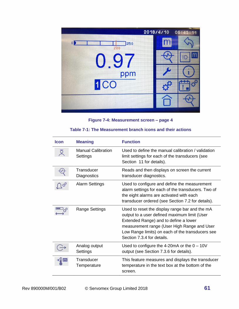
Rev 890000M/001/B02 © Servomex Group Limited 2018 61
Figure 7-4: Measurement screen – page 4
Table 7-1: The Measurement branch icons and their actions
Icon Meaning Function
Manual Calibration
Settings
Used to define the manual calibration / validation
limit settings for each of the transducers (see
Section 11 for details).
Transducer
Diagnostics
Reads and then displays on screen the current
transducer diagnostics.
Alarm Settings Used to configure and define the measurement
alarm settings for each of the transducers. Two of
the eight alarms are activated with each
transducer ordered (see Section 7.2 for details).
Range Settings Used to reset the display range bar and the mA
output to a user defined maximum limit (User
Extended Range) and to define a lower
measurement range (User High Range and User
Low Range limits) on each of the transducers see
Section 7.3.4 for details.
Analog output
Settings
Used to configure the 4-20mA or the 0 – 10V
output (see Section 7.3.6 for details).
Transducer
Temperature
This feature measures and displays the transducer
temperature in the text box at the bottom of the
screen.

62 © Servomex Group Limited 2018 Rev 890000M/001/B02
Icon Meaning Function
Measurement save Used to start recording measurement values to the
analyzer. Data must be saved to a USB drive to
view and must also be deleted from the analyzer
by the user.
Data Smoothing
Filtering
Use this to filter noisy data by applying short,
medium and long filters. Default is to apply no
filter.
Transducer firmware
revision
Displays the currently selected gas transducer
firmware revision in the text box at the bottom of
the screen.
Transducer serial
number
Displays the currently selected gas transducer
serial number in the text box at the bottom of the
screen.
Auto-Cal Sequence
settings
Used to set up the auto-calibration / auto-
validation parameters per selected transducer
when this option is purchased (see Section 11 for
details).
Transducer
Diagnostics
Reads and then displays on screen the current
transducer diagnostics.
Note: The transducer firmware revision, temperature, and serial number display in a text
box at the bottom of the screen when the relevant button is pressed. The
information is valid for the specific gas transducer that was selected.
Note: The Manual calibration and validation descriptions and settings are described later
in the manual in Section 11 along with the Auto-Cal optional features.
Configuring manual calibration and Auto-Cal sequences
> > > Manual
> > > > > Auto-Cal
The sequence of icons to touch to access the manual calibration and auto calibration
configuration pages are shown above. See Section 11.5 and Section 11.6 for details on
how to set up the Manual calibration and the Auto-Cal Sequences.
Rev 890000M/001/B02 © Servomex Group Limited 2018 63
Configuring the measurement alarms
7.2.1 Display the Measurement Alarms Screen
> >
The Alarms screen shows how each of the eight alarms is currently configured. The
standard analyzer is supplied with 2 alarms for each transducer, and a further 2 or 6
alarms per transducer can be optionally purchased. Figure 7-5 shows a CO transducer
where the option for 8 total alarms has been purchased. Note that none of the alarm bells
are grayed out. Alarm #1 is set to High Alarm, Alarm #3 is set to Low Alarm, Alarm #2 is
set to the Low Flow Alarm. Alarms 4, 5, 6, 7 and 8 are not yet configured.
Figure 7-5: Alarms screen showing CO with 8 alarms available: #1, #2, #3 have already been configured.
Note: During a calibration, an alarm will only be activated if the alarm 'Follow' option
is selected (see Section 7.4).
7.2.2 Configuring the Measurement Alarm settings
The Analyzer alarms can be configured to operate in one of four modes: Measurement
alarm, Flow alarm, Span / Reference alarm, and Transducer Temperature alarm. Each
transducer can be configured with multiple alarms.
To configure the alarm:
1. Touch the Alarm Setup icon to see the available alarms (See Figure 7-6). Touch the
icon for the selected alarm.

64 © Servomex Group Limited 2018 Rev 890000M/001/B02
> > >
Figure 7-6: Alarm icons on alarm screen
2. The Alarm setup screen for the selected alarm is displayed. Figure 7-7 shows Alarm
#4 configured for a Measurement Alarm on Transducer #1 .
> > > >
Figure 7-7: Measurement Alarm setup screen for Transducer #1 and Alarm #4
In Figure 7-7 the following alarms have been set or deactivated: Audible alarm is on
, Do Not Follow is on, Do Not Latch is on and no Measurement value
alarm (Hi or Lo) has been selected.
Note: Most of the icons are paired with the Deactivate and Activate icon next to the
Alarm icon on the same row. The exceptions are the High and Low
Measurement Alarm icons that are located at the bottom right side with the
deactivate icon between them in a column.

Rev 890000M/001/B02 © Servomex Group Limited 2018 65
Note: Touch the Accept icon to accept the new configuration, otherwise the
configuration will revert back to the original settings.
Figure 7-8: Measurement Alarm setup screen for Transducer #1 and Alarm #1
In Figure 7-8 the following alarms have been set or deactivated: Audible alarm is off
, Do Not Follow is on, Do Not Latch is on and the Hi Measurement value
alarm has been selected.
Note: Figure 7-7 and Figure 7-8 show examples of the different options available for
specific transducers or system.
3. Press the required icon on the row horizontally across the top of the screen to either
configure or activate the alarm as the main alarm function.
Table 7-2: Measurement Alarm Main icons
Icon Meaning Function
Measurement Alarm Alarm is activated when a measurement
concentration or condition exceeds the limits set
in the alarm mode screen.
Flow Alarm Activates the optional flow switch alarm when the
flow drops below 0.1 L/min (the default location is
on stream #1 for dual streams).
Transducer
temperature alarm
(IR1520 transducers
only)
Alarm condition is activated when the transducer
temperature exceeds 45°C. If the transducer
temperature exceeds 45°C for 30 minutes, the
transducer automatically turns off.
4. Table 7-3 shows the available alarm functions and descriptions, some of which can be
used together on the same alarm.
66 © Servomex Group Limited 2018 Rev 890000M/001/B02
Table 7-3: Measurement Alarm Sub-Branch icons
Icon Meaning Function
Alarm Mode available but
deactivated
Alarm available but is not configured to activate
under any condition. Can use this to quickly
remove an alarm configuration that had been
previously assigned.
Alarm Mode Low Alarm will be activated when a sample
measurement is lower than the pre-set alarm
level.
Alarm Mode High Alarm will be activated when a sample
measurement is higher than the pre-set alarm
level.
Alarm Value Threshold Set the value at which the High or Low alarm
will be activated.
Alarm Value Hysteresis These values determine when an activated
measurement alarm condition will be
deactivated.
Audible Alarm Mode is On Activates the audible alarm so the alarm
sounds when the alarm limit is triggered.
Audible Alarm is
deactivated
Deactivates the audible alarm. Also used to
silence the alarm when the Audible Alarm Mode
is On and has been triggered.
Alarm Following Activates the alarm during a calibration. If the
alarm threshold is reached the alarm will sound.
Alarm Following
deactivated
Deactivates the alarms during a calibration.
This is the default mode.
Alarm Latching The alarm condition remains activated (both
visible and audible) until the alarm is manually
deactivated (see below).
Alarm Latching
deactivated
The alarm condition remains activated until the
sample measurement value falls within the
normal limits, at which point the alarm is
automatically deactivated.
This icon is also used to deactivate all Alarm
Latching conditions.
Rev 890000M/001/B02 © Servomex Group Limited 2018 67
7.2.3 Threshold levels
The Threshold Level is the value at which the measurement will trigger the alarm. To
set the Threshold value for the high or low alarms for the measurement range of the
transducer use the following sequence (specific example below is for Alarm #1 setting the
High Alarm):
> > > > > A
Figure 7-9: Alarm Threshold values set by pressing (A) and number key pad (B).
1. Touch the number to the right of the icon as shown in Figure 7-9 A.
2. Use the number keypad shown in Figure 7-9 B to type in the threshold value then
press to accept the value or to cancel the entry.
3. To save the alarm settings to the current alarm, press the icon shown in the left
screen in Figure 7-9 A.
4. To abort the changes and return to the original settings prior to entering the Alarm
Setting screen, press the icon. This icon appears in place of the Return icon
in Figure 7-9 A if changes have been made to the settings.
Table 7-4: Navigation tools in the Alarm Threshold screen
Icon Function
Touch this icon to delete the last digit typed in.
Touch this icon to accept the value entered in the
keypad.
Touch this icon to return to the previous screen. When
setting has been changed this icon is replaced by .
Touch this icon to accept all the alarm settings.
Touch this icon to cancel the entered value on keypad or
setting change on the Alarm Setting screen.
A
B

68 © Servomex Group Limited 2018 Rev 890000M/001/B02
5. Figure 7-10 displays the alarm setting thresholds on the home screen as red lines
and text on the bar graph at the top of the screen.
6. Once the alarm setting has been configured you may now assign a relay to that
alarm (Section 10).
7. Repeat this for each alarm as required.
Figure 7-10: Home screen showing alarm settings as red lines and text on the bar graph
7.2.4 Hysteresis levels
> > > > >
The Hysteresis level associated with a measurement alarm determines when an
activated alarm condition is deactivated. A single value is entered into the Hysteresis level
and it will be applied to the Measurement Alarm limit depending on the alarm mode
selected as described below.
Table 7-5: Alarm modes and hysteresis effects
Alarm mode Effect of hysteresis
Low alarm Once the low alarm condition has been activated, the alarm condition
will not be deactivated until the value of a sample measurement is
above the low alarm level + hysteresis level.
High alarm Once the high alarm condition has been activated, the alarm
condition will not be deactivated until the value of a sample
measurement is below the high alarm level – hysteresis level.

Rev 890000M/001/B02 © Servomex Group Limited 2018 69
Note: We designate a percent level concentration value as “%-vol” and a percentage
calculation of a range as “%”.
Note: The Measurements Alarm levels can be reported as a percentage (%) of the
measurement range or as a fixed concentration value (in ppm, mg/m3 or %-vol)
depending upon the transducer installed and the user preferential settings. The
Hysteresis levels are set as a fixed concentration value.
Examples:
a. If a 'Low' alarm has an alarm level of 15 %-vol and a hysteresis level of 1
%-vol, the alarm is activated when a sample measurement is < 15 %-vol,
and the alarm is not deactivated until a sample measurement is > 16%-vol.
b. If a 'High' alarm has an alarm level of 3 ppm and a hysteresis level of 1
ppm, the alarm is activated when a sample measurement is > 3 ppm, and
the alarm is not deactivated until a sample measurement is < 2 ppm.
To set the Hysteresis level associated with a measurement alarm use the following
sequence (specific example below is for Transducer #1 and Alarm #1):
1. Touch the number to the right of the icon as shown in Figure 7-11 A.
2. Use the number keypad shown in Figure 7-11 B to type in the threshold value.
> > > > > A
Figure 7-11: Alarm Hysteresis values set by pressing (A) and number key pad (B).
Hint: Ensure that the measurement alarm and hysteresis levels are not too close to
the expected sample measurements. Otherwise minor and potentially
acceptable variations in sample gas concentrations will result in spurious
alarms.
Hint: If you configure one measurement alarm as 'low' and the other measurement
alarm as 'high', ensure that the 'high' alarm with its hysteresis levels is higher
than the 'low' alarm with its hysteresis levels. Otherwise, the analyzer can be
permanently in an alarm condition until the hysteresis levels are adjusted.
A
B

70 © Servomex Group Limited 2018 Rev 890000M/001/B02
7.2.5 Activated alarms details
When a measurement alarm condition is activated or triggered:
• The screen changes to flashing red (Figure 7-12).
• The Alarm Status icon appears at the upper right of the screen (Figure 7-12 A).
• The appropriate alarm relay will be triggered.
Figure 7-12: Measurement alarm condition triggered
Press the following sequence of icons to view the details of the activated alarm (Figure
7-13 A).
> >
Figure 7-13: Alarms screen showing Alarm #1 (A) High Measurement Range triggered
A
A

Rev 890000M/001/B02 © Servomex Group Limited 2018 71
Configuring the User Ranges for mA Output and Screen Display
Each gas transducer has a predefined range based upon the intrinsic measurement range
that was purchased. Dual ranges can be set up on the transducer to provide more
precision using the User Low Range, User High Range and the User Expanded Range
settings. With the auto-range function, both the display and output signals will follow those
ranges. The default settings are based upon the intrinsic measurement of the purchased
transducer. The range limits will be displayed on the bar at the top of the measurement
screen for each of the transducers (see Figure 7-14 as an example).
Figure 7-14: Rectangular box showing the Range Limit bar on Measurement Screen in Blue with Alarm Limits bars with values in Red
To make any changes press the following sequence from the Home page to get to the
Range Setting configuration panel in Figure 7-15:
> >
Figure 7-15: Range setting screen: (A) Auto-range icons (deactivated chosen) and (B) User Expanded Range icons
A
B

72 © Servomex Group Limited 2018 Rev 890000M/001/B02
Note: Several of the icons on this screen look the same ( ) but have very different
functions. Please use the guidance in the document and Figure 7-15 as to which
icon represents the various functions.
Table 7-6: User mA Output and Display Measurement Range Setting Icons
Icon Meaning Function
Auto-Range
Activation /
Deactivation
Auto-range defines how the measurement
output values are handled if multiple ranges
are available (see icons position in Figure
7-15 A). Default mode is active.
User Expanded
Range (Over-
Range) Value
Allows the user to set a new maximum “over-
range” value that the serial output and
analyzer display will reset to if the
measurement value goes over the User High
Range value. If this is not used the default is
the intrinsic measurement range of the
transducer (icon position at the top in Figure
7-15 B).
User High
Range Value
Sets the user defined range maximum
measurement value that will be scaled to the
serial output and analyzer display. If this is not
assigned, the default is the intrinsic
measurement range of the transducer (icon
position in the middle in Figure 7-15 B).
User Low
Range Value
Sets the user defined range minimum
measurement value that will be scaled to the
serial output and analyzer display. The default
User Low setting is 0 (icon position at the
bottom in Figure 7-15 B).
Return Touch this icon to accept the Range settings
and return to the previous screen.

Rev 890000M/001/B02 © Servomex Group Limited 2018 73
Figure 7-16: Range values set using number key pad.
Table 7-7: Standard Navigation tools in the User Range Value screen
Icon Function
Touch this icon to delete the last digit typed in.
Touch this icon to accept the value entered in
the keypad.
Touch this icon to cancel the value entered in
the keypad.
7.3.1 Setting a Custom Expanded (over-range) Range Value
> > >
The User Expanded Range (or over-range) setting is used to define a new over-ranging
maximum value that the serial output and analyzer display will reset to when the sample
gas measurement value exceeds the User High Range value. This range will always be
less than the intrinsic measurement range of the transducer and allows more precision
across a smaller measurement range when over-ranging takes place.
To set a new User Expanded Range for the transducer, touch the icon shown inside
the red box labelled B in Figure 7-15 and use the numeric key pad in Figure 7-16 to enter
the new maximum range value.
Once a new User Expanded Range value is set, and the sample measurement
value is above its maximum value, depending upon the analyzer settings the display and
the serial output may respond differently. See Section 7.3.5 for details and examples of

74 © Servomex Group Limited 2018 Rev 890000M/001/B02
how auto-ranging affects the values sent through the serial output and the analyzer display
panel.
Note: If you do not want the analyzer to report values above the User Expanded
Range maximum value you need to turn auto-range OFF (ON by default).
7.3.2 Setting a custom User High and User Low range
> > > User High
> > > User Low
These settings are used to create a User defined measurement range for the transducer,
lower than both the intrinsic measurement range and the User Expanded range, over
which the serial output and screen displays will span and report. The default setting is the
intrinsic measurement range but by using the User High Range and User Low Range
settings the user can create a range that is lower than the intrinsic measurement range to
provide greater precision.
The serial output range (4-20 mA or 0 – 10V) is determined by the minimum and maximum
range values pre-set by the factory or they can be changed by the user with the User High
Range and User Low Range icons located inside the red box labelled B in
Figure 7-15. Use the numeric key pad shown in Figure 7-16 to enter the new range value.
If auto-ranging is active, the analyzer will automatically detect any over-range and switch
to either the intrinsic measurement range or the User Expanded range value (if assigned).
See Section 7.3.5 for details and examples of how auto-ranging affects the values sent
through the serial output and the analyzer display panel.
Note: If you do not want the analyzer to report values above the User High Range
maximum value you need to turn Auto-range OFF (ON by default).
7.3.3 Auto-range ON/ OFF
> > > ON
> > > OFF
The auto-range function is activated by pressing the auto-range icon and it is
deactivated by pressing the icon. The icons are located at on the bottom middle of the screen shown inside the red box labelled A in Figure 7-15.
The auto-range function is used to define how the measurement output values are handled by both the serial output (mA or volts) and the analyzer display. If there are any User defined ranges (High, Low, Expanded), then the auto-range function will automatically determine which range to use.
When a measurement value goes over a User defined setting (User High Range and / or
User Expanded Range), auto-ranging will switch the measurement range automatically to
Rev 890000M/001/B02 © Servomex Group Limited 2018 75
the higher range and re-scales the serial output (mA or volts) and the bar graph of the
analyzer display panel.
Note: If a measurement has auto-ranged above the User High Range maximum value to
the higher User Expanded range or Intrinsic measurement range, the measurement
value must fall to 10% below the User High Range maximum value before the auto-
range switches back to the lower range. This prevents the output response from
repeatably jumping between the two ranges.
7.3.4 Range Setting Example
If you have a transducer with an intrinsic range maximum of 0-1000 ppm, but the process
values never went above 100 ppm, you may want to define a new “over-range” maximum
value of 100 ppm for better resolution of the measurement values than available using the
intrinsic measurement range of 0 – 1000 ppm.
> > >
This is accomplished by selecting the User Expanded Range icon (Figure 7-15 B)
and setting the value to 100 ppm with the keypad, limiting the maximum range to 100 ppm.
If the actual process measurements values are generally confined to values below 10
ppm, then you might want to define a working range of 0 – 10 ppm to provide even more
precision at the lower process concentration values. You can set the User High Range to
10 and the User Low Range will remain at “0”.
> > > User High Range
> > > User Low Range
7.3.5 Auto-range ON /OFF Functionality Examples
The following two examples illustrate how the serial output and display behave with Auto-
range OFF and with Auto-range ON for a transducer with an intrinsic measurement range
of 0-1000ppm, the User High Range set at 10ppm and the User Expanded Range set at
100ppm.
Example 1 Auto-Range OFF
Initial Settings:
• User High Range set to 10 ppm, User Low Range set to 0 ppm, User Expanded
Range set to 100 ppm.
• The serial output values will be scaled to the User High Range of 10 ppm.
• The display bar and output values will be scaled to the User High Range of 10
ppm.

76 © Servomex Group Limited 2018 Rev 890000M/001/B02
Measured Value ≤ 10 ppm
User Low (0 ppm)
User High (10 ppm)
Expanded (100 ppm)
Serial Output X X
Display Output X X
Any time the gas measurement value is at or above the User High Range of 10 ppm:
• The serial output value will remain fixed at 10 ppm.
• The analyzer display will continue to show the measurement values up to the User
Expanded Range maximum of 100 ppm.
Measured Value ≥ 10 ppm
User Low (0 ppm)
User High (10 ppm)
Expanded (100 ppm)
Serial Output X
Display Output X X
Any time the gas measurement value is at or above 100 ppm:
• The serial output value will remain fixed at 10 ppm.
• The analyzer display value will remain fixed at 100 ppm.
Measured Value ≥ 100 ppm
User Low (0 ppm)
User High (10 ppm)
Expanded (100 ppm)
Serial Output X
Display Output X
Note: If the user does not set an Expanded Range and sets a User High Range of
10 ppm, then for a gas measurement value above 10 ppm the Serial output will
remain at 10 ppm and the analyzer display will continue to show the measurement
values up to the maximum of the intrinsic range of the transducer ie 1000 ppm.
Example 2 Auto-Range ON
Initial Settings:
• User High Range set to 10 ppm, User Low Range to 0 ppm, User Expanded Range
set to 100 ppm.
• The serial output values will be scaled to the User High Range of 10 ppm.
• The display bar and output values will be scaled to the User High Range of 10
ppm.
Measured Value ≤ 10 ppm
User Low (0 ppm)
User High (10 ppm)
Expanded (100 ppm)
Serial Output X X
Display Output X X

Rev 890000M/001/B02 © Servomex Group Limited 2018 77
Any time the gas measurement value is at or above the User High Range of 10 ppm:
• The serial output value will automatically rescale to the User Expanded Range
maximum of 100 ppm.
• The display bar graph value will automatically rescale to the User Expanded Range
maximum of 100 ppm.
Measured Value ≥ 10 ppm
User Low (0 ppm)
User High (10 ppm)
Expanded (100 ppm)
Serial Output X X
Display Output X X
Any time the gas measurement value is at or above 100 ppm:
• The serial output value will remain fixed at 100 ppm.
• The analyzer display value will remain fixed at 100 ppm.
Measured Value ≥ 100 ppm
User Low (0 ppm)
User High (10 ppm)
Expanded (100 ppm)
Serial Output X
Display Output X
Note: If the user does not set an Expanded Range and sets a User High Range of
10 ppm, then for a gas measurement value above 10 ppm the Serial output and
the analyzer display will automatically rescale the measurement values up to the
maximum of the intrinsic range of the transducer ie 1000 ppm.
7.3.6 Configure the measurement mA Output option
> >
Figure 7-17: mA output screen
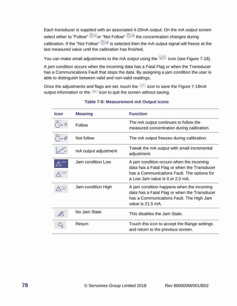
78 © Servomex Group Limited 2018 Rev 890000M/001/B02
Each transducer is supplied with an associated 4-20mA output. On the mA output screen
select either to “Follow” or “Not Follow” the concentration changes during
calibration. If the “Not Follow” is selected then the mA output signal will freeze at the
last measured value until the calibration has finished.
You can make small adjustments to the mA output using the icon (see Figure 7-18).
A jam condition occurs when the incoming data has a Fatal Flag or when the Transducer
has a Communications Fault that stops the data. By assigning a jam condition the user is
able to distinguish between valid and non-valid readings.
Once the adjustments and flags are set, touch the icon to save the Figure 7-18mA
output information or the icon to quit the screen without saving.
Table 7-8: Measurement mA Output icons
Icon Meaning Function
Follow The mA output continues to follow the
measured concentration during calibration.
Not follow The mA output freezes during calibration.
mA output adjustment Tweak the mA output with small incremental
adjustment.
Jam condition Low
A jam condition occurs when the incoming
data has a Fatal Flag or when the Transducer
has a Communications Fault. The options for
a Low Jam value is 0 or 2.0 mA.
Jam condition High
A jam condition happens when the incoming
data has a Fatal Flag or when the Transducer
has a Communications Fault. The High Jam
value is 21.5 mA.
No Jam State This disables the Jam State.
Return Touch this icon to accept the Range settings
and return to the previous screen.

Rev 890000M/001/B02 © Servomex Group Limited 2018 79
> > >
Figure 7-18: mA output adjustment screen
Table 7-9: Navigation tools in the mA output adjustment screen
Icon Function
Delete the last digit typed in.
Accept the value entered in the keypad.
Cancel the value entered in the keypad.
Configure the measurement record option
> > >
The measurement record option allows the operator to save time-stamped concentration
readings in seconds, minutes and hours as a text file to the analyzer which can then be
exported to a USB stick. It is possible to configure multiple record files if there are two or
more transducers.
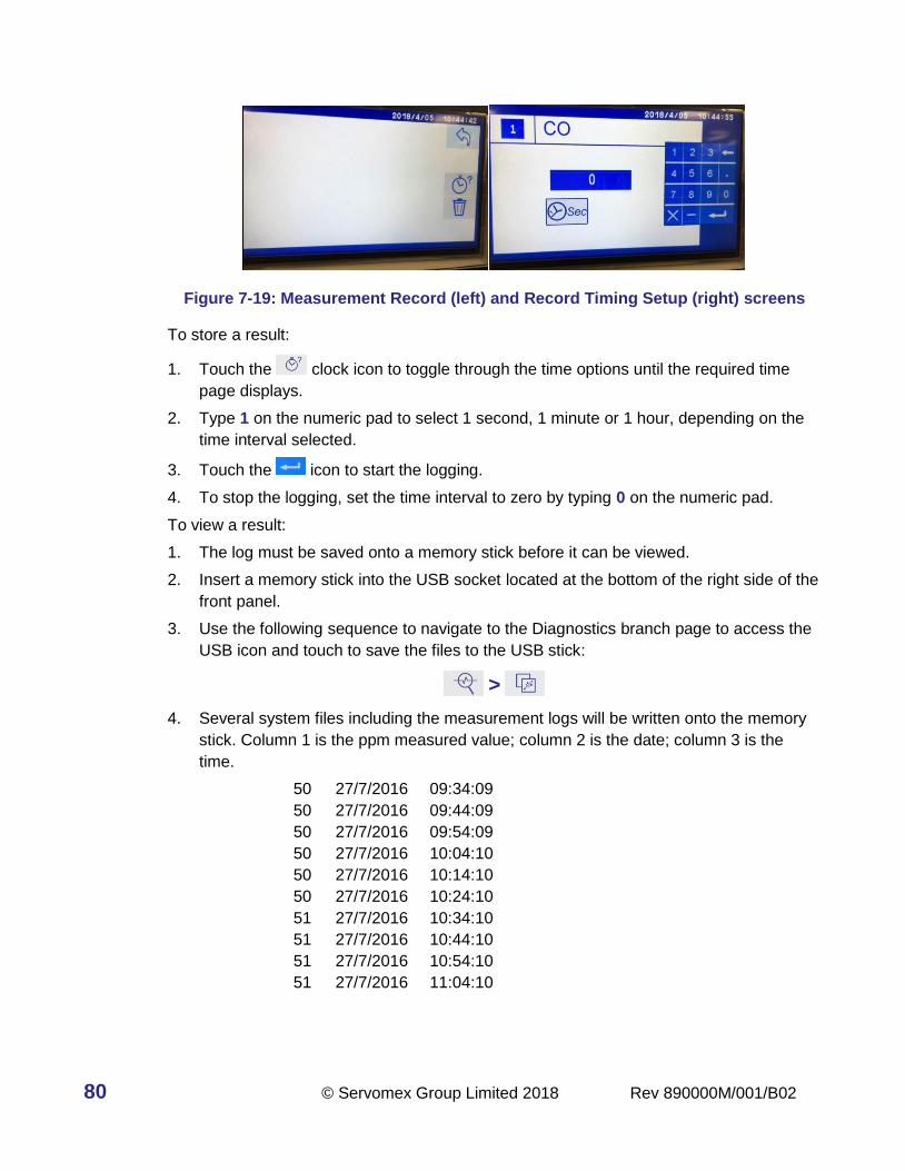
80 © Servomex Group Limited 2018 Rev 890000M/001/B02
Figure 7-19: Measurement Record (left) and Record Timing Setup (right) screens
To store a result:
1. Touch the clock icon to toggle through the time options until the required time
page displays.
2. Type 1 on the numeric pad to select 1 second, 1 minute or 1 hour, depending on the
time interval selected.
3. Touch the icon to start the logging.
4. To stop the logging, set the time interval to zero by typing 0 on the numeric pad.
To view a result:
1. The log must be saved onto a memory stick before it can be viewed.
2. Insert a memory stick into the USB socket located at the bottom of the right side of the
front panel.
3. Use the following sequence to navigate to the Diagnostics branch page to access the
USB icon and touch to save the files to the USB stick:
>
4. Several system files including the measurement logs will be written onto the memory
stick. Column 1 is the ppm measured value; column 2 is the date; column 3 is the
time.
50 27/7/2016 09:34:09
50 27/7/2016 09:44:09
50 27/7/2016 09:54:09
50 27/7/2016 10:04:10
50 27/7/2016 10:14:10
50 27/7/2016 10:24:10
51 27/7/2016 10:34:10
51 27/7/2016 10:44:10
51 27/7/2016 10:54:10
51 27/7/2016 11:04:10

Rev 890000M/001/B02 © Servomex Group Limited 2018 81
Note: To stop the logging you must set the time interval to zero. Type 0 on the
numeric pad and press key to accept the value.
Table 7-10: Measurement Record icons
Icon Function
Set the data recording timing. Once set the
data is recorded until the user stops the
recording from this page.
Data Recording rate in Seconds. To record
data in Minutes touch the icon again to show
the minutes icon, to record in hours touch
again to display the Hours icon.
Access the Delete Data Icon.
Delete the recorded data from the analyzers.
Return to the Alarm settings Home screen.
Delete the last digit typed in.
Accept the value entered in the keypad.
Typing in “0” on the keypad will stop the data
recording if the Return key is pressed.
Cancel the value entered in the keypad.
Configuring the Measurement data filter and gas reporting units
7.5.1 Setting the Measurement data filter
The transducer determines which filter types are available. Trial and error testing will be
needed to determine which filter type is best for the application as well as how many points
are needed in the filter, as there are trade-offs with response time and signal improvement.
The default mode applies no filtering.
There are two kinds of filters available: Moving Average or Finite Impulse Response (FIR)
and Exponential or Infinite Impulse Response (IIR). The filters shown on the left column of
Figure 7-20 are Moving Average, those in the right column are Exponential.

82 © Servomex Group Limited 2018 Rev 890000M/001/B02
For each of these filter types, the smoothing icon shown top to bottom represents the
smoothing function that is faster but less smooth to slower but smoother at the bottom.
> > > >
Figure 7-20: Data Filter screen showing two filter types with short, medium, long time averages (no filter is selected at this time).
With a Moving Average filter, the actual output is the average of the latest value and a
fixed number of previous input values, with the previous inputs weighted less so they
contribute less to the output.
With an Exponential filter the output is an average of the latest value and one or more
previous output values, with previous output values being weighed less. It is called
“infinite” because every new value always makes some contribution to the new output and
diminishing contributions to all subsequent output values.
In either case, the more points used in the average or the higher the weighting is from the
older values, the smoother the response will be, but the consequence is that the response
to changes in the incoming values will be slower.
Transducer Diagnostics
This section provides access to the diagnostics for installed transducers that support
diagnostics at this time. We are working on allowing user access to diagnostics for all our
transducers and these new features will roll out in successive firmware updates. Figure
7-21 shows and example of the diagnostics for a GFX transducer.
> > > > >

Rev 890000M/001/B02 © Servomex Group Limited 2018 83
Figure 7-21: GFX transducer diagnostic screen
The diagnostic values are meant for interpretation by service personnel and be used to
report the values back to a Servomex service person for troubleshooting the problem.

84 © Servomex Group Limited 2018 Rev 890000M/001/B02
8 Diagnostics branch screen
Diagnostic branch icons
>
Touch the Diagnostics icon to see the available diagnostic functions to the right.
The screen views for each of the three pages available within the Diagnostic branch are
shown in Figure 8-1, Figure 8-2, and Figure 8-4 (Relay Diagnostics).
The Relay Diagnostics page allows testing of the assigned the relays. The actual state of
the relay is assigned in the Setting (see Section 10 ).
Note: Page 1 displays first.
To go to the subsequent pages, press the icon.
To return to the previous page, press the icon.
>
Figure 8-1: Diagnostics screen – page 1
Diagnostics
Menu Branch

Rev 890000M/001/B02 © Servomex Group Limited 2018 85
> >
Figure 8-2: Diagnostics screen – page 2
Table 8-1: Diagnostics icons
Icon Meaning Function
Software revision Display the software revision number.
Analyzer Electronics
Temperature
Display the temperature of the internal chassis
electronics of the analyzer.
Analyzer serial number Display the serial number of the analyzer.
Save system files to
USB
Save the system files to a USB memory device.
Unit will beep if you do not have a USB device
installed.
Relay test menu To view and test the relays that were purchased.
When background is blue then the relay is closed.
System Log Display up to 100 pages of logged system
activities with most current date first. Use the
arrow keys to navigate through the pages.
Calibration Log Display up to 100 pages of logged calibration
activities with the most current date first. Use the
arrow keys to navigate through the pages.

86 © Servomex Group Limited 2018 Rev 890000M/001/B02
Saving the system log files
> >
Figure 8-3: Log file save screen
A USB thumb drive must be installed into the slot located on the bottom right side of the
front panel prior to accessing the Log Save icon . The text files will be written to the
USB drive when this icon is touched. The analyser will beep if there is no USB in the port
and the system will stop.
Testing the Relays
The relays are numbered to support quick testing and can be individually tested to help
debug an installation.
> > >
Figure 8-4: Relay diagnostics screen

Rev 890000M/001/B02 © Servomex Group Limited 2018 87
To test the function, press the relay icon to open and close it. If a relay is closed, its icon
background is dark blue ; if a relay is open, its icon has a white background (see
Figure 8-4). When the Relay Diagnostics page is exited, the relays will be reset back to the
state they were in prior to entering the Relay Diagnostics page.
For example, if relay #8 alarm state was triggered then relay #8 would show closed
prior to entering the Diagnostics menu. When exiting the Relay Diagnostics page, relay #8
will be set back to the closed position even if the relay had been opened on the
diagnostics page.
If Auto-Cal function is purchased the last three relays on each transducer option card are
pre-assigned and cannot be changed by the user (see Figure 8-5). The relay number icons
are now replaced by new icons that represent each of the Auto-Cal Zero, Span and
Measure functions.
Relay #6 is pre-set as the Zero or Low Span function , Relay #7 is pre-set as the High
Span function , and Relay #8 is pre-set as the Sample / Measurement function
for Transducer #1. Relays #14, #15, #16 are pre-set in the same manner for Transducer
#2.
> > >
Figure 8-5: Relay diagnostics screen with Auto-Cal option

88 © Servomex Group Limited 2018 Rev 890000M/001/B02
Displaying the System or Calibration Log
The System Log or the Calibration Log can be easily accessed and displayed showing the
most recent activity first on the first page. Activities on the earlier dates can be accessed
via the up and down arrows.
> > >
> > >
Figure 8-6: Example of a Calibration Log Report

Rev 890000M/001/B02 © Servomex Group Limited 2018 89
9 Maintenance branch screen
>
Touch the Maintenance icon to see the available icon choices to the right. The
Maintenance branch menu has one page, shown in Figure 9-1.
Figure 9-1: Maintenance screen
Table 9-1: Maintenance branch icons
Icon Meaning Function
Update firmware To update the firmware in the field when
needed. Insert the USB thumb drive into the
slot in the lower right corner of the front panel,
then touch the icon to update the firmware.
Read config files from
USB memory device
To upload configuration files from a USB
memory device. Insert the USB thumb drive
holding the configuration files into the slot in
the lower right corner of the front panel, then
touch the icon to upload the new configuration
files.
Clear errors To clear any error warnings such as Failed
Calibration.
Maintenance
Menu Branch

90 © Servomex Group Limited 2018 Rev 890000M/001/B02
10 Settings branch screen
Touch the Settings menu icon to see the available settings functions to the right.
The screen views for each of the three pages available within the Settings branch are
shown in Figure 10-1, Figure 10-2, and Figure 10-3.
Note: Page 1 displays first.
To go to the subsequent pages, press the icon.
To go back to the previous page, press the icon.
>
Figure 10-1: Settings main screen 1
> >
Figure 10-2: Settings main screen 2
Settings
Menu
Branch
active
Settings
Menu: Next
List active

Rev 890000M/001/B02 © Servomex Group Limited 2018 91
Figure 10-3: Settings main screen 3
Table 10-1: Settings Branch icons
Icon Meaning Function
Serial port set up Set up serial communications parameters.
Relay set up Set up the relays.
Password set up Access the password security icons for Master
and Operator levels.
Manual relay
over-ride
Manually set the relay to a state (i.e. Off or On);
when selected this will be the permanent state
until the relay function is reset.
Analyzer Date Set the date for the analyzer system.
Analyzer Time Set the time for the analyzer system.
Digital and Analog
Inputs
Set up for any of the analog and/or digital inputs if
purchased.
Pump Off Option is not available for 4900 Multigas therefore
the icons are greyed out.
Pump On Option is not available for 4900 Multigas therefore
the icons are greyed out.
Screen Functions Switch from Single to Multiple gases displayed,
adjust brightness, adjust screen “home” timer.
Data Reporting
Units Selection
Change the units from ppm to mg/Nm3 or the
reverse.

92 © Servomex Group Limited 2018 Rev 890000M/001/B02
Serial mA outputs overview
> >
This section is only an overview of the screens associated with the serial output
communication configurations while the details can be found in Appendix B. The serial
output option operates by transmitting a data frame to the RS232 (or RS 485) output port
at a user defined interval. The format of the data frame is a semi colon separated list of
process variables terminated by <carriage return><line feed>. The data frame is time and
date stamped.
> > >
Figure 10-4. RS232 functions view.
> > >
Figure 10-5. RS485 functions view.
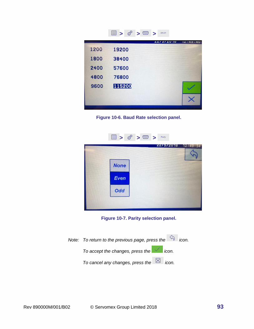
Rev 890000M/001/B02 © Servomex Group Limited 2018 93
> > >
Figure 10-6. Baud Rate selection panel.
> > >
Figure 10-7. Parity selection panel.
Note: To return to the previous page, press the icon.
To accept the changes, press the icon.
To cancel any changes, press the icon.

94 © Servomex Group Limited 2018 Rev 890000M/001/B02
> > >
Figure 10-8. Output ID setting screen
Note: To delete the last digit typed in, press the icon.
To accept the changes, press the icon.
To cancel any changes, press the icon.
> > >
Figure 10-9. Modbus 485 settings screen.

Rev 890000M/001/B02 © Servomex Group Limited 2018 95
Table 10-2: Main Serial mA Analog Output icons
Icon Meaning Function
RS232 communications To select RS232.
RS485 communications To select RS485.
Full Duplex To select full duplex.
Half Duplex To select half duplex.
1 stop bit To set 1 stop bit.
2 stop bits To set 2 stop bits.
Baud rate To set the baud rate.
Parity To set the parity.
RS485 function To assign RS485 functions. Functions on this
section screen are shown in Figure B-3 and
listed below:
RS485 function: DF
communications
To assign RS485 function to legacy Delta F
(DF-485) communications.
RS485 function: Modbus
To assign RS485 function to Modbus
(Appendix C).
RS485 function: None No RS485 function.
RS485 function: periodic
stream
To assign a periodic stream of measurement
results of all transducers.
RS485 function: output
frequency setup
To set the intervals for the output frequency (in
seconds) via a numerical entry screen.
RS485 – Modbus:
Word swapping on To switch on Modbus word swapping.
RS485 – Modbus:
Word swapping off To switch off Modbus word swapping.

96 © Servomex Group Limited 2018 Rev 890000M/001/B02
Assigning relay activity functions
> >
The function of the relay can be assigned using the relay configuration settings menu
and selecting the appropriate relay. Each relay is set up to respond to any function or
combination of functions including Faults, Service in Progress, Any type of Alarm. Once
an activity has been assigned to the relay, the icon will take on a symbol reflecting the
new assigned function (see Figure 10-10).
Note: If Auto-Cal is purchased then Relays at positions #6, #7 and #8 on each of the
transducers will be pre-assigned to output as Zero, Span and Sample /
Measurement modes. They cannot be reassigned (see Figure 10-10).
Figure 10-10: Available relays on the system with Auto-Cal pre-assigned relays.
If there are more relays available, then use the Next icon to access the next page
(see Figure 10-10).
Note: There can be up to eight relays per transducer giving a maximum of 32 if four
transducers are purchased or extra option boards added.
10.2.1 Assigning Alarms, Functions and Activities to the relays
Use the Activity Assignment Menu (Figure 10-11) to assign a function to a specific relay by
touching the functions icon and activating it. Each relay can be assigned to one or more of
the transducers purchased, which will be listed on the screen. Any number of links may be
made between any function to any relay card present within the analyzer.
Note: To go to the other assignment pages, press the icon.
To accept the changes, press the icon.
To cancel any changes, press the icon.

Rev 890000M/001/B02 © Servomex Group Limited 2018 97
> > >
Figure 10-11: Activity Assignment Menu for Relay #12 in an analyzer with two transducers (CO and O2).
Multiple activities can be assigned to one relay. In Figure 10-11 the Calibration, Fault and
Out of Range functions for the CO transducer are all active (so the icons show a dark blue
background) and are assigned to Relay #12.
Those activities can also be linked to different transducers present in the analyzer. In
Figure 10-11 Relay #12 can be assigned alarms for Transducer #1 (CO) and / or
Transducer #2 (O2). To assign an alarm to Transducer #2 (in this case it is O2):
• touch the alarm icon located below the O2 symbol as shown in Figure 10-11
• touch the icon for Alarm #1 as shown in Figure 10-12 to set the alarm
> > > > O2
Figure 10-12: Alarm assignment screen for O2 (Relay #12)

98 © Servomex Group Limited 2018 Rev 890000M/001/B02
Table 10-3: Relay Activity Function Assignment Icons
Icon Meaning Function
Alarm Relay is set as an alarm on a specific transducer.
Service / Calibration in
progress
Relay is set to output “Service in Progress” signal
triggered when a Calibration / Validation is in
progress on a specific transducer. Allows
detection of this state remotely.
Fault Alarm Relay is set to send a signal out if the transducer
incurs a Fault such as over-range of intrinsic
range, communications failure, etc..
Range Change Relay is set to output a “Changed to Expanded
Range” signal on a specific transducer when the
concentration is greater than the User High Span
range.
10.2.2 Assigning Alarms for External 4-20mA Inputs to the relays
There is one external 4-20mA Input per option board. In Figure 10-13 Relay #1 is
assigned to the analog Input High and/or Low alarm. Use the Analog Input Section 10.7.1
to assign the actual limit values for the relays to alarm at.
> > > >
Figure 10-13: Relay Low / Hi alarm fault assignment screen for external mA inputs
• Touch the icon to set the Low Limit alarm (Figure 10-13).
• Touch the icon to set the Hi Limit alarm (Figure 10-13).
• Touch the icon to return to the relay assignment page (Figure 10-13).

Rev 890000M/001/B02 © Servomex Group Limited 2018 99
• Touch the icon (see Figure 10-11) to save the relay information.
Assigning Password Protection
There are two levels of operation under password protection: Master or Operator. The
Master Password allows access to all MASTER and OPERATOR level functions while the
Operator Password allows access to only the OPERATOR level functions.
Touch the Password Assignment icon to see the Operator , Master and
Keystroke Record icons in the column furthest right (see Figure 10-14).
> >
Figure 10-14: Settings Password Protection with Record Keystroke screen
To set a password touch the icon for the required password level then enter the new
password using the keypad (see Figure 10-15).
> > > Master
> > > Operator

100 © Servomex Group Limited 2018 Rev 890000M/001/B02
Figure 10-15: Settings Password Protection screen for Master or Operator
Table 10-4: Password Protection Assignment Icons
Icon Meaning Function
Master Password Set the analyzer master level password.
Operator Password Set the analyzer operator level password.
Keystroke Recording
On
Turn keystroke recording On to capture all
keystrokes used to the System Log file.
Keystroke Recording
Off Turn keystroke recording Off.
Once a master and/or operator password are set all protected icons and operations will
prompt for a password. If no passwords are set, then the protected icons and operations
will not prompt to have a password entered.
To reset or deactivate the OPERATOR password enter the OPERATOR password as a
blank / empty field. You will need the Master password to re-enter either the MASTER or
OPERATOR password. If you have forgotten the MASTER password a remote recovery
service password can be provided with a call to your local customer service center.
Table 10-5: Master and Operator password protection operations
Function Level
ADAPTIVE FILTERING ON/OFF MASTER
CALENDAR MASTER
CLEAR ERRORS MASTER

Rev 890000M/001/B02 © Servomex Group Limited 2018 101
Function Level
CLOCK MASTER
GSF ENTRY OR SELECTION MASTER
INSTALL CONFIG FROM USB MASTER
KEYSTROKE RECORDING MASTER
MILLIAMP OUTPUT MASTER
PASSWORDS MASTER
RANGE SETTING MASTER
RECORD CONTROLS MASTER
SCHEDULED EVENT SETUP MASTER
SENSOR ON/OFF MASTER
RELAY ASSIGNMENT MASTER
SUPPRESS NEGATIVE MASTER
TEST RELAYS MASTER
TRANSDUCER PRESSURE COMPENSATION MASTER
XINT INPUT MASTER
FIRMWARE UPGRADE MASTER
ADJUST FILTERING MASTER
MILLIAMP INPUT MASTER
DIGITAL INPUT MASTER
ALARM SELECTION FOR EDIT OPERATOR
CALIBRATION OPERATOR
LOCK TO SINGLE DISPLAY OPERATOR
MANUALLY SWITCHING RELAYS OPERATOR
SAVE DATA TO USB OPERATOR
ANALOG-IN ALARM SELECTION FOR EDIT OPERATOR
ADJUST SERIAL PORT SETTINGS OPERATOR
Note: Some functions may not be available depending upon the variant of the analyzer
that was purchased.
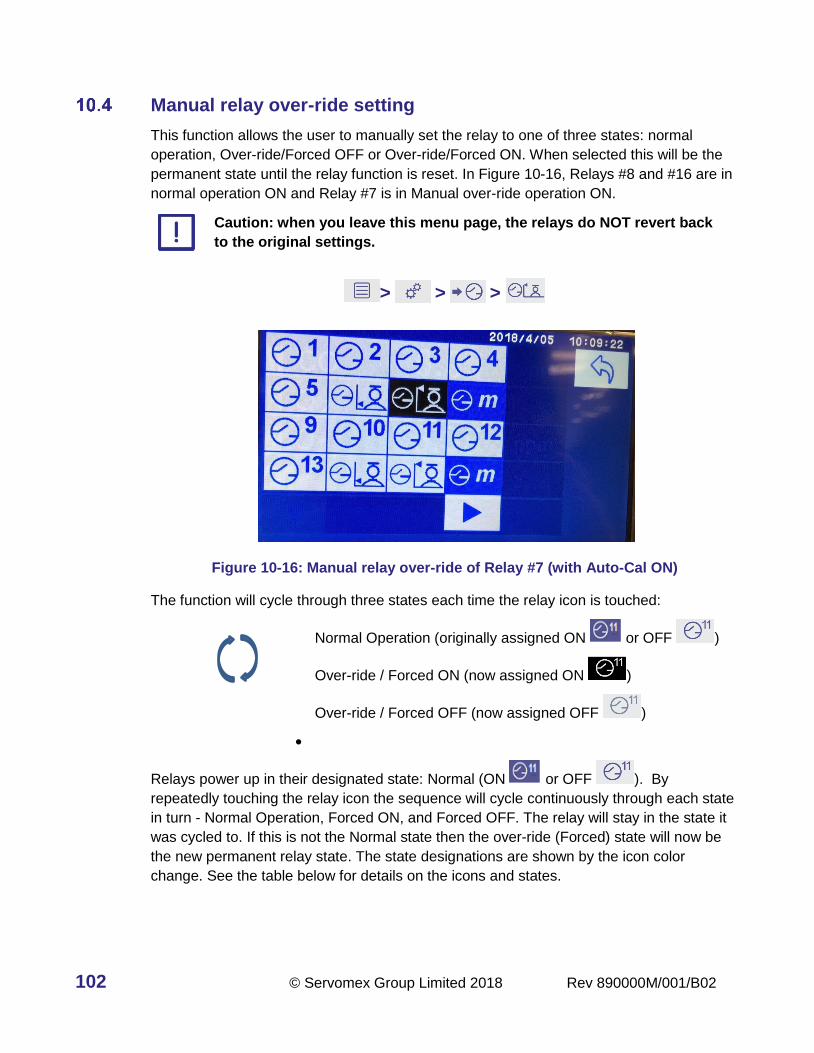
102 © Servomex Group Limited 2018 Rev 890000M/001/B02
Manual relay over-ride setting
This function allows the user to manually set the relay to one of three states: normal
operation, Over-ride/Forced OFF or Over-ride/Forced ON. When selected this will be the
permanent state until the relay function is reset. In Figure 10-16, Relays #8 and #16 are in
normal operation ON and Relay #7 is in Manual over-ride operation ON.
Caution: when you leave this menu page, the relays do NOT revert back
to the original settings.
> > >
Figure 10-16: Manual relay over-ride of Relay #7 (with Auto-Cal ON)
The function will cycle through three states each time the relay icon is touched:
Normal Operation (originally assigned ON or OFF )
Over-ride / Forced ON (now assigned ON )
Over-ride / Forced OFF (now assigned OFF )
•
Relays power up in their designated state: Normal (ON or OFF ). By
repeatedly touching the relay icon the sequence will cycle continuously through each state
in turn - Normal Operation, Forced ON, and Forced OFF. The relay will stay in the state it
was cycled to. If this is not the Normal state then the over-ride (Forced) state will now be
the new permanent relay state. The state designations are shown by the icon color
change. See the table below for details on the icons and states.

Rev 890000M/001/B02 © Servomex Group Limited 2018 103
Table 10-6: Manual Over-ride Icons
Icon Meaning Function
Normal Operation –
relay is Off
Indicates the assigned condition of the relay is off.
If a relay is left in this state when exiting the
screen the Normal operation will now be that the
relay is off – note icon color scheme is light grey
background with dark blue text.
Normal Operation –
relay is On
Indicates the assigned condition of the relay is on.
If a relay is left in this state when exiting the
screen the Normal operation will now be that the
relay is on – note icon color scheme is dark blue
background with light gray text.
Forced Off Over-ride
Operation – relay is Off
Indicates a forced over-ride condition now exists
that turns the relay off. If a relay is left in this state
when exiting the screen the Normal operation will
now be that the relay is off – note icon color
scheme is light gray background with dark gray
text.
Forced On Over-ride
Operation – relay is On
Indicates a forced over-ride condition now exists
that turns the relay on. If a relay is left in this state
when exiting the screen the Normal operation will
now be that the relay is off – note icon color
scheme is black background with light gray text.
Note: There are three general functions to keep in mind that are available for relay
settings and diagnostic testing that are accessed by the icon sequences below:
> > This sequence is used to set and assign tasks / states to the
relays described above in Section 10.2.
> > This sequence will over-ride the original state by forcing the
relay to be On or Off. The condition is permanent until the
relay is switched back to Normal Operation above in Section
10.4. When you exit the Manual Over-ride menu, any changes
will be made permanent.
> > This sequence allows for diagnosis and testing of the relays,
located in the Diagnostics Section 8. When you exit the
Diagnostics menu, there are no changes made to the relays.

104 © Servomex Group Limited 2018 Rev 890000M/001/B02
Setting the analyzer date
> > >
Figure 10-17: Set the analyzer date screen
1. Touch the first set of up or down arrows on the left-hand side to select how the date
will be displayed (DD/MM/YY or MM/DD/YY or YY/DD/MM).
2. To set the date (Figure 10-17 shows the DD/MM/YY format):
a. Touch the second set of up or down arrows from the left-hand side to select
the day (from 1 to 31).
b. Touch the third set of up or down arrows from the left-hand side to select
the month (where 1 is January, and 12 is December).
c. Touch last set of up or down arrows from the right-hand side to select the
year.
3. Touch the icon to accept the value or the icon to leave the screen without
updating the value.

Rev 890000M/001/B02 © Servomex Group Limited 2018 105
Setting the analyzer time
> > >
Figure 10-18: Set the analyzer Time Screen
1. Time is shown as HH:MM:SS (hours : minutes : seconds) and displays in 24 hour
format.
2. Touch the left-hand up or down arrows to increase or decrease the hours (from 00 to
23).
3. Touch the middle up or down arrows to increase or decrease the minutes (from 00 to
59).
4. Touch the right-hand up or down arrows to increase or decrease the seconds (from 00
to 59).
5. Touch the icon to accept the value or the icon to leave the screen without
updating the value.
Setting the Inputs
• There are two types of Inputs available, the mA Analog Input and the Digital Input, See
Figure 10-19, (A) for mA Analog Input and (B) for Digital Input.

106 © Servomex Group Limited 2018 Rev 890000M/001/B02
> > >
Figure 10-19: Settings sub-screen for mA Analog (A) and Digital (B) Inputs
10.7.1 Configuring the mA Analog Inputs
There is one optional mA Analog Input for each option board with a total of up to four in a
fully-configured analyzer. Figure 10-20 shows three mA inputs have been purchased and
their icons are shown in blue. The fourth mA input was not purchased and its icon is
greyed out.
> > > >
Figure 10-20: Active mA Analog Inputs that are purchased appear as blue pictures / text
The mA Analog Input is configured by touching areas on a graphic display. Figure 10-21
shows an example of the mA Analog Input #2 set up for an external Temperature Sensor
located in a plant emissions Stack or Chimney. The temperature input range is mapped to
the 4-20mA from 0oC up to 200oC. The input signal will be displayed as one of the
Analyzer measurement channels named “Stack” with the units or “T(C)”.
A
B
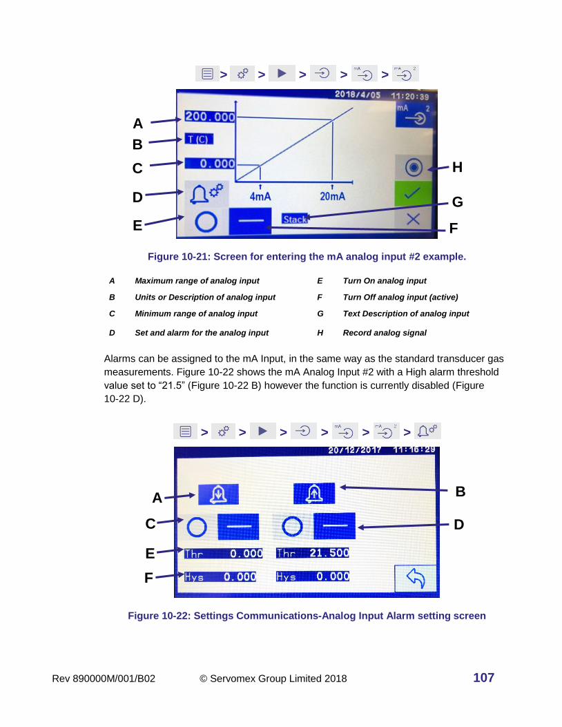
Rev 890000M/001/B02 © Servomex Group Limited 2018 107
> > > > >
Figure 10-21: Screen for entering the mA analog input #2 example.
A Maximum range of analog input E Turn On analog input
B Units or Description of analog input F Turn Off analog input (active)
C Minimum range of analog input G Text Description of analog input
D Set and alarm for the analog input H Record analog signal
Alarms can be assigned to the mA Input, in the same way as the standard transducer gas
measurements. Figure 10-22 shows the mA Analog Input #2 with a High alarm threshold
value set to “21.5” (Figure 10-22 B) however the function is currently disabled (Figure
10-22 D).
> > > > > >
Figure 10-22: Settings Communications-Analog Input Alarm setting screen
D
A
E F
B
G
C H
D
A
E
B
C
F

108 © Servomex Group Limited 2018 Rev 890000M/001/B02
A Low alarm (active) D Turn alarm Off (active)
B High alarm (active) E Alarm threshold set point
C Turn alarm On F Alarm hysteresis set point
Table 10-7: mA Analog Input Icons
Icon Meaning Function
Analog Inputs screen Select an analog input to set up.
Analog Input #2 set up Set up a specific analog input, in this case #2.
Record Records the analog input measurement which
can then be down loaded with a USB stick.
High Alarm Analog Input is set to High Alarm – value and
threshold are set on the page.
Low Alarm Analog Input is set to Low Alarm – value and
threshold are set on the page.
Function is OFF Analog Input is turned off.
Function is ON Analog Input is turned on.
Threshold value Input the threshold value that will trigger the
Alarm.
Hysteresis value Input the hysteresis value at which the Alarm will
reset.
10.7.2 Digital Input Settings
There are two Digital Inputs for each option board for a total of up to 8 for a fully-
configured analyzer. The Digital Input can be used to control the calibration of a transducer
or declare the state of an Analog Input.

Rev 890000M/001/B02 © Servomex Group Limited 2018 109
> > > >
Figure 10-23: Digital Inputs screen for setting up the digital inputs - total of 8 shown in this example)
Figure 10-24 A shows the location of the Calibration operational icons and the Analog
inputs shown in Figure 10-24 B.
> > > > >
Figure 10-24: Digital Inputs screen for Digital Input #2 showing the assignments for (A) Calibration control operational icons and (B) Analog input that can be controlled.
A Digital Input operation is essentially a binary ON / OFF state that detects the contact
closure between the labeled pins on the back-panel connectors. The Digital Input can only
be assigned one action.
To configure a Digital Input operation the user must select both the operation and the
target device.
A
B
Digital Input #2

110 © Servomex Group Limited 2018 Rev 890000M/001/B02
Each Digital Input can be assigned as OFF or one of six possible operations. The available
operations are shown in the box labelled A in Figure 10-24. From top to bottom, left to right
for the transducer:
1. Start Auto-Cal for the designated transducer
Note: It is important know that if more than one Auto-Cal sequence is assigned to a
transducer, the Digital trigger will only launch the first sequence.
2. Stop and disable Auto-Cal
3. Initiate zero gas calibration
4. Initiate span gas calibration
5. Declare the designated Analog Input is working OK (not faulted)
6. Declare that the designated Analog Input is in Calibration
When a Digital Input is assigned one of the left column Transducers it will initiate the
selected operation on that chosen Transducer.
When a Digital Input is assigned one of the right column functions (mA Inputs ) it will
act as a declaration of the status of the external device but otherwise has no control over
the analyzer.
For example, to assign a Digital Input to Start the Span gas calibration for Transducer #2
(Nitric Oxide or NO) press the Span Cal icon within the box labelled A in Figure
10-24 then the #2 on the left side of the Panel next to NO.
As another example, if the user were to select Ext Cal and within the box labelled A
in Figure 10-24 then mA Input #3 within the box labelled B in Figure 10-24 then it
would mean a declaration that the device attached to Analog In #3 is currently in
calibration.
Note: It is important to verify that both device and operation are highlighted before leaving
this page because some selections may cause the other buttons to be reset.
Table 10-8: Digital Input Icons
Icon Meaning Function
Digital Inputs Screen Select a digital input to set up.
Digital Input #8 Set Up Set up a specific digital input, in this case #8.

Rev 890000M/001/B02 © Servomex Group Limited 2018 111
Icon Meaning Function
Auto-Cal Digital input is selected to trigger the Auto-Cal
routine. *
Stop / Disable Auto-
Cal*
Digital input is selected to stop and disable the
Auto-Cal routine. *
Span Calibration* Digital input is selected to trigger the Span
Calibration. *
Zero or Low Span
Calibration
Digital input is selected to trigger the Zero or Low
Span Calibration. *
External Cal Digital input triggers a declaration that the
external device is in Calibration. You select this
and then select a mA Input. When the Digital
input is triggered the device connected to the mA
input would declare it is now in “Service in
Progress”.
External OK Digital input triggers a declaration that the
external device is functioning properly. You select
this and then select a mA Input. When the Digital
input is triggered the device connected to the mA
input would declare it is OK.
mA Analog Input #2 Digital Input is set to control the mA Analog Input
#2.
* Next action - a gas number or a mA Input must then be selected to assign the measurement gas or
input to the operation.

112 © Servomex Group Limited 2018 Rev 890000M/001/B02
Screen Settings
> > > >
Figure 10-25: Screen Settings menu
Table 10-9: Screen Setting Icons
Icon Meaning Function
Split screen
To show two or more gases on the same screen
together on the Home screen. This toggles with
the single screen icon below.
Single screen To show a single screen. This icon toggles with
the split screen icon above.
Increase
brightness
To increase the screen brightness.
Decrease
brightness
To decrease the screen brightness.
Return To return to the previous page

Rev 890000M/001/B02 © Servomex Group Limited 2018 113
Setting the Measurement gas reporting units
When the Units icon is touched the screen adds a column to the right showing the choice
of icons for ppm and mg/m3 icon. The units can be changed even when the analyzer is
recording data. The mA output will rescale automatically to the new unit numbers,
however, the display range bar (shown as a scale that goes from 0 to 500 in Figure 10-26)
will remain showing the units assigned in the User Expanded Range Section 7.3.1.
Note: This is a global setting that will change all GFX Infrared measurements from ppm to
mg/m3 units or mg/m3 to ppm units.
Note: The mg/m3 units are calculated as mg/Nm3).
> > > >
Figure 10-26: Data Units screen showing ppm selected units (mg/m3 is not selected).

114 © Servomex Group Limited 2018 Rev 890000M/001/B02
11 Manual Calibration and Auto-Cal Sequences
Definition of Terms Used
Calibration means that the transducer calibration curve will be changed. Validation means
that the analyzer will measure the gas concentration and then check the value against a
user input certified value. The user input certified value for the High Span calibration point
value will be from the tag value (certified concentration value) of a gas bottle while the Low
Span point is generally set to “0”. Each transducer calibration (or validation) process must
be set up individually and then can be accessed manually or automatically.
If the Auto-Cal feature is purchased, more than one transducer can be calibrated
automatically at the same time using a mixed gas blend containing all required gases at
the Span concentration values. The timing sequence for all of the transducers in this case
will need to be set to the same time and date and the Zero, Span and Sample Measure
times must be the same as well.
This section steps through the process of setting up a manual calibration and the Auto-Cal
sequences.
Introduction to Calibration
The calibration of the transducers in the analyzer may be checked or adjusted either
manually or automatically (requires the Auto-Cal option) and the activity will be logged as
an entry in the calibration history log. The Auto-Cal feature allows the user to set up to
three automatic timing sequences on each of the transducers. These sequences can be
any combination of calibration or validation processes (described in Section 11.6).
External valves or a single multiport switching valve will need to be installed by the
customer to enable the use of the various Span and Zero gases as well as the Sample gas
stream. These valves can then be assigned to the relays associated with each transducer
for controlling Zero, Span and Sample gas. For the Auto-Cal option three relays per
transducer will be pre-assigned as Zero, Span and Sample mode automatically.
If the analyzer is still warming up a ( ) symbol will appear in the corner for each of the
gas icons. If a calibration is attempted, a warning message will appear with an option to
proceed. As each gas transducer warms up this symbol will disappear and at this time a
calibration or validation can be performed on that transducer.
Note: For optimal performance, allow the analyzer to run and stabilize for at least 24
hours from a cold start at 20oC (68 oF). For the higher sensitivity measurements, this
time may be longer.
The operator is guided through the setup sequence choices by a series of menus, icons,
and editable text. Each gas sensor / transducer parameter including output concentration
units, triggers and ranges, must be setup individually.

Rev 890000M/001/B02 © Servomex Group Limited 2018 115
If the Auto-Cal feature is purchased, then the relevant menus and icons will be activated
on the touchscreen. The Auto-Cal can be setup so that the transducers are calibrated or
validated serially (one after another) or timed so that they run simultaneously.
The Auto-Cal process can be initiated by setting up an internal timer, using an external
contact closure or manually through the user interface or triggered via a digital input signal.
In all cases if any of these events occur when the Auto-Cal cycle is in process it will ignore
the request.
The instrument will only respond to a request for an Auto-Cal from the internal timer or
external input if there are no faults indicated. However, the operator can use the analyzer
interface to initiate the Auto-Cal sequence even if there is still a fault displayed.
Note: If the Auto-Cal option has been purchased, the pre-assigned relays will be activated
when performing a manual span calibration and zero calibration, and at their
completion, the sample gas relay will be activated.
Calibration Gas Standard Requirements
Zero and Span gas standards are required to perform the calibration of each of the
transducers fitted into the analyzer. Tolerances and Span bottle certified concentration
values must be inputted for each transducer individually and updated when a cylinder
bottle is replaced.
The quality of the gas standards used will greatly impact the results of the measurement.
Servomex recommends the use of certified gravimetric gas blends and mixtures for the
calibration of the 4900 Multigas analyzer. For highest accuracy use gases from a supplier
that participates in a rigorous regulatory oversight program such as the US EPA Protocol
Gas Verification Program or equivalent programs provided by the European and Asian
National Metrology Institutes. While calibration standards of ±2% accuracy are acceptable,
standards of ±1% accuracy afford the highest accuracy.
Gas standards can be either simple binary mixtures of a span gas and a standard carrier
gas such as N2 or Air, or more complicated mixtures provided the mixture is stable and will
not change over time. If unsure, follow the regulatory guidelines for the region or country.
See Appendix G for a listing of all of the transducers and their full-scale range values, and
Appendix G, Appendix H and Appendix I for details including suggested SPAN values for
the purchased transducer concentration range for the Single Beam Single Wavelength
(SBSW) non-dispersive infrared (NDIR), Paramagnetic oxygen and the NDIR Gas Filter
Correlation (GFX) transducers respectively.

116 © Servomex Group Limited 2018 Rev 890000M/001/B02
Recommended calibration periods
It is recommended that the calibration of the gas sensors be checked on a regular basis
and recalibrated, if required, for best performance. The table below shows the
recommended periods based upon transducer type. Use Appendix G (SBSW CO% and
CO2%), Appendix H (O2%), and Appendix I (GFX) to determine which transducer type is in
the analyser.
Note: More frequent calibration or validation periods may be required by the regional
regulatory body if the analyzers are used in regulatory monitoring such as
continuous emissions monitoring (CEM) systems.
Gas transducer module Low / Zero calibration
High / Span calibration
SBSW NDIR transducer Weekly Daily
Paramagnetic O2 transducer Weekly Weekly
GFX NDIR transducer Weekly Monthly
Hint: The required calibration interval depends on the reliance that you place upon
the accuracy and consistency of the measurements made by the analyzer.
Adjust the calibration interval according to your requirements and the drift
characteristics of your analyzer.
Manual calibration
> >
Figure 11-1: Calibration screen (manual calibration activated)

Rev 890000M/001/B02 © Servomex Group Limited 2018 117
The Manual calibration mode requires the user to manually trigger the transducer
calibration when a Span gas is flowing for the High Span value and when a Zero or Low
concentration gas is flowing for the Low Span / Zero value.
Table 11-1: Manual Calibration Icons
Icon Meaning Function
High Span To set the High Span calibration value based
upon the bottle certified concentration.
Zero or Low Span To set the Low Span calibration point, generally
set to “0” using a zeroing gas like Nitrogen.
Restore Factory
Settings
This icon restores the original factory parameters
and any changes made to the calibration will be
lost. Currently this is supported only for the CO2%
and CO% transducers.
Measurement Alarm
Settings
Touch this icon to set the measurement alarm
values for the transducer.
Home Return back to the system Home screen.
Note: To restore the factory calibration settings, press the icon - take care as any
changes made to the calibration up to this point will be lost. This feature is only
available on the 1520 transducers (CO2% and CO%)
11.5.1 Manual calibration of High Span
Make sure that your equipment is configured to correctly route your high span calibration
gas supply to the analyzer sample gas inlet.
1. Run the High Span calibration gas through the analyzer and wait 15 minutes.
a. Allow the span value to stabilize for one minute.
b. Touch the high span measurement icon shown on the screen (see
Figure 11-1).
2. The new screen (see Figure 11-2) will display the target value along the top bar.
a. The target value will be the last span value that was used to calibrate that
transducer.
b. If the target value is not correct for the calibration gas you are using,
change the target value to the certified gas bottle concentration value using
the numeric keypad (see Figure 11-2).

118 © Servomex Group Limited 2018 Rev 890000M/001/B02
c. accepts the new entry, deletes the last typed value and
cancels the entry.
Figure 11-2: Span value entry keypad with Target Value on the top bar
3. Press to accept the new entry and launch the manual calibration run screen
shown in Figure 11-3.
Figure 11-3: Start calibration – gas filling state
a. A “Service in Progress” signal is triggered, the gas is flowing through the
transducer and the sequence of the calibration step is displayed at the
bottom of the screen in Yellow.
b. The Run icon will stay red (see Figure 11-3) while the gas measured
value is:
• For High Span: less than 80% of the High Span target value (in the
example above this would be ≥ 40 ppm).
• For Zero / Low Span: greater than 20% of the High Span target value
(in the example above this would be ≤ 10 ppm).

Rev 890000M/001/B02 © Servomex Group Limited 2018 119
Figure 11-4: Start calibration – READY State
c. When the gas measured value is near to the target value the Run
icon will turn from RED to GREEN (Figure 11-4).
• For High Span: >80% of the High Span target value (in the example
above this would be ≥ 40 ppm).
• For Zero / Low Span: < 20% of the High Span target value (in the
example above this would be ≤ 10 ppm).
d. Calibration is started by pressing the Run icon
e. When the calibration is finished it reverts back to the screen displaying the
gas reading (see Figure 11-2) to show the post-calibration reading.
4. To repeat the calibration, touch the Run icon again.
5. When the calibration procedure is finished touch the Back icon to terminate
“Service In Progress” and bring up the measurement screen (Figure 11-1).
Note: The User can over-ride the warning given by the Run icon by touching the
icon. The Calibration sequence will continue even though the measured gas value
is not near the target value. This is not recommended as the red icon may be
flagging there is something wrong with the sampling system, the calibration gas or
the transducer.

120 © Servomex Group Limited 2018 Rev 890000M/001/B02
11.5.2 Manual calibration of Zero or Low Span
1. Run the Low Span or Zero calibration gas through the analyzer and wait 15 minutes.
a. Allow the displayed value to stabilize for one minute.
b. Touch the Low Span or Zero measurement icon shown on the
screen in Figure 11-1.
2. Repeat steps 2 through 5 in Section 11.5.1 to calibrate the Zero / Low Span
measurement .
Table 11-2: Manual High Span and Zero Icons
Icon Meaning Function
High Span Set the High Span calibration value based upon
the bottle certified concentration.
Zero or Low Span Set the Low Span calibration point, generally set
to “0” using a zeroing gas like Nitrogen.
Run Calibration with
measured value <20%
away from target.
Start the Manual Calibration run. The icon turns
green when the measured value is within 20% of
the Target value.
Run Calibration with
measured value >20%
away from target.
Start the Manual Calibration run but note that the
measured value is not close to the target value.
The icon stays red until the measured value is
within 20% of the Target value.
Terminate Service in
Progress
Stop the calibration or validation process.
Delete Last
Delete the last digit typed in.
Return
Accept the value entered in the keypad. Typing in
“0” on the keypad will stop the data recording if
the Return key is pressed.
Cancel
Cancel the value entered in the keypad.

Rev 890000M/001/B02 © Servomex Group Limited 2018 121
Auto-Cal validation and calibration sequences
> > > > >
The optional Auto-Cal feature provides validation and calibration sequences that can be
triggered automatically. The validation sequences allow the user to validate the reading
against preset Zero and Span gas value and tolerance. The calibration sequences allow
validation followed by calibration to update the transducer calibration equation.
Figure 11-5: Auto-Cal main screen
Any of the sequences can be set to run at user chosen times and dates automatically. To
validate or calibrate multiple transducers at the same time using a gas blend then each
transducer date, time and repeats must be set up to be the same. The Span value for the
Calibration or Validation must then be added for each gas transducer based upon the
certified value of that gas constituent in the blended cylinder.
External valves or a single multiport switching valve will need to be installed and
connected to the transducer relays by the customer to enable the “Service in Progress”
signal and the Auto-Cal routine to trigger the Zero, Span and Sample modes on each
transducer.
If more than one transducer is present in the analyzer then all of the transducers will turn
Yellow indicating they are no longer producing “good” sample gas readings and are in the
“Service in Progress” mode (see Figure 11-6). Transducers that are in the Auto-Cal or
Auto-Val sequence will show up as black text on the screen while those that are not in
progress are in grey text. In Figure 11-6 the NO and SO2 gas transducer sequence timings
were configured to be the same and they are undergoing Auto-Cal simultaneously as
indicated by the BLACK text.

122 © Servomex Group Limited 2018 Rev 890000M/001/B02
Figure 11-6: Calibration or Validation “Service In Progress” screen
When Auto-Cal is purchased a manual validation check or calibration adjustment can still
be made, using the same transducer relays and valves established in the Auto-Cal
configuration.
The auto-validation and auto-calibration processes can be initiated by four methods:
1. by an internal timer;
2. by an external contact closure;
3. by operator manual request using the analyzer front panel user interface;
4. by an external Modbus or PROFIBUS command
The instrument will only respond to a request for Auto-Cal from the internal timer or
external input if there are no faults indicated. Auto-Cal can be initiated from the user
interface when there is a fault condition.
If any one of these events occurs while the Auto-Cal cycle is in progress the request will
be ignored. Touching the keypad during Auto-Cal will initiate the abort sequence.
The Auto-Cal feature offers custom configurations for automatic Validation and Calibration
operations. The general sequence uses three gas streams (Zero, Span and Sample) and
the Zero gas or the Span gas can be skipped by setting the timing (t1, t2..) to zero,
skipping that step.
Up to three sequences can be assigned to each transducer (see Figure 11-7). They can
be of any form of auto-calibration or auto-validation as needed.
For example, if you need to perform a daily Zero and Span check / validation then you
could assign this to sequence #1 using the auto-validation function. In sequence #2 you
might assign a weekly auto-calibration sequence.

Rev 890000M/001/B02 © Servomex Group Limited 2018 123
Note: The internal analyzer timer will trigger all the Auto-Cal sequences without any
external input required. However, if an external input is used to trigger the Auto-Cal
then only the first sequence will commence.
> > > > > >
Figure 11-7: Sequence setup screen - #1 is shown in the box
An overview of how the Auto-Cal validation sequences are handled is given in Section
11.7 and an overview of how the Auto-Cal calibration sequences are handled is given in
Section 11.8.

124 © Servomex Group Limited 2018 Rev 890000M/001/B02
Auto-validation sequence steps
11.7.1 Auto- validation flow diagram
Start Auto Validation /
Check
Run ZERO / LOWGas
Time >t1? YES
NO
Record ZERO/ LOW As Read
Compare ZERO As Read to ZERO
Tolerance
YES
Run HIGH SPAN GASTime > t2?
YES
Record HIGH SPAN As Read
NO
HIGH SPAN As Read compared to
HIGH SPAN Tolerance
Validation PASSES
RUN SAMPLE Gas
USER INPUTSLOW SPAN GAS Target Concentration (Zero or Low Cal) – Default 0 Acceptance Tolerance (%, ppm-v, mg/m3, or %-vol) Time to Stabilize (t1)HIGH SPAN GAS Target Concentration (Zero or Low Cal) – Default 0 Acceptance Tolerance (%, ppm-v, mg/m3, or %-vol) Time to Stabilize (t2)SAMPLE GAS Time to Stabilize (t3)
Time > t3? YESResume SAMPLE
GAS Reporting
NO
Validation FAILS
Value within Tolerance? NO
Value within Tolerance?YES
NO
(1) Abort Validation sequence(2) Send As Read values to Audit Log(3) Store As Read Value on Analyzer(4) GAS Species RED(5) CAL Icon RED
(1) Send ZERO and HIGH SPAN As Read values to Audit Log(2) Store ZERO and HIGH SPAN As Read values on Analyzer(3) GAS Species GREEN(4) CAL Icon GREEN
Figure 11-8: Flow diagram of the Auto-Validation steps
11.7.2 Auto- validation full sequence example
The full sequence for auto-validation is shown in Figure 11-9 providing a simple Pass or
Fail result. Even if the sequence fails, the gas sample measurements can continue to
report values. Figure 11-9 and Table 11-3 describe how the auto-validation sequence
works. Each transducer must be set up separately to perform an auto-validation.
If you want two or more of the transducers to run auto-validation simultaneously then the
sequence timing as well as the Date and Time settings need to be the same.

Rev 890000M/001/B02 © Servomex Group Limited 2018 125
Note: If the Zero or Span Validation step fails the Transducer gas icon will remain
RED until the user corrects the problem, gas measurement reporting will
continue however.
Figure 11-9: Full auto-validation sequence
Table 11-3: Typical auto-validation sequence on a transducer
Point Function
1 Zero gas routed to transducer and set Service In Progress flag and
turn on any Service In Progress relays.
t1 Time required for Zero gas readings to stabilize.
2 Zero gas “As Found” value recorded and compared to “0” ± tolerance.
If Zero gas “As Found” value Passes - Skip to Point 3.
If Zero gas “As Found” value Fails – Log Failure and turn Gas icon
and Auto-Cal icon RED.
3 Span gas routed to transducer.
t2 Time required for Span gas readings to stabilize.
4 Span gas “As Found” value recorded and compared to High Span
value ± tolerance.
If Span gas “As Found” value Passes - Skip to Point 5.
If Span gas “As Found” value Fails – Log Failure and turn Gas icon
and Auto-Cal icon RED.
5 Sample gas routed to analyzer.

126 © Servomex Group Limited 2018 Rev 890000M/001/B02
Point Function
t3 Time required for Sample gas readings to stabilize and begin reporting
gas measurments. This cannot be set to “0” and is defaulted to 1 sec
before restoring the measurment values.
6 Clear Service In Progress and turn off any Service In Progress
relays and begin reporting Sample gas measurements.
Final output will be Pass or Fail flag
11.7.3 Auto-validation truncated sequence example
The next sequence below describes how to skip the Zero portion of the auto-validation
sequence, performing only a Span Check in the auto-validation (see Figure 11-10 and
Table 11-4).
Figure 11-10: Auto-Validation Span Check only sequence
Table 11-4: Auto-validation Span only sequence on a transducer
Point Function
1 Zero gas switch to analyzer skipped as t1 set to “0”
t1 Zero gas Time set to “0”
2 Zero gas “As Found” read and comparison skipped as t1 set to “0”

Rev 890000M/001/B02 © Servomex Group Limited 2018 127
Point Function
3 Span gas routed to transducer and set Service In Progress flag and
turn on any Service In Progress relays.
t2 Time required for Span gas readings to stabilize.
4 Span gas “As Found” value recorded and compared to High Span
value ± tolerance.
If Span gas “As Found” value Passes - Skip to Point 5.
If Span gas “As Found” value Fails – Log Failure and turn Gas icon
and Auto-Cal icon RED.
5 Sample gas routed to analyzer.
t3 Time required for Sample gas readings to stabilize and begin reporting
gas measurments. This cannot be set to “0” and is defaulted to 1 sec
before restoring the measurment values.
6 Clear Service In Progress and turn off any Service In Progress
relays and begin reporting Sample gas measurements.
Final output will be Pass or Fail flag
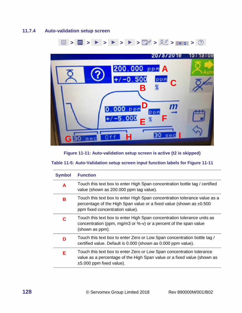
128 © Servomex Group Limited 2018 Rev 890000M/001/B02
11.7.4 Auto-validation setup screen
> > > > > > > >
Figure 11-11: Auto-validation setup screen is active (t2 is skipped)
Table 11-5: Auto-Validation setup screen input function labels for Figure 11-11
Symbol Function
A Touch this text box to enter High Span concentration bottle tag / certified
value (shown as 200.000 ppm tag value).
B Touch this text box to enter High Span concentration tolerance value as a
percentage of the High Span value or a fixed value (shown as ±0.500
ppm fixed concentration value).
C Touch this text box to enter High Span concentration tolerance units as
concentration (ppm, mg/m3 or %-v) or a percent of the span value
(shown as ppm).
D Touch this text box to enter Zero or Low Span concentration bottle tag /
certified value. Default is 0.000 (shown as 0.000 ppm value).
E Touch this text box to enter Zero or Low Span concentration tolerance
value as a percentage of the High Span value or a fixed value (shown as
±5.000 ppm fixed value).
A
C B
D
E F
G H I

Rev 890000M/001/B02 © Servomex Group Limited 2018 129
Symbol Function
F Touch this text box to enter Zero or Low Span concentration tolerance
units as concentration (ppm, mg/m3 or %-v) or a percent of the span
value (shown as units as ppm).
G Touch this text box to enter Time required for Zero gas readings to
stabilize, then take an “As Found” reading (see Section 11.7.2 for
location of #1,t1,#2). Shows t1 as 30 seconds.
H Touch this text box to enter Time required for High Span gas readings to
stabilize, then take an “As Found” reading (see Section 11.7.2 for
location of #3,t2,#4). Shows t2 as Off indicating the High Span Validation
check section will be skipped.
I Touch this text box to enter Time required for Sample gas readings to
stabilize before measurement reporting begins reading (see Section
11.7.2 for location of #5, t3, #6). Shows t3 as 30 seconds.
Symbol showing where Measurement of Sample begins. Has no function.
Touch the Start Auto-Cal icon to run the auto-calibration/validation sequence
straight away or touch the Calendar icon to set a time for the auto-
calibration/validation sequence to start.
Note: To abort the auto-calibration/validation set-up sequence touch . It will also
cancel any future events so have care when using this function.
Table 11-6: Auto-Validation setup screen icons
Icon Meaning Function
Auto-calibration
settings
Selects the auto-calibration sequence setup
screen.
Auto-validation
settings
Selects the auto-validation sequence setup
screen. Blue background indicates active
function.
Auto-Cal Timing
Sets up the timing for the auto-calibration and
auto-validation sequences. Up to 3 sequences
can be set for each transducer.

130 © Servomex Group Limited 2018 Rev 890000M/001/B02
Icon Meaning Function
Start Auto-Cal Forces the current auto-calibration or auto-
validation sequence on the screen to be
executed.
Stop Auto-Cal Disables or cancels the auto-validation or auto-
calibration sequence that is in progress. Be
careful with this function at it also cancels any
future timed events.
Return Returns the screen to the main Maintenance
Menu.

Rev 890000M/001/B02 © Servomex Group Limited 2018 131
Auto-Calibration Sequence Steps
11.8.1 Auto-Calibration Sequence Flow Diagram
Start Auto Calibration
Run ZERO / LOWGas
Time >t1?
YESNO
Record ZERO/ LOW As Read
Compare ZERO As Read to ZERO
Tolerance
YES
Run HIGH SPAN GASTime > t2?
YES
Record HIGH SPAN As Read
NO
HIGH SPAN As Read compared to
HIGH SPAN Tolerance
Validation PASSES
Update HIGH SPAN Calibration Curve
USER INPUTSLOW SPAN GAS Target Concentration (Zero or Low Cal) – Default 0 Acceptance Tolerance (%, ppm-v, mg/m3, or %-vol) Time to Stabilize (t1) for As Read – Validation only Time to Stabilize (t3) for As Read for CalibrationHIGH SPAN GAS Target Concentration (Zero or Low Cal) – Default 0 Acceptance Tolerance (%, ppm-v, mg/m3, or %-vol) Time to Stabilize (t2) for Validation then CalibrationSAMPLE GAS Time to Stabilize (t4) before resume reporting
Validation FAILS
Value within Tolerance? NO
Value within Tolerance?YES
NO
RUN SAMPLE Gas Time > t4?
YES
Resume SAMPLE GAS Reporting
NO
Run ZERO / LOWGas
Time >t3?
YES
NO
Record ZERO/ LOW As Read
Compare ZERO As Read to ZERO
Tolerance
Value within Tolerance?
Update HIGH SPAN Calibration Curve
YES
Validation FAILS
NO
(1) Abort Calibration sequence(2) Send As Read values to Audit Log(3) Store As Read Value on Analyzer(4) GAS Species RED(5) CAL Icon RED
(1) Send ZERO and HIGH SPAN As Read values to Audit Log(2) Store ZERO and HIGH SPAN As Read values on Analyzer(3) GAS Species GREEN(4) CAL Icon GREEN
(1) Abort Calibration sequence(2) Send As Read values to Audit Log(3) Store As Read Value on Analyzer(4) GAS Species RED(5) CAL Icon RED
Figure 11-12: Flow diagram of the Auto-Calibration Steps
11.8.2 Auto-Calibration full sequence example
The full sequence for Auto-Calibration is shown in Figure 11-13 providing a new calibration
curve for the transducer if the validation step passed otherwise the calibration step will not
be performed. Even if the sequence fails, the gas sample measurements can continue to
report values, but a manual calibration must be done if the validation sequence fails. The
user should check to ensure the gas sampling system is working properly and the
calibration gas standards are accurate before attempting another calibration after a failure.
The full sequence Auto-Calibration process reads the Zero gas “As Found” value then
switches to the Span gas to read the “As Found” value, both performed before any

132 © Servomex Group Limited 2018 Rev 890000M/001/B02
calibration curve changes. The second Zero gas “As Found” process is used to set the
Zero calibration point.
Figure 11-13 and Table 11-7 describe how the full Auto-Calibration sequences works and
Section show how to set timing, concentration and threshold limit values. Each transducer
must be set up separately in order to perform an Auto-Calibration.
Note: If the Zero or Span Validation step fails the Transducer gas icon will remain
RED until the user corrects the problem, gas measurement reporting will
continue however.
Figure 11-13: Full Auto-Calibration sequence
Table 11-7: Typical Auto-calibration processes on a transducer
Symbol Function
1 Zero gas routed to transducer and set Service In Progress flag and turn
on any Service In Progress relays.
t1 Time required for Zero gas readings to stabilize.
2 Zero gas “As Found” value recorded and compared to “0” ± tolerance.
If Zero gas “As Found” value Fails – then Auto-Calibration sequence is
terminated, Validation Failure is issued.
3 Span gas routed to transducer.
t2 Time required for Span gas readings to stabilize.

Rev 890000M/001/B02 © Servomex Group Limited 2018 133
Symbol Function
4 Span gas “As Found” value recorded and compared to High Span value
± tolerance.
If Span gas “As Found” value Passes - Calibrate to High Span value.
Skip to Point 5.
If Span gas “As Found” value Fails – then Auto-Calibration sequence is
terminated, Validation Failure flag is issued, and the Gas Component and
Auto-Cal icon turn RED. Skip to Point 7 and switch gas to sample stream.
5 Zero gas routed to analyzer.
t3 Time required for Zero gas readings to stabilize.
If Zero gas “As Found” value Passes Calibrate to Low Span value which
is generally “0”. Skip to Point 7.
If Zero gas “As Found” value Fails – then Auto-Calibration sequence is
terminated, Validation Failure flag is issued, and the Gas Component and
Auto-Cal icon turn RED. Skip to Point 7 and switch gas to sample stream.
7 Sample gas routed to analyzer.
t4 Time required for Sample gas readings to stabilize and begin reporting
gas measurments.
8 Clear Service In Progress and turn off any Service In Progress relays
and begin reporting Sample gas measurements.
Final output will be Pass (Recalibration) or Fail (No Calibration,
Failure Flag set, Switch to Sample gas)
11.8.3 Auto-calibration truncated sequence example
Figure 11-14 and Table 11-8 describe how the auto-calibration sequences can be
configured to skip the first Zero “As Found” validation section and only use the second
Zero “As Found” validation test followed by a calibration. In Figure 11-14 the Span “As
Found” value is obtained prior to performing any calibration curve changes, while the Zero
“As Found” value is obtained after the Span High Calibration point has been changed.

134 © Servomex Group Limited 2018 Rev 890000M/001/B02
Figure 11-14: Auto-calibration without Initial Zero “As Found” read.
Table 11-8: Auto-calibration without Initial Zero “As Found”
Symbol Function
1 Zero gas switch to analyzer skipped as t1 set to “0”
t1 Zero gas Time set to “0”
2 Zero gas “As Found” read and comparison skipped as t1 set to “0”
3 Span gas routed to transducer and set Service In Progress flag and turn
on any Service In Progress relays.
t2 Time required for Span gas readings to stabilize.
4 Span gas “As Found” value recorded and compared to High Span value
± tolerance.
If Span gas “As Found” value Passes - Calibrate to High Span value.
Skip to Point 5.
If Span gas “As Found” value Fails – then auto-calibration sequence is
terminated, Validation Failure flag is issued, and the Gas Component and
Auto-Cal icon turn RED. Skip to Point 7 and switch gas to sample stream.
5 Zero gas routed to analyzer.
t3 Time required for Zero gas readings to stabilize.

Rev 890000M/001/B02 © Servomex Group Limited 2018 135
Symbol Function
6 Zero gas “As Found” value recorded and compared to Low Span “0”
value ± tolerance.
If Zero gas “As Found” value Passes Calibrate to Low Span value which
is generally “0”. Skip to Point 7.
If Zero gas “As Found” value Fails – then auto-calibration sequence is
terminated, Validation Failure flag is issued, and the Gas Component and
Auto-Cal icon turn RED. Skip to Point 7 and switch gas to sample stream.
7 Sample gas routed to analyzer.
t4 Time required for Sample gas readings to stabilize and begin reporting
gas measurments. This cannot be set to “0” and is defaulted to 1 sec
before restoring the measurment values.
8 Clear Service In Progress and turn off any Service In Progress relays
and begin reporting Sample gas measurements.
Final output will be Pass (Recalibration) or Fail (No Calibration,
Failure Flag set, Switch to Sample gas)
Hint: The key difference between the sequences shown in Figure 11-13 and Figure
11-14 is that there is no initial Zero “As Found” value recorded in the sequence
shown in Figure 11-14. The sequence in Figure 11-13 will support regulatory
compliance where both the Zero gas and the Span gas “As Found” readings
need to be recorded prior to any calibration curve changes from the High Span
or the Low / Zero Span calibrations.

136 © Servomex Group Limited 2018 Rev 890000M/001/B02
11.8.4 Auto-calibration screen setup
> > > > > > > >
Figure 11-15: Auto-calibration setup screen is active
Up to 3 sequences can be set up on each transducer as a mixture of auto-calibration and
auto-validation sequences (see Section 11.6). These sequences are initiated by the
internal timer and do not require an external trigger for execution.
Note: If the User Interface, digital input, or Modbus/PROFIBUS command is used to
START or STOP Auto-Cal on a transducer, only the first sequence will be
triggered.
Table 11-9: Auto-Calibration setup screen icons for Figure 11-15
Symbol Function
A Touch this text box to enter High Span concentration bottle tag / certified
value. Figure 11-15 shows 20.900% tag value.
B Touch this text box to enter High Span concentration tolerance value as a
percentage of the High Span value or a fixed value. Figure 11-15 shows
±1.000 %-vol fixed value.
C Touch this text box to enter High Span concentration tolerance units as
concentration (ppm, mg/m3 or %-vol) or a percent of the span value (%).
Figure 11-15 shows units as %-vol.
A
C B
D E F
G H I J

Rev 890000M/001/B02 © Servomex Group Limited 2018 137
Symbol Function
D Touch this text box to enter Zero or Low Span concentration bottle tag /
certified value. Default is 0.000. Figure 11-15 shows 0.000% value.
E Touch this text box to enter Zero or Low Span concentration tolerance
value as a percentage of the High Span value or a fixed value. Figure
11-15 shows ±1.000 %-vol fixed value.
F Touch this text box to enter Zero or Low Span concentration tolerance
units as concentration (ppm, mg/m3 or %-v) or a percent of the span
value. Figure 11-15 shows units as %-vol.
G Touch this text box to enter Time required for Zero gas readings to
stabilize, then take an “As Found” reading (see Section 11.8.2 for
location of #1, t1, #2). Figure 11-15 shows t1 as 30 seconds.
H Touch this text box to enter Time required for High Span gas readings to
stabilize, then take an “As Found” reading, and Calibrate if reading
outside of tolerance (see Section 11.8.2 for location of #3, t2, #4). Figure
11-15 shows t2 as 30 seconds.
I Touch this text box to enter Time required for Zero gas readings to
stabilize, then take an “As Found” reading, and Calibrate if reading
outside of tolerance (see Section 11.8.2 for location of #5, t3, #6). Figure
11-15 shows t3 as 30 seconds.
J Touch this text box to enter Time required for Sample gas readings to stabilize before measurement reporting begins (see Section 11.8.2 for location of #7, t4, #8). Figure 11-15 shows t4 as 30 seconds.
Symbol where Measurement of Sample begins. Has no function.
Either touch to run the auto-calibration/validation sequence straight away, or touch
to set a time for the auto-calibration/validation sequence to start.
Note: Touch to abort the auto-calibration/validation set-up sequence. It will also
cancel any future events so be careful when using this function.

138 © Servomex Group Limited 2018 Rev 890000M/001/B02
Table 11-10: Auto-Calibration setup screen icons for Figure 11-15
Icon Meaning Function
Calibration settings
Selects the auto-calibration setup screen. Blue
background indicates active function as shown in
Figure 11-15.
Validation settings Selects the auto-validation setup screen.
Auto-Calibration/
Validation enabled
Forces the current auto-calibration or auto-
validation sequence on the screen to be
executed.
Auto-Calibration/
Validation disabled
Disables or cancels the auto-validation or auto-
calibration sequence that is in progress. Be
careful with this function at it also cancels any
future timed events!
Auto-Calibration/
Validation Timing
Sets up the timing sequences for the auto-
calibration and auto-validation. Up to 3 sequences
can be set for each.
Return Returns the screen to the main Maintenance
Menu.
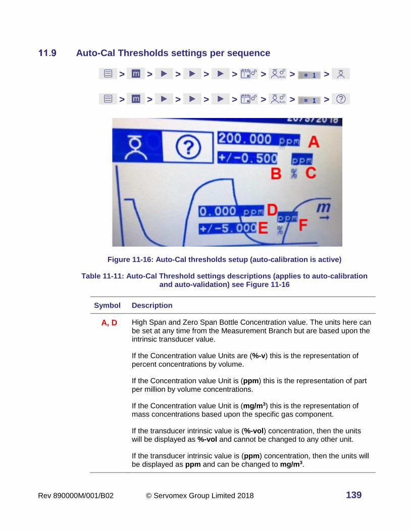
Rev 890000M/001/B02 © Servomex Group Limited 2018 139
Auto-Cal Thresholds settings per sequence
> > > > > > > >
> > > > > > > >
Figure 11-16: Auto-Cal thresholds setup (auto-calibration is active)
Table 11-11: Auto-Cal Threshold settings descriptions (applies to auto-calibration and auto-validation) see Figure 11-16
Symbol Description
A, D High Span and Zero Span Bottle Concentration value. The units here can be set at any time from the Measurement Branch but are based upon the intrinsic transducer value.
If the Concentration value Units are (%-v) this is the representation of percent concentrations by volume.
If the Concentration value Unit is (ppm) this is the representation of part per million by volume concentrations.
If the Concentration value Unit is (mg/m3) this is the representation of mass concentrations based upon the specific gas component.
If the transducer intrinsic value is (%-vol) concentration, then the units will be displayed as %-vol and cannot be changed to any other unit.
If the transducer intrinsic value is (ppm) concentration, then the units will be displayed as ppm and can be changed to mg/m3.
140 © Servomex Group Limited 2018 Rev 890000M/001/B02
Symbol Description
B, E High Span and Zero Span Tolerance Value. The units are set in this screen.
If the Span or Zero gas value “As Read” is outside of this tolerance, then the auto-validation or auto-calibration will fail and no changes will be made to the transducer calibration.
If the Span or Zero gas value “As Read” is inside of this tolerance, then the auto-validation passes and auto-calibration recalibrate the transducer equation using the new value.
C, F High Span and Zero Span Tolerance Value Units. The units are set in this screen.
If the Threshold Value Unit selected is (%-vol) then the value represents a concentration value.
If the Threshold Value Unit selected is (%) then the value represents a percentage calculation of the concentration value entered regardless of the unit type (%-vol, ppm, mg/m3).
If the Threshold Value Units are (mg/m3) then the value represents a fixed concentration value above and below the Span or Zero concentration in mg/m3.
If the Threshold Value Units are (ppm) then the value represents a fixed concentration value above and below the Span or Zero concentration in ppm.

Rev 890000M/001/B02 © Servomex Group Limited 2018 141
Auto-Cal sequence timing setup
> > > > > > >
> > > > > > >
Figure 11-17: Auto-calibration setup screen is active
This section applies to both the auto-calibration and the auto-validation sequences and is
used to set up the date, time and repeats for the automatic runs.
11.10.1 Auto-Cal sequence general timing
Touch the icon in Figure 11-17 to get to the Date screen to set the Day/Month/Year
for the first auto-calibration / auto-validation event. The first set of arrows allows you to
choose to display the values in MM/DD/YY, DD/MM/YY, or YY/MM/DD.
• Touch to accept entry and move to Time Set screen
• Touch to cancel the changes and go back to Sequence Setup initial screen
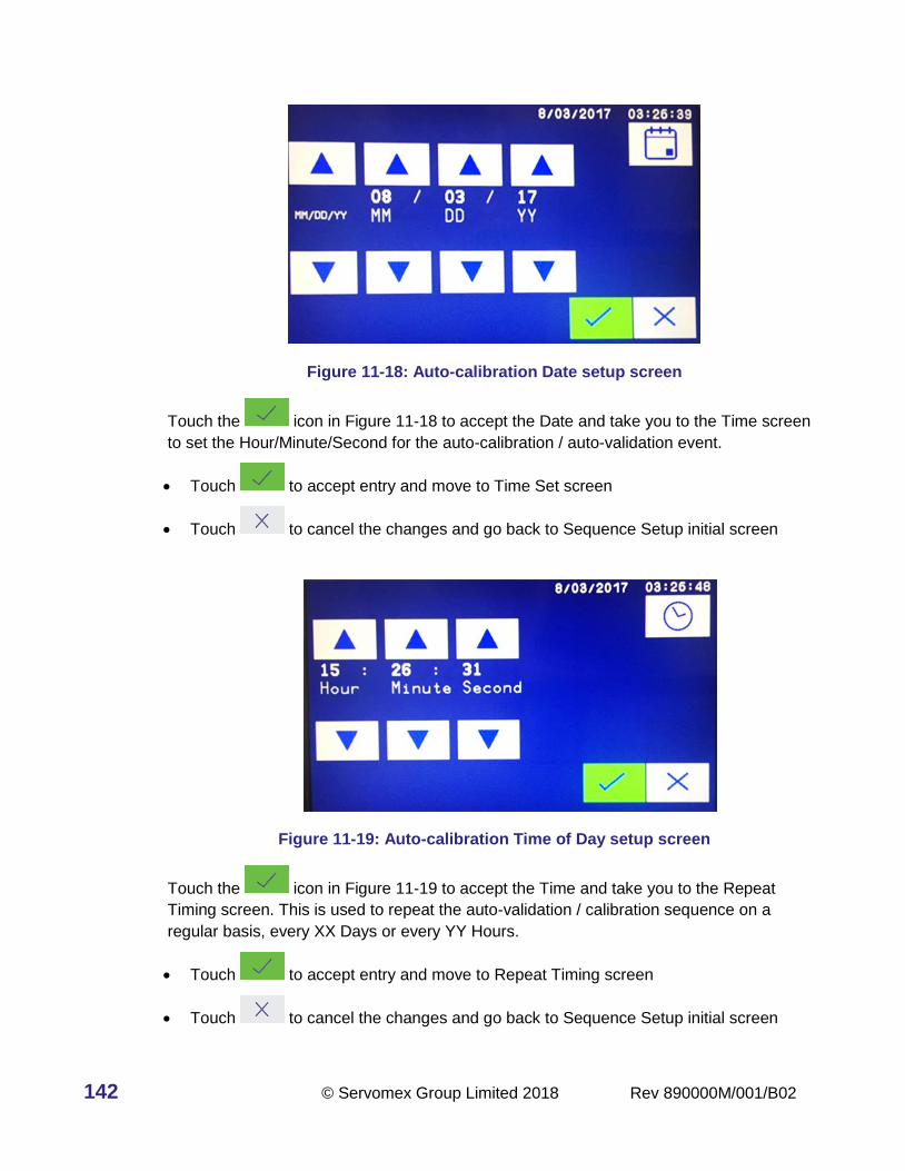
142 © Servomex Group Limited 2018 Rev 890000M/001/B02
Figure 11-18: Auto-calibration Date setup screen
Touch the icon in Figure 11-18 to accept the Date and take you to the Time screen
to set the Hour/Minute/Second for the auto-calibration / auto-validation event.
• Touch to accept entry and move to Time Set screen
• Touch to cancel the changes and go back to Sequence Setup initial screen
Figure 11-19: Auto-calibration Time of Day setup screen
Touch the icon in Figure 11-19 to accept the Time and take you to the Repeat
Timing screen. This is used to repeat the auto-validation / calibration sequence on a
regular basis, every XX Days or every YY Hours.
• Touch to accept entry and move to Repeat Timing screen
• Touch to cancel the changes and go back to Sequence Setup initial screen

Rev 890000M/001/B02 © Servomex Group Limited 2018 143
Figure 11-20: Auto-calibration Repeat Timing setup screen: Left shows repeat Day, Right shows Hour set
• Touch to accept entry and move to back to Auto-Cal Main screen
• Touch to cancel the changes and go back to Sequence Setup initial screen
• Touch to repeat the auto-calibration.
11.10.2 Auto-Cal sequence timing setup for multiple transducers
If you want to run multiple transducers using the same calibration and zero gases, each
transducer in the group must use the same settings for the following items:
• For auto-validation t1, t2, t3 must be the same for all transducers that are to be run at
the same time (see Figure 11-11: G, H, I).
• For auto-calibration t1, t2, t3, t4 must be the same for all transducers that are to be run
at the same time (see Figure 11-17: G, H, I, J).
• For auto-validation or auto-calibration all transducer settings for Date (see Figure
11-18), Time (see Figure 11-19), and Repeat Timing (see Figure 11-20) must be the
same.
Note: The t1, t2, t3, t4 timing should be based upon the gas component that takes the
longest time to come to a steady reading.
Auto-calibration valve installation
The auto-calibration and auto-validation function uses relays to control user provided
external valves or single multiport valve, or to send a signal out indicating which gas
stream is being used at the time of the trigger. If the auto-calibration option is ordered the
analyzer will be equipped with eight relays for each transducer in the analyzer. Relays 6, 7
and 8 for each transducer will be permanently assigned to Zero, Span and Sample
respectively. See Section 10.2 for more details.
Note: It is up to the customer to supply and connect externally powered valves to supply
the correct zero and span gas for each transducer. The analyzer switches

144 © Servomex Group Limited 2018 Rev 890000M/001/B02
automatically according to the auto-calibration or auto-validation sequence timing
and set up.
External inputs for Auto-Cal
To activate the Auto-Cal feature (if purchased), connect the Digital Input (DIN) pins DIN 2B
and DIN 2C (see Figure 11-21 or Figure 1-2) on Jumper 17 (J17).
Figure 11-21. Jumper 17 used for Auto-Cal configurations.
The voltage input is activated by applying (+) 5 – 24 VDC to DIN 1A and (–) 5 – 24 VDC to
DIN 1B. The contact closure input is activated by a contact closure created between DIN
1B and DIN 1C.
Details on setting up the various input signals are found in Section 10.7.
Relays used for auto-calibration / validation
Transducer 1: • Zero or Low Gas Relay #6
• Span (high conc. Calibration gas) Relay #7
• Sample Gas Relay #8
Transducer 2: • Zero or Low Gas Relay #14
• Span (high conc. Calibration gas) Relay #15
• Sample Gas Relay #16
Transducer 3: • Zero or Low Gas Relay #22
• Span (high conc. Calibration gas) Relay #23
• Sample Gas Relay #24
Transducer 4: • Zero or Low Gas Relay #30
• Span (high conc. Calibration gas) Relay #31
• Sample Gas Relay #32

Rev 890000M/001/B02 © Servomex Group Limited 2018 145
Calibration log file
> >
The analyzer calibration history is saved in the config_files directory in the
CalibrationRecord.txt file. The file can be written to a USB drive inserted into the analyzer
using the button sequence shown above. This file can be opened with a program like
Microsoft® Excel.
The example in Figure 11-22 shows an auto-calibration and auto-validation entry. The
measured process result is reported as the ‘Before’ or “As Found” value. The entered span
value is 25ppm and after calibration the validation result is also 25ppm.
Figure 11-22: Example calibration log file
> > >
Figure 11-23: Cal log file displayed on screen
Figure 11-23 shows an example of a Calibration Log File as viewed on the analzyer
screen. Use the and arrow to scroll up or down for more text information on the
Auto-Cal operations and results. The information presented here is the same as in the
output text log from above.
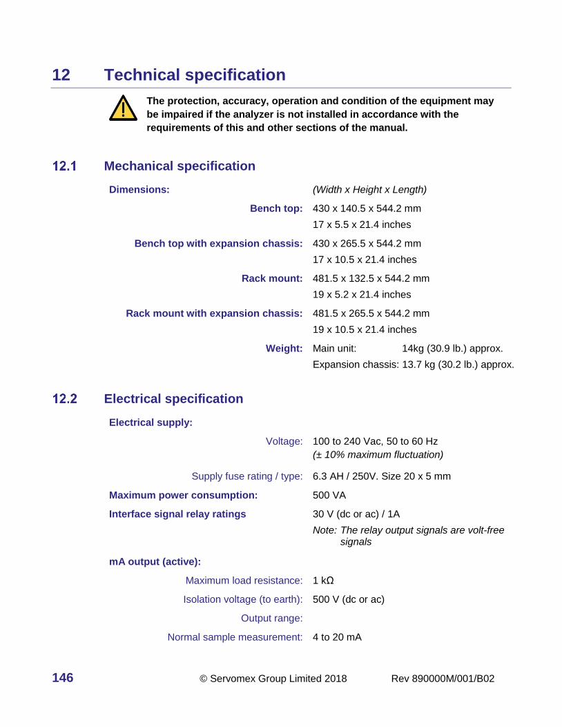
146 © Servomex Group Limited 2018 Rev 890000M/001/B02
12 Technical specification
The protection, accuracy, operation and condition of the equipment may
be impaired if the analyzer is not installed in accordance with the
requirements of this and other sections of the manual.
Mechanical specification
Dimensions: (Width x Height x Length)
Bench top: 430 x 140.5 x 544.2 mm
17 x 5.5 x 21.4 inches
Bench top with expansion chassis: 430 x 265.5 x 544.2 mm
17 x 10.5 x 21.4 inches
Rack mount: 481.5 x 132.5 x 544.2 mm
19 x 5.2 x 21.4 inches
Rack mount with expansion chassis: 481.5 x 265.5 x 544.2 mm
19 x 10.5 x 21.4 inches
Weight: Main unit: 14kg (30.9 lb.) approx.
Expansion chassis: 13.7 kg (30.2 lb.) approx.
Electrical specification
Electrical supply:
Voltage: 100 to 240 Vac, 50 to 60 Hz
(± 10% maximum fluctuation)
Supply fuse rating / type: 6.3 AH / 250V. Size 20 x 5 mm
Maximum power consumption: 500 VA
Interface signal relay ratings 30 V (dc or ac) / 1A
Note: The relay output signals are volt-free signals
mA output (active):
Maximum load resistance: 1 kΩ
Isolation voltage (to earth): 500 V (dc or ac)
Output range:
Normal sample measurement: 4 to 20 mA

Rev 890000M/001/B02 © Servomex Group Limited 2018 147
Fault condition: 0 mA, 2 mA. User selectable
Voltage output (active):
Minimum load resistance: 100 kΩ
Isolation voltage (to earth): 250 V (dc or ac)
Output range:
Normal sample measurement: 0 to 10 V
Fault condition: Fault condition selected as an option at the
time of purchase.
Under range: Not applicable
Signal / voltage / mA / RS485 output terminals suitable for:
Flexible conductors: 0.5 to 1.5 mm2 (20 to 16 AWG)
Solid conductors: 0.5 to 1.0 mm2 (20 to 18 AWG)
Maximum voltage ratings
Common mode compared to chassis ground reference:
Signals: Maximum voltage rating:
I1+, I1-, I2+, I2-, I3+, I3-, I4+, I4-
V1+, V1-, V2+, V2-, V3+, V3-, V4+, V4-
IIN1+, IIN1-, IIN2+, IIN2-
IIN3+, IIN3-, IIN4+, IIN4-
DIN3A, DIN3B, DIN4A, DIN4B
J17(ALL)
250 Vac
All relays C, NC, NO 40 Vac
J6 (ALL)
J8(ALL)
J18 (ALL)
15 Vdc
Differential mode between pairs:
Signals: Maximum voltage rating:
All relays C, NC, NO 30 Vac, dc
IIN1+, IIN- or IIN2+, IIN2- or
IIN3+, IIN3- or IIN4+, IIN4-
40 Vdc wrt V1-, V2-, V3-. V4-
DIN3A, DIN3B or DIN4A, DIN4B 24 Vdc
RS485TX+, RS485TX- 15 Vdc

148 © Servomex Group Limited 2018 Rev 890000M/001/B02
Signals: Maximum voltage rating:
RS485RX+, RS485RX- 15 Vdc
RS232TX, RS232RX 15 Vdc
J17 pin to pin 9 Vdc
Environmental limits
The equipment is suitable for indoor use only.
Ambient temperature range:
Operation: 5 to 45 °C
Storage: 0 to 50 °C
Operating ambient pressure range: 101.3 kPa ± 10% (1.013 bar ± 10%)
Operating ambient humidity range: 10 to 90% RH, non-condensing
Operating altitude range: -500 metres (below sea level) to 2000 metres
(above sea level)
Ingress protection: IP20

Rev 890000M/001/B02 © Servomex Group Limited 2018 149
13 Routine maintenance
The 4900 Multigas analyzer does not contain any user serviceable parts.
Do not attempt to maintain or service the 4900 Multigas analyzer unless
you are trained and know what you are doing. The analyzer must be
maintained by a suitably skilled and competent person.
Do not open or attempt to remove the analyzer cover yourself. If you do,
you will invalidate any warranty on the analyzer, and the analyzer may
not operate safely or provide accurate measurements.
Sample and calibration gases may be toxic or asphyxiant.
Never inspect the inlet filter(s), or service or repair the analyzer while
such gases are still connected to it.
If the analyzer is to be serviced or repaired, it is important that all
pipework is flushed with an inert gas and the analyzer is allowed to freely
vent to local atmosphere.
Cleaning the analyzer
When necessary, use a damp (but not wet) cloth to wipe clean the outer surfaces of the
analyzer (to prevent the entry of dust or other particulates into the interior of the analyzer).
Routine checks
You only need to carry out simple maintenance procedures annually. Carry out the
following regular checks to ensure continuous and safe operation of the monitor.
13.2.1 Inspect / replace the fuse
Ensure that the electrical supply is isolated / locked-out from the
analyzer. If you do not, there will be a danger of injury or death from
electric shock.
Fire Hazard: Only use the same type and rated fuse as recommended.
If you think that an electrical supply fuse has failed, use the following procedure to inspect
the fuses and replace them if necessary:
1. Open the fuse panel on the rear of the analyzer (Figure 13-1). To do this, carefully
insert a small screwdriver into the gap on the right of the panel and press the clip to
open the panel.

150 © Servomex Group Limited 2018 Rev 890000M/001/B02
Figure 13-1: Open the fuse panel
Figure 13-2: Fuse panel opened
2. Pull the red fuse holder out of the panel (Figure 13-2).
Both live and neutral lines have fuse protection. The neutral fuse is shown (1 in Figure
13-3); the live fuse is located in the underside of the red fuse holder (2 in Figure 13-3).
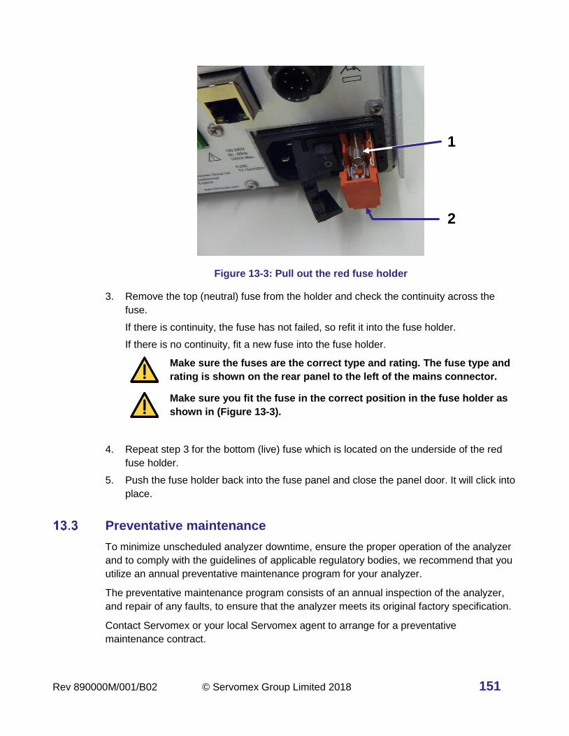
Rev 890000M/001/B02 © Servomex Group Limited 2018 151
Figure 13-3: Pull out the red fuse holder
3. Remove the top (neutral) fuse from the holder and check the continuity across the
fuse.
If there is continuity, the fuse has not failed, so refit it into the fuse holder.
If there is no continuity, fit a new fuse into the fuse holder.
Make sure the fuses are the correct type and rating. The fuse type and
rating is shown on the rear panel to the left of the mains connector.
Make sure you fit the fuse in the correct position in the fuse holder as
shown in (Figure 13-3).
4. Repeat step 3 for the bottom (live) fuse which is located on the underside of the red
fuse holder.
5. Push the fuse holder back into the fuse panel and close the panel door. It will click into
place.
Preventative maintenance
To minimize unscheduled analyzer downtime, ensure the proper operation of the analyzer
and to comply with the guidelines of applicable regulatory bodies, we recommend that you
utilize an annual preventative maintenance program for your analyzer.
The preventative maintenance program consists of an annual inspection of the analyzer,
and repair of any faults, to ensure that the analyzer meets its original factory specification.
Contact Servomex or your local Servomex agent to arrange for a preventative
maintenance contract.
1
2

152 © Servomex Group Limited 2018 Rev 890000M/001/B02
14 Troubleshooting
The following section will help to resolve many of the common operational situations that
occur with the analyser. Try the possible remedies in the order listed.
Error codes
The following codes may be displayed in the event of a problem or error. The table gives a
suitable remedy.
Code Meaning Possible remedy
B: Bad command Internal Software Error Power Cycle
C: Comms fault Data not received from
transducer
Check transducer cable
D: Data fault Data not received from
transducer
Check transducer cable
E: Out of spec The reading exceeds the
maximum range
Check plumbing
S: Calibrating Calibrating Failed Recalibrate, Check Bottle
concentration value
T: Overtemp Transducer temperature is
over range
Reduce ambient temperature
X: Electronics fault Critical Electrical Fault Contact Servomex
Jam conditions
See section 10.1 “Configure and use the mA outputs."

Rev 890000M/001/B02 © Servomex Group Limited 2018 153
15 Storage and disposal
Storage
Refit any protective plastic covers and place the analyzer and any associated equipment in
its original packaging before storage. Alternatively, seal it inside a waterproof plastic bag,
sack, or storage box.
Store the analyzer and any associated equipment in a clean, dry area. Do not subject it to
excessively hot, cold, or humid conditions.
Disposal
Dispose of the analyzer and any associated equipment safely, and in accordance with all
of your local and national safety and environmental requirements.
Hint: If you send the analyzer to Servomex or your local Servomex agent for
disposal, it must be accompanied by a correctly completed decontamination
certificate and a Return Authorization Number (RAN) (17.1Appendix E).
15.2.1 Disposal in accordance with the Waste Electrical and Electronic Equipment
(WEEE) Directive
The label shown in Figure 15-1 is fitted to the analyzer.
Figure 15-1: The WEEE label
This label identifies that:
• The analyzer is considered to be within the scope of the Waste Electrical and Electronic
Equipment (WEEE).
• The analyzer is not intended for disposal in a municipal waste stream (such as landfill
sites, domestic recycling centers and so on), but must be submitted for material
recovery and recycling in accordance with the local regulations which implement the
WEEE Directive.
For additional information and advice on the disposal of the analyzer in accordance with
the requirements of the WEEE Directive, contact Servomex or your local Servomex agent.

154 © Servomex Group Limited 2018 Rev 890000M/001/B02
16 Spares
Do not use spares other than those specified below, and do not attempt
to carry out any maintenance procedures other than those specified in
this manual. If you do, you can damage the analyzer and invalidate any
warranty.
The standard spares available for the analyzer are shown below. You can order these
spares from Servomex or your Servomex agent.
Table 16-1: 4900 Multigas Spares List
Part number Description
089000KITA 4900 Multigas One Year Service Kit contains:
Filter Element, Fan
External Stainless-Steel Filter Kit
Fuse Kit
Back Panel Connector Set
Main Fuse
089000KITB 4900 Multigas Two Year Service Kit contains:
Filter Element, Fan
External Stainless-Steel Filter Kit
Fuse Kit
Back Panel Connector Set
Tubing/Fittings Refurb Kit
Main Fuse
08900920A External inlet line Filter kit for 4900 Multigas

Rev 890000M/001/B02 © Servomex Group Limited 2018 155
Table 16-2: 4900 Multigas Transducer Spares
Gas Molecule Range Transducer Spare PN
O2 0 - 25% 05200941
CO2 0 - 100% 01520701
0 - 50% 0S1520702
0 - 25% 01520703
0 - 10% 01520704
0 - 5% 01520705
0 - 2.5% 01520706
0 - 1.0% 01520707
0 - 5000 ppm 01520708
CO 0 - 10% 01522704
0 - 2.5% 01520706
0 - 1.0% 01522707
0 - 50 / 0 - 500 ppm SD210701
0 - 100 / 0 - 1000 ppm SD1210701A
0 - 200 / 0 - 3000 ppm SD1210702
0 - 500 / 0 - 5000 ppm SD1210702A
N2O 0 - 50 / 0 - 500 ppm SD1210741
CH4 0 - 50 / 0 - 500 ppm SD1210751
0 - 100 / 0 - 1000 ppm SD1210751A

156 © Servomex Group Limited 2018 Rev 890000M/001/B02
Gas Molecule Range Transducer Spare PN
SO2 0 - 100 / 0 - 1000 ppm SD1210711A
0 - 500 / 0 - 2500 ppm SD1210712
0 - 1000 / 0 - 10000 ppm SD1210712A
NO 0 - 100 / 0 - 1000 ppm SD121D721
0 - 200 / 0 - 2000 ppm SD1210721A

Rev 890000M/001/B02 © Servomex Group Limited 2018 157
17 Warranty
Servomex instruments are warranted to be free from defects in workmanship and
materials. Liability under this warranty is limited to servicing, calibrating, and replacing any
defective parts of the instrument returned to an authorized Servomex Service Center for
that purpose. Fuses are specifically excluded from any liability.
This warranty is effective from the date of delivery to the original purchaser. The
equipment must be determined by Servomex to have been defective for the warranty to be
valid.
This warranty applies as follows:
• one year for electronics
• one year for mechanical failures to the transducer
If damage is determined to have been caused by misuse or abnormal conditions of
operation, the owner will be notified, and repairs will be billed at standard rates after
approval.
Servomex Group Limited warrants each instrument manufactured by them to be free from
defects in material and workmanship at the F.O.B. point specified in the order, its liability
under this warranty being limited to repairing or replacing, at the Seller's option, items
which are returned to it prepaid within one year from delivery to the carrier and found, to
the Seller's satisfaction, to have been so defective.
In no event shall the Seller be liable for consequential damages. NO PRODUCT IS
WARRANTED AS BEING FIT FOR A PARTICULAR PURPOSE AND THERE IS NO
WARRANTY OF MERCHANTABILITY.
Additionally, this warranty applies only if: (i) the items are used solely under the operating
conditions and in the manner recommended in the Seller's instruction manual,
specifications, or other literature; (ii) the items have not been misused or abused in any
manner or repairs attempted thereon; (iii) written notice of the failure within the warranty
period is forwarded to the Seller and the directions received for properly identifying items
returned under warranty are followed; and (iv) with return, notice authorizes the Seller to
examine and disassemble returned products to the extent the Seller deems necessary to
ascertain the cause of failure. The warranties stated herein are exclusive. THERE ARE
NO OTHER WARRANTIES, EITHER EXPRESSED OR IMPLIED, BEYOND THOSE SET
FORTH HEREIN, and the Seller does not assume any other obligation or liability in
connection with the sale or use of said products.

158 © Servomex Group Limited 2018 Rev 890000M/001/B02
Maintenance policy
In cases when equipment fault is suspected, please notify your representative of the
problem and provide them with model and serial numbers.
If the problem cannot be resolved, then ask for a Return Product Authorization Number
(RPA in North America and RAN Rest of World) and shipping instructions. The issue of an
RPA/RAN does not automatically imply that the equipment is covered by our warranty -
that will be determined after we receive the equipment.
Pack the equipment in a suitable box with sufficient padding, include the RPA number on
your paperwork, and send the equipment, prepaid, to the designated address. Servomex
will not accept equipment returned without an RPA/RAN, or with reversed shipping or
import/export charges.
If the warranty has expired, or the damage is due to improper use or exposure of the
equipment, Servomex will provide an estimate and wait for approval before commencing
repairs.
For your convenience a Return Product Authorization Request Form is provided in
Appendix E. Fill out the form and sent it back to Servomex to obtain an RPA/RAN.

Rev 890000M/001/B02 © Servomex Group Limited 2018 159
Appendix A Compliance and standards
A.1 Applicable EU Directives
Low Voltage Directive: 2014/35/EU
Electromagnetic Compatibility (EMC) Directive: 2014/30/EU
A.2 Applicable standards
EN 61010-1:2010
EN 61326-1:2013 / IEC 61326-1:2012
EN15267-3:2007 MCERTS Performance Standards for CEMS
EN 14181: 2014 for QAL1

160 © Servomex Group Limited 2018 Rev 890000M/001/B02
Appendix B Optional RS485 / RS232
B.1 Serial Communication introduction
The 4900 Multigas offers the option for RS232 or RS485 serial communications. If RS232
is purchased, the connection is via the 9-pin D-type RS-232 serial connector on the back
plane (Figure B-1). If RS485 is purchased, the connection is via the RS-485 connector on
the back plane (Figure B-1).
Make sure that the electrical installation of any equipment connected to
the analyzer conforms with all applicable local and national electrical
safety requirements.
The RS232 output is separated from the analyzer mains circuits by
reinforced insulation. The terminals must only be connected to circuits
that are themselves separated from mains voltages by at least reinforced
insulation.
To comply with EMC requirements, you must use a shielded cable to
connect to the RS232 output. The shield must also be connected to the
analyzer enclosure at Earth / ground.
B.2 Connections
Figure B-1: Rear panel of the analyzer showing RS232 and RS485 connectors
RS485
RS232
Earth / ground

Rev 890000M/001/B02 © Servomex Group Limited 2018 161
B.3 Serial set up parameters
> >
Figure B-2: Serial parameter setup page
> > >
Figure B-3: Serial parameter page 2
The Serial parameter icons are listed below:

162 © Servomex Group Limited 2018 Rev 890000M/001/B02
Icon Meaning Function
RS232 communications To select RS232.
RS485 communications To select RS485.
Full Duplex To select full duplex.
Half Duplex To select half duplex.
1 stop bit To set 1 stop bit.
2 stop bits To set 2 stop bits.
Baud rate To set the baud rate.
Parity To set the parity.
RS485 function To assign RS485 function. A second screen
(Figure B-3) displays the following functions:
RS485 function: DF
communications
To assign RS485 function to legacy DF
communications.
RS485 function: Modbus
To assign RS485 function to Modbus
(Appendix C).
RS485 function: None No RS485 function.
RS485 function: periodic
stream
To assign a periodic stream of measurement
results of all transducers.
RS485 function: output
frequency setup
To set the intervals for the output frequency (in
seconds) via a numerical entry screen.
RS485 – Modbus:
Word swapping on To switch on Modbus word swapping.
RS485 – Modbus:
Word swapping off To switch off Modbus word swapping.

Rev 890000M/001/B02 © Servomex Group Limited 2018 163
B.4 Streaming RS232 output
In continuous mode, a data frame is transmitted by the serial output port at a user-defined
interval. The format of the data frame is given in the following tables; however, it is a list of
process variables (fields) preceded by a start character, separated by semi-colons and
terminated by carriage return and line feed, i.e. A;B;C;D;E;F;…..;N;<CR><LF>
The frame frequency and generic communications parameters are configured in the
analyser software. The frame frequency sets up the frequency of transmission of the data
frame down the serial communications port. For example, if the value is set to 15 seconds,
then the output data frame will be transmitted once every 15 seconds. The frequency is set
in steps of one second from 1 to 9999 seconds. If the value is set to zero, the transmission
of data down the serial port stops and will not restart until a non-zero value is entered.
Table B-1: Serial output data frame, start, measurement and end sequences
Field Number of characters
Function Entry/format
A 8 Date DD-MM-YY
B 8 Time HH:MM:SS
C 2 Analyzer failure and
maintenance fault status
1st character: F for failure
2nd character: M for maintenance
(Spaces = OK)
D 8 Auto-calibration flags: 2
characters for each of the 4
calibration groups
1st character: Group 1, S for sample,
C for calibration gas
2nd character: Group 1, 1 for cal gas
1, 2 for cal gas 2
Repeat for groups 2, 3 and 4
E 2 Number of process
measurements or variables
03 to 07. The following fields will be
repeated for each transducer and
any derived measurements. The last
two variables will always be the two
external inputs E1, E2

164 © Servomex Group Limited 2018 Rev 890000M/001/B02
Field Number of characters
Function Entry/format
M
easu
rem
ent
se
qu
en
ces (
se
e n
ote
belo
w)
F 2 Measurement identity e.g. I1, D1, E1
G 6 Measurement name e.g. Oxygen
H 6 Value e.g. 20.9
I 3 Units e.g.%
J 4 Alarms One character for each alarm.
1, 2, 3, 4 raised = alarm
Space = OK
K 2 Failure and maintenance
fault status
1st character: F for failure
2nd character: M for maintenance
(Spaces = OK)
L 1 Calibration status C in calibration, or space
M 1 Warming up status W in warming up, or space
N 4 Checksum e.g. 096A
- - End code: <CR> and <LF> ASCII code 13 and 10
Note: Fields F-M are repeated for each measurement (including derived) concluding with
external inputs E1 and E2, before returning to the end sequence of N and the end
codes.

Rev 890000M/001/B02 © Servomex Group Limited 2018 165
Appendix C Implementation guide for Modbus
communications
C.1 Introduction
This appendix details the implementation and use of the Modbus protocol in the 4900
Multigas analyzer.
C.2 References
Document "MODBUS over Serial Line Specification & Implementation guide V1.0 Nov 02”
located on Modbus web site modbus.org.
C.3 Modbus setup
The Modbus setup form will allow the user to configure the following parameters:
Default values are in Bold.
Parameter Options Comments
Address 1 to 247 Slave address of unit.
Mode ASCII or RTU Select serial transmission mode.
Baud rate 2400, 4800, 9600, 19200, 38400
Parity Odd, Even, None
C.4 Supported function codes
For simplicity, only the following function codes will be supported:
Function Description Usage
01 Read coils Read calibration status, pump
state, etc.
02 Read discrete inputs Read faults and alarm states.
03 Read holding registers Read settings.
04 Read input registers Read measurements, units, etc.

166 © Servomex Group Limited 2018 Rev 890000M/001/B02
Function Description Usage
05 Write single coil Change modes, perform
calibration etc.
06 Write single register Change single setting.
16 Write multiple registers Change multiple settings.
C.5 Exception codes
If an error occurs while processing a message one of the following exception codes will be
returned by the instrument:
Code Condition Meaning
01 Illegal function Requested function code is not supported.
02 Illegal data address The combination of data address and transfer
length is invalid for this function.
03 Illegal data value A value contained in the query data field is not an
allowable value. This indicates a fault in the
structure of the remainder of a complex request.
This does NOT mean that a value to be stored in a
register is incorrect as Modbus has no means of
determining what is legal for any particular
register.
04 Slave device failure An unrecoverable error occurred while the unit
was attempting to perform the requested action.
C.6 Addressing
Addresses in Modbus ADU (application data unit), run from 1 – N, whereas addresses in
the Modbus PDU (protocol data unit) run from 0 – N. This appendix gives addresses in the
ADU model. Depending on the particular Modbus master, addresses may have to be
entered as they are given or have 1 subtracted from them. For example, to read register
101 an address of 100 may be needed.
C.7 Floating point numbers
Floating point numbers (e.g. 12.34, –1012.32, etc.), are digitally represented using the
IEEE–754 format. Single precision floating point numbers are used throughout and they

Rev 890000M/001/B02 © Servomex Group Limited 2018 167
require 32 bits of data. Since a Modbus register holds 16 bits it takes 2 registers to
represent a floating-point number. We default to having the most significant word of the
float, bits 16 – 31, in the first register, and the least significant word, bits 0 – 15, in the next
register.
C.8 System data
Supports Function Code
Base Address
Block Base Address Offset
Parameter 1 2 3 4 5 6 8 16
3001 0 0-9 Instrument Serial Number ✓
10-19 Analyzer Firmware ✓
3021 1 0-9 Supervisor Password ✓
10-19 Operator Password ✓
3041 2 0-9 Option Board Digital Firmware ✓
10-19 Option Board Analog Firmware ✓
3061 3 0-9 Reserved ✓
10-19 Bootloader Firmware ✓
3981 49 0 NumberOfInternalTransducers ✓
1 NumberOfExternalTransducers ✓
2 NumberOfTransducers ✓
3 NumberOfMeasurements ✓
4 NumberOfAins ✓
5 NumberOfAouts ✓
6 NumberOfAlarms ✓
7 NumberOfRelays ✓
8 NumberOfDins ✓
9 Number of legacy pressure
devices ✓
10 Number of legacy flow alarms ✓
11 Number of Legacy Heaters ✓
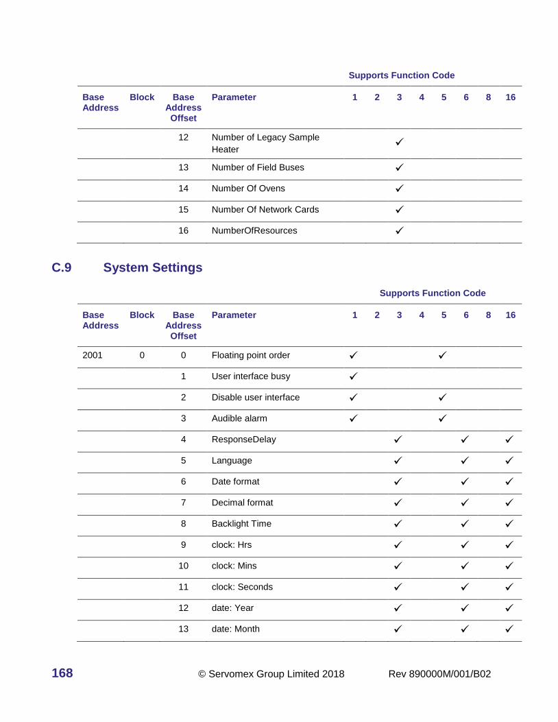
168 © Servomex Group Limited 2018 Rev 890000M/001/B02
Supports Function Code
Base Address
Block Base Address Offset
Parameter 1 2 3 4 5 6 8 16
12 Number of Legacy Sample
Heater ✓
13 Number of Field Buses ✓
14 Number Of Ovens ✓
15 Number Of Network Cards ✓
16 NumberOfResources ✓
C.9 System Settings
Supports Function Code
Base Address
Block Base Address Offset
Parameter 1 2 3 4 5 6 8 16
2001 0 0 Floating point order ✓
✓
1 User interface busy ✓
2 Disable user interface ✓ ✓
3 Audible alarm ✓ ✓
4 ResponseDelay ✓ ✓ ✓
5 Language ✓ ✓ ✓
6 Date format ✓ ✓ ✓
7 Decimal format ✓ ✓ ✓
8 Backlight Time ✓ ✓ ✓
9 clock: Hrs ✓ ✓ ✓
10 clock: Mins ✓ ✓ ✓
11 clock: Seconds ✓ ✓ ✓
12 date: Year ✓ ✓ ✓
13 date: Month ✓ ✓ ✓

Rev 890000M/001/B02 © Servomex Group Limited 2018 169
Supports Function Code
Base Address
Block Base Address Offset
Parameter 1 2 3 4 5 6 8 16
14 date: Day ✓ ✓ ✓
C.10 System Control
Supports Function Code
Base Address
Block Base Address Offset
Parameter 1 2 3 4 5 6 8 16
1 0 0 Service in Progress
✓
✓
0=Not In Service Mode, 1=Service Mode.
Instrument MUST be set to Service in Progress before any calibration or override actions are performed.
C.11 Measurements
Supports Function Code
Base Address
Block Base Address Offset
Parameter 1 2 3 4
1001 0 0 Number Of Measurements ✓
0 1 Repeat (safeguard) ✓
0-49 2(n-1) + 2 Measurement n ✓
C.12 Transducer calibration data
Data for transducer n are found at below address + 20 (n-1) for n=1 to n=4.
Supports Function Code
Base Address
First Block
Number
Block Base Address Offset
Parameter 1 2 3 4 5 6 8 16
4721 0 Tx (n) 0 AutovalState ✓
1 AutovalGas ✓

170 © Servomex Group Limited 2018 Rev 890000M/001/B02
Supports Function Code
Base Address
First Block
Number
Block Base Address Offset
Parameter 1 2 3 4 5 6 8 16
2 AVFinishing ✓
3 AVFailState ✓
4 Number of Cal / Val
Points
✓
5 Select Cal/val point ✓ ✓ ✓
6 LastCal/val Point n
Reading
✓
8 LastCalPoint n Target ✓
10 LastCalPoint n Delta ✓
12 Last Cal point n Time ✓
13 Last Cal point n Date ✓
15 Cal point passed/failed ✓
AVFinishing 0=Not Finishing, 1=Finishing
AVFailState 0=Not in Fail State, 1=In Fail State
Select Cal/val point 0=zero 1=span; This must be written to read corresponding values for last reading,
target, delta. Delta is expressed as floating-point proportion ((target-last reading)/target).
C.13 Transducer live info
Data for transducer n are located at ((below address) + 80(n-1)).
Supports Function Code
Base Address
First Block
Number
Block Base Address Offset
Parameter 1 2 3 4 5 6 8 16
4161 0 Tx
(4n-1)
0 Transducer Type ✓
1 Tag Number ✓
2 Name ✓
11 Measurement ✓

Rev 890000M/001/B02 © Servomex Group Limited 2018 171
Supports Function Code
Base Address
First Block
Number
Block Base Address Offset
Parameter 1 2 3 4 5 6 8 16
13 Pressure
Compensated
Measurement
✓
15 Filtered Measurement ✓
17 Transducer
temperature
✓
4181 1 Tx
(4n)
0 Alarm Active ✓
1 Fault ✓
2 Service in progress ✓
3 Out of Specification ✓
4 Maintenance required ✓
5 Transducer
maintenance fault ✓
6 Transducer error ✓
7 Transducer fatal fault ✓
8 WarmingOn ✓
9 Reserved ✓
10 Reserved ✓
11 Calibration fault ✓
12 Communication fail ✓
13 Transducer not
detected ✓
14 Autoval / cal failed ✓
15 Remote calibration/val
denied ✓
4201 2 Tx
(4n+1)
0 Heartbeat toggling at 1
Hz ✓
1 Remote service in
progress ✓

172 © Servomex Group Limited 2018 Rev 890000M/001/B02
Supports Function Code
Base Address
First Block
Number
Block Base Address Offset
Parameter 1 2 3 4 5 6 8 16
2 Transducer calibration
mode ✓
3 Auto validation/
calibration ✓
4 Incorrect transducer
type ✓
C.14 Transducer settings
Data for transducer n are located at ((address below) + 20(n-1)).
Supports Function Code
Base Address
First Block
Number
Block Base Address Offset
Parameter 1 2 3 4 5 6 8 16
4481 0 Tx (n) 0 Name ✓
9 Units ✓
4561 4 0 Reserved ✓ ✓ ✓
2 Reserved ✓ ✓ ✓
4 Unit selection (scaling
Factor)
✓
✓
✓
6 PMR ✓
8 Cross Interference
correction/
✓
✓
✓
10 Reserved

Rev 890000M/001/B02 © Servomex Group Limited 2018 173
C.15 Relay control
Relay n data is found at ((address below + 20(n-1)) for n=1 to n=32
Supports Function Code
Base Address
First Block
Number
Block Base Address Offset
Parameter 1 2 3 4 5 6 8 16
9081 0 Relay
(n)
0 Active State ✓
✓
✓
1 Override State ✓ ✓ ✓
2 Override ✓ ✓ ✓
3-19 Reserved
9721 32 Relay
(n)
0-19 Reserved
C.16 Resource live info
Supports Function Code
Base Address
First Block
Number
Block Base Address Offset
Parameter 1 2 3 4 5 6 8 16
8741 0 0 0 Chassis temperature ✓ ✓
C.17 Resource settings
Data for transducer n are located at below address + 18(n-1).
Supports Function Code
Base Address
First Block
Number
Block Base Address Offset
Parameter 1 2 3 4 5 6 8 16
8765 Minimum
measurement ✓
✓
8773 Range change point ✓ ✓

174 © Servomex Group Limited 2018 Rev 890000M/001/B02
C.18 Transducer control
Data for transducer n are found at the below addresses + 40(n-1).
Supports Function Code
Base Address
Block Base Address Offset
Parameter 1 2 3 4 5 6 8 16
4001 0 0 Calibration mode on/off ✓ ✓
1 Start auto val ✓
2 Stop auto val ✓
3 Capture and enable baseline
subtraction ✓
✓
4021 1 0 reserved
1 Summary of alarm and relay
states: Reports a bit field of
the alarm states in low byte
and the relay states in high
byte for the designated Tx
✓
2 Calibration gas in use:
0=Sample Gas 1, 1=Sample
Gas 2, …
✓
✓
✓

Rev 890000M/001/B02 © Servomex Group Limited 2018 175
Appendix D PROFIBUS
This appendix contains installation and operation instructions and data tables available
with the PROFIBUS option.
D.1 Safety
Read the rest of this manual carefully before you use this appendix.
D.2 Description
The PROFIBUS option adds DPv0 synchronous and DPv1 asynchronous communication
capabilities to the 4900 Multigas Analyzer. The PROFIBUS option board provides the
following features:
• Supports DPv0/DPv1 PROFIBUS communication with RS485 transmission
• DPv1 communications with class I and class II Master devices
• Separate DPv0 modules to optimize bus load
• Profibus Address can be set from the User Interface
D.3 Electrical installation
Follow the PROFIBUS Installation Guidelines when connecting the
PROFIBUS.
Figure 17-1: PROFIBUS connection on rear of the analyzer
There are no internal termination resistors; if the device is at the end of
the segment, termination resistors should be on the connector or the
segment should have an active termination unit.

176 © Servomex Group Limited 2018 Rev 890000M/001/B02
1. Use recommended PROFIBUS cable, optimized for RS485 transmission.
2. Standard PROFIBUS 9-pin sub-D connector is used for PROFIBUS, the connector is
labelled as “PROFIBUS” on the back of the analyzer.
PROFIBUS connector (Comms 1)
Pin No Signal Definition
3 TxD-P Data line plus (B-Line)
4 RTS PROFIBUS Ready To Send signal
5 DGND Data Ground
6 VP +5V supply for terminating resistors
8 TxD-N Data line minus (A-Line)
Case Shield Ground Connection
3. To ensure correct operation follow the PROFIBUS Installation Guidelines. For
information on the PROFIBUS installation guidelines, refer to www.profibus.com.
D.4 PROFIBUS settings
D.4.1 Confirming PROFIBUS availability
If the analyzer was ordered with the PROFIBUS option, the PROFIBUS connector will be
populated and its presence confirms the unit is configured for serial comms via
PROFIBUS.
D.4.2 Setting the PROFIBUS address
The default PROFIBUS address for the analyser is set to 126.
Press the following icon sequence to change the PROFIBUS address of the analyser.
> > >
After changing the address, turn the unit off and on again for it to respond to the new
address.

Rev 890000M/001/B02 © Servomex Group Limited 2018 177
D.4.3 Monitoring Profibus line Status
The user interface provides information on the PROFIBUS line status. There are three
reports available:
Wait for parameterization: There are no communications between the analyser and the
PROFIBUS master device.
Wait for configuration: Initial parameterization message received, waiting for
configuration data from the PROFIBUS master.
Data exchange: The analyser and the PROFIBUS master device are
communicating, using DPv0 cyclic messages.
D.5 PROFIBUS DPV0 features
D.5.1 DPv0 modules
The synchronous messaging structure of the DPv0 network requires all variables to be
repeated in every message. This means the PLC has to be programmed to parse
incoming and outgoing messages to extract required data. These protocol limitations mean
that only frequently required parameters, which are important to be remotely accessible,
are made available for DPv0 access.
The 4900 Multigas is capable to operate with different module configurations enabling the
user to optimize network traffic. For example, if detailed status information is not required,
the user can choose to omit the Measurement Status modules in the configuration.
The analyzer can support up to 8 modules, and the user can choose to include these
modules in any order. The PROFIBUS master can configure the 4900 Multigas to include
the following modules:
Module name Type Size
Measurement 1 Input and Output 6 Input, 6 Output Bytes
Measurement 2 Input and Output 6 Input, 6 Output Bytes
Measurement 3 Input and Output 6 Input, 6 Output Bytes
Measurement 4 Input and Output 6 Input, 6 Output Bytes
Measurement 1 Status Input 6 Input Bytes
Measurement 2 Status Input 6 Input Bytes
Measurement 3 Status Input 6 Input Bytes
Measurement 4 Status Input 6 Input Bytes
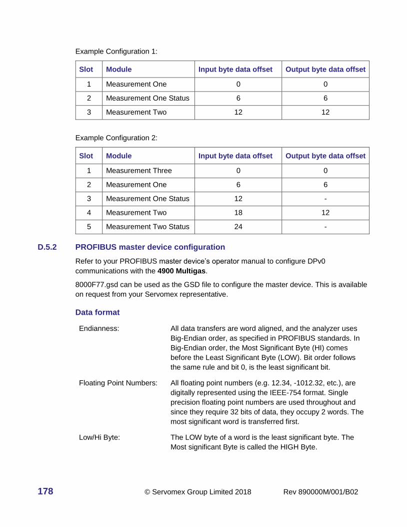
178 © Servomex Group Limited 2018 Rev 890000M/001/B02
Example Configuration 1:
Slot Module Input byte data offset Output byte data offset
1 Measurement One 0 0
2 Measurement One Status 6 6
3 Measurement Two 12 12
Example Configuration 2:
Slot Module Input byte data offset Output byte data offset
1 Measurement Three 0 0
2 Measurement One 6 6
3 Measurement One Status 12 -
4 Measurement Two 18 12
5 Measurement Two Status 24 -
D.5.2 PROFIBUS master device configuration
Refer to your PROFIBUS master device’s operator manual to configure DPv0
communications with the 4900 Multigas.
8000F77.gsd can be used as the GSD file to configure the master device. This is available
on request from your Servomex representative.
Data format
Endianness: All data transfers are word aligned, and the analyzer uses
Big-Endian order, as specified in PROFIBUS standards. In
Big-Endian order, the Most Significant Byte (HI) comes
before the Least Significant Byte (LOW). Bit order follows
the same rule and bit 0, is the least significant bit.
Floating Point Numbers: All floating point numbers (e.g. 12.34, -1012.32, etc.), are
digitally represented using the IEEE-754 format. Single
precision floating point numbers are used throughout and
since they require 32 bits of data, they occupy 2 words. The
most significant word is transferred first.
Low/Hi Byte: The LOW byte of a word is the least significant byte. The
Most significant Byte is called the HIGH Byte.

Rev 890000M/001/B02 © Servomex Group Limited 2018 179
Measurement module data map
Measurement modules contain measurement data related to the measurement modules.
All four module mappings are the same.
PROFIBUS DPv0 inputs
Word # Word R/W Name
0 2 R Measurement as seen on the measurement
display. 32 -bit Floating point data in IEEE-
754 format.
2 1 R Status Word (See Below)
Measurement status word
Byte Bit Name Definition
LO
0 Warming State 0= Not warming, 1= Warming.
1 Heater Fault 0=normal, 1=fault
2 Sample Heater Fault 0=normal, 1=fault
3 Calibration Fault 0=normal, 1=fault
4 Communication alarm 0=normal, 1=fault
5 Transducer not detected 0=transducer detected, 1=transducer
not detected
6 Autoval/cal failed An autocal or autoval operation has
failed to complete
7 Remote calibration/val denied
0=normal, 1=A remote request for
calibration or validation has been
denied
HI
0 Alarm 0=normal, 1=alarm active
1 Fault 0=normal, 1=fault
2 Service in Progress 0=normal, 1=service in progress
3 Out of Specification 0=normal, 1=out of specification
4 Maintenance Required 0=normal, 1=maintenance required
5 Transducer maintenance fault 0=normal, 1=transducer maintenance
fault

180 © Servomex Group Limited 2018 Rev 890000M/001/B02
Measurement status word
Byte Bit Name Definition
6 Transducer error 0=normal, 1=Transducer is indicating
an error code
7 Transducer fatal fault 0=normal, 1=Transducer has identified
a condition requiring return for service
PROFIBUS DPv0 outputs
Word Byte Bit Read/Write Name
0
LOW 0-7 Write Reserved
HI
0 Write Calibration mode on/off (Tx control)
1 Write Start auto validation (Tx control)
2 Write Stop auto validation
3 Write Enable baseline subtraction
1 Write Invoke calibration n
2 Write Sample Gas Selection n
Measurement status data map
Measurement Status modules, contains status related to measurements. All four module
mappings are the same.
PROFIBUS DPv0 inputs
Word offset
# Words Read/Write Name
0 1 Read Calibration and Validation Word
(see below)
1 1 Read Bitfield of alarm states in low byte, relay states in
high byte. Bit 0 - alarm or relay 1, bit 1 – alarm
or relay 2, etc.)
2 1 Read System heartbeat in bit 0, toggles at 1Hz

Rev 890000M/001/B02 © Servomex Group Limited 2018 181
Calibration and validation status word
Byte Bit Name Definition
LOW
0-2 Auto Validation State
000=Idle
001=Pre-warning
010=Inerting
011=Flushing
100=Validating
3-5 Auto Validation Gas
000=zero gas
001=span gas
011=sample gas
6 Auto Validation finishing 0=not finishing
1=finishing
7 Auto Validation fail state 0=normal
1=failed
HI
0
Calibration mode on/off
0= off (normal);
1= on (alarms masked, jamming etc).
Write 1 to turn calibration mode on.
1 Cal point passed/failed
0= failed
1= passed
2 Reserved Reserved
3 Enable Baseline Subtraction
0=disabled
1=enabled
4-7 Reserved Reserved

182 © Servomex Group Limited 2018 Rev 890000M/001/B02
D.5.3 DPv1 communications
The analyser is able to communicate using DPv1 asynchronous PROFIBUS
communications with Class I and Class II masters. The following table shows the
available data for DPv1 communication with Index and Slot numbers.
The user module/slot configuration on the PROFIBUS master device will not affect the
DPv1 slot numbers, only Slot 1 is used.
Write requests are only accepted if the specified data lengths in the requests are same as
the data lengths defined in slot/index table.
Slot Index Read / Write
# Words Data
1 1 Read 72 Measurement 1 Data
1 2 Read/Write 34 Measurement 1 Control
1 11 Read 72 Measurement 2 Data
1 12 Read/Write 34 Measurement 2 Control
1 21 Read 72 Measurement 3 Data
1 22 Read/Write 34 Measurement 3 Control
1 31 Read 72 Measurement 4 Data
1 32 Read/Write 34 Measurement 4 Control
1 240 Read/Write 8 Resource Control
1 241 Read 32 Relay Data
1 242 Read 21 Resource Data
1 243 Read/Write 96 Relay Settings
1 250 Read 20 System Data
1 251 Read 18 System Settings
The field definitions for these indexed data spaces follow sequentially (definitions within a
table also follow as commented).

Rev 890000M/001/B02 © Servomex Group Limited 2018 183
Measurement Data 1 - 4
Word Name Comments
0 Tag Number 16-bit user tag for this measurement
1-9 Name Text Name for measurement 18 bytes
10-11 Measurement 32-bit IEEE float of displayed measurement
12-13 Pressure compensated Pressure compensated measurement
14-15 Filtered measurement Filtered measurement
16-17 Temperature Chassis temperature
18-19 Faults and Alarms Defined in Faults & Alarms table
immediately below
20 Auto Validation State Defined in Calibration 1-4 table below
21 Auto Validation Gas Defined in Calibration 1-4 table below
22 Auto Validation Finishing Defined in Calibration 1-4 table below
23 Auto Validation Fail State Defined in Calibration 1-4 table below
24 Number of Cal / Val Points Defined in Calibration 1-4 table below
25 Select Cal/Val Point* Defined in Calibration 1-4 table below
26-27 Last Cal/Val Point n reading
28-29 Last Cal Point n Target 32-bit float
30-31 Last Cal Point n Delta 32-bit float
32 Last Cal Point n Time 16-bit integer (hhmm)
33-34 Last Cal Point n Date[2] 32-bit integer (yymmdd)
35 Cal point passed/failed

184 © Servomex Group Limited 2018 Rev 890000M/001/B02
Measurement faults and alarms
Word Byte Bit Name Comments
0
LOW
0 Warming On
1 Heater fault
2 Sample heater fault
3 Calibration fault
4 Communication fail
5 Transducer not detected
6 Auto-Cal validation / calibration
failed
7 Remote validation / calibration
failed denied
HI
0 Alarm Active
1 Fault
2 Service in progress
3 Out of specification
4 Maintenance required
5 Transducer maintenance fault
6 Transducer error
7 Transducer fatal fault
1
LOW 0-7 Reserved
HI
0 Clipping Active
1 Remote service in progress
2 Transducer calibration mode
3 Auto-Cal validation/calibration
4 Incorrect transducer type
5-7 Reserved

Rev 890000M/001/B02 © Servomex Group Limited 2018 185
Measurement 1-4 control
Word Byte Bit Name Comments
0
LOW 0-7 Reserved
HI
0 Calibration mode on/off
1 Start Auto-Cal validation
2 Stop Auto-Cal validation
3 Enable baseline subtraction
4-7 Reserved
1 Invoke calibration n
2 Calibration point n gas
3 Sample Gas Selection
4 Select Cal/Val point
5-6 Cross Interference correction/
GSF
7-16 Reserved
Resource Control 1-4 slot 1 index 240
Byte Name Comments
0 cLegacy Pressure 1[8] Defined in Legacy Pressure n table below
1 cLegacy Pressure 2[8]
2 cLegacy Pressure 3[8]
3 cLegacy Pressure 4[8]
4 cLegacy Flow 1[8] Defined in Legacy Flow n table below
5 cLegacy Flow 2[8]
6 cLegacy Flow 3[8]
7 cLegacy Flow 4[8]

186 © Servomex Group Limited 2018 Rev 890000M/001/B02
Legacy pressure n
Bit Name Comments
0 Calibrate pressure mode
1 Calibrate pressure low
2 Calibrate pressure high
Legacy flow n
Bit Name Comments
0 Calibrate flow mode
1 Calibrate zero flow
2 Calibrate normal flow
Relay Data slot 1 index 241
Bit Name Comments
0 iRelay 01 status[8] State, CardNotDetected or
ServiceInProgress
: iRelay n status[8] State, CardNotDetected or
ServiceInProgress
31 iRelay 32 status[8] State, CardNotDetected or
ServiceInProgress
Relay info n
Bit Name Comments
0 State
1 Card not detected
2 Service in progress

Rev 890000M/001/B02 © Servomex Group Limited 2018 187
Resource data (Slot 1 Index 242)
Byte Name Comments
0 iAOUT 1 status[8]
1 iAOUT 2 status[8]
2 iAOUT 3 status[8]
3 iAOUT 4 status[8]
4 iAIN 1 status[8]
5 iAIN 2 status[8]
6 iAIN 3 status[8]
7 iAIN 4 status[8]
8 iDin Card Not Detected[8]
9 iLegacy Pressure 1 status [8]
10 iLegacy Pressure 2 status [8]
11 iLegacy Pressure 3 status [8]
12 iLegacy Pressure 4 status [8]
13 iLegacy Flow Alarm 1 status[16]
14 iLegacy Flow Alarm 2 status[16]
15 iLegacy Flow Alarm 3 status[16]
16 iLegacy Flow Alarm 4 status[16]
17-20 Chassis Temperature

188 © Servomex Group Limited 2018 Rev 890000M/001/B02
Relay Settings (Slot 1 Index 243)
Byte Name Comments
0 iRelay 01 Active State Rsc settings
1 iRelay 01 Override State
2 iRelay 01 Override
3 iRelay 02 Active State
4 iRelay 02 Override State
5 iRelay 02 Override
: iRelay n Active State
: iRelay n Override State
: iRelay n Override
93 iRelay 32 Active State
94 iRelay 32 Override State
95 iRelay 32 Override
System data (Slot 1, Index 250)
Word Name Comments
0-9 hInstrument Serial Number [10] System Data

Rev 890000M/001/B02 © Servomex Group Limited 2018 189
System settings (Slot 1, Index 251)
Word Name Comments
0 hService in Progress System Control
1 System Controls System Settings
2 hResponse Delay
3 hClock: Hrs
4 hClock: Mins
5 hClock: Seconds
6 hDate: Year
7 hDate: Month
8 hDate: Day
System controls word
Byte Bit Name Definition
LOW 0-7 Reserved
HI
0 Floating point order
1 User Interface busy
2 Disable user interface
3-7 Reserved

190 © Servomex Group Limited 2018 Rev 890000M/001/B02
D.6 PROFIBUS Troubleshooting
D.6.1 The analyzer is not detected by the PROFIBUS master device
• Check that the PROFIBUS cable is connected to the analyser, and the master device.
• Check that the termination resistors on the end points of the network are active.
• Check that the analyser node address is set up correctly on the master device.
• Check that there are no other devices configured to use the same address as the
analyser.
Make sure that if there is more than one master device on the system, the correct master
device is configured and connected to the analyser.
On the PROFIBUS master device, make sure that the correct “gsd” file has been used to
configure the analyser, and at least one module is included in the configuration. Refer to
your master device's manual to make sure all steps for the configuration have been
followed.
Some PROFIBUS master devices are configured to stop reporting cyclic data as soon as
an extended diagnostic error message is received. In this case either these faults have to
be cleared on the analyser, or the master device has to be configured to continue normal
operation when diagnostic bits are reported.
Make sure that the PROFIBUS baud rate selected at the Profibus master device, is
suitable for the cabling setup.
Make sure that the PROFIBUS master is running.
Using the Status menu on the analyser, make sure that there is no "PROFIBUS card not
detected" fault. This fault will require servicing of the analyser - Contact Servomex or your
local Servomex representative.
D.6.2 The communication starts, but there are frequent line drops
Make sure that the ‘PROFIBUS Cabling Guidelines’ have been followed. Refer to
www.profibus.com for the latest guidelines.
If possible decrease the network baud rate.

Rev 890000M/001/B02 © Servomex Group Limited 2018 191
Appendix E Return Authorization Request
E.1 Return Authorization Product Number Request
Servomex must approve and then assign a Return Product Authorization (RPA) Number to
any instrument prior to being returned to the factory for repair. The RPA must appear on all
paperwork and packaging. The issuance of an RPA does not automatically imply that the
instrument is covered by our warranty.
In order to serve you better and to protect our employees from any potentially hazardous
contaminants, Servomex must return, unopened and at the sender’s expense, all items
that do not have an RPA and a signed and filled out Decontamination Form.
OSHA Hazard Communication Standard 29CFR 1920.1200 mandated that we take
specific steps to protect our employees from exposure to potential hazards. Therefore, a
letter certifying that the equipment has been decontaminated must accompany all
equipment exposed to hazardous contamination.
To obtain an RPA, fill out the form in section E.2 and email it to one of the following
addresses:
North and South America: [email protected]
Asia, Australia, New Zealand: [email protected]
Europe, Middle East, Africa, India: [email protected]

192 © Servomex Group Limited 2018 Rev 890000M/001/B02
E.2 Return Product Authorization Number (RAN) Request Form
Thank you for requesting a Return Product Authorization (RAN) Number. We will
acknowledge receipt of this form and will forward the RAN number to you.
Date:
Customer information: End-user information: (if different)
Company name: Company name:
Address:
Address:
Contact name: Contact name:
Phone: Phone:
Email: Email:
Billing information: Shipping information:
Name: Name:
Address:
Address:
Contact name: Contact name:
Phone: Phone:
Email: Email:
Shipping Instructions:
(UPS/FedEx Acct, P&A)

Rev 890000M/001/B02 © Servomex Group Limited 2018 193
Analyzer information:
Part or model number: 4900 Multigas Serial number:
Original purchase date: PO number:
Service requested:
(check relevant option)
Repair Required return
Calibration Warranty / failure analysis
Details of problem or failure:
Do you require a rental unit?
No Yes
Do you require specific test documentation to be returned?
No Yes
Servomex provides a Certificate of Calibration with each tested analyser. Any additional test documentation requested is subject to a test report fee.
Have you attached a decontamination certificate?
No Yes
Shipping information:
Please contact the relevant Servomex Support Office (below) for your location to obtain the shipping
address.
Servomex Support contact information:
North and South America: [email protected]
Asia, Australia, New Zealand: [email protected]
Europe, Middle East, Africa, India: [email protected]
We look forward to receiving your request. If you have any questions regarding this form, please
contact your local Servomex Support office.
Thank you for choosing Servomex.
194 © Servomex Group Limited 2018 Rev 890000M/001/B02
E.2 Decontamination Certificate
It is hereby certified that the equipment being returned, as described below, has been
completely decontaminated and poses no possible toxic, corrosive, irritant, flammable,
radioactive or biological hazard to any personnel required to unpack, handle, examine,
maintain or repair it.
Equipment / model: 4900 Multigas Serial number:
Application / process:
Substance(s) exposed to:
Authorized customer contact information:
Company name:
Name: Title:
Phone: Email:
Signature:
Date:
IMPORTANT NOTICE:
Servomex ensures that all products dispatched to customers have been suitably purged and cleaned
prior to packaging so that no hazards from the use of factory calibration gases or liquids are present.

Rev 890000M/001/B02 © Servomex Group Limited 2018 195
Appendix F Transducer FSD values
Table F-1: Transducer FSD values
Transducer FSD (Full Scale)
GFX1210 CO High sensitivity (D1210701) 500ppm CO
GFX1210 CO Mid sensitivity (D1210701A) 1000ppm CO
GFX1210 CO Standard sensitivity (D1210702) 3000ppm CO
GFX1210 CO High range (D1210702A) 5000ppm CO
GFX 1210 CH4 (D1210751) 500ppm CH4
GFX 1210 CH4 High range (D1210751A) 1000ppm CH4
GFX 1210 N2O (D1210741) 500ppm N2O
GFX1210 SO2 High sensitivity (D1210711A) 1000ppm SO2
GFX1210 SO2 Standard sensitivity (D1210712) 2500ppm SO2
GFX1210 SO2 High range (D1210712A) 10000ppm SO2
GFX1210 NO (D1210721) 1000ppm NO
GFX1210 NO High range (D1210721A) 2000ppm NO
IR 1520 100% CO2 100% CO2
IR 1520 50% CO2 50% CO2
IR 1520 25% CO2 25% CO2
IR 1520 10% CO2 10% CO2
IR 1520 5% CO2 5% CO2
IR 1520 2.5% CO2 2.5% CO2
IR 1520 1% CO2 1% CO
IR 1520 0.5% CO2 0.5% CO
IR 1520 0.25% CO2 0.25% CO2
IR 1522 10% CO 10% CO
IR 1522 2.5% CO 2.5% CO
IR 1522 1% CO 1% CO
Pm 3601 0-25% O2 100% O2

196 © Servomex Group Limited 2018 Rev 890000M/001/B02
Appendix G Single Beam Single Wavelength (SBSW)
transducer information
G.1 Transducer low and high calibration
Zero grade nitrogen is recommended for low calibration.
It is recommended that the high calibration gas is in the range 80 to 110% of the
transducer's FSD.
Table G-1: Recommended calibration periods for SBSW NDIR transducers
Gas transducer module Low calibration High calibration
SBSW NDIR transducer Weekly Daily
Table G-2: SBSW NDIR transducer performance specification
Gases measured 1521 CO2 / 1522 CO
Range See Table F-1
Minimum recommended output range 80% of selected range
Intrinsic error
Linearity error
Repeatability
1% of selected range
Lower Detection Limit (LDL)
(95% confidence interval)
0.21% of selected range or 0.41% of
reading, whichever is the larger
Response (T90) <30 seconds at 1.5 l/min
Zero drift / week 2% of selected range
Span drift / day 1% of selected range
Output fluctuation (peak to peak) 0.5% of selected range or 1% of reading,
whichever is the larger.
Ambient pressure coefficient 0.2% of reading per mbar
Ambient temperature coefficient / 10 °C
change
1% of selected range ± <2.0% of reading
Sample flow effect range over full flow range 1.5% of selected range or <3% of
reading, whichever is the larger.

Rev 890000M/001/B02 © Servomex Group Limited 2018 197
Table G-3: SBSW NDIR measurement ranges
Gases measured Full scale measurement range (%)
0.25 0.5 1.0 2.5 5 10 25 50 100
1520 CO2 ✓ ✓ ✓ ✓ ✓ ✓ ✓ ✓ ✓
1522 CO ✓ ✓ ✓

198 © Servomex Group Limited 2018 Rev 890000M/001/B02
Appendix H Paramagnetic transducer information
Table H-1: Recommended calibration periods for paramagnetic transducers
Gas transducer module Low calibration High calibration
Paramagnetic transducer Weekly Weekly
Table H-2: Paramagnetic transducer FSD values
Transducer FSD
% O2 (User set to 0-25%) 100% O2
Table H-3: Paramagnetic transducer performance specification
Gases measured % O2
Range 0 – 100%
Minimum recommended output range 0 – 5%
Intrinsic error ± 0.1% O2
Linearity error
Inherently linear, dependent on calibration gases
< 0.05% O2
Repeatability < 0.1% O2
Lower Detection Limit (LDL)
(95% confidence interval)
0.02% O2
Response (T90) at 1500ml/min < 15 s
Zero drift / week < 0.05% O2
Span drift / week < 0.1% O2
Output fluctuation (peak to peak) ± 0.05% O2
Ambient pressure coefficient Directly proportional to analyzer
vent pressure
Zero temperature coefficient / 10 °C change ± 0.1% O2
Span temperature coefficient / 10 °C change 1% of reading or ± 0.1% O2,
whichever is the larger.

Rev 890000M/001/B02 © Servomex Group Limited 2018 199
Gases measured % O2
Sample flow effect range over full flow range < 2% of reading or 0.1% O2,
whichever is the larger.
H.1 Overview of measurement errors for paramagnetic O2 transducer
For an O2 transducer, the composition of any typical background gas in the gas sample will
have an impact on the analyzer measurement accuracy.
Table H-4 below gives 4 examples of cross-interference errors (O2 measurement errors) in
gases which contain 100% of a specific background gas, for an analyzer which has been
'Lo' calibrated with N2 (nitrogen) and 'Hi' calibrated with O2.
Table H-4: Example cross-interference measurement errors
Background gas Error
Argon -0.22%
Carbon dioxide -0.26%
Halothane -1.93%
Helium -0.29%
Note that the error is directly proportional to the concentration of the background gas in the
sample being measured and, in most cases, can be ignored. A detailed listing of these
measurement errors for a wide variety of background gases are listed in Section 17.1H.2
below.
XINT is a reported concentration adjustment that can be set in the Paramagnetic
Measurement menus. It is a scaling factor that is used to correct the current transducer
reading. The default value is 1.0. If required the operator can change this value to
compensate for the background gas. For example: If you are measuring oxygen in a
background of carbon dioxide -0.26 should be entered as the XINT value.
Figure H-1: XINT icon
If XINIT compensation is to be used, care must be taken to insure that the value used for
the background gases is correct. During a calibration, no XINT compensation is applied
and it is assumed that the calibration gas sample has negligible cross-interference.

200 © Servomex Group Limited 2018 Rev 890000M/001/B02
H.2 Cross interference offsets (for paramagnetic transducer)
Pure gas Formula Molar mag. susc
x 10-6
Cross interference
offsets
20 °C 50 °C
Acetaldehyde CH2CHO –22.70 –0.31 –0.34
Acetic acid CH3CO2H –31.50 –0.56 –0.62
Acetone CH3COCH3 –33.70 –0.63 –0.69
Acetylene HCCH –20.80 –0.25 –0.28
Acrylonitrile CH2=CHCN –24.10 –0.35 –0.39
Allyl alcohol CH2CHCH2OH –36.70 –0.71 –0.79
Ammonia NH3 –18.00 –0.17 –0.19
Argon Ar –19.60 –0.22 –0.24
Benzene C6H6 –54.84 –1.24 –1.36
Boron chloride BCl3 –59.90 –1.38 –1.53
Boron trifluoride BF3 –19.00 –0.20 –0.22
Bromine Br2 –73.50 –1.78 –1.96
1,2 Butadiene C4H6 –35.60 –0.68 –0.75
1,3 Butadiene C4H6 –30.60 –0.54 –0.59
N-Butane C4H10 –50.30 –1.11 –1.22
iso-Butane (CH3)2CHCH2 –51.70 –1.15 –1.26
1 Butene CH3CH2CH=CH2 –41.10 –0.84 –0.93
N–Butyl acetate CH3COOC4H9 –77.50 –1.89 –2.09
iso–Butylene (CH3)2CH=CH2 –44.40 –0.94 –1.03
1 Butyne (Ethylacetylene) CH3C3H2 –43.50 –0.91 –1.00
Carbon dioxide CO2 –21.00 –0.26 –0.29
Carbon disulphide CS2 –42.20 –0.87 –0.96
Carbon monoxide CO –9.80 0.06 0.07
Carbon tetrachloride CCl4 –66.60 –1.58 –1.74
Carbon tetrafluoride CF4 –31.20 –0.55 –0.61

Rev 890000M/001/B02 © Servomex Group Limited 2018 201
Pure gas Formula Molar mag. susc
x 10-6
Cross interference
offsets
20 °C 50 °C
Chlorine Cl2 –40.50 –0.82 –0.91
Chloroethanol ClCH2CH2OH –51.40 –1.14 –1.25
Chloroform CHCl3 –59.30 –1.37 –1.51
Cumene (CH3)2CHC6H5 –89.53 –2.24 –2.47
Cyclohexane C6H12 –68.13 –1.62 –1.79
Cyclopentane C5H10 –59.18 –1.36 –1.50
Cyclopropane C3H6 –39.90 –0.81 –0.89
Diacetylene C4H2 –37.50 –0.74 –0.81
Dichloroethylene (CHCl)2 –49.20 –1.07 –1.18
Diethyl ether (C2H5)2O –55.10 –1.25 –1.37
2,2 Difluoro 1 chloroethane CClH2CHF2 –52.40 –1.17 –1.29
1,2 Difluoro 1,2
dichloroethylene
CFCl=CFCl –60.00 –1.39 –1.53
Difluoro dichloro methane
(Freon 12)
CCl2F2 –52.20 –1.16 –1.28
Dimethoxy methane CH2(OCH3)2 –47.30 –1.02 –1.12
Dimethylamine (CH3)2NH –39.90 –0.81 –0.89
Dimethylether CH3OCH3 –26.30 –0.41 –0.46
Dimethylethylamine (CH3)2NC2H5 –63.60 –1.49 –1.64
Enflurane (Ethrane) C3H2F5ClO –80.10 –1.97 –2.17
Ethane C2H6 –26.80 –0.43 –0.47
Ethanol C2H5OH –33.60 –0.62 –0.69
Ethyl acetate CH3COOC2H5 –54.20 –1.22 –1.34
Ethyl amine C2H5NH2 –39.90 –0.81 –0.89
Ethyl benzene C6H5C2H5 –77.20 –1.88 –2.08
Ethyl bromide C2H5Br –54.70 –1.23 –1.36
Ethyl chloride C2H5Cl –46.00 –0.98 –1.08

202 © Servomex Group Limited 2018 Rev 890000M/001/B02
Pure gas Formula Molar mag. susc
x 10-6
Cross interference
effects
20 °C 50 °C
Ethylene C2H4 –18.80 –0.20 –0.22
Ethylene glycol (CH2OH)2 –38.80 –0.77 –0.85
Ethylene oxide (CH2)2O –30.70 –0.54 –0.60
Ethyl mercaptan C2H5OSO3H –47.00 –1.01 –1.11
Fluorochlorobromomethane CFClBr –58.00 –1.33 –1.46
Fluorodichloromethane
(Freon 21)
CHCl2F –48.80 –1.06 –1.17
Fluroxene CF3CH2OCHCH2 –56.70 –1.29 –1.42
Freon 114 C2Cl2F4 –77.40 –1.89 –2.08
Furan C4H4O –43.09 –0.90 –0.99
Germanium tetrachloride GeCl4 –72.00 –1.73 –1.91
Halothane C2HBrClF3 –78.80 –1.93 –2.13
Helium He –1.88 0.29 0.32
N–Heptane C7H16 –85.24 –2.12 –2.33
N–Hexane C6H14 –73.60 –1.78 –1.96
Hydrogen H2 –3.98 0.23 0.26
Hydrogen bromide Br –35.30 –0.67 –0.74
Hydrogen chloride HCl –22.60 –0.31 –0.34
Hydrogen cyanide HCN –14.50 –0.07 –0.08
Hydrogen iodide HI –48.20 –1.05 –1.15
Hydrogen selenide H2Se –39.20 –0.79 –0.87
Hydrogen sulphide H2S –25.50 –0.39 –0.43
Isoflurane (Forane) C3H2F5ClO –80.10 –1.97 –2.17
Isoprene C5H8 –44.80 –0.95 –1.04
Ketene CH2CO –15.70 –0.11 –0.12
Krypton Kr –28.80 –0.49 –0.54
Methane CH4 –17.40 –0.16 –0.17

Rev 890000M/001/B02 © Servomex Group Limited 2018 203
Pure gas Formula Molar mag. susc
x 10-6
Cross interference
effects
20 °C 50 °C
Methanol CH3OH –21.40 –0.27 –0.30
Methoxyfluorane CHCl2CF2OCH3 –87.10 –2.17 –2.39
Methyl acetate CH3COCH3 –42.60 –0.88 –0.97
Methyl cyclopentane C6H12 –70.20 –1.68 –1.85
Methylene chloride CH2Cl2 –46.60 –1.00 –1.10
Methylethlyketone CH3COCH2CH3 –45.50 –0.97 –1.07
Methyl fluoride CH3F –25.50 –0.39 –0.43
Methyl formate HCOOCH3 –32.00 –0.58 –0.64
Methyl iodide CH3I –57.20 –1.31 –1.44
Methyl iso–butyl ketone
(MIBK)
C4H9COCH3 –69.30 –1.66 –1.82
Methyl mercaptan CH3SH –35.30 –0.67 –0.74
Molybdenum hexafluoride MoF6 –26.00 –0.40 –0.45
Monochlorobenzene C6H5Cl –70.00 –1.68 –1.85
Neon Ne –6.70 0.15 0.17
Nitric oxide NO 1461.00 42.56 42.96
Nitrobenzene C6H5NO2 –61.80 –1.44 –1.59
Nitrogen N2 –12.00 0.00 0.00
Nitrogen dioxide NO2 150.00 5.00 16.00
Ortho–Nitrotoluene C6H4CH3NO2 –72.30 –1.74 –1.92
para–Nitrotoluene C6H4CH3NO2 –76.90 –1.88 –2.07
Nitrous oxide N2O –18.90 –0.20 –0.22
N–Nonane C9H20 –108.13 –2.78 –3.06
N–Octane C8H18 –96.63 –2.45 –2.70
Oxygen O2 3449.00 100.0 100.0
Ozone O3 6.70 0.54 0.60
iso–Pentane C5H12 –64.40 –1.51 –1.67

204 © Servomex Group Limited 2018 Rev 890000M/001/B02
Pure gas Formula Molar mag. susc
x 10-6
Cross interference
offsets
20 °C 50 °C
N–Pentane C5H12 –63.10 –1.48 –1.63
0.01%Phenol C6H5OH –60.21 –1.39 –1.54
Phosphine PH3 –26.00 –0.40 –0.45
Phosphorous oxychloride POCl3 –69.00 –1.65 –1.82
Propane C3H8 –38.60 –0.77 –0.85
iso–Propanol (CH3)2CHOH –47.60 –1.03 –1.13
Propene CH3CH=CH2 –31.50 –0.56 –0.62
N–Propyl acetate CH3COOC3H7 –65.90 –1.56 –1.72
Propyl amine C3H7NH2 –52.40 –1.17 –1.29
Propyl chloride C3H7Cl –56.10 –1.27 –1.40
Propylene C3H6 –31.50 –0.56 –0.62
Propylene oxide OCH2CHCH3 –42.50 –0.88 –0.97
iso–Propyl ether (CH3)4CHOCH –79.40 –1.95 –2.15
Propyl fluoride C3H7F –52.20 –1.16 –1.28
Pyridine N(CH)5 –49.21 –1.08 –1.19
Silane SiH4 –20.50 –0.25 –0.27
Silicon tetrachloride SiCl4 –88.30 –2.20 –2.43
Styrene C6H5CH=CH2 –68.20 –1.62 –1.79
Sulphur dioxide SO2 –18.20 –0.18 –0.20
Sulphur hexafluoride SF6 –44.00 –0.92 –1.02
Tetrachoroethylene Cl2C=CCl2 –81.60 –2.01 –2.22
Tetrahydrofuran C4H8O –52.00 –1.16 –1.27
Toluene C6H5CH3 –66.11 –1.56 –1.72
1,1,2 Trichloroethane
(Freon 113)
CHCl2CH2Cl –66.20 –1.57 –1.73
Trichloroethylene CHCl=CCl2 –65.80 –1.55 –1.71
Trifluorochloroethylene C2F3Cl –49.10 –1.07 –1.18
Rev 890000M/001/B02 © Servomex Group Limited 2018 205
Pure gas Formula Molar mag. susc
x 10-6
Cross interference
offsets
20 °C 50 °C
Trimethylamine (CH3)3N –51.70 –1.15 –1.26
Tungsten fluoride WF6 –40.00 –0.81 –0.89
Urethane CO(NH2)OC2H5 –57.00 –1.30 –1.43
Vacuum – 0.00 0.35 0.38
Vinyl bromide CH2=CHBr –44.80 –0.95 –1.04
Vinyl chloride CH2=CHCl –35.60 –0.68 –0.75
Vinyl fluoride CH2=CHF –28.80 –0.49 –0.54
Water H2O –13.00 –0.03 –0.03
Xenon Xe –43.90 –0.92 –1.02
Xylene (CH3)2C6H4 –77.78 –1.90 –2.09

206 © Servomex Group Limited 2018 Rev 890000M/001/B02
Appendix I 1210 Gas Filter Correlation (GFX) transducer
information
I.1 GFX transducer low and high calibration
The low calibration gas for GFX gas transducer modules may be specified between -5
ppm and +5 ppm of the measured component. Zero grade nitrogen is recommended.
The high calibration gas can be in the range 6 to 110% of the transducer's Full Scale
Deflection (FSD). As GFX transducers are configured as 'dual range' units, it is
recommended that the high calibration gas is selected at the top end of the range used.
Table I-1: Recommended calibration periods for GFX transducers
Gas transducer module Low calibration High calibration
1210 GFX transducer Weekly Monthly
Table I-2: 1210 GFX transducer FSD values for calibration
Transducer FSD
GFX1210 CO High sensitivity 500 ppm CO
GFX1210 CO Mid sensitivity 1000 ppm CO
GFX1210 CO Standard sensitivity 3000 ppm CO
GFX1210 CO High range 5000 ppm CO
GFX 1210 CH4 Standard range 500 ppm CH4
GFX 1210 CH4 High range 1000 ppm CH4
GFX 1210 N2O 500 ppm N2O
GFX1210 SO2 High sensitivity 1000 ppm SO2
GFX1210 SO2 Standard sensitivity 2500 ppm SO2
GFX1210 SO2 High range 10000 ppm SO2
GFX1210 NO Standard range 1000 ppm NO

Rev 890000M/001/B02 © Servomex Group Limited 2018 207
Transducer FSD
GFX1210 NO High range 2000 ppm NO
Table I-3: 1210 GFX transducer performance specification
Gases measured GFX SO2 high range
GFX SO2 standard
sensitivity
GFX SO2
high sensitivity
GFX NO high
range
GFX NO
standard range
Range
0 – 10000
ppm
0 – 2500
ppm
0-1000
ppm
0 – 2000
ppm
0 – 1000
ppm
Min. recommended
output range
0 – 1000
ppm
0 – 200
ppm
0 - 100
ppm
0 – 200
ppm
0 – 100
ppm
Intrinsic error
Linearity error
Repeatability
1% of
reading, or
20 ppm*
1% of
reading, or
5 ppm*
1% of
reading, or
2 ppm*
1% of
reading, or
3 ppm*
1% of
reading, or
2 ppm*
Lower Detection Limit
(LDL) (95%
confidence interval)
0.41% of
reading or
8.2ppm*
0.41% of
reading or
2.1 ppm*
0.41% of
reading or
0.82 ppm*
0.41% of
reading or
1.23 ppm*
0.41% of
reading or
0.82 ppm*
Response (T90) < 30 seconds at 1500 ml/min
Zero drift / week 40 ppm 10 ppm 4 ppm 5 ppm 2 ppm
Span drift / week 2% of
reading, or
40 ppm*
2% of
reading, or
10 ppm*
< 2% of
reading, or
4 ppm*
2% of
reading, or
5 ppm*
2% of
reading, or
2 ppm*
Output fluctuation
(peak to peak)
1% of
reading, or
20 ppm *
1% of
reading, or
5 ppm*
< 1% of
reading, or
2 ppm*
1% of
reading, or
3 ppm*
1% of
reading, or
2 ppm*
Ambient pressure
coefficient
0.75% 0.75% 0.65% 0.3% 0.3%
Of reading per 1% change in analyser vent pressure
Ambient temperature
coefficient / 10 °C
change
3% of
reading, or
40 ppm
SO2*
3% of
reading, or
15 ppm
SO2*
< 3% of
reading, or
5 ppm
SO2*
3% of
reading, or
5 ppm NO*
3% of
reading, or
3 ppm NO*
Sample flow effect
range 1.5 to 2.5 l/min
< 1% of
reading, or
20 ppm
SO2*
< 1% of
reading, or
5 ppm
SO2*
< 1% of
reading, or
2 ppm
SO2*
< 1% of
reading, or
5 ppm NO*
< 1% of
reading, or
2 ppm NO*

208 © Servomex Group Limited 2018 Rev 890000M/001/B02
* whichever is the larger
Gases measured GFX CO high range
GFX CO standard
sensitivity
GFX CO mid
sensitivity
GFX CO high
sensitivity
GFX N2O trace
Range 0 – 5000
ppm
0 – 3000
ppm
0 - 1000
ppm
0 - 500
ppm
0 – 500
ppm
Min. recommended
output range
0 – 500
ppm
0 – 200
ppm
0 - 100
ppm
0 - 50 ppm 0 – 10 ppm
Intrinsic error
Linearity error
Repeatability
1% of
reading, or
5 ppm*
1% of
reading, or
2 ppm*
1% of
reading, or
1 ppm*
1% of
reading, or
0.5 ppm*
1% of
reading, or
0.5 ppm*
Lower Detection Limit
(LDL) (95% confidence
interval)
0.41% of
reading or
2.1 ppm*
0.41% of
reading or
0.82 ppm*
0.41% of
reading or
0.41 ppm*
0.41% of
reading or
0.21 ppm*
0.41% of
reading or
0.21 ppm*
Response (T90) < 30 seconds at 1500 ml/min
Zero drift / week 10 ppm 4 ppm 2 ppm 1 ppm 1 ppm
Span drift / week 2% of
reading, or
10 ppm*
2% of
reading, or
4 ppm*
< 2% of
reading, or
2 ppm*
< 2% of
reading, or
1 ppm*
2% of
reading, or
1 ppm*
Output fluctuation (peak
to peak)
1% of
reading, or
5 ppm*
1% of
reading, or
2 ppm*
< 1% of
reading, or
1 ppm*
< 1% of
reading, or
0.5 ppm*
1% of
reading, or
0.5 ppm*
Ambient pressure
coefficient
0.25% 0.25% 0.25% 0.25% 0.5%
Of reading per 1% change in analyser vent pressure
Ambient temperature
coefficient / 10 °C change
3% of
reading, or
10 ppm
CO*
3% of
reading, or
4 ppm CO*
< 3% of
reading, or
2 ppm CO*
< 3% of
reading, or
1 ppm CO*
3% of
reading, or
1 ppm
N2O*
Sample flow effect range
1.5 to 2.5 l/min
< 1% of
reading, or
10 ppm
CO*
< 1% of
reading, or
2 ppm CO*
< 1% of
reading, or
2 ppm CO*
< 1% of
reading, or
0.5 ppm
CO*
< 1% of
reading, or
0.5 ppm
N2O*
* whichever is the larger

Rev 890000M/001/B02 © Servomex Group Limited 2018 209
Gases measured GFX CH4 high range
GFX CH4
standard range
Range 0 – 1000 ppm 0 – 500 ppm
Min. recommended
output range
0 – 100 ppm 0 – 10 ppm
Intrinsic error
Linearity error
Repeatability
1% of
reading, or
1 ppm*
1% of
reading, or
0.5 ppm*
Lower Detection Limit
(LDL) (95% confidence
interval)
0.41% of
reading or
0.41 ppm*
0.41% of
reading or
0.21 ppm*
Response (T90) < 30 seconds at 1500 ml/min
Zero drift / week 2 ppm 1 ppm
Span drift / week 2% of
reading, or
2 ppm*
2% of
reading, or
1 ppm*
Output fluctuation (peak
to peak)
1% of
reading, or
1 ppm*
1% of
reading, or
0.5 ppm*
Ambient pressure
coefficient
1% 1%
Of reading per 1% change in
analyser vent pressure
Ambient temperature
coefficient / 10 °C change
3% of
reading, or
2 ppm CH4*
3% of
reading, or
1.5 ppm CH4
*
Sample flow effect range
1.5 to 2.5 l/min
< 1% of
reading, or
2 ppm CH4*
< 1.5% of
reading, or
0.5 ppm
CH4*
* whichever is the larger

210 © Servomex Group Limited 2018 Rev 890000M/001/B02
Table I-4: 1210 GFX transducer trace measurement cross-sensitivity information
Interferent: O2 CO2 CO H2O
GFX 1210 SO2
Standard sensitivity or High range
20% CO2
~ 5 ppm
0.5% H2O
~ -15 ppm
GFX 1210 SO2
High sensitivity
20% CO2
~ 2 ppm
0.5% H2O
~ -15 ppm
GFX 1210 NO
20% CO2
~ 2 ppm
0.5% H2O
~ -2 ppm
GFX 1210 CH4 1% O2
~ 0.5 ppm
0.2% CO
~ 0.5 ppm
0.5% H2O
< 1 ppm
GFX 1210 CO
All except high sensitivity
20% CO2
~ 2 ppm
2% H2O
~ 0.5 ppm
GFX 1210 CO
High sensitivity
20% CO2
~ 1 ppm
2% H2O
~ 0.5 ppm
GFX 1210 N2O 500 ppm CO2
~ 0.5 ppm
10 ppm CO
~ 0.5 ppm
2% H2O
~ 0.5 ppm
Rev 890000M/001/B02 © Servomex Group Limited 2018 211
Appendix J Sample wetted materials information
Table J-1: Sample wetted materials
Material Transducer type
Paramagnetic
% O2
1210 series GFX NDIR
1520 series SBSW NDIR
Stainless Steel 303 ✓ ✓ ✓
Stainless Steel 316 ✓ ✓ ✓
Viton ✓ ✓ ✓
Borosilicate glass ✓
Platinum ✓
Platinum Iridium alloy ✓
Electroless Nickel ✓
Gold ✓
Calcium Fluoride ✓
Nickel ✓
Sapphire ✓
Epoxy resin ✓

212 © Servomex Group Limited 2018 Rev 890000M/001/B02
Table J-2: Additional materials
Feature Additional materials
Stream systems Polysulphone
Polypropylene
Nylon (not in sample streams with a GFX)
Flowmeters Borosilicate Glass
Duralumin
Needle valves Brass
Fomblin Grease (suitable for oxygen service)
Flow alarm Glass
Nylon
Silicon Rubber
Aluminium
Internal filter Polycarbonate
Glass Fibre

Rev 890000M/001/B02 © Servomex Group Limited 2018 213
Index
1
1210 Gas Filter Correlation (GFX) transducer information
................................................................................. 205
A
alarms
activation ................................................................... 69
alarm modes .............................................................. 67
hysteresis effects ....................................................... 67
hysteresis levels......................................................... 67
icon ............................................................................ 44
threshold levels ......................................................... 66
navigation tools ..................................................... 66
analog output interface connectors ........................ 24, 25
analyzer menu branch structure ................................... 46
diagnostics ................................................................. 52
maintenance .............................................................. 52
measurement ............................................................ 46
settings ...................................................................... 53
top level ..................................................................... 46
applicable standards .................................................... 158
auto-cal calibration ...................................................... 120
configuration ............................................................. 61
auto-cal external inputs ............................................... 143
auto-cal sequence timing ............................................ 140
general ..................................................................... 140
multiple transducers ............................................... 142
auto-cal threshold settings .......................................... 138
auto-cal validation ....................................................... 120
auto-cal valve installation ............................................ 142
auto-calibration ........................................................... 130
flow diagram ........................................................... 130
full sequence example ............................................. 130
sequence steps ........................................................ 130
flow diagram ....................................................... 130
setup screen ............................................................ 135
truncated sequence example .................................. 132
auto-validation............................................................. 123
flow diagram ........................................................... 123
full sequence example ............................................. 123
icons ........................................................................ 128
sequence steps ........................................................ 123
flow diagram ....................................................... 123
setup screen ............................................................ 127
truncated sequence example .................................. 125
B
bench mounting............................................................. 22
C
calibration
auto-cal ................................................................... 120
manual..................................................................... 115
calibration log ................................................................ 87
display ....................................................................... 87
calibration log file ........................................................ 144
cleaning........................................................................ 148
compliance and standards ........................................... 158
connections
relay ........................................................................... 27
relay ........................................................................... 26
span & sample gas relay (auto-cal) ........................... 28
zero gas relay (auto-cal) ............................................ 28
contents ........................................................................... 3
D
date .............................................................................. 103
decontamination certificate ........................................ 193
diagnostics branch ......................................................... 83
calibration log ............................................................ 87
display ................................................................... 87
icons .................................................................... 83, 84
relay testing ............................................................... 85
saving system log files ............................................... 85
system log ................................................................. 87
display ................................................................... 87
digital inputs ................................................................ 107
icons ........................................................................ 109
disposal ........................................................................ 152
E
electrical installation ..................................................... 24
analog output connections ....................................... 24
electrical safety ......................................................... 24
electrical supply connection ...................................... 29

214 © Servomex Group Limited 2018 Rev 890000M/001/B02
relay connections ...................................................... 25
electrical specification ................................................. 145
EMC considerations ....................................................... 18
environmental limits .................................................... 147
error codes ................................................................... 151
EU directives ................................................................ 158
F
faults
icon ............................................................................ 44
frequently used
icons .......................................................................... 43
frequently used icons
accept ........................................................................ 43
alarm settings ............................................................ 43
calibrate ..................................................................... 43
cancel ........................................................................ 43
diagnostics screen ..................................................... 43
exit ............................................................................. 43
home screen .............................................................. 43
main menu ................................................................ 43
maintenance screen .................................................. 43
measurement screen................................................. 43
next list ...................................................................... 43
return ........................................................................ 43
settings screen........................................................... 43
fuse holder ................................................................... 150
fuse panel .................................................................... 149
fuse replacement ......................................................... 148
G
gas connections ............................................................. 31
gas flow rate .................................................................. 31
gas inlets and outlets ..................................................... 21
gas pipeline connection ................................................. 30
gas connections ......................................................... 31
gas flow rate .............................................................. 31
inlets and outlets ....................................................... 30
gas reporting units ......................................................... 80
configuration ............................................................. 80
H
Home screen .................................................................. 41
I
index ............................................................................ 212
inputs ........................................................................... 104
installation and set-up ................................................... 20
electrical installation ................................................. 24
analog output connections ................................... 24
electrical safety ..................................................... 24
electrical supply connection ................................. 29
relay connections .................................................. 25
gas pipeline connection............................................. 30
gas connections .................................................... 31
gas flow rate ......................................................... 31
gas inlets and outlets ............................................ 30
mechanical installation ............................................. 22
bench mounting .................................................... 22
rack mounting ....................................................... 22
unpacking .................................................................. 20
introduction ..................................................................... 7
automatic calibration intervals ................................. 12
general description ..................................................... 9
manual conventions .................................................... 7
product identification................................................ 12
product overview ........................................................ 8
recommended calibration intervals .......................... 11
regulatory information ................................................ 8
safety information conventions .................................. 7
sample requirements ................................................ 14
scope ........................................................................... 7
J
jam conditions ............................................................. 151
M
mA analog inputs ......................................................... 105
icons ........................................................................ 107
mA output
icons .......................................................................... 71
main screen
icons .......................................................................... 42
maintenance branch ...................................................... 88
icons .......................................................................... 88
maintenance policy ..................................................... 157
manual calibration ....................................................... 115
configuration ............................................................. 61
high span ................................................................. 116
icons ........................................................................ 116
zero or low span ...................................................... 119
manual calibration and auto-cal sequences ................ 113
auto-cal external inputs .......................................... 143

Rev 890000M/001/B02 © Servomex Group Limited 2018 215
auto-cal sequence timing ........................................ 140
auto-cal threshold settings ...................................... 138
auto-cal validation and calibration .......................... 120
auto-cal valve installation ....................................... 142
auto-calibration full sequence example .................. 130
auto-calibration sequence steps ............................. 130
flow diagram ....................................................... 130
auto-calibration setup screen ................................. 135
auto-calibration truncated sequence example ....... 132
auto-validation full sequence example ................... 123
auto-validation sequence steps .............................. 123
flow diagram ....................................................... 123
auto-validation setup screen ................................... 127
auto-validation truncated sequence example ........ 125
calibration gas standard requirements ................... 114
calibration log file .................................................... 144
definition of terms ................................................... 113
introduction to calibration ...................................... 113
manual calibration................................................... 115
recommended calibration periods .......................... 115
relays ....................................................................... 143
manual high span and zero icons................................. 119
manual over-ride ......................................................... 101
icons ........................................................................ 102
markings ........................................................................ 19
measurement alarms ..................................................... 62
activated alarms ........................................................ 69
alarms settings .......................................................... 62
configuration ............................................................. 62
hysteresis levels......................................................... 67
icons .......................................................................... 64
screen ........................................................................ 62
settings ...................................................................... 62
sub-branch icons ....................................................... 65
threshold levels ......................................................... 66
measurement branch .................................................... 58
configuring calibration .............................................. 61
auto-cal ................................................................. 61
manual .................................................................. 61
configuring gas recording units ................................. 80
configuring measurement data filter ........................ 80
configuring measurement record option .................. 78
configuring user ranges ............................................. 70
icons .......................................................................... 60
measurement alarm configuration ........................... 62
screens ...................................................................... 58
transducer diagnostics .............................................. 81
measurement data filter ................................................ 80
configuration ............................................................. 80
setting........................................................................ 80
types .......................................................................... 80
measurement gas reporting units ............................... 112
measurement icons ....................................................... 44
measurement mA output
configuration ............................................................. 76
icons ...................................................................... 77
measurement range setting
icons .......................................................................... 71
measurement record ..................................................... 78
configuration ............................................................. 78
icons .......................................................................... 80
mechanical installation .................................................. 22
bench mounting ........................................................ 22
rack mounting ........................................................... 22
mechanical specification ............................................. 145
menu screen .................................................................. 42
Modbus communications ............................................ 164
O
oepration
switch on and set up ................................................. 34
operation ....................................................................... 33
power up ................................................................... 34
switch off ................................................................... 33
view flow levels ......................................................... 33
P
paramagnetic transducer information ........................ 197
paramagnetic transducers
cross interference offsets ........................................ 199
measurement errors ............................................... 198
password protection ...................................................... 98
icons .......................................................................... 99
operations ................................................................. 99
power up........................................................................ 34
preventative maintenance .......................................... 150
product identification .................................................... 12
PROFIBUS ..................................................................... 174
description .............................................................. 174
DPV0 features.......................................................... 176
electrical installation ............................................... 174
safety ....................................................................... 174

216 © Servomex Group Limited 2018 Rev 890000M/001/B02
settings .................................................................... 175
troubleshooting ....................................................... 189
R
rack mounting ................................................................ 22
RAN ...................................................................... 152, 191
rear panel connections .................................................. 13
relay activity functions ................................................... 95
assigning alarms for external 4-20mA inputs ............ 97
assigning alarms, functions and activities ................. 95
icons .......................................................................... 97
relay testing ................................................................... 85
Return Authorization Number ..................................... 152
Return Authorization Request ..................................... 190
Return Product Authorization Number Request Form 191
routine checks.............................................................. 148
fuse .......................................................................... 148
routine maintenance ................................................... 148
cleaning ................................................................... 148
routine checks ......................................................... 148
fuse replacement ................................................ 148
RS232 ........................................................................... 159
connections ............................................................. 159
streaming output ..................................................... 162
RS485 ........................................................................... 159
connections ............................................................. 159
RS485 / RS232 .............................................................. 159
connections ............................................................. 159
serial set up parameters .......................................... 160
streaming RS232 output .......................................... 162
S
safety ............................................................................. 16
chemical warnings ..................................................... 17
electrical warnings .................................................... 17
general warnings ....................................................... 16
markings .................................................................... 19
safety warnings .............................................................. 16
sample and calibration gas inlets and outlets ............... 30
sample port fittings ........................................................ 31
sample requirements ..................................................... 14
sample wetted materials information ......................... 210
SBSW ............................................................................ 195
screen settings ............................................................. 111
icons ........................................................................ 111
serial mA outputs ........................................................... 91
icons .......................................................................... 94
serial parameters
icons ........................................................................ 160
serial set up parameters .............................................. 160
set date ........................................................................ 103
set inputs ..................................................................... 104
set time ........................................................................ 104
settings branch .............................................................. 89
assign password protection ...................................... 98
assign relay activity functions ................................... 95
icons .......................................................................... 90
manual relay over-ride setting ................................ 101
measurement gas reporting units ........................... 112
screen settings ........................................................ 111
serial mA outputs ...................................................... 91
setting date ............................................................. 103
setting inputs ........................................................... 104
digital inputs ....................................................... 107
mA analog inputs ................................................ 105
setting time ............................................................. 104
Single Beam Single Wavelength (SBSW) transducer
information ............................................................. 195
spares........................................................................... 153
storage ......................................................................... 152
switch off ....................................................................... 33
switch on and set up ...................................................... 34
system icons .................................................................. 44
system log ...................................................................... 87
display ....................................................................... 87
system log files .............................................................. 85
T
technical specification ................................................. 145
electrical .................................................................. 145
environmental limits ............................................... 147
maximum voltage ratings ........................................ 146
mechanical .............................................................. 145
time .............................................................................. 104
touchscreen
icons .......................................................................... 43
operation ................................................................... 38
transducer diagnostics ................................................... 81
Transducer FSD and availability ................................... 194
transducer FSD values ................................................. 194
troubleshooting ........................................................... 151
error codes .............................................................. 151

Rev 890000M/001/B02 © Servomex Group Limited 2018 217
jam conditions ......................................................... 151
U
unpacking....................................................................... 20
user interface ................................................................. 36
general techniques .................................................... 37
measurement icons............................................... 44
system icons .......................................................... 44
touchscreen icons ................................................. 43
touchscreen operation .......................................... 38
Home screen ............................................................. 41
introduction ............................................................... 36
menu screen .............................................................. 42
overview .................................................................... 36
user ranges
auto range ................................................................. 73
auto-range examples ................................................. 74
configuration ............................................................. 70
custom expanded range ............................................ 72
custom user high range ............................................. 73
custom user low range .............................................. 73
range setting example ............................................... 74
V
validation
auto-cal ................................................................... 120
voltage ratings ............................................................. 146
W
warnings
chemical .................................................................... 17
electrical .................................................................... 17
general ...................................................................... 16
warranty ...................................................................... 156
WEEE Directive ............................................................ 152