Gas Analyzer - Emerson
148
www.EmersonProcess.com Instruction Manual HASXEDE-IM-EX 01/2015 Gas Analyzer X-STREAM Enhanced Series Flameproof Variation For Use in Zone 1 and Division 2 Hazardous Areas Instruction Manual Addendum
-
Upload
khangminh22 -
Category
Documents
-
view
0 -
download
0
Transcript of Gas Analyzer - Emerson

www.EmersonProcess.com
Instruction ManualHASXEDE-IM-EX01/2015
Gas AnalyzerX-STREAM Enhanced Series
Flameproof VariationFor Use in Zone 1 and Division 2 Hazardous Areas
Instruction Manual Addendum

ESSENTIAL INSTRUCTIONSREAD THIS PAGE BEFORE PROCEEDING!
Emerson Process Management (Rosemount Analytical) designs, manufactures and tests its products to meet many national and international standards. Because these instruments are sophisticated technical products, you MUST properly install, use, and maintain them to ensure they continue to operate within their normal specifi cations. The following instructions MUST be adhered to and integrated into your safety program when installing, using and maintaining Emerson Process Management (Rosemount Analytical) products. Failure to follow the proper instructions may cause any one of the following situations to occur: Loss of life; personal injury; property damage; damage to this instrument; and warranty invalidation.
Read all instructions prior to installing, operating, and servicing the product.
If you do not understand any of the instructions, contact your Emerson Process Management (Rosemount Analytical) representative for clarifi cation.
Follow all warnings, cautions, and instructions marked on and supplied with the product.
Inform and educate your personnel in the proper installation, operation, and maintenance of the product.
Install your equipment as specifi ed in the Installation Instructions of the appropriate Instruction Manual and per applicable local and national codes. Connect all products to the proper electrical and pressure sources.
To ensure proper performance, use qualifi ed personnel to install, operate, update, program, and maintain the product.
When replacement parts are required, ensure that qualifi ed people use replacement parts specifi ed by Emerson Process Management (Rosemount Analytical). Unauthorized parts and procedures can affect the product’s performance, place the safe operation of your process at risk, and VOID YOUR WARRANTY. Look-alike substitutions may result in fi re, electrical hazards, or improper operation.
Ensure that all equipment doors are closed and protective covers are in place, except when maintenance is being performed by qualifi ed persons, to prevent electrical shock and personal injury.
The information contained in this document is subject to change without notice.
9th edition 01/2015Original Instruction Manual for the purpose of the European Directive 94/9/EC.
Rosemount AnalyticalProcess Gas Analyzer Center of ExcellenceEmerson Process Management GmbH & Co. OHGIndustriestrasse 163594 HasselrothGermanyT +49 6055 884 0F +49 6055 884 209

Emerson Process Management GmbH & Co. OHG TOC-1
X-STREAM XEFDInstruction ManualHASXEDE-IM-EX01/2015
TOC
Tabl
e of
con
tent
s
TABLE OF CONTENTS
Introduction S-1Defi nitions S-1Terms used in this instruction manual . . . . . . . . . . . . . . . . . . . . . . . . . . . . . . . . . . . . . . . . . . S-2Symbols used on and inside the unit . . . . . . . . . . . . . . . . . . . . . . . . . . . . . . . . . . . . . . . . . . . S-3Symbols used in this manual . . . . . . . . . . . . . . . . . . . . . . . . . . . . . . . . . . . . . . . . . . . . . . . . . S-4
Safety Instructions S-5Intended Use Statement. . . . . . . . . . . . . . . . . . . . . . . . . . . . . . . . . . . . . . . . . . . . . . . . . . . . . S-5General safety notice / Residual risk . . . . . . . . . . . . . . . . . . . . . . . . . . . . . . . . . . . . . . . . . . . S-5Additional Literature . . . . . . . . . . . . . . . . . . . . . . . . . . . . . . . . . . . . . . . . . . . . . . . . . . . . . . . . S-5Authorized personnel . . . . . . . . . . . . . . . . . . . . . . . . . . . . . . . . . . . . . . . . . . . . . . . . . . . . . . . S-6Special Conditions for Safe Use. . . . . . . . . . . . . . . . . . . . . . . . . . . . . . . . . . . . . . . . . . . . . . . S-6
Chapter 1 Technical Description 1-11.1 Overview . . . . . . . . . . . . . . . . . . . . . . . . . . . . . . . . . . . . . . . . . . . . . . . . . . . . . . . . . . . . .1-11.2 Design Features. . . . . . . . . . . . . . . . . . . . . . . . . . . . . . . . . . . . . . . . . . . . . . . . . . . . . . . .1-11.3 Protective Measures in Detail . . . . . . . . . . . . . . . . . . . . . . . . . . . . . . . . . . . . . . . . . . . . .1-21.4 High Pressure Option / Purge Option . . . . . . . . . . . . . . . . . . . . . . . . . . . . . . . . . . . . . . .1-31.5 Explosion Protection Compliances . . . . . . . . . . . . . . . . . . . . . . . . . . . . . . . . . . . . . . . . .1-41.5.1 Special Conditions for Safe Use . . . . . . . . . . . . . . . . . . . . . . . . . . . . . . . . . . . . . . . . . .1-51.6 Nameplate Label (Examples). . . . . . . . . . . . . . . . . . . . . . . . . . . . . . . . . . . . . . . . . . . . . .1-61.7 Technical Data . . . . . . . . . . . . . . . . . . . . . . . . . . . . . . . . . . . . . . . . . . . . . . . . . . . . . . . . .1-71.8 Measurements Specifi cations . . . . . . . . . . . . . . . . . . . . . . . . . . . . . . . . . . . . . . . . . . . .1-151.9 Vapor Recovery Application (Simultaneous Measurement of CH4 and Non-CH4) . . . . .1-20
Chapter 2 Installation 2-12.1 Scope of Supply. . . . . . . . . . . . . . . . . . . . . . . . . . . . . . . . . . . . . . . . . . . . . . . . . . . . . . . .2-12.2 Installing the Analyzer . . . . . . . . . . . . . . . . . . . . . . . . . . . . . . . . . . . . . . . . . . . . . . . . . . .2-22.3 Gas Conditioning . . . . . . . . . . . . . . . . . . . . . . . . . . . . . . . . . . . . . . . . . . . . . . . . . . . . . . .2-42.4 Gas Connections . . . . . . . . . . . . . . . . . . . . . . . . . . . . . . . . . . . . . . . . . . . . . . . . . . . . . . .2-62.4.1 Special Conditions . . . . . . . . . . . . . . . . . . . . . . . . . . . . . . . . . . . . . . . . . . . . . . . . . . . .2-92.5 Electrical Installation . . . . . . . . . . . . . . . . . . . . . . . . . . . . . . . . . . . . . . . . . . . . . . . . . . .2-112.5.1 Equipotential bonding conductor . . . . . . . . . . . . . . . . . . . . . . . . . . . . . . . . . . . . . . . .2-23
Chapter 3 Start up 3-13.1 Final Check . . . . . . . . . . . . . . . . . . . . . . . . . . . . . . . . . . . . . . . . . . . . . . . . . . . . . . . . . . .3-13.2 Performing a Leak Test . . . . . . . . . . . . . . . . . . . . . . . . . . . . . . . . . . . . . . . . . . . . . . . . . .3-23.3 Switching On . . . . . . . . . . . . . . . . . . . . . . . . . . . . . . . . . . . . . . . . . . . . . . . . . . . . . . . . . .3-33.4 Symbols and Typographical Conventions . . . . . . . . . . . . . . . . . . . . . . . . . . . . . . . . . . . .3-4

Emerson Process Management GmbH & Co. OHGTOC-2
X-STREAM XEFDInstruction Manual
HASXEDE-IM-EX01/2015
3.5 Front Panel Elements . . . . . . . . . . . . . . . . . . . . . . . . . . . . . . . . . . . . . . . . . . . . . . . . . . .3-53.5.1 Display. . . . . . . . . . . . . . . . . . . . . . . . . . . . . . . . . . . . . . . . . . . . . . . . . . . . . . . . . . . . . .3-53.5.2 Status Line and Text message line . . . . . . . . . . . . . . . . . . . . . . . . . . . . . . . . . . . . . . . .3-53.5.3 Keys . . . . . . . . . . . . . . . . . . . . . . . . . . . . . . . . . . . . . . . . . . . . . . . . . . . . . . . . . . . . . .3-63.6 Software. . . . . . . . . . . . . . . . . . . . . . . . . . . . . . . . . . . . . . . . . . . . . . . . . . . . . . . . . . . . . .3-83.6.1 Access Levels & Codes. . . . . . . . . . . . . . . . . . . . . . . . . . . . . . . . . . . . . . . . . . . . . . . .3-113.6.2 Special Messages . . . . . . . . . . . . . . . . . . . . . . . . . . . . . . . . . . . . . . . . . . . . . . . . . . . .3-123.7 Start up . . . . . . . . . . . . . . . . . . . . . . . . . . . . . . . . . . . . . . . . . . . . . . . . . . . . . . . . . . . . .3-123.7.1 Boot Sequence . . . . . . . . . . . . . . . . . . . . . . . . . . . . . . . . . . . . . . . . . . . . . . . . . . . . . .3-123.7.2 Measurement Display . . . . . . . . . . . . . . . . . . . . . . . . . . . . . . . . . . . . . . . . . . . . . . . . .3-123.8 Language Settings . . . . . . . . . . . . . . . . . . . . . . . . . . . . . . . . . . . . . . . . . . . . . . . . . . . . .3-143.9 Checking the Settings . . . . . . . . . . . . . . . . . . . . . . . . . . . . . . . . . . . . . . . . . . . . . . . . . .3-153.9.1 Installed Options . . . . . . . . . . . . . . . . . . . . . . . . . . . . . . . . . . . . . . . . . . . . . . . . . . . . .3-163.9.2 Confi guring the Display . . . . . . . . . . . . . . . . . . . . . . . . . . . . . . . . . . . . . . . . . . . . . . . .3-173.9.3 Calibration Setup. . . . . . . . . . . . . . . . . . . . . . . . . . . . . . . . . . . . . . . . . . . . . . . . . . . . .3-183.9.4 Setting the Analog Outputs . . . . . . . . . . . . . . . . . . . . . . . . . . . . . . . . . . . . . . . . . . . . .3-203.9.5 Setting Concentration Alarms . . . . . . . . . . . . . . . . . . . . . . . . . . . . . . . . . . . . . . . . . . .3-253.9.6 Backup the Settings . . . . . . . . . . . . . . . . . . . . . . . . . . . . . . . . . . . . . . . . . . . . . . . . . .3-263.10 Web Browser . . . . . . . . . . . . . . . . . . . . . . . . . . . . . . . . . . . . . . . . . . . . . . . . . . . . . . . . .3-283.10.1 Connection via network . . . . . . . . . . . . . . . . . . . . . . . . . . . . . . . . . . . . . . . . . . . . . . . .3-283.10.2 Connection to single computer . . . . . . . . . . . . . . . . . . . . . . . . . . . . . . . . . . . . . . . . . .3-29
Chapter 4 Service and Maintenance 4-14.1 Verifi cations and Tests . . . . . . . . . . . . . . . . . . . . . . . . . . . . . . . . . . . . . . . . . . . . . . . . . . .4-34.1.1 Routine Tests. . . . . . . . . . . . . . . . . . . . . . . . . . . . . . . . . . . . . . . . . . . . . . . . . . . . . . . . .4-34.2 Replacement of Parts . . . . . . . . . . . . . . . . . . . . . . . . . . . . . . . . . . . . . . . . . . . . . . . . . . .4-74.3 Vapor Recovery Application - Special Information . . . . . . . . . . . . . . . . . . . . . . . . . . . . . .4-94.3.1 Determining the converter effi ciency . . . . . . . . . . . . . . . . . . . . . . . . . . . . . . . . . . . . . .4-104.3.2 Replacement Instructions . . . . . . . . . . . . . . . . . . . . . . . . . . . . . . . . . . . . . . . . . . . . . .4-114.3.3 Failure Situation . . . . . . . . . . . . . . . . . . . . . . . . . . . . . . . . . . . . . . . . . . . . . . . . . . . . .4-154.4 Perform a Calibration . . . . . . . . . . . . . . . . . . . . . . . . . . . . . . . . . . . . . . . . . . . . . . . . . . .4-164.4.1 Manual Zero Calibration . . . . . . . . . . . . . . . . . . . . . . . . . . . . . . . . . . . . . . . . . . . . . . .4-174.4.2 Manual Span Calibration . . . . . . . . . . . . . . . . . . . . . . . . . . . . . . . . . . . . . . . . . . . . . . .4-184.4.3 Manual Calibration for Vapor Recovery Applications. . . . . . . . . . . . . . . . . . . . . . . . . .4-19
Chapter 5 Dismounting and Disposal 5-15.1 Dismounting and Diposal of the Analyzer . . . . . . . . . . . . . . . . . . . . . . . . . . . . . . . . . . . .5-1
Appendix A-1A.1 EC Declaration of Conformity . . . . . . . . . . . . . . . . . . . . . . . . . . . . . . . . . . . . . . . . . . . . A-2A.2 ATEX EC Type Examination Certifi cate . . . . . . . . . . . . . . . . . . . . . . . . . . . . . . . . . . . . . A-3
Table of Contents

Emerson Process Management GmbH & Co. OHG TOC-3
X-STREAM XEFDInstruction ManualHASXEDE-IM-EX01/2015
TOC
Tabl
e of
con
tent
s
Table of Figures
A.3 CSA Certifi cate of Compliance. . . . . . . . . . . . . . . . . . . . . . . . . . . . . . . . . . . . . . . . . . . A-16A.4 Block Diagram . . . . . . . . . . . . . . . . . . . . . . . . . . . . . . . . . . . . . . . . . . . . . . . . . . . . . . . A-23A.5 Assignment of Terminals and Sockets . . . . . . . . . . . . . . . . . . . . . . . . . . . . . . . . . . . . A-29
INDEX OF FIGURESFig. 1-1: Frontal View ..............................................................................................................1-1Fig. 1-2: Bottom View ..............................................................................................................1-2Fig. 1-3: Nameplate Label Details (exemplary) .......................................................................1-7Fig. 1-4: Dimensions................................................................................................................1-8Fig. 1-5: Signals Terminals ....................................................................................................1-14Fig. 1-6: Power Terminals / Fuse Holders .............................................................................1-15Fig. 1-7: Vapor Recovery Gas Flow Diagram ........................................................................1-21
Fig. 2-1: Scope of Supply ........................................................................................................2-1Fig. 2-2: Dimensions................................................................................................................2-3Fig. 2-4: Installation in bypass mode .......................................................................................2-7Fig. 2-3: Labelling of gas connectors (example)......................................................................2-7Fig. 2-5: Flame arrestor installed into instrument enclosure....................................................2-8Fig. 2-6: Flame arrestor elements, considering as example FA 01 .........................................2-8Fig. 2-7: Exemplary diagram for a single channel unit with purge option ................................2-9Fig. 2-8: Exemplary diagram for a single channel instrument for high gas pressure ...........2-10Fig. 2-9: Label with fastening torques, installed at the instrument .......................................2-10Fig. 2-10: Allocation of terminals ...........................................................................................2-15Fig. 2-11: Terminals block X1 - analog signals and relay outputs 1-4 ..................................2-17Fig. 2-12: Terminals block X1 - Modbus interface ................................................................2-18Fig. 2-13: Modbus Interface - Ethernet connector .................................................................2-19Fig. 2-14: Terminal blocks X4.1 and X4.2 - Digital inputs and outputs ..................................2-20Fig. 2-15: Terminal block X5 - analog inputs ........................................................................2-21Fig. 2-16: Power terminals.....................................................................................................2-22Fig. 2-17: Equipotential bonding conductor terminal .............................................................2-23
Fig. 3-1: Leak Testing with U-turn Manometer .........................................................................3-2Fig. 3-2: Front panel ................................................................................................................3-5Fig. 3-3: Arrangement of concentration thresholds................................................................3-25Fig. 3-4: Ethernet connectors ................................................................................................3-28
Emerson Process Management GmbH & Co. OHGTOC-4
X-STREAM XEFDInstruction Manual
HASXEDE-IM-EX01/2015
Fig. 3-5: Web browser logon screen ......................................................................................3-30Fig. 3-6: Web browser measurements screen .......................................................................3-30
Fig. 4-1: Leak Testing with U-tube Manometer (Flame arrestor) .............................................4-6Fig. 4-2: Pressure Drop Test ....................................................................................................4-6Fig. 4-3: Vapor recovery application setup ..............................................................................4-9Fig. 4-4: Converter assembly ................................................................................................4-11Fig. 4-5: Converter assembly details .....................................................................................4-11Fig. 4-6: Heated jacket ..........................................................................................................4-12Fig. 4-7: Converter, laid open ................................................................................................4-12Fig. 4-8: Converter fi lling sequence .......................................................................................4-13Fig. 4-9: Jacket in converter assembly .................................................................................4-14Fig. 4-10: Heated jacket ........................................................................................................4-14Fig. 4-11: Converter metallic cover .......................................................................................4-14Fig. 4-12: Location of Overtemperature Protection Device ...................................................4-15
Index of Figures / Index of Tables
INDEX OF TABLESTab. 1-1: Generic Analyzer Data..............................................................................................1-9Tab. 1-2: Standard Interfaces Data........................................................................................1-10Tab. 1-3: Optional Interfaces Data .........................................................................................1-11Tab. 1-4: Increased Pressure Data ........................................................................................1-13Tab. 1-5: Purging Gas Data ...................................................................................................1-13Tab. 1-6: Gas Components and Measuring Ranges, examples ............................................1-16Tab. 1-7: IR, UV, VIS, TCD - Measurement Performance Specifications ..............................1-17Tab. 1-8: Trace Moisture - Measurement Performance Specifications ..................................1-17Tab. 1-9: Oxygen - Measurement Performance Specifications .............................................1-18Tab. 1-10: H2S - Measurement Performance Specifications .................................................1-19Tab. 1-11: Special Performance Specifications for ULCO and ULCO2 .................................1-19Tab. 1-12: Special Performance Specifications for Suppressed Ranges ..............................1-20
Tab. 3-1: Analog output signals settings and operation modes .............................................3-23

Emerson Process Management GmbH & Co. OHG S-1
X-STREAM XEFDInstruction ManualHASXEDE-IM-EX01/2015
SS
afet
y In
stru
ctio
ns
This instruction manual provides information about installing, operating and maintaining/servicing X-STREAM series fl ame proof gas analyzers in hazardous (classifi ed) areas and shall be read in conjunction with the basic analyzer instruction manual only!
This instruction manual covers several X-STREAM series fl ame proof gas analyzer varia-tions and therefore may describe confi gurations and/or options not part of your specifi c analyzer.
INTRODUCTION
The following defi nitions apply to WARNINGS, CAUTIONS and NOTES found throughout this publication.
DEFINITIONS
NOTE!Highlights an essential operating procedure, condition or statement.
HIGHLIGHTS AN OPERATION OR MAINTENANCE PROCEDURE,
PRACTICE, CONDITION, STATEMENT, ETC.
If not strictly observed, could result in injury, death, or long-term health hazards of personnel.
HIGHLIGHTS AN OPERATION OR MAINTENANCE PROCEDURE,
PRACTICE, CONDITION, STATEMENT, ETC.
If not strictly observed, could result in damage to or destruction of equipment, or loss of effectiveness.

Emerson Process Management GmbH & Co. OHGS-2
X-STREAM XEFDInstruction Manual
HASXEDE-IM-EX01/2015
Terms Used In This Instruction Manual
ATEXDirective 94/9/EC, commonly called the ATEX („Atmosphères Explosibles“) directive, dealing with equipment intended to be used in potentially explosive atmospheres.This directive is valid for equipment to be sold into and/or installed and operated in the European Union (EU).
Zone 1Where ignitable concentrations of fl ammable gases can exist some of the time under nor-mal operating conditions. (A guideline value [not part of a standard ] is 10 to 1.000 hours per year.)Zone 2Where ignitable concentrations of fl ammable gases are not likely to exist under normal operating conditions. (A guideline value [not part of a standard ] is less than 10 hours per year.)
Division 2Where ignitable concentrations of fl ammable gases are not likely to exist under normal operating conditions (similiar to Zone 2).
Lower Explosion Limit (LEL)Volume ratio of fl ammable gas in air below which an explosive gas atmosphere will not be formed: the mixture of gas and air lacks suffi cient fuel (gas) to burn.
Upper Explosion Limit (UEL)Volume ratio of fl ammable gas in air above which an explosive gas atmosphere will not be formed: the mixture of gas and air is too rich in fuel (defi cient in oxygen) to burn.
Flammable Gas(es)Gases and gas mixtures are assigned to be fl ammable if they might become ignitable when in a mixture with air.
Explosive Gas(es)Flammable Gases and gas mixtures in a mix-ture with air within the explosive limits.
Intrinsically Safe Cell (IS Cell)Cells supplied with an intrinsically safe power signal, approved by a Test Institute, to operate with explosive gases.The design ensures the IS cells remains safe even in case of failure and explosive gases are not ignited.
Infallible ContainmentThis term is derived from the standards of explosion protection especially from the re-quirements for pressurized housings: thus an infallible containment can be characterized by no intended leakage into the gas paths enabling gas to enter the inner compartment of the analyzer housing.
Protection Class IP66 / NEMA 4XBoth terms are used to specify conditions for equipment to be installed outdoor.IP stands for Ingress Protection, the fi rst num-ber specifi es protection against solid objects (6. = dust tight) while the second number specifi es the degree of protection against liquids (.6 = heavy seas).NEMA stands for National Electrical Manuf-acturers Association. 4X specifi es a degree of protection to personnel against incidental contact with the enclosed equipment; to pro-vide a degree of protection against falling dirt, rain, sleet, snow, windblown dust, splashing water, and hose-directed water; and that will be undamaged by the external formation of ice on the enclosure

Emerson Process Management GmbH & Co. OHG S-3
X-STREAM XEFDInstruction ManualHASXEDE-IM-EX01/2015
SS
afet
y In
stru
ctio
ns
Symbols Used On And Inside The Unit
This symbol at the instrument ... ... means
dangerous voltages may be accessible. Remo-ving covers is permitted only, if the instrument is disconnected from power - and even in this case by qualifi ed personnel only!hot surfaces may be accessible. Removing covers by qualifi ed personnel is permitted only, if the instrument is disconnected from power. Nevertheless several surfaces may remain hot for a limited time.
more detailled information available: see in-struction manual before proceeding!
more detailled information available: see in-struction manual before proceeding!
Wherever one or more of the following symbols appear on or inside the instrument, be careful and read the instructions given in the accompanying manuals!
Strictly observe the given warnings, instructions and information to minimize hazards!

Emerson Process Management GmbH & Co. OHGS-4
X-STREAM XEFDInstruction Manual
HASXEDE-IM-EX01/2015
Symbols Used In This Manual
Where one or more of the following symbols appear within this manual, carefully read the rela-ted information and instructions!
Strictly observe the given warnings, instructions and information to minimize hazards!
This symbol used in the manual ... ... means
dangerous voltages may be exposed
hot surfaces may be exposed
possible danger of explosion
toxic substances may be present
substances harmful to health may be present
indicates notes relating to heavy instruments
electrical components may be destroyed by electrostatic discharges
units must be disconnected from the power source
indicates special instructions or information for operation at low temperatures.
indicates basic conditions or procedures are being described.This symbol may also indicate information impor-tant for achieving accurate measurements.
Emerson Process Management GmbH & Co. OHG S-5
X-STREAM XEFDInstruction ManualHASXEDE-IM-EX01/2015
SS
afet
y In
stru
ctio
ns
SAFETY INSTRUCTIONS
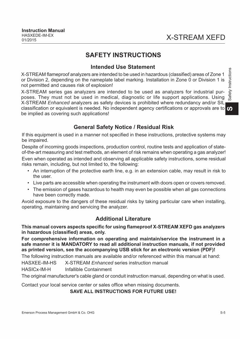
Intended Use StatementX-STREAM fl ameproof analyzers are intended to be used in hazardous (classifi ed) areas of Zone 1 or Division 2, depending on the nameplate label marking. Installation in Zone 0 or Division 1 is not permitted and causes risk of explosion!X-STREAM series gas analyzers are intended to be used as analyzers for industrial pur-poses. They must not be used in medical, diagnostic or life support applications. Using X-STREAM Enhanced analyzers as safety devices is prohibited where redundancy and/or SIL classifi cation or equivalent is needed. No independent agency certifi cations or approvals are to be implied as covering such applications!
General Safety Notice / Residual RiskIf this equipment is used in a manner not specifi ed in these instructions, protective systems may be impaired. Despite of incoming goods inspections, production control, routine tests and application of state-of-the-art measuring and test methods, an element of risk remains when operating a gas analyzer! Even when operated as intended and observing all applicable safety instructions, some residual risks remain, including, but not limited to, the following:
• An interruption of the protective earth line, e.g. in an extension cable, may result in risk to the user.
• Live parts are accessible when operating the instrument with doors open or covers removed.• The emission of gases hazardous to health may even be possible when all gas connections
have been correctly made.Avoid exposure to the dangers of these residual risks by taking particular care when installing, operating, maintaining and servicing the analyzer.
Additional LiteratureThis manual covers aspects specifi c for using fl ameproof X-STREAM XEFD gas analyzers in hazardous (classifi ed) areas, only.For comprehensive information on operating and maintain/service the instrument in a safe manner it is MANDATORY to read all additional instruction manuals, if not provided as printed version, see the accompanying USB stick for an electronic version (PDF)!The following instruction manuals are available and/or referenced within this manual at hand:HASXEE-IM-HS X-STREAM Enhanced series instruction manualHASICx-IM-H Infallible ContainmentThe original manufacturer's cable gland or conduit instruction manual, depending on what is used.
Contact your local service center or sales offi ce when missing documents. SAVE ALL INSTRUCTIONS FOR FUTURE USE!

Emerson Process Management GmbH & Co. OHGS-6
X-STREAM XEFDInstruction Manual
HASXEDE-IM-EX01/2015
Safety Instructions
Authorized PersonnelIn-depth specialist knowledge is an absolutely necessary condition for working with and on the analyzer.
Authorized personnel for installing, operating, servicing and maintaining the analyzer are instructed and trained qualifi ed personnel of the operating company and the manufacturer.
It is the responsibility of the operating company to• train staff,• observe safety regulations,• follow the instruction manual.
Operators must• have been trained,• have read and understood all relevant sections of the instruction manual before commencing
work,• know the safety mechanisms and regulations.
To avoid personal injury and loss of property, do not install, operate, maintain or service this instru-ment before reading and understanding this instruction manual and receiving appropriate training.
SPECIAL CONDITIONS FOR SAFE USE• Only specifi ed screws M16x45 ISO 4762
A2-70 as specifi ed in the maintenance section of this manual shall be used (spare part # 42716945).
• The fl ame joints correspond to the drawing No. 4.271-7112/1 and do not comply with the dimensions mentioned into the Tab. 1 and Tab. 2 of EN 60079-1 ed.2.
• The gas path for the sample gas shall be equipped with additional appropriate fl ame arrestors in case of gas pressure above 1100 hPa to 1500 hPa.
• Appropriate certifi ed cable glands shall be used in accordance with IEC/EN 60079-14
• Vapor recovery application:Pressure of gases not to exceed 1100 hPa.Concentrations of gases must be below 25 % LEL.
• Depending on the particular application all approbriate safety instructions mentioned in this instruction manual on hand must be considered!
• Take special care of formation of fl amma-ble gas at the outlet of breathing and/or purging devices, if the sample gas con-centration is above 25% LEL! If need be, such outlets have to end in a safe area!

Emerson Process Management GmbH & Co. OHG S-7
X-STREAM XEFDInstruction ManualHASXEDE-IM-EX01/2015
SS
afet
y In
stru
ctio
ns
Safety Instructions
EXPLOSION HAZARD BY CONNECTIONS
Consider the waiting time statement on the front door label before opening, if the analyzer is confi gured with selected measurement principles!Do not open instrument when energized.Ensure that external circuitry is disconnected or de-energized before opening the instrument.Ensure that all gas connections are made as labeled and are leak free. Improper gas connections could result in explosion and death.
EXPLOSION HAZARD BY SAMPLE HANDLING
The X-STREAM analyzer may utilize not only sample gas but one or more pressurized carrier gases and/or calibration gases.If an external fl owmeter is required for fl ow control, legislative requirements and instructions for installation in hazardous (classifi ed) areas must be considered.
EXPLOSION HAZARD BY MODIFICATION
Any addition, substitution, or replacement of components installed on or in this device, must be certifi ed to meet the hazardous area classifi cation that the device was certifi ed to prior to any such component addition, substitution, or replacement. In addition, the installation of such device or devices must meet the requirements specifi ed and defi ned by the hazardous area classifi cation of the unmodifi ed device. Any modifi cations to the device not meeting these requirements, will void the product certifi cation(s).Contact Emerson Process Management‘s customer service center for return authorization.
Emerson Process Management GmbH & Co. OHGS-8
X-STREAM XEFDInstruction Manual
HASXEDE-IM-EX01/2015
Safety Instructions
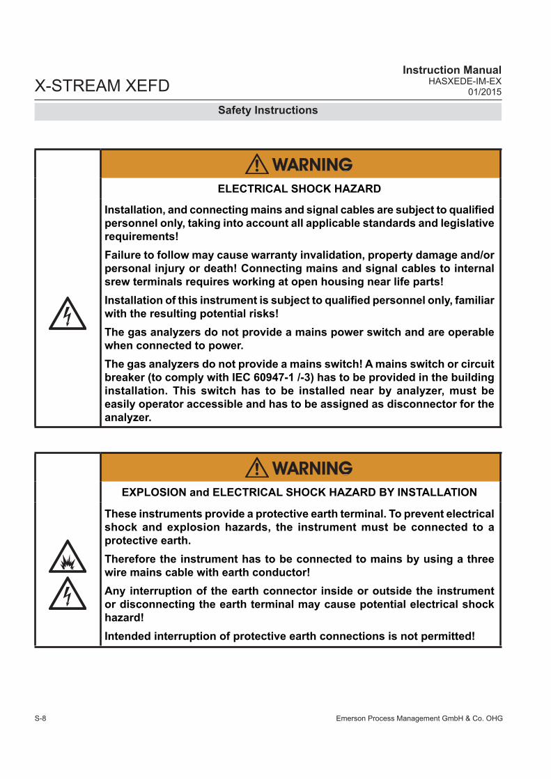
ELECTRICAL SHOCK HAZARD
Installation, and connecting mains and signal cables are subject to qualifi ed personnel only, taking into account all applicable standards and legislative requirements!Failure to follow may cause warranty invalidation, property damage and/or personal injury or death! Connecting mains and signal cables to internal srew terminals requires working at open housing near life parts!Installation of this instrument is subject to qualifi ed personnel only, familiar with the resulting potential risks!The gas analyzers do not provide a mains power switch and are operable when connected to power.The gas analyzers do not provide a mains switch! A mains switch or circuit breaker (to comply with IEC 60947-1 /-3) has to be provided in the building installation. This switch has to be installed near by analyzer, must be easily operator accessible and has to be assigned as disconnector for the analyzer.
EXPLOSION and ELECTRICAL SHOCK HAZARD BY INSTALLATION
These instruments provide a protective earth terminal. To prevent electrical shock and explosion hazards, the instrument must be connected to a protective earth.Therefore the instrument has to be connected to mains by using a three wire mains cable with earth conductor!Any interruption of the earth connector inside or outside the instrument or disconnecting the earth terminal may cause potential electrical shock hazard! Intended interruption of protective earth connections is not permitted!

Emerson Process Management GmbH & Co. OHG S-9
X-STREAM XEFDInstruction ManualHASXEDE-IM-EX01/2015
SS
afet
y In
stru
ctio
ns
Safety Instructions
EXPLOSION HAZARD BY DAMAGED FLAME PATHS
Take care to not damage the housing nor threads, and to not produce scratches on the fl ange, as threads and fl ange function as fl ame paths!Violation may result in explosion and personal injury!
ELECTRICAL SHOCK HAZARD WHEN CONNECTING TO MAINS
Before connecting the analyzer to mains power, please read the chapter on safety warnings and the following instructions carefully.
ELECTRICAL SHOCK HAZARD WHEN OPERATED OPENED
Do not operate without covers secure. Do not open while energized. Installation requires access to live parts which can cause death or serious injury.For safety and proper performace this instrument must be connected to a properly grounded three-wire source of power.Violation may cause explosion and personnel injury!
EXPLOSION HAZARD WHEN OPEN
Do NOT operate the instrument with doors or covers open! This is permitted only when no hazardous atmosphere is present! Depending on the local regulation, this may require a competent hot work supervisor to issue a hot work permit.Use ALL 20 screws to fi x the cover! Violation may cause an explosion hazard!

Emerson Process Management GmbH & Co. OHGS-10
X-STREAM XEFDInstruction Manual
HASXEDE-IM-EX01/2015
Safety Instructions
EXPLOSION HAZARD BY HIGH PRESSURE
Risk of internal overpressure under leakage conditions!For the purge or high sample gas option, take care to limit the total of purge gas fl ow and highest fl ow of sample gas lines into the instrument to max. 2 l/min!Take care of special conditions for safe use, and gas parameter specifi cations ( S-11 and 1-12 )!
EXPLOSION AND ELECTRICAL SHOCK HAZARD
All cables (power and signal) must end (be connected) in either a safe (non-hazardous) area or in a protecting enclosure (e.g. Ex e junction box)!The power and signal cables must be separated by a distance of minimum 1 cm (0.4 in) inside and outside the analyzer!
EXPLOSION HAZARD
Startup, operation and service must not be performed, before reading and understanding all instructions!Especially all warnings in this and the associated manuals have to be considered! Inspection, maintenance and service must be carried out considering all related standards e.g. for „Inspection and maintenance of electrical installations in hazardous areas“ or „Equipment repair, overhaul and reclamation“.
Emerson Process Management GmbH & Co. OHG S-11
X-STREAM XEFDInstruction ManualHASXEDE-IM-EX01/2015
SS
afet
y In
stru
ctio
ns
Safety Instructions
HOW TO STAY IN COMPLIANCE WITH THEEUROPEAN DIRECTIVE 94/9/EC ("ATEX") WHEN PERFORMING GAS
ANALYSIS WITHIN A FLAMEPROOF ENCLOSURE.Special conditions apply to using a fl ameproof enclosure analyzer under the scope of the "European Directive for Equipment used in Explosive Atmosphere" (Directive 94/9/EC; ATEX). To stay compliant with the directive, consider the following clarifi cation sheet re-leased by the European ATEX Notifi ed Body Group (see next page):
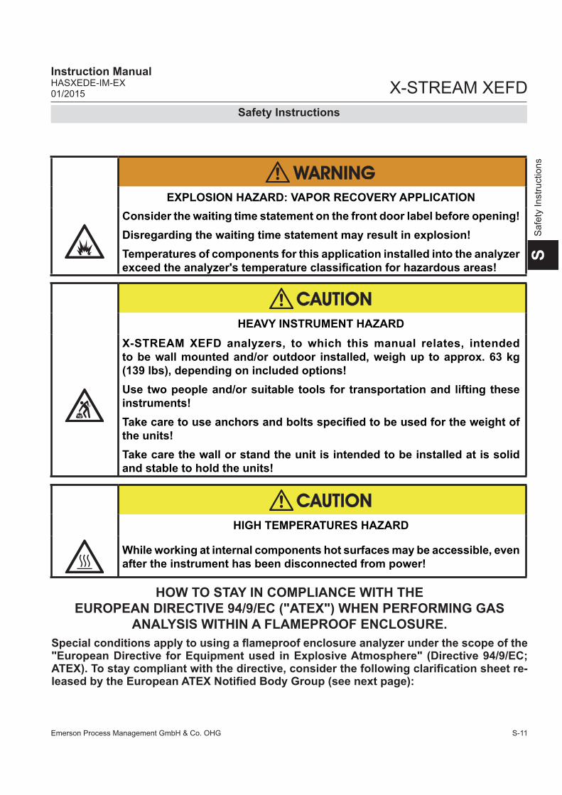
HEAVY INSTRUMENT HAZARD
X-STREAM XEFD analyzers, to which this manual relates, intended to be wall mounted and/or outdoor installed, weigh up to approx. 63 kg (139 lbs), depending on included options!Use two people and/or suitable tools for transportation and lifting these instruments!Take care to use anchors and bolts specifi ed to be used for the weight of the units!Take care the wall or stand the unit is intended to be installed at is solid and stable to hold the units!
HIGH TEMPERATURES HAZARD
While working at internal components hot surfaces may be accessible, even after the instrument has been disconnected from power!
EXPLOSION HAZARD: VAPOR RECOVERY APPLICATION
Consider the waiting time statement on the front door label before opening!Disregarding the waiting time statement may result in explosion!Temperatures of components for this application installed into the analyzer exceed the analyzer's temperature classifi cation for hazardous areas!

Emerson Process Management GmbH & Co. OHGS-12
X-STREAM XEFDInstruction Manual
HASXEDE-IM-EX01/2015
Safety Instructions

Emerson Process Management GmbH & Co. OHG S-13
X-STREAM XEFDInstruction ManualHASXEDE-IM-EX01/2015
SS
afet
y In
stru
ctio
ns
Safety Instructions
HIGH TEMPERATURES
Hot parts may be exposed when working on photometers and/orheated components in the unit.
CRUSHING HAZARD
Take care of crushing hazard when closing the front door of analyzer fi eld housings!Keep out of the closing area between enclosure cover and base!
OPERATION AT LOW TEMPERATURES
When operating an instrument at temperatures below 0 °C (32 °F), do NOT apply gas nor operate the internal pump before the warmup time has elapsed!Violation may result in condensation inside the gas paths or damaged pump diaphragm!
EXPLOSION HAZARD BY INTERNAL BATTERY
This analyzer contains an internal battery!Do NOT OPEN the analyzer enclosure if explosive atmosphere may be present!Disregarding may cause explosion even if the analyzer is de-energized!
Emerson Process Management GmbH & Co. OHGS-14
X-STREAM XEFDInstruction Manual
HASXEDE-IM-EX01/2015
General Operating Notes
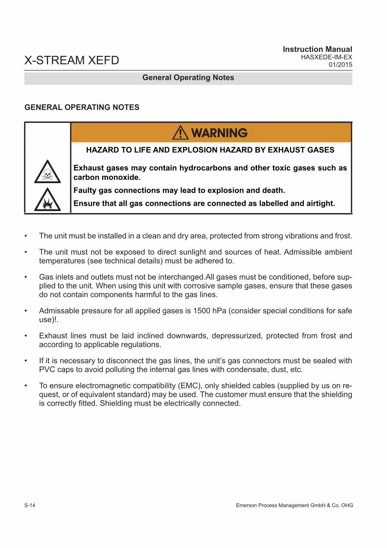
GENERAL OPERATING NOTES
• The unit must be installed in a clean and dry area, protected from strong vibrations and frost.
• The unit must not be exposed to direct sunlight and sources of heat. Admissible ambient temperatures (see technical details) must be adhered to.
• Gas inlets and outlets must not be interchanged.All gases must be conditioned, before sup-plied to the unit. When using this unit with corrosive sample gases, ensure that these gases do not contain components harmful to the gas lines.
• Admissable pressure for all applied gases is 1500 hPa (consider special conditions for safe use)!.
• Exhaust lines must be laid inclined downwards, depressurized, protected from frost and according to applicable regulations.
• If it is necessary to disconnect the gas lines, the unit’s gas connectors must be sealed with PVC caps to avoid polluting the internal gas lines with condensate, dust, etc.
• To ensure electromagnetic compatibility (EMC), only shielded cables (supplied by us on re-quest, or of equivalent standard) may be used. The customer must ensure that the shielding is correctly fi tted. Shielding must be electrically connected.
HAZARD TO LIFE AND EXPLOSION HAZARD BY EXHAUST GASES
Exhaust gases may contain hydrocarbons and other toxic gases such as carbon monoxide.Faulty gas connections may lead to explosion and death.Ensure that all gas connections are connected as labelled and airtight.

Emerson Process Management GmbH & Co. OHG 1-1
1Te
chn.
Des
crip
tion
X-STREAM XEFD Instruction ManualHASXEDE-IM-EX01/2015
Chapter 1Technical Description
1.1 OverviewThe new X-STREAM fl ameproof gas analy-zers are designed to be used in hazardous areas. The flameproof enclosure can be installed at Zone 1 and Division 2 locations without the need of any additional protective measures, e.g. purge gas supply.
1.2 Design FeaturesPackaged into a cast aluminum enclosure, the X-STREAM XEFD gas analyzer provides all the measurement options available for ge-neral purpose instruments, but for installation at locations, where explosive gas atmosphere might be present frequently (Zone 1) or occa-sionally (Zone 2, Division 2).
The basic concept used to protect the sur-rounding atmosphere from being ignited, if an internal failure results in high temperatures, fl ames or even an explosion, is to keep the explosion inside the enclosure and quench all fl ames possibly passing through the fl ange.To provide adequate explosion protection the X-STREAM fl ameproof analyzer feature:• a cast aluminum enclosure, designed to
• withstand an internal explosion,• quench fl ames resulting from an internal
explosion (thus preventing a surroun-ding explosive atmoshere from being ignited).
• fl ame arrestors avoiding fl ame transmissi-on from the gas paths into the surrounding atmosphere.
• approved cable glands (option: conduits), protecting the cable inlets and outlets.
Fig. 1-1: Frontal View
1: Enclosure base2: Screws3: Enclosure cover4: Flange 5: Eyebolts for lifting6: Hinges
1
2
3
54
6

Emerson Process Management GmbH & Co. OHG1-2
X-STREAM XEFD Instruction Manual
HASXEDE-IM-EX01/2015
1.3 Protective Measures in Detail
The cast aluminum enclosure consists of two parts: base and cover, connected by hinges.The area where the two parts are in contact is designed to work as a fl ange, quenching fl ames entering the small path between them. When operated, the analyzer enclosure has to be closed and secured by 20 screws evenly arranged all over the fl ange. The fl ame path between the fl ange parts is manufactured with very low tolerances and best fl atness, to ensure the function of quenching fl ames. For this reason, it is of particular importance to keep the fl anges surfaces free of scratches and other damages! The only openings penetrating the enclosure are threads, to be used for gas and cable in- and outlets:Depending on the measurement application the instrument provides up to 8 gas in- and outlets, each protected by an approved fl ame arrestor. These arrestors are installed into threads at the bottom side of the enclosure base. Two fi tting sizes are available for ex-ternal connection of gas pipes with 3.18 mm (1⁄8") or 6.35 mm (1⁄4") outer diameter (OD). Op-
tionally a clamping ring for 6 mm OD may be used, replacing the 6,35 mm version. Unused threads are closed with blind plugs which are certfi ed within the emerson approvals.Cables are fed into the enclosure utilizing up to 4 cable glands, located at the enclosure`s bottom right side. For installation in North America cable glands are replaced by a combination of conduits and metric-to-NPT thread adapters.All threads are designed to act as a fl ame path of a length ensuring that possibly entering flames are quenched before exiting to the external atmosphere. For this reason, avoid to damage the threads, neither externally nor internally!Unused threads must be closed with plugs when the instrument is operated to ensure explosion protection.
Note!See the X-STREAM series instruction ma-nuals for more information about common gas analyzers features, and special features of the X-STREAM XEFD.
Fig. 1-2: Bottom View
1: Plugged when not used (plugs certifi ed by emerson)2: Gas fi tting (part of fl ame arrestor)3: Plug4: Cable gland (or conduits)
1 2 3 4
1.3 Protective Measures in Detail

Emerson Process Management GmbH & Co. OHG 1-3
1Te
chn.
Des
crip
tion
X-STREAM XEFD Instruction ManualHASXEDE-IM-EX01/2015
1.4 High Pressure Option / Purge Option
1.4 High Pressure Option / Purge OptionNormally fl ameproof housings are permitted to operate under atmospheric conditions only, that is within an ambient pressure range bet-ween 800 and 1100 hPa. For analyzers this pressure range also applies to the gas pressure within the containment system. While the lower limit is not critical, the higher is, because it lowers the permitted sample gas (and calibration gases) pressures by 400 hPa, compared to general purpose analyzers. This results in higher requirements for the sample handling system, as it has to safely reduce the process gas pressure to the permitted range.Another aspect to take care for when ope-rating fl ameproof analyzers is the option of applying a purge gas to the enclosure when measuring low concentrations of gases, being constituent of the ambient air: The ambient air inside the analyzer enclosure cross interfe-rese with the sample gas and infl uences the measuring results. By purging the housing with a gas free of the measured component, this can be avoided, but could increase the pressure inside the analyzer and so would violate the atmospheric pressure condition.
X-STREAM fl ameproof analyzers have been subjected to additional tests to support both situations:• higher sample and calibration gas pres-
suresas well as • purging the housing with a gas for best
measuring results at low concentrations.To permit this, special additional conditions must be taken into account:High sample and calibration gas pressures
Higher gas pressure is specifi ed to be within the range of 1100 hPa to 1500 hPa. The maxi-mum permitted fl ow is 1,5 l/min, depending on the installed measurement system lower limits may apply.The gas paths need additionally to be protected by suitable inline fl ame arrestors, designed and approved for the applied higher gas pressure and for the area of installation. These fl ame ar-restors need to be installed outside the analyzer and in addition to the fl ame arrestors provided by the analyzer.Note!The external inline flame arrestors are not subject of the analyzer certifi cation and may be provided by the customer, or optionally by EMERSON PROCESS MANAGEMENT.A separate analyzer fl ame arrestor has to be installed, operating as a breathing device and so limiting the increase of pressure in the en-closure in case of internal leakage.Purging the housing with clean gas when measuring low concentrationsThe maximum permitted gas fl ow is 2 l/min. The gas must be supplied via a separate fl ame ar-restor. Another fl ame arrestor must be installed, operating as a breathing device and so limiting the increase of pressure in the enclosure.
EXPLOSION HAZARD
When making use of any of above mentioned options, take care of the special conditions given in the technical data section,and in chapter 2 (installation instructions)!

Emerson Process Management GmbH & Co. OHG1-4
X-STREAM XEFD Instruction Manual
HASXEDE-IM-EX01/2015
1.5 Compliances
1.5 Explosion Protection CompliancesThese products are available in two different variations, separately certifi ed by agencies for the use in hazardous (classifi ed) areas:The one variation, to be equipped with cable glands, is certifi ed by Fyzikálně technický zkušební ústav, s.p (FTZÚ), an European Notifi ed Body under the Directive 94/9/EC („ATEX“) and conforms to the provisions of EN 60079-0 and EN 60079-1. See appen-dix for a copy of the EC type examination certifi cate. The second variation, to be equipped with metric-to-NPT adapters and conduits (these components are not part of the instrument certifi cation), is certifi ed by the Canadian Standards Association, an „OSHA Nationally Recognized Testing Laboratory“ (NRTL), for Canada and USA and conforms to the pro-visions of CAN/CSA-E60079-0:02 (R2006), CAN/CSA-E60079-1:02 (R2006), ANSI/ISA-12.00.01-2002 (IEC 60079-0 Mod), ANSI/ISA-12.22.01-2002 (IEC 60079-1 Mod). Fur-thermore, these X-STREAM X2FD analyzers are certifi ed for use in Class I, Division 2, Group BCD T3 areas.See appendix for a copy of the CSA Certifi cate of Compliance.
IECEx certifi cation enables worldwide appro-vals with minimized need of testing. Further-more, based on this approval several national approvals are granted.
For a comprehensive list of applicable certi-fi cates visit our website at
www.emersonprocess.com.
The following certifi cation markings apply to the products:
European Union (EU, ATEX)Category 2, Zone 1:
II 2 GEx d IIB + H2 T4 GbEC ATEX Type Examination Certifi cate: FTZU 08 ATEX 0028 X.IECExEx d IIB+H2 T4IECEx certifi cateIECEx FTZU 08.0004X
Conforms to the provisions of the „Equipment intended for use in Potentially Explosive At-mospheres (ATEX)“ Directive 94/9/EC, EMC Directive 2004/108/EC and CE Directive 93/68/EEC.
USAClass I, Zone 1, AEx d IIB+H2 T3Class I, Division 2, Groups BCD T3
CanadaClass I, Zone 1, Ex d IIB+H2 T3Certifi cate of Compliance 1714037X

Emerson Process Management GmbH & Co. OHG 1-5
1Te
chn.
Des
crip
tion
X-STREAM XEFD Instruction ManualHASXEDE-IM-EX01/2015
1.5 Compliances
KGS KoreaEx d IIB+H2 T4Certifi cate no.: 13-GA4BO-0648XApproved by KGS
EAC Certifi cate Russia1 Ex d IIB+H2 T4 XCertifi cate no.:ТС RU C-DE.ГБ04.В.00327Approved by: CTB
1.5.1 Special Conditions for Safe Use• Only screws M16x45 ISO 4762 A2-70 as
specifi ed in the maintenance section of this manual shall be used (spare part # 42716945).
• The fl ame joints correspond to the drawing No. 4.271-7112/1 and do not comply with the dimensions mentioned into the Tab. 1 and Tab. 2 of EN 60079-1 ed.2.
• The gas path for the sample gas shall be equipped with additional appropriate fl ame arrestors in case of gas pressure above 1100 hPa to 1500 hPa.
• Appropriate certifi ed cable glands shall be used in accordance with IEC/EN 60079-14.
• Vapor Recovery application:Pressure of gases not to exceed 1100 hPa.Concentration of gases must be below 25 % LEL.
• Depending on the particular application all approbriate safety instructions mentioned in this instruction manual on hand must be considered!
• Take special care of formation of fl amma-ble gas at the outlet of breathing and/or purging devices, if the sample gas con-centration is above 25% LEL! If need be, such outlets have to end in a safe area!

Emerson Process Management GmbH & Co. OHG1-6
X-STREAM XEFD Instruction Manual
HASXEDE-IM-EX01/2015
1.6 Nameplate Label
1.6 Nameplate Label (Examples)
Fig. 1-3: Nameplate Label Details (exemplary)
Area Description Area DescriptionThe analyzer´s electrical data, manufac-turing data and serial number
Manufacturer address
Certifi cation Data IECEx / EU (ATEX) North America (CSA)
Area classifi cationII other than mines 2 Category 2 Equipm. (Zone 1) G for explosive Gas atmosphere
Class I Flammable gases, vapors or liquidsZone 1 Zone 1 areas
Protection concepts
Ex Explosion protected d fl ameproofIIB+H2 Group II, Gas Group B plus HydrogenT4 Temperature Class (135 °C)Gb Equipment Protection LevelTamb Ambient Temperature RangeIP66, Type 4X Enclosure Rating (outdoor use)
AEx Explosion protected (US) Ex Explosion protected (CAN)d fl ameproofIIB+H2 Group II, Gas Group B plus Hydrogen T3 Temperature Class (200 °C)Tamb Ambient Temperature RangeIP66, Type 4X Enclosure Rating (outdoor use)
Additional Division Marking, if applica-ble
--
Class I Flammable gases, vapors or liquidsDivision 2 Division 2 areasGroups BCD all Gases, except AcetyleneT3 Temperature Class (200 °C)
Certifi cate numbers IECEx FTZU 08.0004XFTZU 08 ATEX 0028 X 1714037X
Other CE mark, number of Notifi ed Body for Quality assessment
Instruction note where to install the explosion proof seal
Additional warning: Do not open the instrument while energized. Consult manual!
CSA-C/US versionATEX version

Emerson Process Management GmbH & Co. OHG 1-7
1Te
chn.
Des
crip
tion
X-STREAM XEFD Instruction ManualHASXEDE-IM-EX01/2015
1.7 Technical Data
1.7 Technical Data
Cable inlets (enclosure threads; M20 x 1.5)
Flame arrestors with gas fi ttings(enclosure threads: M18 x 1.5)
Eyebolt detailAll dimensions in mm [inches in brackets]
Transport lugs to be removed after installation
Fig. 1-4: Dimensions
HousingPermissible operating ambient tem-perature range, max.*) -20 °C to +50 °C (-4 °F to +122 °F)
Permissible storing ambient tempe-rature range -30 °C to +70 °C (-22 °F to +158 °F)
Weight approx. up to 63 kg (139 lbs),(depending on analyzer confi guration)
Protection class IP 66 (EN 60529) / Type 4X for outdoor installation. Analyzer must not be exposed to direct sun light
*): Limitations apply to selected measurement principles and ranges, Measurement specifi cations!

Emerson Process Management GmbH & Co. OHG1-8
X-STREAM XEFD Instruction Manual
HASXEDE-IM-EX01/2015
1.7 Technical Data
Site of installationHumidity (non-consending)
< 90 % r.h. at +20 °C (68 °F)< 70 % r.h. at +40 °C (104 °F)
Pollution degree 2Installation category IIAltitude 0 to 6560 ft (2000 m) above sea level
Sourrounding atmosphere Analyzers must not be operated in corrosive atmosphere
General Purpose CompliancesElectrical safety
Canada / USA
CSA-C/US, based onCAN/CSA-C22.2 No. 61010-1-04 /UL 61010-1, 2nd Edition
Europe CE, based on EN 61010-1Electromagnetic compatibility
Europe CE, based on EN 61326Australia C-Tickothers NAMUR
Power supplyRated input voltage 100 - 240 V 50 / 60 HzInput voltage range 85 - 264 V 47 - 63 HzNominal input current
standard 1.3 - 0.7 Awith temperature control 3 - 1.5 A
Measurement channels, max. 5Gas connections
Quantity max. 8Specifi cation fl ame arrestors with fi ttingsSizes connections: 6/4 mm or 1⁄4“, stainless steel
Tab. 1-1: Generic Analyzer Data

Emerson Process Management GmbH & Co. OHG 1-9
1Te
chn.
Des
crip
tion
X-STREAM XEFD Instruction ManualHASXEDE-IM-EX01/2015
1.7 Technical Data
Standard interfaces
up to 5 analog outputs(standard: 1 analog output per channel)
electrical specifi cation
4 (0)–20 mA (RB ≤ 500 )optically isolated from each other and from analy-zer electronics
function
user-confi gurable activation and deactivation of concentration levels support for NAMUR NE 43 operation modes, con-fi gurable via keypad and Modbus
4 relay outputs
electrical specifi cation
dry contactsmax. load. 30 V; 1 A; 30 W resistive
function
Each output can be confi gured to provide any of the functions listed in chapter 6 of the X-STREAM Enhanced instruction manual. These functions in-clude, but are not limited toNAMUR NE 107 status signals 'Failure', 'Main-tenance request', 'Out of specifi cation', 'Function check',concentration alarms,control signals for external valves or pumps,and many more
2 Modbus interfaces Ethernet (RJ45 sockets), 10/100 MBit
2 USB ports
specifi cation USB 1.0
function
1 USB connector type A, for connecting external storage devices 1 USB connector type mini AB, for connecting external computers
Tab. 1-2: Standard Interfaces Data

Emerson Process Management GmbH & Co. OHG1-10
X-STREAM XEFD Instruction Manual
HASXEDE-IM-EX01/2015
1.7 Technical Data
Optional interfacesDigital I/O board
7 or 14 digital inputs
electrical specifi cation
max. 30 V, internally limited to 2.3 mAHIGH: min. 4 V; LOW: max. 3 Vcommon GND
function
Each input can be confi gured to any of the functions listed in chapter 6 of the X-STREAM Enhanced instruction manu-al, e. g.
Open valveActivate sample gas pumpZero calibrate all channelsSpan calibrate all channelsZero and span calibrate all channels Abort calibration
9 or 18 additional relay outputs
electrical specifi cation
Dry relay change-over contacts can be used as NO or NCmax. load. 30 V; 1 A; 30 W resistive
function
Each output can be confi gured to provi-de any of the functions listed in chapter 6 of the X-STREAM XE instruction ma-nual.These functions include, but are not limi-ted toNAMUR NE 107 status signals 'Failure', 'Maintenance request', 'Out of specifi ca-tion', 'Function check',concentration alarms,control signals for external valves or pumps,and many more
Tab. 1-3: Optional Interfaces Data

Emerson Process Management GmbH & Co. OHG 1-11
1Te
chn.
Des
crip
tion
X-STREAM XEFD Instruction ManualHASXEDE-IM-EX01/2015
1.7 Technical Data
Optional interfaces
2 Analog inputs
electrical specifi cation
0–1 V, 0–10 V (software selectable) Rin = 100 kΩoptional (requires to fi t wire bridges, Chapter 2 'Installation'):
4 (0)–20 mA ; Rin = 50Ωoptically isolated from analyzer GNDprotected against overload up to ±15 V or ±20 mA
function
Input analog signals from external de-vices, such as e.g.
pressure transmitters, fl ow sensors,analyzers, etc.
for compensation or other purposes
1 Interfaceelectrical specifi cation
9-pin,optically isolated from analyzer elec-tronics
function RS232C, RS485 or Modbus
1 Service interfaceelectrical specifi cation
RS232C,NOT optically isolated from analyzer electronics
function Only to be used by Emerson personnel
Tab. 1-3: Optional Interfaces Data (cont‘d)
Emerson Process Management GmbH & Co. OHG1-12
X-STREAM XEFD Instruction Manual
HASXEDE-IM-EX01/2015
1.7 Technical Data
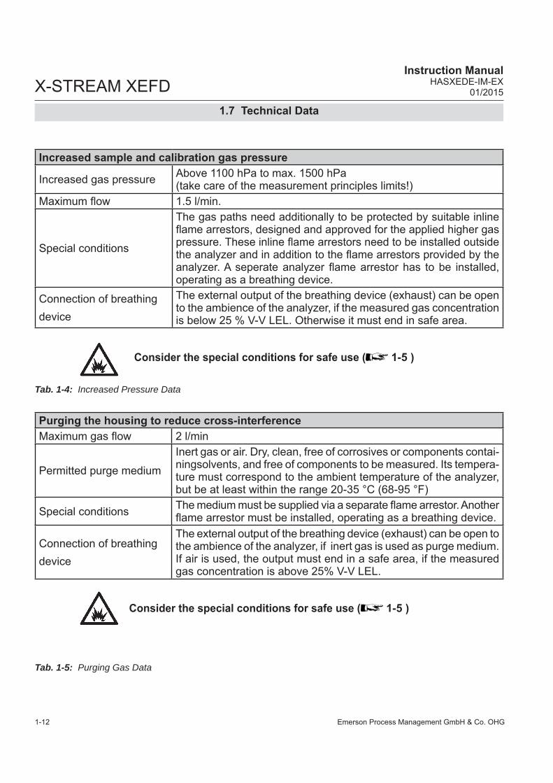
Increased sample and calibration gas pressure
Increased gas pressure Above 1100 hPa to max. 1500 hPa (take care of the measurement principles limits!)
Maximum fl ow 1.5 l/min.
Special conditions
The gas paths need additionally to be protected by suitable inline fl ame arrestors, designed and approved for the applied higher gas pressure. These inline fl ame arrestors need to be installed outside the analyzer and in addition to the fl ame arrestors provided by the analyzer. A seperate analyzer fl ame arrestor has to be installed, operating as a breathing device.
Connection of breathing device
The external output of the breathing device (exhaust) can be open to the ambience of the analyzer, if the measured gas concentration is below 25 % V-V LEL. Otherwise it must end in safe area.
Consider the special conditions for safe use ( 1-5 )
Purging the housing to reduce cross-interferenceMaximum gas fl ow 2 l/min
Permitted purge medium
Inert gas or air. Dry, clean, free of corrosives or components contai-ningsolvents, and free of components to be measured. Its tempera-ture must correspond to the ambient temperature of the analyzer, but be at least within the range 20-35 °C (68-95 °F)
Special conditions The medium must be supplied via a separate fl ame arrestor. Another fl ame arrestor must be installed, operating as a breathing device.
Connection of breathing device
The external output of the breathing device (exhaust) can be open to the ambience of the analyzer, if inert gas is used as purge medium. If air is used, the output must end in a safe area, if the measured gas concentration is above 25% V-V LEL.
Consider the special conditions for safe use ( 1-5 )
Tab. 1-4: Increased Pressure Data
Tab. 1-5: Purging Gas Data

Emerson Process Management GmbH & Co. OHG 1-13
1Te
chn.
Des
crip
tion
X-STREAM XEFD Instruction ManualHASXEDE-IM-EX01/2015
Fig. 1-5: Signals Terminals
1.7 Technical Data
Signal inputs and outputs
Note!Depending on the actual analyzer confi guration not all shown, or different terminals may be provided!
1 Ethernet & USB 2 Analog & digital I/O terminal strips 3 Max. 3 signal cables entries
1 2 3
Signal connections
Analog and digital I/O screw terminals max. 1.5 mm² (14 AWG); end sleeves not required
Other Ethernet: RJ45 sockets; USB-connections*)
Cable glands
Types Cable entry via, IP 68, or conduits with metric-to-NPT adap-tor
Permissible outer cable dia-meter
3…13 mm (0.11 to 0.5 inch), see cable gland / conduit specifi cation
Detailed terminals confi guration 2 Installation

Emerson Process Management GmbH & Co. OHG1-14
X-STREAM XEFD Instruction Manual
HASXEDE-IM-EX01/2015
Fig. 1-6: Power Terminals / Fuse Holders
1.7 Technical Data
Power Connection
1 Power terminals with integrated fuse holders 2 Protective earth terminal (PE) 3 Power cable entry 4 EMI power supply fi lter 3
2
41
Power connections
Power supply Connection via internal screw terminals near cable entries, max 4mm² (10 AWG), end sleeves not required.
Power supply fusesFuse ratings AC 230 V / T 4 A / 5x20 mm
Cable glands
Types Cable gland, classifi ed IP 68 or suitable conduit with metric-to-NPT adaptor
Permissible outer cable dia-meter
3…13 mm (0.11 to 0.5 inch), see cable gland / conduit specifi cation

Emerson Process Management GmbH & Co. OHG 1-15
1Te
chn.
Des
crip
tion
X-STREAM XEFD Instruction ManualHASXEDE-IM-EX01/2015
1.8 Measurements Specifi cations
Sample gas components and measuring ranges (standard confi gurations)In total, more than 60 gases are detectable, so the following table gives an overview only. Consult with Emerson for gases / confi gurations not listed. Not all data is applicable to all analyzer variations. The sample gas(es) and measuring ranges for your specifi c analyzer are given by the order acknowledgement and on the analyzer's name plate label.
Tab. 1-6: Gas Components and Measuring Ranges, examples
Special Specs or Conditions
Standard Specs (see Tab. 1-7 – 1-10)
Enhanced Specs(see Tab. 1-7 & 1-9)
Gas component Principle LowestRange
LowestRange
Lowest Range
Highest Range
Acetone 1 CH3COCH3 UV 0–400 ppm 0–800 ppm 0–3 %Acetone 1 CH3COCH3 IR 0–500 ppm 0–1000 ppm 0–3 %Acetylene C2H2 IR 0–3 % 0–6 % 0–100 %Ammonia NH3 IR 0–100 ppm 0–200 ppm 0–100 %Argon Ar TCD 0–50 % 0–100 % 0–100 %Carbon dioxide CO2 IR 0–5 ppm 5 0–50 ppm 0–100 ppm 0–100 %Carbon monoxide CO IR 0–10 ppm 5 0–50 ppm 0–100 ppm 0–100 %Chlorine Cl2 UV 0–300 ppm 0–600 ppm 0–100 %Ethane C2H6 IR 0–1000 ppm 0–2000 ppm 0–100 %Ethanol 1 C2H5OH IR 0–1000 ppm 0–2000 ppm 0–10 %Ethylene C2H4 IR 0–400 ppm 0–800 ppm 0–100 %Helium He TCD 0–10 % 0–20 % 0–100 %Hexane 1 C6H14 IR 0–100 ppm 0–200 ppm 0–10 %Hydrogen 4 H2 TCD 0–1 % 0–2 % 0–100 %Hydrogen Sulfi de H2S UV 0–2 % 0–4 % 0–10 %Hydrogen Sulfi de H2S IR 0–10 % 0–20 % 0–100 %Hydrogen Sulfi de H2S electrochem. 0–50 ppm – 0–2000 ppm 6
Methane CH4 IR 0–100 ppm 0–200 ppm 0–100 %Methanol 1 CH3OH IR 0–1000 ppm 0–2000 ppm 0–10 %n–Butane C4H10 IR 0–800 ppm 0–1600 ppm 0–100 %Nitrogen dioxide 1 NO2 UV 0–25 ppm 3 0–50 ppm 0–100 ppm 0–10 % Nitrogen monoxide NO IR 0–100 ppm 0–200 ppm 0–100 %Nitrous oxide N2O IR 0–100 ppm 0–200 ppm 0–100 %Oxygen O2 electrochem. 0–5 % – 0–25 % 2 6
Oxygen O2 paramagn. 0–1 % 0–2 % 0–100 %Oxygen, Trace O2 electrochem. 0–10 ppm – 0–10 000 ppm 6
Propane C3H8 IR 0–1000 ppm 0–2000 ppm 0–100 %Propylene C3H6 IR 0–400 ppm 0–800 ppm 0–100 %Sulfur dioxide SO2 UV 0–25 ppm 3 0–50 ppm 0–130 ppm 0–1 % Sulfur dioxide SO2 IR 0–1 % 0–2 % 0–100 % Sulfur hexafl uoride SF6 IR 0–5 ppm 3 0–20 ppm 0–50 ppm 0–2 %Toluene 1 C7H8 UV 0–300 ppm 0–600 ppm 0–5 %Vinyl chloride C2H3Cl IR 0–1000 ppm 0–2000 ppm 0–2 %Water vapor 1 H2O IR 0–1000 ppm 0–2000 ppm 0–8 % Water vapor, Trace 1 H2O capacitive 0–100 ppm – 0–3000 ppm 6
1 Dew point below ambient temperature
2 Higher concentrations decrease sensor lifetime
3 Daily zero calibration requi-red for ranges below lowest standard specs range
4 Special "refi nery" applica-tion with 0–1% H2 in N2 available
5 see Tab. 1-11
6 standard specs only
1.8 Measurements Specifi cations

Emerson Process Management GmbH & Co. OHG1-16
X-STREAM XEFD Instruction Manual
HASXEDE-IM-EX01/2015
1.8 Measurements Specifi cations
Standard and Enhanced Performance Specifi cations
Tab. 1-7: IR, UV, VIS, TCD - Standard and Enhanced Measurement Performance Specifi cations
Tab. 1-8: Trace Moisture - Standard Measurement Performance Specifi cations
1 If installed in series to another measurement system, e. g. IR channel2 Special conditions apply to pressures above 1100 hPa (1.5 psig) up to 1500 hPa (7 psig)
NDIR/UV/VIS Thermal Conductivity (TCD)Standard Spec Enhanced Spec Standard Spec Enhanced Spec
Detection limit (4 σ) 1 4 ≤ 1 % ≤ 0.5 % ≤ 1 % ≤ 0.5 % Linearity 1 4 ≤ 1 % ≤ 1 % Zero-point drift 1 4 ≤ 2 % per week ≤ 1 % per week ≤ 2 % per week ≤ 1 % per weekSpan (sensitivity) drift 1 4 ≤ 0.5 % per week ≤ 1 % per month ≤ 1 % per week Repeatability 1 4 ≤ 0.5 % ≤ 0.5 % Response time (t90)
3 4 s ≤ t90 ≤ 7 s 5 15 s ≤ t90 ≤ 30 s 6
Permissible gas fl ow 0.2–1.5 l/min. 0.2–1.5 l/min.Infl uence of gas fl ow 1 4 ≤ 0.5 % ≤ 1 % 11
Maximum gas pressure 8 14 ≤ 1500 hPa abs. (≤ 7 psig) ≤ 1500 hPa abs. (≤ 7 psig) Infl uence of pressure 2
– At constant temperature ≤ 0.10 % per hPa ≤ 0.10 % per hPa – With pressure compensation 7 ≤ 0.01 % per hPa ≤ 0.01 % per hPa
Permissible ambient temperature 9 0 (-20) to +50 °C (32 (-4) to 122 °F) 0 (-20) to +50 °C (32 (-4) to 122 °F) Infl uence of temperature 1 13
(at constant pressure)– On zero point ≤ 1 % per 10 K ≤ 0.5 % per 10 K ≤ 1 % per 10 K ≤ 0.5 % per 10 K– On span (sensitivity) ≤ 5 % (0 to +50 °C / 32 to 122 °F) ≤ 1 % per 10 K
Thermostat control 6 12 none / 60 °C (140 °F) 5 none / 60 °C (140 °F) 10 Warm-up time 6 15 to 50 minutes 5 approx. 50 minutes
Note! 1 psi = 68.95 hPa1 Related to full scale2 Related to measuring value3 From gas analyzer inlet at gas fl ow of 1.0 l/min
(electronic damping = 0 s)4 Constant pressure and temperature5 Dependent on integrated photometer bench
6 Depending on measuring range7 Pressure sensor is required8 Limited to atmospheric if internal sample pump9 Temperatures below 0 °C (-4 °F) with thermostat
control only
10 Thermost. controlled sensor: 75 °C (167 °F)11 Flow variation within ± 0.1 l/min12 Optional thermostatically controlled box with
temperature 60 °C (140 °F)13 Temperature variation: ≤ 10 K per hour14 Special conditions for > 1100 hPa abs
Note! Do not calibrate, see special calibration notes in the X-STREAM Enhanced instruction manual!
Note! 1 psi = 68.95 hPa
Trace Moisture (tH2O)Measurement range -100 to -10 °C dew point (0–100…3000 ppm)Measurement accuracy ±2 °C dew pointRepeatability 0.5 °C dew point Response time (t95) 5 min (dry to wet)Operating humidity 0 to 100 % r.h.Sensor operating temperature -40 to +60 °CTemperature coeffi cient Temperature compensated across operating temperature range
Operating pressure 2 Depending on sequential measurement system, see analyzer specifi cation 1
max. 1500 hPa abs / 7 psig
Flow rate Depending on sequential measurement system, see analyzer specifi cation 1
0.2 to 1.5 Nl/min

Emerson Process Management GmbH & Co. OHG 1-17
1Te
chn.
Des
crip
tion
X-STREAM XEFD Instruction ManualHASXEDE-IM-EX01/2015
1.8 Measurements Specifi cations
Tab. 1-9: Oxygen - Standard and Enhanced Measurement Performance Specifi cations
Note 1!Not all data listed are applicable to all analyzer versions (e.g. 60 °C thermostatically controlled box is not available for electrochemical and trace oxygen).Note 2!For NDIR/UV/VIS measurements, take into account that • sample gas may diffuse or be released by leakages into the analyzer enclosure• if existent in the analyzer surroundings, the component to be measured may enter the enclosure. Concentrations then may increase inside the enclosure. High concentrations of the component to be measured inside the enclosure may infl uence the measurement by unintended absorption, which could cause drift of the measurement. A remedy for this issue is to purge the housing with gas not containing the component of interest.
1 Related to full scale2 Related to measuring value3 From gas analyzer inlet at gas fl ow of 1.0 l/min
(electronic damping = 0 s)4 Constant pressure and temperature5 Range 0–10…200 ppm: ≤ 5 % (5 to 45 °C /
41 to 113 °F)6 Pressure sensor is required
7 Special conditions for > 1100 hPa abs. (1.5 psig)8 Limited to atmospheric if internal sample pump9 Temperatures below 0 °C (-4 °F) with thermostat
control only10 Thermost. controlled sensor: 35 °C (95 °F)11 For ranges 0–5…100 % and fl ow 0.5…1.5 l/min
12 Optional thermostatically controlled sensor with temperature 60 °C (140 °F)
13 Temperature variation: ≤ 10 K per hour14 No sudden pressure surge allowed
Oxygen SensorsParamagnetic (pO2) Electrochemical (eO2) Trace (tO2)
Standard Spec Enhanced SpecDetection limit (4 σ) 1 4 ≤ 1 % ≤ 0.5 % ≤ 1 % ≤ 1 % Linearity 1 4 ≤ 1 % ≤ 1 % ≤ 1 % Zero-point drift 1 4 ≤ 2 % per week ≤ 1 % per week ≤ 2 % per week ≤ 1 % per week Span (sensitivity) drift 1 4 ≤ 1 % per week ≤ 0.5 % per week ≤ 1 % per week ≤ 1 % per weekRepeatability 1 4 ≤ 0.5 % ≤ 1 % ≤ 1 % Response time (t90)
3 < 5 s approx. 12 s 20 to 80 sPermissible gas fl ow 0.2–1.5 l/min 0.2–1.5 l/min. 0.2–1.5 l/min.Infl uence of gas fl ow 1 4 ≤ 2 % 11 ≤ 2 % ≤ 2 %Maximum gas pressure 7 8 ≤ 1500 hPa abs. (≤ 7 psig) 14 ≤ 1500 hPa abs. (≤ 7 psig) ≤ 1500 hPa abs. (≤ 7 psig)Infl uence of pressure 2
– At constant temperature ≤ 0.10 % per hPa ≤ 0.10 % per hPa ≤ 0.10 % per hPa– With pressure compensation 6 ≤ 0.01 % per hPa ≤ 0.01 % per hPa ≤ 0.01 % per hPa
Permissible ambient temperature 9 0(-20) to +50 °C (32 (4) to 122 °F) 5 to +45 °C (41 to 113 °F) 5 to +45 °C (41 to 113 °F)Infl uence of temperature 1 13 (at constant pressure)
– On zero point ≤ 1 % per 10 K ≤ 0.5 % per 10 K ≤ 1 % per 10 K ≤ 1 % per 10 K 5
– On span (sensitivity) ≤ 1 % per 10 K ≤ 1 % per 10 K ≤ 1 % per 10 K 5
Thermostat control 60 °C (140 °F) 12 none none 10
Warm-up time Approx. 50 minutes - Approx. 50 minutesNote! 1 psi = 68.95 hPa
Note! Take care of the tO2 sensor‘s documentation, providing important calibration instructions!

Emerson Process Management GmbH & Co. OHG1-18
X-STREAM XEFD Instruction Manual
HASXEDE-IM-EX01/2015
1.8 Measurements Specifi cations
Tab. 1-10: H2S - Standard Measurement Performance Specifi cations
Special Performance Specifi cations for Gas Purity Measurements (ULCO & ULCO2)
1 Related to full scale2 Constant pressure and temperature3 Within 24 h; daily zero calibration requested4 Within 24 h; daily span calibration recommended
5 Related to measuring value6 Temperature variation: ≤ 10 K per hour7 From gas analyzer inlet at gas fl ow of 1.0 l/min8 Barometric pressure sensor is required
9 Whichever value is higher10 Limited to atmospheric if internal sample pump11 Special conditions apply to pressures above
1100 hPa (1.5 psig) up to 1500 hPa (7 psig)
0–10…< 50 ppm CO0–5…< 50 ppm CO2
Detection limit (4 σ) 1 2 < 2 %Linearity 1 2 < 1 %Zero-point drift 1 2 3 < 2 % resp. < 0.2 ppm 9
Span (sensitivity) drift 1 2 4 < 2 % resp. < 0.2 ppm 9
Repeatability 1 2 < 2 % resp. < 0.2 ppm 9 Response time (t90) 7 < 10 sPermissible gas fl ow 0.2–1.5 l/min.Infl uence of gas fl ow 1 2 < 2%Maximum gas pressure 10 11 ≤ 1500 hPa abs. (≤ 7 psig)Infl uence of pressure 5
– At constant temperature ≤ 0.1 % per hPa– With pressure compensation 8 ≤ 0.01 % per hPa
Permissible ambient temperature +15 to +35 °C (59 to 95 °F) +5 to +40 °C (41 to 104 °F)Infl uence of temperature 6
(at constant pressure)– On zero point < 2 % per 10 K resp. < 0.2 ppm per 10 K 9
– On span (sensitivity) < 2 % per 10 K resp. < 0.2 ppm per 10 K 9
Thermostat control none 60 °C (140 °F)Note! 1 psi = 68.95 hPa
Tab. 1-11: Special Performance Specifi cations for ULCO and ULCO2
Hydrogen Sulfi de (H2S) Measurement range (sensor dependent) 0 to 50 ppm 0 to 200 ppm 0 to 2000 ppmOvergas limit 200 ppm 500 ppm 10,000 ppmDetection limit 1 < 0.2 %Repeatability 1 < 2 %Drift 1 < 1 % per monthResponse time (t90) < 35 sOperating life > 24 monthsSensor operating temperature -30 to 50 °C
Gas pressure range 800 to 1200 hPa (-3.1 to 2.7 psig)
Gas humidity range (rel. humidity) 15 to 90 %Thermostat control none1 Related to full scale

Emerson Process Management GmbH & Co. OHG 1-19
1Te
chn.
Des
crip
tion
X-STREAM XEFD Instruction ManualHASXEDE-IM-EX01/2015
1.8 Measurements Specifi cations
Special Performance Specifi cations for Gas Purity Measurements (Suppressed Ranges)
Tab. 1-12: Special Performance Specifi cations for Suppressed Ranges
1 Related to suppressed range (98–100 %)2 Constant pressure and temperature3 Daily zero and span calibration requested
4 Switching from absolute to suppressed rangerequires purge time of > 240 s
5 Sample gas pressure sensor mandatory
6 Temperature variation: ≤ 10 K per hour7 Related to permissible ambient temp. range
Note! 1 psi = 68.95 hPa
98–100 % CO2
Detection limit (4 σ) 1 2 ≤ 2 % Linearity 1 2 ≤ 1 % Zero-point drift 1 2 3 ≤ 2 % per daySpan (sensitivity) drift 1 2 3 ≤ 2 % per day Repeatability 1 2 ≤ 2 % Response time (t90)
4 ≤ 30 sPermissible gas fl ow defi ned by constant pressure at inletPermissible gas pressure 1300 hPa (4.4 psig) – 1700 hPa (10.1 psig)Permissible gas pressure variation ± 70 hPa (1 psig)Infl uence of ambient pressure change from 800 to 1100 hPa at constant tem-perature with pressure compensation 1 5
≤ 2 %
Permissible ambient temperature +15 to +35 °C (59 to 95 °F) Infl uence of temperature 1 6
(at constant pressure)– On zero point ≤ 0.5 % per 10 K– On span (sensitivity) 7 ≤ 2 %
Thermostat control 60 °C (140 °F) Warm-up time approx. 50 minutesPurge gas (N2) fl ow approx. 0.1–0.2 l/min

Emerson Process Management GmbH & Co. OHG1-20
X-STREAM XEFD Instruction Manual
HASXEDE-IM-EX01/2015
1.9 Vapor Recovery Application
1.9 Vapor Recovery Application (Simultaneous Measurement of CH4 and Non-CH4)
This application is served by a special confi -guration of the X-STREAM XEFD fl ameproof analyzer.
EXPLOSION HAZARD BY HOT COMPONENTS
Temperatures inside an analyzer for VAPOR RECOVERY applications exceed the analyzer‘s temperature classifi cation for hazardous areas!Special conditions apply to handling this analyzer, consider the safety instructions at the beginning of this manual and the special conditions for safe use ( 1-5 )!Consider the waiting time statement on the front door label before opening!
FA1: Analyzer‘s inlet fl ame arrestorFA2...3: Analyzer‘s outlet fl ame arrestorsF1: FilterT1: ThrottleV1: Valve
The confi guration consists of a dual channel IR measurement, connected to the inlet and outlet of a converter. This converter is instal-led inside the X-STREAM analyzer and is heated to about 280 °C (536 °F).
Fig. 1-7: Vapor Recovery Gas Flow Diagram
Converter
CH2: non-CH4
CH1: CH4
Principle of measurementThe sample gas is taken towards a converter.At it‘s inlet the gas stream is divided into two: one is directly fed to a non-CH4 measurement. The other is supplied to a solenoid valve, normally forwarding the gas to the converter. Within the converter, hydrocarbons higher than CH4 are converted into H2O and CO2. The converter outlet is connected to a second IR measurement system, analyzing the re-maing amount of hydrocarbons (mainly CH4) in the sample gas.
After switching power on, wait about 50 min. for the converter to reach its operating tempera-ture before applying gases!

Emerson Process Management GmbH & Co. OHG 1-21
1Te
chn.
Des
crip
tion
X-STREAM XEFD Instruction ManualHASXEDE-IM-EX01/2015
1.9 Vapor Recovery Application
Converter effi ciencyThe measurement accuracy is highly depen-dent on the converter effi ciency: If this is too low, the converter material needs replace-ment. To measure the converter effi ciency, one has to compare the measurement values of CH1 with and without having the gas fl owing through the converter. This requires activating the valve V1.For the ease of use, special PLC and calcu-lator programs are provided with analyzers for vapor recovery applications, automatically calculating the effi ciency each time after a ca-libration has been performed. The calculated value shows up as a measurement result on the measurement display.To calculate the effi ciency without a prece-ding calibration, you can also start the PLC program manually from the webbrowser interface. 4 Maintenance section of this manual for instructions about when and how to replace the converter material. The appendix contains listings of the PLC and calculator programs, enabling automatic converter effi ciency cal-culation.

Emerson Process Management GmbH & Co. OHG 2-1
2In
stal
latio
n
X-STREAM XEFDInstruction ManualHASXEDE-IM-EX01/2015
Chapter 2Installation
On receipt, check the packaging and its contents thoroughly for damage. Inform the carrier immediately of any damage to packaging or contents, and keep dama-ged parts until clarifi cation. Store the instrument at a dry and clean place, considering the acceptable environmental conditions. We recommend to keep the packaging available for future transportation, because only the ori-ginal packaging ensures proper protection!
HAZARDS FROM MISSING INFORMATION
Compare the content of your package with the pictures below. Analyzers for hazardous areas need additional parts, described in the accompanying documentation refering to hazardous area installations.Call your local sales offi ce if something is missing, and DO NOT continue to install your analyzer, until all parts are at hand!
2.1 Scope of Supply
USB stick Trace oxygen cell
(if applicable)
Analyzer
Instruction manuals:- This manual addendum- X-STREAM XE instruction manual (on USB stick)- if need be addtionial manuals on the USB stick
Allen key for fl ange screws
Fig. 2-1: Scope of Supply

Emerson Process Management GmbH & Co. OHG2-2
X-STREAM XEFDInstruction Manual
HASXEDE-IM-EX01/2015
HEAVY INSTRUMENT HAZARD
X-STREAM XEFD analyzers, to which this manual relates, intended to be wall mounted and/or outdoor installed, weigh up to approx. 63 kg (139 lbs), depending on included options!Use two people and/or suitable tools for transportation and lifting these instruments!Take care to use anchors and bolts specifi ed to be used for the weight of the units!Take care the wall or stand the unit is intended to be installed at is solid and stable to hold the units!
EXPLOSION HAZARD WHEN OPEN
Installing this analyzer requires opening the housing and working at open instrumen! This is permitted only if no hazardous atmosphere is present and the instrument and connected circuitry is deenergized! Depending on the local regulation, this may require a competent hot work supervisor to issue a hot work permit.Use ALL 20 screws to fi x the cover! Violation may cause an explosion hazard!
EXPLOSION HAZARD
Installing and wiring this instrument must comply with all relevant national legislative requirements and regulations.Neither housing nor threads must be damaged, also scratches on fl anges are not permitted, as all these are part of the explosion protection concept!Consider all safety instructions within this on hand manual and all associa- ted analyzer instruction manuals!
2.2 Installing the Analyzer
2.2 Installation - Analyzer

Emerson Process Management GmbH & Co. OHG 2-3
2In
stal
latio
n
X-STREAM XEFDInstruction ManualHASXEDE-IM-EX01/2015
Install the analyzer to a stand or a wall by means of 4 eyebolts, provided at the instru-ments rear side.It is recommended to install the analyzer in an upright (vertical) position; other orientations may affect the measuring results.
Fig. 2-2: Dimensions
Cable inlets (enclosure threads; M20 x 1.5)
Flame arrestors with gas fi ttings(enclosure threads: M18 x 1.5)
Eyebolt detailAll dimensions in mm [inches in brackets]
Transport lugs to be removed after installation
EXPLOSION HAZARD
When installing the analyzer take care to have an area of min. 40 mm (1.6") surrounding the flange free of any solid components not part of the instrument, to ensure proper function of the fl ange!
2.2 Installation - Analyzer

Emerson Process Management GmbH & Co. OHG2-4
X-STREAM XEFDInstruction Manual
HASXEDE-IM-EX01/2015
2.3 Installation - Gas Conditioning
2.3 Gas ConditioningIn order to ensure trouble-free operation, spe-cial attention must be paid to the preparation of the gases:
All gases must be conditioned before supplying to the analyzer, to be• dry, • free of dust and • free of any aggressive com-
ponents which may damage the gas lines (e.g. by corrosi-on or solvents).
Pressure and gas fl ow must remain within the values given in the „Measurement Specifi cations“ section within this manual.If moisture cannot be avoided, it is necessary to ensure that the dew point of the gases is at least 10 °C (18 °F) below the ambient tempe-rature to avoid condensate in the gas lines.
Hints for selected gases• Calibration gases for CO and NO need
to be moistured by supplying them via a cooler.
EXPLOSION HAZARD
Do not supply gases harmful to explosion protection safety components like fl ame arrestors, cable glands or analyzer enclosure!Violation may result in explosion!

Emerson Process Management GmbH & Co. OHG 2-5
2In
stal
latio
n
X-STREAM XEFDInstruction ManualHASXEDE-IM-EX01/2015
2.3 Installation - Gas Conditioning
Enclosure purge optionThe purge medium (e.g. to minimize CO2 interference or for enhanced safety when measuring corrosive or poisonous gases) • must be dry, clean and free of corro-
sives or components containing sol-vents.
• has to be free of components to be measured, to minimize cross interfe-rences.
Its temperature must correspond to the am-bient temperature of the analyzer, but be at least within the range 20…35 °C (68…95 °F).
Consider the Special Condi-tions for Safe Use. We recommend to always purge the analyzer enclosure, if gases are supplied, which may harm analyzer components, if due to a leak released into the analyzer enclosure!
Open reference optionIn some cases, the measuring cell has an open reference side, to be supplied with nitrogen. This nitrogen • at least should be of quality 5.0, which
means nitrogen of purity ≥ 99.999 %.If such gas is not available, the substitute • must be dry, clean and free of corrosi-
ves or components containing solvents. • has to be free of components to be
measured, to minimize cross interfe-rences.
In any case, the gas temperature must cor-respond to the ambient temperature of the analyzer, but at least be within the range 20…35 °C (68…95 °F).Pressure and gas fl ow must remain within the values given in the „Measurement Specifi cations“ section within this manual.
Perform a calibration each time the source of this gas (e. g. bottle) has changed!

Emerson Process Management GmbH & Co. OHG2-6
X-STREAM XEFDInstruction Manual
HASXEDE-IM-EX01/2015
2.4 Installation - Gas Connections
2.4 Gas Connections
Do not confuse gas inlets and outlets. All gases must be conditioned before supplying to the analyzer. When supplying aggressive gases, ensure that the gas lines are not damaged.Max. admissable pressure: 150 kPa / 7 psig; atmospheric with internal pump!Exhaust lines must be installed to incline downwards and be unpressurized and protected against frost, and conform to legal requirements.
TRACE OXYGEN MEASUREMENTS
The sensor for trace oxygen measurements is a consumable.Remaining lifetime counts down when the sensor is in contact with oxygen.For above reasons, the analyzer is shipped with the sensor as extra item in a sealed bag! The sensor must be installed before analyzer startup, according the instructions shipped with the sensor!Do not use plastic tubing for trace oxygen measurements as it can permeate oxygen from the ambient air and cause higher than expected oxygen readings.
HAZARD BY HARMFUL TO HEALTH GASES
Take care that all external gas lines are connected as described and that they are gastight to avoid leakages! Faulty connected gas lines lead to mortal danger!Don‘t breathe the emissions! Emissions may contain harmful to health or toxic components, and may cause headache, sickness, unconsciousness and death. Dispose emissions by a safe gas fl ue and check its function periodically!
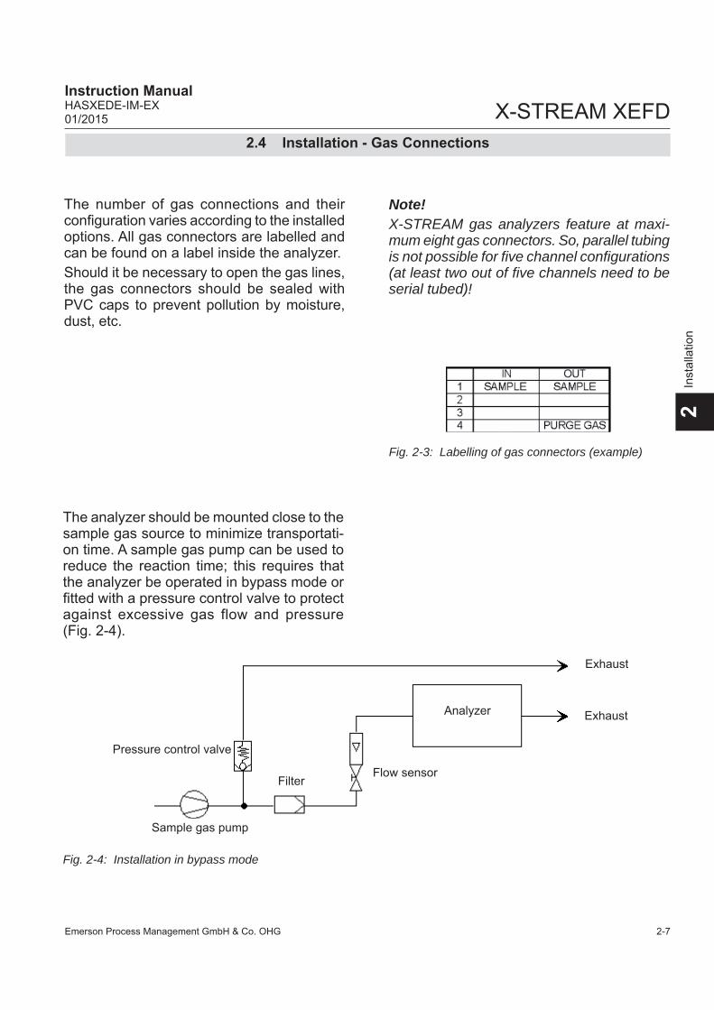
Emerson Process Management GmbH & Co. OHG 2-7
2In
stal
latio
n
X-STREAM XEFDInstruction ManualHASXEDE-IM-EX01/2015
2.4 Installation - Gas Connections
The number of gas connections and their confi guration varies according to the installed options. All gas connectors are labelled and can be found on a label inside the analyzer.Should it be necessary to open the gas lines, the gas connectors should be sealed with PVC caps to prevent pollution by moisture, dust, etc.
Fig. 2-3: Labelling of gas connectors (example)
Pressure control valve
Flow sensor
Exhaust
ExhaustAnalyzer
Sample gas pump
Filter
Fig. 2-4: Installation in bypass mode
The analyzer should be mounted close to the sample gas source to minimize transportati-on time. A sample gas pump can be used to reduce the reaction time; this requires that the analyzer be operated in bypass mode or fi tted with a pressure control valve to protect against excessive gas flow and pressure (Fig. 2-4).
Note!X-STREAM gas analyzers feature at maxi-mum eight gas connectors. So, parallel tubing is not possible for fi ve channel confi gurations (at least two out of fi ve channels need to be serial tubed)!

Emerson Process Management GmbH & Co. OHG2-8
X-STREAM XEFDInstruction Manual
HASXEDE-IM-EX01/2015
1
2
3
4
5
5
67
Gas inlets and outlets are protected by fl ame arrestors, supporting stainless steel pipes of either 3.18 mm (1⁄8“) or 6.35 mm (1⁄4“) outer diameter (OD). The 1⁄4“ fi tting may optionally be supplied with a clamping ring for 6 mm OD pipes.
Fig. 2-5: Flame arrestor installed into instrument enclosure
1: Gas fi tting 1⁄8“ (inside instrument) *)
2: M18 male threat (inside enclosure wall)3: O-ring (optional)4: Gas fi tting 1⁄4“ or 1⁄8“ (outside instrument) *)
5: Hexagon for counter holding while thightening6: Hexagon for wrench when mounting into a M18 threat7: O-ring shoulder
*) FA 01 with 1⁄4“ (outside instrument) and 1⁄8“ (inside) FA 02 with 1⁄4“ at both ends FA 03 with 1⁄8“ at both ends
Fig. 2-6: Flame arrestor elements, considering as example FA 01
When thightening the fi tting, counterhold the fl ame arrestor with a wrench placed at the hexagon (items 5 of fi g. 2-6) next to the cap nut (items 1, 4) to be tightened.
Always counterhold the fl ame arrestor while thightening fi t-tings; otherwise the fl ame arre-stor may be damaged!
The instrument provides up to 8 gas inlets and outlets, depending on the ordered confi gura-tion. Unused entries are closed by approved plugs.
POSSIBLE EXPLOSION HAZARD
Take care not to damage the threats, this may void the instrument´s safety and cause hazards! Maximum permitted fastening torque: 40 Nm (354 in.lb)!Ensure unused entries remain sealed with approved plugs!
2.4 Installation - Gas Connections

Emerson Process Management GmbH & Co. OHG 2-9
2In
stal
latio
n
X-STREAM XEFDInstruction ManualHASXEDE-IM-EX01/2015
2.4.1 Special Conditions
The purge medium must be supplied via a separate fl ame arrestor (purge gas inlet), installed into the analyzer enclosure. Another fl ame arrestor must be installed, operating as a breathing device (purge gas outlet).Connection of breathing device: The external output of the breathing device (exhaust) can be open to the ambience of the analyzer, if inert gas is used as purge medium. If air is used, the output must end in a safe area, if the measured gas concentration is above 25 % V/V LEL.
2.4.1.1 Purging the Housing with Clean Gas when e.g. Measuring Low Concentrations
Fig. 2-7: Exemplary diagram for a single channel unit with purge option
1
2
3
1: Flame arrestors for gas path2: Measuring system3: Flame arrestors for purge gas in-/outlet
EXPLOSION HAZARD BY HIGH PRESSURE
Risk of internal overpressure under leakage conditions!For the following option, take care to limit the total of purge gas fl ow and highest fl ow of sample gas lines into the instrument to max. 2 l/min!Take care of special conditions for safe use, and gas parameter specifi cations ( S-5 and 1-12)!
2.4 Installation - Gas Connections
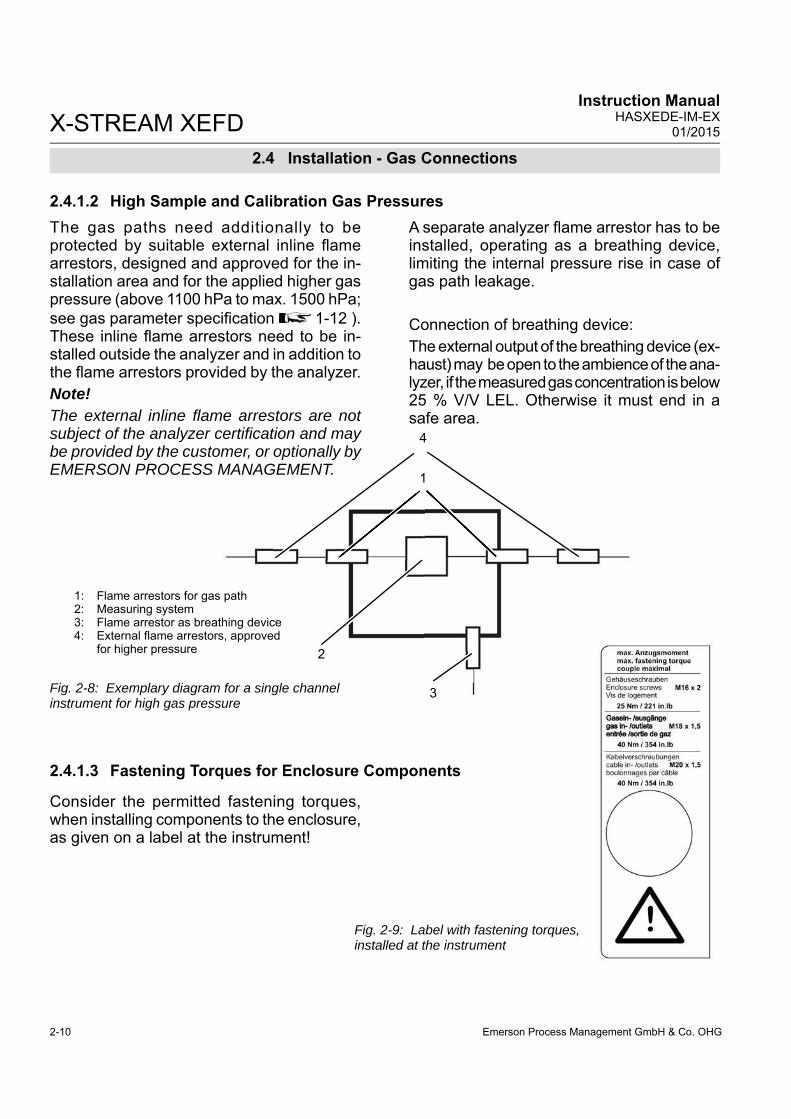
Emerson Process Management GmbH & Co. OHG2-10
X-STREAM XEFDInstruction Manual
HASXEDE-IM-EX01/2015
The gas paths need additionally to be protected by suitable external inline fl ame arrestors, designed and approved for the in-stallation area and for the applied higher gas pressure (above 1100 hPa to max. 1500 hPa; see gas parameter specifi cation 1-12 ).These inline fl ame arrestors need to be in-stalled outside the analyzer and in addition to the fl ame arrestors provided by the analyzer.Note!The external inline fl ame arrestors are not subject of the analyzer certifi cation and may be provided by the customer, or optionally by EMERSON PROCESS MANAGEMENT.
A separate analyzer fl ame arrestor has to be installed, operating as a breathing device, limiting the internal pressure rise in case of gas path leakage.
Connection of breathing device: The external output of the breathing device (ex-haust) may be open to the ambience of the ana-lyzer, if the measured gas concentration is below 25 % V/V LEL. Otherwise it must end in a safe area.
2.4.1.2 High Sample and Calibration Gas Pressures
2.4.1.3 Fastening Torques for Enclosure Components
1
4
2
3
optionally by GEMENT.
1: Flame arrestors for gas path2: Measuring system3: Flame arrestor as breathing device4: External fl ame arrestors, approved for higher pressure
Fig. 2-8: Exemplary diagram for a single channel instrument for high gas pressure
Fig. 2-9: Label with fastening torques, installed at the instrument
Consider the permitted fastening torques, when installing components to the enclosure, as given on a label at the instrument!
2.4 Installation - Gas Connections

Emerson Process Management GmbH & Co. OHG 2-11
2In
stal
latio
n
X-STREAM XEFDInstruction ManualHASXEDE-IM-EX01/2015
2.5 Electrical Installation
2.5 Installation - Electrical
EXPLOSION AND ELECTRICAL SHOCK HAZARD
Failure to follow the instructions provided below may cause warranty invalidation, property damage and personal injury or death!Installation and connecting power and signal cables are subject to qualifi ed personnel only taking into account all applicable standards and legislative requirements!Take care of the relevant installation standards, as there are (but not limited to) e.g. EN 60079-14 (Europe), National Electrical Code (NEC-NFPA 70; USA), Canadian Electrical Code (CEC; Canada), IEC 60079-14 (International) and others, and all corresponding standards.Installation of these instruments is subject to qualifi ed personnel only, familiar with the resulting potential risks! Instruments providing screw terminals for electrical connections may require working near live part!A power switch or circuit breaker (complying with IEC 60947-1/-3) has to be provided in the building installation. This switch has to be installed near by analyzer, must be easily operator accessible and has to be assigned as disconnector for the analyzer.Disconnect instruments with screw terminals from power when working at power terminals (operate power switch / circuit breaker in building installation)!Connecting and disconnecting fl ameproof X-STREAM analyzers is permitted only, if the instrument and all associated power & signal lines are de-energized!The analyzers provide a protective earth terminal. To prevent electrical shock hazards the instruments must be connected to a protective earth. Therefore the instruments must be connected to power by using a three wire power cable with earth conductor!Any interruption of the earth connector inside or outside the instrument or disconnecting the earth terminal may cause potential electrical shock hazzard! The analyzers do not provide a power switch and are operable when connec-ted to power.
Emerson Process Management GmbH & Co. OHG2-12
X-STREAM XEFDInstruction Manual
HASXEDE-IM-EX01/2015
2.5 Installation - Electrical
SELECT THE CORRECT TYPE OF CABLE ENTRY
Before starting to install the analyzer, verify what type of cable entry is required at your site of installation: X-STREAM fl ameproof gas analyzers may be equipped with cable glands (regulated e.g. for installations covered by ATEX) or may be installed with conduits (e.g. in North-America).
EXPLOSION HAZARD WHEN INSTALLING CONDUITS
X-STREAM fl ameproof gas analyzers provide metric threads for installing cable entries. Installing conduits requires using metric-to-NPT adaptors!To stay compliant with the North-American certifi cation use only fl ameproof certifi ed adaptors, e.g. the following type: Redapt AD-U series, stainless steel with captive o-ring seals, size male M20 x 1.5 to female 3⁄4"-NPT or 1⁄2"-NPT.Select a type of conduit according the local code, suitable for above mentioned adaptors and the site of installation. During installation follow the instructions provided by the manufacturer of the conduits!Unused entries must be provided with fl ameproof plugs, secured in place with thread locking compound!
EXPLOSION HAZARD WHEN ENERGIZED
Do not open instrument when energized.Ensure that external circuitry is disconnected or de-energized before opening the instrument.All cables (power and signal) must end (be connected) in either a safe (non-hazardous) area or in a protecting enclosure (e.g. Ex e junction box)!

Emerson Process Management GmbH & Co. OHG 2-13
2In
stal
latio
n
X-STREAM XEFDInstruction ManualHASXEDE-IM-EX01/2015
2.5 Installation - Electrical
EXPLOSION HAZARD WHEN INSTALLING CABLE GLANDS
When using the ADL type cable glands: Take care to use the correct cable gland internal elastomeric ring with an internal diameter supporting the cable to be used! The supported cable diameters are noted on the sealing ring.Use only cables as specifi ed in the cable glands installation instruction, and carefully follow the installation instructions!
EXPLOSION HAZARD BY INTERNAL BATTERY
This analyzer contains an internal battery!Do NOT OPEN the analyzer enclosure if explosive atmosphere may be present!Disregarding may cause explosion even if the analyzer is de-energized!
The next page shows
• the English installation instructions for type AD-U adapters, reprinted with the permis-sion of
Redapt Ltd
Note!See the documentation delivered together with your analyzer for an original version of the cable gland or adapter installation instruc-tions, whatever is applicable !

Emerson Process Management GmbH & Co. OHG2-14
X-STREAM XEFDInstruction Manual
HASXEDE-IM-EX01/2015
2.5 Installation - Electrical
Type AD-U adapter installation instructions

Emerson Process Management GmbH & Co. OHG 2-15
2In
stal
latio
n
X-STREAM XEFDInstruction ManualHASXEDE-IM-EX01/2015
Fig. 2-10: Allocation of terminals
1 Terminals for signal cables2 Power EMI fi lter3 4 cable entries for power and signal cables4 Power terminals with integrated fuses5 Ethernet and USB connectors
2.5 Installation - Electrical
Unused entries during installation have to be provided with plugs.
Installation under CSA certifi cation requires the use of approved conduits and suitable metric-to-NPT adaptors. .
Both plugs and cable entries must be installed properly and fi xed by applying the prescribed torque.
The instrument provides internal screw termi-nals for connecting power and signal cables. This requires opening the instrument during installation:• Unsrew the 20 screws located on the
enclosure fl ange. • Flap down the cover part to gain access
to the analyzer inside.Inside the enclosure, keep all cables as short as possible to prevent from interferences.
ATEX approved analyzers provide 4 cable entries (M20 x 1.5) and are shipped with a set of 4 plugs.Owner of such analyzers are responsible to provide suitable cable glands according all ap-plicable standards (e. g. IEC/EN 60079-14).See maintenance section of this manual for recommended cable glands.
1 42 35
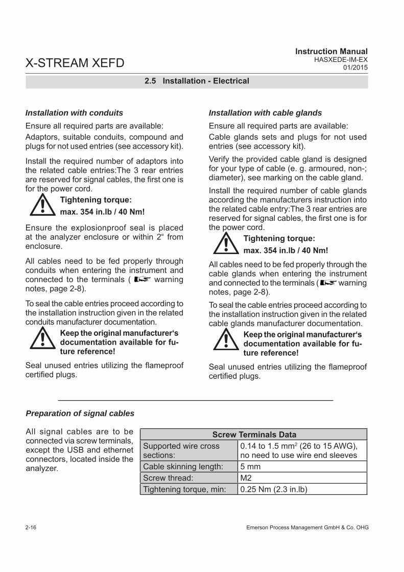
Emerson Process Management GmbH & Co. OHG2-16
X-STREAM XEFDInstruction Manual
HASXEDE-IM-EX01/2015
2.5 Installation - Electrical
All signal cables are to be connected via screw terminals, except the USB and ethernet connectors, located inside the analyzer.
Preparation of signal cables
Screw Terminals DataSupported wire cross sections:
0.14 to 1.5 mm2 (26 to 15 AWG), no need to use wire end sleeves
Cable skinning length: 5 mm Screw thread: M2 Tightening torque, min: 0.25 Nm (2.3 in.lb)
Installation with conduitsEnsure all required parts are available: Adaptors, suitable conduits, compound and plugs for not used entries (see accessory kit).
Install the required number of adaptors into the related cable entries:The 3 rear entries are reserved for signal cables, the fi rst one is for the power cord.
Tightening torque: max. 354 in.lb / 40 Nm!
Ensure the explosionproof seal is placed at the analyzer enclosure or within 2“ from enclosure.
All cables need to be fed properly through conduits when entering the instrument and connected to the terminals ( warning notes, page 2-8).
To seal the cable entries proceed according to the installation instruction given in the related conduits manufacturer documentation.
Keep the original manufacturer‘s documentation available for fu-ture reference!
Seal unused entries utilizing the fl ameproof certifi ed plugs.
Installation with cable glandsEnsure all required parts are available: Cable glands sets and plugs for not used entries (see accessory kit).Verify the provided cable gland is designed for your type of cable (e. g. armoured, non-; diameter), see marking on the cable gland.Install the required number of cable glands according the manufacturers instruction into the related cable entry:The 3 rear entries are reserved for signal cables, the fi rst one is for the power cord.
Tightening torque: max. 354 in.lb / 40 Nm!
All cables need to be fed properly through the cable glands when entering the instrument and connected to the terminals ( warning notes, page 2-8). To seal the cable entries proceed according to the installation instruction given in the related cable glands manufacturer documentation.
Keep the original manufacturer‘s documentation available for fu-ture reference!
Seal unused entries utilizing the fl ameproof certifi ed plugs.
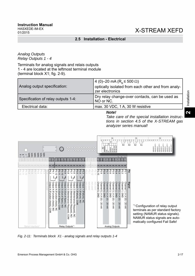
Emerson Process Management GmbH & Co. OHG 2-17
2In
stal
latio
n
X-STREAM XEFDInstruction ManualHASXEDE-IM-EX01/2015
**) Confi guration of relay output terminals as per standard factory setting (NAMUR status signals).NAMUR status signals are auto-matically confi gured Fail Safe!
Fig. 2-11: Terminals block X1 - analog signals and relay outputs 1-4
Analog OutputsRelay Outputs 1 - 4 Terminals for analog signals and relais outputs1 - 4 are located at the leftmost terminal module(terminal block X1; fi g. 2-9).
2.5 Installation - Electrical
Note!Take care of the special installation instruc-tions in section 4.5 of the X-STREAM gas analyzer series manual!
Analog output specifi cation: 4 (0)–20 mA (RB ≤ 500 )optically isolated from each other and from analy-zer electronics
Specifi cation of relay outputs 1-4: Dry relay change-over contacts, can be used as NO or NC.
Electrical data: max. 30 VDC, 1 A, 30 W resistive
PinSignal
P2.1
Channel 1, (+) 4 (0) - 20 m
AP
2.2C
hannel 1, GN
DP
2.3C
hannel 2, (+) 4 (0) - 20 mA
P2.4
Channel 2, G
ND
P2.5
Channel 3, (+) 4 (0) - 20 m
AP
2.6C
hannel 3, GN
DP
2.7C
hannel 4, (+) 4 (0) - 20 mA
P2.8
Channel 4, G
ND
P2.9
Channel 5, (+) 4 (0) - 20 m
AP
2.10C
hannel 5, GN
DP
2.11not used
P2.12
not usedP
3.1not used
P3.2
not usedP
3.3O
utput 1 ( Failure), NC
P3.4
Output 1 ( Failure), N
OP
3.5O
utput 1 ( Failure), CO
MP
3.6O
utput 2 ( Maintenance R
equest), NC
P3.7
Output 2 ( M
aintenance Request), N
OP
3.8O
utput 2 ( Maintenance R
equest), CO
MP
3.9O
utput 3 (Out of S
pec), NC
P3.10
Output 3 (O
ut of Spec), N
OP
3.11O
utput 3 (Out of S
pec), CO
MP
3.12O
utput 4 ( Function check), NC
P4.1
Output 4 ( Function check), N
OP
4.2O
utput 4 ( Function check), CO
MP
4.3not used
P4.4
P4.5
P4.6
P4.7
P4.8
P4.9
P4.10
P4.11
P4.12
Relay Outputs**) Analog OutputsSerial Interface*)
P4.3
not usedP
4.4P
4.5P
4.6P
4.7P
4.8P
4.9P
4.10P
4.11P
4.12
Serial Interface*)
P2.11
not usedP
2.12not used
P3.1
not usedP
3.2notused
P3.2
not used
12 11 10 9 8 7 6 5 4 3 2 1P2P3P4
ANAL
OG
OU
T 4
ANAL
OG
OU
T 2
ANAL
OG
OU
T 3
ANAL
OG
OU
T 1
GRO
UN
D 3
GRO
UN
D 1
GRO
UN
D 2
GRO
UN
D 4
K4 K3 K2 K1
X2
RS 2
32RS
485
2W
RS 4
85 4
W
MO
DBU
S
CAN
FF
9- IOIO -112 11 10 9 8 7 6 5 4 3 2 1 12 11 10 9 8 7 6 5 4 3 2 1
GRO
UN
D 5
ANAL
OG
OU
T 5X

Emerson Process Management GmbH & Co. OHG2-18
X-STREAM XEFDInstruction Manual
HASXEDE-IM-EX01/2015
PinSignal
P2.1
Channel 1, (+) 4 (0) - 20 m
AP
2.2C
hannel 1, GN
DP
2.3C
hannel 2, (+) 4 (0) - 20 mA
P2.4
Channel 2, G
ND
P2.5
Channel 3, (+) 4 (0) - 20 m
AP
2.6C
hannel 3, GN
DP
2.7C
hannel 4, (+) 4 (0) - 20 mA
P2.8
Channel 4, G
ND
P2.9
not usedP
2.10not used
P2.11
not usedP
2.12not used
P3.1
not usedP
3.2not used
P3.3
Output 1 ( Failure), N
CP
3.4O
utput 1 ( Failure), NO
P3.5
Output 1 ( Failure), C
OM
P3.6
Output 2 ( M
aintenance Request), N
CP
3.7O
utput 2 ( Maintenance R
equest), NO
P3.8
Output 2 ( M
aintenance Request), C
OM
P3.9
Output 3 (O
ut of Spec), N
CP
3.10O
utput 3 (Out of S
pec), NO
P3.11
Output 3 (O
ut of Spec), C
OM
P3.12
Output 4 ( Function check), N
CP
4.1O
utput 4 ( Function check), NO
P4.2
Output 4 ( Function check), C
OM
P4.3
not usedP
4.4P
4.5P
4.6P
4.7P
4.8P
4.9P
4.10P
4.11P
4.12Relay Outputs**) Analog OutputsSerial Interface*)
*) See table below
2.5 Installation - Electrical
Modbus InterfaceSpecifi cation and interface control:
Analyzer instruction manual, chapter 9The 9 terminals on the left (28 - 36) of the strip next to the power connections carry the Modbus interface signals.
Fig. 2-12: Terminals block X1 - Modbus interface
Note!Take care of the special installati-on instructions in section 4.5 of the X-STREAM gas analyzer series in-struction manual!Note 2!X-STREAM analyzers are to be con-sidered a DTE (Data Terminal Equip-ment).
Assignment of serial interface terminals
P2.1
Channel 1, (+) 4 (0) - 20 m
AP
2.2C
hannel 1, GN
DP
2.3C
hannel 2, (+) 4 (0) - 20 mA
P2.4
Channel 2, G
ND
P2.5
Channel 3, (+) 4 (0) - 20 m
AP
2.6C
hannel 3, GN
DP
2.7C
hannel 4, (+) 4 (0) - 20 mA
P2.8
Channel 4, G
ND
P2.9
not usedP
2.10not used
P2.11
not usedP
2.12not used
P3.1
not usedP
3.2not used
P3.3
Output 1 (Failure), N
CP
3.4O
utput 1 (Failure), NO
P3.5
Output 1 (Failure), C
OM
P3.6
Output 2 (M
aintenance Request), N
CP
3.7O
utput 2 (Maintenance R
equest), NO
P3.8
Output 2 (M
aintenance Request), C
OM
P3.9
Output 3 (O
ut of Spec), N
CP
3.10O
utput 3 (Out of S
pec), NO
P3.11
Output 3 (O
ut of Spec), C
OM
P3.12
Output 4 (Function check), N
CP
4.1O
utput 4 (Function check), NO
P4.2
Output 4 (Function check), C
OM
P4.3
not used
Relay Outputs**) Analog Outputs
P2
1C
hl1
()4
(0)20
A
P4
4
12 11 10 9 8 7 6 5 4 3 2 1P2P3P4
ANAL
OG
OU
T 4
ANAL
OG
OU
T 2
ANAL
OG
OU
T 3
ANAL
OG
OU
T 1
GRO
UN
D 3
GRO
UN
D 1
GRO
UN
D 2
GRO
UN
D 4
K4 K3 K2 K1
X2
RS 2
32RS
485
2W
RS 4
85 4
W
MO
DBU
S
CAN
FF
9- IOIO -112 11 10 9 8 7 6 5 4 3 2 1 12 11 10 9 8 7 6 5 4 3 2 1
GRO
UN
D 5
ANAL
OG
OU
T 5X
Terminal MOD 485/2 wire
MOD 485/4 wire RS 232
P4.4 SER1 Common Common CommonP4.5 SER2 not used not used RXDP4.6 SER3 not used not used TXDP4.7 SER4 not used RXD1(+) not usedP4.8 SER5 D1(+) TXD1(+) CommonP4.9 SER6 not used not used not used
P4.10 7 not used not used not usedP4.11 8 not used RXD0(-) not usedP4.12 9 D0(-) TXD0(-) not used

Emerson Process Management GmbH & Co. OHG 2-19
2In
stal
latio
n
X-STREAM XEFDInstruction ManualHASXEDE-IM-EX01/2015
Fig. 2-13: Modbus Interface - Ethernet connector
2.5 Installation - Electrical
To install this connection, a cable must be fed through the cable entry without a connector.
The connector can be wired on when the free end has been fed into the instrument: We recommend the VARIOSUB RJ45 QUICK-ON connector (PHOENIX CONTACT), which is supplied with the unit and requires no spe-cial tools. Wiring instructions can be found in the separate manual supplied with the connector.
Modbus RJ45 connection
Pin 1 Pin 8
Pin no. Signal
1 TX+2 TX-3 RX+6 RX-
other not used

Emerson Process Management GmbH & Co. OHG2-20
X-STREAM XEFDInstruction Manual
HASXEDE-IM-EX01/2015
PinSignal
P3.1
Input 1P
3.2Input 2
P3.3
Input 3P
3.4Input 4
P3.5
Input 5P
3.6Input 6
P3.7
Input 7P
3.8G
ND
for Inputs 1-7P
3.9not used
P3.10
Output 5, N
CP
3.11O
utput 5, NO
P3.12
Output 5, C
OM
P4.1
Output 6, N
CP
4.2O
utput 6, NO
P4.3
Output 6, C
OM
P4.4
Output 7, N
CP
4.5O
utput 7, NO
P4.6
Output 7, C
OM
P4.7
Output 8, N
CP
4.8O
utput 8, NO
P4.9
Output 8, C
OM
P4.10
Output 9, N
CP
4.11O
utput 9, NO
P4.12
Output 9, C
OM
P2.1
Output 10, N
CP
2.2O
utput 10, NO
P2.3
Output 10, C
OM
P2.4
Output 11, N
CP
2.5O
utput 11, NO
P2.6
Output 11, C
OM
P2.6
Output 12, N
CP
2.8O
utput 12, NO
P2.9
Output 12, C
OM
P2.10
Output 13, N
CP
2.11O
utput 13, NO
P2.12
Output 13, C
OM
Digital Inputs Digital Outputs
Fig. 2-14: Terminal blocks X4.1 and X4.2 - Digital inputs and outputs
2.5 Installation - Electrical
Note!Take care of the special installation instruc-tions in section 4.5 of the X-STREAM XE gas analyzer series manual!
Notes!Depending on confi guration, an analyzer can be fi tted with up to two of these terminal blocks (the unit will then feature 14 digital inputs and 18 digital outputs). To aid identifi cation, the sockets are labelled X4.1 and X4.2.
Note!The confi guration illustra-ted here is that of the fi rst adapter, labelled X4.1. Inputs 8-14 and outputs 14-22, if available, are on the second adapter X4.2, see label above).
P4
7 or 14 digital inputs electrical data
max. 30 V, internally limited to 2,3 mA,H Signal: min. 4 V; L Signal: max. 3 Vcommon ground (GND), optically isola-ted chassis earth
9 or 18 additional digital-outputs
electrical data max. 30 VDC, 1 A, 30 W resistive
mechanical data
dry change-over relay contacts, can be used as NO or NC max. 30 VDC, 1 A, 30 W
Digital inputs and outputs

Emerson Process Management GmbH & Co. OHG 2-21
2In
stal
latio
n
X-STREAM XEFDInstruction ManualHASXEDE-IM-EX01/2015
2.5 Installation - Electrical
2 analog inputs
0 - 1 (10) V, confi gurable via software; Rin = 100 koptional (requires the use of wire-bridges, see. Fig.):
4 (0) - 20 mA ; Rin = 50Galvanically isolated from analyzer-GNDProtected against overload to 15 V or rather. 20 mA
Fig. 2-15: Terminal block X5 - analog inputs
1 Screw terminals2 Reserved for future application
Analogeingänge
PinSignal
P3.1
nicht verwendet
P3.2
nicht verwendet
P3.3
nicht verwendet
P3.4
nicht verwendet
P3.5
nicht verwendet
P3.6
nicht verwendet
P3.7
nicht verwendet
P3.8
nicht verwendet
P3.9
nicht verwendet
P3.10
nicht verwendet
P3.11
nicht verwendet
P3.12
nicht verwendet
P2.1
BR
1 Hier D
rahtbrücke einsetzen, um E
in-P
2.2B
R 1 gang 1 im
Stromm
odus zu betreiben*)P
2.3E
ingang 1 high (+)P
2.4E
ingang 1 high (+)P
2.5E
ingang 1 low (-)
P2.6
Eingang 1 low
(-)P
2.7B
R 2 H
ier Drahtbrücke einsetzen, um
Ein-
P2.8
BR
2 gang 2 im S
tromm
odus zu betreiben**)P
2.9E
ingang 2 high (+)P
2.10E
ingang 2 high (+)P
2.11E
ingang 2 low (-)
P2.12
Eingang 2 low
(-)
{ }
Mo-dus
Mo-dus
1
2
P3.1
nicht verwendet
P3.2
nicht verwendet
P3.3
nicht verwendet
P3.4
nicht verwendet
P3.5
nicht verwendet
P3.6
nicht verwendet
P3.7
nicht verwendet
P3.8
nicht verwendet
P3.9
nicht verwendet
P3.10
nicht verwendet
P3.11
nicht verwendet
P3.12
nicht verwendet
{ }
Analog inputs
Note!Follow the installation instructions in Chapter 4 of the X-STREAM XE Instruction-Manual!

Emerson Process Management GmbH & Co. OHG2-22
X-STREAM XEFDInstruction Manual
HASXEDE-IM-EX01/2015
Connecting the power cord
To install the cable proceed according to the installation instructions for either conduits or cable glands, given on page 2-11.
Insert the power cord through the foremost entry, strip the outer insulation, skin and connect the conductors to the terminals (a descriptive label is attached nearby the termi-nals), by inserting them from the bottom sides.
2.5 Installation - Electrical
The power cord is connected to screw-type terminals located inside the housing.
ELECTRICAL SHOCK HAZARD
Verify the power supply at installation site meets the specifi cation given on the analyzer´s nameplate label, before installing the instrument!Verify power cables are disconnected and/or instrument is de-energized prior to working at the terminals!Verify the power cord is layed with a distance of at least 1 cm (0.5“) to any signal cable to ensure proper insulation from signal circuits!
Electrical Connections
Power terminals Schraubklemmen mit integrierten Sicherungshalternmax. 4 mm²
Supported wire cross sections 0.2 to 4 mm2 (24 to 12 AWG) no need to use wire end sleevesCable skinning length 8 mm (0.315 inch); Tightening torque, min . 0.5 Nm (4.4 in.lb)Power Inlet Fuses
Data AC 230 V / T 4 A / 5x20 mmCable Inlets
Variations Cable glandes, IP 68, or Conduits with adaptors (metric-2-NPT)
Outer cable diameter (cable glands) depending on cable gland
Power cord entry
L= LineN=NeutralPE=Protective Earth
Fig. 2-16: Power terminals
L
PE
N
th

Emerson Process Management GmbH & Co. OHG 2-23
2In
stal
latio
n
X-STREAM XEFDInstruction ManualHASXEDE-IM-EX01/2015
2.5.1 Equipotential bonding conductor
The X-STREAM XEFD enclosure provides an additional terminal for connecting an equi-potential conductor, located at the base part fl ange´s rear side (see fi g. 2-15), near the nameplate label.
Screw thread: M5 x 10 mm Conductor cross section: min. 4 mm²
The installation has to comply with sound engineering practice (see example to the right). Take care of contact corrosion due to the aluminum cast enclosure.
Fig. 2-17: Equipotential bonding conductor terminal
2.5 Installation - Electrical
1 Lock washer2 Ring terminal3 Flat washer
4 Lock washer5 Screw M5
13
4
2
5
The bonding conductor must be at least the same section as the power supply cable!
The thread depth is 10 mm.
Use a screw with a matching thread length to make sure that the ring terminal (2) of the bonding conductor is securely connected!
Emerson Process Management GmbH & Co. OHG2-24
X-STREAM XEFDInstruction Manual
HASXEDE-IM-EX01/2015
After all connections are established in the specifi ed manner, and verifi ed, • fi x the cables according to the installation
instruction given in the cable glands/ con-duits manufacturer documentation.
• All cable entries must be sealed by me-ans of either Ex d approved cable glands, conduits or sealing plugs.
2.5 Installation - Electrical
• Install the analyzer´s cover by means of ALL 20 screws!
Tightening torque:
25 Nm (221 in.lb)
EXPLOSION HAZARD WHEN OPEN
Do NOT operate the instrument with doors or covers open! This is permitted only when no hazardous atmosphere is present! Depending on the local regulation, this may require a competent hot work supervisor to issue a hot work permit.Use ALL 20 screws to fi x the cover! Violation may cause an explosion hazard!
ELECTRICAL SHOCK HAZARD
Before completing the electrical connection of the instrument, verify cables are inserted and connected in correct manner! Ensure the earthing conductor (protective earth; PE) is connected!
CRUSHING HAZARD
Take care of crushing hazard when closing the analyzer front door!Keep out of the closing area between enclosure cover and base!

Emerson Process Management GmbH & Co. OHG 3-1
X-STREAM XEFDInstruction ManualHASXEDE-IM-EX01/2015
3S
tartu
p
Chapter 3Start up
OPERATION AT LOW TEMPERATURES
When operating an instrument at temperatures below 0 °C (32 °F), do NOT apply gas nor operate the internal pump before the warmup time has elapsed!Violation may result in condensation inside the gas paths or damaged pump diaphragm!
EXPLOSION HAZARD
Ensure all covers, plugs and housing parts are in place and secured properly before supplying power and signal voltages!Ensure all requirements given by the clarifi cation sheet for performing gas analysis within a flameproof enclosure are considered BEFORE supplying gases ( S-11 )!The sheet also gives instructions for the sequence of supplying gases during process and analyzer startup .
3.1 Final CheckEnsure that the analyzer has been installed according to the descriptions in chapter 2, and that all covers and doors are closed and fastened.

Emerson Process Management GmbH & Co. OHG3-2
X-STREAM XEFD Instruction Manual
HASXEDE-IM-EX01/2015
3.2 Leak Test
3.2 Performing a Leak Test
Max. pressure 7.25 psig (500 mbar)!Multi channel instruments:Analyzers with parallel tubing require separate leak tests for each gas path !
To achieve best and proper measuring results you must ensure the gas path system does not have leaks. The following procedure describes how to perform a leak test with focus on the instru-ment. The gas path system should be leak tested at least on a bimonthly basis and after main-tenance, replacement or repair of gas path parts.Note!We recommend to include external equip-ment (e.g. cooler, dust fi lters, etc.) into a leak test!
Required tools U-turn manometer for max. 1.45 psi
(100 mbar) Stop valveProcedure Connect the water fi lled u-turn manome-
ter to the analyzer‘s sample gas output (disconnect external gas lines).
Install the stop valve between gas input fi tting and a nitrogen (N2) supply.
Open the stop valve until the internal gas path is under pressure of approx. 0.725 psi/50 mbar (corresponding to 19.7 inch/500 mm water column)
Close the stop valve. After a short time for the water to balance, the water level must not change over a time period of approx. 5 minutes!
Analyzer
overpressure approx. 0.725 psi / 50 mbar
stop valve
Water
Fig. 3-1: Leak Testing With U-Turn Manometer
HAZARD FROM GASES
Before opening gas paths they must be purged with ambient air or neutral gas (N2) to avoid hazards caused by toxic, fl ammable, explosive or harmful to health sample gas components!

Emerson Process Management GmbH & Co. OHG 3-3
X-STREAM XEFDInstruction ManualHASXEDE-IM-EX01/2015
3S
tartu
p
Once the unit has been unpacked and in-stalled, we recommend to fi rst check the settings, and if necessary adjust them to the user’s needs. e.g:• What hardware is installed?• Is the unit configured to your needs
(alarms, inputs, outputs, etc.)
3.3 Switching On
In order for the information in this chapter to be of any relevance, the unit must have been installed according to the instructions in chapter 2.The following pages describe how to perform a leak test, navigate through the menus and what is to be observed when confi guring the unit. For the fi rst startup after installation, follow the step-by-step instructions for navi-gating the menus, allowing you to familiarise yourself with the unit and its software, and if necessary adjust the settings to your needs.
3.3 Switching On
EXPLOSION HAZARD
Before applying power and signals:• Verify for proper installation• Verify that all covers and plugs are properly installed and in place!• Verify that all gas connections are tight.Violation may result in explosion, personal injury or death!
Switch on the analyzer by applying power.

Emerson Process Management GmbH & Co. OHG3-4
X-STREAM XEFD Instruction Manual
HASXEDE-IM-EX01/2015
3.3 Symbols Used
3.4 Symbols and Typographical ConventionsIn the following sections, the symbols and typographical conventions explained below are used to describe the software menus and navigation.
Symbol DescriptionWithin Process Descriptions
Setup.. Menu title
Setup.. Analog outputs..
Parent (SETUP) and cur-rent menu ( ANALOG OUT-PUTS)
Analog outputs..Output1...5
As an example, the menu for Output1 is shown; the menus for outputs 2 to 5 look identical
Setup..In-/Outputs..
Analog outputs..Output1...5
To access the current menu, access level code 3 has to be entered some-where in the menu history
Access levels:
Access level 1(user)
Access level 2 (expert)
Access level 3 (administrator)
Access level 4 (service level)
Control..Setup..Status..Info..
Service..
Screen shot (here: MAIN MENU)
Convention DescriptionWithin Text
(MENU TITLE) 6-12
For a detailed description of MENU, see page 6-12.
CONTROLIdentifi es the CONTROL menu, e.g. "press ENTER to open CONTROL"
CONTROL - RANGESFrom within the CONTROL menu, select the RANGES menu.
"Valves""Control.."
Parameter or menu line name
Never, 1 min Values to be selected 0 ... 2000 Value to be entered
ENTER press key (here: ENTER key)

Emerson Process Management GmbH & Co. OHG 3-5
X-STREAM XEFDInstruction ManualHASXEDE-IM-EX01/2015
3S
tartu
p
3.5 Front Panel Elements
3.5 Front Panel Elements
Note!During an active webserver session, the heart symbol is replaced by a network sym-bol:
All X-STREAM XE gas analyzers feature an easy-to-use graphical user interface, which displays measurement values, status and error messages, and menus for the input of parameters.For ease of use, the operator at any time can select one of the following languages for
Fig. 3-2: Front Panel
the display: English, French, German, Spa-nish, Portuguese and Polish; Italian is under preparation and may be available at time of publishing this document.The units are operated by six keys on the front panel.
10.000ppmCh1 CO
5.000ppmCh2 CO
7.000ppmCh3 CO
20.000ppmCh4 CO
1/12/10 13:18
10.000ppmCh1 CO
5.000ppmCh2 CO
7.000ppmCh3 CO
20.000ppmCh4 CO
1/12/10 13:18
3.5.1 DisplayThe measurement display can be confi gured to various layouts. The fi gure to the left ex-emplarily shows a four channel layout, and a two channel layout with additional Information and differing letter sizes.
3.5.2 Status Line and Text Message Line
ssion, thenetwork sym-
10.0000ppmInputCh1 CO
10.0000ppmOutputCh2 COFlow 1 0.00 l/min
1/12/10 13:18
Status information is provided by different icons in the display´s fi rst line:
USB = USB device is attachedBell = 'Alarm'Cross = 'Failure'Question mark = 'Off spec'Oil can = 'Maintenance request'Tool = 'Function check'Heart = the analyzer´s 'heart beat', indicating the instrument is operating.Clear text messages appear in the bottom line, replaced by current analyzer date & time if no messages are to be displayed.
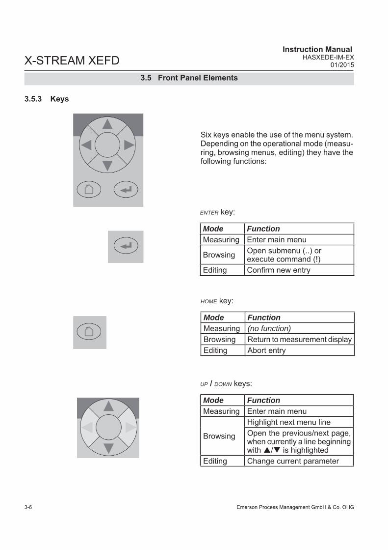
Emerson Process Management GmbH & Co. OHG3-6
X-STREAM XEFD Instruction Manual
HASXEDE-IM-EX01/2015
3.5.3 Keys
Six keys enable the use of the menu system. Depending on the operational mode (measu-ring, browsing menus, editing) they have the following functions:
ENTER key:
Mode FunctionMeasuring Enter main menu
Browsing Open submenu (..) or execute command (!)
Editing Confi rm new entry
HOME key:
Mode FunctionMeasuring (no function)Browsing Return to measurement displayEditing Abort entry
UP / DOWN keys:
Mode FunctionMeasuring Enter main menu
Browsing
Highlight next menu lineOpen the previous/next page, when currently a line beginning with / is highlighted
Editing Change current parameter
3.5 Front Panel Elements

Emerson Process Management GmbH & Co. OHG 3-7
X-STREAM XEFDInstruction ManualHASXEDE-IM-EX01/2015
3S
tartu
p
LEFT key:
Mode Function
MeasuringEnter main menu oropen 2nd measurement display page (if confi gured)
Browsing Go up 1 level or page in menu system
Editing
Move cursor 1 char to the leftLeave channel selectionCancel editing of given para-meterGo to previous menu page, if shows in fi rst menu line
RIGHT key:
Mode FunctionMeasuring Enter main menu or
open 2nd measurement display page (if confi gured)
Browsing Open submenu (..)
EditingGo to next menu page, when shows in last menu lineMove cursor 1 char to the right
3.5 Front Panel Elements
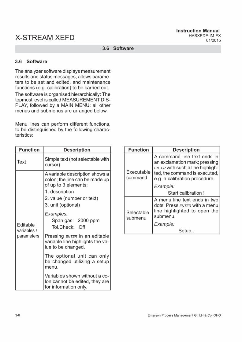
Emerson Process Management GmbH & Co. OHG3-8
X-STREAM XEFD Instruction Manual
HASXEDE-IM-EX01/2015
3.6 Software
The analyzer software displays measurement results and status messages, allows parame-ters to be set and edited, and maintenance functions (e.g. calibration) to be carried out. The software is organised hierarchically: The topmost level is called MEASUREMENT DIS-PLAY, followed by a MAIN MENU; all other menus and submenus are arranged below.
Menu lines can perform different functions, to be distinguished by the following charac-teristics:
3.6 Software
Function Description
Text Simple text (not selectable with cursor)
Editablevariables / parameters
A variable description shows a colon; the line can be made up of up to 3 elements:1. description2. value (number or text)3. unit (optional)
Examples: Span gas: 2000 ppmTol.Check: Off
Pressing ENTER in an editable variable line highlights the va-lue to be changed.
The optional unit can only be changed utilizing a setup menu.
Variables shown without a co-lon cannot be edited, they are for information only.
Function Description
Executable command
A command line text ends in an exclamation mark; pressing ENTER with such a line highligh-ted, the command is executed, e.g. a calibration procedure.Example:
Start calibration !
Selectable submenu
A menu line text ends in two dots. Press ENTER with a menu line highlighted to open the submenu.Example:
Setup..

Emerson Process Management GmbH & Co. OHG 3-9
X-STREAM XEFDInstruction ManualHASXEDE-IM-EX01/2015
3S
tartu
p
3.6 Software
Some menus have more entries than can dis-played at once. In these menus, an indicator in the last () and/or fi rst () line indicates the direction the menu continues in.In the example to the left• page 1 continues downwards• page 4 continues upwards and downwards• page 8 continues upwards.To show the next page (indicator ) • place the cursor in the last accessible line
and press DOWN or• press RIGHT, irrespective of where the cursor
is located.
To show the previous page (indicator )• place the cursor in the fi rst accessible line
and press UP or• press LEFT, irrespective of where the cursor
is located.
Browsing
Program Sequence 1of8Action1: END-OF-PGRMNode1: AllAction2: END-OF-PGRMNode2: AllAction3: END-OF-PGRMNode3: AllAction4: END-OF-PGRMNode4: All
Program Sequence 4of8Action13: END-OF-PGRMNode13: AllAction14: END-OF-PGRMNode14: AllAction15: END-OF-PGRMNode15: AllAction16: END-OF-PGRMNode16: All
Program Sequence 8of8Action29: END-OF-PGRMNode29: AllAction30: END-OF-PGRMNode30: All
Page 1
Page 4
Page 8

Emerson Process Management GmbH & Co. OHG3-10
X-STREAM XEFD Instruction Manual
HASXEDE-IM-EX01/2015
3.6 Software
EditingThe editing mode enables changing parame-ters. It is initiated by pressing ENTER. If the selection is a parameter list, the current entry is highlighted and may be changed by UP and DOWN.If the selection is a value, the cursor is placed over the last character. Use UP and DOWN to change it. Use LEFT and RIGHT to select another character.
The type of available characters depends on the position of the cursor: • It is not possible to select the minus sign or
decimal point as the last character. • It is not possible to select the decimal point
in integer values. • For decimal numbers, the decimal point can
be placed anywhere within certain limits. There are two ways to exit the data entry mode:ENTER: the entry is verifi ed.If it is accepted,
it is saved and the new value dis- played; if not, an error message is displayed.
HOME: Cancel: all settings and changes are reset to their former values.
Component selection menuWithin the analyzer software, one can distin-guish between analyzer related and compo-nent related menus: While the fi rst contain entries, relevant for the analyzer (e.g. time setting), the second contain entries relevant for a specifi c component (channel) only (e.g. calibrating a channel).For single channel analyzers, editing any channel specifi c parameter will only effect this one channel.Different for multi-channel analyzers: Such instruments require selecting a channel prior to changing channel related parameters. When a channel related menu entry is selec-ted, automatically a SELECT COMPONENT menu shows up, to select the component of interest, or to cancel the current action.
Select the component / channel you want to work with, and press ENTER.This menu does not show on single-channel units. Within menu descriptions, the following points out, that for multi-channel instruments a selec-tion is required:
Select Component
Component: Ch1
Press to return
Multi-channel unit:In SELECT COMPONENT select the chan-nel to be ...

Emerson Process Management GmbH & Co. OHG 3-11
X-STREAM XEFDInstruction ManualHASXEDE-IM-EX01/2015
3S
tartu
p
3.6.1 Access Levels & Codes
3.6 Software
Access levels can be used to prevent changes to parameters by unauthorised personnel. The X-STREAM menu system supports four prioritized access levels, which can be acti-vated and deactivated separately, and should be supplied with their own access codes.
Level four has the highest priority and is used for factory settings — only qualifi ed EMERSON service personnel have access to this level.
Level three gives access to system admin parameters, e.g. for confi guring data acqui-sition systems communication.
Level two covers the expert settings, e.g. basic settings for calibrations and measure-ments.
Level one is the user level and includes • parameters which should be set by trained
personnel only.• functions, not to be started by any person
(e.g. start calibrations).
All menus not assigned to one of these levels are not editable or of minor relevance.
Within this manual, the descriptions of the menus and procedures also indicate, which level the menus are assigned. These assign-ments cannot be changed. Access codes for levels 1 to 3 can be defi -ned, activated and deactivated by the client. The analyzer is delivered with the following settings:Level Access code Status 1 00000001 Off 2 00000002 Off 3 00000003 Off
Notes!If a low level is locked (status On), all higher levels will also be locked.If a high level is accessible (code entered when requested by a menu page), automa-tically all lower levels are also accessible.For above reasons, it is always possible to enter a higher code than requested, to gain access to a menu (e.g. if access code 1 is re-quested, you may also enter access code 2).
Entering access codesIf an access code is required for a menu, a message like the following appears:
To enter the code, press• UP/DOWN to change the currently selected
digit, • LEFT/RIGHT to select a different digit,• ENTER to submit the codeor• HOME to exit the edit mode and return to
the previous display.
Access Code 1
Code 00000000
Press to return
We recommend to set new ac-cess codes, if you want to use this option!

Emerson Process Management GmbH & Co. OHG3-12
X-STREAM XEFD Instruction Manual
HASXEDE-IM-EX01/2015
3.7 Start Up
Depending on the last action performed by the user, one of the following messages may be displayed to assist or inform the user.
Confi rmation of execution of function:Confi rms that a function or procedure (e.g. calibration) has been started, or cancelled. The message automatically dissapears after a few seconds.
3.7 Start Up
Information on incorrect entry:The value entered by the user is outside valid limits. The display indicates what limits apply.Press to return to the previous screen to enter an acceptable value.
3.6.2 Special Messages
When the unit is powered up, a series of in-ternal tests is automatically performed. During this time the front panel keys are disabled, while the remaining time counts down in the display.
The measurement display is shown • automaticaly on completion of the boot
sequence• when HOME is pressed• automatically after a set period of time
of inactivity (i.e. with no keys being pressed).
The information displayed in the four lines of the measurement display can be determined by the operator:• Sample gas components, measuring
results and measuring units for each channel
• secondary measurements, e.g. pressu-re, gas fl ow, temperature
• nothing (empty line)The factory settings are as follows:
Line 1: measured value of channel 1Line 2: measured value of channel 2Line 3: measured value of channel 3Line 4: measured value of channel 4
Note!If less than four channels are installed in the unit, only the measureands for these channels are available for selection.
3.7.1 Boot Sequence
3.7.2 Measurement Display
Wrong input
Range 0.1 ... 50
Press to return
Function Executing
Press to return

Emerson Process Management GmbH & Co. OHG 3-13
X-STREAM XEFDInstruction ManualHASXEDE-IM-EX01/2015
3S
tartu
p
SETUP enables several additional confi gu-rations, e.g.• 2 pages measurement display• different font sizes
The very fi rst display line shows• a fl ashing heart, showing the instrument is
operating• one or more status pictograms, if ( NAMUR)
status are active. Some of these are explai-ned by a text message in the last line
• a channel indicator, if the current menu page is related to a specifi c channel only.
The display´s bottom line shows plain text status information (errors, maintenance requests, function checks or off-spec perfor-mance).Active messages are stored in an internal buffer. If there is more than one message in the buffer, the display will cycle through.Most messages also activate a NAMUR relay (if a relay has been assigned to that NAMUR function; X-STREAM Enhanced instruc-tion manual).
Note!There are also functions, that do activate a relay, but are not shown on the display. In such cases, check the status menu for more information.
3.7 Start Up
MEASUREMENT DISPLAY
4 lines display
2 lines display with additional se-condary parameter line
1.000ppmCh1 CO
500ppmCh2 CO
2.400ppmCh3 CO
1.900ppmCh4 CO
10.0000ppmInputCh1 CO
10.0000ppmOutputCh2 COFlow 1 0.00 l/min
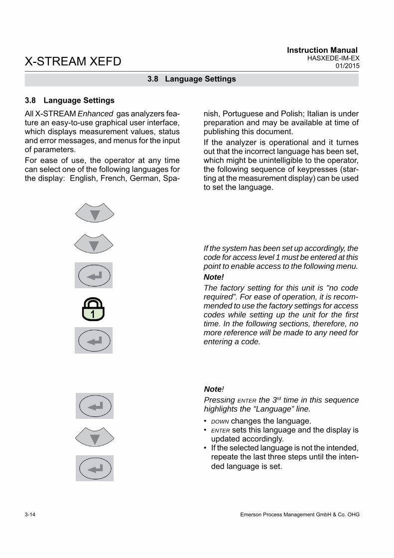
Emerson Process Management GmbH & Co. OHG3-14
X-STREAM XEFD Instruction Manual
HASXEDE-IM-EX01/2015
All X-STREAM Enhanced gas analyzers fea-ture an easy-to-use graphical user interface, which displays measurement values, status and error messages, and menus for the input of parameters.For ease of use, the operator at any time can select one of the following languages for the display: English, French, German, Spa-
3.8 Language Settings
3.8 Language Settingsnish, Portuguese and Polish; Italian is under preparation and may be available at time of publishing this document. If the analyzer is operational and it turnes out that the incorrect language has been set, which might be unintelligible to the operator, the following sequence of keypresses (star-ting at the measurement display) can be used to set the language.
• DOWN changes the language. • ENTER sets this language and the display is
updated accordingly.• If the selected language is not the intended,
repeate the last three steps until the inten-ded language is set.
Note!Pressing ENTER the 3rd time in this sequence highlights the "Language” line.
If the system has been set up accordingly, the code for access level 1 must be entered at this point to enable access to the following menu. Note!The factory setting for this unit is "no code required”. For ease of operation, it is recom-mended to use the factory settings for access codes while setting up the unit for the fi rst time. In the following sections, therefore, no more reference will be made to any need for entering a code.

Emerson Process Management GmbH & Co. OHG 3-15
X-STREAM XEFDInstruction ManualHASXEDE-IM-EX01/2015
3S
tartu
p
3.9 Checking the Settings
Starting with the measurement display ( 3-12 ), pressing any key except HOME will ac-cess the MAIN MENU; from here, follow these steps: (If the display is showing anything other than the measurement display, press HOME to return to the measurement display fi rst).
3.9 Checking the Settings
Set the preferred language for the software.
Note!If you are unfamiliar with the language set:
3-14 shows the sequence of keys to set a different language.
( )
If the system has been set up accordingly, the code for access level 1 must be entered at this point to enable access to the following menu. Note!The factory setting for this unit is "no code required”. For ease of operation, it is recom-mended to use the factory settings for access codes while setting up the unit for the fi rst time. In the following sections, therefore, no more reference will be made to any need for entering a code.
The following sections are structured so that the user can work through them one by one after powering up the unit. After completing
these steps, the unit will be confi gured to the user’s needs and properly functioning.
Setup 1of2Display..Calibration..Measurement..In-/Outputs..Communication..Alarms..Installed Options..Save-Load..
Display
Contrast..Language: EnglishPhrase Version EN1.30Measurements..Measurement Display..Menu Access.. 10 MinAuto Home: 10 Min
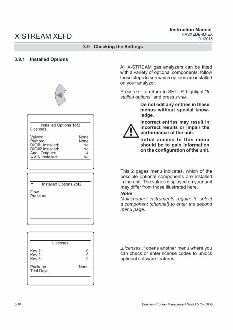
Emerson Process Management GmbH & Co. OHG3-16
X-STREAM XEFD Instruction Manual
HASXEDE-IM-EX01/2015
3.9 Checking the Settings
3.9.1 Installed Options
Press LEFT to return to SETUP, highlight " In-stalled options" and press ENTER.
This 2 pages menu indicates, which of the possible optional components are installed in the unit. The values displayed on your unit may differ from those illustrated here.Note!Multichannel instruments require to select a component (channel) to enter the second menu page.
All X-STREAM gas analyzers can be fi tted with a variety of optional components: follow these steps to see which options are installed on your analyzer.
„Licenses..“ opens another menu where you can check or enter license codes to unlock optional software features.
Do not edit any entries in these menus without special know-ledge.Incorrect entries may result in incorrect results or impair the performance of the unit.Initial access to this menu should be to gain information on the confi guration of the unit.
Installed Options 1of2Licenses..
Valves: NonePumps: NoneDIO#1 installed: NoDIO#2 installed: NoAnal. Outputs: 4AIN installed: No
Installed Options 2of2
Flow..Pressure..
Licenses
Key 1: 0Key 2: 0Key 3: 0
Package NoneTrial Days

Emerson Process Management GmbH & Co. OHG 3-17
X-STREAM XEFDInstruction ManualHASXEDE-IM-EX01/2015
3S
tartu
p
3.9 Checking the Settings
3.9.2 Confi guring the Display
Check the settings for the measurement display, temperature and pressure units, and for menu access: press ENTER to open DIS-PLAY.., select "Measurement display.." and press ENTER.If a setting does not meet your requirements, access that menu and adjust the parameter.
Press LEFT to return to SETUP.
Select the value to be displayed in each line of the measurement display. The following options are available: Comp1 ... Comp5, Temp1 ... Temp5, Press1 ... Press5, Flow1 ... Flow5 Blank (nothing)Note!X-STREAM currently supports one pressure sensor only. Values Press1 to Press5 thus refer to the same sensor.
When entering LABELS.., you may change the channel´s label, that is the fi rst text phra-se in a line showing a measurement value: If here nothing is entered, the default phrases (Ch1 ... Ch4) are used.
Note!Notice the headlines of the menus showing a "1": This indicates that you can setup more than 1 measurement display page.
Display 1 Assignments
Line 1: Comp1Line 2: Comp2Line 3: Comp3Line 4: Comp4Line 5: Blank
Labels..
Display 1 Labels
Line 1:Line 2:Line 3:Line 4:Line 5:
Do yet not change entries here.This fi rst access to the menu is intended to provide information on the analyzer confi guration only. Wrong entries may result in wrong measurements or affect analyzer effi ciency.

Emerson Process Management GmbH & Co. OHG3-18
X-STREAM XEFD Instruction Manual
HASXEDE-IM-EX01/2015
Multi-channel unit:Select the component to be set in the gas component selection menu.
Once the display settings have been chek-ked, press LEFT to return to SETUP and open CALIBRATION to check the calibration settings.
In CALIBRATION - GASES, enter the values for zero and span gas: • See gas supplier´s certifi cate for correct
values.• Values must be correctly set for results to
be accurate. • Multi-channel units: the values for each
channel must be entered separately.
3.9.3 Calibration Setup
3.9 Checking the Settings
Press LEFT to return to CALIBRATION, and enter TOLERANCES .By default the 'Deviation Tolerance check"' option is set inactive (Off). With "DeviatToler" set to On, • during calibration the analyzer checks
whether the values set for zero and span gas conform to the concentration of the gas currently being supplied.
• If the concentrations differ more than the percentage of range entered in the follo-wing lines, the calibration is aborted.This prevents calibration from being performed when the incorrect gas is supplied (e.g. span gas calibration using zero gas), which would result in an incorrectly confi gured unit.
Note!For more detailed information about calibra-tion procedures, X-STREAM Enhanced instruction manual.
Setup..Calibration..
Ch1Calibration
Gases..Tolerances..Procedure..Valve Assignment..Program Sequence..Interval Time..Deviations..
Gases
Zero Gas: 0.000 ppmSpan Gas: 50000.000 ppmRange Gases..
Current Range: Range 1
Ch2Tolerances
DeviatToler.: OffZero Limit: 20.0 %Span Limit: 20.0 %

Emerson Process Management GmbH & Co. OHG 3-19
X-STREAM XEFDInstruction ManualHASXEDE-IM-EX01/2015
3S
tartu
pSignal damping (set in DAMPING) allows smoothing the output signal, but also affects the response time of outputs and display:• The factory setting is 0 seconds. • The maximum possible t90 time is limited by
the size of the internal sampling buffer and the sampling rates of the installed measu-ring principles/sensors.
• Multi-channel units: the value for each channel must be entered separately.
The second page´s last line enables the user • to enter the current ambient pressure ma-
nually, if no pressure sensor is installed, or • to view the current pressure, if a sensor
is installed ( INSTALLED OPTIONS).
If no pressure sensor is installed, enter the current ambient pressure here and adjust it, when signifi cant changes take place: this improves the accuracy of the instrument.
Press LEFT several times to return to SETUP and open MEASUREMENT.
3.9 Checking the Settings
Setup..Measurement..
Ch1Measurement 1of2
Ranges..Damping..Linearization.. Cross Interference.. Average..Delay..
Ch1Measurement 2of2
Cut-off: NonePressure Compensation ..
Ch1Pressure compensation
Manual Pressure: 1013 hPa
Pressure 1013 hPaPressure Status Good

Emerson Process Management GmbH & Co. OHG3-20
X-STREAM XEFD Instruction Manual
HASXEDE-IM-EX01/2015
3.9 Checking the Settings
Press LEFT to return to SETUP, and then open IN/OUTPUTS. and from there enter ANALOG OUTPUTS.
3.9.4 Setting the Analog Outputs
Select the analog output you like to check.Note!The following section only in brief describes the entries currently of interest!
X-STREAM Enhanced instruction manu-al, Chapter 6 for a more detailed description.
Setup..In/Outputs..
Analog outputs..
"Signal” specifi es the value associated with the selected output. The following options (partly dependent on the number of measu-ring channels and sensors installed) are available:
Analog Outputs
Output1..Output2..Output3..Output4..Output5..
Signal: Comp1OutRange: 0-20 mALow Scale: 0.00Max Scale: 100.00AutoScale: YesFailMode: Live0/4 mA: 0.0020 mA: 100.00Hold: No

Emerson Process Management GmbH & Co. OHG 3-21
X-STREAM XEFDInstruction ManualHASXEDE-IM-EX01/2015
3S
tartu
p
3.9 Checking the Settings
*) Numbers 1 to 5 refer to components [chan-nels] 1 to 5: In case of secondary parameters, this means, the selected value is that of the sensor assigned to the given component (Press2 is the pressure value of the sensor assigned to component 2).
In contrast, capital letters A to D imply that these calculator results are component [channel] independent (Calc C is the result of calculator C).
Signal*) DescriptionNone The analog output is deactivated
0 mAA 0 or 4 mA signal is generated, e.g. to check the signal processing in an external system. Whether a 0 or 4 mA signal is generated, is set by the "Out range” line ( next page).
20 mA A 20 mA signal is generated, e.g. to check the signal processing in an exter-nal system.
Comp1 ... 5 Gas concentrationTemp1 ... 5 TemperaturePress1 ... 5 PressureFlow1 ... 5 FlowCalcA ... D Result of calculator
RawVal1 ... 5 Raw value RangeID1 ... 5 ID of selected range
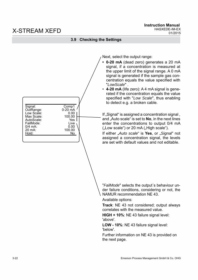
Emerson Process Management GmbH & Co. OHG3-22
X-STREAM XEFD Instruction Manual
HASXEDE-IM-EX01/2015
3.9 Checking the Settings
Next, select the output range: • 0-20 mA (dead zero) generates a 20 mA
signal, if a concentration is measured at the upper limit of the signal range. A 0 mA signal is generated if the sample gas con-centration equals the value specifi ed with "LowScale" .
• 4-20 mA (life zero): A 4 mA signal is gene-rated if the concentration equals the value specifi ed with "Low Scale", thus enabling to detect e.g. a broken cable.
"FailMode" selects the output´s behaviour un-der failure conditions, considering or not, the NAMUR recommendation NE 43. Available options:Track: NE 43 not considered; output always correlates with the measured value.HIGH + 10%: NE 43 failure signal level: 'above'.LOW - 10%: NE 43 failure signal level: 'below'.Further information on NE 43 is provided on the next page.
If „Signal“ is assigned a concentration signal , and „Auto scale“ is set to No, in the next lines enter the concentrations to output 0/4 mA („Low scale“) or 20 mA („High scale“).If either „Auto scale“ is Yes, or „Signal“ not assigned a concentration signal, the levels are set with default values and not editable.
Signal: Comp1OutRange: 0-20 mALow Scale: 0.00Max Scale: 100.00AutoScale: YesFailMode: Live0/4 mA: 0.0020 mA: 100.00Hold: No

Emerson Process Management GmbH & Co. OHG 3-23
X-STREAM XEFDInstruction ManualHASXEDE-IM-EX01/2015
3S
tartu
p
3.9 Checking the Settings
Tab. 3-1: Analog Output Signals Settings and Operational Modes
Operation Modes acc. NAMUR NE 43data acquisition system is enabled to distinguish between the following situations:• valid measured value (signal within range as per Table 3-1) • signal out of range (signal slowly rises or
falls towards the limits given in table 5-1, and holds that value until the concentration returns to within the measuring range).
• failure (signal out of range as per table 5-1, but not 0) • severed cable (no signal [0 mA]),
Table 3-1 provides a summary of all available operational modes.
The common modes for analog outputs do not support the detection of a failure in the measurement system. In such a case, the behaviour of the output signal is undefi ned: either the last value is held, or a random value is sent. System failures cannot be detected by an external data capture system.
NE43 includes recommendations for such cases, but also for the confi guration of analog outputs to detect other measurement states. X-STREAM analyzers incorporate these re-commendations as follows:Setting "FailMode" to HIGH + 10% or LOW - 10% defi nes specifi c analog output signals in case of a failure. Since these values are not output under normal operation conditions, a
Output signal, if
"OutRange" "FailMode"Failure
signal level acc. NE 43
Measured value is
valid
Measured value is below lower limit
("Low scale")
Measured value is above upper limit
("High scale")
An internal failure
occured
Cable is severed
0-20 mA Track - 0…20 mA < -19 mA > 21.7 mA undefi ned 0 mA
4-20 mA Track - 4…20 mA < -19 mA > 21.7 mA undefi ned 0 mA
0-20 mA LOW - 10 % below 0…20 mA -0.20 mA* (-1.80…-0.01 mA)**
20.50 mA*(20.01…21.50 mA)** -2 mA 0 mA
4-20 mA LOW - 10 % below 4…20 mA 3.80 mA* (2.20…3.99 mA)**
20.50 mA*(20.01…21.50 mA)** 2 mA 0 mA
0-20 mA HIGH + 10 % above 0…20 mA -0.20 mA* (-1.80…-0.01 mA)**
20.50 mA*(20.01…21.50 mA)** > 21.7 mA 0 mA
4-20 mA HIGH + 10 % above 4…20 mA 3.80 mA* (2.20…3.99 mA)**
20.50 mA*(20.01…21.50 mA)** > 21.7 mA 0 mA
Note!The application of values marked * or ** depends on the setting of "Cut Mode" (for more information
Chapter 6 of the X-STREAM Enhanced instruction manual).
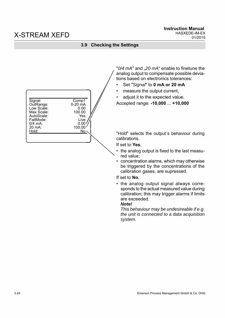
Emerson Process Management GmbH & Co. OHG3-24
X-STREAM XEFD Instruction Manual
HASXEDE-IM-EX01/2015
Signal: Comp1OutRange: 0-20 mALow Scale: 0.00Max Scale: 100.00AutoScale: YesFailMode: Live0/4 mA: 0.0020 mA: 100.00Hold: No
3.9 Checking the Settings
"0/4 mA" and „20 mA“ enable to fi netune the analog output to compensate possible devia-tions based on electronics tolerances: • Set "Signal" to 0 mA or 20 mA• measure the output current, • adjust it to the expected value.Accepted range: -10,000 ... +10,000
"Hold" selects the output´s behaviour during calibrations. If set to Yes,• the analog output is fi xed to the last measu-
red value;• concentration alarms, which may otherwise
be triggered by the concentrations of the calibration gases, are supressed.
If set to No, • the analog output signal always corre-
sponds to the actual measured value during calibration; this may trigger alarms if limits are exceeded. Note!This behaviour may be undesireable if e.g. the unit is connected to a data acquisition system.

Emerson Process Management GmbH & Co. OHG 3-25
X-STREAM XEFDInstruction ManualHASXEDE-IM-EX01/2015
3S
tartu
p
3.9 Checking the Settings
Press LEFT until SETUP is displayed, then open ALARMS - CONCENTRATION
3.9.5 Setting Concentration Alarms
Four concentration limits can be set for each channel:
"Lo" and "Hi" enframe the expected gas concentration,"LoLo" equals or is below "Lo","HiHi" equals or is above "Hi".
See the fi gure to the left for an explanation.If you enter values for any threshold, the above given order has to be considered. A message is displayed, if an entered value does no comply with this condition.
Note!If concentration alarms are not being used, continue with 3-26.
Should the measured concentration go bey-ond one of the threshold levels (areas B, C, D & E in the fi gure), a message is displayed in the message line of the measurement display, the NAMUR pictogram appears (bell) and a corresponding digital output is activated, if assigned.
A hysteresis avoids oscillating alarms in case the concentration is fl uctuating around a threshold.
Fig. 3-3: Arrangement of Concentration Thresholds
Multi-channel unit:Select the channel to be setup in SELECT COMPONENT.
Ch1Concentration
Alarm Monitor: OnLoLo Level: 50.000 ppmLo Level: 100.000 ppmHi Level: 400.000 ppmHiHi Level: 600.000 ppmHysteresis: 10.000 ppmStates..
Note!HiHi and LoLo designate pre-alarms,Hi and Lo designate main alarms.

Emerson Process Management GmbH & Co. OHG3-26
X-STREAM XEFD Instruction Manual
HASXEDE-IM-EX01/2015
3.9 Checking the Settings
The most important settings have now been checked and the unit is confi gured to suite your needs.A backup copy of these confi guration data can now be saved.
Press LEFT until SETUP and then open SAVE-LOAD.
3.9.6 Backup the Settings
This menu gives you the choice, to either• make a local backup to a protected memory
area• restore the factory default settings, or• make a backup to an external USB device.
You may turn the alarm function On or Off separately for each channel ("Alarm Monitor").It´s also possible to use some of the thres-holds only. In this case, set the not used to a level outside the range limits (for this, "Lo" and "LoLo" support entering negative values).In case of an alarm, you may like to enter the STATES submenu, to check which one is triggered.
Ch1Concentration
Alarm Monitor: OnLoLo Level: 50.000 ppmLo Level: 100.000 ppmHi Level: 400.000 ppmHiHi Level: 600.000 ppmHysteresis: 10.000 ppmStates..
Save-Load
Local Backup..Factory Defaults.. USB Backup..
USB Firmware Update..

Emerson Process Management GmbH & Co. OHG 3-27
X-STREAM XEFDInstruction ManualHASXEDE-IM-EX01/2015
3S
tartu
p
3.9 Checking the Settings
Congratulations!You´ve now successfully completed check-ing the unit’s setup! • Press HOME to return to the MEASURE-
MENT DISPLAY.
For now, make a local backup:Enter LOCAL BACKUP and then select "Save..".
Confi rm the operation (select "Yes!").
Wait until "Progress" shows 100 %, then press ENTER to return to LOCAL BACKUP.Copying Data
Busy 0Progress 100 %
Press to return
Local Backup
Save..UsrBack Date 7/29/09 14:26Restore..Undo Restore!Busy 0Progress 0 %
Save new local backupand overwrite old one!
Are you sure?
No!Yes!
We recommend to perform at least a zero calibration, after startup of the instrument, to ensure proper measuring results. 4-16 for information on how to perform a manual calibration. If your instrument features
a valve block, X-STREAM Enhanced instruction manual for a comprehensive de-scription of calibration procedures.

Emerson Process Management GmbH & Co. OHG3-28
X-STREAM XEFD Instruction Manual
HASXEDE-IM-EX01/2015
3.10 Web Browser
IP address for Ethernet1 connectorInfo
Firmware 1.0DSP version 1.0Serial no 123456789Components..Installed options..Ethernet1 IP 123.456.78.9Ethernet2 IP 192.168.1.2 Time 10/01/10 14:00
Fig. 3-4: Ethernet Connectors
To gain access to the instrument´s web brow-ser interface, fi rst ensure the instrument is powered and connected to your network via Ethernet1 connector (Fig. 3-4)
By factory default settings the analyzer is confi gured to receive a valid network address by a DHCP server. Next enter INFO, to check if the instrument has been assigned a valid network IP address:
If no network IP address has been assigned, check the network settings ( X-STREAM instruction manual, page 6-79 )
IIIII
Ethernet1 connector
Ethernet2 connector
Field housings
3.10.1 Connection Via Network
Connect your computer to the network, open a web browser and enter the instrument´s IP address. If everything is confi gured properly, the analyzer's logon screen shows up ( 3-30).
3.10 Web Browser

Emerson Process Management GmbH & Co. OHG 3-29
X-STREAM XEFDInstruction ManualHASXEDE-IM-EX01/2015
3S
tartu
p
3.10 Web Browser
IP address for Ethernet2 connector
To directly gain access to the instrument´s web browser interface, fi rst ensure the instrument is powered. Next connect it to the computer's network adapter via Ethernet2 connector (see Fig. 3-4) by means of an Ethernet cross-over cable. Standard Ethernet cables do NOT support direct connections!• For Ethernet2 connector set "Use DHCP"
to No (see fi gure to the left). Depending on settings possibly carried out earlier, the analyzer may now show an IP (see fi gure to the left). If so, setup your computer's IP the same way, only differing in the last group (here e.g. to 123.456.78.10). Alternatively you may use the analyzer's fi xed IP, that is not shown on any menu page and is accessible via Ethernet2 only:• The analyzer is now assigned the IP
192.168.1.88.• Confi gure your computer's IP to meet the
same net (192.168.1.) and assign a new IP (e. g. 192.168.1.10). Do not use the same IP as is assigned to the analyzer.
3.10.2 Connection to Single Computer
Confi guring an IP Address for Computers Running Microsoft Windows• To confi gure your computer you need an administrator account! • Go to Start > Control Panel > Network Connections• Right-click on your LAN connection and click "Properties"• Under the heading "This connection uses the following items", click "Internet Protocol (TCP/IP)"• Click "Properties"• A new window should pop up, click "Alternate Confi guration"• Click "User Confi gured" radio button• Setup the IP Address as 192.168.1.10, Subnet Mask as 255.255.255.0 and Default Gateway as 192.168.1.1. • Click "OK"• Click "Close" in "LAN connection properties".
On your computer open a web browser and enter the instrument´s IP address. If everything is confi gured properly, the analyzer's logon screen shows up ( next page ).
Ethernet2 MAC 123456789IP: 123.456.78.9Subnet: 255.255.255.1Gateway: 123.456.78.0Use DHCP: NoIP Status ReadyApply Confi guration!
Setup..Communcation..
Ethernet2..
222222222222222222222222222
uratttttttttttttttttttttttttiioioooooooooooioioiiiiii n!

Emerson Process Management GmbH & Co. OHG3-30
X-STREAM XEFD Instruction Manual
HASXEDE-IM-EX01/2015
3.10 Web Browser
Default password is: password
Fig. 3-5: Web Browser Logon Screen
Fig. 3-6: Web Browser Measurements Screen
IP address in web browser´s address line
Enter your password here
MAC address of interface
Analyzer serial number
Analyzer work order number
Analyzer information
After logon, the measurements screen appears.Click on the left most icon (question mark) in the status bar, to receive comprehensive online help on the X-STREAM XE web browser interface.
We recommend to set new pass-words, to limit access to critical submenus (see online help).

Emerson Process Management GmbH & Co. OHG 4-1
4M
aint
enan
ce
X-STREAM XEFDInstruction ManualHASXEDE-IM-EX01/2015
Chapter 4Service and Maintenance
Note!This chapter deals with service and maintenance procedures related to explosion protection only!More detailled instructions about servicing and maintaining general purpose components of X-STREAM XE gas analyzers are subject of the X-STREAM XE analyzer instruction manual.
EXPLOSION HAZARD
Inspection, maintenance and service must be carried out considering all related standards e.g. for „Inspection and maintenance of electrical installations in hazardous areas“or „Equipment repair, overhaul and reclamation.
EXPLOSION HAZARD BY OPEN HOUSING
Service or replacement of safety related components or requiring to open the instrument are permitted only if no hazardous atmosphere is present and both the instrument and connected circuitry are de-energized!Depending on the local regulation this may require a competent hot work supervisor to issue a hot work permit.Consider the waiting time statement on the front door label before opening, if the analyzer is confi gured for vapor recovery measurements!
EXPLOSION HAZARD BY UNAUTHORIZED REPLACEMENTS
After maintenance or replacement of parts concerning explosion protection an authority on explosion protection has to verify that the analyzer still meets the requirements for explosion protection before it is switched on again.Parts essential for explosion protection must not be repaired, they must be replaced if defective!The authority has to issue a certifi cate for this and/or attach a test label to the equipment before startup after maintenance or replacement of parts.
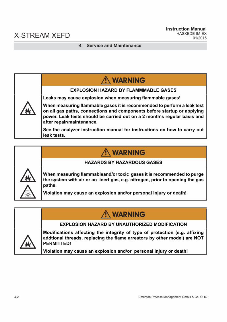
Emerson Process Management GmbH & Co. OHG4-2
X-STREAM XEFDInstruction Manual
HASXEDE-IM-EX01/2015
4 Service and Maintenance
EXPLOSION HAZARD BY FLAMMMABLE GASES
Leaks may cause explosion when measuring fl ammable gases!When measuring fl ammable gases it is recommended to perform a leak test on all gas paths, connections and components before startup or applying power. Leak tests should be carried out on a 2 month‘s regular basis and after repair/maintenance.See the analyzer instruction manual for instructions on how to carry out leak tests.
HAZARDS BY HAZARDOUS GASES
When measuring fl ammableand/or toxic gases it is recommended to purge the system with air or an inert gas, e.g. nitrogen, prior to opening the gas paths.Violation may cause an explosion and/or personal injury or death!
EXPLOSION HAZARD BY UNAUTHORIZED MODIFICATION
Modifi cations affecting the integrity of type of protection (e.g. affi xing addtional threads, replacing the fl ame arrestors by other model) are NOT PERMITTED!Violation may cause an explosion and/or personal injury or death!
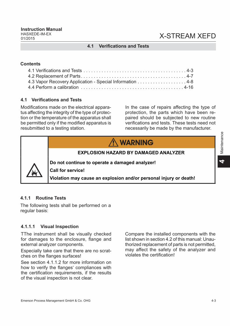
Emerson Process Management GmbH & Co. OHG 4-3
4M
aint
enan
ce
X-STREAM XEFDInstruction ManualHASXEDE-IM-EX01/2015
Modifi cations made on the electrical appara-tus affecting the integrity of the type of protec-tion or the temperature of the apparatus shall be permitted only if the modifi ed apparatus is resubmitted to a testing station.
4.1 Verifi cations and Tests
4.1 Verifi cations and Tests
4.1.1 Routine TestsThe following tests shall be performed on a regular basis:
EXPLOSION HAZARD BY DAMAGED ANALYZER
Do not continue to operate a damaged analyzer! Call for service!Violation may cause an explosion and/or personal injury or death!
4.1.1.1 Visual InspectionTThe instrument shall be visually checked for damages to the enclosure, fl ange and external analyzer components. Especially take care that there are no scrat-ches on the fl anges surfaces!See section 4.1.1.2 for more information on how to verify the fl anges‘ compliances with the certifi cation requirements, if the results of the visual inspection is not clear.
Contents4.1 Verifi cations and Tests . . . . . . . . . . . . . . . . . . . . . . . . . . . . . . . . . . . . . . . . 4-34.2 Replacement of Parts . . . . . . . . . . . . . . . . . . . . . . . . . . . . . . . . . . . . . . . . . 4-74.3 Vapor Recovery Application - Special Information . . . . . . . . . . . . . . . . . . . 4-84.4 Perform a calibration . . . . . . . . . . . . . . . . . . . . . . . . . . . . . . . . . . . . . . . . 4-16
In the case of repairs affecting the type of protection, the parts which have been re-paired should be subjected to new routine verifi cations and tests. These tests need not necessarily be made by the manufacturer.
Compare the installed components with the list shown in section 4.2 of this manual: Unau-thorized replacement of parts is not permitted, may affect the safety of the analyzer and violates the certifi cation!

Emerson Process Management GmbH & Co. OHG4-4
X-STREAM XEFDInstruction Manual
HASXEDE-IM-EX01/2015
4.1 Verifi cations and Tests
4.1.1.2 Detailed Inspection• Check cable inlets (glands or conduits):
If the cable moves, e. g. thighten the cap nut. If tightening is ineffective, replace the cable gland or conduit. Also consider the original manufacturer‘s instructions for maintenance!
• Damages to the fl anges cannot be ac-cepted, as they act as fl ame paths. If need be, submit the unit to one or more of the following measurements to confi rm com-pliance with the certifi cation requirements:
• Evenness of fl ange surfaces: max. accepted 0.04 mm per fl ange
• Roughness Ra of fl anges: max. accepted 6.3 μm
If one or both of above measurements show non-compliances,• take the analyzer out of service by dis-
connecting all electrical connections• submit the unit to the Emerson service
center.

Emerson Process Management GmbH & Co. OHG 4-5
4M
aint
enan
ce
X-STREAM XEFDInstruction ManualHASXEDE-IM-EX01/2015
4.1.1.3 Tests on Flame Arrestors
The following procedure describes how to perform a leak test with the fl ame arrestor installed at the instrument. Required tools Manometer for max. 7.25 psi (500 mbar)
Stop valve
Maintenance is limited to performing visual inspections, leak testing and pressure drop tests on at least a regular basis. The time interval has to be operator defi ned, conside-ring operating conditions and composition of supplied gases.
The fl ame arrestor is completely welded, no inner parts are user accessible. Therefore the fl ame arrestor has to be replaced by a new one, if- a fi re occurred on the fl ame arrestor element- the housing or the fi ttings show visible mechanical damages- contamination of inner elements is detected (e.g. by pressure drop test)- the fl ame arrestor did not pass leak testing
4.1.1.3.1 Leak Testing
Procedure Connect the manometer to the analyzer‘s
sample gas outlet to the fl ame arrestor´s outlet fitting (disconnect external gas lines).
Install the stop valve between gas inlet fi tting and a Nitrogen (N2) supply.
Open the stop valve until the internal gas path is under pressure of approx. 0.725 psi/50 mbar (corresponding to approx. 19.7 inch/500 mm water column)
Close the stop valve. After a short time for the pressure to balance, the level must not change over a time period of approx. 5 minutes!
When using a water fi lled u-tube manometer prevent water from entering backwards into the fl a-me arrestor!Don‘t exceed the maximum pressure applicable to the ana-lyzer as specifi ed in it´s instruc-tion manual!
EXPLOSION HAZARD AND GASES HAZARDOUS TO HEALTH
Maintaining the fl ame arrestor must be carried out considering all applicable safety and legislative rules. Maintenance should be carried out by instructed and trained personnel only!Before opening gas paths they must be purged with safe air or neutral gas (N2) to avoid hazards caused by toxic, fl ammable, explosive or harmful to health sample gas components!
4.1 Verifi cations and Tests

Emerson Process Management GmbH & Co. OHG4-6
X-STREAM XEFDInstruction Manual
HASXEDE-IM-EX01/2015
Fig. 4-1: Leak Testing with U-tube Manometer (Flame arrestor)
Analyzer
overpressure approx. 0.725 psi/50 mbarstop
valve
Water
fl ame arrestors
4.1.1.3.2 Pressure Drop TestTo measure the pressure drop at a fl ame arrestor disconnect internal and external gas lines connect a fl ow meter in series to the fl ame
arrestor connect an air or nitrogen supply to the
fl ow meter connect a manometer in a way to measu-
re the pressure at the fl ame arrestor inlet against the outlet
adjust the fl ow to 1 l/min and compare the resulting pressure drop to the following reference value: (5.1 ± 1) hPa.
Replace the fl ame arrestor if the measured pressure value differs more than 10 % from the reference value given above. Fig. 4-2: Pressure Drop Test
Q = 1 l/min
fl ame arrestor
fl ow meter
manometer
4.1 Verifi cations and Tests

Emerson Process Management GmbH & Co. OHG 4-7
4M
aint
enan
ce
X-STREAM XEFDInstruction ManualHASXEDE-IM-EX01/2015
4.2 Replacement of Parts
EXPLOSION HAZARD BY REPLACEMENTS PARTS
Replacement of parts found defective is permitted only by using original parts!Violation voids the approvals and may cause explosions!
4.2 Replacement of Parts
Specifi cally for ATEX approved analyzers
Cable glandsNOT FOR analyzers for vapor recovery applications!
Any ATEX approved fl ameproof type without compound, suitable according EN 60079-14, e. g.- 8163/2 A2F M20 by Stahl
Cable glandssuitable for all ATEX approved variations
Any ATEX approved fl ameproof type with compound, suitable according EN 60079-14, e. g. - ADE 1FC ISO 20 No. 05 by CAPRI, or- 8163/2–PXSS2K M20 by Stahl
Cable entries stopping plugs
Any ATEX approved fl ameproof type, e. g. - 120209 by CAPRIMale thread: M20 x 1,5Spare part # ETC01754
Parts beside the cast enclosure, the safety of the X-STREAM XEFD relies on:

Emerson Process Management GmbH & Co. OHG4-8
X-STREAM XEFDInstruction Manual
HASXEDE-IM-EX01/2015
4.2 Replacement of Parts
Specifi cally for CSA-C/US approved analyzers
Metric-to-NPT adapters
Any CSA-C/US certifi ed fl ameproof typeMale thread: M20 x 1,5Female thread: 1⁄2“ or 3⁄4“ per requeste.g.- AD-U series by Redapt Ltd.
3⁄4“ version spare part # ETC01877
Cable entries stopping plugs
Any CSA-C/US certifed fl ameproof typeMale thread: M20 x 1,5 e.g.- PD-U by Redapt Ltd.
Spare part # ETC01878
For ATEX and CSA analyzers
Flame arrestors
Type: FA 01, FA 02, FA 03by EMERSON PROCESS MANAGEMENT FA 01: Spare part # 42716625FA 02: Spare part # 42716625-V1FA 03: Spare part # 42716625-V2
Enclosure screws
Material: stainless steel A2-70Thread: M16 x 45 ISO 4762 A2Modifi ed to drawing 4.271-6945by EMERSON PROCESS MANAGEMENTSpare part # 42716945
Internal BatteryType: CR2032 by Varta; Lithium button cell3Vdc; 230 mAh

Emerson Process Management GmbH & Co. OHG 4-9
4M
aint
enan
ce
X-STREAM XEFDInstruction ManualHASXEDE-IM-EX01/2015
4.3 Vapor Recovery Application - Special Information
4.3 Vapor Recovery Application - Special Information
EXPLOSION HAZARD BY HOT COMPONENTS
Consider the waiting time statement on the front door label before opening!Do not open the instrument when energized.Ensure that external circuitry is disconnected or de-energized before opening the instrument.
XEFD analyzers, intended for vapor recovery applications (measuring CH4 and non-CH4), contain additional components and have a special confi guration:• Below the two IR channels a converter
assembly is installed, thermostated to about 270 °C.
• Inside the front door a second power sup-ply unit and another electronics board is installed to supply the converter.
An overtemperature switch limits the tempe-rature of the converter in case of failure of the temperature control board.Inside the converter assembly there is a small stainless steel vessel, filled with catalytic converter material, which is a consumable and needs to be replaced depending on the required converter effi ciency:
2
1
5
3
4
1: IR measurement2: High temperature converter assembly3: Additional temperature control4: Additional power supply unit5: Overtemperature switch
Fig. 4-3: Vapor recovery application setup
The waiting time is calculated to ensure, temperatures of hot components are below the ana-lyzer temperature class for hazar-dous areas! Accessible components still may be hot and harmful to humans!

Emerson Process Management GmbH & Co. OHG4-10
X-STREAM XEFDInstruction Manual
HASXEDE-IM-EX01/2015
4.3 Vapor Recovery Application - Special Information
• Ensure „Pump 1“ within the control menu is set to ON.
Note!„Pump 1“ is used to disable (Off) or enable (On) the gas fl ow through the converter!
• Apply the calibration gas for CH2 (e. g. C6H14). As CH1 and CH2 inside the ana-lyzer are piped in parallel, this gas now goes through the converter.
• When stabilized, write down the measure-ment reading of CH1 (CH4 channel with converter)
• Now change „Pump1“ to Off, to let the gas bypass the converter.
• When stabilized, write down the measure-ment reading of CH1 (CH4 channel with-out converter)
• Calculate the converter effi ciency:
• If the result is below 0.9 (90 %), the con-verter material should be replaced as described in the next section.
Part number for converter replacement ma-terial: ETC02579
Notes!While „Pump 1“ is set to Off, the NAMUR status Function Check is actvated.Don‘t forget to set „Pump 1“ to On again, af-ter fi nishing the calculation of converter ef-fi cieny!
Note!The analyzer is confi gured to measure CH4 at channel 1 (CH1), with the converter in-stalled in front of its measurement cell.The total content of hydorcarbons (CnHm) within the sample gas is measured at chan-nel 2 (CH2).
Zero Calibration..Span Calibration..Advanced Calibration.. Apply Gas.. Lock Menus! AcknowledgementsPump 1: OnPump 2: OffRanges..
4.3.1 Determining the converter effi ciency
•
•
•
•
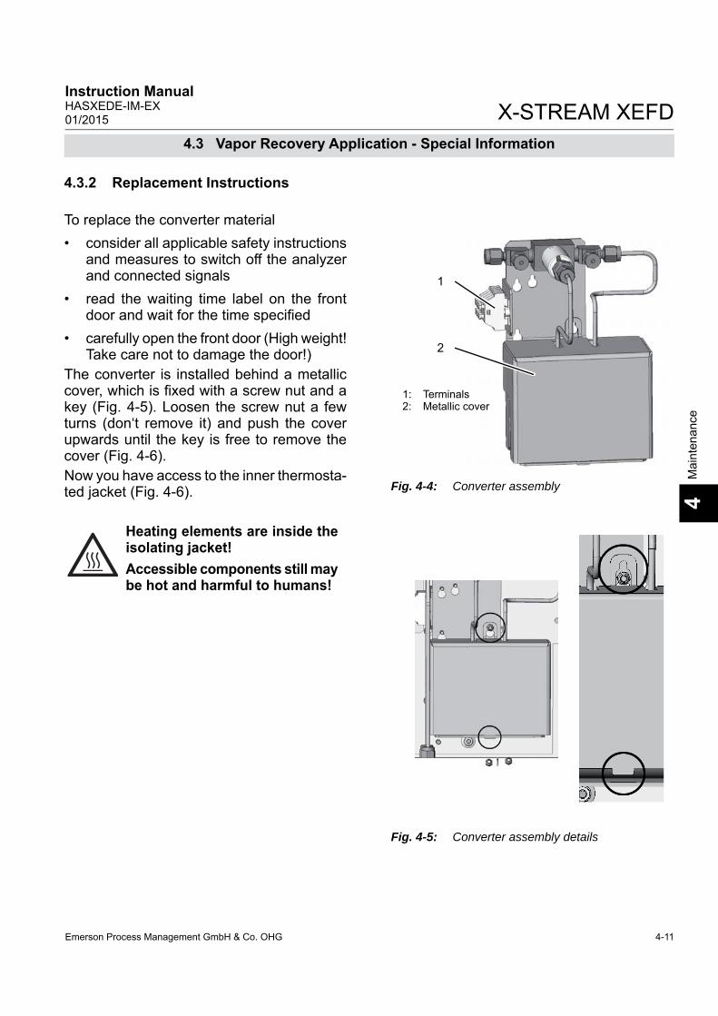
Emerson Process Management GmbH & Co. OHG 4-11
4M
aint
enan
ce
X-STREAM XEFDInstruction ManualHASXEDE-IM-EX01/2015
4.3 Vapor Recovery Application - Special Information
Fig. 4-4: Converter assembly
To replace the converter material• consider all applicable safety instructions
and measures to switch off the analyzer and connected signals
• read the waiting time label on the front door and wait for the time specifi ed
• carefully open the front door (High weight! Take care not to damage the door!)
The converter is installed behind a metallic cover, which is fi xed with a screw nut and a key (Fig. 4-5). Loosen the screw nut a few turns (don‘t remove it) and push the cover upwards until the key is free to remove the cover (Fig. 4-6).Now you have access to the inner thermosta-ted jacket (Fig. 4-6).
Heating elements are inside the isolating jacket! Accessible components still may be hot and harmful to humans!
Fig. 4-5: Converter assembly details
1
2
1: Terminals2: Metallic cover
4.3.2 Replacement Instructions

Emerson Process Management GmbH & Co. OHG4-12
X-STREAM XEFDInstruction Manual
HASXEDE-IM-EX01/2015
Fig. 4-6: Heated jacket
1: Jacket2: Union nuts
1
1. Loosen the lace cord that keeps the jacket closed.
2. Open the jacket to get access to the con-verter.
3. Loosen the union nuts of the fi ttings that connect the gas lines from the converter to the solenoid valve (Fig. 4-7).
Fig. 4-7: Converter, laid open
1: Converter vessel2: End cap
1
2
4.3 Vapor Recovery Application - Special Information
4. Take the converter vessel with connected gas lines out of jacket and analyzer.
2

Emerson Process Management GmbH & Co. OHG 4-13
4M
aint
enan
ce
X-STREAM XEFDInstruction ManualHASXEDE-IM-EX01/2015
Fig. 4-8: Converter fi lling sequence
4.3 Vapor Recovery Application - Special Information
5. Remove the end cap.
6. Remove the washer.
Behind the washer, the vessel is fi lled with converter material. 7. Remove this old material and fi ll the vessel
with new converter material, considering to• hold the vessel vertically while fi lling • completely fi ll the vessel• keep the inner pipe free of converter
material.
8. Put the washer on top of the vessel / new material.
9. Install the end cap.

Emerson Process Management GmbH & Co. OHG4-14
X-STREAM XEFDInstruction Manual
HASXEDE-IM-EX01/2015
Fig. 4-9: Jacket in converter assembly
1: Jacket2: Boot hooks (8 pcs)
1
2
13. Lay the lace cord around the boot hooks and close the jacket.
Fig. 4-10: Heated jacket
1: Union nuts
4.3 Vapor Recovery Application - Special Information
10. Insert the converter vessel into the jacket and place it into the assembly.
11. Connect the open gas lines to the fi ttings of the solenoid valve (Fig. 4-9). Carefully fi x the union nuts.
12. At this point we recommend to perform a leak test to ensure the gas connections are tight! If some are not, they are acces-sible now.
1
Fig. 4-11: Converter metallic cover
14. Install the metallic cover in such a way, that when it is pushed downwards, the key fi ts into the small slot and the screw nut is on top of the butt strap.
15. Fix the cover with the screw nut.16. Make sure all installation has been done
properly and close the front door. Fix the door by means of ALL 20 screws.
Tightening torque:
25 Nm (221 in.lb)
17. You‘re done!

Emerson Process Management GmbH & Co. OHG 4-15
4M
aint
enan
ce
X-STREAM XEFDInstruction ManualHASXEDE-IM-EX01/2015
4.3 Vapor Recovery Application - Special Information
4.3.3 Failure Situation
Separated from the converter assembly an independent over temperature protection de-vice is installed. This device is setup to take control of the jacket heaters if the measured temperature inside the jacket exceeds about 310 °C ( 590 °F), e. g. due to a failure with the temperature control board. The overtemperature device is self-resetting, so the heaters are not continuously discon-nected from power, but only as long as the measured temperature is above the limit. If the temperature goes below this limit, the jacket heaters again are powered. This beha-viour results in a failure operating temperature of 300 to 315 °C ( 572 to 600 °F).
Also, the overtemperature protection device is connect to a X-STREAM digital input. This digital input is setup to provide a failure signal if the overtemperature protection device has taken control of the jacket heaters.
If a failure status is active, check the jacket heaters temperature control. Continuously opera-ting the converter material at a temperature above 280 °C (536 °F) affects the concentra-tion measurement accuracy!
EXPLOSION HAZARD BY HOT COMPONENTS
Consider the waiting time statement on the front door label, if opening the analyzer is required!Do not open instrument when energized.Ensure that external circuitry is disconnected or de-energized before opening the instrument.
1: Overtemperature protection device
1
Fig. 4-12: Location of Overtemperature Protection Device
The waiting time is calculated to ensure, temperatures of hot components are below the ana-lyzer temperature class for hazar-dous areas! Accessible components still may be hot and harmful to humans!

Emerson Process Management GmbH & Co. OHG4-16
X-STREAM XEFDInstruction Manual
HASXEDE-IM-EX01/2015
4.4 Perform a Calibration
4.4 Perform a Calibration
We recommend to perform at least a zero calibration, after startup of the instrument, to ensure proper measuring results.The following steps describe, how to perform a manual calibration. If your instrument fea-
Before performing any actions, make sure the required calibration gas is applied and fl owing!Supply all calibration gases with the same fl ow and pressure as the sample gas (re-commended: approx. 1 l/min), and utilizing the correct gas fi tting.Ensure the warm-up time after switching on has elapsed! Warm-up time depends on installed measuring system and confi guration, measurement specifi cations in section 1.7!
Do NOT calibrate the TRACE MOISTURE sensor!The sensor is completely calibrated with all calibration data stored in its fl ash memory and does not require recalibration:If the sensor is included into a calibration procedure, it might end up with a wrong ca-libration and unusable sensor. Therefore the analyzer's trace moisture measurement channel is confi gured to be excluded from autocalibration procedures, by default calibra-ting all channels. This exclusion is done by factory setup and cannot be changed.For proper measurement results we recommend to exchange the sensor regularly after 12 months of operation. For instructions on how to exchange, X-STREAM Enhanced instruction manual
OPERATION AT LOW TEMPERATURES
When operating an instrument at temperatures below 0 °C (32 °F), do NOT apply gas nor operate an internal pump before the warmup time has elapsed!Violation may result in condensation inside the gas paths or damaged pump diaphragm!
tures a valve block, X-STREAM Enhan-ced instruction manual for a comprehensive description of calibration procedures.
Do NOT calibrate the TRACE OXYGEN sensor without prior reading the instruc-tions!Together with each sensor an installation manual is shipped, also giving comprehensive calibration information. Read these information prior intending to activate calibration procedures!

Emerson Process Management GmbH & Co. OHG 4-17
4M
aint
enan
ce
X-STREAM XEFDInstruction ManualHASXEDE-IM-EX01/2015
4.4 Manual Calibration
4.4.1 Manual Zero Calibration
Starting from the MEASUREMENT SCREEN press DOWN to open the MAIN MENU and enter CONTROL.
To start a zero calibration select the fi rst line:
Multi-channel unit:Select the channel to be calibrated in SELECT COMPONENT.
The fi rst line gives you the choice to cancel the procedure now.
Select the second line to start the calibra-tion.The next lines show • the calibration gas setup (here: required
zero gas concentration is 0.000 ppm), • the currently measured gas concentration• the current gas fl ow.
When fi nished press LEFT several times to return to eitherSELECT COMPONENT (multi channel ana-lyzer only), to perform a zero calibration for another channel,or to CONTROL, where you may start a span calibration. The procedure and screens look similiar to those of a zero calibration:
Control..
Zero Calibration..Span Calibration..Advanced Calibration.. Apply Gas.. Lock Menus! AcknowledgementsPump 1: OffPump 2: OffRanges..
Zero CalibrationCancel!Start!Zero Gas 0.000 ppmConcentration 0.000 ppmFlow 0.00 l/minStatus..Results..Restore..

Emerson Process Management GmbH & Co. OHG4-18
X-STREAM XEFDInstruction Manual
HASXEDE-IM-EX01/2015
Zero Calibration..Span Calibration..Advanced Calibration.. Apply Gas.. Lock Menus! AcknowledgementsPump 1: OffPump 2: OffRanges..
4.4 Manual Calibration
When fi nished, press LEFT several times to re-turn to SELECT COMPONENT (multi channel analyzer only), to perform a span calibration for another channel,or press HOME to return to the MEASUREMENT SCREEN, to fi nish with manual calibration procedures.
4.4.2 Manual Span Calibration
Multi-channel unit:Select the channel to be calibrated in SELECT COMPONENT.
Before selecting any further line make sure the required calibra-tion gas is applied and fl owing!
SPAN CALIBRATION offers the similiar opti-ons as ZERO CALIBRATION.
Select "Span Calibration.."
Span CalibrationCancel!Start!Span Gas 0.000 ppmConcentration 0.000 ppmFlow 0.00 l/minStatus..Results..Restore..

Emerson Process Management GmbH & Co. OHG 4-19
4M
aint
enan
ce
X-STREAM XEFDInstruction ManualHASXEDE-IM-EX01/2015
Zero Calibration..Span Calibration..Advanced Calibration.. Apply Gas.. Lock Menus! AcknowledgementsPump 1: OnPump 2: OffRanges..
4.4 Manual Calibration
4.4.3 Manual Calibration for Vapor Recovery Applications
1. The measurement system for this applications includes a converter, therefore calibration span gas must contain oxygen for the converter to work pro-perly.
2. During channel 1 calibra-tions, the calibration gas must go through the converter. The-refore, before starting calibra-tions, ensure „Pump 1“ within the control menu is set to ON.
Note!„Pump 1“ is used to disable (Off) or enable (On) the gas fl ow through the converter!
Recommended specifi cation of calibration gases:• Zero gases for both channels:
Nitrogen or air, free of hydrocarbons• Span gas for channel 1:
CH4 in air, concentration should be about 90…100 % of measuring range
• Span gas for channel 2: Suitable hydrocarbons (CnHm) in air, con-centration should be about 90…100 % of measuring range.
Perform the zero and span calibrations fol-lowing the procedures described in sections 4.4.1 and 4.4.2.

Emerson Process Management GmbH & Co. OHG 5-1
5D
ism
ount
ing
X-STREAM XEFDInstruction ManualHASXEDE-IM-EX01/2015
Chapter 5Dismounting and Disposal
5.1 Dismounting and Diposal of the Analyzer
HAZARDS FROM DISMOUNTING
Dismounting instruments installed in hazardous area requires special instructions to be followed! Only trained personnel, observing all applicable technical and legal requirements, and aware of the possible risks is permitted to dismount these analyzers.Failure to follow may result in explosion, death or personal injury!
EXPLOSION HAZARD WHEN OPEN
Dismounting requires to open the instrument and is permitted only if no hazardous atmosphere is present and both the instrument and connected circuitry are de-energized!Depending on the local regulation this may require a competent hot work supervisor to issue a hot work permit.Failure to follow may result in explosion!
HEAVY INSTRUMENT
X-STREAM XEFD analyzers, to which this manual relates, intended to be wall mounted and/or outdoor installed, weigh up to approx. 63 kg (139 lbs), depending on included options!Support the instrument before loosening the fi xing screws (risk of dropping instrument).Two people and/or lifting equipment is required to lift and carry these units.Failure to follow may result in personal injury!

Emerson Process Management GmbH & Co. OHG5-2
X-STREAM XEFDInstruction Manual
HASXEDE-IM-EX01/2015
5.1 Dismounting & Disposal
When the instrument has reached the end of its useful life,
When the instrument has reached the end of its useful life, do not throw it in a trash can!This instrument has been made of materials to be recycled by recyclers spe-cialised in this fi eld. Let the instrument and the packing material duly and envi-ronmently friendly be disposed of. Ensure the equipment is free of dangerous and harmful substances (decontaminated).Take care of all local regulations for waste treatment.Consider all instructions given in the X-STREAM Enhanced instruction manual for dismounting and disposal!
Advice concerning the disposal of batteries• This instrument contains a CR primary lithium button cell battery of size CR 2032.
• The battery is soldered to an electronics board and usually does not need to be replaced during the instrument´s lifetime.
• At the end of lifetime, the instrument must be disposed in compliance with the wast regulati-ons, see instructions below.
• purge all gas lines with inert gas • ensure all gas lines are pressureless• disconnect all gas lines • switch off power and signal lines• disconnect and remove all electrical con-
nections• fi ll out the Declaration of Decontamination
( X-STREAM Enhanced instruction manual) properly
• hand over the dismounted instrument to-gether with the Declaration of Decontami-nation to a disposal specialist. The dispo-sal specialist then has to disassemble the instrument, and recycle and dispose it and the contained battery in compliance with all applicable waste treatment regulations.
GASES HAZARDOUS TO HEALTH
Follow the safety precautions for all applied gases and gas cylinders.Before opening the gas lines, they must be purged with air or neutral gas (N2) to avoid danger from escaping toxic, fl ammable, explosive or hazardous gases.

Emerson Process Management GmbH & Co. OHG A-1
AA
ppen
dix
X-STREAM XEFDInstruction ManualHASXEDE-IM-EX11/2013
Appendix
This chapter contains
EC Declaration of Conformity A.1, page A-2
ATEX EC Type Examination Certifi cate A.2, page A-3
CSA Certifi cate of Compliance A.3, page A-16
Block diagram A.4, page A- 23
Assignment of Terminals and Socket A.5, page A- 29

Emerson Process Management GmbH & Co. OHGA-2
X-STREAM XEFDInstruction Manual
HASXEDE-IM-EX11/2013
A.1 EC Declaration of Conformity
A.1 EC Declaration of Conformity

Emerson Process Management GmbH & Co. OHG A-3
AA
ppen
dix
X-STREAM XEFDInstruction ManualHASXEDE-IM-EX11/2013
A.2 ATEX EC Type Examination Certifi cate
A.2 ATEX EC Type Examination Certifi cate
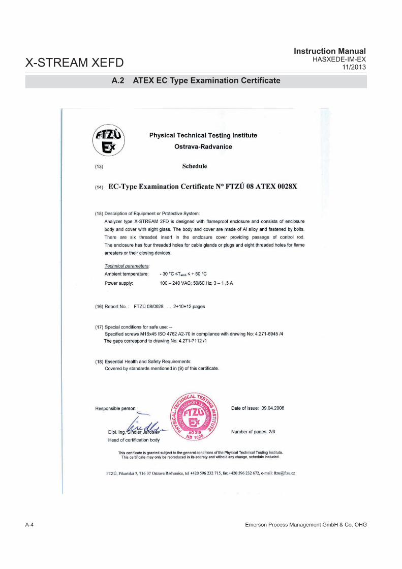
Emerson Process Management GmbH & Co. OHGA-4
X-STREAM XEFDInstruction Manual
HASXEDE-IM-EX11/2013
A.2 ATEX EC Type Examination Certifi cate

Emerson Process Management GmbH & Co. OHG A-5
AA
ppen
dix
X-STREAM XEFDInstruction ManualHASXEDE-IM-EX11/2013
A.2 ATEX EC Type Examination Certifi cate

Emerson Process Management GmbH & Co. OHGA-6
X-STREAM XEFDInstruction Manual
HASXEDE-IM-EX11/2013
A.2 ATEX EC Type Examination Certifi cate
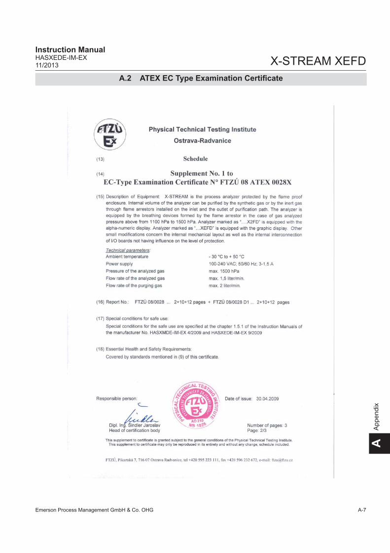
Emerson Process Management GmbH & Co. OHG A-7
AA
ppen
dix
X-STREAM XEFDInstruction ManualHASXEDE-IM-EX11/2013
A.2 ATEX EC Type Examination Certifi cate

Emerson Process Management GmbH & Co. OHGA-8
X-STREAM XEFDInstruction Manual
HASXEDE-IM-EX11/2013
A.2 ATEX EC Type Examination Certifi cate

Emerson Process Management GmbH & Co. OHG A-9
AA
ppen
dix
X-STREAM XEFDInstruction ManualHASXEDE-IM-EX11/2013
A.2 ATEX EC Type Examination Certifi cate

Emerson Process Management GmbH & Co. OHGA-10
X-STREAM XEFDInstruction Manual
HASXEDE-IM-EX11/2013
A.2 ATEX EC Type Examination Certifi cate
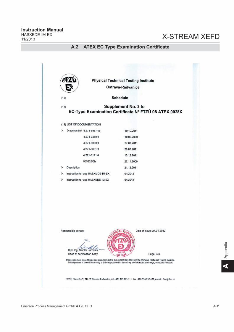
Emerson Process Management GmbH & Co. OHG A-11
AA
ppen
dix
X-STREAM XEFDInstruction ManualHASXEDE-IM-EX11/2013
A.2 ATEX EC Type Examination Certifi cate

Emerson Process Management GmbH & Co. OHGA-12
X-STREAM XEFDInstruction Manual
HASXEDE-IM-EX11/2013
A.2 ATEX EC Type Examination Certifi cate

Emerson Process Management GmbH & Co. OHG A-13
AA
ppen
dix
X-STREAM XEFDInstruction ManualHASXEDE-IM-EX11/2013
A.2 ATEX EC Type Examination Certifi cate

Emerson Process Management GmbH & Co. OHGA-14
X-STREAM XEFDInstruction Manual
HASXEDE-IM-EX11/2013
A.2 ATEX EC Type Examination Certifi cate

Emerson Process Management GmbH & Co. OHG A-15
AA
ppen
dix
X-STREAM XEFDInstruction ManualHASXEDE-IM-EX11/2013
A.2 ATEX EC Type Examination Certifi cate

Emerson Process Management GmbH & Co. OHGA-16
X-STREAM XEFDInstruction Manual
HASXEDE-IM-EX11/2013
A.3 CSA Certifi cate of Compliance
A.3 CSA Certifi cate of Compliance
Certificate of ComplianceCertificate: Master Contract:
Project: Date Issued:
Issued to: Emerson Process Management
GmbH & Co. OHGIndustriestrasse 1Hasselroth, 63594GermanyAttention: Uwe Schmidt
The products listed below are eligible to bear the CSAMark shown with adjacent indicators 'C' and 'US' for
Canada and US or with adjacent indicator 'US' forUS only or without either indicator for Canada only.
Issued by:
PRODUCTSCLASS 2258 82
CLASS 2258 02CLASS 8721 85
CLASS 8721 05
CLASS 8721 05 - LABORATORY ELECTRICAL EQUIPMENT
CLASS 8721 85 - ELECTRICAL EQUIPMENT FOR LABORATORY USE (Certified to U.S. Standards)
X-STREAM (XLF) or X-STREAM Enhanced Field Housing Gas Analyzer (XEF)
X-STREAM (X2GP) or X-STREAM Enhanced (XEGP) General Purpose Gas Analyzer:
X-STREAM Gas Analyzer Core (XCA)
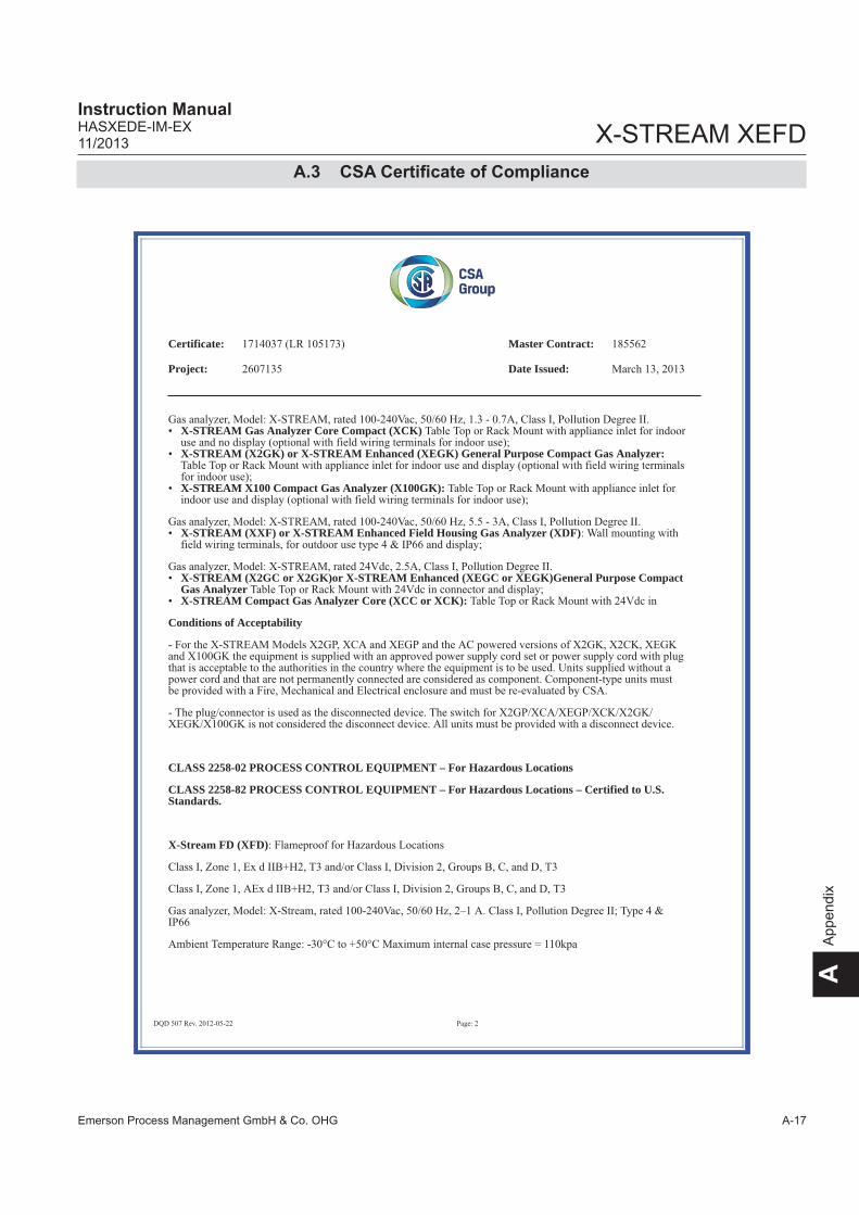
Emerson Process Management GmbH & Co. OHG A-17
AA
ppen
dix
X-STREAM XEFDInstruction ManualHASXEDE-IM-EX11/2013
A.3 CSA Certifi cate of Compliance
Certificate: Master Contract:
Project: Date Issued:
X-STREAM Gas Analyzer Core Compact (XCK)
X-STREAM (X2GK) or X-STREAM Enhanced (XEGK) General Purpose Compact Gas Analyzer:
X-STREAM X100 Compact Gas Analyzer (X100GK):
X-STREAM (XXF) or X-STREAM Enhanced Field Housing Gas Analyzer (XDF)
X-STREAM (X2GC or X2GK)or X-STREAM Enhanced (XEGC or XEGK)General Purpose CompactGas Analyzer X-STREAM Compact Gas Analyzer Core (XCC or XCK):
Conditions of Acceptability
CLASS 2258-02 PROCESS CONTROL EQUIPMENT – For Hazardous Locations
CLASS 2258-82 PROCESS CONTROL EQUIPMENT – For Hazardous Locations – Certified to U.S.Standards.
X-Stream FD (XFD)

Emerson Process Management GmbH & Co. OHGA-18
X-STREAM XEFDInstruction Manual
HASXEDE-IM-EX11/2013
A.3 CSA Certifi cate of Compliance
Certificate: Master Contract:
Project: Date Issued:
X-Stream FD (X2FD)

Emerson Process Management GmbH & Co. OHG A-19
AA
ppen
dix
X-STREAM XEFDInstruction ManualHASXEDE-IM-EX11/2013
A.3 CSA Certifi cate of Compliance
Certificate: Master Contract:
Project: Date Issued:

Emerson Process Management GmbH & Co. OHGA-20
X-STREAM XEFDInstruction Manual
HASXEDE-IM-EX11/2013
A.3 CSA Certifi cate of Compliance
Certificate: Master Contract:
Project: Date Issued:
X-STREAM FD (XEFD)
(XEF)
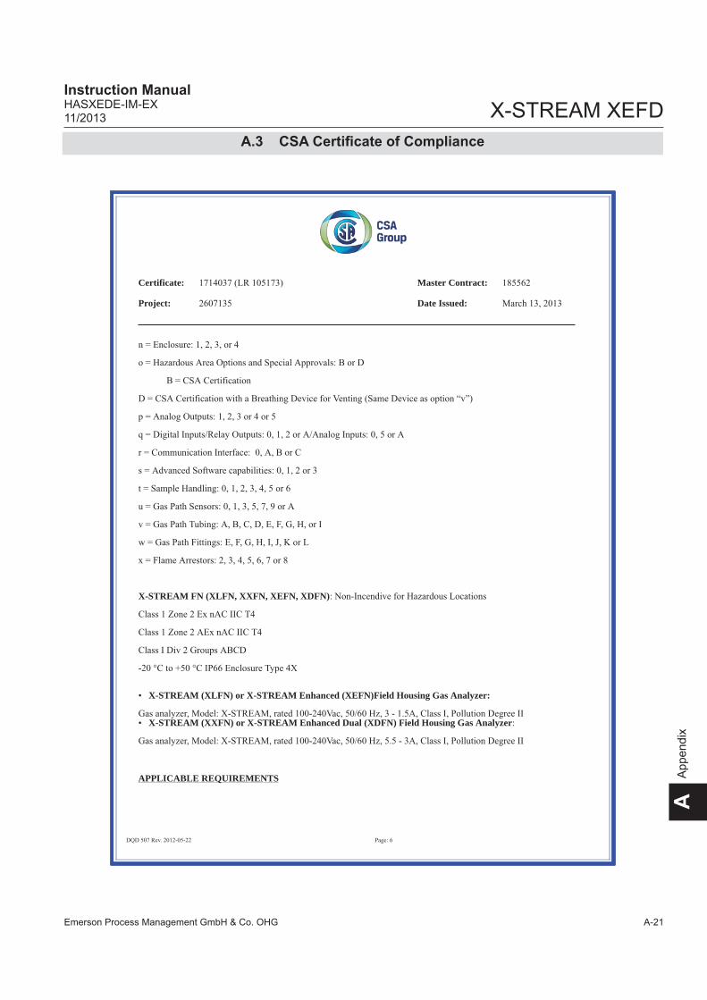
Emerson Process Management GmbH & Co. OHG A-21
AA
ppen
dix
X-STREAM XEFDInstruction ManualHASXEDE-IM-EX11/2013
A.3 CSA Certifi cate of Compliance
Certificate: Master Contract:
Project: Date Issued:
X-STREAM FN (XLFN, XXFN, XEFN, XDFN)
X-STREAM (XLFN) or X-STREAM Enhanced (XEFN)Field Housing Gas Analyzer:
X-STREAM (XXFN) or X-STREAM Enhanced Dual (XDFN) Field Housing Gas Analyzer
APPLICABLE REQUIREMENTS

Emerson Process Management GmbH & Co. OHGA-22
X-STREAM XEFDInstruction Manual
HASXEDE-IM-EX11/2013
A.3 CSA Certifi cate of Compliance
Certificate: Master Contract:
Project: Date Issued:

Emerson Process Management GmbH & Co. OHG A-23
AA
ppen
dix
X-STREAM XEFDInstruction ManualHASXEDE-IM-EX01/2015
Netzteil100V-240V ~
Power SupplyAC 100V-240V ~
wide range24V -24V DC
Netzteil100V-240V ~
Power SupplyAC 100V-240V ~
wide range *124V -24V DC
15.04. Bangert
Walther15.04.
Erdungsbolzen auf der MontageplatteGrounding pin on mounting panel
Erdungsbolzen auf der HeizungsabdeckungGrounding pin on heater cover
Gn/gegn/ye
4.300-8101
4.300-8101
2-adrige Leitung / cable with 2 lines
Symbolerklärung:Description of used icons:
Leitungsfarbe / cable colourbl
Steckverbindung / plug connection
/2.4 Verweis auf Seite 2, Spalte 4 / reference to sh 2, row 4
4.xxx-xxxx Zeichnungs-/Sachnummer / Drawing-/Partnumber
2
Single compartment field housings
L
N
PE
Netzeingangsmodul mit Schraubklemmen, 2-polige Sicherung 5x20 mm
Power entry module with screw terminals,2 fuseholder 5x20 mm
Zeichnung/drawing4.271-6580
Model XEFDPower InputAC 100 - 240 V wide range50 / 60 Hz
EMV Filter2-stufiges Filter
vergossenEMI Filter
2-stage Filterpotted
Stromlaufplan/schematic4.271/6581
Gn/gegn/ye
4.300-8102
T 4 A / 250V
T 4 A / 250V
T 6.3 A / 250VL
N
PE
Netzeingangsmodul mit Schraubklemmen, 2-polige Sicherung 5x20 mm
Power entry module with screw terminals,2 fuseholder 5x20 mm
Zeichnung/drawing4.271-7340
Model XEF, XEFNPower InputAC 100 - 240 V wide range50 / 60 Hz
T 6.3 A / 250V
EMV Filter 6ET11-stufiges Filter
EMI Filter 6ET11-stage Filter
4.300-8102Gn/gegn/ye
4.3
00-8
113
4.3
00-8
108
Netzteil100V-240V ~
Power SupplyAC 100V-240V ~
wide range24V -24V DC 2
4.300-9125
5/A6
XHM 01Stromlaufplan/schematic
4.350-0680/3
P6
2
P9
2
P42
P8
2
P2
2
P7
Optio
nale
Heiz
ung
optional H
eate
r
P1
TemperatursensorTemperaturesensor
4.300-6452
2
4.3
00-8
104
Verb
indung w
enn k
ein
e X
HM
01 e
ingebaut is
tC
onnect
ion if
no X
HM
01 is
used
2
4.300-8112
3
Heizung 1Heater 1ETC02286
Heizung 2Heater 2ETC02286
ÜbertemperaturschalterOvertemperaturswitch
ETC02286
Verb
indung w
enn S
eite
15 a
ktiv
ist
Connectio
n if
Page 1
5 is
activ
e
15/B
8
4.3
00-8
126
Optionales zweites NetzteilOptional second Power Supply
*Hinweis 1: Es sind bis zu zwei Netzteile im Analysator möglich*Note 1: There are up to two power supplies possible inthe analyser
Hinweis: Bei einem NetzteilNote: For one power supply
2
4.300-9125
8/A5
2
4.300-9125
X10
6
We
iterg
ab
e s
ow
ie V
erv
ielfä
ltig
un
g d
iese
rU
nte
rla
ge
, V
erw
ert
un
g u
nd
Mitt
eilu
ng
ihre
sIn
ha
ltes
sin
d n
ur
mit
un
sere
r Z
ustim
mu
ng
ge
sta
tte
t. A
lle R
ech
te v
orb
eh
alte
n.
Copyi
ng o
f th
is d
ocum
ent, a
nd g
ivin
g it to
oth
ers
and the u
se o
r com
munic
ation o
f th
eco
nte
nts
there
of, a
re o
nly
allo
wed w
ith o
ur
agre
em
ent. A
ll rights
are
reserv
ed.
E
Micro Index Änderung, revision Datum Name
Bearb.
Gepr.
20___ Datum Name
Beschreibung, description Zeichnung-Nr.: Drawing-No.: Index
Ident-Nr.:
BlattSheet
vonof
Auftrags-Nr.:
+
=
D
C
B
A
E
D
C
B
A
1 2 3 4 5 6 7 8 9 10 11 12 13 14 15 16
1 2 3 4 5 6 7 8 9 10 11 12 13 14 15 16
4.300-5159/409
X-STREAM XE Block diagram
15.04. Bangert
Walther15.04.B TN387: XPSA jetzt 5-kanalig 28.09.09 MBa
C MBaTN847: Trace Moisture hinzu; TN489 11.11.10
D MBaTN892: Aktualisiert 20.01.11
15F
E MBaTN1274: Aktualisiert 11.11.11
F TN1346, TN1347: Aktualisiert 19.01.12
X-STREAM Version
A.4 Block Diagram
A.4 Block Diagram

X-STREAM XEFD
Emerson Process Management GmbH & Co. OHGA-24
Instruction ManualHASXEDE-IM-EX
01/2015
InternInternal
Fieldhousings (all)
XSP 01 / XIN 01
siehe Blatt 9, 11see sheet 9, 11
P2
UFPSW 01TastaturKeyboard
Stromlaufplan / schematics:4.350-0500
Stromlaufplan / schematics:4.300-4970
XFP 01 LCD
Auf FrontplatteAt front panel
P9
P8
Direkt gekoppeltDirectly coupled
5
P33
10
4.3
00-9
145
P22
26
P1
Sub-D P18
.25
.25.1
.1
XSTA 01Stromlaufplan /
schematics:4.350-0460
XSP 01/P32
3
Serielle
Kom
munik
atio
nS
eria
l Co
mm
un
ica
tion
Option
.9.9
.1.1
Sub-D P17
P1 P7
Serv
ice S
chnitts
telle
Se
rvic
e P
ort
Sub-D P27
XDIO 01 / 02Stromlaufplan /
schematics:4.300-4680
P1
10
P2
Sub-D P4
.25
.25.1
.1
XSTD 01Stromlaufplan /
schematics:4.350-0480
P1
Fla
chbandkabel
Fla
t ribbon c
ableX1 X2 X4.1
4.3
00-9
146
P2
Sub-D P5
.9.9
.1.1
P1
6
4.3
00-9
144
P19
Stromlaufplan / schematics:4.350-0620 XAF 01
P12 P116
Direkt gekoppeltDirectly coupled
siehe Blatt 10, 12see sheet 10, 12
XIN 01/P8
2
+Power
Interner Schraubklemmenadapterinternal screw terminal adapter
Interne Schraubklemmenadapterinternal screw terminal adapters
*)Option
P9
2 x
Ete
rhn
et
CA
N
2 x
US
B 1
.1
RJ45P2, P3
USB-A/USB-MiniP15, P18
P6 P22 P5
Sub-DP13
P10
P11
P7
2
2
4.3
00
-80
57
-V2
Fla
chbandkabel
Fla
t ribbon c
able
4.3
00-9
129
Fla
chbandkabel
Fla
t ribbon c
able
4.3
00-9
130
Fla
chbandkabel
Fla
t ribbon c
able
4.3
00-9
154
4.3
00-9
128
9
4.300-9127Y-KabelY-Cable
4.3
00
-91
25
XSP 01/P3XIN 01/X1
P3
6/A
13
, 7
/A1
3
P8
P913/E11
Siehe auch Blatt 10see also sheet 10
X5
(QSPI)
4.300-9124
10/C611/B412/B412/C613/B...A
nalo
gausg
ang 1
An
alo
g O
utp
ut
1
XS
IA 0
1A
nalo
gausgang 2
An
alo
g O
utp
ut
2S
tro
mla
ufp
lan
/
sch
em
atics:
4.3
50
-03
80
P1
P2
P13
P16
XS
IA 0
1A
nalo
gausgang 3
An
alo
g O
utp
ut
3S
tro
mla
ufp
lan
/
sch
em
atics:
4.3
50
-03
80
P1
P2
P25
P26X
SIA
01
Analo
gausgang 4
An
alo
g O
utp
ut
4S
tro
mla
ufp
lan
/
sch
em
atics:
4.3
50
-03
80
P1
P2
P31
P32
Direkt gekoppelt
Dire
ctly
co
up
led
4 x
“N
AM
UR
”-R
ela
is4
x “
NA
MU
R-R
ela
ys
XS
IA 0
1A
nalo
gausgang 4
An
alo
g O
utp
ut
4S
tro
mla
ufp
lan
/
sch
em
atics:
4.3
50
-03
80
P1
P2
P31
P32
XS
IA 0
1A
nalo
gausgang 5
An
alo
g O
utp
ut
4S
tro
mla
ufp
lan
/
sch
em
atics:
4.3
50
-03
80
P1
P2
P4
P6
XSTI 01Stromlaufplan /
schematics:4.350-0800
XECB 01Stromlaufplan /
schematics:4.350-0400
XASI 01Stromlaufplan /
schematics:4.350-0640
XPSA 01 / 02Stromlaufplan / schematics:4.300-4660 / 4.350-0920
64
+P
ow
er
Sig
na
ls
Op
tion *
1
Op
tion *
1
Hinweis 1: Es sind maximal zwei zusätzliche Optionen möglich(XDIO 01 + XSTD 01) oder (XASI 01 + XSTI 01)
Note 1: At maximum two additional options are selectable(XDIO 01 + XSTD 01) or (XASI 01 +XSTI 01)
P14
CA
N
15/B11,D12
4.300-8130
2
8
Weite
rgabe s
ow
ie V
erv
ielfä
ltigung d
iese
rU
nte
rlage, V
erw
ert
ung u
nd M
itteilu
ng ih
res
Inhalte
s si
nd n
ur
mit
unse
rer
Zust
imm
ung
gest
attet. A
lle R
ech
te v
orb
ehalte
n.
Copyi
ng o
f th
is d
ocu
ment, a
nd g
ivin
g it
to
oth
ers
and the u
se o
r co
mm
unic
atio
n o
f th
eco
nte
nts
there
of, a
re o
nly
allo
wed w
ith o
ur
agre
em
ent. A
ll rights
are
rese
rved.
E
Micro Index Änderung, revision Datum Name
Bearb.
Gepr.
20___ Datum Name
Beschreibung, description Zeichnung-Nr.: Drawing-No.: Index
Ident-Nr.:
BlattSheet
vonof
Auftrags-Nr.:
+
=
D
C
B
A
E
D
C
B
A
1 2 3 4 5 6 7 8 9 10 11 12 13 14 15 16
1 2 3 4 5 6 7 8 9 10 11 12 13 14 15 16
4.300-5159/409
X-STREAM XE Block diagram
15.04. Bangert
Walther15.04.B TN387: XPSA jetzt 5-kanalig 28.09.09 MBa
C MBaTN847: Trace Moisture hinzu; TN489 11.11.10
D MBaTN892: Aktualisiert 20.01.11
15F
E MBaTN1274: Aktualisiert 11.11.11
F TN1346, TN1347: Aktualisiert 19.01.12
A.4 Block Diagram

Emerson Process Management GmbH & Co. OHG A-25
AA
ppen
dix
X-STREAM XEFDInstruction ManualHASXEDE-IM-EX01/2015
Druck
Ch1
P31P30
Pressure
Ch2
Temperatur
Ch1
P18P17P16P11
Temperature
Ch4Ch3Ch2
Durchfluss
Ch1
P6P7P4P5
Flow
Ch4Ch3Ch2
AC-Detektoren
Ch1
P24P25P23P21
AC-detectors
Ch4Ch3Ch2 Ch5
Strahler
Ch1
P15P14P13P12
Source
Ch4Ch3Ch2
DC-Detektoren
Ch1
P20P19P28P26
ChopperDC-detectors
M2M1Ch4Ch2
P27
physikalische Baugruppen (messprinzipabhängig)
thermostatisiert (Option, nicht für XEGC, XEGK)
physical components (depending on measurement system)
Thermostate control (option, not for XEGC, XEGK)
siehe Blatt 3, 5, 8see sheet 3, 5, 8
P3 P32
XSP 01, XPSA 02 and physical components
Durch-fluss-schalterFlow-Switch
8
XSP 01Stromlaufplan / schematics:4.350-0520
XPSA 01 / 02Stromlaufplan / schematics:4.300-4660 / 4.350-0920
Ventil-block 1Valve-unit 1
Ventil-block 2Valve-unit 2
Messgas-pumpe 1Pump 1 Pump 2
P29 P21 P28
siehe auch Blatt 3, 5, 8see also sheet 3, 5, 8
P24
8
8
8
Ch3 Messgas-pumpe 2
P10 P33
SSI 01Stromlaufplan /schematics:4.300-4520
SV2
10
4.3
00-9
164
+P
ow
er
Sig
nals
Serial
FeuchteMoisture
HTS 01Stromlaufplan /schematics:4.300-4400
JP2
9
We
ite
rga
be
so
wie
Ve
rvie
lfälti
gu
ng
die
ser
Un
terla
ge
, V
erw
ert
un
g u
nd
Mitt
eilu
ng
ihre
sIn
ha
ltes
sin
d n
ur
mit
un
sere
r Z
ust
imm
un
gg
est
att
et.
Alle
Re
ch
te v
orb
eh
alte
n.
Co
pyi
ng
of
this
do
cum
en
t, a
nd
giv
ing
it t
oo
the
rs a
nd
th
e u
se o
r co
mm
un
ica
tion
of
the
con
ten
ts t
he
reo
f, a
re o
nly
allo
we
d w
ith o
ur
ag
ree
me
nt.
All
rig
hts
are
re
serv
ed
.
E
Micro Index Änderung, revision Datum Name
Bearb.
Gepr.
20___ Datum Name
Beschreibung, description Zeichnung-Nr.: Drawing-No.: Index
Ident-Nr.:
BlattSheet
vonof
Auftrags-Nr.:
+
=
D
C
B
A
E
D
C
B
A
1 2 3 4 5 6 7 8 9 10 11 12 13 14 15 16
1 2 3 4 5 6 7 8 9 10 11 12 13 14 15 16
4.300-5159/409
X-STREAM XE Block diagram
15.04. Bangert
Walther15.04.B TN387: XPSA jetzt 5-kanalig 28.09.09 MBa
C MBaTN847: Trace Moisture hinzu; TN489 11.11.10
D MBaTN892: Aktualisiert 20.01.11
15F
E MBaTN1274: Aktualisiert 11.11.11
F TN1346, TN1347: Aktualisiert 19.01.12
A.4 Block Diagram
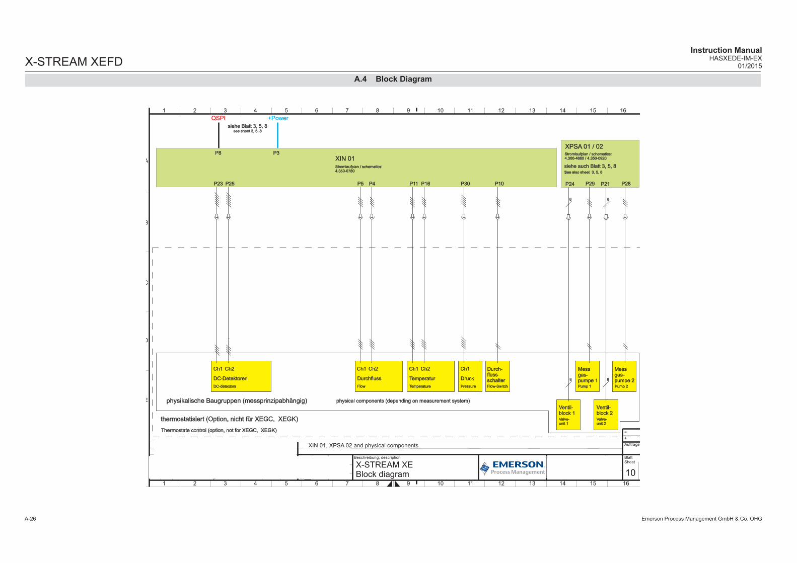
X-STREAM XEFD
Emerson Process Management GmbH & Co. OHGA-26
Instruction ManualHASXEDE-IM-EX
01/2015
Druck
Ch1
P30
Pressure
Temperatur
Ch1
P16P11
Temperature
Ch2
Durchfluss
Ch1
P4P5
Flow
Ch2
DC-Detektoren
Ch1
DC-detectors
Ch2
physikalische Baugruppen (messprinzipabhängig)
thermostatisiert (Option, nicht für XEGC, XEGK)
physical components (depending on measurement system)
Thermostate control (option, not for XEGC, XEGK)
siehe Blatt 3, 5, 8see sheet 3, 5, 8
P8
XIN 01, XPSA 02 and physical components
XIN 01Stromlaufplan / schematics:4.350-0780
P3
+PowerQSPI
P23 P25
Durch-fluss-schalterFlow-Switch
P10
8
Ventil-block 1Valve-unit 1
Ventil-block 2Valve-unit 2
Messgas-pumpe 1Pump 1 Pump 2
P29 P21 P28P24
8
8
8
Messgas-pumpe 2
XPSA 01 / 02Stromlaufplan / schematics:4.300-4660 / 4.350-0920
siehe auch Blatt 3, 5, 8see also sheet 3, 5, 8
10
Weite
rgabe s
ow
ie V
erv
ielfä
ltigung d
iese
rU
nte
rlage, V
erw
ert
ung u
nd M
itteilu
ng ih
res
Inhalte
s si
nd n
ur
mit
unse
rer
Zust
imm
ung
gest
attet. A
lle R
ech
te v
orb
ehalte
n.
Co
pyin
g o
f th
is d
ocu
me
nt,
an
d g
ivin
g it
to
oth
ers
an
d t
he
use
or
co
mm
un
ica
tion
of
the
co
nte
nts
th
ere
of,
are
on
ly a
llow
ed
with
ou
ra
gre
em
en
t. A
ll rig
hts
are
re
se
rve
d.
E
Micro Index Änderung, revision Datum Name
Bearb.
Gepr.
20___ Datum Name
Beschreibung, description Zeichnung-Nr.: Drawing-No.: Index
Ident-Nr.:
BlattSheet
vonof
Auftrags-Nr.:
+
=
D
C
B
A
E
D
C
B
A
1 2 3 4 5 6 7 8 9 10 11 12 13 14 15 16
1 2 3 4 5 6 7 8 9 10 11 12 13 14 15 16
4.300-5159/409
X-STREAM XE Block diagram
15.04. Bangert
Walther15.04.B TN387: XPSA jetzt 5-kanalig 28.09.09 MBa
C MBaTN847: Trace Moisture hinzu; TN489 11.11.10
D MBaTN892: Aktualisiert 20.01.11
15F
E MBaTN1274: Aktualisiert 11.11.11
F TN1346, TN1347: Aktualisiert 19.01.12
A.4 Block Diagram

Emerson Process Management GmbH & Co. OHG A-27
AA
ppen
dix
X-STREAM XEFDInstruction ManualHASXEDE-IM-EX01/2015
SpurensauerstoffmessungTrace Oxygen
4
P1
XOX 01Stromlaufplan /
schematics:4.350-0440
XTEC 02Stromlaufplan/schematic
4.350-1280/3
4.3
00
-80
57
P22
P4
2J2
2P25,P26
TemperatursensorTemperaturesensor
2
Peltier KühlerPeltier Cooler
ÜbertemperaturschalterOvertemperaturswitch
2P23,P24
ÜbertemperaturschalterOvertemperaturswitch
P3
CA
N
2-adrige Leitung / cable with 2 lines
Symbolerklärung:Description of used icons:
Leitungsfarbe / cable colourbl
Steckverbindung / plug connection
/2.4 Verweis auf Seite 2, Spalte 4 / reference to sh 2, row 4
4.xxx-xxxx Zeichnungs-/Sachnummer / Drawing-/Partnumber
2
Physical components
POT 01Elektrochemischer Sensor
Electrochemical sensorStromlaufplan /
schematics:4.350-0600
4
4.3
00-9
150
WAP 100Wärmeleitfähigkeitssensor
Thermal conductivity sensorStromlaufplan /
schematics:4.300-2000
4
JP1 P15
2
P2
3/C
10
5/C
10
8/C
10
11/D
41
2/D
4
4.3
00
-80
57
WärmeleitfähigkeitssensorThermal conductivity sensor
4
JP1
2
ST3
3/C
10
5/C
10
8/C
10
11/D
41
2/D
4
4.3
00
-80
57
Angeschlossen als DC-Detektorsiehe Seite 9, 10, 11 oder 12Connected as a DC detector
see page 9, 10, 11 or 12
Sensoren mit 4 ... 20 mA
SchleifenstromversorgungSensors with 4 ... 20 mA looppower
2
X1
2
3/C
10
5/C
10
8/C
10
11/D
41
2/D
4
4.300-8057
XHA 01Stromlaufplan /
schematics:4.350-0980
SPI 01Stromlaufplan /
schematics:4.350-0200
TCD 01Stromlaufplan /
schematics:4.350-0000
Angeschlossen als DC-Detektorsiehe Seite 9, 10, 11 oder 12Connected as a DC detector
see page 9, 10, 11 or 12
Angeschlossen als DC-Detektorsiehe Seite 9, 10, 11 oder 12Connected as a DC detector
see page 9, 10, 11 or 12
Angeschlossen als DC-Detektorsiehe Seite 9, 10, 11 oder 12Connected as a DC detector
see page 9, 10, 11 or 12
thermostatisiert (Option, nicht für XEGC, XEGK)
Thermostate control (option, not for XEGC, XEGK)
UVSS IIIUV Sensor
UV sensorStromlaufplan /
schematics:4.300-2280
VVS 03IR Sensor
IR sensorStromlaufplan /
schematics:4.300-4300
4 Angeschlossen als AC-Detektorsiehe Seite 9, 10, 11 oder 12Connected as an AC detector
see page 9, 10, 11 or 12
4 Angeschlossen als AC-Detektorsiehe Seite 9, 10, 11 oder 12Connected as an AC detector
see page 9, 10, 11 or 12
OXS 01Elektrochemischer Sensor
Electrochemical SensorStromlaufplan /
schematics:4.300-0800
4
P1
Angeschlossen als DC-Detektorsiehe Seite 9, 10, 11 oder 12Connected as a DC detector
see page 9, 10, 11 or 12
3/C
10
5/C
10
8/C
10
11/D
41
2/D
4
Angeschlossen als DC-Detektorsiehe Seite 9, 10, 11 oder 12Connected as a DC detector
see page 9, 10, 11 or 12
PO2
Paramagn. O -Sensor2
Paramagnetic O sensor2
432
Angeschlossen als DC-Detektorsiehe Seite 9, 10, 11 oder 12Connected as a DC detector
see page 9, 10, 11 or 12
Angeschlossen als Temperatursensorsiehe Seite 9, 10, 11 oder 12
Connected as temperature sensorsee page 9, 10, 11 or 12
Optional angeschlossen an P9siehe Seite 9, 10, 11 oder 12
option, connected to P9see page 9, 10, 11 or 12
Beheiz
er
He
ate
r
Tem
p.-
Senso
rTe
mp
.-S
en
sor
13
Weite
rgabe s
ow
ie V
erv
ielfä
ltigung d
iese
rU
nte
rlage, V
erw
ert
ung u
nd M
itteilu
ng ih
res
Inhalte
s si
nd n
ur
mit
unse
rer
Zust
imm
ung
gest
attet. A
lle R
ech
te v
orb
ehalte
n.
Copyi
ng o
f th
is d
ocu
ment, a
nd g
ivin
g it
to
oth
ers
and the u
se o
r co
mm
unic
atio
n o
f th
eco
nte
nts
there
of, a
re o
nly
allo
wed w
ith o
ur
agre
em
ent. A
ll rights
are
rese
rved.
E
Micro Index Änderung, revision Datum Name
Bearb.
Gepr.
20___ Datum Name
Beschreibung, description Zeichnung-Nr.: Drawing-No.: Index
Ident-Nr.:
BlattSheet
vonof
Auftrags-Nr.:
+
=
D
C
B
A
E
D
C
B
A
1 2 3 4 5 6 7 8 9 10 11 12 13 14 15 16
1 2 3 4 5 6 7 8 9 10 11 12 13 14 15 16
4.300-5159/409
X-STREAM XE Block diagram
15.04. Bangert
Walther15.04.B TN387: XPSA jetzt 5-kanalig 28.09.09 MBa
C MBaTN847: Trace Moisture hinzu; TN489 11.11.10
D MBaTN892: Aktualisiert 20.01.11
15F
E MBaTN1274: Aktualisiert 11.11.11
F TN1346, TN1347: Aktualisiert 19.01.12
A.4 Block Diagram

X-STREAM XEFD
Emerson Process Management GmbH & Co. OHGA-28
Instruction ManualHASXEDE-IM-EX
01/2015
2-adrige Leitung / cable with 2 lines
Symbolerklärung:Description of used icons:
Leitungsfarbe / cable colourbl
Steckverbindung / plug connection
/2.4 Verweis auf Seite 2, Spalte 4 / reference to sh 2, row 4
4.xxx-xxxx Zeichnungs-/Sachnummer / Drawing-/Partnumber
2
4.3
00-8
108
XHM 02Stromlaufplan/schematic
4.350-0680/3
P6
2
P4P8
P7
2
P2
TemperatursensorTemperaturesensor
4.300-9171
2
HeiztascheHeaterjacket
655228
6/B
8
4.3
00-8
126
4.300-9169
2
Netzteil100V-240V ~
Power SupplyAC 100V-240V ~
wide range *124V -24V DC
*Hinweis 1: Es sind nur insgesamt zwei Netzteile im Analysator möglich*Note 1: There are only two power supplies inthe analyser possible
ÜbertemperaturschalterOvertemperaturswitch
ETC02580
X11
4.300-81292
4.300-81301
4.300-81301
8/E14
8/E14
„Vapor Recovery“
15
Weite
rgabe s
ow
ie V
erv
ielfä
ltigung d
iese
rU
nte
rlage, V
erw
ert
ung u
nd M
itteilu
ng ih
res
Inhalte
s si
nd n
ur
mit
unse
rer
Zust
imm
ung
gest
attet. A
lle R
ech
te v
orb
ehalte
n.
Copyi
ng o
f th
is d
ocu
ment, a
nd g
ivin
g it
to
oth
ers
and the u
se o
r co
mm
unic
atio
n o
f th
eco
nte
nts
there
of, a
re o
nly
allo
wed w
ith o
ur
agre
em
ent. A
ll rights
are
rese
rved.
E
Micro Index Änderung, revision Datum Name
Bearb.
Gepr.
20___ Datum Name
Beschreibung, description Zeichnung-Nr.: Drawing-No.: Index
Ident-Nr.:
BlattSheet
vonof
Auftrags-Nr.:
+
=
D
C
B
A
E
D
C
B
A
1 2 3 4 5 6 7 8 9 10 11 12 13 14 15 16
1 2 3 4 5 6 7 8 9 10 11 12 13 14 15 16
4.300-5159/409
X-STREAM XE Block diagram
15.04. Bangert
Walther15.04.B TN387: XPSA jetzt 5-kanalig 28.09.09 MBa
C MBaTN847: Trace Moisture hinzu; TN489 11.11.10
D MBaTN892: Aktualisiert 20.01.11
15F
E MBaTN1274: Aktualisiert 11.11.11
F TN1346, TN1347: Aktualisiert 19.01.12
A.4 Block Diagram

Emerson Process Management GmbH & Co. OHG A-29
AA
ppen
dix
X-STREAM XEFDInstruction ManualHASXEDE-IM-EX01/2015
A.5 Assignment of Terminals and Socket
A.5 Assignment of Terminals and Sockets
Power terminalsFlameproof housing
L
PE
N
Power cord entry
L= LineN= NeutralPE= Protective Earth
Service Port Connector - Serial RS 232 interface
Ethernet connector for Modbus
Pin 1 Pin 8
Pin no. Signal
1 TX+2 TX-3 RX+6 RX-
other not used
Note!Line and neutral terminals with built-in fuse holders
XSTA: Standard strip with standard and optional signals XSTD: Optional strips with 7 Dig Inputs and 9 Dig Outputs each
Pin9876
Pin54321
Pin no. RS 232
1 Common2 RXD3 TXD4 not used5 Common6 not used7 not used8 not used9 not used
*) See table below **) Configuration of relay output terminals as per stan-dard factory setting (NAMUR status signals). NAMUR status signals are automatically configured Fail Safe!
XSTI: Analog inputs
Analog Inputs
PinSignal
P3.1
not usedP
3.2not used
P3.3
not usedP
3.4not used
P3.5
not usedP
3.6not used
P3.7
not usedP
3.8not used
P3.9
not usedP
3.10not used
P3.11
not usedP
3.12not used
P2.1
BR
1 fit a wire bridge here to apply analog
P2.2
BR
1 signal in current mode to input 1
P2.3
Input 1 high (+)P
2.4Input 1 high (+)
P2.5
Input 1 low (-)
P2.6
Input 1 low (-)
P2.7
BR
2 fit a wire bridge here to apply analog
P2.8
BR
2 signal in current mode to input 2
P2.9
Input 2 high (+)P
2.10Input 2 high (+)
P2.11
Input 2 low (-)
P2.12
Input 2 low (-)
{ }
{ }
IN1 Mode
IN2 Mode
PinSignal
P2.1
Channel 1, (+) 4 (0) - 20 m
AP
2.2C
hannel 1, GN
DP
2.3C
hannel 2, (+) 4 (0) - 20 mA
P2.4
Channel 2, G
ND
P2.5
Channel 3, (+) 4 (0) - 20 m
AP
2.6C
hannel 3, GN
DP
2.7C
hannel 4, (+) 4 (0) - 20 mA
P2.8
Channel 4, G
ND
P2.9
Channel 5, (+) 4 (0) - 20 m
AP
2.10C
hannel 5, GN
DP
2.11not used
P2.12
not usedP
3.1not used
P3.2
not usedP
3.3O
utput 1 (Failure), NC
P3.4
Output 1 (Failure), N
OP
3.5O
utput 1 (Failure), CO
MP
3.6O
utput 2 (Maintenance R
equest), NC
P3.7
Output 2 (M
aintenance Request), N
OP
3.8O
utput 2 (Maintenance R
equest), CO
MP
3.9O
utput 3 (Out of S
pec), NC
P3.10
Output 3 (O
ut of Spec), N
OP
3.11O
utput 3 (Out of S
pec), CO
MP
3.12O
utput 4 (Function check), NC
P4.1
Output 4 (Function check), N
OP
4.2O
utput 4 (Function check), CO
MP
4.3not used
P4.4
P4.5
P4.6
P4.7
P4.8
P4.9
P4.10
P4.11
P4.12
Relay Outputs**) Analog OutputsSerial Interface*)
Note!The configuration illustrated here is that of the first adapter (X4.1). Inputs 8-14 and outputs 14-22, if availa-ble, are on the second adapter (X4.2).
PinSignal
P3.1
Input 1P
3.2Input 2
P3.3
Input 3P
3.4Input 4
P3.5
Input 5P
3.6Input 6
P3.7
Input 7P
3.8G
ND
for inputs 1-7P
3.9unused
P3.10
Output 5, N
CP
3.11O
utput 5, NO
P3.12
Output 5, C
OM
P4.1
Output 6, N
CP
4.2O
utput 6, NO
P4.3
Output 6, C
OM
P4.4
Output 7, N
CP
4.5O
utput 7, NO
P4.6
Output 7, C
OM
P4.7
Output 8, N
CP
4.8O
utput 8, NO
P4.9
Output 8, C
OM
P4.10
Output 9, N
CP
4.11O
utput 9, NO
P4.12
Output 9, C
OM
P2.1
Output 10, N
CP
2.2O
utput 10, NO
P2.3
Output 10, C
OM
P2.4
Output 11, N
CP
2.5O
utput 11, NO
P2.6
Output 11, C
OM
P2.7
Output 12, N
CP
2.8O
utput 12, NO
P2.9
Output 12, C
OM
P2.10
Output 13, N
CP
2.11O
utput 13, NO
P2.12
Output 13, C
OM
Digital inputsDigital outputs
Terminal MOD 485/2 wire
MOD 485/4 wire RS 232
P4.4 SER1 Common Common CommonP4.5 SER2 not used not used RXDP4.6 SER3 not used not used TXDP4.7 SER4 not used RXD1(+) not usedP4.8 SER5 D1(+) TXD1(+) CommonP4.9 SER6 not used not used not used
P4.10 7 not used not used not usedP4.11 8 not used RXD0(-) not usedP4.12 9 D0(-) TXD0(-) not used
Assignment of serial interface terminals
(Index:)
/4
NameDatum
Verant.
Bearb.
(Zeichnung Nr.; Drawing No.)
(Benennung; Description)
EWo
EWo
4.271-8120
Bez.-Schild XSTA f. XPSA 02Label XSTA f. XPSA 02
12.12.11
12.12.11
Index Änderung Datum Name
100m
m
30 m
m
128,00 mm
Aufkleber aus 3M SC 3698 A,Grund silberfarbig, Druck einfarbig schwarzund SchutzlackSchutzpapier gekerbtgeschnitten auf Format
12 11 10 9 8 7 6 5 4 3 2 1
P2P3P4
AN
ALO
G O
UT 4
AN
ALO
G O
UT 2
AN
ALO
G O
UT 3
AN
ALO
G O
UT 1
GRO
UN
D 3
GRO
UN
D 1
GRO
UN
D 2
GRO
UN
D 4
K4 K3 K2 K1
X2
RS
232
RS
485 2
W
RS
485 4
W
MO
DBU
S
CAN
FF
9- IOIO -1
12 11 10 9 8 7 6 5 4 3 2 1 12 11 10 9 8 7 6 5 4 3 2 1
GRO
UN
D 5
AN
ALO
G O
UT 5X
*) Alternatively on the curcuit card XASI, the Jumper P2 can be plugged
**) Alternatively on the curcuit card XASI, the Jumper P1 can be plugged

X-STREAM XEFD
Emerson Process Management GmbH & Co. OHGA-30
Instruction ManualHASXEDE-IM-EX
01/2015

Instruction ManualHASXEDE-IM-EX01/2015 X-STREAM XEFD

Instruction ManualHASXEDE-IM-EX
01/2015X-STREAM XEFD
©2015 Emerson Process Management. All rights reserved.
The Emerson logo is a trademark and service mark of Emerson Electric Co. Rosemount Analytical is a mark of one of the Emerson Process Management family of companies. All other marks are the property of their respective owners.
The contents of this publication are presented for information purposes only, and while effort has been made to ensure their accuracy, they are not to be construed as warranties or guarantees, express or implied, regarding the products or services described herein or their use or applicability. All sales are governed by our terms and conditions, which are available on request. We reserve the right to modify or improve the designs or specifications of our products at any time without notice.
AMERICAS
Emerson Process Management Rosemount Analytical 10241 West Little York, Suite 200Houston, TX 77040 USA T 866 422 3683T +1 713 396 8880T +1 713 396 8759 F +1 713 466 [email protected]
ASIA-PACIFIC
Emerson Process ManagementAsia Pacific Private Limited1 Pandan CrescentSingapore 128461Republic of SingaporeT +65 6 777 8211F +65 6 777 [email protected]
MIDDLE EAST AND AFRICA
Emerson Process ManagementEmerson FZEP.O Box 17033Jebel Ali Free ZoneDubai, United Arab EmiratesT +971 4 811 8100F +971 4 886 [email protected]
EUROPE
Emerson Process Management GmbH & Co. OHG Rosemount Analytical Process Gas Analyzer Center of ExcellenceIndustriestrasse 163594 Hasselroth, GermanyT +49 6055 884 0F +49 6055 884 209www.RosemountAnalytical.com