LP-Gas Technologies - Emerson
176
LP-Gas Technologies Regulators and Equipment, LPG/NH 3 LP-31 Buyer’s Guide (2022-2023) The industry leader for durability and quality.
-
Upload
khangminh22 -
Category
Documents
-
view
0 -
download
0
Transcript of LP-Gas Technologies - Emerson

LP-Gas TechnologiesRegulators and Equipment, LPG/NH3LP-31 Buyer’s Guide (2022-2023)
The industry leader for durability and quality.

i
Emerson Automation Solutions
Solving Your Toughest ChallengesIndustries are under constant pressure to cut costs, increase output, reduce energy use and improve safety and emissions. That is why companies around the world turn to Emerson Automation Solutions for technologies, services and expertise to solve problems and deliver proven results.
Expertise and Innovation To Deliver Proven ResultsEmerson Automation Solutions is the automation innovator with the depth of expertise and breadth of technologies to take on our customers’ toughest challenges and bring predictable success anytime, anywhere.
Capital ProjectsAccelerate ROI and deliver projects confidently with Project Certainty.
Operational ExcellenceSafely optimize production with improved reliability and lower emissions.
Industrial IoTHarness the digital revolution for real-time insights and borderless expertise.
Industry ServedProducts, Services and Expertise to Meet your NeedsFor more than a century we’ve worked side-by-side with customers to understand their challenges and help implement effective solutions. This wealth of experience enables us to provide a broad range of industry-specific products and services — and the expertise to put them to work for you.
Food and Beverage Marine
RefiningOil and Gas
Life SciencesChemicalAlternative Energy
Water and Wastewater
Industrial Energy
Metals and Mining Power Pulp and Paper

ii
Regulator Technologies
Control Your System with CertaintyEmerson brings together technology and engineering to provide an expanding array of innovative manufacturing and processing solutions for industrial, commercial and consumer markets. We offer the world’s largest collection of pressure control, flow control and relief valve solutions for process and specialty gases, liquids, steam, natural gas and liquid propane industries.
Our regulators are renowned for setting industry standards for performance and extended service life, while Emerson product sales, service and technical support teams are unrivaled in their ability to serve you locally from offices located strategically around the globe.
Natural Gas SolutionsEmerson leads the way in providing best in-class natural gas conditioning, metering, pressure regulating products and customized skids to the natural gas industry. From regulators to skids, Emerson products offer design innovation, superior performance and unbeatable reliability and durability under extreme conditions in even the world’s most rugged environments. Around the clock, around the world, look to Emerson for natural gas solutions.
LP-Gas SolutionsThroughout the world, Emerson supplies leading liquefied petroleum gas (LP-Gas) suppliers with the broadest available line of Fisher™ commercial service LP-Gas regulators and bulk storage and transport equipment. Renowned as the propane
industry standard for reliable pressure regulation, Fisher LP-Gas valves and regulators provide high value solutions across a range of stationary storage and mobile applications. With more than 2,000 technical experts at over 200 locations worldwide, our service and support remains second to none.
Gas, Liquid and Steam Solutions Emerson offers a dynamic range of direct- and pilot-operated pressure regulators, relief valves and tank management products for industrial gas, liquid and steam applications. Suitable for use in a wide range of environments, from the wellhead to the pharmaceutical plant, their versatility, stability, ease of maintenance and rigorous adherence to ISO-9001 standards for quality and reliability have made them the pressure regulators of choice in tens of thousands of installationsworldwide.
Natural Gas Solutions
• Pressure Reducing Regulators• Relief Valve /
Backpressure Regulators• Odorant Injection Systems• Slam-Shut Valves
LPG Solutions
• Regulators / Changeovers /
Manifolds
• Valves / Relief Valves
• Bulk Storage and
Transport Equipment
Industrial Gas, Liquid and Steam
and Tank Solutions
• Pressure Reducing Regulators
• Backpressure/Relief Regulators
• Vacuum Regulators
www.Emerson.com
A Complete Line of Valves, Actuators and Regulators

iii
Emerson
QualityEmerson ensures the highest quality and safety standards through our global brands – Fisher™, Crosby™, Yarway™, Anderson Greenwood™, Penberthy™ and our regional specific brands Enardo™ and Jeon.
For more than a century we have worked side-by-side with customers to understand their challenges and help implement effective solutions. Our systems, processes and employees are committed to providing defect-free products, information and services that satisfy your expectations on time, every time.
Emerson is dedicated to delivering only the highest product quality and performance utilizing efficient operations. We create value by delivering best-in-class pressure and flow control equipment, systems, services and solutions for an unparalleled range of applications. We execute new product development plans with advanced technologies and solutions that deliver undisputed quality.
To achieve consistent operational and product excellence globally we strive to attract the most talented people and support continuous development of our workforce, products and processes at every level.
ReliabilityWith more than 125 years of experience, Emerson has built a solid reputation for reliability.
Our regulators, valves and flow control systems are engineered to exacting standards, each carefully designed, thoroughly tested and developed to handle higher pressures while providing increased delivery capacity, reduced noise output and zero emission. We go beyond baseline industry standards to ensure our equipment operates reliably in even the most extreme conditions anywhere in the world.
At Emerson, we are committed to continually raising the bar in our efforts to develop still higher quality, more advanced systems that operate safely and reliably well into the future.
TechnologyEmerson’s innovative technologies creates pressure and flow control solutions more productive, efficient and cost-effective. Our proven results are what make us the leader in the industry.
Spanning the globe, our test and evaluation facilities provide the engineering expertise required to ensure superior quality product design and high performance results wherever our products are deployed. At these facilities, we test all sizes and types of regulators under real-world plant conditions to ensure production performance, efficiency, environmental compliance and safety before actual installation at your site.
Our test and evaluation facilities are dedicated to tackling the toughest engineering challenges facing today’s process manufacturing and energy industries, including helping companies deliver record volumes of natural gas and other forms of energy, consume less energy, reduce costs, operate more quietly and reduce greenhouse emissions.
ServiceWith over 2,000 local technical experts to serve you from nearly 200 locations around the world, our sales and service network is one of the largest in the industry.
Whether you need an emergency replacement regulator or need expert assistance on a long-range growth and expansion plan, there is a local Sales Office to respond quickly and professionally.
Regulators and Relief Valves Facilities
Tulsa, Oklahoma
Tank Global COE
Manchester, United Kingdom
Tank Regional COE
McKinney, Texas
Headquarters
Cluj, Romania
Europe for Europe Qingpu, China
Asia for Asia
Chengdu, China
Asia for Asia
Stafford, Texas
PRV Global COE
Nuevo Laredo, Mexico
Americas Manufacturing
El Salto, Mexico
Steam & Americas Manufacturing
iv
Regulator Technologies
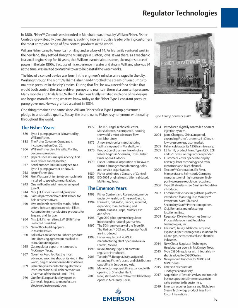
In 1880, Fisher™ Controls was founded in Marshalltown, Iowa, by William Fisher. Fisher Controls grew steadily over the years, evolving into an industry leader offering customers the most complete range of flow control products in the world.
William Fisher came to America from England as a boy of 14. As his family ventured west in the new land, they settled along the Mississippi in Clinton, Iowa. It was there, as a mechanic in a small engine shop for 10 years, that William learned about steam, the major source of power in the late 1800s. Because of his experience in water and steam, William, who was 24 at the time, was invited to Marshalltown to help install the water works.
The idea of a control device was born in the engineer’s mind as a fire raged in the city. Working through the night, William Fisher hand-throttled the steam-driven pumps to maintain pressure in the city’s mains. During that fire, he saw a need for a device that would both control the steam-driven pumps and maintain them at a constant pressure. Many months and trials later, William Fisher was finally satisfied with one of his designs and began manufacturing what we know today as the Fisher Type 1 constant pressure pump governor. He was granted a patent in 1884.
One thing remained the same since William Fisher’s first Type 1 pump governor: a pledge to unequalled quality. Today, the brand name Fisher is synonymous with quality throughout the world.
The Fisher Years1880 Type 1 pump governor is invented by
William Fisher.1888 The Fisher Governor Company is
incorporated on Dec. 26.1906 William Fisher dies. His wife, Martha,
becomes president. 1912 Jasper Fisher assumes presidency; first
sales offices are established. 1937 Serial number 500,000 assigned to a
Type 1 pump governor on Nov. 5. 1938 Jasper Fisher dies. 1940 First Western Union teletype machine is
installed to speed communication. 1943 One millionth serial number assigned
June 9.1944 Mrs. J.H. Fisher is elected president.1946 Sales department holds first school for
field representatives.1950 Two-millionth controller made. Fisher
enters licensee agreement with Elliott Automation to manufacture products for England and Europe.
1954 Mrs. J.H. Fisher retires; J.W. (Bill) Fisher is elected president.1955 New office building opens
in Marshalltown.1960 Ball valves are added to Fisher’s product
line. Licensing agreement reached to manufacture in Japan.
1965 Gas regulator department moves to McKinney, Texas.
1967 Governor Road facility, the most advanced machine shop of its kind in the world, begins operation in Marshalltown.
1969 Fisher begins manufacturing electronic instrumentation. Bill Fisher remains as Chairman of the Board until 1974.
1970 Our first European facility opens at Cornwall, England, to manufacture electronic instrumentation.
1972 The R.A. Engel Technical Center, Marshalltown, is completed, housing
the world’s most advanced flow test laboratory.
1975 A new electronics manufacturing facility is opened in Marshalltown.
1976 Production of our new line of rotary valves begins in Sherman, Texas. Fisher Brazil opens its doors.
1979 Fisher Controls Corporation of Delaware forms a stronger manufacturing, sales and service organization.
1980 Fisher celebrates a Century of Control.1992 ISO 9001 original registration validated,
McKinney, Texas
The Emerson Years1993 Fisher Controls and Rosemount, merge
under ownership of Emerson Electric. 1994 Francel™, Gallardon, France, acquired,
expanding manufacturing and distribution in Europe, Middle East and Africa.
1996 Type 299 pilot-operated regulator introduced to natural gas market.
1997 The 50th anniversary of the Type 99. The FloBoss™ 503 and Regulator Vault
are introduced. 1998 Fisher Regulators FROMEX
manufacturing plant opens in Nuevo Laredo, Mexico.
1999 Revolutionary Type EZR pressure regulator introduced.
2001 Tartarini™, Bologna, Italy, acquired, extending Fisher’s brand and distribution capability in Europe and Asia.
2003 Manufacturing capability expanded with opening of Shanghai Plant.
2003 New, state-of-the-art flow test laboratory opens in McKinney, Texas.
2004 Introduced digitally controlled odorant injection system.
2004 Jeon, Chengdu, China, acquired, expanding Fisher’s presence in China’s low-pressure regulator market.
2005 Fisher celebrates its 125th anniversary.2005 EZ Family product lines, Types EZR, EZH
and EZL pressure regulators expanded.2005 Customer Center opened to display
new regulator technology and train customers and sales channel.
2005 Tescom™ Corporation, Elk River, Minnesota and Selmsdorf, Germany, manufacturer of high-pressure, high-purity pressure regulators, acquired.
2006 Type SR stainless steel Sanitary Regulator introduced.
2007 Commercial Service Regulators platform introduced featuring True Monitor™ Protection, Slam-Shut and Secondary Seat™ Protection options.
2007 Cluj, Romania, manufacturing location online.
2008 Regulator Division becomes Emerson Process Management Regulator Technologies, Inc.
2013 Enardo™, Tulsa, Oklahoma, acquired, expands Fisher’s storage tank solutions for oil and gas, petrochemical and chemical industries.
2014 New Global Regulator Techologies Headquarters opens in McKinney, Texas.
2015 Type CS804 regulator with integral slam-shut is added to CS800 Series.
2015 New product launches for MR95 and MR98 Series.
2015 Emerson celebrates its 125th year anniversary.
2017 Acquisition of Pentair’s valves and controls business positions Emerson as a main valve partner to its customers.
2019 Emerson acquires Spence and Nicholson Steam Technology product lines from Circor International.
Type 1 Pump Governor 1880

v
You Demand High Performance.
We Ensure It.
You demand products to withstand your toughest conditions, while delivering continued optimal performance, efficiency, reliability and safety.
Our design, test and evaluation technologies and techniques validate a full range of product offerings in each of these critical areas, providing flow, material and environmental testing under real-world operating conditions before you place them in your application.
With more than 130 years of application experience in the process industry, our reputation for solving challenging problems and developing products to specifications exceeding regulatory guidelines. Count on Emerson worldwide to deliver the highest quality products available to your site.
Real-World SimulationFlow Testing• Simulates real-world operating conditions using
pipelines up to NPS 32 / DN 800 with compressible and incompressible fluids up to 30,000 psig / 2068 bar
• Ensures product performance, efficiency, environmental compliance, life span and safety
Materials Testing• Develops and tests materials to improve regulator
performance and reliability
• Ensures materials meet customer requirements, national standards, and our own, still higher, brandstandards
• Analyzes and troubleshoots field installations for contamination and composition at an elemental level
Environmental Testing• Simulates real-world operating conditions from the deserts
of the Middle East to the Arctic North
• Validates product lifecycles at field conditions to extend service life
• Verifies product corrosion resistance using extended salt-spray exposure to ensure environmental protection of process equipment

1
REGULATOR APPLICATION MAP . . . . . . . . . . . . . . . . . . . . . . . . . . . . . . . . . .2
VALVE APPLICATION MAP . . . . . . . . . . . . . . . . . . . . . . . . . . . . . . . . . . . . . . . . 4
REGULATOR SELECTION GUIDE . . . . . . . . . . . . . . . . . . . . . . . . . . . . . . . . . . . 9
VALVE SELECTION GUIDE . . . . . . . . . . . . . . . . . . . . . . . . . . . . . . . . . . . . . . .14
ACCESSORIES SELECTION GUIDE . . . . . . . . . . . . . . . . . . . . . . . . . . . . . . . .19
REGULATORS
TWO-STAGE SYSTEMS . . . . . . . . . . . . . . . . . . . . . . . . . . . . . . . . . . . . . . . . . .24
FIRST-STAGE REGULATORS . . . . . . . . . . . . . . . . . . . . . . . . . . . . . . . . . . . . . .25Types R122H, R222H and R622H
SECOND-STAGE REGULATORS . . . . . . . . . . . . . . . . . . . . . . . . . . . . . . . . . . .26Types HSRL, R222, R622, R642 and R652
Two–psi SERVICE REGULATORS . . . . . . . . . . . . . . . . . . . . . . . . . . . . . . . . .27Types R622E and R652E
INTEGRAL TWO-STAGE REGULATORS. . . . . . . . . . . . . . . . . . . . . . . . . . . . .28Types R232A and R632A
INTEGRAL TWO-PSI REGULATORS . . . . . . . . . . . . . . . . . . . . . . . . . . . . . . . .29Types R232E and R632E
COMMERCIAL/INDUSTRIAL HIGH-PRESSURE REGULATORS . . . . . . . . . . . . . . . . . . . . . . . . . . . . . . . . . .30
Types 67CW, 67CH, 67CD, 67CN, 64, 64SR, 627, 630, 99 and 1098-EGR
COMMERCIAL LOW-PRESSURE REGULATORS . . . . . . . . . . . . . . . . . . . . . .36Types CS200, CS400, CS800, 133L, 133H, 299H and 99L
COMMERCIAL SERVICE OVERPRESSURE PROTECTION . . . . . . . . . . . . . .38Types CS403, CS404 and CS803
AUTOMATIC CHANGEOVER REGULATORS . . . . . . . . . . . . . . . . . . . . . . . . .41 Types 64SR, 749B, 803 and R130
MONITOR OVERPRESSURE PROTECTION . . . . . . . . . . . . . . . . . . . . . . . . . .42Types 627M, 99M and 1098
BACKPRESSURE REGULATORS/RELIEF VALVES . . . . . . . . . . . . . . . . . . . . .43Types MR98H, 289H, 1805 and 1808
REGULATOR ACCESSORIES . . . . . . . . . . . . . . . . . . . . . . . . . . . . . . . . . . . . . .44
Where applicable, Fisher™ brand produc ts presented in this catalog are l isted by Under writers Laboratories (UL ®). Use of these products may provide compliance with standards developed by the National Fire Protection Association’s Pamphlets 54 and 58. They may also assist in meeting guidelines established by the Department of Transportation, ASME and other third party agencies. Contact your Fisher brand LPG Regulators and Equipment Distributor for assistance in determining product applications.
VALVES
INTERNAL VALVES . . . . . . . . . . . . . . . . . . . . . . . . . . . . . . . . . . . . . . . . . . . . .46Types C404-32, C407-10, C471, C477, C483, C484 and C486 Types C804-32, C807-10, C871, C877, C883, C884, C897 and C891
INTERNAL VALVE ACCESSORIES . . . . . . . . . . . . . . . . . . . . . . . . . . . . . . . . . .59P600 Series Brake Chamber Actuators P700 Series Rotary Actuators
EMERGENCY SHUTOFF VALVES . . . . . . . . . . . . . . . . . . . . . . . . . . . . . . . . . .61Types N551, N562 and N563Types N851, N862 and N863
EXCESS FLOW VALVES . . . . . . . . . . . . . . . . . . . . . . . . . . . . . . . . . . . . . . . . . .65Types F100, F130, F170, F190 and F202
RELIEF VALVES . . . . . . . . . . . . . . . . . . . . . . . . . . . . . . . . . . . . . . . . . . . . . . . . .66Types H110, H120, H123, H124, H125, H144, H148, H150, H173, H174, H185, H284, H722, H733, H5114 and 63EGLP Series
GLOBE AND ANGLE VALVES . . . . . . . . . . . . . . . . . . . . . . . . . . . . . . . . . . . . .73Types N301, N310, N310F, N350, N401, N410, N410F and N450 N600 and N700 SeriesTypes N801, N810, N810F, N901, N910 and N910F
BACK CHECK VALVES . . . . . . . . . . . . . . . . . . . . . . . . . . . . . . . . . . . . . . . . . . .76Types G100, G101, G102, G104, G105, G106, G107,G109, G112, G200 and G201
HOSE END, FILLER AND LIQUID TRANSFER VALVES . . . . . . . . . . . . . . . . .77Types D138, D139, D140, D141, M455, N456, N480 and N481
BYPASS AND BACKPRESSURE VALVES. . . . . . . . . . . . . . . . . . . . . . . . . . . . .78Types N100, N110 and N120
LIQUID LEVEL INDICATORS . . . . . . . . . . . . . . . . . . . . . . . . . . . . . . . . . . . . . .80Types J-31, J402S, J403S, J415, J415-1 and J700
COUPLINGS AND ADAPTORS . . . . . . . . . . . . . . . . . . . . . . . . . . . . . . . . . . . .81M Series, Types P174 and P104-24
MISCELLANEOUS EQUIPMENT . . . . . . . . . . . . . . . . . . . . . . . . . . . . . . . . . . .84
COMPLIANCE SYSTEMS . . . . . . . . . . . . . . . . . . . . . . . . . . . . . . . . . . . . . . . . .86
CONVERSION FACTORS . . . . . . . . . . . . . . . . . . . . . . . . . . . . . . . . . . . . . . . .87
PRODUCTS LISTING . . . . . . . . . . . . . . . . . . . . . . . . . . . . . . . . . . . . . . . . . . . .88
PILOTS AND REPAIR KITS LISTING . . . . . . . . . . . . . . . . . . . . . . . . . . . . . . 112
EDUCATION AND GUIDANCE . . . . . . . . . . . . . . . . . . . . . . . . . . . . . . . . . . 114
INDEX . . . . . . . . . . . . . . . . . . . . . . . . . . . . . . . . . . . . . . . . . . . . . . . . . . . . . . 169
Table of Contents
R
99First-Stage
299HSecond-
Stage
R652Second-
Stage
R622Second-
Stage
CS400Second-
Stage
HSRLSecond-
Stage
627First-Stage
630First-Stage
67CWHigh-
Pressure
R122HFirst-Stage
CS800Second-
Stage
CS200Second-Stage
CS403Second-Stage
Monitor
CS404Second-Stage UPSO/OPSO
Shutoff
R232AIntegral
Two-Stage
R632AIntegral
Two-Stage
R642Second-
Stage
R622HFirst-Stage
R222HFirst-Stage
R222Second-
Stage
1098First-Stage
CS400Second-Stage
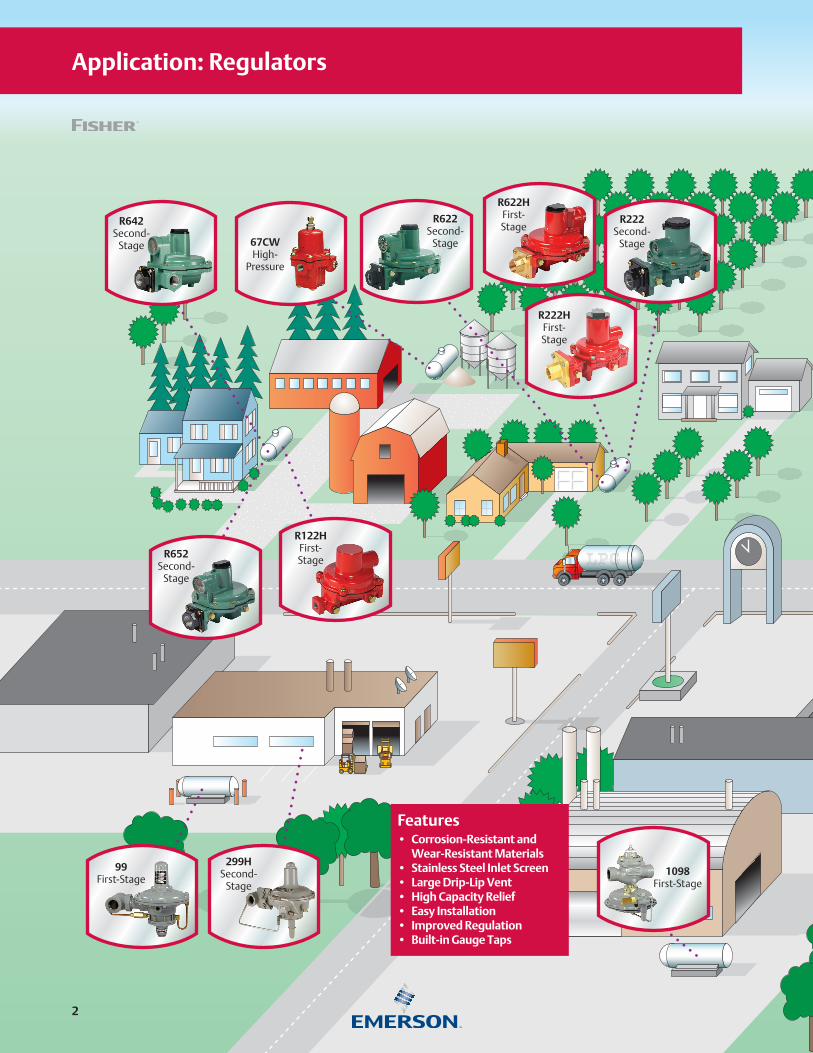
Application: Regulators
Features• Corrosion-Resistant and
Wear-Resistant Materials• Stainless Steel Inlet Screen• Large Drip-Lip Vent• High Capacity Relief• Easy Installation• Improved Regulation• Built-in Gauge Taps
2

99First-Stage
299HSecond-
Stage
R652Second-
Stage
R622Second-
Stage
CS400Second-
Stage
HSRLSecond-
Stage
627First-Stage
630First-Stage
67CWHigh-
Pressure
R122HFirst-Stage
CS800Second-
Stage
CS200Second-Stage
CS403Second-Stage
Monitor
CS404Second-Stage UPSO/OPSO
Shutoff
R232AIntegral
Two-Stage
R632AIntegral
Two-Stage
R642Second-
Stage
R622HFirst-Stage
R222HFirst-Stage
R222Second-
Stage
1098First-Stage
CS400Second-Stage
Fisher Regulator Color Code
First-Stage .................................. RedSecond-Stage ............................. Palm Green2-psi Service ............................... White CapIntegral Two-Stage ..................... GrayPounds to Pounds ....................... RedIndustrial .................................... Black or Gray
IntroductionThe regulator truly is the heart of an LPG installation. It must compensate for variations in tank pressure from 8 to 250 psig / 0.55 to 17.2 bar and deliver a constant outlet pressure of LPG typically at 11 in. w.c. / 27 mbar to consuming appliances. The regulator must deliver this pressure despite the intermittent use of the appliances.
In propane service, NFPA 58 requires Two-Stage regulation on all fixed piping systems that serve
14 in. w.c. / 35 mbar appliance systems (normally operated at 11 in. w.c. / 27 mbar pressure). Two-Stage regulation produces a nearly constant pressure to the appliance and can result in a more efficient LPG operation for the dealer resulting in less maintenance and fewer installation call-backs.
With properly selected regulators, the internal relief valve provides 2 psig / 0.14 bar overpressure protection as required by NFPA 58.
Emerson is a leading international supplier of cost-effective products, services and solutions used in the propane industry. Around the world, Emerson and its distributors offer quality products as well as applications engineering, education programs and after sales service. For any of the products described in this catalog, contact the Fisher™ LPG Equipment distributor near you.
3

C477Jet Bleed™
Internal Valve
H722Relief Valve
N563Emergency Shutoff Valve
C404-32Internal Valve
with P614AActuator
G201Back Check Valve
H733Relief Valve
C483-24with P723
Rotary Actuator
N551 with P327DEmergency
Shutoff Valve
N310-10GlobeValve
N410-10AngleValve
C484-24Jet Bleed™
Internal Valve
H284Relief Valve
C407-10 with P731Internal Valve with
Rotary Actuator
N551 with P539APneumaticActuator 63EGLP
Bulk Storage Relief
Application: Valves and Relief Valves
4
C477Jet Bleed™
Internal Valve
H722Relief Valve
N563Emergency Shutoff Valve
C404-32Internal Valve
with P614AActuator
G201Back Check Valve
H733Relief Valve
C483-24with P723
Rotary Actuator
N551 with P327DEmergency
Shutoff Valve
N310-10GlobeValve
N410-10AngleValve
C484-24Jet Bleed™
Internal Valve
H284Relief Valve
C407-10 with P731Internal Valve with
Rotary Actuator
N551 with P539APneumaticActuator 63EGLP
Bulk Storage Relief
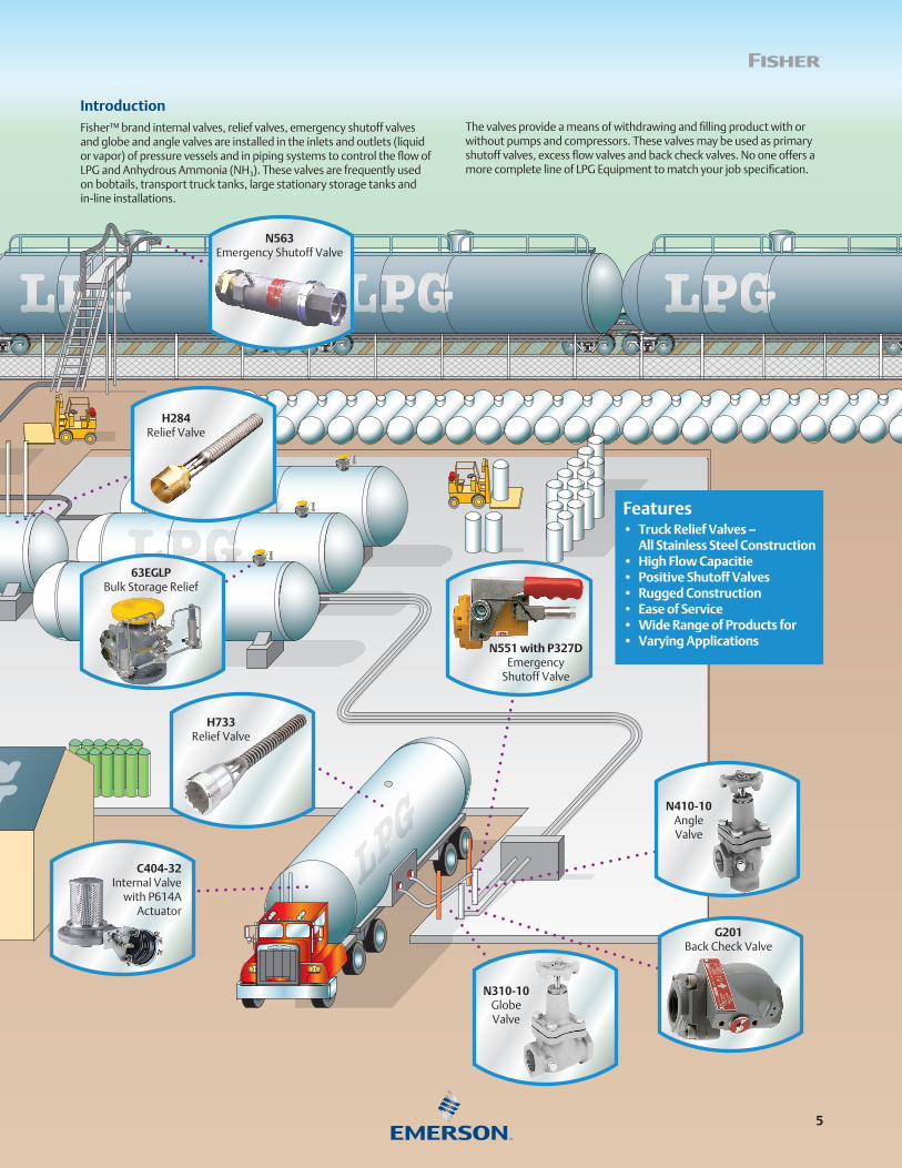
IntroductionFisher™ brand internal valves, relief valves, emergency shutoff valves and globe and angle valves are installed in the inlets and outlets (liquid or vapor) of pressure vessels and in piping systems to control the flow of LPG and Anhydrous Ammonia (NH3). These valves are frequently used on bobtails, transport truck tanks, large stationary storage tanks and in-line installations.
The valves provide a means of withdrawing and filling product with or without pumps and compressors. These valves may be used as primary shutoff valves, excess flow valves and back check valves. No one offers a more complete line of LPG Equipment to match your job specification.
Features• Truck Relief Valves –
All Stainless Steel Construction• High Flow Capacitie• Positive Shutoff Valves• Rugged Construction• Ease of Service• Wide Range of Products for• Varying Applications
5

F131Excess Flow
Valve H124ReliefValve
N100BypassValve
C407-10Internal Valve with
P731 Actuator
N480Hose End Valvewith M570 Back
Check FillerHose Adaptor
G101CheckValve
N401-06AngleValve
N310-16GlobeValve
N310-10GlobeValve
H722Relief Valve
C483-24Jet Bleed™
InternalValve
Pump
SprayFill
VaporLine
PressureRelief
G112CheckValve
J31L-1Rotary Gauge
Application: Bobtail Application Map
6

H733Internal
Relief Valve
C404-32Internal Valve
with P714Actuator
C471-16Jet Bleed™
InternalValve
C471-24Jet Bleed™
InternalValve
C477Jet Bleed™
InternalValve
N310-24GlobeValveN310-24
GlobeValve
N310-16AGlobeValve
N450-04AngleValve
J31L-1Rotary Gauge
PressureReliefValve
PressureReliefValve
SprayFill Vapor
Return
LiquidFill
F131Excess Flow
Valve H124ReliefValve
N100BypassValve
C407-10Internal Valve with
P731 Actuator
N480Hose End Valvewith M570 Back
Check FillerHose Adaptor
G101CheckValve
N401-06AngleValve
N310-16GlobeValve
N310-10GlobeValve
H722Relief Valve
C483-24Jet Bleed™
InternalValve
Pump
SprayFill
VaporLine
PressureRelief
G112CheckValve
J31L-1Rotary Gauge
Application: Transport Application Map
Features• Rugged Designs• All Stainless Steel Construction• Long Life Sealants• Ease of Maintenance• Wide Selection of Products
and Accessoties
7

Hosesto truck LIQ
UID LIN
E
VAPOR LINE
H124External
ReliefValve
N100BypassValve
C407-10Internal Valve with
P731 Actuator
N551Emergency
Shutoff Valve (ESV)
N410-10AngleValve
N310-16GlobeValve
N310-30Globe Valve
H5114Relief Valve
63EGLP
C477-24Jet Bleed™
InternalValve
G112Back
CheckValve
J31L-1Rotary Gauge
Application: Bobtail Application Map
Features• High Flow Capacity• Rugged Designs• Easy Maintenance• Wide Selection of Products
and Accessoties
8
9
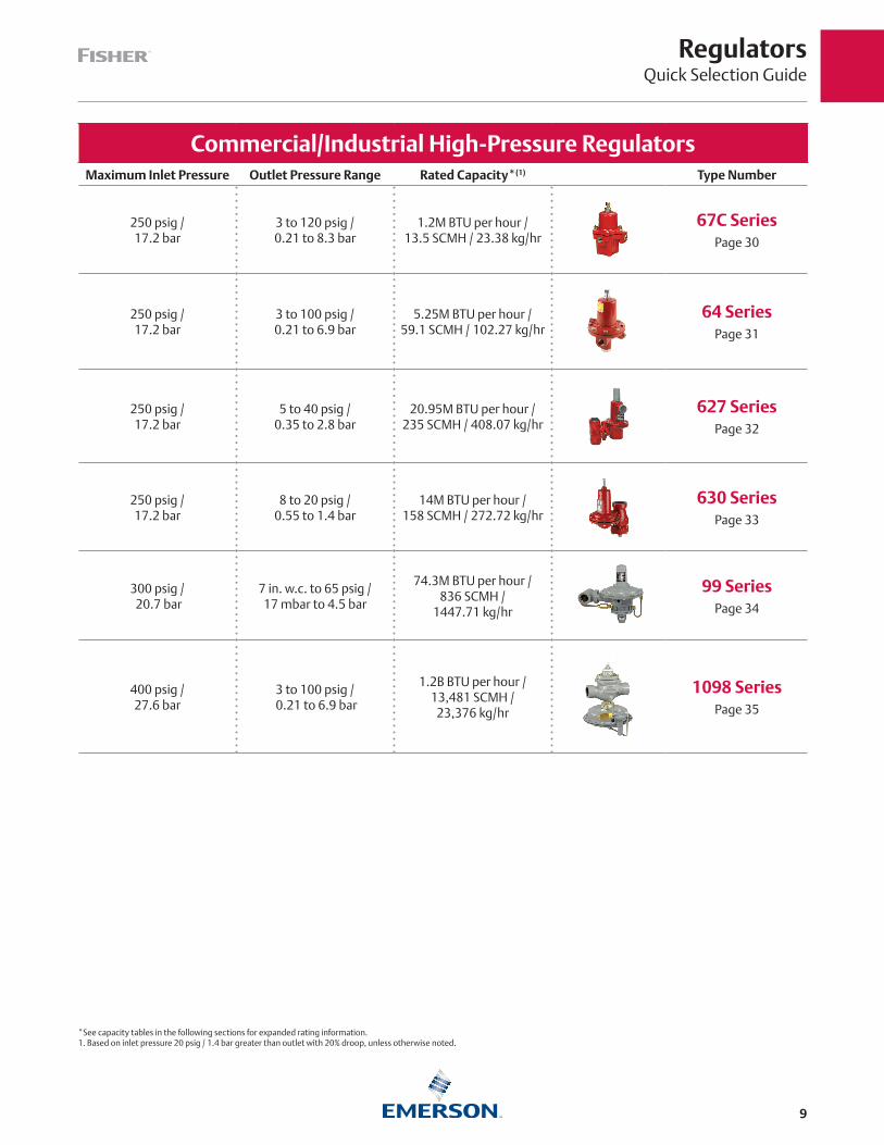
*See capacity tables in the following sections for expanded rating information.1. Based on inlet pressure 20 psig / 1.4 bar greater than outlet with 20% droop, unless otherwise noted.
RegulatorsQuick Selection Guide
Commercial/Industrial High-Pressure RegulatorsMaximum Inlet Pressure Outlet Pressure Range Rated Capacity*(1) Type Number
250 psig / 17.2 bar
3 to 120 psig /0.21 to 8.3 bar
1.2M BTU per hour / 13.5 SCMH / 23.38 kg/hr
67C SeriesPage 30
250 psig /17.2 bar
3 to 100 psig /0.21 to 6.9 bar
5.25M BTU per hour / 59.1 SCMH / 102.27 kg/hr
64 SeriesPage 31
250 psig /17.2 bar
5 to 40 psig /0.35 to 2.8 bar
20.95M BTU per hour / 235 SCMH / 408.07 kg/hr
627 SeriesPage 32
250 psig /17.2 bar
8 to 20 psig /0.55 to 1.4 bar
14M BTU per hour / 158 SCMH / 272.72 kg/hr
630 SeriesPage 33
300 psig / 20.7 bar
7 in. w.c. to 65 psig /17 mbar to 4.5 bar
74.3M BTU per hour / 836 SCMH /
1447.71 kg/hr
99 SeriesPage 34
400 psig /27.6 bar
3 to 100 psig / 0.21 to 6.9 bar
1.2B BTU per hour /13,481 SCMH /
23,376 kg/hr
1098 SeriesPage 35

10
*See capacity tables in the following sections for expanded rating information.1. Based on inlet pressure 20 psig / 1.4 bar greater than outlet with 20% droop, unless otherwise noted. 2. Based on 10 psig / 0.69 bar inlet pressure setting and 20% droop.3. Based on 10 psig / 0.69 bar inlet pressure setting and 2 in. w.c. / 5 mbar droop.4. Types 912-101 and -104 rating at 30 psig / 2.1 bar inlet.
RegulatorsQuick Selection Guide
Commercial/Industrial Low-Pressure RegulatorsMaximum Inlet Pressure Outlet Pressure Range Rated Capacity*(1) Type Number
125 psig /8.6 bar
3.5 in. w.c. to 2 psig /9 mbar to 0.14 bar
3.9M BTU per hour /43.8 SCMH / 75.97 kg/hr(3)
CS200 Series Page 36
125 psig /8.6 bar
3.5 in. w.c. to 5.5 psig /9 mbar to 0.38 bar
8.9M BTU per hour /100 SCMH /
173.37 kg/hr(2)
CS400 Series Page 36
125 psig /8.6 bar
8 in. w.c to 5.5 psig /20 mbar to 0.38 bar
20M BTU per hour/224 SCMH / 389.6 kg/hr
CS800 Series Page 36
60 psig /4.1 bar
1.5 to 3 psig /0.10 to 0.21 bar
66.15M BTU per hour /745 SCMH 1288.6 kg/hr(2)
Type 133H Page 40
60 psig /4.1 bar
8.5 to 18 in. w.c. /21 to 45 mbar
70.8M BTU per hour /797 SCMH /
1380.65 kg/hr(3)
Type 133L Page 40
150 psig /10.3 bar
9 in. w.c. to 16 psig /22 mbar to 1.1 bar
38M BTU per hour /428 SCMH 740.24 kg/hr
299H Series Page 40
150 psig /10.3 bar
7 in. w.c. to 5 psig /18 mbar to 0.35 bar
63.25M BTU per hour/712 SCMH 1232.11 kg/hr
99-500P Series Page 40
250 psig /17.2 bar
3 in. w.c. to 5 psig /7 mbar to 0.35 bar
556,000 BTU per hour /6.2 SCMH / 10.83 kg/hr(4)
912 Series Page 44

11
*See capacity tables in the following sections for expanded rating information.1. Based on 30 psig / 2.1 bar inlet pressure and 20% droop.2. Based on 10 psig / 0.69 bar inlet pressure setting.3. Second-Stage regulators are UL® rated.
RegulatorsQuick Selection Guide
Second-Stage Regulators(3)
Maximum Inlet Pressure Outlet Pressure Range Rated Capacity*(2) Type Number
10 psig /0.69 bar
9 to 13 in. w.c. /22 to 32 mbar
2.6M BTU per hour /29.3 SCMH / 50.65 kg/hr
Type HSRL Page 26
10 psig /0.69 bar
11 in. w.c. /27 mbar
650,000BTU per hour /
7.3 SCMH / 12.66 kg/hr
R222 Series Page 26
10 psig /0.69 bar
11 in. w.c. /27 mbar
1.4M BTU per hour /15.8 SCMH / 27.27 kg/hr
R622 Series Page 26
10 psig /0.69 bar
11 in. w.c. /27 mbar
920,000BTU per hour /
10.4 SCMH / 17.92 kg/hr
R642 Series Page 26
10 psig /0.69 bar
11 in. w.c. /27 mbar
1M BTU per hour /11.2 SCMH / 19.48 kg/hr
R652 Series Page 26
First-Stage Regulators
Maximum Inlet PressureOutlet Pressure
Setting/SetpointRated Capacity*(1) Type Number
250 psig /17.2 bar
10 psig / 0.69 bar+/- 1 psig / 69 mbar
nominal outlet setting(non-adjustable)
1.1M BTU per hour /12.4 SCMH / 21.43 kg/hr
R122H Series Page 25
250 psig /17.2 bar
5 or 10 psig /0.35 or 0.69 bar
standard setpoints
2.0M BTU per hour /22.5 SCMH / 38.96 kg/hr
R222H Series Page 25
250 psig /17.2 bar
5 or 10 psig /0.35 or 0.69 bar
standard setpoints
2.4M BTU per hour /27.0 SCMH / 46.75 kg/hr
R622H Series Page 25

12
*See capacity tables in the following sections for expanded rating information.1. Based on 10 psig / 0.69 bar inlet pressure setting and 20% droop.2. Based on 30 psig / 2.1 bar inlet pressure setting and 2 in. w.c. / 5 mbar droop.
RegulatorsQuick Selection Guide
2-psi Service RegulatorsMaximum Inlet Pressure Standard Setpoint Rated Capacity*(1) Type Number
10 psig /0.69 bar
2 psi /0.14 bar
1.68M BTU per hour /18.9 SCMH / 32.73 kg/hr
R622E Series Page 27
10 psig /0.69 bar
2 psi /0.14 bar
1.5M BTU per hour /16.9 SCMH / 29.22 kg/hr
R652E Series Page 27
Integral Two-Stage RegulatorsMaximum Inlet Pressure Standard Setpoint Rated Capacity*(1) Type Number
250 psig /17.2 bar
First-Stage:Approximately
10 psig / 0.69 bar(non-adjustable)
Second-Stage:11 in. w.c. / 27 mbar
550,000 BTU per hour /6.2 SCMH / 10.71 kg/hr
R232A Series Page 28
250 psig /17.2 bar
First-Stage:Approximately
10 psig / 0.69 bar(non-adjustable)
Second-Stage:11 in. w.c. / 27 mbar
950,000 BTU per hour /10.7 SCMH / 18.51 kg/hr
R632A Series Page 28
13
*See capacity tables in the following sections for expanded rating information.1. Based on 30 psig / 2.1 bar inlet pressure setting and 20% droop.
RegulatorsQuick Selection Guide
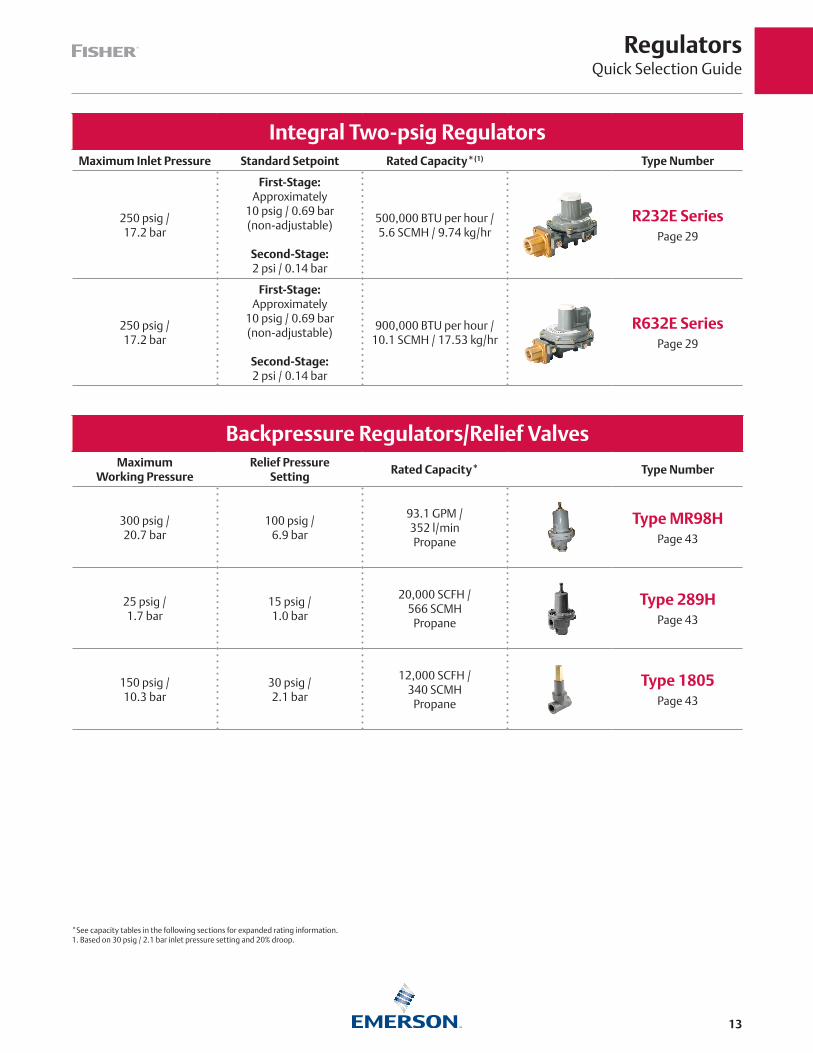
Integral Two-psig RegulatorsMaximum Inlet Pressure Standard Setpoint Rated Capacity*(1) Type Number
250 psig /17.2 bar
First-Stage:Approximately
10 psig / 0.69 bar(non-adjustable)
Second-Stage:2 psi / 0.14 bar
500,000 BTU per hour /5.6 SCMH / 9.74 kg/hr
R232E Series Page 29
250 psig /17.2 bar
First-Stage:Approximately
10 psig / 0.69 bar(non-adjustable)
Second-Stage:2 psi / 0.14 bar
900,000 BTU per hour /10.1 SCMH / 17.53 kg/hr
R632E Series Page 29
Backpressure Regulators/Relief ValvesMaximum
Working PressureRelief Pressure
SettingRated Capacity* Type Number
300 psig /20.7 bar
100 psig /6.9 bar
93.1 GPM /352 l/minPropane
Type MR98H Page 43
25 psig /1.7 bar
15 psig /1.0 bar
20,000 SCFH /566 SCMH
Propane
Type 289H Page 43
150 psig /10.3 bar
30 psig /2.1 bar
12,000 SCFH /340 SCMH
Propane
Type 1805 Page 43

Valves and Relief ValvesQuick Selection Guide
14
*See capacity tables in the following sections for expanded rating information.
Internal/External Relief ValvesMaximum Inlet Pressure
(Body Rating)Standard Setpoint Capacity* Type Number
480 psig /33.1 bar
85 to 375 psig /5.9 to 26 bar
Up to 47,164 SCFM /84,170 SCMH
Type 63EGLP Page 68
480 psig /33.1 bar
125 to 312 psig /8.6 to 21.5 bar
UL®: Up to 11,635 SCFM /
20,764 SCMH Air
ASME: Up to15,286 SCFM /
18,097 SCMH Air
H284 and H5114 Series
Page 67
480 psig /33.1 bar
125 to 312 psig /8.6 to 21.5 bar
UL: Up to 11,315 SCFM /
19,940 SCMH Air
ASME: Up to 13,876 SCFM /
16,400 SCMH Air
H722 and H733 Series
Page 66
420 psig /29.0 bar
35 to 350 psig / 2.4 to 23.8 barFixed Setting
Up to 2456 SCFM /4173 SCMH
H100 Series Page 72
Bypass and Backpressure ValvesMaximum
Working PressureRelief Pressure Range
Body Size and End Connection Style
Type Number
400 psig / 27.6 bar
10 to 150 psig /0.69 to 10.3 bar
3/4 to 2 in. FNPT
N100 Series Page 78

Valves and Relief ValvesQuick Selection Guide
15
*See capacity tables in the following sections for expanded rating information.
Internal ValvesPressure Rating Excess Flow Spring Capacity* Type Number
400 psig /27.6 bar WOG
30 to 80 GPM /113 to 302 l/min
19,200 SCFH /544 SCMH
Propane
C407-10 Series Page 47
400 psig /27.6 bar WOG
60 to 460 GPM /227 to 1741 l/min
178,000 SCFH /5040 SCMH
Propane
C471-16, -24 Jet Bleed
Internal™ SeriesPage 47
400 psig /27.6 bar WOG
100 to 460 GPM /379 to 1741 l/min
178,000 SCFH /5040 SCMH
Propane
C477-16, -24 and C486-24
Jet Bleed Internal™ Series
Page 47
400 psig /27.6 bar WOG
160 to 400 GPM /606 to 1514 l/min
190,000 SCFH /5380 SCMH
Propane
C483-24 Jet Bleed
Internal™ SeriesPage 53
400 psig /27.6 bar WOG
160 to 400 GPM /606 to 1514 l/min
190,000 SCFH /5380 SCMH
Propane
C484-24Jet Bleed
Internal™ SeriesPage 53
400 psig /27.6 bar WOG
340 to 1000 GPM /1287 to 3785 l/min
356,200 SCFH /10,088 SCMH
Type C404-32 Page 55
Valves and Relief ValvesQuick Selection Guide
16
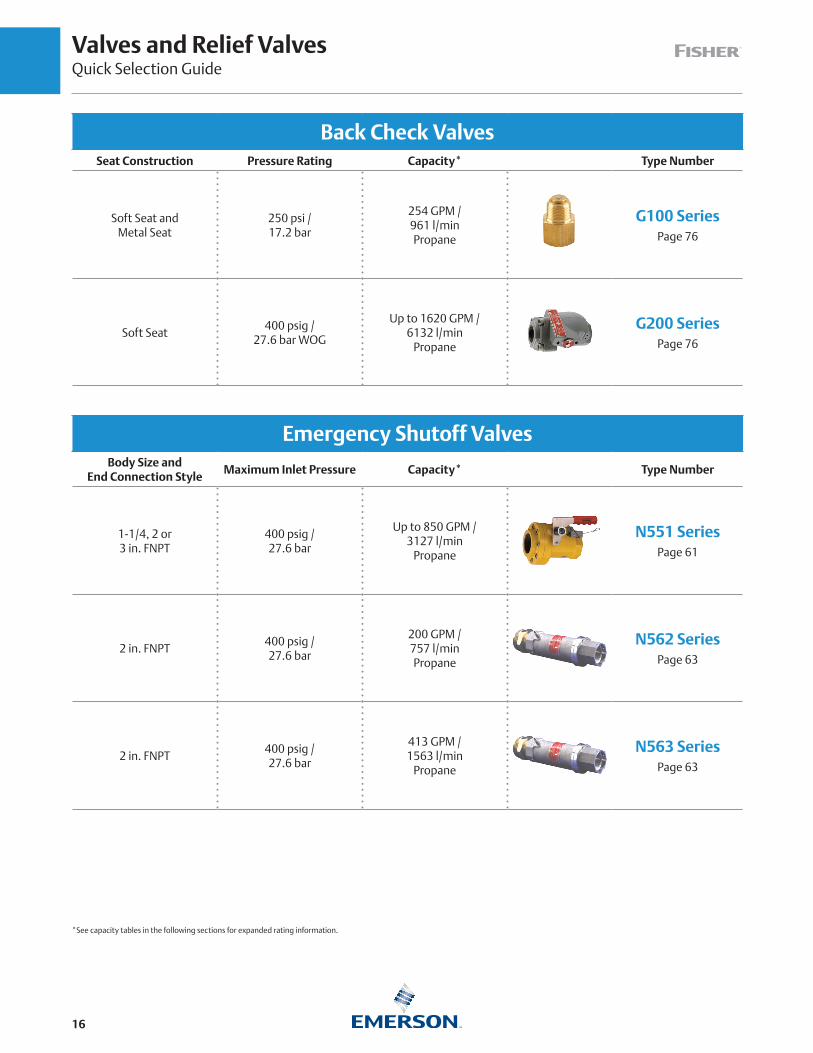
Back Check ValvesSeat Construction Pressure Rating Capacity* Type Number
Soft Seat andMetal Seat
250 psi /17.2 bar
254 GPM /961 l/minPropane
G100 Series Page 76
Soft Seat400 psig /
27.6 bar WOG
Up to 1620 GPM /6132 l/min
Propane
G200 Series Page 76
Emergency Shutoff ValvesBody Size and
End Connection StyleMaximum Inlet Pressure Capacity* Type Number
1-1/4, 2 or3 in. FNPT
400 psig /27.6 bar
Up to 850 GPM /3127 l/min
Propane
N551 Series Page 61
2 in. FNPT400 psig /27.6 bar
200 GPM /757 l/minPropane
N562 Series Page 63
2 in. FNPT400 psig /27.6 bar
413 GPM /1563 l/min
Propane
N563 Series Page 63
*See capacity tables in the following sections for expanded rating information.

Valves and Relief ValvesQuick Selection Guide
17
Globe and Angle Valves
Selection DescriptionMaximum
Operating PressureBody Size and
End Connection StyleType Number
Globe Valve(Heavy Duty Version)
400 psig /27.6 bar
1/2 to 2 in. FNPTN301,
N310 Series Page 73
Globe Valve(Economy Duty Version)
400 psig /27.6 bar
1/2 to3/4 in. FNPT
N350 Series Page 73
Angle Valve(Heavy Duty Version)
400 psig /27.6 bar
1/2 to 2 in. FNPTN401,
N410 Series Page 73
Angle Valve(Economy Version)
400 psig /27.6 bar
1/2 to3/4 in. FNPT
N450 Series Page 73
Globe and Angle Valves(Heavy Duty Version)
400 psig /27.6 bar
1/2 to 3 FNPT, NPS 3 / DN 80 CL300 RF
N600, N700 Series
Page 73
*See capacity tables in the following sections for expanded rating information.
Valves and Relief ValvesQuick Selection Guide
18
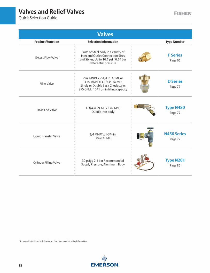
ValvesProduct/Function Selection Information Type Number
Excess Flow Valve
Brass or Steel body in a variety ofInlet and Outlet Connection Sizes
and Styles; Up to 10.7 psi / 0.74 bardifferential pressure
F Series Page 65
Filler Valve
2 in. MNPT x 2-1/4 in. ACME or3 in. MNPT x 3-1/4 in. ACME;
Single or Double Back Check style;275 GPM / 1041 l/min filling capacity
D SeriesPage 77
Hose End Valve1-3/4 in. ACME x 1 in. NPT;
Ductile iron bodyType N480
Page 77
Liquid Transfer Valve3/4 MNPT x 1-3/4 in.
Male ACMEN456 Series
Page 77
Cylinder Filling Valve30 psig / 2.1 bar Recommended
Supply Pressure; Aluminum BodyType N201
Page 85
*See capacity tables in the following sections for expanded rating information.

LPG Equipment and Accessories Quick Selection Guide
19
Regulator AccessoriesProduct/Function Selection Information Type Number
Screened Vents for Regulator1/4 in. FNPT to
1 in. MNPTY602 Series
Page 44
Regulator Mounting BracketsTriangular, Bowtie
or Strap DesignType P100
Page 45
Test Pressure Gauge for Appliance Line Pressure
1/4 in. NPT or Female Hose50 Series
Page 45
Pressure Gauge1/4 in. MNPT;
0 to 400 psi / 0 to 27.6 bar;Ranges in MPa, kg/cm2, bar
J500 SeriesPage 45
Adjustable Orifice ReamerDrill Size No. 80through No. 50
Type P520LPage 85
LPG Equipment and AccessoriesQuick Selection Guide
20
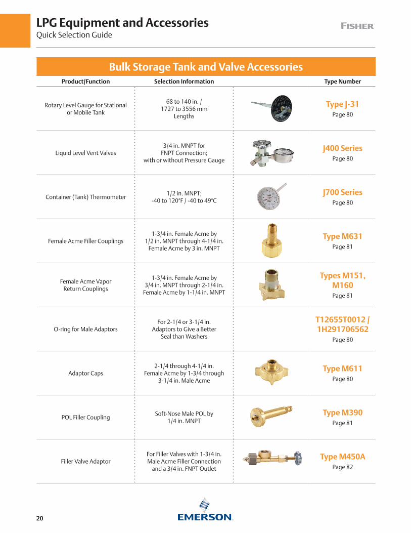
Bulk Storage Tank and Valve AccessoriesProduct/Function Selection Information Type Number
Rotary Level Gauge for Stational or Mobile Tank
68 to 140 in. / 1727 to 3556 mm
Lengths
Type J-31Page 80
Liquid Level Vent Valves3/4 in. MNPT for
FNPT Connection; with or without Pressure Gauge
J400 SeriesPage 80
Container (Tank) Thermometer1/2 in. MNPT;
-40 to 120°F / -40 to 49°CJ700 Series
Page 80
Female Acme Filler Couplings1-3/4 in. Female Acme by
1/2 in. MNPT through 4-1/4 in. Female Acme by 3 in. MNPT
Type M631Page 81
Female Acme Vapor Return Couplings
1-3/4 in. Female Acme by 3/4 in. MNPT through 2-1/4 in.
Female Acme by 1-1/4 in. MNPT
Types M151, M160Page 81
O-ring for Male AdaptorsFor 2-1/4 or 3-1/4 in.
Adaptors to Give a BetterSeal than Washers
T12655T0012 /1H291706562
Page 80
Adaptor Caps2-1/4 through 4-1/4 in.
Female Acme by 1-3/4 through 3-1/4 in. Male Acme
Type M611Page 80
POL Filler CouplingSoft-Nose Male POL by
1/4 in. MNPTType M390
Page 81
Filler Valve AdaptorFor Filler Valves with 1-3/4 in. Male Acme Filler Connection
and a 3/4 in. FNPT Outlet
Type M450APage 82

LPG Equipment and Accessories Quick Selection Guide
21
Bulk Storage Tank and Valve AccessoriesProduct/Function Selection Information Type Number
Swivel POL Adaptorwith Metal Seats
Straight or Angle MalePOL by 1/4 in. MNPT Type M318
Auxiliary Remote CableRelease for Internal Valves
With 25 or 50-Feet /7.6 or 15.2 m Cable
or without Cable
Type P163APage 80
Handle- or Cable-Operated Latch/Remote Release for Internal Valves
Built-In Fusible Link to Close Valve in Case of Fire
Type P313Page 80
Primary Cable Controlfor Internal Valves
4, 5 or 6 in. / 102, 137 or 152 mm Travel
Type P650Page 81
Cable Control, Release Mechanism and
Cable Assembly for Internal Valves
For 1-1/4, 2, 3 and 4 in. /DN 32, 50, 80 and 100
Internal Valves
Types P314Page 81
Relief Valve PipeawayAdaptors for DOT
For Use with Types H284,H5114, H125, H150,
H148 and H173 Valves
Types P104-24,P174Page 80
Filler Hose Adaptor withBack Check Valve
1-3/4 in. Female Acmeby 1-3/4 in. Male Acme
Type M570Page 80

LPG Equipment and AccessoriesQuick Selection Guide
22
Bulk Storage Tank and Valve AccessoriesProduct/Function Selection Information Type Number
Pneumatic ActuatorFor Use with
C407-10 Series Only
Types P389and P731
Page 60
Pneumatic ActuatorFor Type C484-24
Jet Bleed Internal™ Valve
Types P613and P713
Page 60
Pneumatic ActuatorFor Type C483-24
Jet Bleed Internal™ Valve
Types P623and P723
Page 60
Pneumatic ActuatorFor Types C471 and C477 Jet Bleed Internal™ Valves
(2 and 3 in. NPT Sizes)
Types P639and P739
Page 60
Pneumatic ActuatorFor Type C404-32
4 in. / DN 100 Single Flanged Valve
Types P614Aand P714
Page 60
Pneumatic Actuator
For Closing and Opening of N551 Series
Snappy Joe™ Emergency Shutoff Valves (ESVs)
Type P539APage 61

LPG Equipment and Accessories Quick Selection Guide
23
Bulk Storage Tank and Valve AccessoriesProduct/Function Selection Information Type Number
Fuse Plug
208 to 220°F / 98 to 104°C Melting Temperature,
Available in 1/8 and 1/4 in. MNPT Sizes
T1140399982 /T1033699982
Page 60
Protective Caps forRelief Valves
For Types H110 through H174 Valves
Type P206Page 72
Seals and Plugs forFemale Acme Threads
1-1/4 to 4-1/4 in.Male Acme
Types M178,M535-34
Page 82
Female Acme Caps Hand or Wrench InstallationType M108
Page 83
Clamp Hose Couplings
Swivel or Standard:1/2 in. MNPT through 4-1/4 in.
Female Acme for 1/2 through 3 in. Hose
Type M3162Page 84
Spanner Wrench for Large Female Acme Caps
and Couplings
For Use with 2-1/4through 4-1/4 in.
Acme Threads
Types P120BPage 85
Ring and Chain AssembliesFor 1-1/4 through 4-1/4 in.
Acme Caps or Dust Seals
Type P147,P167 and P183
Page 84
24
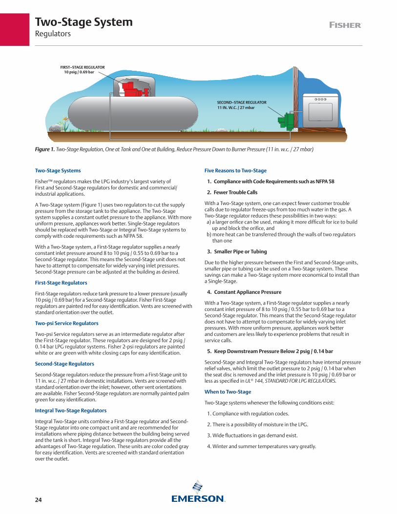
Two-Stage Systems
Fisher™ regulators makes the LPG industry’s largest variety of First and Second-Stage regulators for domestic and commercial/industrial applications.
A Two-Stage system (Figure 1) uses two regulators to cut the supply pressure from the storage tank to the appliance. The Two-Stage system supplies a constant outlet pressure to the appliance. With more uniform pressure, appliances work better. Single-Stage regulators should be replaced with Two-Stage or Integral Two-Stage systems to comply with code requirements such as NFPA 58.
With a Two-Stage system, a First-Stage regulator supplies a nearly constant inlet pressure around 8 to 10 psig / 0.55 to 0.69 bar to a Second-Stage regulator. This means the Second-Stage unit does not have to attempt to compensate for widely varying inlet pressures. Second-Stage pressure can be adjusted at the building as desired.
First-Stage Regulators
First-Stage regulators reduce tank pressure to a lower pressure (usually 10 psig / 0.69 bar) for a Second-Stage regulator. Fisher First-Stage regulators are painted red for easy identification. Vents are screened with standard orientation over the outlet.
Two-psi Service Regulators
Two-psi Service regulators serve as an intermediate regulator after the First-Stage regulator. These regulators are designed for 2 psig / 0.14 bar LPG regulator systems. Fisher 2-psi regulators are painted white or are green with white closing caps for easy identification.
Second-Stage Regulators
Second-Stage regulators reduce the pressure from a First-Stage unit to 11 in. w.c. / 27 mbar in domestic installations. Vents are screened with standard orientation over the inlet; however, other vent orientations are available. Fisher Second-Stage regulators are normally painted palm green for easy identification.
Integral Two-Stage Regulators
Integral Two-Stage units combine a First-Stage regulator and Second-Stage regulator into one compact unit and are recommended for installations where piping distance between the building being served and the tank is short. Integral Two-Stage regulators provide all the advantages of Two-Stage regulation. These units are color coded gray for easy identification. Vents are screened with standard orientation over the outlet.
Five Reasons to Two-Stage
1. Compliance with Code Requirements such as NFPA 58
2. Fewer Trouble Calls
With a Two-Stage system, one can expect fewer customer trouble calls due to regulator freeze-ups from too much water in the gas. A Two-Stage regulator reduces these possibilities in two ways: a) a larger orifice can be used, making it more difficult for ice to build
up and block the orifice, and b) more heat can be transferred through the walls of two regulators
than one
3. Smaller Pipe or Tubing
Due to the higher pressure between the First and Second-Stage units, smaller pipe or tubing can be used on a Two-Stage system. These savings can make a Two-Stage system more economical to install than a Single-Stage.
4. Constant Appliance Pressure
With a Two-Stage system, a First-Stage regulator supplies a nearly constant inlet pressure of 8 to 10 psig / 0.55 bar to 0.69 bar to a Second-Stage regulator. This means that the Second-Stage regulator does not have to attempt to compensate for widely varying inlet pressures. With more uniform pressure, appliances work better and customers are less likely to experience problems that result in service calls.
5. Keep Downstream Pressure Below 2 psig / 0.14 bar
Second-Stage and Integral Two-Stage regulators have internal pressure relief valves, which limit the outlet pressure to 2 psig / 0.14 bar when the seat disc is removed and the inlet pressure is 10 psig / 0.69 bar or less as specified in UL® 144, STANDARD FOR LPG REGULATORS.
When to Two-Stage
Two-Stage systems whenever the following conditions exist:
1. Compliance with regulation codes.
2. There is a possibility of moisture in the LPG.
3. Wide fluctuations in gas demand exist.
4. Winter and summer temperatures vary greatly.
FIRST–STAGE REGULATOR10 psig / 0.69 bar
SECOND–STAGE REGULATOR11 IN. W.C. / 27 mbar
Figure 1. Two-Stage Regulation, One at Tank and One at Building, Reduce Pressure Down to Burner Pressure (11 in. w.c. / 27 mbar)
Two-Stage SystemRegulators
First-Stage RegulatorsRegulators
25
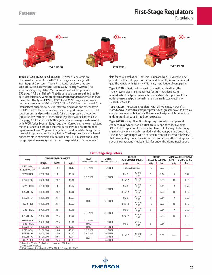
Types R122H, R222H and R622H First-Stage Regulators are Underwriters Laboratories (UL®) listed regulators designed for Two-Stage LPG systems. These First-Stage regulators reduce tank pressure to a lower pressure (usually 10 psig / 0.69 bar) for a Second-Stage regulator. Maximum allowable inlet pressure is 250 psig / 17.2 bar. Fisher™ First-Stage regulators are painted red for easy identification. Vents are screened with standard orientation over the outlet. The Types R122H, R222H and R622H regulators have a temperature rating of -20 to 160°F / -29 to 71°C, but have passed Fisher internal testing for lockup, relief start-to-discharge and reseal down to -40°F / -40°C. The design’s superior relief performance exceeds UL requirements and provides double failure overpressure protection (pressure downstream of the second regulator will be limited close to 2 psig / 0.14 bar, even if both regulators are damaged) when used with R600 Series Second-Stage regulator. Corrosion and wear resistant materials and stainless steel internal parts provide a recommended replacement life of 20 years. A large fabric reinforced diaphragm with molded lips provide precise regulation. The large precision machined orifice assists in minimizing freeze problems. 1/8 in. inlet and outlet gauge taps allow easy system testing. Large inlet and outlet wrench
flats for easy installation. The unit’s Fluorocarbon (FKM) valve disc provides better lockup performance and durability in contaminated gas. The vent is with 3/8 in. NPT for easy installation of vent piping.
Type R122H – Designed for use in domestic applications, the Type R122H’s size makes it perfect for tight installations. Its non-adjustable setpoint makes the unit virtually tamper proof. The outlet pressure setpoint remains at a nominal factory setting of 10 psig / 0.69 bar.
Type R222H – First stage regulator with all Type R622H benefits stated above, but with a compact profile. 65% greater flow than typical compact regulators but with a 40% smaller footprint. It is perfect for underground tanks or limited dome spaces.
Type R622H – High Flow First-Stage regulator with multiple end connections and adjustable outlet pressure spring ranges. A large 3/4 in. FNPT drip-lip vent reduces the chance of blockage by freezing rain or sleet when properly installed with the vent pointing down. Each Type R622H is equipped with a corrosion-resistant internal relief valve that provides high capacity relief and a travel stop on the closing cap. Its size and configuration make it ideal for under-the-dome installations.
First-Stage Regulators
TYPECAPACITIES (PROPANE)(1)(3) INLET
CONNECTION, IN.OUTLET
CONNECTION, IN.
OUTLET ADJUSTMENT RANGE
OUTLETPRESSURE SETTING
NOMINAL RELIEF VALVE START-TO-DISCHARGE
BTU / hr SCMH kg/hr psig bar psig bar psig barR122H-AAJ
1,100,000 12.4 21.43 1/4 FNPT 1/2 FNPT Non-Adjustable 10 0.69 - - - - - - - -R122H-AAJXB(2)
R222H-BGK 1,700,000 19.1 33.121/2 FNPT 1/2 FNPT
4 to 60.28 to
0.415 0.34 9 0.62
R222H-BGJ 1,800,000 20.2 35.06 8 to 120.55 to
0.8210 0.69 16 1.10
R222H-HGK 1,700,000 19.1 33.12FPOL 1/2 FNPT
4 to 60.28 to
0.415 0.34 9 0.62
R222H-HGJ 1,800,000 20.2 35.06 8 to 120.55 to
0.8210 0.69 16 1.10
R222H-JGK 1,875,000 21.1 36.53FPOL 3/4 FNPT
4 to 60.28 to
0.415 0.34 9 0.62
R222H-JGJ 1,875,000 21.1 36.53 8 to 120.55 to
0.8210 0.69 16 1.10
R222H-DGK 2,000,000 22.5 38.963/4 FNPT 3/4 FNPT
4 to 60.28 to
0.415 0.34 9 0.62
R222H-DGJ 2,000,000 22.5 38.96 8 to 120.55 to
0.8210 0.69 16 1.10
R622H-BGK2,000,000 22.5 38.96
1/2 FNPT1/2 FNPT
4 to 60.28 to
0.415 0.34 - - - - - - - -R622H-HGK FPOL
R622H-JGK 2,250,000 25.3 43.83 FPOL 3/4 FNPTR622H-BGJ 2,100,000 23.6 40.91 1/2 FNPT 1/2 FNPT
8 to 120.55 to
0.8310 0.69 - - - - - - - -
R622H-DGJ 2,400,000 27.0 46.75 3/4 FNPT 3/4 FNPTR622H-HGJ 2,100,000 23.6 40.91
FPOL1/2 FNPT
R622H-JGJ 2,250,000 25.3 43.83 3/4 FNPT1. Based on 30 psig / 2.1 bar inlet pressure and 20% droop.2. Vent over gauge taps.3. Metric conversion is based on 2516 BTU/ft3 of gas at 60°F / 16°C.
TYPE R622HTYPE R122H TYPE R222H
USC USC USC
Second-Stage RegulatorsRegulators
26
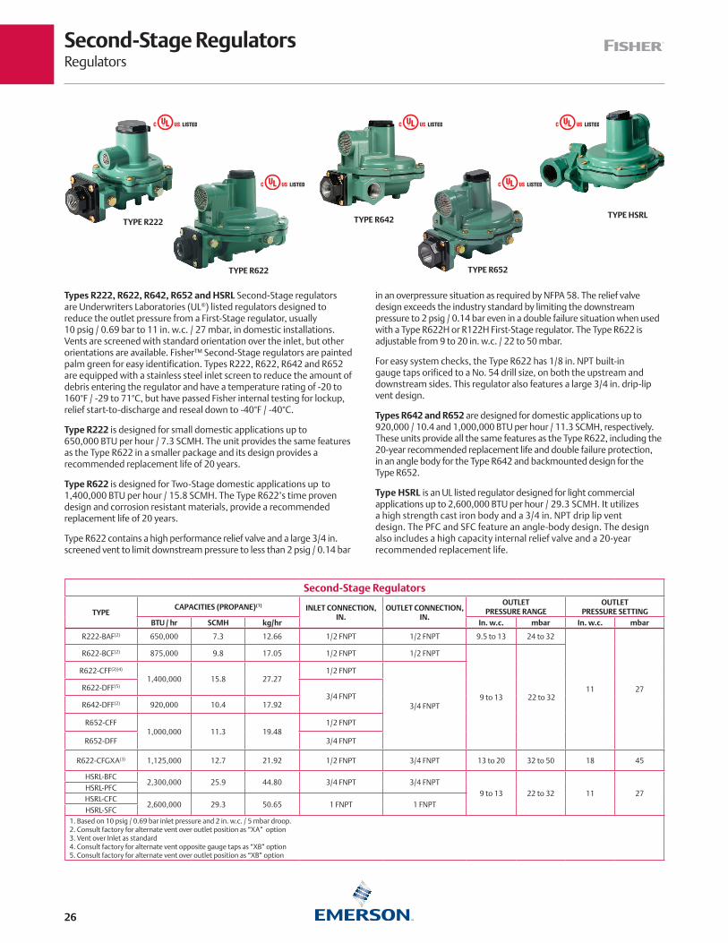
Types R222, R622, R642, R652 and HSRL Second-Stage regulators are Underwriters Laboratories (UL®) listed regulators designed to reduce the outlet pressure from a First-Stage regulator, usually 10 psig / 0.69 bar to 11 in. w.c. / 27 mbar, in domestic installations. Vents are screened with standard orientation over the inlet, but other orientations are available. Fisher™ Second-Stage regulators are painted palm green for easy identification. Types R222, R622, R642 and R652 are equipped with a stainless steel inlet screen to reduce the amount of debris entering the regulator and have a temperature rating of -20 to 160°F / -29 to 71°C, but have passed Fisher internal testing for lockup, relief start-to-discharge and reseal down to -40°F / -40°C.
Type R222 is designed for small domestic applications up to 650,000 BTU per hour / 7.3 SCMH. The unit provides the same features as the Type R622 in a smaller package and its design provides a recommended replacement life of 20 years.
Type R622 is designed for Two-Stage domestic applications up to 1,400,000 BTU per hour / 15.8 SCMH. The Type R622’s time proven design and corrosion resistant materials, provide a recommended replacement life of 20 years.
Type R622 contains a high performance relief valve and a large 3/4 in. screened vent to limit downstream pressure to less than 2 psig / 0.14 bar
in an overpressure situation as required by NFPA 58. The relief valve design exceeds the industry standard by limiting the downstream pressure to 2 psig / 0.14 bar even in a double failure situation when used with a Type R622H or R122H First-Stage regulator. The Type R622 is adjustable from 9 to 20 in. w.c. / 22 to 50 mbar.
For easy system checks, the Type R622 has 1/8 in. NPT built-in gauge taps orificed to a No. 54 drill size, on both the upstream and downstream sides. This regulator also features a large 3/4 in. drip-lip vent design.
Types R642 and R652 are designed for domestic applications up to 920,000 / 10.4 and 1,000,000 BTU per hour / 11.3 SCMH, respectively. These units provide all the same features as the Type R622, including the 20-year recommended replacement life and double failure protection, in an angle body for the Type R642 and backmounted design for the Type R652.
Type HSRL is an UL listed regulator designed for light commercial applications up to 2,600,000 BTU per hour / 29.3 SCMH. It utilizes a high strength cast iron body and a 3/4 in. NPT drip lip vent design. The PFC and SFC feature an angle-body design. The design also includes a high capacity internal relief valve and a 20-year recommended replacement life.
Second-Stage Regulators
TYPECAPACITIES (PROPANE)(1) INLET CONNECTION,
IN. OUTLET CONNECTION,
IN.
OUTLET PRESSURE RANGE
OUTLETPRESSURE SETTING
BTU / hr SCMH kg/hr In. w.c. mbar In. w.c. mbar
R222-BAF(2) 650,000 7.3 12.66 1/2 FNPT 1/2 FNPT 9.5 to 13 24 to 32
11 27
R622-BCF(2) 875,000 9.8 17.05 1/2 FNPT 1/2 FNPT
9 to 13 22 to 32
R622-CFF(2)(4)
1,400,000 15.8 27.271/2 FNPT
3/4 FNPT
R622-DFF(5)
3/4 FNPTR642-DFF(2) 920,000 10.4 17.92
R652-CFF1,000,000 11.3 19.48
1/2 FNPT
R652-DFF 3/4 FNPT
R622-CFGXA(3) 1,125,000 12.7 21.92 1/2 FNPT 3/4 FNPT 13 to 20 32 to 50 18 45
HSRL-BFC2,300,000 25.9 44.80 3/4 FNPT 3/4 FNPT
9 to 13 22 to 32 11 27HSRL-PFCHSRL-CFC
2,600,000 29.3 50.65 1 FNPT 1 FNPTHSRL-SFC
1. Based on 10 psig / 0.69 bar inlet pressure and 2 in. w.c. / 5 mbar droop.2. Consult factory for alternate vent over outlet position as “XA” option3. Vent over Inlet as standard4. Consult factory for alternate vent opposite gauge taps as “XB” option5. Consult factory for alternate vent over outlet position as “XB” option
TYPE R222
TYPE R622
TYPE R642
TYPE R652
TYPE HSRL
USC USC
USC USC
USC

Two-psi RegulatorsRegulators
27
Types R622E and R652E, Two-psi Service Regulators, are designed for Two-psi LPG Regulator Systems and listed by Underwriters Laboratories (UL®). These units are installed downstream from a First-Stage regulator and reduce an inlet pressure of 10 psig / 0.69 bar to a nominal 2 psig / 0.14 bar outlet pressure. Two-psi Service Regulators are designed for domestic applications that supply 2 psig / 0.14 bar LPG to a line regulator located inside the building. In most cases a manifold is used with corrugated stainless steel tubing (CSST) as well as other acceptable piping materials for routing to the line pressure regulator supplying approximately 11 in. w.c. / 27 mbar to appliance regulators.
Types R622E and R652E, Two-psi Service Regulators feature a combination relief valve and large vent that provide overpressure protection and exceed UL requirements. Both units have a stainless steel inlet screen to reduce the amount of debris from entering them. Fisher™ Types R622E and R652E are painted green with a white closing cap for
easy identification and have a temperature rating of -20 to 160°F / -29 to 71°C, but have passed Fisher internal testing for lockup, relief start-to-discharge and reseal down to -40°F / -40°C.
Type R622E – Time proven design constructed of corrosion resistant materials, the Type R622E is designed to provide a recommended replacement life of 20 years. Fisher regulator’s fabric-reinforced diaphragm and large diaphragm area provide accurate regulation at increased capacities. All components provide superior resistance to field conditions that may cause wear and corrosion. Built-in 1/8 in. taps (orificed to a number 54-drill size) on the upstream and downstream sides allow for easy gas system checks.
Type R652E – Provides the same features as the Type R622E, includes a 20-year recommended replacement life with a back mount design.
Two-psi Service Regulators
TYPECAPACITIES (PROPANE)(1)
CONNECTIONINLET X OUTLET, IN.
OUTLET PRESSURE RANGE
OUTLETPRESSURE SETTING
BTU / hr SCMH kg/hr psig bar psig bar
R622E-BCH 1,460,000 16.4 28.44 1/2 x 1/2 FNPT
1 to 2.2 69 mbar to
0.152 0.14R622E-DCH 1,680,000 18.9 32.73
3/4 x 3/4 FNPTR652E-DFH 1,500,000 16.9 29.22
1. Based on 10 psig / 0.69 bar inlet pressure and 20% droop.
Typical Two-psi Installation
TYPE R122H OR R622H
TYPE R622E OR R652E
10 psig / 0.69 bar
2 psig / 0.14 bar
TYPE R652ETYPE R622E
USC USC

Integral Two-Stage RegulatorsRegulators
28
Integral Two-Stage regulators combine a First-Stage regulator and a Second-Stage regulator into one compact unit. Recommended for installations where piping distance is short, integral Two-Stage regulators provide all of the advantages of Two-Stage regulation (refer to page 24). Fisher™ integral Two-Stage regulators are color coded gray for easy identification. Vents are screened with standard Second-Stage vent orientation over the outlet. The Types R632A and R232A first-stage screened vent is threaded to accept a 1/4 in. OD copper tube inverted flare with a 7/16-24 UN thread. The Types R232A and R632A have a temperature rating of -20 to 160°F / -29 to 71°C, but have passed Fisher internal testing for lockup, relief start-to-discharge and reseal down to -40°F / -40°C.
Type R632A – is an Underwriters Laboratories (UL®) listed regulator with a capacity of up to 950,000 BTU per hour / 10.7 SCMH, recommended for on-site cylinder installations, mobile homes and domestic installations, where separation of the First and Second-Stage is not cost effective. This unit offers a POL inlet connection for the easy drop-in replacement of Single-Stage regulators.
Type R632A’s high capacity relief valve and large 3/4 in. screened vent limit downstream pressure to less than 2 psig / 0.14 bar in an overpressure situation as required by NFPA 58. Type R632A is adjustable from 9 to 13 in. w.c. / 22 to 32 mbar, with a factory setpoint of 11 in. w.c. / 27 mbar. The Type R632A features include the 20-year recommended replacement life.
Type R632A has 1/8 in. NPT built-in gauge taps orificed to a No. 54 drill size, on the upstream and downstream sides. These taps provide easy access for testing the proper operation of the First and Second-Stage while the system is pressurized. This regulator also features a large 3/4 in. drip-lip vent to reduce the chance of blockage by freezing rain or sleet when properly installed with the vent pointing down.
Type R232A – Designed for installations with small capacity loads up to 550,000 BTU per hour / 6.2 SCMH. With an overall length of 6.5 or 7 in. / 165 or 178 mm for NPT or FPOL connections respectively, this compact unit fits easily into confined spaces and is ideal for ASME tanks used on small domestic loads. Intermediate and outlet gauge taps facilitate easy system testing. A 3/8 in. NPT vent allows easy installation of vent piping. Use of a valve stem and lever provide stable regulation and excellent durability. A large fabric-reinforced diaphragm provides accurate regulation. The large orifice assists in minimizing freeze problems. Stainless steel internal and corrosion resistant coatings provide excellent corrosion resistance. The Type R232A also has the design that provides a recommended replacement life of 20 years.
Twin Cylinder Installations – The Type R232A can also be used on twin cylinder hook-ups found on travel trailers and stationary applications. These units offer a drip-lip vent style for installations without a vent protector. Proper installation requires the vent to be pointed down in a vertical position. Additional protection may be required if road splatter is a problem.
Integral Two-Stage Regulators
TYPE NUMBERCAPACITIES (PROPANE)(1) INLET
CONNECTION, IN.
OUTLET CONNECTION,
IN.
OUTLET ADJUSTMENT RANGE
OUTLETPRESSURE SETTING
BTU / hr SCMH kg/hr In. w.c. mbar In. w.c. mbar
R232A-BBF
550,000 6.2 10.71
1/4 FNPT
1/2 FNPT 10.2 to 13 25 to 32
11 27
R232A-BBFXA(2)
R232A-HBFFPOL
R232A-HBFXA(2)
R632A-BCF850,000 9.6 16.56
1/4 FNPT
1/2 FNPT
9 to 13 22 to 32
R632A-BCFXA(2)
R632A-CFF950,000 10.7 18.51 3/4 FNPT
R632A-CFFXA(2)
R632A-HCF850,000 9.6 16.56
FPOL
1/2 FNPTR632A-HCFXA(2)
R632A-JFF850,000 9.6 16.56 3/4 FNPT
R632A-JFFXA(2)
1. Based on 30 psig / 2.1 bar inlet pressure and 2 in. w.c. / 5 mbar droop.2. First and Second-Stage spring case vents opposite gauge taps.
TYPE R232A TYPE R632A
USC USC

Integral Two-psi RegulatorsRegulators
29
Integral Two-psi regulators combine a First-Stage regulator and a Second-Stage, Two-psi regulator into one compact unit. Recommended for installations where piping distance is short, integral Two-Stage, Two-psi regulators provide all of the advantages of Two-Stage regulation (refer to page 23). Fisher™ integral Two-Stage, Two-psi regulators are color coded gray with a white cap and white UV rated cover for easy identification. Vents are screened with standard Second-Stage vent orientation over the outlet. The Types R632E and R232E first-stage screened vent is threaded to accept a 1/4 in. OD copper tube inverted flare with a 7/16-24 UN thread. The Types R23E and R632E have a temperature rating of -20 to 160°F / -29 to 71°C, but have passed Fisher internal testing for lockup, relief start-to-discharge and reseal down to -40°F / -40°C.
Type R632E – is an Underwriters Laboratories (UL®) listed regulator with a capacity of up to 810,000 BTU per hour / 9.1 SCMH, recommended for on-site cylinder installations, mobile homes and domestic installations, where separation of the First and Second-Stage is not cost effective. This unit offers a POL inlet connection for the easy drop-in replacement of Single-Stage regulators.
Type R632E’s high capacity relief valve and large 3/4 in. screened vent limit downstream pressure to less than 5 psig / 0.34 bar in an overpressure situation as required by NFPA 58. Type R632E is adjustable from 1 to 2.2 psig / 69 to 152 mbar, with a factory setpoint of 11 in. w.c. / 27 mbar. The Type R632E features a 20-year recommended replacement life.
Type R632E has 1/8 in. NPT built-in gauge taps orificed to a No. 54 drill size, on the upstream and downstream sides. These taps provide easy access for testing the proper operation pressure of the First and Second-Stage while the system is pressurized. This regulator also features a large 3/4 in. drip-lip vent to reduce the chance of blockage by freezing rain or sleet when properly installed with the vent pointing down.
Type R232E – Designed for installations with small capacity loads up to 450,000 BTU per hour / 5.1 SCMH. With an overall length of 6.5 or 7 in. / 165 or 178 mm for NPT or FPOL connections respectively, this compact unit fits easily into confined spaces and is ideal for ASME tanks used on small domestic loads. Intermediate and outlet gauge taps facilitate easy system testing. A 3/8 in. NPT vent allows easy installation of vent piping. Use of a valve stem and lever provide stable regulation and excellent durability. A large fabric-reinforced diaphragm provides accurate regulation. The large orifice assists in minimizing freeze problems. Stainless steel internal and corrosion resistant coatings provide excellent corrosion resistance. The Type R232E also has the design that provides a recommended replacement life of 20 years.
Twin Cylinder Installations – The Type R232E can also be used on twin cylinder hook-ups found on travel trailers and stationary applications. These units offer a drip-lip vent style for installations without a vent protector. Proper installation requires the vent to be pointed down in a vertical position. Additional protection may be required if road splatter is a problem.
Integral Two-psi Regulators
TYPECAPACITIES (PROPANE)(1) INLET
CONNECTION, IN.
OUTLET CONNECTION,
IN.
OUTLET ADJUSTMENT RANGE
OUTLETPRESSURE SETTING
BTU / hr SCMH kg/hr psig mbar psig mbar
R232E-BBH
500,000 5.6 9.74
1/4 FNPT
1/2 FNPT 1 to 2.2 69 to 152
2 138
R232E-BBHXA(2)
R232E-HBHFPOL
R232E-HBHXA(2)
R632E-BCH850,000 9.6 16.56
1/4 FNPT
1/2 FNPT
1 to 2.2 69 to 152
R632E-BCHXA(2)
R632E-CFH850,000 9.6 16.56 3/4 FNPT
R632E-CFHXA(2)
R632E-HCH900,000 10.1 17.53
FPOL
1/2 FNPTR632E-HCHXA(2)
R632E-JFH850,000 9.6 16.56 3/4 FNPT
R632E-JFHXA(2)
1. Based on 30 psig / 2.1 bar inlet pressure and 20% droop.2. First and Second-Stage spring case vents opposite gauge taps.
TYPE R232E TYPE R632E
USC USC

Commercial/Industrial High-Pressure RegulatorsRegulators
30
67C SeriesSuitable for liquid or vapor service, the 67C Series high-pressure (pounds-to-pounds) regulators are used on a variety of applications. All types within the series have a 1/4 in. FNPT side outlet in which a pressure gauge (J500 Series) can be installed. The compact size of the 67C Series regulators make them particularly useful on installations where space is limited. The regulator design utilizes precise guiding of the valve plug to provide close regulation and high performance. The LPG 67C Series has a temperature rating of -20 to 180°F / -29 to 82°C.
Type 67CW – Standard regulator with wrench adjustment.
Type 67CH – Standard regulator with handwheel adjustment. Also available with 1/4 in. NPT threaded exhaust port, Type 67CH-747(2).
Type 67CD – With dial calibration accuracy nearly equivalent to that of a commercial pressure gauge, the Type 67CD eliminates the need for a pressure gauge on portable applications.
Outlet pressure is calibrated on the spring case allowing visual adjustment of the outlet pressure without having to use a pressure gauge. The unit is ideal for service where gauge breakage is a problem.
Type 67CN – Extremely compact unit with a fixed (non-adjustable) outlet setting and a tamper resistant spring case. Three different setpoints are available: 10, 15 and 20 psig / 0.69, 1.0 and 1.4 bar.
Note: 67C Series regulators do not have an internal relief and should be installed with additional/external overpressure protection. These units should not be installed in fixed piping serving 14 in. w.c. / 35 mbar appliance systems. Please consult with your LPG Equipment Distributor for more information.
High-Pressure Regulators
TYPE DESCRIPTIONCAPACITIES (PROPANE)(1) OUTLET PRESSURE
SETTINGOUTLET ADJUSTMENT RANGE INLET AND OUTLET
CONNECTIONS, IN.BTU / hr SCMH kg/hr psig bar psig bar
67CW-683
Basic Regulator (Wrench Adjustment)
675,000 7.6 13.15 15 1.0 3 to 20 0.21 to 1.4
1/4 FNPT
67CW-684 750,000 8.4 14.61 20 1.4 3 to 35 0.21 to 2.467CW-685 1,200,000 13.5 23.38 40 2.8 30 to 60 2.1 to 4.167CW-701 1,000,000 11.3 19.48 50 3.4 50 to 120 3.4 to 8.367CH-751
Basic Regulator (Handwheel Adjustment)
675,000 7.6 13.15 15 1.0 3 to 20 0.21 to 1.467CH-743 750,000 8.4 14.61 20 1.4 3 to 35 0.21 to 2.467CH-742 1,200,000 13.5 23.38 40 2.8 30 to 60 2.1 to 4.167CH-741 1,000,000 11.3 19.48 50 3.4 50 to 120 3.4 to 8.3
67CH-745Basic Regulator
(Handwheel Adjustment) with Type M318 installed
750,000 8.4 14.61 20 1.4 3 to 35 0.21 to 2.4
67CH-747(2)
Basic Regulator (Handwheel Adjustment with 1/4 in. NPT
Exhaust Vent)750,000 8.4 14.61 20 1.4 3 to 35 0.21 to 2.4
67CD-100Dial Cap Adjustment
675,000 7.6 13.15 15 1.0 5 to 20 0.34 to 1.467CD-102 1,200,000 13.5 23.38 40 2.8 20 to 50 1.4 to 3.467CD-103 1,000,000 11.3 19.48 50 3.4 40 to 100 2.8 to 6.967CN-106
Non-Adjustable400,000 4.5 7.79 10 0.69 Non-Adjustable
67CN-104 600,000 6.7 11.69 15 1.0 Non-Adjustable67CN-105 750,000 8.4 14.61 20 1.4 Non-Adjustable
1. Based on inlet pressure 20 psig / 1.4 bar greater than outlet with 20% droop; Liquid capacity = 3 to 5 GPH / 11.4 to 18.9 l/hr.2. Per CSA B149.1, section 5.5.1
TYPE 67CW TYPE 67CH TYPE 67CD TYPE 67CNTYPE 67CH-747
USC USC
USC
USC USC
Commercial/Industrial High-Pressure RegulatorsRegulators
31
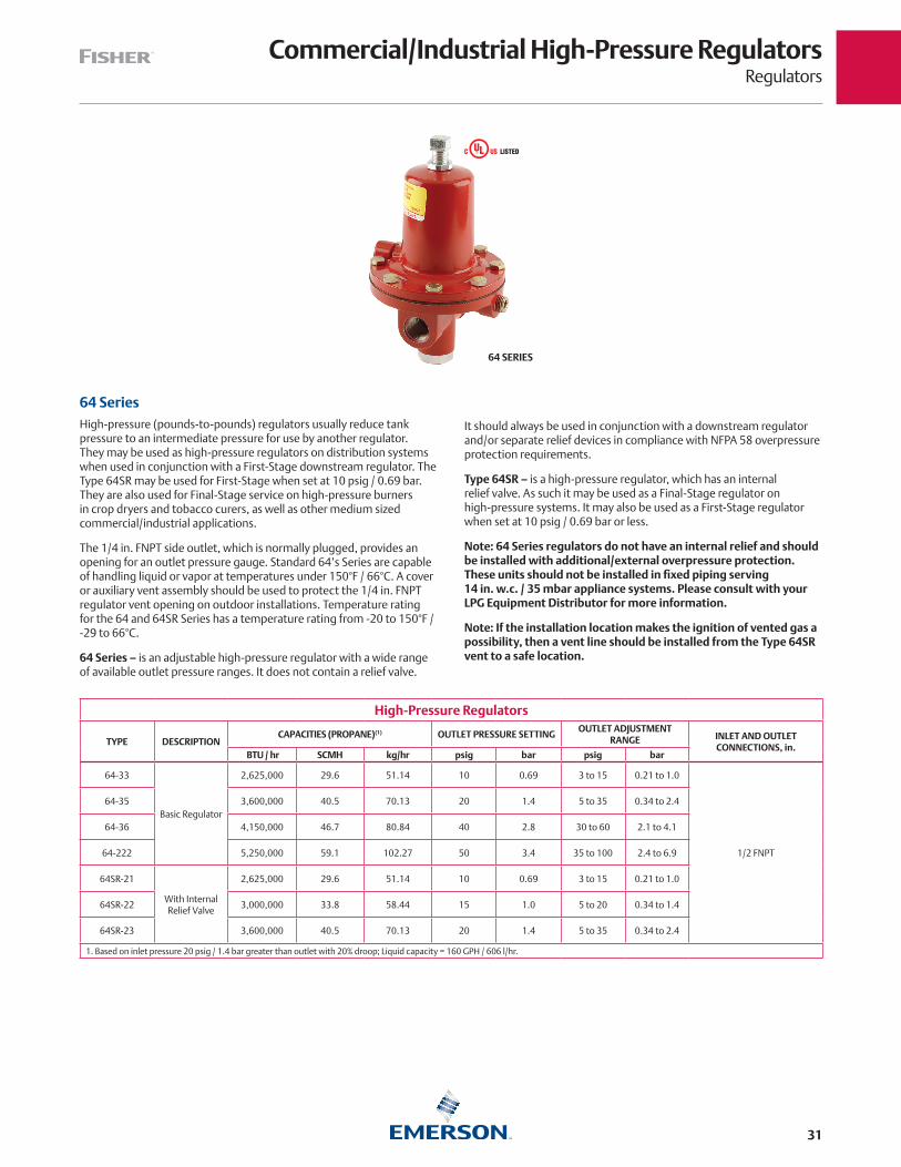
64 SeriesHigh-pressure (pounds-to-pounds) regulators usually reduce tank pressure to an intermediate pressure for use by another regulator. They may be used as high-pressure regulators on distribution systems when used in conjunction with a First-Stage downstream regulator. The Type 64SR may be used for First-Stage when set at 10 psig / 0.69 bar. They are also used for Final-Stage service on high-pressure burners in crop dryers and tobacco curers, as well as other medium sized commercial/industrial applications.
The 1/4 in. FNPT side outlet, which is normally plugged, provides an opening for an outlet pressure gauge. Standard 64’s Series are capable of handling liquid or vapor at temperatures under 150°F / 66°C. A cover or auxiliary vent assembly should be used to protect the 1/4 in. FNPT regulator vent opening on outdoor installations. Temperature rating for the 64 and 64SR Series has a temperature rating from -20 to 150°F / -29 to 66°C.
64 Series – is an adjustable high-pressure regulator with a wide range of available outlet pressure ranges. It does not contain a relief valve.
It should always be used in conjunction with a downstream regulator and/or separate relief devices in compliance with NFPA 58 overpressure protection requirements.
Type 64SR – is a high-pressure regulator, which has an internal relief valve. As such it may be used as a Final-Stage regulator on high-pressure systems. It may also be used as a First-Stage regulator when set at 10 psig / 0.69 bar or less.
Note: 64 Series regulators do not have an internal relief and should be installed with additional/external overpressure protection. These units should not be installed in fixed piping serving 14 in. w.c. / 35 mbar appliance systems. Please consult with your LPG Equipment Distributor for more information.
Note: If the installation location makes the ignition of vented gas a possibility, then a vent line should be installed from the Type 64SR vent to a safe location.
High-Pressure Regulators
TYPE DESCRIPTIONCAPACITIES (PROPANE)(1) OUTLET PRESSURE SETTING
OUTLET ADJUSTMENT RANGE INLET AND OUTLET
CONNECTIONS, in. BTU / hr SCMH kg/hr psig bar psig bar
64-33
Basic Regulator
2,625,000 29.6 51.14 10 0.69 3 to 15 0.21 to 1.0
1/2 FNPT
64-35 3,600,000 40.5 70.13 20 1.4 5 to 35 0.34 to 2.4
64-36 4,150,000 46.7 80.84 40 2.8 30 to 60 2.1 to 4.1
64-222 5,250,000 59.1 102.27 50 3.4 35 to 100 2.4 to 6.9
64SR-21
With InternalRelief Valve
2,625,000 29.6 51.14 10 0.69 3 to 15 0.21 to 1.0
64SR-22 3,000,000 33.8 58.44 15 1.0 5 to 20 0.34 to 1.4
64SR-23 3,600,000 40.5 70.13 20 1.4 5 to 35 0.34 to 2.4
1. Based on inlet pressure 20 psig / 1.4 bar greater than outlet with 20% droop; Liquid capacity = 160 GPH / 606 l/hr.
64 SERIES
USC

Commercial/Industrial High-Pressure RegulatorsRegulators
32
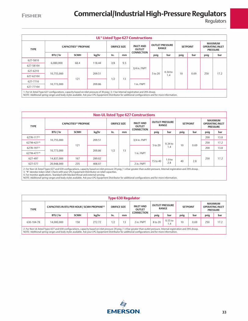
For Commercial and Industrial high-pressure applications like factories, office building, restaurants, etc., Emerson has a wide variety of products. For ease of reference, only the most popular commercial and industrial regulators are shown in these pages. Other orifice sizes, body sizes and outlet pressure ranges are available. The higher capacities on commercial and industrial installations usually require a Two-Stage regulator system.
Note: Because of various spring ranges and orifice sizes, all commercial and industrial regulators should be individually sized for the particular installation. Consult specific product bulletins for maximum pressure ratings. Contact your local LPG Equipment Distributor for assistance.
Types 627 and 630 – Large capacity direct-operated high-pressure regulators designed for loads up to 10,700,000 and 14,000,000 BTU per hour / 120 and 157 SCMH, respectively. The Types 627 and 630 are normally used in conjunction with Type CS400 units, however, they can also be used on Final-Stage (pounds-to-pounds) service. Additional overpressure protection is recommended to prevent excessive build-up in the downstream line. The diaphragm case and body of the Type 627 can be rotated in four positions to allow easy installation. Additional configurations of the Type 627 with internal relief and control line connections for monitor systems are available. For both the Types 627 and 630, additional pressure ranges and orifice sizes are available. Temperature ratings for the Types 627 and 630 is -20 to 160°F / -29 to 71°C.
For Liquid Service, Types 627W and MR95H are available.
Note: Types 627 and 630 regulators do not have an internal relief and should be installed with additional/external overpressure protection. These units should not be installed as part of a two-stage system in fixed piping serving 14 in. w.c. / 35 mbar appliance systems unless additional overpressure protection is installed that will make the system compliant with NFPA 58 requirements for a two-stage system. Please consult with your LPG Equipment Distributor for more information.
Flanged Bodies – The Types 630 and 627 are available with flanged bodies. Flanges are available for 2 in. CL300 FF.
Overpressure Protection – The Type 627 is also available in monitor configurations. Note that the Type 627 monitor regulators have unique type numbers. For more information on monitor overpressure protection, see page 42.
Fluorocarbon (FKM) Trim – The Type 627 is available with Fluorocarbon (FKM) Trim for high temperature applications such as vaporizors. Part numbers are listed below with a ‘V’ suffix. Temperature ratings for the Type 627 with Fluorocarbon (FKM) Trim is 0 to 180°F / -18 to 82°C.
Type 1301F – The proven reliability and accurate regulation of the Type 1301F regulator makes it ideal for numerous high-pressure drop applications. This multi-purpose regulator can be used as pilot supply or pressure-loading regulators where high-pressure operating medium must be reduced for use by gas regulator pilots or pressure-loaded regulators.
TYPE 630 DIRECT-OPERATED REGULATORTYPE 627 DIRECT-OPERATED REGULATOR
USC
Commercial/Industrial High-Pressure RegulatorsRegulators
33
UL® Listed Type 627 Constructions
TYPECAPACITIES(1) PROPANE ORIFICE SIZE INLET AND
OUTLET CONNECTION
OUTLET PRESSURE RANGE
SETPOINTMAXIMUM
OPERATING INLET PRESSURE
BTU / hr SCMH kg/hr In. mm psig bar psig bar psig bar
627-5810 6,080,000 68.4 118.44 3/8 9.5
3/4 in. FNPT
5 to 200.34 to
1.410 0.69 250 17.2
627-5810V
627-6210 10,755,000
121
209.51
1/2 13627-6210V
627-7710 10,773,000 209.86 1 in. FNPT
627-7710V
1. For UL listed Type 627 configurations, capacity based on inlet pressure of 30 psig / 2.1 bar Internal registration and 20% droop. NOTE: Additional spring ranges and body styles available. Ask your LPG Equipment Distributor for additional configurations and for more information.
Type 630 Regulator
TYPECAPACITIES IN BTU PER HOUR / SCMH PROPANE(2) ORIFICE SIZE INLET AND
OUTLET CONNECTION
OUTLET PRESSURE RANGE
SETPOINTMAXIMUM
OPERATING INLET PRESSURE
BTU / hr SCMH kg/hr In. mm psig bar psig bar psig bar
630-104-78 14,000,000 158 272.72 1/2 13 2 in. FNPT 8 to 200.55 to
1.410 0.69 250 17.2
2. For Non-UL listed Types 627 and 630 configurations, capacity based on inlet pressure 20 psig / 1.4 bar greater than outlet pressure, Internal registration and 20% droop. NOTE: Additional spring ranges and body styles available. Ask your LPG Equipment Distributor for additional configurations and for more information.
Non-UL listed Type 627 Constructions
TYPECAPACITIES(2) PROPANE ORIFICE SIZE INLET AND
OUTLET CONNECTION
OUTLET PRESSURE RANGE
SETPOINTMAXIMUM
OPERATING INLET PRESSURE
BTU / hr SCMH kg/hr In. mm psig bar psig bar psig bar
627R-117(3)
10,755,000
121
209.51
1/2 13
3/4 in. FNPT
5 to 200.34 to
1.410 0.69
200 13.8
627M-421(4) 250 17.2
627R-197(3)
10,773,000 209.861 in. FNPT
200 13.8
627M-471(4)
250 17.2627-497 14,837,000 167 289.0215 to 40
1.0 to 2.8
40 2.8627-577 20,948,000 235 408.07 2 in. FNPT
2. For Non-UL listed Types 627 and 630 configurations, capacity based on inlet pressure 20 psig / 1.4 bar greater than outlet pressure, Internal registration and 20% droop.3. “R” denotes token relief. Check with your LPG Equipment Distributor on relief capacities. 4. For monitor applications. Standard with blocked throat and external sensing. NOTE: Additional spring ranges and body styles available. Ask your LPG Equipment Distributor for additional configurations and for more information.

Commercial/Industrial High-Pressure RegulatorsRegulators
34
Pilot-Operated High-Pressure Commercial/Industrial Regulators
TYPECAPACITIES (PROPANE)(1) ORIFICE SIZE INLET AND OUTLET
CONNECTION
OUTLET PRESSURE RANGE
OUTLET PRESSURE SETTING
MAXIMUM OPERATING INLET
PRESSURE
BTU / hr SCMH kg/hr In. mm psig bar psig bar psig bar
99-510P29,400,000 331 572.71
7/8 22
2 in. FNPT 7 in. w.c. to 2
17 mbar to 0.14
1 69 mbar
250 17.2
99F-510P 2 in. / DN 50 CL300 FF
99-511P33,206,000 374 646.85
2 in. FNPT1 to 5
69 mbar to 0.34
5 0.3499F-511P 2 in. / DN 50 CL300 FF
99-513P36,368,000 409 708.45
2 in. FNPT2 to 10
0.14 to 0.69
10 0.6999F-513P 2 in. / DN 50 CL300 FF
99-512P37,950,000 427 739.27
2 in. FNPT5 to 15 0.34 to 1.0 15 1.0
99F-512P 2 in. / DN 50 CL300 FF
99-515P41,112,000 463 800.86
2 in. FNPT10 to 20 0.69 to 1.4 20 1.4
99F-515P 2 in. / DN 50 CL300 FF
99-903P44,275,000 498 862.48
2 in. FNPT10 to 65 0.69 to 4.5 30 2.1
99F-903P 2 in. / DN 50 CL300 FF
99-502PH50,600,000 570 985.69
1-1/8 29
2 in. FNPT1 to 5
69 mbar to 0.34
5 0.34
300 20.7
99F-502PH 2 in. / DN 50 CL300 FF
99-503PH 61,668,000 694 1201.29 2 in. FNPT2 to 10
0.14 to 0.69
10 0.6999F-503PH 61,668,000 694 1201.29 2 in. / DN 50 CL300 FF
99-504PH 63,250,000 712 1232.11 2 in. FNPT5 to 15 0.34 to 1.0 15 1.0
99F-504PH 63,250,000 712 1232.11 2 in. / DN 50 CL300 FF
99-505PH 67,993,000 765 1324.50 2 in. FNPT10 to 20 0.69 to 1.4 20 1.4
99F-505PH 67,993,000 765 1324.50 2 in. / DN 50 CL300 FF
99-901PH 74,318,000 837 1447.71 2 in. FNPT10 to 65 0.69 to 4.5 30 2.1
99F-901PH 74,318,000 837 1447.71 2 in. / DN 50 CL300 FF
1. Capacity based on inlet pressure 20 psig / 1.4 bar greater than outlet pressure, external registration and 0.1 to 0.3 psi / 6.9 to 21 mbar proportional band.NOTE: Additional spring ranges and body styles are available. Ask your LPG Equipment distributor for more information.
For Commercial and Industrial high-pressure applications, such as distributed community systems, factories, office buildings, restaurants, Emerson has a wide variety of products and solutions. For ease of reference, only the most popular commercial and industrial regulators are shown on these pages. Other orifice sizes, body sizes and outlet pressure ranges are available. The higher capacities on commercial and industrial installations usually require a Two-stage regulator system. Temperature ratings for the Type 99 is -20 to 180°F / -29 to 82°C.
Note: Because of various spring ranges and orifice sizes, all commercial and industrial regulators should be individually sized for the particular installation. Consult specific product bulletins for maximum pressure ratings. Contact your local LPG Equipment Distributor for assistance.
Type 99 – Pilot-operated unit keeps outlet pressure constant despite varying flow rates and inlet pressures. Designed to handle loads up to 74,318,000 BTU per hour / 837 SCMH, the Type 99 is ideal for multiple customer installations. The unique pilot design, with fast opening and closing operation, makes the Type 99 ideal for large industrial boiler applications. The Type 99 can be used for low or high-pressure applications. A downstream control line is required. Additional overpressure protection is recommended to prevent excessive buildup in the downstream line.
Note: Type 99 regulators do not have an internal relief and should be installed with additional/external overpressure protection. These units should not be installed as part of a two-stage system in fixed piping serving 14 in. w.c. / 35 mbar appliance systems unless additional overpressure protection is installed that will make the
system compliant with NFPA 58 requirements for a two-stage system. Please consult with your LPG Equipment Distributor for more information.
Flanged Bodies - 99F Series is equipped with 2 in. CL300 flanged bodies.
Overpressure Protection - The Type 99 is also available in monitor configurations. Note that the Type 99 monitor regulators have unique type numbers. For more information on monitor overpressure protection, see page 42.
TYPE 99-901PH PILOT-OPERATED REGULATOR

Commercial/Industrial High-Pressure RegulatorsRegulators
35
Pilot-Operated High-Pressure Commercial/Industrial Regulators
TYPECAPACITIES (PROPANE) ORIFICE SIZE INLET AND
OUTLET CONNECTION
OUTLET PRESSURE RANGE
OUTLET PRESSURE SETTING
MAXIMUM OPERATING INLET
PRESSURE
BTU / hr SCMH kg/hr In. mm psig bar psig bar psig bar
1098-L21 170,500,000(1) 1915(1) 3321.34
2-3/8 60
2 in. FNPT
2 to 100.14 to
0.6910 0.69
400 27.6
1098-L22 215,300,000(2) 2419(2) 4194.04 3 to 40 0.21 to 2.7 20 1.4
1098-L23 322,300,000(3) 3621(3) 6278.40 35 to 75 2.4 to 5.2 50 3.4
1098-F21 170,500,000(1) 1915(1) 3321.342 in. / DN 50
CL300 RF
2 to 100.14 to
0.6910 0.69
1098-F22 215,300,000(2) 2419 4194.04 3 to 40 0.21 to 2.7 20 1.4
1098-F23 322,300,000(3) 3621(3) 6278.40 35 to 75 2.4 to 5.2 50 3.4
1098-F31 356,300,000(1) 4003(1) 6940.72
3-3/8 863 in. / DN 80
CL300 RF
2 to 100.14 to
0.6910 0.69
1098-F32 447,400,000(2) 5026(2) 8715.35 3 to 40 0.21 to 2.7 20 1.4
1098-F33 669,500,000(3) 7521(3) 13,041.86 35 to 75 2.4 to 5.2 50 3.4
1098-F41 551,300,000(4) 6193(4) 10,739.32
4-3/8 1114 in. / DN 100
CL300 RF
2 to 100.14 to
0.6910 0.69
1098-F42 693,500,000(4) 7791(4) 13,509.38 3 to 40 0.21 to 2.7 20 1.4
1098-F43 1,035,500,000(3) 11,633(3) 20,171.54 35 to 75 2.4 to 5.2 50 3.4
NOTE: Additional spring ranges and body styles are available. Ask your LPG Equipment Distributor for more information.1. Capacity based on 30 psig / 2.1 bar inlet pressure and 15 psig / 1.0 bar setpoint.2. Capacity based on 40 psig / 2.8 bar inlet pressure and 20 psig / 1.4 bar setpoint.3. Capacity based on 75 psig / 5.2 bar inlet pressure and 50 psig / 3.4 bar setpoint.4. Capacity based on 25 psig / 1.7 bar inlet pressure greater than outlet pressure setting.
Type 1098 - The Type 1098-EGR regulator provides large capacities for use in large commercial applications and large distributed community systems. Designed to handle loads from 170,000,000 BTU / 1910 SCM (2 in. size) to in excess of 1,000,000,000 BTU / 11,234 SCM (4 in. size) and rated to 75 psig / 5.2 bar for Maximum Outlet Pressure, the Type 1098H is a regulator unmatched in performance in the LPG Industry. The Type 1098’s pilot-operated two-path system is designed to quickly respond to sudden changes in the downstream demand, making this regulator ideal for fuel gas supply to industrial boilers, furnaces, ovens and mixers. Temperature rating for the Type 1098 is -20 to 180°F / -29 to 82°C. Actuator/diaphragm are size 40.
Type 1098H - The Type 1098H-EGR regulator also provides large capacities used in systems similar to Type 1098. The Type 1098H uses a special cast iron actuator assembly that increases the Maximum Downstream Pressure rating of the standard Type 1098 up to 300 psig / 20.7 bar, offering an even greater level of protection with outlet pressure settings up to 125 psig / 8.6 bar. Temperature rating for the Type 1098H is -20 to 180°F / -29 to 82°C. Actuator/diaphragm are size 30.
Flanged Bodies - The Types 1098 and 1098H are available with flanged bodies. Flanges are available in 2, 3 and 4 in. body sizes and CL300 FF end connection.
Note: Type 1098 regulators do not have an internal relief and should be installed with additional/external overpressure protection. These units should not be installed as part of a two-stage system in fixed piping serving 14 in. w.c. / 35 mbar appliance systems unless additional overpressure protection is installed that will make the system compliant with NFPA 58 requirements for a two-stage system. Please consult with your LPG Equipment Distributor for more information.
Overpressure Protection - The Types 1098 and 1098H is also available in monitor configurations. Note that the Type 1098H regulators may be used either as the worker or monitor regulator. For more information on monitor overpressure protection, see page 42.
The Type 1098 regulator is a highly advanced regulator with many configurations for various applications. Always consult Emerson to discuss your application prior to placing your order.
TYPE 1098-L22 PILOT-OPERATED REGULATOR

Commercial Low-Pressure RegulatorsRegulators
36
TYPE CS400 TYPE CS800TYPE CS200
Emerson has a wide range of low-pressure regulators to meet almost any commercial or industrial application. For ease of reference, only the most popular commercial and industrial regulators are shown on this page. Other orifice sizes, body sizes and outlet pressure ranges are available. See the product guides on pages 36 and 38. The Commercial Service (CS) Regulator Series have a temperature rating of -20 to 160°F / -29 to 71°C, but have passed Fisher™ internal testing for lockup, relief start-to-discharge and reseal down to -40°F / -40°C.
Note: Because of various spring ranges and orifice sizes, all commercial and industrial regulators should be individually sized for the particular installation. Consult specific product bulletins for maximum pressures ratings. Contact your local LPG Equipment Distributor for assistance.
Type CS400 – The Type CS400 is a medium capacity low-pressure, direct-operated regulator designed for loads up to 7,800,000 BTU per hour / 88 SCMH, ideal for installations at schools, bakeries and many other commercial/industrial applications. Available in 1-1/4, 1-1/2 and 2 in. body sizes with spring ranges from 4.5 in. w.c. to 5.5 psig / 11 mbar to 0.38 bar.
Low-Pressure Commercial Regulators
TYPECAPACITIES (PROPANE)(1) ORIFICE SIZE INLET AND OUTLET
CONNECTION,IN.
OUTLET PRESSURE RANGE
OUTLET PRESSURE SETTING
MAXIMUM OPERATING INLET PRESSURE
BTU / hr SCMH kg/hr In. mm psig bar psig bar psig bar
CS200IR-6EC1 2,500,000 28 48.7
1/2 13
3/4 FNPT
10 to 14 in. w.c.
25 to 35 mbar
11 in. w.c. 27 mbar
40 2.8CS200IR-6EC3 3,800,000 43 74.02 1 FNPT
CS200IR-6EC6 3,900,000 44 75.97 1-1/4 FNPT
CS400IR-8EC6 6,800,000 76 132.46
3/4 19.1
1-1/4 FNPT
20 1.4CS400IR-8EC7 7,600,000 85 148.05 1-1/2 FNPT
CS400IR-8EC8 7,600,000 85 148.05 2 FNPT
CS800IR-8CC7 10,460,000 118 203.761 25.4
1-1/2 FNPT 8 to 12 in. w.c.
20 to 30 mbar
30 2.1CS800IR-8CC8 21,809,000 245 424.84 2 FNPT
CS200IR-6HC1 3,760,000 42 73.24
1/2 13
3/4 FNPT
1 to 2 0.06 to 0.14
2 0.14
40 2.8CS200IR-6HC3 4,780,000 54 93.11 1 FNPT
CS200IR-6HC6 5,327,000 60 103.77 1-1/4 FNPT
CS400IR-8HC6 9,715,000 109 189.25
3/4 19.1
1-1/4 FNPT
20 1.4CS400IR-8HC7 10,500,000 118 204.54 1-1/2 FNPT
CS400IR-8HC8 8,775,000 99 170.94 2 FNPT
CS820IR-8FC7 15,011,000 169 292.411 25.4
1-1/2 FNPT1 to 2.5 0.06 to 0.17 30 2.1
CS820IR-8FC8 21,436,000 241 417.57 2 FNPT
CS400IR-8IC6 7,365,000 83 143.47
3/4 19.1
1-1/4 FNPT
2 to 5.5 0.14 to 0.38
5 0.35
20 1.4CS400IR-8IC7 6,895,000 77 134.31 1-1/2 FNPT
CS400IR-8IC8 7,365,000(2) 83(2) 143.47 2 FNPT
CS820IR-8HC7 15,262,000 171 297.31 25.4
1-1/2 FNPT2.5 to 5.5 0.17 to 0.38 30 2.1
CS820IR-8HC8 16,532,000 186 322.04 2 FNPT
1. Capacities are based on 10 psig / 0.69 bar and 2 in. w.c. / 5 mbar droop.2. Capacities are based on 10 psig / 0.69 bar and 20% droop. NOTE: Additional combinations of body sizes, spring ranges and orifice sizes are available. See guides on the next page. Consult your LPG Equipment distributor for more information.
Type CS200 – The Type CS200 is a medium capacity low-pressure, direct-operated regulator designed for loads up to 3,800,000 BTU per hour / 44 SCMH, ideal for installations on smaller commercial/industrial applications. Available in 3/4, 1 and 1-1/4 in. body sizes with spring ranges from 3.5 in. w.c. to 2 psig / 9 mbar to 0.14 bar.
Flanged Bodies – The Types CS400 and CS800 are available with a flanged body. Flanges are available in 2 in. / DN 50 body size and CL125 FF end connection.
Type CS800 – The Type CS800 is a direct-operated, spring-loaded regulator which has been engineered for low-pressure commercial service applications. This regulator can accommodate up to 21,600,000 BTU per hour / 243 SCMH of flow capacity and is available in 1-1/2 and 2 in. body sizes with 8 in. w.c. to 5.5 psig / 20 mbar to 0.38 bar pressure ranges.
Note: Types CS200, CS400 and CS800 regulators should be installed with additional/external overpressure protection. These units when installed as part of a two-stage system in fixed piping serving 14 in. w.c. / 35 mbar appliance systems require additional overpressure protection to make the system compliant with NFPA 58 requirements for a two-stage system. Please consult with your LPG Equipment Distributor for more information.

Commercial Low-Pressure RegulatorsRegulators
37
Type CS200 Selection Guide
BASE SENSING RELIEF ORIFICE REGULATOR SETPOINT BODY OPTION
CODE DESCRIPTION CODE DESCRIPTION CODE DESCRIPTION CODESIZE
In. / mmCODE In. w.c. / mbar CODE DESCRIPTION
CS200 Basic I Internal N None 1 1/8 / 3.2 A 3.5 to 5 / 9 to 12 C13/4 in. FNPT,
Cast Iron
R Internal 2 3/16 / 4.8 B 4.5 to 6.5 / 11 to 16 C31 in. FNPT,Cast Iron
3 1/4 / 6.4 C 6 to 8 / 15 to 20 C61-1/4 in. FNPT,
Cast Iron
5 3/8 / 9.5 D 7.5 to 11 / 19 to 27
6 1/2 / 13 E 10 to 14 / 25 to 35
F 12 to 19 / 30 to 47
G 18 to 1 psig / 45 mbar to 0.06 bar
H 1 to 2 psig / 0.06 to 0.13 bar
Type CS400 Selection Guide
BASE SENSING RELIEF ORIFICE REGULATOR SETPOINT BODY OPTION
CODE DESCRIPTION CODE DESCRIPTION CODE DESCRIPTION CODESIZE,
In. / mmCODE In. w.c. / mbar CODE DESCRIPTION
CS400 Basic I Internal N None 2 3/16 / 4.8 A 3.5 to 5 / 9 to 12 C61-1/4 in. FNPT,
Cast Iron
E External R Internal 3 1/4 / 6.4 B 4.5 to 6.5 / 11 to 16 C71-1/2 in. FNPT,
Cast Iron
T Token 5 3/8 / 9.5 C 6 to 8 / 15 to 20 C82 in. FNPT, Cast Iron
6 1/2 / 13 D 7.5 to 11 / 19 to 27 C92 in. / DN 50,
CL150 FF, Ductile Iron
8 3/4 / 19 E 10 to 14 / 25 to 35
F 12 to 19 / 30 to 47
G 18 to 1 psig / 45 mbar to 0.06 bar
H 1 to 2 psig / 0.06 to 0.13 bar
I 2 to 5.5 psig / 0.14 to 0.38
Type CS800 Selection Guide
BASE SENSING RELIEF ORIFICE REGULATOR SETPOINT BODY OPTION
CODE DESCRIPTION CODE DESCRIPTION CODE DESCRIPTION CODESIZE,
In. / mmCODE(1) In. w.c. / mbar CODE DESCRIPTION
CS800 Basic I Internal N None 2 1/4 / 6.4 A 3.5 to 6 / 9 to 15 C61-1/4 in. FNPT,
Gray Iron
CS820 High Outlet E External R Internal 3 3/8 / 9.5 B 5.5 to 8.5 / 11 to 16 C71-1/2 in. FNPT,
Gray Iron
T Token 4 1/2 / 13 C 8 to 12 / 15 to 20 C82 in. FNPT, Gray Iron
Q High Capacity 6 3/4 / 19.1 D 10 to 16 / 25 to 40 C92 in. / DN 50,
CL125 FF, Gray Iron
8 1 / 25 E 14 to 30 / 25 to 75 D112 in. / DN 50,
CL150 FF, Ductile Iron
9 1-3/8 / 35 F 1 to 2.5 psig / 0.06 to 0.17 bar
G 1.5 to 3.5 / 0.10 to 0.24 bar
H 2.5 to 5.5 / 0.17 to 0.38 bar
1. Code A to E only applies to Type CS800. Code F to H only applies to Type CS820.

Commercial Service Overpressure ProtectionRegulators
38
TYPE CS404
TYPE CS803
Type CS403 with Integral True-Monitor™ Protection
1-1/4 in. FNPT to 2 in. FNPT Body Sizes (2 in. / DN 50, CL150 Flange Available) 7.65 to 8.44M BTU per hour / 85.9 to 94.8 SCMH / 149.0 to 164.4 kg/hrInternal Registration
Type CS403: Combines operation of a conventional two-regulator wide-open monitor set into one body. During normal operation, the monitor is in a wide open state at a setpoint higher than the primary regulator. If the downstream pressure should rise due to loss of control by the primary regulator, the integral monitor will assume control and regulate the flow to the downstream system.
See Selection Guide on the next page for available options.
Type CS404 with Integral Slam shut
1-1/4 in. FNPT to 2 in. FNPT Body Sizes (2 in. / DN 50, CL150 Flange Available) 7.65 to 8.44M BTU per hour / 85.9 to 94.8 SCMH / 149.0 to 164.4 kg/hrInternal Registration
Type CS404: Integrates a fast acting shutoff device that provides overpressure shutoff (OPSO) or over/underpressure shutoff (UPSO/OPSO) protection by completely shutting off the flow of gas to the downstream system. The Slam Shut operates independently of the main regulator and does not affect normal operation unless the downstream pressure fluctuates outside of the desired ranges.
See Selection Guide on the next page for available options.
Types CS803 and CS823 with Integral True-Monitor Protection
1-1/2 in. FNPT and 2 in. FNPT Body Sizes(2 in. / DN 50, CL150 Flange Available)10.46 to 21.44M BTU per hour / 118 to 241 SCMH / 203.76 to 415.57 kg/hrInternal Registration
Type CS803: Designed to deliver less than 1 psig, the Type CS803 combines operation of a conventional two-regulator wide-open monitor set into one body. During normal operation, the monitor is in a wide open state at a setpoint higher than the primary regulator. If the downstream pressure should rise due to loss of control by the primary regulator, the integral monitor will assume control and regulate the flow to the downstream system.
Type CS823: Equipped with the same technolgy as the Types CS803 and Type CS823 delivers up to 5.5 psig / 0.38 bar operating pressures.
See Selection Guide on the next page for available options.
PRIMARYSETPOINT
MONITORSETPOINT
MONITOR SPRING RANGE
In. w.c. / mbar In. w.c. / mbar Spring Range
11 / 27 21 / 52 16 to 23 in. w.c. / 40 to 57 mbar
2 psig / 0.14 bar 2.5 psig / 0.17 bar 1.5 to 2.5 psig / 0.10 to 0.17 bar
5 psig / 0.35 bar 6 psig / 0.41 bar 4 to 7.5 psig / 0.28 to 0.52 bar
PRIMARYSETPOINT
MONITORSETPOINT
MONITOR SPRING RANGE
In. w.c. / mbar In. w.c. / mbar Spring Range
11 / 27 21 / 52 16 to 23 in. w.c. / 40 to 57 mbar
2 psig / 0.14 bar 2.5 psig / 0.17 bar 1.5 to 2.5 psig / 0.10 to 0.17 bar
5 psig / 0.35 bar 6 psig / 0.41 bar 4 to 7.5 psig / 0.28 to 0.52 bar
PRIMARYSETPOINT
SLAM-SHUT SETPOINT
OPSO UPSO - OPSO
In. w.c. / mbar In. w.c. / mbar In. w.c. / mbar
7 / 17 17 / 42 - - - -
11 / 27 19 / 47 6.3 / 16 - 25 / 62
14 / 35 30 / 75 8.8 / 22 - 28 / 70
1 psig / 0.07 bar 1.9 psig / 0.13 bar 16 / 40 - 1.9 psig / 0.13 bar
2 psig / 0.14 bar 3.3 psig / 0.23 bar 1 psig / 0.07 bar - 3.2 psig / 0.22 bar
5 psig / 0.35 bar 6.7 psig / 0.46 bar 2.9 psig / 0.20 bar - 7.5 psig / 0.52 bar
TYPE CS403
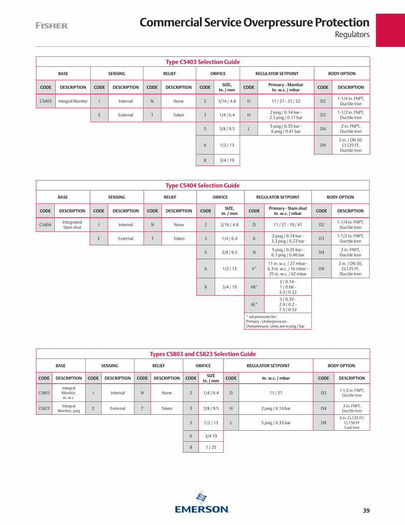
Commercial Service Overpressure ProtectionRegulators
39
Type CS404 Selection Guide
BASE SENSING RELIEF ORIFICE REGULATOR SETPOINT BODY OPTION
CODE DESCRIPTION CODE DESCRIPTION CODE DESCRIPTION CODESIZE,
In. / mmCODE
Primary - Slam shutIn. w.c. / mbar
CODE DESCRIPTION
CS404Integrated Slam shut
I Internal N None 2 3/16 / 4.8 D 11 / 27 - 19 / 47 D21-1/4 in. FNPT,
Ductile Iron
E External T Token 3 1/4 / 6.4 K2 psig / 0.14 bar - 3.3 psig / 0.23 bar
D31-1/2 in. FNPT,
Ductile Iron
5 3/8 / 9.5 N5 psig / 0.35 bar - 6.7 psig / 0.46 bar
D42 in. FNPT,
Ductile Iron
6 1/2 / 13 V*11 in. w.c. / 27 mbar -6.3 in. w.c. / 16 mbar - 25 in. w.c. / 62 mbar
D92 in. / DN 50,
CL125 FF, Ductile Iron
8 3/4 / 19 AB*2 / 0.14 - 1 / 0.06 - 3.2 / 0.22
AE*5 / 0.35 - 2.9 / 0.2 - 7.5 / 0.52
* set pressures for:Primary - Underpressure - Overpressure. Units are in psig / bar
Type CS403 Selection Guide
BASE SENSING RELIEF ORIFICE REGULATOR SETPOINT BODY OPTION
CODE DESCRIPTION CODE DESCRIPTION CODE DESCRIPTION CODESIZE,
In. / mmCODE
Primary - Monitor In. w.c. / mbar
CODE DESCRIPTION
CS403 Integral Monitor I Internal N None 2 3/16 / 4.8 D 11 / 27 - 21 / 52 D21-1/4 in. FNPT,
Ductile Iron
E External T Token 3 1/4 / 6.4 H2 psig / 0.14 bar - 2.5 psig / 0.17 bar
D31-1/2 in. FNPT,
Ductile Iron
5 3/8 / 9.5 L5 psig / 0.35 bar - 6 psig / 0.41 bar
D42 in. FNPT,
Ductile Iron
6 1/2 / 13 D92 in. / DN 50,
CL125 FF, Ductile Iron
8 3/4 / 19
Types CS803 and CS823 Selection Guide
BASE SENSING RELIEF ORIFICE REGULATOR SETPOINT BODY OPTION
CODE DESCRIPTION CODE DESCRIPTION CODE DESCRIPTION CODESIZE
In. / mmCODE In. w.c. / mbar CODE DESCRIPTION
CS803Integral Monitor, in. w.c.
I Internal N None 2 1/4 / 6.4 D 11 / 27 D3 1 1/2 in. FNPT, Ductile Iron
CS823Integral
Monitor, psig E External T Token 3 3/8 / 9.5 H 2 psig / 0.14 bar D4 2 in. FNPT, Ductile Iron
5 1/2 / 13 L 5 psig / 0.35 bar D92 in. CL125 FF/
CL150 FF Cast Iron
6 3/4 19
8 1 / 25

Industrial Service Low-Pressure RegulatorsRegulators
40
Emerson has a wide range of low-pressure regulators to meet almost any commercial or industrial application. For ease of reference, only the most popular commercial and industrial regulators are shown on this page. Other orifice sizes, body sizes and outlet pressure ranges are available.
Note: Because of various spring ranges and orifice sizes, all commercial and industrial regulators should be individually sized for the particular installation. Consult specific product bulletins for maximum pressures ratings. Contact your local LPG Equipment Distributor for assistance.
Type 299H – A high capacity pilot-operated regulator. Incorporates a lightweight design (21 lbs / 10 kg) with dependable operation. With a capacity up to 38,000 000 BTU per hour / 428 SCMH, the Type 299H is ideal for applications from large commercial sites to smaller multi-dwelling establishments. The unit comes with a 1-1/2 or 2 in. cast iron body with internal or external registration. Internal registration allows easy installation while external registration provides higher accuracy. 2 in. / DN 50 flanged body or steel body material also available. Alternate
outlet settings from 3.5 in. w.c. to 60 psig / 9 mbar to 4.1 bar are available. Temperature ratings for the Type 299H is -20 to 150°F / -29 to 66°C. The Type 299H has maximum inlet pressure rating of 150 psig / 10 bar so it cannot be used as a First-Stage regulator.
Type 99 – Pilot-operated unit keeps outlet pressure constant despite varying flow rates and inlet pressures. Designed to handle loads up to 63,250,000 BTU per hour / 712 SCMH, the Type 99L is ideal for multiple customer installations. The unique pilot design, with fast opening and closing operation, makes the Type 99L ideal for large industrial boiler applications. The Type 99L can be used for low pressure. A downstream control line is required. Temperature ratings for the Type 99 is -20 to 160°F / -29 to 82°C.
133 Series – Direct-operated Second-Stage regulator ideal for large industrial applications with loads up to 70,875,000 BTU per hour / 798 SCMH. The unit can be used for either low pressure or pounds service. Maximum inlet pressure is 60 psig / 4.1 bar and a downstream control line is required. The 133 Series has a temperature rating of -20 to 150°F / -29 to 66°C.
Low-Pressure Commercial/Industrial Regulators
TYPECAPACITIES (PROPANE) ORIFICE SIZE INLET AND OUTLET
CONNECTION, IN.
OUTLET PRESSURE RANGE
OUTLET PRESSURE SETTING
MAXIMUM OPERATING INLET PRESSURE
BTU / hr SCMH kg/hr In. mm psig bar psig bar psig bar
299H-101 13,100,000(1) 148(1) 255.19
3/4 19
1-1/2 FNPT 9 to 20 in. w.c.
22 to 50 mbar 11 in. w.c. 27 mbar
150 10.3
299H-102 19,700,000(1) 222(1) 383.76 2 FNPT
299H-103 23,300,000(2) 262(2) 453.88 1-1/2 FNPT6 to 16 0.41 to 1.1 10 0.69
299H-104 38,000,000(2) 428(2) 740.24 2 FNPT
299H-10520,400,000(3) 230(3) 397.39
1-1/2 FNPT9 to 20 in. w.c.
22 to 50 mbar 11 in. w.c. 27 mbar299H-106 2 FNPT
299H-10738,000,000(4) 428(4) 740.24
1-1/2 FNPT6 to 16 0.41 to 1.1 10 0.69
299H-108 2 FNPT
99-501P 49,000,000(6) 552(6) 954.52
1-1/8 29
2 FNPT
7 in. w.c. to 2 psig
17 mbar to 0.14 bar
1 69 mbar
150 10.399-502P 50,600,000(6) 570(6) 985.69 1 to 569 mbar to
0.34 bar5 0.34
99-503P 61,650,000(6) 694(6) 1200.94 2 to 10 0.14 to 0.69 10 0.69
99-504P 63,250,000(6) 712(6) 1232.11 5 to 15 0.34 to 1.0 15 1.0
133L-4 70,875,000(3) 798(3) 1380.65
2 51
8.5 to 18 in. w.c.
21 to 45 mbar 14 in. w.c. 35 mbar
60 4.1133H-1 66,150,000(5) 745(5) 1288.60 1.5 to 3 0.10 to 0.21 3 0.21
133H-3 115,958,000(6) 1305(6) 2258.86 5 to 10 0.34 to 0.69 10 0.69
1. Capacity based on inlet pressure of 10 psig / 0.69 bar, Internal Registration and 2 in. w.c. / 5 mbar droop.2. Capacity based on inlet pressure of 20 psig / 1.4 bar higher than outlet pressure, Internal Registration and 20% droop.3. Capacity based on inlet pressure of 10 psig / 0.69 bar, External Registration and 2 in. w.c. / 5 mbar droop.4. Capacity based on inlet pressure of 20 psig / 1.4 bar higher than outlet pressure, External Registration and 2 in. w.c. / 5 mbar droop.5. Capacity based on inlet pressure of 10 psig / 0.69 bar, External Registration and 20% droop.6. Capacity based on inlet pressure of 20 psig / 1.4 bar higher than outlet pressure, External Registration and 20% droop.NOTE: Additional spring ranges and body styles are available. Ask your LPG Equipment Distributor for more information.
TYPE 299HTYPE 133H OR 133L TYPE 99

Automatic Changeover RegulatorsRegulators
41
Commercial Automatic Changeover Regulators
Designed for large capacity multi-cylinder or tank installations, these regulators are used on applications such as bakeries, motels, restaurants and grain dryers. The manifold portion of the assembly consists of two 64 Series regulators and a direct mounted 803 Series indicator. Temperature rating for the Type 64SR-122 is -20 to 150°F / -29 to 66°C.
Type 64SR-122 – For high pressure (pounds-to-pounds) service with the outlet pressure supplied by a Type 64SR that has internal relief protection.
Commercial Automatic Changeover Regulators
TYPECAPACITIES IN BTU per hour / SCMH / KG/HR PROPANE(1)
INLET CONNECTION, IN.
OUTLET CONNECTION, IN.
OUTLET PRESSURE SETTING, psig / bar
OUTLET ADJUSTMENT RANGE, psig / bar
64SR-122 1,210,000 / 13.6 / 23.57 1/2 FNPT 1/2 FNPT 10 / 0.69 5 to 20 / 0.34 to 1.4
Changeover Manifold AssembliesType R130-21 – Composed of two Type 67C regulators and a special 0 to 60 psig / 0 to 4.1 bar pressure gauge, the Type R130 delivers a 45 psig / 3.1 bar outlet pressure on supply and 30 psig / 2.1 bar on reserve. The gauge, which serves as the changeover indicator, is painted red from 0 to 35 psig / 0 to 2.4 bar. When the dial reads in the 0 to 35 psig / 0 to 2.4 bar range, it indicates that the manifold has switched from the supply to the reserve cylinder. The Type R130-21 has a temperature rating of -20 to 160°F / -29 to 71°C.
Type 749B-21 – Large capacity changeover manifold for commercial and industrial applications. It consists of two 64 Series regulators and a 803 Series direct indicator. The assembly is used primarily in conjunction with either a Type HSRL or 64SR regulator. The standard outlet setting is 15 psig / 1.0 bar from the supply and 5 psig / 0.34 bar from the reserve. Temperature rating for the Type 749B-21 is -20 to 150°F / -29 to 66°C.
Note: These units are intended for use with Second-Stage regulators and/or separate relief devices which provide overpressure protection required by NFPA 58. Capacity of all these changeover manifolds is dependent on the size of the Second-Stage regulator with which they are used. If the manifolds are used as a Final-Stage (pounds-to-pounds), a relief valve is required in the downstream system.
Changeover Manifold Regulators
TYPECAPACITIES IN
BTU per hour / SCMH / KG/HR PROPANE(1)
INLETCONNECTION,
IN.
OUTLETCONNECTION,
IN.
OUTLET PRESSURE SETTING
Supply Setting,psig / bar
Reserve Setting,psig / bar
R130-21 1,475,000 / 16.6 / 28.73 1/4 FNPT 1/4 FNPT 45 / 3.1 30 / 2.1
749B-21 1,500,000 / 16.9 / 29.22 1/2 FNPT 1/2 FNPT 15 / 1.0 5 / 0.34
1. Based on 100 psig / 6.9 bar inlet, reserve setting.
Remote Indicator
803 Series – give remote visual indication that the supply cylinder is empty and that the regulator is withdrawing gas from the reserve cylinder. The indicator has 360° visibility and is weatherproof.
Type 803-21 – Indicator only
TYPE R130-21
TYPE 749B-21
TYPE 803-21
TYPE 64SR-122
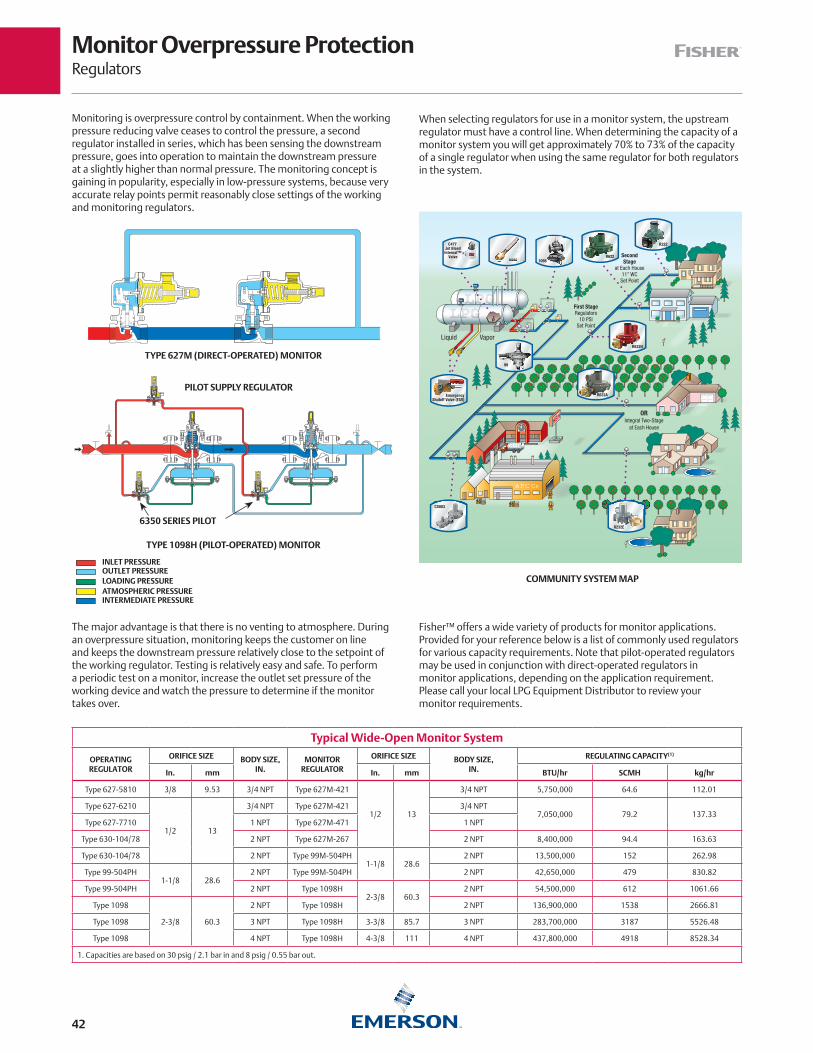
Monitor Overpressure ProtectionRegulators
42
Monitoring is overpressure control by containment. When the working pressure reducing valve ceases to control the pressure, a second regulator installed in series, which has been sensing the downstream pressure, goes into operation to maintain the downstream pressure at a slightly higher than normal pressure. The monitoring concept is gaining in popularity, especially in low-pressure systems, because very accurate relay points permit reasonably close settings of the working and monitoring regulators.
When selecting regulators for use in a monitor system, the upstream regulator must have a control line. When determining the capacity of a monitor system you will get approximately 70% to 73% of the capacity of a single regulator when using the same regulator for both regulators in the system.
Fisher™ offers a wide variety of products for monitor applications. Provided for your reference below is a list of commonly used regulators for various capacity requirements. Note that pilot-operated regulators may be used in conjunction with direct-operated regulators in monitor applications, depending on the application requirement. Please call your local LPG Equipment Distributor to review your monitor requirements.
The major advantage is that there is no venting to atmosphere. During an overpressure situation, monitoring keeps the customer on line and keeps the downstream pressure relatively close to the setpoint of the working regulator. Testing is relatively easy and safe. To perform a periodic test on a monitor, increase the outlet set pressure of the working device and watch the pressure to determine if the monitor takes over.
Typical Wide-Open Monitor System
OPERATING REGULATOR
ORIFICE SIZE BODY SIZE,IN.
MONITOR REGULATOR
ORIFICE SIZE BODY SIZE,IN.
REGULATING CAPACITY(1)
In. mm In. mm BTU/hr SCMH kg/hr
Type 627-5810 3/8 9.53 3/4 NPT Type 627M-421
1/2 13
3/4 NPT 5,750,000 64.6 112.01
Type 627-6210
1/2 13
3/4 NPT Type 627M-421 3/4 NPT7,050,000 79.2 137.33
Type 627-7710 1 NPT Type 627M-471 1 NPT
Type 630-104/78 2 NPT Type 627M-267 2 NPT 8,400,000 94.4 163.63
Type 630-104/78 2 NPT Type 99M-504PH1-1/8 28.6
2 NPT 13,500,000 152 262.98
Type 99-504PH1-1/8 28.6
2 NPT Type 99M-504PH 2 NPT 42,650,000 479 830.82
Type 99-504PH 2 NPT Type 1098H2-3/8 60.3
2 NPT 54,500,000 612 1061.66
Type 1098
2-3/8 60.3
2 NPT Type 1098H 2 NPT 136,900,000 1538 2666.81
Type 1098 3 NPT Type 1098H 3-3/8 85.7 3 NPT 283,700,000 3187 5526.48
Type 1098 4 NPT Type 1098H 4-3/8 111 4 NPT 437,800,000 4918 8528.34
1. Capacities are based on 30 psig / 2.1 bar in and 8 psig / 0.55 bar out.
INLET PRESSUREOUTLET PRESSURE
INTERMEDIATE PRESSUREATMOSPHERIC PRESSURELOADING PRESSURE
Type 1098-EGR Upstream or Downstream “Wide-Open” Monitor
A67
89
INLET PRESSUREOUTLET PRESSURELOADING PRESSURE
INTERMEDIATE PRESSUREATMOSPHERIC PRESSURE
September 2006 Type 1098-EGR
Type 1098-EGR Upstream or Downstream “Wide-Open” Monitor
A67
89
INLET PRESSUREOUTLET PRESSURELOADING PRESSURE
INTERMEDIATE PRESSUREATMOSPHERIC PRESSURE
September 2006 Type 1098-EGR
TYPE 1098H (PILOT-OPERATED) MONITOR
PILOT SUPPLY REGULATOR
6350 SERIES PILOT
TYPE 627M (DIRECT-OPERATED) MONITOR
COMMUNITY SYSTEM MAP
ORIntegral Two-Stage
at Each House
VaporLiquid
First StageRegulators
10 PSISet Point
SecondStage
at Each House11” WC
Set Point
EPR
EPR
EmergencyShutoff Valve (ESV)
C477 Jet BleedInternal™
Valve R622
R222
R622H
99
R632A
CS803
1098H282
R232E
CnK
H282H282
CS803
R232E

Backpressure Regulators/Relief ValvesRegulators
43
Relief Valve for Liquid or Vapor Service
Type MR98H – is a direct-operated relief valve for use on relief and backpressure applications involving large LPG pumping systems and vaporizers. Internal pressure registration eliminates the need for a control line. Body materials are available in Gray Cast Iron, Steel or Stainless Steel. It is available with Nitrile (NBR) gaskets in sizes from 1/4 in. to 2 in. / 6.35 to 50.8 mm. Relief pressure ranges from 15 to 200 psi / 1.03 to 13.8 bar. Temperature ratings are -40 to 180°F / -40 to 82°C for CI and SST and -20 to 180°F / -29 to 82°C for Steel. Available with: gauge port on inlet, gauge port on outlet and Fluorocarbon (FKM) elastomers.
Type MR98HH – Same features as above but relief pressure range is 150 to 375 psig / 10.3 to 25.9 bar.
Liquid Service Relief Valves
TYPEBODY SIZE,
IN.
RELIEF PRESSURERANGE
RELIEF PRESSURESETTING
PROPANE RELIEF CAPACITY GPM / l/min AT FOLLOWING PRESSURE BUILD-UP OVER RELIEF SETTING
5 psig / 0.34 bar 10 psig / 0.69 bar 20 psig / 1.4 bar 30 psig / 2.1 bar 50 psig / 3.4 bar
psig bar psig bar GPM l/min GPM l/min GPM l/min GPM l/min GPM l/min
MR98H-13 1/2 FNPT 25 to 75 1.7 to 5.2 50 3.4 16.9 66.1 26.8 103.4 38.0 140.8 40.8 154.9 49.3 184.5
MR98H-22 3/4 FNPT 70 to 140 4.8 to 9.7 100 6.9 32.4 121.0 53.5 201.4 78.9 300.0 87.3 331.0 104.2 394.4
MR98H-30 1 FNPT 70 to 140 4.8 to 9.7 100 6.9 32.4 121.0 53.5 201.4 78.9 300.0 87.3 331.0 104.2 394.4
MR98H-31 1 FNPT 130 to 200 9.0 to 13.8 175 12.1 29.6 112.4 47.9 178.9 77.5 291.5 90.1 342.3 118.3 446.5
MR98HH-19 1 FNPT 150 to 375 10.3 to 25.9 250 17.2 27.6 104.4 37.7 142.3 61.7 233.8 83.4 315.5 113.0 426.8
Vapor Relief Valves
Type 1805 – relief valve is designed for installation between the First and Second-Stage regulators or in the downstream line from a high-pressure regulator used for a Final-Stage service where high line pressures are allowed. Available in 1 or 2 in. valve bodies with a temperature rating of -20 to 150°F / -29 to 66°C.
Type 289H – relief valve is designed for installation downstream of larger high-pressure or low-pressure regulators in most all relief applications. The larger diaphragm in this relief valve provides extremely sensitive operation, with a temperature rating of -20 to 150°F / -29 to 66°C.
Types 1808 and 1808A – pilot-operated relief valve is designed to protect large high-pressure regulators by offering extremely high relief capacities compared to the Type 289H. The Type 1808 has a temperature rating of -20 to 180°F / -29 to 82°C.
Vapor Relief Valves
TYPE BODY SIZE, IN.
RELIEF START-TO-DISCHARGE
SPRING RANGEPRESSURE BUILDUP OVER
SET PRESSURECAPACITY (AIR)
psig bar psig bar psig bar SCFH Nm3/h
1805-18P 1 FNPT 15 1.03 5 to 35 0.34 to 2.41 15 1.03 6160 at 30 psig 161 at 2.07 bar
1805-19P 1 FNPT 40 2.75 10 to 60 0.69 to 4.1 15 1.03 3120 at 55 psig 83.62 at 3.79 bar
1805-51P 2 FNPT 15 1.03 5 to 20 0.34 to 1.38 15 1.03 28,500 at 30 psig 748 at 2.07 bar
1805-52P 2 FNPT 40 2.75 10 to 50 0.69 to 3.4 15 1.03 14245 at 55 psig 381.77 at 3.79 bar
1808A-61 2 FNPT, Angle 20 1.4 15 to 40 1.03 to 2.76 10 0.69 78,230 at 30 psig 2053 at 2.07 bar
289H-42 1 FNPT 15 1.03 4 to 15 0.28 to 1.03 15 1.03 33,880 at 30 psig 889 at 2.07 bar
289H-2 2 FNPT 24 in. w.c. 60 mbar 1/2 to 2-1/4 34 to 155 mbar 1.13 78 mbar 15,400 at 2 psig 38 at 138 mbar
NOTE: Some regulators will require more than one relief valve. Consult your local Fisher™ LPG Distributor for proper relief valve sizing.
TYPE MR98H TYPE MR98HH
TYPE 1805 TYPE 1808
TYPE 289H

AccessoriesRegulators
44
Vent Assemblies
Attached directly to the regulator vent connection to a regulator vent line, vent assemblies should be pointed downward on outdoor installations to avoid moisture build-up in the regulator spring case. Units with stabilizer assembly are intended for regulators with stability problems. The stabilizer gives a restricted breathing rate under normal conditions, opening for rapid discharge when necessary. Screen material is Monel® with integral plastic screen for all except Type Y602-12.
Small Portable Appliance Regulators
Type 912 – Designed for use on small portable outdoor appliances.
Underwriters Laboratory (UL®) requires horizontally mounted regulators to be installed with vent opening protection to prevent blockage by freezing rain. The 912 Series has a temperature rating of -20 to 160°F / -29 to 71°C.
Vent AssembliesTYPE
SIZE STABILIZERUmbrella Type Angle Type
- - - - Y602-131/4 in. FNPT
No
- - - - Y602-14 Yes
Y602-1 - - - -1/4 in. MNPT
No
Y602-2 - - - - Yes
Y602-3 - - - - 3/8 in. O.D. Tubing (Flare Connection)
No
Y602-4 - - - - Yes
Y602-12 - - - - 1/4 in. MNPT No
- - - - Y602-5 3/8 in. FNPT
No
- - - - Y602-6 Yes
- - - - Y602-71/2 in. FNPT
No
- - - - Y602-8 Yes
- - - - Y602-9 3/4 in. FNPT No
- - - - Y602-23 3/4 in. MNPT No
- - - - Y602-25 1 in. MNPT No
Appliance Regulators
TYPE
PRESSURE RANGEOUTLET
PRESSURERegulator Capacities (Propane)
INLET CONNECTION
OUTLET CONNECTION
ORIFICE SIZE
In. w.c. mbar In. w.c. mbar10 psig, Inlet 25 psig, Inlet 100 psig, Inlet
In. mm In. mm In. mmBTU/hr kg/hr BTU/hr kg/hr BTU/hr kg/hr
912N-194(1) 3 to 7 7 to 17 5 12 101,000 1.97 151,000 2.94 - - - - - - - - 1/4 6.4 1/4 6.4 0.073 1.85
912-104 9.25 to 13 23 to 32 11 27 101,000 1.97 270,000 5.26 349,000 6.80 1/4 6.4 1/4 6.4 0.073 1.85
912N-109(1) 5 to 10 12 to 25 7 17 123,000 2.40 232,000 4.52 556,000 10.83 1/4 6.4 3/8 9.5 0.073 1.85
912-101 9.25 to 13 23 to 32 11 27 110,000 2.14 201,000 3.92 494,000 9.62 1/4 6.4 3/8 9.5 0.073 1.85
912-122 9.25 to 13 23 to 32 11 27 110,000 2.14 201,000 3.92 494,000 9.62 1/4 6.4 3/8 9.5 0.073 1.85
912H-1080.5 to
2.7 psig 0.03 to
0.19 bar1.5 psig 103 131,000 3.93 202,000 3.92 470,000 9.16 1/4 6.4 3/8 9.5 0.094 2.39
1. Not UL listed.
TYPE Y602-13 (ANGLE TYPE)TYPE Y602-1 (UMBRELLA TYPE)
TYPE 912-101
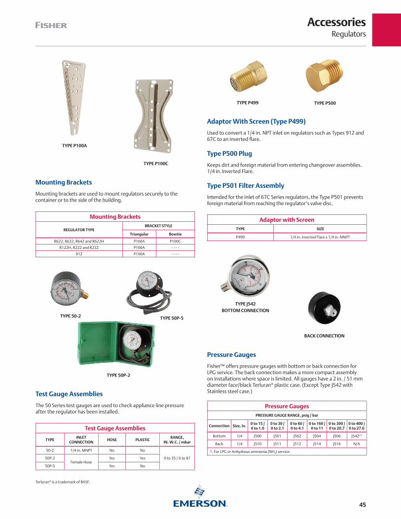
AccessoriesRegulators
45
Adaptor With Screen (Type P499)
Used to convert a 1/4 in. NPT inlet on regulators such as Types 912 and 67C to an inverted flare.
Type P500 Plug
Keeps dirt and foreign material from entering changeover assemblies. 1/4 in. Inverted Flare.
Type P501 Filter Assembly
Intended for the inlet of 67C Series regulators, the Type P501 prevents foreign material from reaching the regulator’s valve disc.
Mounting Brackets
REGULATOR TYPEBRACKET STYLE
Triangular Bowtie
R622, R632, R642 and R622H P100A P100C
R122H, R222 and R232 P100A - - - -
912 P100A - - - -
Adaptor with ScreenTYPE SIZE
P499 1/4 in. Inverted Flare x 1/4 in. MNPT
TYPE P100A
TYPE P100C
TYPE P499 TYPE P500
Mounting Brackets
Mounting brackets are used to mount regulators securely to the container or to the side of the building.
Test Gauge Assemblies
The 50 Series test gauges are used to check appliance line pressure after the regulator has been installed.
Pressure Gauges
Fisher™ offers pressure gauges with bottom or back connection for LPG service. The back connection makes a more compact assembly on installations where space is limited. All gauges have a 2 in. / 51 mm diameter face/black Terluran® plastic case. (Except Type J542 with Stainless steel case.)
Test Gauge Assemblies
TYPEINLET
CONNECTIONHOSE PLASTIC
RANGE, IN. W.C. / mbar
50-2 1/4 in. MNPT No No
0 to 35 / 0 to 8750P-2Female Hose
Yes Yes
50P-5 Yes No
Pressure GaugesPRESSURE GAUGE RANGE, psig / bar
Connection Size, in.0 to 15 / 0 to 1.0
0 to 30 / 0 to 2.1
0 to 60 / 0 to 4.1
0 to 160 / 0 to 11
0 to 300 / 0 to 20.7
0 to 400 / 0 to 27.6
Bottom 1/4 J500 J501 J502 J504 J506 J542(1)
Back 1/4 J510 J511 J512 J514 J516 N/A
1. For LPG or Anhydrous ammonia (NH3) service.
BOTTOM CONNECTIONTYPE J542
BACK CONNECTION
Terluran® is a trademark of BASF.
TYPE 50P-2
TYPE 50-2 TYPE 50P-5
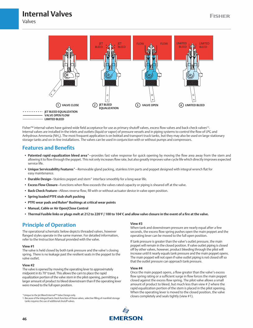
Internal ValvesValves
46
Fisher™ internal valves have gained wide field acceptance for use as primary shutoff valves, excess flow valves and back check valves(1). Internal valves are installed in the inlets and outlets (liquid or vapor) of pressure vessels and in piping systems to control the flow of LPG and Anhydrous Ammonia (NH3). The most frequent application is on bobtail and transport truck tanks, but they may also be used on large stationary storage tanks and on in-line installations. The valves can be used in conjunction with or without pumps and compressors.
Features and Benefits • Patented rapid equalization bleed area*—provides fast valve response for quick opening by moving the flow area away from the stem and
allowing it to flow through the poppet. This not only increases flow rate, but also greatly improves valve cycle life which directly improves expected service life.
• Unique Serviceability Features*—Removable gland packing, stainless trim parts and poppet designed with integral wrench flat for easy maintenance.
• Durable Design—Stainless poppet and stem* interface smoothly for a long wear life.
• Excess Flow Closure—Functions when flow exceeds the valves rated capacity or piping is sheared off at the valve.
• Back Check Feature—Allows reverse flow, fill with or without actuator device in valve open position.
• Spring loaded PTFE stub shaft packing
• PTFE wear pads and Rulon® Bushings at critical wear points
• Manual, Cable or Air Open/Close Control
• Thermal Fusible links or plugs melt at 212 to 220°F / 100 to 104°C and allow valve closure in the event of a fire at the valve.
Principle of Operation The operational schematic below depicts threaded valves, however flanged styles operate in the same manner. For detailed information, refer to the Instruction Manual provided with the valve.
View #1 The valve is held closed by both tank pressure and the valve’s closing spring. There is no leakage past the resilient seats in the poppet to the valve outlet.
View #2 The valve is opened by moving the operating lever to approximately midpoint in its 70° travel. This allows the cam to place the rapid equalization portion of the valve stem in the pilot opening, permitting a larger amount of product to bleed downstream than if the operating lever were moved to the full open position.
View #3 When tank and downstream pressure are nearly equal after a few seconds, the excess flow spring pushes open the main poppet and the operating lever can be moved to the full open position.
If tank pressure is greater than the valve’s outlet pressure, the main poppet will remain in the closed position. If valve outlet piping is closed off by other valves, however, product bleeding through the pilot will increase until it nearly equals tank pressure and the main poppet opens. The main poppet will not open if valve outlet piping is not closed off so that the outlet pressure can approach tank pressure.
View #4 Once the main poppet opens, a flow greater than the valve’s excess flow spring rating or a sufficient surge in flow forces the main poppet closed against the excess flow spring. The pilot valve allows a small amount of product to bleed, but much less than view # 2 where the rapid equalization portion of the stem is placed in the pilot opening. When the operating lever is moved to the closed position, the valve closes completely and seals tightly (view #1).*Unique to the Jet Bleed Internal™ Valve Design only.
1. Because of the integral back check function of these valves, selective filling of manifold storage tanks requires the use of additional shutoff valves.
LIMITED BLEED
JET BLEED EQUALIZATIONVALVE OPEN FLOW
1 2 3 4
JET BLEED
LIMITED BLEED
LIMITED BLEED
FLOW FLOWJET BLEED
VALVE CLOSE JET BLEED EQUALIZATION
VALVE OPEN LIMITED BLEED

Threaded Internal ValvesValves
47
Threaded Internal Valves
Emerson offers the widest variety of threaded internal valves in the industry. While their most frequent use is in the liquid and vapor openings of bobtail and transport trucks, the valves can also be used in stationary storage tanks, complying with NFPA 58 requirements. Designed as primary shutoff valves, the units are designed with several features that help control product discharge.
All UL-listed internal valves are suitable for LPG or Anhydrous Ammonia (NH3) service. Special construction is available for other compressed gases. All threaded internal valves have a compact, one-piece body design. They can be actuated manually, by cable control orwith an air cylinder.
C407-10 Series (1-1/4 in. / DN 32 Body Size) – An excellent valve for vapor return lines on bobtail trucks. Other applications include use as a main valve on small capacity pumping systems, Anhydrous Ammonia (NH3) nurse tanks and in-line installations.
UL® Approved C400 Series Internal Valves
CONNECTIONINLET X OUTLET
TYPE CLOSING FLOW (PROPANE)(2) VAPOR CAPACITY (PROPANE)(2) CLOSING FLOW (NH3)2
Straight Body Tee BodyHalf Coupling Full Coupling 25 psig / 1.7 bar Inlet 100 psig / 6.9 bar Inlet Half Coupling
GPM l/min GPM l/min SCFH SCMH SCFH SCMH GPM l/min
1-1/4 in. MNPT x1-1/4 in. FNPT
C407-10-04 - - - - 40 152 25 95 7400 210 12,700 360 36 136
C407-10-05 - - - - 50 189 35 133 9600 272 16,400 464 45 170
C407-10-08(1) - - - - 80 303 65 246 15,800 447 27,600 781 72 272
2 in. MNPT x2 in. FNPT
C477-16-10 C471-16-10 105 397 60 227 26,100 739 45,000 1274 95 360
C477-16-15 C471-16-15 150 568 80 303 39,400 1116 69,000 1954 136 515
C477-16-25 C471-16-25 250 946 130 492 - - - - - - - - 227 859
3 in. MNPT x3 in. FNPT
C477-24-16 C471-24-16 160 606 120 454 41,100 1164 71,000 2011 145 549
C477-24-26 C471-24-26 265 1003 230 871 71,800 2033 127,000 3596 239 905
C477-24-37 C471-24-37 375 1419 320 1211 99,000 2803 178,000 5040 339 1283
C477-24-46 C471-24-46 460 1741 380 1438 - - - - - - - - 415 1571
3 in. CL300 RF x 3 in. FNPT
C486-24-16 - - - - 160 606 120 454 41,100 1164 71,000 2011 145 549
C486-24-26 - - - - 265 1003 230 871 71,800 2033 127,000 3596 240 908
C486-24-37 - - - - 375 1419 320 1211 99,000 2803 178,000 5040 340 1287
C486-24-46 - - - - 460 1741 380 1438 - - - - - - - - 418 1582
NOTE: Includes a factory installed Type P340 / P341 latch.1. LPG Vapor exceeds UL differential requirement of 15 psid / 1.03 bar d.2. Closing Flows and Vapor Capacities listed are with valve in “bottom of tank” position. See product bulletins for additional data.
C477 Series (Straight-Through Body) – Available in 2 and 3 in. end connections. The most compact and economical unit in the Series, the C477 Series has one bottom outlet. The C477 Series can be used on bobtail, transport, stationary tank and in-line installations.
C471 Series (Tee Body) – Available in 2 and 3 in. end connections. This unit is designed with two outlets, bottom and side. The side outlet permits installing horizontal piping immediately adjacent to the tank without the need for extra pipe fittings. Either connection can be used for truck filling or withdrawal. The C471 Series is used primarily on bobtails and transport trucks.
C486 Series (Flange-by-NPT) – Available in 3 in. end connections. This unit was designed with an integrally cast inlet flange to quickly bolt to existing installations that historically required a valve to be threaded into a flange. Outlet is standard 3 in. FNPT.
C407 SERIES C477 SERIES C471 SERIES C486 SERIES

Special Service Threaded Internal ValvesValves
48
C800 Series Special Service Internal ValvesCONNECTION
INLET X OUTLETBODY STYLE TYPE BODY MATERIAL ELASTOMER AVAILABLE PER ORDER(3)
1-1/4 in. MNPT x 1-1/4 in. FNPT
Straight BodyC807-10 Steel
Fluorocarbon (FKM)
Nitrile (NBR) PTFE - - - - - - - - - - - -C807S-10 SST
2 in. MNPT x 2 in. FNPT
Tee Body C871-16 Ductile Iron
EPDM Viton®(1) Kalrez®(2) Neoprene (CR) Nitrile (NBR) PTFE
Straight Body
C877-16 Ductile Iron
C887-16 Steel
C897-16 SST
3 in. MNPT x 3 in. FNPT
Tee Body C871-24 Ductile Iron
Straight BodyC877-24 Ductile Iron
C897-24 SST
3 in. CL300 RF Flange x 3 in. FNPT
Straight Body C886-24 Steel
1. Viton® or Fluorocarbon (FKM) equivalent2. Kalrez® or Perfluoroelastomer (FFKM) equivalent3. Additional materials can be sourced upon request. Please contact your Fisher LPG Equipment Distributor for more information.
C800 Series Threaded Internal Valves
The Fisher™ C800 Series Internal Valves provide the same primary shutoff and excess flow protection as the C400 Series, but are offered in a wide variety of body materials and elastomeric seals. With industrial process installations spanning the globe, the C800 Series has been the trusted product line for decades.
Specifications
Emerson is the leader in special service conditions and offers a wide selection of metallic and elastomeric components to meet your demands. Every process or special service fluid has unique compatibility properties, pressure ranges and temperature ranges. Please contact your Fisher LPG Equipment distributor to help select the configuration that’s best for you.
C807-10 SERIES
C877 SERIES
C871 SERIES C886 SERIES
C807S-10 SERIES
C897 SERIES

Threaded Internal ValvesValves
49
BOTTOM OF TANK POSITION (VERTICAL DOWN)
TOP OF TANK POSITION (INVERTED UP)
INTERNAL VALVE TANK POSITIONS
In-Line Adaptors (for reference only)*
ZDIMENSION, IN. / mm
X Y D
1-1/4 in. FNPT 4.70 / 119 2.75 / 70 2.05 / 52
2 in. FNPT 6.77 / 172 3.5 / 89 2.80 / 71
3 in. FNPT 7.53 / 191 4.5 / 114 3.80 / 97
* Not for sale.
D
IN-LINE ADAPTOR
Z
X
Y
HORIZONTAL POSITION (REFER BELOW)

Threaded Internal ValvesValves
50
Threaded Valve Specifications
Pressure Rating: 400 psig / 27.6 bar WOG Temperature(1): C470 Series:-20 to 150°F / -29 to 66°C
C800 Series: Contact your Fisher™ LPG Distributor for details
Body: C470 Series: Ductile Iron C407-10 Series: Cast Steel C800 Series: Ductile Iron, Steel, SST
Packing: PTFESeat Discs: C407-10 and C470 Series: Molded, synthetic rubber
C800 Series: Contact your local LPG Distributor for details Stub Shaft and Stem: Stainless steel
! WARNING
A line break downstream of a pump may not actuate the excess flow valve. If any break occurs in the system or if the excess flow valve closes, the system should be shutdown immediately.
DO NOT USE the excess flow function incorporated into Fisher C Series internal valves or F Series excess flow valves to satisfy the passive shutdown requirement in 49CFR§173.315(n)(2). DO NOT include the excess flow incorporated into Fisher C Series internal valves or F Series excess flow valves in a DCE certification under 49CFR§173.315(n)(2). The cargo tank manufacturer must install some other equipment that satisfies the requirement for passive shutdown capability under 49CFR§173.315(n)(2).
Failure to follow this warning could result in serious personal injury or property damage from fire or explosion in the event of an unintentional release of product during an unload operation.
FLOW RATE, GPM / l/min PROPANE
VA
LVE
DIF
FER
ENTI
AL
PRES
SUR
E, p
sig
/ b
ar
Type C477/471-24 “Bottom of Tank” Position Flow Curve, Half Coupling
0
2
4
6
8
10
12
14
16
18
20
0 50 100 150 200 250 300 350 400
Valv
eD
ifffef
rernt
ialP
ress
ure,
psig
Flow, GPM Propane
C477-24-36VeVV rtical Up Position
111.8888883332.5114
V VVa VVaal aav ll
vve vveeD DD
i DDf iifff fffffffff ffff
e ffeeffffffr eerre rreerrrrr rrr
n eennt nntti tta iiaa
l aaP PPr PP
rre rreer rrrs eess
s ssssu ssuu
r uurre rree
, eep pps pp
ssi ssg iigg
CCC444777777-122644-133066VVVeVVeeVVVVVVVV rrrtrrttrrrrrrrr iiicccaaalll UUUppp PPPooosssiiitttiiiooonnn
Unit 1Unit 1
UUniitt 33
50 / 189150 / 568
200 / 757
250 / 946
300 / 1136
350 / 1325
400 / 1514
100 / 379
0
0
20 / 1.4
18 / 1.2
16 / 1.1
14 / 0.97
12 / 0.83
10 / 0.69
8 / 0.55
6 / 0.41
4 / 0.28
2 / 0.14
450 / 1703
160 GPM / 605 L/MIN RATING
265 GPM / 1003 L/MIN RATING
375 GPM / 1419 L/MIN RATING
460 GPM / 1741 L/MIN RATING
0
2
4
6
8
10
12
14
16
18
20
0 50 100 150 200 250 300 350 400
Valv
eD
iffffeff
rerrnt
ialP
ress
ure,
psig
Flow, GPM Propane
C477-24-36VeVV rtrr ical Up Position
Unit 1
1. Product has passed Fisher testing for pressure shutoff down to -40°F / -40°C.

Threaded Internal ValvesValves
51
0
2
4
6
8
10
12
14
16
18
20
0 50 100 150 200 250 300
Valv
eD
ifffef
rernt
ialP
ress
urer
,psi
g
Flow, GPM Propane
C477-16-25Vertrr ical Up Position
21.2211
77.93
2.3671
2211
2
.0
1.3251111.888888883333
2.514
VVV aVVaa lll
vllvv evvee
DDDiii fiiff fffffffff fffff
effeeffff fffrrr erreerrrr rrrr
nnn tnntt ittii aiiaa
lll PPP rrr
erreeseess
sssssuuu r
rr erreerrrr rrrr,e,,
ppp sppss iii
giiggCCC444777777---111666---122055
VVVeVVVeeeVeerrrttrrrrtttrttttiiicccaaalll UUUppp PPPooosssiiitttiiiooonnn
Unit 1
UUUnit 3
Type C477/471-16 “Bottom of Tank” Position Flow Curve, Half Coupling
FLOW RATE, GPM / l/min PROPANE
0
20 / 1.4
18 / 1.2
16 / 1.1
14 / 0.97
12 / 0.83
10 / 0.69
8 / 0.55
6 / 0.41
4 / 0.28
2 / 0.14
VA
LVE
DIF
FER
ENTI
AL
PRES
SUR
E, p
sig
/ b
ar
50 / 189
150 / 568
200 / 757
250 / 946
300 / 1136
100 / 379
0
Type C477-24 Typical Reverse Flow Curve
VALVE CLOSED POSITION
VALVE OPEN POSITION
FLOW RATE, GPM / l/min PROPANE
VA
LVE
DIF
FER
ENTI
AL
PRES
SUR
E, p
sig
/ b
ar
50 / 189150 / 568
200 / 757
250 / 946
300 / 1136
350 / 1325
400 / 1514
450 / 1703
500 / 1893
550 / 2082
600 / 2271
650 / 2460
700 / 2650
100 / 379
00
5 / 0.35
10 / 0.69
35 / 2.4
15 / 1.0
20 / 1.4
25 / 1.7
30 / 2.1
40 / 2.8
Type C477-16 Typical Reverse Flow Curve
VALVE OPEN POSITION
VALVE CLOSED POSITION
FLOW RATE, GPM / l/min PROPANE
VA
LVE
DIF
FER
ENTI
AL
PRES
SUR
E, p
sig
/ b
ar
50 / 189
150 / 568
200 / 757
250 / 946
300 / 1136
350 / 1325
100 / 379
0
0
5 / 0.35
10 / 0.69
15 / 1.0
20 / 1.4
25 / 1.7
30 / 2.1
35 / 2.4
40 / 2.8
45 / 3.1
50 / 3.4
55 / 3.8
105 GPM / 397 L/MIN RATING
150 GPM / 567 L/MIN RATING
250 GPM / 946 L/MIN RATING
0
2
4
6
8
10
12
14
16
18
20
0 50 100 150 200 250 300
Valv
eD
ifffef
rernt
ialP
ress
urer
,psi
g
Flow, GPM Propane
C477-16-25Vertrr ical Up Position
21.2211
77.93
2.3671
2211
2
.0
1.3251111.888888883333
2.514
VVV aVVaa lll
vllvv evvee
DDDiii fiiff fffffffff fffff
effeeffff fffrrr erreerrrr rrrr
nnn tnntt ittii aiiaa
lll PPP rrr
erreeseess
sssssuuu r
rr erreerrrr rrrr,e,,
ppp sppss iii
giigg
CCC444777777---111666---122055VVVeVVVeeeVeerrrttrrrrtttrttttiiicccaaalll UUUppp PPPooosssiiitttiiiooonnn
Unit 1
UUUnit 3
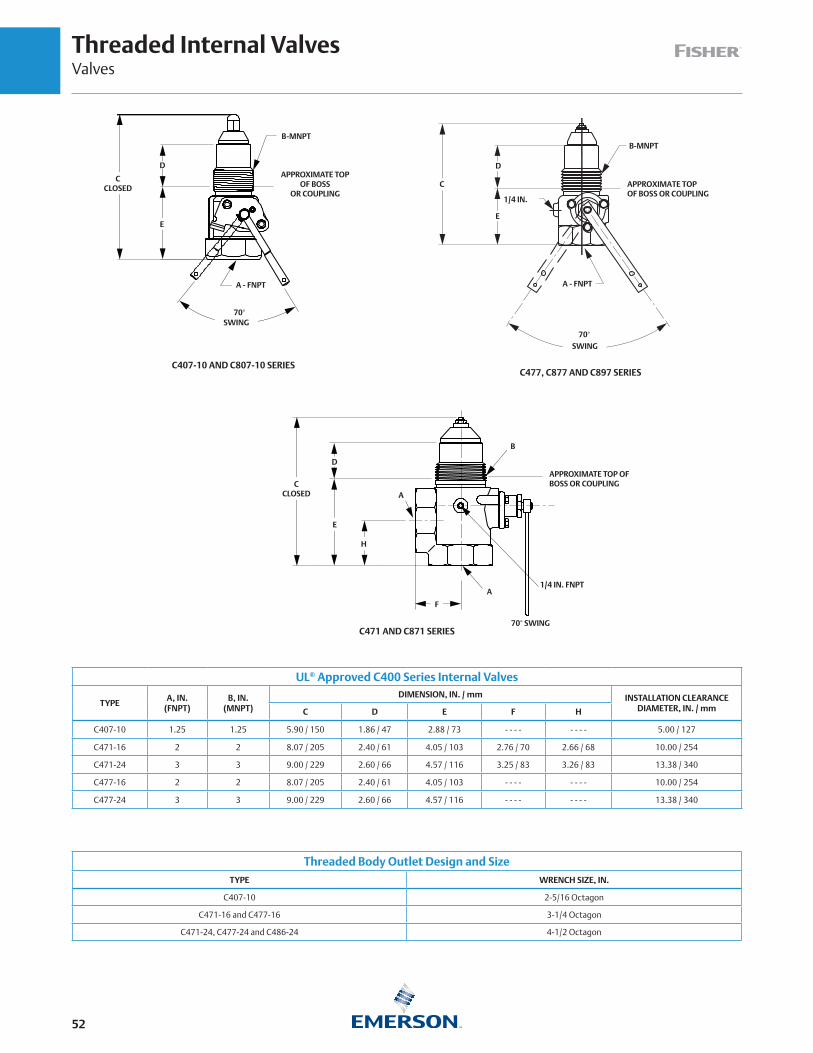
Threaded Internal ValvesValves
52
UL® Approved C400 Series Internal Valves
TYPEA, IN.
(FNPT)B, IN.
(MNPT)
DIMENSION, IN. / mm INSTALLATION CLEARANCE DIAMETER, IN. / mmC D E F H
C407-10 1.25 1.25 5.90 / 150 1.86 / 47 2.88 / 73 - - - - - - - - 5.00 / 127
C471-16 2 2 8.07 / 205 2.40 / 61 4.05 / 103 2.76 / 70 2.66 / 68 10.00 / 254
C471-24 3 3 9.00 / 229 2.60 / 66 4.57 / 116 3.25 / 83 3.26 / 83 13.38 / 340
C477-16 2 2 8.07 / 205 2.40 / 61 4.05 / 103 - - - - - - - - 10.00 / 254
C477-24 3 3 9.00 / 229 2.60 / 66 4.57 / 116 - - - - - - - - 13.38 / 340
E
1/4 IN. FNPT
APPROXIMATE TOP OF BOSS OR COUPLING
70° SWING
D
H
A
A
B
CCLOSED
C471 AND C871 SERIES
F
Threaded Body Outlet Design and SizeTYPE WRENCH SIZE, IN.
C407-10 2-5/16 Octagon
C471-16 and C477-16 3-1/4 Octagon
C471-24, C477-24 and C486-24 4-1/2 Octagon
A - FNPT
C407-10 AND C807-10 SERIES
B-MNPT
APPROXIMATE TOP OF BOSS
OR COUPLING
CCLOSED
E
D
70°SWING
C477, C877 AND C897 SERIES
C
1/4 IN.
B-MNPT
D
E
A - FNPT
SWING70°
APPROXIMATE TOPOF BOSS OR COUPLING

Flanged Internal ValvesValves
53
Flanged Internal Valves
Flanged valves provide a sturdy and compact means of directly mounting a pump or piping connection. Special stud bolts, weakened with a groove on the outside diameter, are furnished with the valves to permit the pump or piping to shear off in the event of an accident, leaving the valve intact. A built-in excess flow valve reduces the chance of uncontrolled product discharge when flow exceeds the rated flow capacity.
All flanged valves have an internal screen for pump protection that can be easily removed if the valve is used primarily for filling the tank. They also contain PTFE packing to resist stub shaft leakage. These valves can be activated manually, by cable control or by air cylinder (refer to pages 60 and 61).
3 in. / DN 80 Flanged Sizes
Type C484-24 – A single-flange unit widely used on bobtail and transport trucks for a compact means of direct pump connection to the valve outlet. Another application for the Type C484-24 is on in-line installations.
Type C483-24 – A double-flange unit designed for special bobtail truck applications where the pump must be lowered to clear the truck frame or other obstacles. A special shear section in the body permits the lower section of the valve to shear off in the event of an accident, leaving the critical shutoff parts within the tank.
TYPE C483-24 TYPE C484-24
UL® Approved 3 In. / DN 80 Flanged Internal Valves
Size
Type Number Closing Flow Propane Closing Flow NH3
Single Flanged Double Flanged
Single Flanged, Bottom of Tank
Position*
Double Flanged, Bottom of Tank
Position*
Single Flanged,Top of Tank
Position*
Double Flanged,Top of Tank
Position*
Single Flanged, Bottom of Tank
Position*
Double Flanged, Bottom of Tank
Position*GPM l/min GPM l/min GPM l/min GPM l/min GPM l/min GPM l/min
3 in. / DN 80
C484-24-16 C483-24-16 160 606 160 606 180 681 180 681 144 545 144 545C484-24-25 C483-24-26 250 946 265 1003 250 946 290 1098 239 905 226 855C484-24-40 C483-24-40 400 1514 400 1514 400 1514 400 1514 361 1366 361 1366
*See Internal Valve Flow Positions (page 49) for description of Bottom of Tank, Top of Tank and Horizontal Flow Positions.
UL Approved 3 In. / DN 80 Flanged Internal Valves
Size
Type Vapor Capacity Propane
Single Flanged Double Flanged
100 psig / 6.9 bar Inlet, Single Flanged, Bottom of Tank
Position**
100 psig / 6.9 bar Inlet, Double Flanged, Bottom of Tank
Position**
100 psig / 6.9 bar Inlet, Single Flanged,
Top of Tank Position*
100 psig / 6.9 bar Inlet, Double Flanged,
Top of Tank Position*
SCFH SCMH SCFH SCMH SCFH SCMH SCFH SCMH
3 in. / DN 80
C484-24-16 C483-24-16 71,000 2011 71,000 2011 96,000 2718 96,000 2718C484-24-25 C483-24-26 NOT LISTED 127,000 3568 NOT LISTED 148,000 4191C484-24-40 C483-24-40 181,000 5125 181,000 5125 190,000 5380 190,000 5380
*See Internal Valve Flow Positions (page 49) for description of Bottom of Tank, Top of Tank and Horizontal Flow Positions.

Flanged Internal ValvesValves
54
Types C483-24 and C484-24 Typical Closing Flow Curve, Standard Position
VA
LVE
DIF
FER
ENTI
AL
PRES
SUR
E, p
sig
/ b
ar
FLOW RATE, GPM / l/min PROPANE
0
2
4
6
8
10
12
14
16
18
20
0 50 100 150 200 250 300 350 400
Valv
eD
ifffef
rernt
ialP
ress
ure,
psig
Flow, GPM Propane
C477-24-36VeVV rtical Up Position
111.8888883332.5114
V VVa VVaal aav ll
vve vveeD DD
i DDf iifff fffffffff ffff
e ffeeffffffr eerre rreerrrrr rrr
n eennt nntti tta iiaa
l aaP PPr PP
rre rreer rrrs eess
s ssssu ssuu
r uurre rree
, eep pps pp
ssi ssg iigg
CCC444777777-122644-133066VVVeVVeeVVVVVVVV rrrtrrttrrrrrrrr iiicccaaalll UUUppp PPPooosssiiitttiiiooonnn
Unit 1Unit 1
UUniitt 33
20 / 1.4
18 / 1.2
16 / 1.1
14 / 0.97
12 / 0.83
10 / 0.69
8 / 0.55
6 / 0.41
4 / 0.28
2 / 0.14
400 / 1514
350 / 1325
300 / 1136
250 / 946
200 / 757
150 / 568
100 / 379
50 / 189
0 450 / 1703
Flanged Valve SpecificationsPressure Rating: 400 psig / 27.6 bar WOG Temperature: Types C483 and C484(1): -20 to 150°F / -29 to 66°C
Type C404-32(2): -20 to 150°F / -29 to 66°CBody: Types C483 and C484-24: Cast steel and WCC
Type C404-32: Stainless steelPacking: PTFESeat Discs: Molded, synthetic rubberStub Shaft and Stem: Stainless steelGaskets: Non-asbestos spiral wound graphite
A line break downstream of a pump may not actuate the excess flow valve. If any break occurs in the system or if the excess flow valve closes, the system should be shutdown immediately.
DO NOT USE the excess flow function incorporated into Fisher™ C Series internal valves or F Series excess flow valves to satisfy the passive shutdown requirement in 49CFR§173.315(n)(2). DO NOT include the excess flow incorporated into Fisher C Series internal valves or F Series excess flow valves in a DCE certification under 49CFR§173.315(n)(2). The cargo tank manufacturer must install some other equipment that satisfies the requirement for passive shutdown capability under 49CFR§173.315(n)(2).
Failure to follow this warning could result in serious personal injury or property damage from fire or explosion in the event of an unintentional release of product during an unload operation.
! WARNING
0
2
4
6
8
10
12
14
16
18
20
0 50 100 150 200 250 300 350 400
Valv
eD
ifffef
rernt
ialP
ress
ure,
psig
Flow, GPM Propane
C477-24-36VeVV rtical Up Position
111.8888883332.5114
V VVa VVaal aav ll
vve vveeD DD
i DDf iifff fffffffff ffff
e ffeeffffffr eerre rreerrrrr rrr
n eennt nntti tta iiaa
l aaP PPr PP
rre rreer rrrs eess
s ssssu ssuu
r uurre rree
, eep pps pp
ssi ssg iigg
CCC444777777-122644-133066VVVeVVeeVVVVVVVV rrrtrrttrrrrrrrr iiicccaaalll UUUppp PPPooosssiiitttiiiooonnn
Unit 1Unit 1
UUniitt 33
160 GPM / 606 l/min RATING
250 GPM / 946 l/min RATING (TYPE C484 ONLY)
265 GPM / 1003 l/min RATING (TYPE C483 ONLY)
400 GPM / 1514 l/min RATING
1. Product has passed Fisher testing for pressure shutoff down to -40°F / -40°C.2. Product has passed Fisher testing for pressure shutoff down to -50°F / -45°C.

Flanged Internal ValvesValves
55
4 in. / DN 100 Flanged Size (Stainless Steel Construction)
Type C404-32 – Used widely on transport trucks and large storage tanks, the 4 in. / DN 100 flanged unit comes standard with all stainless steel construction for maximum protection against rust and corrosion. For easy field maintenance, the seat ring is field replaceable.
UL® Approved 4 In. / DN 100 Flanged Internal Valves
TYPE(1)
INLET, IN. / DN
OUTLET,IN. / DN
CLOSING FLOW,GPM / l/min PROPANE(2)
VAPOR CAPACITY, SCFH / SCMH PROPANE
Cable Air Manual25 psig / 1.7 bar
Inlet100 psig / 6.9 bar
Inlet
C404-32-34 C404A 32-34 C404M 32-34
4 / 100 CL300ASME RF Modified
5-7/8 / 149 mm diameter bore
4 / 100 CL300 ASME RF
340 / 1287 61,600 / 1745 104,800 / 2968
C404-32-40 C404A 32-40 C404M 32-40 400 / 1514 63,900 / 1810 108,600 / 3076
C404-32-60 C404A 32-60 C404M 32-60 600 / 2271 83,200 / 2356 141,500 / 4007
C404-32-80 C404A 32-80 C404M 32-80 800 / 3028 259,600 / 7352 356,200 / 10,088
C404-32-100 C404A 32-100 C404M 32-100 1000 / 3785 - - - - - - - -
1. 4 in. / DN 100 size available in single flange only. 2. Closing flow vertical down.
The Type C404-32 is the only internal valve that cannot be opened and closed by the Type P650 cable control (refer to page 60).
Factory installation of an air cylinder or manual operating handle (with remote release mechanism) is available on the 4 in. / DN 100 flanged valves. Refer to ordering information below.
TYPE C404-32 CAPACITY CURVE
FLOW, GPM / l/min PROPANE
200 / 757
300 / 1136
400 / 1514
500 / 1893
600 / 2271
700 / 2650
800 / 3028
900 / 3407
1000 / 3785
100 / 379
0
8 / 0.55
9 / 0.62
6 / 0.41
7 / 0.48
4 / 0.28
5 / 0.35
1 / 0.07
2 / 0.14
3 / 0.21
VA
LVE
DIF
FER
ENTI
AL
PRES
SUR
E, p
sig
/ b
ar
TYPE C404-32 TYPE C404A32 WITH P614A ACTUATOR TYPE C404M32 WITH P313 HANDLE ASSEMBLY
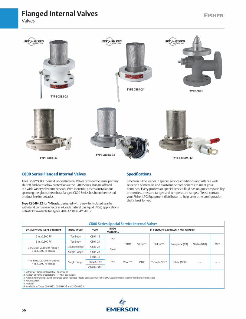
Flanged Internal ValvesValves
56
C800 Series Flanged Internal Valves
The Fisher™ C800 Series Flanged Internal Valves provide the same primary shutoff and excess flow protection as the C400 Series, but are offered in a wide variety elastomeric seals. With industrial process installations spanning the globe, the robust flanged C800 Series has been the trusted product line for decades.
Type C804H-32 for Y-Grade: designed with a new formulated seal to withstand corrosive effects in Y-Grade natural gas liquid (NGL) applications. Retrofit kit available for Type C404-32: RC404YGT012.
C800 Series Special Service Internal Valves
CONNECTION INLET X OUTLET BODY STYLE TYPEBODY
MATERIALELASTOMERS AVAILABLE FOR ORDER(3)
2 in. CL300 RF Tee Body C891-16SST
EPDM Viton®(1) Kalrez®(2) Neoprene (CR) Nitrile (NBR) PTFE3 in. CL300 RF Tee Body C891-24
3 in. Mod. CL300 RF Fange x 3 in. CL300 RF Flange
Double Flange C883-24Steel
Single Flange C884-24
4 in. Mod. CL300 RF Flange x4 in. CL300 RF Flange
Single Flange
C804-32
SST Viton®(1) PTFE Y-Grade NGL(6) Nitrile (NBR) - - - - - - - -C804A-32(4)
C804M-32(5)
1. Viton® or Fluorocarbon (FKM) equivalent2. Kalrez® or Perfluoroelastomer (FFKM) equivalent 3. Additional materials can be sourced upon request. Please contact your Fisher LPG Equipment Distributor for more information.4. Air Actuation.5. Manual.6. Available as Types C804H32, C804HA32 and C804HM32.
TYPE C804-32TYPE C804A-32
TYPE C804M-32
TYPE C883-24
TYPE C884-24TYPE C891
Specifications
Emerson is the leader in special service conditions and offers a wide selection of metallic and elastomeric components to meet your demands. Every process or special service fluid has unique compatibility properties, pressure ranges and temperature ranges. Please contact your Fisher LPG Equipment distributor to help select the configuration that’s best for you.

Flanged Internal ValvesValves
57
C
B
A
E
6” STUD(8 REQUIRED)
D
In-Line Piping
ADIMENSION, IN. / mm OUTLET
B C D E
ASME CL300 RF Flange Pipe Size Reducer Minimum ASME CL300 RF Flange
3 in. / DN 80 6 / 152 6 x 3 / 152 x 76 7.9 / 201 3 in. / DN 80
4 in. / DN 100 8 / 203 8 x 4 / 203 x 102 11.5 / 292 4 in. / DN 100
O.D. AND THICKNESS TO SUITCONTAINER SPECIFICATIONS
45°
MAX.1 IN. / 25 mm MIN.
3/4 - 10 UNCE
B
A
C D
Studding Outlet (modified flange)
Tank Connections
MODIFIEDCL300 ASME RF FLANGE
DIMENSION, IN. / mmMATING
FLANGE O.D., IN. / mm
A B RF
C RF
D E (Modified)(1)
DBC No. Size
3 in. / DN 80 6.62 8 0.75 5.75 / 146 0.06 / 1.5 1.50 / 38 4.62 / 117 8.25 / 210
4 in. / DN 100 7.88 8 0.75 7.00 / 178 0.06 / 1.5 1.56 / 40 5.88 / 149 10.00 / 254
1. Can be increased up to 4.81 in. / 122 mm for 3 in. valve and 6.19 in. / 157 mm for 4 in. valve, if valve and gasket are centered with modified flange opening.

Flanged Internal ValvesValves
58
Flanged Valves
TYPETANK CONNECTION,
IN. / DN
DIMENSION, IN. / mm
A B
C484-243 / 80
CL300 RF Flange6.75 / 171 2.56 / 65
C483-243 / 80
CL300 RF Flange5.33 / 135 5.62 / 143
C404-324 / 100
CL300 RF Flange7.55 / 192 3.48 / 88
3 IN. / DN 80 CL300 ASME RF FLANGE MODIFIED [4.62 in. / 117 mm DIAMETER BORE AND 5.75 in. / 148 mm RF]
70°SWING
A
B
4 IN. / DN 100 CL300 ASME RF FLANGE MODIFIED [5.88 in. / 149 mm DIAMETER BORE AND 7.00 mm RF]
A
B
1.56 / 39.6
4 IN. / DN 100 CL300 ASME RF FLANGE
3 IN. / DN 80 CL300 ASME RF FLANGEMODIFIED [4.62 in. / 117 mm DIAMETER BORE AND 5.75 in. / 148 mm RF]
70°
70°
A
B
SWING
SWING
TYPES C484-24 AND C884-24 TYPES C483-24 AND C883-24
TYPES C404-32 AND C804-32 TYPE C891

Internal Valve AccessoriesValves
59
Cable Controls
Fisher™ cable controls and accessories can be furnished to remotely open and close all internal valves except the 4 in. / DN 100 flanged size. This equipment can be used to comply with NFPA 58 and DOT requirements for MC331 cargo tanks.
Cable systems can also be used on stationary storage tanks at bulk plants and on in-line applications to increase safety during transfer operations. All fusible elements and links used in the cable control systems comply with NFPA 58 and MC331 requirements.
Type P650 or P651 Primary Cable Control – Capable of actuating all Fisher internal valves except the 4 in. / DN 100 Type C404-32, the Type P650 or P651 opens and closes the valve from a remote point, usually the rear of the bobtail or transport. Pulling the handle of the primary control opens the internal valve; pushing the handle closes the valve. There are three notches on the primary control that give a travel of 4, 5 or 6 in. / 102, 127 or 152 mm depending upon the travel required by the valve’s operating lever.
Included with each Type P650 primary control is a 20-foot / 6.1 m cable, Type P134 fusible links, a return spring and mounting hardware. If just the primary cable control is needed, order Type P651, which is available without any of the other accessories.
Type P163A or P164A Auxiliary Remote Release – These units allow the internal valve to be closed from a location other than the primary control point (Type P650 or P651). Pulling the auxiliary release handle trips the release mechanism on the primary control to close the internal valve.
The two assemblies are identical except for the length. Type P163A has an untrimmed length of 25 feet / 7.6 m and Type P164A has an untrimmed length of 50 feet / 15.2 m. Both cables can be trimmed to any length. Both releases can be installed through mounting brackets up to 3/8 in. / 9.5 mm thick.
Type P164B – a release assembly that uses 50 feet / 15 m of cable housing which does not require elaborate guiding like uncovered cables.
Internal Valve AccessoriesINTERNAL VALVE SIZE,
IN. / DNPRIMARY CABLE
CONTROLAUXILIARY REMOTE
RELEASECABLE
ASSEMBLYLATCH/RELEASE
MECHANISM
1-1/4, 2 and 3 / 32, 50 and 80(NPT or Flanged)
Type P650 or P651(1) Type P163A or P164AIncluded
with Type P650
Type P341, P342 (C407-10 Series) or
Type P340 (C400 Series)
4 / 100 FlangedUse Allegheny orWheaton Control
Type P315 Type P314 Type P313(2)
1. Type P651 is a primary control only, no accessories. 2. Use with Type P315 remote release mechanism.
Type P164C – an Auxiliary Remote Release without cable is also available.
Latch/Remote Release Mechanisms
With the exception of the 3 in. / DN 80 flanged sizes, all Fisher internal valves can be fitted with a manual latch/remote release mechanism. When the internal valve’s operating lever is manually moved to the open position, the lever can be latched in the open position. The lever can be released from a remote location by pulling on the cable attached to a pull ring, thus closing the internal valve. A built-in fusible element in the latch/release melts if exposed to fire allowing the operating lever to return to the closed position.
Type P340 – Fits all 2 and 3 in. NPT internal valves (Types C471 and C477). Type P340 is easily installed in the field by removing two of the three gland cap screws.
Type P341 – Fits 1-1/4 in. NPT C407 Series internal valves. Also available factory installed, Type C407M10.
Type P342 – Bi-directional latch/remote release for the 1-1/4 in. NPT C407-10 Series allows operation from two directions.
Type P313 – Fits 4 in. / DN 100 Type C404-32 internal valves. Also available factory installed, Type C404M32. The Type P315 remote release should be used with this release.
Type P314 – This cable assembly is used as an attachment from the Type C404-32 operating lever to the primary cable control. The assembly includes a 40-foot / 12.2 m cable, a special bushing with a fusible element and clamp. The bushing fits in the valve-operating lever and has a built-in fusible element that will melt if exposed to fire, allowing the Type C404-32 to close. The cable connects to the bushing and the clamp permits the other end of the cable to be attached to the fusible link (not furnished) at the primary cable control.
Type P315 – On manually actuated 4 in. / DN 100 valves (Type C404M32), Type P315 remote handle release can be used to close the internal valve from a remote location. Cable linkage (30 feet / 9.1 m) and mounting hardware are included.
TYPE P650 TYPE P340TYPE P341
TYPE P313
TYPE P315
TYPE P163A
TYPE P164C

Internal Valve AccessoriesValves
60
P Series Pneumatic Actuators
All Fisher™ internal valves can be ordered with a pneumatic actuators that permits the valve to be opened and closed from a remote location. Two styles of pneumatic actuators are available: P600 Series ‘Brake Chamber’ style actuators and P700 Series ‘Rotary’ style rack-and-pinion actuators. For the P600 Series when air pressure is applied to the actuator, it moves the actuator’s rod and internal valve operating lever to the open position. Upon loss of air pressure, the valve’s operating lever returns to the closed position. For the P700 Series, when air pressure is applied to the actuator, pistons act on a gear assembly that rotates the internal valve lever to the open position. Upon loss of air pressure, the valve will return to the closed position. Besides air pressure, nitrogen or carbon dioxide can also be used to pressure the actuators. In addition, the P700 Series supply source can be propane vapor.
Use of a pneumatic actuator permits the opening and closing of the internal valve to be tied into the air brake of the transport or bobtail. Pneumatic Actuators can also provide a convenient way to remotely operate a number of internal valves on stationary storage tanks at bulk plants.
Type P389 (1-1/4 in. / DN 32 Size) – This actuator can only be used with the C407-10 Series valve. All necessary hardware for installing the actuator is included. Minimum pressure is 60 psig / 4.1 bar; maximum
pressure is 250 psig / 17.2 bar. Fuse Plug Part Number T1140399982 ordered separately.(1)
Types P613, P623, P639A and P614A Brake Chamber Actuators – The actuator attaches directly to the valve after removal of the cable-operating lever. Included in each assembly is an operating lever and appropriate mounting hardware specific to each respective valve.
These actuators can only be used with the internal valves as specified on the table below.
Types P731, P713, P714, P723 and P739 Rotary Actuators – The actuator attaches directly to the valve after removal of the cable-operating lever. Included in each assembly is an operating lever and appropriate mounting hardware specific to each respective valve in addition to air pressure, nitrogen and carbon dioxide, the P700 Series can be actuated with propane vapor.
Fuse Plugs – When installed in the actuator piping at the valve, will allow the pneumatic pressure to vent closing the valve if the plug is exposed to temperature between 208 to 220°F / 98 to 104°C. Fuse plugs are available in two sizes, 1/8 in. NPT (T1140399982) and 1/4 in. NPT (T1033699982). Fuse Plugs come with all Types P600 and P700 actuators, EXCEPT Type P389. Part Number T1140399982 to be ordered separately.(1)
Pneumatic Actuators Ordering Information
INTERNAL VALVE TYPE
BRAKE CHAMBER STYLE PNEUMATIC ACTUATOR ROTARY STYLE PNEUMATIC ACTUATOR
TypeSupply Pressure Range,
psig / barType
Supply Pressure Range, psig / bar
C407-10 P389(1) 60 to 250 / 4.1 to 17.2 P731 50 to 125 / 3.5 to 8.6
C484-24 P613 20 to 125 / 1.4 to 8.6 P713 25 to 125 / 1.7 to 8.6
C483-24 P623 20 to 125 / 1.4 to 8.6 P723 25 to 125 / 1.7 to 8.6
C471 and C477 (2 and 3 in. NPT Sizes)
P639A 20 to 125 / 1.4 to 8.6 P739 25 to 125 / 1.7 to 8.6
C404-32 P614A 40 to 125 / 2.8 to 8.6 P714 40 to 125 / 2.8 to 8.6
NOTE: INTERNAL VALVES SHOWN ARE NOT INCLUDED.
TYPE P389
TYPE P723 TYPE P739 TYPE P714
TYPE P613 TYPE P623 TYPE P614ATYPE P639A
TYPE P731 TYPE P713
1. Fuse Plug Part Number T1140399982 must be ordered separately.
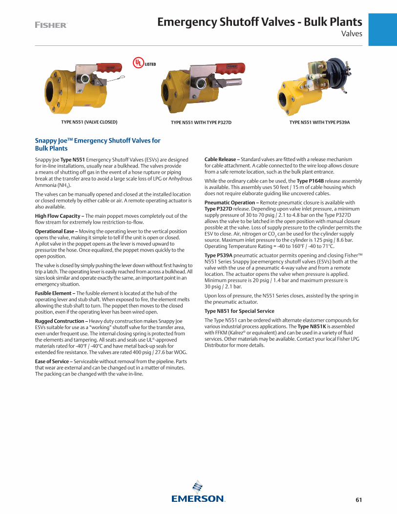
Emergency Shutoff Valves - Bulk PlantsValves
61
Snappy JoeTM Emergency Shutoff Valves for Bulk Plants
Snappy Joe Type N551 Emergency Shutoff Valves (ESVs) are designed for in-line installations, usually near a bulkhead. The valves provide a means of shutting off gas in the event of a hose rupture or piping break at the transfer area to avoid a large scale loss of LPG or Anhydrous Ammonia (NH3).
The valves can be manually opened and closed at the installed location or closed remotely by either cable or air. A remote operating actuator is also available.
High Flow Capacity – The main poppet moves completely out of the flow stream for extremely low restriction-to-flow.
Operational Ease – Moving the operating lever to the vertical position opens the valve, making it simple to tell if the unit is open or closed. A pilot valve in the poppet opens as the lever is moved upward to pressurize the hose. Once equalized, the poppet moves quickly to the open position.
The valve is closed by simply pushing the lever down without first having to trip a latch. The operating lever is easily reached from across a bulkhead. All sizes look similar and operate exactly the same, an important point in an emergency situation.
Fusible Element – The fusible element is located at the hub of the operating lever and stub shaft. When exposed to fire, the element melts allowing the stub shaft to turn. The poppet then moves to the closed position, even if the operating lever has been wired open.
Rugged Construction – Heavy duty construction makes Snappy Joe ESVs suitable for use as a “working” shutoff valve for the transfer area, even under frequent use. The internal closing spring is protected from the elements and tampering. All seats and seals use UL®-approved materials rated for -40°F / -40°C and have metal back-up seals for extended fire resistance. The valves are rated 400 psig / 27.6 bar WOG.
Ease of Service – Serviceable without removal from the pipeline. Parts that wear are external and can be changed out in a matter of minutes. The packing can be changed with the valve in-line.
Cable Release – Standard valves are fitted with a release mechanism for cable attachment. A cable connected to the wire loop allows closure from a safe remote location, such as the bulk plant entrance.
While the ordinary cable can be used, the Type P164B release assembly is available. This assembly uses 50 feet / 15 m of cable housing which does not require elaborate guiding like uncovered cables.
Pneumatic Operation – Remote pneumatic closure is available with Type P327D release. Depending upon valve inlet pressure, a minimum supply pressure of 30 to 70 psig / 2.1 to 4.8 bar on the Type P327D allows the valve to be latched in the open position with manual closure possible at the valve. Loss of supply pressure to the cylinder permits the ESV to close. Air, nitrogen or CO2 can be used for the cylinder supply source. Maximum inlet pressure to the cylinder is 125 psig / 8.6 bar. Operating Temperature Rating = -40 to 160°F / -40 to 71°C.
Type P539A pneumatic actuator permits opening and closing Fisher™ N551 Series Snappy Joe emergency shutoff valves (ESVs) both at the valve with the use of a pneumatic 4-way valve and from a remote location. The actuator opens the valve when pressure is applied. Minimum pressure is 20 psig / 1.4 bar and maximum pressure is 30 psig / 2.1 bar.
Upon loss of pressure, the N551 Series closes, assisted by the spring in the pneumatic actuator.
Type N851 for Special Service
The Type N551 can be ordered with alternate elastomer compounds for various industrial process applications. The Type N851K is assembled with FFKM (Kalrez® or equivalent) and can be used in a variety of fluid services. Other materials may be available. Contact your local Fisher LPG Distributor for more details.
TYPE N551 (VALVE CLOSED) TYPE N551 WITH TYPE P327D TYPE N551 WITH TYPE P539A

Emergency Shutoff Valves - Bulk PlantsValves
62
TYPE N551 CAPACITY CURVE
FLOW, GPM / l/min PROPANE
VA
LVE
DIF
FER
ENTI
AL
PRES
SUR
E, p
sid
/ b
ar d
200 / 757
300 / 1136
400 / 1514
500 / 1893
600 / 2271
700 / 2650
800 / 3028
900 / 3407
1000 / 3785
100 / 379
0
5 / 0.35
10 / 0.69
15 / 1.03
20 / 1.38
25 / 1.72
Emergency Shutoff Valves
TYPE BODY SIZE, IN.
FLOW IN GPM / l/min PROPANE
ACCESSORIES
1 psid / 69 mbar d 2 psid / 0.14 bar d
N551-10 1-1/4 FNPT 110 / 416 150 / 568
Type P164B Cable ReleaseType P327D Pneumatic Release
Type P539A Pneumatic ActuatorN551-16 2 FNPT 190 / 719 295 / 1117
N551-24 3 FNPT 580 / 2195 850 / 3127
TYPE N551-10 WITH TYPE P539A ACTUATOR
TYPE N551-10 WITH MANUAL LEVER
TYPE N551-16 WITH TYPE P539A ACTUATOR
TYPE N551-16 WITH MANUAL LEVER
TYPE N551-24 WITH TYPE P539A ACTUATOR
TYPE N551-24 WITH MANUAL LEVER
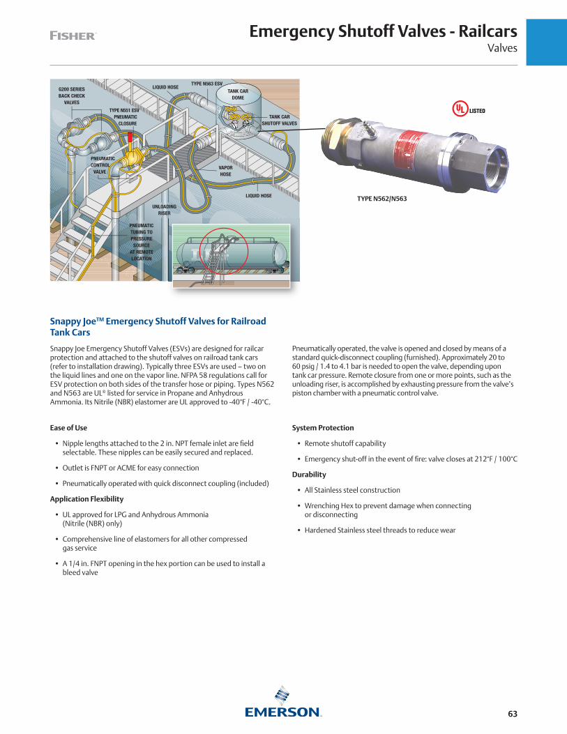
Emergency Shutoff Valves - RailcarsValves
63
Snappy JoeTM Emergency Shutoff Valves for Railroad Tank Cars
Snappy Joe Emergency Shutoff Valves (ESVs) are designed for railcar protection and attached to the shutoff valves on railroad tank cars (refer to installation drawing). Typically three ESVs are used – two on the liquid lines and one on the vapor line. NFPA 58 regulations call for ESV protection on both sides of the transfer hose or piping. Types N562 and N563 are UL® listed for service in Propane and Anhydrous Ammonia. Its Nitrile (NBR) elastomer are UL approved to -40°F / -40°C.
Ease of Use
• Nipple lengths attached to the 2 in. NPT female inlet are field selectable. These nipples can be easily secured and replaced.
• Outlet is FNPT or ACME for easy connection
• Pneumatically operated with quick disconnect coupling (included)
Application Flexibility
• UL approved for LPG and Anhydrous Ammonia (Nitrile (NBR) only)
• Comprehensive line of elastomers for all other compressed gas service
• A 1/4 in. FNPT opening in the hex portion can be used to install a bleed valve
Pneumatically operated, the valve is opened and closed by means of a standard quick-disconnect coupling (furnished). Approximately 20 to 60 psig / 1.4 to 4.1 bar is needed to open the valve, depending upon tank car pressure. Remote closure from one or more points, such as the unloading riser, is accomplished by exhausting pressure from the valve’s piston chamber with a pneumatic control valve.
System Protection
• Remote shutoff capability
• Emergency shut-off in the event of fire: valve closes at 212°F / 100°C
Durability
• All Stainless steel construction
• Wrenching Hex to prevent damage when connecting or disconnecting
• Hardened Stainless steel threads to reduce wear
G200 SERIESBACK CHECK
VALVES
LIQUID HOSE
VAPORHOSE
UNLOADINGRISER
TYPE N551 ESV PNEUMATIC CLOSURE
PNEUMATICCONTROL
VALVE
PNEUMATICTUBING TOPRESSURE
SOURCEAT REMOTELOCATION
TYPE N563 ESVLIQUID HOSE
TANK CARDOME
TANK CARSHUTOFF VALVES
TYPE N562/N563

Emergency Shutoff Valves - RailcarsValves
64
Railcar Emergency Shutoff Valves with Excess FlowTYPE ELASTOMER UL® LISTED INLET CONNECTION, IN. OUTLET CONNECTION, IN.
N562-16
Nitrile (NBR) YES
2 FNPT
2 FNPT
N562-18 2-1/4 Male Acme
N562-26 3-1/4 Male Acme
N862K-16
Kalrez®(1)
NO
2 FNPT
N862K-18 2-1/4 Male Acme
N862K-26 3-1/4 Male Acme
N862V-16
Viton®(3)
2 FNPT
N862V-18 2-1/4 Male Acme
N862V-26 3-1/4 Male Acme
Railcar High Flow Emergency Shutoff ValvesTYPE ELASTOMER UL LISTED INLET CONNECTION, IN. OUTLET CONNECTION, IN.
N563-16Nitrile (NBR) Yes
2 FNPT
2 FNPT
N563-26 3-1/4 Male Acme
N863E-16EPDM
No
2 FNPT
N863E-26 3-1/4 Male Acme
N863K-16Kalrez®(1)
2 FNPT
N863K-26 3-1/4 Male Acme
N863N-16Neoprene (CR)
2 FNPT
N863N-26 3-1/4 Male Acme
N863T-16Teflon®(2)
2 FNPT
N863T-26 3-1/4 Male Acme
N863V-16Viton®(3)
2 FNPT
N863V-26 3-1/4 Male Acme
Type N562 ESV integrates shutoff valve with an excess flow protection to automatically close if flow exceeds 200 GPM / 757 l/min propane at 13 psid / 0.90 bar d.
Type N563 ESV is designed for higher flow needs. It flows up to 413 GPM / 1563 l/m to reduce loading/unloading time and provide faster railcar turnover.
1. Perfluoroelastomer (FFKM) equivalent2. PTFE equivalent3. Fluorocarbon (FKM) equivalent
TYPE N562
HARDENED STAINLESSSTEEL PIPE THREADS
INTERNALTHREADNIPPLE
MAINPOPPET
EXCESS FLOWSPRING
QUICKDISCONNECTNIPPLE
WRENCHINGHEX
FUSE PLUG
PISTONSEATDISCPILOT
VALVE
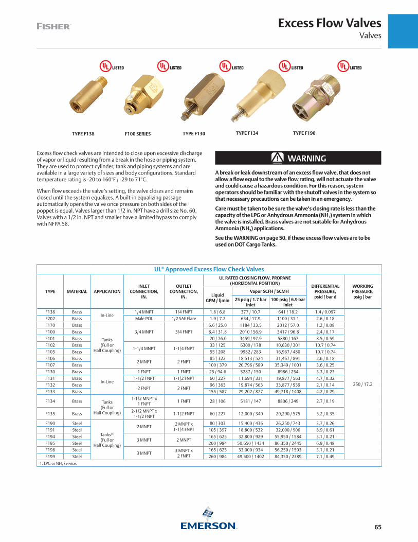
Excess Flow ValvesValves
65
Excess flow check valves are intended to close upon excessive discharge of vapor or liquid resulting from a break in the hose or piping system. They are used to protect cylinder, tank and piping systems and are available in a large variety of sizes and body configurations. Standard temperature rating is -20 to 160°F / -29 to 71°C.
When flow exceeds the valve’s setting, the valve closes and remains closed until the system equalizes. A built-in equalizing passage automatically opens the valve once pressure on both sides of the poppet is equal. Valves larger than 1/2 in. NPT have a drill size No. 60. Valves with a 1/2 in. NPT and smaller have a limited bypass to comply with NFPA 58.
▲ WARNING
A break or leak downstream of an excess flow valve, that does not allow a flow equal to the valve flow rating, will not actuate the valve and could cause a hazardous condition. For this reason, system operators should be familiar with the shutoff valves in the system so that necessary precautions can be taken in an emergency.
Care must be taken to be sure the valve’s closing rate is less than the capacity of the LPG or Anhydrous Ammonia (NH3) system in which the valve is installed. Brass valves are not suitable for Anhydrous Ammonia (NH3) applications.
See the WARNING on page 50, if these excess flow valves are to be used on DOT Cargo Tanks.
UL® Approved Excess Flow Check Valves
TYPE MATERIAL APPLICATIONINLET
CONNECTION, IN.
OUTLETCONNECTION,
IN.
UL RATED CLOSING FLOW, PROPANE(HORIZONTAL POSITION)
DIFFERENTIAL PRESSURE, psid / bar d
WORKING PRESSURE, psig / barLiquid
GPM / l/min
Vapor SCFH / SCMH
25 psig / 1.7 bar Inlet
100 psig / 6.9 bar Inlet
F138 BrassIn-Line
1/4 MNPT 1/4 FNPT 1.8 / 6.8 377 / 10.7 641 / 18.2 1.4 / 0.097
250 / 17.2
F202 Brass Male POL 1/2 SAE Flare 1.9 / 7.2 634 / 17.9 1100 / 31.1 2.6 / 0.18
F170 Brass
Tanks(Full or
Half Coupling)
3/4 MNPT 3/4 FNPT
6.6 / 25.0 1184 / 33.5 2012 / 57.0 1.2 / 0.08
F100 Brass 8.4 / 31.8 2010 / 56.9 3417 / 96.8 2.4 / 0.17
F101 Brass 20 / 76.0 3459 / 97.9 5880 / 167 8.5 / 0.59
F102 Brass1-1/4 MNPT 1-1/4 FNPT
33 / 125 6300 / 178 10,630 / 301 10.7 / 0.74
F105 Brass 55 / 208 9982 / 283 16,967 / 480 10.7 / 0.74
F106 Brass2 MNPT 2 FNPT
85 / 322 18,513 / 524 31,467 / 891 2.6 / 0.18
F107 Brass 100 / 379 20,796 / 589 35,349 / 1001 3.6 / 0.25
F130 Brass
In-Line
1 FNPT 1 FNPT 25 / 94.6 5287 / 150 8986 / 254 3.3 / 0.23
F131 Brass 1-1/2 FNPT 1-1/2 FNPT 60 / 227 11,694 / 331 19,877 / 563 4.7 / 0.32
F132 Brass2 FNPT 2 FNPT
96 / 363 19,874 / 563 33,877 / 959 2.1 / 0.14
F133 Brass 155 / 587 29,202 / 827 49,718 / 1408 4.2 / 0.29
F134 Brass Tanks(Full or
Half Coupling)
1-1/2 MNPT x1 FNPT
1 FNPT 28 / 106 5181 / 147 8806 / 249 2.7 / 0.19
F135 Brass2-1/2 MNPT x
1-1/2 FNPT1-1/2 FNPT 60 / 227 12,000 / 340 20,290 / 575 5.2 / 0.35
F190 Steel
Tanks(1)
(Full orHalf Coupling)
2 MNPT2 MNPT x
1-1/4 FNPT80 / 303 15,400 / 436 26,250 / 743 3.7 / 0.26
F191 Steel 105 / 397 18,800 / 532 32,000 / 906 8.9 / 0.61
F194 Steel3 MNPT 2 MNPT
165 / 625 32,800 / 929 55,950 / 1584 3.1 / 0.21
F195 Steel 260 / 984 50,650 / 1434 86,350 / 2445 6.9 / 0.48
F198 Steel3 MNPT
3 MNPT x2 FNPT
165 / 625 33,000 / 934 56,250 / 1593 3.1 / 0.21
F199 Steel 260 / 984 49,500 / 1402 84,350 / 2389 7.1 / 0.49
1. LPG or NH3 service.
TYPE F138 F100 SERIES TYPE F130 TYPE F134 TYPE F190

Internal Relief ValvesValves
66
Relief Valves for Mobile Tanks and Transports
Primarily for trucks transporting LPG, Anhydrous Ammonia (NH3) or other compressed gases.
Types H722, H733 and H5118 stainless steel relief valves resist rust and corrosion, including a 300 Series stainless steel spring for additional resistance to product contaminants. A thickly molded main seal improves service life and resistance to severe applications. Stainless steel makes it easy to remove the valve from the tank for periodic testing (as prescribed by DOT) and permits standard tank couplings instead of the more costly flanged tank openings. The Type H733 has an optional CL300 RF Flange connection. Standard product temperature rating is -20 to 160°F / -29 to 71°C.
Type H5118: Semi-Internal relief valve for 2 in. threaded recessed well-head connections on transports.
Tight fitting protective caps (Types P297, P298 and P299) are standard on the valve to ensure no debris blocks the valve discharge. Standard setpoints listed with UL for the Type H722 include 125, 156, 250, 265, 275 and 312 psig / 8.6, 10.8, 17.2, 18.3, 19.0 and 21.5 bar. Standard set points listed with UL for the Types H733 and H5118 include 250 and 265 psig / 17.2 and 18.3 bar.
All set points between 100 and 400 psig / 6.9 and 27.6 bar are available with ASME approvals. All Non-UL / ASME valve models MUST have their requested Set-Point for start-to-discharge (STD) declared on all orders.
A 1-1/2 and 2-1/2 in. hex size (Type P304 or P305) wrench can be inserted into the valve socket when installing/removing the valve to provide a means of attaching a standard wrench.
UL® Approved Internal Relief Valves
TYPECONTAINER
CONNECTION, IN.START-TO-DISCHARGE SETTING FLOW CAPACITY, SCFM / SCMH AIR FOR TANK WITH AREA UP
TO(3): Ft2 / m2
PROTECTIVE CAP(INCLUDED)psig bar UL ASME
H722-250
2 MNPT(1)
250 17.2 3635 / 6176 3203 / 5136 171 / 15.9
Type P297H722-265 265 18.3 3556 / 6042 3386 / 5753 166 / 15.4
H722-275 275 19.0 3714 / 6310 3508 / 5960 175 / 16.3
H733-2503 MNPT(2)
250 17.2 10,150 / 17,245 9369 / 15,918 598 / 55.6Type P298
H733-265 265 18.3 10,940 / 18,587 9904 / 16,827 655 / 60.9
H733F3-2503 in. CL300 RF Flange
250 17.2 10,150 / 17,245 9369 / 15,918 598 / 55.6Type P298
H733F3-265 265 18.3 10,940 / 18,587 9904 / 16,827 655 / 60.9
H5118-250(4)
2 MNPT250 17.2 10,530 / 17,891 9724 / 16,521 625 / 58.1
Type P299H5118-265(4) 265 18.3 11,300 / 19,199 10,280 / 17,466 681 / 63.3
1. Order Type P304 (1-1/2 in. hex bar) installation wrench.2. Order Type P305 (2-1/2 in. hex bar) installation wrench.3. Based on UL flow capacities.4. Use with a 3.5 in. hex size installation tool.
Internal Relief Valves, ASME Rated Only (Non-UL)TYPE CONTAINER CONNECTION, IN. SPRING RANGE(3), psig / bar MATERIAL OPTION ASME FLOW RATE FACTOR(4)
H823-1 2 MNPT(1) 100 to 150 / 6.9 to 10.3
Standard - Nitrile (NBR) E - EPDM(6) K - Kalrez® N - Neoprene (CR) V - Viton®
10.18H823-2 2 MNPT(1) 151 to 250 / 10.4 to 17.2
H823-3 2 MNPT(1) 251 to 400/ 17.3 to 27.6
H833-1 3 MNPT(2) 100 to 149 / 6.9 to 10.3
29.77
H833-2 3 MNPT(2) 150 to 200 / 10.3 to 13.8
H833-3 3 MNPT(2) 201 to 275 / 13.9 to 19.0
H833-4 3 MNPT(2) 276 to 330 / 19.0 to 22.8
H833-5 3 MNPT(2) 331 to 400 / 22.8 to 27.6
H833F3-3 3 CL300 RF Flange 201 to 275 / 13.9 to 19.0
H8118-3(5) 2 MNPT 201 to 275 / 13.9 to 19.0Standard - Nitrile (NBR)N - Neoprene (CR)
30.90
1. Order Type P304 (1-1/2 in. hex bar) installation wrench.2. Order Type P305 (2-1/2 in. hex bar) installation wrench.3. ASME-Approved set points approved within these spring ranges.4. ASME Flow Capacity (SCFM Air) = [Set Pressure (psig)*1.2+14.7]* ASME Flow Rate Factor.5. Use with a 3.5 in. hex size installation tool.6. 2 in. H823E-* in EPDM seal trim available up to 250 psi set-point; Types H823E-1 and H823E-2 only. 3" H833E-* available up to 400 psi set-point.
TYPE H722
TYPE H733TYPE H733F3
TYPE H5118
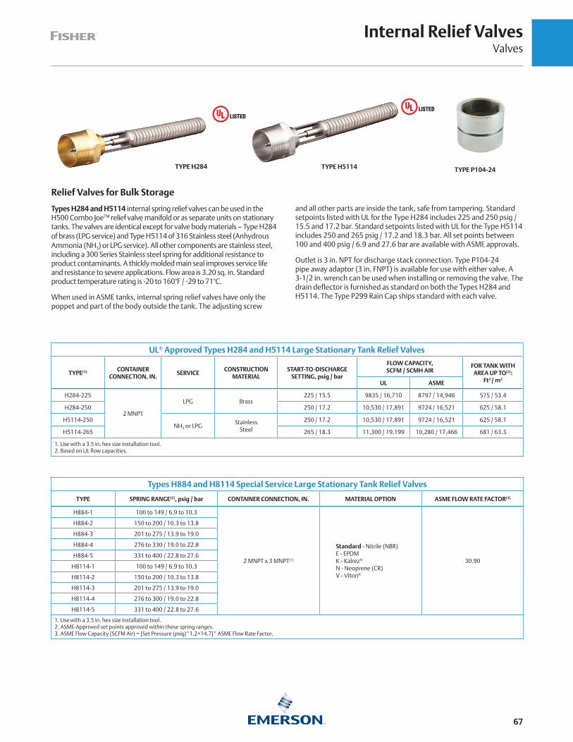
Internal Relief ValvesValves
67
Relief Valves for Bulk Storage
Types H284 and H5114 internal spring relief valves can be used in the H500 Combo JoeTM relief valve manifold or as separate units on stationary tanks. The valves are identical except for valve body materials – Type H284 of brass (LPG service) and Type H5114 of 316 Stainless steel (Anhydrous Ammonia (NH3) or LPG service). All other components are stainless steel, including a 300 Series Stainless steel spring for additional resistance to product contaminants. A thickly molded main seal improves service life and resistance to severe applications. Flow area is 3.20 sq. in. Standard product temperature rating is -20 to 160°F / -29 to 71°C.
When used in ASME tanks, internal spring relief valves have only the poppet and part of the body outside the tank. The adjusting screw
and all other parts are inside the tank, safe from tampering. Standard setpoints listed with UL for the Type H284 includes 225 and 250 psig / 15.5 and 17.2 bar. Standard setpoints listed with UL for the Type H5114 includes 250 and 265 psig / 17.2 and 18.3 bar. All set points between 100 and 400 psig / 6.9 and 27.6 bar are available with ASME approvals.
Outlet is 3 in. NPT for discharge stack connection. Type P104-24 pipe away adaptor (3 in. FNPT) is available for use with either valve. A 3-1/2 in. wrench can be used when installing or removing the valve. The drain deflector is furnished as standard on both the Types H284 and H5114. The Type P299 Rain Cap ships standard with each valve.
UL® Approved Types H284 and H5114 Large Stationary Tank Relief Valves
TYPE(1) CONTAINERCONNECTION, IN.
SERVICECONSTRUCTION
MATERIALSTART-TO-DISCHARGE
SETTING, psig / bar
FLOW CAPACITY, SCFM / SCMH AIR
FOR TANK WITH AREA UP TO(2):
Ft2 / m2 UL ASME
H284-225
2 MNPT
LPG Brass225 / 15.5 9835 / 16,710 8797 / 14,946 575 / 53.4
H284-250 250 / 17.2 10,530 / 17,891 9724 / 16,521 625 / 58.1
H5114-250NH3 or LPG
StainlessSteel
250 / 17.2 10,530 / 17,891 9724 / 16,521 625 / 58.1
H5114-265 265 / 18.3 11,300 / 19,199 10,280 / 17,466 681 / 63.3
1. Use with a 3.5 in. hex size installation tool. 2. Based on UL flow capacities.
Types H884 and H8114 Special Service Large Stationary Tank Relief Valves
TYPE SPRING RANGE(2), psig / bar CONTAINER CONNECTION, IN. MATERIAL OPTION ASME FLOW RATE FACTOR(3)
H884-1 100 to 149 / 6.9 to 10.3
2 MNPT x 3 MNPT(1)
Standard - Nitrile (NBR) E - EPDM K - Kalrez® N - Neoprene (CR) V - Viton®
30.90
H884-2 150 to 200 / 10.3 to 13.8
H884-3 201 to 275 / 13.9 to 19.0
H884-4 276 to 330 / 19.0 to 22.8
H884-5 331 to 400 / 22.8 to 27.6
H8114-1 100 to 149 / 6.9 to 10.3
H8114-2 150 to 200 / 10.3 to 13.8
H8114-3 201 to 275 / 13.9 to 19.0
H8114-4 276 to 300 / 19.0 to 22.8
H8114-5 331 to 400 / 22.8 to 27.6
1. Use with a 3.5 in. hex size installation tool.2. ASME-Approved set points approved within these spring ranges.3. ASME Flow Capacity (SCFM Air) = [Set Pressure (psig)*1.2+14.7]* ASME Flow Rate Factor.
TYPE P104-24TYPE H284 TYPE H5114
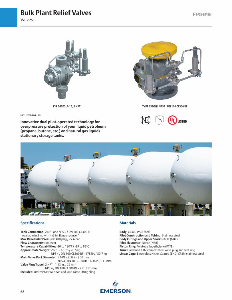
Bulk Plant Relief ValvesValves
68
UL® LISTED FOR LPG
TYPE 63EGLP, NPS4 / DN 100 CL300 RFTYPE 63EGLP-16, 2 NPT
Innovative dual pilot-operated technology for overpressure protection of your liquid petroleum (propane, butane, etc.) and natural gas liquids stationary storage tanks.
Specifications
Tank Connection: 2 NPT and NPS 4 / DN 100 CL300 RF - Available in 3 in. with 4x3 in. flange reducer*Max Relief Inlet Pressure: 400 psig / 27.6 barFlow Characteristic: LinearTemperature Capabilities: -20 to 180°F / -29 to 82°CApproximate Weight: 2 NPT - 45 lbs / 20.5 kg
NPS 4 / DN 100 CL300 RF - 178 lbs / 80.7 kgMain Valve Port Diameter: 2 NPT - 2.38 in. / 60 mm
NPS 4 / DN 100 CL300 RF - 4.38 in. / 111 mmValve Plug Travel: 2 NPT - 1.13 in. / 29 mm
NPS 4 / DN 100 CL300 RF - 2 in. / 51 mmIncluded: UV resistant rain cap and load-rated lifting sling
Materials
Body: CL300 WCB SteelPilot Construction and Tubing: Stainless steelBody O-rings and Upper Seals: Nitrile (NBR)Pilot Elastomer: Nitrile (NBR)Piston Ring: Polytetrafluoethylene (PTFE)Trim: Hardened 416 stainless steel valve plug and seat ringLinear Cage: Electroless Nickel Coated (ENC) CF8M stainless steel

Bulk Plant Relief ValvesValves
69
Type 63EGLP-16 Bulk Plant Relief Valves, 2 NPT
TYPE NUMBER(1)DISCHARGE SET PRESSURE REPLACEMENT PILOT
VALVE TYPE LISTING / APPROVAL
FLOW RATE, AIR
psig bar SCFM SCMM
63EGLP-16-250 250 17.2 6358EBLP-250 UL and ASME Sect VIII, Div. I 11,221(2) 317
63EGLP-16-265 265 18.3 6358EGLP-265 UL and ASME Sect VIII, Div. I 11,805(2) 334
63EGLP-16-EB1 85 to 140 5.9 to 9.7 6358EBLP-1
ASME Section VIII, Div. I 3,709 to 14,768(3) 105 to 418(3)63EGLP-16-EB2 130 to 200 9.0 to13.8 6358EBLP-2
63EGLP-16-EB3 180 to 350 12.4 to 24.1 6358EBLP-3
63EGLP-16-EBH 250 to 375 17.2 to 26.0 6358EBHLP1. All are 2 NPT units with male union coupling included for inlet connection during installation.2. Capacity based on 20% over set pressure, UL-132 Standard.3. Capacity based on 20% over set pressure. ASME Flow Rate (SCFM Air) = 31.78 x [(Set Pressure (psig) x 1.2) + 14.7] .
Type 63EGLP Bulk Plant Relief Valves, NPS 4 / DN 100 CL300 RF
TYPE NUMBER(1)DISCHARGE SET PRESSURE
REPLACEMENT PILOT TYPE LISTING / APPROVALFLOW RATE, AIR
psig bar SCFM SCMM
63EGLP-250 250 17.2 6358EBLP-250 UL and ASME Sect VIII, Div. I 38,794(2) 1099(2)
63EGLP-EB1 85 to 140 5.9 to 9.7 6358EBLP-1
ASME Section VIII, Div. I 13,045 to 51,944(3) 369 to 1471(3)63EGLP-EB2 130 to 200 9.0 to 13.8 6358EBLP-2
63EGLP-EB3 180 to 350 12.4 to 24.1 6358EBLP-3
63EGLP-EBH 250 to 375 17.2 to 26.0 6358EBHLP1. All are NPS 4 / DN 100 CL300 Flange connections. For NPS 3 / DN 80 flanged connection, a NPS 4 x 3 / DN 100 x 80 flange reducer, ERAA07058A0 is available.2. Capacity based on 20% over set pressure, UL-32 Standard.3. Capacity based on 20% over set pressure. ASME Flow Rate (SCFM Air) = 111.78 x [(Set Pressure (psig) x 1.2) + 14.7].
The Fisher Type 63EGLP is the evolutionary leap forward in bulk plant pressure relief combining safety, durability and serviceability into one superior package.
Type 63EGLP-250 is UL listed for propane (LPG) at 250 psig / 17.2 bar. For other model types and set-point ranges, ASME Section VIII is also available for set points of 85 to 375 psig / 5.7 to 25.9 bar. The flow port diameter is 4.38 in. / 111 mm and the plug travel height is 2.0 in./ 51 mm.
Type 63EGLP-16 is UL listed for propane (LPG) and anhydrous ammonia (NH3) at 250 psig / 17.2 bar and 265 psig / 18.3 bar. For other model types and set-point ranges, ASME Section VIII is also available for set points of 85 to 375 psig / 5.7 to 25.9 bar. The flow port diameter is 2.38 in. / 60 mm and the plug travel height is 1.13 in. / 29 mm.
For the NPS 4 / DN 100 CL300 RF version, main body gasket and studs and bolts are not included but can be ordered separately, see Instruction Manual D450321T012.
63EGLP Series Relief Valves
Fisher™ Type 63EGLP relief valve provides superior overpressure protection for large bulk plant applications. Available in steel and stainless steel constructions for LPG and other compressed gas applications. Bringing advanced technology from the petrochemical industry, the Type 63EGLP provides precise and controlled pressure relief in an emergency situation to protect your pressure vessel while simultaneously limiting the amount of product discharged to the atmosphere.
Tight fitting UV resistant caps are standard on all constructions, along with a load-rated lifting sling to assist with lifting and installation. End connections are standard 2 NPT or NPS 4 / DN 100 CL300 RF bolt patterns. Fisher Type 63EGLP relief valve provides the industry with the most advanced relief technologies. The accuracy and repeatability of pilot-operated pressure regulation excercises precise control during relief situations without relying on last-generation pop-style relief mechanics.
TYPE 63EGLP AT NORMAL CONDITION (BOTH MAIN VALVE AND ACTIVE PILOT ARE CLOSED)
TYPE 63EGLP AT OVERPRESSURE CONDITION (ACTIVE PILOT DISCHARGES LOADING PRESSURE, MAIN VALVE DISCHARGES
EXCESS INLET PRESSURE)
ACTIVE PILOT
ACTIVE PILOT
STANDBY PILOT
STANDBY PILOT
PILOT DISCHARGE MAIN VALVE
DISCHARGE

Bulk Plant Relief ValvesValves
70
Higher relief capacity and lower maintenance than multi-port relief
Reduced Maintenance and Ease of Use
• Dual Pilot technology allows removal of a pilot for testing and setpoint validation while Type 63EGLP continue to protect tank's contents.
• Stainless steel internal valve plug, seat ring and orifice cage offer corrosion resistance for all internal moving parts and
sealing components.
Lower Installation Cost (Type 63EGLP, NPS 4 / DN 100 CL300 RF)
• 33% greater surface area protection reduces number of relief valves/tank.
• Compact profile and 60 lbs / 27 kg lighter reduces installation time.
• Lifting strap included.
Better Performance (Type 63EGLP, NPS 4 / DN 100 CL300 RF)
• 40% greater relief capacity - flows 38, 794 SCFM air (versus 28, 000 SCFM).
• Precise and tighter controlled tank pressure relief with the pilot design.
• Pilots allow relief of small pressure build-ups instead of a full discharge from the main valve. This is ideal for high temperature sites.
• Main spring made from chromium-silicon alloy steel for wide temperature range.
More Reliability
• 30+ field proven years with harsh hydrocarbon and petrochemical applications.
• Balanced seat design minimizes stress on main spring and increases service life on main seal.
• Pilot spring is in atmosphere instead of in product, minimizing chance for harsh chemicals to attack spring under compression.
• Durable steel (instead of ductile iron) body and all stainless steel tubing and pilot regulators for corrosion resistance.
Type 63EGLP NPS 4 / DN 100 CL300 RF, Number of Valves Required/Surface Area(1)
Number of Type 63EGLP Surface Area, ft2
1 Up to 3069
2 3070 to 7147
3 7148 to 77, 718
4 11, 719 to 21, 847
1. Based on 38, 794 CFM air at 20% over 250 psig set pressure. Please contact Emerson for other set points.
Type 63EGLP NPS 4 / DN 100 CL300 RF, Number of Valves Required/Surface Area(1)
Tank Size, Gal / L Fisher Type 63EGLP RegO® A8574G MEC™ ME904S-4F
30,000 / 113, 562 1 1 1
45, 000 / 170, 344 1 2 2
60, 000 / 227, 125 2 2 2
90, 000 / 340, 687 2 2 2
120, 000 / 454, 250 2 3 3
1. Recommended values for standard above ground tanks, based on 250 psig set point. Actual relief capacity/surface area must be calculated by user.

Bulk Plant Relief ValvesValves
71
TYPE 63EGLP, NPS 4 / DN 100 CL300 RF
TYPE 63EGLP-16, 2 NPT
16.7 in. / 423 mm
15.8 in. / 402 mm
10.4 in. / 264 mm
11.7 in. / 296 mm
6. 69 in. / 170 mm
TURN RAD68
13.5 in. / 342 mm
16.2 in. / 411 mm
18.5 in. / 469 mm

External Relief ValvesValves
72
External Relief Valves
Typically used as hydrostatic relief, or on smaller ASME tanks or DOT containers. All working parts of these valves are outside the container connection so they must be protected against mechanical damage(1).
The external relief valves use Brass as material of construction. Standard product temperature rating is -20 to 160°F / -29 to 71°C.
Protective caps are shipped with Fisher™ external relief valves. Replacement caps may be ordered separately (refer below).
TYPE P206TYPE H100
TYPE P174 TYPE H185TYPE H173
Small External Relief Valves
TYPECONTAINER
CONNECTION, IN.
START-TO-DISCHARGE PRESSURE
PRESSURE PLUS BUILDUP FLOW CAPACITY, SCFM / SCMH AIR
ACCESSORY
psig bar psig bar Pipeaway Adaptor Protective Cap
H110-250(1) 1/4 MNPT
250 17.2
- - - - - - - -
310 / 527- - - -
P206H125-250
1/2 MNPT610 / 1036
- - - -H135-250(1) 594 / 1009 P174(3)
H150-250
3/4 MNPT
580 / 985
- - - -H160-250(1) 605 / 1028H185-250(1) 2223 / 3777
P145H185-275(1) 275 19.0 2456 / 4173H110-312(1) 1/4 MNPT
312 21.5
390 / 663 P206
H135-312(1) 1/2 MNPT765 / 1300
P174(3)
- - - -H160-312 3/4 MNPT
- - - -H123(1) 1/4 MNPT
375 25.9- - - -
P206
H148(1) 1/2 MNPT903 / 1534(2) P174(3)
H173(1) 3/4 MNPTH120-35
1/4 MNPT
35 2.4 60 4.1 77 / 131
- - - -
H120-60 60 4.1 85 5.9 105 / 178H120-120 120 8.3 145 10 165 / 281H120-150 150 10.3 180 12 191 / 325H120-175 175 12.1 210 14 224 / 380H120-200 200 13.8 240 17 262 / 445H120-225 225 15.5 270 19 280 / 476H120-275 275 19.0 330 23 303 / 515H120-350 350 24.1 420 29 445 / 756
H124(1)
450 31.0 - - - - - - - - - - - - - - - -H144(1) 1/2 MNPTH174(1) 3/4 MNPT
1. Listed under UL® Section 132.2. DOT cylinder water capacity 500 lbs / 227 kg, approved by Bureau of Explosives and CGA.3. 1/2 in. FNPT.
1. These hydrostatic relief valves are not ASME rated nor ASME approved. Check local codes and regulations for applicable use.
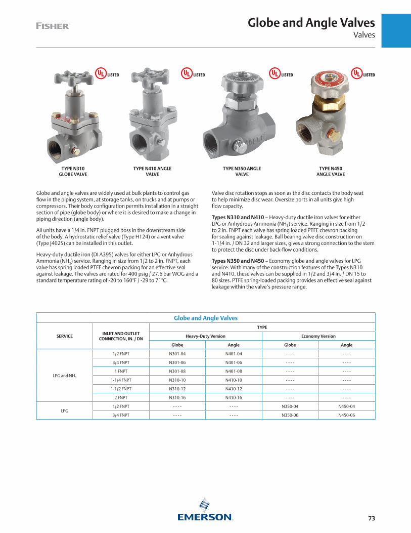
Globe and Angle ValvesValves
73
Globe and angle valves are widely used at bulk plants to control gas flow in the piping system, at storage tanks, on trucks and at pumps or compressors. Their body configuration permits installation in a straight section of pipe (globe body) or where it is desired to make a change in piping direction (angle body).
All units have a 1/4 in. FNPT plugged boss in the downstream side of the body. A hydrostatic relief valve (Type H124) or a vent valve (Type J402S) can be installed in this outlet.
Heavy-duty ductile iron (DI A395) valves for either LPG or Anhydrous Ammonia (NH3) service. Ranging in size from 1/2 to 2 in. FNPT, each valve has spring loaded PTFE chevron packing for an effective seal against leakage. The valves are rated for 400 psig / 27.6 bar WOG and a standard temperature rating of -20 to 160°F / -29 to 71°C.
Valve disc rotation stops as soon as the disc contacts the body seat to help minimize disc wear. Oversize ports in all units give high flow capacity.
Types N310 and N410 – Heavy-duty ductile iron valves for either LPG or Anhydrous Ammonia (NH3) service. Ranging in size from 1/2 to 2 in. FNPT each valve has spring loaded PTFE chevron packing for sealing against leakage. Ball bearing valve disc construction on 1-1/4 in. / DN 32 and larger sizes, gives a strong connection to the stem to protect the disc under back-flow conditions.
Types N350 and N450 – Economy globe and angle valves for LPG service. With many of the construction features of the Types N310 and N410, these valves can be supplied in 1/2 and 3/4 in. / DN 15 to 80 sizes. PTFE spring-loaded packing provides an effective seal against leakage within the valve’s pressure range.
Globe and Angle Valves
SERVICEINLET AND OUTLET
CONNECTION, IN. / DN
TYPE
Heavy-Duty Version Economy Version
Globe Angle Globe Angle
LPG and NH3
1/2 FNPT N301-04 N401-04 - - - - - - - -
3/4 FNPT N301-06 N401-06 - - - - - - - -
1 FNPT N301-08 N401-08 - - - - - - - -
1-1/4 FNPT N310-10 N410-10 - - - - - - - -
1-1/2 FNPT N310-12 N410-12 - - - - - - - -
2 FNPT N310-16 N410-16 - - - - - - - -
LPG1/2 FNPT - - - - - - - - N350-04 N450-04
3/4 FNPT - - - - - - - - N350-06 N450-06
TYPE N310 GLOBE VALVE
TYPE N410 ANGLE VALVE
TYPE N350 ANGLE VALVE
TYPE N450 ANGLE VALVE

Globe and Angle ValvesValves
74
Globe and angle valves are widely used at bulk plants to control gas flow in the piping system, at storage tanks, on trucks and at pumps or compressors. Their body configuration permits installation in a straight section of pipe (globe body) or where it is desired to make a change in piping direction (angle body).
All units have a 1/4 FNPT plugged boss in the downstream side of the body. A hydrostatic relief valve (Type H124) or a vent valve (Type J402S) can be installed in this outlet.
Heavy-duty carbon steel (A105N or WCB) valves for either LPG or Anhydrous Ammonia (NH3) service. Ranging in size from 1/2 to 3 FNPT, each valve has an adjustable graphite and PTFE chevron packing for
Globe and Angle Valves
SERVICE(1) INLET AND OUTLETCONNECTION
TYPE BODY STANDARDS
Globe Angle Version Class Material Design Test
LPG and NH3
1/2 FNPT N601-04 N701-04 Forged CL800 Carbon Steel (A105N) API 602 , ASME B16.34 API 598
3/4 FNPT N601-06 N701-06 Forged CL800 Carbon Steel (A105N) API 602 , ASME B16.34 API 598
1 FNPT N601-08 N701-08 Forged CL800 Carbon Steel (A105N) API 602 , ASME B16.34 API 598
1-1/4 FNPT N610-10 N710-10 Forged CL800 Carbon Steel (A105N) API 602 , ASME B16.34 API 598
1-1/2 FNPT N610-12 N710-12 Forged CL800 Carbon Steel (A105N) API 602 , ASME B16.34 API 598
2 FNPT N610-16 N710-16 Cast CL300 WCB Steel BS 1873 , ASME B16.34 API 598
3 FNPT N610-24 N710-24 Cast CL300 WCB Steel BS 1873 , ASME B16.34 API 598
NPS 3/ DN80 CL300 Flange N610F-24 N710F-24 Cast CL300 WCB Steel BS 1873 , ASME B16.34 API 598
1. All valves are UL Listed to UL 125 for both LPG and Anhydrous Ammonia (NH3)
TYPE N601-04 GLOBE VALVE
TYPE N601-08 GLOBE VALVE
TYPE N610-24 GLOBE VALVE
TYPE N610F-24 GLOBE VALVE
Features
Forged Sizes 1/2 through 1-1/2 in.One-piece, die forged body.All forged globe valves meet the requirements of API 602, ASME B16.34 and the ASME Boiler and Pressure Vessel Code, Section I.
Large spoked handwheelFor ease of operation and locking.
Heavy duty yokeTakes high actuation loads.
Standard hex gland nutsCan be adjusted with standard tools.
Acme stem threadFor maximum strength, smooth quick operation.
Swing bolts hardened pinsFor ease of repacking pins are retained on both ends for maximum strength and safety.
Integral bonnet and yokeOne piece forging is made from ASME Boiler and Pressure Vessel Code Section I listed materials.
Graphite packingRings with built in corrosion inhibitor for leak tight sealing at high and low pressures and temperatures.
Gland/gland flangeRugged, forged steel, gland flange and separate gland are self aligning for straight line thrust against packing. No special tools required for packing adjustment.
High strength bonnet boltingExtra heavy hex head bolts use standard tools for easy maintenance.
Graphite filled stainless gasketWith controlled compression for maximum corrosion resistance and zero leakage.
Forged body and bonnetIn full accordance with ASME Boiler Pressure Vessel Code, Section I design and material requirements.
an effective seal against leakage. The valves are rated for 400 psig / 27.6 bar WOG and a standard temperature rating of -20 to 160°F / -29 to 71°C.
Valve disc rotation stops as soon as the disc contacts the body seat to help minimize disc wear. Full flow ports in all units give high flow capacity.
Types N610 and N710 – Heavy-duty carbon steel (A105N or WCB) valves for either LPG or Anhydrous Ammonia (NH3) service. Ranging in size from 1/2 to 3 FNPT each valve has an adjustable graphite and PTFE chevron packing for sealing against leakage.
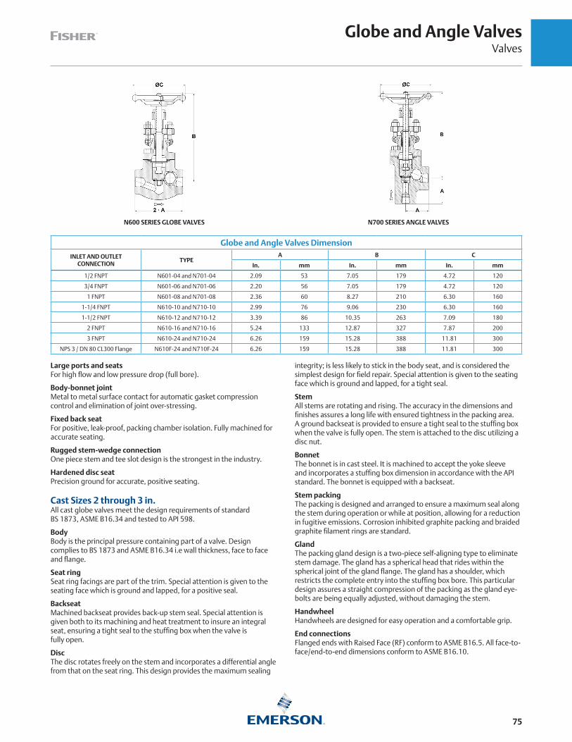
Globe and Angle ValvesValves
75
Globe and Angle Valves Dimension
INLET AND OUTLETCONNECTION
TYPEA B C
In. mm In. mm In. mm
1/2 FNPT N601-04 and N701-04 2.09 53 7.05 179 4.72 120
3/4 FNPT N601-06 and N701-06 2.20 56 7.05 179 4.72 120
1 FNPT N601-08 and N701-08 2.36 60 8.27 210 6.30 160
1-1/4 FNPT N610-10 and N710-10 2.99 76 9.06 230 6.30 160
1-1/2 FNPT N610-12 and N710-12 3.39 86 10.35 263 7.09 180
2 FNPT N610-16 and N710-16 5.24 133 12.87 327 7.87 200
3 FNPT N610-24 and N710-24 6.26 159 15.28 388 11.81 300
NPS 3 / DN 80 CL300 Flange N610F-24 and N710F-24 6.26 159 15.28 388 11.81 300
N600 SERIES GLOBE VALVES N700 SERIES ANGLE VALVES
Large ports and seatsFor high flow and low pressure drop (full bore).
Body-bonnet jointMetal to metal surface contact for automatic gasket compression control and elimination of joint over-stressing.
Fixed back seatFor positive, leak-proof, packing chamber isolation. Fully machined for accurate seating.
Rugged stem-wedge connectionOne piece stem and tee slot design is the strongest in the industry.
Hardened disc seatPrecision ground for accurate, positive seating.
Cast Sizes 2 through 3 in.All cast globe valves meet the design requirements of standard BS 1873, ASME B16.34 and tested to API 598.
BodyBody is the principal pressure containing part of a valve. Design complies to BS 1873 and ASME B16.34 i.e wall thickness, face to face and flange.
Seat ringSeat ring facings are part of the trim. Special attention is given to the seating face which is ground and lapped, for a positive seal.
BackseatMachined backseat provides back-up stem seal. Special attention is given both to its machining and heat treatment to insure an integral seat, ensuring a tight seal to the stuffing box when the valve is fully open.
DiscThe disc rotates freely on the stem and incorporates a differential angle from that on the seat ring. This design provides the maximum sealing
integrity; is less likely to stick in the body seat, and is considered the simplest design for field repair. Special attention is given to the seating face which is ground and lapped, for a tight seal.
StemAll stems are rotating and rising. The accuracy in the dimensions and finishes assures a long life with ensured tightness in the packing area. A ground backseat is provided to ensure a tight seal to the stuffing box when the valve is fully open. The stem is attached to the disc utilizing a disc nut.
BonnetThe bonnet is in cast steel. It is machined to accept the yoke sleeve and incorporates a stuffing box dimension in accordance with the API standard. The bonnet is equipped with a backseat.
Stem packingThe packing is designed and arranged to ensure a maximum seal along the stem during operation or while at position, allowing for a reduction in fugitive emissions. Corrosion inhibited graphite packing and braided graphite filament rings are standard.
GlandThe packing gland design is a two-piece self-aligning type to eliminate stem damage. The gland has a spherical head that rides within the spherical joint of the gland flange. The gland has a shoulder, which restricts the complete entry into the stuffing box bore. This particular design assures a straight compression of the packing as the gland eye-bolts are being equally adjusted, without damaging the stem.
HandwheelHandwheels are designed for easy operation and a comfortable grip.
End connectionsFlanged ends with Raised Face (RF) conform to ASME B16.5. All face-to-face/end-to-end dimensions conform to ASME B16.10.

Back Check ValvesValves
76
Back check valves allow flow in only one direction and are normally closed. They are installed in liquid filling connections on stationary storage tanks, bobtail delivery trucks and liquid transfer lines.
G100 Series
G100 Series – used mainly in tank inlet connections, are offered in two styles of seat construction: metal-to-metal or soft seat. The soft seated construction is for the filling connection on bobtail delivery trucks. Because the valve gives tight shutoff, piping on the bobtail can be depressurized for maintenance or repair without leakage. The G100 Series has a 250 psi / 17.2 bar rating and bubbles at 0.25 psid / 17 mbar d. Standard product temperature rating is -20 to 160°F / -29 to 71°C.
Type G109 – was designed for in-line service at bulk plants with FNPT connections for easy installations.
SpecificationsTypes G200 and G201
Pressure Rating: 400 psig / 28 bar WOGTemperature Rating: -20 to 160°F / -29 to 71°CBody: Ductile ironInternal Parts: Plated steel or stainless steelSeat Disc: Synthetic rubber with metal-to-metal backup
G200 Series
G200 Series – back check valves are specifically intended for heavy-duty in-line service at the bulk plant’s transfer area. The valves are suitable for LPG or Anhydrous Ammonia (NH3) service.
Flow moves the spring loaded poppet to the open position as soon as pressure differential is created. When flow stops, the poppet closes. A soft seat construction gives tight shutoff so that piping can be blown down for maintenance.
With a body designed to reduce flow resistance, flow capacity is high. The 2 in. / DN 50 body size gives 350 GPM / 1325 l/min LPG at 10 psig / 0.69 bar differential pressure.
The G200 Series is built to stay on the job with all internal parts of plated steel or stainless steel.
Type G201 – has a built-in flow indicator mechanism, (see illustration), which can be used to replace sight flow indicators.
G100 Series Back Check Valves
SEATCONSTRUCTION
CONTAINER ORINLET CONNECTION, IN.
OUTLET CONNECTION, IN.
PROPANE FLOWCAPACITY AT 10 psig / 0.69 bar
DIFFERENTIAL PRESSURE
TYPE
Brass Steel(1)
GPM l/min
Metal-to-Metal
3/4 MNPT 3/4 FNPT 21 79.5 G100 - - - -
1-1/4 MNPT 1-1/4 FNPT 55 208 G101 - - - -
2 MNPT 2 FNPT 150 568 G102 G112
2 FNPT 2 FNPT 150 568 G109 - - - -
3 MNPT 3 FNPT 250 946 - - - - G104
Soft Seat
2 MNPT 2 MNPT and 1-1/4 FNPT 137.5 520 - - - - G105
3 FNPT 2 MNPT 254 961 - - - - G106
3 MNPT 3 MNPT and 2 FNPT 254 961 - - - - G107
1. See Instruction Manual or contact Application Engineering support for specific materials. Some Body materials are Ductile Iron (DI) as marked.
G200 Series Back Check Valves
SEATCONSTRUCTION
CONTAINER OR INLET AND OUTLET CONNECTION,
IN.
PROPANE FLOWCAPACITY AT 10 psig / 0.69 bar
DIFFERENTIAL PRESSURE
TYPE
Ductile Iron
GPM l/minNo Flow
IndicatorFlow
Indicator
Soft Seat
1-1/4 FNPT 190 719 G200-10 G201-10
2 FNPT 350 1325 G200-16 G201-16
3 FNPT 800 3028 G200-24 G201-24
G100 SERIES TYPE G105
TYPE G201

Hose End, Filler and Liquid Transfer ValvesValves
77
Hose End Valves
Type N480 – hose end valves are intended for quick opening and closing during bobtail truck deliveries of LPG or Anhydrous Ammonia (NH3). The unique design prevents opening unless attached to a 1-3/4 in. ACME filler valve at the tank. The 45° angle body configuration with 1 in. NPT inlet gives maximum handling ease during the transfer operation. Standard product temperature rating is -20 to 160°F / -29 to 71°C.
For increased safety, the Type N480 is designed to stay closed unless connected even with the operating lever in the open position. This prevents accidental opening during hose reel-up or at other times. The fluted coupler permits quick attachment to the filler valve and the operating lever is easy to reach for opening or closing.
Type M570 – filler hose adaptor, included with the Type N480, permits the hose end valve to be removed from filler valves that fail to close. Standard product temperature rating is -20 to 160°F / -29 to 71°C.
Type N481 – hose end valves without the Type M570 filler hose adaptor can be supplied for Anhydrous Ammonia (NH3) applications. Standard product temperature rating is -20 to 160°F / -29 to 71°C.
Caution: Other brands of filler hose adaptors should not be used with the Type N480 because they could allow accidental opening of the valve while it is being handled.
Large Filler Valves
Emerson offers large filler valves with heavy-duty construction throughout for rapid filling of ASME tanks or trucks. Thick-walled bodies, formed seat retainers and generous wrenching flats minimize damage to internal parts. The flow channel design offers low resistance-to-flow for increased pump and hose service. Standard product temperature rating is -20 to 160°F / -29 to 71°C.
Types D138 and D139 – offer single back check valves for use with either a supplementary G Series back check valve or a manual shutoff valve.
Types D140 and D141 – provide a two-piece design with both an upper and lower back check. The bubble tight upper back check has a resilient seat for maximum service life. A metal-to-metal lower back check protects against loss of product in case of an accident and permits removal of the upper body with the tank under pressure.
Liquid Transfer Valves
The Type N456 attaches to a liquid withdrawal valve or similar constructions. The withdrawal valve is activated by means of a special adaptor on the Type N456 that opens the valve the correct distance to permit liquid transfer from the customer tank to the storage tank. Standard product temperature rating is -20 to 160°F / -29 to 71°C.
Type N456 – Special 3/4 in. MNPT inlet x 1-3/4 in. male ACME outlet. Consists of a Type N450-06 angle valve, a Type M455 inlet adaptor, a Type M215 outlet adaptor and a cap and chain to keep dirt from entering the valve when it is not in use.
Large Filler Valves
TYPECONNECTIONS
CONTAINER MNPT x LINE ACME
BACKCHECK STYLE
FILLING CAPACITYGPM / l/min PROPANE
AT 10 psi / 0.69 bar DIFFERENTIAL
D1382 x 2-1/4 in.
Single 105 / 397
D140 Double 100 / 379
D1393 x 3-1/4 in.
Single 275 / 1041
D141 Double 225 / 852
*Types F171 and F210 valves are obsolete Fisher™ products. Kindly contact your LPG Equipment Distributor for a suitable replacement.
Type M455 – Special 3/4 in. MNPT inlet x 3/4 in. MNPT outlet. Opens the tank’s liquid withdrawal valve the correct distance to permit transfer operations. A Nylon (PA) gasket is supplied for a tight seal with the withdrawal valve.
Types N456 and M455 should be used with Types F171* and F210* Liquid Withdrawal Valves.
TYPE M455 TYPE N456
TYPE N480
TYPE D140 OR D141 TYPE D138 OR D139

Bypass and Backpressure ValvesValves
78
Bypass Valves for Large Pumps
Designed for bypass on 2 to 4 in. size pumps, the N100 Series is widely used on both LPG and Anhydrous Ammonia (NH3) applications. The throttling action of the N100 Series allows only surplus pump discharge to be returned to the tank.
A venturi flow passage gives a boost effect, permitting a greater valve opening for increased flow at the lower pressure build-ups when bypassing full pump output. These features help to give rapid, stable liquid transfer and reduce dangerous pressure pulsations. The valves contain only one moving part - the piston style inner valve.
An external sensing line is not required because tank pressure registers through a hole in the inner valve. Complete field servicing can be made without removing the valve from the piping.
All N100 Series bodies have a 1/4 in. FNPT tapped and plugged boss on the side inlet for either a pressure gauge or a hydrostatic relief valve and have a temperature rating of -20 to 160°F / -29 to 71°C.
Large Pump Bypass Valves
TYPE PUMP SIZE, IN. BODY SIZE, IN.PSID SETTING PSID RANGE
psig bar psig bar
N100A-08-1(1)
2 1 FNPT50 3.4 25 to 75 1.7 to 5.2
N100A-08-2(1) 115 7.9 50 to 150 3.4 to 10.3
N100A-10-1(1)
2 or 3
1-1/4 FNPT50 3.4 25 to 75 1.7 to 5.2
N100A-10-2(1) 115 7.9 50 to 150 3.4 to 10.3
N100A-12-1(1)
1-1/2 FNPT50 3.4 25 to 75 1.7 to 5.2
N100A-12-2(1) 115 7.9 50 to 150 3.4 to 10.3
N100-16-14
2 FNPT 50 3.4 25 to 75 1.7 to 5.2
N100-16-2 2 FNPT 115 7.9 50 to 150 3.4 to 10.3
1. Only the Type N100As are UL® listed.
N100 SERIES

Bypass and Backpressure ValvesValves
79
Bypass Valves for Small Pumps
N110 Series – is intended for bypass service on the smaller pumps (5 to 40 GPM / 18.9 to 151 l/min) used on stationary tanks or delivery trucks. Suitable for LPG or Anhydrous Ammonia (NH3) installations, the valve has an internal sensing orifice and does not require an external sensing line. Standard product temperature rating is -20 to 160°F / -29 to 71°C. A vent opening of the sensing orifice channel allows trapped vapor to escape, eliminating any vapor in the system when the pump is started. The compact size of the N110 Series (less than 6.5 in. / 165 mm overall) permits installation in limited space. A 1/4 in. FNPT tapped and plugged boss on the inlet side of the body can be used to install a hydrostatic relief valve or a pressure gauge. The valve does not have to be removed from the line for servicing; all internal parts can be reached by unscrewing the union nut.
Small Pump Bypass Valves
TYPEPUMPING CAPACITY
BODY SIZE, IN.PSID SETTING PSID RANGE
GPM l/min psig bar psig bar
N110-06-1 5 to 20 18.9 to 75.7 3/4 FNPT50 3.4 25 to 75 1.7 to 5.2
N110-08-1 20 to 40 75.7 to 151 1 FNPT
N110-06-2 5 to 20 18.9 to 75.7 3/4 FNPT100 6.9 75 to 150 5.2 to 10.3
N110-08-2 20 to 40 75.7 to 151 1 FNPT
Backpressure Valves
These valves are soft seated, holding a differential backpressure on liquid meters. A N120 Series backpressure valve is installed after the meter and it holds backpressure on the meter until vapor is forced back to the tank through the vapor eliminator. Standard product temperature rating is -20 to 160°F / -29 to 71°C. In this way vapor cannot form within the meter during liquid delivery.
Intended for smaller pumps, N120 Series are ideal on such applications as cylinder filling installations. All units have a 1/4 in. FNPT tapped and plugged boss on the inlet side of body and can be used for both LPG and Anhydrous Ammonia (NH3) service. The N120 Series has a 1/4 in. FNPT connection in the closing cap for attachment of an external sensing line from the tank vapor space or vapor eliminator.
Backpressure Valves
TYPELIQUID METER SIZE,
IN.BODY SIZE, IN.
PSID SETTING PSID RANGE
psig bar psig bar
N120-06-33/4 or 1
3/4 FNPT12 0.83 10 to 20 0.69 to 1.4
N120-08-3 1 FNPT
N110 SERIES
N120 SERIES

Liquid Level IndicatorsEquipment and Accessories
80
Rotary Gauges
Fisher™ rotary gauges can be used on stationary or mobile tanks to visually indicate the amount of LPG or Anhydrous Ammonia (NH3) in the container. They are also used in filling the tank to the proper liquid level. On mobile applications and some large stationary storage tanks, hangers are recommended to support the horizontal length of the dip tube.
The gauge is operated by opening the small bleed orifice when the tube is in the vapor space of the tank. Moving the pointer on the dial causes the end of the tube to move until it contacts liquid in the container. At that point, discharge from the bleed orifice turns from vapor to liquid and the rotary gauge dial gives the volume percentage of liquid in the tank.
Type J-31 – consists of heavy duty gauges that minimize vibration effects (swaying, bouncing) by a long (68 in. / 1.73 m) stem tube extension. Gauges fit 1 in. / 25.4 mm coupling container connections.
All gauges have stem and dip tubes with an extra large inside diameter. This assures that the correct liquid level can be obtained quickly.
A Nylon (PA) packing sleeve and a friction ring for the pointer indicator gives smooth rotation and long service life. Steel and stainless steel materials resist rust or corrosion. Standard product temperature rating is -20 to 160°F / -29 to 71°C.
Rotary Gauges
LENGTH, IN. / mm
LPG DIAL>1200
GALLON(1)
LPG DIAL<1200
GALLON
NH3 DIAL>1200
GALLON(1)
NO DIAL>1200
GALLON
68 / 1727 Type J31L-1 Type J31S-1 Type J31A-1 Type J31X-1
69 to 92 / 1753 to 2337
Type J31L-2 Type J31S-2 Type J31A-2 Type J31X-2
93 to 108 / 2362 to 2743
Type J31L-3 Type J31S-3 Type J31A-3 - - - -
109 to 140 / 2769 to 3556
Type J31L-3L Type J31S-3L Type J31A-3L Type J31X-3L
Dial Only Type P323 Type P322 Type P324 - - - -
1. The Type P323 for LPG and Type P324 for NH3, now consist of the exact same Dial part with both scales on the same dial. Effectively Type J31L is the same as Type J31A, due to both utilizing same the same Dial.
Liquid Level Vent Valves
Type J415 – with steel construction, can be used on either LPG or Anhydrous Ammonia (NH3) service. They can also be installed on large bulk storage tanks at the maximum filling level. Standard valve comes with a 3/4 in. MNPT container connection and two 1/4 in. FNPT side outlets. Standard product temperature rating is -20 to 160°F / -29 to 71°C.
Type J415-1 – features the addition of a Type J402S liquid level vent valve and Type J542 (0 to 400 psig / 0 to 27.6 bar) pressure gauge installed.
Vent Valves and Fixed Maximum Liquid Level Gauges
Used in all kinds of LPG containers to give positive visual indication of liquid reaching the maximum allowable liquid level. Standard product temperature rating is -20 to 160°F / -29 to 71°C.
Types J402S and J403S do not have dip tubes and must be used in containers where a dip tube has been welded in. Stainless steel constructions are for corrosive service.
Container Thermometers
Suitable for any size tank in LPG and Anhydrous Ammonia (NH3) service, the 2 in. / 51 mm diameter dial reads from -40 to 120°F / -40 to 49°C. They are dustproof and waterproof. Specify J700 Series for a 1/2 in. MNPT by a 4 in. / 102 mm length or Type J701 for a 1/2 in. MNPT by 6 in. / 152 mm length. Type J702S is 1/2 in. MNPT with 2 in. / 51 mm dial and 3 in. / 76 mm stem length and range of -80 to 120°F / -60 to 50°C.
All Thermometers are per ASME B40.1 standard.
TYPE J415TYPE J415-1
TYPES J700 , J701 OR J702S
TYPE J-31
TYPES P323 AND P324
TYPE J402S TYPE J403S

Couplings and AdaptorsEquipment and Accessories
81
Adaptor CapsTYPE FEMALE ACME,
IN.MALE ACME,
IN.Brass Steel
M611 - - - - 2-1/4 1-3/4
M612 M622 3-1/4 1-3/4
M613 M623 4-1/4 3-1/4
O-rings for Male Adaptors
The 2-1/4 and 3-1/4 in. male adaptors listed above can be supplied with replacement O-rings instead of the conventional washer type of gasket. O-rings give a tighter seal in most cases than the washers. Standard product temperature rating is -20 to 160°F / -29 to 71°C.
O-ring for 2-1/4 in. Adaptors . . . . . . . . T12655T0012
O-ring for 3-1/4 in. Adaptors . . . . . . . . 1H291706562
TYPE M612
POL Filler CouplingTYPE
MALE POLMALE NPT,
IN.LENGTH,IN. / mmBrass
M390(1) Soft Nose 1/4 6 / 152
1. Replacement O-ring T12945T0012.
Type M390 POL Filler Coupling
6 in. / 152 mm male POL to 1/4 in. NPT male filler coupling. Brass construction. Replacement O-rings are available. Standard product temperature rating is -20 to 160°F / -29 to 71°C.
TYPE M390
Female ACME Filler CouplingsFEMALEACME,
IN.
OTHERCONNECTION,
IN.
LENGTH,IN. / mm
TYPE
Brass Steel
1-3/4
1/2 MNPT 3 / 76 1 M110 - - - -
3/4 MNPT3 / 76 1 M111 M631-6
6-1/8 / 156 2 - - - - M635-6
1 MNPT3 / 76 1 M112 M631-8
7 / 178 2 - - - - M635-8
2-1/4 1-1/4 MNPT 3-1/4 / 83 3 M120(1) M121
3-1/41-1/4 FNPT 1-1/2 / 38 4 M442 - - - -
2 MNPT 3-3/4 / 95 3 M130(1) M133
4-1/4 3 MNPT 4-1/2 / 114 3 M664-24 M634-24
1. Steel Nipple
Female ACME Filler Couplings
These couplings allow connection of ACME threads to NPT. One side is 1-1/4 through 4-1/4 in. female ACME. The other side is 3/8 through 3 in. NPT. Available in brass or steel. Standard product temperature rating is -20 to 160°F / -29 to 71°C.
1 2 3 4
Female ACME Vapor Return Couplings
FEMALEACME, IN.
MALE NPT,IN.
LENGTH,IN. / mm
TYPE
Brass
1-3/4 1 3-1/4 / 83 5 M1512-1/4 1-1/4 3-3/8 / 86 7 M160
Female ACME Vapor Return Couplings
Vapor return couplings are available with 1-1/4 through 2-1/4 in. female ACME threads on one side and 3/8 through 1-1/4 in. male NPT threads on the other. Brass or steel construction. Standard product temperature rating is -20 to 160°F / -29 to 71°C.
5 6 7

Couplings and AdaptorsEquipment and Accessories
82
Single Piece POL AdaptorsTYPE
POL CONNECTION
OTHERCONNECTION,
IN.Brass
M286Female POL
1/2 MNPT 2
M287 3/4 MNPT 2
M357 Male POL 1/2 FNPT 3
Single-Piece POL Adaptors
These single-piece brass POL adaptors are available in four styles. Connections are 1/4 through 3/4 in. NPT, 3/8 in. flare and 1/2 in. NPT flare. Brass construction. Standard product temperature rating is -20 to 160°F / -29 to 71°C.
2 3
Filler Valve Adaptor
Type M450A – allows methanol to be added through conventional designed double back check filler valves with a 1-3/4 in. male ACME filler connection and 3/4 in. FNPT outlet. Standard product temperature rating is -20 to 160°F / -29 to 71°C.
TYPE M450A
Filler Hose Adaptor
Intended for the outlet of a bobtail truck filling hose, the Type M570 enables the filling hose to be removed if the filler valve fails to close. An integral back check in the adaptor prevents gas from escaping in the event of a failure of the filler valve. The filler valve should be repaired as soon as possible and the Type M570 removed from the filler valve. Standard product temperature rating is -20 to 160°F / -29 to 71°C.
Filler Hose Adaptor
TYPEFILLER VALVE
CONNECTION,IN.
HOSE END VALVECONNECTION,
IN.
BODYMATERIAL
M570 1-3/4 Female ACME 1-3/4 Male ACME Brass
TYPE M570
Seals and Plugs
DUST SEAL PLUGBODY SIZE,
IN.
Type M178 plastic - - - - 1-1/4 Male ACME
Type M179 plastic - - - - 1-3/4 Male ACME
Type M180 plastic - - - - 2-1/4 Male ACME
Type M181 plastic - - - - 3-1/4 Male ACME
- - - - Type M535-34 steel 4-1/4 Male ACME
TYPE M178
Seals and Plugs
ACME plugs of various sizes and materials are used in female ACME threads to keep debris out of the piping systems.
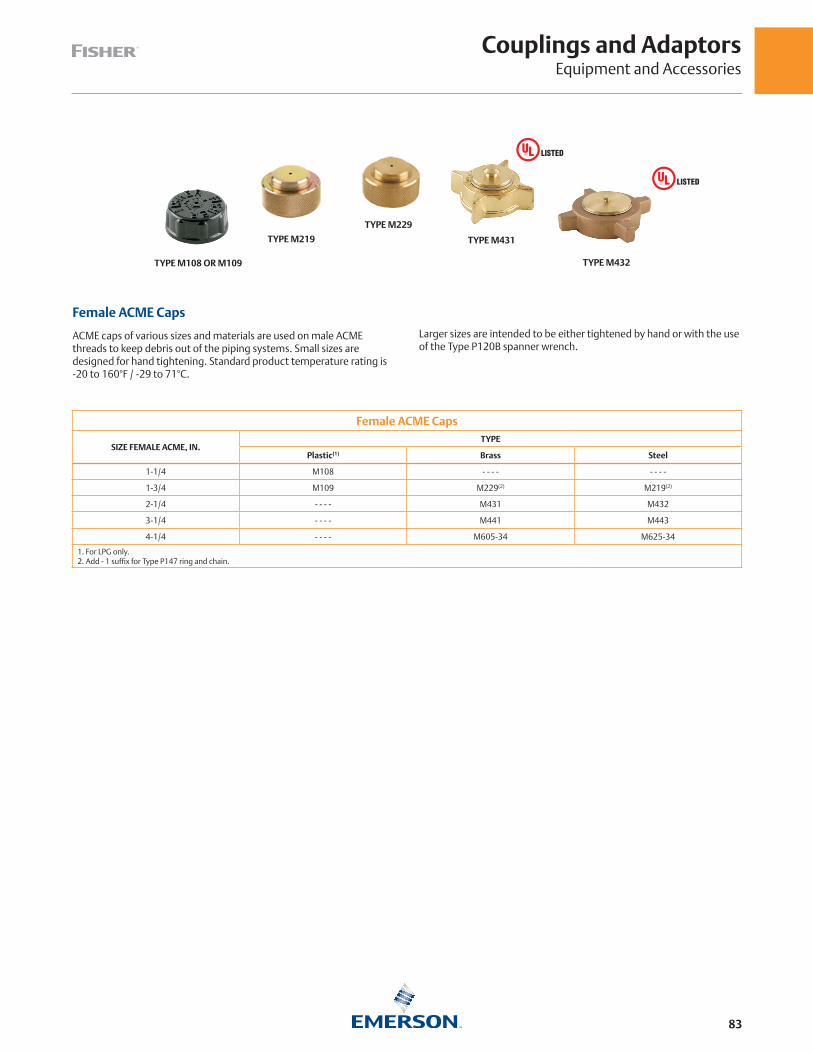
Couplings and AdaptorsEquipment and Accessories
83
Female ACME Caps
SIZE FEMALE ACME, IN.TYPE
Plastic(1) Brass Steel
1-1/4 M108 - - - - - - - -
1-3/4 M109 M229(2) M219(2)
2-1/4 - - - - M431 M432
3-1/4 - - - - M441 M443
4-1/4 - - - - M605-34 M625-34
1. For LPG only. 2. Add - 1 suffix for Type P147 ring and chain.
Female ACME Caps
ACME caps of various sizes and materials are used on male ACME threads to keep debris out of the piping systems. Small sizes are designed for hand tightening. Standard product temperature rating is -20 to 160°F / -29 to 71°C.
TYPE M108 OR M109
TYPE M219
TYPE M229
TYPE M431
TYPE M432
Larger sizes are intended to be either tightened by hand or with the use of the Type P120B spanner wrench.
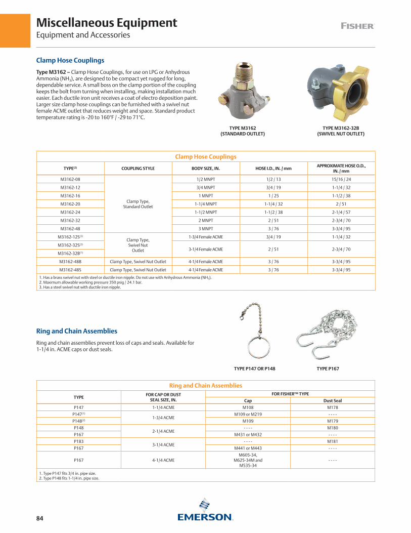
Miscellaneous EquipmentEquipment and Accessories
84
Clamp Hose Couplings
Type M3162 – Clamp Hose Couplings, for use on LPG or Anhydrous Ammonia (NH3), are designed to be compact yet rugged for long, dependable service. A small boss on the clamp portion of the coupling keeps the bolt from turning when installing, making installation much easier. Each ductile iron unit receives a coat of electro deposition paint. Larger size clamp hose couplings can be furnished with a swivel nut female ACME outlet that reduces weight and space. Standard product temperature rating is -20 to 160°F / -29 to 71°C.
Clamp Hose Couplings
TYPE(2) COUPLING STYLE BODY SIZE, IN. HOSE I.D., IN. / mmAPPROXIMATE HOSE O.D.,
IN. / mm
M3162-08
Clamp Type,Standard Outlet
1/2 MNPT 1/2 / 13 15/16 / 24
M3162-12 3/4 MNPT 3/4 / 19 1-1/4 / 32
M3162-16 1 MNPT 1 / 25 1-1/2 / 38
M3162-20 1-1/4 MNPT 1-1/4 / 32 2 / 51
M3162-24 1-1/2 MNPT 1-1/2 / 38 2-1/4 / 57
M3162-32 2 MNPT 2 / 51 2-3/4 / 70
M3162-48 3 MNPT 3 / 76 3-3/4 / 95
M3162-12S(3)
Clamp Type,Swivel Nut
Outlet
1-3/4 Female ACME 3/4 / 19 1-1/4 / 32
M3162-32S(3)
3-1/4 Female ACME 2 / 51 2-3/4 / 70M3162-32B(1)
M3162-48B Clamp Type, Swivel Nut Outlet 4-1/4 Female ACME 3 / 76 3-3/4 / 95
M3162-48S Clamp Type, Swivel Nut Outlet 4-1/4 Female ACME 3 / 76 3-3/4 / 95
1. Has a brass swivel nut with steel or ductile iron nipple. Do not use with Anhydrous Ammonia (NH3).2. Maximum allowable working pressure 350 psig / 24.1 bar.3. Has a steel swivel nut with ductile iron nipple.
TYPE M3162 (STANDARD OUTLET)
TYPE M3162-32B (SWIVEL NUT OUTLET)
Ring and Chain Assemblies
TYPE FOR CAP OR DUST
SEAL SIZE, IN.FOR FISHER™ TYPE
Cap Dust Seal
P147 1-1/4 ACME M108 M178
P147(1)
1-3/4 ACMEM109 or M219 - - - -
P148(2) M109 M179
P1482-1/4 ACME
- - - - M180
P167 M431 or M432 - - - -
P1833-1/4 ACME
- - - - M181
P167 M441 or M443 - - - -
P167 4-1/4 ACMEM605-34,
M625-34M andM535-34
- - - -
1. Type P147 fits 3/4 in. pipe size. 2. Type P148 fits 1-1/4 in. pipe size.
TYPE P167TYPE P147 OR P148
Ring and Chain Assemblies
Ring and chain assemblies prevent loss of caps and seals. Available for 1-1/4 in. ACME caps or dust seals.

Miscellaneous EquipmentEquipment and Accessories
85
Spanner Wrench
Used to tighten and loosen large female ACME caps and couplings in the 2-1/4, 3-1/4 and 4-1/4 in. sizes.
Spanner Wrench
TYPEOVERALL LENGTH,
IN. / mmCONSTRUCTION
MATERIAL
P120B 18 / 457 Aluminum
Adjustable Orifice Reamer
The orifice reamer allows users to clean or ream out orifices of different sizes without changing tools. It allows for a range from 0.125 in. to size no. 52 (0.0635 in.).
TYPE P120B TYPE P520L
Relief Valve Protective CapVALVE TYPE PROTECTIVE CAP TYPE
H110
P206
H125
H150
H148
H173
H123
H120
H124
H144
H174
H722 P297
H733 P298
H284
P299H5114
H5118
TYPE P298
Types P206, P297 and P298 protective caps are used to keep moisture and foreign materials from entering the valves. These units are mounted outside the protective hood on the tank.
Cylinder Filling Valve
Type N201 – fills DOT cylinders by weight and stops the gas supply when specified fill weight is reached. Operated by air pressure, it is designed for beam type scales and requires no electrical or mechanical power.
The assembly comes completely piped up and includes special parts that allow the slide weight on the scale to move to zero. A red button appears in the indicator on top of the Type N201 each time a cylinder is filled to the desired weight. Standard product temperature rating is -20 to 160°F / -29 to 71°C.
TYPE N201

86
DOT Compliance on Jurisdictional Systems? Emerson is Here to Help.
NFPA58 Compliant? Emerson is Here to Help.
Liquid Inlet Lines
Prior Installation
Back Check valve in tank with shutoff
valve in piping
TYPE
N31
0 SH
UTO
FF V
ALV
ETY
PE G
105
BAC
K C
HEC
K V
ALV
E
Liquid Outlet Lines
Prior Installation
Compliance Options
Excess flow valve in tank with shutoff
valve in piping
Replace excess flow valve with internal valve
Install Type N551 ESV as close as practical to
shutoff valve
TYPE
N31
0 SH
UTO
FF V
ALV
ETY
PE F
190
EXC
ESS
FLO
W V
ALV
E
TYPE
C42
7IN
TER
NA
L V
ALV
E
TYPE
F19
0EX
CES
S FL
OW
VA
LVE
TYPE
N55
1 EM
ERG
ENC
Y
SHU
TOFF
VA
LVE
Liquid Inlet and Outlet Lines
Prior Installation
Compliance Options
Excess flow valve in tank with shutoff
valve in piping
Replace excess flow valve with internal valve
Install Type N551 ESV as close as practical to
shutoff valve
Install G200 Series back check valve as close as practical to
shutoff valve (inlet only)
TYPE
N31
0 SH
UTO
FF V
ALV
ETY
PE F
190
EXC
ESS
FLO
W V
ALV
E
TYPE
C42
7IN
TER
NA
L V
ALV
E
TYPE
F19
0EX
CES
S FL
OW
VA
LVE
TYPE
N55
1 EM
ERG
ENC
Y
SHU
TOFF
VA
LVE
TYPE
G20
1 BA
CK
CH
ECK
VA
LVE
TYPE
F19
0EX
CES
S FL
OW
VA
LVE
Relief Valve Over Pressure Protection
• Keeps the customer running with limited increase in the operating pressure
• Releases LPG to atmosphere after primary regulator failure
Monitor System Over Pressure Protection
• Highest station capacity than series regulation
• LPG is not vented to atmosphere
• Pressure is maintained close to normal set point after failure of the primary regulator
Series Regulation Over Pressure Protection
• Station capacity is reduced
• Pressure after primary regulator failure is significantly higher than normal operating pressure

Technical References
87
SI Conversion Factors
Multiply By To Obtain
Length and Area
Millimeters 0.0394 InchesMeters 3.2808 FeetSq. Centimeters 0.155 Sq. InchesSq. Meters 10.764 Sq. Feet
Volume and Mass
Cubic Meters 35.315 Cubic FeetLiters 0.0353 Cubic FeetGallons 0.1337 Cubic FeetCubic cm. 0.061 Cubic InchesLiters 2.114 Pints (US)Liters 0.2642 Gallons (US)Kilograms 2.2046 PoundsTonnes (metric) 1.1024 Tons (US)
Pressure and Flow Rate
Millibars 0.4018 Inches WCOunces/sq. in. 1.733 Inches WCInches w.c. 0.0361 Pounds/sq. in.Bars 14.50 Pounds/sq. in.Kilopascals 0.1450 Pounds/sq. in.Kilograms/sq. cm. 14.222 Pounds/sq. in.Pounds/sq. in. 0.068 AtmospheresLiters/hr. 0.0353 Cubic Feet/hr.Cubic Meters/hr 4.403 Gallons/min.
Miscellaneous
Kilojoules 0.9478 BTUCalories, kg 3.968 BTUWatts 3.414 BTU per hourBTU 0.00001 ThermsMegajoules 0.00948 Therms
Conversion Factors
ASME Conversion Factors
Multiply By To Obtain
Length and Area
Inches 25.4 MillimetersFeet 0.3048 MetersSq. Inches 6.4516 Sq. CentimetersSq. Feet 0.0929 Sq. Meters
Volume and Mass
Cubic Feet 0.0283 Cubic MetersCubic Feet 28.316 LitersCubic Feet 7.481 GallonsCubic Inches 16.387 Cubic cm.Pints (US) 0.473 LitersGallons (US) 3.785 LitersPounds 0.4535 KilogramsTons (US) 0.9071 Tonnes (metric)
Pressure and Flow Rate
Inches w.c. 2.488 MillibarsInches w.c. 0.577 Ounces/sq. in.Pounds/sq. in. 27.71 Inches WCPounds/sq. in. 0.0689 BarsPounds/sq. in. 6.895 KilopascalsPounds/sq. in. 0.0703 Kilograms/sq. cm.Atmospheres 14.696 Pounds/sq. in.Cubic Feet/hr. 28.316 Liters/hr.Gallons/min. 0.2271 Cubic Meters/hr.
Miscellaneous
BTU 1.055 KilojoulesBTU 0.252 Calories, kgBTU per hour 0.293 WattsTherms 100,000 BTUTherms 105.5 Megajoules
Abbreviations
ASME American Society of Mechanical EngineersBTU per hour British Thermal Units per HourCFH Cubic Feet per HourCGA Compressed Gas AssociationCSST Corrugated Stainless Steel TubingDBC Diameter Bolt CircleDOT Department of TransportationFNPT Female National Pipe ThreadFPOL Female POL Portion of CGA 510 Fitting (See POL)GPH Gallons per HourGPM Gallons per MinuteMNPT Male National Pipe ThreadMPOL Male POL Portion of CGA 510 Fitting (See POL)NFPA National Fire Protection AssociationNPT National Pipe ThreadPOL Generic Term For A Compressed Gas Association Fitting #510
psi Pounds per Square Inchpsid Pounds per Square Inch, Differential Pressurepsig Pounds per Square Inch GaugeSAE Society of Automotive EngineersSCFH Standard Cubic Feet per HourSCFM Standard Cubic Feet per MinuteSCMH Standard Cubic Meter per HourPTFE PolytetrafluoroethyleneUL® Underwriters Laboratories Inc.UNC Unified National Course (Defines a thread form/shape)UNF LH Unified National Fine - Left Hand (Defines a thread form/shape)WC Water ColumnWOG Water Oil and Gas
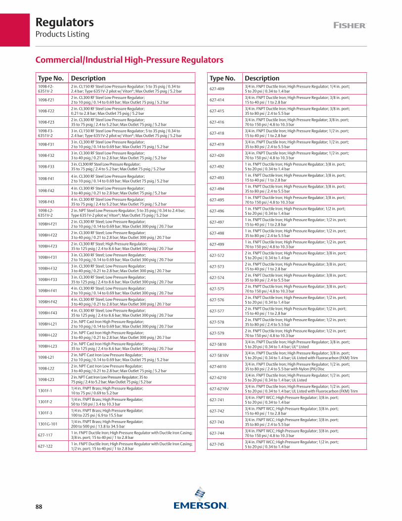
RegulatorsProducts Listing
88
Commercial/Industrial High-Pressure Regulators
Type No. Description1098-F2-6351V-2
2 in. CL150 RF Steel Low Pressure Regulator; 5 to 35 psig / 0.34 to 2.4 bar; Type 6351V-2 pilot w/ Viton®; Max Outlet 75 psig / 5.2 bar
1098-F212 in. CL300 RF Steel Low Pressure Regulator; 2 to 10 psig / 0.14 to 0.69 bar; Max Outlet 75 psig / 5.2 bar
1098-F222 in. CL300 RF Steel Low Pressure Regulator; 0.21 to 2.8 bar; Max Outlet 75 psig / 5.2 bar
1098-F232 in. CL300 RF Steel Low Pressure Regulator; 35 to 75 psig / 2.4 to 5.2 bar; Max Outlet 75 psig / 5.2 bar
1098-F3-6351V-2
3 in. CL150 RF Steel Low Pressure Regulator; 5 to 35 psig / 0.34 to 2.4 bar; Type 6351V-2 pilot w/ Viton®; Max Outlet 75 psig / 5.2 bar
1098-F313 in. CL300 RF Steel Low Pressure Regulator; 2 to 10 psig / 0.14 to 0.69 bar; Max Outlet 75 psig / 5.2 bar
1098-F323 in. CL300 RF Steel Low Pressure Regulator; 3 to 40 psig / 0.21 to 2.8 bar; Max Outlet 75 psig / 5.2 bar
1098-F333 in. CL300 RF Steel Low Pressure Regulator; 35 to 75 psig / 2.4 to 5.2 bar; Max Outlet 75 psig / 5.2 bar
1098-F414 in. CL300 RF Steel Low Pressure Regulator; 2 to 10 psig / 0.14 to 0.69 bar; Max Outlet 75 psig / 5.2 bar
1098-F424 in. CL300 RF Steel Low Pressure Regulator; 3 to 40 psig / 0.21 to 2.8 bar; Max Outlet 75 psig / 5.2 bar
1098-F434 in. CL300 RF Steel Low Pressure Regulator; 35 to 75 psig / 2.4 to 5.2 bar; Max Outlet 75 psig / 5.2 bar
1098-L2-6351V-2
2 in. NPT Steel Low Pressure Regulator; 5 to 35 psig / 0.34 to 2.4 bar; Type 6351V-2 pilot w/ Viton®; Max Outlet 75 psig / 5.2 bar
1098H-F212 in. CL300 RF Steel; Low Pressure Regulator; 2 to 10 psig / 0.14 to 0.69 bar; Max Outlet 300 psig / 20.7 bar
1098H-F222 in. CL300 RF Steel; Low Pressure Regulator; 3 to 40 psig / 0.21 to 2.8 bar; Max Outlet 300 psig / 20.7 bar
1098H-F232 in. CL300 RF Steel; High Pressure Regulator; 35 to 125 psig / 2.4 to 8.6 bar; Max Outlet 300 psig / 20.7 bar
1098H-F313 in. CL300 RF Steel; Low Pressure Regulator; 2 to 10 psig / 0.14 to 0.69 bar; Max Outlet 300 psig / 20.7 bar
1098H-F323 in. CL300 RF Steel; Low Pressure Regulator; 3 to 40 psig / 0.21 to 2.8 bar; Max Outlet 300 psig / 20.7 bar
1098H-F333 in. CL300 RF Steel; Low Pressure Regulator; 35 to 125 psig / 2.4 to 8.6 bar; Max Outlet 300 psig / 20.7 bar
1098H-F414 in. CL300 RF Steel; Low Pressure Regulator; 2 to 10 psig / 0.14 to 0.69 bar; Max Outlet 300 psig / 20.7 bar
1098H-F424 in. CL300 RF Steel; Low Pressure Regulator; 3 to 40 psig / 0.21 to 2.8 bar; Max Outlet 300 psig / 20.7 bar
1098H-F434 in. CL300 RF Steel; Low Pressure Regulator; 35 to 125 psig / 2.4 to 8.6 bar; Max Outlet 300 psig / 20.7 bar
1098H-L212 in. NPT Cast Iron High Pressure Regulator; 2 to 10 psig / 0.14 to 0.69 bar; Max Outlet 300 psig / 20.7 bar
1098H-L222 in. NPT Cast Iron High Pressure Regulator; 3 to 40 psig / 0.21 to 2.8 bar; Max Outlet 300 psig / 20.7 bar
1098H-L232 in. NPT Cast Iron High Pressure Regulator; 35 to 125 psig / 2.4 to 8.6 bar; Max Outlet 300 psig / 20.7 bar
1098-L212 in. NPT Cast Iron Low Pressure Regulator; 2 to 10 psig / 0.14 to 0.69 bar; Max Outlet 75 psig / 5.2 bar
1098-L222 in. NPT Cast Iron Low Pressure Regulator; 3 to 40 psig / 0.21 to 2.8 bar; Max Outlet 75 psig / 5.2 bar
1098-L232 in. NPT Cast Iron Low Pressure Regulator; 35 to 75 psig / 2.4 to 5.2 bar; Max Outlet 75 psig / 5.2 bar
1301F-11/4 in. FNPT Brass; High Pressure Regulator; 10 to 75 psi / 0.69 to 5.2 bar
1301F-21/4 in. FNPT Brass; High Pressure Regulator; 50 to 150 psi / 3.4 to 10.3 bar
1301F-31/4 in. FNPT Brass; High Pressure Regulator; 100 to 225 psi / 6.9 to 15.5 bar
1301G-1011/4 in. FNPT Brass; High Pressure Regulator; 200 to 500 psi / 13.8 to 34.5 bar
627-1171 in. FNPT Ductile Iron; High Pressure Regulator with Ductile Iron Casing; 3/8 in. port; 15 to 40 psi / 1 to 2.8 bar
627-1221 in. FNPT Ductile Iron; High Pressure Regulator with Ductile Iron Casing; 1/2 in. port; 15 to 40 psi / 1 to 2.8 bar
Type No. Description
627-4093/4 in. FNPT Ductile Iron; High Pressure Regulator; 1/4 in. port; 5 to 20 psi / 0.34 to 1.4 bar
627-4143/4 in. FNPT Ductile Iron; High Pressure Regulator; 3/8 in. port; 15 to 40 psi / 1 to 2.8 bar
627-4153/4 in. FNPT Ductile Iron; High Pressure Regulator; 3/8 in. port; 35 to 80 psi / 2.4 to 5.5 bar
627-4163/4 in. FNPT Ductile Iron; High Pressure Regulator; 3/8 in. port; 70 to 150 psi / 4.8 to 10.3 bar
627-4183/4 in. FNPT Ductile Iron; High Pressure Regulator; 1/2 in. port; 15 to 40 psi / 1 to 2.8 bar
627-4193/4 in. FNPT Ductile Iron; High Pressure Regulator; 1/2 in. port; 35 to 80 psi / 2.4 to 5.5 bar
627-4203/4 in. FNPT Ductile Iron; High Pressure Regulator; 1/2 in. port; 70 to 150 psi / 4.8 to 10.3 bar
627-4921 in. FNPT Ductile Iron; High Pressure Regulator; 3/8 in. port; 5 to 20 psi / 0.34 to 1.4 bar
627-4931 in. FNPT Ductile Iron; High Pressure Regulator; 3/8 in. port; 15 to 40 psi / 1 to 2.8 bar
627-4941 in. FNPT Ductile Iron; High Pressure Regulator; 3/8 in. port; 35 to 80 psi / 2.4 to 5.5 bar
627-4951 in. FNPT Ductile Iron; High Pressure Regulator; 3/8 in. port; 70 to 150 psi / 4.8 to 10.3 bar
627-4961 in. FNPT Ductile Iron; High Pressure Regulator; 1/2 in. port; 5 to 20 psi / 0.34 to 1.4 bar
627-4971 in. FNPT Ductile Iron; High Pressure Regulator; 1/2 in. port; 15 to 40 psi / 1 to 2.8 bar
627-4981 in. FNPT Ductile Iron; High Pressure Regulator; 1/2 in. port; 35 to 80 psi / 2.4 to 5.5 bar
627-4991 in. FNPT Ductile Iron; High Pressure Regulator; 1/2 in. port; 70 to 150 psi / 4.8 to 10.3 bar
627-5722 in. FNPT Ductile Iron; High Pressure Regulator; 3/8 in. port; 5 to 20 psi / 0.34 to 1.4 bar
627-5732 in. FNPT Ductile Iron; High Pressure Regulator; 3/8 in. port; 15 to 40 psi / 1 to 2.8 bar
627-5742 in. FNPT Ductile Iron; High Pressure Regulator; 3/8 in. port; 35 to 80 psi / 2.4 to 5.5 bar
627-5752 in. FNPT Ductile Iron; High Pressure Regulator; 3/8 in. port; 70 to 150 psi / 4.8 to 10.3 bar
627-5762 in. FNPT Ductile Iron; High Pressure Regulator; 1/2 in. port; 5 to 20 psi / 0.34 to 1.4 bar
627-5772 in. FNPT Ductile Iron; High Pressure Regulator; 1/2 in. port; 15 to 40 psi / 1 to 2.8 bar
627-5782 in. FNPT Ductile Iron; High Pressure Regulator; 1/2 in. port; 35 to 80 psi / 2.4 to 5.5 bar
627-5792 in. FNPT Ductile Iron; High Pressure Regulator; 1/2 in. port; 70 to 150 psi / 4.8 to 10.3 bar
627-58103/4 in. FNPT Ductile Iron; High Pressure Regulator; 3/8 in. port; 5 to 20 psi / 0.34 to 1.4 bar; UL® Listed
627-5810V3/4 in. FNPT Ductile Iron; High Pressure Regulator; 3/8 in. port; 5 to 20 psi / 0.34 to 1.4 bar; UL Listed with Fluorocarbon (FKM) Trim
627-60103/4 in. FNPT Ductile Iron; High Pressure Regulator; 1/2 in. port; 35 to 80 psi / 2.4 to 5.5 bar with Nylon (PA) Disc
627-62103/4 in. FNPT Ductile Iron; High Pressure Regulator; 1/2 in. port; 5 to 20 psi / 0.34 to 1.4 bar; UL Listed
627-6210V3/4 in. FNPT Ductile Iron; High Pressure Regulator; 1/2 in. port; 5 to 20 psi / 0.34 to 1.4 bar; UL Listed with Fluorocarbon (FKM) Trim
627-7413/4 in. FNPT WCC; High Pressure Regulator; 3/8 in. port; 5 to 20 psi / 0.34 to 1.4 bar
627-7423/4 in. FNPT WCC; High Pressure Regulator; 3/8 in. port; 15 to 40 psi / 1 to 2.8 bar
627-7433/4 in. FNPT WCC; High Pressure Regulator; 3/8 in. port; 35 to 80 psi / 2.4 to 5.5 bar
627-7443/4 in. FNPT WCC; High Pressure Regulator; 3/8 in. port; 70 to 150 psi / 4.8 to 10.3 bar
627-7453/4 in. FNPT WCC; High Pressure Regulator; 1/2 in. port; 5 to 20 psi / 0.34 to 1.4 bar
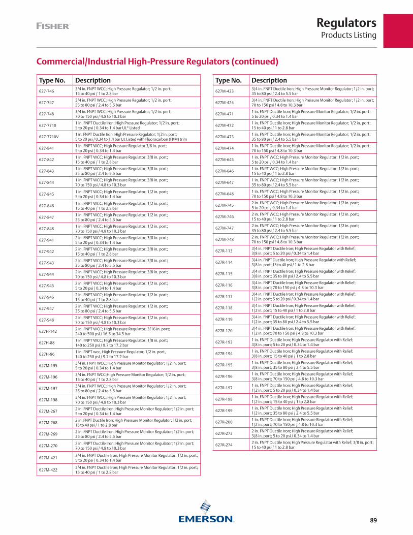
RegulatorsProducts Listing
89
Commercial/Industrial High-Pressure Regulators (continued)
Type No. Description
627-7463/4 in. FNPT WCC; High Pressure Regulator; 1/2 in. port; 15 to 40 psi / 1 to 2.8 bar
627-7473/4 in. FNPT WCC; High Pressure Regulator; 1/2 in. port; 35 to 80 psi / 2.4 to 5.5 bar
627-7483/4 in. FNPT WCC; High Pressure Regulator; 1/2 in. port; 70 to 150 psi / 4.8 to 10.3 bar
627-77101 in. FNPT Ductile Iron; High Pressure Regulator; 1/2 in. port; 5 to 20 psi / 0.34 to 1.4 bar UL® Listed
627-7710V1 in. FNPT Ductile Iron; High Pressure Regulator; 1/2 in. port; 5 to 20 psi / 0.34 to 1.4 bar UL Listed with Fluorocarbon (FKM) trim
627-8411 in. FNPT WCC; High Pressure Regulator 3/8 in. port; 5 to 20 psi / 0.34 to 1.4 bar
627-8421 in. FNPT WCC; High Pressure Regulator; 3/8 in. port; 15 to 40 psi / 1 to 2.8 bar
627-8431 in. FNPT WCC; High Pressure Regulator; 3/8 in. port; 35 to 80 psi / 2.4 to 5.5 bar
627-8441 in. FNPT WCC; High Pressure Regulator; 3/8 in. port; 70 to 150 psi / 4.8 to 10.3 bar
627-8451 in. FNPT WCC; High Pressure Regulator; 1/2 in. port; 5 to 20 psi / 0.34 to 1.4 bar
627-8461 in. FNPT WCC; High Pressure Regulator; 1/2 in. port; 15 to 40 psi / 1 to 2.8 bar
627-8471 in. FNPT WCC; High Pressure Regulator; 1/2 in. port; 35 to 80 psi / 2.4 to 5.5 bar
627-8481 in. FNPT WCC; High Pressure Regulator; 1/2 in. port; 70 to 150 psi / 4.8 to 10.3 bar
627-9412 in. FNPT WCC; High Pressure Regulator; 3/8 in. port; 5 to 20 psi / 0.34 to 1.4 bar
627-9422 in. FNPT WCC; High Pressure Regulator; 3/8 in. port; 15 to 40 psi / 1 to 2.8 bar
627-9432 in. FNPT WCC; High Pressure Regulator; 3/8 in. port; 35 to 80 psi / 2.4 to 5.5 bar
627-9442 in. FNPT WCC; High Pressure Regulator; 3/8 in. port; 70 to 150 psi / 4.8 to 10.3 bar
627-9452 in. FNPT WCC; High Pressure Regulator; 1/2 in. port; 5 to 20 psi / 0.34 to 1.4 bar
627-9462 in. FNPT WCC; High Pressure Regulator; 1/2 in. port; 15 to 40 psi / 1 to 2.8 bar
627-9472 in. FNPT WCC; High Pressure Regulator; 1/2 in. port; 35 to 80 psi / 2.4 to 5.5 bar
627-9482 in. FNPT WCC; High Pressure Regulator; 1/2 in. port; 70 to 150 psi / 4.8 to 10.3 bar
627H-1422 in. FNPT WCC; High Pressure Regulator; 3/16 in. port; 240 to 500 psi / 16.5 to 34.5 bar
627H-881 in. FNPT WCC; High Pressure Regulator; 1/8 in. port; 140 to 250 psi / 9.7 to 17.2 bar
627H-961 in. FNPT wcc, High Pressure Regulator, 1/2 in. port, 140 to 250 psi / 9.7 to 17.2 bar
627M-1953/4 in. FNPT WCC; High Pressure Monitor Regulator; 1/2 in. port; 5 to 20 psi / 0.34 to 1.4 bar
627M-1963/4 in. FNPT WCC;High Pressure Monitor Regulator; 1/2 in. port; 15 to 40 psi / 1 to 2.8 bar
627M-1973/4 in. FNPT WCC; High Pressure Monitor Regulator; 1/2 in. port; 35 to 80 psi / 2.4 to 5.5 bar
627M-1983/4 in. FNPT WCC; High Pressure Monitor Regulator; 1/2 in. port; 70 to 150 psi / 4.8 to 10.3 bar
627M-2672 in. FNPT Ductile Iron; High Pressure Monitor Regulator; 1/2 in. port; 5 to 20 psi / 0.34 to 1.4 bar
627M-2682 in. FNPT Ductile Iron; High Pressure Monitor Regulator; 1/2 in. port; 15 to 40 psi / 1 to 2.8 bar
627M-2692 in. FNPT Ductile Iron; High Pressure Monitor Regulator; 1/2 in. port; 35 to 80 psi / 2.4 to 5.5 bar
627M-2702 in. FNPT Ductile Iron; High Pressure Monitor Regulator; 1/2 in. port; 70 to 150 psi / 4.8 to 10.3 bar
627M-4213/4 in. FNPT Ductile Iron; High Pressure Monitor Regulator; 1/2 in. port; 5 to 20 psi / 0.34 to 1.4 bar
627M-4223/4 in. FNPT Ductile Iron; High Pressure Monitor Regulator; 1/2 in. port; 15 to 40 psi / 1 to 2.8 bar
Type No. Description
627M-4233/4 in. FNPT Ductile Iron; High Pressure Monitor Regulator; 1/2 in. port; 35 to 80 psi / 2.4 to 5.5 bar
627M-4243/4 in. FNPT Ductile Iron; High Pressure Monitor Regulator; 1/2 in. port; 70 to 150 psi / 4.8 to 10.3 bar
627M-4711 in. FNPT Ductile Iron; High Pressure Monitor Regulator; 1/2 in. port; 5 to 20 psi / 0.34 to 1.4 bar
627M-4721 in. FNPT Ductile Iron; High Pressure Monitor Regulator; 1/2 in. port; 15 to 40 psi / 1 to 2.8 bar
627M-4731 in. FNPT Ductile Iron; High Pressure Monitor Regulator; 1/2 in. port; 35 to 80 psi / 2.4 to 5.5 bar
627M-4741 in. FNPT Ductile Iron; High Pressure Monitor Regulator; 1/2 in. port; 70 to 150 psi / 4.8 to 10.3 bar
627M-6451 in. FNPT WCC; High Pressure Monitor Regulator; 1/2 in. port; 5 to 20 psi / 0.34 to 1.4 bar
627M-6461 in. FNPT WCC; High Pressure Monitor Regulator; 1/2 in. port; 15 to 40 psi / 1 to 2.8 bar
627M-6471 in. FNPT WCC; High Pressure Monitor Regulator; 1/2 in. port; 35 to 80 psi / 2.4 to 5.5 bar
627M-6481 in. FNPT WCC; High Pressure Monitor Regulator; 1/2 in. port; 70 to 150 psi / 4.8 to 10.3 bar
627M-7452 in. FNPT WCC; High Pressure Monitor Regulator; 1/2 in. port; 5 to 20 psi / 0.34 to 1.4 bar
627M-7462 in. FNPT WCC; High Pressure Monitor Regulator; 1/2 in. port; 15 to 40 psi / 1 to 2.8 bar
627M-7472 in. FNPT WCC; High Pressure Monitor Regulator; 1/2 in. port; 35 to 80 psi / 2.4 to 5.5 bar
627M-7482 in. FNPT WCC; High Pressure Monitor Regulator; 1/2 in. port; 70 to 150 psi / 4.8 to 10.3 bar
627R-1133/4 in. FNPT Ductile Iron; High Pressure Regulator with Relief; 3/8 in. port; 5 to 20 psi / 0.34 to 1.4 bar
627R-1143/4 in. FNPT Ductile Iron; High Pressure Regulator with Relief;3/8 in. port; 15 to 40 psi / 1 to 2.8 bar
627R-1153/4 in. FNPT Ductile Iron; High Pressure Regulator with Relief;3/8 in. port; 35 to 80 psi / 2.4 to 5.5 bar
627R-1163/4 in. FNPT Ductile Iron; High Pressure Regulator with Relief; 3/8 in. port; 70 to 150 psi / 4.8 to 10.3 bar
627R-1173/4 in. FNPT Ductile Iron; High Pressure Regulator with Relief; 1/2 in. port; 5 to 20 psi / 0.34 to 1.4 bar
627R-1183/4 in. FNPT Ductile Iron; High Pressure Regulator with Relief; 1/2 in. port; 15 to 40 psi / 1 to 2.8 bar
627R-1193/4 in. FNPT Ductile Iron; High Pressure Regulator with Relief; 1/2 in. port; 35 to 80 psi / 2.4 to 5.5 bar
627R-1203/4 in. FNPT Ductile Iron; High Pressure Regulator with Relief; 1/2 in. port; 70 to 150 psi / 4.8 to 10.3 bar
627R-1931 in. FNPT Ductile Iron; High Pressure Regulator with Relief; 3/8 in. port; 5 to 20 psi / 0.34 to 1.4 bar
627R-1941 in. FNPT Ductile Iron; High Pressure Regulator with Relief; 3/8 in. port; 15 to 40 psi / 1 to 2.8 bar
627R-1951 in. FNPT Ductile Iron; High Pressure Regulator with Relief; 3/8 in. port; 35 to 80 psi / 2.4 to 5.5 bar
627R-1961 in. FNPT Ductile Iron; High Pressure Regulator with Relief; 3/8 in. port; 70 to 150 psi / 4.8 to 10.3 bar
627R-1971 in. FNPT Ductile Iron; High Pressure Regulator with Relief; 1/2 in. port; 5 to 20 psi / 0.34 to 1.4 bar
627R-1981 in. FNPT Ductile Iron; High Pressure Regulator with Relief; 1/2 in. port; 15 to 40 psi / 1 to 2.8 bar
627R-1991 in. FNPT Ductile Iron; High Pressure Regulator with Relief; 1/2 in. port; 35 to 80 psi / 2.4 to 5.5 bar
627R-2001 in. FNPT Ductile Iron; High Pressure Regulator with Relief; 1/2 in. port; 70 to 150 psi / 4.8 to 10.3 bar
627R-2732 in. FNPT Ductile Iron; High Pressure Regulator with Relief; 3/8 in. port; 5 to 20 psi / 0.34 to 1.4 bar
627R-2742 in. FNPT Ductile Iron; High Pressure Regulator with Relief; 3/8 in. port; 15 to 40 psi / 1 to 2.8 bar

RegulatorsProducts Listing
90
Commercial/Industrial High-Pressure Regulators (continued)
Type No. Description
627R-2752 in. FNPT Ductile Iron; High Pressure Regulator with Relief; 3/8 in. port; 35 to 80 psi / 2.4 to 5.5 bar
627R-2762 in. FNPT Ductile Iron; High Pressure Regulator with Relief; 3/8 in. port; 70 to 150 psi / 4.8 to 10.3 bar
627R-2772 in. FNPT Ductile Iron; High Pressure Regulator with Relief; 1/2 in. port; 5 to 20 psi / 0.34 to 1.4 bar
627R-2782 in. FNPT Ductile Iron; High Pressure Regulator with Relief; 1/2 in. port; 15 to 40 psi / 1 to 2.8 bar
627R-2792 in. FNPT Ductile Iron; High Pressure Regulator with Relief; 1/2 in. port; 35 to 80 psi / 2.4 to 5.5 bar
627R-2802 in. FNPT Ductile Iron; High Pressure Regulator with Relief; 1/2 in. port; 70 to 150 psi / 4.8 to 10.3 bar
627R-612 in. FNPT WCC; High Pressure Monitor Regulator with Relief; 3/8 in. port; 5 to 20 psi / 0.34 to 1.4 bar
627R-622 in. FNPT WCC; High Pressure Monitor Regulator with Relief; 3/8 in. port; 15 to 40 psi / 1 to 2.8 bar
627R-632 in. FNPT WCC; High Pressure Monitor Regulator with Relief; 3/8 in. port; 35 to 80 psi / 2.4 to 5.5 bar
627R-642 in. FNPT WCC; High Pressure Monitor Regulator with Relief; 3/8 in. port; 70 to 150 psi / 4.8 to 10.3 bar
627R-652 in. FNPT WCC; High Pressure Monitor Regulator with Relief; 1/2 in. port; 5 to 20 psi / 0.34 to 1.4 bar
627R-6581 in. FNPT DI; High Pressure Regulator with Relief; 1/2 in. port; 15 to 40 psi / 1 to 2.8 bar
627R-662 in. FNPT WCC; High Pressure Regulator with Relief; 1/2 in. port; 15 to 40 psi / 1 to 2.8 bar
627R-672 in. FNPT WCC; High Pressure Monitor Regulator with Relief; 1/2 in. port; 35 to 80 psi / 2.4 to 5.5 bar
627R-682 in. FNPT WCC; High Pressure Monitor Regulator with Relief; 1/2 in. port; 70 to 150 psi / 4.8 to 10.3 bar
627R-8173/4 in. FNPT WCC; High Pressure Regulator with Relief; 3/8 in. port; 5 to 20 psi / 0.34 to 1.4 bar
627R-8183/4 in. FNPT WCC; High Pressure Regulator with Relief; 3/8 in. port; 15 to 40 psi / 1 to 2.8 bar
627R-8193/4 in. FNPT WCC; High Pressure Regulator with Relief; 3/8 in. port; 35 to 80 psi / 2.4 to 5.5 bar
627R-8203/4 in. FNPT WCC; High Pressure Regulator with Relief; 3/8 in. port; 70 to 150 psi / 4.8 to 10.3 bar
627R-8213/4 in. FNPT WCC; High Pressure Regulator with Relief; 1/2 in. port; 5 to 20 psi / 0.34 to 1.4 bar
627R-8223/4 in. FNPT WCC High Pressure Regulator with Relief; 1/2 in. port; 15 to 40 psi / 1 to 2.8 bar
627R-8233/4 in. FNPT WCC; High Pressure Regulator with Relief; 1/2 in. port; 35 to 80 psi / 2.4 to 5.5 bar
627R-8243/4 in. FNPT WCC; High Pressure Regulator with Relief; 1/2 in. port; 70 to 150 psi / 4.8 to 10.3 bar
627R-9131 in. FNPT WCC; High Pressure Regulator with Relief; 3/8 in. port; 5 to 20 psi / 0.34 to 1.4 bar
627R-9141 in. FNPT WCC; High Pressure Regulator with Relief; 3/8 in. port; 15 to 40 psi / 1 to 2.8 bar
627R-9151 in. FNPT WCC; High Pressure Regulator with Relief; 3/8 in. port; 35 to 80 psi / 2.4 to 5.5 bar
627R-9161 in. FNPT WCC; High Pressure Regulator with Relief; 3/8 in. port; 70 to 150 psi / 4.8 to 10.3 bar
627R-9171 in. FNPT WCC; High Pressure Regulator with Relief; 1/2 in. port; 5 to 20 psi / 0.34 to 1.4 bar
627R-9181 in. FNPT WCC; High Pressure Regulator with Relief; 1/2 in. port; 15 to 40 psi / 1 to 2.8 bar
627R-9191 in. FNPT WCC; High Pressure Regulator with Relief; 1/2 in. port; 35 to 80 psi / 2.4 to 5.5 bar
627R-9201 in. FNPT WCC; High Pressure Regulator with Relief; 1/2 in. port; 70 to 150 psi / 4.8 to 10.3 bar
627W-133/4 in. FNPT WCC; High Pressure Liquid Regulator; 1/2 in. port; 10 to 20 psi / 0.69 to 1.4 bar
627W-143/4 in. FNPT WCC; High Pressure Liquid Regulator; 1/2 in. port; 15 to 40 psi / 1 to 2.8 bar
Type No. Description
627W-153/4 in. FNPT WCC; High Pressure Liquid Regulator; 1/2 in. port; 35 to 80 psi / 2.4 to 5.5 bar
627W-163/4 in. FNPT WCC; High Pressure Liquid Regulator; 1/2 in. port; 70 to 150 psi / 4.8 to 10.3 bar
627W-371 in. FNPT WCC; High Pressure Liquid Regulator; 1/2 in. port; 10 to 20 psi / 0.69 to 1.4 bar
627W-381 in. FNPT WCC; High Pressure Liquid Regulator; 1/2 in. port; 15 to 40 psi / 1 to 2.8 bar
627W-391 in. FNPT WCC; High Pressure Liquid Regulator; 1/2 in. port; 35 to 80 psi / 2.4 to 5.5 bar
627W-401 in. FNPT WCC; High Pressure Liquid Regulator; 1/2 in. port; 70 to 150 psi / 4.8 to 10.3 bar
627W-612 in. FNPT WCC; High Pressure Liquid Regulator; 1/2 in. port; 10 to 20 psi / 0.69 to 1.4 bar
627W-622 in. FNPT WCC; High Pressure Liquid Regulator; 1/2 in. port; 15 to 40 psi / 1 to 2.8 bar
627W-632 in. FNPT WCC; High Pressure Liquid Regulator; 1/2 in. port; 35 to 80 psi / 2.4 to 5.5 bar
627W-642 in. FNPT WCC; High Pressure Liquid Regulator; 1/2 in. port; 70 to 150 psi / 4.8 to 10.3 bar
630-104-782 in. FNPT Cast Iron; High Pressure Regulator; 1/2 in. port; 8 to 20 psi / 0.55 to 1.4 bar; UL® Listed
630-1222 in. FNPT Cast Iron; High Pressure Regulator; 1/4 in. port; 46 to 95 psi / 3.2 to 6.6 bar; Nylon (PA) Disc
630-3111 in. FNPT Cast Iron; High Pressure Regulator; 1/2 in. port; 3 to 10 psi / 0.21 to 0.69 bar
630-3121 in. FNPT Cast Iron; High Pressure Regulator; 1/2 in. port; 8 to 20 psi / 0.55 to 1.4 bar
630-3131 in. FNPT Cast Iron; High Pressure Regulator; 1/2 in. port; 17 to 30 psi / 1.2 to 2.1 bar
630-3141 in. FNPT Cast Iron; High Pressure Regulator; 1/2 in. port; 27 to 40 psi / 1.9 to 2.8 bar
630-3151 in. FNPT Cast Iron; High Pressure Regulator; 1/2 in. port; 27 to 50 psi / 1.9 to 3.4 bar
630-3161 in. FNPT Cast Iron; High Pressure Regulator; 1/2 in. port; 46 to 95 psi / 3.2 to 6.6 bar
630-3171 in. FNPT Cast Iron; High Pressure Regulator; 1/2 in. port; 90 to 150 psi / 6.2 to 10.3 bar
630-3181 in. FNPT Cast Iron; High Pressure Regulator; 1/2 in. port; 150 to 200 / 10.3 to 13.8 bar psi
630-3191 in. FNPT Cast Iron; High Pressure Regulator; 1/2 in. port; 200 to 275 psi / 13.8 to 19 bar
630-3212 in. FNPT Cast Iron; High Pressure Regulator; 1/2 in. port; 3 to 10 psi / 0.21 to 0.69 bar
630-3232 in. FNPT Cast Iron; High Pressure Regulator; 1/2 in. port; 17 to 30 psi / 1.2 to 2.1 bar
630-3242 in. FNPT Cast Iron; High Pressure Regulator; 1/2 in. port; 27 to 40 psi / 1.9 to 2.8 bar
630-3252 in. FNPT Cast Iron; High Pressure Regulator; 1/2 in. port; 27 to 50 psi / 1.9 to 3.4 bar
630-3262 in. FNPT Cast Iron; High Pressure Regulator; 1/2 in. port; 46 to 95 psi / 3.2 to 6.6 bar
630-3272 in. FNPT Cast Iron; High Pressure Regulator; 1/2 in. port; 90 to 150 psi / 6.2 to 10.3 bar
630-3282 in. FNPT Cast Iron; High Pressure Regulator; 1/2 in. port; 150 to 200 psi / 10.3 to 13.8 bar
630-3292 in. FNPT Cast Iron; High Pressure Regulator; 1/2 in. port; 200 to 275 psi / 13.8 to 19 bar
630-80041 in. FNPT WCC; High Pressure Regulator; 1/2 in. port; 3 to 10 psi / 0.21 to 0.69 bar
630-80081 in. FNPT WCC; High Pressure Regulator; 1/2 in. port; 8 to 20 psi / 0.55 to 1.4 bar
630-80121 in. FNPT WCC; High Pressure Regulator; 1/2 in. port; 17 to 30 psi / 1.2 to 2.1 bar
630-80161 in. FNPT WCC; High Pressure Regulator; 1/2 in. port; 27 to 40 psi / 1.9 to 2.8 bar

RegulatorsProducts Listing
91
Commercial/Industrial High-Pressure Regulators (continued)
Type No. Description
630-80201 in. FNPT WCC; High Pressure Regulator; 1/2 in. port; 27 to 50 psi / 1.9 to 3.4 bar
630-80241 in. FNPT WCC; High Pressure Regulator; 1/2 in. port; 46 to 95 psi / 3.2 to 6.6 bar
630-80281 in. FNPT WCC; High Pressure Regulator; 1/2 in. port; 90 to 150 psi / 6.2 to 10.3 bar
630-80321 in. FNPT WCC; High Pressure Regulator; 1/2 in. port; 150 to 200 psi / 10.3 to 13.8 bar
630-80361 in. FNPT WCC; High Pressure Regulator; 1/2 in. port; 200 to 275 psi / 13.8 to 19 bar
630-80442 in. FNPT WCC; High Pressure Regulator; 1/2 in. port; 3 to 10 psi / 0.21 to 0.69 bar
630-80482 in. FNPT WCC; High Pressure Regulator; 1/2 in. port; 8 to 20 psi / 0.55 to 1.4 bar
630-80522 in. FNPT WCC; High Pressure Regulator; 1/2 in. port; 17 to 30 psi / 1.2 to 2.1 bar
630-80562 in. FNPT WCC; High Pressure Regulator; 1/2 in. port; 27 to 40 psi / 1.9 to 2.8 bar
630-80602 in. FNPT WCC; High Pressure Regulator; 1/2 in. port; 27 to 50 psi / 1.9 to 3.4 bar
630-80642 in. FNPT WCC; High Pressure Regulator; 1/2 in. port; 46 to 95 psi / 3.2 to 6.6 bar
630-80672 in. FNPT WCC,High Pressure Regulator, 3/8 in. port; 90 to 150 psi / 6.2 to 10.3 bar
630-80682 in. FNPT WCC; High Pressure Regulator; 1/2 in. port; 90 to 150 psi / 6.2 to 10.3 bar
630-80722 in. FNPT WCC; High Pressure Regulator; 1/2 in. port; 150 to 200 psi / 10.3 to 13.8 bar
630-80802 in. FNPT WCC; High Pressure Regulator; 1/2 in. port; 275 to 500 psi / 19 to 34.5 bar
64-2221/2 in. FNPT Aluminum; High Pressure Regulator; 35 to 100 psi / 2.4 to 6.9 bar
64-331/2 in. FNPT Aluminum; High Pressure Regulator; 3 to 15 psi / 0.21 to 1 bar
64-351/2 in. FNPT Aluminum; High Pressure Regulator; 5 to 35 psi / 0.34 to 2.4 bar
64-361/2 in. FNPT Aluminum; High Pressure Regulator; 30 to 60 psi / 2.1 to 4.1 bar
64KB-2221/2 in. FNPT High Pressure Regulator for NH3 Service; 35 to 100 psi / 2.4 to 6.9 bar
64KB-331/2 in. FNPT High Pressure Regulator for NH3 Service; 3 to 15 psi / 0.21 to 1 bar
64KB-341/2 in. FNPT High Pressure Regulator for NH3 Service; 5 to 20 psi / 0.34 to 1.4 bar
64KB-351/2 in. FNPT High Pressure Regulator for NH3 Service; 5 to 35 psi / 0.34 to 2.4 bar
64KB-361/2 in. FNPT High Pressure Regulator for NH3 Service; 30 to 60 psi / 2.1 to 4.1 bar
64SR-1221/2 in. FNPT; Automatic Changeover Regulator with Relief; 5 to 20 psi / 0.34 to 1.4 bar
64SR-211/2 in. FNPT Aluminum; High Pressure Regulator with Relief; 3 to 15 psi / 0.21 to 1 bar
64SR-221/2 in. FNPT Aluminum; High Pressure Regulator with Relief; 5 to 20 psi / 0.34 to 1.4 bar
64SR-231/2 in. FNPT Aluminum; High Pressure Regulator with Relief; 5 to 35 psi / 0.34 to 2.4 bar
64SR-241/2 in. FNPT Aluminum; High Pressure Regulator with Relief; 30 to 60 psi / 2.07 to 4.14 bar
67CD-1001/4 in. FNPT; High Pressure Regulator; 5 to 20 psi / 0.34 to 1.4 bar; Dial Cap
67CD-1011/4 in. FNPT; High Pressure Regulator; 5 to 35 psi / 0.34 to 2.4 bar; Dial Cap
67CD-1021/4 in. FNPT; High Pressure Regulator; 20 to 50 psi / 1.4 to 3.4 bar; Dial Cap
67CD-1031/4 in. FNPT; High Pressure Regulator; 40 to 100 psi / 2.8 to 6.9 bar; Dial Cap
67CD-1041/4 in. FNPT; High Pressure Regulator with Type M318; 0 to 60 psi / 0 mbar to 4.1 bar; Dial Cap
Type No. Description
67CD-1151/4 in. FNPT; High Pressure Regulator with Types M318 and M104; 0 to 30 Gauge; 0 to 20 psi / 0 mbar to 2.1 bar; Dial Cap
67CD-1161/4 in. FNPT; High Pressure Regulator with Types M318 and M104; 0 to 30 Gauge (SST Case); 0 to 35 psi / 0 mbar to 2.1 bar; Dial Cap
67CH-1501/4 in. FNPT; High Pressure Regulator; with Types M318, M104 and J502; 0 to 60 psi / 0 mbar to 4.1 bar; Handwheel
67CH-7411/4 in. FNPT; High Pressure Regulator; 50 to 135 psi / 3.4 to 9.3 bar; Handwheel
67CH-7421/4 in. FNPT; High Pressure Regulator; 30 to 60 psi / 2.1 to 4.1 bar; Handwheel
67CH-7431/4 in. FNPT; High Pressure Regulator; 3 to 35 psi / 0.21 to 2.4 bar; Handwheel
67CH-743XB1/4 in. FNPT; High Pressure Regulator; 3 to 35 psi / 0.21 to 2.4 bar; Handwheel; set at 15 psi / 1 bar
67CH-7451/4 in. FNPT; High Pressure Regulator; 3 to 20 psi / 0.21 to 1.4 bar; Handwheel
67CH-7471/4 in. FNPT; High Pressure Regulator;3 to 20 psi / 0.21 to 1.4 bar; Handwheel, with 1/4 NPT Exhaust Vent
67CH-7511/4 in. FNPT; High Pressure Regulator; Type M318; 3 to 20 psi / 0.21 to 1.4 bar; Handwheel
67CH-801/4 in. FNPT; High Pressure Regulator; with Type J504; 30 to 60 psi / 2.1 to 4.1 bar; Handwheel
67CH-901/4 in. FNPT High Pressure Regulator; with Type J501; 3 to 35 psi / 0.21 to 2.4 bar; Handwheel
67CN-1041/4 in. FNPT; High Pressure Regulator; 15 psi / 1 bar setpoint; Non-Adjustable
67CN-1051/4 in. FNPT; High Pressure Regulator; 20 psi / 1.4 bar setpoint; Non-Adjustable
67CN-1061/4 in. FNPT; High Pressure Regulator; 10 psi / 0.69 bar setpoint;Non-Adjustable
67CW-1201/4 in. FNPT; High Pressure Regulator; with Types M104 and F181; 30 to 60 psi / 2.1 to 4.1 bar
67CW-621/4 in. FNPT; High Pressure Regulator; with Type J503; 50 to 100 psi / 3.4 to 6.9 bar
67CW-683 1/4 in. FNPT; High Pressure Regulator; 3 to 20 psi / 0.21 to 1.4 bar
67CW-684 1/4 in. FNPT; High Pressure Regulator; 3 to 35 psi / 0.21 to 2.4 bar
67CW-685 1/4 in. FNPT; High Pressure Regulator; 30 to 60 psi / 2.1 to 4.1 bar
67CW-6871/4 in. FNPT; High Pressure Regulator; with Type M318; 3 to 35 psi / 0.21 to 2.4 bar
67CW-701 1/4 in. FNPT; High Pressure Regulator; 50 to 135 psi / 3.4 to 9.3 bar
749B-211/2 in. FNPT; Changeover Manifold; Supply setting 15 psi / 1 bar; Reserve Setting 5 psi / 0.34 bar
99-502PH2 in. FNPT Cast Iron; High Pressure Regulator; 1-1/8 in. port; 1 to 5 psi / 69 mbar to 0.34 bar; Max P1 300 psig / 20.7 bar
99-502PHM2 in. FNPT Cast Iron; High Pressure Regulator; 1-1/8 in. port; 1 to 5 psi / 69 mbar to 0.34 bar; Max P1 300 psig / 20.7 bar
99-502PHO2 in. FNPT Cast Iron; High Pressure Regulator; 1-1/8 in. port; O-ring Seat; 1 to 5 psi / 69 mbar to 0.34 bar; Max P1 250 psig / 17.2 bar
99-502PHOM2 in. FNPT Cast Iron; High Pressure Regulator; 1-1/8 in. port; O-ring Seat; 1 to 5 psi / 69 mbar to 0.34 bar; Max P1 250 psig / 17.2 bar
99-503PH2 in. FNPT Cast Iron; High Pressure Regulator; 1-1/8 in. port; 2 to 10 psi / 0.14 to 0.69 bar; Max P1 300 psig / 20.7 bar
99-503PHM2 in. FNPT Cast Iron; High Pressure Regulator; 1-1/8 in. port; 2 to 10 psi / 0.14 to 0.69 bar; Max P1 300 psig / 20.7 bar
99-503PHO2 in. FNPT Cast Iron; High Pressure Regulator; 1-1/8 in. port; O-ring Seat; 2 to 10 psi / 0.14 to 0.69 bar; Max P1 250 psig / 17.2 bar
99-503PHOM2 in. FNPT Cast Iron; High Pressure Monitor Regulator; 1-1/8 in. port; O-ring Seat; 2 to 10 psi / 0.14 to 0.69 bar; Max P1 250 psig / 17.2 bar
99-504PH2 in. FNPT Cast Iron; High Pressure Regulator; 1-1/8 in. port; 5 to 15 psi / 0.34 to 1 bar; Max P1 300 psig / 20.7 bar
99-504PHM2 in. FNPT Cast Iron; High Pressure Monitor Regulator; 1-1/8 in. port; 5 to 15 psi / 0.34 to 1 bar; Max P1 300 psig / 20.7 bar
99-504PHO2 in. FNPT Cast Iron; High Pressure Regulator; 1-1/8 in. port; O-ring Seat; 5 to 15 psi / 0.34 to 1 bar; Max P1 250 psig / 17.2 bar
99-504PHOM2 in. FNPT Cast Iron; High Pressure Monitor Regulator; 1-1/8 in. port; O-ring Seat; 5 to 15 psi / 0.34 to 1 bar; Max P1 250 psig / 17.2 bar

RegulatorsProducts Listing
92
Commercial/Industrial High-Pressure Regulators (continued)
Type No. Description
99-505PH2 in. FNPT Cast Iron; High Pressure Regulator; 1-1/8 in. port; 10 to 20 psi / 0.69 to 1.4 bar; Max P1 300 psig / 20.7 bar
99-505PHM2 in. FNPT Cast Iron; High Pressure Monitor Regulator; 1-1/8 in. port; 10 to 20 psi / 0.69 to 1.4 bar; Max P1 300 psig / 20.7 bar
99-505PHO2 in. FNPT Cast Iron; High Pressure Regulator; 1-1/8 in. port; O-ring Seat; 10 to 20 psi / 0.69 to 1.4 bar; Max P1 250 psig / 17.2 bar
99-505PHOM2 in. FNPT Cast Iron; High Pressure Monitor Regulator; 1-1/8 in. port; O-ring Seat; 10 to 20 psi / 0.69 to 1.4 bar; Max P1 250 psig / 17.2 bar
99-510P2 in. FNPT Cast Iron; High Pressure Regulator; 7/8 in. port; 1/4 to 2 psi / 17 mbar to 0.14 bar; Max P1 250 psig / 17.2 bar
99-510PM2 in. FNPT Cast Iron; High Pressure Monitor Regulator; 7/8 in. port; 1/4 to 2 psi / 17 mbar to 0.14 bar; Max P1 250 psig / 17.2 bar
99-511P2 in. FNPT Cast Iron; High Pressure Regulator; 7/8 in. port; 1 to 5 psi / 69 mbar to 0.34 bar; Max P1 250 psig / 17.2 bar
99-511PM2 in. FNPT Cast Iron; High Pressure Monitor Regulator; 7/8 in. port; 1 to 5 psi / 69 mbar to 0.34 bar; Max P1 250 psig / 17.2 bar
99-512P2 in. FNPT Cast Iron; High Pressure Regulator; 7/8 in. port; 5 to 15 psi / 0.34 to 1 bar; Max P1 250 psig / 17.2 bar
99-512PM2 in. FNPT Cast Iron; High Pressure Monitor Regulator; 7/8 in. port; 5 to 15 psi / 0.34 to 1 bar; Max P1 250 psig / 17.2 bar
99-513P2 in. FNPT Cast Iron; High Pressure Regulator; 7/8 in. port; 2 to 10 psi / 0.14 to 0.69 bar; Max P1 250 psig / 17.2 bar
99-513PM2 in. FNPT Cast Iron; High Pressure Monitor Regulator; 7/8 in. port; 2 to 10 psi / 0.14 to 0.69 bar; Max P1 250 psig / 17.2 bar
99-515P2 in. FNPT Cast Iron; High Pressure Regulator; 7/8 in. port; 10 to 20 psi / 0.69 to 1.4 bar; Max P1 250 psig / 17.2 bar
99-515PM2 in. FNPT Cast Iron; High Pressure Monitor Regulator; 7/8 in. port; 10 to 20 psi / 0.69 to 1.4 bar; Max P1 250 psig / 17.2 bar
99-901P2 in. FNPT Cast Iron; High Pressure Regulator; 1-1/8 in. port; 10 to 65 psi / 0.69 to 4.5 bar; Max P1 150 psig / 10.3 bar
99-901PH2 in. FNPT Cast Iron; High Pressure Regulator; 1-1/8 in. port; 10 to 65 psi / 0.69 to 4.5 bar; Max P1 300 psig / 20.7 bar
99-901PHM2 in. FNPT Cast Iron; High Pressure Monitor Regulator; 1-1/8 in. port; 10 to 65 psi / 0.69 to 4.5 bar; Max P1 300 psig / 20.7 bar
99-901PHO2 in. FNPT Cast Iron; High Pressure Regulator; 1-1/8 in. port; O-ring Seat; 10 to 65 psi / 2.4 to 6.9 bar; Max P1 250 psig / 17.2 bar
99-901PHOM2 in. FNPT Cast Iron; High Pressure Monitor Regulator; 1-1/8 in. port; O-ring Seat;10 to 65 psi / 2.4 to 6.9 bar; Max P1 250 psig / 17.2 bar
99-901PM2 in. FNPT Cast Iron; High Pressure Monitor Regulator; 1-1/8 in. port; 10 to 65 psi / 2.4 to 6.9 bar; Max P1 150 psig / 10.3 bar
99-903P2 in. FNPT Cast Iron; High Pressure Regulator; 7/8 in. port; 10 to 65 psi / 2.4 to 6.9 bar; Max P1 250 psig / 17.2 bar
99-903PM2 in. FNPT Cast Iron; HP Monitor Regulator; 7/8 in. port; 10 to 65 psi / 0.69 to 4.5 bar; Max P1 250 psig / 17.2 bar
99-9242 in. FNPT Cast Iron; High Pressure Regulator; 7/8 in. port; 35 to 100 psi / 2.4 to 6.9 bar; Max P1 250 psig / 17.2 bar
99-924PM2 in. FNPT Cast Iron; High Pressure Monitor Regulator; 7/8 in. port; 35 to 100 psi / 2.4 to 6.9 bar; Max P1 250 psig / 17.2 bar
99-9262 in. FNPT Cast Iron; High Pressure Regulator; 1-1/8 in. port; 35 to 100 psi / 2.4 to 6.9 bar; Max P1 150 psig / 10.3 bar
99-926PH2 in. FNPT Cast Iron; High Pressure Regulator; 1-1/8 in. port; 35 to 100 psi / 2.4 to 6.9 bar; Max P1 300 psig / 20.7 bar
99-926PHM2 in. FNPT Cast Iron; High Pressure Monitor Regulator; 1-1/8 in. port; 35 to 100 psi / 2.4 to 6.9 bar; Max P1 300 psig / 20.7 bar
99-926PHO2 in. FNPT Cast Iron; High Pressure Regulator; 1-1/8 in. port; O-ring Seat; 35 to 100 psi / 2.4 to 6.9 bar; Max P1 250 psig / 17.2 bar
99-926PHOM2 in. FNPT Cast Iron; High Pressure Monitor Regulator; 1-1/8 in. port; O-ring Seat; 35 to 100 psi / 2.4 to 6.9 bar; Max P1 250 psig / 17.2 bar
99-926PM2 in. FNPT Cast Iron; High Pressure Monitor Regulator; 1-1/8 in. port; 35 to 100 psi / 2.4 to 6.9 bar; Max P1 150 psig / 10.3 bar
99F-502PH2 in. CL300 RF High Pressure Regulator; 1-1/8 in. port; 1 to 5 psi / 69 mbar to 0.34 bar; Max P1 300 psig / 20.7 bar
99F-502PHM2 in. CL300 RF High Pressure Monitor Regulator; 1-1/8 in. port; 1 to 5 psi / 69 mbar to 0.34 bar; Max P1 300 psig / 20.7 bar
99F-503PH2 in. CL300 RF High Pressure Regulator; 1-1/8 in. port; 2 to 10 psi / 0.14 to 0.69 bar; Max P1 300 psig / 20.7 bar
99F-503PHM2 in. CL300 RF High Pressure Monitor Regulator; 1-1/8 in. port; 2 to 10 psi / 0.14 to 0.69 bar; Max P1 300 psig / 20.7 bar
Type No. Description
99F-504PH2 in. CL300 RF High Pressure Regulator; 1-1/8 in. port; 5 to 15 psi / 0.34 to 1 bar; Max P1 300 psig / 20.7 bar
99F-504PHM2 in. CL300 RF High Pressure Monitor Regulator; 1-1/8 in. port; 5 to 15 psi / 0.34 to 1 bar; Max P1 300 psig / 20.7 bar
99F-505PH2 in. CL300 RF High Pressure Regulator; 1-1/8 in. port; 10 to 20 psi / 0.69 to 1.4 bar; Max P1 300 psig / 20.7 bar
99F-505PHM2 in. CL300 RF High Pressure Monitor Regulator; 1-1/8 in. port; 10 to 20 psi / 0.69 to 1.4 bar; Max P1 300 psig / 20.7 bar
99F-510P2 in. CL300 RF High Pressure Regulator; 7/8 in. port; 1/4 to 2 psi / 17 mbar to 0.14 bar; Max P1 250 psig / 17.2 bar
99F-510PM2 in. CL300 RF High Pressure Monitor Regulator; 7/8 in. port; 1/4 to 2 psi / 17 mbar to 0.14 bar; Max P1 250 psig / 17.2 bar
99F-511P2 in. CL300 RF High Pressure Regulator; 7/8 in. port; 1 to 5 psi / 69 mbar to 0.34 bar; Max P1 250 psig / 17.2 bar
99F-511PM2 in. CL300 RF High Pressure Monitor Regulator; 7/8 in. port; 1 to 5 psi / 69 mbar to 0.34 bar; Max P1 250 psig / 17.2 bar
99F-512P2 in. CL300 RF High Pressure Regulator; 7/8 in. port; 5 to 15 psi / 0.34 to 1 bar; Max P1 250 psig / 17.2 bar
99F-512PM2 in. CL300 RF High Pressure Monitor Regulator; 7/8 in. port; 5 to 15 psi / 0.34 to 1 bar; Max P1 250 psig / 17.2 bar
99F-513P2 in. CL300 RF High Pressure Regulator; 7/8 in. port; 2 to 10 psi / 0.14 to 0.69 bar; Max P1 250 psig / 17.2 bar
99F-513PM2 in. CL300 RF High Pressure Monitor Regulator; 7/8 in. port; 2 to 10 psi / 0.14 to 0.69 bar; Max P1 250 psig / 17.2 bar
99F-515P2 in. CL300 RF High Pressure Regulator; 7/8 in. port; 10 to 20 psi / 0.69 to 1.4 bar; Max P1 250 psig / 17.2 bar
99F-515PM2 in. CL300 RF High Pressure Monitor Regulator; 7/8 in. port; 10 to 65 psi / 0.69 to 4.5 bar; Max P1 250 psig / 17.2 bar
99F-901PH2 in. CL300 RF High Pressure Regulator; 1-1/8 in. port; 10 to 65 psi / 0.69 to 4.5 bar; Max P1 300 psig / 20.7 bar
99F-901PHM2 in. CL300 RF High Pressure Monitor Regulator; 1-1/8 in. port; 10 to 65 psi / 0.69 to 4.5 bar; Max P1 300 psig / 20.7 bar
99F-903P2 in. CL300 RF High Pressure Regulator; 7/8 in. port; 10 to 65 psi / 0.69 to 4.5 bar; Max P1 250 psig / 17.2 bar
99F-903PM2 in. CL300 RF High Pressure Monitor Regulator; 7/8 in. port; 10 to 65 psi / 0.69 to 4.5 bar; Max P1 250 psig / 17.2 bar
99F-9242 in. CL300 RF High Pressure Regulator; 7/8 in. port; 35 to 100 psi / 2.4 to 6.9 bar; Max P1 250 psig / 17.2 bar
99F-924PM2 in. CL300 RF High Pressure Monitor Regulator; 7/8 in. port; 35 to 100 psi / 2.4 to 6.9 bar; Max P1 250 psig / 17.2 bar
99F-926PH2 in. CL300 RF High Pressure Regulator; 1-1/8 in. port; 35 to 100 psi / 2.4 to 6.9 bar; Max P1 300 psig / 20.7 bar
99F-926PHM2 in. CL300 RF High Pressure Monitor Regulator; 1-1/8 in. port; 35 to 100 psi / 2.4 to 6.9 bar; Max P1 300 psig / 20.7 bar
MR95H-1031/4 in. FNPT WCC, Regulator, 70 to 150 psig / 4.8 to 10.3 bar, Trim 2, Max Inlet/Outlet 300 psig / 20.7 bar
MR95H-111 in. FNPT Cast Iron, Regulator, 25 to 75 psig / 1.7 to 5.2 bar, Trim 10, Max Inlet/Outlet 250 psig / 17.2 bar
MR95H-31/4 in. FNPT Cast Iron, Regulator, 70 to 150 psig / 4.8 to 10.3 bar, Trim 10, Max Inlet/Outlet 250 psig / 17.2 bar
MR95H-351/4 in. FNPT Cast Iron, Regulator, 70 to 150 psig / 4.8 to 10.3 bar, Trim 1, Max Inlet/Outlet 250 psig / 17.2 bar
MR95H-41/2 in. FNPT Cast Iron, Reg, 15 to 30 psig / 1 to 2.1 bar, Trim 10, Max Inlet/Outlet 250 psig / 17.2 bar
MR95H-401/2 in. FNPT Cast Iron, Reg, 25 to 75 psig / 1.7 to 5.2 bar, Trim 1, Max Inlet/Outlet 250 psig / 17.2 bar
MR95H-51/2 in. FNPT Cast Iron, Reg, 25 to 75 psig / 1.7 to 5.2 bar, Trim 10, Max Inlet/Outlet 250 psig / 17.2 bar
MR95H-531 in. FNPT Cast Iron, Reg, 70 to 150 psig / 4.8 to 10.3 bar, Trim 1, Max Inlet/Outlet 250 psig / 17.2 bar
MR95H-83/4 in. FNPT Cast Iron, Reg, 25 to 75 psig / 1.7 to 5.2 bar, Trim 10, Max Inlet/Outlet 250 psig / 17.2 bar
R130-21 Small Commercial Changeover Manifold; 1/4 x 1/4 in.
133H-12 in. FNPT Cast Iron; High Pressure Regulator; 1.5 to 3 psi / 0.10 to 0.21 bar
133H-22 in. FNPT Cast Iron; High Pressure Regulator; 2 to 5 psi / 0.14 to 0.34 bar
133H-32 in. FNPT Cast Iron; High Pressure Regulator; 5 to 10 psi / 0.34 to 0.69 bar

RegulatorsProducts Listing
93
Commercial/Industrial Low-Pressure Regulators
Type No. Description
133H-42 in. CL125 FF Cast Iron; High Pressure Regulator; 1.5 to 3 psi / 0.10 to 0.21 bar
133H-52 in. CL125 FF Cast Iron; High Pressure Regulator; 2 to 5 psi / 0.14 to 0.34 bar
133H-62 in. CL125 FF Cast Iron; High Pressure Regulator; 5 to 10 psi / 0.34 to 0.69 bar
133HP-AC12 in. FNPT Cast Iron; Dist. Serv. Self Op Regulator; 6 to 20 psi / 0.41 to 1.38 bar
133HP-AC22 in. FNPT Cast Iron; Dist. Serv. Self Op Regulator; 16 to 30 psi / 1.1 to 2.1 bar
133HP-AC32 in. FNPT Cast Iron; Dist. Serv. Self Op Regulator; 26 to 40 psi / 1.8 to 2.8 bar
133HP-AC42 in. FNPT Cast Iron; Dist. Serv. Self Op Regulator; 36 to 50 psi / 2.5 to 3.4 bar
133HP-AC52 in. FNPT Cast Iron; Dist. Serv. Self Op Regulator; 45 to 60 psi / 3.2 to 4.1 bar
133HP-AC62 in. FNPT Cast Iron; Dist. Serv. Self Op Regulator; 2 to 5 psi / 0.14 to 0.34 bar
133HP-AC72 in. FNPT Cast Iron; Dist. Serv. Self Op Regulator; 4.5 to 10 psi / 4.0.34 to 0.69 bar
133HP-AD12 in. CL125 FF Cast Iron; Dist. Serv. Self Op Regulator; 6 to 20 psi / 0.41 to 1.38 bar
133HP-AD22 in. CL125 FF Cast Iron; Dist. Serv. Self Op Regulator; 16 to 30 psi / 1.1 to 2.1 bar
133HP-AD32 in. CL125 FF Cast Iron; Dist. Serv. Self Op Regulator; 26 to 40 psi / 1.8 to 2.8 bar
133HP-AD42 in. CL125 FF Cast Iron; Dist. Serv. Self Op Regulator; 36 to 50 psi / 2.5 to 3.4 bar
133HP-AD52 in. CL125 FF Cast Iron; Dist. Serv. Self Op Regulator; 45 to 60 psi / 3.2 to 4.1 bar
133HP-AD62 in. CL125 FF Cast Iron; Dist. Serv. Self Op Regulator; 2 to 5 psi / 0.14 to 0.34 bar
133HP-AD72 in. CL125 FF Cast Iron; Dist. Serv. Self Op Regulator; 4.5 to 10 psi / 4.0.34 to 0.69 bar
133HP-BE22 in. CL150 RF Steel; Dist. Serv. Self Op Reg; 16 to 30 psi / 1.1 to 2.1 bar
133L-12 in. FNPT Cast Iron; Low Pressure Regulator; 2 to 4 in. w.c. / 5 to 19 mbar
133L-102 in. CL125 FF Cast Iron; Low Pressure Regulator; 8.5 to 18 in. w.c. / 21 to 45 mbar
133L-112 in. CL125 FF Cast Iron; Low Pressure Regulator; 14 to 28 in. w.c. / 35 to 70 mbar
133L-122 in. CL125 FF Cast Iron; Low Pressure Regulator; 3/4 to 2 psi / 52 mbar to 0.14 bar
133L-22 in. FNPT Cast Iron; Low Pressure Regulator; 3.5 to 6 in. w.c. / 8.7 to 15 mbar
133L-32 in. FNPT Cast Iron; Low Pressure Regulator; 5 to 9 in. w.c. / 12 to 22 mbar
133L-42 in. FNPT Cast Iron; Low Pressure Regulator; 8.5 to 18 in. w.c. / 21 to 45 mbar
133L-62 in. FNPT Cast Iron; Low Pressure Regulator; 3/4 to 2 psi / 52 mbar to 0.14 bar
133L-72 in. CL125 FF Cast Iron; Low Pressure Regulator; 2 to 4 in. w.c. / 5 to 10 mbar
133L-82 in. CL125 FF Cast Iron; Low Pressure Regulator; 3.5 to 6 in. w.c. / 8.7 to 15 mbar
133L-92 in. CL125 FF Cast Iron; Low Pressure Regulator; 5 to 9 in. w.c. / 12 to 22 mbar
299H-1011-1/2 in. FPNT Cast Iron; Pilot Operated Regulator; Internal; 3/4 in. port; 7 to 20 in. w.c. / 17 to 50 mbar
299H-1022 in. FPNT Cast Iron; Pilot Operated Regulator; Internal; 3/4 in. port; 7 to 20 in. w.c. / 17 to 50 mbar
299H-1031-1/2 in. FNPT Cast Iron; Pilot Operated Regulator; Internal; 3/4 in. port; 5 to 16 psig / 0.34 to 1.1 bar
299H-1042 in. FNPT Cast Iron; Pilot Operated Regulator; Internal; 3/4 in. port; 5 to 16 psig / 0.34 to 1.1 bar
Type No. Description
299H-1051-1/2 in. FPNT Cast Iron; Pilot Operated Regulator; External; 3/4 in. port; 7 to 20 in. w.c. / 17 to 50 mbar
299H-1062 in. FPNT Cast Iron; Pilot Operated Regulator; External; 3/4 in. port; 7 to 20 in. w.c. / 17 to 50 mbar
299H-1071-1/2 in. FNPT Cast Iron; Pilot Operated Regulator; External; 3/4 in. port; 5 to 16 psig / 0.34 to 1.1 bar
299H-1082 in. FNPT Cast Iron; Pilot Operated Regulator; External; 3/4 in. port; 5 to 16 psig / 0.34 to 1.1 bar
299H-1091-1/2 in. FNPT Cast Iron; Pilot Operated Regulator; External; 14 to 35 psig / 0.97 to 2.4 bar
299H-1101-1/2 in. FNPT Cast Iron; Pilot Operated Regulator; 14 to 35 psig / 0.97 to 2.4 bar
299H-MAF1-1/2 in. FNPT Cast Iron; Commercial Service Regulator; External; 1/4 x 3/8 in. port; 1 to 3.25 psi / 69 mbar to 0.22 bar
299H-MAG1-1/2 in. FNPT Cast Iron; Commercial Service Regulator; External; 3/8 in. port; 1 to 3.25 psi / 69 mbar to 0.22 bar
299H-MAH1-1/2 in. FNPT Cast Iron; Commercial Service Regulator; External; 1/2 in. port; 1 to 3.25 psi / 69 mbar to 0.22 bar
299H-MAJ1-1/2 in. FNPT Cast Iron; Commercial Service Regulator; External; 3/4 in. port; 1 to 3.25 psi / 69 mbar to 0.22 bar
299H-MAK1-1/2 in. FNPT Cast Iron; Commercial Service Regulator; External; 1 in. port; 1 to 3.25 psi / 69 mbar to 0.22 bar
299H-MAL1-1/2 in. FNPT Cast Iron; Commercial Service. Regulator; External; 1-3/16 in. port; 1 to 3.25 psi / 69 mbar to 0.22 bar
299H-MBF2 in. FNPT Cast Iron; Commercial Service Regulator; External; 1/4 x 3/8 in. port; 1 to 3.25 psi / 69 mbar to 0.22 bar
299H-MBG2 in. FNPT Cast Iron; Commercial Service Regulator; External; 3/8 in. port; 1 to 3.25 psi / 69 mbar to 0.22 bar
299H-MBH2 in. FNPT Cast Iron; Commercial Service Regulator; External; 1/2 in. port; 1 to 3.25 psi / 69 mbar to 0.22 bar
299H-MBJ2 in. FNPT Cast Iron; Commercial Service Regulator; External; 3/4 in. port; 1 to 3.25 psi / 69 mbar to 0.22 bar
299H-MBK2 in. FNPT Cast Iron; Commercial Service Regulator; External; 1 in. port; 1 to 3.25 psi / 69 mbar to 0.22 bar
299H-MBL2 in. FNPT Cast Iron; Commercial Service Regulator; External; 1-3/16 in. port; 1 to 3.25 psi / 69 mbar to 0.22 bar
299H-NAF1-1/2 in. FNPT Cast Iron; Commercial Service Regulator; Internal; 1/4 x 3/8 in. port; 1 to 3.25 psi / 69 mbar to 0.22 bar
299H-NAG1-1/2 in. FNPT Cast Iron; Commercial Service Regulator; Internal; 3/8 in. port; 1 to 3.25 psi / 69 mbar to 0.22 bar
299H-NBH2 in. FNPT Cast Iron; Commercial Service Regulator; Internal; 1/2 in. port; 1 to 3.25 psi / 69 mbar to 0.22 bar
299H-NBJ2 in. FNPT Cast Iron; Commercial Service Regulator; Internal; 3/4 in. port; 1 to 3.25 psi / 69 mbar to 0.22 bar
299H-NBK2 in. FNPT Cast Iron; Commercial Service Regulator; Internal; 1 in. port; 1 to 3.25 psi / 69 mbar to 0.22 bar
299H-NBL2 in. FNPT Cast Iron; Commercial Service Regulator; Internal; 1-3/16 in. port; 1 to 3.25 psi / 69 mbar to 0.22 bar
299H-PAG1-1/2 in. FNPT Cast Iron; Commercial Service Regulator; Dual; 3/8 in. port; 1 to 3.25 psi / 69 mbar to 0.22 bar
299H-PAJ1-1/2 in. FNPT Cast Iron; Commercial Service Regulator; Dual; 3/4 in. port; 1 to 3.25 psi / 69 mbar to 0.22 bar
299H-PAL1-1/2 in. FNPT Cast Iron; Commercial Service Regulator; Dual; 1-3/16 in. port; 1 to 3.25 psi / 69 mbar to 0.22 bar
299H-PBH2 in. FNPT Cast Iron; Commercial Service Regulator; Dual; 1/2 in. port; 1 to 3.25 psi / 69 mbar to 0.22 bar
299H-PBJ2 in. FNPT Cast Iron; Commercial Service Regulator; Dual; 3/4 in. port; 1 to 3.25 psi / 69 mbar to 0.22 bar
299H-PBK2 in. FNPT Cast Iron; Commercial Service Regulator; Dual; 1 in. port; 1 to 3.25 psi / 69 mbar to 0.22 bar
299H-PBL2 in. FNPT Cast Iron; Commercial Service Regulator; Dual; 1-3/16 in. port; 1 to 3.25 psi / 69 mbar to 0.22 bar
912-1011/4 x 3/8 in. FNPT WCB; Single Stage Regulator; 0.073 in. port; 9-1/4 to 13 in. / 23 to 32 mbar; Vent over Outlet
912-101XA1/4 x 3/8 in. FNPT WCB; Single Stage Regulator; 0.073 in. port; 9-1/4 to 13 in. / 23 to 32 mbar; Vent over Inlet

RegulatorsProducts Listing
94
Type No. Description
912-1041/4 x 1/4 in. FNPT WCB; Single Stage Regulator; 0.073 in. port; 9-1/4 to 13 in. / 23 to 32 mbar; Vent over Outlet
912-1121/4 X 3/8 in. FNPT; Single Stage Regulator; 0.073 in. port; 12 to 24 in. w.c. / 30 to 60 mbar; Vent over Outlet
912-1221/4 x 3/8 in. FNPT WCB; Single Stage Regulator; with M318; 0.073 in. port; 9-1/4 to 13 in / 23 to 32 mbar; Vent over Outlet
912-1971/4 x 3/8 in. FNPT Single Stage Regulator; 0.094 in. port; 12 to 24 in. w.c. / 30 to 60 mbar; Vent over Outlet
912-2641/4 x 3/8 in. FNPT Single Stage Regulator; 0.073 in. port; 12 to 24 in. w.c. / 30 to 60 mbar; Vent over Outlet
912-264XA1/4 x 3/8 in. FNPT Single Stage Regulator; 0.073 in. port; 12 to 24 in. w.c. / 30 to 60 mbar; Vent over Inlet
912-2671/4 x 3/8 in. FNPT Single Stage Regulator; 0.073 in. port; 3 to 7 in. w.c. / 7.5 to 17 mbar; Vent over Outlet
912-5691/4 X 3/8 in. FNPT; Regulator; port 13 1/2 in.; 10 to 1 psi / 0.7 to 0.07 bar
912H-1081/4 x 3/8 in. FNPT High-Pressure Regulator; 0.094 in. port; 0.5 to 2.7 psi / 34 mbar to 0.19 bar; Vent over Outlet
912H-5201/4 x 1/4 in. FNPT High-Pressure Regulator; 0.094 in. port; 2.7 to 5 psi / 0.19 to 0.34 bar; Vent over Outlet
912N-108B11/4 x 1/4 in. FNPT High Pressure Regulator; 0.094 in. port; 0.5 to 2.7 psi / 34 mbar to 0.19 bar; Vent over Oulet
912N-1091/4 x 3/8 in. FNPT Single Stage Regulator; 0.073 in. port; 5 to 10 in. w.c. / 12 to 25 mbar; Vent over Outlet
912N-1131/4 x 3/8 in. FNPT Single Stage Regulator; 0.073 in. port; 3 to 7 in. w.c. / 7.5 to 17 mbar; Vent over Outlet
912N-1941/4 x 1/4 in. FNPT Single Stage Regulator; 0.073 in. port; 3 to 7 in. w.c. / 7.5 to 17 mbar; Vent over Outlet
99-501P2 in. FNPT Cast Iron; High Pressure Reg; 1-1/8 in. port; 1/4 to 2 psig / 17 mbar to 0.14 bar; Max Pressure 150 psig / 10.3 bar
99-501PM2 in. FNPT Cast Iron; High Pressure Monitor Regulator; 1-1/8 in. port; 1/4 to 2 psi / 17 mbar to 0.14 bar; Max Pressure 150 psig / 10.3 bar
99-502P2 in. FNPT Cast Iron; High Pressure; 1-1/8 in. port; 1 to 5 psi / 69 mbar to 0.34 bar; Max Pressure 150 psig / 10.3 bar
99-502PM2 in. FNPT Cast Iron; High Pressure Monitor Regulator; 1-1/8 in. port; 1 to 5 psi / 69 mbar to 0.34 bar; Max Pressure 150 psig / 10.3 bar
99-503P2 in. FNPT Cast Iron; High Pressure; 1-1/8 in. port; 2 to 10 psi / 0.14 to 0.69 bar; Max Pressure 150 psig / 10.3 bar
99-503PM2 in. FNPT Cast Iron; High Pressure Monitor Regulator; 1-1/8 in. port; 2 to 10 psi; Max Pressure 150 psig / 10.3 bar
99-504P2 in. FNPT Cast Iron; High Pressure Regulator; 1-1/8 in. port; 5 to 15 psi / 0.34 to 1 bar; Max Pressure 150 psig / 10.3 bar
99-504PM2 in. FNPT Cast Iron; High Pressure Regulator; 1-1/8 in. port; 5 to 15 psi / 0.34 to 1 bar; Max Pressure 150 psig / 10.3 bar
99-505P2 in. FNPT Cast Iron; High Pressure Regulator; 1-1/8 in. port; 10 to 20 psi / 0.69 to 1.4 bar; Max Pressure 150 psig / 10.3 bar
99-505PM2 in. FNPT Cast Iron; High Pressure Monitor Regulator; 1-1/8 in. port; 10 to 20 psi / 0.69 to 1.4 bar; Max Pressure 150 psig / 10.3 bar
CS200IR-6AC13/4 in. FNPT Cast Iron Low Pressure Regulator; 1/2 in. Port Internal/Relief 3.5 to 5 in. w.c. / 8.7 to 12 mbar
CS200IR-6AC31 in. FNPT Cast Iron Low Pressure Regulator; 1/2 in. Port Internal/Relief 3.5 to 5 in. w.c. / 8.7 to 12 mbar
CS200IR-6AC61-1/4 FNPT Cast Iron Low Pressure Regulator; 1/2 in. Port Internal/Relief 3.5 to 5 in. w.c. / 8.7 to 12 mbar
CS200IR-6BC13/4 in. FNPT Cast Iron Low Pressure Regulator; 1/2 in. Port Internal/Relief 4.5 to 6.5 in. w.c. / 11 to 16 mbar
CS200IR-6BC31 in. FNPT Cast Iron Low Pressure Regulator; 1/2 in. Port Internal/Relief 4.5 to 6.5 in. w.c. / 11 to 16 mbar
CS200IR-6BC61-1/4 in. FNPT Cast Iron Low Pressure Regulator; 1/2 in. Port Internal/Relief 4.5 to 6.5 in. w.c. / 11 to 16 mbar
CS200IR-6CC13/4 in. FNPT Cast Iron Low Pressure Regulator; 1/2 in. Port Internal/Relief 6 to 8 in. w.c. / 15 to 20 mbar
CS200IR-6CC31 in. FNPT Cast Iron Low Pressure Regulator; 1/2 in. Port Internal/Relief 6 to 8 in. w.c. / 15 to 20 mbar
CS200IR-6CC61-1/4 FNPT Cast Iron Low Pressure Regulator; 1/2 in. Port Internal/Relief 6 to 8 in. w.c. / 15 to 20 mbar
Type No. Description
CS200IR-6DC13/4 in. FNPT Cast Iron Low Pressure Regulator; 1/2 in. Port Internal/Relief 7.5 to 11 in. w.c. / 19 to 27 mbar
CS200IR-6DC31 in. FNPT Cast Iron Low Pressure Regulator; 1/2 in. Port Internal/Relief 7.5 to 11 in. w.c. / 19 to 27 mbar
CS200IR-6DC61-1/4 FNPT Cast Iron Low Pressure Regulator;1/2 in. Port Internal/Relief 7.5 to 11 in. w.c. / 19 to 27 mbar
CS200IR-6EC13/4 in. FNPT Cast Iron Low Pressure Regulator;1/2 in. Port Internal/Relief 10 to 14 in. w.c. / 25 to 35 mbar
CS200IR-6EC31 in. FNPT Cast Iron Low Pressure Regulator;1/2 in. Port Internal/Relief 10 to 14 in. w.c. / 25 to 35 mbar
CS200IR-6EC61-1/4 FNPT Cast Iron Low Pressure Regulator; 1/2 in. Port Internal/Relief 10 to 14 in. w.c. / 25 to 35 mbar
CS200IR-6FC13/4 in. FNPT Cast Iron Low Pressure Regulator; 1/2 in. Port Internal/Relief 12 to 19 in. w.c. / 30 to 47 mbar
CS200IR-6FC31 in. FNPT Cast Iron Low Pressure Regulator; 1/2 in. Port Internal/Relief 12 to 19 in. w.c. / 30 to 47 mbar
CS200IR-6FC61-1/4 FNPT Cast Iron Low Pressure Regulator;1/2 in. Port Internal/Relief 12 to 19 in. w.c. / 30 to 47 mbar
CS200IR-6GC13/4 in. FNPT Cast Iron Low Pressure Regulator;1/2 in. Port Internal/Relief 18 in. w.c. to 1 psig / 45 mbar to 69 bar
CS200IR-6GC31 in. FNPT Cast Iron Low Pressure Regulator;1/2 in. Port Internal/Relief 18 in. w.c. to 1 psig / 45 mbar to 69 bar
CS200IR-6GC61-1/4 in. FNPT Cast Iron Low Pressure Regulator;1/2 in. Port Internal/Relief 18 in. w.c. to 1 psig / 45 mbar to 69 bar
CS200IR-6HC13/4 in. FNPT Cast Iron Low Pressure Regulator1/2 in. Port Internal/Relief 1 to 2 psig / 69 mbar to 0.14 bar
CS200IR-6HC31 in. FNPT Cast Iron Low Pressure Regulator;1/2 in. Port Internal/Relief 1 to 2 psig / 69 mbar to 0.14 bar
CS200IR-6HC61-1/4 in. FNPT Cast Iron Low Pressure Regulator;1/2 in. Port Internal/Relief 1 to 2 psig / 69 mbar to 0.14 bar
CS205IR-4AC13/4 in. FNPT Cast Iron Low Pressure Regulator; Internal Relief; 5/16 in. Secondary Seat; Seal; 3.5 to 5 in. w.c. / 8.7 to 12 mbar
CS205IR-4AC31 in. FNPT Cast Iron Low Pressure Regulator; Internal Relief; 5/16 in. Secondary Seat; Seal; 3.5 to 5 in. w.c. / 8.7 to 12 mbar
CS205IR-4AC61-1/4 in. FNPT Cast Iron Low Pressure Regulator; Internal Relief; 5/16 in. Secondary Seat; Seal; 3.5 to 5 in. w.c. / 8.7 to 12 mbar
CS205IR-4BC13/4 in. FNPT Cast Iron Low Pressure Regulator; Internal Relief; 5/16 in. Secondary Seat; Seal 4.5 to 6.5 in. w.c. / 11 to 16 mbar
CS205IR-4BC31 in. FNPT Cast Iron Low Pressure Regulator; Internal Relief; 5/16 in. Secondary Seat; Seal; 4.5 to 6.5 in. w.c./ 11 to 16 mbar
CS205IR-4BC61-1/4 in. FNPT Cast Iron Low Pressure Regulator; Internal Relief; 5/16 in. Secondary Seat; Seal 4.5 to 6.5 in. w.c. / 11 to 16 mbar
CS205IR-4CC13/4 in. FNPT Cast Iron Low Pressure Regulator; Internal Relief; 5/16 in. Secondary Seat; Seal; 6 to 8 in. w.c. / 15 to 20 mbar
CS205IR-4CC31 in. FNPT Cast Iron Low Pressure Regulator; Internal Relief; 5/16 in. Secondary Seat; Seal; 6 to 8 in. w.c. / 15 to 20 mbar
CS205IR-4CC61-1/4 in. FNPT Cast Iron Low Pressure Regulator; Internal Relief; 5/16 in. Secondary Seat; Seal; 6 to 8 in. w.c. / 15 to 20 mbar
CS205IR-4DC13/4 in. FNPT Cast Iron Low Pressure Regulator; Internal Relief; 5/16 in. Secondary Seat; Seal 7.5 to 11 in. w.c. / 19 to 27 mbar
CS205IR-4DC31 in. FNPT Cast Iron Low Pressure Regulator; Internal Relief; 5/16 in. Secondary Seat; Seal; 7.5 to 11 in. w.c. / 19 to 27 mbar
CS205IR-4DC61-1/4 in. FNPT Cast Iron Low Pressure Regulator; Internal Relief; 5/16 in. Secondary Seat; Seal; 7.5 to 11 in. w.c. / 19 to 27 mbar
CS205IR-4EC13/4 in. FNPT Cast Iron Low Pressure Regulator; Internal Relief; 5/16 in. Secondary Seat; Seal; 10 to 14 in. w.c. / 25 to 35 mbar
CS205IR-4EC31 in. FNPT Cast Iron Low Pressure Regulator; Internal Relief; 5/16 in. Secondary Seat; Seal; 10 to 14 in. w.c. / 25 to 35 mbar
CS205IR-4EC61-1/4 in. FNPTCast Iron Low Pressure Regulator; Internal Relief; 5/16 in. Secondary Seat; Seal; 10 to 14 in. w.c. / 25 to 35 mbar
CS205IR-4FC13/4 in. FNPT Cast Iron Low Pressure Regulator; Internal Relief; 5/16 in. Secondary Seat; Seal; 12 to 19 in. w.c. / 30 to 47 mbar
CS205IR-4FC31 in. FNPT Cast Iron Low Pressure Regulator; Internal Relief; 5/16 in. Secondary Seat; Seal; 12 to 19 in. w.c. / 30 to 47 mbar
CS205IR-4FC61-1/4 in. FNPT Cast Iron Low Pressure Regulator; Internal Relief; 5/16 in. Secondary Seat; Seal; 12 to 19 in. w.c. / 30 to 47 mbar
Commercial/Industrial Low-Pressure Regulators (continued)

RegulatorsProducts Listing
95
Type No. Description
CS205IR-4GC13/4 in. FNPT Cast Iron Low Pressure Regulator; Internal Relief; 5/16 in. Secondary Seat; Seal; 18 in. w.c. to 1 psig / 45 mbar to 69 bar
CS205IR-4GC31 in. FNPT Cast Iron Low Pressure Regulator; Internal Relief; 5/16 in. Secondary Seat; Seal; 18 in. w.c. to 1 psig / 45 mbar to 69 bar
CS205IR-4GC61-1/4 in. FNPT Cast Iron Low Pressure Regulator; Internal Relief; 5/16 in. Secondary Seat; Seal; 18 in. w.c. to 1 psig / 45 mbar to 69 bar
CS205IR-4HC13/4 in. FNPT Cast Iron Low Pressure Regulator; Internal Relief; 5/16 in. Secondary Seat; Seal; 1 to 2 psig / 69 mbar to 0.14 bar
CS205IR-4HC31 in. FNPT Cast Iron Low Pressure Regulator; Internal Relief; 5/16 in. Secondary Seat; Seal; 1 to 2 psig / 69 mbar to 0.14 bar
CS205IR-4HC61-1/4 in. FNPT Cast Iron Low Pressure Regulator; Internal Relief; 5/16 in. Secondary Seat; Seal; 1 to 2 psig / 69 mbar to 0.14 bar
CS206IR-4AC13/4 in. FNPT Cast Iron Low Pressure Regulator; Internal Relief; 5/16 in. Secondary Seat; Bleed; 3.5 to 5 in. w.c. / 8.7 to 12 mbar
CS206IR-4AC31 in. FNPT Cast Iron Low Pressure Regulator; Internal Relief; 5/16 in. Secondary Seat; Bleed; 3.5 to 5 in. w.c. / 8.7 to 12 mbar
CS206IR-4AC61-1/4 in. FNPT Cast Iron Low Pressure Regulator; Internal Relief; 5/16 in. Secondary Seat; Bleed; 3.5 to 5 in. w.c. / 8.7 to 12 mbar
CS206IR-4BC13/4 in. FNPT Cast Iron Low Pressure Regulator; Internal Relief; 5/16 in. Secondary Seat; Bleed; 4.5 to 6.5 in. w.c. / 11 to 16 mbar
CS206IR-4BC31 in. FNPT Cast Iron Low Pressure Regulator; Internal Relief; 5/16 in. Secondary Seat; Bleed; 4.5 to 6.5 in. w.c. / 11 to 16 mbar
CS206IR-4BC61-1/4 in. FNPT Cast Iron Low Pressure Regulator; Internal Relief; 5/16 in. Secondary Seat; Bleed; 4.5 to 6.5 in. w.c. / 11 to 16 mbar
CS206IR-4CC13/4 in. FNPT Cast Iron Low Pressure Regulator; Internal Relief; 5/16 in. Secondary Seat; Bleed; 6 to 8 in. w.c. / 15 to 20 mbar
CS206IR-4CC31 in. FNPT Cast Iron Low Pressure Regulator; Internal Relief; 5/16 in. Secondary Seat; Bleed; 6 to 8 in. w.c. / 15 to 20 mbar
CS206IR-4CC61-1/4 in. FNPT Cast Iron Low Pressure Regulator; Internal Relief; 5/16 in. Secondary Seat; Bleed; 6 to 8 in. w.c. / 15 to 20 mbar
CS206IR-4DC13/4 in. FNPT Cast Iron Low Pressure Regulator; Internal Relief; 5/16 in. Secondary Seat; Bleed; Seal; 7.5 to 11 in. w.c. / 19 to 27 mbar
CS206IR-4DC31 in. FNPT Cast Iron Low Pressure Regulator; Internal Relief; 5/16 in. Secondary Seat; Bleed; 7.5 to 11 in. w.c. / 19 to 27 mbar
CS206IR-4DC61-1/4 in. FNPT Cast Iron Low Pressure Regulator; Internal Relief; 5/16 in. Secondary Seat; Bleed; 7.5 to 11 in. w.c. / 19 to 27 mbar
CS206IR-4EC13/4 in. FNPT Cast Iron Low Pressure Regulator; Internal Relief; 5/16 in. Secondary Seat; Bleed; 10 to 14 in. w.c. / 25 to 35 mbar
CS206IR-4EC31 in. FNPT Cast Iron Low Pressure Regulator; Internal Relief; 5/16 in. Secondary Seat; Bleed; 10 to 14 in. w.c. / 25 to 35 mbar
CS206IR-4EC61-1/4 in. FNPT Cast Iron Low Pressure Regulator; Internal Relief; 5/16 in. Secondary Seat; Bleed; 10 to 14 in. w.c. / 25 to 35 mbar
CS206IR-4FC13/4 in. FNPT Cast Iron Low Pressure Regulator; Internal Relief; 5/16 in. Secondary Seat; Bleed; 12 to 19 in. w.c. / 30 to 47 mbar
CS206IR-4FC31 in. FNPT Cast Iron Low Pressure Regulator; Internal Relief; 5/16 in. Secondary Seat; Bleed; 12 to 19 in. w.c. / 30 to 47 mbar
CS206IR-4FC61-1/4 in. FNPT Cast Iron Low Pressure Regulator; Internal Relief; 5/16 in. Secondary Seat; Bleed; 12 to 19 in. w.c. / 30 to 47 mbar
CS206IR-4GC13/4 in. FNPT Cast Iron Low Pressure Regulator; Internal Relief; 5/16 in. Secondary Seat; Bleed; 18 in. w.c. to 1 psig / 45 mbar to 69 bar
CS206IR-4GC31 in. FNPT Cast Iron Low Pressure Regulator; Internal Relief; 5/16 in. Secondary Seat; Bleed; 18 in. w.c. to 1 psig / 45 mbar to 69 bar
CS206IR-4GC61-1/4 in FNPT Cast Iron Low Pressure Regulator; Internal Relief; 5/16 in. Secondary Seat; Bleed; 18 in. w.c. to 1 psig / 45 mbar to 69 bar
CS206IR-4HC13/4 in. FNPT Cast Iron Low Pressure Regulator; Internal Relief; 5/16 in. Secondary Seat; Bleed; 1 to 2 psig / 69 mbar to 0.14 bar
CS206IR-4HC31 in. FNPT Cast Iron Low Pressure Regulator; Internal Relief; 5/16 in. Secondary Seat; Bleed; 1 to 2 psig / 69 mbar to 0.14 bar
CS206IR-4HC61-1/4 in. FNPT Cast Iron Low Pressure Regulator; Internal Relief; 5/16 in. Secondary Seat; Bleed; 1 to 2 psig / 69 mbar to 0.14 bar
CS400IN-8EC61-1/4 in. FNPT Cast Iron Low Pressure Regulator; 3/4 Port; 10 to 14 in. w.c. / 25 to 35 mbar; Without Relief
CS400IN-8EC71-1/2 in. FNPT Cast Iron Low Pressure Regulator; 3/4 in. Port; 10 to 14 in. w.c. / 25 to 35 mbar; Without Relief
CS400IN-8EC82 in. FNPT Cast Iron Low Pressure Regulator; 3/4 in. Port; 10 to 14 in. w.c. / 25 to 35 mbar; Without Relief
Type No. Description
CS400IN-8EC92 in. CL125 FF/CL150 FF Ductile Iron Low Pressure Regulator; 3/4 in Port; 10 to 14 in. w.c. 25 to 35 mbar; Without Relief
CS400IN-8HC61-1/4 in. FNPT Cast Iron Low Pressure Regulator; 3/4 in. Port 1 to 2 psig / 69 mbar to 0.14 bar Non-Relief
CS400IN-8HC71-1/2 in. FNPT Cast Iron Low Pressure Regulator; 3/4 in. Port; 1 to 2 psig / 69 mbar to 0.14 bar Without Relief
CS400IN-8HC82 in. FNPT Cast Iron Low Pressure Regulator; 3/4 in. Port; 1 to 2 psig / 69 mbar to 0.14 bar Without Relief
CS400IN-8HC92 in. CL125 FF/CL150 FF Ductile Iron Low Pressure Regulator; 3/4 in. Port; 1 to 2 psig / 69 mbar to 0.14 bar Without Relief
CS400IN-8IC61-1/4 FNPT Cast Iron Low Pressure Regulator; 3/4 in. Port; 2 to 5.5 psig / 0.14 to 0.38 bar Non-Relief
CS400IN-8IC71-1/2 FNPT Cast Iron Low Pressure Regulator; 3/4 in. Port; 2 to 5.5 psig / 0.14 to 0.38 bar Non-Relief
CS400IN-8IC82 in. FNPT Cast Iron Low Pressure Regulator; 3/4 in. Port; 2 to 5.5 psig / 0.14 to 0.38 bar Non-Relief
CS400IN-8IC92 in. CL125 FF/CL150 FF Low Pressure Regulator; 3/4 in. Port; 2 to 5.5 psig / 0.14 to 0.38 bar Non-Relief
CS400IR-3EC82 in. FNPT Cast Iron Low Pressure Regulator; 1/4 Port; 10 to 14 in. w.c. / 25 to 35 mbar with Relief
CS400IR-3EC92 in. CL125 FF/CL150 FF Ductile Iron Low Pressure Regulator; 1/4 in. Port; 10 to 14 in. w.c. / 25 to 35 mbar with Relief
CS400IR-5EC82 in. FNPT Cast Iron Low Pressure Regulator; 3/8 in. Port; 10 to 14 in. w.c. / 25 to 35 mbar with Relief
CS400IR-5EC92 in. CL125 FF/CL150 FF Ductile Iron Low Pressure Regulator; 3/8 Port; 10 to 14 in. w.c. / 25 to 35 mbar with Relief
CS400IR-5IC61-1/4 FNPT Cast Iron Low Pressure Regulator; 3/8 Port; 2 to 5.5 psig / 0.14 to 0.38 bar with Relief
CS400IR-6EC71-1/2 FNPT Cast Iron Low Pressure Regulator; 1/2 in. Port; 10 to 14 in. w.c. / 25 to 35 mbar with Relief
CS400IR-6GC7 1-1/2 FNPT Cast Iron Low Pressure Regulator
CS400IR-6HC61-1/4 FNPT Cast Iron Low Pressure Regulator; 1/2 in. Port;1 to 2 psig / 69 mbar to 0.14 bar with Relief
CS400IR-6HC71-1/2 FNPT Cast Iron Low Pressure Regulator; 1/2 in. Port; 1 to 2 psig / 69 mbar to 0.14 bar with Relief
CS400IR-6HC82 in. FNPT Cast Iron Low Pressure Regulator; 1/2 in. Port; 1 to 2 psig / 69 mbar to 0.14 bar with Relief
CS400IR-6HC92 in. CL125 FF/CL150 FF Ductile Iron Low Pressure Regulator; 1/2 in. Port; 1 to 2 psig / 69 mbar to 0.14 bar with Relief
CS400IR-6IC61-1/4 FNPT Cast Iron Low Pressure Regulator; 1/2 in. Port; 2 to 2.5 psig / 0.14 to 0.17 bar with Relief
CS400IR-6IC71-1/2 in. FNPT Cast Iron Low Pressure Regulator; 1/2 in. Port; with Relief; 2 to 5.5 psig / 0.14 to 0.17 bar
CS400IR-6IC82 in. FNPT Cast Iron Low Pressure Regulator; 1/2 in. Port 2 to 5.5 psig / 0.14 to 0.17 bar with Relief
CS400IR-6IC92 in. CL125 FF/CL150 FF Ductile Iron Low Pressure Regulator; 1/2 in. Port; 2 to 5.5 psig / 0.14 to 0.17 bar with Relief
CS400IR-8BC61-1/4 FNPT Cast Iron Low Pressure Regulator; 3/4 in. Port; 4.5 to 6.5 in. w.c. / 11 to 16 mbar with Relief
CS400IR-8EC61-1/4 FNPT Cast Iron Low Pressure Regulator; 3/4 in. Port; 10 to 14 in. w.c. / 25 to 35 mbar with Relief
CS400IR-8EC71-1/2 FNPT Cast Iron Low Pressure Regulator; 3/4 in. Port; 10 to 14 in. w.c. / 25 to 35 mbar with Relief
CS400IR-8EC82 in. FNPT Cast Iron Low Pressure Regulator; 3/4 in. Port; 10 to 14 in. w.c. / 25 to 35 mbar with Relief
CS400IR-8EC92 in. CL125 FF/CL150 FF Ductile Iron Low Pressure Regulator; 3/4 in. Port; 10 to 14 in. w.c. / 25 to 35 mbar with Relief
CS400IR-8GC61-1/4 FNPT Cast Iron Low Pressure Regulator; 3/4 in. Port; 18 to 28 in. w.c. / 45 to 70 mbar with Relief
CS400IR-8GC71-1/2 FNPT Cast Iron Low Pressure Regulator; 3/4 in. Port; 18 to 28 in. w.c. / 45 to 70 mbar with Relief
CS400IR-8GC8 2 in. FNPT Cast Iron Low Pressure Regulator
CS400IR-8GC92 in. CL125 FF/CL150 Ductile Iron Low Pressure Regulator; 3/4 in. Port; 18 to 28 in. w.c. / 45 to 70 mbar with Relief
Commercial/Industrial Low-Pressure Regulators (continued)
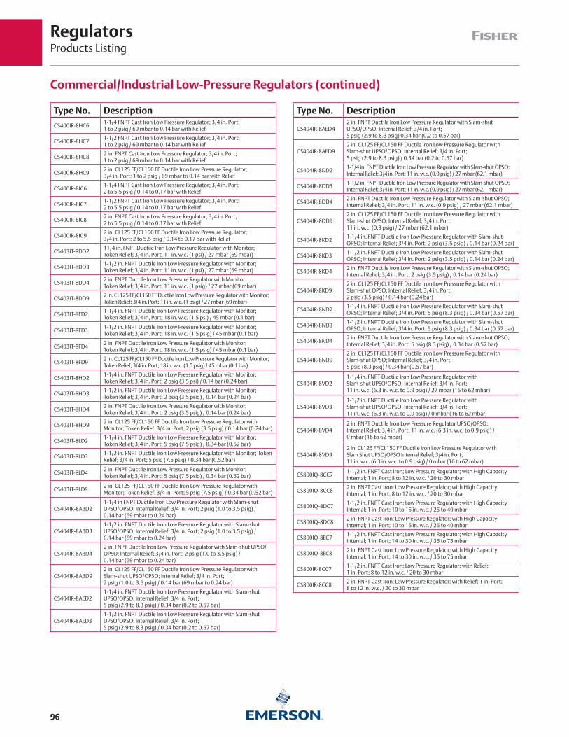
RegulatorsProducts Listing
96
Type No. Description
CS400IR-8HC61-1/4 FNPT Cast Iron Low Pressure Regulator; 3/4 in. Port; 1 to 2 psig / 69 mbar to 0.14 bar with Relief
CS400IR-8HC71-1/2 FNPT Cast Iron Low Pressure Regulator; 3/4 in. Port; 1 to 2 psig / 69 mbar to 0.14 bar with Relief
CS400IR-8HC82 in. FNPT Cast Iron Low Pressure Regulator; 3/4 in. Port; 1 to 2 psig / 69 mbar to 0.14 bar with Relief
CS400IR-8HC92 in. CL125 FF/CL150 FF Ductile Iron Low Pressure Regulator; 3/4 in. Port; 1 to 2 psig / 69 mbar to 0.14 bar with Relief
CS400IR-8IC61-1/4 FNPT Cast Iron Low Pressure Regulator; 3/4 in. Port; 2 to 5.5 psig / 0.14 to 0.17 bar with Relief
CS400IR-8IC71-1/2 FNPT Cast Iron Low Pressure Regulator; 3/4 in. Port; 2 to 5.5 psig / 0.14 to 0.17 bar with Relief
CS400IR-8IC82 in. FNPT Cast Iron Low Pressure Regulator; 3/4 in. Port; 2 to 5.5 psig / 0.14 to 0.17 bar with Relief
CS400IR-8IC92 in. CL125 FF/CL150 FF Ductile Iron Low Pressure Regulator; 3/4 in. Port; 2 to 5.5 psig / 0.14 to 0.17 bar with Relief
CS403IT-8DD211/4 in. FNPT Ductile Iron Low Pressure Regulator with Monitor; Token Relief; 3/4 in. Port; 11 in. w.c. (1 psi) / 27 mbar (69 mbar)
CS403IT-8DD31-1/2 in. FNPT Ductile Iron Low Pressure Regulator with Monitor; Token Relief; 3/4 in. Port; 11 in. w.c. (1 psi) / 27 mbar (69 mbar)
CS403IT-8DD42 in. FNPT Ductile Iron Low Pressure Regulator with Monitor; Token Relief; 3/4 in. Port; 11 in. w.c. (1 psig) / 27 mbar (69 mbar)
CS403IT-8DD92 in. CL125 FF/CL150 FF Ductile Iron Low Pressure Regulator with Monitor; Token Relief; 3/4 in. Port; 11 in. w.c. (1 psig) / 27 mbar (69 mbar)
CS403IT-8FD21-1/4 in. FNPT Ductile Iron Low Pressure Regulator with Monitor; Token Relief; 3/4 in, Port; 18 in. w.c. (1.5 psi) / 45 mbar (0.1 bar)
CS403IT-8FD31-1/2 in. FNPT Ductile Iron Low Pressure Regulator with Monitor; Token Relief; 3/4 in. Port; 18 in. w.c. (1.5 psig) / 45 mbar (0.1 bar)
CS403IT-8FD42 in. FNPT Ductile Iron Low Pressure Regulator with Monitor; Token Relief; 3/4 in. Port; 18 in. w.c. (1.5 psig) / 45 mbar (0.1 bar)
CS403IT-8FD92 in. CL125 FF/CL150 FF Ductile Iron Low Pressure Regulator with Monitor; Token Relief; 3/4 in. Port; 18 in. w.c. (1.5 psig) / 45 mbar (0.1 bar)
CS403IT-8HD21-1/4 in. FNPT Ductile Iron Low Pressure Regulator with Monitor; Token Relief; 3/4 in. Port; 2 psig (3.5 psi) / 0.14 bar (0.24 bar)
CS403IT-8HD31-1/2 in. FNPT Ductile Iron Low Pressure Regulator with Monitor; Token Relief; 3/4 in. Port; 2 psig (3.5 psig) / 0.14 bar (0.24 bar)
CS403IT-8HD42 in. FNPT Ductile Iron Low Pressure Regulator with Monitor; Token Relief; 3/4 in. Port; 2 psig (3.5 psig) / 0.14 bar (0.24 bar)
CS403IT-8HD92 in. CL125 FF/CL150 FF Ductile Iron Low Pressure Regulator with Monitor; Token Relief; 3/4 in. Port; 2 psig (3.5 psig) / 0.14 bar (0.24 bar)
CS403IT-8LD21-1/4 in. FNPT Ductile Iron Low Pressure Regulator with Monitor; Token Relief; 3/4 in. Port; 5 psig (7.5 psig) / 0.34 bar (0.52 bar)
CS403IT-8LD31-1/2 in. FNPT Ductile Iron Low Pressure Regulator with Monitor; Token Relief; 3/4 in. Port; 5 psig (7.5 psig) / 0.34 bar (0.52 bar)
CS403IT-8LD42 in. FNPT Ductile Iron Low Pressure Regulator with Monitor;Token Relief; 3/4 in. Port; 5 psig (7.5 psig) / 0.34 bar (0.52 bar)
CS403IT-8LD92 in. CL125 FF/CL150 FF Ductile Iron Low Pressure Regulator with Monitor; Token Relief; 3/4 in. Port; 5 psig (7.5 psig) / 0.34 bar (0.52 bar)
CS404IR-8ABD21-1/4 in FNPT Ductile Iron Low Pressure Regulator with Slam-shut UPSO/OPSO; Internal Relief; 3/4 in. Port; 2 psig (1.0 to 3.5 psig) / 0.14 bar (69 mbar to 0.24 bar)
CS404IR-8ABD31-1/2 in. FNPT Ductile Iron Low Pressure Regulator with Slam-shut UPSO/OPSO; Internal Relief; 3/4 in. Port; 2 psig (1.0 to 3.5 psig) / 0.14 bar (69 mbar to 0.24 bar)
CS404IR-8ABD42 in. FNPT Ductile Iron Low Pressure Regulator with Slam-shut UPSO/OPSO; Internal Relief; 3/4 in. Port; 2 psig (1.0 to 3.5 psig) / 0.14 bar (69 mbar to 0.24 bar)
CS404IR-8ABD92 in. CL125 FF/CL150 FF Ductile Iron Low Pressure Regulator with Slam-shut UPSO/OPSO; Internal Relief; 3/4 in. Port; 2 psig (1.0 to 3.5 psig) / 0.14 bar (69 mbar to 0.24 bar)
CS404IR-8AED21-1/4 in. FNPT Ductile Iron Low Pressure Regulator with Slam-shut UPSO/OPSO; Internal Relief; 3/4 in. Port; 5 psig (2.9 to 8.3 psig) / 0.34 bar (0.2 to 0.57 bar)
CS404IR-8AED31-1/2 in. FNPT Ductile Iron Low Pressure Regulator with Slam-shut UPSO/OPSO; Internal Relief; 3/4 in. Port; 5 psig (2.9 to 8.3 psig) / 0.34 bar (0.2 to 0.57 bar)
Type No. Description
CS404IR-8AED42 in. FNPT Ductile Iron Low Pressure Regulator with Slam-shut UPSO/OPSO; Internal Relief; 3/4 in. Port; 5 psig (2.9 to 8.3 psig) 0.34 bar (0.2 to 0.57 bar)
CS404IR-8AED92 in. CL125 FF/CL150 FF Ductile Iron Low Pressure Regulator with Slam-shut UPSO/OPSO; Internal Relief; 3/4 in. Port; 5 psig (2.9 to 8.3 psig) / 0.34 bar (0.2 to 0.57 bar)
CS404IR-8DD21-1/4 in. FNPT Ductile Iron Low Pressure Regulator with Slam-shut OPSO; Internal Relief; 3/4 in. Port; 11 in. w.c. (0.9 psig) / 27 mbar (62.1 mbar)
CS404IR-8DD31-1/2 in. FNPT Ductile Iron Low Pressure Regulator with Slam-shut OPSO; Internal Relief; 3/4 in. Port; 11 in. w.c. (0.9 psig) / 27 mbar (62.1 mbar)
CS404IR-8DD42 in. FNPT Ductile Iron Low Pressure Regulator with Slam-shut OPSO; Internal Relief; 3/4 in. Port; 11 in. w.c. (0.9 psig) / 27 mbar (62.1 mbar)
CS404IR-8DD92 in. CL125 FF/CL150 FF Ductile Iron Low Pressure Regulator with Slam-shut OPSO; Internal Relief; 3/4 in. Port; 11 in. w.c. (0.9 psig) / 27 mbar (62.1 mbar)
CS404IR-8KD21-1/4 in. FNPT Ductile Iron Low Pressure Regulator with Slam-shut OPSO; Internal Relief; 3/4 in. Port; 2 psig (3.5 psig) / 0.14 bar (0.24 bar)
CS404IR-8KD31-1/2 in. FNPT Ductile Iron Low Pressure Regulator with Slam-shut OPSO; Internal Relief; 3/4 in. Port; 2 psig (3.5 psig) / 0.14 bar (0.24 bar)
CS404IR-8KD42 in. FNPT Ductile Iron Low Pressure Regulator with Slam-shut OPSO; Internal Relief; 3/4 in. Port; 2 psig (3.5 psig) / 0.14 bar (0.24 bar)
CS404IR-8KD92 in. CL125 FF/CL150 FF Ductile Iron Low Pressure Regulator with Slam-shut OPSO; Internal Relief; 3/4 in. Port; 2 psig (3.5 psig) / 0.14 bar (0.24 bar)
CS404IR-8ND21-1/4 in. FNPT Ductile Iron Low Pressure Regulator with Slam-shut OPSO; Internal Relief; 3/4 in. Port; 5 psig (8.3 psig) / 0.34 bar (0.57 bar)
CS404IR-8ND31-1/2 in. FNPT Ductile Iron Low Pressure Regulator with Slam-shut OPSO; Internal Relief; 3/4 in. Port; 5 psig (8.3 psig) / 0.34 bar (0.57 bar)
CS404IR-8ND42 in. FNPT Ductile Iron Low Pressure Regulator with Slam-shut OPSO; Internal Relief; 3/4 in. Port; 5 psig (8.3 psig) / 0.34 bar (0.57 bar)
CS404IR-8ND92 in. CL125 FF/CL150 FF Ductile Iron Low Pressure Regulator with Slam-shut OPSO; Internal Relief; 3/4 in. Port; 5 psig (8.3 psig) / 0.34 bar (0.57 bar)
CS404IR-8VD21-1/4 in. FNPT Ductile Iron Low Pressure Regulator with Slam-shut UPSO/OPSO; Internal Relief; 3/4 in. Port; 11 in. w.c. (6.3 in. w.c. to 0.9 psig) / 27 mbar (16 to 62 mbar)
CS404IR-8VD31-1/2 in. FNPT Ductile Iron Low Pressure Regulator with Slam-shut UPSO/OPSO; Internal Relief; 3/4 in. Port; 11 in. w.c. (6.3 in. w.c. to 0.9 psig) / 0 mbar (16 to 62 mbar)
CS404IR-8VD42 in. FNPT Ductile Iron Low Pressure Regulator UPSO/OPSO; Internal Relief; 3/4 in. Port; 11 in. w.c. (6.3 in. w.c. to 0.9 psig) / 0 mbar (16 to 62 mbar)
CS404IR-8VD92 in. CL125 FF/CL150 FF Ductile Iron Low Pressure Regulator with Slam Shut UPSO/OPSO Internal Relief; 3/4 in. Port; 11 in. w.c. (6.3 in. w.c. to 0.9 psig) / 0 mbar (16 to 62 mbar)
CS800IQ-8CC71-1/2 in. FNPT Cast Iron; Low Pressure Regulator; with High Capacity Internal; 1 in. Port; 8 to 12 in. w.c. / 20 to 30 mbar
CS800IQ-8CC82 in. FNPT Cast Iron; Low Pressure Regulator; with High Capacity Internal; 1 in. Port; 8 to 12 in. w.c. / 20 to 30 mbar
CS800IQ-8DC71-1/2 in. FNPT Cast Iron; Low Pressure Regulator; with High Capacity Internal; 1 in. Port; 10 to 16 in. w.c. / 25 to 40 mbar
CS800IQ-8DC82 in. FNPT Cast Iron; Low Pressure Regulator; with High Capacity Internal; 1 in. Port; 10 to 16 in. w.c. / 25 to 40 mbar
CS800IQ-8EC71-1/2 in. FNPT Cast Iron; Low Pressure Regulator; with High Capacity Internal; 1 in. Port; 14 to 30 in. w.c. / 35 to 75 mbar
CS800IQ-8EC82 in. FNPT Cast Iron; Low Pressure Regulator; with High Capacity Internal; 1 in. Port; 14 to 30 in. w.c. / 35 to 75 mbar
CS800IR-8CC71-1/2 in. FNPT Cast Iron; Low Pressure Regulator; with Relief; 1 in. Port; 8 to 12 in. w.c. / 20 to 30 mbar
CS800IR-8CC82 in. FNPT Cast Iron; Low Pressure Regulator; with Relief; 1 in. Port; 8 to 12 in. w.c. / 20 to 30 mbar
Commercial/Industrial Low-Pressure Regulators (continued)
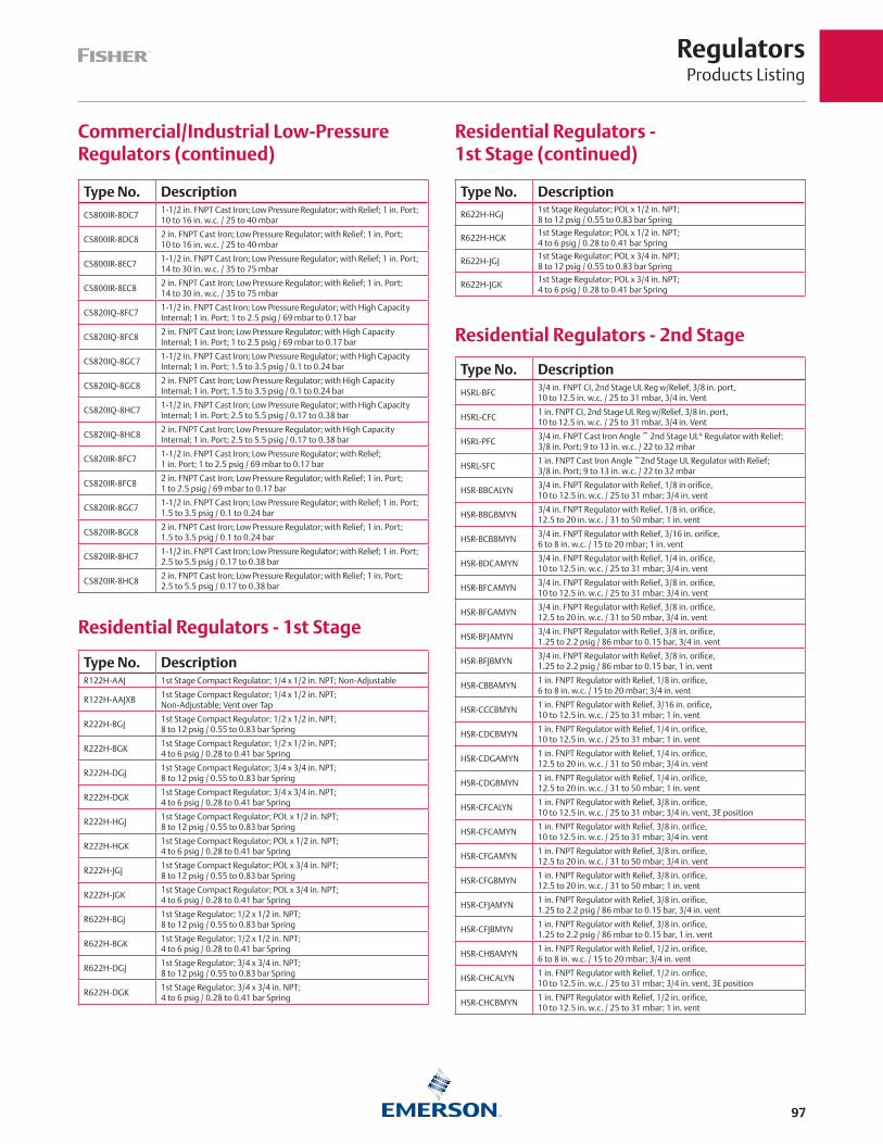
RegulatorsProducts Listing
97
Type No. Description
CS800IR-8DC71-1/2 in. FNPT Cast Iron; Low Pressure Regulator; with Relief; 1 in. Port; 10 to 16 in. w.c. / 25 to 40 mbar
CS800IR-8DC82 in. FNPT Cast Iron; Low Pressure Regulator; with Relief; 1 in. Port; 10 to 16 in. w.c. / 25 to 40 mbar
CS800IR-8EC71-1/2 in. FNPT Cast Iron; Low Pressure Regulator; with Relief; 1 in. Port; 14 to 30 in. w.c. / 35 to 75 mbar
CS800IR-8EC82 in. FNPT Cast Iron; Low Pressure Regulator; with Relief; 1 in. Port; 14 to 30 in. w.c. / 35 to 75 mbar
CS820IQ-8FC71-1/2 in. FNPT Cast Iron; Low Pressure Regulator; with High Capacity Internal; 1 in. Port; 1 to 2.5 psig / 69 mbar to 0.17 bar
CS820IQ-8FC82 in. FNPT Cast Iron; Low Pressure Regulator; with High Capacity Internal; 1 in. Port; 1 to 2.5 psig / 69 mbar to 0.17 bar
CS820IQ-8GC71-1/2 in. FNPT Cast Iron; Low Pressure Regulator; with High Capacity Internal; 1 in. Port; 1.5 to 3.5 psig / 0.1 to 0.24 bar
CS820IQ-8GC82 in. FNPT Cast Iron; Low Pressure Regulator; with High Capacity Internal; 1 in. Port; 1.5 to 3.5 psig / 0.1 to 0.24 bar
CS820IQ-8HC71-1/2 in. FNPT Cast Iron; Low Pressure Regulator; with High Capacity Internal; 1 in. Port; 2.5 to 5.5 psig / 0.17 to 0.38 bar
CS820IQ-8HC82 in. FNPT Cast Iron; Low Pressure Regulator; with High Capacity Internal; 1 in. Port; 2.5 to 5.5 psig / 0.17 to 0.38 bar
CS820IR-8FC71-1/2 in. FNPT Cast Iron; Low Pressure Regulator; with Relief; 1 in. Port; 1 to 2.5 psig / 69 mbar to 0.17 bar
CS820IR-8FC82 in. FNPT Cast Iron; Low Pressure Regulator; with Relief; 1 in. Port; 1 to 2.5 psig / 69 mbar to 0.17 bar
CS820IR-8GC71-1/2 in. FNPT Cast Iron; Low Pressure Regulator; with Relief; 1 in. Port; 1.5 to 3.5 psig / 0.1 to 0.24 bar
CS820IR-8GC82 in. FNPT Cast Iron; Low Pressure Regulator; with Relief; 1 in. Port; 1.5 to 3.5 psig / 0.1 to 0.24 bar
CS820IR-8HC71-1/2 in. FNPT Cast Iron; Low Pressure Regulator; with Relief; 1 in. Port; 2.5 to 5.5 psig / 0.17 to 0.38 bar
CS820IR-8HC82 in. FNPT Cast Iron; Low Pressure Regulator; with Relief; 1 in. Port; 2.5 to 5.5 psig / 0.17 to 0.38 bar
Commercial/Industrial Low-Pressure Regulators (continued)
Residential Regulators - 1st Stage
Residential Regulators - 1st Stage (continued)
Type No. DescriptionR122H-AAJ 1st Stage Compact Regulator; 1/4 x 1/2 in. NPT; Non-Adjustable
R122H-AAJXB1st Stage Compact Regulator; 1/4 x 1/2 in. NPT; Non-Adjustable; Vent over Tap
R222H-BGJ1st Stage Compact Regulator; 1/2 x 1/2 in. NPT; 8 to 12 psig / 0.55 to 0.83 bar Spring
R222H-BGK1st Stage Compact Regulator; 1/2 x 1/2 in. NPT; 4 to 6 psig / 0.28 to 0.41 bar Spring
R222H-DGJ1st Stage Compact Regulator; 3/4 x 3/4 in. NPT; 8 to 12 psig / 0.55 to 0.83 bar Spring
R222H-DGK1st Stage Compact Regulator; 3/4 x 3/4 in. NPT; 4 to 6 psig / 0.28 to 0.41 bar Spring
R222H-HGJ1st Stage Compact Regulator; POL x 1/2 in. NPT; 8 to 12 psig / 0.55 to 0.83 bar Spring
R222H-HGK1st Stage Compact Regulator; POL x 1/2 in. NPT; 4 to 6 psig / 0.28 to 0.41 bar Spring
R222H-JGJ1st Stage Compact Regulator; POL x 3/4 in. NPT; 8 to 12 psig / 0.55 to 0.83 bar Spring
R222H-JGK1st Stage Compact Regulator; POL x 3/4 in. NPT; 4 to 6 psig / 0.28 to 0.41 bar Spring
R622H-BGJ1st Stage Regulator; 1/2 x 1/2 in. NPT; 8 to 12 psig / 0.55 to 0.83 bar Spring
R622H-BGK1st Stage Regulator; 1/2 x 1/2 in. NPT; 4 to 6 psig / 0.28 to 0.41 bar Spring
R622H-DGJ1st Stage Regulator; 3/4 x 3/4 in. NPT; 8 to 12 psig / 0.55 to 0.83 bar Spring
R622H-DGK1st Stage Regulator; 3/4 x 3/4 in. NPT; 4 to 6 psig / 0.28 to 0.41 bar Spring
Type No. DescriptionR622H-HGJ
1st Stage Regulator; POL x 1/2 in. NPT; 8 to 12 psig / 0.55 to 0.83 bar Spring
R622H-HGK1st Stage Regulator; POL x 1/2 in. NPT; 4 to 6 psig / 0.28 to 0.41 bar Spring
R622H-JGJ1st Stage Regulator; POL x 3/4 in. NPT; 8 to 12 psig / 0.55 to 0.83 bar Spring
R622H-JGK1st Stage Regulator; POL x 3/4 in. NPT; 4 to 6 psig / 0.28 to 0.41 bar Spring
Residential Regulators - 2nd Stage
Type No. Description
HSRL-BFC3/4 in. FNPT CI, 2nd Stage UL Reg w/Relief, 3/8 in. port, 10 to 12.5 in. w.c. / 25 to 31 mbar, 3/4 in. Vent
HSRL-CFC1 in. FNPT CI, 2nd Stage UL Reg w/Relief, 3/8 in. port, 10 to 12.5 in. w.c. / 25 to 31 mbar, 3/4 in. Vent
HSRL-PFC3/4 in. FNPT Cast Iron Angle ~ 2nd Stage UL® Regulator with Relief; 3/8 in. Port; 9 to 13 in. w.c. / 22 to 32 mbar
HSRL-SFC1 in. FNPT Cast Iron Angle ~2nd Stage UL Regulator with Relief; 3/8 in. Port; 9 to 13 in. w.c. / 22 to 32 mbar
HSR-BBCALYN3/4 in. FNPT Regulator with Relief, 1/8 in orifice, 10 to 12.5 in. w.c. / 25 to 31 mbar; 3/4 in. vent
HSR-BBGBMYN3/4 in. FNPT Regulator with Relief, 1/8 in. orifice, 12.5 to 20 in. w.c. / 31 to 50 mbar; 1 in. vent
HSR-BCBBMYN3/4 in. FNPT Regulator with Relief, 3/16 in. orifice, 6 to 8 in. w.c. / 15 to 20 mbar; 1 in. vent
HSR-BDCAMYN3/4 in. FNPT Regulator with Relief, 1/4 in. orifice, 10 to 12.5 in. w.c. / 25 to 31 mbar; 3/4 in. vent
HSR-BFCAMYN3/4 in. FNPT Regulator with Relief, 3/8 in. orifice, 10 to 12.5 in. w.c. / 25 to 31 mbar; 3/4 in. vent
HSR-BFGAMYN3/4 in. FNPT Regulator with Relief, 3/8 in. orifice, 12.5 to 20 in. w.c. / 31 to 50 mbar, 3/4 in. vent
HSR-BFJAMYN3/4 in. FNPT Regulator with Relief, 3/8 in. orifice, 1.25 to 2.2 psig / 86 mbar to 0.15 bar, 3/4 in. vent
HSR-BFJBMYN3/4 in. FNPT Regulator with Relief, 3/8 in. orifice, 1.25 to 2.2 psig / 86 mbar to 0.15 bar, 1 in. vent
HSR-CBBAMYN1 in. FNPT Regulator with Relief, 1/8 in. orifice, 6 to 8 in. w.c. / 15 to 20 mbar; 3/4 in. vent
HSR-CCCBMYN1 in. FNPT Regulator with Relief, 3/16 in. orifice, 10 to 12.5 in. w.c. / 25 to 31 mbar; 1 in. vent
HSR-CDCBMYN1 in. FNPT Regulator with Relief, 1/4 in. orifice, 10 to 12.5 in. w.c. / 25 to 31 mbar; 1 in. vent
HSR-CDGAMYN1 in. FNPT Regulator with Relief, 1/4 in. orifice, 12.5 to 20 in. w.c. / 31 to 50 mbar; 3/4 in. vent
HSR-CDGBMYN1 in. FNPT Regulator with Relief, 1/4 in. orifice, 12.5 to 20 in. w.c. / 31 to 50 mbar; 1 in. vent
HSR-CFCALYN1 in. FNPT Regulator with Relief, 3/8 in. orifice, 10 to 12.5 in. w.c. / 25 to 31 mbar; 3/4 in. vent, 3E position
HSR-CFCAMYN1 in. FNPT Regulator with Relief, 3/8 in. orifice, 10 to 12.5 in. w.c. / 25 to 31 mbar; 3/4 in. vent
HSR-CFGAMYN1 in. FNPT Regulator with Relief, 3/8 in. orifice, 12.5 to 20 in. w.c. / 31 to 50 mbar; 3/4 in. vent
HSR-CFGBMYN1 in. FNPT Regulator with Relief, 3/8 in. orifice, 12.5 to 20 in. w.c. / 31 to 50 mbar; 1 in. vent
HSR-CFJAMYN1 in. FNPT Regulator with Relief, 3/8 in. orifice, 1.25 to 2.2 psig / 86 mbar to 0.15 bar, 3/4 in. vent
HSR-CFJBMYN1 in. FNPT Regulator with Relief, 3/8 in. orifice, 1.25 to 2.2 psig / 86 mbar to 0.15 bar, 1 in. vent
HSR-CHBAMYN1 in. FNPT Regulator with Relief, 1/2 in. orifice, 6 to 8 in. w.c. / 15 to 20 mbar; 3/4 in. vent
HSR-CHCALYN1 in. FNPT Regulator with Relief, 1/2 in. orifice, 10 to 12.5 in. w.c. / 25 to 31 mbar; 3/4 in. vent, 3E position
HSR-CHCBMYN1 in. FNPT Regulator with Relief, 1/2 in. orifice, 10 to 12.5 in. w.c. / 25 to 31 mbar; 1 in. vent

RegulatorsProducts Listing
98
Residential Regulators - Integral Two-Stage
Residential Regulators - Integral Two-Stage, 2 psi / 0.14 bar Outlet
Residential Regulators - 2 psi / 0.14 bar Outlet
Type No. Description
R622E-BCH2nd Stage Regulator; 1/2 x 1/2 in. NPT; 1 to 2.2 psig / 69 mbar to 0.15 bar Spring
R622E-DCH2nd Stage Regulator; 3/4 x 3/4 in. NPT; 1 to 2.2 psig / 69 mbar to 0.15 bar Spring
R652E-DFH2nd Stage Regulator; Backmount; 3/4 x 3/4 in. NPT; 1 to 2.2 psig / 69 mbar to 0.15 bar Spring
Type No. Description
R232A-BBFCompact Integral 2nd Stage Regulator; 1/4 x 1/2 in. NPT; 9.5 to 13 in. w.c. / 24 to 32 mbar Spring
R232A-BBFXACompact Integral 2nd Stage Regulator; 1/4 x 1/2 in. NPT; 9.5 to 13 in. w.c. / 24 to 32 mbar Spring; Vent Opposite Tap
R232A-HBFCompact Integral 2nd Stage Regulator; POL x 1/2 in. NPT; 9.5 to 13 in. w.c. / 24 to 32 mbar Spring
R232A-HBFXACompact Integral 2nd Stage Regulator; POL x 1/2 in. NPT; 9.5 to 13 in. w.c. / 24 to 32 mbar Spring; Vent Opposite Tap
R632A-BCFIntegral 2nd Stage Regulator; 1/4 x 1/2 in. NPT; 9 to 13 in. w.c. / 24 to 32 mbar Spring
R632A-BCFXAIntegral 2nd Stage Regulator; 1/4 x 1/2 in. NPT; 9 to 13 in. w.c. / 24 to 32 mbar Spring; Vent Opposite Taps
R632A-BCGIntegral 2nd Stage Regulator; 1/4 x 1/2 in. NPT; 13 to 20 in. w.c. / 32 to 50 mbar Spring
R632A-CFFIntegral 2nd Stage Regulator; 1/4 x 3/4 in. NPT; 9 to 13 in. w.c. / 22 to 32 mbar Spring
R632A-CFFXAIntegral 2nd Stage Regulator; 1/4 x 3/4 in. NPT; 9 to 13 in. w.c. / 22 to 32 mbar Spring; Vent Opposite Taps
R632A-CFGIntegral 2nd Stage Regulator; 1/4 x 3/4 in. NPT; 13 to 20 in. w.c. / 32 to 50 mbar Spring
R632A-HCFIntegral 2nd Stage Regulator; POL x 1/2 in. NPT; 9 to 13 in. w.c. / 22 to 32 mbar Spring
R632A-HCFXAIntegral 2nd Stage Regulator; POL x 1/2 in. NPT; 9 to 13 in. w.c. / 22 to 32 mbar Spring; Vent Opposite Taps
R632A-JFFIntegral 2nd Stage Regulator; POL x 3/4 in. NPT; 9 to 13 in. w.c. / 22 to 32 mbar Spring
R632A-JFFXAIntegral 2nd Stage Regulator; POL x 3/4 in. NPT; 9 to 13 in. w.c. / 22 to 32 mbar Spring; Vent Opposite Taps
Type No. DescriptionR232E-BBH
Compact Integral 2nd Stage Regulator; 1/4 x 1/2 in. NPT; 1 to 2.2 psig / 69 mbar to 0.15 bar Spring
R232E-BBHXACompact Integral 2nd Stage Regulator; 1/4 x 1/2 in. NPT; 1 to 2.2 psig / 69 mbar to 0.15 bar Spring; Vent Opposite Tap
R232E-HBHCompact Integral 2nd Stage Regulator; POL x 1/2 in. NPT; 1 to 2.2 psig / 69 mbar to 0.15 bar Spring
R232E-HBHXACompact integral 2nd Stage Regulator, Pol X 1/2 in. NPT, 1 to 2.2 psig / 69 mbar to 0.15 bar Spring, Vent Opposite Tap
R632E-BCHIntegral 2nd Stage Regulator; 1/4 x 1/2 in. NPT; 1 to 2.2 psig / 69 mbar to 0.15 bar Spring
R632E-BCHXAIntegral 2nd Stage Regulator; 1/4 x 1/2 in. NPT; 1 to 2.2 psig / 69 mbar to 0.15 bar Spring; Vent Opposite Taps
R632E-CFHIntegral 2nd Stage Regulator; 1/4 x 3/4 in. NPT; 1 to 2.2 psig / 69 mbar to 0.15 bar Spring
R632E-CFHXAIntegral 2nd Stage Regulator; 1/4 x 3/4 in. NPT; 1 to 2.2 psig / 69 mbar to 0.15 bar Spring; Vent Opposite Taps
R632E-HCHIntegral 2nd Stage Regulator; POL x 1/2 in. NPT; 1 to 2.2 psig / 69 mbar to 0.15 bar Spring
R632E-HCHXAIntegral 2nd Stage Regulator; POL x 1/2 in. NPT; 1 to 2.2 psig / 69 mbar to 0.15 bar Spring; Vent Opposite Taps
R632E-JFHIntegral 2nd Stage Regulator; POL x 3/4 in. NPT; 1 to 2.2 psig / 69 mbar to 0.15 bar Spring
R632E-JFHXAIntegral 2nd Stage Regulator; POL x 3/4 in. NPT; 1 to 2.2 psig / 69 mbar to 0.15 bar Spring; Vent Opposite Taps
Residential Regulators - 2nd Stage (continued)
Type No. Description
HSR-CHGBMYN1 in. FNPT Regulator with Relief, 1/2 in. orifice, 12.5 to 20 in. w.c. / 31 to 50 mbar; 1 in. vent
HSR-CHHALYN1 in. FNPT Regulator with Relief, 1/2 in. orifice, 20 to 35 in. w.c. / 50 to 87 mbar; 3/4 in. vent, 3E position
HSR-CHJBMYN1 in. FNPT Regulator with Relief, 1/2 in. orifice, 1.25 to 2.2 psig / 86 mbar to 0.15 bar, 1 in. vent
HSR-PFCAMYN3/4 in. FNPT Cast Iron Angle, Low Pressure Regulator with Relief, 3/8 in. port, 10 to 12.5 in. w.c. / 25 to 31 mbar, 3/4 in. Vent
HSR-SFCAMYN1 in. FNPT Cast Iron Angle, Low Pressure Regulator with Relief, 3/8 in. port, 10 to 12.5 in. w.c. / 25 to 31 mbar, 3/4 in. Vent
R222-BAF2nd Stage Compact Regulator; 1/2 x 1/2 in. NPT; 9.5 to 13 in. w.c. Spring
R222-BAFXA2nd Stage Compact Regulator; 1/2 x 1/2 in NPT; 9.5 to 13 in. w.c. / 24 to 32 mbar Spring; Vent over Outlet
R622-BCC2nd Stage Regulator; 1/2 x 1/2 in. NPT; 8 to 10 in. w.c. / 20 to 25 mbar Spring
R622-BCF2nd Stage Regulator; 1/2 x 1/2 in. NPT; 9 to 13 in. w.c. / 22 to 32 mbar Spring
R622-BCFXA2nd Stage Regulator; 1/2 x 1/2 in. NPT; 9 to 13 in. w.c. / 22 to 32 mbar Spring; Vent over Outlet
R622-BCG2nd Stage Regulator; 1/2 x 1/2 in. NPT; 13 to 20 in. w.c. / 32 to 50 mbar Spring
R622-BCMXB2nd Stage Regulator; 1/2 x 1/2 in. NPT; 20 to 35 in. w.c. / 50 to 87 mbar Spring
R622-CFF2nd Stage Regulator; 1/2 x 3/4 in. NPT; 9 to 13 in. w.c. / 22 to 32 mbar Spring
R622-CFFXA2nd Stage Regulator; 1/2 x 3/4 inch NPT; 9 to 13 in. w.c. / 22 to 32 mbar Spring; Vent over Outlet
R622-CFFXB2nd Stage Regulator; 1/2 x 3/4 in. NPT; 9 to 13 in. w.c. / 22 to 32 mbar Spring; Vent Opposite Taps
R622-CFG2nd Stage Regulator; 1/2 x 3/4 in. NPT; 13 to 20 in. w.c. / 32 to 50 mbar Spring
R622-CFGXA2nd Stage Regulator; 1/2 x 3/4 in. NPT; 13 to 20 in. w.c. / 32 to 50 mbar Spring; Vent over Inlet
R622-DFF2nd Stage Regulator; 3/4 x 3/4 in. NPT; 9 to 13 in. w.c. / 22 to 32 mbar Spring
R622-DFFXB2nd Stage Regulator; 3/4 x 3/4 in. NPT; 9 to 13 in. w.c. / 22 to 32 mbar Spring; Vent over Outlet
R622-DFG2nd Stage Regulator; 3/4 x 3/4 in. NPT; 13 to 20 in. w.c. / 32 to 50 mbar Spring
R642-DFF2nd Stage Regulator; Side Outlet; 3/4 x 3/4 in. NPT; 9 to 13 in. w.c. / 22 to 32 mbar Spring
R642-DFFXA2nd Stage Regulator; Side Outlet; 3/4 x 3/4 in. NPT; 9 to 13 in. w.c. / 22 to 32 mbar Spring; Vent over Outlet
R652-CFF2nd Stage Regulator; Backmount; 1/2 x 3/4 in. NPT; 9 to 13 in. w.c. / 22 to 32 mbar Spring
R652-DFF2nd Stage Regulator; Backmount; 3/4 x 3/4 in. NPT; 9 to 13 in. w.c. / 22 to 32 mbar Spring
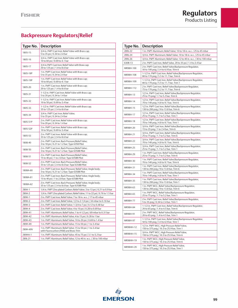
RegulatorsProducts Listing
99
Type No. Description
1805-153/4 in. FNPT Cast Iron; Relief Valve with Brass cap; 5 to 35 psi / 0.34 to 2.4 bar
1805-163/4 in. FNPT Cast Iron; Relief Valve with Brass cap; 10 to 60 psi / 0.69 to 4.1 bar
1805-173/4 in.FNPT Cast Iron; Relief Valve with Brass cap; 20 to 125 psi / 1.4 to 8.6 bar
1805-18P1 in. FNPT Cast Iron; Relief Valve with Brass cap; 5 to 35 psi / 0.34 to 2.4 bar
1805-19P1 in. FNPT Cast Iron; Relief Valve with Brass cap; 10 to 60 psi / 0.69 to 4.1 bar
1805-201 in. FNPT Cast Iron; Relief Valve with Brass cap; 20 to 125 psi / 1.4 to 8.6 bar
1805-311-1/2 in. FNPT Cast Iron; Relief Valve with Brass cap; 5 to 20 psi / 0.34 to 1.4 bar
1805-321-1/2 in. FNPT Cast Iron; Relief Valve with Brass cap; 10 to 50 psi / 0.69 to 3.4 bar
1805-331-1/2 in. FNPT Cast Iron; Relief Valve with Brass cap; 35 to 125 psi / 2.4 to 8.6 bar
1805-343/4 in. FNPT Cast Iron; Relief Valve; 5 to 35 psi / 0.34 to 2.4 bar
1805-51P2 in. FNPT Cast Iron; Relief Valve with Brass cap; 5 to 20 psi / 0.34 to 1.4 bar
1805-52P2 in. FNPT Cast Iron; Relief Valve with Brass cap; 10 to 50 psi / 0.69 to 3.4 bar
1805-532 in. FNPT Cast Iron; Relief Valve with Brass cap; 35 to 125 psi / 2.4 to 8.6 bar
1808-402 in. FNPT Cast Iron; Back Pressure/Relief Valve; 3 to 18 psi / 0.21 to 1.2 bar; Type 6358 Pilot
1808-502 in. FNPT Cast Iron; Back Pressure/Relief Valve; 3 to 18 psi / 0.21 to 1.2 bar; Type 6358B Pilot
1808-512 in. FNPT Cast Iron; Back Pressure/Relief Valve; 15 to 40 psi / 1 to 2.8 bar; Type 6358B Pilot
1808-522 in. FNPT Cast Iron; Back Pressure/Relief Valve; 35 to 125 psi / 2.4 to 8.6 bar; Type 6358B Pilot
1808A-602 in. FNPT Cast Iron; Back Pressure/ Relief Valve; Angle body; 3 to 18 psi / 0.21 to 1.2 bar; Type 6358B Pilot
1808A-612 in. FNPT Cast Iron; Back Pressure/ Relief Valve; Angle body; 15 to 40 psi / 1 to 2.8 bar; Type 6358B Pilot
1808A-622 in. FNPT Cast Iron; Back Pressure/ Relief Valve; Angle body; 35 to 125 psi / 2.4 to 8.6 bar; Type 6358B Pilot
289A-1 1/4 in. FNPT Zinc-plated Carbon; Relief Valve; 3 to 13 psi / 0.21 to 0.9 bar
289A-2 1/4 in. FNPT Zinc-plated Carbon; Relief Valve; 11 to 22 psi / 0.76 to 1.5 bar
289H-1 2 in. FNPT Cast Iron; Relief Valve; 7 to 18 in. w.c. / 17 to 45 mbar
289H-2 2 in. FNPT Cast Iron; Relief Valve; 1/2 to 2-1/4 psi / 34 mbar to 0.16 bar
289H-3 2 in. FNPT Cast Iron; Relief Valve; 1-3/4 to 7 psi / 0.12 to 0.48 bar
289H-4 2 in. FNPT Cast Iron; Relief Valve; 4 to 10 psi / 0.28 to 0.69 bar
289H-41 1 in. FNPT Aluminum; Relief Valve; 1 to 4-1/2 psi / 69 mbar to 0.31 bar
289H-42 1 in. FNPT Aluminum; Relief Valve; 4 to 15 psi / 0.28 to 1 bar
289H-43 1 in. FNPT Aluminum; Relief Valve; 10 to 20 psi / 0.69 to 1.4 bar
289H-49 1 in. FNPT Aluminum; Relief Valve; 15 to 50 psi / 1 to 3.4 bar
289H-49V1 in. FNPT Aluminum; Relief Valve; 15 to 50 psi / 1 to 3.4 barwith Fluorocarbon (FKM) and Brass Trim
289HH-1 1 in. FNPT Aluminum; Relief Valve; 45 to 75 psi / 3.1 to 5.2 bar
289L-21 1 in. FNPT Aluminum; Relief Valve; 12 to 40 in. w.c. / 30 to 100 mbar
Type No. Description289L-22 1 in. FNPT Aluminum; Relief Valve; 10 to 18 in. w.c. / 25 to 45 mbar
289L-24 3/4 in. FNPT Aluminum; Relief Valve; 10 to 18 in. w.c. / 25 to 45 mbar
289L-26 3/4 in. FNPT Aluminum; Relief Valve; 12 to 40 in. w.c. / 30 to 100 mbar
630R-13 2 in. FNPT Cast Iron, Relief Valve, 20 to 35 psi / 1.4 to 2.4 bar
MR98H-1002 in. FNPT Cast Iron, Relief Valve/Backpressure Regulator, 50 to 100 psig / 3.4 to 6.9 bar, Trim 6
MR98H-1081-1/2 in. FNPT Cast Iron, Relief Valve/Backpressure Regulator, 80 to 170 psig / 5.5 to 11.7 bar, Trim 6
MR98H-1091-1/2 in. FNPT Cast Iron, Relief Valve/Backpressure Regulator, 80 to 170 psig / 5.5 to 11.7 bar, Trim 1
MR98H-1122 in. FNPT Cast Iron, Relief Valve/Backpressure Regulator, 75 to 170 psig / 5.2 to 11.7 bar, Trim 6
MR98H-131/2 in. FNPT Cast Iron, Relief Valve/Backpressure Regulator, 25 to 75 psig/ 1.7 to 5.2 bar, Trim 6
MR98H-141/2 in. FNPT Cast Iron, Relief Valve/Backpressure Regulator, 70 to 140 psig / 4.8 to 9.7 bar, Trim 6
MR98H-151/2 in. FNPT Cast Iron, Relief Valve/Backpressure Regulator, 130 to 200 psig / 9 to 13.8 bar, Trim 6
MR98H-171/2 in. FNPT Cast Iron, Relief Valve/Backpressure Regulator, 25 to 75 psig / 1.7 to 5.2 bar, Trim 1
MR98H-181/2 in. FNPT Cast Iron, Relief Valve/Backpressure Regulator, 70 to 140 psig / 4.8 to 9.7 bar, Trim 1
MR98H-203/4 in. FNPT Cast Iron, Relief Valve/Backpressure Regulator, 15 to 35 psig / 1 to 2.4 bar, Trim 6
MR98H-213/4 in. FNPT Cast Iron, Relief Valve/Backpressure Regulator, 25 to 75 psig / 1.7 to 5.2 bar, Trim 6
MR98H-223/4 in. FNPT Cast Iron, Relief Valve/Backpressure Regulator, 70 to 140 psig / 4.8 to 9.7 bar, Trim 6
MR98H-253/4 in. FNPT Cast Iron, Relief Valve/Backpressure Regulator, 25 to 75 psig / 1.7 to 5.2 bar, Trim 1
MR98H-291 in. FNPT Cast Iron, Relief Valve/Backpressure Regulator, 25 to 75 psig / 1.7 to 5.2 bar, Trim 6
MR98H-301 in. FNPT Cast Iron, Relief Valve/Backpressure Regulator, 70 to 140 psig / 4.8 to 9.7 bar, Trim 6
MR98H-311 in. FNPT Cast Iron, Relief Valve/Backpressure Regulator, 130 to 200 psig / 9 to 13.8 bar, Trim 6
MR98H-341 in. FNPT Cast Iron, Relief Valve/Backpressure Regulator, 70 to 140 psig / 4.8 to 9.7 bar, Trim 1
MR98H-351 in. FNPT Cast Iron, Relief Valve/Backpressure Regulator, 130 to 200 psig / 9 to 13.8 bar, Trim 1
MR98H-631 in. FNPT WCC, Relief Valve/Backpressure Regulator, 130 to 200 psig / 9 to 13.8 bar, Trim 6
MR98H-651 in. FNPT WCC, Relief Valve/Backpressure Regulator, 25 to 75 psig / 1.7 to 5.2 bar, Trim 1
MR98H-772 in. FNPT Cast Iron, Relief Valve/Backpressure Regulator, 5 to 35 psig / 0.34 to 2.4 bar, Trim 1
MR98H-841-1/2 in. FNPT Cast Iron, Relief Valve/Backpressure Regulator, 20 to 65 psig / 1.4 to 4.5 bar, Trim 6
MR98H-912 in. FNPT WCC, Relief Valve/Backpressure Regulator, 20 to 65 psig / 1.4 to 4.5 bar, Trim 1
MR98H-971-1/2 in. FNPT Cast Iron, Relief Valve/Backpressure Regulator, 50 to 100 psig / 3.4 to 6.9 bar, Trim 1
MR98HH-121/2 in. FNPT WCC, High Pressure Relief Valve, 150 to 375 psig / 10.3 to 25.9 bar, Trim 1
MR98HH-153/4 in. FNPT WCC, High Pressure Relief Valve, 150 to 375 psig / 10.3 to 25.9 bar, Trim 6
MR98HH-191 in. FNPT WCC, High Pressure Relief Valve, 150 to 375 psig / 10.3 to 25.9 bar, Trim 6
MR98HH-201 in. FNPT WCC, High Pressure Relief Valve, 150 to 375 psig / 10.3 to 25.9 bar, Trim 1
Backpressure Regulators/Relief
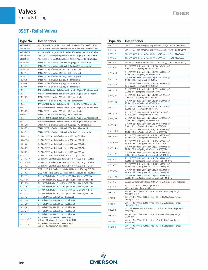
ValvesProducts Listing
100
Type No. Description63EGLP-250 4 in. CL300 RF Flange; UL® Listed Multipilot Relief; 250 psig / 17.2 bar
63EGLP-EB1 4 in. CL300 RF Flange; Multipilot Relief; 85 to 140 psig / 5.9 to 9.7 bar
63EGLP-EB2 4 in. CL300 RF Flange; Multipilot Relief; 130 to 200 psig / 9 to 13.8 bar
63EGLP-EB3 4 in. CL300 RF Flange; Multipilot Relief; 180 to 350 psig / 12.4 to 24.1 bar
63EGLP-EBH 4 in. CL300 RF Flange; Multipilot Relief; 250 to 375 psig / 17.2 to 25.9 bar
H110-250 1/4 in. NPT Relief Valve; UL Listed; 250 psig / 17.2 bar setpoint
H110-312 1/4 in. NPT Relief Valve; UL Listed; 312 psig / 21.5 bar setpoint
H120-120 1/4 in. NPT Relief Valve; 120 psig / 8.3 bar setpoint
H120-145 1/4 in. NPT Relief Valve; 145 psig / 10 bar setpoint
H120-275 1/4 in. NPT Relief Valve; 275 psig / 19 bar setpoint
H120-30 1/4 in. NPT Relief Valve; 30 psig / 2.1 bar setpoint
H120-40 1/4 in. NPT Relief Valve; 40 psig / 2.8 bar setpoint
H120-60 1/4 in. NPT Relief Valve; 60 psig / 4.1 bar setpoint
H123 1/4 in. NPT Hydrostatic Relief Valve; UL Listed; 375 psig / 25.9 bar setpoint
H124 1/4 in. NPT Hydrostatic Relief Valve; UL Listed; 450 psig / 31 bar setpoint
H125-250 1/2 in. NPT Relief Valve; 250 psig / 17.2 bar setpoint
H135-312 1/2 in. NPT Relief Valve; 312 psig / 21.5 bar setpoint
H144 1/2 in. NPT Hydrostatic Relief Valve; UL Listed; 450 psig / 31 bar setpoint
H148 1/2 in. NPT Hydrostatic Relief Valve; UL Listed; 375 psig / 25.9 bar setpoint
H150-250 3/4 in. NPT Relief Valve; 250 psig / 17.2 bar setpoint
H160-312 3/4 in. NPT Relief Valve; 312 psig / 21.5 bar setpoint
H173 3/4 in. NPT Hydrostatic Relief Valve; UL Listed; 375 psig / 25.9 bar setpoint
H174 3/4 in. NPT Hydrostatic Relief Valve; UL Listed; 450 psig / 31 bar setpoint
H185-250 3/4 in. NPT Relief Valve; UL Listed; 250 psig / 17.2 bar setpoint
H185-275 3/4 in. NPT Relief Valve; UL Listed; 275 psig / 19 bar setpoint
H185-312 3/4 in. NPT Relief Valve; UL Listed; 312 psig / 21.5 bar setpoint
H284-125 3 x 2 in. NPT Brass Relief Valve; Set at 125 psig / 8.6 bar
H284-156 3 x 2 in. NPT Brass Relief Valve; Set at 156 psig / 10.8 bar
H284-225 3 x 2 in. NPT Brass Relief Valve; Set at 225 psig / 15.5 bar
H284-250 3 x 2 in. NPT Brass Relief Valve; Set at 250 psig / 17.2 bar
H284-275 3 x 2 in. NPT Brass Relief Valve; Set at 275 psig / 19 bar
H284-312 3 x 2 in. NPT Brass Relief Valve; Set at 312 psig / 21.5 bar
H5114-250 3 x 2 in. NPT Stainless Steel Relief Valve; Set at 250 psig / 17.2 bar
H5114-265 3 x 2 in. NPT Stainless Steel Relief Valve; Set at 265 psig / 18.3 bar
H5114-275 3 x 2 in. NPT Stainless Steel Relief Valve; Set at 275 psig / 19 bar
H5118-250 3 X 2 in. SST Relief Valve, UL, Nitrile (NBR), Set at 250 psig / 17.2 bar
H5118-265 3 X 2 in. SST Relief Valve, UL, Nitrile (NBR), Set at 265 psi / 18.3 bar
H722-125 2 in. NPT Relief Valve; Set at 125 psi / 8.6 bar; Nitrile (NBR) Trim
H722-156 2 in. NPT Relief Valve; Set at 156 psi / 10.8 bar; Nitrile (NBR) Trim
H722-250 2 in. NPT Relief Valve; Set at 250 psi / 17.2 bar; Nitrile (NBR) Trim
H722-265 2 in. NPT Relief Valve; Set at 265 psi / 18.3 bar; Nitrile (NBR) Trim
H722-275 2 in. NPT Relief Valve; Set at 275 psi / 19 bar; Nitrile (NBR) Trim
H722-312 2 in. NPT Relief Valve; Set at 312 psi / 21.5 bar; Nitrile (NBR) Trim
H733-125 3 in. Relief Valve; SST; 125 psi / 8.6 bar set
H733-156 3 in. Relief Valve; SST; 156 psi / 10.8 bar set
H733-250 3 in. Relief Valve; SST; 250 psi / 17.2 bar set
H733-265 3 in. Relief Valve; SST; 265 psi / 18.3 bar set
H733-275 3 in. Relief Valve; SST; 275 psi / 19.0 bar set
H733-312 3 in. Relief Valve; SST; 312 psi / 21.5 bar set
H733F3-2503 in. Relief Valve; ASME CL300 RF Flange; 250 psi / 21.5 bar / 17.2 bar set; Nitrile (NBR)
H733F3-2653 in. Relief Valve; ASME CL300 RF Flange, 265 psi / 18.3 bar set, Nitrile (NBR)
Type No. DescriptionH8114-1 2 in. NPT SST Relief Valve; Non-UL; 100 to 149 psig / 6.9 to 10.3 bar Spring
H8114-2 2 in. NPT SST Relief Valve; Non-UL; 150 to 200 psig / 10.3 to 13.8 bar Spring
H8114-3 2 in. NPT SST Relief Valve; Non-UL; 201 to 275 psig / 13.9 to 19 bar Spring
H8114-4 2 in. NPT SST Relief Valve; Non-UL; 276 to 330 psig / 19 to 22.8 bar Spring
H8114-5 2 in. NPT SST Relief Valve; Non-UL; 331 to 400 psig / 22.8 to 27.6 bar Spring
H8114E-12 in. NPT SST Relief Valve; Non-UL; 100 to 149 psig / 6.9 to 10.3 bar Spring; with EPDM Trim
H8114E-22 in. NPT SST Relief Valve; Non-UL; 150 to 200 psig / 10.3 to 13.8 bar Spring; with EPDM Trim
H8114E-32 in. NPT SST Relief Valve; Non-UL; 201 to 275 psig / 13.9 to 19 bar Spring; with EPDM Trim
H8114E-42 in. NPT SST Relief Valve; Non-UL; 276 to 330 psig / 19 to 22.8 bar Spring; with EPDM Trim
H8114E-52 in. NPT SST Relief Valve; Non-UL; 331 to 400 psig / 22.8 to 27.6 bar Spring; with EPDM Trim
H8114K-12 in. NPT SST Relief Valve; Non-UL; 100 to 149 psig /6.9 to 10.3 bar Spring; with FFKM Trim
H8114K-22 in. NPT SST Relief Valve; Non-UL; 150 to 200 psig /10.3 to 13.8 bar Spring; with FFKM Trim
H8114K-32 in. NPT SST Relief Valve; Non-UL; 201 to 275 psig / 13.9 to 19 bar Spring; with FFKM Trim
H8114K-42 in. NPT SST Relief Valve; Non-UL; 276-330 psig / 19 to 22.8 bar Spring; with FFKM Trim
H8114K-52 in. NPT SST Relief Valve; Non-UL; 331 to 400 psig / 22.8 to 27.6 bar Spring; with FFKM Trim
H8114N-12 in. NPT SST Relief Valve; Non-UL; 100 to 149 psig / 6.9 to 10.3 bar Spring; with Neoprene (CR) Trim
H8114N-22 in. NPT SST Relief Valve; Non-UL; 150 to 200 psig / 10.3 to 13.8 bar Spring; with Neoprene (CR) Trim
H8114N-32 in. NPT SST Relief Valve; Non-UL; 201 to 275 psig / 13.9 to 19 bar Spring; with Neoprene (CR) Trim
H8114N-42 in. NPT SST Relief Valve; Non-UL; 276 to 330 psig / 19 to 22.8 bar Spring; with Neoprene (CR) Trim
H8114N-52 in. NPT SST Relief Valve; Non-UL; 331 to 400 psig / 22.8 to 27.6 bar Spring; with Neoprene (CR) Trim
H8114V-12 in. NPT SST Relief Valve; Non-UL; 100 to 149 psig / 6.9 to 10.3 bar Spring; with Fluorocarbon (FKM) Trim
H8114V-22 in. NPT SST Relief Valve; Non-UL; 150 to 200 psig / 10.3 to 13.8 bar Spring; with Fluorocarbon (FKM) Trim
H8114V-32 in. NPT SST Relief Valve; Non-UL; 201 to 275 psig / 13.9 to 19 bar Spring; with Fluorocarbon (FKM) Trim
H8114V-42 in. NPT SST Relief Valve; Non-UL; 276 to 330 psig / 19 to 22.8 bar Spring; with Fluorocarbon (FKM) Trim
H8114V-52 in. NPT SST Relief Valve; Non-UL; 331 to 400 psig / 22.8 to 27.6 bar Spring; with Fluorocarbon (FKM) Trim
H8118-3 3 X 2 in. SST Relief Valve, Nitrile (NBR), 201 to 275 psig / 13.9 to 19 bar set
H8118N-33 X 2 in. SST Relief Valve, Neoprene (CR), 201 to 275 psig / 13.9 to 19 bar set
H822-12 in. NPT Relief Valve; 100 to 150 psi / 6.9 to 10.3 bar Spring Range; Nitrile (NBR) Trim
H822-22 in. NPT Relief Valve; 151 to 250 psi / 10.4 to 17.2 bar Spring Range; Nitrile (NBR) Trim
H822-32 in. NPT Relief Valve; 251 to 400 psi / 17.3 to 27.6 bar Spring Range; Nitrile (NBR) Trim
H822E-12 in. NPT Relief Valve; 100 to 150 psi / 6.9 to 10.3 bar Spring Range; EPDM Trim
H822E-22 in. NPT Relief Valve; 151 to 250 psi / 10.4 to 17.2 bar Spring Range; EPDM Trim
H823K-12 in. NPT Relief Valve; 100 to 150 psi / 6.9 to 10.3 bar Spring Range; Kalrez® Trim
H823K-22 in. NPT Relief Valve; 151 to 250 psi / 10.4 to 17.2 bar Spring Range; Kalrez® Trim
BS&T - Relief Valves
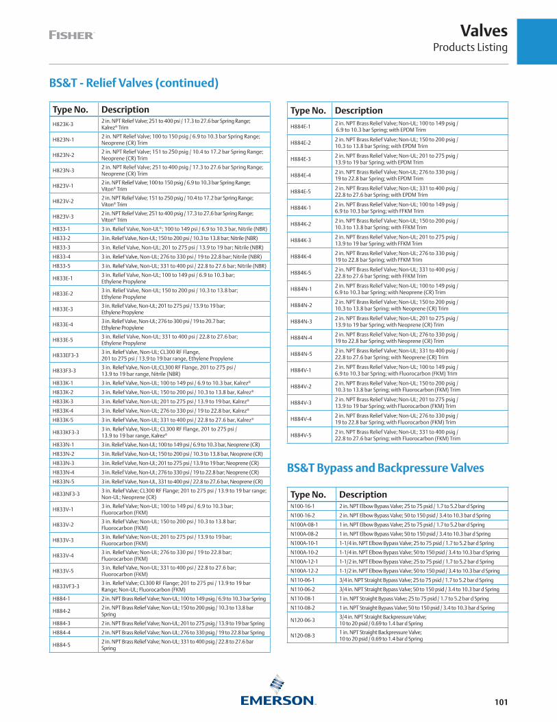
ValvesProducts Listing
101
BS&T - Relief Valves (continued)
Type No. Description
H823K-32 in. NPT Relief Valve; 251 to 400 psi / 17.3 to 27.6 bar Spring Range; Kalrez® Trim
H823N-12 in. NPT Relief Valve; 100 to 150 psig / 6.9 to 10.3 bar Spring Range; Neoprene (CR) Trim
H823N-22 in. NPT Relief Valve; 151 to 250 psig / 10.4 to 17.2 bar Spring Range; Neoprene (CR) Trim
H823N-32 in. NPT Relief Valve; 251 to 400 psig / 17.3 to 27.6 bar Spring Range; Neoprene (CR) Trim
H823V-12 in. NPT Relief Valve; 100 to 150 psig / 6.9 to 10.3 bar Spring Range; Viton® Trim
H823V-22 in. NPT Relief Valve; 151 to 250 psig / 10.4 to 17.2 bar Spring Range; Viton® Trim
H823V-32 in. NPT Relief Valve; 251 to 400 psig / 17.3 to 27.6 bar Spring Range; Viton® Trim
H833-1 3 in. Relief Valve, Non-UL®; 100 to 149 psi / 6.9 to 10.3 bar, Nitrile (NBR)
H833-2 3 in. Relief Valve, Non-UL; 150 to 200 psi / 10.3 to 13.8 bar; Nitrile (NBR)
H833-3 3 in. Relief Valve, Non-UL; 201 to 275 psi / 13.9 to 19 bar; Nitrile (NBR)
H833-4 3 in. Relief Valve, Non-UL; 276 to 330 psi / 19 to 22.8 bar; Nitrile (NBR)
H833-5 3 in. Relief Valve, Non-UL; 331 to 400 psi / 22.8 to 27.6 bar; Nitrile (NBR)
H833E-13 in. Relief Valve, Non-UL; 100 to 149 psi / 6.9 to 10.3 bar; Ethylene Propylene
H833E-23 in. Relief Valve, Non-UL; 150 to 200 psi / 10.3 to 13.8 bar; Ethylene Propylene
H833E-33 in. Relief Valve, Non-UL; 201 to 275 psi / 13.9 to 19 bar; Ethylene Propylene
H833E-43 in. Relief Valve, Non-UL; 276 to 300 psi / 19 to 20.7 bar; Ethylene Propylene
H833E-53 in. Relief Valve, Non-UL; 331 to 400 psi / 22.8 to 27.6 bar; Ethylene Propylene
H833EF3-33 in. Relief Valve, Non-UL; CL300 RF Flange, 201 to 275 psi / 13.9 to 19 bar range, Ethylene Propylene
H833F3-33 in. Relief Valve, Non-UL;CL300 RF Flange, 201 to 275 psi / 13.9 to 19 bar range, Nitrile (NBR)
H833K-1 3 in. Relief Valve, Non-UL; 100 to 149 psi / 6.9 to 10.3 bar, Kalrez®
H833K-2 3 in. Relief Valve, Non-UL; 150 to 200 psi / 10.3 to 13.8 bar, Kalrez®
H833K-3 3 in. Relief Valve, Non-UL; 201 to 275 psi / 13.9 to 19 bar, Kalrez®
H833K-4 3 in. Relief Valve, Non-UL; 276 to 330 psi / 19 to 22.8 bar, Kalrez®
H833K-5 3 in. Relief Valve, Non-UL; 331 to 400 psi / 22.8 to 27.6 bar, Kalrez®
H833KF3-33 in. Relief Valve, Non-UL; CL300 RF Flange, 201 to 275 psi / 13.9 to 19 bar range, Kalrez®
H833N-1 3 in. Relief Valve, Non-UL; 100 to 149 psi / 6.9 to 10.3 bar, Neoprene (CR)
H833N-2 3 in. Relief Valve, Non-UL; 150 to 200 psi / 10.3 to 13.8 bar, Neoprene (CR)
H833N-3 3 in. Relief Valve, Non-UL; 201 to 275 psi / 13.9 to 19 bar; Neoprene (CR)
H833N-4 3 in. Relief Valve, Non-UL; 276 to 330 psi / 19 to 22.8 bar; Neoprene (CR)
H833N-5 3 in. Relief Valve, Non-UL, 331 to 400 psi / 22.8 to 27.6 bar, Neoprene (CR)
H833NF3-33 in. Relief Valve; CL300 RF Flange; 201 to 275 psi / 13.9 to 19 bar range; Non-UL; Neoprene (CR)
H833V-13 in. Relief Valve; Non-UL; 100 to 149 psi / 6.9 to 10.3 bar; Fluorocarbon (FKM)
H833V-23 in. Relief Valve; Non-UL; 150 to 200 psi / 10.3 to 13.8 bar; Fluorocarbon (FKM)
H833V-33 in. Relief Valve; Non-UL; 201 to 275 psi / 13.9 to 19 bar; Fluorocarbon (FKM)
H833V-43 in. Relief Valve; Non-UL; 276 to 330 psi / 19 to 22.8 bar; Fluorocarbon (FKM)
H833V-53 in. Relief Valve, Non-UL; 331 to 400 psi / 22.8 to 27.6 bar; Fluorocarbon (FKM)
H833VF3-33 in. Relief Valve; CL300 RF Flange; 201 to 275 psi / 13.9 to 19 bar Range; Non-UL; Fluorocarbon (FKM)
H884-1 2 in. NPT Brass Relief Valve; Non-UL; 100 to 149 psig / 6.9 to 10.3 bar Spring
H884-22 in. NPT Brass Relief Valve; Non-UL; 150 to 200 psig / 10.3 to 13.8 bar Spring
H884-3 2 in. NPT Brass Relief Valve; Non-UL; 201 to 275 psig / 13.9 to 19 bar Spring
H884-4 2 in. NPT Brass Relief Valve; Non-UL; 276 to 330 psig / 19 to 22.8 bar Spring
H884-52 in. NPT Brass Relief Valve; Non-UL; 331 to 400 psig / 22.8 to 27.6 bar Spring
Type No. Description
H884E-12 in. NPT Brass Relief Valve; Non-UL; 100 to 149 psig / 6.9 to 10.3 bar Spring; with EPDM Trim
H884E-22 in. NPT Brass Relief Valve; Non-UL; 150 to 200 psig / 10.3 to 13.8 bar Spring; with EPDM Trim
H884E-32 in. NPT Brass Relief Valve; Non-UL; 201 to 275 psig / 13.9 to 19 bar Spring; with EPDM Trim
H884E-42 in. NPT Brass Relief Valve; Non-UL; 276 to 330 psig / 19 to 22.8 bar Spring; with EPDM Trim
H884E-52 in. NPT Brass Relief Valve; Non-UL; 331 to 400 psig / 22.8 to 27.6 bar Spring; with EPDM Trim
H884K-12 in. NPT Brass Relief Valve; Non-UL; 100 to 149 psig / 6.9 to 10.3 bar Spring; with FFKM Trim
H884K-22 in. NPT Brass Relief Valve; Non-UL; 150 to 200 psig / 10.3 to 13.8 bar Spring; with FFKM Trim
H884K-32 in. NPT Brass Relief Valve; Non-UL; 201 to 275 psig / 13.9 to 19 bar Spring; with FFKM Trim
H884K-42 in. NPT Brass Relief Valve; Non-UL; 276 to 330 psig / 19 to 22.8 bar Spring; with FFKM Trim
H884K-52 in. NPT Brass Relief Valve; Non-UL; 331 to 400 psig / 22.8 to 27.6 bar Spring; with FFKM Trim
H884N-12 in. NPT Brass Relief Valve; Non-UL; 100 to 149 psig / 6.9 to 10.3 bar Spring; with Neoprene (CR) Trim
H884N-22 in. NPT Brass Relief Valve; Non-UL; 150 to 200 psig /10.3 to 13.8 bar Spring; with Neoprene (CR) Trim
H884N-32 in. NPT Brass Relief Valve; Non-UL; 201 to 275 psig / 13.9 to 19 bar Spring; with Neoprene (CR) Trim
H884N-42 in. NPT Brass Relief Valve; Non-UL; 276 to 330 psig / 19 to 22.8 bar Spring; with Neoprene (CR) Trim
H884N-52 in. NPT Brass Relief Valve; Non-UL; 331 to 400 psig / 22.8 to 27.6 bar Spring; with Neoprene (CR) Trim
H884V-12 in. NPT Brass Relief Valve; Non-UL; 100 to 149 psig / 6.9 to 10.3 bar Spring; with Fluorocarbon (FKM) Trim
H884V-22 in. NPT Brass Relief Valve; Non-UL; 150 to 200 psig / 10.3 to 13.8 bar Spring; with Fluorocarbon (FKM) Trim
H884V-32 in. NPT Brass Relief Valve; Non-UL; 201 to 275 psig / 13.9 to 19 bar Spring; with Fluorocarbon (FKM) Trim
H884V-42 in. NPT Brass Relief Valve; Non-UL; 276 to 330 psig / 19 to 22.8 bar Spring; with Fluorocarbon (FKM) Trim
H884V-52 in. NPT Brass Relief Valve; Non-UL; 331 to 400 psig /22.8 to 27.6 bar Spring; with Fluorocarbon (FKM) Trim
BS&T Bypass and Backpressure Valves
Type No. DescriptionN100-16-1 2 in. NPT Elbow Bypass Valve; 25 to 75 psid / 1.7 to 5.2 bar d Spring
N100-16-2 2 in. NPT Elbow Bypass Valve; 50 to 150 psid / 3.4 to 10.3 bar d Spring
N100A-08-1 1 in. NPT Elbow Bypass Valve; 25 to 75 psid / 1.7 to 5.2 bar d Spring
N100A-08-2 1 in. NPT Elbow Bypass Valve; 50 to 150 psid / 3.4 to 10.3 bar d Spring
N100A-10-1 1-1/4 in. NPT Elbow Bypass Valve; 25 to 75 psid / 1.7 to 5.2 bar d Spring
N100A-10-2 1-1/4 in. NPT Elbow Bypass Valve; 50 to 150 psid / 3.4 to 10.3 bar d Spring
N100A-12-1 1-1/2 in. NPT Elbow Bypass Valve; 25 to 75 psid / 1.7 to 5.2 bar d Spring
N100A-12-2 1-1/2 in. NPT Elbow Bypass Valve; 50 to 150 psid / 3.4 to 10.3 bar d Spring
N110-06-1 3/4 in. NPT Straight Bypass Valve; 25 to 75 psid / 1.7 to 5.2 bar d Spring
N110-06-2 3/4 in. NPT Straight Bypass Valve; 50 to 150 psid / 3.4 to 10.3 bar d Spring
N110-08-1 1 in. NPT Straight Bypass Valve; 25 to 75 psid / 1.7 to 5.2 bar d Spring
N110-08-2 1 in. NPT Straight Bypass Valve; 50 to 150 psid / 3.4 to 10.3 bar d Spring
N120-06-33/4 in. NPT Straight Backpressure Valve; 10 to 20 psid / 0.69 to 1.4 bar d Spring
N120-08-31 in. NPT Straight Backpressure Valve; 10 to 20 psid / 0.69 to 1.4 bar d Spring

ValvesProducts Listing
102
BS&T - Internal Valves
Type No. Description
C403-24-153 in. Flanged Internal Valve; Double Flange Body; Legacy Style; 150 GPM / 568 l/min Spring
C403-24-203 in. Flanged Internal Valve; Double Flange Body; Legacy Style;200 GPM / 757 l/min Spring
C403-24-253 in. Flanged Internal Valve; Double Flange Body; Legacy Style; 250 GPM / 946 l/min Spring
C403-24-403 in. Flanged Internal Valve; Double Flange Body; Legacy Style; 400 GPM / 1514 l/min Spring
C403-24-503 in. Flanged Internal Valve; Double Flange Body; Legacy Style; 500 GPM / 1893 l/min Spring
C404-24-153 in. Flanged Internal Valve; Single Flange Body; Legacy Style; 150 GPM / 568 l/min Spring
C404-24-203 in. Flanged Internal Valve; Single Flange Body; Legacy Style; 200 GPM / 757 l/min Spring
C404-24-253 in. Flanged Internal Valve; Single Flange Body; Legacy Style; 250 GPM / 946 l/min Spring
C404-24-403 in. Flanged Internal Valve; Single Flange Body; Legacy Style; 400 GPM / 1514 l/min Spring
C404-24-503 in. Flanged Internal Valve; Single Flange Body; Legacy Style; 500 GPM / 1893 l/min Spring
C404-32-100 4 in. Flanged Internal Valve; 1000 GPM / 3785 l/min Spring
C404-32-34 4 in. Flanged Internal Valve; 340 GPM / 1287 l/min Spring
C404-32-40 4 in. Flanged Internal Valve; 400 GPM / 1514 l/min Spring
C404-32-60 4 in. Flanged Internal Valve; 600 GPM / 2271 l/min Spring
C404-32-80 4 in. Flanged Internal Valve; 800 GPM / 3028 l/min Spring
C404A32-1004 in. Flanged Internal Valve; 1000 GPM / 3785 l/min Spring; with Type P614 Actuator
C404A32-344 in. Flanged Internal Valve; 340 GPM / 1287 l/min Spring; with Type P614 Actuator
C404A32-404 in. Flanged Internal Valve; 400 GPM / 1514 l/minSpring; with Type P614 Actuator
C404A32-604 in. Flanged Internal Valve; 600 GPM / 2271 l/min Spring; with Type P614 Actuator
C404A32-804 in. Flanged Internal Valve; 800 GPM / 3028 l/min Spring; with Type P614 Actuator
C404FA32-104 in. Flanged Internal Valve; France; Type P614 Air Actuator; 1000 GPM / 3785 l/min Spring
C404M32-1004 in. Flanged Internal Valve; 1000 GPM / 3785 l/min Spring; with Type P313 Operating Lever
C404M32-344 in. Flanged Internal Valve; 340 GPM / 1287 l/min Spring; with Type P313 Operating Lever
C404M32-404 in. Flanged Internal Valve; 400 GPM / 1514 l/min Spring; with Type P313 Operating Lever
C404M32-604 in. Flanged Internal Valve; 600 GPM / 2271 l/min Spring; with Type P313 Operating Lever
C404M32-804 in. Flanged Internal Valve; 800 GPM / 3028 l/min Spring; with Type P313 Operating Lever
C407-10-041-1/4 in. NPT Internal Valve, Straight-Through Body, 40 GPM / 151 l/min Spring
C407-10-051-1/4 in. NPT Internal Valve; Straight-Through Body; 50 GPM / 189 l/min Spring
C407-10-081-1/4 in. NPT Internal Valve; Straight-Through Body; 80 GPM / 303 l/min Spring
C407M10-041-1/4 in. NPT Internal Valve with Type P341 Remote Release, 40 GPM / 151 l/min Spring
C407M10-051-1/4 in. NPT Internal Valve with Type P341 Remote Release; 50 GPM / 189 l/min Spring
C407M10-081-1/4 in. NPT Internal Valve with Type P341 Remote Release; 80 GPM / 303 l/min Spring
Type No. DescriptionC471-16-10 2 in. NPT Internal Valve; Tee Body; 105 GPM / 397 l/min Spring
C471-16-15 2 in. NPT Internal Valve; Tee Body; 150 GPM / 568 l/min Spring
C471-16-25 2 in. NPT Internal Valve; Tee Body; 250 GPM / 946 l/min Spring
C471-24-16 3 in. NPT Internal Valve; Tee Body; 160 GPM / 606 l/min Spring
C471-24-26 3 in. NPT Internal Valve; Tee Body; 265 GPM / 1003 l/min Spring
C471-24-37 3 in. NPT Internal Valve; Tee Body; 375 GPM / 1419 l/min Spring
C471-24-46 3 in. NPT Internal Valve; Tee Body; 460 GPM / 1741 l/min Spring
C471M-16-152 in. NPT Internal Valve; Tee Body; 150 GPM / 568 l/min Spring; with Type P340 Latch
C471M-16-252 in. NPT Internal Valve; Tee Body; 250 GPM / 946 l/min Spring; with Type P340 Latch
C471M-24-373 in. NPT Internal Valve; Tee Body; 375 GPM / 1419 l/min Spring; with Type P340 Latch
C477-16-102 in. NPT Internal Valve; Straight-Through Body; 105 GPM/ 397 l/min Spring
C477-16-152 in. NPT Internal Valve; Straight-Through Body; 150 GPM / 568 l/min Spring
C477-16-252 in. NPT Internal Valve; Straight-Through Body; 250 GPM / 946 l/min Spring
C477-24-163 in. NPT Internal Valve; Straight-Through Body; 160 GPM / 606 l/min Spring
C477-24-263 in. NPT Internal Valve; Straight-Through Body; 265 GPM / 1003 l/min Spring
C477-24-373 in. NPT Internal Valve; Straight-Through Body; 375 GPM / 1419 l/min Spring
C477-24-463 in. NPT Internal Valve; Straight-Through Body; 460 GPM / 1741 l/min Spring
C477M-16-102 in. NPT Internal Valve; Straight-Through Body; 105 GPM / 397 l/min Spring; with Type P340 Latch
C477M-16-252 in. NPT Internal Valve; Straight-Through Body; 250 GPM / 946 l/min Spring; with Type P340 Latch
C477M-24-163 in. NPT Internal Valve; Straight-Through Body; 160 GPM / 606 l/min Spring; with Type P340 Latch
C477M-24-263 in. NPT Internal Valve; Straight-Through Body; 265 GPM / 1003 l/min Spring; with Type P340 Latch
C477M-24-373 in. NPT Internal Valve; Straight-Thru Body; 375 GPM / 1419 l/min Spring; with Type P340 Latch
C477M-24-463 in. NPT Internal Valve; Straight-Through Body; 460 GPM / 1741 l/min Spring; with Type P340 Latch
C483-24-163 in. Flange Internal Valve; Double Flange Body; 160 GPM / 606 l/min Spring
C483-24-263 in. Flange Internal Valve; Double Flange Body; 265 GPM / 1003 l/min Spring
C483-24-403 in. Flange Internal Valve; Double Flange Body; 400 GPM / 1514 l/min Spring
C484-24-163 in. Flange Internal Valve; Single Flange Body; 160 GPM / 606 l/min Spring
C484-24-253 in. Flange Internal Valve; Single Flange Body; 250 GPM / 946 l/min Spring
C484-24-403 in. Flange Internal Valve; Single Flange Body; 400 GPM / 1514 l/min Spring
C486-24-16 3 in. CL300 Flange Inlet x FNPT Outlet Body; 160 GPM / 606 l/min Spring
C486-24-26 3 in. CL300 Flange Inlet x FNPT Outlet Body; 265 GPM / 1003 l/min Spring
C486-24-37 3 in. CL300 Flange Inlet x FNPT Outlet Body; 375 GPM / 1419 l/min Spring
C486-24-46 3 in. CL300 Flange Inlet x FNPT Outlet Body; 460 GPM / 1741 l/min Spring
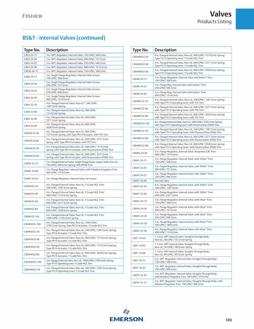
ValvesProducts Listing
103
BS&T - Internal Valves (continued)
Type No. DescriptionC803-24-15 3 in. NPT; Regulator; Internal Valve; 150 GPM / 568 l/min
C803-24-20 3 in. NPT; Regulator; Internal Valve; 200 GPM / 757 l/min
C803-24-25 3 in. NPT; Regulator; Internal Valve; 250 GPM / 946 l/min
C803-24-40 3 in. NPT; Regulator; Internal Valve; 400 GPM / 1514 l/min
C803E-24-15 3 in. NPT; Regulator; Internal Valve; 150 GPM / 568 l/min
C804-24-153 in. Single Flange Regulator; Internal Valve Screen; 150 GPM / 568 l/min
C804-24-203 in. Single Flange Regulator; Internal Valve Screen; 200 GPM / 757 l/min
C804-24-253 in. Single Flange Regulator; Internal Valve Screen; 250 GPM / 946 l/min
C804-24-403 in. Single Flange Regulator; Internal Valve Screen; 400 GPM / 1514 l/min
C804-32-344 in. Flanged Internal Valve; Non-UL®; 340 GPM / 1287 l/min Spring
C804-32-404 in. Flanged Internal Valve; Non-UL; 400 GPM / 1514 l/min Spring
C804-32-604 in. Flanged Internal Valve; Non-UL; 600 GPM / 2271 l/min Spring
C804-32-804 in. Flanged Internal Valve; Non-UL; 800 GPM / 3028 l/min Spring
C804AT32-404 in. Flanged Internal Valve; Non-UL; 400 GPM / 1514 l/min Spring; with Type P614 Actuator; with TFE Trim
C804AT32-604 in. Flanged Internal Valve; Non-UL; 600 GPM / 2271 l/minSpring; with Type P614 Actuator; with TFE Trim
C804AV32-404 in. Flanged Internal Valve; Non-UL; 400 GPM / 1514 l/minSpring; with Type P614 Actuator; with Fluorocarbon (FKM) Trim
C804AV32-604 in. Flanged Internal Valve; Non-UL; 600 GPM / 2271 l/minSpring; with Type P614 Actuator; with Fluorocarbon (FKM) Trim
C804E-24-153 in. Flanged Internal Valve; Single Flange Body; Legacy Style; Non-UL; 150 GPM / 568 l/min Spring; with EPDM Trim
C804E-24-403 in. Flange Regulator; Internal Valve; with Ethylene Propylene Trim; 400 GPM / 1514 l/min
C804F-24-50 3 in. Flange Regulator; Internal Valve; for France
C804H32-344 in. Flanged Internal Valve; Non-UL; Y Grade NGL Trim; 340 GPM / 1287 l/min Spring
C804H32-404 in. Flanged Internal Valve; Non-UL; Y Grade NGL Trim; 400 GPM / 1514 l/min Spring
C804H32-604 in. Flanged Internal Valve; Non-UL; Y Grade NGL Trim; 600 GPM / 2271 l/min Spring
C804H32-804 in. Flanged Internal Valve; Non-UL; Y Grade NGL Trim; 800 GPM / 3028 l/min Spring
C804H32-1004 in. Flanged Internal Valve; Non-UL; Y Grade NGL Trim; 1000 GPM / 3785 l/min Spring
C804HA32-1004 in. Flanged Internal Valve; Non-UL; 1000 GPM / 3785 l/min Spring; Type P614 Actuator; Y Grade NGL Trim
C804HA32-344 in. Flanged Internal Valve; Non-UL; 340 GPM / 1287 l/min Spring; Type P614 Actuator; Y Grade NGL Trim
C804HA32-404 in. Flanged Internal Valve; Non-UL; 400 GPM / 1514 l/min Spring; Type P614 Actuator; Y Grade NGL Trim
C804HA32-604 in. Flanged Internal Valve; Non-UL; 400 GPM / 1514 l/min Spring; Type P614 Actuator; Y Grade NGL Trim
C804HA32-804 in. Flanged Internal Valve; Non-UL; 800 GPM / 3028 l/min Spring; Type P614 Actuator; Y Grade NGL Trim
C804HM32-1004 in. Flanged Internal Valve; Non-UL; 1000 GPM / 3785 l/min Spring; Type P313 Operating Lever; Y Grade NGL Trim
C804HM32-344 in. Flanged Internal Valve; Non-UL; 340 GPM / 1287 l/min Spring; Type P313 Operating Lever; Y Grade NGL Trim
Type No. Description
C804HM32-404 in. Flanged Internal Valve; Non-UL; 400 GPM / 1514 l/min Spring; Type P313 Operating Lever; Y Grade NGL Trim
C804HM32-604 in. Flanged Internal Valve; Non-UL; 600 GPM / 2271 l/min Spring; Type P313 Operating Lever; Y Grade NGL Trim
C804HM32-804 in. Flanged Internal Valve; Non-UL; 800 GPM / 3028 l/min Spring; Type P313 Operating Lever; Y Grade NGL Trim
C804K-24-153 in. Flange Regulator; Internal Valve with Kalrez® Trim; 150 GPM / 568 l/min
C804K-24-253 in. Flange Reg; Internal Valve with Kalrez® Trim; 250 GPM / 946 l/min
C804K-24-403 in. Flange Reg; Internal Valve with Kalrez® Trim; 400 GPM / 1514 l/min
C804MT32-344 in. Flanged Internal Valve; Non-UL; 340 GPM / 1287 l/min Spring; with Type P313 Operating Lever; with TFE Trim
C804MT32-604 in. Flanged Internal Valve; Non-UL; 600 GPM / 2271 l/min Spring; with Type P313 Operating Lever; with TFE Trim
C804MT32-804 in. Flanged Internal Valve; Non-UL; 800 GPM / 3028 l/min Spring; with Type P313 Operating Lever; with TFE Trim
C804MV32-1004 in. Flanged Internal Valve; Non-UL; 1000 GPM / 3785 l/min Spring; with Type P313 Operating Lever; with Fluorocarbon (FKM) Trim
C804MV32-344 in. Flanged Internal Valve; Non-UL; 340 GPM / 1287 l/min Spring; with Type P313 Operating Lever; with Fluorocarbon (FKM) Trim
C804MV32-604 in. Flanged Internal Valve; Non-UL; 600 GPM / 2271 l/min Spring; with Type P313 Operating Lever; with Fluorocarbon (FKM) Trim
C804MV32-804 in. Flanged Internal Valve; Non-UL; 800 GPM / 3028 l/min Spring; with Type P313 Operating Lever; with Fluorocarbon (FKM) Trim
C804N-24-403 in. Flange Regulator; Internal Valve; Neoprene (CR) Trim; 400 GPM / 1514 l/min
C804T-24-153 in. Flange Regulator; Internal Valve; with Teflon® Trim; 150 GPM / 568 l/min
C804T-24-203 in. Flagne Regulator; Internal Valve; with Teflon® Trim; 200 GPM / 757 l/min
C804T-24-253 in. Flange Regulator; Internal Valve; with Teflon® Trim; 250 GPM / 946 l/min
C804T-24-40 Internal Valve
C804T-32-344 in. Flange Regulator; Internal Valve; with Teflon® Trim; 340 GPM / 1287 l/min
C804T-32-604 in. Flange Regulator; Internal Valve; with Teflon® Trim; 600 GPM / 2271 l/min
C804V-24-153 in. Flange Regulator; Internal Valve; with Viton® Trim; 150 GPM / 568 l/min
C804V-24-203 in. Flange Regulator; Internal Valve; with Viton® Trim; 200 GPM / 757 l/min
C804V-24-253 in. Flange Regulator; Internal Valve; with Viton® Trim; 250 GPM / 946 l/min
C804V-24-503 in. Flange Regulator; Internal Valve; with Viton® Trim; 500 GPM / 1893 l/min
C804V-32-404 in. Flange Regulator; Internal Valve; with Viton® Trim; 400 GPM / 1514 l/min
C807-10-041-1/4 in. NPT Internal Valve, Straight-Through Body, Non-UL, 40 GPM / 151 l/min Spring
C807-10-051-1/4 in. NPT Internal Valve; Straight-Through Body; Non-UL; 50 GPM / 189 l/min Spring
C807-10-081-1/4 in. NPT Internal Valve; Straight-Through Body; Non-UL; 80 GPM / 303 l/min Spring
C807-16-152 in. NPT; Regulator; Internal Valve; Straight-Through Body; 150 GPM / 568 l/min
C807-16-252 in. NPT; Regulator; Internal Valve; Straight-Through Body; 250 GPM / 946 l/min
C807E-16-102 in. NPT; Regulator; Internal Valve; Straight-Through Body; with Ethylene Propylene Trim; 100 GPM / 379 l/min
C807E-16-152 in. NPT; Regulator; Internal Valve; Straight-Through Body; with Ethylene Propylene Trim; 150 GPM / 568 l/min

ValvesProducts Listing
104
BS&T - Internal Valves (continued)
Type No. Description
C807E-16-252 in. NPT; Regulator; Internal Valve; Straight-Through Body; with Ethylene Propylene Trim; 250 GPM / 946 l/min
C807K-16-252 in. NPT; Regulator; Internal Valve; Straight-Through Body; with Kalrez® Trim; 250 GPM / 946 l/min
C807N-16-152 in. NPT; Regulator; Internal Valve; Straight-Through Body; 150 GPM / 568 l/min
C807N-16-252 in. NPT; Regulator; Internal Valve; Straight-Through Body; 250 GPM / 946 l/min
C807S-10-041-1/4 in. NPT Regulator Internal Valve, Stainless-Steel Body, Non-UL®; 40 GPM / 151 l/min Spring
C807S-10-051-1/4 in. NPT Regulator; Internal Valve; Stainless-Steel Body; Non-UL; 50 GPM / 189 l/min Spring
C807S-10-081-1/4 in. NPT Regulator; Internal Valve; Stainless-Steel Body; Non-UL; 80 GPM / 303 l/min Spring
C807S-16-152 in. NPT; Regulator; Internal Valve; Straight-Through Body; 150 GPM / 568 l/min
C807S-16-252 in. NPT; Regulator; Internal Valve; Straight-Through Body; 250 GPM / 946 l/min
C807SE16-102 in. NPT; Regulator; Internal Valve; Straight-Through Body; with Ethylene Propylene Trim; 100 GPM / 379 l/min
C807SV10-051-1/4 in. NPT; Regulator; Internal Valve; Straight-Through Body; with Viton® Trim; 50 GPM / 189 l/min
C807SV16-252 in. NPT; Regulator; Internal Valve; Straight-Through Body; with Viton® Trim; 250 GPM / 946 l/min
C807T-10-051-1/4 in. NPT; Regulator; Internal Valve; Straight-Through Body; Non-UL; 50 GPM / 189 l/min Spring; with TFE Trim
C807T-10-081-1/4 in. NPT; Regulator; Internal Valve; Straight-Through Body; Non-UL; 80 GPM / 303 l/min Spring; with TFE Trim
C807T-16-102 in. NPT; Regulator; Internal Valve; with Teflon® Trim; 100 GPM / 379 l/min
C807T-16-152 in. NPT; Regulator; Internal Valve; with Teflon® Trim; 150 GPM / 568 l/min
C807T-16-252 in. NPT; Regulator; Internal Valve; with Teflon® Trim; 250 GPM / 946 l/min
C807V-10-041-1/4 in. NPT; Regulator; Internal Valve, Straight-Through Body, Non-UL, 40 GPM / 151 l/min Spring, with Fluorocarbon (FKM) Trim
C807V-10-051-1/4 in. NPT; Regulator; Internal Valve; Straight-Through Body; Non-UL; 50 GPM / 189 l/min Spring; with Fluorocarbon (FKM) Trim
C807V-10-081-1/4 in. NPT; Regulator; Internal Valve; Straight-Through Body; Non-UL; 80 GPM / 303 l/min Spring; with Fluorocarbon (FKM) Trim
C807V-16-102 in. NPT; Regulator; Internal Valve; with Viton® Trim; 100 GPM / 379 l/min
C807V-16-152 in. NPT; Regulator; Internal Valve; with Viton® Trim; 150 GPM / 568 l/min
C807V-16-252 in. NPT; Regulator; Internal Valve; with Viton® Trim; 250 GPM / 946 l/min
C821E-16-252 in. NPT; Regulator; Internal Valve; Tee Body; with Ethylene Propylene Trim; 250 GPM / 946 l/min
C821E-24-403 in. NPT; Regulator; Internal Valve; Tee Body; with Ethylene Propylene Trim; 400 GPM / 1514 l/min
C821K-16-252 in. NPT; Regulator; Internal Valve; Tee Body; with Kalrez® Trim; 250 GPM / 946 l/min
C821K-24-403 in. NPT; Regulator; Internal Valve; Tee Body; with Kalrez® Trim; 400 GPM / 1514 l/min
C821T-16-102 in. NPT; Regulator; Internal Valve; Tee Body; with Teflon® Trim; 100 GPM / 379 l/min
C821T-16-252 in. NPT; Regulator; Internal Valve; Tee Body; with Teflon® Trim; 250 GPM / 946 l/min
C821T-24-253 in. NPT; Regulator; Internal Valve; Tee Body; with Teflon® Trim; 250 GPM / 946 l/min
C821T-24-403 in. NPT; Regulator; Internal Valve; Tee Body; with Teflon® Trim; 400 GPM / 1514 l/min
C821V-16-102 in. NPT; Regulator; Internal Valve; Tee Body; with Viton® Trim; 100 GPM / 379 l/min
C827E-16-252 in. NPT; Regulator; Internal Valve; Straight-Through Body; with Ethylene Propylene Trim; 250 GPM / 946 l/min
Type No. Description
C827E-24-253 in. NPT; Regulator; Internal Valve; Straight-Through Body; with Ethylene Propylene Trim; 250 GPM / 946 l/min
C827K-16-102 in. NPT; Regulator; Internal Valve; Straight-Through Body; with Kalrez® Trim; 100 GPM / 379 l/min
C827K-16-152 in. NPT; Regulator; Internal Valve; Straight-Through Body; with Kalrez® Trim; 150 GPM / 568 l/min
C827K-16-252 in. NPT; Regulator; Internal Valve; Straight-Through Body; with Kalrez® Trim; 250 GPM / 946 l/min
C827K-24-253 in. NPT; Regulator; Internal Valve; Straight-Through Body; with Kalrez® Trim; 250 GPM / 946 l/min
C827K-24-403 in. NPT; Regulator; Internal Valve; Straight-Through Body; with Kalrez® Trim; 400 GPM / 1514 l/min
C827K-24-503 in. NPT; Regulator; Internal Valve; Straight-Through Body; with Kalrez® Trim; 500 GPM / 1893 l/min
C827N-16-15 2 in. Internal Valve with Neoprene (CR) Trim
C827N-24-153 in. NPT; Regulator; Internal Valve; Straight-Through Body; with Neoprene (CR) Trim; 150 GPM / 568 l/min
C827N-24-253 in. NPT; Regulator; Internal Valve; Straight-Through Body; with Neoprene (CR) Trim; 250 GPM / 946 l/min
C827N-24-403 in. NPT; Regulator; Internal Valve; Straight-Through Body; with Neoprene (CR) Trim; 400 GPM / 1514 l/min
C827T-16-102 in. NPT; Regulator; Internal Valve; Straight-Through Body; with Teflon® Trim; 100 GPM / 379 l/min
C827T-16-152 in. NPT; Regulator; Internal Valve; Straight-Through Body; with Teflon® Trim; 150 GPM / 568 l/min
C827T-16-252 in. NPT; Regulator; Internal Valve; Straight-Through Body; with Teflon® Trim; 250 GPM / 946 l/min
C827T-24-153 in. NPT; Regulator; Internal Valve; Straight-Through Body; with Teflon® Trim; 150 GPM / 568 l/min
C827T-24-203 in. NPT; Regulator; Internal Valve; Straight-Through Body; with Teflon® Trim; 200 GPM / 757 l/min
C827T-24-253 in. NPT; Regulator; Internal Valve; Straight-Through Body; with Teflon® Trim; 250 GPM / 946 l/min
C827T-24-403 in. NPT; Regulator; Internal Valve; Straight-Through Body; with Teflon® Trim; 400 GPM / 1514 l/min
C827T-24-503 in. NPT; Regulator; Internal Valve; Straight-Through Body; with Teflon® Trim; 500 GPM / 1893 l/min
C827V-16-152 in. NPT; Regulator; Internal Valve; Straight-Through Body; with Viton® Trim; 150 GPM / 568 l/min
C827V-16-252 in. NPT; Regulator; Internal Valve; Straight-Through Body; with Viton® Trim; 250 GPM / 946 l/min
C827V-24-253 in. NPT; Regulator; Internal Valve; Straight-Through Body; with Viton® Trim; 250 GPM / 946 l/min
C827V-24-403 in. NPT; Regulator; Internal Valve; Straight-Through Body; with Viton® Trim; 400 GPM / 1514 l/min
C827V-24-503 in. NPT; Regulator; Internal Valve; Straight-Through Body; with Viton® Trim; 500 GPM / 1893 l/min
C871K-16-252 in. NPT Internal Valve; Tee Body; Non-UL; 250 GPM / 946 l/min Spring; with FFKM Trim
C871K-24-373 in. NPT Internal Valve; Tee Body; Non-UL; 375 GPM / 1419 l/min Spring; with FFKM Trim
C871T-16-102 in. NPT Internal Valve; Tee Body; Non-UL; 105 GPM / 397 l/min Spring; with TFE Trim
C871T-16-252 in. NPT Internal Valve; Tee Body; Non-UL; 250 GPM / 946 l/min Spring; with TFE Trim
C871T-24-263 in. NPT Internal Valve; Tee Body; Non-UL; 265 GPM / 1003 l/min Spring; with TFE Trim
C871T-24-373 in. NPT Internal Valve; Tee Body; Non-UL; 375 GPM / 1419 l/min Spring; with TFE Trim
C871V-16-102 in. NPT Internal Valve; Tee Body; Non-UL; 105 GPM / 397 l/min Spring; with Fluorocarbon (FKM) Trim

ValvesProducts Listing
105
BS&T - Internal Valves (continued)
Type No. Description
C871V-16-152 in. NPT Internal Valve; Tee Body; Non-UL®; 150 GPM / 568 l/min Spring; with Fluorocarbon (FKM) Trim
C871V-16-252 in. NPT Internal Valve; Tee Body; Non-UL; 250 GPM / 946 l/min Spring; with Fluorocarbon (FKM) Trim
C871V-24-163 in. NPT Internal Valve; Tee Body; Non-UL; 160 GPM / 606 l/min Spring; with Fluorocarbon (FKM) Trim
C871V-24-263 in. NPT Internal Valve; Tee Body; Non-UL; 265 GPM / 1003 l/min Spring; with Fluorocarbon (FKM) Trim
C871V-24-373 in. NPT Internal Valve; Tee Body; Non-UL; 375 GPM / 1419 l/min Spring; with Fluorocarbon (FKM) Trim
C871V-24-463 in. NPT Internal Valve; Tee Body; Non-UL; 460 GPM / 1741 l/min Spring; with Fluorocarbon (FKM) Trim
C877K-16-102 in. NPT Internal Valve; Straight-Through Body; Non-UL; 105 GPM / 397 l/min Spring; with FFKM Trim
C877K-16-152 in. NPT Internal Valve; Straight-Through Body; Non-UL; 150 GPM / 568 l/min Spring; with FFKM Trim
C877K-16-252 in. NPT Internal Valve; Straight-Through Body; Non-UL; 250 GPM / 946 l/min Spring; with FFKM Trim
C877K-24-263 in. NPT Internal Valve; Straight-Through Body; Non-UL; 265 GPM / 1003 l/min Spring; with FFKM Trim
C877K-24-373 in. NPT Internal Valve; Straight-Through Body; Non-UL; 375 GPM / 1419 l/min Spring; with FFKM Trim
C877K-24-463 in. NPT Internal Valve; Straight-Through Body; Non-UL; 460 GPM / 1741 l/min Spring; with FFKM Trim
C877T-16-102 in. NPT Internal Valve; Straight-Through Body; Non-UL; 105 GPM / 397 l/min Spring; with TFE Trim
C877T-16-152 in. NPT Internal Valve; Straight-Through Body; Non-UL; 150 GPM / 568 l/min Spring; with TFE Trim
C877T-16-252 in. NPT Internal Valve; Straight-Through Body; Non-UL; 250 GPM / 946 l/min Spring; with TFE Trim
C877T-24-163 in. NPT Internal Valve; Straight-Through Body; Non-UL; 160 GPM / 606 l/min Spring; with TFE Trim
C877T-24-263 in. NPT Internal Valve; Straight-Through Body; Non-UL; 265 GPM / 1003 l/min Spring; with TFE Trim
C877T-24-373 in. NPT Internal Valve; Straight-Through Body; Non-UL; 375 GPM / 1419 l/min Spring; with TFE Trim
C877T-24-463 in. NPT Internal Valve; Straight-Through Body; Non-UL; 460 GPM / 1741 l/min Spring; with TFE Trim
C877V-16-252 in. NPT Internal Valve; Straight-Through Body; Non-UL; 250 GPM / 946 l/min Spring; with Fluorocarbon (FKM) Trim
C877V-24-263 in. NPT Internal Valve; Straight-Through Body; Non-UL; 265 GPM / 1003 l/min Spring; with Fluorocarbon (FKM) Trim
C877V-24-373 in. NPT Internal Valve; Straight-Through Body; Non-UL; 375 GPM / 1419 l/min Spring; with Fluorocarbon (FKM) Trim
C877V-24-463 in. NPT Internal Valve; Straight-Through Body; Non-UL; 460 GPM / 1741 l/min Spring; with Fluorocarbon (FKM) Trim
C884-24-16 3 in. Internal Valve; 160 GPM / 606 l/min Spring
C884-24-25 3 in. Internal Valve; 250 GPM / 946 l/min Spring
C884-24-40 3 in. Internal Valve; 400 GPM / 1514 l/min Spring
C884-24-50 3 in. Single Flange Internal Valve ~ Non-UL; 500 GPM / 1893 l/min
C884K-24-163 in. Flange Internal Valve; Single Flange Body; Non-UL; 160 GPM / 606 l/min Spring; with FFKM Trim
C884K-24-253 in. Flange Internal Valve; Single Flange Body; Non-UL; 250 GPM / 946 l/min Spring; with FFKM Trim
C884K-24-403 in. Flange Internal Valve; Single Flange Body; Non-UL; 400 GPM / 1514 l/min Spring; with FFKM Trim
C884N-24-403 in. Flange Internal Valve; Single Flange Body; Non-UL; 400 GPM / 1514 l/min Spring; with Neoprene (CR) Trim
C884T-24-163 in. Flange Internal Valve; Single Flange Body; Non-UL; 160 GPM / 606 l/min Spring; with TFE Trim
Type No. Description
C884T-24-253 in. Flange Internal Valve; Single Flange Body; Non-UL; 250 GPM / 946 l/min Spring; with TFE Trim
C884T-24-403 in. Flange Internal Valve; Single Flange Body; Non-UL; 400 GPM / 1514 l/min Spring; with TFE Trim
C884V-24-163 in. Flange Internal Valve; Single Flange Body; Non-UL; 160 GPM / 606 l/min Spring; with Fluorocarbon (FKM) Trim
C884V-24-253 in. Flange Internal Valve; Single Flange Body; Non-UL; 250 GPM / 946 l/min Spring; with Fluorocarbon (FKM) Trim
C884V-24-403 in. Flange Internal Valve; Single Flange Body; Non-UL; 400 GPM / 1514 l/min Spring; with Fluorocarbon (FKM) Trim
C886K-24-163 in. CL300 Flange Inlet x FNPT Outlet; Non-UL; 160 GPM / 606 l/min Spring; with FFKM Trim
C886K-24-263 in. CL 300 Flange Inlet x FNPT Outlet; Non-UL; 265 GPM / 1003 l/min Spring; with FFKM Trim
C886K-24-373 in. CL300 Flange Inlet x FNPT Outlet; Non-UL; 375 GPM / 1419 l/min Spring; with FFKM Trim
C886K-24-463 in. CL300 Flange Inlet x FNPT Outlet; Non-UL; 460 GPM / 1741 l/min Spring; with FFKM Trim
C886N-24-163 in. CL300 Flange Inlet x FNPT Outlet; Non-UL; 160 GPM / 606 l/min Spring; with Neoprene (CR) Trim
C886N-24-263 in. CL300 Flange Inlet x FNPT Outlet; Non-UL; 265 GPM / 1003 l/min Spring; with Neoprene (CR) Trim
C886N-24-373 in. CL300 Flange Inlet x FNPT Outlet; Non-UL; 375 GPM / 1419 l/min Spring; with Neoprene (CR) Trim
C886N-24-463 in. CL300 Flange Inlet x FNPT Outlet; Non-UL; 460 GPM / 1741 l/min Spring; with Neoprene (CR) Trim
C887K-16-25 2 in. Internal Valve; 250 GPM / 946 l/min Spring
C887N-16-15 2 in. Internal Valve; 150 GPM / 568 l/min Spring
C887N-16-25 2 in. Internal Valve; 250 GPM / 946 l/min Spring
C887T-16-15 2 in. Internal Valve; 150 GPM / 568 l/min Spring
C887T-16-25 2 in. Internal Valve; 250 GPM / 946 l/min Spring
C887V-16-15 2 in. Internal Valve; 150 GPM / 568 l/min Spring
C887V-16-25 2 in. Internal Valve; 250 GPM / 946 l/min Spring
C891-16-102 in. Flange Internal Valve; Stainless Steel Side Outlet Body; Non-UL; 105 GPM / 397 l/min Spring; with Nitrile (NBR) Trim
C891-16-152 in. Flange Internal Valve; Stainless Steel Side Outlet Body; Non-UL; 150 GPM / 568 l/min Spring; with Nitrile (NBR) Trim
C891-16-252 in. Flange Internal Valve; Stainless Steel Side Outlet Body; Non-UL; 250 GPM / 946 l/min Spring; with Nitrile (NBR) Trim
C891-24-153 in. Flange Internal Valve; Stainless Steel Side Outlet Body; Non-UL; 150 GPM / 568 l/min Spring; with Nitrile (NBR) Trim
C891-24-263 in. Flange Internal Valve; Stainless Steel Side Outlet Body; Non-UL; 265 GPM / 1003 l/min Spring; with Nitrile (NBR) Trim
C891-24-403 in. Flange Internal Valve; Stainless Steel Side Outlet Body; Non-UL; 400 GPM / 1514 l/min Spring; with Nitrile (NBR) Trim
C891SN-16-152 in. Flange Internal Valve; Stainless Steel Side Outlet Body; Non-UL; 150 GPM / 568 l/min Spring; with Neoprene (CR) Trim
C891SN-24-163 in. Flange Internal Valve; Stainless Steel Side Outlet Body; Non-UL; 160 GPM / 606 l/min Spring; with Neoprene (CR) Trim
C891SN-24-263 in. Flange Internal Valve; Stainless Steel Side Outlet Body; Non-UL; 265 GPM / 1003 l/min Spring; with Neoprene (CR) Trim
C891ST16-152 in. Flange Internal Valve; Stainless Steel Side Outlet Body; Non-UL; 150 GPM / 568 l/min Spring; with TFE Trim
C891ST16-252 in. Flange Internal Valve; Stainless Steel Side Outlet Body; Non-UL; 250 GPM / 946 l/min Spring; with TFE Trim
C891ST24-263 in. Flange Internal Valve; Stainless Steel Side Outlet Body; Non-UL; 265 GPM / 1003 l/min Spring; with TFE Trim
C891T-16-25 2 in. Internal Valve; 250 GPM / 946 l/min Spring
C897T-16-15 2 in. Internal Valve; SST/STL; 150 GPM / 568 l/min
C897T-16-25 2 in. Internal Valve; 250 GPM / 946 l/min

ValvesProducts Listing
106
BS&T - Back Check Valves
Type No. Description
G1003/4 in. MNPT x 3/4 in. FNPT; Back Pressure Valve; Brass; 21 GPM / 79 l/min
G1011-1/4 in MNPT x 1-1/4 in. FNPT; Back Pressure Valve; Brass; 55 GPM / 208 l/min
G1022 in. MNPT x 2 in. FNPT; Back Pressure Valve; Brass; 150 GPM / 568 l/min
G1043 in. MNPT x 3 in. FNPT; Back Pressure Valve; Steel; 250 GPM / 946 l/min
G1052 x 2 in. MNPT and 1-1/4 in. FNPT; Back Pressure Valve; Steel; Soft Seat
G1063 in. FNPT x 2 in. MNPT; Back Pressure Valve; Steel; Soft Seat; 254 GPM / 961 l/min
G1073 x 3 in. MNPT and 2 in. MNPT; Back Pressure Valve; Steel; Soft Seat; 254 GPM / 961 l/min
G1092 x 2 in. FNPT; Back Pressure Valve; In-Line; Brass; 150 GPM / 568 l/min
G1122 in. MNPT x 2 in. FNPT; Back Pressure Valve; Steel; 150 GPM / 568 l/min
G200-101-1/4 x 1-1/4 in. FNPT; Back Pressure Valve; Ductile Iron; 190 GPM / 719 l/min
G200-162 x 2 in. FNPT; Back Pressure Valve; Ductile Iron; 350 GPM / 1325 l/min
G200-243 x 3 in. FNPT; Back Pressure Valve; Ductile Iron; 800 GPM / 3028 l/min
G201-10 1-1/4 in. Back Pressure Valve; with Flow Indicator
G201-16 2 in. Back Pressure Valve; with Flow Indicator
G201-24 3 in. Back Pressure Valve; with Flow Indicator
BS&T ESV - Emergency Shutoff Valves
BS&T ESV - Emergency Shutoff Valves (continued)
Type No. DescriptionN551-10 1-1/4 in. Emergency Shutoff Valve, UL®
N551-16 2 in. Emergency Shutoff Valve, UL
N551-24 3 in. Emergency Shutoff Valve, UL
N562-16 Railcar valve with 2 in. FNPT Outlet
N562-18 Railcar valve with 2-1/4 in. Male ACME Outlet
N562-26 Railcar valve with 3-1/4 in. Male ACME Outlet
N562-REPAIR Railcar Repair
N563-16Railcar valve with 2 in. FNPT Outlet and 2 in. FNPT Nipple; UL; Nitrile (NBR)
N563-26Railcar valve with 3-1/4 in. ACME Outlet and 2 in. FNPT Nipple; UL; Nitrile (NBR)
N851K-10 1-1/4 in. Emergency Shutoff Valve, Non-UL, Kalrez® Trim
N851K-16 2 in. Emergency Shutoff Valve, Non-UL, Kalrez® Trim
N851K-24 3 in. Emergency Shutoff Valve, Non-UL, Kalrez® Trim
N862K-16 Railcar valve with 2 in. FNPT Outlet; with FFKM Trim
N862K-18 Railcar valve with 2-1/4 in. Male ACME Outlet; with FFKM Trim
N862K-26 Railcar valve with 3-1/4 in. Male ACME Outlet; with FFKM Trim
N862V-16 Railcar valve with 2 in. FNPT Outlet; with Fluorocarbon (FKM) Trim
N862V-18Railcar valve with 2-1/4 in. Male ACME Outlet; with Fluorocarbon (FKM) Trim
N862V-26Railcar valve with 3-1/4 in. Male ACME Outlet; with Fluorocarbon (FKM) Trim
N863-16 Railcar valve with 2 in. FNPT Outlet and 2 in. FNPT Nipple; Nitrile (NBR)
Type No. Description
N863-26Railcar valve with 3-1/4 in. ACME Outlet and 2 in. FNPT Nipple; Nitrile (NBR)
N863E-16Railcar valve with 2 in. FNPT Outlet and 2 in. FNPT Nipple; Ethylene Propylene
N863E-26Railcar valve with 3-1/4 in. ACME Outlet and 2 in. FNPT Nipple; Ethylene Propylene
N863K-16 Railcar valve with 2 in. FNPT Outlet and 2 in. FNPT Nipple; Kalrez®
N863K-26 Railcar valve with 1/4 in. ACME Outlet and 2 in. FNPT Nipple; Kalrez®
N863N-16Railcar valve with 2 in. FNPT Outlet and 2 in. FNPT Nipple; Neoprene (CR)
N863N-26Railcar valve with 3-1/4 in. ACME Outlet and 2 in. FNPT Nipple;Neoprene (CR)
N863T-16 Railcar valve with 2 in. FNPT Outlet and 2 in. FNPT Nipple; TFE
N863T-26 Railcar valve with 3-1/4 in. ACME Outlet and 2 in. FNPT Nipple; TFE
N863V-16 Railcar valve with 2 in. FNPT Outlet and 2 in. FNPT Nipple; Viton®
N863V-26 Railcar valve with 3-1/4 in. ACME Outlet and 2 in. FNPT Nipple; Viton®
BS&T - Globe and Angle Valves
Type No. DescriptionN301-04 1/2 in. NPT Globe Valve
N301-06 3/4 in. NPT Globe Valve
N301-08 1 in. NPT Globe Valve
N310-10 1-1/4 in. NPT Globe Valve
N310-12 1-1/2 in. NPT Globe Valve
N310-16 2 in. NPT Globe Valve
N350-04 1/2 in. Economy Globe Valve
N350-06 3/4 in. Economy Globe Valve
N401-04 1/2 in. NPT Angle Valve
N401-06 3/4 in. NPT Angle Valve
N401-08 1 in. NPT Angle Valve
N410-10 1-1/4 in. NPT Angle Valve
N410-12 1-1/2 in. NPT Angle Valve
N410-16 2 in. NPT Angle Valve
N450-04 1/2 in. Economy Angle Valve
N450-06 3/4 in. Economy Angle Valve
N801T-04 1/2 in. NPT Globe Valve; with TFE Trim
N801T-06 3/4 in. NPT Globe Valve; with TFE Trim
N801T-08 1 in. NPT Globe Valve; with TFE Trim
N810T-10 1-1/4 in. NPT Globe Valve; with TFE Trim

ValvesProducts Listing
107
BS&T - Globe and Angle Valves (continued)
Type No. DescriptionN810T-12 1-1/2 in. NPT Globe Valve; with TFE Trim
N810T-16 2 in. NPT Globe Valve; with TFE Trim
N901T-04 1/2 in. NPT Angle Valve; with TFE Trim
N901T-06 3/4 in. NPT Angle Valve; with TFE Trim
N901T-08 1 in. NPT Angle Valve; with TFE Trim
N910T-10 1-1/4 in. NPT Angle Valve; with TFE Trim
N910T-12 1-1/2 in. NPT Angle Valve; with TFE Trim
N910T-16 2 in. NPT Angle Valve; with TFE Trim
BS&T - Additional Valves (continued)
BS&T - Additional Valves
Type No. Description
F1341-1/2 in. MNPT X 1 in. FNPT X 1 in. FNPT; Excess Flow Valve; 28 GPM / 106 l/min
F1352-1/2 in. MNPT X 1-1/2 in. FNPT X 1-1/2 in. FNPT; Excess Flow Valve; 60 GPM / 227 l/min
F138 Excess Flow; 1/4 X 1/4 in.; 641 SCFH / 17 Nm3/h
F170 Excess Flow; 3/4 X 3/4 in.; 6.6 GPM
F173 Excess Flow; MPOL X 1/4; 204 SCFH / 5.5 Nm3/h
F173A Excess Flow; Soft POL X 1/4 in.; 204 SCFH / 5.5 Nm3/h
F173AW Excess Flow; Soft POL and Wing Nut
F181 Excess Flow; MPOL X 1/4 in.; 570 SCFH / 15 Nm3/h
F183 Excess Flow; MPOL X 9/16 in.; 570 SCFH / 15 Nm3/h
F186-06-1 Excess Flow-Air; 3/4 X 3/4; 171 SCFM / 275 Nm3/h
F187-08-1 Excess Flow-Air; 1 X 1; 189 SCFM / 304 Nm3/h
F187-12-1 Excess Flow-Air; 1.5 X 1.5; 416 SCFM / 669 Nm3/h
F187-16-12 X 2 in. FNPT; Excess Flow Valve; Air; 879 SCFM / 1413 Nm3/h
F188-24-13 in. MNPT X 3 X 2 in. NPT; Excess Flow Valve; Air; 1729 SCFM / 2780 Nm3/h
F1902 X 2 in. MNPT X 1-1/4 in. FNPT; Excess Flow Valve; Steel; 80 GPM / 303 l/min
F1912 X 2 in. MNPT X 1-1/4 in. FNPT; Excess Flow Valve; Steel; 105 GPM / 397 l/min
F1943 X 2 in. MNPT; Excess Flow Valve; Steel; 165 GPM / 625 l/min
F1953 X 2 in. MNPT; Excess Flow Valve; Steel; 260 GPM / 984 l/min
F1983 X 3 in. MNPT X 2 in. FNPT; Excess Flow Valve; Steel; 165 GPM / 625 l/min
F1993 X 3 in. MNPT X 2 in. FNPT; Excess Flow Valve; Steel; 260 GPM / 984 l/min
F202MPOL X 1/2 in. SAE Flare; Excess Flow Valve; 1100 SCFH / 29 Nm3/h
N201 Cylinder Filling Valve
N201-CFHA Cylinder Filling Valve Hose Assembly
N456 Liquid Transfer Valve; 3/4 in. MNPT x 1-3/4 in. ACME
N480 1 in. NPT Hose End Valve; with M570 Adaptor
N481 1 in. NPT Hose End Valve Only
Type No. DescriptionD138 Fill Valve; 2 X 2-1/4 in.; Single Check
D139 3 in. MNPT X 3-1/4 in. ACME; Fill Valve; Single Check
D140 2 in. MNPT X 2-1/4 in. ACME; Fill Valve; Double Check
D141 3 in. MNPT X 3-1/4 in. ACME; Fill Valve; Double Check
F100 3/4 in. MNPT x 3/4 in. FNPT; Excess Flow Valve; 8.4 GPM / 32 l/min
F101 3/4 in. MNPT X 3/4 in. FNPT; Excess Flow Valve; 20 GPM / 76 l/min
F1021-1/4 in. MNPT X 1-1/4 in. FNPT; Excess Flow Valve; 33 GPM / 125 l/min
F1051-1/4 in. MNPT X 1-1/4 in. FNPT; Excess Flow Valve; 55 GPM / 208 l/min
F106 2 in. MNPT X 2 in. FNPT; Excess Flow Valve; 85 GPM / 322 l/min
F107 2 in. MNPT X 2 in. FNPT; Excess Flow Valve; 100 GPM / 379 l/min
F110 Excess Flow POL X 9/16 in.; 204 SCFH / 5.5 Nm3/h
F110A Soft Nose MPOL X 9/16 in. to 18 in UNF LH; 204 SCFH / 5.5 Nm3/h
F110AW Soft Nose MPOL X 9/16 in. to 18 in. UNF LH with Wing Nuts (T20582)
F110LP MPOL X 9/16 in. to 18 in. UNF LH; 204 SCFH
F130 1 X 1 in. FNPT; Excess Flow Valve; 25 GPM / 95 l/min
F131 1-1/2 X 1-1/2 in. FNPT; Excess Flow Valve; 60 GPM / 227 l/min
F132 2 X 2 in. FNPT; Excess Flow Valve; 95 GPM / 360 l/min
F133 2 X 2 in. FNPT; Excess Flow Valve; 155 GPM / 587 l/min

Equipment and AccessoriesProducts Listing
108
Regulator Accessories
Type No. Description
50-2 1/4 in. MNPT; Test Gage; 0 to 35 in. w.c. / 0 to 0.09 mbar
50P-2 Test Gage Kit; Hose and Case
50P-5 Test Gage and Hose
803/21 Service Indicator; For Regulator 966
J500 Pressure Gauge; 0 to 15 psi; Back Connection
J501 Pressure Gauge; 0 to 30 psi; Back Connection
J502 Pressure Gauge; 0 to 60 psi; Back Connection
J504 Pressure Gauge; 0 to 160 psi; Back Connection
J506 Pressure Gauge; 0 to 300 psi; Back Connection
J514 Pressure Gauge; 0 to 160 psi; Back Connection
J516 Pressure Gauge; 0 to 300 psi; Back Connection
J542 Pressure Gauge; 0 to 400 psi; Stainless steel
P100A Triangular Mounting Bracket for R Series
P100C Bowtie Mounting Bracket for R Series
P102A Strap Bracket for 912 Series
P499 1/4 in. Flare X 1/4 in. MNPT Adaptor
P500 1/4 in. Inverted Flare Male Plug
P501 Filter for 67 Series Regulator
Type No. Description
P520L Orifice Reamer
P593-1 Aluminum Body Filter
P594-1 Brass Body Filter
Y602-1 Umbrella Vent; 1/4 in. MNPT
Y602-10 Vent Assembly
Y602-11 Vent Assemblies
Y602-12 S303 Vent Assembly
Y602-13 Angle Vent; 1/4 in. FNPT
Y602-14 Angle Vent; 1/4 in. FNPT; With Stabilizer
Y602-2 Umbrella Vent; 1/4 in. MNPT; With Stabilizer
Y602-23 Angle Vent; 3/4 in. MNPT
Y602-25 Angle Vent; 1 in. MNPT
Y602-5 Angle Vent; 3/8 in. FNPT
Y602-6 Angle Vent; 3/8 in. FNPT; With Stabilizer
Y602-7 Angle Vent; 1/2 in. FNPT
Y602-8 Angle Vent; 1/2 in. FNPT; With Stabilizer
Y602-9 Angle Vent; 3/4 in. FNPT

Equipment and AccessoriesProducts Listing
109
BS&T - Accessories
Type No. Description
J31A-1 Rotary Gauge
J31A-2 Rotary Gauge
J31A-3 Rotary Gauge
J31A-3L Rotary Gauge
J31L-1 Rotary Gauge; 68 in.; Over 1200 Dial
J31L-2 Rotary Gauge; 69 to 92 in.; Over 1200 Dial
J31L-3 Rotary Gauge; 93 to 108 in.; Over 1200 Dial
J31L-3L Rotary Gauge; 109 to 140 in.; Over 1200 Dial
J31X-1 X=No Dial
J31X-2 Less Dial
J31X-3L Gauge
J402S Liquid Vent Valve; 1/4 in.; SST
J403S Liquid Vent; 1/4 in.; Stop Dial; SST
J415 Lever Gauge; 3/4 in.; Steel
J415-1 Liquid Level Vent Valve
J415-2 Angle Valve
J700 Thermometer; 1/2 in.; 4 in. Stem; Steel
J701 Thermometer; 1/2 in.; 6 in. Stem; Steel
J702SThermometer; 1/2 in. MNPT, 2 in. / 51 mm dial, 3 in. / 76 mm stem, -80 to 120°F / -60 to 50°C
M100 Coupling; 1-1/4 in. FACME X 3/8 MNPT
M101 Coupling;1-1/4 in. FACME X 1/2 NMPT
M108 CAP; 1-1/4 in. FACME
M109 CAP; 1-3/4 in. FACME
M109-1 M109 with Type P147 Attached
M110 Coupling; 1-3/4 in. FACME X 1/2 MNPT
M111 Coupling; 1-3/4 in. FACME X 3/4 MNPT
M112 Coupling; 1-3/4 in. FACME X 1 MNPT
M120 Coupling; 2-1/4 in. FACME X 1-1/4 MNPT
M121 Coupling; 2-1/4 X1-1/4 in.; Steel
M130 Coupling; 3-1/4 in. FACME X 2 MNPT
M133 Coupling; 3-1/4 X 2 in. NPT; Steel
Type No. Description
M140 Coupling; 1-1/4 in. FACME X 3/8 in. MNPT
M141 Coupling; 1-1/4 in. FACME X 1/2 MNPT
M150 Coupling; 1-3/4 in. FACME X 3/4 MNPT
M151 Coupling; 1-3/4 in. FACME X 1 MNPT
M160 Coupling; 2-1/4 in. FACME X 1-1/4 MNPT
M178 Dust Seal; 1-1/4 in. MACME; Plastic
M179 Dust Seal; 1-3/4 in. MACME; Plastic
M180 Dust Seal; 2-1/4 in. MACME; Plastic
M181 Dust Seal; 3-1/4 in. MACME; Plastic
M192 Adaptor; 1-1/4 in. MACME X 1/2 FNPT
M193 Adaptor; 1-1/4 in. MACME X 3/4 FNPT
M211 Adaptor; 1-3/4 in. MACME X 3/8 FNPT
M219 CAP; 1-3/4 in. FACME; Steel
M219-1 CAP; 1-3/4 in. ACME; Steel; with Type P147
M229 1-3/4 in. Brass Female Cap
M229-1 Brass CAP and Chain Assembly
M239 1-3/4 in. MACME Dust Plug
M284 Adaptor; FPOL X 1/4 MNPT
M285 Adaptor; FPOL X 3/8 MNPT
M286 Adaptor; FPOL X 1/2 MNPT
M287 Adaptor; FPOL X 3/4 MNPT
M301 Adaptor; FPOL X 1/4 FNPT
M303 Adaptor; FPOL X 1/2 FNPT
M306 Adaptor; CGA 1550 X 1/4 MNPT
M307 Adaptor; CGA 1550 X 9/16 VNF-LH
M3162-08 Clamp Hose Coupling; 1/2 in. MNPT
M3162-12 Clamp Hose Coupling; 3/4 in. MNPT
M3162-12S Clamp Hose Coupling; 1-3/4 in. FACME
M3162-16 Clamp Hose Coupling; 1 in. MNPT
M3162-20 Clamp Hose Coupling; 1-1/4 in. MNPT

Equipment and AccessoriesProducts Listing
110
BS&T - Accessories (continued)
Type No. Description
M3162-24 Clamp Hose Coupling; 1-1/2 in. MNPT
M3162-32 Clamp Hose Coupling; 2 in. MNPT
M3162-32B Clamp Hose Coupling; 3-1/4 in.; Brass
M3162-32S Clamp Hose Coupling; 3-1/4 in.; Steel
M3162-48 Clamp Hose Coupling; 3 MNPT
M3162-48B Clamp Hose Coupling; 4-1/4 in.; Brass
M3162-48S Clamp Hose Coupling; 4-1/4 in.; Steel
M357 Adaptor; MPOL X 1/2 FNPT
M388 Coupling; Soft MPOL X 1/4 MNPT
M390 Coupling; Soft POL X 1/4 NPT; 6 in.
M420 Seal Cap; FPOL
M431 Seal Cap; 2-1/4 in. FACME
M432 Seal Cap; 2-1/4 in. FACME; Steel
M441 M441 Seal Cap; 3-1/4 in. FACME
M442 Adaptor; 3-1/4 ACME X 1-1/4 in. NPT
M443 Seal Cap; 3-1/4 in. FACME; Steel
M450A Unload Adaptor; 1-3/4 ACME X 3/4 in. NPT
M455 Adaptor; 3/4 X 3/4 in.; For Type N456
M498-4-2 Adaptor;1-1/4 ACME X 1/2 in. NPT
M498-6-3 Adaptor; 1-1/4 ACME X 3/4 and 3/8 in.
M535-34 Plug; 4-1/4 in. MACME; Steel
M570 Hose Adaptor; 1-3/4 X 1-3/4 in. ACME
M605-34 Seal cap; 4-1/4 in. FACME
M611 Adaptor; 2-1/4 X 1-3/4 in. ACME
M612 Adaptor; 3-1/4 X 1-3/4 in. ACME
M613 Adaptor; 4-1/4 X 3-1/4 in. ACME
M622 Adaptor; 3-1/4 X 1-3/4 in.; Steel
M623 Adaptor; 4-1/4 X 3-1/4 in.; Steel
M625-34 Seal Cap; 4-1/4 in. FACME; Steel
Type No. Description
M631-6 Coupling; 1-3/4 X 3/4 in. NPT Steel
M631-8 Coupling; 1-3/4 in. ACME X 1 in. NPT Steel
M634-24 Coupling; 4-1/4 ACME X 3 in. NPT; Steel
M635-6 Coupling; 1-3/4 ACME X 3/4 in.; Steel
M635-8 Coupling; 1-3/4 ACME X 1 in. NPT; Steel
M640-4 Coupling; 1-1/4 X 1/2 in. NPT; Steel
M641-8 Coupling;1-3/4 ACME X 1 in. NPT; Steel
M646-6 Coupling; 1-3/4 X 3/4 in. NPT; Steel
M646-8 Coupling; 1-3/4 ACME X 1 in. NPT; Steel
M664-24 Coupling; 4-1/4 in. FACME X 3 MNPT
P104-24 Pipe-Away Adaptor for Type H284/H5114
P105 Deflector; 1/4 NPT; For Type H285
P120B Spanner Wrench for ACME Fittings
P134 Fusible Links for Internal Valve Actuators
P145 Raincap for Types H185, H275 and 1805
P147 Chain and Ring for D101 and E102
P148 Chain and Ring for D200 and E125
P163A Auxiliary Release; 25 ft. Cable; For 1-1/4, 2 and 3 in. Internal Valves
P164A Auxiliary Release; 50 ft. Cable; For 1-1/4, 2 and 3 in. Internal Valves
P164B Auxiliary Release; 50 ft. Cable; For Type N550/N551 ESV
P164C Type P164B without Cable and Cable Casing
P167 Chain and Hook for ACME Caps
P174 1/2 in. FNPT Adaptor for Types H135 and H173
P183 Chain and Hook for 3-1/4 in. Seal
P193 Air Brake Kit; Under 3500 Gallons
P194 Air Brake Kit; Over 3500 Gallons
P195 Air Brake Kit; Twin Barrels
P205 Raincap for Type H348
P206 Raincap for Type H360/H369

Equipment and AccessoriesProducts Listing
111
BS&T - Accessories (continued)
Type No. Description
P209 Raincap for Type H250
P297 Raincap for Type H722/H822
P298 Raincap for Type H733/H833
P299 Raincap for Type H284/H5114
P304 Wrench for Type H722/H822
P305 Wrench for Type H733/H833
P306 Air Kit for transfer with 1 valve
P307 Air kit for transfer with 2 valves
P308 Air kit for transfer with 3 valves
P313 Lever and Release Assembly for Types C204-32, C404-32 and C404M32
P314 Cable Assembly for Types C204-32, C404-32 and C404M32
P315 Release Handle Used with Type P313 Includes 30 ft. Cable
P322 Gauge Dial; for 1200 Gallons or under
P323 Gauge Dial; for 1200 Gallons or over
P324 Gauge Dial; for NH3 Service
P327D Air Cylinder Latch Block for Type N550/N551 ESV
P340 Fusible Element Latch Assembly for 2 and 3 in. NPT Internal Valves
P341 Fusible Element Latch Assembly for 1-1/4 in. NPT Internal Valves
Type No. Description
P342 Bi-Directional Latch Assembly for 1-1/4 in. NPT Internal Valves
P389 Cylinder Style Air Actuator for 1-1/4 in. NPT Internal Valves
P539A Brake Chamber Style Air Actuator for Type N550/N551 ESV
P551External Closing Spring Kit for Type N550/N551 ESV with Cable Release Latch Block
P551AExternal Closing Spring Kit for Type N550/N551 ESV with Type P327A Pneumatic Release Latch Block
P613 Brake Chamber Style Air Actuator for Types C404-24 and C484-24
P614A Brake Chamber Style Air Actuator for Types C204-32 and C404-32
P623 Brake Chamber Style Air Actuator for Types C403-24 and C483-24
P631 Steel Enclosed Air Actuator for Type C407-10
P639 Air Actuator; Types C402, C421 and C427
P639A Brake Chamber Style Air Actuator for 2 and 3 in. NPT Internals
P650 Primary Cable Control; 1-1/4, 2 and 3 in. Internal Valves
P651 Cable Control Only
P713 Rotary Actuator; Type P713; 3 in. Single Flange
P714 Rotary Actuator; Type P714; 4 in. Single Flange
P723 Rotary Actuator; Type P723; 3 in. Double Flange
P731 Rotary Actuator; Type P731; 1-1/4 in. Internal Valve
P739 Rotary Actuator; 2 and 3 in. NPT Internals

Equipment and AccessoriesPilots and Repair Kits Listing
112
Pilots
Repair Kits - Regulators
Repair Kits - Regulators (continued)
Type No. Description
6351V-2 Type 6351 Pilot for Type 1098/1098H; 5 to 35 psig / 0.34 to 2.4 bar; Viton®
6358EBHLP 250 to 375 psig / 17.2 to 25.9 bar; Relief Valve Pilot Assembly; with Elbow
6358EBLP-1 85 to 140 psig / 5.9 to 9.7 bar; Relief Valve Pilot Assembly; with Elbow
6358EBLP-2 130 to 200 psig / 9 to 13.8 bar; Relief Valve Pilot Assembly; with Elbow
6358EBLP-250 UL® Listed Pilot; 250 psig / 17.2 bar setpoint
6358EBLP-3 180 to 350 psig / 12.4 to 24.1 bar; Relief Valve Pilot Assembly; with Elbow
99H-1 99 Series Pilot (Type 61H); 10 to 65 psi / 0.69 to 4.5 bar
99HP-1 99 Series Pilot (Type 61HP); 35 to 100 psi / 2.4 to 6.9 bar
99L-1 99 Series Pilot (Type 61L); 1/4 to 2 psi / 17 mbar to 0.14 bar
99L-2 99 Series Pilot (Type 61L); 1 to 5 psi / 69 mbar to 0.34 bar
99L-3 99 Series Pilot (Type 61L); 2 to 10 psi / 0.14 to 0.69 bar
99L-4 99 Series Pilot (Type 61L); 5 to 15 psi / 0.34 to 1 bar
99L-5 99 Series Pilot (Type 61L); 10 to 20 psi / 0.69 to 1.4 bar
XAPT6352002Type 6352 Pilot for Type 1098 Regulator; 14 in. to 2 psig /35 mbar to 0.14 bar
XAPT6352010Type 6352 Pilot for Type 1098 Regulator; 2 to 10 psig / 0.14 to 0.69 bar
XAPT6352040 Type 6353 Pilot for Type 1098 Regulator; 3 to 40 psig / 0.21 to 2.8 bar
XAPT6352075 Type 6353 Pilot for Type 1098 Regulator; 35 to 125 psig / 2.4 to 8.6 bar
Type No. Description
R299X000012 Type 299 Spare Repair Kit
R61HHX00012 Type 61HH Neoprene (CR)/Diaphragm Nitrile (NBR)/Disc Repair Kit
R61HPX00022 Type 61HP Standard Repair Kit
R61HX000012 Type 61H Nitrile (NBR) Diaphragm/Disc Repair Kit
R61LDX00012 Type 61LD Nitrile (NBR) Diaphragm/Disc Repair Kit
R61LX000012 Type 61L Nitrile (NBR) Diaphragm/Disc Repair Kit
R627HX00S12 Types 627H and 627HM SST/Nylon (PA) Trim Repair Kit
R627RX00A12 Types 627MR and 627R Aluminum/Nitrile (NBR) Trim Repair Kit
R627RX00A22 Types 627MR and 627R Aluminum/Nylon (PA) Trim Repair Kit
Type No. Description
R627RX00S12 Types 627MR and 627R SST/Nitrile (NBR) Trim Repair Kit
R627RX00S22 Types 627MR and 627R SST/Nylon (PA) Trim Repair Kit
R627X000A12 Types 627 and 627M Aluminum/Nitrile (NBR) Trim Repair Kit
R627X000A22 Types 627 and 627M Aluminum/Nylon (PA) Trim Repair Kit
R627X000S12 Types 627 and 627M SST/Nitrile (NBR) Trim Repair Kit
R627X000S22 Types 627 and 627M SST/Nylon (PA) Trim Repair Kit
R627X000V12 Types 627 Aluminum/Fluorocarbon (FKM) Trim Repair Kit
R630X000L12 Type 630 Low Pressure Brass Trim with Comp/Disc Repair Kit
R630X000L22 Type 630 Low Pressure Brass Trim with Nylon (PA)/Disc Repair Kit
R64RX000012 Type 64R Spring Range 3 to 150 Repair Kit
R64RX000H22 Type 64R Spring Range 130 to 200 Repair Kit
R64SRT00012 Type 64SR LPG Regulator Repair Kit
R64X0000012 Type 64 Spring Range 3 to 150 Repair Kit
R64X0000H22 Type 64 Spring Range 130 to 200 Repair Kit
R67CX000012 Type 67C Brass/Nitrile (NBR) Repair Kit
R99HPX00012 Type 99HP Comp Disc 7/8 in. Port Repair Kit
R99HPX00022 Type 99HP Comp Disc 1-1/8 in. Port Repair Kit
R99HX000012 Type 99H Comp Disc 7/8 in. Port Repair Kit
R99HX000022 Type 99H Comp Disc 1-1/8 in. Port Repair Kit
R99LX000012 Type 99L Comp Disc 7/8 in. Port Repair Kit
R99LX000022 Type 99L Comp Disc 1-1/8 in. Port Repair Kit
R99LX000032 Type 99 Vent Assembly Retrofit Repair Kit
RCS200X0012 Type CS200 Repair Kit
RCS400X0012 Types CS400, CS403 and CS404 Repair Kit
RCS403X0012 Type CS403 Repair Kit
RCS404X0012 Type CS404 Repair Kit
RCS800XBLK2 Type CS800 with Black Disc Repair Kit
RCS800XBLU2 Type CS800 with Blue Disc Repair Kit
RCS800XGRN2 Type CS800 with Green Disc Repair Kit
RS100X00012 Types S100 and S102 Spare Less Seat Repair Kit

Equipment and AccessoriesPilots and Repair Kits Listing
113
Repair Kits - Valves (continued)
Repair Kits - Valves
Type No. DescriptionRCN551T0012 Type N551 Packing Repair Kit
RFC40432T12 Type C40432 Retro Fit Kit
RFC4716T012 2 in. NPT Type C471/C477 Jet Bleed Retro Fit Kit
RFC4724T012 3 in. NPT Type C471/C477 Jet Bleed Retro Fit Kit
RFC4824T012 3 in. Flange Type C483/C484 Jet Bleed Retro Fit Kit
RN30008T012 Type N300-8/N400-8 Nitrile (NBR) Trim Repair Kit
RN30012T012 Type N300-12/N400-12 Nitrile (NBR) Trim Repair Kit
RN30016T012 Type N300-16/N400-16 Nitrile (NBR) Trim Repair Kit
RN30024T012 Type N300/N400-24 Nitrile (NBR) Trim Repair Kit
RN350T00012 N350/N450 Series Nitrile (NBR) Trim Repair Kit
T12689T0012 N300/N400 Series Repair Kit; Bonnet, Packing and Stem Assembly
T13090T0012 Type N550 Packing Repair Kit
T11396000B2 Retrofitted Type C404-32 Packing Replacement Kit
T11396000C2 Type C404-32 Seals Replacement Parts Kit
T20377000B22 in. Types C421, C427, C471 and C477;Nitrile (NBR) Gland Assembly with Gland O-ring
T20430000B23 in. Types C421, C427, C471, C477, C483, C484 and C486 Nitrile (NBR) Gland Assembly with Gland O-ring
Type No. Description1P110799152 C404-32 Upper Spiral Wound Gasket
ERAA03396A0 C404-32 Retrofit Cable Pulley Kit
ERSA03240A0C404-32 Lower Spiral Wound Gasket(Replaces T1118299152 and GA26077X032)
MK63EGLP001 Type 63EGLP Mounting Kit; Tank to Valve; Studs and Nuts
MK63EGLP002 Type 63EGLP Mounting Kit; Valve to Reducer; Bolts and Nuts
N56X-REPAIR Contact your Fisher™ Distributor
R63EGLPX012 Repair kit for Type 63EGLP Main body
RC40016T012 2 in. Types C421 and C427 Repair Kit
RC40024T012 3 in. Types C421 and C427 Repair Kit
RC40324T012 3 in. Types C403-24 Repair Kit
RC40424T012 3 in. Types C404-24 Repair Kit
RC404YGT012 Types C404-32 Seal Replacement Parts Kit; Y Grade NGL
RC40710T012 Repair Kit for 1-1/4 in. Type C407-10
RC40710T032Repair Kit Type C407-10, New Spring, Cam, with Gland Assembly,Seals, Nitrile (NBR)
RC40710T042 Type C407-10 Repair Kit, Main and Gland Seals, Cam and Spring
RC47016T012 2 NPT Types C471 and C477 Repair Kit
RC47024T012 3 NPT Types C471 and C477 Repair Kit
RC48324T012 Type C483 Repair Kit
RC48424T012 Type C484 Repair Kit
Repair Kits - Regulators (continued)
Type No. Description
RS200XRT012 Type S200 Stabilizing Retrofit Repair Kit
RS201HX0012 Types S201H and S202H Spare Less Seat Repair Kit
RS201KX0012 Type S201K Spare Less Seat Repair Kit
RS201X00012 Types S201 and S202 Spare Less Seat Repair Kit
RS301FX0012 Types S301D and S301F Spare Less Seat Repair Kit
RS301PX0012Type S301P, High Pressure and Type S302P;High Pressure Spare Less Seat Repair Kit
RS301X00012Type S301, High Pressure; Type S302;High Pressure Spare Less Seat Repair Kit
RS400X00012 S400 Series Orifice Tube; 1/8 in. Repair Kit
RS400X00022 S400 Series Orifice Tube; 3/16 in. Repair Kit
RS400X00032 S400 Series Orifice Tube; 1/4 in. Repair Kit
R63EGLPX012 Repair kit for Type 63EGLP Main body

114
Education and GuidanceLP-15 - Give a Regulator the Attention It Deserves D450144T012
Parts and Principle of Operation of the Regulator
The basic regulator parts are:
• Valve disc and Lever
• Orifice
• Diaphragm
• Main spring
• Vent
As gas pressure enters the regulator inlet, it goes through the orifice, past the disc and pushes upward under the diaphragm, and against the main spring. Since the valve lever is connected to the diaphragm, upward movement of the diaphragm causes the valve disc to move closer to the orifice. As downstream gas demand increases, pressure under the diaphragm decreases allowing the main spring to push the diaphragm downward opening the orifice. This way, the regulator maintains the desired appliance pressure, usually 11 in. w.c. / 27 mbar.
The regulator vent performs two important functions. First, when the regulator valve disc has to move against the orifice to restrict the gas flow, the diaphragm moves upward and air is expelled through the vent. As gas load increases, the diaphragm moves downward and the disc moves away from the orifice. Air is pulled in through the vent. A regulator must “breathe” through the vent to properly regulate downstream pressure.
Second, the regulator vent will exhaust LP-Gas when the internal relief valve opens. Every second stage domestic and light commercial LP-Gas
regulator reducing pressure down to appliance pressure must have an internal relief valve(1). Both the large main spring and the small relief valve spring inside the regulator act to hold the diaphragm down on the relief valve seat. When pressure under the diaphragm becomes too high, it overcomes both springs and allows the diaphragm to move away from the relief valve seat. Pressure then escapes through the regulator vent. An open internal relief valve can exhaust small bubbles of gas or large volumes of gas depending upon the condition that caused the overpressure situation.
Since the regulator must breathe to work properly, the vent cannot be blocked by snow, ice, mud, insects, etc. The vent must always be open. Make sure the screen is in place which keeps out insects such as wasps or mud daubers, which can build nests in the vent and plug the vent opening.
UL 144, Standard for LP-Gas Regulators requires that the second stage regulator internal relief valve must open (begin-to-bubble) between 170% and 300% of the regulator outlet setting. In other words, a regulator with an 11 in. w.c. / 27 mbar outlet setting must have its relief valve start-to-discharge when the pressure climbs into the 19 to 33 in. w.c. / 47 to 82 mbar range. The relief valve spring permits the relief valve to open before pressure gets above 33 in. w.c. / 82 mbar. UL 144 and NFPA 58, Liquefied Petroleum Gas Code also requires the internal relief valve to limit downstream pressure to 2 psi / 0.14 bar if the second stage regulator valve disc is removed. Tampering with the relief valve mechanism is not recommended.
1. Large commercial or industrial regulators supplying 0.5 psig / 0.03 bar systems may not have an internal relief, but are required by NFPA 58 to have an external relief valve or another overpressure protection device that will limit downstream pressure to 2 psi / 0.14 bar or less under specific test requirements.
LP-GAS REGULATOR
CLOSING CAP
MAIN SPRING
VENT
AIR MOVES IN AND OUT AS DIAPHRAGM MOVES UP AND DOWN
APPLIANCE PRESSURE
ORIFICE
DIAPHRAGM
ADJUSTING SCREW
SPRING PUSHES DOWN
GAS PRESSURE PUSHES UP DISCLEVER
GAS FLOW
LP-Gas regulators, after installation, get little attention or consideration as long as the regulator continues to do a good job. However, if troubles occur, the regulator operation impacts both the customer and the gas dealer and requires the full attention of the gas serviceman.
Proper installation and maintenance of the regulator during its time in service will pay big dividends in the form of increased customer satisfaction and fewer service calls.
Before examining some of the things you should be doing with regulator installation, let’s look at the regulator. Understanding the regulator components and operation makes it easier to see how and where problems develop.
INTERNAL RELIEF VALVE BEING OPENED BY EXCESSIVE GAS PRESSURE
RELIEF VALVE SEAT
CONTROL (MAIN) SPRING
RELIEF VALVE SPRING
UPPER SPRING CASE
DIAPHRAGM
VENT
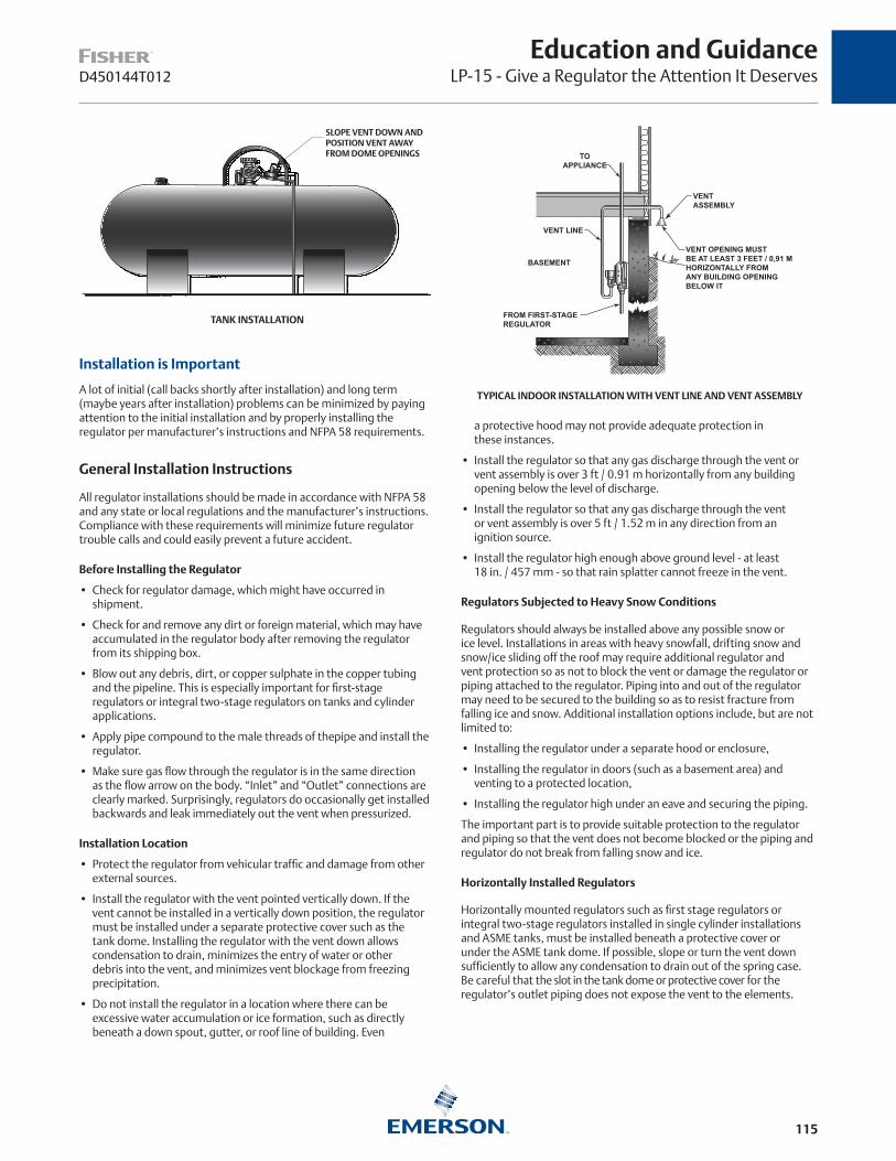
115
Education and GuidanceLP-15 - Give a Regulator the Attention It DeservesD450144T012
Installation is Important
A lot of initial (call backs shortly after installation) and long term (maybe years after installation) problems can be minimized by paying attention to the initial installation and by properly installing the regulator per manufacturer’s instructions and NFPA 58 requirements.
General Installation Instructions
All regulator installations should be made in accordance with NFPA 58 and any state or local regulations and the manufacturer’s instructions. Compliance with these requirements will minimize future regulator trouble calls and could easily prevent a future accident.
Before Installing the Regulator
• Check for regulator damage, which might have occurred in shipment.
• Check for and remove any dirt or foreign material, which may have accumulated in the regulator body after removing the regulator from its shipping box.
• Blow out any debris, dirt, or copper sulphate in the copper tubing and the pipeline. This is especially important for first-stage regulators or integral two-stage regulators on tanks and cylinder applications.
• Apply pipe compound to the male threads of thepipe and install the regulator.
• Make sure gas flow through the regulator is in the same direction as the flow arrow on the body. “Inlet” and “Outlet” connections are clearly marked. Surprisingly, regulators do occasionally get installed backwards and leak immediately out the vent when pressurized.
Installation Location
• Protect the regulator from vehicular traffic and damage from other external sources.
• Install the regulator with the vent pointed vertically down. If the vent cannot be installed in a vertically down position, the regulator must be installed under a separate protective cover such as the tank dome. Installing the regulator with the vent down allows condensation to drain, minimizes the entry of water or other debris into the vent, and minimizes vent blockage from freezing precipitation.
• Do not install the regulator in a location where there can be excessive water accumulation or ice formation, such as directly beneath a down spout, gutter, or roof line of building. Even
a protective hood may not provide adequate protection in these instances.
• Install the regulator so that any gas discharge through the vent or vent assembly is over 3 ft / 0.91 m horizontally from any building opening below the level of discharge.
• Install the regulator so that any gas discharge through the vent or vent assembly is over 5 ft / 1.52 m in any direction from an ignition source.
• Install the regulator high enough above ground level - at least 18 in. / 457 mm - so that rain splatter cannot freeze in the vent.
Regulators Subjected to Heavy Snow Conditions
Regulators should always be installed above any possible snow or ice level. Installations in areas with heavy snowfall, drifting snow and snow/ice sliding off the roof may require additional regulator and vent protection so as not to block the vent or damage the regulator or piping attached to the regulator. Piping into and out of the regulator may need to be secured to the building so as to resist fracture from falling ice and snow. Additional installation options include, but are not limited to:
• Installing the regulator under a separate hood or enclosure,
• Installing the regulator in doors (such as a basement area) and venting to a protected location,
• Installing the regulator high under an eave and securing the piping.
The important part is to provide suitable protection to the regulator and piping so that the vent does not become blocked or the piping and regulator do not break from falling snow and ice.
Horizontally Installed Regulators
Horizontally mounted regulators such as first stage regulators or integral two-stage regulators installed in single cylinder installations and ASME tanks, must be installed beneath a protective cover or under the ASME tank dome. If possible, slope or turn the vent down sufficiently to allow any condensation to drain out of the spring case. Be careful that the slot in the tank dome or protective cover for the regulator’s outlet piping does not expose the vent to the elements.
TANK INSTALLATION
SLOPE VENT DOWN AND POSITION VENT AWAY FROM DOME OPENINGS
TYPICAL INDOOR INSTALLATION WITH VENT LINE AND VENT ASSEMBLY
FROM FIRST-STAGEREGULATOR
BASEMENTVENT OPENING MUSTBE AT LEAST 3 FEET / 0,91 MHORIZONTALLY FROMANY BUILDING OPENINGBELOW IT
VENTASSEMBLY
VENT LINE
TO APPLIANCE
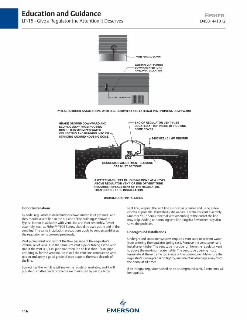
116
Education and GuidanceLP-15 - Give a Regulator the Attention It Deserves D450144T012
Indoor Installations
By code, regulators installed indoors have limited inlet pressure, and they require a vent line to the outside of the building as shown in Typical Indoor Installation with Vent Line and Vent Assembly. A vent assembly, such as Fisher™ Y602 Series, should be used at the end of the vent line. The same installation precautions apply to vent assemblies as the regulator vents covered previously.
Vent piping must not restrict the flow passage of the regulator’s internal relief valve. Use the same size vent pipe or tubing as the vent size. If the vent is 3/4 in. pipe size, then use no less than 3/4 in. pipe or tubing ID for the vent line. To install the vent line, remove the vent screen and apply a good grade of pipe dope to the male threads of the line.
Sometimes the vent line will make the regulator unstable, and it will pulsate or chatter. Such problems are minimized by using a large
3 FEET / 0,91 M
TYPICAL OUTDOOR INSTALLATIONS WITH REGULATOR VENT AND EXTERNAL VENT POINTING DOWNWARD
VENT POINTED DOWN
EXTERNAL VENT POINTED DOWN AND PIPED TO AN APPROPRIATE LOCATION.
REGULATOR ADJUSTMENT CLOSURECAP MUST BE TIGHT
END OF REGULATOR VENT TUBELOCATED AT TOP INSIDE OF HOUSINGDOME COVER
2-INCHES / 51 MM MINIMUM
A WATER MARK LEFT IN HOUSING DOME AT A LEVELABOVE REGULATOR VENT, OR END OF VENT TUBE REQUIRES REPLACEMENT OF THE REGULATOR. THEN CORRECT THE INSTALLATION
GRADE GROUND DOWNWARD AND SLOPING AWAY FROM HOUSING DOME. THIS MINIMIZES WATER COLLECTING AND RUNNING INTO OR STANDING AROUND HOUSING DOME.
UNDERGROUND INSTALLATION
vent line, keeping the vent line as short as possible and using as few elbows as possible. If instability still occurs, a stabilizer vent assembly (another Y602 Series external vent assembly) at the end of the line may help. Adding or removing vent line length a few inches may also solve the problem.
Underground Installations
Underground container systems require a vent tube to prevent water from entering the regulator spring case. Remove the vent screen and install a vent tube. The vent tube must be run from the regulator vent to above the maximum water table. The vent tube opening must terminate at the extreme top inside of the dome cover. Make sure the regulator’s closing cap is on tightly, and maintain drainage away from the dome at all times.
If an integral regulator is used on an underground tank, 2 vent lines will be required.

117
Education and GuidanceLP-15 - Give a Regulator the Attention It DeservesD450144T012
After Installation
Once the regulator is properly installed, the vast majority of operating problems can be attributed to chips–pieces of dirt, pipe scale, and other foreign materials; blocked vents and on occasion, water in the gas.
What to Do About Chips (Debris)
The valve disc and the orifice are critical components for controlling pressure, and especially at lockup (no flow). The synthetic rubber valve disc must be smooth and flat; the orifice must be free of nicks and its “nose” properly formed. A little dirt or chip lodged between the disc and orifice can cause slight pressure deviations that may result in unacceptable regulator performance when the regulator goes to pilot load or lockup.
What makes the chip’s work easier is the fact that the disc rarely moves more than a few thousandths of an inch away from the orifice, even on heavy loads. Trouble shows up when there isn’t much demand for gas–perhaps just the pilot lights are in use. At that time the disc has to move right up against the orifice to throttle the very small flow. If chips hold the disc far enough away to allow just a bit more flow than is being consumed, the pressure in the house piping will build up above the desired appliance pressure.
Excessive appliance pressure means customer service calls for poor appliance operation or the internal relief valve in the regulator opens to discharge some of the excess pressure resulting in gas loss and gas odor complaints.
To minimize chips, always blow out all pipe or tubing fittings when making the installation. When changing ICC cylinders, blow or clean out the cylinder connection before attaching the pigtail to the cylinder service valve.
WATER IN LP-GAS CAN TURN TO ICE AT THE REGULATOR’S INLET AND BLOCK GAS FLOW
GAS LEAKAGE CAUSED BY CHIPS PREVENTING THE DISC FROM SEATING TIGHTLY ENOUGH AGAINST THE ORIFICE
SCALE, DIRT
ICE
LIQUID PROPANE
PROPANE VAPOR

118
Education and GuidanceLP-15 - Give a Regulator the Attention It Deserves D450144T012
While chips are a rough adversary, it still takes a fairly stubborn piece of foreign material to pose serious problems. Many times the powerful force of the valve disc pushing against the orifice can break up the chips and return things to normal.
But no matter what, chips can’t be kept away all of the time. The important thing is to recognize the problem. In most instances, simply blowing out the lines and the regulator inlet will clear up the situation.
Worn or Damaged Regulator Disc and Orifice
The orifice “nose” must be carefully formed and handled by the manufacturer. Even a tiny nick that can hardly be seen will cause leakage when the regulator should lock up tight. When a regulator is taken apart, the orifice should be protected as much as possible.
The orifice nose tends to indent the disc even during ordinary operation. After many years, the disc can become indented enough to prevent tight lockup. Nicked orifices and indented discs result in the same problems as foreign material between the disc and orifice; potential internal relief valve discharge out the regulator vent. The solution is also the same–replace the disc and/or orifice.
Water in the Gas
Under certain conditions ice can form at the orifice inlet and prevent gas from entering the regulator. LP-Gas expands as it is reduced to a lower pressure, and it needs heat to expand. The heat comes through the walls of the regulator, making the inlet much colder. If water is present in the gas, it drops out of the gas at the inlet and eventually turns to ice if the temperature stays low enough.
If you suspect water in the LP-Gas, use methyl alcohol
(one pint to 100 gal. of fuel). Make sure all tanks and cylinders are thoroughly dehydrated before they go into service. Two-stage systems–a first-stage and a second-stage regulator– are much less susceptible to freeze-ups than a single-stage regulator. This is because more heat can be transferred from the outside through two regulators than just one. The second-stage regulator orifice is larger than a single-stage orifice and therefore more resistant to plugging by ice in the regulator inlet. Finally, since the second-stage regulator does not have a large inlet to outlet pressure differential, the cooling effect on the regulator is less which also minimizes ice formation in the regulator inlet.
Regulator Repair
In the current economic environment, regulator repair can fall into the realm of diminishing returns. The cost to replace a regulator may be less than the cost for parts, labor, and equipment investment required to repair regulators. Thus it becomes a company decision on repair versus replacing the regulator.
If the regulator is 15 years old or older, just replace the regulator.
Repair
If repair is the policy, always follow the manufacturer’s instructions for parts replacement and regulator repair. It’s fairly easy to repair regulators. A competent person, some common tools (such as a screwdriver and a crescent wrench), the necessary repair parts, and a test rack are required to do the job.
Repair would consist of the following:
1. The valve disc and the diaphragm should always be replaced, especially on units that have been in service for several years.
2. Check the orifice carefully and replace the orifice if it is dented or scratched on the seating surface.
3. Replace any corroded or damaged parts.
4. On reassembly, do not stretch the diaphragm of the regulator like a drum head.
5. Leave the flange screws loose until the adjusting screw has compressed the main regulator spring about half way.
6. Tighten the flange screws and the required diaphragm slack will be assured.
7. Test the regulator for setpoint, lockup, and leakage before reusing the regulator.
A test rack is needed for testing the regulator; it is available from most regulator manufacturers although some companies make their own. Every repaired regulator must be closely checked, tested, and set before it goes back into service.
No Repair
If repair is not your company policy, there is one check that can be made to potentially save a regulator, especially a relatively new regulator that does not lockup or leaks through the vent. There is a good probability that the lock-up issue or vent leakage is caused by debris in the inlet and at the orifice.
1. Remove the regulator from the line,
2. Blow out the inlet with compressed air,
3. Re-install the regulator, and
4. Check lockup and/or vent leakage again.
5. Replace the regulator if it still does not pass the tests.
Summing Up
There’s nothing that responds to a little care any better than the LP-Gas regulator. But if it is overlooked, all kinds of troubles can result. Remember these points:
1. Install the regulator with the vent pointing down on outdoor service; use a vent line sized for the vent on underground tanks, regulators installed indoors, and where distance requirements from openings or sources of ignition dictate.
2. Keep the vent open and check it periodically to see that it’s not blocked. If the vent has a screen, make certain that it is in place. Protect the regulator and vent from snow buildup and ice/snow falling off a roof.
3. Keep in mind that dirt and chips can cause vent leakage and poor lock-up performance. Clean lines and clean gas connections help reduce chip problems. Replacing the valve disc and orifice will usually correct any troubles.
4. Check the vent periodically to make sure it is not plugged or can be plugged.
5. A regulator that has been covered by water during a flood or heavy rain must to be replaced.
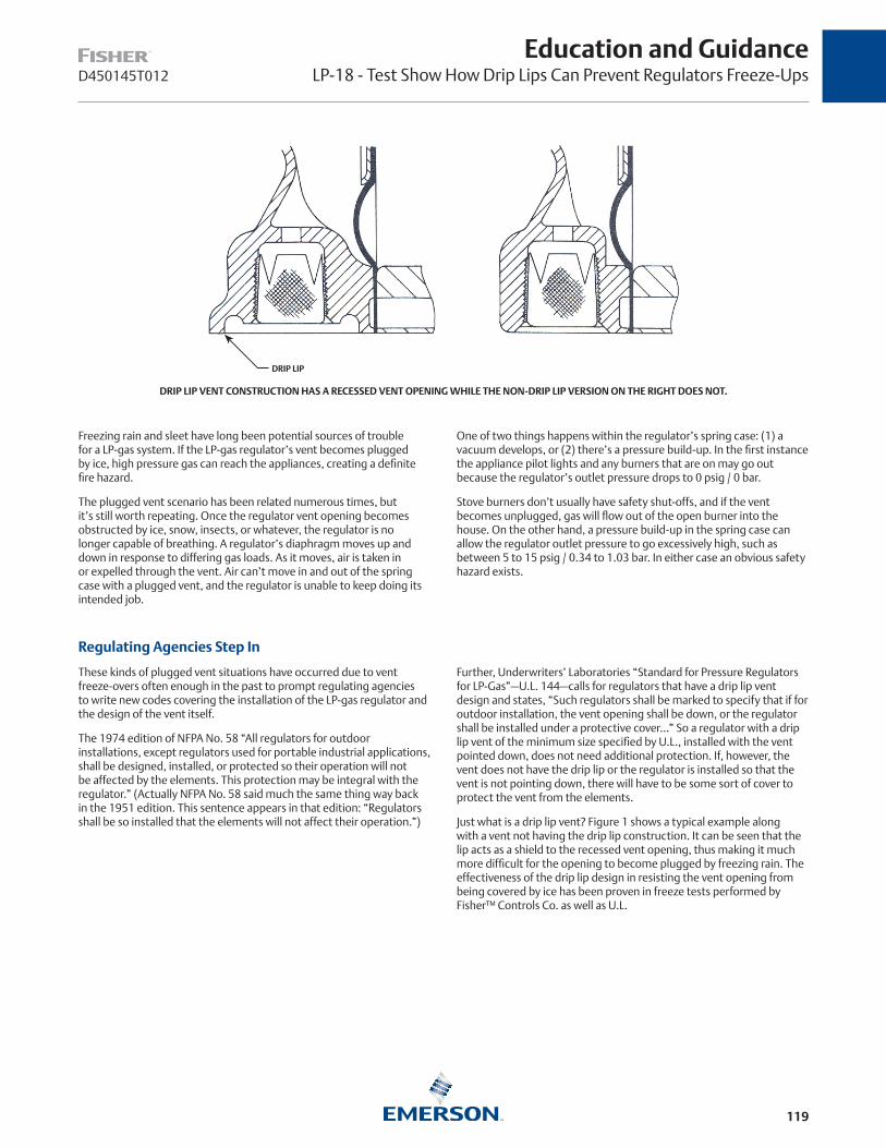
119
D450145T012
Education and GuidanceLP-18 - Test Show How Drip Lips Can Prevent Regulators Freeze-Ups
Freezing rain and sleet have long been potential sources of trouble for a LP-gas system. If the LP-gas regulator’s vent becomes plugged by ice, high pressure gas can reach the appliances, creating a definite fire hazard.
The plugged vent scenario has been related numerous times, but it’s still worth repeating. Once the regulator vent opening becomes obstructed by ice, snow, insects, or whatever, the regulator is no longer capable of breathing. A regulator’s diaphragm moves up and down in response to differing gas loads. As it moves, air is taken in or expelled through the vent. Air can’t move in and out of the spring case with a plugged vent, and the regulator is unable to keep doing its intended job.
DRIP LIP VENT CONSTRUCTION HAS A RECESSED VENT OPENING WHILE THE NON-DRIP LIP VERSION ON THE RIGHT DOES NOT.
DRIP LIP
One of two things happens within the regulator’s spring case: (1) a vacuum develops, or (2) there’s a pressure build-up. In the first instance the appliance pilot lights and any burners that are on may go out because the regulator’s outlet pressure drops to 0 psig / 0 bar.
Stove burners don’t usually have safety shut-offs, and if the vent becomes unplugged, gas will flow out of the open burner into the house. On the other hand, a pressure build-up in the spring case can allow the regulator outlet pressure to go excessively high, such as between 5 to 15 psig / 0.34 to 1.03 bar. In either case an obvious safety hazard exists.
Regulating Agencies Step In
These kinds of plugged vent situations have occurred due to vent freeze-overs often enough in the past to prompt regulating agencies to write new codes covering the installation of the LP-gas regulator and the design of the vent itself.
The 1974 edition of NFPA No. 58 “All regulators for outdoor installations, except regulators used for portable industrial applications, shall be designed, installed, or protected so their operation will not be affected by the elements. This protection may be integral with the regulator.” (Actually NFPA No. 58 said much the same thing way back in the 1951 edition. This sentence appears in that edition: “Regulators shall be so installed that the elements will not affect their operation.”)
Further, Underwriters’ Laboratories “Standard for Pressure Regulators for LP-Gas”—U.L. 144—calls for regulators that have a drip lip vent design and states, “Such regulators shall be marked to specify that if for outdoor installation, the vent opening shall be down, or the regulator shall be installed under a protective cover...” So a regulator with a drip lip vent of the minimum size specified by U.L., installed with the vent pointed down, does not need additional protection. If, however, the vent does not have the drip lip or the regulator is installed so that the vent is not pointing down, there will have to be some sort of cover to protect the vent from the elements.
Just what is a drip lip vent? Figure 1 shows a typical example along with a vent not having the drip lip construction. It can be seen that the lip acts as a shield to the recessed vent opening, thus making it much more difficult for the opening to become plugged by freezing rain. The effectiveness of the drip lip design in resisting the vent opening from being covered by ice has been proven in freeze tests performed by Fisher™ Controls Co. as well as U.L.
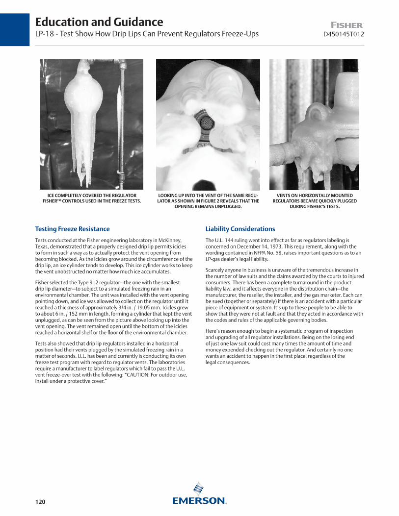
120
D450145T012
Education and GuidanceLP-18 - Test Show How Drip Lips Can Prevent Regulators Freeze-Ups
ICE COMPLETELY COVERED THE REGULATOR FISHER™ CONTROLS USED IN THE FREEZE TESTS.
LOOKING UP INTO THE VENT OF THE SAME REGU-LATOR AS SHOWN IN FIGURE 2 REVEALS THAT THE
OPENING REMAINS UNPLUGGED.
VENTS ON HORIZONTALLY MOUNTED REGULATORS BECAME QUICKLY PLUGGED
DURING FISHER’S TESTS.
Testing Freeze Resistance
Tests conducted at the Fisher engineering laboratory in McKinney, Texas, demonstrated that a properly designed drip lip permits icicles to form in such a way as to actually protect the vent opening from becoming blocked. As the icicles grow around the circumference of the drip lip, an ice cylinder tends to develop. This ice cylinder works to keep the vent unobstructed no matter how much ice accumulates.
Fisher selected the Type 912 regulator—the one with the smallest drip lip diameter—to subject to a simulated freezing rain in an environmental chamber. The unit was installed with the vent opening pointing down, and ice was allowed to collect on the regulator until it reached a thickness of approximately 3/4 in. / 19.05 mm. Icicles grew to about 6 in. / 152 mm in length, forming a cylinder that kept the vent unplugged, as can be seen from the picture above looking up into the vent opening. The vent remained open until the bottom of the icicles reached a horizontal shelf or the floor of the environmental chamber.
Tests also showed that drip lip regulators installed in a horizontal position had their vents plugged by the simulated freezing rain in a matter of seconds. U.L. has been and currently is conducting its own freeze test program with regard to regulator vents. The laboratories require a manufacturer to label regulators which fail to pass the U.L. vent freeze-over test with the following: “CAUTION: For outdoor use, install under a protective cover.”
Liability Considerations
The U.L. 144 ruling went into effect as far as regulators labeling is concerned on December 14, 1973. This requirement, along with the wording contained in NFPA No. 58, raises important questions as to an LP-gas dealer’s legal liability.
Scarcely anyone in business is unaware of the tremendous increase in the number of law suits and the claims awarded by the courts to injured consumers. There has been a complete turnaround in the product liability law, and it affects everyone in the distribution chain—the manufacturer, the reseller, the installer, and the gas marketer. Each can be sued (together or separately) if there is an accident with a particular piece of equipment or system. It’s up to these people to be able to show that they were not at fault and that they acted in accordance with the codes and rules of the applicable governing bodies.
Here’s reason enough to begin a systematic program of inspection and upgrading of all regulator installations. Being on the losing end of just one law suit could cost many times the amount of time and money expended checking out the regulator. And certainly no one wants an accident to happen in the first place, regardless of the legal consequences.
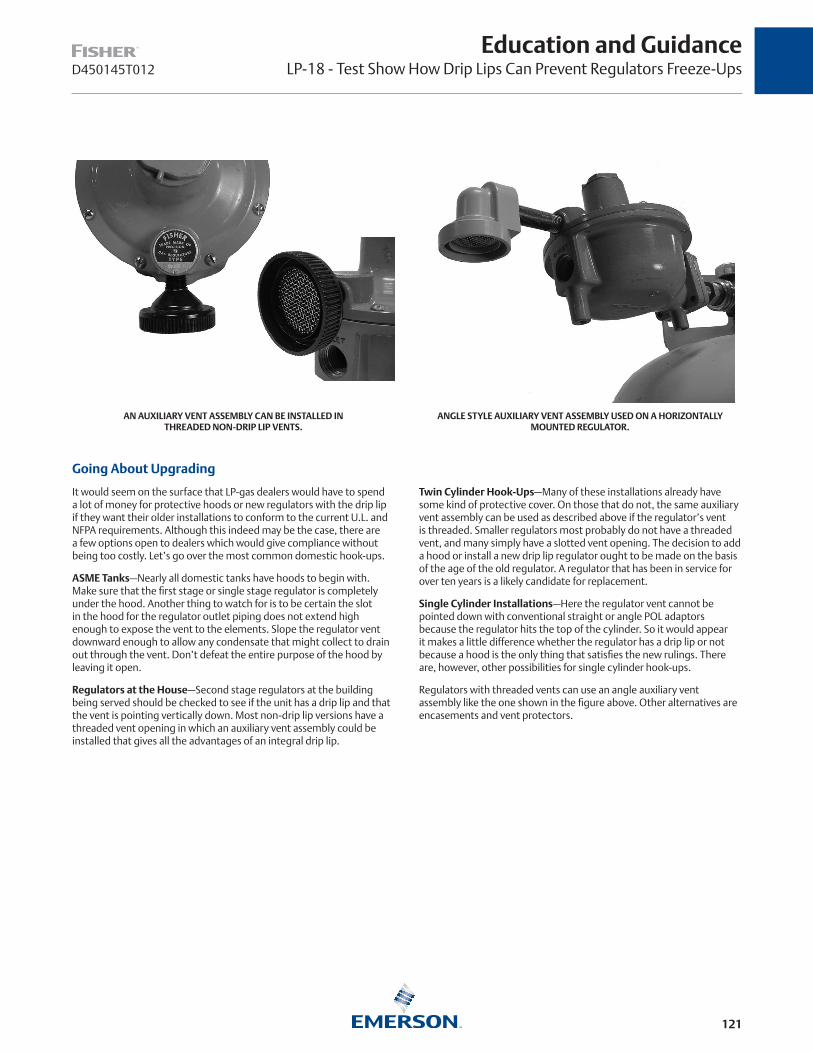
121
Education and GuidanceLP-18 - Test Show How Drip Lips Can Prevent Regulators Freeze-UpsD450145T012
ANGLE STYLE AUXILIARY VENT ASSEMBLY USED ON A HORIZONTALLY MOUNTED REGULATOR.
AN AUXILIARY VENT ASSEMBLY CAN BE INSTALLED IN THREADED NON-DRIP LIP VENTS.
Going About Upgrading
It would seem on the surface that LP-gas dealers would have to spend a lot of money for protective hoods or new regulators with the drip lip if they want their older installations to conform to the current U.L. and NFPA requirements. Although this indeed may be the case, there are a few options open to dealers which would give compliance without being too costly. Let’s go over the most common domestic hook-ups.
ASME Tanks—Nearly all domestic tanks have hoods to begin with. Make sure that the first stage or single stage regulator is completely under the hood. Another thing to watch for is to be certain the slot in the hood for the regulator outlet piping does not extend high enough to expose the vent to the elements. Slope the regulator vent downward enough to allow any condensate that might collect to drain out through the vent. Don’t defeat the entire purpose of the hood by leaving it open.
Regulators at the House—Second stage regulators at the building being served should be checked to see if the unit has a drip lip and that the vent is pointing vertically down. Most non-drip lip versions have a threaded vent opening in which an auxiliary vent assembly could be installed that gives all the advantages of an integral drip lip.
Twin Cylinder Hook-Ups—Many of these installations already have some kind of protective cover. On those that do not, the same auxiliary vent assembly can be used as described above if the regulator’s vent is threaded. Smaller regulators most probably do not have a threaded vent, and many simply have a slotted vent opening. The decision to add a hood or install a new drip lip regulator ought to be made on the basis of the age of the old regulator. A regulator that has been in service for over ten years is a likely candidate for replacement.
Single Cylinder Installations—Here the regulator vent cannot be pointed down with conventional straight or angle POL adaptors because the regulator hits the top of the cylinder. So it would appear it makes a little difference whether the regulator has a drip lip or not because a hood is the only thing that satisfies the new rulings. There are, however, other possibilities for single cylinder hook-ups.
Regulators with threaded vents can use an angle auxiliary vent assembly like the one shown in the figure above. Other alternatives are encasements and vent protectors.

122
D450145T012
Education and GuidanceLP-18 - Test Show How Drip Lips Can Prevent Regulators Freeze-Ups
ENCASEMENTS OR VENT PROTECTORS MAY BE ABLE TO SOLVE THE HORIZONTAL MOUNTING PROBLEM.
Other Factors
While freezing rain or sleet are the most common causes of vent obstruction, they’re not the only ones. Snow, insects, and mud can also plug the vent. It ought to be checked each time a gas delivery is made to see that it is free from any obstruction. In areas where snow can cover the entire regulator, a protective hood should be considered. Don’t install a regulator directIy under roof eaves, down spouts, or in other locations where there can be excessive water accumulation.
Mud and road splatter can pose special difficulties for regulators used on recreational vehicles. The 1974 edition of NFPA No. 501C (Standard for Recreational Vehicles) specifically states, “Regulators shall be installed so the regulator vent will not be affected by the elements such as by...mud or by wheel spray.”
Sometimes the LP-gas container on the RV is installed in a spot where the regulator can catch the full brunt of any spray from the wheels. Conventional covers usually aren’t effective against road splatter because the vent needs protection not only from the top and sides but from the bottom as well. LP-gas dealers can explain the problem to the RV owner when the container is being refilled and possibly remedy the situation.
All regulators should be inspected periodically for internal corrosion. Condensate or water can collect in the regulator’s spring case, especially on horizontally mounted or insufficiently sloped units, and cause corrosion of the internal parts. If any corrosion or water marks are visible within the spring case, the regulator should be replaced. It is recommended that regulators in service over five years—or regulators moved from one location to another—be inspected for internal corrosion at regular intervals.
Checking and updating regulator installations is time well spent from both a liability and a customer acceptance stand-point. It’s a policy that reduces the number of regulator malfunctions (and trouble calls) while at the same time helping to maintain customer satisfaction. And making sure all new regulators have the drip lip type construction will be a big aid in cutting installation costs on domestic hook-ups.
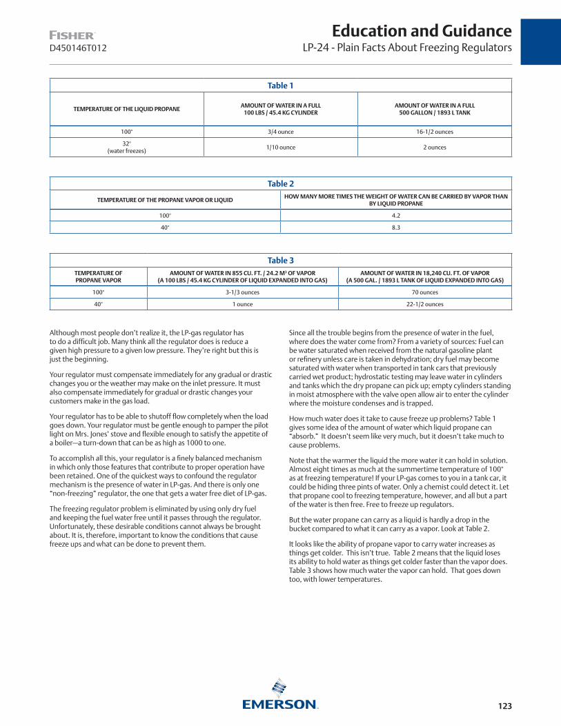
123
D450146T012
Education and GuidanceLP-24 - Plain Facts About Freezing Regulators
Table 1
TEMPERATURE OF THE LIQUID PROPANEAMOUNT OF WATER IN A FULL
100 LBS / 45.4 KG CYLINDERAMOUNT OF WATER IN A FULL
500 GALLON / 1893 L TANK
100° 3/4 ounce 16-1/2 ounces
32°(water freezes)
1/10 ounce 2 ounces
Table 2
TEMPERATURE OF THE PROPANE VAPOR OR LIQUIDHOW MANY MORE TIMES THE WEIGHT OF WATER CAN BE CARRIED BY VAPOR THAN
BY LIQUID PROPANE
100° 4.2
40° 8.3
Although most people don’t realize it, the LP-gas regulator has to do a difficult job. Many think all the regulator does is reduce a given high pressure to a given low pressure. They’re right but this is just the beginning.
Your regulator must compensate immediately for any gradual or drastic changes you or the weather may make on the inlet pressure. It must also compensate immediately for gradual or drastic changes your customers make in the gas load.
Your regulator has to be able to shutoff flow completely when the load goes down. Your regulator must be gentle enough to pamper the pilot light on Mrs. Jones’ stove and flexible enough to satisfy the appetite of a boiler—a turn-down that can be as high as 1000 to one.
To accomplish all this, your regulator is a finely balanced mechanism in which only those features that contribute to proper operation have been retained. One of the quickest ways to confound the regulator mechanism is the presence of water in LP-gas. And there is only one “non-freezing” regulator, the one that gets a water free diet of LP-gas.
The freezing regulator problem is eliminated by using only dry fuel and keeping the fuel water free until it passes through the regulator. Unfortunately, these desirable conditions cannot always be brought about. It is, therefore, important to know the conditions that cause freeze ups and what can be done to prevent them.
Since all the trouble begins from the presence of water in the fuel, where does the water come from? From a variety of sources: Fuel can be water saturated when received from the natural gasoline plant or refinery unless care is taken in dehydration; dry fuel may become saturated with water when transported in tank cars that previously carried wet product; hydrostatic testing may leave water in cylinders and tanks which the dry propane can pick up; empty cylinders standing in moist atmosphere with the valve open allow air to enter the cylinder where the moisture condenses and is trapped.
How much water does it take to cause freeze up problems? Table 1 gives some idea of the amount of water which liquid propane can “absorb.” It doesn’t seem like very much, but it doesn’t take much to cause problems.
Note that the warmer the liquid the more water it can hold in solution. Almost eight times as much at the summertime temperature of 100° as at freezing temperature! If your LP-gas comes to you in a tank car, it could be hiding three pints of water. Only a chemist could detect it. Let that propane cool to freezing temperature, however, and all but a part of the water is then free. Free to freeze up regulators.
But the water propane can carry as a liquid is hardly a drop in the bucket compared to what it can carry as a vapor. Look at Table 2.
It looks like the ability of propane vapor to carry water increases as things get colder. This isn’t true. Table 2 means that the liquid loses its ability to hold water as things get colder faster than the vapor does. Table 3 shows how much water the vapor can hold. That goes down too, with lower temperatures.
Table 3TEMPERATURE OF PROPANE VAPOR
AMOUNT OF WATER IN 855 CU. FT. / 24.2 M3 OF VAPOR (A 100 LBS / 45.4 KG CYLINDER OF LIQUID EXPANDED INTO GAS)
AMOUNT OF WATER IN 18,240 CU. FT. OF VAPOR (A 500 GAL. / 1893 L TANK OF LIQUID EXPANDED INTO GAS)
100° 3-1/3 ounces 70 ounces
40° 1 ounce 22-1/2 ounces

124
D450146T012
Education and GuidanceLP-24 - Plain Facts About Freezing Regulators
ATMOSPHERE 35°F / 1.7°C
REGULATOR BODY 35°F / 1.7°C
35°F / 1.7°C
57 PSI / 3.9 bar 57 PSI / 3.9 bar,
35°F / 1.7°CLOW PRESSURE GAS 15°F / -9.4°C
11 IN. W.C. / 27 mbar
30°F / -1.1°C
ATMOSPHERE 35°F / 1.7°C
REGULATOR BODY 25°F / -3.9°C
28°F / -2.2°C25°F /
-3.9°C
11IN. W.C. / 27 mbar
LOW PRESSURE GAS 15°F / -9.4°C
54 PSI / 3.7 bar
CONDENSATE
54 PSI / 3.7 bar,32°F / 0°C
ICE
LIQUID PROPANE
PROPANEVAPOR
Let’s look at actual operating conditions. Take a cylinder of gas, during the fall, with an outside temperature of 60 degrees. A cold spell drops the temperature to freezing, and water starts to collect in the bottom of the cylinder because neither propane liquid or vapor can “carry” the increased amount of water. It stays cold with the free water at the bottom of the cylinder. As vapor continues to be drawn off, the vapor robs the liquid propane of its water, since vapor can carry much more water than the liquid.
Mrs. Jones’ stove and water heater are connected to this cylinder (through a regulator, of course). She starts cooking and Mr. Jones decides to take a bath. It’s cold—about 35°—and propane vapor at that temperature comes out of the cylinder to the regulator inlet at a pressure of about 57 psi / 3.9 bar. The regulator goes to work maintaining proper appliance pressure, which shows a conventional single stage regulator installed at the customer’s home.
Note that the gas on the low pressure side of the regulator is only 15°. What has happened? It takes heat to expand the gas from its compressed volume at 57 psi / 3.9 bar to its enlarged volume at 11 in. w.c. / 27 mbar for the appliances. This heat comes from the surrounding air through the walls of the regulator. After the gas has left the regulator and entered the outlet tubing, it goes back up to 30°. The only trouble is that the heat is where we don’t need it—at the regulator outlet instead of the inlet.
The figures above show what can happen if the situation goes on for some time. There have been slight changes in pressure and temperature within the cylinder. This always happens when vapor is drawn off, and 54 psi / 3.7 bar is plenty of pressure to do the job. But look what has taken place at the regulator inlet. The expanding gas has pulled the temperature down to 28 degrees and propane condenses at the inlet. Free water appears because we cool the vapor and reduce its ability to carry water. In Figure 2 the condensate forms just ahead of the regulator orifice.
The figure above shows the condensate turned to ice at the orifice. This causes a freeze up unless the action of the regulator can break the ice jam.
There are a number of things you can do to prevent this kind of situation. Number one on the list would be to make sure you’re using dry LP-gas. Secondly, make certain that all tanks and cylinders are thoroughly dehydrated before they go into service.
Here are a few other hints and precautions:
1. Use methyl alcohol if you suspect water (one pint to 100 gallons / 379 liter fuel).
2. Keep cylinder valves closed while cylinders are in storage.
3. Consider two stages of regulation, i.e., a first stage regulator and a second stage regulator. See Fisher’s Handbook of Technical Data for more information.
4. Consider using a regulator with a larger orifice.
5. Install the regulator and pigtail so that condensate drains back to the cylinder.
The above practices should virtually eliminate freeze up complaints and the costly trouble calls that go with them.
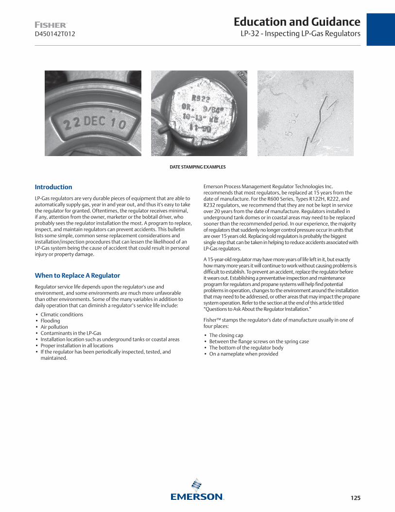
125
Education and GuidanceLP-32 - Inspecting LP-Gas RegulatorsD450142T012
DATE STAMPING EXAMPLES
Introduction
LP-Gas regulators are very durable pieces of equipment that are able to automatically supply gas, year in and year out, and thus it's easy to take the regulator for granted. Oftentimes, the regulator receives minimal, if any, attention from the owner, marketer or the bobtail driver, who probably sees the regulator installation the most. A program to replace, inspect, and maintain regulators can prevent accidents. This bulletin lists some simple, common sense replacement considerations and installation/inspection procedures that can lessen the likelihood of an LP-Gas system being the cause of accident that could result in personal injury or property damage.
When to Replace A Regulator
Regulator service life depends upon the regulator's use and environment, and some environments are much more unfavorable than other environments. Some of the many variables in addition to daily operation that can diminish a regulator’s service life include:
• Climatic conditions • Flooding• Air pollution • Contaminants in the LP-Gas• Installation location such as underground tanks or coastal areas • Proper installation in all locations • If the regulator has been periodically inspected, tested, and
maintained.
Emerson Process Management Regulator Technologies Inc. recommends that most regulators, be replaced at 15 years from the date of manufacture. For the R600 Series, Types R122H, R222, and R232 regulators, we recommend that they are not be kept in service over 20 years from the date of manufacture. Regulators installed in underground tank domes or in coastal areas may need to be replaced sooner than the recommended period. In our experience, the majority of regulators that suddenly no longer control pressure occur in units that are over 15 years old. Replacing old regulators is probably the biggest single step that can be taken in helping to reduce accidents associated with LP-Gas regulators.
A 15-year-old regulator may have more years of life left in it, but exactly how many more years it will continue to work without causing problems is difficult to establish. To prevent an accident, replace the regulator before it wears out. Establishing a preventative inspection and maintenance program for regulators and propane systems will help find potential problems in operation, changes to the environment around the installation that may need to be addressed, or other areas that may impact the propane system operation. Refer to the section at the end of this article titled “Questions to Ask About the Regulator Installation.”
Fisher™ stamps the regulator's date of manufacture usually in one of four places:
• The closing cap • Between the flange screws on the spring case • The bottom of the regulator body• On a nameplate when provided

126
D450142T012
Education and GuidanceLP-32 - Inspecting LP-Gas Regulators
Starting April 1, 2010, Fisher™ regulator date stamping is in the form of a day, month, and year designation.
12APR10 indicating April 12, 2010.
Previously, Fisher stamped the date of manufacture by month and year such as 10-77 for October 1977.
And for a period from 1965 through approximately 1973, a date code was used such as A63.
First Character A = 1960’s B = 1970’s
Second Character 6 in the example = year, so A6 is 1966. B2 would be 1972
Third Character Quarter in which product was made1 = 1st Quarter of year2 = 2nd Quarter of year3 = 3rd Quarter of year4 = 4th Quarter of year
So A63 means the regulator was made in the 3rd Quarter, 1966. See Day Coding Example above.
Prior to 1965 and after 1973: Stamped with Month and Year
Example: 10-77 = October 1977
Year
Month
1965 to 1973: Three Digit Date Code
Example: A 6 3 = 1966, Quarter 3
Built in Quarter 1, 2, 3, or 4
Built in Year 1, 2, ... 8, 9
A = 1960s B = 1970s
April 2010 and Later: Day, Month, and Year
Example: 12 APR 10 = April 12, 2010
Year
Month
Day
DATE CODING EXAMPLE
Proper Regulator Installation
Proper regulator installation is vital for a regulator to function correctly for long periods of time. Therefore, the following information assumes that the regulator is on a vapor system and has been installed per NFPA 58, state or local regulations, and the manufacturer’s instructions.
Wrong Regulator or No Regulator in the System
There are numerous types of LP-Gas systems—Single-Stage, Two-Stage including Integral regulators, 2 psig / 0.14 bar systems, and large commercial/industrial installations. Not having a pressure regulator (it has happened) in the system or a pressure regulator that is not suitable for the installation, high-pressure regulator instead of low-pressure regulator for example, can be disastrous.
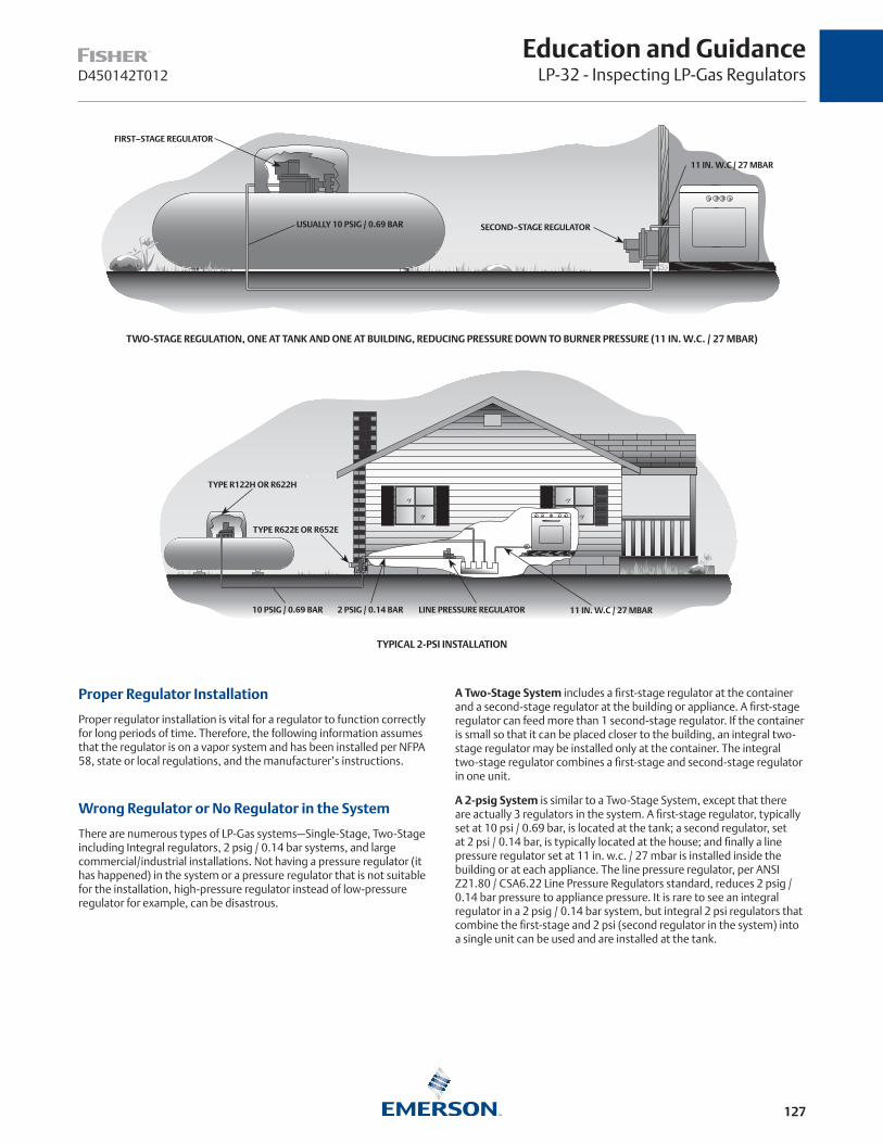
127
Education and GuidanceLP-32 - Inspecting LP-Gas RegulatorsD450142T012
TWO-STAGE REGULATION, ONE AT TANK AND ONE AT BUILDING, REDUCING PRESSURE DOWN TO BURNER PRESSURE (11 IN. W.C. / 27 MBAR)
FIRST–STAGE REGULATOR
USUALLY 10 PSIG / 0.69 BAR
11 IN. W.C / 27 MBAR
SECOND–STAGE REGULATOR
TYPICAL 2-PSI INSTALLATION
TYPE R122H OR R622H
TYPE R622E OR R652E
2 PSIG / 0.14 BAR LINE PRESSURE REGULATOR10 PSIG / 0.69 BAR 11 IN. W.C / 27 MBAR
Proper Regulator Installation
Proper regulator installation is vital for a regulator to function correctly for long periods of time. Therefore, the following information assumes that the regulator is on a vapor system and has been installed per NFPA 58, state or local regulations, and the manufacturer’s instructions.
Wrong Regulator or No Regulator in the System
There are numerous types of LP-Gas systems—Single-Stage, Two-Stage including Integral regulators, 2 psig / 0.14 bar systems, and large commercial/industrial installations. Not having a pressure regulator (it has happened) in the system or a pressure regulator that is not suitable for the installation, high-pressure regulator instead of low-pressure regulator for example, can be disastrous.
A Two-Stage System includes a first-stage regulator at the container and a second-stage regulator at the building or appliance. A first-stage regulator can feed more than 1 second-stage regulator. If the container is small so that it can be placed closer to the building, an integral two-stage regulator may be installed only at the container. The integral two-stage regulator combines a first-stage and second-stage regulator in one unit.
A 2-psig System is similar to a Two-Stage System, except that there are actually 3 regulators in the system. A first-stage regulator, typically set at 10 psi / 0.69 bar, is located at the tank; a second regulator, set at 2 psi / 0.14 bar, is typically located at the house; and finally a line pressure regulator set at 11 in. w.c. / 27 mbar is installed inside the building or at each appliance. The line pressure regulator, per ANSI Z21.80 / CSA6.22 Line Pressure Regulators standard, reduces 2 psig / 0.14 bar pressure to appliance pressure. It is rare to see an integral regulator in a 2 psig / 0.14 bar system, but integral 2 psi regulators that combine the first-stage and 2 psi (second regulator in the system) into a single unit can be used and are installed at the tank.

128
D450142T012
Education and GuidanceLP-32 - Inspecting LP-Gas Regulators
TYPE 627 DIRECT-OPERATED MONITOR OPERATIONAL SCHEMATIC
ORIFICE
VALVE DISK
RELIEF SPRING
RELIEF VALVE STEM
VALVE STEM LEVER
PRESSURE RETAINING PLUG(DO NOT REMOVE WHILE UNIT IS PRESSURIZED)
RELIEF SEAT
MAIN SPRING
ADJUSTING SCREW
TYPE CS400IR INTERNALLY REGISTERED REGULATOR WITH INTERNAL RELIEF OPERATIONAL SCHEMATIC
Regulators standard, reduces 2 psig / 0,14 bar pressure to appliance pressure. It is rare to see an integral regulator in a 2 psig / 0.14 bar system, but integral 2 psi regulators that combine the first-stage and 2 psi (second regulator in the system) into a single unit can be used and are installed at the tank.
While Single-Stage Systems cannot be installed on new 0.50 psig / 0.03 bar fixed pipe gas pressure systems, they do still exist on older installations and therefore need to be inspected. NFPA 58 does not allow a new single stage regulator to be installed after June 30, 1997. Since it has been almost 15 years since a new single stage system could be installed, most existing single stage systems are probably over 15 years of age, and therefore need to be upgraded to a new two-stage regulator system that complies with the current NFPA 58 regulations. A single-stage regulator is installed at the container. Oftentimes the single-stage regulator can be replaced with an integral two-stage regulator resulting in minimal piping changes. If the container is far from the house, both a first and second-stage regulator will have to be installed.
INLET PRESSUREOUTLET PRESSUREATMOSPHERIC PRESSURE
M1077
INLET PRESSUREOUTLET PRESSUREATMOSPHERIC PRESSUREINTERMEDIATE PRESSURE
Commercial and Industrial Systems also have to comply with NFPA 58 requirements for two-stage systems if they supply low-pressure gas to appliances. In some instances a high-pressure regulator that supplies more than 10 psi / 0.69 bar may be installed between the container and the first-stage regulator if needed to meet flow or piping demands. In some instances, additional external overpressure protection will be required between the high-pressure regulator and the first-stage regulator. Regulators used as second-stage regulators in these systems may not have internal relief protection or if they do, the relief valve may have limited capacity so that it may not meet the 2 psig / 0.14 bar relief pressure requirement. Therefore, additional external relief devices or other means of overpressure protection may be required depending upon the regulator construction used as a second-stage regulator. Monitor systems are being used more as another means of overpressure protection. A monitor system provides a “back up” regulator in the event the working regulator no longer controls pressure. Monitor systems do not vent gas to the atmosphere like an internal or external relief valve will do when the relief valve activates. Therefore, monitor systems need to be inspected annually to validate their continued proper operation. Commercial and industrial regulators, monitor regulators, and the external relief devices have to be installed properly and the information discussed in this article would apply equally to these systems along with the recommendations found in the product’s instruction manuals.
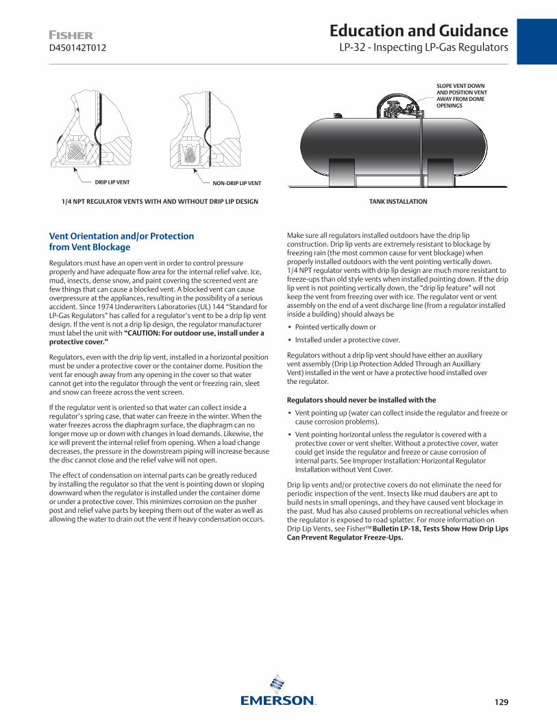
129
Education and GuidanceLP-32 - Inspecting LP-Gas RegulatorsD450142T012
DRIP LIP VENT
1/4 NPT REGULATOR VENTS WITH AND WITHOUT DRIP LIP DESIGN
NON-DRIP LIP VENT
TANK INSTALLATION
SLOPE VENT DOWN AND POSITION VENT AWAY FROM DOME OPENINGS
Vent Orientation and/or Protection from Vent Blockage
Regulators must have an open vent in order to control pressure properly and have adequate flow area for the internal relief valve. Ice, mud, insects, dense snow, and paint covering the screened vent are few things that can cause a blocked vent. A blocked vent can cause overpressure at the appliances, resulting in the possibility of a serious accident. Since 1974 Underwriters Laboratories (UL) 144 “Standard for LP-Gas Regulators” has called for a regulator’s vent to be a drip lip vent design. If the vent is not a drip lip design, the regulator manufacturer must label the unit with “CAUTION: For outdoor use, install under a protective cover.”
Regulators, even with the drip lip vent, installed in a horizontal position must be under a protective cover or the container dome. Position the vent far enough away from any opening in the cover so that water cannot get into the regulator through the vent or freezing rain, sleet and snow can freeze across the vent screen.
If the regulator vent is oriented so that water can collect inside a regulator’s spring case, that water can freeze in the winter. When the water freezes across the diaphragm surface, the diaphragm can no longer move up or down with changes in load demands. Likewise, the ice will prevent the internal relief from opening. When a load change decreases, the pressure in the downstream piping will increase because the disc cannot close and the relief valve will not open.
The effect of condensation on internal parts can be greatly reduced by installing the regulator so that the vent is pointing down or sloping downward when the regulator is installed under the container dome or under a protective cover. This minimizes corrosion on the pusher post and relief valve parts by keeping them out of the water as well as allowing the water to drain out the vent if heavy condensation occurs.
Make sure all regulators installed outdoors have the drip lip construction. Drip lip vents are extremely resistant to blockage by freezing rain (the most common cause for vent blockage) when properly installed outdoors with the vent pointing vertically down. 1/4 NPT regulator vents with drip lip design are much more resistant to freeze-ups than old style vents when installed pointing down. If the drip lip vent is not pointing vertically down, the “drip lip feature” will not keep the vent from freezing over with ice. The regulator vent or vent assembly on the end of a vent discharge line (from a regulator installed inside a building) should always be
• Pointed vertically down or
• Installed under a protective cover.
Regulators without a drip lip vent should have either an auxiliary vent assembly (Drip Lip Protection Added Through an Auxilliary Vent) installed in the vent or have a protective hood installed over the regulator.
Regulators should never be installed with the
• Vent pointing up (water can collect inside the regulator and freeze or cause corrosion problems).
• Vent pointing horizontal unless the regulator is covered with a protective cover or vent shelter. Without a protective cover, water could get inside the regulator and freeze or cause corrosion of internal parts. See Improper Installation: Horizontal Regulator Installation without Vent Cover.
Drip lip vents and/or protective covers do not eliminate the need for periodic inspection of the vent. Insects like mud daubers are apt to build nests in small openings, and they have caused vent blockage in the past. Mud has also caused problems on recreational vehicles when the regulator is exposed to road splatter. For more information on Drip Lip Vents, see Fisher™ Bulletin LP-18, Tests Show How Drip Lips Can Prevent Regulator Freeze-Ups.

130
D450142T012
Education and GuidanceLP-32 - Inspecting LP-Gas Regulators
DRIP LIP PROTECTION ADDED THROUGH AN AUXILIARY VENT
IMPROPER INSTALLATION: HORIZONTAL REGULATOR INSTALLATION WITHOUT VENT COVER
CORROSION DUE TO BELOW GROUND LEVEL INSTALLATION
Regulator Installed Above Ground Level
Regulators installed outdoors should be located at least 18 in. / 457 mm above the ground. This minimizes the amount of “splash back” that can bounce back up onto the screened vent area and either block the vent with ice (in the winter) or enter the regulator and create corrosion problems. This distance also keeps the regulator out of the dirt which can also cause corrosion issues.
Regulators should not be buried in the ground. Refer to Corrosion Due to Below Gound Level Installation image. This regulator was partially buried in the ground. The external corrosion (pitting) extended up onto the back of the lower casing. Inlet pipe boss (Black Arrow) broke away from the actuator. The 3/4 in. NPT vent (White Arrow) was piped away but with a 3/8 in. / 9.5 mm copper tube which restricts the flow through the vent from the internal relief valve.
Regulators should not be installed under a house eave or valley that allows water runoff and snow melt or ice and snow from a roof to fall directly onto the regulator. If the regulator has to be installed in such locations, then additional protection is required such as installing a vent line with an auxiliary vent piped to a better location, hoods, covers or shelters should be installed over the regulator. See the two sections in this article titled Installed away from windows, basements, air intakes, and other openings and regulators installed inside buildings for
additional information on installing vent lines and auxiliary vents. Refer to Vent Installation Away from Windows, Basement Air Intakes and other Openings image.
Installed Away From Windows, Basements, Air Intakes, and Other Openings
NFPA 58 requires that the regulator(s) be installed so that the relief valve discharge from the regulator vent is
• At least 3 ft. / 0.91 m horizontally away from any building opening below the level of the relief valve vent discharge
• Not beneath any building unless well ventilated and not enclosed for more than 50% of its perimeter
• Not less tan 5 ft. / 1.5 m in any direction from ignition sources openings in to direct vent appliances or mechanical ventilation air intakes
If the regulator cannot be moved to comply with these requirements, then a vent line will have to be installed and the end of the vent line terminated at a place where it will comply with the requirements. The end of the vent line must also comply with the vent orientation and protection requirements discussed earlier.
VENT INSTALLATION AWAY FROM WINDOWS, BASEMENT AIR INTAKES AND OTHER OPENINGS
VENT POINTED DOWN
3 FEET / 0,91 m
FROM FIRST-STAGE REGULATOR
BASEMENT
VENT OPENING MUST BE AT LEAST 3-FEET / 0,91 mHORIZONTALLY FROM ANY BUILDING OPENINGBELOW IT
VENT ASSEMBLY
VENT LINE
TO APPLIANCE
BASEMENT OR INDOOR INSTALLATION
TO APPLIANCE
VENT LINE
BASEMENT
FROM FIRST-STAGE REGULATOR
VENT ASSEMBLY
VENT OPENING MUST BE AT LEAST 3 FT. / 0.91 M HORIZONTALLY FROM ANY BUILDING OPENING BELOW IT

131
Education and GuidanceLP-32 - Inspecting LP-Gas RegulatorsD450142T012
Regulators Installed Inside Buildings
Regulators are sometimes installed inside a building because of long piping runs to one or more gas appliances. See Vent Installation Away from Windows, Basement Air Intakes and other Openings and Basement or Indoor Installation. Regulators inside buildings have some special conditions that have to be met in order to comply with NFPA 58 requirements. Some of those requirements include:
• No liquid LP-Gas piped into buildings except under certain conditions.
• No vapor pressure in excess of 20 psi / 1.4 bar except under certain conditions. Note also that second-stage regulators are limited to 10 psi / 0.69 bar maximum inlet pressure. So if 20 psi / 1.4 bar is piped into the building, an additional first-stage pressure regulator will have to be installed to maintain 10 psi / 0.69 bar to the second-stage regulators.
• The regulator vent must be piped to the atmosphere outside the building.
• The end of the vent discharge line must comply with the distance requirements from building openings and the vent orientation and protection requirements discussed earlier.
• The vent discharge piping must be the same nominal pipe size as the vent connection piping so as not to restrict the relief capacity and performance of the regulator. Long vent discharge lines may actually require increased pipe sizes to account for piping line loss.
• Vent discharge piping must be:
– Metal pipe or tubing as allowed by the code or
– PVC material per UL 651, Schedule 40 or 80 Rigid PVC Conduit
• If more than one regulator is installed indoors, separate vent lines must be run from each regulator, or special piping manifolds have to be designed so that discharge from one regulator relief valve will not backpressure the other regulator spring case through the vent connected to the same manifold.
Regulators Installed in Heavy Snow Areas
Providing a snow shelter over the regulator is a good practice. A snow shelter provides protection for a regulator:
• that is subjected to large and frequent snow falls,
• from accumulation of snow, or drifting snow,
• installed under a roof eave where snow and/or ice may slide off the roof and onto the regulator covering the regulator with snow,
• or even physically fracturing the regulator, inlet or outlet piping and shut-off valve below the regulator.
The snow shelter provides protection from heavy, wet snow that can damage the regulator or piping if it falls onto the regulator. A snow shelter could include any of the following:
• A protective cover manufactured or built to go over the regulator. The protective cover can either be home made or commercially available.
• Installing the regulator high above the snow accumulation or drift; it may be up under the eave (support and protect the inlet and outlet piping).
• Installed indoors and the vent piped to the outside (protect the external vent).
The snow shelter provides protection for the regulator vent so that snow does not drift under and up onto the vent screen. A shelter can provide a larger area, free of snow and ice, in which the regulator is installed. This larger open area allows space for the regulator to breathe or vent gas if the relief valve discharges.
There are many types of snow conditions. Some snow conditions are more porous and allow the regulator to breath under the snow. But a dense heavy snow can actually block the regulator vent. Thawing and refreezing also produces ice both over the snow surface and potentially around the regulator so that the regulator may actually become incased in ice, again blocking the regulator vent.
Mark the regulator location with a long stick and flag so that the regulator can be located quickly if needed. See figure Is Your Second-Stage Regulator Under a Snow Bank?
IS YOUR SECOND-STAGE REGULATOR UNDER A SNOW BANK?

132
D450142T012
Education and GuidanceLP-32 - Inspecting LP-Gas Regulators
UNDERGROUND INSTALLATION
REGULATOR ADJUSTMENT CLOSURECAP MUST BE TIGHT
END OF REGULATOR VENT TUBE LOCATED AT TOP INSIDE OF HOUSINGDOME COVER
2-inches / 51 mm MINIMUM
WATER MARK LEFT IN HOUSING DOME AT LEVEL ABOVE REGULATOR VENT, OR END OF VENT TUBE REQUIRES REPLACEMENT OF REGULATOR. THEN CORRECT INSTALLATION
GRADE GROUND DOWNWARD AND SLOPING AWAY FROM HOUSING DOME. THIS PREVENTS WATER COLLECTING AND RUNNING INTO OR STANDING AROUND HOUSING DOME.
REG
ULATO
R A
DJU
STMEN
T CLO
SUR
EC
AP M
UST B
E TIGH
T
END
OF R
EGU
LATOR
VENT TU
BE LO
CATED
AT TOP IN
SIDE O
F H
OU
SING
DO
ME C
OVER2-inches / 51 m
m M
INIM
UM
A WATER
MA
RK
LEFT IN H
OU
SING
DO
ME AT A LEVEL A
BO
VE REG
ULATO
R VEN
T, OR
END
OF VEN
T TU
BE R
EQU
IRES R
EPLAC
EMEN
T OF TH
E REG
ULATO
R. TH
EN C
OR
REC
T THE IN
STALLATIO
N.
GR
AD
E GR
OU
ND
DO
WN
WA
RD
AN
D SLO
PING
AW
AY FRO
M H
OU
SING
DO
ME. TH
IS MIN
IMIZES
WATER
CO
LLECTIN
G A
ND
RU
NN
ING
INTO
OR
STA
ND
ING
AR
OU
ND
HO
USIN
G D
OM
E.REGULATOR ADJUSTMENT CLOSURE
CAP MUST BE TIGHT
END OF REGULATOR VENT TUBE LOCATED AT TOP INSIDE OF HOUSING DOME COVER
2-INCHES / 51 mm MINIMUM
REPLACE THE REGULATOR IF A WATER MARK IS LEFT IN HOUSING DOME AT A LEVEL ABOVE REGULATOR VENT, OR END OF VENT TUBE. THEN CORRECT THE INSTALLATION.
GRADE GROUND DOWNWARD AND SLOPING AWAY FROM HOUSING DOME. THIS MINIMIZES WATER COLLECTING AND RUNNING INTO OR STANDING AROUND HOUSING DOME.
T14448
Regulators Installed in an Underground Container Dome
Regulators, normally a first stage but sometimes an integral two-stage, installed in the dome of an underground container are subjected to a pretty harsh environment -- water, fertilizers, and dirt. These elements can cause excessive corrosion both internally and externally to the regulator. Therefore, underground installations should be inspected more often for corrosion and signs of water inside or having covered the regulator. Proper installation will minimize the damaging effects while still allowing the regulator to control pressure.
A vent line is required for each regulator vent—one vent on a first-stage regulator and 2 vents on an integral regulator. The vent line should be installed tightly in the vent and terminate in the top of the dome above the water line in the dome. The vent line should have a “U” bend and be screened at the end. See Underground Installation.
The closing cap should be on tightly to keep water from seeping into the regulator spring case. If the cap is on tight and water still enters, a gasket or sealing material will have to be used to keep water out.
If water is found inside the regulator, the regulator should be replaced.
If extensive corrosion is visible on the casings, the regulator should be replaced.
Flooded RegulatorsA regulator that has been in a flood must be replaced. Not only does water get into the regulator, but so do mud and other debris. Also, floating logs, limbs, and other items can physically hit the regulator causing physical damage that may lead to leakage. The water can cause corrosion as previously discussed. The mud can block the internal relief valve opening and also cause the diaphragm to rot and eventually to leak. These things may not cause problems immediately but will create problems months or years after the event.
Internal and External Corrosion
Corrosion problems are particularly acute on regulators installed near coastlines, around large bodies of water and in buried containers. Regulator models, which have worked for many years in a dry climate, will fail sooner when they were submerged in water from time to time or located in coastal areas.
A brief visual inspection of the regulator is sufficient to spot signs of external corrosion. External corrosion is normally found on flange screws and fittings. Normally this is more cosmetic in nature than functionally dangerous.
2 IN. / 51 MM MINIMUM
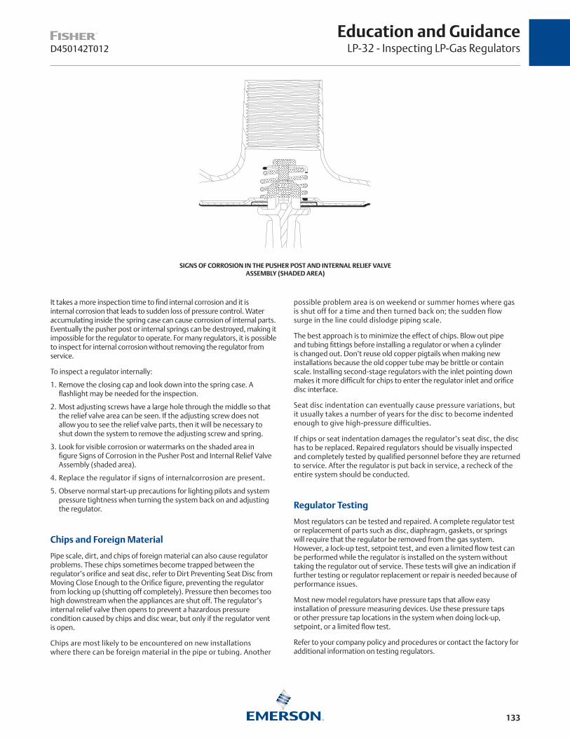
133
Education and GuidanceLP-32 - Inspecting LP-Gas RegulatorsD450142T012
SIGNS OF CORROSION IN THE PUSHER POST AND INTERNAL RELIEF VALVE ASSEMBLY (SHADED AREA)
It takes a more inspection time to find internal corrosion and it is internal corrosion that leads to sudden loss of pressure control. Water accumulating inside the spring case can cause corrosion of internal parts. Eventually the pusher post or internal springs can be destroyed, making it impossible for the regulator to operate. For many regulators, it is possible to inspect for internal corrosion without removing the regulator from service.
To inspect a regulator internally:
1. Remove the closing cap and look down into the spring case. A flashlight may be needed for the inspection.
2. Most adjusting screws have a large hole through the middle so that the relief valve area can be seen. If the adjusting screw does not allow you to see the relief valve parts, then it will be necessary to shut down the system to remove the adjusting screw and spring.
3. Look for visible corrosion or watermarks on the shaded area in figure Signs of Corrosion in the Pusher Post and Internal Relief Valve Assembly (shaded area).
4. Replace the regulator if signs of internalcorrosion are present.
5. Observe normal start-up precautions for lighting pilots and system pressure tightness when turning the system back on and adjusting the regulator.
Chips and Foreign Material
Pipe scale, dirt, and chips of foreign material can also cause regulator problems. These chips sometimes become trapped between the regulator’s orifice and seat disc, refer to Dirt Preventing Seat Disc from Moving Close Enough to the Orifice figure, preventing the regulator from locking up (shutting off completely). Pressure then becomes too high downstream when the appliances are shut off. The regulator’s internal relief valve then opens to prevent a hazardous pressure condition caused by chips and disc wear, but only if the regulator vent is open.
Chips are most likely to be encountered on new installations where there can be foreign material in the pipe or tubing. Another
possible problem area is on weekend or summer homes where gas is shut off for a time and then turned back on; the sudden flow surge in the line could dislodge piping scale.
The best approach is to minimize the effect of chips. Blow out pipe and tubing fittings before installing a regulator or when a cylinder is changed out. Don’t reuse old copper pigtails when making new installations because the old copper tube may be brittle or contain scale. Installing second-stage regulators with the inlet pointing down makes it more difficult for chips to enter the regulator inlet and orifice disc interface.
Seat disc indentation can eventually cause pressure variations, but it usually takes a number of years for the disc to become indented enough to give high-pressure difficulties.
If chips or seat indentation damages the regulator’s seat disc, the disc has to be replaced. Repaired regulators should be visually inspected and completely tested by qualified personnel before they are returned to service. After the regulator is put back in service, a recheck of the entire system should be conducted.
Regulator Testing
Most regulators can be tested and repaired. A complete regulator test or replacement of parts such as disc, diaphragm, gaskets, or springs will require that the regulator be removed from the gas system. However, a lock-up test, setpoint test, and even a limited flow test can be performed while the regulator is installed on the system without taking the regulator out of service. These tests will give an indication if further testing or regulator replacement or repair is needed because of performance issues.
Most new model regulators have pressure taps that allow easy installation of pressure measuring devices. Use these pressure taps or other pressure tap locations in the system when doing lock-up, setpoint, or a limited flow test.
Refer to your company policy and procedures or contact the factory for additional information on testing regulators.

134
D450142T012
Education and GuidanceLP-32 - Inspecting LP-Gas Regulators
DIRT PREVENTING SEAT DISC FROM MOVING CLOSE ENOUGH TO THE ORIFICE
Setpoint Test
A setpoint test establishes the regulator’s setting with a small amount of gas load. Adjust the regulator with a small load (approximately 50,000 BTUs) for a second- stage regulator with a diaphragm casing of about 4 to 5 in. / 102 to 127 mm in diameter. If the setpoint is adjusted with a pilot light load, the accuracy of the setting will vary as the setpoint is too near lock-up. If the setting is made with full load (all appliances are on at one time), the lock-up value during the lock-up test may be too high. Record the pressure gauge reading on the regulator outlet. This is your setpoint.
Lock-up Test
Lock-up is the pressure required to stop flow through the regulator when there is no flow out of the gas system (through an appliance). After adjusting the setpoint, turn off all gas appliances and pilot lights. Record the pressure gauge reading on the regulator outlet. This is your lock-up pressure. The pressure gauge should eventually stop rising. If the pressure continues to increase after about 1 minute, there is a lock-up issue that needs to be fixed.
Limited Flow Test
The limited flow test will tell you the gas delivery pressure with all appliances and gas loads on at the same time. This test is “limited” in that the regulator you are testing is probably capable of supplying 3 or 4 times more gas than the gas system can demand, therefore the term “limited flow test”. Record the pressure gauge reading on the regulator outlet. This is your delivery pressure with a high flow rate.
Regulator Repair
In the current economic environment, regulator repair can fall into the realm of diminishing returns. The cost to replace a regulator may be less than the cost for parts, labor, and equipment investment required to repair regulators. Thus, it becomes a company by company decision on repair versus replacing the regulator.
If the regulator is 15 years old or older, just replace the regulator.
Gas Check and/or Other Similar Preventative Mainte-nance Program
It is imperative that a marketer has a Preventative Maintenance Program for both company owned and customer owned regulators. A Preventative Maintenance Program should schedule the periodic inspection, repair and/or replacement of a regulator prior to its maximum service life or sooner if conditions so dictate. The PERC Gas Check© program or another similar Preventative Maintenance Program that inspects, tests and documents the regulator’s performance, condition, surroundings and age will be invaluable in preventing a potentially hazardous situation from ever taking place.
It’s not very difficult for a serviceperson to make a survey of customer regulators to find the oldest unit. These older units should be inspected for corrosion and aging problems. Regulators of various ages should be examined to get an idea of just how quickly corrosion can become a problem in the particular climate. By doing this a LP-Gas dealer can then identify regulators that need to be replaced.

135
Education and GuidanceLP-32 - Inspecting LP-Gas RegulatorsD450142T012
Questions to Ask About the Regulator Installation
While the following questions may seem obvious and one would think that the situation the question implies could never happen, almost every one of these conditions has occurred. So it is important to reexamine an installation periodically to insure that conditions around the regulator have not changed.
Regulator System Questions
• What type of regulator system is installed?
• Is vapor being piped to the regulator?
• Is there a regulator in the system and is it appropriate for the application?
• Is the final-stage regulator a low-pressure (not a high-pressure or first-stage) regulator?
• For a two-stage or integral regulator system, is there a first-stage and a second-stage regulator?
• If there is only one regulator in the two-stage system, is it an integral regulator that combines both first and second-stage regulators into one construction?
• If this is a 2 psig / 0.14 bar system, is there a first-stage regulator at the tank, a 2 psig / 0.14 bar regulator at the house and a line pressure regulator inside the house?
• On commercial and industrial applications,is the regulator properly sized and does the installation have adequate relief protection?
• Are external relief valve discharge openings open to the atmosphere and protected from the elements?
Regulator Questions
• If the vent is not pointing vertically down, is the regulator covered with a protective cover?
• Does the regulator have a drip lip vent construction?
• If the regulator vent does not have a drip lip design, is an auxiliary vent installed to create a drip lip vent?
• Is the regulator vent or vent line end located at the appropriate distance away from various openings near the regulator?
• Is the line pressure regulator vented properly?
• Is it piped to the outside of the house or does it contain a vent limiter devise?
• Is the vent screen in place?
• Is the vent screen plugged with insect remains or insect nests such as mud daubers or wasps?
• Has the vent screen mesh been painted over with paint?
• Has the regulator been covered with dirt from flowerbeds or fill material?
• Has the regulator been enclosed or covered by a building addition such as a porch or new room? If so, does the regulator need to be moved or a vent line added?
• Is the regulator installed under a roof valley or directly under the drip line of a roof overhang or eave?
• Can snow and ice slide off the roof and cause damage to the regulator?
• Does the regulator need additional protection from the elements such as from excessive snow depths?
• Has the regulator been marked so that it can be found when covered by snow?
• Is the regulator 18 in. / 457 mm above the ground level?
• Is the regulator installed in an area prone to flooding?
• Has the regulator been flooded? If so, replace it.
Indoor Regulator/Vent Tube Questions
• Is the regulator inside a building and if so is there a vent line to the outside open air and is that vent line protected with a screened drip lip vent assembly?
• Is the vent line the same size or larger than the regulator vent pipe connection?
• Does the vent line end have an auxiliary vent assembly that is screened, points down, contains a drip lip construction and does not restrict the relief capacity of the regulator’s internal relief valve?
Underground Installations
• Is the closing cap in place and on tight?
• On underground tank regulators, does the regulator have a vent line?
• Does the vent line keep water out of the regulator?
• Does it extend up above the water level?

136
D450174T012
Education and GuidanceLP-26 - Safety Practices for Domestic Tank Fittings
Domestic tank fittings, like any other type of mechanical equipment, require periodic maintenance and inspection because operating problems can occur. Tank fittings are of vital importance in the LP-gas system from a safety standpoint since they contain and control the product. Everyone handling LP-gas should be aware that there is a limit to the number of years a tank fitting can remain in service without malfunctioning due to damage and wear. Since this time limit can vary widely due to service coriditions, a periodic inspection routine is especially valuable. The following examines ways to avoid and correct potential safety hazards with the most common domestic tank fittings.
Filler Valves
These valves historically have been subject to more operating difficulties than any other fitting. This is probably because the filler valve must open and close more than other fittings and is subjected to high flow surges, product impurities, and rough handling. Problems occur, of course, when the valve fails to close. The filler valve could stick in the wide open position or permit only a small leak past its rubber seat disc. In either case, a hazardous condition results from the escaping gas and corrective action must be taken.
The serviceman could encounter the valve sticking wide open if he quickly disconnects the hose end connection and finds gas rapidly escaping from the tank. Here would be an extreme hazard because there is no way to stop the escape of gas. Hazards of this type can be avoided by not completely disconnecting the Acme coupling until all pressure is bled off. If the pressure does not dissipate, the filler valve has malfunctioned. Never disconnect the hose end under this circumstance.
If light tapping on the valves does not close it, the tank could have to be emptied before the hose can be disconnected. However, if a filling hose adaptor back check (such as Fisher™ M460 or Rego 7577V) is used
CAP
WASHER
UPPER BODY
SCREW
RETAINER
DISC
HOLDER
SPRING
LOWER BODYSUB-ASSEMBLY
TWO-PIECE BODY
CAP
WASHER
RETAINER
DISC
HOLDER
BODYSUB-ASSEMBLY
ONE-PIECE BODY
EXPLODED VIEW OF TYPICAL FILLER VALVE CONSTRUCTIONS
between the filler valve and the hose end valve, the adaptor can be left on a filler valve which fails to close. Then the hose end valve can be removed from the adaptor.
At other times, a filler valve may not completely shut off even though pressure does bleed off before the hose end adaptor is disconnected. A small leak past the seat disc can sometimes be discovered only by applying a leak-detector solution over the seat seal and watching for bubbles. Small leaks waste gas and may also create hazards. Of course, all filler valves should be tightly capped when not in use.
Never jab a tool or some other object at the valve’s poppet in an attempt to make the filler valve seat. Such attempts can damage the poppet so badly that even changing the seat disc will not stop the leakage, making replacement of the filler valve necessary. Tapping the side of the valve may help it to seat, but don’t tap hard enough to further damage the valve. Also never tap on the Acme threads, and never use a tool that could make a spark.
Underwriters’ Laboratories require that the seat disc in filler valves be replaceable under pressure. It should be kept in mind that the internal construction of filler valves differs from manufacturer to manufacturer, and use only the correct spare parts for the particular valve. The figures above show how the disc can be replaced in valves of differing construction, i.e., two-piece and one-piece body designs. Since some gas will be lost because of the metal-to-metal lower back check, caution is necessary during disc replacement.
Filler valves of the two-piece body construction should be tested to make sure the lower back check is still functional before attempting to take the valve apart. The test can be made by forcing the upper back check open with a Fisher M450A or Rego’s 3120 or 3119 adaptors. Take care to dislodge only the upper back check and not both of the back checks. If there is just a little leakage with the upper back check open, then the lower back check is in place and the disc replacement procedure can commence.

137
Education and GuidanceLP-26 - Safety Practices for Domestic Tank FittingsD450174T012
TOP VIEW TOP VIEW
WING GUIDE
INTERNAL GUIDING
A B
RELIEF VALVE POPPETS WITH INTERNAL GUIDING OR WING STYLE GUIDES
ANGLE VALVE
SPECIALADAPTOR LIQUID
WITHDRAWAL VALVE
AB
OPERATIONAL DRAWING OF A LIQUID WITHDRAWAL
△ CAUTION
If the lower check is missing and the filler valve’s upper body is unscrewed, there is nothing to contain the LP-gas within the tank and a very hazardous condition results. A few of the older tanks may not have a separate liquid withdrawal valve, indicating that the filler valve also serves for liquid withdrawal purposes. This can be determined by using an adaptor as described above to slightly open the valve’s upper back check. If significant leakage occurs, the disc should not be replaced under pressure because the leakage represents too great a hazard.
Relief Valves
The relief valve’s purpose is to relieve excessive tank pressure by venting gas until the pressure drops. Excess pressure can be caused by overfilling, improper purging of air, or possibly from overheating of the product. If the relief valve is found to be discharging slightly, check the pressure gauge on the tank. When pressure is in the 240 to 260 psig / 16.5 to 17.9 bar range, the valve is functioning properly by discharging gas. At no time should a person approach or stand directly over a relief valve when tank pressure is high. The valve could pop wide open at any moment, blowing gas, dirt, and other debris into a person’s face and eyes.
These procedures are suggested for checking relief valves that leak:
1. Check to see if the valve reseats as tank pressure drops. If it does, the unit is doing exactly what it’s intended to do, provided tank pressure was in the 240 to 260 psig / 16.5 to 17.9 bar range. Tank pressure could be lowered by either removing product from the tank or cooling the outside of the tank with water.
2. Do not attempt to force the valve closed! This could cause a tank rupture and will probably damage the relief valve.
3. If you find a relief valve that starts discharging when tank pressure is substantially below 240 psig / 16.5 bar, it means the valve is malfunctioning and will have to be replaced after the tank is emptied.
Water, dirt, and other foreign materials are the enemies of the relief valve because they can damage its poppet and seat. A small drain hole in the lower portion of the upper body has been provided, and this opening should always remain unobstructed. There also should be a raincap placed on the valve to protect it from water and debris. Some relief valves utilize internal guiding for the main stem and appear as viewed from above in Relief Valve Poppets with Internal Guiding or Wing Style Guides, drawing B. Other relief valve styles have wings on the poppet for external guiding, as in Relief Valve Poppets with Internal Guiding or Wing Style Guides,drawing A.
Relief valves with wing guides are especially susceptible to corrosion. The wing guides can become “welded” to the guide surface due to prolonged exposure, preventing the valve from opening as required. If these wing guides are found to be corroded or jammed by dirt, the entire valve needs to be replaced. Relief valves are precisely set by the manufacturer for the correct start-to-discharge setting, and field repair should never be attempted. Since the disc in a relief valve is subject to normal deterioration, Fisher recommends that a relief valve not be used for longer than 15 years (almost all valves carry the date of manufacture). Earlier replacement may be required due to severe service conditions.
Liquid Withdrawal Valves
Tradenamed SafEvac®, Chek-Lok® or Checkmate®, these units are for evacuating liquid from the tank. They are installed on the top, side, or bottom of the container, depending on the internal construction of the tank, and are not intended for use as a normal liquid outlet. During the evacuation process, the unit also acts as an excess flow valve. Most of the liquid withdrawal valves in the field today have metal-to-metal seats, and product loss will take place when making connection to the units.
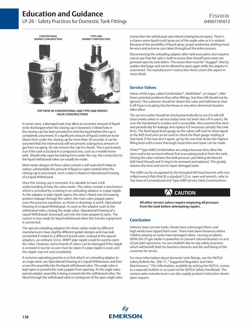
138
D450174T012
Education and GuidanceLP-26 - Safety Practices for Domestic Tank Fittings
CONVENTIONALBONNET CONSTRUCTION
TYPE L680BONNET CONSTRUCTION
TOP VIEW OF CONVENTIONAL AND TYPE L680 SERVICE VALVE CONSTRUCTIONS
In some cases, a damaged seat may allow an excessive amount of liquid to be discharged when the closing cap is loosened. A bleed hole in the closing cap has been provided to vent the liquid before the cap is completely unscrewed. If a significant amount of liquid continues to be blown from under the closing cap for more than 30 seconds, it can be assumed that the internal seat will not prevent a dangerous amount of gas from escaping. Do not remove the cap if in doubt. This is particularly true if the tank is located in a congested area, such as a mobile home park. Should only vapor be leaking from under the cap, the connection to the liquid withdrawal valve can usually be made.
Most newer designs of these valves contain a soft seat which helps to reduce substantially the amount of liquid or vapor vented when the closing cap is unscrewed. Such a valve is shown in Operational Drawing of a Liquid Withdrawal.
Once the closing cap is removed, it is valuable to have a full understanding of how the valve works. The valves contain a mechanism which is activated by screwing in an unloading adaptor or a pipe nipple. As the adaptor or pipe nipple opens the valve’s bleed seat (increasing product leakage through the valve), the main valve poppet opens once the pressure equalizes, as shown in drawings A and B, Operational Drawing of a Liquid Withdrawal. As soon as the adaptor seals to the withdrawal valve, closing the angle valve, Operational Drawing of a Liquid Withdrawal, drawing B, permits the main poppet to open. The system is now ready for liquid withdrawal when the transfer equipment is connected.
The special unloading adaptors for these valves made by different manufacturers have slightly different gasket designs and may leak somewhat if mated to a different brand valve. Instead of the special adaptors, an ordinary 3/4 in. MNPT pipe nipple could be used to open the valve. However, some brands of valves can be damaged if the nipple is screwed in too far so care must be taken if a pipe nipple is used, and the nipple may not seal completely.
A common operating practice is to first attach an unloading adaptor to an angle valve, see Operational Drawing of a Liquid Withdrawal, and then screw this assembly into the liquid withdrawal valve. The angle valve is kept open to prevent the main poppet from opening. As the angle valve-special adaptor assembly is being screwed into the withdrawal valve, the bleed through the withdrawal valve is coming out of the open angle valve
(remember the withdrawal valve bleed is being forced open). There’s a chance some liquid could spray out of the angle valve as it is rotated. Because of the possibility of liquid spray, proper protective clothing must be worn and extreme care taken throughout the entire process.
Disconnecting the unloading adaptor after tank evacuation also requires care to see that the valve’s built-in excess flow shutoff parts were not jammed open by tank debris. The excess flow must be “slugged” shut by sudden discharge and not be allowed to open again while the adaptor is unscrewed. The manufacturer’s instruction sheet covers this aspect in more detail.
Service Valves Valves of this type, called ComboValve®, MultiValve®, or Unipac®, offer fewer potential problems than other fittings, but they still should not be ignored. The customer should be shown this valve and told how to shut it off if gas is escaping into the house or any other abnormal situation takes place.
The service outlet should be checked periodically to see if it will still close (many valves in service today have not been shut off in years). Be sure the handwheel is in place and is accessible. Also examine the stem seal periodically for leakage and replace it if necessary (empty the tank first). The fixed liquid level gauge on the valves will start to show liquid at the 80% level and can be used to check the float gauge reading at that level. If the two don’t agree, go by the one that shows the highest filling level until a more thorough inspection and repair can be made.
Fisher™ Type L680 ComboValves are unique because they allow the stem seal to be serviced without first evacuating product from the tank. Closing the valve contains the tank pressure, permitting the bonnet (left-hand thread) and O-ring to be removed and replaced. This greatly reduces the time and cost to repair damaged seals.
The L680 can be recognized by the threaded left-hand bonnet with two milled wrench flats that fit a standard 1/2 in. open end wrench, refer to Top View of Conventional and Type L680 Service Valve Constructions.
△ CAUTION
All other service valves require emptying all pressure from the tank before attempting repairs.
Conclusion
Vehicles have run into tanks, floods have submerged them, and high winds have tipped them over. There have been instances where children playing on tanks have damaged valves, causing accidents. While the LP-gas dealer is powerless to prevent natural disasters or acts of just plain ignorance, he can establish day-to-day safety practices which will benefit both his business interests and the well being of the customer he serves.
For more information about domestic tank fittings, see the NLPGA Safety Bulletin No. 306-71, “Suggested Regulator and Valve Maintenance.” This information, available by writing the NLPGA, comes as a separate bulletin or as a part of the NLPGA Safety Handbook. The various valve manufacturers can also supply product instruction sheets upon request.

139
Education and GuidanceLP-27 - How Cold Weather Affects Tank CapacityD450147T012
LAYER OF FROST ON UNDERSIDE OF TANK. THE TANK HAS BEEN PAINTED BLACK IN THAT AREA TO MAKE IT EASIER TO IDENTIFY THIS CONDITION.
It’s during severely cold weather that the LP-gas system faces it’s most serious challenge. These are the times of freezing equipment, low tank pressure, and peak customer demand. The portion of the LP-gas installation put under particular stress by winter conditions is the tank and its vaporization rate. Understanding the factors affecting the capacity of an LP-gas system during cold weather therefore becomes vitally important.
The operation of an LP-gas system depends upon the vaporization of the compact liquid stored in the tank. Expanding in volume as much as 270 times, propane vaporizes into a gas which supplies pressure to move itself through the system before it is finally burned as a fuel. It is this central principle of vaporizing liquid fuel that is so adversely affected by winter temperatures.
The liquid in the container must use the temperature difference between its boiling point and the outside temperature in extracting enough available heat to permit vaporization. When gas is withdrawn from the tank, the pressure is lowered below that of equilibrium, lowering the liquid’s boiling point. This action causes more vapor to boil off to restore the pressure. Cold weather results in a reduced tank vapor pressure simply because there is less heat energy In the atmosphere to boil off the liquid fuel into vapor.
Frost Halts SystemA tank will meet load demands until gas is removed faster than boiling can replace it. When this occurs, the outside walls of the tank are chilled, inducing precipitation on the walls from the surrounding atmosphere.
During the winter, moisture on the tank surface quickly transforms into frost up to the level of the liquid. As the layer of frost develops, it acts like an insulator on the tank, greatly restricting heat transfer from the surrounding air to the liquid. The system then fails because the vapor pressure falls below that needed for satisfactory regulator performance.
A simple formula governs the vaporization capacity of any given tank. It is as follows:
Q = U x %A x (T1 - T2)
Where:Q = Heat transferred from the atmosphere through
the tank walls into the liquid (Btuh)U = 2, which is a coefficient accounting for the
convective heat transfer from the air to the tank wall, the thermal conductivity through the wall,and the convection from the inner surface to the liquid (Btu/ft.2 hr. °F); 2 is an average number since wind and sunlight affect this factor
%A = Area of the tank surface up to the level of liquid (ft.2); this is the only portion of the tank transferring significant heat
(T1 - T2) = The difference in temperature between the air temperature, T1, and the temperature of the liquid in the tank, T2.
The most important variable in the equation is %A, the “wetted”surface area of the tank, which is dependent upon several factors.
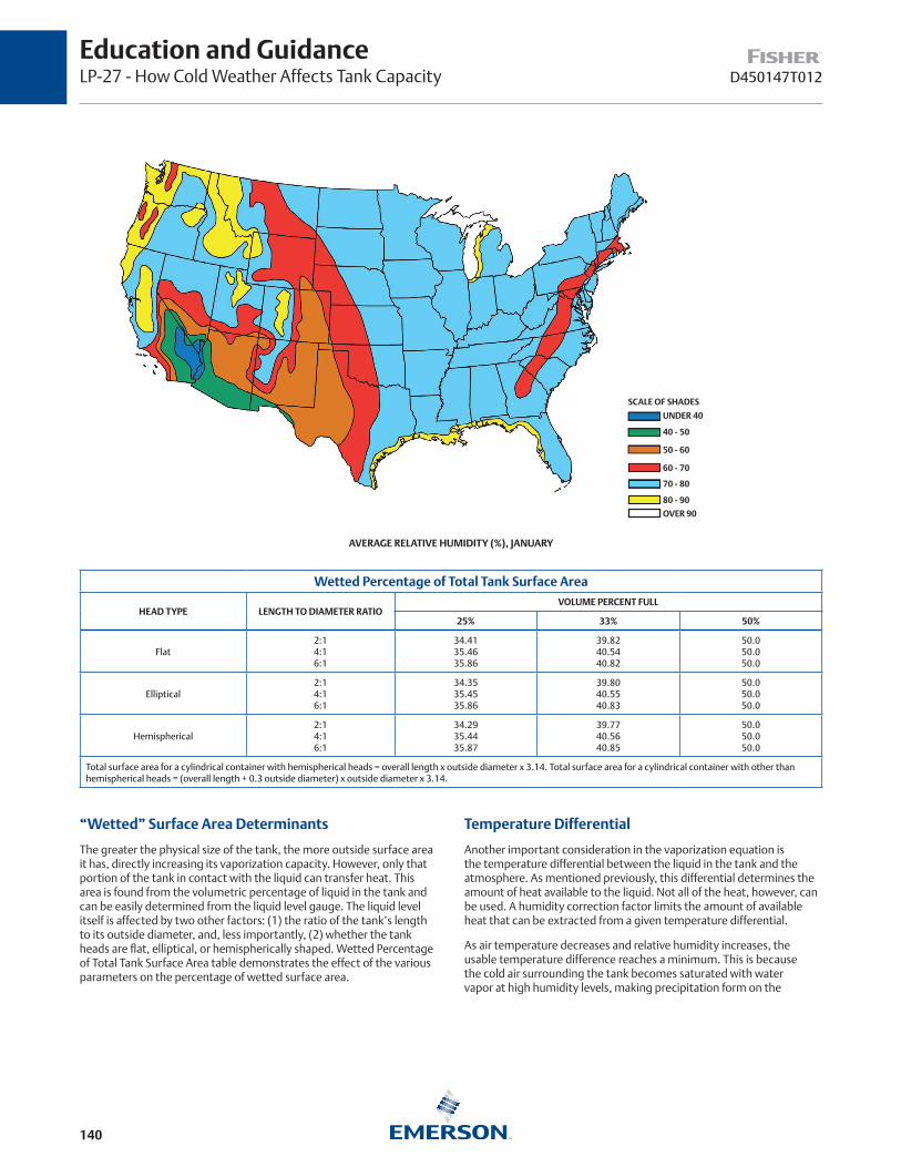
140
D450147T012
Education and GuidanceLP-27 - How Cold Weather Affects Tank Capacity
Wetted Percentage of Total Tank Surface Area
HEAD TYPE LENGTH TO DIAMETER RATIOVOLUME PERCENT FULL
25% 33% 50%
Flat2:14:16:1
34.4135.4635.86
39.8240.5440.82
50.050.050.0
Elliptical2:14:16:1
34.3535.4535.86
39.8040.5540.83
50.050.050.0
Hemispherical2:14:16:1
34.2935.4435.87
39.7740.5640.85
50.050.050.0
Total surface area for a cylindrical container with hemispherical heads = overall length x outside diameter x 3.14. Total surface area for a cylindrical container with other than hemispherical heads = (overall length + 0.3 outside diameter) x outside diameter x 3.14.
“Wetted” Surface Area Determinants
The greater the physical size of the tank, the more outside surface area it has, directly increasing its vaporization capacity. However, only that portion of the tank in contact with the liquid can transfer heat. This area is found from the volumetric percentage of liquid in the tank and can be easily determined from the liquid level gauge. The liquid level itself is affected by two other factors: (1) the ratio of the tank’s length to its outside diameter, and, less importantly, (2) whether the tank heads are flat, elliptical, or hemispherically shaped. Wetted Percentage of Total Tank Surface Area table demonstrates the effect of the various parameters on the percentage of wetted surface area.
Temperature Differential
Another important consideration in the vaporization equation is the temperature differential between the liquid in the tank and the atmosphere. As mentioned previously, this differential determines the amount of heat available to the liquid. Not all of the heat, however, can be used. A humidity correction factor limits the amount of available heat that can be extracted from a given temperature differential.
As air temperature decreases and relative humidity increases, the usable temperature difference reaches a minimum. This is because the cold air surrounding the tank becomes saturated with water vapor at high humidity levels, making precipitation form on the
SCALE OF SHADES
UNDER 40
40 - 50
50 - 60
60 - 70
70 - 80
80 - 90
OVER 90
AVERAGE RELATIVE HUMIDITY (%), JANUARY

141
Education and GuidanceLP-27 - How Cold Weather Affects Tank CapacityD450147T012
Difference Between Air Temperature and Temperature of Frost Formation
AIR TEMPERATURE, °F
RELATIVE HUMIDITY
20% 30% 40% 50% 60% 70% 80% 90%
-30 - - - - - - - - - - - - 8.0(1) 5.0(1) 2.5(1) 1.0(1)
-25 - - - - - - 15.0(1) 11.0(1) 8.0(1) 5.0 3.0 1.5
-20 - - - 20.0(1) 15.0(1) 11.5(1) 8.5 5.0 3.0 1.5
-15 - - - 20.0(1) 15.5 12.0 8.5 5.5 3.0 1.5
-10 27.5(1) 20.5 16.0 12.0 9.0 6.0 3.0 1.5
-5 28.0(1) 21.0 16.0 12.0 9.0 6.0 3.5 2.0
0 29.0 21.5 16.5 12.5 9.0 6.0 4.0 2.0
5 29.5 22.0 17.0 13.0 9.0 6.0 4.0 2.0
10 30.0 22.5 17.0 13.0 9.5 6.5 4.0 2.0
15 31.0 23.0 18.0 13.5 10.0 7.0 4.0 2.0
20 31.5 24.0 18.0 14.0 10.0 7.0 4.0 2.0
25 32.5 24.0 19.0 14.5 10.5 7.5 4.5 2.0
30 33.0 25.0 19.5 15.0 11.0 8.0 5.0 3.0
35 34.0 26.0 20.0 16.0 11.5 8.5 5.0 3.0
40 35.0 27.0 21.0 16.5 12.0 9.0 8.0 8.0
1. If the full temperature difference is used in these cases, the minimum tank pressure may be too low for satisfactory performance. Reprinted with permission from A Practical Guide to LP-Gas Utilization.
Heat (Btu) Needed to Vaporize 1 pound PropaneTEMPERATURE, °F
40 30 20 10 0 -10 -20 -30 -40
159.0 162.0 165.0 168.0 170.5 173.5 176.0 179.0 181.5
Tank 25% Full at 40% Relative Humidity Maximum Continuous Withdrawal Rate (Btuh) Without Tank Frosting If Lowest Outdoor Temperature (24 Hour Average) Reaches:
TANK SIZE, GALLONS
LOWEST OUTDOOR TEMPERATURE (24 HOUR AVERAGE), °F
40 30 20 10 0 -10 -20 -30
150 250500
1000
84 740113 570188 760336 230
77 280103 570172 150306 640
70 50094 480
157 040279 720
65 58087 890
146 080260 200
62 74084 090
139 760248 940
59 91080 300
133 460237 730
55 40074 260
123 420219 840
29 43039 44065 550
116 760
1. For a tank at 1/3 full, multiply Btuh values by 1.144.2. For a tank at 1/2 full, multiply Btuh values by 1.41.

142
D450147T012
Education and GuidanceLP-27 - How Cold Weather Affects Tank Capacity
slightly colder tank surface. At winter temperatures the precipitation immediately turns into frost. As can be seen from Difference Between Air Temperature and Temperature of Frost Formation table, there is only 1°F temperature difference between the air and the tank with a -30°F air temperature and 90% relative humidity. Going the opposite direction, a low humidity of 20% together with an outside temperature of 40°F gives 35° of usable temperature differential.
Take, for example, a 500-gallon tank with hemispherical heads and an overall length-to-diameter ratio of 4:1 that has a total surface area of 97 ft.2. The tank is located in a region where the lowest average temperature is -10°F and the average relative humidity is 80%. (See Average Relative Humidity (%), January for a map showing typical relative humidities for various regions of the United States.) Under these conditions, how much fuel can the tank vaporize without frost build-up if it is one-quarter full?
Using the equation, Q = U x %A x (T1- T2), we find: U = 2
%A = 97 ft.2 x 35.44 (% of total surface area wetted from Wetted Percentage of Total Tank
Surface Area table)
(T1- T2) = 3 (°F, usable temperature difference from Difference Between Air
Temperature and Temperature of Frost Formation Table)
Plugging these numbers into the equation produces a Q value of 206.3 Btuh. Table 3 shows the Btu’s needed to vaporize 1 pound of propane at various temperatures. At -13°F (-10°F atmospheric + -3°F usable temperature difference) it can be interpolated from that table that it takes 174.25 Btu to vaporize 1 pound of liquid propane.
Therefore:
206.3 Btuh -174.25 Btu/lb = 1.18 Ibs/hr (vaporized fuel)Vaporized propane = 21,591 Btu/lb
1.18 Ibs/hr x 21,591 Btu/lb = 25,562 Btuh(the amount the tank can vaporize under these conditions)
If the 25,562 Figure seems exceptionally low, it’s because the high humidity limits the available heat range to a scant 3 degrees for continuous service. Also, the wetted surface area of the tank is small when it is only one-quarter full. Under intermittent loading, the capacity for the tank might be three to four times greater.
Vaporization Capacities
Tables 4 and 5 are generalized listings showing the vaporization capacities of standard size tanks of the 4:1 ratio, one-quarter full, and at 40% and 80% relative humidities. The tables show maximum continuous withdrawal rates that can be achieved without tank frosting taking place. Note the dramatic reduction in tank vaporization capacity with the 80% relative humidity (Tank 25% Full at 80% Relative Humidity Maximum Continuous Withdrawal Rate (Btuh) Without Tank Frosting If Lowest Outdoor Temperature (24 Hour Average) ReachesTable).
In sizing tanks to prevent a winter time overload, it is apparent that four factors should be prime considerations
1. The size of the tank
2. The lowest normal temperature expected
3. The mean relative humidity
4. The lowest percentage volume level the tank will be allowed to reach
This means that for older installations merely maintaining a higher fuel level in the tank will appreciably boost the vaporization rate. When all of the elements of the capacity equation are given proper consideration, the LP-gas system is better prepared to operate effectively through its most challenging period.
Tank 25% Full at 80% Relative Humidity Maximum Continuous Withdrawal Rate (Btuh) Without Tank Frosting If Lowest Outdoor Temperature (24 Hour Average) Reaches:
TANK SIZE, GALLONS
LOWEST OUTDOOR TEMPERATURE (24 HOUR AVERAGE), °F
40 30 20 10 0 -10 -20 -30
150 250 500
1000
33 00044 23073 510
130 940
20 36027 29045 36080 790
16 02021 48035 70063 580
15 76021 12035 10062 530
15 51020 79034 55061 540
11 46015 36025 53045 480
11 29015 13025 15044 800
9 27012 42020 64036 770
1. For a tank at 1/3 full, multiply Btuh values by 1.144.2. For a tank at 1/2 full, multiply Btuh values by 1.41.
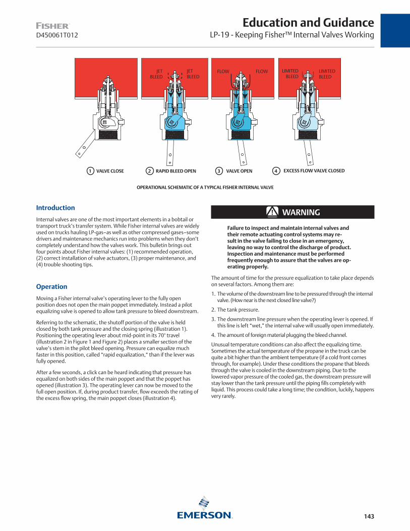
143
Education and GuidanceLP-19 - Keeping Fisher™ Internal Valves WorkingD450061T012
OPERATIONAL SCHEMATIC OF A TYPICAL FISHER INTERNAL VALVE
Introduction
Internal valves are one of the most important elements in a bobtail or transport truck’s transfer system. While Fisher internal valves are widely used on trucks hauling LP-gas–as well as other compressed gases–some drivers and maintenance mechanics run into problems when they don’t completely understand how the valves work. This bulletin brings out four points about Fisher internal valves: (1) recommended operation, (2) correct installation of valve actuators, (3) proper maintenance, and (4) trouble shooting tips.
Operation
Moving a Fisher internal valve’s operating lever to the fully open position does not open the main poppet immediately. Instead a pilot equalizing valve is opened to allow tank pressure to bleed downstream.
Referring to the schematic, the shutoff portion of the valve is held closed by both tank pressure and the closing spring (illustration 1). Positioning the operating lever about mid-point in its 70° travel (illustration 2 in Figure 1 and Figure 2) places a smaller section of the valve’s stem in the pilot bleed opening. Pressure can equalize much faster in this position, called “rapid equalization,“ than if the lever was fully opened.
After a few seconds, a click can be heard indicating that pressure has equalized on both sides of the main poppet and that the poppet has opened (illustration 3). The operating lever can now be moved to the full open position. If, during product transfer, flow exceeds the rating of the excess flow spring, the main poppet closes (illustration 4).
▲ WARNING
Failure to inspect and maintain internal valves and their remote actuating control systems may re-sult in the valve failing to close in an emergency, leaving no way to control the discharge of product. Inspection and maintenance must be performed frequently enough to assure that the valves are op-erating properly.
The amount of time for the pressure equalization to take place depends on several factors. Among them are:
1. The volume of the downstream line to be pressured through the internal valve. (How near is the next closed line valve?)
2. The tank pressure.
3. The downstream line pressure when the operating lever is opened. If this line is left “wet,” the internal valve will usually open immediately.
4. The amount of foreign material plugging the bleed channel.
Unusual temperature conditions can also affect the equalizing time. Sometimes the actual temperature of the propane in the truck can be quite a bit higher than the ambient temperature (if a cold front comes through, for example). Under these conditions the propane that bleeds through the valve is cooled in the downstream piping. Due to the lowered vapor pressure of the cooled gas, the downstream pressure will stay lower than the tank pressure until the piping fills completely with liquid. This process could take a long time; the condition, luckily, happens very rarely.
1 2 3 4
JET BLEED
LIMITED BLEED
LIMITED BLEED
FLOW FLOWJET BLEED
VALVE CLOSE RAPID BLEED OPEN VALVE OPEN EXCESS FLOW VALVE CLOSED
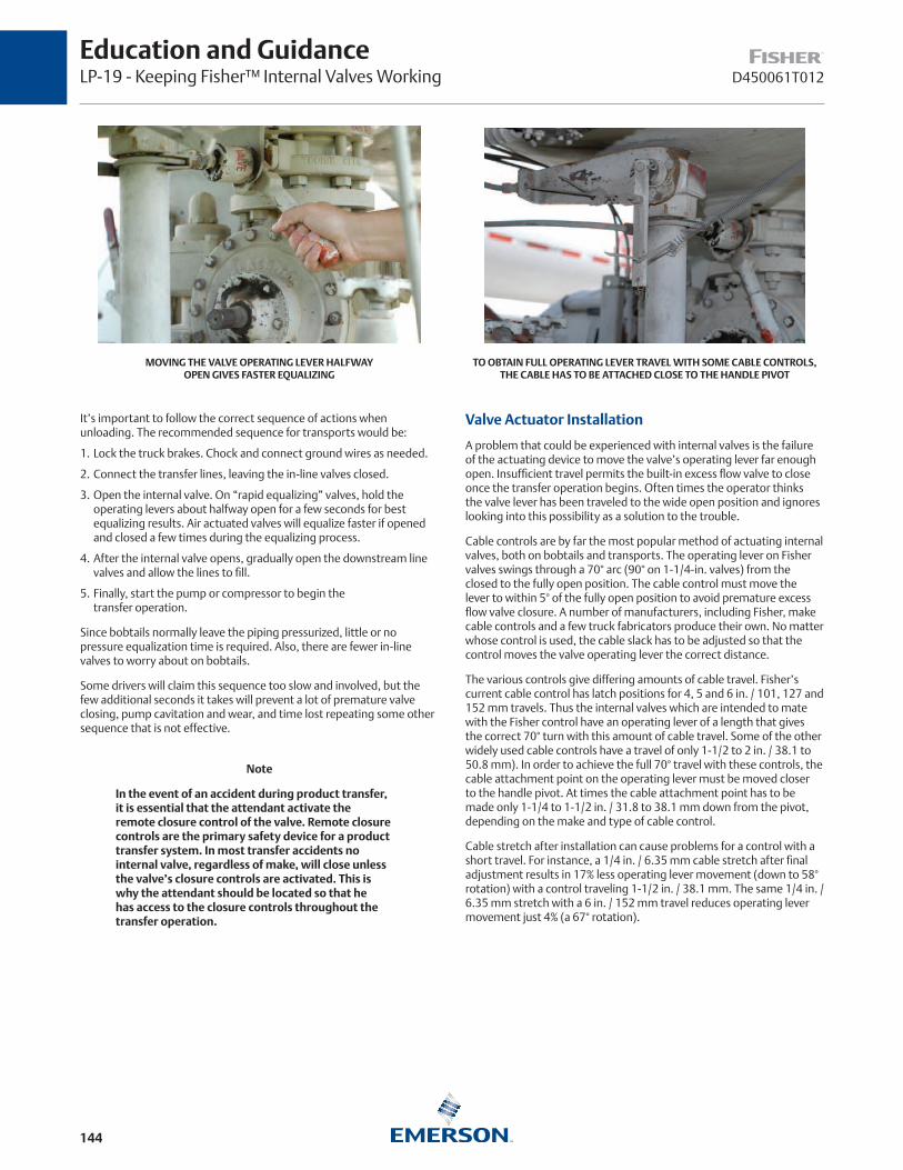
144
D450061T012
Education and GuidanceLP-19 - Keeping Fisher™ Internal Valves Working
MOVING THE VALVE OPERATING LEVER HALFWAY OPEN GIVES FASTER EQUALIZING
TO OBTAIN FULL OPERATING LEVER TRAVEL WITH SOME CABLE CONTROLS, THE CABLE HAS TO BE ATTACHED CLOSE TO THE HANDLE PIVOT
It’s important to follow the correct sequence of actions when unloading. The recommended sequence for transports would be:
1. Lock the truck brakes. Chock and connect ground wires as needed.
2. Connect the transfer lines, leaving the in-line valves closed.
3. Open the internal valve. On “rapid equalizing” valves, hold the operating levers about halfway open for a few seconds for best equalizing results. Air actuated valves will equalize faster if opened and closed a few times during the equalizing process.
4. After the internal valve opens, gradually open the downstream line valves and allow the lines to fill.
5. Finally, start the pump or compressor to begin the transfer operation.
Since bobtails normally leave the piping pressurized, little or no pressure equalization time is required. Also, there are fewer in-line valves to worry about on bobtails.
Some drivers will claim this sequence too slow and involved, but the few additional seconds it takes will prevent a lot of premature valve closing, pump cavitation and wear, and time lost repeating some other sequence that is not effective.
Note
In the event of an accident during product transfer, it is essential that the attendant activate the remote closure control of the valve. Remote closure controls are the primary safety device for a product transfer system. In most transfer accidents no internal valve, regardless of make, will close unless the valve’s closure controls are activated. This is why the attendant should be located so that he has access to the closure controls throughout the transfer operation.
Valve Actuator Installation
A problem that could be experienced with internal valves is the failure of the actuating device to move the valve’s operating lever far enough open. Insufficient travel permits the built-in excess flow valve to close once the transfer operation begins. Often times the operator thinks the valve lever has been traveled to the wide open position and ignores looking into this possibility as a solution to the trouble.
Cable controls are by far the most popular method of actuating internal valves, both on bobtails and transports. The operating lever on Fisher valves swings through a 70° arc (90° on 1-1/4-in. valves) from the closed to the fully open position. The cable control must move the lever to within 5° of the fully open position to avoid premature excess flow valve closure. A number of manufacturers, including Fisher, make cable controls and a few truck fabricators produce their own. No matter whose control is used, the cable slack has to be adjusted so that the control moves the valve operating lever the correct distance.
The various controls give differing amounts of cable travel. Fisher’s current cable control has latch positions for 4, 5 and 6 in. / 101, 127 and 152 mm travels. Thus the internal valves which are intended to mate with the Fisher control have an operating lever of a length that gives the correct 70° turn with this amount of cable travel. Some of the other widely used cable controls have a travel of only 1-1/2 to 2 in. / 38.1 to 50.8 mm). In order to achieve the full 70° travel with these controls, the cable attachment point on the operating lever must be moved closer to the handle pivot. At times the cable attachment point has to be made only 1-1/4 to 1-1/2 in. / 31.8 to 38.1 mm down from the pivot, depending on the make and type of cable control.
Cable stretch after installation can cause problems for a control with a short travel. For instance, a 1/4 in. / 6.35 mm cable stretch after final adjustment results in 17% less operating lever movement (down to 58° rotation) with a control traveling 1-1/2 in. / 38.1 mm. The same 1/4 in. / 6.35 mm stretch with a 6 in. / 152 mm travel reduces operating lever movement just 4% (a 67° rotation).

145
D450061T012
Education and GuidanceLP-19 - Keeping Fisher™ Internal Valves Working
THE CABLE SHOULD BE AT A RIGHT ANGLE TO THE OPERATING LEVER AT THE MID-TRAVEL POSITION.
WIRES LIKE THIS INDICATE A LACK OF VALVE MAINTENANCE.THEY ARE USED TO HOLD THE OPERATING LEVER OPEN–A VERY BAD PRACTICE.
Over-tightening the cable can also be bad. Most internal valves come to a positive stop internally at the full open position. If the cable is adjusted too short and the stop is reached before the control travels to its latching point, a great deal of force is applied to the valve mechanism by strong-arm attempts to latch the cable control. On some controls with a high mechanical advantage, several hundred pounds of cable pull can be developed. This kind of force can damage the valve’s internal parts.
Check the “pull angle” of the cable when routing and attaching it to the lever. At the mid-travel lever position, (see figure above) the cable should pull at a right angle to the lever. Because the control cable may have some drag, be sure to use a return spring on the lever. Protect the cable linkage from the elements with a rubber boot or some other means.
Fusible links, of course, must be installed at both ends of the control cable. Make certain to use links with a load capacity equal to the task. Cable controls with short travels may require fuse links with a higher load capacity than those with longer travels.
Air cylinders and hydraulic fluid systems are other ways of actuating internal valves. Here the clevis on the cylinder rod can be adjusted to move the valve lever to the fully open position (the entire 70° or 90° arc). Air interlock systems with the truck brakes give excellent ease of operation in addition to increased safety.
Test air operated valves for closure periodically. Doing this will reveal if wear or dirt in the air cylinder and linkage would keep the valve from closing. The linkage from the air cylinder to the valve lever should also be protected from mud, dirt, ice and road splatter. And be sure the fusible elements are installed in the air line that opens the valve.
Maintenance
It’s human nature to disregard things that aren’t causing problems. The trouble with this attitude, especially where internal valves are concerned, is that when things go bad they can create difficulties of enormous proportions. Maintenance and inspection programs help to prevent sudden equipment failures which leave a costly bobtail or transport inoperative.
Much too often the only maintenance an internal valve gets takes place when the valve is suspected of slowing or impeding product transfer. There can be a tendency to make a “temporary fix” which then becomes permanent if product transfer hasn’t been slowed down. One such temporary fix is the use of a coathanger wire to hold the valve lever open (see figure above). Obviously such a maneuver destroys the ability of the valve to function as designed. Never wire open an internal valve. It is an unsafe, unnecessary, illegal, and a highly dangerous practice.
A simple preventive maintenance program for the valve and its controls will eliminate a whole bunch of problems, and it takes very little time. Take a few minutes when the truck is having its oil changed or whatever to look over the valves and the controls. Fisher recommends these steps be conducted at least once a month and more often in harsh environments:
1. Inspect the operating lever to see that it moves freely and smoothly. Also examine the stub shaft bonnet nut for leakage using a soap solution. If there is leakage, the bonnet packing will have to be replaced. Replacement shaft seals are inexpensive and easy to store. Although they are seldom needed, it pays to keep them on hand. A sticking lever indicates mechanism wear or trapped dirt. This could mean the need for new shaft seals, shaft bushings, stem bushings, or a few other things. It’s time, in other words, for repair before the trouble gets worse and the valve won’t open (or close!) with a tank full of product.
2. Check for tight closure of both seat discs. With the internal valve closed, exhaust downstream pressure. If piping is cold, allow it to warm to ambient temperature. Then close the first downstream valve and note any pressure build-up between the two closed valves with a pressure gauge. If leakage is indicated, both discs should be replaced. This test can reveal some odd and scary things. An owner of a second-hand transport had shutoff problems with the internal valve. It seems the previous owner, faced with an excess flow rating below his normal pumping rate, had removed all the shutoff parts from the valve!
3. AII operating controls should be inspected and cleaned and oiled. The controls should be checked to see that they fully open – but not overtravel – the internal valve operating lever and work freely to close the valve. If wear is detected that could cause trouble later, order replacement parts now.

146
D450061T012
Education and GuidanceLP-19 - Keeping Fisher™ Internal Valves Working
Trouble Shooting
All of the foregoing won’t completely eliminate the chance of some sort of valve malfunction. Parts in equipment like internal valves which receive almost daily use do eventually wear out. Many times, however, the valve gets the blame when some other component in the system is actually the culprit.
Trouble shooting the valve isn’t too difficult; the most useful tool for the trouble shooter is a pressure gauge installed at the valve outlet. When the valve is opened, the gauge should show the same pressure as in the tank. With flow through the valve, this gauge should always read within a few psi of the tank pressure.
Four common complaints are listed below along with possible solutions:
Internal Valve Will Not Open – Most frequently due to the operator not using the rapid equalizing position when opening the valve, could also be from leakage downstream, engaging the pump too soon, or excessive internal valve wear. (On older valves cam breakage did occur at times, but it has all but been eliminated now). If excessive volume is in the downstream system, a longer time is required to equalize tank and downstream pressures before the pump can be engaged.
To find out if the valve pilot seat is opening, install a pressure gauge at the valve outlet and open the valve. If pressure does not build up to the tank pressure, the pilot seat is not opening. This test should be done with the pump off. A pilot seat not openlng may be due to internal damage or from foreign material plugging the pilot bleed opening. Try back flowing through the valve to clear it out. If the operating lever rotates past the fully open position, there is something wrong internally and the valve will have to be disassembled.
Premature Valve Closure – An improperly connected operating lever which doesn’t fully open the valve (see the “Installation” section) is the first thing to look for. This condition could also be caused from engaging the pump too soon, sudden line surges, or an underrated excess flow spring. The trouble could stem from a valve that has its inlet port obstructed.
Internal Valve Will Not Close – Most frequently due to a faulty or sticking actuator, but the stub shaft or stem could be bent. If the valve leaks even though it seems to close, the seats could be damaged or foreign materials could be trapped on the seats. Before disassembling the valve, check the actuator mechanism to see that it works freely by disconnecting it from the valve lever and cycling it several times. Also, operate the valve lever manually. If it sticks in the open position, the packing and bushings should be replaced which should free the operating mechanism if the valve does not have internal damage.
Low Flow Capacity – First, is the valve large enough? Too small or long downstream piping might be being used. Other possibilities include a plugged screen or strainer, some restriction downstream, or a bypass valve sticking in the open position. The bypass valve could also be set too low and be opening prematurely. Check for high differential pressure across the internal valve to determine if it is at fault.
Conclusion
Internal valves were first introduced in the 1950’s. Since that time, they have gained ever increasing acceptance from users, as well as regulating agencies. The valves of today are greatly improved from a performance and durability standpoint from those of ten or even five years ago. They are capable of giving years of trouble-free service, but they do require minimal attention if they are to remain on the job. This article has attempted to point out ways of keeping the valve working properly so that the truck can stay on the road.

147
Education and GuidanceLP-37 - Transfer Area ValvingD450157T012
TYPE N550 EMERGENCY SHUT-OFF VALVE
G200 SERIES BACK CHECK VALVE TYPE C477 JET BLEED INTERNAL™ VALVE
TYPE N562 EMERGENCY SHUT-OFF VALVE
P1169 P1353 P1041 P1197
IntroductionFisher™ offers a complete line of transfer area valving – Emergency Shut-off Valves (ESV), Back Check Valves, and Internal Valves – that complies with NFPA 58 requirements. All of these valves feature heavy-duty construction for long service life and can be used on LP-Gas as well as anhydrous ammonia (NH3). Only Fisher offers so many different valves for bulk plant and tank car applications, enabling you to find the right equipment for your particular needs.
Snappy Joe™ Emergency Shut-off Valves Two models of Snappy Joe ESVs are available: Type N550 for bulk plants and Type N562 for tank cars. The Type N550 is usually installed in-line behind a bulkhead. Operated manually under normal conditions, it can be remotely closed in an emergency by either a cable or loss of pneumatic pressure. The Type N562 is the only valve on the market specifically designed for tank car use. It is pneumatically opened and closed.
Back Check ValvesWhere there is flow only into the stationary storage, an ESV does not have to be used to satisfy NFPA 58. On these applications, a heavy duty back check valve makes an excellent choice. G200 Series Back Check Valves can be supplied with or without built-in flow indication and offer very low flow resistance (refer to Type G200 Installation Schematic).
Internal ValvesFisher Internal Valves have proven themselves to be reliable performers on bobtail, transport trucks, and bulk storage tanks. They can be opened and closed manually, pneumatically, or by cable. Complete information on the Type C477 is provided on page 154.
Type N550 Snappy Joe™ Emergency Shut-off Valves for Bulk Plants
Type N550 Emergency Shut-off Valves (ESVs) are designed for in-line installation, usually near a bulkhead. (Refer to Installation Schematic of Type N550 with Type P164B Cable and Installation Schematic of Type N550 with Type P539A Pneumatic Actuator). The valves provide an operator a means of shutting off the flow of product in the event of hose rupture, pull away, or piping break at the transfer area to avoid a large scale loss of LP-Gas or NH3 from the storage tank.
Snappy Joes are manually opened, and can be closed manually at the installed location or remotely by either cable or air. A thermal release is built-in.
Features
Operational Ease—Moving the operating lever to the vertical position opens the valve, making it simple to tell if the unit is open or closed. A pilot valve in the poppet opens as the lever is moved upward to pressurize the hose. This allows pressure to equalize, allowing the poppet to move quickly to the open position.
The valve is closed by simply pushing the lever down without first having to trip a latch. It is easy to reach the operating lever from across a bulkhead. All sizes look similar and operate exactly the same, an important point in an emergency situation.
Cable Release—Standard Snappy Joes are fitted with a release mechanism for cable attachment. Connecting a cable to the wire loop allows the valve to be closed from a safe remote location, such as the bulk entrance. While ordinary cable can be used, Type P164B cable release assemblies are available.
Type N550 Emergency Shut-off Valves
TYPE NUMBER BODY SIZEFLOW IN GPM / L/min PROPANE
ACCESSORIES1 psid / 69 mbar d 2 psid / 0.14 bar d
N550-10 1-1/4 in. FNPT 50 / 189 75 / 284Type P164B Cable Release
Type P539A Pneumatic ActuatorT1139599012 Control Valve
N550-16 2 in. FNPT 75 / 284 115 / 435
N550-24 3 in. FNPT 190 / 719 275 / 1041
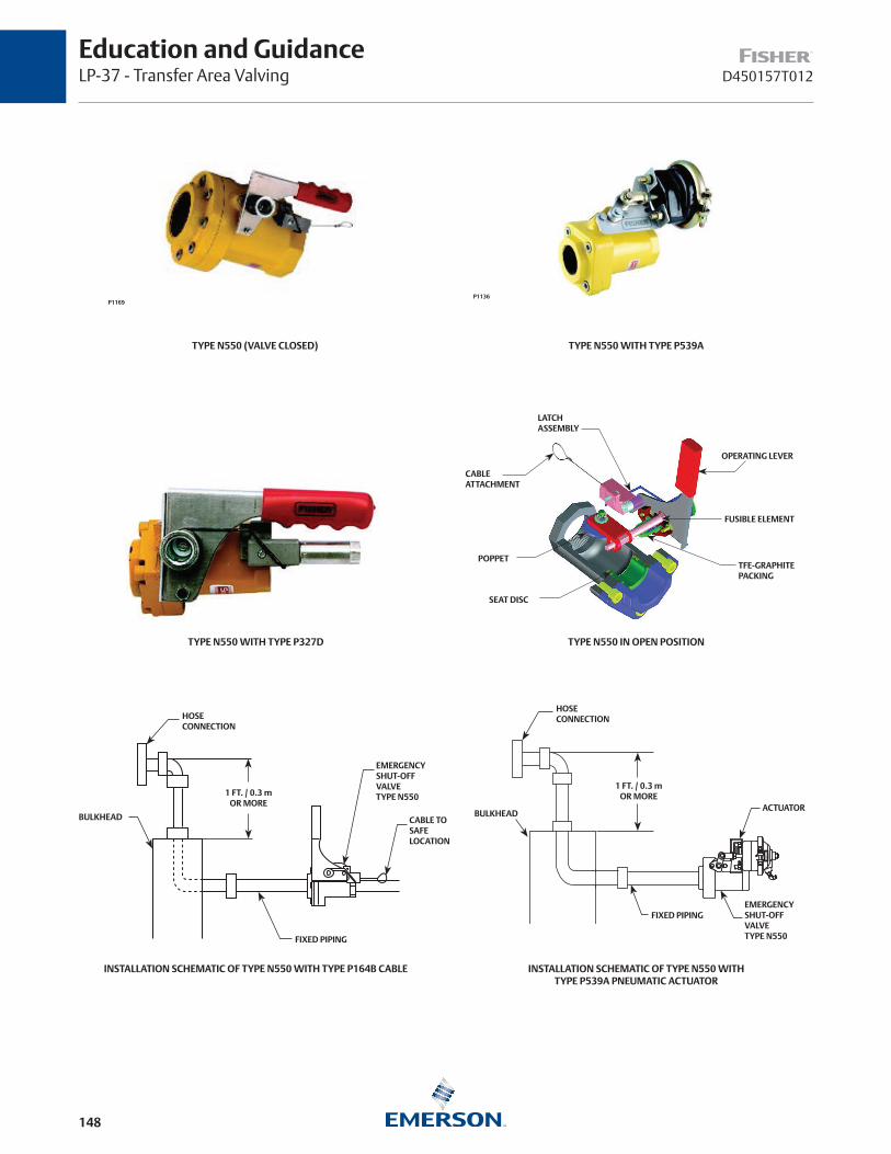
148
D450157T012
Education and GuidanceLP-37 - Transfer Area Valving
LATCH ASSEMBLY
CABLEATTACHMENT
OPERATING LEVER
FUSIBLE ELEMENT
TFE-GRAPHITEPACKING
POPPET
SEAT DISC
TYPE N550 IN OPEN POSITIONTYPE N550 WITH TYPE P327D
TYPE N550 (VALVE CLOSED) TYPE N550 WITH TYPE P539A
P1169P1136
INSTALLATION SCHEMATIC OF TYPE N550 WITH TYPE P164B CABLE
HOSECONNECTION
BULKHEAD
EMERGENCY SHUT-OFFVALVE TYPE N550
CABLE TO SAFELOCATION
FIXED PIPING
1 FT. / 0.3 mOR MORE
HOSE CONNECTION
1 FT. / 0.3 mOR MORE
BULKHEAD
FIXED PIPINGEMERGENCY SHUT-OFF VALVE TYPE N550
ACTUATOR
INSTALLATION SCHEMATIC OF TYPE N550 WITH TYPE P539A PNEUMATIC ACTUATOR

149
Education and GuidanceLP-37 - Transfer Area ValvingD450157T012
TYPE N550 DIMENSIONS
D
P
E
C
B
A
F
J
VIEW A-A
A
A
G
P
H
- - - - - - - - - - - - - - - - - -
Type N550 Dimensions
P,NPT
IN. / mm
A B C D E F G H J
1-1/4 in. 5.9 / 150 9.6 / 244 3.4 / 86 10.4 / 264 2.0 / 51 3.6 / 91 5.1 / 130 3.2 / 81 5.5 / 140
2 in. 7.2 / 183 10.0 / 254 3.9 / 99 11.6 / 295 2.9 / 74 2.6 / 66 5.4 / 137 3.5 / 89 6.0 / 152
3 in. 9.2 / 234 10.6 / 269 4.5 / 114 12.9 / 328 3.5 / 89 1.2 / 30 5.7 / 145 4.2 / 107 6.5 / 165
Type N562 Emergency Shut-off ValvesTYPE NUMBER SHUT-OFF VALVE CONNECTION HOSE CONNECTION
N562-16
2 in. FNPT
2 in. Male Acme
N562-18 2-1/4 in. Male Acme
N562-26 3-1/4 in. Male Acme
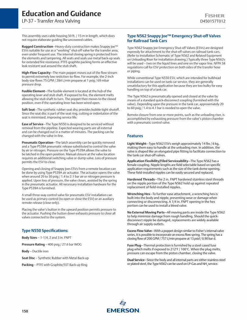
150
D450157T012
Education and GuidanceLP-37 - Transfer Area Valving
This assembly uses cable housing 50 ft. / 15 m in length, which does not require elaborate guiding like uncovered cables.
Rugged Construction—Heavy-duty construction makes Snappy Joe™ ESVs suitable for use as a “working” shut-off valve for the transfer area, even under frequent use. The internal closing spring is protected from the elements and tampering. All seats and seals use metal back-up seals for extended fire resistance. PTFE-graphite packing forms an effective leak resistant seal around the stub shaft.
High-Flow Capacity—The main poppet moves out of the flow stream to permit extremely low restiction-to-flow. For example, the 2-inch body size flows 75 GPM / 284 L/min propane at 1 psig / 69 mbar pressure drop.
Fusible Element—The fusible element is located at the hub of the operating lever and stub shaft. If exposed to fire, the element melts allowing the stub shaft to turn. The poppet then moves to the closed position, even if the operating lever has been wired open.
Soft Seat—The synthetic rubber seat disc provides bubble tight shutoff. Since the seat disc is part of the seat ring, cutting or indentation of the seat is minimized, improving service life.
Ease of Service—The Type N550 is designed to be serviced without removal from the pipeline. Expected wearing parts are all external and can be changed out in a matter of minutes. The packing can be changed with the valve in-line.
Pneumatic Operation—The latch assembly can be quickly removed and a Type P539A pneumatic release substituted to control the valve by air or nitrogen. Pressure on the Type P539A allows the valve to be latched in the open position. Manual closure at the valve location requires an additional switching valve or dump valve. Loss of pressure permits the ESV to close.
Opening and closing of Snappy Joes ESVs from a remote location can be done by using Type P539A air actuator. The actuator opens the valve when around 20 to 30 psig / 1.4 to 2.1 bar air or nitrogen pressure is applied. Upon loss of pressure, the valve closes, assisted by the spring in the pneumatic actuator. All necessary installation hardware for the Type P539A is furnished.
A small three-way control valve for pneumatic ESV installation can be used as primary control (to open or close the ESV) or an auxiliary remote release (close only).
Placing the valve’s button in the upward position permits pressure to the actuator. Pushing the button down exhausts pressure to close all valves connected to the system.
Type N550 Specifications:
Body Sizes – 1-1/4, 2 and 3 in. FNPT
Pressure Rating – 400 psig / 27.6 bar WOG
Body – Ductile iron
Seat Disc – Synthetic Rubber with Metal Back-up
Packing – PTFE with Graphite/SST Back-up Ring
Type N562 Snappy Joe™ Emergency Shut-off Valves for Railroad Tank Cars
Type N562 Snappy Joe Emergency Shut-off Valves (ESVs) are designed expressly for attachment to the shut-off valves on railroad tank cars. (Refer to Installation Schematic of Type N562 and Related Equipment on Unloading Riser for installation drawing.) Typically three Type N562s will be used – two on the liquid lines and one on the vapor line. NFPA 58 regulations call for ESV protection on both sides of the transfer hose or piping.
While conventional Type N550 ESV, which are intended for bulkhead installations can be used on tank car service, they are generally unsatisfactory for this application because they are too bulky for easy handling on top of a tank car.
The Type N562 is pneumatically opened and closed at the valve by means of a standard quick-disconnect coupling (furnished with the valve). Depending upon the pressure in the tank car, approximately 20 to 60 psig / 1.4 to 4.1 bar is needed to open the valve.
Remote closure from one or more points, such as the unloading riser, is accomplished by exhausting pressure from the valve’s piston chamber with a pneumatic control valve.
Features
Light Weight—Type N562 ESVs weigh approximately 14 lbs / 6 kg, making them easy to handle at the unloading riser. In addition, the valve is shaped like an elongated pipe fitting to facilitate connection to the tank car shut-off valves.
Application Flexibility/Filed Serviceability—The Type N562 has a female coupling. Nipple lengths are field selectable based on specific application requirements such as the size of the tank dome opening. These field-installed nipples can be easily secured and replaced.
Hardened Threads—The 2 in. FNPT hardened stainless steel threads on the nipple portion of the Type N562 hold up against repeated replacement of field-installed nipples.
Wrenching Hex—To further ease attachment, a wrenching hex is built into the body and nipple, preventing wear or damage when connecting or disconnecting. A 1/4 in. FNPT opening in the hex portion can be used to install a bleed valve.
No External Moving Parts—All moving parts are inside the Type N562 to help minimize damage from rough handling. Should the quick-disconnect nipple be damaged, replacements are widely available through air supply outlets.
Excess Flow Valve—With a poppet design similar to Fisher’s internal valve series, it is possible to incorporate an excess flow spring. The spring has a closing flow of 200 GPM / 757 L/min propane at 13 psid / 0.90 bar d.
Fuse Plug—Thermal protection is furnished by a steel cased fuse plug which melts if exposed to 212°F / 100°C. When the plug melts, pressure can escape from the piston chamber, closing the valve.
Dual Service—Since the body and all internal parts are either stainless steel or plated steel, the Type N562 can be used on LP-Gas and NH3 service.
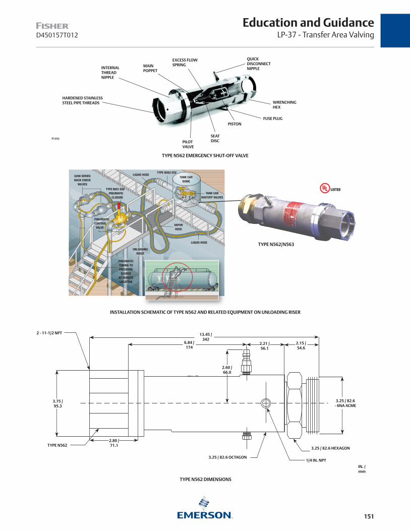
151
Education and GuidanceLP-37 - Transfer Area ValvingD450157T012
HARDENED STAINLESSSTEEL PIPE THREADS
INTERNALTHREADNIPPLE
MAIN POPPET
EXCESS FLOWSPRING
QUICKDISCONNECTNIPPLE
WRENCHINGHEX
FUSE PLUGPISTON
SEAT DISCPILOT
VALVE
TYPE N562 EMERGENCY SHUT-OFF VALVE
P1353
INSTALLATION SCHEMATIC OF TYPE N562 AND RELATED EQUIPMENT ON UNLOADING RISER
TYPE N562 DIMENSIONS
3.75 / 95.3
TYPE N562
13.45 / 342
6.84 / 174
2.21 / 56.1
2.15 / 54.6
3.25 / 82.6 - 6NA ACME
3.25 / 82.6 HEXAGON
1/4 IN. NPT3.25 / 82.6 OCTAGON
2.80 / 71.1
2 - 11-1/2 NPT
2.60 / 66.0
IN. /mm
G200 SERIESBACK CHECK
VALVES
LIQUID HOSE
VAPORHOSE
UNLOADINGRISER
TYPE N551 ESV PNEUMATIC CLOSURE
PNEUMATICCONTROL
VALVE
PNEUMATICTUBING TOPRESSURE
SOURCEAT REMOTELOCATION
TYPE N563 ESVLIQUID HOSE
TANK CARDOME
TANK CARSHUTOFF VALVES
TYPE N562/N563

152
D450157T012
Education and GuidanceLP-37 - Transfer Area Valving
TYPE G201 WITH FLOW INDICATOR
HEAVY-DUTY INTERNAL
PARTS
POPPET MOVES OUT OFFLOW STREAM
SOFT SEAT FORTIGHT SHUTOFF
TYPE G200/G201 SECTIONAL VIEW
P1041
Types G200 and G201 Back Check ValvesTYPE NUMBER
SEAT CONSTRUCTIONCONTAINER OR INLET
CONNECTIONOUTLET CONNECTION
PROPANE FLOW CAPACITY AT
10 psig / 0.69 bar DIFFERENTIAL PRESSURE
DUCTILE IRON
STANDARD FLOW INDICATOR
G200-10 G201-10
Soft Seat
1-1/4 in. FNPT 1-1/4 in. FNPT 190 GPM / 719 L/min
G200-16 G201-16 2 in. FNPT 2 in. FNPT 350 GPM / 1325 L/min
G200-24 G201-24 3 in. FNPT 3 in. FNPT 800 GPM / 3028 L/min
Pneumatic Closure Accessories
Pneumatic controls and fittings are needed to remotely close the Types N562 and N550/P539. (Refer to pages 150 to 152). Fisher™ does not manufacture these items, but these accessories are readily available from a number of sources. A listing of pneumatic accessories that appear to be suitable follows. Fisher has not extensively tested any of this equipment and cannot guarantee these components will function satisfactorily under all conditions.
Control Valves
The push-to-close button type (using the palm of your hand) of pneumatic control valve appears to be the best choice as a remote closure valve. It is usually easy to see if the valve is open or closed, and it’s also easy to close the valve quickly in an emergency situation.
Types G200 and G201 Back Check Valves
G200 Series Back Check Valves are specifically intended for heavy-duty, in-line service at the bulk plant’s transfer area. (Refer to Type G200 Installation Schematic for installation drawing.) As with conventional back check valves, the G200 Series permits flow in one direction only. Flow moves the spring-loaded poppet to the open position as soon as a pressure differential is created. When flow stops, the poppet closes. The valves are suitable for LP-Gas or NH3 service.
Features
Rugged Construction—Type G200s are built to stay on the job with all internal parts of plated steel or stainless steel.
High-Flow Capacity—With body construction similar to the Snappy Joe™ Emergency Shut-off Valves, resistance to flow is very low. For example, the 2 in. body size flows 350 GPM / 1325 L/min propane at 10 psig / 0.69 bar differential pressure.
Soft Seat—This construction gives tight shutoff so that piping can be blown down for maintenance.
Flow Indicator—The Type G201 has a built-in flow indicator mechanism, which can be used to replace sight flow indicators.
Type G200/G201 Specifications:
Body Size – 1-1/4, 2, and 3 in.
Pressure Rating – 400 psig / 27.6 bar WOG
Body – Ductile Iron
Internal Parts – Plated Steel or Stainless Steel
Seat Disc – Synthetic Rubber
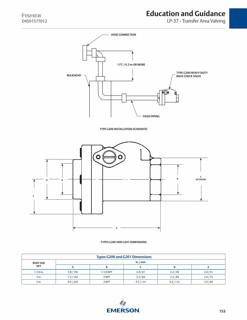
153
Education and GuidanceLP-37 - Transfer Area ValvingD450157T012
Types G200 and G201 Dimensions
BODY SIZE NPT
In. / mm
A B C D E
1-1/4 in. 5.9 / 150 1-1/4 NPT 2.4 / 61 2.3 / 58 2.0 / 51
2 in. 7.2 / 183 2 NPT 3.3 / 84 3.3 / 84 2.9 / 74
3 in. 9.2 / 234 3 NPT 4.5 / 114 4.5 / 114 3.5 / 89
TYPES G200 AND G201 DIMENSIONS
BD
E
A
COCTAGONB
HOSE CONNECTION
1 FT. / 0.3 m OR MORE
BULKHEAD
FIXED PIPING
TYPE G200 HEAVY-DUTYBACK CHECK VALVE
TYPE G200 INSTALLATION SCHEMATIC
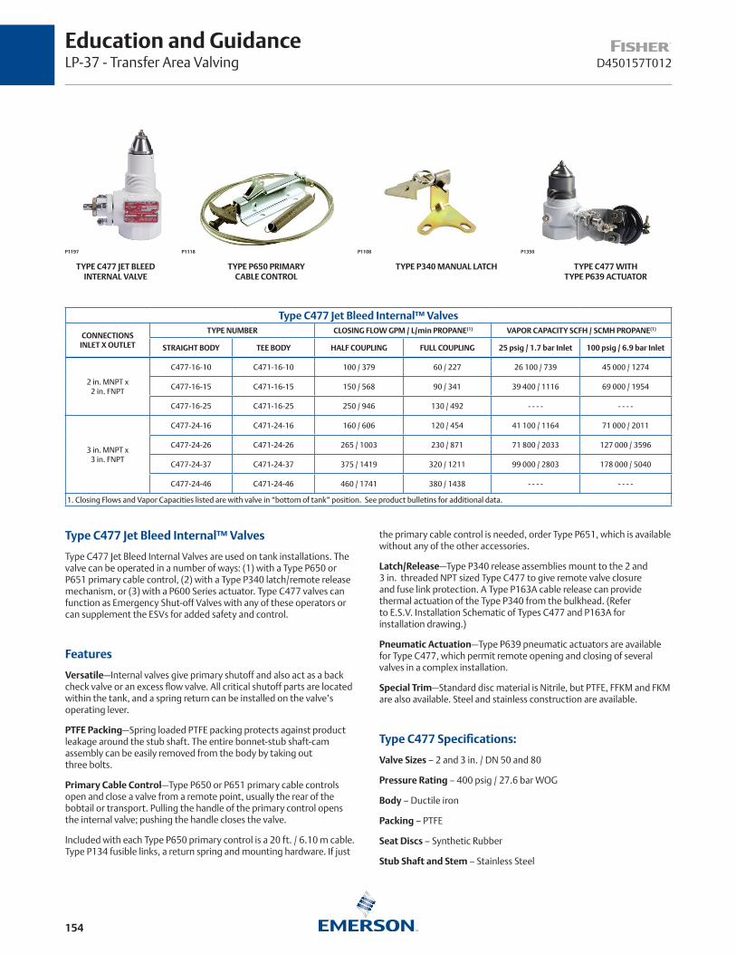
154
D450157T012
Education and GuidanceLP-37 - Transfer Area Valving
TYPE P650 PRIMARY CABLE CONTROL
TYPE P340 MANUAL LATCH TYPE C477 WITH TYPE P639 ACTUATOR
TYPE C477 JET BLEED INTERNAL VALVE
P1197 P1108P1118 P1350
Type C477 Jet Bleed Internal™ Valves
CONNECTIONSINLET X OUTLET
TYPE NUMBER CLOSING FLOW GPM / L/min PROPANE(1) VAPOR CAPACITY SCFH / SCMH PROPANE(1)
STRAIGHT BODY TEE BODY HALF COUPLING FULL COUPLING 25 psig / 1.7 bar Inlet 100 psig / 6.9 bar Inlet
2 in. MNPT x2 in. FNPT
C477-16-10 C471-16-10 100 / 379 60 / 227 26 100 / 739 45 000 / 1274
C477-16-15 C471-16-15 150 / 568 90 / 341 39 400 / 1116 69 000 / 1954
C477-16-25 C471-16-25 250 / 946 130 / 492 - - - - - - - -
3 in. MNPT x3 in. FNPT
C477-24-16 C471-24-16 160 / 606 120 / 454 41 100 / 1164 71 000 / 2011
C477-24-26 C471-24-26 265 / 1003 230 / 871 71 800 / 2033 127 000 / 3596
C477-24-37 C471-24-37 375 / 1419 320 / 1211 99 000 / 2803 178 000 / 5040
C477-24-46 C471-24-46 460 / 1741 380 / 1438 - - - - - - - -
1. Closing Flows and Vapor Capacities listed are with valve in “bottom of tank” position. See product bulletins for additional data.
Type C477 Jet Bleed Internal™ Valves
Type C477 Jet Bleed Internal Valves are used on tank installations. The valve can be operated in a number of ways: (1) with a Type P650 or P651 primary cable control, (2) with a Type P340 latch/remote release mechanism, or (3) with a P600 Series actuator. Type C477 valves can function as Emergency Shut-off Valves with any of these operators or can supplement the ESVs for added safety and control.
Features
Versatile—Internal valves give primary shutoff and also act as a back check valve or an excess flow valve. All critical shutoff parts are located within the tank, and a spring return can be installed on the valve’s operating lever.
PTFE Packing—Spring loaded PTFE packing protects against product leakage around the stub shaft. The entire bonnet-stub shaft-cam assembly can be easily removed from the body by taking out three bolts.
Primary Cable Control—Type P650 or P651 primary cable controls open and close a valve from a remote point, usually the rear of the bobtail or transport. Pulling the handle of the primary control opens the internal valve; pushing the handle closes the valve.
Included with each Type P650 primary control is a 20 ft. / 6.10 m cable. Type P134 fusible links, a return spring and mounting hardware. If just
the primary cable control is needed, order Type P651, which is available without any of the other accessories.
Latch/Release—Type P340 release assemblies mount to the 2 and 3 in. threaded NPT sized Type C477 to give remote valve closure and fuse link protection. A Type P163A cable release can provide thermal actuation of the Type P340 from the bulkhead. (Refer to E.S.V. Installation Schematic of Types C477 and P163A for installation drawing.)
Pneumatic Actuation—Type P639 pneumatic actuators are available for Type C477, which permit remote opening and closing of several valves in a complex installation.
Special Trim—Standard disc material is Nitrile, but PTFE, FFKM and FKM are also available. Steel and stainless construction are available.
Type C477 Specifications:
Valve Sizes – 2 and 3 in. / DN 50 and 80
Pressure Rating – 400 psig / 27.6 bar WOG
Body – Ductile iron
Packing – PTFE
Seat Discs – Synthetic Rubber
Stub Shaft and Stem – Stainless Steel
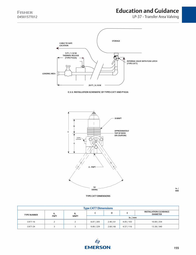
155
D450157T012
Education and GuidanceLP-37 - Transfer Area Valving
Type C477 Dimensions
TYPE NUMBERA,
FNPTB,
MNPTC D E
INSTALLATION CLEARANCEDIAMETER
In. / mm
C477-16 2 2 8.07 / 205 2.40 / 61 4.05 / 103 10.00 / 254
C477-24 3 3 9.00 / 229 2.60 / 66 4.57 / 116 13.38 / 340
TYPE C477 DIMENSIONS
C
D
E
A - FNPT
70° SWING
APPROXIMATELY TOP OF BOSS OR COUPLING
B MNPT
1/4 IN. / 6.35 mm
In. / MM
20 FT. / 6.10 M
INTERNAL VALVE WITH FUSE LATCH(TYPE C477)
STORAGECABLE TO SAFELOCATION
5 FT. / 1.52 MTHERMAL RELEASE
(TYPE P163A)
LOADING AREA
E.S.V. INSTALLATION SCHEMATIC OF TYPES C477 AND P163A
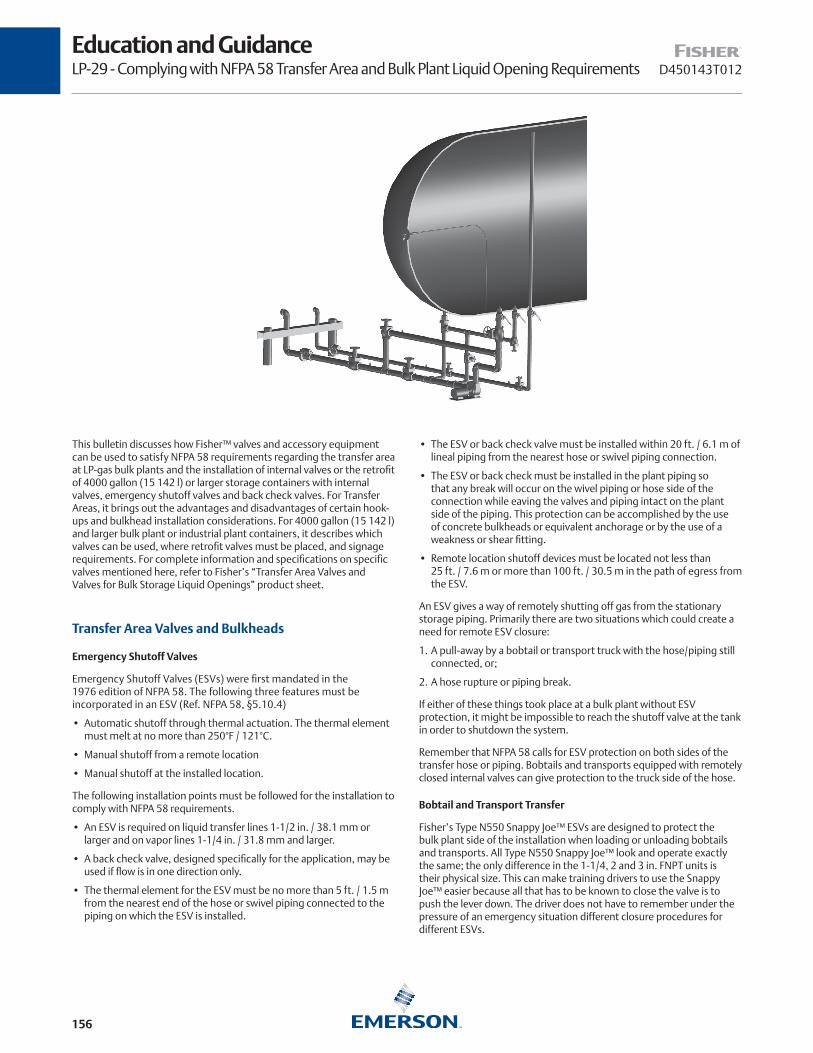
156
D450143T012
Education and GuidanceLP-29 - Complying with NFPA 58 Transfer Area and Bulk Plant Liquid Opening Requirements
This bulletin discusses how Fisher™ valves and accessory equipment can be used to satisfy NFPA 58 requirements regarding the transfer area at LP-gas bulk plants and the installation of internal valves or the retrofit of 4000 gallon (15 142 l) or larger storage containers with internal valves, emergency shutoff valves and back check valves. For Transfer Areas, it brings out the advantages and disadvantages of certain hook-ups and bulkhead installation considerations. For 4000 gallon (15 142 l) and larger bulk plant or industrial plant containers, it describes which valves can be used, where retrofit valves must be placed, and signage requirements. For complete information and specifications on specific valves mentioned here, refer to Fisher’s “Transfer Area Valves and Valves for Bulk Storage Liquid Openings” product sheet.
Transfer Area Valves and Bulkheads
Emergency Shutoff Valves
Emergency Shutoff Valves (ESVs) were first mandated in the 1976 edition of NFPA 58. The following three features must be incorporated in an ESV (Ref. NFPA 58, §5.10.4)
• Automatic shutoff through thermal actuation. The thermal element must melt at no more than 250°F / 121°C.
• Manual shutoff from a remote location
• Manual shutoff at the installed location.
The following installation points must be followed for the installation to comply with NFPA 58 requirements.
• An ESV is required on liquid transfer lines 1-1/2 in. / 38.1 mm or larger and on vapor lines 1-1/4 in. / 31.8 mm and larger.
• A back check valve, designed specifically for the application, may be used if flow is in one direction only.
• The thermal element for the ESV must be no more than 5 ft. / 1.5 m from the nearest end of the hose or swivel piping connected to the piping on which the ESV is installed.
• The ESV or back check valve must be installed within 20 ft. / 6.1 m of lineal piping from the nearest hose or swivel piping connection.
• The ESV or back check must be installed in the plant piping so that any break will occur on the wivel piping or hose side of the connection while eaving the valves and piping intact on the plant side of the piping. This protection can be accomplished by the use of concrete bulkheads or equivalent anchorage or by the use of a weakness or shear fitting.
• Remote location shutoff devices must be located not less than 25 ft. / 7.6 m or more than 100 ft. / 30.5 m in the path of egress from the ESV.
An ESV gives a way of remotely shutting off gas from the stationary storage piping. Primarily there are two situations which could create a need for remote ESV closure:
1. A pull-away by a bobtail or transport truck with the hose/piping still connected, or;
2. A hose rupture or piping break.
If either of these things took place at a bulk plant without ESV protection, it might be impossible to reach the shutoff valve at the tank in order to shutdown the system.
Remember that NFPA 58 calls for ESV protection on both sides of the transfer hose or piping. Bobtails and transports equipped with remotely closed internal valves can give protection to the truck side of the hose.
Bobtail and Transport Transfer
Fisher’s Type N550 Snappy Joe™ ESVs are designed to protect the bulk plant side of the installation when loading or unloading bobtails and transports. All Type N550 Snappy Joe™ look and operate exactly the same; the only difference in the 1-1/4, 2 and 3 in. FNPT units is their physical size. This can make training drivers to use the Snappy Joe™ easier because all that has to be known to close the valve is to push the lever down. The driver does not have to remember under the pressure of an emergency situation different closure procedures for different ESVs.

157
Education and GuidanceLP-29 - Complying with NFPA 58 Transfer Area and Bulk Plant Liquid Opening RequirementsD450143T012
TYPE N550 SNAPPY JOE™ ESV TYPE P164B CABLE RELEASE TYPE P327D PNEUMATIC RELEASE
Fisher™ Emergency Shutoff Valves are listed with Underwriters Laboratories as a primary shutoff valve. The valve is designed to be a “working” shutoff, meaning a globe or angle valve does not have to be installed with a Snappy Joe™ at the bulkhead unless the user desires to do so. However, no ESV eliminates the need for a means of shutoff at the stationary storage tank. NFPA 58, Section 5.7.7 gives a listing of what valving is required in the stationary storage
Standard construction Snappy Joe™ ESVs can be remotely closed by either a cable or a pneumatic cylinder and cannot be opened from a remote location. This was done to assure that inadvertent opening of the valve from a remote point could not take place. A special cylinder actuator, Type P327C, is available that will both open and close the ESV from a remote location, but special precautions must be taken so as to not inadvertently open the valve at the wrong time. The person making the transfer should have control to open the ESV.
Cable Closure
The standard Snappy Joe™ comes with a latch mechanism with a looped cable attachment. A remote release cable such as the Type P164B, consisting of a release mechanism and 50 ft. / 15.2 m of cable, avoids many of the problems associated with ordinary cable. Since Type P164Bs use a shielded cable, ice and dirt are less likely to pose a threat to cable movement. And the cable requires far less guiding; a number of bends can be made without affecting its ability to close the Snappy Joe™. Attachment is made to the valve’s latch mechanism after removing the looped cable portion, a procedure described in the Type N550 instruction manual, Form MCK-1149.
For more details on cables and cable installation see the section on Cable Operation on page 164.
Pneumatic Closure
A pneumatic closure system (using a Snappy Joe™ a Type P327D cylinder) should be considered when any of these conditions are present:
1. More than one ESV is required at the installation.
2. Remote closure point is a long distance from ESV.
3. More than one remote closure point is desired.
4. Other valves in the system are pneumatically operated.
All bulk plant ESV control systems should be hooked-up so that activating any of the remote closure controls closes all ESVs (and internal valves) in the bulk plant. Each ESV, of course, should also be capable of individual control for normal operations. This is easy to do with the Type N550-P327D because the cylinder actuator can be
left pressurized continually and depressurized only when emergency closure is required.
For more details on pneumatic controls see the section on Pneumatic Operation on page 164.
ESVs for Tank Cars
Unlike bobtails and transports, railroad tank cars are not equipped with internal valves. So on tank car installations ESV protection is required on both sides of the hose or swivel piping. The valving for the unloading riser side of the installation can be the same kind of ESVs or back check valves used on conventional hookups. For the tank car side of the hose, however, Fisher felt conventional ESVs were too heavy and awkward to install, and the Type N562 Snappy Joe™ ESV was developed specifically for tank cars.
Exactly the same pneumatic accessories can be used for the Type N562 as the Types N550/P327D covered previously. The same amount of supply pressure 50 psig / 3.4 bar can also be used, making a pneumatic tie-in between all Snappy Joes™ (and internal valves) in the system possible. In this way the entire bulk plant, including the tank car, could be shut down from one or more widely separated locations.
Exactly the same pneumatic accessories can be used for the Type N562 as the Types N550/P327D covered previously. The same amount of supply pressure 50 psig / 3.4 bar can also be used, making a pneumatic tie-in between all Snappy Joes™ (and internal valves) in the system possible. In this way the entire bulk plant, including the tank car, could be shut down from one or more widely separated locations.
Back Checks and Internal Valves
ESVs are not required in every instance, and two other valves could be used under certain conditions to gain NFPA 58 compliance. Where flow is only into the stationary storage tank, such as transport truck unloading point, a back check valve can be used instead of an ESV. It makes sense to use back check valves wherever possible because they are the only valve in the system that works automatically, i.e., when flow stops, the valve closes without action on anyone’s part.
Conventional back check valves were not felt to be of rugged enough construction to function in-line at the bulkhead day after day. For this reason, Fisher introduced the G200 Series of back checks, a valve similar in body construction to the Type N550 Snappy Joe™ valves with heavy duty steel and stainless steel internal parts. Type G201 has a built-in flow indicator and could take the place of the sight flow indicators.

158
D450143T012
Education and GuidanceLP-29 - Complying with NFPA 58 Transfer Area and Bulk Plant Liquid Opening Requirements
TYPE N562 SNAPPY JOE™ ESV FOR TANK CARS
INTERNALTHREAD
NIPPLE
HARDENED STAINLESSSTEEL PIPE THREADS
MAINPOPPET
EXCESS FLOWSPRING
QUICKDISCONNECTNIPPLE
WRENCHING HEX
FUSE PLUG
PISTONSEATDISCPILOT
VALVE
TYPE G201 BACK CHECK VALVE
TYPE G200 OR G201 TYPE G201
Another option is the internal valve where the 20 ft. / 6.1 m lineal piping distance can be met. Some bulk plants already use internal valves in the stationary storage. Where this is the case, all that’s needed is a fusible element at both the internal valve and within 5 ft. / 1.5 m of the hose and a way to close the valve at the valve, such as a Type P340 manual latch or 3 way pneumatic valve installed at the valve and at a safe remote location.
The Type C427 internal valves have proven themselves on truck applications, and many LP-gas dealers use the valves in stationary storage instead of an excess flow valve-globe valve combination. The Type C427 can be closed by cable or pneumatically.
Bulkheads
All Fisher installation drawings of ESVs, back checks, or internal valves show a bulkhead because of NFPA 58, §6.10.8, wording requires for valving to be “…installed in the plant piping so that any break resulting from a pull will occur on the hose or swivel type piping side of the connection while retaining intact the valves and piping on the plant side of the connection.” If the fixed piping can be damaged
by a pull, the safety features the valves were meant to provide become worthless.
There are a number of prefabricated steel bulkheads now on the market, and it is also possible to make a bulkhead out of concrete. Many of the prefabricated bulkheads have undergone pull tests to make certain they can withstand the force generated by a truck attempting to leave without being disconnected. These tests clearly demonstrated the strength of LP-gas hose, taking in the neighborhood of 10 000 to 14 000 lbs / 4536 to 6350 kg of pull before either the hose or a pipe fitting broke. At this kind of force the valving in the truck could be pulled out even though the bulkhead remained unharmed.
One way of reducing the amount of pull necessary to cause a break is to install the piping at the bulkhead as shown in the installation drawing, Bulkhead with a Lever Arm. A lever arm is created by the pipe, and tests have shown that the pipe breaks at the bulkhead at a much lower pull force. (This force can be controlled by changing the length of the lever arm.) By reducing the number of pounds of pull it takes to cause a break, both the valves in the truck and in-line at the bulkhead are in less danger of being damaged.
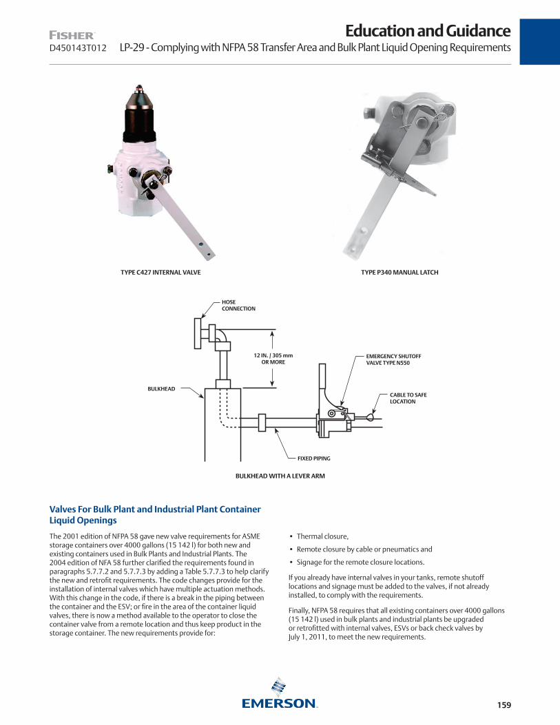
159
D450143T012
Education and GuidanceLP-29 - Complying with NFPA 58 Transfer Area and Bulk Plant Liquid Opening Requirements
TYPE C427 INTERNAL VALVE TYPE P340 MANUAL LATCH
BULKHEAD WITH A LEVER ARM
HOSECONNECTION
12 IN. / 305 mm OR MORE
BULKHEAD
EMERGENCY SHUTOFFVALVE TYPE N550
CABLE TO SAFELOCATION
FIXED PIPING
Valves For Bulk Plant and Industrial Plant Container Liquid Openings
The 2001 edition of NFPA 58 gave new valve requirements for ASME storage containers over 4000 gallons (15 142 l) for both new and existing containers used in Bulk Plants and Industrial Plants. The 2004 edition of NFA 58 further clarified the requirements found in paragraphs 5.7.7.2 and 5.7.7.3 by adding a Table 5.7.7.3 to help clarify the new and retrofit requirements. The code changes provide for the installation of internal valves which have multiple actuation methods. With this change in the code, if there is a break in the piping between the container and the ESV; or fire in the area of the container liquid valves, there is now a method available to the operator to close the container valve from a remote location and thus keep product in the storage container. The new requirements provide for:
• Thermal closure,
• Remote closure by cable or pneumatics and
• Signage for the remote closure locations.
If you already have internal valves in your tanks, remote shutoff locations and signage must be added to the valves, if not already installed, to comply with the requirements.
Finally, NFPA 58 requires that all existing containers over 4000 gallons (15 142 l) used in bulk plants and industrial plants be upgraded or retrofitted with internal valves, ESVs or back check valves by July 1, 2011, to meet the new requirements.

160
D450143T012
Education and GuidanceLP-29 - Complying with NFPA 58 Transfer Area and Bulk Plant Liquid Opening Requirements
Internal Valves In New Installations
Liquid Withdrawal Openings require an internal valve, such as the C400 Series, fitted with remote closure and thermal capability.
Liquid Inlet Openings require an internal valve, such as the C400 Series, fitted for remote closure and thermal capability.
Internal valves come with either 1-1/4, 2 or 3 in. threaded NPT connections with different body configurations. They are also available in 3 or 4 in. / DN 80 or 100 flanged connections.
Internal valves can function as an excess flow or as a back check valve, but not at the same time. Whether the valve is open or closed determines when excess flow or back check function is in operation. Internal valves when open will function as an excess flow valve with the same limitations as an excess flow valve, mainly they may not always close when you need them to close. Internal valves when closed can be used as a back check valve in a tank opening. A differential pressure of 5 to 10 psi / 0.35 to 0.69 bar is generally required to open the internal valve, but when flow stops, the internal valve closes. By connecting the remote release to the internal valve, these valves can be closed from a remote location in the event they are open.
Internal Valves are listed with Underwriters Laboratories as a positive shutoff valve.
Back Check Valves In New Installations
If a container has a dedicated Liquid Inlet Opening a back check valve such as the soft seated Types G105, G106 and G107 or the metal to metal Type G104 or G112 installed in the container and in combination with a positive shutoff valve, Type N310 or N410 Series Globe and Angle Valves installed as close as practical to the back check valve may be used in place of an internal valve.
Since a back check valve closes when flow stops or flow reverses, no remote shutdown is required for this valve installation. However, it is recommended that you periodically test the back check to make sure it is still operational.
Retrofit of Existing Storage Containers by July 1, 2011
Containers built prior to the 2001 edition of NFPA 58, if they didn’t use internal valves in the openings, had liquid openings with either back check or excess flow valves installed in the container wall and positive shutoff valves installed in the piping close to the container wall. See Pre-2001 Liquid Tank Opening Valves if Not Using Internal Valves.
These older containers need to be retrofitted with internal valves, ESVs or back check valves by July 1, 2011, to meet the new requirements.
The Retrofit of a Liquid Withdrawal Opening that has an excess flow valve installed in the tank and a positive shutoff, see Retrofit Options for Liquid Container Valves, on the outlet of the excess flow valve, requires either:
• Option 1: Remove the excess flow and install a C400 Series internal valve fitted with remote closure and thermal capability, or
• Option 2: Install a N550 Series ESV downstream and as close as practical to the positive shutoff valve while keeping the excess flow valve in the tank.
Several options are available for the Retrofit of Liquid Inlet Openings, see Retrofit Options for Liquid Container Valves:
• Option 1: Remove the excess flow and install a C400 Series internal valve fitted with remote closure and thermal capability,
• Option 2: Install a N550 Series ESV downstream and as close as practical to the positive shutoff valve while keeping the excess flow valve in the tank,
• Option 3: For dedicated inlets, install a G200 Series back check valve in the line upstream and as close as practical to the positive shutoff valve and the excess flow valve installed in the container or,
• Option 4: For dedicated inlets, remove the excess flow valve and install a back check valve such as the soft seated Types G105, G106 and G107 or the metal to metal Type G104 or G112 installed in the container and in combination with a positive shutoff valve, Type N310 or N410 Globe and Angle Valves installed as close as practical to the back check valve.
What about Vapor Openings
While the new requirements are mandatory for liquid lines for both valves and valve retrofit, they are not mandatory for vapor lines. However, the application can be applied to vapor lines to provide an even safer bulk plant system. Previous editions of NFPA 58 allowed several valve options for Vapor Inlet and Vapor Outlet connections and included the use of internal valves, back check valves, excess flow valves and positive shutoff valves in various combinations. One combination is the use of a positive shutoff as close as practical to a properly sized excess flow valve installed in the tank. If the vapor line is broken with this combination of valves, the excess flow may not close for a number of reasons, or you may not be able to get to the shutoff valve at the tank to close this line. With this scenario you have an uncontrolled flow of vapor that can cause a significant accident because you can’t stop the vapor flow.
While the tank is down for retrofit of liquid lines, strongly consider the safety value of replacing the excess flow valve in the vapor lines with either an internal valve, a back check valve where applicable, or installing an ESV in the piping just downstream of the positive shutoff valve. Again these upgrades will give you the ability to shutoff the vapor lines from a remote location which results in a safer bulk tank system.
Some states, Texas for example, do require these same or similar requirements for vapor openings. You should refer to your state requirements regarding valves required for vapor openings.
Internal Valve Actuation Methods
Internal Valves can be actuated by several different methods. They can be:
• Opened and closed manually,
• Opened and closed with a cable system,
• Opened and closed with a pneumatic system, and
• Thermally closed.

161
Education and GuidanceLP-29 - Complying with NFPA 58 Transfer Area and Bulk Plant Liquid Opening RequirementsD450143T012
RETROFIT OPTIONS FOR LIQUID CONTAINER VALVES
PRE-2001 LIQUID TANK OPENING VALVES IF NOT USING INTERNAL VALVES
BACK CHECKVALVE
EXCESS FLOW VALVE
POSITIVESHUTOFFVALVE
LIQUID INLET ONLY
LIQUID INLET ANDOULET LIQUID
OULET
OPTION 5
LIQUID INLET ONLY
LIQUIDOUTLET
OPTION 1
OPTION 4
OPTION 3
OPTION 2
LIQUID INLET AND OULET
EXCESS FLOW VALVE

162
D450143T012
Education and GuidanceLP-29 - Complying with NFPA 58 Transfer Area and Bulk Plant Liquid Opening Requirements
△ CAUTION
An internal valve, when in an open position, does include an excess flow function. Various excess flow spring rates are available. However, because of the limitations, such as piping configurations in size, length, valves and pumps which add restrictions to flow, partial breaks that don’t exceed the excess flow rating, and limited inlet pressure at certain times of the year, the excess flow should not be considered a reliable closure method in the event of an emergency.
Manual Operation
Internal Valves, such as the C427 Series, have manual latches, Type P340, that allow you to open and close the valve at the installed location. The latch includes a thermal element and can be connected with a remote cable for closure at a remote location. See the section on thermal releases and cable operation.
Cable Operation
A cable system can be used to open and close the internal valve without having to crawl under the tank. A Fisher™ Type P650 or P651 Primary Cable Control will work with all Fisher threaded internal valves. The Type P650, for example could be installed at the bulk head so that it is easy to open the internal valve. A remote cable is also attached to the Type P650, so that it can be closed from a remote location. Two fusible links are required; one at the Type P650 and one at the internal valve where the cable attaches to the lever.
Types P163A and P164A Auxiliary Remote Releases, consisting of a release mechanism and either 25 ft. / 7.6 m or 50 ft. / 15.2 m of cable, avoid many of the problems associated with ordinary cable. Since they use a shielded cable, ice and dirt are less likely to pose a threat to cable movement. And the cable requires far less guiding; a number of bends can be made without affecting its ability to close the Internal Valves. Attachment is made to the valve’s latch mechanism if a manual latch is used or to the Type P650 if a cable control is used.
A cable system is probably the most economical way to open and close a valve and also provide remote closure capabilities, particularly if there is only one tank at the bulk plant. But cable systems do have limitations. Conduit, pulleys, eyes, or some other means of guiding is needed to run the cable to the internal valve and to run cable to a safe remote location (such as the entrance of the bulk plant). Simply pulling the cable releases the latch mechanism holding the operating lever in the open position.
Open type cables can run into problems in cold weather. Water could get into the conduit and freeze or ice could freeze the cable to the pulleys, making it impossible to close the valve with the cable. Also sharp bends may cause binding and prevent standard cable from being able to close the valve. Cables do stretch, and need to be periodically adjusted. Care must be taken with cable hook-ups to make sure they are capable of not only closing the Internal Valve today but tomorrow as well.
△ CAUTION
Fisher recommends using the remote cable release at least once a month to make certain that it is still functional. The wrong time to find out that your remote release does not close the Internal Valve is when you need it in an emergency.
Pneumatic Operation
A pneumatic closure system should be considered when any of these conditions are present:
1. More than one bulk storage container is at the Bulk Plant or Industrial Plant
2. More than one internal valve is required at the installation.
3. Remote closure point is a long distance from the Internal Valve or ESV.
4. More than one remote closure point is desired.
5. Other valves, such as ESV at the bulk head, in the system are pneumatically operated.
All bulk plant Internal Valve control systems should be hooked-up so that activating any of the remote closure controls closes all Internal Valves and ESVs in the bulk plant. Each Internal Valve, of course, should also be capable of individual control for normal operations. This is easy to do with a 3-way solenoid or button valve in the pneumatic line to each valve. If the individual valve needs to be closed, bleeding the pneumatic pressure between the internal valve and the button valve will close the internal valve.
Bottled nitrogen, CO2, and dry compressed air all have decided advantages as pressure sources. AII of them are readily available, are chemically compatible with commercial pneumatic controls and seals, and do not contain impurities to gum up or freeze in the control system. Available in supply bottles of 30 cu. ft. / 0.85 m3, they can last from months to years in a typical system. Because pressure in the bottles run up to 3000 psig / 207 bar, very high pressure regulators such as welding units or Fisher Type 1301F are required to reduce the pressure to the required level (50 psig / 3.4 bar) is ideal for the Snappy Joe™.
It may be possible to use shop air from small air compressors in the warmer climates. However, in cold weather areas there can be problems with moisture freeze-ups in the lines.
While LP-gas vapor can also be considered as a pressure source, it has several limitations. First, local codes may require metallic or special LP-gas piping for the system. Because system pressure is above 20 psig / 1.4 bar, control lines could be restricted from entering buildings, and discharge of gas from the pneumatic control valves may have to have venting to a safe area. Finally, some codes may require U.L. listed control valves which might not be available.
Regardless of codes, the tubing, valves, and seals must be resistant to LP-gas and be capable of operating with deposits of any likely impurities (heavy ends, etc.). Fisher gives a listing of control valves, fittings, and tubing that appears suitable for use on pneumatic ESV systems in their “Transfer Area Valves and Valves for Bulk Storage Liquid Openings” product sheet. All of this equipment is readily available through air supply outlets.

163
Education and GuidanceLP-29 - Complying with NFPA 58 Transfer Area and Bulk Plant Liquid Opening RequirementsD450143T012
Just as with cable systems, pneumatic controls need to be checked at least once a week from each remote location to validate that closure from the remote location will actually close the internal valves and ESVs.
△ CAUTION
Fisher™ recommends using the remote pneumatic release at least once a month to make certain that it is still functional and will close the internal valves and ESVs. The wrong time to find out that your remote release does not close the Internal Valve is when you need it in an emergency.
Thermal Operation
All Fisher internal valves can be closed by thermal activation. All thermal elements supplied by Fisher will release in the 208° to 220°F / 98° to 104°C temperature range. A thermal element must be installed within 5 ft. / 1.5 m of the internal valve.
In some cases the thermal element is part of the latch mechanism, such as in the Types P340, P341, and P342 manual latches. With cable systems, a fusible link must be installed between the cable and the lever at the valve and at the Type P650 primary cable control.
For pneumatic thermal releases, either 1/8 or 1/4 in. threaded NPT fusible plugs are supplied or made available. The fusible plugs should be installed at the inlet of the control cylinder at the valve. If plastic tubing is used for the pneumatic system, the fusible plugs must still be used to validate the requirement for thermal release at no more than 250°F / 121°C. While plastic tubing will melt, it is seldom marked with its melting temperature and different grades may melt at different temperatures. The use of a marked fusible plug is validation of the melt temperature for you and the local inspector.
Signage and Remote Closure Locations for All Installations
NFPA 58, §6.9 for Internal Valves and 6.10.10 for ESVs define the requirements for Remote Closure locations. The remote shutdown station must be not less than 25 ft. / 7.6 m) or more than 100 ft. / 30 m from the liquid transfer point (where the transfer hose attaches to the bulk head). More than 1 remote shutdown location can be incorporated into the system, but there must be at least one that meets the distance requirements. Ideally, the remote shutdown station is the same station used for the ESV remote shutdown. Both systems can be tied together so that activating one device will close the entire plant.
The remote shutdown station must be identified with a sign that is visible from the transfer point. The sign must incorporate the words “PROPANE--CONTAINER LIQUID VALVE EMERGENCY SHUTOFF”. The letters must be not less than 2 in. / 51 mm high block letters on contrasting background.
Operational Issues with Internal Valves
There are a few things that need to be considered when using internal valves in new or retrofit applications. The following addresses some of the more common issues.
Isolation Valves—If the inlet piping feeds more than one tank, it is recommended that an isolation valve be installed ahead of the internal
valve so that each tank can be isolated during the filling process. If a tank is not isolated, it is possible to overfill one tank while trying to fill another on the same line.
Excess Flow Rate—Because internal valves do have an excess flow function, be sure that the excess flow spring chosen is greater than the liquid or vapor withdrawal rate. Typically, a closing flow of 1-1/2 times the withdrawal rate will prevent premature closures during product transfer.
Valve Cable and Pneumatic Actuation—Make sure the actuation device is working properly. Never wire the internal valve open. If you do, there is no way to remotely close the valve in an emergency. Make sure your cables are correctly tensioned. They will stretch and will have to be adjusted. Make sure pneumatic systems are charged, do not contain water that can freeze, and that the discharge rate is larger than the input rate for the pneumatic pressure source.
Opening Internal Valves—Internal valves open when downstream piping pressure is equal to tank pressure. When the valve lever is moved to the half way travel position, an internal fast bleed is opened to equalize the downstream piping. If piping is not drained, this equalization and opening will be very quick. If the valve will not open consider the following:
• If the piping pressure is 0 psi / 0 bar, then the length and size of the piping will determine the amount of time required to pressurize the piping before the valve will open.
• Pneumatic actuators move the lever to the full open position immediately, bypassing the fast bleed feature in the internal valve. With the full open position, it will take longer for the internal valve to equalize pressure and open. Try activating the pneumatic controls several times which will move the valve through the fast bleed position a number of times helping decrease the time to equalize.
• Extreme temperature differences between tank contents and piping contents can result in opening problems on rare occasions.
On Retrofit Tanks the additional things need to be considered.
Half vs. Full Coupling—Be sure to determine whether the coupling is a half or full coupling into which the internal valve will be installed. The excess flow rate for a full coupling is less than for a half coupling and could cause premature closure.
Stand Pipes Inside the Tank and Attached to the Coupling—If an internal valve is installed into a tank coupling that has a stand pipe, the fill or discharge rate with an internal valve most likely will be greatly reduced if the stand pipe is not larger than the coupling size. In these cases, the use of a back check or Type N550 in the downstream piping may be the best alternative.
Conclusion
There’s no such thing as the typical bulk plant. Since each plant is unique, transfer area valving needs are going to differ from one installation to another. It’s impossible to have a single equipment solution that will take care of every bulk plant.
This is where a Fisher distributor can help you. Fisher has a variety of bulk plant equipment besides the industry’s largest selection of ESVs, back checks, and internal valves. Contacting a Fisher distributor assures you of finding all the valves and associated equipment needed to make bulk plant modifications. These distributors are completely familiar with NFPA 58 requirements and can recommend the best and most economical way to gain compliance with the transfer area rulings.

164
D450169T012
Education and GuidanceFlooded Equipment
Flood Damaged Regulators and Valves
To prevent serious accidents and personal injuries, any Fisher™ equipment covered by floodwaters should be replaced. Periodic flooding of regulators and tank valves can create a potentially hazardous condition in an LP-Gas system both during the flood and
long after the floodwaters have receded. An accident could result if the product should eventually fail either during the flood or at some length of time after the floodwaters have receded.
Regulators
Floodwaters that cover regulators can result in potential hazards such as:
1. Increased pressure caused by the height of the water adding additional force to the topside of the regulator diaphragm and thus raising the outlet pressure. This can occur when the regulator is covered and the appliances are not flooded and thus still operational. This can also occur after floodwaters have receded and if the regulator is installed so that water inside the spring case can not drain out.
2. Dirt and debris settling into the spring case and restricting diaphragm movement or preventing the relief valve from opening if needed.
3. Diaphragm deterioration and internal part corrosion can result in regulator failure months or years after the flood.
Internal damage will not be noticeable by looking at the exterior of the regulator. The regulator’s outside appearance may not give any indication of the internal damage. Therefore it is safest to replace the regulator.
Tank and Cylinder Valves
Any valve on a tank or cylinder, such as relief valves, service valves, fill valves, bleed valves, and combination valves can be contaminated by the dirt and sediment that may settle into working parts, get trapped under ACME caps and rain caps on relief valves.
If this debris hardens it can prevent relief valves from opening. If the dirt is forced into tanks during the use of a tank valve, it may prevent the tank valve from closing, i.e. filler valves and relief valves. The dirt may even eventually be carried into the vapor system through the regulators and into appliance controls.
Tank and cylinder valves should be carefully inspected and debris removed. If there are questions as to the continued safe use of the valves, they should be replaced.
Customer Propane Gas Lines
When replacing regulators, the propane gas lines should be thoroughly cleaned and blown out to ensure that water and contaminants do not enter the regulator and appliance controls.
Bulk Plant Equipment
Bulk plant equipment should be checked to ensure that cable controls to internal valves and emergency shutoff valves are still operational and not corroded or filled with sediment. Valves should be cleaned and checked for proper operation. Gland packing on internal valves and globe and angle valves should be checked for leakage or damage caused by water and sediment.
Relief valves, hydrostatic relief valves, bypass valves, and other product that can collect water should be cleaned, inspected and replaced as necessary.
Unused inventory should be assessed for water damage and disposed of as necessary so as not to replace flooded field product with flooded new and unused product from a dealer’s warehouse.
Additional information for LP marketers and customers can be obtained from the PERC brochure, “Keeping Your Family Safe - Important Information about Propane Safety and Floods”.
165
Education and GuidanceTwo-Stage RegulationD450170T012
Two-Stage Systems Give More Uniform Regulation, Better Relief Protection and Reduced Trouble Calls
The LIQUIFIED PETROLEUM GAS CODE, NFPA 58 requires that “A two-stage regulator system, an integral two-stage regulator, or a 2 psi regulator system shall be required on all fixed piping systems that serve 1/2 psig / 3.4 kPag appliance systems [normally operated at 11 in. w.c capacity (2.7 kPag) pressure].” Two-Stage systems are required on new piping installations or if a single stage piping system is changed, then it must be upgraded to a two-stage system. Single stage regulators
The Two-Stage Advantage
With a two-stage system, a first stage regulator supplies a nearly constant inlet pressure (approximately 10 psig) to a second stage regulator. This means the second stage unit does not have to compensate for widely varying inlet pressures, conceivably as high as 200 psig in the summer and as low as 10 psig in the winter, but can provide nearly constant pressure, typically within +/- 1/4 in. w.c., to the appliance under varying load conditions. A single stage regulator’s outlet pressure will deviate more from 11 in. w.c.because of the widely varying tank inlet pressure. A more common pressure fluctuation due to inlet pressure change would +/- 1 in. w.c.
If the piping distance between the tank and the house is less than 30 ft, an integral regulator is probably sufficient for most loads without having to use a large pipe or tubing size. However, if the distance between the tank and house is greater than 30 ft, a smaller pipe or tubing can be used between the first and second stage regulators due to the higher intermediate pressure, and thus the potential to save on piping costs.
Better Overpressure Protection in an Emergency
The internal relief valve on a single or second stage regulator can provide adequate over pressure protection for a regulator that may not lockup because of a worn disc or debris stuck on to the valve disc. However, only a large capacity relief valve in a second stage regulator can limit downstream pressure to 2 psig to the appliance if there is a mechanical failure in the regulator. Such performance is accomplished because the first stage is presumed to be operational and still providing 10 psi to the second stage regulator. Thus the second stage relief valve doesn’t have to be sized for the full 250 psi tank pressure.
For large Commercial/Industrial systems, most of the regulators used for first and second stage service do not have internal relief valves and if they do, they typically only provide minimal relief protection. Therefore, for large commercial and industrial applications, external relief valves or other means of overpressure protection will have to be installed between the first and second stage regulators and also downstream of the second stage regulator to provide the 2 psig overpressure protection required by NFPA 58.
Regulator Freeze Ups Minimized
A two-stage regulator system provides gives better resistance to internal regulator freeze-ups (ice build-up just before the orifice) from water in the gas because:
• A larger orifice can be used in the second stage regulator;
• Pressure reduction occurs at both the first and second stage regulators, creating less cooling and more heat transfer into each regulator;
• Most second stage regulators are mounted on the side of the wall with the inlet piping coming up out of the ground. This orientation allows any condensed moisture to drain away from the orifice, the coolest part of the regulator during pressure reduction.
With minimal pressure drop at the second stage orifice and moisture draining away from the larger second stage orifice, it becomes more difficult for water to freeze in the second stage regulator.
Fewer Trouble Calls
You can expect fewer customer trouble calls due to regulator freeze-ups, pilot outages and erratic appliance performance with a two-stage system.
can now only be installed on small portable appliances and on outdoor cooking appliances with input ratings of 100,000 BTU/hr or less.
A two-stage regulator system provides a higher level of performance than a single stage regulator system. Single stage regulators in domestic and on nearly all commercial/industrial installations do have their limitations.
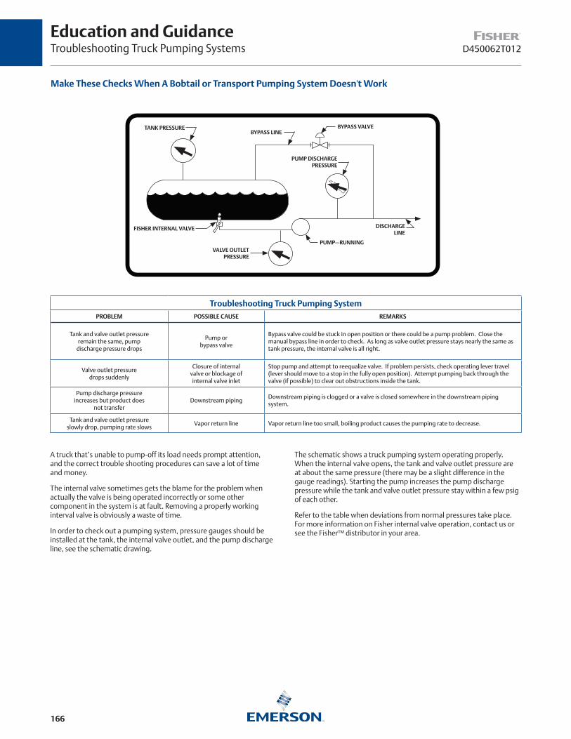
166
D450062T012
Education and GuidanceTroubleshooting Truck Pumping Systems
Make These Checks When A Bobtail or Transport Pumping System Doesn't Work
TANK PRESSUREBYPASS LINE
PUMP DISCHARGEPRESSURE
FISHER INTERNAL VALVE
VALVE OUTLETPRESSURE
DISCHARGELINE
BYPASS VALVE
PUMP—RUNNING
Troubleshooting Truck Pumping SystemPROBLEM POSSIBLE CAUSE REMARKS
Tank and valve outlet pressureremain the same, pump
discharge pressure drops
Pump orbypass valve
Bypass valve could be stuck in open position or there could be a pump problem. Close the manual bypass line in order to check. As long as valve outlet pressure stays nearly the same as tank pressure, the internal valve is all right.
Valve outlet pressuredrops suddenly
Closure of internal valve or blockage ofinternal valve inlet
Stop pump and attempt to reequalize valve. If problem persists, check operating lever travel (lever should move to a stop in the fully open position). Attempt pumping back through the valve (if possible) to clear out obstructions inside the tank.
Pump discharge pressure increases but product does
not transferDownstream piping
Downstream piping is clogged or a valve is closed somewhere in the downstream piping system.
Tank and valve outlet pressure slowly drop, pumping rate slows
Vapor return line Vapor return line too small, boiling product causes the pumping rate to decrease.
A truck that’s unable to pump-off its load needs prompt attention, and the correct trouble shooting procedures can save a lot of time and money.
The internal valve sometimes gets the blame for the problem when actually the valve is being operated incorrectly or some other component in the system is at fault. Removing a properly working interval valve is obviously a waste of time.
In order to check out a pumping system, pressure gauges should be installed at the tank, the internal valve outlet, and the pump discharge line, see the schematic drawing.
The schematic shows a truck pumping system operating properly. When the internal valve opens, the tank and valve outlet pressure are at about the same pressure (there may be a slight difference in the gauge readings). Starting the pump increases the pump discharge pressure while the tank and valve outlet pressure stay within a few psig of each other.
Refer to the table when deviations from normal pressures take place. For more information on Fisher internal valve operation, contact us or see the Fisher™ distributor in your area.

167
D450168T012
Education and GuidanceRegulator Installation
Correct LP-Gas Regulator Installation Can Improve Safety, Give Longer Life
Second stage regulators should always be installed with the vent pointing down. This
reduces the possibility of freezing rain or sleet plugging the vent. It also makes it more
difficult for foreign material (pipe scale, dirt) to enter the regulator.
On single cylinder or domestic tank installations, it is frequently impossible to point the regulator’s vent vertically down.
Here an encasement or hood will be needed to protect the vent from the elements. Be sure
the tank hood completely covers the vent.
On single cylinder or domestic tank installations, it is frequently impossible to point the regulator’s vent vertically down.
Here an encasement or hood will be needed to protect the vent from the elements. Be sure
the tank hood completely covers the vent.
When making new installations or updating old ones, the regulator’s vent is an important consideration. It affects both the safety and the service life of the installation.
Keeping Vents Unplugged
The vent has to remain open in order for the regulator to work properly. Freezing rain is the most common source of vent blockage. If the vent does become plugged, it could allow: (1) High pressure gas to register at the appliance, or (2) The appliance pilot lights to be extinguished. Either instance could result in an explosion and fire.
Nearly all domestic single stage and second stage regulators produced today have “drip lip” style vents. These units resist plugging by freezing rain when installed with their vent pointing vertically down. On installations where it’s impossible to point the vent vertically down, a hood or encasement should be used.
Extending Service Life
Condensation can build up inside the regulator’s spring case. After several years–it doesn’t take place overnight–the condensation may corrode the internal parts of the regulator, causing a sudden regulator failure.
Corrosion problems are another reason for pointing the vent vertically down wherever possible. In this way, any condensation that forms can drain out the vent instead of accumulating inside the regulator.
Extending Service Life
Safe, trouble-free installations begin with a correctly installed regulator, whether the unit is a Fisher or another brand. Realizing the importance of the regulator to any LP-gas system, Fisher™ makes available a variety of free literature about regulators. Besides installation information, the literature covers operation, inspection, and maintenance. Contact us or see the Fisher distributor in your area.

168
Warranty and Liability
In consideration for the discount pricing offered above, the following terms and conditions are accepted by Distributor and shall apply to all products subject to this pricing sheet (“Goods”). Distributor shall extend these limited warranty and limitation of liability provisions, in their entirety and without change, to customers and end users of the products.
1. Limited Warranty: Subject to the Limitation of Remedy and Liability below, Emerson Process Management Regulator Technologies, Inc. (“RTI”) warrants that the Goods manufactured by RTI will be free from defects in materials or workmanship under normal use and care until the expiration of the warranty period. Goods are warranted for five (5) years from the date of manufacture. Products purchased by RTI from a third party for resale to Distributor and/or its customers (each a “Buyer”) (“Resale Products”) shall carry only the warranty extended by the original manufacturer. Buyer agrees that RTI has no liability for Resale Products beyond making a reasonable commercial effort to arrange for procurement and shipping of the Resale Products. If Buyer discovers any warranty defects and notifies RTI thereof in writing during the applicable warranty period, RTI shall, at its option, repair or replace FOB point of manufacture that portion of the Goods found by RTI to be defective, or refund the purchase price of the defection portion of the Goods. Failure by Buyer to give such written notice within the applicable time period specified above shall be deemed an absolute and unconditional waiver of the Buyer’s claims for such defects. All replacements or repairs necessitated by inadequate maintenance, normal wear and usage, unsuitable power sources or environmental conditions, accident, misuse, improper installation, modification, repair, storage or handling, or any other cause not the fault of RTI are not covered by this limited warranty, and shall be at Buyer’s expense. RTI shall not be obligated to pay any costs or charges incurred by Buyer or any other party except as may be agreed upon in writing in advance by RTI. All costs of dismantling, reinstallation, and freight and the time and expenses of RTI’s personnel and representatives for site travel and diagnosis under this warranty clause shall be borne by Buyer unless accepted in writing by RTI. Goods repaired and parts replaced by RTI during the warranty period shall be in warranty for the remainder of the original warranty period or ninety (90) days, whichever is longer. This limited warranty is the only warranty made by RTI and can be amended only in writing signed by RTI. THE WARRANTIES AND REMEDIES SET FORTH ABOVE ARE EXCLUSIVE. THERE ARE NO REPRESENTATIONS OR WARRANTIES OF ANY KIND, EXPRESS OR IMPLIED, AS TO MERCHANTABILITY, FITNESS FOR PARTICULAR PURPOSE OR ANY OTHER MATTER WITH RESPECT TO ANY OF THE GOODS OR SERVICES
2. LIMITATION OF REMEDY AND LIABILITY: RTI SHALL NOT BE LIABLE FOR DAMAGES CAUSED BY DELAY IN PERFORMANCE. THE REMEDIES OF BUYER SET FORTH ABOVE ARE EXCLUSIVE. IN NO EVENT, REGARDLESS OF THE FORM OF THE CLAIM OR CAUSE OF ACTION (WHETHER BASED IN CONTRACT, INFRINGEMENT, NEGLIGENCE, STRICT LIABILITY, OTHER TORT OR OTHERWISE), SHALL RTI’S LIABILITY TO BUYER AND/OR ITS CUSTOMERS EXCEED THE PRICE TO BUYER OF THE SPECIFIC GOODS MANUFACTURED BY RTI GIVING RISE TO THE CLAIM OR CAUSE OF ACTION. BUYER AGREES THAT IN NO EVENT SHALL RTI’S LIABILITY TO BUYER AND/OR ITS CUSTOMERS EXTEND TO INCLUDE INCIDENTAL, CONSEQUENTIAL OR PUNITIVE DAMAGES. THE TERM “CONSEQUENTIAL DAMAGES” SHALL INCLUDE, BUT NOT BE LIMITED TO, LOSS OF ANTICIPATED PROFITS, REVENUE OR USE AND COSTS INCURRED INCLUDING WITHOUT LIMITATION CAPITAL, FUEL AND POWER, AND CLAIMS OF BUYER’S CUSTOMERS. RTI shall not be liable for and Buyer assumes all liability for, all personal injury (including without limitation death) and property damage in connection with or arising from the handling, transportation, possession, processing, further manufacture, other use or resale of the Goods, whether the Goods are used alone or in combination with any other material. Neither transportation charges for the return of the Goods nor any other costs, charges or expenses incurred by Buyer will be paid by RTI unless authorized in advance and in writing by RTI. All Goods returned for repair are to be shipped prepaid for the account of the Buyer by a mode of transportation approved by RTI. If RTI furnishes technical or other advice to Buyer, whether or not at Buyer’s request, with respect to processing, further manufacture, or other use or resale of the Goods, RTI shall not be liable for, and Buyer assumes all risk of, such advice and the results thereof.
3. Emerson Process Management Regulator Technologies, Inc. and their affiliated entities assume no responsibility for the selection, use or maintenance of any product. Responsibility for proper selection, use and maintenance of any product remains solely with the purchaser and end user.
4. The pricing information contained herein is “Confidential” and shall not be disclosed to third parties. While every attempt has been made to assure the accuracy and completeness of the information contained herein, RTI offers no warranty or guarantee, express or implied, regarding the information. All sales are governed by RTI’s terms and conditions of sale, which are available upon request. RTI reserves the right to (i) modify and/or improve its designs or specifications of its products; (ii) discontinue its products; and/or (iii) modify its pricing, without notice, at any time.
The Emerson logo is a trademark and service mark of Emerson Electric Co. All other marks are the property of their prospective owners. Fisher™ is a mark owned by Fisher Controls International LLC, a business of Emerson Automation Solutions.
WARRANTY AND LIABILITY
169
Index
The contents of this publication are presented for informational purposes only, and while every effort has been made to ensure their accuracy, they are not to be construed as warranties or guarantees, express or implied, regarding the products or services described herein or their use or applicability. We reserve the right to modify or improve the designs or specifications of such products at any time without notice.
NOTICE: See individual product instruction manuals supplied with the product for more detailed information. Contact Emerson or your local LPG Regulators and Equipment Distributor if you have additional product questions.
WARNING: Fisher™ equipment must be installed, operated and maintained in accordance with federal, state and local codes, and Fisher instructions. The installation in most states must also comply with National Fire Protection Association 54 and 58 standards.
Only personnel trained in the proper procedures, codes, standards, and regulations of the LPG or Anhydrous Ammonia (NH3) industries should install and service this equipment.
Due to normal wear or damage that may occur from external sources, Fisher equipment must be inspected and maintained periodically. The frequency of inspection and replacement of equipment depends upon the severity of the service conditions or age requirements of local, state, federal regulations and Fisher instructions.
Do not use any Fisher equipment that leaks, fails to work properly or that has damaged or missing parts. Equipment repair or replacement should be made promptly in order to prevent accidents.
Failure to follow these instructions or to properly install and maintain this equipment could result in an explosion and/or fire causing property damage, personal injury or death.
! WARNING
INDEX
Series / Type No. Page No.50 . . . . . . . . . . . . . . . . . . . . . . . . . . . . . . . . . . . . . . . . . . . . . . . . . . . . . . . . . . .4564 . . . . . . . . . . . . . . . . . . . . . . . . . . . . . . . . . . . . . . . . . . . . . . . . . . . . . . . . . . .3164SR . . . . . . . . . . . . . . . . . . . . . . . . . . . . . . . . . . . . . . . . . . . . . . . . . . . . . . . . .3167C . . . . . . . . . . . . . . . . . . . . . . . . . . . . . . . . . . . . . . . . . . . . . . . . . . . . . . . . . .3099 . . . . . . . . . . . . . . . . . . . . . . . . . . . . . . . . . . . . . . . . . . . . . . . . . . . . . . . .34/40133 . . . . . . . . . . . . . . . . . . . . . . . . . . . . . . . . . . . . . . . . . . . . . . . . . . . . . . . . . .40289H . . . . . . . . . . . . . . . . . . . . . . . . . . . . . . . . . . . . . . . . . . . . . . . . . . . . . . . . .43299H . . . . . . . . . . . . . . . . . . . . . . . . . . . . . . . . . . . . . . . . . . . . . . . . . . . . . . . . .40627 . . . . . . . . . . . . . . . . . . . . . . . . . . . . . . . . . . . . . . . . . . . . . . . . . . . . . . . . . .32630 . . . . . . . . . . . . . . . . . . . . . . . . . . . . . . . . . . . . . . . . . . . . . . . . . . . . . . . . . .3263EGLP . . . . . . . . . . . . . . . . . . . . . . . . . . . . . . . . . . . . . . . . . . . . . . . . . . . . . . 68 749B-21 . . . . . . . . . . . . . . . . . . . . . . . . . . . . . . . . . . . . . . . . . . . . . . . . . . . . . .41803 . . . . . . . . . . . . . . . . . . . . . . . . . . . . . . . . . . . . . . . . . . . . . . . . . . . . . . . . . .41912 . . . . . . . . . . . . . . . . . . . . . . . . . . . . . . . . . . . . . . . . . . . . . . . . . . . . . . . . . .441098 . . . . . . . . . . . . . . . . . . . . . . . . . . . . . . . . . . . . . . . . . . . . . . . . . . . . . . . . .351301F . . . . . . . . . . . . . . . . . . . . . . . . . . . . . . . . . . . . . . . . . . . . . . . . . . . . . . . .321805 . . . . . . . . . . . . . . . . . . . . . . . . . . . . . . . . . . . . . . . . . . . . . . . . . . . . . . . . .43C404-32 . . . . . . . . . . . . . . . . . . . . . . . . . . . . . . . . . . . . . . . . . . . . . . . . . . . . . .55C407-10 . . . . . . . . . . . . . . . . . . . . . . . . . . . . . . . . . . . . . . . . . . . . . . . . . . . . . .47C471 . . . . . . . . . . . . . . . . . . . . . . . . . . . . . . . . . . . . . . . . . . . . . . . . . . . . . . . . .47C477 . . . . . . . . . . . . . . . . . . . . . . . . . . . . . . . . . . . . . . . . . . . . . . . . . . . . . . . . .47C483 . . . . . . . . . . . . . . . . . . . . . . . . . . . . . . . . . . . . . . . . . . . . . . . . . . . . . . . . .53C484 . . . . . . . . . . . . . . . . . . . . . . . . . . . . . . . . . . . . . . . . . . . . . . . . . . . . . . . . .53C486 . . . . . . . . . . . . . . . . . . . . . . . . . . . . . . . . . . . . . . . . . . . . . . . . . . . . . . . . .47C800 . . . . . . . . . . . . . . . . . . . . . . . . . . . . . . . . . . . . . . . . . . . . . . . . . . . . . .48/56 CS200 . . . . . . . . . . . . . . . . . . . . . . . . . . . . . . . . . . . . . . . . . . . . . . . . . . . . . . . .36CS400 . . . . . . . . . . . . . . . . . . . . . . . . . . . . . . . . . . . . . . . . . . . . . . . . . . . . . . . .36CS403 . . . . . . . . . . . . . . . . . . . . . . . . . . . . . . . . . . . . . . . . . . . . . . . . . . . . . . . .38CS404 . . . . . . . . . . . . . . . . . . . . . . . . . . . . . . . . . . . . . . . . . . . . . . . . . . . . . . . .38CS404 . . . . . . . . . . . . . . . . . . . . . . . . . . . . . . . . . . . . . . . . . . . . . . . . . . . . . . . .38CS800 . . . . . . . . . . . . . . . . . . . . . . . . . . . . . . . . . . . . . . . . . . . . . . . . . . . . . . . .36 CS803 . . . . . . . . . . . . . . . . . . . . . . . . . . . . . . . . . . . . . . . . . . . . . . . . . . . . . . . .38 D . . . . . . . . . . . . . . . . . . . . . . . . . . . . . . . . . . . . . . . . . . . . . . . . . . . . . . . . . . . .77F100 . . . . . . . . . . . . . . . . . . . . . . . . . . . . . . . . . . . . . . . . . . . . . . . . . . . . . . . . .65G . . . . . . . . . . . . . . . . . . . . . . . . . . . . . . . . . . . . . . . . . . . . . . . . . . . . . . . . . . . .72H100 . . . . . . . . . . . . . . . . . . . . . . . . . . . . . . . . . . . . . . . . . . . . . . . . . . . . . . . . .72H284 . . . . . . . . . . . . . . . . . . . . . . . . . . . . . . . . . . . . . . . . . . . . . . . . . . . . . . . . .67H722 . . . . . . . . . . . . . . . . . . . . . . . . . . . . . . . . . . . . . . . . . . . . . . . . . . . . . . . . .66H733 . . . . . . . . . . . . . . . . . . . . . . . . . . . . . . . . . . . . . . . . . . . . . . . . . . . . . . . . .66H5114 . . . . . . . . . . . . . . . . . . . . . . . . . . . . . . . . . . . . . . . . . . . . . . . . . . . . . . .67
Series / Type No. Page No. H5118 . . . . . . . . . . . . . . . . . . . . . . . . . . . . . . . . . . . . . . . . . . . . . . . . . . . . .66 HSRL. . . . . . . . . . . . . . . . . . . . . . . . . . . . . . . . . . . . . . . . . . . . . . . . . . . . . . .26 J . . . . . . . . . . . . . . . . . . . . . . . . . . . . . . . . . . . . . . . . . . . . . . . . . . . . . . . . . . .80 M . . . . . . . . . . . . . . . . . . . . . . . . . . . . . . . . . . . . . . . . . . . . . . . . . . . . . . . . .81 MR98H . . . . . . . . . . . . . . . . . . . . . . . . . . . . . . . . . . . . . . . . . . . . . . . . . . . .43 N100 . . . . . . . . . . . . . . . . . . . . . . . . . . . . . . . . . . . . . . . . . . . . . . . . . . . . . .78 N110 . . . . . . . . . . . . . . . . . . . . . . . . . . . . . . . . . . . . . . . . . . . . . . . . . . . . . .79 N120 . . . . . . . . . . . . . . . . . . . . . . . . . . . . . . . . . . . . . . . . . . . . . . . . . . . . . .79 N201 . . . . . . . . . . . . . . . . . . . . . . . . . . . . . . . . . . . . . . . . . . . . . . . . . . . . . .85 N301 . . . . . . . . . . . . . . . . . . . . . . . . . . . . . . . . . . . . . . . . . . . . . . . . . . . . . .73 N310 . . . . . . . . . . . . . . . . . . . . . . . . . . . . . . . . . . . . . . . . . . . . . . . . . . . . . .73 N350 . . . . . . . . . . . . . . . . . . . . . . . . . . . . . . . . . . . . . . . . . . . . . . . . . . . . . .73 N401 . . . . . . . . . . . . . . . . . . . . . . . . . . . . . . . . . . . . . . . . . . . . . . . . . . . . . .73 N410 . . . . . . . . . . . . . . . . . . . . . . . . . . . . . . . . . . . . . . . . . . . . . . . . . . . . . .73 N450 . . . . . . . . . . . . . . . . . . . . . . . . . . . . . . . . . . . . . . . . . . . . . . . . . . . . . .73 N480 . . . . . . . . . . . . . . . . . . . . . . . . . . . . . . . . . . . . . . . . . . . . . . . . . . . . . .77 N551 . . . . . . . . . . . . . . . . . . . . . . . . . . . . . . . . . . . . . . . . . . . . . . . . . . . . . .61 N562 . . . . . . . . . . . . . . . . . . . . . . . . . . . . . . . . . . . . . . . . . . . . . . . . . . . . . .63 N563 . . . . . . . . . . . . . . . . . . . . . . . . . . . . . . . . . . . . . . . . . . . . . . . . . . . . . .63 N600/700 . . . . . . . . . . . . . . . . . . . . . . . . . . . . . . . . . . . . . . . . . . . . . . . . . .74 P . . . . . . . . . . . . . . . . . . . . . . . . . . . . . . . . . . . . . . . . . . . . . . . . . . . . . . . . . .60 P120B . . . . . . . . . . . . . . . . . . . . . . . . . . . . . . . . . . . . . . . . . . . . . . . . . . . . .85 P600. . . . . . . . . . . . . . . . . . . . . . . . . . . . . . . . . . . . . . . . . . . . . . . . . . . . . . .47 P700. . . . . . . . . . . . . . . . . . . . . . . . . . . . . . . . . . . . . . . . . . . . . . . . . . . . . . .47 R122H . . . . . . . . . . . . . . . . . . . . . . . . . . . . . . . . . . . . . . . . . . . . . . . . . . . . .25 R130 . . . . . . . . . . . . . . . . . . . . . . . . . . . . . . . . . . . . . . . . . . . . . . . . . . . . . .41 R222 . . . . . . . . . . . . . . . . . . . . . . . . . . . . . . . . . . . . . . . . . . . . . . . . . . . . . .25 R222H . . . . . . . . . . . . . . . . . . . . . . . . . . . . . . . . . . . . . . . . . . . . . . . . . . . . .25 R232A . . . . . . . . . . . . . . . . . . . . . . . . . . . . . . . . . . . . . . . . . . . . . . . . . . . . .28 R232E . . . . . . . . . . . . . . . . . . . . . . . . . . . . . . . . . . . . . . . . . . . . . . . . . . . . .29 R622 . . . . . . . . . . . . . . . . . . . . . . . . . . . . . . . . . . . . . . . . . . . . . . . . . . . . . .26 R622E . . . . . . . . . . . . . . . . . . . . . . . . . . . . . . . . . . . . . . . . . . . . . . . . . . . . .27 R622H . . . . . . . . . . . . . . . . . . . . . . . . . . . . . . . . . . . . . . . . . . . . . . . . . . . . .25 R632A . . . . . . . . . . . . . . . . . . . . . . . . . . . . . . . . . . . . . . . . . . . . . . . . . . . . .28 R632E . . . . . . . . . . . . . . . . . . . . . . . . . . . . . . . . . . . . . . . . . . . . . . . . . . . . .29 R642 . . . . . . . . . . . . . . . . . . . . . . . . . . . . . . . . . . . . . . . . . . . . . . . . . . . . . .26 R652 . . . . . . . . . . . . . . . . . . . . . . . . . . . . . . . . . . . . . . . . . . . . . . . . . . . . . .26 R652E . . . . . . . . . . . . . . . . . . . . . . . . . . . . . . . . . . . . . . . . . . . . . . . . . . . . .27 Y602 . . . . . . . . . . . . . . . . . . . . . . . . . . . . . . . . . . . . . . . . . . . . . . . . . . . . . .44

LP-31 (2022-2023)
LP-Gas TechnologiesRegulators and Equipment, LPG/NH3LP-31 Buyer’s Guide (2022-2023)
Our distribution network offers a full complement of sales and support staff, and more than 2000 technical experts strategically located across nearly 200 locations.
LinkedIn.com/company/emerson-automation-solutions
Twitter.com/emr_automation
Facebook.com/EmersonAutomationSolutions
Emerson Automation Solutions
[email protected] +1 800 558 5853T +1 972 548 3574
EuropeT +39 051 419 0611
Asia PacificT +65 6777 8211
Middle East / AfricaT +971 4811 8100
Fisher.com
D450104T012 © 2009, 2022 Emerson Process Management Regulator Technologies, Inc. All rights reserved. 03/22.The Emerson logo is a trademark and service mark of Emerson Electric Co. All other marks are the property of their prospective owners.Fisher™ is a mark owned by Fisher Controls International LLC, a business of Emerson Automation Solutions.
![_P8LPI]P ;LP;LP;LP 5ZL1F DF8[ - WordPress.com](https://static.fdokumen.com/doc/165x107/631d1be4b8a98572c10d3520/p8lpip-lplplp-5zl1f-df8-wordpresscom.jpg)


![Emersonian : [Emerson College yearbook]](https://static.fdokumen.com/doc/165x107/6321be5e117b4414ec0b98a5/emersonian-emerson-college-yearbook.jpg)