
Direction 5122546-100 Revision 4 GE Healthcare LOGIQ 3 ...
489
Technical Publication Direction 5122546-100 Revision 4 GE Healthcare LOGIQ 3 Basic Service Manual Copyright© 2005-2009 by General Electric Co. Operating Documentation GE Healthcare
-
Upload
khangminh22 -
Category
Documents
-
view
1 -
download
0
Transcript of Direction 5122546-100 Revision 4 GE Healthcare LOGIQ 3 ...

Technical Publication
Direction 5122546-100Revision 4
GE HealthcareLOGIQ 3 Basic Service Manual
Copyright© 2005-2009 by General Electric Co.
Operating Documentation
GE Healthcare


GE HEALTHCARE DIRECTION 5122546-100, REVISION 4 LOGIQ 3 SERVICE MANUAL
i
Important Precautions
• THIS SERVICE MANUAL IS AVAILABLE IN ENGLISH ONLY.• IF A CUSTOMER’S SERVICE PROVIDER REQUIRES A LANGUAGE OTHER THAN
ENGLISH, IT IS THE CUSTOMER’S RESPONSIBILITY TO PROVIDE TRANSLATION SERVICES.
• DO NOT ATTEMPT TO SERVICE THE EQUIPMENT UNLESS THIS SERVICE MANUAL HAS BEEN CONSULTED AND IS UNDERSTOOD.
• FAILURE TO HEED THIS WARNING MAY RESULT IN INJURY TO THE SERVICE PROVIDER, OPERATOR OR PATIENT FROM ELECTRIC SHOCK, MECHANICAL OR OTHER HAZARDS.
• CE MANUEL DE MAINTENANCE N’EST DISPONIBLE QU’EN ANGLAIS.• SI LE PRESTATAIRE DE SERVICES DU CLIENT A BESOIN DE CE MANUEL DANS
UNE AUTRE LANGUE QUE L’ANGLAIS, IL INCOMBE AU CLIENT DE LE FAIRE TRADUIRE.
• NE PAS TENTER D’INTERVENTION SUR LES ÉQUIPEMENTS TANT QUE LE MANUEL DE MAINTENANCE N’A PAS ÉTÉ CONSULTÉ ET COMPRIS.
• LE NON-RESPECT DE CET AVERTISSEMENT PEUT ENTRAÎNER CHEZ LE TECHNICIEN, L’OPÉRATEUR OU LE PATIENT DES BLESSURES DUES À DES DANGERS ÉLECTRIQUES, MÉCANIQUES OU AUTRES.
• DIESES KUNDENDIENST-HANDBUCH EXISTIERT NUR IN ENGLISCHER SPRACHE.
• FALLS EIN FREMDER KUNDENDIENST EINE ANDERE SPRACHE BENÖTIGT, IST ES AUFGABE DES KUNDEN, FÜR EINE ENTSPRECHENDE ÜBERSETZUNG ZU SORGEN.
• WARTEN SIE DIESES GERÄT NUR, WENN SIE DIE ENTSPRECHENDEN ANWEISUNGEN IM KUNDENDIENST-HANDBUCH GELESEN HABEN UND NACHVOLLZIEHEN KÖNNEN.
• WIRD DIESE WARNUNG NICHT BEACHTET, SO KANN ES ZU VERLETZUNGEN DES KUNDENDIENSTTECHNIKERS, DES BEDIENERS ODER DES PATIENTEN DURCH ELEKTRISCHE SCHLÄGE, MECHANISCHE ODER SONSTIGE GEFAHREN KOMMEN.
WARNING
AVERTISSEMENT
WARNUNG

GE HEALTHCARE DIRECTION 5122546-100, REVISION 4 LOGIQ 3 SERVICE MANUAL
ii -
• ESTE MANUAL DE SERVICIO SÓLO ESTÁ DISPONIBLE EN INGLÉS.• SI ALGÚN PROVEEDOR DE SERVICIOS AJENO A GEMS SOLICITA UN IDIOMA
QUE NO SEA EL INGLÉS, LA TRADUCCIÓN ES RESPONSABILIDAD DEL CLIENTE.
• NO SE DEBERÁ DAR SERVICIO TÉCNICO AL EQUIPO SIN HABER CONSULTADO Y COMPRENDIDO ESTE MANUAL DE SERVICIO.
• LA NO OBSERVANCIA DEL PRESENTE AVISO PUEDE DAR LUGAR A QUE EL PROVEEDOR DE SERVICIOS, EL USUARIO O EL PACIENTE SUFRAN LESIONES PROVOCADAS POR DESCARGAS ELÉCTRICAS, PROBLEMAS MECÁNICOS O PELIGROS DE OTRA NATURALEZA.
• ESTE MANUAL DE ASSISTÊNCIA TÉCNICA SÓ SE ENCONTRA DISPONÍVEL EM INGLÊS.
• SE QUALQUER OUTRO SERVIÇO DE ASSISTÊNCIA TÉCNICA, QUE NÃO A GEMS, SOLICITAR ESTES MANUAIS NOUTRO IDIOMA, É DA RESPONSABILIDADE DO CLIENTE FORNECER OS SERVIÇOS DE TRADUÇÃO.
• NÃO TENTE REPARAR O EQUIPAMENTO SEM TER CONSULTADO E COMPREENDIDO ESTE MANUAL DE ASSISTÊNCIA TÉCNICA.
• O NÃO CUMPRIMENTO DESTE AVISO PODE PÔR EM PERIGO A SEGURANÇA DO TÉCNICO, OPERADOR OU PACIENTE DEVIDO A CHOQUES ELÉTRICOS, MECÂNICOS OU OUTROS.
• IL PRESENTE MANUALE DI MANUTENZIONE È DISPONIBILE SOLTANTO IN INGLESE.
• SE UN ADDETTO ALLA MANUTENZIONE ESTERNO ALLA GEMS RICHIEDE IL MANUALE IN UNA LINGUA DIVERSA, IL CLIENTE È TENUTO A PROVVEDERE DIRETTAMENTE ALLA TRADUZIONE.
• SI PROCEDA ALLA MANUTENZIONE DELL’APPARECCHIATURA SOLO DOPO AVER CONSULTATO IL PRESENTE MANUALE ED AVERNE COMPRESO IL CONTENUTO.
• NON TENERE CONTO DELLA PRESENTE AVVERTENZA POTREBBE FAR COMPIERE OPERAZIONI DA CUI DERIVINO LESIONI ALL’ADDETTO ALLA MANUTENZIONE, ALL’UTILIZZATORE ED AL PAZIENTE PER FOLGORAZIONE ELETTRICA, PER URTI MECCANICI OD ALTRI RISCHI.
• KÄESOLEV TEENINDUSJUHEND ON SAADAVAL AINULT INGLISE KEELES.• KUI KLIENDITEENINDUSE OSUTAJA NÕUAB JUHENDIT INGLISE KEELEST
ERINEVAS KEELES, VASTUTAB KLIENT TÕLKETEENUSE OSUTAMISE EEST. • ÄRGE ÜRITAGE SEADMEID TEENINDADA ENNE EELNEVALT KÄESOLEVA
TEENINDUSJUHENDIGA TUTVUMIST JA SELLEST ARU SAAMIST.• KÄESOLEVA HOIATUSE EIRAMINE VÕIB PÕHJUSTADA TEENUSEOSUTAJA,
OPERAATORI VÕI PATSIENDI VIGASTAMIST ELEKTRILÖÖGI, MEHAANILISE VÕI MUU OHU TAGAJÄRJEL.
AVISO
ATENÇÃO
AVVERTENZA
HOIATUS

GE HEALTHCARE DIRECTION 5122546-100, REVISION 4 LOGIQ 3 SERVICE MANUAL
iii
• TÄMÄ HUOLTO-OHJE ON SAATAVILLA VAIN ENGLANNIKSI.• JOS ASIAKKAAN PALVELUNTARJOAJA VAATII MUUTA KUIN
ENGLANNINKIELISTÄ MATERIAALIA, TARVITTAVAN KÄÄNNÖKSEN HANKKIMINEN ON ASIAKKAAN VASTUULLA.
• ÄLÄ YRITÄ KORJATA LAITTEISTOA ENNEN KUIN OLET VARMASTI LUKENUT JA YMMÄRTÄNYT TÄMÄN HUOLTO-OHJEEN.
• MIKÄLI TÄTÄ VAROITUSTA EI NOUDATETA, SEURAUKSENA VOI OLLA PALVELUNTARJOAJAN, LAITTEISTON KÄYTTÄJÄN TAI POTILAAN VAHINGOITTUMINEN SÄHKÖISKUN, MEKAANISEN VIAN TAI MUUN VAARATILANTEEN VUOKSI.
• ΤΟ ΠΑΡΟΝ ΕΓΧΕΙΡΙ∆ΙΟ ΣΕΡΒΙΣ ∆ΙΑΤΙΘΕΤΑΙ ΣΤΑ ΑΓΓΛΙΚΑ ΜΟΝΟ.• ΕΑΝ ΤΟ ΑΤΟΜΟ ΠΑΡΟΧΗΣ ΣΕΡΒΙΣ ΕΝΟΣ ΠΕΛΑΤΗ ΑΠΑΙΤΕΙ ΤΟ ΠΑΡΟΝ ΕΓΧΕΙΡΙ∆ΙΟ ΣΕ ΓΛΩΣΣΑ ΕΚΤΟΣ ΤΩΝ ΑΓΓΛΙΚΩΝ, ΑΠΟΤΕΛΕΙ ΕΥΘΥΝΗ ΤΟΥ ΠΕΛΑΤΗ ΝΑ ΠΑΡΕΧΕΙ ΥΠΗΡΕΣΙΕΣ ΜΕΤΑΦΡΑΣΗΣ.
• ΜΗΝ ΕΠΙΧΕΙΡΗΣΕΤΕ ΤΗΝ ΕΚΤΕΛΕΣΗ ΕΡΓΑΣΙΩΝ ΣΕΡΒΙΣ ΣΤΟΝ ΕΞΟΠΛΙΣΜΟ ΕΚΤΟΣ ΕΑΝ ΕΧΕΤΕ ΣΥΜΒΟΥΛΕΥΤΕΙ ΚΑΙ ΕΧΕΤΕ ΚΑΤΑΝΟΗΣΕΙ ΤΟ ΠΑΡΟΝ ΕΓΧΕΙΡΙ∆ΙΟ ΣΕΡΒΙΣ.
• ΕΑΝ ∆Ε ΛΑΒΕΤΕ ΥΠΟΨΗ ΤΗΝ ΠΡΟΕΙ∆ΟΠΟΙΗΣΗ ΑΥΤΗ, ΕΝ∆ΕΧΕΤΑΙ ΝΑ ΠΡΟΚΛΗΘΕΙ ΤΡΑΥΜΑΤΙΣΜΟΣ ΣΤΟ ΑΤΟΜΟ ΠΑΡΟΧΗΣ ΣΕΡΒΙΣ, ΣΤΟ ΧΕΙΡΙΣΤΗ Ή ΣΤΟΝ ΑΣΘΕΝΗ ΑΠΟ ΗΛΕΚΤΡΟΠΛΗΞΙΑ, ΜΗΧΑΝΙΚΟΥΣ Ή ΑΛΛΟΥΣ ΚΙΝ∆ΥΝΟΥΣ.
• EZEN KARBANTARTÁSI KÉZIKÖNYV KIZÁRÓLAG ANGOL NYELVEN ÉRHETŐ EL.
• HA A VEVŐ SZOLGÁLTATÓJA ANGOLTÓL ELTÉRŐ NYELVRE TART IGÉNYT, AKKOR A VEVŐ FELELŐSSÉGE A FORDÍTÁS ELKÉSZÍTTETÉSE.
• NE PRÓBÁLJA ELKEZDENI HASZNÁLNI A BERENDEZÉST, AMÍG A KARBANTARTÁSI KÉZIKÖNYVBEN LEÍRTAKAT NEM ÉRTELMEZTÉK.
• EZEN FIGYELMEZTETÉS FIGYELMEN KÍVÜL HAGYÁSA A SZOLGÁLTATÓ, MŰKÖDTETŐ VAGY A BETEG ÁRAMÜTÉS, MECHANIKAI VAGY EGYÉB VESZÉLYHELYZET MIATTI SÉRÜLÉSÉT EREDMÉNYEZHETI.
• ÞESSI ÞJÓNUSTUHANDBÓK ER EINGÖNGU FÁANLEG Á ENSKU.• EF ÞJÓNUSTUAÐILI VIÐSKIPTAMANNS ÞARFNAST ANNARS TUNGUMÁLS EN
ENSKU, ER ÞAÐ Á ÁBYRGÐ VIÐSKIPTAMANNS AÐ ÚTVEGA ÞÝÐINGU.• REYNIÐ EKKI AÐ ÞJÓNUSTA TÆKIÐ NEMA EFTIR AÐ HAFA SKOÐAÐ OG SKILIÐ
ÞESSA ÞJÓNUSTUHANDBÓK.• EF EKKI ER FARIÐ AÐ ÞESSARI VIÐVÖRUN GETUR ÞAÐ VALDIÐ MEIÐSLUM
ÞJÓNUSTUVEITANDA, STJÓRNANDA EÐA SJÚKLINGS VEGNA RAFLOSTS, VÉLRÆNNAR EÐA ANNARRAR HÆTTU.
VAROITUS
ΠΡΟΕΙ∆ΟΠΟΙΗΣΗ
FIGYELMEZTETÉS
VIÐVÖRUN

GE HEALTHCARE DIRECTION 5122546-100, REVISION 4 LOGIQ 3 SERVICE MANUAL
iv -
• TENTO SERVISNÍ NÁVOD EXISTUJE POUZE V ANGLICKÉM JAZYCE.• V PŘÍPADĚ, ŽE POSKYTOVATEL SLUŽEB ZÁKAZNÍKŮM POTŘEBUJE NÁVOD V
JINÉM JAZYCE, JE ZAJIŠTĚNÍ PŘEKLADU DO ODPOVÍDAJÍCÍHO JAZYKA ÚKOLEM ZÁKAZNÍKA.
• NEPROVÁDĚJTE ÚDRŽBU TOHOTO ZAŘÍZENÍ, ANIŽ BYSTE SI PŘEČETLI TENTO SERVISNÍ NÁVOD A POCHOPILI JEHO OBSAH.
• V PŘÍPADĚ NEDODRŽOVÁNÍ TÉTO VÝSTRAHY MŮŽE DOJÍT ÚRAZU ELEKTRICKÁM PROUDEM PRACOVNÍKA POSKYTOVATELE SLUŽEB, OBSLUŽNÉHO PERSONÁLU NEBO PACIENTŮ VLIVEM ELEKTRICKÉHOP PROUDU, RESPEKTIVE VLIVEM K RIZIKU MECHANICKÉHO POŠKOZENÍ NEBO JINÉMU RIZIKU.
• DENNE SERVICEMANUAL FINDES KUN PÅ ENGELSK.• HVIS EN KUNDES TEKNIKER HAR BRUG FOR ET ANDET SPROG END
ENGELSK, ER DET KUNDENS ANSVAR AT SØRGE FOR OVERSÆTTELSE.• FORSØG IKKE AT SERVICERE UDSTYRET MEDMINDRE
DENNE SERVICEMANUAL ER BLEVET LÆST OG FORSTÅET.• MANGLENDE OVERHOLDELSE AF DENNE ADVARSEL KAN MEDFØRE SKADE
PÅ GRUND AF ELEKTRISK, MEKANISK ELLER ANDEN FARE FOR TEKNIKEREN, OPERATØREN ELLER PATIENTEN.
• DEZE ONDERHOUDSHANDLEIDING IS ENKEL IN HET ENGELS VERKRIJGBAAR.
• ALS HET ONDERHOUDSPERSONEEL EEN ANDERE TAAL VEREIST, DAN IS DE KLANT VERANTWOORDELIJK VOOR DE VERTALING ERVAN.
• PROBEER DE APPARATUUR NIET TE ONDERHOUDEN VOORDAT DEZE ONDERHOUDSHANDLEIDING WERD GERAADPLEEGD EN BEGREPEN IS.
• INDIEN DEZE WAARSCHUWING NIET WORDT OPGEVOLGD, ZOU HET ONDERHOUDSPERSONEEL, DE OPERATOR OF EEN PATIËNT GEWOND KUNNEN RAKEN ALS GEVOLG VAN EEN ELEKTRISCHE SCHOK, MECHANISCHE OF ANDERE GEVAREN.
• ŠĪ APKALPES ROKASGRĀMATA IR PIEEJAMA TIKAI ANGĻU VALODĀ.• JA KLIENTA APKALPES SNIEDZĒJAM NEPIECIEŠAMA INFORMĀCIJA CITĀ
VALODĀ, NEVIS ANGĻU, KLIENTA PIENĀKUMS IR NODROŠINĀT TULKOŠANU.• NEVEICIET APRĪKOJUMA APKALPI BEZ APKALPES ROKASGRĀMATAS
IZLASĪŠANAS UN SAPRAŠANAS.• ŠĪ BRĪDINĀJUMA NEIEVĒROŠANA VAR RADĪT ELEKTRISKĀS STRĀVAS
TRIECIENA, MEHĀNISKU VAI CITU RISKU IZRAISĪTU TRAUMU APKALPES SNIEDZĒJAM, OPERATORAM VAI PACIENTAM.
VÝSTRAHA
ADVARSEL
WAARSCHUWING
BRĪDINĀJUMS

GE HEALTHCARE DIRECTION 5122546-100, REVISION 4 LOGIQ 3 SERVICE MANUAL
v
• ŠIS EKSPLOATAVIMO VADOVAS YRA IŠLEISTAS TIK ANGLŲ KALBA.• JEI KLIENTO PASLAUGŲ TEIKĖJUI REIKIA VADOVO KITA KALBA – NE ANGLŲ,
VERTIMU PASIRŪPINTI TURI KLIENTAS.• NEMĖGINKITE ATLIKTI ĮRANGOS TECHNINĖS PRIEŽIŪROS DARBŲ, NEBENT
VADOVAUTUMĖTĖS ŠIUO EKSPLOATAVIMO VADOVU IR JĮ SUPRASTUMĖTE• NEPAISANT ŠIO PERSPĖJIMO, PASLAUGŲ TEIKĖJAS, OPERATORIUS AR
PACIENTAS GALI BŪTI SUŽEISTAS DĖL ELEKTROS SMŪGIO, MECHANINIŲ AR KITŲ PAVOJŲ.
• DENNE SERVICEHÅNDBOKEN FINNES BARE PÅ ENGELSK.• HVIS KUNDENS SERVICELEVERANDØR TRENGER ET ANNET SPRÅK, ER DET
KUNDENS ANSVAR Å SØRGE FOR OVERSETTELSE.• IKKE FORSØK Å REPARERE UTSTYRET UTEN AT DENNE
SERVICEHÅNDBOKEN ER LEST OG FORSTÅTT.• MANGLENDE HENSYN TIL DENNE ADVARSELEN KAN FØRE TIL AT
SERVICELEVERANDØREN, OPERATØREN ELLER PASIENTEN SKADES PÅ GRUNN AV ELEKTRISK STØT, MEKANISKE ELLER ANDRE FARER.
• NINIEJSZY PODRĘCZNIK SERWISOWY DOSTĘPNY JEST JEDYNIE W JĘZYKU ANGIELSKIM.
• JEŚLI FIRMA ŚWIADCZĄCA KLIENTOWI USłUGI SERWISOWE WYMAGA UDOSTĘPNIENIA PODRĘCZNIKA W JĘZYKU INNYM NIŻ ANGIELSKI, OBOWIĄZEK ZAPEWNIENIA STOSOWNEGO TłUMACZENIA SPOCZYWA NA KLIENCIE.
• NIE PRÓBOWAĆ SERWISOWAĆ NINIEJSZEGO SPRZĘTU BEZ UPRZEDNIEGO ZAPOZNANIA SIĘ Z PODRĘCZNIKIEM SERWISOWYM.
• NIEZASTOSOWANIE SIĘ DO TEGO OSTRZEŻENIA MOżE GROZIĆ OBRAŻENIAMI CIAłA SERWISANTA, OPERATORA LUB PACJENTA W WYNIKU PORAŻENIA PRĄDEM, URAZU MECHANICZNEGO LUB INNEGO RODZAJU ZAGROŻEŃ.
• ACEST MANUAL DE SERVICE ESTE DISPONIBIL NUMAI ÎN LIMBA ENGLEZĂ.• DACĂ UN FURNIZOR DE SERVICII PENTRU CLIENŢI NECESITĂ O ALTĂ LIMBĂ
DECÂT CEA ENGLEZĂ, ESTE DE DATORIA CLIENTULUI SĂ FURNIZEZE O TRADUCERE.
• NU ÎNCERCAŢI SĂ REPARAŢI ECHIPAMENTUL DECÂT ULTERIOR CONSULTĂRII ŞI ÎNŢELEGERII ACESTUI MANUAL DE SERVICE.
• IGNORAREA ACESTUI AVERTISMENT AR PUTEA DUCE LA RĂNIREA DEPANATORULUI, OPERATORULUI SAU PACIENTULUI ÎN URMA PERICOLELOR DE ELECTROCUTARE, MECANICE SAU DE ALTĂ NATURĂ.
ĮSPĖJIMAS
ADVARSEL
OSTRZEŻENIE
ATENŢIE

GE HEALTHCARE DIRECTION 5122546-100, REVISION 4 LOGIQ 3 SERVICE MANUAL
vi -
• ДАННОЕ РУКОВОДСТВО ПО ОБСЛУЖИВАНИЮ ПРЕДОСТАВЛЯЕТСЯ ТОЛЬКО НА АНГЛИЙСКОМ ЯЗЫКЕ.
• ЕСЛИ СЕРВИСНОМУ ПЕРСОНАЛУ КЛИЕНТА НЕОБХОДИМО РУКОВОДСТВО НЕ НА АНГЛИЙСКОМ ЯЗЫКЕ, КЛИЕНТУ СЛЕДУЕТ САМОСТОЯТЕЛЬНО ОБЕСПЕЧИТЬ ПЕРЕВОД.
• ПЕРЕД ОБСЛУЖИВАНИЕМ ОБОРУДОВАНИЯ ОБЯЗАТЕЛЬНО ОБРАТИТЕСЬ К ДАННОМУ РУКОВОДСТВУ И ПОЙМИТЕ ИЗЛОЖЕННЫЕ В НЕМ СВЕДЕНИЯ.
• НЕСОБЛЮДЕНИЕ УКАЗАННЫХ ТРЕБОВАНИЙ МОЖЕТ ПРИВЕСТИ К ТОМУ, ЧТО СПЕЦИАЛИСТ ПО ТЕХОБСЛУЖИВАНИЮ, ОПЕРАТОР ИЛИ ПАЦИЕНТ ПОЛУЧАТ УДАР ЗЛЕКТРИЧЕСКИМ ТОКОМ, МЕХАНИЧЕСКУЮ ТРАВМУ ИЛИ ДРУГОЕ ПОВРЕЖДЕНИЕ.
• TÁTO SERVISNÁ PRÍRUČKA JE K DISPOZÍCII LEN V ANGLIČTINE.• AK ZÁKAZNÍKOV POSKYTOVATEĽ SLUŽIEB VYŽADUJE INÝ JAZYK AKO
ANGLIČTINU, POSKYTNUTIE PREKLADATEĽSKÝCH SLUŽIEB JE ZODPOVEDNOSŤOU ZÁKAZNÍKA.
• NEPOKÚŠAJTE SA VYKONÁVAŤ SERVIS ZARIADENIA SKÔR, AKO SI NEPREČÍTATE SERVISNÚ PRÍRUČKU A NEPOROZUMIETE JEJ.
• ZANEDBANIE TOHTO UPOZORNENIA MÔŽE VYÚSTIŤ DO ZRANENIA POSKYTOVATEĽA SLUŽIEB, OBSLUHUJÚCEJ OSOBY ALEBO PACIENTA ELEKTRICKÝM PRÚDOM, PRÍPADNE DO MECHANICKÉHO ALEBO INÉHO NEBEZPEČENSTVA.
• DEN HÄR SERVICEHANDBOKEN FINNS BARA TILLGÄNGLIG PÅ ENGELSKA.• OM EN KUNDS SERVICETEKNIKER HAR BEHOV AV ETT ANNAT SPRÅK ÄN
ENGELSKA ANSVARAR KUNDEN FÖR ATT TILLHANDAHÅLLA ÖVERSÄTTNINGSTJÄNSTER.
• FÖRSÖK INTE UTFÖRA SERVICE PÅ UTRUSTNINGEN OM DU INTE HAR LÄST OCH FÖRSTÅR DEN HÄR SERVICEHANDBOKEN.
• OM DU INTE TAR HÄNSYN TILL DEN HÄR VARNINGEN KAN DET RESULTERA I SKADOR PÅ SERVICETEKNIKERN, OPERATÖREN ELLER PATIENTEN TILL FÖLJD AV ELEKTRISKA STÖTAR, MEKANISKA FAROR ELLER ANDRA FAROR.
• BU SERVİS KILAVUZU YALNIZCA İNGİLİZCE OLARAK SAĞLANMIŞTIR.• EĞER MÜŞTERİ TEKNİSYENİ KILAVUZUN İNGİLİZCE DIŞINDAKİ BİR DİLDE
OLMASINI İSTERSE, KILAVUZU TERCÜME ETTİRMEK MÜŞTERİNİN SORUMLULUĞUNDADIR.
• SERVİS KILAVUZUNU OKUYUP ANLAMADAN EKİPMANLARA MÜDAHALE ETMEYİNİZ.
• BU UYARININ GÖZ ARDI EDİLMESİ, ELEKTRİK ÇARPMASI YA DA MEKANİK VEYA DİĞER TÜRDEN KAZALAR SONUCUNDA TEKNİSYENİN, OPERATÖRÜN YA DA HASTANIN YARALANMASINA YOL AÇABİLİR.
ОСТОРОЖНО!
UPOZORNENIE
VARNING
DİKKAT

GE HEALTHCARE DIRECTION 5122546-100, REVISION 4 LOGIQ 3 SERVICE MANUAL
vii

GE HEALTHCARE DIRECTION 5122546-100, REVISION 4 LOGIQ 3 SERVICE MANUAL
viii -
DAMAGE IN TRANSPORTATIONAll packages should be closely examined at time of delivery. If damage is apparent write “Damage In Shipment” on ALL copies of the freight or express bill BEFORE delivery is accepted or “signed for” by a GE representative or hospital receiving agent. Whether noted or concealed, damage MUST be reported to the carrier immediately upon discovery, or in any event, within 14 days after receipt, and the contents and containers held for inspection by the carrier. A transportation company will not pay a claim for damage if an inspection is not requested within this 14 day period.
CERTIFIED ELECTRICAL CONTRACTOR STATEMENT - FOR USA ONLYAll electrical Installations that are preliminary to positioning of the equipment at the site prepared for the equipment shall be performed by licensed electrical contractors. Other connections between pieces of electrical equipment, calibrations and testing shall be performed by qualified GE Healthcare personnel. In performing all electrical work on these products, GE will use its own specially trained field engineers. All of GE’s electrical work on these products will comply with the requirements of the applicable electrical codes.
The purchaser of GE equipment shall only utilize qualified personnel (i.e., GE’s field engineers, personnel of third-party service companies with equivalent training, or licensed electricians) to perform electrical servicing on the equipment.
OMISSIONS & ERRORSIf there are any omissions, errors or suggestions for improving this documentation, please contact the GE Healthcare Global Documentation Group with specific information listing the system type, manual title, part number, revision number, page number and suggestion details. Mail the information to: Service Documentation, 9900 Innovation Drive (RP-2123), Wauwatosa, WI 53226, USA.
GE Healthcare employees should use the iTrak System to report all documentation errors or omissions.
SERVICE SAFETY CONSIDERATIONS
For a complete review of all safety requirements, see the Chapter 1, Safety Considerations section of the LOGIQ 3 Basic Service Manual (5122546-100).
DANGER DANGEROUS VOLTAGES, CAPABLE OF CAUSING DEATH, ARE PRESENT IN THIS EQUIPMENT. USE EXTREME CAUTION WHEN HANDLING, TESTING AND ADJUSTING.
WARNINGWARNING Use all Personal Protection Equipment (PPE) such as gloves, safety shoes, safety glasses, and kneeling pad, to reduce the risk of injury.

GE HEALTHCARE DIRECTION 5122546-100, REVISION 4 LOGIQ 3 SERVICE MANUAL
ix
LEGAL NOTES
The contents of this publication may not be copied or duplicated in any form, in whole or in part, without prior written permission of GE Healthcare.
GE Healthcare may revise this publication from time to time without written notice.
TRADEMARKSAll products and their name brands are trademarks of their respective holders.
COPYRIGHTSAll Material Copyright© 2001-2009 by General Electric Company Inc. All Rights Reserved

GE HEALTHCARE DIRECTION 5122546-100, REVISION 4 LOGIQ 3 SERVICE MANUAL
x -
Revision History
List of Effected Pages
Revision Date Reason for change1 June 30, 2005 Initial Release
2 October 20, 2005 Updated Release
3 March 13, 2007Typo error of the part numbers corrected on the manual, Service
notes added to the manual,FRU part numbers updated.
4 March 25, 2009
Updated Probe Leakage Current Test ProcedureFunctional Checkout test procedures defined after each part replacement
New Service Notes UpdatedUpdated new FRU part numbers
Pages Revision Pages Revision Pages Revision
Title Page 4Chapter3-Installation(pages 3-1 to 3-24)
4Chapter8-Replacement
Proceduresn(pages 8-1 to 8-28)
4
Important Precautions(pages i to X)
4Chapter4-Functional checks
(pages 4-1 to 4-14)4
Chapter9-Renewalparts(pages 9-1 to 9-8)
4
Table of Contents(pages TOC1 to TOC6)
4Chapter5-Components And
functions(pages 5-1 to 5-12)
4Chapter10-Care & maintenance
(pages 10-1 to 10-30)4
Chapter 1 - Introduction(pages 1-1 to 1-18)
4Chapter6-Scan Adjustments
(pages 6-1 to 6-2)4 index 4
Chapter2-Preinstallation(pages 2-1 to 2-8)
4Chapter7-Trouble Shooting and
Diagnostics(pages 7-1 to 7-2)
4 Rear Cover 4

GE HEALTHCARE DIRECTION 5122546-100, REVISION 4 LOGIQ™ 3 SERVICE MANUAL
1
CHAPTER 1
Overview. . . . . . . . . . . . . . . . . . . . . . . . . . . . . . . . . . . . . . . . . . . . . . . . . . . . . . . . . 1 - 1Purpose of Chapter 1 . . . . . . . . . . . . . . . . . . . . . . . . . . . . . . . . . . . . . . . . . 1 - 1Chapter Contents . . . . . . . . . . . . . . . . . . . . . . . . . . . . . . . . . . . . . . . . . . . . 1 - 1Purpose of Service Manual . . . . . . . . . . . . . . . . . . . . . . . . . . . . . . . . . . . . . 1 - 1Typical Users of the Basic Service Manual . . . . . . . . . . . . . . . . . . . . . . . . 1 - 2LOGIQ™ 3 Models Covered by this Manual . . . . . . . . . . . . . . . . . . . . . . . 1 - 2Purpose of OperatorManual(s) . . . . . . . . . . . . . . . . . . . . . . . . . . . . . . . . . . 1 - 2
Safety . . . . . . . . . . . . . . . . . . . . . . . . . . . . . . . . . . . . . . . . . . . . . . . . . . . . . . . . . . . 1 - 3Warnings . . . . . . . . . . . . . . . . . . . . . . . . . . . . . . . . . . . . . . . . . . . . . . . . . . . 1 - 3
Important Conventions . . . . . . . . . . . . . . . . . . . . . . . . . . . . . . . . . . . . . . . . . . . . . . 1 - 4Conventions Used in Book . . . . . . . . . . . . . . . . . . . . . . . . . . . . . . . . . . . . . 1 - 4Standard Hazard Icons . . . . . . . . . . . . . . . . . . . . . . . . . . . . . . . . . . . . . . . . 1 - 5Product Icons . . . . . . . . . . . . . . . . . . . . . . . . . . . . . . . . . . . . . . . . . . . . . . . 1 - 6
Safety Considerations . . . . . . . . . . . . . . . . . . . . . . . . . . . . . . . . . . . . . . . . . . . . . . 1 - 9Introduction . . . . . . . . . . . . . . . . . . . . . . . . . . . . . . . . . . . . . . . . . . . . . . . . . 1 - 9Human Safety . . . . . . . . . . . . . . . . . . . . . . . . . . . . . . . . . . . . . . . . . . . . . . . 1 - 9Mechanical Safety . . . . . . . . . . . . . . . . . . . . . . . . . . . . . . . . . . . . . . . . . . . 1 - 9Electrical Safety . . . . . . . . . . . . . . . . . . . . . . . . . . . . . . . . . . . . . . . . . . . . . 1 - 10Returning/Shipping Probes and Repair Parts . . . . . . . . . . . . . . . . . . . . . . . 1 - 10Labels Locations . . . . . . . . . . . . . . . . . . . . . . . . . . . . . . . . . . . . . . . . . . . . . 1 - 11Dangerous Procedure Warnings . . . . . . . . . . . . . . . . . . . . . . . . . . . . . . . . 1 - 15Lockout/Tagout Requirements (For USA / Europe Only) . . . . . . . . . . . . . . 1 - 15
EMC, EMI, and ESD. . . . . . . . . . . . . . . . . . . . . . . . . . . . . . . . . . . . . . . . . . . . . . . . 1 - 16Electromagnetic Compatibility . . . . . . . . . . . . . . . . . . . . . . . . . . . . . . . . . . 1 - 16Electrostatic Discharge (ESD) Prevention . . . . . . . . . . . . . . . . . . . . . . . . . 1 - 16CE Compliance . . . . . . . . . . . . . . . . . . . . . . . . . . . . . . . . . . . . . . . . . . . . . . 1 - 16
Customer Assistance . . . . . . . . . . . . . . . . . . . . . . . . . . . . . . . . . . . . . . . . . . . . . . . 1 - 17Contact Information . . . . . . . . . . . . . . . . . . . . . . . . . . . . . . . . . . . . . . . . . . 1 - 17System Manufacturer . . . . . . . . . . . . . . . . . . . . . . . . . . . . . . . . . . . . . . . . . 1 - 18

GE MEDICAL SYSTEMS PROPRIETARY TO GEDIRECTION 5122546-100, REVISION 4 LOGIQ™ 3 SERVICE MANUAL
2 -
CHAPTER 2
Overview . . . . . . . . . . . . . . . . . . . . . . . . . . . . . . . . . . . . . . . . . . . . . . . . . . . . . . . . . 2 - 1Purpose of Chapter 2 . . . . . . . . . . . . . . . . . . . . . . . . . . . . . . . . . . . . . . . . . . 2 - 1Chapter Contents . . . . . . . . . . . . . . . . . . . . . . . . . . . . . . . . . . . . . . . . . . . . . 2 - 1
General Console Requirements. . . . . . . . . . . . . . . . . . . . . . . . . . . . . . . . . . . . . . . . 2 - 2Console Environmental Requirements . . . . . . . . . . . . . . . . . . . . . . . . . . . . . 2 - 2Electrical Requirements . . . . . . . . . . . . . . . . . . . . . . . . . . . . . . . . . . . . . . . . 2 - 3Power Requirements . . . . . . . . . . . . . . . . . . . . . . . . . . . . . . . . . . . . . . . . . . 2 - 3EMI Limitations . . . . . . . . . . . . . . . . . . . . . . . . . . . . . . . . . . . . . . . . . . . . . . . 2 - 5Probes Environmental Requirements . . . . . . . . . . . . . . . . . . . . . . . . . . . . . 2 - 6Time and Manpower Requirements . . . . . . . . . . . . . . . . . . . . . . . . . . . . . . . 2 - 6
Facility Needs . . . . . . . . . . . . . . . . . . . . . . . . . . . . . . . . . . . . . . . . . . . . . . . . . . . . . 2 - 7Purchaser Responsibilities . . . . . . . . . . . . . . . . . . . . . . . . . . . . . . . . . . . . . . 2 - 7Required Features . . . . . . . . . . . . . . . . . . . . . . . . . . . . . . . . . . . . . . . . . . . . 2 - 7Networking Pre-installation Requirements . . . . . . . . . . . . . . . . . . . . . . . . . . 2 - 10

GE HEALTHCARE DIRECTION 5122546-100, REVISION 4 LOGIQ™ 3 SERVICE MANUAL
3
CHAPTER 3
Overview. . . . . . . . . . . . . . . . . . . . . . . . . . . . . . . . . . . . . . . . . . . . . . . . . . . . . . . . . 3 - 1Purpose of Chapter 3 . . . . . . . . . . . . . . . . . . . . . . . . . . . . . . . . . . . . . . . . . 3 - 1Chapter Contents . . . . . . . . . . . . . . . . . . . . . . . . . . . . . . . . . . . . . . . . . . . . 3 - 1Average Installation Time . . . . . . . . . . . . . . . . . . . . . . . . . . . . . . . . . . . . . . 3 - 2Installation Warnings . . . . . . . . . . . . . . . . . . . . . . . . . . . . . . . . . . . . . . . . . 3 - 2
Receiving and Unpacking LOGIQ™ 3 . . . . . . . . . . . . . . . . . . . . . . . . . . . . . . . . . . 3 - 3Safety Reminders . . . . . . . . . . . . . . . . . . . . . . . . . . . . . . . . . . . . . . . . . . . . 3 - 7Moving into Position . . . . . . . . . . . . . . . . . . . . . . . . . . . . . . . . . . . . . . . . . . 3 - 8Adjusting System Clock . . . . . . . . . . . . . . . . . . . . . . . . . . . . . . . . . . . . . . . 3 - 8Product Locator Installation Card . . . . . . . . . . . . . . . . . . . . . . . . . . . . . . . . 3 - 8
Preparing for Installation. . . . . . . . . . . . . . . . . . . . . . . . . . . . . . . . . . . . . . . . . . . . . 3 - 9Verify Customer Order . . . . . . . . . . . . . . . . . . . . . . . . . . . . . . . . . . . . . . . . 3 - 9Physical Inspection . . . . . . . . . . . . . . . . . . . . . . . . . . . . . . . . . . . . . . . . . . . 3 - 9EMI Protection . . . . . . . . . . . . . . . . . . . . . . . . . . . . . . . . . . . . . . . . . . . . . . 3 - 9Checking the Components . . . . . . . . . . . . . . . . . . . . . . . . . . . . . . . . . . . . . 3 - 9
Completing the Installation . . . . . . . . . . . . . . . . . . . . . . . . . . . . . . . . . . . . . . . . . . . 3 - 10System Specifications . . . . . . . . . . . . . . . . . . . . . . . . . . . . . . . . . . . . . . . . . 3 - 10Electrical Specifications . . . . . . . . . . . . . . . . . . . . . . . . . . . . . . . . . . . . . . . 3 - 12Probe (Transducer) Connection . . . . . . . . . . . . . . . . . . . . . . . . . . . . . . . . . 3 - 12Power On / Boot Up . . . . . . . . . . . . . . . . . . . . . . . . . . . . . . . . . . . . . . . . . . 3 - 12Power Off/ Shutdown . . . . . . . . . . . . . . . . . . . . . . . . . . . . . . . . . . . . . . . . . 3 - 14
System Configuration . . . . . . . . . . . . . . . . . . . . . . . . . . . . . . . . . . . . . . . . . . . . . . . 3 - 16System Configuration . . . . . . . . . . . . . . . . . . . . . . . . . . . . . . . . . . . . . . . . . 3 - 16
Storage And Operation Requirements . . . . . . . . . . . . . . . . . . . . . . . . . . . . . . . . . . 3 - 18
Optional Peripherals . . . . . . . . . . . . . . . . . . . . . . . . . . . . . . . . . . . . . . . . . . . . . . . . 3 - 19Optional Peripherals/Peripheral Connection . . . . . . . . . . . . . . . . . . . . . . . . 3 - 19Available Probes . . . . . . . . . . . . . . . . . . . . . . . . . . . . . . . . . . . . . . . . . . . . . 3 - 22Peripherals/Accessories Connector Panel . . . . . . . . . . . . . . . . . . . . . . . . . 3 - 22Video Specification . . . . . . . . . . . . . . . . . . . . . . . . . . . . . . . . . . . . . . . . . . . 3 - 30
Software Option Configuration . . . . . . . . . . . . . . . . . . . . . . . . . . . . . . . . . . . . . . . . 3 - 31
Connectivity Installation Worksheet . . . . . . . . . . . . . . . . . . . . . . . . . . . . . . . . . . . . 3 - 32
Loading Base System Software . . . . . . . . . . . . . . . . . . . . . . . . . . . . . . . . . . . . . . . 3 - 33Software Compatible Matrix . . . . . . . . . . . . . . . . . . . . . . . . . . . . . . . . . . . . 3 - 33

GE MEDICAL SYSTEMS PROPRIETARY TO GEDIRECTION 5122546-100, REVISION 4 LOGIQ™ 3 SERVICE MANUAL
4 -
Before You Load Software . . . . . . . . . . . . . . . . . . . . . . . . . . . . . . . . . . . . . . 3 - 33Managing Data, Presets and Images . . . . . . . . . . . . . . . . . . . . . . . . . . . . . . 3 - 33Base Software Load Procedure For BEP Ver 2 , 3, & 4 . . . . . . . . . . . . . . . . 3 - 34
Loading Application Software . . . . . . . . . . . . . . . . . . . . . . . . . . . . . . . . . . . . . . . . . 3 - 37Loading Applications Software . . . . . . . . . . . . . . . . . . . . . . . . . . . . . . . . . . . 3 - 37System Setup . . . . . . . . . . . . . . . . . . . . . . . . . . . . . . . . . . . . . . . . . . . . . . . . 3 - 39
Paperwork . . . . . . . . . . . . . . . . . . . . . . . . . . . . . . . . . . . . . . . . . . . . . . . . . . . . . . . . 3 - 40Product Locator Installation . . . . . . . . . . . . . . . . . . . . . . . . . . . . . . . . . . . . . 3 - 40GE Cares Sticker . . . . . . . . . . . . . . . . . . . . . . . . . . . . . . . . . . . . . . . . . . . . . 3 - 41User Manual(s) . . . . . . . . . . . . . . . . . . . . . . . . . . . . . . . . . . . . . . . . . . . . . . . 3 - 41

GE HEALTHCARE DIRECTION 5122546-100, REVISION 4 LOGIQ™ 3 SERVICE MANUAL
5
CHAPTER 4
Overview. . . . . . . . . . . . . . . . . . . . . . . . . . . . . . . . . . . . . . . . . . . . . . . . . . . . . . . . . 4 - 1Purpose of Chapter 4 . . . . . . . . . . . . . . . . . . . . . . . . . . . . . . . . . . . . . . . . . 4 - 1Chapter Contents . . . . . . . . . . . . . . . . . . . . . . . . . . . . . . . . . . . . . . . . . . . . 4 - 1
Required Equipment. . . . . . . . . . . . . . . . . . . . . . . . . . . . . . . . . . . . . . . . . . . . . . . . 4 - 1
General Procedure . . . . . . . . . . . . . . . . . . . . . . . . . . . . . . . . . . . . . . . . . . . . . . . . . 4 - 2Power On/Boot Up . . . . . . . . . . . . . . . . . . . . . . . . . . . . . . . . . . . . . . . . . . . 4 - 2Using CD-RW Drive/MOD Drive (Optional) . . . . . . . . . . . . . . . . . . . . . . . . 4 - 4Archiving and Loading Presets . . . . . . . . . . . . . . . . . . . . . . . . . . . . . . . . . . 4 - 6Adjusting the Display Monitor . . . . . . . . . . . . . . . . . . . . . . . . . . . . . . . . . . . 4 - 9Lockout/Tagout Requirements (For USA/Europe Only) . . . . . . . . . . . . . . . 4 - 9
Functional Checks . . . . . . . . . . . . . . . . . . . . . . . . . . . . . . . . . . . . . . . . . . . . . . . . . 4 - 10Basic Controls . . . . . . . . . . . . . . . . . . . . . . . . . . . . . . . . . . . . . . . . . . . . . . . 4 - 10B Mode Checks . . . . . . . . . . . . . . . . . . . . . . . . . . . . . . . . . . . . . . . . . . . . . 4 - 11M Mode Controls . . . . . . . . . . . . . . . . . . . . . . . . . . . . . . . . . . . . . . . . . . . . 4 - 14Color Flow Mode Checks . . . . . . . . . . . . . . . . . . . . . . . . . . . . . . . . . . . . . . 4 - 17Doppler Mode Checks . . . . . . . . . . . . . . . . . . . . . . . . . . . . . . . . . . . . . . . . 4 - 19Measurement and Multi Image Checks . . . . . . . . . . . . . . . . . . . . . . . . . . . 4 - 21Basic Measurements . . . . . . . . . . . . . . . . . . . . . . . . . . . . . . . . . . . . . . . . . 4 - 22Probe/Connectors Usage . . . . . . . . . . . . . . . . . . . . . . . . . . . . . . . . . . . . . . 4 - 23Using Cine . . . . . . . . . . . . . . . . . . . . . . . . . . . . . . . . . . . . . . . . . . . . . . . . . 4 - 24Image Management (QG) . . . . . . . . . . . . . . . . . . . . . . . . . . . . . . . . . . . . . 4 - 25Back End Processor Checks . . . . . . . . . . . . . . . . . . . . . . . . . . . . . . . . . . . 4 - 25
Software Configuration Checks . . . . . . . . . . . . . . . . . . . . . . . . . . . . . . . . . . . . . . . 4 - 26
Peripheral Checks . . . . . . . . . . . . . . . . . . . . . . . . . . . . . . . . . . . . . . . . . . . . . . . . . 4 - 27
Safety Issues . . . . . . . . . . . . . . . . . . . . . . . . . . . . . . . . . . . . . . . . . . . . . . . . . . . . . 4 - 28Probe/Connectors Check . . . . . . . . . . . . . . . . . . . . . . . . . . . . . . . . . . . . . . 4 - 28Power Supply Adjustment . . . . . . . . . . . . . . . . . . . . . . . . . . . . . . . . . . . . . . 4 - 28
Site Log . . . . . . . . . . . . . . . . . . . . . . . . . . . . . . . . . . . . . . . . . . . . . . . . . . . . . . . . . 4 - 29
GE MEDICAL SYSTEMS PROPRIETARY TO GEDIRECTION 5122546-100, REVISION 4 LOGIQ™ 3 SERVICE MANUAL
6 -
CHAPTER 5
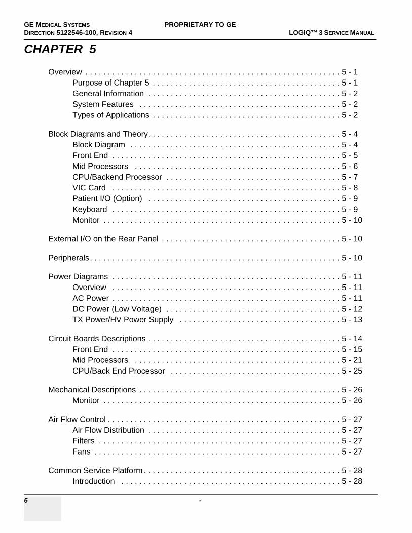
Overview . . . . . . . . . . . . . . . . . . . . . . . . . . . . . . . . . . . . . . . . . . . . . . . . . . . . . . . . . 5 - 1Purpose of Chapter 5 . . . . . . . . . . . . . . . . . . . . . . . . . . . . . . . . . . . . . . . . . . 5 - 1General Information . . . . . . . . . . . . . . . . . . . . . . . . . . . . . . . . . . . . . . . . . . . 5 - 2System Features . . . . . . . . . . . . . . . . . . . . . . . . . . . . . . . . . . . . . . . . . . . . . 5 - 2Types of Applications . . . . . . . . . . . . . . . . . . . . . . . . . . . . . . . . . . . . . . . . . . 5 - 2
Block Diagrams and Theory. . . . . . . . . . . . . . . . . . . . . . . . . . . . . . . . . . . . . . . . . . . 5 - 4Block Diagram . . . . . . . . . . . . . . . . . . . . . . . . . . . . . . . . . . . . . . . . . . . . . . . 5 - 4Front End . . . . . . . . . . . . . . . . . . . . . . . . . . . . . . . . . . . . . . . . . . . . . . . . . . . 5 - 5Mid Processors . . . . . . . . . . . . . . . . . . . . . . . . . . . . . . . . . . . . . . . . . . . . . . 5 - 6CPU/Backend Processor . . . . . . . . . . . . . . . . . . . . . . . . . . . . . . . . . . . . . . . 5 - 7VIC Card . . . . . . . . . . . . . . . . . . . . . . . . . . . . . . . . . . . . . . . . . . . . . . . . . . . 5 - 8Patient I/O (Option) . . . . . . . . . . . . . . . . . . . . . . . . . . . . . . . . . . . . . . . . . . . 5 - 9Keyboard . . . . . . . . . . . . . . . . . . . . . . . . . . . . . . . . . . . . . . . . . . . . . . . . . . . 5 - 9Monitor . . . . . . . . . . . . . . . . . . . . . . . . . . . . . . . . . . . . . . . . . . . . . . . . . . . . . 5 - 10
External I/O on the Rear Panel . . . . . . . . . . . . . . . . . . . . . . . . . . . . . . . . . . . . . . . . 5 - 10
Peripherals. . . . . . . . . . . . . . . . . . . . . . . . . . . . . . . . . . . . . . . . . . . . . . . . . . . . . . . . 5 - 10
Power Diagrams . . . . . . . . . . . . . . . . . . . . . . . . . . . . . . . . . . . . . . . . . . . . . . . . . . . 5 - 11Overview . . . . . . . . . . . . . . . . . . . . . . . . . . . . . . . . . . . . . . . . . . . . . . . . . . . 5 - 11AC Power . . . . . . . . . . . . . . . . . . . . . . . . . . . . . . . . . . . . . . . . . . . . . . . . . . . 5 - 11DC Power (Low Voltage) . . . . . . . . . . . . . . . . . . . . . . . . . . . . . . . . . . . . . . . 5 - 12TX Power/HV Power Supply . . . . . . . . . . . . . . . . . . . . . . . . . . . . . . . . . . . . 5 - 13
Circuit Boards Descriptions . . . . . . . . . . . . . . . . . . . . . . . . . . . . . . . . . . . . . . . . . . . 5 - 14Front End . . . . . . . . . . . . . . . . . . . . . . . . . . . . . . . . . . . . . . . . . . . . . . . . . . . 5 - 15Mid Processors . . . . . . . . . . . . . . . . . . . . . . . . . . . . . . . . . . . . . . . . . . . . . . 5 - 21CPU/Back End Processor . . . . . . . . . . . . . . . . . . . . . . . . . . . . . . . . . . . . . . 5 - 25
Mechanical Descriptions . . . . . . . . . . . . . . . . . . . . . . . . . . . . . . . . . . . . . . . . . . . . . 5 - 26Monitor . . . . . . . . . . . . . . . . . . . . . . . . . . . . . . . . . . . . . . . . . . . . . . . . . . . . . 5 - 26
Air Flow Control . . . . . . . . . . . . . . . . . . . . . . . . . . . . . . . . . . . . . . . . . . . . . . . . . . . . 5 - 27Air Flow Distribution . . . . . . . . . . . . . . . . . . . . . . . . . . . . . . . . . . . . . . . . . . . 5 - 27Filters . . . . . . . . . . . . . . . . . . . . . . . . . . . . . . . . . . . . . . . . . . . . . . . . . . . . . . 5 - 27Fans . . . . . . . . . . . . . . . . . . . . . . . . . . . . . . . . . . . . . . . . . . . . . . . . . . . . . . . 5 - 27
Common Service Platform . . . . . . . . . . . . . . . . . . . . . . . . . . . . . . . . . . . . . . . . . . . . 5 - 28Introduction . . . . . . . . . . . . . . . . . . . . . . . . . . . . . . . . . . . . . . . . . . . . . . . . . 5 - 28

GE HEALTHCARE DIRECTION 5122546-100, REVISION 4 LOGIQ™ 3 SERVICE MANUAL
7
Global Service User Interface (GSUI) . . . . . . . . . . . . . . . . . . . . . . . . . . . . . 5 - 29Service Home Page . . . . . . . . . . . . . . . . . . . . . . . . . . . . . . . . . . . . . . . . . . 5 - 30Error Logs Page . . . . . . . . . . . . . . . . . . . . . . . . . . . . . . . . . . . . . . . . . . . . . 5 - 31Diagnostics . . . . . . . . . . . . . . . . . . . . . . . . . . . . . . . . . . . . . . . . . . . . . . . . . 5 - 36Image Quality . . . . . . . . . . . . . . . . . . . . . . . . . . . . . . . . . . . . . . . . . . . . . . . 5 - 37Calibration . . . . . . . . . . . . . . . . . . . . . . . . . . . . . . . . . . . . . . . . . . . . . . . . . . 5 - 37Configuration . . . . . . . . . . . . . . . . . . . . . . . . . . . . . . . . . . . . . . . . . . . . . . . 5 - 38Utilities . . . . . . . . . . . . . . . . . . . . . . . . . . . . . . . . . . . . . . . . . . . . . . . . . . . . 5 - 39Replacement . . . . . . . . . . . . . . . . . . . . . . . . . . . . . . . . . . . . . . . . . . . . . . . . 5 - 39PM . . . . . . . . . . . . . . . . . . . . . . . . . . . . . . . . . . . . . . . . . . . . . . . . . . . . . . . 5 - 40

GE MEDICAL SYSTEMS PROPRIETARY TO GEDIRECTION 5122546-100, REVISION 4 LOGIQ™ 3 SERVICE MANUAL
8 -
CHAPTER 6
Overview . . . . . . . . . . . . . . . . . . . . . . . . . . . . . . . . . . . . . . . . . . . . . . . . . . . . . . . . . 6 - 1Purpose of Chapter 6 . . . . . . . . . . . . . . . . . . . . . . . . . . . . . . . . . . . . . . . . . . 6 - 1
Regulatory . . . . . . . . . . . . . . . . . . . . . . . . . . . . . . . . . . . . . . . . . . . . . . . . . . . . . . . . 6 - 1
Power Supply Adjustments . . . . . . . . . . . . . . . . . . . . . . . . . . . . . . . . . . . . . . . . . . . 6 - 1Access to Adjustments for LV Power Supply . . . . . . . . . . . . . . . . . . . . . . . . 6 - 1
Monitor Adjustment . . . . . . . . . . . . . . . . . . . . . . . . . . . . . . . . . . . . . . . . . . . . . . . . . 6 - 9Re-calibration the Monitor. . . . . . . . . . . . . . . . . . . . . . . . . . . . . . . . . . . . . . . 6 - 10

GE HEALTHCARE DIRECTION 5122546-100, REVISION 4 LOGIQ™ 3 SERVICE MANUAL
9
CHAPTER 7
Overview. . . . . . . . . . . . . . . . . . . . . . . . . . . . . . . . . . . . . . . . . . . . . . . . . . . . . . . . . 7 - 1Purpose of Chapter 7 . . . . . . . . . . . . . . . . . . . . . . . . . . . . . . . . . . . . . . . . . 7 - 1Diagnostic Procedure Summary . . . . . . . . . . . . . . . . . . . . . . . . . . . . . . . . . 7 - 1
Gathering Trouble Data . . . . . . . . . . . . . . . . . . . . . . . . . . . . . . . . . . . . . . . . . . . . . 7 - 2Overview . . . . . . . . . . . . . . . . . . . . . . . . . . . . . . . . . . . . . . . . . . . . . . . . . . . 7 - 2Collect Vital System Information . . . . . . . . . . . . . . . . . . . . . . . . . . . . . . . . . 7 - 2Collect a Trouble Image with Logs . . . . . . . . . . . . . . . . . . . . . . . . . . . . . . . 7 - 3
Screen Captures. . . . . . . . . . . . . . . . . . . . . . . . . . . . . . . . . . . . . . . . . . . . . . . . . . . 7 - 4Check and Record the P4 Key Function . . . . . . . . . . . . . . . . . . . . . . . . . . . 7 - 4Setting the P4 Key to Screen Capture . . . . . . . . . . . . . . . . . . . . . . . . . . . . 7 - 5Capturing a Screen . . . . . . . . . . . . . . . . . . . . . . . . . . . . . . . . . . . . . . . . . . . 7 - 6Reset the P4 Key to Customer’s Functionality . . . . . . . . . . . . . . . . . . . . . . 7 - 7
Diagnostics . . . . . . . . . . . . . . . . . . . . . . . . . . . . . . . . . . . . . . . . . . . . . . . . . . . . . . . 7 - 8Serviceability . . . . . . . . . . . . . . . . . . . . . . . . . . . . . . . . . . . . . . . . . . . . . . . . 7 - 8
Common Diagnostics . . . . . . . . . . . . . . . . . . . . . . . . . . . . . . . . . . . . . . . . . . . . . . . 7 - 11Utilities . . . . . . . . . . . . . . . . . . . . . . . . . . . . . . . . . . . . . . . . . . . . . . . . . . . . 7 - 11PC Diagnostics (Non-Interactive Tests) . . . . . . . . . . . . . . . . . . . . . . . . . . . 7 - 11
Service Notes . . . . . . . . . . . . . . . . . . . . . . . . . . . . . . . . . . . . . . . . . . . . . . . . . . . . . 7 - 12SN-70411:Daylight Saving Time (DST) - New Dates . . . . . . . . . . . . . . . . . 7 - 14SN 73108: DO NOT USE LOGIQ 3 MONITOR FRU P/N: 2319551-7 . . . . 7 - 16SN 73104:LOGIQ 3 FRU New Collector Parts . . . . . . . . . . . . . . . . . . . . . . 7 - 17SN 73102: LOGIQ 3 FMI 73069 Closure . . . . . . . . . . . . . . . . . . . . . . . . . . 7 - 18SN 73100: LOGIQ 3 FMI 73074 Closure . . . . . . . . . . . . . . . . . . . . . . . . . . 7 - 19SN 73098: LOGIQ 3 Debrief Guidelines . . . . . . . . . . . . . . . . . . . . . . . . . . . 7 - 20SN 73097: LOGIQ 3 FMI 73060 OFFICIALLY CLOSED . . . . . . . . . . . . . . 7 - 24SN 73095: LOGIQ 3 BT05 New FRUs and compatibility matrix . . . . . . . . . 7 - 25Sn 73092: Preventive Maintenance Of LOGIQ 3 Monitor . . . . . . . . . . . . . . 7 - 27Sn:73090 Location Of the Logiq 3 System Additional Label with Serial Number information . . . . . . . . . . . . . . . . . . . . . . . . . . . . . . . . . . . . . . . . . . 7 - 33Sn73084-Keyboard Knobs . . . . . . . . . . . . . . . . . . . . . . . . . . . . . . . . . . . . . 7 - 35Sn 73082: Introduction of FMI 73068,FMI 73070, FMI 73071 . . . . . . . . . . 7 - 36Sn73081-Logiq 3 Win XP Systems with S/W R.4.x.x - Inclusion of Base and Application Software CDs inside the System . . . . . . . . . . . . . . . . . . . . . . . 7 - 38Sn73080-LOGIQ™ 3 - Introduction of Improved Keyboard Assembly . . . . 7 - 39Sn73078-BIOS Settings . . . . . . . . . . . . . . . . . . . . . . . . . . . . . . . . . . . . . . . 7 - 40Sn73077-PC2IP Driver installation on BEP 2 System with PC2IP II board 7 - 48
GE MEDICAL SYSTEMS PROPRIETARY TO GEDIRECTION 5122546-100, REVISION 4 LOGIQ™ 3 SERVICE MANUAL
10 -
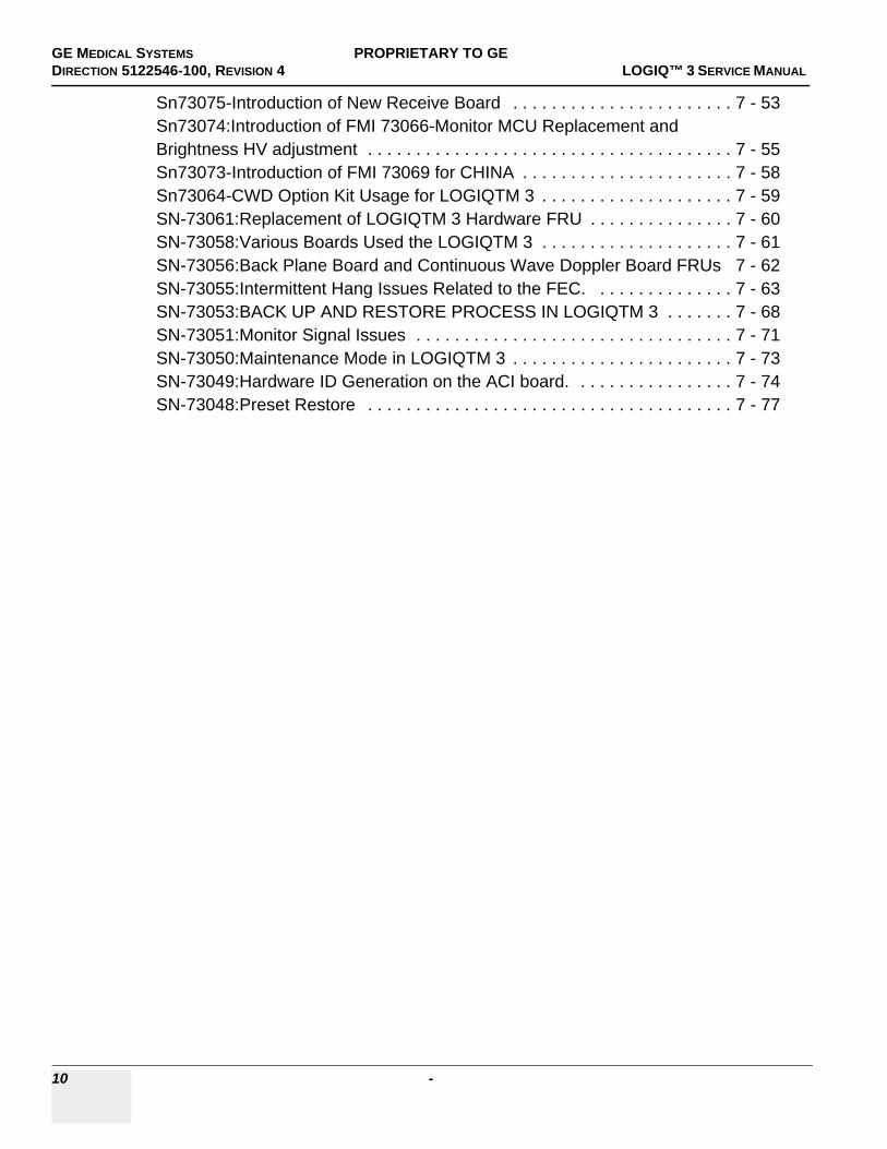
Sn73075-Introduction of New Receive Board . . . . . . . . . . . . . . . . . . . . . . . 7 - 53Sn73074:Introduction of FMI 73066-Monitor MCU Replacement and Brightness HV adjustment . . . . . . . . . . . . . . . . . . . . . . . . . . . . . . . . . . . . . . 7 - 55Sn73073-Introduction of FMI 73069 for CHINA . . . . . . . . . . . . . . . . . . . . . . 7 - 58Sn73064-CWD Option Kit Usage for LOGIQTM 3 . . . . . . . . . . . . . . . . . . . . 7 - 59SN-73061:Replacement of LOGIQTM 3 Hardware FRU . . . . . . . . . . . . . . . 7 - 60SN-73058:Various Boards Used the LOGIQTM 3 . . . . . . . . . . . . . . . . . . . . 7 - 61SN-73056:Back Plane Board and Continuous Wave Doppler Board FRUs 7 - 62SN-73055:Intermittent Hang Issues Related to the FEC. . . . . . . . . . . . . . . 7 - 63SN-73053:BACK UP AND RESTORE PROCESS IN LOGIQTM 3 . . . . . . . 7 - 68SN-73051:Monitor Signal Issues . . . . . . . . . . . . . . . . . . . . . . . . . . . . . . . . . 7 - 71SN-73050:Maintenance Mode in LOGIQTM 3 . . . . . . . . . . . . . . . . . . . . . . . 7 - 73SN-73049:Hardware ID Generation on the ACI board. . . . . . . . . . . . . . . . . 7 - 74SN-73048:Preset Restore . . . . . . . . . . . . . . . . . . . . . . . . . . . . . . . . . . . . . . 7 - 77

GE HEALTHCARE DIRECTION 5122546-100, REVISION 4 LOGIQ™ 3 SERVICE MANUAL
11
CHAPTER 8
Overview. . . . . . . . . . . . . . . . . . . . . . . . . . . . . . . . . . . . . . . . . . . . . . . . . . . . . . . . . 8 - 1Purpose of Chapter 8 . . . . . . . . . . . . . . . . . . . . . . . . . . . . . . . . . . . . . . . . . 8 - 1Returning/Shipping Probes and Repair Parts . . . . . . . . . . . . . . . . . . . . . . . 8 - 1
Monitor . . . . . . . . . . . . . . . . . . . . . . . . . . . . . . . . . . . . . . . . . . . . . . . . . . . . . . . . . . 8 - 3Monitor Assy (FRU No. 100) . . . . . . . . . . . . . . . . . . . . . . . . . . . . . . . . . . . . 8 - 3Monitor Cover Left (FRU No. 101) . . . . . . . . . . . . . . . . . . . . . . . . . . . . . . . 8 - 5Monitor Cover Right (FRU No. 102) . . . . . . . . . . . . . . . . . . . . . . . . . . . . . . 8 - 6Monitor Cover Top (FRU No. 103) . . . . . . . . . . . . . . . . . . . . . . . . . . . . . . . 8 - 7Monitor Cover Front (Bezel) (FRU No. 104) . . . . . . . . . . . . . . . . . . . . . . . . 8 - 8Monitor Switch (S/W) Assy (FRU No. 105) . . . . . . . . . . . . . . . . . . . . . . . . . 8 - 10Task Lamp (FRU No. 106) . . . . . . . . . . . . . . . . . . . . . . . . . . . . . . . . . . . . . 8 - 12
Keyboard . . . . . . . . . . . . . . . . . . . . . . . . . . . . . . . . . . . . . . . . . . . . . . . . . . . . . . . . 8 - 13KeyBoard Assy (FRU No. 200) . . . . . . . . . . . . . . . . . . . . . . . . . . . . . . . . . . 8 - 13Probe Holder (FRU No. 201) . . . . . . . . . . . . . . . . . . . . . . . . . . . . . . . . . . . 8 - 15Speaker Pair . . . . . . . . . . . . . . . . . . . . . . . . . . . . . . . . . . . . . . . . . . . . . . . . 8 - 17Keyboard TGC Assy (FRU No. 202) . . . . . . . . . . . . . . . . . . . . . . . . . . . . . . 8 - 19HUB PCB Assy (FRU No. 203) . . . . . . . . . . . . . . . . . . . . . . . . . . . . . . . . . . 8 - 21 A/N Keyboard Assy (FRU No. 204) . . . . . . . . . . . . . . . . . . . . . . . . . . . . . . 8 - 23Keyboard Trackball Assy (FRU No. 205) . . . . . . . . . . . . . . . . . . . . . . . . . . 8 - 25Keyboard - Freeze Key Assy (FRU No. 206) . . . . . . . . . . . . . . . . . . . . . . . 8 - 27Power switch and Encoder PCB Assy (FRU 207). . . . . . . . . . . . . . . . . . . . 8 - 29Keyboard Power Cable (FRU 208). . . . . . . . . . . . . . . . . . . . . . . . . . . . . . . 8 - 31
Mechanicals . . . . . . . . . . . . . . . . . . . . . . . . . . . . . . . . . . . . . . . . . . . . . . . . . . . . . . 8 - 33Right Cover (FRU No. 300) . . . . . . . . . . . . . . . . . . . . . . . . . . . . . . . . . . . . 8 - 33Left Cover (FRU No. 301) . . . . . . . . . . . . . . . . . . . . . . . . . . . . . . . . . . . . . . 8 - 35Rear Cover (FRU No. 302) . . . . . . . . . . . . . . . . . . . . . . . . . . . . . . . . . . . . . 8 - 37Front Bumper (FRU No. 303) for LOGIQ™ 3 PRO/Black and White . . . . 8 - 39Front Bumper (FRU No. 303) for LOGIQ™ 3 EXPERT . . . . . . . . . . . . . . . 8 - 41Front Rubber Bumper Left (FRU No. 311) . . . . . . . . . . . . . . . . . . . . . . . . . 8 - 43Front Rubber Bumper Right (FRU No. 312) . . . . . . . . . . . . . . . . . . . . . . . . 8 - 45Front Cover (FRU No. 304) for LOGIQ™ 3 PRO / Black and White . . . . . 8 - 47Front Cover (FRU No. 304) for LOGIQ™ 3 EXPERT . . . . . . . . . . . . . . . . 8 - 49Top Cover (FRU No. 305) . . . . . . . . . . . . . . . . . . . . . . . . . . . . . . . . . . . . . . 8 - 51KeyBoard Bottom Cover (FRU No. 306) . . . . . . . . . . . . . . . . . . . . . . . . . . . 8 - 53KeyBoard Bumper (FRU No. 307) . . . . . . . . . . . . . . . . . . . . . . . . . . . . . . . 8 - 55Keyboard Rear Cover (FRU No. 308) . . . . . . . . . . . . . . . . . . . . . . . . . . . . . 8 - 57Left EMI Cover . . . . . . . . . . . . . . . . . . . . . . . . . . . . . . . . . . . . . . . . . . . . . . 8 - 59

GE MEDICAL SYSTEMS PROPRIETARY TO GEDIRECTION 5122546-100, REVISION 4 LOGIQ™ 3 SERVICE MANUAL
12 -
Right EMI Cover . . . . . . . . . . . . . . . . . . . . . . . . . . . . . . . . . . . . . . . . . . . . . . 8 - 61Rear EMI Cover . . . . . . . . . . . . . . . . . . . . . . . . . . . . . . . . . . . . . . . . . . . . . . 8 - 63Nest EMI Cover . . . . . . . . . . . . . . . . . . . . . . . . . . . . . . . . . . . . . . . . . . . . . . 8 - 65Front EMI Cover for LOGIQ™ 3 PRO/Black and White . . . . . . . . . . . . . . . 8 - 67Front EMI Cover for LOGIQ™ 3 EXPERT . . . . . . . . . . . . . . . . . . . . . . . . . 8 - 69VGP Tray . . . . . . . . . . . . . . . . . . . . . . . . . . . . . . . . . . . . . . . . . . . . . . . . . . . 8 - 71Handle Rod(FRU No. 400) . . . . . . . . . . . . . . . . . . . . . . . . . . . . . . . . . . . . . . 8 - 73Front Castor (FRU No. 401) . . . . . . . . . . . . . . . . . . . . . . . . . . . . . . . . . . . . . 8 - 74Rear Castor (FRU No. 402) . . . . . . . . . . . . . . . . . . . . . . . . . . . . . . . . . . . . . 8 - 76Air Filter (FRU No. 403) . . . . . . . . . . . . . . . . . . . . . . . . . . . . . . . . . . . . . . . . 8 - 78Card Cage Fan Assy (FRU No. 404) . . . . . . . . . . . . . . . . . . . . . . . . . . . . . . 8 - 80
I/O Interfaces . . . . . . . . . . . . . . . . . . . . . . . . . . . . . . . . . . . . . . . . . . . . . . . . . . . . . . 8 - 82Rear Panel Assy (FRU No. 500) . . . . . . . . . . . . . . . . . . . . . . . . . . . . . . . . . 8 - 82Rear Panel1 (RP1) Board (FRU No. 501) . . . . . . . . . . . . . . . . . . . . . . . . . . 8 - 84Rear Panel2 (RP2) Board (FRU No. 502) . . . . . . . . . . . . . . . . . . . . . . . . . . 8 - 86Rear Panel Interface (RPI) Board (FRU No. 503) . . . . . . . . . . . . . . . . . . . . 8 - 88Front Panel (FRU No. 504) . . . . . . . . . . . . . . . . . . . . . . . . . . . . . . . . . . . . . 8 - 90Rear Panel Fuse (FRU No. 505) . . . . . . . . . . . . . . . . . . . . . . . . . . . . . . . . . 8 - 92
PCB . . . . . . . . . . . . . . . . . . . . . . . . . . . . . . . . . . . . . . . . . . . . . . . . . . . . . . . . . . . . . 8 - 94PCB Boards (FRU No. 601 ~ 605, 608, 609) . . . . . . . . . . . . . . . . . . . . . . . . 8 - 94Connector Board Assy (FRU No. 606) for LOGIQ™ 3 PRO/Black and White 8 - 97Connector Board Assy (FRU No. 606) for LOGIQ™ 3 EXPERT . . . . . . . . 8 - 99Card Cage with Back Plane Board (FRU No. 607) . . . . . . . . . . . . . . . . . . . 8 - 101BEP Assy (FRU No. 700) . . . . . . . . . . . . . . . . . . . . . . . . . . . . . . . . . . . . . . . 8 - 103Hard Disc Drive (FRU no. 701) . . . . . . . . . . . . . . . . . . . . . . . . . . . . . . . . . . 8 - 106Compact Disc Read Write Drive (FRU no. 702) . . . . . . . . . . . . . . . . . . . . . . 8 - 109BEP Power Supply (FRU no. 703) . . . . . . . . . . . . . . . . . . . . . . . . . . . . . . . . 8 - 111PCVIC PCB (FRU no. 704) . . . . . . . . . . . . . . . . . . . . . . . . . . . . . . . . . . . . . 8 - 113PC2IP PCB (FRU no. 706) . . . . . . . . . . . . . . . . . . . . . . . . . . . . . . . . . . . . . . 8 - 116
Power Block . . . . . . . . . . . . . . . . . . . . . . . . . . . . . . . . . . . . . . . . . . . . . . . . . . . . . . . 8 - 118Transformer Assy (FRU No. 800) . . . . . . . . . . . . . . . . . . . . . . . . . . . . . . . . 8 - 118LVPS Disassy (FRU No. 801) . . . . . . . . . . . . . . . . . . . . . . . . . . . . . . . . . . . 8 - 121AC Interface Board (ACI) (FRU No. 802) . . . . . . . . . . . . . . . . . . . . . . . . . . . 8 - 123Fuse (FRU No. 803) . . . . . . . . . . . . . . . . . . . . . . . . . . . . . . . . . . . . . . . . . . . 8 - 125Circuit Breaker (FRU No. 804) . . . . . . . . . . . . . . . . . . . . . . . . . . . . . . . . . . . 8 - 127Noise Filter(FRU No. 805) . . . . . . . . . . . . . . . . . . . . . . . . . . . . . . . . . . . . . . 8 - 129
Software Loading Procedure . . . . . . . . . . . . . . . . . . . . . . . . . . . . . . . . . . . . . . . . . . 8 - 131Installing Base System Software and Application Software . . . . . . . . . . . . . 8 - 131

GE HEALTHCARE DIRECTION 5122546-100, REVISION 4 LOGIQ™ 3 SERVICE MANUAL
13
Base Load Software Load . . . . . . . . . . . . . . . . . . . . . . . . . . . . . . . . . . . . . . . . . . . 8 - 135Manpower . . . . . . . . . . . . . . . . . . . . . . . . . . . . . . . . . . . . . . . . . . . . . . . . . . 8 - 135Tools . . . . . . . . . . . . . . . . . . . . . . . . . . . . . . . . . . . . . . . . . . . . . . . . . . . . . . 8 - 135Preparations . . . . . . . . . . . . . . . . . . . . . . . . . . . . . . . . . . . . . . . . . . . . . . . . 8 - 135Base Load Software Load Procedure . . . . . . . . . . . . . . . . . . . . . . . . . . . . . 8 - 135Optional Manual Drive Remapping . . . . . . . . . . . . . . . . . . . . . . . . . . . . . . . 8 - 137Optional Manual Configurations . . . . . . . . . . . . . . . . . . . . . . . . . . . . . . . . . 8 - 137Loading Applications Software . . . . . . . . . . . . . . . . . . . . . . . . . . . . . . . . . . 8 - 137Final System Setup . . . . . . . . . . . . . . . . . . . . . . . . . . . . . . . . . . . . . . . . . . . 8 - 137serialno.txt File Creation . . . . . . . . . . . . . . . . . . . . . . . . . . . . . . . . . . . . . . . 8 - 138Optional Check Devices . . . . . . . . . . . . . . . . . . . . . . . . . . . . . . . . . . . . . . 8 - 139Optional Procedure for Changing (Re-mapping) Drive Letters . . . . . . . . . . 8 - 141
Loading Application Software After a Base Image Load . . . . . . . . . . . . . . . . . . . . 8 - 146Manpower . . . . . . . . . . . . . . . . . . . . . . . . . . . . . . . . . . . . . . . . . . . . . . . . . . 8 - 146Tools . . . . . . . . . . . . . . . . . . . . . . . . . . . . . . . . . . . . . . . . . . . . . . . . . . . . . . 8 - 146Preparations . . . . . . . . . . . . . . . . . . . . . . . . . . . . . . . . . . . . . . . . . . . . . . . . 8 - 146Image Management Guide . . . . . . . . . . . . . . . . . . . . . . . . . . . . . . . . . . . . . 8 - 146
Loading Applications Software . . . . . . . . . . . . . . . . . . . . . . . . . . . . . . . . . . . . . . . . . . . . . 8 - 153 . . . . . . . . . . . . . . . . . . . . . . . . . . . . . . . . . . . . . . . . . . . . . . . . . . . . . . . . . . . . . . . . Installing Option Software. . . . . . . . . . . . . . . . . . . . . . . . . . . . . . . . . . . . . . . . . . . . 8 - 161
Preparations . . . . . . . . . . . . . . . . . . . . . . . . . . . . . . . . . . . . . . . . . . . . . . . . 8 - 161Procedures . . . . . . . . . . . . . . . . . . . . . . . . . . . . . . . . . . . . . . . . . . . . . . . . . 8 - 161
Loading Base and Application Software. . . . . . . . . . . . . . . . . . . . . . . . . . . . . . . . . 8 - 163Making BIOS changes . . . . . . . . . . . . . . . . . . . . . . . . . . . . . . . . . . . . . . . . 8 - 164Base Software Load Procedure For BEP Ver 2 , 3, and 4 . . . . . . . . . . . . . 8 - 168Loading Applications Software . . . . . . . . . . . . . . . . . . . . . . . . . . . . . . . . . . 8 - 171

GE MEDICAL SYSTEMS PROPRIETARY TO GEDIRECTION 5122546-100, REVISION 4 LOGIQ™ 3 SERVICE MANUAL
14 -
CHAPTER 9
Overview . . . . . . . . . . . . . . . . . . . . . . . . . . . . . . . . . . . . . . . . . . . . . . . . . . . . . . . . . 9 - 1Purpose of Chapter 9 . . . . . . . . . . . . . . . . . . . . . . . . . . . . . . . . . . . . . . . . . . 9 - 1
List of Abbreviations. . . . . . . . . . . . . . . . . . . . . . . . . . . . . . . . . . . . . . . . . . . . . . . . . 9 - 2
Operator Console Assy . . . . . . . . . . . . . . . . . . . . . . . . . . . . . . . . . . . . . . . . . . . . . . 9 - 3. . . . . . . . . . . . . . . . . . . . . . . . . . . . . . . . . . . . . . . . . . . . . . . . . . . . . . . . . . . . . . . . .MONITOR . . . . . . . . . . . . . . . . . . . . . . . . . . . . . . . . . . . . . . . . . . . . . . . . . . . . . . . . 9 - 5
Keyboard . . . . . . . . . . . . . . . . . . . . . . . . . . . . . . . . . . . . . . . . . . . . . . . . . . . . . . . . . 9 - 6
External Covers . . . . . . . . . . . . . . . . . . . . . . . . . . . . . . . . . . . . . . . . . . . . . . . . . . . . 9 - 8
Mechanical Assembly’s . . . . . . . . . . . . . . . . . . . . . . . . . . . . . . . . . . . . . . . . . . . . . . 9 - 10
I/O Interfaces . . . . . . . . . . . . . . . . . . . . . . . . . . . . . . . . . . . . . . . . . . . . . . . . . . . . . . 9 - 11
PCB Boards . . . . . . . . . . . . . . . . . . . . . . . . . . . . . . . . . . . . . . . . . . . . . . . . . . . . . . . 9 - 12
BEP . . . . . . . . . . . . . . . . . . . . . . . . . . . . . . . . . . . . . . . . . . . . . . . . . . . . . . . . . . . . . 9 - 14
Power Block . . . . . . . . . . . . . . . . . . . . . . . . . . . . . . . . . . . . . . . . . . . . . . . . . . . . . . . 9 - 16
Power Cord . . . . . . . . . . . . . . . . . . . . . . . . . . . . . . . . . . . . . . . . . . . . . . . . . . . . . . . 9 - 17
Probes . . . . . . . . . . . . . . . . . . . . . . . . . . . . . . . . . . . . . . . . . . . . . . . . . . . . . . . . . . . 9 - 17
Peripherals. . . . . . . . . . . . . . . . . . . . . . . . . . . . . . . . . . . . . . . . . . . . . . . . . . . . . . . . 9 - 18
Cables Set . . . . . . . . . . . . . . . . . . . . . . . . . . . . . . . . . . . . . . . . . . . . . . . . . . . . . . . . 9 - 18
Option Parts . . . . . . . . . . . . . . . . . . . . . . . . . . . . . . . . . . . . . . . . . . . . . . . . . . . . . . . 9 - 19
New FRUs for LOGIQTM3 Expert . . . . . . . . . . . . . . . . . . . . . . . . . . . . . . . . . . . . . . 9 - 20Hardware FRU’s for LOGIQ3 BT’05 . . . . . . . . . . . . . . . . . . . . . . . . . . . . . . . 9 - 21
Software FRUs for LOGIQTM3 Expert/PRO/Black and White. . . . . . . . . . . . . . . . . 9 - 22

GE HEALTHCARE DIRECTION 5122546-100, REVISION 4 LOGIQ™ 3 SERVICE MANUAL
15
CHAPTER 10
Overview. . . . . . . . . . . . . . . . . . . . . . . . . . . . . . . . . . . . . . . . . . . . . . . . . . . . . . . . . 10 - 1Periodic Maintenance Inspection . . . . . . . . . . . . . . . . . . . . . . . . . . . . . . . . 10 - 1Purpose of Chapter 10 . . . . . . . . . . . . . . . . . . . . . . . . . . . . . . . . . . . . . . . . 10 - 1
Why do Maintenance . . . . . . . . . . . . . . . . . . . . . . . . . . . . . . . . . . . . . . . . . . . . . . . 10 - 2Keeping Records . . . . . . . . . . . . . . . . . . . . . . . . . . . . . . . . . . . . . . . . . . . . 10 - 2Quality Assurance . . . . . . . . . . . . . . . . . . . . . . . . . . . . . . . . . . . . . . . . . . . . 10 - 2
Periodic Maintenance Schedule . . . . . . . . . . . . . . . . . . . . . . . . . . . . . . . . . . . . . . . 10 - 2How often should care & maintenance tasks be performed? . . . . . . . . . . . 10 - 2
Tools Required . . . . . . . . . . . . . . . . . . . . . . . . . . . . . . . . . . . . . . . . . . . . . . . . . . . . 10 - 4
Standard GE Tool Kit . . . . . . . . . . . . . . . . . . . . . . . . . . . . . . . . . . . . . . . . . 10 - 4Special Tools, Supplies and Equipment . . . . . . . . . . . . . . . . . . . . . . . . . . . 10 - 6
System Maintenance . . . . . . . . . . . . . . . . . . . . . . . . . . . . . . . . . . . . . . . . . . . . . . . 10 - 7Preliminary Checks . . . . . . . . . . . . . . . . . . . . . . . . . . . . . . . . . . . . . . . . . . . 10 - 7Functional Checks (See Also Chapter 4) . . . . . . . . . . . . . . . . . . . . . . . . . . 10 - 8Input Power . . . . . . . . . . . . . . . . . . . . . . . . . . . . . . . . . . . . . . . . . . . . . . . . . 10 - 9Cleaning . . . . . . . . . . . . . . . . . . . . . . . . . . . . . . . . . . . . . . . . . . . . . . . . . . . 10 - 9Physical Inspection . . . . . . . . . . . . . . . . . . . . . . . . . . . . . . . . . . . . . . . . . . . 10 - 10Optional Diagnostic Checks . . . . . . . . . . . . . . . . . . . . . . . . . . . . . . . . . . . . 10 - 11Probe Maintenance . . . . . . . . . . . . . . . . . . . . . . . . . . . . . . . . . . . . . . . . . . . 10 - 11
Electrical Safety Tests . . . . . . . . . . . . . . . . . . . . . . . . . . . . . . . . . . . . . . . . . . . . . . 10 - 12Safety Test Overview . . . . . . . . . . . . . . . . . . . . . . . . . . . . . . . . . . . . . . . . . 10 - 12GEMS Leakage Current Limits . . . . . . . . . . . . . . . . . . . . . . . . . . . . . . . . . . 10 - 13Outlet Test - Wiring Arrangement - USA & Canada . . . . . . . . . . . . . . . . . . 10 - 14Grounding Continuity . . . . . . . . . . . . . . . . . . . . . . . . . . . . . . . . . . . . . . . . . 10 - 15Chassis Leakage Current Test . . . . . . . . . . . . . . . . . . . . . . . . . . . . . . . . . . 10 - 17Isolated Patient Lead (Source) Leakage–Lead to Ground . . . . . . . . . . . . . 10 - 19Isolated Patient Lead (Source) Leakage–Lead to Lead . . . . . . . . . . . . . . . 10 - 22Isolated Patient Lead (Sink) Leakage-Isolation Test . . . . . . . . . . . . . . . . . 10 - 22Probe Leakage Current Test . . . . . . . . . . . . . . . . . . . . . . . . . . . . . . . . . . . 10 - 24
When There's Too Much Leakage Current... . . . . . . . . . . . . . . . . . . . . . . . . . . . . . 10 - 28

GE MEDICAL SYSTEMS PROPRIETARY TO GEDIRECTION 5122546-100, REVISION 4 LOGIQ™ 3 SERVICE MANUAL
16 -
GE HEALTHCARE DIRECTION 5122546-100, REVISION 4 LOGIQ™ 3 SERVICE MANUAL
Chapter 1IntroductionSection 1-1Overview
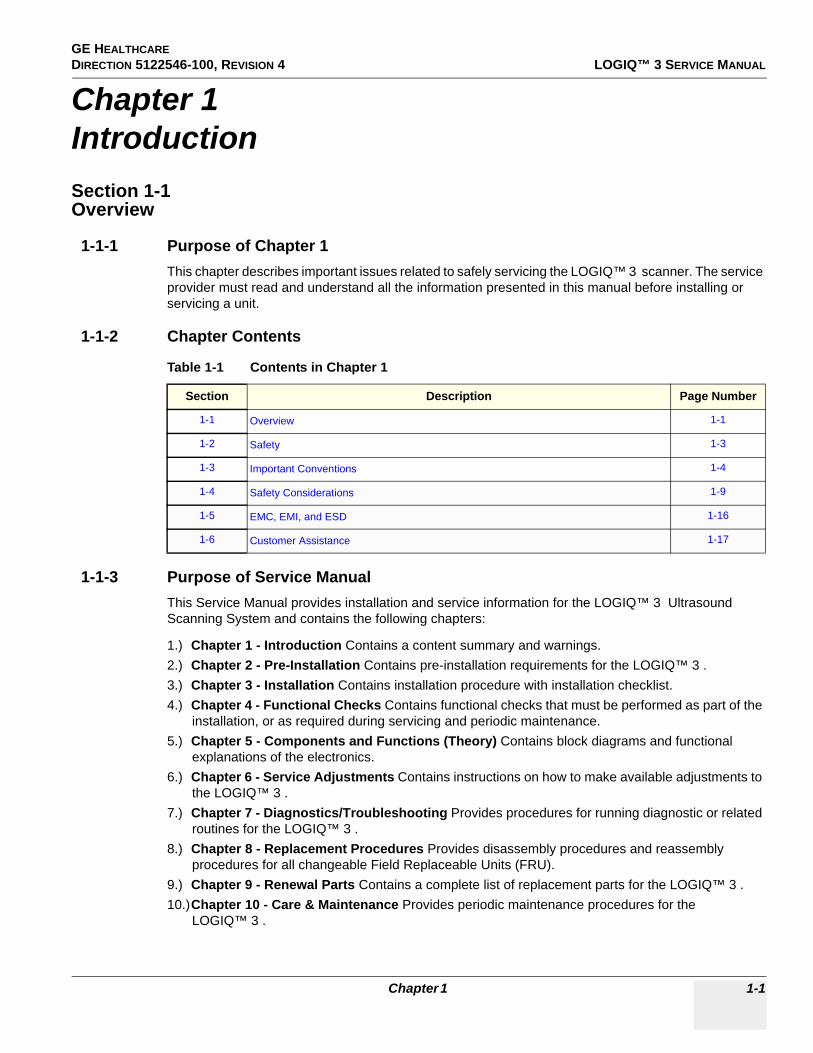
1-1-1 Purpose of Chapter 1This chapter describes important issues related to safely servicing the LOGIQ™ 3 scanner. The service provider must read and understand all the information presented in this manual before installing or servicing a unit.
1-1-2 Chapter Contents
1-1-3 Purpose of Service ManualThis Service Manual provides installation and service information for the LOGIQ™ 3 Ultrasound Scanning System and contains the following chapters:
1.) Chapter 1 - Introduction Contains a content summary and warnings.2.) Chapter 2 - Pre-Installation Contains pre-installation requirements for the LOGIQ™ 3 .3.) Chapter 3 - Installation Contains installation procedure with installation checklist.4.) Chapter 4 - Functional Checks Contains functional checks that must be performed as part of the
installation, or as required during servicing and periodic maintenance.5.) Chapter 5 - Components and Functions (Theory) Contains block diagrams and functional
explanations of the electronics.6.) Chapter 6 - Service Adjustments Contains instructions on how to make available adjustments to
the LOGIQ™ 3 .7.) Chapter 7 - Diagnostics/Troubleshooting Provides procedures for running diagnostic or related
routines for the LOGIQ™ 3 .8.) Chapter 8 - Replacement Procedures Provides disassembly procedures and reassembly
procedures for all changeable Field Replaceable Units (FRU).9.) Chapter 9 - Renewal Parts Contains a complete list of replacement parts for the LOGIQ™ 3 .10.)Chapter 10 - Care & Maintenance Provides periodic maintenance procedures for the
LOGIQ™ 3 .
Table 1-1 Contents in Chapter 1
Section Description Page Number
1-1 Overview 1-1
1-2 Safety 1-3
1-3 Important Conventions 1-4
1-4 Safety Considerations 1-9
1-5 EMC, EMI, and ESD 1-16
1-6 Customer Assistance 1-17
Chapter 1 1-1

GE HEALTHCARE PROPRIETARY TO GEDIRECTION 5122546-100, REVISION 4 LOGIQ™ 3 SERVICE MANUAL
1-1-4 Typical Users of the Basic Service Manual• Service Personnel (installation, maintenance, etc.).• Hospital’s Service Personnel• Contractors (Some parts of Chapter 2 - Pre-Installation)
1-1-5 LOGIQ™ 3 Models Covered by this Manual
1-1-6 Purpose of OperatorManual(s)The Operator Manual(s) should be fully read and understood before operating the LOGIQ™ 3 and also kept near the unit for quick reference.
L OG IQ 3 E xpert-B T'05C onsole HC AT L ogiq 3 Model Name P S I C odeH41772LM LO G IQ 3 E xpert C HILE /KO R E A MO DE L ULO G 3IH41772LN LO G IQ 3 E xpert JAP AN MO DE L ULO G 3IH41772LP LO G IQ 3 E xpert C HINA MO DE L ULO G 3IH41772LR LO G IQ 3 E xpert INDIA MO DE L ULO G 3IH41812LE LO G IQ 3 E xpert E UR O P E MO DE L with printer fixture ULO G 3IH41772LT LO G IQ 3 E xpert AME R IC AS MO DE L ULO G 3I
L OG IQ 3 P ro-B T'05C onsole HC AT L ogiq 3 Model Name P S I C odeH41802LN LO G IQ 3 C HILE /KO R E A MO DE L ULO G 3MH41802LP LO G IQ 3 JAP AN MO DE L ULO G 3MH41802LR LO G IQ 3 C HINA MO DE L ULO G 3MH41802LS LO G IQ 3 INDIA MO DE L ULO G 3MH41812LF LO G IQ 3 E UR O P E MO DE L with P rinter fixture ULO G 3MH41802LW LO G IQ 3 AME R IC AS MO DE L ULO G 3M
L OGIQ 3 B /W-B T'05C onsole HCAT L ogiq 3 Model Name P S I CodeH41802LZ LO G IQ 3 C HILE /KO R E A MO DE L ULO G 3LH41812LA LO G IQ 3 C HINA MO DE L ULO G 3LH41812LB LO G IQ 3 INDIA MO DE L ULO G 3L
1-2 Section 1-1 - Overview
GE HEALTHCARE DIRECTION 5122546-100, REVISION 4 LOGIQ™ 3 SERVICE MANUAL
Section 1-2Safety
1-2-1 Warnings
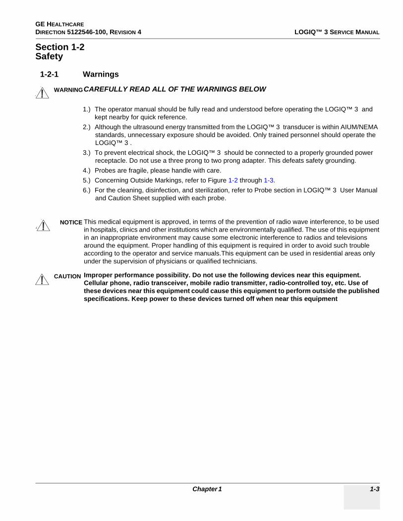
1.) The operator manual should be fully read and understood before operating the LOGIQ™ 3 and kept nearby for quick reference.
2.) Although the ultrasound energy transmitted from the LOGIQ™ 3 transducer is within AIUM/NEMA standards, unnecessary exposure should be avoided. Only trained personnel should operate the LOGIQ™ 3 .
3.) To prevent electrical shock, the LOGIQ™ 3 should be connected to a properly grounded power receptacle. Do not use a three prong to two prong adapter. This defeats safety grounding.
4.) Probes are fragile, please handle with care.5.) Concerning Outside Markings, refer to Figure 1-2 through 1-3.6.) For the cleaning, disinfection, and sterilization, refer to Probe section in LOGIQ™ 3 User Manual
and Caution Sheet supplied with each probe.
WARNINGWARNINGCAREFULLY READ ALL OF THE WARNINGS BELOW
NOTICE This medical equipment is approved, in terms of the prevention of radio wave interference, to be used in hospitals, clinics and other institutions which are environmentally qualified. The use of this equipment in an inappropriate environment may cause some electronic interference to radios and televisions around the equipment. Proper handling of this equipment is required in order to avoid such trouble according to the operator and service manuals.This equipment can be used in residential areas only under the supervision of physicians or qualified technicians.
CAUTION Improper performance possibility. Do not use the following devices near this equipment. Cellular phone, radio transceiver, mobile radio transmitter, radio-controlled toy, etc. Use of these devices near this equipment could cause this equipment to perform outside the published specifications. Keep power to these devices turned off when near this equipment
Chapter 1 1-3

GE HEALTHCARE PROPRIETARY TO GEDIRECTION 5122546-100, REVISION 4 LOGIQ™ 3 SERVICE MANUAL
Section 1-3Important Conventions
1-3-1 Conventions Used in BookIcons
Pictures, or icons, are used wherever they reinforce the printed message. The icons, labels and conventions used on the product and in the service information are described in this chapter.
Safety Precaution Messages
Various levels of safety precaution messages may be found on the equipment and in the service information. The different levels of concern are identified by a flag word that precedes the precautionary message. Known or potential hazards are labeled in one of following ways:
NOTE: Notes provide important information about an item or a procedure. Information contained in a NOTE can often save you time or effort.
DANGER IS USED TO INDICATE THE PRESENCE OF A HAZARD THAT WILL CAUSE SEVERE PERSONAL INJURY OR DEATH IF THE INSTRUCTIONS ARE IGNORED.WARNING IS USED TO INDICATE THE PRESENCE OF A HAZARD THAT CAN CAUSE SEVERE PERSONAL INJURY OR PROPERTY DAMAGE IF INSTRUCTIONS ARE IGNORED.
Caution is used to indicate the presence of a hazard that will or can cause minor personal injury and property damage if instructions are ignored.
Equipment Damage PossibleNotice is used when a hazard is present that can cause property damage but has absolutely no personal injury risk.Example: Disk Drive will crash.
DANGER
WARNING
CAUTION
NOTICE
1-4 Section 1-3 - Important Conventions

GE HEALTHCARE DIRECTION 5122546-100, REVISION 4 LOGIQ™ 3 SERVICE MANUAL
1-3-2 Standard Hazard IconsImportant information will always be preceded by the exclamation point contained within a
triangle , as seen throughout this chapter. In addition to text, several different graphical icons
(symbols) may be used to make you aware of specific types of hazards that could cause harm.
Other hazard icons make you aware of specific procedures that should be followed.
Table 1-2 Standard Hazard Icons
ELECTRICAL MECHANICAL RADIATION
LASER HEAT PINCH
Table 1-3 Standard Icons Indicating a Special Procedure Be Used
AVOID STATIC ELECTRICITY TAG AND LOCK OUT WEAR EYE PROTECTION
LASERLIGHT
Chapter 1 1-5

GE HEALTHCARE PROPRIETARY TO GEDIRECTION 5122546-100, REVISION 4 LOGIQ™ 3 SERVICE MANUAL
1-3-3 Product IconsThe following table describes the purpose and location of safety labels and other important information provided on the equipment.
Table 1-4 Product Icons
LABEL/SYMBOL PURPOSE/MEANING LOCATION
Identification and Rating Plate
Manufacturer's name and addressDate of manufactureModel and serial numbersElectrical ratings
Rear of console near power inletOn each probe
Device Listing/Certification Labels Laboratory logo or labels denoting conformance with industry safety standards such as UL or IEC. Rear of console
Type/Class Label Used to indicate the degree of safety or protection
IP Code (IP68)Indicates the degree of protection provided by the enclosure per IEC 60529. IP68 indicates can be used in operating room environment.
Footswitch
Equipment Type BF (man in the box symbol) IEC 60878 indicates B Type equipment having a floating applied part
Probe connectors and PCG Connectors
Equipment Type CF (heart in the box symbol) IEC 60878 indicates equipment having a floating applied part having a high degree of protection suitable for direct cardiac contact.
ECG connector and Probes marked Type CF
“CAUTIONThis unit weighs...
Special care must be used to avoid..."This precaution is intended to prevent injury that may result if one person attempt to move the unit considerable distances or on an incline due to the weight of the unit.
On the console where easily seen during transport
"CAUTION" The equilateral triangle is usually used in combination with other symbols to advise or warn the user.
Various
ATTENTION - Consult accompanying documents " is intended to alert the user to refer to the operator manual or other instructions when complete information cannot be provided on the label.
Various
"CAUTION - Dangerous voltage" (the lightning flash with arrowhead in equilateral triangle) is used to indicate electric shock hazards.
Various
1-6 Section 1-3 - Important Conventions

GE HEALTHCARE DIRECTION 5122546-100, REVISION 4 LOGIQ™ 3 SERVICE MANUAL
"Mains OFF" Indicates the power off position of the mains power switch. Rear of system adjacent to mains switch
"OFF/Standby" Indicates the power off/standby position of the power switch.CAUTIONThis Power Switch DOES NOT ISOLATE Mains Supply
Adjacent to On-Off/Standby Switch
"Mains ON" Indicates the power on position of the mains power switch.CAUTIONThis Power Switch DOES NOT ISOLATE Mains Supply
Rear of system adjacent to mains switch
"Protective Earth" Indicates the protective earth (grounding) terminal. Internal
Type CF Defib-Proof Applied Part (heart in the box with paddle) symbol is in accordance with IEC 878-02-03
ECG Module
~ Alternating Current Rear Panel, Circuit breaker label of Console and Front Panel
"Non-Ionizing Radiation" indicates that the system applies RF energy. Rear of console
Do not use the following devices near this equipment, Cellular phones, radio transceivers, mobile radio transmitters, radio controlled toy etc.Use of these devices could cause this equipment to perform outside the published specifications.Keep power to these devices turned off when near this equipment.
Rear of console
This Symbol indicates that waste electrical and electronic equipment must not be disposed of as unsorted municipal waste and must be collected separately. Please contact an authorised representative for manufacturer for information concerning the decompositioning of your requirement.
Rear Panel
Table 1-4 Product Icons (Continued)
LABEL/SYMBOL PURPOSE/MEANING LOCATION
Chapter 1 1-7

GE HEALTHCARE PROPRIETARY TO GEDIRECTION 5122546-100, REVISION 4 LOGIQ™ 3 SERVICE MANUAL
Indicates the presence of hazardous substance(s) above the maximumconcentration value. Maximum concentration values for electronicinformation products, as set by the People’s Republic of China Electronic Industry Standard SJ/T11364-2006,include the hazardous substances of lead, mercury, hexavalent chromium,cadmium, polybrominated biphenyl (PBB), and polybrominated diphenylether (PBDE). “20” indicates the number of years during which the hazardous substance(s) will not leakor mutate so that the use of this product will not result in any severe environmental pollution, bodily injury,or damage to any assets.
Rear Panel[For China Only]
Table 1-4 Product Icons (Continued)
LABEL/SYMBOL PURPOSE/MEANING LOCATION
1-8 Section 1-3 - Important Conventions

GE HEALTHCARE DIRECTION 5122546-100, REVISION 4 LOGIQ™ 3 SERVICE MANUAL
Section 1-4Safety Considerations
1-4-1 IntroductionThe following safety precautions must be observed during all phases of operation, service and repair of this equipment. Failure to comply with these precautions or with specific warnings elsewhere in this manual, violates safety standards of design, manufacture and intended use of the equipment.
1-4-2 Human SafetyOperating personnel must not remove the system covers. Servicing should be performed by authorized personnel only. Only personnel who have participated in a LOGIQ™ 3 Training Seminar are authorized to service the equipment.
1-4-3 Mechanical Safety
NOTE: Special care should be taken when transporting the unit in a vehicle:
• Secure the unit in an upright position.• Lock the wheels (brake)• DO NOT use the Control Panel as an anchor point.• Place the probes in their carrying case.• Eject any CD (R/W) disk from the CD(R/W) Drive• Remove the Footswitch and place it in a secure place• Disconnect any other Off board peripherals if used.
NOTE: Keep the Heat venting holes on the monitor unobstructed to avoid overheating of the monitor.
WHEN THE UNIT IS RAISED FOR A REPAIR OR MOVED ALONG ANY INCLINE, USE EXTREME CAUTION SINCE IT MAY BECOME UNSTABLE AND TIP OVER.
ULTRASOUND PROBES ARE HIGHLY SENSITIVE MEDICAL INSTRUMENTS THAT CAN EASILY BE DAMAGED BY IMPROPER HANDLING. USE CARE WHEN HANDLING AND PROTECT FROM DAMAGE WHEN NOT IN USE. DO NOT USE A DAMAGED OR DEFECTIVE PROBE. FAILURE TO FOLLOW THESE PRECAUTIONS CAN RESULT IN SERIOUS INJURY AND EQUIPMENT DAMAGE.
NEVER USE A PROBE THAT HAS FALLEN TO THE FLOOR. EVEN IF IT LOOKS OK, IT MAY BE DAMAGED.
Always lock the Control Console in its parking (locked) position before moving the scanner around.
The LOGIQ™ 3 weights approx 155kg (342lbs), depending on installed peripherals, when ready for use. Care must be used when moving it or replacing its parts. Failure to follow the precautions listed below could result in injury, uncontrolled motion and costly damage.ALWAYS:• Be sure the path way is clear.• Use slow, careful motions.• Use two people when moving on inclines or lifting more than 23 kg (50 lb.).
WARNING
WARNING
WARNING
CAUTION
CAUTION
Chapter 1 1-9
GE HEALTHCARE PROPRIETARY TO GEDIRECTION 5122546-100, REVISION 4 LOGIQ™ 3 SERVICE MANUAL
1-4-4 Electrical SafetyTo minimize shock hazard, the equipment chassis must be connected to an electrical ground. The system is equipped with a three-conductor AC power cable. This must be plugged into an approved electrical outlet with safety ground. If an extension cord is used with the system, make sure that the total current rating of the extension cord is greater than the system rating.
The power outlet used for this equipment should not be shared with other types of equipment.
Both the system power cable and the power connector meet international electrical standards.
1-4-5 Returning/Shipping Probes and Repair Parts
Equipment being returned must be clean and free of blood and other infectious substances.
GEMS policy states that body fluids must be properly removed from any part or equipment prior to shipment. GEMS employees, as well as customers, are responsible for ensuring that parts/equipment have been properly decontaminated prior to shipment. Under no circumstance should a part or equip-ment with visible body fluids be taken or shipped from a clinic or site (for example, body coils or an ultrasound probe).
The purpose of the regulation is to protect employees in the transportation industry, as well as the peo-ple who will receive or open this package.
NOTE: The US Department of Transportation (DOT) has ruled that “items that were saturated and/or dripping with human blood that are now caked with dried blood; or which were used or intended for use in patient care” are “regulated medical waste” for transportation purposes and must be transported as a hazardous material.
CAUTION If the Power Plug is Modified or replaced to Suit the local Conditions and regulations, Ground continuity check should be performed between Ground Pin on the Plug and a Metal Part on the LOGIQ™ 3 .
1-10 Section 1-4 - Safety Considerations

GE HEALTHCARE DIRECTION 5122546-100, REVISION 4 LOGIQ™ 3 SERVICE MANUAL
1-4-6 Labels Locations
Figure 1-1 Label Location
Chapter 1 1-11
GE HEALTHCARE PROPRIETARY TO GEDIRECTION 5122546-100, REVISION 4 LOGIQ™ 3 SERVICE MANUAL
1-4-6 Labels Locations (contd.)
Location:
1.) Grounding reliability Label2.) CISPR Label3.) CE Mark Label4.) EIAJ Label5.) TUV Label6.) Tipping Caution Label7.) Power Indication Label8.) Prescription Device for US Only9.) Gender Determination Label for Asia only10.)Identification and Rating Plate11.)WEEE Marking12.)EFUP Label[For China Only]
1-12 Section 1-4 - Safety Considerations
GE HEALTHCARE DIRECTION 5122546-100, REVISION 4 LOGIQ™ 3 SERVICE MANUAL
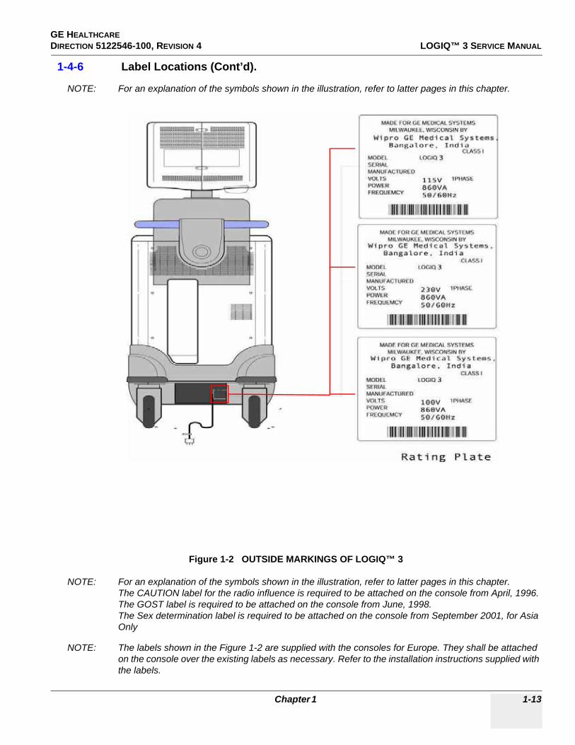
1-4-6 Label Locations (Cont’d).
NOTE: For an explanation of the symbols shown in the illustration, refer to latter pages in this chapter.
Figure 1-2 OUTSIDE MARKINGS OF LOGIQ™ 3
NOTE: For an explanation of the symbols shown in the illustration, refer to latter pages in this chapter.The CAUTION label for the radio influence is required to be attached on the console from April, 1996.The GOST label is required to be attached on the console from June, 1998.The Sex determination label is required to be attached on the console from September 2001, for Asia Only
NOTE: The labels shown in the Figure 1-2 are supplied with the consoles for Europe. They shall be attached on the console over the existing labels as necessary. Refer to the installation instructions supplied with the labels.
Chapter 1 1-13

GE HEALTHCARE PROPRIETARY TO GEDIRECTION 5122546-100, REVISION 4 LOGIQ™ 3 SERVICE MANUAL
1-4-6 Label Locations (Cont’d).Labels at Front Panel
Figure 1-3 OUTSIDE MARKINGS OF LOGIQ™ 3
1-14 Section 1-4 - Safety Considerations

GE HEALTHCARE DIRECTION 5122546-100, REVISION 4 LOGIQ™ 3 SERVICE MANUAL
1-4-7 Dangerous Procedure WarningsWarnings, such as the example below, precede potentially dangerous procedures throughout this manual. Instructions contained in the warnings must be followed.
1-4-8 Lockout/Tagout Requirements (For USA / Europe Only)Follow OSHA Lockout/Tagout requirements by ensuring you are in total control of the plug.
DANGEROUS VOLTAGES, CAPABLE OF CAUSING DEATH, ARE PRESENT IN THIS EQUIPMENT. USE EXTREME CAUTION WHEN HANDLING, TESTING AND ADJUSTING.
EXPLOSION WARNING: DO NOT OPERATE THE EQUIPMENT IN AN EXPLOSIVE ATMOSPHERE. OPERATION OF ANY ELECTRICAL EQUIPMENT IN SUCH AN ENVIRONMENT CONSTITUTES A DEFINITE SAFETY HAZARD.
DO NOT SUBSTITUTE PARTS OR MODIFY EQUIPMENT: BECAUSE OF THE DANGER OF INTERDICTING ADDITIONAL HAZARDS, DO NOT INSTALL SUBSTITUTE PARTS OR PERFORM ANY UNAUTHORIZED MODIFICATION OF THE EQUIPMENT.
DANGER
WARNING
WARNING
Chapter 1 1-15

GE HEALTHCARE PROPRIETARY TO GEDIRECTION 5122546-100, REVISION 4 LOGIQ™ 3 SERVICE MANUAL
Section 1-5EMC, EMI, and ESD
1-5-1 Electromagnetic CompatibilityElectro Magnetic Compatibility describes a level of performance of a device within its electromagnetic environment. This environment consists of the device itself and its surroundings including other equipment, power sources and persons with which the device must interface. Inadequate compatibility results when a susceptible device fails to perform as intended due interface from its environment or when the device produces unacceptable levels of emission to its environment. This interference is often referred to as radio-frequency or electromagnetic interface (RFI/EMI) and can be radiated through space or conducted over interconnecting power of signal cables. In addition to electromagnetic energy, EMC also includes possible effects from electrical fields, magnetic fields, electrostatic discharge and disturbances in the electrical power supply.
1-5-2 Electrostatic Discharge (ESD) Prevention
1-5-3 CE ComplianceThe LOGIQ™ 3 unit conforms to all applicable conducted and radiated emission limits and immunity from electrostatic discharge, radiated and conducted RF fields, magnetic fields and power line transient requirements.
Applicable standards are: 47CFR Part18, IEC/EN 60601-1-2
NOTE: For CE Compliance, it is critical that all covers, screws, shielding, gaskets, mesh, clamps, are in good condition, installed tightly without skew or stress. Proper installation following all comments noted in this service manual is required in order to achieve full EMC performance.
DO NOT TOUCH ANY BOARDS WITH INTEGRATED CIRCUITS PRIOR TO TAKING THE NECESSARY ESD PRECAUTIONS:1.) Always connect yourself, via an arm-wrist strap, to the advised ESD
connection point located on the rear of the scanner (to the right of the power connector).
2.) Follow general guide lined for handling of electrostatic sensitive equipment.
WARNING
1-16 Section 1-5 - EMC, EMI, and ESD

GE HEALTHCARE DIRECTION 5122546-100, REVISION 4 LOGIQ™ 3 SERVICE MANUAL
Section 1-6Customer Assistance
1-6-1 Contact InformationIf this equipment does not work as indicated in this service manual or in the User Manual, or if you require additional assistance, please contact the local distributor or appropriate support resource, as listed below.
Prepare the following information before you call:
- System ID serial number.- Software version.
For GE Service:
Chapter 1 1-17

GE HEALTHCARE PROPRIETARY TO GEDIRECTION 5122546-100, REVISION 4 LOGIQ™ 3 SERVICE MANUAL
1-6-2 System Manufacturer
Table 1-5 System Manufacturer
WIPRO GE HEALTHCARE- INDIA
WIPRO GE Healthcare Pvt. Ltd.PLOT # 4, KADUGODI INDUSTRIAL AREA, SADARAMANGALA,
BANGALORE 560067, INDIA
TEL: (91) 80-41801000FAX: (91) 80-2845-2924
1-18 Section 1-6 - Customer Assistance

GE HEALTHCARE PROPRIETARY TO GEDIRECTION 5122546-100, REVISION 4 LOGIQ™ 3 SERVICE MANUAL
Chapter 2Pre-InstallationSection 2-1Overview
2-1-1 Purpose of Chapter 2This chapter provides the information required to plan and prepare for the installation of a LOGIQ™ 3. Included are descriptions of the facility and electrical needs to be met by the purchaser of the unit.
2-1-2 Chapter Contents
Table 2-1 Contents in Chapter 2
Section Description Page Number
2-1 Overview 2-1
2-2 General Console Requirements 2-2
2-3 Facility Needs 2-7
Chapter 2 2-1

GE HEALTHCARE PROPRIETARY TO GEDIRECTION 5122546-100, REVISION 4 LOGIQ™ 3 SERVICE MANUAL
Section 2-2General Console Requirements
2-2-1 Console Environmental Requirements
2-2-1-1 CoolingThe cooling requirement for the LOGIQ™ 3 is 1366 BTU/hr. This figure does not include cooling needed for lights, people, or other equipment in the room. Each person in the room places an additional 300 BTU/hr. demand on the cooling system.
2-2-1-2 LightingBright light is needed for system installation, updates and repairs. However, operator and patient comfort may be optimized if the room light is subdued and indirect. Therefore a combination lighting system (dim/bright) is recommended. Keep in mind that lighting controls and dimmers can be a source of EMI which could degrade image quality. These controls should be selected to minimize possible interference.
Table 2-2 Environmental Requirements for LOGIQ™ 3 Scanners
Operation Storage Transport
Temperature10 - 40 degree C50 - 104 degree F
-10 - 60 degree C14 - 140 degree F
-40 - 60 degree C-40 - 140 degree F
Humidity30 - 85%non-condensing
30 - 90%non-condensing
30 - 90%non-condensing
Pressure 700 - 1060hPa 700 - 1060hPa 700 - 1060hPa
Table 2-3 Environmental Requirements for an Ultrasound Room
Item Values
Power Source Refer to Table 2-4 on page 2-3.
Current Rating 10A (100V); 8.5A(115V); 5A(230V)
Radiation Shielding NONE REQUIRED for ULTRASOUND ENERGY
Temperature 20-26 DEG. C (68-79 DEG F) for PATIENT COMFORT
Humidity 50% to 70% for PATIENT COMFORT
Heat Dissipation 1366 BTU/Hr.
Floor Landing Approximately 680 - 800 kg/m2 without Accessories
Floor Condition Gradient: WITHIN 5 degrees
Weight 155 kg (342lbs) without Accessories
2-2 Section 2-2 - General Console Requirements

GE HEALTHCARE PROPRIETARY TO GEDIRECTION 5122546-100, REVISION 4 LOGIQ™ 3 SERVICE MANUAL
2-2-2 Electrical Requirements
NOTE: GE Medical Systems requires a dedicated power and ground for the proper operation of its Ultrasound equipment. This dedicated power shall originate at the last distribution panel before the system.
Sites with a mains power system with defined Neutral and Live:
The dedicated line shall consist of one phase, a neutral (not shared with any other circuit), and a full size ground wire (not shared with any other circuit) from the distribution panel to the Ultrasound outlet.
Sites with a mains power system without a defined Neutral:
The dedicated line shall consist of one phase (two lines), not shared with any other circuit, and a full size ground wire (not shared with any other circuit) from the distribution panel to the Ultrasound outlet.
NOTE: Please note that image artifacts can occur, if at any time within the facility, the ground from the main facility's incoming power source to the Ultrasound unit is only a conduit.
2-2-3 Power Requirements Electrical Specifications for LOGIQ™ 3.
2-2-3-1 Inrush CurrentInrush current is not a factor to consider due to inrush current limiting properties of the power supplies.
2-2-3-2 Site Circuit BreakerIt is recommended that the branch circuit breaker for the machine be ready accessible.
Table 2-4 Electrical Specifications for LOGIQ™ 3
PARAMETER AREA LIMITS
Voltage Range
100V 100 VAC ± 10% (90-110 VAC)
230V 230 VAC ±10% (207-253 VAC)
115V 115 VAC ±10% (103-127 VAC)
Power All applications MAX. 860VA
Line Frequency All applications 50/60Hz (±2Hz)
Power Transients All applications
Less than 25% of nominal peak voltage for less than 1 millisecond for any type of transient, including line frequency, synchronous, asynchronous, or aperiodic transients.
Decaying Oscillation All applications Less than 15% of peak voltage for less than 1 millisecond.
DANGER
POWER OUTAGE MAY OCCUR. The LOGIQ™ 3 requires a dedicated single branch circuit. To avoid circuit overload and possible loss of critical care equipment, make sure you DO NOT have any other equipment operating on the same circuit.
Chapter 2 2-3

GE HEALTHCARE PROPRIETARY TO GEDIRECTION 5122546-100, REVISION 4 LOGIQ™ 3 SERVICE MANUAL
2-2-3-3 Site Power OutletsA dedicated AC power outlet must be within reach of the unit without extension cords. Other outlets adequate for the external peripherals, medical and test equipment needed to support this unit must also be present within 1 m (3.2 ft.) of the unit. Electrical installation must meet all current local, state, and national electrical codes.
2-2-3-4 Unit Power PlugIf the unit arrives without the power plug, or with the wrong plug, you must contact your GE dealer or the installation engineer must supply what is locally required.
2-2-3-5 Power Stability RequirementsVoltage drop-out / Max 10 ms.
Power Transients
Refer table 2-4
2-4 Section 2-2 - General Console Requirements
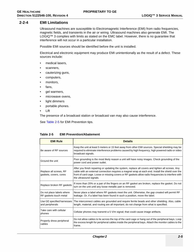
GE HEALTHCARE PROPRIETARY TO GEDIRECTION 5122546-100, REVISION 4 LOGIQ™ 3 SERVICE MANUAL
2-2-4 EMI LimitationsUltrasound machines are susceptible to Electromagnetic Interference (EMI) from radio frequencies, magnetic fields, and transients in the air or wiring. Ultrasound machines also generate EMI. The LOGIQ™ 3 complies with limits as stated on the EMC label. However, there is no guarantee that interference will not occur in a particular installation.
Possible EMI sources should be identified before the unit is installed.
Electrical and electronic equipment may produce EMI unintentionally as the result of a defect. These sources include:
• medical lasers, • scanners, • cauterizing guns, • computers, • monitors, • fans, • gel warmers, • microwave ovens,• light dimmers • portable phones. • LiftThe presence of a broadcast station or broadcast van may also cause interference.
See Table 2-5 for EMI Prevention tips.
Table 2-5 EMI Prevention/Abatement
EMI Rule Details
Be aware of RF sourcesKeep the unit at least 5 meters or 15 feet away from other EMI sources. Special shielding may be required to eliminate interference problems caused by high frequency, high powered radio or video broadcast signals.
Ground the unit Poor grounding is the most likely reason a unit will have noisy images. Check grounding of the power cord and power outlet.
Replace all screws, RF gaskets, covers, cores
After you finish repairing or updating the system, replace all covers and tighten all screws. Any cable with an external connection requires a magnet wrap at each end. Install the shield over the front of card cage. Loose or missing covers or RF gaskets allow radio frequencies to interfere with the ultrasound signals.
Replace broken RF gaskets If more than 20% or a pair of the fingers on an RF gasket are broken, replace the gasket. Do not turn on the unit until any loose metallic part is removed.
Do not place labels where RF gaskets touch metal
Never place a label where RF gaskets meet the unit. Otherwise, the gap created will permit RF leakage. Or, if a label has been found in such a position, move the label.
Use GE specified harnesses and peripherals
The interconnect cables are grounded and require ferrite beads and other shielding. Also, cable length, material, and routing are all important; do not change from what is specified.
Take care with cellular phones Cellular phones may transmit a 5 V/m signal; that could cause image artifacts.
Properly dress peripheral cables
Do not allow cables to lie across the top of the card cage or hang out of the peripheral bays. Loop the excess length for peripheral cables inside the peripheral bays. Attach the monitor cables to the frame.
Chapter 2 2-5

GE HEALTHCARE PROPRIETARY TO GEDIRECTION 5122546-100, REVISION 4 LOGIQ™ 3 SERVICE MANUAL
2-2-5 Probes Environmental Requirements
NOTE: Temperature in degrees C. Conversion to Degrees F = (Degrees C * 9/5) + 32).
2-2-6 Time and Manpower RequirementsSite preparation takes time. Begin Pre-installation checks as soon as possible. If possible, allow six weeks before delivery, for enough time to make necessary changes.
Table 2-6 Operation and storage Temperatures for Probes
ELECTRONIC
Operation: 10 to 40 degree C(50 to 104 degree F)
Storage: -20 to 50 degree C(-4 to 122 degree F)
Temperatures in degree C, conversion to degree F = degree C*(9/5) + 32)
NOTICE
SYSTEMS AND ELECTRONIC PROBES ARE DESIGNED FOR STORAGE TEMPERATURES OF -20 TO + 50(-4 to 122 degree F) degrees C. WHEN EXPOSED TO LARGE TEMPERATURE VARIATIONS, THE PRODUCT SHOULD BE KEPT IN ROOM TEMPERATURE FOR 10 HOURS BEFORE USE.
CAUTION Have two people available to deliver and unpack the LOGIQ™ 3.Attempts to move the unit considerable distances or on an incline by one person could result in injury or damage or both.
2-6 Section 2-2 - General Console Requirements

GE HEALTHCARE PROPRIETARY TO GEDIRECTION 5122546-100, REVISION 4 LOGIQ™ 3 SERVICE MANUAL
Section 2-3Facility Needs
2-3-1 Purchaser ResponsibilitiesThe work and materials needed to prepare the site is the responsibility of the purchaser. Delay, confusion, and waste of manpower can be avoided by completing pre installation work before delivery. Use the Pre installation checklist to verify that all needed steps have been taken. Purchaser responsibility includes:
• Procuring the materials required.• Completing the preparations before delivery of the ultrasound system.• Paying the costs for any alterations and modifications not specifically provided in the sales contract.
NOTE: All electrical installations that are preliminary to the positioning of the equipment at the site prepared for the equipment must be performed by licensed electrical contractors. Other connections between pieces of electrical equipment, calibrations, and testing must also be performed by qualified personnel. The products involved (and the accompanying electrical installations) are highly sophisticated and special engineering competence is required. All electrical work on these products must comply with the requirements of applicable electrical codes. The purchaser of GE equipment must only utilize qualified personnel to perform electrical servicing on the equipment.
The desire to use a non–listed or customer provided product or to place an approved product further from the system than the interface kit allows presents challenges to the installation team. To avoid delays during installation, such variances should be made known to the individuals or group performing the installation at the earliest possible date (preferably prior to the purchase).
The ultrasound suite must be clean prior to delivery of the machine. Carpets are not recommended because they collect dust and create static. Potential sources of EMI (electromagnetic interference) should also be investigated before delivery. Dirt, static, and EMI can negatively impact system reliability.
2-3-2 Required Features
NOTE: GE Medical Systems requires a dedicated power and ground for the proper operation of its Ultrasound equipment. This dedicated power shall originate at the last distribution panel before the system.
Sites with a mains power system with defined Neutral and Live:
The dedicated line shall consist of one phase, a neutral (not shared with any other circuit), and a full size ground wire from the distribution panel to the Ultrasound outlet.
Sites with a mains power system without a defined Neutral:
The dedicated line shall consist of one phase (two lines), not shared with any other circuit, and a full size ground wire from the distribution panel to the Ultrasound outlet.
NOTE: Please note that image artifacts can occur, if at any time within the facility, the ground from the main facility's incoming power source to the Ultrasound unit is only a conduit.
• Dedicated single branch power outlet of adequate amperage meeting all local and national codes which is located less than 2.5 m (8 ft.) from the unit’s proposed location
• Door opening is at least 76 cm (30 in) wide• Proposed location for unit is at least 0.3 m (1 ft.) from the wall for proper cooling of the system• Power outlet and place for any external peripheral are within 2 m (6.5 ft) of each other with
peripheral within 1 m of the unit to connect cables.
Chapter 2 2-7

GE HEALTHCARE PROPRIETARY TO GEDIRECTION 5122546-100, REVISION 4 LOGIQ™ 3 SERVICE MANUAL
NOTE: The LOGIQ™ 3 has three outlets in the unit. One is for the on board peripheral and two for off board peripherals.
• Power outlets for other medical equipment• Power outlets for test equipment and modem within 1 m (3.2 ft) of unit• Clean and protected space to store transducers (in their cases or on a rack)• Material to safely clean probes (done with a plastic container, never metal)
2-3-2-1 Desirable Ultrasound Room Facilities• Door is at least 92cm (3 ft.) wide• Circuit breaker for dedicated power outlet is easily accessible• Lab sink with hot and cold water• Receptacle for bio–hazardous waste, like used probe sheaths• Emergency oxygen supply• Storage for linens and film• Medical equipment storage• Hospital grade equipment electrical outlet• Analog telephone line for connection to InSite• Nearby waiting room, lavatory, and dressing room• Dual level lighting (bright and dim)• Lockable cabinet for GE Software & proprietary manuals• Trash bin.
2-8 Section 2-3 - Facility Needs

GE HEALTHCARE PROPRIETARY TO GEDIRECTION 5122546-100, REVISION 4 LOGIQ™ 3 SERVICE MANUAL
2-3-2-2 Minimal Floor Plan Suggestion
Figure 2-1 Minimal Floor Plan
Chapter 2 2-9

GE HEALTHCARE PROPRIETARY TO GEDIRECTION 5122546-100, REVISION 4 LOGIQ™ 3 SERVICE MANUAL
2-3-3 Networking Pre-installation Requirements
2-3-3-1 Purpose of DICOM Network FunctionDICOM services provide the operator with clinically useful features for moving images and patient information over a hospital network. Examples of DICOM services include the transfer of images to workstations for viewing or transferring images to remote printers. As an added benefit, transferring images in this manner frees up the on-board monitor and peripherals, enabling viewing to be done while scanning continues. With DICOM, images can be archived, stored, and retrieved faster, easier, and at a lower cost.
2-3-3-2 DICOM Option Pre-installation RequirementsTo configure the LOGIQ™ 3 to work with other network connections, the site’s network administrator must provide information to complete the form in Chapter 2 - Worksheet for DICOM Network Information.
Information must include:
• A host name, local port number, AE Title, IP address and Sub Net Mask for the LOGIQ™ 3. • The IP addresses for the default gateway and other routers at the site for ROUTING
INFORMATION.• The host name, IP address, port and AE Title for each device the site wants connected to the
LOGIQ™ 3 for DICOM APPLICATION INFORMATION. A field for the make (manufacturer) and the revision of the device, is also included. This information may be useful for solving errors.
2-10 Section 2-3 - Facility Needs

GE HEALTHCARE PROPRIETARY TO GEDIRECTION 5122546-100, REVISION 4 LOGIQ™ 3 SERVICE MANUAL
2-3-3-2 DICOM Option Pre-installation Requirements (cont’d).
Figure 2-2 Worksheet for DICOM Network Information
LOGIQ™ 3Host Name
AE Title
Local Port IP Address
Net Mask
.
.
. .
.. .
ROUTING INFORMATION
ROUTER2ROUTER3
ROUTER1
.. .
.. .
.. .
.. .
.. .
.. .
.. .
Destination IP Addresses
GATEWAY IP Addresses
Default
DICOM APPLICATION INFORMATION
NAME
Store 2
Store 3
Store 1
MAKE/REVISION IP ADDRESSES PORTAE TITLE
Store 5
Store 6
Store 4
Storage Commit
MPPS
WorkList
.. .
.. .
.. .
.. .
.. .
.. .
.. .
.. .
.. .
Chapter 2 2-11

GE HEALTHCARE PROPRIETARY TO GEDIRECTION 5122546-100, REVISION 4 LOGIQ™ 3 SERVICE MANUAL
This page was intentionally left blank.
2-12 Section 2-3 - Facility Needs

GE HEALTHCARE DIRECTION 5122546-100, REVISION 4 LOGIQ™ 3 SERVICE MANUAL
Chapter 3InstallationSection 3-1Overview
3-1-1 Purpose of Chapter 3This chapter contains information needed to install the unit. Included are references to a procedure that describes how to receive and unpack the equipment and how to file a damage or loss claim
3-1-2 Chapter Contents
Table 3-1 Contents in Chapter 3
Section Description Page Number
3-1 Overview 3-1
3-2 Receiving and Unpacking LOGIQ™ 3 3-3
3-2-1 Safety Reminders 3-7
3-2-2 Moving into Position 3-8
3-2-3 Adjusting System Clock 3-8
3-2-4 Product Locator Installation Card 3-8
3-3 Preparing for Installation 3-9
3-4 Completing the Installation 3-10
3-5 System Configuration 3-16
3-6 Storage And Operation Requirements 3-18
3-7 Optional Peripherals 3-19
3-9 Connectivity Installation Worksheet 3-32
3-10 Loading Base System Software 3-33
3-11 Loading Application Software 3-38
3-12 Paperwork 3-41
Chapter 3 3-1
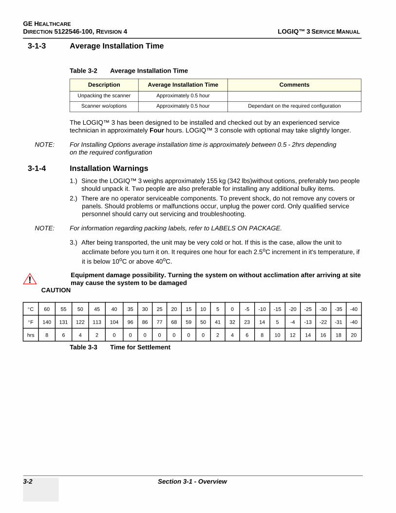
GE HEALTHCAREDIRECTION 5122546-100, REVISION 4 LOGIQ™ 3 SERVICE MANUAL
3-1-3 Average Installation Time
The LOGIQ™ 3 has been designed to be installed and checked out by an experienced service technician in approximately Four hours. LOGIQ™ 3 console with optional may take slightly longer.
NOTE: For Installing Options average installation time is approximately between 0.5 - 2hrs depending on the required configuration
3-1-4 Installation Warnings1.) Since the LOGIQ™ 3 weighs approximately 155 kg (342 lbs)without options, preferably two people
should unpack it. Two people are also preferable for installing any additional bulky items.2.) There are no operator serviceable components. To prevent shock, do not remove any covers or
panels. Should problems or malfunctions occur, unplug the power cord. Only qualified service personnel should carry out servicing and troubleshooting.
NOTE: For information regarding packing labels, refer to LABELS ON PACKAGE.
3.) After being transported, the unit may be very cold or hot. If this is the case, allow the unit to acclimate before you turn it on. It requires one hour for each 2.5oC increment in it's temperature, if it is below 10oC or above 40oC.
Table 3-2 Average Installation Time
Description Average Installation Time Comments
Unpacking the scanner Approximately 0.5 hour
Scanner wo/options Approximately 0.5 hour Dependant on the required configuration
CAUTION
Equipment damage possibility. Turning the system on without acclimation after arriving at site may cause the system to be damaged
°C 60 55 50 45 40 35 30 25 20 15 10 5 0 -5 -10 -15 -20 -25 -30 -35 -40
°F 140 131 122 113 104 96 86 77 68 59 50 41 32 23 14 5 -4 -13 -22 -31 -40
hrs 8 6 4 2 0 0 0 0 0 0 0 2 4 6 8 10 12 14 16 18 20
Table 3-3 Time for Settlement
3-2 Section 3-1 - Overview
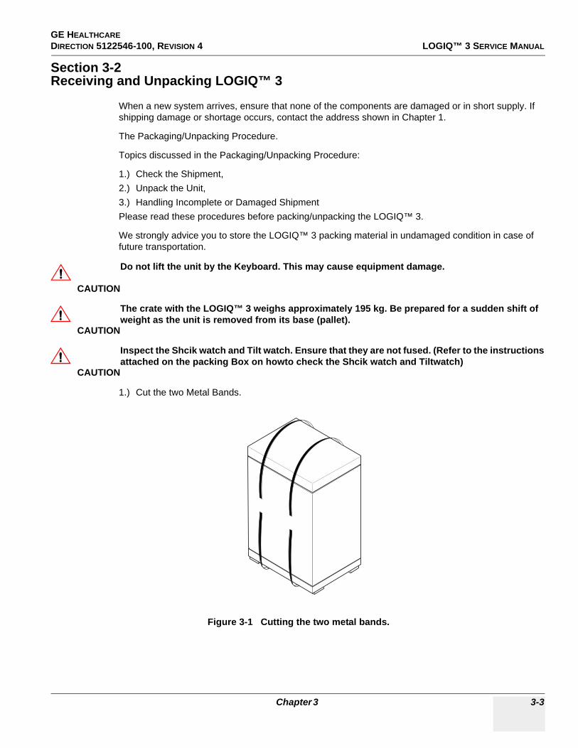
GE HEALTHCARE DIRECTION 5122546-100, REVISION 4 LOGIQ™ 3 SERVICE MANUAL
Section 3-2Receiving and Unpacking LOGIQ™ 3
When a new system arrives, ensure that none of the components are damaged or in short supply. If shipping damage or shortage occurs, contact the address shown in Chapter 1.
The Packaging/Unpacking Procedure.
Topics discussed in the Packaging/Unpacking Procedure:
1.) Check the Shipment, 2.) Unpack the Unit, 3.) Handling Incomplete or Damaged ShipmentPlease read these procedures before packing/unpacking the LOGIQ™ 3.
We strongly advice you to store the LOGIQ™ 3 packing material in undamaged condition in case of future transportation.
1.) Cut the two Metal Bands.
CAUTION
Do not lift the unit by the Keyboard. This may cause equipment damage.
CAUTION
The crate with the LOGIQ™ 3 weighs approximately 195 kg. Be prepared for a sudden shift of weight as the unit is removed from its base (pallet).
CAUTION
Inspect the Shcik watch and Tilt watch. Ensure that they are not fused. (Refer to the instructions attached on the packing Box on howto check the Shcik watch and Tiltwatch)
Figure 3-1 Cutting the two metal bands.
Chapter 3 3-3
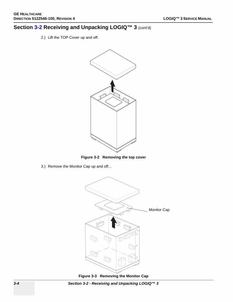
GE HEALTHCAREDIRECTION 5122546-100, REVISION 4 LOGIQ™ 3 SERVICE MANUAL
Section 3-2 Receiving and Unpacking LOGIQ™ 3 (cont’d)
2.) Lift the TOP Cover up and off.
3.) Remove the Monitor Cap up and off...
Figure 3-2 Removing the top cover
Figure 3-3 Removing the Monitor Cap
Monitor Cap
3-4 Section 3-2 - Receiving and Unpacking LOGIQ™ 3

GE HEALTHCARE DIRECTION 5122546-100, REVISION 4 LOGIQ™ 3 SERVICE MANUAL
Section 3-2 Receiving and Unpacking LOGIQ™ 3 (cont’d)
4.) Remove the three Plastic Joints from the Outer Sleeve.(Refer to the Labels on the Packing Box for more detailed instructions)
5.) Remove the Outer Sleeve.6.) Remove the Inner Sleeve.
Figure 3-4 Removing Plastic Joints and Sleeves
Palette Assy
Plastic Joint
Inner Sleeve
Outer Sleeve
Chapter 3 3-5

GE HEALTHCAREDIRECTION 5122546-100, REVISION 4 LOGIQ™ 3 SERVICE MANUAL
Section 3-2 Receiving and Unpacking LOGIQ™ 3 (cont’d)
7.) Remove the Plastic Wrapping around the LOGIQTM 3.8.) Remove the Monitor Support and Monitor Packing.9.) Remove the adhesive tapes attached at the four corners of the Top Cover.10.)Put the Ramp Board on floor and prepare the slope to put the console down.11.)Unlock the brakes on the front castors, then carefully put the console off the Palette.
Figure 3-5 Moving the LOGIQ™ 3 from the crate
3-6 Section 3-2 - Receiving and Unpacking LOGIQ™ 3

GE HEALTHCARE DIRECTION 5122546-100, REVISION 4 LOGIQ™ 3 SERVICE MANUAL
3-2-1 Safety Reminders
NOTE: Check the shipping container for special instructions. Verify that the container is intact. In some cases a secondary container may be used. If so, ask the carrier for unpacking instructions.
Figure 3-6 LABELS ON PACKAGE
DANGER WHEN USING ANY TEST INSTRUMENT THAT IS CAPABLE OF OPENING THE AC GROUND LINE (I.E., METER’S GROUND SWITCH IS OPEN), DON’T TOUCH THE UNIT!
CAUTION
If the unit is very cold or hot, do not turn on its power until it has had a chance to acclimate to its operating environment.
CAUTION
To prevent electrical shock, connect the unit to a properly grounded power outlet. Do not use a three to two prong adapter. This defeats safety grounding.
CAUTION
Do NOT wear the ESD wrist strap when you work on live circuits and more than 30 V peak is present.
CAUTION
Do not operate this unit unless all board covers and frame panels are securely in place. System performance and cooling require this.
CAUTION
OPERATOR MANUAL(S) The User Manual(s) should be fully read and understood before operating the LOGIQ™ 3 and kept near the unit for quick reference.
CAUTION
ACOUSTIC OUTPUT HAZARDAlthough the ultrasound energy transmitted from the LOGIQ™ 3 probe is within AIUM/NEMA standards, avoid unnecessary exposure. Ultrasound energy can produce heat and mechanical damage.
Chapter 3 3-7

GE HEALTHCAREDIRECTION 5122546-100, REVISION 4 LOGIQ™ 3 SERVICE MANUAL
3-2-2 Moving into Position
In general, a single adult can move the LOGIQ™ 3 along an even surface with no steep grades. At least two people should move the machine when large humps, grooves, or grades are encountered. (It is better to pull from the rear rather than push from the front of the unit). Before moving, store all loose parts in the unit. Wrap transducers in soft cloth or foam to prevent damage.
Although LOGIQ™ 3 is a compact and mobile machine, two people should move it over rough surfaces or up and down grades.
3-2-3 Adjusting System ClockSet the system clock for the LOGIQ™ 3 to the local time. For procedure of adjusting the system clock, refer to 4-5 Software Configuration Checks, in Chapter 4, FUNCTIONAL CHECKS.
3-2-4 Product Locator Installation CardFill out proper customer Information on the Product Locator Installation Card. Mail this Installation Card “Product Locator” to the address corresponding to your pole.
NOTE: The Product Locator Installation Card shown may not be same as the provided Product Locator card.
PRODUCT LOCATOR INSTALLATION CARD
CAUTION
Do not lift the unit by the Keyboard.Do not tilt the unit more than 5 degrees to avoid tipping it over.
CAUTION
Equipment Damage Possibility. Lifting the console by holding covers may damage the covers. Do not lift the console by holding any covers.
3-8 Section 3-2 - Receiving and Unpacking LOGIQ™ 3

GE HEALTHCARE DIRECTION 5122546-100, REVISION 4 LOGIQ™ 3 SERVICE MANUAL
Section 3-3Preparing for Installation
3-3-1 Verify Customer OrderCompare items received by the customer to that which is listed on the delivery order. Report any items that are missing, back ordered or damaged.
3-3-2 Physical Inspection
3-3-2-1 Systems Voltage SettingsVerify that the recieved scanner is set to the correct voltage.The Voltage ratings for the LOGIQ™ 3 Scanner is found on Rating label near the Circuit Breaker at the rear of the system
3-3-2-2 Video FormatsCheck that the video format is set to the locally used video standard, NTSC or PAL.This can be done in the Utilities menu.(Refer to Chapter 16 of the Basic Users Manual for the procedure for changinh the settings)
3-3-3 EMI ProtectionThis unit has been designed to minimize the effects of Electo-Magnetic Interference (EMI). Many of the covers, shields, and screws are provided primarily to protect the system from image artifacts caused by this interference. For this reason, it is imperative that all covers and hardware are installed and secured before the unit is put into operation.
3-3-4 Checking the ComponentsWhen a new system arrives, check that nonne of the components are damaged or in short supply. If shipping damage or shortage occurs, contact the address shown in Chapter 1.
WARNINGWARNING CONNECTING A LOGIQ™ 3 SCANNER TO THE WRONG VOLTAGE LEVEL WILL MOST LIKELY DESTROY THE SCANNER.
CAUTION
If the Power Plug is Modified or replaced to Suit the local Conditions and regulations, Ground continuity check should be performed between Ground Pin on the Plug and the Metal Part on the LOGIQ™ 3. Refer Section 10-6-4 for more details.
Chapter 3 3-9

GE HEALTHCAREDIRECTION 5122546-100, REVISION 4 LOGIQ™ 3 SERVICE MANUAL
Section 3-4Completing the Installation
3-4-1 System Specifications
3-4-1-1 Physical DimensionsThe physical dimensions of the LOGIQ™ 3 unit are summarized in Table 3-4 on page 10 .The Size of LOGIQ™ 3, with monitor and peripherals is shown in Figure 3-7 on page 11
Table 3-4 Physical Dimension of LOGIQ™ 3
Height Width Depth Unit
136 49.0 96 cm
53.54 19.29 37.79 inches
3-10 Section 3-4 - Completing the Installation

GE HEALTHCARE DIRECTION 5122546-100, REVISION 4 LOGIQ™ 3 SERVICE MANUAL
Figure 3-7 OVERALL DIMENSIONS
WEIGHT: 155kg (342lbs) NOTE: Length is in mm Variation: +/- 5%
The LOGIQTM 3 Expert will have 3 Probe Ports as seen here
Chapter 3 3-11

GE HEALTHCAREDIRECTION 5122546-100, REVISION 4 LOGIQ™ 3 SERVICE MANUAL
3-4-1-2 Weight with Monitor and without PeripheralsThe Weight of LOGIQ™ 3 with monitor, without peripherals
3-4-1-3 Acoustic Noise Output:Less than 70dB (A) according to DIN 45635 - 19 - 01 - KL2.
3-4-2 Electrical SpecificationsElectrical conduit, junction boxes, outlets, circuit breakers, and switches should be in place before installing the LOGIQ™ 3 console
3-4-3 Probe (Transducer) Connection1.) Connect a transducer to the upper transducer receptacle as follows:
A.) Ensure that the transducer twist lock lever points towards the 9 o'clock position.B.) Insert the transducer connector on the receptacle guide pin until it touches the receptacle
mating surface.C.) Twist the transducer twist lock lever to the 2 o'clock position to lock it in place. Twist the
lever to the 9 o'clock position to disconnect the transducer.
NOTE: It is not necessary to turn OFF power to connect or disconnect a transducer.
Connect the main power cable to a hospital grade power receptacle with the proper rated voltage checked during pre installation. Never use a three-to-two prong adapter; this defeats the safety ground.
3-4-4 Power On / Boot Up
NOTE: After turning off a system, wait at least ten seconds before turning it on again. The system may not be able to boot if power is recycled too quickly.
3-4-4-1 Scanner Power On
1.) Connect the Power Cable to the back of the system.2.) Ensure the Cable Clip slips securely over the shoulders on the molded plug.3.) Connect the Main Power Cable to a hospital grade power receptacle with the proper rated voltage.
Never use an adapter that would defeat the safety ground. 4.) Switch ON the Circuit Breaker at the rear of the system.
Table 3-5 Weight of LOGIQ™ 3
Model Weight [Kg] Weight [lbs]
LOGIQ™ 3 155 342
Table 3-6 Electrical Specification for LOGIQ™ 3
System Voltage Current Frequency
1 100 ~ VAC 10A 50-60 Hz
2 115 ~ VAC 8.2A 50-60 Hz
3 230 ~ VAC 4,1A 50-60 HZ
3-12 Section 3-4 - Completing the Installation

GE HEALTHCARE DIRECTION 5122546-100, REVISION 4 LOGIQ™ 3 SERVICE MANUAL
When power is applied to the scanner and the rear Circuit Breaker is turned ON, power is distributed to the Transformer Assembly.
Figure 3-8 Circuit Breaker and Power Cable on Back of Scanner
Chapter 3 3-13

GE HEALTHCAREDIRECTION 5122546-100, REVISION 4 LOGIQ™ 3 SERVICE MANUAL
3-4-4-2 Back-end Processor Boot UpPress the Standby switch on the Control Panel once.
When the Standby switch on the Control Panel is pressed once, the Power is distributed to the Front-End, to the Peripheral outlets and to the Back End Processor. The Back End Processor starts and the software is initiated to start the scanner.
No status messages are displayed during this process.
3-4-5 Power Off/ Shutdown
NOTE: After turning off a system, wait at least ten seconds before turning it on again. The system may not be able to boot if power is recycled too quickly.
3-4-5-1 Back-end Processor Power Down
1.) Press the Standby switch on the Control Panel once to display the SYSTEM - EXIT menu.2.) Select Shutdown from the SYSTEM - EXIT menu.
Figure 3-9 Standby Switch for Back-end Processor Boot Up
Figure 3-10 System Exit Menu for Back-end Processor Power Down
3
Standby Switch
The LOGIQTM 3 Expert will have 3 Probe Ports as seen here
3-14 Section 3-4 - Completing the Installation

GE HEALTHCARE DIRECTION 5122546-100, REVISION 4 LOGIQ™ 3 SERVICE MANUAL
3-4-5-2 Scanner Shutdown
1.) Switch OFF the Circuit Breaker at the back of the system.2.) Disconnect the Mains Power Cable if necessary. For example: Relocating the scanner.
Figure 3-11 Circuit Breaker and Power Cable on Back of Scanner
NOTICE
Disconnecting the Mains Power Cable before switching OFF the Circuit Breaker will activate the uninterruptible power system (UPS) in the backend processor, forcing an ordered shutdown of the system.
NOTICE
The UPS serves only as a battery backup that allows for a soft shut-down of the scanner to prevent file corruption. IT DOES NOT REGULATE INCOMING VOLTAGE.
Circuit BreakerMains Power Cable
Cable Clip
Chapter 3 3-15

GE HEALTHCAREDIRECTION 5122546-100, REVISION 4 LOGIQ™ 3 SERVICE MANUAL
Section 3-5System Configuration
3-5-1 System Configuration
3-5-1-1 System Settings
1.) Power OFF the scanner.2.) The SYSTEM EXIT window appears. Click on Logoff.
3.) The message window appears. Click on OK.4.) The OPERATOR LOGIN window appears.Change the User level to Admin, then enter Password,
Then Click on OK
Table 3-1 System Configuration
Configuration Category Description
Settings
Enables the user or service personnel to set the date, time, unit, language, basic information about the organization such as the institution name and department.
Figure 3-12 System EXIT window
Figure 3-13 Operator Login Window
3-16 Section 3-5 - System Configuration
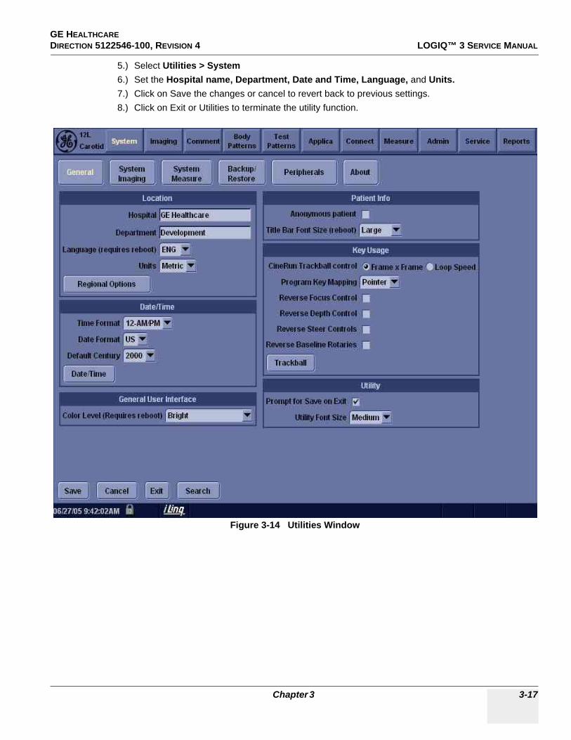
GE HEALTHCARE DIRECTION 5122546-100, REVISION 4 LOGIQ™ 3 SERVICE MANUAL
5.) Select Utilities > System6.) Set the Hospital name, Department, Date and Time, Language, and Units.7.) Click on Save the changes or cancel to revert back to previous settings.8.) Click on Exit or Utilities to terminate the utility function.
Figure 3-14 Utilities Window
Chapter 3 3-17

GE HEALTHCAREDIRECTION 5122546-100, REVISION 4 LOGIQ™ 3 SERVICE MANUAL
Section 3-6Storage And Operation Requirements
The LOGIQ™ 3 is shipped in a single container excluding PROBES. Shipping weight is approximately 430 lbs (195kg). The size of the container is B120 cm x W66 cm x H139 cm. (47 in. x 26 in. x 55 in). Table 3-1 provides a summary of temperature, atmospheric pressure, and humidity tolerances for shipping, installation, and operation.
Table 3-2 STORAGE AND OPERATION REQUIREMENTS
Parameter Storage Operation
Temperature (Deg C) (Deg F)
-10 to 6014 to 140
10 to 4050 to 104
Atmospheric Pressure (hPa)
700 to 1060 700 to 1060
Humidly (%)(non-condensing)
30 to 95 30 to 85
3-18 Section 3-6 - Storage And Operation Requirements
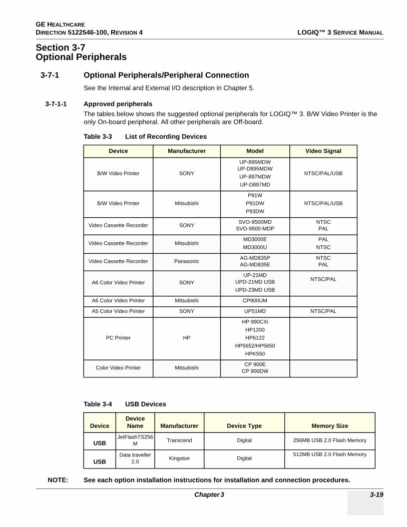
GE HEALTHCARE DIRECTION 5122546-100, REVISION 4 LOGIQ™ 3 SERVICE MANUAL
Section 3-7Optional Peripherals
3-7-1 Optional Peripherals/Peripheral ConnectionSee the Internal and External I/O description in Chapter 5.
3-7-1-1 Approved peripheralsThe tables below shows the suggested optional peripherals for LOGIQ™ 3. B/W Video Printer is the only On-board peripheral. All other peripherals are Off-board.
NOTE: See each option installation instructions for installation and connection procedures.
Table 3-3 List of Recording Devices
Device Manufacturer Model Video Signal
B/W Video Printer SONY
UP-895MDWUP-D895MDWUP-897MDWUP-D897MD
NTSC/PAL/USB
B/W Video Printer MitsubishiP91W
P91DWP93DW
NTSC/PAL/USB
Video Cassette Recorder SONY SVO-9500MDSVO-9500-MDP
NTSCPAL
Video Cassette Recorder MitsubishiMD3000EMD3000U
PALNTSC
Video Cassette Recorder Panasonic AG-MD835PAG-MD835E
NTSCPAL
A6 Color Video Printer SONYUP-21MD
UPD-21MD USBUPD-23MD USB
NTSC/PAL
A6 Color Video Printer Mitsubishi CP900UM
A5 Color Video Printer SONY UP51MD NTSC/PAL
PC Printer HP
HP 990CXiHP1200HP6122
HP5652/HP5650HPK550
Color Video Printer Mitsubishi CP 900ECP 900DW
Table 3-4 USB Devices
Device Device Name Manufacturer Device Type Memory Size
USB JetFlashTS256
M Transcend Digital 256MB USB 2.0 Flash Memory
USBData traveller
2.0 Kingston Digital512MB USB 2.0 Flash Memory
Chapter 3 3-19

GE HEALTHCAREDIRECTION 5122546-100, REVISION 4 LOGIQ™ 3 SERVICE MANUAL
3-7-1-2 Connecting Cables
CAUTION
Equipment damage possibility. Be sure to use the following recommended connecting cables to connect recording devices and a network with LOGIQ™ 3 console.Failure to do so would result in unstable system behaviour and can possibly damage the Equipment
Table 3-5 LIST OF CONNECTING CABLES
Name Part No. Figure NOTE
Power Cable P9509EEUse only approved IEC Couplers
for peripherals connection to System Rear panel
P9509MH Used only for installing Peripherals on front panel of the console
RS232C Cable P9509MN For control signals
P9509NA For InSite connection
Mini-Plug Cable P9509BE For control signals (used only for B/W video printer)
Ethernet Cable 2195662For DICOM capability Included in the DICOM Support option with
Transceivers
3-20 Section 3-7 - Optional Peripherals

GE HEALTHCARE DIRECTION 5122546-100, REVISION 4 LOGIQ™ 3 SERVICE MANUAL
3-7-1-3 Power Consumption of Optional Peripherals
NOTE: At Any point of time, only one peripheral should be activated.
Table 3-6 Power Consumption of Optional Recording Devices
Device Manufacturer ModelPower Consumption
(VA)
B/W Video Printer SONY
UP-895MDWUP-D895MDWUP-897 MDWUP-D897MD
133133133133
B/W Video Printer MitsubishiP91W
P91DWP93DW
144144144
Video Cassette Recorder SONY SVO-9500MDSVO-9500-MDP
7272
Video Cassette Recorder MitsubishiMD3000EMD3000U
4646
Video Cassette Recorder Panasonic AG-MD835PAG-MD835E
3939
A6 Color Video Printer SONYUP-21MD
UP-21MD USBUPD-23 MD
216180230
A6 Color Video Printer Mitsubishi CP900UM 264264
A5 Color Video Printer SONY UP51MD 336
PC Printer HP
HP 990CXiHP1200HP6122
HP5652/HP5650
607232
PC Printer Epson CP 900ECP 900DW
4444
Chapter 3 3-21
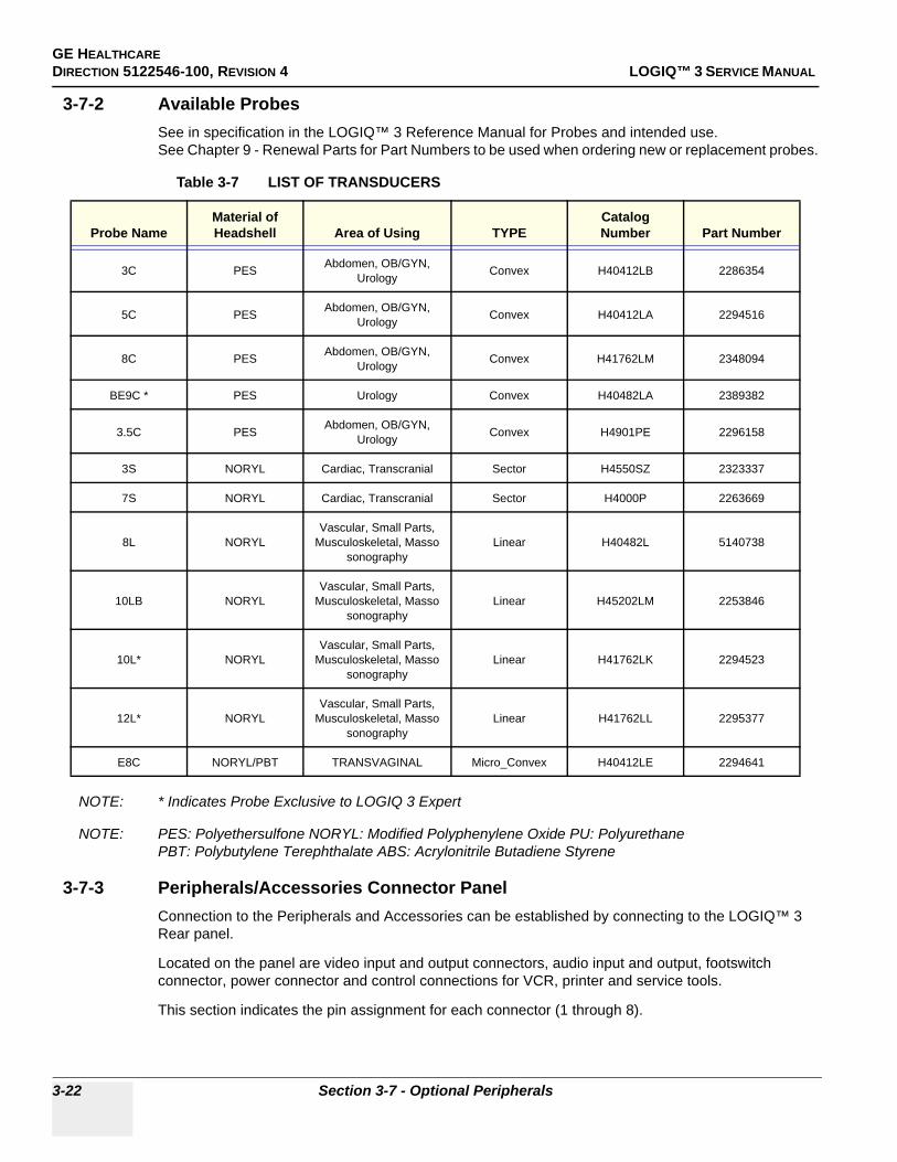
GE HEALTHCAREDIRECTION 5122546-100, REVISION 4 LOGIQ™ 3 SERVICE MANUAL
3-7-2 Available ProbesSee in specification in the LOGIQ™ 3 Reference Manual for Probes and intended use.See Chapter 9 - Renewal Parts for Part Numbers to be used when ordering new or replacement probes.
NOTE: * Indicates Probe Exclusive to LOGIQ 3 Expert
NOTE: PES: Polyethersulfone NORYL: Modified Polyphenylene Oxide PU: PolyurethanePBT: Polybutylene Terephthalate ABS: Acrylonitrile Butadiene Styrene
3-7-3 Peripherals/Accessories Connector PanelConnection to the Peripherals and Accessories can be established by connecting to the LOGIQ™ 3 Rear panel.
Located on the panel are video input and output connectors, audio input and output, footswitch connector, power connector and control connections for VCR, printer and service tools.
This section indicates the pin assignment for each connector (1 through 8).
Table 3-7 LIST OF TRANSDUCERS
Probe NameMaterial of Headshell Area of Using TYPE
Catalog Number Part Number
3C PES Abdomen, OB/GYN, Urology Convex H40412LB 2286354
5C PES Abdomen, OB/GYN, Urology Convex H40412LA 2294516
8C PES Abdomen, OB/GYN, Urology Convex H41762LM 2348094
BE9C * PES Urology Convex H40482LA 2389382
3.5C PES Abdomen, OB/GYN, Urology Convex H4901PE 2296158
3S NORYL Cardiac, Transcranial Sector H4550SZ 2323337
7S NORYL Cardiac, Transcranial Sector H4000P 2263669
8L NORYLVascular, Small Parts,
Musculoskeletal, Masso sonography
Linear H40482L 5140738
10LB NORYLVascular, Small Parts,
Musculoskeletal, Masso sonography
Linear H45202LM 2253846
10L* NORYLVascular, Small Parts,
Musculoskeletal, Masso sonography
Linear H41762LK 2294523
12L* NORYLVascular, Small Parts,
Musculoskeletal, Masso sonography
Linear H41762LL 2295377
E8C NORYL/PBT TRANSVAGINAL Micro_Convex H40412LE 2294641
3-22 Section 3-7 - Optional Peripherals

GE HEALTHCARE DIRECTION 5122546-100, REVISION 4 LOGIQ™ 3 SERVICE MANUAL
3-7-3 Peripherals/Accessories Connector Panel (cont’d).
Figure 3-15 Rear Panel for 230V, 115V and 100V
Chapter 3 3-23
GE HEALTHCAREDIRECTION 5122546-100, REVISION 4 LOGIQ™ 3 SERVICE MANUAL
3-7-3 Peripherals/Accessories Connector Panel (cont’d)
External I/O Connectors.
Figure 3-16
3-24 Section 3-7 - Optional Peripherals

GE HEALTHCARE DIRECTION 5122546-100, REVISION 4 LOGIQ™ 3 SERVICE MANUAL
3-7-3 Peripherals/Accessories Connector Panel (cont’d)
Table 3-8 External I/O Connector Descriptions
Item Connector Name Table Number Description
1 RGB Sync BNC Connector, Color Output
2 S-Video Out Table 3-16 4 pin mini-DIN
3 S- Video In Table 3-16 4 pin mini-DIN
4 VGA Out Table 3-17 DSUB-HD22 15 Pin female
5 Audio Out RCA Phono Jack
6 Audio In RCA Phono Jack
7 Composite Video Out BNC Connector, Color Output
8 Composite Video In BNC Connector, Color Input
9 Shutter Table 3-15 Mini-phone Jack
10 Foot Switch Table 3-14 Hirose Electric Co. RM12BRB-5S,
11 Ethernet Table 3-13 RJ-45 Connector
12 Service Table 3-9 DSUB 9 pin male
13 Remote Table 3-11 DSUB 9 pin female
14 USB Table 3-12
15 Printer DSUB 25 pin female
Chapter 3 3-25

GE HEALTHCAREDIRECTION 5122546-100, REVISION 4 LOGIQ™ 3 SERVICE MANUAL
3-7-3 Peripherals/Accessories Connector Panel (cont’d)
1. Pin Assignment of Remote
Connector: D-SUB, 9 Pin, Female
NOTE: Output level of RS232C signals:
2. Pin Assignment of RS232C for Service
Connector: D-SUB, 9Pin, Male
Pin No. Signal Pin No. Signal
1 N/A 6 DSR
2 RXD 7 RTS
3 TXD 8 CTS
4 DTR 9 N/A
5 GND
Table 3-9 Pin Assignments of RS232C for Remote
Table 3-10 Output Level of RS232C signals
High +3V to +15V
Low -15V to 0V
Pin No. Signal Pin No. Signal Picture
1 NA 6 DSR
2 RXB 7 RTS
3 TXB 8 CTS
4 DTR 9 NA
Table 3-11 Pin Assignments of RS232C for Service
12345
6789
Service
3-26 Section 3-7 - Optional Peripherals

GE HEALTHCARE DIRECTION 5122546-100, REVISION 4 LOGIQ™ 3 SERVICE MANUAL
3-7-3 Peripherals/Accessories Connector Panel (cont’d)
3. Pin Assignment of USB1 & USB2
Connector: USB
4. Pin Assignment of Ethernet
Connector: RJ45
5. Pin Assignment of Foot Switch
Connector: Circularr
Pin No. Signal Pin No. Signal Picture
1 +5 VDC 3 DATA +
2 DATA - 4 GND
Table 3-12 Pin Assignments of USB
Pin No. Signal Pin No. Signal Picture
1 TX+ 2 TX-
3 RX+ 4 RX-
5 NA 6 NA
7 NA 8 NA
Table 3-13 Pin Assignments of Ethernet
Pin No. Signal Picture
1 SW1
2 GND
3 SW2
4 GND
5 SW3
Table 3-14 Pin Assignments of Foot Switch
USB
8 1
Chapter 3 3-27
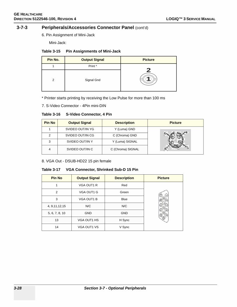
GE HEALTHCAREDIRECTION 5122546-100, REVISION 4 LOGIQ™ 3 SERVICE MANUAL
3-7-3 Peripherals/Accessories Connector Panel (cont’d)
6. Pin Assignment of Mini-Jack
Mini-Jack:
* Printer starts printing by receiving the Low Pulse for more than 100 ms
7. S-Video Connector - 4Pin mini-DIN
8. VGA Out - DSUB-HD22 15 pin female
Table 3-15 Pin Assignments of Mini-Jack
Pin No. Output Signal Picture
1 Print *
2 Signal Gnd
Table 3-16 S-Video Connector, 4 Pin
Pin No Output Signal Description Picture
1 SVIDEO OUT/IN YG Y (Luma) GND
2 SVIDEO OUT/IN CG C (Chroma) GND
3 SVIDEO OUT/IN Y Y (Luma) SIGNAL
4 SVIDEO OUT/IN C C (Chroma) SIGNAL
Table 3-17 VGA Connector, Shrinked Sub-D 15 Pin
Pin No Output Signal Description Picture
1 VGA OUT1 R Red
2 VGA OUT1 G Green
3 VGA OUT1 B Blue
4, 9,11,12,15 N/C N/C
5, 6, 7, 8, 10 GND GND
13 VGA OUT1 HS H Sync
14 VGA OUT1 VS V Sync
12
3-28 Section 3-7 - Optional Peripherals
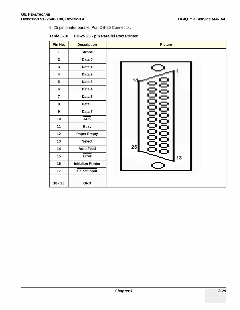
GE HEALTHCARE DIRECTION 5122546-100, REVISION 4 LOGIQ™ 3 SERVICE MANUAL
9. 25 pin printer parallel Port DB-25 Connector.
Table 3-18 DB-25 25 - pin Parallel Port Printer
Pin No. Description Picture
1 Strobe
2 Data 0
3 Data 1
4 Data 2
5 Data 3
6 Data 4
7 Data 5
8 Data 6
9 Data 7
10 ACK
11 Busy
12 Paper Empty
13 Select
14 Auto Feed
15 Error
16 Initialize Printer
17 Select Input
18 - 25 GND
Chapter 3 3-29

GE HEALTHCAREDIRECTION 5122546-100, REVISION 4 LOGIQ™ 3 SERVICE MANUAL
3-7-4 Video Specification
Table 3-19 VIDEO SPECIFICATIONS
Timing Parameter1024x768
75Hz768x576
50Hz800x600
60Hz800x600
75Hz640x480
60Hz1024x768
60Hz
Horizontal Rate [kHz] 60.02 31.25 37.88 46.88 31.47 48.36
Horizontal Period [µs] 16.66 32.00 26.40 21.33 31.78 20.68
Pixel Clock [MHz] 78.75 29.50 40.00 49.50 24.55 65.00
H Blank Width [µs] 3.66 5.97 6.40 5.17 5.70 4.92
H Sync Width [µs] 1.22 2.34 3.20 1.62 2.36 2.09
H Front Porch [µs] 0.20 0.75 1.00 0.32 0.73 0.37
Active Horizontal Period [µs] 13.00 26.03 20.00 16.16 26.07 15.75
Vertical Rate [Hz] 75.03 50.0 60.32 75.00 59.94 60.00
Vertical Period [ms] 13.33 20.0 16.58 13.33 16.68 16.67
V Sync Width [lines=ms] 32=0.53 49=1.57 28=0.74 25=0.53 45=1.43 38=0.79
V Front Porch [lines=µs] 3=50.00 5=160.0 4=105.60 3=64.00 6=190.70 6=124.10
Equalization Gate [lines=µs] 1=16.66 5=160.0 1=26.4 1=21.3 6=190.7 3=62.00
Lines: Field/Frame 800 625/625 628 625 525/525 806
Active Lines/Frame 768 576 600 600 480 768
3-30 Section 3-7 - Optional Peripherals

GE HEALTHCARE DIRECTION 5122546-100, REVISION 4 LOGIQ™ 3 SERVICE MANUAL
Section 3-8Software Option Configuration
Refer to the LOGIQ™ 3 Basic User Manual, Chapter 16, Customizing Your System for information on configuring items like Hospital, Department, Language, Units (of measure), Date, Time and Date Format.
For information on configuring Software Options, Refer to the LOGIQ™ 3 Basic User Manual, Chapter 16, Customizing Your System.
For information on configuring DICOM Connectivity, Refer to the LOGIQ™ 3 Basic User Manual, Chapter 16, Customizing Your System.
Chapter 3 3-31

GE HEALTHCAREDIRECTION 5122546-100, REVISION 4 LOGIQ™ 3 SERVICE MANUAL
Section 3-9Connectivity Installation Worksheet
Site System Information
Services (Destination Devices)
TCP/IP Settings
Device Type Manufacturer Name IP Address Port AE Title123456789101112
Name - AE Title:
Dept:
LOGIQ SN: Type:
Floor:
Room:
REV:
Comments:
CONTACT INFORMATION
Name Title Phone E-Mail Address
Site:
IP Settings
IP Address:
Subnet Mask:
Default Gateway:
Remote Archive Setup
Remote Archive IP:
Remote Archive Name:
3-32 Section 3-9 - Connectivity Installation Worksheet

GE HEALTHCARE DIRECTION 5122546-100, REVISION 4 LOGIQ™ 3 SERVICE MANUAL
Section 3-10Loading Base System Software
3-10-1 Software Compatible MatrixThe following table shows all s/w revisions happend to LOGIQ™ 3.
NOTE: For R4.1.X, BEP2, BEP3, and BEP4 Base Image software is made common to all LOGIQ3 models (Expert, Pro, and B/W).
3-10-2 Before You Load SoftwareSave to CD-R or MOD any patient data, images, and system presets that have been stored or configured. Installing the base operating software destroys all patient data, images and system setups saved on the system.
3-10-3 Managing Data, Presets and ImagesBefore loading software, if you need to save Patient Data, Presets or Images, refer to 8-10-4 "Image Management Guide" on page 8-146.
Chapter 3 3-33

GE HEALTHCAREDIRECTION 5122546-100, REVISION 4 LOGIQ™ 3 SERVICE MANUAL
WARNINGWARNINGThe next steps will destroy ALL data on the Scanner
3-34 Section 3-10 - Loading Base System Software

GE HEALTHCARE DIRECTION 5122546-100, REVISION 4 LOGIQ™ 3 SERVICE MANUAL
3-10-4 Base Software Load Procedure For BEP Ver 2 , 3, & 4
NOTE: Disconnect the system from the network and remove all transducers, all External Drives (USB MOD, Flash Sticks, USB Memory etc.,), Switch Off peripherals like printers, VCR, VGP before installing Base Load.
1.) Insert the disk labeled “Base System Software Load Image as per BEP Type” into the CDROM drive and switch on the system. The following screen appears, Press any key to Continue.
2.) Select 1 if the Patient Data on D drive was less than 2 GB and has been backed up using EXPORT function or Select 2 if the Patient Data on D drive was greater than 2 GB, It will need to be backed up after the Upgrade using EzBackup function.
NOTE: If the Patient image data is large and cannot be backed up by using ‘EXPORT’, It is recommended to select option ‘2’ i.e,Load Bootable C partition only..
Figure 3-17 Base Load Warning Message
Figure 3-18 Base Load Option Message
Chapter 3 3-35

GE HEALTHCAREDIRECTION 5122546-100, REVISION 4 LOGIQ™ 3 SERVICE MANUAL
3.) You will see a screen showing Ghost. This automatically loads the base software onto the hard disk. Let it run to completion (Approximately 10 mins).
4.) A message will be displayed when the process is completed.
Figure 3-19 Ghost Screen
Figure 3-20 Base Load Completion Message
3-36 Section 3-10 - Loading Base System Software

GE HEALTHCARE DIRECTION 5122546-100, REVISION 4 LOGIQ™ 3 SERVICE MANUAL
3-10-4 Base Software Load Procedure For BEP Ver 2 , 3, & 4 (cont’d)
5.) Remove the CD-ROM
NOTE: Remove the CD-ROM from the drive; otherwise you will be repeating the Base System Software Load process.
6.) After removing the CDROM from the drive, properly turn off the scanner by pressing and holding power on button on keyboard for more than 20 sec’s.
7.) Turn the scanner back on. It will now boot up and automatically log on to start checking hardware and Device Manager. This is a normal and should be allowed to run to completion.
NOTE: When booting up the first time it could take 30-90 seconds after the login box appears before the trackball and key board are active. Watch for the arrow cursor to appear.
NOTE: While the script is running, several windows or dialog boxes will appear on the screen. Wait for the “System Settings Change” dialog box “Restart computer now” (approximately 3 minutes after the desktop).
Do NOT touch the system during this process. Activating the keyboard, mouse or front panel could corrupt the installation.
NOTE: At times it may look like the system is unresponsive. PATIENCE! The process takes 3-4 minutes. Wait for the “Restart computer now” message to appear before activating the keyboard, mouse or front panel controls.
8.) Wait till you get a windows reboot message. This may take upto 3 minutes. On this message, Click on NO as shown in the Figure 3-21 below.
Figure 3-21 Windows Restart Screen
Select NO
This screen will look different with WIN XP
Chapter 3 3-37

GE HEALTHCAREDIRECTION 5122546-100, REVISION 4 LOGIQ™ 3 SERVICE MANUAL
Section 3-11Loading Application Software
3-11-1 Loading Applications Software1.) Place the “Application Software” CDROM into the CDROM drive.2.) Move the cursor using Trackball to find the “Start” command button on the Monitor screen3.) Press the Start button on the tool bar at the bottom of the Screen and select “Run…”.4.) Enter “g:\LoadSoftware.bat” into the dialog box as shown in Figure 3-22.
5.) You will see a Command (CMD) window open as shown in Figure 3-23.
Figure 3-22 Run Load Software
3-38 Section 3-11 - Loading Application Software

GE HEALTHCARE DIRECTION 5122546-100, REVISION 4 LOGIQ™ 3 SERVICE MANUAL
Loading Applications Software (cont’d)
6.) Press ” Y” key twice to start the process.7.) During Application Software loading process, the System will auto Shutdown.Manually switch
on the System using the ‘standby- ON/OFF’ switch.8.) After the software loading is completed, the system will pop-up a message, asking to make the
selection for Presets according to location of site as seen in the Figure 3-24 below. Make the appropriate selection.
9.) Wait until the system shuts down automatically (Approx 5 Minutes to shut down).10.)Wait for Approx. 15 seconds.11.)Power on the System and Remove the CD while it boots.12.)The System pops up the Screen asking for Option Key. Enter the Basic Option Key
obtained on ordering of the BT’05 Upgrade.
Figure 3-23 Application CD Installation Popup
Figure 3-24 Preset Selection
Chapter 3 3-39

GE HEALTHCAREDIRECTION 5122546-100, REVISION 4 LOGIQ™ 3 SERVICE MANUAL
3-11-2 System SetupTo complete the system setup:
1.) Connect the system to the network if applicable.2.) Select Utility>Connect>TCPIP Tab. For systems with S/W version lower than R2.2.0, the path
is Utility>Connectivity>TCPIP Tab. 3.) Ensure that DHCP is deselected so you can enter information manually.4.) Input the DICOM information.
* This should be the appropriate DICOM information for the system if it is on the hospital network. If it is not correct, input the correct data.
5.) After all information is entered select SAVE SETTINGS.6.) If the system is NOT on a network you will need to input a set of "dummy" data for proper InSite
and Diagnostic operation. Enter the following data if you are not on a network:* Computer Name: * IP Address: 3.192.28.253* Subnet Mask: 255.255.255.0
7.) After all information is entered select SAVE SETTINGS.8.) Reset the VCR by going to Utilities>System>Setup. 9.) Select Sony 9500 VCR and SAVE10.)Select Exit in the lower left-hand corner of the Touch Screen.11.)Do an auto-shut down12.)Press the STANDBY switch on the Control Panel once to display the SYSTEM - EXIT menu.13.)Select SHUTDOWN from the SYSTEM - EXIT menu.
Figure 3-25 System Exit Menu for Back-end Processor Power Down
3-40 Section 3-11 - Loading Application Software

GE HEALTHCARE DIRECTION 5122546-100, REVISION 4 LOGIQ™ 3 SERVICE MANUAL
Section 3-12Paperwork
NOTE: During and after installation, the documentation (i.e. User Manuals, Installation Manuals...) for the peripheral units must be kept as part of the original system documentation. This will ensure that all relevant safety and user information is available during the operation and service of the complete system.
3-12-1 Product Locator Installation
NOTE: The Product Locator Installation Card shown may not be same as the provided Product Locator card.
Figure 3-1 Product Locator Installation Card
Chapter 3 3-41
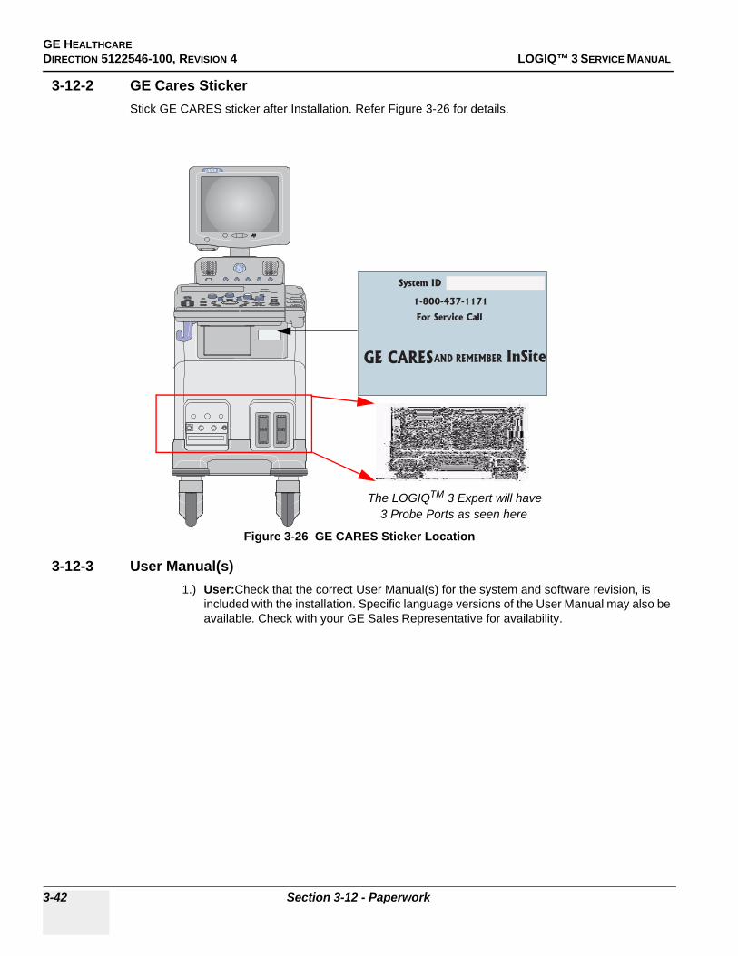
GE HEALTHCAREDIRECTION 5122546-100, REVISION 4 LOGIQ™ 3 SERVICE MANUAL
3-12-2 GE Cares StickerStick GE CARES sticker after Installation. Refer Figure 3-26 for details.
3-12-3 User Manual(s)1.) User:Check that the correct User Manual(s) for the system and software revision, is
included with the installation. Specific language versions of the User Manual may also be available. Check with your GE Sales Representative for availability.
Figure 3-26 GE CARES Sticker Location
3
System ID
1-800-437-1171
For Service Call
GE CARESAND REMEMBER InSite
The LOGIQTM 3 Expert will have 3 Probe Ports as seen here
3-42 Section 3-12 - Paperwork

GE HEALTHCARE DIRECTION 5122546-100, REVISION 4 LOGIQ™ 3 SERVICE MANUAL
This page was intentionally left blank.
Chapter 3 3-43

GE HEALTHCAREDIRECTION 5122546-100, REVISION 4 LOGIQ™ 3 SERVICE MANUAL
3-44 Section 3-12 - Paperwork
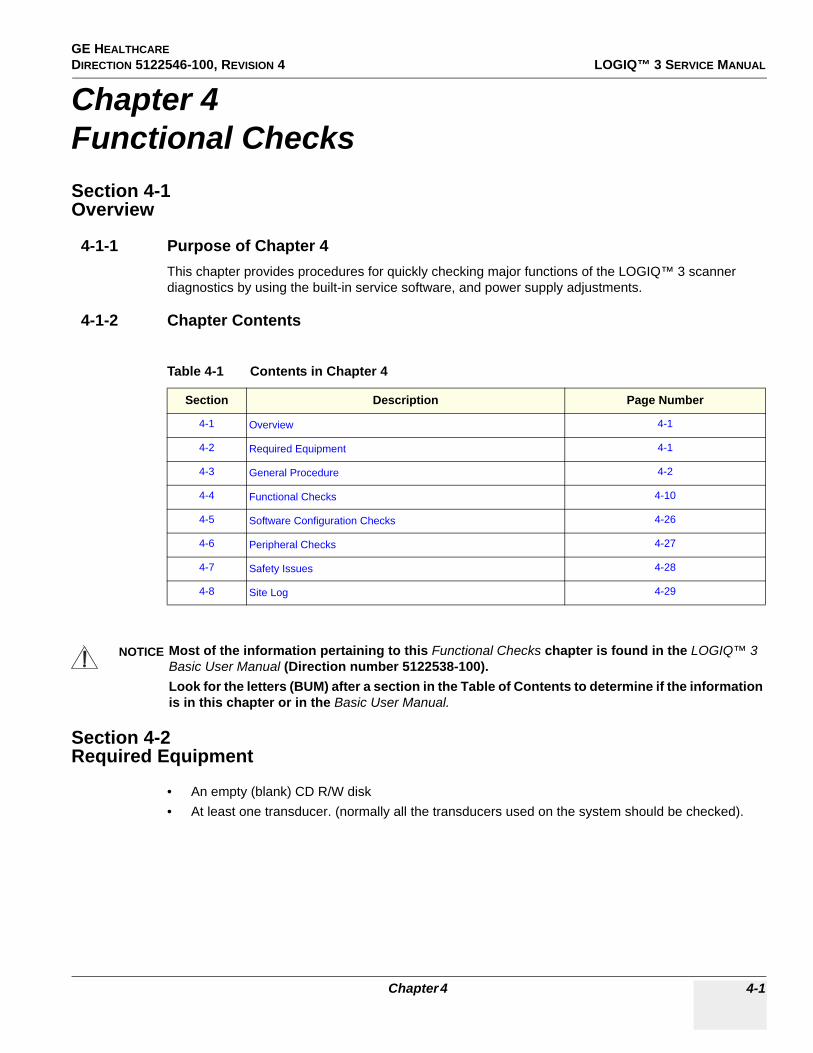
GE HEALTHCARE DIRECTION 5122546-100, REVISION 4 LOGIQ™ 3 SERVICE MANUAL
Chapter 4Functional ChecksSection 4-1Overview
4-1-1 Purpose of Chapter 4This chapter provides procedures for quickly checking major functions of the LOGIQ™ 3 scanner diagnostics by using the built-in service software, and power supply adjustments.
4-1-2 Chapter Contents
Section 4-2Required Equipment
• An empty (blank) CD R/W disk• At least one transducer. (normally all the transducers used on the system should be checked).
Table 4-1 Contents in Chapter 4
Section Description Page Number
4-1 Overview 4-1
4-2 Required Equipment 4-1
4-3 General Procedure 4-2
4-4 Functional Checks 4-10
4-5 Software Configuration Checks 4-26
4-6 Peripheral Checks 4-27
4-7 Safety Issues 4-28
4-8 Site Log 4-29
NOTICE Most of the information pertaining to this Functional Checks chapter is found in the LOGIQ™ 3 Basic User Manual (Direction number 5122538-100).Look for the letters (BUM) after a section in the Table of Contents to determine if the information is in this chapter or in the Basic User Manual.
Chapter 4 4-1

GE HEALTHCAREDIRECTION 5122546-100, REVISION 4 LOGIQ™ 3 SERVICE MANUAL
Section 4-3General Procedure
4-3-1 Power On/Boot Up
NOTE: After turning off the system, wait at least ten seconds before turning it on again. The system may not be able to boot if power is recycled too quickly.
4-3-1-1 Scanner Power On
1.) Connect the Main Power Cable at the rear of the System
2.) Ensure the retainer clamp slips securely over the shoulders on the molded plug.3.) Connect the Main Power cable to an appropriate mains power outlet.4.) Switch ON the Main Circuit Breaker at the rear of the System.
CAUTION SYSTEM REQUIRES ALL COVERSOperate this unit only when all board covers and frame panels are securely in place. The covers are required for safe operation, good system performance and cooling purposes.
NOTICE Lockout/Tagout Requirements (For USA only)Follow OSHA Lockout/Tagout requirements by ensuring you are in total control of the Power Cable on the system.
WARNINGWARNINGProtective earth must be taken care when connecting AC power cable without its plug to wall outlet.
Signed Date
TAG &
LOCKOUT
4-2 Section 4-3 - General Procedure

GE HEALTHCARE DIRECTION 5122546-100, REVISION 4 LOGIQ™ 3 SERVICE MANUAL
4-3-1 Power On/Boot Up (cont’d)
When power is applied to the Scanner, and the Rear Circuit breaker is turned ON, Power is distributed to the Transformer Assembly. When the Control panel ON/OFF key is pressed once, Fans, Control Panel, Monitor, Internal and External I/O’s, Nest Boards, Peripherals and the Back End Processor are given power. Back-end Processor boots up and the system starts in the scanning mode.
Press the ON/OFF (STANDBY) Switch on the Control Panel once.
Figure 4-1 Circuit Breaker
Figure 4-2 Power On/Off Standby Switch Location
Circuit Breaker
Power Cable
3
The LOGIQTM 3 Expert will have 3 Probe Ports as seen here
Chapter 4 4-3

GE HEALTHCAREDIRECTION 5122546-100, REVISION 4 LOGIQ™ 3 SERVICE MANUAL
4-3-1 Power On/Boot Up (cont’d)
When the Standby switch on the Control Panel is pressed once, the Back-end Processor starts and the software code is distributed to initiate the scanner.
No status messages are displayed during this process.
4-3-1-2 Power OffPurpose: This is a description on how to Shutdown the system.
1.) Press the ON/OFFkeys on the keyboard2.) The System Exit dialog box is displayed on the monitor.
Select “Shutdown” from the System Exit dialog box.
3.) The power off sequence begins. The system power turns off automatically when the power off sequence is completed.
4-3-1-3 Power Shutdown
1.) Press the ON/OFF key at the front of the System once. 2.) The System Exit dialog box is displayed on the monitor.
Select “Shutdown” from the System Exit dialog box3.) Switch OFF the Main Circuit Breaker at the rear of the system Refer to Figure 4-1 on page 3 .4.) Disconnect the Main Power Cable if needed.
4-3-2 Using CD-RW Drive/MOD Drive (Optional)
4-3-2-1 Using CD-RW
1.) Use F3 to EJECT
Figure 4-3 System Exit Dialog Box
NOTICE Never move the unit with a disk in the CD-RW because the drive actuator will not be locked and the CD-RW could break.
NOTICE Avoid mechanical ejection whenever possible. Mechanical ejection leaves the actuator unlocked and the CDR-W susceptible to damage if moved. If forced to use this method, reboot the system, then insert and eject a known good disk using one of the other methods.
4-4 Section 4-3 - General Procedure

GE HEALTHCARE DIRECTION 5122546-100, REVISION 4 LOGIQ™ 3 SERVICE MANUAL
NOTE: DON’T Use EJECT Button
4-3-2-2 Using MOD (Optional)
NOTE: MOD can be installed through USB Port of LOGIQ™ 3
1.) Before installing an MO disk in the MOD, check the MO disk for loose hardware or damaged labels which could jam inside the MO Drive. Also ensure that the slide switch in one corner of the disk is set so that the disk is write enabled (disk hole closed).
2.) Insert the disk into the MOD with the label facing up.
3.) There are number of methods to eject a disk from the MOD. Ejection is automatic in some cases. Manual ejection methods, listed in preferred order of use, are:
a.) Press EJECT button on the MOD while system is ON.b.) Press and hold EJECT button while the system is booting.c.) Mechanical eject. Insert the end of a paper clip into the hole next to the EJECT button while
system power is OFF.
Figure 4-4 CD-RW drives
NOTICE Never move the unit with a disk in the MOD because the drive actuator will not be locked and the MOD could break.
NOTICE Avoid mechanical ejection whenever possible. Mechanical ejection leaves the actuator unlocked and the MOD susceptible to damage if moved. If forced to use this method, reboot the system, then insert and eject a known good disk using one of the other methods.
3
CD R/W Drive
Eject Button
The LOGIQTM 3 Expert will have 3 Probe Ports as seen here
Chapter 4 4-5

GE HEALTHCAREDIRECTION 5122546-100, REVISION 4 LOGIQ™ 3 SERVICE MANUAL
4-3-3 Archiving and Loading Presets
NOTE: Always save presets before any software reload. This ensures the presets loaded after the software reload are as up–to–date as possible.
All user presets except changes to Summary, Anatomy, and Biometry pages, can be saved on an CD-RW/MOD disk for reloading on the system.
4-3-3-1 Formatting CD(R/W)/MO Disk
1.) Insert an empty (blank) CD(R/W)/MO Disk into the Device Drive.2.) Press the UTILITY Key on the Keyboard and select Connect> Removable Media. The Tools
screen will be shown on the monitor. For Systems with S/W versions R2.x.x , Press the UTILITY Key on the Keyboard and select Connectivity> TOOLS. The Tools screen will be shown on the monitor.
3.) Select the Media from the media list4.) Type a name for the removable media in label field.5.) Select FORMAT button.
NOTICE Presets should NOT be saved on the same CD-RW/MO disk as images. The Archive Menu lists the images but does NOT list the presets stored on a CD-RW/MO disk.
Figure 4-5 Formatting Removable Media
4-6 Section 4-3 - General Procedure

GE HEALTHCARE DIRECTION 5122546-100, REVISION 4 LOGIQ™ 3 SERVICE MANUAL
4-3-3-2 Archiving Presets to an CD(R/W)/MO Disk
1.) Insert an empty (blank) formatted CD(R/W)/MO disk into the device drive.2.) Press the UTILITY Key in the Keyboard and Select System> BACKUP/RESTORE. For systems
with software version R2.X.X , Press the UTILITY Key in the Keyboard and Select System> BACKUP. The Backup Screen will be shown on the monitor.
3.) Select the item to back up either from Resource Files.4.) Enter backup destination or browse through the disk to locate the destination.5.) Click on BACKUP the backup status for each item is displayed on the Result column.6.) Make sure “Finished OK” is displayed on the Result column.
Figure 4-6 Backup Sheet
Chapter 4 4-7

GE HEALTHCAREDIRECTION 5122546-100, REVISION 4 LOGIQ™ 3 SERVICE MANUAL
4-3-3-3 Loading Presets from an CD(R/W)/MO disk
1.) Insert the CD(R/W)/MO Disk with the archived Presets into the CD(R/W)/MO Disk.2.) Press the UTILITY Key in the Keyboard and Select System> BACKUP/RESTORE. For systems
with software version R2.X.X , Press the UTILITY Key in the Keyboard and Select System> BACKUP. The Backup Screen will be shown on the monitor.
3.) Select the item to restore either from resource files.4.) Click on Restore. A message to make sure the restore process is displayed on the monitor. Click
OK. The restore status for each item is displayed on the Result column.5.) Make sure “Finished OK” is displayed on the result column.
NOTE: This process will restart the System and all selectd Parametrs will be reloaded
Figure 4-7 Restore Sheet
Click Here toRestore Data
4-8 Section 4-3 - General Procedure
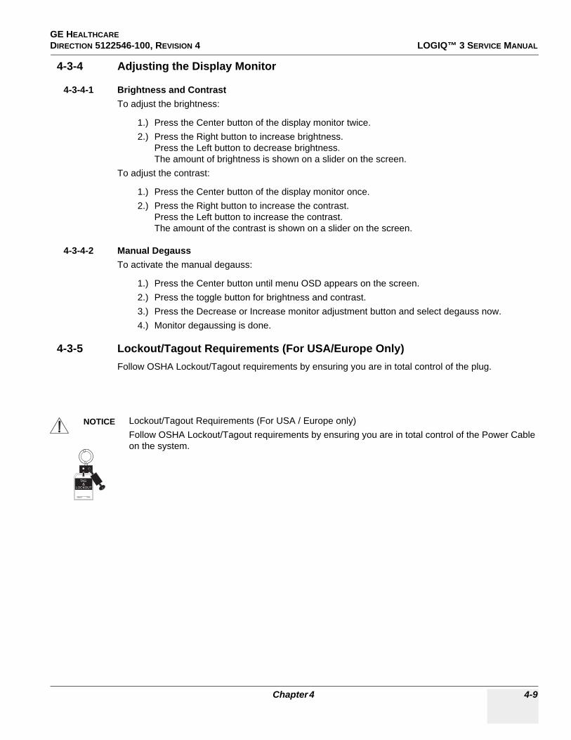
GE HEALTHCARE DIRECTION 5122546-100, REVISION 4 LOGIQ™ 3 SERVICE MANUAL
4-3-4 Adjusting the Display Monitor
4-3-4-1 Brightness and ContrastTo adjust the brightness:
1.) Press the Center button of the display monitor twice.2.) Press the Right button to increase brightness.
Press the Left button to decrease brightness.The amount of brightness is shown on a slider on the screen.
To adjust the contrast:
1.) Press the Center button of the display monitor once.2.) Press the Right button to increase the contrast.
Press the Left button to increase the contrast.The amount of the contrast is shown on a slider on the screen.
4-3-4-2 Manual DegaussTo activate the manual degauss:
1.) Press the Center button until menu OSD appears on the screen.2.) Press the toggle button for brightness and contrast.3.) Press the Decrease or Increase monitor adjustment button and select degauss now.4.) Monitor degaussing is done.
4-3-5 Lockout/Tagout Requirements (For USA/Europe Only)Follow OSHA Lockout/Tagout requirements by ensuring you are in total control of the plug.
NOTICE Lockout/Tagout Requirements (For USA / Europe only)Follow OSHA Lockout/Tagout requirements by ensuring you are in total control of the Power Cable on the system.
Signed Date
TAG &
LOCKOUT
Chapter 4 4-9
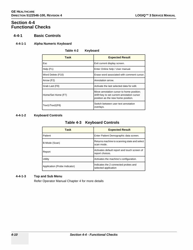
GE HEALTHCAREDIRECTION 5122546-100, REVISION 4 LOGIQ™ 3 SERVICE MANUAL
Section 4-4Functional Checks
4-4-1 Basic Controls
4-4-1-1 Alpha Numeric Keyboard
4-4-1-2 Keyboard Controls
4-4-1-3 Top and Sub MenuRefer Operator Manual Chapter 4 for more details
Table 4-2 Keyboard
Task Expected Result
Esc Exit current display screen.
Help (F1) Enter Online help / User manual.
Word Delete (F10) Erase word associated with comment cursor.
Arrow (F2) Annotation arrow.
Grab Last (F9) Activate the last selected data for edit.
Home/Set Home (F7)Move annotation cursor to home position; shift+key to set current annotation cursor position as the new home position.
Text1/Text2(F8) Switch between user text annotation overlays.
Table 4-3 Keyboard Controls
Task Expected Result
Patient Enter Patient Demographic data screen.
B-Mode (Scan) Returns machine to scanning state and select scan mode.
Report Activates default report and touch screen of report choices.
Utility Activates the machine’s configuration.
Application (Probe Indicator) Indicates the 2 connected probes and selected application
4-10 Section 4-4 - Functional Checks
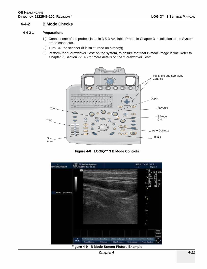
GE HEALTHCARE DIRECTION 5122546-100, REVISION 4 LOGIQ™ 3 SERVICE MANUAL
4-4-2 B Mode Checks
4-4-2-1 Preparations
1.) Connect one of the probes listed in 3-5-3 Available Probe, in Chapter 3 Installation to the System probe connector.
2.) Turn ON the scanner (if it isn’t turned on already))3.) Perform the “Screwdriver Test” on the system, to ensure that that B-mode image is fine.Refer to
Chapter 7, Section 7-10-6 for more details on the “Screwdriver Test”.
Figure 4-8 LOGIQ™ 3 B Mode Controls
Figure 4-9 B Mode Screen Picture Example
PDI
PW
L R
B Pause
Auto
Depth
M
ZoomEllipse
Body PatternMeasure
M/D Cursor
Scan Area
Set
Clear
Comment
Patient
21
Utility Application
xyz
B > PD > CF
ModeParameters
21 4 53
Sub-menu
Depth
B Mode
Top Menu and Sub MenuControls
TGC
ScanArea
Auto Optimize
Gain
Freeze
ReverseZoom
Chapter 4 4-11

GE HEALTHCAREDIRECTION 5122546-100, REVISION 4 LOGIQ™ 3 SERVICE MANUAL
4-4-2-2 B Mode OP Panel Controls
Table 4-4 B Mode Control Panel Controls
Step Task Expected Result(s)
1 Press B Mode key B Mode Starts
2 Adjust Depth
Adjust the field of view. Increasing the depth may view larger/deeper structures rates, and decreasing the depth may view near the skin line.Turn Depth right/left to increase/decrease. Depth displays on the monitor in cm.
3 Adjust Gain
Controls the amount of echo information displayed in an image. Turn B Mode dial to the left/right to increase/decrease Gain. Gain displays on the monitor in G (dB).
4 Adjust Time Gain Compensation (TGC)
Amplifies the returning signals to correct for the attenuation caused by tissues at increasing depth. TGC slide pots spaced proportional to the depth. Move the slide pots to the left/right to decrease/increase TGC. A TGC curve appears on the display.
5 Adjust Scan Area
Widen or narrow the size of the sector angle to maximize the image’s region of interest (ROI). Press Scan Area and move the Trackball to narrow/widen the angle.
6 Activate Auto OptimizeOptimize the image based upon a specified region of interest or anatomy. Press the right Auto control to activate.
7 Adjust ZoomChanges the location of the focal point(s). A triangular focus marker indicates the depth of the focal point.
8 Reverse Toggles the left/right orientation of the scan image.
9 Harmonics (Activate Tissue Harmonics)
Diminishes low frequency high amplitude noise and improves imaging. Enhances near field resolution for improved small parts imaging as well as far field penetration. Press Harmonics Key to activate.
4-12 Section 4-4 - Functional Checks

GE HEALTHCARE DIRECTION 5122546-100, REVISION 4 LOGIQ™ 3 SERVICE MANUAL
4-4-2-3 B Mode Top and Sub menu Controls
Table 4-5 B Mode Top and Sub menu Controls
Step Task Expected Result(s)
1 RejectionAdjust rejection level. When this control is increased, low-level echoes are rejected and appear darker in the B image. Rotate Rejection to left/right to adjust the level. An index number is displayed on the Top Menu to indicate the relative level of rejection.
2 Colorize Colorize the gray scale image to enhance the eyes’ discrimination capability. Rotate the Colorize Knob to cycle through the availabe color maps.
3 Edge Enhance Enhance the gray scale differences corresponding to the edges of structures. Press and turn Edge Enhance left/right to cycle through the settings.
4 Gray Map Displays a map window adjacent to the image.Rotate the Gray Map Knob to select the map. The image reflects the map as scrolled through the selections.
5 Frequency Enables the adjustment of the probe’s operating frequency. Rotate Frequency and select desired value. The selected frequency is displayed in the status window.
6 Virtual ConvexDisplays larger field of view in the far field. Press the Virtual Convex on Top Menu to activate. This mode is Available only on the Linear Probes
7 Frame Average Averages frames together and create more pixel, smoother image. Use the Paddle left/right switch to adjust the value. The selected value is displayed on the Sub Menu.
8 Up-Down Invert Flip the image vertically. Press Up-Down invert to flip up/down.
9 Dynamic Range Dynamic Range controls how echo intensities are converted to shades of gray, thereby increasing the adjustable range of contrast. This Control is available on the Top Menu
10 B Softener Affects the amount of lateral smoothing. This control is available on the Sub Menu
11 Suppression Suppress the Noise level.
12 Focus Width Adjust the Width between two Focus points
13 Power Output Adjust Power Output Level
14 Focus Position and NumberIncreases the number of focal zones or moves the focal zone(s) to tighten up the beam for specific area. Press the control to toggle between Focus Position and Focus Number. Turn Focus Position left/right to move the Focus. Press and Turn the Knob to adjust the focal numbers.
15 Biopsy Biopsy guidelines appears.
16 Line Density Optimizes B-Mode frame rate or spatial resolution.
Chapter 4 4-13

GE HEALTHCAREDIRECTION 5122546-100, REVISION 4 LOGIQ™ 3 SERVICE MANUAL
4-4-3 M Mode Controls
4-4-3-1 Preparations
1.) Connect one of the probes listed in 3-5-3 Available Probe, in Chapter 3 Installation to the System probe connector.
2.) Turn ON the scanner (if it isn’t turned on already)
Figure 4-10 Controls available in M Mode
Figure 4-11 M Mode Screen Picture Example
PDI
PW
L R
B Pause
Auto
Depth
M
ZoomEllipse
Body PatternMeasure
M/D Cursor
Scan Area
Set
Clear
Comment
Patient
21
Utility Application
xyz
B > PD > CF
ModeParameters
21 4 53
Sub-menu
CFM Mode
M/D Cursor
B Pause
M ModeGain
Top Menu and Sub MenuControls
4-14 Section 4-4 - Functional Checks

GE HEALTHCARE DIRECTION 5122546-100, REVISION 4 LOGIQ™ 3 SERVICE MANUAL
4-4-3-2 M Mode OP Panel Controls
Table 4-6 M Mode OP Panel Controls
Step Task Expected Result(s)
1 Press M Mode key M Mode Starts
2 Adjust Gain
Controls the amount of echo information displayed in an image. Turn M Mode dial to the left/right to increase/decrease Gain. Gain displays on the monitor in G (dB).
3 Display M-Mode CursorDisplays the M-Mode cursor on the B-Mode image. Press M/D Cursor and Trackball to position M-Mode Cursor.
4 B Pause
Toggle between simultaneous and update presentation while viewing the M-Mode trace or Spectral Doppler. Press B Pause to toggle between simultaneous and update.
5 Activate M Color Flow Mode
Overlays color on the M-Mode image using velocity and variance color maps. Press M, then CFM Mode key (or vice versa) to activate.
Chapter 4 4-15

GE HEALTHCAREDIRECTION 5122546-100, REVISION 4 LOGIQ™ 3 SERVICE MANUAL
4-4-3-3 M Mode Top and Sub menu Controls
Table 4-7 M Mode Top and Sub Menu Controls
Step Task Expected Result(s)
1 RejectionAdjust rejection level. When this control is increased, low-level echoes are rejected and appear darker in the M image. Use Paddle left/right key to adjust Rejection level. An index number is displayed in the status window to indicate the relative level of rejection.
2 Sweep Speed Changes the speed at which timeline is swept. Rotate Sweep Speed left/right to increase/decrease the value.
3 Edge Enhance Enhance the gray scale differences corresponding to the edges of structures. Press and Rotate Edge Enhance left/right to cycle through the settings.
4 Gray Map Displays a map window adjacent to the image. Rotate the Gray Map knob. The image reflects the map as scrolled through the selections.
5 Power Output Adjust Power output level.
6 Colorize Colorize the gray scale image to enhance the eyes’ discrimination capability. Press and Rotqte the Colorize knob to select the appropriate color map.
7 Full Timeline Displays only timeline screen. Press the Full Time line to activate.
8 Display Format Select the format to display B image and M image on the monitor. Rotate Display Format knob and select from the Top Menu.
9 Dynamic RangeEnables control of the dynamic range or contrast of the image. When dynamic range is set high, the image is softer and more low-level data is visible. Turn Dynamic Range rotation knob left/right to increase/decrease the value.
4-16 Section 4-4 - Functional Checks

GE HEALTHCARE DIRECTION 5122546-100, REVISION 4 LOGIQ™ 3 SERVICE MANUAL
4-4-4 Color Flow Mode Checks
4-4-4-1 Preparations
1.) Connect one of the probes listed in 3-5-3 Available Probe, in Chapter 3 Installation to the System probe connector.
2.) Turn ON the scanner (if it isn’t turned on already)
Figure 4-12 Controls available in Color Flow Mode
Figure 4-13 CFM Mode Screen Picture Example
PDI
PW
L R
B Pause
Auto
Depth
M
ZoomEllipse
Body PatternMeasure
M/D Cursor
Scan Area
Set
Clear
Comment
Patient
21
Utility Application
xyz
B > PD > CF
ModeParameters
21 4 53
Sub-menu
CFM ModeGain
Top Menu and Sub MenuControls
Chapter 4 4-17

GE HEALTHCAREDIRECTION 5122546-100, REVISION 4 LOGIQ™ 3 SERVICE MANUAL
4-4-4-2 Color Flow Mode OP Panel Controls
4-4-4-3 Color Flow Mode Top and Sub Menu Controls
Table 4-8 Color Flow Mode OP Panel Controls
Step Task Expected Result(s)
1 Press CFM-Mode key CFM Mode Starts
2 Adjust Gain Amplifies the overall strength of the echoes processed in the Color Flow window. Turn the Gain dial (CFM Mode key) to the left/right to increase/decrease Gain.
Table 4-9 Color Flow Mode Top and Sub Menu Controls
Step Task Expected Result(s)
1 Threshold Assigns the gray scale level at which color information stops. Rotate Threshold Knob left/right to increase/decrease the gray scale threshold.
2 Packet Size Controls the number of samples gathered for a single color flow vector. Rotate Packet Size left/right to increase/decrease the packet size.
3 Color maps Selects a specific color map. Rotate Color Map left/right to cycle through available maps.
4 Frequency Enables the adjustment of the probe’s operating frequency. Press Frequency and select desired value. The selected frequency is displayed in the status window.
5 Set Frame Average Averages color frames. Rotate Frame Average left/right to smooth temporal averaging. The selected value displays on the Top and Sub Menu.
6 Color Invert Views blood flow from a different perspective. Press Invert to reverse the color map.
7 Virtual Convex The Region of Interest gets enlarged, covering more image area. This is available only in Linear Probes.
8 Spatial Filter Activates Spatial Filter
9 Dynamic RangeEnables control of the dynamic range or contrast of the image. When dynamic range is set high, the image is softer and more low-level data is visible. Turn Dynamic Range rotation knob left/right to increase/decrease the value.
10 ACE Eliminates the motion artifacts. Press Ace on the Sub Menu to activate.
11 Angle Steer Slant the Color Flow linear image left or right to get more information without moving probes. Click Angle Steer to the left/right to slant the linear image.
12 Baseline Changes the spectrum baseline to accommodate higher velocity blood flow. Rotate Baseline left/right to adjust the baseline.
13 PRF / Wall Filter Velocity scale determines pulse repetition frequency. If the sample volume gate range exceeds single gate PRF capability, the system automatically switches to high PRF mode indicated by Multiple gates.
14 Transparency Map Activates Transparency Map.
4-18 Section 4-4 - Functional Checks
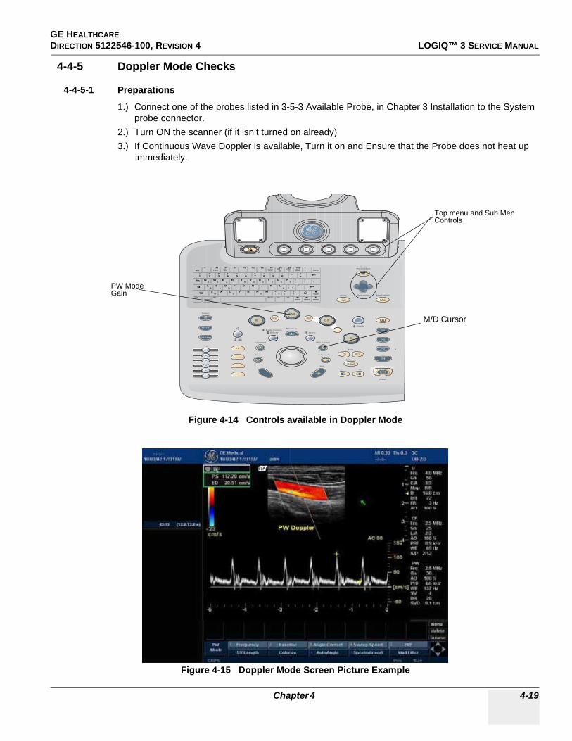
GE HEALTHCARE DIRECTION 5122546-100, REVISION 4 LOGIQ™ 3 SERVICE MANUAL
4-4-5 Doppler Mode Checks
4-4-5-1 Preparations
1.) Connect one of the probes listed in 3-5-3 Available Probe, in Chapter 3 Installation to the System probe connector.
2.) Turn ON the scanner (if it isn’t turned on already)3.) If Continuous Wave Doppler is available, Turn it on and Ensure that the Probe does not heat up
immediately.
Figure 4-14 Controls available in Doppler Mode
Figure 4-15 Doppler Mode Screen Picture Example
PDI
PW
L R
B Pause
Auto
Depth
M
ZoomEllipse
Body PatternMeasure
M/D Cursor
Scan Area
Set
Clear
Comment
Patient
21
Utility Application
xyz
B > PD > CF
ModeParameters
21 4 53
Sub-menu
PW ModeGain
M/D Cursor
Top menu and Sub MenControls
Chapter 4 4-19

GE HEALTHCAREDIRECTION 5122546-100, REVISION 4 LOGIQ™ 3 SERVICE MANUAL
4-4-5-2 Doppler Mode OP Panel Controls
4-4-5-3 Doppler Mode Top and Sub Menu Controls
Table 4-10 Doppler Mode OP Panel Controls
Step Task Expected Result(s)
1 Press PW Mode key PW Mode Starts
2 Adjust Gain Amplifies the overall strength of the echoes processed in the Color Flow window. Turn the Gain dial (PW Mode key) to the left/right to increase/decrease Gain.
3 Display M/D-Mode Cursor Displays the M/D-Mode cursor on the B-Mode image. Press Cursor and Trackball to position sample volume graphic. Rotate SV gate to adjust sample volume gate size.
4 Audio Volume Controls Doppler audio output. Turn Volume left/right to adjust PW Doppler audio.
Table 4-11 Doppler Mode Top and Sub Menu Controls
Step Task Expected Result(s)
1 Rejection Adjust rejection level. When this control is increased, low-level echoes are rejected and appear darker in the PW image. Press Rejection Paddle left/right keys to adjust the level.
2 Sweep Speed Changes the speed at which timeline is swept. Rotate left/right to increase/decrease the value.
3 Full Timeline Displays only timeline screen. Press the Full Time in the Sub-menu screen to activate.
4 Display Format Select the format to display B image and PW image on the monitor. Press Paddle switch and select from the Top Menu
5 Frequency Enables the adjustment of the probe’s operating frequency. Press Frequency and select desired value. The selected frequency is displayed in the status window.
6 Angle Correct Optimizes the accuracy of the flow velocity. Rotate left/right to adjust the angle relative to the probe face
7 Spectral Invert Vertically inverts the spectral trace without affecting the baseline position. Press invert to invert the spectral trace. The Plus and Minus signs on the velocity scale reverse when the spectrum is inverted.
8 Sample Volume Length Sizes the sample volume gate.Rotate SV lenght Knob to resize gate.
9 Spectral Average Activates Spectral Average.
10 Duplex / Triplex Activates Duplex/Triplex Mode of operation
11 Color Map Colorize the gray scale image to enhance the eyes’ discrimination capability. Select the Color Map on the sub menu and select the approporiate map.
12 Trace Direction / Method Provides automatic Trace of the Spectrum above and/or below the base line.
13 Dynamic Range Controls how echo intensities are converted to shades of gray. Click Dynamic Range Paddle key to increase/decrease the value.
14 Auto Calculations Activates Auto Calculations of the Measurements
15 Adjust Angle Steer Slant the Color Flow linear image left or right to get more information without moving probes.Rotate Angle Steer to the left/right to slant the linear image.
16 Move Baseline Adjusts the baseline to accommodate faster or slower blood flows to eliminate aliasing. Rotate Baseline left/right to shift the baseline.
17 PRF / Wall Filter Adjust the velocity scale to accommodate faster/slower blood flow velocities. Rotate PRF left/right to select values
18 Trace Sensitivity Activates Trace Sensitivity.
4-20 Section 4-4 - Functional Checks

GE HEALTHCARE DIRECTION 5122546-100, REVISION 4 LOGIQ™ 3 SERVICE MANUAL
4-4-6 Measurement and Multi Image Checks
4-4-6-1 Performing B Mode Measurements Checks
Figure 4-16 Measurement Keys
Table 4-12 Measurement Checks
Step Task Expected Result(s)
1. Generate the B image. A B image is active on the screen
2. Press Freeze Freeze the image to measure.
3. Press MEASURE on the Control Panel to enter the Assign and Measure modality.
The measurement soft menu for the current exam category is displayed on the Monitor. Select the appropriate exam category and measurement kind.
5. Trackball the cursor Move the cursor to the start point of the measurement
6. Press Set. Anchor the start point of the measurement.
7. Trackball the cursor
Move the cursor to the measurement end point.The current distance value is displayed in the Measurement result table and is instantaneously updated when moving the cursor
PDI
PW
L R
B Pause
Auto
Depth
M
ZoomEllipse
Body PatternMeasure
M/D Cursor
Scan Area
Set
Clear
Comment
Patient
21
Utility Application
xyz
B > PD > CF
ModeParameters
21 4 53
Sub-menu
Measurement
Trackball
Set
Chapter 4 4-21

GE HEALTHCAREDIRECTION 5122546-100, REVISION 4 LOGIQ™ 3 SERVICE MANUAL
4-4-7 Basic Measurements
NOTE: The following instructions assume that you first scan the patient and then press Freeze.
4-4-7-1 Distance and Tissue Depth Measurements
1.) Press MEASURE once; an active caliper displays.2.) To position the active caliper at the start point (distance) or the most anterior point (tissue
depth), move the TRACKBALL.3.) To fix the start point, press Set. The system fixes the first caliper and displays a second active
caliper.4.) To position the second active caliper at the end point (distance) or the most posterior point
(tissue depth), move the TRACKBALL.5.) To complete the measurement, press SET. The system displays the distance or tissue depth
value in the measurement results window.Before you complete a measurement:
To toggle between active calipers, press MEASURE.
To erase the second caliper and the current data measured and start the measurement again, press CLEAR once.
NOTE: To rotate through and activate previously fixed calipers, turn CURSOR SELECT.
NOTE: After you complete the measurement, to erase all data that has been measured to this point, but not data entered onto worksheets, press CLEAR.
4-4-7-2 Circumference/Area (Ellipse) Measurement
1.) Press MEASURE once; an active caliper displays.2.) To position the active caliper, move the TRACKBALL.3.) To fix the start point, press SET. The system fixes the first caliper and displays a second active
caliper.4.) To position the second caliper, move the TRACKBALL.5.) Turn the ELLIPSE control; an ellipse with an initial circle shape appears.
4-22 Section 4-4 - Functional Checks

GE HEALTHCARE DIRECTION 5122546-100, REVISION 4 LOGIQ™ 3 SERVICE MANUAL
4-4-7-2 Circumference/Area (Ellipse) Measurement (cont’d)
NOTE: Be careful not to press the Ellipse control as this activates the Body Pattern.
6.) To position the ellipse and to size the measured axes (move the calipers), move the TRACKBALL.
7.) To increase the size, turn the ELLIPSE control in a clockwise direction. To decrease the size, turn the ELLIPSE control in a counterclockwise direction.
8.) To toggle between active calipers, press MEASURE.9.) To complete the measurement, press SET. The system displays the circumference and area
in the measurement results window.Before you complete a measurement:
- To erase the ellipse and the current data measured, press CLEAR once. The original caliper is displayed to restart the measurement.
- To exit the measurement function without completing the measurement, press CLEAR a second time.
4-4-7-3 WorksheetsMeasurement/Calculation worksheets are available to display and edit measurements and calculations. There are generic worksheets as well as Application specific worksheets. The worksheets are selected from the Measurement Menu.
4-4-7-4 Report Pages Measurements/Calculations that are included on the worksheet can also be displayed on Report Pages.
NOTE: This Feature is not yet fully functional on the LOGIQTM 3
4-4-8 Probe/Connectors Usage
4-4-8-1 Connecting a probe
1.) Place the probe's carrying case on a stable surface and open the case.2.) Carefully remove the probe and unwrap the probe cable.3.) DO NOT allow the probe head to hang free. Impact to the probe head could result in irreparable
damage.4.) Turn the connector locking handle counterclockwise.5.) Align the connector with the probe port and carefully push into place.6.) Turn the connector locking handle clockwise to secure the probe connector.7.) Carefully position the probe cable in the probe cord holder spot so it is free to move, but not
resting on the floor.
4-4-8-2 Activating the probeSelect the appropriate probe from the probe indicators on the NTPUI.
The probe activates in the currently-selected operating mode. The probe's default settings for the mode and selected exam are used automatically.
Chapter 4 4-23

GE HEALTHCAREDIRECTION 5122546-100, REVISION 4 LOGIQ™ 3 SERVICE MANUAL
4-4-8-3 Deactivating the probeWhen deactivating the probe, the probe is automatically placed in standby mode.
1.) Press the Freeze key.2.) Gently wipe the excess gel from the face of the probe. (Refer to the Basic User Manual for
complete probe cleaning instructions.)3.) Carefully slide the probe around the right side of the keyboard, toward the probe holder.
Ensure that the probe is placed gently in the probe holder.
4-4-8-4 Disconnecting the probeProbes can be disconnected at any time. However, the probe should not be selected as the active probe.
1.) Move the probe locking handle counterclockwise. Pull the probe and connector straight out of the probe port.
2.) Carefully slide the probe and connector away from the probe port and around the right side of the keyboard. Ensure the cable is free.
3.) Be sure that the probe head is clean before placing the probe in its storage box.
4-4-9 Using Cine
4-4-9-1 Activating CINEPress FREEZE, then roll the TRACKBALL to activate CINE. To start CINE Loop playback, press Run/Stop. To stop CINE Loop playback. press Run/Stop.
4-4-9-2 Quickly Move to Start/End FramePress FIRST to move to the first CINE frame; press LAST to move to the last CINE frame.
4-4-9-3 Start Frame/End FrameTurn the START FRAME dial to the left to move to the beginning of the CINE Loop. Turn the dial to the right to move forward through the CINE Loop.
Turn the END FRAME dial to the right to move to the end of the CINE Loop. Turn the dial to the left to move backward through the CINE Loop.
4-4-9-4 Adjusting the CINE Loop Playback SpeedTurn the LOOP SPEED dial right/left to increase/decrease the CINE Loop playback speed.
4-4-9-5 Moving through a CINE Loop Frame By FrameTurn FRAME BY FRAME to move through CINE memory one frame at a time.
4-24 Section 4-4 - Functional Checks

GE HEALTHCARE DIRECTION 5122546-100, REVISION 4 LOGIQ™ 3 SERVICE MANUAL
4-4-10 Image Management (QG) For Image Management functionality refer to the LOGIQ™ 3 Quick Guide. It talks about several topics:
• Clipboard• Printing Images• Browsing and Managing an Exam’s Stored Image• Connectivity, and Dataflow Concept and Creation• Starting an Exam• Configuring Connectivity• TCP/IP• Services (Destinations)• Buttons• Views• Verifying and Pinging a Device
4-4-11 Back End Processor ChecksIf all the previous tests have been passed successfully, the backend processor is most likely OK. If the system seems to be operating erratically, Please refer to Chapter7, Diagnostic/Troubleshooting.
Chapter 4 4-25

GE HEALTHCAREDIRECTION 5122546-100, REVISION 4 LOGIQ™ 3 SERVICE MANUAL
Section 4-5Software Configuration Checks
Table 4-13 Software Configuration Checks
Step Task to do Expected Result(s)
1. Check Date and Time setting Date and Time are correct Adjust the Date and Time setting
2. Check that Location (Hospital Name and Department) is correct Location Name is correct Re-enter the correct Location Name
3. Check Language setting Language is proper Set the proper Language
4. Check Units setting Units are proper Set the local units
5 Check assignment of Printer Keys Print1-4 Keys are assigned as desired by the customer
6 Check that all of the customer’s options are set up correct All authorized functions are enabled
4-26 Section 4-5 - Software Configuration Checks

GE HEALTHCARE DIRECTION 5122546-100, REVISION 4 LOGIQ™ 3 SERVICE MANUAL
Section 4-6Peripheral Checks
Check that peripherals work as described below:
Table 4-14 Peripheral checks
Step Task to do Expected Result(s)
1. Press(FREEZE) Stop image acquisition.
2. Press (PRINT 1) or (PRINT 4) on the Control panel The image displayed on the screen is printed on B&W or Color printer, depending on the key assignment configuration.
3. Press VIDEO on the Control Panel. To start the video counter at a different point:
4. Press VIDEO or B MODE on the Control Panel to return to the scanning mode
5. Press REC/PAUSE on the Control panel.to Start RecordingA red dot is displayed in the VCR status area on the Title bar to indicate that recording has begun
6. Press REC/PAUSE on the Control panel.To Stop recordingThe video status icon is changed to (Pause)
7. Press VIDEO on the Control Panel. and the assignable play To start Play back an examination
8. Use the Assignable keys on the Control panelto perform actions on the recorded session, such as stop, pause, rewind or fast forward.The video status icon in updated accordingly.
9. While in playback mode, use the TRACKBALL to adjust the video playback speed and scroll through the record. To search on the tape
10. Press the assignable PAUSE to stop the tape at the desired frame.
11. When playing back an examinationpart of it can be stored on the computer’s memory as a cineloop.The cineloop enables the user to perform further operations on the stored section (see for further information on cineloop operation).
12. Press (FREEZE) while playing back a recorded session. To store a recorded sequence as a cineloop. The last few seconds are stored as a cineloop.
Chapter 4 4-27

GE HEALTHCAREDIRECTION 5122546-100, REVISION 4 LOGIQ™ 3 SERVICE MANUAL
Section 4-7Safety Issues
4-7-1 Probe/Connectors CheckTake the probes and check them as described below:
Do NOT touch the patient and any of the connectors on the ultrasound unit simultaneously, including ultrasound probe connectors.
4-7-2 Power Supply AdjustmentThere are no adjustments on the power supplies. The DC Power is self-regulated. If a voltage is outside the specified range, it means that something is wrong, either with the power supply itself or with a component connected to that specific power outlet.
Table 4-15 Probe and connectors check
Step Task to do Expected Result(s)
1. Test Each delivered Probe it will display pictorial data on the screen
2. Test each probe in each connector slot It will display pictorial data each time
3.
Hold the probe connector vertically with the cable pointing upward.Turn the connector locking handle to the horizontal position.Align the connector with the probe port and carefully push into place.Rotate the locking handle to the full vertical position to lock in place. Position the probe cable so that it is not resting on the floorCAUTION:Do not allow the probe head to hang freely. Impact to the probe head may result in irrepairable damage.
To connect a probe:
4.
Select the appropriate probe key on the Application Menu to activate the probe.Key Light Indicators: - on the ProbeOff - no probe attached to probe port.On: normal intensity - probe attaches to the probe port but not active.On: high intensity - probe attached to the probe port and active.The probe activated in the currently selected operating mode. Previously Selected Application and Preseta are retained.
To select a probe and an application:
5.
Rotate the lock handle counter-clockwise to the horizontal position to unlock the connector.Remove the connector from the portEnsure that the probe head is clean before placing the probe in its storage case.
To disconnect probes:The probes that are not connected to the unit should be stored in their storage case.
WARNINGWARNING Probes can be connected at any time, whether the unit is on or off
WARNINGWARNING Take the following precautions with the probe cables: Keep free from the wheels. Do not bend.Do not cross cables between probes.
4-28 Section 4-7 - Safety Issues

GE HEALTHCARE DIRECTION 5122546-100, REVISION 4 LOGIQ™ 3 SERVICE MANUAL
Section 4-8Site Log
Table 4-16 Site Log
Date Service person Problem Comments
Chapter 4 4-29

GE HEALTHCAREDIRECTION 5122546-100, REVISION 4 LOGIQ™ 3 SERVICE MANUAL
This page was intentionally left blank.
4-30 Section 4-8 - Site Log

GE HEALTHCARE DIRECTION 5122546 -100, REVISION 4 LOGIQ™ 3 SERVICE MANUAL
Chapter 5Components and Functions (Theory)Section 5-1Overview
5-1-1 Purpose of Chapter 5This chapter explains LOGIQ™ 3’s system concepts, component arrangement, and subsystem function. It also describes the Power Distribution System (PDS) and probes.
Table 5-1 Contents in Chapter 5
Section Description Page Number
5-1 Overview 5-1
5-2 Block Diagrams and Theory 5-4
• Top Console 5-9
5-3 External I/O on the Rear Panel 5-10
5-4 Peripherals 5-10
5-5 Power Diagrams 5-11
5-6 Circuit Boards Descriptions 5-14
5-7 Mechanical Descriptions 5-26
5-8 Air Flow Control 5-27
5-9 Common Service Platform 5-28
Chapter 5 5-1

GE HEALTHCAREDIRECTION 5122546 -100, REVISION 4 LOGIQ™ 3 SERVICE MANUAL
5-1-2 General Information• LOGIQ™ 3 is a phased and linear array ultrasound imaging scanner. It has provisions for analog
input sources like ECG and phono. • The system can be used for:
- 2D Black-and-White imaging - 2D Color Flow - M-Mode Black-and-White imaging - Color M-Mode - Pulse Doppler- Different combinations of the above modes
• Only LOGIQ™ 3 Expert supports 192 element Probes. It uses analog and digital delay to focus the beam. The analog delay is short and fixed. The digital delay is used for long delay and dynamic focus. This system also features many advanced image processing controls.
• Signal flow travels from the Probe Connector Panel to the Front End, to the Mid Processors and Back-End Processor, and finally to the monitor and peripherals.
• System configuration is stored on a hard disk and all necessary software is loaded from the hard disk on power up.
5-1-3 System FeaturesThe key design goals of this system are:
- High Image Quality - Increased User Productivity- Multiple Clinical Applications- Planned Upgrade ability- High Mobility
5-1-4 Types of ApplicationsThe LOGIQ™ 3 is a general imaging system which supports many clinical uses. Scan and display parameters may be user selected to default to desired values for each application. The system presets many parameters to clinically determined, optimal values.
- Radiology- Cardiology- OB/GYN- Vascular
The LOGIQ™ 3 system can be divided into an analog signal processing section, a digital signal processing section, and the microprocessor driven system control section, which controls the system based on operator commands and system status information.
5-2 Section 5-1 - Overview

GE HEALTHCARE DIRECTION 5122546 -100, REVISION 4 LOGIQ™ 3 SERVICE MANUAL
Figure 5-1 LOGIQ™ 3 Major Components
Name Plate
Monitor
Monitor Controls
Control Panel
Back-end Processor Chassis
Front CoverB/W Printer Tray (Option)
Front Bumper
ECG Module (Option)
CD
Wheel
Lock
Probe Connectors
TGC Slide pot Knobs
Speakers
Probe & Gel Bottle Holder
Track Ball
Task Lamp
A/N Keyboard Top Menu Controls
Hook for ECG Cables (Option)
The LOGIQTM 3 Expert will have 3 Probe Ports as seen here
Chapter 5 5-3
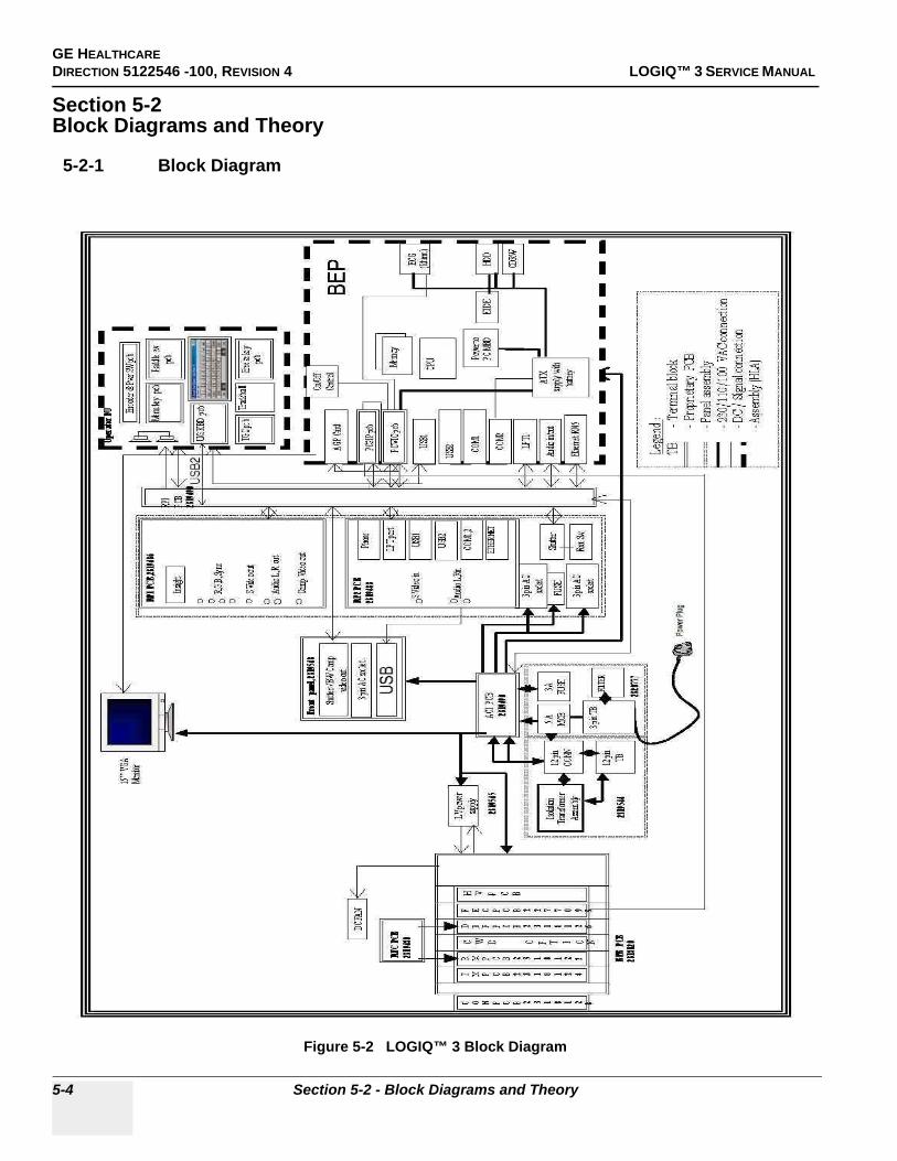
GE HEALTHCAREDIRECTION 5122546 -100, REVISION 4 LOGIQ™ 3 SERVICE MANUAL
Section 5-2Block Diagrams and Theory
5-2-1 Block Diagram
Figure 5-2 LOGIQ™ 3 Block Diagram
5-4 Section 5-2 - Block Diagrams and Theory

GE HEALTHCARE DIRECTION 5122546 -100, REVISION 4 LOGIQ™ 3 SERVICE MANUAL
5-2-2 Front EndThe Front End Consists of Conn. Board, Transmit Board, Receive Board & Digital Beam Former.
Figure 5-3 The Front End
The Front End generates electrical signals which are transmitted by the probes as ultrasound into the body. It also receives weak ultrasound echoes from blood cells and body structure, amplifies these signals and converts them to an 12 bit digital signal.
The digital representation of this signal is presented to the mid processor section.
RXB (Receive Board): The Preamplifier amplifies echo signals. The reception signals are sent to DBF.
DBF (Digital Beam Former): Performs receive delay summing for channels
TXB (Transmit Board): This has channel bipolar drivers, delay calculators.
Chapter 5 5-5
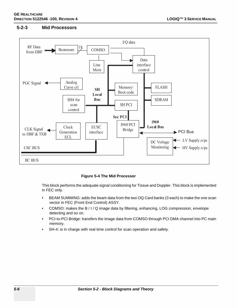
GE HEALTHCAREDIRECTION 5122546 -100, REVISION 4 LOGIQ™ 3 SERVICE MANUAL
5-2-3 Mid Processors
Figure 5-4 The Mid Processor
This block performs the adequate signal conditioning for Tissue and Doppler. This block is implemented in FEC only.
• BEAM SUMMING: adds the beam data from the two OQ Card banks (3 each) to make the one scan vector in FEC (Front End Control) ASSY.
• COMSO: makes the B / I / Q image data by filtering, enhancing, LOG compression, envelope detecting and so on.
• PCI-to-PCI Bridge: transfers the image data from COMSO through PCI DMA channel into PC main memory.
• SH-4: is in charge with real time control for scan operation and safety.
Memory/
Boot code
Line
Mem
Clock
Generation
ECL
Beamsum
Analog
Curve ctl
Data
interface
control
EUSC
interface
COMSO
I960 PCI
Bridge
SH4 for
scan
control
SDRAM
FLASH
i960
Local Bus
SH
Local
Bus
Sec PCI
SH PCI
18
I/Q data
PGC Signal
CLK Signal
to DBF & TXB
USC BUS
RF Data
from DBF
IIC BUS
DC Voltage
Monitoring
LV Supply o/ps
HV Supply o/ps
PCI Bus
5-6 Section 5-2 - Block Diagrams and Theory

GE HEALTHCARE DIRECTION 5122546 -100, REVISION 4 LOGIQ™ 3 SERVICE MANUAL
5-2-4 CPU/Backend Processor
Figure 5-5 CPU/Backend Processor
The Back End Processor grabs the data from the FEC, stores it in a main memory, performs scan conversion to pixel domain and drives the system RGB monitor.
The Back End Processor grabs the data from the Front End, stores it in a main memory, performs scan conversion to pixel domain and drives the system RGB monitor. Back End Processor software is also providing B mode, M mode, CFM, Doppler processing
BEP Box include ATX smps and UPS battery, ATX type P4 motherboard and P4 CPU. Memory capacity is 512MB minimum. AGP and PCI slots on motherboard contains followings
• AGP video card displays image on monitor. Monitor display resolution is 800 x 600, 75Hz.
NOTE: There is no Separate AGP present on the BEP2/3. It is integrated on the motherboard of the BEP2/3
• PCI Slot #1 VIC Card: Video Converter Board for VCR playback and VCR recording and analog video image printing
• PCI Slot #2: Open slot• PCI Slot #3 PC2IP card• PCI Slot #4 Sound Card (integrated on the BEP Motherboard in BEP2/3)• PCI Slot #5 Ethernet Card (integrated on the BEP Motherboard in BEP2/3)• PCI Slot #6: Open slot for 3D sensor card option (to be introduced in the future)Storing Devices:
• Hard Disk Drive (HD Drive) (Inside the PC box)• CD R/W Drive (Available from the front of scanner).• Optional Magneto Optical Drive (MO Drive) (Optional) (Available from the front of scanner).
Chapter 5 5-7

GE HEALTHCAREDIRECTION 5122546 -100, REVISION 4 LOGIQ™ 3 SERVICE MANUAL
5-2-5 VIC Card
VIC Card perform video conversion operations and Power on/off control.
• Video Decoder: Video decoder convert S-VHS or composite video analog signal to digital RGB data and send the RGB digital data into BEP main memory on motherboard through PCI bus. And then this video digital data is displayed on console monitor. Video analog signal comes from rear panel. This video decoder also have IIC bus interface logic.
• VGA to TV Convertor: This device convert the VGA display signal to TV display signal for B/W printer and color printer and VCR recording.
• Shutter Control CPLD: Shutter signals for analog B/W printer and color printer are generated by this CPLD. And this CPLD is controlled by video decoder via IIC bus.
• Power Control FPGA: This FPGA generates power on/off signal. This device is alive always by live DC power which comes from ACI assy in AC Power Assy. So this device monitor the status of power on/off switch on the keyboard. If power switch will be pushed once, this device turn on the LV power supply in AC power assy and after few seconds, turn on the BEP assy.
Figure 5-6 VIC Board
5-8 Section 5-2 - Block Diagrams and Theory

GE HEALTHCARE DIRECTION 5122546 -100, REVISION 4 LOGIQ™ 3 SERVICE MANUAL
5-2-6 Patient I/O (Option)The optional Patient I/O is mounted at the front of the scanner with its connector panel.
Available inputs:
• PCG• ECG• AUX1• AUX2• Top ConsoleThe Top Console includes a Stand By/On switch, a keyboard, different controls for manipulating the picture quality, controls for use in Measure & Analyze (M&A), and loudspeakers for stereo sound output (used during Doppler scanning, inside the Keyboard assy).
5-2-7 Keyboard
Keyboard assy provide all of operator interface for scan.Keyboard assy consist of several pieces of main function assembly.
• USB HUB Assy: The USB HUB assy has USB interface for upstream USB port which comes from BEP. USB HUB assy also has alpha numeric key interface, control functions and USB hub. So the USB trackball, the USB of main assy.
• MAIN Assy: The Main assy has a USB micom to interface between the main assy and USB hub assy. All function keys’ and encoders’ interface and controls are done by an additional control on the micom chip.
Figure 5-7 Keyboard Block Diagram
Chapter 5 5-9
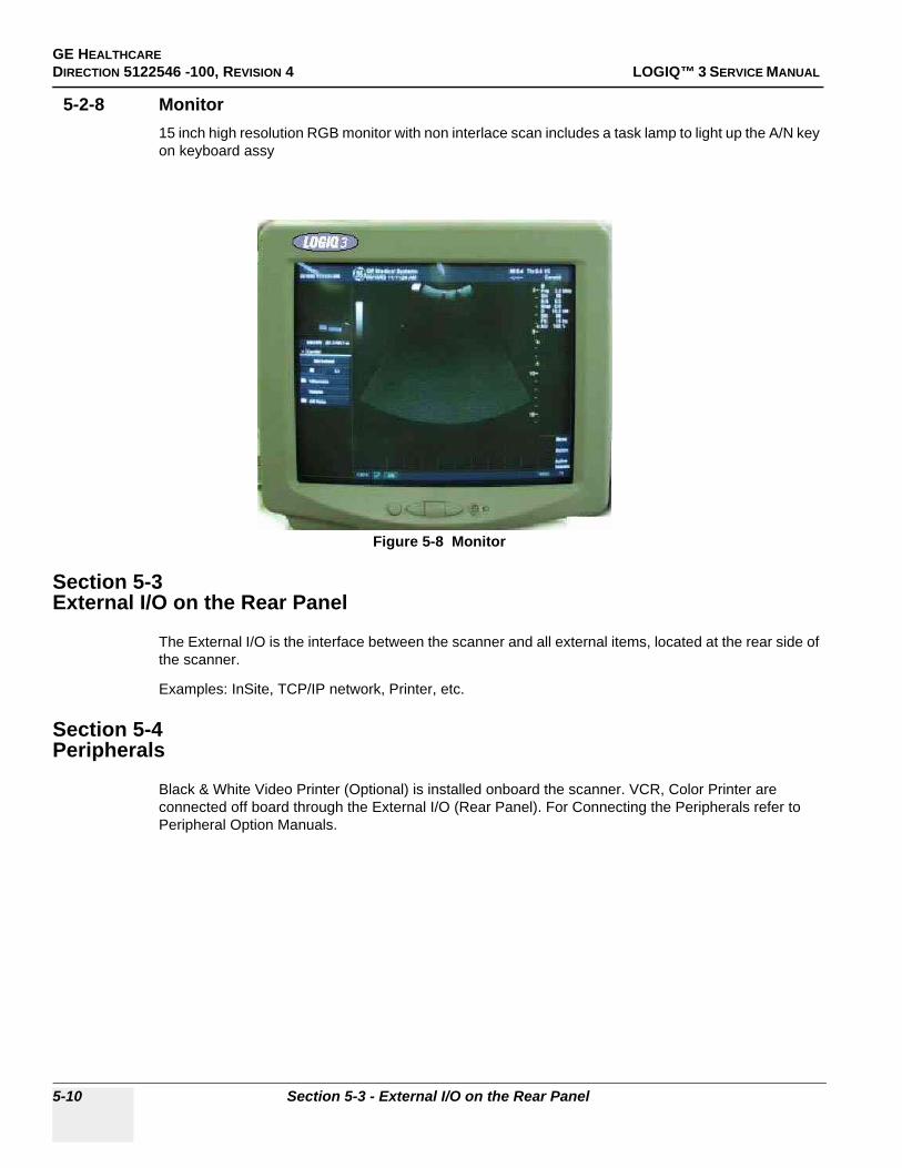
GE HEALTHCAREDIRECTION 5122546 -100, REVISION 4 LOGIQ™ 3 SERVICE MANUAL
5-2-8 Monitor15 inch high resolution RGB monitor with non interlace scan includes a task lamp to light up the A/N key on keyboard assy
Section 5-3External I/O on the Rear Panel
The External I/O is the interface between the scanner and all external items, located at the rear side of the scanner.
Examples: InSite, TCP/IP network, Printer, etc.
Section 5-4Peripherals
Black & White Video Printer (Optional) is installed onboard the scanner. VCR, Color Printer are connected off board through the External I/O (Rear Panel). For Connecting the Peripherals refer to Peripheral Option Manuals.
Figure 5-8 Monitor
5-10 Section 5-3 - External I/O on the Rear Panel

GE HEALTHCARE DIRECTION 5122546 -100, REVISION 4 LOGIQ™ 3 SERVICE MANUAL
Section 5-5Power Diagrams
5-5-1 OverviewThe AC Power’s main tasks are to supply the various internal subsystems and to galvanically isolate the scanner from the on site Mains Power System. To reduce inrush current, an inrush current limiter board has been included in the AC box.
5-5-2 AC Power
Figure 5-9 AC Power Distribution Block Diagram
The mains cord has plugs in one side end. A male plug connects to the mains outlet on site.
The mains voltage is routed to the Main Circuit Breaker, located on the rear of the system.
The Main Circuit Breaker is of the auto fuse type, if for some reason the current grows to high, the switch will automatically break the power.
From the Main Circuit Breaker, the AC power is routed via an Inrush Current Limiter to a internal outlet connector for the Mains Transformer.
PowerSwitch
&Noise Filter
Inrushlimiter &
power relay
PowerTransformer
SecondaryAC output
controlcircuit
AC Pwr Front Panel
AC Pwr Rear Panel
AC Pwr ATX (pc ps)
AC Pwr LVPS
AC Pwr HVPS
AC Pwr CRT(Monitor)AC power Cuntrol Circuit
Per_ONRac_ONSCLSDA5VDDVCCGND ACI Assembly
AC PowerSupply
AC MainsInput.
100VAC,/115VAC/230VAC
AC Pwr Modem
Chapter 5 5-11

GE HEALTHCAREDIRECTION 5122546 -100, REVISION 4 LOGIQ™ 3 SERVICE MANUAL
5-5-2 AC Power (cont’d)
The Transformer is the galvanic barrier between the rest of the scanner and the on site AC Mains. Input voltage to the transformer can be either 230 VAC or 115 VAC or 100 VAC.
AC Power is supplied directly to the ATX PS (PC Power supply, located on the PC box) and to the HV unit CRT Monitor and LV unit via ACI PCB.
When the Power switch is ON, this signal is outputted from VIC board to the following devices via KBD>RPI>VIC> Mother board.
• The signal is sent to PC Box, then sent to ATX PS, so that the ATX PS is switched ON to apply DC power to the PC.
• The signal is sent to ACI PCB so that the SSR is switched ON to apply AC power to the LV unit, HV unit, and CRT monitor.
• The signal is sent to ACI PCB so that the SSR is switched ON to apply AC power to AC outlets of the Rear panel/Front Panel
5-5-3 DC Power (Low Voltage)AC110V is supplied to the LV unit via AC Box > Transformer > ACI PCB. This is multiplied and rectified then step-downed to Low DC voltage to supply the devices/boards in the scanner.
The LV also support 12VDC for the system cooling fan.
DC Output Capacity:
• +3.3V, 20A• +5VD, 14A• +5V, 10A• -5V, 3A• +12V, 4A• -12V, 500mA (Generated on the Back PlaneBoard using DC/DC converter)
5-12 Section 5-5 - Power Diagrams

GE HEALTHCARE DIRECTION 5122546 -100, REVISION 4 LOGIQ™ 3 SERVICE MANUAL
5-5-4 TX Power/HV Power Supply
Figure 5-10 HV Unit Block Diagram
5-5-4-1 OverviewAC110V is supplied to the HV unit via AC Box > Transformer > ACI PCB. This is applied to the PFC, inside the HV unit. The PFC convert AC100V to DC400V, and DC voltage is applied to DC/DC, then to HVH, HVL, and SHV using dropper. They convert DC voltage to proper voltage to be outputted.
5-5-4-2 SpecificationsDC Output Capacity:
• HVH: +/- 0V to +/- 60V variable, Max. 110W, Max. 2A• HVL: +/-0V to +/- 30V variable, Max, 70W, 1A• +SHV: +80V +/- 5%, 80mA• -SHV: -80V +/- 5%, 80mA
5-5-4-3 Output Signal to FECThe following signals are sent to FEC via BACKPLANE board.
• OV (Over Voltage), OC (Over Current) of each power source: HV tests in itself. The result transmits the FEC via BACKPLANE ASSY.
5-5-4-4 Input Signal from FECThe following signals are sent to HV unit via FEC > BACKPLANE board.
• +5V, +/- 12V, HV STOP: These signals are sent to PFC to control DC voltage output of HVH, HVL, and -SHV. Normally HVSTOP is ON
• HVH Ref, HVL Ref: These are the digital signals (8 bits) sent to the DAC of HVH or HVL from FEC. Consequently, The DC Voltage (0 - 60V) is outputted from HV unit.
AC_IN PFC
PWM1(HVH)
PWM2(HVL)
PWM3(SVH)
DROPPER 1
DROPPER 1
DROPPER 2
DROPPER 2
DROPPER 3
DROPPER 3
+HVH(0~60V)
- HVH(0~ - 60V)
+HVL(0~30V)
- HVL(0~ - 30V)
+SVH(80V)
- SVH(80V)
Chapter 5 5-13

GE HEALTHCAREDIRECTION 5122546 -100, REVISION 4 LOGIQ™ 3 SERVICE MANUAL
Section 5-6Circuit Boards Descriptions
The following table lists circuit boards and their respective card cage slot assignments on the mother board of the LOGIQ™ 3 system.
Table 5-2 CIRCUIT BOARD DESCRIPTION
Card Cage Slot Board Name Description Note
1 TXB Transmit Board
2 RXB Receive Board
CWD Continuous Wave Doppler Board
3 DBF Digital Beam Former
4 FEC Front End Controller
5 HVPS High Voltage Power Supply
ACI AC Control Interface
Conn. Connector Board
RPL Rear Panel Assy RPI + RP1 + RP2
LVPS Low Voltage Power Supply
RPI Rear Panel Interface
BPB Back Plane Board
5-14 Section 5-6 - Circuit Boards Descriptions

GE HEALTHCARE DIRECTION 5122546 -100, REVISION 4 LOGIQ™ 3 SERVICE MANUAL
5-6-1 Front End
5-6-1-1 Connector Board
Figure 5-11 Connector Board - 2 Probe Port Type
Figure 5-12 Connector Board = 3 Probe Port Type
Probe
Connector
Probe
Connector
RelaysHV
Mux
128
128
128
FPGAConfig
ROM
B
U
F
USC Interface (From FEC)
Transmit/Receive Board48
Control
HV Supply
RELAY
EEPROM
IIC
Bus
Chapter 5 5-15

GE HEALTHCAREDIRECTION 5122546 -100, REVISION 4 LOGIQ™ 3 SERVICE MANUAL
OverviewConn. Board contains of 2 phased array probe connectors and provides switchable connection between probes and transmitters/receivers.
The main function of Connector Board is as follows.
- 2-to-1 or 3-to-1 selectors for two or three probes.- Interface with USC bus (control bus)- Interface with FEC ASSY for IIC bus.- Supply/Cut control and failure detection of supply voltage for Mux circuit in a Probe.- Device: Mechanical Relay- Switch: 128Ch 2:1 selector- Max. Voltage: 140Vp-p- Max. current: 0.5A- Connector Board can support upto 192 elements , for LOGIQ 3 Expert only.
Interface to Probe• Probe Status detection
- Detects whether or not a probe is connected.(POPEN)- Detects ID code of a connected probe.(PCODE)
• Mux Interface- Transfers control data of Mux to a probe.(CONSYS,CONSTA)- Enables/Disables control of data.- Detects whether Mux data setting is finished or not.
• Power Supply for Mux- Supply/Cut control:
+5V and +12V on a connector are supplied while a probe is connected to the connector.+/-SHV are supplied only while a probe is selected.
• Surface temperature- Detects resistance of a thermistor in a probe head as voltage when the probe is
selected.(PTEMP) This signal is connected to FEC.• LED Blinking
- The LED in a probe glows when the probe is selected. (Only on Selected probe which have LED’s)
IIC bus- Connects signals of IIC bus with a relay when IIC bus access is required.- Selects one of two probes that IIC access with 2-to-1 switch.- Board Rev, Board No., Part No., are stored in EEPROM and sent to FEC through IIC Bus.
5-16 Section 5-6 - Circuit Boards Descriptions

GE HEALTHCARE DIRECTION 5122546 -100, REVISION 4 LOGIQ™ 3 SERVICE MANUAL
5-6-1-2 Transmit Board
OverviewThe TXB Assy (Transmit Board) is designed for LOGIQ™ 3 system transmitter. This Assy has bipolar drivers, transmit pulse generator ASIC and so on.
Key Features- Main Items are
* TXIC: FPGA Interface and controller FPGA.* TPG 2 ASIC: Controller of pulse driver, Mixed signal ASIC.
- Bipolar drivers.
Figure 5-13 Transmit Board Block Diagram
TPG2
FPGAConfig
ROM
B
U
F
USC Interface (From FEC)
Control And Data bus
TPG2
TPG2
Clock
DRV
ECL
to TTL
Transmit Drivers
Transmit Drivers
Transmit Drivers
16
16
16
48
48
48
HV
DischargeHV Supply
48
CON/RX Board
EEPROMIIC Bus
Chapter 5 5-17

GE HEALTHCAREDIRECTION 5122546 -100, REVISION 4 LOGIQ™ 3 SERVICE MANUAL
5-6-1-3 CWD Board (Optional)
The major function of this board is analog beam forming by acting as a steering beam former and de-modulator. It receives analog input from the RXB via the RFC2 board and digital control input from FEC via the BPB.
It gives its digital output to FEC.
Figure 5-14
5-18 Section 5-6 - Circuit Boards Descriptions

GE HEALTHCARE DIRECTION 5122546 -100, REVISION 4 LOGIQ™ 3 SERVICE MANUAL
5-6-1-4 Receive Board
Sub-system receives and amplifies each echo signal. Then, all echo signals are outputted to the DBF Assy.
The RXB ASSY can amplify the echo signals. So, the echo signals are received by a RXB ASSY under appropriate control. The RXB ASSY are inserted into Nest box, which is composed of BACKPLANE and other boards.
The RXB ASSY have main three blocks: TR Switch, Pre-amp and Gain Control and Mode control block.
The Transmit/Receive Switch protects the receive amplifier from high voltage transmit pulse the RXB ASSY amplifies the echo signals. The mode control block selects a maximum gain code via dedicated control signals from FEC.
The analog voltage signal provided by Gain Control block gives total amplified gain.
The block diagram above of the RXB ASSY for a received signal is given. Actually, there are 48 echo adaptive channels in the assy.
The Pre-amp block consists of Low Noise Amplifier (LNA) which amplifies the RX Signal by fixed Gain and Time Gain Control Amplifier (TGC).
The Pre-amp block is controlled by totally 4digital signals and an analog signal. In digital, One for input impedance alternative low or high mode, another (3 bits) for choice of maximum gain code.
Figure 5-15 Receive Board
TR Switch Preamp/ VCA Limiter
TR Switch Preamp/ VCA Limiter
TR Switch Preamp/ VCA Limiter
CONTROL
5V
1.4
V
5V Supply
CON/TX Board DBF Board
48 48
0
1
47
REF GENERATOR
2.5
V
3.6
V
5
Control Signal from FEC
IIC BusEEPROM
Chapter 5 5-19
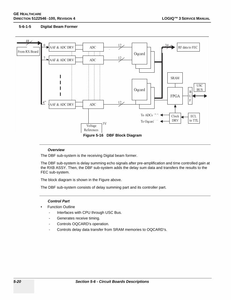
GE HEALTHCAREDIRECTION 5122546 -100, REVISION 4 LOGIQ™ 3 SERVICE MANUAL
5-6-1-5 Digital Beam Former
OverviewThe DBF sub-system is the receiving Digital beam former.
The DBF sub-system is delay summing echo signals after pre-amplification and time controlled gain at the RXB ASSY. Then, the DBF sub-system adds the delay sum data and transfers the results to the FEC sub-system.
The block diagram is shown in the Figure above.
The DBF sub-system consists of delay summing part and its controller part.
Control Part• Function Outline
- Interfaces with CPU through USC Bus.- Generates receive timing.- Controls OQCARD's operation.- Controls delay data transfer from SRAM memories to OQCARD’s.
Figure 5-16 DBF Block Diagram
AAF & ADC DRV ADC
ADC
ADC
AAF & ADC DRV
AAF & ADC DRV
From RX Board
48
0
7
47
5VVoltage
References
2 3 2 1
Oqcard
12
12
12
Oqcard
RF data to FEC34
Clock
DRV
ECL
to TTL
To ADCs (24)
To Oqcard (6)
FPGAB
U
F
SRAM
USC
BUS
5-20 Section 5-6 - Circuit Boards Descriptions

GE HEALTHCARE DIRECTION 5122546 -100, REVISION 4 LOGIQ™ 3 SERVICE MANUAL
• Operation Description- Scan Mode:
This mode is for imaging. The parameters specific to scan line number are sent to OQCARD’s and the start trigger for receiving signals is generated.
- Access Mode:This mode is for accessing SRAM memories and OQCARD’s.
5-6-2 Mid Processors
5-6-2-1 FEC
OverviewKey Features
• CHAF:(SPARE)Three CHAFs have functions of coded excitation decorder and 2nd harmonic filter.
• COMSO:Has functions of detector, B/M mode edge enhance, Log compression, and dynamic range control.
Figure 5-17 FEC Board
Chapter 5 5-21

GE HEALTHCAREDIRECTION 5122546 -100, REVISION 4 LOGIQ™ 3 SERVICE MANUAL
• PCI IF:Converts USC bus in FEC board. The local bus is connected to each block. It transfers B/M mode data to PACO FPGA via the COMSO data bus.
• USC IF:Has functions of generation to USC bus, generation of TGC signal and test signal for self-diagnostics, COMSO control, IIC Bus.
• CLK Generator Block:Generates 40MHz (two phases), and 26.6MHz clock using 160MHz master clock.
• Real Time Controller (RTCL):The TRIG cyclical Real Time Control is done by SH4 RISC processor. SH4 is a one of MID BUS agent through SH-PCI bridge.
• PCI - PCI Bridge:It Bridges between Mid bus and host side PCI bus by using i960RP. Mid bus is basically compliant to Compact PCI. Primary side PCI is connected to Host PC through PCI cable and PC2IP which is mounted on PCI slot of PC-motherboard.
• Image Data Transferring:It receives image data from COMSO, and send them to Host side. Data is buffered when receiving on COMSO data bus. After buffered, data is stored and handled on Local side of i960. And DMA function of i960RP perform data transferring to host PC memory.
• Peripheral Control:The SH4 or i960RP also performs other functions like safety observation, HV Control and so on
5-22 Section 5-6 - Circuit Boards Descriptions

GE HEALTHCARE DIRECTION 5122546 -100, REVISION 4 LOGIQ™ 3 SERVICE MANUAL
5-6-2-2 THI Board (integrated on FEC 2277093-9)
THI board gives an improved axial resolution and contrast feature.
THI is implemented using CHAF ASIC.
Figure 5-18
Chapter 5 5-23

GE HEALTHCAREDIRECTION 5122546 -100, REVISION 4 LOGIQ™ 3 SERVICE MANUAL
5-6-2-3 PC2IP Board
The PC2IP acts a means for communication between FEC and the BEP.
It is implemented using an Intel I960 IC.
Figure 5-19
5-24 Section 5-6 - Circuit Boards Descriptions

GE HEALTHCARE DIRECTION 5122546 -100, REVISION 4 LOGIQ™ 3 SERVICE MANUAL
5-6-3 CPU/Back End Processor
5-6-3-1 PC BOXThe PC Box contains:
- CPU, Mother Board, AGP Video Card and LAN Board- ATX Power Supply- HDD- CD R/W- ECG (Option)
Figure 5-20 PC Box
Part of Motherboard in BEP2/3
Part of Motherboard in BEP2/3
Part of Motherboard in BEP2/3
Chapter 5 5-25
GE HEALTHCAREDIRECTION 5122546 -100, REVISION 4 LOGIQ™ 3 SERVICE MANUAL
5-6-3-2 Rear PanelThe Rear Panel Assy interconnects external signals and power with the LOGIQ™ 3 system.
Safety• Rear Panel Fuses
• Electrical IsolationThe rear-panel's Insite (modem) interface is electrically isolated from the system's internal circuit. The isolator's dielectric strength should be 500VAC RMS or higher within 1 minute (in compliance with IEC60601-1-1).
Printer (Camera) Remote Control InterfaceThe Rear-panel has two remote control interface terminals for B/W and color printers.
Section 5-7Mechanical Descriptions
5-7-1 Monitor• Tilt: 10° forwards and backwards• Swivel: 90° From mean position
Table 5-3 Rear Panel Fuse Specification
AssemblyPower Voltage Rating
(V)Peripheral Current
Rating (A) Trip Time Reset Time
Rear Panel 100 5.0 1 hour max. @ 5.4A, 25 degree C 60 seconds
Rear Panel 115 5.0 1 hour max. @ 5.4A, 25 degree C 60 seconds
Rear panel 230 3.0 1 hour max. @ 3.5A, 25 degree C 60 seconds
Table 5-4 Camera (Printer) Remote Control Interface Specifications
Level (V) Active Polarity Retention Time
Color camera (shutter) control H:2.0/L:0.8 L 60 msec
B/W camera (printer) control H:2.0/L:1.0 L 800 msec
5-26 Section 5-7 - Mechanical Descriptions

GE HEALTHCARE DIRECTION 5122546 -100, REVISION 4 LOGIQ™ 3 SERVICE MANUAL
Section 5-8Air Flow Control
5-8-1 Air Flow DistributionThe four air flow passes allow the scanner to be cooled down as below.
• Pass A (Bottom right> PC Box > Rear upper left) for PC Box cooling.• Pass B (Front lower left > Filter > LV unit > Rear lower left) for HV unit cooling.• Pass C (Bottom left> Scan Box Assy > Rear upper right) for Scan Box Assy cooling.• Pass D (Bottom left> Filter >Nest Assy> Rear upper right) for Nest Assy cooling.
5-8-2 FiltersThe scanner contains one filter located below the Front Bumper Between Two Wheels.
5-8-3 Fans
The scanner contains the five fans at the following positions for producing an air flow.
- One fan: On the PC Box for air flow pass A- Four fans: At the top of the NEST Assy for air flow pass D
Figure 5-21 Fans
Fan for Nest Assy
Fan for PC Box
Chapter 5 5-27
GE HEALTHCAREDIRECTION 5122546 -100, REVISION 4 LOGIQ™ 3 SERVICE MANUAL
Section 5-9Common Service Platform
5-9-1 IntroductionThe Service Platform contains a set of software modules that are common to all PC backend ultrasound and cardiology systems. This web-enabled technology provides linkage to e-Services, e-Commerce, and the iCenter, making GE’s scanners more e-enabled than ever. The Common Service Platform will increase service productivity and reduce training and service costs.
5-28 Section 5-9 - Common Service Platform
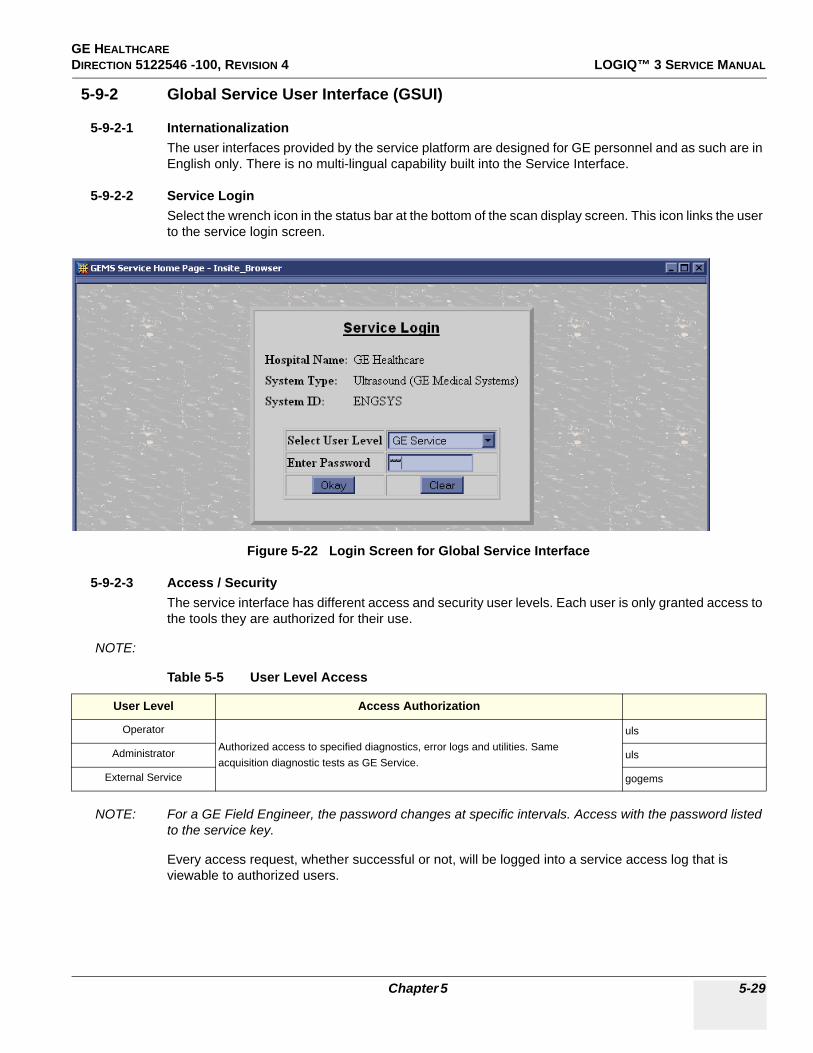
GE HEALTHCARE DIRECTION 5122546 -100, REVISION 4 LOGIQ™ 3 SERVICE MANUAL
5-9-2 Global Service User Interface (GSUI)
5-9-2-1 InternationalizationThe user interfaces provided by the service platform are designed for GE personnel and as such are in English only. There is no multi-lingual capability built into the Service Interface.
5-9-2-2 Service LoginSelect the wrench icon in the status bar at the bottom of the scan display screen. This icon links the user to the service login screen.
5-9-2-3 Access / SecurityThe service interface has different access and security user levels. Each user is only granted access to the tools they are authorized for their use.
NOTE:
NOTE: For a GE Field Engineer, the password changes at specific intervals. Access with the password listed to the service key.
Every access request, whether successful or not, will be logged into a service access log that is viewable to authorized users.
Figure 5-22 Login Screen for Global Service Interface
Table 5-5 User Level Access
User Level Access Authorization
OperatorAuthorized access to specified diagnostics, error logs and utilities. Sameacquisition diagnostic tests as GE Service.
uls
Administrator uls
External Service gogems
Chapter 5 5-29
GE HEALTHCAREDIRECTION 5122546 -100, REVISION 4 LOGIQ™ 3 SERVICE MANUAL
5-9-3 Service Home Page The navigation bar at the top of the screen allows the user to select from several tools and utilities.
5-30 Section 5-9 - Common Service Platform

GE HEALTHCARE DIRECTION 5122546 -100, REVISION 4 LOGIQ™ 3 SERVICE MANUAL
5-9-4 Error Logs PageFrom the Error Logs page the Log Viewer displays four categories with pull-down sub-menus and an Exit selection. The Service Interface allows scanner logs to be viewed by all service users.
The Filter Error log is not available to customer level analysis.
The log entries are color-coded to identify the error level severity at a glance
Table 5-6 Log Entry Key
Severity Error Level Color Code
1 Information Green
2 Warning Blue
3 Error Red
Figure 5-23 Log Viewer/Logs/Log Entries
Chapter 5 5-31

GE HEALTHCAREDIRECTION 5122546 -100, REVISION 4 LOGIQ™ 3 SERVICE MANUAL
5-9-4-1 LogsThe three sub-menus of the Logs category are System, Informatics and Temperature.
NOTE: Figure 5-23 on page 31 Provides a graphical example of the log entries for the System Logs.
Log table headings for the different logs are as follows:
• SystemLog entry headings include Time Stamp; Error Level; Package; and Error Message.
• InfomaticsLog entry headings include TimeStamp, Revision, PtID, PtDOB, PtSex, PtWeight, PtHeight, ExamID, Exam Category, ExamCurDate, and ExamStartTime.
• TemperatureLog entry headings include Time Stamp; Error Level; Package; Upper FEC Sensor; and Lower FEC Sensor.
5-32 Section 5-9 - Common Service Platform

GE HEALTHCARE DIRECTION 5122546 -100, REVISION 4 LOGIQ™ 3 SERVICE MANUAL
5-9-4-2 UtilitiesThe two sub-menus of the Utilities category are Plot Log and Plot Page.
• Plot LogAllows for the color coded plot of all Log contents with the package on the ‘x’ axis and incident count on the ‘y’ axis.
• Plot PageAllows for the color coded plot of all Page contents with the package on the ‘x’ axis and incident count on the ‘y’ axis.
Figure 5-24 Utilities Sub-Menus
Chapter 5 5-33
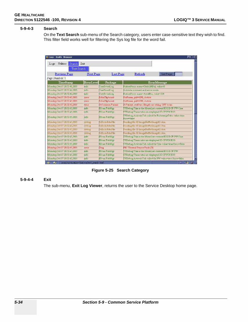
GE HEALTHCAREDIRECTION 5122546 -100, REVISION 4 LOGIQ™ 3 SERVICE MANUAL
5-9-4-3 SearchOn the Text Search sub-menu of the Search category, users enter case-sensitive text they wish to find. This filter field works well for filtering the Sys log file for the word fail.
5-9-4-4 ExitThe sub-menu, Exit Log Viewer, returns the user to the Service Desktop home page.
Figure 5-25 Search Category
5-34 Section 5-9 - Common Service Platform

GE HEALTHCARE DIRECTION 5122546 -100, REVISION 4 LOGIQ™ 3 SERVICE MANUAL
Figure 5-26 Exit Log Sub-Menu
Chapter 5 5-35

GE HEALTHCAREDIRECTION 5122546 -100, REVISION 4 LOGIQ™ 3 SERVICE MANUAL
5-9-5 DiagnosticsDetailed Diagnostic information is found in Chapter 7 Diagnostics/Troubleshooting.
5-9-5-1 Diagnostics ExecutionDiagnostic tests are executable by both local and remote users. The Service Platform provides top-level diagnostic selection based on the user’s level and login access permissions. Remote access will require disruptive diagnostic permissions to run Acquisition diagnostics.
5-9-5-2 Diagnostic ReportsDiagnostic tests return a report to the Service Platform. The platform retains the report and allows for future viewing of the diagnostic logs.
5-9-5-3 Proactive DiagnosticsA system of self-monitoring is largely supported with the integration of iLinq. The scheduler, executive, user interfaces, and some of the proactive diagnostic functions are provided by iLinq. Other tasks will need to be provided by the product team.
5-36 Section 5-9 - Common Service Platform

GE HEALTHCARE DIRECTION 5122546 -100, REVISION 4 LOGIQ™ 3 SERVICE MANUAL
5-9-6 Image QualityThe Image Quality page is intended to contain tools for troubleshooting image quality issues.
5-9-7 CalibrationThe Calibration page is intended to contain the tools used to calibrate the system
Figure 5-27 Image Quality Page
Figure 5-28 Calibration Page
FIELD IS NOT YET POPULATED
FIELD IS NOT YET POPULATED
Chapter 5 5-37

GE HEALTHCAREDIRECTION 5122546 -100, REVISION 4 LOGIQ™ 3 SERVICE MANUAL
5-9-8 ConfigurationThe Configuration page is used to setup various configuration files on the system.
The Service Platform is the access and authorization control for remote access to the configuration subsystem.
The enable/disable of software options can be done from this Configuration page.
Figure 5-29 Configuration Page
5-38 Section 5-9 - Common Service Platform

GE HEALTHCARE DIRECTION 5122546 -100, REVISION 4 LOGIQ™ 3 SERVICE MANUAL
5-9-9 UtilitiesThe Utilities page contains several miscellaneous tools.
5-9-10 ReplacementThe Replacement page intended to contain the tools used to track replacement parts used in the system.
Figure 5-30 Part Replacement Page
Chapter 5 5-39

GE HEALTHCAREDIRECTION 5122546 -100, REVISION 4 LOGIQ™ 3 SERVICE MANUAL
5-9-11 PMThe PM page is intended to contain the tools used in periodic maintenance of the system.
Figure 5-31 Planned Maintenance Page
5-40 Section 5-9 - Common Service Platform

GE HEALTHCARE DIRECTION 5122546-100, REVISION 4 LOGIQ™ 3 SERVICE MANUAL
Chapter 6Service AdjustmentsSection 6-1Overview
6-1-1 Purpose of Chapter 6This chapter describes how to test and adjust the mechanical capabilities of a scanner that may be out of specification. Although some tests may be optional they should only be performed by qualified personnel.
Section 6-2Regulatory
Verify, where applicable, that any regulatory information or tests required by national law are present and accounted for, and any regulatory tests required by national law are performed and documented.
Section 6-3Power Supply Adjustments
This system contains three power supply modules; HV unit, LV unit, and ATX PS. However, the LV unit
only can be adjusted.
1.) Power ON. Wait for about 30 seconds to warm up the console.2.) For each of the VR’s, connect a DVM to the appropriate place shown.3.) Verify that the voltages are as shown in the table 6-3 on the test points in the Transmit and
Recieve Board..
6-3-1 Access to Adjustments for LV Power Supply1.) Remove the left side cover.2.) Remove the LV unit cover.3.) Remove the screws, then pull out the LV unit Assy with the cables connected.
Table 6-1 Chapter 6 Contents
Section Description Page Number
6-1 Overview 6-1
6-2 Regulatory 6-1
6-3 Power Supply Adjustments 6-1
6-4 Monitor Adjustment 6-9
Chapter 6 6-1

GE HEALTHCAREDIRECTION 5122546-100, REVISION 4 LOGIQ™ 3 SERVICE MANUAL
Please ensure that the Voltages at the Test points on the Recieve board and FEC are as per
Specifications given in Table 6-2. If needed, Please re-adjust the potentiometers located on the LVPS as per the specifications given in Table 6-2.
Figure 6-1 LV Power Supply
LVPS
The LOGIQTM 3 Expert will have 3 Probe Ports as seen here
6-2 Section 6-3 - Power Supply Adjustments

GE HEALTHCARE DIRECTION 5122546-100, REVISION 4 LOGIQ™ 3 SERVICE MANUAL
Refer to the Figures mentioned in Table 6-2 for the exact location of the test points on the boards.
Refer to Figure 6-7 for the location of the VR potentiometers on the LVPS.
Refer to the Figure 6-2 for instructions on how to vary the voltage.
NOTE: The Potentiometers are very sensitive. Please be very careful at the time of adjusting the VRs as any extreme changes to the voltages will damage the Front End Boards.
Table 6-2 DC Output Specification for LV Unit
VR (Potentiometer on LVPS) Specifications PCB Name Test Point
VR1 3.3V +/- 34mV FEC D_3_3V - Figure 6-3
VR2 5V +/- 100mVany FEC D5V - Figure 6-4
VR3 5V +/- 100mV RXB P5VA - Figure 6-5
VR4 -5 V +/- 100mV RXB N5VA - Figure 6-6
Figure 6-2 VR Adjustment on the LVPS
Rotate the VR in the
Anti-Clockwise Directionto Reduce theVoltage
Rotate the VR in the Clockwise Directionto Increase the Voltage.
Chapter 6 6-3

GE HEALTHCAREDIRECTION 5122546-100, REVISION 4 LOGIQ™ 3 SERVICE MANUAL
6-3-1-1 Location of the test points.The following figures show the Test points for the various Potentiometers on the LVPS.
Figure 6-3 Test Point for VR1 - D_3_3V on the FEC
D_3_3V
FEC
(VR1)
6-4 Section 6-3 - Power Supply Adjustments

GE HEALTHCARE DIRECTION 5122546-100, REVISION 4 LOGIQ™ 3 SERVICE MANUAL
Figure 6-4 Test Point for VR2 - D5V on the FEC
D5V (VR2)
FEC
Chapter 6 6-5

GE HEALTHCAREDIRECTION 5122546-100, REVISION 4 LOGIQ™ 3 SERVICE MANUAL
Figure 6-5 Test Point for VR3 - P5VA on the RXB
P5VA(VR3)
Receive Board
6-6 Section 6-3 - Power Supply Adjustments
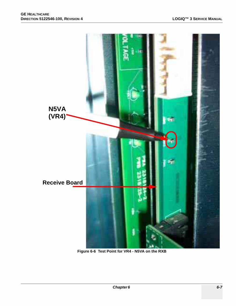
GE HEALTHCARE DIRECTION 5122546-100, REVISION 4 LOGIQ™ 3 SERVICE MANUAL
Figure 6-6 Test Point for VR4 - N5VA on the RXB
N5VA(VR4)
Receive Board
Chapter 6 6-7

GE HEALTHCAREDIRECTION 5122546-100, REVISION 4 LOGIQ™ 3 SERVICE MANUAL
Figure 6-7 Locations of the VR Potentiometers on the LVPS ( As Seen From Top)
VR1
VR2
VR3
VR4
6-8 Section 6-3 - Power Supply Adjustments
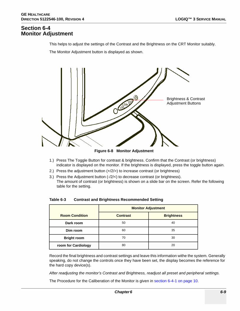
GE HEALTHCARE DIRECTION 5122546-100, REVISION 4 LOGIQ™ 3 SERVICE MANUAL
Section 6-4Monitor Adjustment
This helps to adjust the settings of the Contrast and the Brightness on the CRT Monitor suitably.
The Monitor Adjustment button is displayed as shown.
1.) Press The Toggle Button for contrast & brightness. Confirm that the Contrast (or brightness) indicator is displayed on the monitor. If the brightness is displayed, press the toggle button again.
2.) Press the adjustment button (+/2/>) to increase contrast (or brightness)3.) Press the Adjustment button (-/2/<) to decrease contrast (or brightness).
The amount of contrast (or brightness) is shown on a slide bar on the screen. Refer the following table for the setting.
Record the final brightness and contrast settings and leave this information withe the system. Generally speaking, do not change the controls once they have been set, the display becomes the reference for the hard copy device(s).
After readjusting the monitor’s Contrast and Brightness, readjust all preset and peripheral settings.
The Procedure for the Caliberation of the Monitor is given in section 6-4-1 on page 10.
Figure 6-8 Monitor Adjustment
Table 6-3 Contrast and Brightness Recommended Setting
Room Condition
Monitor Adjustment
Contrast Brightness
Dark room 50 40
Dim room 60 35
Bright room 70 30
room for Cardiology 80 20
Brightness & ContrastAdjustment Buttons
Chapter 6 6-9

GE HEALTHCAREDIRECTION 5122546-100, REVISION 4 LOGIQ™ 3 SERVICE MANUAL
6-4-1 Re-calibration the Monitor.1.) Power on the system and boot into the imaging mode.2.) Press the Utilities button on the front panel and enter the utilities mode as shown in Figure 6-9
Figure 6-9 Utilities Menu
6-10 Section 6-4 - Monitor Adjustment

GE HEALTHCARE DIRECTION 5122546-100, REVISION 4 LOGIQ™ 3 SERVICE MANUAL
3.) Select the Test Patterns Menu as seen shown in the Figure 6-10.
4.) From the Test patterns menu, select the menu White as seen in Figure 6-10.
Figure 6-10 Test Pattern Menu
Chapter 6 6-11

GE HEALTHCAREDIRECTION 5122546-100, REVISION 4 LOGIQ™ 3 SERVICE MANUAL
5.) Locate the Brightness/Contrast button on the monitor bezel as shown in Figure 6-11.
6.) Press and hold the Brightness/Contrast button on the monitor (as shown in Figure 6-11 above) for approximately 3 to 4 seconds.
7.) A menu will appear on the screen.8.) Press the right arrow 3 times to the RGB icon (COLOR TEMP) and press the Brightness/Contrast
button once to select it.9.) Now press right arrow 2 times to CALIBRATION and press Brightness/Contrast button to select it.10.)This will begin the Calibration process during which the monitor will cycle through various colors
and will end with the message “IT HAS COMPLETED...” which will only display for a short time and then disappear. Wait for this message to appear. During the Calibration Process, do not operate any key or the pointer of the system or the monitor Calibration process will not complete accurately.
This completes the Monitor Calibration of the LOGIQTM 3 system.
Figure 6-11 Brightness/Contrast Control
Brightness/Contrast Control
6-12 Section 6-4 - Monitor Adjustment

GE HEALTHCARE DIRECTION 5122546-100, REVISION 4 LOGIQ™ 3 SERVICE MANUAL
Chapter 7Diagnostics/TroubleshootingSection 7-1Overview
7-1-1 Purpose of Chapter 7This section describes how to setup and run the tools and software that help maintain image quality and system operation. Very basic host, system, and board level diagnostics are run whenever power is applied. Some Service Tools may be run at the application level. However most software tests are required.
7-1-2 Diagnostic Procedure SummaryAlthough Diagnostics can be run in any order, the Bottom-up Confidence-Building Order is outlined in this section:
- Provides a framework from which overall diagnostic testability can be determined.- Provides a top-level model that describes the confidence-building aspect of the diagnostics.- Provides a logical step-by-step approach to system check-out and fault isolation.
There are two levels of diagnostic: board-level and system level.
- Board-level diagnostics are intended to test functionality of a single circuit board.- System-level diagnostics are intended to test functionality on more than one circuit board.
Unused system components (board or signals) for each diagnostic test are drawn in gray (ghosted).
NOTE: In this document, the Host includes all hardware upstream of the PCI cable. The diagnostics in this chapter do NOT test anything upstream of the PCI cable. Therefore, any upstream hardware or software must be functional before running these diagnostics.
Table 7-1 Contents in Chapter 7
Section Description Page Number
7-1 Overview 7-1
7-2 Gathering Trouble Data 7-2
7-3 Screen Captures 7-4
7-4 Diagnostics 7-8
7-5 Common Diagnostics 7-11
7-6 Service Notes 7-12
Chapter 7 7-1
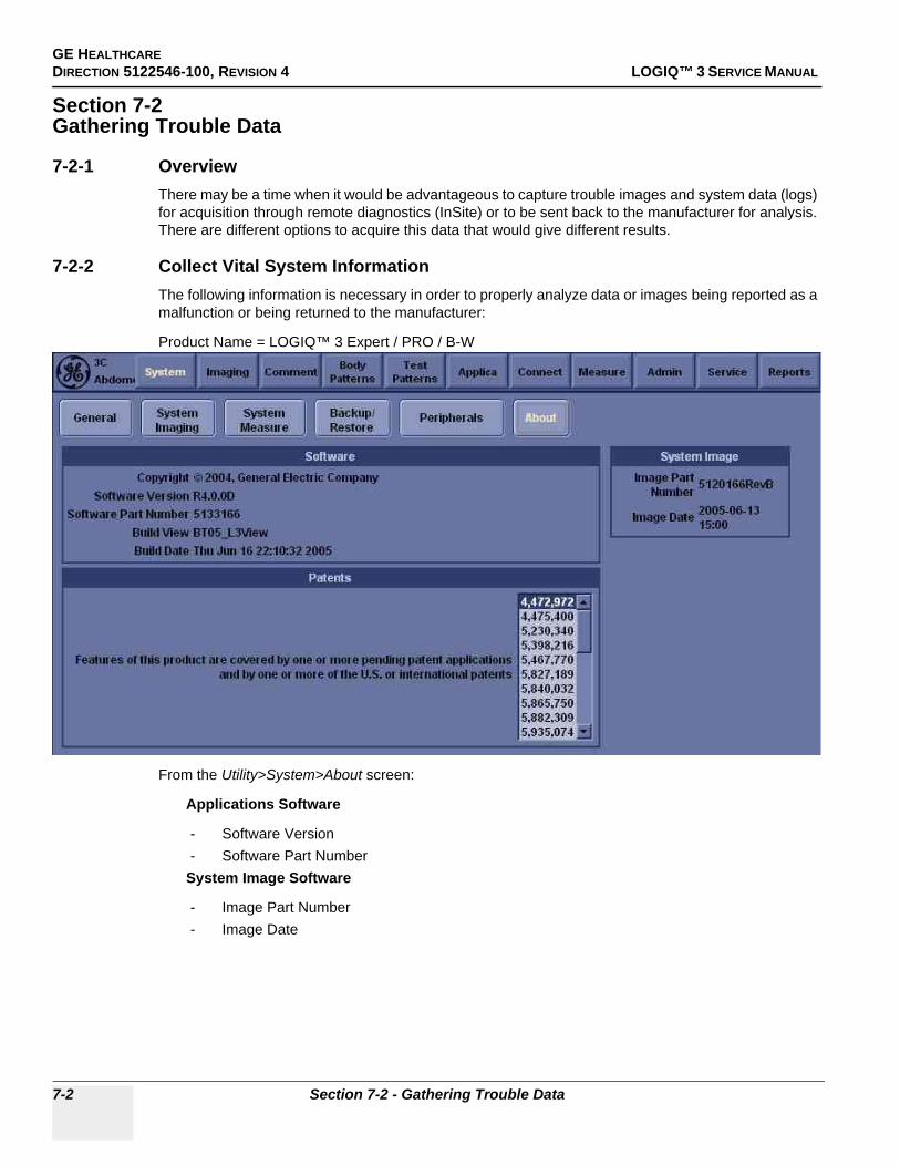
GE HEALTHCAREDIRECTION 5122546-100, REVISION 4 LOGIQ™ 3 SERVICE MANUAL
Section 7-2Gathering Trouble Data
7-2-1 OverviewThere may be a time when it would be advantageous to capture trouble images and system data (logs) for acquisition through remote diagnostics (InSite) or to be sent back to the manufacturer for analysis. There are different options to acquire this data that would give different results.
7-2-2 Collect Vital System InformationThe following information is necessary in order to properly analyze data or images being reported as a malfunction or being returned to the manufacturer:
Product Name = LOGIQ™ 3 Expert / PRO / B-W
From the Utility>System>About screen:
Applications Software
- Software Version- Software Part Number
System Image Software
- Image Part Number- Image Date
7-2 Section 7-2 - Gathering Trouble Data

GE HEALTHCARE DIRECTION 5122546-100, REVISION 4 LOGIQ™ 3 SERVICE MANUAL
7-2-3 Collect a Trouble Image with LogsIf the system should malfunction, press the Alt-D keys simultaneously. This will collect a screen capture of the image monitor, system presets and the following logs:
- Keyboard Shadow Log- Error Logs- Crash Log- Power Supply- Temperature
NOTE: Formate CD before using ‘ALT-D’
NOTE: Power Supply are not currently being updated by the LOGIQ™ 3.
This Alt-D function is available at all times.
When Alt-D is pressed, a menu box appears that allows for:
- A place to enter a description of the problem- A choice to store to a pre-formatted MOD (H: drive), CD-RW or to the Export directory D: drive
(for remote viewing through InSite).
NOTE: You MUST select H: or CD-RW as the destination device if it is to be different than the default Export directory on the hard drive. Choose the H: drive which is the MOD or the CD-RW.
The subsequent file is compressed and time stamped. The screen capture is a bitmap which eliminates the possibility of artifacts from compression.
Figure 7-1 ALT-D Dialog Box
Chapter 7 7-3

GE HEALTHCAREDIRECTION 5122546-100, REVISION 4 LOGIQ™ 3 SERVICE MANUAL
Section 7-3Screen Captures
There may be times when the customer or field engineer will want to capture a presentation on the screen so it may be recovered by the OnLine Center through InSite. This is accomplished by first saving the image(s) to the clipboard using a Print Key.
The P4 key is the factory default print key to accomplish a secondary screen capture. However, the default is for the video area only or the customer may have customized the P4 Key function. Therefore, screen capture should involve the following steps:
1.) Check and record any custom settings for the Print4 button.2.) Set the Print4 button to Whole Screen, Secondary Capture.3.) Capture the required screens to the Hard Drive, MOD or CD-R.4.) Restore the Print4 button to it’s original settings.
7-3-1 Check and Record the P4 Key FunctionCheck the function of the Print 4 Key in the event that the customer may have made some custom settings.
1.) Select Utility from the keyboard.2.) Select Connect from the Utilities Menu.3.) Select the Button tab on the Connect screen.4.) In the PhysicalPrintButtons field, select Print4.
The Connect->Button Screen will be displayed like the one shown in Figure 7-2 on page 4 .
P4 is the factory default Screen Capture Key. If it is not set to Whole Screen or Screen Capture, as shown in Figure 7-2, proceed to step 5 to record the customer’s custom settings.
Figure 7-2 Buttons Set Up Screen
7-4 Section 7-3 - Screen Captures

GE HEALTHCARE DIRECTION 5122546-100, REVISION 4 LOGIQ™ 3 SERVICE MANUAL
7-3-1 Check and Record the P4 Key Function (cont’d)
5.) In the Destinations section, record the service that is displayed. The destinations list displays the following information:* Name: user defined during service configuration* Type: the type of service* Destination Device: the device for which the service was configured* Dir: direction: output, input, or both (I+O)
6.) In the Image generated section, record the parameters related to the service.
7-3-2 Setting the P4 Key to Screen CaptureIf the P4 Key is not set to screen capture:
1.) While on the Connect screen, with the Buttons tab displayed, go to the drop down selection menu in the Destinations section.
2.) From the drop down menu select CopyToWflow_01>Image to Buffer>MyComputer>Out.3.) Ensure that the Image generated section for capture Area is set to Whole Screen, secondary
Capture and No Image Compression.4.) The P4 Key should now be set up for whole screen capture, sending the screens to the image
buffer (clipboard).
Chapter 7 7-5

GE HEALTHCAREDIRECTION 5122546-100, REVISION 4 LOGIQ™ 3 SERVICE MANUAL
7-3-3 Capturing a ScreenThe following is a generic process to capture any screen from the scanner:
1.) Navigate to and display the image/screen to be captured.2.) Press P4. This will place a snapshot of the screen on the “clipboard” displayed at the bottom
of the scan image display.
3.) Highlight the snapshot to be stored to the system hard drive, MOD or CD-R.4.) Select Menu on the right side of the image screen, then highlight and select SAVE AS.
Figure 7-3 Select Image to Capture
Figure 7-4 Menu > Save As
Clipboard Thumbnails
Menu
Save As
7-6 Section 7-3 - Screen Captures

GE HEALTHCARE DIRECTION 5122546-100, REVISION 4 LOGIQ™ 3 SERVICE MANUAL
7-3-3 Capturing a Screen (cont’d)
5.) A Save dialog box will be opened. Choose d:\export folder as the archive location to save the image on the hard disk, MOD or CD-R.
7-3-4 Reset the P4 Key to Customer’s FunctionalityIf the customer had programmed the P4 Key to a function other than screen capture, restore that functionality recorded in section 7-3-1 on page 4. Refer to Figure 7-2.
1.) Select Utility from the NTPUI.2.) Select Connect from the Utilities Menu.3.) Select the Button tab on the Connect screen.4.) In the PhysicalprintButtons field, select Print4.5.) In the Destinations section, select the service(s) recorded in step 5, Section 7-3-1. The
destinations list displays the following information:* Name: user defined during service configuration* Type: the type of service* Destination Device: the device for which the service was configured* Dir: direction: output, input, or both (I+O)
NOTE: Only output services can be associated to the print keys.
6.) In the Image generated section, select the parameters related to the service recorded in step 6, Section 7-3-1.
Figure 7-5 Save Dialog Box
Chapter 7 7-7

GE HEALTHCAREDIRECTION 5122546-100, REVISION 4 LOGIQ™ 3 SERVICE MANUAL
Section 7-4Diagnostics
As described in Chapter 5 - Components and Functions (Theory), the overall service platform uses a web-based user interface (UI) to provide access to common service components.
The Diagnostic home page displays a listing of test categories consisting of Common Diagnostics and LOGIQTM 3 Diagnostics. Expand the desired main category to select groups or individual tests.
Acquisition Diagnostics is one of three main headings under the GSUI Diagnostics Tab.
7-4-1 Serviceability1.) -Latest Service Platform Integrated for R4xx base.2.) -Boot-up into Simulation mode w/o FEC3.) -Latest WinXP with iLinq and InSite4.) -Improved Documentation of PM Procedure5.) -Improved Service Diag and Operator Interface 6.) -Total ALT+D (log file) size < 5MB7.) -No new Service tool.8.) -PC Doctor - compatible with XP9.) -System Network Information10.)-Customer notification (indication that service is logged to system - disruptive mode)11.)-Service presets related to iLinq introduced.12.)-Enter Service Menu using Utility/Service. ‘Wrench’ disabled.
7-8 Section 7-4 - Diagnostics

GE HEALTHCARE DIRECTION 5122546-100, REVISION 4 LOGIQ™ 3 SERVICE MANUAL
Individual selections run diagnostics and return status information identifying any problems.
When you select a test to run, the display changes as shown in Figure 7-7 on page 10 .
1.) Instructions Frame- Displays either a test-specific text or the default instructions.
2.) Status Frame- Initially displays the last known status for a selected diagnostic. Once the diagnostic starts,
the frame displays the “current” status of all test results.- The Status Frame also contains the user interface elements used for Diagnostic Control and
Operator Feedback.3.) Execute Button
- This switch has two modes - each with appropriate text:- Execute - to start the diagnostic- Abort - to stop a diagnostic
Figure 7-6 User Acquisition Diagnostics
Chapter 7 7-9

GE HEALTHCAREDIRECTION 5122546-100, REVISION 4 LOGIQ™ 3 SERVICE MANUAL
4.) Loop Count- This is an editable text field that will only accept numeric values of 4 digits or less. When the
switch is configured as an “execute” switch and pressed, the loop count field will be queried to determine the number of times to execute the diagnostic.
5.) Progress Indicator- Displays a graphical progress indicator for the user.
6.) Short Text Message- Displays brief messages about the test’s progress during execution.
7.) Status Frame Background Color- Initially gray, the Status Frame background color changes upon completion of a diagnostic to
indicate completion status.- Code Status Fail = Red- Code Status Pass = Green- Code Status Executing = Yellow- Code Status neither Pass nor Fail (Example: Aborted) = Gray (default color).
Figure 7-7 Diagnostic Selected
7-10 Section 7-4 - Diagnostics

GE HEALTHCARE DIRECTION 5122546-100, REVISION 4 LOGIQ™ 3 SERVICE MANUAL
Section 7-5Common Diagnostics
7-5-1 Utilities
7-5-2 PC Diagnostics (Non-Interactive Tests)The non-interactive or interactive PC Diagnostic tests are automatically executed only by clicking the following menu. The test log, displayed at the status frame, reports all diagnostic test results, the testing time, and testing date.
7-5-2-1 CPU Tests
7-5-2-2 Hard Drive Tests
7-5-2-3 Memory Tests
7-5-2-4 CD-ROM Drive Tests
7-5-2-5 Video Test
7-5-2-6 USB Test
7-5-2-7 PCI Board Configuration Test
7-5-2-8 Keyboard Test
7-5-2-9 Audio Test
Table 7-2 Utilities Mode
Items Descriptions
DisruptiveEnable: The disruptive diagnostic mode is ON and the other PC connected to the scanner via network
can operate the scanner remotely for troubleshooting.
System Shut Down N/A
Chapter 7 7-11

GE HEALTHCAREDIRECTION 5122546-100, REVISION 4 LOGIQ™ 3 SERVICE MANUAL
Section 7-6Service Notes
Table 7-3 Service Notes
Service Note Number Description Reference Page
SN-70411 Daylight Saving Time(DST)- New Dates Refer to 7-6-1
SN -73108DO NOT USE LOGIQ 3 MONITOR FRU P/N: 2319551-7 Refer to 7-6-2
SN-73104 LOGIQ 3 FRU New Collector Parts Refer to 7-6-3
SN-73102 LOGIQ 3 FMI 73069 Closure Refer to 7-6-4
SN -73100 LOGIQ 3 FMI 73074 Closure Refer to 7-6-5
SN -73098 LOGIQ 3 Debrief Guidelines Refer to 7-6-6
SN -73097 LOGIQ 3 FMI 73060 OFFICIALLY CLOSED Refer to 7-6-7
SN -73095 LOGIQ 3 BT05 New FRUs and compatibility matrix Refer to 7-6-8
SN-73092 Preventive Maintenance for LOGIQ3 Monitor Refer to 7-6-9
SN-73090 Additional System Serial Sticker Label Location Refer to 7-6-10
SN-73084 Keyboard Knobs Refer to 7-6-11
SN-73082 Introduction Of FMI 73068/70/71 Refer to 7-6-12
SN-73081
Logiq 3 Win XP Systems with S/W R.4.0.0 - Inclusion of Base and Application Software CDs inside the System
Refer to 7-6-13
SN-73080LOGIQ™ 3 - Introduction of Improved Keyboard Assembly Refer to 7-6-14
SN-73078 BIOS Settings Refer to 7-6-15
SN-73077
PC2IP Driver installation on BEP 2 System with PC2IP IIboard
Refer to 7-6-16
SN-73075 Introduction of New Receive Board Refer to 7-6-17
SN-73074
Introduction of FMI 73066-Monitor MCU Replacement andBrightness HV adjustment
Refer to 7-6-18
SN-73073 China power cord Refer to 7-6-19
SN-73064 CWD OPtion kit usage fr L3 Refer to 7-6-20
SN-73061 Replacement Of Logiq 3 Hardware FRU Refer to 7-6-21
SN-73058 Various Boards Used On the Logiq 3 Refer to 7-6-22
SN-73056 Various Boards Used On the Logiq 3 Refer to 7-6-23
SN-73055 Intermittent Hang Issues Related to the FEC Refer to 7-6-24
SN-73053 Backup and Restore Process in Logiq 3 Refer to 7-6-25
SN-73051 Monitor Signal Issues Refer to 7-6-26
SN-73050 Profer way to enter Maintenance mode on Logiq 3 Refer to 7-6-27
7-12 Section 7-6 - Service Notes

GE HEALTHCARE DIRECTION 5122546-100, REVISION 4 LOGIQ™ 3 SERVICE MANUAL
SN-73049 Hard ware ID Generation on the ACI Board Refer to 7-6-28
SN-73048 Preset Restore Refer to 7-6-29
Table 7-3 Service Notes
Service Note Number Description Reference Page
Chapter 7 7-13
GE HEALTHCAREDIRECTION 5122546-100, REVISION 4 LOGIQ™ 3 SERVICE MANUAL
7-6-1 SN-70411:Daylight Saving Time (DST) - New Dates
PROBLEM:Issue 1:
DST start and end dates have changed in some countries.
Issue 2:
The automatic Daylight Saving Time feature in Microsoft Windows products may no longer run on thecorrect date, causing the system’s time to be incorrect.
CAUSE:Some countries have changed their start and end dates for DST.
SOLUTION:Access Microsoft website http://support.microsoft.com/kb/928388 to determine if the system’s location site is affected.
Issue 1:
Adjust the system time manually at the start of DST and again at the conclusion.
Issue 2:
If the system relies on the automatic DST feature in Microsoft Windows, turn off the feature and then set the correct system time. Adjust the system time manually at the start of DST and again at the conclusion of DST.
Image Vault only: FMI 77203 for Image Vault 4.2 will be released in April. The upgrade involved with this FMI installs a Microsoft patch to address ongoing Daylight Saving Time changes. After the FMI is applied, the Image Vault will automatically update the system time on the correct date. Therefore, in November (and ongoing DST time periods), there will be no need to manually adjust the system time.
NOTE: For all products, whenever you install or reinstall application software, or perform a complete or partial base image load, confirm that the date and time are set correctly and that the Windows automatic DST feature is off, if applicable.
7-14 Section 7-6 - Service Notes

GE HEALTHCARE DIRECTION 5122546-100, REVISION 4 LOGIQ™ 3 SERVICE MANUAL
FOR ALL LOGIQ 3 PRODUCTS, To turn off the automatic DST feature and set the system time:
1.) Press Utility and then select System -> General.2.) Select Date/Time.3.) On the Date and Time Properties screen, select the Time Zone tab.4.) Uncheck the Automatically adjust clock for daylight saving changes checkbox, and select
Apply.5.) Select the Date & Time tab.6.) Set the proper time for the system’s location and select OK.7.) On the System screen, select Save.
TO CHECK OR SET THE SYSTEM TIME:1.) Press Utility and then select System -> General.2.) Select Date/Time.3.) On the Date and Time Properties screen, select the Date & Time tab.4.) Set the proper time for the system’s location and select OK.5.) On the System screen, select Save.
Chapter 7 7-15

GE HEALTHCAREDIRECTION 5122546-100, REVISION 4 LOGIQ™ 3 SERVICE MANUAL
7-6-2 SN 73108: DO NOT USE LOGIQ 3 MONITOR FRU P/N: 2319551-7
APPLIES TO:LOGIQ 3 FRU Monitor P/N: 2391551-7.
PROBLEM: Potential Monitor Failure issue if FRU P/N: 2391551-7 is used.
Failure Mode: No Display with a smoke from the rear side due to HOT failure.
SOLUTION:Order new monitor FRU P/N: 5308521 from GPO.
NOTE: GPO STOCK OF MONITOR FRU P/N: 2319551-7 is NIL.
7-16 Section 7-6 - Service Notes

GE HEALTHCARE DIRECTION 5122546-100, REVISION 4 LOGIQ™ 3 SERVICE MANUAL
7-6-3 SN 73104:LOGIQ 3 FRU New Collector PartsAPPLIES TO:
All LOGIQ 3 Systems
PROBLEM:LOGIQ 3 FRU new collector parts are introduced.
SOLUTION:New collector part numbers are as follows:
1. Place an order for required parts on GPO using the new collector part numbers.
2. For the parts accompanied with a regulatory label, ensure that the regulatory labels are pasted on the new part used on the system.
NEW FRU P/N: Description OLD FRU P/N: Remark
5308521 L3 Monitor FRU Asm 2319551-7 Packaging and Regulatory label added with the Monitor
5310200 Front Cover 3PP for L3 with labels 5116278 Regulatory label added
5309930 Moniter Side cover right for L3 with label 2320766 Regulatory label added
5309925 Monitor Top Cover for L3 with label 2320762 Regulatory label added
5142625 3 Probe Port EMI Cover Assembly with Copper Finger -------- New Part
5318665 Logiq 3 FRU Transformer Assembly 2406958 VA rating rationalized
2319490-3 ACI -AC Control Board Assembly - Loqiq3 2319490-2 In rush current improved
5248396 Logiq 3 Power cord - EU type 2342033 With molded connector
Chapter 7 7-17
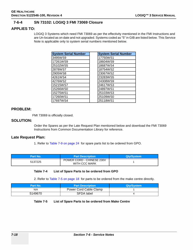
GE HEALTHCAREDIRECTION 5122546-100, REVISION 4 LOGIQ™ 3 SERVICE MANUAL
7-6-4 SN 73102: LOGIQ 3 FMI 73069 ClosureAPPLIES TO:
LOGIQ 3 Systems which need FMI 73069 as per the effectivity mentioned in the FMI Instructions and are Un-located as on date and not upgraded. Systems coded as "5" in GIB are listed below. This Service Note is applicable only to system serial numbers mentioned below.
PROBLEM: FMI 73069 is officially closed.
SOLUTION:Order the Spares as per the Late Request Plan mentioned below and download the FMI 73069 Instructions from Common Documentation Library for reference.
Late Request Plan:1. Refer to Table 7-9 on page 24 for spare parts list to be ordered from GPO.
Table 7-4 List of Spare Parts to be ordered from GPO
2. Refer to Table 7-5 on page 18 for parts to be ordered from the make centre directly.
Table 7-5 List of Spare Parts to be ordered from Make Centre
Part No. Part Description Qty/System
5137225 POWER CORD - CHINESE 230V WITH CCC MARK 1
Part No. Part Description Qty/SystemN/A Power Cord Cable Clamp 1
5149670 SFDA label 4
System Serial Number System Serial Number3495WS9 17750WS117261WS9 18604WS925102WS5 18687WS42878WS7 18754WS22905WS8 23067WS24261WS4 23283WS54276WS2 24308WS915215WS7 24617WS315266WS0 24897WS115275WS1 25103WS317260WS1 25109WS017697WS4 25118WS1
7-18 Section 7-6 - Service Notes
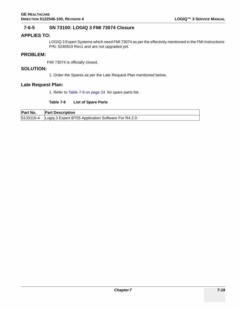
GE HEALTHCARE DIRECTION 5122546-100, REVISION 4 LOGIQ™ 3 SERVICE MANUAL
7-6-5 SN 73100: LOGIQ 3 FMI 73074 ClosureAPPLIES TO:
LOGIQ 3 Expert Systems which need FMI 73074 as per the effectivity mentioned in the FMI Instructions P/N: 5240919 Rev1 and are not upgraded yet.
PROBLEM: FMI 73074 is officially closed.
SOLUTION:1. Order the Spares as per the Late Request Plan mentioned below.
Late Request Plan:1. Refer to Table 7-9 on page 24 for spare parts list.
Table 7-6 List of Spare Parts
Part No. Part Description5133116-4 Logiq 3 Expert BT05 Application Software For R4.2.0.
Chapter 7 7-19
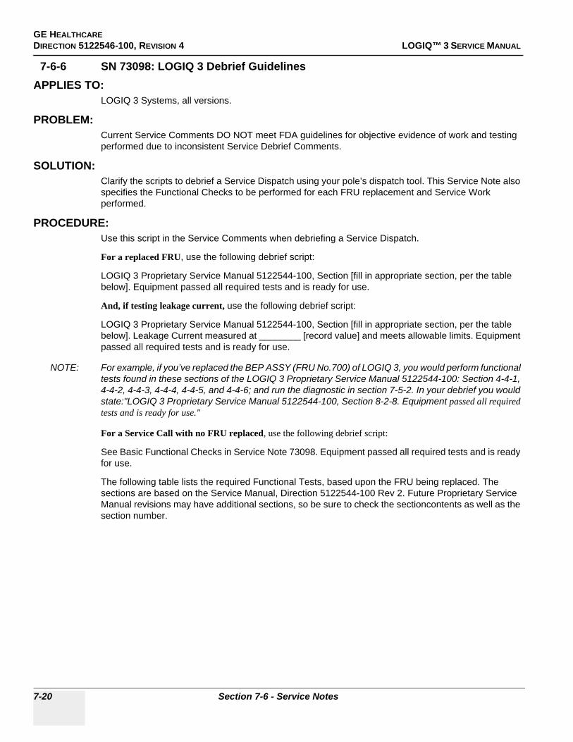
GE HEALTHCAREDIRECTION 5122546-100, REVISION 4 LOGIQ™ 3 SERVICE MANUAL
7-6-6 SN 73098: LOGIQ 3 Debrief GuidelinesAPPLIES TO:
LOGIQ 3 Systems, all versions.
PROBLEM:Current Service Comments DO NOT meet FDA guidelines for objective evidence of work and testing performed due to inconsistent Service Debrief Comments.
SOLUTION:Clarify the scripts to debrief a Service Dispatch using your pole’s dispatch tool. This Service Note also specifies the Functional Checks to be performed for each FRU replacement and Service Work performed.
PROCEDURE:Use this script in the Service Comments when debriefing a Service Dispatch.
For a replaced FRU, use the following debrief script:
LOGIQ 3 Proprietary Service Manual 5122544-100, Section [fill in appropriate section, per the table below]. Equipment passed all required tests and is ready for use.
And, if testing leakage current, use the following debrief script:
LOGIQ 3 Proprietary Service Manual 5122544-100, Section [fill in appropriate section, per the table below]. Leakage Current measured at ________ [record value] and meets allowable limits. Equipment passed all required tests and is ready for use.
NOTE: For example, if you’ve replaced the BEP ASSY (FRU No.700) of LOGIQ 3, you would perform functional tests found in these sections of the LOGIQ 3 Proprietary Service Manual 5122544-100: Section 4-4-1, 4-4-2, 4-4-3, 4-4-4, 4-4-5, and 4-4-6; and run the diagnostic in section 7-5-2. In your debrief you would state:"LOGIQ 3 Proprietary Service Manual 5122544-100, Section 8-2-8. Equipment passed all required tests and is ready for use."
For a Service Call with no FRU replaced, use the following debrief script:
See Basic Functional Checks in Service Note 73098. Equipment passed all required tests and is ready for use.
The following table lists the required Functional Tests, based upon the FRU being replaced. The sections are based on the Service Manual, Direction 5122544-100 Rev 2. Future Proprietary Service Manual revisions may have additional sections, so be sure to check the sectioncontents as well as the section number.
7-20 Section 7-6 - Service Notes

GE HEALTHCARE DIRECTION 5122546-100, REVISION 4 LOGIQ™ 3 SERVICE MANUAL
Table 7-7 Functional Test Matrix of LOGIQ 3
Section FRU No. Description Diagnostics Leakage Current Functional Tests8-2-1 100 Monitor Assy 7-5-3-2 10-7-4, 10-7-5 4-3-1, 4-4-1
8-2-2 ~ 8-2-5 101~104 Monitor Covers 4-3-1, 4-4-1
8-2-6 105 Monitor Switch Assy 7-5-3-2 4-3-1, 4-4-1
8-2-7 106 Task Lamp 4-3-1, 4-4-1
8-3-1 200 Keyboard Assy 7-5-3-1 4-3-1, 4-4-1, 4-4-2, 4-4-3, 4-4-4, 4-4-5, 4-4-6, 4-4-7
8-3-2 201 Probe Holder 4-3-1, 4-4-1
8-3-3 Speaker Pair 7-5-3-2
8-3-4 202 Keyboard TGC Assy 7-5-3-1 4-3-1, 4-4-1, 4-4-2, 4-4-3, 4-4-4, 4-4-5, 4-4-6, 4-4-7
8-3-5 203 HUB PCB Assy 7-5-3-1 4-3-1, 4-4-1, 4-4-2, 4-4-3, 4-4-4, 4-4-5, 4-4-6, 4-4-7
8-3-6 204 A/N Keyboard Assy 7-5-3-1 4-3-1, 4-4-1, 4-4-2, 4-4-3, 4-4-4, 4-4-5, 4-4-6, 4-4-7
8-3-7 205 Keyboard Trackball Assy 7-5-3-1 4-3-1, 4-4-1, 4-4-2, 4-4-3, 4-4-4, 4-4-5, 4-4-6, 4-4-7
8-3-8 206 Keyboard Freezekey Assy 7-5-3-1 4-3-1, 4-4-1, 4-4-2, 4-4-3, 4-4-4, 4-4-5, 4-4-6, 4-4-7
8-3-9 207 Power switch and Encoder PCB Assy 7-5-3-1 4-3-1, 4-4-1, 4-4-2, 4-4-3, 4-4-4, 4-4-5, 4-4-6,
4-4-7
8-3-10 208 Keyboard Power cable 7-5-3-1 4-3-1, 4-4-1, 4-4-2, 4-4-3, 4-4-4, 4-4-5, 4-4-6, 4-4-7
8-4-1 ~ 8-4-3, 8-4-8 ~ 8-4-11,
8-4-13
300 ~ 302, 306 ~ 306,
308Covers 4-3-1, 4-4-1
8-4-4 ~ 8-4-7, 8-4-12
303, 311 ~ 312, 307 Bumpers 4-3-1, 4-4-1
8-4-14 ~ 4-4-19 EMI Covers 10-7-4, 10-7-5 4-3-1, 4-4-1
8-4-20 VGP Tray 4-3-1, 4-4-1
8-4-21 400 Handle Rod 4-3-1, 4-4-1
8-4-22 ~ 8-4-23 401 ~ 402 Front Casotr/ Rear Castor 4-3-1, 4-4-1
8-4-24 403 Air Filter 4-3-1, 4-4-1
8-4-25 404 Card Cage Fan Assy 4-3-1, 4-4-1
8-5-1 ~ 8-5-4 500 ~ 503 Rear Panel 4-3-1, 4-4-1, 4-4-2, 4-4-3, 4-4-4, 4-4-5, 4-4-6, 4-4-7
8-5-5 504 Front Panel 4-3-1, 4-4-1, 4-4-2, 4-4-3, 4-4-4, 4-4-5, 4-4-6, 4-4-7
8-5-6 505 Rear Panel Fuse 4-3-1, 4-4-1
8-6-1 601 ~ 605, 608, 609 PCB Boards 7-6-2 4-3-1, 4-4-1, 4-4-2, 4-4-3, 4-4-4, 4-4-5, 4-4-6,
4-4-7
8-6-2 ~ 8-6-3 606 Connector Board assy 7-6-2 4-3-1, 4-4-1, 4-4-2, 4-4-3, 4-4-4, 4-4-5, 4-4-6, 4-4-7
8-6-5 700 BEP Assy 7-5-2-1 4-3-1, 4-4-1, 4-4-2, 4-4-3, 4-4-4, 4-4-5, 4-4-6, 4-4-7
8-6-6 701 Hard Disk Drive 7-5-2-2 4-3-1, 4-4-1, 4-4-2, 4-4-3, 4-4-4, 4-4-5, 4-4-6, 4-4-7
8-6-7 702 Compact Disk Read Write 7-5-2-4 4-3-1, 4-4-1
8-6-8 703 BEP Power supply 10-7-4, 10-7-5 4-3-1, 4-4-1, 4-4-2, 4-4-3, 4-4-4, 4-4-5, 4-4-6, 4-4-7
Chapter 7 7-21

GE HEALTHCAREDIRECTION 5122546-100, REVISION 4 LOGIQ™ 3 SERVICE MANUAL
8-6-9 704 PCVIC 7-6-2 4-3-1, 4-4-1, 4-4-2, 4-4-3, 4-4-4, 4-4-5, 4-4-6, 4-4-7
8-6-10 706 PC2IP 4-3-1, 4-4-1, 4-4-2, 4-4-3, 4-4-4, 4-4-5, 4-4-6, 4-4-7
8-7-1 800 Transformer Assy 10-7-4, 10-7-5 4-3-1, 4-4-1, 4-4-2, 4-4-3, 4-4-4, 4-4-5, 4-4-6, 4-4-7
8-7-2 801 LVPS 10-7-4, 10-7-5 4-3-1, 4-4-1, 4-4-2, 4-4-3, 4-4-4, 4-4-5, 4-4-6, 4-4-7
8-7-3 802 ACI Board 10-7-4, 10-7-5 4-3-1, 4-4-1, 4-4-2, 4-4-3, 4-4-4, 4-4-5, 4-4-6, 4-4-7
8-7-4 803 Fuse 4-3-1, 4-4-1
8-7-5 804 Circuit Breaker 10-7-4, 10-7-5 4-3-1, 4-4-1, 4-4-2, 4-4-3, 4-4-4, 4-4-5, 4-4-6, 4-4-7
8-7-7 805 Noise Filter 4-3-1, 4-4-1, 4-4-2, 4-4-3, 4-4-4, 4-4-5, 4-4-6, 4-4-7
8-8 ~ 8-12 Base/Application Software Loading
4-3-1, 4-4-1, 4-4-2, 4-4-3, 4-4-4, 4-4-5, 4-4-6, 4-4-7, 4-5
9-14 1100~1103 VCR 10-7-4, 10-7-5 4-6
9-14 1104~1116 Printer 10-7-4, 10-7-5 4-6
9-14 1107~1118 USB 2.0 Flash Memory 4-6
9-15 1200 Cables Set 10-7-4, 10-7-5 4-3-1, 4-4-1, 4-4-2, 4-4-3, 4-4-4, 4-4-5, 4-4-6, 4-4-7
9-16 ECG 10-7-6, 10-7-7, 10-7-8
9-16 1316 THI Board 10-7-4, 10-7-5 4-3-1, 4-4-1, 4-4-2, 4-4-3, 4-4-4, 4-4-5, 4-4-6, 4-4-7
9-16 1317 Additional Probe Port 10-7-9 4-7-1
9-16 1318 Foot Switch 10-7-4, 10-7-5 4 -6
9-13 1000~1011 Probes 10-7-9 4-7-1
Section FRU No. Description Diagnostics Leakage Current Functional Tests
7-22 Section 7-6 - Service Notes

GE HEALTHCARE DIRECTION 5122546-100, REVISION 4 LOGIQ™ 3 SERVICE MANUAL
Table 7-8 Test Key of LOGIQ 3
Section (Test Key) Test Description4-3-1 Power On/Boot Up
4-4-1 Basic Controls
4-4-2 B Mode Checks
4-4-3 M Mode Controls
4-4-4 Color Flow Mode Checks
4-4-5 Doppler Mode Checks
4-4-6 Measurement and Multi Image Checks
4-4-7 Basic Measurements
4--5 Software Configuration Checks
4 -6 Peripheral Checks
4-7-1 Probe/Connectors Check
7-5-2 PC Diagnostics (Non- Ineractive Tests)
7-5-3-1 PC Diagnostics (Interactive Tests) : Keyboard Tests
7-5-3-2 PC Diagnostics (Interactive Tests) : Audio/Monitor Tests
7-6-2 FRU Tests
10-7-4 Grounding Continuity
10-7-5 Chassis Leakage Current Test
10-7-6 Isolated Patient Lead (Source) Leakage–Lead to Ground
10-7-7 Isolated Patient Lead (Source) Leakage–Lead to Lead
10-7-8 Isolated Patient Lead (Sink) Leakage-Isolation Test
10-7-9 Probe Leakage Current test
Chapter 7 7-23
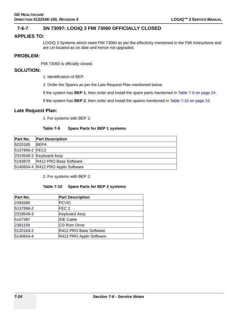
GE HEALTHCAREDIRECTION 5122546-100, REVISION 4 LOGIQ™ 3 SERVICE MANUAL
7-6-7 SN 73097: LOGIQ 3 FMI 73060 OFFICIALLY CLOSEDAPPLIES TO:
LOGIQ 3 Systems which need FMI 73060 as per the effectivity mentioned in the FMI Instructions and are Un-located as on date and hence not upgraded.
PROBLEM: FMI 73060 is officially closed.
SOLUTION:1. Identification of BEP.
2. Order the Spares as per the Late Request Plan mentioned below.
If the system has BEP 1, then order and install the spare parts mentioned in Table 7-9 on page 24 .
If the system has BEP 2, then order and install the spares mentioned in Table 7-10 on page 24
Late Request Plan:1. For systems with BEP 1:
Table 7-9 Spare Parts for BEP 1 systems
2. For systems with BEP 2:
Table 7-10 Spare Parts for BEP 2 systems
Part No. Part Description5220185 BEP45137896-2 FEC2 2319549-3 Keyboard Assy5193870 R412 PRO Base Software5140654-4 R412 PRO Appln Software
Part No. Part Description2393280 PCVIC5137896-2 FEC 22319549-3 Keyboard Assy5167387 IDE Cable2381159 CD Rom Drive5120163-2 R412 PRO Base Software5140654-4 R412 PRO Appln Software
7-24 Section 7-6 - Service Notes

GE HEALTHCARE DIRECTION 5122546-100, REVISION 4 LOGIQ™ 3 SERVICE MANUAL
7-6-8 SN 73095: LOGIQ 3 BT05 New FRUs and compatibility matrixAPPLIES TO:
All LOGIQ 3 Systems with software version R4.x.x.
Note:
Also applicabe to LOGIQ 3 Systems with software version R2.x.x but they have to be upgraded to R4.x.x and the presets have to be re-set accordingly before using the FRUs mentioned below.
Refer Applicability Matrix below.
PROBLEM:The new FRU’s are introduced.
SOLUTION:The FRU part numbers are as follows:
Software:
Hardware:
1. Place an order for required parts at GPO and procure the FRUs.
Part Description Part Number* R4.2.0 Expert Application Software 5133116-4* R4.1.2 PRO Application software 5140654-4* R4.1.2 B-W Application software 5140661-3* BEP4 R4 Base Software 5193870* BEP3 R4 Base Software 5120166-3* BEP2 R4 Base Softwaare 5120163-2
Part Description Part NumberBEP 4 5220185FEC2 5137896-2PC2IP3 5220187Hard Disk 5237487Emblem Set 5224149Logiq 3 Monitor Assembly 2319551-7
Chapter 7 7-25

GE HEALTHCAREDIRECTION 5122546-100, REVISION 4 LOGIQ™ 3 SERVICE MANUAL
COMPATIBILITY MATIX:
7-26 Section 7-6 - Service Notes

GE HEALTHCARE DIRECTION 5122546-100, REVISION 4 LOGIQ™ 3 SERVICE MANUAL
7-6-9 Sn 73092: Preventive Maintenance Of LOGIQ 3 MonitorAPPLIES TO:
All LOGIQ 3 Systems beginning with serial number 28365WS5 and higher.
PROBLEM: Color Tinge issue found on the LOGIQ 3 Monitor. The color tinge (reddish, greenish, or bluish) may be seen across the entire screen or in some regions of the screen.
CAUSE:Polarization of Monitor Magnetic field due to external Magnetic field effect.
Figure 7-8 Color tinge Issue in LOGIQ 3 Monitor
Chapter 7 7-27

GE HEALTHCAREDIRECTION 5122546-100, REVISION 4 LOGIQ™ 3 SERVICE MANUAL
SOLUTION:Degaussing and Calibration of the monitor in "Factory settings mode" resolves the issue mentioned in the "PROBLEM" section. Follow the below process to "Degauss and Calibrate" the monitor as part of the Preventive Maintenance(or as part of service corrective action).
Step:1.)Power on the Logiq 3 system. Wait for the system to boot to the scan screen.Step:2.)Press "Utility" Button.Step:3.)Select "TestPatterns" tab.
Figure 7-9 TestPatterns Tab Selection
A- Test Patterns Tab
A
7-28 Section 7-6 - Service Notes

GE HEALTHCARE DIRECTION 5122546-100, REVISION 4 LOGIQ™ 3 SERVICE MANUAL
Step:4.)Move the track ball pointer over the left hand column of tabs and select "White" test pattern button. Slowly move the trackball pointer away from the "White" test pattern button so as to not accidently select another test pattern, and move the pointer off the screen completely so the pointer is not visible.
Figure 7-10 WhitePatterns Selection
B- White button
B
Chapter 7 7-29

GE HEALTHCAREDIRECTION 5122546-100, REVISION 4 LOGIQ™ 3 SERVICE MANUAL
Step:5.)On the Monitor front please find 3 keys shown in Fig7-50. Press "2" key shown in fig 7-50, which is the menu key, and keep pressing it for 9 seconds to display factory settings on the screen.
NOTE: Please hold the "2- Menu Key" as shown in Figure 7-50 to display Factory settings window[DARK BLUE WINDOW] as shown in Figure 7-51 on the screen.
Figure 7-11 Factory Settings Menu Selection
1-Left Key 2-Menu Key 3-Right Key
Figure 7-12 FACTORY Settings Windows
1- Factory Settings window
1 2 3
1
7-30 Section 7-6 - Service Notes

GE HEALTHCARE DIRECTION 5122546-100, REVISION 4 LOGIQ™ 3 SERVICE MANUAL
Step:6.)Select "DEGAUSS" from "Factory Settings Window" by using Left/Right Menu keys and then press "2-Menu Key" to start "DEGAUSS" operation.
Step:7.)Repeat step 5 to display "Factory Settings window".Step:8.)Select "RGB" by using Left/Right keys.Step:9.) Press "Menu Key" to display "RGB Menu".Step:10.)Select "CALIBRATION" by using Left/Right Menu keys.Step:11.) Press "Menu Key" to start "calibration" process.
Figure 7-13 Settings Windows
1- DEGAUSS Item
Figure 7-14 Settings Windows
1- RGB Item 2- CALIBRATION Item
1
1
2
Chapter 7 7-31

GE HEALTHCAREDIRECTION 5122546-100, REVISION 4 LOGIQ™ 3 SERVICE MANUAL
Step:12.)Calibration process takes few minutes. Please wait without activating the system or keyboard.
Step:13.) Repeat "Step 5" to display "FACTORY SETTINGS Window". Select "RECALL" by using "Left/Right Menu Key" and then press "Menu key" to start "Recall" operation.
Step:14.)Reboot the system. Step:15.)Check whether the color tinge issue is resolved. If not contact OLC for further help
to resolve the issue.
Figure 7-15 Settings Windows
Figure 7-16 Settings Windows
1- RECALL Item
7-32 Section 7-6 - Service Notes
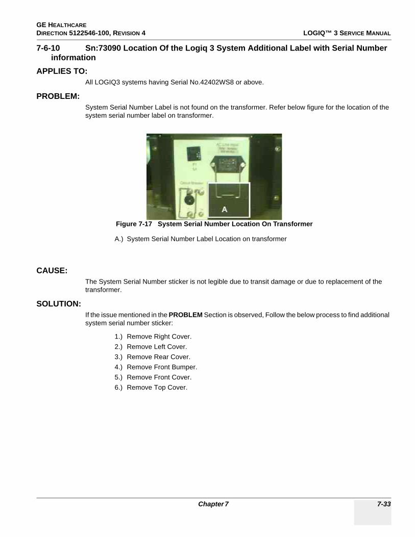
GE HEALTHCARE DIRECTION 5122546-100, REVISION 4 LOGIQ™ 3 SERVICE MANUAL
7-6-10 Sn:73090 Location Of the Logiq 3 System Additional Label with Serial Number information
APPLIES TO:All LOGIQ3 systems having Serial No.42402WS8 or above.
PROBLEM:System Serial Number Label is not found on the transformer. Refer below figure for the location of the system serial number label on transformer.
CAUSE:The System Serial Number sticker is not legible due to transit damage or due to replacement of the transformer.
SOLUTION:If the issue mentioned in the PROBLEM Section is observed, Follow the below process to find additional system serial number sticker:
1.) Remove Right Cover.2.) Remove Left Cover.3.) Remove Rear Cover.4.) Remove Front Bumper.5.) Remove Front Cover.6.) Remove Top Cover.
Figure 7-17 System Serial Number Location On Transformer
A.) System Serial Number Label Location on transformer
A
Chapter 7 7-33
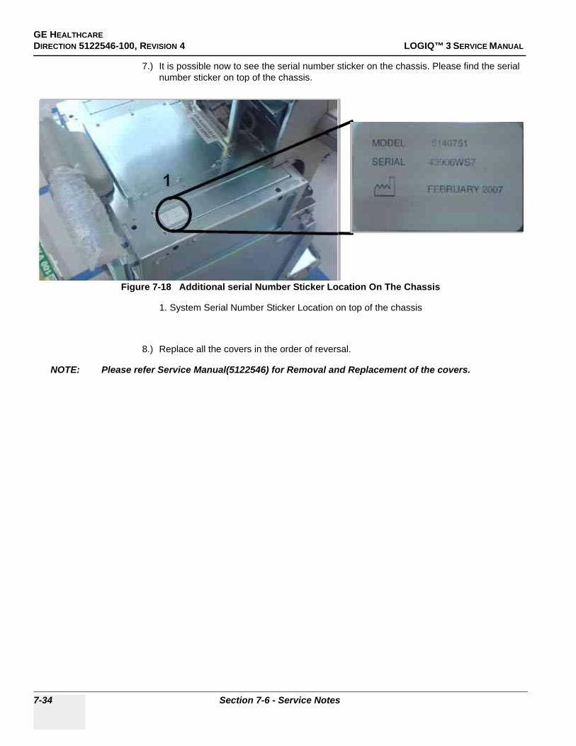
GE HEALTHCAREDIRECTION 5122546-100, REVISION 4 LOGIQ™ 3 SERVICE MANUAL
7.) It is possible now to see the serial number sticker on the chassis. Please find the serial number sticker on top of the chassis.
8.) Replace all the covers in the order of reversal.
NOTE: Please refer Service Manual(5122546) for Removal and Replacement of the covers.
Figure 7-18 Additional serial Number Sticker Location On The Chassis
1. System Serial Number Sticker Location on top of the chassis
1
7-34 Section 7-6 - Service Notes

GE HEALTHCARE DIRECTION 5122546-100, REVISION 4 LOGIQ™ 3 SERVICE MANUAL
7-6-11 Sn73084-Keyboard Knobs APPLIES TO:
All LOGIQ 3 Systems with loose or broken Keyboard knobs.
PROBLEM:Plastic knobs on LOGIQ 3 System keyboard break or become loose in fitting.
SOLUTION:Use Appropriate Knobs to replace the Knobs which are found defective on the keyboard.
PROCEDURE:The Knobs are available as Part of the kit(Part Number: 5155334), Please Order the Part ( 5155334) and Replace appropriate defective Knob.
This kit consists three types of knobs:
1.) Large size plastic knobs used for Imaging Modes and Gain control 2.) Medium size plastic knob used for 'Depth' function 3.) Small size plastic knob used for NTPUI functions, Body pattern, Zoom and Speaker
functions
Chapter 7 7-35

GE HEALTHCAREDIRECTION 5122546-100, REVISION 4 LOGIQ™ 3 SERVICE MANUAL
7-6-12 Sn 73082: Introduction of FMI 73068,FMI 73070, FMI 73071
APPLIES TO:All LOGIQ™ 3 systems with S/W 2.2.X and having the issues noted in the PROBLEM section.
PROBLEM:1.) Failure of Export and/or Move function while copying/moving patient data on to a CD.2.) Spanish Report Translation errors - appearing in Portuguese & English.3.) Windows Network vulnerability: MSO5-011, MSO5-019, MSO5-043, MS05-051.4.) 10 Image Report Template not getting printed in the correct format.
SOLUTION:1.) The issues mentioned in PROBLEM section are resolved by upgrading the LOGIQ™ 3 system with
S/W R2.2.X to R4.0.X by using FMI 73068 or FMI 73070. Refer table 1-1 to order appropriate FMI kit.
2.) If the customer requires prior Patients’ data and Images be retained on the hard drive after the upgrade, the FE may order FMI 73071 Kit(Part Number: 5184450). FMI 73071 Kit consists of USB Hard disk as a tool to support the execution of FMI 73068 or FMI 73070. - USB HDD can not be used with R2xx software (not supported). - The system should be first upgraded to R4.0.X (C: partition only). - Only in the event of "Unable to create new patient" after the upgrade, the USB HDD is needed
to backup patient data. The Ez Backup, Ez Backup with Move or the Export functions can be used.
- After the data is backed up, a full base system s/w reload ( re-ghost) should be performed. For more information, please follow FMI instructions(Part Number: 5162506).
- The USB HARD DRIVE is provided to the field as a tool, and it shouldn't be left at the customer site.
NOTE: The Imaging presets for the 4.0.X version of software are optimized for better Image Quality. The existing 2.2.X Imaging presets are not compatible with the 4.0.X version of software that is installed in the system as part of this FMI. For any specific customer requirement for preset optimization, seek support from Application specialist.
System Type Serial Number BEP Identification Required FMI FMI Kit to Order
LOGIQ™ 3 systems(S/W 2.2.X) with BEP2 or BEP3 Above 3055WS1 Not Required FMI 73068 Kit Part Number:
5162505
LOGIQ™ 3 systems(S/W 2.2.X) with BEP2 or BEP3. Below 3055WS1 Refer Step 3 FMI 73068 Kit Part Number:
5162505
LOGIQ™ 3 systems(S/W 2.2.X) with BEP1. Below 3055WS1 Refer Step 3 FMI 73070 Kit Part Number:
5167186
Table 7-1 Order Appropriate FMI Kit
7-36 Section 7-6 - Service Notes
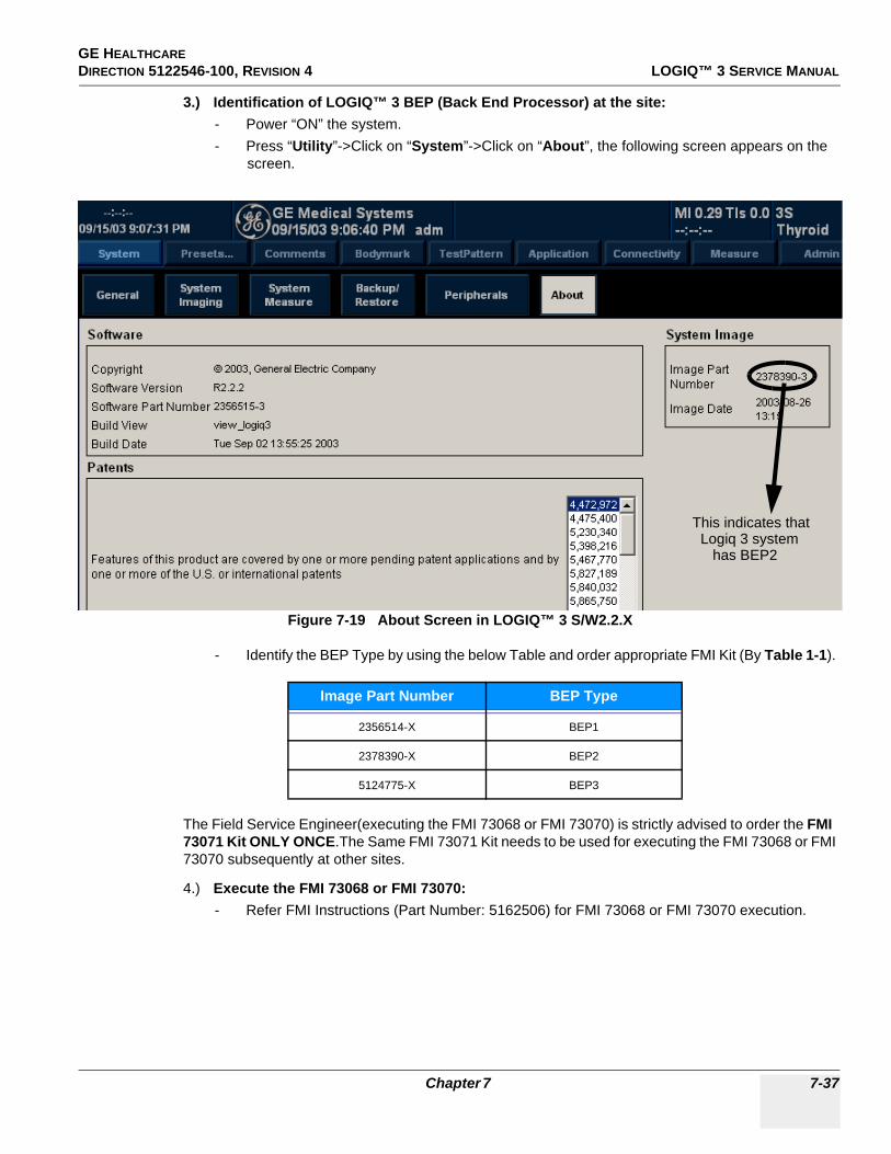
GE HEALTHCARE DIRECTION 5122546-100, REVISION 4 LOGIQ™ 3 SERVICE MANUAL
3.) Identification of LOGIQ™ 3 BEP (Back End Processor) at the site:- Power “ON” the system.- Press “Utility”->Click on “System”->Click on “About”, the following screen appears on the
screen.
- Identify the BEP Type by using the below Table and order appropriate FMI Kit (By Table 1-1).
The Field Service Engineer(executing the FMI 73068 or FMI 73070) is strictly advised to order the FMI 73071 Kit ONLY ONCE.The Same FMI 73071 Kit needs to be used for executing the FMI 73068 or FMI 73070 subsequently at other sites.
4.) Execute the FMI 73068 or FMI 73070:- Refer FMI Instructions (Part Number: 5162506) for FMI 73068 or FMI 73070 execution.
Figure 7-19 About Screen in LOGIQ™ 3 S/W2.2.X
Image Part Number BEP Type
2356514-X BEP1
2378390-X BEP2
5124775-X BEP3
This indicates that Logiq 3 system has BEP2
Chapter 7 7-37
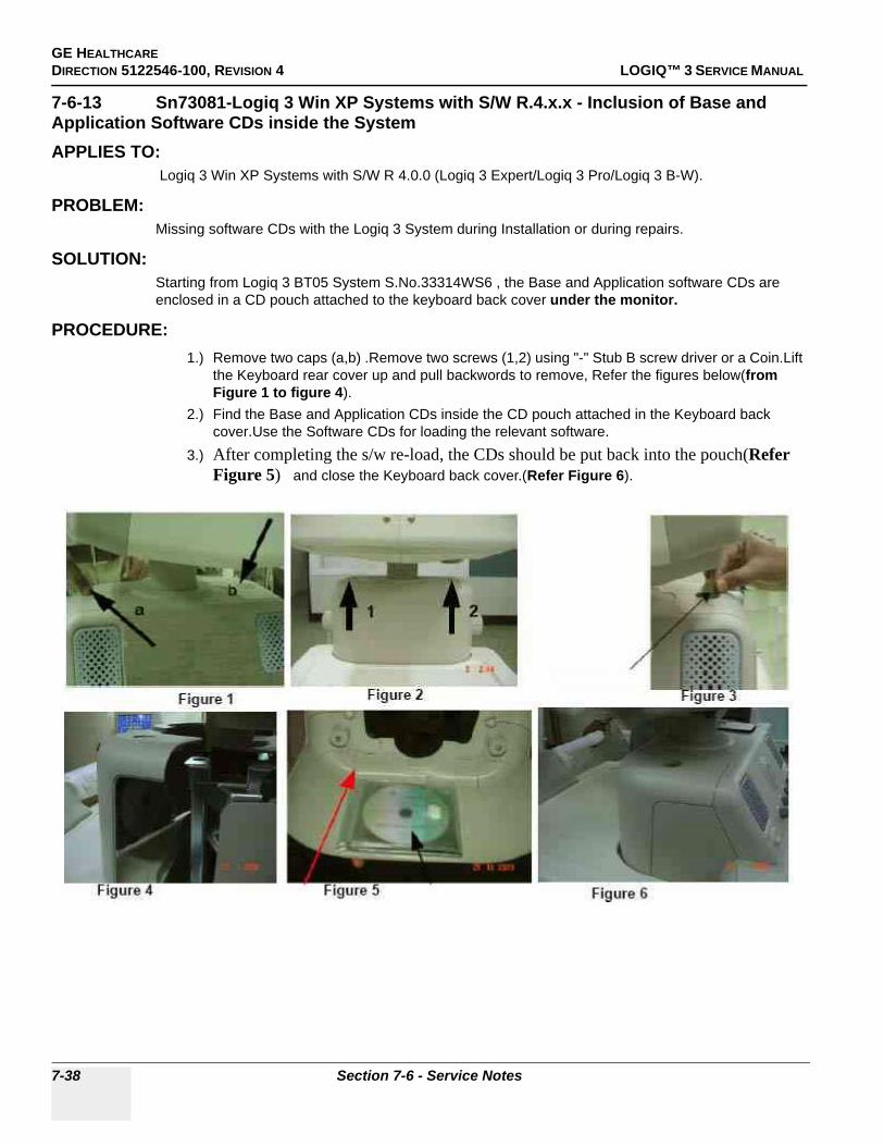
GE HEALTHCAREDIRECTION 5122546-100, REVISION 4 LOGIQ™ 3 SERVICE MANUAL
7-6-13 Sn73081-Logiq 3 Win XP Systems with S/W R.4.x.x - Inclusion of Base and Application Software CDs inside the SystemAPPLIES TO:
Logiq 3 Win XP Systems with S/W R 4.0.0 (Logiq 3 Expert/Logiq 3 Pro/Logiq 3 B-W).
PROBLEM:Missing software CDs with the Logiq 3 System during Installation or during repairs.
SOLUTION:Starting from Logiq 3 BT05 System S.No.33314WS6 , the Base and Application software CDs are enclosed in a CD pouch attached to the keyboard back cover under the monitor.
PROCEDURE:1.) Remove two caps (a,b) .Remove two screws (1,2) using "-" Stub B screw driver or a Coin.Lift
the Keyboard rear cover up and pull backwords to remove, Refer the figures below(from Figure 1 to figure 4).
2.) Find the Base and Application CDs inside the CD pouch attached in the Keyboard back cover.Use the Software CDs for loading the relevant software.
3.) After completing the s/w re-load, the CDs should be put back into the pouch(Refer Figure 5) and close the Keyboard back cover.(Refer Figure 6).
7-38 Section 7-6 - Service Notes

GE HEALTHCARE DIRECTION 5122546-100, REVISION 4 LOGIQ™ 3 SERVICE MANUAL
7-6-14 Sn73080-LOGIQ™ 3 - Introduction of Improved Keyboard Assembly
APPLIES TO :LOGIQ™ 3 Systems having the Problems Mentioned below.
PROBLEM:Doppler Spectrum break or/ and Doppler audio break due to keyboard malfunctioning in PWD Mode, without user intervention(without the user changing any controls like PRF, TGC, Depth or moving the trackball).
CAUSE:
Intermittent TGC output due to improper contact between U2 IC and its socket on the keyboard PWA.
SOLUTION:Replace the Existing Keyboard assembly with the new FRU Keyboard(Part Number:2319549-3).
Chapter 7 7-39
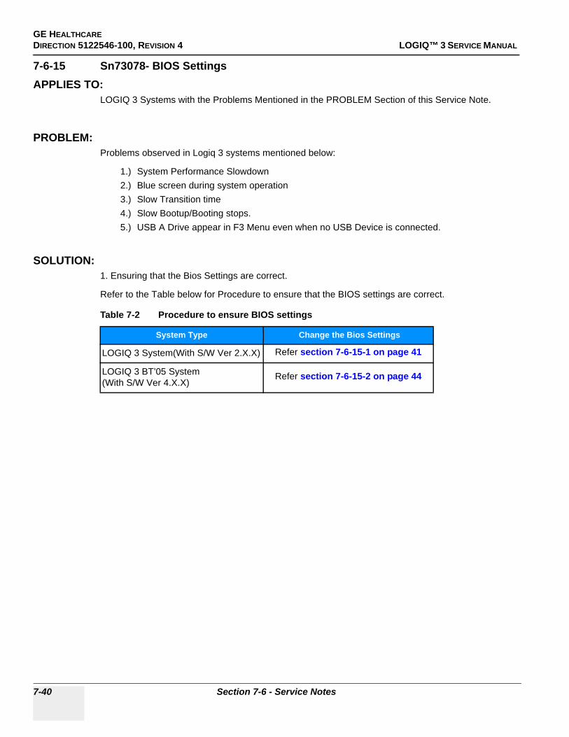
GE HEALTHCAREDIRECTION 5122546-100, REVISION 4 LOGIQ™ 3 SERVICE MANUAL
7-6-15 Sn73078- BIOS Settings APPLIES TO:
LOGIQ 3 Systems with the Problems Mentioned in the PROBLEM Section of this Service Note.
PROBLEM:Problems observed in Logiq 3 systems mentioned below:
1.) System Performance Slowdown2.) Blue screen during system operation3.) Slow Transition time4.) Slow Bootup/Booting stops.5.) USB A Drive appear in F3 Menu even when no USB Device is connected.
SOLUTION:1. Ensuring that the Bios Settings are correct.
Refer to the Table below for Procedure to ensure that the BIOS settings are correct.
Table 7-2 Procedure to ensure BIOS settings
System Type Change the Bios Settings
LOGIQ 3 System(With S/W Ver 2.X.X) Refer section 7-6-15-1 on page 41
LOGIQ 3 BT’05 System(With S/W Ver 4.X.X)
Refer section 7-6-15-2 on page 44
7-40 Section 7-6 - Service Notes

GE HEALTHCARE DIRECTION 5122546-100, REVISION 4 LOGIQ™ 3 SERVICE MANUAL
PROCEDURE:
7-6-15-1 BIOS settings for Logiq 3 Systems (with S/W version 2.X.X ) are as follows:
1.) During Boot Up, Press F2 to enter SetUp Screen.2.) Enter the Password as “dhruva” 3.) Under “Exit”.4.) Enter “Boot” tab, Under “Boot Disk Priority”,select CD RW as the First Boot device as
in Figure 7-20 on page 41 and the Hard disk as the Second Boot Device
Figure 7-20 1 st Boot Device CD R/W
5.) Press ESC
Chapter 7 7-41
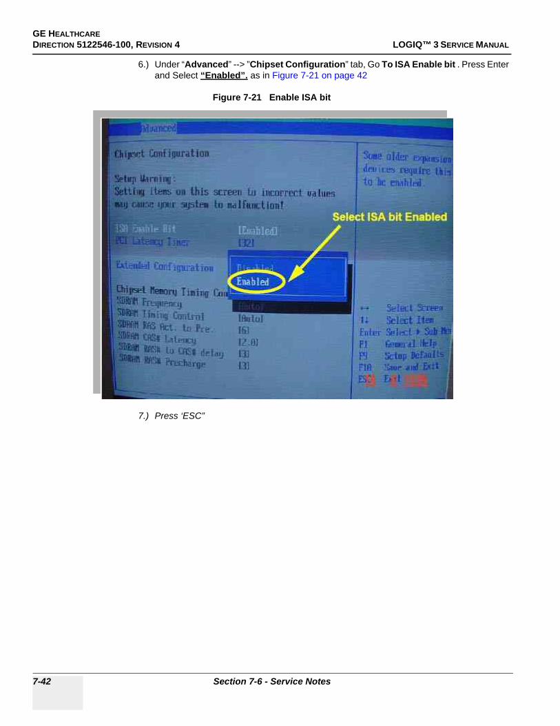
GE HEALTHCAREDIRECTION 5122546-100, REVISION 4 LOGIQ™ 3 SERVICE MANUAL
6.) Under “Advanced” --> ”Chipset Configuration” tab, Go To ISA Enable bit . Press Enter and Select “Enabled”. as in Figure 7-21 on page 42
Figure 7-21 Enable ISA bit
7.) Press ‘ESC”
Select ISA bit Enabled
7-42 Section 7-6 - Service Notes
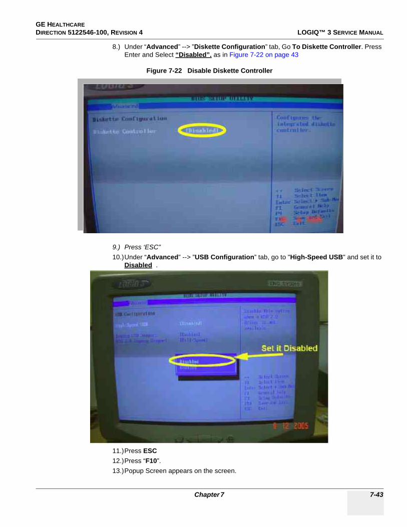
GE HEALTHCARE DIRECTION 5122546-100, REVISION 4 LOGIQ™ 3 SERVICE MANUAL
8.) Under “Advanced” --> ”Diskette Configuration” tab, Go To Diskette Controller. Press Enter and Select “Disabled”. as in Figure 7-22 on page 43
Figure 7-22 Disable Diskette Controller
9.) Press ‘ESC”10.)Under “Advanced” --> ”USB Configuration” tab, go to "High-Speed USB" and set it to
Disabled .
11.)Press ESC12.)Press “F10”.13.)Popup Screen appears on the screen.
Chapter 7 7-43

GE HEALTHCAREDIRECTION 5122546-100, REVISION 4 LOGIQ™ 3 SERVICE MANUAL
14.)Click on “OK” to Save all the changes and exit as per Figure 7-23 on page 44
Figure 7-23 Save changes before Exiting BIOS
15.)Reboot the System..
7-6-15-2 BIOS settings for Logiq 3 BT’05 Systems (with S/W version 4.X,X) are as follows:
1.) During Boot Up, Press F2 to enter SetUp Screen.2.) Enter the Password as “dhruva” 3.) Under “Exit”,go to the “Load Optimal Default Parameters” and press “Enter” Ref.
Figure 7-24 on page 45
7-44 Section 7-6 - Service Notes
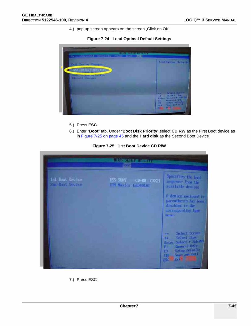
GE HEALTHCARE DIRECTION 5122546-100, REVISION 4 LOGIQ™ 3 SERVICE MANUAL
4.) pop up screen appears on the screen ,Click on OK.
Figure 7-24 Load Optimal Default Settings
5.) Press ESC6.) Enter “Boot” tab, Under “Boot Disk Priority”,select CD RW as the First Boot device as
in Figure 7-25 on page 45 and the Hard disk as the Second Boot Device
Figure 7-25 1 st Boot Device CD R/W
7.) Press ESC
Chapter 7 7-45

GE HEALTHCAREDIRECTION 5122546-100, REVISION 4 LOGIQ™ 3 SERVICE MANUAL
8.) Under “Advanced” --> ”Chipset Configuration” tab, Go To ISA Enable bit . Press Enter and Select “Disabled”. as in Figure 7-26 on page 46
Figure 7-26 Disable ISA bit
9.) Press ‘ESC”
7-46 Section 7-6 - Service Notes

GE HEALTHCARE DIRECTION 5122546-100, REVISION 4 LOGIQ™ 3 SERVICE MANUAL
10.)Under “Advanced” --> ”Diskette Configuration” tab, Go To Diskette Controller. Press Enter and Select “Disabled”. as in Figure 7-27 on page 47
Figure 7-27 Disable Diskette Controller
11.)Press ‘ESC”12.)Under “Advanced” --> ”USB Configuration” tab, Under “2.0 Legacy Support” ,Set the
USB speed to “HiSpeed”
13.)Press ESC14.)Press “F10”.15.)Popup Screen appears on the screen.
Select "HISPEED"
Set it has Enabled
Chapter 7 7-47
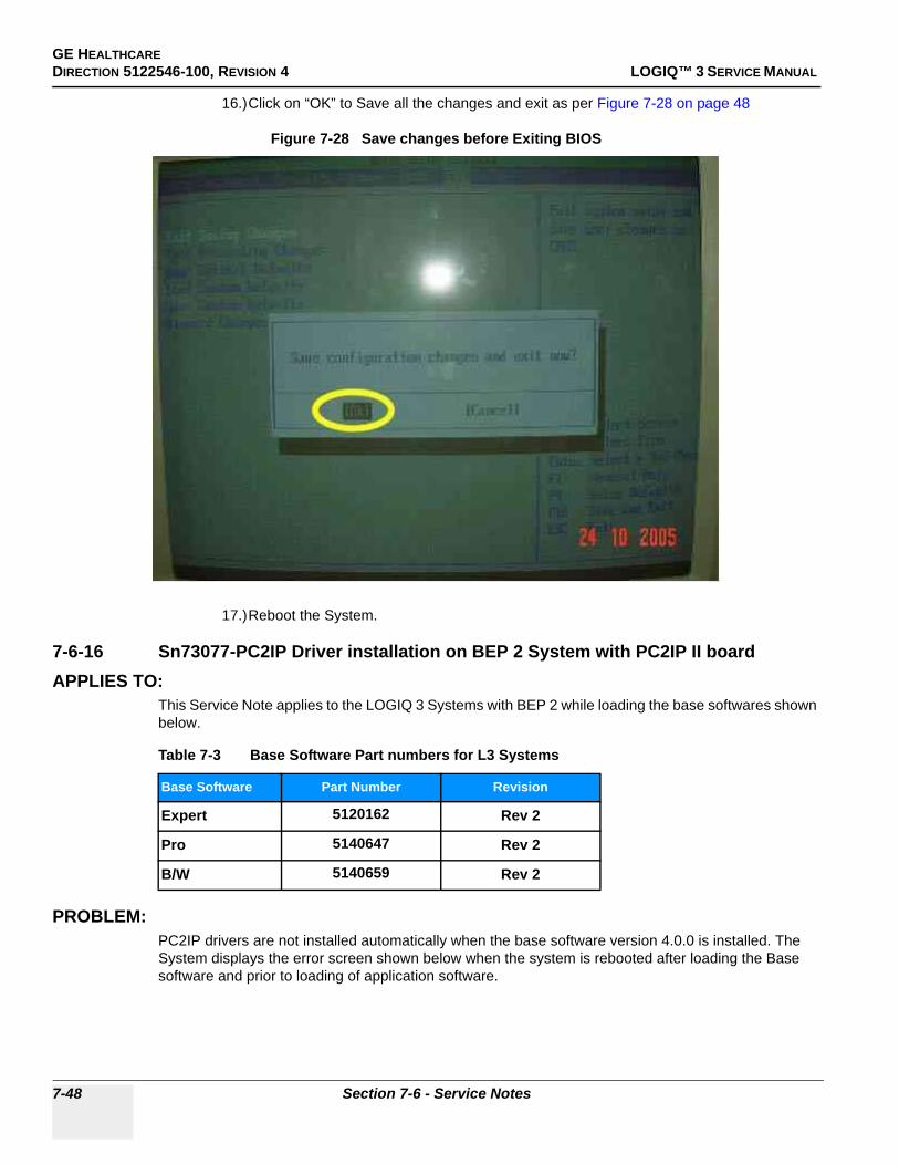
GE HEALTHCAREDIRECTION 5122546-100, REVISION 4 LOGIQ™ 3 SERVICE MANUAL
16.)Click on “OK” to Save all the changes and exit as per Figure 7-28 on page 48
Figure 7-28 Save changes before Exiting BIOS
17.)Reboot the System.
7-6-16 Sn73077-PC2IP Driver installation on BEP 2 System with PC2IP II boardAPPLIES TO:
This Service Note applies to the LOGIQ 3 Systems with BEP 2 while loading the base softwares shown below.
PROBLEM:PC2IP drivers are not installed automatically when the base software version 4.0.0 is installed. The System displays the error screen shown below when the system is rebooted after loading the Base software and prior to loading of application software.
Table 7-3 Base Software Part numbers for L3 Systems
Base Software Part Number Revision
Expert 5120162 Rev 2
Pro 5140647 Rev 2
B/W 5140659 Rev 2
7-48 Section 7-6 - Service Notes
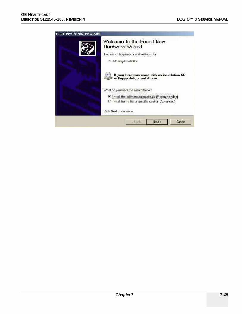
GE HEALTHCARE DIRECTION 5122546-100, REVISION 4 LOGIQ™ 3 SERVICE MANUAL
Chapter 7 7-49

GE HEALTHCAREDIRECTION 5122546-100, REVISION 4 LOGIQ™ 3 SERVICE MANUAL
SOLUTION:Follow the instructions given in the PROCEDURE section of this service note to install the PC2IP driver on the system.
PROCEDURE:Follow the instructions below to install the PC2IP driver for the system.
1.) Select the option as shown in the below figure and select "Next".
2.) Select the option as shown in the below figure and select "Next"
7-50 Section 7-6 - Service Notes

GE HEALTHCARE DIRECTION 5122546-100, REVISION 4 LOGIQ™ 3 SERVICE MANUAL
3.) Select "GE Healthcare" and then Select "Next"
4.) The below figure appears on the screen. Select "Pc2Ip" and then press "Next"
Chapter 7 7-51

GE HEALTHCAREDIRECTION 5122546-100, REVISION 4 LOGIQ™ 3 SERVICE MANUAL
5.) Update Driver Warning dialog box appears on the screen, Press "Yes" to proceed.
6.) The below figure appears on the screen press"Finish" to complete the process of Installation.
7-52 Section 7-6 - Service Notes

GE HEALTHCARE DIRECTION 5122546-100, REVISION 4 LOGIQ™ 3 SERVICE MANUAL
7.) To check whether the drivers are installed, goto the device manager by double clicking the shortcut for device manager on the desktop. Collapse the GEHealthcare option as shown in the Picture below and check if all the 3 image ports are appearing under this option.
If all the image ports are present in the GEHealthcare component, the PC2IP driver is now installed in your system. Now, Proceed with installation of the application software.
7-6-17 Sn73075-Introduction of New Receive Board
APPLIES TO :
Logiq 3 Systems with Noise in the Far field of the Image Area .
PROBLEM:White Band/Streak/Noise/Artifact in the Far Field of the Image Area.
Chapter 7 7-53

GE HEALTHCAREDIRECTION 5122546-100, REVISION 4 LOGIQ™ 3 SERVICE MANUAL
The figure below shows this far field artifact on the Image area.
CAUSE:Oscillations of the VCA Chip on the Receive Board at lower temperature in Receive Board, PN 2318122-2.
SOLUTION:Replace the existing Receive Board with the new improved Receive Board FRU, Part Number: 2318122-3.
7-54 Section 7-6 - Service Notes

GE HEALTHCARE DIRECTION 5122546-100, REVISION 4 LOGIQ™ 3 SERVICE MANUAL
7-6-18 Sn73074:Introduction of FMI 73066-Monitor MCU Replacement and Brightness HV adjustment
APPLIES TO :LOGIQ 3 Systems with Monitors having the following Serial Number Range:
PROBLEMS: 1.) Brightness fluctuationSudden brightness changes when monitor brightness is adjusted.Right after adjusting the brightness, display suddenly turns dark or bright. Brightness may change during normal usageeven without any user intervention.
2.) Color tingeMonitor display is a little bluish, greenish, or reddish.One of primary colors(R, G, B) have been decreased beyond the auto compensation range ofinternal circuit.
NOTICE:If one of Red, Green, or Blue color is completely gone, it may not be a color tinge problem. Check the signal cable connection from BEP to monitor.
IMPORTANT NOTE:Procedure to Isolate whether the Color Tinge is due to internal cable of the Monitor:
Switch on the LOGIQ 3 system. Manipulate the cables as indicated below, while looking at the monitor.
1.) If there is no change in the Monitor color while performing this, it indicates that this issue is associated with the monitor. In this event refer FMI 73066 Instructions for further actions.
2.) If the color changes while performing the cable manipulation, repeat the same to confirm that there is an issue with the cable internal to the monitor. In this event, the monitor will need replacement since this cable cannot be replaced in the field.
Chapter 7 7-55

GE HEALTHCAREDIRECTION 5122546-100, REVISION 4 LOGIQ™ 3 SERVICE MANUAL
NOTE: " VGA cable connector 1 can be seen when the Keyboard Rear cover is removed and VGA Connector 2 is connected to the monitor and can be seen on removal of Monitor Covers "
NOTICEIf these issues are not resolved by executing this FMI, Replace monitor with the latest version of the monitor (PN: 2319551-5).Guidelines for determining the Applicability of the FMI
The part number is 2319551-X, where X indicates the version of the monitor
VGA Connector 1 VGA Connector 2
Monitor Part Number is displayed here.
Monitor Serial Number
7-56 Section 7-6 - Service Notes

GE HEALTHCARE DIRECTION 5122546-100, REVISION 4 LOGIQ™ 3 SERVICE MANUAL
The FMI Kit 5159437 comprises of 2 MCU(MICOM) versions. The MICOM should be selected depending on the part number of the monitor. Please refer to the table below for MICOM selection with respect to the Monitor Part Number.
SOLUTION:
The problems mentioned in the section “PROBLEMS” can be resolved by executing the FMI 73066 (Kit Part Number: 5159437) as mentioned in the FMI instructions 5159456. Please read the instructions carefully before execution of the FMI.
W IP 0 2 A .F 0 5 0 8 2 3 1 9 5 5 1 -1 , 2 3 1 9 5 5 1 -2 , 2 3 1 9 5 5 1 -3
W IP 0 2 B .F 0 5 0 8 2 3 1 9 5 5 1 -4
M C U v e r s io n M o n ito r P a r t N u m b e r
Chapter 7 7-57
GE HEALTHCAREDIRECTION 5122546-100, REVISION 4 LOGIQ™ 3 SERVICE MANUAL
7-6-19 Sn73073-Introduction of FMI 73069 for CHINAAPPLIES TO:
All LOGIQ 3 systems installed in China after Jan 1st, 2003 and manufactured before 1st April, 2005.
PROBLEM:1.) The Power cord shipped with the LOGIQ 3 systems to China during the above period are not
complying with the new Chinese Regulatory requirements. 2.) The Hardcopy of the Chinese Manuals given to the customers did not contain the SFDA
Registration number and the Product registration number.CAUSE:
1.) To Comply with Chinese Regulatory Requirements pertaining to the use of CCC marked (both the plugs and the Cable) Power Cord.
2.) To provide the customer with the hardcopy of Manuals in Chinese as per Chinese regulatory requirements.
SOLUTION:The above-mentioned problems will be resolved by the execution of the FMI-73069. The FMI Kit comprises of the Power cord with the Plug, Socket and the Cable having CCC mark. This Power cord hence complies with Chinese regulatory requirements. The FMI kit assembly with the chinese manuals will be completed at GE Healthcare, China.
For detailed procedure of the FMI execution, Refer to the FMI instructions (PN:5149669) provided in the FMI kit. Place Orders for the Kit (PN:5149657) to GE Healthcare China.
For any clarifications on the FMI, please contact the Pole OLC/ Zheng, Xue_Hua / Bah, ChewYin for support. For urgent help, contact Zheng, Xue_Hua at 8621-5257 4640 ext.64131.
7-58 Section 7-6 - Service Notes

GE HEALTHCARE DIRECTION 5122546-100, REVISION 4 LOGIQ™ 3 SERVICE MANUAL
7-6-20 Sn73064-CWD Option Kit Usage for LOGIQTM 3APPLIES TO:
All LOGIQTM 3 Systems.
NOTE: Ignore All previous Service notes regarding CWD Option Kit, including Service Note 73043A. This Service Note preceeds all other service notes with respect CWD Option Kit.
PROBLEM:Usage of the various CWD Kits for LOGIQTM 3
SOLUTION:
NOTE: The CWD Upgrade has to be performed on systems with software version R2.2.1 and Above only. If the software on the system is of version lower than R2.2.1, please perform the FMI 73060 on the system before performing the CWD upgrade.
Refer to the system serial number and the table below for the selection of the proper kit.
PoleSystem Serial
Number Kit to be usedSystem Serial
Number Kit to be used
Europe5115WS1 and
onwards 2365752(H41722LY) Below 5115WS1 2401844(H41742LM)
Australia3508WS9 and
onwards 2365752(H41722LY) Below 3508WS9 2401844(H41742LM)
China and Hong Kong4279WS6 and
onwards 2365752(H41722LY) Below 4279WS6 2401844(H41742LM)
Japan3442WS1 and
onwards 2365752(H41722LY) Below 3442WS1 2401844(H41742LM)
Korea2795WS3 and
onwards 2365752(H41722LY) Below 2795WS3 2401844(H41742LM)
Singapore5247WS2 and
5361WS3 onwards 2365752(H41722LY)Below 5361WS3 except 5247WS2 2401844(H41742LM)
Americas All Systems 2401844(H41742LM)
Table 7-4 Selection of the CWD Kit
CAUTION The Kit 2401844 contains the Transmit board 2 (2318124-2). If this board is not used, then on activating the CWD mode, the Probe will become very hot, which may result in injury.This will also permanently damage the probe if the system is operated in such a way.
Chapter 7 7-59

GE HEALTHCAREDIRECTION 5122546-100, REVISION 4 LOGIQ™ 3 SERVICE MANUAL
7-6-21 SN-73061:Replacement of LOGIQTM 3 Hardware FRUAPPLIES TO:
All LOGIQTM 3 Systems.
PROBLEM:Change of FRUs and Introduction of New FRUs.
SOLUTION:New FRUs Introduced.
7-6-21-1 Change of FRUs.The following FRUs have changed.
Old Part Number
Old Part Description
New Part Number
New Part Description
Reason For Change Compatibility
2332968 RPA Fuse 3A for LOGIQ 3 5117766
2Amps Thermal Circuit
Breaker
Changed for Regulatory
ComplainaceForward and Backward
2318126 DBF Board for LOGIQ 3 5129931 DBF2 Board
for LOGIQ 3 Productivity
Forward and Backward. This FRU includes
Software R2.2.2, which is needed for the new DBF
board
2277105 HVPS Assy for LOGIQ 3 2390954-2
DBHV Power Supply for LOGIQ 3
Localization of Power supply
Forward and Backward
2319551-3Monitor
Assembly for LOGIQ 3
2319551-4Monitor
Assembly for LOGIQ 3
Change in MICOM software
Forward and Backward
2361975-4 BEP2 Assy for LOGIQ 3 5126610 BEP3 Assy for
LOGIQ 3Obsoloscens
e of BEP2Forward and Backward
2318124-2 Transmit board pcb for LOGIQ 3 2318124-3
Transmit board pcb for
LOGIQ 3
Solution for Diagnostics
error Implemented - TX_TPG2
Error Resolved.
Forward and Backward
Table 7-5 Change of FRUs
7-60 Section 7-6 - Service Notes

GE HEALTHCARE DIRECTION 5122546-100, REVISION 4 LOGIQ™ 3 SERVICE MANUAL
7-6-22 SN-73058:Various Boards Used the LOGIQTM 3APPLIES TO:
All LOGIQTM 3 Systems
PROBLEM:This service note is to inform the field of the various existent variations of the major components of the LOGIQTM 3 in the field.
This table will be updated every time a new part variant is released.
Sl. NO De s cr ip tion Par t Num be r
V ar iation Num be r
V ar 2 V ar 3 V ar 4
1 Transmit Board f or USA Model (H41702LH / 2327754)
2318124 -
2 Transmit Board f or all other models other then USA
2318124 2 CWD support added
3 Receive Board 2318122 2
Diagnos tics issue (Channel f ailure error) solved
4 DBF Board 2318126 -
FEC - 4 FEC - 5 FEC - 6
Firs t Release for L3
CW D support added
Interm ittent hang issues solved , Fixes the HW id error
6 Back plane Board 2318120 3 CWD connec tors CWD noise
7Raide board A ssy - part of
option kit 2288838 4Initial release
Coded harmonics f or L5
8 CWD board A ssy - part of option kit
2401834 -
9 Connec tor Board 2318128 2 3rd Probe port support
10 HV PS A ssy 2277105 2 Initial release
11 A CI PCB A ssy 2319490 - Inrush current limit
12 Rear Panel Interf ace board assy
2319484 -
13 Key board 2319549 2 Reverse capac itor polarity
14 BEP assy 2361975 4Intel motherboard
Supermic ro w ith R 202 Intel w ith R 202
15 LV PS A ssy 2319545 -16 Rear Panel A ssy (100/115V ) 2383299 -17 Rear Panel A ssy (230V ) 2319547 -18 Front Panel A ssy 2383298 -19 Trans f ormer A ssy 2342032 -20 Monitor assy 2319551 -
21 Base Sys tem Sof tw are load Image Rel 2.0.1
2378390 3
22 A pplication Sof tw are Rel 2.0.2 2356515 3 R 202. V C7 sof tw are
R 203. TI and Probe temp f ix
23 Patch Sof tw are Rel 2.0.3 2401921 -24 TSB # 1 Board A ssembly 2319492 -25 RFC board A ssembly 2319480 -
26 RFC2 board A ssembly only w ith CWD
2379706 -
27 Front Panel A ssembly 2383298 -
5 Front End Controller A ssy 2277093 6
Chapter 7 7-61

GE HEALTHCAREDIRECTION 5122546-100, REVISION 4 LOGIQ™ 3 SERVICE MANUAL
7-6-23 SN-73056:Back Plane Board and Continuous Wave Doppler Board FRUsAPPLIES TO:
All LOGIQTM 3 Systems
PROBLEM:In Some LOGIQTM 3 Systems, If Continuous Wave Doppler Option is Installed, during the Pulse Wave Doppler Operation with a liner probe, some noise lines will be seen in the image. This will happen only on systems where the CWD board is 2379704.
SOLUTION:To Correct this issue, the CWD board and the Back Plane Board have been re-designed. The existing CWD Board and BPB will have to replaced. This New CWD Board is available as a FRU.
As the Design change involves both the CWD and the BPB board, both will have to be replaced. The Single Part FRU that has both these boards is the 2405514.
Also, if the BPB - 2318120-2 fails, then it has to be replaced by 2318120-3, available as a part of the FRU - 2328381-3.
If CWD is Installed in systems with BPB 2318120-2, the CWD also has to be changed, as the old CWD board will not function with the Old BPB 2318120-2.
The above mentioned replacements are given in the Matrix below.
SL. No Defective Board Other Board Present Replace with FRU GPN#1 CWD - 2379704 BPB - 2318120 -2 24055142 CWD - 2401834 BPB - 2318120 -3 24018343 BPB - 2318120 -2 CWD - 2379704 24055144 BPB - 2318120 -3 CWD - 2401834 2328381-3
7-62 Section 7-6 - Service Notes

GE HEALTHCARE DIRECTION 5122546-100, REVISION 4 LOGIQ™ 3 SERVICE MANUAL
7-6-24 SN-73055:Intermittent Hang Issues Related to the FEC.APPLIES TO:
This issue will affect all LOGIQTM 3 Systems having Serial Numbers prior to those listed below.
PROBLEM:The Issues seen are one or more of the Following
3.) In Systems with the FEC-4, some systems may show intermittent Hang issues. This can be confirmed by Physically checking the version of the FEC board. The Board Part Number will be as seen in the figure below - Figure 7-29 on page 63
Table 7-6 Effected Systems Serial Numbers
Model GPN# Serial NumberEurope 2327752 5115WS1
China 2327749 4279WS6
USA 2327754 5569WS9
Japan 2327748 3442WS1
Figure 7-29 Checking the FEC-4 Part number
Chapter 7 7-63

GE HEALTHCAREDIRECTION 5122546-100, REVISION 4 LOGIQ™ 3 SERVICE MANUAL
4.) The systems will show a message asking to enter the Option keys. The Hardware Id Shown in this screen will be different from the actual Hardware Id on the system.A sample box can be seen in Figure 7-30 on page 64 below.I
In such cases, The FEC U5 Eprom will have to be replaced.
SOLUTION:1.) If the FEC version for Problem 1 is FEC -4, the The FEC has to be replaced by a FEC -6.2.) The Correct Hardware ID can be checked in the following way. In Start\Run, Type in
"d:\L3_Drivers\SH_Tools\PC2IPIIC_ACI.exe", as shown in Figure 7-31 on page 64 below.
This will bring a screen as shown below. THE Hardware ID can be checked as shown in the screen as shown in Figure 7-32 on page 65 below
Figure 7-30 Asking For Option Keys
Figure 7-31 Selecting the tool.
7-64 Section 7-6 - Service Notes

GE HEALTHCARE DIRECTION 5122546-100, REVISION 4 LOGIQ™ 3 SERVICE MANUAL
If the Hardware ID appearing in Figure 7-32 on page 65 does not match the Hardware ID in Figure 7-30 on page 64 , then the U5 EPROM will have to be replaced. This replacement process is given below.
Figure 7-32 Checking the Hardware ID
Chapter 7 7-65
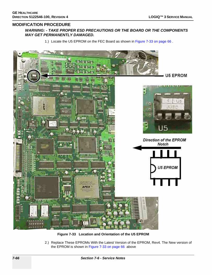
GE HEALTHCAREDIRECTION 5122546-100, REVISION 4 LOGIQ™ 3 SERVICE MANUAL
MODIFICATION PROCEDUREWARNING: - TAKE PROPER ESD PRECAUTIONS OR THE BOARD OR THE COMPONENTS MAY GET PERMANENTLY DAMAGED.
1.) Locate the U5 EPROM on the FEC Board as shown in Figure 7-33 on page 66 .
2.) Replace These EPROMs With the Latest Version of the EPROM, Rev4. The New version of the EPROM is shown in Figure 7-33 on page 66 above
Figure 7-33 Location and Orientation of the U5 EPROM
7-66 Section 7-6 - Service Notes

GE HEALTHCARE DIRECTION 5122546-100, REVISION 4 LOGIQ™ 3 SERVICE MANUAL
3.) These EPROMs can be obtained from the following People in the various service regions.
Table 7-7 Contact Persons
Sl. No Pole Contact Person1 Americas Anna Shikhman
2 Europe Chris Auer
3 Japan Takatoshi Kumagai
4 China Pei Feng Cheng (William Cheng)
5 SEA William KM On
6 India Shilpa M. K.
Chapter 7 7-67

GE HEALTHCAREDIRECTION 5122546-100, REVISION 4 LOGIQ™ 3 SERVICE MANUAL
7-6-25 SN-73053:BACK UP AND RESTORE PROCESS IN LOGIQTM 3
APPLIES TO:ALL LOGIQTM 3 SYSTEMS
7-6-25-1 Back up Process
7-6-25-2 Formatting Media
1.) In the imaging mode, ensure that the back up media, a MOD or a Writable CD is inserted in its Drive.2.) in the imaging mode, go to Utilities\Connectivity\Tools as shown in the figure below. Select the
appropriate media from the Dropdown list as shown.3.) Fill in a label name for the media. Then, click on FORMAT.
7-6-25-3 Taking a Backup
1.) Insert the media in its Drive.
1.) In the imaging mode, go to Utilities\System\Backup/Restore2.) Select on "User Defined Configuration" as shown.
Figure 7-34 Formatting the Media
7-68 Section 7-6 - Service Notes

GE HEALTHCARE DIRECTION 5122546-100, REVISION 4 LOGIQ™ 3 SERVICE MANUAL
3.) Then Click on Backup.
7-6-25-4 Restore Process
1.) Insert the media in tis Drive.2.) In the imaging mode, go to Utilities\System\Backup/Restore3.) Select "User Defined Configuration"
Figure 7-35 Backup Process
Chapter 7 7-69

GE HEALTHCAREDIRECTION 5122546-100, REVISION 4 LOGIQ™ 3 SERVICE MANUAL
4.) Click on Restore.
Figure 7-36 Restore Process
7-70 Section 7-6 - Service Notes

GE HEALTHCARE DIRECTION 5122546-100, REVISION 4 LOGIQ™ 3 SERVICE MANUAL
7-6-26 SN-73051:Monitor Signal Issues
APPLIES TO:ALL LOGIQTM 3 SYSTEMSPROBLEM:
There will not be any image on the monitor, but it will give a message saying "Input Frequency Out Range" or "No signal"
SOLUTION:This is an issue with the improper seating of the monitor cables from the BEP to the Monitor.
This can be resolved by reseating the monitor cables.
The process is shown below.
1.) Locate and remove the two screw caps at positions A and B.2.) Remove the two screws at positions C and D using a coin or a " - " Screw driver.3.) Lift and remove the Keyboard Rear Cover.4.) Locate the two connectors as shown in the Figure 7-37 on page 72 .5.) Open these connectors and reconnect them to the system. 6.) Open the Rear cover and the Rear EMI cover. 7.) Locate the Monitor Cable from the BEP as shown and reseat this cable also.
Chapter 7 7-71
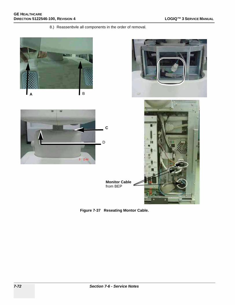
GE HEALTHCAREDIRECTION 5122546-100, REVISION 4 LOGIQ™ 3 SERVICE MANUAL
8.) Reassenbvle all components in the order of removal.
Figure 7-37 Reseating Montor Cable.
A B
C
D
Monitor Cable from BEP
7-72 Section 7-6 - Service Notes

GE HEALTHCARE DIRECTION 5122546-100, REVISION 4 LOGIQ™ 3 SERVICE MANUAL
7-6-27 SN-73050:Maintenance Mode in LOGIQTM 3
APPLIES TO:ALL LOGIQTM 3 SYSTEMS
PROBLEM:It is possible to use the Key Sequence "Ctrl+Alt+Del" with the Service Dongle to go to Maintenance Mode. This is a wrong Process to go to maintenance mode and can cause system data corruption.
SOLUTION:It is best to use the Service Dongle with the following process to go to the maintenance mode.
1.) In the imaging mode, to go to the Maintenance mode, insert the Service Dongle and then press “Ctrl+Alt+R” keys
2.) Click on “Yes” as shown in the figure below.
3.) Now, Enter the service password and enter the maintenance mode.
Figure 7-38 Log Off Screen
Chapter 7 7-73
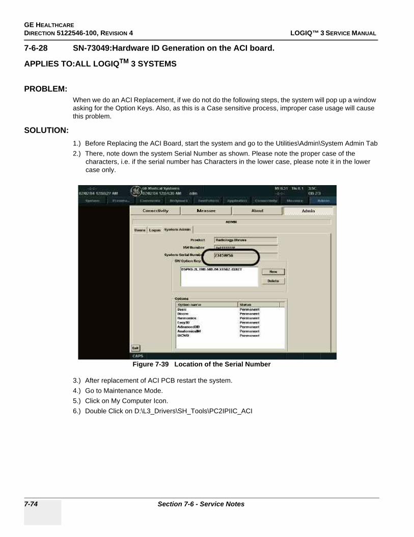
GE HEALTHCAREDIRECTION 5122546-100, REVISION 4 LOGIQ™ 3 SERVICE MANUAL
7-6-28 SN-73049:Hardware ID Generation on the ACI board.
APPLIES TO:ALL LOGIQTM 3 SYSTEMS
PROBLEM:When we do an ACI Replacement, if we do not do the following steps, the system will pop up a window asking for the Option Keys. Also, as this is a Case sensitive process, improper case usage will cause this problem.
SOLUTION:1.) Before Replacing the ACI Board, start the system and go to the Utilities\Admin\System Admin Tab2.) There, note down the system Serial Number as shown. Please note the proper case of the
characters, i.e. if the serial number has Characters in the lower case, please note it in the lower case only.
3.) After replacement of ACI PCB restart the system.4.) Go to Maintenance Mode.5.) Click on My Computer Icon.6.) Double Click on D:\L3_Drivers\SH_Tools\PC2IPIIC_ACI
Figure 7-39 Location of the Serial Number
7-74 Section 7-6 - Service Notes

GE HEALTHCARE DIRECTION 5122546-100, REVISION 4 LOGIQ™ 3 SERVICE MANUAL
7.) The following Screen Appears.
Figure 7-40 ACI Board H/W Serial Number Screen
Key in ACI Board Serial No. As labeled on the ACIBoard - Example of the Sl# ACIU503E010001
Key in ACI Part No. as labeled on theboard- Example - 2319490
Key in ACI Part Rev No. as labeled onthe board- Example - REV1
Key in the System Serial Number as in the RatingPlate affixed at rear of system in Transformer AssyExample - 2974WS4
Chapter 7 7-75

GE HEALTHCAREDIRECTION 5122546-100, REVISION 4 LOGIQ™ 3 SERVICE MANUAL
8.) After entering the system serial #, ACI serial #, ACI Part # and ACI Rev#, Click on Write9.) Hardware ID is generated, close the window.10.)Shut down the system and restart the system in the normal mode. Start Echoloader and ensure that
system boots properly to image screen and check Basic B- Mode Functions.
Figure 7-41 ACI Board
7-76 Section 7-6 - Service Notes

GE HEALTHCARE DIRECTION 5122546-100, REVISION 4 LOGIQ™ 3 SERVICE MANUAL
7-6-29 SN-73048:Preset Restore
APPLIES TO:ALL LOGIQTM 3 SYSTEMS
PROBLEM:If the Backup of a customers data is made on one system and if this data is restored on a completely different system, then on rebooting this, system, it will ask for the Software Option Keys.
This is standard behaviour.
When we make a backup of data on one system, the option keys of that system also get stored on the Backup CD. When this data is restored on a completely different system, the restore process will overwrite the existing option keys and replace them with the option keys of the original system. On rebooting any system, a check of the option key against the Sysiem serial number is done. For the system on which the restore was done, this data will not match as the option keys are for the system on which the backup was done. This causes the system to ask for the option keys.
SOLUTION:A possible solutin is being looked for in the next software release.
PROBLEM:On restoring the Presets made on the software version R1.2.0 on a system with software R2.0.0 and above, it system will ask for Optin Keys.
SOLUTION:The presets backed up on the R1.2.0 systems should not be restored on systems with software versions R2.0.2 and later
Chapter 7 7-77

GE HEALTHCAREDIRECTION 5122546-100, REVISION 4 LOGIQ™ 3 SERVICE MANUAL
This page was intentionally left blank.
7-78 Section 7-6 - Service Notes

GE HEALTHCAREDIRECTION 5122546-100, REVISION 4 LOGIQ™ 3 SERVICE MANUAL
Chapter 8Replacement ProceduresSection 8-1Overview
8-1-1 Purpose of Chapter 8This chapter describes replacement procedures for the following modules and subsystems.
8-1-2 Returning/Shipping Probes and Repair Parts
Equipment being returned must be clean and free of blood and other infectious substances.
GEMS policy states that body fluids must be properly removed from any part or equipment prior to shipment. GEMS employees, as well as customers, are responsible for ensuring that parts/equipment have been properly decontaminated prior to shipment. Under no circumstance should a part or equip-ment with visible body fluids be taken or shipped from a clinic or site (for example, body coils or an ultrasound probe).
The purpose of the regulation is to protect employees in the transportation industry, as well as the peo-ple who will receive or open this package.
NOTE: The US Department of Transportation (DOT) has ruled that “items that were saturated and/or dripping with human blood that are now caked with dried blood; or which were used or intended for use in patient care” are “regulated medical waste” for transportation purposes and must be transported as a hazardous material.
Section Description Page Number
8-1 Overview 8-1
8-2 Monitor 8-3
8-3 Keyboard 8-13
8-4 Mechanicals 8-33
8-5 I/O Interfaces 8-82
8-6 PCB 8-94
8-7 Power Block 8-118
8-8 Software Loading Procedure 8-131
8-9 Base Load Software Load 8-135
8-10 Loading Application Software After a Base Image Load 8-146
8-11 Installing Option Software 8-161
8-12 Loading Base and Application Software 8-163
Table 8-1 Contents in Chapter 8
Chapter 8 8-1

GE HEALTHCAREDIRECTION 5122546-100, REVISION 4 LOGIQ™ 3 SERVICE MANUAL
WARNINGWARNING ONLY QUALIFIED SERVICE PERSONNEL SHOULD REMOVE ANY COVERS OR PANELS. ELECTRICAL HAZARDS EXISTS AT SEVERAL POINTS INSIDE. BECOME THOROUGHLY FAMILIAR WITH ALL HAZARDOUS VOLTAGES AND HIGH CURRENT LEVELS TO AVOID ACCIDENTAL CONTACT
CAUTION Do not wear the ESD wrist strap when you remove a part of power supply unit. Turn OFF power and unplug the power cord before removing a part of power supply unit. However be sure to turn off power and wear the strap before you remove a circuit boards.
8-2 Section 8-1 - Overview

GE HEALTHCAREDIRECTION 5122546-100, REVISION 4 LOGIQ™ 3 SERVICE MANUAL
Section 8-2Monitor
8-2-1 Monitor Assy (FRU No. 100)Purpose: This is a description on how to remove and replace the Monitor Assy.
8-2-1-1 Tools• Coin / "-" Screw Driver
8-2-1-2 Needed Manpower• 2 persons, 15 minutes + travel
8-2-1-3 Preparations• Shut Down the System and switch off the Main Breaker at the rear as described in 4-3-1-3 on page
4-4 .
8-2-1-4 Removal procedureRefer to Figure 8-1 on page 8-3 .
1.) Remove the See “Keyboard Rear Cover (FRU No. 308)” on page 57.2.) Remove 2 connectors from the monitor (between CN601 & CN602 and VGA Connection).3.) Unscrew the rotation stopper screw using coin or ’-’ screw driver.4.) Lift the Monitor Assy upward.
8-2-1-5 Mounting procedure
1.) Install the new parts in the reverse order of removal.
Figure 8-1 MONITOR ASSY DISASSEMBLY
WARNINGWARNING The weight of the monitor is approximately 20 kg. Two person are needed in the next step.
Connectors CN601 & CN602 Rotation Stopper Screw VGA Connector
Chapter 8 8-3

GE HEALTHCAREDIRECTION 5122546-100, REVISION 4 LOGIQ™ 3 SERVICE MANUAL
8-2-1-6 Functional Checkout Procedure
See Section
Functional and/or Leakage Current
Test Debrief Script4-3-1 Power On/Boot Up Service Manual Direction 5122546-100, Section 8-2-1. Equipment passes all required
tests and is ready for use.4-4-1 Basic Controls7-5-2 PC Diagnostics
10-6-4, 10-6-5 Leakage Current
8-4 Section 8-2 - Monitor

GE HEALTHCAREDIRECTION 5122546-100, REVISION 4 LOGIQ™ 3 SERVICE MANUAL
8-2-2 Monitor Cover Left (FRU No. 101)Purpose: This is a description on how to remove the Monitor Cover Left.
8-2-2-1 Tools• Common phillips screwdrivers, Stub B
8-2-2-2 Needed Manpower• 1 person, 15 minutes + travel
8-2-2-3 Preparations• Shut down the System and switch off the Circuit breaker at the rear as described in 4-3-1-3 on page
4-4 .
8-2-2-4 Removal ProcedureRefer to Figure 8-2 on page 8-5 .
1.) Remove 2 screws (a,b) from left cover. 2.) Remove See “Keyboard Rear Cover (FRU No. 308)” on page 57.3.) Rotate Monitor to Right 90×, Use Stub B screwdriver to remove the screw (c) in the bottom.4.) Remove the See “Task Lamp (FRU No. 106)” on page 12.5.) Remove the Monitor Cover Left by pulling backwards.
8-2-2-5 Functional Checkout Procedure
Figure 8-2 Monitor Cover Left
See Section
Functional and/or Leakage Current
Test Debrief Script4-3-1 Power On/Boot Up Service Manual Direction 5122546-100, Section 8-2-2. Equipment passes all required
tests and is ready for use.4-4-1 Basic Controls
a
bc
Chapter 8 8-5

GE HEALTHCAREDIRECTION 5122546-100, REVISION 4 LOGIQ™ 3 SERVICE MANUAL
8-2-3 Monitor Cover Right (FRU No. 102)Purpose: This is a description on how to remove the Monitor Cover Right.
8-2-3-1 Tools• Common phillips screwdrivers, Stub B
8-2-3-2 Needed Manpower• 1 person, 15 minutes + travel
8-2-3-3 Preparations• Shut down the System and switch off the Circuit breaker at the rear as described in 4-3-1-3 on page
4-4 .
8-2-3-4 Removal ProcedureRefer to Figure 8-3 on page 8-6 .
1.) Remove 2 screws (a,b) from monitor right cover.2.) Remove See “Keyboard Rear Cover (FRU No. 308)” on page 57.3.) Rotate Monitor to left 90×, Use Stub B screwdriver to remove the screw (c) in the bottom.4.) Remove the Monitor Cover right by pulling backwards.
8-2-3-5 Functional Checkout Procedure
Figure 8-3 Monitor Cover Right
See Section
Functional and/or Leakage Current
Test Debrief Script4-3-1 Power On/Boot Up Service Manual Direction 5122546-100, Section 8-2-3. Equipment passes all required
tests and is ready for use.4-4-1 Basic Controls
b
a c
8-6 Section 8-2 - Monitor
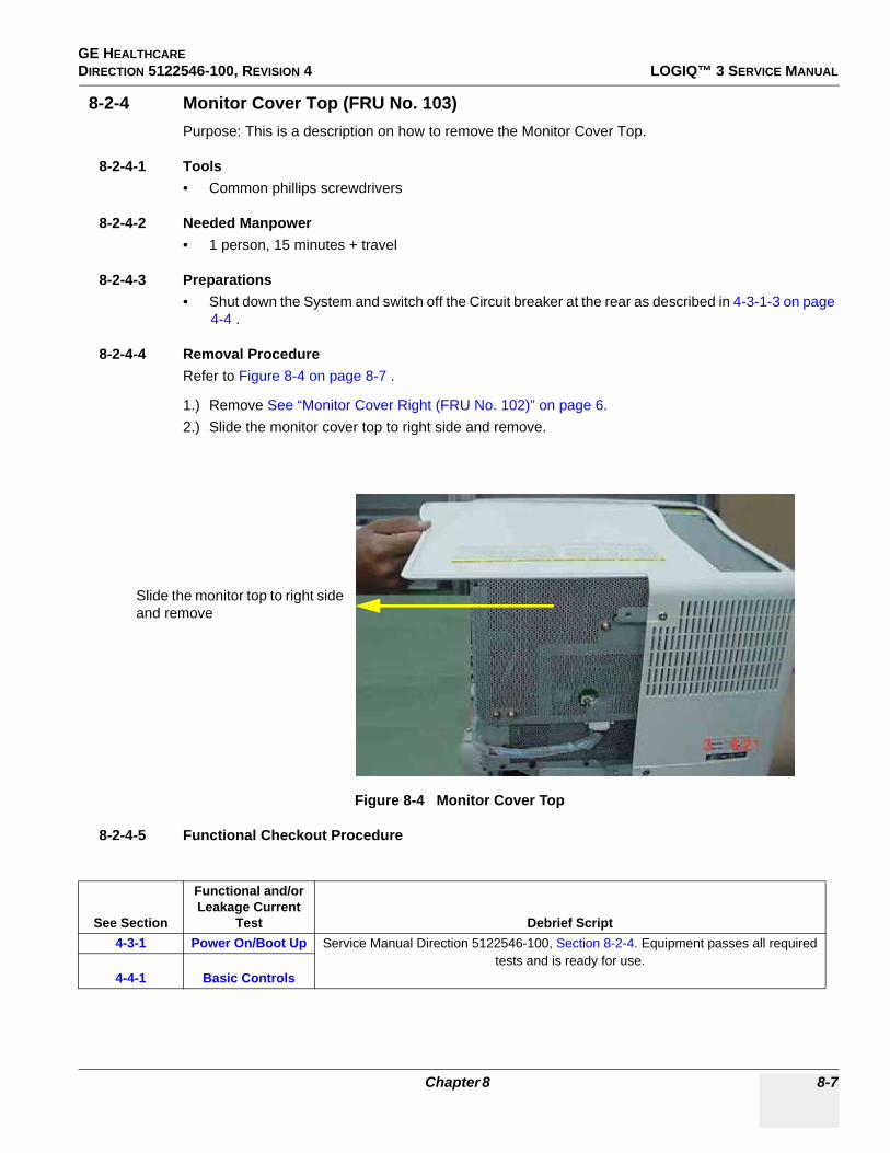
GE HEALTHCAREDIRECTION 5122546-100, REVISION 4 LOGIQ™ 3 SERVICE MANUAL
8-2-4 Monitor Cover Top (FRU No. 103)Purpose: This is a description on how to remove the Monitor Cover Top.
8-2-4-1 Tools• Common phillips screwdrivers
8-2-4-2 Needed Manpower• 1 person, 15 minutes + travel
8-2-4-3 Preparations• Shut down the System and switch off the Circuit breaker at the rear as described in 4-3-1-3 on page
4-4 .
8-2-4-4 Removal ProcedureRefer to Figure 8-4 on page 8-7 .
1.) Remove See “Monitor Cover Right (FRU No. 102)” on page 6.2.) Slide the monitor cover top to right side and remove.
8-2-4-5 Functional Checkout Procedure
Figure 8-4 Monitor Cover Top
See Section
Functional and/or Leakage Current
Test Debrief Script4-3-1 Power On/Boot Up Service Manual Direction 5122546-100, Section 8-2-4. Equipment passes all required
tests and is ready for use.4-4-1 Basic Controls
Slide the monitor top to right side and remove
Chapter 8 8-7
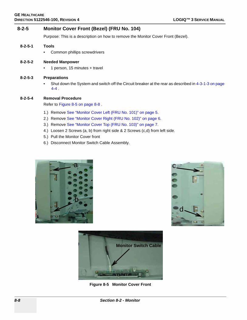
GE HEALTHCAREDIRECTION 5122546-100, REVISION 4 LOGIQ™ 3 SERVICE MANUAL
8-2-5 Monitor Cover Front (Bezel) (FRU No. 104)Purpose: This is a description on how to remove the Monitor Cover Front (Bezel).
8-2-5-1 Tools• Common phillips screwdrivers
8-2-5-2 Needed Manpower• 1 person, 15 minutes + travel
8-2-5-3 Preparations• Shut down the System and switch off the Circuit breaker at the rear as described in 4-3-1-3 on page
4-4 .
8-2-5-4 Removal ProcedureRefer to Figure 8-5 on page 8-8 .
1.) Remove See “Monitor Cover Left (FRU No. 101)” on page 5. 2.) Remove See “Monitor Cover Right (FRU No. 102)” on page 6.3.) Remove See “Monitor Cover Top (FRU No. 103)” on page 7.4.) Loosen 2 Screws (a, b) from right side & 2 Screws (c,d) from left side.5.) Pull the Monitor Cover front6.) Disconnect Monitor Switch Cable Assembly.
Figure 8-5 Monitor Cover Front
a
b
c
d
Monitor Switch Cable
8-8 Section 8-2 - Monitor

GE HEALTHCAREDIRECTION 5122546-100, REVISION 4 LOGIQ™ 3 SERVICE MANUAL
8-2-5-5 Functional Checkout Procedure
See Section
Functional and/or Leakage Current
Test Debrief Script4-3-1 Power On/Boot Up Service Manual Direction 5122546-100, Section 8-2-5. Equipment passes all required
tests and is ready for use.4-4-1 Basic Controls
Chapter 8 8-9

GE HEALTHCAREDIRECTION 5122546-100, REVISION 4 LOGIQ™ 3 SERVICE MANUAL
8-2-6 Monitor Switch (S/W) Assy (FRU No. 105)Purpose: This is a description on how to remove and replace the Monitor S/W Assy.
8-2-6-1 Tools• Common phillips screwdrivers
8-2-6-2 Needed Manpower• 1person, 10 minutes + travel
8-2-6-3 Preparations• Shut Down the System and switch off the Main Breaker at the rear as described in 4-3-1-3 on page
4-4
8-2-6-4 Removal ProcedureRefer to Figure 8-6 on page 8-10
1.) Remove the See “Monitor Cover Front (Bezel) (FRU No. 104)” on page 8.2.) Unscrew two screws (1-2).3.) Remove the Monitor S/W Assy.
8-2-6-5 Mounting procedure
1.) Install the new parts in the reverse order of removal.
Figure 8-6 Monitor Switch Assy
1 2
8-10 Section 8-2 - Monitor

GE HEALTHCAREDIRECTION 5122546-100, REVISION 4 LOGIQ™ 3 SERVICE MANUAL
8-2-6-6 Functional Checkout Procedure
See Section
Functional and/or Leakage Current
Test Debrief Script4-3-1 Power On/Boot Up Service Manual Direction 5122546-100, Section 8-2-6. Equipment passes all required
tests and is ready for use.4-4-1 Basic Controls7-5-2 PC Diagnostics
Chapter 8 8-11

GE HEALTHCAREDIRECTION 5122546-100, REVISION 4 LOGIQ™ 3 SERVICE MANUAL
8-2-7 Task Lamp (FRU No. 106)Purpose: This is a description on how to remove and replace the Task Lamp.
8-2-7-1 Tools• Common phillips screwdrivers, Stub B
8-2-7-2 Needed Manpower• 1person, 15 minutes + travel
8-2-7-3 Preparations• Shut Down the System and switch off the Main Breaker at the rear as described in 4-3-1-3 on page
4-4
8-2-7-4 Removal ProcedureRefer to Figure 8-7 on page 8-12
1.) Remove the See “Keyboard Rear Cover (FRU No. 308)” on page 57.2.) Rotate CRT by 90× left.3.) Unscrew two screws (a, b) using Stub B screwdriver.4.) Unthread the task lamp and remove.
8-2-7-5 Mounting procedure
1.) Install the new parts in the reverse order of removal.
8-2-7-6 Functional Checkout Procedure
Figure 8-7 Task Lamp
See Section
Functional and/or Leakage Current
Test Debrief Script4-3-1 Power On/Boot Up Service Manual Direction 5122546-100, Section 8-2-7. Equipment passes all required
tests and is ready for use.4-4-1 Basic Controls
Rotate CRT by 90° left
a
b
TASKLAMP
8-12 Section 8-2 - Monitor

GE HEALTHCAREDIRECTION 5122546-100, REVISION 4 LOGIQ™ 3 SERVICE MANUAL
Section 8-3Keyboard
8-3-1 KeyBoard Assy (FRU No. 200)Purpose: This is a description on how to remove and replace the Keyboard Assy
8-3-1-1 Tools• Common phillips screwdrivers
8-3-1-2 Needed Manpower• 1person, 15 minutes + travel
8-3-1-3 Preparations• Shut Down the System and switch off the Circuit Breaker at the rear as described in 4-3-1-3 on page
4-4
8-3-1-4 Removal ProcedureRefer to Figure 8-8 on page 8-14 .
1.) Remove the See “Probe Holder (FRU No. 201)” on page 15.2.) Unscrew two screws (g, h) fixing VGP tray. 3.) Slide out the tray. If VGP is Fixed, disconnect the VGP cables from front panel.4.) Unscrew five screws (a, b, c, d, e). loosen 1 screw (f)5.) Lift the Keyboard Up6.) Disconnect the Three USB cables (1,2, 5), one 26 Pin cable(3), 7.) Remove Keyboard Assy.
8-3-1-5 Mounting procedure
1.) Install the new parts in the reverse order of removal.
8-3-1-6 Functional Checkout Procedure
See Section
Functional and/or Leakage Current
Test Debrief Script4-3-1 Power On/Boot Up Service Manual Direction 5122546-100, Section 8-3-1. Equipment passes all required
tests and is ready for use.4-4-1 Basic Controls4-4-2 B Mode Checks4-4-3 M Mode Checks
4-4-4Color Flow Mode
Checks
4-4-5Doppler Mode
Checks
4-4-6Measurement and
Multi Image Checks
4-4-7Basic
Measurements
7-5-2PC Diagnostics: Keyboard Tests
Chapter 8 8-13

GE HEALTHCAREDIRECTION 5122546-100, REVISION 4 LOGIQ™ 3 SERVICE MANUAL
8-3-1 KeyBoard Assy (FRU No. 200) (cont’d)
Figure 8-8 Keyboard Assembly
a
bc
de
h
f
g
Probe Holder
1
2
3
5
8-14 Section 8-3 - Keyboard

GE HEALTHCAREDIRECTION 5122546-100, REVISION 4 LOGIQ™ 3 SERVICE MANUAL
8-3-2 Probe Holder (FRU No. 201)Purpose: This is a description on how to remove and replace the Probe Holder
8-3-2-1 Tools• None
8-3-2-2 Needed Manpower• 1persons, 5 minutes + travel
8-3-2-3 Preparations• Remove Probes from the Holder & the connector, place it in a safe place.
8-3-2-4 Removal ProcedureRefer to Figure 8-9 on page 8-15 .
1.) Disconnect Probes and remove from the probe holder.2.) Lift the Probe Holder from the Bracket.
8-3-2-5 Mounting procedure
1.) Install the new parts in the reverse order of removal
Figure 8-9 Probe Holder
CAUTION Place the Probes back in the Probe Holder.
FRU 201
Chapter 8 8-15

GE HEALTHCAREDIRECTION 5122546-100, REVISION 4 LOGIQ™ 3 SERVICE MANUAL
8-3-2-6 Functional Checkout Procedure
See Section
Functional and/or Leakage Current
Test Debrief Script4-3-1 Power On/Boot Up Service Manual Direction 5122546-100, Section 8-3-2. Equipment passes all required
tests and is ready for use.4-4-1 Basic Controls
8-16 Section 8-3 - Keyboard

GE HEALTHCAREDIRECTION 5122546-100, REVISION 4 LOGIQ™ 3 SERVICE MANUAL
8-3-3 Speaker PairPurpose:This Instruction describes the Removal and Replacement of the Speaker Pair.
8-3-3-1 Tools• Common Phillips screwdrivers and standarad Engineer’s Tool Kit.
8-3-3-2 Needed Manpower• 1person, 30 minutes + travel
8-3-3-3 PreparationsShut Down the System and switch off the Main Breaker at the rear
8-3-3-4 Removal Procedure
Figure 8-10 Speaker Pair
1.) Remove 8 screws (1-8), Indicated With in the section 8-102.) Remove Speaker Pairs from the system.
8-3-3-5 Mounting procedure
1.) Replace Defective Speaker Pair with new Speaker Pair(2319526)2.) Refix 8 screws (1-8).3.) Refix The Key Board Assy.4.) Refix Probe Holder.
1 2
3 4
5 6
7
8
Chapter 8 8-17

GE HEALTHCAREDIRECTION 5122546-100, REVISION 4 LOGIQ™ 3 SERVICE MANUAL
8-3-3-6 Functional Checkout Procedure
See Section
Functional and/or Leakage Current
Test Debrief Script
7-5-2
PC Diagnostics: Audio Tests
Service Manual Direction 5122546-100, Section 8-3-3. Equipment passes all required tests and is ready for use.
8-18 Section 8-3 - Keyboard

GE HEALTHCAREDIRECTION 5122546-100, REVISION 4 LOGIQ™ 3 SERVICE MANUAL
8-3-4 Keyboard TGC Assy (FRU No. 202)Purpose: This is a description on how to remove and replace the Keyboard TGC Assy
8-3-4-1 Tools• Common phillips screwdrivers
8-3-4-2 Needed Manpower• 1persons, 15 minutes + travel
8-3-4-3 Preparations• Shut Down the System and switch off the Main Breaker at the rear as described in 4-3-1-3 on page
4-4
8-3-4-4 Removal Procedure
1.) Disassemble the See “KeyBoard Assy (FRU No. 200)” on page 13.2.) Place the Keyboard Assy on a Table3.) Remove TGC cap from the Keyboard Assy4.) Remove cable A5.) Remove four screws (a-d)
8-3-4-5 Mounting procedure
1.) Install the new parts in the reverse order of removal.
Figure 8-11 TGC Assembly
A
a
b
c
d
TGC Caps
FRU 203
Chapter 8 8-19

GE HEALTHCAREDIRECTION 5122546-100, REVISION 4 LOGIQ™ 3 SERVICE MANUAL
8-3-4-6 Functional Checkout Procedure
See Section
Functional and/or Leakage Current
Test Debrief Script4-3-1 Power On/Boot Up Service Manual Direction 5122546-100, Section 8-3-4. Equipment passes all required
tests and is ready for use.4-4-1 Basic Controls4-4-2 B Mode Checks4-4-3 M Mode Checks
4-4-4Color Flow Mode
Checks
4-4-5Doppler Mode
Checks
4-4-6Measurement and
Multi Image Checks
4-4-7Basic
Measurements
7-5-2PC Diagnostics: Keyboard Tests
8-20 Section 8-3 - Keyboard

GE HEALTHCAREDIRECTION 5122546-100, REVISION 4 LOGIQ™ 3 SERVICE MANUAL
8-3-5 HUB PCB Assy (FRU No. 203)Purpose: This is a description on how to remove and replace the HUB PCB Assy.
8-3-5-1 Tools• Common phillips screwdrivers
8-3-5-2 Needed Manpower• 1persons, 15 minutes + travel
8-3-5-3 Preparations• Shut Down the System and switch off the Main Breaker at the rear as described in 4-3-1-3 on page
4-4
8-3-5-4 Removal Procedure
1.) Disassemble the See “KeyBoard Assy (FRU No. 200)” on page 13.2.) Remove Cables (C1, C2, C3, C4) from the HUB PCB Assy.3.) Remove cable (C5) which is running over the HUB PCB to remove screw d.4.) Unscrew four screws (a, b, c,d). Screw d not shown in the figure.5.) Remove the HUB PCB Assy.
8-3-5-5 Mounting procedure
1.) Install the new parts in the reverse order of removal.
Figure 8-12 HUB PCB Assy
Chapter 8 8-21
GE HEALTHCAREDIRECTION 5122546-100, REVISION 4 LOGIQ™ 3 SERVICE MANUAL
8-3-5-6 Functional Checkout Procedure
See Section
Functional and/or Leakage Current
Test Debrief Script4-3-1 Power On/Boot Up Service Manual Direction 5122546-100, Section 8-3-5. Equipment passes all required
tests and is ready for use.4-4-1 Basic Controls4-4-2 B Mode Checks4-4-3 M Mode Checks
4-4-4Color Flow Mode
Checks
4-4-5Doppler Mode
Checks
4-4-6Measurement and
Multi Image Checks
4-4-7Basic
Measurements
7-5-2PC Diagnostics: Keyboard Tests
8-22 Section 8-3 - Keyboard
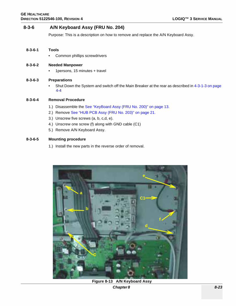
GE HEALTHCAREDIRECTION 5122546-100, REVISION 4 LOGIQ™ 3 SERVICE MANUAL
8-3-6 A/N Keyboard Assy (FRU No. 204)Purpose: This is a description on how to remove and replace the A/N Keyboard Assy.
8-3-6-1 Tools• Common phillips screwdrivers
8-3-6-2 Needed Manpower• 1persons, 15 minutes + travel
8-3-6-3 Preparations• Shut Down the System and switch off the Main Breaker at the rear as described in 4-3-1-3 on page
4-4
8-3-6-4 Removal Procedure
1.) Disassemble the See “KeyBoard Assy (FRU No. 200)” on page 13.2.) Remove See “HUB PCB Assy (FRU No. 203)” on page 21.3.) Unscrew five screws (a, b, c,d, e).4.) Unscrew one screw (f) along with GND cable (C1)5.) Remove A/N Keyboard Assy.
8-3-6-5 Mounting procedure
1.) Install the new parts in the reverse order of removal.
Figure 8-13 A/N Keyboard Assy
a
b
c
d
e
C1
f
Chapter 8 8-23

GE HEALTHCAREDIRECTION 5122546-100, REVISION 4 LOGIQ™ 3 SERVICE MANUAL
8-3-6-6 Functional Checkout Procedure
See Section
Functional and/or Leakage Current
Test Debrief Script4-3-1 Power On/Boot Up Service Manual Direction 5122546-100, Section 8-3-6. Equipment passes all required
tests and is ready for use.4-4-1 Basic Controls4-4-2 B Mode Checks4-4-3 M Mode Checks
4-4-4Color Flow Mode
Checks
4-4-5Doppler Mode
Checks
4-4-6Measurement and
Multi Image Checks
4-4-7Basic
Measurements
7-5-2PC Diagnostics: Keyboard Tests
8-24 Section 8-3 - Keyboard

GE HEALTHCAREDIRECTION 5122546-100, REVISION 4 LOGIQ™ 3 SERVICE MANUAL
8-3-7 Keyboard Trackball Assy (FRU No. 205)Purpose: This is a description on how to remove and replace the Keyboard Trackball Assy.
8-3-7-1 Tools• Common phillips screwdrivers
8-3-7-2 Needed Manpower• 1persons, 15 minutes + travel
8-3-7-3 Preparations• Shut Down the System and switch off the Main Breaker at the rear as described in 4-3-1-3 on page
4-4
8-3-7-4 Removal Procedure
1.) Remove See “KeyBoard Assy (FRU No. 200)” on page 13.2.) Unscrew two screws (a, b)3.) Unscrew one screw (c) along with GND cable.4.) Remove cable (C1) from the Trackball.5.) Remove the Trackball.
8-3-7-5 Mounting procedure
1.) Install the new parts in the reverse order of removal.
Figure 8-14 Keyboard Trackball Assy
a
b
cC1
C1
GND
FRU 206
Chapter 8 8-25

GE HEALTHCAREDIRECTION 5122546-100, REVISION 4 LOGIQ™ 3 SERVICE MANUAL
8-3-7-6 Functional Checkout Procedure
See Section
Functional and/or Leakage Current
Test Debrief Script4-3-1 Power On/Boot Up Service Manual Direction 5122546-100, Section 8-3-7. Equipment passes all required
tests and is ready for use.4-4-1 Basic Controls4-4-2 B Mode Checks4-4-3 M Mode Checks
4-4-4Color Flow Mode
Checks
4-4-5Doppler Mode
Checks
4-4-6Measurement and
Multi Image Checks
4-4-7Basic
Measurements
7-5-2PC Diagnostics: Keyboard Tests
8-26 Section 8-3 - Keyboard

GE HEALTHCAREDIRECTION 5122546-100, REVISION 4 LOGIQ™ 3 SERVICE MANUAL
8-3-8 Keyboard - Freeze Key Assy (FRU No. 206)Purpose: This is a description on how to remove and replace the Keyboard - Freeze Key Assy
8-3-8-1 Tools• Common phillips screwdrivers
8-3-8-2 Needed Manpower• 1persons, 15 minutes + travel
8-3-8-3 Preparations• Shut Down the System and switch off the Main Breaker at the rear as described in 4-3-1-3 on page
4-4
8-3-8-4 Removal Procedure
1.) Remove See “KeyBoard Assy (FRU No. 200)” on page 13.2.) Disconnect Cable C1 from Freeze PCB3.) Unscrew three screws (a, b & c). While remove screw (a) remove GND cable (C2)4.) Remove Freeze Key Assy
8-3-8-5 Mounting procedure
1.) Install the new parts in the reverse order of removal.
Figure 8-15 Keyboard - Freeze Key Assy
ab
cC1C2
Chapter 8 8-27

GE HEALTHCAREDIRECTION 5122546-100, REVISION 4 LOGIQ™ 3 SERVICE MANUAL
8-3-8-6 Functional Checkout Procedure
See Section
Functional and/or Leakage Current
Test Debrief Script4-3-1 Power On/Boot Up Service Manual Direction 5122546-100, Section 8-3-8. Equipment passes all required
tests and is ready for use.4-4-1 Basic Controls4-4-2 B Mode Checks4-4-3 M Mode Checks
4-4-4Color Flow Mode
Checks
4-4-5Doppler Mode
Checks
4-4-6Measurement and
Multi Image Checks
4-4-7Basic
Measurements
7-5-2PC Diagnostics: Keyboard Tests
8-28 Section 8-3 - Keyboard

GE HEALTHCAREDIRECTION 5122546-100, REVISION 4 LOGIQ™ 3 SERVICE MANUAL
8-3-9 Power switch and Encoder PCB Assy (FRU 207).Purpose: This is a description on how to remove and replace the Keyboard -Power switch and Encoder
PCB Assy
8-3-9-1 Tools• Common phillips screwdrivers
8-3-9-2 Needed Manpower• 1persons, 15 minutes + travel
8-3-9-3 Preparations• Shut Down the System and switch off the Main Breaker at the rear as described in 4-3-1-3 on page
4-4
8-3-9-4 Removal Procedure
1.) Remove See “KeyBoard Assy (FRU No. 200)” on page 13.2.) Unscrew Four screws (a, b, c & d). 3.) Disconnect Cable C1 from KBD4.) Remove the 5 Caps5.) Remove nine screws (a-i) and pull out Power Switch & Encoder PCB Assy.
8-3-9-5 Mounting procedure
1.) Install the new parts in the reverse order of removal.
8-3-9-6 Functional Checkout Procedure
See Section
Functional and/or Leakage Current
Test Debrief Script4-3-1 Power On/Boot Up Service Manual Direction 5122546-100, Section 8-3-9. Equipment passes all required
tests and is ready for use.4-4-1 Basic Controls4-4-2 B Mode Checks4-4-3 M Mode Checks
4-4-4Color Flow Mode
Checks
4-4-5Doppler Mode
Checks
4-4-6Measurement and
Multi Image Checks
4-4-7Basic
Measurements
7-5-2PC Diagnostics: Keyboard Tests
Chapter 8 8-29
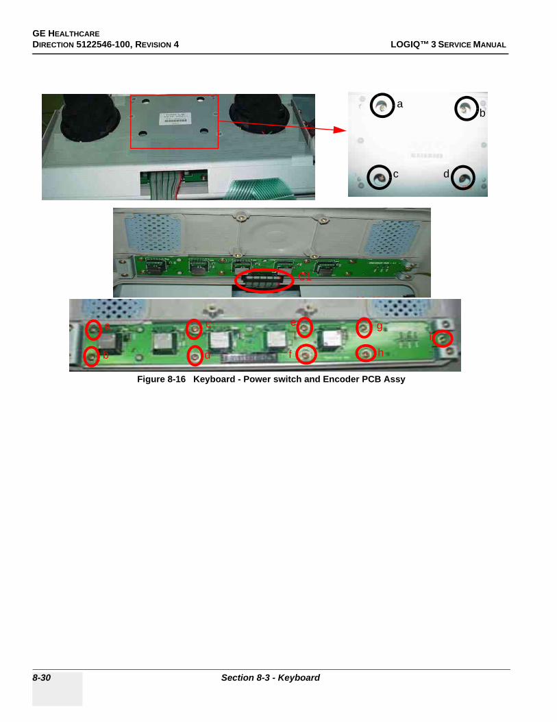
GE HEALTHCAREDIRECTION 5122546-100, REVISION 4 LOGIQ™ 3 SERVICE MANUAL
Figure 8-16 Keyboard - Power switch and Encoder PCB Assy
ab
c d
a
b
c
d
e
f
g
hi
C1
8-30 Section 8-3 - Keyboard

GE HEALTHCAREDIRECTION 5122546-100, REVISION 4 LOGIQ™ 3 SERVICE MANUAL
8-3-10 Keyboard Power Cable (FRU 208).Purpose: This is a description on how to remove and replace the Keyboard Power Cable
8-3-10-1 Tools• Common phillips screwdrivers
8-3-10-2 Needed Manpower• 1persons, 15 minutes + travel
8-3-10-3 Preparations• Shut Down the System and switch off the Main Breaker at the rear as described in 4-3-1-3 on page
4-4
8-3-10-4 Removal Procedure
1.) Remove See “KeyBoard Assy (FRU No. 200)” on page 13.2.) Disconnect Cable C1 from KBD3.) Remove the See “Rear EMI Cover” on page 63.4.) Disconnect the other end of the Cable C1 from RPI Board.5.) Pull out the Cable from the system.
8-3-10-5 Mounting procedure
1.) Install the new parts in the reverse order of removal.
8-3-10-6 Functional Checkout Procedure
See Section
Functional and/or Leakage Current
Test Debrief Script4-3-1 Power On/Boot Up Service Manual Direction 5122546-100, Section 8-3-10. Equipment passes all required
tests and is ready for use.4-4-1 Basic Controls4-4-2 B Mode Checks4-4-3 M Mode Checks
4-4-4Color Flow Mode
Checks
4-4-5Doppler Mode
Checks
4-4-6Measurement and
Multi Image Checks
4-4-7Basic
Measurements
7-5-2PC Diagnostics: Keyboard Tests
Chapter 8 8-31

GE HEALTHCAREDIRECTION 5122546-100, REVISION 4 LOGIQ™ 3 SERVICE MANUAL
Figure 8-17 Keyboard - Power Cable
C1
C1
8-32 Section 8-3 - Keyboard

GE HEALTHCAREDIRECTION 5122546-100, REVISION 4 LOGIQ™ 3 SERVICE MANUAL
Section 8-4Mechanicals
8-4-1 Right Cover (FRU No. 300)Purpose: This is a description on how to remove and replace the Right Cover.
8-4-1-1 Tools• Common Phillips screwdrivers
8-4-1-2 Needed Manpower• 1persons, 15 minutes + travel
8-4-1-3 Preparations• Shut Down the System and switch off the Main Breaker at the rear as described in 4-3-1-3 on page
4-4
8-4-1-4 Removal ProcedureRefer to 8-4-1 on page 8-33 .
1.) Unscrew six screws (1-6).2.) Remove the Right Cover in the direction as shown in the Figure below.
8-4-1-5 Mounting procedure
1.) Install the new parts in the reverse order of removal.
8-4-1-6 Functional Checkout Procedure
See Section
Functional and/or Leakage Current
Test Debrief Script4-3-1 Power On/Boot Up Service Manual Direction 5122546-100, Section 8-4-1. Equipment passes all required
tests and is ready for use.4-4-1 Basic Controls
Chapter 8 8-33

GE HEALTHCAREDIRECTION 5122546-100, REVISION 4 LOGIQ™ 3 SERVICE MANUAL
Figure 8-18 Right Cover
1
25
6
43
8-34 Section 8-4 - Mechanicals

GE HEALTHCAREDIRECTION 5122546-100, REVISION 4 LOGIQ™ 3 SERVICE MANUAL
8-4-2 Left Cover (FRU No. 301)Purpose: This is a description on how to remove and replace the Left Cover.
8-4-2-1 Tools• Common Phillips screwdrivers
8-4-2-2 Needed Manpower• 1person, 15 minutes + travel
8-4-2-3 Preparations• Shut Down the System and switch off the Main Breaker at the rear as described in 4-3-1-3 on page
4-4
8-4-2-4 Removal ProcedureRefer to 8-4-2 on page 8-35
1.) Unscrew 6 screws (1-6).2.) Remove the Left Cover in the direction as shown in the figure below.
8-4-2-5 Mounting procedure
1.) Install the new parts in the reverse order of removal.
Figure 8-19 Left Cover
1
23
4
5
6
A
A. After removing the screws(1-6), then remove the left cover in the direction of arrow.
Chapter 8 8-35

GE HEALTHCAREDIRECTION 5122546-100, REVISION 4 LOGIQ™ 3 SERVICE MANUAL
8-4-2-6 Functional Checkout Procedure
See Section
Functional and/or Leakage Current
Test Debrief Script4-3-1 Power On/Boot Up Service Manual Direction 5122546-100, Section 8-4-2. Equipment passes all required
tests and is ready for use.4-4-1 Basic Controls
8-36 Section 8-4 - Mechanicals

GE HEALTHCAREDIRECTION 5122546-100, REVISION 4 LOGIQ™ 3 SERVICE MANUAL
8-4-3 Rear Cover (FRU No. 302)Purpose: This is a description on how to remove and replace the Rear Cover.
8-4-3-1 Tools• Common Phillips screwdrivers
8-4-3-2 Needed Manpower• 1 persons, 15 minutes + travel
8-4-3-3 Preparations• Shut Down the System and switch off the Main Breaker at the rear as described in 4-3-1-3 on page
4-4
8-4-3-4 Removal ProcedureRefer to Figure 8-20 on page 8-37 .
1.) Unscrew six screws (1-6).2.) Lift and remove the Rear Cover.
8-4-3-5 Mounting procedure
1.) Install the new parts in the reverse order of removal.
Figure 8-20 Rear Cover
1
2
3
4
5
6
Chapter 8 8-37

GE HEALTHCAREDIRECTION 5122546-100, REVISION 4 LOGIQ™ 3 SERVICE MANUAL
8-4-3-6 Functional Checkout Procedure
See Section
Functional and/or Leakage Current
Test Debrief Script4-3-1 Power On/Boot Up Service Manual Direction 5122546-100, Section 8-4-3. Equipment passes all required
tests and is ready for use.4-4-1 Basic Controls
8-38 Section 8-4 - Mechanicals

GE HEALTHCAREDIRECTION 5122546-100, REVISION 4 LOGIQ™ 3 SERVICE MANUAL
8-4-4 Front Bumper (FRU No. 303) for LOGIQ™ 3 PRO/Black and White
NOTE: For LOGIQ™ 3 EXPERT, refer to 8-4-5 "Front Bumper (FRU No. 303) for LOGIQ™ 3 EXPERT" on page 8-41
Purpose: This is a description on how to remove and replace the Front Bumper.
8-4-4-1 Tools• Common Phillips screwdrivers
8-4-4-2 Needed Manpower• 1 persons, 15 minutes + travel
8-4-4-3 Preparations• Shut Down the System and switch off the Main Breaker at the rear as described in 4-3-1-3 on page
4-4
8-4-4-4 Removal ProcedureRefer to Figure 8-21 on page 8-39 .
1.) Remove See “Right Cover (FRU No. 300)” on page 33.2.) Remove See “Left Cover (FRU No. 301)” on page 35.3.) Unscrew four screws (a, b, c, d).4.) Lift the Front Bumper at sides, Press in the Middle of Front Cover to remove the front bumper
8-4-4-5 Mounting procedure
1.) Install the new parts in the reverse order of removal.
Figure 8-21 Front Bumper
Push and Pull the Front Bumper
a
d
b c
Chapter 8 8-39
GE HEALTHCAREDIRECTION 5122546-100, REVISION 4 LOGIQ™ 3 SERVICE MANUAL
8-4-4-6 Functional Checkout Procedure
See Section
Functional and/or Leakage Current
Test Debrief Script4-3-1 Power On/Boot Up Service Manual Direction 5122546-100, Section 8-4-4. Equipment passes all required
tests and is ready for use.4-4-1 Basic Controls
8-40 Section 8-4 - Mechanicals

GE HEALTHCAREDIRECTION 5122546-100, REVISION 4 LOGIQ™ 3 SERVICE MANUAL
8-4-5 Front Bumper (FRU No. 303) for LOGIQ™ 3 EXPERT
NOTE: For LOGIQ™ 3 PRO and LOGIQ™ 3 Black and White, refer to 8-4-4 "Front Bumper (FRU No. 303) for LOGIQ™ 3 PRO/Black and White" on page 8-39
Purpose: This is a description on how to remove and replace the Front Bumper.
8-4-5-1 Tools• Common Phillips screwdrivers
8-4-5-2 Needed Manpower• 1 persons, 15 minutes + travel
8-4-5-3 Preparations• Shut Down the System and switch off the Main Breaker at the rear as described in 4-3-1-3 on page
4-4
8-4-5-4 Removal ProcedureRefer to Figure 8-21 on page 8-39 .
1.) Remove Right Cover. See “Right Cover (FRU No. 300)” on page 33.2.) Remove Left Cover. See “Left Cover (FRU No. 301)” on page 35.3.) Unscrew four screws (a, b, c, d).4.) Lift the Front Bumper at sides, Press in the Middle of Front Cover to remove the front bumper
8-4-5-5 Mounting procedure
1.) Install the new parts in the reverse order of removal.
Figure 8-22 Front Bumper
ab
c d
Chapter 8 8-41

GE HEALTHCAREDIRECTION 5122546-100, REVISION 4 LOGIQ™ 3 SERVICE MANUAL
8-4-5-6 Functional Checkout Procedure
See Section
Functional and/or Leakage Current
Test Debrief Script4-3-1 Power On/Boot Up Service Manual Direction 5122546-100, Section 8-4-5. Equipment passes all required
tests and is ready for use.4-4-1 Basic Controls
8-42 Section 8-4 - Mechanicals

GE HEALTHCAREDIRECTION 5122546-100, REVISION 4 LOGIQ™ 3 SERVICE MANUAL
8-4-6 Front Rubber Bumper Left (FRU No. 311)Purpose: This is a description on how to remove and replace the Front Bumper Left.
8-4-6-1 Tools• Common Phillips screwdrivers
8-4-6-2 Needed Manpower• 1 persons, 15 minutes + travel
8-4-6-3 Preparations• Shut Down the System and switch off the Main Breaker at the rear as described in 4-3-1-3 on page
4-4
8-4-6-4 Removal ProcedureRefer to Figure 8-25 on page 8-47 .
1.) Remove See “Right Cover (FRU No. 300)” on page 33.2.) Remove See “Left Cover (FRU No. 301)” on page 35.3.) Remove See “Front Bumper (FRU No. 303) for LOGIQ™ 3 PRO/Black and White” on page 39.4.) Remove Front Bumper Left.
8-4-6-5 Mounting procedure
1.) Install the new parts in the reverse order of removal
8-4-6-6 Functional Checkout Procedure
Figure 8-23 Front Bumper Left
See Section
Functional and/or Leakage Current
Test Debrief Script
Chapter 8 8-43

GE HEALTHCAREDIRECTION 5122546-100, REVISION 4 LOGIQ™ 3 SERVICE MANUAL
4-3-1 Power On/Boot Up Service Manual Direction 5122546-100, Section 8-4-6. Equipment passes all required tests and is ready for use.
4-4-1 Basic Controls
8-44 Section 8-4 - Mechanicals
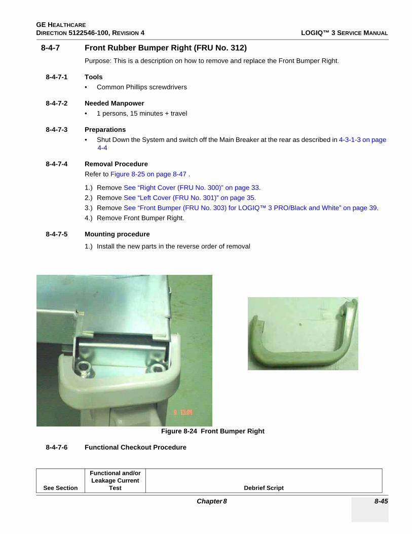
GE HEALTHCAREDIRECTION 5122546-100, REVISION 4 LOGIQ™ 3 SERVICE MANUAL
8-4-7 Front Rubber Bumper Right (FRU No. 312)Purpose: This is a description on how to remove and replace the Front Bumper Right.
8-4-7-1 Tools• Common Phillips screwdrivers
8-4-7-2 Needed Manpower• 1 persons, 15 minutes + travel
8-4-7-3 Preparations• Shut Down the System and switch off the Main Breaker at the rear as described in 4-3-1-3 on page
4-4
8-4-7-4 Removal ProcedureRefer to Figure 8-25 on page 8-47 .
1.) Remove See “Right Cover (FRU No. 300)” on page 33.2.) Remove See “Left Cover (FRU No. 301)” on page 35.3.) Remove See “Front Bumper (FRU No. 303) for LOGIQ™ 3 PRO/Black and White” on page 39.4.) Remove Front Bumper Right.
8-4-7-5 Mounting procedure
1.) Install the new parts in the reverse order of removal
8-4-7-6 Functional Checkout Procedure
Figure 8-24 Front Bumper Right
See Section
Functional and/or Leakage Current
Test Debrief Script
Chapter 8 8-45
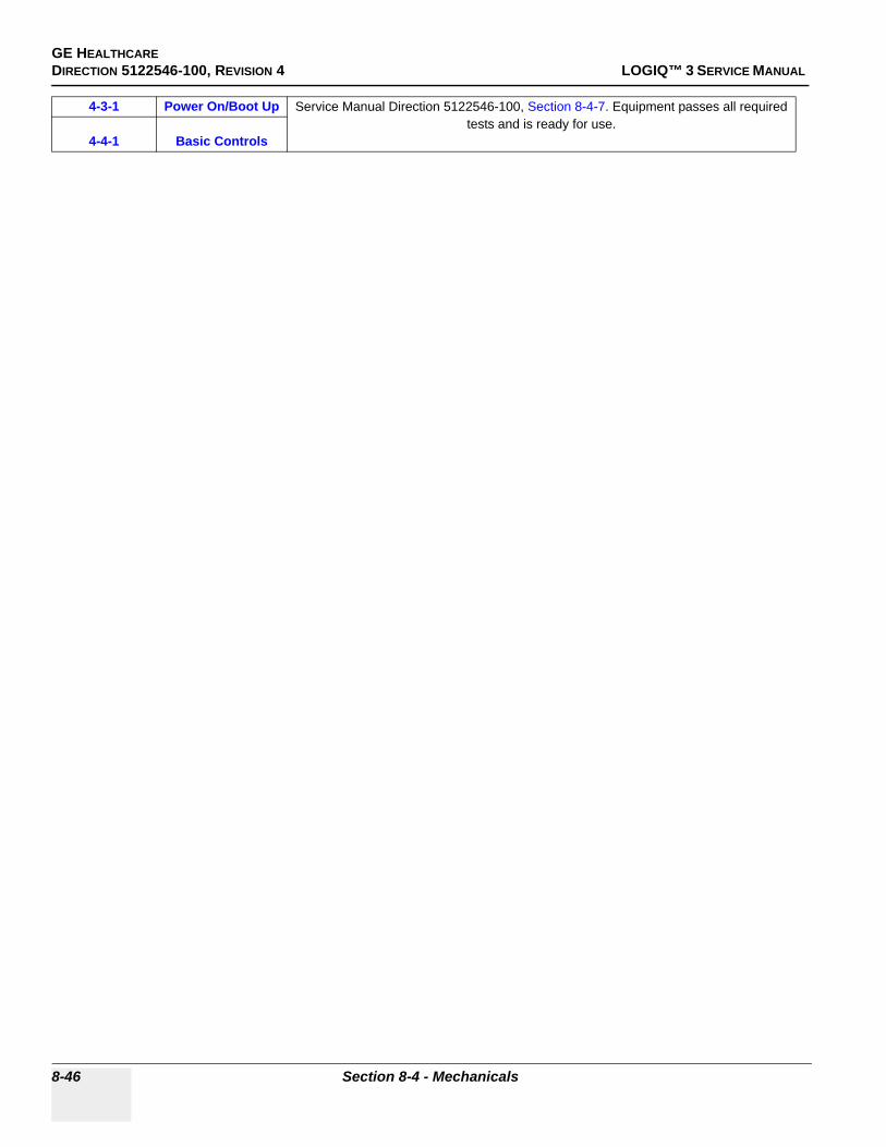
GE HEALTHCAREDIRECTION 5122546-100, REVISION 4 LOGIQ™ 3 SERVICE MANUAL
4-3-1 Power On/Boot Up Service Manual Direction 5122546-100, Section 8-4-7. Equipment passes all required tests and is ready for use.
4-4-1 Basic Controls
8-46 Section 8-4 - Mechanicals

GE HEALTHCAREDIRECTION 5122546-100, REVISION 4 LOGIQ™ 3 SERVICE MANUAL
8-4-8 Front Cover (FRU No. 304) for LOGIQ™ 3 PRO / Black and White
NOTE: For LOGIQ™ 3 Expert, refer to 8-4-8 "Front Cover (FRU No. 304) for LOGIQ™ 3 PRO / Black and White" on page 8-47
Purpose: This is a description on how to remove and replace the Front Cover.
8-4-8-1 Tools• Common Phillips screwdrivers
8-4-8-2 Needed Manpower• 1 persons, 15 minutes + travel
8-4-8-3 Preparations• Shut Down the System and switch off the Main Breaker at the rear as described in 4-3-1-3 on page
4-4
8-4-8-4 Removal ProcedureRefer to Figure 8-25 on page 8-47 .
1.) Remove See “Right Cover (FRU No. 300)” on page 33.2.) Remove See “Left Cover (FRU No. 301)” on page 35.3.) Remove See “Front Bumper (FRU No. 303) for LOGIQ™ 3 PRO/Black and White” on page 39.4.) Unscrew two screws (a, b, c, d)5.) Remove Front Cover.
8-4-8-5 Mounting procedure
1.) Install the new parts in the reverse order of removal.
Figure 8-25 Front Cover
C D
Chapter 8 8-47

GE HEALTHCAREDIRECTION 5122546-100, REVISION 4 LOGIQ™ 3 SERVICE MANUAL
8-4-8-6 Functional Checkout Procedure
See Section
Functional and/or Leakage Current
Test Debrief Script4-3-1 Power On/Boot Up Service Manual Direction 5122546-100, Section 8-4-8. Equipment passes all required
tests and is ready for use.4-4-1 Basic Controls
8-48 Section 8-4 - Mechanicals

GE HEALTHCAREDIRECTION 5122546-100, REVISION 4 LOGIQ™ 3 SERVICE MANUAL
8-4-9 Front Cover (FRU No. 304) for LOGIQ™ 3 EXPERT
NOTE: For LOGIQ™ 3 PRO and LOGIQ™ 3 Black and White, refer to 8-4-8 "Front Cover (FRU No. 304) for LOGIQ™ 3 PRO / Black and White" on page 8-47
Purpose: This is a description on how to remove and replace the Front Cover.
8-4-9-1 Tools• Common Phillips screwdrivers
8-4-9-2 Needed Manpower• 1 persons, 15 minutes + travel
8-4-9-3 Preparations• Shut Down the System and switch off the Main Breaker at the rear as described in 4-3-1-3 on page
4-4
8-4-9-4 Removal ProcedureRefer to Figure 8-25 on page 8-47 .
1.) Remove See “Right Cover (FRU No. 300)” on page 33.2.) Remove See “Left Cover (FRU No. 301)” on page 35.3.) Remove See “Front Bumper (FRU No. 303) for LOGIQ™ 3 PRO/Black and White” on page 39.4.) Unscrew two screws (a, b, c, d)5.) Remove Front Cover.
8-4-9-5 Mounting procedure
1.) Install the new parts in the reverse order of removal.
Figure 8-26 Front Cover
C Da b
Chapter 8 8-49
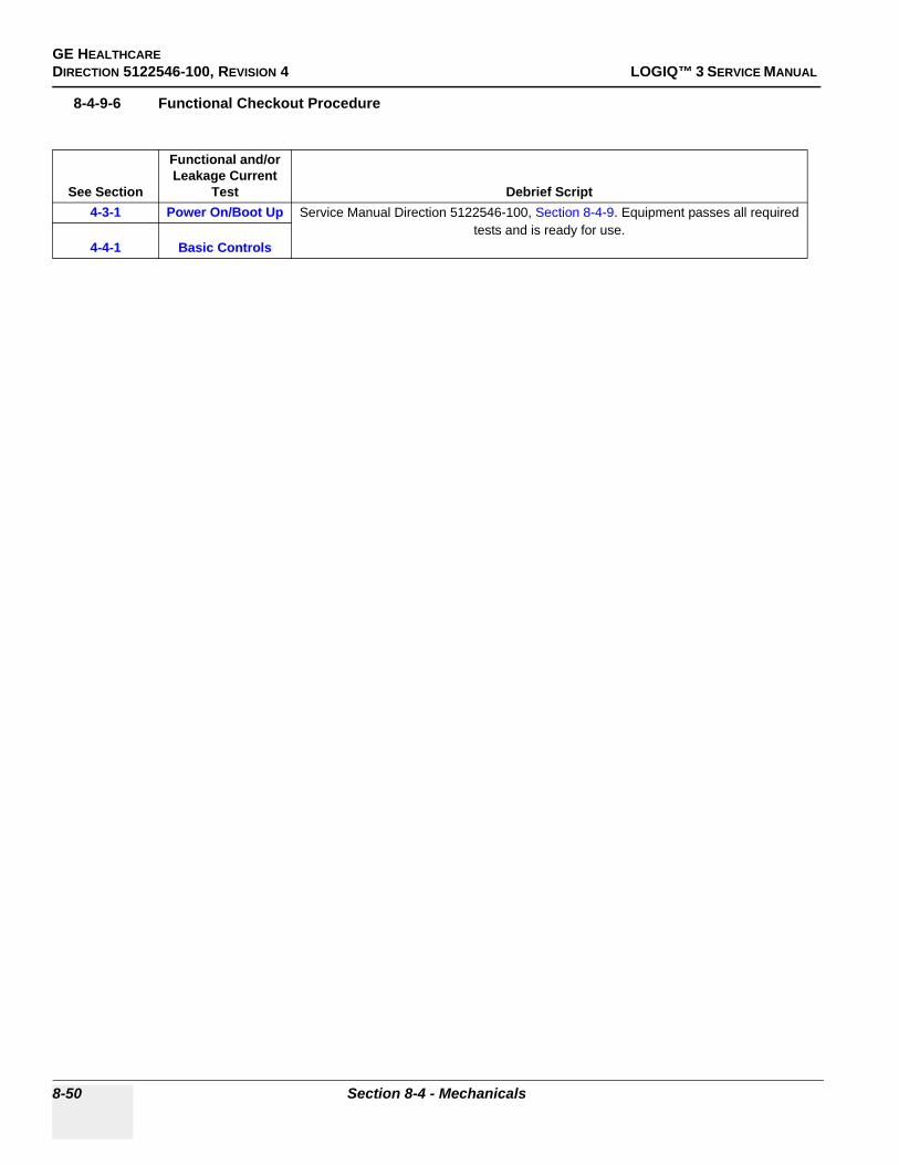
GE HEALTHCAREDIRECTION 5122546-100, REVISION 4 LOGIQ™ 3 SERVICE MANUAL
8-4-9-6 Functional Checkout Procedure
See Section
Functional and/or Leakage Current
Test Debrief Script4-3-1 Power On/Boot Up Service Manual Direction 5122546-100, Section 8-4-9. Equipment passes all required
tests and is ready for use.4-4-1 Basic Controls
8-50 Section 8-4 - Mechanicals

GE HEALTHCAREDIRECTION 5122546-100, REVISION 4 LOGIQ™ 3 SERVICE MANUAL
8-4-10 Top Cover (FRU No. 305)Purpose: This is a description on how to remove and replace the Top Cover.
8-4-10-1 Tools• Common Phillips screwdrivers
8-4-10-2 Needed Manpower• 1 person, 15 minutes + travel
8-4-10-3 Preparations• Shut Down the System and switch off the Main Breaker at the rear as described in 4-3-1-3 on page
4-4
8-4-10-4 Removal ProcedureRefer to Figure 8-27 on page 8-51 .
1.) Remove See “Right Cover (FRU No. 300)” on page 33.2.) Remove See “Left Cover (FRU No. 301)” on page 35.3.) Remove See “Rear Cover (FRU No. 302)” on page 37.4.) Remove See “Front Cover (FRU No. 304) for LOGIQ™ 3 PRO / Black and White” on page 47.5.) Remove See “Keyboard Rear Cover (FRU No. 308)” on page 57.6.) Unscrew four screws (1-4).7.) Pull Up the Top Cover to remove.
8-4-10-5 Mounting procedure
1.) Install the new parts in the reverse order of removal
Figure 8-27 Top Cover Disassembly
1 2
Chapter 8 8-51

GE HEALTHCAREDIRECTION 5122546-100, REVISION 4 LOGIQ™ 3 SERVICE MANUAL
8-4-10-6 Functional Checkout Procedure
See Section
Functional and/or Leakage Current
Test Debrief Script4-3-1 Power On/Boot Up Service Manual Direction 5122546-100, Section 8-4-10. Equipment passes all required
tests and is ready for use.4-4-1 Basic Controls
8-52 Section 8-4 - Mechanicals

GE HEALTHCAREDIRECTION 5122546-100, REVISION 4 LOGIQ™ 3 SERVICE MANUAL
8-4-11 KeyBoard Bottom Cover (FRU No. 306)Purpose: This is a description on how to remove and replace the Keyboard Bottom Cover.
8-4-11-1 Tools• Common Phillips screwdrivers
8-4-11-2 Needed Manpower• 1 persons, 30 minutes + travel
8-4-11-3 Preparations• Shut Down the System and switch off the Main Breaker at the rear as described in 4-3-1-3 on page
4-4
8-4-11-4 Removal ProcedureRefer to Figure 8-28 on page 8-53 .
1.) Remove the See “KeyBoard Assy (FRU No. 200)” on page 13.2.) unscrew four screws (a, b, c, d) fixing VGP support Tray
3.) Unscrew eight screws (1-8).4.) Remove the KBD Bottom Cover.
8-4-11-5 Mounting procedure
1.) Install the new parts in the reverse order of removal
CAUTION Hold the VGP Support Tray below the Keyboard bottom from falling down.
Figure 8-28 Keyboard Bottom
a b
cd
Chapter 8 8-53

GE HEALTHCAREDIRECTION 5122546-100, REVISION 4 LOGIQ™ 3 SERVICE MANUAL
8-4-11-6 Functional Checkout Procedure
See Section
Functional and/or Leakage Current
Test Debrief Script4-3-1 Power On/Boot Up Service Manual Direction 5122546-100, Section 8-4-11. Equipment passes all required
tests and is ready for use.4-4-1 Basic Controls
8-54 Section 8-4 - Mechanicals
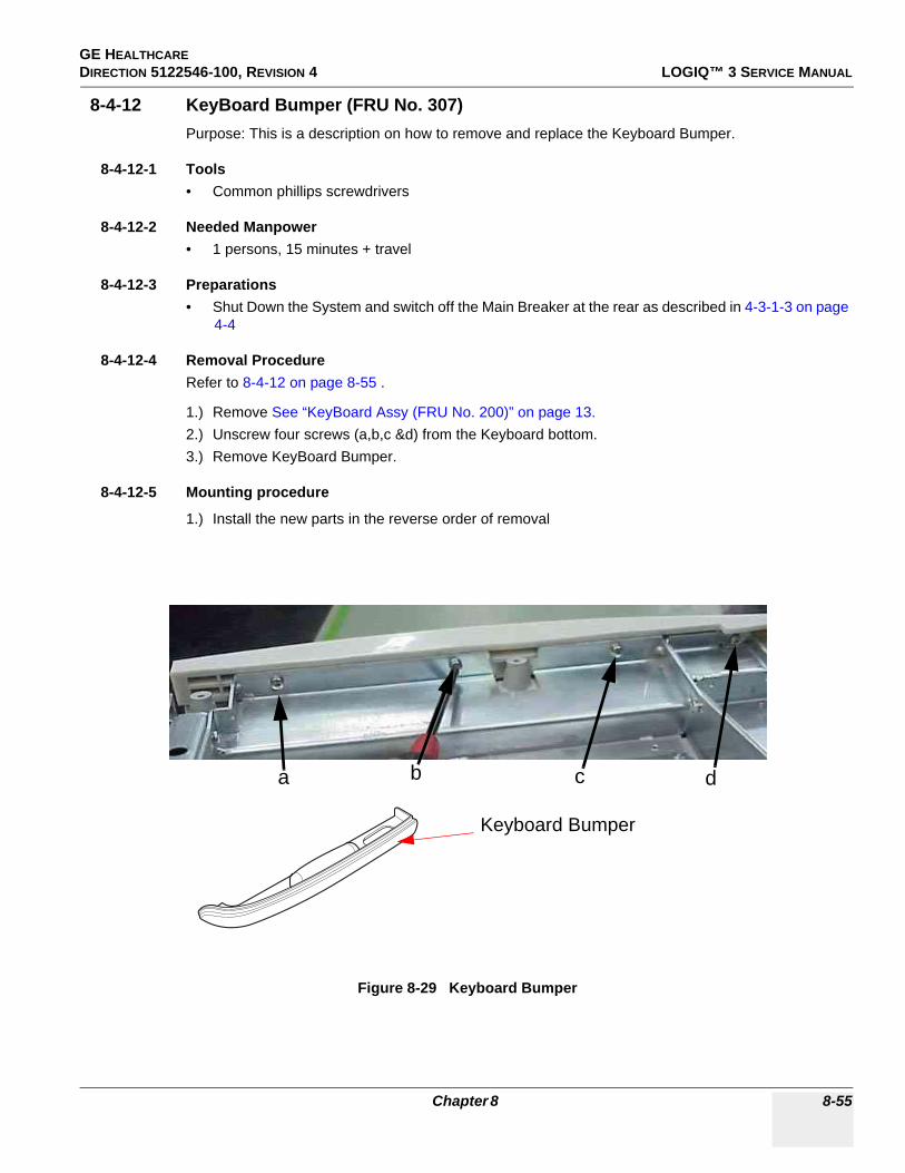
GE HEALTHCAREDIRECTION 5122546-100, REVISION 4 LOGIQ™ 3 SERVICE MANUAL
8-4-12 KeyBoard Bumper (FRU No. 307)Purpose: This is a description on how to remove and replace the Keyboard Bumper.
8-4-12-1 Tools• Common phillips screwdrivers
8-4-12-2 Needed Manpower• 1 persons, 15 minutes + travel
8-4-12-3 Preparations• Shut Down the System and switch off the Main Breaker at the rear as described in 4-3-1-3 on page
4-4
8-4-12-4 Removal ProcedureRefer to 8-4-12 on page 8-55 .
1.) Remove See “KeyBoard Assy (FRU No. 200)” on page 13.2.) Unscrew four screws (a,b,c &d) from the Keyboard bottom.3.) Remove KeyBoard Bumper.
8-4-12-5 Mounting procedure
1.) Install the new parts in the reverse order of removal
Figure 8-29 Keyboard Bumper
a b c d
Keyboard Bumper
Chapter 8 8-55

GE HEALTHCAREDIRECTION 5122546-100, REVISION 4 LOGIQ™ 3 SERVICE MANUAL
8-4-12-6 Functional Checkout Procedure
See Section
Functional and/or Leakage Current
Test Debrief Script4-3-1 Power On/Boot Up Service Manual Direction 5122546-100, Section 8-4-12. Equipment passes all required
tests and is ready for use.4-4-1 Basic Controls
8-56 Section 8-4 - Mechanicals

GE HEALTHCAREDIRECTION 5122546-100, REVISION 4 LOGIQ™ 3 SERVICE MANUAL
8-4-13 Keyboard Rear Cover (FRU No. 308)Purpose: This is a description on how to remove and replace the Keyboard Rear Cover
8-4-13-1 Tools• Coin/ "-" Stubby screwdrivers
8-4-13-2 Needed Manpower• 1persons, 15 minutes + travel
8-4-13-3 Preparations• Shut Down the System and switch off the Main Breaker at the rear as described in 4-3-1-3 on page
4-4
8-4-13-4 Removal Procedure
1.) Remove two caps (a,b).2.) Remove two screws(1,2) using coins / "-" Stub B screwdrivers3.) Lift the Keyboard Rear cover Up and pull backwards to remove.
8-4-13-5 Mounting procedure
1.) Install the new parts in the reverse order of removal.
Figure 8-30 Keyboard Rear Cover
a
b
21
Use Coin to Uncsrew
Chapter 8 8-57

GE HEALTHCAREDIRECTION 5122546-100, REVISION 4 LOGIQ™ 3 SERVICE MANUAL
8-4-13-6 Functional Checkout Procedure
See Section
Functional and/or Leakage Current
Test Debrief Script4-3-1 Power On/Boot Up Service Manual Direction 5122546-100, Section 8-4-13. Equipment passes all required
tests and is ready for use.4-4-1 Basic Controls
8-58 Section 8-4 - Mechanicals

GE HEALTHCAREDIRECTION 5122546-100, REVISION 4 LOGIQ™ 3 SERVICE MANUAL
8-4-14 Left EMI CoverPurpose: This is a description on how to remove and replace the Left EMI Cover.
8-4-14-1 Tools• Common phillips screwdrivers
8-4-14-2 Needed Manpower• 1 person, 15 minutes + travel
8-4-14-3 Preparations• Shut Down the System and switch off the Main Breaker at the rear as described in 4-3-1-3 on page
4-4
8-4-14-4 Removal ProcedureRefer to Figure 8-31 on page 8-59 .
1.) Remove See “Left Cover (FRU No. 301)” on page 35.2.) Unscrew eight screws (1-8).3.) Remove the Left EMI Cover.
8-4-14-5 Mounting procedure
1.) Install the new parts in the reverse order of removal.
Figure 8-31 Left EMI Cover Disassembly
1
2
3
4
5
6
7
8
Chapter 8 8-59

GE HEALTHCAREDIRECTION 5122546-100, REVISION 4 LOGIQ™ 3 SERVICE MANUAL
8-4-14-6 Functional Checkout Procedure
See Section
Functional and/or Leakage Current
Test Debrief Script4-3-1 Power On/Boot Up Service Manual Direction 5122546-100, Section 8-4-14. Equipment passes all required
tests and is ready for use.4-4-1 Basic Controls
10-6-4, 10-6-5 Leakage Current
8-60 Section 8-4 - Mechanicals
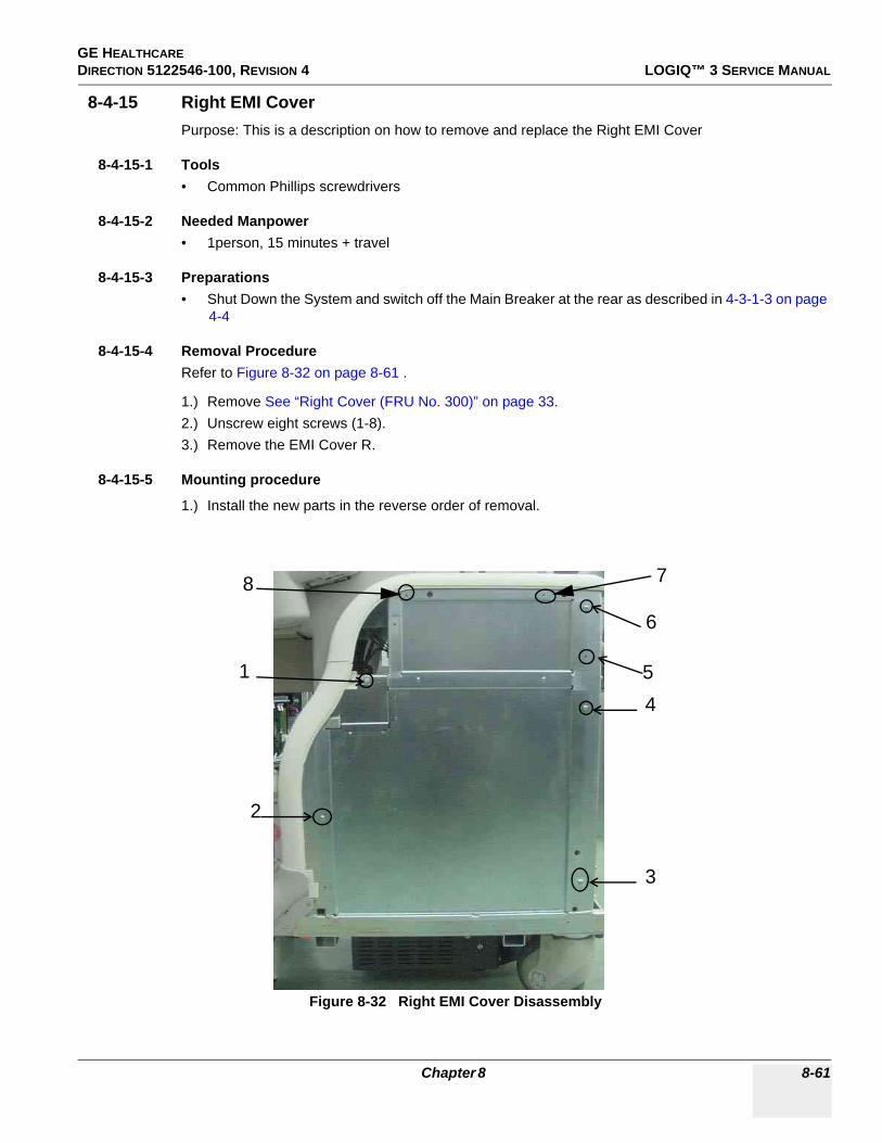
GE HEALTHCAREDIRECTION 5122546-100, REVISION 4 LOGIQ™ 3 SERVICE MANUAL
8-4-15 Right EMI CoverPurpose: This is a description on how to remove and replace the Right EMI Cover
8-4-15-1 Tools• Common Phillips screwdrivers
8-4-15-2 Needed Manpower• 1person, 15 minutes + travel
8-4-15-3 Preparations• Shut Down the System and switch off the Main Breaker at the rear as described in 4-3-1-3 on page
4-4
8-4-15-4 Removal ProcedureRefer to Figure 8-32 on page 8-61 .
1.) Remove See “Right Cover (FRU No. 300)” on page 33.2.) Unscrew eight screws (1-8).3.) Remove the EMI Cover R.
8-4-15-5 Mounting procedure
1.) Install the new parts in the reverse order of removal.
Figure 8-32 Right EMI Cover Disassembly
1
2
3
45
8
6
7
Chapter 8 8-61

GE HEALTHCAREDIRECTION 5122546-100, REVISION 4 LOGIQ™ 3 SERVICE MANUAL
8-4-15-6 Functional Checkout Procedure
See Section
Functional and/or Leakage Current
Test Debrief Script4-3-1 Power On/Boot Up Service Manual Direction 5122546-100, Section 8-4-15. Equipment passes all required
tests and is ready for use.4-4-1 Basic Controls
10-6-4, 10-6-5 Leakage Current
8-62 Section 8-4 - Mechanicals

GE HEALTHCAREDIRECTION 5122546-100, REVISION 4 LOGIQ™ 3 SERVICE MANUAL
8-4-16 Rear EMI CoverPurpose: This is a description on how to remove and replace the Rear EMI Cover
8-4-16-1 Tools• Common Phillips screwdrivers
8-4-16-2 Needed Manpower• 1person, 15 minutes + travel
8-4-16-3 Preparations• Shut Down the System and switch off the Main Breaker at the rear as described in 4-3-1-3 on page
4-4
8-4-16-4 Removal ProcedureRefer to Figure 8-33 on page 8-63 .
1.) Remove See “Rear Cover (FRU No. 302)” on page 37.2.) Unscrew eight screws (1-10) holding the Rear EMI shield3.) Remove the Rear EMI Shield.
8-4-16-5 Mounting procedure
1.) Install the new parts in the reverse order of removal.
Figure 8-33 Rear EMI Cover Disassembly
1
2
3 6
78
910
4 5
Chapter 8 8-63
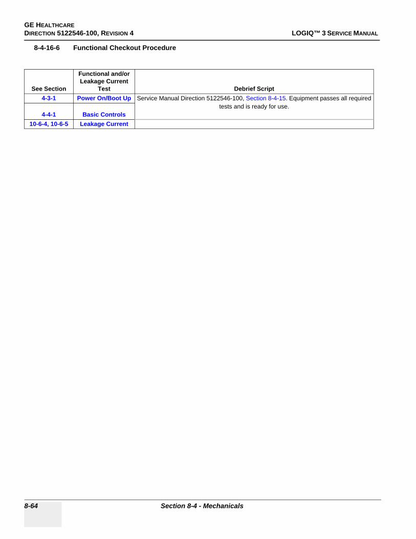
GE HEALTHCAREDIRECTION 5122546-100, REVISION 4 LOGIQ™ 3 SERVICE MANUAL
8-4-16-6 Functional Checkout Procedure
See Section
Functional and/or Leakage Current
Test Debrief Script4-3-1 Power On/Boot Up Service Manual Direction 5122546-100, Section 8-4-15. Equipment passes all required
tests and is ready for use.4-4-1 Basic Controls
10-6-4, 10-6-5 Leakage Current
8-64 Section 8-4 - Mechanicals

GE HEALTHCAREDIRECTION 5122546-100, REVISION 4 LOGIQ™ 3 SERVICE MANUAL
8-4-17 Nest EMI CoverPurpose: This is a description on how to remove and replace the Nest EMI Cover
8-4-17-1 Tools• Common Phillips screwdrivers
8-4-17-2 Needed Manpower• 1person, 15 minutes + travel
8-4-17-3 Preparations• Shut Down the System and switch off the Main Breaker at the rear as described in 4-3-1-3 on page
4-4
8-4-17-4 Removal ProcedureRefer to Figure 8-34 on page 8-65 .
1.) Remove See “Right Cover (FRU No. 300)” on page 33.2.) Remove See “Right EMI Cover” on page 61.3.) Unscrew four screws (1-4) holding the Nest EMI Cover4.) Remove the Nest EMI Cover.
8-4-17-5 Mounting procedure
1.) Install the new parts in the reverse order of removal.
Figure 8-34 Nest EMI Cover Disassembly
1
2 3
4
Chapter 8 8-65

GE HEALTHCAREDIRECTION 5122546-100, REVISION 4 LOGIQ™ 3 SERVICE MANUAL
8-4-17-6 Functional Checkout Procedure
See Section
Functional and/or Leakage Current
Test Debrief Script4-3-1 Power On/Boot Up Service Manual Direction 5122546-100, Section 8-4-17. Equipment passes all required
tests and is ready for use.4-4-1 Basic Controls
10-6-4, 10-6-5 Leakage Current
8-66 Section 8-4 - Mechanicals
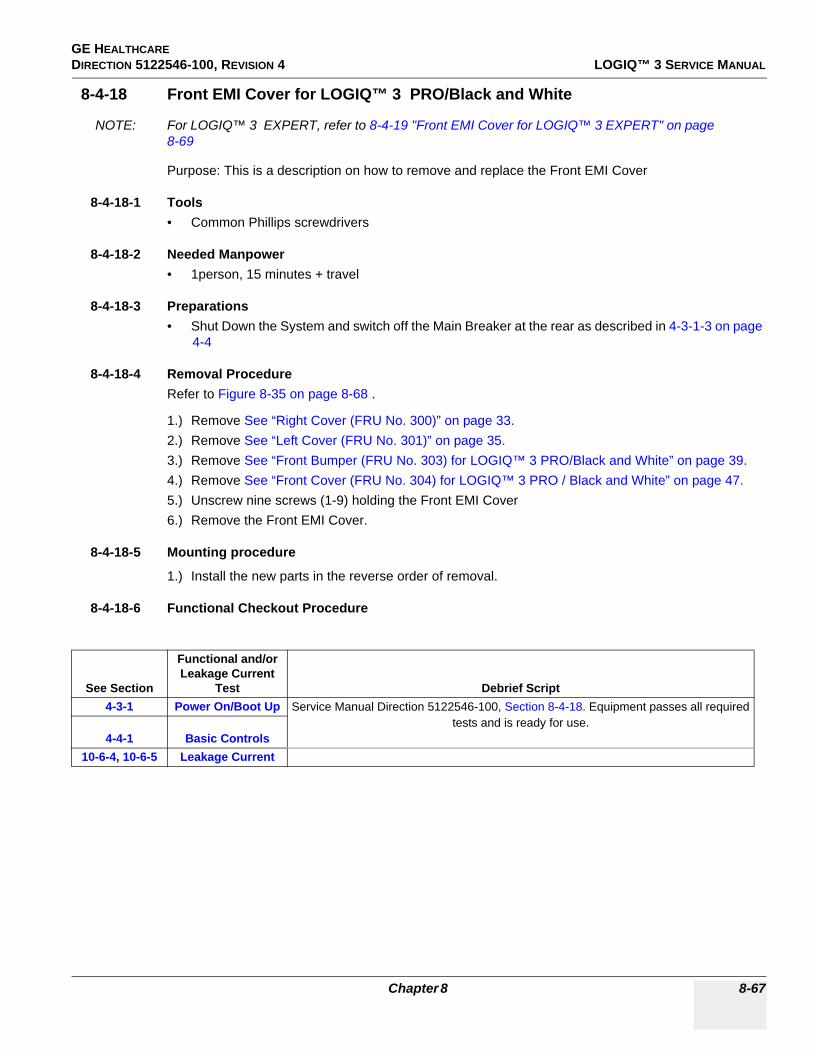
GE HEALTHCAREDIRECTION 5122546-100, REVISION 4 LOGIQ™ 3 SERVICE MANUAL
8-4-18 Front EMI Cover for LOGIQ™ 3 PRO/Black and White
NOTE: For LOGIQ™ 3 EXPERT, refer to 8-4-19 "Front EMI Cover for LOGIQ™ 3 EXPERT" on page 8-69
Purpose: This is a description on how to remove and replace the Front EMI Cover
8-4-18-1 Tools• Common Phillips screwdrivers
8-4-18-2 Needed Manpower• 1person, 15 minutes + travel
8-4-18-3 Preparations• Shut Down the System and switch off the Main Breaker at the rear as described in 4-3-1-3 on page
4-4
8-4-18-4 Removal ProcedureRefer to Figure 8-35 on page 8-68 .
1.) Remove See “Right Cover (FRU No. 300)” on page 33.2.) Remove See “Left Cover (FRU No. 301)” on page 35.3.) Remove See “Front Bumper (FRU No. 303) for LOGIQ™ 3 PRO/Black and White” on page 39.4.) Remove See “Front Cover (FRU No. 304) for LOGIQ™ 3 PRO / Black and White” on page 47.5.) Unscrew nine screws (1-9) holding the Front EMI Cover6.) Remove the Front EMI Cover.
8-4-18-5 Mounting procedure
1.) Install the new parts in the reverse order of removal.
8-4-18-6 Functional Checkout Procedure
See Section
Functional and/or Leakage Current
Test Debrief Script4-3-1 Power On/Boot Up Service Manual Direction 5122546-100, Section 8-4-18. Equipment passes all required
tests and is ready for use.4-4-1 Basic Controls
10-6-4, 10-6-5 Leakage Current
Chapter 8 8-67

GE HEALTHCAREDIRECTION 5122546-100, REVISION 4 LOGIQ™ 3 SERVICE MANUAL
Figure 8-35 Front EMI Cover Disassembly
1
25
3
4
6
7
8
9
8-68 Section 8-4 - Mechanicals
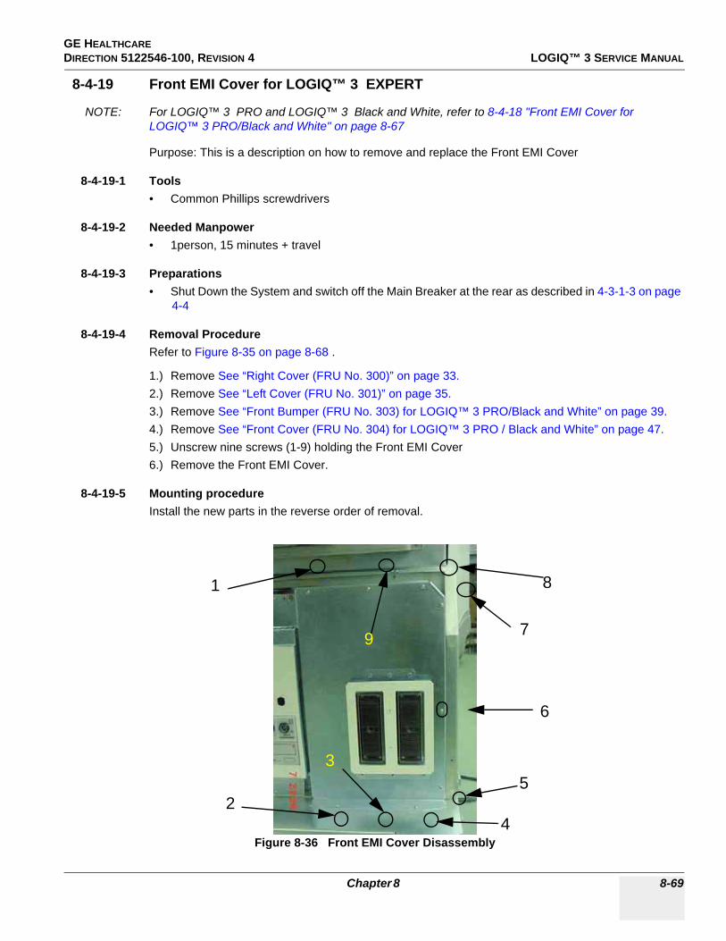
GE HEALTHCAREDIRECTION 5122546-100, REVISION 4 LOGIQ™ 3 SERVICE MANUAL
8-4-19 Front EMI Cover for LOGIQ™ 3 EXPERT
NOTE: For LOGIQ™ 3 PRO and LOGIQ™ 3 Black and White, refer to 8-4-18 "Front EMI Cover for LOGIQ™ 3 PRO/Black and White" on page 8-67
Purpose: This is a description on how to remove and replace the Front EMI Cover
8-4-19-1 Tools• Common Phillips screwdrivers
8-4-19-2 Needed Manpower• 1person, 15 minutes + travel
8-4-19-3 Preparations• Shut Down the System and switch off the Main Breaker at the rear as described in 4-3-1-3 on page
4-4
8-4-19-4 Removal ProcedureRefer to Figure 8-35 on page 8-68 .
1.) Remove See “Right Cover (FRU No. 300)” on page 33.2.) Remove See “Left Cover (FRU No. 301)” on page 35.3.) Remove See “Front Bumper (FRU No. 303) for LOGIQ™ 3 PRO/Black and White” on page 39.4.) Remove See “Front Cover (FRU No. 304) for LOGIQ™ 3 PRO / Black and White” on page 47.5.) Unscrew nine screws (1-9) holding the Front EMI Cover6.) Remove the Front EMI Cover.
8-4-19-5 Mounting procedureInstall the new parts in the reverse order of removal.
Figure 8-36 Front EMI Cover Disassembly
1
25
3
4
6
7
8
9
Chapter 8 8-69

GE HEALTHCAREDIRECTION 5122546-100, REVISION 4 LOGIQ™ 3 SERVICE MANUAL
8-4-19-6 Functional Checkout Procedure
See Section
Functional and/or Leakage Current
Test Debrief Script4-3-1 Power On/Boot Up Service Manual Direction 5122546-100, Section 8-4-19. Equipment passes all required
tests and is ready for use.4-4-1 Basic Controls
10-6-4, 10-6-5 Leakage Current
8-70 Section 8-4 - Mechanicals

GE HEALTHCAREDIRECTION 5122546-100, REVISION 4 LOGIQ™ 3 SERVICE MANUAL
8-4-20 VGP TrayPurpose: This is a description on how to remove and replace the VGP Tray.
8-4-20-1 Tools• • Common Phillips screwdrivers
8-4-20-2 Needed Manpower• • 1 person, 15 minutes + travel
8-4-20-3 Preparations• • Shut Down the System and switch off the Main Breaker at the rear as described in 4-3-1-3 on page
4-4
8-4-20-4 Removal Procedure• Refer to Figure 8-23 on page 25.
1.) Unscrew Two screws (1-2). Screw (2) is not visible.2.) Slide the VGP Tray as shown by the arrow to remove. (If VGP is Fixed Remove VGP and
connecting cables)
8-4-20-5 Mounting procedure
1.) Install the new parts in the reverse order of removal.
Figure 8-37 VGP Tray Disassembly
1
2
Chapter 8 8-71

GE HEALTHCAREDIRECTION 5122546-100, REVISION 4 LOGIQ™ 3 SERVICE MANUAL
8-4-20-6 Functional Checkout Procedure
See Section
Functional and/or Leakage Current
Test Debrief Script4-3-1 Power On/Boot Up Service Manual Direction 5122546-100, Section 8-4-20. Equipment passes all required
tests and is ready for use.4-4-1 Basic Controls
8-72 Section 8-4 - Mechanicals
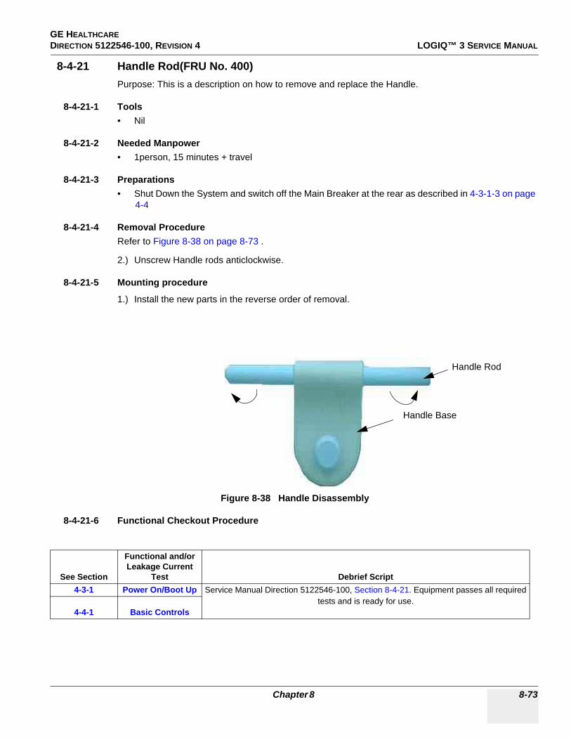
GE HEALTHCAREDIRECTION 5122546-100, REVISION 4 LOGIQ™ 3 SERVICE MANUAL
8-4-21 Handle Rod(FRU No. 400)Purpose: This is a description on how to remove and replace the Handle.
8-4-21-1 Tools• Nil
8-4-21-2 Needed Manpower• 1person, 15 minutes + travel
8-4-21-3 Preparations• Shut Down the System and switch off the Main Breaker at the rear as described in 4-3-1-3 on page
4-4
8-4-21-4 Removal ProcedureRefer to Figure 8-38 on page 8-73 .
2.) Unscrew Handle rods anticlockwise.
8-4-21-5 Mounting procedure
1.) Install the new parts in the reverse order of removal.
8-4-21-6 Functional Checkout Procedure
Figure 8-38 Handle Disassembly
See Section
Functional and/or Leakage Current
Test Debrief Script4-3-1 Power On/Boot Up Service Manual Direction 5122546-100, Section 8-4-21. Equipment passes all required
tests and is ready for use.4-4-1 Basic Controls
Handle Base
Handle Rod
Chapter 8 8-73

GE HEALTHCAREDIRECTION 5122546-100, REVISION 4 LOGIQ™ 3 SERVICE MANUAL
8-4-22 Front Castor (FRU No. 401)Purpose: This is a description on how to remove and replace the Front Castor.
8-4-22-1 Tools• Common Phillips screwdrivers• Allen/Unbraco wrench
8-4-22-2 Needed Manpower• 2 persons, 15 minutes + travel
8-4-22-3 Preparations• Shut Down the System and switch off the Main Breaker at the rear as described in 4-3-1-3 on page
4-4
8-4-22-4 Removal ProcedureRefer to Figure 8-39 on page 8-74 .
1.) Place the wooden block below to lift the system2.) Unscrew eight (8) hexagonal bolts (1-8).3.) Remove the Front Castor.
8-4-22-5 Mounting procedure
1.) Install the new parts in the reverse order of removal.
CAUTION One Person should hold the system while removing & replacing the Castors
Figure 8-39 Front Castor Disassembly
8-74 Section 8-4 - Mechanicals

GE HEALTHCAREDIRECTION 5122546-100, REVISION 4 LOGIQ™ 3 SERVICE MANUAL
8-4-22-6 Functional Checkout Procedure
See Section
Functional and/or Leakage Current
Test Debrief Script4-3-1 Power On/Boot Up Service Manual Direction 5122546-100, Section 8-4-22. Equipment passes all required
tests and is ready for use.4-4-1 Basic Controls
Chapter 8 8-75

GE HEALTHCAREDIRECTION 5122546-100, REVISION 4 LOGIQ™ 3 SERVICE MANUAL
8-4-23 Rear Castor (FRU No. 402)Purpose: This is a description on how to remove and replace the Rear Castor.
8-4-23-1 Tools• Common Phillips screwdrivers• Allen/Unbraco wrench
8-4-23-2 Needed Manpower• 2 persons, 15 minutes + travel
8-4-23-3 Preparations• Shut Down the System and switch off the Main Breaker at the rear as described in 4-3-1-3 on page
4-4
8-4-23-4 Removal ProcedureRefer to Figure 8-40 on page 8-76 .
1.) Place the wooden block below to lift the system2.) Unscrew eight hexagonal bolts (1-8).3.) Remove the Rear Castor.
8-4-23-5 Mounting procedure
1.) Install the new parts in the reverse order of removal.
CAUTION One Person should hold the system while removing & replacing the Castors
Figure 8-40 Rear Castor Disassembly
8-76 Section 8-4 - Mechanicals
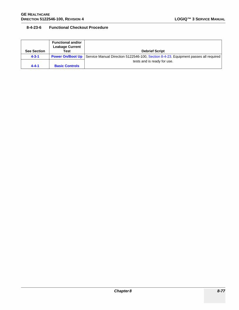
GE HEALTHCAREDIRECTION 5122546-100, REVISION 4 LOGIQ™ 3 SERVICE MANUAL
8-4-23-6 Functional Checkout Procedure
See Section
Functional and/or Leakage Current
Test Debrief Script4-3-1 Power On/Boot Up Service Manual Direction 5122546-100, Section 8-4-23. Equipment passes all required
tests and is ready for use.4-4-1 Basic Controls
Chapter 8 8-77

GE HEALTHCAREDIRECTION 5122546-100, REVISION 4 LOGIQ™ 3 SERVICE MANUAL
8-4-24 Air Filter (FRU No. 403)Purpose: This is a description on how to remove and replace the Air Filter.
8-4-24-1 Tools• Common Phillips screwdrivers
8-4-24-2 Needed Manpower• 1 persons, 5 minutes + travel
8-4-24-3 Preparations• Shut Down the System and switch off the Main Breaker at the rear as described in 4-3-1-3 on page
4-4
8-4-24-4 Removal ProcedureRefer to Figure 8-41 on page 8-78 .
1.) Remove the Air Filter which is situated between Front Casters.
8-4-24-5 Mounting procedure
1.) Install the new parts in the reverse order of removal
8-4-24-6 Functional Checkout Procedure
Figure 8-41 Air Filter
See Section
Functional and/or Leakage Current
Test Debrief Script
Air Filter
Air Filter
8-78 Section 8-4 - Mechanicals

GE HEALTHCAREDIRECTION 5122546-100, REVISION 4 LOGIQ™ 3 SERVICE MANUAL
4-3-1 Power On/Boot Up Service Manual Direction 5122546-100, Section 8-4-24. Equipment passes all required tests and is ready for use.
4-4-1 Basic Controls
Chapter 8 8-79
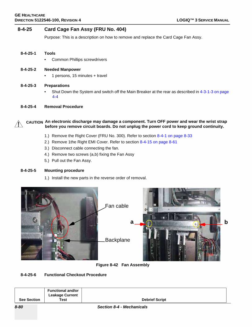
GE HEALTHCAREDIRECTION 5122546-100, REVISION 4 LOGIQ™ 3 SERVICE MANUAL
8-4-25 Card Cage Fan Assy (FRU No. 404)Purpose: This is a description on how to remove and replace the Card Cage Fan Assy.
8-4-25-1 Tools• Common Phillips screwdrivers
8-4-25-2 Needed Manpower• 1 persons, 15 minutes + travel
8-4-25-3 Preparations• Shut Down the System and switch off the Main Breaker at the rear as described in 4-3-1-3 on page
4-4
8-4-25-4 Removal Procedure
1.) Remove the Right Cover (FRU No. 300). Refer to section 8-4-1 on page 8-33 2.) Remove 1the Right EMI Cover. Refer to section 8-4-15 on page 8-61 3.) Disconnect cable connecting the fan.4.) Remove two screws (a,b) fixing the Fan Assy5.) Pull out the Fan Assy.
8-4-25-5 Mounting procedure
1.) Install the new parts in the reverse order of removal.
8-4-25-6 Functional Checkout Procedure
CAUTION An electronic discharge may damage a component. Turn OFF power and wear the wrist strap before you remove circuit boards. Do not unplug the power cord to keep ground continuity.
Figure 8-42 Fan Assembly
See Section
Functional and/or Leakage Current
Test Debrief Script
a b
Fan cable
Backplane
8-80 Section 8-4 - Mechanicals

GE HEALTHCAREDIRECTION 5122546-100, REVISION 4 LOGIQ™ 3 SERVICE MANUAL
4-3-1 Power On/Boot Up Service Manual Direction 5122546-100, Section 8-4-25. Equipment passes all required tests and is ready for use.
4-4-1 Basic Controls
Chapter 8 8-81

GE HEALTHCAREDIRECTION 5122546-100, REVISION 4 LOGIQ™ 3 SERVICE MANUAL
Section 8-5I/O Interfaces
8-5-1 Rear Panel Assy (FRU No. 500)Purpose: This is a description on how to remove and replace the Rear Panel Assy.
8-5-1-1 Tools• Common Phillips screwdrivers
8-5-1-2 Needed Manpower• 1 persons, 15 minutes + travel
8-5-1-3 Preparations• Shut Down the System and switch off the Main Breaker at the rear as described in 4-3-1-3 on page
4-4
8-5-1-4 Removal ProcedureRefer to 8-5-1 on page 8-82 .
1.) Remove the Rear Cover (FRU No.302). Refer to section 8-4-3 on page 8-37 .2.) Remove the Rear EMI Cover. Refer to section 8-4-16 on page 8-63 3.) Unscrew four (4) screws (a, b, c,d) from the Rear Panel Assy.4.) Remove two cable assy from ACI board and one from RPI board.5.) Pull and Remove the Rear Panel Assy.
8-5-1-5 Mounting procedure
1.) Install the new parts in the reverse order of removal.
8-5-1-6 Functional Checkout Procedure
See Section
Functional and/or Leakage Current
Test Debrief Script4-3-1 Power On/Boot Up Service Manual Direction 5122546-100, Section 8-5-1. Equipment passes all required
tests and is ready for use.4-4-1 Basic Controls4-4-2 B Mode Checks4-4-3 M Mode Checks
4-4-4Color Flow Mode
Checks
4-4-5Doppler Mode
Checks
4-4-6Measurement and
Multi Image Checks
4-4-7Basic
Measurements
8-82 Section 8-5 - I/O Interfaces

GE HEALTHCAREDIRECTION 5122546-100, REVISION 4 LOGIQ™ 3 SERVICE MANUAL
Figure 8-43 Rear Panel Disassembly
a
b c
d
Chapter 8 8-83

GE HEALTHCAREDIRECTION 5122546-100, REVISION 4 LOGIQ™ 3 SERVICE MANUAL
8-5-2 Rear Panel1 (RP1) Board (FRU No. 501)Purpose: This is a description on how to remove and replace the Rear Panel1.
8-5-2-1 Tools• Common Phillips screwdrivers
8-5-2-2 Needed Manpower• 1 persons, 15 minutes + travel
8-5-2-3 Preparations• Shut Down the System and switch off the Main Breaker at the rear as described in 4-3-1-3 on page
4-4
8-5-2-4 Removal ProcedureRefer to 8-5-1 on page 8-82 .
1.) Remove the Rear Cover (FRU No.302). Refer to section 8-4-3 on page 8-37 .2.) Remove the Rear EMI Cover. Refer to section 8-4-16 on page 8-63 3.) Remove Rear Panel (FRU No. 500). Refer to section 8-5-1 on page 8-82 4.) Remove three screws (a,b,c).5.) Pull Rear Panel1 (RP1) Board.
8-5-2-5 Mounting procedure
1.) Install the new parts in the reverse order of removal.
Figure 8-44 Rear Panel1 (RP1) Disassembly
ab c
8-84 Section 8-5 - I/O Interfaces

GE HEALTHCAREDIRECTION 5122546-100, REVISION 4 LOGIQ™ 3 SERVICE MANUAL
8-5-2-6 Functional Checkout Procedure
See Section
Functional and/or Leakage Current
Test Debrief Script4-3-1 Power On/Boot Up Service Manual Direction 5122546-100, Section 8-5-2. Equipment passes all required
tests and is ready for use.4-4-1 Basic Controls4-4-2 B Mode Checks4-4-3 M Mode Checks
4-4-4Color Flow Mode
Checks
4-4-5Doppler Mode
Checks
4-4-6Measurement and
Multi Image Checks
4-4-7Basic
Measurements
Chapter 8 8-85

GE HEALTHCAREDIRECTION 5122546-100, REVISION 4 LOGIQ™ 3 SERVICE MANUAL
8-5-3 Rear Panel2 (RP2) Board (FRU No. 502)Purpose: This is a description on how to remove and replace the Rear Panel2.
8-5-3-1 Tools• Common Phillips screwdrivers
8-5-3-2 Needed Manpower• 1 persons, 15 minutes + travel
8-5-3-3 Preparations• Shut Down the System and switch off the Main Breaker at the rear as described in 4-3-1-3 on page
4-4
8-5-3-4 Removal ProcedureRefer to 8-5-1 on page 8-82 .
1.) Remove the Rear Cover (FRU No.302). Refer to section 8-4-3 on page 8-37 .2.) Remove the Rear EMI Cover. Refer to section 8-4-16 on page 8-63 3.) Remove Rear Panel (FRU No. 500). Refer to section 8-5-1 on page 8-82 4.) Remove two stud screws(1-6) holding connectors Printer, COM1, COM2. 5.) Remove three screws (a,b,c).6.) Pull Rear Panel2 (RP2) Board.
8-5-3-5 Mounting procedure
1.) Install the new parts in the reverse order of removal.
Figure 8-45 Rear Panel1 (RP1) Disassembly
a b c
1
2
3
4
5
6
8-86 Section 8-5 - I/O Interfaces

GE HEALTHCAREDIRECTION 5122546-100, REVISION 4 LOGIQ™ 3 SERVICE MANUAL
8-5-3-6 Functional Checkout Procedure
See Section
Functional and/or Leakage Current
Test Debrief Script4-3-1 Power On/Boot Up Service Manual Direction 5122546-100, Section 8-5-3. Equipment passes all required
tests and is ready for use.4-4-1 Basic Controls4-4-2 B Mode Checks4-4-3 M Mode Checks
4-4-4Color Flow Mode
Checks
4-4-5Doppler Mode
Checks
4-4-6Measurement and
Multi Image Checks
4-4-7Basic
Measurements
Chapter 8 8-87

GE HEALTHCAREDIRECTION 5122546-100, REVISION 4 LOGIQ™ 3 SERVICE MANUAL
8-5-4 Rear Panel Interface (RPI) Board (FRU No. 503)Purpose: This is a description on how to remove and replace the Rear Panel Interface.
8-5-4-1 Tools• Common Phillips screwdrivers
8-5-4-2 Needed Manpower• 1 persons, 15 minutes + travel
8-5-4-3 Preparations• Shut Down the System and switch off the Main Breaker at the rear as described in 4-3-1-3 on page
4-4
8-5-4-4 Removal ProcedureRefer to 8-5-1 on page 8-82 .
1.) Remove the Rear Cover (FRU No.302). Refer to section 8-4-3 on page 8-37 .2.) Remove the Rear EMI Cover. Refer to section 8-4-16 on page 8-63 3.) Remove Rear Panel (FRU No. 500). Refer to section 8-5-1 on page 8-82 4.) Remove nine cables (a, b, c, d, e, f, g, h, i, j) connected to the RPI Board5.) Remove eleven screws marked.6.) Pull the RPI Board out.
8-5-4-5 Mounting procedure
1.) Install the new parts in the reverse order of removal.
Figure 8-46 Rear Panel Intrerface Board (RPI) Disassembly
8-88 Section 8-5 - I/O Interfaces
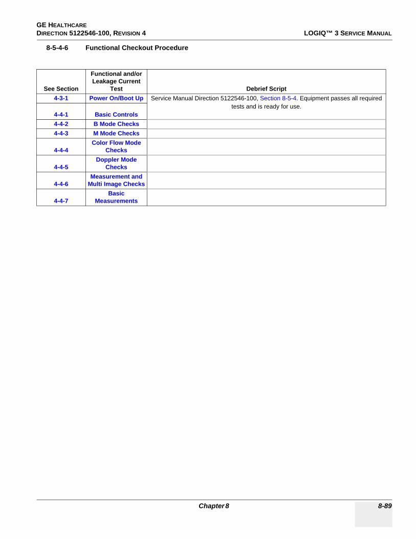
GE HEALTHCAREDIRECTION 5122546-100, REVISION 4 LOGIQ™ 3 SERVICE MANUAL
8-5-4-6 Functional Checkout Procedure
See Section
Functional and/or Leakage Current
Test Debrief Script4-3-1 Power On/Boot Up Service Manual Direction 5122546-100, Section 8-5-4. Equipment passes all required
tests and is ready for use.4-4-1 Basic Controls4-4-2 B Mode Checks4-4-3 M Mode Checks
4-4-4Color Flow Mode
Checks
4-4-5Doppler Mode
Checks
4-4-6Measurement and
Multi Image Checks
4-4-7Basic
Measurements
Chapter 8 8-89

GE HEALTHCAREDIRECTION 5122546-100, REVISION 4 LOGIQ™ 3 SERVICE MANUAL
8-5-5 Front Panel (FRU No. 504)Purpose: This is a description on how to remove and replace the Front Panel.
8-5-5-1 Tools• Common Phillips screwdrivers
8-5-5-2 Needed Manpower• 1 persons, 15 minutes + travel
8-5-5-3 Preparations• Shut Down the System and switch off the Main Breaker at the rear as described in 4-3-1-3 on page
4-4
8-5-5-4 Removal ProcedureRefer to 8-5-1 on page 8-82 .
1.) Remove Rear EMI Cover. Refer to section 8-4-16 on page 8-63 .2.) Remove Left Side Cover.3.) Remove Left EMI Cover.4.) Remove Rear Left EMI Support bracket5.) Disconnect interconnect cables.6.) Remove VGP Tray. Refer section 8-4-20 on page 717.) Unscrew four screws (a,b,c,d)8.) Pull and remove the Front Panel
8-5-5-5 Mounting procedure
1.) Install the new parts in the reverse order of removal.
Figure 8-47 Front Panel Disassembly
a b
c d
8-90 Section 8-5 - I/O Interfaces

GE HEALTHCAREDIRECTION 5122546-100, REVISION 4 LOGIQ™ 3 SERVICE MANUAL
8-5-5-6 Functional Checkout Procedure
See Section
Functional and/or Leakage Current
Test Debrief Script4-3-1 Power On/Boot Up Service Manual Direction 5122546-100, Section 8-5-5. Equipment passes all required
tests and is ready for use.4-4-1 Basic Controls4-4-2 B Mode Checks4-4-3 M Mode Checks
4-4-4Color Flow Mode
Checks
4-4-5Doppler Mode
Checks
4-4-6Measurement and
Multi Image Checks
4-4-7Basic
Measurements
Chapter 8 8-91

GE HEALTHCAREDIRECTION 5122546-100, REVISION 4 LOGIQ™ 3 SERVICE MANUAL
8-5-6 Rear Panel Fuse (FRU No. 505)Purpose: This is a description on how to remove and replace the Rear Panel Fuse.
8-5-6-1 Tools• Common Phillips screwdrivers
8-5-6-2 Needed Manpower• 1 person, 15 minutes + travel
8-5-6-3 Preparations• Shut Down the System and switch off the Main Breaker at the rear as described in 4-3-1-3 on page
4-4
8-5-6-4 Removal Procedure
Refer to Figure 8-64 on page 8-127 .
1.) Remove Rear Panel Assy (FRU No. 500). Refer to Section 8-5-1 on page 8-82 2.) Remove two cables (a,b). 3.) Press and pull the Rear Panel fuse.
8-5-6-5 Mounting procedure
1.) Install the new parts in the reverse order of removal
CAUTION Do not wear the ESD wrist strap when you remove a part of power supply unit. Turn OFF power and unplug the power cord before removing a part of power supply unit. However be sure to turn off power and wear the strap before you remove a circuit boards.
Figure 8-48 Rear Panel Fuse Disassembly
a
b
8-92 Section 8-5 - I/O Interfaces

GE HEALTHCAREDIRECTION 5122546-100, REVISION 4 LOGIQ™ 3 SERVICE MANUAL
8-5-6-6 Functional Checkout Procedure
See Section
Functional and/or Leakage Current
Test Debrief Script4-3-1 Power On/Boot Up Service Manual Direction 5122546-100, Section 8-5-6. Equipment passes all required
tests and is ready for use.4-4-1 Basic Controls
Chapter 8 8-93

GE HEALTHCAREDIRECTION 5122546-100, REVISION 4 LOGIQ™ 3 SERVICE MANUAL
Section 8-6PCB
8-6-1 PCB Boards (FRU No. 601 ~ 605, 608, 609)Purpose: This is a description on how to remove and replace the PCB Boards.
8-6-1-1 Tools• Common Phillips screwdrivers
8-6-1-2 Needed Manpower• 1 persons, 10 minutes + travel
8-6-1-3 Preparations• Shut Down the System and switch off the Main Breaker at the rear as described in 4-3-1-3 on page
4-4
8-6-1-4 Removal Procedure
Refer to Figure 8-49 on page 8-96 .
1.) Remove the Right Cover (FRU No.301). Refer to 8-4-1 on page 8-33 .2.) Remove the Right EMI Cover. Refer to 8-4-15 on page 8-61 .3.) Remove the Nest EMI Cover. Refer to 8-4-17 on page 8-65 4.) Disconnect the PCI Cable if removing the FEC Assy or HVPS. Otherwise skip this step.5.) Disconnect RFC connector board if removing RXB or DBF Assy. Otherwise skip this step.6.) Move the upper and lower board ejector in the direction indicated by the arrow (1) in Figure B.7.) Pull out the board in the direction indicated by the arrow (2) in Figure B, do not bend it.
8-6-1-5 Mounting procedure
1.) Install the new parts in the reverse order of removal.
8-6-1-6 Functional Checkout Procedure
CAUTION An electronic discharge may damage a component. Turn OFF power and wear the wrist strap before you remove circuit boards. Do not unplug the power cord to keep ground continuity.
Do not bend or flex the boards when mounting/dismounting each boards. Surface mount IC boards are very susceptible to damage from flex/torque.
See Section
Functional and/or Leakage Current
Test Debrief Script4-3-1 Power On/Boot Up Service Manual Direction 5122546-100, Section 8-6-1. Equipment passes all required
tests and is ready for use.4-4-1 Basic Controls4-4-2 B Mode Checks4-4-3 M Mode Checks
4-4-4Color Flow Mode
Checks
8-94 Section 8-6 - PCB

GE HEALTHCAREDIRECTION 5122546-100, REVISION 4 LOGIQ™ 3 SERVICE MANUAL
4-4-5Doppler Mode
Checks
4-4-6Measurement and
Multi Image Checks
4-4-7Basic
Measurements7-6-2 FRU Tests
Chapter 8 8-95

GE HEALTHCAREDIRECTION 5122546-100, REVISION 4 LOGIQ™ 3 SERVICE MANUAL
8-6-1 PCB Boards (FRU No. 601 ~ 605, 608, 609) (cont’d)
Figure 8-49 PCB Boards Disassembly
Figure B
TXBCWD
RFC
DBF FEC
HVPS
PCI Cable From PC to FEC
1
1
2
SLOT BOARD FRU NO.1 TXB 6012 RXB 6024 DBF 6035 FEC 6046 HVPS 605- RFC 608
- PCI Cable 609
RXB
RFC2
8-96 Section 8-6 - PCB

GE HEALTHCAREDIRECTION 5122546-100, REVISION 4 LOGIQ™ 3 SERVICE MANUAL
8-6-2 Connector Board Assy (FRU No. 606) for LOGIQ™ 3 PRO/Black and White
NOTE: For LOGIQ™ 3 EXPERT, refer to 8-6-3 "Connector Board Assy (FRU No. 606) for LOGIQ™ 3 EXPERT" on page 8-99
Purpose: This is a description on how to remove and replace the Conn. Board Assy.
8-6-2-1 Tools• Common Phillips screwdrivers
8-6-2-2 Needed Manpower• 1 person, 15 minutes + travel
8-6-2-3 Preparations• Shut Down the System and switch off the Main Breaker at the rear as described in 4-3-1-3 on page
4-4
8-6-2-4 Removal Procedure
Refer to Figure 8-50 on page 8-98 .
1.) Remove the Left Cover (FRU No. 301). Refer to section 8-4-2 on page 8-35 2.) Remove the Right Cover (FRU No. 300). Refer to section 8-4-1 on page 8-33 3.) Remove the Front Bumper (FRU No. 303). Refer to section 8-4-4 on page 8-39 4.) Remove the Front Cover (FRU No. 304). Refer to section 8-4-8 on page 8-47 5.) Remove the Front EMI cover. Refer to section 8-4-18 on page 8-67 6.) Unscrew four screws (1-4) from the connector board.7.) Disconnect connector board assy.
8-6-2-5 Mounting procedure
1.) Install the new parts in the reverse order of removal.
8-6-2-6 Functional Checkout Procedure
CAUTION An electronic discharge may damage a component. Turn OFF power and wear the wrist strap before you remove circuit boards. Do not unplug the power cord to keep ground continuity.
Do not bend or flex the boards when mounting/dismounting each boards. Surface mount IC boards are very susceptible to damage from flex/torque.
See Section
Functional and/or Leakage Current
Test Debrief Script4-3-1 Power On/Boot Up Service Manual Direction 5122546-100, Section 8-6-2. Equipment passes all required
tests and is ready for use.4-4-1 Basic Controls4-4-2 B Mode Checks4-4-3 M Mode Checks
4-4-4Color Flow Mode
Checks
4-4-5Doppler Mode
Checks
Chapter 8 8-97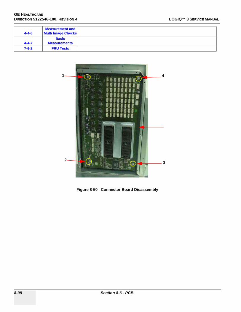
GE HEALTHCAREDIRECTION 5122546-100, REVISION 4 LOGIQ™ 3 SERVICE MANUAL
4-4-6Measurement and
Multi Image Checks
4-4-7Basic
Measurements7-6-2 FRU Tests
Figure 8-50 Connector Board Disassembly
1
2 3
4
8-98 Section 8-6 - PCB

GE HEALTHCAREDIRECTION 5122546-100, REVISION 4 LOGIQ™ 3 SERVICE MANUAL
8-6-3 Connector Board Assy (FRU No. 606) for LOGIQ™ 3 EXPERT
NOTE: For LOGIQ™ 3 PRO and LOGIQ™ 3 Black and White, refer to 8-6-2 "Connector Board Assy (FRU No. 606) for LOGIQ™ 3 PRO/Black and White" on page 8-97
Purpose: This is a description on how to remove and replace the Conn. Board Assy.
8-6-3-1 Tools• Common Phillips screwdrivers
8-6-3-2 Needed Manpower• 1 person, 15 minutes + travel
8-6-3-3 Preparations• Shut Down the System and switch off the Main Breaker at the rear as described in 4-3-1-3 on page
4-4
8-6-3-4 Removal Procedure
Refer to Figure 8-50 on page 8-98 .
1.) Remove the Left Cover (FRU No. 301). Refer to section 8-4-2 on page 8-35 2.) Remove the Right Cover (FRU No. 300). Refer to section 8-4-1 on page 8-33 3.) Remove the Front Bumper (FRU No. 303). Refer to section 8-4-4 on page 8-39 4.) Remove the Front Cover (FRU No. 304). Refer to section 8-4-8 on page 8-47 5.) Remove the Front EMI cover. Refer to section 8-4-18 on page 8-67 6.) Unscrew four screws (1-4) from the connector board.7.) Disconnect connector board assy.
8-6-3-5 Mounting procedure
1.) Install the new parts in the reverse order of removal.
8-6-3-6 Functional Checkout Procedure
CAUTION An electronic discharge may damage a component. Turn OFF power and wear the wrist strap before you remove circuit boards. Do not unplug the power cord to keep ground continuity.
Do not bend or flex the boards when mounting/dismounting each boards. Surface mount IC boards are very susceptible to damage from flex/torque.
See Section
Functional and/or Leakage Current
Test Debrief Script4-3-1 Power On/Boot Up Service Manual Direction 5122546-100, Section 8-6-3. Equipment passes all required
tests and is ready for use.4-4-1 Basic Controls4-4-2 B Mode Checks4-4-3 M Mode Checks
4-4-4Color Flow Mode
Checks
4-4-5Doppler Mode
Checks
Chapter 8 8-99
GE HEALTHCAREDIRECTION 5122546-100, REVISION 4 LOGIQ™ 3 SERVICE MANUAL
4-4-6Measurement and
Multi Image Checks
4-4-7Basic
Measurements7-6-2 FRU Tests
Figure 8-51 Connector Board Disassembly
1 2
3 4
8-100 Section 8-6 - PCB

GE HEALTHCAREDIRECTION 5122546-100, REVISION 4 LOGIQ™ 3 SERVICE MANUAL
8-6-4 Card Cage with Back Plane Board (FRU No. 607)Purpose: This is a description on how to remove and replace the Card Cage with Back Plane Board.
8-6-4-1 Tools• Common Phillips screwdrivers
8-6-4-2 Needed Manpower• 1 person, 15 minutes + travel
8-6-4-3 Preparations• Shut Down the System and switch off the Main Breaker at the rear as described in 4-3-1-3 on page
4-4
8-6-4-4 Removal Procedure
1.) Remove the Connector Board (FRU No.606). Refer to section 8-6-2 on page 8-97 .2.) Remove the all Boards from the Card Cage (FRU NO. 601 to 605).3.) Remove LVPS (FRU No. 801). Refer to section 8-7-2 on page 8-121 4.) Disconnect all cable connected to the Backplane.5.) Remove three screws (a, b, c) and four screws (1-4)6.) Slide the Card cage to Right & Pull forward to remove the Card Cage with Backplane.
8-6-4-5 Mounting procedure
1.) Install the new parts in the reverse order of removal.
CAUTION An electronic discharge may damage a component. Turn OFF power and wear the wrist strap before you remove circuit boards. Do not unplug the power cord to keep ground continuity.
Do not bend or flex the boards when mounting/dismounting each boards. Surface mount IC boards are very susceptible to damage from flex/torque.
Figure 8-52 Card Cage with Backplane
a
b
c
Chapter 8 8-101
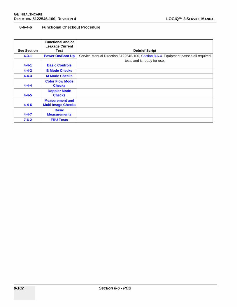
GE HEALTHCAREDIRECTION 5122546-100, REVISION 4 LOGIQ™ 3 SERVICE MANUAL
8-6-4-6 Functional Checkout Procedure
See Section
Functional and/or Leakage Current
Test Debrief Script4-3-1 Power On/Boot Up Service Manual Direction 5122546-100, Section 8-6-4. Equipment passes all required
tests and is ready for use.4-4-1 Basic Controls4-4-2 B Mode Checks4-4-3 M Mode Checks
4-4-4Color Flow Mode
Checks
4-4-5Doppler Mode
Checks
4-4-6Measurement and
Multi Image Checks
4-4-7Basic
Measurements7-6-2 FRU Tests
8-102 Section 8-6 - PCB

GE HEALTHCAREDIRECTION 5122546-100, REVISION 4 LOGIQ™ 3 SERVICE MANUAL
8-6-5 BEP Assy (FRU No. 700)Purpose: This is a description on how to remove and replace the Back End Processor (BEP) Assy.
8-6-5-1 Tools• Common Phillips screwdrivers
8-6-5-2 Needed Manpower• 1 persons, 15 minutes + travel
8-6-5-3 Preparations• Shut Down the System and switch off the Main Breaker at the rear as described in 4-3-1-3 on page
4-4
8-6-5-4 Removal ProcedureRefer to Figure 8-53 on page 8-103 .
1.) Remove the Rear Cover (FRU No.302). Refer to 8-4-3 on page 8-37 .2.) Remove the Rear EMI Cover. Refer to 8-4-16 on page 8-63 .3.) Remove the Left Cover (FRU No.301). Refer to 8-4-2 on page 8-35 4.) Unscrew four screws (1-4) to remove Rear Support Bracket5.) Remove all Cables from the PC Rear Panel6.) Unscrew 3 screws (a,b,c) from the PC Support Bracket7.) Pull Forward to remove the BEP Assy.
8-6-5-5 Mounting procedure
1.) Install the new parts in the reverse order of removal.
Figure 8-53 BEP Assy
12
3
4a b c
PC Support Bracket
Rear Left Support Bracket
Chapter 8 8-103

GE HEALTHCAREDIRECTION 5122546-100, REVISION 4 LOGIQ™ 3 SERVICE MANUAL
8-6-5-6 Functional Checkout Procedure
See Section
Functional and/or Leakage Current
Test Debrief Script4-3-1 Power On/Boot Up Service Manual Direction 5122546-100, Section 8-6-5. Equipment passes all required
tests and is ready for use.4-4-1 Basic Controls4-4-2 B Mode Checks4-4-3 M Mode Checks
4-4-4Color Flow Mode
Checks
4-4-5Doppler Mode
Checks
4-4-6Measurement and
Multi Image Checks
4-4-7Basic
Measurements7-5-2 PC Diagnostics
8-104 Section 8-6 - PCB

GE HEALTHCAREDIRECTION 5122546-100, REVISION 4 LOGIQ™ 3 SERVICE MANUAL
8-6-5 BEP Assy (FRU No. 700) (cont’d)
8-6-5-7 BEP Assy Cable Identification
Figure 8-54 BEP Cable Identification
CAUTION BEP Assy contains battery above the ATX Power supply. Handle With care during Service & Replacements.Disposal of Battery should follow local Environment Guidelines.
Chapter 8 8-105

GE HEALTHCAREDIRECTION 5122546-100, REVISION 4 LOGIQ™ 3 SERVICE MANUAL
8-6-6 Hard Disc Drive (FRU no. 701)Purpose: This is a description on how to remove and replace the Parts in the Back End Processor (BEP)
Assy.
8-6-6-1 Tools• Common Phillips screwdrivers
8-6-6-2 Needed Manpower• 1 persons, 15 minutes + travel
8-6-6-3 Preparations• Shut Down the System and switch off the Main Breaker at the rear as described in 4-3-1-3 on page
4-4
8-6-6-4 Removal ProcedureRefer to Figure 8-53 on page 8-103 .
1.) Remove the Rear Cover (FRU No.302). Refer to 8-4-3 on page 8-37 .2.) Remove the Rear EMI Cover. Refer to 8-4-16 on page 8-63 .3.) Remove the Left Cover (FRU No.301). Refer to 8-4-2 on page 8-35 4.) Remove the BEP (FRU 700). Refer to 8-6-5 on page 8-103 5.) Pull out the BEP Assy and place it on a flat surface.6.) Unscrew the seven screws (1-7) and remove the side cover.7.) Remove the FRC and the Power cable to the HDD (a, b) and the two screws (8, 9). 8.) Slide out the HDD mounting.9.) Remove the two screws marked(10, 11 and 12, 13) on each side of the HDD mounting and remove
the HDD. 10.)Replace this HDD.
8-6-6-5 Mounting Procedure
1.) Replace the parts in the order of removal
8-6-6-6 Functional Checkout Procedure
See Section
Functional and/or Leakage Current
Test Debrief Script4-3-1 Power On/Boot Up Service Manual Direction 5122546-100, Section 8-6-6. Equipment passes all required
tests and is ready for use.4-4-1 Basic Controls4-4-2 B Mode Checks4-4-3 M Mode Checks
4-4-4Color Flow Mode
Checks
4-4-5Doppler Mode
Checks
4-4-6Measurement and
Multi Image Checks
4-4-7Basic
Measurements
8-106 Section 8-6 - PCB
GE HEALTHCAREDIRECTION 5122546-100, REVISION 4 LOGIQ™ 3 SERVICE MANUAL
7-5-2 PC Diagnostics
Chapter 8 8-107

GE HEALTHCAREDIRECTION 5122546-100, REVISION 4 LOGIQ™ 3 SERVICE MANUAL
.8-6-5 Hard Disk Drive (FRU no. 702)(contd.)
Figure 8-55 HDD Replacement
1 2 3
4
56
7
10 11
8 9
12 13
8-108 Section 8-6 - PCB

GE HEALTHCAREDIRECTION 5122546-100, REVISION 4 LOGIQ™ 3 SERVICE MANUAL
8-6-7 Compact Disc Read Write Drive (FRU no. 702)Purpose: This is a description on how to remove and replace the Parts in the Back End Processor (BEP)
Assy.
8-6-7-1 Tools• Common Phillips screwdrivers
8-6-7-2 Needed Manpower• 1 persons, 15 minutes + travel
8-6-7-3 Preparations• Shut Down the System and switch off the Main Breaker at the rear as described in 4-3-1-3 on page
4-4
8-6-7-4 Removal ProcedureRefer to Figure 8-53 on page 8-103 .
1.) Remove the Rear Cover (FRU No.302). Refer to 8-4-3 on page 8-37 .2.) Remove the Rear EMI Cover. Refer to 8-4-16 on page 8-63 .3.) Remove the Left Cover (FRU No.301). Refer to 8-4-2 on page 8-35 4.) Remove the BEP (FRU 700). Refer to 8-6-5 on page 8-103 5.) Pull out the BEP Assy and place it on a flat surface.6.) Unscrew the seven screws (1-7) and remove the side cover.7.) Remove the FRC and Power Cable to the CDRW (a, b).8.) Unscrew the four screws (8-11) connecting the CDRW to the BEP cabinet.9.) Pull forward and replace the CDRW.
8-6-7-5 Mounting Procedure
1.) Replace the parts in the order of removal.
8-6-7-6 Functional Checkout Procedure
See Section
Functional and/or Leakage Current
Test Debrief Script4-3-1 Power On/Boot Up Service Manual Direction 5122546-100, Section 8-6-2. Equipment passes all required
tests and is ready for use.4-4-1 Basic Controls4-4-2 B Mode Checks4-4-3 M Mode Checks
4-4-4Color Flow Mode
Checks
4-4-5Doppler Mode
Checks
4-4-6Measurement and
Multi Image Checks
4-4-7Basic
Measurements7-5-2 PC Diagnostics
Chapter 8 8-109

GE HEALTHCAREDIRECTION 5122546-100, REVISION 4 LOGIQ™ 3 SERVICE MANUAL
Figure 8-56 CDRW Replacement
1 23
4
567
89
1011
a, b
8-110 Section 8-6 - PCB

GE HEALTHCAREDIRECTION 5122546-100, REVISION 4 LOGIQ™ 3 SERVICE MANUAL
8-6-8 BEP Power Supply (FRU no. 703)Purpose: This is a description on how to remove and replace the Parts in the Back End Processor (BEP)
Assy.
8-6-8-1 Tools• Common Phillips screwdrivers
8-6-8-2 Needed Manpower• 1 persons, 15 minutes + travel
8-6-8-3 Preparations• Shut Down the System and switch off the Main Breaker at the rear as described in 4-3-1-3 on page
4-4
8-6-8-4 Removal ProcedureRefer to Figure 8-53 on page 8-103 .
1.) Remove the Rear Cover (FRU No.302). Refer to 8-4-3 on page 8-37 .2.) Remove the Rear EMI Cover. Refer to 8-4-16 on page 8-63 .3.) Remove the Left Cover (FRU No.301). Refer to 8-4-2 on page 8-35 4.) Remove the BEP (FRU 700). Refer to 8-6-5 on page 8-103 5.) Pull out the BEP Assy and place it on a flat surface.6.) Unscrew the seven screws (1-7) and remove the side cover.7.) Remove the cable connections as shown in the figures.8.) Remove the BEP Front cover by removing the four indicated screws (8-11).9.) Remove the cable from the cable clamp (a)10.)Remove the seven screws, marked (12-18), attaching the power supply to the BEP and the four
screws (19-22) attaching the battery to BEP.11.)Replace the power supply and the battery.
8-6-8-5 Mounting Procedure
1.) Replace the parts in the order of removal.
Chapter 8 8-111

GE HEALTHCAREDIRECTION 5122546-100, REVISION 4 LOGIQ™ 3 SERVICE MANUAL
2.) If replacement is done on BEP Ver1, close the PCI slot at the rear of the BEP.
Figure 8-57 BEP Power Supply Replacement
1 2 3
4
56
7
8 9
10 11
a
This arrangement is for BEP Ver 1 only.
1213
1415
1617
18
19, 2021, 22
Slide out the Power supply as shown
Slide out the battery as shown
This arrangement is for BEP Ver 2/3. only
This arrangementis for BEP Ver2/3only
8-112 Section 8-6 - PCB
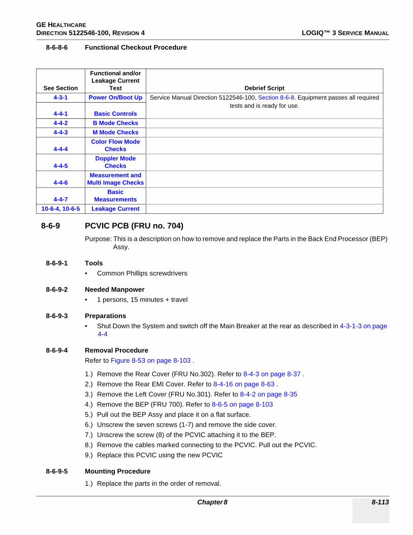
GE HEALTHCAREDIRECTION 5122546-100, REVISION 4 LOGIQ™ 3 SERVICE MANUAL
8-6-8-6 Functional Checkout Procedure
8-6-9 PCVIC PCB (FRU no. 704)Purpose: This is a description on how to remove and replace the Parts in the Back End Processor (BEP)
Assy.
8-6-9-1 Tools• Common Phillips screwdrivers
8-6-9-2 Needed Manpower• 1 persons, 15 minutes + travel
8-6-9-3 Preparations• Shut Down the System and switch off the Main Breaker at the rear as described in 4-3-1-3 on page
4-4
8-6-9-4 Removal ProcedureRefer to Figure 8-53 on page 8-103 .
1.) Remove the Rear Cover (FRU No.302). Refer to 8-4-3 on page 8-37 .2.) Remove the Rear EMI Cover. Refer to 8-4-16 on page 8-63 .3.) Remove the Left Cover (FRU No.301). Refer to 8-4-2 on page 8-35 4.) Remove the BEP (FRU 700). Refer to 8-6-5 on page 8-103 5.) Pull out the BEP Assy and place it on a flat surface.6.) Unscrew the seven screws (1-7) and remove the side cover.7.) Unscrew the screw (8) of the PCVIC attaching it to the BEP.8.) Remove the cables marked connecting to the PCVIC. Pull out the PCVIC.9.) Replace this PCVIC using the new PCVIC
8-6-9-5 Mounting Procedure
1.) Replace the parts in the order of removal.
See Section
Functional and/or Leakage Current
Test Debrief Script4-3-1 Power On/Boot Up Service Manual Direction 5122546-100, Section 8-6-8. Equipment passes all required
tests and is ready for use.4-4-1 Basic Controls4-4-2 B Mode Checks4-4-3 M Mode Checks
4-4-4Color Flow Mode
Checks
4-4-5Doppler Mode
Checks
4-4-6Measurement and
Multi Image Checks
4-4-7Basic
Measurements10-6-4, 10-6-5 Leakage Current
Chapter 8 8-113

GE HEALTHCAREDIRECTION 5122546-100, REVISION 4 LOGIQ™ 3 SERVICE MANUAL
8-6-9-6 Functional Checkout Procedure
See Section
Functional and/or Leakage Current
Test Debrief Script4-3-1 Power On/Boot Up Service Manual Direction 5122546-100, Section 8-6-6. Equipment passes all required
tests and is ready for use.4-4-1 Basic Controls4-4-2 B Mode Checks4-4-3 M Mode Checks
4-4-4Color Flow Mode
Checks
4-4-5Doppler Mode
Checks
4-4-6Measurement and
Multi Image Checks
4-4-7Basic
Measurements7-6-2 FRU Tests
8-114 Section 8-6 - PCB
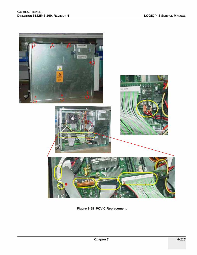
GE HEALTHCAREDIRECTION 5122546-100, REVISION 4 LOGIQ™ 3 SERVICE MANUAL
Figure 8-58 PCVIC Replacement
8
1 2 3
4
567
Chapter 8 8-115

GE HEALTHCAREDIRECTION 5122546-100, REVISION 4 LOGIQ™ 3 SERVICE MANUAL
8-6-10 PC2IP PCB (FRU no. 706)Purpose: This is a description on how to remove and replace the Parts in the Back End Processor (BEP)
Assy.
8-6-10-1 Tools• Common Phillips screwdrivers
8-6-10-2 Needed Manpower• 1 persons, 15 minutes + travel
8-6-10-3 Preparations• Shut Down the System and switch off the Main Breaker at the rear as described in 4-3-1-3 on page
4-4
8-6-10-4 Removal ProcedureRefer to Figure 8-53 on page 8-103 .
1.) Remove the Rear Cover (FRU No.302). Refer to 8-4-3 on page 8-37 .2.) Remove the Rear EMI Cover. Refer to 8-4-16 on page 8-63 .3.) Remove the Left Cover (FRU No.301). Refer to 8-4-2 on page 8-35 4.) Remove the BEP (FRU 700). Refer to 8-6-5 on page 8-103 5.) Pull out the BEP Assy and place it on a flat surface.6.) Unscrew the seven screws (1-7) and remove the side cover.7.) Unscrew the screw (8) and remove the cables marked. Pull out the PC2IP Card.8.) Replace the PC2IP Card.
8-6-10-5 Mounting Procedure
1.) Replace the parts in the order of removal.
8-6-10-6 Functional Checkout Procedure
See Section
Functional and/or Leakage Current
Test Debrief Script4-3-1 Power On/Boot Up Service Manual Direction 5122546-100, Section 8-6-10. Equipment passes all required
tests and is ready for use.4-4-1 Basic Controls4-4-2 B Mode Checks4-4-3 M Mode Checks
4-4-4Color Flow Mode
Checks
4-4-5Doppler Mode
Checks
4-4-6Measurement and
Multi Image Checks
4-4-7Basic
Measurements
8-116 Section 8-6 - PCB

GE HEALTHCAREDIRECTION 5122546-100, REVISION 4 LOGIQ™ 3 SERVICE MANUAL
Figure 8-59 PC2IP Replacement
1 2 3
4
567
8
Chapter 8 8-117

GE HEALTHCAREDIRECTION 5122546-100, REVISION 4 LOGIQ™ 3 SERVICE MANUAL
Section 8-7Power Block
8-7-1 Transformer Assy (FRU No. 800)Purpose: This is a description on how to remove and replace the Transformer Assy.
8-7-1-1 Tools• Common Phillips screwdrivers
8-7-1-2 Needed Manpower• 1 persons, 15 minutes + travel
8-7-1-3 Preparations• Shut Down the System and switch off the Main Breaker at the rear as described in 4-3-1-3 on page
4-4
8-7-1-4 Removal Procedure
Refer to Figure 8-60 on page 8-120 .
1.) Remove Rear cover (FRU No. 302). Refer to section 8-4-3 on page 8-37 2.) Position the caster wheel straight3.) Unscrew two screws (a,b) 4.) Remove GND cable(1)5.) Remove two screws from the stopper plate6.) Disconnect Cable Assy 13.7.) Pull & Remove the Transformer Assy.
8-7-1-5 Mounting procedure
1.) Install the new parts in the reverse order of removal.
8-7-1-6 Functional Checkout Procedure
CAUTION Do not wear the ESD wrist strap when you remove a part of power supply unit. Turn OFF power and unplug the power cord before removing a part of power supply unit. However be sure to turn off power and wear the strap before you remove a circuit boards.
NOTICEReplace Circuit Breaker and Noise Filter in case of transformer failureRefer Disassy procedure of Circuit Breaker and noise filter.
See Section
Functional and/or Leakage Current
Test Debrief Script4-3-1 Power On/Boot Up Service Manual Direction 5122546-100, Section 8-7-1. Equipment passes all required
tests and is ready for use.4-4-1 Basic Controls4-4-2 B Mode Checks4-4-3 M Mode Checks
4-4-4Color Flow Mode
Checks
8-118 Section 8-7 - Power Block

GE HEALTHCAREDIRECTION 5122546-100, REVISION 4 LOGIQ™ 3 SERVICE MANUAL
4-4-5Doppler Mode
Checks
4-4-6Measurement and
Multi Image Checks
4-4-7Basic
Measurements10-6-4, 10-6-5 Leakage Current
Chapter 8 8-119

GE HEALTHCAREDIRECTION 5122546-100, REVISION 4 LOGIQ™ 3 SERVICE MANUAL
8-7-1 Transformer Assy (FRU No. 800) (cont’d)
Figure 8-60 Transformer Assy Disassembly
Stopper plate & two Screws
a b
CA131
Transformer
8-120 Section 8-7 - Power Block

GE HEALTHCAREDIRECTION 5122546-100, REVISION 4 LOGIQ™ 3 SERVICE MANUAL
8-7-2 LVPS Disassy (FRU No. 801)Purpose: This is a description on how to remove and replace the LVPS.
8-7-2-1 Tools• Common Phillips screwdrivers
8-7-2-2 Needed Manpower• 1 person, 15 minutes + travel
8-7-2-3 Preparations• Shut Down the System and switch off the Main Breaker at the rear as described in 4-3-1-3 on page
4-4
8-7-2-4 Removal Procedure
Refer to Figure 8-61 on page 8-122 .
1.) Remove Right Cover (FRU No. 300). Refer to section 8-4-1 on page 8-33 2.) Remove Right EMI Cover. Refer to section 8-4-15 on page 8-61 3.) Unscrew two screws (a,b).4.) Remove two GND Wire (A, B) and disconnect Connectors 301 and 302.5.) Disconnect the cables from the backplane. (CN36, CN29, CN31 and CN34).6.) Disconnect from RPI to LVPS7.) Slide out the LVPS.
CAUTION Do not wear the ESD wrist strap when you remove a part of power supply unit. Turn OFF power and unplug the power cord before removing a part of power supply unit. However be sure to turn off power and wear the strap before you remove a circuit boards.
Chapter 8 8-121

GE HEALTHCAREDIRECTION 5122546-100, REVISION 4 LOGIQ™ 3 SERVICE MANUAL
8-7-2-5 Mounting procedure
1.) Install the new parts in the reverse order of removal
8-7-2-6 Functional Checkout Procedure
Figure 8-61 LVPS Replacement
See Section
Functional and/or Leakage Current
Test Debrief Script4-3-1 Power On/Boot Up Service Manual Direction 5122546-100, Section 8-7-2. Equipment passes all required
tests and is ready for use.4-4-1 Basic Controls4-4-2 B Mode Checks4-4-3 M Mode Checks
4-4-4Color Flow Mode
Checks
4-4-5Doppler Mode
Checks
4-4-6Measurement and
Multi Image Checks
4-4-7Basic
Measurements10-6-4, 10-6-5 Leakage Current
a
b
ABConnectors
301 and 302
8-122 Section 8-7 - Power Block

GE HEALTHCAREDIRECTION 5122546-100, REVISION 4 LOGIQ™ 3 SERVICE MANUAL
8-7-3 AC Interface Board (ACI) (FRU No. 802)Purpose: This is a description on how to remove and replace the ACI Board.
8-7-3-1 Tools• Common Phillips screwdrivers
8-7-3-2 Needed Manpower• 1 persons, 15 minutes + travel
8-7-3-3 Preparations• Shut Down the System and switch off the Main Breaker at the rear as described in 4-3-1-3 on page
4-4
8-7-3-4 Removal Procedure
Refer to Figure 8-62 on page 8-124 .
1.) Remove the Rear Cover (FRU No.302). Refer to section 8-4-3 on page 8-37 .2.) Remove the Right Cover (FRU No. 300). Refer to section 8-4-1 on page 8-33 3.) Remove the Rear EMI Cover. Refer to section 8-4-16 on page 8-63 4.) Remove Rear Right Support by removing four Screws (a, b, c, d)5.) Disconnect eight cables (A - H)6.) Unscrew eight screws (1-8)7.) Remove the ACI Board.
CAUTION Do not wear the ESD wrist strap when you remove a part of power supply unit. Turn OFF power and unplug the power cord before removing a part of power supply unit. However be sure to turn off power and wear the strap before you remove a circuit boards.
Chapter 8 8-123

GE HEALTHCAREDIRECTION 5122546-100, REVISION 4 LOGIQ™ 3 SERVICE MANUAL
8-7-3-5 Mounting procedureInstall the new parts in the reverse order of removal.
8-7-3-6 Functional Checkout Procedure
Figure 8-62 ACI Board Disassembly
See Section
Functional and/or Leakage Current
Test Debrief Script4-3-1 Power On/Boot Up Service Manual Direction 5122546-100, Section 8-7-3. Equipment passes all required
tests and is ready for use.4-4-1 Basic Controls4-4-2 B Mode Checks4-4-3 M Mode Checks
4-4-4Color Flow Mode
Checks
4-4-5Doppler Mode
Checks
4-4-6Measurement and
Multi Image Checks
4-4-7Basic
Measurements10-6-4, 10-6-5 Leakage Current
1
2
3
4 5
6
7
8ab
c
d
A
BC
DE
F
HG
8-124 Section 8-7 - Power Block

GE HEALTHCAREDIRECTION 5122546-100, REVISION 4 LOGIQ™ 3 SERVICE MANUAL
8-7-4 Fuse (FRU No. 803)Purpose: This is a description on how to remove and replace the Fuse.
8-7-4-1 Tools• Common Phillips screwdrivers
8-7-4-2 Needed Manpower• 1 person, 15 minutes + travel
8-7-4-3 Preparations• Shut Down the System and switch off the Main Breaker at the rear as described in 4-3-1-3 on page
4-4
8-7-4-4 Removal Procedure
Refer to Figure 8-63 on page 8-125 .
1.) Remove Transformer Assembly (FRU No. 800). Refer to Section 8-7-1 on page 8-118 2.) Pull two cables (a, b).3.) Press the Fuse in the Direction shown by two arrows and pull the Fuse out.
8-7-4-5 Mounting procedure
1.) Install the new parts in the reverse order of removal
8-7-4-6 Functional Checkout Procedure
CAUTION Do not wear the ESD wrist strap when you remove a part of power supply unit. Turn OFF power and unplug the power cord before removing a part of power supply unit. However be sure to turn off power and wear the strap before you remove a circuit boards.
Figure 8-63 Fuse Disassembly
See Section
Functional and/or Leakage Current
Test Debrief Script
a
b
F1
Chapter 8 8-125

GE HEALTHCAREDIRECTION 5122546-100, REVISION 4 LOGIQ™ 3 SERVICE MANUAL
4-3-1 Power On/Boot Up Service Manual Direction 5122546-100, Section 8-7-4. Equipment passes all required tests and is ready for use.
4-4-1 Basic Controls
8-126 Section 8-7 - Power Block
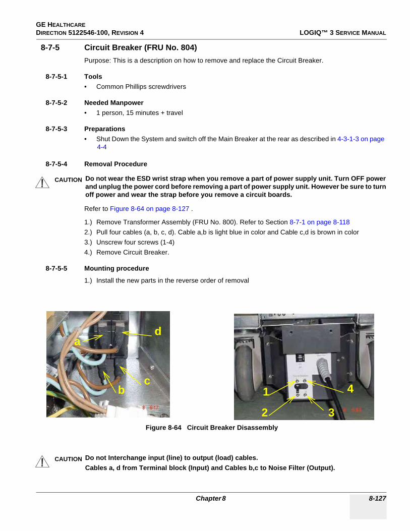
GE HEALTHCAREDIRECTION 5122546-100, REVISION 4 LOGIQ™ 3 SERVICE MANUAL
8-7-5 Circuit Breaker (FRU No. 804)Purpose: This is a description on how to remove and replace the Circuit Breaker.
8-7-5-1 Tools• Common Phillips screwdrivers
8-7-5-2 Needed Manpower• 1 person, 15 minutes + travel
8-7-5-3 Preparations• Shut Down the System and switch off the Main Breaker at the rear as described in 4-3-1-3 on page
4-4
8-7-5-4 Removal Procedure
Refer to Figure 8-64 on page 8-127 .
1.) Remove Transformer Assembly (FRU No. 800). Refer to Section 8-7-1 on page 8-118 2.) Pull four cables (a, b, c, d). Cable a,b is light blue in color and Cable c,d is brown in color3.) Unscrew four screws (1-4)4.) Remove Circuit Breaker.
8-7-5-5 Mounting procedure
1.) Install the new parts in the reverse order of removal
CAUTION Do not wear the ESD wrist strap when you remove a part of power supply unit. Turn OFF power and unplug the power cord before removing a part of power supply unit. However be sure to turn off power and wear the strap before you remove a circuit boards.
Figure 8-64 Circuit Breaker Disassembly
CAUTION Do not Interchange input (line) to output (load) cables.Cables a, d from Terminal block (Input) and Cables b,c to Noise Filter (Output).
d
cb
a
1
2 3
4
Chapter 8 8-127
GE HEALTHCAREDIRECTION 5122546-100, REVISION 4 LOGIQ™ 3 SERVICE MANUAL
8-7-5-6 Functional Checkout Procedure
See Section
Functional and/or Leakage Current
Test Debrief Script4-3-1 Power On/Boot Up Service Manual Direction 5122546-100, Section 8-7-5. Equipment passes all required
tests and is ready for use.4-4-1 Basic Controls4-4-2 B Mode Checks4-4-3 M Mode Checks
4-4-4Color Flow Mode
Checks
4-4-5Doppler Mode
Checks
4-4-6Measurement and
Multi Image Checks
4-4-7Basic
Measurements10-6-4, 10-6-5 Leakage Current
8-128 Section 8-7 - Power Block

GE HEALTHCAREDIRECTION 5122546-100, REVISION 4 LOGIQ™ 3 SERVICE MANUAL
8-7-6 Noise Filter(FRU No. 805)Purpose: This is a description on how to remove and replace the Circuit Breaker.
8-7-6-1 Tools• Common Phillips screwdrivers
8-7-6-2 Needed Manpower• 1 person, 15 minutes + travel
8-7-6-3 Preparations• Shut Down the System and switch off the Main Breaker at the rear as described in 4-3-1-3 on page
4-4
8-7-6-4 Removal Procedure
Refer to Figure 8-64 on page 8-127 .
1.) Remove Transformer Assembly (FRU No. 800). Refer to Section 8-7-1 on page 8-118 2.) Remove the 3 screws marked as “a, b, c” as seen in Figure 8-65 on page 8-129
8-7-6-5 Mounting procedure
1.) Install the new parts in the reverse order of removal
CAUTION Do not wear the ESD wrist strap when you remove a part of power supply unit. Turn OFF power and unplug the power cord before removing a part of power supply unit. However be sure to turn off power and wear the strap before you remove a circuit boards.
Figure 8-65 Noise Filter Disassembly
CAUTION Do not Interchange input (line) to output (load) cables.Cables a, d from Terminal block (Input) and Cables b,c to Noise Filter (Output).
a
b c
Chapter 8 8-129

GE HEALTHCAREDIRECTION 5122546-100, REVISION 4 LOGIQ™ 3 SERVICE MANUAL
8-7-6-6 Functional Checkout Procedure
See Section
Functional and/or Leakage Current
Test Debrief Script4-3-1 Power On/Boot Up Service Manual Direction 5122546-100, Section 8-7-6. Equipment passes all required
tests and is ready for use.4-4-1 Basic Controls4-4-2 B Mode Checks4-4-3 M Mode Checks
4-4-4Color Flow Mode
Checks
4-4-5Doppler Mode
Checks
4-4-6Measurement and
Multi Image Checks
4-4-7Basic
Measurements
8-130 Section 8-7 - Power Block

GE HEALTHCAREDIRECTION 5122546-100, REVISION 4 LOGIQ™ 3 SERVICE MANUAL
Section 8-8Software Loading Procedure
8-8-1 Installing Base System Software and Application Software
8-8-1-1 GeneralThis describes a full system software loading (Windows 2000 Operating System + Echoloader Application) procedure.
Use this instructions when:
- Performing the System Version-up (OS + Application) - Replacing the HDD with a new one (OS + Application)
A Software Loading procedure is outlined:
CAUTION Make sure that all images have been reconstructed and archived on the CD-R or MOD before performing Base System Software (OS) and Application software installation (Refer to Operator Manual). This procedure will re-initialize the hard disk, erasing all images and patient data.
Table 8-2 Software Loading Procedures
Procedures Prerequisite Manpower (Approximately.)
1Saving the Data (Using Utility Function)
a Blank CD-R or MOD 15 minutesSaving the Data (Using Window Explorer)
2 Checking PC Box Type None 5 minutes
3 Installing Base System Software (For Adapted/XXXXXXX or later)
LOGIQ3 Base System Software Load Image CD-
ROM40 minutes
4 Installing Application SoftwareLOGIQ3 Application Software
CD-ROM 20 minutes
5 Restoring the Data None 10 minutes
6 Functional Checks None 30 minutes
Total Manpower 2 h or 2h20m
NOTICE The “Saving the Data” procedure described above does NOT include the image back-up procedures.
Chapter 8 8-131

GE HEALTHCAREDIRECTION 5122546-100, REVISION 4 LOGIQ™ 3 SERVICE MANUAL
8-8-1-2 Saving the Data (Using Utility Function)Always use this back-up procedure.
1.) Format CD-R:
a.) On the scan screen, touch Utility. The OPERATOR LOGIN window appears.b.) Change the User level to Admin, then enter Password. Then click on Log on.
c.) Select Admin > Connectivity > Tools.d.) Insert a blank CD-R into the drive.e.) Type a proper label name (e.x. 011201data), then click on Format.f.) The warning message appears. Click on OK. The formatting procedure starts.
2.) Saving the user data:
a.) Select Admin > Backup.b.) Check the mark at the followings
Figure 8-1 Operator LOGIN window
8-132 Section 8-8 - Software Loading Procedure

GE HEALTHCAREDIRECTION 5122546-100, REVISION 4 LOGIQ™ 3 SERVICE MANUAL
:
c.) Click on Backup Now.d.) The warning message appears. Click on OK. The back-up procedure starts.e.) Verify that “Finished, OK” appears in the Result column. f.) Press the eject button of the drive to eject the CD-R.g.) Write down the comment (e.x. 011201 data) on the surface of the CD-R using a soft felt-tip pen.
Figure 8-66 Backup Screen
Chapter 8 8-133

GE HEALTHCAREDIRECTION 5122546-100, REVISION 4 LOGIQ™ 3 SERVICE MANUAL
3.) Write down the following parameters:
a.) Select Admin > Connectivity > tcpip.
b.) Write down the followings:
4.) Power OFF the scanner.5.) The System Exit window appears. Click on Shut down...
Figure 8-67 TCPIP Screen
Table 8-3 Writing Down the TCPIP Parameters
Items Parameters
Computer Name
IP Address
Subnet Mask
Default Gateway
8-134 Section 8-8 - Software Loading Procedure

GE HEALTHCAREDIRECTION 5122546-100, REVISION 4 LOGIQ™ 3 SERVICE MANUAL
Section 8-9Base Load Software Load
8-9-1 ManpowerOne person,.5 hour + travel
8-9-2 ToolsNone
8-9-3 Preparations1.) Back up any customer preset configurations if necessary.2.) Export and patient exam files if necessary.
8-9-4 Base Load Software Load Procedure
NOTE: While we do not believe it is necessary, It would not hurt to disconnect the system from the network and remove all transducers.
1.) Insert the disk labeled “Base System Software Load Image” into the CDROM drive.2.) Properly Turn Off the scanner. If necessary, hold down the button until the light goes amber.
3.) Turn on the scanner. You will see a screen showing Norton Ghost. This automatically loads a base set of software onto the hard disk. Let it run to completion (Approximately 10 minutes).
A message will be displayed when the process is complete.
Figure 8-68 Shutdown Dialog Box
Chapter 8 8-135

GE HEALTHCAREDIRECTION 5122546-100, REVISION 4 LOGIQ™ 3 SERVICE MANUAL
8-9-4 Base Load Software Load Procedure (cont’d)
4.) Remove the CD-ROM
NOTE: Remove the CD-ROM from the drive; otherwise you will be repeating the Base System Software Load process.
5.) After removing the CDROM from the drive, properly turn off the scanner.6.) Turn the scanner back on. It will now boot up and automatically log on (Base Load -10 or later)
to start checking hardware and mapping disk drives. This is a normal and should be allowed to run to completion.
NOTE: While the script is running, several windows or dialog boxes will appear on the screen. Wait for the "System Settings Change"dialog box "Restart computer now" (approximately 3 minutes after the desktop). Do NOT touch the system during this process. Activating the keyboard, mouse or front panel could corrupt the installation.
NOTE: At times it may look like the system is unresponsive. PATIENCE! The process takes 3-4 minutes. Wait for the "Restart computer now" message to appear before activating the keyboard, mouse or front panel controls.
7.) When you get a message to reboot Windows, wait 15 seconds or until the hour glass disappears and select YES.
Figure 8-69 Base
8-136 Section 8-9 - Base Load Software Load

GE HEALTHCAREDIRECTION 5122546-100, REVISION 4 LOGIQ™ 3 SERVICE MANUAL
8-9-5 Optional Manual Drive RemappingAlthough the Base System Image Software Load is automatic, if the drive remapping is not accomplished properly, the changes can be done manually.
- Follow the instructions in “8-9-11 "Optional Procedure for Changing (Re-mapping) Drive Letters" on page 8-141 to check the drive mapping. If the mapping is not correct, complete the procedure.
8-9-6 Optional Manual ConfigurationsThe Base Image Software Load is automatic. However, there are two configurations of LOGIQ 3 Back End Processors. On older or clinical systems you may need to perform some checks and windows may request that you perform certain actions. These checks and actions are described below.
- Any time you get a request to reboot Windows click OK, and let Windows reboot.Check Sound Card Configuration
- Follow the instructions in 8-9-10 "Optional Check Devices" on page 8-139.
8-9-7 Loading Applications Software- Follow the instructions in “Section 8-10 "Loading Application Software After a Base Image
Load" on page 8-146.- .
8-9-8 Final System Setup- Follow the instructions in “8-9-8 "Final System Setup" on page 8-137” procedure.
Chapter 8 8-137

GE HEALTHCAREDIRECTION 5122546-100, REVISION 4 LOGIQ™ 3 SERVICE MANUAL
8-9-9 serialno.txt File CreationWith the exception of Demo Systems, if the system serial number is not set correctly the authorized options installed on the customer systems will not function.
Prior to the upgrade there is no way for the systems in the field to record the serial number of the system to the backplane. The C:\serialno.txt on the hard drive has been used to record the system serial number up to now.
As part of this FMI the backplane storage code is now available. After an Applications Software Upgrade, when the system is powered up, the serialno.txt file will be read from the hard drive and written to the backplane. This will all work well unless:
- A system Base Image Software was performed. In this case the serialno.txt file must be created and put back on the "C" drive.* Boot up the system with the service dongle attached to the USB port.* It will boot up into Windows.* Go to Start>Programs>Accessories>Notepad. Use Windows Notepad and type in the
serial number of the system. Exactly as it is on the console rating plate. (i.e. 57493US2)* Check the save path for this text file. Save the file directly to the "C:\" drive as file name
serialno.txt. It will NOT function if saved in any other location.- There may be a rare case where the serialno.txt file does not contain the correct system serial
number. If this is the case, repeat the previous steps to edit the serialno.txt file to the proper serial number,
NOTE: If there is any doubt about the contents of serialno.txt, it should be checked before the application is first run, as once the serial number is written into the backplane it can only be changed with a diagnostic.
The serialno.txt file writes it’s information into the Backplane EEPROM. You must use the diagnostic utility to enter the Console Serial Number in the EEP-BP VPD Data.txt file.
8-138 Section 8-9 - Base Load Software Load

GE HEALTHCAREDIRECTION 5122546-100, REVISION 4 LOGIQ™ 3 SERVICE MANUAL
8-9-10 Optional Check Devices 1.) On the desktop, right click on the MY COMPUTER icon, and select PROPERTIES. 2.) Select the Hardware tab, and then the DEVICE MANAGER. It may take up to a minute for the
Device Manager screen to appear.
Figure 8-70 System Properties
Chapter 8 8-139
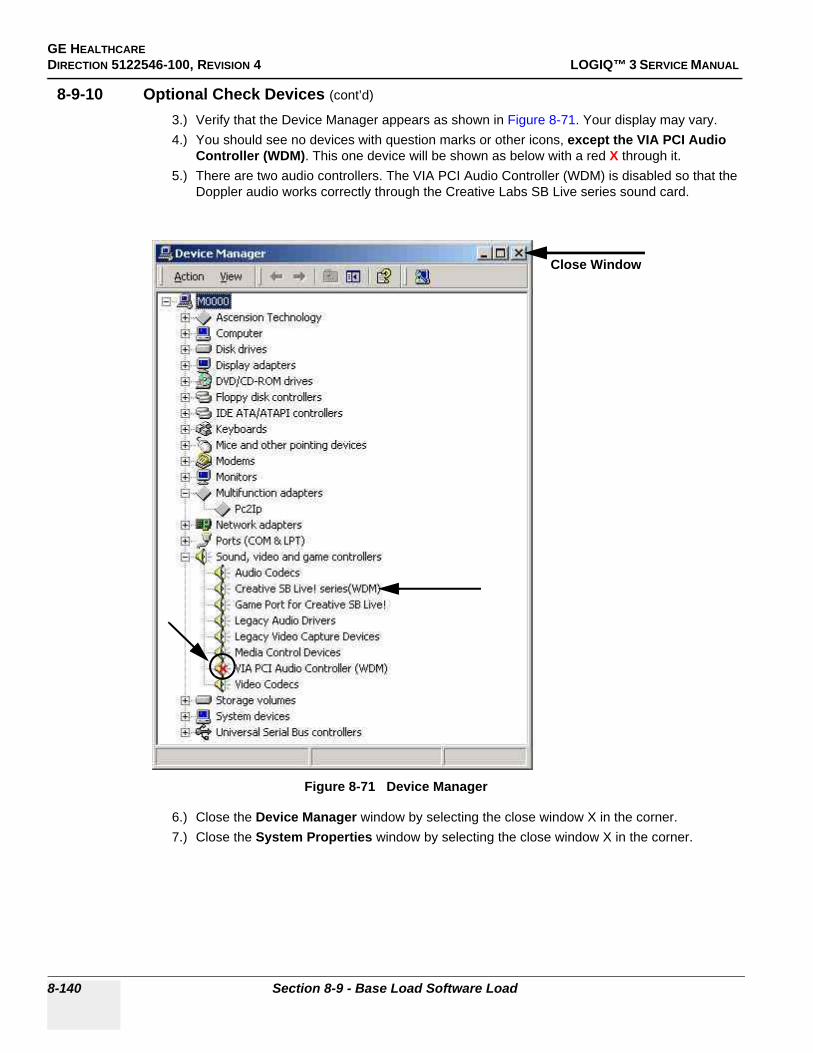
GE HEALTHCAREDIRECTION 5122546-100, REVISION 4 LOGIQ™ 3 SERVICE MANUAL
8-9-10 Optional Check Devices (cont’d)
3.) Verify that the Device Manager appears as shown in Figure 8-71. Your display may vary.4.) You should see no devices with question marks or other icons, except the VIA PCI Audio
Controller (WDM). This one device will be shown as below with a red X through it.5.) There are two audio controllers. The VIA PCI Audio Controller (WDM) is disabled so that the
Doppler audio works correctly through the Creative Labs SB Live series sound card.
6.) Close the Device Manager window by selecting the close window X in the corner.7.) Close the System Properties window by selecting the close window X in the corner.
Figure 8-71 Device Manager
Close Window
8-140 Section 8-9 - Base Load Software Load

GE HEALTHCAREDIRECTION 5122546-100, REVISION 4 LOGIQ™ 3 SERVICE MANUAL
8-9-11 Optional Procedure for Changing (Re-mapping) Drive LettersAn automated process was developed for this. It was implemented in Base Image Load -9 or later.
NOTE: If you are using a Base Image Load of -8 or earlier, or the -9 and later Base Image Load fails to properly map the drives, prodeed with manually assigning the proper drive letters.
First check to see if you need to change the drive letters on the CDROM drive and the Magneto Optical drives – they SHOULD be G: and H: respectively.
Right-click on the “My Computer” icon on the Windows desktop. Select “Manage” you should see a screen like Figure 8-72.
Click on the “Disk Management” icon on the left side of the screen under “Storage”. You’ll see this screen like Figure 8-73.
Figure 8-72 Computer Management
Chapter 8 8-141

GE HEALTHCAREDIRECTION 5122546-100, REVISION 4 LOGIQ™ 3 SERVICE MANUAL
8-9-11 Optional Procedure for Changing (Re-mapping) Drive Letters (cont’d)
Notice that “Disk 1 Removable” is shown as drive letter “G:” and “CD-ROM 0” is shown as drive letter “H:” - These are incorrect drive letters. This procedure will show you how to change them to the proper designations which is the reverse of how they are now.
Left-click on the “Disk 1 Removable” and select “Change Drive Letter and Path…”. You’ll see a screen as shown in Figure 8-74.
Figure 8-73 Disk Management
8-142 Section 8-9 - Base Load Software Load

GE HEALTHCAREDIRECTION 5122546-100, REVISION 4 LOGIQ™ 3 SERVICE MANUAL
8-9-11 Optional Procedure for Changing (Re-mapping) Drive Letters (cont’d)
Right-click on “Edit…” and you’ll see a screen as shown in Figure 8-75.
Now Right-click on the little down arrow and you’ll see the list box open with a list of available drive letters. Select the letter “I:”
Figure 8-74 Change Drive Letter and Path
Figure 8-75 Select Drive to Assign
Chapter 8 8-143
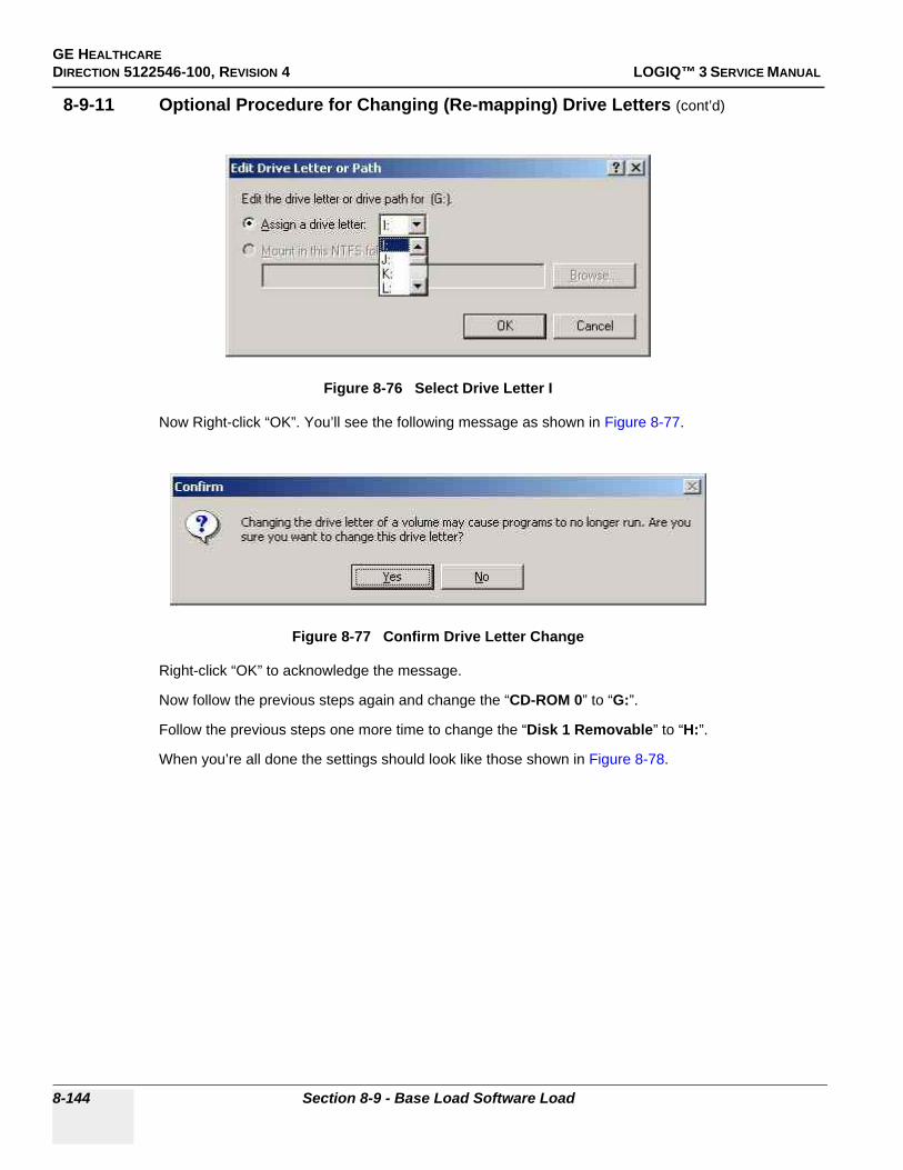
GE HEALTHCAREDIRECTION 5122546-100, REVISION 4 LOGIQ™ 3 SERVICE MANUAL
8-9-11 Optional Procedure for Changing (Re-mapping) Drive Letters (cont’d)
Now Right-click “OK”. You’ll see the following message as shown in Figure 8-77.
Right-click “OK” to acknowledge the message.
Now follow the previous steps again and change the “CD-ROM 0” to “G:”.
Follow the previous steps one more time to change the “Disk 1 Removable” to “H:”.
When you’re all done the settings should look like those shown in Figure 8-78.
Figure 8-76 Select Drive Letter I
Figure 8-77 Confirm Drive Letter Change
8-144 Section 8-9 - Base Load Software Load
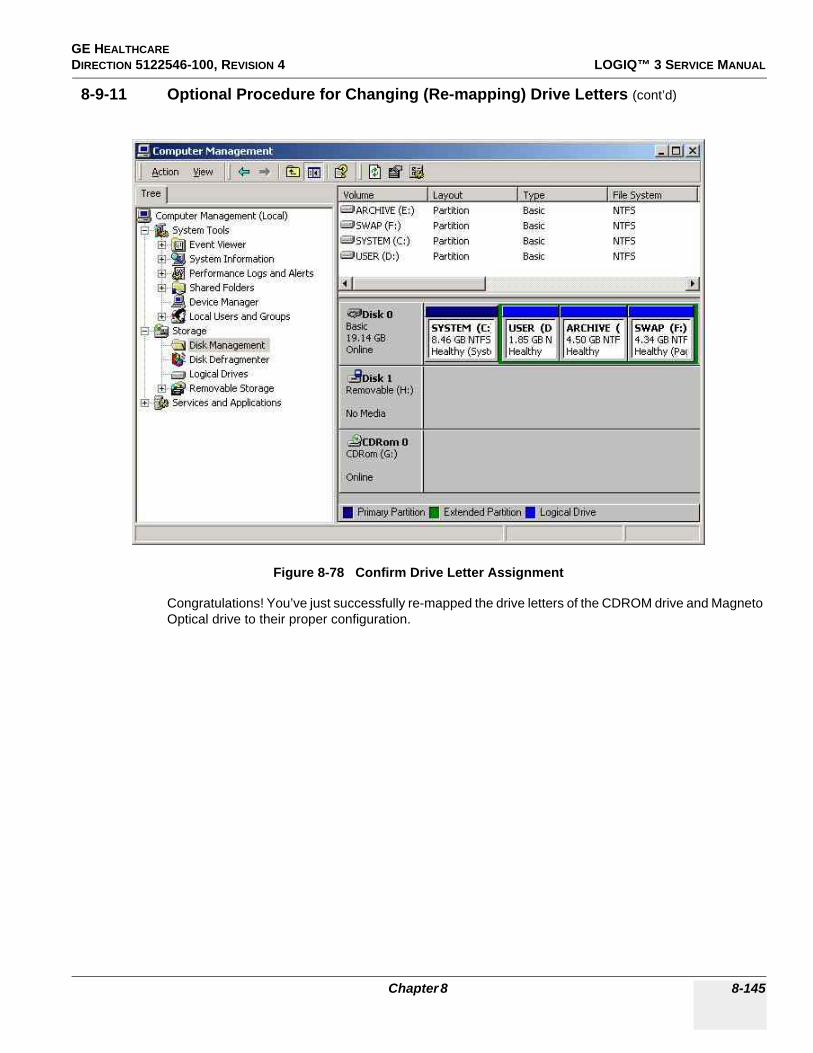
GE HEALTHCAREDIRECTION 5122546-100, REVISION 4 LOGIQ™ 3 SERVICE MANUAL
8-9-11 Optional Procedure for Changing (Re-mapping) Drive Letters (cont’d)
Congratulations! You’ve just successfully re-mapped the drive letters of the CDROM drive and Magneto Optical drive to their proper configuration.
Figure 8-78 Confirm Drive Letter Assignment
Chapter 8 8-145

GE HEALTHCAREDIRECTION 5122546-100, REVISION 4 LOGIQ™ 3 SERVICE MANUAL
Section 8-10Loading Application Software After a Base Image Load
8-10-1 ManpowerOne person, 0.5 hour + travel
8-10-2 ToolsNone
8-10-3 PreparationsLoading applications software is necessary after a Base Image Software Load.
If this is the first time for loading Applicatiopns Software (after a Base Image Load) proceed with the following process.
If this is NOT the first time for loading Applications software (just an applications update) then proceed to Section 8-10 "Loading Application Software After a Base Image Load" on page 8-146.
8-10-4 Image Management GuideSave As to View on any PC - Use this to save images (Dicom or Raw Dicom) in a computer-friendly format (.avi or .jpeg) so you can view it on any PC.
Move Images to Archive - Use this to take images off your Ultrasound system on to removable media for long-term archive. This is the way to free up hard disk space, rather than deleting images.
Export/Import Data/Images Between Systems - Use this to copy both patient data and images for specified patient(s) from one system to another.
8-10-4-1 Save As (Saving Images to CD-ROM to View on Any PC)To save images to the CD-ROM:
1.) Insert the CD.2.) Go to Utility --> Connectivity --> Tools. Select the Media as CD Rewritable.3.) Press Format to format the CD-ROM.4.) Select the image(s) to be saved to CD-ROM, press Menu, and select Save As.5.) The SAVE AS menu appears.
8-146 Section 8-10 - Loading Application Software After a Base Image Load

GE HEALTHCAREDIRECTION 5122546-100, REVISION 4 LOGIQ™ 3 SERVICE MANUAL
8-10-4-1 Save As (Saving Images to CD-ROM to View on Any PC) (cont’d)
6.) Specify Compression and Save As Type and press Save. The image is saved to the CD-ROM.7.) When you have put all the images you want on the CD, press F3 to eject the CD-ROM. Select
CD Rewritable.
8.) Finalize the CD-ROM by selecting Yes. The CD-ROM is ejected from the system.
Storing Images with More Resolution
To store images with more resolution than is available with the JPEG selection, select Save As and select AVI as the Save As Type. You can save single images as .avi files.
Figure 8-79 Save As Menu
Figure 8-80 Eject Media Menu
Figure 8-81 Finalize CD-ROM Menu
Chapter 8 8-147
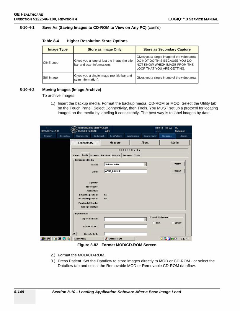
GE HEALTHCAREDIRECTION 5122546-100, REVISION 4 LOGIQ™ 3 SERVICE MANUAL
8-10-4-1 Save As (Saving Images to CD-ROM to View on Any PC) (cont’d)
8-10-4-2 Moving Images (Image Archive)To archive images:
1.) Insert the backup media. Format the backup media, CD-ROM or MOD. Select the Utility tab on the Touch Panel. Select Connectivity, then Tools. You MUST set up a protocol for locating images on the media by labeling it consistently. The best way is to label images by date.
2.) Format the MOD/CD-ROM.3.) Press Patient. Set the Dataflow to store images directly to MOD or CD-ROM - or select the
Dataflow tab and select the Removable MOD or Removable CD-ROM dataflow.
Table 8-4 Higher Resolution Store Options
Image Type Store as Image Only Store as Secondary Capture
CINE Loop Gives you a loop of just the image (no title bar and scan information).
Gives you a single image of the video area. DO NOT DO THIS BECAUSE YOU DO NOT KNOW WHICH IMAGE FROM THE LOOP THAT YOU ARE GETTING.
Still Image Gives you a single image (no title bar and scan information). Gives you a single image of the video area.
Figure 8-82 Format MOD/CD-ROM Screen
8-148 Section 8-10 - Loading Application Software After a Base Image Load

GE HEALTHCAREDIRECTION 5122546-100, REVISION 4 LOGIQ™ 3 SERVICE MANUAL
8-10-4-2 Moving Images (Image Archive) (cont’d)4.) Press More, then select Move Images. The Move Images pop-up appears.
5.) Fill in the From Date, then press Recalculate. Specify to Keep days together. Check that you have enough disk space for the images you want to move. Select Move Images, then press OK. An in-progress message appears. The archive operation is complete when you receive this message.
Figure 8-83 Image Archive Move Pop-up Menu
Figure 8-84 Archive Operation Complete Message
Chapter 8 8-149

GE HEALTHCAREDIRECTION 5122546-100, REVISION 4 LOGIQ™ 3 SERVICE MANUAL
8-10-4-3 Export/Import (Moving Data Between Ultrasound Systems)To move exams from one Ultrasound system to another, you need to export/import exam information.
NOTE: Both database information and images are exported. No data is deleted from the local archive when exporting data.
Exporting Data
To export an exam(s) to a compatible Ultrasound system:
1.) Format the removable media (MOD or CD-ROM). Label the removable media. Answer Yes/OK to the messages.
2.) Press Patient. Deselect any selected patient(s) in the search portion of the Patient screen. Press More (located at the lower, right-hand corner of the Patient menu).
3.) Select Export. Specify the type of removable media (MOD or CD-ROM) on the Export pop-up. Press OK. Then, please wait until the Patient menu is visible.
4.) In the patient list at the bottom of the Patient menu, select the patient(s) you want to export.You can use Windows commands to select more than one patient.
To select a consecutive list of patients, click the cursor on the first name, move the cursor to the last name, then press and hold down the Shift+right Set key to select all the names.
To select a non-consecutive list of patients, click the cursor at the first name, move the cursor to the next name, then press and hold down the Ctrl+right Set key, move the cursor to the next name, then press and hold down the Ctrl+right Set key again, etc.
You can also search for patients via the Search key and string.
Or, Select All from the Select All/Copy Patient Menu:
Figure 8-85 Export Pop-up Message
8-150 Section 8-10 - Loading Application Software After a Base Image Load

GE HEALTHCAREDIRECTION 5122546-100, REVISION 4 LOGIQ™ 3 SERVICE MANUAL
8-10-4-3 Export/Import (Moving Data Between Ultrasound Systems) (cont’d)
NOTE: You need to use your best judgment when moving patients’ images. If there are lots of images or loops, then only move a few patients at a time.
5.) Once you have selected all of the patients to export, press Copy Patient from the Select All/Copy Patient Menu.
6.) Informational status messages appear as the copy is taking place. A final status report pop-up message appears. Press OK.
7.) Press F3 to eject the media. Specify that you want to finalize the CD-ROM.
Figure 8-86 Select All/Copy Patient Menu
Figure 8-87 Export Completion Status Message
Chapter 8 8-151

GE HEALTHCAREDIRECTION 5122546-100, REVISION 4 LOGIQ™ 3 SERVICE MANUAL
8-10-4-4 Importing DataTo import an exam(s) to another Ultrasound system:
1.) At the other Ultrasound system, insert the MOD or CD-ROM.2.) Press Patient, press More, then Import. The Import from pop-up message appears. Press OK.
3.) The Patient menu just shows the patients available for import from the removable media you just loaded onto the system.
4.) Select the patients to be imported.5.) Press Copy Patient from the Select All/Copy Patient menu.6.) Please wait for the patient information to be copied to this Ultrasound system. Informational
messages appear while the import is taking place.7.) Press F3 to eject the media.
Figure 8-88 Import Pop-up Message
8-152 Section 8-10 - Loading Application Software After a Base Image Load

GE HEALTHCAREDIRECTION 5122546-100, REVISION 4 LOGIQ™ 3 SERVICE MANUAL
8-10-5Loading Applications Software
1.) Place the “Application Software” CDROM into the CDROM drive.2.) Move the cursor using Trackball to find the “Start” command button on the Monitor screen3.) Press the Start button on the tool bar at the bottom of the Screen and select “Run…”.
Enter “g:\LoadSoftware.bat” into the dialog box as shown in Figure 8-89 on page 8-153 .
4.) You will see a Command (CMD) window open as shown in Figure 8-115 on page 8-172 .
Figure 8-89 Run Load Software
Chapter 8 8-153
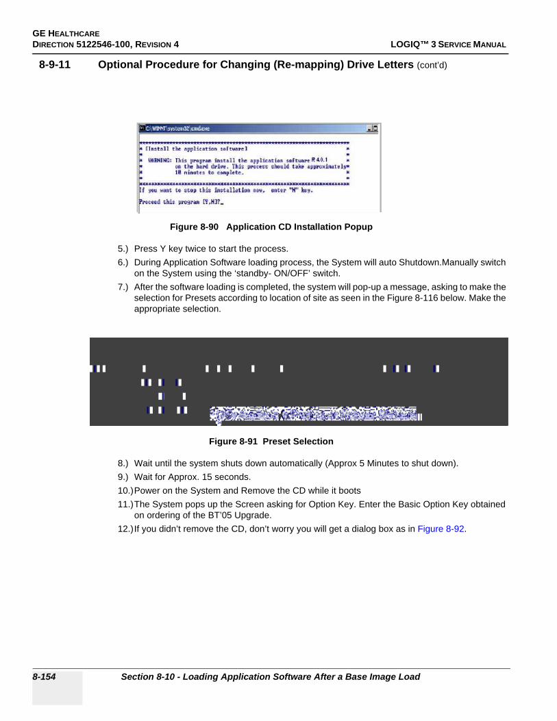
GE HEALTHCAREDIRECTION 5122546-100, REVISION 4 LOGIQ™ 3 SERVICE MANUAL
8-9-11 Optional Procedure for Changing (Re-mapping) Drive Letters (cont’d)
5.) Press Y key twice to start the process.6.) During Application Software loading process, the System will auto Shutdown.Manually switch
on the System using the ‘standby- ON/OFF’ switch.7.) After the software loading is completed, the system will pop-up a message, asking to make the
selection for Presets according to location of site as seen in the Figure 8-116 below. Make the appropriate selection.
8.) Wait until the system shuts down automatically (Approx 5 Minutes to shut down).9.) Wait for Approx. 15 seconds.10.)Power on the System and Remove the CD while it boots11.)The System pops up the Screen asking for Option Key. Enter the Basic Option Key obtained
on ordering of the BT’05 Upgrade.12.)If you didn’t remove the CD, don’t worry you will get a dialog box as in Figure 8-92.
Figure 8-90 Application CD Installation Popup
Figure 8-91 Preset Selection
8-154 Section 8-10 - Loading Application Software After a Base Image Load

GE HEALTHCAREDIRECTION 5122546-100, REVISION 4 LOGIQ™ 3 SERVICE MANUAL
8-10-5-1 Functional Checks for Service Platform (Diagnostic Program)
1.) Make sure that the wrench icon is shown at the bottom of the scan screen. Click on the wrench icon to activate. It will take about ten (10) seconds for activating.
NOTE: If the following dialog box is shown on the monitor, select Do not perform this check in the future and click on the Yes button. This dialog box will not be displayed for next time.
NOTE: If the another dialog box appears on the monitor, follow the instructions of the dialog box to continue the Functional Check procedures.
NOTE: If Caps Lock Active the display will be highlighted in the screen.
Figure 8-92 Wrench Icon
CAUTION If the wrench icon is not displayed on the scan screen, the installation of Service Platform had been failed.
Figure 8-93 Netscape Navigator Window
Chapter 8 8-155

GE HEALTHCAREDIRECTION 5122546-100, REVISION 4 LOGIQ™ 3 SERVICE MANUAL
2.) The Service Login window for Service Platform will be shown on the monitor display.
3.) Select GE Service at the “Select User Level” field. 4.) Enter the password for the Service Platform.5.) Click on Okay.
Figure 8-94 Service Login Window
CAUTION If the Login window for Service Platform is not displayed on the monitor, the installation of the Service Platform has failed.
Figure 8-95 Selecting User Level
8-156 Section 8-10 - Loading Application Software After a Base Image Load
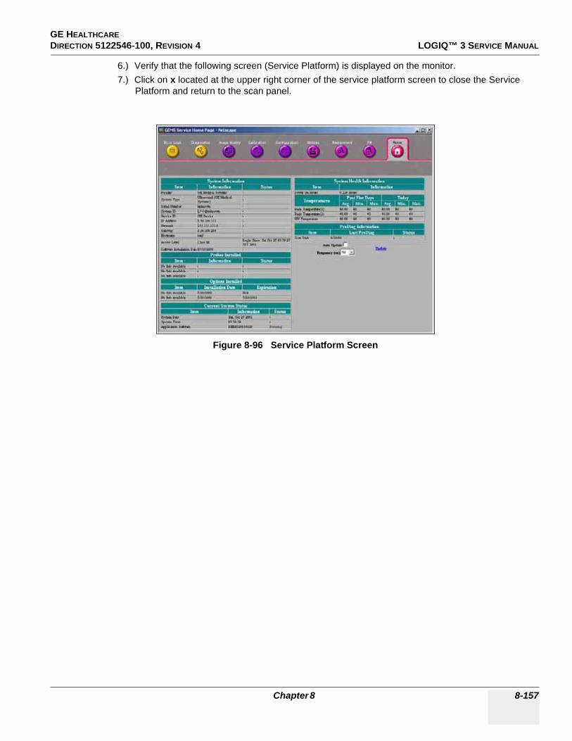
GE HEALTHCAREDIRECTION 5122546-100, REVISION 4 LOGIQ™ 3 SERVICE MANUAL
6.) Verify that the following screen (Service Platform) is displayed on the monitor.7.) Click on x located at the upper right corner of the service platform screen to close the Service
Platform and return to the scan panel.
Figure 8-96 Service Platform Screen
Chapter 8 8-157

GE HEALTHCAREDIRECTION 5122546-100, REVISION 4 LOGIQ™ 3 SERVICE MANUAL
8-10-5-2 Restoring the Data
1.) On the scan screen, touch Utility. The OPERATOR LOGIN window appears.2.) Change the User level to Admin, then enter Password. Then click on Log on.
3.) Select Admin > Restore.4.) Insert the CD-R into which the user parameters have been saved.5.) Check the mark at the followings:
6.) Select the source, then click on Restore Now.7.) The warning message appears. Click on OK. The restore procedure starts.8.) Verify that “Finished, OK” appears in the Result column. 9.) Press the eject button of the CD-R drive to eject the CD-R.
Figure 8-1 Operator LOGIN window
Figure 8-97 Restore
8-158 Section 8-10 - Loading Application Software After a Base Image Load
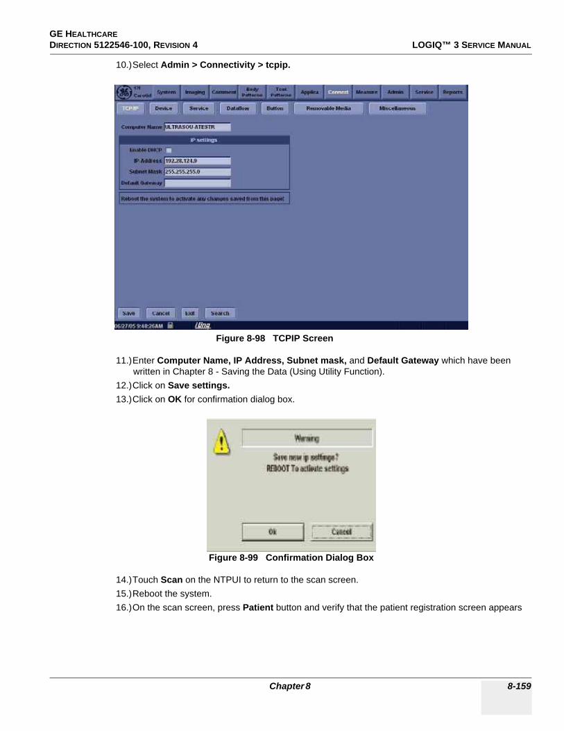
GE HEALTHCAREDIRECTION 5122546-100, REVISION 4 LOGIQ™ 3 SERVICE MANUAL
10.)Select Admin > Connectivity > tcpip.
11.)Enter Computer Name, IP Address, Subnet mask, and Default Gateway which have been written in Chapter 8 - Saving the Data (Using Utility Function).
12.)Click on Save settings.13.)Click on OK for confirmation dialog box.
14.)Touch Scan on the NTPUI to return to the scan screen.15.)Reboot the system.16.)On the scan screen, press Patient button and verify that the patient registration screen appears
Figure 8-98 TCPIP Screen
Figure 8-99 Confirmation Dialog Box
Chapter 8 8-159

GE HEALTHCAREDIRECTION 5122546-100, REVISION 4 LOGIQ™ 3 SERVICE MANUAL
17.)with no error.
8-10-5-3 Functional Checks for Probe Recognition
1.) Touch Scan button on the NTPUI to return to the scan screen.2.) Connect each probe to ensure that they are recognized.3.) Check every probe in the following modes and ensure that no artifacts or no problems are found in:
- B-mode- Color FLow- Pulsed Doppler- M-mode
Figure 8-100 Patient Registration Screen
8-160 Section 8-10 - Loading Application Software After a Base Image Load

GE HEALTHCAREDIRECTION 5122546-100, REVISION 4 LOGIQ™ 3 SERVICE MANUAL
Section 8-11Installing Option Software
8-11-1 Preparations• Option strings (This is a option key with a sequence of letters and numbers. Consult your local OLC
how to get it.)
8-11-2 Procedures1.) Power OFF the scanner to change user login level.2.) The SYSTEM EXIT window appears. Click on Logoff.
3.) The message window appears. Click on OK.4.) The OPERATOR LOGIN window appears.
Change the User level to Admin, then enter Password. Then click on Log on.
Figure 8-101 System EXIT window
Figure 8-102 Operator LOGIN window
Chapter 8 8-161

GE HEALTHCAREDIRECTION 5122546-100, REVISION 4 LOGIQ™ 3 SERVICE MANUAL
8-11-2 Procedures (cont’d)
5.) Select Utility > Admin>System Admin.
6.) Select System Admin tab, then click on NewEnter Option string into New Key dialogue box. Then verify that:- The option string to be entered appears in the SW Option Key list.- The option appears in the Options list as “Permanent”.
• If an option fails to install, delete it as follows:
a.) Click on the option key string to be deleted from the SW Option Key list.b.) Click on Delete.c.) The warning message appears. Click on OK.
Figure 8-103 Utility window
NOTICE Do NOT delete all SW Option Key. If it does, the system can NOT start up!!
8-162 Section 8-11 - Installing Option Software

GE HEALTHCAREDIRECTION 5122546-100, REVISION 4 LOGIQ™ 3 SERVICE MANUAL
Section 8-12Loading Base and Application Software
A Software Loading procedure is outlined below:
S.No Procedures Prerequisites Man Power Refer
1 Changing BIOS BEP2,BEP 3 5 minutes Section 8-12-1
2 Installing Base System Software
LOGIQ™ 3 Base System Load Image CD-ROM
10 minutes Section 8-12-2
3 Installing Application Software
LOGIQ3 Application Software CD-ROM
10 minutes Section 8-9-11
Table 8-5 Soft ware Loading Procedure
Chapter 8 8-163

GE HEALTHCAREDIRECTION 5122546-100, REVISION 4 LOGIQ™ 3 SERVICE MANUAL
8-12-1 Making BIOS changes
1.) During Boot Up, Press F2 to enter SetUp Screen.2.) Enter the Password as “dhruva”3.) Under “Exit”,go to the “Load Optimal Default Parameters” and press “Enter” Ref. Figure 8-104
on page 8-164 4.) pop up screen appears on the screen ,Click on OK.
Figure 8-104 Load Optimal Default Settings
5.) Press ESC
8-164 Section 8-12 - Loading Base and Application Software

GE HEALTHCAREDIRECTION 5122546-100, REVISION 4 LOGIQ™ 3 SERVICE MANUAL
6.) Enter “Boot” tab, Under “Boot Disk Priority”,select CD RW as the First Boot device as in Figure 8-105 on page 8-165 and the Hard disk as the Second Boot Device
Figure 8-105 1 st Boot Device CD R/W
7.) Press ESC
Chapter 8 8-165

GE HEALTHCAREDIRECTION 5122546-100, REVISION 4 LOGIQ™ 3 SERVICE MANUAL
8.) Under “Advanced” --> ”Chipset Configuration” tab, Go To ISA Enable bit . Press Enter and Select “Disabled”. as in Figure 8-106 on page 8-166
Figure 8-106 Disable ISA bit
9.) Press ‘ESC”10.)Under “Advanced” --> ”Diskette Configuration” tab, Go To Diskette Controller. Press Enter and
Select “Disabled”. as in Figure 8-107 on page 8-166
Figure 8-107 Disable Diskette Controller
11.)Press ‘ESC”12.)Under “Advanced” --> ”USB Configuration” tab, Under “2.0 Legacy Support” ,Set the USB speed
to “HiSpeed”
8-166 Section 8-12 - Loading Base and Application Software

GE HEALTHCAREDIRECTION 5122546-100, REVISION 4 LOGIQ™ 3 SERVICE MANUAL
13.)Press ESC14.)Press “F10”.15.)Popup screen appears on the screen.16.)Click on “OK” to Save all the changes and exit as per Figure 8-108 on page 8-167
Figure 8-108 Save changes before Exiting BIOS
17.)Reboot the System..
Chapter 8 8-167

GE HEALTHCAREDIRECTION 5122546-100, REVISION 4 LOGIQ™ 3 SERVICE MANUAL
8-12-2 Base Software Load Procedure For BEP Ver 2 , 3, and 4
NOTE: Disconnect the system from the network and remove all transducers, all External Drives (USB MOD, Flash Sticks, USB Memory etc.,), Switch Off peripherals like printers, VCR, VGP before installing Base Load. If not, this can affect the keyboard functionality after loading the base.
1.) Insert the disk labeled “Base System Software Load Image as per BEP Type” into the CDROM drive and switch on the system. The following screen appears, Press any key to Continue.
CAUTION: DO NOT SELECT OPTION 1 as it will delete the patient images on the Hard disk.2.) SELECT OPTION 2 for C Partition Only.
SL# BEP Part No. Ghost Part Number Reference Software to be used for Base / Application Loading
1 2361975-2 or 2361975-4BEP Ver2
NA
2 2361975-7 or 2361975-8 BEP Ver3
NA Refer Section 9-18 for appropriate Base and Application softwares
3 5193870BEP Ver4
NA
Table 8-6 S/W CD Selection to Begin Load Procedure
Figure 8-109 Base Load Warning Message
8-168 Section 8-12 - Loading Base and Application Software
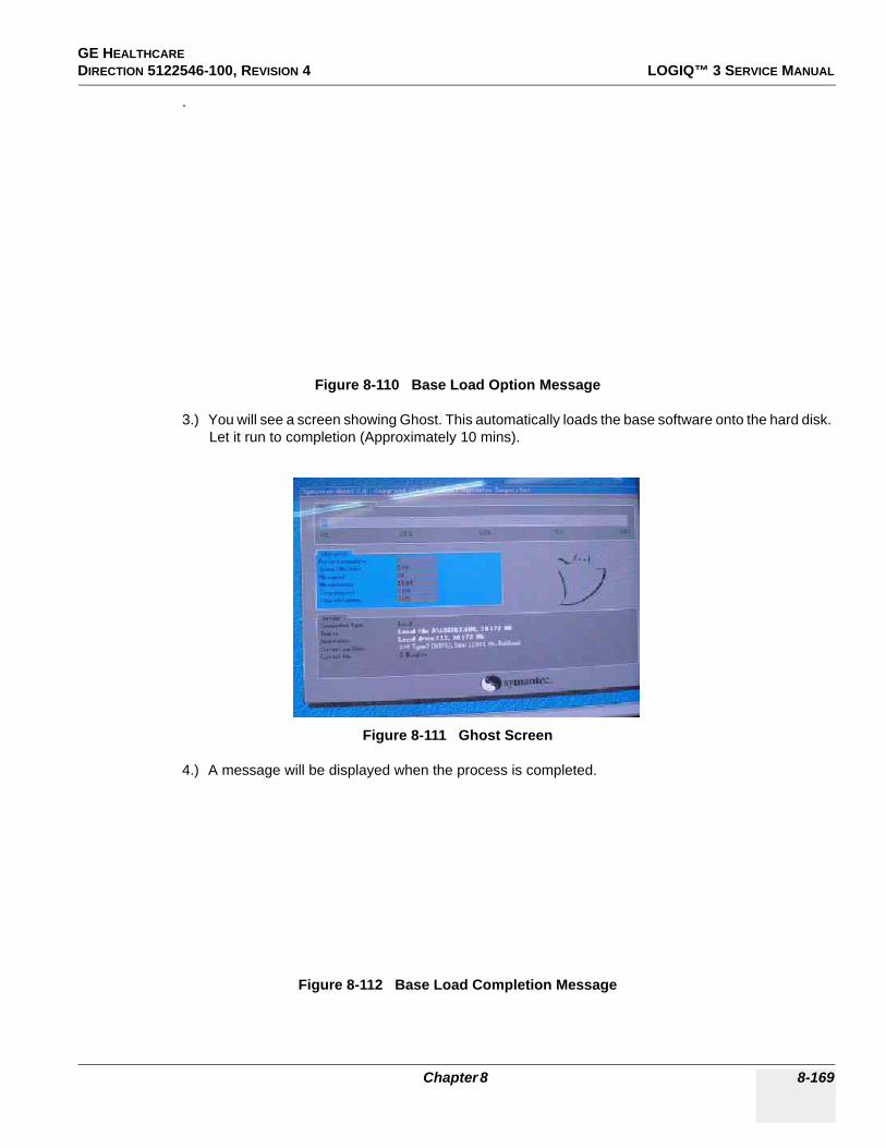
GE HEALTHCAREDIRECTION 5122546-100, REVISION 4 LOGIQ™ 3 SERVICE MANUAL
.
3.) You will see a screen showing Ghost. This automatically loads the base software onto the hard disk. Let it run to completion (Approximately 10 mins).
4.) A message will be displayed when the process is completed.
Figure 8-110 Base Load Option Message
Figure 8-111 Ghost Screen
Figure 8-112 Base Load Completion Message
Chapter 8 8-169

GE HEALTHCAREDIRECTION 5122546-100, REVISION 4 LOGIQ™ 3 SERVICE MANUAL
5.) Remove the CD-ROM
NOTE: Remove the CD-ROM from the drive; otherwise you will be repeating the Base System Software Load process.
NOTE: This Base software loading has changed the system platform from Windows 2000 Professional to Windows XP.
6.) After removing the CDROM from the drive, properly turn off the scanner by pressing and holding power on button on keyboard for more than 20 seconds.
7.) Turn the scanner back on. It will now boot up and automatically log on to start checking hardware and Device Manager. This is a normal and should be allowed to run to completion.
NOTE: When booting up the first time it could take 30-90 seconds after the login box appears before the trackball and key board are active. Watch for the arrow cursor to appear.
NOTE: While the script is running, several windows or dialog boxes will appear on the screen. Wait for the “System Settings Change” dialog box “Restart computer now” (approximately 3 minutes after the desktop).
Do NOT touch the system during this process. Activating the keyboard, mouse or front panel could corrupt the installation.
NOTE: At times it may look like the system is unresponsive. PATIENCE! The process takes 3-4 minutes. Wait for the “Restart computer now” message to appear before activating the keyboard, mouse or front panel controls.
8.) Wait till you get a windows reboot message. This may take upto 3 minutes. On this message, Click on NO as shown in the Figure 8-113 below.
Figure 8-113 Windows Restart Screen
8-170 Section 8-12 - Loading Base and Application Software

GE HEALTHCAREDIRECTION 5122546-100, REVISION 4 LOGIQ™ 3 SERVICE MANUAL
8-12-3 Loading Applications Software
1.) Place the “Application Software” CDROM into the CDROM drive.2.) Move the cursor using Trackball to find the “Start” command button on the Monitor screen3.) Press the Start button on the tool bar at the bottom of the Screen and select “Run…”.4.) Enter “g:\LoadSoftware.bat” into the dialog box as shown in Figure 8-89 on page 8-153 .
5.) You will see a Command (CMD) window open as shown in Figure 8-115 on page 8-172 .
Figure 8-114 Run Load Software
Chapter 8 8-171
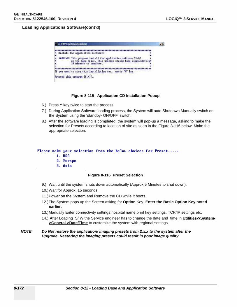
GE HEALTHCAREDIRECTION 5122546-100, REVISION 4 LOGIQ™ 3 SERVICE MANUAL
Loading Applications Software(cont’d)
6.) Press Y key twice to start the process.7.) During Application Software loading process, the System will auto Shutdown.Manually switch on
the System using the ‘standby- ON/OFF’ switch.8.) After the software loading is completed, the system will pop-up a message, asking to make the
selection for Presets according to location of site as seen in the Figure 8-116 below. Make the appropriate selection.
9.) Wait until the system shuts down automatically (Approx 5 Minutes to shut down).10.)Wait for Approx. 15 seconds.11.)Power on the System and Remove the CD while it boots.12.)The System pops up the Screen asking for Option Key. Enter the Basic Option Key noted
earlier. 13.)Manually Enter connectivity settings,hospital name,print key settings, TCP/IP settings etc.14.) After Loading S/ W the Service engineer has to change the date and time in Utilities->System-
>General->Date/Time to customize the system with regional settings.
NOTE: Do Not restore the application/ imaging presets from 2.x.x to the system after the Upgrade. Restoring the imaging presets could result in poor image quality.
Figure 8-115 Application CD Installation Popup
Figure 8-116 Preset Selection
8-172 Section 8-12 - Loading Base and Application Software

GE HEALTHCARE DIRECTION 5122546-100, REVISION 4 LOGIQ™ 3 SERVICE MANUAL
Chapter 9Renewal PartsSection 9-1Overview
9-1-1 Purpose of Chapter 9This chapter gives you an overview of Spare Parts available for the LOGIQ™ 3.
Table 9-1 Contents in Chapter 9
Section Description Page Number
9-1 Overview 9-1
9-2 List of Abbreviations 9-2
9-3 Operator Console Assy 9-3
9-4 MONITOR 9-5
9-5 Keyboard 9-6
9-6 External Covers 9-8
9-7 Mechanical Assembly’s 9-10
9-8 I/O Interfaces 9-11
9-9 PCB Boards 9-12
9-10 BEP 9-14
9-11 Power Block 9-16
9-12 Power Cord 9-17
9-13 Probes 9-17
9-14 Peripherals 9-18
9-15 Cables Set 9-18
9-16 Option Parts 9-19
9-17 New FRUs for LOGIQTM3 Expert 9-20
Chapter 9 9-1

GE HEALTHCAREDIRECTION 5122546-100, REVISION 4 LOGIQ™ 3 SERVICE MANUAL
Section 9-2List of Abbreviations
• Assy - Assembly• BEP - Back End Processor• Ctrl - Control• FEP - Front End Processor• F.O.B - Flock of Birds or 3-D Option• FRU 1 - Replacement part available in parts hub• FRU 2 - Replacement part available from the manufacturer (lead time involved)• Int -Internal• I/O - Input/Output• PWA - Printed Wire Assembly• Recv - Receive• XFRMR - Transformer
9-2 Section 9-2 - List of Abbreviations

GE HEALTHCARE DIRECTION 5122546-100, REVISION 4 LOGIQ™ 3 SERVICE MANUAL
Section 9-3Operator Console Assy
Figure 9-1 Operator Console Assembly
3
Front View
Side View
Chapter 9 9-3

GE HEALTHCAREDIRECTION 5122546-100, REVISION 4 LOGIQ™ 3 SERVICE MANUAL
Section 9-3 Operator Console Assy (cont’d)
Figure 9-2 Operator Console Assembly
Rear View
Top View
9-4 Section 9-3 - Operator Console Assy

GE HEALTHCARE DIRECTION 5122546-100, REVISION 4 LOGIQ™ 3 SERVICE MANUAL
Section 9-4MONITOR
Figure 9-3 Monitor FRU’s
Table 9-2 Monitor FRU’s
Item Part Name Part Number Comments Qty FRU
100 Monitor Assembly 5308521-22319551-7 (old),
5308521 (old)1 1
101 Monitor Cover Left 2320764 1 1
102 Monitor Cover Right 2320766 1 1
103 Monitor Cover Top 2320762 1 1
104 Monitor Cover Front 2320768 Bezel Assy 1 1
105 Monitor Switch Assembly 2300008 Common part with L5 1 1
106 Task Lamp 2317347 Common part with L5
100102 101
103
104
105106
Chapter 9 9-5

GE HEALTHCAREDIRECTION 5122546-100, REVISION 4 LOGIQ™ 3 SERVICE MANUAL
Section 9-5Keyboard
Figure 9-4 Keyboard FRU’s
200 201
207
208
206205
204
202203
9-6 Section 9-5 - Keyboard

GE HEALTHCARE DIRECTION 5122546-100, REVISION 4 LOGIQ™ 3 SERVICE MANUAL
Table 9-3 Keyboard FRU’s
Item Part Name Part Number Comments Qty FRU
200 Keyboard Assembly 2319549-3 English Keyboard Assy 1 1
201 Probe Holder 2319638 1 1
202 Keyboard TGC Assy 2320741 1 1
203 Hub PCB Assy 2350376 1 1
204 A/N Keyboard Assy 2320751 1 1
205 Trackball Assy 2317344 Common part with L5 1 1
206 Freeze Key Assy 2320742 1 1
207 Power Switch & Encoder PCB Assy 2364732 1 1
208 Keyboard Power Cable 2364742 1 1
Chapter 9 9-7

GE HEALTHCAREDIRECTION 5122546-100, REVISION 4 LOGIQ™ 3 SERVICE MANUAL
Section 9-6External Covers
Figure 9-5 External Covers FRU’s
300 301 302 303
304305 306
310309307
308
9-8 Section 9-6 - External Covers
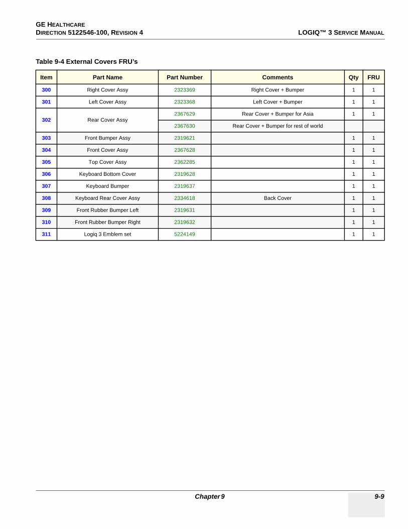
GE HEALTHCARE DIRECTION 5122546-100, REVISION 4 LOGIQ™ 3 SERVICE MANUAL
Table 9-4 External Covers FRU’s
Item Part Name Part Number Comments Qty FRU
300 Right Cover Assy 2323369 Right Cover + Bumper 1 1
301 Left Cover Assy 2323368 Left Cover + Bumper 1 1
302 Rear Cover Assy2367629 Rear Cover + Bumper for Asia 1 1
2367630 Rear Cover + Bumper for rest of world
303 Front Bumper Assy 2319621 1 1
304 Front Cover Assy 2367628 1 1
305 Top Cover Assy 2362285 1 1
306 Keyboard Bottom Cover 2319628 1 1
307 Keyboard Bumper 2319637 1 1
308 Keyboard Rear Cover Assy 2334618 Back Cover 1 1
309 Front Rubber Bumper Left 2319631 1 1
310 Front Rubber Bumper Right 2319632 1 1
311 Logiq 3 Emblem set 5224149 1 1
Chapter 9 9-9

GE HEALTHCAREDIRECTION 5122546-100, REVISION 4 LOGIQ™ 3 SERVICE MANUAL
Section 9-7Mechanical Assembly’s
Figure 9-6 Mechanical Assembly FRU’s
Table 9-5 Mechanical Assembly FRU’s
Item Part Name Part Number Comments Qty FRU
400 Handle Rod 2334639 1 1
401 Front Castor 2300021 Common with L5 2 1
402 Rear Castor 2300022 Common with L5 2 1
403 Air Filter 2326158 1 1
404 Card Cage Fan Assy 2350375 DC Fan Assembly 1 1
405 Speaker Set 2319526 1 1
400
401 402
403404
9-10 Section 9-7 - Mechanical Assembly’s

GE HEALTHCARE DIRECTION 5122546-100, REVISION 4 LOGIQ™ 3 SERVICE MANUAL
Section 9-8I/O Interfaces
Figure 9-7 I/O Interfaces FRU’s
Table 9-6 I/O Interfaces FRU’s
Item Part Name Part Number Comments Qty FRU
500 Rear Panel Assembly2319547 Rear Panel Assy - 230VAC 1 1
2383299 Rear Panel Assy - 100/115VAC 1 1
501 RP1 Assembly 2319486 1 1
502 RP2 Assembly 2319488 1 1
503 Rear Panel Interface Assembly 2319484-2 RPI 1 1
504 Front Panel Assembly 2383298 Front Panel Assy - 115VAC 1 1
505 Rear Panel Fuse - 3A 2332968 3A Fuse
505 Rear Panel Fuse - 5A 2361948 5A Fuse 1 1
500 501
502
503
504
505
Front Panel
Chapter 9 9-11

GE HEALTHCAREDIRECTION 5122546-100, REVISION 4 LOGIQ™ 3 SERVICE MANUAL
Section 9-9PCB Boards
Figure 9-8 PCB Boards FRU’S
601602
611603 604
605
608
610
606 607
609
9-12 Section 9-9 - PCB Boards
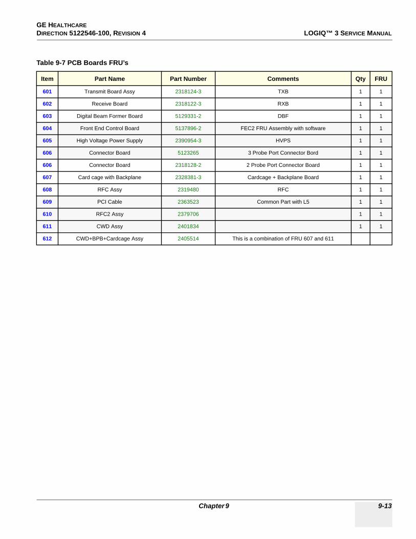
GE HEALTHCARE DIRECTION 5122546-100, REVISION 4 LOGIQ™ 3 SERVICE MANUAL
Table 9-7 PCB Boards FRU’s
Item Part Name Part Number Comments Qty FRU
601 Transmit Board Assy 2318124-3 TXB 1 1
602 Receive Board 2318122-3 RXB 1 1
603 Digital Beam Former Board 5129331-2 DBF 1 1
604 Front End Control Board 5137896-2 FEC2 FRU Assembly with software 1 1
605 High Voltage Power Supply 2390954-3 HVPS 1 1
606 Connector Board 5123265 3 Probe Port Connector Bord 1 1
606 Connector Board 2318128-2 2 Probe Port Connector Board 1 1
607 Card cage with Backplane 2328381-3 Cardcage + Backplane Board 1 1
608 RFC Assy 2319480 RFC 1 1
609 PCI Cable 2363523 Common Part with L5 1 1
610 RFC2 Assy 2379706 1 1
611 CWD Assy 2401834 1 1
612 CWD+BPB+Cardcage Assy 2405514 This is a combination of FRU 607 and 611
Chapter 9 9-13

GE HEALTHCAREDIRECTION 5122546-100, REVISION 4 LOGIQ™ 3 SERVICE MANUAL
Section 9-10BEP
Figure 9-9 PC Block FRU’s
700
Caution: Battery Inside
701
702
703
704
705
:
9-14 Section 9-10 - BEP

GE HEALTHCARE DIRECTION 5122546-100, REVISION 4 LOGIQ™ 3 SERVICE MANUAL
Table 9-8 PC Block FRU’s
Item Part Name Part Number Description Qty FRU
700
BEP3 Assy for S/W 2.X.X 5126610-2 Back End Processor Assy 1 1
BEP3 Assy for S/W 4.0.X 2361975-8 Back End Processor Assy 1 1
BEP4 FRU Assy for S/W 4.1.X 5220185 Back End Processor Assembly 5191287 with USB extender cable 5196002 1 1
701 HDD for S/W 4.X.X 5138280 1 1
702CDRW For BEP 2 - 48x24x48 2381159 1 1
LG Drive: CDRW 2399547-2 1 1
703 Nipron Power Supply for BEP2,BEP3, and BEP4 2399007 1 1
704 PCVIC PCB 2393280 1 1
705
PC2IP PCB for R2.X.X or R4.X.X FB200973, and FC200617 1 1
PC2IP2 PCB for R2.X.X or R4.X.X FB200312, and FC200656 1 1
PC2IP3 PCB For R4.X.X 5220187 PC2IP3(FC200755) with R4.1.X base and application spftware 1 1
CAUTION BEP contains battery above the ATX Power supply. Handle With care during Service & Replacements.Disposal of Battery should follow local Environment Guidelines.
Chapter 9 9-15

GE HEALTHCAREDIRECTION 5122546-100, REVISION 4 LOGIQ™ 3 SERVICE MANUAL
Section 9-11Power Block
.
Figure 9-10 Power Block FRU’s
Table 9-9 Power Block FRU’s
Item Part Name Part Number Description Qty FRU
800 Transformer Assy 2406958 Transformer Assy 1 1
801 LVPS 2319545-2 Low Voltage Power Supply 1 1
802 ACI Assembly 2319490-2 AC Interface Board 1 1
803 Transformer Fuse 2361948 1 1
804 Circuit Breake and Guardr 2405517 1 1
805 Noise Filter 2319501 1 1
NOTICEReplace Circuit Breaker and Noise Filter in case of transformer failureRefer Disassy procedure of Circuit Breaker and noise filter.
800 802
801803
804
Circuit Breaker
9-16 Section 9-11 - Power Block

GE HEALTHCARE DIRECTION 5122546-100, REVISION 4 LOGIQ™ 3 SERVICE MANUAL
Section 9-12Power Cord
Section 9-13Probes
NOTE: * Indicates Probe Exclusive to LOGIQ 3 EXPERT
Table 9-10 Power Cord
Item Part Name Part Number Description Qty FRU
900 Power Cord Assy 2365878 Power Cord - Japan 1 1
901 Power Cord Assy 2343034 Power Cord - India 1 1
902 Power Cord Assy 2342033 Power Cord - Europe 1 1
903 Power Cord Assy 2334499 Power Cord - USA 1 1
904 Power Cord Assy 5137225 POWER CORD - CHINESE 230V WITH CCC MARK 1 1
Table 9-11 Probes
Item Part Name Part Number Description Qty FRU
1000 3C 2286354 Convex Probe 1 2
1001 5C 2294516 Convex Probe 1 2
1002 E8C 2294641 Micro Convex Probe 1 2
1003 10LB 2253846 Linear Probe 1 2
1004 3S 2323337 Sector Probe 1 2
1005 3.5C 2296158 Convex Probe 1 2
1006 7S 2263669 Sector Probe 1 2
1007 10L* 2294523 Linear Probe 1 2
1008 12L Probe* 2295377 Linear Probe 1 2
1009 8C Probe* 2348094 Convex Probe 1 2
1010 BE9C* 2389382 Convex Probe 1 2
1011 8L** 5140738 Linear 1 2
Chapter 9 9-17

GE HEALTHCAREDIRECTION 5122546-100, REVISION 4 LOGIQ™ 3 SERVICE MANUAL
Section 9-14Peripherals
Section 9-15Cables Set
Table 9-12 Peripherals
Item Part Name Part Number Description Qty FRU
1100 SVO-9500MD Local Sony VCR 1 2
1101 SVO-9500MDP Local Sony VCR 1 2
1102 AG-MD835P Local Panasonic VCR 1 2
1103 AG-MD835E Local Panasonic VCR 1 2
1104 UP-895MDW Local Sony B/W Printer 1 2
1105 UP- UPD895 USB Local Sony B/W Printer 1 2
1106 Model P91W Local Mitsubishi B&W Printer 1 2
1107 UP-21MD Local Sony Color Printer 1 2
1108 UP-21MD USB Local Sony Color Printer 1 2
1109 UP-23MD USB Local Sony Color Printer 1 1
1110 CP-900UM Local Mitsubishi Color Printer 1 2
1111 UP-51MD Local Sony Color Printer 1 2
1112 HP 990CXi Local HP PC Printer 1 2
1113 HP 6122 Local HP PC Printer
1114 HP 5652 Local HP PC Printer
1115 CP-900E Local Mitsubishi Color Printer 1 2
1116 CP-CP-900DW Local Mitsubishi Color Printer 1 2
1117 256MB USB 2.0 Flash memory Local Transcend-JetFlashTS256M 1 2
1118 512MB USB 2.0 Flash memory Local Kingston-Data traveller 2.0 1 2
1119 UP-897MDW Local Sony B/W Printer 1 2
1120 UP-D897MD Local Sony B/W Printer 1 2
1121 P93DW Local Mitsubishi B&W Printer 1 2
1122 HP K550 Local HP Office PRO 1 2
Table 9-13 Cables Set - 2367627
Item Part Name Part Number Description Qty FRU
1200 Cable Set 2367627 1 1
9-18 Section 9-14 - Peripherals

GE HEALTHCARE DIRECTION 5122546-100, REVISION 4 LOGIQ™ 3 SERVICE MANUAL
Section 9-16Option Parts
Table 9-14 Option Parts
Item Part Name Part Number Description Qty FRU
1300 ECG Cable Hook 2283028 1 1
1301 ECG Cable Assembly 37 2319535 1 1
1302 Cable Set for B/W Printer 2369943 1 1
1303 Cable Set for B/W Digital Printer 2367622 1 1
1304 Cable Set for Analog Color Printer 2369944 1 1
1305 Cable Set for Digital Color Printer 2367621 1 1
1306 Cable Set for Sony VCR 2367618 1 1
1307 Cable Set for Panasonic VCR 2367620 1 1
1308 VGP Tray for Logiq 3 2334260 1 1
1309 VGP Tray Cover for Logiq 3 2352823 1 1
1310 Color Printer Mounting Plate - A 2377612 1 1
1311 Color Printer Mounting Plate - B 2377613 1 1
1312 VCR Mounting Tray for Logiq 3 2380864 1 1
1313 VCR Mounting Tray Bracket for Logiq 3 2380866 1 1
1314 Global Modem Kit 2245794 1 1
1315 ECG Patient I/O Module FA200801 1 1
1316 THI Board 2288838-2 1 1
1317 Additional Probe port Adapter 2334993 1 1
1318 Foot Switch for Logiq 3 FB200952 1 1
1319 MOD Top Mounting Plate 2380861 1 1
1320 MOD Bottom Mounting Plate 2380862 1 1
1321 MOD for Logiq 3 2384284 1 1
1322 MOD Power Supply 2384285 1 1
1323 Russian Language Kit 2331768 1 1
1324 Greek Langyage Kit 2331769 1 1
1325 PGC Microphone for Logiq 3 2326844 1 1
1326 Cable ECG Marquette IEC 164L0026 1 1
1327 Leadwires ECG Marquette IEC 164L0028 1 1
Chapter 9 9-19
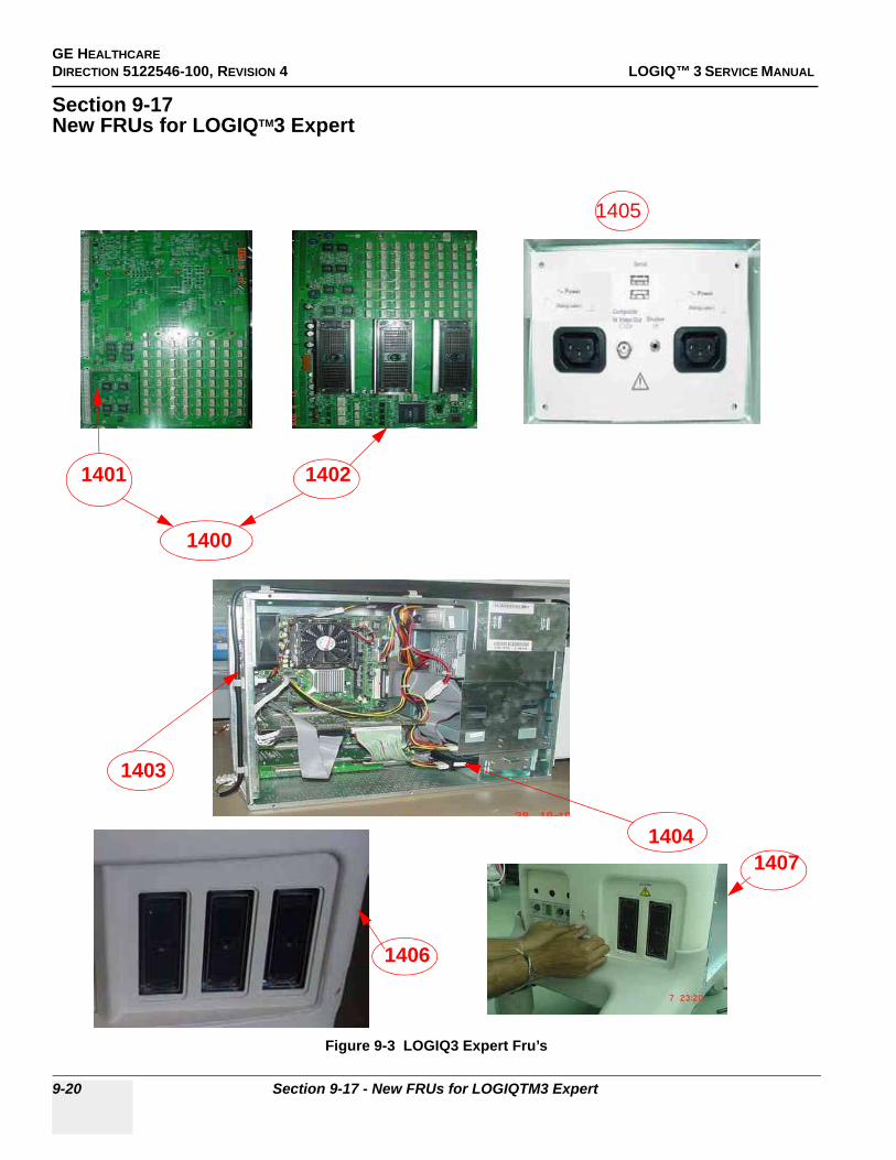
GE HEALTHCAREDIRECTION 5122546-100, REVISION 4 LOGIQ™ 3 SERVICE MANUAL
Section 9-17New FRUs for LOGIQTM3 Expert
Figure 9-3 LOGIQ3 Expert Fru’s
1403
1405
1404
1406
1407
1401 1402
1400
9-20 Section 9-17 - New FRUs for LOGIQTM3 Expert

GE HEALTHCARE DIRECTION 5122546-100, REVISION 4 LOGIQ™ 3 SERVICE MANUAL
9-17-1 Hardware FRU’s for LOGIQ3 BT’05
Section 9-18Software FRU’s for LOGIQ3 Expert/PRO/Black and White
Table 9-2 LOGIQ3 BT’05 Hardware FRU’s
Item Part Name Part Number Description Qty FRU
1400 Standard 3 Port connector board Assembly - Main PCB and Piggy PCB 5123265 1401 and 1402 forms 1400 FRU 1 2
1401 Main board Assembly for Standard 3 port connector board 5119271 1 2
1402 Piggy PCB for Standard 3 port Connector Board Assembly 5117473 1 2
1403
Logiq 3 BEP3 with 80 GB Hard Disk , Additional USB support, PC2IPII Rev 4 and 2.8 GHZ Processor for Software
4.0.X
2361975-8 1 2
BEP4 Back End Processor for L3 S/W 4.2.0 with D865GSA 5220185 1 2
1404 ST380011A SEAGATE 80 GB 7400 RPM HARDDISK FOR LOGIQ 3 5237487 1 2
1405 Dual Power Dual USB Front Panel - for Logiq 3 5121498 1 2
1406 Front-cover-3PP for L3 5116278 1 2
1407 Front-bumper-3PP for L3 5116279 1 2
1408 VCR FIXTURE FOR MITSUBISHI-MD3000 5136090 1 2
1409 VCR FIXTURE BRACKET FOR MITSUBISHI-MD3000 5136091 1 2
1410 Logiq3 BT05 USB cable Asm FRU 5141575 1 2
Table 9-1 Software FRU’s For LOGIQ 3 Expert/PRO/Black and White
Item Part Name Part Number Description Qty FRU
1411 Logiq 3 Expert BT05 Application Software for software R4.2.0 5133116-4 1 2
1412 Logiq 3 PRO BT05 Application Software for software R4.1.2 5140654-4 1 2
1413 Logiq 3 Black and White BT05 Application Software for software R4.1.2 5140661-3 1 2
1414 Base Image software for BEP2 with Intel865 Motherboard for Logiq 3 BT05 5120163-2 1 2
1415 Base Image software for BEP3 with Intel865 Motherboard for Logiq 3 BT05 5120166-3 1 2
1416 Base Image software for BEP4 for Logiq 3 BT05 5193870 1 2
Chapter 9 9-21

GE HEALTHCAREDIRECTION 5122546-100, REVISION 4 LOGIQ™ 3 SERVICE MANUAL
9-22 Section 9-18 - Software FRU’s for LOGIQ3 Expert/PRO/Black and White

GE HEALTHCARE DIRECTION 5122546-100, REVISION 4 LOGIQ™ 3 SERVICE MANUAL
Chapter 10Care & MaintenanceSection 10-1Overview
10-1-1 Periodic Maintenance InspectionIt has been determined by engineering that your LOGIQ™ 3 system does not have any high wear components that fail with use, therefore no Periodic Maintenance Inspections are mandatory. Some Customers Quality Assurance Programs may require additional tasks and or inspections at a different frequency than listed in this manual.
10-1-2 Purpose of Chapter 10This chapter describes Care & Maintenance (PM) on the scanner and its peripherals. These PM procedures are intended to maintain the quality of the ultrasound systems performance. Read this chapter completely and familiarize yourself with the procedures before starting a PM.
CONTENTS IN CHAPTER 10
Table 10-1 Contents in Chapter 10
Section Description Page Number
10-1 Overview 10-1
10-2 Why do Maintenance 10-2
10-3 Periodic Maintenance Schedule 10-2
10-4 Tools Required 10-4
10-5 System Maintenance 10-7
10-6 Electrical Safety Tests 10-12
10-7 When There's Too Much Leakage Current... 10-28
PM Inspection Certificate 10-29
CAUTION Practice good ESD prevention. Wear an anti–static strap when handling electronic parts and even when disconnecting/connecting cables.
DANGER THERE ARE SEVERAL PLACES ON THE BACKPLANE, THE AC DISTRIBUTION, AND DC DISTRIBUTION THAT ARE DANGEROUS. BE SURE TO DISCONNECT THE SYSTEM POWER PLUG AND OPEN THE MAIN CIRCUIT BREAKER BEFORE YOU REMOVE ANY PARTS. BE CAUTIOUS WHENEVER POWER IS STILL ON AND COVERS ARE REMOVED.
CAUTION Do not pull out or insert circuit boards while power is ON.
Chapter 10 10-1

GE HEALTHCAREDIRECTION 5122546-100, REVISION 4 LOGIQ™ 3 SERVICE MANUAL
Section 10-2Why do Maintenance
10-2-1 Keeping RecordsIt is good business practice that ultrasound facilities maintain records of quality checks and corrective maintenance. The Ultrasound Inspection Certificate(Provided on Page 10-29) provides the customer with documentation that the ultrasound scanner is maintained on a periodic basis.
A copy of the Ultrasound Periodic Maintenance Inspection Certificate should be kept in the same room or near the scanner.
10-2-2 Quality AssuranceIn order to gain accreditation from organizations such as the American College of Radiology (USA), it is the customer’s responsibility to have a quality assurance program in place for each scanner. The program must be directed by a medical physicists, the supervising radiologist/physician or appropriate designee.
Routine quality control testing must occur regularly. The same tests are performed during each period so that changes can be monitored over time and effective corrective action can be taken.
Testing results, corrective action and the effects of corrective action must be documented and maintained on the site.
Your GE service representative can help you with establishing, performing and maintaining records for a quality assurance program. Please contact us for coverage information and/or price for service.
Section 10-3Periodic Maintenance Schedule
10-3-1 How often should care & maintenance tasks be performed?The Care & Maintenance Task Schedule (provided on page 10-3) specifies how often your LOGIQ™ 3 should be serviced and outlines items requiring special attention.
NOTE: It is the customer’s responsibility to ensure the LOGIQ™ 3 care & maintenance is performed as scheduled in order to retain its high level of safety, dependability and performance.
Your GE Service Representative has an indepth knowledge of your LOGIQ™ 3 ultrasound scanning system and can best provide competent, efficient service. Please contact us for coverage information and/or price for service.
The service procedures and recommended intervals shown in the Care and Maintenance Task schedule assumes that you use your LOGIQ™ 3 for an average patient load (10-12 per day) and not used as a primary “mobile unit” which is transported between diagnostic facilities.
If conditions exist which exceed typical usage and patient load, then it is recommended to increase the periodic maintenance frequencies
NOTE: If conditions exist which exceed typical usage and patient load, then it is recommended to increase the maintenance frequencies.
10-2 Section 10-2 - Why do Maintenance

GE HEALTHCARE DIRECTION 5122546-100, REVISION 4 LOGIQ™ 3 SERVICE MANUAL
Table 10-2 Customer Care Schedule
Service at Indicated Time Daily Weekly Monthly Annually Notes
Clean Probes •* * or before each use
Clean Probe Holders •
Clean Air Filter • more frequently depending on your environment
Inspect AC Mains Cable • Mobile Unit Check Weekly
Inspect Cables and Connectors •Clean Console •Clean Monitor •Inspect Wheels, Casters, brakes and Swivel Locks • Mobile Unit Check Daily
Console Leakage Current Checks • also after corrective maintenance
Peripheral Leakage Current Checks • also after corrective maintenance
Surface Probe Leakage Current Checks • also after corrective maintenance
Endocavity Probe Leakage Current Checks
TwiceAnnually
Surgical Probe Leakage Current Checks
As Prescribedin probe manual
Measurement Accuracy Checks • also after corrective maintenance
Probe/Phantom Checks • also after corrective maintenance
Chapter 10 10-3

GE HEALTHCAREDIRECTION 5122546-100, REVISION 4 LOGIQ™ 3 SERVICE MANUAL
Section 10-4 Tools Required
10-4-1 Standard GE Tool KitThe following is a description of the “Standard” GE tool kit in the USA. Not all tools are required for PMs.
Table 10-3 Overview of GE-1 Tool Kit Contents
Tool ID Description Tool ID Description
9-45358 Pliers Retaining Ring 9-XL9971MM Xcelite-hex Blade 1.27mm
9-4078 Scribe 9-XL9972MM Xcelite-hex Blade 1.5mm
9-44572 Wrench Open End 3/8 - 7/16 9-XL9973MM Xcelite-hex Blade 2 mm
9-44579 Wrench Open End 1/2 - 9/16 9-XL9974MM Xcelite-hex Blade 2.5mm
9-44579 Wrench Open End 1/2 - 9/16 9-XL9975MM Xcelite-hex Blade 3mm
9-45385 Pliers, Arc Joint 7 inch 9-XL9976MM Xcelite-hex Blade 4mm
9-45378 Pliers, Slip Joint 9-XL9977MM Xcelite-hex Blade 5mm
9-4518 Pliers, Long Nose, Miniature 9-XL991CM Handle
9-4518 Pliers, Long Nose, Miniature C2356E Screw starter - Kedman Quick Wedge
9-44776 Ignition Wrench Set, 10 pc. BLBO Box - 18 Compartment
9-44601 Wrench, Adj., 4 inch DWL4283T Box - 5 Compartment
9-4151 Screwdriver, Blade, Stubby 9-41322 Pickup Tool, Claw type
9-41421 Screwdriver, Blade, Pocket clip 9-6757 6 pc Needle File Set
9-41594 Screwdriver, Blade 1/8 in. x 4 in. 9-9487 Utility Knife
9-41581 Screwdriver, Blade 3/16 in. x 4 in. 9-45341 Pliers Vice Grip 10 inch
9-39451 20' Steel Tape, locking Spring load 9-3001 Xacto Pen Knife
9-GH807 Ratchet, Offset, Slotted 9-HT62002 Solder Aid, Fork and Hook
68-412 Ratchet, Offset, Phillips 9-4099 Mirror, Round, Telescoping
9-GH130 Tapered Reamer 9-GH3001 Steel Rule Decimal 6 inch
9-41584 Screwdriver, slotted 1/4 in.X 6 in. 9-GH300ME Steel Rule Metric 6 inch
9-4118 Screwdriver, Phillips #2, Stubby 9-XL9920 Xcelite-hex Blade.050 inch
9-41293 Screwdriver, Phillips #0 9-XL9921 Xcelite-hex Blade 1/16 inch
9-41294 Screwdriver, Phillips #1 9-XL9922 Xcelite-hex Blade 5/16 inch
9-41295 Screwdriver, Phillips #2 9-XL9923 Xcelite-hex Blade 3/32 inch
9-46677 Hex Keys, 20 pc., Metric 9-XL9924 Xcelite-hex Blade 1/8 inch
9-34701 1/4 in. Standard.Socket set (19 pc) 9-XL9925 Xcelite-hex Blade 5/32 inch
9-43499 1/2 inch Socket 1/4 inch drive 9-XL9926 Xcelite-hex Blade 3/16 inch
9-4355 Flex Spinner 9-XL99764 Xcelite-hex Blade 7/64
9-43523 Breaker 9-XL99964 Xcelite-hex Blade 9/64
9-43531 6 inch Ext. 9-XLM60 Mini-screwdriver kit
10-4 Section 10-4 - Tools Required

GE HEALTHCARE DIRECTION 5122546-100, REVISION 4 LOGIQ™ 3 SERVICE MANUAL
9-65283 Case 8.5 in. x 4.5 in. x 2 in. Deep 9-45072 Pliers 6 inch Diagonal
9-46696 Hex Keys 9-XL100X Wire Stripper/Cutter 5 inch - 100X
9-39829 Torpedo Level, Magnetic 9-XL87CG Pliers - very fine needle nose-87CG
9-38461 Hammer, Ball Peen, 4 oz 9-WEWDT-07 Weller-Soldering-Replacement Tip(1)
9-4280 Universal Joint 1/4 inch 9-WS175-E Wiss - Surgical Scissors
9-WEW60P3 Weller - Soldering Iron, 3 wire KH174 Hemostat 5 inch Straight
9-WECT5B6 Weller - Soldering Iron Tip KH175 Hemostat 5 inch curved
9-WEWDP12 Weller - Desoldering Pump 9-Z9480121 Alignment tool (red)
93383 Flashlight Mini-Mag Lite (AAA Bat.)
9-GH408 Tweezers
21576 Brush - Bristle
9-4516 Pliers 4 1/4 inch Diagonal
Table 10-4 Overview of GE-2 Tool Kit Contents
GE-2 Sears Kit (#99034)
Tool ID Description Tool ID Description
9-45381 Pliers, Arc Joint 9 1/2 inch 9-44067 Socket 1 1/16 in. for 1/2 in. drive
9-45092 Pliers, Linesman 8 1/2 inch 9-42679 Socket 10MM Hex for 1/2 in. drive (2273333)
9-42882 Punch, Pin 3/32 inch 9-44262 Extension 10 inch for 1/2 in. drive (2273405)
9-42884 Punch, Pin 5/32 inch 9-4258 3/8 inch to 1/2 inch Adapter
9-42886 Punch, Pin 1/4 inch 9-34374 3/8 inch Metric Socket Set - 12 PT
9-42973 Cold Chisel 1/2 inch 9-44311 16mm Socket 12 pt.
9-GH77 Center Punch Automatic 9-33485 Metal Socket Tray
9-GH890 File Handle, Adj. 9-33484 Metal Socket Tray
9-31276 File, Round, Bastard 8 inch 9-33484 Metal Socket Tray
9-31277 File, Half Round, Bastard 8 inch 9-52068 Tap and Drill Set
9-31263 File, Flat Mill 8 inch 9-52722 #6 Tap
21045C Close Quarter Saw 9-52723 #8 Tap
9-44604 Wrench, Adj 10 inch High Speed Drill Set
9-41587 Screwdriver 5/16 inch x 8 inch #36 Drill
9-41586 Screwdriver, Stubby 5/16 inch #29 Drill
9-GH19512 Countersink 1/2 inch 9-44046 3/8 inch Socket Set
9-44741 12 PC Combination Wrench Set
Table 10-3 Overview of GE-1 Tool Kit Contents (Continued)
Tool ID Description Tool ID Description
Chapter 10 10-5

GE HEALTHCAREDIRECTION 5122546-100, REVISION 4 LOGIQ™ 3 SERVICE MANUAL
10-4-2 Special Tools, Supplies and Equipment
10-4-2-1 Specific Requirements for Care & Maintenance
Table 10-5 Overview of Requirements for Periodic Maintenance
Tool Part Number Comments
Digital Volt Meter (DVM)
Leakage Current Ultrasound Kit 2113015 For 120V and 220V Units
Anti Static Kit
46–194427P23146–194427P27946–194427P36946–194427P37346–194427P370
Kit includes anti–static mat, wrist strap and cables for 200 to 240 V system3M #2204 Large adjustable wrist strap3M #2214 Small adjustable wrist strap3M #3051 conductive ground cord
Anti Static Vacuum Cleaner46–194427P27846–194427P279
120V230V
Air Filter See Chapter 9 air intake
Safety Analyzer 46–285652G1 DALE 600 KIT (or equivalent) for electrical tests
SVHS VCR CassetteE7010GGE7010GF
60 minute120 minute
SVHS VCR Head Cleaner See VCR user manual for requirements
QIQ Phantom E8370RB RMI Grayscale Target Model 403GS
CD-RW Media For LOGIQ™ 3
B/W Printer Cleaning Sheet See printer user manual for requirements
Color Printer Cleaning Sheet See printer user manual for requirements
Disposable Gloves
10-6 Section 10-4 - Tools Required

GE HEALTHCARE DIRECTION 5122546-100, REVISION 4 LOGIQ™ 3 SERVICE MANUAL
Section 10-5System Maintenance
10-5-1 Preliminary ChecksThe preliminary checks take about 15 minutes to perform. Refer to the system user documentation whenever necessary.
Table 10-6 System Checks
Step Item Description
1 Ask & Listen Ask the customer if they have any problems or questions about the equipment.
2 Paperwork Fill in the top of the Ultrasound Inspection Certificate(see page 10-29). Note all probes and system options.
3 Power up Turn the system power on and verify that all fans and peripherals turn on. Watch the displays during power up to verify that no warning or error messages are displayed.
4 Probes Verify that the system properly recognizes all probes.
5 Displays Verify proper display on the monitor
6 Presets Backup all customer presets on an CD-R.
Chapter 10 10-7

GE HEALTHCAREDIRECTION 5122546-100, REVISION 4 LOGIQ™ 3 SERVICE MANUAL
10-5-2 Functional Checks (See Also Chapter 4)The functional checks take about 60 minutes to perform. Refer to the system user documentation whenever necessary.
10-5-2-1 System Checks
NOTE: * Some software may be considered standard depending upon system model configuration.
Table 10-7 System Functional Checks
÷ Step Description
B-Mode Verify basic B-Mode (2D) operation. Check the basic system controls that affect this mode of operation.
CF-Mode Verify basic CF-Mode (Color Flow Mode) operation. Check the basic system controls that affect this mode of operation.
Doppler Modes Verify basic Doppler operation (PW). Check the basic system controls that affect this mode of operation.
M-Mode Verify basic M-Mode operation. Check the basic system controls that affect this mode of operation.
*Applicable Software Options
Verify the basic operation of all optional modes such as Multi-Image, 3D (Option), Harmonics (Option), Cine, etc. Check the basic system controls that affect each options operation.
Probe Elements Perform an Element Test, on each probe to verify that all probe elements (and system channels) are functional.
System Diagnostic Perform the Automatic Tests, to verify that all boards function according to specifications.
Control Panel Test Perform the Control Panel Test Procedure, to verify that all keyboard controls are OK. This is performed by the internal PC (backend processor) which does a normal keyboard run through.
Monitor Verify basic Monitor display functions. Refer to Chapter 3 of the User Manual.
Measurements Scan a gray scale phantom and use the measurement controls to verify distance and area calculation accuracy. Refer to the User Manual, Chapter 18, for measurement accuracy specifications.
10-8 Section 10-5 - System Maintenance

GE HEALTHCARE DIRECTION 5122546-100, REVISION 4 LOGIQ™ 3 SERVICE MANUAL
10-5-2-2 Peripheral/Option ChecksIf any peripherals or options are not part of the system configuration, the check can be omitted. Refer to the User Manual for a list of approved peripherals/options.
10-5-3 Input Power
10-5-3-1 Mains Cable Inspection
10-5-4 Cleaning
10-5-4-1 General Cleaning
Table 10-8 GE Approved Peripheral/Hardware Option Functional Checks
Step Item Description
1 VCR Verify record/playback capabilities of the VCR. Clean heads and covers if necessary.
2 B/W Printer Verify hardcopy output of the B/W video page printer. Clean heads and covers if necessary.
3 Color Printer Verify hardcopy output of the Color video page printer. Clean heads and covers if necessary.
4 DICOM Verify that DICOM is functioning properly. Send an image to a DICOM device.
5 InSite/iLinq Verify that InSite is functioning properly. Ensure two-way remote communications.(Warranty & Contract Customers only)
6 Camera Verify hardcopy output of the film camera. Clean as necessary.
7 Footswitch Verify that the footswitch is functioning as programed. Clean as necessary.
8 ECG Verify basic operation with customer
Table 10-9 Mains Cable Inspection
Step Item Description
1 Unplug Cord Disconnect the mains cable from the wall and system.
2 Inspect Inspect it and its connectors for damage of any kind.
3 Verify Verify that the LINE, NEUTRAL and GROUND wires are properly attached to the terminals, and that no strands may cause a short circuit.
4 Verify Inlet connector retainer is functional.
Table 10-10 General Cleaning
Step Item Description
1 Console Use a fluid detergent in warm water on a soft, damp cloth to carefully wipe the entire system. Be careful not to get the cloth too wet so that moisture does not enter the console.
2 Probe Holder Clean probe holders (they may need to be soaked to remove excess gel).
3 Monitor TBDFor monitor, use a non-ammonia (just isopropyl and water) lens cleaner. These are available at most computer outlet stores. DO NOT use Windex, Screen-Clean, etc., because these contain ammonia, which will remove the anti-glare coating on the monitor.
Chapter 10 10-9

GE HEALTHCAREDIRECTION 5122546-100, REVISION 4 LOGIQ™ 3 SERVICE MANUAL
10-5-4-2 Air Filter Cleaning \
NOTE: For your convenience or of the air filter is too dirty, replacement filters are available. Refer to Chapter 9 for the air filter replacement part number.
10-5-5 Physical Inspection
Table 10-11 Air Filter Cleaning - frequency varies with your environment
Step Item Description
1 Remove Filter Cover Refer to Chapter 8 for air filter location and removal instructions.
2 Clean Filter The filters can be cleaned in sprinkling water, or they can be dusted with a vacuum cleaner. If the filter is metal wash and/or vacuum. If the filter is fiber or plastic vacuum or replace.
3 Install Filter Install the clean filter.
Table 10-12 Physical Checks
Step Item Description
1 Labeling Verify that all system labeling is present and in readable conditionRefer to the User Manual 2300750 for details.
2 Scratches & Dents Inspect the console for dents, scratches or cracks.
3 Control Panel Inspect keyboard and control panel. Note any damaged or missing items.
4 Control Panel Movement
Verify ease of control panel (Operator I/O Panel) movement in all acceptable directions. Ensure that it latches in position as required.
5 Wheels & Brakes Check all wheels and casters for wear and verify operation of foot brake, to stop the unit from moving, and release mechanism. Check all wheel locks and wheel swivel locks for proper operation.
6 Cables & Connectors
Check all internal cable harnesses and connectors for wear and secure connector seating. Pay special attention to footswitch assembly and probe strain or bend reliefs.
7 Shielding & Covers
Check to ensure that all EMI shielding, internal covers, air flow panels and screws are in place. Missing covers and hardware could cause EMI/RFI problems while scanning.
8 External I/O Check all connectors for damage and verify that the labeling is good.
9 Op Panel Lights Check for proper operation of all operator panel and TCG lights.
10 Monitor Light Check for proper operation of any monitor lights if available.
10-10 Section 10-5 - System Maintenance

GE HEALTHCARE DIRECTION 5122546-100, REVISION 4 LOGIQ™ 3 SERVICE MANUAL
10-5-6 Optional Diagnostic ChecksOptionally you can access the diagnostic software as described in Chapters 5 or 7. View the error logs and run desired diagnostics.
10-5-6-1 View the Logs
1.) Review the system error log for any problems.2.) Check the temperature log to see if there are any trends that could cause problems in the future.3.) Check the Configuration Log; update if needed.
10-5-7 Probe Maintenance
10-5-7-1 Probe Related Checks
10-5-7-2 Basic Probe CareThe system user manuals and various probe handling cards provide a complete description of probe care, maintenance, cleaning and disinfection. Ensure that you are completely familiar with the proper care of GE probes.
Ultrasound probes can be easily damaged by improper handling. See the User Manual and probe care cards for more details. Failure to follow these precautions can result in serious injury and equipment damage. Failure to properly handle or maintain a probe may also void its warranty.
Any evidence of wear indicates the probe cannot be used.
Do a visual check of the probe pins and system sockets before plugging in a probe.
TEE and Interoperative probes often have special considerations and individual probe user manuals. For TEE and Interoperative probes also refer to their separate user manuals.
10-5-7-3 Basic Probe CleaningRefer to the User’s Manual for details on probe cleaning.
NOTE: To help protect yourself from blood borne diseases, wear approved disposable gloves. These are made of nitrile derived from vegetable starch to prevent allergic latex reactions.
NOTE: Failure to follow the prescribed cleaning or disinfection procedures will void the probe’s warranty. DO NOT soak or wipe the lens with any product not listed in the User Manual. Doing so could result in irreparable damage to the probe. Follow care instructions that came with the probe.
NOTE: Disinfect a defective probe before you return it. Be sure to tag the probe as being disinfected.
Table 10-13 Probe Related Checks
Step Item Description
1 Probe Holder Clean probe holders (they may need to be soaked to remove excess gel).
2 Probes Thoroughly check the system probe connectors and remove dust from inside the connector sockets if necessary. Visually check for bent, damaged or missing pins
Chapter 10 10-11

GE HEALTHCAREDIRECTION 5122546-100, REVISION 4 LOGIQ™ 3 SERVICE MANUAL
Section 10-6Electrical Safety Tests
10-6-1 Safety Test OverviewThe electrical safety tests in this section are based on and conform to NFPA 99 (For USA) and IEC/EN 60601-1 Medical Equipment Safety Standards. They are intended for the electrical safety evaluation of cord-connected, electrically operated, patient care equipment. If additional information is needed, refer to the NFPA 99 (For USA) and IEC/EN 60601-1 documents.
Test the system, peripherals and probes for leakage current. Excessive leakage current can cause injury or death in sensitive patients. High leakage current can also indicate degradation of insulation and a potential for electrical failure. Do not use probes or equipment having excessive leakage current.
To minimize the risk that a probe may shock someone the customer should:
• Not use a probe that is cracked or damaged in any way• Check probe leakage current:
* once a year on surface probes* twice a year on endocavitary probes* whenever probe damage is suspected
WARNINGWARNINGTHE USER MUST ENSURE THAT THE SAFETY INSPECTIONS ARE PERFORMED AT LEAST EVERY 12 MONTHS ACCORDING TO THE REQUIREMENTS OF THE PATIENT SAFETY STANDARD IEC-EN 60601-1. ONLY TRAINED PERSONS ARE ALLOWED TO PERFORM THE SAFETY INSPECTIONS MENTIONED ABOVE.
CAUTION To avoid electrical shock, the unit under test must not be connected to other electrical equipment. Remove all interconnecting cables and wires. The unit under test must not be contacted by users or patients while performing these tests.
CAUTION Possible risk of infection. Do not handle soiled or contaminated probes and other components that have been in patient contact. Follow appropriate cleaning and disinfecting procedures before handling the equipment.
10-12 Section 10-6 - Electrical Safety Tests

GE HEALTHCARE DIRECTION 5122546-100, REVISION 4 LOGIQ™ 3 SERVICE MANUAL
10-6-2 GEMS Leakage Current LimitsThe following limits are summarized for NFPA 99 (For USA), IEC 60601-1 Medical Equipment Safety Standards, and IEC 62353 Medical Electrical Equipment — Recurrent test and test after repair of medical electrical equipment. Measurement limits per IEC 60601-1 Medical Equipment Safety Standards, Table IV.
NOTE: *Measurement limits per IEC 60601-1 Medical Equipment Safety Standards, Table 19.5DV.1
**Most meters (like Dale 600/601) measure a composite of the AC and DC leakage current.
Table 10-14 Chassis Leakage Current Limits—Accessible Metal Surfaces
Country Normal Condition Open Ground Open Neutral
USA 0.1 mA 0.3 mA* 0.3 mA
Other 0.1 mA 0.5 mA 0.5 mA
Table 10-15 Type BF Applied Part Leakage Current Limits - Non-Conductive (Floating) Surface and Cavity Probes
All Countries Normal Condition Open Ground Open Neutral
AC 0.1 mA 0.5 mA 0.5 mA
DC** 0.01 mA 0.05 mA 0.05 mA
Table 10-16 Type CF Applied Part Leakage Current Limits - Surgical Probes and ECG Connections
Country Normal Condition Open Ground Open Neutral
USA 0.01 mA 0.05mA 0.05 mA
Other 0.01 mA 0.05 mA 0.05 mA
Chapter 10 10-13

GE HEALTHCAREDIRECTION 5122546-100, REVISION 4 LOGIQ™ 3 SERVICE MANUAL
10-6-3 Outlet Test - Wiring Arrangement - USA & CanadaTest all outlets in the area for proper grounding and wiring arrangement by plugging in the neon outlet tester and noting the combination of lights that are illuminated. Any problems found should be reported to the hospital immediately and the receptacle should not be used.
The Dale 600 has self-contained lamps designed for testing the outlet wiring arrangement. Plug the Dale 600 into each outlet to be tested comparing the lamp status.
NOTE: No outlet tester can detect the condition where the Neutral (grounded supply) conductor and the Grounding (protective earth) conductor are reversed. If later tests indicate high leakage currents, this should be suspected as a possible cause and the outlet wiring should be visually inspected.
Figure 10-1 Typical Alternate Outlet Tester
Figure 10-2 Dale 600 Outlet Test
Combination of
Lights
Condition CORRECTWIRING
REVERSEPOLARITY
OPENGROUND
OPENHOT
HOT/GROUNDREVERSED
10-14 Section 10-6 - Electrical Safety Tests

GE HEALTHCARE DIRECTION 5122546-100, REVISION 4 LOGIQ™ 3 SERVICE MANUAL
10-6-4 Grounding Continuity
Measure the resistance from the third pin of the attachment plug to the exposed metal parts of the case. The ground wire resistance should be less than 0.2 ohms. Reference the procedure in the IEC 601-1.1.
10-6-4-1 Meter ProcedureFollow these steps to test the ground wire resistance.
1.) Turn the LOGIQ™ 3 unit OFF.2.) Plug the unit into the meter, and the meter into the tested AC wall outlet.3.) Plug the black chassis cable into the meter's “CHASSIS” connector and attach the black chassis
cable clamp to an exposed metal part of the LOGIQ™ 3 unit.4.) Set the meter's “FUNCTION” switch to the RESISTANCE position.5.) Set the meter's “POLARITY” switch to the OFF (center) position.6.) Measure and record the ground wire resistance.
CAUTION Electric Shock Hazard. The patient must not be contacted to the equipment during this test
Figure 10-3 Ground Continuity Test
Chapter 10 10-15

GE HEALTHCAREDIRECTION 5122546-100, REVISION 4 LOGIQ™ 3 SERVICE MANUAL
10-6-4-2 Dale 600 - Ground ContinuityThe Dale 600 measures line cord resistance from the third pin of the attachment plug to the meter’s Chassis Cable clamp. Test the grounding continuity of the system to all exposed metal parts in accordance with the IEC 601-1.1 procedure as above. Refer to the Dale 600 Instruction Manual for meter self tests and operation. Record measured resistance of the grounding continuity. The ground wire resistance should be less than 0.2 (Use any safety analyzer.)
Figure 10-4 Dale 600 Ground Continuity Test
ChassisCableClamp
NormalReversePolarity
NeutralOpen/Closed
FunctionsSelector
Outlet TestLamps
10-16 Section 10-6 - Electrical Safety Tests

GE HEALTHCARE DIRECTION 5122546-100, REVISION 4 LOGIQ™ 3 SERVICE MANUAL
10-6-5 Chassis Leakage Current Test
10-6-5-1 DefinitionThis test measures the current that would flow in a grounded person who touched accessible metal parts of the bedside station if the ground wire should break. The test verifies the isolation of the power line from the chassis. The meter is connected from accessible metal parts of the case to ground. Measurements should be made with the unit On and Off, with the power line polarity Normal and Reversed. Record the highest reading.
10-6-5-2 Generic ProcedureThe test verifies the isolation of the power line from the chassis. The testing meter is connected from accessible metal parts of the case to ground. Measurements should be made with the unit ON and OFF, with the power line polarity Normal and Reversed. Record the highest reading of current.
When using the Microguard or a similar test instrument, its power plug may be inserted into the wall outlet and the equipment under test is plugged into the receptacle on the panel of the meter. This places the meter in the grounding conductor and the current flowing from the case to ground will be indicated in any of the current ranges. The maximum allowable limit for chassis source leakage is shown in Table 10-14.
CAUTION Electric Shock Hazard. When the meter's ground switch is OPEN, don't touch the unit!
CAUTION Equipment damage possibility. Never switch the Polarity and the status of Neutral when the unit is powered ON. Be sure to turn the unit power OFF before switching them using the POLARITY switch and/or the NEUTRAL switch. Otherwise, the unit may be damaged.
Figure 10-5 Set Up for Chassis Source Leakage Current, IEC 601-1 Clause 19 - Continuos Leakage Currents and Patient, Auxiliary Currents
Chapter 10 10-17

GE HEALTHCAREDIRECTION 5122546-100, REVISION 4 LOGIQ™ 3 SERVICE MANUAL
10-6-5-3 Dale 600 Meter ProcedureWhen measuring system chassis currents with the Dale 600, always use the CHASSIS selection of the external/chassis function switch. This requires the ground clip lead and changing the meters switches in accordance with the IEC 601-1.1. Refer to the Dale 600 Instruction Manual for meter self-test and operation. Record the highest leakage current measured.
Follow these steps to test the unit for leakage current.
1.) Turn the LOGIQ™ 3 unit OFF.2.) Plug the unit into the meter, and the meter into the tested AC wall outlet3.) Plug the black chassis cable into the meter's “CHASSIS” connector and attach the black chassis
cable clamp to an exposed metal part of the LOGIQ™ 3.4.) Set the tester's “FUNCTION” switch to CHASSIS position.
5.) Follow the test conditions described for respective test points shown in Table 10-17.
6.) Keep a record of the results with other hard copies of PM data kept on site.
Figure 10-6 Ground and Chassis Leakage Current Test
Table 10-17 Chassis Leakage Current Test Condition
TEST CONDITION
1 Mounting screw for probe receptacle
2 Wheel support
3 Mounting screw for CRT housing
4 Mounting screw for peripheral plugged into unit
5 Mounting screw for other peripheral powered by unit
ChassisCableClamp
NormalReversePolarity
NeutralOpen/Closed
FunctionsSelector
Outlet TestLamps
10-18 Section 10-6 - Electrical Safety Tests

GE HEALTHCARE DIRECTION 5122546-100, REVISION 4 LOGIQ™ 3 SERVICE MANUAL
al
10-6-5-4 Data Sheet for Chassis Source Leakage CurrentThe test passes when all readings measure less than the value shown in Table 10-14. Record all data on the PM Inspection Certificate.
10-6-6 Isolated Patient Lead (Source) Leakage–Lead to Ground
10-6-6-1 DefinitionThis test measures the current which would flow to ground from any of the isolated ECG leads. The meter simulates a patient who is connected to the monitoring equipment and is grounded by touching some other grounded surface. Measurements should be made with the ground open and closed, with power line polarity normal and reversed, and with the ultrasound console Off and On. For each combination the operating controls, such as the lead switch, should be operated to find the worst case condition.
Table 10-18 Typical Data Sheet for Chassis Source Leakage Current
Unit PowerTester Polarity
Switch
Tester Neutral or Ground
Switch
Test 1 Probe Connector
Screw
Test 2 Metal on Wheel
Test 3 Screws on
CRT Housing
Optional Test 4
Rear PanelConnectors
OptionTest 5
Enter Name of tested peripheral here:
ON NORM OPEN
ON NORM CLOSED
ON REV OPEN
ON REV CLOSED
OFF NORM OPEN
OFF NORM CLOSED
OFF REV OPEN
OFF REV CLOSED
CAUTION Equipment damage possibility. Never switch the Polarity when the unit is powered ON. Be sure to turn the unit power OFF before switching the polarity using the POLARITY switch. Otherwise, the unit may be damaged.
Chapter 10 10-19

GE HEALTHCAREDIRECTION 5122546-100, REVISION 4 LOGIQ™ 3 SERVICE MANUAL
10-6-6-2 Generic ProcedureMeasurements should be made with the ground open and closed, with power line polarity normal and reversed, and with the unit Off and On. For each combination, the operating controls such as the lead switch should be operated to find the worst case condition.
10-6-6-3 Dale 600 Meter ProcedureThe Dale 600 provides five snap type ECG buttons for testing patient leads. Snap on all patient leads to the meter and assure that the ground clip is connected to the system’s ground terminal. Select the meter’s LEAD-GND function. Select and test each ECG lead positions (except “ALL”) of the LEAD selector, testing each to the power condition combinations found in “PATIENT LEAD LEAKAGE” table in the “PM CHECKLIST”. Record the highest leakage current measured for each Power selection.
Follow these steps to test the ECG module for leakage current.
1.) Turn the LOGIQ™ 3 unit OFF.2.) Plug the unit into the meter, and the meter into the tested AC wall outlet.3.) Plug the black chassis cable into the meter's “CHASSIS” connector and attach the black chassis
cable clamp to an exposed metal part of the LOGIQ™ 3 unit.4.) Connect the patient leads to the corresponding snaps located at the upper front of the Dale 600/
600E. Lead nomenclature for this test is not important.
Figure 10-7 Test Circuit for Measuring Non-Isolated Patient Leads
CAUTION Line voltage is applied to the ECG leads during this test. To avoid possible electric shock hazard, the system being tested must not be touched by patients, users or anyone while the ISO TEST switch is depressed. When the meter's ground switch is OPEN, don't touch the unit!
POWEROUTLET
H (Black)
N (White)
G (Green)
Internalcircuitry
Insulating surface
Polarity reversing switch(use both positions)
Appliance power switch(use both “off” and “on” positions)
Patient connected leads
The connection is at service entranceor on the supply side of a separatelyderived system
Buildingground
Grounding contact switch (use in both“open” and “closed” positions)
Current meterH = HotN = Neutral (grounded)G = Grounding conductor
H
N
G
Patient lead selector switch (if any)(activated as required)
Appliance
Between each patient lead and ground
10-20 Section 10-6 - Electrical Safety Tests

GE HEALTHCARE DIRECTION 5122546-100, REVISION 4 LOGIQ™ 3 SERVICE MANUAL
10-6-6-3 Dale 600 Meter Procedure (cont’d)
5.) Set the meter's “FUNCTION” switch to LEAD TO GROUND position to measure the patient lead to ground leakage current.
6.) Select and test each ECG lead positions (except ALL) of the LEAD selector, testing each to the power condition combinations.
Figure 10-8 ECG Leakage Current Test
Table 10-19 Testing Power Conditions
ECG Power Meter’s Polarity Switch Meter’s Neutral Switch
ON NORM CLOSED
ON NORM OPEN
ON REVERSE CLOSED
ON REVERSE OPEN
OFF NORM CLOSED
OFF NORM OPEN
OFF REVERSE CLOSED
OFF REVERSE OPEN
ECGPatientCable
ISORockerSwitch
ECGLeadSelector
Chapter 10 10-21

GE HEALTHCAREDIRECTION 5122546-100, REVISION 4 LOGIQ™ 3 SERVICE MANUAL
10-6-6-3 Dale 600 Meter Procedure (cont’d)7.) Record the patient lead to ground leakage current measured on the data sheet.8.) Set the meter's “FUNCTION” switch to LEAD TO LEAD position to measure the lead to lead leakage
current.9.) Select and test each ECG lead positions (except ALL) of the LEAD selector, testing each to the
power condition combinations.10.)Record the lead to lead leakage current measured on the data sheet.11.)Set the meter's “FUNCTION” switch to LEAD ISO position to measure the patient lead isolation
current.12.)Select and test each ECG lead positions (except ALL) of the LEAD selector, testing each to the
power condition combinations.13.)Depress the rocker switch to ISO TEST and read the isolation current. To apply the voltage to the
lead safely, the voltage is only applied when the rocker switch is depressed to ISO TEST.14.)Record the patient lead isolation current measured on the data sheet.
10-6-7 Isolated Patient Lead (Source) Leakage–Lead to LeadReference the procedure in the IEC 60601-1. When using the Dale 600, switch the meter’s function selector to the LEAD-LEAD position. Select and test each of the five ECG lead positions (except ALL) on the LEAD selector, testing each to the power condition combinations found in the table. Record the highest leakage current measured.
10-6-7-1 Dale 600 Patient Lead TestsNEUTRAL POLARITY
1.) Closed Normal2.) Open Normal3.) Closed Reversed4.) Open Reversed
10-6-8 Isolated Patient Lead (Sink) Leakage-Isolation TestReference the procedure in the IEC 60601-1. When using the Dale 600, switch the meter’s function selector to the LEAD-ISO. Select the ALL position on the lead selector. Depress the rocker switch to ISO TEST to test lead isolation.
NOTE: It is not necessary to test each lead individually or power condition combinations as required in previous tests.
CAUTION Line voltage is applied to the ECG leads during this test. To avoid possible electric shock hazard, the system being tested must not be touched by patients, users or anyone while the ISO TEST switch is depressed.
10-22 Section 10-6 - Electrical Safety Tests
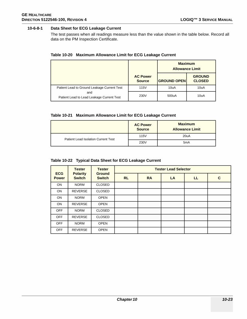
GE HEALTHCARE DIRECTION 5122546-100, REVISION 4 LOGIQ™ 3 SERVICE MANUAL
10-6-8-1 Data Sheet for ECG Leakage CurrentThe test passes when all readings measure less than the value shown in the table below. Record all data on the PM Inspection Certificate.
Table 10-20 Maximum Allowance Limit for ECG Leakage Current
AC Power Source
MaximumAllowance Limit
GROUND OPENGROUND CLOSED
Patient Lead to Ground Leakage Current Testand
Patient Lead to Lead Leakage Current Test
115V 10uA 10uA
230V 500uA 10uA
Table 10-21 Maximum Allowance Limit for ECG Leakage Current
AC Power Source
MaximumAllowance Limit
Patient Lead Isolation Current Test115V 20uA
230V 5mA
Table 10-22 Typical Data Sheet for ECG Leakage Current
ECG Power
Tester Polarity Switch
Tester Ground Switch
Tester Lead Selector
RL RA LA LL C
ON NORM CLOSED
ON REVERSE CLOSED
ON NORM OPEN
ON REVERSE OPEN
OFF NORM CLOSED
OFF REVERSE CLOSED
OFF NORM OPEN
OFF REVERSE OPEN
Chapter 10 10-23

GE HEALTHCAREDIRECTION 5122546-100, REVISION 4 LOGIQ™ 3 SERVICE MANUAL
10-6-9 Probe Leakage Current Test
10-6-9-1 DefinitionThis test measures the current that would flow to ground from any of the probes through a patient who is being scanned and becomes grounded by touching some other grounded surface.
NOTE: Some leakage current is expected on each probe, depending on its design. Small variations in probe leakage currents are normal from probe to probe. Other variations will result from differences in line voltage and test lead placement. It is abnormal if no leakage current is measured. If no leakage current is detected, check the configuration of the test equipment.
10-6-9-2 Test Equipment
Table 10-23 Test Equipment kits (Chapter 10 LOGIQ™ 3 Service Manual)
Kit Description Contents
46-285652G1
Dale 601 - ULTRASOUND SAFETY ANALYZER FIELD KIT
-for 120V unit
• ELECTRICAL SAFETY ANALYZER, DALE, MODEL 601 for 120V unit• Vendor MODEL 600/100 8FT CHASSIS GROUND CABLE• Vendor MODEL 600/102 6FT SALINE BATH GROUND CABLE• Vendor MODEL 600/202 ULTRASOUND PROBE ADAPTER • Vendor MODEL 600/600 SOFT CARRYING CASE• Vendor MODEL 600/900 OPERATORS MANUAL • Vendor MODEL 600/901 LMINATED OPERATORS GUIDE
46-328406G2
Dale 601E - ULTRASOUND SAFETY ANALYZER FIELD KIT
-for 220V unit
• ELECTRICAL SAFETY ANALYZER, DALE, MODEL 601E for 220V unit• Vendor MODEL 600/100 8FT CHASSIS GROUND CABLE• Vendor MODEL 600/101 16FT CHASSIS GROUND CABLE • Vendor MODEL 600/103 8FT CHASSIS GROUND PROBE • Vendor MODEL 600/200 8FT EXTERNAL LEAKAGE GROUND CABLE • #20 WIRE W/MINIGATOR CLIPS, 2 Ft• CARRYING CASE and foam padding• Vendor MODEL 600/900 OPERATORS MANUAL
10-24 Section 10-6 - Electrical Safety Tests

GE HEALTHCARE DIRECTION 5122546-100, REVISION 4 LOGIQ™ 3 SERVICE MANUAL
10-6-9-2 Test Equipment (cont’d).
Table 10-24 Test Equipment and Accessory Description
Dale Part number Accessory Name Picture Description
DALE 600/601/601E Electrical Safety Analyzer
Dale 601 shown
The DALE60x measures Line Voltage, Instrument Current, Ground
Resistance, Earth and Chassis Leakage Current, Patient Lead-to-Ground, Lead-to-Lead and Lead Isolation (MAP) Current, External Gradient, Probe and Transducer
Isolation Current and Point-to-Point Resistance.
Vendor MODEL 600/100
46-285647P2 CHASSIS CABLE
Black coil cord with extended length and black grips.
Used on DALE601/601E to measure earth resistance and enclosure leakage current. Also used as
reference lead for external measurement.
Vendor MODEL600/102
46-285647P4CHASSIS GROUND PROBE
Black coil cord with needle probe for testing receptacles and for
tight spaces.
Also referred to as “Saline Probe” or “Saline Bath Ground Cable”.
Measures earth resistance and enclosure leakage current. Also used
for grounding saline baths for isolation testing of probes.
Used on DALE601/601E. This probe may be substituted for the 600/100
Chassis Cable, and used as a probe instead of a clamp.
Vendor MODEL600/200
46-285647P6
ISO/EXTERNAL LEAKAGE CABLE
Black coiled cord with red grips.
Standard auxiliary cable for external measurements of leakage current and voltage gradient between two
surfaces.Used on DALE601/601E to measure:• Point-to-Point Leakage Current• Probe and Transducer Isolation
CurrentMay only be connected to the female
connector of the Analyzer, labeled EXTERNAL
Chapter 10 10-25

GE HEALTHCAREDIRECTION 5122546-100, REVISION 4 LOGIQ™ 3 SERVICE MANUAL
10-6-9-3 Generic Procedure for Leakage CurrentMeasurements should be made with the ground open and closed, with power line mains polarity normal, and with the unit Off and On. For each combination, the probe must be active to find the worst case condition.
10-6-9-4 Meter Procedure Using Dale Meter to Measure Leakage CurrentThe ultrasound probe’s imaging area is immersed in a solution along with a grounding probe from the test meter to complete the current path. The solution is a mixture of water and salt. The salt adds free ions to the water, making it conductive. Use mixture of 1 Litre of H2O (water) with 9 grams of table salt, mixed thoroughly.
Follow these steps to test each probe for leakage current:
1.) Turn OFF the LOGIQ™ 3 unit.2.) Plug the unit’s mains power cord into the test meter, and plug the test meter into the tested AC wall
outlet.3.) Plug the Chassis Ground Probe (saline probe) into the test meter's “CHASSIS” connector.4.) Set the test meter's “FUNCTION” switch to “CHASSIS” (Dale 600) or "ENCLOSURE LEAKAGE"
(Dale 601).5.) Connect the probe to be tested to the LOGIQ™ 3 unit.6.) Put the saline probe and the probe’s probe face (imaging area of the probe) into the saline bath.
7.) Power ON the LOGIQ™ 3 unit.8.) After the LOGIQ™ 3 unit has completed the boot process, select the probe to be tested so it is the
active probe.9.) Depress the LIFT GROUND rocker switch and record the highest current reading.10.)Follow the test conditions described in Table 10-25 for every probe.
The test passes when all readings measure less than the values shown in Table 10-15 and Table 10-16.
Figure 10-9 Set Up for Probe Leakage Current
CAUTION To avoid probe damage and possible electric shock, do not immerse probes into any liquid beyond the level indicated in the probe users manual. Do not touch the probe, conductive liquid or any part of the unit under test while the LIFT GROUND switch is depressed.
SALINE
10-26 Section 10-6 - Electrical Safety Tests

GE HEALTHCARE DIRECTION 5122546-100, REVISION 4 LOGIQ™ 3 SERVICE MANUAL
10-6-9-4Meter Procedure Using Dale Meter to Measure Leakage Current (cont’d)11.)Keep a record of the results with other hard copies of Planned Maintenance data using Table 10-25.
CAUTIONPower off
Equipment damage possibility. Never switch the Polarity or the status of the Neutral when the Ultrasound unit is powered on. Power off the Ultrasound unit, allow the stored energy to bleed down, and turn the circuit breaker off BEFORE switching the POLARITY switch and/or the NEUTRAL switch on the leakage meter to avoid possible power supply damage.
Table 10-25 Typical Data Sheet For Probe Source Leakage Current
Probe Tested:
Unit PowerTester Power Polarity
SwitchTester NEUTRAL
SwitchTester GROUND
Switch Measurement
Start with System Powered OFF
OFF NORMAL OPEN CLOSED
OFF NORMAL OPEN OPEN
OFF NORMAL CLOSED CLOSED
OFF NORMAL CLOSED OPEN
Open Neutral first, then attempt Power ON
ON NORMAL OPEN CLOSED
ON NORMAL OPEN OPEN
Close Neutral. Power System ON, and wait until Probe under test is active, before continuing
ON NORMAL CLOSED CLOSED
ON NORMAL CLOSED OPEN
Chapter 10 10-27

GE HEALTHCAREDIRECTION 5122546-100, REVISION 4 LOGIQ™ 3 SERVICE MANUAL
Section 10-7When There's Too Much Leakage Current...
CHASSIS FAILSCheck the ground on the power cord and plug for continuity. Ensure the ground is not broken, frayed, or intermittent. Replace any defective part.
Tighten all grounds. Ensure star washers are under all ground studs.
Inspect wiring for bad crimps, poor connections, or damage.
Test the wall outlet; verify it is grounded and is free of other wiring abnormalities. Notify the user or owner to correct any deviations. As a work around, check the other outlets to see if they could be used instead.
NOTE: No outlet tester can detect the condition where the white neutral wire and the green grounding wire are reversed. If later tests indicate high leakage currents, this should be suspected as a possible cause and the outlet wiring should be visually inspected.
PROBE FAILSTest the probe in another connector to isolate if the fault lies with the probe or the scanner.
NOTE: Each probe will have some amount of leakage, dependent on its design. Small variations in probe leakage currents are normal from probe to probe. Other variations will result from differences in line voltage and test lead placement. The maximum allowable leakage current for body surface contact probe differs from inter-cavity probe. Be sure to enter the correct probe type in the appropriate space on the check list.
If excessive leakage current is slot dependent, inspect the system connector for bent pins, poor connections, and ground continuity.
If the problem remains with the probe, replace the probe.
PERIPHERAL FAILSTighten all grounds. Ensure star washers are under all ground studs.
Inspect wiring for bad crimps, poor connections, or damage.
STILL FAILSIf all else fails, begin isolation by removing the probes, external peripherals, then the on board ones, one at a time while monitoring the leakage current measurement.
NEW UNITIf the leakage current measurement tests fail on a new unit and if situation can not be corrected, submit a Safety Failure Report to document the system problem. Remove unit from operation.
ECG FAILSInspect cables for damage or poor connections.
10-28 Section 10-7 - When There's Too Much Leakage Current...

GE HEALTHCARE DIRECTION 5122546-100, REVISION 4 LOGIQ™ 3 SERVICE MANUAL
ULTRASOUND INSPECTION CERTIFICATE
* Scan Format: Phased Array, Linear Array, Curved Array, Mechanical Array or Other
FUNCTIONAL CHECKS PHYSICAL INSPECTION AND CLEANING
COMMENTS: ____________________________________________________________________________________________________________________________________________________________
______________________________________________________________________________
Customer Name: System ID: Dispatch Number / Date Performed: Warranty/Contract/HBS
System Type Model Number: Serial Number: Manufacture Date:
Probe 1: Frequency: Scan Format*: Model Number: Serial Number:
Probe 2: Frequency: Scan Format*: Model Number: Serial Number:
Probe 3: Frequency: Scan Format*: Model Number: Serial Number:
Probe 4: Frequency: Scan Format*: Model Number: Serial Number:
Probe 5: Frequency: Scan Format*: Model Number: Serial Number:
Probe 6: Frequency: Scan Format*: Model Number: Serial Number:
Probe 7: Frequency: Scan Format*: Model Number: Serial Number:
Probe 8: Frequency: Scan Format*: Model Number: Serial Number:
Probe 9: Frequency: Scan Format*: Model Number: Serial Number:
Functional Check (if applicable)OK? or
N/APhysical Inspection and Cleaning
(if applicable) Inspect Clean
B-Mode Function Console
Doppler Modes Function Monitor
CF-Mode Function Air Filter
M-Mode Function Probe Holders
Applicable Software Options External I/O
Applicable Hardware Options Wheels, Brakes & Swivel Locks
Control Panel Cables and Connectors
Monitor GE Approved Peripherals (VCR, CD-RW, Printers)
Measurement Accuracy
GE Approved Peripherals
Chapter 10 10-29

GE HEALTHCAREDIRECTION 5122546-100, REVISION 4 LOGIQ™ 3 SERVICE MANUAL
ELECTRICAL SAFETY
Final Check. All system covers are in place. System scans with all probes as expected.
Accepted by: ______________________________________________________________________
Electrical Test PerformedMax Value Allowed
Value Measured OK? Comments
Outlet (correct ground &wiring config.)
System Ground Continuity
Chassis Source Leakage Current - Probe
Chassis Source Leakage Current - Wheel
Chassis Source Leakage Current - CRT
Patient Lead Source Leakage(Lead to Ground)
Patient Lead Source Leakage(Lead to Lead)
Patient Lead Source Leakage(Isolation)
Peripheral 1 Leakage Current
Peripheral 1Ground Continuity
Peripheral 2 Leakage Current
Peripheral 2Ground Continuity
Peripheral 3 Leakage Current
Peripheral 3Ground Continuity
PROBES
Probe Number (from previous page)
Max Value Allowed
Max Value Measured OK? Comments
Probe 1:
Probe 2:
Probe 3:
Probe 4:
Probe 5:
Probe 6:
Probe 7:
Probe 8:
Probe 9:
10-30 Section 10-7 - When There's Too Much Leakage Current...

GE HEALTHCAREDIRECTION 5122546 -100, REVISION 4 LOGIQ™ 3 SERVICE MANUAL
Index I
A,BApplications Software
Loading, 3-37Backup
Patient Database, 3-33Preset Configurations, 3-33
Base Load SoftwareCheck Devices, 8-139Remapping Drive Letters, 8-141Update, 8-135Video Adapter Configuration, 8-140
Basic MeasurementsFunctional Checks, 4-22
Boot Up, 3-12
CCine
Functional Checks, 4-24Color Mode
Overview, 4-19Connectivity
Worksheet, 3-32Cooling, 2-2Customer Assistance, 1-17
EElectrical Safety, 1-10EMI Limitations, 2-5EMI Protection, 3-9Environmental Conditions
Probes, 2-6
FFunctional Checks
Basic Measurements, 4-22Image Management, 4-25Probes/Connector Usage, 4-23Using Cine, 4-24
GGathering Trouble Data, 7-2General Cleaning, 10-9
HHazard Icons, 1-5Human Safety, 1-9
I
Image ManagementFunctional Checks, 4-25
Installation, 3-1Installation of Option Software, 8-161Installation of Software, 8-131
LLighting, 2-2
MManpower Requirements, 2-6Mechanical Safety, 1-9Minimal Floor Plan Suggestion, 2-9Models Covered, 1-2
PP4 Key Function, 7-4Power Off, 3-14Power On, 3-12Power-up Procedures
Voltage Settings, 3-9Prepearing the Unit for Installation, 3-9Probe Connector Cleaning, 10-11Probes/Connector Usage
Functional Checks, 4-23Purchaser Responsibilities, 2-7
RReceiving and Unpacking the Equipment, 3-3Regulatory, 6-1
SSafety Considerations, 1-9Screen Captures, 7-4Service Adjustments, 6-1Shutdown, 3-14Software
Base Load Update, 8-135Loading Application, 3-37
System Maintenance, 10-7
TTime and Manpower Requirements, 2-6Trouble Image with Logs, 7-3Troubleshooting
Gathering Trouble Data, 7-2Screen Captures, 7-4Trouble Image with Logs, 7-3

GE HEALTHCAREDIRECTION 5122546 -100, REVISION 4 LOGIQ™ 3 SERVICE MANUAL
II Index
Vital System Information, 7-2
UUnpacking the Equipment, 3-3, , 3-4
VVoltage Settings, 3-9
WWarnings and Cautions, 1-9

GE Healthcare
GE Medical Systems: Telex 3797371P.O. Box 414; Milwaukee, Wisconsin 53201, U.S.A.(Asia, Pacific, Latin America, North America)
GE Ultraschall:Tel: +49 (0) 212 28 02 208Deutschland GmbH & Co KGBeethovenstrabe 239, Postfach 11 05 60D-42655 Solingen, Germany