Submittal - The University of Vermont
113
Ph : (802) 862-5900 P. O. Box 728 Williston, VT 05495 Job: Delehanty Hall @ UVM Spec Section No: 180 Colchester Ave Burlington, VT 05405 Submittal No: 23 05 93 2 Sent Date: Revision No: 0 Submittal 10/7/2015 DLR75-000 Due Date: 10/14/2015 Spec Section Title: Submittal Title: Final Balance Report Subcontract VMI PO #: Contractor Architect Engineer Chantal Bitzer Vermont Mechanical, Inc. Contractor: Other: Slade;David General Contractor N/A Lead time after approval: Date items required at project: This submittal has been checked for general conformance with the information given in the contract documents. Final quantities, measurements, and coordination with other trades shall take place in the field. This submittal will now go to the General Contractor, Architect, and Engineer for final approval. \\tline.vmi.vtmechanical.com\Timberline Office\9.5\ACCOUNTING\Report\Standard PJ Submittal Form 1 (T) (CR)2.rpt
-
Upload
khangminh22 -
Category
Documents
-
view
2 -
download
0
Transcript of Submittal - The University of Vermont

Ph : (802) 862-5900
P. O. Box 728
Williston, VT 05495
Job:
Delehanty Hall @ UVM
Spec Section No:
180 Colchester Ave
Burlington, VT 05405
Submittal No:
23 05 93
2
Sent Date:
Revision No: 0
Submittal
10/7/2015
DLR75-000
Due Date: 10/14/2015
Spec Section Title:
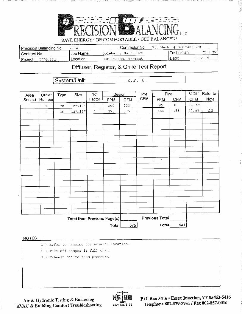
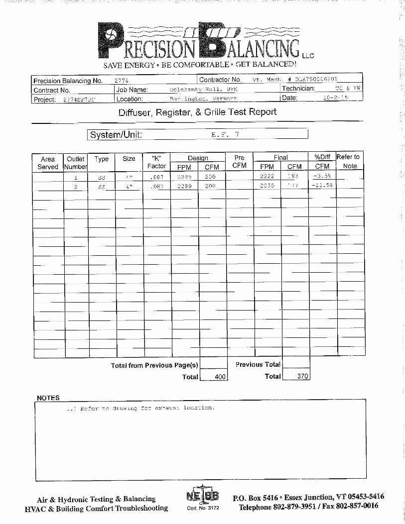
Submittal Title: Final Balance Report
SubcontractVMI PO #:
Contractor Architect
Engineer
Chantal Bitzer
Vermont Mechanical, Inc.
Contractor:
Other:
Slade;David
General Contractor
N/ALead time after approval:
Date items required at project:
This submittal has been checked for general conformance
with the information given in the contract documents. Final
quantities, measurements, and coordination with other
trades shall take place in the field.
This submittal will now go to the General Contractor,
Architect, and Engineer for final approval.
\\tline.vmi.vtmechanical.com\Timberline Office\9.5\ACCOUNTING\Report\Standard PJ Submittal Form 1 (T) (CR)2.rpt


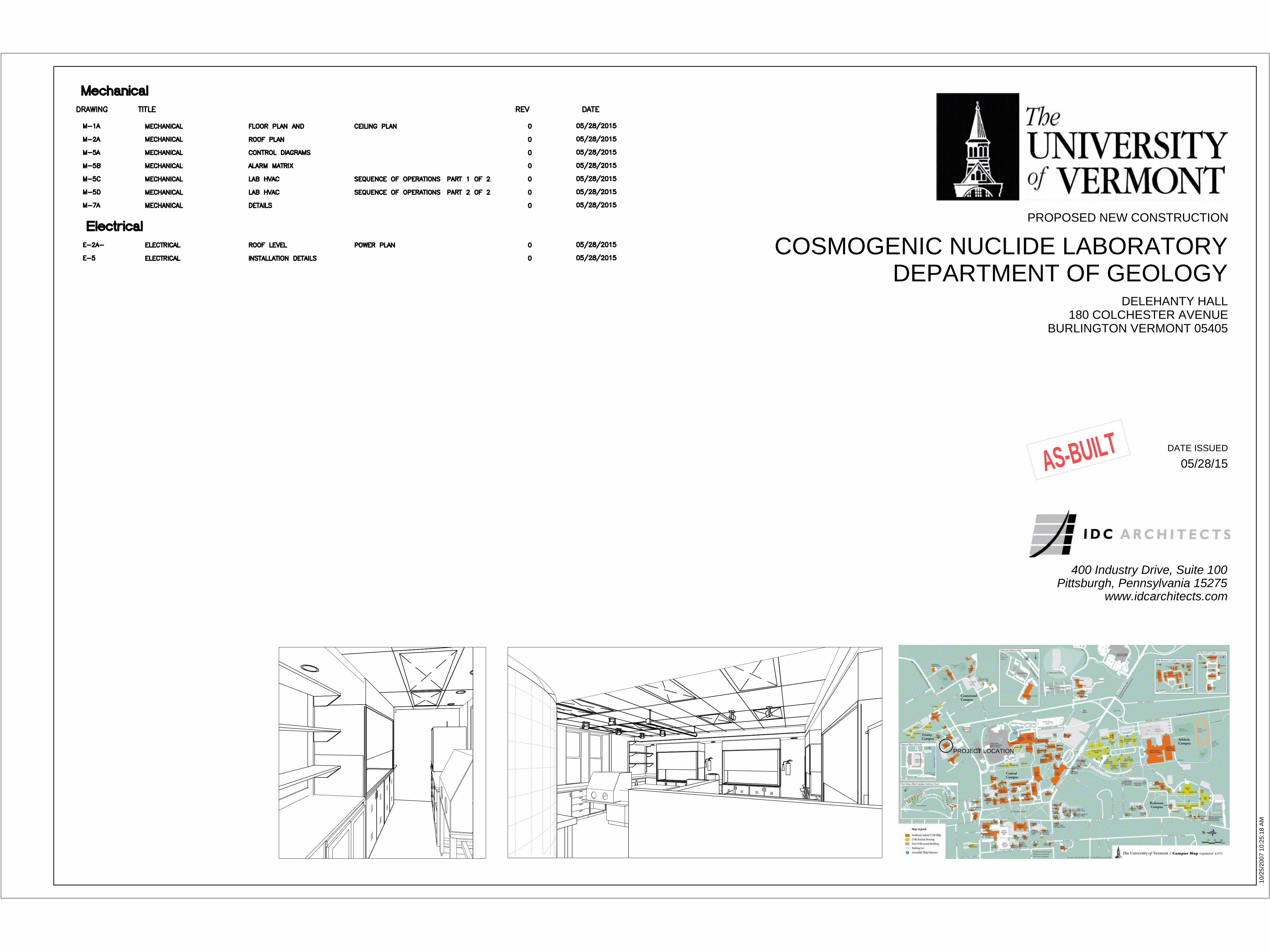
www.idcarchitects.com
Pittsburgh, Pennsylvania 15275
400 Industry Drive, Suite 100
COSMOGENIC NUCLIDE LABORATORY
DEPARTMENT OF GEOLOGY
DELEHANTY HALL
180 COLCHESTER AVENUE
BURLINGTON VERMONT 05405
PROPOSED NEW CONSTRUCTION
DATE ISSUED
PROJECT LOCATION
10/25/2007 10:25:18 A
M
05/28/15ASBUILT

102 SF
HIGH LEVEL
LABORATORY
B
124 SF
WRITE-UP AREA
C
558 SF
PRODUCTION
LABORATORY
D
95 SF
AIRLOCK
VESTIBULE
A
40 SF
ICP HOOD
ROOM
306F
SAC-1
A
AIRLOCK VESTIBULE
SAC-1
B
HIGH LEVEL LABORATORY
FRGWB / SAC-1
C
WRITE-UP AREA
FRGWB / SAC-1
D
PRODUCTION LABORATORY
AREA OF WORK
400 Industry Drive
Suite 100
Pittsburgh, PA 15275
www.idcarchitects.com
Delehanty Hall
Cosmogenic Nuclide
Laboratory
AREA OF WORK
AREA OF WORK
ASBUILT
REFER ALSO TO FINAL BALANCE REPORT

400 Industry Drive
Suite 100
Pittsburgh, PA 15275
www.idcarchitects.com
Delehanty Hall
Cosmogenic Nuclide
Laboratory
AREA OF WORK
AREA OF WORK
ASBUILT
AREA OF
WORK
AREA OF
WORK
400 Industry Drive
Suite 100
Pittsburgh, PA 15275
www.idcarchitects.com
Delehanty Hall
Cosmogenic Nuclide
Laboratory
AREA OF WORKAREA OF WORK
ASBUILT
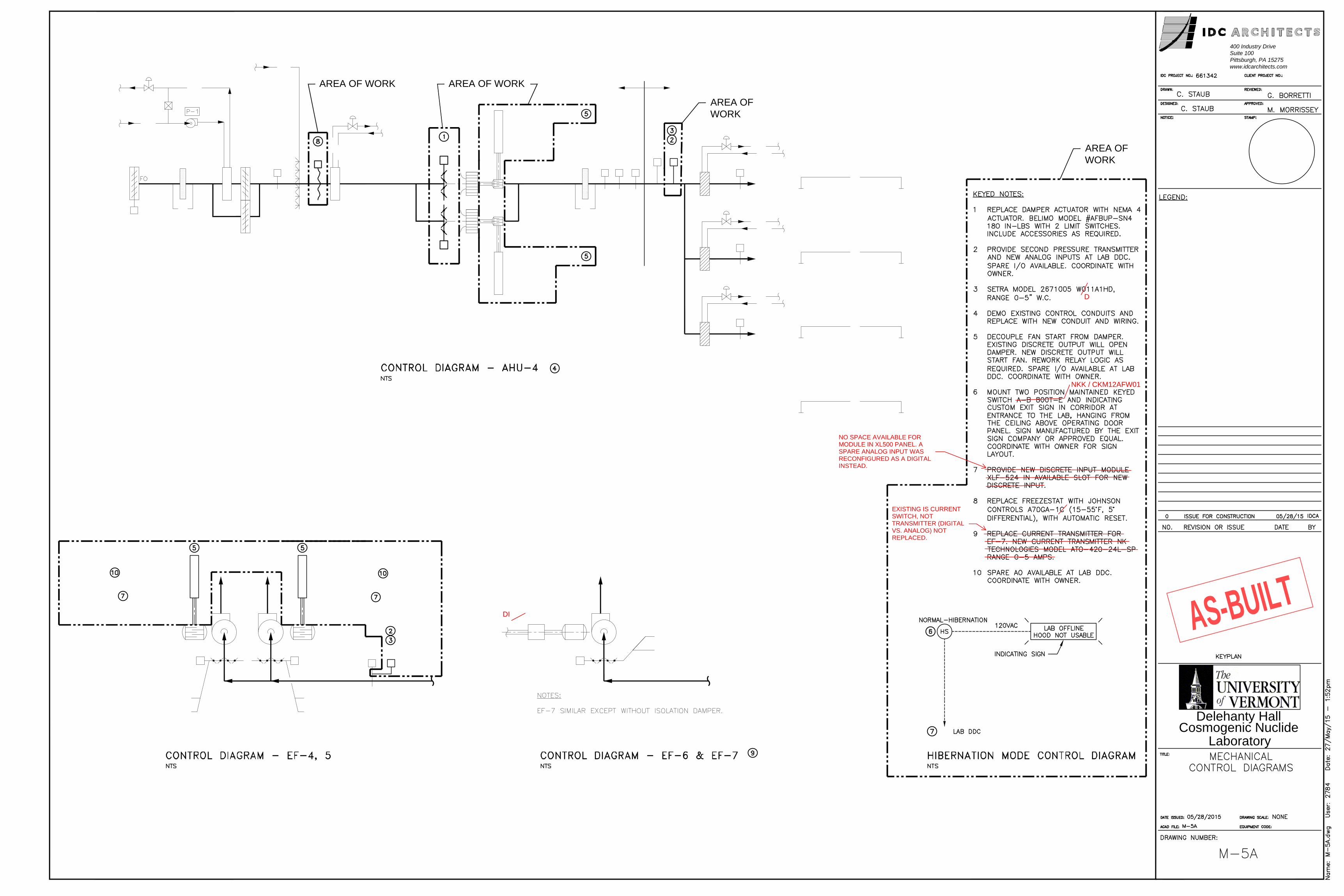
NO SPACE AVAILABLE FORMODULE IN XL500 PANEL. ASPARE ANALOG INPUT WASRECONFIGURED AS A DIGITALINSTEAD.
D
NKK / CKM12AFW01
EXISTING IS CURRENTSWITCH, NOTTRANSMITTER (DIGITALVS. ANALOG) NOTREPLACED.
DI

400 Industry Drive
Suite 100
Pittsburgh, PA 15275
www.idcarchitects.com
Delehanty Hall
Cosmogenic Nuclide
Laboratory
DELEHANTY HALL COSMOS ALARM MATRIX
MAIN CAMPUS COSMOS ALARM SCREENS
EQUIPMENT ALARM CAUSE
ALARM LIGHTR=REDY=YELLOW
SHUNT TRIP OFFUME HOODS
REDUCEDAHU-4 SPEED
REDUCEDEF-4/5 SPEED
HARDSTOP-AHU-4AND ALLEXHAUST FANSSHUTDOWN MISCELLANEOUS
AHU-4 AHU LEAD FAN FAIL LOSS OF RUN STATUS Y X LAG FAN STARTS/ KEEP SYSTEM ONLINE/MANUAL RESET OF FAN REQUIRED
VFD FAILURE Y X LAG FAN STARTS/ KEEP SYSTEM ONLINE/MANUAL RESET OF FAN REQUIRED
BOTH PRESSURE TRANSMITTERS LOW-LEAD FAN ONLINE Y X LAG FAN STARTS/ KEEP SYSTEM ONLINE/MANUAL RESET OF FAN REQUIRED
AHU-4 LOSS OF SUPPLY AIR BOTH FANS FAIL ( LEAD AND LAG) R X XEXHAUST FANS GO TO REDUCE SPEED/ MANUAL RESET REQUIRED TO GO BACK ONLINE/DAMPERS REMAIN OPEN/SYSTEMOFFLINE AFTER COOLDOWN TO MAINTAIN LAB CLEANLINESS
OUTSIDE AIR DAMPER CLOSED R X XEXHAUST FANS GO TO REDUCE SPEED/ MANUAL RESET REQUIRED TO GO BACK ONLINE/DAMPERS REMAIN OPEN/SYSTEMOFFLINE AFTER COOLDOWN TO MAINTAIN LAB CLEANLINESS
BOTH PRESSURE TRANSMITTERS LOW-LAG FAN ONLINE R X XEXHAUST FANS GO TO REDUCE SPEED/ MANUAL RESET REQUIRED TO GO BACK ONLINE/DAMPERS REMAIN OPEN/SYSTEMOFFLINE AFTER COOLDOWN TO MAINTAIN LAB CLEANLINESS
AHU-4 FREEZESTAT R X X X REDUCE HVAC-SUPPLY AND EXHAUST FAN @REDUCED SPEED/ MANUAL RESET REQUIRED
SMOKE DETECTION R X XMAU SHUTDOWN /MAU DAMPERS OPEN/EF-4/5 REDUCE SPEED/SYSTEM OFFLINE AFTER COOLDOWN TO MAINTAINCLEANLINESS
PREFILTER ALARM Y XFINAL FILTER ALARM Y XOUTSIDE DAMPER INCORRECT POSITION Y XFAN INLET DAMPER INCORRECT POSITION Y XHOT WATER PUMP FAIL LOSS OF CURRENT ALARM ONLYHUMIDIFIER GENERAL ALARM ALARM ONLY
SUPPLY AIR DISCH PRESS HI BOTH TRANSMITTERS Y X RED LIGHT INDICATION AT LOCAL PANEL/ SINGLE TRANSMITTER ALARM ONLY
DISCH PRESS LO BOTH TRANSMITTERS Y X RED LIGHT INDICATION AT LOCAL PANEL/ SINGLE TRANSMITTER ALARM ONLY
DISCH PRESS TRANSMITTER COMPARE ALARM ONLYDISCHARGE TEMP HI ALARM ONLYDISCHARGE TEMP LO ALARM ONLY
EF-4/5 AHU LEAD FAN FAIL LOSS OF RUN STATUS Y X LAG FAN STARTS/ KEEP SYSTEM ONLINE/MANUAL RESET OF FAN REQUIRED
VFD FAILURE Y X LAG FAN STARTS/ KEEP SYSTEM ONLINE/MANUAL RESET OF FAN REQUIRED
BOTH PRESSURE TRANSMITTERS LOW-LEAD FAN ONLINE Y X LAG FAN STARTS/ KEEP SYSTEM ONLINE/MANUAL RESET OF FAN REQUIREDEF-4/5 LOSS OF EXHAUST AIR BOTH FANS FAIL ( LEAD AND LAG) R X X MANUAL RESET REQUIRED
BOTH PRESSURE TRANSMITTERS LOW-LAG FAN ONLINE R X X MANUAL RESET REQUIREDEF-4/5 INCORRECT DAMPER POSITION Y XEXH AIR SUCTION PRESS HI BOTH TRANSMITTERS Y X RED LIGHT INDICATION AT LOCAL PANEL/ SINGLE TRANSMITTER ALARM ONLY
SUCTION PRESS LO BOTH TRANSMITTERS Y X RED LIGHT INDICATION AT LOCAL PANEL/ SINGLE TRANSMITTER ALARM ONLY
SUCTION PRESS TRANSMITTER COMPARE ALARM ONLYEF-6 FAN FAILURE LOSS OF CURRENT Y X MANUAL RESET/ AHU-4 REDUCE SPEED THROUGH PRESSURE CONTROL LOOP/EF-4/5 AND EF-7 REMAIN ONLINE
EXHAUST PRESSURE LOW Y X MANUAL RESET/ AHU-4 REDUCE SPEED THROUGH PRESSURE CONTROL LOOP/EF-4/5 AND EF-7 REMAIN ONLINE
INCORRECT DAMPER POSITION Y X MANUAL RESET/ AHU-4 REDUCE SPEED THROUGH PRESSURECONTROL LOOP/EF-4/5 AND EF-7 REMAIN ONLINE
EF-7 FAN FAILURE LOSS OF CURRENT Y X MANUAL RESET/ AHU-4 REDUCE SPEED THROUGH PRESSURE CONTROL LOOP/EF-4/5 AND EF-6 REMAIN ONLINE
EXHAUST PRESSURE LOW Y X MANUAL RESET/ AHU-4 REDUCE SPEED THROUGH PRESSURECONTROL LOOP/EF-4/5 AND EF-6 REMAIN ONLINE
MISC ALARMS INDIVIDUAL FUME HOOD ALARM Y 5 ALARMS TOTAL-INDICATION AT ALARM PANELHF ALARM SNIFFER HIGH ALARM R X HVAC REMAINS ONLINE/EF- 7 GOES ONLINE IF PREVIOUSLY OFFLINE/RED LIGHT INDICATION AT LOCAL PANEL
HCL ALARM SNIFFER HIGH ALARM R X HVAC REMAINS ONLINE/EF- 7 GOES ONLINE IF PREVIOUSLY OFFLINE/RED LIGHT INDICATION AT LOCAL PANEL
LAB ALARMS DIFFERENTIAL PRESSURE HI LEVEL PRODUCTION VS VESTIBULE RED LIGHT INDICATION AT LOCAL PANELDIFFERENTIAL PRESSURE WRITE UP VS VESTIBULE RED LIGHT INDICATION AT LOCAL PANELDIFFERENTIAL PRESSURE PRODUCTION VS VESTIBULE RED LIGHT INDICATION AT LOCAL PANELDIFFERENTIAL PRESSURE CORRIDOR VS VESTIBULE RED LIGHT INDICATION AT LOCAL PANELTEMPERATURE PRODUCTION LABTEMPERATURE HIGH LEVEL LABTEMPERATURE WRITE UP LABRELATIVE HUMIDITY PRODUCTION LABRELATIVE HUMIDITY HIGH LEVEL LABRELATIVE HUMIDITY WRITE UP LABTEMPERATURE RH-26 DISCHARGETEMPERATURE RH-27 DISCHARGETEMPERATURE RH-28 DISCHARGE
SHUNT TRIP ALARMS WILL PAGE AND EMAIL DR. BIERMAN AND PPD (PHYSICAL PLANT DEPT)
ALARMS AND ANALOG READINGS PROVIDED TO MAIN CAMPUS ACROSS BACNET ASBUILT
REFER TO MAIN CAMPUS ALARM SCREENS FOR AS_BUILT CONDITION
(Switches Indicate Fully Closed)
(Switches Indicate Not Fully Open)
(Switches Indicate Not Fully Open)
RRR
YYYY
CAUSES LOW FLOW CONDITION ON AHU - SYSTEM GOES TO REDUCED FLOW MODE
EF-4/5

ASBUILT
38
a function of the freeze-stat. (not adjustable)

ASBUILT

400 Industry Drive
Suite 100
Pittsburgh, PA 15275
www.idcarchitects.com
Delehanty Hall
Cosmogenic Nuclide
Laboratory
AREA OF WORK
ASBUILT

AREA OF WORK
AREA OF
WORK
AREA OF WORK
400 Industry Drive
Suite 100
Pittsburgh, PA 15275
www.idcarchitects.com
Delehanty Hall
Cosmogenic Nuclide
Laboratory
ASBUILT
400 Industry Drive
Suite 100
Pittsburgh, PA 15275
www.idcarchitects.com
Delehanty Hall
Cosmogenic Nuclide
Laboratory
ASBUILT

Component Verification Checklist
Project: Delehanty Cosmogenic Nuclide Laboratory
Checked By: David Slade – Slade Engineering (DCS)
Item Description Specified Make
/Model
Approved Make
/Model
Installed Make
/Model
Notes Date Initials
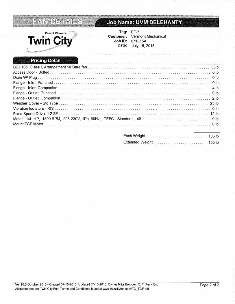
Exhaust Fan for
snorkel hoods (EF)7)
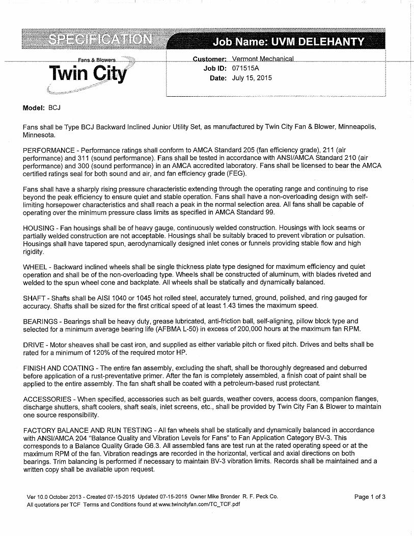
Twin City / BCJ
400 CFM @ 1.2” w.c.
208V, 1 ph, 60 hz
Motor HP: not specified
Motor Type: TEFC
Motor Make/Model: not
specified
Twin City / BCJ
400 CFM @ 1.2” w.c.
208V, 1 ph, 60 hz
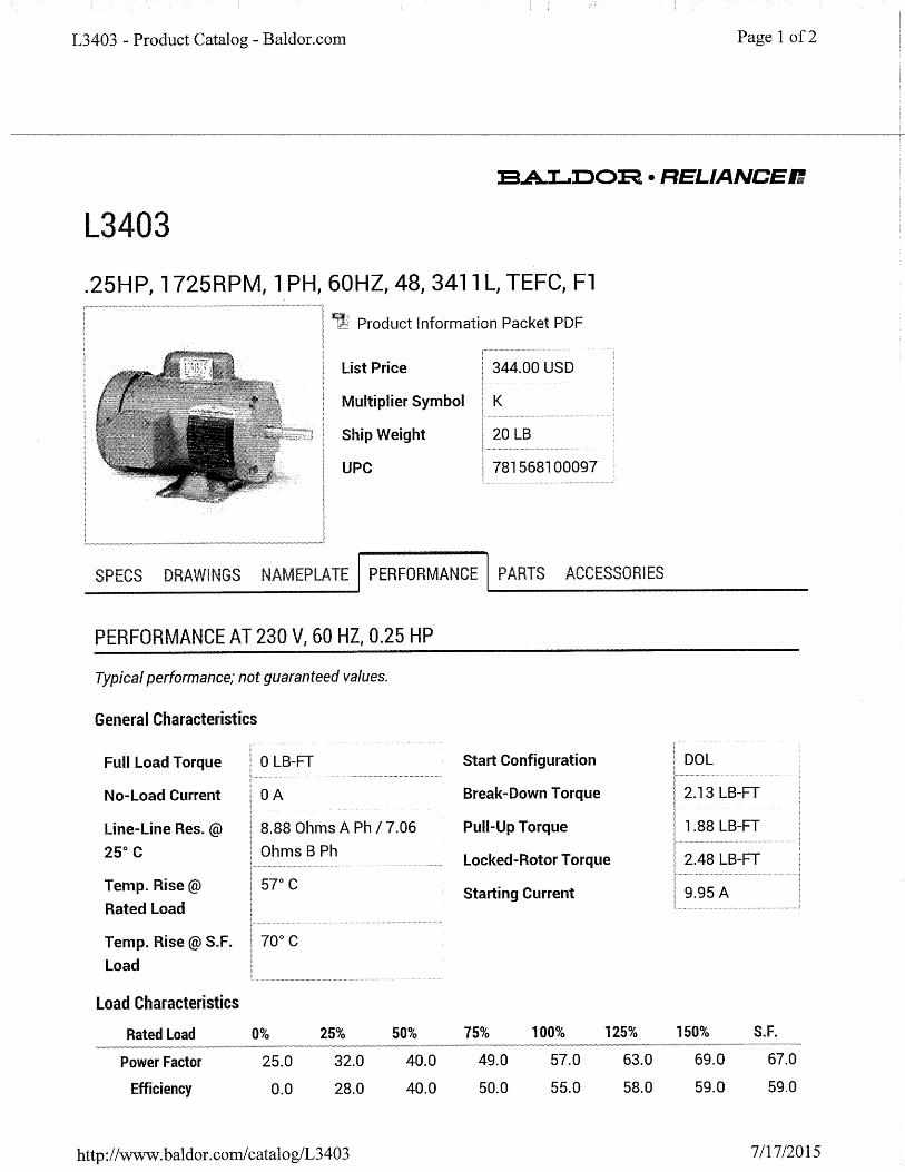
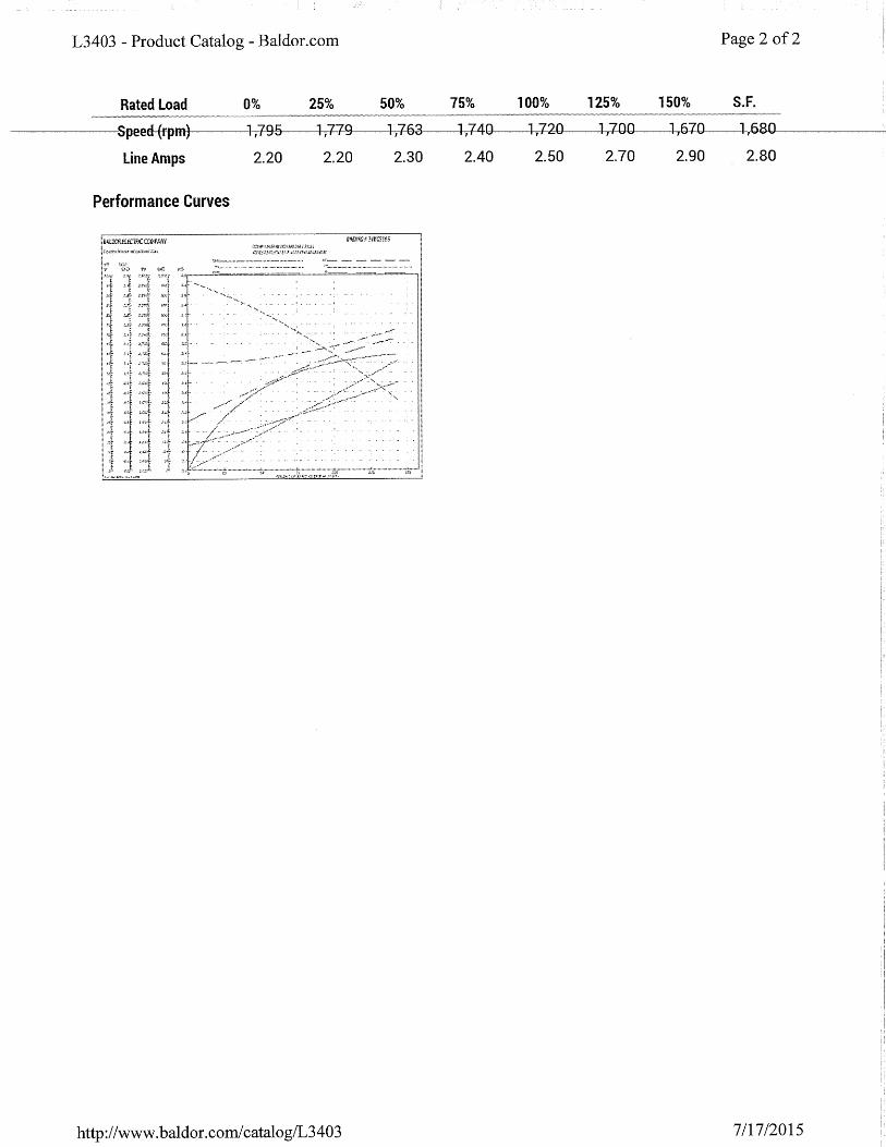
Motor HP: ¼ HP
Motor Type: TEFC
Motor S.F: 1.35
Motor Make/Model:
Baldor / L3403
Twin City / BCJ
400 CFM @ 1.2” w.c.
208V, 1 ph, 60 hz
Motor HP: ¼ HP
Motor Type: TEFC
Motor S.F: 1.15
Motor Make/Model: Twin
City / YC4814C
Fan body as specified and approved.
Motor does not match submittal and is to
be replaced under warranty.
1/14/16 (DCS)
Freezestat for AHU)4 Johnson Controls /
A70GA)1C
Johnson Controls /
A70GA)1C
Johnson Controls /
A70GA)1
“C” suffix is a Johnson Controls sales
designation that has no impact product
specification.
1/14/16 (DCS)
Actuator for Outdoor
Air Damper
(Not scheduled for
replacement in design
documents.)
Belimo / AFBUP)SN4H Belimo / AFBUP)SN4H “H” suffix indicates internal heater for
additional condensation protection.
1/14/16 (DCS)
Actuators for Supply
Fan Dampers
Belimo / AFBUP)SN4 Belimo / AFBUP)SN4 Belimo / AFBUP)SN4 1/14/16 (DCS)
Pressure Transmitter
(AHU)4 Supply)
Setra / 2671005
WO11A1HD
Setra / 2671005
WD11A1HD
Setra / 2671005
WD11A1HD
Specified model # was incorrect by 1
digit. Corrected during submittal review.
1/14/16 (DCS)
Pressure Transmitters
(EF)4&5 Suction)
Setra / 2671005
WO11A1HD
Setra / 2671005
WD11A1HD
Setra / 2671005
WD11A1HD
Specified model # was incorrect by 1
digit. Corrected during submittal review.
1/14/16 (DCS)
Variable Frequency
Drives (VFDs) for
EF)4&5)
Yaskawa / A1000
)or)
ABB / ACH
Yaskawa /
PU2A0030FAA
CIMR)PU2A0030FAA “CIMR” is a Yaskawa standard
designation that has no impact product
specification.
1/14/16 (DCS)
Key Switch for
Hibernation Mode
AB / 800T)E NKK / CKM12AFW01 NKK / CKM12AFW01 Specified model # was incorrect for the
application. Corrected during submittal
review.
1/14/16 (DCS)
Lab Status
Illuminated Sign
(No specific make / model
specified)
i)Signs / Slim)line
SBL824R)J533
Ser. No. 3951)FB12)
D55A
Custom sign so not labeled with model #.
Sign meets specification.
1/14/16 (DCS)

Ph : (802) 862-5900
P. O. Box 728
Williston, VT 05495
Job:
Delehanty Hal @ UVM
Spec Section No:
180 Colchester Ave
Burlington, VT 05405
Submittal No:
23 3416
1
Sent Date:
Revision No: 0
Submittal
7/18/2015
DLR75-000
Due Date: 7/25/2015
Spec Section Title: Centrifugal Fans
Submittal Title: EF-7 Fan
CM2595VMI PO #:
Contractor Architect
Engineer
Chantal Bitzer
Vermont Mechanical, Inc.
Contractor:
Other:
Slade;David
General Contractor
4 WeeksLead time after approval:
Date items required at project:
This submittal has been checked for general conformance
with the information given in the contract documents. Final
quantities, measurements, and coordination with other
trades shall take place in the field.
This submittal will now go to the General Contractor,
Architect, and Engineer for final approval.
\\tline.vmi.vtmechanical.com\Timberline Office\9.5\ACCOUNTING\Report\Standard PJ Submittal Form 1 (T) (CR)2.rpt
Review Status
“Reviewed”: Submittal has been reviewed with no comments. Item(s) may be released forprocurement.
X “Reviewed As Noted”: Submittal has been reviewed and comments have been provided.Item(s) may be released for procurement provided all comments are addressed by Contractor.
“Revise and Resubmit”: Submittal has been reviewed and significant issues/comments havebeen discovered. Submittal must be revised and resubmitted prior to item(s) being released forprocurement.
“Rejected”: Submittal is substantially incomplete, incorrect, or otherwise does not meet theproject requirements. A new submittal shall be generated and submitted for review.
Submittals have been reviewed for general compliance with contract documents, project requirements,and code requirements. This review is not intended to modify, replace, or relieve Contractor fromcomplying with all contract documents, project requirements, and code requirements. Contractor is fullyresponsible for coordinating item(s) covered under this submittal with all other trades including, but notlimited to, field verification of all dimensions, clearances, quantities, and utility requirements. All systemsand components shall be installed in strict compliance with manufacturer’s instructions.
Review Comments Compiled By:David C. Slade - Project Manager
REVIEW COMMENTS:
1) Provide extended grease lines as specified.
No Comments Provided


Ph : (802) 862-5900
P. O. Box 728
Williston, VT 05495
Job:
Delehanty Hall @ UVM
Spec Section No:
180 Colchester Ave
Burlington, VT 05405
Submittal No:
26 05 02
1
Sent Date:
Revision No: 0
Submittal
8/26/2015
DLR75-000
Spec Section Title:
Submittal Title: Sign - For Record
SubcontractVMI PO #:
Contractor Architect
Engineer
Chantal Bitzer
Vermont Mechanical, Inc.
Contractor:
Other:
Slade;David
General Contractor
4 WeeksLead time after approval:
Date items required at project:
This submittal has been checked for general conformance
with the information given in the contract documents. Final
quantities, measurements, and coordination with other
trades shall take place in the field.
This submittal will now go to the General Contractor,
Architect, and Engineer for final approval.
\\tline.vmi.vtmechanical.com\Timberline Office\9.5\ACCOUNTING\Report\Standard PJ Submittal Form 1 (T) (CR)2.rpt
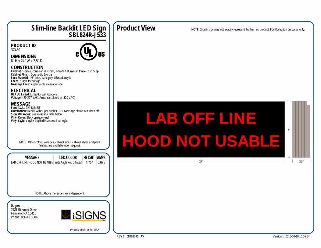
Slim-line Backlit LED SignSBL824R-J533
PRODUCT ID37480
DIMENSIONS8" H x 24" W x 2.5" D
CONSTRUCTIONCabinet: 1-piece, corrosion resistant, extruded aluminum frame, 2.5" deep.Cabinet Finish: Duranodic BronzeFace Material: 1/8" thick, dark grey diffused acrylicFaces: Single faced signMessage Face: Replaceable message face
ELECTRICALUL/cUL Listed: Listed for wet locationsVoltage: 120-277 VAC, Amps calculated at (120 VAC)
MESSAGEFont: Swiss 721 Bold BTIllumination: Backlit with super bright LEDs. Message blanks out when off.Sign Messages: See message table belowVinyl Color: Black opaque vinylVinyl Style: Vinyl is applied in a stencil cut style
NOTE: Other colors, voltages, cabinet sizes, cabinet styles and paintfinishes are available upon request.
NOTE: Above messages are independent.
MESSAGE LED/COLOR HEIGHT AMPSLAB OFF LINE HOOD NOT USABLE Wide Angle Red Diffused 1.75" 0.096
Product View NOTE: Sign image may not exactly represent the finished product. For illustration purposes only.
REV 0 | 08192015 | AV
LAB OFF LINEHOOD NOT USABLE
8"
24" 2.5"
iSigns7625 Birkmire DriveFairview, PA 16415Phone: 866-437-3040
Version 1 (2015-08-19 10:16:54)
Proudly Made in the USA
cbitzer
Text Box
Please change as follows: OFF-LINE HOODS
cbitzer
Text Box
Size 8" x 24" with 1.75" high letters.

Ph : (802) 862-5900
P. O. Box 728
Williston, VT 05495
Job:
Delehanty Hall @ UVM
Spec Section No:
180 Colchester Ave
Burlington, VT 05405
Submittal No:
26 0502
2
Sent Date:
Revision No: 0
Submittal
9/28/2015
DLR75-000
Due Date: 10/5/2015
Spec Section Title: Basic Electrical Construction Materials & Methods
Submittal Title: Key Switch
SubcontractVMI PO #:
Contractor Architect
Engineer
Chantal Bitzer
Vermont Mechanical, Inc.
Contractor:
Other:
Slade;David
General Contractor
N/ALead time after approval:
Date items required at project:
This submittal has been checked for general conformance
with the information given in the contract documents. Final
quantities, measurements, and coordination with other
trades shall take place in the field.
This submittal will now go to the General Contractor,
Architect, and Engineer for final approval.
\\tline.vmi.vtmechanical.com\Timberline Office\9.5\ACCOUNTING\Report\Standard PJ Submittal Form 1 (T) (CR)2.rpt
cbitzer
Text Box
Model No. CKM12AFW01
F
Series CK High Security Keylocks
www.nkk.comF4
Indi
cato
rsA
cces
sori
esSu
pple
men
tTa
ctile
sK
eylo
cks
Rota
ries
Push
butto
nsIll
umin
ated
PB
Slid
esPr
ogra
mm
able
Touc
hTi
lt Ro
cker
sTo
ggle
s
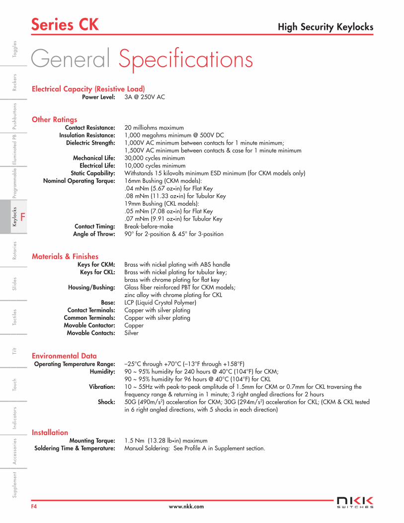
Electrical Capacity (Resistive Load) Power Level: 3A @ 250V AC
Other Ratings Contact Resistance: 20 milliohms maximum Insulation Resistance: 1,000 megohms minimum @ 500V DC Dielectric Strength: 1,000V AC minimum between contacts for 1 minute minimum; 1,500V AC minimum between contacts & case for 1 minute minimum Mechanical Life: 30,000 cycles minimum Electrical Life: 10,000 cycles minimum Static Capability: Withstands 15 kilovolts minimum ESD minimum (for CKM models only)
Nominal Operating Torque: 16mm Bushing (CKM models): .04 mNm (5.67 oz•in) for Flat Key .08 mNm (11.33 oz•in) for Tubular Key 19mm Bushing (CKL models): .05 mNm (7.08 oz•in) for Flat Key .07 mNm (9.91 oz•in) for Tubular Key Contact Timing: Break-before-make Angle of Throw: 90° for 2-position & 45° for 3-position
Materials & Finishes Keys for CKM: Brass with nickel plating with ABS handle Keys for CKL: Brass with nickel plating for tubular key; brass with chrome plating for flat key Housing/Bushing: Glass fiber reinforced PBT for CKM models; zinc alloy with chrome plating for CKL Base: LCP (Liquid Crystal Polymer) Contact Terminals: Copper with silver plating Common Terminals: Copper with silver plating Movable Contactor: Copper Movable Contacts: Silver
Environmental Data Operating Temperature Range: –25°C through +70°C (–13°F through +158°F) Humidity: 90 ~ 95% humidity for 240 hours @ 40°C (104°F) for CKM; 90 ~ 95% humidity for 96 hours @ 40°C (104°F) for CKL Vibration: 10 ~ 55Hz with peak-to-peak amplitude of 1.5mm for CKM or 0.7mm for CKL traversing the frequency range & returning in 1 minute; 3 right angled directions for 2 hours Shock: 50G (490m/s2) acceleration for CKM; 30G (294m/s2) acceleration for CKL; (CKM & CKL tested in 6 right angled directions, with 5 shocks in each direction)
Installation Mounting Torque: 1.5 Nm (13.28 lb•in) maximum Soldering Time & Temperature: Manual Soldering: See Profile A in Supplement section.
General Specifications
cbitzer
Text Box
Model No. CKM12AFW01
F
Series CKHigh Security Keylocks
www.nkk.com F5
Indi
cato
rsA
cces
sori
esSu
pple
men
tTa
ctile
sK
eylo
cks
Rota
ries
Push
butto
nsIll
umin
ated
PB
Slid
esPr
ogra
mm
able
Touc
hTi
ltTo
ggle
sRo
cker
s
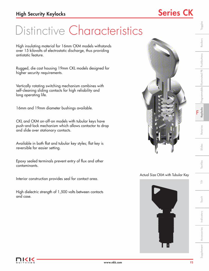
High insulating material for 16mm CKM models withstands over 15 kilovolts of electrostatic discharge, thus providing antistatic feature.
Rugged, die cast housing 19mm CKL models designed for higher security requirements.
Vertically rotating switching mechanism combines with self-cleaning sliding contacts for high reliability and long operating life.
16mm and 19mm diameter bushings available.
CKL and CKM on-off-on models with tubular keys have push-and-lock mechanism which allows contactor to drop and slide over stationary contacts.
Available in both flat and tubular key styles; flat key is reversible for easier setting.
Epoxy sealed terminals prevent entry of flux and other contaminants.
Interior construction provides seal for contact area.
High dielectric strength of 1,500 volts between contacts and case.
Actual Size CKM with Tubular Key
Distinctive Characteristics
cbitzer
Text Box
Model No. CKM12AFW01
F
Series CK High Security Keylocks
www.nkk.comF6
Indi
cato
rsA
cces
sori
esSu
pple
men
tTa
ctile
sK
eylo
cks
Rota
ries
Push
butto
nsIll
umin
ated
PB
Slid
esPr
ogra
mm
able
Touc
hTi
lt Ro
cker
sTo
ggle
s
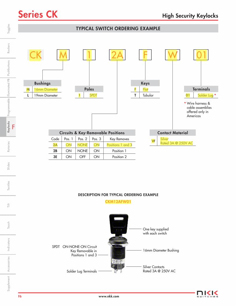
BushingsM 16mm Diameter
L 19mm Diameter
TYPICAL SWITCH ORDERING EXAMPLE
One key supplied with each switch
16mm Diameter Bushing
Silver Contacts Rated 3A @ 250V AC
SPDT ON-NONE-ON Circuit Key Removable in Positions 1 and 3
Solder Lug Terminals
DESCRIPTION FOR TYPICAL ORDERING EXAMPLE
CKM12AFW01
Circuits & Key-Removable PositionsCode Pos. 1 Pos. 2 Pos. 3 Key Removes
2A ON NONE ON Positions 1 and 3
2B ON NONE ON Position 1
3E ON OFF ON Position 2
Contact Material
W Silver Rated 3A @ 250V AC
MCK 2A1 F W 01
KeysF Flat
T Tubular
Poles1 SPDT
Terminals01 Solder Lug *
* Wire harness & cable assemblies offered only in Americas
cbitzer
Text Box
Model No. CKM12AFW01
cbitzer
Highlight
cbitzer
Highlight
cbitzer
Highlight
cbitzer
Highlight
cbitzer
Highlight
cbitzer
Highlight
cbitzer
Highlight
cbitzer
Highlight
cbitzer
Highlight
cbitzer
Highlight
cbitzer
Highlight
cbitzer
Highlight
cbitzer
Highlight
cbitzer
Highlight

F
Series CKHigh Security Keylocks
www.nkk.com F7
Indi
cato
rsA
cces
sori
esSu
pple
men
tTa
ctile
sK
eylo
cks
Rota
ries
Push
butto
nsIll
umin
ated
PB
Slid
esPr
ogra
mm
able
Touc
hTi
ltTo
ggle
sRo
cker
s
KEYS
CONTACT MATERIALS, RATINGS & TERMINALS
Pole & Throw Model
Key Positions
Pos 1 Pos 2 Pos 3
Connected Terminals (Terminal numbers are on switch) Pos 1 Pos 2 Pos 3 Schematic
= Key Removable = Not Removable = Maximum Arc
SPDT CKM12A CKL12A ON NONE ON COM-1 ____ COM-2
SPDT CKM12B CKL12B ON NONE ON COM-1 ____ COM-2
SPDT CKM13E CKL13E ON OFF ON COM-1 OPEN COM-2
Solder Lug Terminalfor CKM
Flat KeyTubular Key(must be pressed inward to actuate)
POLES, CIRCUITS & KEY-REMOVABLE POSITIONS
Silver over SilverPower Level 3A @ 250V AC
Solder Lug TerminalsSolder Lug Terminal
for CKL
F T
W
01
1 2
COM
1 2
COM
OP
EN
POS 1
3
POS 1
3
AT4147 for CKM 16mm Brass with Nickel Plating key base & ABS key handleAT4153 for CKL 19mm Brass with Chrome Plating (crosshatch texture on handle)
One key provided with each switch (no master key available)For ordering additional keys, indicate the same keynumber that is engraved on the face of your switch.
Randomly assigned key number (001 through 010 for CKMmodels & 001 through 025 for CKL models).
Typical Key Ordering Example: AT4153-001
AT4146 for CKM 16mm Brass with Nickel Plating key base & ABS key handleAT4152 for CKL 19mm Brass with Nickel Plating (smooth)
One key provided with each switch (no master key available) For ordering additional keys, indicate the same key number that is engraved on the face of your switch.
Randomly assigned key number (001 through 025 for CKMmodels & 001 through 050 for CKL models).
Typical Key Ordering Example: AT4146-001
(22.3).878
(49.3)1.941
(20.0).787
(1.8).071
(22.5).886
(35.5)1.398(9.6) Dia
.378
(19.0).748
(1.5).059
AT4153
(40.8)1.606
(20.0).787
(3.5).138
(20.0).787AT4147 (26.0)
1.024
(25.0).984
(33.5)1.319
(3.5).138
(7.0) Dia.276
(10.5) Dia .413
AT4152
AT4146
Thk = (0.8) .031
(5.5).217
(2.8).110
(3.1).122 (1.4)
.055
Epoxy Seal(5.0).197
(2.4).094
(2.7).106
(1.2).047
Epoxy Seal
Thk = (0.8) .031
•
POS 1
2
3
cbitzer
Highlight
cbitzer
Highlight
cbitzer
Highlight
cbitzer
Highlight
cbitzer
Highlight
cbitzer
Highlight
cbitzer
Highlight
cbitzer
Highlight
cbitzer
Highlight
cbitzer
Highlight
cbitzer
Highlight
cbitzer
Highlight
cbitzer
Highlight
cbitzer
Highlight

F
Series CK High Security Keylocks
www.nkk.comF8
Indi
cato
rsA
cces
sori
esSu
pple
men
tTa
ctile
sK
eylo
cks
Rota
ries
Push
butto
nsIll
umin
ated
PB
Slid
esPr
ogra
mm
able
Touc
hTi
lt Ro
cker
sTo
ggle
s
TYPICAL SWITCH DIMENSIONS
16mm Bushing • Flat Key
16mm Bushing • Tubular Key
CKM12AFW01
CKM13ETW01
PANEL CUTOUT & STANDARD HARDWARE FOR 16MM BUSHING
Maximum Effective Panel Thickness: .469” (11.9mm)
AT016 16mm Hex Mounting Nutfor CKM 1 included with each switch Steel
(19.0).748
(2.5).098
M16 P1
90°Angular
Throw
45°Angular
Throw
90°Angular
Throw
45°Angular
Throw
M16 P1 (1.2) x (2.4).047 x.094
(5.0).197
(16.0).630
(4.0).157
(20.0).787(24.0).945
(35.2)1.386
00
6(20.0).787
(0.9).035
(1.4).055
0 0 6
90°
POS 1
POS 3
(19.0) Dia .748
M16 P1 (1.2) x (2.4).047 x .094
(5.0).197
(16.0).630
(4.0).157
(20.0).787
(24.0).945
(35.2)1.386
00
2
(0.9).035
0 0 2
POS 1
POS 3
(19.0) Dia .748
POS 245°
45°
0 1 7
POS 1
POS 3
(19.0) Dia .748
POS 245°
45°
M16 P1 (1.2) x (2.4).047 x .094
(5.0).197
(16.0).630
(4.0).157
(25.0).984
(29.0)1.142
(35.2)1.386
017
0 0 4
POS 1
POS 3
(19.0) Dia .748
90°
M16 P1 (1.2) x (2.4).047 x .094
(5.0).197
(16.0).630
(4.0).157
(25.0).984
(29.0)1.142
(35.2)1.386
(15.0).591
(11.0).433
0 0 4
C O M
12
(14.2).559
C O M
12
(14.2).559
C O M
12
(14.2).559
C O M
12
(14.2).559
(16.0) Dia.630
(14.6).575
cbitzer
Highlight
cbitzer
Highlight

F
Series CKHigh Security Keylocks
www.nkk.com F9
Indi
cato
rsA
cces
sori
esSu
pple
men
tTa
ctile
sK
eylo
cks
Rota
ries
Push
butto
nsIll
umin
ated
PB
Slid
esPr
ogra
mm
able
Touc
hTi
ltTo
ggle
sRo
cker
s
0 0 5
90°
POS 1
POS 3
(22.0) Dia .866
0 1 5
45°POS 1
POS 3
(22.0) Dia .866
POS 2
45°
0 4 2
POS 1
POS 2
(22.0) Dia .866
POS 3
45°
45°
0 0 8
POS 1
(22.0) Dia .866
POS 3
90°
TYPICAL SWITCH DIMENSIONS
19mm Bushing • Flat Key
19mm Bushing • Tubular Key
CKL12AFW01
. CKL13ETW01
90°Angular
Throw
45°Angular
Throw
(40.0)1.575
(29.8)1.173
00
5
M19 P1 (1.4) x (2.8).055 x .110
(5.5).217
(17.0).669
(5.4).213
(0.7).028
(22.3).878
(1.0).039
(20.0).787
(40.0)1.575
(29.8)1.173
M19 P1 (1.4) x (2.8).055 x .110
(5.5).217
(17.0).669
(5.4).213
015
(0.7).028
(40.0)1.575
(30.5)1.201
M19 P1 (1.4) x (2.8).055 x .110
(5.5).217
(17.0).669
(5.4).213
(22.5).886
(40.0)1.575
(30.5)1.201
M19 P1 (1.4) x (2.8).055 x .110
(5.5).217
(17.0).669
(5.4).213
(22.5).886
0 0 8
(19.0).748
C O M
12
(16.8).661
PANEL CUTOUT & STANDARD HARDWARE FOR 19MM BUSHING
Maximum Effective Panel Thickness: .496” (12.6mm)
AT019 19mm Hex Mounting Nutfor CKL 1 included with each switch Steel (22.0)
.866
(3.4).134
M19 P1
90°Angular
Throw
45°Angular
Throw
C O M
12
(16.8).661
C O M
12
(16.8).661
C O M
12
(16.8).661
(19.0) Dia.748
(17.2).677
cbitzer
Line
cbitzer
Line
Ph : (802) 862-5900
P. O. Box 728
Williston, VT 05495
Job:
Delehanty Hal @ UVM
Spec Section No:
180 Colchester Ave
Burlington, VT 05405
Submittal No:
26 2923
1
Sent Date:
Revision No: 0
Submittal
7/18/2015
DLR75-000
Due Date: 7/25/2015
Spec Section Title: Variable Frequency Motor Controllers
Submittal Title: VFD's
SubcontractVMI PO #:
Contractor Architect
Engineer
Chantal Bitzer
Vermont Mechanical, Inc.
Contractor:
Other:
Slade;David
General Contractor
2 WeeksLead time after approval:
Date items required at project:
This submittal has been checked for general conformance
with the information given in the contract documents. Final
quantities, measurements, and coordination with other
trades shall take place in the field.
This submittal will now go to the General Contractor,
Architect, and Engineer for final approval.
\\tline.vmi.vtmechanical.com\Timberline Office\9.5\ACCOUNTING\Report\Standard PJ Submittal Form 1 (T) (CR)2.rpt
Review Status
“Reviewed”: Submittal has been reviewed with no comments. Item(s) may be released forprocurement.
X “Reviewed As Noted”: Submittal has been reviewed and comments have been provided.Item(s) may be released for procurement provided all comments are addressed by Contractor.
“Revise and Resubmit”: Submittal has been reviewed and significant issues/comments havebeen discovered. Submittal must be revised and resubmitted prior to item(s) being released forprocurement.
“Rejected”: Submittal is substantially incomplete, incorrect, or otherwise does not meet theproject requirements. A new submittal shall be generated and submitted for review.
Submittals have been reviewed for general compliance with contract documents, project requirements,and code requirements. This review is not intended to modify, replace, or relieve Contractor fromcomplying with all contract documents, project requirements, and code requirements. Contractor is fullyresponsible for coordinating item(s) covered under this submittal with all other trades including, but notlimited to, field verification of all dimensions, clearances, quantities, and utility requirements. All systemsand components shall be installed in strict compliance with manufacturer’s instructions.
Review Comments Compiled By:David C. Slade - Project Manager
REVIEW COMMENTS:
1) Input and output voltage are 208VAC, 3-phase.2) Verify with manufacturer the requirement for filters based on proposed conductor length.3) Ensure discconencts are provided in accordance with the NEC.
No Comments Provided


The performance specifications are nominal and conform to acceptable industry standards. For applications at conditions beyond these specifications, consult the local Johnson Controls office.Johnson Controls, Inc. shall not be liable for damages resulting from misapplication or misuse of its products. © 2015 Johnson Controls, Inc. www.johnsoncontrols.com
1
A70 Series Four-Wire, Two-Circuit Temperature Control
DescriptionThe A70 Series Temperature Control incorporates a vapor-charged sensing element. The A70G, A70H, and A70K have a four-wire, two-circuit contact block that contains two isolated sets of contacts.
The contacts are designed so that when the main contact opens, the auxiliary contact closes.
Refer to the A70, A72 Series Temperature Controls for Refrigeration and Heating Product Bulletin (LIT-125155) for important product application information.
Features• long-life, snap-acting contacts• automatic or manual reset models
ApplicationsTypical applications include energizing an indicator light after a low temperature cutout on a ventilating system.
Selection Charts
Technical Specifications
A70 Series Four-Wire, Two-Circuit Temperature ControlProduct Code Number
Switch Action Range°F (°C)
DifferentialF° (C°)
Bulb and Capillary
Maximum Bulb Temperature °F (°C)
Range AdjusterMain Contacts Auxiliary Contacts
A70GA-1C1
Open low Close low
15 to 55(-9.4 to 12.8)
5 (2.8) 20 ft of 1/8 in. O.D. tubing
400 (204.4)
Screwdriver slot
A70GA-2C 35 to 80 (1.7 to 26.7)
3 to 30(-16.1 to -1.1), factory set at 12 (-11.1)
3/8 in. x 3 in. 6 ft capillary
250 (121)
A70HA-1C1
1. On these models, the low cutout stop is set and sealed at 35°F (1.6°C). It cannot be set lower. The control responds only to the lowest temperature along any 14 to 16 in. section of the entire 20 ft element.
15 to 55(-9.4 to 12.8)
Manual reset
20 ft of 1/8 in. O.D. tubing
400 (204.4)
A70HA-2C 35 to 80(1.7 to 26.7)
3/8 in. x 3 in. 6 ft capillary
250 (121)
A70HA-14C 15 to 55(-9.4 to 12.8)
20 ft of 1/8 in. O.D. tubing
400 (204.4)
A70KA-1C Open high Close high 100 to 170(37.8 to 76.7)
3/8 in. x 3 in. 6 ft capillary
240 (116)
Replacement CoversProduct Code Number DescriptionCVR17A-620R Automatic reset cover
CVR17A-621R Manual reset cover
Electrical RatingsPole Number LINE-M2 (Main) LINE-M1 (Auxiliary)Motor Ratings VAC 120 208 240 277 4801
1. Not compressor motor loads.
6001 120 208 240 277AC Full Load A 16.0 9.2 8.0 — 5.0 4.8 6.0 3.4 3.0 —
AC Locked Rotor A 96.0 55.2 48.0 — 30.0 28.8 36.0 20.4 18.0 —
AC Non-Inductive A 16.0 9.2 8.0 7.2 — — 6.0 6.0 6.0 6.0
Pilot Duty – Both Poles 125 VA, 120 to 600 VAC and 57.5 VA, 120 to 300 VDC
A70 Series
L ine 2
L ine 1
M 1
M 2
Action on Increase
on Temperature a70
s.ep
s
A70 Series Action Diagram A70GA-1 Temperature Control
Code No. LIT-1927140
Issued November 13, 2015

Phone: 800-257-3872 • Fax: 978-264-0292 • setra.com © Setra Systems, Inc. All rights reserved. The Setra Systems name and logo are registered trademarks of Setra Systems, Inc.
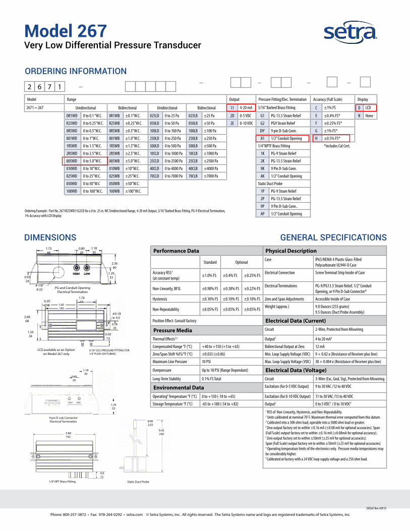
Model 267Very Low Differential Pressure Transducer
Setra’s Model 267 is the most rugged high accuracy, low differ-ential pressure transducer on the market. It delivers accuracies of ±0.25%, 0.4%, 0.5% and ±1% FS and pressure ranges from 0.1” W.C. up to 100” W.C. The 267 is housed in a robust, NEMA 4 rated enclosure and has an optional static pressure probe reducing installation and material costs. The 267 is offered with an optional LCD display and a standard accuracy of ±0.5% making it ideal for high accuracy Pharmaceutical applications.
Customization is StandardThe 267, unlike most competitors, offers many mechanical and electrical options that can be integrated into existing designs. The optional 0.25” diameter pressure probe is made of sturdy extruded aluminum and is designed with baffles to prevent ve-locity pressure errors which saves money and reduces time on the job site.
Robust Enclosure for Difficult ApplicationsThe 267 is housed in a NEMA 4 rated housing and is built to withstand harsh environments. The 267 is available in both wall and duct mount providing the installer with flexible mounting options. The wall mount allows the sensor to be installed anywhere, whereas the duct probe configuration is designed to maximize space efficiency in difficult applications.
The Setra SensorThe core technology of the 267 is the all stainless steel capac-itive sensing element. Setra designs and manufactures all of their sensing elements resulting in full control over the process and quality of every single sensor. The welded dead-ended capacitive sensors requires minimal amplification and delivers excellent accuracy and longterm stability. Setra’s technology has been used in over 8 million installations and has the high-est field acceptance rate in the industry.
n ±0.25%, 0.4%, 0.5%, 1% FS Accuracyn Suitable for Harsh Environmentsn Optional LCD Display
Model 267 Features:
• 0.1” W.C. up to 100” W.C. Pressure Ranges• Optional 3.5 Digit LCD Display w/ 0.5% FS Accuracy• NEMA 4 Rated Housing• PG-9, PG-13 or Conduit Electrical Termination• Integral Static Pressure Probe• 24 VAC or 24 VDC Excitation• Meets CE Conformance Standards
Applications:
• HVAC Systems• Energy Management Systems• Static Duct Pressure• Cleanroom Pressure• Oven Pressurization & Furnace Draft Controls
Phone: 800-257-3872 • Fax: 978-264-0292 • setra.com © Setra Systems, Inc. All rights reserved. The Setra Systems name and logo are registered trademarks of Setra Systems, Inc.
Model 267Very Low Differential Pressure Transducer
SSP267 Rev J 09/15
GENERAL SPECIFICATIONSPerformance Data Physical Description
Standard OptionalCase IP65/NEMA 4 Plastic Glass-Filled
Polycarbonate UL94V-O Case
Accuracy RSS1
(at constant temp)±1.0% FS ±0.4% FS ±0.25% FS
Electrical Connection Screw Terminal Strip Inside of Case
Non-Linearity, BFSL ±0.98% FS ±0.38% FS ±0.22% FSElectrical Terminations PG-9/PG13.5 Strain Relief, 1/2” Conduit
Opening, or 9 Pin D-Sub Connector*
Hysteresis ±0.10% FS ±0.10% FS ±0.10% FS Zero and Span Adjustments Accessible Inside of Case
Non-Repeatability ±0.05% FS ±0.05% FS ±0.05% FSWeight (approx.) 9.0 Ounces (255 grams)
9.5 Ounces (Duct Probe Assembly)
Position Effect: Consult factory Electrical Data (Current)
Pressure Media Circuit 2-Wire, Protected from Miswiring
Thermal Effects2,3 Output7 4 to 20 mA4
Compensated Range °F (°C) +40 to +150 (+5 to +65) Bidirectional Output at Zero 12 mA
Zero/Span Shift %FS/°F (°C) ±0.033 (±0.06) Min. Loop Supply Voltage (VDC) 9 + 0.02 x (Resistance of Receiver plus line)
Maximum Line Pressure 10 PSI Max. Loop Supply Voltage (VDC) 30 + 0.004 x (Resistance of Receiver plus line)
Overpressure Up to 10 PSI (Range Dependant) Electrical Data (Voltage)Long-Term Stability 0.1% FS Total Circuit 3-Wire (Exc, Gnd, Sig), Protected from Miswiring
Environmental Data Excitation (for 0-5 VDC Output) 9 to 30 VAC /12 to 40 VDC
Operating6 Temperature °F (°C) 0 to +150 (-18 to +65) Excitation (for 0-10 VDC Output) 11 to 30 VAC /13 to 40 VDC
Storage Temperature °F (°C) -65 to +180 (-54 to +82) Output3 0 to 5 VDC5 / 0 to 10 VDC5
1 RSS of Non-Linearity, Hysteresis, and Non-Repeatability.2 Units calibrated at nominal 70˚F. Maximum thermal error computed from this datum. 3 Calibrated into a 50K ohm load, operable into a 5000 ohm load or greater.4 Zero output factory set to within ±0.16 mA (±0.08 mA for optional accuracies). Span (Full Scale) output factory set to within ±0.16 mA (±0.08mA for optional accuracy).5 Zero output factory set to within ±50mV (±25 mV for optional accuracies). Span (Full Scale) output factory set to within ±50mV (±25 mV for optional accuracies)6 Operating temperature limits of the electronics only. Pressure media temperatures may be considerably higher.7 Calibrated at factory with a 24 VDC loop supply voltage and a 250 ohm load.
Model Range Output Pressure Fitting/Elec. Termination Accuracy (Full Scale) Display
2671 = 267 Unidirectional Bidirectional Unidirectional Bidirectional 11 4-20 mA 3/16” Barbed Brass Fitting C ±1% FS D LCD
OR1WD 0 to 0.1 “W.C. 0R1WB ±0.1”W.C. 025LD 0 to 25 Pa 025LB ±25 Pa 2D 0-5 VDC G1 PG-13.5 Strain Relief E ±0.4% FS* N None
R25WD 0 to 0.25”W.C. R25WB ±0.25”W.C. 050LD 0 to 50 Pa 050LB ±50 Pa 2E 0-10 VDC G2 PG9 Strain Relief F ±0.25% FS*
0R5WD 0 to 0.5”W.C. 0R5WB ±0.5”W.C. 100LD 0 to 100 Pa 100LB ±100 Pa D91 9 pin D-Sub Conn. G ±1% FS*
001WD 0 to 1”W.C. 001WB ±1.0”W.C. 250LD 0 to 250 Pa 250LB ±250 Pa A1 1/2” Conduit Opening H ±0.5% FS*
1RSWD 0 to 1.5”W.C. 1RSWB ±1.5”W.C. 500LD 0 to 500 Pa 500LB ±500 Pa 1/4”NPTF Brass Fitting *includes Cal Cert.
2R5WD 0 to 2.5”W.C. 2R5WB ±2.5”W.C. 10CLD 0 to 1000 Pa 10CLB ±1000 Pa 1K PG-9 Strain Relief
005WD 0 to 5.0”W.C. 005WB ±5.0”W.C. 25CLD 0 to 2500 Pa 25CLB ±2500 Pa 2K PG-13.5 Strain Relief
010WD 0 to 10”W.C. 010WB ±10”W.C. 40CLD 0 to 4000 Pa 40CLB ±4000 Pa 9K 9 Pin D-Sub Conn.
025WD 0 to 25”W.C. 025WB ±25”W.C. 70CLD 0 to 7000 Pa 70CLB ±7000 Pa AK 1/2” Conduit Opening
050WD 0 to 50”W.C 050WB ±50”W.C. Static Duct Probe
100WD 0 to 100”W.C. 100WB ±100”W.C. 1P PG-9 Strain Relief
2P PG-13.5 Strain Relief
9P 9 Pin D-Sub Conn..
AP 1/2” Conduit Opening
2 6 7 1
Ordering Example: Part No. 2671R25WD11G2CD for a 0 to .25 in. WC Unidirectional Range, 4-20 mA Output, 3/16” Barbed Brass Fitting, PG-9 Electrical Termination, 1% Accuracy with LCD Display
DIMENSIONS
ORDERING INFORMATION

800-543-9038 USA 866-805-7089 CANADA 203-791-8396 LATIN AMERICA
1
06/
10 -
Sub
ject
to c
hang
e. ©
Bel
imo
Airc
ontro
ls (U
SA),
Inc.
Torque min. 180 in-lb, for control of air dampers
ApplicationFor On/Off, fail-safe control of dampers in HVAC systems. Actuator sizing should be done in accordance with the damper manufacturer’s specifications. Control is On/Off from an auxiliary contact, or a manual switch.
The actuator is mounted directly to a damper shaft up to 1.05” in diameter by means of its universal clamp. A crank arm and several mounting brackets are available for applications where the actuator cannot be direct coupled to the damper shaft.
OperationThe AFB N4 and AFX N4 series actuators provide true spring return operation for reliable fail-safe application and positive close off on air tight dampers. The spring return system provides constant torque to the damper with, and without, power applied to the actuator.
The AFB N4 and AFX N4 series provides 95° of rotation and is provided with a graduated position indicator showing 0° to 95°.
The actuator may be stalled anywhere in its normal rotation without the need of mechanical end switches.
The AFBUP-S N4, AFXUP-S N4 versions are provided with two built-in auxiliary switches. These SPDT switches provide safety interfacing or signaling, for example, for fan start-up. The switching function at the fail-safe position is fixed at +10°, the other switch function is adjustable between +10° to +90°.
Dimensions (inches [mm])
6.77
” [17
2]
Clamp Configurations 1/2” Field Selectable 3/4” Centered 1.05” Centered
(Default) (Field Selectable)12.99” [330]
6.45” [163.9]
0.39” [10]
0.92” [23.4]
3.62” [92.1]
9.37” [238] 1.12” [28.5]3.36” [85.2]
3.5”
[0.1
4]
0.81
” [20
.5]
1.17
” [29
.8]
0.79
” [20
]
D31
2_Co
nfi g
Technical Data AFBUP N4, AFBUP-S N4,
AFXUP N4, AFXUP-S N4
Power supply 24...240 VAC -20% / +10%, 50/60 Hz24...125 VDC ±10%
Power consumption running 7 Wholding 3.5 W
Transformer sizing 7 VA @ 24 VAC (class 2 power source)8.5 VA @ 120 VAC18 VA @ 240 VAC
Electrical connection AFBUP... N4 3 ft, 18 GA appliance cable, 1/2” conduit
connector-S models: Two 3 ft, 18 gauge appliance cables with 1/2” conduit connectors
AFXUP... N4 3 ft [1m], 10 ft [3m] or 16 ft [5m] 18 GA appliance cable, with or without 1/2” conduit connector-S models: Two 3 ft [1m], 10 ft [3m] or 16 ft [5m] appliance cables with or without 1/2” conduit connectors
Overload protection Electronic throughout 0 to 95° rotationControl On/OffTorque 180 in-lb [20 Nm] minimumDirection of rotation spring reversible with CW/CCW mounting inside housingMechanical angle of rotation 95° (adjustable with mechanical end stop, 35° to
95°)Running time motor < 75 sec
spring 20 sec @ -4°F to 122°F [-20°C to 50°C];< 60 sec @ -22°F [-30°C]
Position indication visual indicator, 0° to 95°(0° is full spring return position)
Manual override 5 mm hex crank (³⁄₁₆" Allen), suppliedHumidity max. 95% RH non-condensingAmbient temperature -22°F to 122°F [-30°C to 50°C]Storage temperature -40°F to 176°F [-40°C to 80°C]Housing UL Type 4, NEMA 4, IP66Housing material polycarbonateAgency listings † cULus acc. to UL60730-1A/-2-14,
CAN/CSA E60730-1:02, CE acc. to2004/108/EC & 2006/95/EC
Noise level <50dB(A) motor @ 75 seconds≤62dB(A) spring return
Servicing maintenance freeQuality standard ISO 9001Weight 9.7 lbs (4.4 kg), 10 lbs (4.5 kg) with switches† Rated Impulse Voltage 4kV, Type of action 1.AA (1.AA.B for -S version), Control Pollution Degree 4.
AFBUP-S N4, AFXUP-S N4
Auxiliary switches 2 x SPDT 3A (0.5A) @ 250 VAC, UL Approvedone set at +10°, one adjustable 10° to 90°
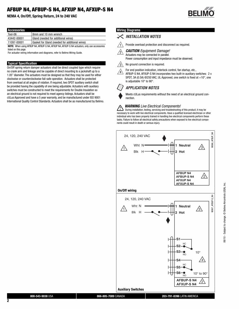
AFBUP N4, AFBUP-S N4, AFXUP N4, AFXUP-S N4NEMA 4, On/Off, Spring Return, 24 to 240 VAC
800-543-9038 USA 866-805-7089 CANADA 203-791-8396 LATIN AMERICA
2
06/1
0 -
Subj
ect t
o ch
ange
. © B
elim
o Ai
rcon
trols
(USA
), In
c.
Accessories
Tool-06 8mm and 10 mm wrench43442-00001 Gland (needed for additional wires)11097-00001 Gasket for Gland (needed for additional wires)NOTE: When using AFBUP N4, AFBUP-S N4, AFXUP N4, AFXUP-S N4 actuators, only use accessories listed on this page.For actuator wiring information and diagrams, refer to Belimo Wiring Guide.
Typical Specification
On/Off spring return damper actuators shall be direct coupled type which require no crank arm and linkage and be capable of direct mounting to a jackshaft up to a 1.05” diameter. The actuators must be designed so that they may be used for either clockwise or counterclockwise fail-safe operation. Actuators shall be protected from overload at all angles of rotation. If required, two SPDT auxiliary switch shall be provided having the capability of one being adjustable. Actuators with auxiliary switches must be constructed to meet the requirements for Double Insulation so an electrical ground is not required to meet agency listings. Actuators shall be cULus Approved and have a 5 year warranty, and be manufactured under ISO 9001 International Quality Control Standards. Actuators shall be as manufactured by Belimo.
AFBUP N4, AFBUP-S N4, AFXUP N4, AFXUP-S N4NEMA 4, On/Off, Spring Return, 24 to 240 VAC
Wiring Diagrams
1 Provide overload protection and disconnect as required.
2 CAUTION Equipment Damage!Actuators may be connected in parallel.Power consumption and input impedance must be observed.
3 No ground connection is required.
4For end position indication, interlock control, fan startup, etc.,AFBUP-S N4, AFXUP-S N4 incorporates two built-in auxiliary switches: 2 x SPDT, 3A (0.5A) @250 VAC, UL Approved, one switch is fi xed at +10°, one is adjustable 10° to 90°.
Meets cULus requirements without the need of an electrical ground con-nection.
WARNING Live Electrical Components! During installation, testing, servicing and troubleshooting of this product, it may be
necessary to work with live electrical components. Have a qualifi ed licensed electrician or other individual who has been properly trained in handling live electrical components perform these tasks. Failure to follow all electrical safety precautions when exposed to live electrical compo-nents could result in death or serious injury.
AFBUP N4 AFBUP-S N4AFXUP N4 AFXUP-S N4
W06
6_AF
BUP_
N4
On/Off wiring
Wht
Blk
AFBUP-S N4AFXUP-S N4
W06
7_AF
BUP-
S_N4
Auxiliary Switches

661342 – UNIVERSITY OF VERMONT MAY 28, 2015– Rev. 0 Air Systems Testing, Adjusting, and Balancing 23 05 93 - 1
SECTION 23 05 93
AIR SYSTEMS TESTING, ADJUSTING, AND BALANCING
PART 1 GENERAL
1.1 SUMMARY
A. Section includes performing balancing and adjusting of heating, ventilating, and air conditioning equipment and associated appurtenances. 1. Adjust and balance complete system as specified herein. 2. Record test data on drawings made from latest available revised set of Drawings. 3. At completion of Work, instruct operating personnel in proper operation and
maintenance of equipment.
1.2 REFERENCES
A. Industry Standard: Perform testing and balancing in accordance with AABC National Standards for Field Measurement and Instrumentation, form number 81266, Volume One.
B. Perform testing of the performance of laboratory fume hoods in accordance with ANSI/ASHRAE Standard 110 – Method of Testing Performance of Laboratory Fume Hoods.
1.3 SYSTEM DESCRIPTION
A. General extent of systems to be balanced is shown on Drawings. Work includes: 1. Baseline readings of Lab supply air and exhaust air systems including air
handling unit, exhaust fans, terminal units, and pressure relationships between the lab spaces as indicated on the drawings prior to any system modifications.
2. Following system modifications, perform testing, adjusting and balancing of supply and exhaust air systems to achieve airflows, velocities, and pressure relationships to match the baseline readings with the exception of one fume hood. The fume hood in the high level lab must be adjusted in accordance with manufacturer’s specifications.
3. Performance testing of Lab fume hoods in accordance with ANSI/ASHRAE Standard 110.
4. Provide assistance during commissioning of control system modifications to help determine control system setpoints for various modes of operation including system responses to failure scenarios and a reduced flow “hibernation” mode for the Lab.
1.4 SUBMITTALS
A. Refer to the Submittal Schedule at the end of Part 3 for a list of Submittal requirements for this Section.

661342 – UNIVERSITY OF VERMONT MAY 28, 2015– Rev. 0 Air Systems Testing, Adjusting, and Balancing 23 05 93 - 2
1.5 QUALITY ASSURANCE
A. Perform Work to obtain optimum performance from systems.
1.6 QUALIFICATIONS
A. Qualifications of Balancing Specialist: 1. Organization whose sole activity is testing, adjusting, and balancing
environmental systems. 2. Organization utilizing only employees experienced and trained specifically in
complete balancing of environmental systems. 3. Organization that has satisfactorily balanced minimum of three systems of
comparable type and size. 4. Organization certified by AABC or NEBB.
1.7 WARRANTY
A. Upon completion of Work and prior to requesting payment, guarantee systems have been balanced to: 1. Tolerances as described in this Section. 2. Lowest sound and vibration levels possible. 3. Lowest energy consumption level possible.
B. Rebalancing: Rebalance environmental systems found outside of criteria specified at no additional cost. This shall include the Lab Hoods if they fail to pass the ANSI/ASHRAE Standard 110 testing.
PART 2 PRODUCTS
2.1 MATERIALS
A. Provided materials, supplies, tools, equipment, labor, and services necessary for balancing, testing, and adjusting Work.
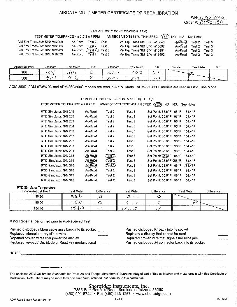
B. Ensure test equipment used in balancing Work has been calibrated within previous 3 months.
PART 3 EXECUTION
3.1 ASSOCIATED WORK
A. System changes required prior to final balance, as determined by initial system check, performed by entity responsible for furnishing and installing that particular system.
661342 – UNIVERSITY OF VERMONT MAY 28, 2015– Rev. 0 Air Systems Testing, Adjusting, and Balancing 23 05 93 - 3
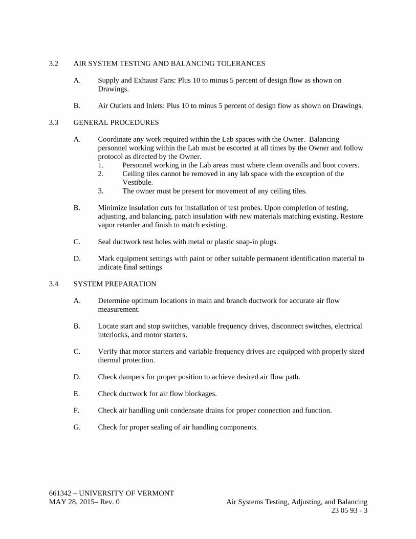
3.2 AIR SYSTEM TESTING AND BALANCING TOLERANCES
A. Supply and Exhaust Fans: Plus 10 to minus 5 percent of design flow as shown on Drawings.
B. Air Outlets and Inlets: Plus 10 to minus 5 percent of design flow as shown on Drawings.
3.3 GENERAL PROCEDURES
A. Coordinate any work required within the Lab spaces with the Owner. Balancing personnel working within the Lab must be escorted at all times by the Owner and follow protocol as directed by the Owner. 1. Personnel working in the Lab areas must where clean overalls and boot covers. 2. Ceiling tiles cannot be removed in any lab space with the exception of the
Vestibule. 3. The owner must be present for movement of any ceiling tiles.
B. Minimize insulation cuts for installation of test probes. Upon completion of testing, adjusting, and balancing, patch insulation with new materials matching existing. Restore vapor retarder and finish to match existing.
C. Seal ductwork test holes with metal or plastic snap-in plugs.
D. Mark equipment settings with paint or other suitable permanent identification material to indicate final settings.
3.4 SYSTEM PREPARATION
A. Determine optimum locations in main and branch ductwork for accurate air flow measurement.
B. Locate start and stop switches, variable frequency drives, disconnect switches, electrical interlocks, and motor starters.
C. Verify that motor starters and variable frequency drives are equipped with properly sized thermal protection.
D. Check dampers for proper position to achieve desired air flow path.
E. Check ductwork for air flow blockages.
F. Check air handling unit condensate drains for proper connection and function.
G. Check for proper sealing of air handling components.

661342 – UNIVERSITY OF VERMONT MAY 28, 2015– Rev. 0 Air Systems Testing, Adjusting, and Balancing 23 05 93 - 4
3.5 LABORATORY FUME HOOD PERFORMANCE TESTING PROCEDURE
A. Provide performance testing of each of the five laboratory fume hoods in accordance with ANSI/ASHRAE Standard 110 – Method of Testing Performance of Laboratory Fume Hoods.
B. Tests shall include: 1. Flow visualization 2. Face velocity measurements 3. Tracer gas containment “as used” (AU) test
C. Testing criteria: 1. Design sash position = 10 inch (verify maximum safe working sash opening) 2. Provide test results at 5 inch also. 3. Minimum face velocity at design sash position = 100 fpm.
3.6 CONSTANT VOLUME AIR SYSTEM BALANCING PROCEDURE
A. Examine fan drives and set proper belt tension and alignment.
B. Adjust fans to deliver total design air flow within maximum allowable rpm listed by manufacturer.
C. Determine fan static pressure as follows: 1. Measure outlet static pressure as far downstream as practicable and upstream
from restrictions, elbows, branches, and transitions. 2. Measure outlet static pressure directly at fan outlet or through flexible
connection. 3. Measure inlet static pressure for single inlet fans in inlet duct as near fan as
possible, upstream from flexible connection and downstream from duct restrictions.
D. Measure static pressure differential across each air handling unit component and each component in ductwork system.
E. Artificially load air filters during balancing to produce air pressure differential midway between initial clean pressure drop and recommended final pressure drop. Submit method and material used for artificial loading to Owner and Engineer for approval prior to testing.
F. Determine variations between design static pressures and actual static pressures. Compare actual system effect factors with design system effect factors. Make corrective changes to align design and actual conditions.
G. Measure system air volume delivery rates by means of duct traverse method.
H. Adjust fans speeds to achieve design air flow rates. Ensure that fan speed adjustments do not overload motors.

661342 – UNIVERSITY OF VERMONT MAY 28, 2015– Rev. 0 Air Systems Testing, Adjusting, and Balancing 23 05 93 - 5
I. Adjust volume dampers for main ductwork, submains, and major branches to design air flows within specified tolerances.
J. Where sufficient space for pitot tube traverse is not available, measure air flow at terminal devices to calculate air flow for that branch.
K. Measure terminal outlets using direct reading hood or outlet manufacturer’s written instruction and calculating factors.
L. Adjust terminal outlets and inlets for each space to design air flows within specified tolerances of design values.
M. Adjust patterns of adjustable outlets for proper distribution without drafts.
N. Ensure that total flow from outlets equals total flow in branch ducts which in turn equal total flow from fan.
O. Ensure that automatic operated devices pertinent to adjustment of air system are set and adjusted to deliver required quantities of air at temperatures specified and shown on Drawings. Coordinate adjustment of automatic control devices with controls specialist.
3.7 MOTORS
A. Test at final balanced condition and record following data: 1. Manufacturer. 2. Model. 3. Serial number. 4. Motor rpm. 5. Efficiency rating. 6. Nameplate and measured voltage for each phase. 7. Nameplate and measured amperage for each phase. 8. Starter thermal protection element rating.
B. Provide following additional tests for motors driven by variable frequency drives: 1. Test for proper operation at speeds varying from minimum to maximum. 2. Test manual bypass (if applicable) for controller to prove proper operation. 3. Record following Variable Frequency Motor Controller information:
a. Manufacturer. b. Model. c. Serial number. d. Nameplate data.
3.8 TEMPERATURE AND HUMIDITY CONTROL VERIFICATION
A. Verify that controllers are calibrated and commissioned.
B. Check transmitter and controller locations and note conditions that would adversely affect control functions.

661342 – UNIVERSITY OF VERMONT MAY 28, 2015– Rev. 0 Air Systems Testing, Adjusting, and Balancing 23 05 93 - 6
C. Record controller settings and note variances between setpoints and actual measurements.
D. Verify operation of limiting controllers.
E. Verify free travel and proper operation of control devices.
F. Verify sequence of operation of control devices.
661342 – UNIVERSITY OF VERMONT MAY 28, 2015– Rev. 0 Air Systems Testing, Adjusting, and Balancing 23 05 93 - 7
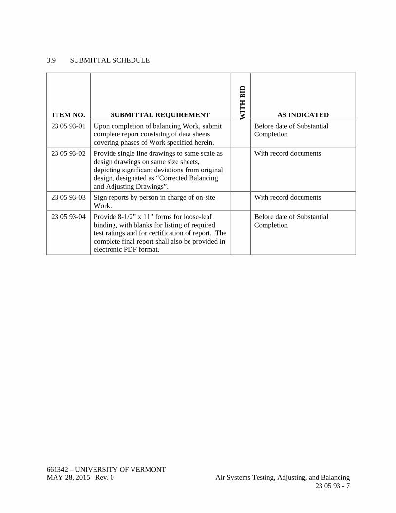
3.9 SUBMITTAL SCHEDULE
ITEM NO. SUBMITTAL REQUIREMENT WIT
H B
ID
AS INDICATED
23 05 93-01 Upon completion of balancing Work, submit complete report consisting of data sheets covering phases of Work specified herein.
Before date of Substantial Completion
23 05 93-02 Provide single line drawings to same scale as design drawings on same size sheets, depicting significant deviations from original design, designated as “Corrected Balancing and Adjusting Drawings”.
With record documents
23 05 93-03 Sign reports by person in charge of on-site Work.
With record documents
23 05 93-04 Provide 8-1/2” x 11” forms for loose-leaf binding, with blanks for listing of required test ratings and for certification of report. The complete final report shall also be provided in electronic PDF format.
Before date of Substantial Completion

661342 – UNIVERSITY OF VERMONT MAY 28, 2015– Rev. 0 Air Systems Testing, Adjusting, and Balancing 23 05 93 - 8
ITEM NO. SUBMITTAL REQUIREMENT WIT
H B
ID
AS INDICATED
23 05 93-05 System Report Data: 1. Fans:
a. Manufacturer, model, and nameplate horsepower.
2. Amperage: a. Nameplate. b. Corrected full load.
3. Operating Voltage: a. Design. b. Operating. c. Motor current characteristics.
4. Speed: a. Design. b. Operating.
5. Brake horsepower: a. Design. b. Operating.
6. Air flow (cfm): a. Design. b. Operating.
7. Suction and discharge static pressures (inches w.c.):
a. Design. b. Operating. c. Test methods for determining
air flow rates.
Before date of Substantial Completion
23 05 93-06 System Report Data: Systems External to Fans:
1. Grille, register, or diffuser reference number and location.
2. Design velocity and cfm. 3. “K” factor.
Before date of Substantial Completion

661342 – UNIVERSITY OF VERMONT MAY 28, 2015– Rev. 0 Air Systems Testing, Adjusting, and Balancing 23 05 93 - 9
ITEM NO. SUBMITTAL REQUIREMENT WIT
H B
ID
AS INDICATED
23 05 93-07 System Report Data: Chilled Water Cooling Coils:
1. Coil face area, rows, and fins/inch. 2. Entering and leaving air condition
(Fdb/Fwb). 3. Air velocity through coil (fpm). 4. Coil static pressure drop (inches
w.g.).
Before date of Substantial Completion
23 05 93-08 System Report Data: Hot Water Heating Coils:
1. Coil face area, rows, and fins/inch. 2. Entering and leaving air condition
(Fdb). 3. Air velocity through coil (fpm). 4. Coil static pressure drop (inches
w.g.).
Before date of Substantial Completion
23 05 93-09 System Report Data: Lab Fume Hoods:
1. Report documenting results of Lab Fume Hood testing per ANSI/ASHRAE Standard 110.
2. Results of flow visualization tests. 3. Fume Hood face velocity
measurements including grid point velocity readings and the average of the integrated readings for each fume hood for both 5” and 10” sash positions.
4. Results of tracer gas tests including the “as used” (AU) performance rating for each hood for both 5” and 10” sash positions. w.g.).
Before date of Substantial Completion
23 05 93-10 Test Equipment: Submit complete list of test equipment used in performing balancing Work complete with serial numbers and verification of latest calibration date.
Prior to delivery
END OF SECTION

661342 – UNIVERSITY OF VERMONT MAY 28, 2015 – Rev. 0 Centrifugal Fans 23 34 16 - 1
SECTION 23 34 16
CENTRIFUGAL FANS
PART 1 GENERAL
1.1 SUMMARY
A. Section includes requirements necessary to furnish and install the following fans: 1. Centrifugal Fans.
B. Related Sections: 1. Section 40 05 15 – Basic Mechanical Requirements.
1.2 PERFORMANCE REQUIREMENTS
A. Provide equipment as indicated on the Equipment Data sheet.
1.3 SUBMITTALS
A. Refer to the Submittal Schedule at the end of Part 3 for a list of submittal requirements for this section.
1.4 QUALITY ASSURANCE
A. Performance Ratings: Conform to AMCA 210.
B. Sound Ratings: AMCA 301, tested to AMCA 300.
C. Balance Quality: Conform to AMCA 204.
1.5 WARRANTY
A. Warrant that materials, equipment, and components supplied will meet specified performance requirements and be free of improper workmanship, faults, leaks, or defects for not less than 1 year after acceptance of equipment by Owner or 18 months after shipment, whichever occurs first. Extend warranty for a period of 1 year for specific repairs made or parts replaced during the initial warranty period.
1.6 DELIVERY, STORAGE, AND HANDLING
A. Receive and inspect fans for damage and shortage at Project Site.
B. Unload fans carefully to avoid damage.
C. Use padded or strap slings.
D. Lift fans only at points recommended by manufacturer.

661342 – UNIVERSITY OF VERMONT MAY 28, 2015 – Rev. 0 Centrifugal Fans 23 34 16 - 2
E. Store fans in safe, dry location.
PART 2 PRODUCTS
2.1 GENERAL
A. The following criteria apply to fans specified in this Section: 1. Belt and Shaft Guards: Provide OSHA approved guards where required for
compliance. 2. Motors:
a. Selection: Provide fan motors rated for at least 110 percent greater horsepower than the required brake horsepower.
b. Provide motor type as indicated on the Equipment Data Sheet. 3. Bearings: Oversized, heavy-duty, grease-lubricated, pillow block ball bearings,
selected for average life (ABMA 9 L10) of not less than 100,000 hours, with extended lube lines.
4. Belt Drives: a. Belt Drive Package: V-belt type, cast iron or steel sheaves, statically and
dynamically balanced, keyed, rated for 120 percent of motor nameplate horsepower. Variable and adjustable pitch sheaves for motors 15 hp and under, selected so required rpm is obtained with sheaves set at mid-position, matched belts.
b. Acceptable Manufacturers: 1) Woods. 2) Browning.
c. Belt and Shaft Guard: Easily removable, OSHA approved with bright yellow finish.
d. Weather Cover: For outdoor applications, factory fabricated drive assembly of same material as fan housing, unless specified otherwise.
e. Provide speed test openings at shaft locations. 5. Vibration Isolation: Provide rubber-in-shear vibration isolation. 6. Access Doors: Provide access doors on the fan housings for inspection of internal
components.
B. Fan Bearings: 1. Select bearings in accordance with standards set forth by the American Bearing
Manufacturer’s Association (ABMA) published rating data. 2. Mount bearings out of the airstream on structural steel supports and/or bases.
Provide either grease-lubricated bearings with external grease fittings and vent lines.
3. Provide self-aligning bearings designed for average life based on ABMA rating designations.
2.2 CENTRIFUGAL FANS – CLASS I THROUGH IV
A. Acceptable Manufacturers: 1. Barry Blower. 2. Howden.

661342 – UNIVERSITY OF VERMONT MAY 28, 2015 – Rev. 0 Centrifugal Fans 23 34 16 - 3
3. Greenheck. 4. Industrial Air Products. 5. New York Blower. 6. Twin City.
B. Centrifugal Fans, General: 1. Centrifugal spiral-shaped fan scroll welded to straight and parallel sides with
welded inlet and outlet flanges. Include a single spun inlet bell ground smooth and treated or coated as specified for the intended service.
2. Bearings: Provide bearing support constructed of structural channels or heavy-formed angles. Mount the bearing out of airstream.
3. Shaft Seals: Install shaft seals to fill the shaft hole in the fan housing. Provide seal materials suitable for intended service.
4. Shafts: Construct shafts with AISI C-1018, 1040, or 1045 hot-rolled steel, ground, polished, and ring gauged. Size shafts so that its first critical speed will be at least 1.35 times the maximum operating speed. Provide 0.0003 inch or less per foot of shaft length for lateral static deflection.
5. Drain: Provide low-point drain in fan scroll, constructed from a threaded pipe coupling welded to the housing scroll, and fitted with a PVC plug.
6. Fan Housing: Constructed of steel of suitable thickness and reinforcement required by the fan class rating and service environment.
7. Finish and coating: Thoroughly degrease and deburr the entire fan assembly and apply a rust-preventative primer. Following fan assembly apply a finish coat of paint to the entire assembly. Coat fan shaft with a rust protectant.
PART 3 EXECUTION
3.1 ISOLATION
A. Isolate sheet metal duct connection from fan using flexible connection to match existing.
B. Install fan mounts using rubber-in-shear isolators as specified in data sheets at the end of this Section.
3.2 INSTALLATION
A. Locate units where shown on the Drawings and provide access space for motor, drive, bearing service, and fan shaft removal.
B. Perform lubrication, drive belt setup, and additional manufacturer’s installation requirements prior to startup.
3.3 FIELD QUALITY CONTROL
A. Startup Services: 1. Provide a manufacturer’s factory-trained technician to assist the Contractor
during installation and to provide written certification that the equipment has been installed as specified and in accordance with the manufacturer’s directions.

661342 – UNIVERSITY OF VERMONT MAY 28, 2015 – Rev. 0 Centrifugal Fans 23 34 16 - 4
2. Log and record startup performance data from field tests and adjust as necessary to meet specified performance.
3. After the fan is operating normally, conduct instructional sessions with the Owner’s service personnel to: a. Review the maintenance manuals. b. Perform each step necessary for startup, shutdown, troubleshooting, and
routine maintenance. c. Schedule this service orientation through the Owner.
4. Upon completion of the inspections, startup, testing, and checkout procedures, submit a written notice to the Owner that the units are ready for beneficial use.
3.4 ATTACHMENTS
A. The following attachments (attached after End of Section) are part of this Section: 1. Equipment Data Sheet.
3.5 SUBMITTAL SCHEDULE
ITEM NO. SUBMITTAL REQUIREMENT WIT
H B
ID
AS INDICATED
23 34 16-01 Provide the following detailed information on the equipment proposed. Itemize deviations from the specified requirements. If not so indicated, unit manufacturer will be required to furnish at no cost to the owner: A. Information requested in the RFQ,
including equipment data sheets, schedules and sketches.
B. Equipment drawings showing dimensions, weights (shipping & operating), configuration, and duct connection sizes and locations.
C. Materials of construction for housing and major components.
X
23 34 16-04 Product Data: Include: A. Unit designation number. B. Type of unit. C. Manufacturer’s name and model number. D. Dimensions of unit, mounting
attachments, and specified accessories. E. Description of fabrication materials for
unit.
X

661342 – UNIVERSITY OF VERMONT MAY 28, 2015 – Rev. 0 Centrifugal Fans 23 34 16 - 5
ITEM NO. SUBMITTAL REQUIREMENT WIT
H B
ID
AS INDICATED
23 34 16-05 Description of unit motor including: A. Manufacturer’s name and model number. B. Nameplate horsepower. C. Efficiency (%). D. Service factor. E. Type enclosure. F. Speed (rpm). G. Electrical characteristics (V/Ph/Hz).
X
23 34 16-06 Description of unit drive package including: A. Manufacturer’s name and model number
for sheaves and belts. B. Horsepower rating. C. Sheave diameters. D. Bushing sizes. E. Belt sizes and numbers. F. Percent adjustment above and below
design setpoint.
X
23 34 16-07 Shipping and operating weights of unit with weight distribution at support points.
X
23 34 16-08 Fan performance curves indicating: A. Air quantity. B. Static pressure. C. Bhp. D. Efficiency. E. Tip speed. F. Rpm. G. Sound power level (dB re10-12 watts) for
each octave band.
X
661342 – UNIVERSITY OF VERMONT MAY 28, 2015 – Rev. 0 Centrifugal Fans 23 34 16 - 6
ITEM NO. SUBMITTAL REQUIREMENT WIT
H B
ID
AS INDICATED
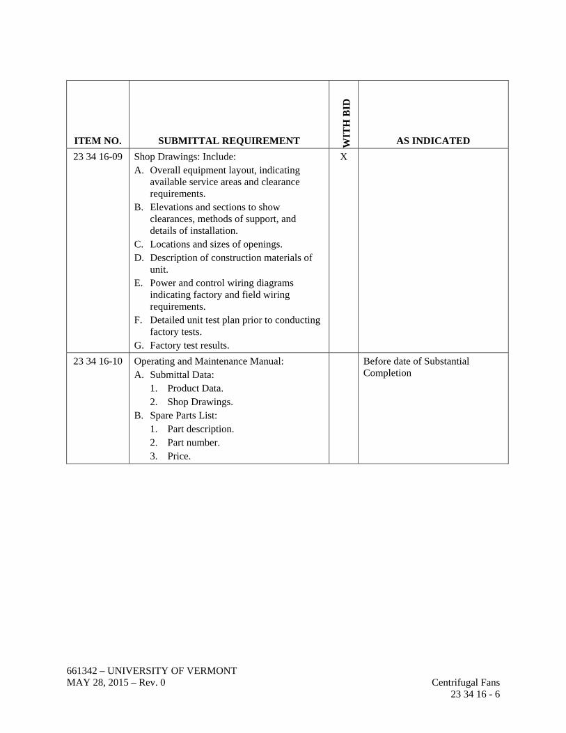
23 34 16-09 Shop Drawings: Include: A. Overall equipment layout, indicating
available service areas and clearance requirements.
B. Elevations and sections to show clearances, methods of support, and details of installation.
C. Locations and sizes of openings. D. Description of construction materials of
unit. E. Power and control wiring diagrams
indicating factory and field wiring requirements.
F. Detailed unit test plan prior to conducting factory tests.
G. Factory test results.
X
23 34 16-10 Operating and Maintenance Manual: A. Submittal Data:
1. Product Data. 2. Shop Drawings.
B. Spare Parts List: 1. Part description. 2. Part number. 3. Price.
Before date of Substantial Completion
661342 – UNIVERSITY OF VERMONT MAY 28, 2015 – Rev. 0 Centrifugal Fans 23 34 16 - 7
By:
Owner: University of Vermont Date:
Equipment No.: EF-7
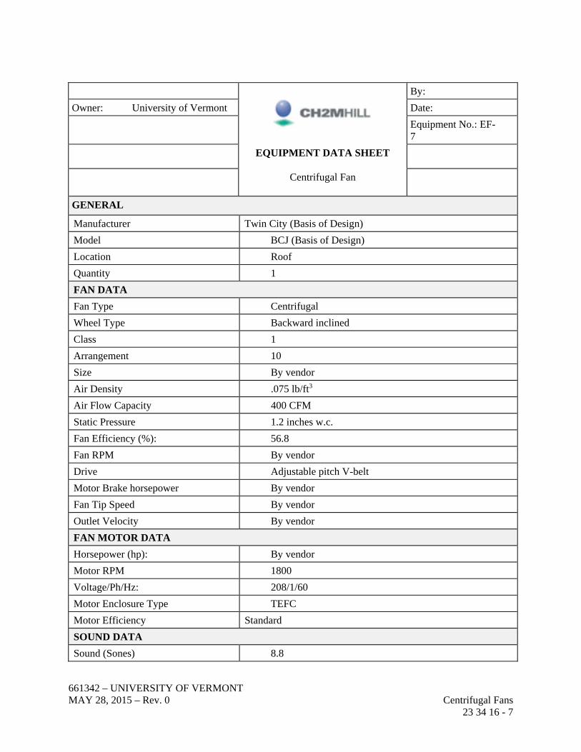
EQUIPMENT DATA SHEET
Centrifugal Fan
GENERAL
Manufacturer Twin City (Basis of Design)
Model BCJ (Basis of Design)
Location Roof
Quantity 1
FAN DATA
Fan Type Centrifugal
Wheel Type Backward inclined
Class 1
Arrangement 10
Size By vendor
Air Density .075 lb/ft3
Air Flow Capacity 400 CFM
Static Pressure 1.2 inches w.c.
Fan Efficiency (%): 56.8
Fan RPM By vendor
Drive Adjustable pitch V-belt
Motor Brake horsepower By vendor
Fan Tip Speed By vendor
Outlet Velocity By vendor
FAN MOTOR DATA
Horsepower (hp): By vendor
Motor RPM 1800
Voltage/Ph/Hz: 208/1/60
Motor Enclosure Type TEFC
Motor Efficiency Standard
SOUND DATA
Sound (Sones) 8.8

661342 – UNIVERSITY OF VERMONT MAY 28, 2015 – Rev. 0 Centrifugal Fans 23 34 16 - 8
By:
Owner: University of Vermont Date:
Equipment No.: EF-7
EQUIPMENT DATA SHEET
Centrifugal Fan
Inlet Sound Power
1st Octave 60
2nd Octave 65
3rd Octave 66
4th Octave 67
5th Octave 67
6th Octave 64
7th Octave 59
8th Octave 50
MAXIMUM DIMENSIONS
Length 27”
Width 20”
Height 27”
Operating Weight 90 lbs
ACCESSORIES
Bolted access door
Housing drain and plug
Inlet and companion flanges
Companion flange and sleeve
Rubber-in-shear vibration isolators
Weather Cover
REMARKS
END OF SECTION

661342 – UNIVERSITY OF VERMONT MAY 28, 2015– Rev.0 Basic Electrical Construction Materials and Methods 26 05 02 - 1
SECTION 26 05 02
BASIC ELECTRICAL CONSTRUCTION MATERIALS AND METHODS
PART 1 GENERAL
1.1 SUMMARY
A. Section includes requirements specifically applicable to Division 26.
B. Section Includes: 1. Vibration isolation. 2. Demolition. 3. Conduit. 4. Wire and cable. 5. Boxes. 6. Cabinets and enclosures. 7. Terminal blocks and accessories. 8. Wiring devices. 9. Supporting devices. 10. Electrical identification. 11. Disconnect switches. 12. Grounding. 13. Equipment and systems to meet project seismic requirements.
C. Work Excluded: 1. Power company metering facilities. 2. Incoming communication service. 3. Interior communication system.
D. The Contractor shall be responsible for furnishing and installing incidental items not actually shown or specified but which are required by good practice to provide complete functional systems.
E. Intent of Drawings: 1. Electrical plan drawings show only general locations of equipment and devices
unless specifically dimensioned. 2. The Contractor shall be responsible for the proper routing of conduit and cable
for power and controls.
1.2 DESIGN REQUIREMENTS
A. For materials specified in this Section, minimum standard of quality shall be in accordance with applicable industry standards, including, but not limited to, NEMA, ANSI, IEEE, UL, and federal standards publications.
B. Electrical components shall be UL listed and labeled and meet applicable requirements of Factory Mutual.

661342 – UNIVERSITY OF VERMONT MAY 28, 2015– Rev.0 Basic Electrical Construction Materials and Methods 26 05 02 - 2
C. Compliance by the Contractor with the provisions of this Specification does not relieve him of the responsibilities of furnishing equipment and materials of proper design, mechanically and electrically suited to meet operating guarantees at the specified service conditions.
D. Equipment and devices to be installed outdoors or in unheated enclosures shall be capable of continuous operation within an ambient temperature of -20 to 120 degrees F, and a relative humidity of zero to 100 percent.
E. Where applicable, equipment and installation shall meet requirements for corrosive and hazardous locations.
F. Conform to the latest codes and legal requirements, obtain permits, and arrange for inspections.
1.3 SUBMITTALS
A. Refer to the Submittal Schedule at the end of Part 3 for a list of submittal requirements for this Section.
PART 2 PRODUCTS
2.1 MATERIALS AND EQUIPMENT
A. Materials and Equipment: Labeled and/or listed as acceptable to the authority having jurisdiction as suitable for the use intended.
B. Where two or more units of the same class of material are required, provide products of a single manufacturer. Component parts of materials or equipment need not be products of the same manufacturer.
C. Provide manufacturer's standard finish color except where specific color is indicated.
2.2 VIBRATION ISOLATION
A. Unit Double Neoprene Pad (DNP): Formed by two layers of 1/4-inch- to 3/8-inch-thick ribbed or waffled neoprene, separated by a stainless steel or aluminum plate with layers permanently adhered together; 40- to 50-durometer neoprene; pads sized so that they will be loaded within manufacturer's recommended range. Provide steel top plate equal to the size of the pad to transfer weight of supported unit to pads and to distribute load evenly over surface of pads.
B. Unit DNP isolators shall be formed from one of the following products: 1. Type NR: Amber/Booth. 2. Type Korpad: Korfund Dynamics. 3. Type WSW: Mason Industries. 4. Type NPS: Peabody Noise Control. 5. Series Shear Flex: Vibration Mountings & Control.

661342 – UNIVERSITY OF VERMONT MAY 28, 2015– Rev.0 Basic Electrical Construction Materials and Methods 26 05 02 - 3
C. Unit Hanger Neoprene or Glass Fiber (HN): Neoprene-in-shear or glass fiber element contained in a steel housing. Provide neoprene neck bushing (or other element) where hanger rod passes through hanger housing to prevent rod from contacting hanger housing; diameter of hole in housing sufficient to permit hanger rod to swing through a 30 degree arc before contacting hanger housing.
D. Unit HN isolators shall be one of the following products: 1. Type BRD-A: Amber/Booth. 2. Type H: Korfund Dynamics. 3. Type HD: Mason Industries. 4. Type RH or FH: Peabody Noise Control. 5. Type RHD or RFD: Vibration Mountings & Control.
E. Structural Isolation Breaks (SIB): 1. Utilize pad isolators for busway, cable tray, wireway, and 4-inch and larger
conduit at SIBs. 2. Support one end on 1-inch isolators for 25-feet on one side of SIB.
F. Flexible Electrical Connections: 1. Type A: Field fabricated using a minimum 24-inch length of flexible conduit or
cable. 2. Type B: Field fabricated using a minimum 48-inch length of flexible conduit or
cable.
2.3 METAL CONDUIT AND FITTINGS
A. Rigid Steel Conduit: Rigid galvanized steel.
B. Intermediate Metal Conduit (IMC): Galvanized steel.
C. PVC Externally Coated Conduit: Rigid steel conduit with external 20-mil PVC coating and internal phenolic coating over a galvanized surface.
D. Electrical Metallic Tubing (EMT): Galvanized tubing.
E. Flexible Metal Conduit: Steel.
F. Liquidtight Flexible Conduit: Flexible metal conduit with PVC jacket.
G. Fittings and Conduit Bodies: Threaded type or [compression type for EMT; material to match conduit.
2.4 NONMETALLIC CONDUIT AND FITTINGS
A. Rigid Nonmetallic Conduit: Schedule 40 PVC.
B. Electrical Plastic Tubing (EPT): PVC.
C. Liquidtight Nonmetallic Flexible Conduit: Flexible plastic conduit.
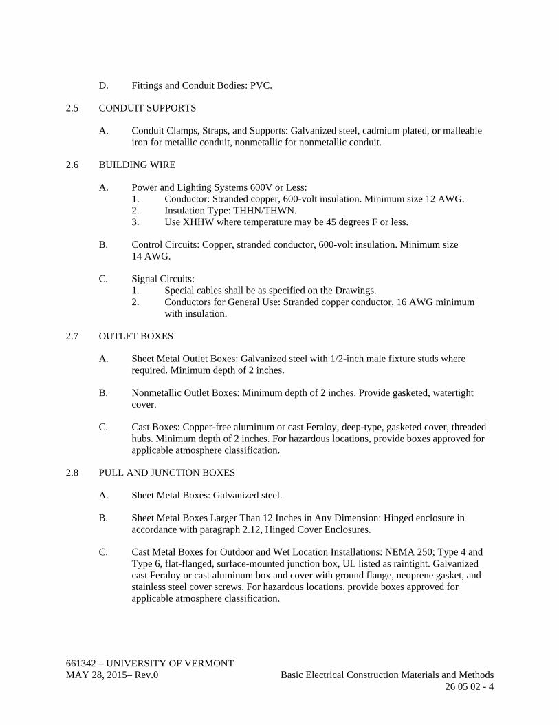
661342 – UNIVERSITY OF VERMONT MAY 28, 2015– Rev.0 Basic Electrical Construction Materials and Methods 26 05 02 - 4
D. Fittings and Conduit Bodies: PVC.
2.5 CONDUIT SUPPORTS
A. Conduit Clamps, Straps, and Supports: Galvanized steel, cadmium plated, or malleable iron for metallic conduit, nonmetallic for nonmetallic conduit.
2.6 BUILDING WIRE
A. Power and Lighting Systems 600V or Less: 1. Conductor: Stranded copper, 600-volt insulation. Minimum size 12 AWG. 2. Insulation Type: THHN/THWN. 3. Use XHHW where temperature may be 45 degrees F or less.
B. Control Circuits: Copper, stranded conductor, 600-volt insulation. Minimum size 14 AWG.
C. Signal Circuits: 1. Special cables shall be as specified on the Drawings. 2. Conductors for General Use: Stranded copper conductor, 16 AWG minimum
with insulation.
2.7 OUTLET BOXES
A. Sheet Metal Outlet Boxes: Galvanized steel with 1/2-inch male fixture studs where required. Minimum depth of 2 inches.
B. Nonmetallic Outlet Boxes: Minimum depth of 2 inches. Provide gasketed, watertight cover.
C. Cast Boxes: Copper-free aluminum or cast Feraloy, deep-type, gasketed cover, threaded hubs. Minimum depth of 2 inches. For hazardous locations, provide boxes approved for applicable atmosphere classification.
2.8 PULL AND JUNCTION BOXES
A. Sheet Metal Boxes: Galvanized steel.
B. Sheet Metal Boxes Larger Than 12 Inches in Any Dimension: Hinged enclosure in accordance with paragraph 2.12, Hinged Cover Enclosures.
C. Cast Metal Boxes for Outdoor and Wet Location Installations: NEMA 250; Type 4 and Type 6, flat-flanged, surface-mounted junction box, UL listed as raintight. Galvanized cast Feraloy or cast aluminum box and cover with ground flange, neoprene gasket, and stainless steel cover screws. For hazardous locations, provide boxes approved for applicable atmosphere classification.

661342 – UNIVERSITY OF VERMONT MAY 28, 2015– Rev.0 Basic Electrical Construction Materials and Methods 26 05 02 - 5
2.9 HINGED COVER ENCLOSURES
A. Construction: NEMA 250; Type 1 for indoor dry locations where enclosed equipment is required to be ventilated, Type 4 for indoor or outdoor wet locations, 4X for indoor or outdoor wet corrosive locations, or 12 for indoor dry locations; steel, except corrosive to be FRP.
B. Finish: Manufacturer's standard enamel finish.
C. Covers: Gasketed with continuous hinge, held closed by flush latch operable by screwdriver.
D. Interior Panel for Mounting Terminal Blocks or Electrical Components: 14-gauge steel, white enamel finish.
2.10 TERMINAL BLOCKS AND ACCESSORIES
A. Power Terminals: Unit construction, closed-back type, with tubular pressure screw connectors, rated 600 volts. Provide 25 percent spare terminals.
B. Signal and Control Terminals: Modular construction type, DIN 46 277/3 channel mounted; screw clamp compression connectors, rated 300 volts. Minimum terminal width of 0.24 inch, capable of holding two 12 AWG or two 14 AWG conductors in each connector. Terminal identification numbers shall be thermoset characters (black) on a white background. Provide 25 percent spare terminals.
2.11 SUPPORTING DEVICES
A. Support Channel or Angle: Galvanized steel in general, stainless galvanized steel in corrosive areas.
B. Hardware: Cadmium- or zinc-plated in general, corrosion resistant in corrosive areas.
C. For individual conduit runs not directly fastened to the structure, use rod hangers manufactured by Unistrut.
D. For multiple conduit runs, use galvanized steel or angle trapeze-type conduit support designed for maximum deflection not greater than 1/8 inch.
2.12 ELECTRICAL IDENTIFICATION
A. Nameplates: Engraved three-layer laminated plastic, minimum 3/16-inch-high white letters on a black background. Emergency Equipment Nameplates: White letters on a red background.
B. Tape Labels: Embossed adhesive tape with minimum 3/16-inch white letters on black background or 3/16-inch Kroy black letters on a white background.

661342 – UNIVERSITY OF VERMONT MAY 28, 2015– Rev.0 Basic Electrical Construction Materials and Methods 26 05 02 - 6
C. Wire and Cable Markers: Clear, heat-shrink tubing type Brady LS2000; cloth or wraparound-adhesive types not approved.
D. Conductor-Color Tape: Colored vinyl electrical tape.
2.13 DISCONNECT SWITCHES
A. Fusible Switch Assemblies: Quick-make, quick-break, load-interrupter enclosed knife switch with externally operable handle interlocked to prevent opening front cover with switch in on position. Handle lockable in off position. Fuse Clips: Designed to accommodate Class R fuses.
B. Nonfusible Switch Assemblies: Type HD; quick-make, quick-break, load-interrupter enclosed knife switch with externally operable handle interlocked to prevent opening front cover with switch in on position. Handle lockable in off position.
C. Enclosures: as indicated on the Drawings.
2.14 GROUNDING
A. Ground Connections: Exothermic welded-type connectors as manufactured by Cadweld or Thermoweld or compression type of connectors designed for this special purpose as manufactured by Burndy or Thomas and Betts.
PART 3 EXECUTION
3.1 BASIC ELECTRICAL INSTALLATION REQUIREMENTS
A. Workmanship: 1. Install work using procedures defined in NECA Standard of Installation. 2. Install material and equipment in accordance with manufacturer's instructions.
Provide calibrated torque wrenches and screwdrivers as required. 3. Utilize booties for work within AHU.
B. Service Continuity: 1. Maintain continuity of electric service to functioning portions of process or
buildings during the hours of normal use. 2. Arrange temporary outages for cutover work with the Owner. Keep the outages
to a minimum number and minimum length of time. 3. Lab downtime is a critical project issue. Minimize lab HVAC downtime during
switchover and reprogramming. This will minimize the possibility of lab contamination and cleaning.
C. Startup Testing and Inspection of Electrical Equipment: 1. Provide tests specified hereinafter and as indicated under individual items of
materials and equipment specified in other sections. 2. Performance Test:
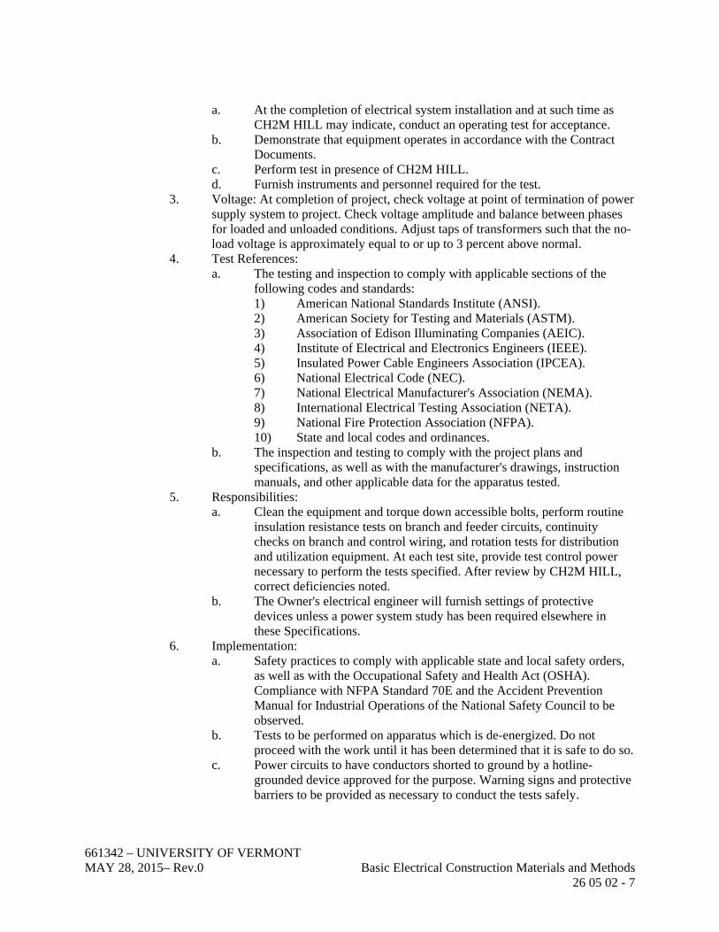
661342 – UNIVERSITY OF VERMONT MAY 28, 2015– Rev.0 Basic Electrical Construction Materials and Methods 26 05 02 - 7
a. At the completion of electrical system installation and at such time as CH2M HILL may indicate, conduct an operating test for acceptance.
b. Demonstrate that equipment operates in accordance with the Contract Documents.
c. Perform test in presence of CH2M HILL. d. Furnish instruments and personnel required for the test.
3. Voltage: At completion of project, check voltage at point of termination of power supply system to project. Check voltage amplitude and balance between phases for loaded and unloaded conditions. Adjust taps of transformers such that the no-load voltage is approximately equal to or up to 3 percent above normal.
4. Test References: a. The testing and inspection to comply with applicable sections of the
following codes and standards: 1) American National Standards Institute (ANSI). 2) American Society for Testing and Materials (ASTM). 3) Association of Edison Illuminating Companies (AEIC). 4) Institute of Electrical and Electronics Engineers (IEEE). 5) Insulated Power Cable Engineers Association (IPCEA). 6) National Electrical Code (NEC). 7) National Electrical Manufacturer's Association (NEMA). 8) International Electrical Testing Association (NETA). 9) National Fire Protection Association (NFPA). 10) State and local codes and ordinances.
b. The inspection and testing to comply with the project plans and specifications, as well as with the manufacturer's drawings, instruction manuals, and other applicable data for the apparatus tested.
5. Responsibilities: a. Clean the equipment and torque down accessible bolts, perform routine
insulation resistance tests on branch and feeder circuits, continuity checks on branch and control wiring, and rotation tests for distribution and utilization equipment. At each test site, provide test control power necessary to perform the tests specified. After review by CH2M HILL, correct deficiencies noted.
b. The Owner's electrical engineer will furnish settings of protective devices unless a power system study has been required elsewhere in these Specifications.
6. Implementation: a. Safety practices to comply with applicable state and local safety orders,
as well as with the Occupational Safety and Health Act (OSHA). Compliance with NFPA Standard 70E and the Accident Prevention Manual for Industrial Operations of the National Safety Council to be observed.
b. Tests to be performed on apparatus which is de-energized. Do not proceed with the work until it has been determined that it is safe to do so.
c. Power circuits to have conductors shorted to ground by a hotline-grounded device approved for the purpose. Warning signs and protective barriers to be provided as necessary to conduct the tests safely.

661342 – UNIVERSITY OF VERMONT MAY 28, 2015– Rev.0 Basic Electrical Construction Materials and Methods 26 05 02 - 8
d. In general utilize methods outlined in acceptance testing specifications for electrical power distribution equipment and systems from the International Electrical Testing Association (NETA), but do not exceed manufacturer’s limitations.
7. Reports: a. The test report to include the following sections:
1) Scope of testing. 2) Equipment tested. 3) Description of test. 4) Test results. 5) Conclusions and recommendations. 6) Appendix, including test forms.
b. Each piece of equipment to be recorded on a data sheet listing the condition of the equipment as found and as left. Include recommendations for necessary repair and/or replacement parts. The data sheets to indicate the name of the engineer who tested the equipment and the date of the test completion.
3.2 INSTALLATION OF VIBRATION ISOLATION
A. Isolated electrical equipment to be positioned so that it is freestanding and does not contact the building structure or other systems.
B. Mechanical Equipment: Electrical connections to vibration-isolated mechanical equipment to be made using flexible electrical connections. Connections made with conduit less than 1 inch to be Type A or Type B; for conduit sized 1 inch and larger, use Type B.
C. Isolation Mounts: 1. Mounts to be aligned squarely above or below mounting points for the supported
equipment. 2. If a housekeeping pad is provided, the isolators to bear on the housekeeping pad
and the isolator baseplate to rest entirely on the pad. 3. Hanger rods for vibration-isolated support to be connected to structural beams or
joists, not from the floor slab between beams and joists. Provide intermediate support members as necessary.
4. Vibration-isolation hanger elements to be positioned as high as possible in the hanger rod assembly, but not in contact with the building structure, and so that the hanger housing may rotate a full 360 degrees about the rod axis without contacting objects.
D. Flexible Electrical Connections: 1. Type B connections to be installed in a grossly slack U shape or a 360 degree
loop. 2. The flexible coupling or conduit not be tied to the building structure or other
rigid material beyond the point where it takes off from the rigid conduit.

661342 – UNIVERSITY OF VERMONT MAY 28, 2015– Rev.0 Basic Electrical Construction Materials and Methods 26 05 02 - 9
3.3 DEMOLITION
A. Verify that field measurements and circuiting arrangements.
B. Verify that abandoned wiring and equipment serve only abandoned equipment.
C. Demolition based on field walkthrough with Owner.
D. Beginning of demolition means Contractor accepts existing conditions.
E. Remove, relocate, and extend existing installations to accommodate new construction.
F. Remove abandoned conductors to source of supply.
G. Remove exposed abandoned conduit, including abandoned conduit above accessible ceiling finishes. Cut embedded or concealed conduit flush with walls and floors and patch surfaces.
H. Disconnect and remove electrical devices and equipment serving utilization equipment that has been removed.
I. Repair adjacent construction and finishes damaged during demolition and extension work.
J. Maintain access to existing electrical installations which remain active. Modify installation or provide access panel as appropriate.
K. Extend existing installations using materials and methods compatible with existing electrical installations or as specified.
L. Clean and repair existing materials and equipment which remain or are to be reused.
3.4 INSTALLATION OF CONDUIT
A. Route exposed conduit and conduit above accessible ceilings parallel and perpendicular to walls and adjacent piping.
B. Maintain minimum 6-inch clearance between conduit and piping. Maintain 12-inch clearance between conduit and heat sources such as flues, steam pipes, and heating appliances. Maintain minimum 18-inch clearance above ceiling grid.
C. Arrange conduit supports to prevent distortion of alignment by wire-pulling operations. Fasten conduit using galvanized straps, lay-in adjustable hangers, clevis hangers, or bolted split stamped galvanized hangers.
D. Do not fasten conduit with wire or perforated pipe straps. Remove wire used for temporary conduit support during construction before conductors are pulled.
E. Cut conduit square using a saw or pipecutter; deburr cut ends.

661342 – UNIVERSITY OF VERMONT MAY 28, 2015– Rev.0 Basic Electrical Construction Materials and Methods 26 05 02 - 10
F. Bring conduit to the shoulder of fittings and couplings and fasten securely.
G. Use conduit hubs for fastening conduit to cast boxes and for fastening conduit to sheet metal boxes in damp or wet locations.
H. Except for communications conduits, use conduit bodies to make sharp changes in direction as around beams. Conduit bodies to be readily accessible.
I. Avoid moisture traps where possible; where unavoidable, provide junction box with drain fitting at conduit low point.
J. Use suitable conduit caps to protect installed conduit against entrance of dirt and moisture. Provide a permanent cap over each end of each empty conduit.
K. Provide a pull rope or pull tape in each empty conduit. Tie pull rope securely to duct plug or wall racking at each end. Provide conduit identification at each end.
L. Install expansion-deflection joints where conduit crosses building expansion or structural isolation break (SIB) joints; Expansion fittings to have copper bonding jumper.
M. Where conduit penetrates fire-rated walls and floors, seal opening around conduit with UL-listed foamed silicone elastomer compound with rating equal to or greater than the wall/floor penetrated.
N. Use PVC-coated rigid steel factory elbows for bends in plastic conduit runs longer than 100 feet or in plastic conduit runs which have more than two bends regardless of length.
O. Wipe plastic conduit clean and dry before joining. Apply full, even coat of cement to entire area that will be inserted into fitting. Let joint cure for 20 minutes minimum.
P. Concealed, embedded, and buried conduit to emerge at right angles to the surface and have none of the curved portion of the bend exposed.
Q. Provide warning tapes above underground conduits.
R. For conduits penetrating other interior areas with at least a 20 degree F delta in temperature, provide seal-offs on each side of the wall, fill both with sealant, and seal the conduit-to-wall interface on both sides.
3.5 CONDUIT INSTALLATION SCHEDULE
A. Exposed Outdoor Locations: Rigid steel conduit.
B. Wet Interior Locations: Rigid steel conduit.
C. Concealed Dry Interior Locations: Electrical metallic tubing.
D. Exposed Dry Interior Locations: Electrical metallic tubing.

661342 – UNIVERSITY OF VERMONT MAY 28, 2015– Rev.0 Basic Electrical Construction Materials and Methods 26 05 02 - 11
E. Corrosive Interior Locations: Schedule 40 PVC conduit.
F. Hazardous (Classified) Locations: Rigid steel conduit.
3.6 INSTALLATION OF BUILDING WIRE
A. Place an equal number of conductors for each phase of a circuit in same raceway or cable.
B. Splice only in junction or outlet boxes. Control cables to be spliced on terminal blocks and only with the written permission of CH2M HILL.
C. Neatly train and lace wiring inside boxes, equipment, and panelboards.
D. Make conductor lengths for parallel circuits equal.
E. Where connection of cables installed under this Section is to be made by others, provide pigtails of adequate length for neat, trained, and bundled connections.
F. Pull all conductors into a raceway at the same time. Use UL-listed wire-pulling lubricate for pulling 4 AWG and larger wires.
G. Install wire in raceway after interior of building has been physically protected from the weather and mechanical work likely to injure conductors has been completed.
H. Completely and thoroughly swab raceway system before installing conductors.
I. Use solderless pressure connectors with insulating covers for copper wire splices and taps 8 AWG and smaller. For 10 AWG and smaller, use insulated-spring wire connectors with plastic caps on lighting and receptacle circuits.
J. Control circuit conductors to be terminated at terminal blocks only.
K. Use split-bolt connectors for copper wire splices and taps 6 AWG and larger. Tape uninsulated conductors and connectors with electrical tape to 150 percent of the insulation value of conductor.
L. Thoroughly clean wires before installing lugs and connectors.
M. Make splices, taps, and terminations to carry full ampacity of conductors without perceptible temperature rise.
N. Terminate spare conductors with electrical tape.
O. Inspect wire and cable for physical damage and proper connection.
P. Torque test conductor connections and terminations to manufacturer's recommended values.

661342 – UNIVERSITY OF VERMONT MAY 28, 2015– Rev.0 Basic Electrical Construction Materials and Methods 26 05 02 - 12
Q. Perform continuity and insulation tests on power and equipment branch circuit conductors. Verify proper phasing connections.
3.7 INSTALLATION OF BOXES
A. Types to be Provided, Steel Raceway System: 1. Exterior Locations: Cast Feraloy with neoprene gaskets. 2. Interior Locations With:
a. Rigid Steel Conduit: Cast Feraloy. b. Intermediate Metallic Conduit: Cast Feraloy. c. Electrical Metallic Tubing: Sheet steel. d. Communications Wireway: Same material as wireway.
3. Interior Wet Locations with Exposed and Concealed Raceways: Cast Feraloy with neoprene gaskets.
B. Types to be Provided – Plastic Raceway System: Nonmetallic.
C. Single In-Line Communications Conduit Runs: 1. 2-inch Conduit and Smaller: Type C conduit bodies of cast Feraloy or
nonmetallic construction as required for the location. Gaskets outdoors and in wet locations.
2. Conduit Larger Than 2-Inch: Straight-through communications wireway as specified for the location.
D. Do not install outlet boxes back to back in walls.
E. Locate outlet boxes in masonry walls to require cutting of masonry unit corner only.
F. Provide knockout closures for unused openings.
G. Support outlet boxes independently of conduit.
H. Use multiple-gang outlet boxes where multiple devices are mounted together; do not use sectional boxes. Provide barriers to separate wiring of different voltage systems.
I. Install outlet boxes in walls without damaging wall insulation.
J. Coordinate mounting heights and locations of outlets mounted above counters, benches, and backsplashes.
K. In inaccessible ceiling areas, position outlets and junction boxes within 6 inches of recessed luminaire to be accessible through luminaire ceiling opening.
L. Provide recessed outlet boxes in finished areas; secure boxes to interior wall and partition studs, accurately positioning to allow for surface finish thickness. Use stamped steel stud bridges for flush outlets in hollow stud wall and adjustable steel channel fasteners for flush ceiling outlet boxes.
M. Locate pull boxes and junction boxes above accessible ceilings or in unfinished areas.
661342 – UNIVERSITY OF VERMONT MAY 28, 2015– Rev.0 Basic Electrical Construction Materials and Methods 26 05 02 - 13
N. Support pull and junction boxes independent of conduit.
O. Provide pull boxes to limit conduit runs to 150 feet and contain no more than three 90 degree, right-angle bends unless accepted by CH2M HILL. For communications raceways limit runs to 100 feet and no more than two 90 degree bends.
P. Provide communications pull boxes of sufficient size and place raceway connections in a manner that ensures the minimum inside cable bend radius is more than 10 times the inside diameter of the conduit. Do not install boxes, bends, elbows, tees, conduit, outlet bodies, and other conduit fittings which do not provide for this minimum inside cable bend radius.
Q. Outlet, pull, and junction boxes to be accessible.
R. Install terminal boxes as indicated.
S. Close openings in boxes, condulets, raceways, and equipment.
3.8 INSTALLATION OF CABINETS AND ENCLOSURES
A. Install cabinets and enclosures plumb; anchor securely to wall and structural supports at each corner, minimum.
B. Provide accessory feet for freestanding equipment enclosures.
C. Install trim plumb.
D. Install terminal blocks as indicated.
3.9 INSTALLATION OF SUPPORTING DEVICES
A. Fasten hanger rods, conduit clamps, and outlet and junction boxes to building structure using precast insert system, expansion anchors, preset inserts, beam clamps, or spring steel clips.
B. Use toggle bolts or hollow wall fasteners in hollow masonry, plaster, or gypsum board partitions and walls; expansion anchors or preset inserts in solid masonry walls; self-drilling anchors or expansion anchor on concrete surfaces; sheet metal screws in sheet metal studs; and wood screws in wood construction.
C. Do not fasten supports to piping, ductwork, mechanical equipment, or conduit.
D. Do not use powder-actuated anchors without written permission from CH2M HILL.
E. Do not drill structural steel members without written permission from CH2M HILL.
F. Fabricate supports from structural steel or steel channel rigidly welded or bolted to present a neat appearance. Use hexagon head bolts with spring-lock washers under nuts.

661342 – UNIVERSITY OF VERMONT MAY 28, 2015– Rev.0 Basic Electrical Construction Materials and Methods 26 05 02 - 14
G. In wet locations, install freestanding electrical equipment on concrete pads or raised channel sills.
H. Install surface-mounted cabinets and panelboards with minimum of four anchors.
I. Bridge studs top and bottom with channels to support recessed mounted cabinets and panelboards in stud walls.
J. Use galvanized supports in areas subject to corrosives.
K. Support systems in compliance with project seismic requirements.
3.10 INSTALLATION OF ELECTRICAL IDENTIFICATION
A. Degrease and clean surfaces to receive nameplates or tape labels.
B. Install nameplates and/or tape labels parallel to equipment lines.
C. Secure nameplates to equipment fronts using screws or rivets. Utilize noncorrosive screws for engraved nameplates. Secure nameplate to outside face of flush-mounted panelboard doors in finished locations.
D. Use tape labels for identification of individual wall switches, receptacles, boxes, and control device stations.
E. Provide wire markers on each phase, neutral, or ground conductor in panelboard gutters, pull boxes, outlet and junction boxes, and at load connection. Identify with branch circuit or feeder number for power and lighting circuits and with control wire number as indicated on schematic and interconnection diagrams or equipment manufacturer's shop drawings for control wiring.
F. Utilize permanent black markers to identify circuits, destinations, and spares on junction and pull box lids. Clarify detail inside larger boxes.
G. Post neutral and phase color codes at each panelboard.
H. Place signs at service equipment noting the location of generator and uninterruptible power supply systems.
I. Place signs at each building disconnect noting where other building disconnects are located.
J. Intrinsically safe conductors to be light blue.
K. Conductors for power circuits shall be identified per the following schedule unless Owner has site standard that needs to be followed:
System Voltage

661342 – UNIVERSITY OF VERMONT MAY 28, 2015– Rev.0 Basic Electrical Construction Materials and Methods 26 05 02 - 15
Conductor 480Y/277V 208Y/120V
Phase A Brown Black
Phase B Orange Red
Phase C Yellow Blue
Neutral White with orange stripe White
Grounding Green Green
Switchleg (lighting) Purple Pink
L. Provide nameplates to identify electrical distribution and control equipment and loads served. Letter Height: 1/8 inch for individual switches and loads served, 1/4 inch for distribution and control equipment identification.
M. Life Safety and Security System Device Identification: 1. Label devices with self-adhesive labels, 1/8-inch characters, white letters on a red
background.
N. Conduit color coding schedule to be as follows unless Owner has site standard that needs to be followed: 1. Use colored tape.to identify conduit by system. 2. Primary Distribution System: Purple. 3. 480-Volt, Three-Phase System: Blue. 4. 208-Volt, Single- and Three-Phase System: Black. 5. Grounding: Green. 6. General Control Systems (non-FMS line voltage): Brown and white. 7. FMS (Facility Management System) and FMS Controlled Circuitry (Low
Voltage): Blue and black.
3.11 INSTALLATION OF INDIVIDUALLY MOUNTED CIRCUIT BREAKERS AND DISCONNECT SWITCHES
A. Install disconnect switches where indicated on the Drawings.
B. Install circuit breakers plumb.
C. Maximum Height: Top of enclosure at 78 inches AFF.
D. Visual and Mechanical Inspection: Inspect for physical damage, proper alignment, anchorage, and grounding. Check for proper installation and tightness of connections for circuit breakers.
3.12 INSTALLATION OF GROUNDING
A. Install grounding system in accordance with NEC Article 250 unless specifically instructed otherwise in these Contract Documents.

661342 – UNIVERSITY OF VERMONT MAY 28, 2015– Rev.0 Basic Electrical Construction Materials and Methods 26 05 02 - 16
B. Provide separate isolated equipment grounding conductor bonded to system at service or separately derived source where required for reduction of electrical noise.
C. Grounding conductors not to be spliced, except in junction or outlet boxes.
D. Provide a separate, insulated equipment grounding conductor in feeder and branch circuits.
E. Grounding Connections: 1. Connect grounding conductors to ground rods at the upper end of the rod with the
end of the rod and the connection point below finished grade.
F. Inspect grounding and bonding system conductors and connections for tightness and proper installation.
3.13 SUBMITTAL SCHEDULE
ITEM NO. SUBMITTAL REQUIREMENT WIT
H B
ID
AS INDICATED
26 05 02-01 Provide product data for wire and cable. 2 weeks after award of contract
26 05 02-02 Provide product data for disconnect switches 2 weeks after award of contract
26 05 02-03 Provide product data for conduit 2 weeks after award of contract
26 05 02-04 Provide test reports. Before final acceptance
26 05 02-05 Provide inspection and permit certificates, certificates of final inspection and acceptance from the authority having jurisdiction, and operation and maintenance manuals.
END OF SECTION

SECTION 26 29 23
VARIABLE FREQUENCY MOTOR CONTROLLERS
PART 1 GENERAL
1.1 SUMMARY
A. Section includes the requirements necessary to furnish and install pulse-width modulated (PWM) variable frequency motor controllers for controlling speed of ac squirrel-cage induction motors.
B. Variable frequency motor controllers are described as the following: 1. Variable frequency drive (VFD). 2. Adjustable frequency drive (AFD).
C. Manufacturer’s Responsibilities: 1. Coordinate application engineering and startup support to ensure drives are
properly selected. 2. Drive problems before and after installation during warranty period at project
site. 3. Provide technical assistance during testing along with shipping and coordination
costs.
1.2 SUBMITTALS
A. Refer to the Submittal Schedule at the end of Part 3 for a list of submittal requirements for this Section.
PART 2 PRODUCTS
2.1 ACCEPTABLE MANUFACTURERS
A. Asea Brown Boveri (ABB) ACH series.
B. Yaskawa A1000 series.
2.2 GENERAL
A. Input Voltage: 208 Vac plus or minus 10 percent, three phase, 60 Hz plus or minus 2 percent.
B. Main Disconnect: Circuit breaker interlocked with enclosure door, breaker rated for 65,000A fault duty symmetrical withstand.
C. Minimum 93 percent drive efficiency.
661342 – UNIVERSITY OF VERMONT MAY 28, 2015 – Rev. 0 Variable Frequency Motor Controllers 26 29 23 - 1
D. Overload Capability: 120 percent for 1 minute.
E. Overload Protection: Thermal overload relays in all three phases.
F. Overcurrent Protection: Current-limiting fuses.
G. Surge Protection: On input terminals, able to withstand 510V line-to-ground.
H. Operating Frequency Range: 3 to 67 Hz.
I. Active current limit to provide 110 percent torque for 1 minute.
J. AFD capable of operating when powered from normal power, engine generator power, solidly grounded power system, or resistance grounded power system.
K. AFD capable of starting and operating without motor connected.
L. Rate AFD for altitude where installed.
M. Provide terminal blocks for control and power interfaces.
N. Enclosure: NEMA 12 unless indicated otherwise.
2.3 COMMUNICATIONS AND CONTROLS
A. Full digital control of frequency and voltage with 7-segment LCD built-in key pad with programming, monitoring, alarms, adjustment, and control features including: 1. Manual/Off/Auto selector with bumpless transfer. 2. Local manual speed, start, stop, reset controls. 3. Local or remote speed reference selector for bumpless transfer via programmable
acceleration/deceleration rates. 4. Adjustment of speed, rate of change, dc boost, current limit, frequency skip. 5. Run pilot light. 6. Remote start-stop control capability via contact. 7. Monitoring of current, frequency, voltage, and speed. 8. Drive diagnostics.
B. Interfaces and Cards: 1. RS232/RS485 and 4-20 mA interfaces. 2. Troubleshooting and diagnostic card. 3. Interfaces and interposing relays per AFD interface drawings. 4. Three programmable contacts for remote indication of events and alarms. 5. Failsafe dry contacts for fail and run indications.
C. Programming and Software: 1. Programming port for laptop running drive vendor configuration software. 2. If control signal is lost, keep speed at previous setting. 3. Flying restart after momentary 0.5 to 20 second power failure.
661342 – UNIVERSITY OF VERMONT MAY 28, 2015 – Rev. 0 Variable Frequency Motor Controllers 26 29 23 - 2

2.4 POWER QUALITY
A. Provide AFD with 5% input line reactors.
2.5 DRIVEN LOAD CHARACTERISTICS
A. Motor Voltage Rating: 208 three phase.
B. Motor Service Factor: 1.0 for inverter rated and 1.15 for others.
C. Motor Temperature Rise: Class B, based on 40 degrees C ambient.
D. Motor Insulation: Class F.
E. Motor Torque Characteristic: NEMA Design B.
PART 3 EXECUTION
3.1 INSTALLATION
A. Install in accordance with manufacturer’s instructions.
3.2 TESTING AND ADJUSTING
A. Test in accordance with manufacturer’s recommendations.
B. Make and record settings in coordination with operating requirements from CH2M HILL.
C. For AFDs sent to driven equipment OEM facilities, provide testing, adjustment, and technical assistance for operation of overall system.
3.3 MANUFACTURERS SERVICES
A. Furnish manufacturer’s representative for the following services at job site or classroom as designated by Owner for minimum workdays listed below, travel time excluded: 1. 1 workday for programming. 2. 2 workdays for functional and performance testing. 3. 1 workday for instruction of personnel.
3.4 FIELD QUALITY CONTROL
A. Retest units failing to meet Specifications to satisfaction of CH2M HILL.
B. Furnish units that perform as specified if AFDs fail second test.
661342 – UNIVERSITY OF VERMONT MAY 28, 2015 – Rev. 0 Variable Frequency Motor Controllers 26 29 23 - 3

3.5 SUBMITTAL SCHEDULE
ITEM NO. SUBMITTAL REQUIREMENT WIT
H B
ID
AS INDICATED
26 29 23-01 Catalog cut-sheets, other descriptive literature
26 29 23-02 Enclosure external and internal layout drawings with bill of material, dimensions and openings
26 29 23-03 Weights
26 29 23-04 Capacities and ratings
26 29 23-05 AFD single-line diagram
26 29 23-06 Speed range and output frequency range in Hertz
26 29 23-07 Maximum continuous output horsepower operating capability
26 29 23-08 Maximum short-term (60-second duration) horsepower without shutdown or damage to AFD
26 29 23-09 Maximum input current under rated load and in speed range for conductor sizing
26 29 23-10 Recommended sizes for line overcurrent protection
26 29 23-11 Fault duty withstand capability in symmetrical amperes
26 29 23-12 Efficiency under rated load at 60, 45, 30, and 15 Hz
26 29 23-13 Mounting, including seismic
26 29 23-14 Performance characteristics
26 29 23-15 Model numbers
26 29 23-16 Data sheets
26 29 23-17 Electrical input and output voltage ratings, load, and interface
26 29 23-18 Wiring, interconnection, and schematic diagrams
26 29 23-19 Control interface
26 29 23-20 Instruction and technical manuals
26 29 23-21 Spare parts list and pricing
661342 – UNIVERSITY OF VERMONT MAY 28, 2015 – Rev. 0 Variable Frequency Motor Controllers 26 29 23 - 4

ITEM NO. SUBMITTAL REQUIREMENT WIT
H B
ID
AS INDICATED
26 29 23-22 Software, files, databases
26 29 23-23 Factory testing results
26 29 23-24 Field test results
26 29 23-25 Operation and maintenance manuals
26 29 23-26 Training
26 29 23-27 AFD settings
END OF SECTION
661342 – UNIVERSITY OF VERMONT MAY 28, 2015 – Rev. 0 Variable Frequency Motor Controllers 26 29 23 - 5

661342 - UNIVERSITY OF VERMONT MAY 28, 2015 – Rev. 0 Commissioning of Instrumentation and Control Systems 40 80 01 - 1
SECTION 40 80 01
COMMISSIONING OF INSTRUMENTATION AND CONTROL SYSTEMS
PART 1 GENERAL
1.1 SUMMARY
A. Section Includes: 1. This Section specifies the requirements for adjusting, testing, and calibrating the
complete instrumentation and control (I&C) system. 2. Provide startup, commissioning, Operational Acceptance Testing (OAT),
Functional Acceptance Testing (FAT), and documentation for the turnover of the instrumentation and control system to the Owner.
3. The instrumentation and controls system includes field instrumentation, control panels, DCS, supervisory control equipment, control networks, and associated software programming.
4. Instrumentation and control system is an existing control system being revised. System revision includes new instrumentation, new I/O, new I/O Modules and software upgrades. Software upgrades include revised programming of the DCS and associated graphics and alarms.
1.2 ADMINISTRATIVE REQUIREMENTS
A. Coordination: 1. The startup/commissioning team will include the commissioning agent,
contractors and the Owner. Testing, startup and commissioning work will be coordinated with the Owner.
2. A member of the startup/ commissioning team is to attend system turnover coordination meetings as requested by the Owner. The intent of these meetings is to provide a report of previous testing, open issues, punch list items, additional work required to turn over systems as well as scheduling testing of upcoming testing.
3. Coordinate the final calibration, balancing and recertification of the lab and acid fume hoods. Coordinate calibration of new and existing control devices including control valves, dampers, etc. supplied by other contractors (e.g., mechanical).
4. Coordinate startup, commissioning and testing with the other contractors to avoid conflicts, errors, delays, and unnecessary interferences with the operation of the lab.
5. Identify anticipated shutdowns to the Owner. Testing or commissioning that requires a shutdown to a system that is operational/turned over cannot be performed until parties agree to a shutdown schedule (duration, testing required, etc.).
6. Identify requirements of other trades to the Owner for installation of missing equipment or the rewiring and reinstallation of instrumentation provided for this project.

661342 - UNIVERSITY OF VERMONT MAY 28, 2015 – Rev. 0 Commissioning of Instrumentation and Control Systems 40 80 01 - 2
7. Site lockout /tag out procedures to be followed during startup/commissioning tests. A copy of the procedure is to be included in system turnover documentation and startup/commissioning procedures
B. Pre-installation Meetings: 1. Coordinate with the owner and Contractor on overall schedule for installation
and testing.
C. Sequencing: 1. The control system testing will not commence until Lab rebalancing and fume
hood recertification is complete.
D. Scheduling: 1. Testing schedule requires approval of the Owner. Subsequent changes to testing
schedule is to be approved by the Owner. 2. Lab downtime is critical to schedule. Minimize time HVAC system is not
providing some ventilation to lab to minimize lab contamination. Possible work arounds and temporary running of HVAC system in non finalized state shall be approved by Owner.
1.3 SUBMITTALS
A. Refer to the Submittal Schedule at the end of Part 3 for a list of submittal requirements for this Section.
B. Submittals should also be provided in .pdf form so information can be uploaded to university website.
1.4 DELIVERY, STORAGE, AND HANDLING
A. Delivery and Acceptance: 1. System acceptance and turnover to the Owner is to be defined as that point in
time when the following requirements have been fulfilled: a. Submittals and documentation have been submitted, reviewed, and
approved. b. The complete system of instrumentation and controls has successfully
completed testing requirements cited herein. c. Owner’s staff training programs have been completed. d. System punch list items have been resolved and accepted by the Owner
and CH2M HILL.
1.5 WARRANTY
A. Provide manufacturer’s one year extended warranty in writing, with Owner named as beneficiary. Warranty is to provide for correction, or at the option of the Owner, removal and replacement of the control system and its components found defective during stated warranty period after the date of Substantial Completion.

661342 - UNIVERSITY OF VERMONT MAY 28, 2015 – Rev. 0 Commissioning of Instrumentation and Control Systems 40 80 01 - 3
1.6 PROJECT RECORD DOCUMENTATION
A. Project record documentation is to be submitted with the system turnover package. The Owner is the sole judge of the adequacy of the submitted documentation. The following provides detailed information required in the system turnover packages: 1. Instruments Data Sheets: required for each field device. Data sheet is to have
pertinent information on the instrument, including tag, model, span, and set point, and is to be provided in both hard and soft copy.
2. Factory and Field Instrument Calibration Sheets: required for each active I&C element (excluding simple hand switches and push buttons). Each sheet is to include instrument tag number, serial number, description, manufacturer, model number, data sheet number, calibration range, input range, output range, and error at 10, 50, and 90 percent of span. For discrete elements, the calibration sheet will include switch setting, contact action, and deadband setting. Sheets are to include space for comments and signoff by calibrator and Owner, and the date. A field calibration sheet is required for instrument that did not have a factory calibration sheet or an instrument that was re-ranged/ recalibrated due to field conditions.
3. Operational Acceptance Test (OAT) Completion Sheet: required for each device. The completion sheet is to include the device tag, project number, date, loop number, and initials of tester. It is also include places to check adjustment complete, calibration complete, installation complete, functional test complete, and a place for comments.
4. Functional Acceptance Test (FAT) Completion sheet: The functional acceptance test is to include as a minimum set points, tuning parameters, VFD settings, Network addresses etc.
5. Continuity tests for control wiring.
B. Provide marked up copies of following documentation. These redlines will be turned over to the Owner during the project closeout. Incorporation of markups is by the Contractor 1. One set of record drawings accurately depicting the final installed system devices
wiring and software is required. Record drawings are to include P&IDs, I/O wiring diagrams, panel drawings, loop diagrams, and network architecture and control riser diagrams.
2. Warranty documentation from the original vendor is to be provided for equipment installed as part of the I&C system.
C. Provide latest copy of software programming in both hard and electronic format. Software programming includes DCS programs and VFD programs.
1.7 ONSITE SUPERVISION
A. Provide an onsite resident engineer to supervise and coordinate installation, calibration, adjustment testing, and startup of the I&C system. The resident engineer is to be present during the total period required to effect a complete and operating system.
B. Provide onsite staff to perform operational and functional testing and startup of system.
661342 - UNIVERSITY OF VERMONT MAY 28, 2015 – Rev. 0 Commissioning of Instrumentation and Control Systems 40 80 01 - 4
PART 2 PRODUCTS
2.1 TEST INSTRUMENTS
A. General Requirements: 1. Use test equipment with at least twice the accuracy of the instrumentation being
tested or be certified. 2. Use certification indicating test equipment that has been tested within 90 days of
use by a Metrology Lab. 3. Use ISO-9000 certified test equipment where specified.
B. Recommended Test Equipment: 1. Digital V.O.M.: Fluke 45-01 or approved equal. 2. Low Range Inclined Manometer: Dwyer 251-AF or approved equal. 3. Precision 12-Inch Diameter Gauge, 0 to 100 psig: Heise Precision or approved
equal. 4. Portable Low Pressure Test Kit: Ametek/U.S. Gauge C-102 or approved equal. 5. Process Calibrator: Biddle 720390 or approved equal. 6. Time domain reflectometer for testing network and communication cables.
C. Software Turnover: Upon completion of the project, prior to Owner acceptance, turn over programming and troubleshooting software to the Owner.
D. Upon completion of the project, schedules developed for routine calibration of equipment is to be turned over to the client.
2.2 GENERAL INSTRUMENTATION
A. Identify accessories that are not installed and are required to complete the functional testing of the system.
B. Coordinate purchase and installation of these missing items with the Owner. Redline as-built documentation to include additional instrumentation purchased to support system turnover.
PART 3 EXECUTION
3.1 GENERAL
A. Provide acceptance testing for the various building systems organized into four steps. 1. Visual inspection and documentation check. 2. Point to point verification of field devices. 3. Operational Acceptance Test (OAT). 4. Functional Acceptance Test of entire system(s) (FAT).
B. Step 1: This step includes a visual inspection of the instrumentation for proper installation and documentation. Installation is to be per the manufacturer’s installation details and recommended practices and the contract drawings. Documentation is to

661342 - UNIVERSITY OF VERMONT MAY 28, 2015 – Rev. 0 Commissioning of Instrumentation and Control Systems 40 80 01 - 5
include proper instrument tags, and testing provided by the instrument installer including wiring continuity and field calibrations. Documentation is to include factory tests and calibration sheets provided by the instrument manufacturer. Provide comprehensive turnover book with separate tabbed sections. Provide detailed forms for each device and the manufacturer’s recommended calibration and test procedure as part of a system binder tab section.
C. Step 2 – Perform the following for point to point verification: 1. Field device to I/O point. 2. I/O point to DCS address. 3. DCS address to correct SCADA database point. 4. Reverse these operations when checking SCADA to field device.
D. Step 3 – Operational Acceptance Test (OAT): The objective of this test is to demonstrate that the I&C system and its components are operational and are ready for final operation. These tests are done on a component by component basis and do not include functional interlocks required for system operation.
E. Step 4 – Functional Acceptance Test (FAT): These tests are for entire systems and may involve other dependent systems. For instance, central plant utilities are to be operational prior to building systems testing. Typical systems in this category are air handlers, heating water, recirculating units and process cooling water. Verify each system operates in accordance with the design sequence of operation in the presence of the Owner’s representative.
F. The Owner will define critical systems to be tested prior to on site installations in a simulated manner. Testing is to meet Owner approval. There are to be no exceptions.
G. .Refer to contract drawings that include Sequence of Operation ( SOOs) and Alarm Matrix for this project.
H. Testing includes verification of control function and alarms locally at the lab and at the front end control system across the BACNET interface.
3.2 INSTRUMENTATION CALBRATION
A. Control Valves: 1. Verify correct instrument. Verify correctness of installation. Continue correct
path. Calibrate and adjust positioners and IP transducers. Verify proper control action (i.e., air to open factory calibration/air to close). Verify proper failure position on loss of air and loss of power. Adjust limit switch settings. Adjust opening and closing speeds and travel stops. Perform five-point calibration check.
2. Stroke control valves by means of associated controller.
B. Control Dampers: 1. Verify correctness of installation. Calibrate and adjust positioners and IP
transducers. Verify proper control action (i.e., air to open/air to close). Verify

661342 - UNIVERSITY OF VERMONT MAY 28, 2015 – Rev. 0 Commissioning of Instrumentation and Control Systems 40 80 01 - 6
proper failure position on loss of air/loss of power. Adjust limit switch settings. Adjust opening and closing speeds and travel stops.
2. Stroke control dampers by means of associated control output.
C. Adjustable Frequency Drives: 1. Verify control-wiring installation to the adjustable frequency drive. Calibrate and
adjust the remote speed control loop and feedback loop. Verify control actions and interlocks. Adjust minimum and maximum speed settings.
2. Ramp adjustable frequency drive by simulation of associated controller output. 3. Verify programming of each VFD.
D. Single Loop Controllers: 1. Verify control wiring for correctness. Verify power wiring. 2. Calibrate and adjust manual and auto control actions of controllers. Set controller
parameters. 3. Stroke associated final element through controller output. 4. Verify set points and alarm functions.
E. Pressure and Differential Pressure Instruments: 1. Perform five-point calibration test in percent of input versus output. 2. Verify zero point under pressure and re-zero if necessary.
F. Temperature Transmitters: 1. Verify element is in correct position and sufficient length to insure accurate
measurement of variable. 2. Verify correct five-point input versus output using decade precision resistance
box or potentiometer.
G. Dewpoint Transmitters: Since this transmitter uses a primary measurement technique, it is more accurate than portable testing means. Follow manufacturer’s directions for pre-startup.
H. Pressure Switches: 1. Verify correct switch operation at set point (make on increasing pressure, break
on increasing pressure, make on decreasing pressure, and break on decreasing pressure).
2. Verify reset (automatic or manual) and deadband if applicable.
I.
3.3 EXAMINATION
A. Verification of Conditions: 1. Conduit installation will be verified and approved before pulling control wiring.
B. Testing: 1. Operational Acceptance Tests:
a. Operational Acceptance Tests:

661342 - UNIVERSITY OF VERMONT MAY 28, 2015 – Rev. 0 Commissioning of Instrumentation and Control Systems 40 80 01 - 7
1) The objective of these tests is to demonstrate that the I&C system is ready for final operation.
2) The I&C system is to be checked for proper installation, adjusted, and calibrated on a loop-by-loop basis to verify that it is ready to function as specified.
3) System elements are to be checked to verify that they have been installed properly and that terminations have been made correctly.
4) Discrete elements and systems are to have their set points adjusted and are to be checked for proper operation (e.g., interlock functions, contact closure on rising/falling, process variables, etc.).
5) Continuous elements and systems are to have three-point calibrations performed. Controller tuning constants are to be adjusted to preliminary settings.
6) The operational acceptance tests are to be completed prior to starting functional acceptance tests. The actual testing program is to be conducted in accordance with prior reviewed procedures and are to be documented as required.
2. Functional Acceptance Tests: a. Functional Acceptance Tests:
1) The objective of these tests is to demonstrate that the I&C system is operating and complying with the specified performance requirements.
2) A witnessed functional acceptance test shall be performed on the complete I&C system. Each function is to be demonstrated and verified by CH2M HILL on a paragraph-by-paragraph and loop-by-loop basis.
3) Each test is to be witnessed and signed off by the Contractor and CH2M HILL upon satisfactory completion.
4) The actual testing program is to be conducted in accordance with procedures developed by CH2MHILL and is to be documented as required herein.
5) Notify CH2M HILL at least 2 weeks prior to the date of the functional acceptance test.
6) Functional acceptance test schedule is to be coordinated with the Owner.
7) If testing requires rework or modifications to DDC code, upon completion of modification, retest the points in question. In addition, retest a percentage of additional points from the DDC code modified to determine if the modifications altered the functionality of points previously tested.
3.4 FIELD QUALITY CONTROL
A. Field Tests: 1. Control wiring and power wiring require continuity tests. 2. Provide balancing test reports for Lab.

661342 - UNIVERSITY OF VERMONT MAY 28, 2015 – Rev. 0 Commissioning of Instrumentation and Control Systems 40 80 01 - 8
3. Provide ASHRAE Certification reports for Fume Hoods.
B. Field Inspections: 1. Control conduits shall be inspected in field before pulling control wiring.
3.5 SYSTEM STARTUP
A. Startup is not limited to the LAB DCS system. Startup also included testing and verification of information received at the front end control system across the BACNET interface.
3.6 ADJUSTING
A. Control sequence will require identifying final system settings during testing. Some test and control functions will be performed multiple time to determine optimum operating conditions for the different modes of operation...
3.7 CLOSEOUT ACTIVITIES
A. Training: 1. Prior to onsite demonstration tests, provide at the jobsite 16 hours of training for
the Owner’s personnel in the operation and maintenance of devices requiring calibration. As a minimum, training is to include demonstration of calibration for different instruments, including control devices purchased under previous referenced sections. Training will be coordinated with the Owner so that personnel from all shifts can attend.
3.8 SUBMITTAL SCHEDULE
ITEM NO. SUBMITTAL REQUIREMENT WIT
H B
ID
AS INDICATED
Continuity tests After completion
Operational Acceptance Test ( OAT) After completion
Functional Acceptance test (FAT) After completion SPECIAL SUBMITTAL CONSIDERATIONS
1. Before startup, testing, and commissioning commences verify that construction is complete to ensure that there are no false starts.
2. Before startup, testing, and commissioning commences provide the Owner with sample documentation of the turnover package. Package is to define which party is responsible for different documents that makeup the completed turnover package.
661342 - UNIVERSITY OF VERMONT MAY 28, 2015 – Rev. 0 Commissioning of Instrumentation and Control Systems 40 80 01 - 9
3. Before startup, testing, and commissioning commences provide the Owner with sample documentation of final testing procedures and documentation that will be used to verify functionality of the control system from the field device up to the supervisory network devices.
4.
B. Reference Submittals: 1. The following is a list of submittals furnished by the various contractors that will
be utilized during the startup and commissioning effort. Submittals used for reference are to be returned to the Owner prior to final system turnover.
2. For each device: a. Catalog cut sheet. b. Instrument data sheet/control valve data sheet. c. Instrument calibration sheet/certificate (manufacturers).
3. For each control panel: a. Catalog cut sheets for devices in panels. b. Shop drawings of panel, including wiring details and schematics. c.
4. Project record documentation. a. O&M manuals.
5. Project record drawings. 6. Data sheets and calibration sheets. 7. DCS program with annotated documentation such as ladder logic diagrams. 8. Supervisory software program documentation, including detailed description of
customized implementation requirements. 9. Instrument loop sheets. 10. Instrument specifications. 11. Instrument check out sheet w/signatures. 12. Factory calibration sheets.
END OF SECTION