
Entergy Nuclear Vermont Yankee, LLC
473
Entergy Nuclear Vermont Yankee, LLC Entergy Nuclear Operations, Inc. Brattleboro, Vr 05302-0500 August 1, 2005 Docket No. 50-271 BVY 05-072 TAC No. MC0761 ATTN: Document Control Desk U.S. Nuclear Regulatory Commission Washington, DC 20555-0001 Subject: Vermont Yankee Nuclear Power Station Technical Specification Proposed Change No. 263 - Supplement No. 30 Extended Power Uprate - Response to Request for Additional Information References: 1) Entergy letter to U.S. Nuclear Regulatory Commission, "Vermont Yankee Nuclear Power Station, License No. DPR-28 (Docket No. 50- 271), Technical Specification Proposed Change No. 263, Extended Power Uprate," BVY 03-80, September 10, 2003 2) Entergy letter to U.S. Nuclear Regulatory Commission, 'Vermont Yankee Nuclear Power Station, License No. DPR-28 (Docket No. 50- 271), Technical Specification Proposed Change No. 263, Supplement No. 24 - Response to Request for Additional Information," BVY 05- 024, March 10, 2005 3) U.S. Nuclear Regulatory Commission (Richard B. Ennis) letter to Entergy Nuclear Operations, Inc. (Michael Kansler), uRequest for Additional Information - Extended Power Uprate, Vermont Yankee Nuclear Power Station (TAC No. MC0761)," July 27, 2005 This letter provides additional information regarding the application by Entergy Nuclear Vermont Yankee, LLC and Entergy Nuclear Operations, Inc. (Entergy) for a license amendment (Reference 1) to increase the maximum authorized power level of the Vermont Yankee Nuclear Power Station (VYNPS) from 1593 megawatts thermal (MWt) to 1912 MWt. The major aspects of this submittal are: 1) An update to Entergy's response to request for additional information (RAI) item SRXB-A-6 regarding certain analytical methodologies of General Electric (GE) that are used for the design and evaluation of VYNPS' fuel. The prior response to SRXB- A-6 was provided with Entergy's letter of March 10, 2005 (Reference 2) and is being superseded by this submittal. ep 0(
-
Upload
khangminh22 -
Category
Documents
-
view
2 -
download
0
Transcript of Entergy Nuclear Vermont Yankee, LLC

Entergy Nuclear Vermont Yankee, LLCEntergy Nuclear Operations, Inc.
Brattleboro, Vr 05302-0500
August 1, 2005
Docket No. 50-271BVY 05-072
TAC No. MC0761
ATTN: Document Control DeskU.S. Nuclear Regulatory CommissionWashington, DC 20555-0001
Subject: Vermont Yankee Nuclear Power StationTechnical Specification Proposed Change No. 263 - Supplement No. 30Extended Power Uprate - Response to Request for Additional Information
References: 1) Entergy letter to U.S. Nuclear Regulatory Commission, "VermontYankee Nuclear Power Station, License No. DPR-28 (Docket No. 50-271), Technical Specification Proposed Change No. 263, ExtendedPower Uprate," BVY 03-80, September 10, 2003
2) Entergy letter to U.S. Nuclear Regulatory Commission, 'VermontYankee Nuclear Power Station, License No. DPR-28 (Docket No. 50-271), Technical Specification Proposed Change No. 263, SupplementNo. 24 - Response to Request for Additional Information," BVY 05-024, March 10, 2005
3) U.S. Nuclear Regulatory Commission (Richard B. Ennis) letter toEntergy Nuclear Operations, Inc. (Michael Kansler), uRequest forAdditional Information - Extended Power Uprate, Vermont YankeeNuclear Power Station (TAC No. MC0761)," July 27, 2005
This letter provides additional information regarding the application by Entergy Nuclear VermontYankee, LLC and Entergy Nuclear Operations, Inc. (Entergy) for a license amendment(Reference 1) to increase the maximum authorized power level of the Vermont Yankee NuclearPower Station (VYNPS) from 1593 megawatts thermal (MWt) to 1912 MWt.
The major aspects of this submittal are:
1) An update to Entergy's response to request for additional information (RAI) itemSRXB-A-6 regarding certain analytical methodologies of General Electric (GE) thatare used for the design and evaluation of VYNPS' fuel. The prior response to SRXB-A-6 was provided with Entergy's letter of March 10, 2005 (Reference 2) and is beingsuperseded by this submittal.
ep 0(

BVY 05-072Docket No. 50-271
Page 2 of 5
2) An executive overview summarizing Entergy's understanding of the keyissues remaining to provide reasonable assurance of steam dryer integrity atEPU conditions and also summarizing the framework for Entergy's responseto those issues.
3) Responses to a significant number of those RAls requested by NRC letter ofJuly 27, 2005 (Reference 3). The remaining RAls that pertain to the steamdryer and piping/nozzle stress evaluations are not included, but will betransmitted as a separate submittal by August 4, 2005.
GE Analytical Methods
In its letter of March 10, 2005, Entergy had proposed in its response to RAI SRXB-A-6 ameans of addressing the NRC staffs questions regarding GE methods. The responsewas consistent with the Methods Interim Process proposed by GE in its letter of March25, 2005 (MFN 05-005). Although Entergy remains confident that the concepts originallyadvanced in the response to RAI SRXB-A-6 are valid, an alternate, VYNPS-specificapproach is provided by this letter. Entergy is revising and superseding the priorresponse to SRXB-A-6 with this submittal.
The alternate approach, discussed in the revised response to RAI SRXB-A-6(Attachment 1), considers those core operating parameters and associated limits thatcould be impacted if all the uncertainties in methodology postulated by the staff werepresent during EPU operation, and then evaluating what, if any, operating restrictionsshould be imposed to compensate for this theoretical condition by providing additionalsafety margins to the affected limits. Using this approach Entergy has determined that achange of 0.02 to the safety limit minimum critical power ratio (SLMCPR) providessufficient additional conservatism and adequate margin to address the postulateduncertainties in GE's methodology. Entergy is therefore proposing a license conditionfor EPU operation that imposes this additional 0.02 SLMCPR restriction until such timethat the generic issues associated with GE analytical methods are adequately resolvedwith respect to VYNPS.
The alternate approach also describes Entergy's basis for confirming the adequacy ofexisting margin to accommodate the postulated uncertainties and assessing their impacton each of the remaining affected core operating parameters and associated limits. Inaddition, actual VYNPS operational experience with regard to core thermal limits isprovided in the revised response to RAI SRXB-A-6.
Steam Dryer Analyses
Attachment 3 provides an overview of Entergy's understanding of the fundamentalissues left to be resolved in order to provide reasonable assurance that steam dryerintegrity will be maintained at EPU conditions. These issues are drawn from 129individual questions posed by the NRC staff. Attachment 3 provides a restatement of

BVY 05-072Docket No. 50-271
Page 3 of 5
Entergy's overall approach to the steam dryer integrity issue and the framework ofEntergy's strategy in addressing the remaining fundamental issues so that the answersto individual questions can be reviewed in that context. Attachment 5 providesresponses to questions associated with computational fluid dynamics and steam dryerloads at EPU conditions. The remainder of the steam dryer-related RAls are in reviewand are expected to be submitted by August 4, 2005.
Response to Requests for Additional Information
Attachments 4, 5, 7, 8, and 9 respond to individual RAls, according to NRC reviewbranch. Of the 200 individual RAls requested by the NRC in Reference 3, 107 whichpertain primarily to uncertainties in the acoustic circuit model, Scale Model Testbenchmark adequacy, and applicability of the insights gained from the Quad Cities 2instrumented dryer tests will be addressed in a future submittal, expected to be providedby August 4, 2005.
The revised response to RAI SRXB-A-6, as well as other responses to Reactor SystemsBranch RAls, (Attachments 1 and 9) contain Proprietary Information as defined by10CFR2.390 and should be handled in accordance with provisions of that regulation.Attachments 1 and 9 are considered to be Proprietary Information in their entirety.Attachments 2 and 10 are non-proprietary versions of Attachments 1 and 9, respectively.Affidavits supporting the proprietary nature of the documents are provided asAttachment 6 (for Attachment 1), and as Attachment 12 (two affidavits for Attachment 9).'Exhibits," which provide supporting information to certain RAI responses are included inAttachment 1 1.
This submittal provides a substantial portion of the information needed to support thepreparation of the NRC's safety evaluation report for EPU and is therefore beingsubmitted in advance of the responses to the remaining questions. In compiling andanalyzing the information for this submittal, Entergy remains convinced that the VYNPScan be safely operated at up to 120% CLTP. It is our understanding that an audit of theunderlying details supporting elements of this submittal will be conducted on or aboutAugust 22, 2005. Entergy anticipates that the nature of the audit will be confirmatoryand respectfully requests that additional requests for information, if any, becommunicated as soon as practical.
The following attachments are included in this submittal:
Attachment | Title II Revised Response to RAI SRXB-A-6 (proprietary version)2 Revised Response to RAI SRXB-A-6 (non-proprietary version)3 Overview of Steam Dryer Issues4 Responses to RAls EEIB-A-1 through EEIB-A-5 (no proprietary
information)5 Responses to RAls EMEB-B-18 through EMEB-B-149, non-
inclusive (non-proprietary version)6 Affidavit for Attachment 1

BVY 05-072Docket No. 50-271
Page 4 of 5
7 Responses to RAls SPSB-C-47 through SPSB-C-52 (noproprietary information)
8 Responses to RAls SPLB-A-25 through SPLB-A-29 (noproprietary information)
9 Responses to RAls SRXB-A-7 through SRXB-A-58 (proprietaryversion)
10 Responses to RAls SRXB-A-7 through SRXB-A-58 (non-proprietary version)
11 RAI Response Exhibits (10)12 Two affidavits for Attachment 913 New Regulatory Commitments (2)
There are two newincorporated into theassociated with theAttachment 13.
regulatory commitments contained in this submittal that areresponses to RAls EEIB-B-1 and EEIB-B-5 regarding actionspostulated station blackout event. They are summarized in
This supplement to the license amendment request provides additional information toclarify Entergy's application for a license amendment and does not change the scope orconclusions in the original application, nor does it change Entergy's determination of nosignificant hazards consideration.
Entergy stands ready to support the NRC staff's review of this submittal and suggestsmeetings (or audits of design files) at your earliest convenience.
If you have any questions or require additional information, please contact Mr. JamesDeVincentis at (802) 258-4236.
I declare under penalty of perjury that the foregoing is true and correct.
Executed on August a2 , 2005.
Sincerely,
6~./Robert J. Vnyk ( /aDirector, Ntcl'ar Safety AssuranceVermont Yankee Nuclear Power Station
Attachments (13)
cc: (see next page)

-
BVY 05-072Docket No. 50-271
Page 5 of 5
cc: Mr. Richard B. Ennis, Project ManagerProject Directorate IDivision of Licensing Project ManagementOffice of Nuclear Reactor RegulationU.S. Nuclear Regulatory CommissionMail Stop 0 8 B1Washington, DC 20555
Mr. Samuel J. Collins (w/o attachments)Regional Administrator, Region 1U.S. Nuclear Regulatory Commission475 Allendale RoadKing of Prussia, PA 19406-1415
USNRC Resident Inspector (w/o attachments)Entergy Nuclear Vermont Yankee, LLCP.O. Box 157Vernon, Vermont 05354
Mr. David O'Brien, Commissioner (w/o proprietary information)VT Department of Public Service112 State Street - Drawer 20Montpelier, Vermont 05620-2601
BVY 05-072Docket No. 50-271
Attachment 2
Vermont Yankee Nuclear Power Station
Proposed Technical Specification Change No. 263 - Supplement No. 30
Extended Power Uprate
Response to Request for Additional Information
Revised Response to RAI SRXB-A-6
NON-PROPRIETARY VERSION
Total number of pages In Attachment 2(excludina this cover sheet) Is 23.

-
Attachment 2BVY 05-072
Docket No. 50-271Page 1 of 23
REVISED RESPONSE TO RAI SRXB-A-6
PREFACE
This attachment provides a revised response to the NRC staffs request for additionalinformation (RAI) dated December 21, 2004,1 regarding RAI SRXB-A-6. The response providedbelow supersedes the response provided by Entergy in its letter dated March 10, 2005.2
In its letter of March 10, 2005, Entergy had proposed in its response to RAI SRXB-A-6 a meansof addressing the NRC staffs questions regarding GE methods. The response was consistentwith the Methods Interim Process proposed by GE in its letter of March 25, 2005 to the NRCstaff3. Although Entergy remains confident that the concepts originally advanced in theresponse to RAI SRXB-A-6 are valid, an alternate, VYNPS-specific approach appears to offerthe most efficient path to resolving the NRC staff's concerns. Therefore, Entergy is revising andsuperseding the prior response to SRXB-A-6 with this submittal.
The alternate approach, discussed in the revised response to RAI SRXB-A-6 below, considersthose core operating parameters and associated limits that could be impacted if theuncertainties in methodology postulated by the NRC staff were present during EPU operation,and then evaluating what, if any, operating restrictions should be imposed to compensate forthis theoretical condition by providing additional safety margins to the affected limits. Using thisapproach Entergy has determined that a change of 0.02 to the safety limit minimum criticalpower ratio (SLMCPR) provides sufficient additional conservatism and adequate margin toaddress the postulated uncertainties in GE's methodology. Entergy is therefore proposing alicense condition for EPU operation that imposes this additional 0.02 SLMCPR restriction untilsuch time that the generic issues associated with GE's analytical methods are adequatelyresolved.
The alternate approach also describes Entergy's basis for confirming the adequacy of existingmargin to accommodate the postulated uncertainties and assessing their impact on each of theremaining affected core operating parameters and associated limits. In addition, actual VYNPSoperational experience with regard to core thermal limits is provided in the revised response toRAI SRXB-A-6.
' U.S. Nuclear Regulatory Commission (Richard B. Ennis) letter to Entergy Nuclear Operations, Inc.(Michael Kansler), uRequest for Additional Information - Extended Power Uprate, Vermont YankeeNuclear Power Station (TAC No. MC0761)," December 21, 20042 Entergy letter to U.S. Nuclear Regulatory Commission, "Vermont Yankee Nuclear Power Station,License No. DPR-28 (Docket No. 50-271), Technical Specification Proposed Change No. 263,Supplement No. 24 - Response to Request for Additional Information," BVY 05-024, March 10, 20053 GE Nuclear Energy (George B. Stramback) letter to U.S. Nuclear Regulatory Commission (HerbertBerkow), "Methods Interim Process (TAC No. MC5780)," MFN 05-005, March 25, 2005

Attachment 2BVY 05-072
Docket No. 50-271Page 2 of 23
Reactor Systems Branch (SRXB)Boilinci Water Reactors and Nuclear Performance Section (SRXB-A)(The RAI is stated below as provided in NRC's letter of December 21, 2004.)
RAI SRXB-A-6
Table 1-1 in Attachment 6 of the application dated September 10, 2004 [sic], lists all the nuclearsteam system codes used for the EPU request. Section 1.2.2 of Attachment 6, 'ComputerCodes," indicates that the VYNPS application of these codes complies with the limitations,restrictions, and conditions specified in the applicable NRC safety evaluation report (SER) thatapproved each code, with exceptions as noted in Table 1-1.
Similarly, review the fuel vendor's analytical methods and code systems used to perform thesafety analyses supporting the VYNPS EPU application and provide the following information:
(a) Confirm that the steady state and transient neutronic and thermal-hydraulic analyticalmethods and code systems used to perform the safety analyses supporting the EPUconditions are being applied within the NRC-approved applicability ranges.
(b) Confirm that for the EPU conditions, the calculational and measurement uncertaintiesapplied to the thermal limits analyses are valid for the predicted neutronic and thermal-hydraulic core and fuel conditions.
(c) Confirm that the assessment database and the assessed uncertainty of models used inall licensing codes that interface with and/or are used to simulate the response of VYNPSduring steady state, transient or accident conditions remain valid and applicable for theEPU conditions.
Revised Response to RAI SRXB-A-6
Margin in GE Analytical Methods Supporting VYNPS EPU Submittal
Summary
As part of Entergy's submittal of a license amendment request for the VYNPS extended poweruprate (EPU), Entergy is proposing an alternate approach to address NRC questions related toGE's standard methodologies to facilitate NRC approval of the request. The alternate approachincludes the addition of an operational restriction on bundle critical power ratio to beimplemented via an adjustment of 0.02 ACPR to the safety limit minimum critical power ratio(SLMCPR). The following discussion provides the bases for the adequacy and additionalconservatism, with respect to the aforementioned NRC questions, of the margins in pertinentsafety parameters for the VYNPS EPU provided by GE's standard methodologies as furtheraugmented by the proposed Entergy alternative operational restriction. It is intended that theoperational restriction in the alternate approach would only be implemented as a condition of the

Attachment 2BVY 05-072
Docket No. 50-271Page 3 of 23
EPU License Amendment until the aforementioned NRC questions are otherwise satisfactorilyresolved.
Introduction
In its review of GE's generic MELLLA+ submittal4, the NRC has asked questions related to theadequacy, given the absence of recent gamma-scan test data, of the standard uncertainties andbiases utilized in GE's bundle lattice and core simulation methodologies (see 'GE BundleLattice and Core Simulation Methodology & Utilization of Gamma Scan and Fuel Isotopic Data"section below) for current fuel designs and operating strategies and the potential effect onsafety parameters influenced by such uncertainties and biases. As noted in the "GE BundleLattice and Core Simulation Methodology & Utilization of Gamma Scan and Fuel Isotopic Data"section, GE has benchmarked its methods using industry standard techniques and utilizedgamma scan data to retrospectively confirm the adequacy of certain elements of its methodsand benchmarking. GE has provided, and continues to provide, information to the NRCsupporting the adequacy of GE's methodologies for application to BWRs and BWR expandedoperating domains.
The following discussion addresses the NRC questions regarding both gamma-scan andisotopic data and supports the alternate approach of addressing the NRC's questions regardinguncertainties and biases which is being proposed by Entergy as an element of the VYNPSextended power uprate (EPU) license amendment request. The alternate approach includes aproposed operational restriction in bundle critical power ratio implemented via an increase in theSLMCPR of 0.02 ACPR. This operational restriction provides additional margin and addressesthe aforementioned NRC questions. The following discussion identifies the fuel parametersrelated to the gamma scan and isotopic data and addresses the effect of uncertainties in thosefuel parameters to the extent each is applicable to the six pertinent safety parameters which areinfluenced by those fuel parameters. For each of the six pertinent safety parameters:
1. the fuel parameters which affect it are identified,2. the treatment of fuel parameter uncertainties in the safety parameter limit development is
considered, and3. the adequacy of the existing treatment in conjunction with the alternate approach is
supported.
Safety Parameters Influenced by Noted Uncertainties and Biases
GE has reviewed its methodologies to determine the uncertainties and biases which wereconfirmed by earlier gamma scan test data or measurements of irradiated fuel isotopics and toconfirm that the existing types of uncertainties already included in GE's NRC-approvedtreatment of uncertainties and biases address the NRC staff questions regarding the absence of
4 MELLLA+ is not part of Entergy's VYNPS EPU application; however, NRC requests for information onthe related subject are contained in that docket and are provided here as reference.

Attachment 2BVY 05-072
Docket No. 50-271Page 4 of 23
recent confirmatory test data.
The associated fuel parameters related to such test data and measurements that are nototherwise measurable directly or indirectly by existing operating plant instrumentation, e.g., localpower range monitors (LPRMs) and TlPs, are:
1. Local fuel pin power and exposure (depletion) vs. axial position,2. Relative local fuel pin power and exposure (local in-bundle peaking),3. Void reactivity coefficient, and4. [[ 1]
The fuel parameter uncertainties of interest are thus related to relative local and pin powerpeaking, void reactivity coefficient, and [[ ]]. Other nodal fuel andbundle parameters, e.g., lattice reactivity, bundle power, and bundle axial power shape, aresatisfactorily and adequately confirmed by comparisons to operating plant data or tests, e.g.,traversing in-core probes (TIP) data and shutdown margin demonstrations.
The safety parameters potentially influenced by the local and relative local pin poweruncertainties and the [[ ]] uncertainty are:
1. Critical power (controlled by the SLMCPR and OLMCPR),2. Shutdown margin (controlled with a technical specification limit of 0.38% AkMk),3. Fuel rod thermal-mechanical performance (controlled by limits on linear heat generation
rate, LHGR),4. LOCA-related nodal power limits (controlled via the maximum average planar linear heat
generation rate, MAPLHGR),5. Stability (protected by the SLMCPR, OLMCPR, and stability solutions), and6. Licensed pellet exposure (e.g., 70 GWd/MT for GE14 fuel)
Each of the uncertainties in question is currently included and addressed in the treatment ofuncertainties and biases in GE's NRC-approved methodologies to determine these safetyparameters. GE believes it is appropriate to continue to utilize the NRC-approved GE treatmentof uncertainties and biases. If consideration of larger uncertainties is deemed appropriate, suchuncertainties can be utilized in the existing treatments of propagation and combination ofuncertainties. Direct application of biases into best estimate codes in an attempt to addresspotential uncertainty concerns is not appropriate because such introduction of unqualifiedbiases would lead to potential non-conservatisms in resulting predictions. Therefore, the fidelityof GE's codes and methods is best maintained by not artificially adding biases. Conservativelimits on safety parameters, developed with consideration for such uncertainties, providereasonable assurance of safety.
A discussion of the adequacy of the margin existing in, and, as applicable, augmented marginfor, each of these safety parameters is provided below, again based on the alternate approachbeing proposed by Entergy for the VYNPS EPU submittal.

Attachment 2BVY 05-072
Docket No. 50-271Page 5 of 23
SLMCPR Margin
The safety limit minimum critical power ratio (SLMCPR) is directly affected by the fuelparameters confirmed by gamma scan data. The local pin power peaking (axial and in-bundle)and [[ ]] uncertainties are factors which affect SLMCPR. SLMCPRis not affected by void reactivity coefficient uncertainties. The other safety parameters,discussed in succeeding sections, already incorporate other conservatisms which encompassthe pin power/exposure, [[ 1] and void reactivity coefficient uncertaintiesor are not influenced by those uncertainties.
GE's NRC-approved process for determining the SLMCPR incorporates the applicableuncertainties in the lattice and core physics parameters, and the method of determiningSLMCPR assures that fuel is protected from boiling transition when such uncertainties areincorporated. Uncertainties in local pin power peaking and [[ ]] (andbundle power) are explicitly included in the SLMCPR determination and considered separately,then cumulatively below.
The potential effect of larger pin power uncertainty on the SLMCPR has been considered. First,in lieu of an arbitrary increase in the uncertainty, a review of [[
]] In the determination of SLMCPR, the use ofadditional pin power uncertainty so derived, i.e., [[
]], providing real additional critical power marginrelative to GE's standard methodology and addressing local peaking uncertainty concerns.
[I ]] is a component of the total bundle power uncertainty.The total bundle power uncertainty for application within GE's NRC-approved SLMCPRdetermination process consists of the component uncertainties in Table SRXB-A-6-1 (FromTable 4.2, page 4-2 in NEDC-32694P-A).

Attachment 2BVY 05-072
Docket No. 50-271Page 6 of 23
Table SRXB-A-6-1
Quantity Uncertainty Source
[[
I I | aGE has continued to provide the NRC with BWR fleet information on the consistency of integralTIP comparisons on periodic basis, e.g., in fuel technology updates. In 2005, GE formallyprovided a large amount of data for uprated plants loaded primarily with 10 x1 0 fuel in methodsrelated RAI responses under the MELLLA+ docket (MFN 05-029, TAC No. MC5780).Examination of these data confirms the applicability and conservatism of the original [[ ]]uncertainty documented in GE's NRC-approved topical report describing the SLMCPRmethodology power distribution uncertainties (NEDC-32601 P-A/NEDC-32694P-A).
[[

Attachment 2BVY 05-072
Docket No. 50-271Page 7of23
1]]
BWRs have always operated at void fractions higher than 70% with some of the earlier gammascan data from fuel exceeding 80% void fractions so that the effect of void fraction is included inconfirmation of local and bundle power peaking uncertainty and, thus, not a significant concern.Instead, the largest differences in bundle power are the result of depletion and are not the resultof differing product lines, composition, or core power. This key aspect is already addressed inthe current NRC approved value [[
]] Therefore, the procedure of using the current gammascan data to determine a conservative bound on the uncertainty is reasonable and valid.
[[
]] This additional critical powermargin provides a real additional assurance of safety and is developed consistent with currentNRC-approved bundle power uncertainty methodology.
The effects of [[the bundle power uncertainty for SLMCPR determination [[
Jlin Table SRXB-A-6-1 on
[1ACPR effect on SLMCPR based on the conservatively increased local peaking [[
]] uncertainties. [[ ]]is further conservative.
]10.02
In summary, use of alternative, even more conservative values for uncertainties in the localpeaking factor [[ flresults in an increase in the SLMCPR for VYNPSof 0.02 relative to that calculated with current GE standard methodology and provides additionalreasonable assurance of safety for VYNPS EPU with respect to SLMCPR.
OLMCPR Margin
The analysis of anticipated operational occurrences (AOOs) examines the change in criticalpower ratio relative to the original starting point conditions and determines the most limiting

Attachment 2BVY 05-072
Docket No. 50-271Page 8 of 23
transient event. The fuel parameters identified previously, i.e., the local pin power peaking, voidreactivity coefficient, and [[ ]] are factors in the evaluation oflimiting A0Os. [[
]] This assures that the analysis is both realisticbut conservative.
Accommodation for uncertainties in local pin power peaking and [[ J] (andbundle power), i.e., consideration of bundle and nodal powers higher (or lower) thanexpectations, is directly incorporated in the licensing methodology. Thus, there is no effect onACPR due to the NRC staff questions regarding the local pin power peaking and [[
]] uncertainties.
Both the ODYN and TRACG transient methodologies have established application ranges forvoid coefficient uncertainty. The approval of and GE confidence in the basis for thesemethodologies are based upon comparison of calculations for a wide variety of plant transientsin which the nominal void coefficient is used. The acceptable performance of these codesrelative to the data justifies that no large errors in void coefficient exist.
The ODYN model uncertainty is based on comparisons to the benchmark Peach Bottom turbinetrip tests. [[
]] Because inputs to the OLMCPR analysis are conservative,and the pressurization transients are conservatively analyzed by ODYN and typically establishthe limiting ACPRs, conservatisms existing in the process of determining OLMCPRs addressNRC questions related to gamma scans and fuel isotopics as they relate to OLMCPR.
In summary, the standard GE methodologies utilized to establish the OLMCPR conservativelyaddress uncertainties issues and provide reasonable assurance of safety for VYNPS EPU withrespect to OLMCPR.
Attachment 2BVY 05-072
Docket No. 50-271Page 9 of 23
Shutdown Margin (SDM)
The analysis of SDM considers whether core reactivity can be safely controlled. The fuelparameters identified previously, i.e., the local pin power peaking and [[
]], are indirect factors in the evaluation of SDM since uncertainties in those parametersmay ultimately influence prediction of fuel depletion and, thus, fuel reactivity. Void reactivitycoefficient is not a contributor since essentially zero voiding is present at hot or cold shutdownconditions. As described in the "GE Bundle Lattice and Core Simulation Methodology &Utilization of Gamma Scan and Fuel Isotopic Data" section, the GE bundle lattice and coresimulation methodologies are best estimate predictions so that validation of operatingbenchmark data, core follow, and core licensing can proceed using consistent methodology.Comparisons to actual plant cold critical states are an important part of this verification becauseany error in bundle or nodal power (or exposure) would tend to degrade the ability of the coresimulator to establish a stable bias (in eigenvalue), a measure of the ability of the model toreliably predict core hot and cold critical conditions. While the Technical Specification for SDMis 0.38% Ak/k reactivity (for an in-sequence check only), normal GE design procedure is toprovide design cold shutdown margins of 1% or more depending on customer request and GEprocedure. For VYNPS, the standard design SDM is 1.1% Ak/k to provide additional flexibility incycle length and operations. The uncertainty in cold critical predictive capability is consideredand included in this choice of SDM requirement.
However, it is very important to note that actual SDM is a demonstrated quantity (plantverification) during plant startups or by use of local criticality confirmations. In addition, trendingof hot eigenvalue (i.e., reactivity anomalies), also required by Technical Specifications andanother direct confirmation of the adequacy of GE's methods with respect to fuel depletion andreactivity predictions, is performed. Because such plant verification data from power upratedplants and plants with modern fuel designs, including GE14, have continued to confirm thatadequate SDM exists and that eigenvalue biases in GE's methods are stable and wellunderstood, there is sufficient justification for the adequacy of GE's bundle lattice and coresimulation methodologies and the uncertainties in the nodal and bundle power and exposureeven without recent confirmatory gamma scan or fuel isotopic data.
In summary, the current design process and design goal, in combination with the existingprocesses of plant verification of SDM and trending of hot eigenvalues, provide reasonableassurance of adequate SDM.
LHGR Margin
For each GNF fuel design, including GE14, thermal-mechanical based linear heat generationrate (LHGR) limits are specified for each fuel rod type (for both U02 and gadolinia-bearing rods)such that, if each rod type is operated within its LHGR limits, all thermal-mechanical design andlicensing criteria, including those which address response to anticipated operationaloccurrences (AOOs), are explicitly satisfied and fuel rod integrity is maintained. The fuelparameters identified previously, i.e., the local pin power peaking, void reactivity coefficient,

Attachment 2BVY 05-072
Docket No. 50-271Page 10 of 23
[l 11' are factors, to differing extents, in the development of LHGRlimits. The fuel parameters ultimately determine the local power, which is explicitly addressed bythe LHGR limit.
Fuel rod thermal-mechanical licensing criteria explicitly considered in the specification of LHGRlimits include fuel centerline temperature, cladding plastic strain, and fuel rod internal pressure.Each of these criteria is limiting over a portion of the fuel rod lifetime. For development of thefinal limit curve, the peak power node is conservatively assumed [[
]]. In addition, model and operating uncertainties are explicitlyaddressed in the development of limits, including an additional power uncertainty of [i ]]power that is not specifically assigned to any cause, as well as a [[ ]] conservative powerbias in the fuel rod internal pressure calculation. The uncertainty and bias also apply toexposure because, in the determination of LHGR limits, the exposure is the integrated power.
Moreover, the model uncertainties in GE's NRC-approved thermal-mechanical analysismethodology (GSTRM) are based upon temperature benchmark data and are also validated viafission gas benchmark data for which the nominal power history is produced in the steady-statecore simulator. Because the large uncertainties included by this process encompass theuncertainties in local and rod power reflected in the NRC staff questions and because separateexperimental benchmarking information confirms that the model uncertainties remain valid, anadjustment to provide additional LHGR margin is unnecessary.
In summary, the standard GE methodology for determining LHGR limits includes conservativeconsideration for, and provides reasonable assurance of adequate margin to address, thepower and void reactivity uncertainties in question.
MAPLHGR Margin
The purpose of the maximum average planar linear heat generation rate (MAPLHGR) limits is toassure adequate protection of the fuel during a postulated loss-of-coolant accident (LOCA) withthe defined operation of emergency core cooling system (ECCS). The fuel parametersidentified previously, i.e., the local pin power peaking and [[ ]],are factors, to differing extents, in the development of LHGR limits. The fuel parametersultimately determine the local power, which is the subject of the MAPLHGR, a local limit. Thevoid reactivity coefficient is not a factor in the ECCS-LOCA analysis.
The ECCS-LOCA analysis applicable to the VYNPS EPU follows the NRC-approvedSAFER/GESTR application methodology documented in NEDE-23785-1-PA Rev. 1, "TheGESTR-LOCA and SAFER Models for the Evaluation of the Loss-Of-Coolant Accident, Volumel1l, SAFER/GESTR Application Methodology," October 1984. The analytical models used toperform ECCS-LOCA analyses are also documented in NEDE-23785-1-PA together withNEDE-30996P-A, -SAFER Model for Evaluation of Loss-of-Coolant Accidents for Jet Pump andNon-jet Pump Plants, Volume I, SAFER - Long Term Inventory Model for BWR Loss-of-CoolantAnalysis," October 1987, and NEDC-32950P, "Compilation of Improvements to GENE's SAFER

Attachment 2BVY 05-072
Docket No. 50-271Page 11 of 23
ECCS-LOCA Evaluation Model," January 2000.
When SAFER/GESTR methodology is applied, the hot bundle is initialized with a [[*3. In addition, a [[
]I. In order to ensure that the SAFER analysis is bounding for all exposures, thehot rod of the hot bundle is placed at the exposure corresponding to the [[
]]. In addition to these analytical conservatisms, margin to theMAPLGHR limits is maintained during plant operations.
Total bundle power is also important to the severity of the ECCS-LOCA analysis. [[
]]. Furthermore, the ECCS-LOCA basis target MCPR isset lower than the OLMCPR so that the OLMCPR is not set by the ECCS-LOCA analysis (thusset by the AOO analysis).
Pin power peaking for the hot rod is set to a []] to further insure that the ECCS-LOCA results are bounding.
Lastly, the axial power profile [[
]]
The above considerations indicate that significant conservatisms related to initial local pin andbundle powers exist in the GE SAFER/GESTR ECCS-LOCA methodology.
In addition to the above conservatisms, the VYNPS Licensing Basis peak clad temperature(PCT) determined by the methodology described above is 19600F. This result includesapplication of Appendix K modeling assumptions. The maximum nominal PCT is about[I ]] lower than the Appendix K value. When the nominal PCT is adjusted to account formodel uncertainties (at 95% probability), the PCT (also known as the Upper Bound PCT in theSAFER/GESTR methodology) is about [[ ]] lower than the Licensing Basis PCT. The95% probability PCT includes an uncertainty of [[ ]] on the LHGR ([[ ]]).
The SAFER/GESTR methodology assumes a bounding post-LOCA core power trajectory and,thus, core kinetics are not modeled. The average and hot bundle void profile is determined bySAFER at the limiting initial conditions described above as well as at the post-LOCA conditions.Uncertainties in predictions of void reactivity have no impact in the SAFER/GESTRmethodology. The overall SAFER/GESTR methodology is designed to maximize the PCT.
In summary, the conservatism of the present ECCS-LOCA methodology used to determine

Attachment 2BVY 05-072
Docket No. 50-271Page 12 of 23
MAPLGHR limits adequately considers the effects of the uncertainties in local and bundle powerand provides reasonable assurance that those limits provide adequate margin to protect thefuel.
Stability
BWR thermal-hydraulic stability analyses are performed to assure that SLMCPR is protected inthe event of a thermal-hydraulic instability event. The fuel parameters in question affect stabilityperformance.
Background: VYNPS has implemented the Option l-D solution documented in "Application of the'Regional Exclusion with Flow-Biased APRM Neutron Flux Scram' Stability Solution (Option l-D)to Vermont Yankee" Licensing Topical Report, GENE-637-018-0793, July 1993. Option l-D has(1) "prevention" elements, these being the Exclusion and Buffer Regions, and (2) a "detect &suppress' element, this being Safety Limit MCPR (SLMCPR) protection provided by the flow-biased APRM flux scram trip (for the dominant core wide mode of coupled thermal-hydraulic/neutronic reactor instability).
The prevention portion of the solution includes separate administratively controlled exclusionand buffer regions which are evaluated for every reload. The detect-and-suppress portion of thesolution is a flow-biased APRM flux scram trip that prevents oscillations of significantmagnitude. This scram ensures the Fuel Cladding Integrity SLMCPR is met for thermalhydraulic oscillations.
Stability analyses for both the EPU and fuel cycle specific conditions are performed to define theexclusion and buffer regions as well as to confirm that the scram setpoints meet the designbasis. With respect to power distribution uncertainties of the nuclear simulator data, the resultspertaining to the exclusion region may be slightly affected, but this is not considered to have anysafety significance for reasons described below. The power distribution uncertainties of thenuclear simulator data are considered in the determination of the limiting bundle conditions andtherefore have insignificant impact on the flow-biased APRM flux scram trip setpoint and theSLMCPR protection. An increase to the void reactivity used in the GE stability analysis models(the frequency domain code ODYSY and the time-domain code TRACG) may also affect thepredicted results. However, the current stability models have been used to model actualinstability events, and the decay ratio acceptance criteria have been established consistent withthe uncertainty as documented in the approved licensing reports. Furthermore, recent instabilityevents at two domestic BWRs have also been evaluated with the stability models and shown tomeet the previously established criteria. This provides high confidence that the GEmethodology is adequately simulating recent fuel designs and fuel power densities. Therefore,no adjustment to stability models or analysis is necessary due to potential void reactivityuncertainties.
Exclusion Region calculation: The NRC-approved ODYSY methodology (NEDC-32992P-A,July 2001) is used in the exclusion region calculation for every reload. The calculation of the

Attachment 2BVY 05-072
Docket No. 50-271Page 13 of 23
exclusion region boundary is based on a very conservative core wide decay ratio ([[]]) that may be influenced by the core wide axial power distribution calculation.
[[
]] An additional protection feature includes a cycle-specific buffer region, which is 5% in rated core power or 5% in rated core flow, beyond theexclusion region. Manual monitoring of the decay ratio is required while operating in the bufferregion.
The decay ratio calculation includes a cycle-specific confirmation that core wide oscillation is thepredominant reactor instability mode .for VYNPS and that regional mode instability is notprobable. The dominance of the core-wide mode oscillation is confirmed for every reload at themost limiting state point on the EPU power/flow map. The calculation to confirm that regionalmode of instability is not likely may be affected by uncertainties in power distribution because itconsiders the limiting bundle power; [[
Therefore, reasonable potential local or bundle power distribution uncertainties do not affect theconfirmation that regional oscillations are not likely for VYNPS.
Detect and Suppress calculation: The detect and suppress evaluation for the VYNPS EPU isperformed under the approved LTR basis (NEDO-32465-A, General Electric Company, "ReactorStability Detect and Suppress Solutions Licensing Basis Methodology for Reload Applications,"August 1996,). The flow biased APRM scram setpoints are initially established withconservative margin such that they are found applicable to future fuel cycles during reloadconfirmation calculations. The calculation of the scram setpoints is based on the limiting fuelbundle being at the Operating Limit MCPR (OLMCPR) and the SLMCPR not being exceededduring the instability oscillation.
The detect and suppress calculation requires the use of the DIVOM (which is defined as theDelta CPR over Initial MCPR Versus the Oscillation Magnitude) curve. Per the new BWROGGuideline (GE-NE-0000-0031-6498-RO, "Plant-Specific Core-Wide Mode DIVOM ProcedureGuideline," June 2005), a plant- and cycle-specific DIVOM evaluation is used to establish theplant specific relationship between the Hot Channel Oscillation Magnitude (HCOM) and therelative change in MCPR such that the initial MCPR value corresponds to the OLMCPR and thelimiting MCPR value remains above the SLMCPR. [[
I'

Attachment 2BVY 05-072
Docket No. 50-271Page 14 of 23
[[
3] The scram setpoint analytical limit is established suchthat the hot channel power is maintained below acceptable values.
In summary, the uncertainties in power distribution calculation and void reactivity do notsignificantly impact the safety margin in the stability analysis for VYNPS.
Margin to Licensed Fuel Exposure
GE fuel designs are licensed to a peak pellet exposure (i.e., 70 GWd/MTU for GE14). This isequivalent to a GE14 rod average exposure of -61.4 GWd/MTU, but there is not an explicit rodaverage exposure limit for GE14 or other GE fuel designs. This limit is used to assure that fuelis not operated beyond its analysis basis. The fuel parameters identified previously (i.e., thelocal pin power peaking, void reactivity coefficient, f: ]3) arefactors, to differing extents, in the development of LHGR limits, and, thus, the fuel exposurelimit. The fuel parameters ultimately determine the local power, which is explicitly addressed bythe LGHR limit.
Fuel rod internal pressure is the limiting licensing criterion at end-of-life for GE fuel designs. Thefuel cladding creep rate is a function of cladding temperature and in turn of LHGR. Asdiscussed previously, the LHGR limits for GE14 are deliberately conservative with respect tolocal rod power, assume a conservative pellet swelling rate uncertainty, and are also specifiedsuch that the margin to the criterion for limiting pellet-cladding gap increase due to rod internalpressure is actually smaller several GWd/MTU before end-of-life than at the peak pelletexposure (end-of-life) limit. Thus, existing uncertainties and margins in GE's NRC-approvedfuel thermal-mechanical methodology adequately address the NRC question regarding localpeaking uncertainty with respect to the licensed fuel exposure limit.
In summary, the GE standard fuel thermal-mechanical analysis basis considers and providesadequate margin for uncertainties in local and bundle power.
Additional Margin Summary
If it is desirable to address NRC questions regarding the adequacy of GE's standarduncertainties in local power/exposure, [[ ]], or void reactivity coefficientfor EPU conditions in the absence of recent confirmatory gamma scan and fuel isotopic data viaan alternate approach of incorporating additional margin in appropriate safety parameters, theevaluation above provides the basis for a determination that an operational restrictionimplemented via an adjustment to the SLMCPR of 0.02 ACPR provides additional andreasonable assurance of safety for VYNPS at EPU conditions. Significant conservatismsalready exist in the processes for determination of the other safety parameters, i.e., OLMCPRmargin, SDM, LHGR, MAPLHGR, thermal-hydraulic stability protections, and fuel (peak pellet)

- - -
Attachment 2BVY 05-072
Docket No. 50-271Page 15 of 23
exposure, to address the NRC staff questions, and adjustments or operational restrictions forthese are, thus, not required.
GE Bundle Lattice and Core Simulation Methodology & Utilization of Gamma Scan andFuel Isotopic Data
Summary
GE's bundle lattice and core simulation codes, TGBLA and PANACEA, are best-estimatemethods with uncertainties and biases in inputs and outputs of those codes addressed by theconservative treatment, previously approved by the NRC, of uncertainties and biasespropagation in GE's calculations of conservative limits for various fuel safety parameters. Thebundle lattice methods have been benchmarked, using industry standard practice, againstMonte Carlo calculations for all GE fuel types. These benchmarks have been further confirmedfor certain GE fuel types, retrospectively, with gamma-scan data available to GE. The coresimulator methodology has been benchmarked, again using industry standard practice, againstthe operating plant instrumentation, e.g., traversing in-core probes (TIPs). [[
]] Operating plant data are continuously utilized toevaluate the accuracy of predictions of the bundle lattice and core simulator methodologies onboth a plant-specific and BWR fleet-wide basis, and such trending is periodically (approximatelyannually) reviewed with the NRC staff in fuel technology update meetings.
In accordance with its understanding of previous NRC-approved licensing topical reports andNRC-issued safety evaluations for GE's methods, GE has evaluated and reflected the accuracyof its methodologies as it has introduced new fuel designs and operating strategies. GE believesthat its bundle lattice and core simulator methodologies, including the associated uncertaintiesand biases utilized by GE, in combination with its NRC-approved treatment of uncertainties andbiases, are adequately predicting the performance and assuring the safety of BWRs at up toand including 120% EPU conditions.
Qualification Process
GE utilized rod gamma scans, i.e., measurements of gamma emissions from certain fissionproduct isotopes in individual irradiated BWR fuel rods, to further confirm the ability of itsbenchmarked methods to adequately predict local (fuel pin) power and exposure (i.e., burnup ordepletion). GE utilized bundle gamma scans, i.e., scans of entire BWR fuel bundles, to confirman appropriate value for uncertainty related to the [[ ]].GE utilized irradiated fuel rod isotopic measurements, i.e., radiochemistry determination ofinventory of certain fission and activation products, which are necessarily limited in number dueto the difficulty in obtaining such measurements, in lattice physics code development but not aspart of code benchmarking.
GE evaluates methods on multiple geometrical bases. The process of monitoring operational

Attachment 2BVY 05-072
Docket No. 50-271Page 16 of 23
core parameters provides an up-to-date (hourly) evaluation of steady-state core reactivitycontrol and provides a way to evaluate the core simulator eigenvalue bias. Comparison ofcalculated to measured TIP signals provides confirmation of the three-dimensional field offlux/power on a very timely basis (monthly) but with a resolution scale that only reflects thecoarse mesh resolution of the three-dimensional simulator. Natural noise in the TIPinstrumentation conservatively results in a fundamental contribution of 1% to the evaluatedcomparison (NEDC-32694P-A, page A-7). Bundle-wise or pin-wise gamma scans allow for abetter resolution in space but result in a poor temporal comparison because the presentconcentration of the typically measured fission product (140Ba) requires an integration of thepower history for the prior sixty days. Moreover, because of limitations, gamma scans may onlybe achievable once per cycle for operating power reactors. Bundle gamma scans usuallyentrain an experimental uncertainty of 1% (Ia) in the measured values while rod gamma scansentrain an uncertainty of 2% (Ia).
Because the injection of experimental error of non-routine benchmarking may confound physicalphenomena of interest and for purposes of more timely and comprehensive evaluation, it ismeaningful to compare production lattice physics methods (TGBLA) to Monte Carlo methodswhose efficacy has been established through comparison to critical benchmarks. Assumingadequate trials have been considered, the local accuracy provides significant insight forexamination of relative local pin peaking accuracy. If the local power is being producedcorrectly, the subsequent depletion of the fuel is occurring at the correct rate and location.Furthermore, assuming the nominal production lattice physics code produces stable coreeigenvalue behavior (evaluated in the operational core follow examination), use of the depletedisotopic compositions from the deterministic code for comparisons to Monte Carlo later in the lifeof the fuel is both meaningful and produces further insight into modeling accuracy. Theconclusion is that it is meaningful and proper to consider comparisons between TGBLA andMonte Carlo methods in evaluation of methods accuracy.
In summary, the GE standard fuel lattice and core simulator methodology qualification processutilizes a large volume of contemporaneous operating plant data supported by availableconfirmatory, retrospective gamma scan to assure high-quality best-estimate predictions oflocal, nodal, bundle, and core power. As discussed above, GE's NRC-approved treatment of theuncertainties in the power predictions assure conservative limits for the safety parametersinfluenced by the local, nodal, bundle, and core power.
VYNPS Core Follow / Required Technical Specification Surveillance Information
In addition to the above arguments related to GE analytical methods, VYNPS and GlobalNuclear Fuels personnel perform core follow and required Technical Specification surveillanceactivities in the effort to ensure the VYNPS core is operating as expected.
CASMO-41SIMULATE-3 Overview
The CASMO-4 and SIMULATE-3 codes are part of the Studsvik Scandpower Core Master

- - -
Attachment 2BVY 05-072
Docket No. 50-271Page 17 of 23
System. CASMO-4 is a multigroup transport theory code which feeds cross sections anddiscontinuity factors into SIMULATE-3. SIMULATE-3 is an advanced two-group nodal diffusioncode with the ability to perform pin-power reconstruction. The code package is primarily used toindependently verify vendor calculations and confirm the core is behaving as predicted duringthe cycle. Entergy receives the most up-to-date versions of the codes when available.
Entergy, through the core follow procedure, uses the CASMO-4/SIMULATE-3 package to trendthe online performance of key core parameters. The key parameters, indicated in the corefollow procedure, include MFLCPR, MFLPD, MAPRAT and gamma TIPS.
Thermal Limits
3D-MONICORE T&' (3DM) is the plant adaptive online software. At the heart of 3DM is thePANACEA-11 (P11) software engine that runs in shape adaptive mode to calculate core statepoints. Offline non-adaptive P11 is used by Global Nuclear Fuels (GNF) engineers to show theagreement between the offline and online comparison during core follow. Offline P11 andSIMULATE-3 are used to model online data provided by 3DM to ensure future predictions withthe codes are correct.

Attachment 2BVY 05-072
Docket No. 50-271Page 18 of 23
MFLCPR (Maximum Fraction Limiting Critical Power Ratio)
UpdaIed Jul.005W C24 MFLCPR
1.N:::: J
0.95 - .. ...............
O.R. - ------- .......... .. ...... .........
gr0.75 - __.* -------------------------------- ----- _---r .. _---o - ........ _ -_-----ow.
-Sir3 Core F olloww C0.70 - - - - -- - -
-a,-- PitI Core Followw. Cl
. 3DM0.65 .
.. , ...... I...............II
0 1 2 3 4 5 6 7 8 9 10 11 12 13 14 is
Exposure (GWdIST)
Figure SRXB-A-6-1Cycle 24 MFLCPR
SIMULATE-3 MFLCPR is calculated through Entergy's own in-house code JAFCPR 2.1 which isfed power distributions and core parameters from SIMULATE-3. The code uses a similarapproach to P1 1's CPR routine giving high confidence in its accuracy to calculate MFLCPR.
SIMULATE-3 shows good agreement with GNF methods as shown in Figure SRXB-A-6-1 andthere is substantial margin where the codes do not agree. The data points beyond the last 3DMpoint represent the as designed expected values for each thermal limit, in this case the Cycle 24(current cycle) Cycle Management Report (CMR), Supplement 2.

Attachment 2BVY 05-072
Docket No. 50-271Page 19 of 23
MFLPD (Maximum Fraction Limiting Power Density)
Updated Jul2005
1.M -_
0.95 - -.
0.90 -
085-
0.- 080-..
e:
VY C24 Pin Power ReconstructIon Based MFLPD
. . .
I
0 1 2 3 4 5 6 7 8 9Exposure (GWd/ST)
10 11 12 13 14 15
Figure SRXB-A-6-2Power Reconstruction Based MFLPDCycle 24 Pin
SIMULATE-3 uses its own pin power reconstruction module to determine MFLPD. As in FigureSRXB-A-6-2, in most cases, SIMULATE-3 and P11 calculate a larger and more conservativeMFLPD than is representative in actual 3DM online operations, but the two offline codes agreerelatively well.

Attachment 2BVY 05-072
Docket No. 50-271Page 20 of 23
MAPRAT (Maximum Average Planer Linear Heat Generation Ratio)
Updated Jul2065VY C24 MAPRAT
. .Sirn3 Core Followw. C
0.95 ,--P-- ... .. v Pl1lCore Followw. C
-. ,3DM0.90 - -- - - - - - --- - - - - - - . _J. _........ . __. _.... _........ ., ___i_...... ... ...0.75 - ------ ..
0.75
0..... .........
0 6 - . . .. -- - - -- - - .. . . -- - -- -- -- --
a 8 .. .. . . .. .. -- - - -- -- -- -- -- - --- -- ...... ....... , ..., .. .. l... ,... .
0.50 < <,,
�r ;r
r1
0 1 2 3 4 5 6 7 a 9 10 11 12 13 14 15
Exposure (GWdfST)
Figure SRXB-A-6-3 - Cycle 24 MAPRAT
MAPLHGR is a nodal parameter and requires no additional SIMULATE-3 module for itscalculation. SIMULATE-3 and P11 have a fairly consistent bias over 3DM as shown in FigureSRXB-A-6-3. MAPRAT is typically the least limiting thermal limit at VYNPS.
Gamma TIPS
SIMULATE-3 TIPS are generated to confirm the accuracy of the model relative to the plant TIPdata set. SIMULATE-3 TIP comparisons to 3DM are created when TIP data becomes available.The TIPS are produced in a Studsvik Scandpower post processing code known as S3post.
The following TIP output, Figure SRXB-A-6-4, depicts the comparison for VYNPS Cycle 24. Thedashed line represents SIMULATE-3 and the solid line, 3DM. The radial, axial, and nodal RMSerror values are calculated for each combined core average TIP. Any larger than expected

-
Attachment 2BVY 05-072
Docket No. 50-271Page 21 of 23
deviations are reviewed with plant reactor engineers, nuclear engineering analysis (NEA)engineers, and the NEA manager, per the core follow procedure, to investigate the discrepancyand, if necessary, take action. The low RMS errors provide a high confidence that the VYNPSSIMULATE-3 model is correctly calculating the power distribution.
Technical Specification Reactivity Anomaly Surveillance
Technical Specification 3/4.3.E requires that at least every equivalent full power month, thecritical rod configuration is compared to the expected configuration. These configurations arerequired to be within 1% Ak/k. The comparisons are performed using the eigenvalue calculatedat that statepoint. As can be seen in Figure SRXB-A-6-5, for VYNPS Cycle 24 (current cycle),the hot eigenvalue has compared well with the predicted eigenvalue, as well as the GNF corefollow eigenvalue. Agreement between these eigenvalues provides confidence that the actualplant operation follows core design.
It should be noted that VYNPS Cycle 24 has not yet ended and data is provided only through apartial cycle.

VERMONT YANKEE CYCLE 24 SIMULATE TO 3DM TIP COMPARISON - JULY 05
I
U .I.Avor2go Azifl TIP Trnqc Nodal Camparfson
- *A7LW a, M t
tRIN mrPwo_ . rk llW_. VW*
MrrLeTh YvcmL1!24QvOc PL 0- W WJ43I 6.1.11
r* E1E vWCYCLE2ACoOFCE . OKflrm ci-4-A 4.717
,i T ,.yI. . Mm-mJv IWRI t wm * mbWr e TF13 . Vmqur -
0
0) CD1 0>-0
-K ) 0 ,
CA) " N N
|Figur6 SRXB-A-6-4.Cycle 24 TIP Comparison Data |

Attachment 2BVY 05-072
Docket No. 50-271Page 23 of 23
Cycle 24 ReactivityAnomaly Elgenvalue Curve
1.UZ
1.0186
1.0172'-- __l *__.5-.
1.3158
1.0102
1.013 ~
1.0102 __ _
1.0088 ~1.0074 A …
1.0046
1.0032tx1.0004
0.999
0.9976 -
0.9962
0.9948 _ -. -- _
0.9934 -*- - -u - - -- _.6 -
0.992
0.99080.989
U.86b4I
0.98 I50 0.5 1 1.5 2 2.5 3 3.5 4 4.5 5 5.5 6 8.5 7. 7.5 8 8.5 9 9.5 10 10.5 11 11.5
EXPosure (GWdIST)MA - e EAh...$b7cd) - Tch Kpf
I -_-z- -Ad is 5% O.Lba3DKxff
.TedhSpcI .N
_-GNFOT. K..ff
- ..- -Aj*.4.73%
IFigure SRXB-A-6-5Figure S.RXB-A-6-5
Cycle 24 Reactivity Anomaly Eigenvalue Curve
Conclusion
SIMULATE-3 gives high confidence through independent means that GNF methods areadequate to model the VYNPS reactor core. The model also gives high confidence that futuredesign cycles are valid and sufficiently accurate to model EPU conditions.
The Technical Specification Reactivity Anomaly surveillance provides confidence that the actualplant operation follows core design.

BVY 05-072Docket No. 50-271
Attachment 3
Vermont Yankee Nuclear Power Station
Proposed Technical Specification Change No. 263 - Supplement No. 30
Extended Power Uprate
Response to Request for Additional Information
Overview of Steam Dryer Issues
Total number of pages In Attachment 3(excluding this cover sheet) is 4.

Attachment 3BVY 05-072
Docket No. 50-271Page 1 of 4
Overview of Steam Drver Issues
By letter dated July 27, 2005 and meetings on May 9, 2005 and June 15-16, 2005, the NRCprovided additional questions with respect to the VYNPS steam dryer analysis provided byEntergy in submittals dated March 31, 2005, April 5, 2005 and June 2, 2005. The purpose ofthis discussion is to provide an overview of Entergy's understanding of the fundamentalissues to be addressed, the approach to address and the results. The major issues that havebeen raised by the staff relative to the VYNPS dryer analysis can be summarized as follows:
* Uncertainties that could exist in the Acoustic Circuit Analysis (ACA)
* Benchmarking and uncertainty of the computational fluid dynamics (CFD) model
* Development/evaluation of the 120% VYNPS load definition
* Adequacy of the GE scale model test (SMT) benchmark of the ACA
. Applicability of knowledge gained from QC2 instrumented dryer tests to VYNPSassumptions, methods and conclusions
The major issues above are the distillation of 129 individual questions. The purpose of thisdiscussion is to provide an overview of Entergy's strategy in addressing the issues to assistthe reviewers in understanding the context of the responses to the individual questions.There is no change to the fundamental approach Entergy has taken, which consists ofdeveloping an analytical model that can convert empirical main steam system strain gageand pressure measurements to loads on the steam dryer. These dryer loads will then becompared to specific acceptance criteria in the power ascension dryer monitoring program.An essential concept in this approach to providing reasonable assurance that steam dryerintegrity will be maintained at EPU is the fact that there is significant margin between thedryer loads at 100% CLTP and the structural fatigue limits. Based on the absence of anysignificant detectable main steam system acoustic excitation at 100% CLTP and industryexperience to date, VYNPS dryer loads at EPU conditions are still expected to providesignificant margin to the structural fatigue limits. The Entergy power ascension dryermonitoring program contains acceptance criteria which will be used to verify that structurallimits are not challenged during power ascension. By taking this approach, Entergy relies ondetecting, and appropriately responding to, any unexpected phenomena that might occurduring power ascension. This can be accomplished with reasonable certainty, rather thanattempting to create a bounding 120% VYNPS EPU load prediction.In response to the NRC questions, Entergy has updated the VYNPS steam dryer structuralintegrity analysis to incorporate the following:
1.) To address the issue of uncertainties that could exist in the ACA, Entergy calculatedthese uncertainties for both the methodology and the measurement techniques andapplied them to the analysis to determine the overall impact on the steam dryer loaddefinition. A significant amount of evaluation has been performed to more preciselydetermine the ACA model uncertainty. This information is described below and willbe presented in response to the applicable RAI's. Three of the four elements of thisuncertainty have been quantified and completed including methodology, strain gage,and venturi uncertainty and the remaining element, instrument location uncertainty, isin final review. The four uncertainty contributors will be combined to quantify aconservative total analysis uncertainty. It is expected that this will be submitted,along with all of the RAls applicable to ACA model uncertainty, for staff review by

Attachment 3BVY 05-072
Docket No. 50-271Page 2 of 4
8/4/05. Entergy anticipates the staff's review of the bases for the model uncertaintydetermination during the audit scheduled for 8/22/05.
2.) To address the issue of benchmarking and uncertainty of the computational fluiddynamics model, Entergy has provided benchmark references and performedsensitivity analyses for mesh size and turbulence intensity in order to quantify theCFD load uncertainty.
3.) To address the issue of development/evaluation of the 120% VYNPS load definition,Entergy developed 120% CFD transient loads and evaluated the impact of theseloads on the structural analysis. Entergy also evaluated the characteristics of theACA signatures based on VYNPS operating data from 80% to 100% CLTP and otherindustry experience.
4.) To address the issue of adequacy of the GE scale model test (SMT) benchmark ofthe ACA, Entergy performed additional benchmark data assessment including reviewof the model setup and operation and the impact of phasing sensitivity. All of theelements of this effort, with the exception of the phasing sensitivity evaluation that isin final verification, are complete. It is expected that this will be submitted, along withall of the RAls applicable to SMT benchmark, for staff review by 8/4/05. Entergyanticipates the staffs review of the bases for the SMT benchmark evaluation duringthe audit scheduled for 8/22/05.
5.) To address the issue of applicability of knowledge gained from QC2 instrumenteddryer tests to VYNPS assumptions, methods and conclusions, Entergy reviewed theQC2 reports for any findings or conclusions that could adversely impact assumptions,methods, or techniques used in the VYNPS analysis. This review has verified thatthe approach implemented by Entergy for VYNPS remains valid, is reinforced by theQC2 79OMWe benchmark data, and the uncertainties applied to the VYNPS analysiscontain sufficient conservatism. It is expected that results will be submitted, along withall of the RAls applicable to the quantification of the impacts of the QC2 testexperience on the VYNPS dryer evaluation, for staff review by 8/4/05. Entergyanticipates the staffs review of the bases for the QC2 impact assessment during theaudit scheduled for 8/22/05.
Acoustic Circuit Analysis UncertaintyThe uncertainty associated with the ACA is a combination of measurement uncertainty andmethodology uncertainty. Entergy evaluated the measurement uncertainty of the ACA bycalculating the error associated with strain gage and pressure sensor measurementmethods. The methodology uncertainty was assessed empirically by comparing predictedresults against measured loads in two benchmark tests (SMT and QC2 full scale).Additionally, the frequency response uncertainties observed in the benchmark tests wereconverted to load uncertainties and included in the methodology uncertainty. The impact ofuncertainty associated with the instrument location relative to the dryer on the analysis wasalso evaluated.CFD Model Benchmarking and Uncertainty
The Fluent CFD methodology has been benchmarked against measured data anddetermined to provide an accurate representation of the modeled system. Included with thejustification are several papers that describe benchmarking of the methodology.To assess the uncertainty associated with CFD loads, a sensitivity analysis of the model

Attachment 3BVY 05-072
Docket No. 50-271Page 3 of 4
mesh size and inlet turbulence parameters was conducted. Results demonstrate that themodel is relatively insensitive to further refinements of mesh size in the steam dome. TheLarge Eddy Simulation (LES)-appropriate fine mesh in the plenum region is sufficient toaccurately compute the hydrodynamic forces acting on the dryer. The CFD model was alsodetermined to be insensitive to large variations in inlet turbulence.Development/Evaluation of 120% VYNPS Drver Load Definition
The VY steam dryer loads are generated from two fluid models. An acoustic circuit model(ACA) developed by Continuum Dynamics Inc. was used to convert empirical data atbetween 80% and 100% CLTP to loads on the dryer face. This methodology will be used tomeasure acoustic loads above 100% CLTP. Because the ACA model may not completelyaccount for low frequency hydrodynamic loads associated with vortex shedding, acomputational fluids dynamics model (CFD) was developed by Fluent Inc. to evaluate theseloads. Stresses from both models are combined in the VYNPS dryer structural analysis. TheACA loads are based on empirical measurements. The ACA methodology that convertsthese measurements to dryer loads was benchmarked to demonstrate the ability of themodel to predict loads on the dryer not only at 100% CLTP, but at increasing steamvelocities as power is increased. The Entergy approach recognizes that the ability to projectacoustic loads at higher power levels could be challenged by the excitation of acousticresonances that occur as flow changes. This is why the fundamental approach does not relyon -a predicted load curve above 100% CLTP. The performance criteria that Entergy hasdeveloped are based on reducing the code allowable stress for the component by the dryerload that is based on the CFD analysis, then determining what additional load is available foracoustic loading and establishing acceptance criteria that ensure acoustic loads are withinthe available margin. Entergy has evaluated CFD loads for both 100% CLTP and 120% EPUconditions and the maximum CFD loads are applied to dryer components.Although the Entergy approach does not rely on a prediction of acoustic loads at EPUconditions, it should be noted that a reasonable extrapolation of ACA load data calculatedbetween 80% and 100% CLTP predicts that there would continue to be a wide marginbetween dryer loads and structural limits at 120% EPU conditions. The absence of anysignificant detectable main steam system acoustic excitation at 100% CLTP and industryexperience to date also support this expectation.

- .
Attachment 3BVY 05-072
Docket No. 50-271Page 4 of 4
Scale Model Benchmark of the ACA
Since the Entergy approach relies heavily on the ability of the ACA methodology toaccurately convert empirical data collected from the Main Steam system to acoustic pressureloads on the face of the dryer, the principle objective in the SMT benchmark test was todemonstrate not only the ability of the ACA to model the transmission of anticipated mainsteam system signals, but also to demonstrate the ability of the model to detect newacoustic sources at EPU flows that are different from those detected at 100% CLTP or thoseobserved at Quad Cities (QC). To accomplish the goal of demonstrating the ability to detectnew acoustic sources, the Entergy benchmark program used broadband signals as inputs toexcite a wide spectrum of acoustic frequencies, not just discrete frequencies that might beexpected based on Quad Cities data. Additionally, a wide range of test conditions such asmultiple flow rates (including a zero flow case) and two diverse broadband sound sourceswere used. Multiple runs were performed to verify repeatability of test data at each testcondition. Finally, microphones were calibrated before, and calibration checked, after testingto ensure reliability of the data.Many of the RAls focus on the impact of differences between the configuration of the SMTfacility and VYNPS plant-specific characteristics. Because the purpose of the benchmark testwas not to predict actual VYNPS loads, these minor differences in configuration are lessimportant to establishing the validity of the ACA than they might be in an effort to predictactual dryer loads. The most important requirement of the scale model is that it accuratelyrepresents the actual acoustic features at VYNPS.Applicability of QC2 Instrumented Dryer Tests/Benchmark to VYNPSThe QC2 benchmark of the ACA performed at 79OMWe used the same version of the ACAmodel used in the SMT benchmark and for VYNPS (e.g. damping, acoustic speed, reflectiveboundary assumptions). Results are similar to SMT benchmark which is generallyconservative.The QC2 results at 79OMWe, along with the SMT benchmark results, were used to developthe ACA load uncertainty applied to the VYNPS dryer load definition.ConclusionsThe CDI acoustic circuit analysis methodology used for the VYNPS dryer load definition isappropriate and reasonably accurate. The ACA methodology was benchmarked against theGE SMT and the Quad Cities 2 instrumented dryer. The QC2 benchmark at OLTP involvedsteam flow velocities similar to those for VYNPS at EPU power levels. The QC2 benchmarkprovides evidence that further supports Entergy's application of the ACA methodology forVYNPS' load definition. A review of the QC2 results supports use of the ACA loads combinedwith the CFD loads for the VYNPS loads and application of appropriate uncertainties isappropriate.Entergy is confident that the FIV load definition and uncertainty values provide conservativeloads and adequate margin to the acceptance limit curves. With the use of these curves,Entergy can ensure dryer structural integrity is maintained through the power ascension toEPU conditions and continued operation at full EPU power levels. This will be accomplishedthrough careful monitoring of main steam system fluctuating pressures during controlledpower ascension, and assessment against acceptance curves.

BVY 05-072Docket No. 50-271
Attachment 4
Vermont Yankee Nuclear Power Station
Proposed Technical Specification Change No. 263 - Supplement No. 30
Extended Power Uprate
Response to Request for Additional Information
Electrical and Instrumentation and Controls Branch RAls
Total number of pages In Attachment 4| (excludino this cover sheet) Is 6. l

-
Attachment 4BVY 05-072
Docket No. 50-271Page 1 of 6
RESPONSE TO REQUEST FOR ADDITIONAL INFORMATIONREGARDING APPLICATION FOR EXTENDED POWER UPRATE LICENSE AMENDMENT
VERMONT YANKEE NUCLEAR POWER STATION
PREFACE
This attachment provides responses to the NRC Electrical and Instrumentation and ControlsBranch's (EEIB) individual requests for additional information (RAIs) in NRC's letter datedJuly 27, 2005.1 Upon receipt of the RAI, discussions were held with the NRC staff to furtherclarify the RAI. In certain instances the intent of certain individual RAls may have beenmodified based on clarifications reached during these discussions. The information providedherein is consistent with those clarifications.
The individual RAls are re-stated as provided in NRC's letter of July 27, 2005.
Electrical and Instrumentation and Controls Branch (EEIB)Electrical Engineerinq Section (EEIB-A)
RAI EEIB-A-1
The licensee's submittal dated March 24, 2005 (Supplement No. 25), provided revisedstation blackout (SBO) analyses for VYNPS in response to a finding documented in theNRC's inspection report dated December 2, 2004. The finding relates to the requirements inTitle 10 of the Code of Federal Regulations (10 CFR) Section 50.63, "Loss of all alternatingcurrent power." Specifically, 10 CFR 50.63(c)(2) requires, among other things, that the timerequired for startup and alignment of the alternate alternating current (AC) power source andrequired shutdown equipment be demonstrated by test. The licensee has not indicated intheir submittal that they are planning to do any kind of integrated test, with all partiesinvolved, to show they can meet the 2-hour basis for starting and aligning the alternate ACpower source (i.e., the Vernon Hydroelectric Station (Vernon Station)), should it have to bere-started during a regional blackout. The staff considers such a test to be critical to showingthat appropriate procedures and protocols are in place to coordinate between the multipleentities that would be involved. Provide a discussion on how the licensee intends to meetthe 10 CFR 50.63(c)(2) test requirements.
Response to RAI EEIB-A-1
Entergy's letter of March 24, 2005,2 described the regular, periodic testing currentlyconducted to demonstrate the ability of the alternate AC (AAC) source to power requiredelectrical loads under a postulated station blackout event. The testing consists of twocomponents:
' U.S. Nuclear Regulatory Commission (Richard B. Ennis) letter to Entergy Nuclear Operations, Inc.(Michael Kansler), ORequest for Additional Information - Extended Power Uprate, Vermont YankeeNuclear Power Station (TAC No. MC0761)," July 27, 20052 Entergy letter to U.S. Nuclear Regulatory Commission, "Vermont Yankee Nuclear Power Station,Technical Specification Proposed Change No. 263 - Supplement No. 25, Extended Power Uprate -Station Blackout and Appendix R Analyses," BVY 05-030, March 24, 2005

Attachment 4BVY 05-072
Docket No. 50-271Page 2 of 6
. Actual black start of the AAC source by TransCanada in accordance with ISO NewEngland operating procedure OP-11, "Black Start Capability Testing Requirements."This testing is conducted and documented annually.
Surveillance testing of the Vernon Tie in accordance with Entergy.VYNPS procedureOP-4142, 'Vernon Tie and Delayed Access Power Source Backfeed Surveillance."Performance of this test demonstrates actual ability to power required SBO loads.This testing is conducted and documented during each refueling outage.
These tests perform all actions required to restart the Vernon Hydroelectric Station (VHS)and, upon delivery of power to the Vernon Tie, the reenergization of a VYNPS 4KV bus. Theonly step not performed is the opening and closing of certain breakers in the interfacingswitchyard as this would cause an unnecessary blackout to the general public. Thesebreaker manipulations are performed in a continuously manned regional operations centerand controlled by system procedures. Completion of these external activities will take lessthan five minutes of the two hour coping duration and are considered simplistic actions notrequiring periodic validation.
Entergy recently held discussions with TransCanada, the owner/operator of the VHS, and theregional grid control center regarding procedural requirements and communication protocolsfor a postulated SBO event. These communications have resulted in system restorationprocedure improvements and have served to promote a better understanding of theexpectations relative to Entergy's reliance on the VHS during a SBO.
Entergy has established administrative controls to assure performance of a once peroperating cycle tabletop review of the procedures that complete the actions to repower aVYNPS 4KV bus from the VHS. Pursuant to discussions with co-host REMVEC, a system-wide annual tabletop review will take place in October 2005. During this meeting Entergy willlead a tabletop review of all actions required to support the restoration of 4KV AC to VYNPS.This review will discuss the interfaces with the operator of VHS and the regional grid operatorto verify that roles and responsibilities and timelines are understood and that there havebeen no changes that would impact the assumption in the VYNPS SBO coping strategy.Entergy will also provide the participants with additional insights regarding offsite powerissues for nuclear power stations including plant response to and consequences of a SBO.
RAI EEIB-A-2
Since the operators of the Vernon Station are not Entergy personnel or Entergy contractorsor vendors, and the station is not manned 24 hours per day, 7 days per week, the NRC staffrequires additional information to have reasonable assurance that the operators will respondto the station as required and perform their duties in a reliable manner as needed to providethe alternate AC power source to VYNPS. Please address the following issues:
a) Are specific operators designated "on-call" to respond to the Vernon Station, as needed,during periods when the station is unmanned?
b) Are the operators subject to any fitness-for-duty requirements?

Attachment 4BVY 05-072
Docket No. 50-271Page 3 of 6
c) Are the operators, responsible for responding to the station when it is unmanned,required to remain within a certain distance from the Vernon Station?
d) The licensee's submittal states that since the Vernon Station is designated a "blackstart" facility under arrangements with the regional grid operator, this designationrequires that the facility be capable of being black-started within 90 minutes after theoperator is notified. From the onset of a regional grid collapse, during a period forwhich the Vernon Station is unmanned, discuss all assumptions regarding the timerequired for the operator to reach the station (e.g., adverse weather conditions, distancetraveled), and the time required for the operator to perform the necessary actions toblack start the station.
Response to RAI EEIB-A-2
Entergy has discussed these questions with TransCanada, the owner/operator of the VernonHydroelectric Station (VHS). In support of its commitment with ISO-NE to provide black startcapability, TransCanada currently has four personnel that work out of the VHS during thenormal day shift and report to that location. These personnel may be used to supportactivities at the other TransCanada units. These workers are trained to return the unit toservice and make it available to be connected to the system. They have an on-callsupervisor assigned who covers the Vernon, Bellows Falls and Wilder hydroelectric facilitiesand carries a pager. For off hour events, TransCanada's control station, which iscontinuously manned and located in Wilder VT, would contact the on-call supervisor whowould call in the necessary support personnel to restart the VHS. Any alarm indication thatthe VHS has tripped off line is treated as a critical alarm and would prompt the call-inimmediately upon receiving the alarm. Based on their experience, which includes off hoursevents in which the VHS needed to be re-started, TransCanada indicated that they hadrestarted the unit within the required ISO-NE response timeframe. They also indicated thatthey had not experienced situations where personnel were unavailable to support restart ofthe unit.
TransCanada indicated that they did have company policies that include a fitness-for-dutyprogram. Although random drug testing is not performed on all personnel, supervisoryobservations that identified a potential for alcohol or drug abuse would lead to drug testing. Itis TransCanada's expectation that the on-duty supervisor be fit to perform this duty when on-call.
A key assumption in the coping evaluation time line is that the personnel in the Wilder controlstation would be aware of a regional black-out almost immediately. During off hours, whichmaximizes response time, the control center would contact the on-call supervisor who wouldcontact and dispatch personnel to restart the VHS. Given current agreements, testingpractices and past experience, the timeline assumes that this will be completed within 90minutes.
For a regional blackout, ISO-NE would direct the system restoration and order thetransmission owner to close the switchyard breakers supplying VYNPS. These breakers canbe operated remotely by the transmission owner. VYNPS' operators would then close thebreakers supplying power to our emergency bus. The VYNPS breakers are operated fromthe VYNPS main control room, and these actions can occur very quickly. The coping study

Attachment 4BVY 05-072
Docket No. 50-271Page 4 of 6
uses a two hours duration which bounds the actions discussed above.
To account for additional unforeseen circumstances (e.g., adverse weather beyond assumedtravel time) the coping study is done with conservative inputs that provide additional margin.For example, should the SBO event occur during a winter snow storm that could delay VHSstartup, the conservatisms in heat sink temperature (which assumes peak summer allowabletemperature) would allow for additional coping time.
Entergy believes that use of a two hour coping time together with conservatisms inherent inthe coping analysis, in addition to conservatively estimated response times, providesreasonable assurance that the VHS will be available to support mitigation of a SBO event.
RAI EEIB-A-3
Provide a discussion on the agreements between Entergy and other entities to bring theVernon Station online from black-start conditions in order to provide electric power to VYNPSduring an SBO event (i.e., whether there are formal written agreements supported by writtenprocedures). If there are no formal written agreements, discuss why there is reasonableassurance that the alternate AC power source will be available, as needed, consistent withthe time frames assumed in the revised VYNPS SBO analyses.
Response to RAI EEIB-A-3
Vermont Yankee has an Alternative AC Source Agreement dated July 31, 2002, with GreenMountain Power (GMP), which is the retail electricity provider in the area, to make availableat the point of interconnection between the Vernon switchyard and the Vernon Tie up to 3MW of energy from the Vernon Station during an emergency affecting Vermont Yankee.This agreement requires GMP to take all reasonable steps to keep the Vernon Tie energizedat all times. GMP has in turn entered into an agreement, dated as of July 31, 2002, withUSGenNE (the operator of the Vernon Station at the time) and now assigned to supply thispower to Vermont Yankee in an emergency, and a Service Agreement for NetworkIntegration Transmission Service Between New England Power Company and GreenMountain Power Corporation, effective July 31, 2002, which commits New England Power(the owner of the transmission facilities at the Vernon Station) to keep the Vernon Tieenergized during normal utility operations and to make reasonable efforts to keep the lineenergized during emergency situations, subject to ISO, NEPOOL and REMVECrequirements. TransCanada has affirmed that they are committed under tariff to provideblack start capability of the VHS to ISO-NE.
Both the NEPOOL and REMVEC procedures state that "the most critical power requirementafter a blackout is the assurance of reliable shutdowns of nuclear generators, and thatexpeditious restoration of alternative off-site power sources to nuclear units is imperative topromote the continued reliability of shutdown operations.' NEPOOL Operating ProcedureNo. 6, System Restoration, App. A (System Restoration Guidelines); REMVEC II OperatingProcedure No. 6, System Restoration, App, B (Guidelines and Philosophies).]
As a backup to local indication available to grid operators of a regional blackout, VYNPSprocedure OT 3122 "Loss of Normal Power" Appendix A 'Station Blackout Procedure" directs

Attachment 4BVY 05-072
Docket No. 50-271Page 5 of 6
operators to immediately contact the regional grid control center to initiate a blackstart of theVHS if the Vernon Tie is unavailable due to a regional grid blackout. The regional gridcontrol center actions are directed by Operating Procedure OP-6 "System Restoration." Thisdirects certain hydro station operators (including the VHS) to initiate blackstart procedures,and upon notification that the units are started, provide instructions to align power to WNPSand to communicate when these actions are complete to the VYNPS control room. Theowner of the VHS has a procedure for the actual blackstart.
RAI EEIB-A-4
With respect to the battery capacity requirements during an SBO event, verify that sufficientDC power is available, under worst case conditions during the two hour coping period, toclose the 4160 volt breakers associated with the alternate AC power source.
Response to RAI EEIB-A-4
A review of the worst case scenario has been performed by adding the 6 amp load of theVernon Tie breaker closing for a full minute, for conservatism, to the end of the 2 hour dutycycle. The run was compared to calculation WC-2154, Rev. 0, MCC 4 and shows nochange to the required battery capacity. This additional load also has no effect on endvoltage.
RAI EEIB-A-5
Provide a discussion regarding the changes required to plant procedures for SBO coping(e.g., which procedures will be changed and brief discussion of the changes to be made).Also, address when the operator training on the revised procedures is expected to becompleted.
Response to RAI EEIB-A-5
Procedure changes for SBO coping include the following:
* Operating Procedure OP 2124, " Residual Heat Removal System" has beenrevised for training" to include direction on how and when to place the secondRHRSW pump per RHR heat exchanger in service when placing the torus coolingmode of RHR in service.
* Operational Transient procedure OT 3122, "Loss of Normal Power" has beenrevised to direct operators to immediately contact the regional grid control centerto initiate a blackstart of the VHS if the Vernon Tie is unavailable due to a regionalgrid blackout. In addition, the procedure has been "revised for training" tocommence a cooldown within one hour of the SBO event, and when power isrestored, to place two RHRSW pumps in service per OP 2124 (see above). Also,a note was added about exceeding the drywell air temperature of 280'F for ashort period of time without exceeding the 280'F drywell shell temperature.

Attachment 4BVY 05-072
Docket No. 50-271Page 6 of 6
Training on the changes to OP 2124 and OT 3122 is currently underway. Once the trainingcycle is complete (scheduled for September 1, 2005), the procedures will be revised andissued for use.
Various operating, surveillance and administrative procedures will be revised to incorporate ahigher condensate storage tank inventory limit as either a precaution or an administrativelimit by October 15, 2005.

BVY 05-072Docket No. 50-271
Attachment 5
Vermont Yankee Nuclear Power Station
Proposed Technical Specification Change No. 263 - Supplement No. 30
Extended Power Uprate
Response to Request for Additional Information
Mechanical and Civil Engineering Branch
| Total number of pages in Attachment 5| (excludina this coversheet) is 28. l

Attachment 5BVY 05-072
Docket No. 50-271Page 1 of 28
RESPONSE TO REQUEST FOR ADDITIONAL INFORMATIONREGARDING APPLICATION FOR EXTENDED POWER UPRATE LICENSE AMENDMENT
VERMONT YANKEE NUCLEAR POWER STATION
PREFACE
This attachment provides responses to the NRC to Mechanical and Civil Engineering Branch's(EMEB) individual requests for additional information (RAis) in NRC's letter dated July 27,2005.1 Upon receipt of the RAI, discussions were held with the NRC staff to further clarify theRAI. In certain instances the intent of certain individual RAls may have been modified based onclarifications reached during these discussions. The information provided herein is consistentwith those clarifications.
The individual RAis are re-stated as provided in NRC's letter of July 27, 2005.
Mechanical and Civil Engineering Branch (EMEB)Component Integrity and Testing Section (EMEB-A)Civil and engineering Mechanics Section (EMEB-B)
RAI EMEB-B-41
On Page 22 of Attachment 6 to Supplement 26, GE discusses the modified steam dryeranalysis results. The acoustic and CFD pressure loadings were calculated up to 100% of thecurrent licensed thermal power (CLTP) level. For the square type dryer similar to the ones atVYNPS and Quad Cities, no significant cracking was identified during operation at 100% OLTP.However, this type of steam dryer failed when Quad Cities Units 1 and 2 operated at EPUconditions. Analysis up to 100% CLTP does not demonstrate dryer integrity at EPU conditions.Provide the evaluation of VYNPS modified steam dryer for EPU conditions.
Response to EMEB-B-41
Entergy's modified steam dryer analysis relies on measured main steam system data for inputto the acoustic circuit analysis in order to generate dryer loads. The CLTP dryer stressescalculated based on those loads, incorporating uncertainty, show substantial margin to theASME fatigue limit. In addition, the CFD analysis performed assuming 120% EPU steam flowconditions does not show a significant increase in hydrodynamic loads. Entergy agrees thatanalysis up to 100% CLTP does not conclusively demonstrate dryer integrity at EPU conditions.The square type dryer installed at VYNPS is similar not only to Quad Cities, but to other BWR's.One such BWR that has been operating at EPU conditions since 1998 recently conducted acomprehensive dryer inspection that found no indications of significant cracking. Although nosignificant cracking was identified at Quad Cities or VYNPS during operation at 100% OLTP,VYNPS is the only square hood plant to perform a comprehensive internal and externalinspection for indications prior to operation at EPU conditions. Additionally, Quad Cities
'U.S. Nuclear Regulatory Commission (Richard B. Ennis) letter to Entergy Nuclear Operations, Inc.(Michael Kansler), "Request for Additional Information - Extended Power Uprate, Vermont YankeeNuclear Power Station (TAC No. MC0761)," July 27, 2005
Attachment 5BVY 05-072
Docket No. 50-271Page 2 of 28
instrumented dryer and main steam system measurements show evidence of acoustic sourceexcitation at 100% OLTP, whereas VYNPS main steam measurements do not. Industryevidence suggests that the increased steam flow rate associated with EPU does not create newacoustic phenomena, rather it exacerbates phenomena that existed at OLTP. Based on theabsence of any significant acoustic excitation at 100% CLTP and industry experience to date,VYNPS dryer loads at EPU are still expected to provide wide margin to the structural fatiguelimits.
Entergy plans to collect data during the controlled and methodical power ascension for use inevaluating EPU dryer loads with respect to defined performance criteria and to verify thatstructural limits are not challenged during power ascension. The performance criteria thatEntergy has developed are based on reducing the code allowable stress for the component bythe dryer load that is based on the CFD analysis, then determining what additional load isavailable for acoustic loading and establishing acceptance criteria that ensure acoustic loadsare within the available margin. Entergy has evaluated CFD loads for both 100% CLTP and120% EPU conditions and the maximum CFD loads are applied to dryer components. By takingthis approach, Entergy relies on detecting, and appropriately responding to, any unexpectedphenomena that might occur during power ascension. This can be accomplished withreasonable certainty, rather than attempting to create a bounding 120% VYNPS EPU loadprediction.
RAI EMEB-B-49
On Page 29 of Attachment 7 to Supplement 26, CDI compares the calculated steam dryer loadsfor Quad Cities Unit 2 and VYNPS. CDI states that the added energy content present in QuadCities Unit 2 is the result of distinct deterministic mechanisms that exist at the feed flow rates atwhich Quad Cities Unit 2 operates, and that these mechanisms are not excited at the muchlower feed flow rates at which VYNPS operates. Discuss the basis for the assumption that thehigher steam flow rates to be achieved during EPU operation at VYNPS, combined with theplant-specific steam system configuration, will not result in the excitation of distinct deterministicmechanisms similar to Quad Cities Unit 2.
Response to EMEB-B-49
There is no explicit or implicit assumption made in the discussion cited by this RAI regardingexcitation of deterministic mechanism at VYNPS as a result of EPU operation. The comparisonof VYNPS acoustic circuit analysis loads with Dresden and Quad Cities in Attachment 7 toSupplement 26 is based on use of measured main steam system data for input. Figure 15 ofAttachment 7 provides a peak load comparison between VYNPS and QC2 at OLTP. Thecomparison discussion asserts that the QC2 peak loads are a result of deterministicmechanisms that are excited at the unit's OLTP feed flow rates. Rated feed flow of QC2 atOLTP is 50% greater than VYNPS. This difference in rated feed flow is cited as the justificationfor why no such sources are detected at VYNPS OLTP operating conditions.
As stated in response to RAI EMEB-B-41, Entergy agrees that analysis up to 100% CLTP doesnot conclusively demonstrate dryer integrity at EPU conditions. Entergy will collect data during

Attachment 5BVY 05-072
Docket No. 50-271Page 3 of 28
power ascension for use in evaluating EPU dryer loads to verify that structural limits are notchallenged during power ascension. By taking this approach, Entergy relies on detecting, andappropriately responding to, any unexpected phenomena that might occur during powerascension.
The discussion cited in this RAI reflects that QC2 has deterministic excitation mechanisms atOLTP. Quad Cities instrumented dryer and main steam system measurements confirm acousticsource excitation at 100% OLTP. Based on the absence of any significant acoustic excitation at100% CLTP, VYNPS dryer loads at EPU are still expected to provide wide margin to thestructural fatigue limits.
RAI EMEB-B-73
With regard to Section 3.1.2 of Attachment 6 to Supplement No. 26, the vortex sheddingpressure loading was input into ANSYS from a Fluent LES compressible flow simulation of thedryer at 100% of CLTP conditions. Entergy should provide documentation that benchmarks andvalidates the CFD code's ability to predict vortex shedding in the complex flows of the dryer.
Response to EMEB-B-73
Exhibits EMEB-B-73-1 through 3, provided in Attachment 11, are papers that benchmark theCFD codes prediction capability through the comparison of LES simulation results measureddata.
EMEB-B-120
With regard to Attachment 1 (Fluent Final Report TM-675, "CFD Modeling of the VermontYankee Steam Dryer Phase - II) to Supplement 29, please provide a more detailed discussionof the lessons-learned during the Phase I analysis of the steam dryer along with moreinformation on how these lessons-learned were addressed by the Phase II analysis.
Response to EMEB-B-120
The Phase I analyses consisted of an incompressible URANS simulation on the full uppervessel geometry and an incompressible LES simulation on a clipped geometry. Comparisons ofthese two results yielded an improved understanding of the flow field and flow structures withinthe dryer. Low frequency shifts in the flow field were noted as a result of the steam jetinteraction occurring at the inlet to the dome. The lesson learned was not to neglect theinteraction between the dome and the plenum. Strong vortices were observed near the steamline inlets as the steam turned into the steam lines. These vortices were noted to rapidly makesmall shifts in position with time, thereby causing large pressure gradient fluctuations on theopposing vertical faceplate. Large pressure gradients within the vortices were consideredunrealistic and assumed to be caused by flow incompressibility. The resulting lesson learnedwas to avoid modeling the fluid (steam) as incompressible. Variations in mass flow at the outletsindicated potential steam line flow interaction. High frequency features were difficult tocharacterize with the limited data collected for this phase. The resulting lesson learned was to

Attachment 5BVY 05-072
Docket No. 50-271Page 4 of 28
collect sufficient data in order to characterize high frequency features.
Lessons learned from the Phase I analysis that were addressed in the Phase II analysesincluded: coupled plenum-dome flow domain to account for transients in dome, flowcompressibility, extension of outlet steam lines to common outlet plenum. Surface pressure(difference) data was collected for all dryer walls.
RAI EMEB-B-121
On page 1 of Attachment 1 to Supplement 29, the Fluent report states that the model geometrywas modified to raise the overall accuracy of the Phase I model. What specific measure orbasis is used to support the improvements in accuracy?
Response to EMEB-B-121
Accuracy improvements were expected because some assumptions from the Phase I modelwere removed and the geometry was better presented in Phase II.
Assumptions in Phase I that were removed:
* Flow is incompressible. This assumption has an affect on the pressure gradient acrossthe vortices in front of the nozzles. Using a compressible gas would allow the fluid tocompress and expand and thus to absorb a portion of centrifugal force in a strong vortexin a density change.
* Interaction between dome and plenum is negligible. A decoupled plenum simulation witha stagnant boundary condition does not reflect the dynamic interaction between the flowin the dome and the plenum.
Better represented geometric components:
* Inclusion of dams* Curvature at steam line nozzle* Extended pipe network* 2" gap around steam dryer
The modifications made in Phase II have led to some changes of the simulation results thatrepresent the problem better than in Phase I. Those modifications and the resultingimprovements included:
* pressure difference across the vortex in front of steam lines is lower because ofcompressibility effects;
* large scale, low frequency oscillations in the dome are observed and feed into theplenum at the face plates;
* curved steam line nozzles allow flow to enter pipes more smoothly;* some flow in the 2" gap has been observed; and* some flow rate oscillations in steam lines were observed.

Attachment 5BVY 05-072
Docket No. 50-271Page 5 of 28
EMEB-B-1 22
On page 1 of Attachment 1 to Supplement 29, the Fluent report states that the model geometrywas modified to raise the overall accuracy of the Phase I model. Are there any furtherrefinements of the geometric details that could be made? Please discuss any remaininggeometric simplifications that are present in the model and the basis for assuming thesesimplifications do not impact the predictions.
Response to EMEB-B-122
The following simplifications were made:
1. Material thickness was neglected. The thickness of the gussets and other interior wallsis small compared to the size of the dryer. By neglecting the thickness the flow area hasincreased by a small amount. Neglecting the wall thickness is common practice in CFDsimulations when the thickness is small compared to the size of the flow path.
2. Hooks and bolts were neglected. Small features such as hooks and bolts create somelocal disturbances but have very little impact on the main flow pattern. These featurescan be neglected if they are small compared to flow path.
3. Dryer vane geometry was not included. Instead a porous media model was used torepresent the pressure loss in the vane bank. The dryer vane banks are locatedrelatively far from the face plate. The influence of the vane banks on the face plateloading was deemed to be small because of its distance to face plate. The question ofthe influence of the porous media and the dryer vane bank on the hydrodynamic loads atthe face plate is discussed in RAI EMEB-141.
4. Steam line simplifications:
* The steam lines were shortened downstream of the strain gauges, any turns wereneglected.
* The valve assembly was simplified.
* Details in the steam lines such as branch lines, dead ends, and contractions wereneglected.
The main purpose of including the steam lines was to obtain pressure data at the location of thestrain gauges and to couple the steam lines to enable communication between the steam lines.It was assumed that the details of the flow in the steam lines do not impact the face plateloading because the steam line flow is downstream of the face plate. Turbulent disturbancescannot be convected upstream except through pressure waves and acoustic modes. However,capturing acoustic modes was not the focus of the analysis.

Attachment 5BVY 05-072
Docket No. 50-271Page 6 of 28
EMEB-B-1 23
On page 1 of Attachment 1 to Supplement 29, the Fluent report states that "the Phase I studyshowed that an LES model could be successfully applied to the dryer model." Please define thesuccess criteria used to support this conclusion.
Response to EMEB-B-123
The LES model was applied successfully in the sense that the simulation was completed withina practical time frame. The time and length scales are such that the volume around the area ofinterest could be resolved with an appropriate mesh while being able to obtain a solution for onescenario within one or two months. Furthermore, the simulation provided some qualitativeinsight into the flow pattern in the steam dryer.
EMEB-B-1 24
On page 1 of Attachment 1 to Supplement 29, the Fluent report states that improvements weremade to the physical models. Assuming that certain assumptions are made in a typical CFDsimulation, please discuss the remaining major assumptions and limitations of the physicalmodels used in relationship to the flow physics and conditions expected in this specific problem.Please describe how computational limitations affected your modeling approach.
Response to EMEB-B-124
Remaining assumptions of the physical model include:
* Steam represented as an ideal gas* Liquid fraction can be neglected* Rigid walls (as opposed to elastic walls), no two-way fluid-structure-interaction
Viscous heating was neglected in the simulation because the amount of energy dissipatedcompared to the thermal energy in the fluid is relatively small. Viscous heating is considered forapplications with very high shear rates, such as torque converters and other rotating machinery,which is not the case in this simulation. Pressure work and turbulent kinetic energy were notincluded in the energy equation because the pressure variations and the turbulent kineticenergy were assumed to be small compared to the thermal energy in the fluid based on generalexperience.
Thermal boundaries were treated as adiabatic.
The pressure variations in the domain are small. Therefore, the ideal gas law should besufficient to describe the density sufficiently in the vicinity of the operating pressure. Themolecular weight was adjusted to match the real gas density of steam at the operating point.
The liquid fraction was small after the flow went through the dryer vane bank and therefore wasneglected.
Attachment 5BVY 05-072
Docket No. 50-271Page 7 of 28
The CFD analysis did not consider any effect of the structural deformations on the flow.Potentially, there could be some fluid structure interaction. The structure can transmit some ofthe energy absorbed from the fluid back to the fluid.
Computational limitations primarily affected the model mesh size, time step, and extent of thegeometry.
EMEB-B-1 25
On page 2 of Attachment 1 to Supplement 29, the Fluent report states that a "highly refinedmesh, consistent with LES requirements" was used in a specific domain. Discuss the specificrationale used to determine the mesh size in the LES-appropriate mesh region and provide thespecific computations used in this determination. Where appropriate, compare mesh sizes torelevant length scales, such as the Taylor or Komolgorov micro-scales or the boundary layerthickness (wall y+). Discuss the size of the mesh in the rest of the model regions (noted to betoo large for ideal LES simulations) in terms of relative size of the mesh compared to an idealLES mesh to give an idea of the relative coarseness of this mesh.
Response to EMEB-B-125
The mesh used in the LES section of the Phase II model was taken from the Phase I LES study.Results from the Phase I URANS calculation were used to define mesh requirements for thePhase I LES model. Meshing guidelines for LES calculations require that computational cellsbe sized such that they are larger than the Taylor length scale and smaller than the integrallength scale. The Taylor length can be estimated as (10vk/-)" 2 and the integral length scalecan be estimated as C.k0'2/I. Based on the estimated k and E fields from the URANScalculation, typical values in the plenum for Taylor and integral length scales are 0.03 inchesand 1.5 inches, respectively. Typical cell size used in the plenum for the LES section of themodel was 0.65 inches. Only one plenum was modeled with this cell size, which wassufficiently representative for the dryer region of greatest interest. In the opposite plenum, thecell size was approximately 1.5 inches. The cell size in the dome ranged from theapproximately 1.5 inches to 6 inches. These cell sizes are appropriate for these regions of themodel for the purpose of capturing the large scale unsteadiness and flow pattern in the dome.
EMEB-B-1 26
On page 3 of Attachment 1 to Supplement 29, the Fluent report discusses a comparison of LESand unsteady Reynolds-Averaged Navier-Stokes (URANS) in an attempt to demonstrate thatthe LES model would not produce significantly different results from the URANS model. Onpage 12, it is noted that Figures 8 through 15 show that the LES model sufficiently representsthe URANS solution. In light of the complex jet interactions in the upper dome of the reactor,explain the basis for using the URANS solution as a reference point given the lack of specificvalidations for this complex flow pattern. In addition, discuss the sufficiency argument for theLES to URANS comparison in the context of Figures 14 and 15 which show a significantvariation in velocity magnitude as well as the spatial variation in the velocity.

Attachment 5BVY 05-072
Docket No. 50-271Page 8 of 28
Response to EMEB-B-126
Phase II model was seen as an improvement over Phase I. The URANS model showed someunsteady behavior that was important to capture in Phase II.
The acceptance criteria for using the LES approach included:* Mean flow contours are similar.* LES model is less diffusive than URANS and therefore shows more pronounced
gradients and higher peaks.* LES model does not show any results that are apparently unphysical.
Some variations between the LES model and the URANS approach were expected. TheURANS solution is sufficient for use as a reference point because it was the best availabledescription of the flow features in the dome at the time of the comparison.
The LES model showed similar unsteady behavior in the dome based on visual inspection ofvelocity magnitude animations.
The LES to URANS comparison is sufficient based on the similarity in flow features. Flowfeatures that are similar in both the URANs and LES cases can be found in Figures 8 through15.
Pressure contours in Figure 10 and Figure 11 are similar. The difference between minimum andmaximum pressure is similar.
Figure 12 and Figure 13: High pressure spot in same location. There is a layer of low pressureon the surface of the dryer. It is more pronounced in the LES results.
Figure 14 and Figure 15: There are differences in peak velocities, however, the spatialdistribution of the flow is quite similar. Flow features that can be found in both URANS and LESinclude:* streak of high velocity in 1 o'clock position along dome,* horizontal streak of high velocity at about 1/4 height of the dome (from outermost dryer
jet),* streak of high velocity pointing in 11 o'clock direction.
The LES results show an additional feature on the right hand side above the horizontal streak ofhigh velocity.
EMEB-B-127
On page 5 of Attachment 1 to Supplement 29, the hybrid mesh is described and it is noted thatthe flow domain is coupled by resolving the entire domain for the LES simulation. Conceptually,discuss the significance of the coarse mesh on this "boundary condition" at the edge of the LESappropriate mesh region. Given the strong dependence of LES solutions on the appliedboundary conditions, discuss the potential for sensitivity of the results to variations in the coarsemesh size.

-
Attachment 5BVY 05-072
Docket No. 50-271Page 9 of 28
Response to EMEB-B13127
The influence of boundary conditions on the result in the flow domain depends in general on theforces that act upon the flow in the domain. If the forces in the domain are very strong then theboundary conditions are less important. If the forces are weak then the boundary conditionshave a big impact on the flow field. For example, in a pipe flow the inlet boundary condition willprolong for a long distance. If the distance is long enough a fully developed pipe flow evolves. Ifthere is a turn in the pipe then the flow is likely to separate on the inner wall. The flow profiledownstream of the turn is more influenced by the turn than by the inlet profile.
For the sensitivity of the solution on the 'boundary condition' at the edge of the LES appropriatemesh regions, two aspects can be considered: first, the distribution of flow entering the LESregion, second the content of turbulent kinetic energy in the flow.
Figure EMEB-B-127-1 shows the velocity distribution on a plane located a small distance infront of the face plate. Velocity magnitude contours from a steady state RANS simulation andtime averaged velocity magnitude contours from the LES simulation (100 % load) are shown.From these figures it can be seen that the LES case represents the flow distribution wellcompared to the RANS study. The spatial distribution and the velocity magnitudes are in goodagreement including the flow distribution in the dome. From this perspective, the boundaryconditions used in the LES model are sufficient.
Potentially, there could be an influence of the solution in the LES region on the 'flow condition' inthe area where the mesh transitions from the coarse mesh to the fine mesh. Vortices that aregenerated upstream could be convected downstream and could influence the solution in theLES region. If the dome region had been adequately resolved, more turbulence would begenerated in the dome and carried over to the face plate.
The distribution of turbulent kinetic energy on the mesh transition face is shown in FigureEMEB-B-127-2 for both the LES and steady state RANS cases. The mesh employed in thesteady-state RANS case is adequate to resolve local turbulent kinetic energy (TKE) productionin the dome. The steady state RANS simulation shows the distribution of TKE on this face. Inboth cases, the TKE carried over from the dome to the face plate is smaller than the TKEgenerated at the face plate. The peak TKE levels are higher in the LES simulation.

l
I
Contours of Mean Velocity Magnitde (nWs) (Iime=7.4521e+00) Jul 28, 2005 contours of Velocity Magntude (rnts)FLUENT 6.2 (3d, segregated, LES, unsteady)
C0To03c0 r
XD Z ED X-J Opso n(0o0 02
-h tO 0 =:r'3- -J0-stow CI Figure EMEB-B-127-1: Velocity Magnitude Contours from RANS (left) and LES (right)

Attachment 5BVY 05-072
Docket No. 50-271Page 11 of 28
Potentially, there could be an influence of the solution in the LES region on the 'flow condition' inthe area where the mesh transitions from the coarse mesh to the fine mesh. Vortices that aregenerated upstream could be convected downstream and could influence the solution in theLES region. If the dome region had been adequately resolved, more turbulence would begenerated in the dome and carried over to the face plate.
The distribution of turbulent kinetic energy on the mesh transition face is shown in FigureEMEB-B-127-2 for both the LES and steady state RANS cases. The mesh employed in thesteady-state RANS case is adequate to resolve local turbulent kinetic energy (TKE) productionin the dome. The steady state RANS simulation shows the distribution of TKE on this face. Inboth cases, the TKE carried over from the dome to the face plate is smaller than the TKEgenerated at the face plate. The peak TKE levels are higher in the LES simulation.

Figure EMEB-B-127-2: Steam Dome and Dryer Face Turbulent Kinetic Energy Contours from
RANS (left) and LES (right)
000
a CD co>
O~ Co n aD0.' . CD-4 N) 0 ,
x-4 M -00 -r% N)CA

Attachment 5BVY 05-072
Docket No. 50-271Page 13 of 28
EMEB-B-1 28
On page 5 of Attachment 1 to Supplement 29, the hybrid mesh is described and it is noted thatthe flow domain is coupled by resolving the entire domain for the LES simulation. Discuss thespatial and temporal filtering that could be expected to occur as the result of excess diffusion inthe coarse tetrahedral region in the upper dome. What is the potential impact of not havingresolved potentially higher frequency spatial and temporal variations on the conceptual "inputboundary" to the LES appropriate mesh region? Could the lack of higher frequency informationin the final results be partially attributed to a lack of resolution of these frequencies in largeportions of the domain?
Response to EMEB-B-128
The effect of the coarse mesh in the dome is a reduced ability of the simulation to resolve localturbulence (in the dome) with high frequency information. At a mean flow velocity of about 10m/s and a mesh size of about 6" or 0.15 m (as can be found in the dome) the maximumfrequency based on the Nyquist criterium is: mean flow velocity/ (4* mesh size) =10/(4*.15)=16.6. The Nyquist criterium requires a minimum resolution of a sinusoidal signal with4 points. With the assumption that a disturbance is convected with the mean flow velocity theabove relationship can be found. Therefore, the high frequency portion of the spectrum isunderresolved in the dome.
Figure EMEB-B-128-1 shows the comparison of the LES results and the steady state RANS.The LES and RANS simulation generate about the same level of turbulence in the dome.
The time averaged velocity magnitudes from a steady state RANS and the LES simulation in thedome are shown in Figure EMEB-B-128-2. The LES results represent the mean flow patter wellcompared to the RANS solution in terms of spatial distribution and peak velocities. The coarsemesh also leads to excess numerical diffusion which causes the jets to diffuse more quickly.
The flow velocities in the plenum are larger than in the dome. The lengths scales are smaller.Therefore, significant contributions at higher frequencies are more likely to be generated in theplenum than in the dome. Figure EMEB-B-128-3 shows the PSD of 62.2 Hz at the face plate.The signal this PSD is based on includes pressure fluctuations from acoustic and hydrodynamicsources. The hydrodynamic sources are represented by the local peaks.

* 3.00ef01 - 3.ODe401
i 2.70e401 2.'| eM0lM - l5e01 2a.:ie l
2.25e401 i 2.25e~Ol2.1M I2.1 De4.0
lT.95erl I l5eMil
1.20e.0i i52eO0l
HOMO 9C00e K e577.0e O 7.50e;006.0| 0 Fs atFe t
3.00e+00 [H50~OMza 4 x0 Y j _ _ _ _ _ _ _ _ _ _ _ _ _ _ _ _ _ _ _ _ _ _ _ _ _ _ _ _ _ _
CnorofIejm 7451eO Jul 29, 2005 Contours of Turbulerre Kinett Energy (k) (m212) Jul 29, 2005FWEN 6.2(3d segegatd, ES, nstedy)FLUENT 6.2 3d, segregated, rke)
00
CD
Figure EMEB-B-128-1: Steam Dome Turbulent Kinetic Energy Contours from RANS (left) and LES (right) |z
C 0 0-, NM 0

000
T 77
Figure EMEB-1-128-2: Velocity Magnitude Contours from RANS (left) and LES (right) CD 0 % 0I cen en o n
O0 ? N CD1N1 K 0 flK) -4 -4

Attachment 5BVY 05-072
Docket No. 50-271Page 16 of 28
* S. Sl
Figure EMEB-B-128-3: PSD of 62.2 Hz at the Dryer Face Plate
EMEB-B-129
On page 5 of Attachment 1 to Supplement 29, it is stated that "the success of obtaining an LESsolution on the hybrid mesh hinged on the capacity for the LES model to sufficiently resolve theflow field on the coarse mesh." The concept was tested by comparing the LES and URANSsolutions. How can one determine that the LES model sufficiently resolves the flow on thecoarse mesh without comparison to data? Is comparing a specific turbulence model to anotherturbulence model considered to be a validation?
Response to EMEB-B-129
Relevant engineering data required of the simulation is based on the resolution of <-70 Hzsignals. The LES model simulation is therefore required to be able to resolve the flowcharacteristics in this frequency range. A sufficiently fine mesh and time step size is requiredfor this resolution. The model was set up to meet and exceed this resolution requirement in theregions where the turbulence production was considered to be significant, i.e., in the plenumregion.
In the dome, a coarser mesh was used. The comparison study, as well as a follow-on steady-state RANS study, showed that the LES model on the coarser mesh in the dome region was

Attachment 5BVY 05-072
Docket No. 50-271Page 17 of 28
able to resolve the mean flow features and low frequency oscillations. The steady-state RANSstudy verifies this quantitatively as discussed in responses to RAI 127 and 128.
In the absence of experimental data, a comparison of results with that of a second or thirdturbulence model along with mesh refinement studies is an appropriate validation. The LESmodel is the most universal turbulence model available and applicable to most flow regimes.Therefore, comparing results obtained from different turbulence models can support thevalidation of results.
EMEB-B-130
On page 9 of Attachment 1 to Supplement 29, it is noted that a central differencing scheme isused. What is the order of accuracy for the solution and what impact does the boundarytreatments have on this accuracy? Does the accuracy at the boundaries impact the overallsolution accuracy? Were higher order schemes attempted? What is the expected sensitivity ofthe solutions to the central differencing scheme and the wall treatment accuracy?
Response to EMEB-B-130
Second-order upwind schemes have been widely used for RANS computations. Numericaldiffusion introduced by upwind schemes is accepted in RANS simulations because the eddyviscosity is orders of magnitude larger than the molecular viscosity. In LES simulation thesubgrid scale viscosity is much smaller than the eddy viscosity in a RANS simulation. Thenumerical diffusion can therefore overwhelm the physical diffusion when upwind schemes areused. To improve the accuracy of LES solutions, Fluent has developed the bounded centraldifferencing scheme that is less diffusive and dissipative than upwind schemes. The centraldifferencing scheme is the recommended scheme for LES problems.
Sensitivity to wall treatment has been discussed in response to RAI 133.
References to differencing schemes can be found in:
Kim, S.E., Mohan, L.S.: "Prediction of Unsteady Loading on a Circular Cylinder in HighReynolds Number Flows Using Large Eddy Simulation", 24th Intemational Conference onOffshore Mechanics and Arctic Engineering, Greece, 2005
Kim, S.E.: Large Eddy Simulation Using Unstructured Mesh and Dynamic Subgrid-ScaleTurbulence Models", AIAA Paper 2004-2458
EMEB-B-131
On page 9 of Attachment 1 to Supplement 29, it is noted that a dynamic Smagorinsky-Lillymodel for subgrid scale stresses is used. What is the expected sensitivity of the solutions tovariations in the subgrid scale stress model?

Attachment 5BVY 05-072
Docket No. 50-271Page 18 of 28
Response to EMEB-B-131
Upon review of this RAI modeling question, it was discovered that the dynamic Smagorinskymodel was not enabled during the simulation as was reported in Attachment 1 to Supplement29. Regardless, the question of sensitivity is addressed in response to this RAI.
The subgrid scale stresses are determined, in part, by the Smagorinsky constant, Cs. Thedefault constant is set to 0.1. The dynamic Smagorinsky model allows for a variation in thisconstant based on local scales and can vary from 0 to 0.23. If the constant is larger, the subgridscale stresses are larger.
On coarse meshes, the computed subgrid scale stresses are likely to be of the same order orsmaller than numerically derived stresses (numerical diffusion) and hence the sensitivity to thesubgrid scale model is small.
On adequately resolved meshes, the subgrid scale stress term becomes important. For freeshear flows, as is found in the VYNPS steam dryer simulation, the Smagorinsky constant isgenerally found to be at the higher end of the spectrum (0.2). Since a lower value was actuallyused (0.1), the local stresses were computed to be lower, and the result would likely be aconservative over-estimation of local pressure forces.
EMEB-B-1 32
On page 9 of Attachment 1 to Supplement 29, it is noted that the turbulence level of theboundary condition is not important because the flow will develop as it traverses through thedryer. Please comment on the accuracy in the turbulence level as it reaches the LESappropriate mesh. Does the turbulence develop appropriately in the porous models within the.dryer? Does the turbulence develop appropriately in the relatively coarse tetrahedral mesh inthe upper dome? Are any sensitivities completed to justify the statement that the turbulencelevel at the inlet "does not have any impact" on the flow in the dryer?
Response to EMEB-B-132
A steady-state RANS simulation was performed to assess the sensitivity of the resolution of theflow field to turbulence inlet boundary conditions. In one case, a low level of turbulence wasapplied (1% intensity with a viscosity ratio of 2). In a second case, a high level of turbulencewas imposed (50% intensity with a viscosity ratio of 20000). Distributions of turbulent kineticenergy (TKE) from these two cases can be seen in the figures below. Figure EMEB-B-132-1compares the TKE near the inlets. The left figure clearly shows a much higher input of turbulentenergy. The overall impact of the change in the dome can be seen in Figure EMEB-B-132-2where it can be seen that the distribution of turbulent kinetic energy within the dome iscomparable between the high and low inlet turbulence cases.

7---\,N
IeLl.,\
I \ \ \:\ .--I';
TKE for 50% and 1% Assumed Dryer In T ence Ine
CD
00
-z
O T n

00
U0CD0) -(o zCD
O I0 C
0 C-to
Figure EMEB-B-132-2: Resulting Dome TKE for 50% and 1% Inlet
w >D< X
0
,CDo D
N)M C

Attachment 5BVY 05-072
Docket No. 50-271Page 21 of 28
EMEB-B-133
On page 10 of Attachment 1 to Supplement 29, it is noted that y+ values are in the range of3,000 to 15,000. What are "best practice" values for y+ in an LES simulation? Assuming the y+values used are larger than "best practice" guidelines would require, discuss the potentialimpact of the wall treatment (wall boundary condition) on LES predictions.
Response to EMEB-B-133
In general, best practice y+ values for LES simulations should be on the order of 1. However,these constraints can be relaxed for conditions when wall-bounded effects are unimportant. Forthe present study, free shear flows dominate the region: e.g., free jets, vortical structuresimpinging on the vertical faceplates and turning into the steam lines.
Boundary layers are important to resolve in external aerodynamic application such as thefuselage of an aircraft, or in flows that are dominated by friction near a wall, such as pipe flow.In case of the VYNPS steam dryer simulation, the large eddies are dictated by the arrangementof the geometry and the flow distribution. These eddies are much larger than the thickness ofthe boundary layer. The size of eddies generated in the boundary layer are expected to be atthe same order of magnitude as the boundary layer thickness and associated time scales areproportionally smaller.
EMEB-B-134
On page 10 of Attachment 1 to Supplement 29, the time step size is listed. Please providefurther details on the determination of the time step size for this type of LES analysis.
Response to EMEB-B-134
The time step size was selected to resolve the hydrodynamic effects of the smallest, resolvededdies. It was not the objective of this simulation to model the acoustic effects. An appropriatetime scale can be estimated from local velocity and length scales with an assumed Courantnumber (UAtIAx) of 1. By imposing the Courant number constraint, disturbances traveling at avelocity U can be resolved a distance Ax away in a time span of At. Local mean velocitieswithin the plenum did not exceed 40 in/sec. With a cell size of -0.65 in (0.016m), thecorresponding At is -0.0004 seconds.
EMEB-B-135
On page 11 of Attachment 1 to Supplement 29, the determination of pressure differences isdiscussed. Are pressure fluctuations expected on the back side of the plate? Would this modeldetermine pressure fluctuations in this region given the location of the inflow boundary condition

- -
Attachment 5BVY 05-072
Docket No. 50-271Page 22 of 28
and the non-prototypical influence of the porous media regions? What impact might theseassumptions have on the reported pressure fluctuations?
Response to EMEB-B-135
As a mass flow inlet boundary condition type was used, pressure fluctuations could arise at theinlet to enforce the constant mass flow rate condition. These fluctuations were not expected tobe significant, but were nevertheless accounted for in the calculation for pressure differences.The presence of the porous media would tend to isolate any disturbances in pressure within theregions separated by the media. Turbulence generation is expected to be low upstream of thedryer vanes because of the low flow velocity in this region. Neither location of the inflowboundary condition nor porous media assumptions have significant impact on pressurefluctuations.
EMEB-B-1 36
Given the complex nature of the jets and interactions highlighted in Figure 32 of Attachment 1 toSupplement 29, discuss the impact of the coarse tetrahedral mesh on these flows and itspotential subsequent impact on the "boundary" to the LES appropriate mesh region.
Response to EMEB-B-136
See the response to RAI 127.
EMEB-B-1 37
On page 17 in the first paragraph of Attachment 1 to Supplement 29, it is implied thatimprovements to accuracy are obtained locally in the specific region that is resolved using theLES appropriate mesh. The basic question is whether or not additional fluctuations would bepresent if the entire domain were modeled with an LES appropriate mesh. Please summarizethe basis for assuming that the prediction in a local region is accurate when the predictions inthe surrounding regions can be assumed not to be accurate. This discussion should considerthe importance of boundary conditions in LES predictions.
Response to EMEB-B-137
The basis for using a coarse mesh in the dome was the assumption that the bulk of theproduction of the turbulence occurs in the plenum. Figure EMEB-B-137-1 shows the turbulentproduction distribution in a steady state RANS simulation. The highest production of turbulenceoccurs in the plenum.

.77e5 __-7e05L WS 1.8i5 .68e405
e05 ___U15e405- l51esO _ l' 1 51e405- 2e5 1 -2es05
r -j1.3es05 _ ___ 1.33es05'-24* 51.24e;05U.5ei. i.l5eit5
e 5 ., 1.i. 05
e 9.75e044886e* 86e04
7.974] 7.97e:44
6.20e*6.20e0445.32e 5 _32ef04
__.7s4j= .. S t- -- 4,3es04
4 8B6es03
537e-06 ._ 537e6 \ \X \ ,
Gortours of Produdbn of k pbm-s3) Jul 29, 2005 Contours of Prtucdbn of k gVm-s3) Jul 29, 2005| FWENT 6.2 (, segregated, rke) FWENT 6.2 3d, segregate, rke)
00
U CD >
I (no <'Figure EMEB-B-137-1: RANS Turbulent Production Distribution w Cn o 3
-F 30 CD
I-4-4Co - K) M

Attachment 5BVY 05-072
Docket No. 50-271Page 24 of 28
EMEB-B-1 38
With regard to the work described in Attachment 1 to Supplement 29, discuss in general theapplicability of a single CFD prediction (no sensitivity studies for key assumptions orparameters) in a flow domain where no data are used for validation or benchmarking.
Response to EMEB-B-138
Generally, CFD is applied as a complementary tool to other analytical techniques, includingexperimentation. CFD is useful in extracting absolutes (validation quality) and for sensitivitystudies. Ideally, results from a model are validated with specified experimental data beforeperturbations to the model are studied. In the absence of experimental data, sensitivities tomodeling parameters are warranted. Given the immense CPU requirements associated withLES modeling, such sensitivity studies can become impractical. Under these conditions, themodeler must rely on using sound engineering judgments and best practices to achieve asolution developed from the governing equations of motion. Supported by complementarystudies, single CFD predictions can still be considered a useful tool. Sensitivity studies wereperformed to investigate the impacts of varying mesh size and inlet turbulence intensity. Thesestudies were performed using a steady state RANS version of the VYNPS steam dryer CFDmodel. Results of these sensitivity studies are contained in responses to RAI's 127, 132, 136and 140. Benchmarking of Fluent LES methodology against experimental data is described inthree papers enclosed as Exhibits EMEB-B-73-1 through 3.
EMEB-B-140
On page 9 of Attachment 1 to Supplement 29, a uniform inlet turbulence intensity of 2% isspecified. The inlet dissipation rate (which along with turbulence intensity defines characteristicflow length scales) is not specified. Entergy is requested to discuss the sensitivity of thesimulated steam dryer loading to the inlet turbulence intensity and dissipation rate.
Response to EMEB-B-140
The LES model was set-up such that it used a constant mass flow rate at the inlet. The massflow inlet boundary condition does not allow specifying any perturbations of the inlet velocity.Velocity variations could have occurred because of pressure and density fluctuations. An inletdissipation rate does not apply to the LES model.
The response to RAI 132 highlights the lack of sensitivity to inlet turbulent boundary conditionsfor this particular case using a RANS model.
EMEB-B-1 41
On page 9 of Attachment 1 to Supplement 29, a porous media is described which simulates thehead loss across the dryer. Entergy is requested to describe the effects of the porous mediamodel on the turbulence intensity and characteristic length scales of the jet flow emanating from

Attachment 5BVY 05-072
Docket No. 50-271Page 25 of 28
the top of the dryer. Also, the sensitivity of the simulated steam dryer loading to the porousmedia should be provided.
Response to EMEB-B-141
The porous media model does not have any direct influence on the turbulence intensity andlength scales. Through the pressure loss term in the momentum equations the porous mediamodels the flow resistance of the dryer vane bank. The flow distribution adjusts accordingly.Turbulence is generated only from stream line curvature and shear in the flow.
The loss coefficient in flow direction is derived from known pressure drops.
EMEB-B-142
The PSDs averaged over the dryer face plate are compared for 100% of CLTP and 120% ofCLTP conditions (or EPU conditions) in Figures 45 and 46 of Attachment 1 to Supplement 29.The comparison shows significant increases in loading at EPU condition at frequencies of about32, 45, and 62 Hz. The amplifications strengthen near the MSL inlets. Entergy indicated onpage 48 that low-frequency increases are due to hydrodynamic effects, and high-frequencyincreases are due to acoustic effects. Entergy also indicated that the time step size used in thecompressible LES solutions is too large to resolve acoustic effects accurately. Entergy isrequested to explain whether the peaks at 32, 45, and 62 Hz are due to acoustic amplification,and if so, explain how the time step size affects the amplitudes of the peaks. The evaluationshould be based on an assessment of significant acoustic modes of the MSLs and domecontributing to pressure fluctuations on the steam dryer.
Response to EMEB-B-142
In order to verify the acoustic nature of frequencies larger than 30 Hz a Fast Fourier Transform(FFT) was performed on time series of pressures at the dryer surface, including the top, the faceplate and the skirt. The FFT generates coefficients of cosine and sine functions for eachfrequency under consideration. The signal at each frequency is represented asa_n*cos(wt)+b.n*sin(wt). Figures EMEB-B-142-1, EMEB-B-142-2 and EMEB-B-142-3 show thea n -coefficients for 32Hz, 45.5 Hz and 62.2 Hz, respectively. The data is taken from the 120%load case.
The contours plots indicate that the dome and the gap around the skirt interact to form acousticmodes. The 32Hz mode oscillates in vertical direction. The 45.5 Hz and 62.2Hz modes oscillatefrom one plenum to the opposite plenum. There could also be a component in circumferentialdirection in the gap around the dryer. The face plates are impacted by these acoustic modes ascan be seen from the contour plots.
Accurate predictions of the propagation of pressure waves can be obtained if the time step ischosen such the Courant number based on the speed of sound is close to unity. The time stepchosen was based on the fluid flow velocity rather than the speed of sound and is about 10times larger than required for tracking sound waves. With a large time step pressure waves arepropagating at the speed of sound. However, a sharp pressure front could be diffused and

Attachment 5BVY 05-072
Docket No. 50-271Page 26 of 28
attenuated with distance from its origin. The large time step relative to acoustic phenomenacould have a damping effect on any acoustic signal.

Attachment 5BVY 05-072
Docket No. 50-271Page 27 of 28
-B-1i4Z-Z: an coefficient Tor 40.OHz

-
Attachment 5BVY 05-072
Docket No. 50-271Page 28 of 28
figure LMtL-ti-14Z-J: an co

BVY 05-072Docket No. 50-271
Attachment 6
Vermont Yankee Nuclear Power Station
Proposed Technical Specification Change No. 263 - Supplement No. 30
Extended Power Uprate
Response to Request for Additional Information
GE Affidavit for Attachment 1
Total number of pages in Attachment 6| (excludina this cover sheet) Is 3. l

General Electric Company
AFFIDAVIT
I, Robert E. Gamble, state as follows:
(I) I am Manager, ESBWR, General Electric Company ("GE"), have been delegated thefunction of reviewing the information described in paragraph (2) which is sought to bewithheld, and have been authorized to apply for its withholding.
(2) The information sought to be withheld is contained in Enclosure I of GE letter, GE-VYNPS-AEP-393, Margin in GE Analytical Methods Supporting Vermont Yankee EPUSubmittal, dated July 29, 2005. The proprietary information in Enclosure 1, Basis forMargin in GE Analytical Methods Supporting Vermont Yankee EPU Submittal, isdelineated by a double underline inside double square brackets. Figures and largeequation objects are identified with double square brackets before and after the object.In each case, the superscript notation (3) refers to Paragraph (3) of this affidavit, whichprovides the basis for the proprietary determination.
(3) In making this application for withholding of proprietary information of which it is theowner, GE relies upon the exemption from disclosure set forth in the Freedom ofInformation Act ("FOIA"), 5 USC Sec. 552(b)(4), and the Trade Secrets Act, 18 USCSec. 1905, and NRC regulations 10 CFR 9.17(a)(4), and 2.390(a)(4) for "trade secrets"(Exemption 4). The material for which exemption from disclosure is here sought alsoqualify under the narrower definition of "trade secret", within the meanings assigned tothose terms for purposes of FOIA Exemption 4 in, respectively, Critical Mass EnergyProject v. Nuclear Regulatorv Commission. 975F2d871 (DC Cir. 1992), and PublicCitizen Health Research Group v. FDA, 704F2d1280 (DC Cir. 1983).
(4) Some examples of categories of information which fit into the definition of proprietaryinformation are:
a. Information that discloses a process, method, or apparatus, including supportingdata and analyses, where prevention of its use by General Electric's competitorswithout license from General Electric constitutes a competifive economicadvantage over other companies;
b. Information which, if used by a competitor, would reduce his expenditure ofresources or improve his competitive position in the design, manufacture,shipment, installation, assurance of quality, or licensing of a similar product;

c. Information which reveals aspects of past, present, or future General Electriccustomer-funded development plans and programs, resulting in potential productsto General Electric;
d. Information which discloses patentable subject matter for which it may bedesirable to obtain patent protection.
The information sought to be withheld is considered to be proprietary for the reasons setforth in paragraphs (4)a., and (4)b, above.
(5) To address 10 CFR 2.390 (b) (4), the information sought to be withheld is beingsubmitted to NRC in confidence. The information is of a sort customarily held inconfidence by GE, and is in fact so held. The information sought to be withheld has, tothe best of my knowledge and belief, consistently been held in confidence by GE, nopublic disclosure has been made, and it is not available in public sources. Alldisclosures to third parties including any required transmittals to NRC, have been made,or must be made, pursuant to regulatory provisions or proprietary agreements whichprovide for maintenance of the information in confidence. Its initial designation asproprietary information, and the subsequent steps taken to prevent its unauthorizeddisclosure, are as set forth in paragraphs (6) and (7) following.
(6) Initial approval of proprietary treatment of a document is made by the manager of theoriginating component, the person m6st likely to be acquainted with the value andsensitivity of the information in relation to industry knowledge. Access to suchdocuments within GE is limited on a "need to know" basis.
(7) The procedure for approval of external release of such a document typically requiresreview by the staff manager, project manager, principal scientist or other equivalentauthority, by the manager of the cognizant marketing function (or his delegate), and bythe Legal Operation, for technical content, competitive effect, and determination of theaccuracy of the proprietary designation. Disclosures outside GE are limited toregulatory bodies, customers, and potential customers, and their agents, suppliers, andlicensees, and others with a legitimate need for the information, and then only inaccordance with appropriate regulatory provisions or proprietary agreements.
(8) The information identified in paragraph (2), above, is classified as proprietary because itcontains detailed bases, results, and conclusions regarding GE Methods supportingevaluations of the safety-significant changes necessary to demonstrate the regulatoryacceptability for the expanded power/flow range of extended power uprate andMELLLA+ for a GE BWR, utilizing analytical models and methods, includingcomputer codes, which GE has developed, obtained NRC approval of, and applied toperform evaluations of transient and accident events in the GE Boiling Water Reactor("BWR"). The development and approval of these system, component, and thermal
. .

hydraulic models and computer codes was achieved at a significant cost to GE, on theorder of several million dollars.
The development of the evaluation process along with the interpretation and applicationof the analytical results is derived from the extensive experience database thatconstitutes a major GE asset.
(9) Public disclosure of the information sought to be withheld is likely to cause substantialharm to GE's competitive position and foreclose or reduce the availability of profit-making opportunities. The information is part of GE's comprehensive BWR safety andtechnology base, and its commercial value extends beyond the original developmentcost. The value of the technology base goes beyond the extensive physical database andanalytical methodology and includes development of the expertise to determine andapply the appropriate evaluation process. In addition, the technology base includes thevalue derived from providing analyses done with NRC-approved methods.
The research, development, engineering, analytical and NRC review costs comprise asubstantial investment of time and money by GE.
The precise value of the expertise to devise an evaluation process and apply the correctanalytical methodology is difficult to quantify, but it clearly is substantial.
GE's competitive advantage will be lost if its competitors are able to use the results ofthe GE experience to normalize or verify their own process or if they are able to claiman equivalent understanding by demonstrating that they can arrive at the same or similarconclusions.
The value of this information to GE would be lost if the information were disclosed tothe public. Making such information available to competitors without their having beenrequired to undertake a similar expenditure of resources would unfairly providecompetitors with a windfall, and deprive GE of the opportunity to exercise itscompetitive advantage to seek an adequate return on its large investment in developingthese very valuable analytical tools.
I declare under penalty of perjury that the foregoing affidavit and the matters stated thereinare true and correct to the best of my knowledge, information, and belief.
Bxecutcd on this 30th day of July 2005.
Robert E GamblcGeneral 1lecetic Company

BVY 05-072Docket No. 50-271
Attachment 7
Vermont Yankee Nuclear Power Station
Proposed Technical Specification Change No. 263 - Supplement No. 30
Extended Power Uprate
Response to Request for Additional Information
Probabilistic Safety Assessment Branch
Total number of pages in Attachment 7(excludina this cover sheet) is 5.

Attachment 7BVY 05-072
Docket No. 50-271Page 1 of 5
RESPONSE TO REQUEST FOR ADDITIONAL INFORMATIONREGARDING APPLICATION FOR EXTENDED POWER UPRATE LICENSE AMENDMENT
VERMONT YANKEE NUCLEAR POWER STATION
PREFACE
This attachment provides responses to the NRC Probabilistic Safety Assessment Branch's(SPSB) individual requests for additional information (RAls) in NRC's letter dated July 27,2005.1 Upon receipt of the RAI, discussions were held with the NRC staff to further clarify theRAI. In certain instances the intent of certain individual RAls may have been modified based onclarifications reached during these discussions. The information provided herein is consistentwith those clarifications.
The individual RAIs are re-stated as provided in NRC's letter of July 27, 2005.
Probabilistic Safety Assessment Branch (SPSB)Containment and Accident Dose Assessment Section (SPSB-C)
RAI SPSB-C-47
The response to RAI SPSB-C-41 is not clear as to why required NPSH values, based on lowerpre-EPU suppression pool temperatures, satisfy pump requirements at the higher EPUsuppression pool temperatures. Does the increased suppression pool temperature affect themagnitude of the required NPSH or the time period at a given required NPSH, or both?
Response to RAI SPSB-C-47
The pump NPSH requirements are based on the lower pre-EPU suppression pool temperaturesonly to the extent that the pump vendor used the minimum available NPSH based on thosetemperatures and no overpressure credit as their starting point in evaluating the core spray andresidual heat removal pumps capability. Attachment 5 of calculation VYC-08082, the vendor'ssummary report, recommended time-dependent minimum NPSH requirements which boundedthe minimum available NPSH values. These requirements are not dependent on any particularscenario or suppression pool temperature. Therefore, neither the magnitude nor the time periodat a particular NPSH is affected.
The minimum NPSH requirements continue to be met at the higher pool temperaturesassociated with EPU conditions by crediting containment overpressure. Therefore, the licenseamendment requested credit for containment overpressure for DBA-LOCA and ATWS events.
1 U.S. Nuclear Regulatory Commission (Richard B. Ennis) letter to Entergy Nuclear Operations, Inc.(Michael Kansler), "Request for Additional Information - Extended Power Uprate, Vermont YankeeNuclear Power Station (TAC No. MC0761)," July 27, 2005
2 Calculation VYC-0808, Rev. 8 was provided to the NRC in VYNPS Proposed Change No. 263,Supplement No. 18, BVY 04-106, October 5, 2004
Attachment 7BVY 05-072
Docket No. 50-271Page 2 of 5
RAI SPSB-C-48
In response to RAI SPSB-C-39, Entergy stated that the emergency operating procedure NPSHcurves are independent of specific event scenarios. However, credit was taken for the minimumavailable NPSH curves. Aren't these curves event-specific to the large break loss-of-coolantaccident (LBLOCA) at pre-EPU conditions? Why is this acceptable?
Response to RAI SPSB-C-48
The emergency operating procedure (EOP) NPSH curves are based on the minimum requiredNPSH from Attachment 5 of calculation VYC-0808. The minimum required NPSH is acharacteristic of the pump in question and is not dependent on any particular event. As notedabove in the response to RAI SPSB-C-47, the required NPSH values are only based on thelower pre-EPU suppression pool temperatures in the sense that the pump vendor used theavailable NPSH at those lower temperatures as the starting point in evaluating the core sprayand residual heat removal pumps' capability to function under those conditions.
For any specific event, operators refer to the core spray and residual heat removal NPSHcurves included in the EOPs to confirm operation within NPSH limits. The EOP curves allow theoperators to account for flow, pool temperatures, and containment overpressure.
RAI SPSB-C-49
Supplement 25, dated March 24, 2005, states that credit for containment accident pressure isno longer required in determining adequate available NPSH for the residual heat removal andcore spray pumps for the postulated Appendix R fire and the SBO scenario. Was it necessaryto take credit for the minimum available NPSH curves in reaching this conclusion?
Response to RAI SPSB-C-49
Yes. The NPSH curves used in the evaluations for the postulated Appendix R fire and the SBOscenario are based on the minimum required NPSH from Attachment 5 of calculation VYC-0808. These are the same curves used to evaluate NPSH margin for current licensed thermalpower operating conditions.

Attachment 7BVY 05-072
Docket No. 50-271Page 3 of 5
RAI SPSB-C-50
Provide a comparison of the emergency core cooling system (ECCS) pump flow rates for the 10CFR 50.46 LBLOCA analysis with the ECCS flow rates used for the short-term and long-termNPSH analyses.
Response to RAI SPSB-C-50
For conservatism, minimum flows are assumed for the 10 CFR 50.46 analysis and maximumflows are assumed for short-term and long-term NPSH analysis. The 10 CFR 50.46 values (aspresented below in Tables SPSB-C-50-1, SPSB-C-50-2, and SPSB-C-50-3) are defined as afunction of the differential pressure between the reactor vessel and containment.
Table SPSB-C-50-1One RHR Pump injecting into one recirculation loop (LPCI mode)
10 CFR 50.46 AnalysisPressure Difference (psid) Pump Flow (gpm)
260 020 6,3000 6,550
RHR pump NPSH evaluations for a single pump, regardless of mode (LPCI, containment spray,torus cooling) assume a maximum flow rate of 7,400 gpm constant.
Table SPSB-C-50-2Two RHR Pumps injecting into one recirculation loop (LPCI mode)
10 CFR 50.46 AnalysisPressure Difference (psid) Pump Flow (gpm)
260 020 11,2510 11,765
RHR pump NPSH evaluations for two pumps injecting into one recirculation loop assume amaximum flow rate of 14,200 gpm constant.
Table SPSB-C-50-3One CS Pump injecting into the reactor vessel
10 CFR 50.46 AnalysisPressure Difference (psid) Pump Flow (gpm)
260 020 2,8000 4,000
CS pump NPSH evaluations assume 4,600 gpm constant for short-term (i.e. first ten minutes ofthe DBA-LOCA event) and 3,500 gpm constant for long-term (beyond the first ten minutes of the

Attachment 7BVY 05-072
Docket No. 50-271Page 4 of 5
DBA-LOCA event, the pump is assumed to be throttled).
RAI SPSB-C-51
Describe how instrument uncertainty is taken into account, either in the EPU containmentanalyses (both peak pressure and minimum pressure for NPSH), surveillance procedures, or insome other way.
Response to RAI SPSB-C-51
Instrument uncertainty is factored into the input parameters in certain key areas. See TableSPSB-C-51-1 below. The input parameters defining initial conditions are based on design basisor technical specification limits.
Table SPSB-C-51-1Parameter Input Instrument Uncertainty
ValueInitial Reactor 1950 A 2% uncertainty is assumed. This accommodates all thePower MWt instrument uncertainties that provide input to the plant heat
balance calculations, which are used to monitor compliancewith the licensed operating power.
Initial 900F This is the Technical Specification maximum. The requiredsuppression pool condition is less than 87.30F to accommodate worst casetemperature instrument uncertainty.Initial 68,000 This is the Technical Specification minimum. The requiredsuppression pool cu ft condition is greater than 68,255 cu ft to accommodatevolume instrument uncertainty.
Instrument uncertainty is also applied to the RHR and core spray flow rates assumed in theNPSH analysis. Surveillance procedures assure the pumps meet their Technical Specificationrequirements. The acceptance criteria in the procedures accommodate instrumentuncertainties. The instrument uncertainties are applied to assure the pumps meet minimumhead and flow requirements. Since NPSH margins are minimum when the pump flow rates aremaximized, the NPSH analysis is based on assuming the instrument uncertainties are applied inthe opposite direction.

Attachment 7BVY 05-072
Docket No. 50-271Page 5 of 5
RAI SPSB-C-52
The effects of a loss-of-ventilation on a SBO event are discussed in Supplement No. 25,Attachment 2, Section 2.3. Please provide the references listed in that section for NRC staffreview (i.e., References 3, 6, 7, 12, 13, and 16).
Response to RAI SPSB-C-52
Those sections of the requested calculations that deal with the loss of ventilation are provided inAttachment 11 as Exhibits SPSB-C-52-1 through SPSB-C-52-6. The information provided in theExhibits is summarized in Table SPSB-C-52-1 below.
Table SPSB-C-52-1
ExhibitNo. Reference Discussion
SPSB- No.C-52-
13 VYC-0886, Rev. 2, Calculation Change Notice (CCN) Number 4, isprovided. CCN 4 specifically addresses the impact of power uprate onVYC-0886, Rev. 2. The relevant information is on pages 5 and 6 ofAttachment A.
2 6 VYC-1347, Rev. 0, calculates the heat-up in the main steam tunnel uponloss of ventilation for two scenarios (1) main steam and feedwaterisolated and (2) main steam and feedwater not isolated. Scenario (1)applies to SBO. This is called Case MST1 in the calculation, and theresults are discussed in Section 2.2.1 on pages 20 and 21. The resultsshow that the HPCI and RCIC isolation setpoints would not be exceededuntil approximately 18 hours after the loss of ventilation.
3 7 VYC-1 502, Rev. 0, calculates the heat-up in the control room due to lossof ventilation for an Appendix R event. The heat loads for the AppendixR event bound those for the SBO event.
4 12 VYC-2405, Rev. 0, calculates the drywell heat-up for the SBO event andwas done specifically for power uprate operating conditions and a 2 hourcoping time.
5 13 VYC-2279, Rev. 0, evaluated the effect of power uprate on ambientspace temperature during normal operation. Only those portions thatdeal with the steam tunnel are provided. The calculation shows thatambient steam tunnel temperatures during normal operation will increaseby less than 1 degree F due to power uprate.
6 16 Only those parts of Operating Procedure OP-2192, Rev. 31, "Heating,Ventilating, and Air Conditioning System," related to the loss of controlroom ventilation are included.

BVY 05-072Docket No. 50-271
Attachment 8
Vermont Yankee Nuclear Power Station
Proposed Technical Specification Change No. 263 - Supplement No. 30
Extended Power Uprate
Response to Request for Additional Information
Plant Systems Branch
| Total number of pages in Attachment 81 (excludina this cover sheet) is 12. I
Attachment 8BVY 05-072
Docket No. 50-271Page 1 of 12
RESPONSE TO REQUEST FOR ADDITIONAL INFORMATIONREGARDING APPLICATION FOR EXTENDED POWER UPRATE LICENSE AMENDMENT
VERMONT YANKEE NUCLEAR POWER STATION
PREFACE
This attachment provides responses to the NRC Plant Systems Branch's JSPLB) individualrequests for additional information (RAls) in NRC's letter dated July 27, 2005. Upon receipt ofthe RAI, discussions were held with the NRC staff to further clarify the RAI. In certain instancesthe intent of certain individual RAls may have been modified based on clarifications reachedduring these discussions. The information provided herein is consistent with those clarifications.
The individual RAls are re-stated as provided in NRC's letter of July 27, 2005.
Plant Systems Branch (SPLB)Balance of Plant Section (SPLB-A)
RAI SPLB-A-25
Section 6.3.1 of Attachment 6 of the application dated September 10, 2003, indicates that in theunlikely event of a complete loss of spent fuel pool (SFP) cooling capability, the SFP will reachthe boiling temperature in six hours. This conclusion does not appear to be consistent with theinformation that is provided for the alternate cooling system (ACS) in Updated Final SafetyAnalysis Report (UFSAR) Section 10.8 which indicates that upon a loss of all SFP cooling,boiling will occur in two-to-three days. Please explain this apparent inconsistency.
Response to RAI SPLB-A-25
The apparent inconsistency is due to two different scenarios-one assumes a batch off-load,the other a full core off-load.
Section 10.8.4 of the current UFSAR indicates that upon a loss of all SFP cooling, boiling willoccur in two-to-three days. Section 10.8.4 also indicates that this time is based on a fuel poolheat load of 7.8 x 1 06 BTU/hr. This heat load is based on a batch off-load.
The six hour time to boil value for extended power uprate (EPU) is based on a full core off-load.Following extended power uprate, the time to boil value for a batch off load is approximately twodays.
' U.S. Nuclear Regulatory Commission (Richard B. Ennis) letter to Entergy Nuclear Operations, Inc.(Michael Kansler), "Request for Additional Information - Extended Power Uprate, Vermont YankeeNuclear Power Station (TAC No. MC0761)," July 27, 2005

Attachment 8BVY 05-072
Docket No. 50-271Page 2 of 12
RAI SPLB-A-26
UFSAR Section 10.8 indicates that the deep basin has a water capacity of 1.48 million gallonsand that a water inventory of 1.45 million gallons is sufficient to assure seven days worth of ACScooling capability. Please explain in detail how this conclusion was reached for post-EPUoperation, quantifying all water additions and losses that are assumed to occur over this seven-day period along with how these values were determined, and how much inventory is requiredat the end of seven days to satisfy pump net positive suction head (NPSH) requirements.
Response to RAI SPLB-A-26
Water losses are due to evaporation, drift and external factors (e.g., pipe drainage during ACSsetup, silt buildup and collapse of non-seismic portions of cooling structure). No makeup to thecooling tower is assumed for the entire duration of the ACS event. For ACS mode design basisheat loads and meteorological conditions, total seven day losses due to evaporation and driftwere calculated to be 1,040,000 gallons and 29,000 gallons, respectively. Total losses due toexternal factors were calculated to be 266,800 gallons. The cooling tower has a minimumcapacity of 1,451,700 gallons. Therefore, remaining inventory at the end of seven days of ACSoperation is 116,000 gallons, equating to an inventory margin of 8%.
To maintain positive margin on NPSH over the entire seven day ACS event, two of the fourRHRSW pumps are removed from service after 48 hours. The resultant reduction in suctionheader friction losses compensates to some degree for the reduction in suction static headcaused by evaporative losses. At the end of four pump operation at 48 hours, minimum basinlevel is calculated to be 10 ft. above the first stage impeller of the RHRSW pumps. For themaximum pump flowrate at this point (approximately 2,105 gpm), required NPSH is 19.4 ft., andavailable NPSH is calculated to be 26.1 ft., yielding a margin of 6.7 ft., or 34%. At the end ofseven days of ACS operation with only two pumps in operation, minimum basin level iscalculated to be 4.2 ft. above the first stage impeller of the RHRSW pumps. For the maximumpump flowrate at this point (approximately 2,144 gpm), required NPSH is 19.9 ft. and availableNPSH is calculated to be 29.9 ft., providing a margin of 10 ft., or 50%.
RAI SPLB-A-27
The response to RAI SPLB-A-17 in Supplement No. 28 indicates that there is sufficient marginbetween the minimum transient reactor feedwater pump (RFP) suction pressure and the currentRFP suction pressure trip setpoint to ensure RFP operation during normal operation and theloss of one condensate pump transient. This does not appear to be consistent with theinformation provided in the RAI response that indicates that the condensate pumps only have a7% flow margin to pump runout conditions, which would suggest that two condensate pumpsoperating are not sufficient to ensure RFP operation following the loss of one condensate pump.Please explain the basis for concluding that continued RFP operation is assured following theloss of one condensate pump.

Attachment 8BVY 05-072
Docket No. 50-271Page 3 of 12
Response to RAI SPLB-A-27
For clarification, the response to RAI SPLB-A-17 in Supplement No. 28 relates to the impact oncurrent equipment and system margins due to EPU implementation.
The 7% condensate pump flow (CP) margin discussion applies to normal EPU operation with allthree CPs operating. The 7% flow margin is determined by comparing total condensate systemflow during normal EPU conditions and the maximum possible condensate system flow demandassuming minimum total condensate and feedwater system resistance. That is, at EPU, theCPs will be required to produce 7% more flow to sustain the maximum possible system flow.This is well within the capabilities of the CPs since the runout flow for the CPs is 7,450 gpmwhereas the maximum required system runout flow per CP is 5,781 gpm.
The RFP suction pressure trip setpoint discussion relates to the basis for selection of the RFPsuction pressure trip setpoint. This setpoint is based on assuring that, for normal and off-normaloperation (including the trip of one condensate pump), sufficient pressure exists at the suction ofthe RFPs to provide more NPSH available than NPSH required by the pump to avoid potentiallyharmful pump suction cavitation.
The response to RAI SPLB-A-17 in Supplement No. 28 also described an automatic runback ofthe recirculation pumps that will be implemented for EPU. This feature is designed to ensurethat upon a trip of a condensate pump or a feedwater pump, a recirculation pump runback willoccur to quickly reduce reactor power and steam flow to values that allow the remainingoperating pumps to support continued plant operation.
The loss of an operating CP at EPU conditions results in:
1. Reduced feedwater flow, which affects reactor water level. That is, with two operatingCPs, following a loss of one of the three CPs, the condensate and feedwater system isincapable of supplying feedwater flow rates necessary for full power operation-even ifthe demineralizers are at the cleanest condition and the feedwater regulating valves are100% open.
Upon a loss of a CP, to maintain full power, each remaining CP would have to provideabout 8,100 gpm. However, given the system hydraulic characteristics with thefeedwater regulating valves 100% open, the maximum flow possible per CP is calculatedto be 7,537 gpm following a loss of a CP. Thus, it is not possible to maintain full powerfollowing a loss of a CP.
As indicated above, the reactor recirculation (RR) system runback feature is intended toquickly reduce reactor power and steam flow to values that allow the remainingoperating pumps to support continued plant operation at a reduced power level.
2. The calculated RFP suction pressure following the trip of one CP at EPU isapproximately 124 psig. This suction pressure is the minimum pressure predicted priorto the RR runback assuming the feedwater regulating valves are full open and maximumDP across the condensate demineralizers. The RFP low suction pressure trip setpoint iscurrently set to 98 psig, to avoid a RFP suction pressure trip following a CP trip. Thissetpoint will be retained for EPU conditions.

Attachment 8BVY 05-072
Docket No. 50-271Page 4 of 12
3. The remaining two operating CPs will continue to maintain sufficient NPSHA for theRFPs at the maximum resulting individual CP flow of 7,537 gpm. This maximum flow of7,537 gpm would be available prior to the runback, assuming the feedwater regulatingvalves are full open and minimum DP across the condensate demineralizers.
The resulting individual CP flow of 7,537 gpm is 87 gpm or approximately 1% more thanthe published characteristic curve maximum flow of 7,450 gpm (i.e., 7,537 - 7,450 = 87gpm). Since the increased flowrate is practically insignificant, reasonable estimates ofCP capabilities, TDH and NPSHR, can be obtained by extrapolating the pumpcharacteristic curve to the slightly higher flowrate. From this extrapolation, it is estimatedthat at the resulting flow rate of 7,537 gpm, the CP NPSHA is about 10 feet above theestimated pump NPSHR indicating that more than sufficient NPSHA exists to preventCP cavitation.
Since the remaining two CPs continue to operate with more than sufficient NPSHA, thelowest calculated RFP suction pressure will be approximately 124 psig or well above theRFP suction trip setpoint of 98 psig.
RAI SPLB-A-28
EPU operation will result in a substantial reduction in the available condensate and feedwatersystem operating margin and plant modifications must now be credited for preventingchallenges to reactor safety systems that would otherwise occur upon the loss of a RFP or acondensate pump. Because the plant response to loss of RFP and condensate pump eventsfollowing EPU implementation is substantially different from the response at the current licensedpower level, and the expected EPU response has not been confirmed by previous full powertests or plant transients, the NRC staff requires that the power ascension test program includesufficient testing at the 100% EPU power level to confirm that the plant will respond as expectedfollowing a) the loss of a RFP, and b) the loss of a condensate pump. Please provide acomplete description of the full-power testing that will be completed in this regard for the staff'sreview and approval, and propose a license condition that will assure that the proposed testingwill be completed as described and that the results are fully satisfactory as a prerequisite forcontinued operation at the EPU power level.
Response to RAI SPLB-A-28
This response is supported by the information previously provide in response to RAI SPLB-A-17, page 9 of 23, and RAI-SPLB-A-18, page 12 of 23, as Attachment 1 to Entergy letter BVY-05-046, dated April 22, 2005.
A modification to the condensate and feedwater system was installed at VYNPS to add areactor recirculation (RR) pump runback as a trip avoidance feature to reduce the potential for areactor low water level scram on the loss of either a feedwater or condensate pump at EPUconditions. Although not required to achieve full EPU operation, Entergy determined it isprudent to avoid this potential plant transient/trip in the very unlikely event that a condensatepump (CP) or reactor feedwater pump (RFP) trips at EPU operating conditions. A dynamicanalysis of a single feedwater pump trip at EPU conditions indicates that an automatic reactor

Attachment 8BVY 05-072
Docket No. 50-271Page 5 of 12
recirculation runback can reduce core flow and thermal power to within the capability of therunning feedwater pumps and avoid a reduction in reactor water level to the scram setpoint.
VYNPS has been analyzed to respond to a reactor trip on low reactor water level at EPUconditions and maintains adequate margin to safety for this event. The RR pump runbackfeature is not a safety function because the reactor is designed to scram if operating limits areexceeded; it is rather an operational reliability issue because it is preferred that the loss of acondensate or feedwater pump not result in a scram.
The runback logic is enabled when reactor power exceeds the capability of two feedwaterpumps, as measured by total steam flow (approximately 112% of CLTP). A runback is initiatedwhen fewer than three feedwater pumps and three condensate pumps are running and totalfeedwater flow exceeds the capacity of two feedwater pumps. The automatic runback willrapidly reduce core flow to approximately 60% of rated EPU core flow.
A transient analysis performed by GE in support of VYNPS using an NRC approved code(ODYN) shows that even in a degraded condition:
"The results of the single feedwater pump trip evaluations show that even thecases with a very degraded response and 1-element feedwater control show theacceptability of the reactor recirculation run back. Reactor water level remainsabove the low reactor water scram setpoint and below the high reactor water leveltrip setpoint (Level 8) for all conditions."
Thorough logic testing was performed as part of the modification, including using breaker tripsto initiate the runback circuitry and monitoring RR pump controls. Based on the analysis of theplant response to the pump trip and the offline testing performed during post-modificationtesting, it has been determined that no functional test is warranted.
The EPU configuration differs from the current configuration which uses two RFPs with one RFPavailable as a standby pump. During steady state EPU operation, the three RFPs will operateat lower pump capacity (5,831 gpm) with less stress on pumps and motors than two RFPsoperating at CLTP (6,965 gpm). This reduction in individual RFP flow increases the availablemargin from normal operating flows to runout for the individual pump. Each CP will be requiredto provide the increased flow associated with EPU operation with the same number of pumps(i.e., three) currently being used. The CP flow margin between the EPU conditions and therunout with three RFPs and three CPs will be approximately 7% greater than the required EPUflow. Industry criteria typically recommend a 5% margin. As such, the available margin exceedsthat typically required by industry.
The operation of the feedwater and condensate systems in terms of required response toinitiating events does not fundamentally change at EPU. At CLTP the trip of a CP requiresoperator action to reduce RR flow/power level to a point supported by the remaining pumps.When one RFP is out of service operations must also reduce flow/power rapidly to avoid the lowlevel trip. In fact, without the modification the likelihood today is that the trip of a RFP without astandby pump in autostart will likely result in a reactor trip. The RFPs and CPs at VYNPS have

Attachment 8BVY 05-072
Docket No. 50-271Page 6 of 12
a long history of reliable operation. No pump trips at power have occurred in at least the last tenyears of power operation.
Based on discussions with others in the nuclear industry, no other uprated BWR needed toperform an integrated test to confirm the RR runback performed as designed. Additionally, forBWRs that installed the runback feature as part of original plant design, only one BWR plantcould be identified as having performed the test.
This modification was installed for both operational support and economic reasons. Theeconomic reasons include keeping the plant on line and minimize operator response to atransient involving the loss of a single RFP or CP at EPU conditions. The operational supportreasons are to avoid an unnecessary low level scram during EPU conditions due to a loss of aRFP or CP at EPU conditions.
NRC's Standard Review Plan (SRP) 14.2.1, Section III.B.1 states: "The reviewer should assessif the licensee adequately identified functions important to safety that are affected by EPU-related modifications, setpoint adjustments, and changes in plant operating parameters. Inparticular, the licensee should have considered the safety impact (emphasis added) of first-of-a-kind plant modifications, the introduction of new system dependencies or interactions, andchanges in system response to initiating events. The review scope can be limited to thosefunctions important to safety (emphasis added) associated with the anticipated operationaloccurrences described in Attachment 2 to this SRP, "Transient Testing Applicable to ExtendedPower Uprates." To assist in this review, Attachment 2 also includes typical transient testingacceptance criteria and functions important to safety associated with these anticipated events."
The RR runback based on a RFP or CP trip or low feedwater pump suction pressure does notmeet any of the criteria per Attachment 2, "Transient Testing Applicable to Extended PowerUprates." However, additional insight is gained by review of the exception criteria provided inSRP 14.2.1 Section III.C.
Addressing SRP Section III.C:
a. Previous operating experience:
Entergy is unaware of any VYNPS or industry EPU operating experience thatsupports performance of this test. The operational history of VYNPS and thevery limited industry experience with RFP and CP trips at power supports thatthere is little benefit in injecting this transient.
b. Introduction of new thermal hydraulic phenomena or identified systeminteractions:
There are no new thermal hydraulic phenomena (reducing RR flow based on apump trip is not a new thermal hydraulic phenomena) or system interactions thatmay be introduced as a result of the RR runback. Feedwater flow changes dueto plant events (e.g., pump trip, valve malfunction) result in pre-analyzed

Attachment 8BVY 05-072
Docket No. 50-271Page 7 of 12
transients (low water level reactor trip, high level turbine trip).
C. Facility conformance to limitations associated with analytical analysis methods:
The ODYN analysis cannot provide 100% confidence that a scram is avoided. Itis dependent on the actual runback rate and various systems' performance atthe time of the postulated event. There may be certain operating conditionswhere the plant is more vulnerable to scram. The'real margin to a scram willdepend on the actual instrument setting and whatever instrument drift upwardsmay occur. This is acceptable as the impacted systems are not safety relatedand uncertainty in the analysis would not alter potential outcomes (no outcomedifferent than analyzed events).
d. Plant staff familiarization with facility operation and trial use of operation andemergency operating procedures:
Plant operators have been trained on both the automatic plant response and anyrequired operator actions in response to these events. This includes simulatorexercises that include these events. No different types of operator actions arerequired.
e. Margin reduction in safety analysis results for anticipated operationaloccurrences:
There is no reduction in margin to safety in either installation of the modificationperformed or the lack of an online integrated test. The modification was installedto minimize operational transients and avoid a plant trip in response to the pumptrip. Failure of the modification to initiate the runback, failure in the execution ofthe runback, or a plant response to the runback different than that modeled in theanalysis will lead to a reactor low level trip or a high level turbine trip (analyzedevents that have been experienced at VYNPS and elsewhere).
f. Guidance contained in vendor technical reports:
No guidance is contained in vendor technical reports related to performingintegrated tests related to the RR runback.
g. Risk implications:
VYNPS is not proposing a risk informed basis for not performing certain transienttests.

Attachment 8BVY 05-072
Docket No. 50-271Page 8 of 12
Conclusion
Entergy has instituted all of the necessary modifications and required post-modificationtesting at VYNPS to provide reasonable assurance that the feedwater and condensatesystem will remain highly reliable, and in the event of a pump trip, no new challenge tosafety occurs. Therefore, Entergy believes that there is no need for a license condition,and no need to perform an integrated plant test to trip both a CP and separately a RFPat full EPU conditions to demonstrate the ability of the RR runback and feedwater lowsuction pressure modification to function as designed.
RAI SPLB-A-29
The licensee's response to RAI SPLB-A-20(a) in Supplement No. 28, is incomplete in that onlythe balance-of-plant (BOP) startup transient response criteria for the main steam isolation valveclosure and generator load rejection transients were addressed. In accordance with the reviewcriteria provided in NRC Review Standard RS-001 and draft Standard Review Plan (SRP)Section 14.2.1, the staff's request applies to the BOP transient response for all of the startuptests that are potentially impacted by the proposed EPU. Please provide the additionalinformation that is needed in this regard.
Response to RAI SPLB-A-29
For all startup tests that are potentially impacted by the proposed EPU, GE Document No22A2217, Revision 1, Vermont Yankee Startup Test Specification, dated January 5, 1973 wasreviewed to determine if any of the original VYNPS balance of plant (BOP) startup testingtransient response criteria are affected. The criteria section of this document specifies Level 1and Level 2 criteria which are defined as follows:
Level 1:
These values of process variables assigned in the design of the plant and equipment areincluded in this category. If a Level 1 criterion is not satisfied, the plant will be placed ina hold condition which is satisfactory, until a resolution is made. Tests compatible withthe hold condition may be continued. Following resolution, applicable tests must berepeated to verify that the requirements of the Level 1 criterion are satisfied.
Level 2:
The limits considered in this category are associated with expectations in regard to theperformance of the system. If a Level 2 criterion is not satisfied, operating and testingplans would not necessarily be altered. Investigations of the measurements and of theanalytical techniques used for the predictions would be started.

Attachment 8BVY 05-072
Docket No. 50-271Page 9 of 12
Table SPLB-A-29-1 below lists the startup tests that are potentially impacted by the proposedEPU, and the Level 1 and Level 2 Acceptance Criteria per GE Document No 22A2217, Revision1, Vermont Yankee Startup Test Specification, dated January 5, 1973.
Conclusion:
After reviewing the list below, for all of the startup tests that are potentially impacted by theproposed EPU, none of the original VYNPS balance of plant (BOP) startup testing transientresponse criteria are affected.
Table SPLB-A-29-1Test Description BOP Transient Response Acceptance Criteria Evaluation
I Chemical and Level 1:Radiochemical
o Water quality must be known and must conform towater quality and fuel warranty specifications.
o The activity of gaseous and liquid effluents must beknow and must conform to license limitations.
o Chemical factor defined in the TechnicalSpecifications must be maintained within limitsspecified.
Level 2:
o None
2 Radiation Measurements Level 1:
o The radiation doses of plant origin and occupancytimes shall be controlled consistent with theguidelines of the standards for protection againstradiation 10CFR20.
Level 2:
o None

Attachment 8BVY 05-072
Docket No. 50-271Page 10 of 12
10 IRM Performance Level 1:
o None
Level 2:
o The IRM channels will be calibrated to read equalto or grater than the actual percent of reactor ratedthermal power, and will overlap the SRM andAPRM reading.
12 APRM Calibration Level 1:
o The APRM channels must be calibrated to readequal to or greater than the actual core thermalpower.
Level 2:
o None
19 Core Performance Level 1:
o Reactor power, maximum fuel surface heat flux,and minimum critical heat flux ratio (MCHFR) mustsatisfy the following limits:
o Maximum fuel rod surface heat flux shallnot exceed 134 W/cm2 (425,500 BTU/hr-ft2).
o Minimum CHF ratio shall not be less than1.9 when evaluated at the operatingpower level. The basis for evaluation ofMCHFR shall be 'Design Basis for CriticalHeat Flux Condition in BWRs" APED-5286, Sept. 1966.
o Normal reactor power shall be limited to1593 MWt for the steady state conditions.
Level 2:
o None

Attachment 8BVY 05-072
Docket No. 50-271Page 11 of 12
22 Pressure Regulator Level 1:
o The decay ratio must be less than 1.0 for eachprocess variable that exhibits oscillatory responseto pressure regulator changes.
Level 2:
o The decay ratio is expected to be less than orequal to 0.25 for each process variable thatexhibits oscillator response to pressure regulatorchanges when the plant is operating above thelower limit setting of the Master Flow Controller.
o During the simulated failure of the operatingpressure regulator, the backup pressure regulatorshall control the transient such that the reactordoes not scram.
23 Feedwater Control System Level 1:Testing
o The decay ratio must be less than 1.0 for eachprocess variable that exhibits oscillatory responseto feedwater system changes.
Level 2:
o The decay ratio is expected to be less than orequal to 0.25 for each process variable thatexhibits oscillator response to feedwater systemchanges when the plant is operating above thelower limit setting of the Master Flow Controller.

-
Attachment 8BVY 05-072
Docket No. 50-271Page 12 of 12
24 Turbine Valve Surveillance Level 1:
o The decay ratio must be less than 1.0 for eachprocess variable that exhibits oscillatoryresponse to bypass valve changes.
Level 2:
o The decay ratio is expected to be less than orequal to 0.25 for each process variable thatexhibits oscillator response to bypass valvechanges when the plant is operating above thelower limit setting of the Master Flow Controller.This transient is not expected to cause a scram.
25 Main Steam Isolation Valves Level 1:
o MSIV stroke time will be between 3 and 5seconds. Reactor pressure shall be maintainedbelow 1230 psig, the setpoint of the first safetyvalve, during the MSIV closure event.
Level 2:
o The maximum reactor pressure should be 35 psibelow the first safety valve setpoint. This is amargin of safety for safety valve weeping.
100 Main Steam and Feedwater Not part of the original Startup Test SpecificationPiping Vibration I

BVY 05-072Docket No. 50-271
Attachment 10
Vermont Yankee Nuclear Power Station
Proposed Technical Specification Change No. 263 - Supplement No. 30
Extended Power Uprate
Response to Request for Additional Information
Responses to Reactor Systems Branch RAls
NON-PROPRIETARY VERSION
Total number of pages in Attachment 10(excluding this cover sheet) is 126.

Attachment 10BVY 05-072
Docket No. 50-271Page 1 of 126
RESPONSE TO REQUEST FOR ADDITIONAL INFORMATIONREGARDING APPLICATION FOR EXTENDED POWER UPRATE LICENSE AMENDMENT
VERMONT YANKEE NUCLEAR POWER STATION
PREFACE
This attachment provides responses to the NRC Reactor Systems Branch's sSRXB) individualrequests for additional information (RAIs) in NRC's letter dated July 27, 2005. Upon receipt ofthe RAI, discussions were held with the NRC staff to further clarify the RAI. In certain instancesthe intent of certain individual RAls may have been modified based on clarifications reachedduring these discussions. The information provided herein is consistent with those clarifications.
The individual RAls are re-stated as provided in NRC's letter of July 27, 2005.
Reactor Systems Branch (SRXB)Boiling Water Reactors and Nuclear Performance Section (SRXB-A)
RAI SRXB-A-7
Table 1-1 of the VYNPS Power Uprate Safety Analysis Report (PUSAR) (i.e., Attachment 4 ofthe application dated September 10, 2003), lists computer codes used for CPPU for transientanalysis. Please clarify which code was used for the over-pressure protection analysis.
Response to RAI SRXB-A-7
The over-pressure protection analysis was performed using version 10 of the ODYN code2,which is applicable to plants that use variable speed pumps for recirculation flow control.
RAI SRXB-A-8
Section 3.10.1 of the VYNPS PUSAR discusses the shutdown cooling (SDC) analysis forCPPU. However, SDC with single loop operation was not discussed in the PUSAR. Pleaseclarify which criteria apply to SDC with single loop operation, and whether the criteria aresatisfied at CPPU conditions.
Response to RAI SRXB-A-8
]] The reactor shutdown cooling under abnormalconditions with either loss of the normal suction flow path or loss of one SDC loop, is considereda licensing basis, not a design basis.
1 U.S. Nuclear Regulatory Commission (Richard B. Ennis) letter to Entergy Nuclear Operations, Inc.(Michael Kansler), "Request for Additional Information - Extended Power Uprate, Vermont YankeeNuclear Power Station (TAC No. MC0761)," July 27, 2005
2"Qualification of the One-Dimensional Core Transient Model (ODYN) for Boiling Water Reactors,"NEDO-241 54-A, Vols. 1 - 3, August 1, 1986, NEDC-241 54P-A Supplement 1, Volume 4, February 2000

Attachment 1 0BVY 05-072
Docket No. 50-271Page 2 of 126
There is no licensing basis or design basis requirement for single loop SDC analysis becauseVYNPS has no commitment to Reg. Guide 1.139, or Technical Specification requirement thatspecifies SDC operation using single RHR loop.
Evaluations have been performed for certain events (i.e., an Appendix R fire) that assume onlythe capability of one loop of RHR shutdown cooling. The SDC capability is evaluated at poweruprate conditions as part of the specific event scenario in which SDC is credited, usingassumptions appropriate for the specific event. Section 3.10.1 of the VYNPS PUSAR providesevaluation of the RHR SDC design basis consistent with the design and licensing basis for theVY SDC mode of operation.
RAI SRXB-A-9
Section 2.2 of the PUSAR states that a representative cycle core was used for the CPPUevaluation. Please define the VYNPS 'representative" cycle core and discuss which GE fueltype is limiting from the standpoint of fuel thermal limits.
Response to RAI SRXB-A-9
A Power Uprate Representative Equilibrium Cycle (PUREC) core design was generated atLPU/100% rated core flow conditions representing a full-core loading of GE14 fuel and an 18-month equilibrium operating cycle. In addition, refer to the response to NRC RAI SRXB-A-19.
RAI SRXB-A-10
Please provide the following additional information regarding the VYNPS LBLOCA analysis forthe CPPU:
a) Describe the VYNPS limiting single failure LBLOCA event for the current licensing basisconditions and for EPU conditions, respectively. Typically, the events are the same; but ifthe events are different for VYNPS, then explain the reasons. Also, describe the type ofreactor core that was assumed for the EPU analysis (i.e., whether the core was assumed tobe loaded with the same kind of GE fuel, or a mixed-core was assumed). If it was a mixed-core, then describe which GE fuel types used, their proportions and burnup level, etc.
b) The peak cladding temperature (PCT) changes due to CPPU are typically within 20 'F; butfor the VYNPS EPU, it was determined to increase by 50 "F. Discuss the reasons behindsuch a comparatively large increase of the PCT, and why VYNPS is an exception in thisregard.
Response to RAI SRXB-A-10
a) At both current licensing basis and EPU conditions, the limiting large break LOCA casefor VYNPS is the maximum recirculation line break with a DC power source (battery)failure. This case results in the large break with the least amount of ECCS available.

Attachment 10BVY 05-072
Docket No. 50-271Page 3 of 126
Consistent with the approved SAFER/GESTR-LOCA methodology, the VYNPS EPUECCS-LOCA analysis assumed an equilibrium core loading. This approach isacceptable because [[
]]
b) The <20IF impact due to EPU is the expected average result across the BWR fleet.However, the impact on a given plant may be larger due to plant specific characteristics.A comparison of the VYNPS Appendix K LOCA response for the two operatingconditions show almost identical responses with the vessel water level for the EPU casereflooding the bottom of the core only slightly later (i.e., about 4 seconds). This isexpected for the EPU case which initializes with higher voids (resulting in less initialvessel inventory) and less subcooling (resulting in more inventory loss due to flashingfrom depressurization). At the time of reflooding the cladding heatup rate for VYNPS isabout [[ JJ which results in the [[ 1] difference in PCT. This rate is highbecause [[
]]
RAI SRXB-A-11
As shown in Supplement No. 4, Attachment 4 (NRC Review Standard RS-001, BWR TemplateSafety Evaluation (SE) as revised for VYNPS), Section 2.8.6, .Fuel Storage," draft GeneralDesign Criterion (GDC) 66 is applicable to the NRC's review of the affect of the proposed EPUon new and spent fuel storage. This GDC requires prevention of criticality in fuel storagesystems by physical systems or processes, preferably utilizing geometrically safeconfigurations. The NRC staff did not find any discussion on criticality of new and spent fuelstorage in the licensee's submittals. Please provide this information.
Response to RAI SRXB-A-11
For EPU, Vermont Yankee is not changing its licensing basis requirements for new or spent fuelstorage, which are listed in Technical Specification 5.5. These include the following:
a) The new fuel storage facility shall be such that the effective multiplication factor (Keff) ofthe fuel when dry is less than 0.90 and when flooded is less than 0.95.
b) The Keff of the fuel in the spent fuel storage pool shall be less than or equal to 0.95.
c) Spent fuel storage racks may be moved (only) in accordance with written procedureswhich ensure that no rack modules are moved over fuel assemblies.
d) The number of spent fuel assemblies stored in the spent fuel pool shall not exceed 3353.
e) The maximum core geometry infinite lattice multiplication factor of any segment of thefuel assembly stored in the spent fuel storage pool or the new fuel storage facility shallbe less than or equal to 1.31 at 200C.

Attachment 10BVY 05-072
Docket No. 50-271Page 4 of 126
RAI SRXB-A-12
In Section 7.2.1, Step # 3, NUMARC 87-00, Revision 1, "Guidelines and Technical Bases forNUMARC Initiatives Addressing Station Blackout at Light Water Reactors," it is indicated thatthe minimum permissible usable gallons of water in the condensate storage tank (CST) shouldbe recorded in the plant Technical Specifications (TSs). In Supplement No. 25, Attachment 2,Section 2.1, the licensee stated that in order to ensure that at least 100,000 gallons of usableCST inventory is available during an SBO, the minimum administrative limit for CST levelidentified in procedure OP 0150, "Conduct of Operations and Operator rounds," will beincreased. The current CST minimum volume in TS 3.5.E.1.b is 75,000 gallons. Please justifywhy the TSs do not need to be revised, consistent with the recommendations in NUMARC 87-00.
Response to RAI SRXB-A-12
The purpose of Section 7.2.1 of NUMARC 87-00, Rev. 1 is to ensure that adequate condensateinventory is available for decay heat removal during an SBO event for the required copingduration. Procedural Step 3 of Section 7.2.1 provides one measure for assessing the adequacyof condensate inventory requirements and is not a recommendation to revise the TSs.
VYNPS relies on administrative controls (i.e., plant procedures) to meet the SBO condensateinventory requirements. Step 5 of Section 7.2.1 provides the criteria for establishing additionalwater sources in addition to the TS limit value of the condensate storage tank (CST). VYNPS'scredit of the administratively controlled additional CST volume meets the four criteria specifiedin Step 5 of NUMARC 87-00, Rev. 1 and therefore is an acceptable means to demonstrate thatacceptable water is available to support the coping period.
1OCFR50.36(c)(2)(ii) establishes criteria for Technical Specification limiting conditions foroperation. The CST inventory required for copying with an SBO event does not satisfy thesecriteria because it does not involve:
1. Installed instrumentation that is used to detect, and indicate in the control room, asignificant abnormal degradation of the reactor coolant pressure boundary.
2. A process variable, design feature, or operating restriction that is an initialcondition of a design basis accident or transient analysis that either assumes thefailure of or presents a challenge to the integrity of a fission product barrier.
3. A structure, system, or component that is part of the primary success path andwhich functions or actuates to mitigate a design basis accident or transient thateither assumes the failure of or presents a challenge to the integrity of a fissionproduct barrier. An SBO event is not a design basis accident or transient eventthat either assumes the failure of or presents a challenge to the integrity of afission product barrier.
4. A structure, system, or component which operating experience or probabilisticrisk assessment has shown to be significant to public health and safety. SBOrisk is assessed to be low.

Attachment 10BVY 05-072
Docket No. 50-271Page 5 of 126
Furthermore, in accordance with 10CFR50.36(c)(2)(iii), a licensee is not required to-propose tomodify technical specifications that are included in any license issued before August 18, 1995,to satisfy the criteria in paragraph (c)(2)(ii) of this section.
RAI SRXB-A-13
As discussed in PUSAR Section 2.4, "Stability," VYNPS currently operates under the Option l-Dsolution. Please provide a clarification for the following areas:
a) The current flow-biased average power range monitor (APRM) scram provides automaticdetection and suppression of core wide instability. Provide the technical basis thatsupports the conclusion that regional mode reactor instability is not probable under EPUconditions.
b) Describe any alternative method to provide automatic detection and suppression of anymode of instability other than through the current flow-biased APRM scram.
c) Describe how the dominance of the core-wide mode oscillations is maintained under theEPU conditions. Specifically, describe how the effects on axial and power distributions(which change for EPU core loadings) have been taken into account in the new calculationsto ensure the dominance of the core-wide mode. Are there any negative effects on stabilityof the EPU core loadings?
Response to RAI SRXB-A-13
a) As stated in NEDO-31960-A 3, the Option l-D solution is applicable to plants that haverelatively tight fuel inlet orificing and relatively small diameter cores. For plants with tightinlet orificing, the probability of regional oscillations is very low and the expected mode ofoscillation is core-wide. In addition, plants with small diameter cores are also less likelyto experience regional oscillations because of the strong preference of the fundamentalmode of the neutronics. Even though the implementation of EPU at VYNPS does notchange the fuel inlet orificing or the core diameter, the EPU core design might drive ahigher core decay ratio due to higher power at extended operation. The APRM flow-biased flux scram line has been redesigned with three slopes for ARTS/MELLLAoperation and rescaled for EPU operation such that the SLMCPR is protected againstthermal-hydraulic instability events. [[
]] Calculations will continue to be performed for eachVYNPS reload cycle to demonstrate that the probability of regional oscillations is verylow.
b) Response: There is no other method to provide automatic detection and suppression ofany mode of instability for Option l-D plants other than through the current flow-biasedAPRM scram.
3 NEDO-31960-A, -BWR Owners' Group Long-Term Stability Solutions Licensing Methodology,"Licensing Topical Report, November 1995

Attachment 10BVY 05-072
Docket No. 50-271Page 6 of 126
c) The dominance of the core-wide mode oscillation can be demonstrated by calculatingthe core and channel decay ratio at the most limiting power/flow state point (i.e., theintersection of Natural Circulation Line and MELLLA boundary). If the calculatedchannel decay ratio is = 0.56, the dominance of the core-wide mode of oscillation isdemonstrated.
A limiting axial power shape with a 2.00 magnitude axial power shape peaked at node 3is applied to the hottest channel and this gives a relatively conservative axial powershape in the hot channel decay ratio evaluation.
Calculations will continue to be performed for each VYNPS reload cycle to demonstratethat the hot channel decay ratio criterion is met and thus the probability of regional modeoscillations is very low.
RAI SRXB-A-14
Provide the technical basis that supports a conclusion that the hot bundle oscillation magnitudeportion of the detect-and-suppress calculation is not dependent upon the core and fuel design.
Response to RAI SRXB-A-14
As stated in NEDO-32465-A 4, the hot channel oscillation magnitude (HCOM) is dependent onplant-specific factors. Some of the parameters that affect the hot bundle oscillation magnitudeare: core size, LPRM assignments, trip setpoints, growth rate, harmonic power distributions(contours), LPRM failures, trip overshoot, and oscillation frequency. The only parameter thatcould potentially be affected by the core and fuel design would be the contours. However, theEPU power distributions are not significantly different from the pre-EPU power distributions tohave a significant effect on the harmonic power distributions and hence, the hot bundleoscillation magnitude. Please note that the HCOM values have been revised for Cycle 24 EPUoperation to demonstrate that the APRM flow-biased flux scram line provides adequateSLMCPR protection against thermal-hydraulic instability events.
RAI SRXB-A-15
The hot channel decay ratio provided for EPU is very close to acceptable criteria limits. Inaddition, the core-wide decay ratio is not provided. Have the proposed EPU core loadingsdegraded the stability performance significantly? Provide a table of hot channel and core-widedecay ratios at the most limiting state point for the last three cycles and the proposed EPUcondition. The purpose is to evaluate the impact of the EPU on relative stability of the plant,and the applicability of Option l-D to VYNPS under these new conditions.
4 NEDO-32465-A, 'Reactor Stability Detect and Suppress Solutions Licensing Basis Methodology forReload Applications,' Licensing Topical Report, August 1996

Attachment 10BVY 05-072
Docket No. 50-271Page 7 of 126
Response to RAI SRXB-A-15
The limiting hot channel and procedure core decay ratios at the most limiting state point for thelast three cycles including the proposed EPU condition are provided in Table SRXB-A-15-1below:
Table SRXB-A-15-1Cycle Limiting Hot Channel Procedure Core
Decay Ratio Decay Ratio22 [[
24 (EPU) ]3
Note that the Cycle 22 decay ratios were computed with FABLE/BYPSS methodology andtherefore are not directly comparable to the Cycle 23 and Cycle 24 results, which werecomputed with ODYSY methodology. (The limiting hot channel and procedure core decayratios at the most limiting state point were not computed for Cycle 21.) By comparing the Cycle23 and Cycle 24 results, it can be seen that the proposed EPU core loadings do not significantlyimpact the stability performance of the plant. [[
]] Therefore, the dominant mode ofoscillations is core-wide and Option l-D is applicable to VYNPS under these new conditions.
RAI SRXB-A-16
It appears that the APRM flow-biased scram setpoint will be maintained at the same absolutelevels (in terms of megawatts) for EPU as for CLTP. Please address the following:
a) Because the distance (in terms of megawatts (MWs)) between the most limiting power/flowoperating point and the scram setpoint represents the oscillation amplitude required forscram, has this distance (i.e., the maximum oscillation amplitude) changed for EPU?Provide a graphical power/flow map representation of the new and old operating domainsand the VYNPS scram setpoints, including the exclusion region. Note that the most limitingcondition in terms of the oscillation amplitude is not necessarily the most unstable point, butthe one that results in the largest amplitude.
b) If the above distance (i.e., the oscillation amplitude required for scram) has changed, is theCLTP scram setpoint still conservative for the EPU?
c) Has the resolution of the recent DIVOM (delta critical power ratio (CPR) over initialminimum CPR versus oscillation magnitude) 10 CFR Part 21 notification had any effect onVYNPS implementation of Option l-D? What DIVOM correlation is used to justify the EPUscram line? Is it a plant-specific or generic correlation? Please provide details.

Attachment 10BVY 05-072
Docket No. 50-271Page 8 of 126
Response to RAI SRXB-A-16
a) The rated rodline has been redefined for EPU and the APRM scram line has beenrescaled for EPU. Therefore, as can be seen in Figures SRXB-A-16-1 and SRXB-A-16-2, the difference in power at natural circulation between the rated rodline and the APRMscram setpoint decreases from 15.3% of rated power for pre-EPU to 4.6% of ratedpower for EPU. This decrease in the power difference occurs for core flows higher thannatural circulation as well. The corresponding hot channel oscillation magnitude(HCOM) is reduced for EPU. This is offset somewhat by a larger value of DIVOM forEPU. The net effect is an improvement in margin to the SLMCPR.
b) The APRM scram setpoint has been rescaled for EPU and the scram setpoint isconservative for EPU. Calculations will continue to be performed for each VYNPSreload cycle to demonstrate that the SLMCPR is protected against thermal-hydraulicinstability events.
c)]] This conservative DIVOM
slope addresses the recent DIVOM 10 CFR Part 21 issue. Consistent with theresolution of the Part 21 issue, for future cycles, VYNPS plans to use a plant- and cycle-specific core-wide mode DIVOM curve in accordance with the BWROG Plant-SpecificCore-Wide Mode DIVOM Procedure Guideline (GE-NE-0000-0031-6498-RO, June 2,2005).

Attachment 10BVY 05-072
Docket No. 50-271Page 9 of 126
Vermont Yankee EPU, Power/Flow Map
Core Flow (MlIb/lir)
0 5 10 15 20 25 30 35 40 45 50 55
"I
Pi
Ca
I..
2200
2000
1800
1600 c_
1400 rI-I
1200 W0
1000 ;Ea..
800 -P
600
400
200
0 10 20 30 40 50 60 70 80 90 100 110 120Core Flow (%)
Figure SRXB-A-16-1

Attachment 10BVY 05-072
Docket No. 50-271Page 10 of 126
Vermont Yankee Pre-EPU, Power/Flow Map
Core Flow (MlIb/hr)
300 10 20 40 50120
110
100-
90 -
8O
70 -L.
60 -
E 50c
- 40 -
30 -
20 -
10 -
0
_-
MELLLA Upper Boundary Line
108%CLTPRodLine 1593 IWtL
APRM Scram
/ /, .*I '01/OO CLTP Rod Line
15.3% Power Difference -oo
Minimum Pump Speed
Natural Circulation Minimum Power Line
- - -------- 1 1,- - - - - - - - - - - - -_
I0O%CLTP -1593 MWt100/ /OLTP -1593WItI |100% Care low - 4.0 Mlbbhr
1800
t 1600
1400
. 1200
1000
800
t 600
. 400
200
-O
120
r.
L.*(U
05-
.0
co
E-
I I I
0 10 20 30 40 50 60 70
Core Flow (%)80 90 100 110
Figure SRXB-A-16-2

Attachment 10BVY 05-072
Docket No. 50-271Page 11 of 126
RAI SRXB-A-17
In Supplement 4, Attachment 5, Matrix 8, page 13, note for SE Section 2.8.5.4.1, there is anexplanation for uncontrolled control rod withdrawal from a subcritical or low power startup'condition. In this explanatory section, this event is considered as an accident and a fuelenthalpy of 170 calories/gram is given as the acceptance criterion. However, in SRP Section15.4.1, this event is considered as a transient, not as an accident, and hence specifiedacceptable fuel design limit criteria is applied. Why is this event considered as an accidentrather than a transient?
Response to RAI SRXB-A-17
This event is indeed considered to be a transient consistent with the SRP. For these low powerconditions, the acceptance criterion for transients is the cladding failure threshold of 170cal/gram, which is much lower than the acceptance criterion of 280 cal/gram for accidents suchas a Control Rod Drop event. The approved GESTAR fuel Licensing Topical Report (LTR)NEDE-24011-P-A-14-US refers to NEDO-10527 (GESTAR Reference S-12), which documentsboth the criteria and methods used in the RWE transient. The analysis of the RWE transient isdocumented in NEDO-23842.
RAI SRXB-A-18
Review Standard RS-001, BWR Template SE for Sections 2.8.5.1, 2.8.5.2.1, 2.8.5.2.2,2.8.5.2.3, 2.8.5.3.1, 2.8.5.4.3, 2.8.5.5 and 2.8.5.6.1, guides the NRC staff to reach a conclusionregarding reactor coolant pressure boundary (RCPB) pressure limits not being exceeded.However, the revised template reflecting the VYNPS licensing basis (provided in SupplementNos. 4 and 8) does not include any acceptance criteria in the 'Regulatory Evaluation" portion ofeach of these SE sections related to the RCPB. Please confirm that draft GDC-9, "ReactorCoolant Pressure Boundary," is applicable to these sections and provide a markup of the SEtemplate accordingly.
Response to RAI SRXB-A-18
Draft GDC-9, "Reactor Coolant Pressure Boundary," is applicable to Review Standard RS-001,BWR Template SE for Sections 2.8.5.1, 2.8.5.2.1, 2.8.5.2.2, 2.8.5.2.3, 2.8.5.3.1, 2.8.5.4.3,2.8.5.5 and 2.8.5.6.1. See the SE template markups for these sections as Exhibit SRXB-A-18-1in Attachment 11.
RAI SRXB-A-19
The following question relates to the review for SE template Section 2.8.5.4.3, 'Startup of aRecirculation Loop at an Incorrect Temperature and Flow Controller Malfunction Causing anIncrease in Core Flow Rate."
VYNPS UFSAR Section 14.5.6 states that: "[flow dependent operating limits, MCPR(F)[minimum critical power ratio (MCPR) flow-dependent limit], LHGRFAC(F) [linear heat

Attachment 10BVY 05-072
Docket No. 50-271Page 12 of 126
generation rate (LHGR) flow-dependent multiplication factor] and MAPFAC(F) [maximumaverage planar linear heat generation rate (MAPLHGR) flow-dependent multiplication factor] aredeveloped to ensure that core thermal limits are not violated for the limiting flow increasetransients." This UFSAR section also states that "[t]hese flow-dependent limits are genericARTS [APRM and rod block monitor TS] program limits and are derived from a conservativetreatment of a two recirculation pump slow flow runout event. The validity of the flow-dependentlimits for the core flow increase transients was reconfirmed for the GE14 fuel introduction."Confirm that validity of the flow-dependent limits were verified for the EPU operating conditions.
Response to RAI SRXB-A-19
It has been shown that the operating limit MCPR is not significantly affected and that the powerand flow dependent limits are unaffected by CPPU 5. The licensed core flow and theconservative control rod line are unchanged with EPU. Consistent with the CPPU methodology,the rated and off-rated MCPR operating limits are established for each fuel cycle as part of thereload analysis.
RAI SRXB-A-20
With respect to PUSAR Section 6.5, "Standby Liquid Control System":
a) The results of the licensee's anticipated transients without scram (ATWS) analyses at EPUconditions determined that the calculated peak vessel bottom pressure is 1490 psig asshown in PUSAR Table 9-5. However, the standby liquid control system (SLCS) pumpdischarge pressure value proposed for the surveillance test is only 1325 psig (referenceproposed revision to Surveillance Requirement (SR) 4.4.A.1). Clarify why this test pressureis acceptable.
b) PUSAR Section 6.5 states that because of the increase in SLCS pump discharge pressureunder EPU conditions, the surveillance test pressure in SR 4.4.A.1 will be increased from1320 psig to 1325 psig. What is the SLCS discharge relief valve setpoint under EPUconditions? Taking relief valve setpoint tolerance into consideration, how much margin isthere to prevent the relief valve from lifting?
Response to RAI SRXB-A-20
a) The peak pressure referenced above (1490 psig at the vessel bottom) occurs very earlyin the transient event. Depending on the event, the first peak generally occurs within thefirst 10 to 50 seconds (see Figure SRXB-A-20-1). The SLCS pump discharge testpressure of 1325 psig is based on the peak reactor pressure that occurs during SLCSoperation. This pressure is 1292 psia (1277 psig), occurring during the PRFO BOCevent.
b) The minimum SLCS pump relief valve nominal setpoint for EPU is 1400 psig. Based onthe 1325 psig discharge test pressure, there is a minimum of 75-psi margin. This marginprovides allowance for SLCS pump relief valve setpoint drift and for SLCS pump
5"Constant Pressure Power Uprate", NEDC-33004P-A, Revision 4, July 2003

Attachment 10BVY 05-072
Docket No. 50-271Page 13 of 126
pressure pulsations. The GE recommendation for relief setpoint margin is 75 psi.
Oh wOD 4WD "JD woo OW woo D "MD "MO 2Ad~Tirm ("C)
Figure SRXB-A-20-1Vermont Yankee Long-Term PRFO Transient Response at LPU and BOC
RAI SRXB-A-21
With respect to PUSAR Section 9.1, "Anticipated Operational Occurrences," identify the staffapproved evaluation model used for the plant-specific loss of feedwater flow event analysis.
Response to RAI SRXB-A-21
The SAFER code was used in the analysis of long-term Loss-of-Feedwater events.
RAI SRXB-A-22
With respect to PUSAR Section 9.3.1, "Anticipated Transients Without Scram:"
a) Identify the staff-approved evaluation model used for the plant-specific ATWS analysis.
b) Confirm that operator actions specified in the VYNPS emergency operating procedures areconsistent with the generic Emergency Procedure Guidelines/Severe Accident Guidelinesinsofar as they apply to the operator actions for ATWS. Specify the time delay used in theATWS analysis for starting of the SLCS pumps.
Response to RAI SRXB-A-22
a) The ATWS reactor transient analysis was performed using version 10 of the ODYN code(Ref. 1), which is applicable to plants that use variable speed pumps for recirculation

Attachment 10BVY 05-072
Docket No. 50-271Page 14 of 126
flow control. The GE computer model STEMP04 was used for the suppression poolheatup calculation. The analytical models of STEMP have been accepted by the NRCin previous applications (Ref. 2) and other ATWS analyses.
b) The VYNPS Emergency Operating Procedures (EOPs) are consistent with Revision 2 ofthe Boiling Water Reactor Owners' Group (BWROG) Emergency Procedure and SevereAccident Guidelines (EPGs/SAGs), insofar as they apply to the operator actions forATWS. With respect to the EPGs, plant specific setpoints, limits, equipment, andoperating characteristics are substituted, as necessary, to ensure fidelity to the plant.
As discussed in the VYNPS PUSAR section 9.3, plant-specific analyses were performedto ensure the ATWS acceptance criteria of peak vessel bottom pressure less than 1500psig (the ASME Service Level C limit), peak suppression pool temperature less than 281degrees F (the wetwell shell design temperature), and peak containment pressure lessthan 62 psig (110% of drywell design pressure), were met. The limiting events withrespect to these criteria are the Pressure Regulator Failure - Open (PRFO) and MainSteam Isolation Valve Closure (MSIVC) events. Each event was analyzed at beginning-of-cycle and end-of-cycle conditions.
As noted in the NRC SER to the Constant Pressure Power Uprate (CPPU) LicensingTopical Report (CLTR), NEDC-33004P-A, boron injection from SLC is assumed to startat the later of either (1) reaching the boron injection initiation temperature (BIIT) or (2)two minutes after the ATWS recirculation pump trip on either low reactor level or highreactor pressure. In the ATWS analyses of VYNPS at EPU conditions, the SLC initiationis assumed to occur two minutes after the recirculation pump trip on high reactorpressure.
In addition to boron injection, a number of other operator actions (consistent with theEPGs) are assumed in the VYNPS EPU ATWS analyses. These operator actions areassumed to occur at the same time or later than the timing assumed for the pre-uprateATWS analyses, consistent with the NRC SER for NEDC-33004P-A.
The ATWS analyses methodology assumes operator action to reduce feedwater flow tothe reactor in order to decrease reactor water level. This action occurs at the later ofeither reaching the BIIT or 90 seconds after the MSIV closure. In the ATWS analyses ofVYNPS at EPU, this event was assumed to be initiated by operator action at the BIIT.
Finally, the ATWS analytical methodology assumes operator action to initiate toruscooling. For VYNPS the time at which operators initiate torus cooling was increased fromthe 10 minutes assumed in the pre-uprate ATWS analysis to 15 minutes at EPUconditions. This assumption, while increasing margin for operator action, is analyticallymore conservative because it allows additional torus water heat-up prior to initiatingcooling.
In summary, operator actions assumed in the VYNPS EPU ATWS analyses areconsistent with the operator actions in the EPGs and documented in the NRC SER forthe CLTR.

Attachment 1 0BVY 05-072
Docket No. 50-271Page 15 of 126
RAI SRXB-A-23
Supplement No. 24, Attachment 3, Table 6-4, 'Metric Summary for VYNPS (120%)" presentsthe predicted maximum bundle powers and bundle power-to-flow ratios with exposure for theprojected uprated conditions. In support of the staffs review of the LOCA analyses, pleaseprovide the following information specific to VYNPS:
a) For the peak power fuel assemblies, provide the limiting axial power distributions and radialpeaking factors. For different exposures, select bundles with limiting axial power peakingoperating with bottom peaked, double-hump or mid-peaked, and top peaked axial powerdistributions. Please assure that the axial power distribution corresponding to the exposurewith the highest hot bundle exit void fraction is also provided.
b) Include in the selected bundles, the power distribution and peaking corresponding to themaximum powered bundle selected for the cycle state point of 13.184 gigawatt days perstandard ton. Table 6-4 also shows that the bundle is operating at 7.51 MW. Pleaseprovide the corresponding predicted bundle operating conditions, including axial powerdistribution, void fraction distribution and bundle nodal exposure.
c) Please also include the bundle inlet mass flow rate and inlet temperature.
Response to RAI SRXB-A-23
The requested data are provided in the following tables at selected points during the cycle aswell as 13.184 GWd/ST. A range of bottom-peaked, mid-peaked, and top-peaked axial shapesare included.

Attachment 10BVY 05-072
Docket No. 50-271Page 16 of 126

Attachment 1 0BVY 05-072
Docket No. 50-271Page 17 of 126

Attachment 10BVY 05-072
Docket No. 50-271Page 18 of 126
I r T

Attachment 10BVY 05-072
Docket No. 50-271Page 19 of 126
Attachment 10BVY 05-072
Docket No. 50-271Page 20 of 126
RAI SRXB-A-24
Supplement No. 24, Attachment 3, Figure 6-6, presents the peak LHGR [[]] Are bundles
(pins) setting the peak limit for non-GE14 fuel? What uncertainties are applied to the peakLHGR to account for the calculational uncertainties?
Response to RAI SRXB-A-24
The peak LHGR values for Cycle 18 of Plant A are indeed close and sometimes [[]] These peak LHGR values came from a simulation of Cycle 18 operation and
are a result of the over-calculation of peak LHGR by the predictive off line nuclear methods.The limits in question are for GE14 fuel. In actual operation, the peak LHGR never exceededthe limit value (see response to RAI-5 of MFN 05-029 TAC NO. MC5780). The uncertaintiesapplied to the peak LHGR value are discussed in the alternate approach and the response toRAI SRXB-A-41.
RAI SRXB-A-25
Explain the reason for the increase in the [[
]] The RAI response proposed void fraction weighting
]] Justify why the nodal uncertainties for [[]] in order to establish the
uncertainties that should be applied to VYNPS bundle powers and thermal limits.
Response to RAI SRXB-A-25
It is assumed that in the first part of the question, by 'nodal uncertainties," is meant pin powerpeaking uncertainties. The data referred to are not used to establish the power allocation factoruncertainty, but were used to confirm the pin power uncertainty obtained from Monte Carlocomparisons, manufacturing uncertainties, and channel bow uncertainties. The overall deriveduncertainty is [[
]] The model differences have been evaluated and are correctly accounted for inNEDE-32601-P-A. The influence of pin power peaking on the R-factor uncertainty is discussedfurther in the response to RAI SRXB-A-41. The second part of the question refers to applicationof nodal uncertainties to VYNPS bundle power uncertainties. The process computer applicationof the PANAC core simulator model adapts the solution such that the axial shape is consistentwith the measured TIP distribution. The radial component of the error is used to evaluate theuncertainty in the process computer bundle power. The practice of using the average RMS overa number of plants was approved by the staff in NEDE-32601 and NEDE-32694. This averageis a best estimate of the uncertainty in the bundle power. In most of the US applications, the

- -
Attachment 10BVY 05-072
Docket No. 50-271Page 21 of 126
bundle RMS is [[]] assumed in the SLMCPR evaluation. This procedure, along with periodic
updates to assure the accuracy is not changing, is adequate to ensure the plant operates withinlimits.
RAI SRXB-A-26
]] Demonstrate that for the 20% uprate condition for the entire operating domain,VYNPS would not operate with core power/flow ratio greater than [[.
Response to RAI SRXB-A-26
The uprated power for VYNPS is 1912 Mwt, and the 100% flow value is 48 Mlbm/hr. Hence atthe 100% power/flow point, the power/flow metric has a value of 39.8. The vast majority ofoperating history will be accumulated at this point.
With regard to the nodal and axial uncertainties, they are relevant only for the predictivecapability of the 3-D Simulator. In monitoring mode, the solution is adapted to the measuredTIP and LPRM readings (see response to RAI SRXB-A-28). The monitor nodal uncertaintydepends on the radial uncertainty, (See NEDE-32694, response to question 11.5) which is shownto [[ ]]. The nodal uncertainty in themonitoring mode is [
RAI SRXB-A-27
State what criteria are used to establish that the axial and nodal uncertainties are acceptableand do not reflect degradation of the neutronic methods predictions of the nodal and axial powerdistribution and peaking.
Response to RAI SRXB-A-27
Axial power distributions have an impact on both the expected thermal margins for a particularnuclear design, as well as the accuracy of the cycle length prediction. The alternate approachdiscusses the relationship between methods accuracy and design margin. If the methods errorsfall outside the design margins, the design will not meet its requirements. Also, if the methodsuncertainty of the process computer model is significantly larger than those assumed in theSLMCPR and LHGR limits, the safety limits have to be revised.
Inaccuracy in axial power distribution may also indicate a fundamental problem in the fuel orpoison depletion model. Most of the time, these effects show up when a significant change is

- - -
Attachment 10BVY 05-072
Docket No. 50-271Page 22 of 126
made either in the power density, discharge exposure, or cycle length for a particular plant.Core tracking calculations are performed in the predictive mode in order to continually assessthe accuracy of the nuclear methods and to verify the design margin used in the design of futureoperating cycles. Further, the RMS difference of all predictive to measured TIP responsesresults in an average difference of less than [[ ]] for the reference BWRs, indicating thataxial power distributions are also predicted adequately. The radial RMS is checked to see if theaverage over a number of plants exceeds the [[ ]] assumed in the SLMCPR analysis.Criteria for the nodal RMS are not reflected in any licensing analysis, but generally any nodalRMS values over [[ ]] observed consistently require further explanation and review of thenuclear methods accuracy.
RAI SRXB-A-28
State where the axial and nodal uncertainties are accounted for in the thermal limits calculationsand safety limit analyses.
Response to RAI SRXB-A-28
The relationship between thermal limits, safety limits and methods accuracy is discussed in thealternate approach section. A number of questions have related to the impact of axial or nodaluncertainties on thermal limits. In order to clarify all of the answers, it is important to emphasizethe dual role of the nuclear methods. The 3-D simulator, PANACEA, is used in both thepredictive and monitoring mode.
In the monitoring mode, the simulator is part of the plant process computer. The plant processcomputer accepts core operating conditions, and in-core instrument reading from TIPs and localpower range monitors (LPRM) and converts them into a three dimensional map of linear heatgeneration rates and critical power ratios. The reactor operator relies on the process computeroutput to ensure that the LHGR and Safety Limits are not violated during operation. Theuncertainties input to the SLMCPR and limiting LHGR are those applied in the monitoring mode.In order to increase the accuracy of the process computer, GE developed an adaptive mode forthe 3-D simulator. The adaptive mode for the original model (PANAC10) is described in NEDE-32694-PA and NEDC-32773 for the current model (PANAC11). In the adaptive mode,adjustments are made to the local diffusion parameters such that the axial distribution of TIPand LPRM readings calculated by the simulator are identical to the measured values. Hence inthe monitoring mode, the axial RMS difference is zero, and the nodal TIP RMS is equal to theradial TIP RMS. The SLMCPR involves uncertainties in axially integrated quantities and is afunction of the radial TIP RMS. The LHGR uncertainty is related to the nodal RMS, which is thesame as the radial RMS. The LHGR uncertainty also includes the uncertainty in the TIP andLPRM signals.
The predictive mode is used in fuel and operating strategy design and as input to transientanalysis. In the predictive mode there are no in-core instruments to normalize to, so there maybe differences between the real and calculated axial power distributions. In the predictivemode, differences between the projected operating results and the actual operating history isaccounted for by using design margin. In operation, the ratio between operating MCPR or

Attachment 10BVY 05-072
Docket No. 50-271Page 23 of 126
LHGR must never exceed 1.0. The designer is constrained to design the core such that there isa given amount of margin between the expected limiting value and the safety limit. Coretracking calculations, such as those presented in the answers to RAI-5, RAI-25, and RAI-27 ofMFN 05-029 TAC NO. MC5780, are performed in the predictive mode in order to continuallyassess the accuracy of the nuclear methods and to verify the design margin used in the designof future operating cycles. The radial RMS is checked to see if the average over a number ofplants exceeds the [[ ]] assumed in the SLMCPR analysis. Criteria for the nodal RMS arenot reflected in any licensing analysis, but generally any nodal RMS values over [[ ]]observed consistently for several cycles require further explanation and review of the nuclearmethods accuracy.
RAI SRXB-A-29
State whether or not the axial and nodal uncertainties are accounted for in the initial steady-state conditions calculations for the transients and accident conditions (ECCS-LOCA). Forexample, the axial power peaking and distribution affect the response to LOCA and transients.Therefore any under-predictions in the axial nodal powers could change the plants response. Ifnodal and axial uncertainties are not applied, justify how potential under-predictions in the axialand nodal powers are accounted for.
Response to RAI SRXB-A-29
The conservatism of the inputs to transient evaluations is assured by assuming an operatingstrategy yielding the most severe transient impact. The primary mechanism for shutting down atransient event is control blade scram. Control blade scram effectiveness is minimized whenthe power distribution is peaked at the top of the core. GE design procedures require abounding analysis, which minimizes the effectiveness of the scram function for input to transientanalyses. These bounding analyses result in greater penalties to the transient behavior thanany caused by misprediction of axial power by the nuclear methods. This bounding analysis isfurther described in the alternate approach section and in the response to RAI SRXB-A-48.
RAI SRXB-A-30
Explain how the axial and nodal uncertainties are applied to the nodal exposures, the operatingMAPLHGR (MAPRAT), and the operating LHGR (PKLHGR), to account for the nodalinaccuracies of the steady-state neutronic method and code systems.
Response to RAI SRXB-A-30
The alternate approach section contains a discussion of the relationship of nuclear and otheruncertainties on the determination of LHGR and MAPLHGR limits. The LHGR limits include anallowance for monitoring uncertainties. In addition the fuel rod in question is assumed tooperate on limits for its entire history, thereby maximizing the generation of fission productgasses and susceptibility to transient events. The peak clad temperature (MAPLHGR)

Attachment 10BVY 05-072
Docket No. 50-271Page 24 of 126
evaluation conservatively [[ ]]. For VYNPS,the axial power distribution is assumed to be a cosine shape. (See reply to RAI SRXB-A-23)
RAI SRXB-A-31
[[
]] Comparing against afixed limit value assumes that the selected maximum powered bundles are limited to lowexposures bundles. State whether the ratio of the peak LHGR to the LHGR limit monitored inthe core simulator (e.g. 3D MONICORE) includes the decrease of the LHGR limit with exposure.
Response to RAI SRXB-A-31
The metrics tabulated in Table 6-2 and Figure 6-6 of the original response to RAI SRXB-A-6 aremeant to illustrate the highest LHGR in the experience base and were not intended to becompared against the limits curve. For VYNPS, the thermal-mechanical limits are incorporatedinto the monitoring system directly as a function of rod type (product line, local Gdconcentration, and maximum Gd concentration anywhere in the rod) and local (pin) exposure.Therefore, the decrease of the LHGR limit with exposure is accounted for.
RAI SRXB-A-32
State if any uncertainty is applied to the LHGR limit in the core monitoring system and if theuncertainty value is increased with exposure as the limit decreases. This is important since thepeak reactivity and nodal powers increase with exposure, when the Gadolinium (Gd) bums out(>8 GWD/ST) and the thermal-mechanical limit decreases with exposure at approximately 15GWD/ST.
Response to RAI SRXB-A-32
The treatment of LHGR uncertainties is discussed in the alternate approach section and theresponse to RAI SRXB-A-31.
RAI SRXB-A-33
Describe how the core monitoring system and offline calculations calculate the peak nodalLHGR and the corresponding pin-wise peak LHGR, MAPLHGR and the accumulated exposure.

- -
Attachment 10BVY 05-072
Docket No. 50-271Page 25 of 126
Response to RAI SRXB-A-33
The three dimensional power distribution, adapted to the TIP and LPRM response, isdetermined by the 3-D simulator. The method for the PANAC11 system used at VYNPS issimilar to the one described in NEDC-32694P-A and is described in specific detail in NEDC-32773P. The nodal power, Pnode, represents the average power in a roughly 6 inch cube at aparticular place in the core. For a given fuel type, a set of infinite lattice pin peaking factors arestored as a function of exposure, history water density and water density. The infinite latticepeaking factors are then corrected for fast and thermal flux gradients across the node inquestion. Fluxes and powers from adjacent nodes are used to construct the correction factors.Pin powers are then established for each pin segment in each node in the core. Similarly, a pinexposure distribution is established. Limiting pin power values are established for each pin inthe node, depending on the type of fuel rod and the local pin exposure. The maximumcalculated-to-limiting power ratio is established for the node in question and also for the entirecore. The MAPLHGR is related to the average pin power in the node. The average pin powercan also be evaluated and compared to a limit usually constant with exposure but is a functionof bundle mechanical configuration.
RAI SRXB-A-34
Since no gamma scans or isotopic inventory measurements are available for the current fueldesigns (GE14) as operated, justify why it is acceptable to base the assessment of thepredictions of the nodal powers and the pin powers on code-to-code comparisons.
Response to RAI SRXB-A-34
The process computer nodal power can be thought of as the product of three quantities. 1) Theaverage radial four bundle power associated with a given TIP string, 2) an axial distributionobtained from the TIP response, and 3) a bundle power allocation factor giving the powerdistribution for the four bundles surrounding the TIP string. Factor 1) has been extensivelyqualified for recent applications [[ ]]Factor 2) comes directly from plant instrumentation. Qualification of factor 3), the powerallocation factor has been performed to this point with the results of bundle gamma scan data.GE recognizes that the gamma scans were carried out on older designs and applications, and iscurrently acting to obtain additional gamma scan data. The new gamma scan data will form thebasis for a revised value for the power allocation uncertainty. Until these new data are obtainedit is proposed that the current standard deviation of [[ ]] be increased to [[
]] For additional information on the proposed uncertainties for the SLMCPR,refer to the alternate approach section.
RAI SRXB-A-35
Provide VYNPS-specific core follow data for operation at the current licensed thermal power.Include axial individual TIP measured versus calculated data for limiting conditions in terms of

Attachment 10BVY 05-072
Docket No. 50-271Page 26 of 126
four-bundle nodal powers. Provide the individual TIP data for different power peaking (top-peaked, bottom-peaked and mid-peaked or double-hump). Include the corresponding fourbundle predicted conditions (e.g., void fractions, nodal exposures).
Response to RAI SRXB-A-35
It is requested that the measured and calculated TIP readings surrounding hot bundle locationsbe examined in more detail so as to exclude effects of statistical averaging on the comparisonsusing plant instrumentation. The following figures and tables provide the information requestedwhich demonstrate the accuracy of the nuclear methods for VYNPS for Cycles 23 and 24.These data are the off-line calculated instrument readings compared to the measuredinstrument readings from the plant. The power and void fraction data associated with thesefigures and tables are from the off-line calculations using TGBLA and PANAC.For each plant cycle, the following information is provided for one or more points in each cycle.1. A summary through the cycle of TIP radial, axial and nodal core average RMS differences
between calculated and measured TIPs. In addition, the summary indicates the radial,axial and nodal differences for the TIP instrument that is in the hot channel. In this case,the "hot channel" is defined as the instrumented location with the highest power bundle.Cycle points where more detailed data are provided is also indicated.
2. For each selected cycle exposure point (noted as 'B' for BOC, 'M' for MOC, or 'E' forEOC), a map by TIP string of the radial and axial TIP RMS difference across the core isprovided. If the TIP instrument is "Failed", the TIP string was declared non-operational bythe plant process computer and may be ignored. The failed TIP strings are marked inthese maps.
3. For each cycle exposure point selected for more detailed study, a plot of each measuredand calculated TIP instrument reading as a function of axial height is provided. The TIPplots are arranged on a core-wide map to give the relative position of the TIP within thecore.
4. For each cycle exposure point selected for more detailed study, a numerical table with thenodal powers, exposures and void fractions corresponding to the four bundlessurrounding the instrument adjacent to the hot channel and one additional channel isprovided. The choice of the additional channel is arbitrary. An attempt was made to find astring with a different axial shape than the one adjacent to the hot channel.
5. All of the TIP comparisons exclude node 1, 24, and 25. The TIP strings are 144 incheslong and hence, go to node 24. Node 24 has been eliminated because on some plantsthere is TIP string hardware that distorts the signal. The power is very low in this nodeand does not affect the overall power distribution. Node 1 is eliminated because it usuallyis loaded with natural uranium, the power is low, and it contains the effects of the lower tieplate.
The overall statistics for the VYNPS core follow shows good power distribution agreementbetween the measured and calculated data. The average Radial RMS is [[ ]] for Cycle23 and [[ ]] for Cycle 24. The nodal RMS agreement is excellent, [[ ]] for Cycle23 and [[ ]] for Cycle 24.Tables SRXB-A-35-2 and SRXB-A-35-14 contain eigenvalue and thermal limit tracking data forCycles 23 and 24 respectively. The eigenvalue behavior is consistent with that observed in allof the benchmark plants. The only exception to this consistent eigenvalue behavior is Cycle 11

Attachment 10BVY 05-072
Docket No. 50-271Page 27 of 126
of Plant E. This exception is not due to power uprate, but is due to an initial reload with a verylarge batch fraction (close to 50%).

Attachment 10BVY 05-072
Docket No. 50-271Page 28 of 126
VYNPS Cycle 23
Table SRXB-A-35-1 VYNPS TIP Comparison Data as a Function of Cycle 23 Exposure
[[

- - -
Attachment 10BVY 05-072
Docket No. 50-271Page 29 of 126
Table SRXB-A-35-2 VYNPS Cycle 23 Summary Data
[[

-
Attachment 10BVY 05-072
Docket No. 50-271Page 30 of 126

Attachment 1 0BVY 05-072
Docket No. 50-271Page 31 of 126
Table SRXB-A-35-3 VYNPS Cycle 23 and Cycle 24 Cold Critical Data
1JI[[1

Attachment 10BVY 05-072
Docket No. 50-271Page 32 of 126
Table SRXB-A-35- 4 VYNPS Four Bundle Powers and TIP String Comparisons atBOC
[[

Attachment 10BVY 05-072
Docket No. 50-271Page 33 of 126
Figure SRXB-A-35-1 VYNPS Cycle 23 TIP String Comparisons at BOC
[[,

Attachment 10BVY 05-072
Docket No. 50-271Page 34 of 126
Table SRXB-A-35-5 VYNPS Four Bundle Nodal Power & Void Fraction Comparisons for Hot Channel Instrument [String 12] at BOC
4 4

Attachment 10BVY 05-072
Docket No. 50-271Page 35 of 126
Table SRXB-A-35-6 VYNPS Four Bundle Nodal Power & Void Fraction Comparisons for Hot Channel Instrument [String 5] at BOC
t 1-
]]

Attachment 10BVY 05-072
Docket No. 50-271Page 36 of 126
Table SRXB-A-35-7 VYNPS Four Bundle Powers and TIP String Comparisons Cycle23 MOC
[[
II .

Attachment 10BVY 05-072
Docket No. 50-271Page 37 of 126
Figure SRXB-A-35-2 VYNPS Cycle 23 TIP String Comparisons at MOC
]]

Attachment 10BW 05-072
Docket No. 50-271Page 38 of 126
Table SRXB-A-35-8 VYNPS Four Bundle Nodal Power & Void Fraction Comparisons for Hot Channel Instrument [String 16] at MOC
4. 4

Attachment 10BVY 05-072
Docket No. 50-271Page 39 of 126
Table SRXB-A-35-9 VYNPS Four Bundle Nodal Power & Void Fraction Comparisons for Hot Channel Instrument [String 12] at MOC

Attachment 10BVY 05-072
Docket No. 50-271Page 40 of 126
Table SRXB-A-35- 0 VYNPS Four Bundle Powers and TIP String Comparisons Cycle23 EOC
[[
1]

Attachment 10BVY 05-072
Docket No. 50-271Page 41 of 126
Figure SRXB-A-35-3 VYNPS Cycle 23 TIP String Comparisons at EOC
[[
JA

Attachment 10BVY 05-072
Docket No. 50-271Page 42 of 126
Table SRXB-A-35-11 VYNPS Four Bundle Nodal Power & Void Fraction Comparisons for Hot Channel Instrument [String 6] at EOC
4- + 4-

O CVT CD
C) 0 0
BZ 0u CD
0ox
CD
0
E
c
0L.
w
c
I
0
LL
U)
.,
Q
4-
T-
IL
C?
._
oU0.E0oC.
C
0)
34
(U
m-
LL
0
4
o CV .- to-r -c(D
E, I,- C V
toZ CD
E0
Us
00
0.
x
C)a-
ien
0
0iC]
U)
I .-
0
T)CL
0U
CM
Li-
(U
to§
L )( a
IL Ua(U~
0l1

- .
Attachment 10BVY 05-072
Docket No. 50-271Page 45 of 126
Table SRXB-A-35-14 VYNPS Cycle 24 Summary Data

-
Attachment 10BVY 05-072
Docket No. 50-271Page 46 of 126

Attachment 1 0BVY 05-072
Docket No. 50-271Page 47 of 126
Table SRXB-A-35-15 VYNPS Four Bundle Powers & TIP String Comparisons at Cycle24 BOC
[[

Attachment 10BVY 05-072
Docket No. 50-271Page 48 of 126
Figure SRXB-A-35-4[[
VYNPS Cycle 24 TIP String Comparisons at BOC
1]

Attachment 10BVY 05-072
Docket No. 50-271Page 49 of 126
Table SRXB-A-35-16 VYNPS Four Bundle Nodal Power & Void Fraction Comparisons for Hot Channel Instrument [String 11] at BOC
4 4 4 4-

Attachment 10BVY 05-072
Docket No. 50-271Page 50 of 126
Table SRXB-A-35-17 VYNPS Four Bundle Nodal Power & Void Fraction Comparisons for Hot Channel Instrument [String 5] at BOC

Attachment 10BVY 05-072
Docket No. 50-271Page 51 of 126
Table SRXB-A-35-18 VYNPS Four Bundle Powers & TIP String Comparisons Cycle 24MOCI
[[

Attachment 10BVY 05-072
Docket No. 50-271Page 52 of 126
Figure SRXB-A-35-5 VYNPS Cycle 24 TIP String Comparisons at MOC1
[[

Attachment 10BVY 05-072
Docket No. 50-271- Page 53 of 126
Table SRXB-A-35-19 VYNPS Four Bundle Nodal Power & Void Fraction Comparisons for Hot Channel Instrument[String 11] at MOCI
[[, ..

Attachment 10BVY 05-072
Docket No. 50-271Page 54 of 126
Table SRXB-A-35-20 VYNPS Four Bundle Nodal Power & Void Fraction Comparisons for Hot Channel Instrument [String 8] at MOCI
1]

Attachment 10BVY 05-072
Docket No. 50-271Page 55 of 126
Figure SRXB-A-35-21 VYNPS Four Bundle Powers & TIP String Comparisons Cycle 24MOC2
[[
1]

Attachment 10BVY 05-072
Docket No. 50-271Page 56 of 126
Figure SRXB-A-35-6 VYNPS Cycle 24 TIP String Comparisons at MOC2
[[
1]

Attachment 10BVY 05-072
Docket No. 50-271Page 57 of 126
Table SRXB-A-35-22 VYNPS Four Bundle Nodal Power & Void Fraction Comparisons for Hot Channel Instrument [String 7] Cycle 24 MOC2
4 + + +

Attachment 10BVY 05-072
Docket No. 50-271Page 58 of 126
Table 35-23 SRXB-A-VYNPS Four Bundle Nodal Power & Void Fraction Comparisons for Hot Channel Instrument [String 16] Cycle 24 MOC2

Attachment 10BVY 05-072
Docket No. 50-271Page 59 of 126
RAI SRXB-A-36
The individual axial TIP data shows that the [[
]] Explain how it can beascertained that the PCTIP peaking being closer to specific bundle power peaking is not due tovariability in the positions of the TIPs which may reflect the response of specific bundles and notnecessarily the maximum powered bundles. Provide an evaluation that establishes the reasonthat the measured PCTIP reflects the response of specific bundles.
Response to RAI SRXB-A-36
It is important to point out that what is measured in these comparisons is the gamma TIPresponse and not the axial power. The gamma TIP axial response is close to the axial powerdistribution, but it is not an exact match. The gamma TIP response is proportional to thegamma flux at the instrument location. Most of the gamma rays come from the fission process,but some come from capture gamma rays emitted when a neutron is captured in the Gadoliniumpoison, so the source of gamma rays is not directly proportional to the fission energy, and varieswith bundle exposure. Also, the TIP response varies with void fraction, because the gammarays interact with the electrons in the water. This variation of TIP response with void fractionand exposure is not large, but will cause the axial TIP response to be different that the axialpower. The 3-D simulator contains a gamma tip response function derived from explicit MonteCarlo gamma transport calculations, providing an accurate estimate of the relationship betweenthe instrument response and the bundle power density adjacent to the TIP string.
RAI SRXB-A-37
Section 3.1.1 Model Uncertainty of NEDC-32601P-A discusses the method used to determinethe accuracy of TGBLA in computing the fuel pin peaking factors. The accuracy of the TGBLAmodel was established by comparing its peaking factor distributions with Monte Carlo (MCNP)benchmark results. Table 3-1 presents the RMS differences between the MCNP and TGBLArod differences for 8x8, 9x9 and 10x1O lattice designs
]] Confirm that this isthe case. Specifically, MCNP is not a depletion code and there are no biases assumed forMCNP calculations to demonstrate that the impact of the infinite pin power peaking withexposure is accounted for. Justify why it is acceptable to establish infinite lattice pin powerpeaking at BOL conditions to determine the uncertainties associated with pin power peaking asthe bundles deplete under hard spectrums with fuel designs and loading that do not reflect thecurrent core conditions.

Attachment 10BVY 05-072
Docket No. 50-271Page 60 of 126
Response to RAI SRXB-A-37
The comparisons presented in NEDE-32601P all came from TGBLAIMCNP comparisonsperformed at beginning of life. Since that time, a number of studies, using a 'snapshot'approach have shown that the maximum TGBLAIMCNP differences occur at zero exposure. Inthe snapshot approach, the TGBLA model is used to evaluate the isotopic abundances for eachpin in the lattice, which are transferred into the MCNP model. The pin power differencesbetween TGBLA and MCNP are then compared for an isotopic snapshot for a given exposure.The results for a GE14 lattice design with a very high enrichment and Gadolinium content isshown in Figure 37-1. The snapshot process is conservative for evaluating RMS vs exposurebecause higher power pins will deplete faster than lower power pins resulting in lower U235inventory, resulting in lower power for the next exposure. Hence power differences tend to evenout with increasing exposure. This reduction in RMS with exposure was observed in theTGBLAILANCER studies presented to the staff. The peak RMS at beginning of life conditions isnot surprising because the presence of poison rods makes the transport calculation moredifficult. Fewer poison rods simplify the TGBLA evaluations. Studies on low enrichment latticeswith no poison rods show TGBLAIMCNP RMS values of less than [[ ]] for all voidfractions.
Figure SRXB-A-37-1 Pin RMS vs Lattice Exposure
The average RMS obtained by the snapshot approach decreases with exposure. The 90%RMS has been included up to an exposure of 13 GWd/st. Design studies show that at thesehigh void fractions, there is very little burnup because of the low powers. [[
]] The GEXL correlation relates the occurrence ofdry out to the quality for a given flow condition. The quality is proportional to the axiallyintegrated power. The R-factor relates the local quality near a given pin to the average qualityover the entire lattice.

Attachment 10BVY 05-072
Docket No. 50-271Page 61 of 126
RAI SRXB-A-38
Table 3-1, "Summary of TGBLAI MCNP Pin Power Comparisons," of NEDC-32601P-Acombines the RMS differences in rod power using historical GE fuel designs (8x8, 8x8 GE9, 9x9GE11, 10x1O GE12 and 10x1O SVEA96) [[
]] Justify why theuncertainty calculation should not be limited to fuel designs with similar characteristics andoperated conditions, since pin power peaking is dependent on the fuel design, loading(enrichment, Gd loading, etc.) and operation (e.g., high void conditions).
Response to RAI SRXB-A-38
GE agrees that the infinite lattice peaking factor uncertainties should be based on up to dateproduct lines (GE14) and designs. To this end, the TGBLAIMCNP snapshot burnup study wascarried out on an aggressive application of the GE14 product. The lattice forming the basis forFigure SRXB-A-37-1 is a GE14 application with a lattice enrichment of [[
]] Gadoliniumconcentration. As illustrated in the reply to RAI SRXB-A-37, the peak RMS [[
]]. A series of TGBLNMCNP comparisons have been carried out on GE14 latticesrepresentative of EPU applications. The updated data set consists of 13 beginning of lifelattices, and has an average pin power RMS of [[ ]]. The average value of [[ ]] isless than the [[ ]] uncertainty derived from an extensive and conservative review of pin-by-pin gamma scan data obtained by GE. This [[ ]] is referred to in the AlternateApproach.
RAI SRXB-A-39
[[:
]] The fueldesigns used to establish the gradient peaking [[ ]] is not discussed in the SLMCPR LTR.
Attachment 10BVY 05-072
Docket No. 50-271Page 62 of 126
a) State if similar [[ ]] analyses were performed for coresloaded with GE14 fuel and core designs that reflect the current and proposed operatingconditions.
b) Demonstrate the validity of the currently used gradient peaking of [[ ]] for the currentoperating strategies and fuel designs (GE14). State if similar [l
]] to establish the influence ofneighboring bundles on the local peaking distribution.
c) State whether the core simulations calculations are performed at different exposures. Ifnot, establish a methodology that accounts for the exposure dependence.
Response to RAI SRXB-A-39
a) One of the four DIF3D studies documented in NEDE-32601P-A (BWR/6 800 BundleEquilibrium Core) was performed using the GE12 lattice configuration, which is identical toGE14. The average gradient peaking RMS obtained for this application was [[ j],which is quite consistent with the RMS values obtained with the other cores. Thisapplication was based on an equilibrium design for a large BWR/6 with an 18 month cycle,consistent with current power uprate strategies.
b) Currently, a value of [[ ]] is used to represent the gradient uncertainty. As pointedout in part a), the 800 bundle BWR/6 example is quite representative of currentapplications. No studies have been carried out at void fractions larger than [l ]]- Theresults in Table 3-2 of NEDE-32601P-A show [[
c) The core simulations were performed on beginning of cycle configurations. A set ofbundles with different exposures were used make up the core configuration. High andmedium exposure lattices were placed adjacent to each other as one might see in a typicalbeginning of cycle core configuration. The BWR/6 core is shown below in Table SRXB-A-39-1.

Attachment 10BVY 05-072
Docket No. 50-271Page 63 of 126
Table SRXB-A-39-1 Quarter Core Map for DIF3D Benchmarkrr
11

Attachment 10BVY 05-072
Docket No. 50-271Page 64 of 126
RAI SRXB-A-40
]] State if the current plant-specific SLMCPR calculations [[]] uncertainty was included in the [[ ]].
Response to RAI SRXB-A-40
The [[ ]] uncertainty is included in the plant specific SLMCPR calculations andin the determination of additional margin discussed in the alternate approach section.
RAI SRXB-A-41
In the review of the SLMCPR methodology, the staff asked in RAI 5 the following, " The processcomputer monitors peak kw/ft and MAPLHGR. While MCPR depends primarily on the radialbundle power distribution, peak kw/ft and MAPLHGR depend on the bundle axial powerdistribution and, consequently are significantly more sensitive to the 3-D MONICOREreplacement of the TIP/LPRM axial power distribution. Provide an uncertainty analysis for the3-D MONICORE prediction of peak kw/ft and MAPLHGR." Update this RAI response. Justifywhy the peak Kw/ft uncertainty (see RAls addressing changes in the peak and nodaluncertainties) would not change for the current operating strategies and fuel designs (GE14).Describe how the uncertainty is applied in 3D MONICORE.
Response to RAI SRXB-A-41
Table SRXB-A-41-1 is a summary of all the components included in the total pin LHGRuncertainty for the process computer. Listed are the values originally approved in NEDE-32601 P-A and those proposed for application to EPU designs.
Table SRXB-A-41-1Summary of Uncertainty Components for Process Computer LHGR Evaluations
[[
.1 4

Attachment 10BVY 05-072
Docket No. 50-271Page 65 of 126
1]]The revised infinite lattice and power allocation (PAL) uncertainties are discussed in thealternate approach section. Since the publication of NEDE-32601, the [[
]]. The PANAC11 version of the 3-D simulatorcontains an improved model for acting for the impacts of flux gradients on the pin power. TheDIF3D studies described in RAI SRXB-A-39 show PANAC11 Gradient effects uncertainty to be[[ ]]. This [[ ]] was representative of both the entire data set and the single 10x1Olattice core. The revised total uncertainty is [[ ]]. A local uncertainty of [[is assumed in the generation of the thermal mechanical limit values.
RAI SRXB-A-42
Section 3.2, 'Conversion of Peaking Uncertainty to R-factor Uncertainty" of NEDC-32601P-Adiscusses that the R-factor represents the influence of the rod power peaking on the criticalpower. In addition, the R-factor methodology is described in NEDC-32505P, "An R-FactorCalculation Method for GE11, GE12, and GE13 Fuel," dated July 1999. The bundle R-factor isan input to the GEXL correlation. [[
]] Tables 3.4a, b, and c of NEDC-32601-P-Aprovide the basis for the[[ ]]. Explain how theuncertainties in the lattice physics pin power data are accounted for in [[
]] Explain how the void andexposure dependency of the uncertainties of pin peaking factors is incorporated in the R-factormethodology. Specifically, explain how the exposure dependence of pin powers uncertaintiesare established if the infinite lattice pin power uncertainties are established using MCNP/TGBLAcode to code benchmarking based in BOL or the standard GE MCNP/TGBLA comparisons withexposure is used.
Response to RAI SRXB-A-42
Based on questions raised by the staff, the procedure for evaluating the R-factor uncertaintywas modified. The modified procedure is documented in NEDE-32601-PQC and is the basis forthe currently used R-factor uncertainty of [[ ]]. This approach takes into account the factthat the ff ]] The lattice modeluncertainties are based on the beginning of life MCNP/TGBLA comparisons based on the

-
Attachment 10BVY 05-072
Docket No. 50-271Page 66 of 126
arguments presented in the response to RAI SRXB-A-37. [[]] The overall distribution of R-factor uncertainties is
illustrated in NEDE-32601-PQC. This procedure is used to evaluate all new R-factoruncertainties based on updated model and channel bow uncertainties described in the alternateapproach.
RAI SRXB-A-43
The subcooling increases for the EPU conditions in comparison with operation at rated powerand lower domains. Justify why the uncertainty due to core inlet temperature (Section 2.5NEDC-32601 P-A) would not change.
Response to RAI SRXB-A-43
The basis of the core inlet temperature uncertainty is discussed in Section 2.5 of NEDC-32601P-A. In this discussion, it states that "It is concluded that the core inlet temperatureuncertainty of [[ ]] specified in the (GETAB Analysis Basis) is adequately conservative toaccommodate as much as a factor of [[
]] stated in that reference. This level of conservatism is judgedto be adequate to accommodate all plant specific variations."
RAI SRXB-A-44
State if VYNPS EPU conditions would result in any bypass voiding due to the high bundle powerconditions. The LPRM uncertainty increases with increasing void, [[
]] If any non-solid bypass voiding would occur duringsteady state, evaluate the LPRM and TIP uncertainties and justify why the current uncertaintybased on zero bypass voiding remain applicable. Consider an increase in the random noise. Ifbypass voiding does occur during transient events (e.g., RPT) and plant maneuvers in the off-rated high power/low conditions, provide an evaluation of the impact of non-solid bypass voidingon the reliability and accuracy of the instrumentation.
Response to RAI SRXB-A-44
The design specification for limited local voiding in the bypass region at the uppermost LPRMdetector for the highest power four-bundle configuration assures that the effects of voiding areinsignificant for the limiting fuel operating conditions. The presence of bypass voids at theuppermost LPRM detector can result in a small decrease in measured power by thermalneutron detectors for that location due to reduced moderation of the neutron flux. However,since the power is divided among the four fuel assemblies and averaged with the largermeasured power in the lower, un-voided fuel nodes, the total effect of the maximum voids wasdetermined to be [[ ]] for the MCPR calculation.

Attachment 10BVY 05-072
Docket No. 50-271Page 67 of 126
Furthermore, it should be noted that VYNPS has installed gamma TIPS which will normalize theLPRM reading to the correct nodal power level since they are not sensitive to bypass voids, andthis would essentially eliminate the impact of bypass voids for steady state operation.The evaluation of the impact of non-solid bypass voiding on the reliability and accuracy of theinstrumentation is based on a calculation of the MCPR overprediction by the process computerwhen the LPRM reading is not properly normalized to the correct power. The TIP system isused to both normalize the LPRM readings throughout the core, and establish the axial shapebetween the LPRM readings for the process computer. The TIP system is utilized periodicallyafter core power and power distribution changes, and after LPRM sensitivity changes. [[
]]
The bypass voiding could increase the random noise at the LPRM due to passage of thebubbles around the LPRM detector as explained in the response to RAI SRXB-A-55. However,since the void level is less than 5%, the extra noise magnitude is small, and since this extranoise would add to the existing noise as the square root of the sum of the squares, the impact of

Attachment 10BVY 05-072
Docket No. 50-271Page 68 of 126
the extra noise is negligible. Moreover, since the voiding is only at the D level, its effect on thebundle power measurement is insignificant.
There is no reliance on the process computer calculation of MCPR during transient conditions,and therefore no requirement exists for monitoring MCPR under local bypass voiding forconditions outside the normal steady state operating map (such as after a two pump trip). Theimpact of bypass voids after a two pump trip, and other effects of bypass voiding duringtransient conditions are addressed in the response to RAI SRXB-A-55.
RAI SRXB-A-45
Explain why the axial TIP RMS is not included in the calculation of the SLMCPR limit, when theSLMCPR limit calculation is non-adaptive. The staff understands that the core [[
]]. Therefore, explain how theaxial power distribution is accounted for in the (offline) calculation that establishes the SLMCPRvalue.
Response to RAI SRXB-A-45
The purpose of the use of the 3-D simulator in the evaluation of the SLMCPR is twofold:
1. The SLMCPR methodology sums up contributions of the probability of boiling transitionfrom every node in the core, and hence is affected by the relative power distribution. A flatpower distribution results in a higher SLMCPR because more nodes are near the limitingnode and contribute materially to the probability of boiling transition. The 3-D simulator isused to establish a limiting power distribution, usually one that is as flat as possible andthen the power is increased until one of the bundles is on limits. This search for thelimiting power distribution leads to possible operating distributions, and since the limitingbundle is arbitrarily placed on limits, has little to do with the uncertainty of the power in thatbundle. The axial power is calculated to be consistent with the core state. For a givencore state, the critical power is a very weak function of small changes in the axial power.Further, the RMS difference of all predictive to measured TIP response results in anaverage difference of less than [[ ]] for the reference BWR's, indicating that axialpower distributions are also predicted adequately. Changes in TIP and LPRM signalsaffect the axial power and are modeled in the SLMCPR process.
2. The 3-D simulator is used to evaluate the impact of changes in operating conditions suchas operating pressure, core flow, instrument response, pressure drop and a variety ofother inputs. Since the simulator is used to evaluate changes relative to a base state, theabsolute accuracy of the model does not contribute to the magnitude of the change.

Attachment 10BVY 05-072
Docket No. 50-271Page 69 of 126
Since the intended purpose of the 3-D simulator in the SLMCPR evaluation does not depend onthe axial power accuracy and only to set the initial conditions and to evaluate changes, thepredictive mode is used to set the initial power distribution.
RAI SRXB-A-46
Describe GE's standard approach for determining the cross-sections for operation at high voidconditions (fit/interpolate/extrapolate). Discuss why the cross-sections are not directlygenerated for void fractions above 70%, using TGBLA. Describe any code-to-codecomparisons that were performed in order to assess this method at high void fractions.
Response to RAI SRXB-A-46
The extrapolation accuracy beyond 70% voids has been discussed extensively in Section 2.1 ofMFN-04-026. In these studies the extrapolated inputs to the 3-D simulator were compared toMCNP Monte Carlo values. Despite the fact that extended operation at 90% voids is rare, evenfor the highest power density plants, the extrapolation errors were shown to be small andacceptable for use in the 3-D simulator. Further, the application of the current 3-D simulator tohigh power density applications show little or no degradation in methods accuracy. Finally, themargin proposed in the Alternate Approach is designed to provide assurance that the accuracyand margin standards are upheld.
RAI SRXB-A-47
Provide plots of the isotopic concentrations and fission fractions of U-235, U-236, U-238,Pu-239, Pu-240, and Pu-241 as functions of burnup. Use lattices that are limiting in terms ofenrichment and the number of hot pins and Gd concentration. Present the isotopicconcentration vs. exposure plots for depletion at 40%, 70%, and 90% void conditions. Theobjectives are to baseline potential changes due to spectral hardening for operation at differentvoid conditions and to determine both the accuracy of TGBLA and how TGBLA's accuracychanges with void fraction. Provide plots similar to the plots in Figures 3-8 and 3-9 ofNEDE-20944-P for depletion at different void conditions and for different lattices.
Response to RAI SRXB-A-47
Plots of the atomic density of the identified isotope as a function of exposure and void fractionare provide in the attached figures. U-234 is included to identify that an initial fraction of U-234is present in the initial isotopic inventory.Five lattices designed for use in Vermont Yankee Cycle 25 are provided for use in observing theeffect of void fraction on the transmutation of U-238 into higher atomic number actinide
- -
Attachment 10BVY 05-072
Docket No. 50-271Page 70 of 126
isotopes. The range of data provided is 0, 40, 70, and 90% void fractions and the exposurerange from 0 to 65 GWd/st. The lattices provided are as follows:
Lattice Number Lattice Lattice Nuclear NameDesignation Type
696Dominant P1 ODNAL453-16G6.0-10OT-T6-6996 D6996
6997 Dominant P1 ODNAL453-12G6.0-10OT-T6-6997Domiant 6997
6999 Vanished P1 ODNAL448-12G6.0-10OT-V-6999Vanihed T6-6999P 1 ODNAL413-14G6.0-10OT-T6-7007 Dominant 7007
7009 Vanished P1 ODNAL403-14G6.0-10OT-V-7009 Vnishe T6-7009
For each lattice analyzed there are 7 plots that contain the isotopic inventory in the units of atomdensity for the required isotopes. The enrichment and gadolinium are given in Table 1 of eachsection. The plots of isotopic concentration in order of presentation are U-234, U-235, U-236,U-238, Pu-239, Pu-240, and Pu-241. A list figures and tables is provided below for plot andtable identification.
Table SRXB-A-47.1-1 Enrichment and Gadolinium Distribution for Lattice 6996Figure SRXB-A-47.1-1 Lattice 6996 U234 Isotopic ConcentrationFigure SRXB-A-47.1-2 Lattice 6996 U235 Isotopic ConcentrationFigure SRXB-A-47.1-3 Lattice 6996 U236 Isotopic ConcentrationFigure SRXB-A-47.1-4 Lattice 6996 U238 Isotopic ConcentrationFigure SRXB-A-47.1-5 Lattice 6996 Pu239 Isotopic ConcentrationFigure SRXB-A-47.1-6 Lattice 6996 Pu240 Isotopic ConcentrationFigure SRXB-A-47.1-7 Lattice 6996 Pu241 Isotopic Concentration
Table SRXB-A-47.2-1 Enrichment and Gadolinium Distribution for Lattice 6997Figure SRXB-A-47.2-1 Lattice 6997 U234 Isotopic ConcentrationFigure SRXB-A-47.2-2 Lattice 6997 U235 Isotopic ConcentrationFigure SRXB-A-47.2-3 Lattice 6997 U236 Isotopic ConcentrationFigure SRXB-A-47.2-4 Lattice 6997 U238 Isotopic ConcentrationFigure SRXB-A-47.2-5 Lattice 6997 Pu239 Isotopic ConcentrationFigure SRXB-A-47.2-6 Lattice 6997 Pu240 Isotopic ConcentrationFigure SRXB-A-47.2-7 Lattice 6997 Pu241 Isotopic Concentration
Table SRXB-A-47.3-1 Enrichment and Gadolinium Distribution for Lattice 6999

Attachment 10BVY 05-072
Docket No. 50-271Page 71 of 126
Figure SRXB-A-47.3-1Figure SRXB-A-47.3-2Figure SRXB-A-47.3-3Figure SRXB-A-47.3-4Figure SRXB-A-47.3-5Figure SRXB-A-47.3-6Figure SRXB-A-47.3-7
Lattice 6999 U234 Isotopic ConcentrationLattice 6999 U235 Isotopic ConcentrationLattice 6999 U236 Isotopic ConcentrationLattice 6999 U238 Isotopic ConcentrationLattice 6999 Pu239 Isotopic ConcentrationLattice 6999 Pu240 Isotopic ConcentrationLattice 6999 Pu241 Isotopic Concentration
Table SRXB-A-47.4-1 Enrichment and Gadolinium Distribution for Lattice 7007Figure SRXB-A-47.4-1 Lattice 7007 U234 Isotopic ConcentrationFigure SRXB-A-47.4-2 Lattice 7007 U235 Isotopic ConcentrationFigure SRXB-A-47.4-3 Lattice 7007 U236 Isotopic ConcentrationFigure SRXB-A-47.4-4 Lattice 7007 U238 Isotopic ConcentrationFigure SRXB-A-47.4-5 Lattice 7007 Pu239 Isotopic ConcentrationFigure SRXB-A-47.4-6 Lattice 7007 Pu240 Isotopic ConcentrationFigure SRXB-A-47.4-7 Lattice 7007 Pu241 Isotopic Concentration
Table SRXB-A-47.5-1 Enrichment and Gadolinium Distribution for Lattice 7009Figure SRXB-A-47.5-1 Lattice 7009 U234 Isotopic ConcentrationFigure SRXB-A-47.5-2 Lattice 7009 U235 Isotopic ConcentrationFigure SRXB-A-47.5-3 Lattice 7009 U236 Isotopic ConcentrationFigure SRXB-A-47.5-4 Lattice 7009 U238 Isotopic ConcentrationFigure SRXB-A-47.5-5 Lattice 7009 Pu239 Isotopic ConcentrationFigure SRXB-A-47.5-6 Lattice 7009 Pu240 Isotopic ConcentrationFigure SRXB-A-47.5-7 Lattice 7009 Pu241 Isotopic Concentration

Attachment 10BVY 05-072
Docket No. 50-271Page 72 of 126
47.1 Lattice PIODNAL453-16G6.0-IOOT-T6-6996 Isotopic ResultsER[
[.

Attachment 1 0BVY 05-072
Docket No. 50-271Page 73 of 126

Attachment 10BVY 05-072
Docket No. 50-271Page 74 of 126
[[,
rr-LL

Attachment 10BVY 05-072
Docket No. 50-271Page 75 of 126
Attachment 10BVY 05-072
Docket No. 50-271Page 76 of 126
r rIL

Attachment 10BVY 05-072
Docket No. 50-271Page 77 of 126
1]

Attachment 10BVY 05-072
Docket No. 50-271Page 78 of 126
rr11.

Attachment 10BVY 05-072
Docket No. 50-271Page 79 of 126
1]

-
Attachment 10BVY 05-072
Docket No. 50-271Page 80 of 126
47.2 Lattice PIODNAL453-12G6.0-10OT-T6-6997 Isotopic Results[I ' -- I
Attachment 10BVY 05-072
Docket No. 50-271Page 81 of 126
]]

Attachment 10BVY 05-072
Docket No. 50-271Page 82 of 126
rrLL-

Attachment 1 0BVY 05-072
Docket No. 50-271Page 83 of 126

Attachment 10BVY 05-072
Docket No. 50-271Page 84 of 126

Attachment 10BVY 05-072
Docket No. 50-271Page 85 of 126
1]

Attachment 10BVY 05-072
Docket No. 50-271Page 86 of 126
[[I I
[[

Attachment 10BVY 05-072
Docket No. 50-271Page 87 of 126

Attachment 10BVY 05-072
Docket No. 50-271Page 88 of 126
47.3 Lattice PIODNAL448-12G6.0-1OOT-V-T6-6999 Isotopic Results[[ I I
[[

Attachment 10BVY 05-072
Docket No. 50-271Page 89 of 126
1]

-
Attachment 10BVY 05-072
Docket No. 50-271Page 90 of 126
FrI .
1]

Attachment 10BVY 05-072
Docket No. 50-271Page 91 of 126
11

Attachment 10BVY 05-072
Docket No. 50-271Page 92 of 126

-
Attachment 10BVY 05-072
Docket No. 50-271Page 93 of 126

Attachment 10BVY 05-072
Docket No. 50-271Page 94 of 126
[[

-
Attachment 10BVY 05-072
Docket No. 50-271Page 95 of 126
]]

Attachment 10BVY 05-072
Docket No. 50-271Page 96 of 126
47.4 Lattice PlODNAL413-14G6.0-IOOT-T6-7007 Isotopic Results[[ I I

Attachment 10BVY 05-072
Docket No. 50-271Page 97 of 126

Attachment 10BVY 05-072
Docket No. 50-271Page 98 of 126
r r'LI

- -
Attachment 10BVY 05-072
Docket No. 50-271Page 99 of 126
1]

- - -
Attachment 10BVY 05-072
Docket No. 50-271Page 100 of 126
[[
11

Attachment 10BVY 05-072
Docket No. 50-271Page 101 of 126
1]

Attachment 10BVY 05-072
Docket No. 50-271Page 102 of 126
rrL I
1]
S. *.I

Attachment 10BVY 05-072
Docket No. 50-271Page 103 of 126

-
Attachment 10BVY 05-072
Docket No. 50-271Page 104 of 126
47.5 Lattice PlODNAL403-14G6.0-10OT-V-T6-7009 Isotopic Results

Attachment 10BVY 05-072
Docket No. 50-271Page 105 of 126
1]

Attachment 10BVY 05-072
Docket No. 50-271Page 106 of 126

Attachment 10BVY 05-072
Docket No. 50-271Page 107 of 126

- - -
Attachment 10BVY 05-072
Docket No. 50-271Page 108 of 126
[[, r
1]

Attachment 10BVY 05-072
Docket No. 50-271Page 109 of 126

Attachment 10BVY 05-072
Docket No. 50-271Page 110 of 126
1]
[[

Attachment 1 0BVY 05-072
Docket No. 50-271Page 111 of 126

Attachment 10BVY 05-072
Docket No. 50-271Page 112 of 126
RAI SRXB-A-48
With respect to the accuracy of the steady state neutronic methods for current fuel design(GE14) and operating strategies, demonstrate that possible variations in isotopic content, underapplicable EPU conditions, have been accounted for including consideration of void reactivitycoefficient.
Response to RAI SRXB-A-48
In the response to RAI-25, RAI-27, and RAI-29 of MFN 05-029 TAC No. 5780, data have beenpresented which show that under power uprate conditions of 20%, the exit void fractionincreases by about 3% on average. Figure 29-5 of RAI-29 shows that under high power uprateand long cycle conditions, exposure weighted void histories do not exceed 85% and thosenodes with voids greater than 83% rarely exceed 20 GWD/st.
At this point in exposure, the lattice reactivity is changing and the void coefficient is dependenton the inventory of four major isotopes: Gd157, Gd155, U235, and PU239 (U238 is important,but the percentage change with exposure is small). The total change in void reactivity over thisrange from BOL to 20 GWD/st is about a factor of two based on a number of factors, includingGd depletion, Pu buildup and U235 depletion. Changes in depletion history can change thedetail of the overall void coefficient behavior, but these effects are much smaller than the overallchange. The major driver for transient response is not the effect of isotopics on void coefficient,but the influence of lattice depletion and operating strategy on the axial power distribution at theend of an operating cycle. For pressurization transients, which are the most severe transientsfor most BWR's, including VYNPS, the single most important parameter is the scram reactivity,which influences how effectively the transient is mitigated. Operating history can have asignificant effect on scram reactivity, as shown in Figure SRXB-A-48-1.

Attachment 10BVY 05-072
Docket No. 50-271Page 113 of 126
Figure SRXB-A-48-1 Axial Power and Exposure1.I - 35000
1.2 - 000CtSI
*1
i 0.8
i 0.6
I 0.4
0.2
0
_ t* .i ' - 4 -,- - 21'
* I,,/- .,,, .,,...,,,.1.l '.1 ', :. .....
_ * ''1lj > i,* ,j , ,4;,,> ; b_.r I' , H R',\,,._1
0 5 10 15 20 25
Axial Node (I=bottom, 25-top)
5000
7000
5000 ,
I 000 I
;0004
- Nominal Power HBB Power -Nominal Exposure - HBB Exposure |
Note that the end of cycle HBB exposure shape is peaked to the bottom of the core relative tothe nominal exposure and has a significant impact on the EOC power distribution. The HBBpower shape is peaked to the top of the core. This power shape is conservatively used todetermine the end of cycle transient response and is significantly different from the nominalpower shape. As the control blades enter the bottom of the core, the scram strength is sensitiveto the power level near the bottom. This difference in power shape is an important nuclearcontributor to the transient response. It is influenced by the exposure and core isotopics, in thatthey play a role in the overall power shape. Their influence on void coefficient is secondary.For this reason, the HBB strategy has become the primary mechanism for ensuringconservative nuclear inputs to the transient evaluation process.
RAI SRXB-A-49
With respect to the GEXL correlation, for the VYNPS EPU conditions, state if any double-humppower shape is projected. Describe the methods and criteria used to determine that noadditional SLMCPR penalty should apply. If any double hump power shape is predictedirrespective of the corresponding bundle power level, justify why it is acceptable to predict theMCPR performance of a bundle using a correlation that was developed with out the specificpower shape, without adding a bias.
Response to RAI SRXB-A-49
The GEXL correlation for double humped axial power shape has been evaluated by comparisonto data trends from GETAB (Ref. 1) and KTH (Ref. 2) and by benchmarking to detailed

Attachment 10BVY 05-072
Docket No. 50-271Page 114 of 126
subchannel calculations. These comparisons all showed a consistent trend that the criticalpower was overpredicted by approximately [[ ]] for most GNF-A fuelproducts. These comparisons were then used to develop a bounding penalty at the [[ ]]confidence level to the bias and to the uncertainty of the GEXL correlation for the doublehumped axial power shape. When the SLMCPR is evaluated, the axial power shape isexamined for all bundles in the core, and the above bias is applied to those bundles that have adouble humped axial power shape. Note, the SLMCPR is determined on a cycle specific basis.This process was described in detail to the NRC at the 2002 technology update meeting (Ref.3). There were no double humped axial power shapes for the VYNPS EPU cycle 25.
RAI SRXB-A-50
For the transient and LOCA events analyzed along the proposed operating domain statepoint,state if the power/flow ranges fall within the data base for which the GEXL correlation wasdeveloped. Give specific examples.
Response to RAI SRXB-A-50
The critical power correlation for GNF-A fuel is developed from critical power test data. Thecritical power data are obtained for bundle mass fluxes ranging from [[
]], inlet subcoolings [[]] and pressures from [[ ]]. These data cover flow
ranges from less than natural circulation to well beyond rated flow and include the flow rangesfor EPU/MELLLA+ applications. As these data cover power levels up to the critical power foreach flow, void fractions up to [f ]] are included in the data. These parameter ranges alsocover the expected ranges for LOCA and transient events. The process follows the NRCapproved process as described in GESTAR II (Ref. 1). An example of this process is shown inFigure SRXB-A-50-1 that shows the GE14 application range together with the expected rangefor typical operational transients. For LOCA application, the GEXL correlation is used for thecalculation of the early boiling transition during the flow coast down immediately following thebreak. This typically occurs when the flow has dropped to 30-50% of the initial value. This iswell within the application range for the GEXL correlation.
[[

Attachment 10BVY 05-072
Docket No. 50-271Page 115 of 126
RAI SRXB-A-51
Provide an evaluation that demonstrates that the void reactivity coefficients are applicable andwere developed for the ranges of core thermal-hydraulic conditions expected for the transientand accident conditions, including ATWS and SBO.
Response to RAI SRXB-A-51
The Alternative Approach section summarizes the use of the 3-D simulator as the basis for all ofthe nuclear input to transient evaluations. The 3-D simulator has a bypass void model and thenuclear inputs are accounted for. The discussion in the answer to SRXB RAI-48 lists thereactivity response to axial power shapes changes and the physical reason that for all transients(including ATWS), the most important feedback from void reactivity comes from the power at thebottom of the core. The nuclear input is supplied on a nominal basis, whether it is supplied tothe ODYN, TRACG, or stability evaluation tools. Conservatism is accounted for by operatingassumptions, and in the case of the TRACG code, extensive statistical analysis base onvariations of input parameters.

Attachment 10BVY 05-072
Docket No. 50-271Page 116 of 126
The VYNPS SBO analyses do not specifically model any particular transient or accidentconditions with respect to core performance. Therefore, void reactivity coefficient changes donot influence the results.
RAI SRXB-A-52
Demonstrate that the pressure drop measurement database include GEI4 fuel designs and thetest were performed to cover the ranges expected for operation at EPU conditions. Include inyour response, the maximum range of bundle power to flow ratios and bundle mass flux overwhich the data were taken. With respect to bundle delta pressure validation, the informationprovided to date indicates an underprediction in delta pressure for high bundle power to flowratios. How are the delta pressure uncertainties applied?
Response to RAI SRXB-A-52
The range of mass flux and power to flow ratio for the GE14 pressure drop measurements aregiven in Section 2.2 Figures 2-41 and 2-42 of MFN 04-026. The pressure drop measurementscover from 30% of rated flow up to 120% of rated flow. The maximum mass flux in Figure 2-41of 1.5 Mlb/hr/ft2 corresponds to a bundle flow of 148,000 lb/hr and covers power to flow ratios upto 1.52(MW/(lb/hr))*10E-4, compared with a maximum of 0.9(MW/(lb/hr))*10E-4 observed in thecompilation of bundle power to flow ratios (Figure 6-2 of BVY05-024). This maximum power toflow ratio is therefore 50% larger than expected in EPU applications. All predictions are within[l ]] of the measured values, with a maximum of [[ ]] at high power to flow values.The standard deviation of all the errors is [[ ]]. An uncertainty of ff ]] isassumed in the SLMCPR analysis documented in NEDC-32601P-A. A change in channelpressure drop of [[ ]] has a negligibly small impact on the SLMCPR.
RAI SRXB-A-53
The document states that the ASEA-813 and ASEA-513 tests, which varied rod powerdistributions and side-to-side or in-out skew, were not included in the correlation developmentbecause of concerns over bias in the measurement. Enclosure 3 adds that there are manypoints of consistent overlap with ASEA-713 and the data serves well to validate the correlationdeveloped using the most accurate data sources. Provide a tabulation or other means ofjustification that shows the data points supporting the validation of the correlation to the highvoid ranges. Identify the corresponding power profiles for the specific data set, the applicabletest conditions /ranges (e.g., the bundle power/flow ratios.) and fuel designs and characteristics.

Attachment 10BVY 05-072
Docket No. 50-271Page 117 of 126
Response to RAI SRXB-A-53
Consideration of uncertainties in the void correlation and where they are actively considered inthe GE licensing methodology are addressed in the response to RAI SRXB-A-54. Justificationof the void-quality correlation in use by GE is contained in Attachment A (page A-39) of NEDC-32601 P-A, "Methodology and Uncertainties for Safety Limit MCPR Evaluations". Thisattachment addresses sensitivity of the void fraction to bundle type, water rods, part length rods,spacers, and pin peaking.
RAI SRXB-A-54
An EPU or a high density plant can have an exit void fraction of [[
]] in the corresponding water density calculations?
Response to RAI SRXB-A-54
The void fraction prediction from the core simulator is best-estimate and further utilized foridentification of appropriate cross sections for the state. The uncertainty in the void fractionimpacts the flow and power distributions. As a result, any inaccuracy in the void fractionprediction is quantified as a part of the bundle & nodal TIP comparisons. (e.g. see the responseto RAI SRXB-A-35). It is to be noted that such comparisons also include the direct effects ofcore instrumentation & measurement uncertainty. Therefore, the total uncertainties in theseparameters and therefore also the effect of the void fraction uncertainty are accounted for in theSLMCPR.
VY EPU void fractions for realistic core designs (Cycle 24 and Cycle 25) are not expected toexceed 87% while the database for the void-quality correlation extends to 95% void fraction.
RAI SRXB-A-55
The VYNPS response to RAI SRXB-A-6 states that the review of the steady state calculations atnatural circulation indicates that the [[
]]. The RAI response thenjustifies applying the [[
]] would not have significant impact on the thermal-hydraulicconditions and, therefore, the coupled reactivity feedback would not be affected.
As an Option 1D plant, VYNPS relies on APRM scram to provide SLMCPR protection foroperation in the high powered/low flow zone of the power/flow map. For void fractions greater
Attachment 10BVY 05-072
Docket No. 50-271Page 118 of 126
than [[ ]], issues that had not been addressedin the response are whether, (1) the SLMCPR would be protected before an ARPM scramoccurs in order to meet GDC-12, and (2) would the reliability and effectiveness of the APRMsfor stability protection be impacted by the high void conditions. Specifically, with 2RPT eventconditions, [
]] the instrument noise, andpotentially the temperature, could increase, affecting the reliability of the APRMs relied upon forinstability protection. Right after a 2RPT event, the core thermal-hydraulic conditions mayresult in an SLMCPR value that is higher than for the cycle-specific SLMCPR value. In addition,the coupled neutronic and thermal-hydraulic response at the cited void ranges may changedepending on the response of the void reactivity coefficient with void fraction. Therefore, theRAI response is inadequate.
Provide an evaluation that considers all impacts discussed above, including the any increases inthe uncertainties of the [[
]]. For any conclusions or assessment made, please providethe supporting bases.
Response to RAI SRXB-A-55
The impact of high in-channel voids (such as those that could occur under 2 RPT conditions) onthe methods and on SLMCPR determination, is described in the alternate approach. Thisresponse will focus on the impact of the high bypass voids on the protection provided by theAPRM scram in mitigating stability events under 2 RPT conditions.
The primary effect of voiding in the bypass region on the neutron detectors (LPRMs and TIPs) isto reduce the detector response, assuming the same power in the adjacent fuel. This reductionis due to a decrease in the moderation which decreases the thermal neutron flux incident on thedetectors for the same neutron flux generated in the adjacent fuel. There is also the potentialfor some additional noise in the neutron flux signal, but that has minor impact on steady stateoperation. These impacts are greatest for the highest elevation LPRM (D level) where thehighest bypass voiding occurs, and are discussed quantitatively below.
1. Impact of Bypass Voids on LPRM and TIP
[[

- - .
Attachment 10BVY 05-072
Docket No. 50-271Page 119 of 126
]]
The impact of bypass voids on the APRM can be estimated by determining the bypass voids[[ ]] at each of the [[ ]] 4 LPRM elevations (A, B, C and D) and each of [ 1]LPRM strings in that APRM, reducing the LPRM signals [[ ]] and averagingthem, and then comparing this average to average of the LPRM signals Rid without the reductiondue to bypass voids.
2 Impact of High Bypass Voids on VY Option 1 D Stability Solution
For VY Option 1D stability solution, the APRM flow biased scram is used to mitigate stabilitytransients. The analytical limit for the scram setpoint is based on assuring that scram occursbefore stability oscillations get large enough to cause the MCPR to approach the SLMCPR.High bypass voids can potentially reduce the APRM reading, and so the margin to scram wouldincrease and this could be non-conservative from the stability mitigation point of view since itwould take higher amplitude oscillations to initiate APRM scram.

- - -
Attachment 10BVY 05-072
Docket No. 50-271Page 120 of 126
1]]
3. Bases of the VY Option 1 D Stability Setpoint Analytical Limit Validity
The detect and suppress evaluation for the VYNPS EPU is performed under the approved LTRbasis (NEDO-32465-A, General Electric Company, "Reactor Stability Detect and SuppressSolutions Licensing Basis Methodology for Reload Applications," August 1996.). The flowbiased APRM scram setpoint analytical limits are initially established with conservative marginsuch that they are found applicable to future fuel cycles during reload confirmation calculations.The calculation of the scram setpoint analytical limits is based on the limiting fuel bundle beingat the Operating Limit MCPR and the Safety Limit MCPR not being exceeded during theinstability oscillation.
The detect and suppress evaluation for Cycle 24 under EPU conditions has been re-performedto demonstrate the adequacy of safety margins should a thermal-hydraulic instability eventdevelop at VYNPS.
The detect and suppress calculation assumes a flow runback along the rated licensing rodline tonatural circulation flow. The APRM flow-biased flux scram setpoint analytical limit has beenrescaled for EPU operation. The flow-biased APRM trip analytical limit at natural circulation is53.7% of rated power. The best-estimate power level on the rated rodline at natural circulationis 49.4% of rated power. [
1]]
The discussion in item 2 of this response shows that [
]] because of the conservatism in the stabilityevaluation, the margin to current setpoint analytical limit (AL) is adequate to include the effect ofbypass voids, and that no downward adjustment of the setpoint is required.

Attachment 10BVY 05-072
Docket No. 50-271Page 121 of 126
]] Hence, the SLMCPR is fully protected for VY EPU 2RPT runback conditions.
4. Impact on Noise due to Bypass Voidinq
The increased voiding in the bypass region could potentially affect (increase) the LPRM noisebecause of the steam bubbles going by the LPRM instrument assembly in the water gap. Theincrease in noise depends upon the bubble dynamics as described below. Note that thediscussion in this section refers only to the extra noise caused by the bubbles in the bypassregion, and not the normal noise (-2% for APRM) that is present because of the flow inducedvibration of the LPRM assembly in the water gap and because of other thermal-hydraulicphenomena inside the fuel channels. Note that there is an additional LPRM detector noisecomponent due to the random nature of the process that produces neutron flux, which isproportional to the square-root of the neutron flux and is the source of the signal used for theIRM detectors. However the magnitude of that noise for LPRMs is small in the low frequencyrange of interest in this measurement, and does not need to be considered for this evaluation.

- -
Attachment 10BVY 05-072
Docket No. 50-271Page 122 of 126
The noise due to bypass voids slightly increases the overall APRM neutron noise at off ratedconditions where the voids may be significant. However the impact of this noise on the APRMscram setpoint is negligible because the setpoint (derived from the analytical limit byconsidering noise and other instrument errors) is based on the normal (no void) noise at ratedconditions (-2% of rated power), and this bounds the increased noise at off-rated conditionssince the decrease in normal noise at off-rated conditions is more than the increase due tobypass voiding.
5. Impact of LPRM Temperature Increase due to Bypass Voiding
There is no significant increase in detector temperature due to an increase in bypass flow voids.The basis for this conclusion is that bypass flow temperature external to the LPRM tubes islimited to a range from approximately 40 degrees Fahrenheit subcooled to saturation and thatthe heat transfer coefficient on the LPRM tube surface is not sensitive to the void content.Additionally, LPRM tubes for BWRI2 to BWRI5 plants have internal cooling flow that maintainseven lower temperatures at the LPRM detectors and in internal tube component surfaces. Notethat LPRM and TIP detectors are ionization chambers made of high temperature materials andare capable of operating reliably at higher temperatures. For example, the BWR-6 LPRMdetectors operate in a dry tube, where the temperatures are higher.

Attachment 10BVY 05-072
Docket No. 50-271Page 123 of 126
References:
1. NEDO-32465-A, Reactor Stability Detect and Suppress Solutions Licensing BasisMethodology for Reload Applications, August 1996
2. OG01-0228-001, Additional information - Determination of Figure of Merit for StabilityDIVOM Curve Applicability, July 16, 2001 (updated at NC and 45% flow, 1/16/2004)
RAI SRXB-A-56
Provide an evaluation of the impact on instrument random noise and reliability for operation athigh power/low flow conditions during plant maneuvers and SLO operation.
Response to RAI SRXB-A-56
This discussion addresses the treatment of noise in the instrument readings for both high andlow power and flow. The EPU includes a new operating region in the high power high flowoperating conditions only. The operation below - 75% flow in terms of absolute power and flow,which includes single loop operation (SLO), is the same as pre-EPU MELLLA, so there are nonew low flow noise effects with EPU for VYNPS.
The effect of process noise on both the power and flow instrumentation is accounted for asuncertainties in the calculation of the SLMCPR, and in the calculation of APRM setpoints andthese are different for two and single loop operation. Also, for SLO there is an additional biasthat needs to be considered in the drive flow to core flow relationship because of the effects ofthe reverse flow through the inactive jet pumps. However, this is not a noise source and isaccounted for properly in the SLO APRM setpoint calculation. There is some additionaluncertainty in power and flow measurements in SLO and that is accounted for in the licensinganalysis through the use of approved uncertainties for the calculation of the SLMCPR(Reference 1) for both dual and single loop operation. These uncertainties are applicable toEPU operation because they reflect normal BWR noise and are given in terms of % of power.
Also, reactor power and flow noise during steady state operation is significantly reduced byBWR instrumentation because of the multiple measurements used both in power (multipleLPRM detectors) and flow (multiple jet pump DP transmitters). Additionally, noise filters areused in the instrumentation system to improve the measurement of average power and flowduring steady state operation. The noise in the power signal is approximately proportional tothe absolute power, but the noise at the APRM output at rated EPU power is approximately thesame as at rated pre-EPU power because the APRM instruments read normalized power. Thechange in noise for EPU has no impact on the ability to perform normal plant maneuvers andsurveillance tests. The effect of noise on instrumentation reliability during transient conditions isaddressed in response to RAI SRXB-A- 55.

Attachment 10BVY 05-072
Docket No. 50-271Page 124 of 126
Reference:
1. Letter F. Akstulewicz (NRC) to G. A. Watford (GE), Acceptance for Referencing of LicensingTopical Reports NEDC-32601P, "Methodology and Uncertainties for Safety Limit MCPREvaluations"; NEDC-32694P, "Power Distribution Uncertainties for Safety Limit MCPREvaluation"; and Amendment 25 to NEDE-24011-P-A on Cycle-Specific Safety Limit MCPR(TAC NOS. M97490, M99069 and M97491), March 11, 1999
RAI SRXB-A-57
In the response to RAI SRXB-A-6, the licensee states "[t]he reactivity events are analyzed withthe steady state tools and the results presented regarding steady-state methods in thisresponse are directly applicable. There are some increases in power, which are significant butremain within the comparisons between the above plants for corresponding events." This RAIresponse does not provide sufficient detail.
a) State the specific reactivity event being referred to (e.g., control rod drop accident, rodwithdrawal error).
b) State what steady state methods evaluation were described in the response to the RAISRXB-A-6 response. The [[ ]] would notserve to demonstrate that impact of local reactivity event on the fuel enthalpy andperformance. Revise the RAI response and provide an explicit discussion of the event.
Response to RAI SRXB-A-57
The two transient reactivity events are the control rod withdrawal error (RWE) and themislocated bundle error (MLE).
RWE
The RWE analysis is performed by first finding a limiting condition during the plant cycle withhigh rod worth conditions. The event represents the normal withdrawal of a control rod by theoperator, however an error is made in the rod selection such that the operating fuel limits maybe exceeded. The core simulator is then used to determine the change on MCPR for thecondition with the maximum worth rod from a fully withdrawn condition. This MCPR, from thechange in conditions at the limiting bundle plus a statistical adder to ensure it is bounding, isadded to the safety limit MCPR (SLMCPR) to compare with the plant operating limit MCPR(OLMCPR) from other events to determine the most limiting value. In addition, the RWEanalysis confirms compliance to the 1% plastic strain criteria. The type of hardware installed atthe plant determines the type of rod withdrawal analysis that has to be performed. The RBM isnot credited at VYNPS, so the highest worth rod is chosen from a fully withdrawn condition. The

Attachment 10BVY 05-072
Docket No. 50-271Page 125 of 126
BWR steady-state simulator is used for the analysis throughout the core cycle evaluation,determination of the highest worth rod and the MCPR analysis since this is a slow event whereanalyzing the neutronic and thermal-hydraulic conditions in equilibrium is appropriate. Theconditions for this analysis lie within the range of the methods applications defined in the RAISRXB-A-6 response. The following are the bases for the analysis:
1. The core is operating in a high worth nominal control rod pattern. The operating state ischaracterized by a control rod pattern, which is at high power and in an equilibrium xenoncondition.
2. The RWE transient occurs over sufficient time to allow void re-distribution and heat transferto reach equilibrium while leaving xenon concentrations and core inlet conditionsunchanged.
3. The highest worth control rod when withdrawn will insert the maximum reactivity into thecore and cause the greatest local bundle power response.
MLE
This is not specifically a transient event in that it is due to a bundle being mislocated in the core.The analysis is to determine the ?CPR for a bundle which is mislocated to a location, whichwould increase the power of such a bundle to a value greater than it would be in its plannedlocation. Since core instrumentation does not monitor some fuel bundles, no analysis credit istaken for higher local power which may be detected by the instrumentation. The BWR simulatoris applied for the fuel cycle and the specific bundle analysis. The selection process involveshigh reactivity worth bundles being placed in high power regions. The design limit calculated isthe MCPR. The change in MCPR is added to the SLMCPR to determine the limiting value tocompare with other plant transient events to provide the core operating limit MCPR.
RAI SRXB-A-58
For the transients, LOCA and ATWS, during the initial condition, the axial power peaking anddistributions and the accuracy of the steady state neutronic methods affect the plants response.State whether uncertainties are applied to the axial nodal powers, and the calculated voidfraction. If uncertainties are not applied, please justify.
Response to RAI SRXB-A-58
All power distributions input to the transient process are based on nominal 3-D simulatorcalculations. As stated in the Alternate Approach section, the operating strategy and burninputs are structured to obtain power distributions giving the maximum transient, or conservative

Attachment 10BVY 05-072
Docket No. 50-271Page 126 of 126
response. The hard bottom burn assumptions ensure that the control blade scram reactivityresponse is minimized, yielding conservative results.
In Section 5.6 of NEDC-24154P-A, (Supplement 1-Volume 4), it is stated that the ODYNcomparison to TRACG and TRAC-BE1 demonstrates that it qualifies as a best estimate code forATWS analysis, which is conservative in most cases. It is also stated in this section that forATWS applications, prior regulatory approval has been granted for best-estimate codeapplication based on the low probability of the event, conservatisms in key inputs and theacceptance criteria.
The axial power profile [[
]] The average and hot bundle void profile isdetermined by SAFER at the initial and post-LOCA conditions. Uncertainties in predictions ofvoid reactivity have no impact in the SAFER/GESTR methodology.

BVY 05-072Docket No. 50-271
Attachment 11
Vermont Yankee Nuclear Power Station
Proposed Technical Specification Change No. 263 - Supplement No. 30
Extended Power Uprate
Response to Request for Additional Information
Exhibits
Exhibit SPSB-C-52-1Exhibit SPSB-C-52-2Exhibit SPSB-C-52-3Exhibit SPSB-C-52-4Exhibit SPSB-C-52-5Exhibit SPSB-C-52-6Exhibit EMEB-B-138-1Exhibit EMEB-B-138-2Exhibit EMEB-B-138-3Exhibit SRXB-A-1 8-1

BVY 05-072Docket No. 50-271
Exhibit SPSB-C-52-1
Vermont Yankee Nuclear Power Station
Proposed Technical Specification Change No. 263 - Supplement No. 30
Extended Power Uprate
Response to Request for Additional Information
Calculation VYC-0886, Rev. 2
Total number of pages in this Exhibit(excludina this cover sheet) is 13. |

VY CALCULATION CHANGE NOTICE (CCN)
CCN Number: 04 Calculation Number: VYC-0886
Calculation Title: Station Blackout Documentation Analysis
Initiating Document: EPU
Rev. No. 2
VYDC/MMfrM/Spec. No.J other
mnber: N/ASafety Evaluation Nu
Superseded Calculation: N/A
Implementation Required: 0 Yes El No
Computer Codes: N/A
Superceded by N/A
Reason for Change:The VYC-0886 Rev 2 is updated to assess the effect of Extended Power Uprate (EPU) on this calculation.
Description of Change:This CCN updates VYC-886 Rev 2, for EPU.
Technical Justification for Change:See Attachment A
Conclusions:The results of Reference I were addressed at EPU conditions. The effect of EPU on VIYC-886Rev2 are summarized inAttachment A.
Are there any open items in this CCN? E Yes [ No
Prepared By/Date Interdiscipline Review By/Date Independent Review By/Date Approved By/Date
02/ill 1ch jt7l - 7 a {nGoLiliane Schor /lff/ S9 "
Alan L. Roberts aw Jaes G. Rogers
Final Turnover to DCC (Section 2):
1) All open items, if any, have been closed.
2) Implementation Confirmation (Section 2.3.4)Q Calculation accurately reflects existing plant configuration,
(confirmation method indicated below)5 Walkdown El As-Build input review a Discussion with
OR (print name)0 N/A, calculation does not reflect existing plant configuration
3) Resolution of documents identified in the Design Output Documents Section of VYAPF 0017.07 has been initiated asrequired (Section 2.3.6, 2.3.7)1
J_ _
Print Name Signature Date
Total number of pages in package including all attachments: 13 pages
Note: VYAPF 0017.07 should be included immediately following this form. VYAPF 0017.08AP 0017 Rev. 8Page I of I

VY CALCULATION DATABASE INPUT FORM
Place this form in the calculation package immediately following the Title page or CCN form.
VYC-0886/CCN04 2 N/A N/AVY Calculation/CCN Number Revision Number Vendor Calculation Number Revision NumberVendor Name: N/A PO Number: N/AOriginating Department: DesignEngineeringCritical References Impacted: E UFSAR Z DBD El Reload. "Check" the appropriate box if any critical document is identified in the tables below.EMPAC Asset/Equipment ID Number(s): N/AEMPAC Asset/System ID Number(s): N/AKeywords: Decay Heat. SBO. Torus Temperature. Condensate Storage Tank. VentilationFor Revision/CCN only: Are deletions to General References, Design Input Documents or Design Output Documents required? a Yest Z No
Design Input Documents and General References - The following documents provide design input or supporting information to this calculation. (Refer toAppendix A, sections 3.2.7 and section 4)
Significant CriticalDifference Affected Reference
* Reference # ** DOC # REV # ***Document Title (including Date, if applicable) Review tt Program (/)
1 VYC-0886 2 Station Blackout Documentation Analysis, 01/03/2001
2 TE 2003-064 Station Blackout PUSAR Input l
3 GE-VYNPS- N/A Letter, Michael Dick (GE) to Craig Nichols (ENOI), VYNPS EPU Task T0400: Decay HeatAEP-146 for Containment Analysis dated March 10,2003.
4 VYC-2282 0 Vessel Stored Energy wth GE14 Fuel at 20% Power Uprate, dated 5/9/03
5 NUMARC 87- N/A NUMARC 87-00, dated 11/20/87, including NRC accepted errata and 0 & A's from00 MUMARC seminars and Topical Report F.
6 NVY 91-98 N/A Letter, USNRC to VYNPC, NVY 91-98, 'Vermont Yankee Station Blackout Analysis,'June 5, 1991
7 N/A ASME Steam Tables
8 N/A VY Technical Specification
9 VYC-2270 0 VY GE 14 Appendix R at 20% Power Uprate, dated 05/09/2003
10 VYC-415 0 Appendix RIRCIC, HPCI & ECCS Room Cooling, dated 4/29/1986
11 VYC-415 0 Appendix R/RCIC, HPCI & ECCS Room Cooling, dated 9/04/2002CCN 01
VYAPF0017.07AP 0017 Rev. 8Page 1 of 4

Significant CriticalDifference Affected Reference
* Reference # ** DOC # REV # ***Document Title (including Date, if applicable) Review tt Program (1)12 VYC-886 2 Station Blackout Documentation Analysis, dated 9104/2002
CCN313 VYC-2279 0 Evaluation of EPU Impact on Ambient Space Temperatures During Normal Operation,
dated 04/111200314 VYC-1347 0 Main Steam Tunnel Heatup Calculation, dated 11/1/9615 OT-3122 19 Loss of Normal Power, 04/18/0016 VYC-1628D 0 Torus Temperature Response to Appendix R and Station Blackout Scenarios, dated
CCN02
VYC-0886 Rev 2 CCN04, Page 3 of 7
VYAPF0017.07AP 0017 Rev. 8Page 2 of 4

VY CALCULATION DATABASE INPUT FORM (Continued)
Design Output Documents - This calculation provides output to the following documents. (Refer to Appendix A, section 5)
tttCritical**** Affected Reference
* Reference # ** DOC # REV # Document Title (including Date, if applicable) Program (1)
VYC-1432 4 VY Vessel Level for Appendix R, 05/17/1996
VYC-1458 0 Station Blackout Load Capacity Analysis, 10/15/1996
_ VYC-1628 0 Torus Temperature and Pressure Response to Large Break LOCA and MSLB Accident
CCN3 Scenarios, 3/21/2002
VYC-1628D 0 Torus Temperature Response to Appendix R and Station Blackout Scenarios-datedNovember 5, 1998.
VYC-2159 0 VY-Cycle Independent Decay Heat-Comparison Between ORIGEN-2 and ANSI/ANS5.1-1979 Standard, 2/27/2001
VYC-2314 0 Minimum Containment Overpressure for Non-LOCA Events, 9/03/2003
DBD SADBD DBD .
DBD CPS DBD /
DBD HPCI DBD
DBD HVAC DBD V
DBD MS DBD
DBD NBVI DBD /
DBD RCIC DBD V
DBD RIR DBD
SSCA Vol I Appendix R
VYC-0886 Rev 2 CCN04, Page 4 of 7
VYAPF00 17.07AP 0017 Rev. 8Page 3 of 4LPC# 6

VY CALCULATION DATABASE INPUT FORM (Continued)
* Reference # -
**Doc#-
*** Document Title -
**** Affected Program -
ttt
ti.t
Assigned by preparer to identify the reference in the body of the calculation.Identifying number on the document, if any (e.g., 5920-0264, G191172, VYC-1286)List the specific documentation in this column. "See attached list" is not acceptable. Design Input/Output Documents should identify thespecific design input document used in the calculation or the specific document affected by the calculation and not simply reference thedocument (e.g., VYDC, MM that the calculation was written to support.List the affected program or the program that reference is related to or part of.
If "yes," attach a copy of "VY Calculation Data" marked-up to reflect deletion (See Section 3.1.8 for Revision and 5.2.3.18 for CCNs).If the listed input is a calculation listed in the calculation database that is not a calculation of record (see definition), place a check markin this space to indicate completion of the required significant difference review. (see Appendix A, section 4.1.4.4.3). Otherwise, enter"N/A."If the reference is UFSAR, DBD or Reload (IASD or OPL), check Critical Reference column and check UFSAR, DBD or Reload, asappropriate, on this form (above).
Note: All calculations in the Design Output list were reviewed. No revision required.
Other Design Output were reviewed. The following revisions are required:
1) DBDs referencing VYC-886 Rev2 need to be addressed.
2) Calculation VYC-1347 should be addressed for EPU.
VYC-0886 Rev 2 CCN04, Page 5 of 7
VYAP0017.07AP 0017 Rev. 8Page 4 of 4LPC#6

Page 6 of 15VY CALCULATION REVIEW FORM
Calculation Number: VYC-0886 Revision Number: 2 CCN Number: 04
Title:-Station Blackout Documentation Analysis
Reviewer Assigned:. Alan Robertshaw Required Date: February 2004
l:] Interdiscipline Review `7 Independent Review
Comments*
-1. Assumptions on page I of Att. A need Reference.
Resolution
1. Added
2. Need Reference for Table I in Att. A. 2. Done
3. On page 5 of Att. A please state the TS CST Inventorv. 3. Added TS CST inventory
OA Q abbe avatf ,~-~- / }oVA /zc o -
*Reviewer Signature Date / Calculation Preparer (Comments Resolved)I-.' -
Date
Mcthod of Review: | Calculation/Analysis Review ultin/ ayEl Alternative Calculation
El Qualification Testing Reviewer Signature (Comments Resolved) Date /*Commrents shall be specific, not general. Do not list questions or suggestions unless suggesting wording to ensure the correct interpretation of issues.Questions should be asked of the preparer directly.
VYC-0886 Rev 2 CCN04, Page 6 of 7
VYAPF0017.04AP 0017 Rev. 8Page 1 of I

Calculation VYC-0886 Rev2 CCN04 page 7 of 13
Page 7 of 7
Calculation Number: VYC-886
Open Item
VY CALCULATION OPEN iTEM LIST
Revision Number: 2
Resolution
CCN Number: 4
Method of 01 Tracking or Date Closed
DEDs referencing VYC-886 Rev2 need to
be verified for changes to torus temperatures.
VYC-1347 needs to be CCN for EPU
VYC-0886 Rev 2 CCN04, Page 7 of 7
VYAPF0017.05AP 0017 Rev. 8Page 1 of 1

Calculation VYC-0886 Rev 2 CCN 04 Page 1 of 6
Attachment A
Reason for Revision
Revision 2 of VYC-0886 is updated to incorporate the EPU changes
This CCN incorporates:
1) Condensate Inventory Requirements at EPU incorporating:- The decay heat at EPU from Reference 3.- Vessel stored energy at EPU from Reference 4 (VYC-2282).
2) Loss of ventilation
3) Torus Temperature
Assumptions (same as in reference 1)
1. No off-site power available (SBO)
2. The reactor depressurizes from 1095 psia to 100 psia during the SBO scenario. The 1095 psia isassumed to be an average SRV setpoint. The 100 psia is assumed a low pressure setpoint whereRHR system is deployed for shutdown cooling.
3. It is assumed that at about 8 hours, the vessel pressure decreased to about 100 psia.
4. It is assumed that at 100 psia the fluid and solids in the reactor vessel are at the same temperature.This is a reasonable assumption, since at 8 hours, most of the metal in the vessel will be at thefluid saturation temperature.
Condensate Inventory Reouirements
The inventory required for decay heat removal will be calculated using a formula given in NUMARC87-00 and also using the decay heat calculated in Reference 3.
Condensate Inventory to Remove Decay Heat
From Reference 5
V = 35.55 galIMWt = 35.55 * 1912 * 1.02 = 69331 gallons for 8 hours
From the decay heat calculation
Q decay at 8 hours (interpolated in the integrated decay heat table - Table 1, Reference 3, next page)
20000 4.68951E+0828800 6.11079E+0840000 7.91978E+08

Calculation VYC-0886 Rev 2 CCN 04 Page 2 of 6
Attachinent A
Table 1 - Integrated Decay Heat for 20% power Uprate
Time (sec)0.000000.100000.150000.200000.400000.600000.800001.000002.000004.0000010.0000020.0000040.0000060.0000080.00000100.00000150.00000200.00000400.00000600.00000800.00000
1000.000001500.000002000.000004000.000006000.000008000.0000010000.0000015000.0000020000.0000040000.0000060000.0000080000.0000086400.00000100000.00000150000.00000172800.00000200000.00000259200.00000345600.00000400000.00000432000.00000600000.00000800000.00000864000.000001000000.00000
GE 2 sigma P/Po1.000000.992100.962500.932800.747100.590800.493800.338800.154800.060730.052340.045460.039860.036870.034660.033210.030730.029090.025500.023460.021970.020790.018610.017070.013700.012090.011140.010470.009860.009180.007750.006990.006470.006330.006080.005390.005150.004920.004510.004060.003840.003730.003270.002900.002810.00265
Integrated0.000000.099610.148470.195850.363840.497630.606090.689350.936151.151681.490891.979892.833093.600394.315694.994396.592898.0883913.5473918.4433922.9863927.2623937.1123946.0323976.80239102.59239125.82239147.43239198.25739245.86739415.22739562.63739697.19739738.15099822.545791109.270791229.460991366.412991645.274592015.282592230.162592351.266592939.182593556.482593739.394594110.81059
Integrated Kwsec0.00000
1.94254E+052.89552E+053.81959E+057.09580E+059.70503E+051.18203E+061.34440E+061.82572E+062.24606E+062.90760E+063.86127E+065.52521E+067.02163E+068.41664E+069.74026E+061.28577E+071.57743E+072.64207E+073.59690E+074.48290E+075.31682E+077.2378 1E+078.97742E+071.49783E+082.00080E+082.45384E+082.87529E+083.86649E+084.79500E+088.09793E+081.09728E+091.35970E+091.43957E+091.60416E+092.16334E+092.39774E+092.66483E+093.20868E+093.93028E+094.34935E+094.58553E+095.7321 lE+096.93599E+097.29272E+098.01707E+09
Integrated, BTU0.00000
1.89980E+052.83182E+053.73556E+056.93969E+059.49152E+051.15602E+061.31483E+061.78556E+062.19664E+062.84363E+063.77632E+065.40366E+066.86715E+068.23147E+069.52598E+061.25749E+071.54273E+072.58394E+073.51777E+074.38427E+075.19985E+077.07858E+078.77992E+071.46488E+081.95678E+082.39985E+082.81203E+083.78143E+084.68951E+087.91978E+081.07314E+091.32979E+091.40790E+091.56887E+092.11575E+092.34499E+092.60621E+093.13809E+093.84382E+094.25367E+094.48465E+095.60601E+096.78340E+097.13228E+097.84069E+09

. . . .. - .. Z @ . @ . "
Calculation VYC-0886 Rev 2 CCN 04 Page 3of 6
Attachment A
Q = M (h(g) - h(l)) to calculate the inventory requirement
Where:h(g) (Reference 1) = 1187 Btu/lbm (average between 1095 and 100 psia) [see note on page 22
of Reference 1)h(l) = 118 Btullbm (150 'F conservative temperature of CST)v(l) = 0.01634 ft3/lbm @ 150'F
All properties are from Reference 7.
6.11079 E8 * 0.01634 * 7.48
(1187 -118)= 69867 gal
This inventory matches very well the NUMARC formula and it will be used.Therefore the inventory requirement for 8 hours of decay heat is 69867 gallons.
Condensate needed to remove the vessel stored energy to depressurize from 1095 psiato 100 psia.
Stored Energy in Fluid
The fluid energy at full power (EPU conditions is) (Reference 4)
Fluid (EPU, t=0.0) Mass Enthalpy Total Energy(Ibm) (Btu/lbm) (BTU)
Liquid 386,971 525.54 2.03369E8Steam 13,186.12 1191.05 0.15705E8Total 2.19074E8
The fluid energy at 100 psia is not changed from Reference 4. The level will be the same afterdepressurization for current licensed power (CLP) as for EPU. Hence the volumes of steam andliquid will be the same, as well as the enthalpy.
Fluid (depressurized at Mass Enthalpy Total Energy100 psia) (lbm) (Btuflbm) (BTU)
Liquid 510322.4 298.4 1.5228E8Steam 703.13 1187.2 0.008E8Total 1.5311E8
Thus, the difference in fluid energy: AEflUid = 2.19074e8-1.5311E8 = 0.65964E8 Btu
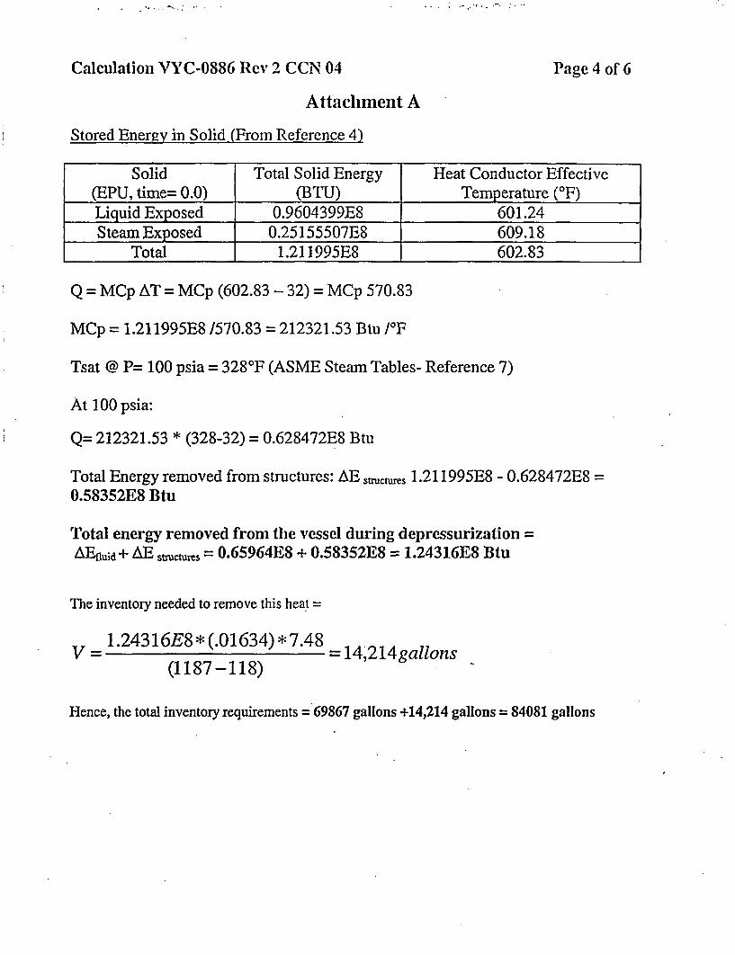
Calculation YYC-0886 Rev 2 CCN 04 Page 4 of 6
Attachment A
Stored Energy in Solid (From Reference 4)
Solid Total Solid Energy Heat Conductor Effective(EPU, time= 0.0) (BTU) Temperature (°F)Liquid Exposed 0.9604399E8 601.24Steam Exposed 0.25155507E8 609.18
Total 1.211995E8 602.83
Q = MCp AT = MCp (602.83 - 32) = MCp 570.83
MCp = 1.211995E8 /570.83 = 212321.53 Btu /OF
Tsat @ P= 100 psia = 328°F (ASME Steam Tables- Reference 7)
At 100 psia:
Q= 212321.53 * (328-32) = 0.628472E8 Btu
Total Energy removed from structures: AE stuctures 1.211995E8 - 0.628472E8 =0.58352E8 Btu
Total energy removed from the vessel during depressurization =AEfluid + AE stuctms = 0.65964E8 + 0.58352E8 = 1.24316E8 Btu
The inventory needed to remove this heat =
V = 1.24316E8 * (.01634) * 7.48
(1187-118)= 14,214gallons
Hence, the total inventory requirements = 69867 gallons +14,214 gallons = 84081 gallons

Calculation VYC-0886 Rev 2 CCN 04 Page 5 of 6
Attachment A
For the CLP (Reference 1) the total CST inventory requirements for removing the decay heat andvessel stored energy = 75,837 gallons.
The TS (Reference 8) CST inventory of 75000 gallons is exceeded at both EPU and CLP for the 8hours coping duration. /
The HPCI'RCIC taking suction from CST has to make up for the vessel leakage (TS allowable andpump seal leakage of 61 gpm - Reference 6, page 17 of TER, also used in both Appendix R analysis(Reference 9, VYC-2270) and in Reference 1. The leakage amount does not change for EPU.
The needed CST inventory to account for leakage;V= 61 gpm * 8 hours *60 min/hour = 29, 280 gallons.
This inventory, added to that already calculated for decay heat and depressurization would total:
V = 29280 + 84081 = 113361 gallons, which would normally be available from CST but, if notcould easily be made available from the torus. Therefore, the conclusions of VYC-886 Rev2 that theTechnical Specifications CST inventory requirement of 75000 gallons is not adequate for an 8 hourduration is valid at EPU. However, with Alternate AC (Vernon Tie) and low pressure systemsavailable, sufficient inventory is available from the torus for the required 8 hours.
The power uprate results in a need for more inventory, 113361 gallons versus 105117 gallons atCLP.
Reactor Coolant Inventorv
The depletion of the available inventory in CST will not jeopardize reactor coolant inventory becausemakeup inventory can be provided from the torus. When the torus temperature exceeds 140 OF andRCIC and HPCI can not be used with suction from the torus, reactor inventory can be provided fromthe torus via low pressure pumps. Since VY is an Alternate AC plant, crediting use of the lowpressure pumps is acceptable. This conclusion is unaffected by power uprate.
Loss of Ventilation
The heat-up due to the loss of ventilation due to an SBO event for RCIC Room, HPCI Room, MainSteam Tunnel, Control Room, Switchgear Room, and Intake Structure is addressed in Reference 1.
RCIC Room
The heat-up calculation is based on VYC415 RevO (Reference 10 modified by CCN 1 (Reference11)). The heatup is based on the piping temperature, RCIC turbine and Switch Heat Loss. The RCICRoom Temperature calculated in Reference 12 is unaffected by EPU.

Calculation VYC-0886 Rev 2 CCN 04 Page 6 of 6
Attachment A
HPCI Room.
The heat-up calculation is based on heat loads from VYC-0415 Rev 0 (Reference 10). The heat loadsare from the piping and the HPCI turbine. The heat loads are unaffected by power uprate. Thereforethe calculation for HPCI room heat-up is not affected by EPU.
Main Steam Tunnel
The issue is isolation of HPCI and RCIC on high steam tunnel temperature.Reference 13 calculated an increase of 0.6 0F in the normal temperature of the steam tunnel, at EPU.The conclusion of VYC-886 Rev 2, that the main steam tunnel heat-up is slow on loss of ventilationand the reactor will already be in the process of cool-down, is valid at EPU.
Furthermore, Reference 14 (VYC-1347) concluded that the heat-up in the main steam tunnel is lessthan that required to isolate HPCI and RCIC. For the case when the feedwater and main steamisolates (SBO conditions), the peak room temperature from Reference 14 is 1740F (isolationtemperature assuming loop accuracy) at approximately 18 hours. Based on the results of Reference13, the change in Main Steam Tunnel Heatup will be very small at EPU. Furthermore, procedureOT-3122 (Reference 15) limits HPCI & RCIC operation to 2 hours; hence the reactor pressure after 2hours should be low enough to permit operation of the Low Pressure Pumps (CS and RHR).
Therefore the impact of power uprate on heatup of the Main Steam Tunnel is negligible. It isrecommended that calculation VYC-1347 be updated for EPU conditions.
Control Room
Restoration of ventilation in the Control Room is governed by Procedure OT-3122 and is unaffectedby Power Uprate. Control Room Heatup for loss of ventilation is unaffected by power uprate.
Switchacar Room
The heat loads in the switchgear room are unaffected by the power uprate.
Intake Structure
The heatup of the Intake structure on loss of ventilation with only 2 Service Water available isunaffected by the power uprate since the heat loads in the intake structure are unaffected by poweruprate.
Torus Temperature
The Torus Temperature calculation for SBO at power uprate was performed in Reference 16 (VYC-1628D CCNO2). The peak suppression pool temperature is 187.9 'F.
BVY 05-072Docket No. 50-271
Exhibit SPSB-C-52-2
Vermont Yankee Nuclear Power Station
Proposed Technical Specification Change No. 263 - Supplement No. 30
Extended Power Uprate
Response to Request for Additional Information
Calculation VYC-1347, Rev.0
Total number of pages in this Exhibit(excludina this cover sheet) is 29.

t
7,, x 4f/ 17
ORIGINAL,Rev. 1:
* Rev. 2:Rev. 3:
PAGE 1 of / 17 PAGESPAGE 1 of PAGESPAGE 1 of PAGESPAGE 1 of PAGES
OA RECORD? IMS NO. M02.01O05
I/ YES RECORD TYPE 09.C16.004
NO W.OJP.O. NO. 4055
YANKEE NUCLEAR SERVICES DIVISIONCALCULATIONIANALYSIS FOR
TITLE Maln steam Tunnel Heatup Calculation
PLANT Vermont Yankee CYCLE _ NIA
CALCULATION NUMBER VYC-1 347
KEYWORDS GOTHIC: Room: Heat-up: RRU
G htiUCLEAR SERVICES DIVISION
YANKEEATOMIC ELECTRIC COMPANY580 MAIN STREET
BOLTON, MASSACHUSETTS 01 740

YANKEE NUCLEAR SERVICES DIVISION CALC. NO. VYG1347 REV. _ DATE 11--9
TITLE Main Steam Tunnel Heatup Calculation
PREPARED BY Jim Pappas REVIEWED BY - PAGE 2 OF
TABLE OF CONTENTS
Section Description Pane
LIST OF TABLES.. 3
LIST OF FIGURES.. 4
1.0 PROBLEM DESCRIPTION. 5
1.1 Objective. 51.2 Method of Solution ....................................... ; 61.3. Design Inputs. 61.4 Assumptions...................................................................................................... 9
2.0 PROBLEM ANALYSIS .. 10
2.1 GOTHIC Model Input ................... 10
2.1.1 Control Volumes .102.1.2 Thermal Conductors .112.1.3 Heaters: Main Steam Isolation Valves .................................. : 11
2.2 GOTHIC Runs .. 20
2.2.1 Run MST .202.2.2 Run MST2 .24
3.0 CONCLUSION . . .29
4.0 REFERENCES ......... 30
Appendices
A GOTHIC Run MSTI .35B GOTHIC Run MST2 .81C Computer Code Evaluation .................... 112D Reviewers Comments .114

1111111- -- - -- I
YANKEE NUCLEAR SERVICES DIVISION
TITLE MaTn Steam Tunnel Heatup Calculation
PREPARED BY Jim Pappas REVI
CAMC. NO. VYrC-1347 REV. - DATE -1.-19
IEWED BY PAGE -O3 OF_
LIST OF TABLES
Table No. Description Pane
1.3-11.3-2
2.1-la2.1-1b.2.1-2a2.1-2b
Thermo-Physical Properties.....................................................................Outer Environment Temperatures ...........................................................
MvST2 Dimensional Data..MST2'i DmninlDt............................ ...................................West Wall Dimensional Data........................... ...... ............................
Piping Design Data................ ..........................................................Piping Heat Transfer Surface Areas..........................................................
7a
161718

w * n: N o { *
. .I
I
YANKEE NUCLEAR SERVICES DIVISION CAMC. NO. VYC-G1347 REV. DATE 11-1-96
TITLE Main Steam Tunnel Heatup Calculation
PP.PARED BY Jim Pappas REVIEWED BY, PAGE 4 OF
LIST OF FIGURES
Figure No. Descriotion Pape
2.1.3-1 MSIV Valve Outline Drawing .192.2-la MST1 Schematic 222.2-lb MST1 Temperature Profile .232.2-2a MST2 Schematic . 262.2-2b MST2 Temperature Profile to Seven Days .272.2-2c MST2 Temperature Profile to Four Hours .28
A-1 MST1 Schematic. 38A-2 MST1 Input Tables .39A-3 MST1 Graphical Results.55A-4 MST1 Output Verifying the MSIV Model .70A-S MST1 Output Showing Condensation Heat Transfer Fluctuations. 73
A-1 MST2 Schematic .82A-2 MST2 Input Tables ............. 83A-3 MST2 Graphical Results .98
1�

YANKEE NUCLEAR SERVICES DIVISION CALC. NO. Y LQ:1347 REV. DATE 11-1-96
TITLE Main Steam Tunnel Heatup Calculation
PREPARED BY Am Pannas REVIEWED BY PAGE 5 OF
1.0 PROBLEM DESCRIPTON
This calculation determines the temperature rise in the main steam tunnel with a loss of HVAC to
document whether this rise will result in an automatic isolation of the HPCI and RCIC systems. The
HPCI/RCIC excess air temperature switches, within the main steam tunnel, provide automatic
8; isolation of the HPC1 and RCIC lines if a temperature of 185'F i 5*F is sustained for longer than
30 minutes (References' 23 and 24). The loop accuracy is 6F (Reference 36). Therefore HPCI and
RCIC isolation can occur at a steam tunnel temperature as low as 174'F. This high temperature
isolation scheme' is for line break protection and it is not intended for non-line break events, such as
loss of main steam' tunnel cooling under loss of normal power.
Normal ventilation in the main steam tunnel is supplied by the Reactor Building Ventilation System
and by RRUs 17A and 17B, located in the tunnel. A Reactor Transfer Fan (RTF-IA/ IB) exhausts air
from the main steam' tunnel at approximately 4200 cfm. Each fan has a total caprcity of 14,400 cfm
and takes inlet air from'various locations in the Reactor Building. The RRUs circulate and cool air
inside the main steam tunnel. The fan capacity of each RRU is 5000 cfm and service water, supplied
to coils within the RRUs, provides the cooling.
RTF-lA and both RRUs are powered from 480v MCC 6A. This MCC is NNS and is supplied from 4160v
Bus 1. RTF-I1 is powered from 480v MCC 7A, which is also NNS, and is supplied from 4160v Bus 2.
Controls are located on the Turbine Building HVAC control panel, with auxiliary indications on the
Control Room 9-25 panel. Typically, one fan and both RRUs are operating, with the second fan in
stand-by. The operating fan and the RRUs maintain the main steam tunnel environment temperature
at a yearly average of 125F, as described in the Vermont Yankee Environmental Qualification Program
(Reference 25). A review of temperature data for the main steam tunnel indicates that the air
temperature can peak at about 150F during the summer months (Reference 30).
1.1 Oblective
The objective of this calculation is to determine the temperature rise of the air in the main steam
tunnel, during a loss of normal power and under the following conditions:
* Loss of HVAC In the main steam tunnel.
. Summer peak temperature for initial and boundary conditions.
* Main steam and feedwater lines in the tunnel are:
- Isolated (steam and water are not flowing, GOTHIC run MSTI).- Not isolated (steam and water are flowing, GOTHIC run MST21.

YANKEE NUCLEAR SERVICES DMSION CALC. NO. WC-1347 REV. DATE 11-1-96
TITLE Main Steam Tunnel Heatup Calculation
PREPARED BY Jim 1Paoas REVIEWED BY PAGE 6 OF
1.2 Method of Solution
A lumped parameter GOTHIC model of the main steam tunnel is used to calculate the air temperiture
rise on loss of HVAC. GOTHICl33A34) is a general purpose thermal-hydraulic computer program for
design, licensing3 safety, and operating analysis of nuclear power plant containment and other
confinement buildings. See Appendix C for verification of the GOTHIC version used.
The models consist of volumes, flow pcths, & thermal conductors arranged and connected to represent
the thermal-hydraulic response of the main steam tunnel. The thermal mass of each conductor is
included in the GOTHIC computation.
1.3 Design Inputs
1.3.1 The thermo-physical properties for the materials used are shown in Table 1.3-1..
1.3.2 The boundary temperatures for spaces surrounding the main steam tunnel are shownin Table 1.3-2.

YANKEE NUCLEAR SERVICES DIVISION
TITLE Maln Steam Tunnel Heatup CalculationPREAE B. m , A, R.
PREPARED BY. ,Jim Pappas REMI
CAMC. NO. .Y-1347 - REV. - DATE i-.
EWED BY PAGE 7 OF__
: . _~Tab. 1 .31
Thermo-Physical Properties
... .W * 0
ConcreteP1 ')' 75 1.05 142 0.156
Steel Plpel'. 68 25.0 487 0.11
: 1000 0.073
900. 0.067
800 0.060
700 0.055
Insulation0 600 0.050 15O o.io¢'
500 0.046.
400 0.042
-300 0.038
200 0.036
100 0.033
a) Superscript numbers refer to References In Section 4.0.b) Assumed.

YANKEE NUCLEAR SERVICES DIVISION
TITLE -:-n t TUnnel Heatup Calculation
PREPARED BY Jim Paopas REVI
CALC. NO. MCf1347 . REV. DATE 11-1-
,EWED BY PAGE 8 OF-
Table 1.3-2Outer Environment Temperatures
r .. aK- _ M _ -Z'AA ir
Normal 150"F 125"F 100°F 83eF0"Operation 160F 125F 100¶ 83F°
Peak Summer 1604F 1300F 1200F 90OF~b
Notes
a) Vermont Yankee FSAR (Reference 32), Table 2.3.2, Highest mean daily maxirr Jm for'summermonths.
b) Vermont Yankee FSAR (Reference 32), SecUon 10.12, Summer design temperature.

I YANKEE NUCLEAR SERVICES DIVISION CALC. NO. C13 347 REV. DATE _1:i
TITLE Main Steam Tunnel Heatul Calculation
PREPARED BY Jim Pappas REVIEWED BY PAGE 9 OF
1.4 Assumptions
The critical assumptions used in the GOTHIC models are as follows:
1.4.1 Initial main steam tunnel air temperature is 1507F. This is based on Reference 30 andis considered conservative. Reference 30, describes that this value is derived from atemperature element that is close to hot process lines. Therefore, the correspondingambient room temperature should be lower.
1.4.2 Initial main steam thermodynamic statepoint is saturated steam at 985 psia based onthe heat balance shown on Figure 1.6-1 in the PSAR (Reference 32). Therefore, thetemperature is 543'F.
1.4.3 Initial feedwater thermodynamic statepoint is saturated water at 373F based on theheat balance shown on Figure 1.6-1 in the FSAR (Reference 32). Therefore, thepressure is 179.8 psia.
1.4.4 HPCI and RCIC turbine steam supply temperatures are 543'F.
1.4.5 Both RRUs are inoperative for the analysis.
1.4.6 The air temperatures in the spaces surrounding the main steam tunnel are listed inTable 1.3-2 and are assumed to be constant throughout the transients.
1.4.7 In model MST1, where the main steam lines are isolated and the feedwater pumps areoff, the four main steam lines (MS-1A through D) and the feedwater lines(FDW-14/15/16/17) dissipate the heat in the line volume, cooling down as they do so.All other lines contain fluid at their respective constant temperatures, as listed inTable 2.1-2a.
1.4.8 In m6del MST2, where the main steam lines do not isolate, all lines contain fluid attheir respective constant temperatures, as listed in Table 2.1-2a.
1.4.9 Miscellaneous piping, steel, and equipment are left out of the models.
1.4.10 The floor is left out of the models to add conservatism to the room heat-up.I .*
1.4.11 The west wall contains a metal section through which the main steam lines pass andwhich two blowout panels are installed. This metal section is modeled in the GOTHICruns. However, other non-concrete wrall sections are not. They include:
a) ventilation duct with blowout damper in the north wall,b) a blowout ranel and a blowout door in the south wall, andc) various duct work and pipe sleeves.
This is assumed to be conservative since it inhibits natural circulation that wouldnormally exist in the room.

M -- i
YANKEE NUCLEAR SERVICES DIVISION
TITLE Main Steam Tunnel Heatup CaDculation
PREPARED BY Jim Pan REV,
CALC. NO. Wrc1347 REV. - DATE 11-1-96
IEWED BY _I PAGE 10 OF
2.0 PROBLEM ANALYSIS
2.1 GOTHIC Model Input
The following sections describe the major input that was calculated for the GOTHIC models.
2.1.1 Control Volumes
Main Steam Tunnel
The main steam tunnel is Volume 1 in the models. The relevant dimensional data of the main steam
tunnel for construction of the models are shown in Table 2.1-1. From these data, the wall surface
areas and the room overall volume are obtained. The volume of the steam tunnel is:
VuST = (North Wall) x (East Wall) x (Height)
VMST = 36.25 x 24' x 25.5 = 22,185 1t5
The hydraulic diameter is:
Dh = 4API
where A is the cross sectional area of the volume (i.e., the ceiling or floor area) and P, is the wetted
perimeter. P,, is defined by GOTHIC as S/h or the surface area of all structures divided by the height
of the volume. S would, therefore, be the total surface area of all the walls and the ceiling. The floor is
not modeled.
4AhDh s
D '" _-.=b Anoh'+AM + Aeut + Aest + Aceng
4(870X25.5)Dh 97438 + 924.38 + 612 + 612 + 870
Dt = 225 ft
In the run where the main steam and feedwater lines are isolated, those lines are modeled as separate
control volumes. The four main steam lines are lumped into one volume as are the two feedwater

I, .. -, .
o
YANKEE NUCLEAR SERVICES DMSION CAL. NO. VYQ=1347 REV. DATE 11-1-96
TITLE Main Steam Tunnel HeatUp Calculation
PREPARED BY Jim Pangas REVIEWED BY PAGE I11 OF
lines. The volumes are obtained from the pipe data in Table 2.1-2b, and follow. The hydraulic
diameters are simply the pipe diameters.
Main Steam Lines
VMSL 4 X x )2 L
VMSL 4 x n(8062 I12)2 x 46.5
VMSL = 263.75 f 3
Feedwater Lines
VFCIW 2 a R)2 14 116 + 115,17)
VFDw = it(6.781 1 12)2 (45.7 + 47.9)
VFDW = 93.90 ft
2.1.2 Thermal Conductors
The input for the thermal conductors that represent the steam tunnel walls and ceiling is taken from
Table 2.1-1. The floor is left out of the model to add conservatism. Typically there is little heat
transfer through the floor of a heated room.
The thermally significant piping found in the main steam tunnel are described in Table 2.1-2. The
GOTHIC input for these conductors is also shown in the table.
2.1.3 Heaters: Main Steam Isolation Valves
The main steam isolation valves (MSIV) in the steam tunnel have a substantial amount of un-insulated
structure that makes up the yoke and actuator. Figure 2.1.3-1 (Reference 39) shows the outline of the
valve. Heat will conduct through and out of this structure into the main steam tunnel. There are four
such valves in the tunnel.
The yoke of each MSIV consists of four 3' solid rods attached to the bonnet (Reference 40). The yoke
acts as a support for the actuator and ns a spring guide. Through the center of the yoke, the valve
stem travels.

YANKEE NUCLEAR SERVICES DIVISION CALC. NO. YC1A347 REV. DATE .11J-9
TITLE Main Steam Tunnel Heatup Calculation
PREPARED BY Jim Pappas REVIEWED BY PAGE 12 OF
The method of modeing the heat transferred to the main steam tunnel by this assembly will be to treat
each 3" yoke rod and the stem as a fin. The stem will be modeled as though it were a fifth yoke rod.
Therefore, each MSIV will be modeled as having five 3" solid rod fins heated at one end. The heated
end is that attached to the body of the valve. It is assumed that the actuator is far enough away from
the valve body that any heat conducted to it is negligible.
GOTHIC cannot model this situation because it involves two-dimensional conductive heat transfer.
GOTHIC can only model one-dimensional conduction. Therefore, a formulation of the heat rate
provided by the yokes will be derived here and input into GOTHIC as a theater".
The general equation for such a fin is (Reference 29):
q = Jhk(r, - T,.)tanh(mL)
where: q = heat rate (Btulhr)
h = convective heat transfer coefficient (Btulhrft2F)
P = perimeter of the fin (7td ) (ft)
d = diameter of the rod (ft)k c thermal conductivity of the rod material (Btu/hrftt.F)
A c cross sectional area of the fin (*1)
T. temperature of the heated end ("F)
T = ambient room temperature ("F)
m= W (ft')
L =length of the fin (ft)
The values in the following table will be used. The value for h is taken from Reference 38 and is
considered to be conservative. In a transient calculation, it would be expected to vary around a value
of 0.5 Btu/hr-ft 2 IF to 1.0 Btu/hr ft2-@F. The length, L, Is taken as the 'AC' dimension from
Figure 2.1.3-1. This is clearly much longer than the actual length of the yoke. However, the yoke
dimension is not given. So, the more conservative, longer length is arbitrarily used. This presents
hardly any penalty In heat rate to the room because the value is used in the tanhO function which is
barely sensitive to the length. For example, using the 9 ft value tanh(9) - 0.9999 and using half that
value tanh(4.5) - 0.9998.
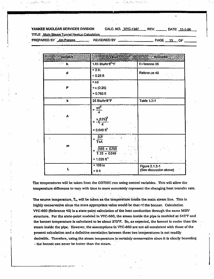
m = --
YANKEE NUCLEAR SERVICES DIVISION
TITLE Main Steam Tunnel Heatun CalculationPREPARED BY Jim Pasnas REV
CALC. NO. WC-1347 REV. - DATE 11-1-96
VIEWED BY PAGE 13 OF
- .- '***'*'.�'
�
h 1.65 Btudhrfe-F Rp erence 38
= 3 ind Reference 40
= 0.25 ft
=rtd
P =,n (0.25)
= 0.785 ft
k 25 Btu/hrfrF Table 1.3-1
A = 2
4
= 0.049 ft2
m
m = l- 165 x 0.785-.
25 x 0.049
=1.028fr .
= 108 in Figure 2.1.3-1L = 9 It (See discussion above)
The temperatures will be taken from the GOTHIC run using control variables. This will allow the
temperature difference to vary with time .to more accurately represent the changing heat transfer rate.
The source temperature, T., will be taken as the temperature inside the main steam line. This is
highly conservative since the more appropriate value would be that rf the bonnet. Calculation
VYC-660 (Reference 40) is a state-point calculation of the heat conduction through the same MSIV
structure. For the state-point modeled in VYC-660, the steam inside the pipe is modeled at 545'F and
the bonnet temperature is calculated to be about 375'F. So, as expected, the bonnet is cooler than the
steam inside the pipe. However, the assumptions in VYC-660 are not all consistent with those of the
present calculation and a definitive correlation between these two temperatures is not readily
derivable. Therefore, using the steam temperature is certainly conservative since.it is clearly bounding
- the bonnet can never be hotter than the steam.
_

--V "
YANKEE NUCLEAR SERVICES DMSION CALC. NO. VC1347 REV. - DATE 11-1-96
iTITLE Main Steam Tunnel 1eatuo Calculation
* PREPARED BY Jim Pappas REVIEWED BY PAGE j4 OF
The ambient temperature, T,,, is the bulk room temperature calculated by GOTHIC.
So, the heat rate generated by a single yoke rod is:
q f . x 0.785 x 25 x .049)(T - T.)tanh(1028 x 9)
q = 126(T; - T,) Btulhr
Each of the four MSIVs is to be modeled as having flive wirh rods, and GOTHIC requires input in unitsof Btu/sec. So, the final input to GOTH(C is:
q =4 MSIVs x 5 Rods x hr x 126(T T)360 sec xt6T
q a= 0.007(r. - T.,) Btu/s
In GOTHIC this will be represented as a heater with a heat rate of 0.007 Btu/s multiplied by a forcing
function. The forcing function is in turn equated to a control variable. And, the control variable
represents the temperature difference between the main steam line and the room average of the
tunnel.

YANKEE NUCLEAR SERVICES DIVISION
TITLE Main Steam Tunnel Heatup Calculation
PREPARED BY Jim Pappas REV
CALC. NO. -C Y=-l347 REV. DATE 11-1-96
IEWED BY PAGE 15 OF _
Table a. iLliMain Steam Tunnel DimeunQalData
I.
Superscript numbers refer to References in Section 4.0.

YANKEE NUCLEAR SERVICES DMSION
TITLE Main Steam Tunnel Heatup Calculation
PREPARED BY Jim Pappas REVI
CALC. NO. VYA1347 REV. DATE A1-1-96
EWED BY PAGE 16 OF-
Table 2.t -1kbMs al imnil~a V
Length 2( ~ 2 ~2200) 2 4 24 .002'24
Height I Wkdth 25.5(12 8.0t' , 25.5
Area. 612.0 192 420
Thickness 3.0(t) 0.25 in"" 3.0
Superscript numbers refer to References in Section 4.0.

YANKEE NUCLEAR SERVICES DMSION
PREPARED BY Jim Papoas REV
CALC. NO. WYC 1347 REV. DATE _11-1-96
IEWED BY PAGE 17 OF
Table 2. I *2aeipg~LnD~
MSIA IBM 80 Z _
MS-1B is an 543
* MS-IC 181M ea
MS-1D 18("m 80 3.5&n 543")
MS-4A0) 10'9) 80 3.5(19) 543(1I
MS-4Bb') 10(9 ) 2.009 5430'
FDW-1414i 16 ( _) 120 20(va)( w 373a)
FDW-1 5117 16(18) 120 2 0(40)a.) 373 )
MS-5A0) 3(fl) 160 2.0(22) 543
.RCIC-2") 4(21) 120 None2"1 140")
RCIC-813 4(21) 120 2.0(21) 14 00 )
RCIC4AW 4(21) 120. 140ch)
HPCI-1 SB() 14(2o) 120 2.5'"2 1 40(d)
HPC-14Aw) 14(20) 120 2.5(27) 14
a Notes
a) Reference 27 says 2.5Sb) HPCI Steam Supplyc) RCIC Steam Supplyd) FSAR (Reference. 32), Figure 6.4-1 (Highest temperature at Location 2)e) Supe~rsipt numbers refer to References in Section 4.0.f) RCIC Dischargeg) HPCI Dischargeh) FSAR (Reference 32), Figure 4.7-3 (Highest temperature at Location 3)i) Assumption 1.4.2j) Assumption 1.4.3

YANKEE NUCLEAR SERVICES DIVISION
TITLE _Main team TUnnel Heatuo Calculation
PREPARED BY Jim Panpas REV
CALC. NO. WC-i347 REV. DATE 11-1-96
IEWED BY PAGE - 18 OF.
Table 21 e-2bPiDins HeatTafer Surface Areas
II MS-iA. -,. .. 8.062 9.000 46.56.T) 304.3
MS-lB 8.062 9.000 46.5t7 304.3
MSIC 8.062 9.000 46.5'" 304.3
m S-ID 8.062 9.000 46.5(-7 304.3
MS4Ao' 4.781 6.375 17.6(19) 81.8
MS-4BP' 4.781 5.375 35.2'9) 135.9
FDW-14116 6.781 8.000 45.7('e) 239.3
; FDW-16117 6.781 8.000 47.913) 250.8
MS.SA'c) 1.312 1.750 46.7P) 91.7
RCIC-I(' 1.812 2.250 28.712') 33.8
RCIC-2') 1.812 2.250 29.7(21 35.0
RCIC-8B° 1.812 2.250 655(21) 14.5
RCIC-8A') 1.812 2.250. 11.42') 25.4
HPCI-15B() 5.906 7.000 40.6() 202.0
HPCI-15A(0 ' 5.906 7.000 9.2m 45.8
I I
Notes
a) Area 2ic(Outer Radius + Insulation) x (1 ft12 In) x Lengthb) HPCI Steam Supplyc) RCIC Steam Supply .
e) Superscript numb-3rs refer to References in Section 4.0.n) RCIC Dischargeg) HPCI Discharge

I
i
I!

YANKEE NUCLEAR SERVICES DMSION
.TITLE MainSteamTunnel HeatupCalculation
PREPARED BY JinmPappas REV. ..I . .
. CALC. NO.. VC1347 L. REV. - DATE 11-1-96
IEWED BY _ PAGE 20 OF
.2.2 GOTHIC Runs
2.2.1 Run MST1
I"
i .ItI
1 7?, , .I 1. '.
i !� . .i, .1:-:1 , ... . .
This run of the main steam tunnel heat-up represents a typical loss-of-normal power event. On a loss-
of-power, the HVAC system trips and the MSIVs and feedwater pumps isolate. The room then heats
up because of the heat gain from the pipes within it. However, the major loads are from the main
steam and feedwater lines and the fluids in those lines are not flowing. Therefore, their heat gain to
-the room diminishes as the transient progresses and the room eventually peaks out and then begins to
drop in temperature.'
This run represents a typical heat-up of the tunnel following loss of ventilation, however many
conservatisms are included so that the results are assured to bound a true event. These
conservatisms include:
* The initial main steam tunnel temperature of 150'F is based on the Reference 30 data andrepresents a peak room temperature as opposed to an average room temperature. A morerepresentative average (initial) room temperature would be something lower.
Miscellaneous structures and equipment in the room are not modeled. They would act asheat sinks resulting in a temperature rise that is slower than that predicted by GOTHIC.
* Miscellaneous 'cold' piping, such as service water piping, is not modeled as heat sinks.
* Wall openings such as ventilation ducts/dampers or pipe sleeves are not modeled inhibitingcooling by natural circulation.
* Natural circulation through the RRUs is not modeled. The RRUs trip on loss of powerhowever they continue to receive cool servkle water and would contribute a small'amount ofcooling.
* On a loss of power, HPCI and RCIC would automatically start resulting in flushing some ofthe 373'F water from the feedwater lines and replacing it with 140"F water. This is notaccounted for.
* The MSIV. heat gain is conservative as described in Section 2.1.3. Most notably, the sourcetemperature of the yoke, modeled as a series of fins, is the steam temperature itself asopposed to the bonnet temperature of the valve.
* The floor as a heat sink is not modeled.
The non-conservatisms in the model are:
* Main'steam line drains are not modeled. They would add heat to the room but only a smallamount because the lines are about 2Y2' NPS. This is believed to be counteracted by thelack of 'cold' piping being modeled as well.
* There is no account for MSIV leakage that would continuously add a slight heat load to themain steam lines. (Run MST2 in Section 2.2.2 accounts for this).

i
YANKEE NUCLEAR SERVICES DIVISION CAC. NO. V YrQ347 REV. DATE Jjj1-9
TITLE MTunnel Hp o Ci;-tatidn
PREPARED BY Jim Pappas REVIEWED BY PAGE 21 OF
There Is no spatial definition in the model, therefore an axial temperature gradient is notcalculated. Because the HPCI/RCIC temperature switches are in the upper, ceiling, areathey may experience a higher temperature than that of the bulk room. This is believed tobe counteracted by the initial room temperature of 150'F which represents a temperaturefriom' a hot area of the steam tunnel.' (See Assumption 1.4.1).
It is believed that the conservatisms listed above far outweigh the non-conservatisms. Therefore, it
can be assured that the true heat-up profile of the main steam tunnel will be a curve that is below -
and therefore bounded by - the GOTHIC result.
The GOTHIC model MSTI is shown schematically in Figure 2.2-la. It consists of the following:
* Volume i representing the main steam tunnel.
* Volume 2 representing the main steam lines isolated at t 0 seconds.
* Volunme 3 representing the feedwater lines with pumps off and no flow at t 0 seconds.
. Flow path 1 connecting Volume 1 with a pressure boundary condition I P. This flow pathand boundary condition are used to maintain the pressure within'the main steam tunnel at14.7 psia as the air heats up.
* Thermal Conductors 1-6, 8, 9, 11-16 connecting the heat sources and sinks to Volume 1.
Thermal Conductor 7 connecting Volume 2 to Volume 1.
* Thermal Conductor 10 connects Volume 3 to Volume 1.
* Heater I representing the MSIVs.
Appendix A contains the detailed listing of the GOTHIC input for this run. Included are graphical
results and calculations validating the run. The model is run for 7 days to determnine the temperature
rise profile of the air in the main steam tunnel. The heat-up of the main steam tunnel is shown in
Figure 2.2-lb for the full 7 days.
The graph shows that the steam tunnel reaches a peak average temperature of 174F after
approximately 3i of a day. It then drops during the remainder of the transient. The peak is considered
to bound the actual peak that would result during a true loss-of-ventilation scenario because of the
conservatism discussed above.
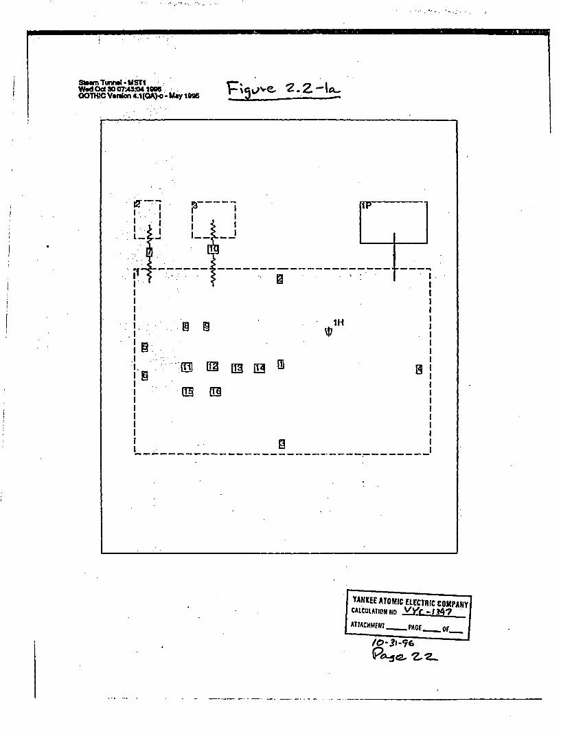
Smwn Tuwbl USTI :Wed Oct 30 07A3S0 1WO.O0ThiC Vim 4.1(A)-C May 1996 FP %5o 2.Z-
JT - -- j- - --- ----- -----lH]
' -- - - - - - - - - - . - - - - - - - - - -
I, B..w
I .II aI
I YANKEE ATOMIC ELECTRIC COM PANyCALCULATION ND V L474 |
ATTACHMENIT PAGE_ Of_
%c0 31-6--
P*d T, -z-

oxaz=
Sum Tumnr - USTIWed Oct30 07V Son 19 -MGOTHIC Verulon 4.1 (GA)-, - May1995
I; od . Z-67 7
I Steam Tunnel Bulk Room Temperature
-. a TV1.I 00-
. e
a.
I-
Time (days)GOTHIC 4.1 (Alc 10/29/96 15:56:41 i
YANKEE ATOMIC ELECTRIC COMPANY ]ICALCULATIONNO VYC-1347
ATTACHMETI - PAGE _ of_
(o ^3 I ?hick. Z 2 '

YANKEE NUCLEAR SERVICES DIVISION CAMC. NO. VYC-1347 REV. DATE Jj-19
TItLE 'IMain Steam Tunnel Heatup Calculation
PREPARED BY. Jim Pappas REVIEWED BY : PAGE 24 OF
2.2.2 Run MST2
This run of the main steam tunnel heat-up represents an extreme loss-of-normal power event. As
stated in Section 2.2.1, on a loss-of-power, the MSIVs and feedwater pumps normally isolate.
However, the poissibility exists that one or more isolation function fails - suck as a MSIV not closing.
Fufthermore, as stated in the non-conservatisms of run MSTI, it is more than likely that some leakage
would exist past the MSIVs.
Justifably uantifying such conditions is not stiaighit forward. However, the situation can be
bounded. The most bounding scenario is that nonelof the main isteam anc. feedwater lines isolate and
the steam/water continues to flow. The initial temperature of the fluids within these lines is,
therefore, constant throughout the transient resulting in a much higher heat gain to the room. This
modeling technique also clearly bounds any postulated leakage past isolated MSIVs.
The model, itself, is identical to MST1 except:
* the volumes representing the main steam and feedwater lines are removed.
* the conductors (7 and 10) that connected those volumes are moved into the main steamtunnel volume as internal conductors.
* the boundary heat transfer coefficients on conductors 7 and 10 are fixed temperaturesrepresenting the steam and feedwater temperatures.
All other conservatisms and non-conservatisms listed'for run MST1 remain in this run.
The GOTHIC model MST2 is shown schematically in Figure 2.2-2a. It consists of the following:
* Volume I representing the main steam tunnel.
* Flow Path 1 connecting Volume 1 with a pressure boundary condition I P. This flow pathand boundary condition are used to maintain the pressure within the main steam tunnel at14.7 psia as the air heats up.
* Thermal Conductors I - 16 connecting the heat sources and sinks to Volume 1.
* Heater 1 representing the MSIVs.
Appendix B contains the detailed listing of the GOTHIC input for this run and graphical results. The
model is run for 7 days to determine the temperature rise profilel of the air in the main steam tunnel.
The heat-up of the main steam tunnel is shown in Figures 2.2-2b for the full 7 days and 2.2-2c for the
first four hours. The first four hours is of particular interest for Appendix R scenarios.

YANKEE NUCLEAR SERVICES DIVISION
TITLE Ma unnel Heatun Calcution
PREPARED BY Jim PaDoas REVI
CAMC. NO. WC-1 347 REV._ DATE 11--9
IEWED BY PAGE. 25 OF
The graphs show that the steam tunnel reaches an average temperature of 172?F after four hours. It
continues to rise until it is about 207'F at 7 days and still rising.
As with MST1, these results are considered to bound the actual temperature rise that would result
during such a scenario. Furthermore, because the scenario itself is extreme by nature, the results
greatly bound any possible steam tunnel heat rise that may bc postulated.

0 N II
SbwM TwUn - UST2'W.dOd oo3074A20 198
GOTHRC Vision 4.1(QA)4 -May 1995ail~e 2. 1-2a_
I .
I In E
. .
I.Il -.. .
-- - - - - -- - - - - -- - - - - -
YANKEL AT0t41C ELECTRIC COMPANYIcA/cu 0-. ?l-l'NC.
P/C - OF _~c |
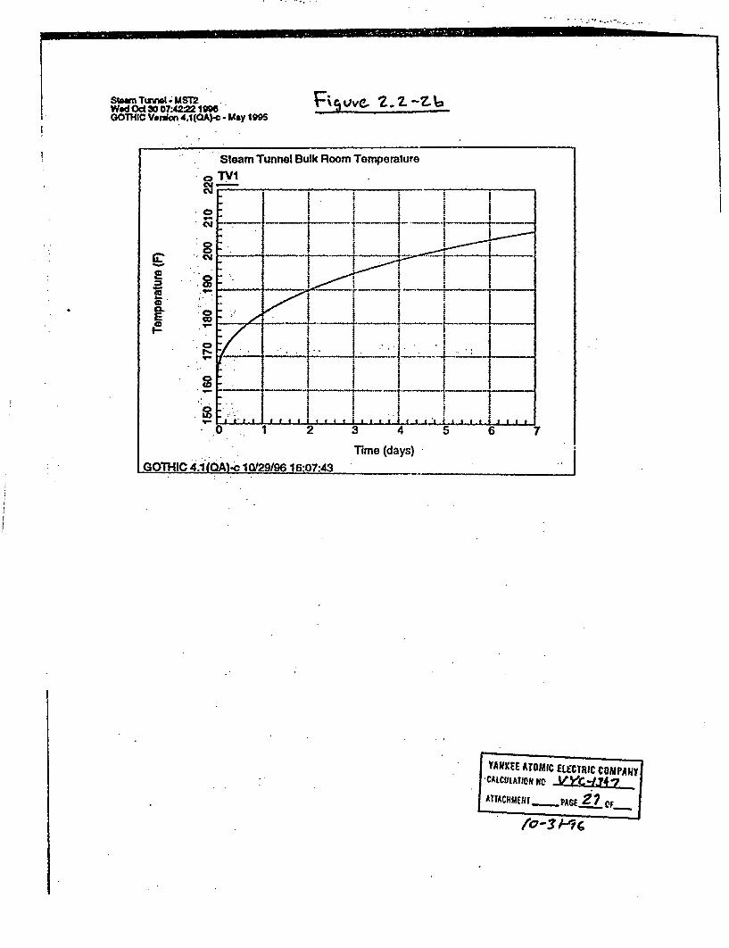
Stun Ttu -alMS72Wed Od 30 07422 1996GOTHIC Verion 4.1(QA)-c - May 1995
FILvvc Z.Z-Z?-7-
Steam Tunnel Bulk Room Temperature
CD
.... .... . ., ..... .
1 - 2 3 4 5 6
Time (days)GOTHIC 4.1 (QA)-c 10/29196 16:07:43 __-
IANKEE ATOMIC ELECTRIC COMPANY'CALCULtATION F1W .ia.kyt~jATACHMEfHr pAGf Z? cf .
o - - 'i

Stwm TunW e-MST2WehdOt3007:42 1996OOTHIC VYuon 4.1(QA).o May IMs
. .
* I- _ . _
Rvci-Z Zt 2.2- c~.--- ._---
Steam Tunnel Bulk Room Temperature to 4 Hours..l. v 'V
co ______ ____,____
2
%.....
' .'E !.. .0,9 ,..I.v -
I- - - - - - - - . .- - -I I I I I II I I_ I � I- *1* t I
an I I IL (LI::
ain . .1. . . . . .. .. .. .. . . .. . . . . ..... 4...
I 0.5 1- 1 .5 2 2S - 3 4
G ,': 4.-1 Q 1 /6,:-GOTHIC 4,1 (OA c 10/29/96 16:07:43
rime (hours)
YANKEE ATOMIC ELECTRIC COMPANYCAtCUtrofH 11 m ?
ATTACHmENT PAG -0 F.. '... I - -

YANKEE NUCLEAR SERVICES DIVISION CAMC. NO. -VYb1347 REV. DATE 11--9
TITLE Main Steam Tunnel Heatuo Calculation
PREPARED BY JimPaoas REVIEWED BY PAGE 29 OF
3.0 CONCLUSION
The results of the two G3THIC runs show the air temperature in the steam tunnel to approach about
172PF in the first four hours of each transient. Both transients show almost the same profile for that
time'frame because the cooldown of the main steam and feedwater lines is not large enough in the first
four hours to' have a significant effect on the room temperature rise.
In the case where the main steam lines and feedwater lines isolate, the peak room temperature is
about 174F at approximately 18 hours. In the case where these lines do not isolate, the room
temperature rises to 174"F at about 6'h hours. It continues to rise and is about 2077 at the end of
the seven day +ransient and still rising.
As discussed in Section 2.2, the many conservatism included in the model offer a high degree of
confidence that the GOTHIC results envelop any true heat-up profile of the steam tunnel. Therefore,
the actual room heat-up is expected to be something less and it is concluded that HPCI and RCIC
would not isolate under the conditions modeled.
The results of this calculation do not affect the FSAR, Technical Specifications, Technical Programs, or
controlled drawings.

BVY 05-072Docket No. 50-271
Exhibit SPSB-C-52-3
Vermont Yankee Nuclear Power Station
Proposed Technical Specification Change No. 263 - Supplement No. 30
Extended Power Uprate
Response to Request for Additional Information
Calculation VYC-1502, Rev.0
| Total number of pages In this ExhibitI (excludina this cover sheet) is 43.

1,ORIGINAL:
REV. 1:REV. 2REV. 3:
RECORD TY
71OJ.O
PAGE I OF LY-PAGESPAGE 1 OFt__PAGE I:OF PhiAGESPAGE 1 OF PAGES
10. A08,0. . ..4
PE '3.C16.036, 13.C09.OO.. . .0..
N0. 4055 -.
. 2'
6�'.
4' . ]. �.
.'.--.6� I:TIThE �
.YANKEE~ NUCLEAR'SERVI7CES DIVIION.
CALGULATIONVANALYSIS FOR'.
44i?
6om r v~ ~d e td oss o IiV A
_ _ _ _ _ _ C y *_ _ _ _ _ _ _ _
CCC:FORM CLE- 03N
- - . -L2.
ev_

f 6
. .. .. .. .. ...
.. .. . .. . .. ..... :
2* . ... . .A..L. ...CO.N.EU..S
`3 MO
21Hsi rcF. .
2.2 Heat~i............... -15:'jWrof1 -Ms odt ...
-4 .4 A
- n- *7 I -it
31 G~Co~roI 3 i~fh1I OM-\ 3.'.:A.swn fi46) RA .is. .... 21
W:4P5O4lCMdl~sntn3~o~~met-an~~aio~sxpin .. z2
4~0~ ~* *.*~.. 44 .j *
V.''23n
.1.' *.~ JL00.kI *
A- dii-. d .k 'r ea.t 4
*'"~ eau et pTI inu oO q... .. ...
,~A~pn~ixB~Cnto1~oonAGOTiCin~itMoeI . .. --. a ,- - .
Aj?¶~~i~~C r 146~ii Hat Lod-TeP 9at*a .
T r . ~ 4 . . *
~'Apendi E on~6 Rom ~ tx~ Opton ~, Jnhl Mod N.

Control ]Room Heatup due to Loss of HVAC; VYC-1502 Rev. 0 Pagpa
1.0 Objective
The objective of this cWcilation is to determine the tempera ire of the control room as afunction of time as a resilit of a los:; of ventilation of the co.Atrol room due to an Appendix Rfire io. The suicess criteria 1,r this analysis is to have the control room maintained ina habit ble'condition and one which ensures equipment operability. Based on publishedguideiis, both are safied by maintaiig control room temperature at or below 120°F [1]
2.0 - Method
The 6opltol room is an inclosed room vith concrete vAalls, floor and roof. The roof; northS . aid all are expo~d to -the outdoor environment while the west wall is a common wall
ith. te turbine builiigad the south. all is a c omnnn wal with the reactor buildin.:- ia tile '. ligthticng iael hldb the sseddciigsncue-. : rote; Als a ilin g blowtle contrl room roof abole which ventilation duing is
t .. ..-riid. i it sand lig fanes"ar']i by he sdsped ceiling strtktue.
; he.,.cobtrl 6 m ias ebicd h itas ny Ciontr6l panels and cabinets with a variety of. .elt ico nsuc h as ra, indicating lights, powlrsupplies and control systems.
e ~ R : .-. e. as Well as 'other snintdes (computers, refrigerator, copycheat Tis beat is iorially remnoved by an HVAC system.
Bu .it postulatethatan AppendixR-event in specifin locations may render the HVAClg * a .ain t of the contol room.
. .c %en b i oi 4iieof key parameters. The first keyj.. i'--'.' 'o : musSt be removed by convection-
:';; ..;.no' tuiii~r.-mGiven''alossofventaion mass transfer is not available to -r -toh reov the heit throhest-.
: : i74St~ iheiviormidentnn. :Since hit removal by, convecton and .... ; ci~aaui'Ofl , * 0 to ietCDJ~i{5rCWICTel across lewl,-ina
"'-ed oti aoeirr i a i t hm ie t ar t m e.Hetinn en ldfiecsjc wihn eniaCi eoe tr~o' w t
.:. of , ctin an Mlln- no ifiie- s d ugb the surrounhdinlg walls to thei.;g w i~ ai jfheat rEnmoval is deedei on the thermaln conduciiy of.i
th . . . .:ile~wiudl. lfeconete. on of heat from teaiine room to the inside wll.ffi:uuf: . .;and frrntieod w~all srae to ft e ouiitsde ai.' .These three facors mnake up.the
& .:-. t: rmi r iuthfe valLt Ths lira r istaS iceis the second key pareter and tle* i h hcsiihe h uredi d hiffrentiaifl temperatne b ween the :
' .outsideairadeiisdedir. '
The : thiirdl keyi mei is intncail thermal conductors and aects only the transient heatup ofan, - .'* .; loe rooni~giŽTh first'Wo paramees ia 't an tera resistance, .can be used topre.dict the sd.stae eera e in the room sinceiii wty state heat inp t eqiuls heat
rea h,,. - d t'- -
S ~~lb:di -keylwmettis J Htmo+l emalaductosand'iffectso'hnlythe tansient ......h...........a............f.. ..r.-.'be t~.paaet . -rt 'eu essac, ca be ,s~ 'd .
~~O 01. frt"
4e, ~ em a. -*co.. *f.i.............................................................. is c@ 2-d t a g l 't a s ei t n
' -5: .'-*Y'<--.i;\'.4;' .,'x'-.; w. .,.9< ..... 6S 'e<74.

Contrbl Room Heaup due to Loss of HVAQ WC-1502 Rev. o Pace
respobse by acting as'a beat sink (as oomheats up, some of the beat is absorbed by theinterrWal conddctoras it heats up) or a heat souce (if the heat sink started out hotter than thesurrojnmiig air, it will give up its beat to the surroundings.)
In this problem, Al tee key ptaraeters need to be detemined in order to solve the transientheatup of the control room followu g a loss of vehtiladon. These parameters were determinedusiacombinat on oftest and aaysis. lhe physical configuration of the outer walls of the.Con*im ca eemied foim drawings and allows for determining the heat removal
.du4convection and ondton. Th. e inte confgdumion of the room with respect tointeril heait sources 4ida si1 is more problematic and the method of determining these twopb~urieiei 4`6lned-m he subseqtimt -seaos
YThetnsient control room heatup will be calculated using the GOTHIC computer code L2].-boun g scenaio isdetermined in order to irovide conservative input for the code.. In
t didn conse :ve:,imrdary-and i Ucondit are -chdoe The GOTHIC 6ode .: 'to; : & a ofofitrol tomperatre i ersus te wich can then be used in:e .eatr atinn eas ventilation, to the control room.
t.e GOTHIC 64np4t& code is capale-of solin:g g theemo-bydraulic problems and bas.: many Ii eful tools (ihtcral conductrs, heat so , conro mechanims, air properes a a:s-:idn ofpsurne nrmperature,.d). GOTHIC has bee validated for this type ofiplication [2]..
24.
g:: . 2.1- . Heat Sources.:
e ea sources in icontrol room can be classfed as follows:
l.cti-i.0 - so of biat due to iR losses in elecicdal equipment A variety of electrical;q - ns .. - :tthh e conrfbl room (computrs, monitors, relay; ambient lighting,W conitwlaand mdica4Znssonveniences such as :refrigeratiss .cpy -machines, microwave ovens,
tc A i is r1igher than the inside air temperatu eat isAmbieth-if- the `convi~.e...urha d - nn ito the room.
. -. .nel - ohet Andthat beat L, given off to the surroundings. The total heat;eit b y peo pe dson the numer of eople in the control room at any one time.ai4 t type-,- eing romed(the more strenuou the activity, the greater thiheat '
:-by'
24r: ba' beeno compile Rvw ; of HVi!C docuents reveail at-least one source of inforaion : :.
Y.
2'','~~~~._ .,'.''' .................... '*'.-'\- ........... '''. __ __ __ __ __ ; ' ............. . 't___
-S.ist of , ' .'. s.
M 6 'fht-______IS _____o___p______.c *.. tat o w nj ,..-t. .. .

., Ii
; .7
ow RomHe.l dto 1
insth ofE data teiod
ldihbn~a tet as.pro
~ihfiecon~trol room;:.
smin T:is combinaton~ol
transe m-ent heatu2l,5 ;} -.t ms s, . .. - .F-.,..,,.r,
1S of HVAC; VYC-1502 Rev. 0 pase<
I alcule tht totalkieat generauion in the control room. This data.he HVAC system Inclding jII1l wate flows and tenpeuratre. In
id r f whic ixas mthe ifIowtrough the control roomirAteiiircs. xThisdt can be used to calculate the totadbeat rate
...... , . -
t test da a nalysis an adequate heat source can be detesmined
. .ditin **.*. K
at tranifeir: ht fr.76m t .inside. ar to the outside ambient air. Ihedeteiinedbywldi on'ifomaion-ondrawigs. How6eve.ib-oe tbt-asx r 6ffbit t6 the room ld donot trasii*-more dificxlt.t6 ;jj ;mmhee ties s.scan bv in. many .-
Im r'. u i *..M-aiw >9-m soshe u "tc. e.'. .aM t w as s c icte oalos diafficqits ofdatathat cn b
oution -oow o -fd Xcn1:.A, !.~I; , + ... -1 SZ ,; 0 ;,
si e o ia test T-hiunng A plained outge of thee HVAC3XS~,hi -A, ii-:
=0 = .......... 2.-".-:citr oo qeuord i e ifii.
L-canto $ ndiddcoittime of -teit" ieteted inihe ' .i~sintm~clug th tiasiet ten-e-ure ddata s clo~sel aY-0 iile
ca hnb sd intecnrlro oelfreaiigte .:
* 4f -;f- it -nta etidios . * . . .-
usuedi efointii ac1d. -Tefort mcdIh9~t
n hntett minks. .eco-s model assesd thie &,ntrol wrno ..jj j . ad~~sof& . AC~to the cont o rpom.' ' 1,
ottoSw~i osbe optosIat can mitigate-<o4-mmg -c
t.v Winror a.o .- ';. .uo
) i befhecfrl6i'tnprtwreiow 110 0F (othis& occurs>io'r 3i:.tiiositem i ao ar .
HI AoAo pM dh
ra| t i l e §S.a + ' 'X' S'Montro I'* C IM .'. ....................w..............-''*' '. -**bel-*ow ........12............................r.....t.. 6 -I6 ;
V;s Ci . -,;,- C........*,.-*, ............ ,.'..,..................'b,
:< '*:~.~ .,. . .o. ; ' *f.^s ; i.; .- ....... ,:fs.,* ..... 0..'_ DI. .. &*,:'.,,e I* to:N: .............................
a < ;'':~ ;-'''.'..f<. w AH

=MM
1,:, " , " . '.'; !��iI . . I
I *. I'~-:
-,& i;at-o
&yatleas
,s of HVAC; VYC-1502 ReV. 0 Page
al fm~inhe iintrol soom Itis exjiected that shortly after four
c~ t~ will r and exceed:120 OF.
a *w.4 aclion can cU1 that th6 contiol room xemins-fo our; TiV e m e t of mntigai the room heatup
~ lt 1id ln t~!controI room. It was foubid thatensurthat the contOi room long-term
ld ti u in ontrol -iooi h.at lohm.) it 'Wu
in Vtda .alf ' _q on a control room heat52 perent' l k in,. t the contiol room Iong-term temperare
'~~~~~~~~~~~ ,,.'..'. . - .. . .. , :.
s in this ladOM Thse iude:
lratedtermned tby test- is iy1 0 pe to accout for
,,~-'-' aS
maY eat9~ ~leerwndby tesis decrased by 10 perrcentto
'.' troloS tc ps. .
tr ;~ -n *o* * .. 9
Wdi 'o il c, s e h * i t fi.ti* s -cou be
t -~61 - -t a - -- w
HIM
ith' -c
...-< - r- - - ~ ;; ~. 1;
n d o our o t h t daxs ro.t
Wlmth otars jiot a'ccntdoi(hsoudnrae the eat
j..

I----- - MCMUMMM -- �M . - - - - - - - -
Contol Room Reatump due 7 L=s of HVAC; VYC-1S502 Rev. 0 Page 7
3.0 Input and MAisption s
The ipu and assiptons used for the GOTHIC model wlM be addressed step by step based' uponh GOTHC piit tables¢: lhis secton will describe and address the physical
cofig ion of the"""" rom model. aSton 4 willsddiiss how fte model was used andly any o caons to th mdel tht wemae in oider to aess specific variations
-,:q~ " s . ... purp or' clcuilating ,te tansient control room heat up. For -intance,: ." e thatn`,o duplicit fiet 6-ntro room heatup test will have specific initial
conditiions. The n6l1:ati fe tilin 1cm ring anA.iR f ivhe diernt initial codtions. This seon descri theco stwiratw *Ii:id moin l A lisng of t'=e GOTHIC input tables for the controlo em tr modelis f incldied s APpdix A. The input tables for the control room
;. .- - ts~ti~t~eis.is nclued 'as .di 1.'
Figur4 ;3]E ][6i npovides a -cbematic plan view;of the control room envelope.
3e.1 -. s.GeThconoloIC Mode5
Th.....e Conol;. is moled as a fw~o lemgd-paramer volimes Thc GOTHIC model is :on.:- i Figur+2.Wle the Cintrol Room has a more complicated dtree-.
geomer iloyvby two ped- rae mariatioZ . :k.: into aecoiu857
From .j~ure -- th' Fkooi iz~sideplan'. .dimensions are: .80.063 feei (twest wls) x 48.5wls):
, feV t'.')(io~i;,c -Conirol R h stfive sparate, smaller rooms along
::ion it was fd t ihe drs o ese ooms are norally
t S .umed tha tfie dors rooms are opin an.Oid the'';~ or these :o~ w up 6;s=e rate & rest f the Control Room. Thus;the Ir a; f-orthContro Ro~o'm issi~mp i - -f W two side dimensons
' ' ' imd- t r.,>: - .. .... . ........... .. -, . t . ... r
hefoor ' .."on trol Room-is 272.5 ft andhth roof elevation is 290.0 ft [3]... -'
"i5467,,ft for a tol insi i ht of l5.833'. However the Cont.ol
R66Matedc" "cilig teome*trd' w'.instale dd ciling.. From h
"- oberwtiSn,<it is~i ~t' re.op cphings arei airVy,!fficip -in prevenfing coimingl ..gULAf. E, s: eul g f i 'iz. ,befmr., rwfwir re, ue 'ir spae-:i beii idh t illbemodeled -as separate h:Apc dper : r
?S; ;jtoitiik Aaretw ;IciToisof o iln Te st is a 34 A x 32 -f (8 xi?.:: irld cb x 38 ines above trst ofte ceiling l7]. The.second results an s. cefihlev of 10 t aboehe Control Room 'loor and represeits tbe -. :;;
baln. of DthCorl R~iom c irgel. tinl ie five oficeuility spaces the drop ceiling;--.C. .. .:..... , . :ia dies., be;
on.-sSai
p = ttt4~
th .'
.:./.f.

oom tcanp due t9 L=s of HVAC VYC.I1502 1kv. 0 PWgc
EID S
.4..r'.
�4* .�
3
1-. *. ~ -TZ
FI 0~:'levcllo:. 272.
2r, w.
P-01
.. *.*.4 ,J i m
8 3 6 V
m ~ c i a ~ P ~ a n V e w ..
. .-. Z,
R orh .i 2 f-x 3 6BecsnsejnyA 0e te 9Co t~ox flo yx3pcin
A .ilxfl4S 373or ' *'
oo v 1 if C ilp.7I f c z e u fi i n o 4r i n
- ** 4 ) , .-
im i o ngy s i m n h ii v d a o u c a c ~ d x ii~ C 1 1 O ~ & e ~ f~ b~~ wh

- * -P: In
-
C
t I . . . . " .'
Control ;tLHP ' ticqs of UVAC VYC-1502 Rv.O: .; ; l, X,,.,..: s'_ ^.S4 :,.', ,',;, . .' ', ' "
..
JCRbi*6Heaft,7omt ModS
:
kI��**�%*;.
FrII ..-. . - . :..I' -.. .- '.:".:. t. .:..: I.. -- ".� . r
..-
i.~ -*- .rs -
i * .2*;*
Ciw, ~ ~ -w -- -,S .,,.,; ,.
'_ --- - - L A n , _ _ _ _9
,> -," : ." .; ; -, - '" .. '.-'-. .
* 9
,.V � ..
-A.
fPage
�*9
4-
.9 .
.19. .4
-I-
5
I
I*�4�L242P it>. -
I:;*1
I. - .
4., �
-14
Iq.1
¶9 �...:*,
- .h
* C* A�
N....*1* -, . .9 9IC.b
9� $4.
- ...
adc iif 1'Y Co0n'l61 RO 6A
5.s .'-w . i. m1 5 .
.,

- . . . .- - - . . .
:,�' -. ,. , T. - , - . . ... . . 1�t v . �w.
Contoi Room Hmp due t%. Lss of HVAC; VYC-1502 Rcv. 0.. Pagc
fIt shoi d be noetaed.;lie contol roon. hi liarge arrays of cabines and control panels. Mostcabin Mo, i.en-backed nd .not f1y Senclosd. .Thus, the fre volume of the control
room is not dcd f-ithe o ii i n Foi ,ie nl ' i, that are enclosed, it isve oitespt ;to tie avnrage room t eat the cabinets do not reduce the
* freaiiS space since the hat load in the ontrol drc, in gener, contaiiied within the
Th-:hydraulc diaim is ctalciite from 4*Ar I Wetted Peimcter
4 -l* (80063 .:49.573) / (2 * 80.063.+2 * 4.8573) =. 6046 ft
The volume above the,,dwp ceilings can b~e bund .b: dcida g the total volume of these e by t c twazid subt tg e *olume below the drop ceilin cal
Vbui ve A:i-vropCe'.iling 80.063e'*-48.753' * 15.833' -.41533.75 ff3 20267.4 fi.
f.eoffie ceiling in tihe control room-Th el-oj eiin 'rine- Is tin cicaua
v-. Nolii 27 ft. b05 85 L-
; ;d ing i,.th e:differee betee the ceiling el on (rf
-Too ". vlue lvaion: .,. , -* ~-~~':Zy -~~>, 7-- -.
. l;.
: *:
. ,>.
. .
;,
s .!: 4
.
,_.
. .?.
.:'.
.e >
j
. :. .,
. ;;
* s;
::: aQ
: *.o
;
*;N @ @ . e
:
:
aI
. 1,
-Vwii:vltnneis Iihe aehi drauilic diamee of ihe control . ..
i d walls aid.aWre -same plan dimen:.o: .
r usdto dc ondensaion orvucration .
ue is t A ai Wd P-h?1Ii vaue calicuai ted b e.; .., . . , .
d.. W 'ITA
s are cludeI b t o eArepressur bounrycpr rinore to econtrl room ind d cei>.g
hei)pressure.
ent con ti f 1 90°F in ccodance WIth4 *.*a . n.
a- , >*- S, .: .~. .4. - 5 . .. *U r ,I.*. -SJ

--
. I , -..... . ..
ICono I Heaup d to Loss of HVAC; VYC-1502 Rev. 0 Page II
.Itis .dIhathuthe control room. model .'ill -undero only beating, no cooling, and will tryt io p s`sA]rW Since-the 'bowday condition is set to maintain a constant prsure,
w mass~rill ftom Tfe control room to the bundary co:dition to maintain the constant. ';-finl be no uf 1w frm the bdixdary condition, the ternperature of the
tTables 'thru.uh .3F ~ * ' ' | z'* ! t' ,
Four flow p.h arespcified:in the Iodel. Two of these.flow ths connect the controlrI',i. Sd cili :Volumes to hciirespe-htiv flu~d.boimdary condition and the othr.two
7 cozhect thi6il' ilvolmnie With the contiol o o ie.i
flow pahs connecting the voiimies tii conditions, the connection.l::eilons^;aretarb rly buit 2witiii~evcifia The connection height is set... iig i.S.l : y ,-2'fe Te -A1was s-t t a ciendtly large area to ensure that
*t¢e " *o'vouie o not ccUr. ckwi the hydraulic diameterlength :.eictto .ensure no pressrizion. Ihe loss coeffiient-
w .ov , e .soe oSS 1 U: not su.ffilcient to pprssurize the model volumes..J ~.~ -. ot~ o :i h
:.ivh1 p i he bon irol roonmvolume and the drop ceiling volume sre modeledW . * .:t ............... ceiling~idov to .'a ow air circulinw* h p......................6liijn>.';Ti ;.oW pgatiare~iedio model the nins as it allows bidire~cforial
j;* O - . ob ; .C flow -trough, a junctonsl S . .;-Uwe.;z z zz, tinwih hdro
Sc f source.f;tint control room isn the control.TOOM'oieie g ihppanclilllo w -i.the het an r ise-d the nomially cooler air m
- ." fall.: The onnecons-art Elevation andheights to allow.h- 4contdl volume too inuncatwith he bt of the dwp ceiling
-v r0i ume: , .
E 3v. ; 28ft S8eight0.01 ;_ .Vol: Eie- W83:= ; Height-0.01 AR .-
- , E . .i - :1-
. .. ; . . .. .- ......... . -.
Th-lwae s40 ft2 ea based n A O p iebc nig re oved and the panelsare o~n
. : :Theiydraul eiametis based on the individuil 2 ft x 4 R opening:
10 Oc~ib d~tfffr ~ebto wWrWifr wee Om Mwuol nok it wwb
. : .' : ..'.'*-- T. ." * .,. : ;

- -w
Con I RomHau 6ue to Lsf HVAC; VYC-150! Ridv. 0
Th6 kdtaIA' -ij~ iAketo' bd thj~btien e venter of the control romm
v14dbet in ' `66 ', -IF u's e, vbout 5I8-ibch (sue
J. - -
Aw, amonditioeinigtile
-,Z I
MW ntslietf.;I9
44
. .Mjhtb" w = ...
-. ej.
j,V-
thcmaVoiutr hr
ceeM~al-C oe Aft c
At.

* Af~~-
4 *¢. , j . . ;
Control Room Hcaw due to Loss of HVAC; VYC-1502 Rev. 0
;iohe l th waii ofth drop ciig volume,
.i. i. fthe- of hie control room vown
- ~pn~ 12' ix internairoom h tsirks.
.. ..w. � - :Ale x --- --. P. - �- -, ..C.,
Pagp /3
-.,.
4r,.'':-
Thasawc�
..#�#3�Est/WestW#
, a -,, , ..
kulated
.. : 8Q.063.ft 10.0fi .- &.63 f*
A.i. . 48.573 ft *10.0 -. 485.73 f
l~g Tle, Roof: 48.73 ft*8O.63 ft 3888.9fta - ;
.i :..80.63' i * 5.833 467.0 it
Val 48."573 ft * . 33f* 283t3 ft2
en m heatsik i is; udas a le to match.te test a
Aallded to in thie rl A descripton and detisii of ihe
I ~ b c ' d e s ~ i b ~ d ' i a l a t e rm pct i o n,
-.: film hidgied to the
ide~ot~eeofpemw thr a
=;,die. aa lArge

Control PLoom Ieamp due to. iss of HVAC; VYC-1502 Rev. 0 Page/s'-
The eW for surces (Volume A connee dons for themal conductors #1 - #5 & #7 - #11) usean assdmed i u o nv edion e trasfei coefficicnt represaita:ive of their orientationcoupleA with a psepe.dtemperature bounay cdnditionh on the expected temperaturesof the adjoining spa= le they the ffribilding tune buldg or outside air.
The spkific vilues 'jj:for the lheas 6nfer ificients are cxplained further ia the nextsecin4 . .:
_t T e C cits T.Ruis .t,,
Heat ti-ns fEents - 2 & 3 arethe nd";iconvection 6rrelation coefficientsco Idmg to a1, face up or'f dow m spectvly. These wre used .ithno Mo6difcaton.
,;i S. ; + S , " on 6he +at tansfer:rcoefficients.Th.,eseeic sare i desption of the outside surface }ha trafisfir coefficientsor; 4 e.d 9 ~ibnien temperatres ire= ir6 e. btC doei not!allow one to
,B5Se Ao-Xe.'IOoMfent wn as.ecied The Vlues of these.coci-b . a geuerur 1.O.F..tempn. .e diferece beten thie wall s i :a2 -ndee atrnfr tcoirelafons of interest are given by [10]:
. :' ' ' '.t. 9t for he
h'.0.2VAf oioia: ,o ; 9p tesfacing upward whena bated in the twi .'-ent
V i- r - h UV :*-and L n ut of;f .
J ,.. '.:' . .'
zh'- a for hiot plateh 0.47.0fg wwdih in
`- ' . -:B7U-/'r' .-!
sertcal pleac'; .t . D a ., O .BoU r c.fl2
Ffs tle', to *-v *f , t ,o a r h
vA -A

Con~o 6olP -Om Hcalup du to Loss of HVAC; VYC-1502 -Rev. 6 ae/
The boundary~ &afidiins for the out±de waland roof and floor) surfame consist of specifiedtuansfdic~efcients 'with a constant abient teziqetature For those 'wajjs with o~n
otorePosur&en aw-verage.-e rdur i chosen ba'ed on the SOLAIR, ietho of tkrf.al..inoactbuislt fetig fth hesuaunins 10MWSLI m;.p., i _,~as wAllandroofbhavbe~l]~ Ta!'-~provid~ th24 bour ftrnsienft SOLAIR temperatr o
&* d~r~j surbace i h sta b~en4rt6c~um is the :avera-ge tcmperat-m-.
1-"'. Tble 1 -24jHqiir SOL-AIRTempratre
t~~t5.99~~ 900090 '72
~1V.
~..~ :2.~1S0;.-4.96/. -84 * i
.1 ~ -. _ ____ ____ ___7
P4. ". V ..
D5o4. J ., 660
Y. .*.,:. 2 , V.-r4!. 6S A- --
.- 107. 19.4
.O AI b.f a___ ___ ____ _ _ ___ ____ ___ -= .. ,
-. .- AbuIe ii~ iub j tI sc inciorbatz"it W gmhlAf~
.1 -, ~uUU~ammdiheA

- - I- . . _ ' . ... . . . . . . - .. . !E. �. .. IM - -_. - - --
Contiol Room HeaWp due to Loss of HVAC; VYC-1502 Rev. 0 Page LG
Trie of fay .N&6 MOall East WaJ RZof Tc=n.- ~:rcii-p...* Temp.
|1200 _ A4.: *4.48 :.20231- 136 1736 261..2
t .i9 -:- 89.28 28 . 19I3
AVerge.; % .... 76,4g ; .2 114.1.
Te verage SOLIR iathii Ahe transient temperature for ease ofA : Dy6A1 thick concrete lowel condutivit) of the walls and roof the effect
Tpof any bisi sufficiely da ta .space is, i cessenoso,
>.¢ - - fe offa them .un :u-d;i'Al ;' e'; . -i ' tth * * *e;
i : : li buildics From the FSAR, s Fn
3 saximnu decne the turbie egisc105F. Hvr, he.
n.amenltn-'euiej .f tdhe i facor bd i;dtt '.a 1c0e Thaway ottde m he ratur .Biow'the nLnv1 room te aible l ad bttimon is tthe outside
-s<b sthnle samiA syst- as the room nr rom hus , a -emter-'oI '' 'oos .u -rf This ni1 i';to the c cntto room r fite o n a
'5n+a' :' ""-. - :
-1zit '^. 6kimtroo teIs reqir d rthi udig.o. Fem the PSAR, the.t -10 ,;.;s the. .l l~~ftemj e:
.;&.W31,. :',:'., I~bi6iid uitf Iofii.1i -O e: Svcdofi tO.1-23]. . .:-
l f thsl~ i& iiickcnrt~~b(oth&Wstells itni~ ki ;n ;lo
2ftzh&MVCq:i; 2ckcoucrolJoe telab(Est i ll
-B '. i>:- jexeeSalsst of -, hE.abie l ibabteymhiS h
i9"W -- C~ a 11166i ffeh ibe4i~d6 ib:o n 7e hair thme iie vault
ansrm thmE aeh'e't a h cnrl om
'2'.x ,' ''.n.' -; .- 'b ': ' " ' '
$gt_ .' ' ..
_,. f 'th . I .' . ' .* 3a -, t .'"d .' ' . ro - .
i * 6 room is ta -k -
jf ': ).ii c orwla ito Ws ilsad ~
rxd-f-^. ro. :u lh -d -'. -m- t:
dM .. 'a. '. at '' I ....... ,
',': '; ', ':'.' 's.,' .(Nrt & Wes .alin Mor
2i . .. 2......k- coci6,'i Mis W... .. -:
SX"''~~~~~~~-Y.............w;',l'i.;.':,:"S ........,:-s

Codirol Room Heampduc to Loss of HVAC; VYC-1502 Rev. 0 Page 1;
4. 4 ft tlick conete slab(South Wall)
5. 5/8" tickceilingtile
6;- 12 1g s r abstra iateral tbrmal conductor
† The UC ai atiec su sionlrouti i describd in the GOTIWC User Manual. It* . . va gen'ai me point in . laonduc-or given constraLits (startig and
,Coe I udres) and q$ualtative assessmets ohhe slab-g l.eat .si i i~ofi~ zents. For al slb sides be qualitative assesent of the heat
r. n sf-er codficiet isuVERY LOW. E regi is dvided into 10 subregions.
e :t Ti b oiir o'thte control rm south Wall, 2 feet thick j?] and the adjacei.rt biildall, also; 2 feet thick:k (12]. This results in a total thickness of 4 feet'zeacW. -2:. - .
;... . r .inthe(,3OT : model, concrete, acoustic tile and abstract therial -:
b. ii ler arcamdto have con taphysical properties and for thek (650F t 2000° b is a ged assumption.
DedW 4 .1 6 i~ibm/ft 2 ;(3. {i3 b e 443 .;
3] ' w' t" ;
Sp: . 5. TX fbmsl].Tab e. ..25:
-Aroustid iei aeilTp 2..(0 Chapter2.Tbe ,Mnrl iebad wetk feted'
* ; S . : 2 . . .* -cousti ,.'
Th.,.... r',,''' ''Co .' du .iy~0O9 -. - .'-f ": . -'. ;,. . .' '
_4,
'W 'Can. 'Wm

- - ... .M!W' Sw ~ ~ ..
I*....
Contol Room Heatup due to Loss of HVAC; VYC-15Q Rev. 0 PaWe /
Abs~ac Thermal Conductor is Material Type 3 (steel was used as the basis for this thermalconductor since a vis% in on of the control room girres the impression that the majorityof th6 internal conductor is steel in the fornmbf thick cabiziets.)[. 13, pg 6f.i SteeL:- APS Cl020] 4
Dcnst D 490.1 I'bm/ifTher . Tal Coadciity 27 BTU/hr-ft-vF:SPCCITC Rest O. iO6TrU/Ibm-0F
F' S~glla,-
Two different heati are modeled. These are-
. ;i- ;ecEricaleatIoad..
- 2. 1 ci~ ts; 1.833 BTU/sec
e C.ltiil he ai is determined 4ljiusti d in Section 4.2.
T . - iQ cupantsie J on61o "ring -the Unient in question is
^::;obe12. .e load per person is taken as 550 BIU/br.0m] -.(C.r26, iab ) " .: .. . w
w- - included ii te modl. nei do riot representivolumetoiisi&Waoethi- Ila D used `lat e effiectof the operators e g ihe ceiling
iPa . 'l. u, th. - , , 't)mbi . f.-. te ~onitpI oam.As uch the inu ausInhe: volumetri fAn tables ame chose bitr'niM
Erow-td ensure, thtthe' air In th w o in s Ismxdthorougly
f l a i u the model. They are msed to model the opening of the ceilig.m ;ebyth& q uic to control ti tiS that t occus. When the ciling
e g' ivedc ths arck oCpen iltes as o allow the exrbazhng of
-- ,.,-- .i' : ''' : . - - - -. ' ';-
*_ .

- - - - - - - - - __ . 2 pi: I
ComW RPom Heip di-to Loss of HVAC; VYC-1502 Rev. 0 Page*
:.:- Onevave, uick cose type, is includ d to prvent m than one presure boundaryvoiue qu-heci Cntl prolumet;t oh.ion iib. *gdkve etayon diyte, WhA j & f uowpathsbe tw inU1room
.i th w ow ptl to one of the boundary!rvn ' o. C ;fifr kbati o&
IN" -avsisi-dd
I a . oftiS:: -as llkiid losss we in d in the flow pathslosany ui i v ie sos z 'n io pro any~moerestictive openig f
:l:re & s s l h Low:
10-'~~~~P& -eitiS.:-
.. the l M valves and the volumetric fin. It is postuated that the operators;. - .ctionto, on .theeil.tiles.'whea the conol room teperature reaches 100F.
V,,. ; d7ffncd 4; ' ;iable into a form which cm be used as
~~~~~to. *t' . Of.; ,!t ,,,
ThS~e d~fis u coixtrl variableis used to get the cIt rom e so that it can belo. - o used Ms a fing futon for i he components described previnouly.
1 -;* ..... *.: i,;:--; ..... .,, :.......:.- ........
l vre arst.F initilly but can b modifed based upon the given scenarioie ts T i ty is fot ieaiVe ay sOficant effect but is set to the
esi ; S GSecn .10223].
iy ibort wi*thspect to di: resttr<.:: o -imt .lc i~b i,: iifile in tlz he dnWia dMd ;B
air,
,,t,>. wo^4 * * * - ,>. s. S,*;t -*? z' v.. -Q) -;*
'' S''.;*, ,'*,-J,,4v'is _
L' ~~~~~~~---W';-; 4'*- *.,
g f ' ' ' "-'";*J"'-' ' ' ' ' - " - "* 'L;

. . I. . - . - . -.- .. - - - --. .- 1-. . I . .;_ . -4- - I.- - - - --- .. .-- . -. f ... - - ...
Coatrol Room Heatp di to Loss of HlAC; VYC-1502 Rev. 0
: ti:ihand ndfe intervals de Inc the trsieudperiod for dctemnimg the-inihh roo Ib4j weich~ose5n 4 bound th period of ftaa (the m
.i~ . Y-SSR)taw sa~-ft d ,; .iiPA. . %-....: . - .: ;..........
ii~~~~t.e . s o'A *ff s:e .Dt-4io7"A:rie 'the cioniiiion "' uations to cmieci e anda
#0. : .,iiel ;Ows lihi e c Euiin 167 eaih cqiffitium mmne. Wbile.
i.': i *o*n'r'te time
do ai,-t1, 1t i
-V.i
I' -p :.
AI
Z~
~!7,
'Vt.'.",,,-i -.-.!. ,'." '
W - z * ~~¶~ .-. :t%..4t' i~.iFa.,r -* -; btt- Y-.... . . ..... .. . . .. '-'*v* ;
t > 4 t 9 4 "" ' <*-.;-, R;**- I^- ,. ,

, -
Cotuut Room Hea~up d&e to Loss of HVAC; VYC-1502 Rev. 0 Page?-!
32 Assumptions
~easiptions sdi_..n this calculation are presented in se;arate sections as there ame someexplct and iiplict; aptions th.t apply to the GOThC model and those that apply to thetest dsta iteretionsa and calculations associated with the test data.
3.2.1 ;GOTH2IC ModelAssumpftio
n desi~biig the basic. control room mod il GOTHIC input several explicit assumptions weremade. a li ere for reference.
I. hallway otide ithe control room and the c-ble vault/battety room lose HVAC at. sametime as the control room and experence the same temperature transient as
:tie conrol room.
2. Hhe th r thie conro ro reacies 1100? the operators have removedW -. .: cufiit t es iii th ceiling .ush ,Ihat:te two model volumes are now the
.g : : . lenttoe.,ylume.
t RD2ofomiHeit oan Cfc lation'Assumptions
a of .. o.t6 room hiea loid tat follows, there are several explicit and
on-,' a ' h ih"r 'ti ' n~ .. oIn ti filtrtin ex itrion ad heiat liosses tbro* the - g are negligible or iginor s
Thu: -:oniisl 0 Ocessiwc by the lack'bf informabii n available t assess the-t . ; . i - exfll, .ion oreducti loses iniaton is conidered
.; . rom HVAC system ^isdcijed to be able torprideV ,f f at e ; . - :;* vendldringvtrio 9US -aCCdit conditdons wee excessi infi ion
*j. ; . . ledk excesivediation 4oQs to th peraoa Sinn e the pts fort.4i -le D .. 'PI ,a = ih ep i * * - -b-.
cx-Ijrat.on ::eje ..a asme pai-s 20r~niuon ana -mitraion is asLnned to be:. .ne.l. --. - 'N=¢§ the- <-'6cnlain'a bZ nae fori . Efj~yre
ung .he ests ..w.. lw., 'is
w,..However, a l.0;pcr~tizi*r in control i n heat lonadwll be taken to account forn ;on-co-Se mpre=f -due to this astumpton. [14J
'Whe. aiA66n
.:2 W h theU i r in te contal room ral 100 F, the opertors take action to. : : . SmovC ei&in-gtiles ( or miori JSasmd in thin calcton) to ..
.allow akir! -ihe66ntrb ir mid vinc i'. . ;
.4 . . .- .. ; . . :
X: 'k '' ''' ,., .2s
~~~. e, .....S.;.; > .................... <;. > :

Contiroi Room dHeax due to Loss of HVAC; VYC-1502 Rev. 0 Paket_-
3. h I fourhosfr th ]oss of Ii VAC, aciion is taken to mitigate the temperature rise.I ,Two posibiii ar postuated
a., t atia,-is Adidd thd brings in at least 6600 cf& of 6ztside air .
jm tilaion is -prov id 1hat brings i.at least 3 f of ou e(90t *; ' *heat load ui t cot root moii is rcduced by 52 per:ent
T - -ee chosen - o theiri ibety toraintai n tfie contrl oom at. or.
. . I
'4..
i:t~ ';v-.,'; ,--
2.* *. * ' '- ',,;.;-., .,. .. r .
E ;X0 -.- 5 or ,,,. , t S .,_,
L~~. .- M ..
f

Control Room Hleatup due to Loss of HVAC; VYC-1502 Rev. 0 Page ?3
* . .. I
4.0 ! Calcultion
The calculation is divided into several .sections. he objecWive of the calculation is tocalcuie he c.xrorom trasien' temperatre following a loss of ventilation due to an-Appqc R eveintx 7pyi ch)flfigrtJon a'd tnbdel of the control room has been
ol .eiD ion,3,i Two b * pieces of i on are rquired to complete thejnodll contl rbom:b loadand contol:rom in b heat sink characteriation. Testswere onduc on theHVAC systei and. tie 'data th was taken can be used to chaacrimzeboth the heat lcadne internalheat s .
Section 4.i l description of he data to calcudate the contzol room heato Iad i td the tialo f thea1to ' sn 4uses the beat load information
H :aswe thasthroolrc m Io- daacterize the control roomzt-riia .het s -n4.3 uises;.boae tices oo t a ontrOl rooI.
-.6tref6U 10g4an a loss oih in ue o anem Secl 4-- :: . proun.osegiven p0 k -. :i o t :.
pe be longstermcorrective ai o :mitigate the.,,; ,N,. . M .cin .;..I.t ..eij ,,,-..>.
:4.1 'Contro R~~eat Load Calcultion
T hdpw :-stsre:.condu that obtained data that can be used to charactrie i. c;6&', t - - ^ h is ,k 6 -txrx Oweett df~otroltrodrh at16d ot ettokI er~rreauc~ents at the inlet a d"'oietf.
t 011 toj'- M^ro oni du;r* i-rflow measaein the HVAC duct-orkdf,, tio ,A, hcoli roo,m 46 load.'-'-''
N-tei tei tas-.pe fm using tiuxnenin it zonram norweretheyperonnidusi - 'iged t ide ;the-y vvere perfizuoedn by
.ts''a'f'< ;''. QA'e ;:.test '-procS&durg. h owever,cojle.yir:eendenly. I combintin, they provide a sizflienbsisM for judging thie
th, : coiitroroom'het loaWd. . ...' .
. y
. 4i-oi"a -1..
is tet was t nse to t necessityto hA rze the beat load and hesitp ..r:o : ?c;hfti3 rom 4j1141 Iata is w 'takeniilili the ctrol room HVACM-1: tUiOiie air flow mce twn -'ta on -te inlet ilde of tii cot .,:
. oom. cr . 6 were tAken at ie supply.au return poifts so fo the.ffi ;- tion o l heat 16dk n iditywl luave to 1,e esmd
.. . '. -.
!:.: ' - ' '' ":';;' ' *.
'Di. ' ' ' . . '" 4''

* . * . -
Control Roomn Hcatp'p adue o Loss of HVAC: VYC-1502 Rev. 0 Page 1-4-
Tl flown obtine forair 1.ow through the' control room:
-AirFo16 =S59&7*fmi 10
* Reprn empi~i-re 3. FdbThMown qations:- are tme irsu'lt of sipems n encrg balance relatio)ns. 7b yai~e
wh~ hat dddtoiostair. betWe~e-a'pOitsl- anlJ-2
.4
* -ih~~a wa A . !RH' es~ Assushg the ncom~u~ir was~at 60 I (frp test daita), ,the enthalpieargieby
W..
*- J,
.. - - O6298!
w 1~oHJroL air..si
W
-. oizes. lb-
.p. .. "
Si. 4-
'(S

ControI Room Hentup *Ci tl6 Loss of HVAC; VYC-1502 Rev. 0 Page.LS
For b.22
4)=0.60
VA=0'0217 psia (at t 737)
I p=14.7-jpsa!
14.7;-0.2413G2
h2&871U lbdau
'Durnn "Js est'It ~iflle ssmdtath ao1oionhectolroom is neglgbe
fj'-.. * o-O-,.01f V38
W .103
M ' Ths th nryde ote i rmhasu jsiiithe control room isgiveby:~! r
.Crit
$P; (287 IN4 47) -2916,64BTU/ZifiU or175,007TIqhr or 4861 BTU/se
'Ii au or tc.otoiro etla oldb tlat+ O ae on tile*. Aii .
* ~ ,-
.5 .'. 4
?~-~4 .4
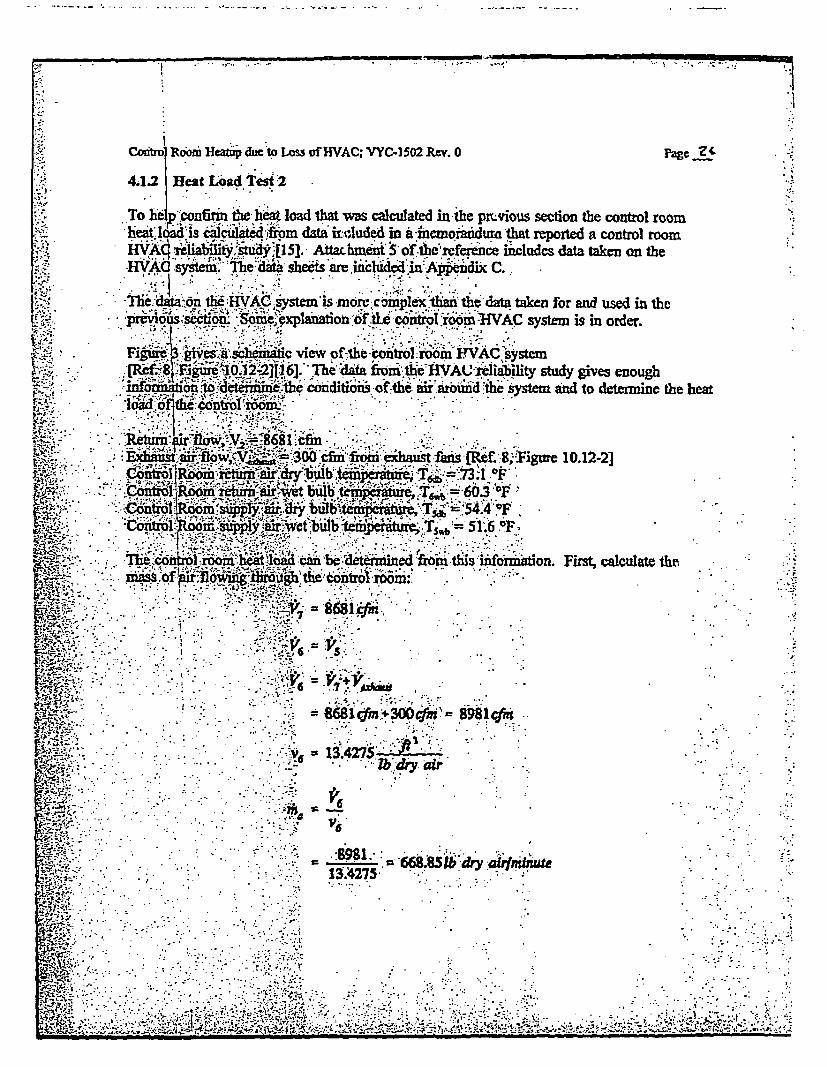
w:PF
LACoMtr Room Heatup due to Lss of HVAC; VYC-1502 Rev. 0 Pagc?-
4,1.2 Heat Load Test `2.. ,. # . .
To he p onfirin te heat load that Ws calculated in the prLvious section the control roomheat lqed is cate frpm data uicuded in a imneoraudurn that reported a control room
i HVA iyt l5]. bment S of the refece includcs data taken on theINMVAC Ssy The daaet s are inched in Apedix C.:
iAC m ismor c~ pldx t e datataken for and used in thep[u. p O Som fte t rool AiVAC system is in order.
i' 3 'ca s c view of th cotrol room VAC systen0 .32n F[16]. Ihe daa irmnthse IWACeiability sd gives enougb
g ' t'-P''me -c on itio ns of -thwoid and to determj~f~~iotiaii~aroiundtsystem an odtnie the heat
oIbti~lic ,
3 fro s8,-}igme 10.12-2]
mass> of :G ir flRing-siro bub the- 603r~ ioF
L04~O .3.
- < = 51;G6 °F.
'MWv . *thits uifif on. First, caculate thie.;
W .' : -i3 300ii 8981(f
g -. - l . ...."b -d a y .1
W . .; -131 4275 5 '-
71:' ~.:''-. -' ,'., :','' . '. ."''-

Control Room Heap d Loss of HVAC, VYC-ISQ2 Rev. 0 Page Zf
E
- L
oJ3
Li
.1: . >
r.4C.. .. : i
W '' - - ::U i Ciel r ° q
PAA
Ai .Hsl e Co n t ro I. Room
FinrW Contro .po HVA Si, chpemanati - of thc enteijag and leaving .
*.. A rnO~~~.24+W01040
. iCt.. K:(093O.556fW~Q.24O~-tijRe pr W = a on
-. .'- 1.9
v.'- ' '- -^', .
'' ;.- '., uI J ' UMJ.....,;,T.-:t ', F 'i X, ~* ,{*; ,* . -* ,* . .;:;;:bk
C,.
t V(OW-144
f. -A4U
ttv l 74*1.

- -.1". - -
roomlm lcawop dac t oss~ of RVAC VYC-15(02 Rev. 0specifically, at dth inlet'
t =54.47~
0v --. 0081374
1093 4:0.444 t- i*. ~(.1093-03556 51.6 ;.bb813-74-O.240 (S4.4-51.6)
1093 *0.444 .54.&,, ,51.6:
)r~"'b240.& (1061+~0.444r)
= O2454.4`7A 5310-s'(1061 +0.44454A4)
M.
VM 10360F
b 103-0M6'OW-.3).240M,.20.. 109340444t-t 1 ~0.
£ .h'.k ''W1093 +OA444'7.I .03
- .203.1 .&265 '10' '(161 .0A444'3.1)
qjli
-
Page .za
.IIA
*1
I
4

WEMCW :1.,1 - 9 11111M
Ccoftr.o=Rv Heatup due to Loss of fWAC; VyC-1502 Rev. 0 PnNCg Zdiand th6 total heat addition to the air stream from the control room is:
If qz,.im7(h 6 -h)
m 668.85Tb dry airyminute
h6 = 26.582BU/Th dry air
2 21;578 2'TU18 /d air
;q -. 68.85(,6.582-21.578) = 3346.9 DBMtnin o, 200,815 BT1hr or 55.78 1T/sec
Teimz-:ertainties in this ialue of control room heat load are not entirely known since.u.ncrtaunt values 'are not directly attributable to the instruments used.
4: 13 Determin'tion of Limiting Control Room Rest Load
Wo v f controm hebt load have heen calculated using independent methods,*.1..TW.! USJ rcnil etla v
i::. o t tIn nd eonnel. onie values obtained are: 175,000 BTU/hr and;2. !8s 13T/lir. T a value was determined with data taken on a warm day inU mid-
valuU w* - obtained on a cool day in late:May. Vaiations in solar beatS ld £ :caJ o ancy an iistruiment accuracy can accunt for this diference. Eh
o ¢ dfthese ;ues liaCI t joad fmcoiductior into or out of the control room thiugh thecontrol room wall, ~ h.. eat load. Thus, there is an inherent conservatism in thesev auesd eihtir wiseg Ohuc ideli will be as electrical .l6ads (conduction andC p.;ng explicpit iputs in the GOTHIC model input.)
T r.,. to nswe a ding value for control room beat load is used, the average of the- -- two vQues f10 % nid e.tho control room heat load used for dtrmining the control room
r to a loss of HVAC due to an Appendix R fie event. ThisIbi e c'ntrolthe information received regarding the potential electrical loAds
.:q =17 000 + 200815S) 2 1.1 = 206,700 BIU hr or 57A2 BlTU/sec
n .'* ' ,'
-<', .... - ' ..:

___ _ _ _ ~ _ _ ZMMMU
Control Room Heanip due to Loss of HVAC; VYC-1502 Rtv. 0 Pagc3
4.2 Characterization of Abstract Heat Conductor
As xnitioned previously, the transient temperature of the control room due to a loss ofHVA: dependion twoimportant actors: te heat load in the control roor and the interialheat asorbig r This section attempts to characterize the internal heat absorbing;cr as a GOTIC heat conductor using test data obtained during a control room heaup
O.- ~test.
,n a hdated room, the :rinsient temperature rise is predicated on two major factors: the heatload and the heat absorbing structures. For the control room, the previous sections haveidentified the hiat load. 'Thus, to be able to predict tbh nransient temperature profile, the heat:absoing struturs must be able to be modeldd; However, the coutrl room has a very
cornpl4 array of beat absorbing structres (cabinets, panels, etc.) making it difficult to model
with -accacy. TIhus, a test was performed to gather data (tempeture rise versus time and
'.-he Io9Mb)hat can be uicd to charicterize the heat absorbing struchues.
.,; In the iedviosections, the control room beat load during the test is characterized. Giventhi isE hea loiad and kkowi ambient conditions, it is possible to modify the GOTHIC modeldevelod Previously to-attempt to model ti test condidons. An abstt inteal heatS;flUXt? ca~r. i b -iriad in the GOTHIC model othe test. By vanying the surface area of.^abs.irth hat coridur-itisthe trbmto abh etanient'test data and thus have a fairlygood is tivetni conddcormodel fbr use in laier control room heatup analyses.
The;, .tes Id, iS~a seres of temperatures at differeft locations within te control room take... :.over a d of boif3Srnutes,: Bcae the o introl room is a three-dimensional structe
with '," c"rr"n d ,''. lize heat sorc lights, rilays,-'power pies, etc.) but theGOTHIC - -. ~lt the conto room is one dmensionial.(a lumped parameter volume),it is not W 'GOTHI model i matche etest results exactly. However, toadeq.te, : .barde ii int hieat conducts, matcing the slope of the temperaue' i.nuat .s w @f'lt ::ope offi th temperatriewl bmfiinL'I a found that the slpe of thei temperature rise was fairly conttover the different locatioesof the tempeathm eadings. In fact, it was much more constantta ,.the , o lute s betwenlo ons.
Th'e est da -is include in Appendix D. TMe test data is plotted in Figure 4, Figure 5 and-Pigure 6 along with-les`howing the least res linear data fit for each of the data sets.
?';Te following equaions s wused to obtain the lea, t squares fit. Note that since the slope is
theon.ly variable of concern, only the slope is calc dated.
.
:;;.. ,- . .

S.,..,.... '-.
.*�
I ��I' *. �:.1*
* �*I. �
4p .'*.
� .� .�* f 'I...
--
Ak�
81 .
77 -.-
M-..A 76~
1.'.. lyE
�* a
0
.1
.I
a,
09
73"
72
71 A
0
. . . . lo-
p .. -,
. - .. : i � :...41P . . .. -
#- .1 .. .Po od.09
I'AAr 6
II
.1lI I
. I.
20
... Timle ..(minutes)30 40
-. . . .
�5S
* .: . . . : . I

S... 4�
I.
'S...
4* 4*
A'.
S.. *
,4.
.5... ..
4.
/
74. -. 5
72 - 2,~:2*'
9
a'I
r 'i-C:)
£ q-
F II
I1
.0a 10.> 20
me (mn .'.
30 40
. . ......- . p . . . .. *
. . .. .
. .�.'"..
. .
.....
- - ., . , - .. : I.: , i..:. . " , : -, , -,-- .. . .- . . . .".. .. .. -; -. : ' : '..�L' - "" , -
. ... .. o- , "..- -! S..- .5.. .. - . . .. - I .. -

.. . 44 .. � .
tV.�.
-. '�'*�..'.94-.� -. II :....
Vew t -d dI"errg.( .LY1
*1B
F
- -U
i' . -_ .
-. s.'.72_~.F; .. ~ .. :. . :
-;-{;:~~~~~~.-. . -.4...-;... Tie( n
.t'. r. .. . o 5 1 15 0 2530
@0r;~..i"'.:"'":> :':''- ''I.4.
.. ;o i -i ! .; '- .2 *. * * 5
0%
I
I
i
II
II
ii
4
tI
Ii
i
I
.:.-
LA
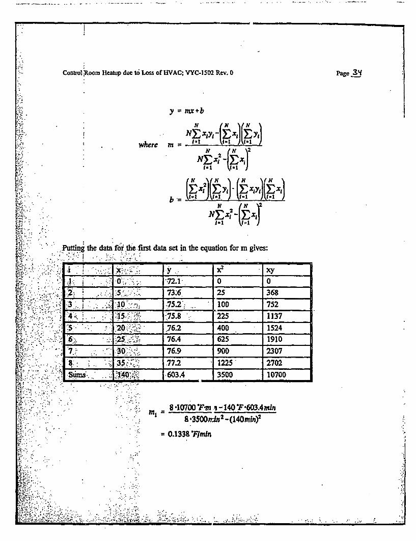
Control Room Heatup due to Loss of UVAC; VYC-1502 Rev. 0 Page 3Y
y =x+b
where m-
b . . P)~L ). (1 XiY )(~Ht ) (N 2
N 'N x?- Exd
Purting the data for ithe first data set in the equation for m gives:
73 25 ,36,8so
-*.3. .i'.75X2': 752 1'-'
4 . . ..:- 12.. .5.8 : :*. 3 -22 11376i2 1 ; 3 t *1 i ?4 0 524
_ _ _ _ --. _ _i _ _4- . : A5.x y ?. 2s13
3 10 ... 76.2 400 7526 2s 76.4 625 19107 30 76.9 9 2307S 3 .77.2 1225 2702.Su6 .03A 3500 10700
C..
i . 8 10700 Fm .-t140"F 603.4min8 '3500rin2 -(140mW)2
= 0.13387Fmin
...- . * . . .
.
... . '- .. , , I .,.. .. ..
Cootrol Room Hcap due to Loss of HVAC; VYC-1502 Rev. 0 Page,
The balance of the datacan be similarly manipulated and the results are:
Data Sit Slope1 0.1338 °F/mii2 0.1317:OF/rnin3 1 0.08262 0Flrin4 O.1057.F/z°in5 0.1 14.6'/bin.6 0.1264 6F/itin7 0 1 .1414L°P/nin
eb9 . .$ .0.1350:0F/nuin
E.ch sl reperaure increase in a local region in the control room. Asr * such, it LStrmind in part by the at load and the intenal heat conductors in tiat local.e~gion. iSince othei tes data a given i average heat load in the control room during the
. test (Section 4.1.1), th.aberage of these slopes will give a iepresentation of the combineda verage:iffc of all t *hea coidudors in the control room.
1.e
Ave A slope=0.12216 °P/min
t e t 6vpe of the transient temperature curve for the GOTHIC model; Ibev<t-. -:;:dificA~ors kd4i"iod to the initial input model are-
d-; ors #12b: t heat sin:: Area 25,00D fP:: . l - all init teperatures at 73.16 'F 6
o-.fHicients - all temperature boundaiy conditions set to 70° F to, ; r fithe rielfIvly mild conditions in the rooms adjacent to the control room andthi; .utd.oi a-r ii atu=e (ly cloudy day based on t est data.)C.o:ers.HeaCeis -Heatr #1 (eBTtUical oad) /see based on results-f.. ,mSwdoi~fi"4.n Al;t, .Heatr #2 (occupants) set to 3.25 BTU/sec based on 30 siated
r~fiq. eq la 390; `Ulhr [14][10].-;Volumetic Fan - i trip set to 106 seconds, off trip set to 0 seconds (no opening of
fi . .r' ' , '. i nesgt'ies.) ::., ,-::' troIO's- tnpseto seconds, offtrip set to seconds (no opening oftr~tFS;j; ;ceillg tiles^): .-
Volume tiitil itions - Volume I (Coitrol Room) set to 73.16 °F 6, Volume 2(Drop Cei"ing set to 72.1 TF to match Time 0 test data.
AircraV Tim. 0 katr Wxtmpca ftvc tz IWAl dta.
',a'.' .... S~, .. bi 0.Wide wdriemp MqWfWubi"v 1e tred on T U80offtiew kmlcrcwx WM a~n udh o fl onlmy a bzr. ntO -;R*-qy CM 'voq tile' wall twlthnei XhS would aftat dkwaUb;asi2 e 1w sde t 4W o Rai IuoA4 MP at VsIl wien proffa could IM portulsted hu t he Wo'Coadlwo, fth tfi oaJ66ow bedt up Is neJ1bla.
e.- * '-li 8i7 @-
>A'-S' ' -;. :'.,.d..1'

.. 1 . ... - I
- . . ' . - ' -
Control boom Heatup due 'o Loss of HVAC; VYC-1502 Rev. 0 Pagc 3b
,'* Run Citol Par60 meter - the tes lasted forT35 minutes; the GOTHIC problem will- un fr6; nto be-lie to cover theist peniod and see any short team trends.
The GOTJHC inisft fXbles forthis r.odel -are inciudd in4Appendix A. The GOTHIC outputresults ¢incijide on icwflche u-d the filenen CONTROL.SOI.
Ths.he, tso Is hii are shown :.r7and ieS. -The temper e plot sbow aC minitl slsatp incease in peure f"(o6v& b alower but steady increase. The initils. h^ ~ ii se inD c6~ie is net vdij seen m the t d but'can be explaind by the: . beaioftihe-'h er coefflcxent tb ie .code, -Irnaly, the ldifferential temperatue
:al . aS.onlt'l the heat dnucis isvery smal. .This leads to a ve' y smallh ¢ .sfer'coeficint~idch is based n 'difrcnidal tlhrture (the correlAtion heatt>r.f.f :..eflieic ~.).3Ts in~itialy, very: lttlehea±is removed from the vapor phse in the
odeL; tliiitiieatup i-svery sm*.ro an adiabatic p of the room.
A s th e romhe . eea t conductor sudraes fncreass as< _ f nf;ercl th(e conductanceof heeatstrctur
; s h ia nom anditigates the control room tempeatre rise. Tbee 'al~Z >ii0 -f gs:co1ex.i1ciiiafed from GOTiIC~o oiwaum;ton-..................................... -;. ..
I ...- - - * . - ; - . 5....... * aT'T . , .u i of the.- TAGa of 25,6. n
g w~AlIO5 £ y 82°M to.550
0 fe. At 360 subseunt-dalss T 76D
10se)*.60-sedzhi 0.1231 OFlmini .
Cnaedwtthtstsoeof.0J216'Fmi"'e eut swthin 1% 6'o'f the' desrird ~~
-4.. *-w .- n O. .o . -.;
(5- b 5'."I ui de-use
- 7-g -:\ ..... ' ~.::; -. ' : .- ':'5- ,...................................

Control Room Heatup due to Loss of EVAC; VYC-1502 Rev. 0 Page 37
:.WCai Poom H~tv T- Modm_TVIt .2 -
MM xt$.1 .. :6. .
C 7xx
3%
.Jy
.' . "; .. . ._
I9 -,Ij 4 I
t~~~~~~ " -v *' ' S] 4 ¢ S * ( .
. - . A..
HufT - o--.ff ickhW
,~~~~ . .* * .;. ,. - G. ,.~: ,..-
t'-,'~~~F~ur ''','¶,''',' ''' -7 Control Roo .''u Tes M:a Voum Vapor''''' ..
, 1-.S.X. Of Hip)C:A 4 tS r *tm'i-s-6 *5.. -- * : _ _ _ _ _ __2 * sP ; s. * , -* * .
eN]-*''-''. -';* ;>,-;'o'Rtt. ......................- '.. ..... ...... ..5.:-. .,V~r.'4 dtl....... on iitpTs ofSlce al................ .
F . ;'' a f a ~ 'C" " "~. Pt;.,. ...- ;,..,..; ,,.-....-, ;, ....................-
W - ' .,: .'.:,:.. .. ' : , ................. : I .
**;t 4 g ,,5: '

I . ...
.. . Control Room Heanup due to Loss of HVAC; VYC-1502 Rev. 0 Page39
43 Control Room Heatup Daring App. R Event
Given the information available fim the test data, it is novw possible to adequately model thecontroom during 8 ioss 0ofVA.C' following an Appendbc R event. The generic controlroom GOHC input model descn led previously is used wvith modifications to the modelm ad dn the bisis of the test results describedin previous sections.
'The modifications and additions to the intial input model are:1.h rm.1Conductors - #12 sbstract hdat sink Area =2,500 ft
* i m'her nta t - all inii 78 F* Heat Triasferr; ffcients - fbr walls x ed to outside conditions, the temperature
;;. oundsrycondhtitns set to r tve aeag SOLAiRempers. .o lcri/Hee - eater#l (eliloa)stot57.42.BTU/se based on results
.- ;f1:~~~ .. in Section 4.1.^3-.;- umetric Fa - Otrip set to 11IOF control room temp e in accordance with- . . - V piously disc.ed
.O..n, tp st to 00 cwntrol room tempeatwure in accordance withthe: re1VOus>ydiscus * . *
.. * - olum.ii iti i- Vatues:1 ; aiia2sare settb-78 F;&Pa- * * U rl;IIleters - the G problem will rim for a four hour transient
g : : (d400 3:.:
.; . Thie GOT C ipt tbleisfor this indoe are incluWed in Appendix B. Te GOICoutputr t i ;,i ,ndej the f:lena'ie ']EA . .. Sor.
bip-e. z rLore ~igrmel2 9 The ittiismy show that the control
.4. ; .ac:onno included: inh6idel. f feci of tli oeiBj oP the ceiling tiles caicearlyj be ...
'tan- the s ft conDrl room since tb e h eat sources are in th e control room.
,!t .r*old r y be expeted that the teipeintue seenu bythfie operaors ad esqsipentwold b..d less than hoow tby thitetis oe ceiingftotl can. Co lmem-on.-experience owsth is a notceble differen e in lie tempe at floor level ad the;.temeue at ceilingtIamlan he atd room.
.hees'" ' hk $h''- b' th ' 'i .'i jsn oh eln.Cmo
owstw '. d ,', f',t,, '"
km'M- tM a etdro"
...
4).-Y

Conftro Room Heatp duc to Loss of HVAC; VYC41502 Rev. 0 pape
WVo ibv4 Roc 8HrM-Lca ft HVAC
GOV8¶V~on S~(AO -Aprd199
f* I
2 ~ContW Room Hoalup, Loss of HVAC:.TV1 TV12
.... ...
Its ---..---- z...... ......... . . -. . -. ,. . .
.14.
Fiue9 CnrlRoomi He~atip, .Lcisi of HVAC Tiica=Tmin

__ . A . .. *- Ig
._1Control Room Heatup due to Loss of HVAC; VYC-1502 Rev. 0 Page 'e
I
i
i
4.4 Control Room Heatup Mitigs ion Options
As sden by the results in Section 43, during the first four hours of the control room loss ofHVAb transient i1he pet re h the control room stays under 120 'F. However, due to theeatoadn the room and the insulating effect of the thick- concrete wallsv , the steady state
terpraue is eictd to be welr above 120 "F. To mitigate this temperature rise, twopossiile options are explored. Any option chosen wil have to do one of two things, eithersingl or in combinaion. Either the heat 1o6d will have to be reduced or somie alternateventilationlcoolin will have to be prov ded.
The first option explored was to provide a means of alternate ventilaton. Given sometenipqrary venilaion usizng outside air the control r im temperature can be maintained at or
L below 120°F. ;:A GOTHIC model was used to determine the amount of air flow required..lbesecond option was to reduce the heat load and iprvide some means of alternatevenfi1tion (at-some reduced level fromntthe first option.)
.be asic f'GIOTM codtrol room model &veloped .previously was used wit some orn odiIcations.i schtic of the newGOTHIC model is 6hown in Figure 10. As seen on
rA:ie.shnac, an'dditionai flow boundary coilition id a flow path to that boundaryconldition were ded. ls th' mifions-are outlined below for each optioiL
Option i- The inputftables for this option are included as Appendix E. The output for thisu' iLs! insluded onmicrofiche uder'thte fiename nOPPTONN .SOT .
<;, -Oit2oh2- TIe input taibles for dii option are included as Appendix F. The output for thisis insl'dad on microfiche under the idenazr 4t ~OPTION2.SOT".
. : Fluid Bo .Conditions - a flow boundiry condition was added to simulate aeci:s:ant.,'ntila<flon air flow; n this case, the flow was set to a function ibich hadzewoflow upt&'4400 seconds (four hcurs) and 110 cfs (6600 cfi for Option 1) or56.cfs -30009cf;for Option 2)therea te ' wd-iswactualyregativne, ito thbo ,iM o lin the control room press boundary condition to provide
^ . . -the .Wei
-.-Flow Pah-;aflow path was modeled connecting tbe new fluid boundary condition*t the c o the flow path is not ni endedto model any particular
.vea iiction and for s-mplici v was sct io the same parameters as the othercontrol mdmy condition connestn flow path';
CoolIrfeateri/ - a forcing fiunction was assigned to the electrical heat lead; forOpion I, tifing fimction was unity (no c 'in heat load) but for Option 2,
gthis fiorcig fntion was set to 0.48 at four hours to represent a reduction in heat load
The tempat tsn results of these models re shown in Figure }I and Figure 12.
PSI..:: . : : .
t 4 r., .?-,- "wt ' ;*r :-!.. :' ' ................................. :- ''ti '
. P
. :, .. . . Z;

Control ikoom Hcatnp.4tae to los of HVAC: VYC-I502 Rev. 0 Page .L
VY frol ROOM HmdAtup-osW I AC OPtSo IUmAD28 14:2020 19982MI frsonl 5.V,(QA)-C -AOI 99
10A. IV5p.
.~- r~~n~pu ~ ... C. -I.r .O 2
2tM * .4:a vb2Md
v.I---- -

Control Room~ Heamup duco t Los of HVAC; VYC-I 502 Rey. 0 Page~~
* I olF M oaito. Los* of HVAC.Opgton
32.0 2'!. IS 1A Ia 2.
2' F6n im
*3. 7..2 a1.. 1A 1 21.8
* .FigireV Contol oam eatu Re 'lts Otion 2 -I Na~W~AC~cPZ
2~: C~oIA~m~I~Heat Load

1-
IA~
Control itoom Hcit duc 6i Loss of HVAC; VYC-1502 Rev. 0 Page '
5.0 |ConcdiMous
... It has beei shown-hi.forthe fixtt four hours aftera control room loss of HVAC tmsient,2? -i."m~initol WS not *x.20 02given opertor actontoremove.su.fi.cien± ced in g -, room te p - er a rea 110F -To p m the co tol roomtp f. d.iig l2Os wfour o, sorm ctdon is requied to itigate the
0 . ;tion-h ai' been idht tia which ensure control roomdedtr d.e :;t> 120I in a long tiemi Wenti:.
. a ventiltionproviding at least 6600 efin of outside air, or
* D. :-;iS 3 rewdui by at leat 52% accpanie by at least 3000 cfm of outsde air.
b ' : o*d eas.... t ,ar. ",X .''. .*.
511~
W- 1-* I -;
4''.
W |ft;* I
MS . ' ,*-> ',*@ S s
m.* *N ,- 'vfi S@, *- '- .,sZ 21v- -A- ';L'............... '1'^''~'.......................'-,.... ..'. .-
m *; ~~~~~~~- t''' ¢r '.*
w--S e b;e **->? -*e,, , *
,±~ -' > i- - ...- *
::*1'..-:,;;,,-_..k-......=r
- - C.-r

BVY 05-072Docket No. 50-271
Exhibit SPSB-C-52-4
Vermont Yankee Nuclear Power Station
Proposed Technical Specification Change No. 263 - Supplement No. 30
Extended Power Uprate
Response to Request for Additional Information
Calculation VYC-2405, Rev.0
Total number of pages in this Exhibit(excludina this cover sheet) is 85. 1

CALCULATION COVE1R PAGEO IP-2 f IP-3 El 1A} []PNPS ED VY
Calculation No. This revision incorporates the following MERLIN Sh 1 fVY 41Re.0 DNs or Minor Calc Changes: Seet I of 85
Title: Dryw6lI Temperature Calculation for a Station ZQR EINQRBlackout Event at Extended Power Uprate.
Discipline: Fluid Systems Design Engineering Design Basis Calculation? ZYes []No
This calculation supersedes/voids calculation: N/A
Modification NolTask No/ER No: EPU
EI No software used
0 Software used and filed separately (Include Computer Run Summary Sheet).If BYES', Code: GOTHIC V7.0p2
O Software used and filed with this calculation. If "YES', Code:
System NoIName:
Component NoJName:
.(Attach additional pages if necessary)
' ' Print/SignREV # STATUS PREPARER REVlElENNR/ OTIEER APPROVER DATE
(Prel, Pend, DESIGN REVIEWER/A, V, S) VERIFIER DESIGN
- . . VERIFIER
o Prelim Liliane Alan L. James G.Schor Robertshaw Roge 7
t/:& A 7/C A
ENN-DC-126 REV.A ATTACHMENT 9.2 CALCULATION COVER PAGEENN-DC-126 REV, 4 ATTACHMENT 9.2 CALCULATION COVER PAGE

-Entergy Calculation VYC-2405 Rev. 0ae f.
Page 2of 85 -.
ENN-DC-126 REV. 4 ATTACHMENT 9.6 CALCULATION RECORD OF REVISIONS
RECORD OF REVISIONS
Calculation Number: VYC-2405 Rev 0 Page 2 of 85
Drywell Temperature Calculation for a Station Blackout Event at Extended Power Uprate.
Revision No. Description of Change Reason For Change0 Original Issue N/A

Entergy Calculation VYC-2405 Rev. 0 Page 3 of 85
ENN-DC-126 REV. 4 ATTACHMENT 9.4 CALCULATION SUMMARY PAGE
CALCULATION SUMMARY PAGE
Calculation No. VYC-2405 Revision No.0
Drywell Temperature Calculation for a Station Blackout Event at Extended Powver Uprate.
CALCULATION OBJECTIVE:
This calculation will address the VY drywell temperature for Station Blackout (SBO) atExtended Power Uprate (EPU) Conditions. The calculation will look into means to mitigatethe drywell temperature for this event, such that there will be no need for EmergencyDepressurization.
CONCLUSIONS:
See Section 7.0
ASSUMPTIONS:
See Assumption in Section 4.0. (see also list of open items - assumptions which needverification or implementation - Section 4.1)
DESIGN INPUT DOCUMENTS:
See Design Input Documents identified in References Section 8.0
AFFECTED DOCUMENTS:
See Assumption Section, Section 4.2
METHODOLOGY:
See Section 3.0

- Entergy Calculation VYC-2405 Rev. 0 Page 4 of 85
TABLE OF CONTENTS
Cover Sheet (ENN-DC-126 Attachment 9.2) ................................................................ 1
Record of Revisions (ENN-DC-126 Attachment 9.6) ................................................................. 2
Calculation Summary Page (ENN-DC-126 Attachment 9.4) .......................................................... 3
Table of Contents .......................................... 4
List of Effective Pages (ENN-DC-126 Attachment 9.15) ........................................ 5
* 1.0 Background.6
2.0 Purpose.6
* 3.0 Method of Analysis.7
4.0 Inputs and Assumptions.7
5.0 Input and Design Criteria ......... 15
6.0 Calculation / Analyses ......... ;26
7.0 Results and Conclusions ......... ;;67
8.0 Backgr oun d ............................................................................................................. ;...........................6
Computer Run Summary Sheet (ENN-DC-126 Attachment 9.10)..71
Calculation In p act Review Page (ENN-DC-126 Attachment 9.7)7..............................................72
Calculation Design Verification and Review (ENN-DC-134) ............................................. 77
Files on CD ............................................. 85
Attachments
Attachment A.Al - A39
TOTAL NUMBER OF PAGE (Including Attachments) ...................................... 124

6 f .. . .) i w s w w w
-Eniergy Page 5 of 85 -Calculation VYC-2405 Rev. 0
ATTACHMENT 9.15 LIST OF EFFECTIVE PAGES
LIST OF EFFECTIVE PAGES
Calculation Number: VYC-2405 Revision Number: 0 Page 5 of 85
Torus Temperature Calculation for.a Station Blackout Event at Extended Power Uprate.
PAGEAll
REV.0
PAGE REV. PAGE REV.

-- Entergy Calculation VYC-2405 Rev. 0 Page 6 of 85 b'
1.0 Background
The Station Blackout (SBO) torus temperature calculation (Reference 1) accommodated a highercoping time of 2 hours versus 10 minutes previously assumed. In addition to an increased copingtime, Reference 1 also eliminated the potential need for Containment Overpressure (COP) for theSBO event. In the process, it was determined that in order to implement coping strategies for thetwo hours, two additional parameters need to be analyzed:
- Drywell temperature and the coping strategy to accommodate an expected higher drywelltemperature, and
- Procedural direction for the operators (if needed) to limit the drywell temperature whileensuring capability of HPCI/RCIC to maintain vessel level
2.0 Purpose
This calculation will address the VY drywell temperature for. Station Blackout (SBO) atExtended Power Uprate (EPU) Conditions. Th'e calculation will look into means to reduce thedrywell temperature for this event, such that there will be no need for Reactor Pressure Vessel.Emergency Depressurization (RPVED Reference 30).
This analysis will address control of the drywell temperature by controlled depressurization(cooldown) and will show that RCIC/HPCI injection is maintained until power is restored andthe low pressure pumps (RHR and CS) are available.
As indicated in Section 1.0 of Reference 1, for the SBO event, the Alternate AC (AAC) powersource is restored at 2 hours into the event. After the restoration of power, torus cooling anddrywell spray will become available.
2.1 Acceptance Criteria
To evaluate the results the following criteria are applied:
1. The maximum allowable drywell bulk average temperature should remain below the EQtemperature (340TF for the first 30 minutes and 325TF for the next 270 minutes)(Reference 19).
2. The maximum allowable drywell surface temperature is 281 F (Reference 20).
3. The maximum allowable drywell air pressure is 56 psig, (Reference 27).
4 Maintain the torus pressure below PSP curve (Reference 30) during the 2 hour copingduration and the 10 minutes of low pressure pumps restoration period.
5. The analyses should provide assurance that there is no need to spray the drywell in theunsafe region of the DWSIL curve (Reference 30).
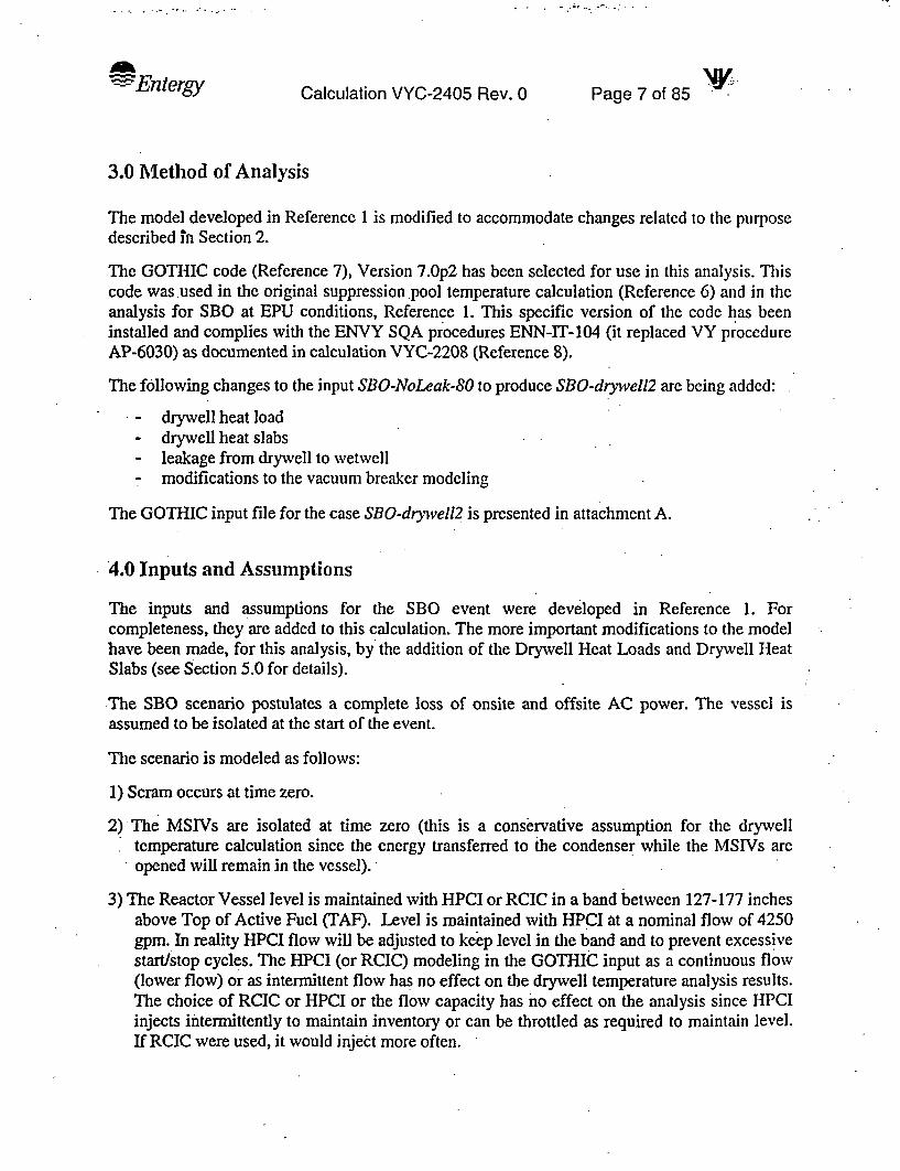
s + - t D D w w ffi
Entergy Calculation VYC-2405 Rev. 0 Page 7 of 85
3.0 Method of Analysis
The model developed in Reference 1 is modified to accommodate changes related to the purposedescribed In Section 2.
The GOTHIC code (Reference 7), Version 7.Op2 has been selected for use in this analysis. Thiscode was used in the original suppression pool temperature calculation (Reference 6) and in theanalysis for SBO at EPU conditions, Reference 1. This specific version of the code has beeninstalled and complies with the ENVY SQA procedures ENN-IT-104 (it replaced VY procedureAP-6030) as documented in calculation VYC-2208 (Reference 8).
The following changes to the input SBO-NoLeak-80 to produce SBO-drywell2 are being added:
- drywell heat load- drywell heat slabs- leakage from drywell to wetwell- modifications to the vacuum breaker modeling
The GOTHIC input file for the case SBO-dryvell2 is presented in attachment A.
4.0 Inputs and Assumptions
The inputs and assumptions for the SBO event were developed in Reference 1. Forcompleteness, they are added to this calculation. The more important modifications to the modelhave been made, for this analysis, by the addition of the Drywell Heat Loads and Drywell HeatSlabs (see Section 5.0 for details).
The SBO scenario postulates a complete loss of onsite and offsite AC power. The vessel isassumed to be isolated at the start of the event.
The scenario is modeled as follows:
1) Scram occurs at time zero.
2) The MSIVs are isolated at time zero (this is a conservative assumption for the drywelltemperature calculation since the energy transferred to the condenser while the MSIVs areopened will remain in the vessel).
3) The Reactor Vessel level is maintained with HPCI or RCIC in a band between 127-177 inchesabove Top of Active Fuel (TAF). Level is maintained with HPCI at a nominal flow of 4250gpm. In reality HPCI flow will be adjusted to keep level in the band and to prevent excessivestart/stop cycles. The HPCI (or RCIC) modeling in the GOTHIC input as a continuous flow(lower flow) or as intermittent flow has no effect on the drywell temperature analysis results.The choice of RCIC or HPCI or the flow capacity has no effect on the analysis since HPCIinjects intermittently to maintain inventory or can be throttled as required to maintain level.If RCIC were used, it would inject more often.

Entergy Calculation VYC-2405 Rev. 0 Page 8 of 85 NV
4) HPCI takes suction from CST at 1350F. The CST inventory available for injection is 75000gal.
The GOTHIC input value in Ibm = 75000 gals * 1 ft3n.48 gals /0.01627 Ibn/ft3
(Reference 31 for the density a 135 OF) = 616271.7 ibm
5) Power is restored at 2 hours. Torus cooling is initiated at 2 hours and 10 minutes. Two RHRService Water pumps are available at 2 hours and 10 minutes, delivering 4700 gpm. Thesecond RHRSW pump is discontinued at 16 hours in the transient to maintain the CornerRoom temperatures below the EQ limit (Reference 1, Attachment B). The drywelltemperature analysis is performed for only 25000 seconds for the base case and for 14400 (4hours) seconds for the sensitivity cases since, after 2 hours and 10 minutes (7800 seconds),the low pressure pumps are available to spray the drywell, if needed, hence there is no needto analyze the drywell temperature for a longer duration.
6) An orderly reactor cooldown is initiated at one hour in order to maintain the drywell.temperature below the EQ limit (Reference 19) and the drywell shell metal below 281 TF(Reference 20). Two cooldown rates will be analyzed: 800 F/hr and 45TF/hr.
7) The -RPV level is controlled by HPCI until the CST is depleted or HPCI shutoff pressure isreached. When the pressure permissive is reached, one Core Spray pump starts (after 2 hoursand 10 minutes) to inject into the vessel . After the level is recovered in the normal range, theCore Spray system is used to maintain the level with the vessel pressure being controlled byan SRV cycling between 50 and 100 psig. The suppression pool is cooled continuously bythe RHR system. The reactor vessel is maintained in this configuration. The RHR pump intorus cooling is also available for drywvel spray after 2 hour and 10 minutes.
.8) The HPCI turbine takes steam from the vessel to provide its motive power. It returns theexhaust steam to the torus. The steam to the turbine is not modeled since the model assumesSRV opening and closing to maintain pressure. Any steam not removed by the HPCI turbinewill be removed through the SRV. to maintain a certain pressure. The total flow through theSRV is increased, but the details of SRV flow are not important for this applications and thetwo (SRV flow and HPCI turbine) can be combined for model simplicity.
9) The liquid leak is modeled as a fixed flow of 8.4585 lb/sec (61 gpm, Reference 3) [(61 gpm/60 s/min /7.4805 gal/ft3 /0.0161 ft3Ilb = 8.4585 lb/sec)] and it stays on for the entiretransient. (Analyses will be performed with and without leak for one depressurization(cooldown) rate: 80 TF/hour). In reality, the leak is variable depending on pressure. Assuminga density of 62 lb/ft3 and fixed flow is conservative for the drywell temperature analysis.
Analysis. of drywell temperature for a 45 TF/hour cooldown with no RPV leakage was notperformed because for the case .with 80 TF/hr cooldown, for the period of interest the drywelltemperature stays below 300 0F for both cases (with and without RPV Leakage). For the 45*F/hour cooldown, the temperature in the drywell for the no-leak case is expected to remainbelow 300 TF as in the 45 TF/hour cooldown case with RPV leakage for the analysis duration.

- Entergy Calculation VYC-2405 Rev. 0 Page 9 of 85
10) The analysis will assume a fouling of 0.0018 in the tubes and 0.0005 in the shell. Thiscorresponds to an overall RHR Heat Exchanger (RHRHX) fouling of:
R. = Rfi (d) + Rfo
where:
Rfi and Rfo = tube and shell fouling factors, respectively (hr-ft2 -°F/Btu)do = outside tube diameter (in)di= inside tube diameter (in)
do = 0.625 in (Reference 22)di= 0.527 in (Reference 22)Rfo = 0.0005 hr-ft2 -FJBtu (Reference 22)Rfi = 0.0018 hr-ft2?-F/Btu (from 0.0020)
Overall RHRHX fouling
0.625Rf =0.00l8*(o 62)+0.0005=0.0026
0.527
This number compares well with the maximum fouling calculated in Reference 23 of0.002307 and 0.002445 for the RHR HX E14-lA and RHR IIX E-14-IB, respectively.
11) A variable SW temperature is used, consistent with Reference 1.*Since this change of depressurization (cooldown) function of service water temperaturerequires procedure changes, it is added in Section 4.1 as an unverified Assumption.
- For SW> 750F, depressurize the vessel at 80 °F/hr or higher.- For lower SW temperature (SW < 75TF no restrictions on depressurization) rates.
12) - Various assumptions made concerning the added Heat Conductors:
- The heat load decreases linearly when the temperature difference between RPV anddrywell becomes smaller.
- For all conductors, only heat conduction is conservatively assumed in the air and concretelayers.
- The outer surface boundary condition is conservatively assumed to be adiabatic (i.e., theheat transfer coefficient is set to zero)

---Entergy Page 10 of 85 . -Calculation VYC-2405 Rev. 0
Table 1 - Vessel and Core Initial Conditions and Parameters, Primary Variables
Parameter Nominal Analysis Basis_ Value ValueInitial Reactor Power 1912 Mwth 1950 MWth 100% power +2 % uncertainty (per NEI-
87-001, SBO can be performed at 100%power, however this analysis used 102%power, consistent with CLTP and theReference I analysis).
Core Decay Heat ANS 5.1 ANS 5.1 +2 ca ANS 5. 1 1979 standard+2 a uncertainty-(Reference 24)
MSIV closure time 3.0-5.0 sec 0.0 sec (MSIVs Minimum value allowed retains thenot modeled) maximum energy in the vessel.
RPV Pressure 1015-1025 psia 1045.2 psia Higher value, conservative, maximizes(Reference 28) the vessel energy.
Initial Vessel Level 162 inches 172 inches Analysis value conservatively accountsfor 3 inches increase above normal(uncertainty and operational fluctuations)and 7 inches for dimensionaluncertainties. These assumptions areLOCA assumptions and are judgedconservative for SBO.
Core Flow Rate 48.0E6 lb/hr 51.36e6 lb/hr Includes ICF of 7%.Initial Feedwater Flowrate 7.876e6 lb/hr 8.076e6 lb/hr Reference 25 (TE 2003-20)Initial feedwater 393.5-393.6 OF 393.9 OF See discussion in Reference 25.temperature Feedwater is tripped at time .0, due to
SBO. The feedwater is used only for thesteady state initialization.
SRV Cycling 1080-1047.6 psi 1080-1047.6 psi The setpoints for the SRVs are nominal.(between RPV (between RPV No additional as found allowable of 3% isand Drywell) and Drywell) added since it will have no effect on the
drywell temperature since the SRVs opento remove the decay heat and, until thedepressurization starts, indifferent ofsetpoints, the SRVs will cycle to removethe decay heat.The operators will take manual control ofthe SRV and will cycle between 800 and1000 psig (EOP-1- Reference 37) toreduce the numbers of times the valvescycle. There is no effect on thecalculation since the valves in anyoperational mode will open to removedecay heat.
Vessel Leak 61 gpm 61 gpm A constant 61 gpm leakage is assumed;(Reference 3). The analysis will beperformed with & without leakage, sincethe drywell temperature will have adifferent profile for the cases with noleakage.

v . w t t . o s A. . S \ \ ^
i- Entergy Page 11 of 85 N:Calculation VYC-2405 Rev. 0
Table 2- ECCS Initial Conditions and Parameters
Parameter Nominal Analysis Value Basis CommentsHPCI flow rat 4250 gpm 4250 gpm Tech Spec Flow Since the flow is intermittent there is
(Reference 2) no need to use the min flow of 3570gpm (uncertainty added) (References2 and 5). In reality the HPCI flowwill be adjusted to maintain level to
l prevent excessive pump stop/start.HPCI pressure 1135-165 psia 1135-165 psia Reference 5 and 27. HPCI is shut offrange if vessel pressure drops below 165
psia.CST Temperature 120 OF 135 OF OPEN ItemCST available 75000 gallons 75000 gallons Available CST Per Reference 3, the Tech Spec valueinventory (VY Tech inventory for HPCI can be used.
Spec - injection An administrative limit for the CSTReference 2) level of 25% is required.
Core Spray Flow Curve of flow Same as The core spray The Core Spray System will be usedvs. vessel- nominal. flow rate used in for level control only after the CST istorus AP. the SBO analysis depleted and/or the low pressure is
of Reference I will reached.be used. The flowrate is determined OPL4 -Reference 5as a function of thevessel-torus AP.(consistent with theLOCA analysis)
RHR Flow 7000 gpm 6400gpm 6400gpm used in Consistent with Reference I(t=7800 seconds) analyses limiting case and Reference 5.RHR Hx Fouling 0.0005 shell, 0.0005 shell, Assumption input #10, supported by
0.0018 tube .0.0018 tube Reference 23.RHR Hx Tube NIA 5% Allowable Design value providing margin abovePlugging plugging margin the current plugging value of 3.6%
RHRSW Flow 4700 4700 gpm (2 4700 gpm (Reference 4)RHRSW pumps)4700 gpm =650.98 lb/sec (at85 OF)
RHRSW Inlet 32-85 OF Variable, see If SW is > 75 'F, Maximum Allowable Service WaterTemperature assumptions, depressurize the Temperature (Reference 2) only for
based on RPV with rates 80 depressurization rates > 80 TF/hrdepressurization 0F/hr or higher. For lower depressurization rates the(cooldown) rate SW has to be below 75 'F. This
requirement is derived from the torustemperature calculation (Reference1). The rate of depressurization wasshown in this calculation to haveminimal impact on the strategies tocontrol the drywell temperature for
._ SBO.
'I

'FEntergy Page 12 of 85 -Calculation VYC-2405 Rev. 0
Table 3- Primary Containment Initial Conditions and Parameters
Parameter Nominal Value Analysis Basis CommentsValue
Drywell 110-170 OF 170 OF Reference 5 The highest drywellTemperature temperature is used.
Drywell Pressure 16.4 psia 16.4 psia VY Tech Spec(Reference 2)
Wetwell 88 OF 90 OF Maximum Tech Spec A 2.F uncertainty is appliedTemperature Value (Reference 2) via procedure to account for
instrument uncertainty(Reference 26)
Wetwell Pressure 14.7 psia 14.7 psia Normal Torusoperating pressure(vented toatmosphere viaStandby GasTreatment System)
Drywell Humidity 20 -100 % 100% (base Nominal Values: Use maximum drywellcase) VY UFSAR humidity consistent with
(Reference 27) Reference I for the baseSensitivity case. Sensitivitiesperformed at performed at 20% drywell20% humidity humidity.
Wetwell Humidity 100% 100% Nominal Values: Minimal to no impact on theVY UFSAR SBO drywell temperature.(Reference 27)
Wetwell Water 68000 ft 68000 ft3 Minimum Tech.Volume Spec. Value
(Reference 2)
Drywell free 128,370 -131,470 131,470 ft Reference 5 The maximum value involume ft3 (includes OPL-4A is used for
vents) Consistent with SBLOCA, IBLOCA andReference 6, the Small Steam Breaks.
The values volume of the Vents: 16703 ft2 (VYC-proposed are drywell side of the 2306 -Reference 32)consistent with torus-drywell vacuumOPL4A breakers of 372.3 ft3 Total Drywell Volume =
will be added to the 131470 - Vents Volume +proposed value. Drywell side of Vacuum
Breakers = 131470 -16703 +372.3 = 115139.3 ft3
Wetwell free For the minimum Nominal Reference 5 The value at Dp>0 ofvolume water level of Values used. I _ _ _ 105,932.0 ft3 is used for a

'Entergy Page 13 of 85Calculation VYC-2405 Rev. 0
Parameter Nominal Value Analysis Basis CommentsValue
68000 ft3 , the Consistent with total volume of 105,932 +wetwell free The values Reference 6, the 68,000 = 173932 ft3
volume is proposed are volumes of the107,104.8 ft3 for consistent with drywell side of the Used in calculation: 173932Dp =0.0 and OPL-4A torus-drywell vacuum + 99.4 = 174031.4 ft2
105,932.0 for breakers of 99.4 ft3
Dp>0.0 where Dp will be added theis the pressure proposed Value.difference betweendrywell and torus.
Vacuum Breakers- 0.5 psi 0.5 psi 0.5 psi Reference 2pressure differencebetween wetwelland drywell forvacuum breakersto be fully openDr-ywell-to Max allowable Base case Reference 5 for the maxWetwell Bypass area =0.12 ft2 =0.12 ft2 leakage, Reference 33 forLeakage Tech Spec Allowable
.Tech Spec Allowable Sensitivity=0.0033 ft2 =0.0033 ft2

AEntergy Calculation VYC-2405 Rev. 0 Page 14 of 85
4.1- Assumptions that need Verification or Iniplementation
1) Two (2) hour restoration of outside power (coping time).2) TVn (10) minutes to start RHR flow through the RHRHX, and the use of 2 RIIRSW
pumps and CS.3) Acceptability of using 75000 gal from CST (change of level setpoint).4) Maximum CST temperature of 135TF.5) The depressurization rate function of Service Water temperature needs to be verified
and proceduralized as follows:For SW> 750F; depressurize the vessel at 800F/hr or higher.
- For lower SW temperature (SW S 750F) no restrictions on cooldown rates.
4.2 Affected Documents
1) DBD - for Residual Heat Removal - change the maximum tube side fouling resistancefrom 0.002 hr 2-f'F/Btu to 0.0018 hr-ft2 -°FfBtu as well as the total fouling.
2) Change the description of the SBO event in the DBD for Safety Analysis.3) Change all DBDs and documents that address the SBO coping time (identify and
modify).4) Change DBD Containment Pressure Suppression System to incorporate results of this
calculation.5) Review following documents for need of modification: VY UFSAR, and PUSAR.6) Modify SBO procedure (OT-3122-Reference 36) to incorporate cooldown at one hour
and provide guidance to the operators such that RPVED is precluded based on the resultsof this calculation.
Note: Section 4.1.& 4.2 items are being tracked via LO-VTYLO-2005-00135.
I .

Entergy. Page 15 of 85 -- :Calculation VYC-2405 Rev. 0
5.0 Input and Design Criteria
The GOTIJC input from Reference I is modified to implement the features described in thissection. The modified input is called SBO-dryvell2.
The main features added to the SBO model are the drywell heat load and drywell heat structures.A schematic of the system modeled is presented in Figure I
*OryweflL' ,/van
WetwaC.
bxus Weat
servlceWater
Figure 1 - VY Containment and the Associated Systems
Note: only RCIC pump is shown in this simplified model. Actually, HPCI is assumed to inject.

Ad Entergy Page 16 of 85 'Calculation VYC-2405 Rev. 0
5.1 Drywell Heat Load Calculation
The Drywell Heat Load Summary at Current Licensed Thermal Power (CLTP) is summarized inReferenceJ1O. The total amount of heat given to the drywell at CLTP is 1,691,300 Btulhr. Thedrywell heat load was recalculated in Reference 18 for the Extended Power Uprate (EPU) as1,700,675 Btu/hr. Since the Extended Power Uprate is performed at constant pressure, only thefeedwater pipe and valves will be at higher temperatures (Reference 18), hence a higher Q forthis component; (124,000 Btu/hr -Reference 10 versus 133,375 Btu/hr at EPU -Reference 18) iscalculated.
The total power to the drywell for EPU is presented in Table 4.
Table 4 Drywell Heat Load (Reference 18)
Item Component Cooling LoadNo. I (Btu/hr)1 Reactor Vessel 459,0002 Recirc. Pumps, Valves and Pipe 278,0003 Feedwater Pipe & Valves 133,375 (EPU Modified-
Reference 18)4 Steam Pipe & Valves 212,0005 Condensate & Instrument Lead Lines 82,0006 Control Rod Drive Pipe 50,4007 Clean-up Pipe & Valves 17,8008 Shutdown Supply Pipe 8,1009 Steam Safety/Relief Valves 206,60010 Biological Shield (Gamma Heating) 16,40011 Safeguards System Piping 82,00012 Steam Leak 155,000Total . 1,700,675 Btu/hr

Entergy Calculation VYC-2405 Rev. 0 Page 17 of 85 -
5.1.1 Drywell Load Modeling
The drywell heat is modeled as two heater #45H and 4#6H. The heater 5 represents the heat sourcewhich varies function of the liquid temperature in the vessel, while heater 6 represents the heatsource which varies as a function of the vapor temperature in the vessel. See explanation of thesetwo heaters in Section 5.1.2.
The heat loads which are exposed to the steam atmosphere (for Heater #611) are:
Table 5 Heat Loads Exposed to Steam
Item No.' Component Cooling LoadI_ (Btu/hr)
1 30% of Reactor Vessel Heat Load 459,000*0.3 = 1377004 Steam Pipe & Valves 212,0009 Steam Safety/Relief Valves 206,60012 Steam Leak 155,000Total 711,300
The normal level is at about 0.3 of the total vessel height. From Reference 34 the distance fromthe 152 inches above TAF to the top of the vessel is 21.432 ft in the GOTHIC vessel model andto the vessel bottom is 41.193 ft.
The middle range of 152 inches is calculated as (177 inches + 127 inches)/2 = 152 inches.The model assumes a normal level of 172 inches (Table 1) which is 20 inches above the 152inches, hence from 172 inches above TAF to the top of the vessel there are -21.432 - 1.667 =19.765 ft
The liquid height = 41.193 + 1.667 ,42.86 ft
Total GOTHIC vessel height = 62.625ft (from Reference 34 =330.542 - 267.917 =62.625 ft)
Steam region = 19.765 /62.625 = 0.31 (used 0.3)
Heater 6 load = 711300 /3600 = 197.58 Btu/sec
Total Heat load = 1,700,675/3600 = 472.41 Btu/sec
Thus, Heater 5 load = 472.41 - 197.58 = 274.83 Btu/sec

I
Enlergy Calculation VYC-2405 Rev. 0 Page 18 of 85 NY;
5.1.2 Transient Heat Load Behavior
It is assumed that the heat load decreases linearly when the temperature difference between RPVand drywell becomes smaller. In order to calculate the transient heat load, the following transientheat load pocedure is used
1. When the difference between the vessel temperature and the drywell temperature isless than or equal to zero, the power of the heat source is zero.
2. When the temperature difference is greater or equal with to Tset, the heater power willincrease above the nominal value.
3. When a temperature difference exists between Tset, and zero, the power is linearlyinterpolated between the nominal value and 0.0.
T3w is defined in the way that the calculated power of the heat source is equal to the nominalvalue at the beginning of the transient. Two GOTHIC control variable CV 41 and CV 42 arcdefined as the temperature difference between the vessel internal water temperature and thetemperature inside the drywell (CV41) and between the vessel steam temperature and thetemperature inside the drywell (CV42), respectively. The model shows higher steam temperaturethan saturation because of the heat slab exposed to steam which represents the heat structures inthe Reactor Pressure Vessel (RPV) exposed to a steam environment. Sensitivity studies whichplaced this heat structure in liquid eliminated the steam superheat, as expected. This. is aconservatism of the model. In reality all structures will be exposed to Tsat = Tliq= Tvap
The control variables are used as the independent variable of the functions, which gives thetransient heat loads to the drywell, as described above.
5.2 Drywell Thermal Conductor Model Development
The following thermal conductors are being added to the model.
There'are several types of heat sinks and thermal conductors inside the drywell. The componentsincluded as heat sinks are the metal mass of 4 RRUs, vent pipes and the drywell liner.Miscellaneous steel exists in the drywell, but has not been previously quantified in detail.Minimum heat sink components are considered conservative; therefore, miscellaneous steel isnot included as heat sinks.
Drvwell liner divided in (Reference 21):
l) Lower Drywell spherical portion,2) Upper Drywell cylindrical portion, and3) Drywell head.
The drywell wall consists of the concrete, the inner surface steel plate and the air gap. Zero heatflux boundary condition on the outside surface of the drywell wall is used.

Enterqy Calculation VYC-2405 Rev. 0 Page 19 of 85
The data on OPL-4A (Reference 5) is used to model the steel liner. The surface area calculationfor the liner was performed in Reference 9.
N Table 6 - Drywell Steel Liner
Elevation Steel Thickness (in) Surface Area (ft2) GOTHICItem #-from Ref. 9 thermal
conductorNo.
2, page 47 of Ref. 9 El. 237.74'-El 1.0 page 47 of Ref 9 1856.24 5257.75' |
3,page 47 of Ref. 9 El. 247.24'-EI 0.8125 page 51 of Ref 9 2041.28 6257.75'
4.1, page 47,48 of Ref. 9 El. 257.75'-El. 0.6875 page 51 of Ref 9 1250.47 9259.92'
4.2, page 48 of Ref. 9 El. 259.92'-E1 0.6875 page 51 of Ref 9 3802.73 7283.69'
5, page 48 of Ref. 9 El. 283.69'-EI. 2.5 page 51 of Ref 9 780.68 8289.61'
6, page 48 of Ref. 9 El. 289.61'-El 0.635 page 51 of Ref 9 1898.24 10308.00'
7, page 48,49 of Ref. 9 El. 308.00'- El 1.25 page 51 of Ref 9 1114.72 11318.50' _
8, page 49 of Ref. 9 El 318.50'- El 1.25 page 51 of Ref 9 783.4 12327.75' l
9, page 49 of Ref. 9 El. 327.75'-top 1.3125 page 51 of Ref 9 1718.3 13of drywell I
Total 15246.06 ft'
The items 2 through 7 have 0.0025 inches of paint per Reference 13 and Reference 9, AppendixVI (for properties) and a 2 inches thick air gap (Reference 14) and a conservative low thicknessof concrete of 24 inches is used from Reference 21.
Item 8 (side of drywell head -small cylinder) is modeled, with a 2.5 ft air gap outside the steelwall and conservatively low thickness of 1.5 ft of concrete (scaled from Reference 21). Thethermal conductor has an adiabatic heat transfer boundary condition. Only heat conduction isassumed in the air and concrete layers. This is conservative.
Item 9 (top of drywell head) is modeled with a 6.7ft air gap outside the steel wall and aconservative low thickness of 24 inches of concrete (part of the concrete plugs) - (scaled fromReference 21).
RRUs (References II and 12)
ARRU = 1272.8 ft2. thickness =0.125 inches (used in OPL4A-Reference 12).

Entergy Page 20 of 85 .-Calculation VYC-2405' Rev. 0
Vent Pipes
Vent pipes surface area
A vent pipe,= 2885.7 ft2, thickness =0.125 inches (used in OPL-4A-Reference 12)
NOTE: The total Surface Area of the steel components adds up to the value obtained from OPL-4a (i.e., Table 6 Total = 15246.06 ft2, RRUs = 1272.8 ft2, Vent Pipes = 2885.7 ft2, thusTotal = 19405 ft2)
Total Surface area of Concrete Exposed to Drywell Air Space
The surface area of the pedestal is the only concrete component quantified in OPL-4A. .The
drywell floor is ignored because it may be covered with liquid and not directly exposed to thedrywell airspace. Only the outer surface area of the pedestal was considered in OPL- 4A as wellas Reference 9 because the inner surface *has limited communication with. the drywellatmosphere. The biological shield wall (BSW) is a concrete structure surrounding the reactorpressure vessel and located above the reactor pedestal. Because of the proximity to the reactorpressure vessel the BSW is at a temperature greater than the drywell (DW) ambient and thus aheat source (already incorporated into- the drywell ..heater) and a heat sink only when itstemperature drops 'below the DW temperature. Because of the uncertainty of the BSWtemperature and its limited value as a heat sink, the BSW is not considered here.
The OPL-4A value for the area is used and = 2068 ft2 (A value of 2108 ft2 was used in themodel, addressed in Case 5).
Thickness of Concrete Exposed to Drywell Air Space'
From Reference 5 = 4ft.
Properties of Materials
Table 7 - Thermo physical properties of Passive Heat Sink Materials (Reference 5)
Material Density (Ibm/ft3 ) Specific Heat Thermal References(Btuflbm-0 F) Conductivity
(Btulhr-ft 0F)Carbon Steel 489.0 0.11 32 F 31.8 15
68 OF 31.2212 OF 30.0392 OF 27.8572 °F 26.0
Concrete 145 0.156 0.92 16Paint 288 0.2 0.125 9

Enteigy Calculation VYC-2405 Rev. 0 Page 21 of 85-4
Air Thermal Properties
From Reference 15.
T (1F) K(Btu/hr-ft-0 F) Cp (Btu/lbm-0 F) p(lbm/fl3 )
100 0.0157 0.24 0.07092150 0.0167 0.241 0.06511200 0.0181 0.241 0.06017250 0.0192 0.242 0.05593300 0.0203 0.243 0.05225400 0.0225 0.245 0.04617
Heat Transfer Boundary Conditions
On the inner surface of all the thermal conductors, the heat transfer coefficient is calculated bythe GOTHIC code. The following options are used:
-Direct'Heat transfer Option.-Summation of the condensation and convection heat transfer.-Max of Uchida and Guido-Koestel condensation heat transfer option (sensitivity with
Uchida for the limiting cases).- Radiation heat transfer option is OFF for all heat structures with exception of the
drywell dome.(sensitivity with option OFF for the limiting case).- The surface orientation is "FACE DOWN for the drywell dome", thermal conductor
#13,and "VERT SURF' for heat conductors 5 through 12.-All thermal conductors use 'VAP" option.
The outer surface boundary condition is conservatively assumed to be adiabatic. The heattransfer coefficient is set to zero.
5.3 GOTHIC Drywell SBO Model Development
The following changes to the input SBO-NoLeak-80 (Reference 1) to produce SBO-dry-weIl2 arebeing added:
- drywell heat load- drywell heat slabs- leakage from drywell to wetwell- modifications to the vacuum breaker modeling
The GOTHIC input is presented in Attachment A.
The GOTHIC model used for all cases is presented in Figure 2.

A Entergy Page 22 of 85Calculation VYC-2405 Rev. 0
SBO - 80P-Noleak-drywelllMar/15/2005 14:09:56
NGOTHIC Version 7.0p2(QA) - April 2002*File: /home/scbor/vyc-2120ccn/SENSITIVITY/SBO/drywell-SBO/SBO-drywell2
I
Figure 2 - GOTHIC SBO Model

9 9 - ale o S
Ad Entergy Calculation VYC-2405 Rev. 0 Page 23 of 85.
Flow Paths
.Flow path 21 is added to model the vacuum breakers leakage path from the drywell air space to.the wetwell air space. Per Reference 5, the maximum leakage area is 0.12 ft2. The elevations andthe height of this junction were elected to be the same as the vacuum breaker junction since theleakage is around the vacuum breakers.
The K rever =K forward = 1.5 (expansion & contraction) (Reference 29)
Thermal Conductors
Twelve new thermal conductors were added. The description of the thermal conductors wasgiven in Section 5.2.
The temperatures of 11 of the thermal conductors were set at 160 TF, the pedestal thermalconductor is set at 152 'F. On page 73 of Reference 9 the average temperature for the middle andthe top drywell node is calculated as 151.94 'F. Hence, the thermal conductors are set,conservatively at i 60 'F. The pedestal is in the lower drywell and middle drywell hence 152 'F isused (average for middle and top drywell is conservative). In Case 5, the temperatures of theheat slabs which represent the drywell wall were set at 170 'F (very conservative assumption).
Functions
Two new functions are added
Function 17 (FF17) represents the power to the drywell from the structures exposed to steam.
The function multiplies Q initial and represents (Tliquid - Tdzyell).
The FF17 is:
AT (CV41)-500 00 0380 1380000 1000
The independent variable is the temperature difference between (Tuquid - Tdrwell), CV4 1.
Function 18 is identical to the Function 17, but the independent variable is CV42 (T vapor TdyweCll)
Tref = Initial Vessel temperature - Initial Drywell temperature = 550VF -170GF =380 OF where550 'F is the initial vessel temperature, and 170 'F is the initial drywell temperature. (550 isdetermined from the GOTHIC model at time zero and 170 'F is the maximum drywelltemperature, OPL4A-Reference 5).

Entergy Calculationr VYC-2405 Rev. 0 Page 24 of 85
Valves
A new valve (V5) was added to represent the vacuum breaker. It opens on trip 33 (0.5 psidifference between wetwell and drywell (Reference 2) and it closes on trip 34 (0.3 psi-arbitrary,since the vacuum breaker valves reseat when the pressure difference becomes less than 0.5 psi. Aquick close valve is used for this component since the valve will close as soon as the 0.5 psidifference between wetwell and drywell disappears.
The vacuum breaker valve is modeled as Valve Type 3, with an area of 17.6737 ft2 (Reference9). Note: the area of the valve from Reference 9 is slightly larger than the area of the flow path inwhich it is located. The valve area will have minimal impact on this analysis because the flow islimited by the area of the flow path. The area of the valve was changed to the area of the flowpath in the final case analyzed, Case 5.
Materials
Four new materials are added. The properties for the new materials are described in Section 5.2.
Trips and Controls
Trip 18 is modified to ADS when the vessel pressure difference between RPV and drywell islower than 100 psi instead of 50 psi in the original model. This trip is not used, however, theSRV valves will open at a AP of 100 psi, not 50 psi.
Trip 21 is modified to start depressurization (cooldown) at one hour (3600 seconds) in order tolimit the drywell temperatures.
Trips 33 and 34 are added to open the vacuum breakers valves at 0.5 psi pressure differencebetween wetwell and drywell (trip 33) and close it on a AP of 0.3 psi.
Coolers & Heaters
Two new heaters are added, 5H and 6H to model the vessel heat to the drywell. These heaters aredescribed in Section 5.1.
For heater 5H the heat rate of 274.83 is multiplied by the FF 17, while for heater 6H the heat rateof 1997.58 is multiplied by FF 18.

.. ; - ... . . .
Entergy Calculation VYC-2405 Rev. 0 Page 25 of 85 -
Heat Transfer Coefficients Types
Two heat transfer coefficients arc added.
The following options are used:
-Direct Heat transfer Option.-Summation of the condensation and convection heat transfer.-Max of Uchida and Guido-Koestel condensation heat transfer option (sensitivity with
Uchida for the limiting cases).- Radiation heat transfer option is OFF for heat transfer coefficient type 6.- Radiation heat transfer option is ON for heat transfer coefficient type 7.
The use of the radiation option has no effect on the results at these low temperatures
- The surface orientation is "VERT SURF' for heat transfer coefficient type 6.- The surface orientation is "FACE DOWN for the drywell dome", heat transfer
coefficient type 7.
The use of the surface orientation is appropriate since this is the thermal conductorphysical arrangement.
- -The heat transfer coefficient types 6 and 7 use 'VAP" option since this is the drywellmedium.
-Convection bulk T model: Tg-Tf. The bulk temperature is the calculated vaportemperature. Tf is the maximum between the calculated wall temperature and thecalculated saturation temperature.
- Condensation heat transfer Bulk T Model : Tb -T, used. Tb is the minimum between thecalculated vapor temperature and the calculated saturation temperature.
Control Variables
Two control variables are added, 41 and 42 they represent the AT between Tliq in RPV and Tvdrywell and between Tvap in RPV and Tv drywell, respectively. See Section 5.1.2 for additionalinformation on the operation of these Control Variables.

. _:- 11 I
Enter gy Calculation VYC-2405 Rev. 0 Page 26 of 85
6.0 Calculation / Analyses
Five (5) cases are analyzed:
Case I is called SBO-dryivell2. It is the base deck, developed from Reference 1 and described inSection 5.3. Case 1 assumes no RPV leakage, depressurization (cooldown) with a rate of80 TF/hour a 100% humidity and base deck inputs as described in Section 5.0.
Case 2 is called Case SBO-drywell2-80-sensy2-NoLeak. Case 2 is identical to Case 1 with thechange in humidity, changes in the leakage area and minor changes in the heat transfertype 6 and 7. Case 2 assumes 20% humidity and minor changes in the heat transfer type 6and 7. These changes are described in Section 6.2.1.
Case 3 is identical to case SBO-drywell2-80-sensy2-NoLeak but with leak. It is called SBO-drywvell2-Leak-80-sensy. These changes are described in Section 6.3.1.
Case 4 is called SBO-drywell2-Leak45-sensy and is identical to Case 3 but with a slowerdepressurization (cooldown) rate. It assumes a depressurization of 45 TF/hour with leak inorder to show that with an early depressurization and slower cooldown rate the results arenot changed and the drywell temperature is not impacted negatively by a slowercooldown. Consistent with Reference 1, the RHRSW temperature is changed to 75 'F.Case 5 addresses changes found during documentation and as part of review. Thesechanges are described in Section 6.4.1.
Case 5 is called SBO-drywell2-comments. The following changes are made in Case 5 to addresschanges found during documentation and review:
. change the temperatures of the steel structures from 160 'F to 170 'F (veryconservative assumption),
. change the K reverse for the Junction 3 from to 3.93 from 3.964,* set the V3 Valve with the same area as the junction, and* change the area for the pedestal from 2108 ft2 to 2068 ft2, consistent with OPL-4A.
Case 5 changes are described in Section 6.5.1.

* Entergy Calculation VYC-2405 Rev. 0 Page 27 of 85
6.1.1 SBO-drywell2 Model Development
SBO-dryvell2 represents the base model for this calculation. The modification to the input arepresented in Section 5.0 and the GOTHIC input deck is presented in Attachment A.
6.1.2 Case SBO drywell2 Results
Figure 3 through Figure 11 present the main parameters for the base case SBO-drywel]2. Figure3 presents the drywell temperature. The drywell temperature increases to about 285 0F after onehour. The heatup is arrested due to depressurization. At about 4 hours into the transient thetemperature in the drywell starts increasing due to lower heat removal into the passive heat sinks(walls). The maximum drywell temperature is 290 'F. The air gap acts as an insulation and thesteel liner is almost at 245 'F. However, after 2 hours and 10 minutes the low pressure pumps areavailable so the operators can spray the drywell with the RHR pump, if needed. The resultsindicate that the temperatures in the drywell stay below the EQ limit and the'drywell liner is wellbelow the 281 OF for the SBO coping duration.
-Figure 4 presents the containment pressure. Due to the higher leak area the drywell and thewetwell are at the same pressure. At about 2 hours the pressure in the drywell is too low to spraythe drywell, (unsafe area of DWSIL(EOP-3 -Primary Containment Control -Reference 30))however the pressure increases' to about 6 psig at about 12000 seconds at which point theoperators would able to spray the drywell with the RHR pump, if needed.
Figure 5 presents the RPV pressure. At one hour into the event it is assumed that the operatorsstart depressurization (cooldown). The pressure drops to the HPCI shutoff pressure of 165 psia atabout 12000 seconds. At that point only about 450000 lb were injected from CST. (Figure 12). At-this point the RPV is depressurized and the CS is available to inject.
Figure 7 presents the RPV level. The core stays covered. There is a dip in the normal level atabout 12000 seconds when HPCI stops injecting and CS pump has not yet injected. This is due tothe fact that the CS pump was set to inject at 14000 seconds; however CS is ready to inject at7800 seconds..
Figure 8, Figure 9, and Figure 10 presents the drywell liner temperature. The drywell liner staysbelow 260 F for the 7 hours analyzed. After 2 hours and 10 minutes the low pressure pumps areavailable for suppression pool cooling, drywell spray and maintaining vessel inventory.
Figure 11 presents the suppression pool temperature. Since the vessel is depressurized early, thesuppression pool temperature is below the maximum of 182.2 'F calculated in Reference 1,hence no containment overpressure is required.

Entergy Calculation VYC-2405 Rev. 0Pa.g
Page 28 of 85 -K
SBO - SOP-Noleak-drywelllMar/03/2005 13:28:01GOTHIC Version 7.0p2(QAI - April 2002File: /home/schor/vyc-2120ccn/SENSITIVITY/SBQ/drywell-SBO/SBO-drywell2
L Drpwell Temperature
Dlye l Ior] la
3 . 14.4 8 2.n eas
.. Time (Sac)
goe 1-4,24# M..J6112S 1tt46,49
Figure 3 Drywell Temperature Case SBO-drywell2
SBO - 80P-Noleak-drywelliMar/03/2005 13:33:59GOTHIC Version 7.0p2(QA) - April 2002File: /home/schor/vyc-212occn/SENSITIVITY/SBO/drywell-SBO/SBO-drywell2
3-centulneza Wrestflr!
-i .- Illli- Sc 1 T
p .. 1 T l
S (see)
<nne ww~f"} srISsItSIS 11,45,45
Figure 4 Containment Pressure - case SBO-drywell2

- Entergy -Page 29 of 85 -Calculation VYC-2405 Rev. 0
SBO - 80PF-oleak-drywelllMar/03/2005 13:29:48GOTHIC Version 7.0p2t(A) - April 2002File: /home/schor/vyc-2I20cn/SENSITIVITY/SBO/drywell-SBO/SBO-drywell2
24 VT1 pressures
.to
C-
: c .~
-c
1. Tt (c1o) .
sg t p~tJ^ 1.,/S3fl/g3 IK.4s.4I
Figure 5 - RPV Pressure - Case SBO -drywell2
SBO -. 80F-Noleak-drywelllMar/03/2005 13:30:33GOTHIC Version 7.Op2CQA) - April 2002.Pile: /home/schor/vyc-2120ccn/SENSITIVITY/SBO/drywell-SBO/SBO-drywell2
4 , Reactor Vessel Temperature
Tv4 n.4 ST4 Th4
Z Liqui
Oatu r To
IIiiS j T i.n
Tilke (;ec)
G*t 7 0*4211 ".I/6912M 4149M
Figure 6- RPV Temperature - Case SBO-drywell2

':Entergy Page 30 of 85 ; 'Calculation VYC-2405 Rev. 0
SBO - 8CP-Noleak-drywelllMar/03/2005 13:01:07GOTnIC Version 7.0p2(QA) - April 2002File: /home/schor/vyc-212Occn/SENSITIVITY/SEO/drywell-SBO/SBO-drywell2
21 P" Liqid Lewel
114
34 _-- - -
-s % _ _ Io C l C.....1....
N 4 .12l 20 2 8 32 , *3zT5a* (see)
4#=2t 1.021ti)s N"/0/2185 21,46.44
Figure 7- RPV Level - Case SBO-drywell2
SBO - 8OP-Noleak-drywelllMar/03/2005 13:29:11GOTBIC Version 7.0p2(QA) - April 2002File: /bene/schor/vyc-2l20ccn/SENSITIVTY/SBO/drywell-SBO/SBO-drywell2
48 s5uf att Tetzature
TJS 73I T78o _ _ _ _
I.
4WM t 172tt*O Pv/¢1411S 11,4c,43
Figure 8 - Surface Temperature for Heat Slabs 5,6 & 7 - Case SBO-drwell2

. . - i .. I -
Entergy NMCalculation VYC-2405 Rev. 0 Page 31 of 85
SBO - 80P-Noleak-drywelllMar/03/2005 13:28:24GOTHIC Version 7.0p2(QA) - April 2002Pile: /home/scbor/vyc-2120ccn/SENSITIVITY/SBO/drywell-SBO/SBO-ddrywell2
SI Surface X~eurezt ire
G738733 120 i31UU
I..ttt...1t.1
' 3.571 7.14) 07 1~--4.2
. Tiac (ceo)
m. l 1.h24,a gg..}e)2eS5 u1,4c.,,
Figure 9 Surface Temperature for Heat Slabs 8,9,10,11 - Case SBO-drwell2
SBO - 80F-Noleak-drywelllMar/14/2005 14:45:07GOTHIC Version 7.Op2(QA) - April 2002File: /homelschor/vyc-2120ccn/SENSITIVITY/SBO/drywell-SBO/SBO-drywell2
surface tesperatmraT313 7312
z
tI0.
TSae (Sao)
M 7.022(0) H2st C/141205 11t2SS4S
Figure 10 - Surface Temperature for Heat Slabs 12 and 13 - Case SBO-drwell2
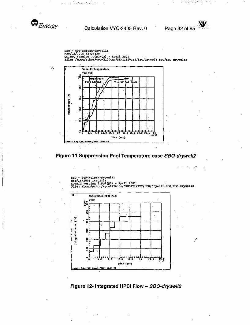
-Entergy Page 32 of 85Calculation VYC-2405 Rev. 0
S80 - 80P-Nolean-drywelllMar/03/2005 13:31:38GOTHIC Version 7.0p2(QA) - April 2002Pile: /bome/scbor/vyc-2120ccn/SENSITIVITY/SBO/drywell-SBO/SBO-drywell2
2 VttwtU Tnperature
ST2 1i2
o= i _
bZ.v -Mi
.ia* (sec)
*t? ?w.*P2tts) rPrWS1266 1J.46,48
Figure 11 Suppression Pool Temperature case SBO-drywell2
SBO - 80W-Noleak-drywelllMar/14/2005 14:02:38GOTHIC Version 7.0p2(QA) - April 2002Pile: /home/g6chor/vyc-2120ccn/SENSITIVITY/SBO/drywell-SBO/SBO-drywIll2
40 zutegrated )Wcl Flow
c33
r o _
. .. , . I
S.F 7.2 1t0.t 24;4 :18 21.6 25. 2
S .(Se)
tXI I.2t}Wl/2s1.XXf
Figure 12- Integrated HPCI Flow - SBO-drywell2
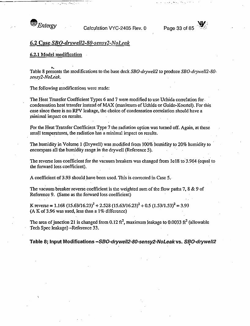
Ad Entergy Calculation VYC-2405 Rev. 0 Page 33 of 85 -7-r A
6.2 Case SBO-drvwell2-80-sensV2-NoLeak
6.2.1 Model modification
Table 8 presents the modifications to the base deck SBO-drywell2 to produce SBO-drywell2-80-sensy2-NoLeak.
The following modifications were made:
The Heat Transfer Coefficient Types 6 and 7 were modified to use Uchida correlation for.condensation heat transfer instead of MAX (maximum of Uchida or Guido-Koestel). For thiscase since there is no.RPV leakage, the choice of condensation correlation should have aminimal impact on results.
For the Heat Transfer Coefficient Type 7 the radiation option was turned off. Again, at thesesmall temperatures, the radiation has a minimal impact on results.
The humidity in Volume 1 (Drywell) was modified from 100% humidity to 20% humidity toencompass all the humidity range in the drywell (Reference 5).
The reverse loss coefficient for the vacuum breakers was changed from IeI8 to 3.964 (equal tothe forward loss coefficient).
A coefficient of 3.93 should have been used. This is corrected in Case 5.
The vacuum breaker reverse coefficient is the weighted sum of the flow paths 7, 8 & 9 ofReference 9. (Same as the forward loss coefficient)
K reverse = 1.168 (15.63/16.23)2 + 2.528 (15.63/16.23)2 + 0.5 (1.53/1.53)2 = 3.93(A K of 3.96 was used, less than a 1 % difference)
The area of junction 21 is changed from 0.12 ft2, maximum leakage to 0.0033 ft2 (allowableTech Spec leakage) -Reference 33.
Table 8; Input Modifications -SBO-drywell2-80-sensy2-NoLeakvs. SBO-drywell2

Entergy Calcufation VYC-2405 Rev. 0 Page 34 of 85
Modifications in /hame/schor/vyc-2120ccn/SENS]TIVITY/SBO/drywell-SBO/SBO-dryhvell2-80-senMar/10/2005 10:42:03GOTHIC Version 7.0p2(QA) - April 2002File: /home/schor/vyc-2120ccn/SENSITIVITY/SBO/drywell-SBO/SBO-drywell2-80-sensy2-NoLeak
> Graphs (continued)
GraphGp Title
42 Heat to the sup43 Leak Flow44 Integrated Leak45 Title464748 Surface Tempera49 Surface Tempera50 Surface Tempera51 Surface Tempera52 Surface tempera535455 Drywell Tempera
Curve NumberMon 1 2 3 4
CQ4H CQ2HFL4 FL19 FL20cv40cv39FV18 FL18 FOIDcv38TB5 TB6 TB7TA8 TA9 TA10TA11 TA12 TA13TB8 TB9 TB10 TB11TB13 TB12
TP8t630 TP9t600 TPlOt60 TP11t60TP13t5S TP12t50lVl TU -
5
Heat Transfer Coefficient Types - Table I
Heat. Cnd .Sp Nat ForType Transfer Nomtnal Cnv Cnd Cnv Cnv Cnv Rad
# Option Value FF Opt Opt HTC Opt Opt Opt
1 Correlat 0 VERT SURF PIPE FLOW OFF2 Correlat 0 VERT SURF PIPE FLOW OFF3 Correlat FACE DOWN PIPE FLOW OFF4 Correlat . FACE UP PIPE FLOW OFF5 Sp Heat 0.6 Direct ADD UCHI VERT SURF PIPE FLOW OFF7 Direct ADD UCHI FACE DOWN PIPE FLOW OFF
Run Control Parameters (Seconds)
Time DT DT DT End Print Graph M'x. Dump Phs ChngInt Min Max Ratio Time Int Int CPU Int Time Scale
I le-06 1. 1. 100. 5. 0.1 le+06 0. DEFAULT2 le-06 1. 1. .1200. 50. 1. 1e+06 0. DEFAULT3 le-06 1. 1. 1300. 500. 10. le+06 0. DEFAULT4 le-06 1. 1. .25000. 600. 10. le+06 -0. DEFAULT

7~Entergy Page 35 of 85 'Calculation VYC-2405'ReV. 0
Modifications in /hane/schor/vyc-2120ccn/SENSITIVITY/SBO/drywell1-SBO/SBO-drywel112-80 -senMar/1012005 10:42:03GOTHIC Version 7.0p2(QA) - April 2002File: /hcrme/schor/vyc-2120ccn/SENSITIVITY/SBO/drywell -SBO/SBO-drywel112-80-sensy2-NoLeak
N Volune Initial Conditions
Vol Pressure Vapo# (psia) R
Liquid Relative Li-quid Ice IceT7~. Humidity Volume Volume Surf .A.
(M Fractio Fract. (ft2)
def1234
14.716.414.716.4
1045.2
80. 80. 60. 0. 0.170. 170. 20. 0. 0.90. 90. 100. 0.39497 0.90.- 90. 100. 0.00595 0.
549.97 533.12 100. 0.60794 0.
0 .0 .0 .0.0.
Gr~ph
12345.-6789
11121314151617181920212223242526272829303132333435363738394041
.Graphs
TitleCurve Number 4 5
DrywI 1 TeaperaWewel1 TemperaContalrinent PreReactor VesselPRiR Heat ExchanReactor VesselTorus Water VolHeat ExchangerWetwell. VesselConductor TenpeIntegral VesselVapor & Conduct:Liquid & ConducVapor & Conduct.Liquid & ConducVapor Heat TranLiquid Heat TraVapor Heat TranLiquid Heat TraFeedwvater & BreRPV Liq~uid LeveSRV and ADS FloFeedwater EnthaRPV PressuresFeedwater ConrtrInte~rated Feed
Vessel Droplet.ECCS InjectionRPV PressureADS Valve PositSRV PositionCool dow~n FLo.wVessel Drop DiaReactor VesselSuppression pooReactor VesselSupression Poo
HPIFlow RateIntegrated HPCICore Spray Flow
IVi1V2PRITV4
AL2
1 L2NAl
TL4TV2TL2HAI.hA2HA3hA4FL9LL4FVIOcv29PR4cv27cv4FL5AD4FL7PR4'VC3Vvc2VFV16D14PR4112PR4112FL18cv39FL8
Thi112
PR211-4 ST4 TD4
t2lHTL4 TLITA2 TA3
TA2TA3TA4
TA4
FL4
FV11
cv28
FL12 FL14VC2V FL7

AdEntergy Page 36 of 85'Calculation VYC-2405 Rev. 0
Modifications -in /home/schor/vyc-2120ccn/SENSITIVITY/SBO/drywell-SBO/SBO-drywel12-80-senMar/10/2005 10:42:03GOTHIC Version 7.0p2(QA) - April 2002File: /home/schor/vyc-2120ccn/SENSITIVITY/SBO/drywell-SBOISBO-drywel12-80-sensy2-NoLeak
FlIow FlowPath Area
# (ft2)-
1 283.5292 286.1143 15.63.4 0.0010055 3.146 3.147 3.148 3.149 3.14
10 0.0994511 0.397812 3.1413 3.1414 3.1415 3.1416 3.1417 3.14
-18 3.1419 0.545420 0.545421 0.0033
Flow Paths - Table 2
iyd. Inertia Friction RelatDiam. Length Length Rouc(ft.) (ft) (ft.) nes
6.751.948
1.56250.03568
2.2.2.2.2.
0.355840.3554
2.2 .2 .
* 2 .2 .2 .2 .
0.83330.5454
1 .
89.134.16'
44.9250.1
0.010.010.010.010.010.010.010.010.010.010.010.010.010.010.10.1
* 1.
0.0.
28.72
0.10.10.
lAve Dep;h- Bend55 (deg)
. O.-1.0.0.0.0.0.0.0.0.0.0.0.0.0.0.0.0.
Man StratTrn Flowopt Opt
- NONE- NONE- NONE- NONE- NONE- NONE- NONE- NONE- NONE- NONE- NONE'- NONE- NONE- NONE- NONE- NONE- NONE- NONE- NONE- NONE- NONE
Flow Paths - Table 3
FlowPath
I23456789101112131415161718192021
Fwd. Rev.Loss Loss Caow.
Coeff. Coeff. Opt.
4.2243 4.2243 ON1. 0.78 ON
3.964 3.964 ON0. OFF
OFFOFFOFFOFFOFFOFFOFFOFFOFFOFFOFF
le+18 OFFOFFOFFOFFOFF
1.5 1.5 OFF
Critical Exit. DropFlow Loss BreakupModel Coeff. Model
TABLES 1. OFFTABLES 1. OFFOFF 0. OFF
TABLES 1. OFFOFF 0. OFFOFF 0. OFFOFF 0. OFFOFF .0. 0FFOFF 0. OFF
TABLES 0. OFFTABLES 0. OFFOFF 0. OFFOFF 0. OFFOFF 0. OFFOFF 0. OFFOFF 0. OFFOFF 0. OFFOFF 0. OFFOFF 0. OFFOFF. 0. OFFOFF 0. OFF
)

- -
.. . - ..
:Entery Calculation VYC-2405 Rev. 0 Page 37 of 85
6.2.2 Case SBO drawell2-80-sensy2-NoLeak Resuflts
Figure 13 through Figure 20 present the main parameters for the case SBO-drywvell2-80-sensy2-NoLeak. Figure 13 presents the drywell temperature. The maximum drywell temperature is about289.4 TF and is reached after one hour and 30 minutes.. The heatup is arrested due todepressurization. At about 4 hours into the transient the temperature in the drywell startsincreasing due to lower heat removal into the passive heat sinks (walls) . The air gap acts as aninsulation and the steel liner is almost at 255 'F. However, after 2 hours and 10 minutes the lowpressure pumps are available so the operators can spray the drywell with the RHR pump, ifneeded. The results indicate that the temperatures in the drywell stay below the EQ limit and thedrywell liner is well below the 281 OF for the SBO coping duration.
Figure 14 presents the containment pressure. Due to a lower leak area the drywell and thewetwell are at not at the same pressure, the vacuum breaker opens to relieve the pressuredifference at about 14000 seconds. At about 2 hours the pressure in the drywell is too low tospray the drywell, (unsafe area of DWSIL (EOP-3 -Primary Containment Control .-Reference30)) however the pressure increase to about 6 psig at about 10800 seconds at which point theoperators would be able to spray the drywell with the RHR pump, if needed.
Figure 15 presents the RPV pressure. At one hour into the event it is assumed that the operatorsstart depressurization. The pressure drops to the HPCI shutoff pressure of 165 psia at about12000 seconds. At this point only about 450000 lb were injected from CST (Figure 17). TheRPV is depressurized, and the CS pump is available to inject.
Figure 16 pump presents the RPV level. The core stays covered. There is a dip in the normallevel at about 12000 seconds when HPCI stops injecting and CS does not inject yet. This is dueto the fact that the CS pump was set to inject at 14000 seconds; however CS is ready to inject at7800 seconds, provided the pressure permissive is reached.
Figure 18, Figure 19, and Figure 20 presents the drywell liner temperature. The drywell linerstays below 260 'F for the 7 hours analyied. After 2 hours and 10 minutes the low pressurepumps are available for suppression pool cooling, drywell spray and maintaining vesselinventory.
The suppression pool temperature for this case is very similar to the case SBO-drywell2 since theinput changes results in minor changes to the drywell temperature and pressure but not in thesuppression pool temperature since the heat transferred to the drywell is not subtracted from thevessel energy.

-
- Entergy Page 38 of 85; -Calculation VYC-2405 Rev: 0
SB0 - 80F-Noleak-drywell2-sensitivities-set2Mar/10/2005 10:36:15.GOTHIC Version 7.0p2(QA) - April 2002File: /home/schor/vyc-2120ccn/SZNSITIvITY/SBo/drywell-sBo/sBo-drywel12-80
5Drwell Temptraftre
Tvi TlI
i 0Li
., - -. _,....
*0'
- Dime (see)
4ms
Figure 13 - Drywell Temperature -Case SBO-drwell2-80-sensy2-NoLeak
EBO - 80F-Noleak-drywell2-sensitivities-set2 :Mar/10/2005 10:56:11GOH1IC Version 7.0p2(QA) - April 2002Pile: '/ome/schor/vyc-212 0ccn/SENSITlVITY/SBO/drywell-SDO/SBO-drywelI2-80
3 ContA maut resmre
-l -Pi
.Dnryll relsurt
f.t . I.. f2
Time (Ste)
Figure 14 -Containment Pressure - Case SBO-drwell2-80-sensy2-NoLeak

=Entergy NVyyCalculationVYC-2405 Rev.O Page 39 of 85 - I
SBO - 80P-Noleak-drywell2-sensitivities-setZMar/10/2005 11:11:35GOTHIC Version 7.Op2(QA) - April 2002File: /home/schor/vyc-212Occn/SENSITIVITY/SBO/drywell-SDO/SBO-drywell2-80
24 "V Frsusmrts
-'n 1 1 IN ' L:-oI -1 '
I F-FVat (Ste)'
Figure 15- RPV Pre ssure - Case SB0-drwell2-80-sensy2-NoLeak
SBO - BOF-Noleak-drywell2-sensitivities-set2Mar/10/2005 11:15:46GOTHIC Version 7.0p2(QA) - April 2002Pile: /home/schor/vyc-2120ccn/SENfSTIVrmY/SDO/drywell-SBO/SBO-drywell2-80
I sRPV Liquid Levl
LL4
Tih (Sao)
* 7 ft "- /t/J . - - - - - . -
Figure 16 - RPV Level - Case SBO-drwell2-80-sensy2-NoLeak

. . . I . - ; Ws -1. -- z
.. l7ntergy '.y.1 . h -Calculation VYC-2405 Rev. 0 Page 40 6f185
SBO - SOF-Noleak-drywell2-sensitivities-set2Mar/10/2005 11:10:47WCMHIC Version 7.0p2(QA) .- April 2002File: /home/sdcor/vyc-212 eccn/STNSITIVITY/SBO/drywell-SBO/SBO-drywell2-80
0 Xtegratd )WC1 71w.
j L.
Us 1 1'.1
.6 7. .8O 4. * 2A.nt
T3mc (sec)
4*Th ?.$ZCt9A o.zII*IU*IS *I,@.452
Figure 17 Integrated HPCI Flow - Case SBO-drwell2-80-sensy2-NoLeak
SBO - 80P-Noleak-drywell2-sensitivities-set2Var/1D/2005 10:33:12GOrBIC Version:7.0p2(QA) - April 2002File: /home/schor/vyc-2120ccn/S SITSVITY/SBO/drywell-SBO/SBO-drywe112-80
Surface Temperature
TDS TD6 737
TJc (Ste)
6Tir 7.02CsA) 1a1.0pSI8S *141,-52
Figure 18- Surface Temperature for Heat Slabs 5,6 & 7 - Case SBO-drwell2-80-sensy2-NoLeak

I . - Entergy- Page 41 of'85 ''Calculation VYC-2405 Rev. 0
SBO - B0F-Moleak-drywell2-sensitivities-set2Mar/10/2005 10:34:30GOTHIC Version 7.Op2tQA) - April 2002File: /hone/echor/vyc-2120ccn/SEHNSITrVITY/SB0/drywell-SBO/SBO-drywell2-B0
a.
R.
I-
Surface Teartrature
DZ8 529 TR30 11
. - . .SIAR (see)
-e74ts -1t~e291266% t 5
Figure 19 - Surface Temperature for Heat Slabs 8, 9, 10 & 1180-sensy2-NoLeak'
- Case SBO-drwell2-
SBO - 80F-Moleak-drywell2-sensitivities-set2Mar/10/2005 10:32:24GOaTIC Version 7.0p2(QA) -P April 2002Pile: Jhome/schor/vyc-2120ccn/SKNSITxVIr/SBO/drywel1 -SBO/SBO-drywe112-80
52 surac t a 7trature
D313 D312
o _
a.s At
o NMat 31)1 12
Tlse (stc)
$*t7000"llt oa
Figure 20 Surface Temperature for Heat Slabs 12 & 13 - Case SBO-drwell2-80-sensy2-NoLeak
Entergy ' - Calculation VYC-2405 Rev. 0 Page 42 of 85 : -
6.3 Case SBO-drywell2-Leak-80-sensv
6.3.1 Model modification
Table 9 presents the modifications to the deck SBO-drywell2-80-sensy2-NoLeak to produceSBO-drywell2-Leak-80-sensy
The following modifications were made:
On BC 13, the ON trip is set to zero (0). This allows for a constant leak of 8.4585 lb/sec to leavethe vessel.
The end time was changes to 14400 seconds (4 hours) since the purpose of this calculation wasto show that the drywell temperature stays below the EQ drywell temperature and the drywellshell stays below 281 TF for the duration of 2 hour and 10 minutes.
Table 9 SBO-drywell2-Leak-80-sensy vs SBO-dryvell2-80-sensy2-NoLeak

,~~~~~~~ ~ _t .. ! ' _ V'' _ _
.. . .. Entergy Calculation VYC-2405 Rev. 0 PNa 4Page 43 of '85
Modifications in /home/schor/vyc-2120ccn/SENSITIVITY/SBO/drywell-SBO/SBO-drywel12-Leak-8Mar/14/2005 15:38:40GOTHIC Version 7.0p2(QA) - April 2002File: /home/schor/vyc-2120ccn/SENSITIVITY/SBO/drywell-SBO/SBO-drywell2-Leak-80-sensy
Fluid Boundary Conditions - Table 1
Press. Tem. Flow ON OFFBC# Description (psia) FF (F) FF (lbm/s) FF Trip Trip
IF RHR/LPCI Suctio 20. 160 v-0.002 8 1 132C RHR/LPCI Discha 20. 1603F LPCS Suction 20. 160 v-0.002 7 30 314C LPCS Discharge 20. 1605F Feedwater 1000. el 5 1000 9 1 56F RHRlTorus Suctl 20. 160 v-0.002 6 21 17C RHR/Torus Disch 20. 160 08F HPCI/RCIC Sucti 20, . 160 -326.1 9 1 09C HPCI/RCIC Disch 20. 1601OP Cooldown Inlet 1. 10 1 11 21 011F Cooldown Outlet 1. 10 1 11 1 1212F CST Tank 14.7 135 587 13 28 2713F Vessel Leak 1050. 554. -8.4585 13 014C Vessel leak to 1050. 0 554
Run Control Parameters (Seconds)
Time DT LT DT End Print Graph Max Dump Phs ChngInt Min Max Ratio Time Int Int CPU Int Time Scale
I le-06 1. 1. 100. 5. 0.1 le+06 0. DEFAULT2 le-06 1. 1. 1200. 50. 1. le+06 0. DEFAULT3 le-06 .1. 1. 1300. 500. 10. le+06 0. DEFAULT4 le-06 1. 1. 14400. 600. 10. le+06 0. DEFAULT
Graphs
Graph Curve NumberI Title Mon 1 2 3 4 5
1 Drwell Tempera2 Wetwell Tempera3 Containment Pre4 Reactor Vessel5 RHR Heat Exchan6 Reactor Vessel7 Torus Water Vol8 Heat Exchanger9 Wetwell. Vessel10 Conductor Tempe11 Integral Vessel12 Vapor & Conduct13 Liquid & Conduc14 Vapor & Conduct15 Liquid & Conduc16 Vapor Heat Tran17 Liquid Heat Tra18 Vapor Heat Tran19 L~quid Heat Tra20 Feedsater & Bre
lViTV2PR1TV4xqlHAL4AL2tllHTL2TA1
TL4TV2TL2
hA2HA3hFMFL9
TL1TL2PR2TL4 ST4 TD4
t21H114 ILlTA2 TA3V4
. A1TA2TA3TA4
TAM
FL4

lEntergy Page 44 of 85 "Calculation VYC-2405 Rev. 0
Modifications in /home/schor/vyc-2l2Occn/SENSITJVITY/SBO/drywell-SBO/SBO-drywel12-Leak-8Mar/14/2005 15:38:40GOTHIC Version 7.0p2(QA) - April 2002File: /hcme/schor/vyc-2120ccn/SENSITIVITY/SBO/drywell-SBO/SBO-drywel 112-Leak-80-sensy
Graphs (continued)
GraphTitle Mon 1
Curve Number2 3 4 5
21 RPV Li u22 SRV and23 Feedwate24 RPV Pres25 Feedwate26 Integrat27 RHR F 1028 Vessel D29 ECCS In330 RPV Pres31 ADS Valv32 SRV Posi33 Cooldown34 Vessel D35 Reactor36 Suppress37 Reactor38 Su press39 HPC] Flc40 Integrat41 Core Spr42 Heat to43 Leak Flc44 Integrat45 Title464748 Surface49 Surface50 Surface51 Surface52 Surface5354
xXooos xwOL
ud LeveADS Floer Enthasureser Contred Feed
Droplet3efflonsureve Posittioni. FLowDrop DiaVesselsion pooVesselsion Poow Rateled HPCIra Flowtne supw,ed Leak
LL4FV10 FV11cv29PR4cv27 cv28.cv4FL5AD4FL7 fL12 FL14PR4 VC2V FL7
- VC3VVC2VFV16D14PR4TL2 -PR4LL2FL1Bcv39FL8.CQ4H CQ2H
.FL4 FL19 FL20cv4OCv39FV18 FL18 FD18cv38TB5 TB6 1837TAB TB6 TAI1TAll TA12 TA13TB8 TB9 I TB10 TB11TB13 TB12
TP~t600 TP9t600 TPIOt6O TPI1t6OTP13t58 TP12t50
xxx xooooXc voooo= sooooax xouooxx XXXoox
TemperaTemperaTemperaTemratempera
tEntergy Calculation VYC-2405 Rev. 0 Page 45 of 85
6.3.2 Results Case SBO-drvwell2-Leak-80-sensy
Figure 21 through Figure 29 present the main parameters for the case SBO-drywell2-Leak-80-sensy. Figuire 21 presents the drywell temperature. The maximum drywell temperature is about290 TF and is reached at about 12240 seconds (3.4 hours). The drywell heatup rate is arrested dueto depressurization, however the leak brings enough energy from the vessel to continue theheatup. At 7800 seconds the drywell temperature is 285.8 OF, well below the EQ limit of 325 OF.
Figure 22 presents the containment pressure. The available water to spray the drywell (Reference30) is the Diesel fire pump per Appendix M of OE 3107 (Reference 35) and it takes about onehour for aligning the fire pump for drywell spray. The drywell pressure is high enough to allowfor drywell spray, if needed. The drywell temperature does not exceed the EQ drywelltemperature limit and the drywell shell temperature stays below the limit of 281 TF hence theanalysis shows that drywell spray is not needed for the coping duration. At about 3 hours and 30minutes the wetwell pressure reaches equilibrium with drywell and slightly exceeds the drywellpressure. The vacuum breakers do not open during the time of interest.
At about 4 hours the wetwell pressure is about 26 psig, close to the PSP limit of 27 psig.However at this time the RHR pump is available for containment spray.
Figure 23 presents the RPV pressure. At one hour into the event it is assumed that the operatorsstart depressurization. The pressure drops to the HPCI shutoff pressure of 165 psia at about12000 seconds. At that point only about 540000 lb were injected from CST (Figure 25). At thistime the RPV is depressurized, and the CS pump is available to inject.
Figure 24 pump presents the RPV level. The core stays covered. There is a dip in the normallevel at about 12000 seconds when HPCI stops injecting and CS does not inject yet. This is dueto the fact that the CS pump was set to inject at 14000 seconds; however, CS is ready to inject at7800 seconds, provided the pressure permissive is reached.
Figure 27, Figure 28, and Figure 29 presents the drywell liner temperature. The drywell linerstays below 280 TF for the 4 hours analyzed. After 2 hours and 10 minutes the low pressurepumps are available for suppression pool cooling, drywell spray and maintaining vesselinventory.
The suppression pool temperature is not a parameter of importance for this calculation. InReference I it was shown that the suppression pool temperature is lower for the cases RPV withleakage and lower for earlier depressurization hence the maximum suppression pool temperaturewill be lower that 182.2 TF, calculated in Reference 1.

-- Entergy Page 46 of 85Calculation VYC-2405 Rev. 0
SDO - 8OF-Noleak-drywell2-Leak-80-sonsitivitiesMar/14/2005 11:02:51GOTHIC Version 7.0p2(QA) - April 2002Pile: /home/schor/vyc-2l20ccn/SHNSITIVITY/SBO/drzywell-SBO/SBO-drywel12-Le
1r*rell Teaperature
blvi Il td mpral
J--
TUC (see)
.0= 1. 2( a) .~M MU
xre
Figure 21 -Drywell Temperatures - SBO-drywell2-Leak-80-sensy
SBO - BOP-Noleak-drywell2-Leak-80-sensitivitiesMar/14/2005 11:03:43GOTIC version 7.Op2(QA) - April 2002File: /bome/schor/1yc-2120ccf/SENSITIVITY/SBO/drywell-SBO/SBO-drywel12-I.e
3Cetaiment pressu"
It7.2 (0.8
. T~t~e (See
drme s2}"!!~@5 s8$
Figure 22- Containment Pressure - SBO-drywell2-Leak-80-sensy

* v - t ; # .
.. Entergy Calculation VYC-2405 Rev. 0 Pg4o8Page 47 of 85 .
SBO - 8OF-.Ioleak-drywcll2-Leak-80-BensitivitiesMar/14/2005 12:05:31GOTHIC Version 7.0p2(QA) - April 2002File: /bone/rc!cor/vyc-2120ccn/SENSITIVITY/SBO/drywell-SDO/SBO-drywell 2-Le
24 pv ?ressurts
5R4Zo I
rime (see)
VW$ 1 .67201)s "-103/2015 16,1. tI 1
Figure 23- RPV Pressure - SBO-drywell2-Leak-80-sensy
SBO - 8OP-Noleak-drywell2-Leak-80-sensitivitiesMar/14/2005 11:04:51GOTHIC Version 7.0p2(QA) - April 2002File: /home/schor/vyc-2120ccn/SmNSITIVIrY/SBO/drywell-SBO/SBO-drywell2-Le
21 ra Liquid Level
LL4
o- _
T ' )tia (sic)
Figure 24 RPV Level - SBO-drywell2-Leak-80-sensy

-Entergy\'Jy.
Calculation VYC-2405 Rev. 0 Page 48 of 85
SBO - BOP-Noleak-drywell2-Leak-80CsensitivitiesMar/14/2005 11:09:57GOTHIC Version 7.0p2(QA) - April 2002File: /home/schor/vyc-2l20ccn/SENSITIVITY/SBO/drywell-SBO/SBO-drywell2-Le
40 Xategrated 210 7ic.
S j-
* :
Tim (9SC)
somg t42/2 -111s2|285 IS~A3.2
LW1
Figure 25 - Integrated HPCI Flow - SBO-drywell2-Leak-80-sensy
SBO - 80P-Noleak-drywell2-Leak-80-sensitivitiesMar/14/2005 11:10:57
'GOTHIC Version 7.0p2(QA) - April 2002Pile: /home/schor/vyc-2120ccn/SENSITIVITY/SBO/drywell-S5O/SBO-dryweel22-Le
13 Leak ?low
.4 1S L20
1A
. ..
o~ ~ ~ ~ ( ~.i24; S.;c)3. 11.2 12.6 rTUm (see)
40 7 42.112X 1 }2@SAtt
Figure 26-Leak Flow - SBO-drywell2-Leak-80-sensy

- Entergy Page 49 of 85'Calculation VYC-2405 Rev: 0
SBO - SOF-Noleak-dzywell2-Leak-80-sensitivitiesMar/14/2005 11:07:22GOTHIC Version 7.0p2(QA) - April 2002File: /home/schor/vyc-2120ccn/SENSITIVITY/SBO/drywell-SBO/SDO-drywell2-Le
48 uface Temptratre -
XIS 136 137
o *
at .6 .,
Time (sta)
_1222
s~~~~~- -.,-,,_,--.--,.
Figure 27 - Surface Temperature, Heat Structures 5,6,7 - SBO-drywell2-Leak-80-sensy
SBO - 80P-Noleak-drywell2-Leak-80-sensitivitiesMar/14/2005 11:06:34GOTHIC Version 7.0p2(QA) - April 2002Pile: /home/schor/vyc-212Occn/SKNSISIVITY/SBO/drywell-SBO/SBO-drywell2-Le
51 Smrfaee reperat~x
Si
2 a
sime (see)
4*3 7h31*k1 *^)I)S1212 11.21.1
Figure 28 - Surface Temperature, Heat Structures 8, 9, 10, 11 - SBO-drywell2-Leak-80-sensy

LII)qery -. Calculation VYC-2405 Rev. 0 Page 50 of 85 W -
SBO - 80P-Noleak-drywell2-Leak-80-sensitivitiesMar/14/2005 .11:09:22GOThIC Version 7.0p2(QA) - April 2002Pile: /hboe/schor/vyc-2120ccn/SENSITIVITY/SBO/drywell -SBO/SBO- drywell2 -Le
7...52 surface te.eratnre
.all Tin
. .
. I.
Figure 29 - Surface Temperature, Heat Structures 12,13 - SBO-drywell2-Leak-80-sensy

-Entergy Calculation VYC-2405 Rev. 0 Page 51 6f 85
6.4 Case SBO-drywell2-Leak-45-sensv
6.4.1 Model modification
Table 10 presents the modifications to the deck SBO-dryivell2-Leak-80-sensy to produce SBO-drysvell2-Leak-45-sensy.
Two modifications are made, the depressurization (cooldown) table, is changed from 80 0F/hourto 45 0F/hr (same cooldown curve as in Reference I- Function 10).
The RHRSW temperature is changed from 85 TF to 75 &F consistent with Assumption 13 andReference 1.
Table 10 SBO-drywell2-Leak-45-sensy vs SBO-drywell2-Leak-80-sensy

- Entergy CalculationVYC-2405 Rev. 0 Page 52 of'85 N :.
Modi ficati ons in /home/schor/vyc-2120ccn/SENSITIVITYiSBO/drye1ell-SBOISBO-drywel12-Leak-4Mar/14/2005 17:49:07GOTHIC Version 7.0p2(QA) - April 2002File: /hone/schor/vyc-2120ccn/SENSITIVITY/SBO/drywell-SBO/SBO-drybell2-Leak-45-sensy
Functions
FF# Description Ind. Var. Dep. Var. Points.
0 ConstantI RHR H Tube2 RHR HX Shell3 Decay Heat4 Punp Heat'5 Feed Enthalpy6 RHR/Torus7 LPCS Flow Curve8 LPCI Flow Curve9 Feed Flow
10 Cooldown Pressu11 Cooldown Temper12 'Cooldown Flow13 Constant14 'ECCS Pump Heat15. Check Valve16 SW.17 Drywell Power C18 Drywell Power C
- 0Reynolds N Nusselt Nu 34Reynolds N Nusselt Nu 34Time (sec) Decay Heat 50Time (sec) Heat Rate 6
cv4 Dep. Var. 34Time (sec) Flow (gpm) 3
cv26 Flow (gpm) 13cv26 Flow (gpm) 12cv28 Dep. ar. 3
Time (sec) Pressure ( 39cv33 Dep. Var. 3cv32 Dep. Var. 3
Ind. Var. Dep. Var. 6Time (sec) Heat Rate 6
Ind. Var. Dep. Var. 6Time (sec) Service Wa 6
cv41 Dep. Var. 4cv42 Dep. Var. 4
Heat Exchangers - Table 2
Heat Scndy Scnd Scndy Scnd Ext; Ext.Ex. Flow Flow Terrp Temp Flow Flow# (lbm/s) FF (F) F F (llm/s) FF
*1H 1. 16 75.
Ext.Heat
(Btu/s)
Ext.HeatFF
Graph4 Title Mon
1 Drywell Tempera2 Wetwell Tenpera3 Containment Pre4 Reactor Vessel5 RHR Heat Exchan6 Reactor Vessel7 Torus Water Vol8 Heat Exchanger9 Wetwell, Vessel10 Conductor Tempe11 Integral Vessel12 Vapor & Conduct13 Liquid & Conduc14 Vapor & Conduct15 Liquid & Conduc16 Vapor Heat Tran17 Liquid Heat Tra18 Vapor Heat Tran
Graphs
Curve Number.1 2 3
TV1 TLITV2 TL2PRI PR2TV4 TL4 ST4xqlHAL4AL2tllH t21H1T2 TL4 TL1TA1 TA2 TA3QL4 QV4TV4 TA1TL4 TA2TV2 TA3TL2 TMHAIhA2HA3
4 5
TD4
TM

- Entergy Calculation VYC-2405 Rev. 0 Page 53 of 85 :
Modifications in /hcme/schor/vyc-2120ccn/SENSITIVITY/SBO/dry)well-SBO/SBO-drywel12-Leak-4Mar/14/2005 17:49:07GOTHIC Version 7.0p2(QA) - April 2002File: /home/schor/vyc-2120ccn/SENSITIVITY/SBO/dryw l -SBO/SBO-drywel12-Leak-45-sensy
*'. Graphs (continued)
GraphTitle Mon 1
19 Liqutd Heat Tra hA420 Feedwater & Bre FL921 RPV Liquid Leve LL422 SRV and ADS Flo FV1023 Feedwater Entha cv2924 RPV Pressures PR425 Feedwater Cortr cv2726 Integrated Feed cv427 RHR Flow FL528 Vessel Droplet AD429 ECCS Injection FL730 RPV Pressure PR431 ADS Valve Posit VC3V32 SRV-Position VC2V33 Cooldown FLow FV1634 Vessel Drop Dia 01435 Reactor Vessel PR436 Suppression poo TL237 Reactor Vessel PR438 Suppression Poo LL239 HPCI Flow Rate FL1840 Integrated HPCI cv3941 Core Spray Flow FL842 Heat to the sup CQ4H43 Leak Flow FL444 Integrated Leak cv4O45 Title cv3946 FV1847 cv3848 Surface Tempera TB549 Surface TeTpera TAB50 Surface.Tempera TA1151 Surface Tezpera TB852 Surface tenpera TB1353 TP8t60054 TP13t5O55
Curve Number2 3 4 5
FL4
FV11
cv28
FL12 FL14VC2V FL7
CQ2H.FL19 FL20
FL18 FD18
TB6 TB7TA9 .TA10TA12 TA13TB9 TB10 TB11TB12 . -
7P9t600 TP10t60 TPllt607P12t50

.Entergy Calculation VYC-2405 Rev. 0 Page 54 of 85
Modifications in /home/schor/vyc-2120ccn/SENSITIVITY/SB0/drywell-SBO/SBO-drywell2-Leak-4Mar/14/2005 17:49:07GOTHIC Version 7.0p2(QA) - Apr1l 2002File: /hure/schor/vyc-2120ccn/SENSITIVITY/SBO/drywell-SBO/SBO-drywell2-Leak-45-sensy
Function10
Coolda-i PressureInd. Var.: Time (sec)
Dep. Var.: Pressure (psia)
Ind. Var. Dep. Var. Ind. Var. Dep. Var.
0. 1078.5 600. 1014.51200. 953.5 1800. 895.32400. 839.8 3000. 787.3600. 736.8 4200. 689.14800. 643.7 5400. 600.76000. 559.9 6600. 521.37200. 484.8 7800. 450.28400. 417 6 9000. 386.89600. 357.8 10200. 330.5
10800. 304.9 11400. 280.812000. 258.2 12600. 237.113200. 217.3 13800. 198.914400. 181.7 15000. 165.615600: 150.8 16200. 136.916800. 124.2 17400. 112.318000. 101.4 18600. 91.319200. 82.1 19800. 73.620400. 65.8 21000. 58.721600. 52.3 22200. 46.4
1000000. 46.4

-Enlergy Calculation VYC-2405 Rev. 0 Page 55 of 85 -
6.4.2 Results Case SBO-drvwell2-Leak-45-sensy
Figure 30 through Figure 38 present the main parameters for the case SBO-drypvell2-Leak-45-sensy. Figure 30 presents the drywell temperature. The maximum drywell temperature is about293 0F and is reached at the end of the run (4 hours). The run was not extended beyond the 4hours even though the drywell temperature continues to increase because at 4 hours the RHRpump is available for drywell spray, if needed. The mission time of 2 hour and .10 minutes is.achieved. The drywell heatup rate is arrested due to depressurization; however the leak bringsenough energy from the vessel to continue the heatup. At 7800 seconds the drywell temperatureis about 290 TF, well below the EQ limit of 325 F .
Figure 31 presents the containment pressure. The drywell pressure is high enough to allow fordrywell spray after one hour into the transient, if needed. The available water to spray is theDiesel fire pump (Reference 30) per Appendix M of OE 3107 (Reference 35) and it takes aboutone hour for aligning the fire pump for drywell spray. The drywell temperature does not exceedthe EQ drywell temperature limit and the drywell shell temperature.stays below the limit of 281'F for the mission time of 2 hour and 10 minutes hence spray from Diesel fire pump is not
needed.
The vacuum breakers do not open during the time of interest.
At 4 hours the torus pressure is about 25 psig and increasing, close to the PSP limit of 27 psig.However at this time the RHR pump is available for containment spray.
Figure 32 presents the RPV pressure. At one hour into the event it is assumed that the operatorsstart depressurization. The vessel pressure during the 4 hours of the run time does not reach theshutoff pressure for the HPCI pumps, so at 4 hours the HPCI pumps still inject to maintaininventory. At 4 hour into the event only about 540000 lb were injected from CST (Figure 34). Atthis time the RPV is not depressurized, and the HPCI pump continues to inject.
Figure 33 presents the RPV level. The core stays covered and HPCI maintains inventory for theduration of the analyses. There is no need to continue the calculation beyond 4 hours because the-coping time of 2 hours was demonstrated.
Figure. 35 shows that the leak is maintain constant for the duration of the transient.
Figure 36, Figure 37, and Figure 38 presents the drywell liner temperature. The drywell linerstays below 280 TF for the 4 hours analyzed. After 2 hours .and 10 minutes the low pressurepumps are available for suppression pool cooling, drywell spray and maintaining vesselinventory.
The suppression pool temperature is not a parameter of importance for this calculation. InReference 1 it was shown that the suppression pool temperature is lower for the cases with leakand lower for earlier depressurization hence the maximum suppression pool temperature will belower that 182.2 "F, calculated in Reference 1.

Entergy N.Calculation VYC-2405 Rev. 0 Page 56 of 85
SHO - drywell2-Leak-45-sensitivitiesMar/09/2005 18:54:07GOTHIC Version 7.0p2(QA) - April 2002
; Pile: /home/schor/vyc-2120ccn/SENSITIVITY/SBO/drywel -SBO/SBO-drywell2-Le
I I�ryweU Tes�ptratlare
5.
I.SZ
DzywtV1 21 rature
T1 TLI
,, matl , "W69120*3 IS15 ,64
Time (sea)
Figure 30 -Drywell Temperature -Case SBO-drywell2-Leak-45-sensy
SO - dryvfell2-Leak-45-sensitivitiesMar/14/2005 17:59:16GOTHIC Version 7.0p2(QA) - April 2002File: /hboe/schor/vyc-2120ccn/SENSITiVITY/SBO/drywell-SBO/SBO-dlywell2-Le
3 contaiment ?rtssoxt
In t 2 1
o !
9.A
TAt (SeC)
arst pq..eS2BO 15,123,4
Figure 31 -Containment Pressure - Case SBO-drywell2-Leak-45-sensy

WEntergy Page 57 of 85 .Calculation VYC-2405 Rev. O
SBO - drywell2-Lcak-45-sensitivitiesMar/09/2005 18:59:19GOTHIC Version 7.0p2(QA) - April 2002File: /home/schor/vyc-2120ccn/SENSITIVITY/SBO/drywell-SBO/SBO-drywell2-Le
.' I24 PV Pressuvres
gat S
Tint ($to)
arms T~fttfa ox) I-41104 IS,12,44
-I
Figure 32- RPV Pressure -Case SBO-drywell2-Leak-45-sensy
SBO - drywell2-Leakc-45-sensitivitiesMar/09/2005 19:05:53GOTHIC Version 7.0p2(QA) .- April 2002Pile: /home/schor/vyc-2120ccn/SENSITIVITY/SBO/drywell-SB0/SBO-drywell2-Le
21 . .?? Liquid Level
LL4
- TItse (see)
fwrms7 1.S.)te1 H.,-IjV260% 15,12 24
Iir~
Figure 33 - RPV Level - Case SBO-drywell2-Leak-45-sensy

'Entergy Page 58 of 85 -Y--Calculation VYC-2405 Rev. 0
SBO - dxywell2-Leak-45-sensitivitiesMar/C9/2005 19:14:51GOTHIC version 7.Op2(QA) - April 2002File: /home/schor/vyc-2120ccn/SZNSIT7IVITY/SBO/drywell-SDO/SBO-drywe 12-Le
9N 40 ThtjArated Ha'l t10W
. 3.6 7.2 1.1 i
Time (see)
8*1 ?.!12(11) .,-y091295 13.1t.04
Figure 34 - Integrated HPCI Flow - Case SBO-drywell2-Leak-45-sensy
SBO - drywell2-Leak-45-sensitivitiesMar/09/2005 19:16:54GOTHIC Version 7.Op2(QA) - April 2002File: /home/schor/vyc-212Occn/SENSITIVlTY/SBO/drywell-SBO/SBO-drywel12-Le
43 SLea Flow
11L4 7LI rL20
a..
t ..0n
IA
* . 3. . . 4 .s 11.2 .22.8
Tine (sec)
Zest ?.ei2(fi) Mtr§/O2f2C5 X5.12."4
Figure 35 - Leak Flow -Case SBO-drywell2-Leak-45-sensy

- Entergy- Page 59 of 85 -Calculation VYC-2405 Rev. 0
SBO - drywcll2-Leak-45-sensitivitiesMar/09/2005 19:06:59GOTHIC Version 7.0p2(QA) - April 2002Pile: /home/schor/vyc-2l20ccn/SENSITIVITY/SBO/drywell-SBO/SBO-dry-well2-Le
Surface Traperatore
TDS Ta6 S3?
I.- _
o
* a
4UeJ 7.A,2(9A P..,1U112Se5 1.12.,4
SA (set)
Figure 36 - Surface Temperature, Heat Structures 5,6,7 - SBO-drywell2-Leak-45-sensy
SBO - drywell2-Leak-45-sensitivitiesMar/09/2005 19:08:37GOTHIC Version 7.0p2(QA) - April 2002File: /hoete/schor/vyc-212occn/SENSITIVITY/SBO/drywell-SB0/SBO-drywell2-Le
51 5srface Tmperatere
138 133 Tale Tall
3 7 2
? S (Sao)
$WM* 7.6t2mA) er/491260 15.1264
Figure 37 Surface Temperature, Heat Structures 8,9,10,11 - SBO-drywell2-Leak-45-sensy

Entergy Calculation VYC-2405 Rev. 0 Page 60 of 85
SBO - drywell2-Leak-45-sensitivitiesMar/09/2005 19:11:15GOTHIC Version 7.0p2(QA) - April 2002File: /hcze/schor/vyc-2120ccn/SENSITIVITY/SBO/drywell-SEO/SBO-drywell2-Le
surface teaperature
Th13 TM1
. _S_ 6
* , C bo
TIAC (see)
Cmii1.)iUA) 4.z/,It*5 M22,1I4
Figure 38 - Surface Temperature, Heat Structures 12,13 - SBO-drywell2-Leak-45-sensy

:Entergy Calculation VYC-2405 Rev. 0 Page 61 of'85'
6.5 Case SBO-drvwell-comments
6.5.1 Model Modifications
This case addresses the reviewer comments and also some discrepancies found during thedocumentation. The following changes are being made:
-change the initial temperature for Heat Structures 14 from 160 0F to 170 'F.-change the Knverse in junction 3 to 3.93 from 3.964.-change the flow area of the valve V3 to 15.63 ft2, same as the flow path flow area-change the surface area of the concrete pedestal to 2068 ft2
The changes are made to case 2 but it could be done to any of the other cases.
Table 11 presents the modifications made to file SBO-dryIvell2-80-sensy2-NoLeak to createSBO-drywel12-comments.
Table 11 Comparison between SBO-dryvell-corments vs SBO-drywell2-80-sensy2-NoLeak.

Entergy - Calculation VYC-2405 Rev. 0Page 62 of 85
Modifications in /home/schor/vyc-2120ccn/SENSITIVITY/SBO/dry3el1-SBO/SBO-drywell-comentMar/15/2005 14:07:44GOTHIC Version 7.0p2(QA) - April 2002File: /howe/schor/vyc-212Occn/SENSITIVITY/SBO/drywell-SBOlSBO-drywell-comments
Flow Paths - Table 3
Flow FWd.Path Loss
r Coeff.
Rev.Loss
Coeff.
Critical Exit DropCa. Flow Loss BreakupOpt. Model Coeff. Model
.123456 .78
. 91011'12-131415161718.192021
4.2
3.
1243 4.2243 ON.1. 0.78 ON
.964 ' 3.93 ON0. OFF
OFFOFFOFFOFFOFFOFFOFFOFFOFFOFFOFF
le+18 OFFOFFOFFOFFOFF
1.5 1.5 OFF
TABLESTABLESOFF
TABLESOFFOFFOFFOFF
-OFFTABLESTABLES
OFFOFFOFFOFFOFFOFFOFFOFFOFFOFF
1. OFF1. OFF0. OFF1. OFF0. OFF0. OFF0. OFF0. OFF0. OFF0. OFF0. OFF0. OFF0. OFF0. OFF0. OFF0. OFF0. OFF0. OFF0. OFF0. OFF0. OFF
Thermal Conductors - Table 1
Cond# Description
1 Steam E'xposure2 Liquid Exposure3 Torus, Vapor4 Torus, Liquid5 Lower Drywell6 Lower Drywell7 *Middle.Drywell8 Middle Drywell9 'Middle Drywell
10 Middle drywell11 Middle DrpRl112 Top Drywell13 Too Drywell14 RRUs15 Vent Pipes16 Concrete Shield
Vol HT Vol HT Cond S. A.A Co B Co Type (ft2)
Init.T.(F) Or
4 1 4 1 1 2965.72 609.23 14 2 4 2 1 11521.8 647.4 12 3 2 5 2 13553.7 90. I2 4 2 5 2 13553.7 90. 11 5 1 6 3 1856.24 170. I1 5 1 6 4 2041 28 170- I1 5 .1 6 5 3802.73 170'. I1 5 1 6 6 780 .68 170. .I1 5 1 6 5 1250.47 170. 11 5 1 6 7 1898.24 170. 11 5 1 6 8 1114.72 170.. 11 5 1 6 13 783.45 170. 11 5 1 '7 14 1718.3 170. 11 5 1 6 11 1272.8 170. 13 5 3 6 11 2885.7 160. I1 5 1 6 12 2068. 152. 1
Modifications in i /hane/schor/vyc-2l2Occn/SENSITIVITY/SBO/drywell-SBO/SBO-drywell-ccmnentMar/15/2005 14:07:44GOTHIC Version 7.0p2(QA) - April 2002File: /home/schor/vyc-2120ccn/SENSITIVITY/SBO/drywll-SBO/SBO-drywell-coments
Valve/Door Types
ValveType ValveF* Option
I QICK OPEN2 CHECK CALVE3 QUICK CLOSE
Stem LossTravel Coeff.Curve Curve
0 00 15O 0
FlowArea(ft2)
3.14115.63

:; Ia
-"Entergy . Calculation VYC-2405 Rev. 0 Page 63 of 85
65.2 Case SBO-dr'well-commeznts Results
The results of this case are presented in Figure 39 through Figure 40. Figure 39 presents thedrywell termperature. Due to the fact that the initial temperature for the drywell thermalconductors increase by 10 0F, the drywell temperature is increased from 289.4 &F to 295.2 T.
The containment pressure (Figure 40) is identical to the Case 2, hence the changes in the vacuumbreaker inputs have no effect on results, as described in section 6.2.1.
Figure 41, Figure 42, Figure 44 presents the drywell liner temperature. The drywell liner staysbelow 260 0F for the 7 hours analyzed. After 2 hours and 10 minutes the low pressure pumps areavailable for suppression pool cooling, drywell spray and maintaining vessel inventory.
SB0 - 80F-Noleak-drywell2-sensitivities -coazentsMar/15/2005 14:03:50GOTHIC Version 7.Dp2(QA) - April 2002File: /home/schor/vyc-2120ccn/SENSITIVITY/SBC/drywellSBO/SBO-drywell -cOmD
S5 DryvelL TexperatureTV17L1l
. I_*1
fig
I A Jwf.. .,_ EIvus.. ..
CI-go 1 C.
wT
M.2Xle3aL (sac)
.
Figure 39- Drywell Temperature - Case SBO-drywell-comments

Eniergy CalculatiorinWC-2405 Rev. 0 Page 64 of'85 .-
SBO - S0P-Noleak-drywrell2-sensitivities-comr entsMar/15/2005 14:05:35GOTHIC Version 7.0p2(QA) - April 2002Pile: Tloine/Ichor/vyc-2120cen/SENSlTIVITY/SBo/drywell-SDO/SBO-drywell-com
% 3 Containment PreseurePRIPRfl
p.2
Time (sec) Xle3
Figure 40- Containment Pressure - Case SBO-drywell-comments
SBO - 80P-Noleak-drywel2-Bensitivities-cornentsMar/15/2005 14:04:06GOTHIC Version 7-Cp2(QA) - April 2002File: /boxne/schor/vyc-212Dccn/SENSITIVITY/SBO/dryvell-SBO/SBO-dxywell-com
Surface Temperaturef5 TE16TH
oB76B _
C.- o-
F11a
t.2Xle3Time (3ec)
..& T.ft a f..M24 ..,,4_.5 . ... .
Figure 41 - Surface Temperature, Heat Structures 5,6,7 - SBO-drywell-comments

E-Lntergy. Calculation VYC-2405 Rev. 0 Page 65 of 85 NY-
SBO - 60P-Noleak-drywe1l2-sensitivities-cOcmeantsMar/15/2005 14:04:52GOTHIC Version 7.Op2(QA) - April 2002File: /bone/schor/vyc-212 Occn/SENSITIVITY/SBO/drywell-SBO/SBO-drywell-cotn
51 Surface TexperatureH8e T9 *T10 11
N3 :
14 f
-U 3.6 7.2- 10.T (14e4
- Tize (aec).- il .4 {1 .- MI526fit I~t.4A. .. .
25.2XI e3
Figure 42 - Surface Temperature, Heat Structures.8,9,10,11 - SBO-drywell-comments
SBO - BOP-Koleak-drywell2-sensitivities-commentsMar/15/2005 14:05:12.GOTHIC Version 7.0p2f(A) - April 2002File: /bomne/schor/vyc-2120ccn/SENSITIVITY/SBO/drywell-SBO/SBO-drywell-cocm
52 Surface temperature
CD -
N t BeatSlab 12
14s (ac) 4eCD Eeat 13('4
(' 3. . 814 .. 18... Z.2
Time (3ec) X1e3
.--- -1-1-1 � --- ------- --------
Figure 43 - Surface Temperature, Heat Structures 8,9,10,11 - SBO-drywell-comments

i-Entergy.. .
Page 66of 85Calculation VYC-2405 Rev. 0
SBO - SOP-Noleak-drywell2-sonsitivities-commentsMar/15/2005 14:05:12GOTHIC Version 7.0p2(QA) - April 2002File: /bome/schor/vyc-2120ccn/SEMSITIVITY/SBO/drywell-SBO/SBO-dryvell-com
52 Surface temperature.213Tn12
a--
C3
8 N.
CO
o AdHeat Slab 12C3
o eatL 1
3. ' 114.4 18 '1. 5.2
Time (sec) Zle3
Figure 44- Surface Temperature Heat Structures 12, 13 - Case SBO-drywell-comments

4 $ * .- z w . .- . . .. .. .. .. .. . - ..
*Enfegy Calculation VYC-2405 Rev; 0 Page 67 of85
7.0 Results and Conclusions
Assuminge Station Blackout with RPV depressurization (cooldown) at I hour after the event thefollowing results and conclusions arc found:
1) The drywell temperature for all cases analyzed stays below the EQ drywelltemperature profile for the entire SBO coping period of 2 hours and the additional 10minutes to power the low pressure pumps (i.e., the drywell temperature for all casesanalyzed stays below 300 TF for more than 4 hours of transient).
2) The drywell liner temperature stays below the design temperature of 281 TF for morethan 4 hours after the SBO event.
3) The drywell pressure stays below the design pressure of 56 psig.
4) For 2 hour and 10 minutes the wetwell pressure stays below the PSP curve for allcases analyzed.
5) The analysis shows that there is no need to spray the drywell when in the unsaferegion of DWSIL.
6) There is enough inventory in the CST to insure that the CST is not depleted before thetime of low pressure pumps availability such that the core stays covered. A CSTinventory of 75000 gallons was assumed.
7) The maxim suppression pool temperature for all cases stays below 182.2 'F.
8) The analysis predicts a conservatively high drywell temperature. Several factorscontribute to this conservatism:
* The heat transfer from the vessel to the drywell is based on a constant heattransfer coefficient at normal operating differential temperatures. However, thisheat transfer coefficient will vary with the temperature difference to the 1/4
power based on the dependence on the Grashoff number.* The heat transfer to the drywell from the drywell heaters is not subtracted from
the vessel.* The reactor building side of the thermal conductors are considered adiabatic.* A constant leakage is assumed; the leakage will decrease as the vessel is
depressurized.
9) No restriction on the rate of cooldown is applied to protect the drywell temperaturebeyond the restriction of depressurization (cooldown) function of RHRSWtemperature (Reference 1).
Note: "Unverified Assumptions" and "Affected Documents" items are being tracked via LO-VTYLO-2005-00135 (also see Section 4.1 and 4.2).

Entergy Calculation VYC-2405 Rev. 0 Page 68 of 85
8.0 References
The References are divided into Section 8.1 and General References (Section 8.2). Section 8.1includes all references.
8.1 Design Input References and General References:
1 VYC-2398 Rev 0 Torus Temperature Calculation for a Station Blackout Event at Extended PowerUprate, dated March 2005.
2 VY Tech Spec.
3 NUMARC 87-00, dated 11/20/87, including NRC accepted errata and Q&A from NUMARCseminars and Topical Report F.
4 VYC-2397, Maximum RHRSW Flow to RHRHX for SBO & Appendix R, dated 1/24/2005.
5 DRF 0000-0011-5646, OPL-4A (Containment Analysis Input Values) for Vermont Yankee NuclearPower Station EPUIMELLLA+, dated 2/6/03.
6 Calculation VYC-1628 Rev 0, Torus Temperature and Pressure Response to Large Break LOCA andMSLB Accident Scenarios, dated 4/27/98.
7 George, T. L., et. al, GOTHIC Containment Analysis Package, Version 7.0, July 2001.
8 VYC-2208 "GOTHIC 7.0 Code Installation Validation and Verification at VY", dated July18, 2002.
9 VYC-1457, VY Containment Heatup Analysis - Appendix R Application, dated 8/19/96.
10 GE Design Specification, No. 22A1 184, "Drywell Atmosphere Cooling System", Table I,Drywell Cooling Load Summary, #8 on Sheet 9.
11 VYC-1254 Rev 3, Containment and RPV Volume Calculations, dated 5/21/98.
12 VYC-1850 Rev 1, OPL-4A Input Preparation, dated 6/22199.
13 GE Design Specification # 22A1182 RevI "Protective Coatings-Special"
14 Drawing G191526 Rev 2.
15 J. P. Holman, "Heat Transfer", McGraw Hill Book Company, 1981.
16 Standard Review Plan Branch Technical Position CSB 6-1.
17 VYC-1628D Rev 0 CCN02, Torus Temperature and Pressure Response for to Appendix R andStation Blackout Scenarios, dated 06/23/2003.

5Enlergy Calculation VYC-2405 Rev: O Page 69 of'85
18 VYC-2279, Evaluation of EPU Impact on Ambient Space Temperatures During Normal Operation,dated 8/26/2003.
19 EQ Manual Vol 1.
20 22A1265, Rev 1, Reactor Containment Design Specification, September 1969.
21 VY Drawing G191489 Rev 2.
22 VYC-1290 Rev 0, Vermont Yankee Post-LOCA Torus Temperature and RHR HeatExchanger Evaluation, approved Augustl, 1994.
23 VYC-2045 Rev 0 Residual Heat Removal Heat Exchangers Fouling Factors and ProjectedHeat Rates for Cycle 21, dated 12/11/99.
24 GE-VYNPS-AEP-146, Letter Michael Dick (GE) to Craig Nichols (ENOI), VYNPS EPUTask T0400: Decay Heat for Containment Analysis dated March 10, 2003.
25 TE-2003-020, Feedwater Parameters for Power Uprate, April 14, 2003.
26 VY Memo VYS 2000/39, P A Rainey/T. P. Bowman to J. R. Lynch, "TorusTemperature/SW Design Temperature Recommendations", April 16, 2000.
27 VY UFSAR Rev. 19.
28 OP 0105 Rev 11, Reactor Operation.
29 Crane Technical Paper No. 410, Flow of Fluids through Valves, Fittings, and Pipe, 1976Crane Co.
30 EOP-3 Primary Containment Control; Rev3, dated 10/19/02.
31 ASME Steam Tables -Third Edition, 1977.
32 VYC-2306, Torus Temperature for Appendix R events at EPU Conditions, dated 08/29/2003.
33 VYC-I 850A Rev 0, "OPL 4A Input Preparation", dated 7/28/99.
34 VYC-1 628B Rev 0, "Torus Temperature and Pressure Response to Small Break LOCAScenarios, Model Development", dated 11/3/98.
35 OE-3107 Rev 17, EOP/SAG Appendices dated 04/29/2004.
36 OT 3122 Rev 19, Loss of Normal Power, dated 04/18/2000.
37 EOP-1 Rev2 RPV Control, dated 10/19/02

Entergy. CalculationrVYC-2405 Rev. 0 Page 70 of 85
8.1 General References
Georgejy. L., et. al, GOTHIC Containment Analysis Package, Version 7.0, July 2001
GOTHIC 7.0 Code Installation Validation and Verification at VY, dated July 18, 2002.
ASME Steam Tables -Third Edition, 1977
J. P. Holman, "Heat Transfer", McGraw Hill Book Company, 1981
Crane Technical Paper No. 410, Flow of Fluids through Valves, Fittings, and Pipe, 1976Crane Co.

Entergy Calculation VYC-2405 Rev. 0 Page 71 of 85 *w>
ATTACHMENT 9.10 COMPUTER RUN SUMMARY SHEET
COMPUTER RUN SUMMARY SHEET
Page I of I
Calculation No. VYC-2405 Revision 0 Date 16 March 2005
Sheet I of 1
Subject: Drywell Temperature Calculation for a Station Blackout Event at Extended Power Uprate
Code GOTHIC V7.0p2 Catalog No.02543 Version 7.0
SQA Classification Level A
Run Title (variable, described in Section 6.0 and Att. A)
Run No. No Run Date By
Output Use: 5 Variable Values As Noted 3 Plot Attached0 Disk. D File No.
Description Of Output:* Figures in text.* Input file on Disk.* Multiple cases were run, all are described in Section 6.0.* One case (base case) is attached in attachment A).* The Figures in text, for each case, have the date of the run & the run name.
Comments: None
(Attached additional pages if necessary)
Review: 0 Information Entered Above is Accurate
0 Input Entry Accurate
0 Code Properly Executed (Based on User Manual)
0 Output Accurately Extracted or Location Specified
Reviewer Comments /lo.t' e
Preparer (Print/Sign) Date Reviewer (Print/Sign) DateLiliane Schor Alan L. Robertshaw
3|15105 3//0f

' Entergy - Calculation VYC-2405 Rev. 0 Page 72 of 85
Calculation Impact Review Pages (ENN-DC-126 Attachment 9.7)
From System Engineering
NUCLEAR QvAMRA ENN-DC-126 REV.4-= EnteW r MANAGaEENT...: tA .E NUAL N. PAGE 35 OF 57
ArrAcENr 9.7 CAuLiAnom luPAcT REviEw PAGE
CALCULATION IUPACT REVIEW PAGEDate: 14 Febsiary 2005 aR . 3NQR
(Note: X Indicates required distribution)To: __Mechanical Engineering X Licensing X Operations
I&C Engineertng - Elect Maintenance Chemistry_Electrical Engineering - I&C Maintenance HP/Radieolgical
* _ CIM Engineering _ Mech Maintenance - Conputer ApplicationsX Systern Engineering - Component Engineering _ Rad Engineering
Reactor Engineering - Program Engineering ISI EngineeringX DBD Owner RHR. P. Perez - Nuclear Engineering - [ST Engineering
BX BD Owner SA. P. Perez _ E _ PSA.:(Name) (Other) --
Fromr: Llllnre Schor 802-451-3013(Originator Print Name and Phone extension)
Calculation No.: VYC-2405 Revision No. Q
Tite: DrvweD Temperature Calculation tor a Station Blackout Event at Extended Power Upzrate.
Reference: WA
Date'Response Required 16 Februarv 2005
MESSAGE: Work organizations are requested to review the subject calculation (parts attached) to-Identify Impacted calculations, procedures, Technical Speckiatlons, FSAR sections, other designdocuments (e.g.. EQ files.DBD, Appendr R. ISIAST, PSA, MOVsIAOVs, etc.) and other documents.which must be updated because of the calculation results. Also provide the name of tie Indh/ldualresponsible for the action and the tracking number. The tracking Rem should Incude a requirement toensure that any ER Implementation associated with the Item is completed prior to revising theImpacted document. Sign and return the form to the originator.
IMPACT REVIEW RESULTS:
Affected Documents Responsible Tracking RemarksIndividual Number
r-0oP S-3~ , J
Responding SupervisorfManager (or designee): &'.i Ljecs w 4 J .-//oSName/Signature Dale

. - I ... I' . t w fl
- .. rEntergy. Page 73 of 85 ; -Calculation VYC-2405 Rev. 0
Calculation Impact Review Paues (ENN-DC-126 Attachment 9.7). Continued
From System Engineering
NUCLEAR (QUMMRIELZATD ENN.DC126 REV. 4
. .nery MANUAL USE0ADOrAL PAGE 350F57
ATTACHMENT 9.7 CALCULATI IMPACT REvcw PAGE
CALCULATION IMPACT REVIEW PAGEDate: 14 February 2005 ' R . NOR
(Note: X Indicates required distnbution)To: _ Mechanical Engineering _XjLlcensing .. - _ Operations
- I&C Engineering . __Elect Maintenance . -. Chemistry_ Electrical Engineerlng - I&C Maintenance __HP/Radiological
- Civil Engineering Mech Maintenanoe - Computer Applications_XSyslem Engineering Component Engineering - Rad Engineering
__Reactor Engineering . _ Program Engineering - ISI Engineering* X DBD Owner RHR. P. Perez - Nuclear Engineering - IST Engineering
X DBD Owner SA. P.- Perez __EO . _ PSA(Name) (Oter)
From: Liliane Schor 82-451-3013* (Originator Print Name and Phone cxtension)
Calcutatiop No.: VYC-2405 Revislon No. 0
Tite. Drywel Temoxatur Calcuation for a Statfon Blackout Event at Externded Power Uriate.
Reference: WA
Date Response Sequired: 16 February 2005
MESSAGE. Work orgarnzations arm requested to review the subject calculation (parts attached) toideny irmcted calculations. procedures, Technical Speciriations. FSAR sections other designdctirents (e., EO Oes, DBD, Appendbx R. IISVIST. PSA, MOWstAOVs, etc.) and other documents,which must be updated because of the calcubaSion resuLs. Also provide the rame of the individualresponsible for the action and the tracldrig nurmber. Jhe tracking Item should include a requirement toensure that any ER lmplementation'msaociated with the kern Is completed prior to revising the*Ipacted docurnenL Sign and return the form to the originator.
IMPACT REVIEW RESULTS:
Affected Documents Responsible Tracking RemarksIndividual Number
OP 4032 S. Jonasch See attadhed comnents
Responding SupervisortManager (or designee): Stephen Jonasch 3160NametSignature Date

Eniergy Calculation VYC-2405 Rev.O Page 74 of 85 .-
Calculation Impact Review Pages (ENN-DC-126 Attachment 9.7). Continued
From RHR and SA DBD Owner
ATTACHMENT 9.7 CALCULATION IMPACT REVWW PAGE
CALCULATION IMPACT REVIEW PAGEDate: 14 Februarv 2005 ;DR O NOR
(Note: X indicates required distribution)- To: _ Mechanical Engineering -,X...Licensing * X.Operations
* I&C Engineering Elect Maintenance - ChemistryElectrical Engineering __I&C Maintenance __HP/RadiologicalCivil Engineering . __Meeh Maintenance __Computer Applications
X System Ergineering Component Engineering Rad Engineering=-Reactor Engineering - Program Engineering _ ISI Engineering
X DBD Owner RHR. P. Perez __Nuclear Engineering _ IST EngineeringX DBD Owner SA. P. Perez _ EQ *_ PSA
(Name) . (Other)
From: Ullane Schor 802-45143013(Originator Print Name and Phone extehsion)
Calculation No: VYC-2405 * Revision No. 0
Title, Drywell Temperature Calulation or Station 3lackout Event at Extended Poweir Uorate.
Reference: NIA
* Date Response Required: 16 Februarv 2005
MESSAGE: Work organizations pre requested to review the pubject calculation (parts attached) toidentify impacted calculations, procedures, Technical Speeifications, FSAR sections. other design.documents:(e.g., EQ files, DBD, Appendix r ISI/iST, PSA, MOVs/AOVs, etc.) and other documents,whch rmust be updated because of the calcutation resuls. Also provide the name of the individual .*responsble for the action and the tracking number. The traciog Item should Include a requirement toensure that any ER implenerdtati6n associated with the Item Is completed prior to revising the.inpacted document Sign and returi the formito the originator.
IMPACT REVIEW RESULTS:Aftfected Documents Responsible Tracking Remarks. Idivivdual Number
. SA-DBD P. Pertz LO-VTYLO- May need update for Drywell -.2005-00135 SBO assumptions I Methodology
_'_ _ ._ _ -___._.of VYC-2405.
Responding Supervisor/Manager (or designee): _______ __ __ ___ ___* Namrnwg"nhhre,- - Crate

Entergty - Calculation VYC-2405 Rev. 0 Page 75 of 85N. -
Calculation Impact Review Pages (ENN-DC-126 Attachment 9.7), Continued
From Operations - EPU Engineering
ATrACHMENT S.7 CALCutArlnn IuPjtT R~vFwPI~&e
CALCULATION IMPACT REVIEW PAGEDate: 14 February 2005 MOR 0 NOR
To: __Mechanical Engineering- I&C Engineering_ Electrical Engineering- Civil EngineeringXSystem Engineering_ Reactor EngineeringX DBD Owner 1RHR P. Perr
* X DBD Owner SA P. Perez(Name)
Frorn: tLlilane Schor 802-451-34
(Note: X indicates required distribution)X tLcensing . X Operations
Eect Maintenance _-Chemistry&ac Maintenance _ HPlRadiological
Mech Maintenance _ Computer Applications_Component Engineering Rad Engineering
Program Engineering ISI Engineeringez = Nuclear Engineering - IST Engineering
_ EQ _ PSA
)13
(Other)
(Orig.nator Print Name and Phone extension)
Calculation No.: WC-2405 Revision No. a
Title: Drywell Temperature Calculation for a Station Blackout Event at Extended Power Uprate.
Reference: NIA
Date Response Required: 16 FebruarY 2005
MESSAGE: Work orgarizations are requested to review the sutbect calculation (parts attached) toidentify Impacted calculations. procedures. Tedrual Specifications. .FSAR sections, other designdocuments (e.g.. EQ ies. DBD. Appendix R. ISVIST. PSA. MOVsIAOVs. etc.) and other documents.which must be updated because of the calculation results. Also provide the name of the individualresponsible for the action and the'tracking number. The tracking item should indude a requirement toensure that any ER implementation associated with te item Ls completed prior to revising theImpacted documenL Sign and return the form to the originator.
IMPACT REVIEW RESULTS:
Affected Documents Responsible Tracking Remarks. . tndividual Number
EOP-3 Study Guide
OT-3122
Lesson Plan for EOP-3
ON-3147 . ..
O N 3 14 3 _ _ _ _ _ _ _7__ _ _ _ _ _ _ _ _ _ _
Responding SupervlsorlManager (or desinee): Brvan-Croke
Name/Signature
3116/2005
Date

. . .. . . ... .*.. .. .
Entergy PNe7Page 76 o6f 85' -.* " Calculation VYC-2405 Rev. 0
Calculation Impact Review PaNes (ENN-DC-126 Attachment 9.7), Continued
From Licensing
NUCLEAR QUVAU" RuATD EN 1-DC-Z6 R V.4
M Entefy KANAGEME:NTI .ElANUAL e yoMMAAEOENL rUSE PAGE 35 OF 57
ATTACHMENT 9.7 CALCULA ON ImPACT REviEw PAGE
CALCULATION IMPACT REVIEW PAGEDate; 14 February 2005 SQR [QNQR
(Note: X Indicales required distribution)To: _ Mechanical Engineering X LUcensing X Operations
I&C Engineerkg _ Elect Maintenance __Chemistry__Electrical Engineering I&C Maintenance HP/Radiologlcal= ClvD Engineering __Mech Maintenance = Computer Aplications__ System Engineering __Component Engineering Raod Engineering
_ Reactor Engineaftg. - Program Engireering _ ISI EngineeringX DBD Owner RHR P. Perez _ Nuclear Engineering IST EngineeringX DBD Owner SA P. Perez _- EQ =_PSA
(Name) (Other)
Frorn: L113ans Schor 802-451.3013(Originator Print Name and Phone extension)
Calculation No.: VYC-2405 Revision No. Q
Title: _Drywell Temperature Calculation for a Station Blackout Event at Extended Power Uprate.
Reference: WA
Date Response Required: 16 February 2005
MESSAGE: Work rganizations are requested to review the subject calculation (parts attached) toIdenm Impacted calculions, procedures, Technical Spocifications, FSAR sections. other designdocuments (e.g.. EQ ess. DBO, Appendix R, 15SVIST, PSA, MOVs/AOVs. etc.) and other documents.which must be updated bemuse of the calcutation'results. AJso providc the name of the Individualresponsible for the action and the tracidnig nurmber. The tracking item should Include a requiement toensure that any ER hlmiipmentalion associated uvth the Item Is completed prior to revising theImpacted document. Sign and return tho torm to tte originacor.
IMPACT REVIFW RFSLLTS:Affected Docurnents Responsible Tracking Remarks
Individual . Number _
- .07-'7- _-e 2 ' __Z
I - I. ..Responding SupervsortManager (or designee): - i2 Qo i A C OEZ��-
Namelisqgature 6- Date
P St;{-,"' fy dor 5<
. - ___ 0p' -,,,-.9 ,c '

* I Entergy - - Calculation VYC-2405 Rev. 0 Page 77 of 85 -
Calculation Design Verification and Review (ENN-DC-134)
'ENN-DC-134 REVISION I ATrACHMENT 9.1 DESOGNVERInAcoN COVERPAGE
DESIGN VERIFICATION COVER PAGE
El IP-2 OIP-3 OlAF EPNPS [VYY
Document No. WC-2405 Revision O Page 1 of 8
Tatle: Drywell Temperature Calculation for a Station Blackout Event al Extended Power Uprate
M Quality Related LiNon Quality Related
DV Method: [3Design Review - QAlternate Calculation OQualification Testing
VERIFICATION VERIFICATION COMPLETE AND COMMENTSREQUIREDDISC NE RESOLVED (DVprint, sign, and dac)
Ol Electrical
El Mechanical
El . Instrument and Control
O (:Civil/Structural
Design Eneineirinj! Alan L Robertshaw.
. FluidSystems c , 7 2/11/o <:
PrlntrSlgn After Comments Have Been Resolved
Originator: Date:Liliane Schor 3 1710
I I
Design Verification for VYC-2405 Page I of 8

; Entergy Page 78 of 85 -Calculation VYC-2405 Rev. 0
'ENN-DC-1 34 REVISION I ArrAcHMENT 9.7 CALCuLA.nON DESIGN VERIricATroN CHECKUST
IDENTIFICATION: DISCIPLINE:
Document Title: Drywell Temperature Calculation for a Station EI CiviV/StructuralBlackout Event at Extended Power Uprate [l Electrical
Doc. No.: WC-2405 Rev. 0 QA Cat. E T & C
Alan L. Robertshaw I] MechanicalVerifier: WrSin I)= El NuclearMmag1er aubriatxi~ frarn suipx >"orptring - Other:
pa'rifi r C16"mL npirmicisi sip Design Engineering.
] N/A Fluid Svstems
METHOD OF VERTFICATION:
Design Review 0 Alternate Calculations El QualificationTesi El1 Design Inputs -Were the Inputs corredy selected and
Incorporated Into the design?Design h-puts Include design baser, plart operational conditiors, perforrmancerequirements, regulatory requirements end comrmitments, codes, standards,feld data. etc. Al Information used as deain khuts shoutd have beenreviewed and approved by the responsible design organization, as 8pplicable.
Al hnpuAs need to be retrlevable or excerpts of documrents used should beattached.See site specific design hnput procedtres for guidance In Identeifyng Iputs.
Yes0 No l NiA lVerifier Comments:
Rerertcrc
PagcNu. S&ctin s 0rVYC-2405ORParagraph No.
Completion of the Referenre BDoxes isoptional for ES questions.
Section 5.0, Input and Design Criteria, of VYC-2405, has been satisfactorily reviewed. Anyidentified Design Input needing verification is listed in Section 4.1 of VYC-2405 and tracked viaLO-VTYL.O-2005-00135 (see Itern #2 ofthis Calculation Design Verification Checklist). All otherDesign Tnput 'has been verified in VYC-2405.
Resolution: None needed.
Attachment 9.7 Calculation Design Verification Checklist
Design Verification for VYC-2405 Page 2 of 8

Ad ~Entergy Calculation VYC-2405 Rev. 0 Page 79 of 85 '
a Assumptions - Have the assumptions been verified? 'ReferencePage No. Cacki,,Lon Suxnmry Pare aMd Sect4 1 orVYC-2405
YesL No0 N/A LIORPar..Sph No.
Vcriflcr Comments:
Section 4. 1, Assumptions that need Verification or Jmplementation, and LO-VTYLO-2005-00135CA02, document identified "Unverified Assumptions" from VYC-2405 Drywell TemperatureCalculation for a Station Blackout Event at Extended Power Uprate. The following lists the various"Unverified Assumptions' from WC-2405:
1) 2 hour restoration ofoutside power (coping time).2) 10 minutes to start RHR through the RHRHX, 2 RHRSW pumps and CS.3) Acceptability of using 7500C0 gal from CST (change of level setpoint).4) Maximum CST temperature of .1357F.5) The depressurization raie function of Service Water temperature needs to be verified and
proceduralized as follows:- For SW> 757F; depressurize the vessel at 800F/hr or higher.- For lower SW temperature (SW < 757F) no restrictions on depressurization rates.
Upon verification of these assumptions; the calculation should be revised to convert theassumptions to Design Input and the alciulationr Status should be changed.
Resolution:
LO-VTYLO-2005-00135 CA02 has bocn issued to track thcsc Unvcrificd Assumptions.
Upon verification of these assumptions, the calculation should be revised to convert theassumptions to Design Input and the calculation Status should be changed.
3 Quality Assurance - Is the Ouarity level correct7Rccmcc.Piae No. ('over Saed or VYC-2405
Yes Z No l N/A [3 ORPamara; Ph No. _ _ _ _ _ _ _
Verifier Comments: WC-2405 is correctly designated "Quality Related.'
Resolution: None needed.
Attachment 9.7 . Calculation Design Verification Checklist
Design Verification for WC-2405 Page 3 of 8

Entergy Calculation VYC-2405 Rev. 0 Page 80 of 85 -
4 Codes, Standards and Regulatory Requirements -RerrotAre the applicable codes, standards and regulatory age N.n.requirements, Including Issue and addenda properlyORidentified and are their requirements for design met? Panpu ph No.
Yes [0 No - N/A EllVerifier Comments: Appropriate use of requirements (inputs, assumptions, methodology) setforth in the VY Technical Specifications and UFSAR have been followed in VYC-2405 asneeded.
Resolution: None needed.
5. Operating Experience - Have applicable construction and Referenceoperating experience been considered? Page No.
ORYes E No l N/A El ParamphNo.
Verifier Comments:
Consideration (discussions and reviews) has been given to various timelines for operator actions,equipment start times, cooldown rates, etc- Somne Unverified Assumptions exists which will relyon, in part, to VY operating experience(e.g. two hour restoration of outside power (coping timeof 2 hours and 10 minutes), ten minutes to start RH1R flow through the RHRHTX, the use of 2RHRSW pumps and CS, and the acceptability of using 75000 gal from CST (change of levelsetpoint). See Item #2, Assumptions, of this Calculation Design Verification Checklist.
Resolution: Consideration has been given to VY operating experience. Some UnverifiedAssumptions exist (for which commitments have been issued). See Resolution of Item #2,Assumptions, of this Calculation Design Verification Checklist.
Interfaces - Have the design Interface requirements been Rtfirenoesatisfied and documented? Pare No -_-----
.0 ORYes 1 No El N/A P |arranphNo.
Verifier Comments:
The relationship between the Fluid Systems (Idesign group") and other organizations within VYhave been satisfactorily met using the Calculation Impact Review Page. The Calculation ImpactReview Page was completed by persons in the Operations Department, System Engineering,Licensing, and various DBD owners.
Resolution:
None Needed.
Attachment 9.7 * Calculation Design Verification Checklist
Design Verification for VYC-2405 Page 4 of 8

AEke~gPage 81 of 85 :Calculation VYC-2405 Rev. 0
7. Methods -Was an appropriate analytical method used? RfrrauraVaae N. Section 3 of VYC-2405
Yes0 No l N/Aa ORPanriph No.
Verifier Comments:
The GOTHIC code (Reference 7 & 8 of VYC-2405), Version 7.0p2 was selected for use in VYC-2405.
Resolution: None Needed.
8. Design Outputs - Is the output reasonable compared to theinputs?
Refert._cePTe4 , NO -. ..
IoYes 'No l N/A I PartphNo.
Verifier Comments; The'output is reasonable compared to the inputs. Previous, similar DrywellSBO analyses are familiar with the preparer and reviewer ofihis SBO calculation and thus theoutput given in VYC-2405 was reasonable for the various changes and modifications made to theprevious input.Resolution: None Needed.
9.- Acceptance Criteria -Are the acceptance criteriaincorporated in the calculation sufficient to allow verificationthat design requirements have been satisfactortlyaccomplished?
Yes No O NIA L
Verifier Comments:Section 2.1 was added to include the Acceptance Criteria.
Resolution:None Needed.
R ererencePa.gc No. Scoion2.1orWYC-240;ORP au giaph N o. _ _ _ _ _ _ _ _
Attachment 9.7 Calculation Design Verification Checklist
Design Verification for VYC-2405 Page 5 of 8

.Entergy Calculation VYC-2405 Rev. 0 ' Page 82 of185 --
1,. Records and Documentation - Are requirements for. record preparation, review, approval, retention, etc.,
adequately specified?Are al documents prepared In a clear leWtile manner suiitate ror rnicroflrning andforother docurnentation storage mnethod? Have el Impacted documents been Identifedfor update?
ReicirencePate No. Secion 4.2 of WC.2405
ORPwugraph No. _ _ _ _ _ _ _
Yes E No [li NIA ElVerifier Comments: VYC-2405 was prepared in a clear legible manner suitable formicrofilming and/or other documentation storage method. All impacted documents (DesignOutput) have been identified for update in Section 4.2 of VYC-2405 and in LO-VTYLO-2005-00135 CA01.
Resolution: LO-VTYLO-2005-00135 CA01 has been issued to track these affected documents.If any other documents are identified during the Calculatioi Impact Review process, othercommitments will be generated.
11. Software Quality Assurance- For a calculation that utilizedsoftware applications (e.g., GOTHIC, SYMCORD), was itproperty verified and validated in accordance vvith ENN IT-104 or previous ste SQA Program?
RetemenceP'age We. Sectiop 3 of VYC-2405ORP=V* Na _____
Yes Ax No El NIA [E1
Verifier Comments: The GOTHIC code (Reference 7 & 8 of VYC-2405), Version 7 .Op2 wasselected for use in VYC-2405. This code was used in similar SBO analysis (References I ofVYC-2405). This specific version of the code has been installed and complies with the ENVYSQA procedures ENN-IT-104 (replaced VY procedure AP-6030) as documented in calculationVYC-2208 (Reference 8 of VYC-2405).
Resolution: None Needed.
OTHER COMMENTS
See Attached list or General comnments from review of VYC-2405
RESOLUTIONS
Attached General comments have been made to reviewer's satisfaction.
All comments for "NO" answers have been resolved satisfactorily.
Attachment 9.7 Calculation Design Verification Checklist
Design Verification for VyC-2405 Page 6 of 8

- -Entergy Calculation VYC-2405 Rev. 0 Page 83 of 85
General Comments ftrom Alan L. Robertshaw from Review of VYC-2405(Attached to Calculation Design Verification Checklist)
* In Section 2.0, Add addition Section (2.1) entitled "Acceptance Criteria" and add appropriateacceptance criteria.
Done
* In Section 3.0, discussion of GOTIUC code and V&V calculation need appropriatereferences.
Done
* In Section 4.0:
1. For Assumption #4, please correct the imits for density (value is correct).2. For Assumption #9, add that 61 gpm is from Reference 3.3. Add VYC-2306 to Reference (from Diywell Free Volume of Table 3).
Added
* In Section 5.0:
1. In Section 5.3.1 show in more detail how total Heater ,5 loads are calculated.Done
2. In Section 5.4, recommend addition of simple" drawing of DrywellDone
3. In Section 5.4 show that the total Surface Area adds up to the Value obtained fromOPL-4a (i.e., Table A Total =15246.06 fl,, RRUs = 1272.S fl2, Vent Pipes = 2885.7ft2, thus Total - 19405 a2
)
AdIded
4. Add to description of Item 8 'Side of Drywell Head."5. Add to description of Item 9 'Top of Drywell Head.'
Done, both items
6. Is RRU area Reference I1 or 12 or other? Please correct if needed.Both, added
7. Flow Path 21 Forward and Reverse loss coefficients should reference CRANE (orsimilar), data not found in steam table. Need to add CRANE to references
Done
8. Please add additional information on new valve added (vacuum breaker, Valve R5.e.g., size, type, etc.).
Done
Design Verification for VYC-2405 Page 7 of 8
'~Entergy CalculatioriVYC-2405 Rev. 0 Page 84 of 85
9. Also for Valve discussion, note that the valve area'is different from the line area usedin Flow Path 21
Added10. Initial Temperatures of the Thermal Conductors are not given (and reference).
Added
I 1. Please flirther explain why a loss coefficient of 3.964 was used instead of thecalculated value of 3.93 for the vacuum breaker flow path. Any impact on analysis?
I added this discussion in the document, I also said that the difference is less than /% and willmakeno differcnce on the analysis. Anyway, was corrected in Case 5.
In Section 6.0:
1. List Five case individually to add clarity.Done
2. See minor grammatical / spelling concerns.noted in marked-up calc drafiDone
3. Section 6.2.1 please add info on FlowPath 21 (Leakage) area change.1)one
* In Section 8.0, Reference Section:
1. Need to add Reference for ASME Steam Tables and one for CRANE Technical Paper(if needed)
Added
2. Are References 11 and 13 used?.
Yes, Refeience 71 and 72 are RRU references and 13 isfor thepaint (addedsome more discussionabout the paint)
* In the GOTHIC Input Deck, Thermal Conductor #16, Concrete Shield, a surface area value of2108 f17 was used. Avalue of 2068 fi2 was given in the text of VYC-2405 (Section 5.4). Bothof these numbers are found on page 35 of WC-l 850, Rev. 1 for OPL4A preparation. Thelargervalue (2108f12) is fortotal surface area, the smaller value (2068 112) subtracts the"Slots." ThevalueusedinVYC-1850, Rev. I CCN-0l (OPL4A. Resolved for Analysis)uses the 2068 ft2 value. Please discuss this in the analysis and determine which value to use,any sensitivities, etc.
Case S addresses this
* In Attachment A, it appears that Figure on page A14 isa duplicate figure and should beremoved.
Removed
Design Verification for WC-2405 Page 8 of 8

. - . . , .. __ il, -, _ ' .
'Entergy Page 85 of 85 i-N:Calculation VYC-2405 Rev. 0
Files on CD:H"_ E"~C''
4l.JC.._ : Z r.*- S.-. --- * Sv .
E .. -.2'- r. I:flr!
* k" PafeIosStOtu
j o hSE34 i QSE346SGTH* I Wtb j S20" eR4MdfiTH
Web4 IwtPe
* X# =4ymQ"*-KGfTH
.CD ;~ U (D:).
* CD Wm
; F.mSpam:G eIdSJSX *ADOB .-
_ = = WM,,NM'..6116KB GTHF1C4515A K GTHFk
18240 KB .GTH Fiiars GtHFb
.443KB GlHb4JKB GTH6FLb
* 6.117K BGTH Fb
tnt M0511;ZAMc342109A%4C3/1ltfZ35l N
5/15,Z11:01MAm .Olmrm4.1OFN
3ar% Ras52AMD. v m15 Fm
Wednesday. Marrh 16.2005 503:11 PM

BVY 05-072Docket No. 50-271
Exhibit SPSB-C-52-5
Vermont Yankee Nuclear Power Station
Proposed Technical Specification Change No. 263 - Supplement No. 30
Extended Power Uprate
Response to Request for Additional Information
Calculation VYC-2279, Rev.0
| Total number of pages in this Exhibit |I (excludina this cover sheet) is 14. |

This document contains Vermont Yankee proprietary information. This information may not be transmitted in wholeor in part, to any other organization without permission of Vermont Yankee.
I VY CALCULATION TITLE PAGE
VYC-2279 0 N/A NIAVY Calculation Number Revision Number Vendor Calculation Number Revision Number
Title: Evaluation of EPU Impact on Ambient Space Temperatures During Normal Operation
QAStatus: 0 SC ENNS El OQA Operating CycleNumber* NIA
* The Operating Cycle Number should only be entered here if the results of the calculation only apply during a specific operating cycleotherwise enter "N/A'.
Calculation Supports A Design Change/Specification? ED Yes El No VYDC 2003-008VYDC/MMrM/Spec No.
Calculation Done as a Study Only? a Yes 0 NoImplementation Required? 0 Yes El No
Safety Evaluation Numnber. N/A
Superseded Calculation Number, Title and Revision: N/A
For Revisions: List CCNs, lUs, or SAs incorporated/superseded by this revision: N/A
Computer Code(s): None used
Are thre open items in this calculadon/revision? 0 Yes 0 No
Review and Approval: (Print and Si
Preparer. Gene O'Brien
Intcrdiscipline (Heat Balance, Att. B only) Preparer(s): N. Zervos
Interdiscipline (Heat Balance, Att. B only) Review ): R Srini
Independent RceviewersfAansour ojibian-
Final Turnover to DCC (Section 2):
1) All open items, if any, have been closed.
2) Implementation Confirmation (Section 23.4)
o Calculation accurately reflects existing plant configuration,(confirmation method indicated below)
O Walkdown El As-Built input review 0 Discussion with
Total No. Pages in Package 64(including all attachments)
(Print Name)OR
E N/A, calculation does not reflect existing plant configuration
3) Resolution of documents identified in the Design Output Documents Section ofVYAPF 0017.07 has been initiated asrequired (Section 23.6,23.7)
_/ _IPrinted Name Signature
Page I of 28 Pagess
Date
* For calculations performod using AP 0017 this is the number of pages in the body of the calculation.For vendor calculations, this is the number of pages of AP 0017 forms added.
(Title page, review forms, data sheets, 50.59, etc.)
VYAPF 0017.01AP 0017 Rev. 8Page 1 of ILPC #2

Calculation Number: VYC-2279 Revision Number: 0 CCN: 0 Page 6 of 28
TABLE OF CONTENTS
SECTION PAGE NO;
VY CALCULATION TITLE PAGE ..................................... I
VY CALCULATION DATABASE INPUT FORM ..................................... 2
TABLE OF CONTENTS................................................................................................................................6
I Calculation ...................... 7
1.1 Objective .................. .... 71.2 Summary of Results ...................... 71.3. Method of Solution ...................... 81.4 Inputs and Assumptions ...................... 10
1.4.1 Inputs ..................... 101.4.2 Assumptions ..................... 14
1.5 Calculation ..................... 141.6 Results ..................... 261.7 Conclusion ..................... 27Attachments ..................... 28
Attachment A ..................... A IAttachment B ....................... B IAttachment C ..................... C1Attachment D ..................... DIAttachment E ..................... El

- -
CALCULATION NUMBER NrYC-2279 Rev. 0 CCN 0 Pmage 7 of 28
I Calculation
1.1 ObjectiveThe purpose of this calculation is to evaluate ambient temperature increases in several plant spacesfollowing the increase in reactor power level to 102% of 120%, hereafter referred to as Extended PowerUprate (EPU). The EPU will increase core thermal power from the current licensed level of 1593 MWt to1912 MWt. For bounding purposes, the 122% (1950.9 MWt) heat balances are used for EPU HVACevaluations.
This calculation evaluates the EPU impact on ambient air temperature in the following buildings or areasduring normal plant operation:
Reactor Buildingm Drywell
Steam u nnei " the-rReactor Building Areas
Turbine Building* Reactor Feed Pump Room* Condensate Pump Room* HP Heater Area (including steam line shelf containing main steam lines)* LP Heater Area
Note: Comments to this calculation provided by letters PUPVY-03-208 dated 7/16/03 and PUPVY-03-212 dated 7/18/03 have been reviewed and incorporated (see Attachment D).
Increases in area heat gain and ambient air temperatures, as a result of EPU, are predominately caused byincreases in operating temperature of piping systems, and equipment, and air-cooled motors operatingunder increased loads. The preuprate piping system temperatures are selected or extrapolated from aPEPSE Heat Balance that is tuned to match preuprate (current) plant data. The EPU piping systemtemperatures are selected or extrapolated from a PEPSE Heat Balance that provides the most conservativeresults.
Affected areas are evaluated to determine the temperature gain due to increases in heat loss from pipingand mechanical equipment.
1.2 Summary of ResultsThe results of this calculation show the effects of the EPU in terms of increased ambient temperature andheat load are due to increased feedwater temperature, as well as increased horsepower from thecondensate and feedwater pumps. The ambient temperature increases are specified in Section 1.6(Results).
Calculation Number: VYC-2279 Reision Number: 0 CCN: 0 Paae 8 of 28
1.3. menthod of SolutionThis calculation evaluates the temperature increase in a specified area using current fluid and ambient airtemperatures and EPU fluid temperatures to predict the EPU ambient air temperature and correspondingtemperature rise. PEPSE H-leat Balances at 100% CTP and EPU at 122% CTP (References 7 and 8) areused to obtain preuprate and EPU piping temperatures. The incre'ase in heat loss from piping isdetermined by comparing the ratio of "temperature differential between EPU pipe and area airtemperatures" to "differential temperature between pre-uprate pipe and pre-uprate area ambient air".
The basis for using this scaling approach to determine increased heat loss from piping and equipment canbe obtained by referencing the ASHRAE Fundamental Handbook (Reference 12) Section 20.
Formula (9) - AS1JRAE 20.9 is used for flat surfaces
qj =(tjs-t os)/R
Formula (1O) -ASHRAE 20.9 is used for cylindrical flat surfaces
q,=(ti.-t O.) /[r. In (r/r,)]/k1 + [r5 In (r..rz)]/k2
Formula (I 1) -ASIJRAE 20.9 for determining heat flow per area of pipe surface
q. =qs (r At ;)
Where
q,= rate of heat transfer per unit area of outer surface of insulation
q0 = rate of heat flow per unit area of pipe surface, Btu/(hr)(ft2)
R = surface to surface thermal resistance
k = thermal conductivity of insulation at calculated mean temperature.
t= Temperature of inner surface
t = Temperature of outer surface
r1= inner radius of insulation
ri, r2 = outer radius of intermediate insulation
r1= outer radius of insulation
In = natural or Napemian logarithm
For the purposes of this calculation it can be assumed that there is one layer of insulation, thereforeFormula 10 can be simplified as follows:
q, =(tL,-t j) / [r. In (r1/rj)]/kj
The increase or delta in heat transfer per unit area of insulation can be stated as follows:
Aq =EPU [(tL,-t .) / [r5 In (rl/ri)]/kl] / pre-EPU[(t1 5-t j / [r, In (r1/rj)]/k1 ]
There is no change in either: rl, r,, or r1,.

Calculation Number: VYC-2279 Revision Number: 0 CCN: 0 Paae 9 of 28
Based on the predicted temperature increases in the various process streams it can be assumed that thereis no appreciable change between the preuprate and EPU values for k.
Therefore
Aq = EPU [(ti,-t S / pre-EPU[(tL,-t O,)
Present station operating ambient air temperatures are used in the evaluation. If operating data is notavailable, plant design area temperatures are used. An iterative process using an Excel spreadsheet isutilized. First, an EPU ambient air temperature is estimated. Next, the EPU area heat gain multiplier isobtained using the ratio of the EPU pipe / ambient air temperature difference to the preuprate (current)pipe / ambient air temperature difference as shown below:
(EPU pipe temperature - EPU ambient air temperature) - EPU Area Heat Gain Multiplier(preuprate pipe temperature - preuprate ambient air temperature)
The EPU factor is obtained by subtracting I from the EPU heat gain multiplier.
The EPU factor is then multiplied by the preuprate temperature difference between the air in and out of aparticular air handling unit to calculate the estimated EPU temperature rise. The temperature rise is thencompared to the difference of estimated EPU and preuprate ambient air temperatures. If required, a newEPU ambient air temperature is estimated and the process repeated until the temperature rise is equal tothe difference of estimated EPU and preuprate ambient air temperatures.
Feed water and Condensate pumps, flows from preuprate and EPU PEPSE Heat Balances along withapp! i ate pump curves will be used to determine horsepower changes in the respective pump motors todeterm the heat gain increase to the room. The percentage increase in heat gain to the room will beutilized wit e temperature rise of ventilating/cooling air currently being supplied to the room or areabeing evaluated.
The heat load from the ensate and feedwater pumps is evaluated by calculating brake horsepower(BHP) at preuprate and EPUws. BHP is calculated using the following equation from page B-9 ofReference 14:
Bhp (hp) = Q(gpm)*H(fi)* p(lbJft3 ) / [2 0 * pump efficiency]
The flow, Q, is calculated from the mass flow rate cified on the heat balance using the fluid density, p,calculated at the average of pump inlet and outlet tem >atures. The pump head, H, and efficiency areobtained from the pump curve.
The heat generated is due to pump motor inefficiency and is ca ted using Chapter 26, Equation 21from Reference 12:q (BTU/hr) = BHP (hp)*2545 (BTU/hr hp) *[100-% efficiency]/ % effici
The heat load due to the pump motor inefficiency is calculated for preuprate and conditions. Theoverall heat removal capability of the coolers at preuprate conditions is determined an sensible heatload due to piping is obtained by subtracting pump heat load from cooler heat removal capac Thepiping heat load at EPU is scaled due to the increase in fluid temperature and added to the EPU p heatload to obtain total heat load for the room. The temperature increase across the coolers is calculated WigEquation 39.6(b) from Reference 13:

Calculation Number: VYC-2279 Revision Number: 0 CCN: 0 Page 10 of 28
;[Tin - (Btu/hr) / [cfm * 1.08 (Btu minl(ft3 hr 0F))]
Both the feedwater and conensate pump e aluated in this manner.
1.4 Inputs and Assumptions
1.4.1 InputsThe inputs for this evaluation are the fluid temperature in system piping and ambient room temperature ofthe areas considered. The pre EPU fluid temperatures are obtained from a PEPSE heat balance basedupon current plant operating data adjusted to 5.00" Hg. condenser backpressure to obtain maximum fluidtemperatures (Reference 7). For those cases where the fluid temperature is not explicitly listed, thetemperature is obtained based upon the pressure and enthalpy listed using ASME steam tables (Reference9). The EPU fluid temperatures are obtained from the 122% heat balance with a condenser pressure of5.00" HIg (Reference 8) which provided the highest, and therefore conservative, temperatures.
The current ambient steam tunnel and pump room temperatures are obtained from HVAC system designcriteria (Reference 5). The main steam tunnel design temperature is 1307F, the reactor feedwater pumproom and condensate pump room design temperatures are 105'F. The current HP and LP heater areatemperatures are 125TF as taken from the Environmental Qualification Program Manual (Reference 6,page 11). The 20'F Pre-EPU Vent/Cooling Air AT contained in the Table below for the HP and LP heaterarea spaces is based upon transfer air at 105TF.
The design conditions for the air handling units are obtained from Reference 4, except for TRU-5 andTSFIA/IB, which have their design conditions specified in Reference 19.
Table 1.4-1
Area Equip. ID Flow, cfm I Tin(°F) Tout(°F) ATReactor Feedwater Pump Room TRU-1,-2,-3,-4 16,750 105 85 20Condensate Pump Room TRU-5 21,400 105 85 20Condensate Pump Room TSF-IA/1B 5,000 90 105 15Drywvell RRU-l,-2,-3,-4 16,000 [135 97 38Main Steam Tunnel RRU-17A, -17B* 5000 t130 105 25*Per Reference 18, the coils for these coolers are incorrectly piped as parallel flow rather than counter flow
The design inputs for piping are summarized in the table below:Table 1.4-2
Pre-EPU pipe Temp EPU pipe Temp Pre-EPU ambient air Pre-EPU Vent/Cig'F (Ref. 7) 'F (Ref. 8) Temp 'F Air AT OF
tIP Heater Are
ESS to FWHI _3 403.7 125.0 | 20.0
FWHI Shell 383.3 03403.7 125.0 | 20.0
FW to FWH1 330.7 346.4 125.0 20.0
FW Ivg FWH1 374.4 392.6 125.0 20.0
Drains lvg FWHI 343.6 356.9 125.0 20.0

- -
Calculation Number: VYC-2279 Revision Number: 0 CCN: 0 Pagc 11 of 28
Pre-EPU pipe Temp EPU pipe Temp Pre-EPU ambient air Pre-EPU Vent/Clg°F (Ref. 7) °F (Ref. 8) Temp °F Air AT °F
ESSvto FWH2 338.0 358.1 125.0 20.0
FWH2 ell 338.0 358.1 125.0 20.0
FW to FW H s 299.3 312.5 125.0 20.0
FW lvg FWH2 330.7 346.4 125.0 20.0
Drains lvg FWH2 309.7 322.6 125.0 20.0
LP hleater Area _ _
ESS to FWH13 _ __.4 321.2 125.0 | 20.0
FWH13 Shell 305.4 321.2 125.0 20.0
CND to FWH3 227.6 238.4 125.0 20.0
CND lvg FWH3 296.6 \309.8 125.0 20.0
Drains lvg FWI13 235.0 24 4 125.0 20.0
ESS to FWI-I4 239.0 252.1 125.0 20.0
FWH4 Shell 239.0 252.1 125.0 20.0
CND to FWH4 167.9 180.9 125.0 20.0
CND lvg FWH4 227.6 238.4 12 0 20.0
Drains lvg FWH4 175.1 189.1 125.0 20.0
ESS to FWH5 173.9 181.8 125.0 _ 20.0
FWH5 Shell 173.9 181.8 125.0 20.0
CND to FWH5 135.1 134.7 125.0 20.0
CND lvg FWH5 167.9 180.9 125.0 |O
Drains lvgFWH5 145.1 141.8 125.0 20.0
CND Pump Room .-
CND to CNP 133.8 133.8 105.0 20.0

Calculation Number: VYC-2279 Revision Number: 0 CCN: 0 Page 1 2 of 28
Prc-EPU pipe Temp EPU pipe Temp Pre-EPU ambient air Pre-EPU Vent/Clg°F (Ref. 7) IF (Ref. 8) Temp °F Air AT OF
Lv_ CNP 133.1 133.1 105.0 20.0
.RlN' \'Pump Room
CND to RFP 296.6 _-SLS 105.0 20.0
FW Ivg RFP 299.3 312.5 20.0
Main Steam ITunnel _
FWIvg FWH1 374.4 392.6 130.0 25.0
Main Steam | 547.6 547.6 130.0 25.0(~_ ___ I __ _ I _ __ I _ ___ I ___
Pump information:Reactor Feedwater Pumps
Table 1.4-3_ _ Preuprate (Reference 7) EPU (Reference 8)
Flow 64 __ 8048044 lb/hrI/of RFPs * 2 3 3
per pump 3203763 lb/hr 26826________Tin __6_ . IF 309.8 OF _
Tout 299.31°F 312.5 DF
Condensate PumpsTable 1.4-4
_ Preuprate (Reference 7) EPU (Reference 8)Flow -64d 75261Ib/hr 8076444 lb/hrf of CNPs 3 3per pump 2145842 lb/hr 2692148 lb/hrTin 133.8 °F OFTout 133.1 OF 133.1
Drywell information (Reference 17):Drywell Cooling Load Summary*
Table 1.4-5Compon _ Btu/lhrReactor Pressuress1 459,000Recirc. Pumps, Valves, anP_ 278,000Feedwater Pipe & Valves 124,000Steam Pipe & Valves 212,000Condensate & Instrument Lead 82,000Lines ___

Calculation Number: VYC-2279 Revision Number: 0 CCN: 0 Page 13 of 28
Component Btu/hl |Control Rod Drive Pipe ___ {0,400Control Rod Drive Pipe 569,000**Clean-up Demineralizer Pipe & 17,800Valves _
Shutdown Supply Pipe 8,100Steam Safety/Relief Valves 206,600Biological Shield (Gamma 16,400Heating)Safeguards system Piping (RCIC, 82,000LPCI, HPCI. and core spray) /
'Sensible Heat Gain Total, Normal 1,536,300-Operation
Steam Leal;, Valves /155,000Latent Heat Gain Total, Normal 155,000Operation
Total Cooling Load, Normal Operation 1,691,300* Excluding allowance for drywell cooler motors** Temporary initial load immediately following scram

Calculation Number: VYC-2279 eRevision Number: 0 CCN: 0 Page 14 of 28
1.4.2 Assumptions
For the piping in the el, it is assumed the feedwater piping contributes 1/3 to the totalheat gain and the main steam piping contributes 2/3 due to their respective surface areas. This is basedupon the fact there are four 18" main steam lines and two 16" feedwater lines. From Reference 14, theexternal surface area of four 18" pipes is 4 * 4.712 ft2 per foot of pipe 18.848 ft2 per foot of pipe and theexternal surface area of two 16" pipes is 2 * 4.189 ft2 per foot of pipe = 8.378 ft2 per foot of pipe. Noconfirmation is required.
It is assumed there is no appreciable change between the preuprate and EPU values for the thermalconductivity, k, of the pipe insulation based on the predicted temperature increases in the various processstreams.
1.5 Calculation
Piping:A sample calculation for the estimated temperature rise from the feedwater piping in the steam tunnel isshown below. -
Preuprate pipe temp. (0F) 374.4 Reference 7EPU pipe temp. (0F) 392.6 Reference 8Preuprate ambient air temp. (OF) 130 Reference 5Preuprate Air HIandling Unit 25 Reference 4 (RRU-17A, 130 - 105 = 25)(AHU) AT (0F) I I
The EPU ambient air temperature is initially estimated at 131 'F. [used for initial iteration and checkedlater]
The EPU Area Heat Gain Multiplier is obtained using the equation in Section 1.3.
EPU Area Heat Gain Multiplier = (EPU pipe temperature - EPU ambient air temperature)(preuprate pipe temperature - preuprate ambient air temperature)
EPU Area Heat Gain Multiplier = (392.6 - 131) IF(374.4 - 130) F
EPU Area Heat Gain Multiplier = 1.070
The EPU factor is obtained by subtracting I from the EPU Area Heat Gain Multiplier:EPU factor = 1.070 -1 = 0.070
From Assumptions section, the feedwater piping contributes 1/3 to the total heat gain in the main steamtunnel, so the EPU factor becomes:EPU factor= 0.070 *1/3EPU factor= 0.023

Calculation Number: VYC-2279 Revision Number: 0 CCN: 0 Page 15 of 28
The temperature rise is then calculated by multiplying the EPU factor by the AHU temperaturedifferential.Temp. rise = 0.023 * 25.00 F = 0.586
The difference between estimated EPU and preuprate ambient air temperatures is:131 - 130 = I (this is not close enough to the calculated temperature rise of 0.586°F)
Try a different EPU ambient air temperature of 130.6 and repeat the process.Preuprate pipe temp. (F) 374.4 Reference 7EPU pipe temp. (F) 392.6 Reference 8Preuprate ambient air temp. (F) 130 Reference 5Preuprate AH-U AT (0F) 25 l Reference 4 (RRU-17A, 130 - 105 = 25)
The EPU ambient air temperature is estimated at 130.6 'F.
The EPU Area Heat Gain Multiplier is obtained using the equation in Section 1.3.
EPU Area Heat Gain Multiplier = (EPU pipe temperature - EPU ambient air temperature)(preuprate pipe temperature - preuprate ambient air temperature)
EPU Area Heat Gain Multiplier = (392.6 - 130.6)(374.4 - 130)
EPU Area Heat Gain Multiplier = 1.072
The EPU factor is obtained by subtracting I from the EPU Area Heat Gain Multiplier:EPU factor = 1.072 -1 = 0.072
From Assumptions section, the feedwater piping contributes 1/3 to the total heat gain in the main steamtunnel, so the EPU factor becomes:EPU factor= 0.072 *1/3EPU factor = 0.024
The temperature rise is then calculated by multiplying the EPU factor by the AHU temperaturedifferential.Temp. rise = 0.024 * 25.00 F = 0.60 F
The difference between estimated EPU and preuprate ambient air temperatures is:130.6 - 130 = 0.6 (this equals the calculated temperature rise of 0.6 0F)
The temperature rises for the remainder of the pipelines was calculated using the same method using anExcel spreadsheet.
The results are shown in Table 1.5-1.

CALCULATION NlUMRER VYC.2279 Rev. 0 CCN O Page 16of28
Table 1.5-1 - Design Temperature Differential
LA, - - -* C * NA. 410 .. WJ14
wal VN402) 01-* 1443i 444 14443 1 #4.440 WM3l 0n44.W b. .9
10S04-, ma1 sin 136 11 MO la S. C-... 0073 Mc
0,1SWd IN133 N 0137 120 211 107 S3. C-1 '073 210 406
1.721l l 270 344 321 0 1.164 4070m S. C,-I 0070 300 44a
214.471.1 3744 M720 1250 1214 400G S. CI-I. 007 20 0 44D - .
FVM,11 3431 21 1210 121 I WA S. C,-m 004 M10 44 34103l.4) 4I:-IPPP.4T-S3 VA
Too1.3 71 3211 SAO0 4% 4 ¶21 W .~ 0210 a1 33 3I4..S.l
014 220 221 I 4In0 131 F 421? S. C.1 0217 210 37?
l.7.4Q32 0721 121 4204 40WA S..Ce- 0074 2100 44
31)? 34d lms0 1204 4Iw0 S. 0070O )D00 44
3, , ro39 m0 210 4212 I M)1 &. C-. 0213 200 413
30344340e .321 10__312. _ 4200 1211 ton0 S1. 1..-i 0cam .…10 - 4 .
v0d YA0 01 - 1200 *.. I M407 S. cl-`1 DO. . 210 a I40
2270~G N6 204 4200 1321 IWO ObO...3. OO 10
220. .O '06. .. 1200 - 421 ion S. CT-i.. 000 M1 44
7210*I M M4 I I420. .4219 - 434 S. C-... DM? Mo. I4
MO M$ MD0. 204. .40 - 3m0 - - WO -. $S.C... . W -- 210 .1
40 ~MI Ml N y S.C 2 4.1 us00.1I
me 34213 4720 leis Mo21 4 1 121 ' S. C- .0144 M10 232
w460.,S Iwo04040 .320 4INS I 3v S. C*- 0421. 210 . .12
4.4,42 I1ll 4210e 42s0 434465 N em 4207 ,1011.6.... 0207 210 114
144134 44 MP 4446 - '200 11Th hIa" S.C- 0W0 DO I
(417-37 244T# 10 21 03 .Cco01 0
(4803(4. 4313 4234 Kee0 MO IWO S. C- 04 210 a00 WA 400
10406404 .44r
!W444344 W74 . 37 I .l . . 7 . 413D 40Iwo 0322 0074 20 00. INSWI W . . 470 210 . . 44 34 04 20G-
.OT-.-. S60
3..70044444430434133 (1044033.42.417-- 0. y~Of steed to __ _ __ _ -,
3. 4444 P,400.3 4433415440l344 641.4 s-l,4 - L~ 1.63 -,.- 440 m4.344.P. 3c .''* -- ITP - -.. .-, ..-. -. - .. . .. .-

Calculation Number: VYC-2279 Revision Number: 0 CCN: 0 Page 20 of 28
The Total Cooling Load for Nor-mal EPU Operation is: 1,700,675 Btu/br
The ratio of cooling loads to differential temperatures is:q'pt / qp = ATCPU / ATPreATepi, = (qcu * ATpr,)/ qprc = (1,700,675 Bt (135 - 97)0F) / 1,691,300 BTU/hrAT~pu= 38.21 TF
Since ATp,, = 135 - 97 = 38The increase in dryw perature due to the higher feedwater temperature is:AT = ATP 38.2F- 380 F
T 'mbient drywell temperature at EPU is 135 TF + 0.2 0F = 135.2 0F
Main Steam Tunnel (RRU-17A, -17B )q (Btufhr) = cfm * 1.08 (Btu min/ft3 hr 'F) * [Tin - Tout]0Fq = 5000 cfm * 1.08 (Btu min/ft3 hr°F) * [130 - 105]°Fq = 1.35 x 10⁵ Btu/hr
The main steam tunnel piping is evaluated using the Excel spreadsheet described above. As stated in theassumption section, the temperature rise from the feedwater piping is "weighted" at 33% based upon itssurface area ratio when compared to main steam piping. The increased feedwater temperature will resultin an ambient temperature increase of approximately 0.60F to 130.6°F. As previously noted, the servicewater to RRU-1 7A&B is piped backwards, such that there is parallel flow rather than counter flow(Reference 18). Because of this, both coils are in continuous operation rather than the initial design ofone in operation and the other as a back-up. The minimal increase in ambient temperature due to EPUwill not adversely affect current operation due to the fact the current peak allowable temperature in thetunnel is 150°F (Reference 6, pg. 10). Also, per Reference 6, Section 7.5.2.5, the high space temperaturealarm set point is ] 60°F and the MSIV close/scram set point is 200°F.
Reactor Feedwater Pump Room (TRU-1.-2.-3.-4)Theat removal capability of the reactor feedwater pump room is:q (Btu/ = cfm * 1.08 (Btu min/ft3 hr °F) * [Tin - Tout]°Fq = 4 * 167 ifm * 1.08 (Btu min/Pt3 hr °F) * [105 - 85]°Fq= 1.45x I06 r
From above, the preuprate oad due to two pumps operating is 0.97 x 10⁶ Btu/hr and the EPU heatload due to three pumps operatini 1.47 x 10⁶ Btu/hr.
Using the heat removal capability with a oolers running, the preuprate heat load due to the pipingis:1.45 x 10⁶ Btu/hr - 0.97 x 10⁶ Btu/hr= 0.50 x 10⁶ Btu/
The temperature scaling method using the preuprate and EPU he ances shows the ambienttemperature will increase 1.2°F.
The EPU increase in piping heat load due to higher feedwater temperature can be imated using:qpr = mCrATp,. and qppu = mCpATpu\Since mCp is the same preuprate and EPU,qPU / qpZ = AT~pu / ATp,, orq. = qp% *(AT 1,. / ATpre)

Calculation Number: VYC-2279 Revision Number: CCN: 0 Page 26 of 28
T 1reas that contain condensate and feedwater piping arc the only areas that will experience an ambienttempere increase during normal operation due to EPU. The following systems will not experience anambient tempeatture increase during normal operation due to EPU: Reactor Recirculation (RRS), ReactorCore Isolation C ng (RCIC), Residual Heat Removal (RH-R), Reactor Water Clean Up (RWCU), HighPressure Coolant Injec PCI) and Core Spray (CS) (References 20 through 25).
Reactor Building open areasTemperatures in the open areas of the reac ilding will not increase during normal operation as aresult of EPU (Reference 26).
Control RoomAs shown in Calculation VYC-1502 (Reference 28), Section 2.1, heat sourl the control room arefrom electrical equipment, ambient outside air temperature, and personnel. None Uo ese sources willincrease at EPU. Therefore, the Control Room HVAC system's ability to provide appropri temperatureand humidity conditions for personnel and equipment during all modes of operation and emergeincondition is not impacted by EPU.
1.6 Results
The results of this calculation are shown in Table 1.6-1 below.
._ Table 1.6-1
Area EPU Ambient Temperature Increase (OF)Drywell 0.2Main Steam Tunnel 0.6LP Heater Area 4.1HP Heater Area 1.7Feedwater Pump Room 7.6Condensate Pump Room 3.5
The ncrasein ainsteam tunnel ambient temperature due to the higher EPU feedwater temperature is
The results of the piping evaluation are shown in Table 1.5-1. At normal operating EPU conditions, theam!.tbemperature in the LP heater area will increase approximately 4.10F to 129.10F and the HP heaterarea will in e 1.70F to 126.70F.
The increase in feedWa mp room ambient temperature due to the higher EPU feedwater temperatureis 7.67F to 112.6°F. This res achieved using both design and empirical information.
The increase in condensate pump roomm t temperature due to the higher EPU feedwater temperatureis 3.5 'F. The ambient temperature in the conden ump room at EPU based upon design informationis 113.2 'F and 122.50F based upon empirical data.
It is noted that the temperatures obtained in this calculation are cons emaximum temperatures forthe purposes of obtaining bounding temperature increases within the subject ar Actual EPUmaximum temperatures are anticipated to be lower than those calculated.
BVY 05-072Docket No. 50-271
Exhibit SPSB-C-52-6
Vermont Yankee Nuclear Power Station
Proposed Technical Specification Change No. 263 - Supplement No. 30
Extended Power Uprate
Response to Request for Additional Information
Operation Procedure OP- 2192, Rev. 31
| Total number of pages In this ExhibitI (excludina this cover sheet) Is 5.

62VERMONT YANKEE NUCLEAR POWER STATION
l ll OPERATING PROCEDURE
OP 2192
REVISION 31
HEATING. VENTILATING, AND AIR CONDITIONING SYSTEM
USE CLASSIFICATION: REFERENCE
RESPONSIBLE PROCEDURE OWNER: Manager, OperationsI
IREQUIRED REVIEWS Yes/No
E-Plan IOCFR50.54( ) NoSecurity 1OCFR50.54(p) NoProbable Risk Analysis (PRA) NoReactivity Management No
LPC EffectiveNo. Date
1 10/26/04 App A Pg 15 of 24
2 11/16/04 51 & ADDED 51A of 62
3 01/22/05 60 of 62
4 05/26/05 29 of 62
IImplementation Statement: N/A
Issue Date: 07/06/2004
OP 2192 Rev. 31Page 1 of 62

TABLE OF CONTENTS
PURPOSE3
D ISC U S S IO N .................................................................................................................................................... .....................................3
ATTACHMENTS .......... 6.................................................................................................6
QA REQUIREMENTS CROSS REFERENCE................................................................................................6
REFERENCES AND COMMIT NTS ................................ 7
PRECAUTIIONS/LIMITATIONS ................................ 9
PREREQ ISITES...........................................................................................................................................I
PROCEDURE .............................. 12PROCE URE....................................... ..... ........................................................................................ 1Startup, Shutdown and Transfer of Service Building HVAC .12Startup, Shutdown and Transfer of Turbine Building HVAC .15Startup, Shutdown and Transfer of Reactor Building HVAC .25Startup, Shutdown and Transfer of Radwaste Building HVAC .31Startup and Shutdown of Intake Structure HVAC .33Startup and Shutdown of Discharge Structure HVAC ..................................... 34Startup and Shutdown of Switchyard House HVAC .34Startup and Shutdown of Steam Heat HVAC .37Startup, Shutdown and Transfer of Advanced Off Gas Building HVAC .38Operation of Control Room and Cable Vault Battery Room HVAC ............................................. 42Operation of Chiller Units SCH-1 and 2 .44Cross-Connecting SAC-1 and 2 Chilled Water.Systems .46Startup and Shutdown of UPS-2A-AC1 HVAC .48John Deere Diesel Generator Ventilation Controls .50Startup and Shutdown of Turbine Deck Office HVAC ..................................................................... 51Startup and Shutdown of Switchgear Room HVAC ......................... 52Loss of Control Room Ventilation (UND98080) ......................... 53Local Manual Operation of EDG Room A(B) Exhaust Fan TEF-2(3) (Use
VYOPF 2192.01) (ER990738_01) ......................... 53Startup and Shutdown of Steam Heat to the CST ......................... 55SCH-1-1 and SCH-1-2 Reset After Low Pressure Trip ......................... 56Temporary Space Heating ......................... 57
FINAL CONDITIONS ......................... 62
OP 2192 Rev. 31Page 2 of 62

The Turbine Lube Oil Room fire dampers are controlled by a local hand switch locatedoutside the Lube Oil Room door.
The air is exhausted to the atmosphere by wall exhaust fans, roof exhaust fans or throughthe station stack. Several areas, such as the Control Room and office spaces recirculate air on acontinuous cycle.
The system serving the Control Room is designed to provide cooling during the summerand heating during the winter. Air is circulated through a chilled water cooling coil, steampreheat coil, a steam reheat coil and ductwork by one of two system fans. Fresh air is normallydrawn into the system mixing with the recirculated flow. A humidistat, on the west hallway wallin the first fan room, controls the relative humidity between 20% and 50% with a humidifierlocated in SRHC-1. It is operated with instrument air and controls humidity by spraying steaminto the air flow. Two exhaust fans in the North wall of the Control Room, kitchen and restroom, serve to exhaust these rooms. The "Control Room H and V" switch on CRP 9-25 isprovided to allow the operator to isolate the Control Room and Computer Room by closing thefresh air dampers and the Control Room kitchen and bathroom exhaust vents during off normalconditions. This is accomplished by moving the switch from "NORMAL" to "EMER". If areport was received of a toxic gas release which could affect Control Room personnel, theoperators would don the self-contained breathing apparatus located in the Control Room. If
Contol oom oolng s copleelylost emrgecy cooling can be initiated using portablesmoke ejectors. (UND98OSO)
The Control Room and Service Building chilled water cooling coils are located in theSAC-1 and SAC-2 supply fan housings respectively. The cooling coils are cooled by dualcompressor refrigeration units SCH-1 and 2 that cycle as necessary to maintain chilled watertemperature. Demineralized water from the chilled water pumps circulates through the chillerheat exchanger and gives off its heat to the chiller units. The cooled water passes from the chillerunits to the cooling coils. The amount of chilled water flowing into the cooling coils iscontrolled by the mixing valves. Each mixing valve is controlled by a thermostat that sensessupply air temperature. The Services Building chilled water piping system can be valved into theControl Room HVAC because both the NNS piping system and the current SC3 piping system,respectively, were designed and built to the same specifications (i.e., non-seismic), therefore,failure mechanism(s) are the same for each system. In addition, isolation of the NNS and SC3systems can be accomplished because the valves are in a mild environment area. Continuedoperation of the Control Room HVAC by valving in the Service Building HVAC to supplychilled water is consistent with the Safety Class Manual and the HVAC DBD.
Air for air compressor cooling is drawn through a wall louver located in the outside wall.This louver also supplies any required room ventilation air. Discharge dampers which exhaustinto the room are located on the air compressor discharge duct to allow for air recirculation.
Two oil-fired steam boilers supply steam for the heating coils and some of the unitheaters. Other unit heaters are run electrically.
All RRUs and TRUs utilize service water as the cooling medium except the drywellRRU-1 through RRU-4 which use RBCCW. (MOOID9502 14)
OP 2192 Rev. 31Page 4 of 62

7. For minimum ECCS RRU comer room support operation, RRU 7 must be operable forthe Northeast comer room and RRU 8 must be operable for the Southeast comer room.RRUs 7 and 8 can be removed from service for maintenance and the associated CoreSpray Pump/RHR Pump may remain operable. Refer to OP 2181, ServiceWater/Alternate Cooling Operating Procedure, Precautions and Limitations, foradministrative requirements and actions necessary to maintain operability.
8. SP-1, SCH-1 and SAC-1 supply air conditioning for the Control Room. This is a SafetyClass 3 system and requires special consideration for its timely repair.
9. To prevent the possibility of reverse air flow, building ventilation should be secured inthe following order:
a. Radwaste Buildingb. Turbine Buildingc. Reactor Buildingd. Service Building
10. Minimize the time that TEF-2/3 are operated in manual. The UFSAR specified minimumTurbine Building design temperature, which includes the DG rooms, is 500F and theAS-2 battery load calculation assumes an electrolyte temperature of 500F.(ER960055_01)
11. Securing TRU-5 with the condensate pumps running will result in a condensate pumpbearing temperature rise. Planned maintenance on TRU-5 should be coordinated suchthat the time the unit is out of service is minimized.
1. Control Room temperatures in excess of 78°F are indicative of a need for correctiveaction. Corrective actions need to be completed prior to exceeding 95°F to ensure theControl Room does not reach 120°F (upper temperature operability limit for Control /
Roomistruentation). (UND98080)/
13. HS-139 and HS-140 in the Reactor Building must remain locked closed during plantoperation due to House Heating Steam, High Energy Line Break concerns. These valvesmay only be opened with the permission of the Design Engineering Department.(ER96-0482, TAG_REVIEW_9703-26)
14. The Main Station Battery Room must be maintained at >600F. The main station batteryload calculations are based upon this minimum temperature.
15. One of the two standby gas treatment trains should be placed in service whenever normalReactor Building ventilation is secured.
16. In order to meet environmental qualification program requirements, the RCIC room fanor alternate ventilation from the Reactor Building must be operable and the RCIC roomtemperature must be less than 1120F. However, to satisfy station blackout analysis, theRCIC Room temperature must be maintained less than 1040F. (EPCQ9504)
OP 2192 Rev. 31Page 10 of 62

2. Shutdown
a. Secure the West S teaRoom exhaust fan SWGR-EF-1A.
b. If emperature cannot be maintained in the required range, notify theOperations Manager of the need to initiate actions to provide supplementalheg< coling.
Q. Loss of Control Room Ventilation (UND98080)
1. If a loss of normal Control Room ventilation occurs, refer to Section J and placeSAC-IB in service.,
2. If Control Room cooling is lost, perform applicable action:
a. Refer to Section L and cross-connect chilled water from the ServiceBuilding to the Control Room.
b. Perform the following:
1) In the Control Room back panel area, remove 11 full size ceilingtiles.
2) Open Control Room panel doors.
3) Notify Security and Shift Engineer that Control Room doors willbe opened.
4) Open Control Room doors.
5) Using two smoke ejectors or other portable cooling equipment to\ ~create temporary air flow paths, ventilate Control Room./
6) Imnplement the administrative requirements of AP 0077.
R. Local Manual Operation of EDG Room A(B) Exhaust Fan TEF-2(3) (UseVYOPF2192.01) (ER990738_01)
1. Ensure the selected EDG Room temperature is [RATS-1A(B)].
2. Obtain Shift Manager permnissio ocal manual operation of TEF-2(3).
3. Obtain key#D
4. t ion a dedicated Auxiliary Operator at the selected Diesel Generator Roomarea.
OP 2192 Rev. 31Page 53 of 62

BVY 05-072Docket No. 50-271
Exhibit EMEB-B-138-1
Vermont Yankee Nuclear Power Station
Proposed Technical Specification Change No. 263 - Supplement No. 30
Extended Power Uprate
Response to Request for Additional Information
Prediction of Unsteady Loading on A Circular Cylinder in High Reynolds Number Flowsusing Eddy Simulation.
Total number of pages in this ExhibitI (excludina this cover sheet) is 9. l

Proceedings of OMAE 2005:24th International Conference on Offshore Mechanics and Arctic Engineering
June 12 - 16, 2005, Halkidiki, Greece
OMAE 2005-67044
PREDICTION OF UNSTEADY LOADING ON A CIRCULAR CYLINDER IN HIGH REYNOLDSNUMBER FLOWS USING LARGE EDDY SIMULATION
Sung-Eun Kim ---Fluent Incorporated, Lebanon, N.H.
03766, U.S.A.
ABSTRACT
Large eddy simulations were carried out for the flowaround a hydrodynamically smooth, fixed circular cylinder attwo Reynolds numbers, one at a subcritical Reynolds number(Re = 1.4 x 10⁵) and the other at a supercritical Reynoldsnumber (Re= 1.0 x 10⁶). The computations were made using aparallelized finite-volume Navier-Stokes solver based on amultidimensional linear reconstruction scheme that allows useof unstructured meshes. Central differencing was used fordiscretization of both convection and diffusion terms. Time-advancement scheme, based on an implicit, non-iterativefractional-step method, was adopted in conjunction with athree-level, backward second-order temporal discretization.Subgrid-scale turbulent viscosity was modeled by a dynamicSmagorinsky model adapted to arbitrary unstructured mesheswith the aid of a test-filter applicable to arbitrary unstructuredmeshes. The present LES results closely reproduced the flowfeatures observed in experiments at both Reynolds numbers.The time-averaged mean drag coefficient, root-mean-squareforce coefficients and the frequency content of fluctuatingforces (vortex-shedding frequency) are predicted with acommendable accuracy.
INTRODUCTION
Unsteady loading on a circular cylinder caused by the flowis a precursor to its vortex-induced vibration (VIV). The majordifficulty of computing flows around circular cylindersoriginate from the fact that circular cylinder flows of practicalinterest are high Reynolds number (Re) flows, often involving alaminar-to-turbulent transition in various regions of the flowssuch as boundary layer, separated shear-layer, or near-wake.The location of transition and the extent of laminar or turbulentflow regime, in real flows, depend on such factors as Reynoldsnumber, freestream turbulence, surface roughness, span-diameter ratio (LID), and blockage, among others. The state ofthe flow in those regions dictates the formation and evolution
L. Srinivasa MohanFluent IndiaPune, India
of large-scale turbulent structure around a circular cylinder,which in turn affects unsteady loading on the cylinder.Apparently, turbulence modeling is an issue here.
There are largely three approaches being explored by CFDpractitioners to modeling high-Re turbulent flows aroundcircular cylinders and bluff bodies in general. One approachemploys unsteady Reynolds-averaged Navier-Stokes (URANS)equations supplemented by turbulence models as the governingequations. URANS-based approach, despite its lowcomputational cost mainly due to less demanding meshresolution requirement, is fundamentally ill equipped to capturelarge-scale turbulent structure present in the flows. Resultsobtained using URANS computations typically underpredictthe amplitudes of fluctuating forces. Obviously, thisshortcoming has a serious negative implication to accurateprediction of VIV.
Fundamentally more viable than URANS-based approachfor bluff-body flows is large eddy simulation (LES). LES isdesigned to directly resolve large eddies, with the effects ofunresolved smaller eddies, namely subgrid-scale turbulence, onthe resolved large eddies accounted for by turbulence models.However, LES is computationally very expensive, oftenprohibitively, especially when thin turbulent boundary layer is apredominant feature of the flow in question to be accuratelyresolved in a LES. Resolving near-wall turbulence withinfinitesimal length and time scales requires extremely finemesh and small time-step size. For that matter, LES is morefeasible for free flows such as jets, mixing layer, and wakes,and massively separated flows.
There are very few LES studies published in the literatureof flows around circular cylinders at high Reynolds numbers.Breuer [I) was the one of the very few who tackled the case ofa high subcritical Reynolds number, Re = 1.4 x 10⁵, at whichthe experiment of Cantwell and Coles [2] was conducted.Using a multi-block, structured-mesh-based finite-volumesolver with an explicit time-marching scheme, Breuer was ableto predict the global parameters of the flow, and the mean flowand turbulence with a commendable accuracy. More recently,
I Copyright © 2005 by ASME

Catalano et al. [3] attempted LES for three Reynolds numbersin critical to supercritical Reynolds regime (Re = 0.5 x 10⁶, 1.0x 10⁶, 2.0 x 10⁶). Their predictions of the global flowparameters were in reasonable agreement with the experimentaldata, although the skin-friction and the Reynolds number-dependency of the mean drag coefficient were poorly predicted.
A more recent trend in turbulence modeling of bluff-bodyflows is to employ what may be called "hybrid" approaches inwhich one attempts to adjust turbulence models to local meshresolution in one way or another. In one such approachreferred to, in the literature, as detached eddy simulation(DES), either a RANS-based or a subgrid-scale (SGS)turbulence model is invoked depending on whether or not thefilter-length (local mesh size) is larger than the local integrallength-scale of turbulence. In DES, turbulence modelsessentially reduce to RANS models in near-wall region or whenthe local mesh size is too coarse to explicitly resolve energy-containing eddies. One fundamental criticism about DES comesdown to the lingering question of how one can possiblyreconcile a RANS turbulence model and a subgrid-scaleturbulence model, two very different models in terms of theirspectral content, at the common interface. It should also berealized that, as a consequence of falling back to a RANSmodel in near-wall region, the fidelity of DES would be solelydetermined by that of the embedded RANS model. Quite a fewstudies employing DES have appeared recently on circularcylinder flows. Among others, Travin et al.[4], Vatsa andSinger[5], and more recently Pandya et al. [6] all employedDES based on an eddy-viscosity transport model to study theflow around a smooth circular cylinder at subcritical andsupercritical Reynolds numbers. The results of these DES aremixed, insofar as some of the global flow parameters such asthe r.m.s. force coefficients and the mean flow in the near-wakewere predicted poorly.
The objective of this study is to assess the feasibility ofLES for high Reynolds number flows around a fixed, smoothcircular cylinder. To that end, two Reynolds numbers, one insubcritical (Re = 1.4 x 10⁵) and the other in supercritical (Re =L Ox 10 6) regime were deliberately chosen so that they straddlethe critical Reynolds number (- 3 x 10⁵). The main concern ishow well LES can reproduce the known characteristics of theflow at the two Reynolds numbers and the changes in the globalflow parameters such as drag coefficient, r.m.s. forcecoefficients, and vortex-shedding frequency as the Reynoldsnumber increases.
The results of the LES will be compared wheneverpossible, with the experimental data and other LES and DESresults reported in the literature.
NUMERICAL METHOD
The computations were carried out using the segregatedsolver in FLUENT, a general-purpose CFD software. Thedetails of the numerical method are described in the following.
SPATIAL DISCRETIZATION SCIIENMES
FLUENT employs a cell-centered finite-volume methodbased on a multidimensional linear reconstruction scheme thatpermits use of computational elements (cells) with arbitrarypolyhedral topology, including quadrilateral, hexahedral,
triangular, tetrahedral, pyramidal, prismatic, and hybridmeshes. The solution gradients at cell centers that are neededto compute convective and diffusive fluxes are determinedapplying the Green-Gauss theorem [7]. Diffusive fluxes arediscretized using central differencing. Discretization ofconvective fluxes requires great caution in LES. Upwind-biased schemes such as second-order upwind scheme have beenwidely used for RANS computations. Unfortunately, numericaldiffusion introduced by upwind schemes, which might beacceptable in RANS computations for high-Re flows whereeddy-viscosity is larger than molecular viscosity by orders ofmagnitude, can overvhelm physical diffusion that is typicallymuch smaller in LES; subgrid-scale turbulent viscosity issmaller than RANS-based eddy viscosity by orders ofmagnitude. For this reason, a central differencing scheme 113]was employed for the discretization of convection terms in thisstudy.
TINME-ADV'ANCENMENT SCIIENMES
An implicit fractional-step method (FSM) [8] incombination with a second-order. accurate, three-levelbackward-differencing scheme for time-discretization wasemployed to advance the solution in time. In this algorithm, themomentum equations are decoupled from the continuityequation using an approximate factorization of the coupledNavier-Stokes equations. For incompressible flows, the FSMpreserves the formal second-order temporal accuracy withouthaving to perform, at each time-step, costly outer iterations tocouple velocity and pressure. The FSM thus provides a highlyefficient algorithm for CPU-intensive transient computationslike LES.
Consider a semi-discrete form of the Navier-Stokesequations in "pressure-correction" (+p"+ = p"+I - p") form,
ID 0J4,')0)(I)
where unt and r are the velocity vector and the momentumsource vector, respectively, and the integer n the time level,with n+1 refers to the current time level. A is the coefficientmatrix defined in terms of the discrete convective and diffusiveoperators and the time-advancement scheme chosen, and G andD the discrete gradient and divergence operators, respectively.
The coupled system of equations in Equation (I) isextremely difficult to solve as it stands, since the matrix A hasto be inverted for every iteration. In the FSM, the originalcoupled equations in Equation (I) are approximated by
[A 0 iF' AGl( u.,r"(r+[O(A, 2AID AtDGJLIO "P~,. 0)IoLJ
(2)
Factorizing equation (2), we have a series of split operationsthat consist of
AO = -GP' + r
AtDG~p/+' = DOi
U" = 6 -AGJ"
(3)
2 Copyright © 2005 by ASME

Ta, I'l r,=-CVZ11On a per-iteration basis, the series of operations inEquation (3) closely resemble the SIMIPLI.C scheme. Thedifference is that, in the iterative SIMPLEC scheme, the seriesof operations in Equation (3) are repeated in a loop until thesolutions converge, while the FSM needs only one sweep. Topreserve second-order accuracy with the FSMr, however, sub-iterations are needed for the set of three momentum equationsand individual scalar equations to account for the nonlinearityin and coupling among the individual equations and high-ordersource terms. Yet, the non-iterative FSM is takes much lessCPU time than the iterative SIMPLEC scheme.
The system of discretized governing equations are solvedusing a point-implicit, Gauss-Seidel relaxation along with analgebraic multigrid (AMG) method to accelerate solutionconvergence. The solver and the subgrid-scale turbulencemodel are fully parallelized.
As a validation for the spatial discretization schemes andthe transient algorithm, we computed laminar flow around acircular cylinder at the Reynolds number of 100 with both non-iterative FSM and iterative SIMPLEC scheme. At thisReynolds number, the flow exhibits a periodic vortex-shedding.A C-type structured mesh with 48,000 cells was used for thecomputation. A dimensionless time-step size of a, = 0.04 (non-dimensionalized by D/UI D being the cylinder diameter, U0 thefreestream velocity) was used, with which one period of thevortex-shedding was resolved with approximately 150 time-steps. The predicted mean drag coefficient (CD), r.m.s. liftcoefficient (c), and Strouhal number (St) are summarized inTable 1. The FSM gives practically the same predictions as theiterative SIMPLEC scheme, and the global parameterspredicted by both methods are seen to closely match the otherpredictions and the experimental data.
Table 1. Summary of the global flow parameters predictedfor laminar flow (Re = 100) - Norberg [101 compilednumerical results whose references can be found in ref. 1101
(5)
We determine the model constant, C,, using the dynamicSmagorinsky model (DSM) originally proposed by Germano etal. [12]. To implement the dynamic procedure for the presentfinite-volume solver requires a special test-filter applicable toarbitrary unstructured meshes. The dynamic procedure employedin the present study is "local" in the sense that it does not requirethe existence of any statistically homogeneous directions, beingapplicable to arbitrary complex three-dimensional flows. Thedetails of the implementation of the DSM in the framework ofunstructured mesh based finite-volume solver can be found inKim [13]. The DSM has been validated for a number of wall-bounded flows such as a square cylinder and a sphere.
SOLUTION DOMAIN AND COMPUTATIONAL MESH
Our choices of the solution domain and the computationalmesh were guided by the findings in Breuer's LES study [1].What one should keep in mind in determining the size of thesolution domain is that the spanwise extent of the domainshould be larger than the spanwise correlation length ofturbulence. Fortunately, the spanwise correlation length isknown to decrease as the Reynolds number increases. We tookadvantage of this fact, having decided to use a spanwise lengthof 2.OD for both the subcritical and the critical Re numbers.The top and bottom boundaries of the domain were placed at10.5D from the cylinder axis. Thus, the blockage ratio of ournumerical model (HID, where H is the height of the domain) isapproximately 4.8 %. The upstream inlet and the downstreamexit boundaries are located at 8.5D upstream and 20.5Ddownstream of the cylinder axis, respectively.
A locally refined, hexahedral mesh with a total of 6.8million cells was used for the computations for both Reynoldsnumbers. The overall mesh resolution is comparable to case"Bl" in Breuer 111. The near-wall mesh resolution is such thatthe distance from the cylinder surface is 104D at the wall-adjacent cells, which translates to y4(=u,)/I) well under 1.0 forthe subcritical flow, and below 6.0 for the supercritical flow.For the subcritical flow, the boundary layer was resolved with10- 18 cells in the laminar region.
BOUNDARY CONDITIONS AND OTHER DETAILS OFCOMPUTATION
.CD CL StPresent - FSM 1.336 0.28 0.165Present - SIMPLEC 1.345 0.28 0.166
Park etal. [9] 1.33 0.33 0.165
Norberg [10] - 0.23/0.29 -
WVilliamson [Il] - - 0.164
SUBGRID-SCALE TURBULENCE MODELING
For incompressible flows, the filtered Navier-Stokesequations can be written as
ai7, +ai =,-l ap -Irl a V aui (4)'at ax, p ax, ax, axet axJ
where r,, = uju, - J is the subgrid-scale turbulent stress. In
this study, the subgrid-scale (SGS) stress is modeled usingisotropic eddy-viscosity as
On the cylinder wall, we employ a law-of-the-wall thatinvokes proper wall-laws depending on the mesh resolution,namely, y 4 at the wall adjacent cells. The top and bottom wallboundaries were treated as a slip (zero-stress) wall. Aperiodicity condition was applied on the pair of lateralboundaries in the span-wise direction. At the upstream inletboundary, the freestream condition was specified. At thedownstream exit boundary, we extrapolated the solutionvariables from the adjacent interior cells in a mass-conservingmanner.
The time-step size (4t) used for the computations is 0.005in a dimensionless unit for both Reynolds numbers. The time-step size was determined based on the estimate of the
3 Copyright 0 2005 by ASME

characteristic length and time scales ot the smallest resolvededdies, -r=l/d', where ( was taken as 0.05D, and d as0.2U0. From these rough estimates and with the dimensionlesstime-step size of 0.005, one turnover time of the smallestresolved eddies will be resolved with 50 time steps.
To shorten the initial transient period of the solution and toquickly attain a statistically stationary state, we took, as theinitial condition, a partially converged steady RANS solutionwith pseudo-random fluctuating velocity componentssuperimposed on the mean velocity field.
The computations were carried out on a 16-CPU Inx86cluster with AMD Opteron processors and Infinibandinterconnects. With the non-iterative FSM, the computationtook approximately 12 CPU-seconds per a time-step, whichtranslates into being able to complete roughly 7,200 time-stepsin 24 hours.
RESULTS
Table 2. Summary of the global nowr parameters predicted bythe present LES for Re = 1.4 x 10 , compared X ith othernumerical reults (Breuer [1]; )lES-TS - Travin et a/.14]; DES-LS- Travln et al.[4]; and experimental data (CC - Cantivell &Coles[2], WA - WVest & Apelt 1141, SB: Szepessy & Bearnian [15],NO - Norberg 110], ZD: Zdravkovich [161)
CD C, c C rL, StLES (Present) 1.13 0.59 1.20 0.67 0.205LES (Breuer) 1.45 - 1.76 0.34 0.204DES-TS 0.59 0.06 0.67 1.2 0.31DES-LS 1.08 0.29 1.04 1.1 0.21Exp.(CC) 1.24 - 1.21 0.5 0.18Exp.(WA) 1.3 0.58 - - -
Exp.(SB) 1.35 0.5 1.05-sExp.(NO) - 0.52 - 0.18/0.195Exp. (ZD) 1.15 0.5/0.6 1.05/1.2 0.18/0.21
Subcritical Reynolds number (Re = 1.4 x10⁵ )
Figure I depicts the flow structure around the cylinder.Although the near-wake flow appears chaotic, the figure clearlyshows the existence of a large-scale motion, namely alternatevortex-shedding known to occur in the subcritical Re numberrange. The color map of the resolved turbulent kinetic energyin Figure I also indicates that the boundary layer remainslaminar up to the separation point, and transition occurs in theseparated shear layer.
The present LES gave the mean CD around 1.13, whichfalls within the scatter of the experimental data (1.1 - 1.35) forsmooth cylinders. Interestingly, our prediction came outsubstantially lower than Breuer's prediction despite thecomparable mesh resolution, the same formal order of spatialaccuracy (second-order) and the same dynamic SGS turbulencemodel used in both computations.
4d
Figure 1. The flow structure behind the circular cylinder atRe = 1.4 x 10⁵ - iso-surface of the second invariant ofvelocity deformation tensor, colored by the resolvedturbulent kinetic energy
The global flow parameters predicted by the present LESare summarized in Table 2 along with the LES prediction ofBreuer [1] and the DES predictions of Travin et al. [4], and theexperimental data. As for Breuer's LES result, among thecases involving different mesh resolution and SGS turbulencemodels, we picked the result of case "B`1," whose mesh andSGS turbulence model (dynamic Smagorinsky mode) closelymatch ours. In selecting the experimental data for thecomparison, we gave more weight to the ones measured onsmooth cylinder surface, and with sufficiently large span-wiselengths (LID > 5) and smaller blockage-ratio (HID < 0.1).
400 450 500Non-dimensional lime, 1* (= tUJD)
Figure 2. Time histories of the drag and lift coefficientspredicted by the present LES for Re = 1.4 X 10⁵
The DES-TS result [4] is shown to severely underpredictthe mean CD, better matching the data obtained with roughcylinders [17J, which is consistent with the DES predictions byothers [5, 6]. It has been found that DES, run in a normalmode with finite freestream turbulence, essentially yields atripped boundary layer, leading to a premature transition toturbulence and an early drag crisis even at a subcriticalReynolds number. The DES-LS result [4] based on the so-called "tripless" approach, in which laminar flow is essentiallyenforced in the boundary layer, better predicts the mean CD.
4 Copyright © 2005 by ASME
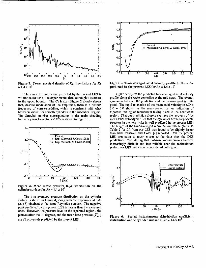
10
10
I0
° .0 0.2 0.4 0.6 0.8 1.0* 1.2 1.4 1.6 1.8 2.0St
Figure 3. Power spectral density Of CL time-history for Re= 1.4 x 10o
The r.m.s. lift coefficient predicted by the present LES iswithin the scatter of the experimental data, although it is closerto the upper bound. The CL history Figure 2 clearly showsthat, despite modulation of the amplitude, there is a distinctfrequency of vortex-shedding, which is consistent with whathas been known for smooth cylinders in the subcritical regime.The Strouhal number corresponding to the main sheddingfrequency was found to be 0.205 as shown in Figure 3.
2.0
-Present1. a Exp. (Cantwell & Coles,1983)
* Exp. (Sarioglu & Yavuz, 2002)
;- 0.0 -
-2.0 30 60 90 120 150 180
0 (deg.)
Figure 4. Mean static pressure (Cp) distribution on thecylinder surface for Re = 1.4 x 10⁵
The time-averaged pressure distribution on the cylindersurface is shown in Figure 4, along with the experimental data[2, 18] obtained at the same Reynolds number. The negativepeak predicted by the present LES is larger than the measuredones. However, the pressure level in the separated region - theplateau after 0 = 90 degrees, and the mean base pressure (UPB)
are all accurately predicted by the present LES.
1-.o 0 l.0 2.0 3.0 4.0 5.0 6.0 7.0 8.0x/D
Figure 5. Time-averaged axial velocity profile in the wakepredicted by the present LEIS for Re = 1.4 X 10⁵
Figure 5 depicts the predicted time-averaged axial velocityprofile along the wake centerline at the mid-span. The overallagreement between the prediction and the measurement is quitegood. The rapid relaxation of the mean axial velocity in x/D =1.0 - 3.0 shown in the measurement is an indication ofvigorous mixing of momentum taking place in the near-wakeregion. That our prediction closely captures the recovery of themean axial velocity verifies that the dynamics of the large-scalestructure in the near-wake is well predicted in the present LES.The length of the time-averaged recirculation bubble (see alsoTable 2 for Lr) from our LES was found to be slightly largerthan what Cantwell and Coles [2] reported. Yet the presentLES prediction is much closer to the data than the DESpredictions. Considering that hot-wire measurements becomeincreasingly difficult and less reliable near the recirculationregion, our LES prediction is considered quite good.
5.0 - Lower surface
0.0
-5.0
0 30 60 90 120 150 1800 (deg.)
Figure 6. Scaled instantaneous skin-friction coefficientdistribution on the cylinder surface at Re = 1.4 x 10⁵
5s Copyright © 2005 by ASME

- -
. . - . ^ U w -
peaks at 3.0 around 0= 50 degrees, which is closely reproducedby the present LES.
Supercritical Reynolds number Case (Re = 1.0 x10⁶ )
0 (deg.)
Figure 7. Resolved turbulent kinetic energy distribution at0.0001D above the cylinder surface, predicted the presentLES at Re = 1.4 x 10⁵
As mentioned earlier, the experimental evidence [19]indicates that, in the subcritical regime, the boundary layerremains laminar until it finally separates from the cylindersurface. Therefore, it would be of much interest to see howclosely LES can reproduce the physics associated with theseparation and the transition. Figures 6 and 7 depict thecircumferential variations of two quantities along the cylindersurface that shed some light on how the LES predicts theseparation and transition.
Figure 6 shows a plot of the instantaneous skin-frictioncoefficient - rescaled to match the non-dimensionalizationadopted by Achenbach [19] - against the circumferential angle.First, it is noticeable that the skin-friction distribution exhibits aconsiderable top-bottom asymmetry. This is a clearly the(upstream) influence of the large-scale, alternate vortex-shedding. What is most interesting in the figure is theappearance of small transient separation bubbles on both upperand lower surface starting as early as 70 - 75 degrees.Interestingly, this range largely coincides with the range ofseparation angles reported by many others [2, 19] deduced fromthe inflection point of mean Cp curve; 77 degree by Cantwelland Coles [2], and 78 degrees by Achenbach [19] at Re = 1.0 x10⁵. Although not shown here, the separation angle determinedbased on the time-averaged velocity field obtained from thepresent LES was found to be much larger than the onesdetermined from Cp distribution, reaching around 98 degree,which was also found by Breuer [1]. Based on theinstantaneous skin-friction distribution, we surmise that atransient laminar separation occurs much earlier than the meanseparation angle.
The distribution of the resolved turbulent kinetic energydepicted in Figure 7 supports the possibility of an intermittentlaminar separation around 70 - 75 degrees, insofar as theturbulent kinetic energy is still quite low there. The completetransition occurs a little'downstream as indicated by the rapidincrease in the resolved turbulent kinetic energy between 75and 85 degrees. The magnitude of the skin-friction coefficientpredicted by the present LES is also in good agreement withAchenbach's data [19] measured at Re = 1.0 x 10⁵.Achenbach's data show that the scaled skin-friction coefficient
Figure 8. The flow structure behind the circular cylinder atRe = 1.0 X 10⁶ - an iso-surface of the second invariant ofvelocity deformation tensor, colored by the resolvedturbulent kinetic energy
Figure 8 portrays an impression of the instantaneous flowstructure. Compared to the flow structure for the subcriticalflow shown in Figure 1, the wake is much narrower and morechaotic without any trace of a large-scale alternate vortexshedding, suggesting a delayed turbulent separation. This istypical of the flow in the supercritical regime. The color mapon the iso-suraface - representing resolved turbulent kineticenergy - also indicates that the laminar boundary layer issustained farther downstream than the subcritical flow.
Table 3. Summary of the global quantities predicted by LES forRe = 1.0 x 10', compared with other LES result and theexperimental data; CA - Catalano et al.[3]; SZ - Szechenyl.120];SHI - Shih et al. [211; ZD - Zdravkovich [16])
C D I C;.L I CpE St
LES (present) 0.27 0.12 0.28 -LES (CA) 0.31 - 0.32 0.35Exp.(SZ) 0.25 -Exp.(SH) 0.24 - 0.33 -
Exp. (ZD) .0.2/04 0.1/0.15 0.2/0.34 0.18/0.5
The global flow parameters predicted by the present LESare summarized in Table 3. Our prediction of the mean dragcoefficient (CD) closely matches the data of Szechenyi [20] andShih et al. [21] interpolated at the present Reynolds number.We consider their data more reliable than others in view of thesufficiently large spanwise lengths used (LID = 9.3 and 8.0,respectively), relatively low blockage ratio (7% and 11%,respectively), surface smoothness, and relatively lowturbulence intensity of the wind tunnels - 0.08 % for Shih etal.'s data [21]. The r.m.s. lift coefficient prediction by thepresent LES falls within the scatter of the experimental datacompiled by Zdravkovich [16]. The base pressure is also seento be in the range of the experimental data.
6 Copyright 0 2005 by ASME

U~~' *'*' 1" '1'jI
-0 ._ I . .- ... ; .. ,I4 40 VI 4
-0.2-
-04 420 440 460 480Non-dimensional time, l* (= tU0/D)
Figure 9. Time histories of drag and lift coefficients for thecircular cylinder at Re = 1.0 x 10⁶
The time histories of drag and lift coefficients are shown inFigure 9. Consistent with the flow structure portrayed in Figure8, the CL-history at this supercritical Reynolds number is morerandom than that for the subcritical flow. Indeed, no singlefrequency of vortex-shedding could be identified at thisReynolds number, as shown in the plot of the power spectraldensity of CL in Figure 10. This finding is consistent with theothers' experimental observations, for instance, Shih et al. [21 ]who found that coherent vortex shedding disappeared on asmooth cylinder beyond Re = 4 x 10⁵.
-02
10' t
Uo 610
I,t
10 0 0.2 0.4 0.6 0.8 1 1.2 1.4 1.6 1.8 2Strouhal Number
Figure 10. Power spectral density of the lift coefficient (CL)for the critical Reynolds number (Re = 1.0 x 10⁶)
For a smooth cylinder, the experimental data collected byZdravkovich [16] and Achenbach's data [19] indicate that,above the Reynolds number of 1.5 x 10⁶ referred to as "TrBL4"in [16], transition clearly precedes the boundary layerseparation. The exact location of the transition depends onsuch factors as freestream turbulence level and surfaceroughness. At Re = 1.0 x 10⁶ falling in the range referred to as"TrBL3", however, both sets of data seem to suggest thattransition occurs near the separation.
As before, we plotted the circumferential variations of theinstantaneous skin-friction and the resolved turbulent kineticenergy in Figures II and 12. The top-bottom asymmetry of theskin-friction distribution is seen to be much less pronouncedthan for the subcritical flow. Figure 12 suggests that theboundary layer sustains being laminar down to 90 degrees. Theseparation angle of the time-averaged velocity field from thepresent LES was found to be around 108 degrees, which isclose to 106 degrees estimated by Shih et al.[21] using theirexperimental data on a smooth cylinder at approximately thesame Reynolds number. All this taken together, our LES resultsuggests that the boundary layer undergoes transition starting asearly as 90 degrees, before it finally separates - "turbulently" -at around 108 degrees.
-Upper surface5.0 - Lowersurface|
0.
-50
* 0 30 60 90 120 150 1800 (deg.)
Figure 11. Scaled instantaneous skin-friction coefficientdistribution on the cylinder surface at Re =1.0 x 10⁶
0 (deg.)
Figure 12. Resolved turbulent kinetic energy distribution at0.OOO1D above the cylinder surface, predicted the presentLES at Re= 1.0 x 10O
The skin-friction prediction, including the location of thepeak and the magnitude, is also in good agreement with theexperimental data of Achenbach [19] measured at Re = 8.5 x10 and Re = 3.6 x 10⁶. At these two Reynolds numbers,
7 Copyright C 2005 by ASME

Achenbach's data show that the scaled skin-frictiondistributions have the maximum values in the range of 3.5 - 4.0occurring around 0= 60 - 65 degrees. As shown in Figure I1,our LES prediction closely matches Achenbach's data. This isin a sharp contrast with the LES prediction by Catalano et al.[3], which significantly overpredicted the overall level of theskin-friction on the front half of the cylinder. Contrary to whatis suggested by the experimental evidence, their LES seem toyield too early a transition, giving a skin-friction level typicalof a turbulent boundary layer from immediately downstream ofthe front stagnation point. As they pointed out [3], one mostlikely cause for the discrepancy is the substantially coarsermesh (yV around 50) used in their LES predictions.
SUMMARY AND CONCLUSIONS
Turbulent flow around a smooth fixed circular cylinderwas computed using large eddy simulation (LES) at twoReynolds numbers (Re = 1.4 x 10⁵, 1.0 x 10⁶). Thecomputations were carried out using a second-order accurate,parallelized finite-volume Navier-Stokes solver capable ofhandling arbitrary unstructured meshes. An implicit, non-iterative fractional-step method was employed in favor of itshigh efficiency in LES for incompressible flows.
The LES results for both Reynolds numbers predicted,with a good accuracy, the global flow parameters such as meandrag coefficient, r.m.s. lift coefficient, and the Strouhal number.Furthermore, the salient features of the subcritical and thesupercritical flows experimentally observed and measured on asmooth cylinder, such as the separation angle, mean velocity inthe wake, length of the recirculation bubble, and transitionlocation, are largely reproduced by the LES. Despite the use ofa large number of computational elements (6.8 million cells),the solution turnaround time was quite reasonable.
To summarize what has been achieved through this study:
* The spatial discretization method (finite-volume onunstructured meshes) and the solution algorithm(implicit fractional-step method) employed in this studyhave been shown to be sufficiently robust and accurateto be used in LES for high Reynolds number flows.
* The dynamic Smagorinsky model adapted tounstructured meshes using a novel test-filter [13] hasbeen shown to work robustly and accurately forcomplex, high Reynolds number turbulent flows.
* The present LES capability has been shown to predictthe salient features of turbulent flow around a smoothcircular cylinder at both subcritical and supercriticalregimes with a good accuracy and reasonablecomputational cost.
It is planned to continue this work to include higherReynolds numbers.
ACKNOWLEDGEMENT
The authors acknowledge that FLUENT and GAMBITsoftware were used for this study. The authors are alsothankful to Dr. Mustafa Sarioglu at Karadeniz Technical
University in Turkey for kindly allowing me to use hisexperimental data.
REFERENCE
[I] Breuer, M., 2000, "A Challenging Test Case for LargeEddy Simulation: High Reynolds Number CircularCylinder Flow," Int'l J. Heat and Fluid Flow, 21, pp. 648 -654.
[2] Cantwell, B. and Coles, D., 1983, "An Experimental Studyof Entrainment and Transport in the Turbulent Near-Wakeof a Circular Cylinder," J. Fluid Mlech., 136, pp. 321 - 374.
[3] Catalano, P., WVang, M., Iccarino, G. and Moin, P., 2003,"Numerical Simulation of the Flow Around a CircularCylinder at High Reynolds Numbers," Int'l J. Heat andFluid Flow, 24, pp. 463 - 469.
[4] Travin, A., Shur, M., Strelets. M. and Spalart, P., 1999,"Detached-Eddy Simulation Past a Circular Cylinder,"Flow, Turbulence and Combustion, 63, pp. 293 - 313.
[5] Vatsa, V. N. and Singer, B. A., 2003, "Evaluation of aSecond-Order Accurate Navier-Stokes Code for DetachedEddy Simulation Past a Cricular Cylinder," AIAA Paper2003-4085.
[6] Pandya, M. J., Frink, N. T., Abdol-Hamid, K. S., andChung, J. J., 2004, "Recent Enhancements to USM3DUnstructured Flow Solver for Unsteady Flows," AIAAPaper 2004-5201.
[7] Kim, S. E., Makarov, B., and Caraeni, D., 2004, "Multi-Dimensional Reconstruction Scheme for UnstructuredMeshes," AIAA Paper 2004-2548.
[8] Kim, S. E. and Makarov, B., 2005, "An ImplicitFractional-Step Method for Efficient Transient Simulationof Incompressible Flows," To be presented at 17Th AIAAComputational Fluid Dynamics Conference, June 6 - 9,Toronto, Ontario.
[9] Park, J., Kwon, K., and Choi, H., 1998, "NumericalSolutions of Flow Past a Circular Cylinder at ReynoldsNumbers up to 160," KSAIE nt. J., 12, pp. 1200 - 1205.
[10]Norberg, C., 2003, "Fluctuating Lift on a CircularCylinder: Review and New Measurements," J. Fluids andStructures, 17, pp. 57 - 96.
[I I]Williamson, C.H.K., 1989, "Oblique and Parallel Modes ofVortex Shedding in the Wake of a Circular Cylinder atLow Reynolds Numbers," J. Fluid Mech., 206, pp. 579 -627.
[12]Germano, M/, Piomelli, U., Moin, P., and Cabot, W. H.,1991, "Dynamic Subgrid Scale Eddy Viscosity Model,"Physics of Fluids A, 3, 19, pp.1760- 1765.
[13]Kim, S. E., 2004, "Large Eddy Simulation UsingUnstructured Mesh and Dynamic Subgrid-ScaleTurbulence Models," AIAA Paper 2004-2548.
[14]West, G. S. and Apelt, C. -J., 1993, "Measurements offluctuating Pressures and Forces on a Circular Cylinder inthe Reynolds Number Range 104 to 2.5 x 10⁵," J. Fluidsand Structures, 7, pp.227 - 244.
[15] Szepessy, S. and Bearman, P. W., 1992, "Aspect Ratio andEnd Plate Effects on Vortex Shedding from a CircularCylinder, J. Fluid Mech., 234, pp. 191 - 217.
[16]Zdravkovich, M. M., 1997, "Flow Around CircularCylinders, Fundamentals, Vol. 1, Oxford Univ. Press(Chapter 6).
8 Copyright © 2005 by ASME

117]Roshko, A., 1961, "Experiments on the Flow Past aCircular Cylinder at a Very High Reynolds Number," J.Fluid Alech., 10, No. 3, pp. 345 - 356.
[18]Sarioglu, M. and Yavuz, T., 2002, "Subcritical FlowAround Bluff Bodies," AMAA J. Vol. 40, No. 7, July.
[19]Achenbach, E., 1968, "Distribution of Local Pressure andSkin-Friction Around a Circular Cylinder in Cross-Flow upto Re = 5 x 10⁶,,, J. Fluid Mech., 34, Part 4, pp. 625 - 639.
[20]Szechenyi, E., 1975, "Supercritical Reynolds NumberSimulation for Two-Dimensional I-low Over CircularCylinders," J. Fluid. Mech., 70, pp. 529 - 542.
[21IShih, W. C. L., Wang, C., Coles, D., and Roshko, A., 1993,"Experiments on Flow Past Rough Circular Cylinders atLarge Reynolds Numbers," J. Wind Eng. And Indus.Aerodynamics, 49, pp. 351 - 368.
9- Copyright © 2005 by ASME

BVY 05-072Docket No. 50-271
Exhibit EMEB-B-138-2
Vermont Yankee Nuclear Power Station
Proposed Technical Specification Change No. 263 - Supplement No. 30
Extended Power Uprate
Response to Request for Additional Information
Large Eddy Simulation of Confined Swirling Coaxial Jets.
Total number of pages in this ExhibitI (excludina this cover sheet) is 10. |

. D D .. . +- + D
Proceedings of ASME-FED:2nd Symposium on Measurements and Modeling of Large-Scale Turbulent Structures
June 19 - 23, 2005
FEDSM 2005-77085
LARGE EDDY SIMULATION OF CONFINED SWIRLING COAXIAL JETS
Sung-Eun Kim, Fluent Inc.,Lebanon, NH 03766, U.S.A.
Xuelei Zhu, Fluent Inc., Lebanon,NH 03766, U.S.A.
Stefano Orsino, Fluent Inc.,Lebanon, NH 03766, U.S.A.
ABSTRACT
Large eddy simulations (LES) have been carried out forconfined swirling coaxial jets discharged into a suddenlyexpanded pipe, which was studied experimentally by Robackand Johnson [1, 21. The computations were made using aparallelized finite-volume-based Navier-Stokes solver that issecond-order accurate in time and space, and permits use ofunstructured meshes. The computational domain starts from aninlet placed upstream of the swirl generator, which makes theinlet boundary condition easy to specify. Subgrid-scaleturbulent stresses were modeled using a dynamic Smagorinskymodel applicable to complex three-dimensional flows withoutany statistically homogeneous directions. Subgrid-scaleturbulent scalar flux is modeled using a constant Schmidtnumber in conjunction with the dynamically computed subgrid-scale turbulent viscosity. The LES predictions were found toclosely reproduce the salient features of the flow and thespecies concentration downstream of the expansion. One of theconclusions was that a good resolution of the mean flow andturbulence in the upstream region is crucial in accuratelypredicting the mixing downstream of the expansion.
INTRODUCTION
Confined swirling co-axial jets discharging into a suddenlyexpanded pipe [1, 2] have been studied numerically by severalothers using the Reynolds-Averaged Navier-Stokes (RANS)equations [3, 4] and large eddy simulation [6]. The flow inquestion consists of a non-swirling jet in the center, and anouter annual jet with a swirl imparted by a 8-vane, variable-angle swirl generator, with a swirl number of approximately0.41.
Earlier numerical studies using RANS-based turbulencemodels [3, 4] have shown that the mean velocity field in themixing region .- the shear layer between the jets and the innerrecirculation region - was predicted with a reasonably goodaccuracy. However, the predictions of the mean species
concentration were much less satisfactory. The majordiscrepancy was found in the core region, where the meanspecies concentration was grossly underpredicted by the RANScomputations. Evidently, the RANS model employed givesrise to an excessive mixing. Brankovic et al. [31 investigatedthe sensitivity of their RANS predictions to such parameters asthe turbulent Schmidt number and the inlet turbulence level.However, the influence of these parameters was negligiblysmall. The poor prediction of the species mixing has beenattributed to the inability of RANS-based turbulence models toaccurately represent the mixing by large-scale turbulentstrmctuirc (or large eddies).
Playing a major role in mixing, large eddies are alsoresponsible for undesirable yet somewhat subtler phenomenasuch as combustion instability and acoustic excitation insidecombustors. To address these issues properly, one has to turnto high-level turbulent simulation like LES. Akselvoll andMoin [5] used LES to compute the flow and the speciesconcentration in non-swirling coaxialjets. Pierce and Moin [6]attempted LES for the same confined coaxial swirling jet as isconsidered here. These studies demonstrated that LES canindeed predict the flow and the species concentration inconfined coaxial jets with a commendable accuracy. LES alsoallows one to directly compute r.m.s. velocity fluctuations andr.m.s. species fluctuation which are important quantities in thecontext of turbulent combustion.
The present study concerns a LES computation for theswirling coaxial jets using a finite-volume solver that permitsuse of unstructured meshes. Unlike the study of Pierce andMoin [6], however, our computational domain starts from aninlet boundary placed upstream of the swirl generator. Despitethe larger solution domain and the implied increase in thecomputational resource, having the inlet boundary upstream ofthe swirl generator makes it straightforward to specify the inletboundary conditions. Meshing the computational domainincluding the swirl generator, which could become a difficultand time-consuming task with structured meshes, is madeeasier by the flexibility offered by unstructured mesh allowedby the present finite-volume solver.
I Copyright C) 2005 by ASME

This paper is, in many aspects, a pi( .. epoIl aboutl anongoing study whose ultimate goal is to finbl awn oplimalstrategy based on the technique of LES fur modeling turbulentflow and species mixing in coaxial conmbustors with or withoutswirl.
The paper is organized as follows. F:irst, we briefly discussthe numerical method and the subgrid-scale turbulence modelsfor stresses and scalar flux. Special emphasis is laid on atransient algorithm whose efficiency significantly benefits thepresent study. This is followed by the details of the LEScomputations regarding the choices of the solution domain,mesh (resolution), boundary conditions, timne-step size, and theoverall solution strategy. The results are then presented.
NUMERICAL METHOD
The computation were carried out using the segregatedsolver in FLUENT, a general-purpose CFD software.FLUENT employs a cell-centered finite-volume method basedon a multi-dimensional linear reconstruction schemne thatpermits use of computational elements (cells) with arbitrarypolyhedral cell topology including quadrilateral, hexahedral,triangular, tetrahedral, pyramidal, prismatic, and hybridmeshes. The solution gradients at cell centers that aIe neededto compute convective and diffusive fluxes are obtained byapplying Green-Gauss theorem [9]. Diffusive and convectivefluxes are discretized using central differencing [8J.
An implicit fractional-step method (I SM) [10] inconjunction with a second-order accurate, three-levelbackward- differencing scheme for time-discrelizition wasemployed to advance the solution in time. In this algorithill, themomentum equations are decoupled from the continuityequation applying an approximate factorization of the coupledNavier-Stokes equations. For incompressible flows, the FSMIpreserves the formal second-order temporal accuracy withouthaving to perform, at each time-step, costly outer iterations tocouple velocity-field and pressure. '[he FSNI thus provides ahighly efficient algorithm for CPJU-intensive transietcomputations like LES.
Consider the semi-discrete form of the Navier-Stokesequations in "pressure-correction" (4y",I = p"/' - p") form:
[A G] u"-` -=(r (I)ID 0] 4,j; ) 0
where un`t and r are the velocity vector and the momentumsource vector, respectively, and the integer n is the time level.A is the coefficient matrix defined in terms of the discreteconvective and diffusive operators and the timc-advancementscheme chosen, and G and D are the discrete gradient anddivergence operators, respectively. The coupled system ofequations in Equation (1) is extremely difficult to solve as it is,since the matrix A has to be inverted for every iteration. In thefractional-step method, the original coupled equations inEquation (I) are approximated by
Aii=-Gp" + r'
(3)
fi = a, - AYG,"-
On a per-iteration basis, the series of operations inEquation (3) closely resembles SIMPLEC schiemc. Thedifference is that, in the iterative SIMNIP.LEC scheme, theoperations in Equation (3) are repeated in an o0.teI loop untilthe all the solution variables converge, whereas the FSMI needsonly one sweep. To preserve second-order accuracy) with theFSM, however, sub-iterations are needed for the set of threemomentum equations and individual scalar eqtuations loaccount for the nonlinearity in and coupling among theindividual equations and high-order source terms. Yet, non-iterative FSM is takes much less CPU time than iterativeSIMPLEC scheme.
The system of discretized governing equations are solvedusing a point-implicit, Gauss-Seidel relaxation along withalgebraic multi-grid (AMG) method to accelerate solutionconvergence. The N-S solver and the SGS turbulence modelare fully parallelized.
SUBGRID-SCALE TURBULENCE MODELING
For incompressible flows, the filtered Navicr-Stokesequations can be written as
aw, +2a =_i I DJP arqij a , [ aI,~717 ax, TX,-_- -(4)
where -rv =u~u,-j is the subgrid-scalc turbulent stress. In
this study, the subgrid-scale stress is modeled using isotropiceddy-viscosity as
TO, 110 -ra = -2C,25Z|MSij (5)
We determined the model constant, C,, using the dynamicSmagorinsky model (DSM) originally proposed by Germano etal. [7, 8].
The filtered transport equation for a passive scalar is givenby
3+ 2aii= a (sav P qa, ax axe ax. i
(6)
where q is the subgrid-scale turbulent flux of the species
concentration (s7), and a the molecular diffusivity. The subgrid-.scale flux is modeled using
[A o1 AZG1( u _=(r + [O(A2)]
ID AiDG IO' I JV0+)t)
(2)SC, ax,
(7)
Factorizing equation (2), we have a series of split operations as
2 Copyright © 2005 by ASME

where Sc, is the subgrid-scale tobtulent Schmidi nmibecr. In thisstudy, we used a constaln vaILue (f 0.9.
To implement the dynamic procedtlre for the present finite-volume solver requires a test-filter applicable to arbitraryunstructured meshes. The test-filter finally adopted for this studyis a top-hat filter involving a volume comprising the cell in thecenter plus the neighboring cells that share the faces with thecenter cell. To make the dynamic procedure tractable, anapproximation was made that is tantamount1l to a non-varying C,over the test-filter volume. Thus, the (Irilalic procedureemployed in this study is "approximately local" in the sense that,despite the ad hoc assumption, it does not require an existence ofany statistically homogeneous directions, being applicable tocomplex three-dimensional flows. To avoid numerical instabilitylikely to be caused by a large fluctuation of the model constant,we smoothed the model constant by applying the test-filter on it,and also clipped it so that the effective viscosity remains positive.The additional details of the implementation of the DSM in theframework of an unstructured mesh based finite-volume solvercan be found in the reference 18]. The DSNI has been validatedfor a number of wall-bounded flows such as fully-developedchannel flows and flows around bluff bodies such as a squarecylinder and a sphere.
DETAILS OF COMPUTATIONS
Solution domain, swirl vane geonmetry and meshes
A partial view of the computational domain is depicted inFigure 1, along with the coordinate system. The inlet boundaryis placed at LO.D upstream of the sw"irl generator, where D isthe downstream pipe diameter (D = 122 mm). The exitboundary is at 15D downstream of the pipe expansion. Thecomputational domain thus has the swirl generator in it. Theentire inlet tube, 8 swirl vanes, and the downstream pipe weremodeled without using any periodic boundaries.
Figure 2. A sectional view(medium-sized mesh wiith 2.7computations.
of the compltational meshniilliori lements) used in the
pipec expaelmionl
The computational meshes were built using Gambit. Weused three progressively refined, unstructured hexahedralmeshes. for the computations. The three meshes have 1.1million (coarse), 2.7 million (niedium), and 4.8 million (fine)elements, respectively. A sectional view of the medium-sizemesh is shown in Figure 2. The resolution of the medium meshis such that, in the mixing region, it can resolve the integrallength-scale estimated around 20 mnm based on the experimentalobservation [1, 2], which is equivalent to D/6, withapproximately 20 elements. It can resol ve the smallestobservable eddies of a size around 6 mm, which were observedin the experiment [1, 2], with 6 - 7 elements.
It is worth mentioning here that the mesh resolution in andaround the inner and the annular tubes and the swirl vanes istoo coarse to resolve the energy-containing eddies originatingfrom and transported in that upstream region. We recognizethat poor resolution of the turbulent structure in the upstreamregion will negatively impact the prediction in the downstream,particularly in the shear layers of the mixing region, inasmuchas the energy-carrying eddies from upstream feed the turbulentstructure being developed in the downstream mixing region.Furthermore, none of the three meshes are fine enough toaccurately resolve the viscous sublayer on the pipe walldownstream of the expansion. This 'as deemed justifiable inlight of a relatively passive role played by the wall downstreamof the expansion in the mixing occurring near the central core.
Boundary conditions, time-step size, and solution strategy
On the annular jet inlet, a uniform axial velocity of 1.667n/s was specified according to the data given by Roback andJohnson [1). For the velocity boundary condition at the innerjet inlet, we used 0.797 m/s, a value derived from thevolumetric flow-rate (6.2 gallon per minute) given in Ref. [1],instead of the inlet velocity mentioned in the same report (0.52mi/s). The inlet velocity of 0.52 n/s quoted in the report doesnot match the given volume flow-rate, and is inconceivably toolow considering that the measured axial velocity immediatelydownstream of the expansion is around 0.8 n/s.
On wvall boundaries, we employed a blended law-of-the-wall that invokes proper wall-laws depending on the local meshresolution, namely y/ at the wall-adjacent cells. Thedownstream exit boundary was treated as a "pressure-outlet"boundary offered in FLUENT. In essence, the solution
swirl vane
C-'
.-. '., .,�
-� -.-.
inlte L Z
Figure 1. A partial view of the computational domain
The swirl generator consists of 8 identical vanes mountedon the hub with an equal spacing in ihe azimuthal direction.The blade-section has a camber and a vane-angle that changewith the radius. The blade geometry was taken from thedesign data given in the Ref. [1]. A NURB surface was builtbased on the digitized surface geometry.
3 Copyright © 2005 by ASME

variables are extiapol;died in a mass-conserving manner on thisboundary.
'rhe influence ol the exit boundary condition wasdiscussed at length by Pierce and Moin (6]. They found thatthe usual convective outtlow boundary condition applied on anexit boundary with a cross-section of the downstream pipeyielded a central recirculation zone that is far smaller than what
'The LiS was slarle(l osing a steady RANS solution as theinitial guess. To accelerate the solution to a statisticallystationary'state, we superimposed a pseudo-random fluctuatingvelocity-field on the mean velocity field taken from the RANSsolution. Before tile statistics are collected, tile LEScomputation was run until the initial transients in the solutionare completely washed out, which typically took 2 - 3 flow-through times; one flow-through time is taken to be LlUb,where L is the length of the downstream pipe, and Ub the axialmean bulk velocity.
RESULTS
Figure 4. Instantaneous velocity vectors in the r-z plane
__ . ., *;**...**
. _%. . .- ,T k'. ~-E *. . , ,. . .- , -
Figure 3. Instantaneous velocity vectors at four axiallocations - top-left, z = 25 mm; top-right, z= 51 mm;bottom-left, z=1 02 mm, hottom-right, z = 203 mm
was observed in the experiment. They were able to bring theirLES prediction much closer to the experimental data by puttinga second expansion before the exit boundary, which wasconceived based on an argument that it better represents thesettling chamber used in the experiment.
We also investigated the effect of the second expansion,comparing the result to what was obtained without heexpansion. However, we could not notice any appreciabledifference between the two. The insignificantly smalldifference found in our computations is perhaps due to the waythe solution variables are extrapolated at "pressure-outlet"boundary that could be different from their treatment of theconvective boundary.
The time-step size used in the present LES was determinedbased on the estimated characteristic time-scale of the smallesteddies to be resolved in the LES. We took v = 1.0 m/s and .1= 0.05D (D = 0.122 m) as the characteristic velocity-scale andlength-scale of the smallest eddies. These estimates give aneddy-tumover time of v =e/v= 0.006 second. It was finallydecided to use a time-step size of At = 0.0002 second, whichwill resolves one eddy-turnover time (T) of the smallestresolved eddies roughly in 30 time steps.
Figure 5. Time-averaged velocity vectors in the r-z plane
To obtain stable statistics of the solution, the transientcomputations were continued for a sufficiently long period oftime, typically for more than 7 - 8 flow-through times, untilthe time-averaged velocity and species concentration fieldslargely recover an axisynimletry.
Regarding the mesh-dependency of the solutions, it wasfound that the LES results from the meditim mesh (2.7 millioncells) and the fine mesh (4.8 million cells) showed littledifference, while the coarse mesh result deviates a little fartherfrom other two. Unless stated otherwise, the results presentedin this paper are for the meditim mesh.
4 Copyright © 2005 by ASME
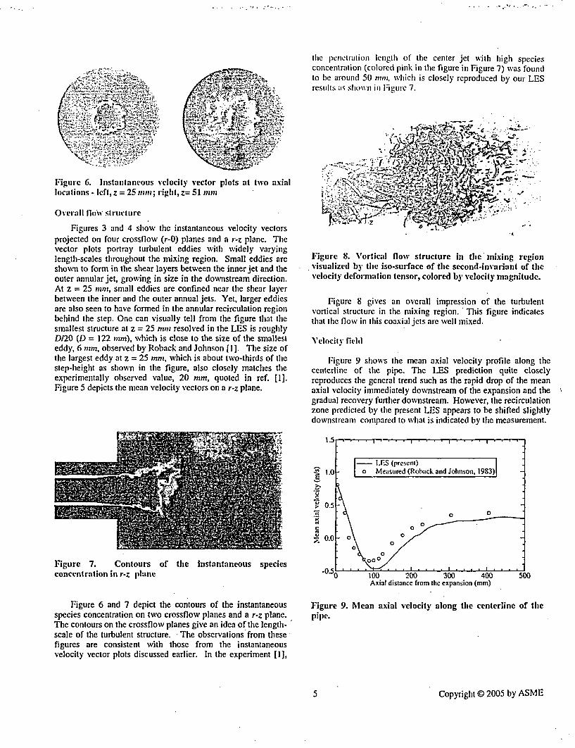
the penetration length of the center jet with high speciesconcentration (colored pink in the figure in Figure 7) was foundto be around 50 nmnm, which is closely reproduced by our LESresults as shown in Figure 7.
Figurc 6. Jnstantaneous velocity vector plots at two axiallocations - left, z = 25 mrzs; right, z= 51 mmi
Overall flo'llv Structure
Figures 3 and 4 show the instantaneous velocity vectorsprojected on four crossflow (r-0) planes and a r-z plane. Thevector plots portray turbulent eddies with widely varyinglength-scales throughout the mixing region. Small eddies areshown to form in the shear layers between the inner jet and theouter annular jet, growing in size in the downstream direction.At z = 25 mnt, small eddies are confined near the shear layerbetween the inner and the outer annual jets. Yet, larger eddiesare also seen to have formed in the annular recirculation regionbehind the step. One can visually tell from the figure that thesmallest structure at z = 25 mm resolved in the LES is roughlyD/20 (D = 122 mm), which is close to the size of the smallesteddy, 6 mm, observed by Roback and Johnson [I]. The size ofthe largest eddy at z = 25 mm, which is about two-thirds of thestep-height as shown in the figure, also closely matches theexperimentally observed value, 20 mm, quoted in ref. [1].Figure 5 depicts the mean velocity vectors on a r-z plane.
Figure 8. Vortical flow structure in the mixing regionvisualized by the iso-surface of the second-invariant of thevelocity deformation tensor, colored by velocity magnitude.
Figure 8 gives an overall impression of the turbulentvortical structure in the mixing region. This figure indicatesthat the flow in this coaxial jets are well mixed.
\'elocitv field
Figure 9 shows the mean axial velocity profile along thecenterline of the pipe. The LES prediction quite closelyreproduces the general trend such as the rapid drop of the meanaxial velocity immediately downstream of the expansion and thegradual recovery further downstream. However, the recirculationzone predicted by the present LES appears to be shifted slightlydownstream compared to what is indicated by the measurement.
I1 .. . . . . . . . . . . . . . . . . . . . .
i
.9
UC.
0,
1.01- U.FS (present)
0 { Measured (Roback and Johnson, 193)1
0 0
. 00 I
2\ a;~0
0\ °
.. 0..1....
0.0
Figure 7. Contours of the instantaneous speciesconcentration in r-z plane
Figure 6 and 7 depict the contours of the instantaneousspecies concentration on two crossflow planes and a r-z plane.The contours on the crossbow planes give an idea of the length-scale of the turbulent structure. The observations from these-figures are consistent with those from the instantaneousvelocity vector plots discussed earlier. In the experiment [1],
- I,.10( 200 300 400Axial distance from the expansion (mm)
500
Figure 9. Mean axial velocity along the centerline of thepipe.
5s Copyright C 2005 by ASME

- e w o -o �
z = 5 miii z = 5 mm1.5
U
U
1OF-
I o Measured (Roback and Johnson, 1983)- Present LES
00
I 0 000
0
00
0 /
(.51-
O. I.-
I I0.2 0.4
r/rO0.6 0.8
z = 25 mm
-
e
.3
U
I-
r/rO
z=5l mm z=51 mm1.0
>C 0.5._
C
TM 0.
13
.el0.
Measured (Roback and Johnson, 1983)- Prescnt LES
oOIO 0 0
_00 00
0 000 o 8
[is,-U.Jz 0.2 0.4 0.6 0.8
rlrO
Figure 10. Mean axial and azimuthal velocity profiles at two axial locations (z = 25 mm, z = 51 mm)
Figure 10 shows the radial profiles of the mean axial andazimuthal velocity components at three axial locations (z = 5mm, 25 mm, 51 mm). The profiles shown in the figure were
obtained by averaging the radial profiles taken at fourazimuthal locations (0= 0°, 90°, 1800, 2700). The predictionsare seen to capture the overall trends and the peak values of the
6 Copyright © 2005 by ASME

velocity components. However, it is cle;rl) noliceable that thelocations of the peaks predicted by the LES arc generallyshifted toward the centerline. This implies that the outerannular jet expands or opens up less than it does in reality.This also means that the annular recirculation zone predicted bythe present LES is longer (in the axial direction) than in theexperiment. The underprediction of the jet angle is alsocorrelated with the downstream shift of the central recirculationzone discussed earlier.
z = 25 mm
E 0.6
, 0.4
0A
c:- 0.21
used in this study, including tile fine mesh (4.8 mS1illion cells),are tine enough to accurately resolve the enerev-meollaijllingeddies generated in the upstream region.
The r.m.s. axial velocity fluctuation shown in Figure I Iseems to support our reasoning. The r.m.s. axial "elocityfluctuation at the centerline (r = 0) at z = 25 inn: show'n in thetop-figure, and the one at z = 5 min (not shown here) areseverely underpredicted in the LES computation. As shown inthe bottom-figure for z = 51 mm, further downstreami ol the jetexit, the r.m.s. axial velocity fluctuation calchies up with thedata, as the turbulent eddies generated in tile shear layerbecome full-fledged.
The impact of the incoming turbulent eddies on the mixingin the downstream as suggested above and the cost implicationof using an extremely fine mesh in the upstream region beg aquestion; what would be the best practice that can be adopted toobtain a sufficiently accurate prediction of the fow and speciesmixing occurring in a coaxial jet combustor with LES? Wewill ponder a little upon this question at the very end.
Species concentration
Figure 12 shows the profile of the mean speciesconcentration along the pipe centerline. The LES predictionclosely reproduces the trend - the plunge of the mean speciesconcentration occurring near z = 50 mint. One noticeablediscrepancy between the prediction and the mcasurenlent is in thelength of the inviscid core for the species concentration. The LESyields an inviscid core for the species concentration almost downto z = 35 mm, whereas the experimental data indicates that themean species concentration starts being diffused away almostimmediately, after the expansion. We think that this is again, in amajor part, due to the poor resolution of the incoming turbulenteddies which would take part in "tearing" the inner jet.
z=51 mm
.0
U2
T/ro
Figure 11. rams. axial velocity fluctuationflow planes (z = 25 mm, z = 51 m)
at two cross-
We surmise that, among others things, the most likelyculprit for this discrepancy is the lack of mesh resolution in theregion upstream of the expansion, in and around the inner andthe outer annular pipes, and the swirl vanes. As mentionedearlier, turbulent eddies coming from the upstream region feedthe shear layers developed downstream of the expansion,enhancing the mixing of the momentum and the speciesconcentration in the inner and the annular jets with thesurrounding flow, which will lead to an increase in the jetangle. In our LES computations, these energy-feeding eddiesare almost missing, since none of the computational meshes
Figure 12. Mean species concentration along the centerlineof the pipe
The radial profiles of the mean species concentration at twoaxial locations are shown in Figure 13. The predictions are ingood agreement with the measurements at both locations. Themean species concentration profile at z = 25 mm predicted by theLES computation shows a sign of being "under-diffused", insofar
7 Copyright 3 2005 by ASME

as it has a fuller profile than the leastie(l one. The prediction atz = 51 mm is somewhat lower than the measurement near thecenterline. However, the overall agreement at this location isremarkably good in view of the steep change of the mean speciesconcentration near z = 51 mm, as can be seen in Figure 12. Itshould be noted, in passing, that the RANS predictions reportedin the literature [3] severely under-predicled the mean speciesconcentration at this axial location.
r.m.s. value at z = 25 nmm, located in tile sheal layerl between theinner and the outer annUlar jets, is ;lso considerablyunderpredicted. Apparently, the LIES utnderpredicts theentrainment of the ambient fluid occurrineg at this location. At z= 51 mm, the prediction conies milc h closer to themeasurement, as the r.m.s. velocity luc1tluationr did at the sameaxial location.
z = 25 nini z = 25 mini
C0
C0U2
CJ
z=51 mm z = 51 nini
r/r11 r/ro
Figure 13. Mean species concentration at two axial Figure 14. r~m.s. species concentration at two axial locationslocations (z = 25 mm, 51 mm) (z = 25 mm, 51 mm)
Equally important - probably even more important than themean species concentration in the context of modelingturbulent combustion, is the fluctuation of speciesconcentration. The usual RANS-based turbulence modelscannot directly predict the r.m.s. fluctuating speciesconcentration, unless the transport equation for the variance offluctuating species concentration is explicitly solved. Oneobvious benefit from LES is that one can directly compute it.Figure 14 depicts the r.m.s. fluctuating species concentration atthe two crossflow planes. At z = 25 mm, as in the case of ther.m.s. axial velocity fluctuation, the LES result grosslyunderpredicts the r.m.s. value in the core region. The peak
The same remarks given regarding what might have causedthe discrepancy in the r.m.s. velocity fluctuation (Figure 11)largely apply to the results for the r.m.s. fluctuating speciesconcentration.
PRELMINARY RESULTS WITH LOCALLY REFINEDMESHES
The fact that the fine mesh (4.8 million cells) offers ameager improvement over the medium mesh (2.7 million cells)in terms of the mesh resolution (spacing) warrants additional
8 Copyright ( 2005 by ASMIE

Computations vsith siuhbanitially finer mesh, for instance, byhalving the grid sspacing in all three (axial, radial, andazimuthal) directions. However, doubling the number ofelements in the three directions results in an eight-fold increasein the total cell counts, which becomes unwieldy.
z=51 mm2..-
2.0
E
a;CM
V
1.5i
I .0
0.51
M acasurcd (Rotack & Johnson IlIl)_ - ILES (2.7NM ccli mesh)
--- LES (2.7NM cell & locaily refined)
0 CS
D 0.2 0.4 0.6 0.8r1r,
z=51 mm
0.0
.0.5
CONCLUSION
The flow and tile species transport in confined swirlingcoaxial jets were conimpited using LES. An unstructured mesh-based finite-volumne solver was employed for the computations.A highly efficient timc-advancement scheme was used inconjunction with second-order accurate temporal and spatialdiscretization schemes. A dynamic Smagorinsky modeladapted to general three-ditnensional flows was employed asthe subgrid-scale turbulence model.
For LES, it is evidently a bold attempt and a costlyproposition to include the upstream components of a combustorlike the swirl generator and the upstream tubes in thecomputational domain. Nevertiheless, the present LEScomputations closely reproduce the salient features of the flowand the species concentration in the mixing region. For anaccurate prediction of the mixing in the downstream (e.g.,combustion chamber), a good resolution of the mean flow andthe turbulence in and around the inner and the outer annulartubes, and the swirl vanes turned out to be more important thanoriginally thought. The numerical evidence found from thisstudy indicates that the three globally refined meshes used inthe present study, despite the largest cell counts reaching up to4.8 million cells, still cannot provide a sufficient resolution ofthe upstream region. We believe that the lack of meshresolution is responsible for the discrepancy between thepredictions and the measurements, most notably the overallshift of the velocity peaks toward the centerline.
Finally, a preliminary result was presented which wasobtained with a new mesh locally refined in the upstream partof the domain. The significant improvement from this locallyadapted mesh supports our conclusion, and at the same time,provides us with an avenue to improving the accuracy of LESprediction for the subject flow.
ACKNOWLEDGEMENT
The authors acknowledge that FLUENT and GAMBITsoftware were used for this study. The LES-cluster in FluentInc. was used for the computations.
I .0
1�.22:1V
1>Cri4!
0.5
. Measured- LES (2.7NM ccll mesh)--- LES (2.7M cell mesh & locally refined)
-I 0o~
00
I I . I
0.0
0.2 0.4 0.6 0.8r/ro
Figure 15. Mean axial and azimuthal velocity profiles attwo axial locations - predicted with a locally refined mesh
To keep the mesh size under a tractable limit, the mediummesh was locally refined only in the domain upstream of theexpansion. Furthermore, only the cells within a specifieddistance from the wall, roughly 0.07D in this study, wererefined to further save the cell counts. The local refinementresulted in a total of 6.5 million cells. The computation hasbeen carried out on this mesh. The results are shown in Figure15, being compared with the medium mesh results, for theradial profiles of the mean axial and azimuthal velocitycomponents at z = 51 mm. Clearly, the predictions with theadapted mesh are significantly improved over the predictionswith the medium mesh. The overall shift of the velocity peaksis now far smaller than what we saw earlier, and the predictionscapture the profiles of the mean velocity components muchmore closely.
REFERENCES
[I] Roback, R. and Johnson, B. V., "Mass and MomentumTurbulent Transport Experiments with Confined SwirlingCoaxial Jets," NASA CR-168252, 1983.
[2] Johnson, B. V. and Roback, R., "Mass and MomentumTurbulent Transport Experiments with Confined SwirlingCoaxial Jets - Part I," AIAA-84-1380, Presented atAIAAISAE/ASME 20 'h Joint Ppropulsion Conference,Cincinnati, OH, June II - 13, 1984.
[3] Brankovic, A., Ryder, Jr. R. C., and Syed, S. A., 1998,"Mixing and Combustion Modeling for Gas TurbineCombustors Using Unstructured CFD Technology," AIAAPaper 98-3854, Presented at 34th AIAA/ASME/SAE/ASEEJoint Propulsion Conference & Exhibit, July 13 - 15, 1998,Cleveland, 011.
9 Copyright © 2005 by ASME
14J l in. C.- A., "IModeling a Contined Swirling Coaxial Jet,"Annzual Ressearcht Brief, 1998, Center for TurbuileniceRtesearchl., Stanford University, ]998.
15] Akselvoll, K. and Moin, P., 1996, ''Large-Eddy-Simullationlof Turbulent Confined Coannuair Jets," J. fluid ine(chI.,315,pli. 3 87-41
16] P'ierce, C. D. and Moin, P., 1998, "Large Eddy Simulationof a Confined Jet with Sw~irl and Heat Release," AIAAPaper, 9S-2S892.
171 Germano, M/, Piomelli, U., Moin, P., and Cabot, XV. II.,1991, "Dynamnic Subgrid Scale Eddy Viscosity Model,"Physics of Fluidls A, 3, 19, pp. 1760 - 1765.
18] Kim, S. E., 2004, "Large Eddy Simulation UsingU~nstructured Mesh and Dynamic Subgrid-ScaleTurbulence Models," AIAA Paper 2004-2548.
191 Kim, S. E., Makiarov, B., and Caraeni, D., 2004, "Mulfli-.Dimensional Reconstruction Scheme for UnstructuredMeshes," AIAA Papser 2004-2548.
[10] Kim, S. E. and Makarov, B., 2005, "An ImplicitFractional-Step Method for Efficient Transient Simulationof Incompressible Flowvs," To be presented at 17 'h AIAAComputational Fluid Dynamics Conference, June 6 - 9,Toronto, Ontario.
10 Copyright C) 2005 by ASME

BVY 05-072Docket No. 50-271
Exhibit EMEB-B-138-3
Vermont Yankee Nuclear Power Station
Proposed Technical Specification Change No. 263 - Supplement No. 30
Extended Power Uprate
Response to Request for Additional Information
Large Eddy Simulation Using Unstructured Meshes and Dynamic Subgrid-ScaleTurbulence Models.
| Total number of pages in this ExhibitI (excludinc this cover sheet) is 17. |

34th AIAA Fluid Dynamics Conference and Exhibit. June 28 - July 1, Portland Oregon
Large Eddy Simulation Using Unstructured Meshes andDynamic Subgrid-Scale Turbulence Models
Sung-EunL Kim*Fluent Inc, Lebanon, Nrew Hampshire, 03766, U.S.A.
This paper concerns development of a large eddy simulation (LES) capability based on a finitc-volumesolver that permits use of unstructured meshes. The solver employs a cell-centered scheme along with amulti-dimensional linear reconstruction. Convection and diffusion terms are discretized using a second-ordercentral-differencing scheme. A three-level second-order scheme is used for temporal discretization. Subgrid-scale turbulent stresses are closed using dynamic Smagorinsky model and dynamic turbulent kinetic energytransport model. A test-filter was designed for the dynamic procedure which is applicable to unstructuredmeshes ofarbitrary cell-topology. The dynamic procedure also avails itself to three-dimensional flows withoutany statistically homogenous directions. W\'all boundary conditions are imposed using a wall-function approachthat applies appropriate wall-laws depending on near-wall mesh resolution. The LES capability is validatedfor a wide range of wall-bounded flows. We present here the results for a fully-developed channel flow and twobluff-body Blows. The predictions are in good agreement with direct numerical simulation (DNS) results andthe experimentalaiata
1. Introduction
IITE encounter many industrial applications of computational fluid dynamics (CFD) where the flows are dominatedVWby unsteady, large-scalc coherent structures. Those large-scale structures impact, to a great cxtcnt, various
aspects of the flows such as energy consumption, safety, comfort, and noise. The ramification of whether or notone can harness the large-scale structures is therefore quite significant. Attempts to numerically predict such flowsusing unsteady Reynolds-Averaged Navier-Stokes (URANS) equations have been met with limited success. Some ofthe better RANS models seem to be capable of capturing the "Jargest" scale occurring often in the form of alternatevortex-shedding. However, the remaining coherent structures are left largely unresolved.
Large eddy simulation (LES) is fundamentally suited to the task of predicting coherent structures. The majorobstacle in using LES for practical high Reynolds-number (Re) flows, from the practitioners' standpoint, is its highcost incurred by an unwieldy number of computational elements and painfully long solution time. Yet today's ever-increasing computing power is rapidly making LES feasible. Another difficulty often encountered when attemptingLES for industrial applications comes from complex geometry. In CFD, meshing for industrial applications involvingcomplex geometry by itself can become a grand challenge. It is hugely time-consuming or often impossible to generatehigh-quality structured meshes for complex configurations, which has led industrial CFD practitioners to opt forunstructured meshes. Although unstuctured meshes are routinely used today in RANS computations for industrialapplications, attempts to conduct LES with unstructured meshes are just starting to appear in the literature.1-5 As yetthe efficacy of unstructured meshes for LES for practical high-Re flows has not been fully established. Among theissues yet to be addressed are numerical accuracy, stability, and subgrid-scale turbulence modeling.
This paper is concerned with evaluating a LES capability developed using a finite-volume solver based on second-order numerics. Permitting use of unstructured meshes, the resulting LES capability can easily handle complex ge-ometries encountered in industrial applications. In addition, it lends itself to local mesh adaptation that can be utilized
'Principal Engineer, Fluent Inc., Lebanon N.H., Menmber AIAA.Copyright 0 2004 by Fluent Inc.. Published by the American Institute of Aeronautics and Astronautics, Inc. with permission.
I of 17
Arnerican institute of Aeronautics and Astronautics Paper 2004-2548

to efficiently allocate computational cells, substantially reducing the computational cost. Adequacy of second-orderspatial discretization for LES has often been questioned, and there are some misgivings about using it for LE-S. It willbe shown in this paper, however, that the second-ordercentral differencing scheme adopted in the present work yields acommendable accuracy for LES. For subgrid-scale (SGS) turbulence closure, we implemented two dynamic SGS vis-cosity models in the framework of unstructured meshes, namely, the dynamic Smagorinsky model originally proposedby Germano et al.,6 and Lilly' and the dynamic turbulence kinetic energy transport model of Kim and Menon.8 9 Forthe dynamic procedure, a test-filter readily applicable to unstructured meshes was designed. The resulting dynamicSGS models can be used for three-dimcnsional flows without any statistically homogeneous directions.
The paper is organized as follows. We start with a brief description of the two dynamic subgrid-scale turbulencemodels and the details of their implementations. This will be followed by an overview of the numerical methods andalgorithms adopted in this work. Finally, validations will be presented for a selected number of wall-bounded flowsranging from a fully-developed channel flow to a couple of bluff-body flows including one around a squarc-cylinderwith salient edges and another past a smooth sphere.
II. Filtered Navier-Stokes Equation and Subgrid-Scale 71urbulencc Modeling'
A. Implicit filter with finite-volume discrelization
The governing equations for LES are generally obtained by filtering the Navier-Stokes equations in either Fourier(wave-number) or physical space. In the present work, the filtering operation (denoted by an overhar) is defined as aspatially convoluted integral of the variable in question as
¢(X) = | (y)G(x,y)dy (1)
where D is the computational domain, y E VD and G is the filter function.With the cell-centered finite-volume discretization and the linear reconstruction scheme employed in this work,
the discrete solution variable at a cell-center (co) can be written as
C(co) = f, (Y)d, y C V (2)
where V is the volume of a computational cell.The definition in Equation (2) of a discrete solution variable at cell center can be interpreted as a filtering operation
¢(x) -(CO) = V (y)dy, y E V (3)
The implied filter function, G(x )), is then a top-hat filter
G(x,y) = {/V for Ix - l E (4)0 otherwise
Using the filtering operation in Equation (3), the filtered Navier-Stokes equations for incompressible flows (as-sumed for brevity) can be written as
_+ a _ ap arij + a (5)at axj - Tpx, a5x- axj axjJ
antiwhere 'rij is the subgrid-scale stress defined by;
7jj-U_7j - Rj (7)
which is unknown and needs a closure.Thus, we used in this work grid and finite-volume discretization as an implicit filter.
2 or 17
American Institute of Aeronautics and Astronautics Paper 2004-2548
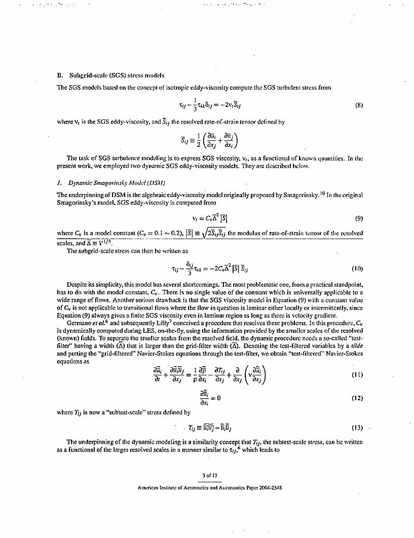
B. Subgrid-scale (SGS) stress models
The SGS models based on the concept of isotropic eddy-viscosity compute the SGS turbulent stress from
Tjj -3Tkk 5iJ = -2VS3j (8)
where v, is the SGS eddy-viscosity, and S3j the resolved rate-of-strain tensor defined by
- I / aTh a~\ii 2 xj DxiJ
The task of SGS turbulence modeling is to express SGS viscosity, v,, as a functional of known quantities. In thepresent work, we employed two dynamic SGS eddy-viscosity models. They are described below.
1. Dynamic Smagorinsky AModel (DSAM)
The underpinning of DSM is the algebraic eddy-viscosity model originally proposed by Smagorinsky.' 0 In the originalSmagorinsky's model, SGS eddy-viscosity is computed from
v, = c jsj 1sl (9)
where Cv is a model constant (Cv 0.1 0.2), SI _ / the modulus of rate-of-strain tensor of the resolved
scales, and a VI/ 3.The subgrid-scale stress can then be written as
Tij - .tA =-2cvA IsI si (10)
Despite its simplicity, this model has several shortcomings. The most problematic one, from a practical standpoint,has to do with the model constant, Cv. There is no single value of the constant which is universally applicable to awide range of flows. Another serious drawback is that the SGS viscosity model in Equation (9) with a constant \,'lueof Cv is not applicable to transitional flows where the flow in question is laminar either locally or intermittently, sinceEquation (9) always gives a finite SGS viscosity even in laminar region as long as there is velocity gradient.
Germano et aL6 and subsequently Lilly7 conceived a procedure that resolves these problems. In this procedure, Cvis dynamically computed during LES, on-the-fly, using the information provided by the smaller scales of the resolved(known) fields. To separate the smaller scales from the resolved field, the dynamic procedure needs a so-called "test-filter" having a width (A) that is larger than the grid-filter width (A). Denoting the test-filtered variables by a tildeand putting the "grid-filtered" Navier-Stokes equations through the test-filter, we obtain "test-filtered" Navier-Stokesequations as
G-i + - -- -+- I v-I (11)at axi TX, aXJ aXj A )
- =0 (12)ax,
where Tj is now a "subtest-scale" stress defined by
Tij =1iftiJ-Thlij (13)
The underpinning of the dynamic modeling is a similarity concept that Tij, the subtest-scale stress, can be writtenas a functional of the larger resolved scales in a manner similar to Tij,6 which leads to
3 of 17
American Institute Of Aeronauhics and Astronautics Paper 2004-2548

T j =- "jT =-2 S Sij (14)T2v T
where Q is the test-filter width. Note that the same model coefficient, C., is used in the expressions for both tij and Tij.Equation (14) alone is not helpful at all in determining Cv, because Tij is not known in LI-S. The breakthrough
came from the realization that 'Tij and Tjj are related to each other by6
= Uij-U in(tj- j-I-izxj
= uizj-iij_ (15)
The stress, Lij, which might be called subtest-scale Leonard stress, can be interpreted as the stress associated withthe smaller resolved scales between the test-filter scale (a) and the grid-filter scale (a). Since Lij can be directlycomputed from the resolved scales in LES, the identity given by Equation (15) can be used to detenninc C.,.. Thus, wehave
Ljj- -} Lkk = ajCv - OiJCv (16)
where
aj= -2A2 S Sj (17)
-2-2 1SISij (18)
One predicament that makes it difficult to determine Cv from Equation (16) is the fact that C, in the second termon the right-hand side of the equation is under the test-filtering operator. As it stands, Equation (16) is an integralequation for Cv as discussed at length by Ghosal et al.1 1 This difficulty can be avoided by taking out Cv from the
Lij- 8jLkk = Cv (aijr-ij) (19)
We followed this rather ad hoc approach in this work despite its mathematical inconsistency, which amounts to as-suming that Cv remains constant in the computational cells associated with the test-filter.
Since there are more equations in Equation (19) than the unknowns, the model constant Cv is obtained by seekingfor Cv which minimizes the error norm defined by
E== (Lij-8j_ Lkk-CVMij) (20)
whereA1j =aij - -i =-2 (a2S _- 2 I [)
Taking aE/aCv and setting it zero, we obtain
- i= UM (21)
Cv determined in this way varies with time and space. In fact, it varies in a wide range, often taking either largenegative or positive value. Although negative Cv and consequently negative eddy-viscosity is often interpreted asrepresenting "back-scatter" (flow of energy from smaller to larger scales), too large a negative eddy-viscosity causesnumerical instability, ultimately leading to divergence of numerical solutions. The usual remedy for this numericaldifficulty is to average Cv in statistically homogeneous directions. Obviously, this workaround can be exploited onlywhen there are such homogeneous directions, which is a rarity in practical applications. Even if there are any statisti-cally homogeneousdirections, the averagingbecomesextremelycumbersomewith unstnictured meshes. In the present
4 of 17
American Instilute of Aeronautics and Astronautics Paper 2004-2548

work, we simply "condition" the C, computed by Equation (21) by test-filtering it. This simple volume-weighted aver-aging better preserves the locality of the model constant. To ameliorate the potential numerical difficulty caused by Cvbeing negative for an extended period of time, we evaluated two alternative approaches. In one approach, we simplyclip Cv at 0 when it becomes negative. This option therefore rules out any chance for the model to mimic backscatter.In another, effective viscosity (v+v,) instead of Cv is clipped at zero, permitting small negative SGS viscosity tohappen. As yet we do not have any conclusive evidence that supports superiority of one approach to another in termsof prediction accuracy, except an indication that computations with teie first approach appear numerically more robust.For this reason, we used the first approach in the computations presented in this paper.
As mentioned earlier, the dynamic procedure described above requires a test-filter. The most important criterionthe test-filter should satisfy specifically for this work is that it should be applicable to unstructured meshes of arbitrarycell topology without incurring unduly high cost. The test-filter finally adopted is a top-hat filter that involves a volumecomprising the cell itself plus the neighboring cells that share the cell faces with the center cell. Thus, the test-filteroperation amounts to a volume-weighted averaging of the variable in question, which is easily implementable andtakcs advantage of the data structure of the underlying finite-volume solver. With hexahedral mcshcs, the ratio of thetest-filter to the gird-filter scale (A/A) is approximately 2.1 (= 91/3). The ratio for tetrahedra is smaller, being around1.7(= 51/ 3 ).
2. Localized Dynamic Kinetic Energy Model (LDKEAI)
The dynamic Smagorinsky's model described so far is essentially an algebraic model in which subgrid-scale stressesare modeled using the resolved velocity field. A more elaborate SGS stress model would be the one which is directlybased on SGS turbulence and can be used to parametrize SGS stresses. The most widely used ones among othersare what can be called "one-equation" models in which SGS turbulent kiinetic energy, kg, = ( ik2 - -i)/2, is explicitlycomputed by solving its transport equation.8' 9' 11,12
In the present work, a localized dynamic k,,,-equation model of Kim and Menon8 9 was chosen in favor of itsoverall efficacy.13 14
In the LDKEM, the subgrid-scale eddy viscosity, v,, is computed from
vI = Ck A (22)
Consequently, SGS stress is can be written as
2rj-3k,, = -2Cxk:,g, ASjj (23)
k.., is obtained by solving its transport equation"' 9
+1 _Tij = -_C~_ - + a ) +V ](24)a, aTx, axi T Xj a, axi
The only difference between the original formulation and the present one is that the contribution from the moleculardiffusion of keg, is included in this work-I
As shown above, there are three model parameters appearing in these equations, namely, Ck, Cc, and ckk, whichneed to be specified. In the current implementation of the LDKEM, the first two are determined from the dynamicprocedures to be described in the following, whereas Ok is simply set to a constant value of 1.0. The underpinning ofthe dynamic procedure employed in the LDKEM is the hypothesis corroborated by the experimental evidence 15' 6 thatthere is a strong correlation between the subgrid scale stress, rij, and the subtest-scale Leonard's stress, Loj. In placeof parameterizing Tj and utilizing the Germano's identity as was done in the DSM, the LDKEM models Lij directlyas
L;}- Lkk = -2CkAk-,, Sij (25)
5 of 17
American Institute of Aeronautics and Asironamilics RPa.r 2004-2548

where ke,, is the resolved turbulent kinetic energy associated with the scales between the test-filtcr (A) and the grid-filter (A). It can be directly computed from
kl.% I k = 14 214 (Z itt-ttl (26)
The model parameter, C*, can then be determined from Equation (25) by minimizing the error norn as in the DSM.Consequently wc have
CA _(27)
with Alij defined by
>1;j = -2Ak-,/Ssr Sij (28)
The model parameter, CE, of the dissipation term in Equation (24) is also determined by a dynamic procedure,whose underpinning is the hypothesis that the dissipation-rate of kle (e) can be expressed in the same functional formas the dissipation-rate of k
1-3/2e = Ci "" (29)
The dissipation-rate of klet can also be computed from
e=(V+Nv,) D~-aX 1 an) (30)(vv (axi acti axi ax-i)
From Equation (29) and Equation (30), C' is given in a closed form
A(V+vt) (ai,, ai a h'- (31)
keg axj axj axj a.rj
The DKEM has several desirable attributes that the DSM lacks. First, as a consequence of parameterizing Ljdirectly, the dynamic procedure in the LDKEM does not involve any test-filter operation on the model parameter, C*.Thus, unlike the DSM model, C'k is a genuine, local quantity free from any mathematical inconsistency. Secondly, Ckin the LDKEM behaves numerically more benignly than Cv in the DSM, having much less fluctuation. As a smallpremium, one can even save a small amount of computational effort with the LDKEM, inasmuch as the test-filtering onthe SGS stress done on in the DSM is not needed. Lastly and probably most important, the LDKEM enjoy~sthe benefitsof a high-order turbulence model. Adopting SGS turbulent kinetic energy to parametrize the SGS stress renders theLDKEM better suited to non-equilibrium flows. By accounting the ktg,-budget more rigorously, backscatter of kineticenergy is allowed in the LDKEM on a much sounder physical basis than in the DSM.
III. Boundary conditions
WVall boundaries are the most crucial and yet difficult ones to handle in LES. In LES resolving all the way downto viscous sublayer, no-slip would be clearly the choice for wall boundary condition for the resolved velocity field.However, the cost of such "wall-resolving" LES is prohibitively high for practical flows involving high-Re flows. Apractical alternative is to use the law-of-the-wall bridging the wall and the first grid point (cell center) off the wall. Thesimplest implementation of the wall-law can done using
U' +'y for y+ < ), (32)'= ln(Ey+) fory+>y+
where E = 9.793, K = 0.419, y+- =Uy/v, =+ _1u/i, yv+ is the "cross-over"at which the two wall laws intersect. Thisdemarcation of the entire inner layer into the two distinct layers is apparently a simplification which is at odds with the
6 of 17
American Institute of Aeronautics and Astronautics Paper 2004-2548

presence of a buffer region in reality between the viscous sublayer and the log-layer. However, this is much better thanexclusively relying on no-slip condition. One can mimic the presence of the buffer layer by blending the linear andthe logarithmic laws using an adequate blending function. The blending has some merits, inasmuch as, besides givinga smooth transition between the two layers (numerically more stable) and representing the mean velocity profile inthe buffer layer more accurately, the blending also allows the respective laws in the two regions to be independentlymodified or extended to take into account other effects such as pressure gradient, surface roughness, and transpiration.In the present work, we employed the blending function suggested by Kader.17
In the finite-volume discretization adopted in this work, the blended wall-law is employed to compute wall-shear,essentially diffusion flux at wall. To that end, the wall-law is applied to the parallel components of the resolved velocityat wall-adjacent cells to compute the friction-velocity (Far) in an iterative manner.
The LDKEM needs a wall boundary condition for k To that end, either a Dirichlet-type boundary condition(ksg, = 0) or a Neumann boundary condition (Dk-g,/1n = 0, in view of kgi )92) is conceivable. In the present work,we simply set the diffusion flux of k.,,a at walls to zero, which is essestially equivalent to the Neumann boundarycondition.
I\' Flow solver
The present work was carried out using FLUENT, a general-purposc CFD code. FLUENT employs a cell-centcrcdfinite-volume method based on a multi-dimensional linear reconstruction scheme, which permits use of computationalelements (cells) with arbitrary olyhedral ppology, including quadrilateral, hexahedral, triangular, tetrahedral, pyra-midal, prismatic, and hybrid meshes. There are several choices of the solver algorithms in FLUENT including coupledexplicit, coupled implicit, and segregated solvers. For the computations presented in this paper, we used the segregatedsolver exclusively.
Inthe segregated solver, the goverm-g e-quationsa-re solv-ed s-equ-enitally.-Sev-eraditerent solution--algoritihms areoffered including SIMPLE, SIMPLEC, PISO, and fractional-step method (FSM). The temporal discretization in thesegregated solver employs a fully-implicit, threc-level second-order scheme. Time-accurate solutions can be obtainedusing either iterative time-advancement (ITA) scheme or non-iterative time-advancement (NITA) scheme. The NITAscheme greatly saves CPU time, since the costly outer iterations arc not needed. Unless stated otherwise, wc used thefractional-step method in conjunction with the NITA scheme in this study.
Accurate spatial discretization is crucial in LES. The spatial discretization schemes employed in this work arebased on a multi-dimensional linear reconstruction scheme.18 -20 Diffusive fluxes are discretized using central differ-encing. Discretization of convective fluxes requires caution in LES. Upwind-biased schemes such as second-orderupwind, QUICK, and third-order MUSCL schemes have been most widely used for RANS computations. Unfortu-nately, numerical diffusion introduced by upwind schemes, which might be acceptable in RANS computations forhigh Reynolds-number flows, is detrimental to LES. This is because, in LES, numerical diffusion, however small itis, can easily overwhelm physical diffusion. This is the case even with high-order upwind schemes. For this reason,for LES, central-differencing schemes have been preferred for their meritoriously low - or zero in ideal conditions -numerical diffusion. Thus we added a second-order central differencing (CD) scheme for discrctization of convectiveterms specifically for LES.21 Unfortunately, any pure CD schemes are susceptible to producing unphysical oscillationsin the solution fields, which becomes especially pervasive in high Peclet-number situations - low diffusivity and coarsemesh which is almost a norm in LES for industrial applications. The usual remedy is to add a modicum of numericaldissipation, either explicitly or implicitly, to suppress the oscillations at the price of sacrificing spatial accuracy. Inour implementation of CD, however, no numerical dissipation was explicitly added. And, unless stated otherwise, theCD scheme was used in this work. To back up the CD scheme in case it fails, we also developed what may be calleda bounded central differencing (BCD) scheme that essentially detects in the solution fields any wiggles with a wavelength of 2Ax or less (% < 2Ax) and suppress them by switching to upwind schemes of varying orders depending on theseverity of the wiggles, while retaining the CD elsewhere. It should be emphasized that the BCD scheme significantlydiffers from the often-employed hybrid schemes blending central differencing and upwind schemes with a fixed ratio.The BCD scheme is reserved for industrial applications involving high-Reynolds number flows and less-than-ideal
7 of 17
American Institute of Aeronautics and Astronautics Paper 2004-2548

meshes.The discretized algebraic equations are solved using a point-wise Gauss-Seidel iterative algorithm. An algebraic
multi-grid (AMG) method is employed to accelerate solution convergence. The solver is fully parallelized, which iscrucial in LES for industrial applications.
V Validations
The LES capability described so far has been validated for a wide range of wall-hounded flows from simple. tocomplex ones. In this paper, we present the results of a fully-developed channel flow and two bluff-body flows. Thechannel flow case is a fundamentally important case whose subtlety offers an opportunity to critically evaluate variousaspects of SGS turbulence modeling such as the dynamic procedure used to determine the model constants.
The bluff-body flows include the one around a cylinder with square cross-section at a moderately high Reynoldsnumber and the one around a sphere at two Reynolds numbers. Deliberately chosen, both involve large-scale, co-herent structures around the bodies and in the wake, representing typical bluff-body flows encountered in industrialapplications.
A. Ftilly-developed channel flow at Ret = 180
A fully-developed channel flow was computed for the Reynolds number of Ret = 180 (ReH = 3,300) using the twodynamic models. The computational domain is a box of the size [2iTH x 2H x 7tH] in the axial, normal, and spanwiscdirections, respectively. The computational domain is bounded by two walls on the bottom and the top of the channel,two pairs of periodic boundaries in the axial and the spanwise directions. The computations w"re carried out usingtwo hexahedral grids; a coarse grid with 36 x 36 x 36 cells and a globally refined mesh with 72 x 72 x 72 cells. Theresolutions of the meshes are such that, with the coarser mesh, y+ value at the wall-adjacent cells is approximately0.6, and the cell size is dy+ = 27 near the channel centerplane. The channel walls are treated effectively as no-slipboundaries due to sufficiently low y+ values at the wall-neighboring cells. On the pair of periodic boundaries in theaxial direction, a pressure-drop across the pair derived using the given wall-shear (Xs, = pu2) was specified, with theflow-rate determined as a part of the solution. The time-step size of At+ = 0.3 was used, where At+ = At 112/v. TheCD scheme was used for the discretization of convection terms.
The mean axial velocity (U+) and the three r.m.s.velocity components (uf+, V+, iV+) predicted using the two dy-namic models are shown in Figure 1 on the following page along with the DNS results of Kim et al.22 The predictionswith the coarse mesh are seen to overpredict U+ by about 8 - 12% near the center of the channel. The peak in the W'+profile is also overpredicted with the coarse mesh, whereas the peaks in the profiles of Vi+ and sw1 are underpredicted.Our results with the coarse mesh show largely the same trends as found by others who employed grids of somewhatfiner resolutions (32 x 64 x 32 mesh,2 3 65 x 65 x 65 mesh'), yet closely matching their predictions despite the coarsermesh employed in this work. However, our predictions of the r.m.s. velocity components near the channel center isrelatively poor. We surmise that the much larger grid spacing near the channel center (Ay+ = 27) is responsible forthat.
The predictions improve greatly with the fine mesh. Both dynamic models reproduce the DNS results remarkablywell. The mean axial velocity and the r.m.s. fluctuating velocity components are accurately predicted throughoutthe entire range of y+. Particularly noteworthy is the excellent agreement with the DNS data in terms of the peaksvalues and their locations of the r.m.s.fluctuating velocity components. Overall, the results obtained with the fine meshcompare favorably with other results mentioned earlier." 23 For instance, our predictions are substantially closer to theDNS data than the results of Haworth and Jansent who computed the same channel flow using LES on a 65 x 65 x 65node mesh using the Lagrangian dynamic Smagorinsky's model.* The present results are promising, inasmuch as they demonstrate that the second-order CD scheme in conjunctionwith the dynamic models is able to accurately predict this fundamentally important wall-bounded flow carrying anintricate near-wall physics. Regarding the impact of SGS modeling, we did not find any significant difference betweenthe results from the two dynamic models. This should not come as a big surprise, however, since the fully-developedchannel flow is near equilibrium in the mean.
.8 of 17
American Institute of Aeronautics and Astronautics Paper 2004-2548

(a) Mean velocitv (Ut I nredictions (b) r.m.s. vclocitv (u" ' nredictions
t > 5//. +0.6 .v
0.4 Ft / - Prese, DSNI (36x36x36 meh) _ Presnt. DSM (36x3/ ---- Present. DSM (72x72x72 mesh) 0.4 --.- Present. DSM (72x7
Present, LDKEM (36x36x36 mesh) ------ Present, LDKEM (3.02 _ Present LDKEM (72x72x2 mesh) 3 Prcsent LDKEM (7
. ! DNS (Kim et al., 1987) 0.2 o DNS (Kin et al .,..... 192
0 50 100 150 200 0 1 00
Y y
(c) r.m.s. velocity (VI+) predictions (d) r.m.s. velocity (m" ) prr
Figure 1. The results of LES using two dynamic SGS turbulence models for Ret = 180
9 of 17
edictions
American Institute of Aeronautics and Astronautics Paper 2004-2548

13. Flow around a square cylinder
The flow past a square cylinder measured by Lyn et al.2 4 was considered. The Reynolds number based on the
freestream velocity (Uo) and the width of the cylinder (H) is 22,000. The subject flow is featured by a massive flowseparation accompanied by unsteady large-scale structures of widely varying length scales. As such, it aptly representsturbulent flows around bluff bodies with sharp edges. Some others have also tackled this flow using LES.13 25
The domain size and the mesh resolution were chosen in reference to the earlier studies by others. 1'325 A morecomprehensive study using different mesh resolutions -andUoma-nsizes (san-wis m p-artic-ular) is deTerre-dfr-a-futurestudy. Our objective here is to evaluate the efficacy of the present LES capability by comparing the predictions withother results based on meshes with comparable resolution. The computational domain is bounded by an upstreaminlet boundary, top and bottom boundaries located 7.0 H from the center of the cylinder, and an exit boundary at 20 H.from the cylinder axis. Freestream conditions were specified at the inlet. The top and the bottom boundaries weretreated as symmetry planes (frictionless walls). The exit boundary was modeled as a pressure boundary where thesolution variables are extrapolated in a mass-conserving manner. A pair of periodic boundaries separated with a spanof 3.0H were used in the spanwise direction. The computational domain is filled with a hexahedral mesh with 660,000elements. NVe took advantage of our unstructured mesh capability, embedding a block of locally refined mesh aroundthe cylinder to better resolve the near-wall and wake regions as depicted inJgure 2 on the next page. The averagedwall-distance at the wall-adjacent cells is 0.012 11. The time-step size (At) used for the present computations is 0.02time unit (H/Uo) which is comparable to that used by others.' 3 The CD scheme was used for the discretization ofconvective terms. The statistics were obtained during the LES for a sufficiently long period of time, typically for morethan several scores of thne units.
Figure 2 on the following page shows the profiles of the mean axial velocity (U/Uo) and the r.m.s.velocity fluctua-tions (' and Vl) along the centerplane (y = 0) in the wake predicted using the two dynamic models. The time-averagedaxial velocity distributions show that the length of the recirculation bubble behind the cylinder is predicted by the twodynamic models to be around L, = 0.9 which agrees remarkably well with the experimental value (L, ; 0.9). Thenegative peak and the recovery of the mean velocity in the near-wake are also captured very closely. However, thepredictions start to deviate from the measurement forx/H > 2.0, reaching 0.8 Uo asymptotically in the far-wake. Asshown in the figure, this value is considerably larger than what the measurement indicates (0.62Uo).24 Interestingly,others who computed the same flowt3' 25 also have grossly overpredicted the recovery of the axial mean velocity. OurLES predictions of the mean axial velocity in the far-wake with both dynamic models were found to be largely com-parable to the prediction by Sohankar et al.13 based on their dynamic one-equation model denoted by "OEDSMA"in their paper. However, the present LES predictions reproduce the mean velocity profile in the recirculation bubblemore accurately than others. Particularly noteworthy is that our DSM yields somehow a much better prediction thanthe DSM model used by Sohankar et al. in terms of the recirculation bubble size and the asymptotic value of theaxial mean velocity in the far-wakc, which begs a question of what could possibly contribute to this sizable difference.One possible cause is the effectively finer mesh used in the present computations which was made possible by theembedded region of fine mesh around the cylinder. It is also quite likely that the differences in the details of the DSMimplementation is responsible. In this regard, it should be noted that Sohankar el aL average Cv in the spanwise(homogeneous) direction, whereas the DSM used here does not.
The r.m.s.fluctuating velocity components are also predicted with a reasonable accuracy by the present LES. Thepeak values are appreciably underpredicted. However, the locations of the peaks are closely captured. Another obser-vation worthy of mentioning is that V is relatively poorly predicted by both dynamic models.
Table I on page 12 summarizes other global parameters predicted by the present computations, along with theresults predicted by others.13 '25 Our LES predictions of the mean drag coefficient, Strouhal number, and r.m.s.liftcoefficient well match the measurements and the predictions by others.
lo of 17
American Institute of Aeronautics and Astronautics Raper 2004-2548

1.0
0.4
0.2 - LES with DSNI (present)----- LES with LDKEMI (present)
0.0 = = et o tal. (I 995)
HILM
_O 2_0 _ 40 6.0 8.0 10.0
X1l1
(a) Mesh with an embedded fine nmesh (b) Axial mean velocity
00.3 - 000 0.6-
0.2-04-LES with DSMI (present)
LES with LDKEM (present) - LES with DSM (present)0.1 o Lyn et al. (1995) 0.2 t------ LES with LDKEM (present) -
Ia Lyn et al. (1995)
_ ___- I I I I5. 0 10.0 ]!J.0 2.0 4.0 6.0 8.0 10.0
(c) rm.s. axial fluctuating velocity (d) rm.s. vertical fluctuating velocity
Figure 2. Mesh used for the flow around a square cylinder and the rnean axial velocity and normal stress distributions along the wakecenterline
Il of 17
American Institute of Aeronautics and Astronautics Paper 2004-2548

Table 1. Summary of the LES predictions of the global quantities for the square-cylinder case (Reif = 22,000)
Methods L, St CD CIL
DSM (present) 0.9 0.133 2.19 1.19DSM (Sohankaretal.13 ) ~0.6 0.126 2.03 1.23DSM (Furcby et aL25) 0.83 0.132 2.0 1.34LDKEM (present) 0.9 0.131 2.14 1.17OEDSM (Sohankaretal.'3 ) :0.6 0.132 2.32 1.54LDKEM (Fureby etal.25 ) 0.74 0.130 2.10 1.32Measured (Lyn et aL.24) 0.9 0.13 : 2.1 1.2
C. Flow around a sphere
1. Direct simulationfor RCD = 300
Before tackling the turbulent flow cases, laminar flow at ReD = 300 was computed on a hybrid unstructured mesh usingdirect numerical simulation. At this Reynolds number, the flow exhibits a weak unsteadiness leading to oscillations indrag and lift forces. The hybrid mesh has a total of 860,000 cells, consisting of prismatic cells in the near-wall regiongrown from the surface triangles on the body surface and tetrahedral cells filling the rest of the solution domain. Thetime-step size of 0.04 D/U was used. Several others have computed this flow to validate their numerics.26-2 8
Table 2. Summary or thc prediction for the laminar flow over a sphere(kCD.!QQ09)
Methods St CD
Present 0.133 0.667iTomboulides e: al7- 0.136 0.67 1Johnson andd'; Iitc_26 .0137__._ __ 0.6561Measured 2 9 0.15 - 0.16 0.629:
The results are summarized in Table 2 along with others' predictions. 2 62 8 Tomboulides et aL27 and Johnson andPatel2 6 used, respectively, a high-order spectral element method and a second-order upwind finite difference schemeon high-quality structured meshes. As shown, our predictions agree well with others' results, which is remarkableconsidering that a hybrid unstructured mesh was used in this work in conjunction with the second-order discretizationscheme.
2.Tu rbulent flows
We considered two Reynolds numbers (ReD = 1 .0 X 104, 1.14 x 10⁶), one being in sub-critical and the other in super-critical regime. The subcritical flow case has been numerically studied by several others,2 8' 30 while the supercriticalcase was studied experimentally by Achenbach. 31
In this work, a hybrid unstructured mesh was deliberately used for both Re cases. The hybrid mesh has in total2.46 million cells, consisting of 0.6 million prismatic cells in the near-wall region and tetrahedral cells filling the restof the solution domain, with a large fraction of the total cell counts clustered in the near-wake region (see Figure 3).The mesh quality is not exceptionally high and yet quite reasonable, except the rapid expansion of cell size around the
12 of 17
American Inslilute of Aeronautics and Astronatimics Paper 2004-2548

(a) Hybrid mesh consisting of prismatic and tetrahedral elements (b) Enlarged view of the near-wall mesh
Figure 3. Hybrid unstructured mesh used for the flow around a sphere
cell-clustered region. The average distance from the wall at the wall-adjacent cells is around 1.1 x 10⁻³ D. For thelower-Re case, the near-wall mesh is sufficiently fine to resolve the boundary layer, with they+ values at the wall cellsbelow y+ = 1.0 for most part of the wall. For the higher-Re case, however, the near-wall mesh is far from being fineenough to accurately resolve the boundary layer which is much thinner than the lower-Re case, and the y+ values atthe wall cells increase by almost two orders of magnitude. Thus, the wall adjacent cells are most likely to penetrate thefully turbulent region (log-layer) on a significant portion of the wall, especially near 0 = 90° where the skin-frictionreaches a maximum. The mesh being not ideal, the higher-Re case offers a good opportunity to assess the wall-functionbased approach adopted in this work. Partial views of the mesh are shown in Figure 3.
Attempts to use the pure CD scheme have not been successful for this case. Numerical oscillations were observedsporadically in a few spots rather remote from the body where the cell size increases rapidly, being accompanied byabnormally large velocity magnitude. Although the oscillations were not catastrophic and affected the global quantitiesvery little, the subsequent computations were carried out using the BCD scheme discussed earlier. A time-step sizeof 0.02D/U was used for both Reynolds numbers. The data were collected for more than hundreds of time units.Figure 4 shows the time-histories of CD for the lower-Re case recorded during the LES using the two dynamic models.
Table 3. Summary of the LES prediction for turbulent flow past a sphere (ReD = 10,000)
Methods CD StLES with DSM (present) 0.438 0.182 86- 87 86 - 88LES with LDKEM.(present) 0.433 0.185 86- 87 86 - 88DES (Pelacz et aL)30 0.430 - _ _
DES (Constantinescu et aL)28 0.397 0.200 84 - 87 93 - 108
LES (Constantinescu e aL.)28 0.393 0.195 84 - 86 86 - 88Measured 31' 32 A:0.40 0.185 - 0.19
Correlation33 0.46 -
13 of 17
American Institute of Aeronautics and Astronautics Paper 2004-2548

The global quantities predicted for the lower Re case are summarized in Table 3 on the page before along withothers' results. The predicted CD values (0.438 and 0.433 for the DSM and LDKEM, respectively) are in fair agreementwith the ofteen-quoted experimental value of 0.4 measured in 1920's34 and other predictions. Constantinescu et al28
predicted CD, at around 0.4 using LES and detached eddy simulation (DES) on a structured hexahedral mesh having450,000 nodes. Our predictions are closer to the value obtained by Pelaez et al.30 (C) ; 0.43) who carried out aDES on an unstructured mesh with 770,000 nodes. The Strouhal numbers predicted by tie two dynamic models cameout very close to each other, matching the measured one quite closely in view of the scatter in the experimental data.The data of Achenbach 3t and Kim and Durbin35 favor lower Strouhal number around St = 0. 15, whereas Sakamoto'sdata 32 suggests a higher value between 0.18 and 0.19. The locations of flow separation (0,) predicted by the twodynamic models are nearly identical and were found in 860 870. The locations of laminar-lo-turbulent transition(¢,), which were obtained in this work by reading off the angle beyond which v, or /g, increases rapidly, were foundin 860 88° for both dynamic models, which compare well with the LES predictions by Constantinescu e al28
0.s5 I I
0.50
II
103
t 1t51Hilil1 1 1Experimental .102o LES with DSMIo24 1!1|| ||a LESwithLDKEM i .
l~~~~~~~ :U~...... -.. 1 minar calc.i
10
10. 1 I X 1_1
1500 200 30 ' 400 500 600 t i' 1 ) .I UJD Reg)
(a) Time histories of CD) for Reg = 10.000 (b) Comparison of the predicted time-averagcd CD values (ReD =
300,10,000,1.14 x I06) and the experimental mean CD-curve fora range of Reynolds number
Figure 4. Time histories of drag coefficient (CD) and and the predicted Mean drag coeflicients for the sphere
With the higher-Re case, the flow in reality has already undergone the "drag crisis", and the flow structure haschanged drastically from those of subcritical regime. The change in the flow structure can be seen from Figure 5 andFigure 6. Depicted in these figures are the iso-contours of the second-invariant of the deformation tensor, (f5ijQij -
SijSj)/2. Both figures aptly portray the hairpin-like vortical structures in the wake observed in experiments. The wakefor the higher-Re case (Figure 6) is much narrower than in Figure 5, which is the consequence of the delayed onsetof flow separation. The CD values predicted by the DSM and the LDKEM are 0.139 and 0.142, respectively. Thesevalues are fairly close to the range of values (CD = 0.12 0.14) measured by Achcnbach. 3 1
For the higher-Re case, the predictions of the locations of the separation and the onset of transition were much lesssatisfactory. At Re = 1.14 x 10⁶, the experimental results3t show that the transition occurs near 970 98° well beforethe separation occurring near 120°. The present predictions failed to reproduce this experimental finding. The presentresults exhibit too early a separation at around 1000 and a delayed transition. This discrepancy is most likely due tothe use of too coarse a mesh in this work to resolve the very thin boundary layer for the high-Re case.
The drag coefficients predicted in this study for the three Reynolds numbers are plotted in Figure 4 along with themean experimental curve.
14 of 17
American Institute of Aeronautics and Astronautics Paper 2004-2548

Figure 5. Vortical structure in the near-wake of the sphere for ReD = 10,000 - visualized using the iso-contour or the second-invariant orthe velocily, deormation tensor
Figure 6. Vortical structure In the near-wake of the sphere forReD = 1.14 x 10⁶ - visualized using the Iso-contour of the second-invariantof the velocity deformation lensor
15 of 17
American Institute of Aeronautics and Astronautics Riaper 2004-2548

VI. Summary and Conclusion
A large eddy simulation capability based on a finite-volume solver has been developed and validated for a num-ber of wall-bounded flows. The finite-volume solver employs second-order numerics and permits use of unstructuredmeshes, thus being able to easily handle industrial applications involving complex geometry. Turbulence closure forsubgrid-sale stresses is effected using two dynamic subgrid-scale viscosity models, namely, the dynamic Smagorin-sky model (DSM) and the localized dynamic k-equation model (LDKEM). These two dynamic models allow one tocompute arbitrary three-dimensional flows without any statistically homogeneous directions. The validations demon-strated that the present LES capability is capable of predicting the wall-bounded flows of varying complexity witha commendable accuracy, having a potential to provide a practical tool for high-level simulation of turbulent flowsencountered in industrial applications.
VII. Acknowledgments
The author gratefully acknowledges use of Fluent Inc.'s software and thanks the members Of the developmentgroup at Fluent Inc. Special thanks go to Sunil Vijay Unaune at the Fluent India who contributed the mesh used forthe computation of the flow past a sphere.
References
t Haworth, D. C. and Jansen, K.. "Large-Eddy Simulation on Unstructured Deforming Meshes: Towards reciprocating IC Engines," ComputersFluids. Vol. 29,2000. pp. 493-524.
2 K. Mahesh, G. Constantinescu, P. M., "Large Eddy Simulation of Gas Turbine Conibustors:' Annual Reserach Briefs, Center for TurbulenceResearch, NASA Ames/Stanford University, 2000, pp. 219-229.
3 Urbin, G. and Knight, D.. "Large Eddy Simulation of a Supersonic Boundary Layer Using an Unstructured Grid' AIAA Journal, Vol. 39,No. 7, July 2001, pp. 927-935.
4K. Jansen, T. M. and Reba, R., "Finite-Elemnent Based Largc-Eddy Simulation of the Near-Nozzle Region of a Compressible Round Jet:'Aiaa paper 2002-2358, 2002.
5S. Benhamadouche, K. M. and Constantinescu, G., "Colocated Finite-Volume Schemes for Large Eddy Simulation on Unstructured Grids:'Proceedings of the Summer Program, Center for Turbulence Research, NASA Aames/Stanford University, 2002, pp. 143-154.
6M. Germano, U. Piomelli, P. M. and Cabot, W. II., "Dynamic Subgrid Scale Eddy Viscosity Model:' Physics of Fluids A. Vol. 3, 1991,pp. 1760-1765.
7 Lilly. D. K., "A Proposed Modification of the Germano Subgrid Scale Closure Method:' Physics of Fluids A, Vol. 4, No. 3,1992, pp. 633-635.
SKim, W.-W. and Menon, S., "A New Dynamic One-Equation Sub-Grid Scale Model for Large Eddy Simulations:' Aima paper 95-0356.1995.
9Kim, W.-W. and Menon, S., "Application of the Localized Dynamic Subgrid.Scale Model to Turbulent Wall-Bounded Flows," Aiaa paper97-0210, 1997.
1'Smagorinsky, J., 'General Circulation Experiments with the Primitive Equations, part I The Basic Experiment," Mlonthly Weatlher Review,Vol. 91, 1963, pp. 99-165.
1 IS. Ghosal, T. Lund, P. M. and Akselvoll, K., "A Dynamic Localization Model for Large Eddy Simulation of Turbulent Flows:' Journal ofFluid Mechanics, Vol. 286, 1995, pp. 229-255.
12Davidson, L., "Large Eddy Simulation: A Dynamic One-Equatio Subgrid Model for Three Dimensional Recirculating Flow:' Proceedingsof the 11th International Symposium Turbulent Shear Flows, ol. 3,1997, pp. 26.1-26.6.
13A. Sohankar, L. D. and Norberg, C., 'Large Eddy Simulation of Flow Past a Square Cylinder Comparison of Different Subgrid ScaleModels:' Journal of Fluids Engineering, Vol. 122, No. 1 .2000, pp. 376-404.
14Krajnovic, S. and Davidson, L., "Large Eddy Simulation or the Flow Around a Bluff Body:' AIAA Journal, Vol. 40, No. 5, May 2002,pp. 927-935.
15S. Liu, C. M. and Katz, J., "On the Properties of Similarity SUbgrod-Scale Models as Deduced from Measurements in a Turbulent Jet,'Journal of Fluid Mfechanics, Vol. 275, 1994, pp. 83-119.
16S. Liu, C M. and Katz, J., Experimental Study of Similarity Subgrid-Scale Models of Turbulence in the Far-Field of a Jet, Direct and LargeEddy Simnulation, Kluwer, 1994.
t7Kader, B. A., 'Temperature and Concentration Profiles in Fully Turbulent Boundary Layers:' Int. J. Heat fass Transfer, Vol. 24, No. 9,1981,pp. 1541-1544.
't Mathur, S. R. and Murthy.J. Y., "A Pressure-Based Method for Unstructured Meshes:' NumericalHeat Transfer,Vol. 31,1997. pp. 195-215.
16 of 17
American Institute of Aeronautics and Astronautics Pliper 2004-2548

"9S.-E. Kim, S. R. Mathur. J. Y. M. and Choudhury, D., "A Reynolds-Averaged Navier-Stokes Solver Using Unstructured Mesh-Based Finite-Volume Scheme.' Aiaa paper 98-0231. 1998.
2tS.-E. Kim, B. MI. and Caraeni, D., "A Multidimiensional L.inear Reconstnrction Scheme for Arbitrary Unstructured Grids:' Aiaa paper2003-3990, Jan. 2003.
21L. Davidson, D. Cokijat, J. F. M. A. L. C. KI. W. R.. "LESFOIL: Large Eddy Simulation of Flow Around a High Lift Airfoil:' Afores onNumerical Fluid lechanics and Alutidisciplinary Design - I'vlunie 83, Springer, 2002.
22J. Kim, P. M. and NMoser, R.,"Turbulent Statistics in Fully Developed Channel Flow at Low Reynolds Number," Journal of Fluid lMechanics,Vol. 177,1987, pp. 133-166.
23D.Ch!opiD._Prasad, M. W. and Pierce, C., "Evaluation of an Industrial CFD code for LES ApplicationsProceed/ingsof rhie 2000 SuinijerProgram. Center for Turbulence Research, NASA AamneslStanford University, 2000, pp. 221-228.
24D. A. Lyn, S. Einav, W. R. and Park, J. H., "A Laser Doppler Velocitimetry Study of Ensemble Averaged Characteristics of the TurbulentNear-Wake of a Square Cylinder," Journal of Fluid Alechanics, Vol. 304, 1995, pp. 285-319.
25C. Fureby, G. Tabor. G1. G. W. and Gosman. A. D.. "Large Eddy Simulation of the Flow Around a Square Prism' AMAA Journal. Vol. 38.No. 3, May 2000, pp. 442-452.
26johnson, T. A. and Patel, V. C., "Flow Past a Sphere up to a Reynolds Number of 300:' Journal of Fluid Mechanics, Vol. 378, 1999,pp. 19-70.
27A. G. Tomboulides, S. A. Orszag. G. A. K., "Direct and Large-Eddy Simulations of Axisymmetric Wakes:' Aiaa paper 93-0546, Jan. 1993.28G. Constantinescu, NM. C. and Squires, K., "Turbulence Modeling Applied to Flow over a Sphere' AIAA Journal, Vol. 41, No. 9, 2003,
pp. 1733-1742."Roos, F. W. and Williams, W. W., "Some Experimental Results on Sphere and Disk Drag.: AIAA Journal, Vol. 9, No.2, 1971. pp. 285-291.30J. Pelaez, D. J. M. and Kandil, O., "Unsteady Analysis of Separated Aerodynamic Flows Using an Unstructured Multigrid Algorithm:' Aiaa
paper200108gThr203tAchenbach E., "Experiments on the Flow past Spheres at Very Iligh Reynolds Numbers:'Journal of Fluid Aechanics, Vol. 54, No.3. 1972,
pp. 565-575.32Sakamoto, H. and lianiu, 11., "A Study on Vortex Shedding from Spheres in an Unifonm Flow:' Journal of Fluids Fngineering. Vol. 112,
1990. pp. 386-393.33White, F. M., Viscous Fluid Flow, McGraw-Hill, 1974.34Schlichting, H., Boundary-Layer Theory, NMcGraw-llill, 1979.35Kim, K. J. and Durbin, P. A., "Observation of the Frequencies in a Sphere Wake and Drag Increase by Acoustic Excitation:' Physics of
Fluids, Vol. 31, No. 11, 1988, pp. 3260-3265.
17 of 17
American Institute of Aeronautics and Astronautics Paper 2004-2548

BVY 05-072Docket No. 50-271
Exhibit SRXB-A-1 8-1
Vermont Yankee Nuclear Power Station
Proposed Technical Specification Change No. 263 - Supplement No. 30
Extended Power Uprate
Response to Request for Additional Information
"RS-001, BWR Template SE"
| Total number of pages In this ExhibitI (excludina this cover sheet) Is 8. I

(2) draft GDC-9, insofar as it requires that the reactor coolant pressureboundary shall be designed and constructed so as to have anexceedingly low probability of gross rupture or significant leakagethroughout its design lifetime;
2.8.5 Accident and Transient Analyses
2.8.5.1 Decrease In Feedwater Temperature, Increase in Feedwater Flow, Increase InSteam Flow, and Inadvertent Opening of a Main Steam Relief or Safety Valve
Reaulatorv Evaluation
Excessive heat removal causes a decrease In moderator temperature which Increases corereactivity and can lead to a power level Increase and a decrease In shutdown margin. Anyunplanned power level Increase may result In fuel damage or excessive reactor systempressure. Reactor protection and safety systems are actuated to mitigate the transient. TheNRC staff's review covered (1) postulated Initial core and reactor conditions, (2) methods ofthermal and hydraulic analyses, (3) the sequence of events, (4) assumed reactions of reactorsystem components, (5) functional and operational characteristics of the reactor protectionsystem, (6) operator actions, and (7) the results of the transient analyses. The NRC'sacceptance criteria are based on (1) draft GDC-6, insofar as It requires that the reactor core be\desi nezto function throughout its design lifetime without exceeding acceptable fuel damageimits,(Ydraft GDC-14 and 15, Insofar as they require that the core protection system be
designed to act automatically to prevent or suppress conditions that could result In exceedingacceptable fuel damage limits and that protection systems be pr*,ided for sensing accidentsituations and Initiating the operation of necessary ESFs; and (X) draft GDC-27 and 28, Insofaras they require that at least two reactivity control systems be provided and be capable of makingand holding the core subcritical from any hot standby or hot operating condition sufficiently fastto prevent exceeding acceptable fuel damage limits. Specific review criteria are contained InSRP Section 15.1.1-4 and other guidance provided In Matrix 8 of RS-001.
Technical Evaluation
[insert technical evaluation. The technical evaluation should (1) clearly explain why theproposed changes satisfy each of the requirements In the regulatory evaluation and(2) provide a clear link to the conclusions reached by the NRC staff, as documented In theconclusion section.]
Conclusion
The NRC staff has reviewed the licensee's analyses of the excess heat removal eventsdescribed above and concludes that the licensee's analyses have adequately accounted foroperation of the plant at the proposed power level and were performed using acceptableanalytical models. The NRC staff further concludes that the licensee has demonstrated that thereactor protection and safety systems will continue to ensure that the s nd the RCPBpressure limits will not be exceeded as a result of these events. Based on tis, the NRC sta Hiconcludes that the plant will continue to meet the requirements of draft GDC6,A4, 5, 27, and28 following implementation of the proposed EPU. Therefore, the NRC staff finds the proposedEPU acceptable with respect to the events stated.
INSERT 8 FOR SECTION 32 . BWR TEMPLATE SAFETY EVALUATIONDECEMBER 2003

(2) draft GDC-9, insofar as it require$ that the reactor coolant pressureboundary shall be designed and constructed so as to have anexceedingly low probability of gross rupture or significant leakagethroughout its design lifetime;
2.8.5.2 Decrease In Heat Removal by the Secondary System
2.8.5.2.1 Loss of External Load; Turbine Trip; Loss of Condenser Vacuum; CMain Steam Isolation Valve; and Steam Pressure Regulator Failure
Reoulatory Evaluation
A number of initiating events may result in unplanned decreases In heat removsecondary system. These events result in a sudden reduction In steam flow arresult In pressurization events. Reactor protection and safety systems are acttthe transient. The NRC staffs review covered the sequence of events, the anmused for analyses, the values of parameters used in the analytical models, andtransient analyses. The NRC's acceptance criteria are based on (1) draft GDOrequires that the reactor core be desIgned to funojon throughout Its design lifel
,losure of(Closed)
val by theid, consequently,Wated to mitigatedlytical modelsthe results of the
:6, insofar as ittime without
exceeding acceptable fuel damage lirni, and (tYdraft GDC-27 and 28, Insofar as they requirethat at least two reactivity control systems be provided and be capable of making and holding thecore subcritical from any hot standby or hot operating condition sufficiently fast to preventexceeding acceptable fuel damage limits. Specific review criteria are contained in SRPSection 15.2.1-5 and other guidance provided in Matrix 8 of RS-001.
Technical Evaluation
[insert technical evaluation. The technical evaluation should (1) clearly explain why theproposed changes satisfy each of the requirements In the regulatory evaluation and(2) provide a clear link to the conclusions reached by the NRC staff, as documented in theconclusion section.]
Conclusion
The NRC staff has reviewed the licensee's analyses of the'decrease in heat removal eventsdescribed above and concludes that the licensee's analyses have adequately accounited foroperation of the plant at the proposed power level and were performed using acceptableanalytical models. The NRC staff further concludes that the licensee has demonstrated that thereactor protection and safety systems will continue to ensure that the(KAMb F9)and the RCPBpressure limits will not be exceeded as a result of these events. Based on -Ws, the NRC sta qconcludes that the plant will continue to meet the requirements of draft GDC-6, 27, and 28following Implementation of the proposed EPU. Therefore, the NRC staff finds the proposedEPU acceptable with respect to the events stated.
INSERT 8 FOR SECTION 3.2- BWR TEMPLATE SAFETY EVALUATIONDECEMBER 2003

(2) draft GDC-9, insofar as it requires that the reactor coolant pressureboundary shall be designed and constructed so as to have anexceedingly low probability of gross rupture or significant leakagethroughout its design lifetime;
2.8.5.2.2 Loss of Nonemergency AC Power to the Station Auxiliaries
Reaulatory Evaluation
The loss of nonemergency ac power is assumed to result in the loss of all power to the stationauxiliaries and the simultaneous tripping of all reactor coolant circulation pumps. This causes aflow coastdown as well as a decrease In heat removal by the secondary system, a turbine trip,an Increase In pressure and temperature of the coolant, and a reactor trip. Reactor protectionand safety systems are actuated to mitigate the transient. The NRC staffs review covered(1) the sequence of events, (2) the analytical model used for analyses, (3) the values ofparameters used In the analytical model, and (4) the results of the transient analyses. TheNR~C~'s acceptance criteria are based on (1) draft GDC-6, insofar as it requires that the reactorcore bedesined to function throughout its design lifetime without exceeding acceptable fuel
amage7limitsand (draft GDC-27 and 28, Insofar as they require that at least two reactivitycontrol systems be provided and be capable of making and holding the core subcritical from anyhot standby or hot operating condition sufficiently fast to prevent exceeding acceptable fueldamage limits. Specific review criteria are contained in SRP Section 15.2.6 and other guidanceprovided in Matrix 8 of RS-O001.
Technical Evaluation
[Insert technical evaluation. The technical evaluation should (1) clearly explain why theproposed changes satisfy each of the requirements in the regulatory evaluation and(2) provide a clear link to the conclusions reached by the NRC staff, as documented In theconclusion section.]
Conclusion
The NRC staff has reviewed the licensee's analyses of the loss of nonemergency ac power tostation auxiliaries event and concludes that the licensee's analyses have adequately accountedfor operation of the plant at the proposed power level and were performed using acceptableanalytical models. The NRC staff furtherconcludes that the licensee hs.Lemonstrated that thereactor protection and safety systems will continue to ensure that thelAFiand the RCPBpressure limits will not be exceeded as a result of this event. Based on this, the NRC staff 9concludes that the plant will continue to meet the requirements of draft GDC-6, , and 28following Implementation of the proposed EPU. Therefore, the NRC staff finds the proposedEPU acceptable with respect to the loss of nonemergency ac power to station auxiliaries event
INSERT 8 FOR SECTION 3.2 -BWR TEMPLATE SAFETY EVALUATIONDECEMBER 2003

(2) draft GDC-9, insofar as it requires that the reactor coolant pressureboundary shall be designed and constructed so as to have anexceedingly low probability of gross rupture or significant leakagethroughout its design lifetime;
2.8.5.2.3 Loss of Normal Feedwater Flow
Regulatory Evaluation
A loss of normal feedwater flow could occur from pump failures, valve malfunctions, or a LOOP.Loss of feedwater flow results In an increase In reactor coolant temperature and pressure whicheventually requires a reactor trip to prevent fuel damage. Decay heat must be transferred fromfuel following a loss of normal feedwater flow. Reactor protection and safety systems areactuated to provide this function and mitigate other aspects of the transient. The NRC staffsreview covered (1) the sequence of events, (2) the analytical model used for analyses, (3) thevalues of parameters used In the analytical model, and (4) the results of the transient analyses.The NRC's acceptance criteria are based on (1) draft GDC-6, Insofar as it requires that thereactoro signed tQ function throughout its design lifetime without exceeding acceptable
fuel damage limitsand (4Y'draft GDC-27 and 28, insofar as they require that at least tworeactivity control systems be provided and be capable of making and holding the core subcriticalfrom any hot standby or hot operating condition sufficiently fast to prevent exceeding acceptablefuel damage limits. Specific review criteria are contained In SRP Section 15.2.7 and otherguidance provided In Matrix 8 of RS-001.
Technical Evaluation
lnsert technical evaluation. The technical evaluation should (1) clearly explain why theproposed changes satisfy each of the requirements In the regulatory evaluation and(2) provide a clear link to the conclusions reached by the NRC staff, as documented In theconclusion section.]
Conclusion
The NRC staff has reviewed the licensee's analyses of the loss of normal feedwater flow eventand concludes that the licensee's analyses have adequately accounted for operation of the plantat the proposed power level and were performed using acceptable analytical models. The NRCstaff further concludes that the licensee has demonstrated that the reactor protection and safetysystems will continue to ensure that the(tDs and the RCPB pressure limits will not beexceeded as a result of the loss of norrneecwater flow. Based on this, the NRC staff 9concludes that the plant will continue to meet the requirements of draft GDC-6, 7, and 28following implementation of the proposed EPU. Therefore, the NRC staff finds the proposedEPU acceptable with respect to the loss of normal feedwater flow event.
INSERT B FOR SECTION 3.2 - BWR TEMPLATE SAFETY EVALUATIONDECEMBER2003

(2) draft GDC-9, insofar as it requires that the reactor coolant pressureboundary shall be designed and constructed so as to have anexceedingly low probability of gross rupture or significant leakagethroughout its design lifetime;
2.8.5.3 Decrease In Reactor Coolant System Flow
2.8.5.3.1 Loss of Forced Reactor Coolant Flow
Reaulatorv Evaluation
A decrease in reactor coolant flow occurring while the plant Is at power could result In adegradation of core heat transfer. An increase in fuel temperature and accompanying fueldamage could then result I are exceeded during the transient. Reactor protection andsafety systems are actuated to mitigate the transient. The NRC staff's review covered (1) thepostulated initial core and reactor conditions, (2) the methods of thermal and hydraulic analyses,(3) the sequence of events, (4) assumed reactions of reactor systems components, (5) thefunctional and operational characteristics of the reactor protection system, (6) operator actions,and (7) the results of the transient analyses. The NRC's acceptance criteria are based on (1)draft GDC-6, Insofar as it requires that the reactor core be designed to function throughout itsdesign lifetime without exceeding acceptable fuel damage limitswand (;)draft GDC-27 and 28,Insofar as they require that at least two reactivity control systems be provided and be capable ofmaking and holding the core subcritical from any hot standby or hot operating conditionsufficiently fast to prevent exceeding acceptable fuel damage limits. Specific review criteria arecontained In SRP Section 15.3.1-2 and other guidance provided In Matrix 8 of RS-001.
Technical Evaluation
[Insert technical evaluation. The technical evaluation should (1) clearly explain why theproposed changes satisfy each of the requirements In the regulatory evaluation and(2) provide a clear link to the conclusions reached by the NRC staff, as documented In theconclusion section.]
Conclusion
The NRC staff has reviewed the licensee's analyses of the decrease In reactor coolant flowevent and concludes that the licensee's analyses have adequately accounted for operation ofthe plant at the proposed power level and were performed using acceptable analytical models.The NRC staff further concludes that the licensee has demonstrated that the reactor protectionand safety systems will continue to ensure that the(~ and the RCPB pressure limits willnot be exceeded as a result of this event. Based on this, the NRC staff concludes that the plant qwill continue to meet the requirements of draft GDC-6V27, and 288tollowing implementation ofthe proposed EPU. Therefore, the NRC staff finds the proposed EPU acceptable with respect tothe decrease in reactor coolant flow event.
INSERT8 FOR SECTION 3.2 -BWRTEMPLATE SAFETY EVALUATIONDECEMBER 2003

- -
I (2) draft GDC-9, insofar as it requires that the reactor coolant pressureboundary shall be designed and constructed so as to have anexceedingly low probability of gross rupture or significant leakagethroughout its design lifetime;
2;8.5.5 Inadvertent Operation of ECCS or Malfunction that Increases Reactor CoolantInventory
Regulatory Evaluation
Equipment malfunctions, operator errors, and abnormal occurrences could cause unplannedIncreases In reactor coolant Inventory. Depending on the temperature of the Injected water andthe response of the automatic control systems, a power level increase may result and, withoutadequate controls, could lead to fuel damage or ovdrpressurization of the RCS. Alternatively, apower level decrease and depressurization may result. Reactor protection and safety systemsare actuated to mitigate these events. The NRC staffs review covered (1) the sequence ofevents, (a) the analytical model used for analyses, (3) the values of parameters used In theanalytical model, and (4) the results of the transient analyses. The NRC's acceptance criteriare based on (1) draft GDC-T,insofar as it re uire the reactor core be designed t function
throughout its design ietime without exce ding acceptable fuel damage limitsand (%NdraftGDC-27 and 28, Insofar as they require that at least two reactivity control systems be providedand be capable of making and holding the core subcritical from any hot standby or hot operatingcondition sufficiently fast to prevent exceeding acceptable fuel damage limits. Specific reviewcriteria are contained in SRP Section 15.5.1-2 and other guidance provided in Matrix 8 ofRS-001.
Technical Evaluation
[Insert technical evaluation. The technical evaluation should (1) clearly explain why theproposed changes satisfy each of the requirements in the regulatory evaluation and(2) provide a clear link to the conclusions reached by the NRC staff, as documented in theconclusion section.]
Conclusion
The NRC staff has reviewed the licensee's analyses of the Inadvertent operation of ECCS ormalfunction that Increases reactor coolant Inventory and concludes that the licensee's analyseshave adequately accounted for operation of the plant at the proposed power level and wereperformed using acceptable analytical models. The NRC staff further concludes that thelicensee s demonstrated that the reactor protection and safety systems will continue to ensurethat theAFD nd the RCP pressure limits will not be exceeded as a result of this event. +
Based on is, the NRC staff concludes that the plant will continue to meet the requirements ofdraft GDC re, the Rstaff finds the proposed EPU acceptable with respect to the Inadvertent operation of ECCS ormalfunction that increases reactor coolant inventory.
INSERT 8 FOR SECTION 3.2 - BWR TEMPLATE SAFETY EVALUATIONDECEMBER 2003

(2) draft GDC-9, insofar as It requires that the reactor coolant pressureboundary shall be designed and constructed so as to have anexceedingly low probability of gross rupture or significant leakagethroughout its design lifetime;
2.8.5.4.3 Startup of a Recirculation Loop at an Incorrect Temperature and Flow ControllerMalfunction Causing an Increase In Core Flow Rate
Regulatory Evaluation
A startup of an Inactive loop transient may result in either an Increased core flow or theintroduction of cooler water into the core. This event causes an Increase In core reactivity due todecreased moderator temperature and core void fraction. The NRC staffs review covered(1) the sequence of events, (2) the analytical model, (3) the values of parameters used In theanalytical model, and (4) the results of the transient analyses. The NRC's acceptance criteriaarbased on (1 draft GDC-6, insof a require that the reactor core be desigr ed to functionthroughout its design lifetime without exceeding accepa e el damage limits,(2draft GDC-14and 15, Insofar as they require that the core protection systems be designed to act automaticallyto prevent or suppress conditions that could result In exceeding acceptable fuel damage limitsand that protection systems be provided for sensing accident situations and Initiating theoperation of necessary ESFs; Updraft GPC-32, Insofar as It requires that limits, which Includeconsiderable margin, be placed on the maximum reactivity worth of control rods or elements andon rates at which reactivity can be Increased to ensure that the potential effects of a sudden orlarge change of reactivity cannot (a) rupture the reactor coolant pressure boundary or (b) disruptthe core, its support structures, or other vessel internals sufficiently to Impair the effectiveness ofemergency core cooling; and (Wfdraft GDC-27 and 28, Insofar as they require that at least tworeactivity control systems be provided and be capable of making and holding the core subcriticalfrom any hot standby or hot operating condition sufficiently fast to prevent exceeding acceptablefuel damage limits. Specific review criteria are contained In SRP Section 15.4.4-5 and otherguidance provided In Matrix 8 of RS-001.
Technical Evaluation
[Insert technical evaluation. The technical evaluation should (1) clearly explain why theproposed changes satisfy each of the requirements In the regulatory evaluation and(2) provide a clear link to the conclusions reached by the NRC staff, as documented In theconclusion section.]
Conclusion
The NRC staff has reviewed the Scensee's analyses of the increase in core flow event andconcludes that the licensee's analyses have adequately accounted for operation of the plant atthe proposed power level and were performed using acceptable analytical models. TheNRC staff further concludes that the licensee has demonstrated that the reactor protection andsafety systems will continue to ensure that Dand the RCPB pressure limits will not beexceeded as a result of this event. Based on this, he NRC staff concludes that the plant willcontinue to meet the requirements of draft GDC b,'14, 15, 27, 28, and 32 followingImplementation of the proposed EPU. Therefore, the NRC staff finds the proposed EPUacceptable with respect to the increase in core flow event.
INSERT 8 FOR SECTION 3.2 -BWR TEMPLATE SAFETY EVALUATIONDECEMBER 2003

(2) draft GDC-9, Insofar as it requires that the reactor coolant pressureboundary shall be designed and constructed so as to have an
-exceedingly low probability of gross rupture or significant leakagethroughout its design lifetime;
.8.5.6 Decrease In Reactor C6olant Inventory
2.8.5.6.1 Inadvertent Opening of a Pressure Relief Valve
Regulatorv Evaluation
The Inadvertent opening of a pressure relief valve results In a reactor coolant Inventory decreaseand a decrease in RCS pressure. The pressure relief valve discharges into the suppressionpool. Normally there Is no reactor trip. The pressure regulator senses the RCS pressuredecrease and partially closes the turbine control valves (TCVs) to stabilize the reactor at a lowerpressure. The reactor power settles out at nearly the Initial power level. The coolant Inventory ismaintained by the feedwater control system using water from the condensate storage tank viathe condenser hotwell. The NRC staffs review covered (1) the sequence of events, (2) theanalytical model used for analyses, (3) the values of parameters used In the analytical model,and (4) the results of the transient analyses. The NRC's acceptance criteria are based on (1)
ft GDC-6 Insof as uires tha r e be designed to function throughout Itsdesig eimeswithout exceeding acceptable fuel damageimitand (kpdraft GDC-27 and 28,insofar as they require that at least two reactivity control systems be provided and be capable ofmaking and holding the core subcritical from any hot standby or hot operating conditionsufficiently fast to prevent exceeding acceptable fuel damage limits. Specific review criteria arecontained in SRP Section 15.6.1 and other guidance provided In Matrix 8 of RS-001.
Technical Evaluation
I
[insert technical evaluation. The technical evaluation should (1) clearly explain why theproposed changes satisfy each of the requirements In the regulatory evaluation and(2) provide a clear link to the conclusions reached by the NRC staff, as documented In theconclusion section.]
Conclusion
The NRC staff has reviewed the licensee's analyses of the inadvertent opening of a pressurerelief valve event and concludes that the licensee's analyses have adequately accounted foroperation of the plant at the proposed power level and were performed using acceptableanalytical models. The NRC staff further concludes that the licensee has demonstrated that thereactor protection and safety systems will continue to ensure that the(A9FDLI-and the RCPBpressure limits will not be exceeded as a result of this event. Based on Ris-The NRC staffconcludes that the plant will continue to meet the requirements, of draft GD C6in u.following implementation of the proposed EPU. Therefore, the NRC staff finds the proposedEPU acceptable with respect to the inadvertent opening of a pressure relief valve event.
INSERT8 FORSECTION 3.2 BWRTEMPLATESAFETY EVALUATIONDECEMBER 2003

BVY 05-072Docket No. 50-271
Attachment 12
Vermont Yankee Nuclear Power Station
Proposed Technical Specification Change No. 263 - Supplement No. 30
Extended Power Uprate
Response to Request for Additional Information
GE Affidavits for Attachment 9
Total number of pages in Attachment 12(excluding this cover sheet) is 6.

General Electric Company
AFFIDAVIT
I, Robert E. Gamble, state as follows:
(1) I am Manager, ESBWR, General Electric Company ("GE") and have been delegated thefunction of reviewing the information described in paragraph (2) which is sought to bewithheld, and have been authorized to apply for its withholding.
(2) The information sought to be withheld is contained in Enclosure 2 to GE letter GE-VYNPS-AEP-395, Michael Dick (GE) to Craig Nichols (ENOI), Responses to NRC RAIs SPSB-51and SRXB-7, 8, 9, 10, 13, 14, 15, 16, 17, 19, 20, 21, 22, and 23, dated July 29, 2005. TheEnclosure 2 proprietary information, Responses to NRC RAIs SPSB-51 and SRXB-7, 8, 9,10, 13, 14, 15, 16, 17, 19, 20, 21, 22, and 23, is delineated by a double underline insidedouble square brackets. The header of each page in Attachment 2 carries the notation "GEProprietary Information. (3)." In each case, the superscript notationt refers to Paragrph(3) of this affidavit, which provides the basis for the proprietary determination.
(3) In making this application for withholding of proprietary information of which it is theowner, GE relies upon the exemption from disclosure set forth in the Freedom ofInformation Act ("FOIA"), 5 USC Sec. 552(b)(4), and the Trade Secrets Act, 18 USC Sec.1905, and NRC regulations 10 CFR 9.17(a)(4), and 2.390(a)(4) for "trade secrets"(Exemption 4). The material for which exemption from disclosure is here sought alsoqualify under the narrower definition of "trade secret", within the meanings assigned tothose terms for purposes of FOIA Exemption 4 in, respectively, Critical Mass EnergyProiect v. Nuclear Regulatory Commission. 975F2d87l (DC Cir. 1992), and Public CitizenHealth Research Group v. FDA, 704F2d1280 (DC Cir. 1983).
(4) Some examples of categories of information which fit into the definition of proprietaryinformation are:
a. Information that discloses a process, method, or apparatus, including supporting dataand analyses, where prevention of its use by General Electric's competitors withoutlicense from General Electric constitutes a competitive economic advantage over othercompanies;
b. Information which, if used by a competitor, would reduce his expenditure of resourcesor improve his competitive position in the design, manufacture, shipment, installation,assurance of quality, or licensing of a similar product;
c. Information which reveals aspects of past, present, or future General Electriccustomer-funded development plans and programs, resulting in potential products toGeneral Electric;
d. Information which discloses patentable subject matter for which it may be desirable toobtain patent protection.
GBS-04-12-AFAf GE-VY-AEP-395.docAffidavit Page I

The information sought to be withheld is considered to be proprietary for the reasons setforth in paragraphs (4)a., and (4)b, above.
(5) To address 10 CFR 2.390 (b) (4), the information sought to be withheld is being submittedto NRC in confidence. The information is of a sort customarily held in confidence by GE,and is in fact so held. The information sought to be withheld has, to the best of myknowledge and belief, consistently been held in confidence by GE, no public disclosure hasbeen made, and it is not available in public sources. All disclosures to third partiesincluding any required transmittals to NRC, have been made, or must be made, pursuant toregulatory provisions or proprietary agreements which provide for maintenance of theinformation in confidence. Its initial designation as proprietary information, and thesubsequent steps taken to prevent its unauthorized disclosure, are as set forth in paragraphs(6) and (7) following.
(6) Initial approval of proprietary treatment of a document is made by the manager of theoriginating component, the person most likely to be acquainted with the value andsensitivity of the information in relation to industry knowledge. Access to such documentswithin GE is limited on a "need to know" basis.
(7) The procedure for approval of external release of such a document typically requires reviewby the staff manager, project manager, principal scientist or other equivalent authority, bythe manager of the cognizant marketing function (or his delegate), and by the LegalOperation, for technical content, competitive effect, and determination of the accuracy ofthe proprietary designation. Disclosures outside GE are limited to regulatory bodies,customers, and potential customers, and their agents, suppliers, and licensees, and otherswith a legitimate need for the information, and then only in accordance with appropriateregulatory provisions or proprietary agreements.
(8) The information identified in paragraph (2), above, is classified as proprietary because itcontains detailed results and conclusions from evaluations of the safety-significant changesnecessary to demonstrate the regulatory acceptability for the constant pressure power upratefor a GE BWR, utilizing analytical models and methods, including computer codes, whichGE has developed, obtained NRC approval of, and applied to perform evaluations oftransient and accident events in the GE Boiling Water Reactor ("BWR"). The developmentand approval of these system, component, and thermal hydraulic models and computercodes was achieved at a significant cost to GE, on the order of several million dollar.
(9) Public disclosure of the information sought to be withheld is likely to cause substantialharm to GE's competitive position and foreclose or reduce the availability of profit-makingopportunities. The information is part of GE's comprehensive BWR safety and teclmologybase, and its commercial value extends beyond the original development cost. The value ofthe technology base goes beyond the extensive physical database and analyticalmethodology and includes development of the expertise to determine and apply theappropriate evaluation process. In addition, the technology base includes the value derivedfrom providing analyses done with NRC-approved methods.
The research, development, engineering, analytical and NRC review costs comprise asubstantial investment of time and money by GE.
GBS-04-12-AFAf GE-VY-AEP-395.docAffidavit Page 2

- -
The precise value of the expertise to devise an evaluation process and apply the correctanalytical methodology is difficult to quantify, but it clearly is substantial.
GE's competitive advantage will be lost if its competitors are able to use the results of theGE experience to normalize or verify their own process or if they are able to claim anequivalent understanding by demonstrating that they can arrive at the same or similarconclusions.
The value of this information to GE would be lost if the information were disclosed to thepublic. Making such information available to competitors without their having beenrequired to undertake a similar expenditure of resources would unfairly provide competitorswith a windfall, and deprive GE of the opportunity to exercise its competitive advantage toseek an adequate return on its large investment in developing these very valuable analyticaltools.
I declare under penalty of perjury that the foregoing affidavit and the matters stated therein aretrue and correct to the best of my knowledge, information, and belief.
Executed on this 9 day of Thl'. 2005.
Robert E. GamblcGeneral Electric Company
GBS-04-12-AFAf GE-VY-AEP-395.docAffidavit Page 3

General Electric Company
AFFIDAVIT
I, Robert E. Gamble, state as follows:
(1) I am Manager, ESBWR, General Electric Company ("GE"), have been delegated thefunction of reviewing the information described in paragraph (2) which is sought to bewithheld, and have been authorized to apply for its withholding.
(2) The information sought to be withheld is contained in Enclosure 1 of GE letter, GE-VYNPS-AEP-396, Responses to NRC RAIs SRXB-24-58, dated August 1, 2005. Theproprietary information in Enclosure 1, Responses to NRC RAIs SRXB-24-58 (Proprietary),is delineated by a double underline inside double square brackets. Figures and large equationobjects are identified with double square brackets before and after the object. In each case,the superscript notationt31 refers to Paragraph (3) of this affidavit, which provides the basisfor the proprietary determination.
(3) In making this application for withholding of proprietary information of which it isthe owner, GE relies upon the exemption from disclosure set forth in the Freedom ofInformation Act ("FOIA"), 5 USC Sec. 552(b)(4), and the Trade Secrets Act, 18 USC Sec.1905, and NRC regulations 10 CFR 9.17(a)(4), and 2.390(a)(4) for "trade secrets"(Exemption 4). The material for which exemption from disclosure is here sought also qualifyunder the narrower definition of "trade secret", within the meanings assigned to those termsfor purposes of FOIA Exemption 4 in, respectively, Critical Mass Energy Project v. NuclearRegulatorv Commission, 975F2d871 (DC Cir. 1992), and Public Citizen Health ResearchGroup v. FDA, 704F2d1280 (DC Cir. 1983).
(4) Some examples of categories of information which fit into the definition ofproprietary information are:
a. Information that discloses a process, method, or apparatus, includingsupporting data and analyses, where prevention of its use by General Electric's competitorswithout license from General Electric constitutes a competitive economic advantage overother companies;
b. Information which, if used by a competitor, would reduce his expenditure ofresources or improve his competitive position in the design, manufacture, shipment,installation, assurance of quality, or licensing of a similar product;
c. Information which reveals aspects of past, present, or future General Electriccustomer-funded development plans and programs, resulting in potential products to GeneralElectric;

d. Information which discloses patentable subject matter for which it may bedesirable to obtain patent protection.
The information sought to be withheld is considered to be proprietary for the reasonsset forth in paragraphs (4)a., and (4)b, above.
(5) To address 10 CFR 2.390 (b) (4), the information sought to be withheld is beingsubmitted to NRC in confidence. The information is of a sort customarily held in confidenceby GE, and is in fact so held. The information sought to be withheld has, to the best of myknowledge and belief, consistently been held in confidence by GE, no public disclosure hasbeen made, and it is not available in public sources. All disclosures to third parties includingany required transmittals to NRC, have been made, or must be made, pursuant to regulatoryprovisions or proprietary agreements which provide for maintenance of the information inconfidence. Its initial designation as proprietary information, and the subsequent steps takento prevent its unauthorized disclosure, are as set forth in paragraphs (6) and (7) following.
(6) Initial approval of proprietary treatment of a document is made by the manager of theoriginating component, the person most likely to be acquainted with the value and sensitivityof the information in relation to industry knowledge. Access to such documents within GE islimited on a "need to know" basis.
(7) The procedure for approval of external release of such a document typically requiresreview by the staff manager, project manager, principal scientist or other equivalent authority,by the manager of the cognizant marketing function (or his delegate), and by the LegalOperation, for technical content, competitive effect, and determination of the accuracy of theproprietary designation. Disclosures outside GE are limited to regulatory bodies, customers,and potential customers, and their agents, suppliers, and licensees, and others with alegitimate need for the information, and then only in accordance with appropriate regulatoryprovisions or proprietary agreements.
(8) The information identified in paragraph (2), above, is classified as proprietary becauseit contains detailed bases, results, and conclusions regarding GE Methods supportingevaluations of the safety-significant changes necessary to demonstrate the regulatoryacceptability for the expanded power/flow range of extended power uprate for a GE BWR,utilizing analytical models and methods, including computer codes, which GE has developed,obtained NRC approval of, and applied to perform evaluations of transient and accidentevents in the GE Boiling Water Reactor ("BWR"). The development and approval of thesesystem, component, and thermal hydraulic models and computer codes was achieved at asignificant cost to GE, on the order of several million dollars.
The development of the evaluation process along with the interpretation andapplication of the analytical results is derived from the extensive experience database thatconstitutes a major GE asset.

(9) Public disclosure of the information sought to be withheld is likely to causesubstantial harm to GE's competitive position and foreclose or reduce the availability ofprofit-making opportunities. The information is part of GE's comprehensive BWR safety andtechnology base, and its commercial value extends beyond the original development cost.The value of the technology base goes beyond the extensive physical database and analyticalmethodology and includes development of the expertise to determine and apply theappropriate evaluation process. In addition, the technology base includes the value derivedfrom providing analyses done with NRC-approved methods.
The research, development, engineering, analytical and NRC review costs comprise asubstantial investment of time and money by GE.
The precise value of the expertise to devise an evaluation process and apply thecorrect analytical methodology is difficult to quantify, but it clearly is substantial.
GE's competitive advantage will be lost if its competitors are able to use the results ofthe GE experience to normalize or verify their own process or if they are able to claim anequivalent understanding by demonstrating that they can arrive at the same or similarconclusions.
The value of this information to GE would be lost if the information were disclosed tothe public. Making such information available to competitors without their having beenrequired to undertake a similar expenditure of resources would unfairly provide competitorswith a windfall, and deprive GE of the opportunity to exercise its competitive advantage toseek an adequate return on its large investment in developing these very valuable analyticaltools.
I declare under penalty of perjury that the foregoing affidavit and the matters stated thereinare true and correct to the best of my knowledge, information, and belief.
Executed on this 3 0 day of July 2005.
Robert E. GambleGeneral Electric Company

BVY 05-072Docket No. 50-271
Attachment 13
Vermont Yankee Nuclear Power Station
Proposed Technical Specification Change No. 263 - Supplement No. 30
Extended Power Uprate
Response to Request for Additional Information
Commitments
I Total number of pages in Attachment 13| (excludina this cover sheet) is 1. I

ENN NON-QUALITY RELATED EN-LI-106 Revision INUCLEAR ADMINISTRATIVE
z-Entergy MANAGEMENTMANUAL INFORMATION USE Page I of I
Licensee Identified Commitment FormThis form identifies actions discussed in this letter for which Entergy Nuclear Operations, Inc. (Entergy)commits to perform. Any other actions discussed in this submittal are described for the NRC's informationand are not commitments.
(BVY 05-072)TYPE
(Check one)CO MI ME T) SCHEDULED
E COMPLETION DATE
: c a E. (If Required)0
Entergy has established administrative controls to assureperformance of a once per operating cycle tabletop review X Oct. 31, 2005of the procedures that complete the actions to repower aVYNPS 4KV bus from the VHS. Pursuant to discussionswith co-host REMVEC, a system-wide annual tabletopreview will take place in October 2005. During thismeeting Entergy will lead a tabletop review of all actionsrequired to support the restoration of 4KV AC to VYNPS.This review will review the interfaces with the operator ofVHS and the regional grid operator to verify that roles andresponsibilities and timelines are understood and thatthere have been no changes that would impact theassumption in the VYNPS SBO coping strategy. Entergywill also provide the participants with additional insightsregarding offsite power issues for nuclear power stationsincluding plant response to and consequences of a SBO.
Training on the changes to OP 2124 and OT 3122 iscurrently underway. Once the training cycle is complete X Oct. 15, 2005(scheduled for September 1, 2005), the procedures will berevised and issued for use.
Various operating, surveillance and administrativeprocedures will be revised to incorporate a highercondensate storage tank inventory limit as either aprecaution or an administrative limit by October 15, 2005.