June 1962 - World Radio History
100
A A EUR RADIO 27 Feature Articles Special VHF Section June 1962 4O¢
-
Upload
khangminh22 -
Category
Documents
-
view
3 -
download
0
Transcript of June 1962 - World Radio History

A A EUR RADIO
27 Feature Articles
Special VHF Section
June 1962
4O¢

AMATEURCRYSTALS
~ FA-5
Amateurs throughout the world d epend on In te rna tional crystals forprecision frequency con trol.Manufactured by the same highlysk illed craftsmen who produce In te r national com mercial crysta ls for thebroadcast industry , two-way radiocom m u nicat ion, and ou r space a ndmissile program.Inter nat ional Amateur Crystals1000 kc to 137 me - .01 % toleranceWire mounted , plated and hermetically sealedin meta l hol ders. FA-5 and FA-9 are HC/ 6Upin t ype. The FM-9 is an HC/18U pin t ype.
Pric ed from $3.30 to $10.00
the PERFECT combination
f A-9
" Ta TA.
FA-9 ~
~ FM·9
Spec ify crystal type and:... freque ncy when ord:er ing.
f.1-5 ," rI" flU• 1000· 1499 kc ~ Ol , ..01.01.· I~· 1799 kc ~ ol ~Iillbl .
fuMl m. nl. 1 • HIll - Iffl "' ~ .t ",il,bi.2000· 9999 ' e IOOD . 9999 ffl ~e
10000 • H99'l "' 10000 - 1:.000 ke1:.000 · l'OOOO ' C 1~1·19999.99'l kc
". 1 ~.99 me ~ ot 1.. ,llbl.O, .. lon. l3rd) ,;. 19.99 me l'D. 39.99 me". ~9.99 me 40· ~.99 me
00· 75.99 me (,(J. 89.99 me1),-.. I.n. (5Ih) n· 99,99 10, \(I • 100 Me
Nol "';labl . 101 - 1119.99 meO..,\on. (71nl <00. 131 me lIO - 137 me
• ""o~ lh,.. I. I"", d., p,oUIl;nc.
for FREOUENCYCONTROL
CRYSTALSWITCHES---
When you design or b ui ld . . . combine In te rna t ion a l crysta ls and crys ta lsw itches. S witches a va ilab le from3-posit ion to 24-position. F or a nten nasa nd labora tory work use Inter na tion alcoax ial switches.
Priced from $2.75 to $19.50
1. S-121 Triple Socket Crysta l Switch. Cat.No. 150·126.
2. AC·44 Single Pole, 24-Position Crystal Switch.Cat. No. 150-131.
3. 12·Pos it ion Crysta l Switch. Cat. No. 150-163.4. 3-Pos ition Coaxial Switch. Cat . No. 100·112.
Write today for International's Free catalogof preci sion made crystals and equipment.
..
18 NORTH LEE. OKLAHOMA CITY, OKLAHOMA

73 Magazine 1379 E. 15 Street-Brooklyn 3D, N. Y. June 1962 • Vol. VII, No. IWayne Green W2NSD-Ed itor, eteetera Phone: DE 6-8880Echo Deluxe John Wonsowicz W9DUT . . . . . . . . 6T wo m ete r t ransm itter with a com mer cia l a ppearance.
The Friendly Frequency lloyd Hanson W9YCB . . . . . . . . . . 1452.525 me.
Six and Two Meter Nuvistor Pre-Amplifiers John Lange K9ARA 16Preamplifie r s a re ea sier to h uild than converters.
Milliwatt RF Power Measurements .. .. . ... ......•. David Bernays K4UWX . . . . . . . . . . 18For those low power transistor rig s and transceiver s .
Noise Limiter for the NC-300 Bill Davidson W81QN , ' " 20Rate-of-cha ng e type limiter .Six Meter Transistor Converter John specialny W3HIX 22Runs di rec t ly f rom your 12 vo lt syst em.
Simple Tuner for Long Waves W. G. Eslick KjlVQY. . . . . . . . . . . . 24Explore these long-forgotten frequencies .
A KW/ SW R Power Meter ' James Lee W6VAT " 26You ca n leave i t in the line if you wa nt.
Selectivity Plus Marion Culver W90FD . . . . . . . .. 30Putting a mechanical fi lter in the home-brew receiver.Overload Relay Harvey Pierce WfJOPA . . . . . 34Beats fuses all hollow .
73¢ Noise Clipper James Garrity KIlWML 36A good price. Connects between receiver and headphones.Tape Recorder on SsB Ted Wilds KZ5SW . . . . . . .. 38Uee tape loops for t hose long, long CQ's.Phase Inversion Dean Cupp W4JKL . . . . . . . . . . .. 40Hi~fi 00 the hambanda 1 Forsooth IElectronic Keyer AI Brogdon K3KMO . . . . . . . . . . .. 42Cheap. simple a nd effective. Get cr a ck in g 1Pop Box Tom Lamb K8ERV . . . . . 44Now YOU can generate your own ig n ition in t erference. Make friends with the neighbors.Selected Circuits Roy Pafenberg W4WKM . . . . . . . . 46Looking at the RF Com mun ica tions A ssoc. s ideba nd tra nsceiver.Diathermy Roy Pafenberg W4WKM . . . . . . .. 50If it isn't too la te you might grab any a vailable u n its.
160 Meter Converter Hank Cross WI OOP . . . . . .. . . . . . 52Lots doing down on 160. hut m aybe yo ur receiver doesn't cover the band.
Crystal Control for the DSB-I 00 Edson Snow W2BZN . . . . . . . . . . . . 54For nets, Novices. etc.Break-in CW with the 20-A Donald Bramer K2ISP . . . . . . . . . . .. 58O r a ny other im itation of the 20A .73 Tests the Knight Kit Code Practice Oscillator . ... . Larry Levy WA2INM . . . . . . . . . . . . 56Inexp ensive a nd works fine.Seneca Modulation and Keying Jerry Vogt WA2GCF . . . . . . . . . . . 60Couple of modification s for Sen eca owners.How Is Your Ham Image? Martin Krey K7NZA . . . . . .. 62Martin makes som e good poi nt s .Calibrate Your Antenna System Allie Peed K2DHA . . . . . . . . . . . . . . 64Getting som e m ileage out of your SW R met er .
The Perfect Setup Douglas Hedin KjlOFB/ 2 . . . . . . . .. 74Some imp rovements on overall s ta t ion set up .
A Review ofthe NC-190 and the NC-155 Staff .. . . . . . .. . . .. .. 69They' r e OK. \Propagation Charts Dave Brown K21GY . . . . . . . . . . . .. 78Goodbye ten meters.A Crystal Diode Noise Generator Karl TIppie W5TEV . . . . . . . . . . . .. 80Except ionally handy fo r tuning up r eceivers. Bu i lds in m in ut es.Receivership Raymond De Vos W2TAM . . . . . . . 82Ray h a s had h is problems.Values, Etc Jim Kyle K5JKX . . . . . . . . . . . . . . .. 86Som e basic discu ss ion on pa r ts va lues. Read.
Brackets 13 FM to AM 24 letters 85Canadian Representative : Robert J . Buckle nd CO. VE3AQE, P. O. Box 563, Chethem, ant. Ph .: (51 91 EL 4.3106Western Representative: J im Morrisett WA6EXU, 2103 Ind io St. , Los Ange les 39, Co lif. Ph .: (213 ) NO 4-7840Cover: Design by Bob Kelly K2VLO
73 Magazine is p ub lished m onthly by Amateur Radio Publishing, Inc.. 116 Main Street, Norwalk,Connecticut. P lea se not e that t he address of t h e business office where you are to send aU correspondence.subscr ip t ion s , subm i t t ed artic les , etc., is at t he top of this page. The telephone number is here tooa nd we da r e you to try to get it from the phone company. Subscription rates. while covered r a thercomp le tely in t he regular subscription ad. are : U.S.A. a nd possessions, APO. FPO. Canada a nd Mexico:one year for $3.50. two years $6.50, t hree years $9.00. Foreign : One year $4.00. Second class postagep aid at N orwa lk. Conn ecticut and at a dditional m a iling offices. Printed in the U .S.A. Entire contentscopyrig ht 1962 by A mateur Radio Publishing, Inc. Poatmaster : Please sen d form 3579 to 73 Magazine, 137'Eaat 15th Street, Br ook ly n 30, New York.

• • • de W2NSD. . . never say die
E urope has been visited. I n the very besttourist trad it ions Vh-z lniu and I shopped a ndphotographed our way through GermanyAust r ia , Italy, Switze r land , France, Belgi um,Luxembourg, and Nethe rlands. Rathel' thandevote the n ext twelve issues of 73 to a detailed account of our tr ip and vi si t s with DXhams, I 'll t.rv t o enca psulate some of ou r impression s from time to ti me fo r you. The ba sicdi scovery of the tourist in Europe is t he differentness of everythi ng.
T ravelling, a s should he obvious b y now, isone of my enthusiasms a nd as such is onemore of the t hing'S which I try to pass on toothers. One of my basic character faults ismy innate wish to share pleasures with othersruther t ha n j ust enjoying them myself. T hi smanifest s itself as editorials on Pot-aches,E urope, and the like. I su ppose t hat I ambeing completely impractica l, but st r a ng-eideas come t o my m ind such as ham-cl ubtour ist flight s to visit ham clubs in maj orEuropean cities, 0 1' even a round-the-worldflight with ham gea r on the plane, etc. I su ppose that trips like this would be way beyondthe means of most amateurs though and probably arc not something to promote in 7:t Atwenty day tour of Europe would cost at least.$500, in cluding jet round t rip f are, an u nlimited rail pass for E urope, food and lodging.
Berlin
The strongest im pressions of our entireEuropean t r ip came from our short visit toBerl in. \Ve ha d, like everyone else, seen pictures of t he wall and read many stories aboutwha t it is like behind t he iron curtain. I t wa sst ill qui te an expe r ience to act ua lly see it inperson and see the wreaths ma rking s potswhere East Berliners have been killed t ryingto esca pe from Commu nism. It was im pressive to see the health and vigor of WestBerlin, with its c rowds of people, filled stores,busy r est a ur a nt s, and heavy traffic and compare this with the almost completely desertedst reets of E ast Berlin, where much of the wardamage of 1945 is st ill in evidence a nd whatfew peopl e t here are a round do not dare evenlook at you .
P erhaps we shou ld keep in mind that only afew voices a re now able to get t hrough t hecu rta in : t hose of a handful of tourists whoare mostly kept separate from the people bythe ever p resen t Intou rist Guide, the reading
2
matter in the few magazines that are able topass t h rough ( they cannot send out money fors ubscr ipt ions) , the radio programs from theVoice of America and Radio Free E u ro pe andradio amateurs. Of t he lot we sta nd t he bestchance of a ctua lly spea king on a personalbasis to those behind the curtain. We have tobe ca ref u l though and not get them in trouble.Probably on e of the bes t approaches is to remember t hat there are a lot of S WL's thereand tr y to put our best f oot forward wheneverwe a re transmitting a signa l that might beheard beh ind t he cu r tain .
If t he countries behi nd the iron cu r t a in areas different from the U.S . a s those in the restcf Europe t hen I s us pect that the people therehave very litt le idea what it is really like overhere . In t alk ing' with European amateurs Ifou nd that few of t hose who ha d not actuallyvis ited the U.S . real ly had a concept of whatou r count ry is really li ke. We are j udged as awhole by the few Americans t hey have seen .Uufortunately the ones that st a nd out are t henoi sy overbearing on es , t he r est being genera lly mistaken for English, etc . It is qui tepossible that they don 't know any more abou tus than ' ve do about t hem, eh?
International Ham-Hop
An informal sort of club has evolved, madeu p of hams who are interested in playing hostto visi ting amateurs f rom ot her count r ies. T heHam-Hop Club is fai r -l y well established inE urope, wi th member-s in most of t he largerciti es and most of the countries.
Maybe you a re interested in t hi s . If ) 'OU
plan to do a ny traveling you would do wellto join the cl ub a nd let them put you in touchwith amateurs in the variou s countries youplan t o visit. :\Ian~' of t hese chaps can put youu p for a day or two and will be glad to takethe t ime t o s how you around and head youtoward t he more reasonable but good rest au r ants. One of the g reat joys of travel is t hemeeting of people in new countr ies a nd beingable to sit down and lear n about the m andtheir cou nt ry. I n return you give them bet t erperspective on our country and yourself. Youwill he a mazed at the s t r a nge ideas they h~v"
gat hered about the U.S . from what few tourits they may have encounte red and the moviest hey have seen.
If you aren't planning to tr-avel it is everybit as enjoyable to have a foreign ham st opfor a brief vis it with his wife and g et to know
13 MAGAZIN E

TOP VALUECOMMUNICATIONS RECEIVER
.90 Watts Phone or CW on 80 Thru 10 Meters. Built-in 3·Section low-Pass Filter. Clear, Chirpless Grid Block KeyingDollar for dollar you can't beat this new lafayett e Starflltet ransmitter. Ea sy to build and operate, it glistens with qualityand performance all -over, f eat ures in addit ion to those ustedabove: 5 crystal positions and provisions for external VFO,ill uminated edgewise panel meter and pin -net work output forproper antenna match. Buy one now - we know you'll be satisf ied with it.KT-390 , " .... , Net 82.75
KT·200in Kit Form
64.50HE·l0
79.95WIRED AND TESTED
NO MONEY DOWN99.95
THE LAFAYETTE HE·3D
COMPARE QUALITY!
COMPARE PRICE!
MADEIN USA
LAFAYETTE RADIOFOR BIGGER VALUE-PROGRESSIVE DESIGN
Announcing
the NEW STARFLITE ™
90 WATT PHONEand CW TRANSMITTER KIT
• TUNES 550 KCS TO 30 MCS IN FOUR BANDS• BUILT-IN Q-MULTIPLIER FOR CROWDED PHONE OPERATION• CALIBRATED ELECTRICAL B-ANDSPREAD ON AMATEUR BANDS
80 THRU 10 METERS. STABLE OSCILLATOR AND BFO FORCLEAR CW AND sse RECEPTION. BUILT· IN EDGEW ISE S·METER
Se nsitivity is 1.0 microvolt for 10 db, Signal to Noi se rat io,Se lectivi ty Is ::!: 0.8 KCS at -6db with Q·MULTIPlIER. TUBES:6BA6-RF Amp, 68E6 Mixe r, 68E6 OSC. , GAV6 Q-Multlpl ierBFa, 2-6BA5 IF Amp., GAV6 Oet·AF Amp. AN L, BAQS·Audi o cutput, 5Y3 Rectifier.
• SUPERHET CIRCUIT UTILIZING 8TUBES AND RECTIFIER TUBE. BUILT·
IN "5" METER WITH ADJUSTMENT CONTROL. FULL COVERAGE81).10 METERS. COVERS 455KC TO 31 Me • VAR IABLE BFOAND RF GAIN CONTROLS • SWITCHABLE Ave AND AUTOMAT iCNOiSE LIMITERThe Communicatio ns Receiver that meets eve ry amateur needavailable in easy-tc-essembte ki t form. Signal. to noise ratio Is10 db at 3.5 MC with 1.25 mic rovol t sig nal. Se lectivity is --60db at 10 kc, image ref lecti on is -40 db at 3 Me. Tubes: 36806 , 2-68E6, 2-6AV6, 1- 6ARS, I-SY3.
Made inU.S.A.
114.95
• Highly Sensitive Superheterodyne ReceiverSection for 50·54 Mc
• Effective Series Gate No ise Limiter• a-stage, 12·Watt Transmitter with 2£26 Final• Illuminated Panel Meter for Plate Current and "S" Readings• Pi·Network Transmitter Output• sunt-in 117 VAC and 12 VDC Power Supplies• Push·To·Talk Ceramic Microphon_e
Provides maximum convenience and flexibil ity in eith ermobil e or f ixed operation.
LAFAYETTE HE·50 lO-METER TRANSCEIVERSimilar to above except for 10 meter operation 109.50 NO MONEY DOWN
--: ~i';i:-~ ;" - - - --------------------i~.-: , ' '''~ I LAFAYETTE RADIO, DEPT. 13F-2 0 Send FREE 1962 SU MMER Catalog IIooi,,- ;;: ';":"~ I P.O. BOX 10 Supplement feat uring the fu ll li ne of I"' ;f'f,6"''''m SYOSSET liN Y La fayette Amateur Equipment.-C "5, l"~. I ' . 0' . . ." " ,.. enclosed for Stock No. ." I...~ .w ~ __
:!! '.'>~: ~,, !, 'f' Name __.__ IAddress .- --- -.-.._--- -.................................................................................................. ICity _ _ __ Zone .s t at e .......................•.........•._. I
--------------------- _1JU NE 1962 3

Grab that DX with thes estrudy E·Z Way Towers!
(Moun t ing Kits)
MODE L G P K·S40 . Tilt·OverGrou nd P ost. Am. Net . $75. 00
MOD EL BAK·S40· Galvaniz edwa l l bra c ket and hinge ba s e.
Amateur Net $ 10.50A note from the author catches an error in
the schematic which you will want to changeon page 7 of your April issue of 73. T2 shouldshunt C7 and T3 should shunt e8. Put in that
(Turn to page 90)
April 6M SSB Transmitter
Old Man Bites Back
The scope monitor, on page 62, should haveisolating condensers (.01/1000 v) in ser ies withthe arrows coming f r om pins 8 and 11 of thescope tube. Makes it work better.
April Correction
It is heartening to find the old amateur experimenter spir it st ill popping up here andthere. A note f r om t he Arizona AmateurRadio Society says that they are now planningto install a two meter repeater st a tion onMadera P eak near Miami, Arizona (7300 feetup) which should enable anyone in the st ateto reach anyone else. The repeater will be controlled f rom Phoenix on 10,000 me. I sure hopewe see some a r t icles coming out of this effort.
My little piece on the place of certificatesin our hobby last month, together with mygentle chiding of people calling t hemselvesOLD MEN, brought a fast, if not concise, r esponse from an OLD MAN. " ... stupid . .. illadvised .. . half-cocked . . . obnoxious .. .cussingyou . .. don't have brain one . .. misfit clown ..•odd-ball ... screw-ball damn fool . .. crazy ...degenerated garbage soa p-box out pour ings. .. prankster OJ, et c. It offends my falsemodesty to fill the magazine with all this talkabout my attributes, so those of you that havea morbid interest in t he full t ext can have onefor the price of a st am ped envelope. It isn'tworth it.
more about them and their country. You'lllearn more about the world in a few minutesof this than you will f rom any documentarymovies or travel books. It is a lot of fun totake these visitors out and show them yourtown. You should remember that our priceson everything- are half again to double anyt hing they are familiar with and to add to themoney problem, they probably make a lot lessthan you do to start with. Make things as easyas you can for them.
Travel in the U.S. is very expensive for theE uropean, so if we can g-et together a nd encourage t hem to come over and enjoy ourhospitality through the I.H .H.C. we can do alot toward international friend ship. If you areinterested in joining the club drop a note tothe U.S. representative W8SZF, 3075 Scarborough Road, Cleveland 18, Ohio.
Repeater
Here is a self-supporter t hat is topfavoritcofradio amateurs around t hewor ld . The famous E-Z Way designis Now Better Than Ever! 55, 000PSI high tens ile s teel has been incorpora ted in to our tri ed and provendesign to "assur e yo u of t he sturdi est , most versatile tower your moneycan buy! Cranks up-cranks d owntilts over- s ta nds a lone. See thecomplete E~Z Wa y line at your nea rest distributor.
• Put your Trihonder at 41 ' in70 mph wind (125 mph crank.ed down to 24').
• Tilts over for E • Z accessto array.
__ Mounts Hom-M Rotor insidetower head. Top radiol bush.ing and vertical thrust bearing.
• Safety rest locks tower atdesired height. No weight onthe cables.
• E.I.A. RS-222 s pe cs. Heavywall structuol s t e el tube legs,solid steel rod diagonal and
horizontal bracing - arc weld-
~ed. ALL ST;EL 55,000~
MODEL RBS·40P .Dip pc int ed
MODEL R BS·40G. "Hot d i pped
galvanized , Am Net $ 209.50•
4 73 MAGAZINE

"•
E. F. JOHNSON COMPANYWA S E CA , M IN N E S O I A, U.S .A .
®
I.
)
NEWSTiUNG
•••NEWFE'\TiJRES!
,
I
E. F. Johnson also manuf actures aline of higher power transmitters:SSB equipment: amplifiers: stationaccessories : keys and practice sets• . . all described in detail in ourne ....est amateur catalog. Write foryour copy today !
• Bu ilt-in provisions for use with SSBadapter increased communicationspower VFO designed for outstandingstability so vital to SSB operation!Newly restyled-an d offering many new opera ting and perfo rmance features.the " Valiant II" gives you o utstanding flexibility and performance in a co mpact desk-top rig ! Co mpletely bund switchin g 160 thro ugh 10 meters-c.delivers a full 275 wat ts inpu t C W or sse (wit h auxiliary SSB exci ter o r thenew Viking SSB Adap ter) and 200 wat ts A M! Low level audio clippi ngpre vent s ovcrmodu lation and increases modulat ion level and intellig ibi lityfor increa sed com munications po wer. Differentiall y tempera ture co mpensa ted VFO opera tes in the 1.75 to 2 me. and 7.0 to 7.45 me. ran gcsprovides the extreme stability necessary fo r peak SSB operatio n. Highefficiency pi-ne twork tan k circu it will ma tch loads from SO to 600 oh ms andtunes o ut large a mou nts of reactance- fina l ta nk coil is silver-pla ted . Otherfeat ures : co mplete T VI suppression : timed sequence (grid block) keying :high gain push-to-talk audio system for use with high impedance crystal ordynamic microphones; bui lt-in lo w pass audio filte r; self-contai ned powersupply; and single cont rol mode switching.AS AN EXCITER- T he " Va lian t II" will drive any of the popula r kilowattlevel tubes. and will provide a high quality speech d river system for highpowered modulato rs. T he v-pm receptacle on the rea r of the transmitterbrings ou t TV) filtered control and audio leads for exciter operation . .. A lsopermits the " Va liant II " to be used as a filament and plate powe r so urce, aswell as a modu lator for aux iliary eq uipments such as a VHF transmi tter.SSB OPERATION- New in the "Valiant II " are pro visio ns for pl ug-inSSB opera tion with no in tern al mod ifi ca tio ns necessa ry . Rea r pa nel coaxfittin gs a re pro vided fo r VFO outpu t and SSB in put, a nd a S·pin p lug, a lsoloca ted o n the rea r panel. p rovides co nnect ions fo r remo te contro l of thefina l a m plifier bias a nd VFO keyin g th ro ugh the VOX con trol of th eSS B a da pter.
A vailab lc co mpletely wired and tested o r in a com plete k it.
Cat. No. 240·105-1 Vik in g" Valiant II" Kit with t ubes, less $ 3750 0crysta ls AMATEUR NET
Cat. No. 240·105-2 Viking " Valiant II " wired and tested withtubes. less crystals Amateur Net $495.00
uVewCataQog
FACTORY AUTHORIZED SERVICE Instead of shipping to o ur fa ctory, .quipm.nt to be serviced ma y also be sent t o:
[Jectros.on7 Cor'p.-[mpir. Stat. Di.... Par t -"'rmatur. Co. H.ilht. (I.dronk.. Inc. 8 and S [l.-dron k .. Inc, Radio Comm and h ,r.6 5·37 Qu.en. Blvd. 121 8 Columbu. ....... . 1 4 5 HaI.t. d SU••t 6326 W. Roos.....lt R12. Pin.hur.t P1ac.
Woodside 77. N.* York Bo.ton 20. M. . .. Choea.a H...hlS, III Oat Park, III Charlott. 9 , N. C.

"Ec ho" De Luxe
J ohn W o nsowicz W9 DUT4227 No rt h O ri ole Aven ueChicago 34, Ill inois
TilEtwo meter transmitter described in thefo llowing pages resembles a gallon type
powerhouse, however this ma y surp rise you,it is only a 25 wetter. Th e r eas on beh ind suchconst r uction is better efficie ncy, g ood reliabilityand ease of ser vice . Al t hough such construct ion is pract iced by m a nv.. commerci al manufacturers w ho st r ess r eliability, some of t hewhole heat-ted am ateurs who are forever m a king changes and adjustments t o their gear willshy a wa y f r om i t . The r emain inz m inor ity t hat
Bottom view showing th e a rra ng e ment of coilsand a shield between th e rf section and th emod ula tor. The bottom of UTe mod ulationt ra nsforme r can a lso be seen in the powersupply chassis.
,,
6
• • •
take pr ide in building somet hing with eye a ppeal a nd exce llent innards will find t his rig tobe a cha lleng-e worthy of under taki ng.
As you ca n [udze from the photos, the desi g-n work r equired qui te a number of hou rs,not to mention t he t ime of const ruction ; butemphasis wa s pla ced on perform ance a nd fol lowed through. A lt houg h t he powe r in put isrelatively s ma ll , t he fina l amplifier delivers ast ing worthy of no t ice, a s can be attested byits proud owner K!lEPB.
T he fi nal ampl ifie r section buil t a round thetrusted 832 A a nd using a High Q aluminumtank circuit previously descr ibed in 7a, r eprese nts the n ucleu s of t hi s power package. Thisampli fier whi ch is hou sed in an a luminums hield t og ether w ith its 6:160 driver is shownin the photo.
::\Iultiplier stages located bet ween t he frontpanel and the P. A. enclosure are br oad band eda nd require no a djustments wh en swit ch ing'c rystal frequen cy f or a ny "one m egacycle"seg ment in t he t wo meter band.
Cr ysta ls are of the 8 me type and ares wi tched in f rom t ~ e f ront pa nel. There are 4crystals behind the pa nel and one " net " frequency crystal socket on t he fron t panel f oreasy access to pet f requencies.
Three S im pson meters are provided on t hefront panel fo r monitoring all ci rcuits. Th isincludes g r id dr ive to all s t ages as well asreading plate current and volt age of the poweramplifier and current and voltage t o the modula to r.
73 MAGAZINE

The rf modu le which is complete from crystal oscillator to the final amplifie r is fo rcedair cooled. The blower is not shown in thephot o, but it is fastened to a bracket a nd inst a lled a s t he last item after wiring is comp leted . The bracket is secu red by t wo scr ewsto t he s ide of the main chassi s j ust oppositethe G3GO tank circu it. The complete mod ula tor which is built on a sepa ra te 4" x 7"alumin um plate develops 17 watts of audio inclass A B 1. This is more than adequate fo r100 % modulation of the fi nal amplifier operating at the calculated input. A speech clipperand fi lter is also added to raise the aver agetalking power without sideba nd spla t t er . Threedifferent types of mike connectors are usedto add fl ex ibil it y in making a m icrophonechoice, and a modulation gain control is provided on t he front panel to offset some weakou t put m ikes.
...Back view of the completed trans mitte r. The
gea r d rive of t he final amplifier capacitor canbe seen under the middle meter.
The t wo husk y well filtered and hum freepower sup lies are bu ilt on a separ ate chassisa nd each one is separ a te ly fu sed and independently switched .
Relays are used t h roug hout for switching ofci r cu its a nd are a ctuated by the "transmit"switch on t he f r ont panel.
The f ront panel which is crackle gray aluminum, car r ies a ll eng r aved nomenclature enabling anyone f a milia r with ham gea r to set it inoperation wi t hout the use of operating instrucCons.
CONSTRUCTION
RF Section
l op view of t he transmitte r with cove r overthe fin a l a mplifier re moved . The slug tunedmult iplier coils ca n be seen between the amplifier shield an d th e 6C4 t ube shields.
When t he power amplifier and the antennacoupl ing device was com pleted a s per p revi ous articl e in 73, it was housed on a separ a techaSSIS pla te t ogether with other components
144 M<; FINAL AMPLIFIER
6605
•
TRANSFORMER
TAPPED FOR3700.11. 'l:
'""
2~mmf
1 ""rxv
632 A
470 mmf
30K lOW
6 .3vFIG. J.
C 3 Hammarlund MCD 35-SX (2 pla tes removed from each stator)
L6 1112" x 2Yl' # 10 hairp in shapedL7 Aluminum Tank
J UNE 1962 7

..................................................................................................................,
Photo showing the complete rf module.
comprising the entire r f section. The xtal oscilia tor using a 6C4 tube and the 8 me fundamental crystals is tuned to 8 me a t its plateby Ll. A 50 mmfd coupling ca pacitor d rivesthe grid of the next stage which is also a 6C4.T he plate of th is triode is tuned to the thirdharmonic by L2 and opera t es at 24 me. Fromthe plat e of this tripler a 33 mmfd is used tocouple t he energy to the grid of the following6C4. T he plate coil L3 of this t riode is tunedto the second ha rmonic of the incoming signa lmaking it resonant a t 48 me. In order to getbalanced drive to the final amplifier a pushpull arrangement was used and a 6360 dualtetrode which operates a s a t t -ipler and drivesthe grids of the fi nal ampl ifier at 144 me wasselected. T he grids of this t ube are drivena t 48 me by li nk coupling of t he preceding
st age a s seen on the schematic. Plate andscreen voltages to the 6360 are low, allowing itto just loaf along. As seen in the bottom view,the hair-pin t a nk circuit with its HammarlundHFD 15X split stato r capacitor is mountedover t he 832A socket to tune the plate circuitof the 6360 trippler. Parallel to this tank as imila r loop and of t he sa me dimension is soldered to the grid posts of the 832A socket andadjusted for maximum grid drive of the final.Suffic ient dr ive is obta ined in this manner,eliminating an extra control and a possibilityof t uning t he final gr id to some odd harmonic.
Since the power amplifier is operated belowthe ees tube r ating, protective cathode biaswas dispensed with for t he sa ke of better partsarrangement and better by-passing. Accidentalloss of grid drive by tube failure cannot damage the final due to the relatively low voltagesand adequate metering of the circuits to detectsuch faults. Off r esonance loss of drive canonly result by rotating the dials beyond theengraved portion of the drive capacitor. Ineither case, damage to the transmitter canonly result from prolonged unorthodox practice.
The wid e-vue 3th" Simpson meter to theleft, is used to meter all grid circuits and is ao to 3 rna full scale. With one to one and ahalf mills of grid cur ren t to the final amplifier,the negative grid voltage developed is up to37 volts which is sufficient to drive the 832 atthe figured input with good effic iency.
Coils for the osc illa tor and the multiplierst ages are ¥.l " O. D. s lug tuned cera mic coil
I
LI
L2
Ll
30T # 26E close wound (8mc ) J. W. Miller(ceramic form) # 43AOOOC BI
17T # 26 close wound (24mc) J. W. Miller# 43000CBl Ierrn
liT # 20 close wound last 4T spaced tofill form and two turn link on cold sideJ. W. Miller Ierm #43000CBl (48 me)
All rf by-pass capacitors
L4 13T #20 spaced to fill form (slug removed) tapped at center , and 2T linkfo,m #43000CBI 148 mel
l5 # 10 bore copper 21/2" long (144mc)C I Johnson II MB 11 10.8 mmfdC2 Ham marl und H FD 15X two plates removed
from each rotor
are RMC discaps
73 l.4AGAZINE

• BEST NOISE FIGURE?
ARE YOU READYfor the VHF
CONTEST •
• OVERLOAD PROTECTED?
•
•
J•
Ii
SAM HARRIS - W IFZJ/W I BU
Just imagine your poor 'ole converter when TEN Kilowatt Rigs are firedup within a couple of miles of your Contest QTH. Just imagine the rushingnoise from your converter screaming in your ears for the entire durationof the contest. WE DID, and now we are geared for the contest. Wemade sure that we could hear the weakest of the weak signals even withKilowatts next door. Naturally, WE HAVE TELco Converters. They aredesigned to eliminate your overload problems. and have fantastically lownoise. TELco converters are System Designed. Order your TELco 20 I and202 converters NOW - In time for the contest.
SEND YOUR ORDER TODAY!!! (Postpaid to your door.)
MODEL 201 - six meters MODEL 202 - two metersNUVISTOR front-end COMPLETELY NUVISTORIZEDHIGH Overload Resistance 2.4 DB Noise FigureLow, low Noise Figure HIGH Overload Resistance25 DB Gain 30 DB GainCompletely Shielded 50 Ohms IN & OUTPRICE: $37.40 Ready to go. PRICE: $49.50 Ready to go.
* MATCHING POWER SUPPLY FOR 201 AND 202 - $15.40 - COMPLETE
99 Elm St., West Newton 65. Mass.ADDITIONAL INFORMATION ON REQUEST
JUNE 1962 9

RF Section Tu ning
•
•
•
Phot o showing the complete audio sectionjack I to b are for jumpers to by-pass thedipper if desired.
forms obtained from J . W. Miller Co. andcarry a number of 4:3AOOOCBl. These coil sare ruggedly built and adapt themselves forbroad band rf circuits very nicely. In thedesign of these coils broad banding was <:00
sidered to eliminate ex t r a tuning control s ands uch was accomplished by making the coil!'resonant to the des ign frequency without theuse of sh unt tuning capacitors. This ca lled fora f ew extra turns to build up the necessarjvinductance and with the use of a grid dipperthis presented no problem.
Crystals as cheap as t hey are today, overruled the built in VFO for that extra st a bility ,although provisions have been made to f eedt he V F O into t he front panel xtal socket ifso desired. The xtals se lected for this transmitter ha ve a differential of 100 kc and canbe switched through the entire set of 5 during"on the air" operation without touching upthe multiplier or driver st ages.
Detailed description and parts lay out ofthe rf section seemed unnecessary since thephotos and the schematics enco. 1p:lSS s uchinfor mation.
The best wav to handle rf circuits is towork on one st a ge at a time and this callsfor set t ing the crystal oscillator on frequencyand making su re that it takes off without hesitation when power is applied to it. When allcomponents are solder ed to and around the6C.t oscillator tube, check it for oscillation byconnecting a 1 meg resistor to the grid andread the negative grid voltage with a VTVi\Ior 20,000 ohm per volt meter at the 1 megresistor and ground . Tune the slug in the pla t ecoil L l for the highest reading , t hen triggerthe B + several t imes to make su re t hat t heoscill a tor k icks in every time. Afte r t he second stage which is t he t ripler and operatingat 24 me is wired in, the oscillator can bepeaked by observing the grid current of thistripler stage. This should read a pproximately.6 ma at the test point. Same procedure canbe carried out to the other st ages by s implyreading the grid cu r r en t in the following st age.The 6360 plate circuit can be checked for 14.tme operation by listening to it on a receiver.Better a ssurance of the proper frequency canbe obtained by a grid dipper or a simple wavemeter.
The final amplifier stage should be close todesign frequency if the dimensions of thetank circuit were carried out as per article.Optimizing- the completed rf module may beundertaken for the assurance t ha t ma ximumefficiency is derived f r om all stages, particula rly the 832A fi nal. The sugested ' vay tobring the povver where it will do t he most goodis by using a load resistor shown on t he d r a wing and reading the voltage developed across
this load.Proceed as follows :
1. Use twent y I GOO ohm 2 wat t com poa.t tonres is t ors to make u p a 50 ohm .to watt non-
•
"
~..wt1'...TO SIIIIIPSOfO
100_ MEtER
210 ~
or,.,
•" " • ow
"f 270
•- coo,
sr",.cOIICI ~S <:H()I(E
20 !'Il
•
•~....
''I'
•
•
.. 300
.n:650 -
•
ALL CAP ACITORS El(;[ P l EL ECTROlytIC t AtHODE flY -PASS """E flY<: MtAPS
, OI'T'
411 1M lOOOn ' 2~ ~O ~.",. .",. .",..",.
.. F .._
6AU6
Cl lPPEII.,""t2AU7
FIG J
IQ 73 MAGAZIN E

,The e ng ra ved fr ont panel showing handl es
for protectio n of meters a nd dia ls. The finaltuning kn ob is driven by a 2 to I gear ratio.
inductive load simula t ing t he an t enna . Seedetailed dr awing .
2. Connect t he du mmy load to the out p utof the amplifie r th r ough a piece of coax.
3. Connect a IN34 or s imilar diode in se r ieswith a vo ltmeter such as the Si mpson 260 andr ead the de voltage a cross the d ummy load .
4. Calculate t he power output by the equat ion E 2-7- R. Of course th is is not t he truepower indica t ion, bu t it is r easonably close and
can be regarded as such in pract ical cases .Once t he set-up is made, adj ustments in
the grid drive, s ize and variations of t hepick-up IO:Jp will t ell you just what happensto your carrier. Therefore " on t he a ir" inf ormation which in mo st cases is erroneousca n be avoided.
ModulatorAs ca n be seen in the photo, the 6BQ5 push
pull mod ulator with its dr iver st ages is madeup as a c rmplete module a nd f a st ened over acut ou t in the main chassis which measures17 x 7 x 3 and houses the completed rf un it.The first t u be f'a cin-r the fro nt panel is a6AU6 voltage a mpli fier r unning- wide open.The next tube is a 12AU7 which is used a s thes peech cli p pe r and followin g it is the 20 hyclip per fil t er choke wh ich connects with thegain control in the grid of the 6C4 used a s aphase sp lit ter . This t u be in t ur n drives theg r ids of t he 6BQ5 modulator tubes . A UT Cun iversal modula tion transformer S i D is usedand the primary s ide t o the 6BQ5 is tappedto presen t a load impeda nce of 8000 ohms.The seconda ry of this t r a nsfor mer is tappedf OI" :n oo ohms wh ich is close to the final ampl i-
•
•,
II,11I1
I
ee lGAl7A4POT ITl'lANSf
I""'"
,----- ,II!; lAC
x
REMOlt
STANO- BY S1rrCH
SwrrCHCRAFT LEV-RSPOT NO. 3033LON FRONT PANEL
,,,,,,,,
IIC-!.,j'o--;
I" --- -----,I I
""NE5l
•
,
OOW-KEYCOAX· RY
'0'".
•
=
Rf SECTIONO'l--- r-" 320
C-J71O
• •
FIG.
I I- -- -30.,.,.., 40rnrnrsoo , 45 0 .
•
r_ _ l'It FROM
MOD SUPPLY
~".S '",'0 "'"
PC 8410 -STANCOR
• '"! 1 'ow.>0"'''
-, 3P FEMALE, -I mm! 10 0rnrnf
"'o• 450.
•" 5U4
BLOWER
'"
HUBBELLAC CONN.
"
STANCOR•
P6466 FIL TRANS
~~_~:-=-~ ~_ 6 .3v AT 3ARF SECTION
•
JUNE 1962 1,

READ DC \IOLTAGE
E'Ii"- Po
MY LOAD ~OA.
•STAL. 0l00E
CENT ER OF AMPWERtlI.. CONNSOlDERED TO DISC.
:~_WI Il E LEADS CUT . OFF AIIIDSOlDERED TO DIsc.
_ _ HO T SID(
~__ 20 - 1000 A.' 2W COhI 0$1101'1RtSlSTOfl$
CoPPEll DISCS
/~OU.
XM TR
_ CRY
r:",:s..(ZJ
50 OHM 4 0 WATT OUMMY LOAD
FIG. 6
SWITCHING
All switching pertaining to "on a nd off" theair mode is accomplished by relays as indicated on t he dra wings. This system requ iresonly a simple toggle switch to a pply powerto the relays which carry t he load throughheavy plated contacts that can easily bereached for cleaning in case of need.
The Dow-key coaxial antenna relay ismounted on top of t he power supply chassisand is coax connected to the final amplifierlink through a *" hole in the top of thechassis as seen in the top photo. This relay
former, a C-1710 choke, and the filter capacitors. As noted on the schematic, a 1 mfdcapacitor is used in the input to hold the devoltage down to 300 volts. A 100 mfd electrolytic capacitor is used in the output of the pisection filter to eliminate all traces of 120cycle ripple.
Values of the four filter capacitors in thetwo pi-section power supply filters should bein mfd., not mmf, as shown.
Each supply is separately f used andswitched from the front panel. Above eachswitch is a neon pilot lite indica ting t hatpower is a pplied to the primary of the t r -ansformers. DC is obtained by grounding thecenter t a p of each transfo rmer through adouble pole Pot ter Brumfield relay MRllA.
T wo toggle switches are provided on t hefront panel just to the right of the meter s tomonitor the current a nd voltage of each supply. Trouble can immediately be spotted ineither unit by unusual indication of the inst r umen ts.
Remote control receptacle is provided on theback of this chassis and wired in parallel withthe transmit-receive switch on the front panelto allow one switch operation; either from thetransmitter or the receiver.
...'O W
, -,,--_. TO Pl.ATE- AND SCREEN
OF 832 A
,~ ,
wsr...
UTC SI930 WAT T MOO,
TRANS ,
- .CZl
CZl'1 -t=.-~
lid 9I 1P3ON WDE'VUEc-rec vo.J METER
'1/2" SNPSON WU-vlJ[ O-IOOMA
6BO~
'0 .'OW
METERSWITCHING
."",.
POWER SUPPLIES
Both of the power supplies are built on astandard 17 x 6 x 3 alumi num chassis a nda re of full wave design, us ing 5U4 rectifiersbeca use of their ruggedness and ease of replacement. The supply used in t he rf sectionproduces 320 volts under fu ll load, a nd ismade up of Stancor P C8411 power transformer, Stancor C-I710 150 rna filter chokesand the electrolytic capacitors indica ted on theschematic. Extra filament transformer wasused for all heaters in the rf section to allowthe power transformer to run cooler.
The supply used in the modulator sectionstarts with a Stancor C-8410 power trans-
fier load of 4100 ohms. Although the modulatoris capable of only 17 watts of audio, a 30 watttransformer was used for that extra safetyfactor that is so frequently overlooked.
Coupling capacitors in the audio amplifierstages are purposely made small to pass onlythe high audio frequencies t hat seem to givethat added punch to a well balanced ca rrier.Tho C-1515 Stancor choke seen in t he bot t omview is the clipper fi lter. It is mounted on 1inch spacers to allow extra room for othercomponents around it.
Testing the modulator before connecting therf load to it can be accomplished by connectingan audio output transformer across the second.ar-y of the modulation transformer using thesame taps as the rf load, and listening on aspeaker. Make sure that the audio transformerhas an input impedance of approximately 4000ohms to match the taps on the UTe S19 secondary. In this way adjustments can be madeif necessary in the shack rather than on theair.
I~ 73 MAGAZINE

,_ Heavy Duty Square Aluminum Boom,10 Ft. Long
• All Elements are Sleeve ReinforcedAnd Completely Pre-a ssembled With"Snap-Out" Lock-Tite Brackets
• Boom Suspension Rods Are SuppliedCompletely Pre-assembled. Ready To BeSnapped Into Upper End Of Mast
ON Z METERS: ON 6 METERS:18 Elements Full 4 ElementsI-Folde;d Dipole Plus Special I-Folded
Pna stn g Stu b Dipole1- 3 Element Colli near I-Reflector
Reflector . Z-Oirectors4-3 Element Collinear
Directors
The Only Single Feed Line
6&2 METERCOMBINATION YAGI ANTENNA
<Iil
from F'NCO
Palenl RE 24,413Other patents pending5 & 2 MeterModel No. A·52Amateur Net A·52 $33.00Slacking Kit AS·52 $2.19
•TWO ANTENNAS
IN ONE*"a not he r F,UT from F,Hco
is operated through a P & B GA17A transferrelay that also applies power to the pilot litesa nd the P & B MRllA. All long wires runningto a nd from r elays and pilot lites are colorcoded and laced for easier circuit tracing andneat appearance.
Bread Board BracketsBuilding exper imental circuits in bread
board form first is a time and money sa ver .But mounting parts such a s switches, jacks,and potentiometers usually involves complica ted panel mounting provisions. Your hardware store has a ready-made solu t ion to yourwoes : 1 inch aluminum angle s tock, ir inchthick.
The angle stock (Reynolds Com pa ny) ca nbe easily sa wed off in shor t lengths, using anykind of sa w. I found 2 inch lengths just rightfor most small parts, and 1 inch sufficien t forsing le connectors.
Drill two sma ll mounting holes in one faceof each bracket. and the component mountinghol e in the other face. Plan the mounting holelocations so that you can mount or removethe bracket while the part is in place.
•• • Bentley
OPERATIONU nder nominal opera ting conditions the
power amplifier operates at a plate voltage of320 volts and drawing 78 mills of combinedplate and screen current. This' conditions figures to an input power of 25 watts and a rfload impedance of 4100 ohms. At this powerinput to the amplifier , 28 volts rms was measured across the pure non-inductive dummyload previously mentioned, a nd power outputcalcula ted by the equa tion of E 2...;-.. R figures tobe 15.7 watts.
The ca lcula ted effi ciency which is ( p o+ PI ) x100 = 15.7 + 25 = 62.7%.
This is be tter t han average power amplifierefficiency consider ing the operating frequencyat which it was ca lcula ted , and com pa ra t ivetests on the air have proved it.
My t ha nks to K9EPB for processing- allphotos. . . . W 9DUT
A2·10 2 Meier 10 ElementAmateur Net $11.88Suckinc Kit AS-Z $1..83
A6-4 6 Meter .f ElementAmateur Nel $17.16Stackinc Kit AS·G $2.19
Al tA·IOItA Meter to ElementAmateur Net $11.88Stacking Kit AS·I 1,4 $1.26
See Your F,HCO Distributoror write for Catalag 20..226 tO I
THE FINNEY COMPANYDe,L a, 3 4 W. Inter state St., Bedford. Ohio
JUNE 196% 13

O perating the
\IFriend Iy FIf
requency
lloyd Henson W9YCBElectrica l Engineering Departmen tTrl-Stete Co llegeAng ola . India na
Photos by Gentry K9GLL
The re are avai lable through the va r ioussu rp lus outlets a la rge nu mber of FM t ransmitter receiver combinations which may bereadily and economically modified for operation on six and two meters. The challenge for
improved circuit operation and convenience ispr ese n t in a degree seldom fou nd on t he " DCbands."
Typical of the equipment available at lowcost is the AN/VHC-2 and the A N / VRC-2X.These units are cr~..stal controlled wide bandFM units (40F3) which before modificationcovel' the f requency range of 30 to 40 m egacycles.
These units when complete consist of a radiotransmitter T-322, T-193, T -193A or a T-1938;a receiver R-435, R-237, R-237A or R-237B ;control head, fu se box, loudspeaker, antennaand ca bles. T he su ffix un its differ ma inly inprimary power source a nd voltage.
Complete information on these and similar
HEADQUARTERS FOR
SIX METER FM GEAR-Contacl' Us-
FORT WAYNE ELECTRONICSSUPPLY, INC.
3606 Maum ee Ave., Fort W ayne, Ind.
14
units may be fou nd in Tl\I 11-668, " F~l Transmitters a n d Receive rs ," available from GPO.T l\I 11-607 or T O 1Ii-30VRC2-5 avai lable f romsu r plus outlets and "Motorola 25 to 44 me I nst r uct ion Slanual," ylotorola part number~4P474i83-0. These manuals will s u pply d ia grams, theorv a nd a djustment procedu re.
Fow that you have the inside f act s on t heequipment examine t he photos for a typ icalmobile 12 volt version modified to operate onthe .. Friendly Frequency" of 52.525 Ir..C andtypica l ac conversion which operates on 52.525me an I 52.640 me at t he fl ip of a switch . It isposr ible to int r oduce a nother frequency of52.775(1) m e for three channel operations allwithout retu ning, just push the button . Nice.huh?
T he re are well over 250 mobile a nd base s ta tion u n it s of th is type on 52 .525 me wi th in theU nited States. I nterest is s pr eading rapidly
and groups are spr inging up from coast tocoast and Ha wa ii. DX is common and will improve as more units are put into operation.For A REC and other types of emergency workthe re a re few systems available which offers uch low cost, high reliability a nd interferencefree communications.
Also there is a move afoot to register 52.525a s a na t iona l calling frequency with repeatersta t ions a nd all. T wenty-foul' hours a day youw ill find help a nd companionshi p on " T heFriend ly F requency" of 52.525 me. Climbaboard for the best thing that has happenedto amateur radio in many a veer-• • •
Remember FM is the Finer Medium.. . . W 9YCB
(1\ :-;2. 775 mr-, wa s c hosen !I ll i t represents the ex t r emeFrequency which can he used wit hou t ret u ning'.
73 MAGAZI NE

Exh'llfl1'i lise llf lolli' 1"'I'st'nl 14 ~h! SSB, AM an dC\\' Trllll",lIIilll'I' In 50 ;\Ic Umul
T II IH's : 6":1.6 O ..c·illaIOl", 57(j:~ ,' Ii :",r and 61·.6Lim"lIt" Amp., with 2-0H.2 nl·~llhlt(Jr",.
l ' i-i\l'I Olllplll In lIIal.·~1 50· 100 nhm Au tenn u Load
( ' I ' I S ' 0 " 7 " It)".nurm- 0" ' : 0 x x
PmH'1" S U)l p l,,- U.·fl"irl·lllf'nl", ; ( H ea th k it 111'-20 orsimifur )
6 .3 V. AC-2 .7 Am p", ( Ft la mcn ts)300 V. n C.60 ) 1u, (OM·.•;\IiXt·.-)
600 V. DC-120 .Ma. (Amplifil·.-).tso v, IH ;· ( A III JI . Uin!' )
•
.......,.,..
•
_.• •• •...".....••
•
NOW AVAILABLE IN KITS!
TWO PREWIRED A ND TESTED MODULESAND A L L OTHER STU FF!
. "
.~
.,., .
HIVERTER 50
HIVERIER50COMPLETE WITH TUBES & CRYSTALLESS POWER SUPPLY $99.50
COMPLETE KIT. INCLUDING TUBES ANDC RYSTA L LESS POWER SUPPLY $59.95
PREVERTER50 &144
THE BEST PREAMPLIFI ERS AVAILABLE ATANY PRICE- TRANSISTORIZED- 12 volt. NONEED FOR EXPENSIVE HIGH VOLTAGE SUPPLIES-LOW NO ISE FIGURE-b or 2 Meter model .. . ... $14.95 post paid.
NOW AV AILABLE AT BETTER DEALERS
WRITE fOR COMPLETE INFOR MA TION AND THE LATEST LIST OfOUR ETCHED CIRCUIT BOARDS-A 100 models
( ) IRVINe ELECTRONICSF. O . BO X 9222
SAN A NTON IO 4, TEXA$
JUNE 19b2 /5

Cascode 6 & 2 Meter
Nuvistor Pre-Amps J ohn R. longe Jr. K9ARA1703 N. Karlov AvenueChiceqc 39. lIlinoi,
N UVISTORS have been around for a yearnow and enough has been written about
them so they probably will soon be calledOldvistors. By way of encoura gement to thosefew VHF'ers who haven't yet succumbed tothe 6CW4, I thought I'd pass along the resultsof my bout with 'em.
The results are indeed good. Careful comparison tests between these Nuvistor preampsand a set of 417A converters using a 5722noise diode and a switchable 3 db pad resultin only .25 db difference in favor of the 417A's.
The six meter unit gives 2.25 db vs 2.0 dband the two meter unit 3.25 db vs 3 db. Thisought to be enough to get you into action.
The pre-amps were built on 2"x4"xlO" chaas is . In the interests of simplicity of use Iincluded a small power supply with each preamp. T he whole works for each unit came infor under $12.00.
The use of two nuvistors in a cascode circuitmakes for less critical neutralizing adjust.menta, better gain and a good noise figure.
Try them! • •. K9ARA
I Cl2CII I
GREE?J
50-75 OHMOUTPUT
TCIO
:s:=000AFe0(lC3
"000 •AFC
c.
v,v,
l3 ,,• 'I •
•• L' -A' ce
A' C7 r C'-C4 - A3 A.
r1 RFC/ AFeR'S AOJ
I toAPPfl:OX HEREFOR 70...
50- 7~ OHMNPUT
co
SiJ; Meter Pn-amp
CI thru C8. CIl thru CU- 500 mmfd.
Ll-8T #20, tapped 3lhT up from eround end. turMspaced one turn on %, " dia. slue tuned l orm.
L2- 9T #24 on %'" dta, insulated rod or air core.
U -16T #24, 5/32"' inside dla,
U -8ame a s 1.3.
L5--8T #20 spaced one tu rn on %"' dia. s lue tunedform, Millen #19 Mix or CTC-20063D.
L6-1 ~!2T #20 insulated and wound In opposite directionaround cold en d of 1.5.
RFe-26T #28. 6/ 32" inside dill. or Ohmite Z~144.
CI thro C8. Cll t hru CH-.OOI mtd.Ll-12T #28 enam, tapped 3T up from ground end on
%, " dill. s lu&, tuned form.L2-0hmite Z-50 RF choke with lOT removed from one
end.U - -Obmlte Z-50 RF choke wi th 20T removed. 10 from
eeeb end.U-8ame u 1.3.L5-15T #28 enam. on %" dia. s lue tu n ed form. U..
hhrb freq. core. Millen No. 19 Mix or CTC-2OQ63Dcoded white.
Lt-alAlT #28 enem, wound In opposite direction aroundecld end of L5.
R Fe-obmite Z-50 RF choke,
Same for both P r _ mp.
R I . R2- 56 ohmsR3, R.f- 1.8K. 2WR5-47 ohmsJ - Closed circuit phone jack for T.R switch.Dl -D2- S llicon lWctifler diodes. 40t) PIV 600 ma. RCA
INI763 or eq uiv.T- 126v 16 rna lraosformen, Stancor PS8411.Socket-Cincb 138 66 01 001.
16 73 MAGAZINE

, ..1,
••
••••
•
....• •
Here's the VHF Receiveryou've dreamed of-CLEGG'S
new INTERCEPTOR for 6 & 2/Clegg's new Interceptor Receiver for 6& 2 meters introduces revolutionary newconcepts in VHF receiving techniques.Now you can realize the benefits of engineering features that are years aheadof their time!
Just imagine, for example, a receiverso free of cross modulation, images andnoise, and so sensitive that it's possibleto work duplex (on antennas separatedby no less than 60' ) with stations transmitting within 25 kc of your own frequency. Imagine, too, tuning in SSBwith the ease of amplitude modulation. . . selecting any CW signal from the"pile-up" at will.
Take a look at all of the advantagesyou get with this great new receiver :* Virtually no cross modulation.* Maximum rejection of spurious signals
and responses.
* Nuvistor RF stages that give minimumnoise figures on both 6 & 2 meters.* Stability equal to exacting requirementsof SSB and CWo* Hermetically sealed 10.7 Me crystallattice filter that provides optimumselectivity for both AM and SSB. Selectivity 3.1 kc at 6 db points; 8 kc at75 db points.
* Sensitivity of better than .1 microvolt.* Frequency tuning accuracy of less than3 kc in calibrated 1 Me ranges.
And that isn't all! Here are someother great Interceptor features - onesthat will help make your station secondto none:* Input provision for 220 Me, 432 and
other UHF converters.
* A slide rule dial with full electricalband-spread and flywheel loaded, nobacklash tuning makes it easy to separate the weak ones .* Maximum hash suppression with specially designed noise limiter.* Output terminal for Pan-adapter andmonitoring scope.* Tuning meter calibrated in both S unitsand db above reference.
* Cabinet and panel matching the Zeustransmitter.
No doubt about it - if you are aserious operator on 6 & 2, don't wait!see the Interceptor at your Clegg dealer'stoday. Or write for complete information!
Amateur Net Price: $473.
Ck." LABORATORIESO A k woo d 7-6 8 00.
504 ROUTE 53, MT. TABOR, NEW JERSEY
JUNE 1962 17

Accu rate Milliwatt Level
RF Power Measurements
Devid J . Bemevs K4UWXHAMBOARDSBox 13 158Pine Castle, Florida
• • • • ••. . . ... ,~
.. .. ........-'.
..
T he probe is made of a shor t sect ion ofHG-58U 50 ohm coaxial cable. An rf connector,in t his case type BNe. is inst alled at one e nd.The other end is str ipped clear of insulation,taking care not to cut the braid under it, forabout four inches. The inner conductor is thencarefully worked out through the side of thebraid. After this is done, alligator clips arefa stened to both leads approximately one inchfrom where the inner conductor is brought out.Insulators on the alligator clips prevent a ccidental short circuits. I t is important t ha t t hedistance from the point where the inner conductor is brought out of its braided j acket tot he alligator clips be kept at a minimum sincethat section of the ca ble no longer represents50 ohms. If the sepa ra ted lead !'; are excess ivein length, ser ious er rors can occur in theobserved voltages.
The adapter is simple to operate and requiresin addition only a VTVl\I. (A VO l\I won'twork). Connect the adapter to t he equipmentbeing tested using st andar d coax hardware. If
added to the VTVl\I r eading to take into account the drop across the diode.
T he adapter is constructed on a 5 lug terminal st r ip inside a 3 1/1 x 2% x 1% Minibox.F ig. 2 shows t he parts layout and lead dre ss.T he screw which holds the terminal stripshould extend an ext ra % inch beyond the outside of the case to provide a convenient placeto clip t he VTV:\I common lead. All leadsshould be kept as short as possible. Care mustbe taken when installing the diode to be sureit is not damaged by excessive heat. This istrue to a lesser extent of the resistors as changing their values will obviously throw the calibration of the adapter plus VT Vl\l combinationoff.
~*"\L no:~£,,:.::~=~,....,~: ::,ALL RESISTORS 5%. 1/ 2 WATT UNLESS NOn::O OTHERWISECAPACI TORS IN ",,,,Id
A CCURATE measurement of rf power in themilliwatt range is frequently a difficult
task and one whose results may often be morea matter of opinion than measurement. \Viththe advent of transistors and the resultant lowpower transceivers and transmitters developedusing them the need to make such power measurements has increased. This problem aroserecently at K4U\VX during the design of atwo meter transistor transmitter. A quick examination of the catalogs showed conclusivelythat commercial equipment designed for thisjob was priced completely out of reach! Aninexpensive rf probe for the VTVl\l on theother hand had such lengthy leads and spreadout internal circuitry as to be unreliable ateven the lowest VHF frequencies.
After much head scratching and severa l cansof beer. the solution finally appeared and ultimately took the form of the circuit shown below. The adapter, becaure of its compact design, gives accurate resuLs at all frequenciesfrom 160 to 1 %. meters. It may be modified,as noted further on, to extend it s range to include transmitters up to 5 watts input . Bestof all, the parts, even if purchased new, costless tlan $5.00. This assumes, of course, thatyou have, or can beg, borrow or steal a VTV::\I!The graph, Fig. 3, is provided to read powerdirectly in milliwatts.
A circuit description is as follows. The twowatt, 61 ohm composition resistor provides anaccurate 51 ohm load for t he equipment under't est . It is usable continuously up to power dissipations of one watt. This resistor is followedby an rf version of the fam iliar ac-dc powersupply type half wave rectifier. T he rectifierin this case is a gold bonded germanium diode.
type IN281. The following filter is capacitorinput and in operation charges up to one halfthe peak rf voltage applied across the load resistor. The 4.3 megohm and 270K resistors,combined with the 11 megohm impedence of atypical VTVM, form a voltage divider, so arranged that the VTVM will read a de voltageequal to .707 times the voltage the .001 capacitor has across it. Net result-the VTVM readsrms rf voltage. One tenth of a volt should be
18 13 MAGAZINE

QTH
this is not possible use the probe, with the inner conductor going to the "hot" rf point andthe braided lead to ground. A .001 capacitormay be connected in ser ies with t he inner conductor to block de if necessary. Plug the VTVMdc probe into the adapter jack and clip thecommon lead to the adapter case. Test. TheVTVIH shou ld be set on an appropriate negative dc sca le . ( If it makes you happier to readpositive voltages , reverse the diode l )
During actual operation the voltage dropa cross the diode must be added to any voltagereading to get a n accurate r-ms r f voltage. Inthe case of t he IN281 this amounts to approximately .1 volt. T his voltage drop also creat esa sma ll error in any power readings t hat maybe made unless it is taken into account. Thegraph in Fig. 3 has been drawn for a n adapterusing a I N281 d iode. It may be used to readpower d irectly in milliwatts,
For those who like t o calculate things, thisgraph was derived a s follows. The actual rmsvoltage is equal to the voltage observed on theVTVM plus .1. This, plus E = IR and so oncan be scr a mbled to yield ( Voe + II
P ,\Voc + J )
"or, in milliwatts, p. 20 (lVoe)z +2 Vee ... .Oll
where V d e is the voltage read on the VTVl\LIf a different type of high frequency diode
than the gold banded germanium IN281 isused the diode drop should be changed accordingly, about .13 volts for a regular g ermaniumdiode and .30 t o .35 for sil icon types . Thesedrops are considerably less t ha n t hose usuallya ssociated with such diodes. This is easily explained, however, a s published values a r e normally measured with rated current flow ingt hrough the diode. Conduction in the microampere range actually begins a t m uch lowervoltages. S ince the currents flow ing in thediode portion of the adapter circu it are minute,t o obtain a ccurate resu lts it is necessary t ouse the diode voltage drop when cond uctionbegins rather than that present with ratedcurrent flowing.
Power outputs great er than 1 watt can bemeasured if two parallel 100 ohm, 2 watt,compos it ion resi stor s are subst it u t ed f or the 51ohm unit shown. Do not t r y t o subst it u te wire
..: ~:
JUNE 1962
wound resi stors. They behave like inductorsrather than res istors at rf frequencies ! Powermay then be calculated from P =E2/R usingthe VTVl\I r ead ing as the diode drop contribu tes negl igible error above one watt. This modification will permit the adapter to be usedwith transmitters running up to 5 wat t s input, which includes the Heath Tener, S ixerand Twoer a s well a s all CB r igs.
This unit ca n al so be used where the devicet o be measured presents an impedance g reatert han 50 ohms if a series r es istor is placed between the point of rf voltage t o be m easured
•~I~'111:':>
and t he hot lead of the adapter probe. Forinstance, 200 ohms may be matched to t hemeter by inserting a 150 ohm ser ies r esistor .Power a s shown with this adapter would then,of course, be one fourth t hat which was a ct ually available. T he voltage indicated wouldalso be one fourth, minus the .1 volt diodedrop, of the actual voltage available. This t echnique has proven handy w hen developing oscillator, doubler and driver st a ges.
In the f ew months s ince it was built t hislittle adapter has become one of the indispensable pieces of test equipment at K4UWX. Ifyour interests are similar , it will probably dot he sa me in your sha ck. . .. K4UWX
AMATEUR RADIOLOCATION MAP
United Stotes & Adj. Ports Conodo~Mexico
BRAND NEW - UP TO DATE!SHOWS MANY CITIES OF 250 POP. & ALL OVER 5,000TOPOGRA PHIC FEATURES, RAILROADS, HIGHWAYS
& RIVERSPERTINENT DATA ALL STATES IN THE LOWER MARGININ 6 BEAUTifUL COLO RS 52" x 34" IDEAL MURAL SIZE
CO-ORDINATE S FOR QUICK QTH DETERMINATIONA CA LLBOOK COMPAN ION - IDEAL PIN MAP
CHART SHOWS ALL FREQUENCIES OF RADIO SPECTRUM(AMATEUR & COMMERCIAL) (500 KC-30,OOO MC)
SCALE 1" - 65 MILES; MAILED IN STURDY MAP TUBEPRICE: $3.00
Mak e checks paya b le to N orman Wal ker WSGO S
905 Midlond Savings Bldg•• Midland, TexasADDL. POSTAGE OUTSIDE U.S.A.
19

\\'hy clip the noise off at the same level as the desiredsignal-'lvhell yOIl call yan]: it out by the roots?
Here's how ... a
Bi ll Devldscn W81QN79 CentroI AvenueDeyton b, Ohio
Rate-of-Change Noise Limiter
for the NC-300
.,.
•"A x",w N'oi"", Li mittr Ci rcuit" by J . Kyle,K5JKX/6 A pr il 1961 " 73," Pase 16.
satisfactory limiter action. Fortunately, nochanges were required in the AVe circuit.
In t he NC300 three changes were requiredin the April 73 circuit. It was noted that distor tion on very strong signals resulting fromdetector overload occurred when load resistorsof 27K ohms and 18K ohms were used. Uponsubstitution of 150K ohms and 120K ohms,two improvements were noted: (1) No distortion was present regardless of signal strengthand (2) absolutely no loss of audio occurredwith the limiter on. Limiter action remainedvery good, as before. In view of these improvements, the use of the ANL off-on switch isnot mandatory, but it's nice to be able to checkhow effective the limiter actually is on varioustypes of noise.
The second change from t he April 73 circu it was the use of the existing 220 mmfddetector filter capacitor (C42) rather than the20 mmfd specified. This caused no detectablechange in limiter performance.
The third change is the use of a 33K resistor in place of the 330K in the April circuit. This results in maximum limiting actionas evidenced on an oscilloscope. A slight decrease in audio will be noticed but the receiverstill has plenty of gain to spare.
The following changes should be made attube socket V6 (6AL5):
P in 1 Disconnect one megohm resistor(R29) ; add 33K resistor and 82 mmfdcapacitor.
Pin 2 Disconnect brown striped shieldedlead (from ANL potentiometer) ; addlOOK and 150K resistors.
Pins 3, 4, 5 and 6 No changes.Pin 7 Disconnect 33K resistor (R43); add
120K resistor and connect 150K resistor from pin 2.
Connect .1 mfd capacitor as shown in schematic diagram. Complete wiring of componentslisted above as shown in schemat ic. Disconnect27K resistor (H.30) from junction of 33K(R43) a nd 470K (R55). Connect lead fromthis junction to junction of AVe li ne, onemegohm resistor (R24) and 220 mmfd capacitor (C42) .
Add a lOOK resistor from V9 (l2AT7) pin
,'"
'""'0 ••,-'0
"
'00'L---+'SEE TU T!"'"
'0."
•
,..
12011
for incorporating a new type limiter whichovercomes the limitations of most limiters.
As stated in April 1961 73* t he "Rate-ofChange" Noise L imit er is cons iderably moreeffective, especially on short duration pulsenoise (such as automobile ignition), and introduces no distortion.
The NC300 is easily converted because (1)the receiver already utilizes the one megohmvolume control and 6AL5 tube required, (2)changes are necessary on only three pins ofthe 6AL5 tube socket, and (3) the off-onswitch of the exist.ing noise limiter can beutilized (if desired) without rewiring.
The only complication encountered in adapting the Rate-of-Change Limiter to t he NC300was caused by the S meter circuitry incorporated in the receiver. If th is circuitry is notmodified, the result is a loss of audio and un~
O N E common complaint of NC300 owners isthe difficulty of copying certain A:\I sig
nals with the noise limiter on. Although thenoise is substantially reduced, the distortionintr oduced greatly impairs legibility. In addition, the standard full wave series-diode limit eris far from being the most effective but isused by most equipment manufacturers due toits simplicity and low cost. This article describes the circuit modifications of an NC300
20 73 MAGAZINE

••
$99.95
"Where Q uality Counts First"
THE CONTINTAL "SIX"TRANSMITTING CONVERTER
~
•••
SSB, AM, CW ON SIX METERS AT A REASONABLECOST FROM CONTINENTAL ELECTRONICS
'~l.--- \ . -,
~Ct¥' ~,
ft;"~\~S> ~. ~ ' ~i
... -- L' ••HERE'S A RIG BASED ON THE DESIGN OF K4RLX (See August 1961 VHF Magazine).36 STATES CONFIRMED ON 6 METER TWO.WAY SSB.
FEATURES:• low drive requirements-Can be driven by any • Uses min imum of operating adjustments when
AM or SSB exciter with 20 me'.r output, such changing Irequeey.as 20.A, 10-9, OX-lS, HT~37, KWM-2, .fc. • Extremely high "0" circuit, high stability, exeel-
• Power Requirements: 400 volts @ 15 mils, 150 lent shielding and straightforward design toI I d f I provide many hours of treuble-free operation.
ve Is regu ate I 6.3 volts i amenh. • Mod.rn two-toned grey low temperafur•• - 30 Watts P. E. P. sse, reduced output on AM. cabinet, only 5 3/." high, 8 1l/16" wide,• Horizontal meter reads · PA plate and relativo 11 1/4" deep, and exceptionally lightweight.
RF output. • Individually factory aligned and tested.
SEPARATE POWER SUPPLY AVAILABLE, Will MATCH CONTINENTAL "SIX".-COMING SOON:THE CONTINENTAL "SIXTY-ONE" 100 WATIS P.E.P. ON SIX METERS AND THE CONTINENTAL"TWO" 175 WATIS PoE.P. ON TWO METERS.
Order Direct From: CONTINENTAL ELECTRONICS - Sumter, S. C.
i to ground. T he value of t his resistor determines t he sensitivity of t he S meter a nd maybe as low as 50 K or as high as two megohmsdepending upon personal preference. Si nce theNC300 has a reputation for being overly generous in its S meter readings, the lOOK valueresults in more accurate S meter action. However, if generous r ea di ngs a re des ired, a onemegohm r esist or may be subst ituted.
Now for the changes on t he topside of t heNC300: Disconnect either end of jumper wirefrom switch on Al\" L to A NL potentiometer.Disconnect shielded lead from lower end of .01mfd capacitor (C60) on Mode Switch. Add33K res istor from t he shielded lead to lowerend of CGO.
Add 82 mmfd capacitor from junction ofshielded lead and 33K resistor to ground lugnearby on mode switch.
Tha t should complete it. Double checkagainst t he schema t ic to be sure no erro rshave been ma de.
K4ZAJ reports that t his same circuit ha sbeen incorporated into his SXIOO with excellent results. 'Ve both agree that for the shortt ime required to accomplish the receiver modificat ion, t he benefits of improved li mi ter a ct ionw ithout distortion a re indeed worthwhile. Manyt hanks to J im Kyle, K5JKX/ 6 for bringingthe Ra te-of- Cha nge Li mit er to our attention !
••• W8IQN
This five tube unit <ons ish of a comp te te twameter receive r founda tion, req uir ing only the addit ion of a power supp ly and on a udio stage to provide you w ith 0 fab ulous receive r. Using on ly 200volts DC a t 38 m". and 6.3 volts a t 2 amperes forthe fi lomenh. Sensi t ivi ty is better than one mi<rovoltfor fu ll ou tput w ith 0 bandwidth of 20 kc. All tube so re ind uded, o nd it is fu lly wired , not a kit , b utrather 0 working uni t rea d y to insto ll in your <ob i-net. Postpaid ..........•......•..• .. . . . .. . $59.95
A deluxe model , in<orporo ting trip le ee nverelen,Aufomat i< Freq uen<y Control ond sq uelth w ith provisions for bo th 0 frequen<y deviotion o nd on " S"meter giving one te nth miuovolt sensi tivi ty with 5KC bondwidth using 7 tubes . Postpa id . . • • . . $164.95
All units a re made in West Germa ny by NOGOTO Nond use sta ndo rd Amerkon cvc ile ble ports a nd tubes.All un its fu lly guoranteed. Deolen ' inquiries inv ited.
SEACOR, Inc. ~ie~~::d ~,~. Mt. Vernon, N.Y.
JUNE 1962 21

TransistorizedJ ohn Speclelnv W3H IXPhllcc Corp.Lensdele, Pe nne .
C.C. Converter
for Six•
double tuned circuit made up of coila L, andL,. Capactors ell and es tune the coils to thedesired frequency. Neutralization is providedbp capacitors C1 a nd Ct. The tuned circuits a resuffic iently broadband so that they can be fi xedtuned.
:\Ianual forward gain control is used to r educe the gain on st rong signals . This methodof rf gain control is accomplished in the f ollowing manner. As t he collector current isincrea sed , t he voltage between the collector andemit t er drops due to t he ser ies resistors R, andR~, hence, the gain of the stage drops. TheMicro Alloy Diffused-Base type of transistor iswell su ited for t his type of gain control andprovides much better overload performancet han t he conventional reverse gain controlmethod. If ga in control R! provides maximumst a ge gain when set fuBy clockwise. B~' var-ying the gain control counter clockwise, thevalue of collector current increases caus ing the
"\
\
'-",
T HE article describes a si x meter convert erusing three Philco :\IADT VHF transistors.
I t operates at a supply voltage of 12 voltsa nd works int o a communications receiver capable of tuning the 7 to 11 me frequency range.
Circuit DescriptionA Philco T1 832 transi stor is employed in the
neutralized rf amplifier s ta ge. It operates as acommon emit t er st age with the in coming s ignal being applied to the base through the inputtuning network consi sting of coil L I and sh untcapaci tor Ct. It works with either a 50 or 70ohm antenna sys tem. The output utilizes a
LOPHILCOT-le59
TO RCVR
q1
•
SEE FlG Z
XTAL- 4 3 MC
,--jlf---,
CI3 lit
T- -- -'"H8T
•
1/3T• • w
*'0'"
"" 00
MIXERPHILCO
T- IB33
ca,..-:c JFD VC4 G
c00>
FIG ZL3 8 T
ON/OFF SlY
crTOO"ra «
'"ST LZ
"coo
.1 ". I8ATT
ISH IE LDce
"AX IAL
'" II
- I... IL---.-_ -+
cs00'
T SPR AGUER4 508C1000-=
RF AMPPHIl,..CO
T-1832
"zroo
'"T OO5
"" 00
eo'0.
ceJI'D VC4G
1-18 ,_~PISTON
RF GAIN CONTROL
.AU. RESISTORS In WAT T
lit CASES GROUNDED TO OiASSISCI4 RIZ Rft410T 1500 2~
FIG I
22 73 MAGAZINE

MixerL Orna
Total with dividercurrent7.0ma
TABLE I(max. gain)
1.2 rnaRFArnp
10
Lo1.7 rna
Performance
with the gain control set for maximum, anoverall power gain of 45 db was obtained at51.5 me. The gain drops off to about 42.0 dbat 50 and 53 me. A noise figure of 4.1 db wasmeasured using a noise diode generator. TableI indicat es t he value of collector current flowing in each of the stages . • .• W3HIX
L.. An injection voltage of 0.15 to 0.25 ,rms should be measured at the emitter te:nals of the mixer. Emitter resistor R» and b.dividing r esistors Rc and Re provide de stabilization in the local oscilla tor sta ge. A 43 meover tone crys tal is used to control the frequeney of the local oscillator. A Philco T1869is used for the local oscillator.
Note: Eigure 1 shows a value of 2300 ohmsfor Rll. A value of 3300 ohms is preferable(preferable-t ha t means t he draftsman readm y " 3" as a "2").
The converter was constructed on a 7" x5" x 2" aluminum chassis. The accompanyingphotographs show the placement of the circuitcomponents. The top view of the chassis isshown in photograph A whereas the bottomview is shown in photograph B.
TO~~"O
TOOUTPUT
COLLECTOR
TO"O~~.;.:
L4 - L5
L ' ca.LECTQR 1=5-TO OF MIXER
TO TO BASECOLLEC TOR GM:l TO C8
"'''F'IG. 2
L2~L3-Mad(! fro m a single sect ion of n & WMi n idu ctor N o. 3003. If.,'' dla, 16 tur ns p er in.f he coil is cut at 8% tu rns and both leads arethen un wound a half turn in both d irections andare us s-d to connect the cold ends of L2 & L 3 tot he proper p oin ts .I.' - Closcwou nd N o. 30 Nvclnd copper w ire on alh" dia. for m t o OCCUpy a w indi ng leng t h of U".L6-15 tu rns N o. 28 N yc l.d copper w ire closewound over cold end of Lt , F orm: Cambion LS7.I ron core : Cambia n X2018D Red Dot.
ga in to drop. Emitter resistor R, a nd the biasdividing resistor network consi sting of RII RIand R. provide t he necessary de s tab ili za t ionfor t he rf s ta ge.
A 1833 is used as a mi xer with t he s igna lbeing applied to t he base th rough a t a p on t hecoil 1.3. The output transformer TI tunes t oabout 8.5 mc and couples the output from thecoll ector to the out put connecto r . A loadingresi stor R, is placed ac ross t he prima r y winding L, of tra nsfo rmer T 1 t o flatten t he if r esponse of t he outpu t circuit with some sacr ificeof converter gain. Emitter resistor R, and biasdividing resi stors R, and R1 provide the dcsta bil iza t ion for t he mixer s tage.
E mitter in j ection is obtained by tapping t heemitter capacitor ell) on the oscillator t a nk coil
TERRIFIC SAVINGSon . . .
INDUSTRIAL TUBES RECEIVING TUBES SEMICONDUCTORSIte m Ea . 10 Item Eo. 10 Item Eo. 10
g:? : ~~ :~~ ~~jgT :~ :~~ ~:ma ~=piv $~.99 $1.79OC3 .78 .70 5U4G .65 .59 mo piv .99 2.690 03 .78 .70 6AG5 .75 .69 300ma 200piv .35 .33
~~:lA 3.;~ 2.~ ~A~~ ~ .~~ ~.~; 300ma 300piv .39 .362E26 2:85 2:65 6:K6 :95 :89 SOOma 200piv .39 .363B28 3.95 3.65 6ALS .59 .55 SOOma 300piv .49 .454-125A 24.95 23 .95 6AQ5 .69 .65 SOOmo BOOpiv .99 .954-250A 35.95 33.95 6AT6 .59 .55 750 400 . 59 94.400A 35.95 33.95 6AU6 .69 .65 me p lV • .44B32 7.95 6 .95 6BA6 .69 .65 750mo 600piv .89 .694XI50A 12.95 11.95 6BE6 .69 .65 2a mp 100pi v .59 .49
~~~~gY ~:~~ J:~~ ~~~ :;~ :~~ 20mp 200piv .79 .656C4W 3.45 2.95 6J6 .95 .89 2amp 400piv .99 .796J6W .89 .79 6N7 1.05 .99 20mp 600piv 1.69 1.396L6WGB 3.45 2.99. .. 'SJ"77 ,1.
0° 5
5.9999 150mp l00piv 2.49 1.99
6SN7WGT 1.39 1.1 . • 15 200 . 299 2 912AT7WA 1.85 1.59 6SK7Y 1.05 .99 amp p rv . .5807 1.49 1.29 6Sl7 1.05 .99 T5amp 400piv 3.99 3.398298 8.95 7.95 6SN7 .89 .79 500mp 25piv 2.99 2.59929 .99 .89 6 V6GT .79 .69 SOamp 50p iv 4.50 3.595654/6AK5W 1.29 1.09 6X4 .55 .49 50amp 100piv 6.00 5.00
g~~;:~:,U~ 1 '~~ 1'8; g~~~ .~~ .~~ 50amp 200piv 7.50 6.005750/6BE6W 1:59 1:39 12AX7 :82 :75 PNP-2N155etc .79 .5961 46 3.95 3.65 12SL7 .49 .39 PNP-CKn2etc .59 .496360 4.40 4.25 83 1.05 .99 NPN·GT222etc .69 .55
NOTE: All tubes listed a bove o r. NEW-CLEAN in origina l manufactu rer 's cortanl . Fully g uoront••d. Subject toyour a pp roval. Semiconductors ore AMERICAN MADE and individua lly t. ,ted ta meet above ratin gs.
SEND fOR fREE CArALOG
Available direct or throughyour local distributor

•
.rn ple Tunerfor Long Waves
w. G. Eslick K~VQY
increase the voltage to 12 volts for weakerstations. Six volts is fine for nearer and givesless distortion.
The parts can be juggled to match yourjunk box. Any diode will do just fine. If youuse an NPN transistor then r everse the battery. A 50L6 output transformer is betterthan one for a 6V6 or 3Q5 since it matchesthe transistor better. Tap the coil for loudestsignals with your antenna. The coil consistsof 80 turns of #22 or #24 wire closewoundon a 2" form.
Perhaps, if enough of you start listeningto this band, we can get 73 to publish a listing of the s ta t ions st ill operating there. Ihope you'll get as much enjoyment as I haveout of tuning this relic of the early days ofradio communications. • •• KpVQY
.01
+ -.,
GK72212NI07c,.....~~--
GNO
T H E growing use of ham-band-only receivers, while it makes for better ham com
munications, is depriving more and more chapsfrom the fun of tuning other frequency bandsand hearing some of the interesting thingsgoing on there. One badly neglected band isthe 200-550 meter band. Though most stat ionshave moved up into the shor t er wavelengthsdown through the years, and many right upinto the VHF's, there are still a few stationsoperating in this old band. Here is a simpletuner which will let you listen in to theseremnants of another age.
You can build this tuner in just amout anysmall box you may happen to have around. Iinstalled it in an old antenna rotator controlbox, using the dial space for a small speaker.You'll need an antenna ..• about 20 feet didfine for me. You don't have to worry muchabout lead lengths at these low frequencies.I didn't even put in a volume control, depending upon detuning the stations for this.Simple as this is, it produces enough volumeto be heard all over the basement.
I put in four flashlight batteries back inNovember and they're still going strong, running day and night since I didn't put in anon-off switch. This unit takes so little current that even old tired batteries will giveseveral months operation. You may want to
More of FM to AMnot impaired.
A more modern equipment using this technique is described in the 20th issue of "TUNGSOL TIPS," published by Tung-Sol ElectricInc. The article, "Hybrid Al\I-FM Auto Receiver," by W . Guell, describes a unit designedby the Advanced Development Department ofTung-Sol's Radio and T.V. Tube Division. Thepurpose of the proj ect was to demonstrate tothe auto manufacturers the desirability andfeasibility of such an automotive receiver. Thereceiver uses many common circuits which include use of the Fl\1 limiter as the AM detector.
Figure 1 shows a simplified and redrawnschema t ic of the AM detector. This ciruit ismore versatile than the one described in t heoriginal article and provides AM detection,along with if and rf stage AV e voltage, fromthe first limiter grid. This techn ique is of greatvalue in sur plus conversion work and shouldbe considered in the design of any dual-modereceiver because of the inherent s implicityand economy. . .. W4WKM
I" F M to AM," W4WKM, April, 1962 73 MAGAZINE.ZINK
f RO M flIOISCRlMI"lATOII
'M~'" 'rc"".'M'
12EZ6:..L:" f M 1$T
107 MC UMITER
--, ;-~~"_~I
''1'-,:>." •
I' ".,. 0015, " .,..,TUNER '" 'M .03m1
" "" --:I:' 06 '" f
•
The original short article' on the use ofgrid rectification in an FM receiver limiterfor AM detection cited a fairly old item ofmilitary surplus equipment in which this technique was used. This method of Al\I detectionhas obvious advantages in sur plus conversionwork since few additional parts are requiredand the original FM reception capability is
24 73 MAGAZINE

(Uht~ the cAQQ cAJewCRYSTAL CONTROLLED ,
. .FREQUENCY SYNTHESIZER
ssa· CW.AM
The Barker & Williamson Model 6100 Transmitter has been engineeredand buil t to give the discriminating operator the ultimate in SSB andCW operation.The crystal lattice filter method of sideband generation is employed,Excellent sideband suppression, advanced ALC circuitry, and many otherfeatures are included in this ruggedly constructed transmitter.
Delivery; September .•• •. Price $875.00I
D ROP US A CAlm (DE PT. 14) FO I: COLOltFUL, DESCJ:JPTIVE mWCHUl:El
BARKER & WILLIAMSON, Inc.CRadlo CommuHlCatiml 8qulpment g(ltce 1992
BRISTOL, PENNSYLVANIA • STillwell 8-5581

'OIlWARO
aKWSWR/PowerMeter
Jemes G. l ee W6VATBox -+5621l os Ange les 45, Cellfcmle
W IT H the declining sunspots , usage of thelower frequency bands is defin itely in
creasing. The resulting increased QR:'\I ishelpful to no one and only efficient equipmentand operating procedures will result in amaximum number of QSO's. T he S\VR/ P \VRmeter descr ibed her e won't make you a betteroper ator, bu t it can help you be sure t ha t youare delivering the most rf to your an tennaf rom your r ig. Fig. 1 shows a front view ofthe meter.
The basic circuit is a directional couplerswitched to sample either forward or reversevoltage and a voltmeter to read this voltage.
This type of coupler has an output proportional to length, power, and frequency. Thelonger it is, the more output it gives. S inceit puts a sma ll impedance "bump" in the line,t he leng th of the coupler should be lim ited tonot over 1/ 20 wavelength at the highest frequency, or it may begin to contr ibute noticeably to t he SWR itself. F or a g iven power,if the frequency of t he rf flowing t hrough thecoupler is reduced, the maximum coupler output is reduced. T his means that you can get
26
full scale readings on 10 1\1 with a lot lesspower than on 80 :\1. The meter described her.egives half sca le deflection on 40 M, at maxrmum sens it ivit y, with about 350 watts of forward power . If your r ig is a KW this meterwill fill the requirements for SWR/ P WRmeasurements nicely. It can be left in the linea t a ll times to monitor SWR or Power delivered to the a ntenna or other load. If desired,a Ba rker and Williamson type 551A coaxialswitch can be used to inser t the meter in t heline for test purposes and than switch it outduring operating per iods.
Construction
The unit is built in a gray hammer-toneL::\IB type 1..11 box . T he dimensions of thisbox are 3" x 4" x 6" . Fig. 2 shows the partsplacement and should a nswer an)' quest ionsconcer-ning la yout.
T he coax direct ional coupler is made f rom a14" length of HG-8/ U. The outer cove r ing iss lit lengthwise with a knife and peeled off.Take ca re here not to cut in to the woven braid.The woven braid is t hen bunched towa rd thecenter to loosen it. Next. a length of #22enameled wire is passed through the braidat about 2 %," from one end and run underthe braid next to the inner insulation. It isbrought out at the other end, again 2 1,4"from the end of the shield braid. " ' hen thisis done, smooth the braid back to its originalposition carefully to avoid scr a tching theenamel on t he #22 wire. The #22 enameledwire should lay a s stra ight as possible underthe braid. It should have no slack nor shouldit twist around the inner insulation to any
13 MAGAZINE

•
If your receiver has a nervous cough, unnettle it with a Waters Q-Mu lliplierj NotchFilter. Enjoy a clear signal, the signal youwere meant to hear, with the WatersQ-Multiplier/Notch Filter . .. ava ilable in 2models,the 337· 755·1 and the 337-KWM-2. Thesefilters are designed to elimina te heterodynes and other undesirable signals in thej·f passband of the Colli ns 755-1 receiversand KWM-l transceivers. Tunable over a5KC range. 2.5 KC on either side of the455 KG center frequency, they require verylittle power from the Collins equipment:.3a.@ 6.3v. and 1.4 rna @ 140 v, (275 v. inthe KWM-2). The notch depth is greaterthan 40 db. Either Filter comes completelyassembled with easy to follow instructionsfor insta llation and connection.Available alleading distributors.
Q-MULTIPLIER/NOTCH FILTERS•
WATERS
WATERS MANUFACTURING, INC.WAYLAND , MASSACHUSETTS
n0 p- ~~
•• •
~ ~-.~~~J I ." .•" ~~ I :~::i.·: fr'd., ..... ~.~ ~. .. . .' ' .
L .•• •• _ _ I' ..' ' . '
UNNETTLES RIGS
great degree. The ends of the shield braid aretrimmed back far enough to be solder ed toAmphenol 83-1 H hoods. The inner insulationis trimmed off so a s to expose about 3/ 16" ofthe inner conductor . The inner conductors aret hen soldered to Amphenol 83-1R fema le typechassis mount coax connectors . The couplermay now be set a side and the rest of the meterconstructed.
Potentiometer R, is mounted on 1/16" x 1"x 4" piece of bakelite and positioned approximately in the center of the box to minimizeca pacit y to ground. T he metal rear cover isremoved from the pot for the sa me reason.T he pot ground lea d is to the center of t hecoax and is wire in last. The diode D, shouldbe protected from damage by heat when solder ing it in the circuit. Long nose pliers gri ppingthe leads near t he body of t he diode are sa tisf a ctory. The directional coupler is the lastitem soldered in place. As can be seen in thephotos-the coax connectors are mounted fromthe ins ide of the box . When t he #22 enameledleads are solder ed to SI they should be thesame leng t h, and again, t ake care not toscr a tch the enamel or a shor t circui t mayoccur a nd you'll have to do it all over again.
C alibration
T here are any number of ways to calibrat ethe SWR/ P WR meter, but the way most hamswill use is their own rig and a suitable dummyload. Though very limited in power, a 2 watt50 ohm resistor such as made by Ohmite,IRC and other s, mounted inside an Amphenol83-1SP male coax plug makes a very gooddummy loa d. Although no t completely noninductive, th is dummy loa d is far su per ior tosuch real unknowns a s light bulbs, elect r iciron hea ting elements, etc. T his particular loadis 50 ohms shunted by 6 mmfd over t he rangeof 3-30 me. It is a good dummy load-though alow power one.
With the back cover off, attach the dummyload to J l, t he load jack. Set R], the SensitivityControl, to maximum a nd SI to FORWARD.Next apply power by hooking your rig (orother r f sour ce ) to J 1, the t r a nsmitte r jack.Make sure that the r f applied is 28-30 me,or, t he highest frequency you operate in the3-30 me region. T his meter is sensi t ive to fr equency. S t ra y capacities and other unbalanceswill have their g-reatest effect at the highestf requencies. In any event, ca libr a te the uniton t he highest frequency your rig will tunein the 3-30 me region. With power applied,set R2 so t he meter reading is at least halfsca le and switch SI to REVERSE. T his willresult in a lower meter reading. RI should thenbe adjusted for a minimum reading on t hemeter. U sing t he sugges t ed load, you will notget a complete null, but the null should notbe much more than 50 ua for half scale deflection in the FORWARD position on Sr.Don't put too much power in to the dummy
JVNE 1962 27

SWR =
let Irwd = 500 ua and I rn = 50 ua, then
Using The Meter
known fixed value you only need t o knowthe voltage across (or the current through)the load. The PO\VER position on S~ is usedwith S . set to FORWAHD. R3 is merely setto a scale reading t hat is convenient for allband s if on ly a relative reading if; u sed. If agood 50 ohm high power dummy load is avail able, you may make accurate calibrations byusing a VTV::\[ plus high frequency detectorprobe and measuring the actual voltage acrossthe load. Just put aT-connector on the loadjack J). Put the dummy load on one arm ofthe lOT" and read the voltage at the other arm.200 volts across a pure resistive load of 50ohms is equal to 800 watts of power. If yourri A' delivers a key down 800 watts to a loa dthen you could set R3 at 0.8 rna on the scale ,etc. The scale will not be precisely linear,particularly at low powers, but if enough resist a nce is used at R. the effects should beminimum. Since the coupler voltage is frequency se ns it ive on e se t t ing of R. will nothold for all bands . If desired, R" could be replaced with a s wit ch and a number of selectedresistors (one for each ba nd). This would keepthe scale factor constant between bands. Thiscould be done for R~ as well, bu t complicateslin otherwise s imple device= 1.22:1
550
45050
500 + 50
500SWR =
To make S \VR measurements you need onlyinsert it in the line and set S I to FORWARDand S~ to S\VR. Adjust the sens it ivit y controlfor at least a half scale reading. Then switch81 to REVERSE and read the value. S \VRis then calculated by the following:
For example:,
load since excessive dissipation can ruin itand change its chnructer iatics greatly. If youhave a higher power dummy load whose characte ristics you know accurately, by all meansuse it, hut r emember a light bulb is not agood load. Once nu lled, lock the nut on R,taking care not to disturb the setting . Replacethe back cover and using the dummy load, recheck the null to make certain that it has nots hifted.
Paris I.i ~ t
IU - Ui lf oh m 1"'1. sc rewdr-iver- ad j ustment w/lockingnu t-c-Dhmit e CLU-251 t.
U"-!)OK pot - -Ohmite CB-50:n.1t3- 50 K " " ' . sc rewd t-lver 1I.l j ul'tment w/ lot"k inp; nut-
O"'mit t' C I.U-50:U.n &: <'2-.005 uf . 600 V disc ceram ic.' " - I N G7 diode.S l -DPDT rnt a r-y swt tc h-c-Cent rnlab 1462 .S2- S PDT slide sw itch .JI & J2-Amp ... . ·nul sa-I H fe male c"'a~ ~ i >l eon nec tore
wit h twu Sa- I H ... ..ods.,'1,11 - 0-1 m u 3 " meter- Triplett #32 1.Clu.IlIlUr--3" x 4" x 6" LMIl #141" g ray hummer-tone.
O peration
Once calibrated, the meter is very simple touse. Just hook it in the line at some convenient point and apply power. \Vith S, setto FO RWARD and S ~ se t to SWR, adjustIL for at least a half sca le rending', SwitchS . to REVEHSE and you will then be able tocontinuously monitor your reverse power. Forpower measurements , set 8 . to FOR\VARDand S, to PWR . Apply power a nd the meterwill be monitoring your forward power continuou sly. R, is a sc rew driver adjusted pot.It ca n be set , and locked at a po int which allows operat ion on all the bands you operate.T he scale reading- on each band will be different, but once set , these readings can be jotteddown in your log book and any change quicklynoted. This meter is also an excellent devicefor the antenna "tinkerer," or if you have coaxcoupling between sta ges in your rig it ca n beused t o provide proper power t r a nsfe r . Besto f all, it is not expensive nor difficult to const ruct . Try one and you won't be without oneagain. . .. \V6VAT
E
»<:
r:r~• ~
RI
<ID2500
,~
WARD51
----::-+ REVE RS• ------ ------ _.~
01l":: iN67
R2SOK !
5WR SENSITIVITY52
PWR R3SOK !
MI RJlNER ADJ.CI<D - oosur• -
O-I MA C2
.OOSUF
FOR
The meter is useful for tune-up purposeswhere exact SW R is not needed . Just keep theFORWARD reading at a constant value andtune for minimum HEVER8 E reading-so Theexact SWR can be calculated whe n you havefound the lowest REVERSE position.
The POWER position may appear to beessentially the same a s the SWR posit ion andit is. When measuring power into a loud of
JI 14" LENGTH a:- RG-B!u J2TRANS lQA.D
26 73 MAGAZINE

•
-
If'" FlHe~.....",,....-:
" MAn" MATTHEWS, K4KMF, enjoys occasiona l skeds withother members of the "Raytheon field team " and membersof the headquarters staff.
FIELD ENGINEERING WITH A FUTURE
Man on the move
Meet Matt Matthews, Ra yt heon Field E ngineerand truly a man on the move. S ince joining Raytheon's Electronic Services Division in la te 1958,Matt has held a series of increasingly responsiblea ssignments that have provided him with the necessary technical and administrative backgroundfor his present pos ition. As the Raytheon representative at a major SAC base, Matt's currentproject responsibilities incl ude on-the-spot engineering and logistical s u ppor t .
From his basic orientation program at ElectronicServices Division headquarters, Matt progressedto comprehensive in-p la n t and field training a ss ig n ments that broadened his knowledge of thelatest airborne inertial guidance systems andadvanced capability radars .
It is possi ble that you too can qualify for a Ray-
theon Field Engineering futu re. Requi rementsfor a ca reer in this area of engineering specializa tion include an E .E. degree or its equivalentin practical experience in guided missiles, fi recont rol, radar, sona r or communications equipment.
Raytheon's extensive benefits program includesattractive starting salaries with regular mer itrev iews; life a nd hospitaliza t ion insur a nce ; liberal retirement benefits ; educational a nd relocation a ssi stance, and an outstanding opportunityfor advancement.
F or details concerning Raytheon Field Engineering, pl ease forward your resume to Mr. R. E.Guittarr, Electronic Services Division, RaytheonCompany, Northwest Industr ial Park, Bur li ngton,Massachusetts . An equal opportu nity employer .
ELECTRONIC SERVICES DIVISION
RAYTHEON COMPANY

•
Seleetivity PIus!
Merten Culver W90FD184 1 South Calhoun StreetGriffit h, lndlene
I T'S not original to observe that the ama-teur bands are more crowded t han t hey
were in the not-too-distant past (if I saidhow distant, I would be telling my age). Forthis reason the decision was made to try todo something about the cond ition, in regardto the rece iv ing end of t he stat ion here. Aft era lot of thought, it seemed the mechanicalfilter bought the most selectivity per dollar.
These filters are compact and need no tedious adj ustment. \Vhile t hey are not quite asrugged as a battleship, they can be expectedto give a lifetime of ser vice if they are giventhe same sort of handling as, say, a fine wristwatch . Their cost varies from a ten spot tothree t imes that much, depending on which adyou read.
The mechanical filter is a compact unit whichcan be likened in many ways to an if transformer. Because it has little mechanicallyresonant discs within it, t hough, it has prop-
a secondary winding, each of which has to bebr ought into resonance with a small t r immer,j ust like an if t ransformer. The difference isthat in the case of the if can, the if energyin the primary is inductively couj led to thesecondary, and in t he mechanical fi lter thereare six little resonant discs between the twowindings.
The primary drives one di sc headphone style.It, in turn, drives the next one mechanically,and so on down to the end of the string, Thislast disc ha s a special coupling to t he secondary coil. The filters are symmetrical a nd t huscan be turned end for end without altering thecharacteristic.
While a mechanical filter can be used tomerely replace a n ~f t ransfor mer 1, in manycases realizing selectivity such as the operatorhas never experienced, the nearly ideal selectivity characteristic of one of these filters makesposs ible design of a much more exotic system.
In the case here, a fi lter was obtained which
s..,"'
91~ KC 250 KC 250~ KC esc KC 2~0 'KC 250 KC PRODUCTMlXER IECHAN1CAL -"EO llETECTOA'"OM n.TER
ReV"0 •
1165 KC •• 2SOKC
•
665 K 915- KC I,ARYINO THIS OSC. CHANGESOSC. PITCH 4NI) TlNlNG W1TMOUT
665 - KC CHANGWG ALTER POSITION 2~ ~5KC
ALTER 9 15K9AD..lJSTAIlLE
osc
'" VARYING THIS OSC MOVE
'" 250 KC
1l6~MIXER fILTER .-cROSS PoII SSBA
I xc WI THOUT CHANGlltG lUllSETTINGS,
1165-KCf iLTER
erties of select ivit y which will separate stationson the crowded bands like a whole battery ofQ-multipliers.
I ndeed , this analogy is most applicable be.cause whereas the Q of an if transformer canbe increased to somet hing in the vicinity of5000 with the aid of positive feedback in theQ multiplier circuit, the Q of each of t he sixresonant discs in the mechanical fi lter is in theregion of 5000 also, without benefit of anytricky regenerative circuits.
Electrically, there is no difference in thehook-up of t he fi lter a nd of an if t ra nsformer .The filter can be said to have a primary and
o
had a bandpass of 3.2 kc at a carrier designfrequency of 250 kc. The official description ofthe unit is an "upper sideband 250 kc" filter.An incoming carrier in t he if strip is t uned tofall on the lower-f requency slope of the filterand is about 25 db down in response. Some200 cycles higher, the filter ri ses to its maxi.mum response. This response continues unchanged to a frequency of approximately 253.2kc. W it h the BFO operating at 250 kc andan AM station tuned to zero beat, only theupper 3.2 kc of his signal will be received, and
'See " Ta ke Your Pick," our technical article in theApril '61 teeue lor a usable circuit-editor.
10 n MAGAZINE

this win be received in exalted-carrier fashion.The response on the low-f requency side of250 kc is down 60 to 80 db because of thephenomenal select ivit y cha r acter ist ic. In thereceiver built here, in daily use for the pasttwo years, no audio image has been st rongenough to be detected even under t he mostideal condit ions.
To put it in figures, the response of thelower side of this filter f all s 60 db in halfa kilocycle, while the u pper side fall s the same60 db but takes a f ull kc to do it. Thus, theresponse of the fl at top is 3200 cycles wide-but the response 60-db down (limit of audibility f or most people) is st ill less than 5 kc, Instead of the 12 to 20 kc to be found in manyreceivers. Also, you can see tha t for bestsideband r ejection, only the lower side of thefi lter should be tuned t o a carr ier.
' Vhen one becomes accustomed to using areceiver with this character istic, he find s holesin the band wh ich cannot be located with moreconvent iona l setups. Indeed, on many occasions, I have tuned in broadcast sta t ions onadjacent 10-kc channels, each having a signalwhich rocks the boat, and then have returnedto put the 3-kc passband exactly between themand watched the S-meter f all almost to zero.H the modulation of each station is voice, ther eceiver goes almost silent . For our purposes,such an opening on a ham band would be consider ed a clear channel.
If I wanted to li sten to an AM station'supper sideband and get nearly infinite rejection of the lower sideband, the system to usewould be simply the mechanical filter by itselfas described above. A system of sum and differ ence heterodyning with sepa r ate oscillatorswould give sideband select ion. But please don'tstop reading yet; there's more to come. Passband tuning!
While the homebrew r eceiver I'm using thisdevice on has many other features (productdetection, hang ave, always-active S-meter,squelch, and a panoramic display in the works)the thing I'm talking about here is simply themechanical filter circuitry.
The device is basically a superhet circuitwith a r estricted tuning range (10 kc at themost) and an input frequency derived from theoriginal receiver's inter media te frequency,which in my case is 915 kc. The block diagramidentifies components.
Since the receiver if is 915 kc and the intermediate frequency of the device (which I'mgoing to call the slicer from here on in) is 250kc, determined by the filter, obviously we musthave a mixer somewher e.
This mixer is the fir st s tage of the slicer.To develop the desired 250 kc output, we mustfeed it either 665 ke or 1165 kc in additionto the 915 kc input from the receiver.
As I sa id earlier, you could use separate
Specificat ions:
Mu,M ClulrG , s,,'"'.' .1"",. h , I" ,,,,." .-.1•• , .. , _. . ' , •. .... '" .. , ' 89.50Mo.I_1 CWII', Thi, ""il I",; "'« ..0.... 120 " ,Ie. •lJO CPS, SO I'A .~II." '. O'h" .p«i~,.'i.". , ••"
",~i,o", /"', "I••, bi. , _. __ _. " " . . . . ." $79 ,51)
$99.50
F" sedf:ffici"" c!! : 85',1
$134.95
.I10dd CIOXDG F~r CVW >l8 K ll'.\f_1 & K JV.tt ·:;:
0,,11'"'" 800 I'DC (.325 A m<;". )280 l'OC (.2 1A maz. )LC Filtrr M,d Reloy-50 lu _90-rDC BWI
Model CIOW/I,, " F ol' S"'Oll (n/1 ",,,,Ielsj, a ls" adaplable ta Collin s KII'.tI·1 " "d KW M-Z.
Oalpals : 600 I 'DC ( moxi,.." m .H5A )300 r DC (ma"b,,,,,,, .5.4)0·120 I 'nc (ph,s or ",in" " 50 VA ma;rimnm )I"k r"or J".imary p<;"'eT I"r,w,," reloll
$ 119.95
M",!. l C IOll'D!1 Fm' G6,,..t "G-16"
O" lp" ,s: 650 I'DC (.385A max.)270 \ 'D C (.13,\ max. )LC FiltaTurn-on olld High R + Relay.
MOBILE
GENERAL SPECIFIC ATIONS FOR ALL MODELS:
Jnl'1I1 l:cq,d".mr"ts : 11·15 \ 'DC, 13 1'011. nominalII'dgM: AI'I"'o, i,,,,"el!! 1 1/.../-'0" :"'- O«II'"t: 250 11',01/ . Pl<)dd CIO,'(DG, 260 Watls )
POWER AT EXCEPTIONALLY LOW COST.. :<:')
To az Statk Con''erte r~ operate t~o majority of mobile tr ansmitters a nd receh·era. Throughn.~ eonce l'I in converter circuitry ' t hese unit.'! dc1iv~r mo.re watts p~r dollar t hsT! any con;"parable un~t. In nddition, they are smal ler and lIghte~ In we,ght, and hIgher In efficiency, T hI smeana incree. ",d "" ving. t hrough longer h(. o( batler,es and generatora.
~ew model. nrc now availa~le designed specifically for or adaptable to the (ollowing appli.cations :
TOPAZ 250 WATTCONVERTERS
• Short circuit protected
. Cumpad ..,.."nly 3 ,:~ ·X4 %" x 6 \-Ii '"
• Epoxied inagnetic componenh
• Epo:t}' IiberKlaoa printed mcni tbOOrd
• ACOOlI-.ihk. flffii. to·"'i·condcn..rs and uall,u"to!'S
• Regulilu,rldnve powedoi extra IOn.¢ lif"and hlllh ..,llIcillllt'}'
• Unconditi.me.ijyguaranti-OOOtlOill"f qmocu.in rna lerial' l!nd workllUllJlhipfor aperioJ<)(6mo1lQui
<.. , '~ ,~ .. _ _ , '-- .~-- '-:=... <-0.0.""". _ "'.. ~_ .- _.. .._
JUNE 1962 31

oscillators to get these frequencies-but thatapproach gives you four sepa ra te oscillators( first L. 0., two slicer oscillators, and theBF O) in t he com plete receiver. This approachdoes it with three.
To eliminate the extra oscillator, we buildup a st able oscillator a t the receiver if of 915kc. The important thing in construction of thisoscillator is to keep it reasonably isolated fromeverything but the circuit it fe eds if you wishto have tweet-free t un ing without the BFO on.Physical separation between t his ci rcuit a ndthe if input, sh ielding of long leads, ceramicbypasses across the heater leads, and shortcomponent lea ds within the circu it accomplishthis isolation.
The 915 kc signa l produced by this oscilla toris fed into a mixer circuit along with a signalf r om the 250 kc BFO. Everything about t h ismixer is sta nda rd , with one exception. In it soutput you have a choice of tv....o bandpassfilters, one tuned to 665 kc and the other to1165 kc. They are selec ted b)' a tap switch, andthe output of the selected filter is fed to themixer which is the slicer 's first st age.
The remainder of the slicer is conventionalif and detector clrcultrya which should g iveno trouble to a confirmed homebrew a ddict.
Bandpass tuning is achieved by bringingout what would normally be the B FO pitchcontrol to the front panel. Now, when the BFOfrequency is cha nged, let's see what happens.Assume you're listening to a sta tion on 14.105ke. The receiver is tuned so that his s ignal isat exactly 914 kc when it enters t he slicer .With the BFO at 250 kc a nd the injectionswitch set to 1165 kc, his signa l is transformedto 251 kc to go through the filter . In the det ector, it beats with the 250 kc BFO signalt o give )TOU a 1000-c).'cle output. All is well.
Now, a ssume a kilowatt opens up on 14.107kc. His signa l comes to the slicer at 912 kc,is transformed to 253 kc, goes r ight throught he fi lter along with t he signal you want, andbeats with the 250 kc BFO in the detector to
asee the technical article "The Diligent Detector "in t he Janua ry issue if you need AM detector ideas, or" Beat Generation" in the F ebruary issue for SS B a ndC W detector el rcui ts--editor.
g ive }'OU a screa ming 3 kc QRM signal. All isdi stinctly not 'vell at this point.
However , you adjust the BF O "p itch" knoband change the BF O frequency to 21>2 kc. T heinjection f requency fed to the slicer 's mixeris automatically cha nged to 1167 kc. This mixertransforms the incoming 91-1 kc signal (theone you want) to 253 kc which goes throughthe filter and beats with the 252 kc BFO togive you the sa me IOOO-c)'c1e output you hadbefore. T he in terfer ing !H2 kc signal becomes255 kc after mixing with t he 11 67 kc injection of the slicer, and is rejected by the fi lter.
This elect r ica l ganging of the BFO and t heslicer mi xer let you push interference overeither side of the filter. It works equall y wellin either position of the sideba nd selecto rswitch , but t he 1165 kc injection position givesyou a st eeper cliff to push t he QRl\I over .
For the C\V gang, about the only t hing leftto be sa id is that 300-cycle-wide mechanicalfilter s a re available now for a s little a s tenbucks.
Needless to sa}' , the BFO pitch is attainedby tuning the s ignal to the desired part of thepassband with the main tuning controls. TheBFO frequency controls only t he position ofthe passband with relation to t he receiver if.H owever , this is no drawback in operation.Once you tune the station to the pitch }'OU
want, you ca n sweep the passband back andforth around it and the pitch won't changeby even a cycle.
A word about schema t ic diagrams. The receiver of which th is syst em is a part was designed to fill my own specia l desires, and I'msur e that not one of you would want to duplicate it item by item. Every circuit in thesyst em is st a ndard and has been publishedelsewhere" only the way in which they're puttogether, a s shown in the block diagram, isunusual. Therefore schemat ics have beenomitted a s unnecessary j use t he idea with a nypet circuit you have. . .. \V 90 FD
3F or schematics of Indivdu al ci rcui ts which may beused. see our series of tech nical articles on receiver- cir cuits in the November t hrough J u ly issues. Other circu itsma y be fou nd in the Radio Ama teur 's Handbook or int he Ra di o Ha ndbook (available f rom Radio Bookshop) editor.
RADIO AMATEUR CALLBOOK, Inc.4844 Fullerton Avenue, Chicago 39. Illinois, Depl. ST-6
Forei9n Section, per copy $3.00 plus 25¢ for
(All co un tries outside U.S.A.) mailing.
The SUMM ER issues of the CALLBOOK are now on sale at your fevorite rad io parh store. Be sure to ask for your copies of the latestedition. Or order direct by mail from the publisher:
per copy $5.00 plus 25; for
mailing.
SUMMER 1962 CALLBOOKS
United States Section,
(A ll K & W calls )
SUMMER ISSUEJUST OUT
32 73 MAGAZINE

,
•
Units ha'e 6 posit. tap switc"mounted on ceramic coil form.Mod. 4/111 designed for usewith two 807's or 6146's (in par·allel). Freq . Range 3.5 to 29.1 mc;Mod. 4/112 is designed for usewith single 807 or 6146. Handlesup to 60 w. Range: 3.5 to 29.7 mc.Mod. 4/111 or 4/112, eacll $4.95
AMECO NUVISTORPREAMPLIFIER
fOR 50, 144 If 2211 IIIC.Ower 20 db ,ain plus I 'lIw"noise filure. Z tuned cUs,6cwe Mu,ist,r complettl, ItItralized. N,is. 'ipr. Is 2.' R@ 50 mc 3.0 db @ 144 IICalld 4.0 d6 @ UO mc. PllwerreqlliremhU: 100-150 ' . @ •ma, and 6.3 ,. at .13 amps.Specif, frequenc, desired.
Mod. PV. wired & testedS13 . 95-
COMING SOON - Our New Bronch -At225 Mata Street. Norwalk, Connecticut ,
..~
MAil ORDERS PROMPT!.Y PROCESSEDSAME DAY SHIPMENT FROM STOCK
AMECO NUVISTOR CONVERTERSChoice Of separate model s for
1\ 50,144 or 220 me hnds. Output, . } ff ell.Ueney easily d anted forI ,' ~j , prrs ent an d f uture requirem eats.
. Mf -:.-"'l Three RCA 6eW4 HI/vistors used,~_. two as RF amps. one .lIS mixer
_ -~ With 6J6 oscill ator. NOiSt fil,'~ ure: 2.5 db for 50 me mode .
t:; 1.0 db for 144 mc, a nd 4.0 db'-. for 220 mc model. Image, spuri·
-- ous and IF rejection better thanSpecify desired IF outp ut for 70 db. Power required: 100.150conve rter model selected. V @ 30 rn a, 6.3 V @ 1 amp.
Kit, CN·50K, CN-"",,, CN-220'. eac' $34.95Wired & Tested: CN·SOW, CN·144W or CN-220W, each $49.95
Also a va ila b le for 27 m",, Citizens band.
Amateur Net $3.95
Versatile MinIature TransformerSame IS used In W2EWL SS9 Ri( - Marcil1951 1ST. Tllree sets .f CT windlnzs forI combination of Impedances: 100 ohms,5200 ohms. 22000 ollms. (91 uslne eeetertaps tile ImpedanclS .re Quartered.) T1leIdeal transformer for I S$8 transmitter.Other VSlS l Intersta" , translstllr, hiebImpedanCl chok.. line to Irld or plat.,ete, Siz• • nly 2" II. I ~.... I 0/4" d~NI. and 'ully shltldtd.
3 f., 53.49 Amalllll NIl Sl.39 10 f., SID.75ARROW Auth.rlzed distributor ,f HEATHKIT Iqulpment
•
PRECISION PLANETARY.VERNIERfor exceptionally fine tuning
Superb craftsmanship II, Jackson Bros.II' Enlland. Ball bearlnl drill. V4'"dl,. 'haft, 1Vi;" lon" 8:1 ratio,Vy n for fine tuning. Easll, adlPt~
;~~:'b~II~:t'o Iny ,h.ft. Comparabl,vIlue - $5.95.
Ama'eur Net $1.50 eo.S,own 10 '.r $13.50
approximatelyactual sI ze
AMERICAN GELOSa V.F.O .' s
Wired , tes ted, calibrated, . r ~ a d Jfor use. Mod. 4/1 04 fir dnnneon! 801 or 6146 f inal in A~ ~rCW unde r Cln s " C" cond ition s.Mod. 4/ 102 for IIrt,;nc two 801'sOf 6146' s f inal. Has 5 hnd s.Supplied with Mod . 1640dial ass'y,Mod. 4/ 103 lor 144-148 .,"(bands. Comb ines YFO pnmaryffeq . of 18 me with Italfuallame nlal freq . of 12 mc .Supplied wit ll Mod . 1641dial ass'y.
Mod. 4 /104 , 4/102 or 4/103less tub es and xtal, each $29.g~
Send for Arrow's F'REENew 1962 Catalog
at
TO SAVE C.U.D. CHAReES , PLEASE INCLUDE SUFFICIENTPOSTAGE WITH YOUR ORDER . ANY EXTRA MONn ,WILL BERETURNED.
ALL PRICES F.0.8. N. Y. e.Arrow's bport Dept. Ships To All Pam Of The World!
Prkes Subject To Change Without Hotke.
PRECISION BALL DRIVE D'AL
.........-.... Another superb producl of JacksonBros. 01 England. 4" dia. dial witb 6:1ball drive ratio. Fits standard Y,"shaft. For that "I"t touch •••
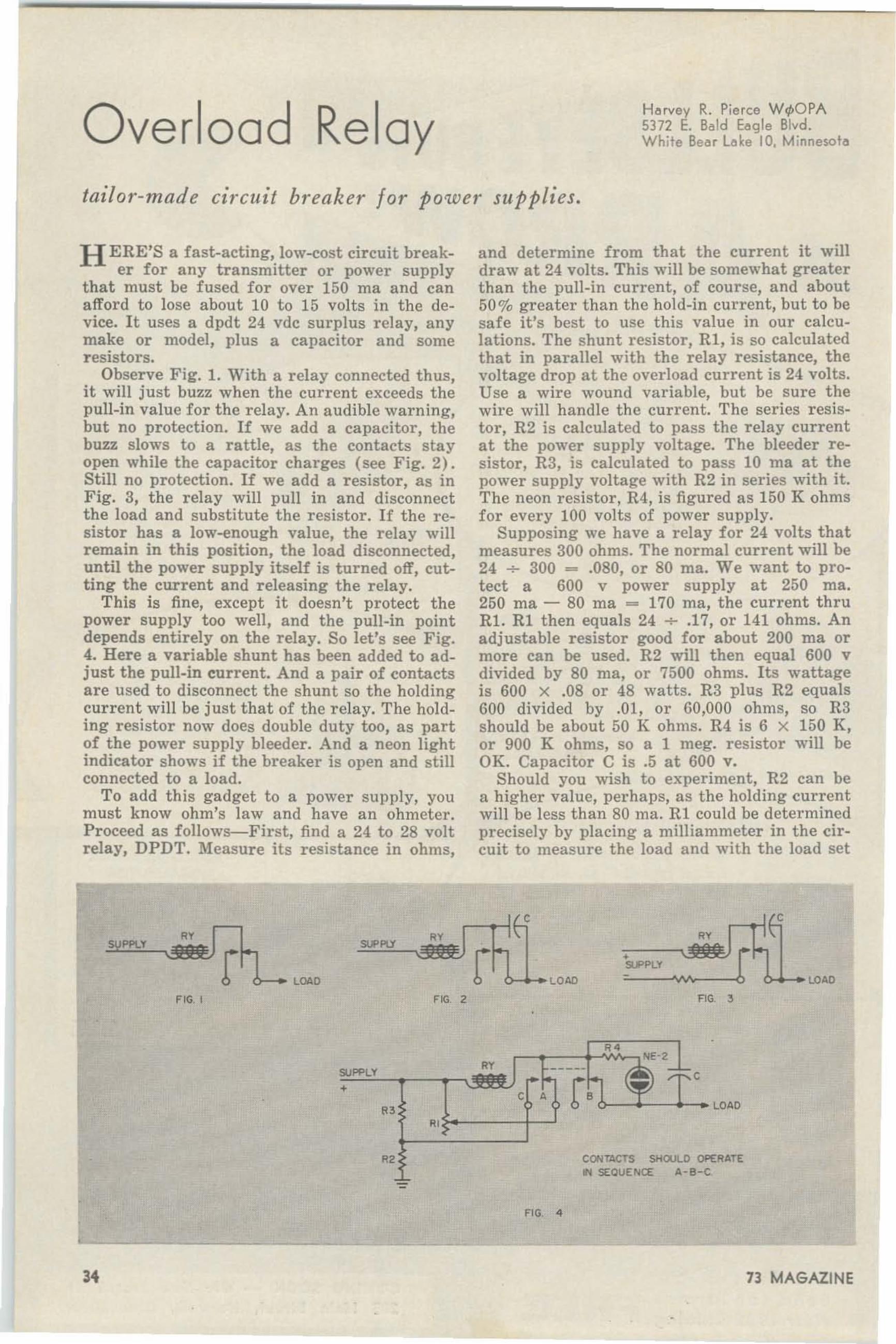
Overload RelayHe rvey R. Pierce WrpOPA5372 E. Bald Eeqle Blvd.White Beer Lake 10, Minnesota
tailor-made circuit breaker for power supplies.
H ERE'S a fast-acting, low-cost circuit break-er for any transmitter or power supply
that must be fused for over 150 rna and cana fford to lose about 10 to 15 volts in the device. It uses a dpdt 24 vdc surplus r elay, anymake or model, plus a capacitor a nd someresistors.
Observe Fig. 1. With a r elay connect ed thus,it will just buzz when the current exceeds thepull-in value for the relay. An audible warning,but no protection. If we add a capacitor, thebuzz slows to a rattle, as the contacts sta yopen while the capacitor charges (see Fig. 2).Still no protection. If we add a r esistor. a s inFig. 3, the relay will pull in and disconnectthe load and subst itu te the r esistor. If the resistor has a low-enough value, the r elay willremain in this position, the load disconnected,until the power supply itself is turned off, cutting the current and releasing the r elay.
This is fine, except it doesn't protect thepower supply too well, and the pull-in pointdepends entirely on the r elay. So let's see Fig.4. Here a variable shunt has been added to adjust the pull-in current. And a pair of contactsare used to disconnect the shunt so the holdingcurrent will be just that of the relay. The holding resistor now does double duty too, a s partof the power supply bleeder. And a neon lightindicator shows if the breaker is open and st illconnected to a load.
To add this gadget to a power supply, youmust know ohm's law and have an ohmeter.Proceed a s follows-First, find a 24 to 28 vol trelay, DPDT. Measure its resistance in ohms,
and determine from that the cur rent it willdraw at 24 volts. This will be somewha t greaterthan the pull-in current, of course, and about50% greater than the hold-in current, but to besa fe it's best to use t h is value in our calculations. The shunt r esistor, R1 , is so calcula tedthat in parallel with t he r elay r esistance, thevoltage drop a t the over load cur ren t is 24 volts.Use a wire wound variable, but be sure thewire will handle the current. The series rest stor, R2 is calculated to pass the relay currentat the power supply voltage. The bleeder r esistor , R3, is calculated to pass 10 ma at thepower supply voltage with R2 in series with it.The neon resistor, R4, is figured as 150 K ohmsfor every 100 volts of power supply.
Supposing we have a relay for 24 volts thatmeasures 300 ohms. The normal cur rent will be24 -+- 300 = .080, or 80 mao We want to protect a 600 v power supply at 250 rna.250 rna - 80 rna """ 170 rna, the current thruRL R1 then equals 24 -+- .17, or 141 ohms. Anadjustable r esistor good for about 200 rna ormore can be used. R2 will then equal 600 vdivided by 80 rna, or 7500 ohms. Its wattageis 600 X .08 or 48 watts. R3 plus R2 equals600 divided by .01, or 60,000 ohms, so R3should be about 50 K ohms. R4 is 6 X 150 K,or 900 K ohms, so a 1 meg. r esistor will beOK. Capacitor C is .5 at 600 v,
Should you wish to exper iment, R2 can bea higher value, perhaps, as the holding currentwill be less than 80 rna . R1 could be determinedprecisely by placing a milliammeter in the circuit t o measure the load a nd wi th the load set
C
RV RVPPl.V """'"r r •Sl,PPLV
LOAD LOAD LOAD
FIG. , nc 2 FlO ,
R'
c
C A f,6---'--'-_ LOAO
RV
+
R'~---I-..J
R2 CONTACTS SHOULD OPERATE~ SEQUENCE A-B-C
FIG. 4
73 MAGAZINE

Pcttern is beamed toward the horiJ:onfor opt imum response .
Mounting Structure Does Not AffectRadiation Pattern
HIGH GAIN ANTENNASCONTROLLED RADIATION
..~. - . .~
G·4',·M• _ e
"TEAM- MATES"TG-S-S 1144· 170 m <j TG-2-R
~ I$ 74.25 Net $ 18.00 Net3 EL EMENTS Half WoveFixed Stati on f lement3X Power of Maximum
TG-2-R Pos sible Ga in
Althou gh independent use of theTG· 5-S a nd TG ·2 -R give ama z-ing performance, their comb ineduse as " Tea m-Motes" producethe ultima te in gain and efficiency. The engineered compatible characteristics of pureverti cal polarization andmatched feed points, w iththe e limina tion of horizon-tal polarization , make the ~'~~" Tea m-Motes" lea ders in C!the field of communication
Ga in f igures, Radi ation Pat..terns CIl'Id Ca ta logs Listi ng
i All Mode ls are Ava ilable
at the desired value increasing Rl until thebreaker trips. R1 can be a n adjustable rheost a t , and its pointer calibra ted in rna.
While any relay of the DPDT variety willwork, it is better to have one t hat requiresmoderately low cur r ent so that t he size (wattage) of R2 will not be too large. Higher voltage r elays entail higher voltage drops and moreloss of power supply voltage. 24 vdc r elays, socommon a nd cheap, will seldom ca use morethan a 12 v drop in normal u se. 12 v r ela ysca n also be used, but many of them take morecur rent than you may want to protect against(250 rna is a common 12 v relay cur rent. )
To re-set the breaker, just turn the voltageoff. If the short or overload continues, thebreaker will break again as soon as volt age isapplied. It can be made adjustable from thepanel if desir ed. About the only precaution t obe taken in installing it is in insulat ing ther elay from ground, as most 24 v relays werenot insulated f or high voltages (over 250 v ).The ca pacitor C should be able to withstandthe high voltage and should be of fairly highca pacity, at least .5 mid. If adj ust ments ca nbe made to t he relay, contacts "B" (load )should open after "A," and j ust before "C"closes. It is sometimes possible to reduce thecur r ent r equirements of t he r elay by reducingthe spring t ension a bit. These la st suggest ionsar e f or the experimenters.
Put one of these things in your rig. It maysave its cost or more in recti fiers the fir st t imeit works! • •. W.pOPA
Here's th e simple easy way to go VHF on TWOMETERS! J ust feed the 20 meter output of you rp resen t SSB, AM o r CW exci te r into the P&H 2-150a nd you have 175 Watts PEP on TWO M ETERS, ei thercrysta l o r VFO controlled, depending on your exciterfe a tures. Resis tive Pi-Pad and switchcble Ha lf-Po w e rPad permits operation w ith any 5 to 100 Watte xciter, Since the 2-1 SO is a hig h stability mixi ng d e vice, the o utput sig na l stabili ty is the some as t hat ofyour exci ter. Use s a 6 EA8C rystal Osci llator / TripIer;a 6360 cat ho de follower; a 6360 8alanced Mixerand a 7854 p u sh -p ull O utput Tub e . Po w e r input to7854 final : 175 Watts PEP on SSB, 165 Watts
CW, 90 W atts linear AM . En tire chassi s a nda ll shielding is COPPER PLATED. Output jock p rovided to furnis h osci llator signa l injectio n fo r receiving converter. Q uiet 200 CFM fo rced-air co olin g .50-70 ohm inp ut a nd output impedances. Husk ybuilt-in power supp ly has th ree separate re ctifi ersand filter combinations . Meter rea d s: PA GR ID, PAPLATE a nd RELATIVE Rf OUTPUT. Mode rn ist ic cu rvedcorner grey cabinet: 9 " X 15" X 101,7" . The P&H2-150 is so thoroughly shie lde d, by-passed a nd pa rcaine-Free that it operates as smooth ly as o n 80meter tran smi tter . P& H also manufactures t he Mod el6 -150: 175 Wa tts on 6 Mete rs.
WRITE fOR LITERATURE
Complete - With Built-in Power Supply,All Tubes and Crystal, for Only $329.9S ·
* Slig htly higher west of Rockies
p •
~ 8<- ELECTRONICS INC.~ 424 Columbia, lafayette. Ind.
JUNE 1962 35

A 731
Noise
Clipper
J e mes F. G .Hrity KIf.lWMl1228 Ashla nd Ave nueSt. Pa ul 4, Minnesot ....
ONE of the handier accessories in the shackis the noise clipper. Connected between
the audio sour ce and t he headphones, it w illchop off noise peaks a nd prevent excessivelyloud signals from getting through to yourears. In most cases it can be used withoutmodification to the receiver, which should appeal to the owners of commercial gear. Best ofall, it costs only 73¢ (or rather, it cost me73¢; it will cost you somewhere in the neighborhood of 57¢) .
The circuit is shown in Fig. 1. The clippingaction relies on the forward conduction curveof silicon diodes, shown in Fig. 2. So long asthe signal peaks stay below the knee of t hecurve, the clipping is insign ificant . However ,if a noise peak goes over the knee, t he diodeswill conduct heavily and, combined with t heinternal resistance of the source, limit t he peakto one or two volt s. A nother way of lookingat the clipping action is to p icture a five ohmresistor which is shunted across t he hea dphones during noise peaks. T he res istor bypasses most of the noise. I ncidentally, thisalso explains why the clipper will not workeffectively with a speaker. Five ohms shuntedacross a four ohm speaker won't reduce thevolume appreciably.
Although any of the common silicon powerrectifiers will work in this circuit, the TABdiodes were specified from an economy standpoint. Similarly, the l\IC-385 provides the
Photography by Bob Jacobs.
chassis, plug and jack at minimum expense.Originally, it was used to transform low impedance headphones for use in high impedancecircuits, and the miniature autotransformerit contains should have some possibilities intransistor work.
Construction takes about thirty minutes.First, remove the cover to the l\IC-385 and remove the transformer. Next, connect the diodesin pairs, as in Fig. 3. Don't allow the diodecases to touch. Solder one end of the first pairto the plug connection. Use shor t leads or thediodes won't fit in the case. Connect one leadof the second pair to the ground lug on thejack, again with shor t leads. Connect the remaining leads of each pair together in midair or to a solder terminal. Finally, connecta wire from the plug to the remaining lug ont he jack.
To use the clipper, connect it between thea udio output and the headphones. The clipperwill work in any of the common output circuits, except the ones shown in Fig. 4. I n thatcase, t he dc voltage drop across the phoneswill bias one set of diodes into conduction, effect ively rectifying any signal (new detector,maybe?). A word of warning: if you have ahigh-powered audio system (like push-pull6L6's) it is possible to exceed the di ssipationratings of the diodes on high volume levels.At one watt each, the limit for the clipper isfour watt s. . .• K~WML
FIG I
•zw•so
VOLT/l.G£
e, , FIG 3 ,~ ,
Fig. I 4 diodes 25 piv 750 ma @ 9c each fromTAB, I I I Li berty Street, New York 6, N. Y. O neMC.385 @ 6 for $1,00 from Selectrenics, 1206
S. Napa Street, Phila.• Pe.
36
Fig. 2 Forward conduction curve of silicon diodes.
Fig . 3 Arrangement of diode pairs.Fig. 4 Clipper won't work in these circuits.
73 MAGAZINE

lHE HAMMARLUND "epeMWllo.Q «Jouch"
ELECfRO Ie KEVER HK-18Hard to believe-but true ... and backed upby the most distinguished name in Amateurrad io--HAMMARLUND.
The new Hammarlund 'Personal Tou ch ' keyeris an incredible value -packed with the performance and features found in "Big-Money"units-yet priced at just half t he cost ofcomparable-quality keyers.
This compact, fully·transistorized code gener-
ator combines every desirable feature of electronic sending with distinctive dot/dash controlto give messages your own distinctive "touch".Ideal for expert or novice alike, it provides afull range of speeds to match ind ividualproficiency.
Study these " $ $ $ $" features and convinceyoursel f that the HK·IB is the " Best Buy" inelect ronic keyer history!
. SIMPLE
VERSATILE
PORTABLE
PROTECTED Keying relay contactshavegreater current carrying capability thana transistor-removing limitation of transistor keying and eliminating possibletransi stor damage due to reversingpolarity.
Low drain transistor circuitry results in indefinite life fromstandard 22\1, vol t battery.CompactOnly T" wide, 4\02" deep, 2%" high.
Transistorized circuitryfor extended service.
Automatic, semi-a utomatic (bug) or straight key operation.Volume adjustable sidetone signal formonitoring or code pract ice.Speed Range wi thvariable dol/dashratio.(Approx. 8·50 WPM)Baltery operation and compact size forideal field day exercise use.
JUNE 1962 37

"T. R." on SSBTed Wads KZ5SWBox 2519, Belboe .Cenel Zone
A FEW years ago with the advent of thelow-cost t a pe recorder many of us ob
tained one for family use. After the "new"had wor n off recording the children, partytapes, and not-so-h i-f dubbings of the top tentunes of the day, many of these units wereeither relegated to the sto rage closet or sa wtemporary service in the ham sha ck. It usuallydi d not stay in the sha ck too long because oft he tedious procedure used on A ::\I . It necessitated recording a CQ or direct ional call , rewinding the ta pe, playing it back on the a ir,and if no results were obtained, rewinding, reth reading, usually, and going thru the process
5001< "4 'II,.4 01401 ... h~ ..~
o",,:.;,~-------~tT~ PLUG
" '" l - TO FITOUT PUT _ XMTR
."INPU T
Ta pe out put may be up to 16 ohms Z. If 500raise value of R to prevent input stage overload.Try 3 megohms to start, and adjust as required.
a 15 second "TESTING" transmission andsign your call . This will leave about ten seconds of dead air on the tape. Play it back andlisten for t wo possible defects . One is noiseon the t ape dur ing the dead a ir period. If anyshows up, let the tape run thru the mach ineon "record" with the volume down to cleanoff any previous recording, so that the noisewon't trip the VOX in t he " listen" per iod.He-r ecord your brief test transmission. Secondly list en to yourself for undue pauses betweenwords that will aUow the VOX to drop outunnecessarily during the transmitting periodof t he cycle. The obj ect is to make a smootht ransmission followed by a dead a ir periodwhen the VOX will drop out and turn t he receiver on.
Now let's con sider the use of the tape machine with the rig. T he simplest way is to putt he station mike in front of the recorder speaker and let it run. Adjust the volume of therecorder so that it trips the VOX smoothly. Atthe end of your test transmission, the deadair period will let the VOX drop out and thereceiver operate. Thi s will repeat itself overand over again until you sh ut t he darn thingoff. Unless you have an unusual fondness for
ANY METAL sox , GftO\..WD IT.
the sound of your own vo ice, you will want asilent means of doing this , particularly if yourscheduled st a t ion is a few minutes late !
Most home type tape machines have a 4 oh mext er nal or auxil iary spea ker output jack.Make up a connecting cable with a plug on oneend t hat will fit the microphone input jack onyou r t ransmitter. On the other end put aplug that fits the 4 ohm output jack on the taperecorder. In ser ies with the hot lead in one ofthese plugs put a half megohm l,4 watt reelstor. If you want to get rea l fancy, make up asmall swit ch ing box a s shown in the diagram.
T he on-the-air procedure is to make a recording calling your scheduled st a t ion usinghis call about three times followed by yourca ll once, with the rest of t he loop blank. Turnon t he tape in the playback posit ion a nd sitback a nd relax. All you will hea r will be t hereceiver noi se during the "listen" portion ofthe tape until your sta t ion comes back to you.\Vhen he does, turn off the tape, plug in your
(Tur n to bottom of page 40)
over again . It wasn't worth the effort. W ithsideband , or other VOX operation, t he taperecorder can be a real convenience. It is possible to use a tape deck to advantage withpractically no effort. The secret of this newconvenience is the "closed loop" of tape. W ithit you can make a 15 or 20 second call followed by a period of listening, then the wholedeal r epeats itself all automatically. I find itparticularly useful for calling schedules , direct ional CQs, and for opening up a band thatsounds dead from lack of activity.
Basically, this is how it works. You cut an8 to 10 f oot length of heavy duty (MYLARpreferred) recording tape and splice the endstogether forming a loop of tape. This you puton your recorder, with the excess ha ng ingover the back of the table or desk. A smallweight in the form of loop solder is hungon the dangling bottom of the loop. This pullsthe tape so it won't foul up in the capstan.When you make t he splice in the tape, use acolored cellophane tape or the regular whitesplicing tape. The reason for th is is to havea visible "beginning" and "ending" spot . Setyour recorder on the slowest speed usually31,6 i.p. s. a nd time the in t erva l that it takesthe colored splice to make one trip thru themachine. This should be from 25 to 40 seconds.If it is less than 25 seconds make a new andlonger loop. Now, us ing the microphone thatcomes with t he recorder (for s implici ty ) make
SPO'S. •
38 73 MAGAZINE

-. -
•
Take your equipmentI•
-,_.-
I•
ELECTRA POWER110 voltjAC generatorgives you 3300 watts,instantly, on the moveor parked! only $16250
plus tax
Now, without any modificationsat all , you can take . .. and use. .. your home rig in your car.
Your Electra Power contro ls mounteasily under the da sh, finger-tipcl ose, and ready for instant use.
No more power supply troubles.Now you can send and rece ivefrom any place you take your rig.
mounts on your
AUTO . TRUCK . TRACTOR . BOATTh is is what you have wailed for! Now there are
no more special mobile power-supply problems.
You can use the same rig in your home or in yourcar. For the first time, full 1000 watt mobile oper
ation is real ly possible for everyone.
Fan-belt driven, the Eleclra Power gene rato r
develops full output when engine RP Ms are
slightly over idle. Electra Power also allows CO
operat ions from areas ordinarily conside red
"boxed-in" for lower powered transmi tters.
J. W.of long Beach reports, "letsme operate onany band SSB2kw PEP at home or in my car wi th the same rig."
GADCO ELECTRA/ ELECTRA POWER2325 WILSHIRE BLVD., SANTA MONICA, CALIF.
DISTRIBUTORS WANTED
See Electra Power displayat A.R. R.l. convention in
bisn~yt(\ndJUNE 1·2·3.
JUNE 1962 39

Phase InversionDean Cupp W4JKlRoute #4Morristown. Tennessee
Since the advent of phone transmission,hams (engineers too) have been striving toincrease the effectiveness of the modulator beit Al\l, SSB, or Fl\1 while keeping t he size,cost, weight, a nd complexity of the circuit s to
• •a minimum.Although the circuit shown here may not
increase the effectiveness of a r ig t o kilowattproportions, I f eel i t will help with all t heother qualities mentioned. Now, before someone dies of curiosity, Fig. 1 is a unique circuit
'""
CAPIlIER atINPU T
RI • C,tl,RR:ER 8AL,tl,~(
increasing bias reduces the current throughV3. When the grid of V2 goes more negativethe opposite happens: less current flowin gthrough V2 causes less drop across the cathoderesistor, and more current in V3. Presto: phaseinversion, exactly 180 degrees with no worriesabout matching resistor and capacitor valuesor paying for a transformer. R3 is the normalcathode r es istor for class A or ABl operation.
---oYO
FIG 2
FIG. I
that provides phase inversion right in t hepush-pull output stage of a dr iver , modulator,or a ud io amplifier. T his eliminates the needfor a phase inversion stage (complex) or in terstage transformer (heavy, large, a nd expensive). At th is time all CW men should QSYto the page labeled de \V2NSD, unless t heycare for hi-fi or some such.
VI is an ordinary speech amplifier st a ge,V2&3 is the yank-shove output stage. Assumethe s ignal across R2 goes positive (less negative) causing larger plate current to flow inV2, which causes more voltage drop across thecathode resistor R3 (cathode more positive toground). The grid of V3 is grounded and the
Other classes of operat ion should not be attempted since they require power that a voltage amplifier can't deliver. There's little choicebut to use a transformer when using A B2 orB, since a phase inverter can't supply thepower either. IU , R2, and Cl are the values
--'J
+)~ FL . !--
r.::--I ; [:;.!- -r
" . CARRIER 8ALAfWC(
,.
(Continued from pag e 381
s ta tion m ike instead of the recorder cable andproceed normally.
T his gadget is particularly usef ul for contest operation, where you make t he same CQContest call many many t imes during a weekend. The MY LAR tape was suggest ed earlierbecause I fi nd that acetate tape will wear outin a relatively shor t time. A MYLAR looplasts me about three months of daily use.(For the uninitiated: you must have VOXoperation for the system to work! !!) . If youwant to have some fun, tape-call your localbuddy on the air and call him on the landline at the same time. He do get confused!
•.. KZ5SW
RG'
normally used with Vl. Do no t by-pass thecathodes of V2&3, th is would make V3 inoperative. (Note: this circuit also sa ves the costof t he by-pass.) AM fellows may stop herea nd let t he SSE fans read on.
The followi ng is not solder -no solder directions, but food for thought. F ig. 2 is a commonba lanced mod ulato r. Fig. 3 is a mod ified versionusing the circuit of Fig. 1 to achieve phaseinver sion. T he audio is fed to the grid, rf t ot he cathodes. This might be tried w ith differenttypes of balanced modu lators. Although I havenot tried the SSB version everything indicatesit would work and I am quite interested tohear from anyone who tries it. How brave areyou? .. , W4JKL
73 MAGAZINE

GOOD MOBILES GO• ••
10·15·20·40·75 METERS1I(l1 ....sr
r T"').1 MAST
NEW·TRONICS•
- "-- *
MOBILE . u
~.. IS ,' .,
ROO 10
ANTENNA - •
• Now, Get Fixed Station Reports with the "HUSTLER"Buy only the mast and resonators for the bands you operate. No need for matching devices , no feed linelength problems. Use any length o f 52 ohm cable. This is a new, efficient concept of center loading.Each of the five re sonators has a coi l spec ially designed f or maximum rad iation f or a particular band.Cent er frequenc y t uning is b y m eans of an adjustable sta inless steel rod in the resonator.
The 54 ·inch fold -over, heat treated, liz -inch a luminum mast permits inst ant aneou s interchange ofresonators . Mast f olds ov er for garage sto rag e. When opened t o full height. the two sections of thepermanently hinged mast are held rigid ly in positi on by a shake proof s leeve arrangement . Mast has%-24 ba se stud to fit a ll standard mobile mounts. Power rating is 75 watts de input A.M. - 250 wattsPEP input for SSB.
ANTENNA ASSEMBLY CONSISTS OF 1 MAST and 1 RESONATORPart No. Description Total Height of Antenna Amateur Net
MD· l 54 " Mast fold s at I S" from base (Fo r Rear Deck or Fender Mount) $ 7.95MO-2 54 " Mast fo lds at 27" from base (For Bum per M ount) 7.9 5RM -I 0 10 Meter Resonator Maximum 80 " _ Minimum 75 " 5.9 5RM-15 15 Meter Resonator Maximum 81 " - M in imum 76" 6.95RM·20 20 Meter Resonator Maximum 83 " M inimum 78 " 7.95RM -40 40 Meter Resonator Maximum 92 " - Minimum 87" 9.95RM·75 75 Meter Resonator Maximum 97'" Minimum 91 " 11.95
ANY MAST OR RESONATOR MAY BE PURCHASED SEPARATELY
FITS MORE CARS THAN ANY OTHER BUMPER MOUNT!MODEL BM-l Flat alloy stee l st rap fits t ightly against any shape bum per yetis inconspicuous. Length of st rap permi ts its attachment to both large andsmall bum pers.
Assembly is he ld in place by two "J" bolts at the top of t he bumper and strapclamp at the bottom. "J " bolts may be inserted between top of bumper and carbody where clearance is as low as 1,4".
Whip receptacle assembly cons is t s of a heavily chrome plated 1 1!z " die castZamak ball w ith %-24 thread . Ad justable so as t o maintain whip in tru e vertica lpos ition . Bla ck phenoli c base. All metal parts o f the bumper mount are heavycadm ium plated $6.9 5
See these outstanding NEW-TRONleS products at your electronics dis..tributor. If he cannot supply you send check or money order for imrnediate delivery. Write for literature on the complete NEW-TRONleS line.
JUNE 1962 41

an Electronic Keyerfor laz y, stingy perfectionist>
AI Brcqdcn, W~UWA/K3KMO316 W est Peirmount AvenueStete College, Pannsvlvenle
IF you are by nature a lazy person, who likesto be able to send CW witbout baving to
poke out each character-and stingy, so youwant an electronic keyer for under $20-anda perfectionist, so you want nice self-completing characters-read on.
The original circuit from which this keyerevolved was developed by G. Franklin Montgomery, W3FQB, and was published in theMarch, 1952, issue of CQ magazine. As anindication of its quality, the basic circuit hasbeen outright copied or slightly modified foruse in composite circuits over a half dozentimes in later issues of CQ and QST. This isthe same circuit as the one in the 1960 ARRLHandbook, which was the first electronic keyercircuit ever to appear in the Handbook.
Correspondence with Jack Gallagher, W5HZB-another electronic keyer designer ofwide-spread fame-brought to the attentionof the author (me, in other words) theW5HZB simplification of tbe W3FQB circuit.This modification produced equal quality C'Vwith one less triode section than the originalcircuit. After a few more simpli ficat ions bythe author, the circuit as shown in Fig. 1 wasfound to be the simplest possible circuit thatwould produce good, reliable CWo
The Field Day Special
The local Nittany Amateur Radio Club wasmaking plans for Field Day 1960 and wasdesperate for CW operators. As a last r esort, they invited the author, who holds theAmateur Extra First Class Lid License, toparticipate on the 420 mc CW position. Sincethe author had previously traded his electronic
V~~I(EY ING "'" •
ecce LEVER
IIro...m V" JiNTR... '"". ..""
"."""
P arts List
VI-Dual triode: 6SN7. 12AT7, 12AU7. 6CG7 a re OK.TI-AF Transformer with pusb-pul! windine . Secondary
not used.T2-120v @ 20 rna, 6.3v @ 300 rna. minimum.SR-8elenium or emcee rectifier. 60 ma minimum.Cl-30mld is good. more is better. 160vdc.RY-See text.
42
keyer in a horse-trade, it was obvious thatanother keyer must be built in shor t order.The keyer as shown in Fig. 2 was built in agreat hurry. This model was built on a u sedchassis, utilizing existing holes, and was rewired several times in the process of gettingthe best performance. This resulted in therat's nest of wiring as shown in Fig. 3. Allowme to digress. Most amateur radio magazinesshow pictures of the undersides of electronicsequipment with nice, neat work, wiring harnesses and the works. The author is sure thatthe r eaders of 73 will enjoy, for a change,seeing a piece of equipment that looks as badas anything they ever built.
The Stikky Peanut Butter jar is actuallythe plate-sensitive relay. The jar was part ofthe relay, serving as a dust cover. The labelwas added as a touch of color, and came fromMad magazine. The switch hanging by onehand from the left s ide of the chassis is aSPDT spring-r eturn switch which is used toclose the key in one position, f or tuning purposes, and to turn the VFO on in the other
Fig. 2
position, for f requency spotting. It is notshown in the keyer schemat ic, but may beadded as desired.
For a discussion of the theory of operationof this keyer, refer to either the 1960 ARRLHandbook, or the original article in March,1952, CQ. Basicclly, Va is a sa w-tooth OSCil4
lator, and Vlb is a limiter, so that the outputis approximately a squa re wave.
The relay used for this circuit should be aplate-sensitive relay that pulls in a t 3 rna orless. The Sigma 41F-5000S-SIL or equivalent(5000 ohm coil ) would be a good r elay forthis keyer, However, a good buy in a relaymay be found in the current Burstein-Applebee general catalog (bargain section, whereelse'i) • The catalog number for this relay is
73 MAGAZINE

18B156, a nd t he cost is $3.95. This is a Sigmarelay ( Sigma number unknown) wi th a 16000ohm coil, a nd full y adjustable cont a cts, whichis a necessity for the best adjustment and, consequently, the best operation. This r elay isshown on W3SMV's keyer in Fig. 4. W3SMV'scir cuit is the same a s F ig. 1, using a 12AT7.From his observations, the 12AT7 is the bestminiature tube for this circuit , wit h either a12AU7 or 6eG7 being perfectly acceptablesubst itut es.
Incidentally, while you have the B-A ca talogopen to the bargain sect ion , check for a smallpower t ransformer and an a udio transformerwith a push-pull winding. You will find t heyalso have good prices on t hese items.
Fig. 4
Keyer Adjustment
The relay should be carefully adj usted forbest operation with this circu it, or a ny elect ronic keyer circuit. First, push the r elayclosed by hand and adjust the closed contactsso that good, solid contact is made. Then,with the r elay in the r elaxed position, adjustthe relaxed conta ct so that t her e is 1/32 inchor less spacing between t he keying contacts.
Now set the weight cont rol a t minimum,and the other t wo controls (speed a nd rat io)near mid-range. Advance the weight cont roluntil closing one s ide of the key produceschara cters of some sort. Now a dj ust the ratiocontrol for a dot:dash r a t io of 1 :3. One of theeasiest ways to adjust this ratio is t o sendudididididahdahdididididahdah," etc., adj usting the ratio so that t he dit st r ings take exactly the same amount of time to send as thedah str ings (four dots and the enclosed threespaces is equa l to t wo dashes and t he enclosedone space) . After this ratio is adjusted,adjust the weight again so t hat t he spacebetween dot s or dashes is equal to the lengthof the dots. Once these t wo adjustments aremade (ra t io and weight) t hey will not haveto be touched a gain, so the controls may be
JUNE 1962
Fig. 3put on t he back panel or some other out-oft he-way place. The speed control may bevaried t hr oughout its en t ire range withoutupsetting these a dj ust ments .
It should be noted t hat a good relay withsoft silver contacts sho uld not be used to keyhigh currents, a s in a transmitter where allst ages are s imultaneously cathode-keyed.Such use will cause the relay conta ct s to become dirty, eventually pitted, and will likelyca use them to weld themselves together just a syou snag some rare DX (Murphy's Law). Theauthor's keyer is used to key a grid-block timesequence system, where little current flow sthrough the relay conta cts . 'V3SMV uses hist o key a Vackar VFO cir cu it , with all buffersa nd the final operat ed either with fixed biasor cathode bias.
If t he speed range pr ovided by this keyeris not what you wa nt , cha nging the value ofthe speed cont rol and the fixed resistor inser ies with i t will cha nge both the range ofvariation, and the highest (or lowest) speedavailable. Adding r esist ance causes the keyerto operat e at a slower speed.
After you have built t h is circuit, and havet he keyer oper a t ing properly, practice with ituntil you ca n send decent CW before puttingit on t he ai r. Nothing sounds so downrightembar rassing as a ham learning to use anelect ronic keyer by getting on the air with i t.Don't be like the fellow on 40 CW with anew \Vhaleyscrathers St raddyva rious keyerwho sa id, "MHE KIYEL HR IH W J9TOMODEAS, 50W DO IS IT HOUNB?" TheF CC, unfortunately, does not permit our t elling him how it sounds .
If you would like to hear the "Eield DaySpecia l" in opera t ion, look for K3KMO eitheron t he WPA t r affic net or on the low end of80 meter CW chasing DX.
Photo credit goes to Ca r l Volz, J r., W3SMV.F or the benefit of t he photo bugs in the reading audience, Ca rl made the pictures indoorswith available light t h rough a sing le window,using wet plates. • • . K3KMO
43

This gadget saves gas and patienceif )'011 are hllilding a noise limiter.
Tom l.emb K8ERV1066 La rchwood Rd.Mansfield , Ohio ,
Use
To use t he Pop Box, just set it near yourreceiver and turn it on. If necessary, plug ashort whip or piece of wire into the antennajack to obtain the desired pulse st rengt h. Nowturn on the noi se limiter and note the noi se
of insulated wire wrapped around the HV terminal on the coil couples the spa rk pulse tothe antenna jack. The spa rk gap is not criticalso long as a stable spa rk is obtained. ,My gapwas about 'h ".
ANTJACK
c:
r
p
R210 K
R3Ion
~~ 2D21
RI10K
125V 2~...
TI
115V
the
Box
formance, so the Pop Box generates a st ableignition type of noi se useful in testing theeffectiveness of a limiter.
The schema t ic shows the Pop Box to be aminiature ignition circuit, with a t hyratron forthe points and a model coil fo r the spark. T het hyratron grid is fed out of phase with t heplate to prevent too early fir ing. Should thecircuit not operate, reverse the 6v or the H Vleads.
N OW why would anyone want to generateignition noi se when 199,999 hams are
trying to get rid of it? I'm not really sure,but don't tell w a yne or he may not print this.One possible reason would be to save gasoline.You did run the buggy to check that last noiselimiter circuit, didn't you?
Actually, it is quite fa shionable to fightnoise with noi se. Just a s wide band noise generators are used to measure converter per-
Construction
\Vhile I used a wood box, it would be betterto use a shielded enclosure, such as a l\Iinibox.The parts placement is not important. A piece
reduction. The main idea is that with a scopeto show just what is happening, and the PopBox to cause it to happen, a noise limiter circuit can be adjusted for best performance inyour receiver. . .. K8ERV
73 MAGAZINE

AM . FSK . SSB . ISB . CW . FAX
,
\
\\
SERIES
,
I
I
TRANSMITTER
TMC Models SST-1 K series of transmitters provide conservatively rated 1 kw PEP o utp ut inSSB modes, with Signal to Distortion ratio of4 0db, and 1 kw overage power in conventionalcommunication mo de s within the fr equency rangeof 2 to 32 Mes.
Stabilities of 1 part in 10' to synthesizedaccuracy of 1 pa rt in 10' . with J00 cps increme ntal tuning, are featured in this se ries oftransmitters.
The TMC SBT-1 K series of transmitters areattractively housed in semi-pressur ized cabinetswith many customer options for wide band orna rrow band a udio, antenna tuners. bose mo unto r rug ge d MIL a cce pte d shipboard mounts forall mobile a pp li ca tions.
Fo r inform a tion o n this tr ansmitter se ries,req uest SSB number 1001 .
-.
SI N G L ES IDEBAND
AN/URT·19(V)
AN/FRT·53
AN/FRT·56
AN/FRT·57
THE TECHNICAL MATERIEL CORPORATIONMAMARONECK, NEW YORK
OTTAWA, CANADA • AL EXANDRIA, VIRGINIA • GAR LA ND, TEXAS • LA MESA, CALi fORNIA • POMPANO BEACH , FLORIDA

SelectedCircuits
Roy Pefenberq W4WKM
M U CH communications equipment, designedfor other than the amateur market, con
tains circuit features worthy of incorporationin amateur const r ucted gear. One such equipment is the Model SB-6F single s ideba ndtransceiver manufactured by RF Communlcat ions Associates of Rochester, New York. Thistransceiver is rated at 125 watts PEP and isprovided with 6 fixed tuned channels in therange of 1.6 to 16 me.
The equipment is aimed at the commercialcommunications market and is designed to beoperated by non-technical personnel. Built tocommercial sta nda rds, it provides top performance and, for such equipment, is nominallypriced at around $1,300. \Vhile few amateurswould be interested in the transceiver for usein the ham bands, certain circuit details areworth considering for your next SSB rig.
The schema t ic diagram shows the s ideba ndgenerating portion of the SB·6F, along withthe audio and VOX circuitry. The block diagram shows how it fits into the system . Theschema tic has been simplified by r emovingsome of the Transmit-Receive switching cir-
cuitry and showing the circuit in the transmitSSB condition.
Although the speech amplifier uses the conventional dual-triode circuit, two inputs areprovided. A high impedance dynamic micro.phone may be connected t o the 6US grid circuit or a carbon microphone connected betweenthe 6US cathode and ground. The unused inpu t should be grounded in either case
The VOX a ssembly, available as an eccessory to the SB-6F, is about a s s imple a s sucha device can be. The voltage doubler audiodetector uses a pair of IN24S4 silicon diodesand insures adequate cont rol voltage for reliable operation. This voltage doubler techniqueis a good one to remember since it can oftensa ve a st age of amplification. The relay, K2,is a 10,000 ohm, 2.5 rna unit.
The heart of any sideba nd exciter is thesideband generator proper. In this transceiver,an RCA 7360 bea m-deflect ion balanced modulator feeds a 2.1 kc Collins mechanical filter.T his happy marriage results in a maintainable50 db su pp ression of carrier and undesiredsideba nd. Those who have fought the battleof maintaining transmission st a ndar ds in SSBcommunications systems will appreciate theimportance of this cla im. The 7360 circuit isless complex than some that have been published, however it is capable of providing goodbalance and excellent carrier su ppression . Bothcarrier (Pll) and quadrature (P9) balancecontrols are provided. Car r ier is injected t othe control grid of the 7360 through CI56
· 200.
·200.
,,,'" CJ~~
YIO-4 If oz ~ r
feU8 I\.
.1'1'r--..--'t, ....
•
~~,~::i' _'Il' _
DYl<I 4 "'C C&I'l&ONMIK E " ,KENPUT ' INPUT
Vtl-&
~ 6AZ8
:.'",n
, ,,""
••
'"'
•
-rfl-YOX ASSEIIIll~ - ~I-'--
..,.. ..,.. 12AT7
•
46
•
73 MAGAZINE

------, r- -- --, , , ,, , , ,.', • ... , . a .., .,Q , ..' " , m--- . ~- •• ..' ...(R • 2!Cl ''' [ R f · 1S T , ~ . .. , ltoO of __-~ ~. on., ..... - ~ Qllf ., ,, _.
~ ,u n ., ,u n - ~ un ., ~. Q'O u.~, ,I ,, ,,
~ ,~ ;..,..,TR RIlL.' ,.',
'"Q,-, .. •• ,C"._~ '0 .. 00:: .~ KC b'OK cec -U~ - _. -'Y~, ",,~lrJ Ylf-l
, TO •
-
v-re V-lOBCAIlRIf:R ~." CONTROL OC ',un ., ~ CN IIHr',(
V -lOA.. .. .. ..\ .-~ ." v-ue ." .~ ." v _''I V_'T
.!f;- .....~ . F . ..~ ~~ r- ,,- .u U ,... _0 - (>011:R ~. IIRtVl: r- .. , ,....~ .~ Ill! UU .,.0 '" U .. ' U T? ~ e&u ,u n n~
~, U OOf J _ TR_ . Tn: Rg,o._11 UO'{ S - II(CVYER ~,
~ U"U _ CO_ ON OC'' ,- u ro~- ". eE USEII .. ·(Jlc....... ...... 1# D( WOW, , ,
which is connected to the untuned plate circuitof a 6AU6 Pierce oscilla to r. C163, which isalso connected to the 7360 cont rol grid, couplesa portion of the carrier signa l to an AM carrier insertion circuit which is not shown.
The in formation presented here has been madeavailable by RF Communications Associates,
Inc., with the understanding that its publication does not const itute a license for commercial use of the proprietary portions. However ,if some of the circuit features discussed turnup in amateur constructed equipment, thenthis article will have served its purpose.
••• W4WKM
Review of the
Cornell-DubilierAR-22 Rotor
The CDE Model AR-22 Rotor was my choiceto r otate an 8-element 2-l\Ieter beam becauseI was mounting a ground-plane above the beamand needed a rotor rugged enough to withstandthe combined weights of the two antennas. Inaddition, I planned to eventually mount astacked 8-over -8 on this r otor, and one of theoffset rotors probably wouldn't stand the st ra infor very long. The in-line design of the AR-22makes it the only TV-type rotor that would bedependable enough for the job and st ill providethe convenience of automatic positioning.
Because of the automatic positioning feature,I am able to log the dial readings for the directions of those stations with whom I holdrepeated QSO's and thus be able to put thebeam on them with a flick of the control knob.The pointer of the control knob is set at thegiven direction, and the rotor then turns untilit reaches that direction, where it automatically stops. The accuracy with which the antenna finds the chosen direction makes it possible to spot weak stations that I must findfor nets, skeds , etc.
The AR-22 is very easy to install. It u ses
inexpensive, readily available d-wire controlcable. Although t here are detailed instruct ionsfor synchr onizing the rotor with the controlbox (an easy procedure), I found that minewas already perfectly synchronized when Ifirst tried it.
A transformer in the control box changesthe 110 volts A-C to 24 volts for the controlcable and rotor unit, in accordance with electrical codes. P.lany hams are illegally andhazardously using rotors that have 110 voltson the control cable and rotor unit.)
I can give one word of caution to anyoneinstalling any rotor: Be sure to leave a largeenough loop in the antenna transmission linewhere it passes around the rotor. I lea rnedthis the hard way, because I didn't leaveenough on my ground-plane lead. The first timeI rotated the antennas, the AR-22 showed offits mighty power by snapping my coaxial cablein two!
My installa t ion has been up for about ninemonths, and neither blizzard nor ext reme coldhas affected its operation. There h as been nosign of drift, even in the extreme winds t hatwhipped across my hill-top locat ion last winter.
The AR·22, together with plenty of controlcable, cost less than $35. Since this is onlyabout $10 more than the cheapest T V rotors,it is certainly a bargain in extra performancefeatures.
•.. Lloyd N. G a rdine r K2PSW
JUNE 1962 47

..........•••••
. . ,-
new value packed Heathkits for[
First complete filter-type SSB transmitter in kit fo rm ...over two years in development. An outstanding array offeatures, combine with neat , funct ional styling, clean opencircuit layout. Quality construction and mate rials bringyou performance, convenience and dependab ility unheardof in this low price range! Special features include : Precision gear-drive tuning assembly with approximately 10 kcper turn for precise frequency settings .. . smooth action;a full-function accessory socket provides for receiver muting, amplifier cutoff bias, 11 7 vee antenna relay power, crc.:A switched 117 vac out let powers monitor scope or otheraccessories ; "Spot" cont rol; Voice control (VOX); Drivelevel control and many, many more! All cont rol functionsare located on the fro nt panel fo r convenience and ease ofopera tion ... no doors or hatches to open .. . no eq uipment to move ! Here is a t ransmitter you will be proud toown and use for years to come ! Allow 60 hours for assembly. Complete details avai lable o n request. 92 lbs.Kit HX·10 . . . no money down, as low as $22 me•• . .$334.95
SPECIFICATIONS -E mission : SSB (UDDer or tower sideband:. CW, AM and FS K.P o w er Inpu l: 180 watts PEP-SSB and CW, 75 watts AM. Output Impe dance : 50to 75 ohms .... ,th not more Iha n eDDro~imlitely 2:1 SWR. Frequency ranlle : (MC : )3.5 to 4.1: 6.9 10 7.5; 13.9 to 14.5; 20.9 10 21.5: 27.9 to 28.5; 28.5 to 29.1: 29.1 to 29.7. Fre.quency .tabili ty: within 100 c ps. e ve-a n. e arl ier su ppressio n: 50 db below peakoutput. Unwanteit sid e band su ppreil lo n : !;05 db below peakoutput. Keylnll e ha,ac.leflsUn: Bleak.'n CW prOVIded by OperlitinQ VOX from II keyed tone USlnlllJfld·blockkeyin",. Aud io output: Hig h impedance rmc-concoe. Audio ftequenc y , e s POns . :4100 to 3000 cps at ±3 db. Powef fequi femenb : OFF . watts: STANDBY-200 walts:KEY OOWN-400 watts at 111 volts . fJJ/60 c-eres AC. Cabinet sin: 19" W l\ 11,X" HX16' D.
A FEW OF THE 32 FEATURESTHAT MAKE THE MARAUDER
AN AMAZING BUY!
• All crystals furnished for 80 throug h10 meters
• Operates SSB (upper or lowersideband), AM, CW & FSK
• VOX controlled break-in CWoperation
• Mu lti-section hermetically sealedcrysta l band-pass filter
• Dual conversion ; crystal controlledheterodyne osci llato r
• Preheated, tem peraturecompensated V FO
• VFO or crysta l frequency control
• A utomati c level control for higherta lk power
• 165 to 1 gear drive tuning as sembly
• Air-cooled, shielded final amplifier
48 73 MAGAZINE
-

ualit~-conscious, econom -minded hams
H eathkit HX-20 SSB M O B I LE TRANSMITTER• Same basic ci rc ui t ry as Heathkit HX-10 . Completeband switc hing -80 throu gh 10 meters . Hermeticall ysealed crystal bandpass filter . Crystal contro ll eddu al con version heterodyne ci rcu itry . Automati clevel cont rol for maximum talk power, low di stortion• Fixed 50 ohm loading fo r easy tuneup • VOX orPTT ope rat ion . Switch selecti on of USB, LSB & CWKit HX.20, 19 lbs .•no money down , $1 9 mo $199.95GH-12; Microphone ill ustrated $6.95SP ECIFIC A T IO NS - Types of emlnlon : 5SB (Upper or lower) and CWoP owe r input: 90 walls PEP, 5SB and CWo Output im pedanee: 50 to 75Ohms IV,th not more than eeo-c• • 2:1 SWR. Fr eq u enc y range (Me): 3.5 104: 7.0 to 7.5: 14.010 14.5: 21.0 10 21.5: 28.0 10 '29.5 (us'"o crys tals furnished;exIra crystat reuuned fo. 29.5 10 29.1 MC). F, ,,q u ,,nc y . ta b ilit y: OvereulreQuency s tabil,ty w,thin 100 CPS IIlt"r warmup. C ;lrr il!r $u p pre.-io n :50 OB below peak output. Unw ;I " t l!d .idl! ba nd $UPP''''-;o ,,: 55 DB belowpeak oulout. th y in", cha.ade,ist iu : Grid block key,no throughout. Aud ioIn p u t : H,gh ,mpedance rmcronbone. P o w e , ,equi,emenl. : 6.3 V at 8 amps.o. 1<'.6 V at 4 amps.:-t25 volts 20 m,lI,amps; 300 verts 100 m,lIiamps; 600 verts130 milliamps (uses Hea lh .HP.2O or HP. IO powe. supplies). C a b in et s ill! :12,l{" W x 6X" H x 9Y." D.
H eathk it HR-20 SSB MOBILE RECEIVER
• Modern a-tube superhet circuit . T unes 558 ,AM & CW sig nals-aD through 10 meter s . CrystalI. F. ban dp ass filter . Crystal cont rol led BFO' s fo rselecta ble sideband reception . Built-in cali brated" 5" meter . 30-1 gea r drive tun ing . Fast or slowA VC select ion . Series noise li mi te rK it HR-20 .•• 11lbs .
no money down , $1 3 mo••• ••• • • •• •. . . • .. • .$134.50S PE CIFIC AT IO NS-F, equen cy ,a n g e : 80 Ihru 10 meter s in 5 banos.a.s to 4.0 : 1.0 to 7.3: 14.010 t4.35; 21.0 10 21.5: 28.0 10 '29.7 Me . Int erm ed iatefreqU enc y fill e, : Ce nter rrecceocv, 3.0 MC: Band wid th et - 6 db. 3.0 KC;Bandwidfh et -60 d b, 10 .0 KG Ma•. : Hermel ically sealed . P ;ln" l co ntro ls:Sideband Selec l; RF. qa,n; A.f . gain-Oil-On: Noise Li m,le r: AVC select;main tu nino ; band s witc h: a nten na trjmmer; SSB. CW.AM s .... ' tch, S ig na l.to-noile ' ;llio : 10db a t 1 m,croVOIt Of less. O ulpul im ped.n c: . : 5OOO)hmsantlBohms. P o we r .equi ,emenl.: 6.3 Vat 8 amos. Of 1<'.6 Val 4 amos. AC Of DC.300 \/Oils DC at 120 MA. (Uses Hea th k,t HP.tO or HP·20 po wer scoonesr.C. bi ne t , iz.: 6y'- H x 12y'- W x 19r.;- D.
IIII
011011""0 ' '' ' 1" IIUC:TlO.. ' : F,Uout ,oe 0'0., 0" "' , ">< 'u" . ,".,• ••'oo D"<O' "".1 .«",.,0. t. ~ t.,_0. [.•,... oo"" ..., ., ,,... c ...._ COI"<1, "II "','...f .O,B , , " .C" , .. ~
,,_, " ' ' on .. ' coo.""_._ P, 110~ ••It>-""" OM _ • •~ ......"-'._.
Address _
Na me _
Cily Zone sre te _
~-- -- ---------- --- ------------------------------ -.
L ~
FREEC AT A L O G ISend in today lor
your fr ee 100·page catalog.Over 250 kits
in thrs mostcomplete catalog
01 k i ts. [ ve, ymece is top
qualIty . .. sneup to 50%
JUNE 1962 49

tame one of these medica monstrositiesand you've got a real bargain-type KWI
Roy E. Pefenberq W4WKM316 Stretford AvenueFoirfolt, Virginio!l
Ionospheric Heaters
" '1AXY newcomers to amateur radio mayIv not be familiar with the wandering, rawac signals that once rendered large segmentsof t he high frequency u ntenable. Medicaltreatment diathermy equipment manufacturedin the late thirties and early forties consistedof a high power oscillator fed from a raw acor, at best, a rectified and unfiltered de platesupply. No means of frequency stabilizationwas employed and adherence to a llocated frequencies was a hit or miss proposition. Thepowers used and the application of this equipment are such that complete and effectiveshielding of the equipment and the treatmentroom would be required to reduce interferenceto a toler able level.
\Vit h t hese devices becoming more popular,showing up in doctor's offices and clinics allover the country, something had to be doneand was. The FCC outlawed the use of theolder equipment and set up strict standardsgovern ing the design a nd use of radio frequency hea t ing equipment. Older equipment wasmade obsolete by these regulations and, hav-
50
ing little if any resale value, rapidly becamea drug on the market. Much of this gear wasgiven away or junked. However, even at thislate date, there is a substantial quantitygathering dust in doctor's basements and clinicstorage areas.
The amateur who will search out this equipment can acquire a good selection of heavyduty power supply components at little or nocost . Also, the configuration of many diat hermy " machines" is ideally suited to amateur construction. The schematic diagram ofa Burdick Corporation device. a fairly typicalunit, is shown in Figure 1. Plug-in assembliesare used to provide output on 3.75, 12 and 50megacycles to meet var ious treatment andsurgical requirements. The rf components usedin most equipments will have little attractionfor the amateur; primary interest lies in thepower supply and possibly the enclosure.
Power supply components in this equipmentwere heavy duty and desig ned for continuousservice. Control systems in some models were
73 MAGAZINE

CORNELL·DUBILIER
Some years ago, we installed several of ourrugged, precision HAM·M antenna rotorson the roof of our plant and set them inmotion. They've been going constantlyever since - under heavy antenna loading,through ice storms and hurricane-forcewinds - at the reversal rate of once every1 min, 40 sees.
That's the equivalent service, per rotor, ofover 268'h years. Now that's dependability,the kind of dependability you have the rightto expect from Cornell ·Dubilier! What'smore, the HAM·M is backed by the famousCDE li fet ime factory service warranty.
At $119.50 amateur net, the HAM·M is thegreatest rotor value around! Ask your loca lCDE Radiart Distributor for all details.
CORNELL.DUBILI ER ELECTRONIC S. DIV. OF FEDERALPACIFIC ELECTRIC CO., 50 PARIS ST., NEWARK I, N. J .
_.' .-
••..-
• •'.
Fig. . 1: . Schematic dia gram of a typical diathermy unit. This equipment was menufactured by Burd id Corporation andprovided output on 3.75, 13 and 50 MC.
quite elabora te and eas ily adapted to amateurequipment requirements. Tapped power transformers with selector swit ches or Variacswere almost a lways used to compensate for awide range of primary voltage a nd to permitadjustment of output power.
Inspect ion of Figure 1 will disclose that theaddition of a filter choke a nd capacitor wouldresult in an excellent high power plate supply.The photographs show a diathermy unit ofunknown make and model adapted to amateuruse. The power supply components of thisparticular unit are good for 2,500 volts at 500rna which is a full kilowatt in anyone's book.
The captions tell the s tor y and it is convincing. So get on your horse and star t lookingbefore it is too late. One word of warning:Wear old clothes and take help with you. Basements are dusty a nd these beasts are heavy!
.. . W4WKM
-_..
•--
PhotograPhic C,~dit: }.[D1'gan S. Gassman. J, .
JUNE 1962 51

LAST year t he 75-meter DX was pretty good,so Dana W1HKK figured that this winter
he shou ld gi ve 160 a whirl. He had a brandnew 758 3 a nd wanted to be able to use itwithout messing u p it s ot her fun ction s a ndfeatures, so we made him a converter.
Before st a r t ing projects that look like work(for me) I like to get advice (free) . W1BBsa id that coverage from 1750 to 2015 mightbe desirable fo r working foreign sta t ions.W1FZJ said put in a good preselector Fourguys on six said they used to like 160. Somebody on 220 sa id I was nuts . W1QXQ sa idthere was no accounting for t as tes but he. 'pamted the panel.
After a month of di scussion, I was nudgedinto doing someth ing by Dana, who boughtcr yst a ls, dug' up a cabinet, and drilled someholes in the chassis (this explains the sparet ube socket- I hadn't really made up my mind,bu t he was in a hole-punching mood .) The
crystals were to make the Collins tune 28.2and so on to 28.8. Thus a 26 .5 converter rockmade the two US bands come out 100-125 on1'28A" and 75-100 on "28B." It turns out thePRESELECTOR knob on the 75S3 need notbe touched , but the rf knob on the converterwants repeaking about every 5 ke.
The photos and schemat ic show the finalproduct. The converter could have been madesma ller , but we can't ima gine how it couldwork better. Power is stolen from the linecord ( ll-p in ) socket of the Collins; only unfiltered 150 volts is available, so a choke andelectrolytic are included. The filament drain(600 rna) seems small, and the main powertransformer still runs cool. The receiver has
52
160 MConverter
Henry Cross WIOOP111 Birds Hill AvenueNeedham 92, Mass.
no regulators, so we didn't bother ei ther. T herf st age was set up for a gain control pot int he cathode, and this was installed recently.The schemat ic shows how to put one in. P.loret urns in L3 will give you some gain to turndown.}
T he m ixer stage is pretty ordinary, exceptt ha t converters going U P usually have t roublewith t he LO being near the output frequency.An oscillator-frequency trap usually fixes this,so the 6U8 plate has one. To get injection atwo turn coil in the ca t hode of the mixer iswound over the oscillator plate tank turns;the reactance is not enough to bother at twome.
Hig h Q in the rf coils is impor tant; luckilyt he National " Blue Chip" ser ies of chokeswas built for use by filter-makers and theferr ite coil s are excellent at 2 mc. I found thatby removing 48 turns from no. B17331 220microhenry coil I got the right inductance(tunes 2.1 me with about 100 mmf) and aQ of 190. I tried Ferri-Loopsticks and othercommerc ially available coil s, nothi ng betterthan 130. The photos show a toroid in put coil:it's better (I hand-wound it with 20 /44 litzon carbonyl iron), the Q (unloaded) is 250,but how to get another? Incidentally, the Na~ional coils are wound with self -st ri pping Iitz,Just push the celanese back and solder to theenameled st r a nds . Be s ure to get equal inducta nce in the two coils .
The crystal, and the circuit, are from I nternational Crystal Mfg. Co. Ours hit withinfifty cycles of 26.500.
The "normal-through" switching (familiarto Gonset converter users) demands a twosect ion s wit ch with a s hie ld. A sheet of 1/32
73 MAGAZINE

inch brass d id this ; the switch was stretched,for convenience, by putting it on a separateindex assembly (PA-302). T he other shieldingproblem was t hat I forgot to ground the metalplate between t he stators of t he t un ing condenser. T he 6BJ6 oscillated until I remembered .
Tune-up
T he B plus should be off the crys tal osc illator. Wi th a BC348, or a Sky Buddy, orsomet hing t uned to 1.9 me plug-ged in t heoutput (that 28 me coil passes a little at 160)put a 1.9 me aignal in the input and peak thetwo trimmers while the tuning gang is abouthalf (open or closed, take your pick.)
If you don 't own a signal generator, try aBC set tuned to 1445 kc (good about half amile) . P ea king should be sha r p but not jumpy.T urn off t he signal, and maybe you can do iton noise (I did ). Next make t he oscilla tor go.Remem ber if t hings arc tuned below 26.5 itmay decide that 8.8 me is where to oscillatebe sure it is working properly.
F ind the 26.5 juice with a grid dippercoupled to t he mixer output tank. Now suckit out by t uning the tra p trimmer. To checkt ha t the trap t unes (i t's easy to get mixedu p) take power off, shor t 6U8 plate to groundand di p the trap coil , which is mounted abovechassis. Dip at 26.5 mc-one dip. I t tunes thesame place, almost, with the shor t off andproperly adj usted.
Hooked up to t he 75S, the output coil slugcan be pea ked a t 28.3 or 28.4 ; the r f shouldbe retrimmed on t he an tenna you're using, a ndyou ought to be in bu siness.
The neon bulb and RC net might sa ve youan antenna coil , a s one or two watts can cookit.
73 and good hunt ing. See you on 432.03when t he long waves st a r t to pa ll.
o 0 0 WIOOP
Coil Ta bleI.I-A nt . pri. Wou nd on L 2 form, n ext to pie.
SO ohms 2t. any k ind of m agnet wire.3 00 ohms St. as above.
1.2-N a t iona l Co. B-I73:n remove 4St. Q=1 90 .1.3- R F p late 61. wound o n IA form, no. 24 sae or such.lA-Mix er grid sa me as 1.2.I.5-Xt al O!:lC. plate 22t. no. 26 rormva r on e TC LS6
for m, green s luR'.L6- Mixer euthode.. zt. wound over L5.L7- Mix er p lnte, 20t. like L5.I.8-0utput link. 3t. wound over L7.CO-Trap coi l Nation a l 8 15976 10 minohf'nry choke.
If you ca n' t get above wind your ow n on 7~ -inch
plns t.ie rod.I.I O-Fi lte r choke. (Sl ancor C-2:l18, C-1279, C-1706 ) 25
rna or more de. 5 henry or more. 400 ohms or less .Tuning Condt'nser-Hflmm a r lu nd HFD-50 ( lIFD-IOO will
work.In/out swl teh-e-Cen tralub P A -202 1 (2 pos., 3 poles used
rear section , 1 pole front section) .P A_102 index.
Cr)'sta l-International Cr vstal Co. Type FA-9, 26.5 me.
L9
265 -TRAP~ 1.5-7
r"' 4 .7 K~ IW
A-3o 0"
B-2
HTRS
I MEG
LlOSHY
6U 8-A
60UF 0.1T: 250V 1400V..LELECTR:)
6BJ6
;'-50VAR,
//
//
/I
// "F- - ...L--o PEAKING
I 4.7KIW
4 .7KIW
6BJ6
s'
l50fl
7330K
012Q(N
22
.001
SECTION
(NEXT TO PANEL)
5-50VAR,
//
//
/ RF GAI N, SET
/ _ 2KL _
6U8-B~;II-l
L2
Ion 9
A-I A-2 AND A-3 ON REARor SWITCH8 'S ARE FRCNT waFER
126.5 . 22KMe 8
IN
JUNE 19b2 53

Crystal Control
for the
CSB-100Edson B. Snow W2BZN139 Edgeview LaneRochester IB, New Ynrk
'0E-
D..6AKS- • '"2.5"'",
• oot}------30 """
, ~_ ..,. mm,- ""'00 2.5"'''
'00. 265~- ".
rear apron. Use Switcheraft 3501FP jackswhich mount in a single 1,4" hole. Locate theholes carefully to clear components on the ins ide and not to interfere with t he replacementof the cabinet. Remove t he coax lead that r unsf rom pin 8 of V9 (the vfo tube), to t he capacitor C63 which is tied to pin 1 of the mixertube V5. From each of these points run separ ate coax leads (Amphenol sub minax type21-597 ) to the t wo jacks that you have justmoun ted. Leave C63 still in the circuit. Markthe jacks "VFO" and "M IX" respectively soyou won't be confused when the rig is buttonedup again. To restore normal operation whileyou are working on the external gear, make aj umper using two RCA t ype phono plugs anda short piece of RG59U.
The external gear may be run from its ownpower supply, but while you have the GBS-I00opened up it is easy to add a socket to stealpower. I reloca ted the grounding bolt and usedits hole for a %" socket punch which makest he right size hole to mount an Am phenol# 78-848 socket. This provides the commonground, six volts ac for the filaments, 150 voltsregulated, and 275 volts unregulated.
Almost any crystal oscillator that will takea 5 mc crystal will fi ll the bill. I\Iy first modelused a 12AU7 as a Pierce oscillator and cathode follower to provide the ultimum of isolation. However , after some experimenting anda li ttle cogitation I settled for the simple gridplate circuit with untuned output shown inFig. I. The output of t he V F O to the mixerin normal operation is very small, thereforethe crystal substitute can loaf along, with
...., = ,
The GSB-IOO uses a 12AU7, one half ofwhich is a via tuning from 5.0 to 5.6 me, andthe other half a cathode follower. This signalis later mixed with appropriate crystals togive output on all bands. T he low impedanceoutput of the cathode follower is led aroundthe chassis to the grid of the mixer via aminiature coax cable. If we cut this coax leadand switch in the output from an externalcrystal oscillator using cheap surplus crystalsin t he 5.0 to 5.6 me range, the GSB-lOO willnever suspect that it is being crystal controlled. A bonus to this scheme is that onecrystal gives output in a number of bands, butdo your arithmetic carefully because somecombinations land outside a ham band!
Minimum modification of t he GSBIOO requires the mounting of two phono jacks on the
CO~Il\fERCIAL Sideband Exciters like the Gonset GSBIOO put out a beautiful CW
signals, run at the right input and would befine for Novice use except for one t hing: theyhave no provision for crystal control.
Modification of this rig for crystal control isnot difficult. The trick is to do it without destroying resale value or affecting its normaloperation. This precludes extensive internalwiring changes and extra knobs on t he frontpanel. If the modifications can also serve afuture purpose, the value of the rig could beenhanced! The following applies specifically tothe GSB-IOO but probably could be applied toother rigs.
73 MAGAZINE

hTEXASOUCRYSTALS~1000 Cry. ta l Dri"e, Fort Myero, Florida
D e p t . 73-6 Phone WE 6-2100
FOR SHIPMENT VI A FIRST CLASS MAIL AT NO EXTR,ACOST ATTACH T HIS ADVT. TO YOUR ORDE'R I
Citizen Band Class "0" CrystalsCITIZEN BAND CLASS " 0" CRYSTALS
3rd overtone - .005 % tolerance - to $2 95meet all F CC requirements. Hermeticallysea led HC6/ U holders. V2" pin spaeing. ""CH.050 pins. (Add 15c per crystal f or .093pins) .
All 22 megacycle frequencies in stock: 26.965, 26.975, 26. 985,27.005. 27.015. 27.025, 27.035, :;:7.055, 27.065; 27.075, 27.085.27.105. 27.115, 27.125, 27.135, :1,7.155, 27.165, 27.175, 27.185,27.205, 27.215, 27.22 5.Matched crystal sets for ALL CI\.·units (Specify equipmentmake and model numbers) _.__.._ _.. $5.90 p er set
CRYSTALS IN HC6/U HOLDERS
SEALE D .486 pin spacing - .050 diameter - .005%OVERTONE tolerance
15 to 30 MC _.._.._ _..... _ .$3.85 ea.30 to 45 MC _.._._ _..... . $4.10 ea.45 to 60 MC __. $4.50 ea.
FUNDAMENTAL From 1400 KC to 2000 KCFREQ. SEALED .005% tolerance _ ...__..._....._.._ $5.00 ea.
From 2000 KC to 10,000 KC, anyfrequ ency, .005% tolerance .._ ..$3.50 ea.
RADIO Specify f requency..05 pins spaced %~ (AddCO NTROL 15c for .093 pins) .•..._.._ __$2.95 ea.
Send for NEWFREE CATALOG # 96 1
with oscillatorcircuits .......
QUARTZ CRYSTALSFOR EVERY SERVICE
All crystals made from . Grade " A"imported quartz-ground a nd etched toexact f requencies. Unconditionallyguaranteed! Supplied in :
FT-243 holden MC·7 holdenPin spacing h ~ P in spacing 3;.0 "
Pin diameter .093 P in diameter .125•
CRIA/ AR holdeu FT·l71 holdenPin spaeing W· P in spacing 3;.0"
Pin diameter .125 Banana pins
MAD E TO ORDE R CRYSTALS .• . Specif,. holder ....a n t ..d10 01 KC t o 1600 KC : .005% tolerance _.._ _ $4.50 ea.160 1 KC t o 2500 KC : .005% tolerance _ _ ~__ $2.75 ea.2501 KC to 9000 KC : .005% tolerance _.__.. ._$2.50 ea .90~1 KC to 11,000 KC : .~0 5% tolerance . $3.00 ea.
Amateur, Novice, Technician Band Crystals.01% Tolerance .. . $ 1.50 ..a . - 80 meters (3 701·3749 KC)40 meters (715 2-7198 KC) , 15 meters (7034-7082 KC), 6 meters(8335-8650 KC) within 1 KCFT-24 1 Lattice Crystals in all f requencies f r om 370 KC t o540 KC (011 except 455 KC end 500 KC) •.__.._..._ .....50e ea.Pin spacing lh" Pin diameter .09 3Matched patrs _ 15 cycles $2.50 per pair200 KC Crystals, $2.00 ea. ; 455 KC Cr ys tals , $1.25 ea. ; 500 XCCrystals. $ 1.25 ea. ; 100 KC F requency Standard Crystals inH eG/ V holders $4.50 ea.; Socket for FT-243 Crystal 15c e• . ;Dual Socket f or FT-2 43 Crystals, 15e ea. ; Sockets for MC-7 a ndFT-171 Cr)'stals 25e ..... ; Ceramic Socket for HC6/ V Crystals20e u .
ENG INEERING SAMPLES and small quantities f or prototypesnow made at either Chiceec or Fort Myers plants with 24 hourservice. IN CHICAGO, PHONE GLadstone 3.3555. .IF YOUR PARTS DEALER DOESN'T STOCK Texas Crysta ls,order direct and send us his name.
T ERM S: All items subject to prior sale and change of pr icewithout notice . All crystal orders must be accompanied by check,money order or cash with payment in full.
We h a v e s p a red no expense (to you ) t o provide the m o st b e autiful library b f ndfng f orVo lume I o f 73. Each B ound V o lume i s indiv idually numbered a n d autographed b y thee d itor. The b indin g is in bright red! V o lume[ consists of the fifteen i s su e s from October1960 t h rough Dec ember 1961 , p lus the cumula tiv e i n dex f or the period . This is a bou t t h eo n ly w a y of getting one of those e lusive J anuary 1961 i s sues o f 73, w hic h a re now sellingfor as much as $5 e ach w hen you can find'em. Bound Volume I ••• $15.0013 • 1379 E . 15th St. • Brooklyn 30, N . Y .
IMPEDANCE BRIDGE Comple'e In,".c';on,(August 1961 issue of 731
14 fu ll scale diag rams of t he pa rts necessary forthis replica of a $350 G eneral Radio RF Impeda nceBridge. Complete with reprint of the origina larticle. $1.0073 • 1379 E. 1Sth St• • Brooklyn 30 • N. Y.
output to spare. The circuit works with anycrystal. There are no tuning adjustments, andthe elect r on coupling in the tube provides goodisolation. Even the high impedance outputwith the coax cable capacity shunting theoutput still permits adequate drive t o themixer. Even with these losses, t he output maystill be more than is required. This is easilycorrected by increasing the valu e of the 47Kscreen r esistor. Also note that this oscillatorr uns continuously as did the VFO.
The unit pictured, was built in a Minibox,4" x 2 %" x 1 %" (Bud 3002A ) and used a 6AK6Tube. This tube was selected because it has alow fi lamen t drain, is well scr eened and because I had one. A 6AH6, a 6CL6, a 5763 andprobably sever al others would work just aswell. There is nothing critical about const r uction or placement of parts.
When Novice days are over , you h ave thechoice of VFO, or crystal f or spot frequencies.You have a ut ilit y cryst al oscillator f or manyuses around the shack. You can FSK thecr ystal for RTTY. Also, with the jacks on theback of the GSBIOO making it possible to control its frequency from an externa l sour ce, youmight want to investigate the idea of usingthe VFO in your receiver and a suitable mixerto be able to "trunceive." For example theoscilla tor in the Dr ake lA tunes from 4.0 to4.6 t o cover the same ranges as the GBS100.A couple of tubes and one crystal should dothe iob !
BOUND VOLUMES
BINDERSAlright . s t o p writin g . W e now h a ve binde r sa v ailable for the 1960-61 a n d 1962 iss ues of 73.The first b in d e r h a s r oom f or 15 issue s , thes e c o n d 12 is sue s . These binders a re i n brightr e d t o match o u r balan c e sh eet. Each iss tam p e d in solid 14K gold wit h e n o ugh i d e n tification t o eliminate any m y stery a s towhat you have o n y our library shelves. N o wt h a t y o u r issu es of 73 a re a lready dog -e ared.h e r e i s a h andy way t o pre serv e them tha tway . Specifiy 1960-61 or 1962 b inders . $3.0013 • 1379 E. 15th St. • Brooklyn 30, N . Y .
JUNE 1962 5S

(\l
Cil@ @ (J)
knighte
73 test the
Knight CPO
l orry Levy WA2 1NM
TO COAX
Before ~'OU turn to the next article, thinkingthat since you already have your ticket, whatuse would ~..ou have for a code practice oscillator, I would like to point out that there aremany uses that a ham has for one of theseversatile gadgets aside from learning thecode . T he Knight code practice oscillator is aone transistor oscillator powered by a singlepenlight cell. It has enough output for comfortably driving a pair of headphones and isvery u seful for learning the code or for increasing your code speed, the use that it isintended for. There are other uses. The kitcosts only $:l.89, very little for such a usefulaccessory. The const r uction takes about %hour. There are several large, clear, diagramswhich speed up construction, as do the step-bystep instructions.
Besides learn ing the code, the oscillator canbe used for sending l e W. It is only necessaryto put a 5k resistor across the phone jack andcouple the audio into the microphone jackthrough two .05 condensers (one in each lea d) .This should help the use of code on VH Fwhere many of the s ta ti ons have no bfo's intheir transceivers and therefore cannot copya normal CW signal. By using it in the samebasic manner, it can be used for an audiosignal generator for trouble-shooting modulators and other equipment. It can be used fora monitor and for sending MeW by buildingthe fol low ing detector. T he detector consistsof a diode, capacitor, rf choke, and a way ofobtaining the proper rf voltage. For highpower transmitters, it is only necessary tohave a piece of hookup wire near the trans-
m ittel' (see Fig 1) . For lower power rigs, thepower should be taken from the coax throughresistor "R." Resistor lOR" should be determined by placing a 10k resistor across theoutput and adjusting the output until thevoltage is about 1 lhv. The voltage should bechecked even if a wire is used. The battery isremoved from t he osc. and t he detector is connected to where the battery was. Be careful toobserve polarity. The key jack is then shorted.Whenever the carrier is turned on, the oscillator will oscillate. The oscillator only requires afew mflliwatts so it takes very little powerfrom the transmitter. I'm sure that monitoringwill im prove the fists of a lot of amateurs andmake many more solid contacts . For MC\V,connect the oscillator to the detector as formonitor ing, but connect the output to themicrophone input as in IC'V. The carrier iskeyed. The oscillator will provide a note tothe modulator whenever the carrier is on.T his type of emission is useful on VHF duringa n aurora when you cannot tell if a station ist un ing with his BFO on or not .
... WA21NM
Audio Filters for Selectivity
It now seems that everybody is getting filterhappy. No wonder, with t he bands as crowdedas they are. \V4T H U st irred up a new waveof interest with his article in the March issue"Cure That Angry Band," starting a run o~FL-5 and FL-8 filters. Best price we've seenso far is from S.E.G. Sales, 1306 Bond St.L. A. 15, Calif. F L-5 or FL-8, $2.49 each. S~cheap it's un rea sonable not to have one or two~andy to insert in your receiver audio outputlines for added select ivity.
Newcomers to this particular gimmik are astounded to find they can copy signals theynever heard before. \Ve old-timers and W-tensknew that.
IFIG 1
IN:54 OR ANY G P DiODE
J'IF PICKuP WIREIS USED. CONNECTHERE
56 73 MAGAZINE
De-chirping the Heath VF 0
KbUGT Fred Blechrnen14512 Deube rt St.Son Fernendo, Cellf.
(3) Connect one end of a 4K 5\V resistor tolug #2 of terminal st r ip J . P lace th is r esistorin the area between terminal strip J and theceramic trimmer capacitor.
(4) Solder the red power lead removed fromlug # 2 of termina l str ip J to t he free end ofthe 4K 5\V r esist or. The resi st or lead is st iffenough t o su ppor t the connection.
(5) Prepare a 7-pin m iniat ure tube socketby soldering a I -inch long # 18 bare wire t olug #5, and a 1 'h-inch long # 18 bare wireto lug #7.
(6) \Vith t he new t ube socket pl aced between t ermin a l strip J and tube socke t B, andoriented for t he new tube to extend horizontally across the unders ide of t he chassis, soldert he wire from socket lug #5 to terminal stripJ, Lug #2. U se sleeving.
(7) Solder the bare wire from new tubesocket lug # 7 to Jug #5 of tube socket B.
(8 ) Insert an OB2 Voltag e Regula tor lea din t he new socket, and bend t he socket leadwires as requ ired to suppor t the tube.
Make s u re t he VFO input voltage is increased to about 350 Volts. Wi th a DX-40, thisis easy ; just replace the resistor attached top in -1 of the accessory socket with a 10K to12K 10 watt resistor. The lowered resist a ncemeans less voltage drop, and t herefore highervol t age at the VFO.
Operat e t he VFO in t he same manner a spreviously . All switch functions are u nchanged. P ower consumption is not increasedenough to talk about. On phone operation thereshould be less tendency to FM when modulating t he transmitter. . .• K6UGT
4 1( 5W .
11m.
r
•
•
T=
THERE a re no doubt literally t housands ofH ea t h VF-l VFO's in use today, and t he
majority of them are most likely being usedwith H ea th DX-40's. I n my case-s-and I 'veheard of others with the same problem-thechirp on C' V when usi ng t he VFO was ver ynoticeable, especially on 10 a nd 15 met er s.
Considering t hat with t he cathode-keyedDX-40 t he VF O input volt age would varyabout 20 volts from key up to key down, it wasnot surprising that t he VFO chirped. T he VRtube in the VFO regulated the screen voltageokay, but the 6AU6 plate voltage shiftedenough to cause chirp. One solution to t hisprob lem , of course , is to use a separate powersu pply for the VFO ; another approach is t ovo ltage regula te the 6A UG plate. I elected todo t he latter, a nd it worked out so well t ha t,even on 10 meters , my C W note is very closeto crystal quality.
T he modification involves the substitution ofa res istor, addition of a VR t ube , and u pp ingthe VF O source voltage to 350 vo lts ( changing one 35¢ res ist or in DX-40). See Fig . 1.
All t his amount s to is add ing an OB2 regula t or tube between plate a nd screen of t he6AU6, and changing t he current limiting resistor.
Step-by-step instructions follow:(I) Remove the 15K 5\V res istor from lug
#2 of terminal strip J and lug #5 of t ubesocket B. Put in your junk box.
(2) Remove t he red power lead from lug#2 of terminal strip J .
JUNE 1962 57

modified VOX Doneld w. Bremer K2lSP45 Thoyer RoodFairport, New York
Break-in CW with the 20-A
....
• TOlNAL AMP
OR KEYINGY ETC.
ps- 005 OR EOUI\lll.LENT
20-A, but with little imagination the ideamight well be applied to the 10-B, SB-lO, andother similar exciters. We shall confine ourdiscussion to modification of the 20-A.
In the 20-A, as shown in Fig. 1, one sectionof a GAL5 dual diode load resistor, R40, a nd a.25 mfd capacitor, C40, determines the VOXt ime constant. The recti fied voltage is posi t iveat t his point. The other section of the 12AT7voice amplifier tube is used to operate theVOX relay which in turn keys the transmitteron and off by a grid-block type action. Instandby, negat ive 100 volts is applied to t hegrids of the mixer and ampli fier stages. Thisvolta ge also appears at the rear strip , terminal #7, for block biasing any external amplifier. In transmit, this voltage is shorted out toground by the VOX relay with the operationswitch in the manual or VOX position whenany small positive voltage from the voice rect ifier will tr ip the relay with the resultantkeying of the t ransmitter.
Additional contact sets are provided on therelay, and are connected to the rear terminalstrip . These contacts are usually used to keya n antenna change-over relay and mute thereceiver when ever t he transmitter is "on."Section 2 of t he operation selector switch connects t he grid of the relay control tube to thepositive output of the voice rectifier for VOXoperation, or to a voltage divider for manualoperation. This divider consists of R42 and
220K, -100. BUST 6AlS
1"~;
KEYED-IOO,0' .33 MIXER a F
10 I,CE
lOOK 02 ~ 12AT1\.~
5.- CONTROL RELAY- '"
SHOWN ENERGIZED
- ---,\+-0 40~~ C40470K es
T " ee,
'?- " e ---20
" a 470 1<.J,.
.,!,, e • • 3: • r • • 0
• SPARES F~
'",. 2.7K - I-.~1 ANT. REL A
0., . c(j ~O-
-- 814!)()v OCVO
4 1 1< OUTPUT4.71< XF MR ""'0.
KEY 044 043 -68K 4 70K
IV +300. IV.
-ico, + 30 0 .- 01-02 - PACf'lC SEMICONDUCTORS-
FR<>\IDl....
I T is poss ible to operate f ull break-in C\Vwi th your present SSB exciter, providing it
incorporates a VOX circuit.Various systems of voice controlled break-in
are in use, but they are all basically the same.Some of the audio from the speech amplifieris ampl ified again and rectified, a nd t he 'resul tant de signal is used to key a relay controltube. This high speed relay is in turn used tokey one or more stages in the SSB exciter ortransmitter, blank the receiver at the timewhen the signal is on, and also actuate theantenna relay at the appropriate moment.Voice-controlled circuits must have a smallamount of " hold" or t ime constant built in tothem so that they will hold in between words,but turn on rapidly at the slightest voice signalcoming through the speech amplifier.
For operating convenience the voice rectifiert ime-constant and relay control tube may beutilized , a s described below, as an a utomat ictransmitter "turncr-onner" for C' V. The station switches over to the complete "transmit"condition when the first dot is sent, and holdsin as long as the operator maintains about 10words a minute or faster. The system can becla ssified as fu ll-b reak-in in that it permitshearing the other fellow whenever t he key isup for more than but a few milli-seconds.
Full break-in operation with excellent keying characteristics is easy to come by if youare a proud owner of a Central Electronics
58 73 MAGAZINE

K2ISP• • •
*Patent-2,875,865
Especiall y'DESIGNED
•for
Amateur",use!
II
-oaeeTOWERS*
, JiuTIN DESIGN~TIN SALES
\\
ROHN\
Manufacturing CompanyP. O . Bo x 2000 • Peoria , Illinois
" WorlrJ'H largest exclusive manufacturerof TV-Com munication towers"
potential on t he grid of the cont rol tube to holdin the cont r ol relay a s long a s a cer tain minimum code speed of about 10 words per minuteis maintained. The relay hold-time togetherwith the minimum code speed requirement maybe modified somewhat to suit the operatorstaste by va r ying the size of C40. The receiverat the a uthors QTH is muted by in ter r upt ingthe speaker line while transmitting. The spa recontacts, on terminals 8, 9, and 10 of the rearterminal st r ip are used to key the antennachange-over relay.
With but a few minutes of actual on- t he-airoperating, you will be quick to r ealize the advantages of this type of syst em.
ROHN " fold-over" towers are ESPEC I A L L Y made for amateur use. The y arethe most practi ca l tower in design becausethey a llow you to work ON THE GROUNDfor a ntenna maintenance a n d se r vici n g.You'lI qu ickly agree that thi s is Ii mostwonderful feature for an amateur tower. I nadd ition . these lowers a re made and d es ig ned for true , hea vy duty lise. They ares t ructu rally s tu rdy for use u p to 70 feet andin eno ugh si zes for all types and s izes ofamateur a n te n nae. 'I' h is m eans t hat theycan easil y handle you r require ments. Theyha ve unexcelled workmanship. They are
I' hot -dipped galvanized afte r fabricationwhich means you have n o problem of main tena nce . They co me as a complete packagewith all materials a nd accessories included .Add a ll these wonderful features togethera nd you see why they 're the most demand ed tower today! Priced from $ 186.
FREE literature and nea r source of supply g ladly sent.Be Sure yo u investigate ROHN lowers before b uyin g I
R43, which is connected between plus 300 voltsand ground. It furnishes about 30 volts posit ive through a 1 meg current limiting resistorto the grid of the cont rol tube. When an openkey is inserted in the key jack, 30 volts negative appears at the junction of R42 and R4 3.When the key is closed, the voltage at thejunction returns to 30 volts positive. The application of the negative voltage while the keyis open provides fast er relay release for highspeed keying. However, a s should be obvious,the VOX r elay is actuated with the resultanta uxilary antenna change-over a nd muting, foreach and every dot or dash pounded out on thekey or bug.
Fig. 1 also shows the relatively s imple modifications necessary to incorporate the VOXt ime const a nt and relay control circuitry forC\V operation while st ill maintaining its or-ig 'inal functions for VOX phone use. Only twodiodes, a .33 mfd. ca paci tor and a few minorwiring changes are required.
The combination of the 6AL5 diode and itstime-const a nt load, R40 and C40, together withthe additional diodes D, and D2 and the .33mfd capacitor form in essence what is knownto com puter people a s an "OR" gate. Simply,the R40 C40 timing circuit may be chargedeither by voice energy rectified by the 6AL5diode Or by t he discharging of the .33 mfdcapa cit or through D. whenever the key isclosed.
With no key inserted in the jack, the circuitfunctions a s normal f or VOX and Manual oper at ion. In this case transmitter keying ishandled as usual t hrough contacts of the control relay.
'When an open key is inserted , the paththrough t he relay contacts is broken. The .33mid capacitor is allowed to cha rge to the negat ive 100 volt bias level through diode Ds. Whenthe key is then closed, the stored charge in theca pa cit or is released through diode DI, andt he char ge is thus transferred to t he R40 / C40time constant. C40 takes on a good sha re ofthe cha rge previ ously stored in the .33 midcoupling ca pacitor. The new charge on theR40 / C40 circuit dr ives the grid of the cont roltube positive with the resultant energizing oft he r elay. The above sequence occurs when thefirst dot or dash of a transmission is sent a ndin effect reoccurs for every dot and dash sentf or that particular tr a nsmiss ion . C40, however , cannot di scharge as fast a s it can ber echarged by successive char g ing and di scha rg ing of the .33 mfd ca pa citor due t o thekeying operation. The very low forward resist ance of D, provides t he sho rt chargingt ime constant for the .33 mfd capacit or so thatit may receive a new char ge between every dotor dash while the high back resistance helpsto maintain t he necessary energy level r equiredto supply the R40 /C40 VOX time constantcircuit .
C40, therefore, maintains sufficien t positive
JUNE 1962 59

•
Seneca Modulation
and
KeyingJe rry Vogt WA2 G CF160 Grofton StreetRocheste r 21. New York
M ANY t imes when a Seneca user gets onthe air someone will remark that the r ig
sounds good but doesn't have the punch ofplate modulation. This is quite true-it isn'tquite l ike plate modulation.
First of a ll, we must unde rstand that byplate mod ulation we don't mean basic H eisingmodulation. \Ve mean regular, r un-of-the-milltransformer coupled, plate modulation. \ Ve nowwant to know whether plate modulat ing- theSeneca will be an advantage or disadvantage.Let's con sider good and bad points of bothplate modulating t he Seneca or leaving the riga s the factory recommends-with controlledcarrier screen modulating.
T r ue, with plate modulation you can run alit tl e higher plate current, but not as much a syou would for C\V operation . Since you aredoubling your plate voltage with 100% modulation you cannot run the Seneca at as h igh alevel of plate current a s on C' V because ) 'OU
would exceed normal plate dissipation by doingso. I n practice you can run the 6146's at 140watts plate modulated, however, many trickshave to be employed such as changing yourfi nal plate feed-through capacitor and us ingf orced-air cooling. H eath , however , f r owns ont his since it st ill exceeds the published ratingson 6146's in push-pull.
when running the Seneca with plate modulation, you can always watch the average platecur rent on the met er, which now should remainst eady. You would also have an advantage inasmuch as your s ig na l would always be <I covering the noi se-level" more than with screen modulation t hat H eat h uses. These are a f ew oft he reasons f or us ing external plate modulation. Before running out to buy an Eico modulator let's look at the advantages of playingwith the screen modulation Heath says is morepractical.
The major reason for leaving the screenmodulation alone in the Seneca is probably thebest: money. The second reason is almost asgood: time and work.
W hen using the Seneca as is, I have foundthat it ha s a certa in punch to it t ha t no amount
60
of clipping or speech compression in a platemodulator can deliver. This is due t o the factthat you nearly fully modulate the carrier atany instant during the talk cycle. Since thecarrier power varies w ith speech, your voicewill ca use enough modulation of avai lable carrier at any instant to give "sol id modulation"of what power there is instantaneously. S inceno form of clipping is employed to get thispunch, no di stortion occurs a s it does when ahigh level of s peech clipping is u sed. Thisseems to me to be a definite advantage overplate modulation. This punch is especially useful on aurora open ings where the "mush" ofthe reflection seems to swa llow the signal. Thepunchi ng effect of controlled-carr-ier modulat ion will get t hrough when other for ms w illfai l. This can also be seen in single-sidebandwhere t he carrier is not impor t an t , but wheret he modulation pulls through because of itspunch. A Seneca can be tuned in during anaurora opening the sa me a s a s ideband st a t ionand the effect is much the sa me. When a platemodulated station is tuned in this way thecarrier is much more s teady and therefore the"mush effect" ha s a g reater action on themodula t ion.
These aren't a ll t he pro's and con's on thesubj ect , but are to be considered seriously before making a decision about it. I have beenplate modulating my Seneca for about fivemonths with an Eico model 730 modulator andhave gotten excellent reports. I have gone backto screen modulation recently for auroraDX'ing. If you are interested in pla te modula ti ng the Seneca, you will be s ur pr ised howeasy it ma y be done.
For the CW man on G, a simple modificationon the Seneca will g ive you better keying.Cha nge the key to key the triode sect ion ofthe 6A1'\8 multiplier. This will r educe receiverblocking and reduce the possibility of clamptube oscillation.
Step-by-step instructions :Ref er r ing to pictor ia l #15, page 42 of t he
manual , in stall a .001 mfd capacitor betweenlugs # 1 and 4 on socket V-9. Next install a
73 MAGAZINE

Bullet in
Addreu=------=--_-=--=-----~":IO:I:.=__ _ _ _ _~_=_-zo"eC1lyo Send New Colo109(J Send a econdit ioned
Norne==---------===h " Surprise" ollo wclMce 0"'__
Who' il the ,.." e
•••••••••••••••••••••••••••WAllER ASHE RADIO COMPANY
Dept . 5_6_62 St l oui". Missouri1125 Pine St reet , . . _ _ -
I I om intere sted 11'_O k_Woke me up .
PLEASANT DREAMS!
Want to lie awake at night? That's whathappens to the people who write fo r our
trade in quote before they are ready to go.Don't let ou r quotes disturb you r sleep!
D on't clip the coupon unless you can standthe best trade in offe r in the bu siness.
IlilN, T • •
I~~:T\I'~ N,
T~41 S
t: (llJI'() N
Polaroid PlugsUnbeknown to many hams who own or
use Polaroid cameras , is t he fact that manyuseful objects may be sa lvaged from a box ofPolaroid film. The first item is the containerwhich holds the print coater, This little gemcan be used a s a coil form or a s a containerfor hardware or non-corrosive liquids. Mounting t he t ube on a cha ssis or workbench is accomplished by drilling a small hole through t heca p and f ast en ing this to its mounting with asmall screw. The print coa ter itself can beused to coat decals (i f you're careful not topress too hard) . The empty film r eel can alsobe saved and used a s a spacer (up to threea nd three qua rter inches) for open lines, et c.So the next t ime you fini sh a roll of P olaroidfilm save all that "junk," it might come inhandy. K2KQJ
small #6 solder lug under the mounting nutadjacent to lug #4 of the same socket . P la ceit close to lug 4 and solder . This will pr eventt he clamp tube oscillation which may haveoccured.
Remove the lead between pin 7 of V-10 andground lug on V-11. Install an insulated leadfrom V~10, pin 7 t o terminal st r ip GG-4.
Referring to pictorial 18, page 52, install a.005 mid d isc capacitor between lugs #1 and 3on terminal st r ip DD. Disconnect the negativelead of the 40 mfd capa ci tor from ground lugGL and r econnect to lug # 2 of r elay at location K.
These changes will connect the OA2-VR tubea nd 40 mid capacitor t o the cen ter tap of thelow volta ge transformer and should r educe r eceiver blocking.
Referring to pictorial #8, page 20, andpictorial # 29, 74, install a .001 mfd feedthrough capaci tor in a convenien t location nearFT-4 so it will not affect the operation of themultiplier bandswitch. Disconnect the groundend of the 1000 ohm resistor coming from pin# 3 of the 6AN8 socket and reconnect to thefeedthrough ca pacitor . Connect a lead fromother end of fe ed-through ca pacitor t o FT-7 ondriver housing.
This modification should be of definite advantage to the C\V man, and if you're an Al\'1 manlike myself you may wi sh to perform thisoperation on your r ig just in case some goodaurora comes along. . • . , VA2GCF
BACK ISSUES 73JANUARY 1961 - - $5.00All others - - - •• SOc
While They Last.73 • 1379 E. 15th • BROOKLYN 30 • N. Y.
(Q uoIts confined to gear made since 1945)
Anxious? Call us at CHestnut 1-1125
WALTER ASHE RADIO CO.-
1125 Pine 51., Dept. 5-6-62, St . Loui$ 1, Missouri
JUNE 19b2 bl

Morfin W. Krey K7NZA
How Is Your
Ham Image?T H IS IS the ~ge o.f images, the ag.e of build.
ing a specia l picture In the mind of thepublic. Keenly intelligent advertising men workhard at this task. President Kennedy is saidto be more conscious of hi s political imagethan was any other President in hi story. Bya cons tant effort to appear to advantage, hehopes to retain favor in the public eye. Observa nt Americans everywhere may well see inthe President's example, encouragement touse a little spit and polish on their own personal images. One very prominent politicianand former ham operator, Senator Barry Goldwater of Arizona, has taken a step towardalerting the ham fraternity to the significa nceof it s image abroad.
Speaking in Phoenix before the 1961 Southwest District Convention of the ARRL, SenatorGoldwater st ated that courtesy in DX operating might go a long way toward cor r ectingthe distorted, vicious picture that the worldhas of the United States. We must make aconscious effort to present a good "ham image"every time we go on the air. It stands toreason that if we a re sincer e in letting hamseverywhere know what we are really like, theywill want to use our example in judging Americans as a whole.
Since we are on international display ever ytime we press the mike button, regardless ofwhether or not 'we are talking to a foreignham, we should improve our ham image inthe area of courtesy. Courtesy was singledout by Senator Goldwater as being the areain which we could spruce up a bit.
Eactly what are we doing wrong? 'Veil, let'slook at a few specific complaints that thiswriter has known hams to make about otherhams and about themselves.
One ot her wise excelle nt ham confides thathe always tunes his transmitter on any frequency the pointer indicates, just so it's onthe band. He honestly admits that he neverli stens to make sure t he frequency is clear.Then when the rig is all tuned, he simplymoves to a clear spot to oper a te. Naturally thiscreates beautiful heterodynes and makes ashambles of QSO's. Is it courteous? No. Is itfair? No. Does it create a good ham image inthe mind of a ny listener, foreign or American?In a pig's eye !
One of the most brazen bits of discourtesyhappened to this writer on 20 meters recently.After I had called CQ, a ham in Californiaca me back to me and immedia tely r equestedthat I note my "S" meter. "I'm going to swingthe cl ' beam a round toward Honolulu," he sa id."Then you can give me a comparative report
b2
off the back end." I provided the comparativereport and turned the QSO back to the otherham. He was still pointed toward Honolulu."O.K. old budy," he said, "and now I'm goingto say 73 to you. Gatta get into the Islands."With that he signed out and immediately began calling CQ on my frequency. This treatment st ill rankles in my brain, a s it wouldin any ham's.
There is an old ham out in the Southwestwho is on the air almost daily. He's got a lotof years on him, and he's got his troubles.Sometimes he makes the mistake of unloadingvitriol on something or someone who has goneagainst his hardened grain. Result-peopleare offended; and before you know it, otherhams are on the frequency giving the oldspa rk-gapper a piece of their mind. One hamzeroed in on him one day and spent half anhour carefully timing CW transmissions tothe old ham's phone receptions. The old hamwent off the air, but not before deliveringhimself of a barrage of epithets a nd offensiveclaims to the point that hi s adversary didn'teven have a window to throw something outof and had brains to match. One could onlyhope that there were a limited number offoreign and domestic hams on t he frequency.
\Ve owe a lot to the shr inking band of oldapark-gappers, and when we hear their gravelvoices in QSO, we ought to maintain a respect ful distance from their frequencies. Theymake mistakes, but they were surely right ona lot of things way back when ham radio wastrying to get certain privileges. Besides, thewhole world respects those who show properreg-ard for age and exper ience.
Recently an Arizona ham tried without success to make a scheduled contact with a hamin Wisconsin. Every time he finished callingthe \Visconsin st a t ion, a ham in Indiana answer ed with a booming signa l that dominatedthe frequency. The Arizona ham ignored thisdiscourtesy sever al times, but in desperationhe fi nally answered. \Vhat did the India na hamwant? Nothing special. He was just kind ofwondering what the weather was like down inArizona.
Al so a problem is the ham who is so anxiousto get on t he air that he doesn't think of theother hams operating in his immediate vicinity. In my neighborhood, wh ere there are anumber of hams within the proverbial stone'sthrow, we have an unwritten agreement tolook out for each other. T ime was when itwas every man for himself, with no holdsbarred. I once folded my ear all over thespea ker , trying desperately to hear a mobilein Colorado tell what myoid home QTH nowlooked like. But all I heard was the ham nextdoor reading down the list of J oneses in thephone book, t rying to find the right one for another ham who had just called in with phonepatch traffic. I asked for numerous r epeatst hrough that interminable list of J oneses, but
13 MAGAZINE

MODEL. BA1430/ 1.1
Communication and TV Antennas
rex LABORATORIESASBURY PARK 40, NEW JERSEY, U.S.A.
NOW! A Broad-Band 'Balun" fo r your10, 15 and 20 Meter Tri ·Band
$ 85
with
- "tk- -1U1e"-with a "MATERIAL" difference!
SINCE1921
For TOP-MAN -ON-THE-FREQUENCY results . . .
Insta ll a Telrex antenna ... dollar fordolla r better in every way ! Antennasystems from $6.95 to $12,000.00
long per iods of time. And does it engenderthoughts of admiration in the minds of foreignand domestic hams? Hardly.
The cr uelest ham in America is the one whounloads this bombshell : "I don't think we canmake a go of it, old man. Either you ain'tr unning much power or your antenna ain'tright. I sure ca n 't read you ." Then he sometimes adds, "I'm running a full gallon myself.That rig of yours ought to be used on the higherfrequencies!' This must really turn lights onin the other ham's head-red lights. Particularly if he happens to be in a le ss fortunateland and has built hi s r ig out of hard-wonodds and ends.
'Ve a ll do a good job of oper at ing , generally; but we all make mistakes. Unfortunatelyour mistakes a re t he kind we ca nnot call back,beca use they are indelibly printed on anotherham's mind. T he truth is t hat the Americanham is usually, in nearly all areas of hamming,helpful, t houghtful, generous, and intelligent.How ironic that he is often judged solely on hisoperating "ham image" !
Bobby Burns, the amorous Highla nds poet,once took hi s arm f rom ar ound a lassie's waistlong enough to observe that if we could seeourselves as ot hers see us, we might changeour ways. Although he had some difficulty infollowing his own advice, it is conceivable thathis idea can be for us hams a pretty Scotchway of ill umina ting that isolated fauIt thateach of us might have. Then we can each poli shup our t echnique, and all of us can take pridein having done ou r bit to spruce up the Amertcan "ham image." And if Senator Goldwater'shunch is right, t here could be a correspondingimprovement in the attitude of foreign peoplestoward our fair count ry.
fi nally gave up. I wonder how tha t ridiculouscontest sounded to a ha m, say. up in Canada.
Some ha ms practice t he a nnoying habit ofbreaking into QSO's during t r ansmissions, a ndthen they pull ou t and aren't around whenasked to identify The practice of breakinghelps to give a lot more hams a cha nce to"get in" on the lower f r equencies, but itought to be done when t he f requency has justbeen turned from one ham to another in theQSO. Also, logic seems to demand that anybody who br eaks a QSO be around when thedoor is opened to let him in.
With the advent of sideba nd has come st illanot her discou r t esy: ca lling on sideband, aCQ to "anybody on the f requency," and t henrefus ing to a nswer the A::\[ ham who comesback. One AM operator acknowledges that heresponds to every sideba nd CQ tha t does notclea r -l y rule him out . If t he sidebander ignoreshim, the AM ham begins a relentless doggingof t he sideba nder , following him all over thethe band on occasion and stopping only whenthe sideba nder answers or gives up. This pract ice would not appear to have much immediateprestige value to add to t he American hamimage. The solut ion is simple : Sidebandersshould be specific about whom they will ta lk to ;and A::\I hams should r ealize that if a sidebander does not answer t hem, it is beca use heforgot to r eveal t hat he was partia l to sideba nd come-backs.
One of t he most t houghtless of all hams isthe one who fires up t he old rig and thensettl es down to a solid five minutes of callingCQ. Most hams will move off in despair longbefore he gives them a chance to answer, a ndso he is impelled by a la ck of comebacks tolengthen hi s CQ'ing on the next cr ack. Thispractice effectively t ies up a f r equ ency f or • • • K7NZA
JUNE 19b2 63

Alli e Peed , Jr.. K2DHA34 Ashley Drive ,Rochester 20, New Yo rk
Calibrate
Your Antenna
System""
FREQIJ[Nty .. '"'
FIG 3
"
ee
"ec
~ ..0
"•• "•,
scu•" ae•• ec•• "• •••• •
o
"
Fig. 3-G ra phical plot of th e 40·meter d ipoledescribed in t he t ext. C urve A is theperfo rman ce of the a ntenna as origi
na lly cut. C urve B is the performanceafter trimmin g as described.
most important parts of your transmitter system is probably totally uncalibrated . This isthe antenna syst em, a nd your SWR meter isj ust the gadget t hat you need to do a calibrat ion job on it over t he frequency range covered by your transmitter.
All that is necessary is a basic understanding of what you want to accomplish here, aworking procedure to suit your particularhardware and skywire configuration, and alittle time.P ick an afternoon when there isn't muchdoing on t he bands anyway. In fact , a daywhen the " bot tom has fallen out" is a goodone si nce you will then be causing a minimumof interference to others a nd you won't bemissing any juicy QSO's either. Those sadtimes when we have a three or four day magnetic storm are fine. On the higher frequencybands you can do your work during times ofthe day when the bands are closed to all ex cept local traffic.
F unda menta lly, all that you are go ing todo is t une and load your transmitter on a program throughout its fu ll range of coveragein such a way as to get a big-picture view ofthe system's performance. The data resultingfrom this investigation you will preserve ingraphical form for f utu re easy reference.
This work will go mu ch faster if you willfirst decide on t he frequency ranges that youare going to cover , and the sampling intervals.Then prepare a data sheet which will ser veto guide you in your manipulations and alsog ive you a place to note your data for la tertranscription into graphical form. Of course
d' 'you can mo if'y th is data sheet t o suit thefrequency ranges which you wish to coverand you may choose different in tervals oftesting depending on t he degree of precisiontha t you wish to have in your curves. Natur-ally you wili work only on those f requencies ' ....hieh are covered by you r equipmenta nd authorized by your license. (If you haveantennas for only two bands, you won't try to
I-The Heathkit Refl ected Power a ndSW R Bridg e is typical of seve ral suchinstru ments curre nt ly on th e me rket,
Fig.
STA N DIXG wave ratio instruments are nowf'air-ly common items of equipment in ham
shacks since there are several good ones onthe market at inexpensive prices both in kitform and f ully assembled. Since these a repa ss ive devices (requiring no power supply)a nd since most of t hem can be left in serieswith the an tenna lead at a ll times, the re is atendency to ins t all t hem; play with them for afew days; a nd then, more-or-less ignore themthereafter. Oh, they probably receive an occasional glance to assure that all is well ; andif found to be reading excessively high, theaverage operator will try to find out what'swrong . . . Did one end of the antenna falldown? Did some water get inside t he coax?Has wind-whip broken the feed line someplace? But t his is the extent of the attent ionthat they will receive in the average operation.They are used, in essence, a s a casual sor t of"go/no-go" gauge.
This s itua tion is unfortunate because theSWR meter is capable of giving you more information if you'll but take the time to workit out. You probably have all sorts of calibrated devices on your bench- VFO, grid-dipmeter, signa l generator, frequency meter, etc.- none of which would you fee l secure inusing without t he calibration . Yet, one of the
64 73 MAGAZINE

run curves on other bands. Or if you workonly the C\V sub-bands you may not wish torun your curves into the 'phone sub-bands.When you are testing in the C\V sub-bands,you will be sure that your modulator is offa nd t hat you proper-ly ident ify your testemissions in codc.)
A word abou t recordi ng t he da ta-someS WR meters have both a linear "Percent Reflee ted Power" sca le and a log a rithmic S \VRsca le. For the sake of recording a nd plot ting,t he percentage read ing s are a li ttle easier touse. You can put both scales on your g raphical plots a nd ha ve both types of informationeven though you originally record only thereflected power data.
I n drawing up your data sheets, the following intervals are suggested: F or 160, 80, a nd-to-mete r bands, a ppropr iate calibration intervals a r e 20 or 25 kc. Fuss-budg et s might goto 10 kc intervals , but th ia doubles the wor kand doesn't g ive a great d eal more informat ion in most cases. For 15 a nd 20 meters, in-
Fig. 4-A 20 - meter dipo le exhibiting goodbroad-band characte ristics, but toolong for optimum performance a crosst he whole band . It shoul d be trimmedto raise the resonant point up into th eband for bette r efficiency across alarge r podion of the band.
tervals of 50 kc seem advisable although 20 kccan be used here too if desired . On 10 meter s ,a 50 kc interva l is usually adequate and even100 kc ca n be used if your a nten na is suffi ciently broadband in its response. On t heba nds above this , 100 kc or even 250 kcintervals may be s ufficient. In t he course ofdeter mining the data, you ma y find that youra ntenna ha s a rather s harply defined resonantdip. If so, i t would be well to decrease yourfrequency intervals on either s ide of this pointin order to arrive at a good resolution of thecurve in the vicinity of resonance and thuslocate the point of resonance rather precisely.For th is reason, when you discover a regionof s har-ply d ipping reading on your meter,you'd better decrea se your testing interva l tohalf the nomin al value a nd obta in some a ddit ional points. You'll n eed them later when youstart p lotting t he data grap hicall y.
Having drawn up your da t a s heet, you areready to begin. Start at one end of the first
band and adjust your transmitter for the indicated frequency using the minimum amountof power that you can obtain from your transmit ter and still achieve a full -scale deflectionon your S W R meter in the forward measuringmod e. Calibrate your freq uency carefully,p ref eruhl y using- a hetrodyne freq uency meter(vis . a BC-221 , bor rowed for the occasion ifpossi ble) or other- r eliable method of frequencycheck ing which you may ha ve (crystal ca libra to r , cal ib rated recei ver, e tc.). It is im por t.a nt that yo ur f requency read ings be reasonablya ccurate in this testing 01' your results willnot be reliable. When you come to frequenciesat the band edges, for safety's sake you maywish to do your testing at a s pot 2 or 3 kcinside the band rather than using the exactband edge. .Just plot t he exact frequency used.You can extrapolate the curve out to the bandedge when you are plotting' the data la t er .
After zeroing-in the des ir ed starting frequency, tune the transmi t t er acco rdi ng ly andadjust the S \VR meter fo r f u ll-sca le deflectionin the forward meas u ring mode. Then, switchto t he reverse reading and determine your reflected power or S \VR, whichever you havedecided to read. Record this on your datasheet. Then note the next test frequency onyour data sheet and move the VF O to it.Touch up the rest of the transmitter tuning.Check the adjustment of the S \VR meter andmake your second reading. Continue throught he remai nder of your data sheet for ther ange of f requencies and bands which youhave elected to ca li br a te. ( Be sure to changeantennas when you c-ha nge bands- if you havesepara te a ntennas r ather tha n a mul tibandm-ruy.)
I f your a ntennas are fa irly narrowband intheir response, you may not wish to run datafor the whole amateur band. E stabli sh some
"..1\
"2,•
" ;••••9••u
Zl~ ZlZ Z1Z~ 213 ZIJ5 214 2145
'REOUEtCl.. M<,. ,5-Third harm onic performance of an in.
ductive ly loaded 40-m eter dipole onIS-meters. Optimum efficiency is notvery good since th e SWR does notdrop below 2:1 at th e resonant frequ ency. This antenna cou ld be usedwith fai r effectiveness only in t he
'p hone sub-band.
,...eoeeec
• .,w• ••••• aswt scw
",
•w• ec- "~ 0, ,••• .~ "
Fig.
,4 J 14.35'4.Z
n1EOU£'lCl ,~ Me
.. ,
eo
""• .,
~ "• "• '""u• "u•• ec- "•~
0,0,.,
JU NE 1962 65

~ REFLECTED PO WER AND recorded S\VR readings sta r t your verticalsca le in the lower- left hand corner of theplot with I ( not zero) and proceed upward inincrem ent s of 0.2 for exam ple to your abitrarylimit of 5 :1 or 6:l.
when you have established th is coord inateframework, it is but a few minutes work totransfer the points from your data sheet to thegraph paper. Loca t e each frequency point andgo up vertica lly from that point until you cometo t he corresponding percent age point on thevertical sca le and make a dot with your pencil.When you have plotted all of these for oneba nd, use a French curve to connect these dotswith a smoot h curve which conforms to line ofdots a s nearly a s possible.
After you have finished with the first band,draw up a new set of coordinates on a freshsheet of paper for the next band. Or, if youwish to place all of your curves on one sheetof paper , you can use the same ver tical scalefor all, but you will have to plot di fferent frequency scales along the horizontal axis anduse different colored pencils for the sca les andcorresponding function lines.
You now have a complete calibration of youranten na system's performance over your totaloperating spectrum. Thereaf t er when you wishto hand-bop, or operate a contest you ca n referto your curves in selecting the frequencieswhere your system is most efficient. In settingschedules or making decisions to QSY, you canmake your frequency select ions with assura nce of how your rig will perform at the newspot.
H your a ntenna system is typical, you'llprobably fi nd in the course of making t hesedeterminations that your syst em is not performing exactly at optimum. You may findthat it favors one end of the band at the expense of the other and perhaps you like towork both ends equally wel l. Or , you ma y findthat it favors one end when in fact you preferto work t he other end . F rom the informationin t he curves, you ca n determine fai rly closelywhat should be done to optimize the s it uat ionand then proceed directly to do it without alot of guesswork or cut-and-try.
You'll probably be surprised to fi nd thatan tennas cut by " the formula" when erectedunder your actual set of conditions do notnecessarily perform according to t he mat hematical predict ions. Surrounding objects,height above ground, and similar practicalconsiderations alter the performance over thetheoretical ideal conditions a ssumed by themathematics.
You can use the data contained in yourcurves to make some a lterat ions to optimizethese conditions. F or example, a ssume thatyour 40 meter antenna exhibits its lowest SWRat 7.2 mc on your curve. Assume further thatyou work very little C'V on this band, butthat you like to work the whole 'phone subband. Obviously, the ideal condition using this
\ .~ 'i'A~t._~tl<:
~...- "'• •~......• •
2-Many meters provide a dual seale. Thelinur percentag e reflected power read-ings are easier to read and plot gra ph.ically.
a rbitrary lim it of reflected power or S\VRbeyond which you would not consider use ofthe system anyway-c-say, 75% reflected power.or a S 'VR of 6:1 for example. When yourreadings exceed this value, cease your effortson that band. .
Now, with your data neatly tabulated, youare ready to plot the graphs which will giveyou a pict ure of your antenna's perfor mance.Obtain some rectangula r coordinate graphpaper (from a stationery store, drawing sup.ply house, or even the "five-and-dime" store).The type of ruling is of no great consequence.That which has heavily ruled squares of theorder of one-quarter to one-half inch on thes ide with each of these blocks t hen dividedin to fo ur or five smaller squares by lightergreen or gray lines is quite satisfactory. Ifyou have an ARRL logbook, you'll find onesheet of paper of this type bound into theback of the logbook, and this is a good place tokeep your antenna calibration curves. If youwi sh to put all of your curves on one sheet ofpaper, it will be best to draw the curves oft he differen t bands in various colors of inkor pencil a nd use t he same color for the corresponding frequency scale along t he bottom ofthe paper for each band.
Having obtained your graph paper, choose areasonable sca le for the band of frequencies ofthe first band along the hor izontal scale of thepaper (oriented with the short dimension vertical). F or exa mple, if t he fir s t band t hat youwish to plot iSl 80 meters , you'Il have 500 kcto be indicated along the lower hor izontalaxis. If your particular graph paper has 25of its large squares along this axis, you mightlet each of these represent 20 kc. Or youmight decide to use less of the paper, and let12.5 squares represent the total scale at 40 keeach. Let ter in the poin ts on th is f requencyscale along t he hor izont al ax is .
Next decide on your vertical scale. If youare plotting percent reflected power readings,let each of the larger blocks represent 5% or10% and carry your scale up to your arbitrary upper limit of 60 or 75%. If you have
73 MAGAZINE

6 & 2 M DUOBANDER18 ELEMENTS 2M
2 METERS
4 ELEMENTS 6M
Single Feed LineA ruggedly conet ructed, 52 ohm ' fed V HF'.Duobander, developing- Il .O db for-war-d gainon 6M a nd 15.0 db on 2M. Front to backratio averages 15·20 db and SWR is 1.5 :1 orless , both bands.Boom is l~ ~" OD aluminum; elements 7/ 16"00, f a ctory preassembled. Net. "'"t. : 8.5 Ibe ,Boom length : 10 ft . Longl'6t elerm-nt : 10 i t.
•
6 METERS
Model D862
$32.95
• 1:1....... " '.. Th O' H ) ' . C a i n M od..1 68lJ d .....·lop .. Ul.. en-.rn..ndous r ....... ..ni g a in of 1 2 .1 d lo wi t h 2 :; d b F ib r atio ,W ei!:!>l" g n n ly {I Ibs . • llli ll AM (wam m a y 1>.. rut.atffl b yany T V r "W\<.r . Hoom Itl tl .. l o ng<-,,! .. Io·n,.."t~ n . B in. 1I.. !.a m a t.ch a lld C.... tory "rt-llI" ... I , $32.95
5 1:I ..m .. n ls. Thh. 2 m .. t(>r 1I1·lb .lld . -... :'0100,,1 2:;. I s <'.._0-.. " 1)' li g ht ... <-Ig hl _ 2 ".. 11>,. . C'ol1ll,J ..k>l y t ...t-,r)" p ......tun ' . U..., !warn Oll'Y 10.. r..... .. ILl,.. .. ""ax Or ",.rall.. .. D, ....,,,1<-" 1.:111 : ~ fl . .a In., 10111f<'5 t ..1,>nIt'Il L' 4 1 :1~ · · .
H <11, lI .. i n . ~::a 511 )' ' .....L.. t<·•.L $8.95
5 EI . n ••"h. T h .. 1I)' · (; ., In :>l"d,'1 G~1l ....... l l!:h$ " n l)' G IhR. ;Is .."Lr<,m .. l)' ""S}' Lo In s \.a ll " nd ..,la..... IJ <,vl'lops II d hf o ....." .rd "al" ."'1 25 d b . ' / 11 r " Lio. Boo m 1+ f t .. T""I!:<,st<,I,"""'nt II ft. i'l In . A ll hN",'Y ........a s>l..mull'd.DII"ft'tI "n ~ fnr sUK'k inli;" 1"<,l,,d .~I. $18.95
1 0 E l.. m ."h. Til ." ..... " 1"1 <1.,, m,,~t Is'p u b r 2 m<' t "r b ..am,t il{' :>h,d .. 1 :J I ll "rr"rR 13 .4 d l> 1'::1l11l "" l t ll <,,,r<,I1 .. " t .. / BraI l" ""'I nu <,,<,m l,.. ,ml~,·. W, ' ll(lll n K " n l)' 41/.. 11' $. . itm,,)' I.....a"lI)' I'ULa"..... UN.... maWlllnll:. Boom $Is 12 ft. 10ul:". IAO" " . ·"t .. I.. m<",t•./.1 ".. ... 14.95
11 Element, 114 M Beam, Mode l 111, -I Ills . 1-1.2 d b gain $ 13.9513 Element. 1.i M Beam. " Iod t' l 313, 2 los . 16.1 d b gain $12 .95Dual Stacking- Ki t (o r t o V H F Hearns a dds 3 db gain $ " .95Qua d StackinK Kit (or fou r VH F Beams adds 6 d b Kain $ 15.95Stacking Frame (o r mounting (our s t ac ked beama $59 .50
6 METER 2 METEROn.. In,,11 .Ilan"'..... aluminum tuul n c . U..ta mal.ctl""an": .......t u n ....1 for p<>rtfl"L nUIl..,h to 5 2 uhm ....,.,..()·...,lae ...._ l.aJ< ..s· I" m t. :>lod.. l IUt ·GU, ~ 12 .9 5 .
:. (t. tl' Il'''''''I'i l\&" m.a.. c.. :.1 .-1 11 :>111 . ~ • . 9 5 .
I .•· Ulan In>.. u ... l>lod..1 1111 · 2 8 I.. . ..... I n d l•• wi thh ..,. ..-.11, ~':I" dl•• aluminum t uhl n l!:. lI<·ta n•• t<'h . o.t;ond ( ........ry p..., tu".-d. (.' , . to 15 db c;o i n 0 ........ .....n.I ".a1....hlp, ~ 5 . 95 . l:- ......klnlr kit ro r t wo 1111· 20 ' ., ' • . 9 $ .
HALO DUOBANDERSU n I.,,,.. <'Omhln.t ion o ( hoth h a lo . fo r 6 '" 2 M O,,..,.,,UOll ..... Ithand low S Wll. S lmpllO ,-.;1 Il~~<·m!>l)·. ;\10,.1<'1" 1111· 28 and 1I 1t · lill
d o u !> l.. f ..<"d ll n..$18.95
antenna productsDEPT. 1216 LINCOLN, NE8RASKA
JUNE 1962 67

same a ntenna would be to have it resonateat t he middle of the 'phone sub-band so thatthe SW R is equalized at each end of the subba nd. Assume al so that you or-iginally cutthe antenna by the formula for 7.25 me, butthat your curves show it to resonate, a s previously s ta ted , at 7.2 me. Obviously, ~TOU needto prune this antenna just a bit to raise itsresonant point to the middle of the 'phonesegment. You can do this without re-measuring you r antenna, or any cut-and-try work.
J ust use the formula to calculate the electrical leng t h of your existing antenna usingthe resonant f'requ ency determined from yourcurve. I n the case cited above, subt ract thisfrom the actual physical length. This will giveyou the f ew inches difference which must betrimmed from your wire. Divide this in halfand clip this much from each end of the wire.No need to re-measure the whole antenna.
To make this clear, we'll go through thecalculations for the problem outlined above.T he antenna was cut originally by t his calculation:
Length in feet = 468 -+- Jreq. In me= 468 -7- 7.25= 64.6 feet
The curve indica tes t hat under the condit ionsof erecti on a nd opera tion it act ually resona tesa t 7.2 me a nd t hus it acts as if it is elect r icallythe fo llowing leng th:
leng th in feet = 468 = 65 feet .7.2 me
T hus it performs as if it is too long by :
65' - 64.6' = 0.4 feet or 4.8-inches
The indications are t hat we should trimhalf th is amount f rom each end of the wireabout 2 Ih inches f rom each end would probablydo the job. Of course, if t he sit ua tion hadbeen reve rsed and we wanted to lower t heresonant point of the a ntenna, we would havehad to add 2lh inches to each end of t he radiutors, or cut new radiators to the longer lengthif there wasn't enough surplus wire in t heend-wrap to allow this a moun t of extension.
You may al so find that on some of yourplots ~'OU really do not have a dip in the curveindicating the location of t he resonant pointof the system. In these cases, if the curvesta rt s high at one end of the band and generally declines toward the other end, the ch ancesare that the resonant point is a ctually outs idethe band beyond t he end with t he lowest reflected power reading. In such cases, youmight do well to shorten or lengthen t he antenna slightly (depending on whether resona nce a ppea rs to be above or below the band)a nd r un a new set of data to see if th is movesthe resonant point back into the band . Oncet he resonant point is found , you ca n then got h rough t he ca lcu lations ou tlined previouslyto pla ce resonance a t t he desired spot in theband for your pa rt icula r operating- needs.
. .. K2DIlA
YOU OWE US A SUBSCRIPTION
don't you?•magazine,You're enjoying 73, aren't you?You like it better than any other ham
I}2)3) W e're putting in an insane number of hours a day to make sure that you get the
best ham magazine possible at the lowest subscription rate we can survive.4) If you're with us on this fool thing then get someone to subscribe so we can
maybe make ends meet.5) Or maybe send in your own subscription.
--------------------------------------------------------------------•
•• • • • • • • • • • • • • • • • • • • • • • • • • • • • • • • • ••••• • • • • •• • ••• • • • • • • • • • • • • • • • • • • • • • • • • • • • • • • • • • • • • • • •• ••• ••• • •name cell name call
• • • • • • • • • • • • • • • • • • • • • • • • • • •• • • • •• •• • • • • • • • • ••
• • • • • • • • • • • • • • • • • • • • • • • • • • • • •• •• • • • • • • • • • • ••••
•• • • • • • • • • • • • • • • • • • • • • • • • • • • • • • • • • • • • • • • • • • • • • • • •
city zone sfate
o $40 LIFE
o Renewal
o New subscription
eddress (QTH)
o $3.50 one yea r
o $6.50 two years
o $9.00 three years
. .. . . . ..zone state
o $40 LIFE
o Renewal
o New subscription
eddress (QTH I
• • • • • • • • • • • • • • • • • • • • • • • • •
city
$3.50 one year
o $b.50 t wo years
o $9.00 thr. e years
Start with: cu rre nt issue 0 next issue 0 Start with : current issue 0 next issue 0
1379 EAST 15th STREET.BROOKLYN 30, N. Y.
1379 EAST 15th STREET,BROOKLYN 30. N. Y.
68 73 MAGAZINE

Staff
A Review of the
and the
NC-190
T wo of the mos t popular receivers to appearon the ham market in the past few years
are National Radio Company's new NC-155and NC-190 . The NC-190 is a double conversion general coverage rece iver t uning 540 kcto 30 me, and the NC-155 is its ham-band-onlyequivalent covering all a mateur bands between80 and 6 meters. \Vhile both receivers arepriced at t he lower end of the National line,t hey offer features and performance equal tomost receivers of sim ilar types selling in themedium to high price a rea, a nd in a couple ofinsta nces (which we will t ake up separately)provide conveniences which are found in noother units t hat we a re aware of.
Both receivers are quite simila r in appearance and identical in s ize. T hey a re both finished in a handsome color combination of darkblue a nd silver gray, a nd measure a very compact 8% " high, 15% " wide and 9" deep. \Vit hthe exception of f r on t end circuitry, the tworeceivers a re extremely simila r electrically(see block diagram Fig. 1). A 6BZG is useda s a pentacle rf amplifier exh ibiting semiremote cut-off characteristics t o provide goodAVC contro l and low in t ermodu la tion. TheGBE6 first mixer with its self-cont a ined localoscillator converts the sig na l frequency to thefi rst -if of 2215 kc. Great care has obviouslybeen taken in the local osc illator portion of thefi rst mixer in both receivers to obtain maximum stabili ty through the use of ceramic coil
JUNE 19b2
National
NC-155
form s, rigid wirmg techniques and the use ofa solid 1,k" st eel front panel rather t han alumi num. T he 2215 kc if signa l moves along tot he second 6BE6 mixer and local oscillatorcombina t ion, where it is converted a ga in to230 kc and introduced into the Ferr ite Filter.T his little package, which was first developedby National for use in the well-known NC-270,is composed of ferr ite cu p cores wi t h Q's of500 to provide a high degree of select ivi ty ata relatively high intermediate f requency, thusreducing seconda r y images. Capacitive coupling between the cup cores is varied to obtainbandwidths of 600 cycles, 3 kc, a nd 5 kc forCW, SSB, and AM respectively. Coming out oft he F err it e Filt er, the signal is fed to two6BA6 if a m plifi ers also operating a t 230 kcafter which (depending upon the mode of recept ion) t he signal passes to eit her a diodeAl\I detecto r or a triode product detector usingone-half of a 12AX7. The other half of the12AX7 is used a s t he variable BFO. T hetr iode sect ion of a 6T8 is used for the firstst age of audio amplification, and the threediodes ava ilable in the OT8 envelope a re usedfor AM detection, t he extremely effi cient AMnoise limiter, a nd the clamp to provide delayedAVC operation for maximum sens iti vity onweak signa ls . T he aud io out put f rom the 6T8is fed to t he grid of the 6C\V5 which prov idesup to one watt of audio at t he a.2 ohm speakerterminals. So m uch for the circuit descript ion-Now let's see how they work!
b9

The NC-190, the general coverage receiver,is a little wonder-This is the first generalcoverage unit we have laid our hands on (withthe exception of some equipment designedprimarily for the military in the two kilobuckprice region) which handles like a conventional ham - band - only box - Probably thegreatest s ingle reason for the "feel" of theNC- IVO is the m in ia tu re Velvet Ver nie r employed in the bandspread dial to provide adrive reduction of 60 : I-As a result, the tuning ratio of the '190 approximates that ofthe average ham-band receiver. ' Ye underst a nd from National that the planetary drivein qu esti on ,viII be soon available as a se paratecomponent. We foresee a hap py future forthis little goadget since it provides a 5: 1 reduction in a packag-e the s ize of an overgrownshaft bushing-c-Dr-ill one hole, sli p in the vernier, tighten up the lock nut and the job isdone (if you are wondering how the 60:1r a t io is achieved, the 5: 1 vernier drives a 12: 1pi nch mechanism-5 x 12 = 60) A shinylittle knob under the bandspread scale entitledDUll S elector caught cu r attention a s soon asthe receiver was unpacked . A quiver withanticipation, we approached the knob caref ully, pulled it out a fraction of an inch androtated it 180 degrees , Lo a nd beheld, a wholenew set of handspread sca les appeared in thedial window calibrated for the five most popular foreign broadcast bands! You fellows whooccasionally like to listen to foreign broadcastst a t ions fi nally have a receiver that allowsyou to locate a station by frequency! Anotherim medi a tel y apparent advantage of the NC190 is the use of jive main tuning bands ratherthan the usual three or four-Thus instead ofcovering the 10 to 30 mc range in one fells woop, this range is divided into two 10 mcbands which thereby afford greatly improvedcal lb ru t ion and stabil ity (the latter as a resultof more efficient temperature compensationover a reduced tuning range) ,
We operated the XC-190 for approximatelytwo weeks on A::\l, C\V, and SSB. we foundthe receiver to be remarkably sensit ive in allmodes of operation (National cla ims sensitiv ity better than one microvolt for 10 db ) ,with excellent electrical and mechanical stability. SSB operation is easier than we everthought possible on a general coverage receiver, and this is accounted for in large partby the very high tuning- ratio together witht he excellent product detector a nd SSB /C \VAGe system , S ideband selection is by meansof a USB /LSB calibrated BFO control, whichtakes the guess-work out of properly set t ingthe BFO for proper reception. C\V performance was excellent, and with the Ferrite Filterset in the liOO cycle position, single s ig na l CWreception was easily atta ined.
In summary, the NC-HIO offers a su r pr isingamount of performance for 220 bucks, andseems to us to be an ideal receiver for theSUPREME
ELECTRONICSINC.
FRONT & MAIN 5T5.UPLAND, PENNA.
70 13 MAGAZINE
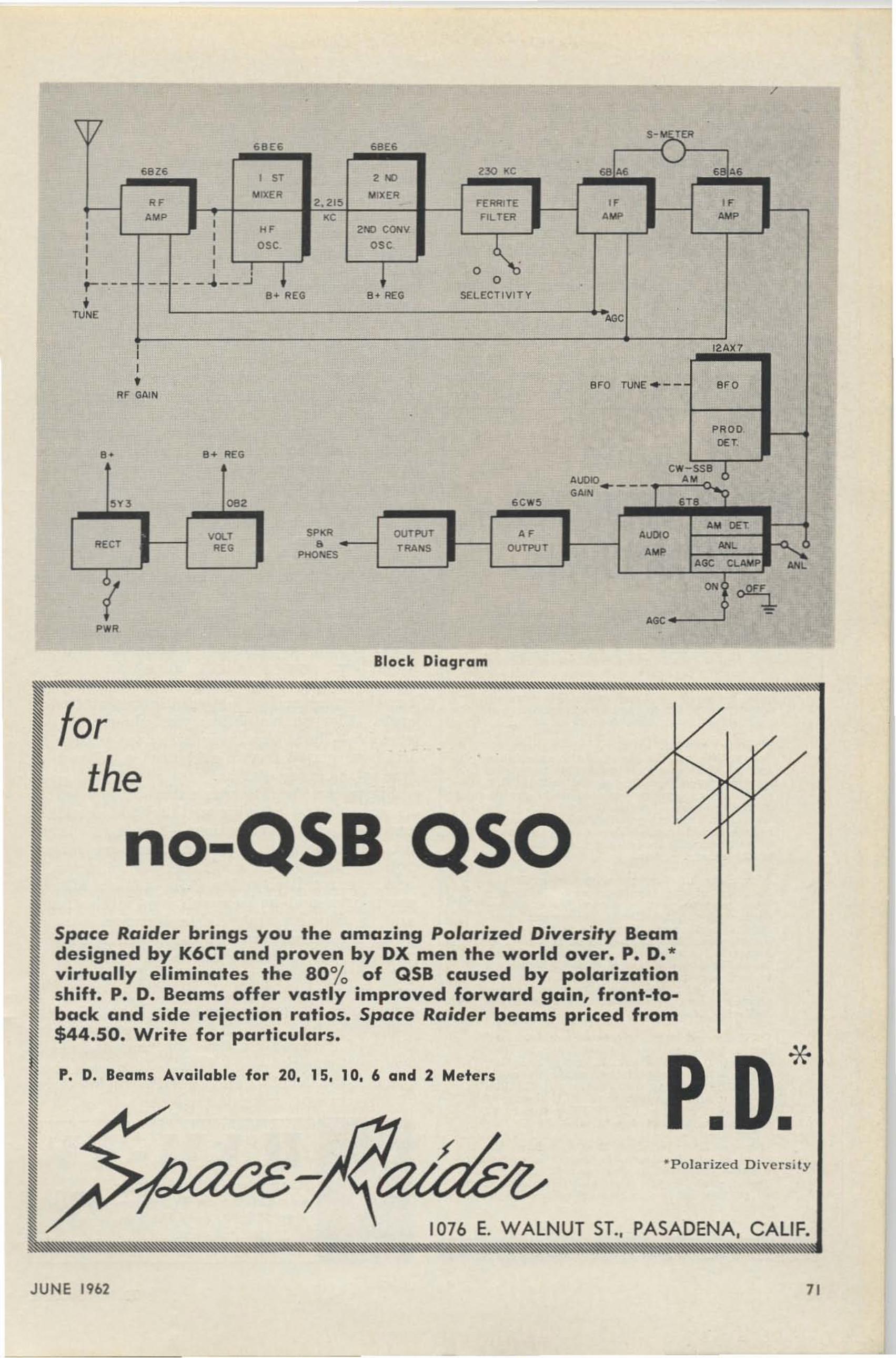
/
\1/ S- ~EFJ69E6 6BE6
'-./6816 "., 2~ KC 6846 s ", sr
toI lXER ".IXEROF" 2. 21~ FERRITE ".., <C FILTEFl .... '",, ,
"' e-o CONY, ,OS<I I 050 6
I I •
I _ __ " _ _ J 0
r --- - - 0 •
Ie. REG B4 REG SELECTIVIT Y
TU NE .';C, I2;AX1II,
' '0 TUNE . - - ",0Fl F GAI N
•
PRODon,. a.. REG
CW-SSB 6'00>0 ••....- --GNO
~,n 062 6CW!5 s-r
AM onVOL' $PKR OlITPUT " "'000
~FlEeT R<G a TRANS OUTPUT ,"LPHONES ..,
'GC CLAM P "<L
?ON o2!l
' GC
Siock DiaCjram
*••
' Polarized D ive rs ity
soS8
P. D. Beams Available for 20. 15. 10. 6 and 2 Meters
no-
forthe
Space Raider brings you the amazing Polarized Diversity Beamdesigned by K6CT and proven by DX men the world over. P. D.'virtually eliminates the 801'0 of QSB caused by polarizationshift. P. D. Beams offer vastly improved forward gain, front-toback and side rejection ratios. Space Raider beams priced from$44.50. Write for particulars.
JUNE 19b2 71

ham who wants excellent ha m band performance along wit h general cover age at a relatively low price. We forsee a couple of othera reas where t he NC-190 will be quit e popular-as a general coverage stand-by receiver fort he snazzy ham-band-only shack and as atunable if for some of the new VHF converters- The combination of price and per formance on th is package is hard to beat !
The trial of the ham-band-only NC-155 wasviewed with some trepidation in view of t he$199 price tag. Twenty-five years ago it wasposs ible to buy an awful lot of rece iver fo rt his kind of money, but t he cost of labor a ndmaterials has risen to the point where it takesaround $250 to start getting t he kind of performance necessa r y for today's more sophistica ted operation. ' Ve were, therefore, pre-
wanted
RADIO OPERATOR'TECHNICIANS
The U.S. Government hae a continuingrequirement for single and married menbetween the ages of 20 and 30 with radiooperator-technician experience. Individualswith lese than minimum required experiencecan qualify for training. Persons with pastapplicable experience who for some timehave been out of touch with t h is type ofactivity will be trained. Assignments areoverseas at interesting foreign posts.
Starting nn nuu l sa la r ies, which will bedetermined by the applicant's experienceand ability, range from $4830 to $5885 .Normal promotional progress w ithin thissa la ry range may be expected when qualityof performance d ictetes, Beyond this latterlevel advancement possibilities exist on aselective and competitive basis. Standardgovernment allowances are paid in additionto the salary.
A variety of for eig n posts is available.Rotation of the employee and his familyfrom post to post is accomplished in accordance with standard government regulations and usually involves tours of 24months duration at each post followed byStateside lea ve between assignments. Workis challenging and varies from post to post.If you are in good health. not subject tomilitary d ra ft , and are interested in theabove openings, please write, giving us thefollowing information:
1) Name, address. telephone number. andhours when you can be reached; 2) Dateof birth; 3) Military history. includingdates. schools. experience, grade or rank,and MOS (primary and others); 4) Civiliantraining and experience; 5) FCC license ifany; 6) OW speed: 7) Typing speed: 8)Marital status and dependents.
If your tetter indicates that you have therequired qualifications, a formal interviewwill be arranged in the near future. Ad 4
dress letters to Mr. Carlton H . Broadnax.P. O. Box 82G4, Southwest Station. Wash.ington 24. D. C.
72
pa red to be disappointed in the NC-155 evenin view of its h andsome a ppearance a nd highqu ality of fi nish and construction. This feeling bega n to be dispelled as soon as we laida hand on t he main tuning dial , and by theend of our fi r st for ty-five minut e session witht he N C-155 our original opin ion was completely replaced by the ha pp y conclusion that theNC-155 was more t han able to hold its ownin far higher priced company ! Just as in t heNC-190, the first operating feature noticedwas the extraordinarily smooth tuning mechanism. The NC-155 also uses a 60:1 dialreduction, and t he combination of the heavyflywheel on the tuning dial and the VelvetVernier in a ha m-band-only receiver resultsin a "feel" which closely approaches that ofour own NC303. According to National, the60 :1 reduction on t he NC-155 is almost twicea s high a s t hat of any other ham-band-onlyreceiver, a nd as a result it is possible to workin on sideband almost. as easily as AM (advanced modulation). Dial calibration and il lumina t ion is excellent, and electrical featuresar e basically the same a s those of t he NC-190since bot h r eceivers are almost identical fromthe fi rst mixer back to the loud speaker. T heNC-155 seems to be as mecha nica lly stable asany receiver we have yet tried with a crystalcontrolled f ront end-We t uned in a relativelyst rong CW signal on 20 meters, picked thefront of t he receiver up three inches and letgo-T here was a slight rnicrophonic bongwhen t he Flip Foot cr ashed on t he tabletop,but t he rece iver had apparently not shifted acycle. Elect rical stability was almost as impressive-Total observed dr ift over a fo ur tofive hour period from a cold start on 15 meterswas in the order of 1 kc.
Six meter stability was naturally not nearlyas good, but sensitivity on this band cer tainlyexceeded our expectations-National claimssix meter sensitivity better tha n one microvolt for 10 db, and while we did not a ctuallymeasure sensitivity, the '155 dug u p all t he~'eak ones and had enough hop in t he frontend to show a n appreciable decrea se in noisewhen the antenna was replaced with a 50 ohmresistor . Six meter signals were quite easy totune as a result of the excellent dial r a tio, andwe a re presently toying with the possibili ty ofusing t he six meter range on the '155 as atunable if for 2 and PAc meter converters because of its complete 4 me coverage a nd excellent performance.
Both t he NC-155 a nd NC-190 fill big holesin the current crop of receivers.
Com pie t e instructionsfor getting on TV for under S50.00. Join the Fun.
73 MAG. 1379 E 15. Bklyn 30. N.Y.
73 MAGAZINE

4- RADIO AMATEUR CAll BOOK- Summer Ed it ion. JustOu t. S5.00
48-BASIC ELECTRONICS - Covers subject completely.Written for us. w ith RCA Inst itute training cou rse . $9.25
5-ANTENNAS - Kra us (W8JK). The most complete bookon antennas in p rint, but largely desig n ond theory,comp lete with moth . $12.00
49-ElECTRONIC COMMUNICATION -Shrode, . Huge booka imed a t g iving all information necenary for FCCcommercia l a nd a mateur licenses. $13.00
Circle the book numbers you wish to order.Please include cesh, check. money order • . .or something we CGn deposit in the bent.
Order Form
74- HANDBOOK OF ELECTRONIC TABLES & FORMULASFormula s & lo ws, constants, sttlnd a rds, symbols a ndcodes Mtlth. tab les, misc. dtl ta. $2.95QAN':'SECOND CLASS RADIOTELEPHONE HANDBOOKNoll (W3fQJ) . Every thi ng you need to know to p,?uthe FCC exa m a nd get sta rted serv icing two-w a y equIpment. Much more tha n just a Q & A mo nual $3.95
BON-fIRST CLASS RADIOTElEPHONE LICENSE HAND.BOOK. Everything you need to know to , get your h tlice nse. More than 0 Q & A book, you II und~ntondwhat it is a ll a bout when you get through thiS one.
$4.95
EGT-ELECTRONIC GAMES AND TOYS YOU CAN IUILD.IS Orig ina l ga mes and toys, none ova!lobl~ commercia lly. Test your steady nerves; your reaction ti me, battlea lie dete ctor, e tc. Guaranteed rouser. $2.50
NHP-BUlLDINO UP YOUR HAM SHACK-Pyle (W70E).A practical d iscun ian of points to cons!der whe.n youa re buying hom equipmen', com p lete With descrip tionsof much of the ovoilob le commercial ge« . It 's lustpossible tho. Pyle might keep you from making 0 ",1. take which would cost a 10' more than his b ook. $2.50
BEO-OSCILLATOR CIRCUITS. One of the most thoroughtreatments of the sub ject yet to be published . Uses the"ew four-color system for explalni"g what actuolly goeson in the oscilla to r circuits . $2.95
G-93-RADIO CONTROL HANDBOOK b y McEntee . This Isthe largest o " d mos t com plete book ever published 0"the subject. 304 pagesI It coven in detail every possib leospect of rodio control. $4.95
G94 -TRANSISTO RS. Selected art icles fr om Rodio Electron ics on how to te st transistors a nd how to b uild allt ra nsistor test eq uipme nt. $ t .95
R261 -MAGNETIC AMPLIfiERS. This new Rider book Isa comp lete home -stud y cou rse in M-A. Expl icit ly illust ra ted . We don't find M -A in hom use ~et, but the ya re g row ing in industriol use. a s mor~ e ng ineers unc!e r.sta nd the o ppli cotions of thiS re la tive ly new deVice.11 2 pages. $2.45
731-HAM-TV-W'I'Kya . This is the only book a vailableon this fa scinating branch of ham radio. Describes comp le te ham TV sta t ion tha t eests under $50. $3.00
732-FULL SCALE PRINTS FOR MARK III IMPEDANCEBRIDGE FROM AUGUST 1961 ISSUE OF 73. These en .largements of the published $ca le drow ing$ g reotlysimp lif y home construction of thi$ t erri~c . piece ~f te !tequip me nt. A comp lete copy of the onglnal ar t icle ISa lso Included. $1.00
734-INDEX TO SURPLUS- Bibligor a phy of all surplusa rt icles printe d in 011 radio magazines ' 0 dote. Briefde script ion , e tc. $1.50735-BOUND VOLUME- Od ober 1960 .hrough Decemberl S issues (Vol. u. $15.00SEE MARCH ISSUE FOR LIST OF CONVERSION MANUALS
9O-TELEPRINTERS, MODEl 31A- Thi s midget, prln ter,comple te wi th case, mea $ures only 11" x 16" x 12" a ndis light e nough to throw in the co r for portable use .Complete wi th ke yboard, rea d y to opera te . $100 .00
(W6SAIJ.handbook
$8.50
blahblahblah blah blah
40-RADIO HANDBOOK, t5th EDITION-OrrThis Is f tlr t1nd t1 w tly the best t1mateur rtld ioever p rinted. Over 800 page,.
37-tOI WAYS TO USE YOUR HAM TEST EQUIPMENTMiddl eton. Grid -dip meters, o nte nna Imp.do"~ mete",oscilloscope s, bridge., , Imple noise generators, ondre flected power mete,. are covered. Tell. how to chasetrouble out of hom gear. 168 poges • $2.50
36-CALl LETTER LI CENSE PLATE- Re gulotio" $ize Iice " seplate. Pleo se g ive yo ur ca ll a nd the color of letters ondb ackground. $3.00
13-REFERENCE DATA FOR RADIO ENGINEERS. Ta b le s.formulas, graphs. You w ill find this reference book onIhe desk of almost every electroni c engineer i" thecountry. Pub lished by International Telephone and Telegraph. $6.00
28-TELlVISION INTERFERENCE-Rand (W1DBM). This Isthe outhorltative book on the .ubled of ge"ing TVI outof your rigs and the nelghbo,. seh. $1.7'
47-PRACTICAL ELECTRON ICS-Hert zberg (W2DJJ). AI.most solid w ith picture•• Tou che$ lig htly on many a s.peers of eledronics: ham radio, TV, transistor radios,hi-fl, microwa ves, t roubl e. shooti" g, Novice stat ion,antennas, test equipment, e tc. $2_50
t-ELECTRONICS & RADIO ENGINEERING-Termo n. Oneof the most complete text books ever printed. 1078pa ges. Theor y, but easy 011 the math. $15 .50
If you'll just read some of these booksyou'll know what you are talking about.
8-RADI0-TElEVISION & BASIC ELECTRONICS- O ldfie ld .l ogicol presentation o nd descript ive illu stration makethis all ideal book fo r the begi nner. Wr itten by self .leorn i"g of e lectroniu p rincip les. 342 pages. $4.95
32- RCA RADIOTRON DESIGNERS HANDBOOK-1S00page s of design note s on every possible type of circuit.Fabulou s. Every design engi neer needs this eee, $7.50
52-HOW TO READ SCHEMATIC DIAGRAMS- Ma rks.Components & Diagrams; e lectrica l, electronic, c e, de,a ud io, rf, TV. Storts with Individual circuits and ca rrier$thr oug h compl ete equipments. $3.50
63-G.E . TRANSISTOR MANUAL 6th EDITION.
55-TRANSISTOR CIRCUIT HANDBOO K- Simp le,u"c:lentand expJa"ation of 'ransb.ot> circuih.of Interesting opplicatlo"s.
RADIO BOOKSHOP1379 e.,t 15th Street, Brooklyn 3D, N. Y.
(N.Y.C• •dd 3"1. tex)
• • • • • •
Call . . ...
State ..
• • • • • • • • • • • • • • • • • • • • • •
• • • • • • • • • • • •
• • • • • • • • • • •
Address
Name . . .
City. ..$2.00
Clark.$10.75
eO$y teDOlens
S4.95
Another$ 13.00
ANALYSIS- Joyce &
& DESIGN- Fitche" .67-TRANSISTO R CIRCUITtop notch Fitchen book.
65-TRANSISTOR CIRCUITChoice of top schools.
JUNE 1962 73

The Perfect Setup
Dcuqles G. Hedin Kl/.lOFB219 Blencherd Blvd.Syracuse 9, New York
T HE key to good hamming is a good st a t ionsetup, and this is a lot easier to achieve than
you may t hi nk. W hether you are t rying todecide how to set up the new h-f station orhave been operating for a while but aren'tgetting out like you should , t his article is foryou.
F or all the sour-grapes balderdash one hearson the bands about system-eng ineered hamequ ipme nt, t he idea is perfectly sound: eachpart of the system must work properly withat least one ot her par t . If we investigate t hisworki ng-together concept more closely, howeve r , we find that such a system really is j usta n umber of "twosomes." For example, thefollowing twosomes will be found in any a mat eur st a t ion : space-an ten na , antenna-feedline j
feedline-transmitt er; and feedline-receiver. Itmakes no difference whether they are made towork together at a factory or you make themwork with ingenuity and hot solder .
In f act , it is because of t hese twosomes, or"interfaces," a s t hey arc properly called, t hatit is easy to set up an amateur st a t ion properl y and at low cost. I t isn't necessary to perform a set of si multa neous equations in a halfdozen unknowns, but on the other hand, a stati on cannot be set up j ust one part at a time.(Can you imagine only one con nector connecting? )
In genera l , the antenna, especially the highcurrent , cen te r portion , should be a s h igh a spossible. There are sever a l reasons f or this.The higher the a ntenna is above the averageterra in , the lower ( and better for d-x} wilt bethe minimum usable radiation angle. Thehigher the an ten na is above trees and otherconduct ing obj ects, t he less power they willabsorb during both transmission and reception.The h igher (up to a point) an a ntenna is aboveg round, the h igher will be its radiation r esi stance and , hence, its effi ciency.
'.._._ ....
-,•
_ _ I~--_._..
74
Horizontal, half-wave dipoles usually areused on the h-f bands, primarily because, dolla r for dollar, t heir simplicit y and light weightpermit t hem to be er ect ed at greater heightsthan any other antenna. To be sure, the lowradiation angles of vertical antennas are idealfor DX work ; but efficient vertical h-f antennas are cumbersome and difficult to) erect, theyare more vulnerable to man-made noi se, a ndunless a good artificial ground is const r uctedfor them a prohibitive a mount of power will belost in the ea r t h .
A widely-held, somewha t er roneous idea isthat the user of a horizontal antenna ca n communicate in only two general d irect ions, because the horizontal radiation pa ttern of ahorizontal dipole is two lobes a t right anglesto the antenna wire. But what about the ver t ical radiation pattern?
It should be remembered that from a horizontal doublet, only part of the t otal energyis radiated br oadside to the w ire and that thepolarity-ver sus-amplitude of the energ y radiated in a ny direction depends on both t he elevation angle and the azimuth considered. l\[uchof the energy is radiated from tl hori zontaldipole in line with the wire, or "off the ends."This energy will be received j ust a s well byan antenna the end of which is toward thetransmitting antenna a s will the energy radiated at right angles be r eceived by an an tennawhich is broadside to the transmitting antenna .This vertically-polarized energy is r ad iated atsomewhat high radiation angles; but the on lyshor t coming of the end-r adi a ted rf is t ha t theskip, or maximum range of communication willbe somewhat shor ter than that for the horizontally-polarized energy from the sa me antenna.
It is relatively easy to work all bands, from3.5 to 29.7 me, with only one feedline if s inglewire, center-fed, half-wave dipoles are used.T he di poles are merely cut to the proper lengthand connected together a s shown in Fig. 1.l\lost of the amateurs who use this multi-dipolea ntenna system do not include a dipole forthe I f i- Met er band, because the 40-l\l eter d ipolewill load up fairly well on 15 Meters . However , the radiation pattern thus produced contains seve ra l narrow lobes instead of the twowider lobes characteristic of a half-wave dipolewhen oper a ted on its resona n t frequency. The
73 MAGAZINE

TOWERSSULLIVANILLINOIS
FRm! $59.98Send for FREE li tera ture on the ~om
plete li ne of YA:\GUARD radiot:>OOnH.fo r industry. Ci\"11 Defense. CAP .Citizens and Amateur bands. Made Inthe U.S.A. and guaranlud 5 yean.VANGU ARD EL ECTRO N iC LABS.190-48 99th Avo.• HolliS 23. N. Y.
WALKIE-TALKIE RADIOPHONES
TONS OF AMATEUR E QU IPMENT IN STOCK
\V\VIE$lrIEIRU~ IRt~IDIIOSAN DIEGO
1331 Inaia Street BE 9-036 1MaN -FRI 8:30 ,. 8:00 SAT 8 :30 ,. S~OO
--
The biggest improvement in crank-upsyet - you crank up the antenna andnot t he tower. It takes a minimum ofspace , is fa st to erect, and you ca nnever fall offl Makes it a <nap to changebeams or make adjust ments wheneveryou please. You can even crank t hebeam up to the best height for currentpropagation cond itions. See the photoson page 15 of the Ma rch '62 73 for abetter idea of what this is all about.Government a nd commercial installat ions a specialty. Send for lite rat ure and
•prices:
HY·TRACK TOWERS
88 mhy TOROID BONUS 88 mhy-JUNE. JULY Clod AUGUST '62
fREE .033 mfd. (Spa ce) and .068 mfd. (Mork) 200 V.factory fre sh Cornetl -Oubilier MYLAR copa citor$ witheoch order for 5 Te relds,
88 mhy. TOROIDS, with mounting hordwore. Uncosed;like new . Info rmat ion shee t included . $1 ee., 5 /$4 postpoid.
K C M P. O . 80X 8.MILWAUKEE 13. WISCONSIN
CAVIN INSTRUMENTS, Inc.6M FILTER? Low pass .•.•.••. .••.• . 516.95With Power Meter •...••• . .•.. ..•.. 534.7580M·l0M F;IIer ..•.••••. ..•..•.••... $24.95
More details on p. 27 Ma y 73
P. O . 60x 413. SOMER.VILLE. N. J .
'"" '--- -i;- - i;-- -J;. - t-- ,:;-- -!;;-- -;!, 0
flC!*l 2
eo
••'"· '"-u• ,:! u~"•s• eaj '"
author once used one of these multi-dipole antenna in which a Is-Meter dipole was omitted ;operation was excellent on all bands except 5Meter-s, until a Hi-Meter d ipole was added.The new dipole really made a difference, andthe author heartily recommends that it be included.
\ Vhile the impedance of a half-wave dipolemay be about 72 ohms in free spa ce, it variescons ider ably at the heights amateurs have towork with. Most amateurs should be familiarwith the st a nda r d graph of theoretical antennaimpedance ( fo r a half-wave dipole) versusheight above perfect ground. The graph alsois fairly accura t e for heights of more than0.3 wavelength above "real" ground level.However, it g ives no indication of what theactual impeda nce of a dipole over "real"g-round may be for lower heights, because theimpedance is shown to approach zero a s theheight of the antenna approaches zero.
OO r-- ,-- ..-- -,- --,-- --r- --.- --,
"'f--/H-\Ij------\+ I-+--*--+----.,l
Actual measurements" over Ureal" ground,however, have shown that t he antenna impedance fall s no lower than about 45 ohms at 0.06wavelength (16 feet at 3.75 me), and in factbegins to rise quite rapidly a s antenna heightdecreases fu rther. F ig. 2 shows the antennaimpedances to be ex pected on the h-f bands forheights up to 70 feet or 0.7 wavelength, whichever is lower for a particular band.
Of course, the depth of electrical groundbelow "real" g round level will vary from location to location, and thus will affect the a ccuracy of Fig. 2. It should be remembered,however, that electrical ground usually is nomore than a few feet below "real" ground at30 me, and less than 10 f eet below "real"g round at 3.5 me. Thus, the accuracy of t hegraph will va ry only sligh tl y for different locations, probably not enough to be detectable.
Amateurs usually use either 52- or 72-ohmcoax or 72-ohm twin-lead to feed half-waved ipoles. Referring to Figure 2, the dashed liner epresents 62 ohms, or half-way between 52
. H en ny. Keith. Radio Enlrin~ring Handbook. Four thEdition, 1950, McG ra w-Hili. pa ge 635 (graph ).
JU NE 1962 75

ohms and 72 ohms. The closer the impedanceof the feedline matches the impedance of theantenna, the more power will be transferredbetween the antenna and the feedline, and thelower will be the standing wave ratio. Therefore, if the impedance of an antenna (as determined from Fig. 2) will be higher than 62ohms, it should be fed with 72-ohm twin-leador coax. If the impedance will be lower than62 ohms, the antenna should he fed with 52ohm coax.
Just as maximum power will be t r ansferredbetween the feedline and the antenna if theimpedances are the same, maximum power willbe transferred between the feedline and thetransmitter or receiver if the feedline impedance is the sa me a s that of the transmitter orreceiver.
Before the days of pi-output circuits, t.ransmittel's usually were link-coupled to the feedlines, if feedlinea were used at all. The impedance or the link didn't matter much, because the coupling of the link t o the final tankcoil could be changed to com pensate for wide
......- '1--- --.-
\.~ -t:._-"..---- PO . ....
Today, however, the impedances most oftenencountered in amateur installations are 52,72, and 300 ohms. wtth only these three impedances to match, amateurs now can usebaluns instead of antenna couplers. Unlike theantenna coupler, t he balun never requires retuning, so it can be tucked up out of the wayand forgotten. Even more important, however,is that with only three values of impedance tomatch, four basic s~..s t ems may be designed,one of which is almost su re to sa t isf y the requirements of your equipment and antenna. Adescription of these four syst ems follows .
Fig. 3 shows a syst em in which the transmitter ou t put impedance is either 52 or 72
ranges of Iink-feedline impedance mismatches.Receivers had all kinds of input impedances;ea ch manufacturer apparently threw dice 01'
else counted tea leaves, which was about allthat could be done anyway because there wereno sta nda r d impedances at the time. Standingwaves could st a nd until they got tired, andopen-wire f eeders were the thing. Those werethe days of the universal, indispensable antenna coupler.
PO • •••• '( 71-,-•• _......-
r"_.-- -..,
--•• , /,..- f-.~l.
T_O ••' _
'-0 - .-.,.~- - ..~.. l •••
_.-......-.."
T_..."'"
_.--:..:-1- .,..
ru6CL6
330A
ORIGINAL. ";;-"12 TUlN LINK
112 CRI.. PA2,--'
OUT
3-1,1 0010!>d"MC 416 T
112 CRL PA2
2 TURNLINK'" 20
7 BS2
7 BS 2
,.
••cs
TO POINT ACRL F'l12 ,
TO LUG 2 .
'"
to•
A f ull st ep by step conversion sheet is available from \V4NUT at no charge.
Parts required.2 68 mmfd silver s. MATCHED1 Airdux 416-T1 CRL P A2 2 pole 6 pOB. SW
CO, 7~ l.";-.;-,.••vs"APPROX CENTER1llPPEO GO 10
EXISTI NG 50 Me.ro,
Fort Leuderdele, Horide12 18 SW 21 St. Court
Cepte!n George M. Hunt W 4NUT/Mm
Heath SB-10 on Six
Being a VHF addict, I recently purchaseda SB-lO from Heath for the express purpose of putting this phasing type Single Sideband Adapter on 6 meter s. The object was touse it in conj unction with the Heath VHF 1" Seneca." Using the 50 mc drive from theSeneca , converting t o single sideba nd withthe SB-lO, then driving either the Senecafinal in AB or other linear that would requireno more than 8 watts of dr ive.
The operation was s uccessf ul, the SB-lOworks as intended, 50 me sideba nd driven fromthe Seneca. The SB-lO conversion is as f ollows. Disconnect t he 10 meter section of theadapter, and in sert (; meter coil sect ions outboard of the existing coils , using the waferswitch points formerly used for 10 meters.Add one more cer a mic wafer switch to theex ist ing st ack , replace the 110 mmfd 1%micas in t he phasing stack with a matchedpair of 68 mmfd s ilvers. Remove 3 turns fromthe 10 meter slug tuned coil, feed three wattsof 50 me drive and 8 watts PEP 50 me singles ideba nd, upper, or lower comes out the backend. Easi er than hetrodyning, no mixers, justtune a s per t he S B-I0 instructions.
76 13 MAGAZINE

,
CALI F.2769 CAROLINAREDWOOD CITY,
No Books 10 Reod-No VilualGimm icks To Distrad You. JUlt
listen and learn
B..... . n mod...n IIl)'Cho'ttl."tfthnl llu" _ 1 11 11 ceurw will taka"au bey,nd 13 •.11.111 . I•
L ESS T H AN ~ THE TIMEAvailable also on magn.tic ta p.
Su You,. DraIer N0'U11
•
PRICE$9.95
EPSILOKRECORDS
GENERALIZE YOURSELFI
LEARN RADIO CODEThe EASY WAY
TO READ MY LATEST SURPLUSFLIER. RUSS-W2UFU
I DARE YOU
MANUFACTURERS • • •Looking for a ham rep?
Write IVAN HARRISON WSHBE6822 Mimosa l ane. Dalla s 30, Texas
Phone : EM 3-32 18
SPERA ELECTRONICS37-10 33rd Street
Long Island City, N. Y.
WITH DOW·S
PREAMPLIFIERGet signals you d idn·t hearr
Not a gimmick. but a tftted...-.d proven acc:1I!'SSOIY. Pre~cision ~. fuJly bKkecl byDow-Key"s tr.aditioNll F.aoryWarranty.
HELP YOUR RECElVER lThe DKC-RFB Booster Is ..
price • • • $1 0 .75 so to 70 ohm Impedance. . " • matching "broachlnd pre_
amplifIer guaranteed to Increase the e-er-en gain by I to 6 "5"ur:>its on all bands 11.5 to 30 mel . To improve sensitivity. wo....w.th OX. and bring up _ ..I.. "., intelligible sign"l" you'll want.OKC_RFB, Designed for te«ivers up to tke $300 (:1"51,
DUMMY LOADSNon_Radiating-SWR_Below 2 :1 AllBandl Thru 2 Meten . 52 ohms.100 WaUl ICAS P .P. S 4 .8S--WI~d
200 Wattl ICAS 7.95-Wired500 Watts ICAS 12.95 K it1000 WaU s ICAS 15.95 Wired
Add $4S.·.. Y""r D ..a l ,.'r <>r Ortler Dire ct .HAM KITS , 308 EDGAR RD.,80x 175
CRANFORD, N. J .
Album ContainsThre. 12" lP's
21h Hr.\.. Ins'ru ct ion
Several hundred readers have already b it on ourthree -O mops. Most of the m have written in to admitthet for once they didn't go wrong. What hom shockis complete w ithout a nice big world or U.S. map?None, what 's what. The se mops w e are vending arenationally advertised and di stributed a t $9.95. Wehad to prom ise that we would not sell them forany leu. We didn't promise not to sw ee te n the pota bit with jus t a hint of di scount in the shape ofa wee subscript ion to 73. If you invest in either oflhe maps we' ll send you a one year subscription to73 a t no extra charge. Don' t tell the manufacturer•• • OK? These maps, by the way, or. printed ineight colors (a ll di fferent) and are 28 V2" x 18V2" .They a re carefu lly ma de so the mountain s stick upin the right places. There is a map index includedwhich fits in a compartment behind the map. Thefrome is a lso includ ed . If you don't comprehendthe e normous s ize of these three dimensional maps,Ie' me tr a nslate it into more understandable dimens ions: 44 ,82 x 10 -ti miles wide by 29.09 x 10⁻⁵ mileshigh. Specify world or U.S. map, new renewolsub scrip tion.
MAPS
ohms, the r eceiver impedance is 52 or 72ohms, and the antenna is either a dipole or amulti-dipole system. Although it is the simplestsystem possible, it also is the best, becauseever yt hing except the antenna is shielded bythe outer conductor of the coax (keeping spurious radiation in and noise out). Incidentally,coax (unbalanced) feed is just as good as twinlead (balanced) for h-f work; feeding a balanced antenna with coax becomes a problemonly when the diameter of the coax becomesmore than a small fraction of a wavelength.
F ig. 4 shows a 52- or 72-ohm receiver andtransmitter used with a balun a nd 300-ohmtwin-lead fo r feeding a folded dipole. Noticethat t he balun, which matches t he receiver andtransmitter- to t he 300-ohm line, is on t he a ntenna side of t he T-R switch , and it must carry the output power of the transmitter.
Figure 5 shows a 52- or 72-ohm transmitterused with a 300-ohm receiver and either a dipole or multi-dipole antenna. In this system,the balun is placed between the r eceiver andthe T-R switch, and thus does not carry a ppreciable power.
Fig'. 6 shows a 52- or 72-ohm transmitterand a 300-ohm receiver used with 300-ohmtwin-lead and a folded dipole. In this syst em,an op en relay or switch may be used.
In summa ry, if your equipment is in goodoperat ing condition, and if all connections aremade properly, a very sat isfactor y amateurst a t ion can be assembled if t he following suggestions a r e heeded :
(1) P lace t he antenna as high in t he air aspossible.
(2) Use horizonta l, half-wave, center-fedantenna(s).
(3) Select the feedline impedance on thebasis of the a ntenna impedance.
(4) Use a balun to match impedances.
73 • 1379 E. 15th St• • Brooklyn 30 • N. Y.
JUNE 19b2 77

ALASKA
ARGENT INA
AUSTRALIA
CANAL ZONEENGLAND
GERMANY
HAWAII
INDIA
JAPAN
MEXICOPHILIPPINE'S
PuERTO RICO
SOUTH AFRICA
U.S S R.
ALASKA
ARGENTINA
AUSTRALIA
Ct. NAL ZONE
ENGLAND
GERMANY
HAWAI I
INDIA •
JAPAN
MEXICO
PHILIPPINE'S
PuERTO RICOSOUTH AFRICA
U.S.S.R. .
ALASKA
ARGENTINA
AUSTRALIA
CANAL ZONEENGLAND
GERMANY
HAWAII
INDI A
JAPAN
MEXICOPHILIPPINE'S
PuERTO RICOSOUTH AFRICA
U S.S .R.
L£GEND
liliiiililiiii••••••••••••••••liliiiililiiiililiiiililiiiililiiiiI11III""" ""' """ ::::, ::,::::::,:: ::':: ',"::""" """"'"~~~~~~~ ~~~ ~
liliiiiII1IIliliiiil1li........ • ••••••mmmlllllll1III1III1III1III1III1IIIIII•••••lIIIImmlllllllllllllllllll
····· ... .......... -- ........ . ........ ..... :.::::..... .. .. . .••••••••••••liliiiil1lililiiiililiiiililiiiililiiiililiiiililiiiililiiiiII1IIII1II.••••••••••••IIIIIIIIIIIIIIIIIIIIIIIIIIIIIIIIIIIIIIIIIW•••1IIIIII1IIIIII1IIIIII1IIIIII1IIIIII•••••••••••mlllllllmmmmmlllllll•••••••••••••liliiiil1liII1IIII1IIII1IIII1IIII1IIII1IIII1IIII1IIl1liWlllll••••••••••••••llllllllllllmmlllllllllllllllllll.',·!' IIIIII IIIIIII IIIIII••••••••lIIIIIIlIIIIIlIIIIIImmllllllllllllllllllllllllllllmliliiii•••••••••••••••II1IIII1IIII1III11IIIII1III11IIIII1III11III1IIIII•••••••••••lIIIlIIIIIIIlIIIIImmlllllllllllllllllllllllli!!!··1IIIIII1IIIm •••••••••llllllmllllllmllllllllllllllllllmllllllllllll!··! , I11IIIII1IIl1li••••••••••••••l1lililiiii9I11IIIII1III11III••••
lIIIIIIIIlIIIIlIIIIIlIIIIIImllll•••••••••mlllllllllllllllllllllmmmmml1lim liliiii111II1II liliiii I11III m ••••mmIIIImlllll
". ..... ...... . ......... .... .•••••••••••••••• ••••••• ••••••••• ••••••••• •............ . .
1IIIIIIIIIIIIIIIIIIIImllllll••••••••••••••mg~m· IIIImmmlllllllllm•••••lllllllllllmmmm· . ....... . .... ... . - .:: :::: ::: :: : :: :::. :::: :. ::::::. ::::: :: ::: .••••••••••••••mmmmmlllllllllllllll•••••••••••••••••lIIIIlIIIIIIlIIIIIIlIIIIIImmmm.1III1IIIII1IIIII1IIIII1IIII1IIIII•••••••••mllllllllllllmmmmllllm ••••••••••••••••mllllllllllmlllllllllllllmmmlllllmmlllllll••••••••mmmmmlllllmmm1IIIIII1II•••••••••••••lIIIIlIIIlIIIIIlIIIIImlllllllllmllll1IIIIIIIIIIIIIIIIIIIIIIIIIIIIIIIIIIIIm••••••••llllmlllllllllllllmlllllllllmlllllll!> mmm••••••••lllllllllllmIlllUIIIIIIIIIIIIIIIIIIIIIIIIIIIIIII !!!!! !>IIIIIIIlIIIIIIm•••••••••m.mllllllllllllllllllllllllllllllllllll.mllllll••••••••••••••••mllllllllllllm••••
~lIIIImlllllllllllllllllllmlllllmlllllllmllllllm·m·.·.·••··.·.·IIIII·mmllllllllllllll!llll~~~~••:::::: - .
"00" .. . ·liliiii II1II••••••••••••""".m""" """m""" "" '.",,"...... . .:::::: :::::: :::: :; :::::: :: :: :: :: ::::::::: 1........... ........... m· ....I11III..... m··· ···I111•••••••lllllmmmmlllll "'" """ .."" ""''''''''..... . .
•••••••••••••••••lIIIImmmmm.•••••••••••••••••mlllllmm•••.. .... IIIIIIIIllIllllIIIII•••••••mlllllllllmmmmm·.. . .· ...... ... . .. ....•.... ..
mmmwBlllllm•••••••••lllllllmmmmlllllllllllllllIIIImllllllllllllllllllllllllllllllllll•••••••••lllllllllllllllmmllllllllllIIIIIlIIIImmlllll•••••••••mmmmmmlllllmmlllll1IIIIIIIIIIIIIIIIIIIIIIIIIImmllllll•••••••••mmmmmlllllm1IIIIII1IIIIII1IIIIII1IIIIII•••••••••lIIIIIIImmlllllllllllllllllllllllllllllllllllll1111111911111I111111m••••••••••lllllllllllllllmmlllllllllllllllllllll••••••••••••••••II1IIII1IIliliiiiII1IIII1II•••
- -

Propagation Charts
Devid A. Brown K21GY30 Lambert AvenueFermlnqdele , N. Y.
For the DX propagation chart, I have listedthe HBF which is t he best H a m Band Frequency to be used for the time periods given.A higher lIBF will not work and a lower HBFsomet imes will work, but not nearly as well.The time is in G~IT, not local time.
The Short Path propagation chart has beenset up to show what HBF to use for coverage
Advance Forecast : June 1962
Good: 7.24, 26.30
Fair: 5-6, 25
Bad: 1-4
between the 48 states. Alaska and Hawaii arccovered in the DX chart. T he use of this chartis somewhat d ifferent than the DX chart.First, t he time is the local time centered onthe mid-point of the path. Second, the di stancegiven in miles is the Great Circle path distancebecause of the Earth's curvature, Here are acouple of examples of how to use the chart.A .) To work the path Boston to Miami (1250miles), the local time centered on the midpoint of the path is t he sa me in Boston asin Miami. Looking up t he HB F 's next to t he1250 mile listings will give the H BF to useand the time periods given will be the sa meat each end of the circuit. B.) To work thepath New York to San Francisco (2,600miles), the local time centered on the mid-poin tof the path will be 1% hours later than atSan Francisco and 1 % hour s ea rl ier than inNew York (the time difference between NewYork and San Francisco is 3 hours). Lookingup the HBF's next to the 2,500 mile listingswill give the HBF to use. In San Franciscosubt ra ct 1 % hours from the time periods listedfor local time and in New York arid 1'h hoursto the time periods listed for local time•
••••••••mmm•••••••mmmmme•••••••m•••••••••mmmmm~.•••••••m~mm~m~•••mmmm.m.••••••••~•••••••eeeee•••••••••••••••••••mmmem•••••••••••••••••••••m•••••........................1111111 111111111111111111111111111111111 11111111••••••••••••••••••
1 1II1 1II! 1II 1 111 111 1 1111 111 111111 1 111111 1 1 1 1111 ~ 1II 11 111 111 1 1111•••••••••••••IIII1111 IIIIII/lIIIIIIII
1111 111 1111111 111111 11 !1II111111 111 111 111 1111111111 111 11 11 111 111 11 11 1111111111111 11 11111 111 !1II11 11 1II1111!111 11 111 11 11111111 11 11:•••11111111 11 1111 11 111111111111111
111111111111 1111 _ _
750 MILES000 MILES
250 MILES500 MILES
1250 MILES
1750 MILES1500 MILES
2000 MILES2250 MILES
VIBRO·KEYER
FREEFolde r
In huildlnll' flf'Ctmnil" I n n, m ining unlll , Vi hro -K I'H"rI UI.p ll es the perfect I,ut,WlIh a Ihl .'I~' Iloll shed buse3~" by . 'h" and a wolghto( 2* lb•. 11 88 aamo cont a cts and 1l1lt"ly t1llhhed"__\' Ihroplt" x pa Tt8. :-:tan<lard.at $17.95; n e r. us e . '11th(11n1ffit" I' la ted Base. priced dat $:!2A5. Or er
MAKES SENDING A PLEASURE With
V I .. nOli I. I~ X Xin
HAM SHACK NOVELTYAuthentic.looking. two-color certificate claiming tonguein-cheek ownersh ip of an acre on the Moon', surface.Ideal gift or conversation piece (or shack, bar. den oroffi ce. (S" P(I . 1l9-hul. 61, CO.) W ith eold sea l andname and eal! inscr-ibed only $1.00 eacb. Six for $5.00.Send cheek or M.O, to--
BOX DXG. 173B- 201 St., Ba yside 60, N. Y.
E XCLUSIVEO ld )'00 lInow Bob Graham dt'l.lI I nly tn Amlt~ur B l dloKQulpm~ntf Did )'ou know he hu two atoeee handling onlyeQuipment l uch al Colllna. Natlonll , Ih lllcran en , Hammarlu nd,Goolet , Johnl on , Central E lectronlea, Clegg, G lobe. etc.' Did)'OU know hi lerrlee. III t)'Dfl! of ham gear .. "ell U bun,tradu. 1.IpI, r ents , and Install' lQulpmftlU Did )'ou lInow hehu • Ilrlt l electlon 0( reeooditiooed and I'Illranteoed .Ied.earr You dldn'tl Well DOW 70U do.
GRAHAM RADIO INC.505 Main St., R.ading, Mass. • T.1. 944-40001105 No . Main $1., Randolph, Mon . • T.l. WO 3-5005
JUNE 1962 79

KarI Tipple W 5TEVDept . of Electricol Engr.Southe rn Met hodist Univ.Delles, Texes
Constru ction and Use
Noise
DiodeCrystal
Generator
A
RI • 10.000-" PCJ1'- - LOG TAPEP PREFERRE:OR2' V2 ..TT "ION- 1~OlJCTlVE RESISTOR EQUAL
TO U~E IMPEOANCE
'" ,
majority of amateurs something less expensiveand more readily available is needed. A crystalnoise generator, which can be constructed fora few dollars and which will enable anyone tomake before and after comparisons of noi sefigure, is such a device.
Briefly, the theory behind the use of thenoise generator follows. The sensitivit y of areceiver is highly dependent on the ability oft he rf stages to amplify a weak signal as m uchas possible while a dding a minimum amountof noise to the signal. Noise of this type willbe heard at the receiver output a s a familiarhiss or "rushing" sound. Now, if an exter na lsour ce of broadband or white noise (randomnoise independent of frequency) is connectedto the receiver antenna terminals, an increasein noise or hiss will be noted at the receiveroutput. And if t he noise generator output isadjusted to provide exactly twice as m uch receiver output noise a s existed before the application of the noi se generator, then the generator must be providing a noise signa l equ.alto that generated in the receiver. Thus, if thereceiver can be modified so as to reduce thenoise generator signal required to double thereceiver noise output, the noise figure of thereceiver will have been improved.
A noi se generator of the type described inthis article can not be used for measurement ofabsolute noise figure without additional calibrating equipment. It can, however, be usedfor concparieon. of noise figures. It enables oneto determine whether a receiver really has beenimproved a nd it can be used to determinewhich of a number of possible modificationswill yield the best results in terms of minimumnoi se figure (maximum sensitivity). Use of thedevice will be di scussed in more detail later.
A basic noise generator circuit is shown inF ig.!. The noise is produced by CRl, a silicon
"'
1~21
'"RI 1~23
>-:-"'f'- ce•
DC IIl ILS(TnT l6 _ = 61
MOST amateurs who do very much operat. ing at the higher frequencies where receiver sensitivity rather than QRI\{ often deter mines success even t ually come to the conclusionthat their present receiving equipment is nota s sensit ive a s would be desirable and that acha nge is in order . And once that change hasbeen made, whether it takes the form of a newconver ter or modification of exist ing rf st a ges ,one nearly a lways wonders whether the newreally is better than the old. Comparisons ofsigna l st r engt h with new and old equipmentare er ratic and unreliable at best and do notnecessarily g ive the desired information sincethe absolute output level or "S" meter readingis not the problem. what is actually of concern is whether the signal to noise ratio of thereceiving system ha s been improved. Or inother words, does a given rf signa l produce anaudio output signal from the new receivingequipment that is louder in comparison to thebackground noise than did the same inputsignal with the original receiving equipment .If it does, t he noise figure of the new receivingequipment is smaller (better) and it should bepossible to copy a weaker signal than before.
Unfortunately few of us own or have accessto a signal generator of the proper frequencyrange, with an accurately calibrated attenuator and shielded out put , for making the typeof measurem ents mentioned above. For the
80 73 MAGAZINE

diode of the 1N21 or 1N23 variety. These diodeshave been widely available on t he surplusmarket for several years. T hey are also readilyavailable new at small cost; however as willbe explained later, it may be desirable to usea surplus diode rather than a new one.
... ,RI = 10,000 ohm pot-109 ta per preferredR2= Yl watt non ind uct ive resisto r equal to line impeda nceO the r paris sa me <!IS Fig. I
T he current supplied to the d iode from thebattery a nd therefore t he noise gener a ted byt he d iode is determi ned by t he sett ing ofRl. The best value f or Rl is necessarily acompromise since in i t s maximum resistanceposition it must limit t he current to a low valuebut it must also not change r esis tance too r a pidly at the low resistance end of t he rangeor the nor mal operating range of the instrument will be limited to only a few degrees rotation of the R1 shaft. A 10,000 ohm log taperpot should prove satisfactory.
The value of R2 should be about the sameas the transmission line impedance. A goodvalue might be 56 or 68 ohms, although if itis desired to use t he noise generator withequipment which nor mally oper ates from higher impedance lines , a larger va lue should beselected for R2. In t h is case one might comepromise with a value of 100 ohms. Cl servesas bypass capacitor and may be either micaor disc ceramic.
A more elaborate arrangement was used inthe construction of the unit shown in Photo. 3.A schematic of this generator appears in F ig.2. Here a tapped battery (2 peneells) was usedto minimize the range to be covered by R I. Itshould also be noted that the diode is shown
"-.L OHIQH
"T[XT~tJ:1II-l -sec"
•rexr .,e,
"" .,•
reverse biased in Fig. 2. Many of the surplusdiodes available ha ve very poor reverse resistances, which will allow reverse bias operation, and when operated under these conditions will generate considerably more noisefor t he same bias current t han when operatedin the more convent ional configuration shownin F ig. 1. T he diode must ha ve a reverse resist a nce of only a f ew t housand ohms or lessif it is t o work successf ully in t he reverse biasconnect ion. Therefor e unless t he reader canobtain some surplus diodes and select one wit ha low reverse resista nce, it will probably benecessary to operate t he diode for ward bia sedand to use t he higher battery voltage of F ig. 1.
T he meter range depends upon t he batteryvoltage and the resistance of t he diode inwhichever connection it is used. The meter usedin Fig. 2 was a 0-4 rna surplus meter. H owever, if t he diode is opera ted in t he forwardbiased connect ion a meter of somewhat higher current r ating will p roba bly be needed.Therefor e, it is suggested that a low r a ngemeter be obta ined and if mor e t ha n full sca lecur rent is r equired for t he diode to develop aufficient noise, a shunt resistance can be placedacross t he meter ter mina ls to extend t he meterr a nge. An inexpensive meter can be used s inceall that is needed is a relative indication ofcurrent.
VOlnlETER
fiG. ~
For t hose not familiar wi th the IN21-1N23type diodes it might be mentioned t hat theyha ve no wi re lea ds. The a node connection is abrass shell on one end of the unit a nd thecathode connection is a brass pin at t he otherend. Al t hough external connecting wires mightbe soldered to the brass ends, there is dangerthat the diode will be over heated and destroyed by such techniques. It is safer to makeconnections by clamps made from small plateor grid caps or fahnstock cl ips.
. CUTS WIRING COSTS!
M ODEL 24
$8.50OFFERS YOU 6 SOCKETS WHERE YOU NOW HAVE 1
IlATED15 AMPERES .
131 VOLT$.
Heavy duty features insure long-life and complete • Pallel Mon Ied ru e • Monlinl Emutility for use on equipment or in shop o r plant! _ ,•.'I-o,', S.Wildl • SilmGrlySumlm
SEND FOR LITERATURE • 101 1&I HammerlaneCaseQUOTATION FOR SPECIAL UNITS ON REQUEST ",.Ut... : U:I~~dup~Ulcafd s et • "U" Graund
_ WABER ELECTRONICS, INC ~ ~. ".LA""'" ....""1,,• • 'Co ... . Campu enls • AlIaplaf rreeHancock & Somerset Sts. Philo. 33, Pa. ..... ' 11 \(,.. Md el 2. CI (CI,cllitllUh, Type) S1I.5D
JUNE 1962 II

Receiversh ip
It should be evident from the above discussion that t here is nothing critical about thecons t r uct ion of a noise generator of th is k indand that a number of di ffe rent circui t variations are possible. Even if the device ,v'ereconstructed enti rely of new components t hecost should be less than $8 and with a littleingenuity the cost ca n be reduced subs ta nt ia ll yth ro ugh t he use of su r plus part s.
Perhaps use of t he noise generator can bestbe illustrated by considering an example ofnoise generator application . Suppose tha t youwant to use eit her one of two available G meterconve r te rs with your low band receiver andt hat you wish to det ermine which converterwill provide t he best weak signa l r eception. Atest set-up is shown in Fig . 3.
The ac volt met e r is used to measure theaudio out put of the receiver and may he eithera multimeter or a VTVM . It can be connectedacross the s peaker terminal s or al'1'08S the headphone l ine. Hi gher voltages ca n generally beobta ined f rom the headphone output and thisconnect ion will probably have to be used ifa multimeter without a very low ac range isused.
The measurements can be started by measuring the ac noise output voltage f rom the receiver with the noise genera tor turned "off".Then the noise generator sho uld be t u rned"on" a nd t he g enerator level adjusted until theout put meter rea ding has doubled . At this pointa note should be ma de of the noi se generatorsetting. The above p rocedure can now be r epea ted with t he second converter connected tothe receiver. Whichever receiver-convertercombina t ion requires the smaller noise g-enerator curren t set t ing- to double the noise output
H AVE vou ever wondered what happenedto H og a r th? He was t he little fellow with
the big eyes, the overs ized glasses , steel helmetand fa t igues who used to peer at us from thepages of va r ious amateur magazines promising us a new and better receiver as soon asthe war was over .
The war ha s gone, but I am beginning tosus pect t hat Hogarth never made it. Poorfellow ! 'Vhi le waiting for the promised receiver I bought some ot her post war sa mples ,j ust to stay in the field. I k new exactly whatI wa nted. F irst of all it had to he st ark. Thismeans , no ch rome trim or aluminum st ri ps ,no mult icolored dial s and various shades ofg rey fini sh ... just plain black crack le fi ni shwi th bare knobs. I assumed that the morefu ncti ona l it looked . the better should be theinsides , and even if this were not the case,the casual onlooke r would never sus pect tha t
82
is the combination that will provide the bestweak sig na l reception.
The noi se passed by the receiver is a function of the bandwidth of t he r eceiver. Also thereading g iven by a particul ar ou t put meter isdependent on its bandwidth. Therefore thebandwidth of the receiver should not becha nged during measurements and the sa meoutput meter should be used thoughout a setof measurements.
The techn ique described above can also beused to determi ne which of a n umber of rfampli fier t ubes will g ive the best performance.The noi se generator can be used for alig-nmentof rf sta ges.
For the man who const r ucts his own converters or r eceivers the device is a tremendousboon since s uch adjustments a s determining theoptimum antenna to grid coil coupling can bemade simply by adjusting for maximum increase in noise when the generator is switched"on". (This technique gives the sa me resultsas adj ust ing f or minimum noise generatorsetting to double noise output and it is a bi teasier to use when adjustments must be made.]If the in put circuit uses a single tapped coilin stead of two coil s, the best tap position canbe determined .
The uses mentioned above are on ly a few ofthe possible applications of this noi se g enerator, and for the amateur who constructshis own receiving equipment the device is indispensable . . . . \V5TEV
It E F EIU:S CESl onOllllhf'ric R a dio Pj-upa g at inn, Nation a l Bu reau o r S tand
srll~ Circular 462. JU lie 25. 1\l4R. PI', :H-aa.Ti lto n . N olse Gl'n f'r ator l'l-Thl'ir UlIl'S lind Ltmfte tiuns ,
QST. Ju ly . 195:1. I). In.
Raymond De Ves W2TAM140 Summit AvenueW est Trenton. New Jersey
it wasn't all it appeared to be. Then it had t ohave razor-sharp tuning' with at least 10 cycleresetabiltty, noise limit er , AVet BFO and )..OU
name it.Guess what I set tled for? Tuning charac
ter istics at lea st 10 kc wide, t hi s in order notto miss anything (which it didn't), resctability fair with luck and a crystal calibrator(outboard type) . no noi se limiter, no S meterand a barely functioning BFO. The colorscheme ranged from emerald green to dullbeige, with a green on-off swi tch lamp andred and white dial lights, aluminum ventilating louvres, chromed ski r t ing and gilded knobs.The dia l mechan ism was a wonder to behold.It looked like a s pider web of st r ing heldtaut by some half dozen sp r ings all propelledby a cou nt er we igh ted knob of gargantuan proportions . A flick of the dial knob would causethe pointer to travel from one end of the
13 MAGAZINE

sli .ie I-U I2 d.al to the other with incredibles peed , and unless you were agile enough tostop the revolving knob before it reached theend of the dial sca le , the poin t er would d isa ppear from sigh t and coul d on ly be ret rievedf rom the innards hy dext ro us use of tweezers,forceps o r haem ost .a t s. It was easy to hea r thera re ones wit h th is receiver because they werea ll rare.
Afte r st r uggli ng- with t h is u nit a f ewmonths and wondering- why t here were so fewamateurs on the ai r I fi nally succu mbed a ndtraded it in on another one. T h is one was sureto be better , at least it had a n S-meter andless eolor. The dial mechanism was a lledg edlyrgear d r -i ven, but sprocket driven would havebeen m ere exact. A quarter t urn of the knobwould move the dia l fi ne, but somehow t hetun ing condense r f ailed to get the message.Th is receiver was adverfised a s a "su rp rise"and i t sure met all qualificat ions. It was asurm-ise when one turned the band changesw.tch to 20 m et er-s a n d actually g ot the 20meter ba nd , it w as a su r prise to see t hat theSvmeter was not pinned, that t he BFO fu nct ioned when it was needed, that the re was nosmc ke coming from the power transformer,and that you could actually hear someone retUl'nin~ your' call. T he biggest su r pr ise , however, I reserved for the deale r who t ook it ina s a trade on another v entu re.
You guessed it , I was going' t o make myown . I f aithf ull y copied a parts l ist f rom t hearticle describing- t he rece ive r to be built andleft the list with the owner of the radio ernpot-l u m. A few days later he ca lled me t o comeand pick up my order a nd m umbled so methi ngabout it be ing complete but wi th a few minorsubst it u t ions. I was too worried about pa y ingfor the parts to care much a bout a few " minor" s ubst it u t ions so I let the matter r ide.When it came to the a ct ua l a ssembling andbu ilding I began to realize what "minor" subst it ut ions are. Nothi ng would fit t he originalplan . T he variable condenser wa s t oo long ,the power transformer too big, the dia l mechanism di ffere nt, etc. . . . I did t he best I cou ldby cha ng ing the layout and st r ess ing the economy f actor, thus saving face. If anyone a skedme, I could always claim t hat it was " mo reeco nomica l" tha t way. I ho pe secretly that Iwill never h a ve to say t hat again . The rece ive r , when finished, performed remarkablywell on the broadcast ba nd. I ca nnot sa y whatit could do on the other bands s ince I neverheard anything there. E vent ua lly I dismantledthe "thing" and put the parts in " stock" andset out to buy a nother one. This time I wasgoing to get wh at I had a lways wa nted, n omatter what the cost, a nd I was not to beswa yed by hon eyed wor ds from s pecia li sts inse lli ng r adio rece ivers. As luck would haveit, by the time I had enough cash scra ped t oget her to make a downpayment [ hea rd of anamateur on t he other end of town who was
K8/PALEE
2X6" • ~2,OO • - - 2XS" - S2.50
AMATEUR CALL PINS
II'#IR ~ X2 ~ • S 1.00l Y,X2Y," .. 51.50
SA R ProductsE N GRAVER S OF PLA STI C
2972 HARRISBURG RD. N.E.CANTON 5, OHIO
PLASTIC SIGNS FOR THE AMATEUR
ON .. OFF STATION SIGN
2 METER CONVERTER, Xio l controlled, " dbnoi.e figure, 5 low noi.e VHF I r gr'l$ i ~tors . ~uires 15 mo @11 -15 VDC . Complete .... ith inSlruc tions, S " 9 . 95
6 METER CONVERTER, .Jl toleonlrol led. 4 d bnoi.e figure , 4 low noi.e VH~ t ronl i ltors . Requires 13 mo @11 -15 VDC . Complete .... ith ;" " .....<:Iions. S 44 . 95
2 METER PREAMPLIFIER, 4 d b noi.efigure . 21db 9a;n, only I " 2-3/ 8 i"che~ for eosy i">Iallotio n . Req uire,2 . 5 ma @ II- 15 VOc. Complete wi th instruct ions. $ 13.95.
K3SLZ
~~~~;;D-.~;I/- ii)..-. -Reduces hrterf trenu and fl)f' ALL Amateur Trani ·Noise an All Maku Shorl mItior i . Guara nl u d forW.., Re..lve,. . Maku Wffl d MID Watts P ower for PI .Wide RIC' IlII ,n S tron . .... Nel er link Direct F Md.CI.arer , .. All Bandll LI.ht. NUl. W,alh ' ",",'
Complete IS lbuwn total le nClh 101 Ct . wltb 87 It. or 11 obmbala UNd rndlln'. 1I1· lmlJul molded r lllOClant trap• . CWt. a os..I" :l $" laic) . Yeu JllIt t un. to dnl"d band ror beamll.a relulu. E J:«llent for AI.L world-wlda II _t-" ava reeeh an andIo mateur lranlmIU.u. For r-O\"lC~; Ar-U ALL CLAK:l A1 IA TEl;RSI xo EXTIU -ruxens on GAIlHETS ,.EIWlm 'Ellmtnattl S lep.nte a ntennll ...Ilh nullent {lt rlormancaruarantttd. ..... .. Inverted V for all band power ..In. r- OH AYWIRE BOegE APP EARAN CE I ~;ASY lNSTA I.LAT IONI~O -fO ·'ZO · I$· I O m.ter b.ndl. Complete.•• ...• .• .••..• .• $14 .9S( 0- ;,;0· 1$·10 meter bandl. 5f -H. • nt. (belt fo r w - ... 1...1'1) 13.9S~0· 1$ - 1 0 meter hand•. Dual T r.p. 2f ·H. • nteen• . .. . • • • • I IUI,S EN D ONLY 15.00 ICllh. dr. .• mo l .nd P.,. pl}Ilm.n b.l.nceCOO plu_ OOfItl.r nn I r rlll) or l end full price lor pottpalddl"llvl"f"Y. jcrce Info rma tion.
An llable onl,. fro m:WESTERN RADiO Dept. "' 7.6 K ear ney. Nebraska
4 X 8" ... 54.00 SINGL Y 52.50
9 LAC K WITH R ED, WHITE OR GR E ENLETTERS WHEN !lACK LIGHTED.
LAMINATED PLASTIC SIGNS WITHAMATEUR CALL LETTERS.
.W& RT R•
ON THE AIR
83JUNE 1962

moving, or going into the army or to college(a standa rd one) and was obliged to sbed blaequipment including a very very excellent lowmileage receiver. I feU for it and he got mymoney and I got his "junk." I hope he wentinto the army and was sent to the North Pole.I know for certain that he had no choice butto move after he sold his equipment. Of courseI had a "try before you buy" test, but I hadno sta nda rd of comparison since my previousexperience had been limited to practically deadsilence. To me it sounded good, and evidentlymy friend s had been bribed to sa y nothingsince none advised me against this purchase.
After a few months of extensive dial twisting, band changing, tube changing, tr immeradjusting, if adjusting and broadcast listeningI gave up and advertised it for sale verycheap. To date no one has come forth, andperhaps no one will. I hate to give the thingto a young amateur for fear of giving himthe wrong impression of amateur radio. Inall fairness I must say tha t the dial mechani sm incorporated in th is receiver was theMOST. It looked like a four speed synchromesh transmission and even had a clutch tomatch. I could scan the Be band in first, second, third or fourth and if I just wanted toturn the knob and cha nge nothing I evencould do t hat. Secretly I think it was the gearbox that sold me and sometimes I am temptedto remove it and put it on the desk just forthe amazement of visitors or as a conversation
•piece.Since I absolutely had to have a receiver and
cash was a bit hard to come by, I saved whatI could and plunked it down for a sur plusreceiver. Even when I bought it I knew itwould only be a stop-ga p, a temporary meaaure, until I could save more and buy the best.Since I paid for it by the pound there waslittle justification in compla ining. Sure, it hadsome drawbacks but they were only "minor"ones. The receiver t uned from 4 kc to 18 meand picked up every signal between these frequ encies. The for ty meter band was covered
TRAVEL ABROAD with IHHe-Lower Costs !-Lots More Fun!
-Members In 50 countrie sW8SZf, 3075 SCARBOROUGH RO AD
CLEVElAND 18, OHIO
in 1AJ;" of dial and the 20 meter band in %oilspace. It took a steady hand to sepa ra te stetions, but I st ill had one then. The lack ofbandspread was admittedly a little inconvenient , but a magnifying glass and holding thebreath while tuning over ca me this handicapto some extent. There was no S-meter, but Isurely did not need one after all these years.In retrospect, I believe the feature that finallymade me get rid of it (trade-in) was a ratherpeculiar phenomenon which went as follows.There were four bands with a band switch toselect anyone band. The receiver functionedvery nicely about the center of each band, butat either end, when tuned for maximum gain,it would issue the most agoniz ing howl everhear d. I am st r ictl y against cruelty to animalsand t his sounded too much like a shot rabbit.Even the XYL and the kids begged me to stop.Rather than having the family ostracize meand getting the SPCA to issue a summons orto make an investigation, I decided to partwith the sur plus gem. Honestly, it did not takemuch urging, a nd this time I had the familyon my side so I went in hock, but good. Ibought the latest and most super-duper jobavailable to my limited means. There are nomore shr ieks from the receiver, but only moansfrom the operator when the monthly paymentsare due. So, how do I like it? 'Veil •.. ofcourse, I have an S-meter and lots of othergoodies but I also have a rubber dial. Themanufacturer of this unit must have a ballof pure latex between the dial a nd the tuningcondenser. If I set the dial of 3620 kc and release the knob it promptly jumps back to3610 kc. Perhaps the idea is to tune 10 kc.high and then let go. This may be an idea inthe field of semi-a utoma tion, but since I canhardly keep up with new developments theunderstanding of this new tuning system esca pes me. At any rate, it confuses my friendsand leads to no end of merriment all of whichdoes not help me to tune in any wanted sta tions.
In looking back I see that every receiver Iever owned had at least one redeeming feature. Now, why should I not be able to findone that had the best of all my previous onesand none of the bad features? Basically thereis circui t ry and tuning mechanism. I promisemyself that the "next" one will have the bestof each. Oh well, I guess I will have to buyanother receiver..•.
•.. W2TAM
TELEWRITER FREQUENCYSHIFT CONVERTER
• • ' ~,",""""""I
.~_ ...... '_t..'''" ,,,-- •..,-"'-... .- I
• .r~ ..'-
- Q ..•• .-.-
• ~ ti QJ • • - -J-- "' ''" '--0' - -- $1 89.00 Rack Maunt.d- $14.50 for Cab i....
The N.,. MMeI "K" Tel_it.. ConQrt... ( d. I, nN by M. J...0 ...•• Willilli W4EHU ) IlIClud.: I. Liltai' IIUdle dlwrf.lnlt.,.lIh hl,h Q tOl'llh f.r IIlU IMUIIl Interfwlne. njedl... . 2. Adqlcod keyl", tubo elnult te c._pen$.lte I... dlltortl...Ith If...t , ...'".....trol. s. Sell<ll..... lIIa,n.t CW'f'eltt fU"ly .lth 1Il1ll1"a11I.ttr. 4. Dual .y. Indicator. 5. ChaMll t .....I..I. lor p.l.,. rolay ~I.. S·R,.Ia)'. MId IHII. I . F,...t "'* J_u lor Iloyboard Uld ".I.t.... 7. Send.Ru. ud Pel.,.lty Rft.nlll' ..Ite"•• For furtb.., I.I.I1I,t1...... ......dltl ...... ",.tyP. lilt••rlt. : AlItrMlCI H••anI C.... 8 •• II, BNte. I, II... (RII"."d 2·G048).
73 MAGAZINE
-

Antenna Systems and Installations
BLITZ-BUGS
Factory Parts & Service for:
Marine Radio
Citizens Band
Stereo
SPO pIllS teepostage
Oh io Residents add3% Sales Tax
JO. lost issue.
COAXIAL LIGHTNING ARRESTER
1 MODEL LAC-1 wil h one ma le ClOd one. • femole Type 83 con necto rs ; in u all di rect ly to equipment . PRICE $3 .95 NET
2 MO DEL l AC-2 with d oub le femo le Type• 83 co nne ctors fo r " in· the -ca ble" in
stollotion. PRICE $4A5 NET
3 MODEL LAC-2 N w it h doub le femo te• Type N co n nectors fo r comme rcial "le
the· ccble' " inslollot io n . PRICE $5.95 NETBLI TZ· BUGS provide lightning p rotectionf o r crncteur, cifizen -bond, tw o -w a y ond 011o ther cooll io l co ble systems .See Your Distributor or Write for Catalog
Amateur & Commercial translnit..ters & receivers
looking for Service?
Test Equipment
Power Supplies
Hi-Fi
See Article poge
C-Y ELECTRONICS3810 E. 36Sth STREET, WILLOUGHBY, OHIO
D. S. B.-A. M. TRANSMITTERSideband On Six!!
Audio tone genera torVO X controlled ope rotion5" 1l7" Fibreglass P.C. board6 Sheets of drawings
Letters
Dear W a yne :Do YOU supp ose that " S up er American" W6RNC f ailed
to pay his dues in the J oh n Birch Society, got a Section8 from the Cali fo rnia Vigilantes and now figures to makea name for him self by stirring up ham radio ? I wa sdi srnayed to r ead his ad in CQ because he will undoubtedly attract some other do-goodera like himself,not even to mention some communists ( non hams ) whowill se ize any opportunity to forment dissent. It w as ar e lief to read your reply to h is letter. I hope enoughhams read your letter to kill this deadly idea.
Desp i te the wrangling that som et imes goes on over t heair on ham problems, we have a pretty dem ocr a t ic hobby.If you went to a ham club meeting and sa w the gangwhom you had known many yea rs , cou ld y ou guess h owmany were Democrats and h ow many were R epublicans ?• • . or Communists for that matter? K2 JFV sp ent s ixweeks in Russia this su mm er a nd he tells me that theirhams are the sam e way. The common interest is thehobby and they just don' t talk politics. For a Russianto get to be a ham and to have equipment capab le ofworking t he U.S. means t hat he has to be a p rettysma r t fellow and have learned t o sp ea k our langu age.H ow many of t hese are there? H ow many would listento a U .S. ham g ive him a line of propaganda "/ W e arecertainly much better off to let him listen to a happybu nch of w-ha ms enjoying thei r h obby and lea ve himJust a bit envious.
It is obvious that you a re not a DX'CT an d haven't yet'l/}IJ rked a Russian station. I'd like to see you find one singleU.S. amateur who does contact the USSR stations to backup you,. statements. Are these the kind 01 "facts 01 communism" you are engaged in educating! Y es, I'v e readM asters of D eceit. Since my interest in nudity hadn'tprogressed bey ond the Danish sunbathing magazines Ihadn't thought to read "The Naked Communist." How.somever, the loJ/owing Jetter tlkiy be interest. • • • Wayne.
Dear 01\1:I read your reply t o W 6RNC in Decem ber 73 Magazine
a nd feel very s t rong ly about your reaction . If you hadever read the Communist Manifesto, the book, Ma stersof Deceit or "The Naked Communist" you certainlyshou ld know t h a t no Commun ist can be trusted. If thesehams have talked with Americans it is not in good faith,but to lcarn somet h ing . You should know that they wouldnever be allowed to operate unless they w ere fully indoctrinated in com m u n ism. I am actively engaged ineducating the people a s to the fa cts of communism.
J ohn L. Satter lee K9LLT
E dson S now W2HZN
Dear W ayne :Re your 73 R eviews t he QZ-5 35 R eceiver on page 66
of t he December isaue ; I ha ve u sed this receiver in con ju nction with my H Q· 110 fo r about stx months andfind i t will do all W4U WA says i t will. On the 20 a nd40 meter bands you ca n cut the selec t ivity down toon e or two kc by throwing in the Q-multiplier. Thesereceivers are made by the handicapped persons of theSheltered Workshops, Inc., Santa Monica, Ca lifor nia.When you buy one of these receivers y ou get a nicelit tle certificate.
AMATRONICS, INC.(formerly Eastern Communications)
91·46 LEFFERTS BOULEVARD
RICHMOND HILL 18, NEW YORK
Phone: Hickory 1.7890AI. W4LSA
JUNE 19b2

Volues. etc.Jim Kyle KSJKX
lVIA~Y things prove puzal.ng to t he new-comer to ham r adio construction : what
k ind of tube sockets should he use, how shouldhe arrange t he parts on the chassis, what tubecan he subst it u te for that XY Z-34ABX hisdea ler never hea r d of'?
For 10 these many months we at 73 h a ve beentrying to help him fi nd the answers, a s well asto help hi s more advanced brethren find newprojects and idea s for construction. :\Iost of thenewcomer's questions can be answered speedily.
But one qu est ion which comes up f requentlymay leave even an old-t imer a t a loss fo r agood answer : " Why don 't t hey make, SUJ'
.a 1,300-ohm r esistors? ' Vh y do resistors comeonly in these odd-ball values like 33, 39, -17, or56 ohms?"
It's a good question, too. Often, when we calcula te the size of the resistor we need for so mecircuit where both voltage a nd current a recritical, we come up with non-standard values.It's only natural to wonder why we can't goout and buy the si ze r esistor we need.
There was a time-nearly 20 years ago n ow-when you could do just t ha t , almost . BeforeWorld W ar II , resistors anti capaci tora weremarked according to a decimal standard system. The values went someth ing like t his: 10,15, 20, 25, 30, 35, 40, 45, 50, 55, 60, 65, 70,75, 80, 85, 90, 95, 100. T hen the series s ta rt edall over again 150, 200, 250, etc. T hen , if youneeded a 50,OOO-oh m resistor , you got on e ofthat size-not one marked 47,000 ohms inst ead.
That is, you got it if you r sup plier had itin stock. With 18 different values of res istorto stock in each 10-to-1 resi stunce range, he hadto keep 90 different s izes of resistors in stock tocover the range Irom 10 ohms to 1 megohm ; ont op of t hi s, he ha d to stock each of t hese DOsizes in %-wa tt , I-watt, a nd 2-watt units , andeach of the 270 result .ing kinds of resistor in
Ii-percent, In-percent, a nd 20-percent t oler ances. Wi t h 810 different resistor bins on theshelf, it's sma ll wonder one or more of themwas often empty!
Wi t h the need fo r rapid increa se of elect r onics manufacturing capabi lity in Wor-ldWa r II , 810 d ifferent ki nds of r es istor s (notto mention the additional 810 units introducedby the need for both wire-wound and composition types) proved too much of a good th ingfo r t he armed forces.
About that time, somebody fig u red out thatit was tota lly senseless to ma ke resistors insuch value steps as "75, 80, 85" if the tole rance was no closer than 20 percent. The reasonis simple : a resi stor marked 80 ohms, with 20percent tolerance, may have an actual valueanywhere between 64 oh ms and 96 ohms. Insuch a case, why even bother t o have va lues of65, 70, 75, 85, UO, or 95 in t he series-youcouldn't tell t he difference!
This two-pronged idea- to reduce the number of different types in stock, and to makethe resistance steps more reali stic-producedthe set of odd-ball values we can buy today.The steps, fo r 20 percen t t olerance, run : 10,1 5,22, 33, 47, 68, and t hen repeat for t he nextdecade. Thus, a 10-oh m resistor "..ith 20 percent tolerance may be a s large as 12 ohms. A15-ohm unit, al so 20-percent tolerance but ont he low side, ma y be a s low a s 12 ohms. Inth is manner , the possi ble res ista nce val ues meetand t he total 10-t o-1 range is covered.
You can see how t he number of values iscut down, too. The old syst em had 18 differentvalues between 10 a nd 100 ; the new one has6, for 20 percent units .
If you need closer tole rances, of course, youpurchase 10-percent r a t ed un it s. These, natura lly, won't cover the ent .i re range with only 6values; the nu mber of units moves up to 12.T he steps , for IO-percent units, run : 10,12, 15,18, 22, 27, 33, 39, -!7, 56, 68, 82. You can seethat t hese include t he original six values, plusthe six "half way-bet ween" values which markthe tole rance limi t s of each of the c rhrl nal sixva lues.
For 5-percent tolerances, the "halfway-between" points of the lO-percent scale must beadded a s well; thi s results in 24 steps. ' ''hileth is is s ix more steps than were used in t heolder sca le , t he old sca le didn't COVt' l" t he enli re ran g-e (then:' were holes bet ween values t .The 5-percent tolera nce sca le is : 10, II , 12, 1 :~ .15, 16, 18, 20, 22, 24, 27, 30, :3:3. 36, :HJ, 43, ·17,51, 56, 62, 68, 75,82, 9 1.
•ME""
FIG. I
MATCH
' ,"S<TMTY
•''''' R2 RESISTANCE
R3 100 ce. ,."'"R 04 10 1< Ii ".....T
R~ 1M
I•BAH
ce.
,.
86 73 MAGAZINE

eo 2
Fig. 2. For added accura cy, add three moresteps to the MULTIPLIER switch as shown here.Parts not shown or li sted are the same as inFig. I. The MATCH terminals are used whenmatching two resistors to be th e same value,when th e closeness of th e match is more important than the absolute resistance value. Th isposition is hand y in a lignment of phase-shiftfilters, and in audio work.
TO ".
+8ATT
R, .0....
A4 IOOA
AS IXlOA
RC; 10K ""' '0'><.. ,. ~
TO CCW£NO OF R2
TO METERa UNKNOWN
w ithin t he range of the composite unit 's tolera nce.
The closes t sing le res istor available of thosewe've list ed so far would be a 43K, S-percentunit. Thi s is only 1700 ohms (abou t 4 percent)a way from t he desired a ctual value, and t heIi-percent tolera nce guarantees that actual res ist a nce is between 40,850 ohms and 45, 150ohm s, Cost of a t -watt, 5-percent resistor is35 cents.
If, though, you mu st have -11,300 ohms plusor minus a s little a s possible, you have oneof t hree courses open to you : you can selectfrom a number of -13K, 5-percent units, using'a n accurate {Lpercent tolerance) resistancebridge, until you find one that is the exact value you need ; you can use a variable resistorof about 50K ohms (or a 33K fixed resistorin ser-ies with a 10K var iable, for "bandspread") and again adjust it to exa ct valuewith t he aid of a n accurate bridge ; or, finally,you can bu ild up t he value )"OlJ need from 1-
(Turn Pag e)
One band ISO·watt t ra nsce iver
.---Swan SSB Transceiver'----'l
Net
Tucson. Arizona
$275
I 25·Watt Transisto rized SupplyOv al Outpu t 500V & 2S0V @ 12SwInput 12V positiv e or negative groundLig ht but rugged! 4 :II 4 :II S" .Des igned to r :g id $49 50aircraft specifications •
AIR ELECTRO N ICS CO.72S0 H:nds Ave., N. Holl ywood, Cal.
• ••... .: . '.
418 N. 4th Ave.,
ELLIOTT ELECTRONICS, INC.
Ask abo ut the new 12-volt DC Power Supply.Most model s evelleble for immediate shipmentSW-175-140.120.
Thus, with t he old sca le of 18 units perdecade, 5-1 values were needed in each decadeto include all th ree tolerances ; with t he newsca le, only 42 val ues a r e needed . The dealerneed stock only 6:30 types of resistor, inst ea dof 810 a s before.
\Vhen the new sets of val ues were fi rst introduced, t hey were appl ied to r esi stor s only.However, they a re also applicable to t he marking of ca pacitot-s-c-wit h the sa me advantagesa nd so the indus t ry began switching over itscapacitor markings to th is scale also. T hisswitchover is st ill in progress; for instance,most firms make 0.005 mf di sc cera mic capacitors , but it's ha rd to find that value in apaper tubular unit ( but easy to get a 0.0047mf one ) .
Thi s a nswe rs t he quest ion, " Why the oddball va lues ?" Yet to be answered is the impli ed qu est ion, "How do I get a 41,300-ohmresistor if I need it?"
The obvious; a nswer, of cou rse, is to connecta number of resistors in series to get the des ired va lue : sa y, a 33 K, a 6.8K, and a 1500ohm resi sto r . These va lues tota l 41,300 ohmsexactly.
But t hi s answer isn't a lway..s r ight. T he"33K" unit could actually be anywhere between 27,000 and 39,000 ohms if you use 20percent-tolerance resistors. Likewise, the 6.8Kcould be anything f rom 5600 to 8200 ohms, a ndt he I 500-ohm unit could be between 1200 a nd1800 ohms. Thus, your "41,300 ohms" wouldcome out to be somewhere between 3-1 ,100 ohmsand 49,000 ohms.
If this range of possible values is sa tisfuctor )' to you , t here's no need to use three uni ts :t wo res istor-s (:!:lK and 10K) in se res total4a ,000 ohms nominal va lue, with about thesame spread of possible values. And by goinjrto a lO-percent unit , you could buy either a39K or a 47K res istor; either of these fall s
JUN~ 1962 87

, .not among its strong points. To get accuracyto four significant figures in a bridge costsconsiderable amounts of cash ; a s a ham, suchan investment would be much better spent in,say. a Tektronix 545 scope (around $1000) andt he surplus left over after buying the scopecould put you up a set of 80, 40, 20, 15, and10-meter stacked a-element beams!
\Ve may have exaggerated the cost of a fourd igit bridge a bit in that la st paragraph-butnot ver y much if any. T he point is, you 'll neverha ve enough use for one to justify the investment. On the rare occasions that you do needsuch a gadget , contact the physics departmentof your nearest college or univers it y; most ofthem have such instruments. or can at leasttell you where one is located.
For general use, though, in trurtching resistors against each other to I-percent accuracy or in measuring ind ividual resistors towithin about 2 percent, an inexpensive bridgeis a handy t hing to have. As mentioned earlier, you can buy one in kit form from Hea t h,E ico, Pa co, or almost any other manufacturerof test instrument kits.
However. if you already have a VO~l inthe shack (you mean you don't! Get one!) youcan put one of these bridges together for cons iderably less than $5. The schema t ic is shownin Fig. 1 ; a s shown, you can measure resistancebetween 10 ohms and 10 megohms, but accur acy falls off somewha t at each end of each
,
FIG. 3
' .'~""'-""".j'
,••
10
percent tolerance resistors. A 41.2 K unit inseries with a IOO-ohm unit would give you41 ,300 ohms exactly (nominal value), withtolerance li mit s of 40,882 and 41,718 ohms.
Since the standard values for t -percent unitsinclude 96 steps per decade, it's a bit large toinclude here. It's printed in f ull on page 112of Lafayette Radio's 1961 catalog, however,together with the prices of t-percent units:'l-watt, I-percent resistor prices start at 90cents each, so be sure you need that kind ofaccuracy before investing in precision resistors.
Earlier. we menitoned an accurate bridgea s a help in selecting exact resistance valuesfrom a number of s imilar units. As in everything else, accuracy isn't cheap. While the $20variety of R-C bridge available from almostevery kitmaker is a great help around the experimenter's bench, "four-digit" accuracy is
SICNAL EYE OPENERS!RADIART
Mobile Vlbrapack . 6 volt D .C. Input 300 vde @ 90 rna. outpu t.('omplf{lI with rablea. l \II'itchlnlC Un'.BRAND NEW •• 1 for $7.50 ; $3.95 ee.
LAND LIN E CO NTROL UNITT'nle CG 2.3269. I~PUT 110 n e 60ry. T hl l II a rn l dandy. Coo lllllof : 2 n ch 807 tubet; 1 .m 5Z3lube ; 1 f!'t;dl 0 ·10 ne metu; 25 ohm100 watt r h_ t at. 3 H .D. G.E. R~IIY loIf'lloid unll l pawleT trarufOl'meT :688 1"olta @ .163 A : li .2~ .... ~ 3Amp.: 6.6 .... ~ 1.11 A. AL L THiSA:'\D MORE HOUSED IS" A UI~CH ALl;MI:,,\U).( RACK CAB ISET A:'\D B RAl'o"D I'o"EW. WORTH10 .00 In SCR AP AI. U?>IlNUM.Shipping Wt. 165 Ibe, ONT,Y $19.95.
ALL EICO KITS In I tock. Kltl. hl p ped pOltpald anvwhf're In U.B.
F R/rE FO R FLYERS
BC· 604 Tranlmi ller. 20- 27. 9 MCe n ·ltal ·("on lrolled 80-cha nnel tranl mltter . Brand new In origi nal cartoni . I dnl tnr en. ell,. to p'" nn10 Meten . Only eeSf'l of 80 brand nl!'W CrYltab forebo-e, Ihtludel 1 500 K C CaUbra tloo tryl ta l • •• •• ••.. •• . •• •• . $5.95Both fOl' . • . • •. • • • •• . • •.• ••. •$9.95
CB 6. 10 Meier 16·hbe TTalIw,IWlt.F amoul BC ·133li. FrI!'Q. nnle 2738.9 MC. 2-thlnne! l ta l-eontroll...-l .emeu eompart uni t. H II built -I nII a nd 1lI ,olt power lupply. lnddelike new, outl lde nred!; notoucblnl.SOme tubea m lll inl. but WOW l
$14.9li
Phllco 21'0 1478 T RANSISTOR. Medium eurrent nrmantum. lliO-2tiOm.w. dI u . I'N P min VeRo 30. 50f ea.RCA 2 N398 TRAN SI STOR ecmputer & Rwllchlnll' Type BVcBo 100,ZC 100. P t !iO PNP type.. 5Oi! eachIN70 O};S};UAL PURPOSE DIODES. 100 V . 2 for $1.00.
WANTED WANTEDYOUR SURPLUS GEARFOR CASH OR TRADE
Need DesperatelyRight Now
All mili tary units a ndpa rts for same bearinga nomenclature of PRC·GRC· VRC· VRQ· TRC. •. BC·61 O-E·F·G·H or I... T-368/GRC·26 orW hat Have You?WRITE NOW AND GET
TOP CASH DOLLAR
OPEN DAILY 9·6MONDAY & FRIDAY 9-9
SUND AY 10-47 DAYS A WEEK
SIGNAL ELECTRONIC SUPPLY13618 5. WESTERNGARDENA, CALIF.FA 1-4167 (213)
SAVE A1 SIGNAl!All orden fO B Gardena, Calif. Minimum 2.5% with order. Minimum order $3. Calif Rei. add .4% ,lat. lOlL
88 73 MA6AZINE

1 __------------------------------
City .•.• .. .•••....•.•••.. . .• .••.. .• .. .. .• .. .• St.te .••..•.• .
•._-----------------------------_.DEPT. 73-6
.......... ............ .... .... .... ... ...... ........
... _ " .
30 Watt M-ttile Xmtr. W i t V. Pewer Supp ly $9.95.In ' lOCk: :\10810:0" RN.Ill, and Yo:o rt lu ll . Wr it e.12 Volt Cou lal R" ay. TaIr.M .landud 831~P eonnl'etorl.eRIE) $5.95.12 VOLTS DYNAMOTOR . Out put : 425 V DC @ 315 ~r. .Ut / !-; ) $6.95.CAP AC ITOR SPECIALS : 1 111M @ 1000 VDC w/bucketC4' 35ot: 12 Mfd (4 urh 3 ~lfd ) @ 600 \VYIlC \I"lbrarket(til $1.00: C. D . .001 Mfd @ 2500 VDC (test 5 K Yj Mlu @30¢.P ILOT LIGHT ASSEMBLY : I" dtametee, Amber B uil l'eye. By D ia leo. S ped ll SS~.
6 W. G.E. 110 VOLTS LA MPS f or' above @ 3Of. RHOD ESONE HOU R TIM E R: TYPE C6. Comp lete 1M' d ia l laeea nd knob. 76¢.MI N IATUR E MOUNTIN G RACK. Bra nd new. On rouesmall shock mounts. ltack measures 6'1i!" lI: 4""". oraeeMount FT- I41 . GOt.METER S P EC IA LS : 1 ~ " Sq . 0-1 M•. n eee. l id. $2.95:s rmoeco 3" R d. 0 -150 Ma. 1l ~' @ $4.9 5 : Weston 2'1i1" Sq.0 · 1 M I . H erm . lid. (CI I./Yu (b ) . $2.50 : B urllna too DCAmmeter. 2Y.a " Sq. 0-5 MI . Ind 0-50 Amps. (FS : 1 H a ).$2 .60.GLOBE SCO UT 680A XMTR . 8 n l nds (6 thru 80). $79.95.HALL ICRAFTERS : S X-HO R eceiver. $8,5.00; SX-99 @565.00.NAT IONAL RECEIVER NC·98 @ $49.95.TM C VFO VOX (2 t. 64 Mca) . $550 .00.TECHNI CAL MATERIEL CORP . MODEL DCU Duar .Di vetllfy Miler'. $99.95.TECH . MATERIEL CORP. MODEL DV M P....,..,. leAnalyter. $99.95.S TA NCOR FILAMENT TRAN SFORMER : P rt : 115 VACl!t 60 CPS Sec : 10 V.C.T. l!t 12 Amp• . (1 600 V. In. II1).Orlc . boa. Stancor :: 1'· 500 2. $9.95 . S AL E _ Brand fl. ...f.etory IrMh Ceu Cabl. : RG · 59A/ U $5..00 per hundred n.RG -8/ V $1.50 Pet' hundred. RG · 8A/ V $12.00 POI" hundred.It O- II / V $8 .00 per hundred.4C X300A TUBE $47 .00.SK·71 0 S OC K ET fot 4CX 300 A tulle @ $ 14.00.REDMOND 160 C. F . M. BLOWER . 115 VAC @ 60 CPS.New. W / 6 foot cord .nll "SnIPlt" switch . $12. 95.RCA 4XI 50A T UBES. New JA N ltock. $12.50.RCA COMPACT 125 WATT MOD. XF MR. 3 lb•. $4 .95.7000 VCT II A MP. RCA PLATE XF MR {3500-0 -3500 V.(ql I Amp) T IWPed prf : 208 to 240 V. p lu. or minus U V .Un used . 166 ioe. $65 .00 .GE NERAL EL ECT Ri C FULL·WAVE BRIDGE GE R MA·N IUM RECTIF IER : In : U 1" VAe . Out : U5 VOO @ 10Amps. 1"%" W I 4" D . w r : 3'Jt Ibs . $19.00.E LECTRON IC REGULATED POWER SUPPLY. I n : 115--60 CPS. Ou t : 260-300 VHC «Y 100 - 125 :Ma. High Volt Ige Intenulttent 1600 V. SUPDly. EIrellent f llr SSB Icre&n, UDply & 11011'61" supply for I monltotlna l CODO Ro/ E . $15. 00 .S TA NCOR POWER TRA NSFORMER P· 6165 : P rt : 117vAC @ 60 CPS.800 "' L'T @ 200 ~Ia. ; 5 \'CT @ 4 Amps. ; 6 .3 VCT @ 5. 5Amps. $4 .50 .MINN . H ONEYWEL L W6 12A _ 12 Volt a ll Tt lUu llterMobil . Rad l. P ...t Supply. Out : 500 VDC @ 300 Ma... / tap (Ii 250 YDC @I 200 )I a. $94 .95.BUY YOUR RME 6900 RK . iver Ir_ Us . .. .... , flerOle" I"' t t ....... i ...Ham",... lund EIKt,.. .. le Keyer H K. IB . Fully t ran. ls tor b ed.$39.95 DOIIt"ld/48 States.50 fed tl ronductor robbo:or color· ('Odf'd Cable . II I-q l tJ" . $%.50.COME IN SATURDAY S FROM 10 AM to 2 PM . Fr..Coflee . r ree Gitts !ll
BARRY ELE CTRONICS CORP.512 aROA DWAY, NEW YORK 12, N. Y.W ALKE R 5-7000. AREA CODE : 212
.... tltlf" .
Company
... ........... ...... ..... ..... .. ............. , .
o !-:nciooed Is money order or rheck Inti my order. P rlces 1'·OB.N. Y.C . ShlplllffitS over 20 IlJs . wil l be sh ip ped coll ect t 'lfshl lliling charges. Lo ss Lhun 2t1 IlJs . Include sufficient posta lle.Any Ovefage will be eerun ced.
o Send copy or summer "G reen S heet" C.talog.o Send Inrorm aucn on :••• •.••. . .•.• . . . . . • .• . ••••••• .• •• · •· •o I have lullable for t rade-In the rouowine . . . . •• • . .• .•.• .••
r' BARRY ~."."''''''''~.''. ''.'''.H'''''' i• ELECTRONICS CORP. •
• JUNE SPECIALS' !!
I :O;ame .. ....... ..•. _•...•.. • .•.. ...•.....•.•....•.• .. ..TltleIIIIII
of t he three ranges. You Ca n get better accur acy <at s lightly higher cost) hy adding t hreeoverlapping r a nges a s shown in Fig. 2.
Construction is simplici ty itself-the onlyessent ia l t h ing is to make sure t he indicatordial can be r ead to t he accuracy you want. Asample d ial f a ce suita ble for the specified potentiometer only is shown in Fig. 3; if t h isdial face is enlarged to 5 inches in diameter,you can ea s ily read values to 2-percent a ccuracy. Enlarging the dial f ace to 10 incheswould allow I-percent accuracy of reading,but t he components specifi ed won't give youmore than 2 percent accuracy a nywa y so making the dial face larger than 5 inches is awaste of time.
In case you may be wonder-ing about theca libra t ion of the scale (especia lly if you'rehep about Wheatst one bridges ), this scalecompensa tes f or a s ligh t irregularity in thepotentiometer a s well a s r ead ing out the m ult iplier for t he resista nce.
To use t his bridge, connect a dry battery(a t least 3 volts) to t he BATT termina ls, connect the VOM to the METER terminals, setthe l\IU LT IP LIE R swit ch to the approximatevalue of t he r esi st ance to be measured, andset the SE NSIT IVIT Y knob to its f ul l-dockwise position. Now, set the VOM to t he lowestcur rent sca le which does not pin t he needl e.Set the RE SISTANCE knob to t he extremeclockwi se position (below 0.1) , and a dj ust t heSE NS IT IVIT Y knob for a f ull-scale read ingon t he meter.
Now, connect t he unknown resistance to theU N KNOWN terminals and adjust t he R E.SIST A NCE knob for a dip on the meter. \Vhenyou a chieve the dip , readjust the SE NSIT IVITY knob for f ull-scale read ing a gain and attempt to deepen t he dip. \Vhen the bridge isproperly balanced, t he meter will ind icate zerocurrent on it s most sensit ive sca le, wit h theSE NS IT I VIT Y knob in its f ull counter -clockwise position. At t his point, the product of t hereadings on t he RE SISTA r\CE and the .).I ULT IP LIE R scales will be equal to t he r esistanceof the unknown r esistor ; for inst a nce, if t he~[ U LTI PLI ER is set t o 10K and the RE SI ST A NCE scale reads 0.92 a t balance, t he unknown resistor is a 9,200-ohm unit. S ince a ccuracy of t he bridge is 2 percent, it wouldbe more precise to sa y t he value of the unknown resi stor is between 9,016 a nd 9,384ohm s.
On e ca ution is in order-when you 're working nea r the balance point, most of t he protect ive r es istance (inserted by t he SENS ITIVITY cont rol ) is out of the ci rcuit; thus,if you should jogg le t he RE SISTANCE knobfar off the r a t ed va lue, you might send enoughcurrent t hrough the meter to damage themovement. There's no danger to the meter ifyou're careful-but alwa ys return the SENSITIVITY control to its extreme clockwise position before either moving the RE SISTANCEknob or disconnecting the unknown resistor.
JUNE 1962 89
•

(W2NSD hom p.g. 41
Advert ising Pays
Cne of ou r adver tise r s dropped us a not awi t h a breakdow n of his advertis ing costs a ndt he result s obta ined t her ef rom . Inter es t lnz .His cost per unit sold through advertisi ng in73 came to about half h is cost in Brands X andY. I am runn ing in to more problems se lli ngadverti sin g- in 73, particu la rly wit h t he smalle rnew compa n ies , d ue to t heir not being' a ble t okeep up with the orders t han I am wi t h la ck ofava ila ble money. Perhaps ) ' OU have noticed thegrowing number of products that are beinga dvertised exclusively in 73 these days? A fewmanufa cture rs still are not sup porting us. Youwait, when t hey come in then make 'em rich.
Nationa l a nno unced t heir one year g uar an tee la st month. T his is a new and we lcomeidea for the ind ust r y. This ma y have a s idebenefit in t he building u p of service facilitiesfe r ha m gear such a s, to mention a n advertise rof ou rs, Amatro nics, Incor pora ted. On e f acetof t he National a nnouncement which you mayhave not iced wa s t he va ried colors of the se alsin the a ds in the three ha m mag azines. I mention this with a note of triumph since we ran
cor rection rig-ht now, eh? .l ohn a ssures us thatt he r ig' does a beautiful job in s pite of it sgreat s im plicity.
512 BroadwayNew York 12
WA 5·7000
Send for Catalog
BUYSTUBES
&EQUIPMENT
BarryElectronics
HUN DREDS O F TOP OUALITYITEM S- Ht ~" ' i",·rs. T rllnsnolt ters •
.\Ii"rol'lion.'S. 1nvcrters, Power l"1lI' I.ll,,,,• .\I ('I,·rs. 1'lwII ' ·s. Antl'll ll11s. Ind iclII(>rs . F illers. TlllIl SrOrnH' r ~ . Aru Vlill"rs. IIndsl'ls. Convert..r., . , 'ont rolIsoxes, 1» 'namotors. Test ):'IIlII>lIlent.~ I O{ors. mOWI'N. Cable. K..ye rs,(·Ilok"". Jland....ts , Swln-h..s. "1<'.. ..1<'.&11.1 ror Fr~ Cau log-IJ'·I.It . 73.
FAST& FAIR
SWAPSHAMGEAR
SELLS
-F R E E P ARK INGTHOUSANDS OF ITEMS -
COME IN FOR OUR SATURDAY SPECIALS
THOUSANDS OF BARGAINSAP'X-6- UHf transponder, perfect for 1215 mc. Very litt leconversion needed - complele w/tubes ..••.• NEW $18.95ATK/BC-1 2 11- TV comero w/iconoscope e nd all tubes. AIabout 1/ 3 losl surplus price end "<Yo of goveromentprice. for closed circu it TV.....•. ...•..... . l /N EW 99.50AXR- Rece iver-Monilor for ATK . . ... .... . • ••• . EXC 29 .95ATX - Xmtr u /w ATK -comero. incl. an tenna .. . .. EXC 39.9'
PE-I0 3- Dyn w /foher & star' re lay. In 6 or 12v @ 21co/ ll a;Oul 500" @ 150mo , .. EXC 12.50DY-17 - Dyn for ART ·13, w/fo ller, 28 v to EXC 11.45PE -73 - Dyn 24vdc 10 lO00v @ 0. 30, w / fil ter EXC 7.95DO-15 - Dyn 12124 10 265/ 540v 120126ma . . . • . NEW B.45BOO- 1-lnver ter 2.4 ·28dc to 115/ 1/800 @ 1 kva used fort.oron . .•.....••. ..•.....•.................. EXC 12.95Sets AN /APN ·9 elc. Mfr : Ecl ipse -Pioneer . .••• . • •• 4/4$.00
BC-1206 -KCVR 195-420k c. 5 lubes, .4 Ibs.•• . ... EX C 8.95BC-611- RCVR 30-50me, fM, :dol cont rolled .• • . EXC 22.45R/8ARN8-RCVR 75mc, l /tube s, f B fo r pa rts . •. . EXC 2.95
IS_9B Voltoge divider, dummy lood . .••..... NEW8C-221 - freq. meter w /ceol ib. chor! .•...••••....• .IS ·35-X·Bond frf'q. & pwr. meier ..•.....•.•. EXC1-1 96B- S:g . Gen. 150-230mc-lerriflc buy ..... NEW
...72.4561.45
1.4$
8C-929- 3" Scope, ees. eeev. fo r bench ..•.•..• EXC 12.95A5B - lnd ic' r . Seope w!S8PI, easy conv.. .• • . . • •NEW 15.45ID/ 68/ APN-4- S" lorao Scope, easily conv..•... EXC 11.95T5-239- Fa mou$ leo b scope by La voie • . Speciol . . EXC 119.45
Rl -45 - XCVR 14-50mc, 807 fino l, w/ 0-200meo mtr.NEW 18.45
5CR-522- XCVR l CO-l56mc, 832 fo nol, 30 Wa lts .. EXC 18.45BC-620- XCVR 20-27-9mc, w/ tubes ..• ...•• • . .. NEW 12.45BC-1I58-XMTR .5O·97mc, 815 fonal AM- few left-
NEW 24.45BC-458 - XMTR S.3·1mc, ceon run 120 Walls ..••. EXC 6.95
IGO -9- XMTR O.3-IBmcs, 100 Walls, 2 8U3's fl oa !.NE W 54.50
tSC-604 - XMTR 20·27·9mc, 30w, l Och-barga in . . NEW 9.4.5
H-63/1J - Heod sel & Boom Mi ke . • . . Iow price . .•• E).. C 4.)(1f-26-Mob ile chest ceorbon " mike" ••..•• NEW 4/4 .00 1.15J_5_ f lomeproof key .• . .•• buy two .•••.• NEW 2/ 1.25 .6-1AN/ CRT-18- Sonobua y w / tubes & p'chute 70-YUmu
NEW 11.4$A_62_ Phantom a nt. 20·29mc, hondles SOw .••. NEW Ld
CorporollonIndustrialAmberELECTRONICS
••division. . • a
NEW, UNUSED SURPLUS TUBE SPECIALS - GUARANTEED
4X150A .. tJ .OO 829A . . • .4 .00 SCOPE TU8E5 6H6 30 Coax Conne ctors - Pl 259 or 50239 3/1.0\.3E29 •.... 4.95 837 • • . • • • 1.00 3AP1 ..•. 5.00 6SS1 . . • • • .70 Dummy Ante nna - Telescope w /S02;JlJ301A . . 2 / 1.00 6AK5 ...•.6O 3PB1 •• •.. 3.50 1625 • .. 3 /1.00 fittmg ...•.....•• ..•.•.....•.. .••• 1.001018 .. . . . 2.95 6AC7 .... .4O 5BP4 ..• • 6.95 1626 •• •5 /1.00 The rmal Relay-tube type B1626 .. . 5 /4 .00 .99B03 ••••.•2.95 6SN1 . ..• .40 5CP1 •••. 4.50 1698 • • . . 25.00 Antenn a Dish - Poroha l re Oedor, 30 ioch 4.95807 .. ...• 1. 10 65H1 10/12 .00 7BP1 •.... 5.50 9004 •• •8 /1 .00 Circuit Br'Icr-11 7 Voc, 3 Amp., Cur ve 1 1.00
All price s FOB l ioden, N. J. Some quoot it ies limited.Prices subject to change wi thout notice. Mio. order $4.00.
1920 E. Ed9ar Road Linden. New Jerseyon Highw eo y U.S. 1 - eouon fr om En o Research leobs
u. S. il l
90 73 MAGAZINE

the seal in g'old w hile QST m anag-ed a beigecolor and CQ used the usua l red .
Dear FCC
I see you a rc now officially p ropos ing alicense f ee for us. In my us ual role as champio n of unpopular causes must cheer you on.I sor t of wis h that your proposal had ment ioned even briefly that we would get something extra for our money. It is difficult t have to start paying for somet h ing t hat youa re used to getting for free . . I will refrainfrom giving a ny examples a s proof of th iss t a t em ent . I t would be nice if you could giveus little extras such a s reg-ular F CC examin ations for the T ech nicia n license instead of thepresent "honor " syst em. We'd li ke to have achance to get s pec ia l call letters where t her eare extenuating circumstances, a s we u sed to.We 'd like to have more leeway for experimentat ion with s pecia l licenses for repeatersta t ions and other ne w projects t ha t don 'tquite fl t in ou r present syst em of rules . \Vea re not inte rested in just ha ving t he radiotax join all the ot her tax mon ies in t he b igpot in w a s hing ton .
If m y ex perience in twisting- arms f or m aga zine subscript ions a t ham fest s a nd convent ions for over seve n years is any indicationyou m a y fi nd t he amateur ranks th inn ingfa ster than t hey are g rowi ng at present. Fivedoll a r s seems like a modest Rum when you compare it with the m oney that fe llows will spen dfor cigarettes, drin king, movies, and Collinsg ear. J oin m e a t t he next conven tion and h ea rabout 2000 ha ms sto p by the boot h and exp la inthat they su re wa nt to s pend the $5 t o subscri be, but t hey just don't have t ha t m uchsaved u p yet . Some bring a long their wivesa nd t ry piti f ully to coax t hem out of th is enor mous sum.
Now, t hough I'm basically onposed to thedoctrine of "Something for N oth ing" andprefer to pay my own way whenever I canrather t han tak ing- a free r ide, I m ust a dmitthat the proponents of free ha m licen ses h a vea gcod point. We ha ms do provide a r atherfine pool of tech nical talent for t apping in timeof emerg-ency. as we proved dur-ing the lastbig fray. We also provide a pool of other wisencn-subaidized experimenters whose outputdwarfs even the largest commercial or mili itary laboratories . In case you 're s uffer ingfrom s hor t ness of memory I m ig ht remindycu that the parametric amplifier was firstoper-ated on s ix meters \Ve more tha n payour way every t ime there is a local emergencyanywhere in the country. H a m radio is t hemost flexible and ubiqu itou s emergency comm unications s ys tem there is. F or every r ea lpublic ser vice pe r for med by a commercia lbroadcast or TV st a t ion we can poin t to 50amateur s who have done more.
(Turn to pag e 92)
JUNE 1962
REA D AND SAVEAld ol Bl ow er 24 vdc 58 CfM (w ks on 12) $2.95WE 255A Pobr Rela y 4.50Sockets for WE 2SSA Polar Rela y (new)..... . 2 .50Coax Switch 8 NC conn. 24 vdc coit . . . . . . . . . . 5 .00Coa x Canneclors Pl ·2S9. 50·239, 10\·359 . . any 3/1.00Spe rti Vacu um SW for ART·13 e tc. New . . . . . . 1.00D~mmy l oa d 27 ·40mu 30 Walt A·83. New . . . 1.00Velve t vern:er dial MfG by Natiano1. New . . . 1.00Hi voltage relay 26 .5 vdc coil cnh. rtd . 6KV . . 5 .000-150 voc mtr. 2 :v.. .. rd. We,ton mod 5 17. New 3.00Dual scafe mtr. 0 ·500 ond 0 ·250 mo cc 23,4"
rd . New 2.508C·496 cont I. b ox duol for ARC-5. New . . . . . 1.00
TEST Et;lUIPMENT8C_221 Fr e~ . Mtr. 125kc·20mc 64.50RCA WY· 17A Jr. voltohmy st . Ne w 27 .50T$ _269 D/U crystol diode tes ter .... . .......• 22 .50TS· 375 A/U VTVM _. 65.00
DC-AC Chopper $Ieven, -Arnold, type 222, 50m~ 5.00Push-on type coa x fitting , . mole and femole
3 pn _ 1.00
TUB E S807 . . . ... .. . . . • . . . 1.25 5Y4G 75c5881 1.50 SR4GY SOt6f4 a corn 1.75 6A K5 50c4X150A , 12.50 6AG5 3Se'2C39A 7.50 6AS6 75t'7218 3.50 12AU7 or 12AT7 S0e'
WRITE FOR fREE BUllET IN .::;73Min order $5.00. P~e include postage. Excess re fu nded immed ia te ly. All price, F08 our Woreho...se,8ronx, N. Y.
~pl1ce ELECTRONICS CO.218 West Tremont Ave ., Bronx 53, New York
TRemont B-S222
2METER STATION $27.50HThe Fo bulou' ARC·3 Tronsmitter and Receiver, bothNATU RALS for 2 Metersl Buy them seporotely 0 1 Ihi slow, low price, o r loget her fo~ o.n even better bo~gain. Tron smitte r ... ses 2 832 A s In final. Automal lctuning onembly oligns Itself ou'omotical1y. Bothtronsmitler ond receiver con be used on 2 Metersr ight owoy with hord ly ony changes. For a del uxejob on the rece iver see conversion a rticle on p. 22Dec. 73 Mog o:;ne . Don' t min this borgoinl If you·reon 2 olreadr yo... con' , afford 10 min thi s opporlunity 10 set up Ihat extro stal!on 10 monito.r re peate rs ,favor ite chan...e l, e tc. leave lion 0 11 the time- ruggedgov 't s pecs lARC-3 2-Meter Transm itter _ $14.95ARC-3 2·Meler Receiver 514.95Bolh units 527.50
GOOD Condition. Complete w ith tubes.
J. J. GLASS CO.1624 S. Main St.. Los Angeles 15, Calif.
RI 9·1179 (2131Send for Cala log1
91

509 No. Victory Blvd ., Burbank, Calif.DOD 0"0 213 - VI 9-2411
J. J. CAN DE E CO.
Measurements Corp . Model 80Signal Gen. 2·400 Me, all in A·l nc. condo $395.00
LM Freq . Meiers wi tn matching colibra tionbooks, exe. condo .. .......• . ..••......•.•• $47.50
Roy Pa fenberg W 4 W KMhas occomplished a mojoreffort in this compilation.It lists every known sur·plus conversion a rt icle,giving a capsule rundownon the eenverslee accomp lishe d and the magazinein wh ich it wa s publishe d.If you do any surp lus eonversion work this book ca nsave you a lot of t imeby te lling you exactlywhat conversions have a lready been published. 64pages packed wi th infor·mat ion. Price . . . $1.5 0
73 Magazine1379 Eost 15th St.,Brooklyn 30, N. Y.
To sum Up: if your purpose in proposing the$5 license fee for ama teurs is to pr ovide uswith better service a nd you are not concer nedwith t he drop in our numbers t hat will probably resul t, then tax away. We are alreadytaxed, double taxed and triple taxed on justabout everything we buy or do , many of usprobably won't rea lly notice t his extra dun.
June Last YearAdvertising was u p a lit tle in J une, so we
in creased from 64 pages to 72. The supply ofJ une issues is running short, so if you wantone don't put it off for long. Still only 50c.One of the best articles was by J ohn Rei nartzK 6BJ on preci sion ca pa cit y measuring . Hissi m ple method is one you 'll find very useful ifyou do much constr uction and exper imentation. You can get it righ t down to the fractionof a mmfd. B ill Orr W6SAI came up withsome good ideas on imp roving t he Lafa yet t eKT-200 receiver. T he idea s also apply to mostother lower priced receivers. K2TKN introduced hi s Abe Lincoln t wo met er antenna.Th is has a lot of advantages over the halo forboth mobile and home use, the only problemseems to be one of construction . .. a nd unusual looks. \V A6DZL ran a short article ona little transistor ized 751\1 conver te r . \V4APItested t he E lectrot one M-100 m odulator.K2IGY's part II of his t wo ar t icles on thesu nspot minimum which we are approaching... discouraging. \V5S UC came up with anelaborate A::\I modulation monitor. \V6A OI presented part I of hi s two part a r ti cle on asimple puda pting adaptor which connects yourreceiver to yo ur oscilloscope so yo u can seet he bands while you t u ne. Then we had atransistor gadget for preventing overmodulation, clever idea. The big sta ff article startedto tackle power su pplies and found it too muchfor one article. K5JKX showed us how to usepunched cards fo r keeping t r ack of magazinearticles. 'V6NKE imparted some ideas on DXchasing which s hould be re read by everyone.There were a lot more short articles filling inthe cracks between the big construction a ndtechnical articles. Better send for a June '6 1now. 50c.
$3.00
$2.95
$2.49
$3.95$1.00
$.98$2.95$5.00
s .49$ .49
$12 .95$2.95$5.00
$14.95$1.49
FOR THE GAMBLER I I IGoody -Box, anorted ports and components,e tc. e tc. e tc. epprox, wt. 20 lbs, and over . .
KY-65/ARA-26 KEYER-This litt le gem will automoticolly key 0 xmtr.in the CW mode or will modu late the xmt r, inthe MCW mode. Code d isCi ore used to determine the messoge sent. osed-exe. condo ....AN INTERE STING ARTI CLE ON ABO VE KEYE Il:Apr il '73; poge 66.
AM-26 /AIC 28 vdc ca mp. with a ll tub es, exc.condo (less Dyn .) • ••• •• • ••• • •••• • • • • • • • . •28 vde Dyn. fo r above unit ..
APX-6 TRAN5PONDER_Camp. w ith 011 tubes ..•• ••.. • •• • •• • ••• . .Conversion Manual . . . ..• • •..•• • •.•• • •. . . .
GET ON 420 MC' s THE CHEAP WAY:APS-13 less tubes and dyn. . .•• . • . .•• . ..•••APN -l camp. w ith tubes •• . .• • • •••• • • ••• • •or2for ..•..•..••.....•...••• • ••• . . • ••.•
AN EXCElLENT CONVERSION FOR AN-26/AICcan be found in Surplus Conversion MonuolNo. 2.••...•..•..• _.••••...••. • . .••..••..
BC·37s: 100 w olt xmtr. 200·12500 kc by emp loy ing right tuning unit . CW or MCW •. . .Tuning Heods for BC·375 ..or 2 for . ..•; ..•. _... _••..•••• ...•....••
FOR TRANSISTOR NUTS-:~i lco Tra ,:,shtor #2N1478 ••• ••••••• • • • •..
A Transntor # 2N398 •• • •• • • • ••••• .••• . •
KEEP CANDEE HANDEE!!SUMMER SPECIALS
HEADSET BARGAINS!H5·23: Hi impedance. t ecther eeveeed heed -bond. Brond new. Great buy. O nly $5.95H$·33 : low impedonce. Leolhe, covered head-band. Brand new. A J. J . Candee Special . . . 6 .95Hi Fi Heod. et: 15.000 cycles I Brand new withchamois cushions. Terrific! Only ...... . . ..• . . . 9 .95CD-307A Heod•• t htenlion Cord : Brand new.Aporo ll imalel y .5 ft. le ......l h . Only . . . . . . . . . . . . .9 8
T-17 : Corbon Mikes, used exe. .. . . . ... . . • . . $2 .95R5-38 : Type Corbon Mikes , used exe $2.95Curley Cords. used ext. $.79 or 6 for $4 .50
COMMAND SET SPECIALS lFamous 0·5'er. 190·550 Iu:. The receiver you've beenlooking fo r at only ..•••.••. . .••••• .••••••• $9.95BC-454/R·26: 3-6 Mc. •.. . •• • . ..•• . ..••• . . . • 7.95BC-455/R·27: 6-9.1 Mc 7.95MD·7 MODULATOR : Speciol .. . ... . ...• . . . • • 3.95T·18 /ARC-5 XMTR . 2. 1-3 MC excellent condi t ion 4.95T·19/ARC·5 XMTR. 3·4 MC excellent condit ion 6.95T-20/ARC-5 XMTR. 4-5 .3 MC excellent condition 4.95T_21 /ARC_5 XMTR. 5.3·7 MC ellcellent condition 4.95
AN /ARR-2 11 tube UH F tunable receiver 234·258 MC • • . .••.•• •• • . . •• . • . • • • . • • •• • .'. • • .• 52.95or 2 for ....• .•••..•.••..•..••.••• . •...•• 55.00
ARC.3 SPECIAL-Now you con get on 2 me ters for less the nyou eve r dr eo med of. Xmtr••• . . • •• . • . .•••• $13.95Revr... . . . •.. • •. . • .. •..•• ..•. • ••• •• • •• . • • $13.95or save by buying 2 for $25.00
n MAGAZINE

IT'S CATALOG TIME AGAINI 2500 ke to 15.000 ke, funda menta l frequencies 15 me to30 me. third mode30 me to 50 me
AR 20
AMERICANK C; .6.MO.
Amateur &.CB Crystals
$3.00
POPULAR Q·S'ER8C-453-8 : 190-550 kc; I.f. 85 ke. UM 01 rev,. 01tunable I.f.• 01 dccble- conversion for ~Ih., .,cyn.Checked out, good cond., w/schem., ol,gn. ,"$ft.,pwr sply dolo, etc. RoilEx only, fob $12.95Los Angeles ... •.• ••• • • • • •••• ••.....For Fixers : Some, inoperat ive . . ..•• . . .• . . . . . . . $5_95
QX·S35 RECEIVER5_ p . 66 Dec. 73 or write us for reprint. This isthe 8C.453-8 in handsome case w ith drmr-type pwrspl y, speoker, c:-II controls, p hone jack, $37.50ready to plug tn ond use ..•• . . . . • • • •
RED HOT RECEIVER AT NEWLOW PRICE
RBS: 2 to 20 me 14-tube superhet has voice filter forlow noise ear,sover AGC, etc. Strictly for communicationsl Very hotl 1.1:. 1255 ke, Checked, aligned,w/power suppl y, cords, schematic, Instructions, fobCharleston S.C. or Los Angeles, Calif. $79.50Only •• • . . • . . • . . . . . . • .• . . . . . • . . . . . . .
R. E. GOODHEART CO.BO X 1220-CC BEVER LY HILLS. CALIF.
$3.50
AMERICAN CRYSTAL CO.P.O. BOX 2366 • KANSAS CITY 42. MO.
2-METER RECEIVER & 2 /6/10METER XMTR
SCR-S22 ecvr, llmtr, radt &COHo ••c. condo 19 tubes in- ~-'elude 832A',. 100-156 me AM.Sat Isfaction grid. So ld at 1.'1than the tube cost in surplus'Shpg wt 85 lb.. FOB Brem.rton, Wa sh . $14.95Only . • . . . . . • • •Add $3.00 for comple,e tem"ieol doto group includingoriginal schematia & pam ::;;._ ..list., I.f., xtl formulal, instruct. ..... -for AC pwr sply, for rcvr con- .tlouou . tuning, for xmtr 2 -meler use, Clod for pullingxm'T on 6 and 10 me ters.
All crystals for amateurs areset at 20 mmfd, hermeticallysealed with pins optional:.050" (CR-!); .093" ( IT241 /3 ); .125" (HC-6); %"centers.
Citizens Band transmitter crystals in stockfor the following eq uipment : jR-800, 76lA,CDt. GWIO, CDS, CDtOO, CDIOOA,TR330, C27, AT20, Messenger, MK7.R2700, TR91O. 27C2. ED27. CR1l7,CDDS, Crt . RPllS. CD27, TECT. Guaranteed .004$ of nominal: $3.00.
rC 0 1147 Venice BI.-d.
• los Angel•• 15, Calif,
WRITE FOR ITNOW!
FREE! FREE! FREE!COLUMBIA'S HUGE NEWCATALOG OF SURPLUSELECTRONIC BARGAINS!
BLANK CALIB RATION BOOK fer BC-221Frequency Meter, suitable for LM also.BOled NEW $2.50
TUBE DATA CARDS for 1-I77A and B wllhMX-949 Adaplar daled Oel. 1952. NEW 2.50
A RT-13 CABLE with Plugs U-7U and U-9U,10-pin M & F. NEW 4.00
DYNAMOTOR 12 VDC. O,lp,l 500 VDC@ 250 ma. Boxed NEW B.7S
DYNAMOTOR 6 VDC. O,lp,l 600 VDC@ 175 rna. BOled NEW 6.75
CONTACTOR 12 VDC for 12V Dynamo.tor. NEW 1.35
" SATISFACTION GUARANTEED"
HIWAY
AVIV ELECTRONICS CO.463 Berrim an St., Brooklyn 8, N. Y.
phone CL 7-3576 2·10 p .m.
HAM & CB INSTALLATION andREPAIRS
Transmitters-Receivers-Antenna Systems
DX·lOO OWNERSIncrease powe r by 50%.
Run 240 wette AM-300 watts CW or 8SB. Comp letekit and instructions for adding another 6146 to flnalonly $19.95 . S imila r k it (or TX-I. Order or write.
W4K UV-W4NZS.8EST RAD IO SERViCE
610 N. Modison Goldsboro, N. C.
JUNE 1962 93

• • • • • • • • • • • • • • • • • • • • • • • • • • • • • • • • • • • • • •
Adve rtisersAir .............•.......................... 87Alco ..•....•.......................... ..... 23Allied 96Allt ronics-Howa rd 84Amatronics 85American Cry stal 93Arr ow .. . . . . . . . . . . . . . . . . . . . . . . . . • . . . . • . . . . . 33Ashe . . . . . . . . . . . . . . . . . . . . . . . . . . . . . . . . . . . . . . . 61Aviv 93Ba rry 89, 90Best ..............................•........ 93Brccdnex 72B&W 25Condee 92Columbio 93Clegg 17Contin entol 21Cornell -Dubilier 51Cushcroft • • . . . . . . . . . . . • . . . . . . . . . . . . . . . . . . . . 85C· Y 85Dow Key nDrake Cover IIIEbco _ 87Elliot .. .. ............. ..........•....•..... 87Epsilon nE-Z Woy 4Fa ir 90F'mney 13Fort Wayne . . . . . . . . . . . . . . .. . . . .. . . . . . . . . . . . . 14Gedee -Heene ..........••............. .... 39Gam 35Gavin 75Glass 9 1Goodheort 93Hom -Boords 83Ham Hop. . . .. . . .. . . . . . . . . . . . .. . . . . .. . . . . 84Ham Kits 77Homm::ulund 37Horr ison Rodlo 77He oth 48, 49Hi-W :JY .........................•........ . . 93Hy-G :>:n .. ..........................•...... 67In 'c rnotional Crystal ... .....•.....•...... Cover IIlrv:ng 15John son 5KCM 75KTV Towers .......... .. . .....••. ... . ....... 75l afa yette 3Maps. 30 . ... . .................... ......•... 77Maps, W5GOS 19Nat ional Cover IVNew ·Tronies 4 1P&H · · 35Radio Amateur Call Book 32Ra d io 8ookshop 73Raytheon . .. ........ . . .... ...... . ..... .....• 29Rohn · . · ................. .... ..... .....•.... 59Sor ................•. ....•..... ........... . 83Seeeer ................... . ...............•• 21S.E.G. 94Signal 88Space 91Space R~id~; · : : : : : : : : : : : : : : : : : : : : : : : : : : : : : : : 71Spero ..... ................ .... . ....••.....• 77Subscription 68Supreme 70TAB 95Tapetane . . . . . . . . . . . . . . . . . . . . . . . . . . . . . . . . . . 9Technicol Moleriol Corp. 45Ietrex 63Te xos CrY 5toi 55TOpOl . . . . . . . . . . . . . . . . . . . . . . . . . . . . . . . . . . . . . . 3 1U. S. .;:1 90Vanguord 75Vibroplex 79weber 81Waters 27We stern Radi o (Neb .) 83We stern Rodia (Ca lif.) 75W5GOS Maps . . . . . . . . . . . . . . . . . . . . . . . . . . . . . . . 1973 Index to Surp lus . . . . . . . . . . . . . . . . . . . . . . . . . 9273 Back Inues 6173 Bound Volumes 5573 Impeda nce Bridge 55
••-
SALES
•
ORDER BLANKPlease send me . . .. FL·8 a t $2,49
. . .. FLllF each.
SEG
These extremely selective audio filters have sixt uned circuits an d can be used to either peaka signal of 1020 cycles or reject it. The fi lteris very simple to use , j ust connec t it in theheadphone line or at the input 10 your lasta udio sta ge a nd you a re se t 10 go. The filtersa re a n ou tstanding succe ss for CW operat ionswhere they are one of the grea test single-signalcircuits ever devised . When you switch to" pea k" all yo u hear are 1020 cycle signals,everyt hing else is fil tered ou l. On phone youswitch to "null" and take out heterodynes. Yoncan read all about the filter in the March 1962issue of 73 in the W4THU article: "Cure ThatAng:ry Band". The one fi lter gives you bettertha n .5 kc (to 60 db down) se lectivity. If youare interested in seeing what two or more willdo von might check the November 1957 issueof CQ, pa ge 60. where (our are used (or aselec tivity of 1:>0 cycles at 50 db down! Youhave 10 build a smal l amplifier to make up forthe lo~" of gain of four un its cascaded likethat. These filters normally sell (or about $5each, when yon can fi nd them. Note our "halfpri ce" sale. The FL-8 has a switch b uilt inthe hox, the FL·5 rr-quirce an external switch10 cha nge from peak to null 10 ou t. The FL-5IS a hit Letter for buildi ng into things, whilethe FL-R is handier to Il!"C outhoard. l ust tryone of th ese filters an d see what a differenceit makes.
POSTPAID 52.49
FI L T E R S
BOG Bond Sireet, Los Angeles 15, Calif.
CITy STATE .
NAME
ADDHESS .
•••••••• •••••••••••••• •••••• ••••• •••••••••••••••••••••••••••
94 73 MAGAZINE

nIl . /p ly2 10/ 300
.29
rms /ply77011100
1. 50
tins /ply rms /llly350/5011 42:016011
.44 .53""'/IIIY rms/ply630/900 700/1000
.911 1.011
m u /p lyS!l /50.07
rms/, Iy2110/400...rm'I ,'"560/800
.85
" TAB" SILICON 750MA- DIODES. ' arlory Tes ted Otd.l
"'·f.·WEST TYPE I L O W L EAKA CED.C. o r n .."y. Dera,• .10"-
-~~--r mS/llly t ms /" I"70 / 100 140/200
. /4 . 19
1.0 '" I' r iO't'd '1'300 Silicon D lodMlI , ted 400 p,I / 280rm. @300!ob @ 100·C
.2 5 tao h : 30 f j;f $7: 10::1 for $20 ;
Diode order ' 10 . hlpped P .,., /1'_ZENER DIODES 1'-,1) 10 100 :'I IWl'.\I" U I Ttl~ t I'r kl!' . W i th in :!It";\" Itatl lor l' SI , 3 for ! 2. 20 for $1 0,KIT Z E NE R DIOD ES up to 101l:\1\\' .SINGLE &. DOUBLE ENDED 2ler $1 : 12 for S5: 100 for 536.
" TAB fO R TRA NSISTORS & DIO DESI"",,/1 l. ...n J:: fh I."Q ,I~ For"'ry T..n ..,1
&: c .. a ,an,.·...u , .....;... . 1f} 1{.
~I' .'\"I' II i I'ow<"r }.; .\lI1p . TU:$.\ T II:l.; Hound ('..kll:' .:.':"HL ~-"'~~, SI. 25'!!! . 10 for5 11 . ~.'\"H:! . :.'-",~, s !3@ . 2 for! 5 ; :.'.'\"H3. ~XI,1 U @. 2 for$7 : ~:\'fi ,7 SI @ . 12 for
oro: :.':"fl~~.\ S2@. 6 f llr SlO : :.'-"'1;~711- 3 @ . 4 for ! IO : :.'Xr,7~C S.l @ . 2 for S2.1':" 1" :.':"1:.'3. r xmr. l'K, :! ~ 5 for SI ::" I'.'\" ~:"~!I:!. ~!I:I. P X I' :!-"':.':!3 30t@ . 12or 59. 100 ' or !65 ; I' .'\"I' :!.'\" ';,fI / 30tl:\ IW
',Ot @. 10 for ~ : PI' ~:"6~1/1 W a ll 75t ,10 for ss.
I RND t T036 ), Dr Diamllnd (l0 3) Imtca k it 30t ea. Power H eat S ink~' Innttl (1I0 " sQ. ) SI .39.
GTO I P owe r · Diamond . Trlns lltotlFaetllry Telted
···;\IFGRJ) In U.S.A .I ·nil'. I t "I' ll-nll ' l
2N l .l5. 2N 156. 2N234.~N 256 . ~N3t)7 . 21"55 1
SPEC IAL T 0 3 GP 55t . 10 lor $5100 for $15 ; 50U far 1200
$10 or more 1111 1 item we pay P .f'./U. FI. A.
I Kit Grass Di od es eq ui ". I N3I A. 46. I48. .H . ,' 0. 64, 87 . 105 . 109 . 141 , 281 .:.' t ;~. :.'!t.' . 12 for $ 1, 10(l Itt $7 . ~ .
SILICON POW ER DIODE STUDS"Opnation Up to 12S"C c ase Tem".
D.C. .;o P iv IOOPi" 150PiyAmps 35 Rml 70Rms 105R ml
2 . 23 .34 .423 .60 .65 1. 106 .70 .95 L IS
12 .85 1. 15 1.3535 1.80 2 .20 2.95:0 3. 75 4.50 5 .00
2 10 4.50 5,-lO 7.70
SPECI Al! TRANSISTORS & DIODES!! IFa ctory T ested &. Guaranteed !
FULL. L E N GTH LEAD Sex tea 1' :"1' 1:i('. l~ tor $;;. 100/ $:1,:.':\:!!l:.' x I·X j:;(', l ~ for $:;. 1It u / $:i,:.':\~!j3 :\ I 'X I ~,r . I ~ r"r sa. 100 /$:17:.':":.'~:l 1' :" 1' ~tlr . •. ••••• 100/ $ll:;~:\'-.! t ~ 1' :\1 ' 11." 0 • • ••.• li/$ I O~ :" :;~l ~ 1' :" 1' $I.!'fI ..•••• 6/$10:.':\~,!j!t 1':\ 1' j.3."u 3 /$ 111$ 10 or Mue. T h is it em I'osl pal d U.:-: . A.
" S UP ER IOR" Pllwerstat TyPe 10165W til 132V $6 n ell; 2 lor S IO
NEW BATTERYC HARGER BC 6 ·12V FOR
6 V OR 12VOLTBA TTERIES. TR ICKLE &
FULL CHARGE u" t ,10 AMPS
B uilt B C6-1 2Y10 . P rtce Complet. $14.
--------D.-C ' - iOCW iv -jlif p iv 400PiyAm ps I40Rm$ ZIOR ms 'lUI R"'$
2 .49 . 60 .M3 1.2:5 1.50 1.806 l AO 1.65 1.95
12 1.60 1.85 2.0735 3. 25 4.90 6. 1070 5.60 8.80 Query
240 9.00 Qu r:ry Query' Vn-ot, .lO~ for BoU,ry tw Clltontif1'l.ood o r D.C. BJor:ki"1l1•S t" d tI1Dw"ud 0 " H ,at-sink
I TWO 866A'. Ind FI LAM EN T So IXFMR 10 Ky h••ltd SPECIA L '"
Tub..
s.ec,~.'.M.~".,~... "
h r $ J.-1 .II' U 1.DlInI' l LOGJ~r l :1.00$C. r l $._Sf:rl \ 6.00$'11'1 ... '. ....$'1"1 .. .. ......$'1'1 ....... LOG$\1<1'1 ZO.M
uQrl . ~ !!!u ...r , . .......urI . . . s.ooU ' '''I . ».00$' ''1'7 2$.00SHI'I 00SlIrz ' 00SH'.r. ZS.OOSI<' .rz J.l..00~K llrz Z$OO
s-:ru ; .00~:rs ....... 1.00$'-1': ' 1.00S...· I H S.OO$1"' 1.. . 1"00S" ' I\ 1..00S,,'S 1.00$1'1'7.< 1.00s t r ll J.ooSl'1' IH ....• 6 ,00
StU'1 11l.1Il'SJ" I Z.OOSJI'2 1.00SJI' !I .. " " zs.ooSr,I' 1 Ia.ooSU 'I ~ Z5.00SI.I· I 6,01)SI.I·1.\ 6.00$111'1 ,2.>.00$.'1' ; IS.OO
a .I·1:..,.,"1 1'7' Jr l"I . r~10HI'I10....·:Iz, .r~
IZVI'~IZ"'I"I.
IUl'7 .. ...IUll.1 7$lUll . . ...U Rn ...12BF" 2.112116 •...... S . 1I ZJ~ . . .. ...un ...u ..a 70u;c.:' :1. ' 1
12SG1 ~12;117 .60IZSJ7 . 60012S.. r .7SU>L7 .s.IZ,': ..,..1 2>o R ~ ..,Z...; :1.00ZH6 I-ZSzn.. .. .. z ..
ZST ..... $.(' 0ZSLS •.. .rzZ~l6 ....... .al Sl:i ". .1lS1< ..1. . ..... Z.SIlSIl t... .. Z . 1rs .. .a lI.n ~ . 1ZOOOT ISIl,OO1\ 1$0"; I ~.OO
I\Z..III •.... 3".001-100 J3.oo2.>IlTL 11.00.lOa · ].1' R~Z .. s ..lllII.t • 2 ' 13 SO.' 1.00.lSllK 1.00.. 11-1> ~ H
.SIlTI I 2.>.00
Test $ets and Equ ipment
ISOTL z•.oo S~I'H ZI.OOu.o 11.50 S(ll'l a.OIl~O,fI I.ZS i ll·I 6 .0071St: _10.00 $'\1'21 _:lUK Z.50 SI l' l 2.>00:ls.. ···· :l.SIl : 111'1 S.OO*O~ 1.35 7Bl'l $.00., -.. _ 1.10 :1"'1< ". S.OOa ll 1... 7111' , _ z.oo. 110 _.. 1.:$ ,111'7< s.oo
. IZ . _ :I..Sa u IZOIl' I~ I . ~$e2'>11 ••.•••• ~.soau , s..o..a:J.H _ _u : " I~""". I.se'~I IOI I"~' · IO' I
.M' .~1. 111.1".:1.1$·..'".~o
I .. ..
All Tubes Stocked ot Law Price . I
S.nd 2Sf for Catalog II.a,-
...... 2.50.-• • _• ... "-SO.... 2 '1
.. ·· ... 2 II
....... 1.Oll_... 2.-10
...... s....
SPECIAL ot 4ge , 5 for $2, 100 for $35.
0 " · .. ·.. ,." "17 . . ..... . ... ~, .. ..... I .~Q0 .. · .' i 6'" 7 ........ ." - .. ..... •."0" ..... .. ~ .. ...... .M ~~ ~.~ ........ ~ ...~.., ....... .n ~, ....... .W0 0' ........ I " on ... S7U ..... . .1SOU .. . ~. . " .roT . ..... .~. S~» .... '" ...'"' ........ M ... .. ...... .n S:S1 ....... ,-,~ ........ •" u<n .... - . ." "" .. ..... "...·....... s " IU T7 ..... ~ se 7. .. .... If!1;<4 ...... . - lUI. . ..... M ~... ..... ,~
ITI .60I TS .5Su s . 1l IS SIU .99ZU.~ 1'.00zuo s.ooKU i-5D:to::S1 1.25ZOZI Z. II
ii'''TAB'' Tub•• Fo.;o,>, T••, .d. In. p, 'd.Sh: M. nt" . Guarantudl "I , R,Jeel,1 Boxedl
GOYT & MFGRS_Surplus I New & Used
SPECIAL at 4ge. 5 for $2, 100 for $35.
I' Amplifier 2S5J. ·GT760. 1"1111 . lilA. 139, 1 11, '09.110.113. a". '16 ond O'heu.
(quo, to CK760. CK7~. 2SU. 1"1111. II • • 135. 136,1)7. laO, 119. '11 . 412• • 1• • 41S ond Othe r•.
W. Swap Tub.ll What Da/U Ha.... ?
""ZUIZUSZf.Uz..uZ'1<;
'"1<:21JOU,,~
l VS .as'-"u " .50"US< Zt,Ol)t-250 1 .• .... 33.00l\ ISIl.' I 1.001\2:;(> l ~.ooI \.\.OO J ,,OI)SRI 1.00STI .. ... Z .I51. . .~S
S\' I .19SU .S9St.l .a.U , ...,,~ ft .996 ' 01 Z.t!...' ;7 ........u ;S .s.U ' .1 Z .I6<"$ . ..
Wanted
uu .5'6 1('~ .. ........1<6 , ~
""S1 z.a:;..T6 ......u.. .:-0" lUI ...." 1<1:6 .~'"fI ' 1_ .."1<11" ....
II U F Liberty St.. N, Y, 6, N. V• • HE 2,0245
Top SSS Paid for 304TL, 813, 811A. 812A
Top SSS Paid I • • XMrR Tub.s l
"' " M, " .. •• • .. 1:--1' , ,,~..u .,~ 10,19 •• • .. I II'N '"-..." • .. ,~ , ~. ' ... .1' I 12.00"U. ... Z " lf02S •" I........ 12.00... .:1 .... ..... " .. la\l'1 u ....,"" •.. ,.~ ... •" 1:"'1 II .DO"11 . ·... I., Z ~ ,~ 17'1'1 1' .00"J ~ • .. SSI ~ ... Z .. 1:"'1" 11.00.,. • .. - 1.' , 191>.. 1 ...
"" .., .""1.1 .""'\1"'IlH~,.
...-""'..... .......",."'-:[No
"TAB" TERM S : Mill Ord'" $~n%wit h ord.... F .O.B. "1_ Y......~Ten day ,uarant... ,,1'1.. I fmdt...n ly. Our lit. year.
f·,'r.e .11.....1'• ... . , • ." r. eI••••• •
.~••"0.
---------------iitit iti itititit ititi itiiC
SElENIUM F. W . BRIDGE RECTIFIERS
CC
I D.C. Pllwer Sup ply 115 V 60 t o 800 ICys. Out put 330 &. 165 VDC up t il 150MA. Cased S P EC IAL $5.
Gld ! OCt.ISlIico!l--5U4G_Tube R'. ,placement 1120 RMS 1600 P'y $4 0
2: ffW S6; • IDl" SIO
L() PRICED stereosTU nE: REPt .4CIHIE;,"·T S
W I T" n UIL T I ff SU RGE;.4 .\·D S f: RIf:S R.4 L .4.n:I.\G
P ROTECTl Off
TVPE YR MS/P IY AMPS PRIC ETIl66 .; OIJ O/ I IJ I!!O 11.:1 $16T5 R.f 1 ! ' l lU / ~X!l 1l 0... $7
Tran. lltor PowerCO NV E RTER
' 2"DC to 500VDCup to 200M.\.
100 Waffl 7 Tap•sowe
OB500 $3312V DC t o 250V DC up to ISOMA
Typ e CI225E $30
DC IIlVA C 35 V ,& C 72V .... C I~ V A
AM P IIVDC 28V DC ~VDC ICOV D-- V. s1.00 SU O S3.85 $5.00-eI 1.30 2.00 ' .00 8. 15-to 2 2.15 3.00 6.25 '1. 10, 3 2.90 ' .00 8.60 13.·45• 6 4.1 5 8 .CO 18 .75 31. ' 0•• " 6. 10 '2.15 26 .30 4LCO- " 7.7 5 14.SO 30.95 4 ~ .4 5,
20 / 2.85 24. 60 W rite Foro " 15.00 29.45 Rretificr Catato
Lee~e lVet,i lle Char.er SyuemeSealed Silicon S 'ud R ee rljie r
Finned S l acle. Direer Repla ce m e " ."'on 6 or l ~VIJC @ 100A.
T ype Yl9 Sl8
9
ISend 25t for New Catalog I" TAB" BARGAINS
:\'.." . \' a t l al:'S/ or "'-jull· O ' Ia.·. '· / ~ . 5.\ $15.30X.." \ ' a rh M / Ot ('<lui, 1I·I3.H' / :I ,'ml' $10.65I H." :\I~:T~;R I . ..jur .~oo :\l a / :? ~ " $J @.I.e :\ITR 100:\l a l :! ~ " S3 @.R P ·:'IIT(; f a ; 17:; :\1, I.: ;; Amp U @. 2 $71l(' , :'I IET EU On... :\h ~ .. U,I. .. $5.@. 2 . $8:-l:"OHI' t:U:-lI '(IJ' E T I ' HE e-' ... ss e. 2 $9:\II:"I-~·.\ :" .; or ra v.vo flO I ' n S2 @ . 3 55XmlU i nll:' lila ' • .t)II~ In ~.'OU \· . 5 fOf" $1. 00hl.;t) l' m lr / I.11 Ii T. ' 1. 2 fM' $1. 00~Il ~ .\ Xfrllr. :!.5 \ ' / I t).' / IO Ii \· In... . . $3.95.\ Il r ro, .. lt l'll H I / :-lI':"l' /311 .' 011' -l'lt @.Tnt,.. ( 'I aml " Hlrt r·h.. t ....••••.. 5 I Of' SI .OO. lll ~ ,t :?~K, ( 'U l'OlI<l t ll<tr .. .. S ' @.\\. ~; ( 'hoke 1I1)· / 1.jt) ~l a l ~ 7 u h",. H [email protected] n~ F ill tr 50. \ m l, / :?:.1I , •.\( ' ... S1O@ .U n", . ' il l",r 2110.\ mll / 130'·.\ C . . [email protected] min&, l 'ara U",1 6" Rult ... . 69t@ .K:-l L; 13 ~ Llnur I" a"toolh l'ot . . 2 lor SI .OO" I.'T C" J)~ I ~ )' U n", 1 :\l k l'Oll <"(" ", $ I @ . 3/ 12\' at'uulll l 'Ofl"' ~" (i iJ:\lmrd/' .51i,· . 53@ ,

•- I•
COMPLETE DELUXE 185·WATT 6 AND 2 METER TRANSMITTER
ALLIED SUPER-BONUS PACKAGE
100 ft.RG·8/ UCable
CESCOI eM-52SWR Bridge
FINCO6 and 2Meter Beam
MicrophoneConnector
TURNER254 Mike.PTT button orbar tor desk orhand-held use
CLEGG "ZEUS"TRANSMITTERRegular Price $6750 0
$10 0FOR JUST MORE
you get all these extras
worth $9183 !
,.•
SUPERBONUS
Name,;-;;:::;- Call _
Ship me:
o Clegg " Zeus" Transmitt er, $675 ,00, No. 77 SU 927-288
o Complete Deluxe Station, plusall extras shown above, $676.00, No. 20 SU 341 ·488
o Send No Money Down on Allied's Credit Fund Plan0 $.. .. ,enclosed (check) (money order}
COMPLETE DELUXE VHF $6~600PACKAGE-EXCLUSIVE
ALLIED BUY, AT ONLy •• • ••
orJ.r 'odoy NO MONEY DOWN
C :18 :.&QTwo PL-259Connectors
--------------...ALLIED RADID •100 N. W estern Av e •• Chica go BO , III. I
IIIIIIII A ddress I
I City Zone_State I~--------------------~
-•- ----0• ••
••••
•
183
r '
185 WATTS OF SOLiD "'TALK POWER"Get the moat in carrier ou t put and highestlevel of modulation power. Have 185 solidwatts on both AM and CW, with automaticmodulation control that will actually let you"out-talk" many kilowatt rigs! Put a ZEUS
on 6 and 2 and watch the QSO's roll in!
NO MONEY DOWN:Allied's Credit Fund Plan gives you upto 50% more buying powe r; up to 24months to pay. Write for application.
SPECIFICATIO NS: 2-unit construction -handsome 15 19 I g"tabletop unit (ill ustrated) contains all RF stages. audio preamp and VFO; rem ote unit 17 x 11 x 13" (not illustrated )contains all power supplies, audio driver slages and ClassB modulator system . Automatic feedback control of lowlevel speech clipping permits 120% positive modulationpeaks lor mllimum splatter-free talk power . Visual mon oitoring of modulation . Frequency response flat ± 2 dbbetween 400 and 3400 cps and down at least 18 db at ISOand 4500 cps . Hum and noise levels down to at least 40 dbbelow 70% modulation • Up to 18 db speech clipping,adjusted with calibrated pinel control . VfO mainta insfrequency stability 011 part in 10' per degree F. per houralter IS-minute warmup. Zero back·lash flywheel di l l .Maxi mum TVI suppression. 6 meter output led through pinetwork .2 meter output coupled to high efficiency tank .Units supplied complete with 10-It. interconnecting power pcable. Complete shpg. wt. IIllbs.
1...- ,.
•IIIIIII
KING-SIZE TRADES:For that top trade-In deal, wri te Don Koby,W9VHI, % Tech Service Dept.
r: ALLIED RADIO96 7J MAGAZINE

. ,. so says K01LM and she shouldknow. Sixteen months ago Mrs.Fran k (Eileen) Cline of FortMadison, Iowa, wrote askingif the Drake 2-A would meetthese specs. Subseq uent testsconducted by her in cooperationwith ou r engineering departmentproved several changes werenecessary. These changes, plus500 cycle selectivity, wereincorporated in the Drake 2-8.
•
~~.'
Write us for information onK0ILM's transmitter-receiver hook-up forbreak-in and monitoring at high speeds.
If you question t he 60 WPM of K01LM just quiz someof the other high speed operators on t he low end of40. You ' ll f ind her there on week-nights after 0400GMT. She prefers rag chewing. Had her f ill of t raff icduring t he war as a civilian radio operator for t heArmy six days a week. In between her duties as wife.mother, and bookkeeper she participates in RACESand is secretary of the Mississippi Valley RadioClub. She was first licensed as W5KMM in 1941.
R.L.DRAKE COMPANYMIAMISBURG, OHIO
I
*With theDRAKE 2-B RECEIVERyou can work. break-in andmonitor 'yourown signal
at 60 WPM."
cw operators • • .whether you operate at 5 or60 WPM-take a t ip fromK0ILM tor more operati ngenjoyment and see for yourself why t hese fo ur featuresmake t he Drake 2-8 Receiver "tops fo r CW".
• Selectivity SOO cycles at6 db down and only 2.75KC at 60 db down
• Stability Plus-less than400 cycles warm up drift-less than 100 cyclesafter warm up
• Movable-passband tunerfor interference rejectionand signal peaking
• Fast AVe for break-In ew
Quoting part of her recentletter, "The outstanding
advantage of the 2-8 is thatit can be used for break-in
CW without any elaboratecircuitry. I can hear a break
station between Jetters at60 WPM. The fast AVC andsteep sided 500 cycle filter
enable me to perfect lymoni tor my signal w ithout
objectionable sharp clicksand loud thumps and my
sending quality has improvedtremendously at high speed.
The remarkable sta bi lityof the 2·8 avo ids constant
ret uning, im portant for CW".
•

•
Rush me free, complete informa tion on the National NC·2]O.
Name .
Address .
City State .If you would like a copy of National's 270 instruction manualenclose 25t. :3-03$279,95 - Slirhtly hir,her wesl 01 Rockies .ndoutside USA.


![Pep Pac [1962] - Internet Archive](https://static.fdokumen.com/doc/165x107/6333c77d3108fad7760f3690/pep-pac-1962-internet-archive.jpg)