Technical Memorandum - EZview
64
City of Cosmopolis Mill Creek Dam Improvements Project 1 Task Order 2: Initial Regulatory Consultation and Preliminary Design Criteria Task Order 2.1: Initial Geotechnical, Environmental, and Survey Technical Memorandum To: Darrin Raines, Director of Public Works; City of Cosmopolis From: Tim Hume, Project Manager; HDR Prepared by: Matthew Gray, Karissa Kawamoto, Stan Schweissing, Michael Witter, and Richard Hannan; HDR Reviewed by: Chris Krivanec, Keith Ferguson; HDR Date: November 25, 2013 Subject: Mill Creek Dam Improvements Project Task Order 2: Initial Regulatory Consultation & Preliminary Design Criteria Task Order 2.1: Initial Geotechnical, Environmental, and Survey 1.0 Introduction The City of Cosmopolis (City) desires to improve the Mill Creek Dam, which was breached in November 2008. To accomplish this objective, the City has developed a multiple-objective plan to assesses the entire Mill Creek system and identify opportunities for improvements. Prior to the 2008 breach, the 100-foot wide by 20-foot tall earth embankment and gravity concrete dam impounded approximately 2 acres within Mill Creek Park and created a recreational fishing pond. A 100’ long footbridge (located above the dam and part of the pond’s loop trail) also failed during the dam breach. Flooding downstream of the dam along G, H, and I Streets has been occasional since the dam breach during storm events, and the culvert at C Street collapsed in November 2012. Photo 1. Downstream Face of Dam prior to Breach Photo 2. Upstream Face of Dam Repairs following Breach Photo 3. Downstream Face of Dam Repairs following Breach Photo 4. Downstream Face of Dam Repairs following Breach Photo 5. Mill Creek Pond Upstream of the Dam prior to Breach Photo 6. Mill Creek through Former Pond Upstream of the Dam Photo 7. Footbridge above Dam following Breach Photo 8. Mill Creek Culvert Collapse at C Street
-
Upload
khangminh22 -
Category
Documents
-
view
5 -
download
0
Transcript of Technical Memorandum - EZview

City of Cosmopolis Mill Creek Dam Improvements Project 1 Task Order 2: Initial Regulatory Consultation and Preliminary Design Criteria Task Order 2.1: Initial Geotechnical, Environmental, and Survey
Technical Memorandum
To: Darrin Raines, Director of Public Works; City of Cosmopolis
From: Tim Hume, Project Manager; HDR
Prepared by:
Matthew Gray, Karissa Kawamoto, Stan Schweissing, Michael Witter, and Richard Hannan; HDR
Reviewed by:
Chris Krivanec, Keith Ferguson; HDR
Date: November 25, 2013
Subject: Mill Creek Dam Improvements Project Task Order 2: Initial Regulatory Consultation & Preliminary Design Criteria Task Order 2.1: Initial Geotechnical, Environmental, and Survey
1.0 Introduction
The City of Cosmopolis (City) desires to improve the Mill Creek Dam, which was breached in November 2008. To accomplish this objective, the City has developed a multiple-objective plan to assesses the entire Mill Creek system and identify opportunities for improvements.
Prior to the 2008 breach, the 100-foot wide by 20-foot tall earth embankment and gravity concrete dam impounded approximately 2 acres within Mill Creek Park and created a recreational fishing pond. A 100’ long footbridge (located above the dam and part of the pond’s loop trail) also failed during the dam breach. Flooding downstream of the dam along G, H, and I Streets has been occasional since the dam breach during storm events, and the culvert at C Street collapsed in November 2012.
Photo 1. Downstream Face of Dam prior to
Breach
Photo 2. Upstream Face of Dam Repairs
following Breach
Photo 3. Downstream Face of Dam Repairs
following Breach
Photo 4. Downstream Face of Dam Repairs
following Breach
Photo 5. Mill Creek Pond Upstream of the Dam prior to Breach
Photo 6. Mill Creek through Former Pond Upstream of the Dam
Photo 7. Footbridge above Dam following
Breach
Photo 8. Mill Creek Culvert Collapse at C
Street

City of Cosmopolis Mill Creek Dam Improvements Project 2 Task Order 2: Initial Regulatory Consultation and Preliminary Design Criteria Task Order 2.1: Initial Geotechnical, Environmental, and Survey
Key components of the plan are to evaluate repair/replacement of Mill Creek Dam, Mill Creek Pond, the looped gravel walking trail and footbridges around the pond, and address the downstream culverts and three tide gates near the confluence with the Chehalis River.
1.1 Overview
This technical memorandum documents the findings of the efforts conducted under Task Orders 2 and 2.1:
Task Order 2: Initial Regulatory Consultation & Preliminary Design Criteria
Meetings were held with project stakeholders to identify project goals, objectives, environmental compliance, and dam safety requirements for the replacement or repair of the existing Mill Creek Dam and pond. The intent is to establish the coordination processes; identify studies, reports, and permits required by each agency; understand timelines and review processes; and initiate a sense of collaboration and teamwork.
Initial regulatory consultations occurred with the Washington Department of Fish and Wildlife (WDFW), the Washington State Recreation and Conservation Office (RCO), the Washington Department of Ecology Dam Safety Office (DSO), the Federal Emergency Management Agency (FEMA), and the United States Army Corps of Engineers Civil Works Regulatory Program and Permits (USACE).
Preliminary design criteria were obtained from DSO Dam Safety Guidelines (Ecology, 1992) and supplemented using other federal agency guidelines.
Task Order 2.1: Initial Geotechnical, Environmental, and Survey
One-half to one-day site visits were conducted to obtain initial field data for the project regarding geotechnical, environmental (wetlands), and surveying for base mapping.
1.2 Background
The Mill Creek Dam Improvements Project (project) is being implemented in several phases using task orders. Brief descriptions of the task orders are provided below:
• Task Order 1 – Data Acquisition and Site Visit (Completed 2012) Task Order 1 involved data collection and organization, field visit, identification and confirmation of alternatives to be evaluated, and development of a strategic plan that identified the overall “road map” for advancing this project forward.
• Task Order 2 – Initial Regulatory Consultation and Preliminary Design Criteria Task Order 2.1 – Initial Geotechnical, Environmental, and Survey These task orders are documented in this technical memorandum.
• Task Order 3 – Field Data Collection and Engineer’s Report (Future) Field data will be collected including geotechnical and environmental baseline data. An Engineer’s Report will be prepared that evaluates how to restore the function and value of the dam. The report will address each of the criteria developed in Task Order 2 and provide the City’s preferred final configuration (type, size, and location) of the dam repair, pond, footbridge, and downstream culverts.
• Task Order 4 - Final Design and Permitting (Future) The dam, pond, footbridge, and downstream culvert replacement elements will be

City of Cosmopolis Mill Creek Dam Improvements Project 3 Task Order 2: Initial Regulatory Consultation and Preliminary Design Criteria Task Order 2.1: Initial Geotechnical, Environmental, and Survey
developed into plans and specifications for bidding from construction contractors. Required permit applications will be prepared and submitted.
• Task Order 5 – Services During Bidding and Construction (Future) Bid documents will be developed for the public construction contracting process, and services will be provided to assist, as needed, during bidding, and construction management/observation. Tasks may include assistance in answering bidder questions, preparing addenda, tabulating bids, and checking contractor references. Assistance may also be provided in managing construction by performing on site observations, reviewing contractor submittals, managing contractor’s requests for information, reviewing progress pay requests, and other construction-related engineering services.
2.0 Initial Regulatory Consultation
Meetings were held with project stakeholders to discuss project goals, objectives, environmental compliance, and dam safety requirements for the replacement dam and pond. The intent was to establish a coordination process, identify studies, reports, and permits required by each agency, understand timelines and review process, and initiate a sense of collaboration and teamwork.
Initial regulatory consultations were conducted with the following:
• Washington Department of Fish and Wildlife (WDFW)
• Washington State Recreation and Conservation Office (RCO)
• Washington State Department of Ecology Dam Safety Office (DSO)
• Federal Emergency Management Agency (FEMA)
• US Army Corps of Engineers Civil Works Regulatory Program and Permits (USACE)
2.1 Washington Department of Fish and Wildlife
A meeting was conducted with Amy Spoon, WDFW Area Habitat Biologist, at Mill Creek Park on July 18, 2013 (meeting notes are included in Appendix A).
The key project element confirmed by WDFW during the site visit is that fish passage will be required as part of the dam improvements. Design requirements for fish passage can be found in the 2013 Water Crossing Design Guidelines and supplemental guidelines specific to dam structures. WDFW would prefer a bypass channel rather than a fish ladder; however, WDFW will issue a permit provided that the current requirements are achieved.
2.2 Washington State Recreation and Conservation Office
RCO is the state agency responsible for managing the Federal Land and Water Conservation Fund (LWCF) grant which helped develop the Mill Creek Park. A telephone conference was conducted with Adam Cole, RCO Outdoor Grants Manager, on August 1, 2013 (notes are included in Appendix A). Mr. Cole is familiar with the park and the history and therefore did not feel an on-site meeting was needed at this time.
RCO does not want recreation capacity diminished through resale or conversion to other uses and that the outdoor recreational uses must be replaced with similar types of facilities. RCO is
City of Cosmopolis Mill Creek Dam Improvements Project 4 Task Order 2: Initial Regulatory Consultation and Preliminary Design Criteria Task Order 2.1: Initial Geotechnical, Environmental, and Survey
comfortable with the City’s intentions and suggested that they be updated on progress and confirm their level of comfort with project intentions.
2.3 Washington State Department of Ecology Dam Safety Office
A site visit meeting with Martin Walther and Gustavo Ordonez, engineers with DSO, occurred on September 18, 2013 (notes are included in Appendix A). DSO is familiar with the project as Martin Walther was on site the afternoon of the dam failure in 2008.
After review of the project area, DSO indicated that the situation may qualify as a maintenance/repair effort rather than a replacement project to be determined by the project team. DSO will be looking for verification of acceptable structural stability, soils (both embankment and foundation soils), type of structure, liquefaction and other seismic factors in the project application. DSO will consider the length of the dam from left to right abutments, and not consider the 200 feet of the right-side earthen embankment (including the existing concrete blocks) as part of dam as previously described in the Ecology DSO documentation. If a new dam is designed to a higher elevation, then the designers will need to prove that embankments and new fill meet current specifications. The design team will have to establish the dam hazard classification and comply with DSO’s 8-step decision framework to determine the design and performance goals for the project.
2.4 Federal Emergency Management Agency
HDR contacted Mark Riebau, FEMA Region X Floodplain Management and Insurance Branch Chief, on October 1, 2013 (notes are included in Appendix A). Mr. Riebau felt that there was no need to meet with FEMA at this time about the project.
Mr. Riebau suggested that it would only be necessary to meet with FEMA if there was a possibility that the base flood elevations (BFE) shown on the City’s existing Flood Insurance Rate Map (FIRM) were to be changed as a result of the project. The current plan is that flood elevations would not be changed. If the BFEs are changed by the project, then the Risk Analysis Branch of the FEMA Region X office would need to be involved because of any changes to the FIRM.
2.4.1 Background with FEMA
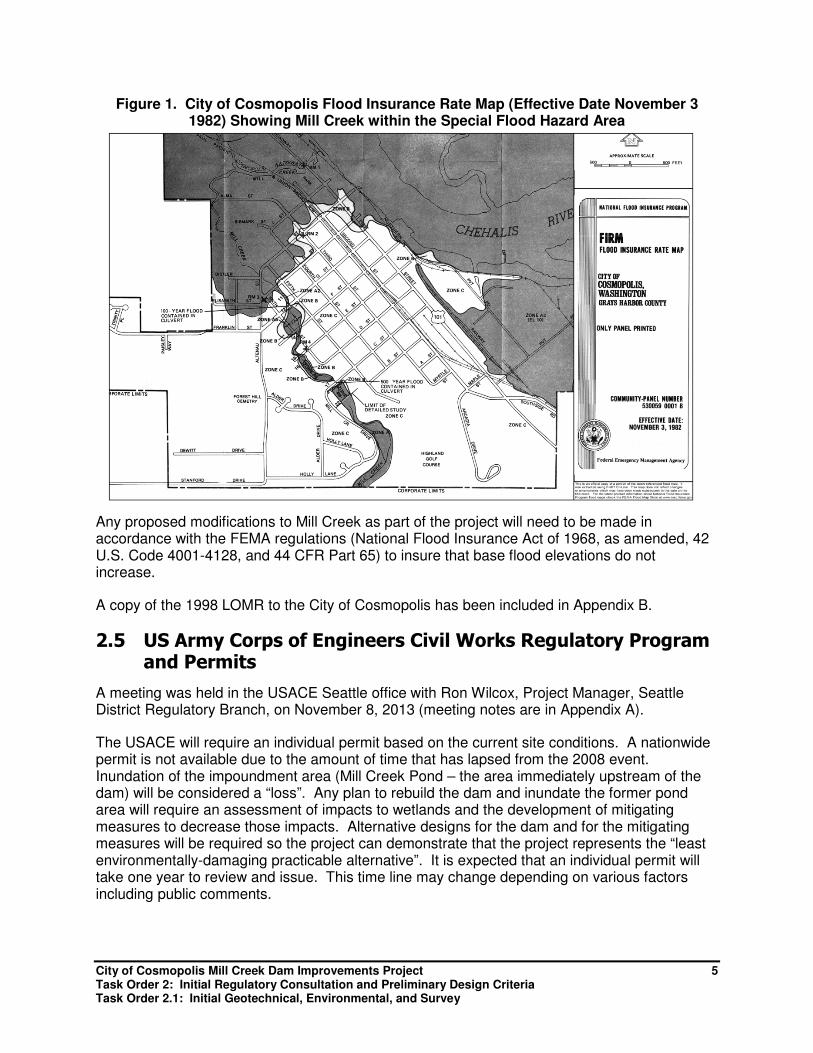
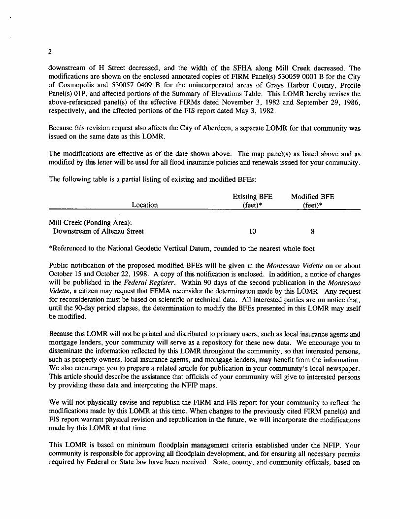
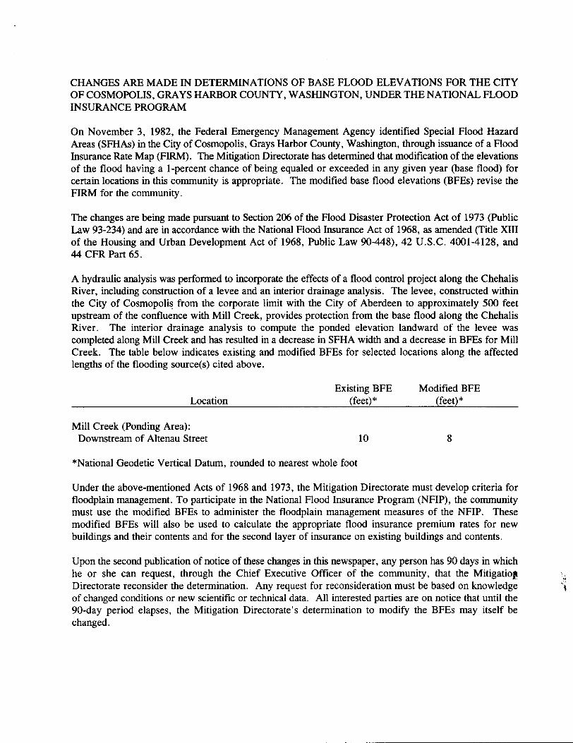
In September 1998 FEMA issued a Letter of Map Revision (LOMR) in response to the September 1997 request by the City of Aberdeen to revise the effective FIRM, and the affected portions of the Flood Insurance Study Report, to show the effects of construction of a flood control levee along the Chehalis River in the area of Mill Creek. The levee was constructed to provide protection from the flood having a 1-percent chance of being equaled or exceeded in any given year (base flood). Interior drainage analyses were completed by the US Army Corps of Engineers, Seattle District, to compute the ponding elevations landward of the levee along a number of creeks (including Mill Creek). The result of the modification increased the base flood elevation for the Chehalis River and decreased the base flood elevation and Special Flood Hazard Area of Mill Creek from elevation 10 feet (NGVD) to elevation 8 feet (NGVD) downstream of West Huntley Street (Figure 1) (FEMA, 1998).
City of Cosmopolis Mill Creek Dam Improvements Project 5 Task Order 2: Initial Regulatory Consultation and Preliminary Design Criteria Task Order 2.1: Initial Geotechnical, Environmental, and Survey
Figure 1. City of Cosmopolis Flood Insurance Rate Map (Effective Date November 3 1982) Showing Mill Creek within the Special Flood Hazard Area
Any proposed modifications to Mill Creek as part of the project will need to be made in accordance with the FEMA regulations (National Flood Insurance Act of 1968, as amended, 42 U.S. Code 4001-4128, and 44 CFR Part 65) to insure that base flood elevations do not increase.
A copy of the 1998 LOMR to the City of Cosmopolis has been included in Appendix B.
2.5 US Army Corps of Engineers Civil Works Regulatory Program and Permits
A meeting was held in the USACE Seattle office with Ron Wilcox, Project Manager, Seattle District Regulatory Branch, on November 8, 2013 (meeting notes are in Appendix A).
The USACE will require an individual permit based on the current site conditions. A nationwide permit is not available due to the amount of time that has lapsed from the 2008 event. Inundation of the impoundment area (Mill Creek Pond – the area immediately upstream of the dam) will be considered a “loss”. Any plan to rebuild the dam and inundate the former pond area will require an assessment of impacts to wetlands and the development of mitigating measures to decrease those impacts. Alternative designs for the dam and for the mitigating measures will be required so the project can demonstrate that the project represents the “least environmentally-damaging practicable alternative”. It is expected that an individual permit will take one year to review and issue. This time line may change depending on various factors including public comments.
City of Cosmopolis Mill Creek Dam Improvements Project 6 Task Order 2: Initial Regulatory Consultation and Preliminary Design Criteria Task Order 2.1: Initial Geotechnical, Environmental, and Survey
2.5.1 Initial Environmental Field Review
An HDR environmental scientist conducted a one-half day site visit to Mill Creek Park on October 10, 2013, to observe wetland conditions at the pond site behind the dam and documented the findings in a brief field report included in Appendix C.
The key project-related findings resulting from the site visit are that the silt that has built-up behind the old dam structure is now vegetated with species that are common within wetland areas. Most of the area that was inundated by the former pond area is likely to meet the regulatory definition of wetlands. Wetland habitat in these areas is very rudimentary and could be enhanced by introducing additional habitat structures and increasing plant species diversity.
3.0 Preliminary Design Criteria
The objective of this task is to begin identifying and documenting design criteria based on the comments received during the initial regulatory consultations. The use of the preliminary design criteria will conform to the requirements of the DSO and be supplemented, as appropriate, by the design guidelines from the USACE technical engineering guidance, Natural Resources Conservation Service (NRCS), and/or the U.S. Bureau of Reclamation (Reclamation) so that when the project is completed, the dam and appurtenant structures will conform to an appropriate standard of care that meets federal and state requirements for similar projects in Washington and throughout the western United States. The list of engineering guidance and reference manuals is in Appendix E.
It is expected that DSO will be the primary source of requirements as they are supported by Washington Administrative Code (Chapters 173-175 WAC) for jurisdiction applicable to dams which can impound a volume of 10 acre-feet or more of water as measured at the dam crest elevation. The water impounded can be of any quality or can contain any substance in combination with water to exist in a liquid or slurry state at the time of initial impoundment.
Supplemental criteria will be provided by the following agencies, as appropriate, to ensure that federal and state standards are achieved.
• The USACE typically regulates dams that are 25 feet or more in height, or have a capability of impounding 50 acre-feet of water or more (with water up to the top of the dam); or its been determined that their failure would cause appreciable property damage or any loss of life.
• NRCS provides design procedures and provides minimum requirements for planning and designing earth dams and associated spillways. Their guidance applies to all Low Hazard Class dams with a product of storage times the effective height of the dam of 3,000 acre-feet or more, those that are more than 35 feet in effective height, and all Significant and High Hazard Class dams.
• Reclamation's Dam Safety Program was implemented in 1978 with passage of the Reclamation Safety of Dams Act, Public Law 95-578 and amended several times. The program requires that Reclamation and other Interior bureaus' dams must be operated and maintained in a safe manner, ensured through inspections for safety deficiencies, analyses utilizing current technologies and designs, and corrective actions if needed based on current engineering practices.

City of Cosmopolis Mill Creek Dam Improvements Project 7 Task Order 2: Initial Regulatory Consultation and Preliminary Design Criteria Task Order 2.1: Initial Geotechnical, Environmental, and Survey
Preliminary criteria have been identified for the following elements:
• Design Step Determination
o Dam Break Inundation Analysis
o Downstream Hazard Classification
• Hydrology and Hydraulic Engineering
o Inflow design flood
o Reservoir routing
o Hydraulic design of spillway
o Hydraulic design of outlet works
• Geotechnical
o Seismic basis of design
o Foundation excavation and treatment
o Seepage
o Stability
o Other geotechnical design criteria
• Structural
o Spillway structural design
o Outlet structural design
• Electrical/Mechanical
These preliminary criteria are described in more detail below.
3.1 Design Step Determination (DSO)
DSO provides dam design and guidance in its Dam Safety Guidelines (Ecology, 1992). The guidance is intended to provide a broad perspective on design philosophy, engineering design considerations, and engineering and construction practices primarily focused on earthen embankments (Ecology, 1993). The Dam Safety Guidelines do not discuss concrete structures in any depth due to the unique design problems that should be addressed by specialty firms well versed and qualified to formulate a suitable design (Ecology, 1993).
Identification of DSO requirements depends on working through a decision framework process to determine the necessary design step. The design steps range from Step 1 to Step 8 (Figure 2) with increasingly more stringent requirements to satisfy at the higher steps. Design Step 1 is applicable where the downstream consequences of failure would be minimal, and there would be no potential for loss of life. Design Step 8 is applicable where the consequences of dam failure could be catastrophic with hundreds of lives at risk. Design Step 8 utilizes extreme design events and design loads to provide the extremely high levels of reliability needed to properly protect the public.
City of Cosmopolis Mill Creek Dam Improvements Project 8 Task Order 2: Initial Regulatory Consultation and Preliminary Design Criteria Task Order 2.1: Initial Geotechnical, Environmental, and Survey
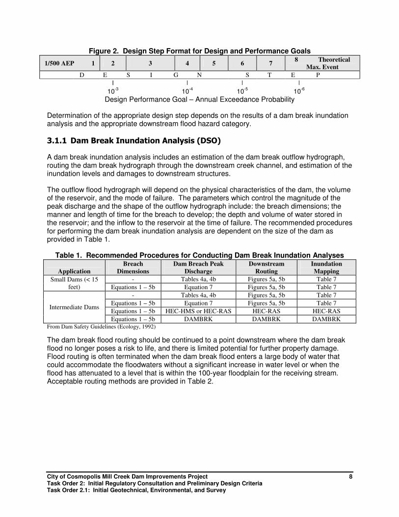
Figure 2. Design Step Format for Design and Performance Goals
1/500 AEP 1 2 3 4 5 6 7 8 Theoretical
Max. Event
D E S I G N S T E P
| | | |
10-3 10
-4 10-5 10
-6
Design Performance Goal – Annual Exceedance Probability
Determination of the appropriate design step depends on the results of a dam break inundation analysis and the appropriate downstream flood hazard category.
3.1.1 Dam Break Inundation Analysis (DSO)
A dam break inundation analysis includes an estimation of the dam break outflow hydrograph, routing the dam break hydrograph through the downstream creek channel, and estimation of the inundation levels and damages to downstream structures.
The outflow flood hydrograph will depend on the physical characteristics of the dam, the volume of the reservoir, and the mode of failure. The parameters which control the magnitude of the peak discharge and the shape of the outflow hydrograph include: the breach dimensions; the manner and length of time for the breach to develop; the depth and volume of water stored in the reservoir; and the inflow to the reservoir at the time of failure. The recommended procedures for performing the dam break inundation analysis are dependent on the size of the dam as provided in Table 1.
Table 1. Recommended Procedures for Conducting Dam Break Inundation Analyses
Application
Breach
Dimensions
Dam Breach Peak
Discharge
Downstream
Routing
Inundation
Mapping
Small Dams (< 15
feet)
- Tables 4a, 4b Figures 5a, 5b Table 7
Equations 1 – 5b Equation 7 Figures 5a, 5b Table 7
Intermediate Dams
- Tables 4a, 4b Figures 5a, 5b Table 7
Equations 1 – 5b Equation 7 Figures 5a, 5b Table 7
Equations 1 – 5b HEC-HMS or HEC-RAS HEC-RAS HEC-RAS
Equations 1 – 5b DAMBRK DAMBRK DAMBRK From Dam Safety Guidelines (Ecology, 1992)
The dam break flood routing should be continued to a point downstream where the dam break flood no longer poses a risk to life, and there is limited potential for further property damage. Flood routing is often terminated when the dam break flood enters a large body of water that could accommodate the floodwaters without a significant increase in water level or when the flood has attenuated to a level that is within the 100-year floodplain for the receiving stream. Acceptable routing methods are provided in Table 2.
City of Cosmopolis Mill Creek Dam Improvements Project 9 Task Order 2: Initial Regulatory Consultation and Preliminary Design Criteria Task Order 2.1: Initial Geotechnical, Environmental, and Survey
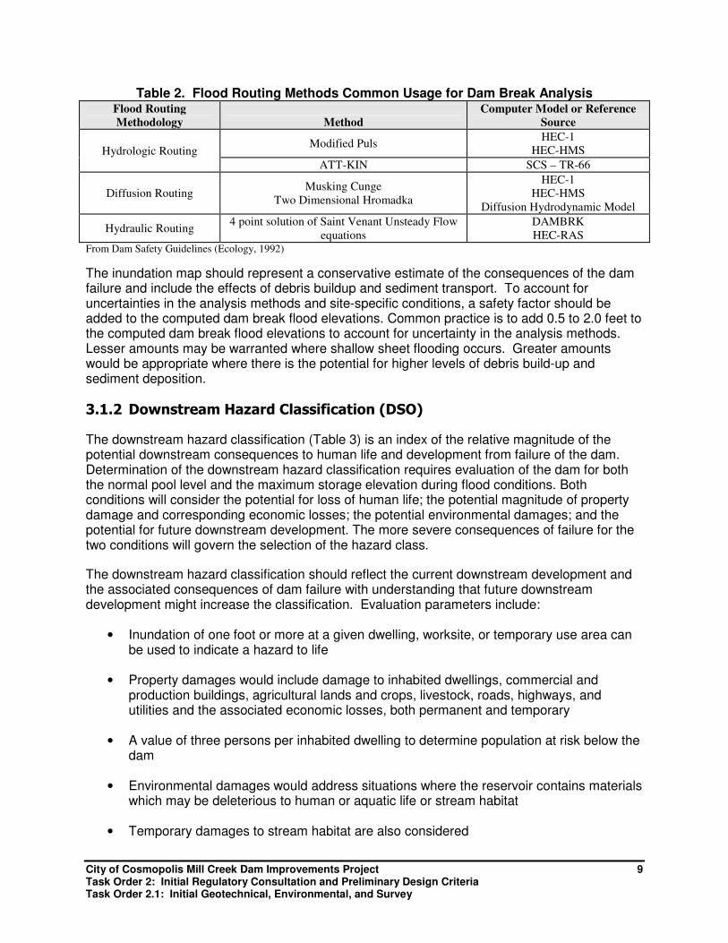
Table 2. Flood Routing Methods Common Usage for Dam Break Analysis Flood Routing
Methodology Method
Computer Model or Reference
Source
Hydrologic Routing Modified Puls
HEC-1
HEC-HMS
ATT-KIN SCS – TR-66
Diffusion Routing Musking Cunge
Two Dimensional Hromadka
HEC-1
HEC-HMS
Diffusion Hydrodynamic Model
Hydraulic Routing 4 point solution of Saint Venant Unsteady Flow
equations
DAMBRK
HEC-RAS From Dam Safety Guidelines (Ecology, 1992)
The inundation map should represent a conservative estimate of the consequences of the dam failure and include the effects of debris buildup and sediment transport. To account for uncertainties in the analysis methods and site-specific conditions, a safety factor should be added to the computed dam break flood elevations. Common practice is to add 0.5 to 2.0 feet to the computed dam break flood elevations to account for uncertainty in the analysis methods. Lesser amounts may be warranted where shallow sheet flooding occurs. Greater amounts would be appropriate where there is the potential for higher levels of debris build-up and sediment deposition.
3.1.2 Downstream Hazard Classification (DSO)
The downstream hazard classification (Table 3) is an index of the relative magnitude of the potential downstream consequences to human life and development from failure of the dam. Determination of the downstream hazard classification requires evaluation of the dam for both the normal pool level and the maximum storage elevation during flood conditions. Both conditions will consider the potential for loss of human life; the potential magnitude of property damage and corresponding economic losses; the potential environmental damages; and the potential for future downstream development. The more severe consequences of failure for the two conditions will govern the selection of the hazard class.
The downstream hazard classification should reflect the current downstream development and the associated consequences of dam failure with understanding that future downstream development might increase the classification. Evaluation parameters include:
• Inundation of one foot or more at a given dwelling, worksite, or temporary use area can be used to indicate a hazard to life
• Property damages would include damage to inhabited dwellings, commercial and production buildings, agricultural lands and crops, livestock, roads, highways, and utilities and the associated economic losses, both permanent and temporary
• A value of three persons per inhabited dwelling to determine population at risk below the dam
• Environmental damages would address situations where the reservoir contains materials which may be deleterious to human or aquatic life or stream habitat
• Temporary damages to stream habitat are also considered

City of Cosmopolis Mill Creek Dam Improvements Project 10 Task Order 2: Initial Regulatory Consultation and Preliminary Design Criteria Task Order 2.1: Initial Geotechnical, Environmental, and Survey
The 1988 Bureau of Reclamation Downstream Hazard Classification Guidelines may be used to provide more detailed information on the hazards posed by various combinations of floodwater depth and velocity and has extensive commentary on classifying the downstream hazard.
Table 3. Downstream Hazard Classification Downstream
Hazard
Potetnial
Downstream
Hazard
Classification
Column 1A
Population at
Risk
Column 1B Economic Loss
Generic Descriptions
Column 1C
Environmental Damages
Low 3 0
Minimal. No inhabited
structures. Limited agriculture
development.
No deleterious materials
in water
Significant 2 1 to 6
Appreciable. 1 or 2 inhabited
structures. Notable agriculture
or work sites. Secondary
highway and/or rail lines.
Limited water quality
degradation from reservoir
contents.
High 1C 7 to 30
Major. 3 to 10 inhabited
structures. Low density
suburban area with some
industry and work sites.
Primary highways and rail
lines. Severe water quality
degradation potential from
reservoir contents and
long-term effects on life. High 1B 31-300
Extreme. 11 to 100 inhabited
structures. Medium density
suburban or urban area with
associated industry, property
and transportation features.
High 1A More than
300
Extreme. More than 100
inhabited structures. Highly
developed densely populated
suburban or urban area.
Detailed procedures for performing the dam break inundation analysis and downstream hazard classification are presented in Technical Note 1 of the Dam Safety Guidelines (Ecology, 1992). Results of the analysis will be documented in the Engineer’s Report.
3.2 Hydrology and Hydraulic Engineering
3.2.1 Inflow Design Flood (DSO)
The inflow design flood (IDF) is the loading condition used to design and evaluate the project’s spillway and storage requirements. The IDF is typically dependent on the magnitude and duration of the precipitation event and its distribution and is usually computed using rainfall-runoff computer models. Determination is based on analysis of several storm durations to determine which flood characteristics will control the design of the project. The controlling flood is labeled the IDF.
The storm duration (short, intermediate, or long) which will generate the flood that controls the project design will not normally be known prior to conducting the flood analyses. Estimation of the magnitude of the candidate design storms for the various durations and temporal distribution is based on procedures described in Technical Note 3, Design Storm Construction (Ecology, 2009). Spatial distribution of extreme storms is limited and probabilistic procedures described in Schaefer, HMR-43/57 and NOAA Atlas #2. Recommended procedures and worksheets for
City of Cosmopolis Mill Creek Dam Improvements Project 11 Task Order 2: Initial Regulatory Consultation and Preliminary Design Criteria Task Order 2.1: Initial Geotechnical, Environmental, and Survey
construction of design storm hyetographs are contained in Technical Note 3 of the Dam Safety Guidelines (Ecology, 2009).
Additional information necessary to conduct the analysis requires antecedent conditions in the tributary watershed prior to the occurrence of the design storm. Considerations include the season of occurrence of the extreme storm/design event. The time of year (month) selected should represent a time for which 10% or more of extreme storms have been observed to occur and which is associated with meteorological and hydrologic conditions conducive to generation of floods. Information in Schaefer and in HMR-43 can be used to aid in selection of the month of occurrence based on the historical record.
Initial streamflow is based on the time of year when the design storm is assumed to occur. Where the design or operation of a project during flood conditions is sensitive to the magnitude of normal inflow, a more conservative initial inflow should be assumed. In this situation, a discharge with 1 in 10 chance of being exceeded during the selected month would be a reasonable assumption. If streamflow gages are not available within their tributary watershed, transposition of streamflow statistics from hydrologically similar watersheds is normally used.
Soil moisture and runoff parameters chosen for use in rainfall-runoff modeling should be selected based on the typical meteorological conditions to be expected for the time of year associated with the occurrence of the design storm. In those cases where soil moisture and runoff parameters cannot be confirmed by calibration of the model with observed rainfall-runoff data, streamflow data, or by soil moisture water budgets, conservative estimates of the parameters should be selected.
Where interflow is expected to be a significant contribution to runoff, which is common in western Washington, computations must be conducted to explicitly account for the volume and timing of interflow. Computation procedures applicable to interflow conditions are described in Characterization and Simulation of Rainfall-Runoff Relations for Headwater Basins in Western King and Snohomish Counties, Washington (USGS, 1990) and Runoff from Snowmelt (USACE, 1960).
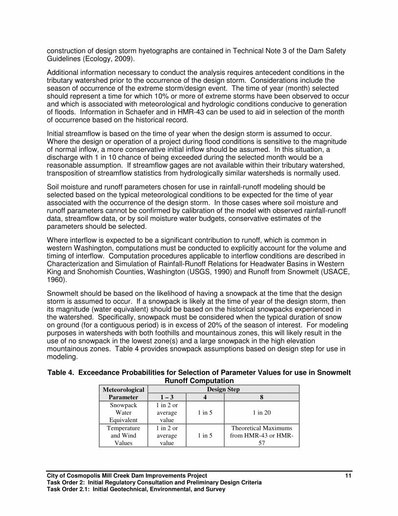
Snowmelt should be based on the likelihood of having a snowpack at the time that the design storm is assumed to occur. If a snowpack is likely at the time of year of the design storm, then its magnitude (water equivalent) should be based on the historical snowpacks experienced in the watershed. Specifically, snowpack must be considered when the typical duration of snow on ground (for a contiguous period) is in excess of 20% of the season of interest. For modeling purposes in watersheds with both foothills and mountainous zones, this will likely result in the use of no snowpack in the lowest zone(s) and a large snowpack in the high elevation mountainous zones. Table 4 provides snowpack assumptions based on design step for use in modeling.
Table 4. Exceedance Probabilities for Selection of Parameter Values for use in Snowmelt Runoff Computation
Meteorological
Parameter
Design Step
1 – 3 4 8
Snowpack
Water
Equivalent
1 in 2 or
average
value
1 in 5 1 in 20
Temperature
and Wind
Values
1 in 2 or
average
value
1 in 5
Theoretical Maximums
from HMR-43 or HMR-
57
City of Cosmopolis Mill Creek Dam Improvements Project 12 Task Order 2: Initial Regulatory Consultation and Preliminary Design Criteria Task Order 2.1: Initial Geotechnical, Environmental, and Survey
For snowmelt computations, information is needed for air temperatures, temperature lapse rates and wind speeds which accompany the design storm. Selection of appropriate values should be based on conditions which have occurred during observed extreme storms. This information may be obtained from Climatological Bulletins published by the NWS21 and Phillips22. Theoretical maximum values may be obtained from NWS publication HMR-43/573.
The reservoir level which is assumed to be present at the start of the design flood should be determined based on the expected operation of the project. The selection of a starting level should be based on the time of year when the design storm is assumed to occur, the reservoir inflows expected at that time, and the proposed reservoir operation scheme.
For projects with ungated spillways, it is common to assume the reservoir level to be at or above the invert of the principal spillway. In those cases where insufficient data is available to ascertain the likely initial reservoir level or where the reservoir level is highly variable, a suitably conservative estimate should be used.
Sensitivity analyses should be conducted on those parameter values which are anticipated to be a source of uncertainties to determine the sensitivity of the resultant flood hydrograph. Potential sources of uncertainty would include factors such as: the temporal distribution of the design storm; soil moisture deficits and soil infiltration rates; unit hydrograph lag times; snowpack magnitudes; and initial reservoir levels. The results of any sensitivity studies should be used as a basis for final selection of the IDF.
The candidate design flood may be accepted as the IDF if the value of the sensitive parameter(s) used in the analyses has less than 1 chance in 10 of being exceeded during the season of interest.
3.2.2 Reservoir Routing (DSO)
Reservoir routing procedures, such as used in computer models HEC-1 and DAMBRK, are normally used to determine the flood hydrograph released through the spillway(s) at the dam. Hydraulic routing procedures are usually used to route the flood through the downstream valley and determine the flood levels and areal extent of inundation. Recommended methods of routing are provided in Table 2, Flood Routing Methods Common Usage for Dam Break Analysis.
3.2.3 Hydraulic Design of Spillway (DSO)
Several spillway types are acceptable to DSO and are listed in the Dam Safety Guidelines (Ecology, 1992). Technical design information can be obtained from the various federal design manuals and technical articles listed in Appendix E, Engineering Guidance and Reference Manuals.
The selected spillway should match the intended way it will be operated, the frequency of site visits, and allow for easy maintenance and inspection. The following items should be taken into account in the selection and design of the spillway (Ecology, 1992).
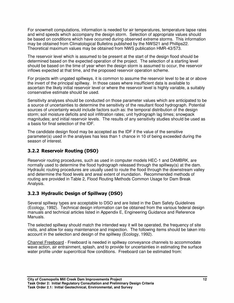
Channel Freeboard - Freeboard is needed in spillway conveyance channels to accommodate wave action, air entrainment, splash, and to provide for uncertainties in estimating the surface water profile under supercritical flow conditions. Freeboard can be estimated from:
City of Cosmopolis Mill Creek Dam Improvements Project 13 Task Order 2: Initial Regulatory Consultation and Preliminary Design Criteria Task Order 2.1: Initial Geotechnical, Environmental, and Survey
�ℎ����������� ��� = 2 + 0.025 × � × ��.���
where: V = Velocity of flow (ft/sec) at a given location
y = Depth of flow (ft) at a given location
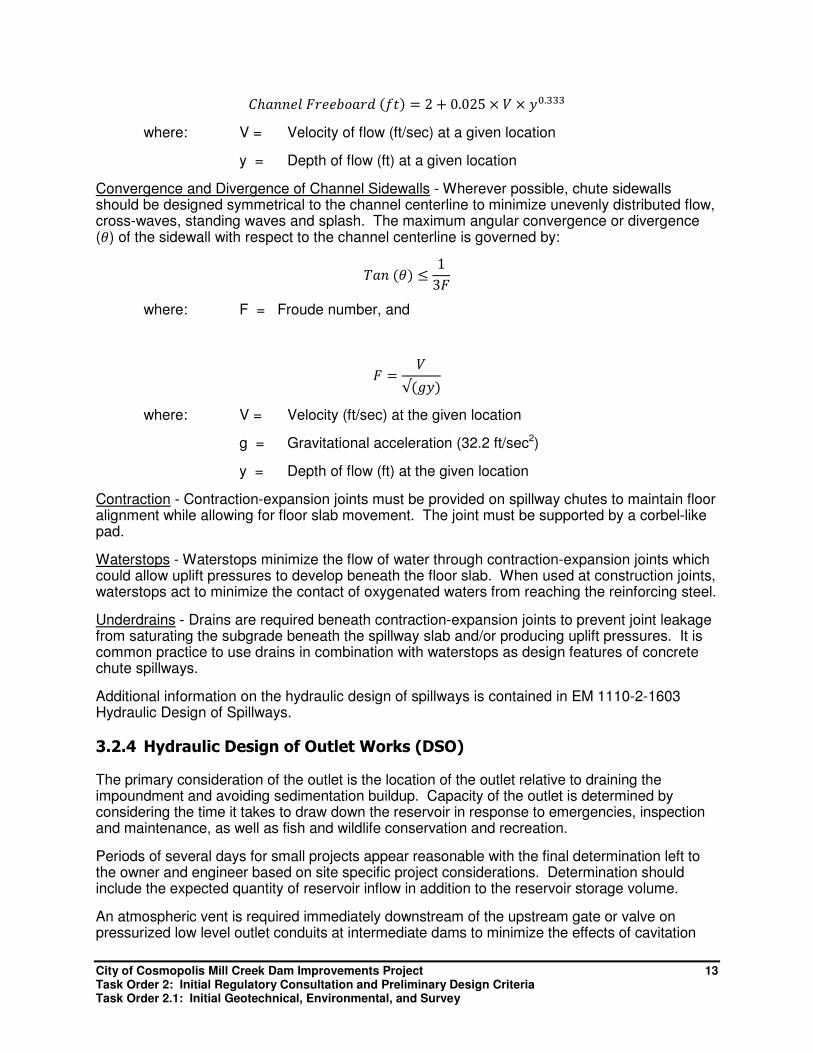
Convergence and Divergence of Channel Sidewalls - Wherever possible, chute sidewalls should be designed symmetrical to the channel centerline to minimize unevenly distributed flow, cross-waves, standing waves and splash. The maximum angular convergence or divergence (�) of the sidewall with respect to the channel centerline is governed by:
��� �� ≤1
3�
where: F = Froude number, and
� =�
√ "��
where: V = Velocity (ft/sec) at the given location
g = Gravitational acceleration (32.2 ft/sec2)
y = Depth of flow (ft) at the given location
Contraction - Contraction-expansion joints must be provided on spillway chutes to maintain floor alignment while allowing for floor slab movement. The joint must be supported by a corbel-like pad.
Waterstops - Waterstops minimize the flow of water through contraction-expansion joints which could allow uplift pressures to develop beneath the floor slab. When used at construction joints, waterstops act to minimize the contact of oxygenated waters from reaching the reinforcing steel.
Underdrains - Drains are required beneath contraction-expansion joints to prevent joint leakage from saturating the subgrade beneath the spillway slab and/or producing uplift pressures. It is common practice to use drains in combination with waterstops as design features of concrete chute spillways.
Additional information on the hydraulic design of spillways is contained in EM 1110-2-1603 Hydraulic Design of Spillways.
3.2.4 Hydraulic Design of Outlet Works (DSO)
The primary consideration of the outlet is the location of the outlet relative to draining the impoundment and avoiding sedimentation buildup. Capacity of the outlet is determined by considering the time it takes to draw down the reservoir in response to emergencies, inspection and maintenance, as well as fish and wildlife conservation and recreation.
Periods of several days for small projects appear reasonable with the final determination left to the owner and engineer based on site specific project considerations. Determination should include the expected quantity of reservoir inflow in addition to the reservoir storage volume.
An atmospheric vent is required immediately downstream of the upstream gate or valve on pressurized low level outlet conduits at intermediate dams to minimize the effects of cavitation

City of Cosmopolis Mill Creek Dam Improvements Project 14 Task Order 2: Initial Regulatory Consultation and Preliminary Design Criteria Task Order 2.1: Initial Geotechnical, Environmental, and Survey
and/or vacuum buckling. Additional information on vent sizing is contained in EM 1110-2-1602 Hydraulic Design of Reservoir Outlet Works (USACE, 1980).
3.3 Geotechnical
Geotechnical criteria is provided by DSO and supplemented with USACE information. A preliminary assessment by an HDR geotechnical engineer was conducted on October 17, 2013, by observing geotechnical soils conditions along the left abutment and three test pit locations near the dam, which were excavated using a backhoe. A brief trip report documenting the findings is included in Appendix D.
Results of the preliminary assessment include identification of relatively weak, competent sandstone bedrock. The top of the sandstone bedrock areas drop in elevation moving upstream of the dam and to the right abutment. The bedrock also appears to drop off in the downstream direction suggesting that the existing dam is well situated for the location. The sands in the immediate vicinity of the dam are relatively loose and will probably liquefy in a more frequent seismic design event such as the 100-year return period. Additional evaluations will be required to determine seepage, stability, and seismic analysis requirements.
3.3.1 Seismic Basis of Design (DSO)
The project should be configured so as to be able to experience earthquakes without releasing the reservoir contents except under an appropriately remote level of earthquake shaking (Ecology, 1992). The DSO does not endorse a particular method for the assessment of deformations and the potential for a liquefaction condition to occur.
DSO provides a general procedure that outlines the steps that the engineer would take in developing the design ground motions to be used in a conducting a seismic assessment. In recognition that existing detailed seismic studies often are unavailable at a proposed project site, DSO provides a process to estimate ground motions from existing public domain, seismic risk studies in the Dam Design and Construction (Ecology, 1993).
3.3.2 Foundation Excavation and Treatment (USACE)
The foundation upon which the dam is sited must be evaluated for settlement, foundation underseepage, and sliding stability. The deformation modulus may be determined by several different methods or approaches, but the effect of rock inhomogeneity on foundation behavior must be addressed. The determination should consider both elastic and inelastic (plastic) deformations.
Methods for evaluating foundation moduli include in situ (static) testing; laboratory testing (uniaxial compression tests, ASTM C 3148; and pulse velocity test, ASTM C 2848); seismic field testing; empirical data (rock mass rating system, correlations with unconfined compressive strength, and tables of typical values); and back calculations using compression measurements from instruments such as a borehole extensometer. The foundation deformation modulus is best estimated or evaluated by in situ testing to more accurately account for the natural rock discontinuities. Laboratory testing on intact specimens will yield only an “upper bound” modulus value. If the foundation contains more than one rock type, different modulus values may need to be used and the foundation evaluated as a composite of two or more layers.
Sliding stability must be considered along seams or faults in the foundation. Before stability analyses are performed, engineering geologists must provide information regarding potential failure planes within the foundation. This includes the location of zones of low shear resistance,

City of Cosmopolis Mill Creek Dam Improvements Project 15 Task Order 2: Initial Regulatory Consultation and Preliminary Design Criteria Task Order 2.1: Initial Geotechnical, Environmental, and Survey
the strength of material within these zones, assumed potential failure planes, and maximum uplift pressures that can develop along the failure planes. Every effort is made to grout pervious zones within the foundation prior to constructing the dam. Where grouting is impractical or ineffective, uplift pressure can be reduced to safe levels through proper drainage of the pervious zone. Detailed information on technical criteria and guidance on foundation grouting is contained in EM 1110-2-3506 Grouting Technology (USACE, 1984).
3.3.3 Seepage (USACE)
Excessive seepage is undesirable from the aspect of structural stability and because of the adverse appearance of water seeping on the downstream dam face, the economic value associated with lost water, and possible long-term adverse impacts on durability. The joints between the concrete lifts and interface with structural elements are the major pathways for potential seepage through the dam. This condition is primarily due to segregation at the lift boundaries and discontinuity between successive lifts. It can also be the result of surface contamination and excessive time intervals between lift placements.
Seepage can be controlled by incorporating special design and construction procedures that include contraction joints with waterstops making the upstream face watertight, sealing the interface between layers, and draining and collecting the seepage.
A collection and drainage system is a method for stopping unsightly seepage water from reaching the downstream face and for preventing excessive hydrostatic pressures against conventional concrete spillway or downstream facing. It will also reduce uplift pressures within the dam and increase stability. Collection methods include vertical drains with waterstops at the upstream face and vertical drain holes drilled from within the gallery near the upstream or downstream face. Collected water can be channeled to the dam toe.
3.3.4 Stability Analysis (USACE)
USACE Gravity Dam Design (EM 1110-2-2200) provides information on the stability analysis of concrete gravity dams. The design is performed through an iterative process involving a preliminary layout of the structure followed by the stability and stress analysis. Analysis is typically conducted at the base and at selected planes within the structure for several loading conditions. Criteria are present in Table 5. If week seams or planes exist in the foundation, they should also be analyzed. If the structure fails to meet criteria then the layout is modified and reanalyzed.
Table 5. Stability and Stress Criteria
Load
Condition
Resultant
Location
at Base
Minimum
Sliding FS
Foundation Bearing
Pressure
Concrete Stress
Compressive Tensile
Usual Middle 1/3 2.0 ≤ allowable 0.3 f’c 0
Unusual Middle 1/2 1.7 ≤ allowable 0.5 f’c 0.6 f’c2/3
Extreme Within
base 1.3 ≤ 1.33 x allowable 0.9 f’c 1.5 f’c
2/3
Note: f’c is 1-year unconfined compressive strength of concrete. The sliding factors of safety (FS) are based on a
comprehensive field investigation and testing program. Concrete allowable stresses are for static loading conditions.

City of Cosmopolis Mill Creek Dam Improvements Project 16 Task Order 2: Initial Regulatory Consultation and Preliminary Design Criteria Task Order 2.1: Initial Geotechnical, Environmental, and Survey
3.3.5 Static and Dynamic Stress Analyses (USACE)
A geological and seismological investigation of all dam sites is required for projects located in Seismic Zones 2 through 4. The objectives of the investigation are to establish maximum credible earthquake (MCE) and operating basis earthquake (OBE) and the corresponding ground motions for each to assess the controlling condition to determine the possibility of earthquake-induced foundation dislocation at the site.
Gravity dams should be capable of surviving the controlling earthquake without a catastrophic failure that would result in loss of life or significant damage to property. Inelastic behavior with associated damage is permissible under the MCE scenario. Gravity dams should be capable of resisting the controlling OBE within the elastic range, remain operational, and not require extensive repairs.
For preliminary designs, simplified methods using cantilever beam models for two-dimensional analysis or the trial load twist method for three-dimensional analysis are appropriate as described in the 1996 Reclamation’s Design of Gravity Dams. The finite element method is ordinarily used for final design stages if a more exact stress investigation is required.
3.4 Structural (DSO)
Concrete structures for dams are subject to an extreme environment that can greatly shorten their service life. Specifically, concrete will be exposed to: hydraulic pressures, wet-dry and freeze-thaw cycles, abrasion and erosion from sediment-laden water, and static and seismic loadings. Repairing deteriorated concrete structures frequently approaches efforts similar in scope to original construction, with all of the attendant costs, dangers, and environmental consequences. Structural design considerations include proper concrete mix design, sufficient cover of reinforcing steel, and provisions to limit cracking.
3.4.1 Spillway Structural Design
3.4.1.1 Concrete Mix Design Recommendations
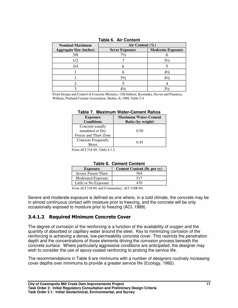
One of the major threats to concrete in a damp or wet environment is the deterioration resulting from cycles of freezing and thawing of the moist concrete. The principal method of minimizing freeze-thaw damage is the utilization of an air-entraining agent in the concrete. Secondary measures include the lowest water-cement ratio, selecting concrete mix on both strength and durability, and reducing the permeability of the concrete. Design and Control of Concrete Mixtures (Kosmatka, 1988) suggests the air content percentages shown in Table 6. Maximum water-cement ratios are provided in Table 7, and Table 8 provides the suggested cement content per cubic yard of concrete.
City of Cosmopolis Mill Creek Dam Improvements Project 17 Task Order 2: Initial Regulatory Consultation and Preliminary Design Criteria Task Order 2.1: Initial Geotechnical, Environmental, and Survey
Table 6. Air Content
Nominal Maximum
Aggregate Size (inches)
Air Content (%)
Sever Exposure Moderate Exposure
3/8 7½ 6
1/2 7 5½
3/4 6 5
1 6 4½
1 5½ 4½
2 5 4
3 4½ 3½
From Design and Control of Concrete Mixtures, 13th Edition; Kosmatka, Steven and Panarese,
William; Portland Cement Association, Skokie, Il, 1988, Table 5-4
Table 7. Maximum Water-Cement Ratios Exposure
Conditions
Maximum Water-Cement
Ratio (by weight)
Concrete usually
inundated or Dry
Freeze and Thaw Zone
0.50
Concrete Frequently
Moist 0.45
From ACI 318-89, Table 4.1.2
Table 8. Cement Content Exposure Cement Content (lb. per cy)
Severe Freeze-Thaw 564
Moderated Exposure 517
Little or No Exposure 470
From ACI 318-89, and Commentary, ACI 318R-89,
Severe and moderate exposure is defined as one where, in a cold climate, the concrete may be in almost continuous contact with moisture prior to freezing, and the concrete will be only occasionally exposed to moisture prior to freezing (ACI, 1989).
3.4.1.2 Required Minimum Concrete Cover
The degree of corrosion of the reinforcing is a function of the availability of oxygen and the quantity of absorbed or capillary water around the steel. Key to minimizing corrosion of the reinforcing is achieving a dense, low-permeability concrete cover. This restricts the penetration depth and the concentrations of those elements driving the corrosion process beneath the concrete surface. Where particularly aggressive conditions are anticipated, the designer may wish to consider the use of epoxy-coated reinforcing to prolong the service life.
The recommendations in Table 9 are minimums with a number of designers routinely increasing cover depths over minimums to provide a greater service life (Ecology, 1992).

City of Cosmopolis Mill Creek Dam Improvements Project 18 Task Order 2: Initial Regulatory Consultation and Preliminary Design Criteria Task Order 2.1: Initial Geotechnical, Environmental, and Survey
Table 9. Concrete Cover for Steel Reinforcement Location Minimum Cover (inches)
Concrete cast against and permanently exposed to earth (or backfill) 3
Concrete exposed to earth or weather 2
Concrete not exposed to weather or in contact with ground 1 ½
From ACI 318-89, Table 4.1.2
3.4.1.3 Joints
For most walls and slabs, joint spacing is on the order of 15 to 40 feet, with smaller spacing used when relatively large thermal gradients are anticipated and on the estimated degree of slab restraint (Ecology, 1992) to address the shrinkage and expansion of concrete over the life of the project.
Where control joints are necessary and where they are submerged continuously or intermittently, they shall include a waterstop.
3.4.2 Outlet Works Structural Design (DSO)
Outlet conduits are considered critical project elements and design features are necessary which address the relatively unique and severe service condition of conduits within dams. The concepts of redundancy, inspectability, serviceability, and consequent dependent design features are all pertinent to the design and construction of conduits.
Redundant valves are necessary to allow for conduit inspection and repair and to provide for emergency shutoff. Redundant features are also needed for those elements which have experienced problems in the past. These include defense mechanisms such as reinforcing pipe joints, increasing pipe wall thickness and minimizing seepage and piping potentials.
Conduits are susceptible to corrosion, abrasion, and long-term deterioration. It is important to include features in the design which allow for inspection and monitoring of the condition of the conduit.
The useful life of the dam may far exceed the service life of the conduit. Provisions are needed in the design to allow for future renovation. This is normally accomplished by providing oversized conduits, straight alignments, and locating valves where they can be readily removed or at least will not obstruct the future sleeving of the conduit.
An atmospheric vent is needed at the entrance of the conduit to stabilize the flow and preclude the occurrence of siphon action and slug flow.
All pressurized conduits must have an upstream valve or other means of effecting a shut-off.
Principal geotechnical/structural design considerations for all conduits which pass through earthen embankments include:
• Maintaining the integrity of the individual lengths of pipe and the joints between pipe sections in undergoing the strains produced by long-term static and dynamic loadings.
• Minimizing the likelihood of overstressing the pipe during installation and, after completion of the facility, under normal service conditions.
• Minimizing seepage along the perimeter of the pipe.
City of Cosmopolis Mill Creek Dam Improvements Project 19 Task Order 2: Initial Regulatory Consultation and Preliminary Design Criteria Task Order 2.1: Initial Geotechnical, Environmental, and Survey
• Improving the durability of the conduit considering corrosion, abrasion, and free-thaw action. Providing a means to facilitate inspection of the pipe.
• Incorporating features in the design to allow for future renovation of the pipe.
3.5 Electrical/Mechanical (DSO)
Electrical and mechanical elements are required to take a systems approach to reliability that they will function properly to prevent a failure under extreme loading. The systems approach requires that the main system and redundant elements meet certain constraints. These include the following:
• A suitable maintenance and testing program must be implemented so that the primary system, and each of the redundant elements can reasonably be presumed to remain functional.
• The failure of one actuating system should not "lock up" the equipment preventing redundant systems from operating it.
• Independent power sources, delivery systems and controls should be provided to actuate a critical mechanism.
• Instrumentation should be provided to give accurate information on the functioning of critical systems.
• An emergency action plan that provides for the use of redundant systems must be developed, and the staff periodically tested in implementing it in realistic, simulated emergencies.
4.0 Summary and Next Steps
This memorandum documents the findings of the efforts conducted under Task Orders 2 and 2.1. Meetings were held with five regulatory agencies, preliminary design criteria have been developed, and initial geotechnical, environmental, and surveying has been conducted. These activities allow identification of the approach and requirements for developing the design and environmental compliance elements of the project.
Therefore, these findings prepare the City and the HDR project team for advancement of the project to the next step: Task Order No. 3 – Field Data Collection and Engineer’s Report, where project specific field data will be obtained and the project Engineer’s Report will be prepared to address the design criteria and provide the City’s preferred configuration for the dam, pond, footbridge, and downstream culverts.

City of Cosmopolis Mill Creek Dam Improvements Project Task Order 2: Initial Regulatory Consultation and Preliminary Design Criteria Task Order 2.1: Initial Geotechnical, Environmental, and Survey
This page left intentionally blank.

City of Cosmopolis Mill Creek Dam Improvements Project Task Order 2: Initial Regulatory Consultation and Preliminary Design Criteria Task Order 2.1: Initial Geotechnical, Environmental, and Survey
Appendix A Agency Meeting Notes

City of Cosmopolis Mill Creek Dam Improvements Project Task Order 2: Initial Regulatory Consultation and Preliminary Design Criteria Task Order 2.1: Initial Geotechnical, Environmental, and Survey
This page left intentionally blank.
City of Cosmopolis Mill Creek Dam Improvements Project Task Order 2: Initial Regulatory Consultation and Preliminary Design Criteria Task Order 2.1: Initial Geotechnical, Environmental, and Survey
Meeting Notes
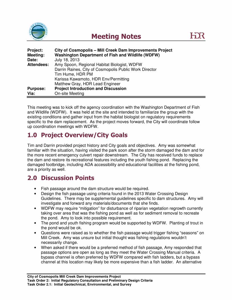
Project: City of Cosmopolis – Mill Creek Dam Improvements Project Meeting: Washington Department of Fish and Wildlife (WDFW) Date: July 18, 2013 Attendees: Amy Spoon, Regional Habitat Biologist, WDFW Darrin Raines, City of Cosmopolis Public Work Director Tim Hume, HDR PM Karissa Kawamoto, HDR Env/Permitting Matthew Gray, HDR Lead Engineer Purpose: Project Introduction and Discussion Via: On-site Meeting
This meeting was to kick off the agency coordination with the Washington Department of Fish and Wildlife (WDFW). It was held at the site and intended to familiarize the group with the existing conditions and gather input from the habitat biologist on regulatory requirements specific to the dam replacement. As the project moves forward, the City will coordinate follow up coordination meetings with WDFW.
1.0 Project Overview/City Goals
Tim and Darrin provided project history and City goals and objectives. Amy was somewhat familiar with the situation, having visited the park soon after the storm damaged the dam and for the more recent emergency culvert repair downstream. The City has received funds to replace the dam and restore its recreational features including the youth fishing pond. Replacing the damaged footbridge, including ADA accessibility and educational facilities at the fishing pond, are a priority as well.
2.0 Discussion Points
• Fish passage around the dam structure would be required.
• Design the fish passage using criteria found in the 2013 Water Crossing Design Guidelines. There may be supplemental guidelines specific to dam structures. Amy will investigate and forward any materials/documents that she finds.
• WDFW may require “mitigation” for disturbance of riparian vegetation regrowth currently taking over area that was the fishing pond as well as for sediment removal to recreate the pond. Amy to look into possible requirement.
• The pond and youth fishing program would be supported by WDFW. Planting of trout in the pond would be ok.
• Questions were raised as to whether the fish passage would trigger fishing “seasons” on Mill Creek. Amy was unsure but initial thought was fishing regulations wouldn’t necessarily change.
• When asked if there would be a preferred method of fish passage, Amy responded that passage options are open as long as they meet the Water Crossing Manual criteria. A bypass channel is often preferred by WDFW compared with fish ladders, but a bypass channel at this location may likely be more expensive than a fish ladder. An alternative
City of Cosmopolis Mill Creek Dam Improvements Project Task Order 2: Initial Regulatory Consultation and Preliminary Design Criteria Task Order 2.1: Initial Geotechnical, Environmental, and Survey
analysis is not necessary for WDFW to approve the selected fish passage system – the design criteria compliance is more important.
• Flood control, replacement of an existing structure, and the addition of fish passage should make for a permittable project.
• From WDFW perspective, dam removal would be preferred but a permit to replace is possible if designed to latest guidelines.
• City should involve Quinault and Chehalis tribes as the project moves forward. Section 106 consultation would be triggered by Corps permit.
• Regarding fish passage requirements for the existing culverts downstream from the dam, Amy indicated that dam replacement could be permitted without addressing the culverts, as addressing the culverts may be triggered by other requirements in the future.
3.0 Next Steps
• Amy to look into additional dam replacement guidelines over and above the 2013 Water Crossing Design Guidelines and forward to the team.
• Amy to double check on whether Mill Creek would be subject to “fishing seasons.”
• Amy to investigate whether WDFW would require mitigation off-set disturbance to new riparian cover or sediment removal.
• Design Team to organize follow up coordination meetings as design progresses.
City of Cosmopolis Mill Creek Dam Improvements Project Task Order 2: Initial Regulatory Consultation and Preliminary Design Criteria Task Order 2.1: Initial Geotechnical, Environmental, and Survey
Meeting Notes
Project: City of Cosmopolis – Mill Creek Dam Improvements Project Meeting: Washington State Recreation and Conservation Office (RCO) Date: August 1, 2013 Attendees: Adam Cole, RCO Outdoor Grants Manager – (360) 902-3019 Karissa Kawamoto, HDR Env/Permitting Purpose: Project Introduction and Discussion Via: Telephone
In the mid to late 1970s, Mill Creek Park was developed with federal Land and Water Conservation Funds (LWCF). The project team wanted early input from the RCO on the redevelopment options before moving forward with alternative concepts and criteria. HDR contacted Adam Cole, the new grants manager covering Grays Harbor County and discussed the project by phone. The call was to gather input from the planner on any recreational regulatory requirements or funding conditions that could place limits on the type, size, or location of the dam replacement. As the project moves forward, the City will coordinate follow up coordination meetings with RCO.
1.0 Project Overview/City Goals
Karissa reviewed project history and City goals and objectives. Adam knew the park well and was familiar with the damaged dam. The City has received funds to replace the dam and restore its recreational features including the youth fishing pond. Replacing the damaged footbridge, including ADA accessibility and educational facilities at the fishing pond, are a priority as well.
2.0 Discussion Points
• The 1970s grants were for park development and improvements not for purchase of the park property.
• State responsibility is more to ensure functionality of the park features and inspection.
• The physical asset of the park itself is more important than the specific uses provided on site. For example, the City could choose to replace the picnic shelter with play equipment and RCO would probably approve. If the City was interested in selling a portion of the park and converting it to a use other than recreational would constitute a physical alternation which would not be allowed.
• Adam stated that the changes should consider the current park audience and users and try to maintain that level of service in the dam replacement development. The overall recreational capacity must be maintained.
• The footprint acreage for recreational uses provided at the park needs to stay the same.
• A meeting on-site at this time is not warranted. Based on our discussion, he is comfortable with the City intentions and based on the early coordination with RCO he has an understanding of what some of the changes will be considered.
• Adam is more than willing to participate in alternative development planning sessions, review conceptual plans, and provide general recreational office support as needed. He
City of Cosmopolis Mill Creek Dam Improvements Project Task Order 2: Initial Regulatory Consultation and Preliminary Design Criteria Task Order 2.1: Initial Geotechnical, Environmental, and Survey
often is not brought in for comment until well into design of a project so this is a good place to start.
• Karissa asked about some ADA specific grants that may be available from RCO. Adam suggested contacting the RCO ADA specialist – Rory Calhoun. Adam will send contact information.
3.0 Next Steps
• Adam to forward contact info for the RCO ADA specialist.
• Design Team to organize follow up coordination meetings as design progresses.

City of Cosmopolis Mill Creek Dam Improvements Project Task Order 2: Initial Regulatory Consultation and Preliminary Design Criteria Task Order 2.1: Initial Geotechnical, Environmental, and Survey
Meeting Notes
Project: City of Cosmopolis – Mill Creek Dam Improvements Project Meeting: Washington State Department of Ecology Dam Safety Office (DSO) Date: September 18, 2013 Attendees: Marty Walther, PE – Dam Safety Engineer, Water Resources Program Gus Ordonez, PE – Dam Safety Office, Water Resources Program Darrin Raines, City of Cosmopolis Public Work Director Tim Hume, HDR PM
Stan Schweissing, HDR Senior Advisor Karissa Kawamoto, HDR Env/Permitting Matthew Gray, HDR Lead Engineer Purpose: Project Introduction and Discussion Via: On-site Meeting
This meeting was to kick off the agency coordination with the Washington Department of Ecology Dam Safety Office. It was held at the site and intended to familiarize the group with the existing conditions and gather input from the Martin Walther (Water Resources Engineer) and Gustavo Ordonez (Geotechnical Engineer) on regulatory requirements specific to the reconstruction of the dam. As the project moves forward, the City of Cosmopolis (City) will coordinate follow up coordination meetings with Ecology.
1.0 Project Overview/City Goals
Tim and Darrin provided project history and City goals and objectives. Marty was somewhat familiar with the situation, having visited the park soon after the November 2008 storm that damaged the dam. The City has received funds to replace the dam and restore its recreational features including the youth fishing pond. Replacing the damaged footbridge, including Americans with Disabilities Act (ADA) accessibility and educational facilities at the fishing pond, are a priority as well.
2.0 Discussion Points
• Marty was on site in the afternoon of the dam failure in 2008.
• The situation appears to qualify as a Maintenance/Repair effort rather than a new project. Biggest difference between the two is the fee.
• There is a 2009 update of dam safety storms. The website contains a Table of Contents of things to consider. The 8 step design process has not changed.
• Marty sees the modeling effort of the spill way design flood to be pretty straightforward and doesn’t have to be overly complex. HEC-RAS is not necessary since they know where the water went during the 2008 damage. HSPF is ok. Simplifying assumptions can be made for spillway design.
• Things that dam safety will be looking for: demonstration of structure stability, soils, type of structure, liquefaction and other seismic factors etc.
• Probably include excavation of entire reservoir area up to bridge at the upstream end of reservoir.
City of Cosmopolis Mill Creek Dam Improvements Project Task Order 2: Initial Regulatory Consultation and Preliminary Design Criteria Task Order 2.1: Initial Geotechnical, Environmental, and Survey
• All agreed that the 200’ foot long dam description in their records is probably in error. The ecology block edge of the reservoir pool was likely included in the overall dam length. Gus agreed that the dam is much shorter and would only extend to the anchorage points.
• Applications should include the fee but they have accepted them for early review without the fee. There is also an annual permit and inspection fee after construction.
• Flooding occurred in areas of Altenau, G, H, and I Streets during breach event.
• Access and ownership issues will help discuss type of dam to be selected at site. Earth embankment with 12 foot top and 75 bottom width may not be the desirable type of dam due to space limitations.
• DSO will consider length of dam from left to right abutments. They will not consider the right-side earthen embankment or use of concrete blocks as part of dam.
• Project will have to decide if new or replacement dam.
• DSO clarified that hazard implies the amount of water released downstream and that safety is associated with the dam.
• DSO would like to see low grass cover near the dam abutments to be able to inspect abutments for piping, burrowing animals and so forth similar to USACE vegetation policy.
• If new dam is designed to a higher elevation, then the design will need to prove that embankments and new fill meet current specifications.
• DSO is currently busy with Inspection and reports in September to November timeframe. However plans are typically a high priority and the department has usually turned reviews around in 3 to 4 weeks.
• DSO asked if we need to talk with other Ecology departments as they typically coordinate release of review and applications with considerations to other departments.
• We will probably require State Historic Preservation Office compliance for cultural resources
3.0 Next Steps
• Review wetland issues with Mike Witter. Consider field visit with Mike.
• Review geotechnical information with Rich Hannan. Consider field visit with Rich to assess around left abutment and below dam with a City Crew to identify competent rock. Coordinate with Darrin. Future explorations will depend on what type of structure will be proposed. It would be helpful to try and focus our recommendation.
• Identify survey team, setup control, survey in geotech pits, wetlands, and other information to be identified.
City of Cosmopolis Mill Creek Dam Improvements Project Task Order 2: Initial Regulatory Consultation and Preliminary Design Criteria Task Order 2.1: Initial Geotechnical, Environmental, and Survey
Meeting Notes
Project: City of Cosmopolis – Mill Creek Dam Improvements Project Meeting: Federal Emergency Management Agency (FEMA) Date: October 1, 2013 Attendees: Mark Riebau, FEMA Region X Floodplain Management and Insurance Branch
Chief, (425) 487-4691 Jerry Louthain, HDR Engineering (360) 570-4416 Purpose: Project Introduction and Discussion Via: Telephone
HDR explained to Mark Reibau about the Mill Creek Park Dam Improvements Project and intent.
1.0 Discussion Points
It was agreed that a meeting at this point in the project would not be necessary.
FEMA’s Risk Analysis Branch of the Region X would only be involved if there was any possibility that the base flood elevations (BFE) shown on the City’s existing Flood Insurance Rate Map (FIRM) were to be changed as a result of the project. Tamra Biasco is the Risk Analysis Branch Chief. She can be reached at (425) 487-4645.
2.0 Next Steps
• Contact Tamra Fiasco if BFE elevations on the FIRM will be changed.

City of Cosmopolis Mill Creek Dam Improvements Project Task Order 2: Initial Regulatory Consultation and Preliminary Design Criteria Task Order 2.1: Initial Geotechnical, Environmental, and Survey
This page left intentionally blank.

City of Cosmopolis Mill Creek Dam Improvements Project Task Order 2: Initial Regulatory Consultation and Preliminary Design Criteria Task Order 2.1: Initial Geotechnical, Environmental, and Survey
Meeting Notes
Project: City of Cosmopolis – Mill Creek Dam Improvements Project Meeting: US Army Corps of Engineers Civil Works Regulatory Program and Permits
(USACE) Date: November 8, 2013 Attendees: Ron Wilcox, Regulatory Specialist, USACE Regulatory Program Darrin Raines, City of Cosmopolis Public Work Director (by telephone) Tim Hume, HDR Project Manager (by telephone)
Michael Witter, Ecologist Karissa Kawamoto, HDR Env/Permitting Matthew Gray, HDR Engineer Purpose: Project Introduction and Discussion Via: Meeting at USACE offices in Seattle
This meeting was to kick off the agency coordination with the US Army Corps of Engineers Civil Works Regulatory Program and Permits. Meeting was held at the USACE offices in Seattle with the purpose of identifying USACE permits and special studies required for the replacement, rebuilding, and to bring the project components up to current standards. Project components might include the replacement or repair of the dam, removal of sediment from the dam impoundment area, ADA compliant access to the trails and potential features, fish passage around dam and potentially fix downstream culverts and tide gates. Ron Wilcox is assigned all Corps permit applications for projects proposed in Grays Harbor County.
1.0 Project Overview/City Goals
Tim and Darrin provided project history and identified that beside the dam several components were envisioned to be included in the project such as fish passage, trails, docks, sediment removal, and other park amenities. The purpose of the project is to restore both flood control and recreation. Flooding downstream of the dam along G, H, and I Streets has been occasional since the dam breach during storm events.
2.0 Discussion Points
• Need to really define project purpose need and focus the Corps permit application to just those elements within the Corps regulatory jurisdiction. If there is a recreational component that triggers another permit from the Corps but is not critical to the dam replacement/pool fill, it was suggested that it wait until the larger, more complicated Individual Permit process runs its course and then come back with the application for the ancillary features that can be permitted under the nationwide programmatic permits.
• USACE will look at the project as it currently exists to determine ‘lines of jurisdiction’ (as it relates to wetlands/streams/Waters of the US) and not that it once was a reservoir.
• Inundation of water will result in a ‘loss’ and will be considered a ‘fill’.
• A nationwide permit #3 is not available due to the amount of elapsed time.
• Project will be subject to an individual permit (IP) process which will require an alternatives analysis, Biological Opinion from USFWS and NMFS.
City of Cosmopolis Mill Creek Dam Improvements Project Task Order 2: Initial Regulatory Consultation and Preliminary Design Criteria Task Order 2.1: Initial Geotechnical, Environmental, and Survey
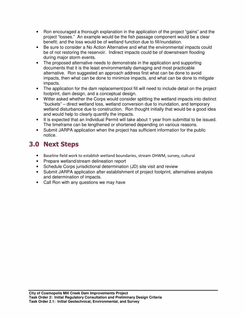
• Ron encouraged a thorough explanation in the application of the project “gains” and the project “losses.” An example would be the fish passage component would be a clear benefit; and the loss would be of wetland function due to fill/inundation.
• Be sure to consider a No Action Alternative and what the environmental impacts could be of not restoring the reservoir. Indirect impacts could be of downstream flooding during major storm events.
• The proposed alternative needs to demonstrate in the application and supporting documents that it is the least environmentally damaging and most practicable alternative. Ron suggested an approach address first what can be done to avoid impacts, then what can be done to minimize impacts, and what can be done to mitigate impacts.
• The application for the dam replacement/pool fill will need to include detail on the project footprint, dam design, and a conceptual design.
• Witter asked whether the Corps would consider splitting the wetland impacts into distinct “buckets” – direct wetland loss, wetland conversion due to inundation, and temporary wetland disturbance due to construction. Ron thought initially that would be a good idea and would help to clearly quantify the impacts.
• It is expected that an Individual Permit will take about 1 year from submittal to be issued. The timeframe can be lengthened or shortened depending on various reasons.
• Submit JARPA application when the project has sufficient information for the public notice.
3.0 Next Steps
• Baseline field work to establish wetland boundaries, stream OHWM, survey, cultural
• Prepare wetland/stream delineation report
• Schedule Corps jurisdictional determination (JD) site visit and review
• Submit JARPA application after establishment of project footprint, alternatives analysis and determination of impacts.
• Call Ron with any questions we may have

City of Cosmopolis Mill Creek Dam Improvements Project Task Order 2: Initial Regulatory Consultation and Preliminary Design Criteria Task Order 2.1: Initial Geotechnical, Environmental, and Survey
Appendix B 1998 FEMA LOMR

City of Cosmopolis Mill Creek Dam Improvements Project Task Order 2: Initial Regulatory Consultation and Preliminary Design Criteria Task Order 2.1: Initial Geotechnical, Environmental, and Survey
This page left intentionally blank.


City of Cosmopolis Mill Creek Dam Improvements Project Task Order 2: Initial Regulatory Consultation and Preliminary Design Criteria Task Order 2.1: Initial Geotechnical, Environmental, and Survey
This page left intentionally blank.

City of Cosmopolis Mill Creek Dam Improvements Project Task Order 2: Initial Regulatory Consultation and Preliminary Design Criteria Task Order 2.1: Initial Geotechnical, Environmental, and Survey
Appendix C Initial Environmental Review

City of Cosmopolis Mill Creek Dam Improvements Project Task Order 2: Initial Regulatory Consultation and Preliminary Design Criteria Task Order 2.1: Initial Geotechnical, Environmental, and Survey
This page left intentionally blank.

City of Cosmopolis Mill Creek Dam Improvements Project Task Order 2: Initial Regulatory Consultation and Preliminary Design Criteria Task Order 2.1: Initial Geotechnical, Environmental, and Survey
Technical Memorandum
To: Darrin Raines, Director of Public Works, City of Cosmopolis
From: Tim Hume; HDR
Prepared by:
Mike Witter; HDR
Reviewed by:
Karissa Kawamoto; HDR
Date: October 15, 2013
Subject: Mill Creek Dam Improvements Project Task Order 2.1: Initial Environmental Services
1. Introduction
The objective of Task Order 2.1 was to obtain information to bridge gaps between Task Orders 2 and 3. A one-half day site visit to Mill Creek Park was conducted on October 10, 2013 to observe wetland conditions at the pond site behind the dam. This tech memo documents the findings of the initial environmental review efforts.
2. Environmental Site Visit Observations
The key project related findings resulting from the site visit include:
• The silt that has built-up behind the old dam structure is now vegetated. The vegetation present includes species that are common within wetland areas including reed canarygrass (Phalaris arundinacae), Touch-me-not (Impatiens noli-tangere), and common cattail (Typha latifolia). There are also some areas that are starting to become dominated by red alder (Alnus rubra) saplings.
• Most of the area that was inundated by the former pond area is likely to meet the regulatory definition as wetlands.
• The wetlands present provide some floodplain functions and may help filter out sediments during higher flows and thus improving water quality for downstream areas.
• Wetland habitat in these areas is very rudimentary and could be enhanced by introducing additional habitat structures and increasing plant species diversity.
These observations will be beneficial for discussions during the upcoming initial consultation with the US Army Corps of Engineers on November 8.

City of Cosmopolis Mill Creek Dam Improvements Project Task Order 2: Initial Regulatory Consultation and Preliminary Design Criteria Task Order 2.1: Initial Geotechnical, Environmental, and Survey
This page left intentionally blank.

City of Cosmopolis Mill Creek Dam Improvements Project Task Order 2: Initial Regulatory Consultation and Preliminary Design Criteria Task Order 2.1: Initial Geotechnical, Environmental, and Survey
Appendix D Initial Geotechnical Review

City of Cosmopolis Mill Creek Dam Improvements Project Task Order 2: Initial Regulatory Consultation and Preliminary Design Criteria Task Order 2.1: Initial Geotechnical, Environmental, and Survey
This page left intentionally blank.

City of Cosmopolis Mill Creek Dam Improvements Project Task Order 2: Initial Regulatory Consultation and Preliminary Design Criteria Task Order 2.1: Initial Geotechnical, Environmental, and Survey
Technical Memorandum
To: Darrin Raines, Director of Public Works, City of Cosmopolis
From: Tim Hume, HDR
Prepared by: Rich Hannan, HDR
Reviewed by: Matthew Gray, HDR
Date: November 14, 2013
Subject: Mill Creek Dam Improvements Project Task Order 2.1: Initial Geotechnical Services
1. Introduction
The objective of Task Order 2.1 was to obtain information to bridge gaps between Task Orders 2 and 3. On October 17, 2013 a site visit was made to the Mill Creek Dam Site located within the community of Cosmopolis, Washington. The purpose of the visit was to perform a preliminary geotechnical evaluation of the existing dam site to determine feasible options for the site. This tech memo documents the findings of the initial geotechnical review efforts.
Upon arrival I met with Matt Gray HDR Bellevue; Tim Hume, Project Manager, HDR Olympia; Darrin Raines, City of Cosmopolis Director of Public Works; and Jack Thompson, City of Cosmopolis contracted equipment operator. To assist with the evaluation, the City provided an excavator and operator to excavate test pits to help evaluate shallow subsurface conditions at the site.
An initial site evaluation was made and pit locations selected. Three test pits and a series of probes were made to evaluate overburden type and depth and establish the probable depth to bedrock. A description of the pits is provided below. See Figure 1 at the end of the memorandum for a site plan and the location of the test pits and probe locations.
2. Background
Mill Creek Dam was reportedly constructed in the late 1970s to provide flood protection and create a recreation pond. The dam is a small concrete gravity structure with a central spillway and two gated outlet pipes located at the base of the dam. The dam is about 35 feet long at the crest with an estimated height of 12 feet measured from its bedrock foundation. The dam created a pond covering an estimated 3-4 acres and has a storage capacity of about 20 acre feet. A portion of the right abutment (right side looking downstream) has been breached resulting is loss of the pool.
Based on observation, the left abutment (left side looking downstream) and valley section of the dam was founded on sandstone bedrock. The right abutment was keyed into an earthen berm. A sheet pile cutoff was extended from the upstream right side of the dam into the berm for an undetermined distance. A portion of a sheet pile remains attached to the structure and several 8-foot-long pieces of sections were stacked along the upstream right abutment. The sheet pilling is believed to have been driven or pushed to refusal in bedrock. At this time no design drawings or as-builts are available. In 2008, the right abutment failed allowing the stream to breach the abutment creating a channel about 10 feet wide between the dam and right
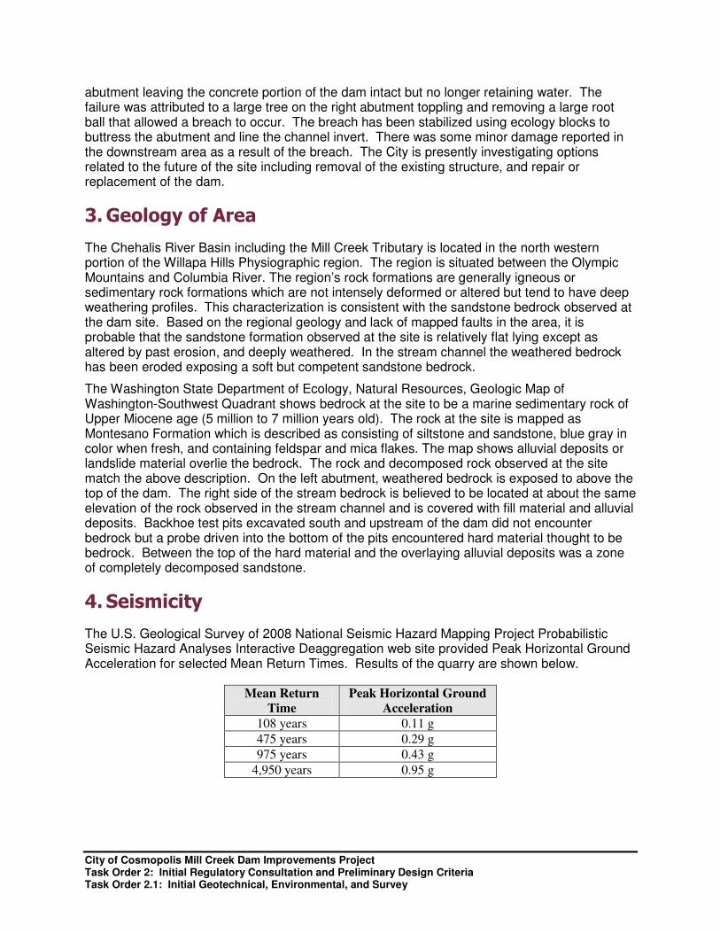
City of Cosmopolis Mill Creek Dam Improvements Project Task Order 2: Initial Regulatory Consultation and Preliminary Design Criteria Task Order 2.1: Initial Geotechnical, Environmental, and Survey
abutment leaving the concrete portion of the dam intact but no longer retaining water. The failure was attributed to a large tree on the right abutment toppling and removing a large root ball that allowed a breach to occur. The breach has been stabilized using ecology blocks to buttress the abutment and line the channel invert. There was some minor damage reported in the downstream area as a result of the breach. The City is presently investigating options related to the future of the site including removal of the existing structure, and repair or replacement of the dam.
3. Geology of Area
The Chehalis River Basin including the Mill Creek Tributary is located in the north western portion of the Willapa Hills Physiographic region. The region is situated between the Olympic Mountains and Columbia River. The region’s rock formations are generally igneous or sedimentary rock formations which are not intensely deformed or altered but tend to have deep weathering profiles. This characterization is consistent with the sandstone bedrock observed at the dam site. Based on the regional geology and lack of mapped faults in the area, it is probable that the sandstone formation observed at the site is relatively flat lying except as altered by past erosion, and deeply weathered. In the stream channel the weathered bedrock has been eroded exposing a soft but competent sandstone bedrock.
The Washington State Department of Ecology, Natural Resources, Geologic Map of Washington-Southwest Quadrant shows bedrock at the site to be a marine sedimentary rock of Upper Miocene age (5 million to 7 million years old). The rock at the site is mapped as Montesano Formation which is described as consisting of siltstone and sandstone, blue gray in color when fresh, and containing feldspar and mica flakes. The map shows alluvial deposits or landslide material overlie the bedrock. The rock and decomposed rock observed at the site match the above description. On the left abutment, weathered bedrock is exposed to above the top of the dam. The right side of the stream bedrock is believed to be located at about the same elevation of the rock observed in the stream channel and is covered with fill material and alluvial deposits. Backhoe test pits excavated south and upstream of the dam did not encounter bedrock but a probe driven into the bottom of the pits encountered hard material thought to be bedrock. Between the top of the hard material and the overlaying alluvial deposits was a zone of completely decomposed sandstone.
4. Seismicity
The U.S. Geological Survey of 2008 National Seismic Hazard Mapping Project Probabilistic Seismic Hazard Analyses Interactive Deaggregation web site provided Peak Horizontal Ground Acceleration for selected Mean Return Times. Results of the quarry are shown below.
Mean Return
Time
Peak Horizontal Ground
Acceleration
108 years 0.11 g
475 years 0.29 g
975 years 0.43 g
4,950 years 0.95 g
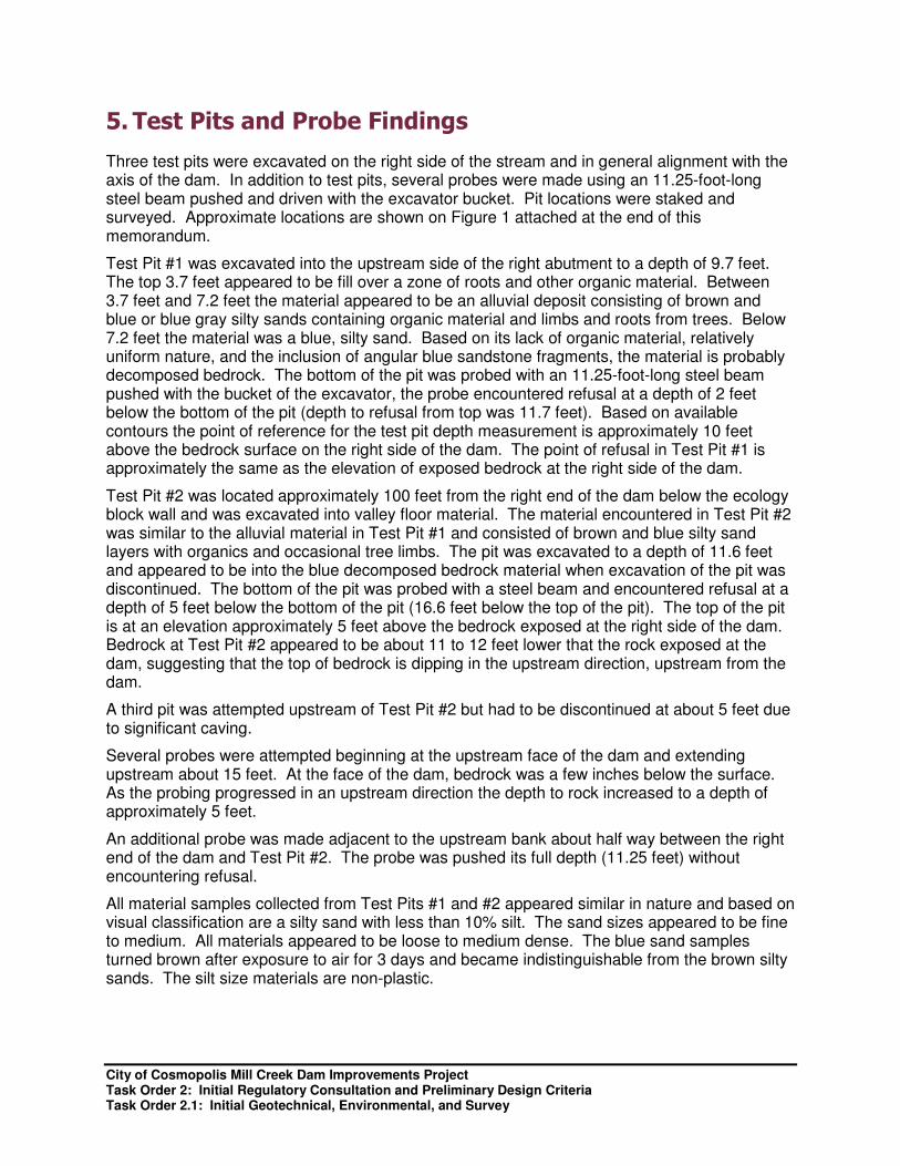
City of Cosmopolis Mill Creek Dam Improvements Project Task Order 2: Initial Regulatory Consultation and Preliminary Design Criteria Task Order 2.1: Initial Geotechnical, Environmental, and Survey
5. Test Pits and Probe Findings
Three test pits were excavated on the right side of the stream and in general alignment with the axis of the dam. In addition to test pits, several probes were made using an 11.25-foot-long steel beam pushed and driven with the excavator bucket. Pit locations were staked and surveyed. Approximate locations are shown on Figure 1 attached at the end of this memorandum.
Test Pit #1 was excavated into the upstream side of the right abutment to a depth of 9.7 feet. The top 3.7 feet appeared to be fill over a zone of roots and other organic material. Between 3.7 feet and 7.2 feet the material appeared to be an alluvial deposit consisting of brown and blue or blue gray silty sands containing organic material and limbs and roots from trees. Below 7.2 feet the material was a blue, silty sand. Based on its lack of organic material, relatively uniform nature, and the inclusion of angular blue sandstone fragments, the material is probably decomposed bedrock. The bottom of the pit was probed with an 11.25-foot-long steel beam pushed with the bucket of the excavator, the probe encountered refusal at a depth of 2 feet below the bottom of the pit (depth to refusal from top was 11.7 feet). Based on available contours the point of reference for the test pit depth measurement is approximately 10 feet above the bedrock surface on the right side of the dam. The point of refusal in Test Pit #1 is approximately the same as the elevation of exposed bedrock at the right side of the dam.
Test Pit #2 was located approximately 100 feet from the right end of the dam below the ecology block wall and was excavated into valley floor material. The material encountered in Test Pit #2 was similar to the alluvial material in Test Pit #1 and consisted of brown and blue silty sand layers with organics and occasional tree limbs. The pit was excavated to a depth of 11.6 feet and appeared to be into the blue decomposed bedrock material when excavation of the pit was discontinued. The bottom of the pit was probed with a steel beam and encountered refusal at a depth of 5 feet below the bottom of the pit (16.6 feet below the top of the pit). The top of the pit is at an elevation approximately 5 feet above the bedrock exposed at the right side of the dam. Bedrock at Test Pit #2 appeared to be about 11 to 12 feet lower that the rock exposed at the dam, suggesting that the top of bedrock is dipping in the upstream direction, upstream from the dam.
A third pit was attempted upstream of Test Pit #2 but had to be discontinued at about 5 feet due to significant caving.
Several probes were attempted beginning at the upstream face of the dam and extending upstream about 15 feet. At the face of the dam, bedrock was a few inches below the surface. As the probing progressed in an upstream direction the depth to rock increased to a depth of approximately 5 feet.
An additional probe was made adjacent to the upstream bank about half way between the right end of the dam and Test Pit #2. The probe was pushed its full depth (11.25 feet) without encountering refusal.
All material samples collected from Test Pits #1 and #2 appeared similar in nature and based on visual classification are a silty sand with less than 10% silt. The sand sizes appeared to be fine to medium. All materials appeared to be loose to medium dense. The blue sand samples turned brown after exposure to air for 3 days and became indistinguishable from the brown silty sands. The silt size materials are non-plastic.

City of Cosmopolis Mill Creek Dam Improvements Project Task Order 2: Initial Regulatory Consultation and Preliminary Design Criteria Task Order 2.1: Initial Geotechnical, Environmental, and Survey
6. Site Observations and Findings
The following summarizes observations and findings:
• The dam is founded on relatively soft but competent sandstone.
• The valley floor downstream from the dam for at least 100 feet consisted of in place bedrock.
• The left abutment was tied into sandstone bedrock similar to that exposed in the foundation area. The sandstone is exposed in the valley walls upstream and downstream of the dam.
• The right end of the dam appeared to have been placed directly against the soil material forming the right abutment with sheetpiling installed forming a cutoff from the concrete dam into the abutment for an undetermined distance.
• The bedrock surface appeared to drop off upstream and downstream of the dam, but remained at a relatively constant elevation for an unknown distance to the right side of the dam, and rose steeply to the left side of the dam.
• Overburden materials observed on the right side and upstream of the dam appeared to be a loose, fine to medium silty sand with less than 10% silt, and should be considered potentially liquefiable during any significant seismic event.
• With the exception of the right end of the dam (the portion placed against the soil abutment), the dam was intact and potentially reusable. The right end of the dam had a significant overhang resulting from the erosion of the abutment material. Stability analysis would be required to determine if the existing dam would meet minimum seismic stable criteria during a design earthquake.
• Due to the relatively high bedrock forming the dam foundation and extending under the right abutment, it is probable that a dam founded on bedrock could be economically constructed at this location. A sheetpile or other type of cutoff probably would be needed for a short distance into the right abutment to control potential seepage around a new dam section.
7. Conclusions
Due to the relatively high bedrock forming the foundation of the existing dam and extending under the right abutment, the site appeared to be suitable for construction of a dam that would be stable during a design earthquake and not have excessive seepage around or under the structure.
Because of the relatively rapid decrease in bedrock elevation in the upstream and downstream direction, a structure with a small footprint would likely be the most economical solution. An embankment-type dam would probably not be the most economical solution. A concrete gravity dam or other gravity-type structure constructed in the same location as the existing structure would likely be the most economical and require the least amount of foundation excavation and dewatering effort.
It is probable that the existing dam can be economically incorporated into any new structure. Additional explorations would be necessary to adequately define conditions on both abutments and better determine the seismic stability of the right abutment.
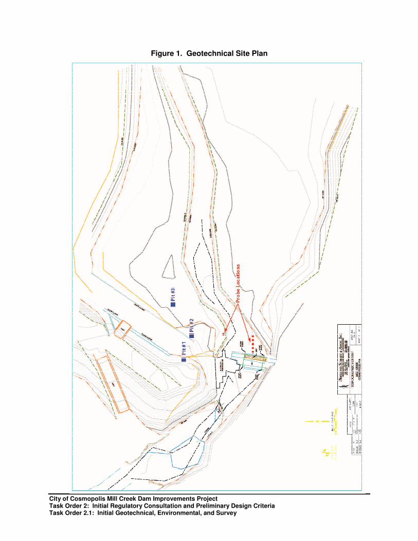
City of Cosmopolis Mill Creek Dam Improvements Project Task Order 2: Initial Regulatory Consultation and Preliminary Design Criteria Task Order 2.1: Initial Geotechnical, Environmental, and Survey
Figure 1. Geotechnical Site Plan

City of Cosmopolis Mill Creek Dam Improvements Project Task Order 2: Initial Regulatory Consultation and Preliminary Design Criteria Task Order 2.1: Initial Geotechnical, Environmental, and Survey
This page left intentionally blank.
City of Cosmopolis Mill Creek Dam Improvements Project Task Order 2: Initial Regulatory Consultation and Preliminary Design Criteria Task Order 2.1: Initial Geotechnical, Environmental, and Survey
Appendix E Engineering Guidance and Reference Manuals
American Society of Civil Engineers
American Society of Civil Engineers, Current Trends in Design and Construction of Embankment Dams, 1979, p. 32.
American Society of Civil Engineers, Journal of Geotechnical Engineering, Basic Properties of Sand and Gravel Filters, Vol. 110, No. 6, June 1984, p. 684-700.
American Society of Civil Engineers, Journal of Geotechnical Engineering, Filters for Silts and Clays, 110(6) June 1984, p. 707.
American Society of Civil Engineers, Journal of Geotechnical Engineering Whitman, R. V., Evaluating Calculated Risk in Geotechnical Engineering, Vol 110, No. 2, 1984.
American Society of Civil Engineers, Journal of Geotechnical Engineering, Earthquake-Induced Permanent Deformations: Probabilistic Approach, Vol. 117, No. 1, January, 1991.
American Society of Civil Engineers, Journal of Geotechnical Engineering, Hydroconsolidation Potential of Palouse Loess, Vol. 107, 1981.
American Society of Civil Engineers, Journal of Hydraulic Engineering, Flow and Energy Dissipation Over Stepped Gabion Weirs, , Vol. 118, No.5, May 1990.
American Society of Civil Engineers, Journal of Structural Engineering, River and Lake Ice Processes Relevant to Ice Loads, March 1983, pp. 121-138.
American Society of Civil Engineers, Journal of Structural Engineering, Measurement of Ice Forces on Structures, March 1983, pp. 139-155.
American Society of Civil Engineers, Journal of the Geotechnical Engineering, Loess Soils in Southeastern Washington, Vol. 105, No. GT6, 1979, pp. 786-791.
American Society of Civil Engineers, Journal of the Geotechnical Engineering, Load Transfer and Hydraulic Fracturing in Zoned Dams, Vol. 102, GT9, Proc. Paper 12400, 1976, pp. 963-974.
American Society of Civil Engineers, Journal of the Geotechnical Engineering, Field Performance and Analysis of Steep Riprap, Vol 118, No. 9, 1992, pp 1431-48.
American Society of Civil Engineers, Journal of the Hydraulics Division, Straight Drop Spillway Stilling Basin, May 1965.
American Society of Civil Engineers, Journal of the Structural Division, New Distribution of Extreme Winds in the United States, July 1968.
American Society of Civil Engineers, Minimum Design Loads for Buildings and Other Structures, July, 1990.
City of Cosmopolis Mill Creek Dam Improvements Project Task Order 2: Initial Regulatory Consultation and Preliminary Design Criteria Task Order 2.1: Initial Geotechnical, Environmental, and Survey
Federal Highway Administration
Federal Highway Administration, Hydraulic Charts for the Selection of Highway Culverts, Hydraulic Engineering Circular No. 5, December 1965.
Federal Highway Administration, Hydraulic Design of Energy Dissipaters for Culverts and Channels, Hydraulic Circular No. 14, US Dept. of Transportation, September, 1983.
Federal Highway Administration, Hydraulic Design of Improved Inlets for Culverts, Hydraulic Engineering Circular No. 13, August 1972.
Federal Highway Administration, Minimizing Embankment Damage during Overtopping Flow, FHWA-RD-88-181, November 1988.
Natural Resources Conservation Service (formerly Soil Conservation Service)
U.S. Dept. of Agriculture, Soil Conservation Service, Chute Spillways, Section 14, Part 634, National Engineering Handbook, 1985.
U.S. Dept. of Agriculture, Soil Conservation Service, Drop Spillways, Section 11, Part 634, National Engineering Handbook, 1986.
U.S. Dept. of Agriculture, Soil Conservation Service, Gated Outlet Appurtenances, Technical Release 46, 1982.
U.S. Dept. of Agriculture, Soil Conservation Service, Riprap for Slope Protection against Wave Action, Technical Release No. 69, February, 1983.
U.S. Dept. of Agriculture, Soil Conservation Service, Riprap Lined Plunge Pool for Cantilever Outlet, Design Note No. 6, 1986.
U.S. Dept. of Agriculture, Soil Conservation Service, Sedimentation, Part 632, National Engineering Handbook, 1971.
U.S. Dept. of Agriculture, Soil Conservation Service, Spillway Hydraulics and Design, Section 4, National Engineering Handbook
U.S. Dept. of Agriculture, Soil Conservation Service, Urban Hydrology for Small Watersheds, Technical Release No. 55, January 1975.
National Weather Service
National Weather Service, Interduration Precipitation Relations for Storms - Western United States, Technical Report NWS 27, NOAA, Washington D.C., 1981
National Weather Service, NOAA ATLAS 2, Precipitation - Frequency Atlas of the Western United States, Volume IX - Washington, U.S. Department of Commerce, Washington D.C., 1973.

City of Cosmopolis Mill Creek Dam Improvements Project Task Order 2: Initial Regulatory Consultation and Preliminary Design Criteria Task Order 2.1: Initial Geotechnical, Environmental, and Survey
National Weather Service, Hydrometeorological Report 43, Probable Maximum Precipitation for the Pacific Northwest, U.S. Department of Commerce, NOAA, U.S. Weather Bureau, Washington D.C., 1966.
National Weather Service, Hydrometeorological Report 57, Probable Maximum Precipitation for the Pacific Northwest, U.S. Department of Commerce, NOAA, U.S. Weather Bureau, Washington D.C., replaces HMR-43, 1994.
U.S. Army Corps of Engineers
U.S. Army Corps of Engineers, Biddability, Constructability and Operability, Engineer Regulation, ER 415-1-11, 2013.
U.S. Army Corps of Engineers, Computation of Freeboard Allowances for Waves in Reservoirs, Engineer Technical Letter, ETL 1110-2-8, Office of the Chief of Engineers, Wash. D.C., 1966.
U.S. Army Corps of Engineers, Design of Pile Foundations, Engineering Manual, EM 1110-2-2906, 1991.
U.S. Army Corps of Engineers, Earth and Rock Fill Dams, Engineering Manual, EM 1110-2-2300, May, 1982.
U.S. Army Corps of Engineers, Earthquake Design and Analysis for Corps of Engineers Projects, Engineer Regulation, ER 1110-2-1806, 1995.
U.S. Army Corps of Engineers, Evaluation and Repair of Concrete Structures, Engineering Manual, EM 1110-2-2002, 1995
U.S. Army Corps of Engineers, General Spillway Investigation, U.S. Army Corps of Engineers, Waterway Experiment Station, Technical Report HL-85-1, March 1985.
U.S. Army Corps of Engineers, Geological Investigations, Engineering Manual, EM 1110-1-1801, Change 2, April 1978.
U.S. Army Corps of Engineers, Geophysical Exploration, Engineering Manual, EM 1110-1-1802, 1995.
U.S. Army Corps of Engineers, Grouting Technology, Engineering Manual, EM 1110-2-3506, 1984.
U.S. Army Corps of Engineers, Hydraulic Design of Flood Control Channels, Engineering Manual, EM 1110-2-1601, 1970.
U.S. Army Corps of Engineers, Hydraulic Design of Outlet Works, Engineering Manual, EM1110-2-1602, 1980.
U.S. Army Corps of Engineers, Hydraulic Design of Reservoir Outlet Works, Engineering Manual, EM 1110-2-1602, Washington DC, October 1980.
U.S. Army Corps of Engineers, Hydraulic Design of Spillways, Engineering Manual EM1110-2-1603, March 1965.
City of Cosmopolis Mill Creek Dam Improvements Project Task Order 2: Initial Regulatory Consultation and Preliminary Design Criteria Task Order 2.1: Initial Geotechnical, Environmental, and Survey
U.S. Army Corps of Engineers, Ice Engineering, Engineering Manual, EM1110-2-1612, 1982.
U.S. Army Corps of Engineers, Instrumentation for Concrete Structures, Engineering Manual, EM 1110-2-4300, 1987.
U.S. Army Corps of Engineers, Laboratory Investigations and Materials Testing, Engineer Regulation, ER 1110-1-8100, 1997.
U.S. Army Corps of Engineers, Periodic Inspection and Continuing Evaluation of Completed Civil Works Structures, Engineer Regulation, ER 1110-2-100, 1994.
U.S. Army Corps of Engineers, Planning and Design of Hydroelectric Power Plant Structures, Engineering Manual, EM 1110-2-3001, 2008.
U.S. Army Corps of Engineers, Practical Riprap Design, U.S. Army Corps of Engineers Waterways Experiment Station, Vicksburg MS, Miscellaneous Paper H-78-7, June 1978.
U.S. Army Corps of Engineers, Rationalizing the Seismic Coefficient Method, Miscellaneous Paper GL-84-13, Final Report, Waterways Experiment Station, Vicksburg, Miss., July 1984.
U.S. Army Corps of Engineers, Retaining and Flood Walls, Engineering Manual, EM 1110-2-2502, 1989
U.S. Army Corps of Engineers, Roller Compacted Concrete, Engineering Manual, EM 1110-2-2006, 2000.
U.S. Army Corps of Engineers, Runoff from Snowmelt, Engineering Manual EM 1110-2-1406, January 1960.
U.S. Army Corps of Engineers, Seattle District, Unpublished Data on the Magnitude-Frequency- Duration of Observed Winds at Selected Stations in Washington, 1987.
U.S. Army Corps of Engineers, Seepage Analysis and Control for Dams, Engineering Manual, EM 1110-2-1901, 1986.
U.S. Army Corps of Engineers, Seismic Design Guidelines for Essential Buildings, Technical Manual, TM 5-809-10-1, 1986.
U.S. Army Corps of Engineers, Coastal Engineering Manual Part I – VI, Engineering Manual, EM 1110-2-1100, 2002.
U.S. Army Corps of Engineers, Stability of Earth and Rockfill Dams, Engineering Manual, EM 1110-2-1902, 1970.
U.S. Army Corps of Engineers, Standard Practice for Concrete for Civil Works Structures, Engineering Manual, EM 1110-2-2000, 2001.
U.S. Army Corps of Engineers, Structural Design of Spillways and Outlet Works, Engineering Manual, EM 1110-2-2400, 2003.
U.S. Army Corps of Engineers, Waterstops and Other Preformed Joint Materials for Civil Works Structures, Engineering Manual, EM 1110-2-2102, 1995.
City of Cosmopolis Mill Creek Dam Improvements Project Task Order 2: Initial Regulatory Consultation and Preliminary Design Criteria Task Order 2.1: Initial Geotechnical, Environmental, and Survey
U.S. Army Corps of Engineers, Wind-Wave Generation on Restricted Fetches, Coastal Engineering Research Center, Waterways Experiment Station, Vicksburg, MS., 1991.
U.S. Bureau of Reclamation
U.S. Bureau of Reclamation, A Rapid Method of Construction Control for Embankments of Cohesive Soil, No. 26, 1961.
U.S. Bureau of Reclamation, Air-Water Flow in Hydraulic Structures, Engineering Monograph No. 41, 1980.
U.S. Bureau of Reclamation, Beggs Deformeter-Stress Analysis of Single-Barrel Conduits, No. 14, 1968.
U.S. Bureau of Reclamation, Cavitation in Chutes and Spillways, Engineering Monograph No. 42, 1990.
U.S. Bureau of Reclamation, Concrete Manual, 8th Edition, Denver, Colo., 1988.
U.S. Bureau of Reclamation, Control of Cracking In Mass Concrete Structures, No. 34, 1981.
U.S. Bureau of Reclamation, Criteria and Guidelines for Evacuating Reservoir Storage Reservoirs and Sizing Low-level Outlet Works, Technical Memorandum No. 3, 1982.
U.S. Bureau of Reclamation, Design Criteria for Concrete Arch and Gravity Dams, No. 19, 1977.
U.S. Bureau of Reclamation, Design of Gravity Dams, 1976.
U.S. Bureau of Reclamation, Design of Small Canal Structures, 1974.
U.S. Bureau of Reclamation, Design of Small Dams, 1987.
U.S. Bureau of Reclamation, Discharge Coefficients for Irregular Overfall Spillways, Engineering Monograph No. 9, 1952
U.S. Bureau of Reclamation, Downstream Hazard Classification Guidelines, Technical Memorandum No. 11, 1988.
U.S. Bureau of Reclamation, Effect of Snow Compaction on Runoff from Rain on Snow, No. 35, 1966.
U.S. Bureau of Reclamation, Embankment Dams, Design Standards No. 13, 1984.
U.S. Bureau of Reclamation, Estimating Foundation Settlement by One-Dimensional Consolidation Tests, 1953.
U.S. Bureau of Reclamation, Estimating Reversible Pump Turbine Characteristics, Engineering Monograph No. 39, 1977.
U.S. Bureau of Reclamation, Friction Factors for Large Conduits Flowing Full, Engineering Monograph No. 7, 1965.

City of Cosmopolis Mill Creek Dam Improvements Project Task Order 2: Initial Regulatory Consultation and Preliminary Design Criteria Task Order 2.1: Initial Geotechnical, Environmental, and Survey
U.S. Bureau of Reclamation, Ground-Water Movement, Engineering Monograph No. 31, 1964.
U.S. Bureau of Reclamation, Guide for Preliminary Design of Arch Dams, No. 36, 1977.
U.S. Bureau of Reclamation, Guidelines for Defining Inundated Areas Downstream from Bureau of Reclamation Dams, 1982.
U.S. Bureau of Reclamation, Hydraulic Design of Stilling Basin for Pipe and Culvert Outlets, Research Report No. 24, 1978.
U.S. Bureau of Reclamation, Hydraulic Design of Stilling Basins and Energy Dissipaters, Engineering Monograph No. 25, 1983.
U.S. Bureau of Reclamation, Hydraulic Design of Transitions for Small Canals, Engineering Monograph No. 33, 1964.
U.S. Bureau of Reclamation, Hydraulic Laboratory Practice, Engineering Monograph No. 18, 1953.
U.S. Bureau of Reclamation, Hydrodynamic Pressures on Dams Due to Horizontal Earthquake Effects, No. 11, 1952.
U.S. Bureau of Reclamation, Moments and Reactions for Rectangular Plates, Engineering Monograph No. 27, 1963.
U.S. Bureau of Reclamation, Physical Properties of Some Typical Foundation Rocks, Concrete Laboratory Report No. SP-39, Engineering Laboratories Branch, 1953.
U.S. Bureau of Reclamation, Rock Mechanics Properties of Typical Foundation Rock Types, REC-ERC-74-10, Engineering and Research Center, 1974.
U.S. Bureau of Reclamation, Stress Analysis of Concrete Pipe, No. 6, 1950.
U.S. Bureau of Reclamation, Theory and Problems of Water Percolation, Engineering Monograph No. 8, 1953.
U.S. Bureau of Reclamation, Welded Steel Penstocks, Engineering Monograph No. 3, 1966.
U.S. Geological Survey
U.S. Geological Survey, Characterization and Simulation of Rainfall-Runoff Relations for Headwater Basins in Western King and Snohomish Counties, Washington, Water Resources Investigations Report 89-4052, Tacoma WA, 1990.
U.S. Geological Survey, Measurement of Peak Discharge at Dams by Indirect Methods, Publication in Applications of Hydraulics, 1967.
U.S. Geological Survey, Miscellaneous Streamflow Measurements - in the State of Washington 1980 - January 1961, Water Supply Bulletin No. 23, Pacific Northwest District, Tacoma, WA.

City of Cosmopolis Mill Creek Dam Improvements Project Task Order 2: Initial Regulatory Consultation and Preliminary Design Criteria Task Order 2.1: Initial Geotechnical, Environmental, and Survey
U.S. Geological Survey, Probabilistic Estimates of Maximum Seismic Horizontal Ground Motion on Rock in the Pacific Northwest and the Adjacent Outer Continental Shelf, USGS Open-File Report 80-471, 1980.
U.S. Geological Survey, Streamflow Statistics and Drainage Basin Characteristics for the Puget Sound Region, Washington, Volume II - Eastern Puget Sound from Seattle to the Canadian Border, Open File Report 84-144B, 1985.
U.S. Geological Survey, Streamflow Statistics and Drainage Basin Characteristics for the Southwestern and Eastern Regions, Washington, Volume I - Southwestern Washington, Open File Report 84-145-A, 1985.
U.S. Geological Survey, Streamflow Statistics and Drainage Basin Characteristics for the Southwestern and Eastern Regions, Washington, Volume II - Eastern Washington, Open File Report 84-145-B, 1985.
U.S. Geological Survey, Streamflow Statistics and Drainage Basin Characteristics for the Puget Sound Region, Washington, Volume I - Western and Southern Puget Sound, Open File Report 84-144-A, 1985.
U.S. Geological Survey, Water Resources Data - Washington, Annual Periodical, 1961-present, Pacific Northwest District, Tacoma, WA.
U.S. Geological Survey, Workshop on Evaluation of Earthquake Hazards and Risk in the Puget Sound and Portland Areas, Proceedings of Conference XLVIII, Portland, Oregon, March 28-30, 1989: U.S. Geological Survey Open-File Report 89-465.
Selected References from Washington Department of Ecology DSO
Abt, R., and Johnson, T.L., Riprap Design for Overtopping Flow, ASCE Journal of Hydraulic Engineering, Vol 117, No. 8, August, 1991 pp 959-972.
Akhmedov, T.K., Calculation of the Depth of Scour in Rock Downstream of a Spillway, Water Power and Dam Construction, December 1988.
American Iron and Steel Institute, Handbook of Steel Drainage and Highway Construction Products, Second Edition, 1971.
Brater, E.F., and H.W. King, Handbook of Hydraulics, McGraw Hill, Sixth Edition, 1976.
Bucknam, R.C., et. al, "Abrupt Uplift Within the Past 1700 Years at Southern Puget Sound, Washington", Science, Vol. 258, December 1992, pgs. 1611-1614.
Chow, V.T., Open Channel Hydraulics, McGraw-Hill, 1959.
Cohee, B.P., Somerville, P.B., Abrahamson, N.A., "Ground Motions from Hypothesized Mw=8 Subduction Earthquakes in the Pacific Northwest", 1989, submitted to Bulletin of the Seismological Society of America.
Design and Control of Concrete Mixtures, 13th Edition; Kosmatka, Steven and Panarese, William; Portland Cement Association, Skokie, Il, 1988

City of Cosmopolis Mill Creek Dam Improvements Project Task Order 2: Initial Regulatory Consultation and Preliminary Design Criteria Task Order 2.1: Initial Geotechnical, Environmental, and Survey
Draft Safety Evaluation by the Office of Nuclear Reactor Regulation Relating to Geology and Seismology, Washington Public Power Supply System, Nuclear Project No. 3, Docket No. 50-508,January 4, 1991.
Duncan, J. M., and Buchignani, A. C., An Engineering Manual for Slope Stability Studies, University of California, Berkeley, March 1975.
Earthquake Engineering for Concrete Dams: Design, Performance, and Research Needs, National Research Council, National Academy Press, Washington, D.C., 1990, p. 10.
Elevatorski, E., A., Hydraulic Energy Dissipators, McGraw Hill, New York, 1959.
Fread, D.L., BREACH: An Erosion Model for Earthen Dam Failures, Hydrologic Research Laboratory, NOAA, NWS, June, 1987.
Fread, D.L., DAMBRK: The NWS-Dam Break Flood Forecasting Model, Office of Hydrology, National Weather Service, Silver Spring, MD, June 20, 1988.
Galster, Richard W. (Chairman), Engineering Geology in Washington, Washington Division of Geology and Earth Resources, Bulletin 78, Washington State Department of Natural Resources, 2 Volumes, 1989.
Green, K.G., "Earthquake Ground Motions for the Evaluation of Dams", Association of State Dam Safety Officials, Western Regional Technical Seminar, Seismic Evaluation of Existing Dams, Sept. 26-27, 1990.
Hager, W.H., Discharge Characteristics of Gated Standard Spillways, Water Power and Dam Construction, January 1988.
Idriss, I.M., "Evaluating Seismic Risk in Engineering Practice", Proceedings of the 11th International Conference on Soil Mechanics and Foundation Engineering, San Francisco, August 12-16, 1985,A.A. Balkema (Publ.), pgs. 255-320.
Idriss, I.M., Duncan, J.M., "Earthquake Response Analysis of Embankment Dams", Advanced Dam Engineering for Design, Construction, and Rehabilitation, Jansen, R.B. (ed.), Van Nostrand Reinhold, 1988, pgs. 251-252.
International Conference of Building Officials, Uniform Building Code, 1988.
King County Surface Water Management Division, Surface Water Design Manual, King County Department of Public Works, 1990.
Koerner, Robert M., Designing with Geosynthetics, 2nd Edition, Prentice Hall Publ. Co., 1990, pp. 83.
Makdisi, F.I., Seed, H.B., A Simplified Procedure for Estimating Earthquake-Induced Deformations in Dams and Embankments, Report No. UCB/EERC-77/19, University of California, Berkeley, August 1977, pgs. A1-A15.
Mantei, C. Leo, 1985, Seepage Control for Embankment Dams USBR Practice, In R.L. Volpe and W.E. Kelly (eds.), Seepage and Leakage from Dams and Impoundments. Proceedings of a

City of Cosmopolis Mill Creek Dam Improvements Project Task Order 2: Initial Regulatory Consultation and Preliminary Design Criteria Task Order 2.1: Initial Geotechnical, Environmental, and Survey
Geotechnical Engineering Division symposium in Denver, Co., May 5, 1985, American Society of Engineers, New York, N.Y., p. 229.
Marcuson III, W.F., Hadala, P.F., Franklin, A.G., Current Methods of Dynamic Analysis for Seismic Stability of Earth Dams, Engineering Geology, Vol. 16, 1980, p. 27.
Mohraz, B., Elghadamsi, F.E., "Earthquake Ground Motion and Response Spectra", The Seismic Design Handbook, Naeim, F. (ed.), Van Nostrand Reinhold, New York, 1989, pg. 57.
National Research Council, Liquefaction of Soils During Earthquakes, Report No. CETS-EE-001, Committee on Earthquake Engineering, National Academy Press, Washington, D.C., 1985.
Osterberg, J.O., "Failures in Exploration Programs", Dowding, C.H., ed., Site Characterization and Exploration, Proceedings - Specialty Workshop, Northwestern University, June 12-14, 1978, pp. 3-9.
Pansic, N. and Borg, J.E., Determining Inflow Design Floods for a System of Dams, Hydro Review, pp 60-67, September, 1992.
Phillips, E.J., Washington Climate, Multiple Volumes by County, Washington State University Extension Service, Pullman, WA.
Powledge, G.R. and Dooge, R.A., Overtopping of Small Dams - An Alternative for Dam Safety, Hydraulics and Hydrology in the Small Computer Age, Vol. 2, ASCE Hydraulics Division Specialty Conference, 1985.
Qamar, A., Ludwin, R., Crosson, R., Malone, S., Earthquake Hypocenters in Washington and Northern Oregon - 1982-1986, Washington Division of Geology and Earth Resources Information Circular 84, 1987, pgs. 78.
Rouse, C.B., (May 1991), Ground Motion Attenuation Equations for Earthquakes on the Cascadia Subduction Zone, Earthquake Spectra, Vol. 7, No. 2, pp. 201-236.
Savage, J.C. and Lisowski, M. (April 5, 1991), Strain Measurements and the Potential for a Great Subduction Earthquake Off the Coast of Washington, Science, Vol. 252, pp
Schaefer, M.G., Characteristics of Extreme Precipitation events in Washington State, Washington State Department of Ecology, Publication 89-51, October 1989.
Schaefer, M.G., Regional Analysis of Precipitation Annual Maxima in Washington State, Water Resources Research, Vol. 26, No.1, pp. 119-132, January 1990.
Schaefer, M.G., Selection of Design/Performance Goals for Critical Project Elements, Technical Note 2, Dam Safety Guidelines, Washington State Department of Ecology, Olympia, WA., July, 1992.
Schaefer, M.G., Shaft Spillways, Fundamental Hydraulics and Hydrology of Dam Design, University of Missouri Short Course, May 1981, Available through Dam Safety Section, Dept. of Ecology, Olympia, Washington.
City of Cosmopolis Mill Creek Dam Improvements Project Task Order 2: Initial Regulatory Consultation and Preliminary Design Criteria Task Order 2.1: Initial Geotechnical, Environmental, and Survey
Schaefer, M.G., Technical Note 1, Dam Break Inundation Analysis and Downstream Hazard Classification, Dam Safety Guidelines, Washington State Department of Ecology, Olympia, WA., July, 1992.
Seed, H.B., Makdisi, F.I., DeAlba, P., The Performance of Dams during Earthquakes, Report No. UCB/EERC-77/20, University of California, Berkeley, August 1977.
Seed, H.B., Ugas, C., Lysmer, J., "Site-Dependent Spectra for Earthquake-Resistant Design", Bulletin of the Seismological Society of America, Vol. 66, No. 1, February 1976, pgs. 225-234.
Seed, R.B., Mitchell, J.K., Seed, H.B., Slope Stability Failure Investigation: Landfill Unit B-19, Phase I-A, Kettleman Hills, California, Report No. UCB/GT/88-01, Department of Civil Engineering, U. of Berkeley, California, July 1988, pp. 92.
Sherard, J.L., Woodward, R.J., Gizienski, S.F., and Clevenger, W.A., Earth and Earth-Rock Dams, John Wiley and Sons, 1963.
Silva, W.J., Wong, I.G., Darragh, R.B., "Engineering Characterization of Earthquake Strong Ground Motions with Applications to the Pacific Northwest", preprint of paper submitted to USGS Professional Paper on "Assessing and Reducing Earthquake Hazards in the Pacific Northwest", 1990.
Simiu,E., Changery, M.J., and Filliben, J.J., Extreme Wind Speeds at 129 Stations in the Contiguous United States, U.S. Department of Commerce, National Bureau of Standards, March, 1973.
Swiger, W.F., "Preparation of Rock Foundations for Embankment Dams", in Hirschfeld, R.C., and Poulos, S.J., eds., Embankment Dam Engineering Casagrande Volume, 1973, pp. 355-364.
Talbot, J.R. and Ralston, D.C., 1985, Earth Dam Seepage Control, SCS Experience. In R.L. Volpe and W.E. Kelly (ed.), Seepage and Leakage from Dams and Impoundments. Proceedings of a Geotechnical Engineering Division Symposium in Denver, Colorado, May 5, 1985. American Society of Civil Engineers. New York, N.Y., p. 44-65.
Terzaghi, K., "Effect of Minor Geologic Details on the Safety of Dams", Geology and Engineering for Dams and Reservoirs, American Institute of Mining And Metallurgical Technical Publication 215, 1929, pp. 31-46.
Vanmarcke, E.H., Probabilistic Stability Analysis of Earth Slopes, Engineering Geology, Elsevier Scientific Publishing Co., Vol. 16, 1980, pp. 29-50.
Washington State Dept. of Transportation, Highway Hydraulic Manual, Section 3.06.00, M23-03(HB)