Design Basis Memorandum
123
Rev No. Prepared by/ Date Reviewed by/ Date Approved by/ Date Pages Revised Remarks A B. Zeleny/ 2006-09-27 -- Issued for Review B B. Zeleny/ 2006-12-10 -- Issued for Final Review C B. Zeleny/ 2007-02-22 J. MacLeod 2007-02-28 G. Toth/ 2007-06-11 -- Issued for Director Approval 0 B. Zeleny/ 2007-06-12 J. MacLeod / 2007-06-12 G. Toth/ 2007-06-12 -- Issued for Construction Anchor Loop Project Design Basis Memorandum
-
Upload
khangminh22 -
Category
Documents
-
view
2 -
download
0
Transcript of Design Basis Memorandum

Rev No.
Prepared by/ Date
Reviewed by/ Date
Approved by/ Date
Pages Revised
Remarks
A B. Zeleny/ 2006-09-27 -- Issued for Review
B B. Zeleny/ 2006-12-10 -- Issued for Final Review
C B. Zeleny/ 2007-02-22
J. MacLeod 2007-02-28
G. Toth/ 2007-06-11 -- Issued for Director Approval
0 B. Zeleny/ 2007-06-12
J. MacLeod / 2007-06-12
G. Toth/ 2007-06-12 -- Issued for Construction
Anchor Loop Project
Design Basis Memorandum

Date: 2007-06-12
Revision No.: 0
Anchor Loop Project
Design Basis Memorandum Page 3 of 100
C:\Documents and Settings\sherri_woodside\My Documents\Anchor Loop DBM\00 Anchor Loop Design Basis Memorandum Revision 0 - IFC.doc
EXECUTIVE SUMMARY
The Anchor Loop Pipeline Expansion Design Basis Memorandum (DBM) defines basic design philosophies and concepts for the Anchor Loop Pipeline Expansion Project. The DBM is a living document and will be updated as required to reflect the evolving requirements and new information as the project progresses. A separate Project Execution Plan (PEP) will describe the execution of the detailed design, procurement, construction, and commissioning elements of the project.
The Trans Mountain pipeline was originally designed to transport a medium crude oil (viscosity of 23 centistokes (cSt)). Subsequent modifications have enabled a variety of crude oils and refined products to be transported in batches through the pipeline. Today, regular shipments of gasoline, diesel fuel, iso-octane, light crude, synthetic crude, medium crude, and heavy crude are made.
The pipeline portions of the TMPL system was constructed between 1952 and 1954 includes a NPS 24 pipeline that runs from Edmonton, Alberta, to Burnaby, British Columbia and two (2) 85 km NPS 30 loops from Edson to Hinton in Alberta, and from Darfield to Kamloops in British Columbia. The facilities on the TMPL system has been expanded and contracted a number of times over time; it currently has a total of 11 pump stations, five (5) located in Alberta and six (6) located in British Columbia.
The initiating pump station and batch assembly tanks are located at Edmonton, Alberta. Intermediate injection points and injection tanks are located in Edson, Alberta, and Kamloops, British Columbia. Intermediate take-off points and take-off tanks are located in Kamloops and Sumas, British Columbia. Tanks are also located at the end of the pipeline at the Burnaby terminal.
Kinder Morgan Canada Inc. (KMCI) has initiated a series of expansions for the Trans Mountain Pipeline (TMPL) system. The Trans Mountain Expansion Project (TMPSE) currently under construction will install ten (10) new pump stations by first quarter 2007. An additional pump station at Blue River has been added to the TMPSE project scope with an on-stream date of April 2008. The TMPSE project is expected to increase the Operating Capacity from 225,000 bpd to close to 260,000 bpd of a batch train that includes 20% heavy crude by volume.
The TMX – Anchor Loop Project includes the construction and installation of 7.7 km of NPS 30 and 151.9 km of NPS 36 pipeline loop. The parallel section of NPS 24 TMPL will be isolated and placed into an idle state. The facilities portion of the project includes the construction and installation of one (1) intermediate pump station in Alberta (Wolf) and one (1) other in British Columbia (Chappel). It also provides for the installation of scraper trap components at the Hinton Pump Station and at the new Hargreaves Scraper Trap site. The project also includes the installation of remotely actuated mainline valve site facilities, deactivation of the Niton Pump Station; downgrade the existing Hinton Scraper Trap facility to a valve site, and completing the connection of the new loop to the Jasper Pump Station.
The Project will increase the TMPL Operating Capacity from about 260,000 bpd to 300,000 bpd by November 2008. These volumes include a 20% proportion of Heavy Crude. The Project is planning to provide an interim capacity of about 287,000 bpd by April 2008 by connecting most of the Alberta section of the Loop, about 96 km and commissioning the new Wolf and Chappel pump stations.
Key project success factors have been identified as Health and Safety, Environmental Protection, Regulatory Compliance, Schedule, Project Integration, Capital Cost, and Operating Cost. Within the context of these success factors, the pipelines will be designed “fit for purpose”.

Date: 2007-06-12
Revision No.: 0
Anchor Loop Project
Design Basis Memorandum Page 4 of 100
C:\Documents and Settings\sherri_woodside\My Documents\Anchor Loop DBM\00 Anchor Loop Design Basis Memorandum Revision 0 - IFC.doc
Design of the pipeline will be guided by several additional fundamental philosophies:
Commitments
− Existing commitments to regulatory bodies and other parties will be honoured.
Codes and Standards
− Design will comply with all applicable federal, provincial, and municipal codes and standards.
Cost Effective Design
− Life-cycle costs will be minimized, while safety and environmental standards are maintained.
− Pipeline designs will be based on detailed operating requirements and fluid parameters provided by upstream, downstream, and integration design teams. Steady-state and transient hydraulic calculations will be used to determine and optimize line sizes, wall thicknesses, and power requirements.
Life and Reliability
− Design life of the Loop will be 100 years; system reliabilities will be optimized based on life-cycle costs.
− Wolf and Chappel Pump Stations and the Hargreaves Scraper Trap Facility shall be designed for a temporary life.
Future Expansion
− Provision for easily expanded facilities to accommodate future flows up to the hydraulic capacity of the line will be considered.
Special Design Consideration
− Design for wetlands will be given special consideration.
− The design shall consider rock blasting and working in close proximity to the operating TMPL system.
Power
− Facilities will be electrically powered; emergency power will be installed.
Control and Custody
− The automated block valves and pump stations will be remotely controlled from KMCI’s Control Centre. No custody transfer metering will be installed.
Corrosion Control
− All buried and above grade pipe will be externally coated; cathodic protection systems will be installed.
Maintenance
− Provision will be made for cleaning and in-line inspection tools, shop, and in-situ maintenance.
Health and Safety
− Design will provide for healthy and safe work environments for operations and maintenance.
Date: 2007-06-12
Revision No.: 0
Anchor Loop Project
Design Basis Memorandum Page 5 of 100
C:\Documents and Settings\sherri_woodside\My Documents\Anchor Loop DBM\00 Anchor Loop Design Basis Memorandum Revision 0 - IFC.doc
General Environmental Responsibility
− Protective devices and containment will be installed at the facilities; mainline valves will be remotely operable where practical.
− Designs shall accommodate the environmental and heritage resource sensitivities of Jasper National Park and Mount Robson Provincial Park.
Leak Detection
− Leak detection systems will be installed for pipelines and facilities.
− Components will be installed as required to maintain or improve on the current sensitivity of approximately 100m3/hr
Governing Regulations
− The Onshore Pipeline Regulations (OPR 99) shall be considered the governing regulation for all Canadian facilities. Any conditions issued with the NEB permit shall be considered of equal precedence to the OPR 99 regulations.
Schedule
− Construction of the Loop is to commence on or about August 15, 2007. The pipeline and facilities are to be in-service prior to November 30, 2008. The interim capacity increase is to be achieved by April 30, 2008. The completion of deactivation activities is presently undetermined.
Date: 2007-06-12
Revision No.: 0
Anchor Loop Project
Design Basis Memorandum Page 6 of 100
C:\Documents and Settings\sherri_woodside\My Documents\Anchor Loop DBM\00 Anchor Loop Design Basis Memorandum Revision 0 - IFC.doc
Table of Contents 1.0 PURPOSE...................................................................................................................................10 2.0 PROJECT DESCRIPTION..........................................................................................................10
2.1 Anchor Loop Project.....................................................................................................10 2.2 System Capacity............................................................................................................11
2.2.1 Peak Flow Rate ..................................................................................................11 2.2.2 Design Capacity.................................................................................................11 2.2.3 Operating Capacity............................................................................................11 2.2.4 Base Annual Throughput..................................................................................11
2.3 Pipeline Loop.................................................................................................................11 2.4 Facilities .........................................................................................................................12
2.4.1 New Pump Stations ...........................................................................................12 2.4.2 Scraper Traps ....................................................................................................13 2.4.3 Idling of Niton Pump Station (KP 173.4) ..........................................................15 2.4.4 Tie-In to Jasper Pump Station..........................................................................16 2.4.5 Mainline Block Valve (MLBV) Sites and Ancillary Facilities..........................16
3.0 PROJECT SUCCESS FACTORS ..............................................................................................17 4.0 FUNDAMENTAL PHILOSOPHIES.............................................................................................18
4.1 Fitness-for-Purpose ......................................................................................................18 4.2 Codes and Standards ...................................................................................................18 4.3 Cost Effective Design ...................................................................................................18 4.4 Life and Reliability.........................................................................................................18 4.5 Future Expansion ..........................................................................................................19 4.6 Special Design Considerations....................................................................................19 4.7 Power..............................................................................................................................19
4.7.1 Wolf and Chappel Pump Stations ....................................................................20 4.7.2 Mainline Block Valve Sites ...............................................................................20
4.8 Control, SCADA, and Communications ......................................................................20 4.9 Corrosion Control .........................................................................................................21 4.10 Maintenance...................................................................................................................21 4.11 Health and Safety ..........................................................................................................21 4.12 General Environment Responsibility ..........................................................................21 4.13 Commitments ................................................................................................................22 4.14 Leak Detection and Response .....................................................................................22
5.0 SPECIFIC PHILOSOPHIES AND REQUIREMENTS.................................................................23 5.1 Regulatory Approvals ...................................................................................................23
5.1.1 Coordination ......................................................................................................23 5.1.2 Federal................................................................................................................23 5.1.3 Provincial ...........................................................................................................24 5.1.4 Other ...................................................................................................................24
5.2 Codes and Standards ...................................................................................................24 5.2.1 Pipeline Loop .....................................................................................................24 5.2.2 Facilities .............................................................................................................25 5.2.3 Environmental....................................................................................................26 5.2.4 Project Standards and Specifications .............................................................27
5.3 Sparing ...........................................................................................................................27 5.4 Future Expansion ..........................................................................................................27 5.5 Special Design Considerations....................................................................................27
Date: 2007-06-12
Revision No.: 0
Anchor Loop Project
Design Basis Memorandum Page 7 of 100
C:\Documents and Settings\sherri_woodside\My Documents\Anchor Loop DBM\00 Anchor Loop Design Basis Memorandum Revision 0 - IFC.doc
5.5.1 Fluid Properties .................................................................................................27 5.5.2 Pipeline Operating Limits .................................................................................28 5.5.3 Hydraulic Modeling ...........................................................................................29 5.5.4 Surge Protection................................................................................................30 5.5.5 Temperature Differential ...................................................................................31 5.5.6 Electrical Design Considerations ....................................................................31 5.5.7 Power..................................................................................................................31 5.5.8 Constructability .................................................................................................31 5.5.9 Temporary Tie-in ...............................................................................................31
5.6 Control, SCADA, and Communications ......................................................................32 5.6.1 Station Control...................................................................................................32 5.6.2 SCADA................................................................................................................33 5.6.3 Telecommunications Systems .........................................................................34
5.7 Corrosion Control .........................................................................................................34 5.7.1 Coatings .............................................................................................................34 5.7.2 Cathodic Protection (CP) ..................................................................................35
5.8 Maintenance...................................................................................................................35 5.9 Health and Safety ..........................................................................................................36
5.9.1 Work Environment and Hygiene ......................................................................36 5.9.2 Safety..................................................................................................................36
5.10 Environmental Responsibility......................................................................................36 5.10.1 Facilities .............................................................................................................36 5.10.2 Pipeline Loop .....................................................................................................37
5.11 Environmental Design ..................................................................................................38 6.0 DESIGN PARAMETERS AND CONCEPTS ..............................................................................39
6.1 Fluid Characteristics.....................................................................................................39 6.1.1 Design Product Classification..........................................................................39 6.1.2 Product Type and Composition .......................................................................39
6.2 Environmental Conditions............................................................................................39 6.2.1 Atmospheric.......................................................................................................39 6.2.2 Soils & Topography...........................................................................................40
6.3 Hydraulic Analysis ........................................................................................................40 6.3.1 Refinement of the Hydraulic Modeling ............................................................40
6.4 Pipeline Loop.................................................................................................................42 6.4.1 Pipeline Design Pressures ...............................................................................42 6.4.2 Location Classification .....................................................................................42 6.4.3 Pipe Size.............................................................................................................42 6.4.4 Pipe Specification..............................................................................................42 6.4.5 Wall Thickness...................................................................................................43 6.4.6 Bends..................................................................................................................44 6.4.7 Fittings................................................................................................................45 6.4.8 Pipe Quantity Calculations ...............................................................................45 6.4.9 Coatings .............................................................................................................46 6.4.10 Joining................................................................................................................46 6.4.11 Depth of Cover...................................................................................................47 6.4.12 Separation from Parallel Facilities...................................................................48 6.4.13 Water Crossings ................................................................................................49 6.4.14 Road Crossings .................................................................................................54 6.4.15 Railway Crossings.............................................................................................57
Date: 2007-06-12
Revision No.: 0
Anchor Loop Project
Design Basis Memorandum Page 8 of 100
C:\Documents and Settings\sherri_woodside\My Documents\Anchor Loop DBM\00 Anchor Loop Design Basis Memorandum Revision 0 - IFC.doc
6.4.16 TMPL Crossings ................................................................................................58 6.4.17 Foreign Crossings.............................................................................................59 6.4.18 Parallel Power Line Relocations ......................................................................63 6.4.19 Parallel Fibre Optic Cable Relocation..............................................................63 6.4.20 Rock....................................................................................................................63 6.4.21 Cathodic Protection ..........................................................................................64 6.4.22 Buoyancy Control..............................................................................................65 6.4.23 Geotechnical Design .........................................................................................66 6.4.24 Hydrostatic Testing ...........................................................................................66 6.4.25 Constructability Review....................................................................................66 6.4.26 Right-of-Way (ROW) ..........................................................................................66 6.4.27 Route Information..............................................................................................67 6.4.28 Wetlands.............................................................................................................68 6.4.29 Right-of-Way Layout .........................................................................................68 6.4.30 Construction Sites.............................................................................................70 6.4.31 Construction Access.........................................................................................71 6.4.32 Post Construction .............................................................................................71 6.4.33 Facility Tie-Ins....................................................................................................72
6.5 Valve Sites .....................................................................................................................73 6.5.1 Gate Valve Sites.................................................................................................73 6.5.2 Check Valve Sites..............................................................................................75 6.5.3 Valve Site Location Criteria ..............................................................................75 6.5.4 Valve Sites – Grading and Fencing..................................................................76 6.5.5 MLBV Installation ..............................................................................................76
6.6 Pump Stations and Scraper Trap Facilities ................................................................76 6.6.1 General Requirements ......................................................................................77 6.6.2 Access Roads and Access Paths ....................................................................79 6.6.3 Grading and Site Drainage ...............................................................................81 6.6.4 Fencing and Gates ............................................................................................81 6.6.5 Buildings and Shelters......................................................................................82 6.6.6 Mechanical Equipment......................................................................................84 6.6.7 Piping (including valves) ..................................................................................85 6.6.8 Electrical and Instrumentation .........................................................................88 6.6.9 Decommissioning............................................................................................100

Date: 2007-06-12
Revision No.: 0
Anchor Loop Project
Design Basis Memorandum Page 9 of 100
C:\Documents and Settings\sherri_woodside\My Documents\Anchor Loop DBM\00 Anchor Loop Design Basis Memorandum Revision 0 - IFC.doc
APPENDICES Appendix A.................................................................................................................Project Schematic Appendix B...................................................................................................................................Permits Appendix C................................................................................ Project Standards and Specifications Appendix D.......................................................................................Environmentally Significant Sites Appendix E ..................................................................................................Declared Wilderness Areas Appendix F ......................................................................................................................... Climatic Data Appendix G................................................................................................... Hydraulic Analysis Report Appendix H...........................................................................................................Water Crossing Detail Appendix I ...................................................................................................................... Blasting Report Appendix J ...................................................................Elevation Profile and Static Hydrostatic Head Appendix K.................................................................................................................... Rock Quantities Appendix L ................................................................................................Bridge Assessment Reports Appendix M ..............................................................................Valve Section Draindown Assessment Appendix N................................................................................................................Draindown Review Appendix O...................................................Typical Pump Station and Scraper Trap Facility Layout
Date: 2007-06-12
Revision No.: 0
Anchor Loop Project
Design Basis Memorandum Page 10 of 100
C:\Documents and Settings\sherri_woodside\My Documents\Anchor Loop DBM\00 Anchor Loop Design Basis Memorandum Revision 0 - IFC.doc
1.0 PURPOSE
This DBM outlines the design philosophy, criteria, and definition of the scope of the Anchor Loop Pipeline Expansion project. In addition, the DBM also explicitly lists assumptions and areas that require further study or development.
The purpose of this DBM is:
• To obtain consistency and compatibility between all design aspects of the project;
• To define basic design philosophies and concepts for the project;
• To obtain commitment to the design basis by all involved parties; and
• To provide a vehicle to communicate the project design basis to management, owners, and, if appropriate, government agencies.
2.0 PROJECT DESCRIPTION
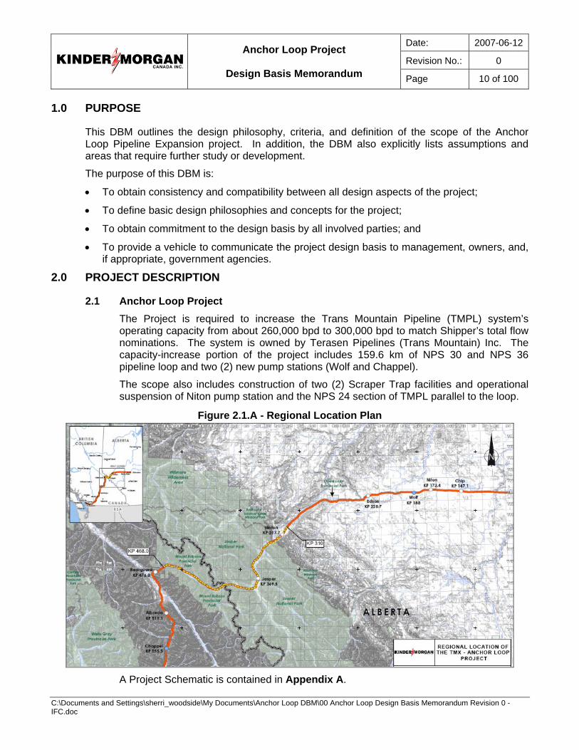
2.1 Anchor Loop Project The Project is required to increase the Trans Mountain Pipeline (TMPL) system’s operating capacity from about 260,000 bpd to 300,000 bpd to match Shipper’s total flow nominations. The system is owned by Terasen Pipelines (Trans Mountain) Inc. The capacity-increase portion of the project includes 159.6 km of NPS 30 and NPS 36 pipeline loop and two (2) new pump stations (Wolf and Chappel).
The scope also includes construction of two (2) Scraper Trap facilities and operational suspension of Niton pump station and the NPS 24 section of TMPL parallel to the loop.
Figure 2.1.A - Regional Location Plan
A Project Schematic is contained in Appendix A.
Date: 2007-06-12
Revision No.: 0
Anchor Loop Project
Design Basis Memorandum Page 11 of 100
C:\Documents and Settings\sherri_woodside\My Documents\Anchor Loop DBM\00 Anchor Loop Design Basis Memorandum Revision 0 - IFC.doc
2.2 System Capacity The flow rates and capacities reported are ex. Edmonton and a function of existing and proposed configurations. The target operating capacity for the TMPL system after completion of the Project is 300,000 bpd. The expected increase in flow is detailed in Section 5.5; peak flow rate, design, and operating capacity are defined as follows.
2.2.1 Peak Flow Rate The peak flow rate is the maximum safe flow rate that can be achieved with a maximum station discharge pressure at MOP. The peak flow rate will vary over time depending on the type and location of the batches in the pipeline. This peak rate is typically used to determine the installed power requirements and is the highest flow rate that can be maintained for an extended period (i.e. no allowance for shutdowns).
2.2.2 Design Capacity The design capacity is the calculated hydraulic capacity of the system over a period of 24 consecutive hours without interruption of service. The design flow rate used in the hydraulic analysis is the total of the Shippers’ nominations divided by a “sustainability factor”. The capacity is determined using a six-day cycle batch mix identified in Section 5.5.2 which includes super heavy crude of 20% of total throughput.
2.2.3 Operating Capacity The operating capacity is the design capacity multiplied by the “sustainability factor”. This factor represents the percentage of time that the pipeline can operate, on average, allowing for periods when pipeline operations are affected by planned maintenance or power, equipment, or other failures along the pipeline. KMCI uses a factor of 0.95 on TMPL.
2.2.4 Base Annual Throughput The base annual throughput is an annual average throughput equal to 92.5% of design capacity based on a heavy oil component of 20% of total throughput.
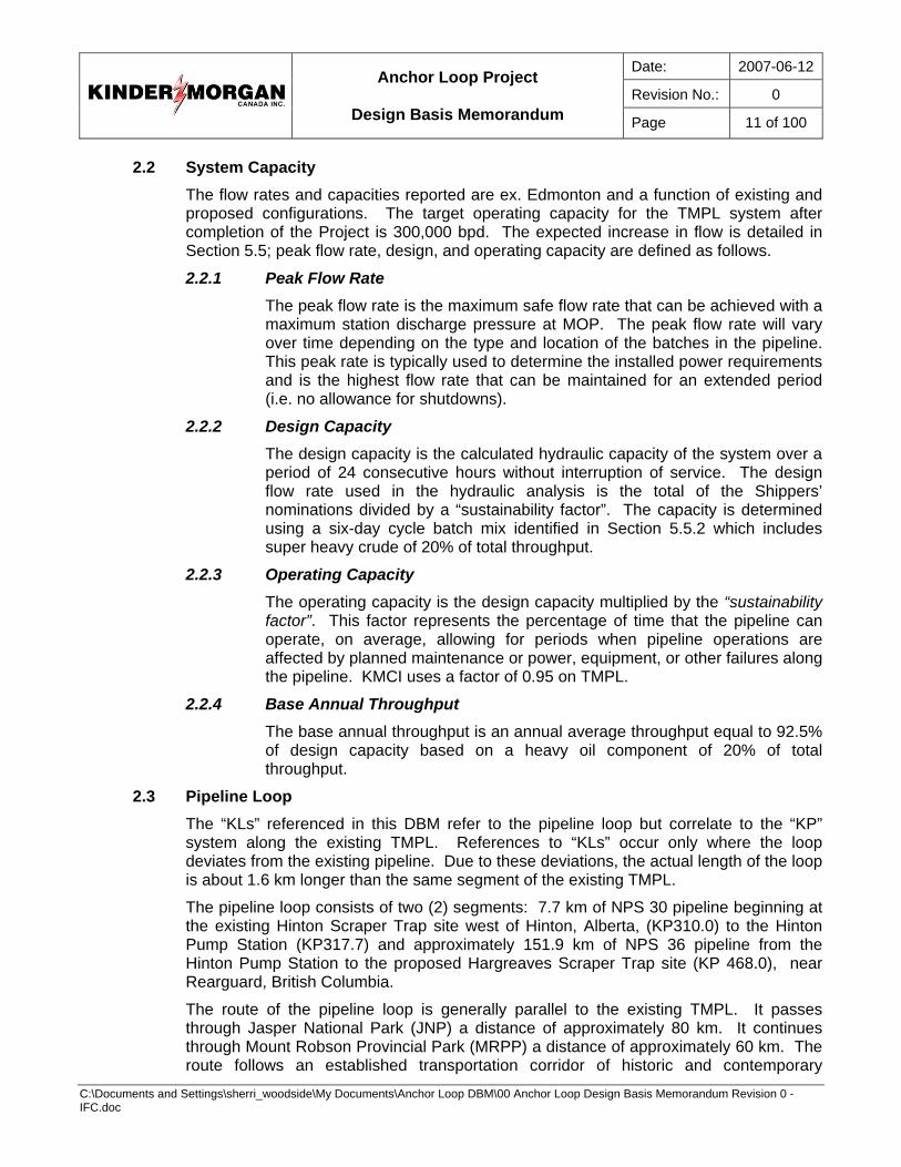
2.3 Pipeline Loop The “KLs” referenced in this DBM refer to the pipeline loop but correlate to the “KP” system along the existing TMPL. References to “KLs” occur only where the loop deviates from the existing pipeline. Due to these deviations, the actual length of the loop is about 1.6 km longer than the same segment of the existing TMPL.
The pipeline loop consists of two (2) segments: 7.7 km of NPS 30 pipeline beginning at the existing Hinton Scraper Trap site west of Hinton, Alberta, (KP310.0) to the Hinton Pump Station (KP317.7) and approximately 151.9 km of NPS 36 pipeline from the Hinton Pump Station to the proposed Hargreaves Scraper Trap site (KP 468.0), near Rearguard, British Columbia.
The route of the pipeline loop is generally parallel to the existing TMPL. It passes through Jasper National Park (JNP) a distance of approximately 80 km. It continues through Mount Robson Provincial Park (MRPP) a distance of approximately 60 km. The route follows an established transportation corridor of historic and contemporary
Date: 2007-06-12
Revision No.: 0
Anchor Loop Project
Design Basis Memorandum Page 12 of 100
C:\Documents and Settings\sherri_woodside\My Documents\Anchor Loop DBM\00 Anchor Loop Design Basis Memorandum Revision 0 - IFC.doc
significance. The corridor contains Highway 16 (Yellowhead TransCanada Highway), CN Railway, the TMPL, ATCO GAS Pipeline, ATCO Electric powerline, Telus fibre-optic lines, and other abandoned rail and roadbed easements. The route abuts the existing TMPL alignment for approximately 56% of its entire length. It is on or abutting other linear rights-of-way (i.e., highways, roads, powerlines, abandoned rail grades) for 43% of its entire length. The remaining 1% of the route is connections between these existing linear features.
Figure 2.3.A - Loop Schematic
2.4 Facilities The scope of facilities includes:
• Two (2) new pump stations,
• Two (2) scraper trap facilities,
• Idling of one (1) pump station,
• Tie-in at Jasper Pump Station, and
• Installation of Mainline Block Valves (MLBV), actuators, power, and data communications along the pipeline loop.
2.4.1 New Pump Stations New pump stations will be installed at Wolf in Alberta (KP188.0) and at Chappel (KP 555.5) in British Columbia. Both stations will be constructed on previously undisturbed sites. Station and equipment layout shall be on an approximate 100m x 100m footprint.
A summary of the scope of work consists of the following items:
• Installation of two (2) new mainline centrifugal pumps, complete with 5,000 HP (3,700 kW) 4160V electric drivers and forced lube oil systems
• Installation of a buried double walled fibreglass sump tank with lift and injection pumps
• Installation of above ground process piping, station suction / discharge headers, valves, and piping supports
Date: 2007-06-12
Revision No.: 0
Anchor Loop Project
Design Basis Memorandum Page 13 of 100
C:\Documents and Settings\sherri_woodside\My Documents\Anchor Loop DBM\00 Anchor Loop Design Basis Memorandum Revision 0 - IFC.doc
• Installation of a drain system for process piping, above ground where practical. All drain piping above grade or within the frost zone shall be electrically heat traced and insulated.
• Installation of automation and instrumentation suitable for unmanned operation and protection with remote control from the existing Edmonton Control Centre, including SCADA communication equipment
• Power supply substations
• Installation of all necessary electrical equipment including switchgear, transformers, VFDs, and 600V Motor Control Centre (MCC)
• Installation of an unheated, metal clad, gable end pump building to cover both pump sets. The pump buildings shall be designed to facilitate installation and removal of mainline pump units with an overhead monorail and hoist; mainline motor installations and removal design shall be based on a jack-and-roll process.
• Installation of two (2) pre-fabricated and pre-wired buildings (one (1) Electrical and one (1) Operator).
• Site spill containment and leak detection.
• All earthworks, roadways, finish gravelling, and fencing.
2.4.2 Scraper Traps General Scraper Traps will be installed at the Hinton Pump Station (KP 317.7) and at the new Hargreaves site (KP 468.0). The traps and most of the infrastructure at the existing Hinton Scraper Trap site (KP 310.0) will be removed and the site shall be reclaimed.
Common features of scraper trap facilities shall include:
• Trap shelter with truck access to the launcher and receiver barrels;
• Sump tank sized to contain the drain down volume of both launcher and receiver barrels and positioned to serve both launcher and receiver pads;
• Launcher, receiver, and bypass interconnecting piping;
• Sump lift pump;
• Mainline re-injection pump;
• Interconnecting piping; and
• Associated valves and instrumentation (including pig sigs, pressure and temperature transmitters, level switches, and a combustible gas detection system).
Barrel supports or skids shall be designed to minimize space and comply with CSA-Z662-03 S4.6.4.2. The receiving barrel shall have scraper bars installed at the nozzles together with an internal perforated metal cylinder to contain and center incoming pigs.
Date: 2007-06-12
Revision No.: 0
Anchor Loop Project
Design Basis Memorandum Page 14 of 100
C:\Documents and Settings\sherri_woodside\My Documents\Anchor Loop DBM\00 Anchor Loop Design Basis Memorandum Revision 0 - IFC.doc
Scraper trap drain lines will have the same heat tracing / insulation requirement as the pump stations.
Hinton Pump Station Scraper Traps A new, permanent trap facility will be constructed within the existing Hinton Pump station land limits. The trap facility shall be sized to accommodate planned expansion flow rates via the incoming NPS 30 line and outgoing NPS 36 line.
The Hinton Scraper Trap shall be designed as a permanent facility to integrate with existing infrastructure at Hinton Pump Station with control instrumentation selected to avoid duplication of what is already operational at Hinton Pump Station. Areas of integration shall include a Power, Service and Controls, and SCADA communications.
Components installed at the Hinton Pump Station (KP 317.7) will enable receipt of In-Line Inspection (ILI) tools and cleaning pigs from the upstream segment of new NPS 30 pipeline loop and launching of ILI tools and cleaning pigs into the downstream NPS 36 pipeline segment.
Hargreaves Scraper Trap Facility A new, temporary trap facility will be constructed at Hargreaves, just upstream of the Rearguard Pump Station. The Hargreaves site (KP 468.0) is a green-field location 2 km outside and west of MRPP.
The facility will accommodate receipt of NPS 36 ILI tools and cleaning pigs from the loop and the launching of NPS 24 tools downstream into the TMPL pipeline. The Hargreaves trap facility shall be constructed for short-term use. It will be sized to accommodate planned expansion flow rates via the incoming NPS 36 and outgoing NPS 24 lines.
Distinct features of the Hargreaves Scraper Trap facility shall include:
• Reduced trap shelter height to minimize impact on the highway line of sight;
• Power, Service and Controls (MCC), and SCADA communications managed locally;
• The existing MCC building at the Hinton Scraper Trap Facility reused at Hargreaves; and
• Hargreaves designed as a temporary facility with movable, reusable components as much as practicable.
Existing Hinton Scraper Trap Facility The existing Scraper Trap facility at Hinton (KP 310.0) is not required for future operations, and the facility will be mostly removed and become a MLBV site. The new NPS 30 loop will tie-into the existing NPS 30 loop at a point within the yard directly downstream of the existing below grade NPS 30 valve. This NPS 30 valve will remain in place and serve as a MLBV. Modifications will be made as required to enable the valve to be remotely actuated.
Date: 2007-06-12
Revision No.: 0
Anchor Loop Project
Design Basis Memorandum Page 15 of 100
C:\Documents and Settings\sherri_woodside\My Documents\Anchor Loop DBM\00 Anchor Loop Design Basis Memorandum Revision 0 - IFC.doc
The trap facility currently contains the following:
• NPS 24 valve (buried) on the incoming NPS 24 mainline
• NPS 24 mainline terminated above grade by blind flange on S-bend
• NPS 26 sending barrel including NPS 10 kicker line with automated isolation on outgoing NPS 24 pipeline
• NPS 36 receiving barrel including NPS 12 trap outlet piping with automated isolation on incoming NPS 30 loop
• NPS 16 wedge flow meter on mainline bypass including NPS 16 automated isolation valves
• NPS 12 Dan Flo relief valve on NPS 12 relief line bypass including NPS 12 manual isolation and downstream check valve
• Scraper trap shelter partially enclosed with spill containment slab (located under the barrels, bypass line, associated valves, and piping) and controlled surface drain
• Waste oil sump tank with re-injection pumps
• EOS instrumentation for the SCADA system leak detection software (densitometer and temperature transmitters)
• 6.3 tonne manually operated overhead crane
• MMC building housing the PLC cabinet (Solartron Density Converter, SCADA RTU cabinet, AGT cabinet, chart recorder, front panel and status lamps), and MCC-B (lighting, starters and control).
Existing scraper trap facilities shall be fully removed from the NPS 30 segment of the pipeline loop and this facility shall be maintained as a MLBV site. The original NPS 24 pipeline from this trap facility to the Hinton pump station, which is about 7.7 km long, shall be deactivated in accordance with CSA Z662.
Timing of decommissioning activities shall be selected to minimize impact on the maintenance pigging schedule, and brought as close as possible to activation of the Hinton Pump Station scraper trap facilities.
Components of the existing trap facility shall be assessed for their reusable value and application to the new trap facilities at Hinton Pump Station and Hargreaves.
2.4.3 Idling of Niton Pump Station (KP 173.4) The Niton station is not required until future pipeline and facility expansion is implemented. It is to be temporarily isolated from the system and prepared as necessary to place into an idle state.
Deactivation of Niton pump station shall entail:
• Schedule activities to arrange for a light sweet batch of material, without any butane blending, to be within the Niton Station when it is shut down.
Date: 2007-06-12
Revision No.: 0
Anchor Loop Project
Design Basis Memorandum Page 16 of 100
C:\Documents and Settings\sherri_woodside\My Documents\Anchor Loop DBM\00 Anchor Loop Design Basis Memorandum Revision 0 - IFC.doc
• Shutdown of the two (2) mainline pumps and motors;
• Isolate station suction and discharge piping; complete gravity drain down to the sump tank. Inject nitrogen at the high point vent locations. After the piping is drained, as confirmed by the sump tank level not changing, nitrogen flow will continue into the piping until completely purged. Maintain nominal nitrogen pressure inside the drained process piping;
• Re-inject products from the sump tank into the mainline and clean the tank;
• Blind the mainline from station suction and discharge piping, by flipping the existing spectacle blinds, located on the station side of the station isolation valves;
• Isolate the station re-injection piping from the mainline by installing a line blank on the station side of the re-injection to mainline isolation valve;
• Purge with nitrogen all remaining lines and equipment in previous volatile service. Equipment to be drained and purged includes the wedge meter, control valves and unit isolation valves, pressure relief valves, sump pump, and sump pump discharge line. All valve bodies to be drained of any product;
• Electrically isolate both units to the extent necessary without affecting safety, security and the environment. Lockout ancillary equipment;
• Maintain limited electrical power supply to the entire station for equipment integrity, cathodic protection, security, and critical instrument monitoring, i.e. mainline temperature pressure and density, station pressure, gas detection, fire detection, smoke detection, floor sump level;
• Use of signage to clearly identify the status of all equipment; and
2.4.4 Tie-In to Jasper Pump Station Jasper Pump Station will be tied into the new NPS 36 line; and the existing components to the NPS 24 line will be isolated or removed as required. All isolated sections shall be drained of oil, filled with Nitrogen, and subsequently monitored.
The tie-in shall ensure that flow through the NPS 36 line can be routed through the station pumps as required by Operations.
2.4.5 Mainline Block Valve (MLBV) Sites and Ancillary Facilities Actuators for the remote motorized operation of eleven (11) Gate valves on the pipeline loop will be purchased and commissioned as a part of the project. Additional valves are required at the Hinton Pump Station and at Hargreaves Scraper Trap facility. One (1) existing NPS 30 valve at the Hinton Scraper Trap site will remain in place and be used as a MLBV. Power, Civil, and Mechanical ancillary components required to support operations at the valve sites will be installed.
Date: 2007-06-12
Revision No.: 0
Anchor Loop Project
Design Basis Memorandum Page 17 of 100
C:\Documents and Settings\sherri_woodside\My Documents\Anchor Loop DBM\00 Anchor Loop Design Basis Memorandum Revision 0 - IFC.doc
The existing right-of-way shall provide primary access to each valve site to the extent possible. Additional requirements for locations with MOV’s shall include:
• Perimeter fencing with a lockable gate;
• Valve controls enclosure;
• Power receptacle (for connection to auxiliary power); and
• A Motorola Moscad communications system complete with tower or standard pipe antennas (as required by site for the locations where direct connection to Telecom service providers is not possible).
3.0 PROJECT SUCCESS FACTORS
To ensure the overall success of the project, designs will address the following key success factors over the life of the pipelines and facilities:
• Health and Safety
− The health and safety of construction, operations, maintenance personnel and the public.
− Total Recordable Injury Frequency Rate, Loss Time Injury Frequency Rate and Motor Vehicle Accident rate.
• Environmental Protection
− The protection of water courses, groundwater, soil, the atmosphere, and animal and plant life.
• Regulatory Compliance
− The compliance with directives of the regulatory agencies having jurisdiction over the Anchor Loop Pipeline System and the commitments made to those agencies.
• Schedule
− Meeting key milestones of the “Base” Schedule including partial in-service objective.
• Project Integration
− The seamless physical, start-up, and operating compatibility of the TMPL systems
• Capital Cost
− The lowest, “value improved”, capital cost, within the context of the other success factors.
• Operations
− The provision of pipeline and facility components integrated with the existing system and optimized and balanced in respect of operational requirements and life-cycle costs. Project success will be measured using weighted criteria within each success factor and “stretch” or “excellence” targets and ranges of acceptability for each criteria. Additional information will be compiled within the Project Execution Plan.

Date: 2007-06-12
Revision No.: 0
Anchor Loop Project
Design Basis Memorandum Page 18 of 100
C:\Documents and Settings\sherri_woodside\My Documents\Anchor Loop DBM\00 Anchor Loop Design Basis Memorandum Revision 0 - IFC.doc
4.0 FUNDAMENTAL PHILOSOPHIES
4.1 Fitness-for-Purpose The Anchor Loop pipelines and facilities shall be designed to be capable of transporting the required volumes of products, allowing for planned maintenance and reasonable unplanned outage.
Equipment will be selected based on a balance of life-cycle capital and operating costs. It is preferable that the equipment chosen for the initial (2007) phase of the expansion will be of standard sizes suitable for service through to and including the final phase (hydraulic capacity) without replacement, and that minimal disruption to pumping is required to upgrade for future phases.
The facilities will be easily operable and maintainable with reasonable maintenance access. A balance will be met between automated and manual operation and between ease of maintenance and cost of maintenance.
Facilities not required for the primary function of the pipeline system, or not contributing significantly to its reliability, operability or maintainability would not be incorporated.
The project shall be designed to meet the operating capacity objective of 300,000 bpd, allowing for planned maintenance and expected system reliability.
Design, procurement, and construction at Wolf and Chappel Pump Stations shall be cognizant of their anticipated short operational life span (estimated three (3) years). The salvage value of these stations shall be optimized.
Product Quality shall be considered in the design of facilities. “Dead-legs” in piping shall be minimized, but not at the expense of good piping design.
4.2 Codes and Standards Design of the pipeline loop and facilities will respect applicable federal, provincial, municipal, and project codes, regulations, and standards as specified in Sections 5.1 and 5.2.
The design of pipelines and ancillary components, facilities, and access roadways shall use existing internal standards and practices where possible. These will be updated as required to reflect project specific conditions and actual local design requirements.
4.3 Cost Effective Design A cost effective design approach will be used with the goal of minimizing life-cycle cost while meeting the project requirements for safety, environmental protection, regulatory compliance, and performance. Synergy with KMCI standards and practices will be maintained, where positive life-cycle cost benefits can be demonstrated.
4.4 Life and Reliability For detailed design purposes, a minimum design life of 100 years will be used in predictive modeling of the pipeline loop. In certain situations where opportunities exist, an even more prudent allowance towards a safer design will be applied. For instance, river bed scour design will provide protection from flood events having a 200-year recurrence interval.
Date: 2007-06-12
Revision No.: 0
Anchor Loop Project
Design Basis Memorandum Page 19 of 100
C:\Documents and Settings\sherri_woodside\My Documents\Anchor Loop DBM\00 Anchor Loop Design Basis Memorandum Revision 0 - IFC.doc
The design of facilities will meet the requirements of OPR, relevant industry standards, and internal specifications but will consider the anticipated short life cycle of Wolf, Chappel, and Hargreaves facilities.
4.5 Future Expansion Provision for easily expanded facilities to accommodate future flows up to the hydraulic capacity of the line will be considered.
4.6 Special Design Considerations Routing through JNP and MRPP requires special considerations for enhanced environmental protection. These considerations will influence the separation of pipelines; spacing of isolation valves; provisions for valve automation; pipe wall thickness; and crossing designs for road, railway, and watercourses.
The presence of wetlands was considered in the routing. Where wetlands areas could not be avoided, appropriate engineering procedures will be required for access roads, station grading and building and equipment foundations. Cost studies will determine the optimal construction methods.
The water table may be high at the pump station locations and due consideration will be given to buoyancy. It may be necessary to provide hold down anchors for buried piping and sump tanks.
In addition to hydraulic requirements, the pump station locations will consider foundation soil conditions, proximity to access roads, and proximity to power supplies.
Layout and design of the two (2) pump stations will be modeled from the currently in-progress Trans Mountain Pump Station Expansion Project (TMPSE).
Standard station designs shall be completed early in the detailed engineering phase with the identification of specific variations where required. Construction drawing sets for the individual stations shall be based on the standard station design with a specific dedicated set of drawings for each station
Efforts shall be made to maximize the amount of shop work and to minimize the amount of field work required. All piping will be shop fabricated and tested to the furthest extent practical. All piping and equipment will be shop coated.
4.7 Power Facilities power requirements shall be met by a combination strategy of existing power supply, new distribution lines, and new transmission lines. Supply of the power infrastructure will be provided through a combination of agreements in Alberta and British Columbia and is subject to several regulatory approval processes.
There are no planned upgrades to the power supply at the Hinton Pump Station to accommodate the scraper trap facility.
An existing 14KV single-phase power supply will service the planned Hargreaves (British Columbia) scraper trap. The service will be provided by BC Hydro.
UPS power at each pump station will be provided and sized for instrumentation, control, and monitoring systems, as well as provide ESO capability for station isolation valves.
Date: 2007-06-12
Revision No.: 0
Anchor Loop Project
Design Basis Memorandum Page 20 of 100
C:\Documents and Settings\sherri_woodside\My Documents\Anchor Loop DBM\00 Anchor Loop Design Basis Memorandum Revision 0 - IFC.doc
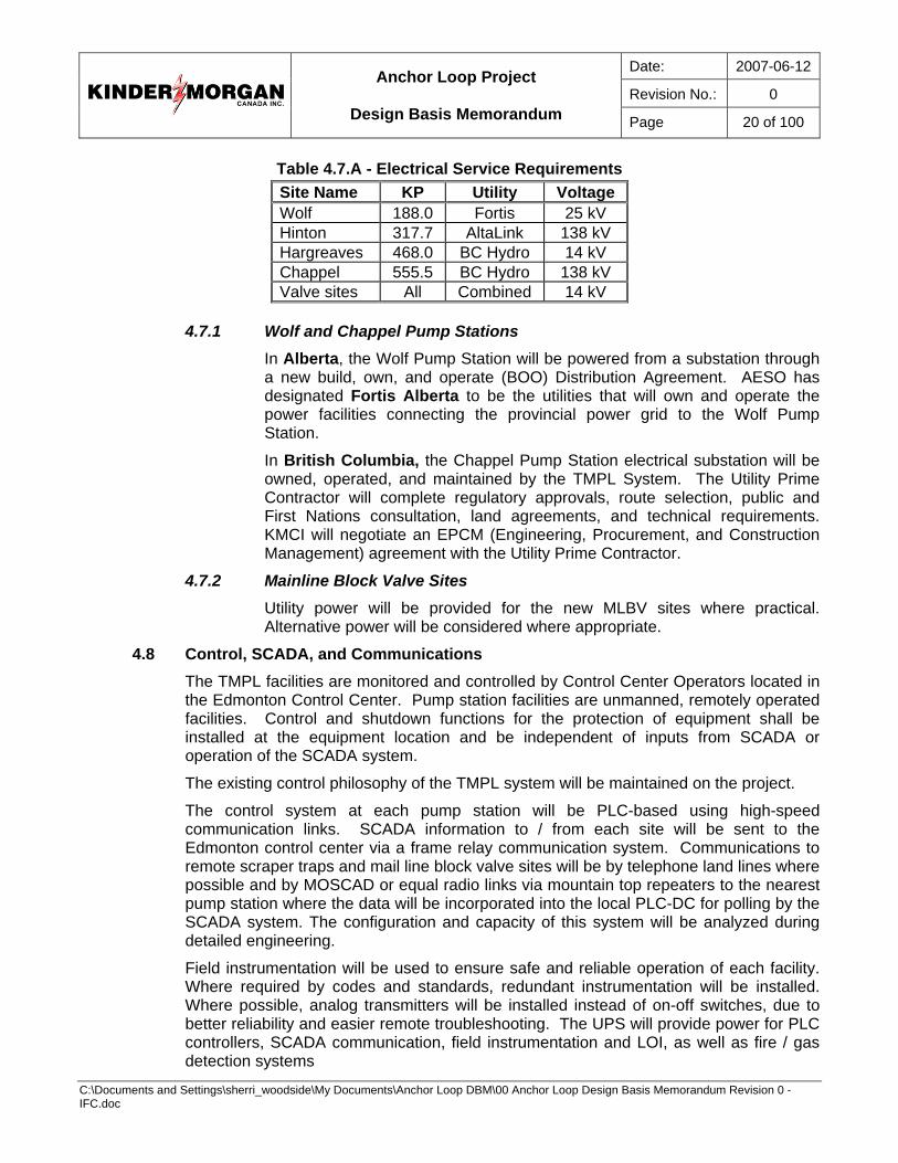
Table 4.7.A - Electrical Service Requirements Site Name KP Utility Voltage Wolf 188.0 Fortis 25 kV Hinton 317.7 AltaLink 138 kV Hargreaves 468.0 BC Hydro 14 kV Chappel 555.5 BC Hydro 138 kV Valve sites All Combined 14 kV
4.7.1 Wolf and Chappel Pump Stations
In Alberta, the Wolf Pump Station will be powered from a substation through a new build, own, and operate (BOO) Distribution Agreement. AESO has designated Fortis Alberta to be the utilities that will own and operate the power facilities connecting the provincial power grid to the Wolf Pump Station.
In British Columbia, the Chappel Pump Station electrical substation will be owned, operated, and maintained by the TMPL System. The Utility Prime Contractor will complete regulatory approvals, route selection, public and First Nations consultation, land agreements, and technical requirements. KMCI will negotiate an EPCM (Engineering, Procurement, and Construction Management) agreement with the Utility Prime Contractor.
4.7.2 Mainline Block Valve Sites Utility power will be provided for the new MLBV sites where practical. Alternative power will be considered where appropriate.
4.8 Control, SCADA, and Communications The TMPL facilities are monitored and controlled by Control Center Operators located in the Edmonton Control Center. Pump station facilities are unmanned, remotely operated facilities. Control and shutdown functions for the protection of equipment shall be installed at the equipment location and be independent of inputs from SCADA or operation of the SCADA system.
The existing control philosophy of the TMPL system will be maintained on the project.
The control system at each pump station will be PLC-based using high-speed communication links. SCADA information to / from each site will be sent to the Edmonton control center via a frame relay communication system. Communications to remote scraper traps and mail line block valve sites will be by telephone land lines where possible and by MOSCAD or equal radio links via mountain top repeaters to the nearest pump station where the data will be incorporated into the local PLC-DC for polling by the SCADA system. The configuration and capacity of this system will be analyzed during detailed engineering.
Field instrumentation will be used to ensure safe and reliable operation of each facility. Where required by codes and standards, redundant instrumentation will be installed. Where possible, analog transmitters will be installed instead of on-off switches, due to better reliability and easier remote troubleshooting. The UPS will provide power for PLC controllers, SCADA communication, field instrumentation and LOI, as well as fire / gas detection systems
Date: 2007-06-12
Revision No.: 0
Anchor Loop Project
Design Basis Memorandum Page 21 of 100
C:\Documents and Settings\sherri_woodside\My Documents\Anchor Loop DBM\00 Anchor Loop Design Basis Memorandum Revision 0 - IFC.doc
4.9 Corrosion Control Above ground components, including piping, equipment, and structures, will be coated; however, paint colors of facilities will be selected with regard to compatibility with surrounding facilities.
Piping to be insulated will only require a prime coating. No internal coating of piping or piping components is required.
The existing Cathodic Protection (CP) system will be supplemented as required with new or replacement components (e.g. rectifiers, groundbeds). CP shall be applied to all buried high-pressure pipeline components including the respective section of temporarily suspended NPS 24 TMPL pipeline.
4.10 Maintenance Maintenance of the new facilities will follow the same philosophies as the existing TMPL facilities. Facilities will be designed to allow for efficient in-situ equipment maintenance.
4.11 Health and Safety The facilities will be designed to provide a healthy and safe working environment for operations and maintenance personnel. Designs will include adequate ventilation, area and task lighting, handrails and ladders / stairways at elevated structures, guards and adequate working or access space around rotating equipment, and the minimizing of confined spaces.
Fire, smoke, combustible gas detectors, and other safety sensors and alarms will be provided.
Facilities will be designed to provide an appropriately comfortable and hygienic work environment. Remote, normally unmanned facilities will include water and basic sanitation facilities except at remote MLBV sites.
All facilities will provide a safe working environment in accordance with Occupational Health and Safety requirements and KMCI’s safety practices. Safety will be a significant consideration in the layout and features of facilities:
• Stairways will provide the primary access to elevated structures where frequent access is required.
• “Side-step” ladders will be considered for elevated structures requiring infrequent access.
• Confined spaces will be minimized.
• Coupling guards or other guards will be provided for all exposed rotating equipment.
• Suitable warning signs will be posted for these and other hazards.
• Fire, smoke, combustible gas detectors, and other safety related sensors and alarms would be provided, as required.
Final safety designs will be reviewed through Process Hazard Assessments.
4.12 General Environment Responsibility Fugitive emissions from the pipelines or facilities will be minimized through appropriate design and operating procedures, regular maintenance, routine monitoring and
Date: 2007-06-12
Revision No.: 0
Anchor Loop Project
Design Basis Memorandum Page 22 of 100
C:\Documents and Settings\sherri_woodside\My Documents\Anchor Loop DBM\00 Anchor Loop Design Basis Memorandum Revision 0 - IFC.doc
inspection, and the installation of protective devices on piping, storage tanks, sump tanks, etc. In addition, in order to minimize the severity of any accidental releases, isolation, containment, leak detection, and response systems will be included in the Anchor Loop system designs.
Protective devices will include high-pressure sensors and relief systems on piping and level sensors on tanks.
MLBVs will be placed, on either side of major river crossings and at other appropriate intervals to reduce the volumes that could be released due to line leaks. Their location is selected, in part, on an analysis of potential draindown volumes. All motor operated gate valves will be remotely operable.
Future government environmental policies will be anticipated and considered during technology selection particularly with respect to energy conservation.
Prevention of oil spills reaching the local environment shall be considered in the design of facilities. Pump station and scraper trap facilities shall be designed to drain groundwater from areas of potential hydrocarbon releases through a controlled route with the capability of impounding liquids. Groundwater outlet piping from containment catchments shall be controlled by normally closed manual valves. Hydrocarbon detectors shall be provided in the catchments at remote stations to provide an alarm to the Control Center Operator in the event of an oil release.
Detailed environmental assessments were prepared during the early planning phases of the project, and submitted with the regulatory applications. Specifications for the construction of facilities shall incorporate environmental mitigation measures consistent with commitments made to the regulatory authorities as outlined in the Environmental Protection Plan (EPP). In the event that additional environmental conditions are received with the approvals for the work, the additional conditions will be incorporated into the designs and specifications at that time.
4.13 Commitments Commitments made to the Regulatory Agencies, such as those identified in the EPP, as well as those contained in responses to Information Requests, will be honoured.
Other commitments that may develop during the course of the project, such as those negotiated with stakeholders, will also be honoured.
4.14 Leak Detection and Response Components of the project will be integrated through SCADA into the existing leak detection system. TMPL’s existing pipeline leak detection system, the Computational Pipeline Modeling (CPM) program, will be used.
Metering will be installed where required at the pump stations in order to maintain the current level of leak detection sensitivity of approximately 100m3/hr.
The individual facility containment systems will be provided with leak detection alarms. These will consist of single or multiple level alarms, hydrocarbon detection sensors, or combination of both. Flow based leak detection will be provided for mainline pump mechanical seals.
In cases where a pipeline leak is detected, the Edmonton Control Center Operator (CCO) can activate an emergency shutdown of the various pumping stations along the
Date: 2007-06-12
Revision No.: 0
Anchor Loop Project
Design Basis Memorandum Page 23 of 100
C:\Documents and Settings\sherri_woodside\My Documents\Anchor Loop DBM\00 Anchor Loop Design Basis Memorandum Revision 0 - IFC.doc
pipeline. As required, the CCO may activate the closure of MLBVs. Once activated, the location of the leak will be found and the cause of the leak rectified. After the leak is repaired, a manual reset at each station will be required.
5.0 SPECIFIC PHILOSOPHIES AND REQUIREMENTS
5.1 Regulatory Approvals 5.1.1 Coordination
The Alberta regional office of the Canadian Environmental Assessment Agency (CEAA) is the Federal Assessment Coordinator for the project. Its role is to coordinate the participation of federal and provincial authorities in the environmental assessment process.
5.1.2 Federal National Energy Board (NEB) The project requires a NEB Certificate of Public Convenience and Necessity pursuant to Section 52 of the OPR. The NEB, through the Pipeline Act and the OPR, establishes requirements for pipeline and facilities design, construction and commissioning with a focus on public safety and environmental considerations.
The National Energy Board conducted a public hearing August 8 - 10, 2006. NEB Approval was received October 26, 2006.
Decommissioning of the respective segment of the existing NPS 24 TMPL pipeline will be completed through a subsequent application pursuant to Section 44 of the OPR.
Department of Fisheries and Oceans (DFO) There are 101 watercourses crossings, including three (3) ponds, of which about 40 are determined to be medium to high sensitivity for fish. The occurrence of Harmful Alteration, Disruption or Destruction (HADD) of fish and habitat is anticipated in over 20 watercourses and compensation for no net loss shall be developed and submitted to DFO for their acceptance.
Transport Canada – Navigable Waters Transport Canada (TC) has identified 14 watercourse crossings as being navigable. These will require specific authorizations for pipeline installation and temporary bridging.
Application may be made for temporary installation of one (1) additional access bridge across the Miette River (Approx. KL 395). The access crossing is not within the proximity of the pipeline right-of-way.
Further application will be made as related to the temporary installation of hydrostatic test water piping within waterways.
Parks Canada Parks Canada will act as Lead Responsible Authority (RA) under CEAA. Other RA’s include the NEB, DFO, Transport Canada, Environment Canada, Health Canada, etc.
Date: 2007-06-12
Revision No.: 0
Anchor Loop Project
Design Basis Memorandum Page 24 of 100
C:\Documents and Settings\sherri_woodside\My Documents\Anchor Loop DBM\00 Anchor Loop Design Basis Memorandum Revision 0 - IFC.doc
5.1.3 Provincial BC Ministry of Environment A number of activities, including timber clearing and working in and around streams within British Columbia, must be authorized by the Ministry.
BC Ministry of Forests Application must be made to Front Counter BC for the required licence to cut. The application must include all aspects of timber management as related to the project.
BC Legislative Approval All lands required for construction in MRPP must be specifically defined and temporarily removed from the Park by legislative authority. Following construction, the boundaries are to be amended once again to return lands to the parks that are not required for future operations and maintenance.
Alberta Pipeline Agreement (PLA) Approval is required from Alberta Sustainable Resources in order to construct in Alberta, excluding JNP.
5.1.4 Other A listing of required minor permits is included in Appendix B.
5.2 Codes and Standards 5.2.1 Pipeline Loop
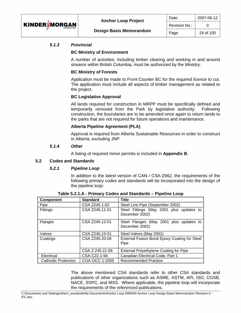
In addition to the latest version of CAN / CSA-Z662, the requirements of the following primary codes and standards will be incorporated into the design of the pipeline loop:
Table 5.2.1.A - Primary Codes and Standards – Pipeline Loop Component Standard Title Pipe CSA Z245.1-02 Steel Line Pipe (September 2002) Fittings CSA Z245.11-01 Steel Fittings (May 2001 plus updates to
December 2002)
Flanges CSA Z245.12-01 Steel Flanges (May 2001 plus updates to December 2002)
Valves CSA Z245.15-01 Steel Valves (May 2001) CSA Z245.20-06 External Fusion Bond Epoxy Coating for Steel
Pipe Coatings
CSA Z 245.21-06 External Polyethylene Coating for Pipe Electrical CSA-C22.1-94 Canadian Electrical Code, Part 1 Cathodic Protection CGA OCC-1-2005 Recommended Practice
The above mentioned CSA standards refer to other CSA standards and publications of other organizations such as ASME, ASTM, API, ISO, CGSB, NACE, SSPC, and MSS. Where applicable, the pipeline loop will incorporate the requirements of the referenced publications.
Date: 2007-06-12
Revision No.: 0
Anchor Loop Project
Design Basis Memorandum Page 25 of 100
C:\Documents and Settings\sherri_woodside\My Documents\Anchor Loop DBM\00 Anchor Loop Design Basis Memorandum Revision 0 - IFC.doc
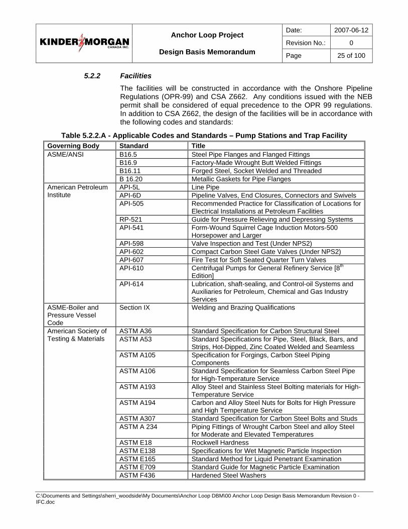
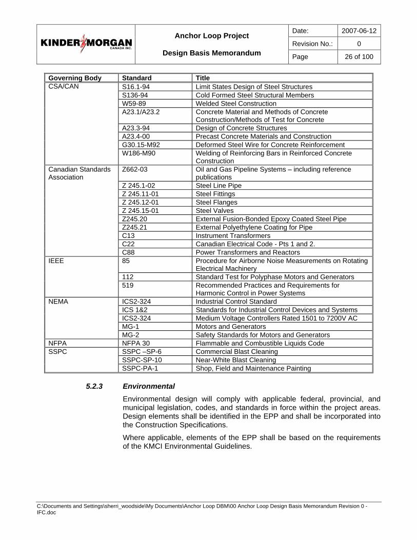
5.2.2 Facilities The facilities will be constructed in accordance with the Onshore Pipeline Regulations (OPR-99) and CSA Z662. Any conditions issued with the NEB permit shall be considered of equal precedence to the OPR 99 regulations. In addition to CSA Z662, the design of the facilities will be in accordance with the following codes and standards:
Table 5.2.2.A - Applicable Codes and Standards – Pump Stations and Trap Facility Governing Body Standard Title
B16.5 Steel Pipe Flanges and Flanged Fittings B16.9 Factory-Made Wrought Butt Welded Fittings B16.11 Forged Steel, Socket Welded and Threaded
ASME/ANSI
B 16.20 Metallic Gaskets for Pipe Flanges API-5L Line Pipe API-6D Pipeline Valves, End Closures, Connectors and Swivels API-505 Recommended Practice for Classification of Locations for
Electrical Installations at Petroleum Facilities RP-521 Guide for Pressure Relieving and Depressing Systems API-541 Form-Wound Squirrel Cage Induction Motors-500
Horsepower and Larger API-598 Valve Inspection and Test (Under NPS2) API-602 Compact Carbon Steel Gate Valves (Under NPS2) API-607 Fire Test for Soft Seated Quarter Turn Valves API-610 Centrifugal Pumps for General Refinery Service [8th
Edition]
American Petroleum Institute
API-614 Lubrication, shaft-sealing, and Control-oil Systems and Auxiliaries for Petroleum, Chemical and Gas Industry Services
ASME-Boiler and Pressure Vessel Code
Section IX Welding and Brazing Qualifications
ASTM A36 Standard Specification for Carbon Structural Steel ASTM A53 Standard Specifications for Pipe, Steel, Black, Bars, and
Strips, Hot-Dipped, Zinc Coated Welded and Seamless ASTM A105 Specification for Forgings, Carbon Steel Piping
Components ASTM A106 Standard Specification for Seamless Carbon Steel Pipe
for High-Temperature Service ASTM A193 Alloy Steel and Stainless Steel Bolting materials for High-
Temperature Service ASTM A194 Carbon and Alloy Steel Nuts for Bolts for High Pressure
and High Temperature Service ASTM A307 Standard Specification for Carbon Steel Bolts and Studs ASTM A 234 Piping Fittings of Wrought Carbon Steel and alloy Steel
for Moderate and Elevated Temperatures ASTM E18 Rockwell Hardness ASTM E138 Specifications for Wet Magnetic Particle Inspection ASTM E165 Standard Method for Liquid Penetrant Examination ASTM E709 Standard Guide for Magnetic Particle Examination
American Society of Testing & Materials
ASTM F436 Hardened Steel Washers
Date: 2007-06-12
Revision No.: 0
Anchor Loop Project
Design Basis Memorandum Page 26 of 100
C:\Documents and Settings\sherri_woodside\My Documents\Anchor Loop DBM\00 Anchor Loop Design Basis Memorandum Revision 0 - IFC.doc
Governing Body Standard Title S16.1-94 Limit States Design of Steel Structures S136-94 Cold Formed Steel Structural Members W59-89 Welded Steel Construction A23.1/A23.2 Concrete Material and Methods of Concrete
Construction/Methods of Test for Concrete A23.3-94 Design of Concrete Structures A23.4-00 Precast Concrete Materials and Construction G30.15-M92 Deformed Steel Wire for Concrete Reinforcement
CSA/CAN
W186-M90 Welding of Reinforcing Bars in Reinforced Concrete Construction
Z662-03 Oil and Gas Pipeline Systems – including reference publications
Z 245.1-02 Steel Line Pipe Z 245.11-01 Steel Fittings Z 245.12-01 Steel Flanges Z 245.15-01 Steel Valves Z245.20 External Fusion-Bonded Epoxy Coated Steel Pipe Z245.21 External Polyethylene Coating for Pipe C13 Instrument Transformers C22 Canadian Electrical Code - Pts 1 and 2.
Canadian Standards Association
C88 Power Transformers and Reactors 85 Procedure for Airborne Noise Measurements on Rotating
Electrical Machinery 112 Standard Test for Polyphase Motors and Generators
IEEE
519 Recommended Practices and Requirements for Harmonic Control in Power Systems
ICS2-324 Industrial Control Standard ICS 1&2 Standards for Industrial Control Devices and Systems ICS2-324 Medium Voltage Controllers Rated 1501 to 7200V AC MG-1 Motors and Generators
NEMA
MG-2 Safety Standards for Motors and Generators NFPA NFPA 30 Flammable and Combustible Liquids Code
SSPC –SP-6 Commercial Blast Cleaning SSPC-SP-10 Near-White Blast Cleaning
SSPC
SSPC-PA-1 Shop, Field and Maintenance Painting
5.2.3 Environmental Environmental design will comply with applicable federal, provincial, and municipal legislation, codes, and standards in force within the project areas. Design elements shall be identified in the EPP and shall be incorporated into the Construction Specifications.
Where applicable, elements of the EPP shall be based on the requirements of the KMCI Environmental Guidelines.
Date: 2007-06-12
Revision No.: 0
Anchor Loop Project
Design Basis Memorandum Page 27 of 100
C:\Documents and Settings\sherri_woodside\My Documents\Anchor Loop DBM\00 Anchor Loop Design Basis Memorandum Revision 0 - IFC.doc
5.2.4 Project Standards and Specifications Project specific material, equipment, and installation specifications will be developed on an as needed basis. Design of the facilities and roadways shall use existing TMPSE specifications and KMCI standards to the extent practical. The KMCI base standards and TMPSE specifications are listed in Appendix C.
The standards will include an Engineering Records System (ERS), which will be based on KMCI Standard G1100, Rev. 1.
KMCI Drafting Standards will be used. Full-size drawing sets will be ANSI D (22”x34”). Reduced size drawing sets will be B (11”x17”) size.
5.3 Sparing Other than critical spare parts, redundant equipment and inventory spare parts shall not be purchased for the project.
5.4 Future Expansion The pipelines and facilities will be designed to be easily expandable up to the hydraulic capacity of the lines. It is preferable that the equipment chosen for the initial phase of the expansion will be suitable for service through to and including the final phase in terms of hydraulic capacity without replacement and that minimal disruption to pumping is required to upgrade for future phases. Equipment should be selected and designed on a “modular” basis, which can be repeated for subsequent additions required to meet the anticipated flow build-up.
The existing easement through JNP is 6.1 metres wide and will contain TMPL and the proposed loop. Parks Canada have indicated no additional easement will be allowed so where the loop deviates from the TMPL pipeline by more than 4.5 metres centre to centre, the easement is likely to be split so the sum of widths will not exceed 6.1 metres. Opportunity for future looping is limited.
5.5 Special Design Considerations 5.5.1 Fluid Properties
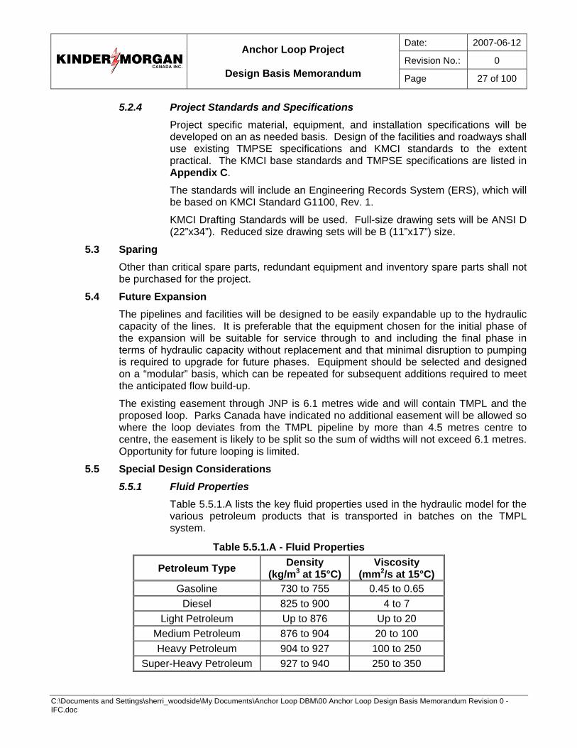
Table 5.5.1.A lists the key fluid properties used in the hydraulic model for the various petroleum products that is transported in batches on the TMPL system.
Table 5.5.1.A - Fluid Properties
Petroleum Type Density (kg/m3 at 15°C)
Viscosity (mm2/s at 15°C)
Gasoline 730 to 755 0.45 to 0.65 Diesel 825 to 900 4 to 7
Light Petroleum Up to 876 Up to 20 Medium Petroleum 876 to 904 20 to 100 Heavy Petroleum 904 to 927 100 to 250
Super-Heavy Petroleum 927 to 940 250 to 350

Date: 2007-06-12
Revision No.: 0
Anchor Loop Project
Design Basis Memorandum Page 28 of 100
C:\Documents and Settings\sherri_woodside\My Documents\Anchor Loop DBM\00 Anchor Loop Design Basis Memorandum Revision 0 - IFC.doc
5.5.2 Pipeline Operating Limits TMPL is a multi-product pipeline system. Shippers nominate individual volumes of crude and refined products to be transported through the pipeline. TMPL accepts all nominations up to the point where the pipeline’s capacity is exceeded. Once nominations exceed the pipeline’s available capacity, all nominations are decreased a proportional amount and the system is said to be operating in apportionment. When the system operates in apportionment for an extended period, TMPL considers expanding its capacity.
To expand the system’s capacity, TMPL canvasses Shippers to determine the types of crude and refined product and the amount of each different fluid that the Shippers plan to transport in the system then determines a target pipeline operating capacity and formulates a batch line-up. The target design capacity is the total of the Shipper’s nominations divided by the “sustainability factor” of 0.95.
The batch line-up is the sequence of different volumes of fluids that will be transported in the pipeline system. The batch line-up employed in the TMPL system is designed to limit the amount of inter-fluid contamination and is based on the following constraints:
• the pipeline operates on a recurring six (6)-day cycle – in order to provide a steady supply of light crude to the Chevron Refinery in Burnaby
• this cycle includes three (3) days of refined products – in order to provide a steady supply of gasoline and diesel fuel to BC
• the cycle also includes three (3) days of crude oil
• super heavy crude batches are included in the three (3) days of crude and is assumed to be 20% of the batch cycle
• super heavy crude batches are limited to a maximum volume of 30,000 m3
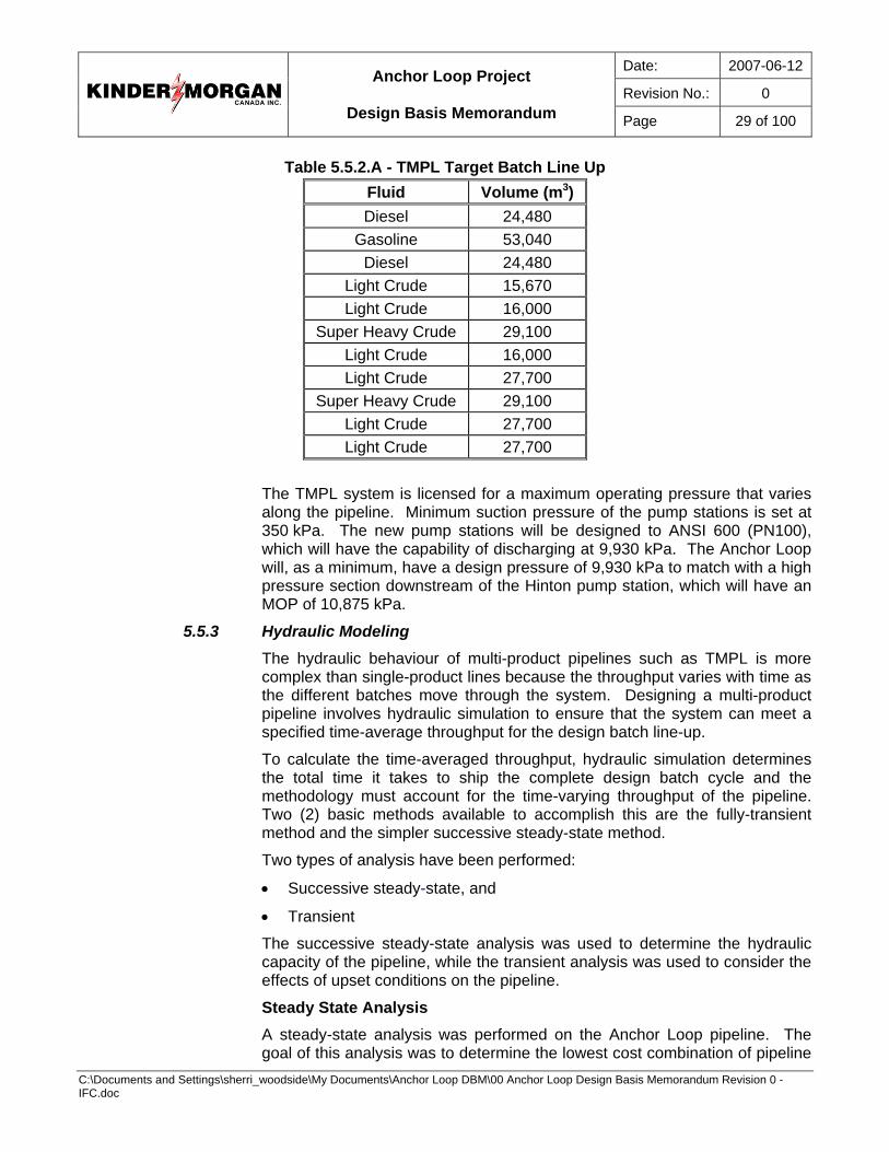
Trans Mountain has formulated a target operating capacity of 47,770 m3/d (300,000 bpd) for the batch line-up shown in Table 5.5.2.A.
Date: 2007-06-12
Revision No.: 0
Anchor Loop Project
Design Basis Memorandum Page 29 of 100
C:\Documents and Settings\sherri_woodside\My Documents\Anchor Loop DBM\00 Anchor Loop Design Basis Memorandum Revision 0 - IFC.doc
Table 5.5.2.A - TMPL Target Batch Line Up Fluid Volume (m3) Diesel 24,480
Gasoline 53,040 Diesel 24,480
Light Crude 15,670 Light Crude 16,000
Super Heavy Crude 29,100 Light Crude 16,000 Light Crude 27,700
Super Heavy Crude 29,100 Light Crude 27,700 Light Crude 27,700
The TMPL system is licensed for a maximum operating pressure that varies along the pipeline. Minimum suction pressure of the pump stations is set at 350 kPa. The new pump stations will be designed to ANSI 600 (PN100), which will have the capability of discharging at 9,930 kPa. The Anchor Loop will, as a minimum, have a design pressure of 9,930 kPa to match with a high pressure section downstream of the Hinton pump station, which will have an MOP of 10,875 kPa.
5.5.3 Hydraulic Modeling The hydraulic behaviour of multi-product pipelines such as TMPL is more complex than single-product lines because the throughput varies with time as the different batches move through the system. Designing a multi-product pipeline involves hydraulic simulation to ensure that the system can meet a specified time-average throughput for the design batch line-up.
To calculate the time-averaged throughput, hydraulic simulation determines the total time it takes to ship the complete design batch cycle and the methodology must account for the time-varying throughput of the pipeline. Two (2) basic methods available to accomplish this are the fully-transient method and the simpler successive steady-state method.
Two types of analysis have been performed:
• Successive steady-state, and
• Transient
The successive steady-state analysis was used to determine the hydraulic capacity of the pipeline, while the transient analysis was used to consider the effects of upset conditions on the pipeline.
Steady State Analysis A steady-state analysis was performed on the Anchor Loop pipeline. The goal of this analysis was to determine the lowest cost combination of pipeline
Date: 2007-06-12
Revision No.: 0
Anchor Loop Project
Design Basis Memorandum Page 30 of 100
C:\Documents and Settings\sherri_woodside\My Documents\Anchor Loop DBM\00 Anchor Loop Design Basis Memorandum Revision 0 - IFC.doc
diameter, wall thickness, pipeline maximum operating pressure, steel grade, and pump power that will ensure design daily flow rates can be achieved.
A proprietary single-phase, successive steady-state model was used to complete the steady state hydraulic analysis for the pipeline. The maximum discharge pressure of each pump station was set at MOP. The minimum suction pressure at the inlet of each pump station was set at 300 kPa, and the minimum pipeline pressure was set at 150 kPag to prevent slack flow.
Head loss calculations were performed for the pipelines only. Pressure losses within pump stations were assumed and added into the pump power calculations.
Transient Analysis A transient hydraulic analysis has been performed on the Anchor Loop pipeline for the peak flow rate. The goal of the transient analysis was to ensure each pipeline segment can be safely protected under upset conditions.
The transient analysis considered pressure surges created within the pipeline under the following, most severe upset conditions:
• Unplanned closure of a MLBV during ESD
• Unplanned loss of an entire pump station
Pressure surges created within the confines of pump stations and pressure surges within pump stations caused by a MLBV closure were not considered.
The transient analysis provides pressures at critical locations along the pipeline versus time. The critical locations along the pipeline will vary depending on the location of the upset condition, but in general, the critical locations will be at the low elevation points upstream of the upset condition.
The transient analysis:
• Determined if pressure relieving, pressure limiting, or pressure shut-down devices must be installed or if other methods must be considered to ensure the pipeline pressure does not exceed 110% of pipeline MOP under these upset conditions, and
• Determined if special methods must be considered to ensure the pipeline pressure does not fall below 150 kPag under these upset conditions.
5.5.4 Surge Protection The transient analysis of the TMPL system was completed by CIMARRON Engineering Ltd. Results of the analysis indicate that surge protection must be incorporated into most existing stations and all new stations to be constructed. A copy of this analysis will be provided to the EP Consultant(s) selected to work on this project.
Date: 2007-06-12
Revision No.: 0
Anchor Loop Project
Design Basis Memorandum Page 31 of 100
C:\Documents and Settings\sherri_woodside\My Documents\Anchor Loop DBM\00 Anchor Loop Design Basis Memorandum Revision 0 - IFC.doc
As part of the facilities design during detailed engineering, transient analysis shall be performed again to determine if relief valves or over pressure protection is required to protect upstream piping, metering, etc., against surges due to power failure or valve closure.
An appropriate means of surge protection shall be incorporated into the new station design and included in the upgrade work at existing stations as required.
5.5.5 Temperature Differential To avoid any pipeline movements caused by thermal changes from transferring to the facilities piping, large radii bends and pipe loops will be considered during design within the facilities property. Requirements for anchor block or aboveground anchor points will be determined by completing a stress analysis during detailed design.
5.5.6 Electrical Design Considerations Mainline pump motors on the line will have a 1.15 service factor, which may be used under some conditions. VFDs must be capable of allowing motors to be run at full-service factor power from normal on-line operating speed to 110% of synchronous speed. Pump and motor speed range required is expected to be 40% to 110% of synchronous speed (e.g. 1,440 rpm to 3,960 rpm for a nominal 3,600 rpm motor). This means motors will most likely need to be stiff shafted, highly damped and critical, or of a special design.
5.5.7 Power Facility power requirements shall be met by a combination strategy of existing power supply, new distribution lines, and new transmission lines.
The preferred power strategy at Wolf, Chappel, and Hargreaves facilities shall reflect the anticipated lifetime of these facilities (about three (3) years).
5.5.8 Constructability The following techniques will be used during the design process to ensure the optimal constructability of designs:
• Participation by construction personnel in the design process and during regular constructability reviews
• Regular interface meetings between the Pipeline Consultant, KMCI, and the Facilities Consultant design teams.
• Incorporation of appropriate levels of modularization
• Use of 3D design tools
• Incorporation of lessons learned from the original TMPL construction process.
5.5.9 Temporary Tie-in Near the Alberta / British Columbia border, components shall be installed to enable the NPS 36 loop to be connected to TMPL on a temporary basis. The
Date: 2007-06-12
Revision No.: 0
Anchor Loop Project
Design Basis Memorandum Page 32 of 100
C:\Documents and Settings\sherri_woodside\My Documents\Anchor Loop DBM\00 Anchor Loop Design Basis Memorandum Revision 0 - IFC.doc
site shall contain all components required to fully commission, operate the upstream sections of pipeline loop, and transfer product into TMPL until such time that the downstream section of loop is built and readied for service. The precise location for the crossover is to be determined. The design shall consider the future need to provide an in-line connection between upstream and downstream sections of pipeline loop.
5.6 Control, SCADA, and Communications 5.6.1 Station Control
Pump station control systems will be based on programmable logic controller (PLC) hardware. PLC systems will consist of a Data Concentrator PLC, a Station PLC and a Flow Computer PLC, where applicable. Each pump unit will be controlled through a dedicated I/O rack communicating on a Control Net with Station PLC. Flow computers will be used to provide custody transfer measurement and meter proving control. Level of integration and redundancy with existing PLC system will be considered during detailed design.
Station control shall be a low select Proportional and Integral (PI) system controlling station suction pressure, station discharge pressure, or station kilowatts simultaneously, automatically selecting the control variable. PI control functions will be done by the station PLC in the same manner as existing TMPL facilities. Start-and-Stop commands and setpoints for the PI system will originate either from the SCADA system or from the local HMI.
Station local control systems will consist of:
• Fire and gas detection
• Process alarming and ESD of each pump unit
• Pump control
Pump Station Control
• Station suction pressure (pump cavitation protection) will be provided as a control variable under program control in the PLC. The PLC program will ensure suction pressure is maintained within preset limits to ensure safe operation of the pump.
• Station discharge pressure control will be provided by redundant station discharge pressure transmitters, located downstream of the station discharge block valve. The pressure transmitters will ensure the maximum discharge pressure is in accordance with the licensed MOP. The recommended maximum discharge pressure controller set point will be based on licensed MOP for each site. If pressure control through the operation of the VFD is unable to prevent the discharge pressure from exceeding the station discharge pressure set point, the station PLC will initiate a unit quick stop (no shutdown sequence).
• If Station Kilowatts (kW consumption) increase over the kW setpoint, the controller will limit power consumption at the pump station by reducing pump speed.

Date: 2007-06-12
Revision No.: 0
Anchor Loop Project
Design Basis Memorandum Page 33 of 100
C:\Documents and Settings\sherri_woodside\My Documents\Anchor Loop DBM\00 Anchor Loop Design Basis Memorandum Revision 0 - IFC.doc
• Station and unit protection shall be based on the attached shutdown key. An Operating Limits and Protective Device Document, which will be incorporated into the TMPL Operating Limits and Protective Device Document and approved by the Manager, Technical Services, shall be developed to detail both the protection and the operating limits of the equipment and pipeline at the new sites.
Hinton Scraper Trap Facility Control The Hinton Scraper Trap facility control requirements shall be integrated with the Hinton Pump Station operations and defined during detailed design.
Hargreaves Scraper Trap Facility Control Local controls for the Hargreaves Scraper Trap facility shall be located in its service / control building (to be relocated from the existing trap facility near Hinton). Control requirements shall be defined during detailed design.
Automated Mainline Block Valve Sites Control Remote valve site control requirements shall be integrated with central control center operations and defined during detailed design.
5.6.2 SCADA All facilities shall be monitored from either the Primary Control Centre (PCC) located in Sherwood Park, Alberta, or the Secondary Control Center (SCC) in south Edmonton using a SCADA system; the precise monitoring location for each facility shall be determined during detailed design HAZOPS.
Database points and new graphic display screens will also be added to support the new sites. The leak detection system and the operator simulator / trainer will also be modified.
The SCADA system and supporting communications system infrastructure will build upon the existing system and will be expanded to accommodate the new instrumentation and control signals for the new MLBVs. SCADA system modifications and communications will be arranged by KMCI. SCADA equipment shall be suitably enclosed.
Database points and new graphic display screens will also be added to support the new sites. The leak detection system and the operator simulator / trainer will also be modified.
The SCADA system will interface with the station Data Concentrator PLC. Local monitoring and control of the facility will consist of a PLC control system and dedicated LOI. Capacity of the existing Telvent (formerly Metso, previously Valmet) SCADA system will be evaluated during detailed engineering phase. New SCADA I/O points and screens will be programmed into existing system to accommodate control of new devices.
The final SCADA system will provide the Control Room Operators with ability to:
• Acquire data and remotely monitor pipeline facilities and MLBVs
• Remotely open and close pump station valves and MLBVs
Date: 2007-06-12
Revision No.: 0
Anchor Loop Project
Design Basis Memorandum Page 34 of 100
C:\Documents and Settings\sherri_woodside\My Documents\Anchor Loop DBM\00 Anchor Loop Design Basis Memorandum Revision 0 - IFC.doc
• Change set points of station controllers
• Initiate pump start or stop sequences
• Initiate Emergency Shut Down (ESD) of the pump stations
5.6.3 Telecommunications Systems Telecommunications systems will provide communications to the following:
• Pump stations, terminal facilities, and scraper trap sites
• MLBV locations
• The Edmonton Control Center
• Maintenance personnel along the pipeline
Existing telecommunication system will be used where possible; and if necessary, new equipment will be added to accommodate new facilities.
5.7 Corrosion Control 5.7.1 Coatings
Facility equipment, piping, and tanks will be coated externally to project coating standards.
Following KMCI’s standards, facility piping and equipment coatings will be chosen based on:
• adhesion,
• toughness during handling,
• suitability for repair,
• operating temperature,
• historical performance,
• cost, and
• availability.
Joint coatings will be suitable for easy field application and compatible with shop-applied coating. Additional considerations will include ambient application conditions, preheat, and drying time requirements.
Piping that is exposed to the atmosphere (such as at valve assemblies) will be protected from external corrosion by the application of a protective coating, such as paint.
Fusion Bond Epoxy (FBE) has been selected for external coating of the buried pipeline. An additional abrasion resistant coating will be applied to all pipe that will be installed by trenchless methods. The pipe will not be internally coated.
Field weld joints will be coated with brush or roller applied two-part liquid epoxy after sandblasting Utilization of automated field applied liquid epoxy systems will be investigated.
Date: 2007-06-12
Revision No.: 0
Anchor Loop Project
Design Basis Memorandum Page 35 of 100
C:\Documents and Settings\sherri_woodside\My Documents\Anchor Loop DBM\00 Anchor Loop Design Basis Memorandum Revision 0 - IFC.doc
Other components such as valves and fabricated assemblies that are shop fabricated will be sandblasted and coated as per KMCI specifications.
FBE coating that is exposed to the sun will deteriorate with time. Storage conditions will be appraised and coated pipe that is at risk of UV damage will be white-washed or an alternative protection will be put in place.
5.7.2 Cathodic Protection (CP) External coating combined with CP will provide corrosion control. CP will meet standard practices and consist of impressed current and sacrificial anodes. CP will be installed and activated as soon as possible after pipe installation to provide maximum corrosion protection. All new installations will be integrated into the existing TMPL system.
CP designs will consider the following:
• Length of the system and segments
• Coating specifications
• Locations of stations and MLBVs
• Soil analysis
• Water table
• Proximity to other utilities
• Insulation from reinforced concrete
• Locations and performance of existing TMPL anodes and rectifiers
• Availability of AC power
Some of the issues that the design will also address are:
• paralleling existing pipelines with CP systems operated by others,
• paralleling AC power lines, and
• special situations where additional CP technologies such as zinc ribbons would be required and appropriate.
Test lead locations will generally match existing locations and will be placed on all pipeline crossings where approved by the pipeline owners. Test leads will also be placed on both sides of primary highway crossings for safety reasons so that KMCI operations personnel by allowing CP readings to be taken without the need to cross the travel lanes
5.8 Maintenance Facilities will be designed to allow for efficient in-situ equipment maintenance.
In general, the types of equipment that will require mechanical lifts will be motors, pump casings and internals, valves, valve operators and internals, meters and internals, and cleaning and inspection tools The cost of installed lifting equipment and truck loading areas will be weighed against the cost for mobilizing other internal or external equipment over the life of the facilities.

Date: 2007-06-12
Revision No.: 0
Anchor Loop Project
Design Basis Memorandum Page 36 of 100
C:\Documents and Settings\sherri_woodside\My Documents\Anchor Loop DBM\00 Anchor Loop Design Basis Memorandum Revision 0 - IFC.doc
In cases where noise, safety, containment, or other considerations result in the requirement for shelters at facilities, the additional cost of shelter hatches to allow for the use of third-party cranes will be determined for the analysis.
The relative costs of installed versus off-site lifting equipment during construction will also be considered.
5.9 Health and Safety 5.9.1 Work Environment and Hygiene
Facilities will provide an appropriately comfortable and hygienic work environment. In addition to natural ventilation, forced ventilation, heating, and air conditioning will be considered to control temperature to appropriate levels for the work to be undertaken at various facilities. Area and task lighting will be suitable for the work to be carried out.
Office and other workspaces will be reasonably sized for their intended frequency and duration of use. Desks, filing cabinets, and other furnishings will be suitable for the work to be carried out and the materials to be stored.
Washrooms will be provided at all pump station sites. As a minimum, this shall include a toilet and hand-cleaning facility as well as an emergency shower.
5.9.2 Safety All facilities will provide a safe working environment in accordance with OHSA requirements and KMCI safety practices.
All buildings will be ventilated in accordance with electrical classification requirements.
Safety will be a significant consideration in the layout and features of facilities. Guards with handrails will be provided at all elevated structures. Where frequent access is required, stairways will provide the primary access to elevated structures. “Side-step” ladders will be considered for elevated structures requiring infrequent access or for secondary accesses. Multiple access and escape routes will be provided for large areas. Where possible, “walking” clearance will be provided under elevated structures. Confined spaces will be minimized. Guards will be provided for all exposed rotating equipment and for equipment operating at high temperatures. Suitable warning signs will be posted for these and other hazards.
Fire, smoke, combustible gas detectors, and other safety related sensors and alarms will be provided.
5.10 Environmental Responsibility 5.10.1 Facilities
The pump station and scraper trap facilities will be designed in a manner that minimizes the risk of spills during construction, operations, and maintenance.
A list of all environmental issues that may affect the pump station and scraper trap facilities will be developed along with an assessment of short and long-term impact, risk, and consequences.
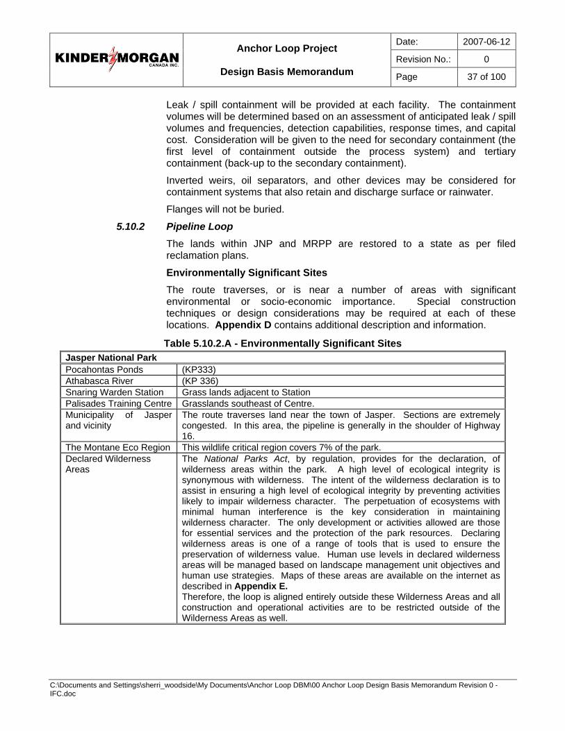
Date: 2007-06-12
Revision No.: 0
Anchor Loop Project
Design Basis Memorandum Page 37 of 100
C:\Documents and Settings\sherri_woodside\My Documents\Anchor Loop DBM\00 Anchor Loop Design Basis Memorandum Revision 0 - IFC.doc
Leak / spill containment will be provided at each facility. The containment volumes will be determined based on an assessment of anticipated leak / spill volumes and frequencies, detection capabilities, response times, and capital cost. Consideration will be given to the need for secondary containment (the first level of containment outside the process system) and tertiary containment (back-up to the secondary containment).
Inverted weirs, oil separators, and other devices may be considered for containment systems that also retain and discharge surface or rainwater.
Flanges will not be buried.
5.10.2 Pipeline Loop The lands within JNP and MRPP are restored to a state as per filed reclamation plans.
Environmentally Significant Sites The route traverses, or is near a number of areas with significant environmental or socio-economic importance. Special construction techniques or design considerations may be required at each of these locations. Appendix D contains additional description and information.
Table 5.10.2.A - Environmentally Significant Sites Jasper National Park Pocahontas Ponds (KP333) Athabasca River (KP 336) Snaring Warden Station Grass lands adjacent to Station Palisades Training Centre Grasslands southeast of Centre. Municipality of Jasper and vicinity
The route traverses land near the town of Jasper. Sections are extremely congested. In this area, the pipeline is generally in the shoulder of Highway 16.
The Montane Eco Region This wildlife critical region covers 7% of the park. Declared Wilderness Areas
The National Parks Act, by regulation, provides for the declaration, of wilderness areas within the park. A high level of ecological integrity is synonymous with wilderness. The intent of the wilderness declaration is to assist in ensuring a high level of ecological integrity by preventing activities likely to impair wilderness character. The perpetuation of ecosystems with minimal human interference is the key consideration in maintaining wilderness character. The only development or activities allowed are those for essential services and the protection of the park resources. Declaring wilderness areas is one of a range of tools that is used to ensure the preservation of wilderness value. Human use levels in declared wilderness areas will be managed based on landscape management unit objectives and human use strategies. Maps of these areas are available on the internet as described in Appendix E. Therefore, the loop is aligned entirely outside these Wilderness Areas and all construction and operational activities are to be restricted outside of the Wilderness Areas as well.
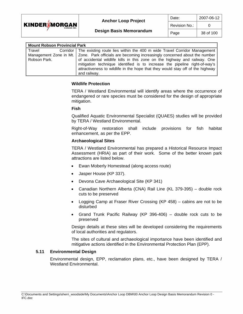
Date: 2007-06-12
Revision No.: 0
Anchor Loop Project
Design Basis Memorandum Page 38 of 100
C:\Documents and Settings\sherri_woodside\My Documents\Anchor Loop DBM\00 Anchor Loop Design Basis Memorandum Revision 0 - IFC.doc
Mount Robson Provincial Park Travel Corridor Management Zone in Mt. Robson Park.
The existing route lies within the 400 m wide Travel Corridor Management Zone. Park officials are becoming increasingly concerned about the number of accidental wildlife kills in this zone on the highway and railway. One mitigation technique identified is to increase the pipeline right-of-way’s attractiveness to wildlife in the hope that they would stay off of the highway and railway.
Wildlife Protection TERA / Westland Environmental will identify areas where the occurrence of endangered or rare species must be considered for the design of appropriate mitigation.
Fish Qualified Aquatic Environmental Specialist (QUAES) studies will be provided by TERA / Westland Environmental.
Right-of-Way restoration shall include provisions for fish habitat enhancement, as per the EPP.
Archaeological Sites TERA / Westland Environmental has prepared a Historical Resource Impact Assessment (HRIA) as part of their work. Some of the better known park attractions are listed below.
• Ewan Moberly Homestead (along access route)
• Jasper House (KP 337).
• Devona Cave Archaeological Site (KP 341)
• Canadian Northern Alberta (CNA) Rail Line (KL 379-395) – double rock cuts to be preserved
• Logging Camp at Fraser River Crossing (KP 458) – cabins are not to be disturbed
• Grand Trunk Pacific Railway (KP 396-406) – double rock cuts to be preserved
Design details at these sites will be developed considering the requirements of local authorities and regulators.
The sites of cultural and archaeological importance have been identified and mitigative actions identified in the Environmental Protection Plan (EPP).
5.11 Environmental Design Environmental design, EPP, reclamation plans, etc., have been designed by TERA / Westland Environmental.
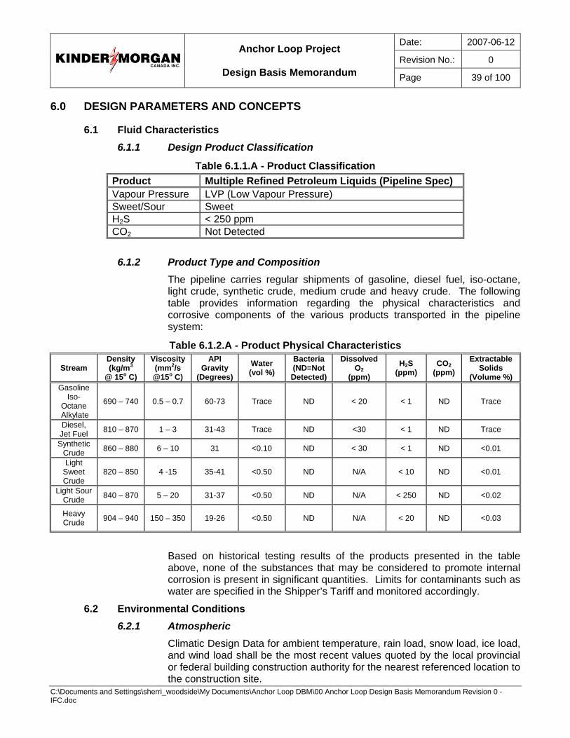
Date: 2007-06-12
Revision No.: 0
Anchor Loop Project
Design Basis Memorandum Page 39 of 100
C:\Documents and Settings\sherri_woodside\My Documents\Anchor Loop DBM\00 Anchor Loop Design Basis Memorandum Revision 0 - IFC.doc
6.0 DESIGN PARAMETERS AND CONCEPTS
6.1 Fluid Characteristics 6.1.1 Design Product Classification
Table 6.1.1.A - Product Classification Product Multiple Refined Petroleum Liquids (Pipeline Spec) Vapour Pressure LVP (Low Vapour Pressure) Sweet/Sour Sweet H2S < 250 ppm CO2 Not Detected
6.1.2 Product Type and Composition The pipeline carries regular shipments of gasoline, diesel fuel, iso-octane, light crude, synthetic crude, medium crude and heavy crude. The following table provides information regarding the physical characteristics and corrosive components of the various products transported in the pipeline system:
Table 6.1.2.A - Product Physical Characteristics
Stream Density (kg/m3
@ 15o C)
Viscosity (mm2/s @15o C)
API Gravity
(Degrees) Water (vol %)
Bacteria (ND=Not Detected)
DissolvedO2
(ppm) H2S
(ppm) CO2
(ppm) Extractable
Solids (Volume %)
Gasoline Iso-
Octane Alkylate
690 – 740 0.5 – 0.7 60-73 Trace ND < 20 < 1 ND Trace
Diesel, Jet Fuel 810 – 870 1 – 3 31-43 Trace ND <30 < 1 ND Trace
Synthetic Crude 860 – 880 6 – 10 31 <0.10 ND < 30 < 1 ND <0.01
Light Sweet Crude
820 – 850 4 -15 35-41 <0.50 ND N/A < 10 ND <0.01
Light Sour Crude 840 – 870 5 – 20 31-37 <0.50 ND N/A < 250 ND <0.02
Heavy Crude 904 – 940 150 – 350 19-26 <0.50 ND N/A < 20 ND <0.03
Based on historical testing results of the products presented in the table above, none of the substances that may be considered to promote internal corrosion is present in significant quantities. Limits for contaminants such as water are specified in the Shipper’s Tariff and monitored accordingly.
6.2 Environmental Conditions 6.2.1 Atmospheric
Climatic Design Data for ambient temperature, rain load, snow load, ice load, and wind load shall be the most recent values quoted by the local provincial or federal building construction authority for the nearest referenced location to the construction site.
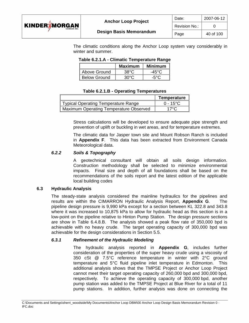
Date: 2007-06-12
Revision No.: 0
Anchor Loop Project
Design Basis Memorandum Page 40 of 100
C:\Documents and Settings\sherri_woodside\My Documents\Anchor Loop DBM\00 Anchor Loop Design Basis Memorandum Revision 0 - IFC.doc
The climatic conditions along the Anchor Loop system vary considerably in winter and summer.
Table 6.2.1.A - Climatic Temperature Range Maximum Minimum Above Ground 38°C -45°C Below Ground 30°C -5°C
Table 6.2.1.B - Operating Temperatures
Temperature Typical Operating Temperature Range 0 - 15°C Maximum Operating Temperature Observed 17°C
Stress calculations will be developed to ensure adequate pipe strength and prevention of uplift or buckling in wet areas, and for temperature extremes.
The climatic data for Jasper town site and Mount Robson Ranch is included in Appendix F. This data has been extracted from Environment Canada Meteorological data.
6.2.2 Soils & Topography A geotechnical consultant will obtain all soils design information. Construction methodology shall be selected to minimize environmental impacts. Final size and depth of all foundations shall be based on the recommendations of the soils report and the latest edition of the applicable local building codes
6.3 Hydraulic Analysis The steady-state analysis considered the mainline hydraulics for the pipelines and results are within the CIMARRON Hydraulic Analysis Report, Appendix G. The pipeline design pressure is 9,990 kPa except for a section between KL 322.8 and 343.8 where it was increased to 10,875 kPa to allow for hydraulic head as this section is in a low-point on the pipeline relative to Hinton Pump Station. The design pressure sections are show in Table 6.4.8.B. The analysis showed a peak flow rate of 350,000 bpd is achievable with no heavy crude. The target operating capacity of 300,000 bpd was achievable for the design considerations in Section 5.5.
6.3.1 Refinement of the Hydraulic Modeling The hydraulic analysis reported in Appendix G, includes further consideration of the properties of the super heavy crude using a viscosity of 350 cSt @ 7.5°C reference temperature in winter with 2°C ground temperature and 5°C fluid pipeline inlet temperature in Edmonton. This additional analysis shows that the TMPSE Project or Anchor Loop Project cannot meet their target operating capacity of 260,000 bpd and 300,000 bpd, respectively. To achieve the operating capacity of 300,000 bpd, another pump station was added to the TMPSE Project at Blue River for a total of 11 pump stations. In addition, further analysis was done on connecting the
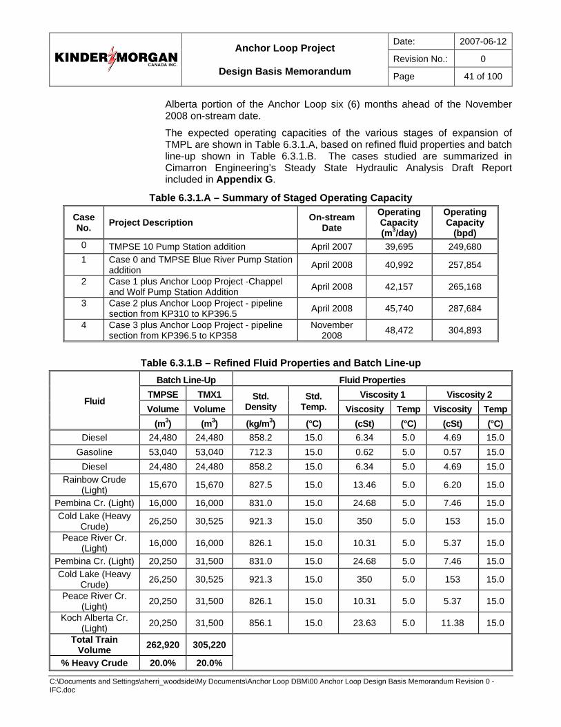
Date: 2007-06-12
Revision No.: 0
Anchor Loop Project
Design Basis Memorandum Page 41 of 100
C:\Documents and Settings\sherri_woodside\My Documents\Anchor Loop DBM\00 Anchor Loop Design Basis Memorandum Revision 0 - IFC.doc
Alberta portion of the Anchor Loop six (6) months ahead of the November 2008 on-stream date.
The expected operating capacities of the various stages of expansion of TMPL are shown in Table 6.3.1.A, based on refined fluid properties and batch line-up shown in Table 6.3.1.B. The cases studied are summarized in Cimarron Engineering’s Steady State Hydraulic Analysis Draft Report included in Appendix G.
Table 6.3.1.A – Summary of Staged Operating Capacity
Case No. Project Description On-stream
Date Operating Capacity (m3/day)
Operating Capacity
(bpd) 0 TMPSE 10 Pump Station addition April 2007 39,695 249,680 1 Case 0 and TMPSE Blue River Pump Station
addition April 2008 40,992 257,854
2 Case 1 plus Anchor Loop Project -Chappel and Wolf Pump Station Addition April 2008 42,157 265,168
3 Case 2 plus Anchor Loop Project - pipeline section from KP310 to KP396.5 April 2008 45,740 287,684
4 Case 3 plus Anchor Loop Project - pipeline section from KP396.5 to KP358
November 2008 48,472 304,893
Table 6.3.1.B – Refined Fluid Properties and Batch Line-up
Batch Line-Up Fluid Properties TMPSE TMX1 Viscosity 1 Viscosity 2 Volume Volume
Std. Density
Std. Temp. Viscosity Temp Viscosity Temp
Fluid
(m3) (m3) (kg/m3) (°C) (cSt) (°C) (cSt) (°C) Diesel 24,480 24,480 858.2 15.0 6.34 5.0 4.69 15.0
Gasoline 53,040 53,040 712.3 15.0 0.62 5.0 0.57 15.0 Diesel 24,480 24,480 858.2 15.0 6.34 5.0 4.69 15.0
Rainbow Crude (Light) 15,670 15,670 827.5 15.0 13.46 5.0 6.20 15.0
Pembina Cr. (Light) 16,000 16,000 831.0 15.0 24.68 5.0 7.46 15.0 Cold Lake (Heavy
Crude) 26,250 30,525 921.3 15.0 350 5.0 153 15.0 Peace River Cr.
(Light) 16,000 16,000 826.1 15.0 10.31 5.0 5.37 15.0
Pembina Cr. (Light) 20,250 31,500 831.0 15.0 24.68 5.0 7.46 15.0 Cold Lake (Heavy
Crude) 26,250 30,525 921.3 15.0 350 5.0 153 15.0 Peace River Cr.
(Light) 20,250 31,500 826.1 15.0 10.31 5.0 5.37 15.0 Koch Alberta Cr.
(Light) 20,250 31,500 856.1 15.0 23.63 5.0 11.38 15.0 Total Train
Volume 262,920 305,220
% Heavy Crude 20.0% 20.0%
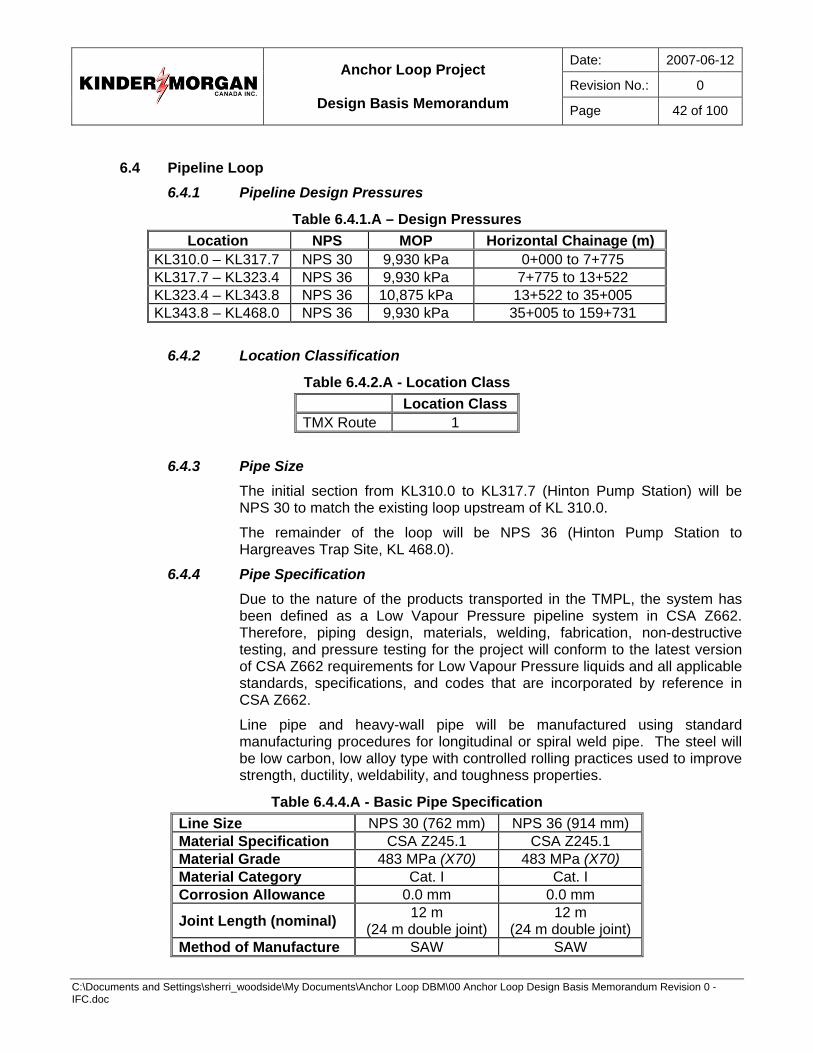
Date: 2007-06-12
Revision No.: 0
Anchor Loop Project
Design Basis Memorandum Page 42 of 100
C:\Documents and Settings\sherri_woodside\My Documents\Anchor Loop DBM\00 Anchor Loop Design Basis Memorandum Revision 0 - IFC.doc
6.4 Pipeline Loop
6.4.1 Pipeline Design Pressures
Table 6.4.1.A – Design Pressures Location NPS MOP Horizontal Chainage (m)
KL310.0 – KL317.7 NPS 30 9,930 kPa 0+000 to 7+775 KL317.7 – KL323.4 NPS 36 9,930 kPa 7+775 to 13+522 KL323.4 – KL343.8 NPS 36 10,875 kPa 13+522 to 35+005 KL343.8 – KL468.0 NPS 36 9,930 kPa 35+005 to 159+731
6.4.2 Location Classification
Table 6.4.2.A - Location Class Location Class TMX Route 1
6.4.3 Pipe Size The initial section from KL310.0 to KL317.7 (Hinton Pump Station) will be NPS 30 to match the existing loop upstream of KL 310.0.
The remainder of the loop will be NPS 36 (Hinton Pump Station to Hargreaves Trap Site, KL 468.0).
6.4.4 Pipe Specification Due to the nature of the products transported in the TMPL, the system has been defined as a Low Vapour Pressure pipeline system in CSA Z662. Therefore, piping design, materials, welding, fabrication, non-destructive testing, and pressure testing for the project will conform to the latest version of CSA Z662 requirements for Low Vapour Pressure liquids and all applicable standards, specifications, and codes that are incorporated by reference in CSA Z662.
Line pipe and heavy-wall pipe will be manufactured using standard manufacturing procedures for longitudinal or spiral weld pipe. The steel will be low carbon, low alloy type with controlled rolling practices used to improve strength, ductility, weldability, and toughness properties.
Table 6.4.4.A - Basic Pipe Specification Line Size NPS 30 (762 mm) NPS 36 (914 mm) Material Specification CSA Z245.1 CSA Z245.1 Material Grade 483 MPa (X70) 483 MPa (X70) Material Category Cat. I Cat. I Corrosion Allowance 0.0 mm 0.0 mm
Joint Length (nominal) 12 m (24 m double joint)
12 m (24 m double joint)
Method of Manufacture SAW SAW
Date: 2007-06-12
Revision No.: 0
Anchor Loop Project
Design Basis Memorandum Page 43 of 100
C:\Documents and Settings\sherri_woodside\My Documents\Anchor Loop DBM\00 Anchor Loop Design Basis Memorandum Revision 0 - IFC.doc
The line pipe material and associated fittings will be selected in accordance with a maximum design stress level of 80% of Specified Minimum Yield Strength (SMYS). This maximum design stress level will be reduced as required by regulations at specific locations, such as uncased railway crossings and underneath roads based on fatigue analysis.
Following negotiations with representatives of JNP, the NPS 36 pipe installed through the park shall be subject to additional testing of pipe body and seam weld to demonstrate notch toughness properties consistent with that required for Category II pipe.
The additional testing includes:
• On one (1) pipe from each heat of steel produced and applied to the order, the following will be performed:
− One (1) set of Charpy V-notch test specimens, prepared from the parent material of the pipe as outlined for body tests in CSA Z 245.1-02, will be subjected to testing at a temperature of -5°C, results to be reported for information only.
− One (1) set of Drop Weight Tear Test specimens, prepared from the parent material as outlined in Clauses 7.7.1 and 7.7.2 of CSA Z 245.1-02, will be subjected to testing at a temperature of -5°C, results to be reported for information only
• On every tenth pipe referenced above (i.e. from every tenth heat), and as agreed to in earlier correspondence, the following will also be performed:
− One (1) set of Charpy V-notch test specimens, prepared from the deposited weld metal of the longitudinal seam as outlined in Clause 8.5.1 of CSA Z 245.1-02, will be subjected to testing at a temperature of -5°C, results to be reported for information only.
− One (1) set of Charpy V-notch test specimens, prepared from the heat-affected zone of the longitudinal seam, will be subjected to testing at a temperature of -5°C, results to be reported for information only.
6.4.5 Wall Thickness The formula in Clause 4.3.3.1.1 of CSA Z662 will be used to determine the minimum wall thickness of the line pipe used for the pipeline loop. Stresses will be calculated to determine any restrictions on installation temperatures.
Additionally, the pipeline loop will contain short lengths of heavy-wall pipe as required for crossings of roads, railways and major streams. The exact allocation of heavy-wall will be determined during the detailed design phase.
The following table details what the wall thickness to be used in various applications within the project is.
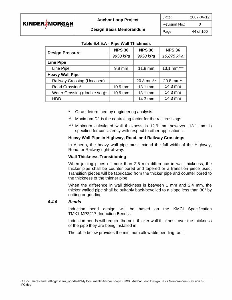
Date: 2007-06-12
Revision No.: 0
Anchor Loop Project
Design Basis Memorandum Page 44 of 100
C:\Documents and Settings\sherri_woodside\My Documents\Anchor Loop DBM\00 Anchor Loop Design Basis Memorandum Revision 0 - IFC.doc
Table 6.4.5.A - Pipe Wall Thickness NPS 30 NPS 36 NPS 36 Design Pressure
9930 kPa 9930 kPa 10,875 kPa Line Pipe
Line Pipe 9.8 mm 11.8 mm 13.1 mm*** Heavy Wall Pipe
Railway Crossing (Uncased) - 20.8 mm** 20.8 mm** Road Crossing* 10.9 mm 13.1 mm 14.3 mm Water Crossing (double sag)* 10.9 mm 13.1 mm 14.3 mm HDD - 14.3 mm 14.3 mm
* Or as determined by engineering analysis.
** Maximum D/t is the controlling factor for the rail crossings.
*** Minimum calculated wall thickness is 12.9 mm however; 13.1 mm is specified for consistency with respect to other applications.
Heavy Wall Pipe in Highway, Road, and Railway Crossings In Alberta, the heavy wall pipe must extend the full width of the Highway, Road, or Railway right-of-way.
Wall Thickness Transitioning When joining pipes of more than 2.5 mm difference in wall thickness, the thicker pipe shall be counter bored and tapered or a transition piece used. Transition pieces will be fabricated from the thicker pipe and counter bored to the thickness of the thinner pipe
When the difference in wall thickness is between 1 mm and 2.4 mm, the thicker walled pipe shall be suitably back-bevelled to a slope less than 30° by cutting or grinding.
6.4.6 Bends Induction bend design will be based on the KMCI Specification TMX1-MP2217, Induction Bends .
Induction bends will require the next thicker wall thickness over the thickness of the pipe they are being installed in.
The table below provides the minimum allowable bending radii:
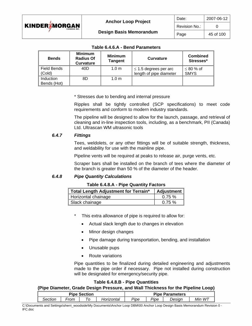
Date: 2007-06-12
Revision No.: 0
Anchor Loop Project
Design Basis Memorandum Page 45 of 100
C:\Documents and Settings\sherri_woodside\My Documents\Anchor Loop DBM\00 Anchor Loop Design Basis Memorandum Revision 0 - IFC.doc
Table 6.4.6.A - Bend Parameters
Bends Minimum Radius Of Curvature
Minimum Tangent Curvature Combined
Stresses*
Field Bends (Cold)
40D 1.0 m ≤ 1.5 degrees per arc length of pipe diameter
≤ 80 % of SMYS
Induction Bends (Hot)
8D 1.0 m
* Stresses due to bending and internal pressure
Ripples shall be tightly controlled (SCP specifications) to meet code requirements and conform to modern industry standards.
The pipeline will be designed to allow for the launch, passage, and retrieval of cleaning and in-line inspection tools, including, as a benchmark, PII (Canada) Ltd. Ultrascan WM ultrasonic tools
6.4.7 Fittings Tees, weldolets, or any other fittings will be of suitable strength, thickness, and weldability for use with the mainline pipe.
Pipeline vents will be required at peaks to release air, purge vents, etc.
Scraper bars shall be installed on the branch of tees where the diameter of the branch is greater than 50 % of the diameter of the header.
6.4.8 Pipe Quantity Calculations
Table 6.4.8.A - Pipe Quantity Factors Total Length Adjustment for Terrain* Adjustment Horizontal chainage 0.75 % Slack chainage 0.75 %
* This extra allowance of pipe is required to allow for:
• Actual slack length due to changes in elevation
• Minor design changes
• Pipe damage during transportation, bending, and installation
• Unusable pups
• Route variations
Pipe quantities to be finalized during detailed engineering and adjustments made to the pipe order if necessary. Pipe not installed during construction will be designated for emergency/security pipe.
Table 6.4.8.B - Pipe Quantities (Pipe Diameter, Grade Design Pressure, and Wall Thickness for the Pipeline Loop)
Pipe Section Pipe Parameters Section From To Horizontal Pipe Pipe Design Min WT
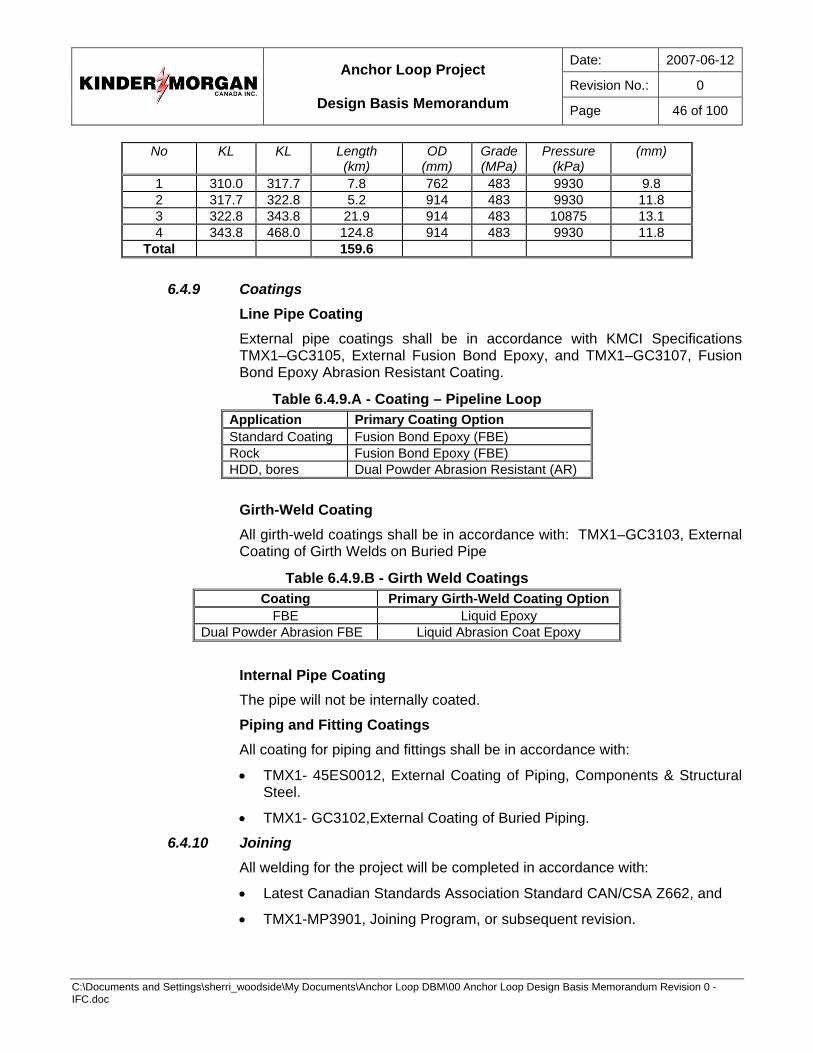
Date: 2007-06-12
Revision No.: 0
Anchor Loop Project
Design Basis Memorandum Page 46 of 100
C:\Documents and Settings\sherri_woodside\My Documents\Anchor Loop DBM\00 Anchor Loop Design Basis Memorandum Revision 0 - IFC.doc
No KL KL Length (km)
OD (mm)
Grade(MPa)
Pressure (kPa)
(mm)
1 310.0 317.7 7.8 762 483 9930 9.8 2 317.7 322.8 5.2 914 483 9930 11.8 3 322.8 343.8 21.9 914 483 10875 13.1 4 343.8 468.0 124.8 914 483 9930 11.8
Total 159.6
6.4.9 Coatings Line Pipe Coating External pipe coatings shall be in accordance with KMCI Specifications TMX1–GC3105, External Fusion Bond Epoxy, and TMX1–GC3107, Fusion Bond Epoxy Abrasion Resistant Coating.
Table 6.4.9.A - Coating – Pipeline Loop Application Primary Coating Option Standard Coating Fusion Bond Epoxy (FBE) Rock Fusion Bond Epoxy (FBE) HDD, bores Dual Powder Abrasion Resistant (AR)
Girth-Weld Coating All girth-weld coatings shall be in accordance with: TMX1–GC3103, External Coating of Girth Welds on Buried Pipe
Table 6.4.9.B - Girth Weld Coatings Coating Primary Girth-Weld Coating Option
FBE Liquid Epoxy Dual Powder Abrasion FBE Liquid Abrasion Coat Epoxy
Internal Pipe Coating The pipe will not be internally coated.
Piping and Fitting Coatings All coating for piping and fittings shall be in accordance with:
• TMX1- 45ES0012, External Coating of Piping, Components & Structural Steel.
• TMX1- GC3102,External Coating of Buried Piping.
6.4.10 Joining All welding for the project will be completed in accordance with:
• Latest Canadian Standards Association Standard CAN/CSA Z662, and
• TMX1-MP3901, Joining Program, or subsequent revision.
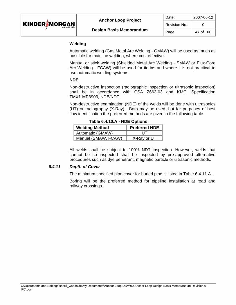
Date: 2007-06-12
Revision No.: 0
Anchor Loop Project
Design Basis Memorandum Page 47 of 100
C:\Documents and Settings\sherri_woodside\My Documents\Anchor Loop DBM\00 Anchor Loop Design Basis Memorandum Revision 0 - IFC.doc
Welding Automatic welding (Gas Metal Arc Welding - GMAW) will be used as much as possible for mainline welding, where cost effective.
Manual or stick welding (Shielded Metal Arc Welding - SMAW or Flux-Core Arc Welding - FCAW) will be used for tie-ins and where it is not practical to use automatic welding systems.
NDE Non-destructive inspection (radiographic inspection or ultrasonic inspection) shall be in accordance with CSA Z662-03 and KMCI Specification TMX1-MP3903, NDE/NDT.
Non-destructive examination (NDE) of the welds will be done with ultrasonics (UT) or radiography (X-Ray). Both may be used, but for purposes of best flaw identification the preferred methods are given in the following table.
Table 6.4.10.A - NDE Options Welding Method Preferred NDE Automatic (GMAW) UT Manual (SMAW, FCAW) X-Ray or UT
All welds shall be subject to 100% NDT inspection. However, welds that cannot be so inspected shall be inspected by pre-approved alternative procedures such as dye penetrant, magnetic particle or ultrasonic methods.
6.4.11 Depth of Cover The minimum specified pipe cover for buried pipe is listed in Table 6.4.11.A.
Boring will be the preferred method for pipeline installation at road and railway crossings.
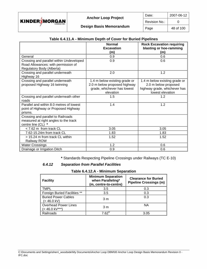
Date: 2007-06-12
Revision No.: 0
Anchor Loop Project
Design Basis Memorandum Page 48 of 100
C:\Documents and Settings\sherri_woodside\My Documents\Anchor Loop DBM\00 Anchor Loop Design Basis Memorandum Revision 0 - IFC.doc
Table 6.4.11.A - Minimum Depth of Cover for Buried Pipelines Normal
Excavation (m)
Rock Excavation requiring blasting or hoe-ramming
(m) General 0.9 0.6 Crossing and parallel within Undeveloped Road Allowances: with permission of Regulatory Body (Alberta)
0.9 0.6
Crossing and parallel underneath Highway 16
2.0 1.2
Crossing and parallel underneath proposed Highway 16 twinning
1.4 m below existing grade or 2.0 m below proposed highway
grade, whichever has lowest elevation
1.4 m below existing grade or 2.0 m below proposed
highway grade, whichever has lowest elevation
Crossing and parallel underneath other roads
1.5 1.2
Parallel and within 8.0 metres of lowest point of Highway or Proposed Highway prisms.
1.4 1.2
Crossing and parallel to Railroads measured at right angles to the track centre line (CL) *
< 7.62 m from track CL 3.05 3.05 7.62-15.24m from track CL 1.83 1.83 > 15.24 m from track CL within Railway ROW
1.52 1.52
Water Crossings 1.2 0.6 Drainage or Irrigation Ditch 0.9 0.6
* Standards Respecting Pipeline Crossings under Railways (TC E-10)
6.4.12 Separation from Parallel Facilities
Table 6.4.12.A - Minimum Separation
Facility Minimum Separation
when Paralleling* (m, centre-to-centre)
Clearance for Buried Pipeline Crossings (m)
TMPL 3.5 0.3 Foreign Buried Facilities ** 3.5 0.3 Buried Power Cables (< 46.0 kV) 3 m 0.3
Overhead Power Lines (< 46.0 kV***) 3 m NA
Railroads 7.62iv 3.05
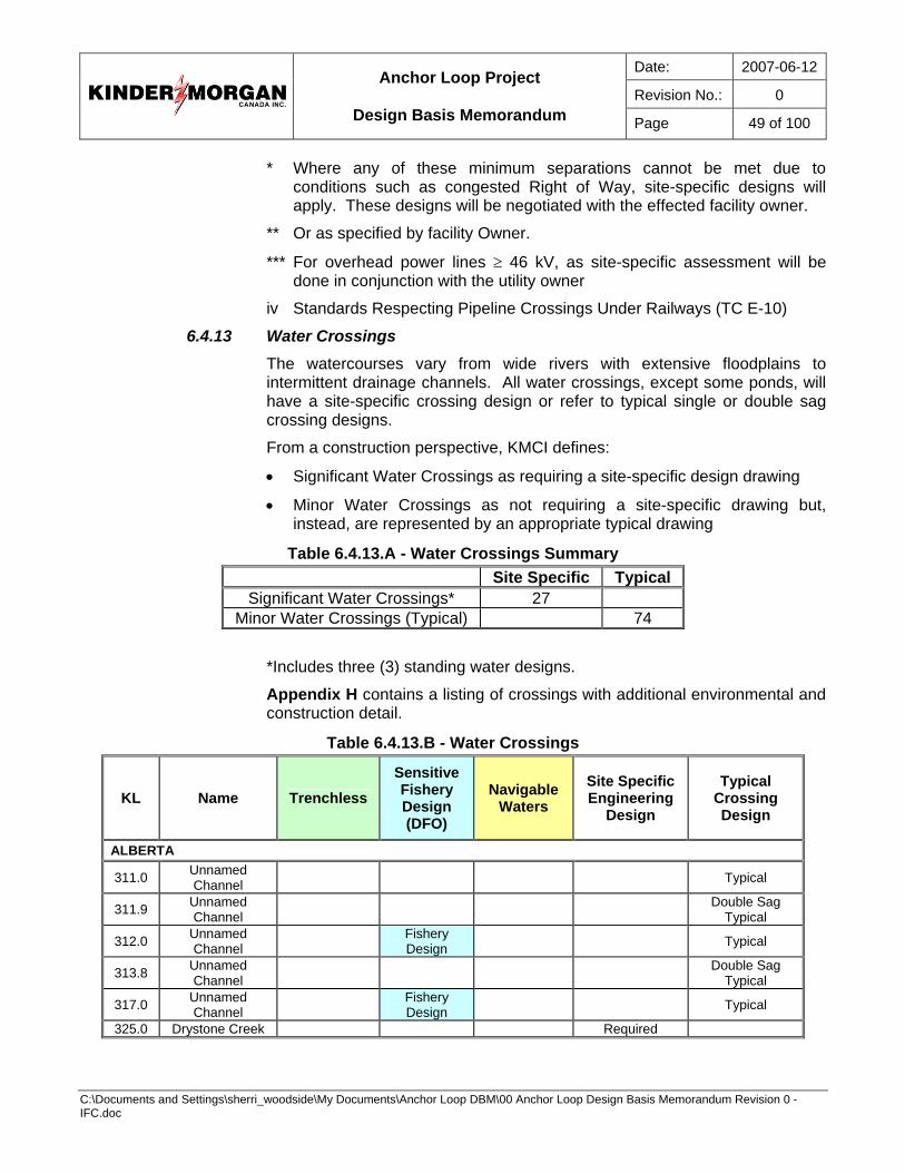
Date: 2007-06-12
Revision No.: 0
Anchor Loop Project
Design Basis Memorandum Page 49 of 100
C:\Documents and Settings\sherri_woodside\My Documents\Anchor Loop DBM\00 Anchor Loop Design Basis Memorandum Revision 0 - IFC.doc
* Where any of these minimum separations cannot be met due to conditions such as congested Right of Way, site-specific designs will apply. These designs will be negotiated with the effected facility owner.
** Or as specified by facility Owner.
*** For overhead power lines ≥ 46 kV, as site-specific assessment will be done in conjunction with the utility owner
iv Standards Respecting Pipeline Crossings Under Railways (TC E-10)
6.4.13 Water Crossings The watercourses vary from wide rivers with extensive floodplains to intermittent drainage channels. All water crossings, except some ponds, will have a site-specific crossing design or refer to typical single or double sag crossing designs.
From a construction perspective, KMCI defines:
• Significant Water Crossings as requiring a site-specific design drawing
• Minor Water Crossings as not requiring a site-specific drawing but, instead, are represented by an appropriate typical drawing
Table 6.4.13.A - Water Crossings Summary Site Specific Typical
Significant Water Crossings* 27 Minor Water Crossings (Typical) 74
*Includes three (3) standing water designs.
Appendix H contains a listing of crossings with additional environmental and construction detail.
Table 6.4.13.B - Water Crossings
KL Name Trenchless Sensitive Fishery Design (DFO)
Navigable Waters
Site Specific Engineering
Design
Typical Crossing Design
ALBERTA
311.0 Unnamed Channel Typical
311.9 Unnamed Channel Double Sag
Typical
312.0 Unnamed Channel Fishery
Design Typical
313.8 Unnamed Channel Double Sag
Typical
317.0 Unnamed Channel Fishery
Design Typical
325.0 Drystone Creek Required
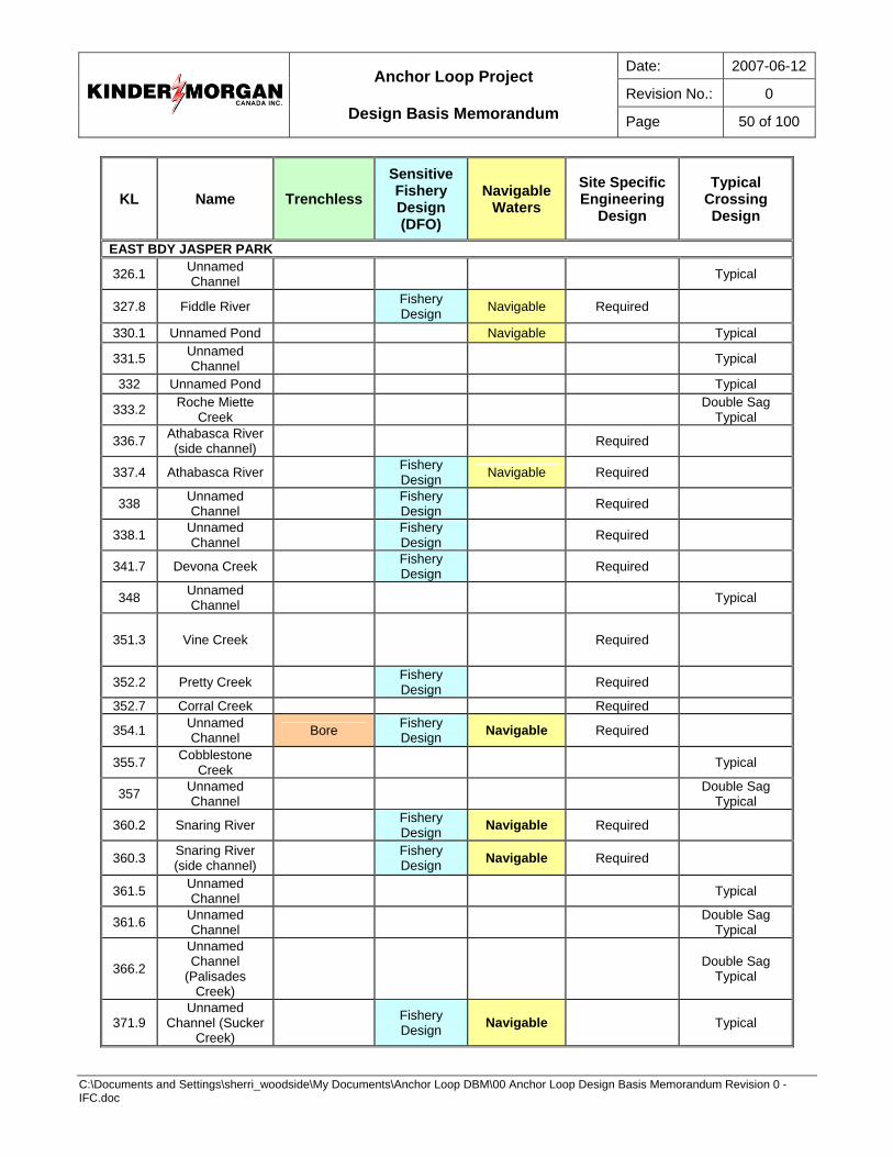
Date: 2007-06-12
Revision No.: 0
Anchor Loop Project
Design Basis Memorandum Page 50 of 100
C:\Documents and Settings\sherri_woodside\My Documents\Anchor Loop DBM\00 Anchor Loop Design Basis Memorandum Revision 0 - IFC.doc
KL Name Trenchless Sensitive Fishery Design (DFO)
Navigable Waters
Site Specific Engineering
Design
Typical Crossing Design
EAST BDY JASPER PARK
326.1 Unnamed Channel Typical
327.8 Fiddle River Fishery Design Navigable Required
330.1 Unnamed Pond Navigable Typical
331.5 Unnamed Channel Typical
332 Unnamed Pond Typical
333.2 Roche Miette Creek Double Sag
Typical
336.7 Athabasca River (side channel) Required
337.4 Athabasca River Fishery Design Navigable Required
338 Unnamed Channel Fishery
Design Required
338.1 Unnamed Channel Fishery
Design Required
341.7 Devona Creek Fishery Design Required
348 Unnamed Channel Typical
351.3 Vine Creek Required
352.2 Pretty Creek Fishery Design Required
352.7 Corral Creek Required
354.1 Unnamed Channel Bore Fishery
Design Navigable Required
355.7 Cobblestone Creek Typical
357 Unnamed Channel Double Sag
Typical
360.2 Snaring River Fishery Design Navigable Required
360.3 Snaring River (side channel) Fishery
Design Navigable Required
361.5 Unnamed Channel Typical
361.6 Unnamed Channel Double Sag
Typical
366.2
Unnamed Channel
(Palisades Creek)
Double Sag Typical
371.9 Unnamed
Channel (Sucker Creek)
Fishery Design Navigable Typical
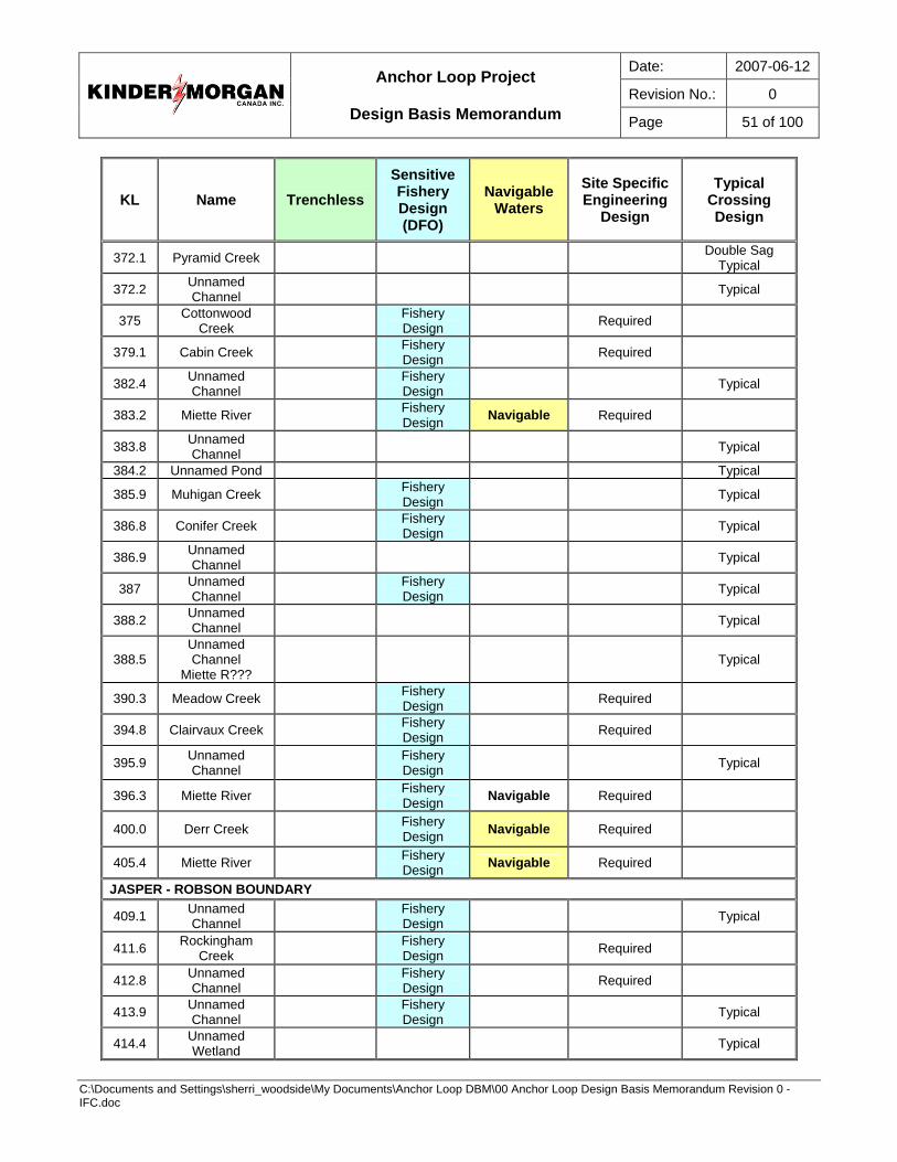
Date: 2007-06-12
Revision No.: 0
Anchor Loop Project
Design Basis Memorandum Page 51 of 100
C:\Documents and Settings\sherri_woodside\My Documents\Anchor Loop DBM\00 Anchor Loop Design Basis Memorandum Revision 0 - IFC.doc
KL Name Trenchless Sensitive Fishery Design (DFO)
Navigable Waters
Site Specific Engineering
Design
Typical Crossing Design
372.1 Pyramid Creek Double Sag Typical
372.2 Unnamed Channel Typical
375 Cottonwood Creek Fishery
Design Required
379.1 Cabin Creek Fishery Design Required
382.4 Unnamed Channel Fishery
Design Typical
383.2 Miette River Fishery Design Navigable Required
383.8 Unnamed Channel Typical
384.2 Unnamed Pond Typical
385.9 Muhigan Creek Fishery Design Typical
386.8 Conifer Creek Fishery Design Typical
386.9 Unnamed Channel Typical
387 Unnamed Channel Fishery
Design Typical
388.2 Unnamed Channel Typical
388.5 Unnamed Channel
Miette R??? Typical
390.3 Meadow Creek Fishery Design Required
394.8 Clairvaux Creek Fishery Design Required
395.9 Unnamed Channel Fishery
Design Typical
396.3 Miette River Fishery Design Navigable Required
400.0 Derr Creek Fishery Design Navigable Required
405.4 Miette River Fishery Design Navigable Required
JASPER - ROBSON BOUNDARY
409.1 Unnamed Channel Fishery
Design Typical
411.6 Rockingham Creek Fishery
Design Required
412.8 Unnamed Channel Fishery
Design Required
413.9 Unnamed Channel Fishery
Design Typical
414.4 Unnamed Wetland Typical
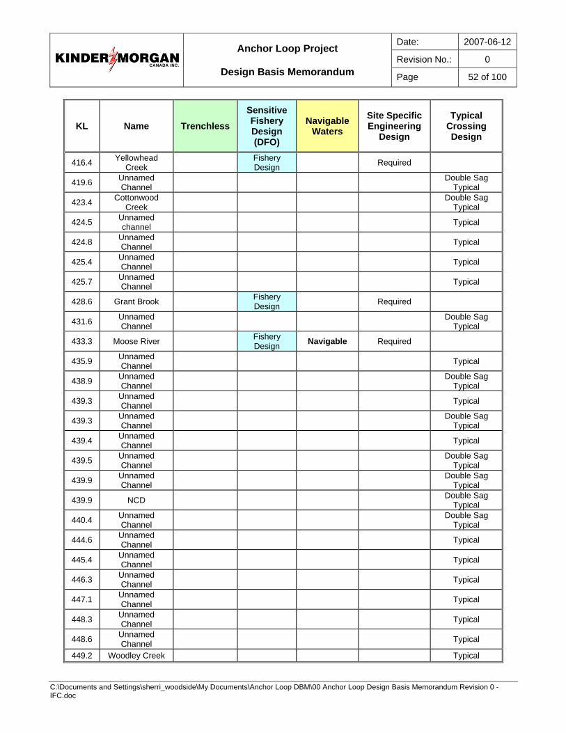
Date: 2007-06-12
Revision No.: 0
Anchor Loop Project
Design Basis Memorandum Page 52 of 100
C:\Documents and Settings\sherri_woodside\My Documents\Anchor Loop DBM\00 Anchor Loop Design Basis Memorandum Revision 0 - IFC.doc
KL Name Trenchless Sensitive Fishery Design (DFO)
Navigable Waters
Site Specific Engineering
Design
Typical Crossing Design
416.4 Yellowhead Creek Fishery
Design Required
419.6 Unnamed Channel Double Sag
Typical
423.4 Cottonwood Creek Double Sag
Typical
424.5 Unnamed channel Typical
424.8 Unnamed Channel Typical
425.4 Unnamed Channel Typical
425.7 Unnamed Channel Typical
428.6 Grant Brook Fishery Design Required
431.6 Unnamed Channel Double Sag
Typical
433.3 Moose River Fishery Design Navigable Required
435.9 Unnamed Channel Typical
438.9 Unnamed Channel Double Sag
Typical
439.3 Unnamed Channel Typical
439.3 Unnamed Channel Double Sag
Typical
439.4 Unnamed Channel Typical
439.5 Unnamed Channel Double Sag
Typical
439.9 Unnamed Channel Double Sag
Typical
439.9 NCD Double Sag Typical
440.4 Unnamed Channel Double Sag
Typical
444.6 Unnamed Channel Typical
445.4 Unnamed Channel Typical
446.3 Unnamed Channel Typical
447.1 Unnamed Channel Typical
448.3 Unnamed Channel Typical
448.6 Unnamed Channel Typical
449.2 Woodley Creek Typical
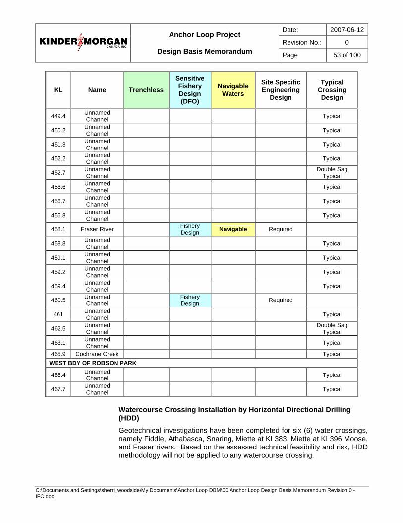
Date: 2007-06-12
Revision No.: 0
Anchor Loop Project
Design Basis Memorandum Page 53 of 100
C:\Documents and Settings\sherri_woodside\My Documents\Anchor Loop DBM\00 Anchor Loop Design Basis Memorandum Revision 0 - IFC.doc
KL Name Trenchless Sensitive Fishery Design (DFO)
Navigable Waters
Site Specific Engineering
Design
Typical Crossing Design
449.4 Unnamed Channel Typical
450.2 Unnamed Channel Typical
451.3 Unnamed Channel Typical
452.2 Unnamed Channel Typical
452.7 Unnamed Channel Double Sag
Typical
456.6 Unnamed Channel Typical
456.7 Unnamed Channel Typical
456.8 Unnamed Channel Typical
458.1 Fraser River Fishery Design Navigable Required
458.8 Unnamed Channel Typical
459.1 Unnamed Channel Typical
459.2 Unnamed Channel Typical
459.4 Unnamed Channel Typical
460.5 Unnamed Channel Fishery
Design Required
461 Unnamed Channel Typical
462.5 Unnamed Channel Double Sag
Typical
463.1 Unnamed Channel Typical
465.9 Cochrane Creek Typical WEST BDY OF ROBSON PARK
466.4 Unnamed Channel Typical
467.7 Unnamed Channel Typical
Watercourse Crossing Installation by Horizontal Directional Drilling (HDD) Geotechnical investigations have been completed for six (6) water crossings, namely Fiddle, Athabasca, Snaring, Miette at KL383, Miette at KL396 Moose, and Fraser rivers. Based on the assessed technical feasibility and risk, HDD methodology will not be applied to any watercourse crossing.
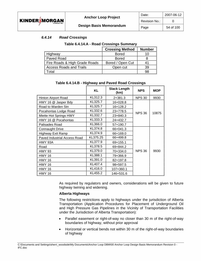
Date: 2007-06-12
Revision No.: 0
Anchor Loop Project
Design Basis Memorandum Page 54 of 100
C:\Documents and Settings\sherri_woodside\My Documents\Anchor Loop DBM\00 Anchor Loop Design Basis Memorandum Revision 0 - IFC.doc
6.4.14 Road Crossings
Table 6.4.14.A - Road Crossings Summary Crossing Method Number Highway Bored 10 Paved Road Bored 8 Fire Roads & High Grade Roads Bored / Open Cut 41 Access Roads and Trails Open cut 39 Total 98
Table 6.4.14.B - Highway and Paved Road Crossings
KL Slack Length (km) NPS MOP
Hinton Airport Road KL312.3 2+381.3 NPS 30 9930 HWY 16 @ Jasper Bdy KL325.7 16+028.8 Road to Warden Stn KL325.7 16+128.2 Pocahontas Lodge Road KL332.6 23+778.5 Miette Hot Springs HWY KL332.7 23+840.3 HWY 16 @ Pocahontas KL333.3 24+432.7 Palisades Road KL366.0 57+190.7
NPS 36 10875
Connaught Drive KL374.8 66+041.3 Highway Exit Ramp KL374.9 66+169.0 Paved Industrial Access Road KL375.25 66+499.8 HWY 93A KL377.9 69+155.1 Road KL378.5 69+844.2 HWY 93 KL379.0 70+334.0 HWY 16 KL388.1 79+366.9 HWY 16 KL391.0 82+197.8 HWY 16 KL407.4 98+597.5 HWY 16 KL416.0 107+360.1 HWY 16 KL455.2 146+531.6
NPS 36 9930
As required by regulators and owners, considerations will be given to future highway twining and widening.
Alberta Highways The following restrictions apply to highways under the jurisdiction of Alberta Transportation (Application Procedures for Placement of Underground Oil and High Pressure Gas Pipelines in the Vicinity of Transportation Facilities under the Jurisdiction of Alberta Transportation):
• Parallel easement or right-of-way no closer than 30 m of the right-of-way boundaries of highway, without prior approval
• Horizontal or vertical bends not within 30 m of the right-of-way boundaries of highway
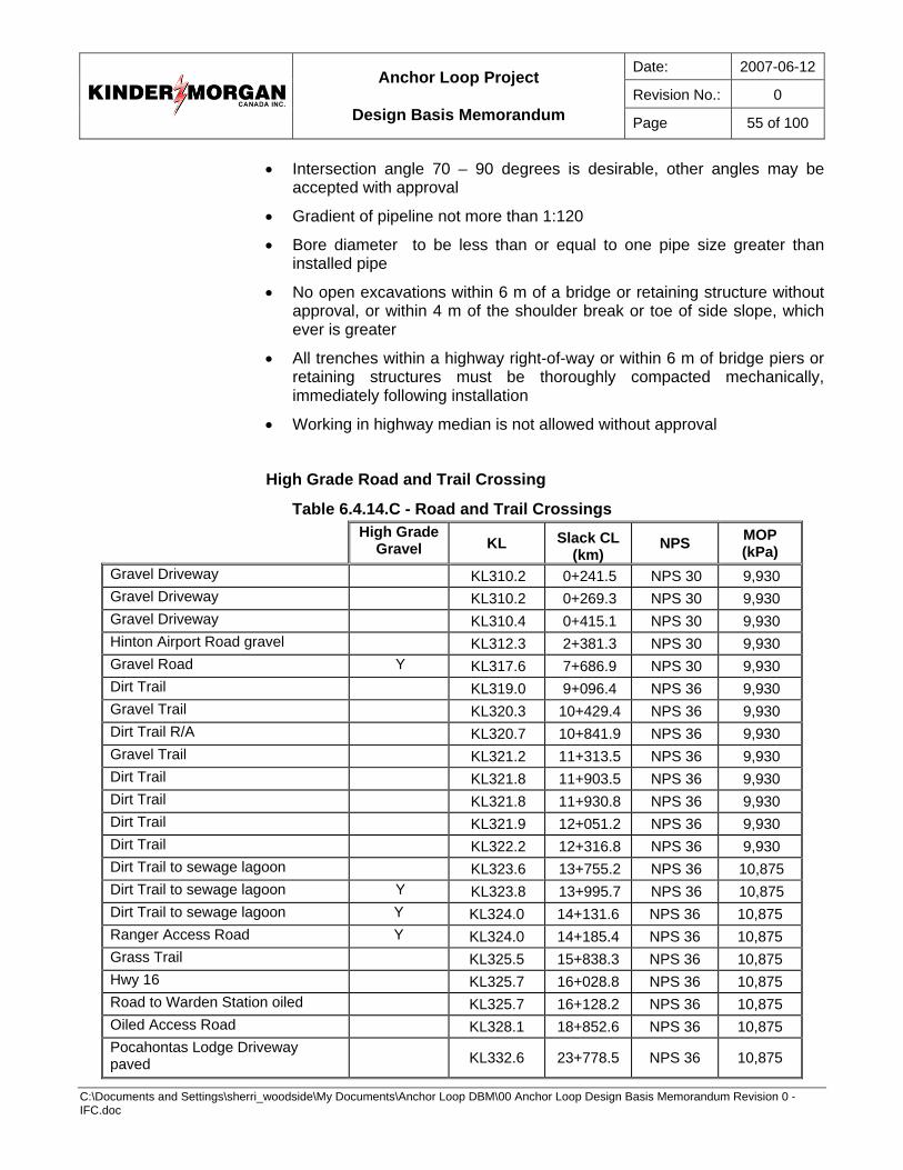
Date: 2007-06-12
Revision No.: 0
Anchor Loop Project
Design Basis Memorandum Page 55 of 100
C:\Documents and Settings\sherri_woodside\My Documents\Anchor Loop DBM\00 Anchor Loop Design Basis Memorandum Revision 0 - IFC.doc
• Intersection angle 70 – 90 degrees is desirable, other angles may be accepted with approval
• Gradient of pipeline not more than 1:120
• Bore diameter to be less than or equal to one pipe size greater than installed pipe
• No open excavations within 6 m of a bridge or retaining structure without approval, or within 4 m of the shoulder break or toe of side slope, which ever is greater
• All trenches within a highway right-of-way or within 6 m of bridge piers or retaining structures must be thoroughly compacted mechanically, immediately following installation
• Working in highway median is not allowed without approval
High Grade Road and Trail Crossing
Table 6.4.14.C - Road and Trail Crossings
High Grade
Gravel KL Slack CL(km)
NPS MOP (kPa)
Gravel Driveway KL310.2 0+241.5 NPS 30 9,930 Gravel Driveway KL310.2 0+269.3 NPS 30 9,930 Gravel Driveway KL310.4 0+415.1 NPS 30 9,930 Hinton Airport Road gravel KL312.3 2+381.3 NPS 30 9,930 Gravel Road Y KL317.6 7+686.9 NPS 30 9,930 Dirt Trail KL319.0 9+096.4 NPS 36 9,930 Gravel Trail KL320.3 10+429.4 NPS 36 9,930 Dirt Trail R/A KL320.7 10+841.9 NPS 36 9,930 Gravel Trail KL321.2 11+313.5 NPS 36 9,930 Dirt Trail KL321.8 11+903.5 NPS 36 9,930 Dirt Trail KL321.8 11+930.8 NPS 36 9,930 Dirt Trail KL321.9 12+051.2 NPS 36 9,930 Dirt Trail KL322.2 12+316.8 NPS 36 9,930 Dirt Trail to sewage lagoon KL323.6 13+755.2 NPS 36 10,875 Dirt Trail to sewage lagoon Y KL323.8 13+995.7 NPS 36 10,875 Dirt Trail to sewage lagoon Y KL324.0 14+131.6 NPS 36 10,875 Ranger Access Road Y KL324.0 14+185.4 NPS 36 10,875 Grass Trail KL325.5 15+838.3 NPS 36 10,875 Hwy 16 KL325.7 16+028.8 NPS 36 10,875 Road to Warden Station oiled KL325.7 16+128.2 NPS 36 10,875 Oiled Access Road KL328.1 18+852.6 NPS 36 10,875 Pocahontas Lodge Driveway paved KL332.6 23+778.5 NPS 36 10,875
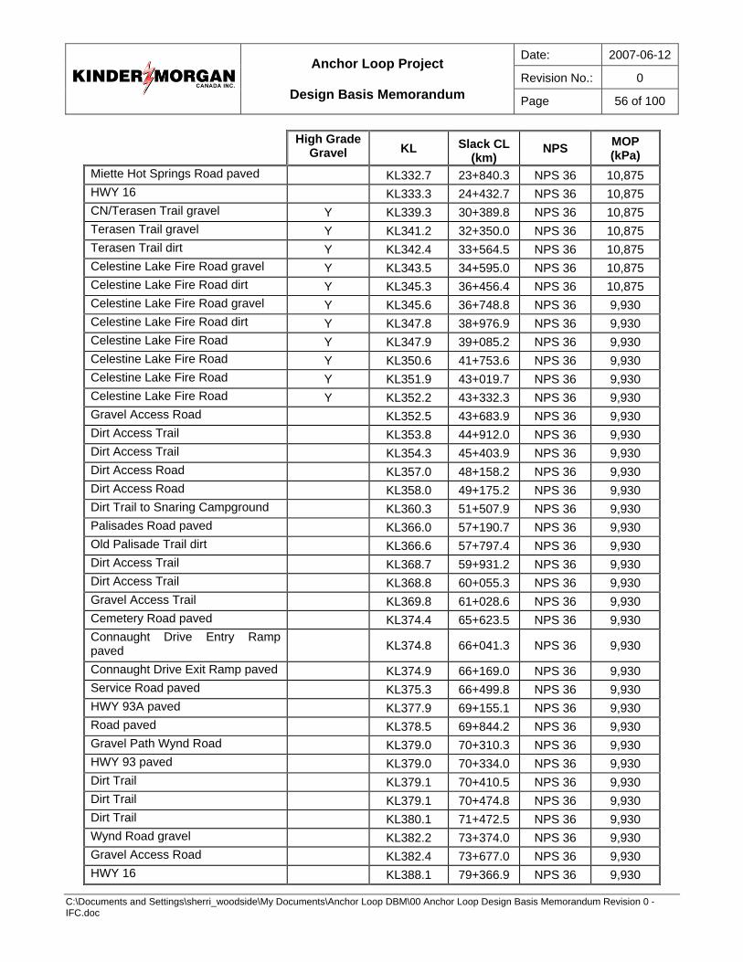
Date: 2007-06-12
Revision No.: 0
Anchor Loop Project
Design Basis Memorandum Page 56 of 100
C:\Documents and Settings\sherri_woodside\My Documents\Anchor Loop DBM\00 Anchor Loop Design Basis Memorandum Revision 0 - IFC.doc
High Grade
Gravel KL Slack CL(km)
NPS MOP (kPa)
Miette Hot Springs Road paved KL332.7 23+840.3 NPS 36 10,875 HWY 16 KL333.3 24+432.7 NPS 36 10,875 CN/Terasen Trail gravel Y KL339.3 30+389.8 NPS 36 10,875 Terasen Trail gravel Y KL341.2 32+350.0 NPS 36 10,875 Terasen Trail dirt Y KL342.4 33+564.5 NPS 36 10,875 Celestine Lake Fire Road gravel Y KL343.5 34+595.0 NPS 36 10,875 Celestine Lake Fire Road dirt Y KL345.3 36+456.4 NPS 36 10,875 Celestine Lake Fire Road gravel Y KL345.6 36+748.8 NPS 36 9,930 Celestine Lake Fire Road dirt Y KL347.8 38+976.9 NPS 36 9,930 Celestine Lake Fire Road Y KL347.9 39+085.2 NPS 36 9,930 Celestine Lake Fire Road Y KL350.6 41+753.6 NPS 36 9,930 Celestine Lake Fire Road Y KL351.9 43+019.7 NPS 36 9,930 Celestine Lake Fire Road Y KL352.2 43+332.3 NPS 36 9,930 Gravel Access Road KL352.5 43+683.9 NPS 36 9,930 Dirt Access Trail KL353.8 44+912.0 NPS 36 9,930 Dirt Access Trail KL354.3 45+403.9 NPS 36 9,930 Dirt Access Road KL357.0 48+158.2 NPS 36 9,930 Dirt Access Road KL358.0 49+175.2 NPS 36 9,930 Dirt Trail to Snaring Campground KL360.3 51+507.9 NPS 36 9,930 Palisades Road paved KL366.0 57+190.7 NPS 36 9,930 Old Palisade Trail dirt KL366.6 57+797.4 NPS 36 9,930 Dirt Access Trail KL368.7 59+931.2 NPS 36 9,930 Dirt Access Trail KL368.8 60+055.3 NPS 36 9,930 Gravel Access Trail KL369.8 61+028.6 NPS 36 9,930 Cemetery Road paved KL374.4 65+623.5 NPS 36 9,930 Connaught Drive Entry Ramp paved KL374.8 66+041.3 NPS 36 9,930
Connaught Drive Exit Ramp paved KL374.9 66+169.0 NPS 36 9,930 Service Road paved KL375.3 66+499.8 NPS 36 9,930 HWY 93A paved KL377.9 69+155.1 NPS 36 9,930 Road paved KL378.5 69+844.2 NPS 36 9,930 Gravel Path Wynd Road KL379.0 70+310.3 NPS 36 9,930 HWY 93 paved KL379.0 70+334.0 NPS 36 9,930 Dirt Trail KL379.1 70+410.5 NPS 36 9,930 Dirt Trail KL379.1 70+474.8 NPS 36 9,930 Dirt Trail KL380.1 71+472.5 NPS 36 9,930 Wynd Road gravel KL382.2 73+374.0 NPS 36 9,930 Gravel Access Road KL382.4 73+677.0 NPS 36 9,930 HWY 16 KL388.1 79+366.9 NPS 36 9,930
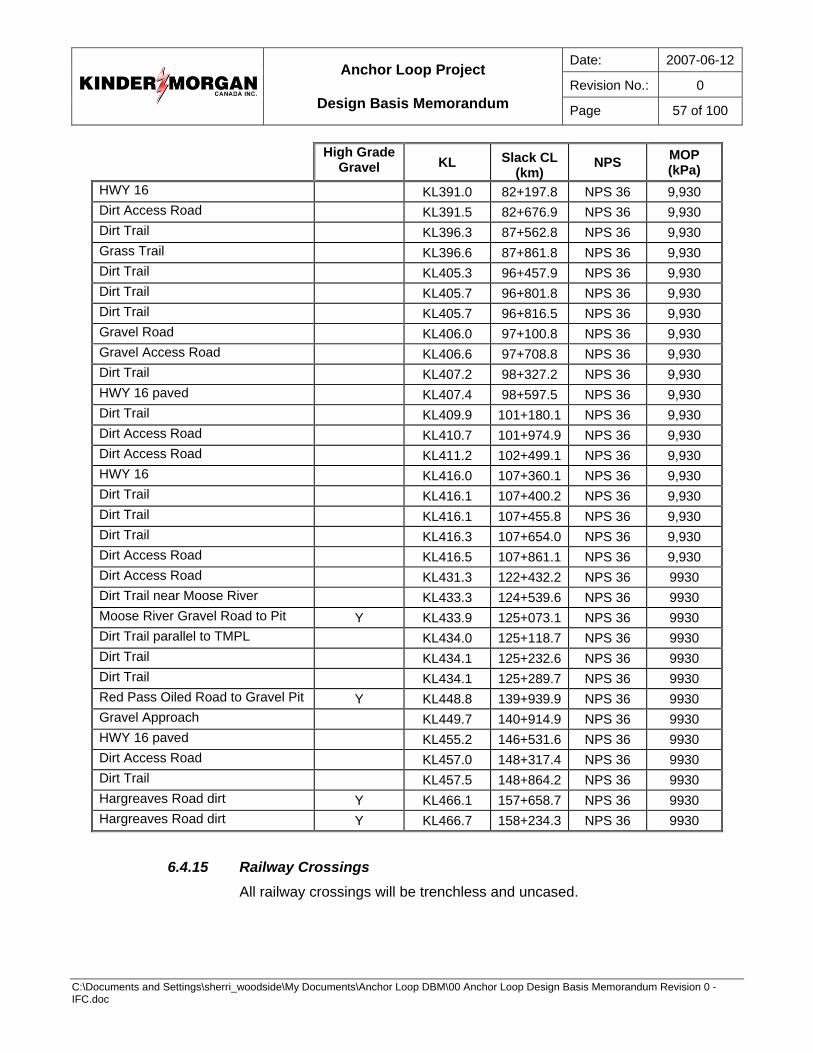
Date: 2007-06-12
Revision No.: 0
Anchor Loop Project
Design Basis Memorandum Page 57 of 100
C:\Documents and Settings\sherri_woodside\My Documents\Anchor Loop DBM\00 Anchor Loop Design Basis Memorandum Revision 0 - IFC.doc
High Grade
Gravel KL Slack CL(km)
NPS MOP (kPa)
HWY 16 KL391.0 82+197.8 NPS 36 9,930 Dirt Access Road KL391.5 82+676.9 NPS 36 9,930 Dirt Trail KL396.3 87+562.8 NPS 36 9,930 Grass Trail KL396.6 87+861.8 NPS 36 9,930 Dirt Trail KL405.3 96+457.9 NPS 36 9,930 Dirt Trail KL405.7 96+801.8 NPS 36 9,930 Dirt Trail KL405.7 96+816.5 NPS 36 9,930 Gravel Road KL406.0 97+100.8 NPS 36 9,930 Gravel Access Road KL406.6 97+708.8 NPS 36 9,930 Dirt Trail KL407.2 98+327.2 NPS 36 9,930 HWY 16 paved KL407.4 98+597.5 NPS 36 9,930 Dirt Trail KL409.9 101+180.1 NPS 36 9,930 Dirt Access Road KL410.7 101+974.9 NPS 36 9,930 Dirt Access Road KL411.2 102+499.1 NPS 36 9,930 HWY 16 KL416.0 107+360.1 NPS 36 9,930 Dirt Trail KL416.1 107+400.2 NPS 36 9,930 Dirt Trail KL416.1 107+455.8 NPS 36 9,930 Dirt Trail KL416.3 107+654.0 NPS 36 9,930 Dirt Access Road KL416.5 107+861.1 NPS 36 9,930 Dirt Access Road KL431.3 122+432.2 NPS 36 9930 Dirt Trail near Moose River KL433.3 124+539.6 NPS 36 9930 Moose River Gravel Road to Pit Y KL433.9 125+073.1 NPS 36 9930 Dirt Trail parallel to TMPL KL434.0 125+118.7 NPS 36 9930 Dirt Trail KL434.1 125+232.6 NPS 36 9930 Dirt Trail KL434.1 125+289.7 NPS 36 9930 Red Pass Oiled Road to Gravel Pit Y KL448.8 139+939.9 NPS 36 9930 Gravel Approach KL449.7 140+914.9 NPS 36 9930 HWY 16 paved KL455.2 146+531.6 NPS 36 9930 Dirt Access Road KL457.0 148+317.4 NPS 36 9930 Dirt Trail KL457.5 148+864.2 NPS 36 9930 Hargreaves Road dirt Y KL466.1 157+658.7 NPS 36 9930 Hargreaves Road dirt Y KL466.7 158+234.3 NPS 36 9930
6.4.15 Railway Crossings All railway crossings will be trenchless and uncased.
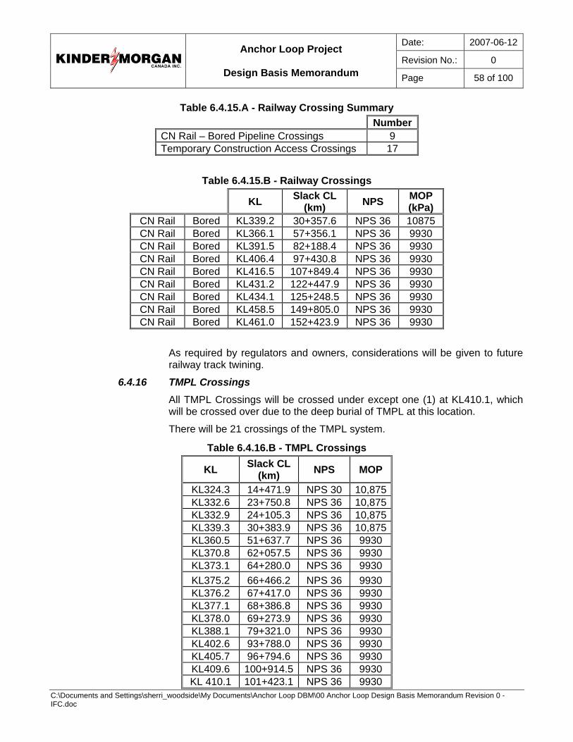
Date: 2007-06-12
Revision No.: 0
Anchor Loop Project
Design Basis Memorandum Page 58 of 100
C:\Documents and Settings\sherri_woodside\My Documents\Anchor Loop DBM\00 Anchor Loop Design Basis Memorandum Revision 0 - IFC.doc
Table 6.4.15.A - Railway Crossing Summary Number CN Rail – Bored Pipeline Crossings 9 Temporary Construction Access Crossings 17
Table 6.4.15.B - Railway Crossings
KL Slack CL (km) NPS MOP
(kPa) CN Rail Bored KL339.2 30+357.6 NPS 36 10875 CN Rail Bored KL366.1 57+356.1 NPS 36 9930 CN Rail Bored KL391.5 82+188.4 NPS 36 9930 CN Rail Bored KL406.4 97+430.8 NPS 36 9930 CN Rail Bored KL416.5 107+849.4 NPS 36 9930 CN Rail Bored KL431.2 122+447.9 NPS 36 9930 CN Rail Bored KL434.1 125+248.5 NPS 36 9930 CN Rail Bored KL458.5 149+805.0 NPS 36 9930 CN Rail Bored KL461.0 152+423.9 NPS 36 9930
As required by regulators and owners, considerations will be given to future railway track twining.
6.4.16 TMPL Crossings All TMPL Crossings will be crossed under except one (1) at KL410.1, which will be crossed over due to the deep burial of TMPL at this location.
There will be 21 crossings of the TMPL system.
Table 6.4.16.B - TMPL Crossings
KL Slack CL(km) NPS MOP
KL324.3 14+471.9 NPS 30 10,875KL332.6 23+750.8 NPS 36 10,875KL332.9 24+105.3 NPS 36 10,875KL339.3 30+383.9 NPS 36 10,875KL360.5 51+637.7 NPS 36 9930 KL370.8 62+057.5 NPS 36 9930 KL373.1 64+280.0 NPS 36 9930 KL375.2 66+466.2 NPS 36 9930 KL376.2 67+417.0 NPS 36 9930 KL377.1 68+386.8 NPS 36 9930 KL378.0 69+273.9 NPS 36 9930 KL388.1 79+321.0 NPS 36 9930 KL402.6 93+788.0 NPS 36 9930 KL405.7 96+794.6 NPS 36 9930 KL409.6 100+914.5 NPS 36 9930 KL 410.1 101+423.1 NPS 36 9930
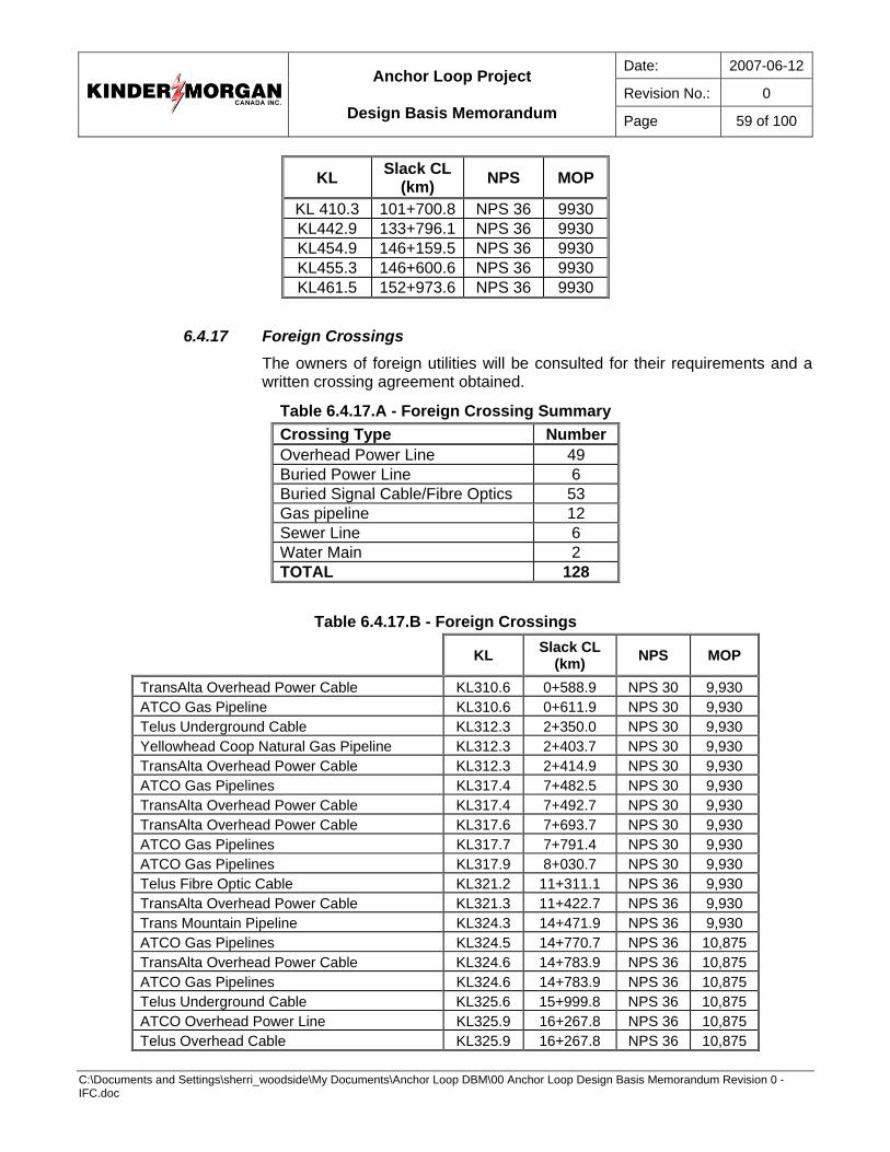
Date: 2007-06-12
Revision No.: 0
Anchor Loop Project
Design Basis Memorandum Page 59 of 100
C:\Documents and Settings\sherri_woodside\My Documents\Anchor Loop DBM\00 Anchor Loop Design Basis Memorandum Revision 0 - IFC.doc
KL Slack CL(km) NPS MOP
KL 410.3 101+700.8 NPS 36 9930 KL442.9 133+796.1 NPS 36 9930 KL454.9 146+159.5 NPS 36 9930 KL455.3 146+600.6 NPS 36 9930 KL461.5 152+973.6 NPS 36 9930
6.4.17 Foreign Crossings The owners of foreign utilities will be consulted for their requirements and a written crossing agreement obtained.
Table 6.4.17.A - Foreign Crossing Summary Crossing Type Number Overhead Power Line 49 Buried Power Line 6 Buried Signal Cable/Fibre Optics 53 Gas pipeline 12 Sewer Line 6 Water Main 2 TOTAL 128
Table 6.4.17.B - Foreign Crossings
KL Slack CL (km) NPS MOP
TransAlta Overhead Power Cable KL310.6 0+588.9 NPS 30 9,930 ATCO Gas Pipeline KL310.6 0+611.9 NPS 30 9,930 Telus Underground Cable KL312.3 2+350.0 NPS 30 9,930 Yellowhead Coop Natural Gas Pipeline KL312.3 2+403.7 NPS 30 9,930 TransAlta Overhead Power Cable KL312.3 2+414.9 NPS 30 9,930 ATCO Gas Pipelines KL317.4 7+482.5 NPS 30 9,930 TransAlta Overhead Power Cable KL317.4 7+492.7 NPS 30 9,930 TransAlta Overhead Power Cable KL317.6 7+693.7 NPS 30 9,930 ATCO Gas Pipelines KL317.7 7+791.4 NPS 30 9,930 ATCO Gas Pipelines KL317.9 8+030.7 NPS 30 9,930 Telus Fibre Optic Cable KL321.2 11+311.1 NPS 36 9,930 TransAlta Overhead Power Cable KL321.3 11+422.7 NPS 36 9,930 Trans Mountain Pipeline KL324.3 14+471.9 NPS 36 9,930 ATCO Gas Pipelines KL324.5 14+770.7 NPS 36 10,875 TransAlta Overhead Power Cable KL324.6 14+783.9 NPS 36 10,875 ATCO Gas Pipelines KL324.6 14+783.9 NPS 36 10,875 Telus Underground Cable KL325.6 15+999.8 NPS 36 10,875 ATCO Overhead Power Line KL325.9 16+267.8 NPS 36 10,875 Telus Overhead Cable KL325.9 16+267.8 NPS 36 10,875
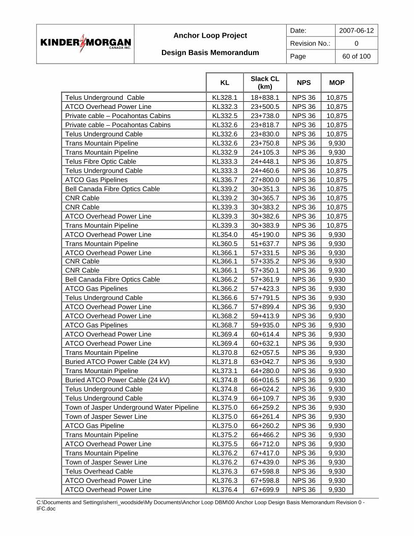
Date: 2007-06-12
Revision No.: 0
Anchor Loop Project
Design Basis Memorandum Page 60 of 100
C:\Documents and Settings\sherri_woodside\My Documents\Anchor Loop DBM\00 Anchor Loop Design Basis Memorandum Revision 0 - IFC.doc
KL Slack CL (km) NPS MOP
Telus Underground Cable KL328.1 18+838.1 NPS 36 10,875 ATCO Overhead Power Line KL332.3 23+500.5 NPS 36 10,875 Private cable – Pocahontas Cabins KL332.5 23+738.0 NPS 36 10,875 Private cable – Pocahontas Cabins KL332.6 23+818.7 NPS 36 10,875 Telus Underground Cable KL332.6 23+830.0 NPS 36 10,875 Trans Mountain Pipeline KL332.6 23+750.8 NPS 36 9,930 Trans Mountain Pipeline KL332.9 24+105.3 NPS 36 9,930 Telus Fibre Optic Cable KL333.3 24+448.1 NPS 36 10,875 Telus Underground Cable KL333.3 24+460.6 NPS 36 10,875 ATCO Gas Pipelines KL336.7 27+800.0 NPS 36 10,875 Bell Canada Fibre Optics Cable KL339.2 30+351.3 NPS 36 10,875 CNR Cable KL339.2 30+365.7 NPS 36 10,875 CNR Cable KL339.3 30+383.2 NPS 36 10,875 ATCO Overhead Power Line KL339.3 30+382.6 NPS 36 10,875 Trans Mountain Pipeline KL339.3 30+383.9 NPS 36 10,875 ATCO Overhead Power Line KL354.0 45+190.0 NPS 36 9,930 Trans Mountain Pipeline KL360.5 51+637.7 NPS 36 9,930 ATCO Overhead Power Line KL366.1 57+331.5 NPS 36 9,930 CNR Cable KL366.1 57+335.2 NPS 36 9,930 CNR Cable KL366.1 57+350.1 NPS 36 9,930 Bell Canada Fibre Optics Cable KL366.2 57+361.9 NPS 36 9,930 ATCO Gas Pipelines KL366.2 57+423.3 NPS 36 9,930 Telus Underground Cable KL366.6 57+791.5 NPS 36 9,930 ATCO Overhead Power Line KL366.7 57+899.4 NPS 36 9,930 ATCO Overhead Power Line KL368.2 59+413.9 NPS 36 9,930 ATCO Gas Pipelines KL368.7 59+935.0 NPS 36 9,930 ATCO Overhead Power Line KL369.4 60+614.4 NPS 36 9,930 ATCO Overhead Power Line KL369.4 60+632.1 NPS 36 9,930 Trans Mountain Pipeline KL370.8 62+057.5 NPS 36 9,930 Buried ATCO Power Cable (24 kV) KL371.8 63+042.7 NPS 36 9,930 Trans Mountain Pipeline KL373.1 64+280.0 NPS 36 9,930 Buried ATCO Power Cable (24 kV) KL374.8 66+016.5 NPS 36 9,930 Telus Underground Cable KL374.8 66+024.2 NPS 36 9,930 Telus Underground Cable KL374.9 66+109.7 NPS 36 9,930 Town of Jasper Underground Water Pipeline KL375.0 66+259.2 NPS 36 9,930 Town of Jasper Sewer Line KL375.0 66+261.4 NPS 36 9,930 ATCO Gas Pipeline KL375.0 66+260.2 NPS 36 9,930 Trans Mountain Pipeline KL375.2 66+466.2 NPS 36 9,930 ATCO Overhead Power Line KL375.5 66+712.0 NPS 36 9,930 Trans Mountain Pipeline KL376.2 67+417.0 NPS 36 9,930 Town of Jasper Sewer Line KL376.2 67+439.0 NPS 36 9,930 Telus Overhead Cable KL376.3 67+598.8 NPS 36 9,930 ATCO Overhead Power Line KL376.3 67+598.8 NPS 36 9,930 ATCO Overhead Power Line KL376.4 67+699.9 NPS 36 9,930
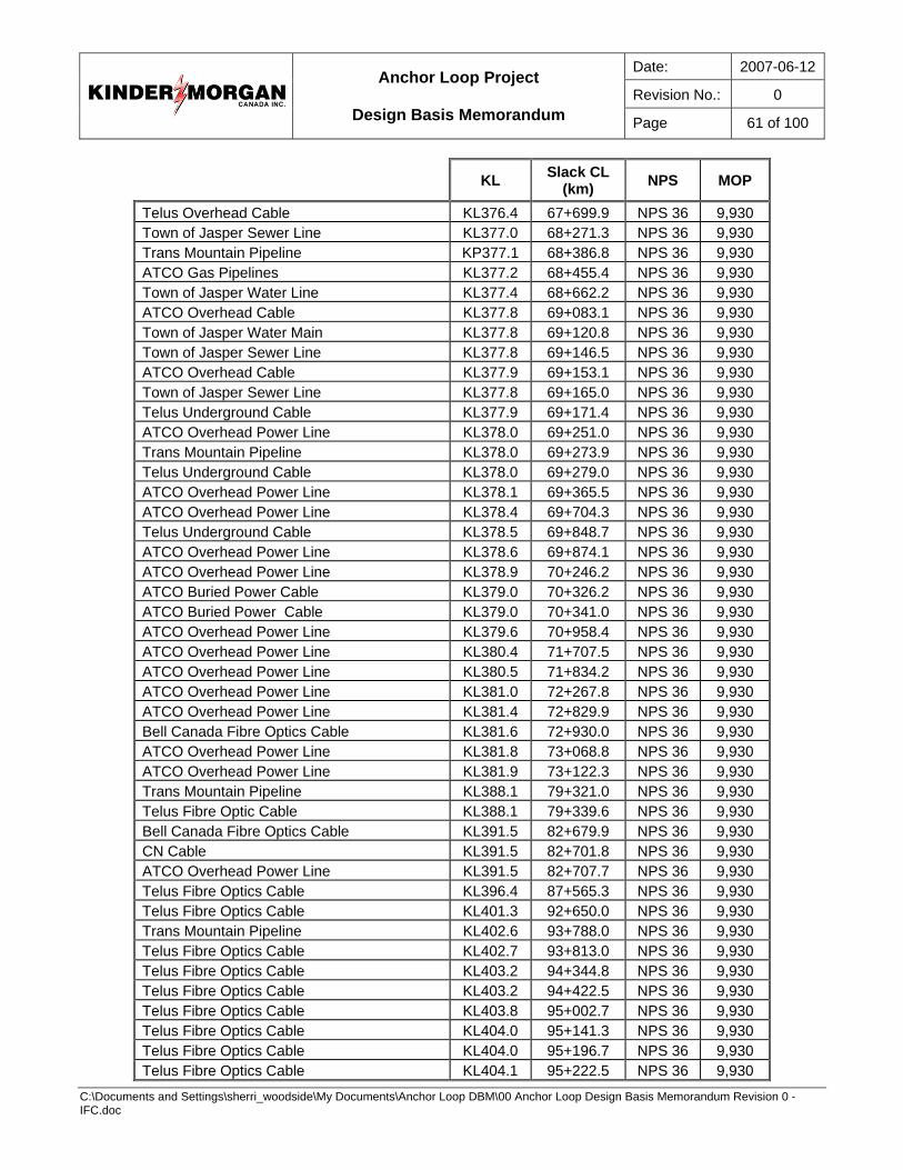
Date: 2007-06-12
Revision No.: 0
Anchor Loop Project
Design Basis Memorandum Page 61 of 100
C:\Documents and Settings\sherri_woodside\My Documents\Anchor Loop DBM\00 Anchor Loop Design Basis Memorandum Revision 0 - IFC.doc
KL Slack CL (km) NPS MOP
Telus Overhead Cable KL376.4 67+699.9 NPS 36 9,930 Town of Jasper Sewer Line KL377.0 68+271.3 NPS 36 9,930 Trans Mountain Pipeline KP377.1 68+386.8 NPS 36 9,930 ATCO Gas Pipelines KL377.2 68+455.4 NPS 36 9,930 Town of Jasper Water Line KL377.4 68+662.2 NPS 36 9,930 ATCO Overhead Cable KL377.8 69+083.1 NPS 36 9,930 Town of Jasper Water Main KL377.8 69+120.8 NPS 36 9,930 Town of Jasper Sewer Line KL377.8 69+146.5 NPS 36 9,930 ATCO Overhead Cable KL377.9 69+153.1 NPS 36 9,930 Town of Jasper Sewer Line KL377.8 69+165.0 NPS 36 9,930 Telus Underground Cable KL377.9 69+171.4 NPS 36 9,930 ATCO Overhead Power Line KL378.0 69+251.0 NPS 36 9,930 Trans Mountain Pipeline KL378.0 69+273.9 NPS 36 9,930 Telus Underground Cable KL378.0 69+279.0 NPS 36 9,930 ATCO Overhead Power Line KL378.1 69+365.5 NPS 36 9,930 ATCO Overhead Power Line KL378.4 69+704.3 NPS 36 9,930 Telus Underground Cable KL378.5 69+848.7 NPS 36 9,930 ATCO Overhead Power Line KL378.6 69+874.1 NPS 36 9,930 ATCO Overhead Power Line KL378.9 70+246.2 NPS 36 9,930 ATCO Buried Power Cable KL379.0 70+326.2 NPS 36 9,930 ATCO Buried Power Cable KL379.0 70+341.0 NPS 36 9,930 ATCO Overhead Power Line KL379.6 70+958.4 NPS 36 9,930 ATCO Overhead Power Line KL380.4 71+707.5 NPS 36 9,930 ATCO Overhead Power Line KL380.5 71+834.2 NPS 36 9,930 ATCO Overhead Power Line KL381.0 72+267.8 NPS 36 9,930 ATCO Overhead Power Line KL381.4 72+829.9 NPS 36 9,930 Bell Canada Fibre Optics Cable KL381.6 72+930.0 NPS 36 9,930 ATCO Overhead Power Line KL381.8 73+068.8 NPS 36 9,930 ATCO Overhead Power Line KL381.9 73+122.3 NPS 36 9,930 Trans Mountain Pipeline KL388.1 79+321.0 NPS 36 9,930 Telus Fibre Optic Cable KL388.1 79+339.6 NPS 36 9,930 Bell Canada Fibre Optics Cable KL391.5 82+679.9 NPS 36 9,930 CN Cable KL391.5 82+701.8 NPS 36 9,930 ATCO Overhead Power Line KL391.5 82+707.7 NPS 36 9,930 Telus Fibre Optics Cable KL396.4 87+565.3 NPS 36 9,930 Telus Fibre Optics Cable KL401.3 92+650.0 NPS 36 9,930 Trans Mountain Pipeline KL402.6 93+788.0 NPS 36 9,930 Telus Fibre Optics Cable KL402.7 93+813.0 NPS 36 9,930 Telus Fibre Optics Cable KL403.2 94+344.8 NPS 36 9,930 Telus Fibre Optics Cable KL403.2 94+422.5 NPS 36 9,930 Telus Fibre Optics Cable KL403.8 95+002.7 NPS 36 9,930 Telus Fibre Optics Cable KL404.0 95+141.3 NPS 36 9,930 Telus Fibre Optics Cable KL404.0 95+196.7 NPS 36 9,930 Telus Fibre Optics Cable KL404.1 95+222.5 NPS 36 9,930
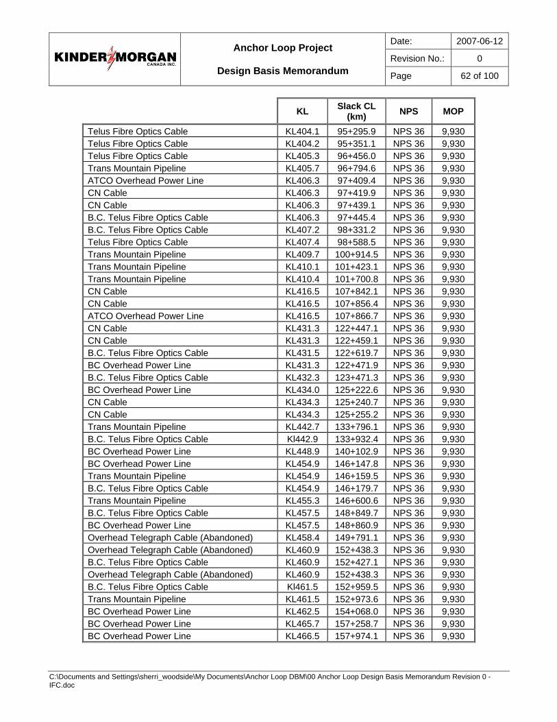
Date: 2007-06-12
Revision No.: 0
Anchor Loop Project
Design Basis Memorandum Page 62 of 100
C:\Documents and Settings\sherri_woodside\My Documents\Anchor Loop DBM\00 Anchor Loop Design Basis Memorandum Revision 0 - IFC.doc
KL Slack CL (km) NPS MOP
Telus Fibre Optics Cable KL404.1 95+295.9 NPS 36 9,930 Telus Fibre Optics Cable KL404.2 95+351.1 NPS 36 9,930 Telus Fibre Optics Cable KL405.3 96+456.0 NPS 36 9,930 Trans Mountain Pipeline KL405.7 96+794.6 NPS 36 9,930 ATCO Overhead Power Line KL406.3 97+409.4 NPS 36 9,930 CN Cable KL406.3 97+419.9 NPS 36 9,930 CN Cable KL406.3 97+439.1 NPS 36 9,930 B.C. Telus Fibre Optics Cable KL406.3 97+445.4 NPS 36 9,930 B.C. Telus Fibre Optics Cable KL407.2 98+331.2 NPS 36 9,930 Telus Fibre Optics Cable KL407.4 98+588.5 NPS 36 9,930 Trans Mountain Pipeline KL409.7 100+914.5 NPS 36 9,930 Trans Mountain Pipeline KL410.1 101+423.1 NPS 36 9,930 Trans Mountain Pipeline KL410.4 101+700.8 NPS 36 9,930 CN Cable KL416.5 107+842.1 NPS 36 9,930 CN Cable KL416.5 107+856.4 NPS 36 9,930 ATCO Overhead Power Line KL416.5 107+866.7 NPS 36 9,930 CN Cable KL431.3 122+447.1 NPS 36 9,930 CN Cable KL431.3 122+459.1 NPS 36 9,930 B.C. Telus Fibre Optics Cable KL431.5 122+619.7 NPS 36 9,930 BC Overhead Power Line KL431.3 122+471.9 NPS 36 9,930 B.C. Telus Fibre Optics Cable KL432.3 123+471.3 NPS 36 9,930 BC Overhead Power Line KL434.0 125+222.6 NPS 36 9,930 CN Cable KL434.3 125+240.7 NPS 36 9,930 CN Cable KL434.3 125+255.2 NPS 36 9,930 Trans Mountain Pipeline KL442.7 133+796.1 NPS 36 9,930 B.C. Telus Fibre Optics Cable Kl442.9 133+932.4 NPS 36 9,930 BC Overhead Power Line KL448.9 140+102.9 NPS 36 9,930 BC Overhead Power Line KL454.9 146+147.8 NPS 36 9,930 Trans Mountain Pipeline KL454.9 146+159.5 NPS 36 9,930 B.C. Telus Fibre Optics Cable KL454.9 146+179.7 NPS 36 9,930 Trans Mountain Pipeline KL455.3 146+600.6 NPS 36 9,930 B.C. Telus Fibre Optics Cable KL457.5 148+849.7 NPS 36 9,930 BC Overhead Power Line KL457.5 148+860.9 NPS 36 9,930 Overhead Telegraph Cable (Abandoned) KL458.4 149+791.1 NPS 36 9,930 Overhead Telegraph Cable (Abandoned) KL460.9 152+438.3 NPS 36 9,930 B.C. Telus Fibre Optics Cable KL460.9 152+427.1 NPS 36 9,930 Overhead Telegraph Cable (Abandoned) KL460.9 152+438.3 NPS 36 9,930 B.C. Telus Fibre Optics Cable Kl461.5 152+959.5 NPS 36 9,930 Trans Mountain Pipeline KL461.5 152+973.6 NPS 36 9,930 BC Overhead Power Line KL462.5 154+068.0 NPS 36 9,930 BC Overhead Power Line KL465.7 157+258.7 NPS 36 9,930 BC Overhead Power Line KL466.5 157+974.1 NPS 36 9,930
Date: 2007-06-12
Revision No.: 0
Anchor Loop Project
Design Basis Memorandum Page 63 of 100
C:\Documents and Settings\sherri_woodside\My Documents\Anchor Loop DBM\00 Anchor Loop Design Basis Memorandum Revision 0 - IFC.doc
Buried Facilities Typically, foreign crossings will be crossed under.
Power lines The owners of power lines will be consulted to determine voltages, potential hazards, and if temporary raising of the line is required. Written crossing agreements will be acquired.
Cased Crossings It is intended not to use cased crossings. However, for highway crossings that cannot be conventionally bored, extra large diameter hammered casing may be used with the pipeline well separated from the casing pipe and no end seal installed.
Cased crossings would be sealed and completely filled with a material such as gel or wax. All cased crossing designs will be reviewed by Cathodic Protection designers.
6.4.18 Parallel Power Line Relocations Four (4) sections of power lines require relocation to eliminate the construction hazard and to provide additional workspace for construction. Power line relocations have been requested of the utility service providers at:
• Sleepy Hollow Road at Intersection of Hwy 93 (KL 379)
• Wynd Road (KL 379-KL 382.5)
• Sucker Creek (KL 372-KL 373), and
• KL 461-KL 466.
Power lines will be moved by utility owner.
6.4.19 Parallel Fibre Optic Cable Relocation Arrangements will be made to remove the Telus Fibre Optic Cable from KL 403 to KL 405 to facilitate construction. During construction, signals will be temporarily rerouted through a nearby 360 Networks cable. A replacement fibre optics line is to be laid into the pipeline ditch through the interval between appropriate cable splice points. Due to potential damages from pipeline construction, the section of fibre optics cable between about KL 396 and KL 405 shall be subsequently tested for continuity and suitably repaired as may be required.
6.4.20 Rock Rock Coatings Coatings, such as Rock Jacket (flexible concrete coating), wood lagging, and dual powder abrasion coatings, will be selected to provide protection in rocky areas.
Rock Shield Rock shield will be applied in the field where backfill materials contain sharp rock, which may damage the pipe coating.
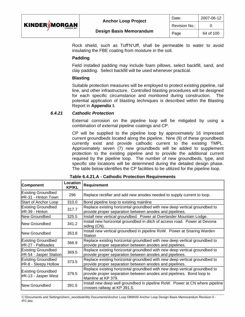
Date: 2007-06-12
Revision No.: 0
Anchor Loop Project
Design Basis Memorandum Page 64 of 100
C:\Documents and Settings\sherri_woodside\My Documents\Anchor Loop DBM\00 Anchor Loop Design Basis Memorandum Revision 0 - IFC.doc
Rock shield, such as Tuff’N’Uff, shall be permeable to water to avoid insulating the FBE coating from moisture in the soil.
Padding Field installed padding may include foam pillows, select backfill, sand, and clay padding. Select backfill will be used whenever practical.
Blasting Suitable protection measures will be employed to protect existing pipeline, rail line, and other infrastructure. Controlled blasting procedures will be designed for each specific circumstance and monitored during construction. The potential application of blasting techniques is described within the Blasting Report in Appendix I.
6.4.21 Cathodic Protection External corrosion on the pipeline loop will be mitigated by using a combination of external pipeline coatings and CP.
CP will be supplied to the pipeline loop by approximately 16 impressed current groundbeds located along the pipeline. Nine (9) of these groundbeds currently exist and provide cathodic current to the existing TMPL. Approximately seven (7) new groundbeds will be added to supplement protection to the existing pipeline and to provide the additional current required by the pipeline loop. The number of new groundbeds, type, and specific site locations will be determined during the detailed design phase. The table below identifies the CP facilities to be utilized for the pipeline loop.
Table 6.4.21.A - Cathodic Protection Requirements
Component Location KP/KL Requirement
Existing Groundbed #R-31 - Hinton Town 296 Replace rectifier and add new anodes needed to supply current to loop.
Start of Anchor Loop 310.0 Bond pipeline loop to existing mainline Existing Groundbed #R-39 - Hinton 317.7 Replace existing horizontal groundbed with new deep vertical groundbed to
provide proper separation between anodes and pipelines. New Groundbed 325.5 Install new vertical groundbed. Power at Overlander Mountain Lodge.
New Groundbed 341.2 Install new horizontal groundbed in ditch of access road. Power at Devona siding (CN).
New Groundbed 353.8 Install new vertical groundbed in pipeline RoW. Power at Snaring Warden Station
Existing Groundbed #R-27 - Pallisades 366.9 Replace existing horizontal groundbed with new deep vertical groundbed to
provide proper separation between anodes and pipelines. Existing Groundbed #R-54 - Jasper Station 369.5 Replace existing horizontal groundbed with new deep vertical groundbed to
provide proper separation between anodes and pipelines. Existing Groundbed #R-8 - Sleepy Hollow 373.5 Replace existing horizontal groundbed with new deep vertical groundbed to
provide proper separation between anodes and pipelines.
Existing Groundbed #R-13 - Jasper West 379.5
Replace existing horizontal groundbed with new deep vertical groundbed to provide proper separation between anodes and pipelines. Bond loop to Mainline at KP 379.
New Groundbed 391.5 Install new deep well groundbed in pipeline RoW. Power at CN where pipeline crosses railway at KP 391.5.

Date: 2007-06-12
Revision No.: 0
Anchor Loop Project
Design Basis Memorandum Page 65 of 100
C:\Documents and Settings\sherri_woodside\My Documents\Anchor Loop DBM\00 Anchor Loop Design Basis Memorandum Revision 0 - IFC.doc
Component Location KP/KL Requirement
Existing Groundbed #R-44 - Yellowhead 406.6 Replace existing horizontal groundbed with new deep vertical groundbed to
provide proper separation between anodes and pipelines.
New Groundbed 415.9 Install new deep well groundbed in pipeline RoW. Power at CN where pipeline crosses railway at KL 416.5.
New Groundbed 433.1 Install new deep well groundbed in pipeline RoW. Power at CN where pipeline crosses railway at KL 434.1.
Existing Groundbed #R-51 Red Pass 449.8 Existing groundbed to supply current for loop. Bond new and old pipelines
together at about KP 448.8.
New Groundbed 461.0 Install new horizontal groundbed along ditch of access trail perpendicular to TM (north side of Fraser River) Power at adjacent power line.
End of Anchor Loop Hargreaves 468.0 Bond pipeline loop to existing mainline.
Existing Groundbed #R-37 Rearguard 477.0 Replace rectifier to supply additional current needed by the Project.
The CP system will be common to both the existing pipeline and the pipeline loop as it is the most economic approach and avoid potential interference effects that could result if cathodic protection was applied separately to TMPL and the loop.
The pipeline loop will be connected to the existing CP system by:
• the installation of bond cables between existing and new pipelines at each end of the pipeline loop and at other discrete points as required;
• the attachment, if possible, of rectifier negative cables to the pipeline loop at all grounded locations;
• changes and additions will be made to some of the existing groundbeds due to;
• the increased current demands of the pipeline loop;
• the need to provide sufficient separation between anodes and pipelines; and
• the life expectancy of existing anodes.
Test stations will be attached to the pipeline loop at locations approximating those on the existing TMPL, as well as other locations as needed. Test stations will have a maximum spacing of 5 km.
6.4.22 Buoyancy Control The Anchor Loop traverses sections of wet, and / or muskeg-type terrain requiring some form of buoyancy control. Screw anchors shall be considered if there are favourable anchoring conditions and sufficiently long intervals to be economically viable. Care will be taken to ensure they will have sufficient hold down capacity for voided pipe.
Where the muskeg is shallower than the depth of the ditch, set-on or saddle weights may be used when the weight rests on competent mineral soil.
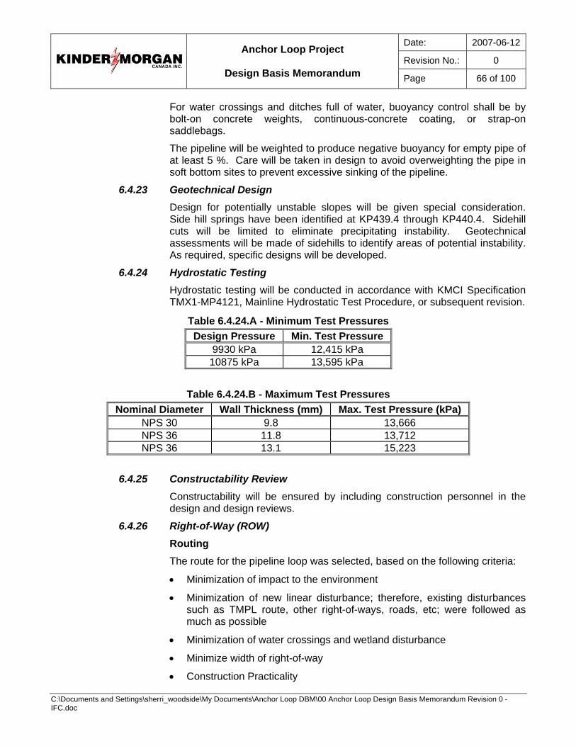
Date: 2007-06-12
Revision No.: 0
Anchor Loop Project
Design Basis Memorandum Page 66 of 100
C:\Documents and Settings\sherri_woodside\My Documents\Anchor Loop DBM\00 Anchor Loop Design Basis Memorandum Revision 0 - IFC.doc
For water crossings and ditches full of water, buoyancy control shall be by bolt-on concrete weights, continuous-concrete coating, or strap-on saddlebags.
The pipeline will be weighted to produce negative buoyancy for empty pipe of at least 5 %. Care will be taken in design to avoid overweighting the pipe in soft bottom sites to prevent excessive sinking of the pipeline.
6.4.23 Geotechnical Design Design for potentially unstable slopes will be given special consideration. Side hill springs have been identified at KP439.4 through KP440.4. Sidehill cuts will be limited to eliminate precipitating instability. Geotechnical assessments will be made of sidehills to identify areas of potential instability. As required, specific designs will be developed.
6.4.24 Hydrostatic Testing Hydrostatic testing will be conducted in accordance with KMCI Specification TMX1-MP4121, Mainline Hydrostatic Test Procedure, or subsequent revision.
Table 6.4.24.A - Minimum Test Pressures Design Pressure Min. Test Pressure
9930 kPa 12,415 kPa 10875 kPa 13,595 kPa
Table 6.4.24.B - Maximum Test Pressures Nominal Diameter Wall Thickness (mm) Max. Test Pressure (kPa)
NPS 30 9.8 13,666 NPS 36 11.8 13,712 NPS 36 13.1 15,223
6.4.25 Constructability Review Constructability will be ensured by including construction personnel in the design and design reviews.
6.4.26 Right-of-Way (ROW) Routing The route for the pipeline loop was selected, based on the following criteria:
• Minimization of impact to the environment
• Minimization of new linear disturbance; therefore, existing disturbances such as TMPL route, other right-of-ways, roads, etc; were followed as much as possible
• Minimization of water crossings and wetland disturbance
• Minimize width of right-of-way
• Construction Practicality
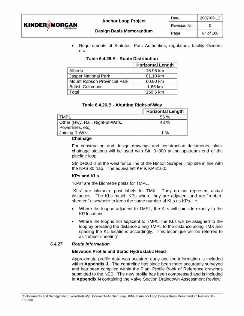
Date: 2007-06-12
Revision No.: 0
Anchor Loop Project
Design Basis Memorandum Page 67 of 100
C:\Documents and Settings\sherri_woodside\My Documents\Anchor Loop DBM\00 Anchor Loop Design Basis Memorandum Revision 0 - IFC.doc
• Requirements of Statutes, Park Authorities, regulators, facility Owners, etc
Table 6.4.26.A - Route Distribution Horizontal Length Alberta 15.95 km Jasper National Park 81.10 km Mount Robson Provincial Park 60.90 km British Columbia 1.65 km Total 159.6 km
Table 6.4.26.B - Abutting Right-of-Way
Horizontal Length TMPL 56 % Other (Hwy, Rail, Right-of-Wats, Powerlines, etc)
43 %
Joining RoW’s 1 % Chainage For construction and design drawings and construction documents, slack chainage stations will be used with Stn 0+000 at the upstream end of the pipeline loop.
Stn 0+000 is at the west fence line of the Hinton Scraper Trap site in line with the NPS 30 trap. The equivalent KP is KP 310.0.
KPs and KLs “KPs” are the kilometre posts for TMPL.
“KLs” are kilometre post labels for TMX. They do not represent actual distances. The KLs match KPs where they are adjacent and are “rubber-sheeted” elsewhere to keep the same number of KLs as KPs, i.e.:
• Where the loop is adjacent to TMPL, the KLs will coincide exactly to the KP locations.
• Where the loop is not adjacent to TMPL, the KLs will be assigned to the loop by prorating the distance along TMPL to the distance along TMX and spacing the KL locations accordingly. This technique will be referred to as “rubber sheeting”.
6.4.27 Route Information Elevation Profile and Static Hydrostatic Head Approximate profile data was acquired early and the information is included within Appendix J. The centreline has since been more accurately surveyed and has been compiled within the Plan, Profile Book of Reference drawings submitted to the NEB. The new profile has been compressed and is included in Appendix N containing the Valve Section Draindown Assessment Review.
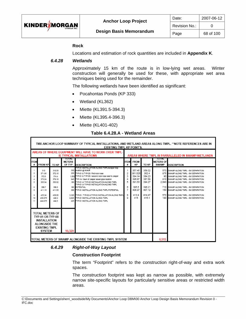
Date: 2007-06-12
Revision No.: 0
Anchor Loop Project
Design Basis Memorandum Page 68 of 100
C:\Documents and Settings\sherri_woodside\My Documents\Anchor Loop DBM\00 Anchor Loop Design Basis Memorandum Revision 0 - IFC.doc
Rock Locations and estimation of rock quantities are included in Appendix K.
6.4.28 Wetlands Approximately 15 km of the route is in low-lying wet areas. Winter construction will generally be used for these, with appropriate wet area techniques being used for the remainder.
The following wetlands have been identified as significant:
• Pocahontas Ponds (KP 333)
• Wetland (KL362)
• Miette (KL391.5-394.3)
• Miette (KL395.4-396.3)
• Miette (KL401-402)
Table 6.4.28.A - Wetland Areas
6.4.29 Right-of-Way Layout
Construction Footprint The term “Footprint” refers to the construction right-of-way and extra work spaces.
The construction footprint was kept as narrow as possible, with extremely narrow site-specific layouts for particularly sensitive areas or restricted width areas.

Date: 2007-06-12
Revision No.: 0
Anchor Loop Project
Design Basis Memorandum Page 69 of 100
C:\Documents and Settings\sherri_woodside\My Documents\Anchor Loop DBM\00 Anchor Loop Design Basis Memorandum Revision 0 - IFC.doc
Table 6.4.29.A - Construction Footprint Typical Footprint Width Alberta 35 m Jasper National Park 25 m Mount Robson Provincial Park 30 m British Columbia 33 m
Jasper National Park Within JNP, legal boundaries are generally not available for roads, rails, and other features, outside of the Municipality of Jasper. Much of the routing is, therefore, based on distances from rail tracks, TMPL, edges of pavement, and other physical features.
In JNP, the existing TMPL right-of-way is 6.1 m (20 feet) wide, within which the location of the pipe is variable and may not lie entirely within the legal right-of-way. The legal boundary for TMPL has been reconstructed based on the 1953 legal survey and the TMPL ILI location has been overlain.
It is expected that the existing easement area within Jasper will not be increased and the lands will have to be split into two (2) separate right-of-ways where the loop and TMPL deviate. Wherever the loop and TMPL lay adjacent to one another, they will be generally separated 4.5 m, centre-to-centre, in order to reposition the 6.1 m right-of-way around both pipelines. Elsewhere, the project follows other existing right-of-ways / easements (legal or otherwise), roads or disturbances.
Mount Robson Provincial Park In MRPP, the existing TMPL right-of-way is 18.28 m (60 ft) wide, within which the location of the pipe is variable and may not lie entirely within the legal right-of-way.
How the new legal right-of-way for the loop will be defined has not yet been concluded. It is likely that the existing area within MRPP will not be increased and the lands will have to be split between the two right-of-ways. Wherever possible, the loop is proposed to lie 8 m from TMPL, centre-to-centre, in order to reposition the 18.28 m right-of-way around both pipelines. Elsewhere, the loop follows other existing right-of-ways / easements (legal or otherwise), roads, or disturbances.
Much of the loop follows CN Rail’s right-of-way; and CN lands will be used for workspace, with the pipeline being generally installed either immediately inside or immediately outside CN property.
Construction is not allowed within MRPP. Therefore, the lands required for construction must be removed temporarily from the park, requiring an Act of the British Columbia Legislature, and returned to the park following construction. The construction space required for the installation of the loop has been identified early, so that the lands can be removed from MRPP for the duration of the construction. These are referred to as the “Robson Lands”, within the project.
Date: 2007-06-12
Revision No.: 0
Anchor Loop Project
Design Basis Memorandum Page 70 of 100
C:\Documents and Settings\sherri_woodside\My Documents\Anchor Loop DBM\00 Anchor Loop Design Basis Memorandum Revision 0 - IFC.doc
The lands for removal or “Robson Lands” have been precisely defined through the preparation of legal drawings. All subsequent design and construction plans must be developed such that all disturbances and construction activities remain within the “Robson Lands”.
Alberta (Outside Jasper National Park) The proposed right-of-way lies entirely on Crown Land within Alberta.
The proposed Cougar Ridge Resort lies along the right-of-way near the Hinton Airport Road, KL312.3.
The TMPL right-of-way is 18.28 m (60 ft) wide. The loop right-of-way is to be 18.28 m to 20 m wide.
Portions of the loop construction footprint will overlap ATCO’s abutting right-of-way. Approval from ATCO will be required for use of these lands.
British Columbia (Outside Mount Robson Provincial Park) The proposed right-of-way lies mostly on Crown Land within British Columbia and is to be generally 18.28 m wide.
The TMPL right-of-way is 18.28 m (60 ft) wide. The loop is typically aligned 23 m to 28 m from TMPL in this section.
Extra Work Space (EWS) Various lengths of temporary workspace, from 5 to 30 m in width, have been identified for:
• spoil piles, storage, and general workspace; and
• truck turnarounds, etc.
At other locations, extra workspace will be required to minimize adverse impacts on streams, water bodies, historical resources, and individual landowners.
6.4.30 Construction Sites Construction sites have been identified for:
• Stockpile sites for pipe,
• Borrow Pits for sand and padding,
• Work Camps,
• RV Trailer Parks,
• Contractor Yards, and
• Vehicle Parking.
Parks Canada will not permit operation of borrow pits in JNP. Material requirements will be addressed through a specifically developed soil management plan or imported from approved pits outside of the park.
Date: 2007-06-12
Revision No.: 0
Anchor Loop Project
Design Basis Memorandum Page 71 of 100
C:\Documents and Settings\sherri_woodside\My Documents\Anchor Loop DBM\00 Anchor Loop Design Basis Memorandum Revision 0 - IFC.doc
6.4.31 Construction Access All construction access routes off common public access have been identified. Some upgrades will be required:
• Widening for vehicle passage, such as at Windy Point;
• Brushing corners for visibility;
• Bridges to accommodate construction traffic (Emperor Bridge on Hargreaves Road);
• Bridge at Derr Creek – a temporary bridge will be installed for construction;
• The existing Snaring Bridge and the Decoigne Bridge have been evaluated for maximum load capacities – the reports are included in Appendix L; and
• A temporary bridge across the Miette River, at KL402.3, may be required for construction traffic.
6.4.32 Post Construction Clean Up Final clean up will be conducted according to the requirements of the EPP and to ensure the sites disturbed during construction will be left in a state at least as good as when they were first identified.
Pipeline Markers All regulatory authorities require pipelines to be posted with ownership, and emergency contact information. Signage will be developed that meets the requirements of all regulatory bodies, and where specific requirements for the signs are not given, the Alberta Pipeline Regulation requirements will be used.
Pipeline warning signs will be installed at suitable locations, such as:
• Highway and road crossings,
• Water crossings,
• Rail crossings,
• Facility crossings, and
• Fence lines as required by landowners and authorities.
Warning signs at rivers and creeks will be in accordance with the Navigable Waters Protection Act.
Pipeline warning balls shall be installed on overhead power lines as required.
Aerial Markers Aerial markers will be installed at KL points to aid in reconnaissance of the loop by patrol aircraft, on the loop’s right-of-way, where significant deviations from the existing right-of-way occur.

Date: 2007-06-12
Revision No.: 0
Anchor Loop Project
Design Basis Memorandum Page 72 of 100
C:\Documents and Settings\sherri_woodside\My Documents\Anchor Loop DBM\00 Anchor Loop Design Basis Memorandum Revision 0 - IFC.doc
Aerial markers will not be placed in sections where the pipeline directly abuts a highway.
Operational Access Unless otherwise directed by regulators and the EPP, it is preferred that access routes be left along the right-of-way for operators and maintenance personnel to the extent that this is physically practical and with due consideration of regulatory requirements and environmental requirements identified in the EPP.
Permanent access will be in accordance with Emergency Response Plans (ERP) and requirements for control points, MLBVs, etc. Control points will be suitable for deployment of oil spill containment and recovery equipment.
Access to the right-of-ways will use existing roads, trails, and segments of the new right-or-way, as required. Access to the right-of-way will be gated or otherwise blocked to avoid creating new public access.
Land Owners Existing land owners, such as Municipality of Jasper, Pocahontas Lodge, Robson Ranch, and identified developments, such as Cougar Ridge Resort, will be taken into consideration in the restoration of the construction footprint, construction sites, and access.
6.4.33 Facility Tie-Ins All tie-ins will facilitate internal pigging.
Hinton Scraper Trap Tie In The upstream tie-in point is at KP 310.0 , which is immediately downstream of the NPS 30 Block Valve 30 N (valve label),
The existing Hinton Trap facility at KP 310.0 will be decommissioned with the equipment being removed to the extent of minimizing maintenance and maximizing reuse at the new scraper traps.
Hinton Pump Station Tie In The NPS 30 loop will terminate at the Hinton Pump Station, at a receiver trap. The NPS 36 loop will originate at the Hinton Pump Station, at a launcher.
Jasper Pump Station Tie In The loop will pass through the Jasper Pump Station yard and shall be tied into the facility as required.
Hargreaves Pig Trap Tie In A NPS 36 pig launcher will be installed at the end of the loop at KP 468.0, on the south side of the right-of-way. Design and construction of the loop will end at the upstream end of the NPS 36 receiver assembly.
Tie-In Pipe 100 m of heavy wall pipe has been allocated to each tie-in location; specifically, Hinton Scraper Trap Site (NPS 30), Hinton Pump Station (each
Date: 2007-06-12
Revision No.: 0
Anchor Loop Project
Design Basis Memorandum Page 73 of 100
C:\Documents and Settings\sherri_woodside\My Documents\Anchor Loop DBM\00 Anchor Loop Design Basis Memorandum Revision 0 - IFC.doc
NPS 30 and NPS 36), Jasper Pump Station (NPS 36), and Hargreaves Trap Site (NPS 36).
6.5 Valve Sites 11 gate valves and seven (7) check valves (including one (1) at Jasper Pump Station) will be installed along the loop. Additional valves will be required at the Hinton Pump Station and the Hargreaves Scraper Trap Site. Automation of an existing NPS 30 MLBV is also required at KP.310.0
Power, civil, and mechanical ancillary facilities required at the valve sites will also be installed. Gate and check valves have been selected as sectionalizing valves. Pipeline design will consider requirements of MLBV sites, in terms of space and locations, and their impact on side bend locations and design, cover requirements, etc.
6.5.1 Gate Valve Sites Gate valves will have valve actuators serviced by utility-supplied power where available, or by an alternative, reliable, low maintenance DC/AC power source where utility-supplied power is impractical.
Gate valves will be full-flow through conduit slab in accordance with CSA Z245.15. All design specifications will be established during the detailed design phase.
Automated Gate Valve Assembly Each gate valve assembly will have pipe risers (NPS 4 or sized as required for flooding and subsequent operations) on either side complete with isolation valves and by-pass piping. Bypass valves will normally be closed. The valve assemblies will be prefabricated from “rail wall” (20.8mm WT) pipe. Two (2) joints of heavy wall pipe will be installed at each valve location. Valves will be installed after the pipeline has been hydrostatically tested.
Valves shall be fitted with electric motor operators as per KMCI specifications.
Power Block valve sites will be serviced by 240 VAC single-phase utility-supplied power. Actual power supply will depend on availability.
Where grid access power supply is impractical, reliable, low-maintenance DC/AC power source will be integrated into the design. The system will consist of battery, solar, and gen-set arrangements sized to provide all necessary power for all lighting, actuator, and heating requirements.
Additional components will include:
• Transformer (as required by site)
• Power receptacle (for connection to auxiliary power)
Communications The TMPL system is monitored and controlled by the Supervisory Control and Data Acquisition (SCADA) system and the PCC in Edmonton, Alberta.

Date: 2007-06-12
Revision No.: 0
Anchor Loop Project
Design Basis Memorandum Page 74 of 100
C:\Documents and Settings\sherri_woodside\My Documents\Anchor Loop DBM\00 Anchor Loop Design Basis Memorandum Revision 0 - IFC.doc
A Motorola Moscad data radio system complete with tower or standard pipe antennas (as required by site for the locations where direct connection to Telecom service providers is not possible) will be installed at each site.
KMCI has Industry Canada licensed frequencies in the Jasper / Valemount area set aside for this opportunity.
Voice and Data Communications Adequate provisions for field communications shall be in place throughout construction and for valve site monitoring and control during operation of the loop.
SCADA primary communications will be provided using the preferable 56k Telus frame relay; however, where installation costs are prohibitive, satellite based communications will be used. The local industrial network will be Allen Bradley Controlnet.
Data Communications hardware shall be of sufficient bandwidth to support integration with Citrix systems.
Pump Station Communications Both Wolf and Chappel pump stations will have four (4) telephone lines connected to the public service telephone network (PSTN). One (1) line will be dedicated to standard voice communications. The second line, connected to a modem, will be used for SCADA backup communications. The third line, connected to an Ethernet network modem, will be used for remote access to PLC and HMI information.
The fourth line shall be dedicated to network computing.
Hinton Scraper Trap Facility Communications Hinton Scraper Trap facility communication requirements shall be integrated with existing communication hardware at the Hinton Pump Station.
Hargreaves Scraper Trap Facility Communications Moscad radio systems described below shall be considered.
As an alternative, The Hinton Scraper Trap facility shall have three (3) telephone lines connected to the public service telephone network (PSTN). One (1) line will be dedicated to standard voice communications. The second line, connected to a modem, will be used for SCADA backup communications. The third line, connected to an Ethernet network modem, will be used for remote access to PLC and HMI information.
Mainline MOV Block Valve Sites Communications Each of the block valves will communicate via radio, with an MCP-M (Master) located at the nearest pump station. This Master communicates with the Data concentrator PLC, then Frame relay circuits and onto CCO. The Moscad master communicates via VHF licensed frequencies to a strategically placed “repeater or relay” station on a mountain or large hill. This repeater station location usually has “line-of-sight” paths to its intended block valves to ensure reliable communications. This repeater relays the signal to the intended block valves.
Date: 2007-06-12
Revision No.: 0
Anchor Loop Project
Design Basis Memorandum Page 75 of 100
C:\Documents and Settings\sherri_woodside\My Documents\Anchor Loop DBM\00 Anchor Loop Design Basis Memorandum Revision 0 - IFC.doc
6.5.2 Check Valve Sites Check valves will be full port, weld end and piggable in accordance with CSA Z245.15. These will be installed at suitable locations such as the downstream side of major river crossings where generally ascending topography is favourable for a check valve function. Check valves shall be fitted with manual gear operators. All design specifications will be established during the detailed design phase.
Check Valve Assembly Each check valve assembly will have pipe risers (NPS 4) on either side complete with isolation valves and by-pass piping. The valve assemblies will be prefabricated from “rail wall” (20.8mm WT) pipe.
1.0 m or less of “rail-wall” (20.8 mm WT) pipe will be attached to each side of the pre-fabricated valve sections.
Two joints of heavy wall pipe will be installed at each valve location. Valves will be installed after the pipeline has been hydrostatically tested.
6.5.3 Valve Site Location Criteria The location of MLBV sites along the pipeline loop was first determined in accordance with Clause 4.4, Valve Location and Spacing, of CSA Z662. Additionally, in order to limit the consequences associated with a pipeline leak and for pipeline maintenance flexibility, additional valves were added at strategic locations along the pipeline loop’s route. The following were considered in selecting the MLBV locations:
• topography
• the location of environmentally sensitive features and terrain
• population
• accessibility of electrical power
• draindown calculation modelling (Report is included in Appendix M).
A review of the draindown model was performed with more accurate elevation data and with consideration to a proposal from Parks Canada to add valves. The recommendations from the report are presently under consideration. The report is in Appendix N.
The following table summarizes the locations and types of MLBVs proposed for the Project and indicate the primary function of each. The locations may be adjusted slightly to optimize the location and minimize aesthetic impacts. The table below identifies 14 remotely-operated valve sites and seven (7) check valves.
Date: 2007-06-12
Revision No.: 0
Anchor Loop Project
Design Basis Memorandum Page 76 of 100
C:\Documents and Settings\sherri_woodside\My Documents\Anchor Loop DBM\00 Anchor Loop Design Basis Memorandum Revision 0 - IFC.doc
Table 6.5.3.A - Loop Valves Valve
Location Function (Facility Valve or Isolation of Sensitive Features) Type of Valve NPS MOP
(kPa) KL 310.0 Beginning of Loop. Existing MLBV location Gate NPS 30 9930 KL 317.59 Isolation Valve, Hinton Pump Station Mainline Block Valve Gate NPS 30 9930 KL 317.73 Isolation Valve, Hinton Pump Station Mainline Block Valve Gate NPS 36 9930 KL 325.5 Isolation Valve, Upstream of Fiddle River Gate NPS 36 10,875
KL 332.3 Isolation Valve Downstream of Fiddle River, Upstream of Pocahontas Ponds and Athabasca River Gate NPS 36 10,875
KL 339.4 Isolation Valve Downstream of Athabasca River Check NPS 36 10,875 KL 353.8 Isolation Valve, Upstream of Snaring River Gate NPS 36 9930 KL 363.0 Isolation Valve, Downstream of Snaring River and Ponds Check NPS 36 9930 KL 369.5 Jasper Pump Station, Upstream of Jasper Town Check NPS 36 9930
KL 378.5 Isolation Valve, downstream of Jasper Town, Upstream of Miette River Gate NPS 36 9930
KL 383.4 Isolation Valve, Downstream of Miette River Check NPS 36 9930 KL 391.1 Isolation Valve, Downstream of wetlands and Miette River Check NPS 36 9930 KL 396.5 Isolation Valve, Downstream of wetlands and Miette River Check NPS 36 9930 KL 400.3 Isolation Valve, downstream of Miette River Gate NPS 36 9930
KL 415.9 Isolation Valve, upstream of Yellowhead Creek. Also for operational control Gate NPS 36 9930
KL 422.8 Isolation Valve, limits potential draindown Gate NPS 36 9930 KL 428.5 Isolation Valve, upstream of Grant Brook Creek Gate NPS 36 9930 KL 433.1 Isolation Valve, upstream of Moose River Gate NPS 36 9930 KL 433.4 Isolation Valve, downstream of Moose River Check NPS 36 9930 KL 450.0 Isolation Valve, limits potential draindown Gate NPS 36 9930 KL 457.7 Isolation Valve, upstream of Fraser River Gate NPS 36 9930 KL 468.0 End of Loop - Mainline Block Valve at Hargreaves Trap Site Gate NPS 36 9930
6.5.4 Valve Sites – Grading and Fencing
Each valve site will be graded level and fenced except as prohibited by Parks Canada. Where permitted, fencing will consist of 1.8 m high chain-link topped with three strands of barbed wire. Valves will be buried and not installed in vaults. Access to valve sites shall be along existing routes and loop right-of-way only.
6.5.5 MLBV Installation Valve assemblies will be installed after the pipeline loop has been hydrostatically tested and dewatered.
6.6 Pump Stations and Scraper Trap Facilities The construction requirements describe construction conditions of work that is applicable at most loop project sites. Exact requirements shall be determined for each site during detailed design.
Design and construction shall meet all applicable design codes, standards, and specifications included within this document.
Date: 2007-06-12
Revision No.: 0
Anchor Loop Project
Design Basis Memorandum Page 77 of 100
C:\Documents and Settings\sherri_woodside\My Documents\Anchor Loop DBM\00 Anchor Loop Design Basis Memorandum Revision 0 - IFC.doc
Except where the area has been pre-logged, pre-bushed, or pre-mowed, clearing activities shall be scheduled outside the Restricted Activity Period (RAP) of May 1, 2007, to July 31, 2007.
A standardized design will be used for pump stations, scraper trap facilities, and valve sites, with site-specific variation only where necessary. Individual drawing packages are required for each pump station based on common drawings, with site specific variances only. Typical Pump Station and Scraper Trap Facility layouts are included in Appendix O.
6.6.1 General Requirements The following requirements shall apply to all pump stations, scraper trap stations, and valve sites. Exact requirements shall be determined for each site during detailed design:
Construction Elevation and Coordinates The EP Consultant shall use geodetic elevations and coordinates for layout and design of the new facilities. The EP Consultant shall establish and define permanent construction benchmarks for construction purposes.
The plot plan will provide space for the utility power suppliers’ substation (as required for transmission power supply).
Soils Survey A geotechnical consultant will obtain all soils design information. Construction methodology shall be such that environmental impacts are minimized. Final size and depth of all foundations shall be based on the recommendations of the soils report and the latest edition of the applicable local building codes.
Clearing and Grubbing The entire site, as bounded by the fence line shown on plot plan drawings plus adequate space outside the fence line for transitioning the grade to existing and access roadways, shall be cleared and grubbed. Additional clearing and grubbing for temporary construction workspace, decking timber, cathodic beds, etc., shall be well defined on the drawings and kept to within the legal survey limits of the property.
All areas disturbed during site work shall be restored in accordance with commitments made to the NEB and responses to subsequent IR’s.
Topsoil and Root Zone Material handling The entire pump station site, as bounded by the fence line shown on plot plan drawings plus adequate space outside the fence for transitioning the grade to existing and access roadways, will be stripped of organic topsoil. Disturbance to native vegetation shall be minimized.
Using the recommended seed mix from the EPP, the topsoil and root zone material at Wolf and Chappel shall be reseeded as soon as possible.
Topsoil is to be stockpiled or spread over undeveloped land within the site lease area.
Date: 2007-06-12
Revision No.: 0
Anchor Loop Project
Design Basis Memorandum Page 78 of 100
C:\Documents and Settings\sherri_woodside\My Documents\Anchor Loop DBM\00 Anchor Loop Design Basis Memorandum Revision 0 - IFC.doc
At Wolf Pump Station, the location of topsoil or root zone berm material shall be noted in site record files. Topsoil or root zone material removed from the Wolf site, as well as access roads, shall be salvaged as directed by the Environmental Inspector. Topsoil or root zone material shall not be salvaged under extremely windy conditions.
Weed Control The transfer of weeds from weed-infested areas to new sites shall be minimized as much as possible. Standard weed mitigation measures shall include cleaning of equipment used in topsoil or root zone material handling.
Each completed facility shall be included in a weed monitoring and control program.
Foundations and Concrete Slabs on Grade All foundations and reinforced concrete structures (where required) shall be designed to withstand the anticipated dead and superimposed loads. Design of reinforced concrete members shall be performed using, “Ultimate Strength” design methods in accordance with CSA A23.1.
Geotechnical information and economics will drive the design for use of steel driven piles or cast-in-place concrete piles to support the Electrical and Operator buildings, pump base foundation, skids, equipment, pipe supports, etc. The mainline pump base shall be cast-in-place concrete.
The pump foundation design shall be analyzed with dynamic loads from the pump and motor using DYNA 5, Ansys or Algor, FEA computer programs for calculating the foundations response to dynamic loading.
A concrete slab on grade will be required to support the pre-engineered pump building. The design of the slab shall be dependant on the final design of the pump / motor removal method. The slab shall incorporate a 150 mm perimeter containment curb with ramp up and down for vehicular entry. External concrete aprons shall slope away from all building openings.
Structural and Miscellaneous Steel Design of pipe supports, miscellaneous steel, platforms, etc., shall be standardized at all sites and shall be designed to meet the most stringent requirements of local, provincial and federal regulations. Local climatic loads will be considered and the design shall be in accordance with good engineering practice. All structural and miscellaneous steel shall be designed to withstand the anticipated dead and superimposed loads.
Material, Fabrication, and Coatings All fabrication, miscellaneous steel, and related materials shall be shop-coated prior to shipping to site; all fabrication and ship loose materials shall maintain traceability throughout the fabrication and installation process.
Coating of internal steel for shop-fabricated buildings shall be prime coat only; concrete embedded steel shall be galvanized.
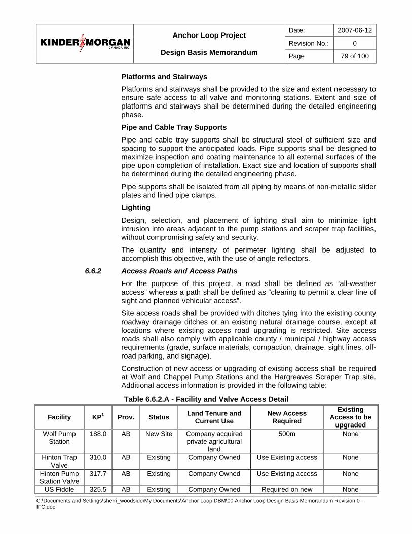
Date: 2007-06-12
Revision No.: 0
Anchor Loop Project
Design Basis Memorandum Page 79 of 100
C:\Documents and Settings\sherri_woodside\My Documents\Anchor Loop DBM\00 Anchor Loop Design Basis Memorandum Revision 0 - IFC.doc
Platforms and Stairways Platforms and stairways shall be provided to the size and extent necessary to ensure safe access to all valve and monitoring stations. Extent and size of platforms and stairways shall be determined during the detailed engineering phase.
Pipe and Cable Tray Supports Pipe and cable tray supports shall be structural steel of sufficient size and spacing to support the anticipated loads. Pipe supports shall be designed to maximize inspection and coating maintenance to all external surfaces of the pipe upon completion of installation. Exact size and location of supports shall be determined during the detailed engineering phase.
Pipe supports shall be isolated from all piping by means of non-metallic slider plates and lined pipe clamps.
Lighting Design, selection, and placement of lighting shall aim to minimize light intrusion into areas adjacent to the pump stations and scraper trap facilities, without compromising safety and security.
The quantity and intensity of perimeter lighting shall be adjusted to accomplish this objective, with the use of angle reflectors.
6.6.2 Access Roads and Access Paths For the purpose of this project, a road shall be defined as “all-weather access” whereas a path shall be defined as “clearing to permit a clear line of sight and planned vehicular access”.
Site access roads shall be provided with ditches tying into the existing county roadway drainage ditches or an existing natural drainage course, except at locations where existing access road upgrading is restricted. Site access roads shall also comply with applicable county / municipal / highway access requirements (grade, surface materials, compaction, drainage, sight lines, off-road parking, and signage).
Construction of new access or upgrading of existing access shall be required at Wolf and Chappel Pump Stations and the Hargreaves Scraper Trap site. Additional access information is provided in the following table:
Table 6.6.2.A - Facility and Valve Access Detail
Facility KP1 Prov. Status Land Tenure and Current Use
New Access Required
Existing Access to be
upgraded Wolf Pump
Station 188.0 AB New Site Company acquired
private agricultural land
500m None
Hinton Trap Valve
310.0 AB Existing Company Owned Use Existing access None
Hinton Pump Station Valve
317.7 AB Existing Company Owned Use Existing access None
US Fiddle 325.5 AB Existing Company Owned Required on new None
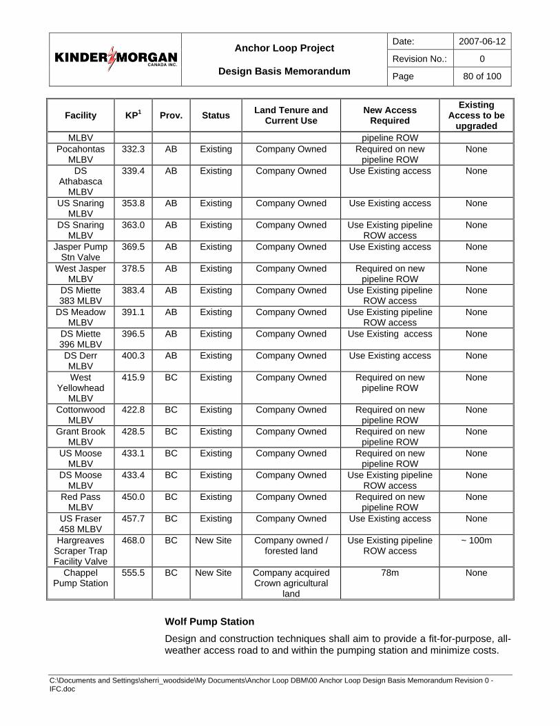
Date: 2007-06-12
Revision No.: 0
Anchor Loop Project
Design Basis Memorandum Page 80 of 100
C:\Documents and Settings\sherri_woodside\My Documents\Anchor Loop DBM\00 Anchor Loop Design Basis Memorandum Revision 0 - IFC.doc
Facility KP1 Prov. Status Land Tenure and Current Use
New Access Required
Existing Access to be
upgraded MLBV pipeline ROW
Pocahontas MLBV
332.3 AB Existing Company Owned Required on new pipeline ROW
None
DS Athabasca
MLBV
339.4 AB Existing Company Owned Use Existing access None
US Snaring MLBV
353.8 AB Existing Company Owned Use Existing access None
DS Snaring MLBV
363.0 AB Existing Company Owned Use Existing pipeline ROW access
None
Jasper Pump Stn Valve
369.5 AB Existing Company Owned Use Existing access None
West Jasper MLBV
378.5 AB Existing Company Owned Required on new pipeline ROW
None
DS Miette 383 MLBV
383.4 AB Existing Company Owned Use Existing pipeline ROW access
None
DS Meadow MLBV
391.1 AB Existing Company Owned Use Existing pipeline ROW access
None
DS Miette 396 MLBV
396.5 AB Existing Company Owned Use Existing access None
DS Derr MLBV
400.3 AB Existing Company Owned Use Existing access None
West Yellowhead
MLBV
415.9 BC Existing Company Owned Required on new pipeline ROW
None
Cottonwood MLBV
422.8 BC Existing Company Owned Required on new pipeline ROW
None
Grant Brook MLBV
428.5 BC Existing Company Owned Required on new pipeline ROW
None
US Moose MLBV
433.1 BC Existing Company Owned Required on new pipeline ROW
None
DS Moose MLBV
433.4 BC Existing Company Owned Use Existing pipeline ROW access
None
Red Pass MLBV
450.0 BC Existing Company Owned Required on new pipeline ROW
None
US Fraser 458 MLBV
457.7 BC Existing Company Owned Use Existing access None
Hargreaves Scraper Trap Facility Valve
468.0 BC New Site Company owned / forested land
Use Existing pipeline ROW access
~ 100m
Chappel Pump Station
555.5 BC New Site Company acquired Crown agricultural
land
78m None
Wolf Pump Station Design and construction techniques shall aim to provide a fit-for-purpose, all-weather access road to and within the pumping station and minimize costs.
Date: 2007-06-12
Revision No.: 0
Anchor Loop Project
Design Basis Memorandum Page 81 of 100
C:\Documents and Settings\sherri_woodside\My Documents\Anchor Loop DBM\00 Anchor Loop Design Basis Memorandum Revision 0 - IFC.doc
Chappel Pump Station Same as above.
Hinton Trap Station Existing access shall be maintained.
Hargreaves Trap Station Design and construction techniques shall aim to provide a fit-for-purpose, all-weather access road to and within the trap stations and minimize costs.
Valve Sites Existing pipeline right-of-way access shall be used to the extent possible. The need for additional access shall be determined on a site-by-site basis. Where the need for additional access is necessary, primary consideration shall be given to optimizing existing pipeline construction access or the construction of a new access path.
6.6.3 Grading and Site Drainage Grading and site drainage requirements shall apply to all facilities with above ground installations except as clarified.
The general drainage philosophy shall be to locally drain away from areas adjacent to equipment and building foundations. Whenever possible, run-off shall be directed to one side of the site to permit access to all buildings without having to track through areas impacted by a spill or significant rain fall.
Provisions will be made to collect all site drainage in areas of aboveground piping, valves, and instrumentation for monitoring purposes, prior to discharge to area drainage systems. The run-off catchment shall be equipped with hydrocarbon detection equipment to aid in the early detection of an oil leak. At Wolf Pump Station and Hargreaves Scraper Trap, an appropriately sized berm shall be installed on the sites down slope to control surface runoff and provide containment in the event of a spill.
The entire site shall be proof rolled after grading to verify a suitable sub-base prior to placing and compacting of required granular fill materials.
6.6.4 Fencing and Gates Perimeter fencing is required at all facilities with above ground installations, except as clarified. It shall consist of a standard 1.82 m high chain link fence. All gates shall open outward from the site.
Substation fencing will conform to high-voltage installation code requirements and will be electrically isolated from pump station fencing by using either physical separation or the use of an insulated fence section between the pump station and substation fencing. Barbed wire fencing will be used to enclose topsoil stockpiles on three sides while the fourth side will be adjacent to the main site perimeter fencing.
The facilities main access and the power utilities substation yard will have a 7.3 m wide double access gate. Man gates will be a standard 0.9 m wide and
Date: 2007-06-12
Revision No.: 0
Anchor Loop Project
Design Basis Memorandum Page 82 of 100
C:\Documents and Settings\sherri_woodside\My Documents\Anchor Loop DBM\00 Anchor Loop Design Basis Memorandum Revision 0 - IFC.doc
be equipped with panic hardware and metal shielding to prevent operating of the lock release bar from outside the fence. Man gates shall be unlockable from the outside.
Design shall ensure that egress from the fenced area can be achieved on the uphill side of the facility.
6.6.5 Buildings and Shelters Enclosed buildings shall be required at pump stations and open shelters at trap facilities. Structures with similar functions shall be of a common design at pump stations and trap facilities. As much as practical, a standardized design layout shall be maintained at all pump stations and at all trap facilities.
All designs shall meet the most stringent requirements of local building regulations and / or climatic load requirements that would allow for relocation of a building to another location on the TMPL system. The building materials, fabrication, and erection shall be in accordance with the drawings and construction specifications.
Building exterior walls, trim, canopies, and roof panels shall be pre-painted to match existing TMPL pump station paint scheme as per the construction specifications.
Building interior walls, unless otherwise noted, shall be finished flat white.
Portable fire extinguishers will be installed in or at all buildings and at strategic locations near outdoor equipment.
Pump Station Buildings Pump station building design shall be consistent with the TMPSE design philosophy.
General Requirements All building man doors will be equipped with an intruder alarm system that is wired to the station PLC.
Building design shall be weatherproof and incorporate rain gutters, ice rakes, downspouts including splash pads and man door canopies, as required. All buildings with the exception of the pump building shall be insulated.
Electrical Buildings Electrical buildings shall be self-framing and shop fabricated on a structural steel floor frame. The building shall be delivered to site complete with all electrical equipment installed, pre-wired, and field termination points clearly identified in a marshalling panel. Building dimensions will be finalized during detail design and equipment selection; design shall be optimized to minimize transport costs.
HVAC equipment for electrical buildings shall be selected to the following criteria:
• Three (3) 25-tonne units (one (1) of which is redundant) with failure alarms.
Date: 2007-06-12
Revision No.: 0
Anchor Loop Project
Design Basis Memorandum Page 83 of 100
C:\Documents and Settings\sherri_woodside\My Documents\Anchor Loop DBM\00 Anchor Loop Design Basis Memorandum Revision 0 - IFC.doc
All man doors shall be steel with panic hardware, door closers, wire-reinforced double-glazing, and painted to match the building exterior.
To minimize heat loss, walls shall be insulated with a minimum R20 insulation value; the floor and roof shall be insulated to a R40 insulation value.
The electrical building will be raised off grade by 1.0 m to allow for bottom cable entry. The underside of the building shall be metal clad (minimum 22 gauge material) to eliminate insect or animal entry.
Pump Building The pump building will be a weatherproof, unheated, metal clad, gable roof structure.
All man doors shall be steel with panic hardware, door closers, wire-reinforced double-glazing and painted to match the building exterior.
The pump building area classification shall be Class 1, Zone 1. The mainline motors will be approved for Class 1, Zone 2. Ventilation equipment shall be provided with capacity to meet code requirements to de-classify the pump building to Class 1, Zone 2, for the mainline motors. Additional ventilation shall be provided to ensure adequate ventilation to maintain interior building temperature within 5°C of outside ambient air temperature but in no case shall the interior temperature exceed 40°C (i.e. to address heat generated by mainline motors). A 50% level of redundancy in the ventilation for the pump building shall be incorporated into the design.
Operator Building The operator building (combination office / shop / storage building) will be a steel-stud framed, metal-clad structure fabricated on a structural steel floor frame. The building layout shall be in accordance to that implemented as part of TMPSE and equipped with integral shelving and tool boards. It will be equipped with an HVAC system based solely on comfort requirements.
Design of the operator building shall incorporate a supply water tank and appropriately sized black and grey water holding tanks (1,600 gallon).
To minimize heat loss, the walls shall be of 2” x 6” construction with R20 value insulation. The floor and roof shall be insulated to a R40 insulation value.
The operator building shall be raised off grade by about 0.6 m. The underside of the building shall be metal clad to eliminate insect or animal entry. The electrical and operator buildings shall be connected by a catwalk.
Scraper Trap Facility Structures General Requirements The existing trap shelter at the Hinton Trap Facility shall be removed and assessed to determine whether it is feasible to reuse at the Hinton Pump Station or the Hargreaves Trap facilities. The assessment will also consider the technical and economic feasibility of splitting the shelter for use at both locations.
Date: 2007-06-12
Revision No.: 0
Anchor Loop Project
Design Basis Memorandum Page 84 of 100
C:\Documents and Settings\sherri_woodside\My Documents\Anchor Loop DBM\00 Anchor Loop Design Basis Memorandum Revision 0 - IFC.doc
Trap Shelters Trap facility shelters shall be sized to cover the launcher / receiver pads / skids and active work areas.
Shelter design shall incorporate rain gutters, ice rakes, and downspouts including splash pads, as required. The design shall also allow for clear grade access from each side. Components shall be shop-fabricated to the extent practical. The shelters shall not be heated or insulated.
Trap shelter skid floors or concrete slabs shall incorporate the following features:
• Perimeter containment with floor sloped to a central sump
• Equipped with a means to collect and channel rain water and snow melt, to a controlled release location
Operator / Electrical (MCC) Building The MCC building at the existing trap station near Hinton shall be removed with installed equipment and reused at Hargreaves trap facility.
Existing operator and electrical buildings at the Hinton Pump Station shall be integrated to support the Hinton Trap facility. Key areas of integration shall include:
• HMI
• SCADA
• Pig Sig communication
• PLC inputs from Instrument Sensors (gas detectors, level sensors)
6.6.6 Mechanical Equipment Mainline Pumps Each pump station shall be equipped with mainline pumps. KMCI shall directly purchase new pump and motor sets for the new stations.
The pumping configuration for all pump stations shall be identical. The pumps shall have left-hand-side suction nozzles and right-hand-side discharge nozzles. Piping at stations on the south or east side of the pipeline shall have crossover piping to accommodate pump configuration.
Sump Tanks General The requirements of this section shall apply to all sump tanks installed on loop facilities.
All drain lines will be routed to a below grade central sump tank. The sump tank will be buried below grade.
Hatches for level measurement equipment will be centered on the tank maximum vertical radius. Sump tanks shall be equipped with manual means of inspecting the interstitial space. All drain lines will be routed to drain by gravity to the sump tank.
Date: 2007-06-12
Revision No.: 0
Anchor Loop Project
Design Basis Memorandum Page 85 of 100
C:\Documents and Settings\sherri_woodside\My Documents\Anchor Loop DBM\00 Anchor Loop Design Basis Memorandum Revision 0 - IFC.doc
A submersible lift pump and piston-type high-pressure injection pump will be installed to allow re-injection of sump contents into the mainline. As well, pump out to a tanker truck will be possible through a tank stinger and above ground connection. Vent and access openings shall be designed to prevent spillage during piping drain down.
Pump Station Sump Tanks Each pump station shall be equipped with a sump tank located to serve all drain lines from the facility. The sump tank shall be sized to allow drain down of all station piping between the station suction and discharge valves plus the volume of the piping and pump of one mainline unit. This volume will be calculated between minimum operating level in the tank and the maximum fill level of the tank.
Scraper Trap Facility Sump Tanks The two (2) barrels at each trap facility will also be served by a common sump tank. The sump tank shall be sized to contain the combined volume of both launcher and receiver barrels.
6.6.7 Piping (including valves) Piping design, materials, welding, fabrication, non-destructive testing, and pressure testing shall conform to the requirements for low vapour pressure liquids of CSA Z662-03 “Oil and Gas Pipeline Systems” Category 1 service. All codes, standards, and specifications listed in Section 5.2 shall be strictly adhered to.
General Piping Design Requirements The following requirements shall apply to piping procurement and installation at all facilities as applicable (pump stations, scraper trap stations, and valve sites):
• Loop facilities piping shall be designed to ANSI 600 (PN100)
• Design shall incorporate thermal relief on all process piping; the relief shall be set at 5% above MOP
• Surge relief design shall meet the requirements outlined in the TMPSE Surge Analysis Report.
• All process piping will be installed above grade excluding the S-bends to the mainline tie-ins (excludes MLBV sites).
• All valve actuators shall be mounted at minimum elevation while satisfying maintenance clearances under valves. Ball valves shall be mounted with the stems oriented horizontally to prevent fouling at the bottom of the valve and shall operate with the ball rotating in a manner to flush any particulate matter trapped on the upstream side of the ball during the initial rotation of the ball. All trunnion-mounted ball valves shall incorporate a “Chevron” packing design acceptable to KMCI..
• Gravity-flow drains from pumps, thermal relief valve discharge, and seal leak pots to a local sump.
Date: 2007-06-12
Revision No.: 0
Anchor Loop Project
Design Basis Memorandum Page 86 of 100
C:\Documents and Settings\sherri_woodside\My Documents\Anchor Loop DBM\00 Anchor Loop Design Basis Memorandum Revision 0 - IFC.doc
• Preference is to install drain piping above grade where practical, but design elevation of process piping and / or equipment shall not be elevated to do so. Drain piping that is above grade or within the frost zone shall be electrically traced and insulated.
• Main drain headers shall be sized NPS 4, drain laterals shall be sized NPS 2. Drain cleanouts will be installed where required.
Pump Station Piping Design Requirements Station piping design will incorporate the following functions:
• Station inlet and outlet piping shall tie into a common mainline bypass header complete with a mainline sectionalizing valve and a check valve consistent with the design of the TMPSE facilities.
• A pig sig (detector) shall be located upstream of the station suction valve on the mainline header to enable notification to the Control Center Operator of the arrival of a pig; a second pig sig shall be located downstream of the station discharge valve on the mainline header to enable notification that the pig is past the station.
• A pig “parking” facility shall be provided on the downstream side of the station inlet branch (tee). The pig “park” shall be sized to accommodate two (2) pigs.
• Mainline sectionalizing valve shall be a through conduit slab gate, station and mainline pump unit isolation shall be trunnion-mounted ball valves.
• The station discharge downstream of the discharge header U-bend shall incorporate an allowance for an orifice flange pair with ten (10) straight upstream diameters and five (5) straight downstream diameters. The orifice flange taps shall be plugged and a spacer (stainless steel) of equivalent thickness of an orifice plate rated for PN100 service shall be installed. No instrumentation is to be installed for this future provision.
• Suction and discharge piping at mainline pump units shall be consistent with pump operating characteristics.
• A removable flanged run of pipe will be installed immediately upstream of each pump to allow for installation or removal of temporary start-up strainers.
• Mainline pump and motor equipment trim within the pump skid shall be by the equipment vendors. Design shall incorporate a tubing vent including sight glass from the pump casing vent to the drain header.
• Final station piping arrangement will be subject to a flexibility and pipe stress review for each of the standardized designs.
Maximum Pump Station Discharge Pressure Maximum station discharge pressure will be determined during detailed design from the results of the hydraulic study.
Date: 2007-06-12
Revision No.: 0
Anchor Loop Project
Design Basis Memorandum Page 87 of 100
C:\Documents and Settings\sherri_woodside\My Documents\Anchor Loop DBM\00 Anchor Loop Design Basis Memorandum Revision 0 - IFC.doc
Scraper Trap Piping Design Requirements Station piping design will incorporate the following functions:
• Scraper receiving and launching barrels will be isolated with a through conduit slab gate, trap facility bypass piping, kicker, and relief (if applicable); line isolation shall be trunnion-mounted ball valves.
• The diameter of each scraper receiving and launching barrels will be sized 6 inches larger than the incoming or outgoing mainline.
• Closure type for receivers and launchers will be determined during detailed design
• Scraper receiver design shall incorporate barred tees and internal cages
Piping Materials All material shall be in strict compliance with the codes, standards, and specifications stated in Section 5.2. Cold temperature materials will be used only when required by code, all impact testing requirements shall be strictly adhered to.
Maximum design stress levels at all facilities shall be limited to 80% of SMYS, with no corrosion allowance. At a minimum, standard wall thickness will be used for all station pressure piping, piping NPS 2 and under shall be a minimum Schedule 80 wall thickness.
Welding, Non-Destructive Examination (NDE), and Pressure Testing Shop fabrication, NDE, and pressure testing shall be maximized to limit field scope of work. Upon completion of field installation, NDE will be completed on all tie-in welds and a pneumatic service / tightness leak check will be completed on the process and drain piping systems.
Insulation and Coating All piping fabrication and / or straight run piping shall be shop coated prior to shipping to site. All fabrication and ship loose materials shall maintain trace ability throughout the fabrication and installation processes. Coatings shall be in strict compliance to the specification guidelines within Section 5.2.
Drain piping that is electrically traced and insulated, shall be prime coated only. All traced flanges, valves, instrumentation, etc, shall be insulated with removal blankets for ease of maintenance.
Cathodic Protection Pump stations and scraper trap stations shall require isolation from the existing pipeline cathodic protection system. This shall be accomplished with the use of insulating kits on the first flange pair entering the station or trap facility and the last flange pair exiting the station or trap facility.
To ensure continuity in the cathodic protection system, a jumper shall be installed on the pipeline upstream of the first isolation kit and connected to the pipeline downstream of the second isolation kit.
Date: 2007-06-12
Revision No.: 0
Anchor Loop Project
Design Basis Memorandum Page 88 of 100
C:\Documents and Settings\sherri_woodside\My Documents\Anchor Loop DBM\00 Anchor Loop Design Basis Memorandum Revision 0 - IFC.doc
Tie-Ins to Existing Pipeline Complete of mainline tie-ins will require shutdowns of the pipeline. This work shall require significant planning to minimize disruptions to the operation of the pipeline and allow safe execution of the work. It is planned to perform all tie-ins by KMCI crews or KMCI-directed crews.
6.6.8 Electrical and Instrumentation Applicable Codes and Standards The most recent version of Canadian Electrical Code CSA C22.1 Part 1 will govern the installation of all electrical equipment.
Canadian Standards Association approval of all electrical and instrumentation equipment is required.
General Equipment tags and wire numbers will be the same at all sites with the exception of a site identifier as a prefix. Site identifier prefix for the loop facilities shall be as follows (MLBV sites will be by KP or KL post):
• Niton Pump Station – NT
• Wolf Pump Station – WL
• Existing Hinton Scraper – HN
• Hinton Pump Station – HS
• Jasper Pump Station – JA
• Hargreaves Scraper Trap – HG
Electrical Utility Power Supply Pump Stations Supply of the power infrastructure will be provided through a combination of agreements in Alberta and British Columbia and is subject to several regulatory approval processes.
In Alberta, Fortis will build, own, and operate new distribution lines to the Wolf Pump Station as well as the substation.
In British Columbia, ATCO Electric will be the Prime Contractor for construction of the transmission line and a substation at Chappel Pump Station. ATCO, as the Prime Contractor will complete regulatory approvals, route selection, public and First Nations consultation, land agreements, and technical requirements. KMCI will negotiate an EPCM (Engineering, Procurement, and Construction Management) agreement with ATCO.
The following identifies the preliminary proposals for electrical service requirements at each location:
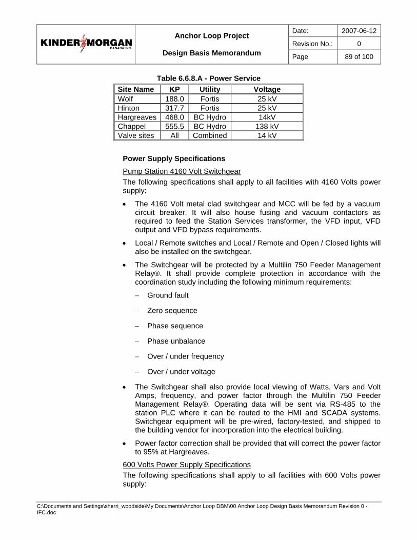
Date: 2007-06-12
Revision No.: 0
Anchor Loop Project
Design Basis Memorandum Page 89 of 100
C:\Documents and Settings\sherri_woodside\My Documents\Anchor Loop DBM\00 Anchor Loop Design Basis Memorandum Revision 0 - IFC.doc
Table 6.6.8.A - Power Service Site Name KP Utility Voltage Wolf 188.0 Fortis 25 kV Hinton 317.7 Fortis 25 kV Hargreaves 468.0 BC Hydro 14kV Chappel 555.5 BC Hydro 138 kV Valve sites All Combined 14 kV
Power Supply Specifications Pump Station 4160 Volt Switchgear The following specifications shall apply to all facilities with 4160 Volts power supply:
• The 4160 Volt metal clad switchgear and MCC will be fed by a vacuum circuit breaker. It will also house fusing and vacuum contactors as required to feed the Station Services transformer, the VFD input, VFD output and VFD bypass requirements.
• Local / Remote switches and Local / Remote and Open / Closed lights will also be installed on the switchgear.
• The Switchgear will be protected by a Multilin 750 Feeder Management Relay®. It shall provide complete protection in accordance with the coordination study including the following minimum requirements:
− Ground fault
− Zero sequence
− Phase sequence
− Phase unbalance
− Over / under frequency
− Over / under voltage
• The Switchgear shall also provide local viewing of Watts, Vars and Volt Amps, frequency, and power factor through the Multilin 750 Feeder Management Relay®. Operating data will be sent via RS-485 to the station PLC where it can be routed to the HMI and SCADA systems. Switchgear equipment will be pre-wired, factory-tested, and shipped to the building vendor for incorporation into the electrical building.
• Power factor correction shall be provided that will correct the power factor to 95% at Hargreaves.
600 Volts Power Supply Specifications The following specifications shall apply to all facilities with 600 Volts power supply:
Date: 2007-06-12
Revision No.: 0
Anchor Loop Project
Design Basis Memorandum Page 90 of 100
C:\Documents and Settings\sherri_woodside\My Documents\Anchor Loop DBM\00 Anchor Loop Design Basis Memorandum Revision 0 - IFC.doc
• The 600 VAC secondary of the station services transformer will feed a MCC, which will distribute power to all 600 Volt three-phase loads. Cells will incorporate circuit breakers, magnetic circuit protectors, and combination starters as required.
• New MCCs will be pre-wired, factory-tested, and shipped to the building vendor for incorporation into the electrical building.
120/208 Volts Power Supply Specifications A three-phase transformer with a 600 VAC primary winding and 120/208 Volts secondary winding will be fed from a three-phase, 600 Volt breaker in the 600 Volt MCC. This transformer will feed a three-phase breaker panel incorporating 1, 2 and 3 pole breakers and ground fault circuit interrupters (GFCI’s) to supply the 120/208 Volts load.
Un-Interruptible Power Supply (UPS) Systems A three-phase, 120/208 Volt UPS shall be installed at each pump station to provide emergency power to critical equipment.
UPS systems are only required to maintain communications at scraper traps and valve sites.
At pump stations only, the UPS system will be used to power all protective devices, PLCs, and communications. Station suction and discharge valves will also be powered from this UPS system in order to allow for isolation of the station in the event of a loss of primary power. It shall be sized to provide two (2) hours of power to support the normal connected load plus power required to isolate the station. Emergency lighting in all buildings except the pump building shall be wall mount, integral power pack units or power pack units with remote heads. In the pump building, egress lighting will be powered by the UPS.
Existing UPS systems at Hinton Pump Station shall be confirmed to be adequate for the scraper trap power demands.
Area Classification Hazardous area classification shall be determined by the most stringent of:
• API RP 505 “Recommended Practice for Classification of Locations for Electrical Installations Classified as Class 1, Zone 0, Zone 1, or Zone 2”, latest edition.
• The Canadian Electrical Code, CSA C22.1-02 Part 1 as modified by Provincial amendments.
Pump building area classification shall be Class 1, Zone 1 at all sites. The mainline motors will be approved for Class 1, Zone 2 at all sites. All other pump building electrical equipment will be specified as Zone 1. Wiring and associated electrical devices will be supplied and installed as Zone 1.
Ventilation equipment shall be specified as Class 1, Zone 1, provided with capacity to meet code requirements to de-classify the pump building to Class 1, Zone 2 for the mainline motors.
Date: 2007-06-12
Revision No.: 0
Anchor Loop Project
Design Basis Memorandum Page 91 of 100
C:\Documents and Settings\sherri_woodside\My Documents\Anchor Loop DBM\00 Anchor Loop Design Basis Memorandum Revision 0 - IFC.doc
General Wiring Requirements The following wiring requirements shall apply to all loop facilities:
Grounding These grounding requirements shall apply to all Loop facilities.
Grounding shall be designed to IEEE 80-2000 standard, CEC, Provincial, and local utility standards as applicable. The ground grid will be based on stranded 4/0 copper conductor and 10’x3/4” ground rods, following KMCI Grounding Standards.
Quantity of rods and size of grid will be calculated depending on local soil conditions and resistivity in accordance with IEEE-811.
Non-current-carrying metal structures, fences (substations only), buildings, and pad mounted equipment will be bonded to the grid. Compression-type connections will be used throughout.
Valves Motor operated valves will be connected using HL-rated Teck 90 cable with an internal ground conductor bonding the valve to the supply. Starters will be located in the MCC (or valve control enclosures at valve stations), with the exception of the starters on the station isolation valves, which shall be located in the motor operators. Separate control and power cables shall be used to connect the valves. Additional equipment grounds will be bonded to the 2/0 or 4/0 ground conductors (as applicable) installed in the cable tray containing the valve control and power cables.
Instruments All instruments shall be connected using individual shielded pairs or triads with a minimum of 6 lays per foot in an HL-rated cable. An equipment bonding conductor will be incorporated in the cable and used to bond the device to the source ground only.
Heat Tracing Heat tracing will be of the self-regulating-type rated at 8 Watts per foot activated at a predetermined temperature by a thermostat and approved for installation in a Class 1, Zone 1 hazardous area. Approved termination kits will be used. Heat trace cable shall be installed with no crossing of the cable. All heat traced pipe will be insulated.
Pump Station Wiring The following wiring requirements shall apply to all Anchor Loop pump stations only:
Pump Building In the pump buildings, the wiring method shall be HL-rated Teck 90 cable in tray approved for the classification of the hazardous area, terminated with cable glands approved for the area classification or rigid metal conduit where mechanical protection is required for a single run such as for lighting.

Date: 2007-06-12
Revision No.: 0
Anchor Loop Project
Design Basis Memorandum Page 92 of 100
C:\Documents and Settings\sherri_woodside\My Documents\Anchor Loop DBM\00 Anchor Loop Design Basis Memorandum Revision 0 - IFC.doc
Approved explosion proof boxes and fittings shall be factory threaded for connection to cable glands or rigid metal conduit.
Threaded joints that are required to be explosion-proof shall be tapered. Tapered threads shall have at least five (5) fully engaged threads; running threads shall not be used. Where thread forms differ between the equipment and the wiring system, approved adapters shall be used.
Cables shall be installed and supported in a manner to avoid tensile stress at the cable glands. Where flexible fittings are used for connection at motor terminals and similar places, they shall be of a type approved for the location.
Electrical Building The electrical building and all components shall be assembled, wired, and tested at the building vendor’s site prior to shipment.
The equipment will be designed to allow interconnections to be done either between cells in the metal clad switchgear or in cable tray installed overhead. The tray will be installed on a substantial support system at a suitable height above the top of the highest switchgear cell to allow cables to be installed, without damage and within the minimum cable bending radius requirements of the applicable codes.
The building will be installed 1 m above grade to allow bottom entry of all medium voltage cables entering or leaving the building. A gland plate will be installed at floor level where the cable glands will be installed. The area between the gland plate and bottom building skin will be filled with expanding fire-stop material after the cables are installed and terminated. There shall be no openings left through which insects or animals could enter. All terminations will be bolted compression lugs.
All low voltage power and control cable shall enter or leave the building in the floor of the building inside of the appropriate marshalling panel.
Wiring that supports the control systems or the interconnection of power systems up to 4160 VAC shall be installed in cable tray for which a suitable support system shall be incorporated into the building design. Cable shall be arranged in an orderly fashion within the building in cable trays maintaining all separations required and shall be supported where it leaves the tray to enter equipment. 4160 VAC cables shall be installed in a separate tray installed above the tray system intended for lower voltage cables.
All internal wiring that supports the environment of the building and that must be installed on the walls or directly to the ceiling will be installed in rigid metal conduit installed following the applicable code. Power drops to lighting fixtures will be installed in flexible metal conduit and the fixture shall be supported following the applicable code rules.
All cable tray systems installed in the electrical building shall have a bare stranded copper ground conductor, size 2/0, installed the full length of each tray and bonded to every tray and component section as well as the support structure. The ground shall be bonded to the electrical building perimeter ground with size 4/0 insulated copper conductor in two (2) places.
Date: 2007-06-12
Revision No.: 0
Anchor Loop Project
Design Basis Memorandum Page 93 of 100
C:\Documents and Settings\sherri_woodside\My Documents\Anchor Loop DBM\00 Anchor Loop Design Basis Memorandum Revision 0 - IFC.doc
Operator Building The operator building shall be wired using typical commercial building wiring practices such as Electrical Metallic Tubing (EMT) and armoured BX cable. The building will be pre-wired at the manufacturer’s site during building construction and tested prior to shipping to site. All conductors shall be stranded.
Electrical Equipment and Instrumentation The following requirements shall apply to all electrical equipment and instruments to be used on the Loop facilities, as applicable. All equipment will be chosen based on the “fit-for-purpose” axiom. Determination of equipment will be based on cost, suitability, and historic reliability. Transmitters will be used in place of switches where possible. Switching set points and ultimate action will be resolved in the PLC.
General Electrical Equipment Requirements The following requirements shall apply to equipment and instruments to be used on Loop facilities:
Hydrocarbon Sensors A hydrocarbon sensor will be installed in close proximity to the containment area discharge valve. If hydrocarbons are sensed on the surface of the water being discharged, the valve will be closed and the ECC will be alarmed.
Combustible gas detectors are only required at pump stations and scraper traps.
PLC (Programmable Logic Controller) As much as possible, processors, cards, and other components will be selected to ensure compatibility with similar equipment in existing TMPSE stations. Software used for programming the PLC will be the same as currently used for existing applications. Ladder logic programming will be used to ensure field maintenance technicians will not require additional training to maintain it. A programming standard has been developed to ensure a consistent approach and result. A single comprehensive set of logic drawings will be developed for all locations. Site specific routines will be developed and incorporated only where required. These routines will be identified as site specific on the logic drawings for a site and in the program documentation. Program documentation will include descriptions of the intent of each routine in the program.
PLC equipment is required at pump stations, scraper traps, and MLBV sites.
Pump Station Equipment The following requirements shall apply to equipment and instruments to be used on Anchor Loop pump stations only:
Fire Detection Fire detection in the station pump house building will be handled by one (1) UV/IR device per unit. This device will be a stand-alone unit with contact
Date: 2007-06-12
Revision No.: 0
Anchor Loop Project
Design Basis Memorandum Page 94 of 100
C:\Documents and Settings\sherri_woodside\My Documents\Anchor Loop DBM\00 Anchor Loop Design Basis Memorandum Revision 0 - IFC.doc
outputs wired to the PLC for both fire and protective device fault. Both contacts will be included in the ESD circuit. The protective device fault contact will not cause an ESD if a second detector is functioning in close proximity.
Fire detection is only required at pump stations.
Combustible Gas Detection Combustible gas detection will be installed within 15 cm (6”) of the pump room floor near the air intake to the mainline motor. Detectors will be stand-alone units with analog outputs connected to the PLC where logic will output signals for explosive atmosphere and for protective device fault. PLC contacts for Emergency Shutdown will be included in the ESD circuit. The protective device fault contact will not cause an ESD if a second detector is functioning in close proximity.
Combustible gas detectors are only required at pump stations.
Seal Failure Detection Seal failure switches shall be thermal insertion flow sensors using a reference element and a sensing element. Upon seal failure, pipeline product flowing through the seal will cause a differential temperature between the sensor elements which will open a fail-safe circuit. The Form C contact will be connected to the PLC where logic will cause a unit lockout on seal failure. A seal failure bypass switch will be provided to allow the operator to flush seal drain lines.
Seal failure detection is only required at pump stations.
Mainline Motor The mainline motors shall be 5,000 horsepower, 3,600 RPM synchronous speed, horizontal shaft machines. They will have Class F insulation and a 1.15 service factor and operate at Class B Insulation temperature rise at 1.15 Service Factor by RTD. Motors will meet KMCI Specification 47ES0001, Mainline Pump Motors, and API-541, Form Wound Squirrel Cage Induction Motors - 500 Horsepower and Above, current revisions.
Nine (9) 120 Ohm nickel RTDs, three (3) per phase, spaced equal-distance on the circumference of the stator, will be embedded in the stator slots between the inner and outer windings. Six (6) RTDs will be used for motor protection and three (3) reserved as spares.
The motors will be protected by fuses, coordinated as determined in a coordination study and by a Multilin 469 Motor Protection Relay (MPR) providing:
• ground fault,
• zero sequence,
• time-over-current,
• phase sequence,
Date: 2007-06-12
Revision No.: 0
Anchor Loop Project
Design Basis Memorandum Page 95 of 100
C:\Documents and Settings\sherri_woodside\My Documents\Anchor Loop DBM\00 Anchor Loop Design Basis Memorandum Revision 0 - IFC.doc
• phase unbalance,
• over / under frequency,
• over / under voltage,
• diminished thermal capacity start prevention,
• under current or under power, and
• differential protection.
RTDs will also be used to measure drive end and opposite drive end bearing temperature and provide bearing high temperature protection. The MPR will provide integral display of motor electrical and temperature data. This data will also be sent, via RS-485, to the station PLC where it can be routed to the HMI and SCADA systems.
For vibration protection, velocity transmitters will be installed horizontally, as close as possible to the motor shaft center line at each bearing. The transmitter output will be connected to an analog input card in the PLC. The PLC will initiate a unit lockout when the vibration exceeds the protective device setting.
Provisions for surge arrestors are to be provided in the motor junction box.
Motors will be designed with a minimum of 6mm end float either side of electrical center. Thrust will be controlled by the pump thrust bearing.
Mainline Pump The mainline pumps will be identical horizontal shaft, single-stage centrifugal pumps designed to achieve the maximum flow rate and required head for the expansion.
Coupling to the motor will be determined by a torsional analysis study undertaken by the pump Manufacturer.
The pump will have radial sleeve bearings and a tilt pad thrust bearing will be utilized. A separate forced lubrication system will provide lubrication to the pump and motor bearings.
RTDs will be installed in both the drive end and opposite drive end radial bearings and in each thrust bearing pad as close as possible to the bearing face without damaging the bearing. A separate RTD will be installed in a thermowell installed in the pump case. All bearing RTDs will be connected to the unit MPR, which will provide over temperature protection on these points. The pump case RTD will be connected to an analog input card in the PLC which will provide high pump case temperature protection.
A pressure transmitter will be installed in the pump suction piping and connected to the PLC. The PLC will initiate a unit quick stop when a suction pressure below the protective device setting is detected.
A pressure transmitter will be installed in the pump discharge piping and connected to the PLC. The PLC will initiate a unit quick stop when a discharge pressure above the protective device setting is detected.
Date: 2007-06-12
Revision No.: 0
Anchor Loop Project
Design Basis Memorandum Page 96 of 100
C:\Documents and Settings\sherri_woodside\My Documents\Anchor Loop DBM\00 Anchor Loop Design Basis Memorandum Revision 0 - IFC.doc
For vibration protection, velocity transmitters will be installed horizontally, as close as possible to the pump shaft center line at each bearing. The transmitter output will be connected to an analog input card in the PLC. The PLC will initiate a unit lockout when the vibration exceeds the protective device setting.
A thermal seal failure detection switch will be installed in each seal drain line on the pump. The output of this switch will be connected to the PLC. The PLC will initiate a unit lockout when seal failure is detected. A seal failure bypass switch will be provided to allow operating personnel to flush the seal drain lines.
Bearing Lube Oil System A bearing lube oil system in accordance with API Standard 614, current edition, shall be provided for each mainline unit. The pressure lubrication system must have the capacity to supply the mainline motor bearings as well as the mainline pump bearings. There will be two (2) lube oil pumps, both electric motor driven. One (1) of these will be redundant with switching to alternate operation of the pumps.
All electrical equipment shall be CSA-approved for a Class I, Zone 1, Group D and shall be stamped or tagged accordingly. Electrical power supplies will be 600V/3Ø/60 Hz with 120V, single-phase, 60Hz control circuits. All wiring shall be to a local control panel mounted on the lube oil skid. Starters will be located in a remote MCC.
A thermostatically controlled electric immersion reservoir heater shall be provided to heat the lube oil from -30°C to minimum start-up temperature in 12 hours or less. The sump size shall be adequate (ample surface area and residence time) to provide sufficient oil cooling at hottest ambient temperature (40°C). If this is not practical, an oil to air heat exchanger with a low noise fan shall be provided. Stainless steel supply piping (tubing) after the filter is required. “Swagelok” tubing fittings shall be used. A duplex strainer shall allow filter selection and change-out without shutting down the flow of lubricating oil.
Pressure gauges, switches, and controls shall be mounted on the pump skid. Alarm and shutdown switch contacts shall both be closed and energized when conditions are normal.
Variable Frequency Drive (VFD) A VFD shall be used to control the speed of one (1) mainline pump motor, and also to bring that motor up to a speed where it can be connected direct to the utility (synchronized); following which the drive will be required available to accelerate a second motor to maintain station control.
Drives shall be suitable and approved for installation in any expansion location. Power for the VFD and motors will be supplied through switchgear approximately as outlined on the attached single line diagrams. The power supply will be brought in through a step-down, isolation transformer from the utility distribution system. The VFD Motor combination must meet the
Date: 2007-06-12
Revision No.: 0
Anchor Loop Project
Design Basis Memorandum Page 97 of 100
C:\Documents and Settings\sherri_woodside\My Documents\Anchor Loop DBM\00 Anchor Loop Design Basis Memorandum Revision 0 - IFC.doc
harmonic specifications throughout the frequency range and the complete torque range as specified in the utility requirements.
The VFD will start and operate the motor. It will be capable of operating the loaded motor through the specified speed range with an input voltage variation of +\-10% from nominal. The drive shall provide a continuous capacity to allow full service factor operation of the motor. It shall have a further 10% overload capacity for one minute. The VFD will, upon operation of an external PLC (station) 120 volt AC output module, synchronize the running motor to the supply line and send a signal to close an external bypass contactor, unload the VFD and open the VFD output contactor. The VFD will then accelerate and operate another motor in a similar manner.
The VFD will be able to synchronize to a motor operating on the bypass contactor and take over speed control. Synchronization and de-synchronization shall be done with a bump-less transfer in each direction by the VFD PLC. The VFD shall have the ability to ride through a momentary power loss with all three phases dropping to 70%, or one phase dropping to 50% for up to one second duration, and then reaccelerate the load.
Instrumentation Station Protection An Operating Limits and Protective Device document will be developed to detail both the protection and the operating limits of the equipment and pipeline at the new sites.
Equipment Selection All equipment will be chosen based on the “fit-for-purpose” axiom. Determination of equipment will be based on cost, suitability, and historic reliability. Transmitters will be used in place of switches where possible. Switching set points and ultimate action will be resolved in the PLC.
Temperature Measurement Temperature measurement for protection primary elements will be three-wire 120 Ohm nickel RTDs connected to the protective device or PLC at an RTD input card and wired directly to the end device using lead length compensation practices.
Temperature measurement for leak detection primary elements will be four-wire 100 Ohm platinum RTDs connected to the PLC at an RTD input card and wired directly to the end device using lead length compensation practices.
Temperature measurement is not required at valve sites.
Level Measurement Level measurement shall be required at pump stations and scraper trap stations sump tanks.
Level measurement in the waste oil sump tanks shall be accomplished using a radar level gauge fit for purpose. This system will incorporate an analog output proportional to tank fill level which will be sent to the PLC. The PLC
Date: 2007-06-12
Revision No.: 0
Anchor Loop Project
Design Basis Memorandum Page 98 of 100
C:\Documents and Settings\sherri_woodside\My Documents\Anchor Loop DBM\00 Anchor Loop Design Basis Memorandum Revision 0 - IFC.doc
shall be programmed with set-points for low level and high level. Backup protection for high level shall be by displacer or float switch mounted to detect the “High-High” level. The PLC program will also incorporate logic to provide a sump tank volume for use in the Control Centre.
Density Measurement Density measurement will be accomplished using a Nuclear Density Gauge.
Trap stations and valve sites shall not be equipped with density measurement instrumentation.
Flow Measurement At all pump stations, provisions to install an orifice plate shall be provided for flow measurement should the need arise for flow measurement modulation of the VFD maximum speed.
Scraper Trap stations and valve sites shall not be equipped with flow measurement instrumentation.
Vibration Measurement Mainline pump unit vibration transducers will be an integral seismic sensor / transmitter producing a 4-20 ma output. The signal will be processed in the PLC where protective functions and start-up attenuation will occur. The signal will be trended on the local HMI for operator review.
Scraper Detectors (Pig Sigs) At pump stations, the scraper detectors shall be a bi-directional, insertion-type mounted in a Williamson coupling. Logic will be designed to alert the Edmonton Control Centre on arrival of a scraper. The Operator will choose when to shut the station down forcing the scraper to pass. The Operator will restart the station when the scraper has passed the down stream scraper detector.
Scraper Trap Facilities and Valve Sites The following requirements shall apply to equipment and instruments to be used on scraper trap facilities only.
Scraper trap facilities (and valve sites) shall not be equipped with Flow measurement or density measurement instrumentation.
Scraper Traps (Barrels) The scraper traps shall be designed such that scrapers and inspection tools can be launched and received at full mainline flow.
The outer diameter of each receiving scraper trap barrel shall be a minimum of 6 nominal inches larger than the size of the line (ie. For NPS 24 line, NPS 30 barrel would be used). A concentric reducer shall be used to transition from the barrel size to line size.
The inside diameter of each launching scraper trap barrel shall be a minimum of 2 nominal inches larger than the inside diameter of the line. An eccentric

Date: 2007-06-12
Revision No.: 0
Anchor Loop Project
Design Basis Memorandum Page 99 of 100
C:\Documents and Settings\sherri_woodside\My Documents\Anchor Loop DBM\00 Anchor Loop Design Basis Memorandum Revision 0 - IFC.doc
reducer (flat on bottom) shall be used to transition from the barrel size to line size.
The receiving scraper barrel trap shall contain an internal cage to support the scraper, and to allow product to flow around the scraper with minimal obstruction. The cage shall be fabricated from perforated sheet or assembled from bar stock (suitable for maximum weight and dimensions of a given scraper). The cage and barrel shall have permanent tabs to allow fastening and removal of the cage. A cage is not required for the launch barrel.
Scraper Trap Closure Devices End closures of the traps shall be quick opening, hinged (horizontal opening), and be equipped with a positioning plate and an interlocking device which will not allow the closure to open until the barrel has been depressurized. The closure design shall provide a tight seal under the full range of operating pressures, without relying on positive pressure inside the trap for seal energization. End closures shall be designed in accordance with ASME Section VIII, Div. 1.
Scraper Detectors (Pig Sigs) Scraper detectors shall be a bi-directional, insertion-type mounted in a Williamson coupling with flanged bases. They shall have adjustable penetration.
Pig sig logic will be designed to alert the Edmonton Control Centre on arrival of a scraper.
Pig sigs shall be located upstream of the trap receiving valve to confirm receipt of the pig at the trap facility and downstream of the trap receiving valve to confirm that the pig is in the barrel.
A pig sig shall be located downstream of the trap sending valve to confirm the pig has left the trap facility.
Temperature Measurement Temperature measurement is not required at valve sites.
Crossover and Auxiliary Piping Auxiliary piping shall include gravity-flow drains from scraper trap barrels and thermal relief valves to the local sump.
Drain piping shall be installed above ground, complete with electrical heat tracing and insulation. Drain cleanouts shall also be installed where required.
Pressure Measurement Pressure measurement shall be addressed during detailed design.
Pressure Relief Pressure relief shall be addressed during detailed design.
Date: 2007-06-12
Revision No.: 0
Anchor Loop Project
Design Basis Memorandum Page 100 of 100
C:\Documents and Settings\sherri_woodside\My Documents\Anchor Loop DBM\00 Anchor Loop Design Basis Memorandum Revision 0 - IFC.doc
Human Machine Interface (HMI) HMI shall be required at pump stations and scraper trap stations.
The Hinton Trap facility shall be integrated with the Hinton Pump Station HMI. It shall be confirmed during detailed design that the existing power and HMI interface at Hinton are able to support the trap facilities.
The HMI at the existing trap station near Hinton shall be relocated to Hargreaves trap station.
A personal computer, configured with appropriate hardware interface and software shall be used as an HMI. Screens will be developed to mimic station piping and shall dynamically refresh to display valve positions, unit status, alarm status, event status, trends and process data. Mainline pressures and temperatures, station and unit power information, vibration data, and any other data that may be deemed important, along with all status and alarm information, will be logged on the HMI hard disk sub-system. A standard will be developed for HMI software programming to ensure consistent displays. All screens will be the same at all sites with site specific information on separate screens.
The hard disk sub-system will consist of two (2) 160 GB hard drives connected to a RAID1 controller configured for disk mirroring. Files will be configured to start a new file at midnight every day and will be identified by a file name in the format yyyymmdd.log. All log files will be in .csv, .xls, .dbf or .mdb format. Each file will be kept for a period of 366 days at which time it may be over-written to save disk space.
SCADA See description in Section 5.6.2.
6.6.9 Decommissioning Niton Pump Station Refer to Section 2.4.3, Niton pump station de-activation
Hinton Scraper Trap Refer to Section 2.4.2, Hinton KP 310.0 Existing Scraper Trap Removal

APPENDIX A
Project Schematic
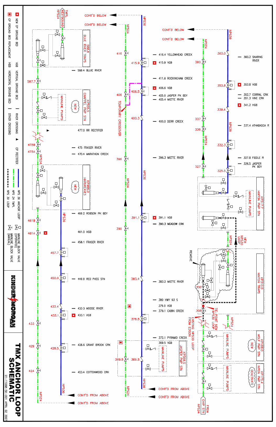

APPENDIX B
Permits
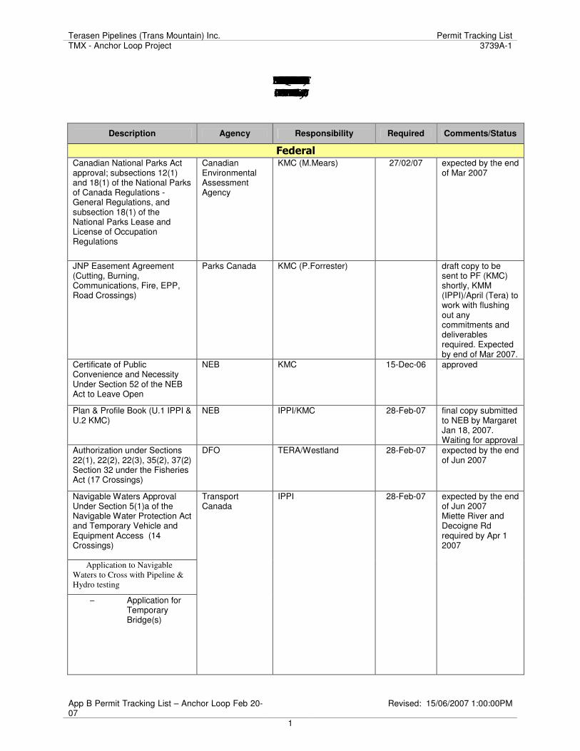
Terasen Pipelines (Trans Mountain) Inc. Permit Tracking List TMX - Anchor Loop Project 3739A-1
App B Permit Tracking List – Anchor Loop Feb 20-07
Revised: 15/06/2007 1:00:00PM
1
SUMMARY OF PERMIT REQUIREMENTS FOR THE TMX-ANCHOR LOOP PROJECT (ADAPTED FROM IPPI's PERMIT TRACKING LIST February 20, 2007)
Description Agency Responsibility Required Comments/Status
Federal
Canadian National Parks Act approval; subsections 12(1) and 18(1) of the National Parks of Canada Regulations - General Regulations, and subsection 18(1) of the National Parks Lease and License of Occupation Regulations
Canadian Environmental Assessment Agency
KMC (M.Mears) 27/02/07 expected by the end of Mar 2007
JNP Easement Agreement (Cutting, Burning, Communications, Fire, EPP, Road Crossings)
Parks Canada KMC (P.Forrester) draft copy to be sent to PF (KMC) shortly, KMM (IPPI)/April (Tera) to work with flushing out any commitments and deliverables required. Expected by end of Mar 2007.
Certificate of Public Convenience and Necessity Under Section 52 of the NEB Act to Leave Open
NEB KMC 15-Dec-06 approved
Plan & Profile Book (U.1 IPPI & U.2 KMC)
NEB IPPI/KMC 28-Feb-07 final copy submitted to NEB by Margaret Jan 18, 2007. Waiting for approval
Authorization under Sections 22(1), 22(2), 22(3), 35(2), 37(2) Section 32 under the Fisheries Act (17 Crossings)
DFO TERA/Westland 28-Feb-07 expected by the end of Jun 2007
Navigable Waters Approval Under Section 5(1)a of the Navigable Water Protection Act and Temporary Vehicle and Equipment Access (14 Crossings)
Application to Navigable
Waters to Cross with Pipeline &
Hydro testing
− Application for Temporary Bridge(s)
Transport Canada
IPPI 28-Feb-07 expected by the end of Jun 2007 Miette River and Decoigne Rd required by Apr 1 2007
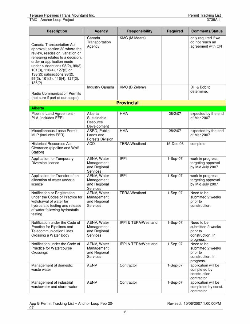
Terasen Pipelines (Trans Mountain) Inc. Permit Tracking List TMX - Anchor Loop Project 3739A-1
App B Permit Tracking List – Anchor Loop Feb 20-07
Revised: 15/06/2007 1:00:00PM
2
Description Agency Responsibility Required Comments/Status
Canada Transportation Act approval; section 32 where the review, rescission, variation or rehearing relates to a decision, order or application made under subsections 98(2), 99(3), 101(3), 116(4), 127(2) or 138(2); subsections 98(2), 99(3), 101(3), 116(4), 127(2), 138(2)
Canada Transportation Agency
KMC (M.Mears) only required if we do not reach an agreement with CN
Radio Communication Permits (not sure if part of our scope)
Industry Canada KMC (B.Zeleny) Bill & Bob to determine.
Provincial
Alberta
Pipeline Land Agreement - PLA (includes EFR)
Alberta Sustainable Resource Development
HMA 28/2/07 expected by the end of Mar 2007
Miscellaneous Lease Permit MLP (includes EFR)
ASRD, Public Lands and Forests Division
HMA 28/2/07 expected by the end of Mar 2007
Historical Resources Act Clearance (pipeline and Wolf Station)
ACD TERA/Westland 15-Dec-06 complete
Application for Temporary Diversion licence
AENV, Water Management and Regional Services
IPPI 1-Sep-07 work in progress, targeting approval by Mid July 2007
Application for Transfer of an allocation of water under a licence
AENV, Water Management and Regional Services
IPPI 1-Sep-07 work in progress, targeting approval by Mid July 2007
Notification or Registration under the Codes of Practice for withdrawal of water for hydrostatic testing and release of water following hydrostatic testing
AENV, Water Management and Regional Services
TERA/Westland 1-Sep-07 Need to be submitted 2 weeks prior to construction.
Notification under the Code of Practice for Pipelines and Telecommunication Lines Crossing a Water Body
AENV, Water Management and Regional Services
IPPI & TERA/Westland 1-Sep-07 Need to be submitted 2 weeks prior to construction. In progress.
Notification under the Code of Practice for Watercourse Crossings
AENV, Water Management and Regional Services
IPPI & TERA/Westland 1-Sep-07 Need to be submitted 2 weeks prior to construction. In progress.
Management of domestic waste water
AENV Contractor 1-Sep-07 application will be completed by construction contractor
Management of industrial wastewater and storm water
AENV Contractor 1-Sep-07 application will be completed by const. contractor
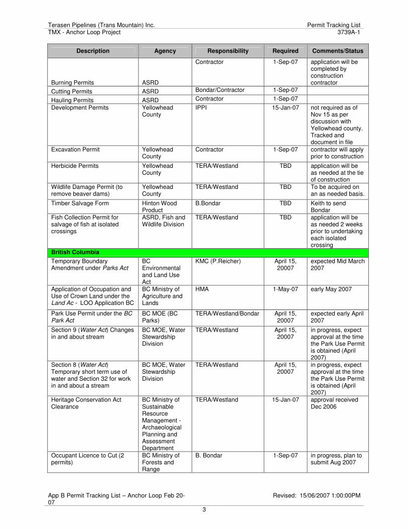
Terasen Pipelines (Trans Mountain) Inc. Permit Tracking List TMX - Anchor Loop Project 3739A-1
App B Permit Tracking List – Anchor Loop Feb 20-07
Revised: 15/06/2007 1:00:00PM
3
Description Agency Responsibility Required Comments/Status
Burning Permits ASRD
Contractor 1-Sep-07 application will be completed by construction contractor
Cutting Permits ASRD Bondar/Contractor 1-Sep-07
Hauling Permits ASRD Contractor 1-Sep-07
Development Permits Yellowhead County
IPPI 15-Jan-07 not required as of Nov 15 as per discussion with Yellowhead county. Tracked and document in file
Excavation Permit Yellowhead County
Contractor 1-Sep-07 contractor will apply prior to construction
Herbicide Permits Yellowhead County
TERA/Westland TBD application will be as needed at the tie of construction
Wildlife Damage Permit (to remove beaver dams)
Yellowhead County
TERA/Westland TBD To be acquired on an as needed basis.
Timber Salvage Form Hinton Wood Product
B.Bondar TBD Keith to send Bondar
Fish Collection Permit for salvage of fish at isolated crossings
ASRD, Fish and Wildlife Division
TERA/Westland TBD application will be as needed 2 weeks prior to undertaking each isolated crossing
British Columbia
Temporary Boundary Amendment under Parks Act
BC Environmental and Land Use Act
KMC (P.Reicher) April 15, 20007
expected Mid March 2007
Application of Occupation and Use of Crown Land under the Land Ac - LOO Application BC
BC Ministry of Agriculture and Lands
HMA 1-May-07 early May 2007
Park Use Permit under the BC
Park Act BC MOE (BC Parks)
TERA/Westland/Bondar April 15, 20007
expected early April 2007
Section 9 (Water Act) Changes in and about stream
BC MOE, Water Stewardship Division
TERA/Westland April 15, 20007
in progress, expect approval at the time the Park Use Permit is obtained (April 2007)
Section 8 (Water Act) Temporary short term use of water and Section 32 for work in and about a stream
BC MOE, Water Stewardship Division
TERA/Westland April 15, 20007
in progress, expect approval at the time the Park Use Permit is obtained (April 2007)
Heritage Conservation Act Clearance
BC Ministry of Sustainable Resource Management - Archaeological Planning and Assessment Department
TERA/Westland 15-Jan-07 approval received Dec 2006
Occupant Licence to Cut (2 permits)
BC Ministry of Forests and Range
B. Bondar 1-Sep-07 in progress, plan to submit Aug 2007
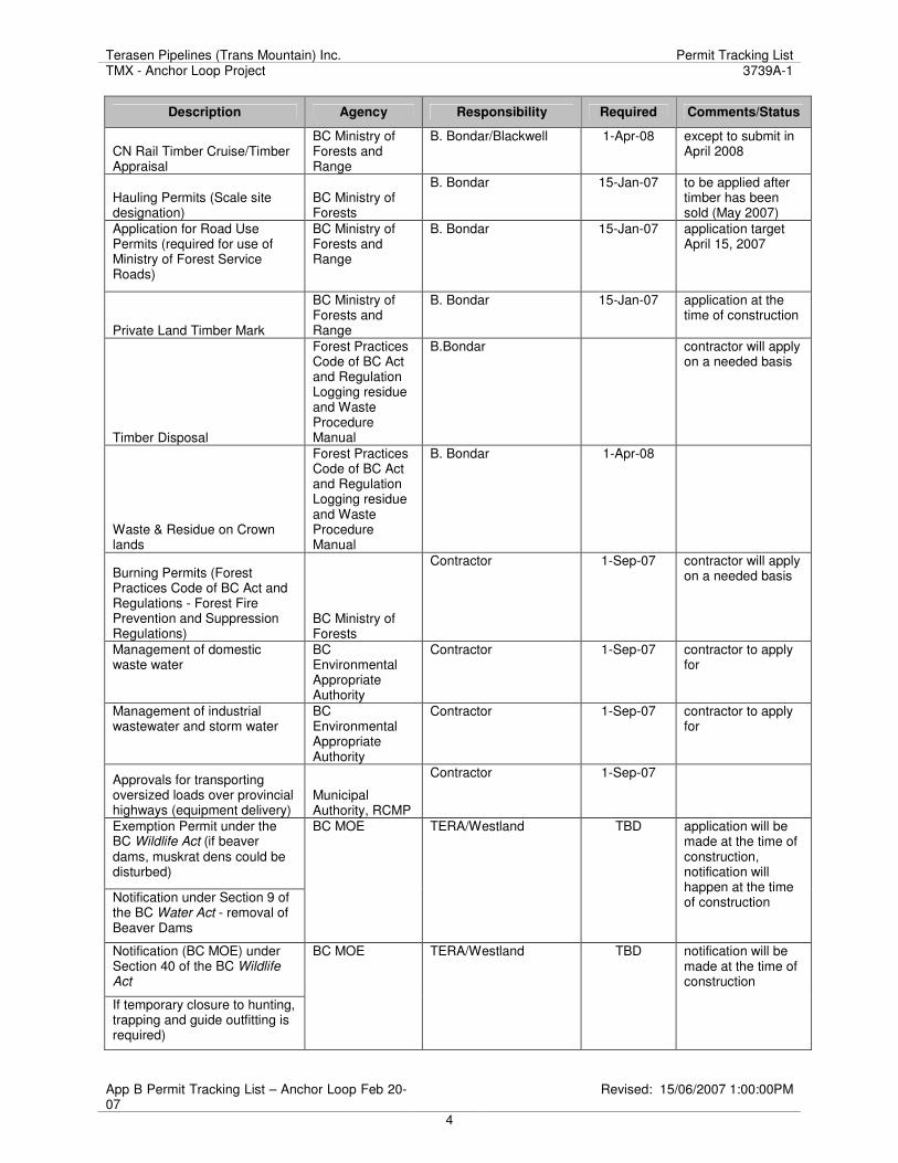
Terasen Pipelines (Trans Mountain) Inc. Permit Tracking List TMX - Anchor Loop Project 3739A-1
App B Permit Tracking List – Anchor Loop Feb 20-07
Revised: 15/06/2007 1:00:00PM
4
Description Agency Responsibility Required Comments/Status
CN Rail Timber Cruise/Timber Appraisal
BC Ministry of Forests and Range
B. Bondar/Blackwell 1-Apr-08 except to submit in April 2008
Hauling Permits (Scale site designation)
BC Ministry of Forests
B. Bondar 15-Jan-07 to be applied after timber has been sold (May 2007)
Application for Road Use Permits (required for use of Ministry of Forest Service Roads)
BC Ministry of Forests and Range
B. Bondar 15-Jan-07 application target April 15, 2007
Private Land Timber Mark
BC Ministry of Forests and Range
B. Bondar 15-Jan-07 application at the time of construction
Timber Disposal
Forest Practices Code of BC Act and Regulation Logging residue and Waste Procedure Manual
B.Bondar contractor will apply on a needed basis
Waste & Residue on Crown lands
Forest Practices Code of BC Act and Regulation Logging residue and Waste Procedure Manual
B. Bondar 1-Apr-08
Burning Permits (Forest Practices Code of BC Act and Regulations - Forest Fire Prevention and Suppression Regulations)
BC Ministry of Forests
Contractor 1-Sep-07 contractor will apply on a needed basis
Management of domestic waste water
BC Environmental Appropriate Authority
Contractor 1-Sep-07 contractor to apply for
Management of industrial wastewater and storm water
BC Environmental Appropriate Authority
Contractor 1-Sep-07 contractor to apply for
Approvals for transporting oversized loads over provincial highways (equipment delivery)
Municipal Authority, RCMP
Contractor 1-Sep-07
Exemption Permit under the BC Wildlife Act (if beaver dams, muskrat dens could be disturbed)
Notification under Section 9 of the BC Water Act - removal of Beaver Dams
BC MOE TERA/Westland TBD application will be made at the time of construction, notification will happen at the time of construction
Notification (BC MOE) under Section 40 of the BC Wildlife
Act
If temporary closure to hunting, trapping and guide outfitting is required)
BC MOE TERA/Westland TBD notification will be made at the time of construction
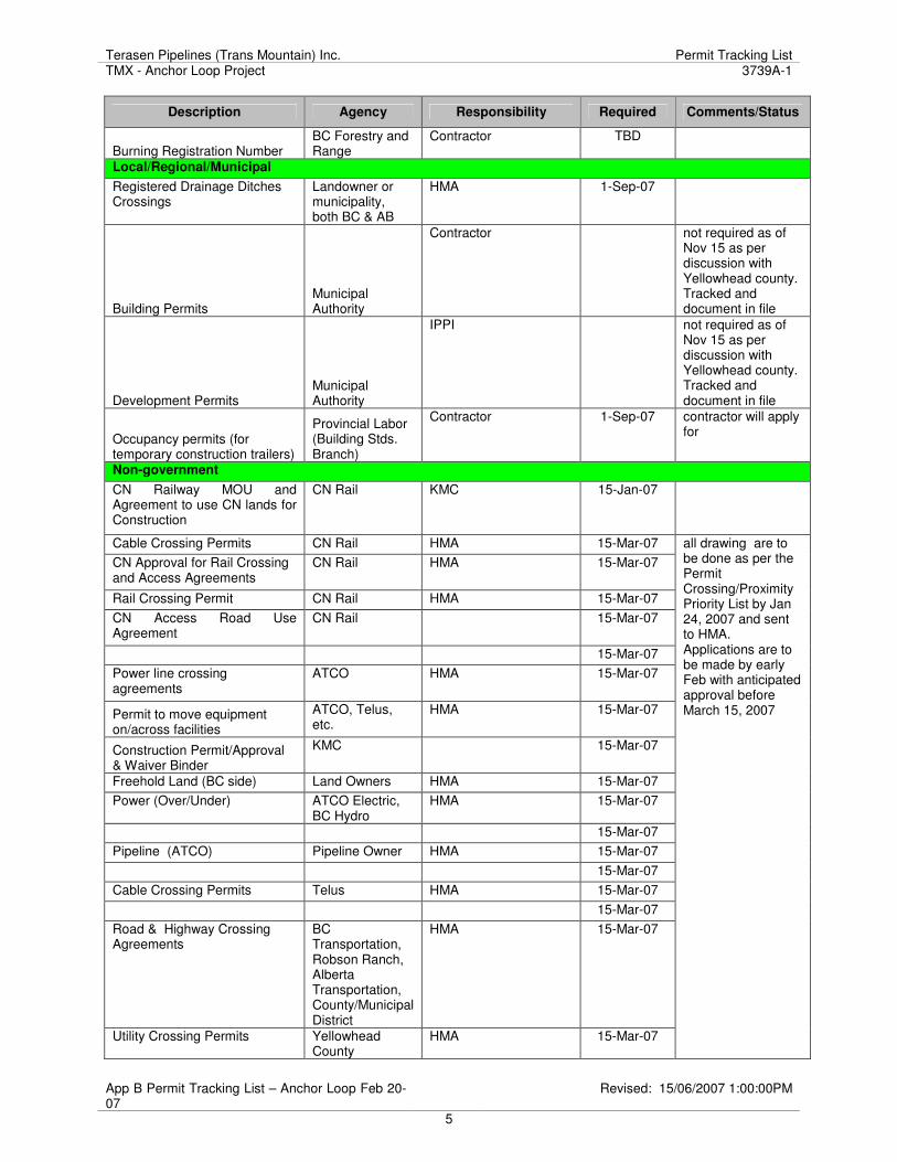
Terasen Pipelines (Trans Mountain) Inc. Permit Tracking List TMX - Anchor Loop Project 3739A-1
App B Permit Tracking List – Anchor Loop Feb 20-07
Revised: 15/06/2007 1:00:00PM
5
Description Agency Responsibility Required Comments/Status
Burning Registration Number BC Forestry and Range
Contractor TBD
Local/Regional/Municipal
Registered Drainage Ditches Crossings
Landowner or municipality, both BC & AB
HMA 1-Sep-07
Building Permits Municipal Authority
Contractor not required as of Nov 15 as per discussion with Yellowhead county. Tracked and document in file
Development Permits Municipal Authority
IPPI not required as of Nov 15 as per discussion with Yellowhead county. Tracked and document in file
Occupancy permits (for temporary construction trailers)
Provincial Labor (Building Stds. Branch)
Contractor 1-Sep-07 contractor will apply for
Non-government
CN Railway MOU and Agreement to use CN lands for Construction
CN Rail KMC 15-Jan-07
Cable Crossing Permits CN Rail HMA 15-Mar-07
CN Approval for Rail Crossing and Access Agreements
CN Rail HMA 15-Mar-07
Rail Crossing Permit CN Rail HMA 15-Mar-07
CN Access Road Use Agreement
CN Rail 15-Mar-07
15-Mar-07
Power line crossing agreements
ATCO HMA 15-Mar-07
Permit to move equipment on/across facilities
ATCO, Telus, etc.
HMA 15-Mar-07
Construction Permit/Approval & Waiver Binder
KMC 15-Mar-07
Freehold Land (BC side) Land Owners HMA 15-Mar-07
Power (Over/Under) ATCO Electric, BC Hydro
HMA 15-Mar-07
15-Mar-07
Pipeline (ATCO) Pipeline Owner HMA 15-Mar-07
15-Mar-07
Cable Crossing Permits Telus HMA 15-Mar-07
15-Mar-07
Road & Highway Crossing Agreements
BC Transportation, Robson Ranch, Alberta Transportation, County/Municipal District
HMA 15-Mar-07
Utility Crossing Permits Yellowhead County
HMA 15-Mar-07
all drawing are to be done as per the Permit Crossing/Proximity Priority List by Jan 24, 2007 and sent to HMA. Applications are to be made by early Feb with anticipated approval before March 15, 2007
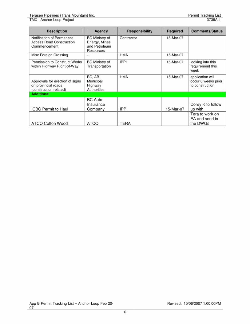
Terasen Pipelines (Trans Mountain) Inc. Permit Tracking List TMX - Anchor Loop Project 3739A-1
App B Permit Tracking List – Anchor Loop Feb 20-07
Revised: 15/06/2007 1:00:00PM
6
Description Agency Responsibility Required Comments/Status
Notification of Permanent Access Road Construction Commencement
BC Ministry of Energy, Mines and Petroleum Resources
Contractor 15-Mar-07
Misc Foreign Crossing -- HMA 15-Mar-07
Permission to Construct Works within Highway Right-of-Way
BC Ministry of Transportation
IPPI 15-Mar-07 looking into this requirement this week
Approvals for erection of signs on provincial roads (construction related)
BC, AB Municipal Highway Authorities
HMA 15-Mar-07 application will occur 6 weeks prior to construction
Additional
ICBC Permit to Haul
BC Auto Insurance Company IPPI 15-Mar-07
Corey K to follow up with
ATCO Cotton Wood ATCO TERA
Tera to work on EA and send in the DWGs

APPENDIX C
Project Standards and Specifications
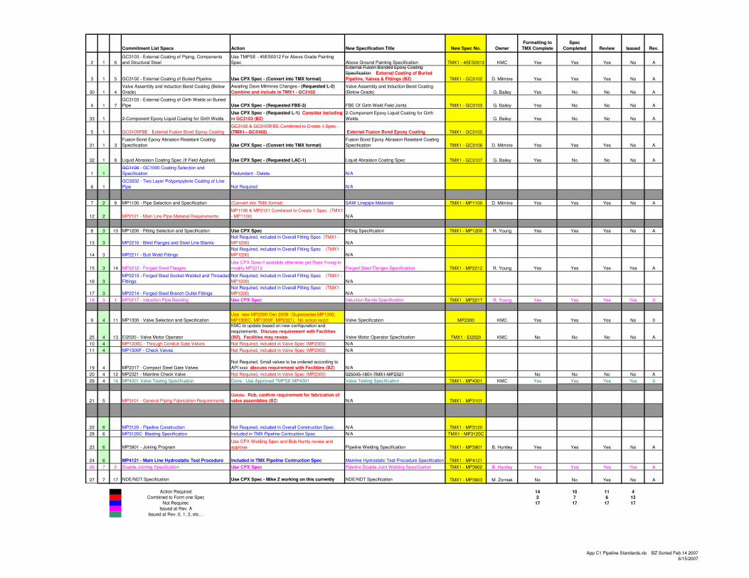
Commitment List Specs Action New Specification Title New Spec No. Owner
Formatting to
TMX Complete
Spec
Completed Review Issued Rev.
2 1 6
GC3103 - External Coating of Piping, Components and Structural Steel
Use TMPSE - 45ES0012 For Above Grade Painting Spec Above Ground Painting Specification TMX1 - 45ES0012 KMC Yes Yes Yes No A
3 1 5 GC3102 - External Coating of Buried Pipeline Use CPX Spec - (Convert into TMX format)
External Fusion Bonded Epoxy Coating
Specification External Coating of Buried
Pipeline, Valves & Fittings (BZ) TMX1 - GC3102 D. Milmine Yes Yes Yes No A
30 1 4
Valve Assembly and Induction Bend Coating (Below Grade)
Awaiting Dave Milmines Changes - (Requested L-2)
Combine and include in TMX1 - GC3102
Valve Assembly and Induction Bend Coating (Below Grade) G. Bailey Yes No No No A
4 1 7
GC3103 - External Coating of Girth Welds on Buried Pipe Use CPX Spec - (Requested FBE-3) FBE Of Girth Weld Field Joints TMX1 - GC3103 G. Bailey Yes No No No A
33 1 2-Component Epoxy Liquid Coating for Girth Welds
Use CPX Spec - (Requested L-1) Consider including
in GC3103 (BZ)
2-Component Epoxy Liquid Coating for Girth Welds G. Bailey Yes No No No A
5 1 GC3105FBE - External Fusion Bond Epoxy Coating
GC3102 & GC3105FBE Combined to Create 1 Spec
(TMX1 - GC3102) External Fusion Bond Epoxy Coating TMX1 - GC3105
31 1 3
Fusion Bond Epoxy Abrasion Resistant Coating Specification Use CPX Spec - (Convert into TMX format)
Fusion Bond Epoxy Abrasion Resistant Coating Specification TMX1 - GC3106 D. Milmine Yes Yes Yes No A
32 1 8 Liquid Abraision Coating Spec (If Field Applied) Use CPX Spec - (Requested LAC-1) Liquid Abraision Coating Spec TMX1 - GC3107 G. Bailey Yes No No No A
1 1
GC1100 - GC1000 Coating Selection and Specification Redundant - Delete N/A
6 1
GC3202 - Two Layer Polypropylene Coating of Line Pipe Not Required N/A
7 2 9 MP1100 - Pipe Selection and Specification (Convert into TMX format) SAW Linepipe Materials TMX1 - MP1100 D. Milmine Yes Yes Yes No A
12 2 MP2121 - Main Line Pipe Material RequirementsMP1100 & MP2121 Combined to Create 1 Spec (TMX1 - MP1100) N/A
8 3 10 MP1200 - Fitting Selection and Specification Use CPX Spec Fitting Specification TMX1 - MP1200 R. Young Yes Yes Yes No A
13 3 MP2210 - Blind Flanges and Steel Line BlanksNot Required, included in Overall Fitting Spec (TMX1 - MP1200) N/A
14 3 MP2211 - Butt Weld FittingsNot Required, included in Overall Fitting Spec (TMX1 - MP1200) N/A
15 3 14 MP2212 - Forged Steel FlangesUse CPX Spec if available otherwise get Russ Young to modify MP2212 Forged Steel Flanges Specification TMX1 - MP2212 R. Young Yes Yes Yes Yes A
16 3
MP2213 - Forged Steel Socket-Welded and Threaded
FittingsNot Required, included in Overall Fitting Spec (TMX1 - MP1200) N/A
17 3 MP2214 - Forged Steel Branch Outlet FittingsNot Required, included in Overall Fitting Spec (TMX1 - MP1200) N/A
18 3 1 MP2217 - Induction Pipe Bending Use CPX Spec Induction Bends Specification TMX1 - MP2217 R. Young Yes Yes Yes Yes 0
9 4 11 MP1300 - Valve Selection and SpecificationUse new MP2300 Dec 2006 (Supersedes MP1300, MP1300C, MP1300F, MP2321). No action req'd. Valve Specification MP2300 KMC Yes Yes Yes No 0
25 4 13 EI2020 - Valve Motor Operator
KMC to update based on new configuration and
requirements. Discuss requirement with Facilities
(BZ). Facilities may revise. Valve Motor Operator Specification TMX1 - EI2020 KMC No No No No A
10 4 MP1300C - Through Conduit Gate Valves Not Required, included in Valve Spec (MP2300) N/A
11 4 MP1300F - Check Valves Not Required, included in Valve Spec (MP2300) N/A
19 4 MP2317 - Compact Steel Gate Valves
Not Required. Small valves to be ordered according to
API xxxx discuss requirement with Facilities (BZ) N/A
20 4 12 MP2321 - Mainline Check Valve Not Required, included in Valve Spec (MP2300) 025045-1801-TMX1-MP2321 No No No No A
29 4 16 MP4301 Valve Testing Specification Done - Use Approved TMPSE-MP4301 Valve Testing Specification TMX1 - MP4301 KMC Yes Yes Yes Yes 0
21 5 MP3101 - General Piping Fabrication Requirements
Delete. Rob, confirm requirement for fabrication of
valve assemblies (BZ) N/A TMX1 - MP3101
22 6 MP3120 - Pipeline Construction Not Required, included in Overall Construction Spec N/A TMX1 - MP3120
28 6 MP3120C Blasting Specification Included in TMX Pipeline Contruction Spec N/A TMX1 - MP3120C
23 6 MP3901 - Joining ProgramUse CPX Welding Spec and Bob Huntly review and approve Pipeline Welding Specification TMX1 - MP3901 B. Huntley Yes Yes Yes No A
24 6 MP4121 - Main Line Hydrostatic Test Procedure Included in TMX Pipeline Contruction Spec Mainline Hydrostatic Test Procedure Specification TMX1 - MP4121
26 7 2 Double Jointing Specification Use CPX Spec Pipeline Double Joint Welding Specification TMX1 - MP3902 B. Huntley Yes Yes Yes Yes A
27 7 17 NDE/NDT Specification Use CPX Spec - Mike Z working on this currently NDE/NDT Specification TMX1 - MP3903 M. Zorniak No No Yes No A
Action Required 14 10 11 4
Combined to Form one Spec 3 7 6 13
Not Required 17 17 17 17
Issued at Rev. AIssued at Rev. 0, 1, 2, etc…
App C1 Pipeline Standards.xls BZ Sorted Feb 14 20076/15/2007
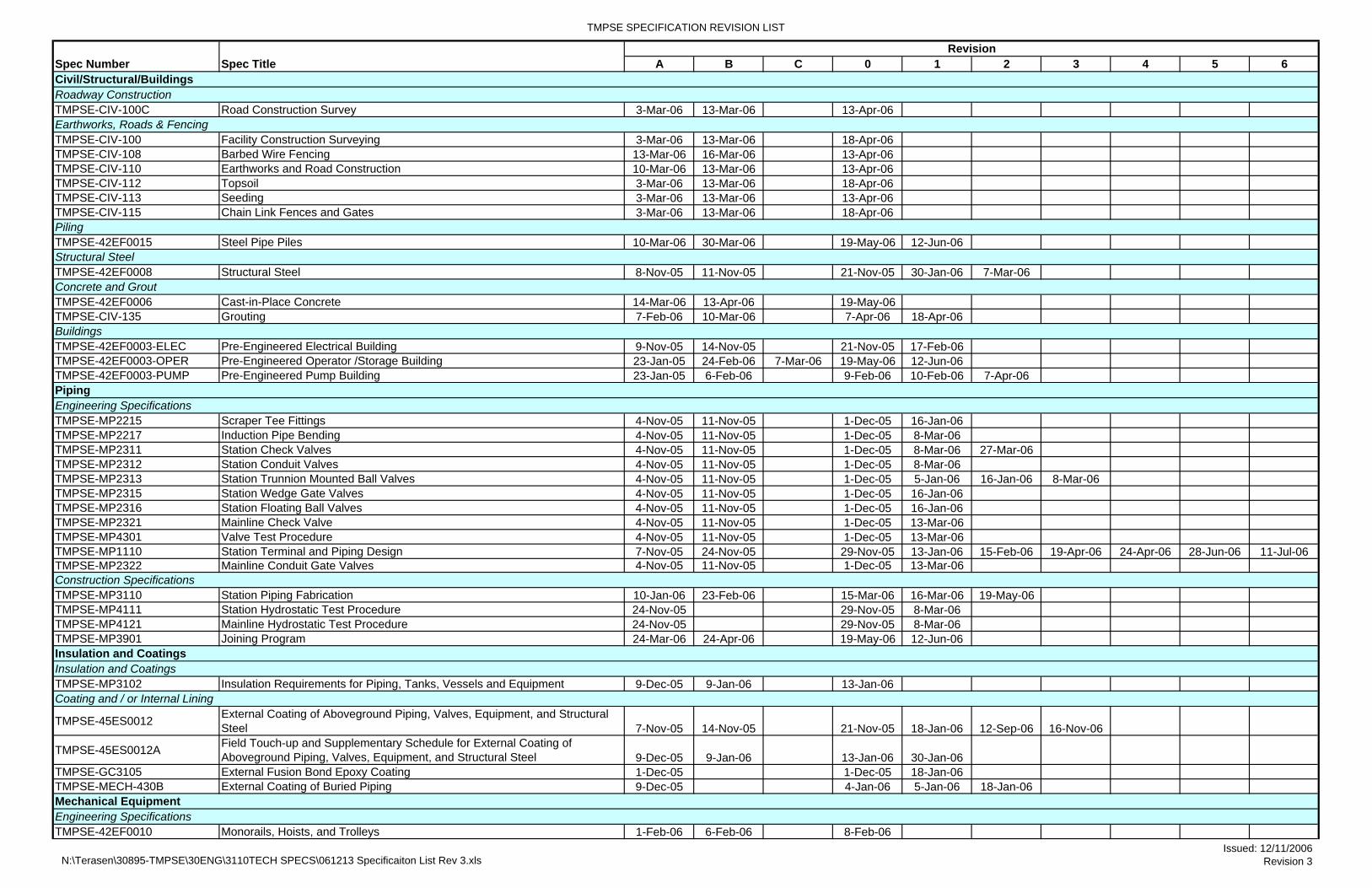
TMPSE SPECIFICATION REVISION LIST
A B C 0 1 2 3 4 5 6
TMPSE-CIV-100C Road Construction Survey 3-Mar-06 13-Mar-06 13-Apr-06
TMPSE-CIV-100 Facility Construction Surveying 3-Mar-06 13-Mar-06 18-Apr-06TMPSE-CIV-108 Barbed Wire Fencing 13-Mar-06 16-Mar-06 13-Apr-06TMPSE-CIV-110 Earthworks and Road Construction 10-Mar-06 13-Mar-06 13-Apr-06TMPSE-CIV-112 Topsoil 3-Mar-06 13-Mar-06 18-Apr-06TMPSE-CIV-113 Seeding 3-Mar-06 13-Mar-06 13-Apr-06TMPSE-CIV-115 Chain Link Fences and Gates 3-Mar-06 13-Mar-06 18-Apr-06
TMPSE-42EF0015 Steel Pipe Piles 10-Mar-06 30-Mar-06 19-May-06 12-Jun-06
TMPSE-42EF0008 Structural Steel 8-Nov-05 11-Nov-05 21-Nov-05 30-Jan-06 7-Mar-06
TMPSE-42EF0006 Cast-in-Place Concrete 14-Mar-06 13-Apr-06 19-May-06TMPSE-CIV-135 Grouting 7-Feb-06 10-Mar-06 7-Apr-06 18-Apr-06
TMPSE-42EF0003-ELEC Pre-Engineered Electrical Building 9-Nov-05 14-Nov-05 21-Nov-05 17-Feb-06TMPSE-42EF0003-OPER Pre-Engineered Operator /Storage Building 23-Jan-05 24-Feb-06 7-Mar-06 19-May-06 12-Jun-06TMPSE-42EF0003-PUMP Pre-Engineered Pump Building 23-Jan-05 6-Feb-06 9-Feb-06 10-Feb-06 7-Apr-06
TMPSE-MP2215 Scraper Tee Fittings 4-Nov-05 11-Nov-05 1-Dec-05 16-Jan-06TMPSE-MP2217 Induction Pipe Bending 4-Nov-05 11-Nov-05 1-Dec-05 8-Mar-06TMPSE-MP2311 Station Check Valves 4-Nov-05 11-Nov-05 1-Dec-05 8-Mar-06 27-Mar-06TMPSE-MP2312 Station Conduit Valves 4-Nov-05 11-Nov-05 1-Dec-05 8-Mar-06TMPSE-MP2313 Station Trunnion Mounted Ball Valves 4-Nov-05 11-Nov-05 1-Dec-05 5-Jan-06 16-Jan-06 8-Mar-06TMPSE-MP2315 Station Wedge Gate Valves 4-Nov-05 11-Nov-05 1-Dec-05 16-Jan-06TMPSE-MP2316 Station Floating Ball Valves 4-Nov-05 11-Nov-05 1-Dec-05 16-Jan-06TMPSE-MP2321 Mainline Check Valve 4-Nov-05 11-Nov-05 1-Dec-05 13-Mar-06TMPSE-MP4301 Valve Test Procedure 4-Nov-05 11-Nov-05 1-Dec-05 13-Mar-06TMPSE-MP1110 Station Terminal and Piping Design 7-Nov-05 24-Nov-05 29-Nov-05 13-Jan-06 15-Feb-06 19-Apr-06 24-Apr-06 28-Jun-06 11-Jul-06TMPSE-MP2322 Mainline Conduit Gate Valves 4-Nov-05 11-Nov-05 1-Dec-05 13-Mar-06
TMPSE-MP3110 Station Piping Fabrication 10-Jan-06 23-Feb-06 15-Mar-06 16-Mar-06 19-May-06TMPSE-MP4111 Station Hydrostatic Test Procedure 24-Nov-05 29-Nov-05 8-Mar-06TMPSE-MP4121 Mainline Hydrostatic Test Procedure 24-Nov-05 29-Nov-05 8-Mar-06TMPSE-MP3901 Joining Program 24-Mar-06 24-Apr-06 19-May-06 12-Jun-06
TMPSE-MP3102 Insulation Requirements for Piping, Tanks, Vessels and Equipment 9-Dec-05 9-Jan-06 13-Jan-06
TMPSE-45ES0012 External Coating of Aboveground Piping, Valves, Equipment, and Structural Steel 7-Nov-05 14-Nov-05 21-Nov-05 18-Jan-06 12-Sep-06 16-Nov-06
TMPSE-45ES0012A Field Touch-up and Supplementary Schedule for External Coating of Aboveground Piping, Valves, Equipment, and Structural Steel 9-Dec-05 9-Jan-06 13-Jan-06 30-Jan-06
TMPSE-GC3105 External Fusion Bond Epoxy Coating 1-Dec-05 1-Dec-05 18-Jan-06TMPSE-MECH-430B External Coating of Buried Piping 9-Dec-05 4-Jan-06 5-Jan-06 18-Jan-06
TMPSE-42EF0010 Monorails, Hoists, and Trolleys 1-Feb-06 6-Feb-06 8-Feb-06
Revision
Coating and / or Internal Lining
Insulation and CoatingsInsulation and Coatings
Construction Specifications
Engineering Specifications
Earthworks, Roads & Fencing
Piling
Civil/Structural/BuildingsRoadway Construction
Spec TitleSpec Number
Structural Steel
Concrete and Grout
Buildings
Piping
Engineering SpecificationsMechanical Equipment
N:\Terasen\30895-TMPSE\30ENG\3110TECH SPECS\061213 Specificaiton List Rev 3.xlsIssued: 12/11/2006
Revision 3
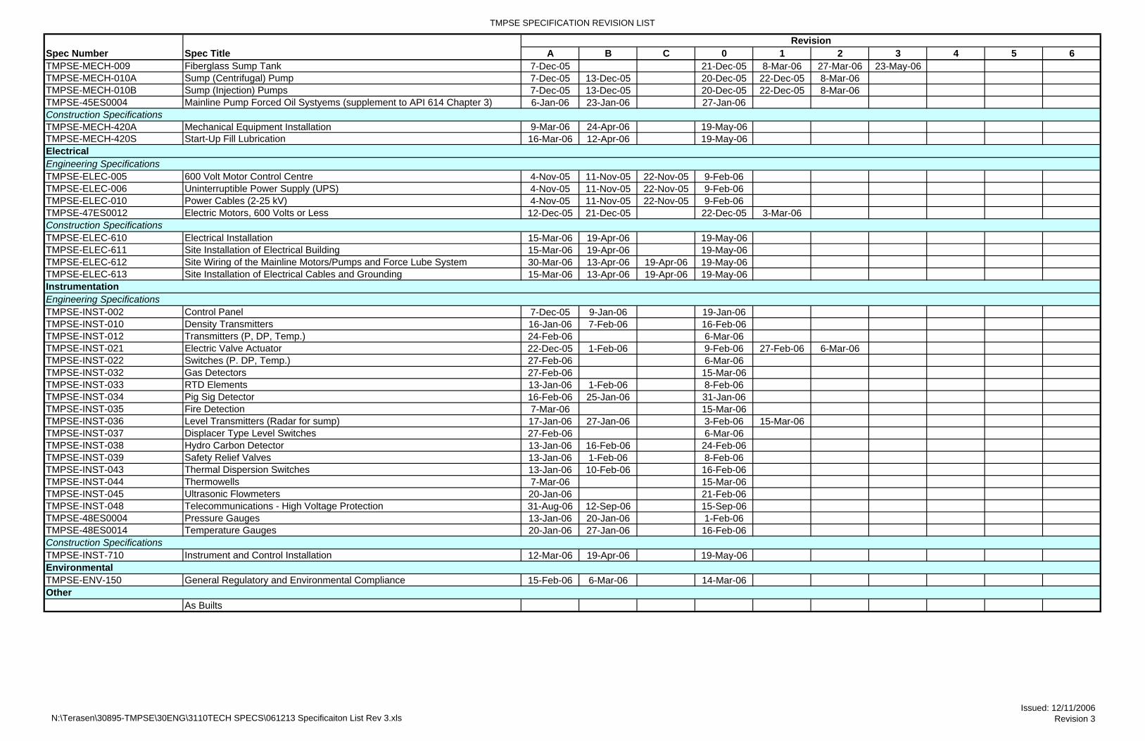
TMPSE SPECIFICATION REVISION LIST
A B C 0 1 2 3 4 5 6Revision
Spec TitleSpec NumberTMPSE-MECH-009 Fiberglass Sump Tank 7-Dec-05 21-Dec-05 8-Mar-06 27-Mar-06 23-May-06TMPSE-MECH-010A Sump (Centrifugal) Pump 7-Dec-05 13-Dec-05 20-Dec-05 22-Dec-05 8-Mar-06TMPSE-MECH-010B Sump (Injection) Pumps 7-Dec-05 13-Dec-05 20-Dec-05 22-Dec-05 8-Mar-06TMPSE-45ES0004 Mainline Pump Forced Oil Systyems (supplement to API 614 Chapter 3) 6-Jan-06 23-Jan-06 27-Jan-06
TMPSE-MECH-420A Mechanical Equipment Installation 9-Mar-06 24-Apr-06 19-May-06TMPSE-MECH-420S Start-Up Fill Lubrication 16-Mar-06 12-Apr-06 19-May-06
TMPSE-ELEC-005 600 Volt Motor Control Centre 4-Nov-05 11-Nov-05 22-Nov-05 9-Feb-06TMPSE-ELEC-006 Uninterruptible Power Supply (UPS) 4-Nov-05 11-Nov-05 22-Nov-05 9-Feb-06TMPSE-ELEC-010 Power Cables (2-25 kV) 4-Nov-05 11-Nov-05 22-Nov-05 9-Feb-06TMPSE-47ES0012 Electric Motors, 600 Volts or Less 12-Dec-05 21-Dec-05 22-Dec-05 3-Mar-06
TMPSE-ELEC-610 Electrical Installation 15-Mar-06 19-Apr-06 19-May-06TMPSE-ELEC-611 Site Installation of Electrical Building 15-Mar-06 19-Apr-06 19-May-06TMPSE-ELEC-612 Site Wiring of the Mainline Motors/Pumps and Force Lube System 30-Mar-06 13-Apr-06 19-Apr-06 19-May-06TMPSE-ELEC-613 Site Installation of Electrical Cables and Grounding 15-Mar-06 13-Apr-06 19-Apr-06 19-May-06
TMPSE-INST-002 Control Panel 7-Dec-05 9-Jan-06 19-Jan-06TMPSE-INST-010 Density Transmitters 16-Jan-06 7-Feb-06 16-Feb-06TMPSE-INST-012 Transmitters (P, DP, Temp.) 24-Feb-06 6-Mar-06TMPSE-INST-021 Electric Valve Actuator 22-Dec-05 1-Feb-06 9-Feb-06 27-Feb-06 6-Mar-06TMPSE-INST-022 Switches (P. DP, Temp.) 27-Feb-06 6-Mar-06TMPSE-INST-032 Gas Detectors 27-Feb-06 15-Mar-06TMPSE-INST-033 RTD Elements 13-Jan-06 1-Feb-06 8-Feb-06TMPSE-INST-034 Pig Sig Detector 16-Feb-06 25-Jan-06 31-Jan-06TMPSE-INST-035 Fire Detection 7-Mar-06 15-Mar-06TMPSE-INST-036 Level Transmitters (Radar for sump) 17-Jan-06 27-Jan-06 3-Feb-06 15-Mar-06TMPSE-INST-037 Displacer Type Level Switches 27-Feb-06 6-Mar-06TMPSE-INST-038 Hydro Carbon Detector 13-Jan-06 16-Feb-06 24-Feb-06TMPSE-INST-039 Safety Relief Valves 13-Jan-06 1-Feb-06 8-Feb-06TMPSE-INST-043 Thermal Dispersion Switches 13-Jan-06 10-Feb-06 16-Feb-06TMPSE-INST-044 Thermowells 7-Mar-06 15-Mar-06TMPSE-INST-045 Ultrasonic Flowmeters 20-Jan-06 21-Feb-06TMPSE-INST-048 Telecommunications - High Voltage Protection 31-Aug-06 12-Sep-06 15-Sep-06TMPSE-48ES0004 Pressure Gauges 13-Jan-06 20-Jan-06 1-Feb-06TMPSE-48ES0014 Temperature Gauges 20-Jan-06 27-Jan-06 16-Feb-06
TMPSE-INST-710 Instrument and Control Installation 12-Mar-06 19-Apr-06 19-May-06
TMPSE-ENV-150 General Regulatory and Environmental Compliance 15-Feb-06 6-Mar-06 14-Mar-06
As Builts
Engineering SpecificationsElectrical
Other
Environmental
Construction Specifications
Engineering Specifications
Construction Specifications
Instrumentation
Construction Specifications
N:\Terasen\30895-TMPSE\30ENG\3110TECH SPECS\061213 Specificaiton List Rev 3.xlsIssued: 12/11/2006
Revision 3

APPENDIX D
Environmentally Significant Sites
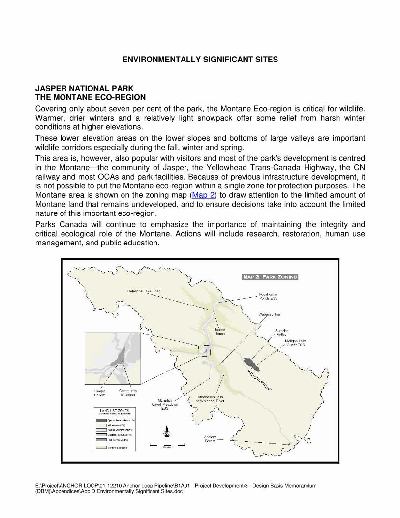
E:\Project\ANCHOR LOOP\01-12210 Anchor Loop Pipeline\B1A01 - Project Development\3 - Design Basis Memorandum (DBM)\Appendices\App D Environmentally Significant Sites.doc
ENVIRONMENTALLY SIGNIFICANT SITES
JASPER NATIONAL PARK THE MONTANE ECO-REGION
Covering only about seven per cent of the park, the Montane Eco-region is critical for wildlife. Warmer, drier winters and a relatively light snowpack offer some relief from harsh winter conditions at higher elevations.
These lower elevation areas on the lower slopes and bottoms of large valleys are important wildlife corridors especially during the fall, winter and spring.
This area is, however, also popular with visitors and most of the park’s development is centred in the Montane—the community of Jasper, the Yellowhead Trans-Canada Highway, the CN railway and most OCAs and park facilities. Because of previous infrastructure development, it is not possible to put the Montane eco-region within a single zone for protection purposes. The Montane area is shown on the zoning map (Map 2) to draw attention to the limited amount of Montane land that remains undeveloped, and to ensure decisions take into account the limited nature of this important eco-region.
Parks Canada will continue to emphasize the importance of maintaining the integrity and critical ecological role of the Montane. Actions will include research, restoration, human use management, and public education.

E:\Project\ANCHOR LOOP\01-12210 Anchor Loop Pipeline\B1A01 - Project Development\3 - Design Basis Memorandum (DBM)\Appendices\App D Environmentally Significant Sites.doc
POCAHONTAS PONDS
The wetlands of the Athabasca floodplain near Pocahontas are known locally as the Pocahontas Ponds. This area of small ponds and active and dead stream channels is very important to wildlife. The area provides critical winter range for elk and moose and is also important to small mammals. Carnivores are attracted by these prey species. Numerous bird species occur in high densities, many of which are not found elsewhere in the parks. Raptors such as osprey and bald eagle nest here. The area also provides habitat for the river otter, a species which is rare in the park.
Any major construction in the area (e.g., roads) will change sedimentation and erosion patterns. Care must be taken that any development and use do not have a negative impact on the area’s special resources.

APPENDIX E
Declared Wilderness Areas
E:\Project\ANCHOR LOOP\01-12210 Anchor Loop Pipeline\B1A01 - Project Development\3 - Design Basis Memorandum (DBM)\Appendices\App E WILDERNESS AREA.doc
WILDERNESS AREA
JASPER NATIONAL PARK
Internet site http://canadagazette.gc.ca/partI/1999/19991106/html/regle-e.html is a public site to access the Declared Wilderness maps for Jasper National Park. This corresponds to the Zone II Wilderness areas in the Jasper Management Plan. In reviewing these 1:50,000 scale maps against TMPL's existing right-of-way, there are 24.7 km of the 80 km in the Park, where TMPL was used as the wilderness boundary. There is a 25m offset from existing RoW centerline.
The following approximate KP ranges are where TMPL borders the wilderness boundary: 333.0 to 336.3; 339.3 to 340.8; 342.0 to 343.2; 343.7 to 345.2; 348.1 to 350.5; 352.8 to 353.8; 354.5 to 366.0; 399.9 to 402.2.
From east to west, the TMPL Alignment Sheets that cover the Trans Mountain route in Jasper are:
• 83903 Miette 83F/4
• 83919 Snaring River 83E/1
• 83913 Jasper 83D/16

APPENDIX F
Climatic Data
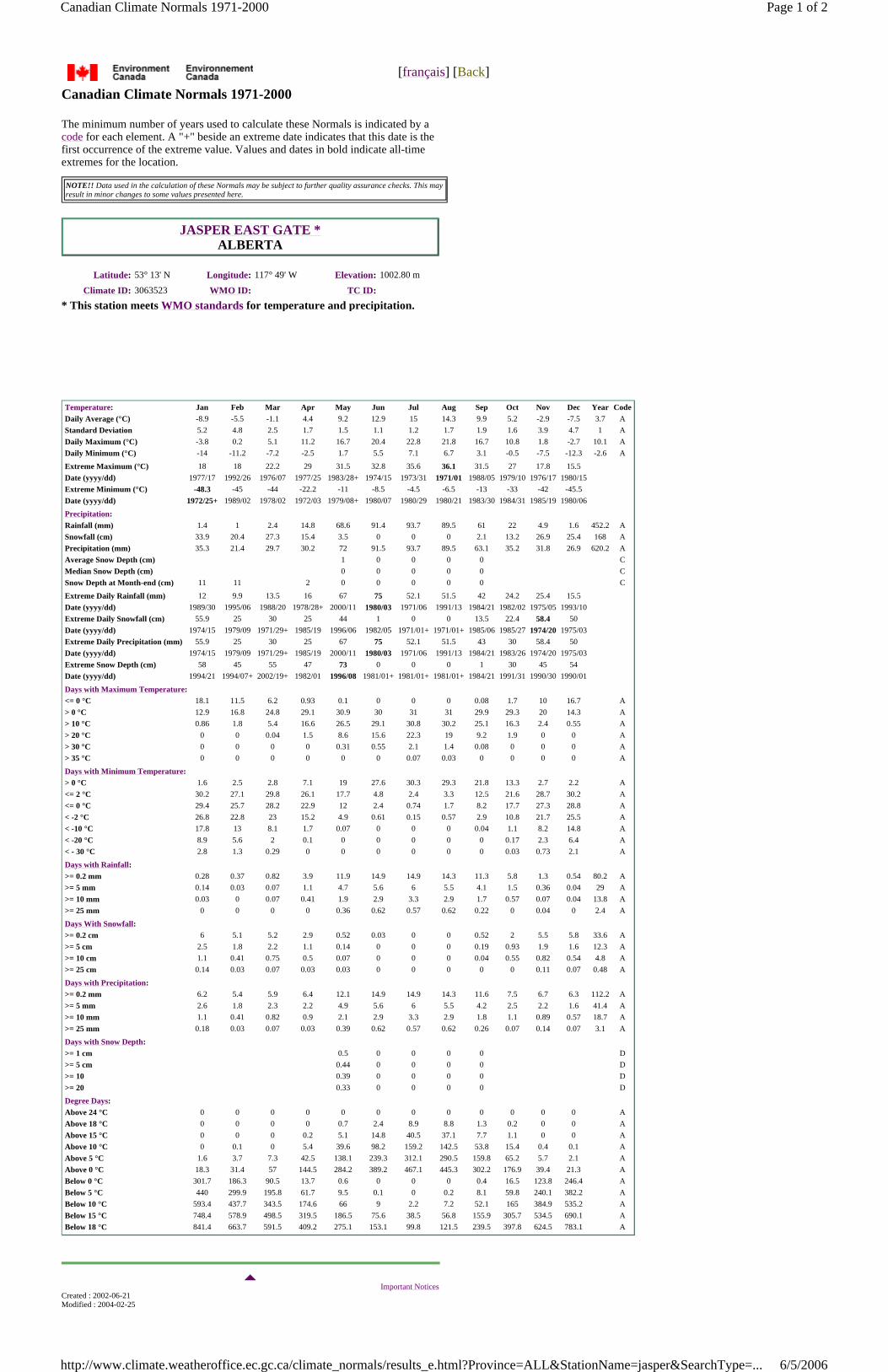
[français] [Back]
Canadian Climate Normals 1971-2000
The minimum number of years used to calculate these Normals is indicated by a code for each element. A "+" beside an extreme date indicates that this date is the first occurrence of the extreme value. Values and dates in bold indicate all-time extremes for the location.
NOTE!! Data used in the calculation of these Normals may be subject to further quality assurance checks. This may result in minor changes to some values presented here.
JASPER EAST GATE * ALBERTA
Latitude: 53° 13' N Longitude: 117° 49' W Elevation: 1002.80 m
Climate ID: 3063523 WMO ID: TC ID:
* This station meets WMO standards for temperature and precipitation.
Temperature: Jan Feb Mar Apr May Jun Jul Aug Sep Oct Nov Dec Year CodeDaily Average (°C) -8.9 -5.5 -1.1 4.4 9.2 12.9 15 14.3 9.9 5.2 -2.9 -7.5 3.7 AStandard Deviation 5.2 4.8 2.5 1.7 1.5 1.1 1.2 1.7 1.9 1.6 3.9 4.7 1 ADaily Maximum (°C) -3.8 0.2 5.1 11.2 16.7 20.4 22.8 21.8 16.7 10.8 1.8 -2.7 10.1 ADaily Minimum (°C) -14 -11.2 -7.2 -2.5 1.7 5.5 7.1 6.7 3.1 -0.5 -7.5 -12.3 -2.6 A
Extreme Maximum (°C) 18 18 22.2 29 31.5 32.8 35.6 36.1 31.5 27 17.8 15.5Date (yyyy/dd) 1977/17 1992/26 1976/07 1977/25 1983/28+ 1974/15 1973/31 1971/01 1988/05 1979/10 1976/17 1980/15Extreme Minimum (°C) -48.3 -45 -44 -22.2 -11 -8.5 -4.5 -6.5 -13 -33 -42 -45.5Date (yyyy/dd) 1972/25+ 1989/02 1978/02 1972/03 1979/08+ 1980/07 1980/29 1980/21 1983/30 1984/31 1985/19 1980/06
Precipitation: Rainfall (mm) 1.4 1 2.4 14.8 68.6 91.4 93.7 89.5 61 22 4.9 1.6 452.2 ASnowfall (cm) 33.9 20.4 27.3 15.4 3.5 0 0 0 2.1 13.2 26.9 25.4 168 APrecipitation (mm) 35.3 21.4 29.7 30.2 72 91.5 93.7 89.5 63.1 35.2 31.8 26.9 620.2 AAverage Snow Depth (cm) 1 0 0 0 0 CMedian Snow Depth (cm) 0 0 0 0 0 CSnow Depth at Month-end (cm) 11 11 2 0 0 0 0 0 C
Extreme Daily Rainfall (mm) 12 9.9 13.5 16 67 75 52.1 51.5 42 24.2 25.4 15.5Date (yyyy/dd) 1989/30 1995/06 1988/20 1978/28+ 2000/11 1980/03 1971/06 1991/13 1984/21 1982/02 1975/05 1993/10Extreme Daily Snowfall (cm) 55.9 25 30 25 44 1 0 0 13.5 22.4 58.4 50Date (yyyy/dd) 1974/15 1979/09 1971/29+ 1985/19 1996/06 1982/05 1971/01+ 1971/01+ 1985/06 1985/27 1974/20 1975/03Extreme Daily Precipitation (mm) 55.9 25 30 25 67 75 52.1 51.5 43 30 58.4 50Date (yyyy/dd) 1974/15 1979/09 1971/29+ 1985/19 2000/11 1980/03 1971/06 1991/13 1984/21 1983/26 1974/20 1975/03Extreme Snow Depth (cm) 58 45 55 47 73 0 0 0 1 30 45 54Date (yyyy/dd) 1994/21 1994/07+ 2002/19+ 1982/01 1996/08 1981/01+ 1981/01+ 1981/01+ 1984/21 1991/31 1990/30 1990/01
Days with Maximum Temperature: <= 0 °C 18.1 11.5 6.2 0.93 0.1 0 0 0 0.08 1.7 10 16.7 A> 0 °C 12.9 16.8 24.8 29.1 30.9 30 31 31 29.9 29.3 20 14.3 A> 10 °C 0.86 1.8 5.4 16.6 26.5 29.1 30.8 30.2 25.1 16.3 2.4 0.55 A> 20 °C 0 0 0.04 1.5 8.6 15.6 22.3 19 9.2 1.9 0 0 A> 30 °C 0 0 0 0 0.31 0.55 2.1 1.4 0.08 0 0 0 A> 35 °C 0 0 0 0 0 0 0.07 0.03 0 0 0 0 A
Days with Minimum Temperature: > 0 °C 1.6 2.5 2.8 7.1 19 27.6 30.3 29.3 21.8 13.3 2.7 2.2 A<= 2 °C 30.2 27.1 29.8 26.1 17.7 4.8 2.4 3.3 12.5 21.6 28.7 30.2 A<= 0 °C 29.4 25.7 28.2 22.9 12 2.4 0.74 1.7 8.2 17.7 27.3 28.8 A< -2 °C 26.8 22.8 23 15.2 4.9 0.61 0.15 0.57 2.9 10.8 21.7 25.5 A< -10 °C 17.8 13 8.1 1.7 0.07 0 0 0 0.04 1.1 8.2 14.8 A< -20 °C 8.9 5.6 2 0.1 0 0 0 0 0 0.17 2.3 6.4 A< - 30 °C 2.8 1.3 0.29 0 0 0 0 0 0 0.03 0.73 2.1 A
Days with Rainfall: >= 0.2 mm 0.28 0.37 0.82 3.9 11.9 14.9 14.9 14.3 11.3 5.8 1.3 0.54 80.2 A>= 5 mm 0.14 0.03 0.07 1.1 4.7 5.6 6 5.5 4.1 1.5 0.36 0.04 29 A>= 10 mm 0.03 0 0.07 0.41 1.9 2.9 3.3 2.9 1.7 0.57 0.07 0.04 13.8 A>= 25 mm 0 0 0 0 0.36 0.62 0.57 0.62 0.22 0 0.04 0 2.4 A
Days With Snowfall: >= 0.2 cm 6 5.1 5.2 2.9 0.52 0.03 0 0 0.52 2 5.5 5.8 33.6 A>= 5 cm 2.5 1.8 2.2 1.1 0.14 0 0 0 0.19 0.93 1.9 1.6 12.3 A>= 10 cm 1.1 0.41 0.75 0.5 0.07 0 0 0 0.04 0.55 0.82 0.54 4.8 A>= 25 cm 0.14 0.03 0.07 0.03 0.03 0 0 0 0 0 0.11 0.07 0.48 A
Days with Precipitation: >= 0.2 mm 6.2 5.4 5.9 6.4 12.1 14.9 14.9 14.3 11.6 7.5 6.7 6.3 112.2 A>= 5 mm 2.6 1.8 2.3 2.2 4.9 5.6 6 5.5 4.2 2.5 2.2 1.6 41.4 A>= 10 mm 1.1 0.41 0.82 0.9 2.1 2.9 3.3 2.9 1.8 1.1 0.89 0.57 18.7 A>= 25 mm 0.18 0.03 0.07 0.03 0.39 0.62 0.57 0.62 0.26 0.07 0.14 0.07 3.1 A
Days with Snow Depth: >= 1 cm 0.5 0 0 0 0 D>= 5 cm 0.44 0 0 0 0 D>= 10 0.39 0 0 0 0 D>= 20 0.33 0 0 0 0 D
Degree Days: Above 24 °C 0 0 0 0 0 0 0 0 0 0 0 0 AAbove 18 °C 0 0 0 0 0.7 2.4 8.9 8.8 1.3 0.2 0 0 AAbove 15 °C 0 0 0 0.2 5.1 14.8 40.5 37.1 7.7 1.1 0 0 AAbove 10 °C 0 0.1 0 5.4 39.6 98.2 159.2 142.5 53.8 15.4 0.4 0.1 AAbove 5 °C 1.6 3.7 7.3 42.5 138.1 239.3 312.1 290.5 159.8 65.2 5.7 2.1 AAbove 0 °C 18.3 31.4 57 144.5 284.2 389.2 467.1 445.3 302.2 176.9 39.4 21.3 ABelow 0 °C 301.7 186.3 90.5 13.7 0.6 0 0 0 0.4 16.5 123.8 246.4 ABelow 5 °C 440 299.9 195.8 61.7 9.5 0.1 0 0.2 8.1 59.8 240.1 382.2 ABelow 10 °C 593.4 437.7 343.5 174.6 66 9 2.2 7.2 52.1 165 384.9 535.2 ABelow 15 °C 748.4 578.9 498.5 319.5 186.5 75.6 38.5 56.8 155.9 305.7 534.5 690.1 ABelow 18 °C 841.4 663.7 591.5 409.2 275.1 153.1 99.8 121.5 239.5 397.8 624.5 783.1 A
Important Notices
Created : 2002-06-21 Modified : 2004-02-25
Page 1 of 2Canadian Climate Normals 1971-2000
6/5/2006http://www.climate.weatheroffice.ec.gc.ca/climate_normals/results_e.html?Province=ALL&StationName=jasper&SearchType=...
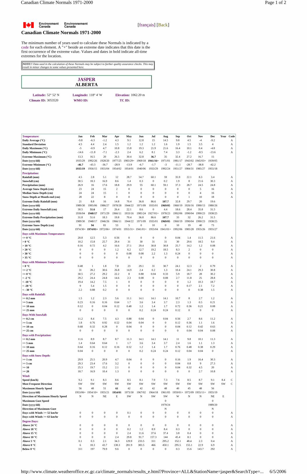
[français] [Back]
Canadian Climate Normals 1971-2000
The minimum number of years used to calculate these Normals is indicated by a code for each element. A "+" beside an extreme date indicates that this date is the first occurrence of the extreme value. Values and dates in bold indicate all-time extremes for the location.
NOTE!! Data used in the calculation of these Normals may be subject to further quality assurance checks. This may result in minor changes to some values presented here.
JASPER ALBERTA
Latitude: 52° 52' N Longitude: 118° 4' W Elevation: 1062.20 m
Climate ID: 3053520 WMO ID: TC ID:
Temperature: Jan Feb Mar Apr May Jun Jul Aug Sep Oct Nov Dec Year CodeDaily Average (°C) -9.8 -6.3 -1.2 4.3 9.1 12.8 15 14.5 9.8 4.5 -4 -9.2 AStandard Deviation 4.5 4.4 2.4 1.5 1.2 1.2 1.2 1.6 1.9 1.5 3.5 4 ADaily Maximum (°C) -5 -0.9 4.7 10.8 15.8 19.3 21.9 21.6 16.4 10.1 0.4 -4.8 ADaily Minimum (°C) -14.6 -11.8 -7.1 -2.3 2.4 6.2 8.1 7.4 3.3 -1.2 -8.5 -13.6 A
Extreme Maximum (°C) 13.3 16.5 20 26.5 30.4 32.8 36.7 35 32.4 27.2 16.7 15Date (yyyy/dd) 1935/29 1992/26 1928/20 1977/25 1983/29+ 1969/18 1941/16+ 1971/01 1981/17 1943/02 1945/03+ 1939/05Extreme Minimum (°C) -46.7 -43.3 -36.7 -28.9 -13.9 -6.7 -1.7 -3 -11.1 -28.7 -38.8 -42.2Date (yyyy/dd) 1935/19 1956/15 1955/04 1954/02 1954/01 1940/06 1933/29 1992/24 1951/27 1984/31 1985/27 1955/18
Precipitation: Rainfall (mm) 4.5 2.8 5.1 12 28.7 54.7 60.1 59 35.9 22.1 8.3 3.4 ASnowfall (cm) 30.5 18.3 16.9 8.6 1.4 0.3 0 0.2 1.9 8 21.6 30.3 APrecipitation (mm) 26.9 16 17.6 18.8 29.9 55 60.1 59.1 37.3 28.7 24.5 24.8 AAverage Snow Depth (cm) 23 24 15 2 0 0 0 0 0 0 5 16 AMedian Snow Depth (cm) 24 24 15 1 0 0 0 0 0 0 4 16 ASnow Depth at Month-end (cm) 28 22 8 0 0 0 0 0 0 1 10 18 A
Extreme Daily Rainfall (mm) 21 8.8 16 14.8 70.4 36.8 86.6 107.7 32.8 29.7 20 19.6Date (yyyy/dd) 1989/30 1995/06 1986/27 1978/28 1944/22 1971/09 1935/01 1969/05 1960/19 1926/16 1990/13 1980/26Extreme Daily Snowfall (cm) 30.5 51.6 17 26.4 22.1 8.6 0 4.4 18.6 28.4 35.8 31.5Date (yyyy/dd) 1936/04 1948/17 1971/29 1966/11 1933/16 1985/24 1927/01+ 1978/23 1992/06 1990/04 1990/23 1938/25Extreme Daily Precipitation (mm) 31.8 51.6 18.3 19.8 70.4 36.8 86.6 107.7 33 32 26.2 31.5Date (yyyy/dd) 1989/30 1948/17 1946/26 1966/11 1944/22 1971/09 1935/01 1969/05 1960/19 1990/04 1990/23 1938/25Extreme Snow Depth (cm) 91 94 81 53 5 0 10 0 10 19 40 73Date (yyyy/dd) 1974/30+ 1974/01+ 1972/06+ 1974/01 1955/31+ 1941/01+ 1955/04 1941/01+ 1992/06 1985/28 1955/26 1955/27
Days with Maximum Temperature: <= 0 °C 20.8 12.5 5.3 0.56 0 0 0 0 0.04 1.4 11.5 21.6 A> 0 °C 10.2 15.8 25.7 29.4 31 30 31 31 30 29.6 18.5 9.4 A> 10 °C 0.16 0.72 4.2 16.6 27.1 29.4 30.8 30.8 25.7 14.2 1.2 0.08 A> 20 °C 0 0 0 1.2 6.2 12.7 19.2 18.5 8.3 2 0 0 A> 30 °C 0 0 0 0 0.08 0.08 2.2 1.3 0.24 0 0 0 A> 35 °C 0 0 0 0 0 0 0 0 0 0 0 0 A
Days with Minimum Temperature: > 0 °C 0.48 1 1.8 7.8 23 29.1 31 30.7 24.1 12.3 2 0.79 A<= 2 °C 31 28.2 30.6 26.8 14.9 2.4 0.2 1.3 10.4 24.1 29.3 30.8 A<= 0 °C 30.5 27.2 29.2 22.2 8 0.88 0.04 0.33 5.9 18.7 28 30.2 A< -2 °C 29.2 24.4 24.8 14.6 2.3 0.08 0 0.08 2.7 11.8 25 28.8 A< -10 °C 19.4 14.2 7.5 1 0 0 0 0 0 1.2 10.3 18.7 A< -20 °C 9 5.4 1.5 0 0 0 0 0 0 0.17 2.1 7.2 A< - 30 °C 2.2 0.88 0.2 0 0 0 0 0 0 0 0.38 1.5 A
Days with Rainfall: >= 0.2 mm 1.5 1.2 2.3 5.6 11.1 14.1 14.1 14.1 10.7 8 2.7 1.2 A>= 5 mm 0.23 0.16 0.16 0.64 1.7 3.6 3.4 3.7 2.3 1.3 0.5 0.21 A>= 10 mm 0.12 0 0.04 0.12 0.48 1.2 1.4 1.7 0.72 0.36 0.21 0.08 A>= 25 mm 0 0 0 0 0 0.2 0.24 0.24 0.12 0 0 0 A
Days With Snowfall: >= 0.2 cm 11.2 8.4 7.5 4.3 0.88 0.04 0 0.04 0.56 2.7 8.6 11.2 A>= 5 cm 1.8 0.76 0.92 0.52 0.04 0.04 0 0 0.12 0.36 1.1 1.6 A>= 10 cm 0.68 0.32 0.28 0 0.04 0 0 0 0.04 0.12 0.42 0.63 A>= 25 cm 0 0 0 0 0 0 0 0 0 0.04 0.04 0.08 A
Days with Precipitation: >= 0.2 mm 11.6 8.9 8.7 8.7 11.3 14.1 14.1 14.1 11 9.8 10.1 11.3 A>= 5 mm 1.4 0.64 0.64 1 1.7 3.6 3.4 3.7 2.4 1.6 1.1 1.3 A>= 10 mm 0.64 0.16 0.12 0.16 0.52 1.2 1.4 1.7 0.76 0.48 0.38 0.29 A>= 25 mm 0.04 0 0 0 0 0.2 0.24 0.24 0.12 0.04 0.04 0 A
Days with Snow Depth: >= 1 cm 29.9 25.5 20.9 4.7 0.04 0 0 0 0.16 1.9 16.4 30.3 A>= 5 cm 29.3 23.4 17.6 3.2 0 0 0 0 0.04 0.8 9 27.3 A>= 10 25.3 19.7 15.2 2.1 0 0 0 0 0.04 0.32 4.5 20 A>= 20 18.7 16.9 10.4 1.3 0 0 0 0 0 0 2.7 10.8 A
Wind: Speed (km/h) 9.2 9.1 8.3 8.6 8.5 8.1 7.9 7.3 7.6 8.5 8.7 9.1 8.4 CMost Frequent Direction SW SW SW SW SW SW SW SW SW SW SW SW SW C
Maximum Hourly Speed 56 48 51 61 42 42 42 48 40 45 48 56Date (yyyy/dd) 1953/06+ 1954/10+ 1955/21 1954/01 1973/30 1967/02 1964/18 1961/05 1959/01+ 1972/09 1955/11+ 1955/19Direction of Maximum Hourly Speed N N NE E SW N SW SW W N N NE E
Maximum Gust Speed 0 0Date (yyyy/dd) 1979/24 1989/20Direction of Maximum Gust N NDays with Winds >= 52 km/hr 0 0 0 0 0.1 0 0 0 0 0 0 0 ADays with Winds >= 63 km/hr 0 0 0 0 0 0 0 0 0 0 0 0 A
Degree Days: Above 24 °C 0 0 0 0 0 0 0 0 0 0 0 0 AAbove 18 °C 0 0 0 0 0.2 1.2 8.9 8.4 0.3 0 0 0 AAbove 15 °C 0 0 0 0 2.4 11.6 37.6 37.4 3.8 0.4 0 0 AAbove 10 °C 0 0 0 2.4 29.8 91.7 157.3 144 45.4 8.1 0 0 AAbove 5 °C 0.1 0.3 2.1 34.3 129.9 233.5 311 295.2 152.1 48.4 2.3 0.4 AAbove 0 °C 6 18.3 43.7 138.3 281.9 383.5 466 450.1 295.5 155.1 22.9 6.9 ABelow 0 °C 311 197 79.9 9.6 0 0 0 0 0.3 15.6 143.7 292 A
Page 1 of 2Canadian Climate Normals 1971-2000
6/5/2006http://www.climate.weatheroffice.ec.gc.ca/climate_normals/results_e.html?Province=ALL&StationName=jasper&SearchType=...

Below 5 °C 460.1 320.1 193.4 55.6 3 0.1 0 0.1 6.8 63.9 273.1 440.5 ABelow 10 °C 615 461 346.3 173.7 57.9 8.3 1.3 3.9 50.1 178.5 420.8 595.1 ABelow 15 °C 770 602.2 501.3 321.3 185.5 78.1 36.6 52.3 158.6 325.8 570.8 750.1 ABelow 18 °C 863 686.9 594.3 411.3 276.2 157.8 100.9 116.3 245.1 418.5 660.8 843.1 A
Bright Sunshine: Total Hours 73.6 99.5 162.8 203.4 225.3 230.1 253.2 235.1 167.3 135.8 79 55.1 1920.2 DDays with measureable 24 24.5 28.7 29.1 29.7 29.1 29.9 29.7 27.6 28 24.2 21.6 326 D% of possible daylight hours 29 35.9 44.4 48.7 46 45.6 49.9 51.5 43.8 41.2 30.1 23.1 40.8 D
Extreme Daily 6.9 9.3 10.9 13 14.3 14.7 14.7 13.8 11.8 10 7.5 5.3 DDate (yyyy/dd) 1978/30+ 1978/28+ 1984/31+ 1980/30+ 1982/29+ 1979/25+ 1978/02+ 1978/03 1988/01 1987/01 1976/01 1983/01+
Humidex: Extreme Humidex 10.7 15.9 18.5 26.1 30 31.3 37.3 36.8 32.1 25 16.1 12.3Date (yyyy/dd) 1993/30 1992/26 1994/30 1957/30 1993/12 1973/22 1959/22 1967/18 1988/05 1991/11 1975/04 1980/16
Wind Chill: Extreme Wind Chill -53.6 -50.5 -43.8 -30.2 -12.8 -5.3 -2 -4.8 -15.6 -34.4 -51.6 -51.1Date (yyyy/dd) 1972/25 1956/15 1955/03 1954/01 1954/01 1976/03 1972/01 1973/19 1972/27 1984/31 1985/27 1968/28
Humidity: Average Relative Humidity - 0600LST (%) 81.4 80.9 80.8 80.2 80 81 83 87 86.8 82.3 83.5 82.3 AAverage Relative Humidity - 1500LST (%) 70.9 61.5 49.9 38.5 38.3 40.5 41.8 44.2 47.1 50.8 66.7 74.3 52 C
Important Notices
Created : 2002-06-21 Modified : 2004-02-25 Reviewed : 2004-02-25 Url of this page : http://www.climate.weatheroffice.ec.gc.ca/climate_normals/results_e.html
The Green LaneTM, Environment Canada's World Wide Web Site.
Page 2 of 2Canadian Climate Normals 1971-2000
6/5/2006http://www.climate.weatheroffice.ec.gc.ca/climate_normals/results_e.html?Province=ALL&StationName=jasper&SearchType=...
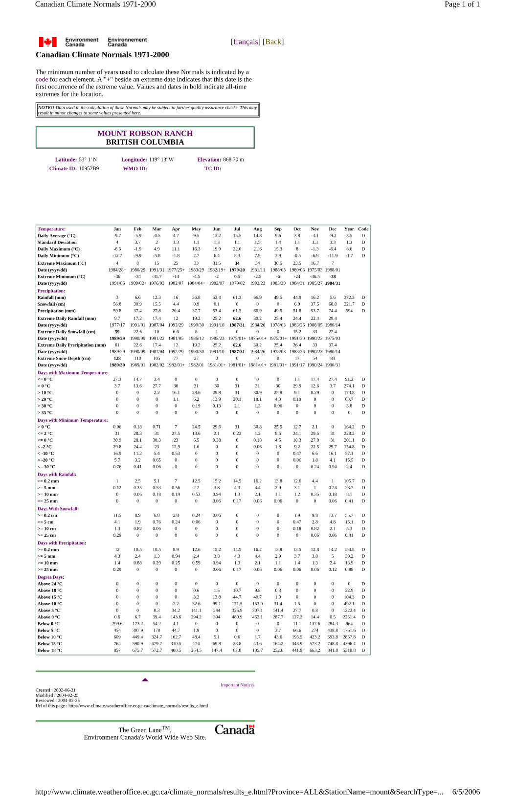
[français] [Back]
Canadian Climate Normals 1971-2000
The minimum number of years used to calculate these Normals is indicated by a code for each element. A "+" beside an extreme date indicates that this date is the first occurrence of the extreme value. Values and dates in bold indicate all-time extremes for the location.
NOTE!! Data used in the calculation of these Normals may be subject to further quality assurance checks. This may result in minor changes to some values presented here.
MOUNT ROBSON RANCH BRITISH COLUMBIA
Latitude: 53° 1' N Longitude: 119° 13' W Elevation: 868.70 m
Climate ID: 10952B9 WMO ID: TC ID:
Temperature: Jan Feb Mar Apr May Jun Jul Aug Sep Oct Nov Dec Year CodeDaily Average (°C) -9.7 -5.9 -0.5 4.7 9.5 13.2 15.5 14.8 9.6 3.8 -4.1 -9.2 3.5 DStandard Deviation 4 3.7 2 1.3 1.1 1.3 1.1 1.5 1.4 1.1 3.3 3.3 1.3 DDaily Maximum (°C) -6.6 -1.9 4.9 11.1 16.3 19.9 22.6 21.6 15.3 8 -1.3 -6.4 8.6 DDaily Minimum (°C) -12.7 -9.9 -5.8 -1.8 2.7 6.4 8.3 7.9 3.9 -0.5 -6.9 -11.9 -1.7 D
Extreme Maximum (°C) 4 8 15 25 33 31.5 34 34 30.5 23.5 16.7 7Date (yyyy/dd) 1984/28+ 1980/29 1991/31 1977/25+ 1983/29 1982/19+ 1979/20 1981/11 1988/03 1980/06 1975/03 1988/01Extreme Minimum (°C) -36 -34 -31.7 -14 -4.5 -2 0.5 -2.5 -6 -24 -36.5 -38Date (yyyy/dd) 1991/05 1989/02+ 1976/03 1982/07 1984/04+ 1982/07 1979/02 1992/23 1983/30 1984/31 1985/27 1984/31Precipitation: Rainfall (mm) 3 6.6 12.3 16 36.8 53.4 61.3 66.9 49.5 44.9 16.2 5.6 372.3 DSnowfall (cm) 56.8 30.9 15.5 4.4 0.9 0.1 0 0 0 6.9 37.5 68.8 221.7 DPrecipitation (mm) 59.8 37.4 27.8 20.4 37.7 53.4 61.3 66.9 49.5 51.8 53.7 74.4 594 D
Extreme Daily Rainfall (mm) 9.7 17.2 17.4 12 19.2 25.2 62.6 30.2 25.4 24.4 22.4 29.4Date (yyyy/dd) 1977/17 1991/01 1987/04 1992/29 1990/30 1991/10 1987/31 1984/26 1978/03 1983/26 1988/05 1980/14Extreme Daily Snowfall (cm) 59 22.6 10 6.6 8 1 0 0 0 15.2 33 27.4Date (yyyy/dd) 1989/29 1990/09 1991/22 1981/05 1986/12 1985/23 1975/01+ 1975/01+ 1975/01+ 1991/30 1990/23 1975/03Extreme Daily Precipitation (mm) 61 22.6 17.4 12 19.2 25.2 62.6 30.2 25.4 26.4 33 37.4Date (yyyy/dd) 1989/29 1990/09 1987/04 1992/29 1990/30 1991/10 1987/31 1984/26 1978/03 1983/26 1990/23 1980/14Extreme Snow Depth (cm) 128 110 105 77 27 0 0 0 0 17 54 83Date (yyyy/dd) 1989/30 1989/01 1982/02 1982/01+ 1982/01 1981/01+ 1981/01+ 1981/01+ 1981/01+ 1991/17 1990/24 1990/31
Days with Maximum Temperature: <= 0 °C 27.3 14.7 3.4 0 0 0 0 0 0 1.1 17.4 27.4 91.2 D> 0 °C 3.7 13.6 27.7 30 31 30 31 31 30 29.9 12.6 3.7 274.1 D> 10 °C 0 0 2.2 16.1 28.6 29.8 31 30.9 25.8 9.1 0.29 0 173.8 D> 20 °C 0 0 0 1.1 6.2 13.9 20.1 18.1 4.3 0.19 0 0 63.7 D> 30 °C 0 0 0 0 0.19 0.13 2.1 1.3 0.06 0 0 0 3.8 D> 35 °C 0 0 0 0 0 0 0 0 0 0 0 0 0 D
Days with Minimum Temperature: > 0 °C 0.06 0.18 0.71 7 24.5 29.6 31 30.8 25.5 12.7 2.1 0 164.2 D<= 2 °C 31 28.3 31 27.5 13.6 2.1 0.22 1.2 8.5 24.1 29.5 31 228.2 D<= 0 °C 30.9 28.1 30.3 23 6.5 0.38 0 0.18 4.5 18.3 27.9 31 201.1 D< -2 °C 29.8 24.4 23 12.9 1.6 0 0 0.06 1.8 9.2 22.5 29.7 154.8 D< -10 °C 16.9 11.2 5.4 0.53 0 0 0 0 0 0.47 6.6 16.1 57.1 D< -20 °C 5.7 3.2 0.65 0 0 0 0 0 0 0.06 1.8 4.1 15.5 D< - 30 °C 0.76 0.41 0.06 0 0 0 0 0 0 0 0.24 0.94 2.4 D
Days with Rainfall: >= 0.2 mm 1 2.5 5.1 7 12.5 15.2 14.5 16.2 13.8 12.6 4.4 1 105.7 D>= 5 mm 0.12 0.35 0.53 0.56 2.2 3.8 4.3 4.4 2.9 3.1 1 0.24 23.7 D>= 10 mm 0 0.06 0.18 0.19 0.53 0.94 1.3 2.1 1.1 1.2 0.35 0.18 8.1 D>= 25 mm 0 0 0 0 0 0.06 0.17 0.06 0.06 0 0 0.06 0.41 D
Days With Snowfall: >= 0.2 cm 11.5 8.9 6.8 2.8 0.24 0.06 0 0 0 1.9 9.8 13.7 55.7 D>= 5 cm 4.1 1.9 0.76 0.24 0.06 0 0 0 0 0.47 2.8 4.8 15.1 D>= 10 cm 1.3 0.82 0.06 0 0 0 0 0 0 0.18 0.82 2.1 5.3 D>= 25 cm 0.29 0 0 0 0 0 0 0 0 0 0.06 0.06 0.41 D
Days with Precipitation: >= 0.2 mm 12 10.5 10.5 8.9 12.6 15.2 14.5 16.2 13.8 13.5 12.8 14.2 154.8 D>= 5 mm 4.3 2.4 1.3 0.94 2.4 3.8 4.3 4.4 2.9 3.7 3.8 5 39.2 D>= 10 mm 1.4 0.88 0.29 0.25 0.59 0.94 1.3 2.1 1.1 1.4 1.3 2.4 13.9 D>= 25 mm 0.29 0 0 0 0 0.06 0.17 0.06 0.06 0.06 0.06 0.12 0.88 D
Degree Days: Above 24 °C 0 0 0 0 0 0 0 0 0 0 0 0 0 DAbove 18 °C 0 0 0 0 0.6 1.5 10.7 9.8 0.3 0 0 0 22.9 DAbove 15 °C 0 0 0 0 3.2 13.8 44.7 40.7 1.9 0 0 0 104.3 DAbove 10 °C 0 0 0 2.2 32.6 99.1 171.5 153.9 31.4 1.5 0 0 492.1 DAbove 5 °C 0 0 0.3 34.2 141.1 244 325.9 307.1 141.4 27.7 0.8 0 1222.4 DAbove 0 °C 0.6 6.7 39.4 143.6 294.2 394 480.9 462.1 287.7 127.2 14.4 0.5 2251.4 DBelow 0 °C 299.6 173.2 54.2 4.1 0 0 0 0 0 11.1 137.6 284.3 964 DBelow 5 °C 454 307.9 170 44.7 1.9 0 0 0 3.7 66.6 274 438.8 1761.6 DBelow 10 °C 609 449.4 324.7 162.7 48.4 5.1 0.6 1.7 43.6 195.5 423.2 593.8 2857.8 DBelow 15 °C 764 590.9 479.7 310.5 174 69.8 28.8 43.6 164.2 348.9 573.2 748.8 4296.4 DBelow 18 °C 857 675.7 572.7 400.5 264.5 147.4 87.8 105.7 252.6 441.9 663.2 841.8 5310.8 D
Important Notices
Created : 2002-06-21 Modified : 2004-02-25 Reviewed : 2004-02-25 Url of this page : http://www.climate.weatheroffice.ec.gc.ca/climate_normals/results_e.html
The Green LaneTM, Environment Canada's World Wide Web Site.
Page 1 of 1Canadian Climate Normals 1971-2000
6/5/2006http://www.climate.weatheroffice.ec.gc.ca/climate_normals/results_e.html?Province=ALL&StationName=mount&SearchType=...